JP6924056B2 - clothing - Google Patents
clothing Download PDFInfo
- Publication number
- JP6924056B2 JP6924056B2 JP2017064494A JP2017064494A JP6924056B2 JP 6924056 B2 JP6924056 B2 JP 6924056B2 JP 2017064494 A JP2017064494 A JP 2017064494A JP 2017064494 A JP2017064494 A JP 2017064494A JP 6924056 B2 JP6924056 B2 JP 6924056B2
- Authority
- JP
- Japan
- Prior art keywords
- auxiliary band
- auxiliary
- body covering
- band
- wearer
- Prior art date
- Legal status (The legal status is an assumption and is not a legal conclusion. Google has not performed a legal analysis and makes no representation as to the accuracy of the status listed.)
- Active
Links
Images


Classifications
-
- A—HUMAN NECESSITIES
- A61—MEDICAL OR VETERINARY SCIENCE; HYGIENE
- A61H—PHYSICAL THERAPY APPARATUS, e.g. DEVICES FOR LOCATING OR STIMULATING REFLEX POINTS IN THE BODY; ARTIFICIAL RESPIRATION; MASSAGE; BATHING DEVICES FOR SPECIAL THERAPEUTIC OR HYGIENIC PURPOSES OR SPECIFIC PARTS OF THE BODY
- A61H3/00—Appliances for aiding patients or disabled persons to walk about
-
- A—HUMAN NECESSITIES
- A41—WEARING APPAREL
- A41B—SHIRTS; UNDERWEAR; BABY LINEN; HANDKERCHIEFS
- A41B9/00—Undergarments
- A41B9/001—Underpants or briefs
-
- A—HUMAN NECESSITIES
- A41—WEARING APPAREL
- A41B—SHIRTS; UNDERWEAR; BABY LINEN; HANDKERCHIEFS
- A41B9/00—Undergarments
- A41B9/14—Waistbands forming part of the undergarments; Closures therefor
-
- A—HUMAN NECESSITIES
- A41—WEARING APPAREL
- A41D—OUTERWEAR; PROTECTIVE GARMENTS; ACCESSORIES
- A41D13/00—Professional, industrial or sporting protective garments, e.g. surgeons' gowns or garments protecting against blows or punches
- A41D13/0015—Sports garments other than provided for in groups A41D13/0007 - A41D13/088
-
- A—HUMAN NECESSITIES
- A61—MEDICAL OR VETERINARY SCIENCE; HYGIENE
- A61F—FILTERS IMPLANTABLE INTO BLOOD VESSELS; PROSTHESES; DEVICES PROVIDING PATENCY TO, OR PREVENTING COLLAPSING OF, TUBULAR STRUCTURES OF THE BODY, e.g. STENTS; ORTHOPAEDIC, NURSING OR CONTRACEPTIVE DEVICES; FOMENTATION; TREATMENT OR PROTECTION OF EYES OR EARS; BANDAGES, DRESSINGS OR ABSORBENT PADS; FIRST-AID KITS
- A61F5/00—Orthopaedic methods or devices for non-surgical treatment of bones or joints; Nursing devices; Anti-rape devices
- A61F5/01—Orthopaedic devices, e.g. splints, casts or braces
- A61F5/0102—Orthopaedic devices, e.g. splints, casts or braces specially adapted for correcting deformities of the limbs or for supporting them; Ortheses, e.g. with articulations
- A61F5/0104—Orthopaedic devices, e.g. splints, casts or braces specially adapted for correcting deformities of the limbs or for supporting them; Ortheses, e.g. with articulations without articulation
- A61F5/0106—Orthopaedic devices, e.g. splints, casts or braces specially adapted for correcting deformities of the limbs or for supporting them; Ortheses, e.g. with articulations without articulation for the knees
- A61F5/0109—Sleeve-like structures
-
- D—TEXTILES; PAPER
- D04—BRAIDING; LACE-MAKING; KNITTING; TRIMMINGS; NON-WOVEN FABRICS
- D04B—KNITTING
- D04B1/00—Weft knitting processes for the production of fabrics or articles not dependent on the use of particular machines; Fabrics or articles defined by such processes
- D04B1/22—Weft knitting processes for the production of fabrics or articles not dependent on the use of particular machines; Fabrics or articles defined by such processes specially adapted for knitting goods of particular configuration
- D04B1/24—Weft knitting processes for the production of fabrics or articles not dependent on the use of particular machines; Fabrics or articles defined by such processes specially adapted for knitting goods of particular configuration wearing apparel
-
- D—TEXTILES; PAPER
- D04—BRAIDING; LACE-MAKING; KNITTING; TRIMMINGS; NON-WOVEN FABRICS
- D04B—KNITTING
- D04B21/00—Warp knitting processes for the production of fabrics or articles not dependent on the use of particular machines; Fabrics or articles defined by such processes
- D04B21/20—Warp knitting processes for the production of fabrics or articles not dependent on the use of particular machines; Fabrics or articles defined by such processes specially adapted for knitting articles of particular configuration
- D04B21/207—Wearing apparel or garment blanks
-
- A—HUMAN NECESSITIES
- A41—WEARING APPAREL
- A41B—SHIRTS; UNDERWEAR; BABY LINEN; HANDKERCHIEFS
- A41B2500/00—Materials for shirts, underwear, baby linen or handkerchiefs not provided for in other groups of this subclass
- A41B2500/10—Knitted
-
- A—HUMAN NECESSITIES
- A61—MEDICAL OR VETERINARY SCIENCE; HYGIENE
- A61H—PHYSICAL THERAPY APPARATUS, e.g. DEVICES FOR LOCATING OR STIMULATING REFLEX POINTS IN THE BODY; ARTIFICIAL RESPIRATION; MASSAGE; BATHING DEVICES FOR SPECIAL THERAPEUTIC OR HYGIENIC PURPOSES OR SPECIFIC PARTS OF THE BODY
- A61H3/00—Appliances for aiding patients or disabled persons to walk about
- A61H2003/007—Appliances for aiding patients or disabled persons to walk about secured to the patient, e.g. with belts
-
- A—HUMAN NECESSITIES
- A61—MEDICAL OR VETERINARY SCIENCE; HYGIENE
- A61H—PHYSICAL THERAPY APPARATUS, e.g. DEVICES FOR LOCATING OR STIMULATING REFLEX POINTS IN THE BODY; ARTIFICIAL RESPIRATION; MASSAGE; BATHING DEVICES FOR SPECIAL THERAPEUTIC OR HYGIENIC PURPOSES OR SPECIFIC PARTS OF THE BODY
- A61H2201/00—Characteristics of apparatus not provided for in the preceding codes
- A61H2201/16—Physical interface with patient
- A61H2201/1602—Physical interface with patient kind of interface, e.g. head rest, knee support or lumbar support
- A61H2201/165—Wearable interfaces
-
- A—HUMAN NECESSITIES
- A61—MEDICAL OR VETERINARY SCIENCE; HYGIENE
- A61H—PHYSICAL THERAPY APPARATUS, e.g. DEVICES FOR LOCATING OR STIMULATING REFLEX POINTS IN THE BODY; ARTIFICIAL RESPIRATION; MASSAGE; BATHING DEVICES FOR SPECIAL THERAPEUTIC OR HYGIENIC PURPOSES OR SPECIFIC PARTS OF THE BODY
- A61H2205/00—Devices for specific parts of the body
- A61H2205/10—Leg
- A61H2205/102—Knee
-
- D—TEXTILES; PAPER
- D10—INDEXING SCHEME ASSOCIATED WITH SUBLASSES OF SECTION D, RELATING TO TEXTILES
- D10B—INDEXING SCHEME ASSOCIATED WITH SUBLASSES OF SECTION D, RELATING TO TEXTILES
- D10B2331/00—Fibres made from polymers obtained otherwise than by reactions only involving carbon-to-carbon unsaturated bonds, e.g. polycondensation products
- D10B2331/02—Fibres made from polymers obtained otherwise than by reactions only involving carbon-to-carbon unsaturated bonds, e.g. polycondensation products polyamides
-
- D—TEXTILES; PAPER
- D10—INDEXING SCHEME ASSOCIATED WITH SUBLASSES OF SECTION D, RELATING TO TEXTILES
- D10B—INDEXING SCHEME ASSOCIATED WITH SUBLASSES OF SECTION D, RELATING TO TEXTILES
- D10B2331/00—Fibres made from polymers obtained otherwise than by reactions only involving carbon-to-carbon unsaturated bonds, e.g. polycondensation products
- D10B2331/10—Fibres made from polymers obtained otherwise than by reactions only involving carbon-to-carbon unsaturated bonds, e.g. polycondensation products polyurethanes
Description
本発明は、身体能力低下者およびその予備軍に好適に用いることができて、自身の筋力による関節運動を楽にして筋力低下を効果的に抑制し、日常の身体活動を維持したり高めたりする衣類に関するものである。 The present invention can be suitably used for persons with physical weakness and their reserve forces, and can ease joint movements due to their own muscle strength, effectively suppress muscle weakness, and maintain or enhance daily physical activity. It is about clothing to be used.
近年、世界的な高齢化が急速に進行している。人々が年を重ねてもその能力に応じて働き続け、あるいは自立的で活動的な日常生活をおくることを支援しながら、増大する医療費や社会保障費をいかに抑えていくかが大きな社会的課題となっている。 In recent years, the global aging of the population has progressed rapidly. How to curb rising medical and social security costs while helping people continue to work according to their abilities as they grow older, or to lead independent and active daily lives is a major social issue. It has become a challenge.
筋力を高めることは、日常生活を送るための能力を維持および向上させる上で重要な要素となっている。高齢者にとって筋力の低下は、関節への負担を大きくするだけでなく、起居動作などの日常の活動に支障をきたす結果を招くと言われている。また、柔軟性を高めることは、関節の可動域や関節の機能を改善したり、筋の緊張を和らげたりすることによって、傷害の予防につながる。特に歩行などの自然な体の動きを再現するような関節運動を促進することは、健常者の身体能力の機能維持はもとより、身体能力低下者の機能回復のためのリハビリテーションの現場においても、重要なアプローチとなっている。 Strengthening is an important factor in maintaining and improving the ability to lead a daily life. It is said that for the elderly, the decrease in muscle strength not only increases the burden on the joints, but also hinders daily activities such as getting up. In addition, increasing flexibility leads to prevention of injuries by improving the range of motion of joints, joint function, and relieving muscle tone. In particular, promoting joint movements that reproduce natural body movements such as walking is important not only for maintaining the function of the physical ability of healthy people, but also in the field of rehabilitation for recovering the function of people with reduced physical ability. Approach.
身体能力や活動度に問題ない人々、あるいは相対的に身体能力や活動度が高い人々に向けては、スポーツウェアやスポーツインナー、およびサポート機能を持った様々な衣料が提案されている。例えば、下肢部の衣服圧を部分的に変化させた衣類(特許文献1参照)や、特定部分の締め付け力を高めた衣類(特許文献2参照)、伸縮性の方向性が異なる素材を組み合わせた衣類(特許文献3参照)、着用者の筋肉または靭帯に沿う部分に補強部が設けられた衣類(特許文献4参照)などが知られており、これらはその衣服圧からコンプレッション衣料と総称されている。 For people who have no problem with their physical ability and activity, or those who have relatively high physical ability and activity, sportswear, sports innerwear, and various clothing with support functions have been proposed. For example, clothing in which the clothing pressure of the lower limbs is partially changed (see Patent Document 1), clothing in which the tightening force of a specific portion is increased (see Patent Document 2), and materials having different elasticity directions are combined. Clothes (see Patent Document 3), garments with reinforcements along the wearer's muscles or ligaments (see Patent Document 4), etc. are known, and these are collectively called compression garments because of their garment pressure. There is.
しかしながら、これらのコンプレッション衣料は、特定の筋肉に衣服圧がかかるように設計され、その筋肉を保護あるいは増強することを目的としたものであり、関節の動きを直接補助するものではなかった。また、全体として締め付け力が強いものが多く、握力が弱い身体能力低下者やその予備軍にとって履いたり着用したりしにくく、特に加齢に伴い腹回り径が増す傾向にある高齢者にとっては長時間の着用が困難であるという問題もあった。また、身体能力低下者やその予備軍、例えば運動習慣がない一般の中高年はそもそも筋力が極めて低い人が多く、上記のコンプレッション衣料を着用して根気よく運動を継続してやっと得られる筋力の増強は気力や持久力の面で受け入れられにくい面があった。 However, these compression garments were designed to apply clothing pressure to specific muscles, with the purpose of protecting or strengthening those muscles, and not directly assisting the movement of joints. In addition, many of them have strong tightening force as a whole, and it is difficult for people with weak physical strength and their reserves to wear or wear them, especially for elderly people who tend to increase their abdominal circumference with aging. There was also the problem that it was difficult to wear the time. In addition, many people with reduced physical abilities and their reserve forces, such as middle-aged and elderly people who do not have exercise habits, have extremely low muscular strength in the first place. There were some aspects that were difficult to accept in terms of energy and endurance.
そのように筋力がない身体能力低下者に向けては、特許文献5および6に代表されるような股関節の振り出しを少し補助して歩行を楽にする電気駆動式のアシスト装具が、様々な自動車メーカー、材料メーカー、および大学から提案され始めている。
For those with physical weakness who do not have such strength, various automobile manufacturers have electrically driven assist orthoses that slightly assist the hip joint swinging and make walking easier, as represented by
しかし、特許文献5および6に示される上記のアシスト装具は電気駆動式であるがゆえにバッテリーが必須であり、現状のリチウムイオン電池バッテリー容量ではアシスト装具の重量が非常に大きなものとなり、このアシスト装具の使用時間などに制約がある。また、着用回毎に着用者の身体能力に合わせて専門家による補助力の電子的な設定や、機械的な調整が必要であり、着用に要する手間が煩雑であるという課題もある。
However, since the above-mentioned assist orthosis shown in
そこで、本発明は、上記課題を解決するためになされたものであり、その目的は、電気的な駆動源を必要とせず、低コストで、着用性や安全性に優れ、人の自然な動きを再現するような体の関節運動に対し、それを効果的に補助する衣類を提供することにある。 Therefore, the present invention has been made to solve the above problems, and an object of the present invention is that it does not require an electric drive source, is low in cost, is excellent in wearability and safety, and is a natural movement of a person. The purpose is to provide clothing that effectively assists the joint movement of the body that reproduces the above.
本発明者は前記課題を解決するために鋭意検討をおこなった結果、次のような手段を採用することにより課題を解決できることを見出した。 As a result of diligent studies to solve the above-mentioned problems, the present inventor has found that the problems can be solved by adopting the following means.
(1)身体被覆地に補助帯が配置された衣類であって、前記補助帯は、前記身体被覆地における着用者の関節を覆う部分を挟んで一方の端部側から他方の端部側にかけて着用者の身体表面に沿うように前記身体被覆地に配置されており、前記補助帯と前記身体被覆地とは、互いに分離されて独立して伸縮することができるように前記補助帯は前記身体被覆地に固定され、前記補助帯の前記一方の端部側と前記他方の端部側とを結ぶ方向Sの前記衣類の着用時における張力T1が、前記補助帯と重なっている前記身体被覆地の前記方向Sに平行な方向の前記衣類の着用時における張力T2よりも大きい衣類。 (1) A garment in which an auxiliary band is arranged on a body covering material, and the auxiliary band extends from one end side to the other end side with a portion covering the wearer's joint in the body covering material. The auxiliary band is arranged along the body surface of the wearer, and the auxiliary band and the body covering are separated from each other and can expand and contract independently. The body covering material which is fixed to the covering material and whose tension T1 at the time of wearing the clothing in the direction S connecting the one end side and the other end side of the auxiliary band overlaps with the auxiliary band. A garment having a tension T2 greater than the tension T2 when the garment is worn in a direction parallel to the direction S of the garment.
(2)前記張力T1と前記張力T2との比、(T1/T2)が3以上100以下である前記(1)記載の衣類。 (2) The garment according to (1) above, wherein the ratio of the tension T1 to the tension T2, (T1 / T2) is 3 or more and 100 or less.
(3)前記張力T1を調整する手段を有する前記(1)または(2)記載の衣類。 (3) The garment according to (1) or (2) above, which has means for adjusting the tension T1.
(4)A1とA2の2つの補助帯を備えており、前記身体被覆地が、着用者の腰周部を覆う部分A、着用者の右膝周部を覆う部分Bおよび着用者の左膝周部を覆う部分Cを備えており、補助帯A1の一方の端部が前記部分Aに着脱可能な状態で固定されており、補助帯A1の他方の端部が前記部分Bに着脱可能な状態で固定されており、補助帯A2の一方の端部が前記部分Aに着脱可能な状態で固定されており、補助帯A2の他方の端部が前記部分Cに着脱可能な状態で固定されている前記(1)〜(3)のいずれかに記載の衣類。 (4) Two auxiliary bands, A1 and A2, are provided, and the body covering material covers the waist circumference of the wearer, the portion B covering the wearer's right knee circumference, and the wearer's left knee. A portion C that covers the peripheral portion is provided, one end of the auxiliary band A1 is fixed to the portion A in a detachable state, and the other end of the auxiliary band A1 is detachable to the portion B. It is fixed in a state, one end of the auxiliary band A2 is fixed to the portion A in a detachable state, and the other end of the auxiliary band A2 is fixed to the portion C in a detachable state. The clothing according to any one of (1) to (3) above.
(5)さらに調節帯を備え、前記身体被覆地が、着用者の腰周部を覆う部分Aを備えており、前記衣類の着用時に着用者の左右の腸骨稜付近を覆う前記身体被覆地の部分が前記調節帯により被覆されており、前記部分Aの少なくとも一部と前記調整帯とを着脱可能な状態で固定する腰締結部を有する前記(1)〜(4)のいずれかに記載の衣類。 (5) Further, the body covering material provided with a moderator band, the body covering material includes a portion A covering the waist circumference of the wearer, and covers the vicinity of the left and right iliac crests of the wearer when the garment is worn. (1) to (4), wherein the portion is covered with the adjusting band and has a waist fastening portion for fixing at least a part of the portion A and the adjusting band in a detachable state. Clothing.
(6)前記身体被覆地が、着用者の上腕部を覆う部分D、着用者の肘部を覆う部分E、および着用者の手首部を覆う部分Fを備えた筒状体であり、補助帯の一方の端部が前記部分Dに着脱可能な状態で固定されており、補助帯の他方の端部が前記部分Fに着脱可能な状態で固定されている前記(1)〜(3)のいずれかに記載の衣類。 (6) The body covering is a tubular body including a portion D covering the wearer's upper arm, a portion E covering the wearer's elbow, and a portion F covering the wearer's wrist, and is an auxiliary band. Of the above (1) to (3), one end is fixed to the portion D in a detachable state, and the other end of the auxiliary band is fixed to the portion F in a detachable state. Clothing listed in any.
本発明によれば、身体能力低下者およびその予備軍に好適に用いて、身体運動を楽にして体を動かす意欲を引き出し、結果として筋力低下を効果的に抑制することができ、電気的な駆動源を必要とせず、低コストで、着用性や安全性に優れ、人の自然な動きを再現するような体の動きを効果的に補助する衣類を提供することができる。 According to the present invention, it can be suitably used for a person with reduced physical ability and a reserve army thereof to ease physical exercise and motivate the body to move, and as a result, it is possible to effectively suppress muscle weakness and electrically. It is possible to provide clothing that does not require a drive source, is low in cost, is excellent in wearability and safety, and effectively assists body movements that reproduce the natural movements of a person.
本発明の衣類は、身体被覆地に補助帯が配置された衣類であって、前記補助帯は、前記身体被覆地における着用者の関節を覆う部分を挟んで一方の端部側から他方の端部側にかけて着用者の身体表面に沿うように前記身体被覆地に配置されている。ここで、前記補助帯と前記身体被覆地とは、互いに分離されて独立して伸縮することができるように前記補助帯は前記身体被覆地に固定されており、さらに、前記衣類の着用時における前記補助帯の前記一方の端部側と前記他方の端部側とを結ぶ方向Sの張力T1が、前記補助帯と重なっている前記身体被覆地の前記方向Sに平行な方向の張力T2よりも大きい。 The garment of the present invention is a garment in which an auxiliary band is arranged on a body covering material, and the auxiliary band is from one end side to the other end with a portion covering a wearer's joint in the body covering material. It is arranged on the body covering material so as to be along the body surface of the wearer toward the part side. Here, the auxiliary band and the body covering material are fixed to the body covering material so that they can be separated from each other and expanded and contracted independently, and further, when the clothing is worn. The tension T1 in the direction S connecting the one end side of the auxiliary band and the other end side is from the tension T2 in the direction parallel to the direction S of the body covering material overlapping the auxiliary band. Is also big.
このように、対象とする着用者の関節の両側に補助帯の一方の端部と片方の端部とを配置し、上記の張力T1が上記の張力T2よりも大きくなるように予め適度に引っ張っておくことで、補助帯がもとに戻ろうとする力を利用して関節の初動運動を望ましい方向に誘導することができる。本発明の衣類においては、対象とする着用者の関節の部分で身体被覆地と前記補助帯とは互いに分離されて独立して伸縮するので、補助帯は身体被覆地との固定点以外では拘束されることがなく、前記補助帯と前記関節を覆う部分とが重なる部分において、補助帯は身体被覆地の伸びを阻害しない。そのため、従来のコンプレッション衣料に比べて圧迫感が小さく長時間の着用にも耐えられる。また、補助帯と身体被覆地が互いに独立して伸縮することで、補助帯の一方の端部と他方の端部とが直接引き合い、その力は分散されることなくダイレクトに着用者の関節部位に伝わりやすくなる。ここで、補助帯がもとに戻ろうとする力をより効率的に利用するためには、前記身体被覆地と、前記補助帯が前記身体被覆地に固定されていない部分との静摩擦係数が低いことが望ましい。 In this way, one end and one end of the auxiliary band are arranged on both sides of the joint of the target wearer, and the tension T1 is appropriately pulled in advance so as to be larger than the tension T2. By doing so, it is possible to guide the initial movement of the joint in a desired direction by utilizing the force that the auxiliary band tries to return to its original position. In the garment of the present invention, since the body covering material and the auxiliary band are separated from each other and expand and contract independently at the joint portion of the target wearer, the auxiliary band is restrained except at the fixed point with the body covering material. In the portion where the auxiliary band and the portion covering the joint overlap, the auxiliary band does not hinder the elongation of the body covering. Therefore, the feeling of oppression is smaller than that of conventional compression clothing, and it can withstand long-term wearing. In addition, since the auxiliary band and the body covering material expand and contract independently of each other, one end of the auxiliary band and the other end are directly attracted to each other, and the force is not dispersed and the joint part of the wearer is directly attracted. It becomes easier to convey to. Here, in order to more efficiently utilize the force that the auxiliary band tries to return to its original state, the coefficient of static friction between the body covering material and the portion where the auxiliary band is not fixed to the body covering material is low. Is desirable.
本発明の衣類がサポートの対象とする関節は、上肢では肩関節、肘関節、手関節、手および指の関節、前腕など、下肢では股関節、膝関節、足関節、足指の関節、頸部および胸腰部などが具体的に挙げられる。すなわち、上記の関節は、骨と骨が連結されている部分であれば特に限定されず、補助帯は複数の関節に跨っていても差し支えない。また、これらの関節には屈曲、伸展、内転、外転、内旋、外旋、回内、回外など部位毎に決まった運動方向と角度で表される可動域があり、着用者の状態に応じて、望ましい部位において、望ましい関節運動を誘引するように補助帯を配置することが望ましい。 The joints supported by the clothing of the present invention include shoulder joints, elbow joints, wrist joints, hand and finger joints, and forearms in the upper limbs, and hip joints, knee joints, ankle joints, toe joints, and neck joints in the lower limbs. And the chest and waist are specifically mentioned. That is, the above-mentioned joint is not particularly limited as long as it is a portion where the bones are connected to each other, and the auxiliary band may straddle a plurality of joints. In addition, these joints have a range of motion represented by the movement direction and angle determined for each part such as flexion, extension, adduction, abduction, internal rotation, external rotation, supination, and supination. Depending on the condition, it is desirable to place an auxiliary band at the desired site to induce the desired range of motion.
本発明の衣類において補助帯は複数であってもよく、複数の補助帯は別の位置に配置されても、重ね合わせて配置されてもよい。 In the garment of the present invention, there may be a plurality of auxiliary bands, and the plurality of auxiliary bands may be arranged at different positions or may be arranged so as to overlap each other.
ここで、図1は、本発明の一実施形態例に係る衣類の着用時における概略正面図を示す。この衣類20aは身体被覆地21aおよび2つの補助帯2a、2bを有し、この身体被覆地21aは、衣類の着用時に着用者の腰周部を覆う部分(A)1、衣類の着用時に着用者の右膝周部を覆う部分(B)4、衣類の着用時に着用者の左膝周部を覆う部分(C)5、および4つの対となる係止部の一方を有している。また、補助帯2a、2bはそれぞれ2つの対となる係止部の他方を有している。すなわち、補助帯2a、2bに設けられた対となる係止部の他方側を構成するものが身体被覆地21aに設けられた対となる係止部の一方側を構成するものに係止されることにより、補助帯2a、2bは身体被覆地21aに着脱可能な状態で固定される。
Here, FIG. 1 shows a schematic front view when wearing clothing according to an embodiment of the present invention. The
また、身体被覆地21aに設けられた4つの対となる係止部の一方側を構成するものは、前記の腰周部を覆う部分Aの右側部R1および左側部L1と、前記の右膝周部を覆う部分Bの左側部L2と、前記の左膝周部を覆う部分Cの右側部R2とに、それぞれ1つずつ配置されている。また、補助帯2a、2bに設けられた2つの対となる係止部の他方側を構成するものは、一方の端部3aと他方の端部3bに配置されている。
Further, one side of the four pairs of locking portions provided on the body covering 21a is the right side portion R1 and the left side portion L1 of the portion A covering the waist circumference portion, and the right knee portion. One is arranged on the left side L2 of the portion B covering the peripheral portion and one on the right side R2 of the portion C covering the peripheral portion of the left knee. Further, those constituting the other side of the two paired locking portions provided on the
そして、2つの補助帯2a、2bのうち2aは、この補助帯2aの一方の端部3aに設けられた係止部が腰周部を覆う部分Aの右側部R1に設けられた係止部に係止されることにより、補助帯2aは着脱可能な状態で固定されており、この補助帯2aの他方の端部3bに設けられた係止部が右膝周部を覆う部分Bの左側部L2に設けられた係止部に係止されることにより、補助帯2aは着脱可能な状態で固定されている。また、2つの補助帯2a、2bのうち2bは、この補助帯2bの一方の端部3aに設けられた係止部が腰周部を覆う部分Aの左側部L1に設けられた係止部に係止されることにより、補助帯2bは着脱可能な状態で固定されており、この補助帯2bの他方の端部3bに設けられた係止部が左膝周部を覆う部分Cの右側部R2に設けられた係止部に係止されることにより、補助帯2bは着脱可能な状態で固定されている。
Of the two
また、2つの補助帯2a、2bは、これらの補助帯の2つの端部3aと3bが着用者の股関節を挟むように、かつ着用者の大腿前面の身体表面に沿うように配置されている。ここで、上記のとおり補助帯2a、2bが身体被覆地21aの表面に配された状態で、補助帯2aまたは2bの一方の端部3a側と他方の端部3b側とを結ぶ方向Sの張力T1が、補助帯と重なっている身体被覆地21aの前記方向Sに平行な方向の張力T2よりも大きいため、本発明の衣類は着用者の股関節の屈曲運動を適切に補助し、着用者は歩行アシストの効果を得ることができる。
Further, the two
また、本発明の衣類は、上記に例示されるような構成を採用するものであるため電気的な駆動源を必要とせず生産性に優れ低コストであり、また、衣類であるため電気駆動式のアシスト装具に比べ軽量で安全性が高く、さらに安全性にも優れる。 Further, since the garment of the present invention adopts the configuration as illustrated above, it does not require an electric drive source, is excellent in productivity and low cost, and is an electrically driven type because it is a garment. It is lighter and safer than the assisted equipment of, and is also excellent in safety.
本発明の衣類において、前記張力T1と前記張力T2との比、(T1/T2)は3以上100以下であるのが望ましい。T1/T2を3以上とすることで、補助帯がもとの形状に戻ろうとする力が十分に発揮され、関節の運動を望ましい方向により適切に誘導することができる。一方で、T1/T2を100以下とすることで、補助帯の2つの端部同士が引き合う力が適度なものとなり、衣類の着用性がより向上するとともに、関節運動の誘導前の姿勢および体位の維持による疲労をより軽減することができる。また、T1/T2の下限は、7以上であることがより好ましく、T1/T2の上限は80以下であることがより好ましい。 In the garment of the present invention, the ratio of the tension T1 to the tension T2, (T1 / T2), is preferably 3 or more and 100 or less. By setting T1 / T2 to 3 or more, the force for the auxiliary band to return to the original shape is sufficiently exerted, and the movement of the joint can be more appropriately guided in the desired direction. On the other hand, by setting T1 / T2 to 100 or less, the force with which the two ends of the auxiliary band are attracted to each other becomes appropriate, the wearability of clothing is further improved, and the posture and body position before the induction of joint movement are achieved. The fatigue caused by the maintenance of the body can be further reduced. Further, the lower limit of T1 / T2 is more preferably 7 or more, and the upper limit of T1 / T2 is more preferably 80 or less.
図2は、本発明の他の実施形態例に係る衣類の着用時における概略正面図である。ここで、この衣類20bは図1に示された衣類20aを構成する部材と同一の部材から構成されているが、補助帯2cと2dの張力T1が図1に示された衣類20aの補助帯2aと2bの張力T1よりも弱くなるように身体被覆地21bに固定されている点で図1に示された衣類20aとは異なる。例えば、同一の2つの補助帯において、一方の補助帯を長さ方向に特定の力で引っ張った際の補助帯の張力と他方の補助帯を長さ方向に上記の特定の力よりも弱い力で引っ張った際の補助帯の張力とを比較すると、後者の張力の方が弱くなる。このような図1に示された衣類20aと図2に示された衣類20bの差異は、本発明の衣類が張力T1を調整する手段を有することで実現する。
FIG. 2 is a schematic front view of clothing according to another embodiment of the present invention. Here, the
そして、このように同一の衣類で補助帯の張力T1を調整できることによって、例えば、運動訓練初期時はまず張力の弱い状態とし、慣れて来たら着用者にとって最適と感じられる張力に段階的に強めたり弱めたりしながら最適な位置を探ることができる。人の体調や身体能力は季節や時間帯でも変化するので、こうした張力の調整によりその時の能力に応じた補助力が得られるので好ましい。さらに、四肢の能力に左右差がある場合にも、左右の張力を変えることで左右のバランスを整えることができる。これは、従来のコンプレッション衣料の多くが着用者の筋肉または靭帯に沿う部分に補強部が設けられているだけで、個々の能力に応じた張力の調整を着用後などにできないのに対し大きな利点である。個々の能力に応じた張力の調整ができることは着用の習慣化と関節運動の定着化が図られやすい。以上のように着用者の身体能力に合わせて柔軟な関節補助の調整効果を得ることができる。 By adjusting the tension T1 of the auxiliary band with the same clothing in this way, for example, at the initial stage of exercise training, the tension is first weakened, and once it gets used to it, the tension is gradually strengthened to the optimum tension for the wearer. You can search for the optimum position while weakening or weakening. Since a person's physical condition and physical ability change depending on the season and time of day, it is preferable to adjust such tension because an auxiliary force corresponding to the ability at that time can be obtained. Furthermore, even if there is a difference in the ability of the limbs between the left and right, the balance between the left and right can be adjusted by changing the tension between the left and right. This is a great advantage compared to the fact that many conventional compression garments only have reinforcements along the wearer's muscles or ligaments, and tension cannot be adjusted according to individual abilities, such as after wearing. Is. Being able to adjust the tension according to individual abilities makes it easier to get into the habit of wearing and to establish joint movements. As described above, it is possible to obtain a flexible joint assist adjustment effect according to the physical ability of the wearer.
また、上記の張力T1を調整する手段としては、長さ方向に引っ張られていない補助帯の長さを変更する方法と、補助帯と身体被覆地との固定部間の長さを変更する方法の2つを例示することができる。前者の方法(補助帯の長さを変更する方法)にはアパレル副資材で通常使用されるナイロンやポリアセタール等の各素材や幅のバックルやアジャスターを好適に使用することができる。バックルやアジャスターの調整により補助帯の非固定部の長さが長いほど張力T1は小さくなり、逆に補助帯の非固定部の長さが短いほど張力T1を大きくすることができる。一方、後者の方法(補助帯と身体被覆地との固定部間の長さを変更する方法)は、面ファスナーやスナップボタンなど、補助帯と身体被覆地とを部分的に止着できる副資材が適用され得る。例えば、補助帯の少なくとも一つの端部に面ファスナーを予め設けておき、身体被覆地の対応する部分に面ファスナーを設け、身体被覆地に設ける面ファスナーの長さや幅を補助帯の端部に設ける上記面ファスナーに対して大きく設けておけば、補助帯の端部に設ける上記の面ファスナーを係止する身体被覆地に設ける面ファスナーの部位を調整することで、補助帯の固定部間の距離を調整することができ、結果として、張力T1を容易に変更することができる。 Further, as means for adjusting the tension T1, a method of changing the length of the auxiliary band that is not pulled in the length direction and a method of changing the length between the fixed portion between the auxiliary band and the body covering material are used. Two of these can be exemplified. In the former method (method of changing the length of the auxiliary band), each material such as nylon or polyacetal, which is usually used as an apparel auxiliary material, and a buckle or adjuster having a width can be preferably used. By adjusting the buckle and the adjuster, the longer the length of the non-fixed portion of the auxiliary band, the smaller the tension T1, and conversely, the shorter the length of the non-fixed portion of the auxiliary band, the larger the tension T1. On the other hand, the latter method (a method of changing the length between the fixed portion between the auxiliary band and the body covering material) is an auxiliary material such as a hook-and-loop fastener or a snap button that can partially fix the auxiliary band and the body covering material. Can be applied. For example, a hook-and-loop fastener is provided in advance at at least one end of the auxiliary band, a hook-and-loop fastener is provided at the corresponding portion of the body covering material, and the length and width of the hook-and-loop fastener provided on the body covering material are set at the end of the auxiliary band. If it is provided large with respect to the provided hook-and-loop fastener, the portion of the hook-and-loop fastener provided on the body covering material for locking the above-mentioned hook-and-loop fastener provided at the end of the auxiliary band can be adjusted between the fixed portions of the auxiliary band. The distance can be adjusted and, as a result, the tension T1 can be easily changed.
ここで、面ファスナーは、面と面を押し付けるとそれだけで貼り付くようになっているもので、貼り付けたり剥がしたりすることが自在にできる。一般的に面ファスナーはフック面とループ面からなるものが多いが、フックとループ両方が埋め込まれており区別のないタイプ、フック面がマッシュルーム状や鋸歯状となっており結合力を強めたタイプなども好ましく使用できる。面ファスナーにも伸縮性を有するタイプがあり、運動追従性が高まるので、対となる面ファスナーのいずれか片方には伸縮性タイプを使用するのが望ましい。同一の補助帯であれば、補助帯の固定部間の長さを長くして、すなわち、より引っ張った状態の補助帯を身体被覆地に止着するほど張力Aは大きくなり、補助帯の固定部間の長さを短くして、すなわち、より引っ張っていない状態の補助帯を身体被覆地に止着するほど張力Aは小さくなる。 Here, the hook-and-loop fastener is designed so that it can be attached by itself when the surfaces are pressed against each other, and can be freely attached or detached. In general, most hook-and-loop fasteners consist of a hook surface and a loop surface, but both the hook and loop are embedded and indistinguishable, and the hook surface is mushroom-shaped or serrated to strengthen the coupling force. Etc. can also be preferably used. There is also a type of hook-and-loop fastener that has elasticity, which enhances motion followability. Therefore, it is desirable to use the stretchable type for one of the paired hook-and-loop fasteners. If the auxiliary band is the same, the tension A becomes larger as the length between the fixed portions of the auxiliary band is increased, that is, the more pulled the auxiliary band is fixed to the body covering, and the auxiliary band is fixed. The tension A becomes smaller as the length between the parts is shortened, that is, the auxiliary band in the less pulled state is fixed to the body covering.
なお、張力T1を調整するタイミングは、衣類の着用前でも着用後でもよい。すなわち、衣類の着用前に張力T1を調整し、着用者にとって望ましい補助力を予め設定した上で衣類を着用しても良いし、補助帯を固定しない状態で衣類を着用してから、その日その時間帯の着用者の能力や体調に合わせて張力T1を調整してもよい。簡単でアナログ的な調整手段であるので、例えば一度、訓練を受けた専門家の指導や立会いのもと着用者の身体能力に合わせた補助力を設定しておけば、着用者は自宅でその配置を再現することにより自発的なリハビリテーションや効果的な運動を行うことができる。 The timing for adjusting the tension T1 may be before or after wearing the clothing. That is, the tension T1 may be adjusted before wearing the garment to set the desired auxiliary force for the wearer in advance, and then the garment may be worn, or the garment may be worn without fixing the auxiliary band, and then that day. The tension T1 may be adjusted according to the wearer's ability and physical condition during the time period. Since it is a simple and analog adjustment method, for example, once the auxiliary power is set according to the wearer's physical ability under the guidance and witness of a trained expert, the wearer can do so at home. By reproducing the arrangement, spontaneous rehabilitation and effective exercise can be performed.
ここで、張力T1の値としては4N以上55N以下であるのが好ましい。張力T1の値を4N以上とすることで、補助帯がもとの形状に戻ろうとする力が十分に発揮され、関節の運動を望ましい方向により適切に誘導することができる。一方で、張力T1の値を55N以下とすることで、補助帯の2つの端部同士が引き合う力が適度なものとなり、衣類の着用性がより向上するとともに、関節運動の誘導前の姿勢および体位の維持による疲労をより軽減することができる。 Here, the value of the tension T1 is preferably 4N or more and 55N or less. By setting the value of the tension T1 to 4N or more, the force for the auxiliary band to return to the original shape is sufficiently exerted, and the movement of the joint can be more appropriately guided in the desired direction. On the other hand, by setting the value of the tension T1 to 55 N or less, the force that attracts the two ends of the auxiliary band to each other becomes appropriate, the wearability of clothing is further improved, and the posture before the induction of joint movement and the posture before induction of joint movement and Fatigue due to maintaining the posture can be further reduced.
ここで、補助帯は天然ゴムや合成プラスチック、金属(スプリング状に加工したもの)など伸縮可能な材料を含み適度な弾性を有するものであれば特に制約はない。ただし、人が着用する衣類に用いるものであるので、万が一転倒しても安全性が担保できる観点から、補助帯はゴムや樹脂などの弾性材料や伸縮性のある繊維材料からなるものであることが望ましい。また、アレルギー体質の人の中には天然ゴムにアレルギー反応を示す人がいるため、特に合成プラスチックなどの弾性体からなるものであることが好ましく、例えばポリエステル系エラストマー樹脂ハイトレル(登録商標)からなる補助帯が好ましく使用される。 Here, the auxiliary band is not particularly limited as long as it contains a stretchable material such as natural rubber, synthetic plastic, or metal (processed into a spring shape) and has appropriate elasticity. However, since it is used for clothing worn by humans, the auxiliary band must be made of elastic material such as rubber or resin or elastic fiber material from the viewpoint of ensuring safety even if it falls over. Is desirable. In addition, since some people with allergies have an allergic reaction to natural rubber, it is particularly preferable that the material is made of an elastic material such as synthetic plastic, for example, polyester-based elastomer resin Hytrel (registered trademark). Auxiliary bands are preferably used.
補助帯に好適に用いることができる繊維材料としては、絹やウールなどの天然繊維やレーヨンなどの再生繊維およびアクリル系繊維やポリエステル系繊維などの合成繊維などからなる群より選ばれる少なくとも1種の繊維に弾性繊維(ポリウレタン繊維、ポリエステルエラストマー繊維など)を混用したもので編成した伸縮性織編物等、あるいは弾性繊維単独で編成した伸縮性織編物等が挙げられる。また、弾性繊維を使用しないで、例えば一方がポリトリメチレンテレフタレート(PTT)を主体としたポリエステルである2種類のポリエステル重合体を繊維長さに沿ってサイドバイサイドに貼りあわせた複合繊維のマルチフィラメントを経糸および緯糸の少なくとも一方に用いたポリエステル系伸縮性織編物も好適に使用することができる。 As the fiber material that can be suitably used for the auxiliary band, at least one selected from the group consisting of natural fibers such as silk and wool, recycled fibers such as rayon, and synthetic fibers such as acrylic fibers and polyester fibers. Examples thereof include elastic woven and knitted fabrics knitted by mixing elastic fibers (polyurethane fibers, polyester elastomer fibers, etc.) with fibers, and elastic woven and knitted fabrics knitted by elastic fibers alone. Further, without using elastic fibers, for example, a multifilament of a composite fiber in which two types of polyester polymers, one of which is a polyester mainly composed of polytrimethylene terephthalate (PTT), is bonded side by side along the fiber length is formed. A polyester-based elastic woven or knitted fabric used for at least one of the warp and weft can also be preferably used.
前記繊維材料の構成は、織物および編物いずれであってもよいが、高い伸縮特性を有し、かつ組織構造により吸汗および速乾機能などを付与できる点で編物の方がより好ましい。編組織は経編および緯編のいずれでもよいが、より好ましくは高い伸縮性を有する経編が好ましい。 The composition of the fiber material may be either a woven fabric or a knitted fabric, but a knitted fabric is more preferable because it has high elasticity and can impart sweat absorption and quick-drying functions depending on the tissue structure. The knitting structure may be either warp knitting or weft knitting, but more preferably warp knitting having high elasticity is preferable.
前記補助帯は単一材料でもよいが複数の素材を複合してもよい。複合方法として、例えば、異なる伸長率を有する複数の素材を重ねても、繋いでも、その両方でもよく、複合化することで所望の張力を微調整することができる。 The auxiliary band may be a single material, or a plurality of materials may be combined. As the compounding method, for example, a plurality of materials having different elongation rates may be stacked, connected, or both, and the desired tension can be finely adjusted by combining them.
補助帯の形状は、着用者の関節を覆う部分を挟んで一方の端部側から他方の端部側にかけて着用者の身体表面に沿うように前記身体被覆地に配置できれば特に制約はない。しかしながら、人の関節部周辺の躯体は周径が連続的に変化しているので、周径の大きい部位から小さい部位に補助帯を配置する際には補助帯を先細のテーパー状とし、テーパー状補助帯の先細になっている先端部分が周径の小さい躯体部位に固定され、テーパー状補助帯のもう一端の太い部分が周径の大きい躯体部位に固定されるよう配置するのが好ましい。 The shape of the auxiliary band is not particularly limited as long as it can be arranged on the body covering material along the body surface of the wearer from one end side to the other end side across the portion covering the wearer's joint. However, since the circumference of the skeleton around the human joint is continuously changing, when arranging the auxiliary band from the part with the large diameter to the part with the small diameter, the auxiliary band is tapered and tapered. It is preferable that the tapered tip portion of the auxiliary band is fixed to the skeleton portion having a small peripheral diameter, and the thick portion at the other end of the tapered auxiliary band is fixed to the skeleton portion having a large peripheral diameter.
テーパー状補助帯の作成には特に制約はないが、同じ幅の補助帯の一部が部分的に重なるようにV字状に折り曲げて幅広の部分から幅狭の部分にかけて連続的に幅が狭くなっているテーパー状補助帯を作成することができる。V字とすることで、関節運動の振り子の動きにあわせてV字の補助帯の片方の帯がのびた時にはもう片方の帯が縮み、そして、今度は伸びていたほうの帯が縮むときはもう片方の帯が伸びるというように交互に伸び縮みするので、例えばI字の補助帯に較べて、張力がかかるのが分散され耐久性も向上し、相互に帯が伸び縮みすることから帯の先細部分が大きく左右にふれることが抑制され、補助帯の長さ方向にパワーが集中し、望ましい関節運動の安定感を高められる。また、体肢の太い部分の身体被覆地は必然的に伸長率が高くなる傾向にあるが、補助帯の幅が小さいと一箇所に応力が集中し、身体被覆地にさらなる応力がかかり、破れたりほつれたり損傷が起こりやすくなる。これに対し、体肢の太い部分には太幅の補助帯、体肢の細い部分には細幅の補助帯、すなわちテーパー状の補助帯を使用することで、特定の部位に応力が集中過ぎることなく、部位太さに応じてバランスよく身体をカバーして補助力を作用させることができる。 There are no particular restrictions on the creation of the tapered auxiliary band, but the width is continuously narrowed from the wide part to the narrow part by bending it in a V shape so that parts of the auxiliary band of the same width partially overlap. A tapered auxiliary band can be created. By making it V-shaped, when one band of the V-shaped auxiliary band stretches according to the movement of the pendulum of the joint movement, the other band shrinks, and this time when the stretched band shrinks, it is already. Since one of the bands expands and contracts alternately, for example, compared to the I-shaped auxiliary band, the tension is dispersed and the durability is improved, and the bands expand and contract with each other, so the band is tapered. The part is greatly suppressed from touching left and right, the power is concentrated in the length direction of the auxiliary band, and the sense of stability of the desired joint movement can be enhanced. In addition, the body covering material of the thick part of the body limbs inevitably tends to have a high elongation rate, but if the width of the auxiliary band is small, stress is concentrated in one place, and further stress is applied to the body covering material, resulting in tearing. It is prone to fraying and damage. On the other hand, by using a wide auxiliary band for the thick part of the body limb and a narrow auxiliary band for the thin part of the body limb, that is, a tapered auxiliary band, the stress is too concentrated on a specific part. It is possible to cover the body in a well-balanced manner according to the thickness of the part and apply an auxiliary force.
補助帯の沿わせ方としては、図1などに示すとおり、身体表面を補助帯2a、2bが斜めに横切るように、体肢を周回しながら沿わせるのが望ましい。このような補助帯の沿わせ方を採用することで、補助帯の長さを、限られた身体表面において相対的に長く保つことができ、大きな張力エネルギーを蓄積することができるためである。より好ましくは、対象とする関節とその両側の体肢を筒にみなしたとき、図1に示すように、補助帯2aの一方の端部3aから他方の端部3bに至る外側線をELとした場合、外側線ELの始点(一方の端部3a側にあるもの)と筒体の中心軸を含む面に対して、外側線ELの終点(他方の端部3b側にあるもの)と筒体の中心軸を含む面がなす角度、すなわち、筒体に対する補助帯の周回角度が135°〜225°であるのが好ましい。筒体とみなした身体表面に対する補助帯の周回角度が135°より小さいと補助帯が緩んだとき身体表面との隙間が開きやすく、階段の手すりなどの突起物等が上記の隙間に入り込み身体を持っていかれる恐れがあり、また長さが短いので補助帯の張力をさほど蓄積できずパワーが関節に伝わりにくくなる。筒体とみなした身体表面に対する補助帯の周回角度が225°を超えて補助帯を身体表面に周回しすぎると、補助体が身体へ拘束されるので、関節に力が作用しにくくなる。
As shown in FIG. 1 and the like, it is desirable that the auxiliary bands are aligned while orbiting the body limbs so that the
また、上記の位置関係において、補助帯を沿わせる方向(時計周り又は反時計回り)を替えるだけで関節運動補助の方向性を容易に変更することができ、トレーニングの自由度が極めて高くなり好ましい。 Further, in the above positional relationship, the direction of the joint movement assistance can be easily changed only by changing the direction (clockwise or counterclockwise) along the auxiliary band, which is preferable because the degree of freedom in training is extremely high. ..
補助帯の伸びやすさは、すなわち弾性を示す「ばね」に負荷をかけたときのばね定数で表現される。一般に、ばね定数が大きい素材は伸びにくく、ばね定数が小さい素材は少しの力で伸びやすいが、補助帯のばね定数は0.01〜0.50N/mmであることが好ましい。上記ばね定数の値が0.01N/mmより小さいと、補助帯がもとに戻ろうとするばねの力が弱くなり、関節を望ましい方向に誘導することが難しくなる。一方で、ばね定数の値が0.50N/mmより大きいと、補助帯の端部同士が引き合う力が強くなりすぎ、着用しづらくなったり、あるいは関節運動の誘導前の姿勢および体位を維持するのに疲れてしまう。そこで、補助帯のばね定数は0.01〜0.50N/mmであるのが好ましい。なお、所望のばね定数を得るためには、異なるばね定数を有する素材を重ねても、繋いでも、その両方でもよい。同じ素材を2枚重ねると合成ばね定数は約2倍になり、異なるばね定数を持つ素材をつなぐと合成ばね定数の逆数は各ばね係数の逆数の和の関係になる(フックの法則)ので、所望のばね定数を得るためのシミュレーション計算ができるため、適切な補助力の検討期間の短期化にもつながる。 The stretchability of the auxiliary band is expressed by the spring constant when a load is applied to the "spring" that exhibits elasticity. In general, a material having a large spring constant is difficult to stretch, and a material having a small spring constant is easy to stretch with a small force, but the spring constant of the auxiliary band is preferably 0.01 to 0.50 N / mm. If the value of the spring constant is smaller than 0.01 N / mm, the force of the spring that the auxiliary band tries to return to its original position becomes weak, and it becomes difficult to guide the joint in a desired direction. On the other hand, if the value of the spring constant is larger than 0.50 N / mm, the force of attracting the ends of the auxiliary band becomes too strong, making it difficult to wear, or maintaining the posture and posture before inducing joint movement. I get tired of it. Therefore, the spring constant of the auxiliary band is preferably 0.01 to 0.50 N / mm. In order to obtain a desired spring constant, materials having different spring constants may be stacked, connected, or both. If two sheets of the same material are stacked, the synthetic spring constant will be approximately doubled, and if materials with different spring constants are connected, the inverse of the synthetic spring constant will be the sum of the inverses of each spring coefficient (Hooke's law). Since the simulation calculation for obtaining the desired spring constant can be performed, the examination period of the appropriate auxiliary force can be shortened.
身体被覆地に用いられる生地は伸縮性を有する伸縮性生地であることが望ましい。上記の生地の伸縮性が低く身体被覆地と身体との間に大きな隙間があると、衣類がずり上がったり型が崩れたりし、補助帯の張力を身体にうまく伝えられず、望ましい関節運動を誘引しにくくなる。このようなずり上がりや型崩れを防ぎ、前記補助帯が身体被覆地に固定される固定部が関節運動の支点として作動するためにも、身体への密着性を優れたものとするとの観点からも身体被覆地に用いられる生地は伸縮性生地であることが望ましいのである。さらに、前記伸縮性生地の伸び率は30%以上であることが好ましい。伸び率を30%以上とすることで、人体運動時の皮膚の伸びに十分に伸縮性生地が追従し、運動追従性を高めることができる。さらに、衣類のずり上がりを抑制するため、身体被覆地の少なくとも一部に滑り止め機能を持つ素材を使用してもよく、具体的には、滑り止め機能を有する生地や巾テープ等の張り合わせや樹脂の塗布が考えられる。 It is desirable that the fabric used for the body covering material is a stretchable fabric having elasticity. If the above-mentioned fabric has low elasticity and there is a large gap between the body covering material and the body, the clothing will slide up or lose its shape, and the tension of the auxiliary band will not be transmitted well to the body, attracting desirable joint movements. It becomes difficult to do. From the viewpoint of preventing such slip-up and shape loss, and in order for the fixed portion in which the auxiliary band is fixed to the body covering to operate as a fulcrum for joint movement, the adhesion to the body is excellent. However, it is desirable that the fabric used for the body covering material is a stretchable fabric. Further, the elongation rate of the stretchable fabric is preferably 30% or more. By setting the elongation rate to 30% or more, the elastic fabric sufficiently follows the elongation of the skin during human exercise, and the exercise followability can be improved. Further, in order to prevent the clothes from slipping up, a material having a non-slip function may be used for at least a part of the body covering material. Application of resin is conceivable.
前記伸縮性生地はポリウレタン弾性繊維を使用したものが望ましく、なかでも、ポリウレタン弾性繊維は、市販のライクラ(登録商標)、T−127C(商品名)を使用するのが望ましい。小さい力で大きく伸び、素早く元の状態に戻る性質を備えるためである。ここで、身体被覆地は必ずしも対象とする関節周囲を全て被覆している必要はなく、ムレを防ぎ衣類の通気性と快適感を高めるため、一部に孔が空いていてもよい。身体被覆地として、メッシュ状の生地や補助帯との重なり部分に孔を空ける構造も好適に使用できる。 It is desirable that the elastic fabric uses polyurethane elastic fiber, and among them, it is desirable to use commercially available lycra (registered trademark) and T-127C (trade name) for the polyurethane elastic fiber. This is because it has the property of extending greatly with a small force and quickly returning to its original state. Here, the body covering material does not necessarily cover the entire circumference of the target joint, and may have a hole in a part in order to prevent stuffiness and enhance the breathability and comfort of the garment. As a body covering material, a structure in which a hole is formed in a mesh-like fabric or an overlapping portion with an auxiliary band can also be preferably used.
本発明が対象とする関節は特に限定されないが、歩行運動の要である股関節を対象とするのが特に望ましい。ここで、図1〜5には股関節を補助対象とする本発明の衣類の形態例を示す。図1に基づいて以下説明すると、この衣類20aは補助帯として2a、2bの2つを備えており、身体被覆地21aが、着用者の腰周部を覆う部分(A)1、着用者の右膝周部を覆う部分(B)4および着用者の左膝周部を覆う部分(C)5を備えている。これら2つの補助帯2a、2bのうち2aの一方の端部3aが、前記衣類の着用時における腰周部を覆う部分Aの右側部R1(右腰外側)に着脱可能な状態で固定されており、補助帯2aの他方の端部3bが前記衣類の着用時における右膝周部を覆う部分Bの左側部L2(右膝内側)に着脱可能な状態で固定されている。これらの2つの補助帯2a、2bのうち2bの一方の端部3aが、前記衣類の着用時における腰周部を覆う部分Aの左側部L1(左腰外側)に着脱可能な状態で固定されており、補助帯2bの他方の端部3bが前記衣類の着用時における左膝周部を覆う部分Cの右側部R2(左膝内側)に着脱可能な状態で固定されている。前記補助帯2a、2bは大腿前面の身体表面に沿って配置されている。
The joint targeted by the present invention is not particularly limited, but it is particularly desirable to target the hip joint, which is the key to walking exercise. Here, FIGS. 1 to 5 show an example of the form of the garment of the present invention in which the hip joint is an auxiliary target. Explaining below based on FIG. 1, the
ここで補助帯の身体表面への沿わせ方としては、例えば図1〜4のように、補助帯2a、2b、2c、2d、2e、2f、2g、2h、2iおよび2jを大腿部の身体前面側に沿わせる方法と、図5のように、補助帯2kおよび2mを身体後ろ面側に沿わせる方法があるが、歩行能力低下者に向けては、大腿部の身体前面側に沿わせるのが望ましい。そうすることで、股関節伸展時に補助体が伸びて蓄積される張力エネルギーが、股関節振り出しの際に解放されアシスト力に変換されるためである。高齢者が躓きやすいのは、前記股関節振り出し力低下に起因するところが大きいので、これを適切に補助することで足を振り出しやすくし躓きや転倒を予防することができる。一方で、前記のように補助帯にエネルギーを蓄積することは、歩行能力低下者にとって相応の労力が必要ではないかという懸念があるが、股関節が伸展する時は脚が地についた状態であり、体の自然な動きである慣性と体重移動を利用して伸展するので大きな負担感はない。着用者は自身の歩行能力に合わせて前記アシスト力を適宜調整しながら自身の筋力による歩行運動を楽にして筋力低下を効果的に抑制することができる。
Here, as a method of aligning the auxiliary band with the body surface, for example, as shown in FIGS. 1 to 4, the
ここでの補助帯の沿わせ方は、右腰外側から右膝内側に斜めに沿わせるのがさらに好ましい。図1の形態例では、対象とする関節が股関節であり、太腿の体肢を筒にみなしたとき、図1に示すように、補助帯2aの一方の端部3aから他方の端部3bに至る外側線をELとした場合、外側線ELの始点(一方の端部3a側にあるもの)と筒体の中心軸を含む面に対して、外側線ELの終点(他方の端部3b側にあるもの)と筒体の中心軸を含む面がなす角度、すなわち、筒体に対する補助帯の周回角度が175〜185°であるように配置させている。そうすることで、例えば、右腰外側から右膝外側というように、まっすぐ沿わせたとき(前記角度が0°)に比べ、相対的な長さを長くとることで、より張力エネルギーを蓄積できる。さらに着用者のへそ周辺から膝部外側に補助帯を斜めに沿わせる方法もあるが、股関節を振り上げたときに股付近に補助帯と身体被覆地との隙間がややできやすくなる。そのため補助帯が一連の歩行動作を通じて補助帯と身体被覆地の間に隙間ができにくい右腰外側から右膝内側に配置するのが望ましい。より好ましくは、腰周部においては骨盤稜線部付近の着用者の身長方向長さ5cmであって胴周囲方向長さ15cmの領域に補助帯の一方の端部を固定し、膝部においては内側側副靭帯を中心に着用者の身長方向長さ15cmであって膝周囲方向長さ3cmの領域に補助帯のもう片方の端部を固定するように補助帯を配置するのが望ましい。
It is more preferable to run the auxiliary band diagonally from the outside of the right hip to the inside of the right knee. In the morphological example of FIG. 1, when the target joint is a hip joint and the body limbs of the thigh are regarded as a cylinder, as shown in FIG. 1, one
また、伸縮性の生地を使用した身体被覆地は履きにくい面があるので、図6のように裾部にファスナー6を設けておくとさらに好ましくなる。
Further, since the body covering material using the elastic material has a surface that is difficult to wear, it is more preferable to provide the
こうした歩行補助により身体能力や活動度が向上してきたら、図5のように補助帯2k、2mの身体表面への沿わせ方を身体背面側に沿わせる方法に変えてもよい。そうすることで、股関節振り出し(すなわち股関節収縮)時には逆に負荷がかかるようになり(すなわち股関節伸展のアシスト)、着用者の筋力をさらに鍛えることもできる。もちろん、本発明は、身体能力や活動度に問題ない人々、あるいは相対的にそれらが高い人々(アスリート、スポーツ選手など)の身体能力増強にも好適に使用できる。
If the physical ability and activity are improved by such walking assistance, the method of aligning the
身体被覆地の身生地をどのようなパターンで製作するかに制約はないが、図13に示す身生地のパターンのように補助帯が通る位置を身体被覆地のパターンに反映させて、縫い目と兼ねて案内ラインを予め設けておくのがよい。さらに、図8に示す身体被覆地の一実施形態例のように、補助帯の適切な長さと幅を身体被覆地側に別の案内ライン7a、7b、8a、8bで段階的に示してもよい。どの位置に補助帯を付ければよいかが明確化され、自分にあった張力を再現することが容易になる。
There is no restriction on the pattern of the body covering material, but the position where the auxiliary band passes is reflected in the body covering material pattern as in the pattern of the body material shown in FIG. It is advisable to provide a guide line in advance as well. Further, as in the example of one embodiment of the body covering shown in FIG. 8, the appropriate length and width of the auxiliary band may be shown stepwise on the body covering side by another
さらに、本発明の衣類のウエストを着用者のウエスト周りにあわせて調整する調整帯を備え、この調整帯が着用者の少なくとも左右の腸骨稜付近を覆い、図1に示す腰周部を覆う部分(A)1を調整帯が被覆することが好ましい。そして、上記腰周部を覆う部分(A)1の少なくとも一部と調整帯とを着脱可能な状態で固定する腰締結部を有することがさらに好ましい。この調整帯が腸骨稜付近を覆いつつ着用者の腰部を締めることで、股関節周りの衣類と体のズレにより補助帯の張力が股関節に作用するのが低下しないようにすることができるためである。また、それほど肥満という体型でなくとも内臓を支える筋力の低下により内臓が骨盤に降りてきて下腹部のみが骨盤の位置に対して前方に出ている高齢者にとって、身体被覆地を着用する際(すわなち、身体被覆地の着用者の腰周部を覆う部分A(以下、ウエスト部ともいう)を着用者の下腹部が通過する際)にはウエスト部と着用者の下腹部の間に十分な隙間を確保することができ、ウエスト部が着用者の腰周部に配置されている身体被覆地の着用後の状態時には着用者の腰周部をウエスト部によって締め、ウエスト部と着用者の腰周部との間の隙間を十分に減少させることができる。調整帯に用いられる生地は伸縮性を有する伸縮性生地であることが好ましく、伸縮性生地としては前記したものを使用することができる。腰締結部としては、例えば、腰周部を覆う部分(A)1に一方の係止部を設け、調整帯に他方の係止部を設け、調整帯に設けた係止部が腰周部を覆う部分(A)1に設けた係止部に係止されることにより締結される構造を採用することができる。また、この係止部としては、面ファスナーを採用することができる。また、身体被覆地の股上を深く設定し、前述した、内臓を支える筋力の低下により内臓が骨盤に下りてきて下腹部のみが骨盤の位置に対して前方に出ている高齢者の、前記下腹部をすっぽり覆う構造にすることにより、身体被覆地のずり下がりを抑制することが、さらに望ましい。 Further, an adjustment band for adjusting the waist of the garment of the present invention according to the circumference of the wearer's waist is provided, and this adjustment band covers at least the vicinity of the left and right iliac crests of the wearer and covers the waist circumference shown in FIG. It is preferable that the adjustment band covers the portion (A) 1. Further, it is more preferable to have a waist fastening portion for fixing at least a part of the portion (A) 1 covering the waist peripheral portion and the adjusting band in a detachable state. By tightening the wearer's waist while this adjustment band covers the vicinity of the iliac crest, it is possible to prevent the tension of the auxiliary band from acting on the hip joint due to the displacement between the clothing around the hip joint and the body. be. Also, for elderly people who are not so obese but have weakened muscles that support the internal organs and the internal organs come down to the pelvis and only the lower abdomen protrudes forward with respect to the position of the pelvis, when wearing a body covering ( That is, when the lower abdomen of the wearer passes through the portion A (hereinafter, also referred to as the waist portion) that covers the waist circumference of the wearer of the body covering material, between the waist portion and the lower abdomen of the wearer. A sufficient gap can be secured, and when the waist is placed on the wearer's waist circumference after wearing the body covering, the wearer's waist circumference is tightened by the waist, and the waist and the wearer The gap between the waist and the waist can be sufficiently reduced. The fabric used for the adjusting band is preferably an elastic fabric having elasticity, and the above-mentioned fabric can be used as the elastic fabric. As the waist fastening portion, for example, one locking portion is provided in the portion (A) 1 covering the waist circumference portion, the other locking portion is provided in the adjusting band, and the locking portion provided in the adjusting band is the waist circumference portion. A structure that is fastened by being locked to a locking portion provided in the portion (A) 1 that covers the portion (A) can be adopted. Further, as the locking portion, a hook-and-loop fastener can be adopted. In addition, the rise of the body covering material is set deeply, and the above-mentioned lower part of the elderly who has the internal organs descending to the pelvis due to the decrease in muscle strength supporting the internal organs and only the lower abdomen protrudes forward with respect to the position of the pelvis. It is more desirable to prevent the body covering from sliding down by having a structure that completely covers the abdomen.
ここで、図3は、本発明の他の実施形態例に係る衣類の着用時における概略正面図を示す。この衣類20cは、少なくとも4つの補助帯を装着することができる身体被覆地を有しており、2つの補助帯2e、2fが上記の身体被覆地に装着されている。また、これら2つの補助帯2e、2fのうちの一方の補助帯2eは右腰外側から右膝内側にかけて身体に沿うように身体被覆地に固定されており、もう一方の補助帯2fは左腰外側から左膝内側にかけて身体に沿うように身体被覆地に固定されている。また、この実施形態例では、補助帯を身体被覆地に固定する手段として対となる面ファスナーが用いられており、身体被覆地には対となる面ファスナーを構成する一方の係止部9が配されている。また、この実施形態例では、上記の対となる面ファスナーを構成する一方の係止部9のうちの身体被覆地の膝内側に配されているもの(以下、内側係止部ともいう)と膝外側に配されているもの(以下、外側係止部ともいう)が着用者の身長方向に比較的長い形状となっている。そこで、着用者は膝内側に配される補助帯の端部を内側係止部9の着用者の身長方向の任意の位置に固定することで補助帯の張力T1を所望のものに調整することができる。
Here, FIG. 3 shows a schematic front view of clothing according to another embodiment of the present invention when worn. The
ここで、図4は、本発明の他の実施形態例に係る衣類の着用時における概略正面図を示す。この衣類の実施形態例が有する身体被覆地は、図3に示す衣類の実施形態例が有する身体被覆地と同一のものであり、この衣類の実施形態例では、図3に示す衣類の実施形態例に、さらに2つの補助帯を加えた、計4つの補助帯2g、2h、2iおよび2jが身体被覆地に装着されている点で図3に示す衣服の実施形態例とは異なる。
Here, FIG. 4 shows a schematic front view of clothing according to another embodiment of the present invention when worn. The body covering material of the embodiment of the garment is the same as the body covering material of the embodiment of the garment shown in FIG. 3, and in the embodiment of the garment, the embodiment of the garment shown in FIG. It differs from the embodiment of the garment shown in FIG. 3 in that a total of four
ここで、図5は、本発明の他の実施形態例に係る衣類の着用時における概略背面図を示す。この衣類20eの実施形態例においては、この衣類20eが有する身体被覆地の背面に2つの補助帯2k、2mが装着されている。また、これら2つの補助帯2k、2mのうち一方の補助帯2mは右腰外側から右膝内側にかけて身体に沿うように身体被覆地に固定されており、もう一方の補助帯2kは左腰外側から左膝内側にかけて身体に沿うように身体被覆地に固定されている。
Here, FIG. 5 shows a schematic rear view of clothing according to another embodiment of the present invention when worn. In the embodiment of the
ここで、図6(a)は図3および4に示された本発明の衣類の一実施形態例に用いられる身体被覆地の概略左側面図を示し、図6(b)は図3および4に示された本発明の衣類の一実施形態例に用いられた身体被覆地の概略正面図を示し、図6(c)は図3および4に示された本発明の衣類の一実施形態例に用いられた身体被覆地の概略右側面図を示す。この身体被覆地は、その腹部に2つの径止部10を有し、その右腰外側および左腰外側にそれぞれ1つの径止部10を有し、その右膝外側および右膝内側にそれぞれ1つの径止部10を有し、その左膝外側および左膝内側にそれぞれ1つの径止部10を有している。
Here, FIG. 6A shows a schematic left side view of the body covering material used in one embodiment of the garment of the present invention shown in FIGS. 3 and 4, and FIG. 6B shows FIGS. 3 and 4. A schematic front view of the body covering used in the example of the garment of the present invention shown in FIG. 6 (c) is shown, and FIG. 6 (c) shows an example of the garment of the present invention shown in FIGS. The schematic right side view of the body covering material used for is shown. This body covering has two
ここで、図7(a)、(b)は、図1〜5に示された本発明の衣類の一実施形態例に用いられる補助帯の概略正面図を示す。この補助帯2n、2pは、補助帯2nおよび2pを、それぞれ部分的に重なるようにV字状に折り曲げて一端の幅広の部分Wから幅狭の部分Nにかけて連続的に幅が狭くなっているテーパー状補助帯であり、このテーパー状補助帯2n、2pの両端には対となる面ファスナーを構成する他方の係止部11が、それぞれ配されている。
Here, FIGS. 7 (a) and 7 (b) show schematic front views of the auxiliary band used in one embodiment of the garment of the present invention shown in FIGS. 1 to 5. The
ここで、図8(a)は図1および2に示された本発明の衣類の一実施形態例に用いられた身体被覆地の概略左側面図であり、図8(b)は図1および2に示された本発明の衣類の一実施形態例に用いられた身体被覆地の概略正面図であり、図8(c)は図1および2に示された本発明の衣類の一実施形態例に用いられた身体被覆地の概略右側面図を示す。この身体被覆地は、補助帯を身体被覆地に適切に装着するための案内ライン7a、7b、8aおよび8bを備えている。
Here, FIG. 8A is a schematic left side view of the body covering material used in one embodiment of the garment of the present invention shown in FIGS. 1 and 2, and FIG. 8B is FIG. 1 and FIG. 2 is a schematic front view of the body covering used in the example of the garment embodiment of the present invention shown in FIG. 2, and FIG. 8 (c) is an embodiment of the garment of the present invention shown in FIGS. 1 and 2. A schematic right side view of the body covering used in the example is shown. The body covering is provided with
ここで、図9(a)は図5に示された本発明の衣類の一実施形態例に用いられた身体被覆地の概略左側面図であり、図9(b)は図5に示された本発明の衣類の一実施形態例に用いられた身体被覆地の概略正面図であり、図9(c)は図5に示された本発明の衣類の一実施形態例に用いられた身体被覆地の概略右側面図を示す。この身体被覆地は、前面のみならず、その背面にも補助帯を身体被覆地に適切に装着するための案内ラインが設けられている。12a、12b、13a、13b、14aおよび14bは案内ラインであり、15は係止部である。 Here, FIG. 9A is a schematic left side view of the body covering material used in one embodiment of the garment of the present invention shown in FIG. 5, and FIG. 9B is shown in FIG. It is a schematic front view of the body covering material used in one embodiment of the garment of the present invention, and FIG. 9 (c) shows the body used in one embodiment of the garment of the present invention shown in FIG. The schematic right side view of the covering is shown. This body covering is provided with a guide line not only on the front surface but also on the back surface for appropriately attaching the auxiliary band to the body covering. 12a, 12b, 13a, 13b, 14a and 14b are guide lines, and 15 is a locking portion.
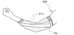
ここで、図10は、本発明の他の実施形態例に係る衣類の着用時における概略右側面図を示す。この衣類20fの実施形態例においては、補助の対象となる関節は肘関節である。すなわち、この衣類20fが有する身体被覆地21cは肘関節および、この肘関節の周辺の躯体を被覆しており、この衣類20fが有する補助帯2qは、上記の衣類20fの着用時に、上記の身体被覆地における着用者の肘関節を覆う部分を挟んで一方の端部側から他方の端部側にかけて着用者の身体表面に沿うように身体被覆地に配置されている。
Here, FIG. 10 shows a schematic right side view when wearing clothing according to another embodiment of the present invention. In the embodiment of the
ここで、図11は、図10に示された本発明の衣類20fの一実施形態例に用いられる身体被覆地21cの概略右側面図を示す。この身体被覆地21cは、その両端に対となる面ファスナーを構成する一方の係止部16をそれぞれ有している。
Here, FIG. 11 shows a schematic right side view of the
また、肘関節においては、前記身体被覆地21cが、着用者の上腕部を覆う部分D、着用者の肘部を覆う部分E、および着用者の手首部を覆う部分Fを備えた筒状体であり、補助帯2qの一方の端部が、前記衣類20fの着用時における前記部分Dに着脱可能な状態で固定されており、前記補助帯2qの他方の端部が前記衣類20fの着用時における前記部分Fに着脱可能な状態で固定されているのが望ましい。こうすることで、肘を過度に回転させ腕を捻ることなく、自由に所望のパワーや角度が設計可能となり、着用者の体力や機能に応じた関節運動を導くことができる。
Further, in the elbow joint, the
ここで、図12は、図6(a)(b)(c)に示された本発明の衣類の一実施形態例に用いられた身体被覆地の構成パーツの概略展開図を示す。これらの構成パーツを縫い合わせることで図6(a)(b)(c)に示された本発明の衣類の一実施形態例に用いられた身体被覆地が得られる。 Here, FIG. 12 shows a schematic development view of the constituent parts of the body covering material used in one embodiment of the garment of the present invention shown in FIGS. 6A, 6B, and 6C. By sewing these constituent parts together, the body covering material used in one embodiment of the garment of the present invention shown in FIGS. 6 (a), (b) and (c) can be obtained.
ここで、図13は、図8(a)(b)(c)に示された本発明の衣類の一実施形態例に用いられた身体被覆地の構成パーツの概略展開図を示す。これらの構成パーツを縫い合わせることで図8(a)(b)(c)に示された本発明の衣類の一実施形態例に用いられる身体被覆地が得られる。 Here, FIG. 13 shows a schematic development view of the constituent parts of the body covering material used in one embodiment of the garment of the present invention shown in FIGS. 8A, 8B, and 8C. By sewing these constituent parts together, the body covering material used in one embodiment of the garment of the present invention shown in FIGS. 8 (a), (b) and (c) can be obtained.
ここで、図14(a)は、本発明の他の実施形態例に係る衣類の着用時における概略正面図、図14(b)は、本発明の他の実施形態例に係る衣類の着用時における概略右側面図、図14(c)は、本発明の他の実施形態例に係る衣類の着用時における概略背面図を示す。この衣服には、身体被覆地の着用者の腰周部を覆う部分Aの周長を調整するための調整帯22が配置されている。この補助帯の両端部は、着用時に着用者の両側の腸骨稜付近を被覆する身体被覆地の部分に、それぞれ配置および固定されており、この補助帯の両端部の間の部分は着用者の腰部を覆うように固定されている。また、補助帯の両端部が着用者の骨盤上部に引っかかって調整帯が固定されるように、補助帯の両端部を着用時に着用者の両側の腸骨稜付近、望ましくは腸骨稜上部を被覆する身体被覆地の部分に、それぞれ配置することが好ましい。図14(a)(b)(c)に示す衣類では、衣類の着用者の歩行時などに大腿部に配置された補助帯の張力によりウエスト部が下方部に引っ張られ徐々にウエスト部が下がってくることが抑制され、身体被覆地と補助帯の適切な位置を維持することができる。
Here, FIG. 14 (a) is a schematic front view when wearing clothing according to another embodiment of the present invention, and FIG. 14 (b) is a schematic front view when wearing clothing according to another embodiment of the present invention. 14 (c) is a schematic right side view in the above, and shows a schematic rear view when wearing clothing according to another embodiment of the present invention. An
ここで、図15は、図14に示された本発明の衣類に用いられた一実施形態例に係る調整帯の概略正面図を示す。この調整帯22は、両方の端部から中央部にむかって幅が太くなっている。また、この調整帯22の両端部およびに中央部には、対となる面ファスナーを構成する係止部の一方23が、それぞれ配されている。
Here, FIG. 15 shows a schematic front view of an adjustment band according to an example of an embodiment used for the garment of the present invention shown in FIG. The
以下、本発明をさらに実施例により詳細に説明する。 Hereinafter, the present invention will be described in more detail with reference to Examples.
(伸び率)
伸び率は、JIS L 1096(2010年版)「織物及び編物の生地試験方法」に基づいて測定した。このJISで定める定速伸長形の試験機を使用し、つかみ間隔20cm、引っ張り速度20cm/分の条件で引張荷重14.7Nまで伸長させたときの伸び率をタテ方向およびヨコ方向についてそれぞれ求めた。
(Growth rate)
The elongation rate was measured based on JIS L 1096 (2010 edition) "Fabric test method for woven fabrics and knitted fabrics". Using this JIS-defined constant-speed extension type testing machine, the elongation rates when extended to a tensile load of 14.7 N under the conditions of a grip interval of 20 cm and a tensile speed of 20 cm / minute were determined in the vertical and horizontal directions, respectively. ..
(伸長回復率)
伸長回復率は、タテ方向およびヨコ方向についてJIS L 1096(2010年版)「織物及び編物の生地試験方法」B−1法に基づいて、それぞれ測定した。試験片にクランプとその下端から20cmのところに印をつけ、14.7Nの荷重を加え1時間保持後の印間の長さと、荷重を取り除いた後30秒後の印間の長さを測定し、伸長回復率を求めた。
(Expansion recovery rate)
The elongation recovery rate was measured in the vertical direction and the horizontal direction based on JIS L 1096 (2010 edition) "Fabric test method for woven fabrics and knitted fabrics" B-1 method, respectively. Mark the test piece 20 cm from the clamp and its lower end, apply a load of 14.7 N, and measure the length between the marks after holding for 1 hour and the length between the marks 30 seconds after removing the load. Then, the elongation recovery rate was calculated.
(ばね定数)
テンシロン引張試験機を用い、荷重は4.9N、標線間距離は補助帯の非固定部の長さとして、その長尺方向に定速(1000mm/分)で元の長さに対してさらに30%伸長時の応力−歪み曲線を描き、その傾きよりばね定数(N/mm)を求めた。
(Spring constant)
Using a Tensilon tensile tester, the load is 4.9 N, the distance between the marked lines is the length of the non-fixed part of the auxiliary band, and the constant speed (1000 mm / min) is added to the original length in the long direction. A stress-strain curve at 30% elongation was drawn, and the spring constant (N / mm) was obtained from the slope.
(張力T1、張力T2)
本発明の衣類を着用し、補助帯と身体被覆地にたるみがない状態での補助帯と身体被覆地の両固定部分に印をつけ、その両固定部分間に存在する非固定部の長手方向の長さを身体表面に沿って測定した。この長さをXとする。次に、衣類を脱ぎ、張力がかかっていない状態で、補助帯と身体被覆地の非固定部の長さ(前記印間の長さ)をそれぞれ測定した。衣類を脱いだ状態では、身体被覆地側の非固定部の長さのほうが、補助帯側の非固定部長さよりも長くなり、たわんでいることが多い。その状態において、補助帯に沿って測定した非固定部の長手方向の長さをY、身体被覆地に沿って測定した非固定部の長手方向の長さをZとする。
(Tension T1, Tension T2)
Wearing the garment of the present invention, mark both the auxiliary band and the body covering with no slack in the auxiliary band and the body covering, and the longitudinal direction of the non-fixing portion existing between the fixing portions. The length of the body was measured along the surface of the body. Let this length be X. Next, the clothes were taken off, and the lengths of the auxiliary band and the non-fixed portion of the body covering (the length between the marks) were measured in a state where tension was not applied. When the clothes are removed, the length of the non-fixed part on the body covering side is longer than the length of the non-fixed part on the auxiliary band side, and it is often bent. In that state, the longitudinal length of the non-fixed portion measured along the auxiliary band is Y, and the longitudinal length of the non-fixed portion measured along the body covering is Z.
張力T1はエー・アンド・ディ社製テンシロン万能材料試験器RTG−1210を用いて、250Nのロードセル条件において、補助帯の両端部を各2枚のアルミ板(幅10cm×高さ5cm×厚み0.5mm)を介して挟んだ状態でつかみ間隔長さYでセットし、その長さYから前記Xの125%まで1000mm/分で伸長して張力(N)−変位曲線を描き、変位Xのときの張力(N)を読み取り、その3回の算術平均値を張力T1とした。
For the tension T1, a Tencilon universal material tester RTG-1210 manufactured by A & D Co., Ltd. was used, and under a load cell condition of 250 N, both ends of the auxiliary band were each made of two aluminum plates (
張力T2は身体被覆地を補助帯に重なる部位を補助帯の大きさに等しく切り出したものをサンプルとし、やはり両端部を各2枚のアルミ板(幅10cm×高さ5cm×厚み0.5mm)を介して挟んだ状態でつかみ間隔長さをZにセットし、長さZから前記Xの125%まで1000mm/分で伸長して張力(N)−変位曲線を描き、変位Xのときの張力(N)を読み取り、その3回の算術平均値を張力T2とした。このようにして、補助帯を着用した状態における張力T1と張力T2を模擬的に求めた。
The tension T2 is a sample in which the part where the body covering material overlaps the auxiliary band is cut out equal to the size of the auxiliary band, and both ends are also made of two aluminum plates (
(動作解析)
補助帯の効果を検証するため、5名の被験者(A:男性25歳、B:男性44歳、C:男性78歳、D:女性74歳、E:女性40歳)に、合図と共にまず片方の足を一歩踏み出してもらい、次に残された足を先に踏み出した足に揃えて直立する動作をしてもらった。そして、先に踏み出した側の膝関節の動作を深度センサー(商品名「Kinect」, Microsoft製)を用いて計測した。計測した情報をもとに関節の動作解析を実施した。動作解析は膝関節の移動距離に注目し、後記する4条件の実験動作より膝関節の移動距離を求めて比較した。膝関節の移動距離が大きいことは前記股関節の振り上げが補助されていることを示す。
(Operation analysis)
To verify the effect of the auxiliary band, five subjects (A: male 25 years old, B: male 44 years old, C: male 78 years old, D: female 74 years old, E: female 40 years old) were first given a signal. I asked him to take a step forward, and then he was asked to stand upright by aligning the remaining leg with the one that stepped forward first. Then, the movement of the knee joint on the side where the person stepped out earlier was measured using a depth sensor (trade name "Kinect", manufactured by Microsoft). Joint motion analysis was performed based on the measured information. The motion analysis focused on the movement distance of the knee joint, and the movement distance of the knee joint was obtained and compared from the experimental movements under the four conditions described later. The large movement distance of the knee joint indicates that the swinging up of the hip joint is assisted.
本実施例では、補助帯を右足側のみに装着して補助帯の効果を検証した。被験者には、可能な限り普段と変わらない力感覚で1歩踏み出すように指示した。下に示す4条件の実験動作(a)〜(d)を順に各7回ずつ計測した。
(a)補助帯を装着していない状態において、右足で1歩を踏み出す
(b)補助帯を装着していない状態において、左足で1歩を踏み出す
(c)補助帯を右足のみに装着した状態において、右足で1歩を踏み出す
(d)補助帯を右足のみに装着した状態において、左足で1歩を踏み出す
装着する補助帯の種類は被験者の身体能力に応じて試行錯誤的に決定した。
5名の被験者に用いた補助帯のばね定数と、張力T1と、張力T2と、(T1/T2)の値を後記する表1に示す。
In this example, the auxiliary band was attached only to the right foot side, and the effect of the auxiliary band was verified. The subjects were instructed to take one step with the same sense of force as usual. The experimental operations (a) to (d) under the four conditions shown below were measured 7 times each in order.
(A) Take one step with your right foot without the auxiliary belt (b) Take one step with your left foot without the auxiliary belt (c) With the auxiliary belt attached only to your right foot (D) Taking one step with the right foot In the state where the auxiliary band is worn only on the right foot, the type of the auxiliary band to be worn is determined by trial and error according to the physical ability of the subject.
The spring constants of the auxiliary bands used for the five subjects, the tension T1, the tension T2, and the values of (T1 / T2) are shown in Table 1 below.
計測は前記した深度センサー(フレームレート:30[Hz])を用いて行い、被験者が始めに1歩踏み出した側の膝関節の下記式(1)で示される3次元位置の時系列データを取得した。ここで、nはフレーム番号である。膝関節の移動距離の評価では、計測開始時点の膝関節位置(1フレーム目のデータ)を原点として定義した。そして、(a)〜(d)の実験動作ごとに、7回計測したデータそれぞれに対して原点と膝関節位置の2点間における相対位置の最大値dkneeを下記式(2)より抽出し、7回の相対位置の最大値dkneeの算術平均値を膝関節の移動距離として評価した。 The measurement is performed using the depth sensor (frame rate: 30 [Hz]) described above, and the time-series data of the three-dimensional position represented by the following equation (1) of the knee joint on the side where the subject first takes one step is acquired. bottom. Here, n is a frame number. In the evaluation of the movement distance of the knee joint, the knee joint position (data in the first frame) at the start of measurement was defined as the origin. Then, for each of the experimental operations (a) to (d), the maximum value d knee of the relative position between the two points of the origin and the knee joint position is extracted from the following equation (2) for each of the data measured seven times. , The arithmetic average value of the maximum value d knee of the relative position of 7 times was evaluated as the moving distance of the knee joint.

(実施例1)
ナイロン糸とポリウレタン弾性繊維(ライクラ(登録商標)、商品名「T−127C」)を用いてトリコットに編成し、染色加工により、ナイロン70%、ポリウレタン30%の伸縮性生地(目付250g/m2)を得た。伸び率はタテ方向140%、ヨコ方向100%、伸長回復率はタテ方向92%、ヨコ方向86%であった。上記生地を用いて各パーツを図12のように切り出してフラットシーマミシンで縫合して図6のような下衣を作成した。なお、図6の斜線部分にはストレッチ性を有するB面ファスナー(雌)を設けた。
(Example 1)
Nylon yarn and polyurethane elastic fiber (Lycra (registered trademark), trade name "T-127C") are used to knit into a tricot, and by dyeing, a stretchable fabric of 70% nylon and 30% polyurethane (with a grain of 250 g / m 2). ) Was obtained. The elongation rate was 140% in the vertical direction and 100% in the horizontal direction, and the elongation recovery rate was 92% in the vertical direction and 86% in the horizontal direction. Using the above fabric, each part was cut out as shown in FIG. 12 and sewn with a flat seam sewing machine to prepare an undergarment as shown in FIG. A stretchable B-side fastener (female) was provided in the shaded area of FIG.
次にナイロン糸とポリウレタン弾性繊維(ライクラ(登録商標)、商品名「T−127C」)を用いて編成し、染色加工によりパワーネットを得た。前記パワーネットを生地の長さ方向が長手となるように長さ76cmで幅5cmのものを切り出し、切り出したものの一部が部分的に重なるようにV字に折り曲げ、その両端部に長さ5cmで幅5cmのYKK製B面ファスナー(雄)と、長さ5cmで幅8cmのYKK製B面ファスナー(雄)を縫合し、図7のような幅広の部分から幅狭の部分にかけて連続的に幅が狭くなっているテーパー状補助帯を得た。テーパー状補助帯のB面ファスナー部を除く、非固定部の長さは28.5cmであった。(両端のB面ファスナー部込みでは38.5cm) Next, nylon yarn and polyurethane elastic fiber (Lycra (registered trademark), trade name "T-127C") were used for knitting, and a power net was obtained by dyeing. Cut out the power net with a length of 76 cm and a width of 5 cm so that the length direction of the fabric is longitudinal, fold it into a V shape so that a part of the cut out part overlaps, and lengthen 5 cm at both ends thereof. A YKK B-side fastener (male) with a width of 5 cm and a YKK B-side fastener (male) with a length of 5 cm and a width of 8 cm are sewn together, and continuously from the wide part to the narrow part as shown in FIG. A tapered auxiliary band with a narrow width was obtained. The length of the non-fixed portion excluding the B-side fastener portion of the tapered auxiliary band was 28.5 cm. (38.5 cm including B-side fasteners on both ends)
続いて、前記下衣を被験者Aに着用してもらい、前記テーパー状補助帯を前記補助帯の非固定部の長さが元の28.5cmから48.8cmとなるよう、やや引っ張った状態で図3のように取り付けた。その状態で動作解析を行い、膝関節の移動距離(cm)を測定した結果を後記する表2に示す。 Subsequently, the subject A was asked to wear the undergarment, and the tapered auxiliary band was slightly pulled so that the length of the non-fixed portion of the auxiliary band was changed from the original 28.5 cm to 48.8 cm. It was attached as shown in FIG. Table 2 below shows the results of measuring the movement distance (cm) of the knee joint by performing motion analysis in that state.
(比較例1)
被験者Aに実施例1と同じ下衣を着用してもらい、補助帯を取り付けずに動作解析を行い、膝関節の移動距離(cm)を測定した結果を後記する表2に示す。
(Comparative Example 1)
Table 2 below shows the results of measuring the movement distance (cm) of the knee joint by having subject A wear the same undergarment as in Example 1 and performing motion analysis without attaching an auxiliary band.
表2に示すように、実施例1は比較例1に比べ膝関節の移動距離が増加していた。 As shown in Table 2, in Example 1, the moving distance of the knee joint was increased as compared with Comparative Example 1.
(実施例2)
実施例1と同じ前記下衣を被験者Bに着用してもらい、前記テーパー状補助帯を前記補助帯の非固定部の長さが元の28.5cmから48.7cmとなるよう、やや引っ張った状態で図3のように取り付けた。その状態で動作解析を行い、膝関節の移動距離(cm)を測定した結果を後記する表2に示す。
(Example 2)
Subject B was asked to wear the same undergarment as in Example 1, and the tapered auxiliary band was slightly pulled so that the length of the non-fixed portion of the auxiliary band was changed from the original 28.5 cm to 48.7 cm. It was attached as shown in FIG. 3 in this state. Table 2 below shows the results of measuring the movement distance (cm) of the knee joint by performing motion analysis in that state.
(比較例2)
被験者Bに実施例1と同じ下衣を着用してもらい、補助帯を取り付けずに動作解析を行い、膝関節の移動距離(cm)を測定した結果を後記する表2に示す。
(Comparative Example 2)
Table 2 below shows the results of measuring the movement distance (cm) of the knee joint by having subject B wear the same undergarment as in Example 1 and performing motion analysis without attaching an auxiliary band.
表2に示すように、実施例2は比較例2に比べ膝関節の移動距離が増加していた。 As shown in Table 2, in Example 2, the moving distance of the knee joint was increased as compared with Comparative Example 2.
(実施例3)
ナイロン糸とポリウレタン弾性繊維(ライクラ(登録商標)、商品名「T−906C」)を用いてトリコットに編成し、染色加工により、ナイロン70%、ポリウレタン30%の伸縮性生地(目付200g/m2)を得た。伸び率はタテ方向120%、ヨコ方向95%、伸長回復率はタテ方向93%、ヨコ方向92%であった。上記生地を用いて各パーツを図13のように切り出してフラットシーマミシンで縫合して図8のような下衣を作成した。なお、図8の斜線部分には伸縮性を有するB面ファスナー(雌)を設けた。
(Example 3)
Nylon yarn and polyurethane elastic fiber (Lycra (registered trademark), trade name "T-906C") are used to knit into a tricot, and by dyeing, a stretchable fabric of 70% nylon and 30% polyurethane (with a grain of 200 g / m 2). ) Was obtained. The elongation rate was 120% in the vertical direction and 95% in the horizontal direction, and the elongation recovery rate was 93% in the vertical direction and 92% in the horizontal direction. Using the above fabric, each part was cut out as shown in FIG. 13 and sewn with a flat seam sewing machine to prepare an undergarment as shown in FIG. A stretchable B-side fastener (female) was provided in the shaded area of FIG.
次に幅5cmの帯ゴムを長さ76cm切り出し、切り出したものの一部が部分的に重なるようにV字に折り曲げ、その両端部に長さ5cmで幅5cmのYKK製B面ファスナー(雄)と、長さ5cmで幅8cmのYKK製B面ファスナー(雄)を縫合し、図7のような幅広の部分から幅狭の部分にかけて連続的に幅が狭くなっているテーパー状補助帯を得た。テーパー状補助帯のB面ファスナー部を除く、非固定部の長さは28.5cmであった。 Next, cut out a 5 cm wide band rubber with a length of 76 cm, fold it into a V shape so that a part of the cut out part overlaps, and attach a YKK B-side fastener (male) with a length of 5 cm and a width of 5 cm at both ends. A YKK B-hook-and-loop fastener (male) with a length of 5 cm and a width of 8 cm was sewn to obtain a tapered auxiliary band whose width was continuously narrowed from the wide portion to the narrow portion as shown in FIG. .. The length of the non-fixed portion excluding the B-side fastener portion of the tapered auxiliary band was 28.5 cm.
続いて、前記下衣を被験者Cに着用してもらい、前記テーパー状補助帯を前記補助帯の非固定部の長さが元の28.5cmから48.5cmとなるよう、やや引っ張った状態で図1のように取り付けた。その状態で動作解析を行い、膝関節の移動距離(cm)を測定した結果を後記する表2に示す。 Subsequently, the subject C was asked to wear the undergarment, and the tapered auxiliary band was slightly pulled so that the length of the non-fixed portion of the auxiliary band was changed from the original 28.5 cm to 48.5 cm. It was attached as shown in FIG. Table 2 below shows the results of measuring the movement distance (cm) of the knee joint by performing motion analysis in that state.
(比較例3)
被験者Cに実施例3と同じ下衣を着用してもらい、補助帯を取り付けずに動作解析を行い、膝関節の移動距離(cm)を測定した結果を後記する表2に示す。
(Comparative Example 3)
The results of measuring the movement distance (cm) of the knee joint by having subject C wear the same undergarment as in Example 3 and performing motion analysis without attaching an auxiliary band are shown in Table 2 below.
表2に示すように、実施例3は比較例3に比べ膝関節の移動距離が増加していた。 As shown in Table 2, in Example 3, the moving distance of the knee joint was increased as compared with Comparative Example 3.
(実施例4)
実施例3の下衣を被験者Dに着用してもらい、前記テーパー状補助帯を前記補助帯の非固定部の長さが元の28.5cmから48.9cmとなるよう、やや引っ張った状態で図4のように取り付けた。その状態で動作解析を行い、膝関節の移動距離(cm)を測定した結果を後記する表2に示す。
(Example 4)
Subject D was asked to wear the lower garment of Example 3, and the tapered auxiliary band was slightly pulled so that the length of the non-fixed portion of the auxiliary band was changed from the original 28.5 cm to 48.9 cm. It was attached as shown in FIG. Table 2 below shows the results of measuring the movement distance (cm) of the knee joint by performing motion analysis in that state.
(比較例4)
被験者Dに実施例3と同じ下衣を着用してもらい、補助帯を取り付けずに動作解析を行い、膝関節の移動距離(cm)を測定した結果を後記する表2に示す。
(Comparative Example 4)
The results of measuring the movement distance (cm) of the knee joint by having subject D wear the same undergarment as in Example 3 and performing motion analysis without attaching an auxiliary band are shown in Table 2 below.
表2に示すように、実施例4は比較例4に比べ膝関節の移動距離が増加していた。 As shown in Table 2, in Example 4, the moving distance of the knee joint was increased as compared with Comparative Example 4.
(実施例5)
ナイロン糸とポリウレタン弾性繊維(ライクラ(登録商標)、商品名「T−906C」)を用いてトリコットに編成し、染色加工により、ナイロン70%、ポリウレタン30%の伸縮性生地(目付け250g/m2)を得た。伸び率は縦方向95%、ヨコ方向120%、伸長回復率はタテ方向93%、ヨコ方向92%であった。上記生地を用いて各パーツを図13のように切り出してフラットシーマミシンで縫合して図8のような下衣を作成した。なお、図8の斜線部分には伸縮性を有するB面ファスナー(雌)を設けた。
(Example 5)
Nylon yarn and polyurethane elastic fiber (Lycra (registered trademark), trade name "T-906C") are used to knit into a tricot, and by dyeing, a stretchable fabric of 70% nylon and 30% polyurethane (meshing 250 g / m 2) ) Was obtained. The elongation rate was 95% in the vertical direction and 120% in the horizontal direction, and the elongation recovery rate was 93% in the vertical direction and 92% in the horizontal direction. Using the above fabric, each part was cut out as shown in FIG. 13 and sewn with a flat seam sewing machine to prepare an undergarment as shown in FIG. A stretchable B-side fastener (female) was provided in the shaded area of FIG.
次に、ナイロン糸とポリウレタン弾性繊維(ライクラ(登録商標)、商品名「T−127C」)を用いて編成し、染色加工によりパワーネットを得た。前記パワーネットを生地の長さ方向が長手となるように長さ76cmで幅5cmのものを切り出し、切り出したものの一部が部分的に重なるようにV字に折り曲げ、その両端部に長さ5cmで幅5cmのYKK製B面ファスナー(雄)と、長さ5cmで幅8cmのYKK製B面ファスナー(雄)を縫合し、図7のような幅広の部分から幅狭の部分にかけて連続的に幅が狭くなっているテーパー状補助帯を得た。テーパー状補助帯のB面ファスナー部を除く、非固定部の長さは28.5cmであった。(両端のB面ファスナー部込みでは38.5cm) Next, nylon yarn and polyurethane elastic fiber (lycra (registered trademark), trade name "T-127C") were used for knitting, and a power net was obtained by dyeing. Cut out the power net with a length of 76 cm and a width of 5 cm so that the length direction of the fabric is longitudinal, bend it into a V shape so that a part of the cut out part overlaps, and lengthen 5 cm at both ends thereof. A YKK B-side fastener (male) with a width of 5 cm and a YKK B-side fastener (male) with a length of 5 cm and a width of 8 cm are sewn together, and continuously from the wide part to the narrow part as shown in FIG. A tapered auxiliary band with a narrow width was obtained. The length of the non-fixed portion excluding the B-side fastener portion of the tapered auxiliary band was 28.5 cm. (38.5 cm including B-side fasteners on both ends)
続いて、前記下衣を被験者Eに着用してもらい、前記テーパー状補助帯を前記補助帯の非固定部の長さが元の28.5cmから47.5cmとなるよう、やや引っ張った状態で図3のように取り付けた。その状態で動作解析を行い、膝関節の移動距離(cm)を測定した結果を後記する表2に示す。 Subsequently, the subject E was asked to wear the undergarment, and the tapered auxiliary band was slightly pulled so that the length of the non-fixed portion of the auxiliary band was 47.5 cm from the original 28.5 cm. It was attached as shown in FIG. Table 2 below shows the results of measuring the movement distance (cm) of the knee joint by performing motion analysis in that state.
(比較例5)
被験者Eに実施例5と同じ下衣を着用してもらい、補助帯を取り付けずに動作解析を行い、膝関節の移動距離(cm)を測定した結果を後記する表2に示す。
表2に示すように、実施例5は比較例5に比べ膝関節の移動距離が増加していた。
(Comparative Example 5)
The results of measuring the movement distance (cm) of the knee joint by having subject E wear the same undergarment as in Example 5 and performing motion analysis without attaching an auxiliary band are shown in Table 2 below.
As shown in Table 2, in Example 5, the moving distance of the knee joint was increased as compared with Comparative Example 5.
(実施例6)
下衣は実施例5と同様のものを使用した。補助帯に使用する生地は実施例5と同様のパワーネットとし、前記パワーネットを生地の長さ方向が長手となるように長さ40cmで幅5cmのものを切り出し、切り出したものの一部が部分的に重なるようにV字に折り曲げ、その両端部に長さ2.5cmで幅5cmのYKK製B面ファスナー(雄)と、長さ2.5cmで幅8cmのYKK製B面ファスナー(雄)を縫合し、図7のような幅広の部分から幅狭の部分にかけて連続的に幅が狭くなっているテーパー状補助帯を得た。テーパー状補助帯のB面ファスナー部を除く、非固定部の長さは15.0cmであった。(両端のB面ファスナー部込みでは20.0cm)
(Example 6)
The lower garment used was the same as in Example 5. The cloth used for the auxiliary band is the same power net as in Example 5, and the power net is cut out with a length of 40 cm and a width of 5 cm so that the length direction of the cloth is the length direction, and a part of the cut out part is partially cut out. Bend it into a V shape so that it overlaps with each other, and at both ends, a YKK B-side fastener (male) with a length of 2.5 cm and a width of 5 cm and a YKK B-side fastener (male) with a length of 2.5 cm and a width of 8 cm. Was sewn to obtain a tapered auxiliary band whose width was continuously narrowed from the wide portion to the narrow portion as shown in FIG. The length of the non-fixed portion excluding the B-side fastener portion of the tapered auxiliary band was 15.0 cm. (20.0 cm including B-side fasteners on both ends)
続いて、前記下衣を被験者Eに着用してもらい、前記テーパー状補助帯を前記補助帯の非固定部の長さが元の15.0cmから20.5cmとなるよう、やや引っ張った状態で図2のように取り付けた。その状態で動作解析を行い、膝関節の移動距離(cm)を測定した結果を後記する表2に示す。 Subsequently, the subject E was asked to wear the undergarment, and the tapered auxiliary band was slightly pulled so that the length of the non-fixed portion of the auxiliary band was changed from the original 15.0 cm to 20.5 cm. It was attached as shown in FIG. Table 2 below shows the results of measuring the movement distance (cm) of the knee joint by performing motion analysis in that state.
(比較例6)
被験者Eに実施例5と同じ下衣を着用してもらい、補助帯を取り付けずに動作解析を行い、膝関節の移動距離(cm)を測定した結果を後記する表2に示す。
表2に示すように、実施例6は比較例6に比べ膝関節の移動距離が増加していた。
(Comparative Example 6)
The results of measuring the movement distance (cm) of the knee joint by having subject E wear the same undergarment as in Example 5 and performing motion analysis without attaching an auxiliary band are shown in Table 2 below.
As shown in Table 2, in Example 6, the moving distance of the knee joint was increased as compared with Comparative Example 6.
1 着用者の腰周部を覆う部分(A)
2a、2b、2c、2d、2e、2f、2g、2h、2i、2j、2k、2m、2n、2p、2q 補助帯
3a 補助帯の一方の端部
3b 補助帯の他方の端部
4 着用者の右膝部を覆う部分(B)
5 着用者の左膝部を覆う部分(C)
6 ファスナー
7a、7b 案内ライン
8a、8b 案内ライン
9 係止部
10 係止部
11 係止部
12a、12b 案内ライン
13a、13b 案内ライン
14a、14b 案内ライン
15 係止部
16 係止部
20a、20b、20c、20d、20e 衣類
21a、21b、21c 身体被覆地
22 調整帯
23 係止部の一方
D 着用者の上腕部を覆う部分
E 着用者の肘部を覆う部分
F 着用者の手首部を覆う部分
EL 補助帯の外側線
R1 腰周部を覆う部分(A)の右側部
L1 腰周部を覆う部分(A)の左側部
R2 左膝周部を覆う部分(C)の右側部
L2 右膝周部を覆う部分(B)の左側部
1 Part that covers the wearer's waist circumference (A)
2a, 2b, 2c, 2d, 2e, 2f, 2g, 2h, 2i, 2j, 2k, 2m, 2n, 2p,
5 Part that covers the wearer's left knee (C)
6
Claims (4)
前記補助帯は、前記身体被覆地における着用者の関節を覆う部分を挟んで一方の端部側から他方の端部側にかけて着用者の身体表面に沿うように前記身体被覆地に配置されており、前記補助帯が、同じ幅の補助帯の一部が部分的に重なるようにV字状に折り曲がっており、幅の広い部分から幅の狭い部分にかけて連続的に幅が狭くなっているテーパー状の補助帯であり、
前記補助帯と前記身体被覆地とは、互いに分離されて独立して伸縮することができるように前記補助帯は前記身体被覆地に固定され、
前記補助帯の前記一方の端部側と前記他方の端部側とを結ぶ方向Sの前記衣類の着用時における張力T1が、前記補助帯と重なっている前記身体被覆地の前記方向Sに平行な方向の前記衣類の着用時における張力T2よりも大きく、
A1とA2の補助帯を備えており、
前記身体被覆地が、着用者の腰周部を覆う部分A、着用者の右膝周部を覆う部分Bおよび着用者の左膝周部を覆う部分Cを備えており、
補助帯A1の一方の端部が前記部分Aの右側部(右腰外側)に着脱可能な状態で固定されており、補助帯A1の他方の端部が前記部分Bの左側部(右膝内側)に着脱可能な状態で固定されており、
補助帯A2の一方の端部が前記部分Aの左側部(左腰外側)に着脱可能な状態で固定されており、補助帯A2の他方の端部が前記部分Cの右側部(左膝内側)に着脱可能な状態で固定されている、衣類。 Clothing with auxiliary bands placed on the body covering
The auxiliary band is arranged on the body covering material so as to be along the wearer's body surface from one end side to the other end side with a portion covering the wearer's joint in the body covering material. , The auxiliary band is bent in a V shape so that a part of the auxiliary band of the same width partially overlaps, and the width is continuously narrowed from the wide part to the narrow part. It is a shape auxiliary band,
The auxiliary band is fixed to the body covering so that the auxiliary band and the body covering can be separated from each other and expanded and contracted independently.
The tension T1 when the clothing is worn in the direction S connecting the one end side of the auxiliary band and the other end side is parallel to the direction S of the body covering material overlapping the auxiliary band. It is larger than the tension T2 when the garment is worn in the above direction.
Equipped with A1 and A2 auxiliary bands,
The body covering includes a portion A that covers the waist circumference of the wearer, a portion B that covers the wearer's right knee circumference, and a portion C that covers the wearer's left knee circumference.
One end of the auxiliary band A1 is detachably fixed to the right side of the part A (outside the right hip), and the other end of the auxiliary band A1 is the left side of the part B (inside the right knee). ) Is fixed in a detachable state,
One end of the auxiliary band A2 is detachably fixed to the left side of the part A (outside the left hip), and the other end of the auxiliary band A2 is attached to the right side of the part C (inside the left knee). ), Clothes that are detachably fixed.
前記身体被覆地が、着用者の腰周部を覆う部分Aを備えており、
前記衣類の着用時に着用者の左右の腸骨稜付近を覆う前記身体被覆地の部分が前記調節帯により被覆されており、
前記部分Aの少なくとも一部と前記調整帯とを着脱可能な状態で固定する腰締結部を有する、請求項1〜3のいずれかに記載の衣類。 It also has a moderator band
The body covering includes a portion A that covers the wearer's waist circumference.
The portion of the body covering that covers the vicinity of the left and right iliac crests of the wearer when the garment is worn is covered with the moderator band.
The garment according to any one of claims 1 to 3, which has a waist fastening portion for fixing at least a part of the portion A and the adjusting band in a detachable state.
Applications Claiming Priority (2)
| Application Number | Priority Date | Filing Date | Title |
|---|---|---|---|
| JP2016069759 | 2016-03-30 | ||
| JP2016069759 | 2016-03-30 |
Publications (3)
| Publication Number | Publication Date |
|---|---|
| JP2017186726A JP2017186726A (en) | 2017-10-12 |
| JP2017186726A5 JP2017186726A5 (en) | 2020-01-23 |
| JP6924056B2 true JP6924056B2 (en) | 2021-08-25 |
Family
ID=59965645
Family Applications (1)
| Application Number | Title | Priority Date | Filing Date |
|---|---|---|---|
| JP2017064494A Active JP6924056B2 (en) | 2016-03-30 | 2017-03-29 | clothing |
Country Status (7)
| Country | Link |
|---|---|
| US (1) | US20190105216A1 (en) |
| EP (1) | EP3437501A4 (en) |
| JP (1) | JP6924056B2 (en) |
| CN (1) | CN109068772A (en) |
| CA (1) | CA3019495A1 (en) |
| TW (1) | TW201739430A (en) |
| WO (1) | WO2017170272A1 (en) |
Families Citing this family (3)
| Publication number | Priority date | Publication date | Assignee | Title |
|---|---|---|---|---|
| KR20200087850A (en) * | 2017-12-21 | 2020-07-21 | 아사히 가세이 가부시키가이샤 | Bottom medical |
| KR20220044722A (en) | 2019-08-09 | 2022-04-11 | 도레이 카부시키가이샤 | proofreading tool |
| WO2023225016A1 (en) * | 2022-05-16 | 2023-11-23 | Massachusetts Institute Of Technology | Bottom garment with embedded harness |
Family Cites Families (12)
| Publication number | Priority date | Publication date | Assignee | Title |
|---|---|---|---|---|
| JP2603769B2 (en) * | 1991-05-22 | 1997-04-23 | 株式会社 ワコール | Lower leg supporter with taping function worn by pressing against human body surface |
| JP3587742B2 (en) * | 1999-07-13 | 2004-11-10 | ダイヤ工業株式会社 | Taping device |
| TW475887B (en) * | 2000-04-20 | 2002-02-11 | Wacoal Corp | Leg portions supporting wear |
| US6430752B1 (en) * | 2001-10-25 | 2002-08-13 | Gregory Steven Bay | Compression short |
| ITMI20070706A1 (en) * | 2007-04-05 | 2008-10-06 | Dy & Vy S R L | HELP OF HELP TO MOVE FOR THE HUMAN BODY. |
| WO2009034621A1 (en) * | 2007-09-12 | 2009-03-19 | Wacoal Corp. | Clothing with crotch for exercise |
| CA2762845C (en) * | 2009-05-21 | 2019-01-15 | Skins International Trading Ag | Compression garments and method of manufacture |
| WO2012091080A1 (en) * | 2010-12-28 | 2012-07-05 | 興和株式会社 | Leg supporter |
| JP5099800B1 (en) * | 2012-05-31 | 2012-12-19 | マキクリエイション株式会社 | Posture improvement girdle |
| US10271592B2 (en) * | 2013-03-13 | 2019-04-30 | Nike, Inc. | Monolithic protective article with flexible region |
| JP5947328B2 (en) * | 2014-03-11 | 2016-07-06 | 美津濃株式会社 | clothes |
| CN203860497U (en) * | 2014-05-19 | 2014-10-08 | 余荣顺 | Knee-protecting fabric structure |
-
2017
- 2017-03-24 EP EP17774809.2A patent/EP3437501A4/en not_active Withdrawn
- 2017-03-24 CA CA3019495A patent/CA3019495A1/en not_active Abandoned
- 2017-03-24 WO PCT/JP2017/012154 patent/WO2017170272A1/en active Application Filing
- 2017-03-24 US US16/087,513 patent/US20190105216A1/en not_active Abandoned
- 2017-03-24 CN CN201780021949.1A patent/CN109068772A/en active Pending
- 2017-03-29 JP JP2017064494A patent/JP6924056B2/en active Active
- 2017-03-29 TW TW106110432A patent/TW201739430A/en unknown
Also Published As
| Publication number | Publication date |
|---|---|
| CN109068772A (en) | 2018-12-21 |
| TW201739430A (en) | 2017-11-16 |
| WO2017170272A1 (en) | 2017-10-05 |
| EP3437501A4 (en) | 2019-11-06 |
| EP3437501A1 (en) | 2019-02-06 |
| US20190105216A1 (en) | 2019-04-11 |
| CA3019495A1 (en) | 2017-10-05 |
| JP2017186726A (en) | 2017-10-12 |
Similar Documents
| Publication | Publication Date | Title |
|---|---|---|
| US11590046B2 (en) | Flexible members for anchoring to the body | |
| US10987534B2 (en) | Exercise garment | |
| CN103153404B (en) | Antigravity muscle training aids clothing and the method tempering deep appearance and antigravity muscle | |
| US20150306441A1 (en) | Exercise garment with ergonomic and modifiable resistance bands | |
| WO2010050540A1 (en) | Garment | |
| WO2015021395A1 (en) | Posture control and therapy system | |
| WO2006126300A1 (en) | Bottom clothes | |
| CN102470040A (en) | Posture improving garment | |
| JP6527629B1 (en) | Motion assistance work clothes | |
| JP6924056B2 (en) | clothing | |
| US11412794B2 (en) | Limb sleeves for body alignment | |
| KR20160129872A (en) | Knee supporter and method for supporting knee joint | |
| KR101766644B1 (en) | Support Clothes for Muscle Strengthening | |
| US20200214869A1 (en) | Soft braces to prevent injury to a joint or body segment | |
| JP2017192719A (en) | Operation assistance work clothes | |
| US20210228394A1 (en) | Wearable Tension Apparatus | |
| JP2018201846A (en) | Supporter for lower limb | |
| JP2008002035A (en) | Inner wear | |
| KR200395879Y1 (en) | The clothes band for the walking campus and a muscular power reinforcement | |
| JP6270800B2 (en) | tights | |
| JP2019081986A (en) | Garment | |
| JP2017104271A (en) | Walking assist device | |
| KR200351861Y1 (en) | The Lower part of the body Sports Elastic force Band of Ordinary Worn Possible | |
| JP7420139B2 (en) | lower limb orthotics | |
| JP2019170410A (en) | Walking support tool |
Legal Events
| Date | Code | Title | Description |
|---|---|---|---|
| A521 | Written amendment |
Free format text: JAPANESE INTERMEDIATE CODE: A523 Effective date: 20171016 |
|
| A521 | Written amendment |
Free format text: JAPANESE INTERMEDIATE CODE: A523 Effective date: 20191206 |
|
| A621 | Written request for application examination |
Free format text: JAPANESE INTERMEDIATE CODE: A621 Effective date: 20191206 |
|
| A977 | Report on retrieval |
Free format text: JAPANESE INTERMEDIATE CODE: A971007 Effective date: 20201217 |
|
| A131 | Notification of reasons for refusal |
Free format text: JAPANESE INTERMEDIATE CODE: A131 Effective date: 20201222 |
|
| A521 | Written amendment |
Free format text: JAPANESE INTERMEDIATE CODE: A523 Effective date: 20210218 |
|
| TRDD | Decision of grant or rejection written | ||
| A01 | Written decision to grant a patent or to grant a registration (utility model) |
Free format text: JAPANESE INTERMEDIATE CODE: A01 Effective date: 20210706 |
|
| A61 | First payment of annual fees (during grant procedure) |
Free format text: JAPANESE INTERMEDIATE CODE: A61 Effective date: 20210730 |
|
| R150 | Certificate of patent or registration of utility model |
Ref document number: 6924056 Country of ref document: JP Free format text: JAPANESE INTERMEDIATE CODE: R150 |