WO2017170272A1 - Garment - Google Patents
Garment Download PDFInfo
- Publication number
- WO2017170272A1 WO2017170272A1 PCT/JP2017/012154 JP2017012154W WO2017170272A1 WO 2017170272 A1 WO2017170272 A1 WO 2017170272A1 JP 2017012154 W JP2017012154 W JP 2017012154W WO 2017170272 A1 WO2017170272 A1 WO 2017170272A1
- Authority
- WO
- WIPO (PCT)
- Prior art keywords
- auxiliary
- auxiliary band
- garment
- wearer
- band
- Prior art date
Links
Images


Classifications
-
- A—HUMAN NECESSITIES
- A61—MEDICAL OR VETERINARY SCIENCE; HYGIENE
- A61H—PHYSICAL THERAPY APPARATUS, e.g. DEVICES FOR LOCATING OR STIMULATING REFLEX POINTS IN THE BODY; ARTIFICIAL RESPIRATION; MASSAGE; BATHING DEVICES FOR SPECIAL THERAPEUTIC OR HYGIENIC PURPOSES OR SPECIFIC PARTS OF THE BODY
- A61H3/00—Appliances for aiding patients or disabled persons to walk about
-
- A—HUMAN NECESSITIES
- A41—WEARING APPAREL
- A41B—SHIRTS; UNDERWEAR; BABY LINEN; HANDKERCHIEFS
- A41B9/00—Undergarments
- A41B9/001—Underpants or briefs
-
- A—HUMAN NECESSITIES
- A41—WEARING APPAREL
- A41B—SHIRTS; UNDERWEAR; BABY LINEN; HANDKERCHIEFS
- A41B9/00—Undergarments
- A41B9/14—Waistbands forming part of the undergarments; Closures therefor
-
- A—HUMAN NECESSITIES
- A41—WEARING APPAREL
- A41D—OUTERWEAR; PROTECTIVE GARMENTS; ACCESSORIES
- A41D13/00—Professional, industrial or sporting protective garments, e.g. surgeons' gowns or garments protecting against blows or punches
- A41D13/0015—Sports garments other than provided for in groups A41D13/0007 - A41D13/088
-
- A—HUMAN NECESSITIES
- A61—MEDICAL OR VETERINARY SCIENCE; HYGIENE
- A61F—FILTERS IMPLANTABLE INTO BLOOD VESSELS; PROSTHESES; DEVICES PROVIDING PATENCY TO, OR PREVENTING COLLAPSING OF, TUBULAR STRUCTURES OF THE BODY, e.g. STENTS; ORTHOPAEDIC, NURSING OR CONTRACEPTIVE DEVICES; FOMENTATION; TREATMENT OR PROTECTION OF EYES OR EARS; BANDAGES, DRESSINGS OR ABSORBENT PADS; FIRST-AID KITS
- A61F5/00—Orthopaedic methods or devices for non-surgical treatment of bones or joints; Nursing devices; Anti-rape devices
- A61F5/01—Orthopaedic devices, e.g. splints, casts or braces
- A61F5/0102—Orthopaedic devices, e.g. splints, casts or braces specially adapted for correcting deformities of the limbs or for supporting them; Ortheses, e.g. with articulations
- A61F5/0104—Orthopaedic devices, e.g. splints, casts or braces specially adapted for correcting deformities of the limbs or for supporting them; Ortheses, e.g. with articulations without articulation
- A61F5/0106—Orthopaedic devices, e.g. splints, casts or braces specially adapted for correcting deformities of the limbs or for supporting them; Ortheses, e.g. with articulations without articulation for the knees
- A61F5/0109—Sleeve-like structures
-
- D—TEXTILES; PAPER
- D04—BRAIDING; LACE-MAKING; KNITTING; TRIMMINGS; NON-WOVEN FABRICS
- D04B—KNITTING
- D04B1/00—Weft knitting processes for the production of fabrics or articles not dependent on the use of particular machines; Fabrics or articles defined by such processes
- D04B1/22—Weft knitting processes for the production of fabrics or articles not dependent on the use of particular machines; Fabrics or articles defined by such processes specially adapted for knitting goods of particular configuration
- D04B1/24—Weft knitting processes for the production of fabrics or articles not dependent on the use of particular machines; Fabrics or articles defined by such processes specially adapted for knitting goods of particular configuration wearing apparel
-
- D—TEXTILES; PAPER
- D04—BRAIDING; LACE-MAKING; KNITTING; TRIMMINGS; NON-WOVEN FABRICS
- D04B—KNITTING
- D04B21/00—Warp knitting processes for the production of fabrics or articles not dependent on the use of particular machines; Fabrics or articles defined by such processes
- D04B21/20—Warp knitting processes for the production of fabrics or articles not dependent on the use of particular machines; Fabrics or articles defined by such processes specially adapted for knitting articles of particular configuration
- D04B21/207—Wearing apparel or garment blanks
-
- A—HUMAN NECESSITIES
- A41—WEARING APPAREL
- A41B—SHIRTS; UNDERWEAR; BABY LINEN; HANDKERCHIEFS
- A41B2500/00—Materials for shirts, underwear, baby linen or handkerchiefs not provided for in other groups of this subclass
- A41B2500/10—Knitted
-
- A—HUMAN NECESSITIES
- A61—MEDICAL OR VETERINARY SCIENCE; HYGIENE
- A61H—PHYSICAL THERAPY APPARATUS, e.g. DEVICES FOR LOCATING OR STIMULATING REFLEX POINTS IN THE BODY; ARTIFICIAL RESPIRATION; MASSAGE; BATHING DEVICES FOR SPECIAL THERAPEUTIC OR HYGIENIC PURPOSES OR SPECIFIC PARTS OF THE BODY
- A61H3/00—Appliances for aiding patients or disabled persons to walk about
- A61H2003/007—Appliances for aiding patients or disabled persons to walk about secured to the patient, e.g. with belts
-
- A—HUMAN NECESSITIES
- A61—MEDICAL OR VETERINARY SCIENCE; HYGIENE
- A61H—PHYSICAL THERAPY APPARATUS, e.g. DEVICES FOR LOCATING OR STIMULATING REFLEX POINTS IN THE BODY; ARTIFICIAL RESPIRATION; MASSAGE; BATHING DEVICES FOR SPECIAL THERAPEUTIC OR HYGIENIC PURPOSES OR SPECIFIC PARTS OF THE BODY
- A61H2201/00—Characteristics of apparatus not provided for in the preceding codes
- A61H2201/16—Physical interface with patient
- A61H2201/1602—Physical interface with patient kind of interface, e.g. head rest, knee support or lumbar support
- A61H2201/165—Wearable interfaces
-
- A—HUMAN NECESSITIES
- A61—MEDICAL OR VETERINARY SCIENCE; HYGIENE
- A61H—PHYSICAL THERAPY APPARATUS, e.g. DEVICES FOR LOCATING OR STIMULATING REFLEX POINTS IN THE BODY; ARTIFICIAL RESPIRATION; MASSAGE; BATHING DEVICES FOR SPECIAL THERAPEUTIC OR HYGIENIC PURPOSES OR SPECIFIC PARTS OF THE BODY
- A61H2205/00—Devices for specific parts of the body
- A61H2205/10—Leg
- A61H2205/102—Knee
-
- D—TEXTILES; PAPER
- D10—INDEXING SCHEME ASSOCIATED WITH SUBLASSES OF SECTION D, RELATING TO TEXTILES
- D10B—INDEXING SCHEME ASSOCIATED WITH SUBLASSES OF SECTION D, RELATING TO TEXTILES
- D10B2331/00—Fibres made from polymers obtained otherwise than by reactions only involving carbon-to-carbon unsaturated bonds, e.g. polycondensation products
- D10B2331/02—Fibres made from polymers obtained otherwise than by reactions only involving carbon-to-carbon unsaturated bonds, e.g. polycondensation products polyamides
-
- D—TEXTILES; PAPER
- D10—INDEXING SCHEME ASSOCIATED WITH SUBLASSES OF SECTION D, RELATING TO TEXTILES
- D10B—INDEXING SCHEME ASSOCIATED WITH SUBLASSES OF SECTION D, RELATING TO TEXTILES
- D10B2331/00—Fibres made from polymers obtained otherwise than by reactions only involving carbon-to-carbon unsaturated bonds, e.g. polycondensation products
- D10B2331/10—Fibres made from polymers obtained otherwise than by reactions only involving carbon-to-carbon unsaturated bonds, e.g. polycondensation products polyurethanes
Definitions
- the present invention can be suitably used for persons with reduced physical abilities and their reserves, and can ease joint movement by their own muscular strength to effectively suppress muscular weakness and maintain or enhance daily physical activity. It is related to clothing.
- Enhance muscle strength is an important factor in maintaining and improving the ability to live everyday life. It is said that a decrease in muscle strength not only increases the burden on the joints but also results in hindrance to daily activities such as moving up. Further, increasing the flexibility leads to the prevention of injury by improving the range of motion of the joint, the function of the joint, and relaxing the muscle tension. In particular, promoting joint movement that reproduces natural body movements such as walking is important not only in maintaining the physical ability of healthy subjects but also in the field of rehabilitation to restore the function of those with reduced physical ability. Approach.
- these compression garments are designed to apply clothing pressure to specific muscles, and are intended to protect or strengthen the muscles, and do not directly support joint movement.
- many people with physical disabilities and their reserves, for example, general middle-aged and older people who do not have exercise habits have many people with extremely low muscle strength in the first place. There were aspects that were unacceptable in terms of energy and endurance.
- JP-A-10-130915 Japanese Patent Laid-Open No. 10-280209 JP 2006-219778 A JP 2013-227717 A JP 2009-095645 A JP 2014-018536 A
- the present invention has been made to solve the above-described problems, and its purpose is not to require an electric drive source, to be low in cost, excellent in wearability and safety, and natural movement of a person. It is an object of the present invention to provide a garment that effectively assists body joint movement that reproduces the above.
- the auxiliary band is disposed along the body surface of the wearer, and the auxiliary band is separated from each other so that the auxiliary band can be expanded and contracted independently.
- the body covering ground fixed to the covering ground and having a tension T1 when the garment is worn in a direction S connecting the one end side and the other end side of the auxiliary band overlapping the auxiliary band. Clothing larger than tension T2 at the time of wearing of the clothing in a direction parallel to the direction S.
- auxiliary bands A1 and A2 are provided, and the body covering area covers a wearer's waist circumference part A, a wearer's right knee circumference part B and a wearer's left knee A portion C that covers the periphery is provided, one end of the auxiliary band A1 is fixed to the part A in a detachable state, and the other end of the auxiliary band A1 is detachable to the part B
- the auxiliary band A2 is fixed in a state where one end of the auxiliary band A2 is detachably attached to the part A, and the other end of the auxiliary band A2 is fixed in a state where it is detachable from the part C.
- the clothing according to any one of (1) to (3).
- the body covering place further comprising an adjustment band, wherein the body covering place includes a portion A covering the waist circumference of the wearer, and covers the vicinity of the left and right iliac crests of the wearer when wearing the clothing.
- the portion is covered with the adjustment band, and has a waist fastening portion for fixing at least a part of the portion A and the adjustment band in a detachable state. Clothing.
- the body covering ground is a cylindrical body provided with a portion D covering the upper arm portion of the wearer, a portion E covering the elbow portion of the wearer, and a portion F covering the wrist portion of the wearer.
- One end of the auxiliary belt is fixed to the portion D in a detachable state, and the other end of the auxiliary band is fixed to the portion F in a detachable state.
- the present invention can be suitably used for a person with reduced physical ability and its reserve army, and the desire to move the body with ease of physical exercise can be derived, resulting in effective suppression of muscle weakness, It is possible to provide a garment that does not require a drive source, is low in cost, is excellent in wearability and safety, and effectively assists the movement of the body to reproduce the natural movement of a person.
- FIG. 1 is a schematic front view when a garment according to an embodiment of the present invention is worn.
- FIG. 2 is a schematic front view when a garment is worn according to another embodiment of the present invention.
- FIG. 3 is a schematic front view when a garment is worn according to another embodiment of the present invention.
- FIG. 4 is a schematic front view of a garment worn according to another embodiment of the present invention.
- FIG. 5 is a schematic rear view of a garment according to another embodiment of the present invention.
- 6 (a) is a schematic left side view of a body covering according to an embodiment used in the garment of the present invention shown in FIGS. 3 and 4, and
- FIG. 6 (b) is a diagram of FIGS. FIG.
- FIG. 6 (c) is a schematic front view of a body covering according to an embodiment used in the garment of the present invention shown in FIG. 4, and FIG. 6 (c) is used in the garment of the present invention shown in FIG. 3 and FIG. It is a schematic right view of the body covering ground which concerns on the example of 1 embodiment.
- 7 (a) and 7 (b) are schematic front views of an auxiliary band according to an embodiment used in the garment of the present invention shown in FIGS. 1 to 5.
- FIG. FIG. 8A is a schematic left side view of a body covering according to an embodiment used in the garment of the present invention shown in FIGS. 1 and 2
- FIG. FIG. 8 (c) is a schematic front view of a body covering according to an embodiment used in the garment of the present invention shown in FIG.
- FIG. 8 (c) is used in the garment of the present invention shown in FIG. 1 and FIG. It is a schematic right view of the body covering ground which concerns on the example of 1 embodiment.
- 9A is a schematic left side view of a body covering according to an embodiment used in the garment of the present invention shown in FIG. 5, and FIG. 9B is a book shown in FIG.
- FIG. 9C is a schematic front view of a body covering ground according to an embodiment used in the garment of the invention, and FIG. 9C is a body covering according to the embodiment used in the garment of the present invention shown in FIG. It is a schematic right side view of the ground.
- FIG. 10 is a schematic right side view when a garment is worn according to another embodiment of the present invention.
- FIG. 10 is a schematic right side view when a garment is worn according to another embodiment of the present invention.
- FIG. 11 is a schematic right side view of a body covering according to an embodiment used in the garment of the present invention shown in FIG.
- FIG. 12 is a schematic development view showing the constituent parts of the body covering used in the embodiment of the clothing of the present invention shown in FIGS. 6 (a), 6 (b) and 6 (c).
- FIG. 13 is a schematic development view showing the constituent parts of the body covering used in the embodiment of the garment of the present invention shown in FIGS. 8 (a), (b) and (c).
- FIG. 14 (a) is a schematic front view when a garment according to another embodiment of the present invention is worn
- FIG. 14 (b) is a schematic right side when the garment according to another embodiment of the present invention is worn.
- FIG. 14 (c) is a schematic rear view of a garment according to another embodiment of the present invention.
- FIG. 15 is a schematic front view of an adjustment band according to an embodiment used in the garment of the present invention shown in FIGS. 14 (a), 14 (b) and 14 (c).
- the garment of the present invention is a garment in which an auxiliary band is disposed on a body covering ground, and the auxiliary band is located from one end side to the other end across a portion covering the joint of the wearer in the body covering ground. It arrange
- the auxiliary band is fixed to the body covering ground so that the auxiliary band and the body covering ground are separated from each other and can be expanded and contracted independently.
- the tension T1 in the direction S connecting the one end side and the other end side of the auxiliary band is greater than the tension T2 in the direction parallel to the direction S of the body covering that overlaps the auxiliary band. Is also big.
- the auxiliary band In this way, one end and one end of the auxiliary band are disposed on both sides of the joint of the intended wearer, and the tension T1 is appropriately pulled in advance so that the tension T1 is greater than the tension T2. By doing so, it is possible to guide the initial motion of the joint in a desired direction by using the force that the auxiliary band tries to return to.
- the body covering ground and the auxiliary band are separated from each other at the joint portion of the intended wearer and extend and contract independently, so that the auxiliary band is restrained at a point other than the fixing point with the body covering ground.
- the auxiliary band does not hinder the growth of the body cover in a portion where the auxiliary band and the portion covering the joint overlap.
- the auxiliary band and the body covering area expand and contract independently from each other, so that one end of the auxiliary band and the other end of the auxiliary band are directly attracted, and the force is not dispersed and the joint part of the wearer directly. It becomes easy to be transmitted to.
- the coefficient of static friction between the body cover and the portion where the auxiliary band is not fixed to the body cover is low. It is desirable.
- the joints supported by the clothing of the present invention are shoulder joints, elbow joints, hand joints, hand and finger joints, forearms, etc. in the upper limbs, hip joints, knee joints, ankle joints, toe joints, neck parts in the lower limbs.
- Specific examples include the thoracolumbar region. That is, the joint is not particularly limited as long as it is a portion where the bone is connected to the bone, and the auxiliary band may extend over a plurality of joints.
- these joints have a range of motion expressed by the direction and angle of motion determined for each part, such as flexion, extension, adduction, abduction, internal rotation, external rotation, pronation, and extroversion. Depending on the condition, it may be desirable to place an auxiliary band to induce the desired joint motion at the desired site.
- auxiliary bands there may be a plurality of auxiliary bands, and the plurality of auxiliary bands may be arranged at different positions or may be arranged in an overlapping manner.
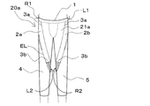
- FIG. 1 shows a schematic front view when a garment according to an embodiment of the present invention is worn.
- the garment 20a has a body covering area 21a and two auxiliary bands 2a and 2b.
- the body covering area 21a is a portion (A) 1 that covers the wearer's waist when wearing clothes, and is worn when wearing clothes.
- a part (B) 4 covering the right knee circumference of the wearer, a part (C) 5 covering the left knee circumference of the wearer when wearing clothing, and one of four pairs of locking portions.
- Each of the auxiliary bands 2a and 2b has the other of two pairs of locking portions.
- auxiliary bands 2a, 2b are fixed to the body covering ground 21a in a detachable state.
- what constitutes one side of the four pairs of engaging portions provided on the body covering ground 21a includes the right side R1 and the left side L1 of the portion A covering the waist circumference and the right knee.
- One each is arranged on the left side L2 of the part B covering the peripheral part and the right side R2 of the part C covering the left knee peripheral part.
- what constitutes the other side of the two pairs of engaging portions provided on the auxiliary bands 2a, 2b is disposed at one end 3a and the other end 3b.
- auxiliary band 2a includes an engaging part provided on the right side R1 of the part A where the engaging part provided on one end 3a of the auxiliary band 2a covers the waist.
- the auxiliary band 2a is fixed in a detachable state by being locked to the left side of the portion B where the locking part provided at the other end 3b of the auxiliary band 2a covers the right knee circumference.
- the auxiliary band 2a is fixed in a detachable state by being locked by a locking portion provided in the portion L2.
- 2b is an engaging part provided on the left side L1 of the part A where the engaging part provided on one end 3a of the auxiliary band 2b covers the waist.
- the auxiliary band 2b is fixed in a detachable state by being locked to the right side of the portion C where the locking part provided at the other end 3b of the auxiliary band 2b covers the left knee circumference.
- the auxiliary band 2b is fixed in a detachable state by being locked by a locking portion provided in the portion R2.
- the two auxiliary bands 2a and 2b are arranged so that the two ends 3a and 3b of these auxiliary bands sandwich the hip joint of the wearer and along the body surface of the front surface of the wearer's thigh. .
- the auxiliary band 2a or 2b in the direction S connecting the one end 3a side and the other end 3b side of the auxiliary band 2a or 2b. Since the tension T1 is larger than the tension T2 in the direction parallel to the direction S of the body covering material 21a overlapping with the auxiliary belt, the clothing of the present invention appropriately assists the bending motion of the wearer's hip joint, Can obtain the effect of walking assist.
- the garment of the present invention employs the configuration exemplified above, it does not require an electrical drive source, and is excellent in productivity and low cost, and since it is a garment, it is electrically driven. It is lighter and safer than other assistive devices, and it is also safer.
- the ratio (T1 / T2) of the tension T1 and the tension T2 is 3 or more and 100 or less.
- T1 / T2 By setting T1 / T2 to 3 or more, the force for the auxiliary band to return to the original shape is sufficiently exhibited, and the motion of the joint can be appropriately guided in a desired direction.
- T1 / T2 when T1 / T2 is set to 100 or less, the force with which the two ends of the auxiliary band are attracted to each other becomes appropriate, and the wearability of the clothes is further improved, and the posture and body position before induction of joint motion Fatigue due to maintenance can be further reduced.
- the lower limit of T1 / T2 is more preferably 7 or more
- the upper limit of T1 / T2 is more preferably 80 or less.
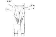
- FIG. 2 is a schematic front view when a garment is worn according to another embodiment of the present invention.
- the garment 20b is made of the same member as that constituting the garment 20a shown in FIG. 1, but the tension T1 of the auxiliary bands 2c and 2d is the auxiliary band of the garment 20a shown in FIG. It is different from the garment 20a shown in FIG. 1 in that it is fixed to the body covering ground 21b so as to be weaker than the tension T1 of 2a and 2b.
- the tension of the auxiliary band when one auxiliary band is pulled with a specific force in the length direction and the force that is weaker than the above specific force in the length direction of the other auxiliary band The tension of the latter is weaker when compared with the tension of the auxiliary band when pulled by.
- the ability to adjust the tension T1 of the auxiliary belt with the same garment in this way for example, in the initial stage of exercise training, the tension is first weakened, and gradually increases to a tension that is felt to be optimal for the wearer when getting used. You can find the optimal position while weakening or weakening. Since a person's physical condition and physical ability change also in a season and time zone, since the auxiliary power according to the ability at that time is obtained by adjustment of such tension, it is preferable. Furthermore, even when there is a left-right difference in the ability of the limbs, the left-right balance can be adjusted by changing the left-right tension.
- pulled in the length direction and the method of changing the length between the fixing parts of an auxiliary belt and a body covering ground Two of these can be illustrated.
- materials such as nylon and polyacetal that are usually used in apparel sub-materials, buckles and adjusters having a width can be suitably used.
- the tension T1 decreases as the length of the non-fixed portion of the auxiliary band increases, and conversely, the tension T1 can increase as the length of the non-fixed portion of the auxiliary band decreases.
- the latter method is a secondary material that can partially fix the auxiliary band and the body covering ground, such as a hook-and-loop fastener and a snap button.
- a hook-and-loop fastener is provided in advance in at least one end of the auxiliary band
- a hook-and-loop fastener is provided in a corresponding part of the body covering ground
- the length and width of the hook-and-loop fastener provided in the body covering ground are set in the end of the auxiliary band.
- the surface fastener is provided larger than the provided surface fastener, by adjusting the portion of the surface fastener provided on the body covering ground for locking the surface fastener provided at the end of the auxiliary belt, between the fixed parts of the auxiliary belt The distance can be adjusted, and as a result, the tension T1 can be easily changed.
- hook-and-loop fasteners are designed to stick together when they are pressed against each other, and can be freely attached or removed.
- hook-and-loop fasteners often consist of a hook surface and a loop surface, but both the hook and loop are embedded and are indistinguishable, and the hook surface is mushroom-shaped and serrated to enhance the bonding force. Etc. can also be preferably used.
- hook-and-loop fasteners that have stretchability, so that movement followability is enhanced. Therefore, it is desirable to use the stretchable type for either one of the pair of hook-and-loop fasteners.
- the auxiliary band is the same, the length between the fixing parts of the auxiliary band is increased, that is, the tension A increases as the auxiliary band in a more pulled state is fixed to the body covering ground, and the auxiliary band is fixed.
- the tension A becomes smaller as the length between the parts is shortened, that is, the auxiliary band in a state of being pulled less is fixed to the body covering ground.
- the timing for adjusting the tension T1 may be before or after wearing the clothing. That is, the tension T1 may be adjusted before wearing the garment, and the garment may be worn after setting a desired assisting force for the wearer in advance. You may adjust tension
- the value of the tension T1 is preferably 4N or more and 55N or less.
- the value of the tension T1 is preferably 4N or more and 55N or less.
- the auxiliary band is not particularly limited as long as it has an appropriate elasticity including a stretchable material such as natural rubber, synthetic plastic, metal (processed into a spring shape).
- the auxiliary belt is made of an elastic material such as rubber or resin or a stretchable fiber material from the viewpoint of ensuring safety even if it falls down. Is desirable.
- an elastic body such as a synthetic plastic, such as polyester elastomer resin Hytrel (registered trademark).
- An auxiliary band is preferably used.
- the fiber material that can be suitably used for the auxiliary band is at least one selected from the group consisting of natural fibers such as silk and wool, regenerated fibers such as rayon, and synthetic fibers such as acrylic fibers and polyester fibers.
- natural fibers such as silk and wool
- regenerated fibers such as rayon
- synthetic fibers such as acrylic fibers and polyester fibers.
- examples thereof include a stretch woven or knitted fabric knitted with a mixture of elastic fibers (polyurethane fiber, polyester elastomer fiber, etc.), or a stretch woven or knitted fabric knitted with elastic fibers alone.
- a multifilament of composite fibers in which two types of polyester polymers, one of which is polyester mainly composed of polytrimethylene terephthalate (PTT), are bonded side by side along the fiber length.
- a polyester stretch woven or knitted fabric used for at least one of warp and weft can also be suitably used.
- the composition of the fiber material may be either woven or knitted, but knitted is more preferable in that it has high stretch properties and can impart sweat absorption and quick-drying functions depending on the tissue structure.
- the knitting structure may be either a warp knitting or a weft knitting, but more preferably a warp knitting having high stretchability.
- the auxiliary band may be a single material or a plurality of materials.
- a composite method for example, a plurality of materials having different elongation rates may be stacked, connected, or both, and the desired tension can be finely adjusted by combining them.
- the shape of the auxiliary band is not particularly limited as long as it can be arranged on the body covering ground along the wearer's body surface from one end side to the other end side with a portion covering the joint of the wearer interposed therebetween.
- the auxiliary band is tapered and tapered. It is preferable that the tapered tip end portion of the auxiliary band is fixed to the housing part having a small peripheral diameter, and the thick part at the other end of the tapered auxiliary band is fixed to the housing part having a large peripheral diameter.
- the width is continuously narrowed from the wide part to the narrow part by bending it into a V shape so that part of the auxiliary band with the same width partially overlaps.
- Tapered auxiliary bands can be created. By making it V-shaped, when one band of the V-shaped auxiliary band stretches according to the movement of the pendulum of the joint movement, the other band contracts, and now when the one that has been extended contracts As one band stretches alternately, it stretches and shrinks alternately. For example, compared to an I-shaped auxiliary band, tension is distributed and durability is improved, and the band stretches and contracts mutually.
- auxiliary band Large portions are prevented from touching left and right, power is concentrated in the length direction of the auxiliary band, and a desirable sense of stability of the joint motion can be enhanced.
- the body coverage of the thick limbs inevitably tends to increase in elongation, but if the width of the auxiliary band is small, the stress concentrates in one place and further stress is applied to the body coverage and tears. Fraying or damage is likely to occur.
- using a wide auxiliary band for the thick part of the limb and a narrow auxiliary band for the thin part of the limb, that is, a tapered auxiliary band stress is concentrated too much on a specific part. Without any problem, it is possible to cover the body in a well-balanced manner according to the thickness of the part and to apply the auxiliary force.
- the auxiliary belts are laid around the limbs so that the auxiliary belts 2a and 2b obliquely cross the body surface. This is because the length of the auxiliary band can be kept relatively long on a limited body surface and a large amount of tension energy can be accumulated by adopting such an auxiliary band alignment method. More preferably, when the target joint and the limbs on both sides thereof are regarded as cylinders, as shown in FIG. 1, the outer line from one end 3a of the auxiliary band 2a to the other end 3b is denoted as EL.
- the end point of the outer line EL (on the other end 3b side) and the cylinder with respect to the surface including the starting point of the outer line EL (on the one end 3a side) and the central axis of the cylinder is preferably 135 ° to 225 °.
- the lap angle of the auxiliary band with respect to the body surface regarded as a cylinder is smaller than 135 °, a gap with the body surface is likely to open when the auxiliary band is loosened, and projections such as handrails on stairs enter the gap and There is a risk of being carried, and since the length is short, the tension of the auxiliary band cannot be accumulated so much and the power is not easily transmitted to the joint. If the rotation angle of the auxiliary band with respect to the body surface regarded as a cylinder exceeds 225 ° and the auxiliary band is rotated around the body surface, the auxiliary body is constrained to the body, so that the force hardly acts on the joint.
- the direction of joint motion assistance can be easily changed simply by changing the direction along the auxiliary belt (clockwise or counterclockwise), which is preferable because the degree of freedom of training is extremely high. .
- the ease of extension of the auxiliary band is expressed by the spring constant when a load is applied to the “spring” that shows elasticity.
- the spring constant of the auxiliary band is preferably 0.01 to 0.50 N / mm.
- the value of the spring constant is smaller than 0.01 N / mm, the force of the spring that the auxiliary band tries to return to becomes weak, and it becomes difficult to guide the joint in a desired direction.
- the spring constant of the auxiliary band is preferably 0.01 to 0.50 N / mm.
- materials having different spring constants may be stacked, connected, or both. If the same material is stacked two times, the combined spring constant will be approximately doubled, and if you connect materials with different spring constants, the reciprocal of the combined spring constant will be the sum of the reciprocal of each spring coefficient (Hooke's law). Since a simulation calculation for obtaining a desired spring constant can be performed, it leads to a shortening of a study period of an appropriate auxiliary force.
- the fabric used for the body covering is a stretchable fabric having stretchability. If the above fabric is low in elasticity and there is a large gap between the body covering and the body, the clothing will rise or the shape will collapse, and the tension of the auxiliary band will not be transmitted well to the body, attracting the desired joint movement It becomes difficult to do. From the viewpoint of excellent adhesion to the body, in order to prevent such sliding and losing shape, and the fixed part where the auxiliary band is fixed to the body covering ground operates as a fulcrum of joint motion. It is desirable that the fabric used for the body covering is a stretchable fabric. Furthermore, the stretch rate of the stretchable fabric is preferably 30% or more.
- the stretchable fabric sufficiently follows the elongation of the skin during the human body exercise, and the exercise followability can be enhanced. Furthermore, in order to prevent the clothing from slipping up, a material having a non-slip function may be used for at least a part of the body covering ground. Application of resin is conceivable.
- the elastic fabric is preferably made of polyurethane elastic fiber, and the polyurethane elastic fiber is preferably a commercially available lycra (registered trademark) or T-127C (trade name). This is because it has the property of extending greatly with a small force and quickly returning to its original state.
- the body covering ground does not necessarily have to cover all the surrounding joints, and a hole may be partially formed in order to prevent stuffiness and improve the breathability and comfort of clothing.
- a structure in which a hole is formed in an overlapping portion with a mesh-like cloth or an auxiliary band can also be suitably used.
- FIGS. 1 to 5 show an example of the form of the garment according to the present invention in which the hip joint is an auxiliary object.
- this garment 20a includes two auxiliary belts 2a and 2b, and a body covering area 21a is a portion (A) 1 that covers the waist circumference of the wearer.
- a portion (B) 4 covering the right knee circumference and a portion (C) 5 covering the wearer's left knee circumference are provided.
- one end 3a of 2a is fixed to the right side R1 (outer right waist) of the portion A that covers the waist circumference when the garment is worn.
- the other end 3b of the auxiliary band 2a is fixed to the left side L2 (the inner side of the right knee) of the portion B covering the right knee circumference when the garment is worn.
- one end 3a of 2b is fixed in a detachable manner to the left side L1 (outside of the left waist) of the part A that covers the waist circumference when the garment is worn.
- the other end 3b of the auxiliary band 2b is fixed to the right side R2 (inner left knee) of the portion C covering the left knee circumference when the garment is worn.
- the auxiliary bands 2a and 2b are arranged along the body surface on the front surface of the thigh.
- the auxiliary bands 2a, 2b, 2c, 2d, 2e, 2f, 2g, 2h, 2i, and 2j are set on the thigh.
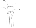
- FIG. 5 there are a method of running along the front side of the body and a method of placing the auxiliary bands 2 k and 2 m along the back side of the body. It is desirable to keep it along. By doing so, the tension energy that the auxiliary body stretches and accumulates at the time of hip joint extension is released and converted into assist force at the time of hip joint swing.
- the auxiliary belt is aligned obliquely from the outer right hip to the inner right knee.
- the target joint is a hip joint
- the limb of the thigh is regarded as a cylinder, as shown in FIG. 1, from one end 3a to the other end 3b of the auxiliary band 2a.
- the outer line that reaches is EL
- the end point of the outer line EL (the other end 3b) with respect to the surface including the start point of the outer line EL (on the one end 3a side) and the central axis of the cylinder.
- the angle formed by the surface including the central axis of the cylinder and the rotation angle of the auxiliary band with respect to the cylinder is 175 to 185 °. By doing so, for example, it is possible to accumulate more tension energy by taking a relative length longer than when straight along the right hip outer side to the right knee outer side (the angle is 0 °). .
- an auxiliary belt is obliquely extended from the wearer's navel to the outside of the knee, but when the hip joint is swung up, a gap between the auxiliary belt and the body covering area is slightly easily formed near the crotch.
- the auxiliary belt is disposed from the outer side of the right waist to the inner side of the right knee where a gap is not easily formed between the auxiliary belt and the body covering ground through a series of walking motions. More preferably, one end of the auxiliary band is fixed to a region having a length of 5 cm in the height direction of the wearer near the pelvic ridge line at the waist circumference and a length of 15 cm in the circumference of the waist, and the inner side at the knee. It is desirable to arrange the auxiliary band so as to fix the other end of the auxiliary band in a region having a length of 15 cm in the height direction of the wearer and a length of 3 cm in the circumferential direction around the collateral ligament.
- the body covering using stretch fabric has a surface that is difficult to wear, it is more preferable to provide a fastener 6 at the hem as shown in FIG.
- the method of extending the auxiliary belts 2k, 2m along the body surface as shown in FIG. By doing so, when the hip joint swings out (that is, hip joint contraction), a load is applied on the contrary (that is, hip joint extension assist), and the wearer's muscle strength can be further strengthened.
- the present invention can also be suitably used to enhance the physical ability of people who have no problem with physical ability or activity level, or those who have relatively high levels (athletes, athletes, etc.).
- the auxiliary belt passes like the body cloth pattern shown in FIG. It is also preferable to provide a guide line in advance. Furthermore, as in the embodiment of the body cover shown in FIG. 8, the appropriate length and width of the auxiliary band may be indicated stepwise on the body cover side by separate guide lines 7a, 7b, 8a, 8b. Good. It is clarified in which position the auxiliary band should be attached, and it becomes easy to reproduce the tension that suits you.
- an adjustment band for adjusting the waist of the garment according to the present invention around the waist of the wearer is provided, and the adjustment band covers at least the left and right iliac ridges of the wearer and covers the waist circumference shown in FIG. It is preferable that the adjustment band covers the part (A) 1. And it is further preferable to have a waist fastening portion for fixing at least a part of the portion (A) 1 covering the waist circumference portion and the adjustment band in a detachable state.
- the fabric used for the adjustment band is preferably a stretchable fabric having stretchability, and the above-described stretchable fabric can be used.
- the waist fastening portion for example, one locking portion is provided in the portion (A) 1 covering the waist circumference portion, the other locking portion is provided in the adjustment band, and the locking portion provided in the adjustment band is the waist circumference portion. It is possible to adopt a structure that is fastened by being locked to a locking portion provided in the portion (A) 1 that covers. Moreover, a hook-and-loop fastener can be employed as the locking portion.
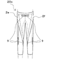
- FIG. 3 shows a schematic front view when a garment according to another embodiment of the present invention is worn.
- the garment 20c has a body covering area on which at least four auxiliary bands can be attached, and two auxiliary bands 2e and 2f are attached to the body covering area.
- One of the two auxiliary bands 2e and 2f is fixed to the body covering ground along the body from the outer side of the right waist to the inner side of the right knee, and the other auxiliary band 2f is fixed to the left waist. It is fixed to the body covering ground along the body from the outside to the inside of the left knee.
- a pair of hook-and-loop fasteners are used as means for fixing the auxiliary belt to the body covering ground, and one locking portion 9 constituting the pair of hook-and-loop fasteners is provided on the body covering ground. It is arranged.
- one of the locking portions 9 constituting the pair of hook-and-loop fasteners disposed on the knee inner side of the body covering ground (hereinafter also referred to as an inner locking portion).
- What is arranged on the outer side of the knee (hereinafter also referred to as an outer locking portion) has a relatively long shape in the wearer's height direction. Therefore, the wearer adjusts the tension T1 of the auxiliary band to a desired one by fixing the end of the auxiliary band arranged on the inner side of the knee to an arbitrary position in the height direction of the wearer of the inner locking portion 9. Can do.
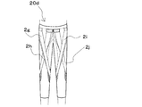
- FIG. 4 shows a schematic front view when a garment according to another embodiment of the present invention is worn.
- the body cover of the garment embodiment is the same as the body cover of the garment embodiment shown in FIG. 3, and in this garment embodiment, the garment embodiment shown in FIG.
- the embodiment is different from the embodiment example of the garment shown in FIG. 3 in that four auxiliary bands 2g, 2h, 2i and 2j, which are two auxiliary bands added to the example, are attached to the body covering.
- FIG. 5 shows a schematic rear view when the garment according to another embodiment of the present invention is worn.
- two auxiliary bands 2k and 2m are attached to the back surface of the body covering ground of the garment 20e.
- one auxiliary band 2m is fixed to the body covering ground from the outer side of the right waist to the inner side of the right knee
- the other auxiliary band 2k is the outer side of the left waist. It is fixed to the body covering ground along the body from the inside to the left knee.
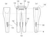
- FIG. 6A shows a schematic left side view of the body covering used in the embodiment of the garment of the present invention shown in FIGS. 3 and 4
- FIG. 6B shows FIGS. Fig. 6 (c) is a schematic front view of a body covering used in an embodiment of the garment of the present invention shown in Fig. 6 and Fig. 6 (c) shows an embodiment of the garment of the present invention shown in Figs.
- a schematic right side view of the body covering used is shown.
- This body covering ground has two diameter stop portions 10 on its abdomen, one diameter stop portion 10 on each of its right outer waist and left waist, and one on each of its right knee outer side and right knee inner side. It has one diameter stop part 10, and has one diameter stop part 10 on the left knee outer side and the left knee inner side, respectively.
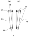
- FIGS. 7A and 7B are schematic front views of auxiliary bands used in one embodiment of the clothing of the present invention shown in FIGS.
- the auxiliary bands 2n and 2p are continuously narrowed from the wide part W to the narrow part N at one end by bending the auxiliary bands 2n and 2p into a V shape so as to partially overlap each other. It is a taper-shaped auxiliary band, and the other latching
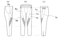
- FIG. 8 (a) is a schematic left side view of the body covering used in the embodiment of the garment of the present invention shown in FIGS. 1 and 2
- FIG. Fig. 8 is a schematic front view of a body covering used in one embodiment of the garment of the present invention shown in Fig. 2
- Fig. 8 (c) is an embodiment of the garment of the present invention shown in Figs.
- the schematic right view of the body covering used for the example is shown.
- This body covering place is provided with guide lines 7a, 7b, 8a and 8b for appropriately attaching the auxiliary belt to the body covering place.
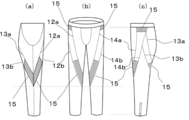
- FIG. 9 (a) is a schematic left side view of the body covering used in the embodiment of the garment of the present invention shown in FIG. 5, and FIG. 9 (b) is shown in FIG.
- FIG. 9C is a schematic front view of a body covering used in an embodiment of the garment of the present invention
- FIG. 9C is a body used in the embodiment of the garment of the present invention shown in FIG.
- a schematic right side view of the cover is shown.
- the body covering ground is provided not only with the front surface but also with a guide line for properly attaching the auxiliary band to the body covering ground on the back surface.
- Reference numerals 12a, 12b, 13a, 13b, 14a, and 14b are guide lines, and 15 is a locking portion.
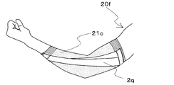
- FIG. 10 shows a schematic right side view when a garment according to another embodiment of the present invention is worn.
- the joint to be assisted is an elbow joint. That is, the body covering ground 21c possessed by the garment 20f covers the elbow joint and the casing around the elbow joint, and the auxiliary band 2q possessed by the garment 20f serves as the body when the garment 20f is worn. It arrange
- FIG. 11 shows a schematic right side view of the body covering place 21c used in the embodiment of the garment 20f of the present invention shown in FIG.
- the body covering ground 21c has one locking portion 16 constituting a pair of hook-and-loop fasteners at both ends thereof.
- the said body covering ground 21c is the cylindrical body provided with the part D which covers a wearer's upper arm part, the part E which covers a wearer's elbow part, and the part F which covers a wearer's wrist part
- one end of the auxiliary band 2q is fixed in a removable state to the portion D when the garment 20f is worn, and the other end of the auxiliary band 2q is fixed when the garment 20f is worn. It is desirable to be fixed to the part F in a removable state. By doing so, it becomes possible to freely design a desired power and angle without excessively rotating the elbow and twisting the arm, and it is possible to guide the joint motion according to the wearer's physical strength and function.
- FIG. 12 shows a schematic development view of the constituent parts of the body covering used in the embodiment of the clothing of the present invention shown in FIGS. 6 (a), 6 (b) and 6 (c). By sewing these constituent parts together, a body covering material used in an embodiment of the garment of the present invention shown in FIGS. 6 (a), 6 (b) and 6 (c) is obtained.
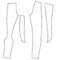
- FIG. 13 shows a schematic development view of the constituent parts of the body covering used in the embodiment of the clothing of the present invention shown in FIGS. 8 (a), (b) and (c). By stitching these constituent parts together, a body covering used in one embodiment of the garment of the present invention shown in FIGS. 8 (a), (b) and (c) can be obtained.
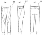
- FIG. 14 (a) is a schematic front view of a garment according to another embodiment of the present invention
- Fig. 14 (b) is a garment according to another embodiment of the present invention
- FIG. 14C is a schematic rear view of the garment according to another embodiment of the present invention.
- an adjustment band 22 for adjusting the circumference of the portion A that covers the waist circumference of the wearer of the body cover is disposed. Both ends of this auxiliary band are respectively placed and fixed on the body covering area covering the iliac crest on both sides of the wearer when worn, and the part between both ends of this auxiliary band is the wearer It is fixed to cover the waist.
- both ends of the auxiliary band are hooked on the wearer's pelvis and the adjustment band is fixed, both ends of the auxiliary band are worn near the iliac crest on both sides of the wearer, preferably the upper part of the iliac crest. It is preferable to arrange each in the part of the body covering ground to cover.
- the waist portion is gradually pulled downward by the tension of the auxiliary belt disposed on the thigh when the wearer of the garment walks, etc. Lowering is suppressed and the proper position of the body covering and the auxiliary belt can be maintained.
- FIG. 15 shows a schematic front view of an adjustment band according to an embodiment used in the clothing of the present invention shown in FIG.
- the adjustment band 22 is thicker from both ends toward the center. Further, one end 23 of a locking portion constituting a pair of hook-and-loop fasteners is disposed at both ends and the center of the adjustment band 22.
- the elongation recovery rate was measured based on JIS L 1096 (2010 edition) “Fabric and knitted fabric test method” B-1 method in the vertical and horizontal directions. Mark the test piece at 20 cm from the clamp and its lower end, measure the length between the marks after 14.7 N load was applied and held for 1 hour, and 30 seconds after the load was removed. The elongation recovery rate was determined.
- the tension T1 was measured using a Tensilon universal material tester RTG-1210 manufactured by A & D, under the load cell condition of 250N, and both ends of the auxiliary band were each two aluminum plates (width 10 cm x height 5 cm x thickness 0). .5mm) is set with the gripping interval length Y, drawn from the length Y to 125% of the X at 1000mm / min to draw a tension (N) -displacement curve, and the displacement X The tension (N) at the time was read, and the arithmetic average value of the three times was defined as the tension T1.
- Tension T2 is a sample obtained by cutting out the part of the body covering layer that overlaps the auxiliary band to the same size as the auxiliary band, and each end has two aluminum plates (width 10 cm x height 5 cm x thickness 0.5 mm).
- the gripping length is set to Z while being sandwiched through the wire, and stretched at a speed of 1000 mm / min from the length Z to 125% of the above X to draw a tension (N) -displacement curve. (N) was read, and the arithmetic average value of the three times was defined as the tension T2.
- assistant band were calculated
- n is a frame number.
- the knee joint position (data of the first frame) at the start of measurement was defined as the origin.
- the maximum value d knee of the relative position between the two points of the origin and the knee joint position is extracted for each of the data measured seven times from the following equation (2).
- the arithmetic average value of the maximum value d knee of the seven relative positions was evaluated as the movement distance of the knee joint.
- Example 1 Nylon yarn and polyurethane elastic fiber (Lycra (registered trademark), trade name “T-127C”) are knitted into a tricot and dyed to give a stretchable fabric (weight per unit: 250 g / m 2 ) of 70% nylon and 30% polyurethane. ) The elongation rate was 140% in the vertical direction, 100% in the horizontal direction, and the recovery rate in elongation was 92% in the vertical direction and 86% in the horizontal direction. Each part was cut out as shown in FIG. 12 using the cloth and stitched with a flat seam sewing machine to create a garment as shown in FIG. In addition, the B surface fastener (female) which has stretch property was provided in the shaded part of FIG.
- B surface fastener female
- nylon yarn and polyurethane elastic fiber (Lycra (registered trademark), trade name “T-127C”) were knitted, and a power net was obtained by dyeing.
- the power net is cut out with a length of 76 cm and a width of 5 cm so that the length direction of the dough is long, bent into a V shape so that a part of the cut portion partially overlaps, and a length of 5 cm at both ends.
- the YKK B surface fastener (male) 5cm wide and the YKK B surface fastener (male) 5cm long and 8cm wide are sewn and continuously from the wide part to the narrow part as shown in FIG.
- a tapered auxiliary band with a narrow width was obtained.
- the length of the non-fixed portion excluding the B-surface fastener portion of the tapered auxiliary band was 28.5 cm. (38.5cm with B-side fastener at both ends)
- the subject A wears the lower garment, and the tapered auxiliary band is slightly pulled so that the length of the non-fixed portion of the auxiliary band is 28.5 cm to 48.8 cm. It was attached as shown in FIG. Table 2 below describes the results of motion analysis performed in this state and the movement distance (cm) of the knee joint measured.
- Example 1 As shown in Table 2, in Example 1, the movement distance of the knee joint was increased as compared with Comparative Example 1.
- Example 2 Subject B wears the same undergarment as in Example 1, and the tapered auxiliary band is slightly pulled so that the length of the non-fixed portion of the auxiliary band is from the original 28.5 cm to 48.7 cm In the state, it attached as shown in FIG. Table 2 below describes the results of motion analysis performed in this state and the movement distance (cm) of the knee joint measured.
- Nylon yarn and polyurethane elastic fiber are knitted into a tricot and dyed to give a stretchable fabric of 70% nylon and 30% polyurethane (200 g / m 2 basis weight) )
- the elongation rate was 120% in the vertical direction and 95% in the horizontal direction, and the recovery rate in elongation was 93% in the vertical direction and 92% in the horizontal direction.
- Each part was cut out as shown in FIG. 13 using the cloth and stitched with a flat seam sewing machine to create a garment as shown in FIG.
- the B surface fastener female which has a stretching property was provided in the shaded part of FIG.
- a band rubber having a width of 5 cm was cut out to a length of 76 cm, bent into a V shape so that a part of the cut out partly overlapped, and a YKK B surface fastener (male) having a length of 5 cm and a width of 5 cm at both ends.
- a YKK B surface fastener (male) 5 cm long and 8 cm wide was sewn to obtain a tapered auxiliary band continuously narrowing from the wide part to the narrow part as shown in FIG. .
- the length of the non-fixed portion excluding the B-surface fastener portion of the tapered auxiliary band was 28.5 cm.
- Example 4 In a state where the lower garment of Example 3 was worn by the subject D, the tapered auxiliary band was slightly pulled so that the length of the non-fixed portion of the auxiliary band was changed from the original 28.5 cm to 48.9 cm. It was attached as shown in FIG. Table 2 below describes the results of motion analysis performed in this state and the movement distance (cm) of the knee joint measured.
- Table 2 shows the results of having subject D wear the same lower garment as in Example 3, performing a motion analysis without attaching an auxiliary band, and measuring the movement distance (cm) of the knee joint.
- Example 4 As shown in Table 2, in Example 4, the movement distance of the knee joint was increased compared to Comparative Example 4.
- Nylon yarn and polyurethane elastic fiber (Lycra (registered trademark), trade name “T-906C”) are knitted into a tricot and dyed to give a stretchable fabric of 70% nylon and 30% polyurethane (weight per unit: 250 g / m 2) )
- the elongation was 95% in the longitudinal direction, 120% in the horizontal direction, and the recovery rate in elongation was 93% in the vertical direction and 92% in the horizontal direction.
- Each part was cut out as shown in FIG. 13 using the cloth and stitched with a flat seam sewing machine to create a garment as shown in FIG.
- the B surface fastener female which has a stretching property was provided in the shaded part of FIG.
- the subject E wears the lower garment, and the tapered auxiliary band is slightly pulled so that the length of the non-fixed portion of the auxiliary band is 28.5 cm to 47.5 cm. It was attached as shown in FIG. Table 2 below describes the results of motion analysis performed in this state and the movement distance (cm) of the knee joint measured.
- Example 5 Table 2 shows the results of having subject E wear the same lower garment as in Example 5, performing a motion analysis without attaching an auxiliary band, and measuring the movement distance (cm) of the knee joint. As shown in Table 2, the movement distance of the knee joint in Example 5 was increased compared to Comparative Example 5.
- Example 6 The lower garment was the same as in Example 5.
- the cloth used for the auxiliary band is the same power net as in Example 5, and the power net is cut out with a length of 40 cm and a width of 5 cm so that the length direction of the cloth is long, and a part of the cut out part is partially Folded into a V shape so that they overlap each other, YKK B surface fastener (male) 2.5 cm long and 5 cm wide and YKK B surface fastener (male) 2.5 cm long and 8 cm wide And a tapered auxiliary band having a continuously narrowing width from a wide part to a narrow part as shown in FIG. 7 was obtained.
- the length of the non-fixed portion excluding the B surface fastener portion of the tapered auxiliary band was 15.0 cm. (20.0cm with B surface fastener at both ends)
- the subject E wears the lower garment, and the tapered auxiliary band is slightly pulled so that the length of the non-fixed portion of the auxiliary band is 15.0 cm to 20.5 cm. It was attached as shown in FIG. Table 2 below describes the results of motion analysis performed in this state and the movement distance (cm) of the knee joint measured.
- Example 6 Table 2 shows the results of having subject E wear the same lower garment as in Example 5, performing a motion analysis without attaching an auxiliary band, and measuring the movement distance (cm) of the knee joint. As shown in Table 2, in Example 6, the movement distance of the knee joint was increased compared to Comparative Example 6.
Abstract
Description
伸び率は、JIS L 1096(2010年版)「織物及び編物の生地試験方法」に基づいて測定した。このJISで定める定速伸長形の試験機を使用し、つかみ間隔20cm、引っ張り速度20cm/分の条件で引張荷重14.7Nまで伸長させたときの伸び率をタテ方向およびヨコ方向についてそれぞれ求めた。 (Growth rate)
The elongation was measured based on JIS L 1096 (2010 edition) “Fabric and knitted fabric test method”. Using this constant speed extension type tester defined by JIS, the elongation rate when the tensile load was extended to 14.7 N under the conditions of a grip interval of 20 cm and a pulling speed of 20 cm / min was obtained for each of the vertical and horizontal directions. .
伸長回復率は、タテ方向およびヨコ方向についてJIS L 1096(2010年版)「織物及び編物の生地試験方法」B-1法に基づいて、それぞれ測定した。試験片にクランプとその下端から20cmのところに印をつけ、14.7Nの荷重を加え1時間保持後の印間の長さと、荷重を取り除いた後30秒後の印間の長さを測定し、伸長回復率を求めた。 (Elongation recovery rate)
The elongation recovery rate was measured based on JIS L 1096 (2010 edition) “Fabric and knitted fabric test method” B-1 method in the vertical and horizontal directions. Mark the test piece at 20 cm from the clamp and its lower end, measure the length between the marks after 14.7 N load was applied and held for 1 hour, and 30 seconds after the load was removed. The elongation recovery rate was determined.
テンシロン引張試験機を用い、荷重は4.9N、標線間距離は補助帯の非固定部の長さとして、その長尺方向に定速(1000mm/分)で元の長さに対してさらに30%伸長時の応力-歪み曲線を描き、その傾きよりばね定数(N/mm)を求めた。 (Spring constant)
Using a Tensilon tensile tester, the load is 4.9 N, the distance between the marked lines is the length of the non-fixed part of the auxiliary band, and further in the longitudinal direction at a constant speed (1000 mm / min) with respect to the original length A stress-strain curve at 30% elongation was drawn, and the spring constant (N / mm) was determined from the slope.
本発明の衣類を着用し、補助帯と身体被覆地にたるみがない状態での補助帯と身体被覆地の両固定部分に印をつけ、その両固定部分間に存在する非固定部の長手方向の長さを身体表面に沿って測定した。この長さをXとする。次に、衣類を脱ぎ、張力がかかっていない状態で、補助帯と身体被覆地の非固定部の長さ(前記印間の長さ)をそれぞれ測定した。衣類を脱いだ状態では、身体被覆地側の非固定部の長さのほうが、補助帯側の非固定部長さよりも長くなり、たわんでいることが多い。その状態において、補助帯に沿って測定した非固定部の長手方向の長さをY、身体被覆地に沿って測定した非固定部の長手方向の長さをZとする。 (Tension T1, Tension T2)
Wearing the garment of the present invention, marking both fixed parts of the auxiliary band and the body covering in a state where there is no slack in the auxiliary band and the body covering, and the longitudinal direction of the non-fixed part existing between the two fixed parts Was measured along the body surface. Let X be this length. Next, the clothes were taken off, and the length of the non-fixed portion of the auxiliary band and the body covering ground (the length between the marks) was measured in a state where no tension was applied. In the state where the clothes are taken off, the length of the non-fixed part on the body covering ground side is longer than the length of the non-fixed part on the auxiliary belt side and is often bent. In that state, the length in the longitudinal direction of the non-fixed part measured along the auxiliary band is Y, and the length in the longitudinal direction of the non-fixed part measured along the body covering ground is Z.
補助帯の効果を検証するため、5名の被験者(A:男性25歳、B:男性44歳、C:男性78歳、D:女性74歳、E:女性40歳)に、合図と共にまず片方の足を一歩踏み出してもらい、次に残された足を先に踏み出した足に揃えて直立する動作をしてもらった。そして、先に踏み出した側の膝関節の動作を深度センサー(商品名「Kinect」, Microsoft製)を用いて計測した。計測した情報をもとに関節の動作解析を実施した。動作解析は膝関節の移動距離に注目し、後記する4条件の実験動作より膝関節の移動距離を求めて比較した。膝関節の移動距離が大きいことは前記股関節の振り上げが補助されていることを示す。 (Operation analysis)
In order to verify the effect of the auxiliary band, one of the five subjects (A: male 25 years old, B: male 44 years old, C: male 78 years old, D: female 74 years old, E: female 40 years old) with a signal first He stepped on one foot, and then got the remaining foot aligned with the foot he stepped on first, and had him move upright. Then, the movement of the knee joint on the first step was measured using a depth sensor (trade name “Kinect”, manufactured by Microsoft). Based on the measured information, joint motion analysis was performed. In the motion analysis, attention was paid to the movement distance of the knee joint, and the movement distance of the knee joint was obtained and compared based on the following four experimental operations. A large movement distance of the knee joint indicates that the hip joint swing-up is assisted.
(a)補助帯を装着していない状態において、右足で1歩を踏み出す
(b)補助帯を装着していない状態において、左足で1歩を踏み出す
(c)補助帯を右足のみに装着した状態において、右足で1歩を踏み出す
(d)補助帯を右足のみに装着した状態において、左足で1歩を踏み出す
装着する補助帯の種類は被験者の身体能力に応じて試行錯誤的に決定した。
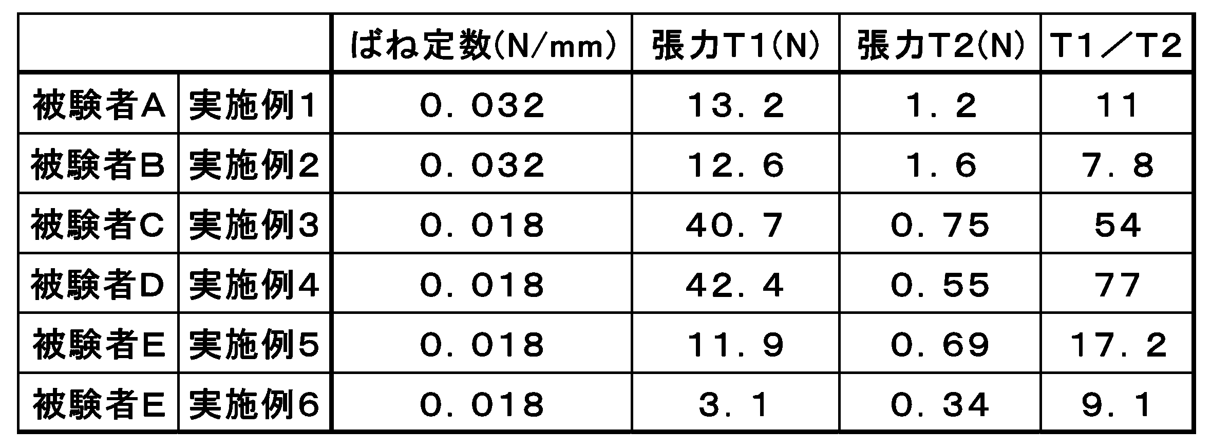
5名の被験者に用いた補助帯のばね定数と、張力T1と、張力T2と、(T1/T2)の値を後記する表1に示す。 In this example, the effect of the auxiliary band was verified by wearing the auxiliary band only on the right foot side. Subjects were instructed to step one step as much as possible with the same force sensation as possible. The experimental operations (a) to (d) under the four conditions shown below were measured 7 times each in order.
(A) Taking one step with the right foot when the auxiliary belt is not worn (b) Taking one step with the left foot when the auxiliary belt is not worn (c) State where the auxiliary belt is worn only on the right foot (D) In the state where the auxiliary band is worn only on the right foot, the type of the auxiliary band to be worn on the left foot is determined by trial and error according to the physical ability of the subject.
The spring constant of the auxiliary band used for the five subjects, the tension T1, the tension T2, and the value of (T1 / T2) are shown in Table 1 below.
Pknee(n)=[xknee(n)、yknee(n)、zknee(n)] Formula (1)
Pknee (n) = [ xknee (n), yknee (n), zknee (n)]
dknee=max〔[xknee(n)2+yknee(n)2+zknee(n)2]1/2〕 Formula (2)
d knee = max [[x knee (n) 2 + y knee (n) 2 + z knee (n) 2 ] 1/2 ]
ナイロン糸とポリウレタン弾性繊維(ライクラ(登録商標)、商品名「T-127C」)を用いてトリコットに編成し、染色加工により、ナイロン70%、ポリウレタン30%の伸縮性生地(目付250g/m2)を得た。伸び率はタテ方向140%、ヨコ方向100%、伸長回復率はタテ方向92%、ヨコ方向86%であった。上記生地を用いて各パーツを図12のように切り出してフラットシーマミシンで縫合して図6のような下衣を作成した。なお、図6の斜線部分にはストレッチ性を有するB面ファスナー(雌)を設けた。 Example 1
Nylon yarn and polyurethane elastic fiber (Lycra (registered trademark), trade name “T-127C”) are knitted into a tricot and dyed to give a stretchable fabric (weight per unit: 250 g / m 2 ) of 70% nylon and 30% polyurethane. ) The elongation rate was 140% in the vertical direction, 100% in the horizontal direction, and the recovery rate in elongation was 92% in the vertical direction and 86% in the horizontal direction. Each part was cut out as shown in FIG. 12 using the cloth and stitched with a flat seam sewing machine to create a garment as shown in FIG. In addition, the B surface fastener (female) which has stretch property was provided in the shaded part of FIG.
被験者Aに実施例1と同じ下衣を着用してもらい、補助帯を取り付けずに動作解析を行い、膝関節の移動距離(cm)を測定した結果を後記する表2に示す。 (Comparative Example 1)
Table 2 below shows the results of having subject A wear the same garment as in Example 1, performing motion analysis without attaching an auxiliary band, and measuring the movement distance (cm) of the knee joint.
実施例1と同じ前記下衣を被験者Bに着用してもらい、前記テーパー状補助帯を前記補助帯の非固定部の長さが元の28.5cmから48.7cmとなるよう、やや引っ張った状態で図3のように取り付けた。その状態で動作解析を行い、膝関節の移動距離(cm)を測定した結果を後記する表2に示す。 (Example 2)
Subject B wears the same undergarment as in Example 1, and the tapered auxiliary band is slightly pulled so that the length of the non-fixed portion of the auxiliary band is from the original 28.5 cm to 48.7 cm In the state, it attached as shown in FIG. Table 2 below describes the results of motion analysis performed in this state and the movement distance (cm) of the knee joint measured.
被験者Bに実施例1と同じ下衣を着用してもらい、補助帯を取り付けずに動作解析を行い、膝関節の移動距離(cm)を測定した結果を後記する表2に示す。 (Comparative Example 2)
Table 2 below shows the results of having subject B wear the same garment as in Example 1, performing motion analysis without attaching an auxiliary band, and measuring the movement distance (cm) of the knee joint.
ナイロン糸とポリウレタン弾性繊維(ライクラ(登録商標)、商品名「T-906C」)を用いてトリコットに編成し、染色加工により、ナイロン70%、ポリウレタン30%の伸縮性生地(目付200g/m2)を得た。伸び率はタテ方向120%、ヨコ方向95%、伸長回復率はタテ方向93%、ヨコ方向92%であった。上記生地を用いて各パーツを図13のように切り出してフラットシーマミシンで縫合して図8のような下衣を作成した。なお、図8の斜線部分には伸縮性を有するB面ファスナー(雌)を設けた。 (Example 3)
Nylon yarn and polyurethane elastic fiber (Lycra (registered trademark), trade name “T-906C”) are knitted into a tricot and dyed to give a stretchable fabric of 70% nylon and 30% polyurethane (200 g / m 2 basis weight) ) The elongation rate was 120% in the vertical direction and 95% in the horizontal direction, and the recovery rate in elongation was 93% in the vertical direction and 92% in the horizontal direction. Each part was cut out as shown in FIG. 13 using the cloth and stitched with a flat seam sewing machine to create a garment as shown in FIG. In addition, the B surface fastener (female) which has a stretching property was provided in the shaded part of FIG.
被験者Cに実施例3と同じ下衣を着用してもらい、補助帯を取り付けずに動作解析を行い、膝関節の移動距離(cm)を測定した結果を後記する表2に示す。 (Comparative Example 3)
Table 2 below shows the results of having subject C wear the same garment as in Example 3, performing motion analysis without attaching an auxiliary band, and measuring the movement distance (cm) of the knee joint.
実施例3の下衣を被験者Dに着用してもらい、前記テーパー状補助帯を前記補助帯の非固定部の長さが元の28.5cmから48.9cmとなるよう、やや引っ張った状態で図4のように取り付けた。その状態で動作解析を行い、膝関節の移動距離(cm)を測定した結果を後記する表2に示す。 (Example 4)
In a state where the lower garment of Example 3 was worn by the subject D, the tapered auxiliary band was slightly pulled so that the length of the non-fixed portion of the auxiliary band was changed from the original 28.5 cm to 48.9 cm. It was attached as shown in FIG. Table 2 below describes the results of motion analysis performed in this state and the movement distance (cm) of the knee joint measured.
被験者Dに実施例3と同じ下衣を着用してもらい、補助帯を取り付けずに動作解析を行い、膝関節の移動距離(cm)を測定した結果を後記する表2に示す。 (Comparative Example 4)
Table 2 shows the results of having subject D wear the same lower garment as in Example 3, performing a motion analysis without attaching an auxiliary band, and measuring the movement distance (cm) of the knee joint.
ナイロン糸とポリウレタン弾性繊維(ライクラ(登録商標)、商品名「T-906C」)を用いてトリコットに編成し、染色加工により、ナイロン70%、ポリウレタン30%の伸縮性生地(目付け250g/m2)を得た。伸び率は縦方向95%、ヨコ方向120%、伸長回復率はタテ方向93%、ヨコ方向92%であった。上記生地を用いて各パーツを図13のように切り出してフラットシーマミシンで縫合して図8のような下衣を作成した。なお、図8の斜線部分には伸縮性を有するB面ファスナー(雌)を設けた。 (Example 5)
Nylon yarn and polyurethane elastic fiber (Lycra (registered trademark), trade name “T-906C”) are knitted into a tricot and dyed to give a stretchable fabric of 70% nylon and 30% polyurethane (weight per unit: 250 g / m 2) ) The elongation was 95% in the longitudinal direction, 120% in the horizontal direction, and the recovery rate in elongation was 93% in the vertical direction and 92% in the horizontal direction. Each part was cut out as shown in FIG. 13 using the cloth and stitched with a flat seam sewing machine to create a garment as shown in FIG. In addition, the B surface fastener (female) which has a stretching property was provided in the shaded part of FIG.
被験者Eに実施例5と同じ下衣を着用してもらい、補助帯を取り付けずに動作解析を行い、膝関節の移動距離(cm)を測定した結果を後記する表2に示す。
表2に示すように、実施例5は比較例5に比べ膝関節の移動距離が増加していた。 (Comparative Example 5)
Table 2 shows the results of having subject E wear the same lower garment as in Example 5, performing a motion analysis without attaching an auxiliary band, and measuring the movement distance (cm) of the knee joint.
As shown in Table 2, the movement distance of the knee joint in Example 5 was increased compared to Comparative Example 5.
下衣は実施例5と同様のものを使用した。補助帯に使用する生地は実施例5と同様のパワーネットとし、前記パワーネットを生地の長さ方向が長手となるように長さ40cmで幅5cmのものを切り出し、切り出したものの一部が部分的に重なるようにV字に折り曲げ、その両端部に長さ2.5cmで幅5cmのYKK製B面ファスナー(雄)と、長さ2.5cmで幅8cmのYKK製B面ファスナー(雄)を縫合し、図7のような幅広の部分から幅狭の部分にかけて連続的に幅が狭くなっているテーパー状補助帯を得た。テーパー状補助帯のB面ファスナー部を除く、非固定部の長さは15.0cmであった。(両端のB面ファスナー部込みでは20.0cm) (Example 6)
The lower garment was the same as in Example 5. The cloth used for the auxiliary band is the same power net as in Example 5, and the power net is cut out with a length of 40 cm and a width of 5 cm so that the length direction of the cloth is long, and a part of the cut out part is partially Folded into a V shape so that they overlap each other, YKK B surface fastener (male) 2.5 cm long and 5 cm wide and YKK B surface fastener (male) 2.5 cm long and 8 cm wide And a tapered auxiliary band having a continuously narrowing width from a wide part to a narrow part as shown in FIG. 7 was obtained. The length of the non-fixed portion excluding the B surface fastener portion of the tapered auxiliary band was 15.0 cm. (20.0cm with B surface fastener at both ends)
被験者Eに実施例5と同じ下衣を着用してもらい、補助帯を取り付けずに動作解析を行い、膝関節の移動距離(cm)を測定した結果を後記する表2に示す。
表2に示すように、実施例6は比較例6に比べ膝関節の移動距離が増加していた。 (Comparative Example 6)
Table 2 shows the results of having subject E wear the same lower garment as in Example 5, performing a motion analysis without attaching an auxiliary band, and measuring the movement distance (cm) of the knee joint.
As shown in Table 2, in Example 6, the movement distance of the knee joint was increased compared to Comparative Example 6.

2a、2b、2c、2d、2e、2f、2g、2h、2i、2j、2k、2m、2n、2p、2q 補助帯
3a 補助帯の一方の端部
3b 補助帯の他方の端部
4 着用者の右膝部を覆う部分(B)
5 着用者の左膝部を覆う部分(C)
6 ファスナー
7a、7b 案内ライン
8a、8b 案内ライン
9 係止部
10 係止部
11 係止部
12a、12b 案内ライン
13a、13b 案内ライン
14a、14b 案内ライン
15 係止部
16 係止部
20a、20b、20c、20d、20e 衣類
21a、21b、21c 身体被覆地
22 調整帯
23 係止部の一方
D 着用者の上腕部を覆う部分
E 着用者の肘部を覆う部分
F 着用者の手首部を覆う部分
EL 補助帯の外側線
R1 腰周部を覆う部分(A)の右側部
L1 腰周部を覆う部分(A)の左側部
R2 左膝周部を覆う部分(C)の右側部
L2 右膝周部を覆う部分(B)の左側部 1 Part covering the waist circumference of the wearer (A)
2a, 2b, 2c, 2d, 2e, 2f, 2g, 2h, 2i, 2j, 2k, 2m, 2n, 2p,
5 Part covering the left knee of the wearer (C)
6
Claims (6)
- 身体被覆地に補助帯が配置された衣類であって、
前記補助帯は、前記身体被覆地における着用者の関節を覆う部分を挟んで一方の端部側から他方の端部側にかけて着用者の身体表面に沿うように前記身体被覆地に配置されており、
前記補助帯と前記身体被覆地とは、互いに分離されて独立して伸縮することができるように前記補助帯は前記身体被覆地に固定され、
前記補助帯の前記一方の端部側と前記他方の端部側とを結ぶ方向Sの前記衣類の着用時における張力T1が、前記補助帯と重なっている前記身体被覆地の前記方向Sに平行な方向の前記衣類の着用時における張力T2よりも大きい、衣類。 Clothing with auxiliary belts placed on the body covering area,
The auxiliary band is arranged on the body covering ground so as to be along the surface of the wearer's body from one end side to the other end side across a portion covering the wearer's joint in the body covering ground. ,
The auxiliary band is fixed to the body covering so that the auxiliary band and the body covering can be separated and expanded and contracted independently,
A tension T1 when the garment is worn in a direction S connecting the one end side and the other end side of the auxiliary band is parallel to the direction S of the body covering that overlaps the auxiliary band. Clothing which is larger than tension T2 at the time of wearing of the clothing in any direction. - 前記張力T1と前記張力T2との比、(T1/T2)が3以上100以下である、請求項1に記載の衣類。 The clothing according to claim 1, wherein a ratio (T1 / T2) of the tension T1 and the tension T2 is 3 or more and 100 or less.
- 前記張力T1を調整する手段を有する、請求項1または2に記載の衣類。 The clothing according to claim 1 or 2, further comprising means for adjusting the tension T1.
- A1とA2の2つの補助帯を備えており、
前記身体被覆地が、着用者の腰周部を覆う部分A、着用者の右膝周部を覆う部分Bおよび着用者の左膝周部を覆う部分Cを備えており、
補助帯A1の一方の端部が前記部分Aに着脱可能な状態で固定されており、補助帯A1の他方の端部が前記部分Bに着脱可能な状態で固定されており、
補助帯A2の一方の端部が前記部分Aに着脱可能な状態で固定されており、補助帯A2の他方の端部が前記部分Cに着脱可能な状態で固定されている、請求項1~3のいずれかに記載の衣類。 It has two auxiliary bands A1 and A2,
The body covering ground includes a portion A that covers the waist circumference of the wearer, a portion B that covers the wearer's right knee circumference, and a portion C that covers the wearer's left knee circumference,
One end of the auxiliary band A1 is fixed to the part A in a removable state, and the other end of the auxiliary band A1 is fixed to the part B in a removable state.
One end of the auxiliary band A2 is fixed to the part A in a detachable state, and the other end of the auxiliary band A2 is fixed to the part C in a removable state. 4. Clothing according to any one of 3. - さらに調節帯を備え、
前記身体被覆地が、着用者の腰周部を覆う部分Aを備えており、
前記衣類の着用時に着用者の左右の腸骨稜付近を覆う前記身体被覆地の部分が前記調節帯により被覆されており、
前記部分Aの少なくとも一部と前記調整帯とを着脱可能な状態で固定する腰締結部を有する、請求項1~4のいずれかに記載の衣類。 In addition, with an adjustment band,
The body covering ground includes a portion A covering the waist circumference of the wearer,
A portion of the body covering that covers the vicinity of the left and right iliac crests of the wearer when the clothing is worn is covered by the adjustment band;
The garment according to any one of claims 1 to 4, further comprising a waist fastening portion that fixes at least a part of the portion A and the adjustment band in a detachable state. - 前記身体被覆地が、着用者の上腕部を覆う部分D、着用者の肘部を覆う部分E、および着用者の手首部を覆う部分Fを備えた筒状体であり、
補助帯の一方の端部が前記部分Dに着脱可能な状態で固定されており、補助帯の他方の端部が前記部分Fに着脱可能な状態で固定されている、請求項1~3のいずれかに記載の衣類。 The body covering ground is a cylindrical body provided with a part D covering the upper arm part of the wearer, a part E covering the elbow part of the wearer, and a part F covering the wrist part of the wearer.
The one end of the auxiliary band is fixed to the portion D in a detachable state, and the other end of the auxiliary band is fixed to the portion F in a removable state. Clothing according to any one.
Priority Applications (4)
| Application Number | Priority Date | Filing Date | Title |
|---|---|---|---|
| CA3019495A CA3019495A1 (en) | 2016-03-30 | 2017-03-24 | Garment |
| CN201780021949.1A CN109068772A (en) | 2016-03-30 | 2017-03-24 | Clothing |
| EP17774809.2A EP3437501A4 (en) | 2016-03-30 | 2017-03-24 | Garment |
| US16/087,513 US20190105216A1 (en) | 2016-03-30 | 2017-03-24 | Garment |
Applications Claiming Priority (2)
| Application Number | Priority Date | Filing Date | Title |
|---|---|---|---|
| JP2016069759 | 2016-03-30 | ||
| JP2016-069759 | 2016-03-30 |
Publications (1)
| Publication Number | Publication Date |
|---|---|
| WO2017170272A1 true WO2017170272A1 (en) | 2017-10-05 |
Family
ID=59965645
Family Applications (1)
| Application Number | Title | Priority Date | Filing Date |
|---|---|---|---|
| PCT/JP2017/012154 WO2017170272A1 (en) | 2016-03-30 | 2017-03-24 | Garment |
Country Status (7)
| Country | Link |
|---|---|
| US (1) | US20190105216A1 (en) |
| EP (1) | EP3437501A4 (en) |
| JP (1) | JP6924056B2 (en) |
| CN (1) | CN109068772A (en) |
| CA (1) | CA3019495A1 (en) |
| TW (1) | TW201739430A (en) |
| WO (1) | WO2017170272A1 (en) |
Families Citing this family (3)
| Publication number | Priority date | Publication date | Assignee | Title |
|---|---|---|---|---|
| WO2019124525A1 (en) * | 2017-12-21 | 2019-06-27 | 旭化成株式会社 | Bottom garment |
| CN114144147A (en) * | 2019-08-09 | 2022-03-04 | 东丽株式会社 | Correction appliance |
| WO2023225016A1 (en) * | 2022-05-16 | 2023-11-23 | Massachusetts Institute Of Technology | Bottom garment with embedded harness |
Citations (3)
| Publication number | Priority date | Publication date | Assignee | Title |
|---|---|---|---|---|
| JP2001032108A (en) * | 1999-07-13 | 2001-02-06 | Daiya Kogyo Kk | Bandaging device |
| WO2008122873A1 (en) * | 2007-04-05 | 2008-10-16 | Specialities S.R.L. | Garment for assisting movement of the human body |
| JP2015172255A (en) * | 2014-03-11 | 2015-10-01 | 美津濃株式会社 | Garment |
Family Cites Families (9)
| Publication number | Priority date | Publication date | Assignee | Title |
|---|---|---|---|---|
| JP2603769B2 (en) * | 1991-05-22 | 1997-04-23 | 株式会社 ワコール | Lower leg supporter with taping function worn by pressing against human body surface |
| TW475887B (en) * | 2000-04-20 | 2002-02-11 | Wacoal Corp | Leg portions supporting wear |
| US6430752B1 (en) * | 2001-10-25 | 2002-08-13 | Gregory Steven Bay | Compression short |
| JP4578527B2 (en) * | 2007-09-12 | 2010-11-10 | 株式会社ワコール | Crotch clothing for exercise |
| CN102573536B (en) * | 2009-05-21 | 2016-01-20 | 斯金丝国际贸易股份公司 | Compression garments and manufacture method |
| JP5901022B2 (en) * | 2010-12-28 | 2016-04-06 | 興和株式会社 | Lower leg supporter |
| JP5099800B1 (en) * | 2012-05-31 | 2012-12-19 | マキクリエイション株式会社 | Posture improvement girdle |
| US10271592B2 (en) * | 2013-03-13 | 2019-04-30 | Nike, Inc. | Monolithic protective article with flexible region |
| CN203860497U (en) * | 2014-05-19 | 2014-10-08 | 余荣顺 | Knee-protecting fabric structure |
-
2017
- 2017-03-24 US US16/087,513 patent/US20190105216A1/en not_active Abandoned
- 2017-03-24 WO PCT/JP2017/012154 patent/WO2017170272A1/en active Application Filing
- 2017-03-24 CA CA3019495A patent/CA3019495A1/en not_active Abandoned
- 2017-03-24 CN CN201780021949.1A patent/CN109068772A/en active Pending
- 2017-03-24 EP EP17774809.2A patent/EP3437501A4/en not_active Withdrawn
- 2017-03-29 JP JP2017064494A patent/JP6924056B2/en active Active
- 2017-03-29 TW TW106110432A patent/TW201739430A/en unknown
Patent Citations (3)
| Publication number | Priority date | Publication date | Assignee | Title |
|---|---|---|---|---|
| JP2001032108A (en) * | 1999-07-13 | 2001-02-06 | Daiya Kogyo Kk | Bandaging device |
| WO2008122873A1 (en) * | 2007-04-05 | 2008-10-16 | Specialities S.R.L. | Garment for assisting movement of the human body |
| JP2015172255A (en) * | 2014-03-11 | 2015-10-01 | 美津濃株式会社 | Garment |
Non-Patent Citations (1)
| Title |
|---|
| See also references of EP3437501A4 * |
Also Published As
| Publication number | Publication date |
|---|---|
| CN109068772A (en) | 2018-12-21 |
| EP3437501A4 (en) | 2019-11-06 |
| JP6924056B2 (en) | 2021-08-25 |
| EP3437501A1 (en) | 2019-02-06 |
| JP2017186726A (en) | 2017-10-12 |
| US20190105216A1 (en) | 2019-04-11 |
| TW201739430A (en) | 2017-11-16 |
| CA3019495A1 (en) | 2017-10-05 |
Similar Documents
| Publication | Publication Date | Title |
|---|---|---|
| US20230029625A1 (en) | Posture Control and Therapy System | |
| US11590046B2 (en) | Flexible members for anchoring to the body | |
| US9895569B2 (en) | Exercise garment with ergonomic and modifiable resistance bands | |
| DK2736362T3 (en) | Bra for sensory motor stimulation and method of application | |
| CN102470040B (en) | Posture improving garment | |
| US9119707B2 (en) | Sensory motor stimulation garment and method | |
| DK2856895T3 (en) | Garment and method for sensory-motor stimulation | |
| WO2010050540A1 (en) | Garment | |
| US20130211302A1 (en) | Sensory Motor Stimulation Garment and Method | |
| JP6527629B1 (en) | Motion assistance work clothes | |
| US11412794B2 (en) | Limb sleeves for body alignment | |
| KR101766644B1 (en) | Support Clothes for Muscle Strengthening | |
| WO2017170272A1 (en) | Garment | |
| JP2008002035A (en) | Inner wear | |
| JP2004100116A (en) | Garment, method for forming posture, and training instruction method | |
| JP7138274B2 (en) | stretching equipment | |
| JP2017089045A (en) | tights | |
| JP2017104271A (en) | Walking assist device | |
| JP6443765B2 (en) | Body adjustment clothing | |
| JP2004100114A (en) | Garment, method for forming posture, and training instruction method | |
| JP2023082605A (en) | Lower body underwear | |
| JP2004100115A (en) | Garment, method for forming posture, and training instruction method | |
| SK1182014U1 (en) | Costume for the treatment of motoric disorders and for the central nervous system disease |
Legal Events
| Date | Code | Title | Description |
|---|---|---|---|
| ENP | Entry into the national phase |
Ref document number: 3019495 Country of ref document: CA |
|
| NENP | Non-entry into the national phase |
Ref country code: DE |
|
| WWE | Wipo information: entry into national phase |
Ref document number: 2017774809 Country of ref document: EP |
|
| ENP | Entry into the national phase |
Ref document number: 2017774809 Country of ref document: EP Effective date: 20181030 |
|
| 121 | Ep: the epo has been informed by wipo that ep was designated in this application |
Ref document number: 17774809 Country of ref document: EP Kind code of ref document: A1 |