JP6923402B2 - Monolith nitinol alloy - Google Patents
Monolith nitinol alloy Download PDFInfo
- Publication number
- JP6923402B2 JP6923402B2 JP2017179861A JP2017179861A JP6923402B2 JP 6923402 B2 JP6923402 B2 JP 6923402B2 JP 2017179861 A JP2017179861 A JP 2017179861A JP 2017179861 A JP2017179861 A JP 2017179861A JP 6923402 B2 JP6923402 B2 JP 6923402B2
- Authority
- JP
- Japan
- Prior art keywords
- nitinol
- weld
- laser
- shape memory
- monolith
- Prior art date
- Legal status (The legal status is an assumption and is not a legal conclusion. Google has not performed a legal analysis and makes no representation as to the accuracy of the status listed.)
- Active
Links
Images


Classifications
-
- C—CHEMISTRY; METALLURGY
- C22—METALLURGY; FERROUS OR NON-FERROUS ALLOYS; TREATMENT OF ALLOYS OR NON-FERROUS METALS
- C22F—CHANGING THE PHYSICAL STRUCTURE OF NON-FERROUS METALS AND NON-FERROUS ALLOYS
- C22F1/00—Changing the physical structure of non-ferrous metals or alloys by heat treatment or by hot or cold working
- C22F1/006—Resulting in heat recoverable alloys with a memory effect
-
- B—PERFORMING OPERATIONS; TRANSPORTING
- B23—MACHINE TOOLS; METAL-WORKING NOT OTHERWISE PROVIDED FOR
- B23K—SOLDERING OR UNSOLDERING; WELDING; CLADDING OR PLATING BY SOLDERING OR WELDING; CUTTING BY APPLYING HEAT LOCALLY, e.g. FLAME CUTTING; WORKING BY LASER BEAM
- B23K26/00—Working by laser beam, e.g. welding, cutting or boring
- B23K26/0006—Working by laser beam, e.g. welding, cutting or boring taking account of the properties of the material involved
-
- B—PERFORMING OPERATIONS; TRANSPORTING
- B23—MACHINE TOOLS; METAL-WORKING NOT OTHERWISE PROVIDED FOR
- B23K—SOLDERING OR UNSOLDERING; WELDING; CLADDING OR PLATING BY SOLDERING OR WELDING; CUTTING BY APPLYING HEAT LOCALLY, e.g. FLAME CUTTING; WORKING BY LASER BEAM
- B23K26/00—Working by laser beam, e.g. welding, cutting or boring
- B23K26/02—Positioning or observing the workpiece, e.g. with respect to the point of impact; Aligning, aiming or focusing the laser beam
- B23K26/06—Shaping the laser beam, e.g. by masks or multi-focusing
- B23K26/062—Shaping the laser beam, e.g. by masks or multi-focusing by direct control of the laser beam
- B23K26/0622—Shaping the laser beam, e.g. by masks or multi-focusing by direct control of the laser beam by shaping pulses
-
- B—PERFORMING OPERATIONS; TRANSPORTING
- B23—MACHINE TOOLS; METAL-WORKING NOT OTHERWISE PROVIDED FOR
- B23K—SOLDERING OR UNSOLDERING; WELDING; CLADDING OR PLATING BY SOLDERING OR WELDING; CUTTING BY APPLYING HEAT LOCALLY, e.g. FLAME CUTTING; WORKING BY LASER BEAM
- B23K26/00—Working by laser beam, e.g. welding, cutting or boring
- B23K26/352—Working by laser beam, e.g. welding, cutting or boring for surface treatment
- B23K26/355—Texturing
-
- B—PERFORMING OPERATIONS; TRANSPORTING
- B23—MACHINE TOOLS; METAL-WORKING NOT OTHERWISE PROVIDED FOR
- B23K—SOLDERING OR UNSOLDERING; WELDING; CLADDING OR PLATING BY SOLDERING OR WELDING; CUTTING BY APPLYING HEAT LOCALLY, e.g. FLAME CUTTING; WORKING BY LASER BEAM
- B23K26/00—Working by laser beam, e.g. welding, cutting or boring
- B23K26/36—Removing material
- B23K26/40—Removing material taking account of the properties of the material involved
- B23K26/402—Removing material taking account of the properties of the material involved involving non-metallic material, e.g. isolators
-
- B—PERFORMING OPERATIONS; TRANSPORTING
- B23—MACHINE TOOLS; METAL-WORKING NOT OTHERWISE PROVIDED FOR
- B23K—SOLDERING OR UNSOLDERING; WELDING; CLADDING OR PLATING BY SOLDERING OR WELDING; CUTTING BY APPLYING HEAT LOCALLY, e.g. FLAME CUTTING; WORKING BY LASER BEAM
- B23K26/00—Working by laser beam, e.g. welding, cutting or boring
- B23K26/50—Working by transmitting the laser beam through or within the workpiece
- B23K26/53—Working by transmitting the laser beam through or within the workpiece for modifying or reforming the material inside the workpiece, e.g. for producing break initiation cracks
-
- B—PERFORMING OPERATIONS; TRANSPORTING
- B23—MACHINE TOOLS; METAL-WORKING NOT OTHERWISE PROVIDED FOR
- B23K—SOLDERING OR UNSOLDERING; WELDING; CLADDING OR PLATING BY SOLDERING OR WELDING; CUTTING BY APPLYING HEAT LOCALLY, e.g. FLAME CUTTING; WORKING BY LASER BEAM
- B23K26/00—Working by laser beam, e.g. welding, cutting or boring
- B23K26/60—Preliminary treatment
-
- B—PERFORMING OPERATIONS; TRANSPORTING
- B29—WORKING OF PLASTICS; WORKING OF SUBSTANCES IN A PLASTIC STATE IN GENERAL
- B29C—SHAPING OR JOINING OF PLASTICS; SHAPING OF MATERIAL IN A PLASTIC STATE, NOT OTHERWISE PROVIDED FOR; AFTER-TREATMENT OF THE SHAPED PRODUCTS, e.g. REPAIRING
- B29C71/00—After-treatment of articles without altering their shape; Apparatus therefor
- B29C71/04—After-treatment of articles without altering their shape; Apparatus therefor by wave energy or particle radiation, e.g. for curing or vulcanising preformed articles
-
- C—CHEMISTRY; METALLURGY
- C22—METALLURGY; FERROUS OR NON-FERROUS ALLOYS; TREATMENT OF ALLOYS OR NON-FERROUS METALS
- C22C—ALLOYS
- C22C19/00—Alloys based on nickel or cobalt
- C22C19/007—Alloys based on nickel or cobalt with a light metal (alkali metal Li, Na, K, Rb, Cs; earth alkali metal Be, Mg, Ca, Sr, Ba, Al Ga, Ge, Ti) or B, Si, Zr, Hf, Sc, Y, lanthanides, actinides, as the next major constituent
-
- C—CHEMISTRY; METALLURGY
- C22—METALLURGY; FERROUS OR NON-FERROUS ALLOYS; TREATMENT OF ALLOYS OR NON-FERROUS METALS
- C22F—CHANGING THE PHYSICAL STRUCTURE OF NON-FERROUS METALS AND NON-FERROUS ALLOYS
- C22F1/00—Changing the physical structure of non-ferrous metals or alloys by heat treatment or by hot or cold working
- C22F1/10—Changing the physical structure of non-ferrous metals or alloys by heat treatment or by hot or cold working of nickel or cobalt or alloys based thereon
-
- B—PERFORMING OPERATIONS; TRANSPORTING
- B23—MACHINE TOOLS; METAL-WORKING NOT OTHERWISE PROVIDED FOR
- B23K—SOLDERING OR UNSOLDERING; WELDING; CLADDING OR PLATING BY SOLDERING OR WELDING; CUTTING BY APPLYING HEAT LOCALLY, e.g. FLAME CUTTING; WORKING BY LASER BEAM
- B23K2103/00—Materials to be soldered, welded or cut
- B23K2103/30—Organic materials
- B23K2103/42—Plastics other than composite materials
-
- B—PERFORMING OPERATIONS; TRANSPORTING
- B23—MACHINE TOOLS; METAL-WORKING NOT OTHERWISE PROVIDED FOR
- B23K—SOLDERING OR UNSOLDERING; WELDING; CLADDING OR PLATING BY SOLDERING OR WELDING; CUTTING BY APPLYING HEAT LOCALLY, e.g. FLAME CUTTING; WORKING BY LASER BEAM
- B23K2103/00—Materials to be soldered, welded or cut
- B23K2103/50—Inorganic materials other than metals or composite materials
-
- B—PERFORMING OPERATIONS; TRANSPORTING
- B29—WORKING OF PLASTICS; WORKING OF SUBSTANCES IN A PLASTIC STATE IN GENERAL
- B29C—SHAPING OR JOINING OF PLASTICS; SHAPING OF MATERIAL IN A PLASTIC STATE, NOT OTHERWISE PROVIDED FOR; AFTER-TREATMENT OF THE SHAPED PRODUCTS, e.g. REPAIRING
- B29C35/00—Heating, cooling or curing, e.g. crosslinking or vulcanising; Apparatus therefor
- B29C35/02—Heating or curing, e.g. crosslinking or vulcanizing during moulding, e.g. in a mould
- B29C35/08—Heating or curing, e.g. crosslinking or vulcanizing during moulding, e.g. in a mould by wave energy or particle radiation
- B29C35/0805—Heating or curing, e.g. crosslinking or vulcanizing during moulding, e.g. in a mould by wave energy or particle radiation using electromagnetic radiation
- B29C2035/0838—Heating or curing, e.g. crosslinking or vulcanizing during moulding, e.g. in a mould by wave energy or particle radiation using electromagnetic radiation using laser
-
- B—PERFORMING OPERATIONS; TRANSPORTING
- B29—WORKING OF PLASTICS; WORKING OF SUBSTANCES IN A PLASTIC STATE IN GENERAL
- B29C—SHAPING OR JOINING OF PLASTICS; SHAPING OF MATERIAL IN A PLASTIC STATE, NOT OTHERWISE PROVIDED FOR; AFTER-TREATMENT OF THE SHAPED PRODUCTS, e.g. REPAIRING
- B29C35/00—Heating, cooling or curing, e.g. crosslinking or vulcanising; Apparatus therefor
- B29C35/02—Heating or curing, e.g. crosslinking or vulcanizing during moulding, e.g. in a mould
- B29C35/0266—Local curing
-
- C—CHEMISTRY; METALLURGY
- C21—METALLURGY OF IRON
- C21D—MODIFYING THE PHYSICAL STRUCTURE OF FERROUS METALS; GENERAL DEVICES FOR HEAT TREATMENT OF FERROUS OR NON-FERROUS METALS OR ALLOYS; MAKING METAL MALLEABLE, e.g. BY DECARBURISATION OR TEMPERING
- C21D2201/00—Treatment for obtaining particular effects
- C21D2201/01—Shape memory effect
-
- C—CHEMISTRY; METALLURGY
- C22—METALLURGY; FERROUS OR NON-FERROUS ALLOYS; TREATMENT OF ALLOYS OR NON-FERROUS METALS
- C22B—PRODUCTION AND REFINING OF METALS; PRETREATMENT OF RAW MATERIALS
- C22B9/00—General processes of refining or remelting of metals; Apparatus for electroslag or arc remelting of metals
- C22B9/16—Remelting metals
- C22B9/22—Remelting metals with heating by wave energy or particle radiation
- C22B9/221—Remelting metals with heating by wave energy or particle radiation by electromagnetic waves, e.g. by gas discharge lamps
- C22B9/223—Remelting metals with heating by wave energy or particle radiation by electromagnetic waves, e.g. by gas discharge lamps by laser beams
Landscapes
- Engineering & Computer Science (AREA)
- Physics & Mathematics (AREA)
- Optics & Photonics (AREA)
- Mechanical Engineering (AREA)
- Chemical & Material Sciences (AREA)
- Plasma & Fusion (AREA)
- Materials Engineering (AREA)
- Metallurgy (AREA)
- Organic Chemistry (AREA)
- Thermal Sciences (AREA)
- Crystallography & Structural Chemistry (AREA)
- General Chemical & Material Sciences (AREA)
- Oil, Petroleum & Natural Gas (AREA)
- Chemical Kinetics & Catalysis (AREA)
- Electromagnetism (AREA)
- Manufacturing & Machinery (AREA)
- Oral & Maxillofacial Surgery (AREA)
- Health & Medical Sciences (AREA)
- Laser Beam Processing (AREA)
- Physical Or Chemical Processes And Apparatus (AREA)
- Cleaning In General (AREA)
- Cleaning And De-Greasing Of Metallic Materials By Chemical Methods (AREA)
- Glass Compositions (AREA)
- Moulds For Moulding Plastics Or The Like (AREA)
- Powder Metallurgy (AREA)
Description
本出願は、2009年8月7日出願の米国仮特許出願番号第61/232,243号および2010年1月5日出願の同第61/292,367号の優先権を主張するものであり、それらは共に参照により本明細書に援用される。 This application claims the priority of US Provisional Patent Application Nos. 61 / 232,243 filed on August 7, 2009 and 61/292, 367 filed on January 5, 2010. , Both of which are incorporated herein by reference.
本明細書は、金属、合金および形状記憶材料を含む材料の加工に関する。形状記憶材料としては、形状記憶合金(SMA)と形状記憶ポリマー(SMP)がある。本明細書は特に、所定の結果を得るために、制御された方法で所定領域の局所的な化学的性質を調整するための、材料の加工または処理方法とその装置に関する。 The present specification relates to the processing of materials including metals, alloys and shape memory materials. Shape memory materials include shape memory alloys (SMA) and shape memory polymers (SMP). The present specification specifically relates to a method of processing or processing a material and an apparatus thereof for adjusting the local chemical properties of a given region in a controlled manner in order to obtain a given result.
材料加工は、種々の用途の製品用として種々の特性を有する材料を製造するために、ほとんどすべての産業で利用されている。一部の領域では、材料加工の方法は現在も発展中であり、形状記憶材料の領域もこの中に含まれる。 Material processing is used in almost every industry to produce materials with different properties for products of different applications. In some areas, material processing methods are still evolving, including the area of shape memory materials.
形状記憶材料は、高温で特定の形状を保持しそれに戻るように仕込め、低温で可鍛性を有する材料である。低温で違った形状に曲げられたとしても、高温になると仕込まれた形状に戻る。この材料が仕込まれた高温構成に戻る温度は、一般的に変態点と呼ばれる。これらの材料で生じる形状記憶効果は、温度低下に伴ってオーステナイト状態とマルテンサイト状態間で材料が転移する可逆的な固相転移に関係する。マルテンサイト状態では、形状記憶材料はより容易に変形し、一般的には、ほとんど一定の応力レベルで大きな塑性変形にも適応できる。形状記憶材料がマルテンサイト状態の場合、加熱することができ、熱の印加によってオーステナイト状態に戻る金属となる。この転移は、特定の温度あるいは温度範囲で起こり得る。形状記憶材料は周知になってきており、医療(例えばステント)、工業、自動車、航空宇宙およびその他種々などの多くの用途で利用されている。 A shape memory material is a material that retains a specific shape at a high temperature, is charged to return to it, and is malleable at a low temperature. Even if it is bent into a different shape at low temperatures, it will return to its original shape at high temperatures. The temperature at which this material returns to the high temperature configuration in which it is charged is commonly referred to as the transformation point. The shape memory effect that occurs with these materials is related to the reversible solid phase transition in which the material transitions between the austenite and martensite states as the temperature decreases. In the martensitic state, the shape memory material deforms more easily and is generally adaptable to large plastic deformations at almost constant stress levels. When the shape memory material is in the martensite state, it can be heated and becomes a metal that returns to the austenite state by applying heat. This transition can occur at a particular temperature or temperature range. Shape memory materials are becoming well known and are used in many applications such as medical (eg, stent), industrial, automotive, aerospace and many others.
形状記憶材料は一般に、形状記憶金属/合金(SMA)と形状記憶ポリマー(SMP)に分けられる。多くの合金は、処理されて、いくつかの磁性材料や合金を含む形状記憶材料になり得る。SMAの主要な3タイプは、1)ニッケル−チタン(NiTi)、2)銅−亜鉛−アルミニウム−ニッケル、3)銅−アルミニウム−ニッケル、である。 Shape memory materials are generally divided into shape memory metals / alloys (SMAs) and shape memory polymers (SMPs). Many alloys can be processed into shape memory materials, including some magnetic materials and alloys. The three main types of SMA are 1) nickel-titanium (NiTi), 2) copper-zinc-aluminum-nickel, and 3) copper-aluminum-nickel.
他のSMAとしては、これに限定されないが、1)Ag−Cd(Cd:44/49原子%)、2)Au−Cd(Cd:46.5/50原子%)、3)Cu−Al−Ni(Al:14/14.5質量%、Ni:3/4.5質量%)、4)Cu−Sn(Sn:約15原子%)、5)Cu−Zn(Zn:38.5/41.5質量%)、6)Cu−Zn−X(X=Si、Al、Sn)、7)Fe−Pt(Pt:約25原子%)、8)Mn−Cu(Cu:5/35原子%)、9)Fe−Mn−Si、10)Pt合金、11)Co−Ni−Al、12)Co−Ni−Ga、13)Ni−Fe−Ga、14)Ti−Pd(含量は種々)、15)Ni−Ti(Ni:55原子%)、などが挙げられる。 Other SMAs include, but are not limited to, 1) Ag-Cd (Cd: 44/49 atomic%), 2) Au-Cd (Cd: 46.5 / 50 atomic%), and 3) Cu-Al-. Ni (Al: 14 / 14.5% by mass, Ni: 3 / 4.5% by mass), 4) Cu-Sn (Sn: about 15 atomic%), 5) Cu-Zn (Zn: 38.5 / 41) .5% by mass), 6) Cu-Zn-X (X = Si, Al, Sn), 7) Fe-Pt (Pt: about 25 atomic%), 8) Mn-Cu (Cu: 5/35 atomic%) ), 9) Fe-Mn-Si, 10) Pt alloy, 11) Co-Ni-Al, 12) Co-Ni-Ga, 13) Ni-Fe-Ga, 14) Ti-Pd (various contents), 15) Ni-Ti (Ni: 55 atomic%), and the like.
SMPとしては、これに限定されないが、1)イオン成分またはメソゲン成分を有するポリウレタン系形状記憶ポリマー、2)無水マレイン酸で架橋させたポリエチレン−テレフタレート−ポリエチレンオキシド(PET−PEO)ブロック共重合体などが挙げられる。 The SMP is not limited to this, but 1) a polyurethane-based shape memory polymer having an ionic component or a mesogen component, 2) a polyethylene-terephthalate-polyethylene oxide (PET-PEO) block copolymer crosslinked with maleic anhydride, etc. Can be mentioned.
最も一般的な形状記憶材料の1つが、ニッケルとチタンの合金であるニチノール(NiTiとも呼ぶ)である。本出願では、特にSMAとニチノールに焦点を当てているが、当業者には理解されるように、同様の原理は、他のSMA、SMPあるいは形状記憶材料に適用可能である。 One of the most common shape memory materials is nitinol (also called NiTi), which is an alloy of nickel and titanium. Although this application focuses specifically on SMA and nitinol, similar principles are applicable to other SMA, SMP or shape memory materials, as will be appreciated by those skilled in the art.
SMAは典型的には、単一の変態点を有し得るモノリスな材料である。SMAの弾性や剛性を含む物性は、該SMAの化学組成やこれが受ける特定の処理などの種々のファクタの影響を受ける。特に、わずかに異なる近等原子比ベース金属組成を有するニチノールSMAでは、NiとTiの比率が変態点に著しく影響し得る。 SMA is typically a monolithic material that can have a single transformation point. Physical properties, including elasticity and rigidity of the SMA, are affected by various factors such as the chemical composition of the SMA and the specific treatments it receives. In particular, for Nitinol SMAs with slightly different near-atomic ratio-based metal compositions, the Ni to Ti ratio can significantly affect the transformation point.
その優れた擬弾性、形状記憶および生体適合性によって、ニチノールは、航空宇宙、マイクロエレクトロニクスおよび医療機器を含む種々の用途で最有力候補になってきた。ニチノールはその擬弾性特性により、18%までの歪みに耐え、その開放時には実質的に完全に回復できる。形状記憶効果は、冷却中に剛体の高温オーステナイト相から可鍛性の低温マルテンサイト相に転移するニチノールの能力に起因する。オーステナイト相での高温形状をひとたびニチノールのワークピースに仕込むと、その後、マルテンサイト相まで冷却して弾性的に変形させられるが、加熱すると、該材料は再びオーステナイト相に転移して当初の形状に戻る。変態点に影響する主要な要因としては、1)合金化元素(すなわち、NiとTiの比率)、2)熱−機械加工、および3)金属マトリックスに埋め込まれた析出物などが挙げられる。 Due to its excellent pseudoelasticity, shape memory and biocompatibility, nitinol has become a leading candidate for a variety of applications, including aerospace, microelectronics and medical devices. Due to its pseudoelastic properties, nitinol can withstand up to 18% strain and can recover substantially completely when it is open. The shape memory effect is due to Nitinol's ability to transition from the rigid hot temperature austenite phase to the malleable cold martensite phase during cooling. Once the high temperature shape of the austenite phase is charged into the nitinol workpiece, it is then cooled to the martensite phase and elastically deformed, but when heated, the material transitions back to the austenite phase and returns to its original shape. return. Major factors affecting the transformation point include 1) alloying elements (ie, the ratio of Ni to Ti), 2) heat-machining, and 3) precipitates embedded in the metal matrix.
変態点が1つのニチノールの特性は周知であるが、SMAの用途範囲を広げる目的および既存用途でより一層有用なものにする目的で、近年、複数の変態点を有するモノリスニチノールの製造が試みられている。 Although the properties of nitinol with one transformation point are well known, the production of monolith nitinol with multiple transformation points has recently been attempted for the purpose of expanding the range of applications for SMA and making it even more useful in existing applications. ing.
本出願人は、複数の変態点を有するSMAを提供するために、基本成分からモノリスな形状記憶合金を形成するために用いられることを意図して開発中の、2つの材料形成技術を認識している。 Applicants recognize two material forming techniques under development intended to be used to form monolithic shape memory alloys from basic components to provide SMAs with multiple transformation points. ing.
1)テープ成形では、種々の組成の粉末成分を用い、それらを焼結してモノリス材料を形成する。焼結した近等原子比ニッケル−チタン粉末は、近年、形状記憶効果を示した。また、モノリスシート上の局所組成を変える試みも行われてきたが、酸化させるべきチタン固有の性質のために、実際の組成を制御することは非常に困難であり、該加工では脆性構造が形成され得る。また、焼結の間に形成される多孔性材料は一般に、機械的特性が劣る。 1) In tape molding, powder components having various compositions are used and sintered to form a monolith material. Sintered near-atomic nickel-titanium powders have shown shape memory effects in recent years. Attempts have also been made to change the local composition on the monolith sheet, but due to the unique properties of titanium to be oxidized, it is very difficult to control the actual composition, and the process forms a brittle structure. Can be done. Also, the porous material formed during sintering is generally inferior in mechanical properties.
2)レーザ加工ネットシェイピング法(LENS)は、市販のラピッドプロトタイピング法であり、粉末成分を用いて層状構造を形成する。プロセスパラメータを変えることによって、加工中に変態点を変更することが可能であり得る。しかしながら、加工が複雑であるために、変態点を正確に調整することは困難である。また、最終製品の表面仕上げが通常粗く、相当な後加工が必要になり得る。 2) Laser processing The net shaping method (LENS) is a commercially available rapid prototyping method, in which a layered structure is formed by using a powder component. It may be possible to change the transformation point during machining by changing the process parameters. However, due to the complexity of processing, it is difficult to accurately adjust the transformation point. Also, the surface finish of the final product is usually rough and may require considerable post-processing.
前述のことから、複数の変態点を有する材料および上記の懸案事項の少なくとも一部を克服するための試みを提供するために、材料、特に形状記憶材料を加工又は処理する改良された方法と装置が求められている。 From the above, improved methods and equipment for processing or processing materials, especially shape memory materials, to provide attempts to overcome at least some of the above concerns and materials with multiple transformation points. Is required.
本明細書におけるある態様では、材料の所定部分に制御された方法でエネルギを印加して、前記所定部分の局所的な化学的性質を変えて所定の結果を提供するステップを備える材料の処理方法が提供される。 In one aspect of the specification, a method of treating a material comprising applying energy to a predetermined portion of the material in a controlled manner to alter the local chemical properties of the predetermined portion to provide a predetermined result. Is provided.
制御された方法でのエネルギの印加では、前記材料の一部分のみを処理し他の部分は一般に影響を受けないようにでき、前記局所的な化学的性質および構造のより複雑な調整も可能である。SMAの文脈では、これによって、一般に所定の変態点を有する材料の所定位置に、記憶あるいは付加的な記憶を配置できる。ある場合には、前記所定部分は前記材料のすべてを含んでもよいことは理解されるであろう。 The application of energy in a controlled manner can treat only one portion of the material and leave the other portion generally unaffected, allowing for more complex adjustments of said local chemistry and structure. .. In the context of SMA, this allows memory or additional memory to be placed in place in a material that generally has a predetermined transformation point. In some cases, it will be understood that the predetermined portion may include all of the material.
特定の場合では、前記エネルギを印加するステップは、前記所定部分をレーザで加工するステップを備える。この場合、前記の方法は、前記所定の結果を得るために、レーザに対する電力、ビームサイズおよび移動速度を選択するステップと、前記所定部分のサブセット上に前記レーザの焦点を合わせるステップと、前記レーザからのビームが前記所定部分のすべてに当たるように前記レーザと前記材料の空間的関係を調節するステップと、を備えていてもよい。ある場合には、エネルギの印加を制御するために、前記レーザをパルス操作してより短いエネルギ爆発を提供してもよい。 In certain cases, the step of applying the energy includes a step of processing the predetermined portion with a laser. In this case, the method comprises selecting the power, beam size and moving speed for the laser to obtain the predetermined result, focusing the laser on a subset of the predetermined portion, and the laser. It may include a step of adjusting the spatial relationship between the laser and the material so that the beam from the laser hits all of the predetermined portion. In some cases, the laser may be pulsed to provide a shorter energy explosion in order to control the application of energy.
上記のように、一般に、印加されるエネルギを制御して材料の所定部分外への伝導を低減する。 As described above, generally, the applied energy is controlled to reduce the conduction of the material out of the predetermined portion.
種々の特定の場合では、前記所定のあるいは所望の結果は、前記材料の所望の利用/用途と前記材料特性に応じて変わってもよい。 In various specific cases, the predetermined or desired result may vary depending on the desired use / use of the material and the material properties.
例えば、前記材料が形状記憶材料の場合には、前記所定の結果は、前記形状記憶材料の所定部分に付加的な記憶を提供する(すなわち、前記材料の残りの変態点とは異なる変態点を前記所定部分に提供する)か、あるいは、前記形状記憶材料の擬弾性特性を変えて付加的な擬弾性領域を提供することであってもよい。 For example, if the material is a shape memory material, the predetermined result provides additional memory for a predetermined portion of the shape memory material (ie, a transformation point different from the remaining transformation points of the material). (Provided to the predetermined portion), or the pseudoelastic property of the shape memory material may be changed to provide an additional pseudoelastic region.
必ずしも形状記憶材料に限定されない他の例では、他の結果が意図されてもよい。 In other examples, not necessarily limited to shape memory materials, other results may be intended.
例えば、前記所定部分は、前記材料の表面または表面層であってもよく、前記所定の結果は、前記表面または表面層の成分濃度を調節して前記材料の表面に酸化被膜を形成し、耐食性を提供することであってもよい。前記表面層の深さは、材料特性、エネルギ印加方法、前記材料の目的とする利用などに依存することは理解されるであろう。 For example, the predetermined portion may be a surface layer or a surface layer of the material, and the predetermined result is that the component concentration of the surface or the surface layer is adjusted to form an oxide film on the surface of the material, and corrosion resistance is obtained. May be provided. It will be understood that the depth of the surface layer depends on the material properties, the method of applying energy, the intended use of the material, and the like.
別の例では、前記所定の結果は、前記材料から汚染物質を除去することであってもよい。 In another example, the predetermined result may be the removal of contaminants from the material.
さらに別の例では、前記所定の結果は、前記材料中に少なくとも1つの付加的な相粒子を生成することであってもよい。付加的な相に粒子を形成することによって、粒成長のための核形成サイトが提供され、これによって次に前記材料を強化できる。 In yet another example, the predetermined result may be the formation of at least one additional phase particle in the material. Forming the particles in the additional phase provides a nucleation site for grain growth, which in turn can reinforce the material.
ある場合には、前記材料の前記所定部分の冷却を制御して所定の結果を得てもよい。例えば、前記所定部分を所定の速度で冷却して、前記所定部分の表面テクスチャを変えてもよい。 In some cases, cooling of the predetermined portion of the material may be controlled to obtain a predetermined result. For example, the predetermined portion may be cooled at a predetermined speed to change the surface texture of the predetermined portion.
更に別の場合では、前記方法は、前記エネルギ印加中に利用する充填材を添加するステップを備えていてもよい。この場合、前記材料の成分の添加量は、前記所定部分の組成(例えば、特定の成分の濃度など)を変えるものであってもよく、あるいは他の材料を添加して前記所定部分の局所的な化学的性質に違った方法で影響を及ぼしてもよい。 In yet another case, the method may include the step of adding a filler to be utilized during the energy application. In this case, the amount of the component added to the material may change the composition of the predetermined portion (for example, the concentration of the specific component), or another material may be added to localize the predetermined portion. It may affect different chemical properties in different ways.
さらに別の場合では、前記材料は2つの形状記憶材料片を含み、前記所定部分は、前記2つの片が結合する領域を含み、前記所定の結果は、前記2つの片の内の少なくとも1つの変態点とは異なる変態点を前記所定部分に与えることを含む。 In yet another case, the material comprises two shape memory material pieces, the predetermined portion comprises a region where the two pieces are bonded, and the predetermined result is at least one of the two pieces. It includes giving a transformation point different from the transformation point to the predetermined portion.
本明細書における別の態様では、少なくとも2つの変態点を含む形状記憶材料であって、少なくとも1つの変態点は、前記材料の形成後に加えられることを特徴とする形状記憶材料が提供される。特定の場合では、前記少なくとも2つの変態点の内の少なくとも1つは、前記の方法で形成される。 In another aspect herein is a shape memory material comprising at least two transformation points, wherein the at least one transformation point is added after the formation of the material. In certain cases, at least one of the at least two transformation points is formed by the method described above.
本明細書における別の態様では、材料の所定部分にエネルギを印加するエネルギモジュールと、前記材料とエネルギモジュールを互いに関連させて位置決めする位置決めモジュールと、前記位置決めモジュールとエネルギモジュールを制御して、前記材料の前記所定部分の局所的な化学的性質を変えて所定の結果を提供するように前記材料を処理する加工モジュールと、を備える材料処理装置が提供される。 In another aspect herein, the energy module that applies energy to a predetermined portion of the material, the positioning module that positions the material and the energy module in relation to each other, and the positioning module and the energy module are controlled to control the positioning module and the energy module. A material processing apparatus is provided comprising a processing module for processing the material so as to change the local chemical properties of the predetermined portion of the material to provide a predetermined result.
本明細書に記載の実施形態をより理解するために、また、それらの実施方法をより明確にするために、例示の目的のみで添付図を参照し、実施形態例とその詳細を説明する。
図面の簡略化と明確化のために、対応するまたは類似の成分あるいはステップには同じ参照番号を付す。また、本明細書に記載の例示的な実施形態の完全な理解のために多くの特定的な詳細が述べられるが、本明細書に記載の実施形態は、これらの特定的な詳細なしに実施できることは当業者には理解されるであろう。本発明の実施形態を曖昧にしないために、周知の方法、手順および成分を詳細には記載していない実例もある。また、この記載は、本明細書に記載の実施形態の範囲をいかなる意味でも限定するように解釈されるものではなく、単に、本明細書に記載の種々の実施形態の実施を記載するものとして解釈される。 Corresponding or similar components or steps are given the same reference numbers for simplification and clarification of the drawings. Also, many specific details are given for a complete understanding of the exemplary embodiments described herein, but the embodiments described herein are practiced without these specific details. Those skilled in the art will understand what they can do. In order not to obscure the embodiments of the present invention, there are some examples in which well-known methods, procedures and components are not described in detail. Also, this description is not to be construed as limiting the scope of the embodiments described herein in any way, but merely to describe the implementation of the various embodiments described herein. Interpreted.
以下の議論はある程度、形状記憶合金(SMA)に焦点を当てているが、この原理、加工および装置は他の形状記憶材料にも同様に適用できることは理解されるであろう。また、興味ある結果として、形状記憶材料に関連して当初開発されたプロセスは、後述の金属を含む他の材料にもある程度応用できる。 Although the discussion below focuses to some extent on shape memory alloys (SMAs), it will be appreciated that this principle, processing and equipment can be applied to other shape memory materials as well. Also, as an interesting result, the processes originally developed in connection with shape memory materials can be applied to some extent to other materials including metals described below.
従来の形状記憶合金(SMA)はバッチ処理されて、単一の変態点を有するモノリスシートに作られている。この加工は、SMA内の均質な組成および構造の故に最適である。このように、この加工は、SMAが、ある「記憶された」形状のための単一の変態点を有することだけを可能とする。 Conventional shape memory alloys (SMAs) are batch processed into monolith sheets with a single transformation point. This process is optimal due to the homogeneous composition and structure within the SMA. Thus, this process only allows the SMA to have a single transformation point for a "memorized" shape.
上述のように、複数の変態点を有するSMAの製造が試みられてきた。異なる変態点を有する2つのSMA(ニチノール)片の結合の可能性を検討するために、本出願人は、溶接法を用いてニチノールを試験した。特に、ニチノールの2つのモノリス片の溶接の可能性について検討するために、本出願人は、ニチノールのモノリスシート(ニチノールワークピース)の中心点に溶接レーザを照射する「ビードオンプレート」法を用いて試験した。このプロセスの間、エネルギを印加したため、温度が従来の溶接法で用いられたものを超える場合もあった。興味深いことには、レーザの効果により、ニチノールの対象領域はより高温で溶解するが、ニチノールの局所部分は十分に溶解する(すなわち、ニチノールは相変化する)ものの、溶融ニチノールの表面張力によりその場所に保持された。ある場合には、付加的な中間相転移(ニチノールのR−相など)が起こるが、該付加的な中間相は、さらに以下で議論する形状記憶効果において重要な役割を演じていないように思われた。 As described above, production of SMA having a plurality of transformation points has been attempted. To investigate the possibility of binding two SMA (Nitinol) pieces with different transformation points, Applicants tested Nitinol using a welding method. In particular, to examine the possibility of welding two Nitinol monolith pieces, Applicants used the "bead-on-plate" method of irradiating the center point of the Nitinol monolith sheet (Nitinol workpiece) with a welding laser. Tested. Due to the application of energy during this process, temperatures sometimes exceeded those used in conventional welding methods. Interestingly, due to the effect of the laser, the area of interest for nitinol dissolves at a higher temperature, while the local portion of nitinol dissolves well (ie, nitinol undergoes a phase change), but the surface tension of the molten nitinol causes its location. Was held in. In some cases, additional mesophase transitions (such as the R-phase of nitinol) occur, but the additional mesophase does not appear to play an important role in the shape memory effects discussed below. I was struck.
レーザの局所照射の間、局所温度と分圧効果によって溶解が起こるが、それは材料またはその成分の沸騰と考えられる。その時点では予測できないが、以降の試験によって、ニチノールワークピースのレーザ処理部分は、処理された部分/領域の変態点の変化を示した。ニチノールの溶解とその後の凝固によって、ニチノールの局所的な化学的性質が変化するものと思われた。その結果、加工された領域は付加的な記憶を示すが、残りの未処理材料は依然として、当初の物性と記憶を示した。この予期しない進展によって、本明細書でより詳細に記載する処理の装置及び方法の背景が提供された。特に、該装置と方法によって、1つまたは複数の付加的な記憶をモノリスな形状記憶材シートに仕込みできる。理解されるように、付加的な記憶を有することによって、多くの用途に対する付加的な機能が可能となる。 During local irradiation of the laser, dissolution occurs due to the local temperature and partial pressure effect, which is considered to be the boiling of the material or its components. Although unpredictable at that time, subsequent tests showed that the laser-treated portion of the Nitinol workpiece showed a change in the transformation point of the treated portion / region. The dissolution of nitinol and subsequent coagulation appeared to alter the local chemistry of nitinol. As a result, the processed area showed additional memory, but the remaining untreated material still showed its original physical properties and memory. This unexpected development provided a background for the processing devices and methods described in more detail herein. In particular, the device and method allow one or more additional memories to be charged into the monolithic shape storage material sheet. As will be appreciated, having additional memory allows for additional functionality for many applications.
変態点の変化は、変態点がニチノールの局所的な構造と化学的性質に非常に影響を受けるためであると考えられる。溶解中の気化(関連する温度と分圧による)のために、以前のミクロ構造は、溶融金属がその後再凝固するまでの間、不安定になる。ニチノールの場合は特に、NiTiの当初の基材が典型的に均質構造であり、ニッケル(Niが50原子%超の場合)またはチタン(Tiが50原子%超の場合)のいずれかで飽和されている。この構造は通常、該合金をアニーリングし(500〜1200℃で)その後焼き入れしてNiTi構造を保持することによって得られる。特定の場合には、合金のアニーリングを約800℃で行ってもよい。さらに、圧延などの機械加工を行って、該ミクロ構造を改良し強度を上げてもよい。しかしながら、この構造を溶解し再凝固させる(例えば、さらに後述のようにレーザを用いて)と、1つまたは複数の成分が気化し、残りの飽和した成分は、その特定の化学的性質がリッチな凝固する最終液との凝固先端に沿うように押しやられる。その後、この局所領域は金属間化合物(すなわち、NiリッチなNi3Ti、Ni4Ti3、TiリッチなTi2Ni)になって安定する。組成がアンバランスな時にこの結果が生じ得るが、他のメカニズムも関与し得る。再凝固金属の全体の化学的性質は一般的に変わらない(マトリックスおよび金属間化合物を含めて)が、マトリックスの化学的性質は当初の基材とは異なっているであろう。従って、該局所領域のマトリックスの変態点は違っているであろう。興味深いことには、ある場合には、ピーク温度を十分に高く長く維持して、該局所領域がある程度の加工後熱処理(アニーリングなど)を経験するようにもでき、これには熱影響域が含まれてもよい。 The change in the transformation point is thought to be due to the fact that the transformation point is highly influenced by the local structure and chemistry of nitinol. Due to vaporization during melting (due to the associated temperature and partial pressure), the previous microstructure becomes unstable until the molten metal is subsequently resolidified. Especially in the case of Nitinol, the original substrate of NiTi typically has a homogeneous structure and is saturated with either nickel (if Ni is greater than 50 atomic%) or titanium (if Ti is greater than 50 atomic%). ing. This structure is usually obtained by annealing the alloy (at 500-1200 ° C.) and then quenching to retain the NiTi structure. In certain cases, the annealing of the alloy may be carried out at about 800 ° C. Further, machining such as rolling may be performed to improve the microstructure and increase the strength. However, when this structure is dissolved and re-coagulated (eg, using a laser as described below), one or more components are vaporized and the remaining saturated components are rich in their particular chemistry. It is pushed along the coagulation tip with the final liquid that coagulates. This local region then becomes an intermetallic compound (ie, Ni-rich Ni 3 Ti, Ni 4 Ti 3 , Ti-rich Ti 2 Ni) and stabilizes. This result can occur when the composition is unbalanced, but other mechanisms may also be involved. The overall chemistry of the resolidified metal is generally unchanged (including the matrix and intermetallic compounds), but the chemistry of the matrix will be different from the original substrate. Therefore, the transformation points of the matrix of the local region will be different. Interestingly, in some cases, the peak temperature can be kept high enough and long enough to allow the local region to experience some post-processing heat treatment (such as annealing), which includes the heat-affected zone. It may be.
SMAの局所溶解は、アニーリングなどの合金/金属の熱処理における一部の低温度形成と対称的である。なぜなら、こうした低温プロセスでは、固相状態での内部構造や化学的性質に与える影響が溶液状態でのものより少ないためである。また、溶解プロセスは適切に行えば、マルテンサイト状態のSMAの超弾性を変化させ得るが、その完全破壊は起こさない。またさらに、該プロセスは、基本成分からのSMA形成に用いられるプロセスとは対照的に、上述のように既存の材料で行える。 Local dissolution of SMA is symmetrical with some low temperature formations in alloy / metal heat treatments such as annealing. This is because these low temperature processes have less effect on the internal structure and chemistry in the solid phase than in the solution. Also, if the dissolution process is done properly, it can change the superelasticity of SMA in the martensitic state, but it does not cause complete destruction. Furthermore, the process can be carried out with existing materials as described above, as opposed to the process used for SMA formation from the basic ingredients.
この予期しない情報に基づいて、本明細書における出願人は、材料のある領域における局所的な化学的性質/構造を変えるために材料の加工/処理の方法と装置を開発し、所定の結果を得た。ある特定の結果とは、変更された特性、特にモノリス材料の異なるゾーンに複数の変態点を有するSMAやニチノールなどの形状記憶材料を提供することである。 Based on this unexpected information, the applicant herein has developed methods and equipment for processing / processing the material to alter local chemical properties / structures in certain areas of the material, with the desired results. Obtained. One particular result is to provide shape memory materials such as SMA and nitinol that have altered properties, especially multiple transformation points in different zones of the monolith material.
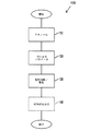
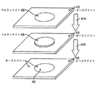
図1は、複数の変態点を有するニチノールのモノリスシートまたはワークピースの処理/形成方法100の実施例を示すフローチャートである。さらに後述のように、所望の結果を提供するために、局所的な化学的性質/構造を変える目的で多材料のプロセスに適用できることは理解されるであろう。
FIG. 1 is a flowchart showing an example of a
プロセス100は、ニチノールのモノリスシートの投入で開始される。ニチノールのモノリスシートまたはワークピースを最初に加工して、特定の形状記憶を該モノリスシート110に付与してもよい。第1の形状記憶(および変態点)を付与するニチノールの加工は当分野で周知である。しかしながら、該形状記憶効果を発揮させるのに十分な組成を有する未加工の合金を加工してもよく、その場合には、プロセス100を用いて第1の記憶が仕込まれる。その後、レーザ処理される加工ステーションに処理されたニチノールワークピースを移動させる。
該方法は、所望の変態点、化学組成あるいは所定の結果に基づいて、用いられる加工120のプロセスパラメータを自動的に算出するプロセッサなどの使用を備えていてもよい。該算出あるいは表の調査などに用いられる、NiTiの化学的性質などの機能としての変態点を含む情報の種類の一例としては、例えば、Tang Wの、Thermodynamic Study of the Low−Temperature Phase B19’ and the Martensitic Transformation in Near−Equiatomic Ti−Ni Shape Memory Alloys,Metallurgical and Materials Transactions A,Volume28A,March,1997,pp.537−544などが挙げられる。本実施形態のこの態様は、計算機(プロセッサ)で実行されると、実行手順を形成する、物理メディア上のコンピュータで読み取り可能な命令で構成され得ることは理解されるであろう。
The method may include the use of a processor or the like that automatically calculates the process parameters of the
その後、該ニチノールワークピースの局所的な化学的性質を変える領域をレーザ処理130し、この場合には、異なる変態点を提供する。ニチノールワークピースの必要領域のレーザ処理を保証するために、用途に応じてレーザを移動させてもよいこと、あるいは、ニチノールワークピースをレーザに対して移動させてもよいことは理解されるであろう。該レーザ処理130では、エネルギをニチノールの局所領域に印加して、溶解および気化を少なくとも一部生じさせる(該局所領域の温度と分圧に基づいて)。ニチノールなどのSMAに対する融点の範囲は、加熱プロセスで生じ得る該SMAの化学組成と化学変化に影響される。当分野で既知のように、気化速度も局所圧によって影響される。ニチノールに対しては、約1,000℃以上の温度に加熱後に、一部の効果が得られる。この温度範囲は、アニーリングなどの合金/金属の熱処理における一部の低温度形成と対称的である。なぜなら、これらのプロセスでは、固相状態での内部構造に与える影響が溶液状態でのものより少ないためである。さらに特定の場合では、該ニチノールを約1,250〜1,280℃に加熱してもよい。別の場合では、ニチノールは約1,300℃以上に、例えば約1,320〜1,340℃に加熱される。一般的に言えば、十分なレベルの溶解と気化を生じさせて局所的な化学的性質を変化させ、付加的な変態点などの所望の結果を提供するための温度が選択される。
The region that alters the local chemistry of the nitinol workpiece is then laser treated 130, in this case providing different transformation points. It is understood that the laser may be moved depending on the application, or the Nitinol workpiece may be moved relative to the laser to ensure laser treatment of the required area of the Nitinol workpiece. Let's go. In the
加熱のためのエネルギの印加は好適には局在化され、局所的な化学的性質の変化が局在化されて、該SMAシートの他の領域にはこの効果が不適に広がらないように構成される。多くの場合、エネルギを短期間印加するプロセスによって、局所的な化学的性質が明確に変化した、従って変態点の変化が局在化した領域または区間をより良好に定義し得る。このように、レーザ溶解は好適であるが、抵抗溶解またはプラズマ溶解などの他の加熱形態を用いてもよい。レーザ溶解の場合、通常、1msec以内という短い時間で適切な温度に達し、SMAの非常に急速な加熱と処理が行える。特定の場合では、0.5msecで適切な温度に達し得る。抵抗加熱またはプラズマ加熱であっても、熱印加時間は1秒以下と短くできる。 The application of energy for heating is suitably localized so that local changes in chemical properties are localized so that this effect does not spread unsuitably to other regions of the SMA sheet. Will be done. In many cases, the process of applying energy for a short period of time can better define the region or interval in which the local chemistry is clearly altered, and thus the transformation point change is localized. Thus, laser melting is preferred, but other heating forms such as resistance melting or plasma melting may be used. In the case of laser melting, the appropriate temperature is usually reached within a short time of less than 1 msec, and the SMA can be heated and processed very rapidly. In certain cases, the appropriate temperature can be reached in 0.5 msec. Even with resistance heating or plasma heating, the heat application time can be shortened to 1 second or less.
レーザ加熱であっても他の加熱であっても、エネルギ印加プロセスは一般に、アルゴンやまたは同様の既知の生産ガスなどのシールドガスの存在下で行われるであろう。該成分や形状記憶材料は酸素と反応して不要な副生成物を作るために、シールドガスを用いる。 Whether laser heating or other heating, the energy application process will generally take place in the presence of a shield gas such as argon or a similar known production gas. The component or shape memory material uses a shield gas to react with oxygen to produce unwanted by-products.
処理された材料の冷却および再凝固は、エネルギ源を除去後直ちに起こるであろう。プロセスパラメータは、制御されたその場の冷却速度が提供できるように構成できる。ある場合には、ニチノールワークピースをさらに加工(140)し、例えば、より急速な冷却用のヒートシンク(すなわち、冷却装置または冷温ガスとしての銅ブロック)を用いて冷却や再凝固を制御してもよい。付加的な加工はさらに、以下の一実施例で述べるような熱処理あるいは特定の用途に対して準備される他の加工を備えていてもよい。 Cooling and resolidification of the treated material will occur immediately after removal of the energy source. Process parameters can be configured to provide controlled in-situ cooling rates. In some cases, the Nitinol workpiece may be further machined (140) to control cooling or resolidification, for example, with a heat sink for faster cooling (ie, a cooling device or a copper block as a cold gas). good. Additional processing may further include heat treatment as described in one example below or other processing prepared for a particular application.
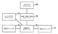
図2は、局所的な化学的性質/構造の変化を生じさせるための、ある実施形態による材料の加工装置のブロック図である。この特定の実施形態では、該装置は、複数の変態点を有するSMAを形成するものである。該装置は、ニチノールワークピースを、処理前およびまたは処理中にニチノールワークピースの位置を調節する位置決めモジュール160に提供する供給モジュール150と、さらに加工するために前記ニチノールワークピースを移動させる除去モジュール170と、を備える。該装置は、前記位置決めモジュールに保持されたニチノールワークピースの適切な領域にエネルギを印加する加熱/溶解モジュール180を備えていてもよい。本明細書に記載するように、前記加熱/溶解モジュール180は、エネルギを印加するレーザまたは他の装置/材料を備えていてもよい。該装置は、前記加熱/溶解プロセス中の不要な反応を防止するシールドガスを提供するシールドガスモジュール190も含む。一部の実施形態では、該装置は、入力パラメータまたは入力パラメータに基づいて自動的に計算された値に基づいた、前記位置決めモジュール160と加熱/溶解モジュール180の制御に用いられる加工モジュール200を含んでいてもよい。入力パラメータは、実行される加工の種類または所望の結果に関連していてもよい。
FIG. 2 is a block diagram of a material processing apparatus according to an embodiment for causing local chemical property / structural changes. In this particular embodiment, the device forms an SMA with multiple transformation points. The device provides a
本明細書に記載の方法と装置は、1つまたは複数の加工ステーションで行われてもよく、また、別の加工ステーションとして記載されたものが適宜組み合わせられてもよいことは理解されるであろう。同様に、第1の成分が移されたと記載された場合は、代替となる成分が移されて前記第1の成分がその場所に残されてもよく、あるいは両方の成分が移されてもよい。例えば、前記レーザ、前記ニチノールワークピース、あるいはその両方が局所領域の処理を提供するために移されてもよい。本明細書に記載の装置及び方法は、NiMnGaなどの磁気形状記憶合金で有効となるように予想されることもまた注目されるべきである。 It is understood that the methods and equipment described herein may be performed at one or more processing stations, and that those described as different processing stations may be combined as appropriate. Let's go. Similarly, if it is stated that the first component has been transferred, the alternative component may be transferred and the first component may be left in place, or both components may be transferred. .. For example, the laser, the nitinol workpiece, or both may be transferred to provide treatment of the local area. It should also be noted that the devices and methods described herein are expected to be effective with magnetic shape memory alloys such as NimnGa.
レーザ処理によってニチノールの局所変態点を首尾よく変更する実験を行った。上記の通り、この効果は主に、各成分の蒸気圧の差によって生じる選択成分の気化に基づくものと考えられる。また、その後の溶解金属の再凝固の間に生じる分離によって、前記局所的な化学的性質をさらに変える。これらの結果は、再凝固部分の局所的な化学的性質に変化をもたらし、次に局所変態点と形状記憶効果とを変えて、単一のワークピースあるいは部分が複数の形状記憶効果を有することが可能になるものと考えられる。局所的な化学的性質の変化は、用いられるプロセスパラメータに応じて非常に僅かなものでものであり得る。 Experiments were conducted to successfully alter the local transformation point of nitinol by laser treatment. As described above, this effect is considered to be mainly due to the vaporization of the selective component caused by the difference in vapor pressure of each component. Also, the separation that occurs during the subsequent resolidification of the molten metal further alters the local chemistry. These results result in changes in the local chemistry of the resolidified moiety, which in turn alters the local transformation point and shape memory effect so that a single workpiece or moiety has multiple shape memory effects. Is considered to be possible. Local changes in chemical properties can be very small, depending on the process parameters used.
ある実験では、ネオジム−ドープイットリウムアルミニウムガーネット(Nd:YAG)レーザを用いた。いくつかの主要パラメータを用いてパルスNd:YAGレーザ処理を制御する。これらのパラメータは、これに限定されないが、パルス幅、ピーク電力、周波数、レーザ移動速度(溶接速度とも呼ぶ)および焦点はずし距離などである。材料に受け渡されたエネルギ量を概念化するために、パルスエネルギと平均電力も用いられる。オペレータは、レーザ加工機のピーク電力、パルス幅および周波数を事前にセットする。ピーク電力はレーザパルスの瞬間的な電力であり、材料の温度上昇に影響を及ぼすことができる。十分な熱が存在して、該ワークピースの液化温度以上にピーク温度が上がると溶解が始まる。このプロセスは、伝導と対流による熱損失を克服するステップを含む。パルス幅は、各パルスがワークピースを照射する時間である。パルス幅が大きければ大きいほど、ピーク電力が印加される時間が長くなる。最後に、パルス周波数は、レーザが1秒間当たりにパルス化される回数であり、これを用いてパルスのオーバラップ量とワークピースに入力する熱量が制御できる。この実験では、パルスレーザを用いるが、これは必ずしも本明細書における要件ではない。 In one experiment, a neodymium-doped yttrium aluminum garnet (Nd: YAG) laser was used. Pulse Nd: YAG laser processing is controlled using several key parameters. These parameters include, but are not limited to, pulse width, peak power, frequency, laser moving speed (also called welding speed) and defocusing distance. Pulse energy and average power are also used to conceptualize the amount of energy passed to the material. The operator presets the peak power, pulse width and frequency of the laser machine. The peak power is the instantaneous power of the laser pulse and can affect the temperature rise of the material. Melting begins when sufficient heat is present and the peak temperature rises above the liquefaction temperature of the workpiece. This process involves overcoming heat loss due to conduction and convection. The pulse width is the time each pulse irradiates the workpiece. The larger the pulse width, the longer the peak power is applied. Finally, the pulse frequency is the number of times the laser is pulsed per second, which can be used to control the amount of pulse overlap and the amount of heat input to the workpiece. A pulsed laser is used in this experiment, but this is not necessarily a requirement herein.
レーザの移動速度と焦点はずし距離は、ワークピースの全体的な加工にも影響を及ぼし得るパラメータである。レーザ移動速度は、あるパルス周波数に対する各スポットサイズ上のオーバラップ量に影響する。しかしながら、パルス周波数とレーザ移動速度は、典型的には相互に関連して所望のスポットオーバラップが得られる。溶接の分野では、スポットオーバラップは典型的に、溶接部強度用途では約50%から変化し、溶接部を気密シールの形成に用いる用途では80%から変化する。 Laser moving speed and defocusing distance are parameters that can also affect the overall machining of the workpiece. The laser moving speed affects the amount of overlap on each spot size for a certain pulse frequency. However, the pulse frequency and the laser moving speed are typically interrelated to obtain the desired spot overlap. In the field of welding, spot overlap typically varies from about 50% for weld strength applications and from 80% for applications where the weld is used to form an airtight seal.
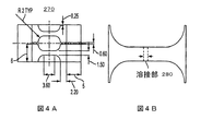
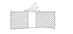
図3Aは、伝導溶接と呼ばれる方法での材料加工を示し、図3Bは、レーザ加工中に生じるキーホール溶接モードを示す。伝導モード中のレーザビーム210からのレーザ強度は、単にワークピースの溶解に十分なものであってもよい。溶融池220は表面で発生し、伝導によって全ての方向に成長して半楕円形の溶接部および熱影響域230ができる。レーザエネルギは材料の頂面に吸収されるだけなので、伝熱量は材料の反射率によって実質的に低減される。 FIG. 3A shows material machining by a method called conduction welding, and FIG. 3B shows the keyhole welding mode that occurs during laser machining. The laser intensity from the laser beam 210 in conduction mode may simply be sufficient to melt the workpiece. The molten pool 220 is generated on the surface and grows in all directions by conduction to form a semi-elliptical weld and a heat-affected zone 230. Since the laser energy is only absorbed by the top surface of the material, the amount of heat transfer is substantially reduced by the reflectance of the material.
キーホールモードは、表面のピーク温度が十分高くワークピース材料が気化するときに生じる。融解した溶融池250のキーホール凹部240は、気化圧で形成されてもよい。これによって、図3Bに示すように、深い突入と熱影響域260を有する狭小な溶接部が得られる。伝導溶接と比較して、キーホール溶接はワークピースへの伝熱を有してより効率的である。キーホールは、レーザエネルギを捕捉し、キーホール内の内部反射によって黒体として作用できる。
The keyhole mode occurs when the peak surface temperature is high enough to vaporize the workpiece material. The keyhole recess 240 of the melted
この実験では、市販のSE508ニチノール片(厚み:0.37mm)を用いた。この特定の合金の化学的性質は、Niが55.8質量%、Tiが44.2質量%、酸素および炭素の最大含量がそれぞれ0.05質量%および0.02質量%であった。これの冷間圧延材を800℃×1時間加熱して、擬弾性特性を得た。フッ化水素酸と硝酸の希釈液を用いて、レーザ加工前に表面の黒い酸化物を除去した。 In this experiment, a commercially available SE508 nitinol piece (thickness: 0.37 mm) was used. The chemistries of this particular alloy were 55.8% by weight Ni, 44.2% by weight Ti, and maximum oxygen and carbon contents of 0.05% by weight and 0.02% by weight, respectively. The cold-rolled material was heated at 800 ° C. for 1 hour to obtain pseudoelastic properties. A diluted solution of hydrofluoric acid and nitric acid was used to remove black oxides on the surface prior to laser machining.
スポット径400μm、パルス時間3msecでレーザ加工を行った。この実験では、最小基準として、十分な突入と気密シール状態(オーバラップ80%)が含まれていた。十分な突入の形成は、0.6kWのピークパルス電力で十分であると判断された。慣例的には、80%の溶解スポットオーバラップによって、気密シール状態が形成されることが示されている。下記の表1には、選択されたパラメータと、パルス周波数およびピーク電力を含む可変プロセスパラメータが示されている。パラメータは、周波数(f)、スポット径(ds)、レーザ移動速度(V)およびオーバラップパーセント(%OL)を含む種々のパラメータを相互に関連付けた式1を用いて選択した。
f=100V/(ds)(100−%OL) 〔1〕
Laser machining was performed with a spot diameter of 400 μm and a pulse time of 3 msec. In this experiment, the minimum criteria included sufficient intrusion and airtight seal (80% overlap). Sufficient plunge formation was determined to be sufficient with a peak pulse power of 0.6 kW. By convention, 80% dissolution spot overlap has been shown to form an airtight seal. Table 1 below shows the selected parameters and the variable process parameters including pulse frequency and peak power. The parameters were selected using
f = 100V / (ds) (100-% OL) [1]
上記式から、パルス周波数とレーザ移動速度は直接に関連する(すなわち、パルス周波数が高ければ高いほど、溶接速度は速くなる)ことが示される。従って、レーザ移動速度(V)は、パルス周波数(T)と呼ばれることもある。
機械的な変形時のバリの影響を最小化するために、ワイヤ放電加工(EDM)切断を用いて引張試験片を準備した。溶接部金属とベース金属の両方の影響を調べるために、横溶接部の構成を選択した。図4Aは、ゲージ長に沿って十分な溶接部領域を有するように、サブゲージドサンプルが選択された寸法を有する試験片の引張試験片270を示す概略図である。図4Bは、溶接部位置280を有する試験片を示す。ロードセル分解能が±3NのInstron型5548ミクロ引張試験機を用いて、試験を行った。試験はすべてほぼ室温(25℃)で行った。第1の載荷サイクルを歪みが0.06mm/mmになるまで行い、次に、除荷サイクルを応力が7MPaに低下するまで行う繰り返し載荷を、クロスヘッド速度0.04mm/分で行った。母材試験片およびレーザ溶接試験片に対して、同じサイクルを50回(50サイクル)繰り返した。50サイクル終了後、クロスヘッド速度0.4mm/分で破断するまで試験片を引っ張った。
Tensile test strips were prepared using wire electric discharge machining (EDM) cutting to minimize the effects of burrs during mechanical deformation. A transverse weld configuration was selected to investigate the effects of both weld metal and base metal. FIG. 4A is a schematic showing a
擬弾性挙動を示す典型的なNiTiに対する載荷−除荷サイクルにおける応力−歪み曲線の概略図を図5に示す。擬弾性パラメータE1、E2および永久残留歪みがこの図で定義される。E1は、1つの完全なサイクルにおいて単位体積当たりに消失されるエネルギであり、E2は、載荷時に単位体積当たりに蓄積され、除荷中に解放時に利用可能なエネルギである。エネルギ蓄積効率(η)は、式2で表され得る。
η=E2/(E2+E1) 〔2〕
FIG. 5 shows a schematic diagram of the stress-strain curve in the loading-unloading cycle for typical NiTi showing pseudoelastic behavior. Pseudoelastic parameters E1, E2 and permanent residual strain are defined in this figure. E1 is the energy lost per unit volume in one complete cycle and E2 is the energy stored per unit volume during loading and available at release during unloading. The energy storage efficiency (η) can be expressed by
η = E 2 / (E 2 + E 1 ) [2]
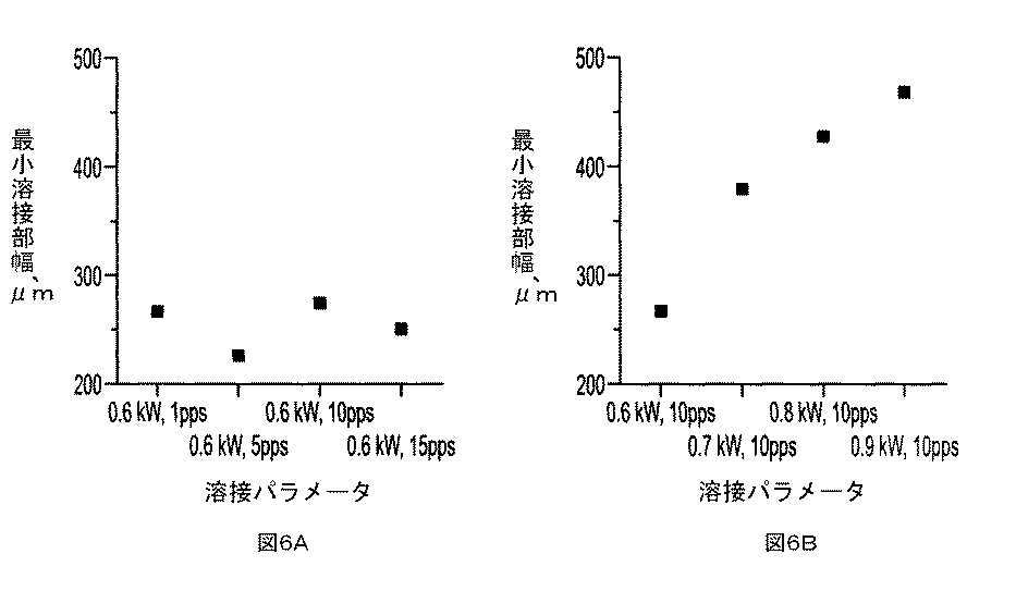
金属組織学的手法を用いて溶接部の寸法を測定した。連続的に減少するグリットサイズを有するSiCペーパを用いて搭載サンプルを磨いた。1μmダイヤモンド用いてサンプルを研磨し、HNO3:14ml、HF:3mlおよびH2O:82mlを用いてエッチングした。図6Aおよび図6Bは、パルス周波数とピーク電力の最小溶接部幅への影響を示す。図6Aに示すように、溶接電力が維持された状態でのパルス周波数の上昇に伴って、溶接部幅に対する名目変化が見られた。しかしながら、図6Bに示すように、溶接電力が0.6kWから0.9kWに上昇するのに伴って、最小溶接部幅は260μmから460μmまで上昇した。 The dimensions of the weld were measured using a metallographic technique. The mounted sample was polished with SiC paper with a continuously decreasing grit size. Samples were polished with 1 μm diamond and etched with HNO3: 14 ml, HF: 3 ml and H2O: 82 ml. 6A and 6B show the effects of pulse frequency and peak power on the minimum weld width. As shown in FIG. 6A, as the pulse frequency increased while the welding power was maintained, a nominal change with respect to the weld width was observed. However, as shown in FIG. 6B, as the welding power increased from 0.6 kW to 0.9 kW, the minimum weld width increased from 260 μm to 460 μm.
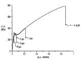
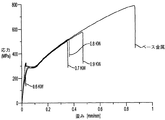
未溶接試験片と溶接試験片について、パルス周波数と入力電力を種々変えた時の工学的応力−歪み曲線の比較を、それぞれ図7および図8に示す。ベース金属試験片では、形状記憶合金の典型的な擬弾性挙動が見られたが、それは、歪みが0.03mm/mm、応力が290MPa近傍の、線形的弾性歪み後の平坦領域(水平域)で示されている。歪みが0.12mm/mmを超えると、マルテンサイトの塑性変形が生じて荷重は歪み硬化によって上昇し、その後歪みが0.90mm/mm近傍で破断した。 A comparison of the engineering stress-strain curves of the unwelded test piece and the welded test piece when the pulse frequency and the input power are variously changed is shown in FIGS. 7 and 8, respectively. In the base metal test piece, the typical pseudoelastic behavior of the shape memory alloy was observed, which was the flat region (horizontal region) after linear elastic strain with a strain of 0.03 mm / mm and a stress of around 290 MPa. It is indicated by. When the strain exceeded 0.12 mm / mm, plastic deformation of martensite occurred, the load increased due to strain hardening, and then the strain broke at around 0.90 mm / mm.
図7は、0.6kWレーザ溶接試験片では、パルス周波数の上昇(5pps、10ppsおよび15pps)と共に延性と強度が低下したことを示している。これは、十分な応力を印加して隣接のベース金属をマルテンサイトに転移する前の、溶接部帯の初期破壊によるものであった。しかしながら、0.6kWレーザ溶接での最小パルス周波数1ppsにおいて、延性と強度の僅かな上昇が見られた(図7)。該1pps溶接物では、ゲージ長に沿ってマルテンサイトの塑性変形を生じさせることができる歪みに達することもできた。パルス周波数を一定(10pps)にし、ピーク電力を0.6、0.7、0.8および0.9kWに変えた溶接条件での工学的応力−歪み曲線を図8に示す。0.6kW溶接を除いた他の条件(0.7、0.8および0.9kW)の各々では擬弾性領域を超えた。しかしながら、すべての溶接試験片の破断強度と延性は、ベース金属に対してそれぞれ70%と50%未満であった。溶接電力の上昇に伴う引張り強度の上昇は、溶接パラメータの効果であった。レーザ溶接したNiTi合金の破断歪みの低下は、凝固時の溶質の分離や溶接部金属中の粗粉と樹枝状構造を含むいくつかの要因によるものである。しかしながら、電流の結果からは、溶接パラメータが機械的特性に影響を与え得ること、具体的には、入力エネルギが大きくパルス周波数が低いほど、機械的性能が改善されることが示されている。 FIG. 7 shows that in the 0.6 kW laser welded test piece, the ductility and intensity decreased with increasing pulse frequency (5 pps, 10 pps and 15 pps). This was due to the initial fracture of the weld zone before applying sufficient stress to transfer the adjacent base metal to martensite. However, at the minimum pulse frequency of 1 pps in 0.6 kW laser welding, a slight increase in ductility and intensity was observed (Fig. 7). The 1 pps weld was also able to reach a strain that could cause plastic deformation of martensite along the gauge length. The engineering stress-strain curve under welding conditions with the pulse frequency constant (10 pps) and the peak powers changed to 0.6, 0.7, 0.8 and 0.9 kW is shown in FIG. Pseudoelastic regions were exceeded in each of the other conditions (0.7, 0.8 and 0.9 kW) except 0.6 kW welding. However, the breaking strength and ductility of all welded test pieces were less than 70% and less than 50% with respect to the base metal, respectively. The increase in tensile strength with the increase in welding power was an effect of welding parameters. The reduction in fracture strain of laser-welded NiTi alloys is due to several factors, including solute separation during solidification and coarse powder and dendritic structures in the weld metal. However, the current results show that the welding parameters can affect the mechanical properties, specifically, the higher the input energy and the lower the pulse frequency, the better the mechanical performance.
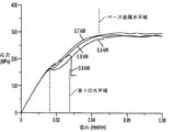
図9は、未溶接試験片と溶接試験片とで溶接電力を変えた場合の、弾性変形から擬弾性変形開始までの応力−歪み線図を詳述するものである。多くの引張り試験片の引張り(オーステナイト→マルテンサイト)の間に、マルテンサイト(SIM)転移によって生じる応力によるNiTiの典型的な擬弾性挙動が見られた。しかしながら、溶接試験片において、ピーク溶接電力の上昇に伴ってより顕著となる初期降伏の兆候が結果から示された。これらの結果から、ベース金属の通常の擬弾性挙動前の引張り時に、溶接部帯で非弾性変形が起こったことが示唆される。横溶接部引張り試験片では、載荷の間、ベース金属と溶接部金属の両方に応力が発生した。従って、初期降伏は溶接部領域に起因し、その後の擬弾性特性は残りの基材から起こり得る。 FIG. 9 details a stress-strain diagram from elastic deformation to the start of pseudoelastic deformation when the welding power is changed between the unwelded test piece and the welded test piece. During the tension of many tensile test pieces (austenite → martensite), the typical pseudoelastic behavior of NiTi due to the stress caused by the martensite (SIM) transition was observed. However, the results showed signs of initial yield in the weld specimen, which became more pronounced with increasing peak welding power. These results suggest that inelastic deformation occurred in the weld zone during tension before the normal pseudoelastic behavior of the base metal. In the transverse weld tensile test piece, stress was generated in both the base metal and the weld metal during loading. Therefore, the initial yield is due to the weld region and subsequent pseudoelastic properties can occur from the remaining substrate.
初期降伏は、歪みが0.015mm/mm〜0.022mm/mmの間に溶接部金属で生じ、その後、付加的な引張りによって残りのゲージ長での転移が生じた。該SIM転移は、ベース金属(BM)の応力−歪み曲線を反映すると解釈される。図9では、溶接試験片における降伏が低応力で発生しており、転移が溶接部で生じたことがこれから示唆される。ピーク電力の上昇と共に拡大する降伏領域は、図6Bで見られるように、溶接部幅の上昇によるものであり得る。溶接電力の上昇に伴って最小溶接部幅が大きくなった。従って、ゲージ長内の溶接部領域が大きくなるほど、初期SIM転移が起こる。 Initial yielding occurred in the weld metal with strain between 0.015 mm / mm and 0.022 mm / mm, followed by additional tension resulting in a transition at the remaining gauge length. The SIM transition is interpreted as reflecting the stress-strain curve of the base metal (BM). In FIG. 9, it is suggested that the yield in the welded test piece occurred at low stress and the transition occurred in the weld. The yield region that expands with increasing peak power can be due to an increase in weld width, as seen in FIG. 6B. The minimum weld width increased as the welding power increased. Therefore, the larger the weld region within the gauge length, the more the initial SIM transition occurs.
十分な付加的応力がある温度で加えられると、双晶マルテンサイト相の塑性変形による変形は不可逆になることは既知である。この非双晶化をさらに詳述するために、2−サイクル載荷試験を室温で行った。図10は、歪みが最高で0.06mm/mmとなる0.9kW×10ppsの溶接条件での第1の載荷曲線と第2の載荷曲線を示す。初期載荷の間、該降伏で示される溶接部金属の非双晶化が起こり、その後、基材のSIM転移が起こる。第2の載荷サイクルでは降伏は起こらず、これによって、溶接部金属内で不可逆的の非双晶化が起こっていることが示された。 It is known that when a sufficient additional stress is applied at a temperature, the deformation of the twin martensite phase due to plastic deformation becomes irreversible. To further elaborate on this non-twinning, a 2-cycle loading test was performed at room temperature. FIG. 10 shows a first loading curve and a second loading curve under welding conditions of 0.9 kW × 10 pps with a maximum strain of 0.06 mm / mm. During the initial loading, non-twinning of the weld metal indicated by the yield occurs, followed by a SIM transition of the substrate. No yielding occurred in the second loading cycle, indicating that irreversible non-twinning occurred in the weld metal.
ニチノール変態点は、SIM転移に緊密に関連しており、加工経路と方法によって強く影響され得る。レーザ加工による再溶解によってベース金属の構造が変更され、ニチノールでは、樹枝状晶や粗粉の形成および粒界分離が起こり得る。また、レーザ処理によるニチノールの異常な室温相シフトも起こり得る。溶接部金属に対するこうした変更は、その変更された変態点によるものであり得る。変態点の変更をもたらすすべての要因を決定するには、溶接部金属のより詳細なミクロ構造分析が必要であると思われる。 Nitinol transformation points are closely associated with SIM transitions and can be strongly influenced by processing pathways and methods. Remelting by laser machining modifies the structure of the base metal, and nitinol can lead to the formation of dendritic crystals and coarse powders and intergranular separation. Also, an abnormal room temperature phase shift of nitinol due to laser treatment can occur. These changes to the weld metal may be due to the changed transformation point. A more detailed microstructural analysis of the weld metal may be needed to determine all the factors that cause the transformation point change.
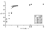
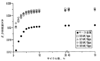
図11Aおよび図11Bに、サイクル回数(N)に伴うエネルギ蓄積効率(η)および永久残留歪みの変化を示す。0.06mm/mm歪み前に初期破壊が起こるため、5pps、10ppsおよび15pps×0.6kW電力でのレーザ溶接サンプルでは繰り返し載荷は行わなかった。図11Aは、ベース金属と溶接部金属の両方に対する1〜5サイクル間の永久残留歪みの急激な上昇を示す。5サイクルを越えると、各材料は定常状態に達した。材料の除荷後に当初の形状を回復する能力は、永久残留歪みによって測定できる。最高0.06mm/mmまでの引張り時、すべての溶接試験片は、BMと比較して大きな永久残留歪みを示した。10サイクル後、ベース金属および溶接部金属での残留歪みの大きさは、それぞれ0.020%および0.026%であった。図11Bは、サイクル数(N)の関数としてのエネルギ蓄積効率(η)を示す。基材および溶接部材では共に、5サイクルまでにηが上昇した。溶接部材では、最初の5サイクルの間に効率がわずかに上昇した。20サイクルを超えると、効率は0.9%近傍で安定した。従って、溶接試験片では、ベース金属に比べて全体的な残留永久歪みが高く、最初の5サイクル時のエネルギ効率が僅かに高いことが示された。 11A and 11B show changes in energy storage efficiency (η) and permanent residual strain with the number of cycles (N). Repeated loading was not performed on laser welded samples at 5 pps, 10 pps and 15 pps x 0.6 kW power because initial fracture occurs before 0.06 mm / mm strain. FIG. 11A shows a sharp increase in permanent residual strain for 1 to 5 cycles for both the base metal and the weld metal. After 5 cycles, each material reached a steady state. The ability to restore the original shape after unloading the material can be measured by permanent residual strain. When pulled up to 0.06 mm / mm, all weld specimens showed greater permanent residual strain compared to BM. After 10 cycles, the magnitudes of residual strain in the base metal and weld metal were 0.020% and 0.026%, respectively. FIG. 11B shows the energy storage efficiency (η) as a function of the number of cycles (N). In both the base material and the welded member, η increased by 5 cycles. For welded members, efficiency increased slightly during the first 5 cycles. After 20 cycles, the efficiency stabilized at around 0.9%. Therefore, it was shown that the welded test piece had higher overall residual permanent strain and slightly higher energy efficiency during the first 5 cycles than the base metal.
前述のように、溶接部金属では初期降伏が起こり、冷間加工された溶接部領域が得られた。従って、溶接試験片の永久残留歪みの上昇は、初期載荷後の永久SIM転移によるものであり得る。また、大きな入力電力で作られた試験片における永久残留歪みの僅かな上昇は、溶接部幅の上昇によるものであり得る。向上したη値は、冷間加工されたTiNi SMAによるものであり得ることが示された。従って、溶接部金属における初期サイクル時の効率の向上は、溶接部金属の初期サイクル後の、非弾性変形が生じる塑性変形によるものであり得る。 As mentioned above, initial yielding occurred in the weld metal, resulting in a cold-worked weld region. Therefore, the increase in the permanent residual strain of the welded test piece may be due to the permanent SIM transition after the initial loading. Also, a slight increase in permanent residual strain in a test piece made with a large input power may be due to an increase in weld width. It was shown that the improved η value could be due to cold-worked TiNi SMA. Therefore, the improvement in efficiency of the weld metal during the initial cycle may be due to the plastic deformation that causes inelastic deformation after the initial cycle of the weld metal.
各溶接試験片の引張り試験片の溶接部帯に破断が生じた。ベース金属の破壊表面には、延性破壊を示唆するくぼんだ表面が現れた。溶接条件が0.6kW×1ppsの破壊表面の引張り強度は最小であった。溶接部の指向性の樹枝状凝固構造を示す平滑な破壊表面が見られた。これは、破壊が樹枝状晶界面で伝播する粒内破壊であることを示す。対照的に、溶接条件が0.9kW×10ppsでは比較的粗い表面が現れた。詳しく観察すると、より微細なくぼんだ構造が露出していたが、これは、融合部樹枝状晶を貫く延性粒内破断であることを示唆している。これらの結果から、溶接条件を変えることによって、違った破断モードになり得ることが明らかであるが、しかしながら、この破断モード遷移を起こすメカニズムを決定するためには、溶接部ミクロ構造を詳述するさらなる研究が必要であることが示唆される。 A fracture occurred in the weld zone of the tensile test piece of each weld test piece. On the fracture surface of the base metal, a recessed surface suggesting ductile fracture appeared. The tensile strength of the fracture surface at a welding condition of 0.6 kW × 1 pps was the minimum. A smooth fracture surface showing a directional dendritic solidification structure of the weld was observed. This indicates that the fracture is an intragranular fracture propagating at the dendritic interface. In contrast, a relatively rough surface appeared at welding conditions of 0.9 kW x 10 pps. Closer observation revealed a finer, depressed structure exposed, suggesting a ductile intragranular fracture through the dendritic crystals at the fusion site. From these results, it is clear that different welding conditions can result in different fracture modes, however, in order to determine the mechanism that causes this fracture mode transition, the weld microstructure will be detailed. It is suggested that further research is needed.
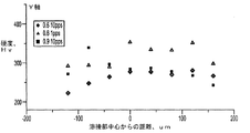
図12Aおよび図12Bは、溶接部横断面の硬度跡を示す。すべてのサンプルで、融合部の硬度はX軸に沿って低下した。溶接部中心線から離れ最終的にベース金属の溶接部中心線に収束するまでの間、硬度値は徐々に上昇する。ベース金属硬度値の範囲は370〜400Hvであった。溶接部硬度最小値は、0.6kW×10ppsの条件時に見られ、ほぼ250Hvであった。対照的に、0.6kW×1ppsおよび0.9kW×10pps溶接条件での溶接部硬度最小値は、ほぼ280Hvであった。先にアニーリングした材料の溶接部中心の硬度が低いことは、ほとんど歪みのないより大きな再結晶粒を生じ得る、溶接による再凝固によるものであり得る。しかしながら、軟化を生じた主要な理由は、室温でのより柔らかいマルテンサイトへの局所相変化によるものであり得る。 12A and 12B show hardness marks in the cross section of the weld. In all samples, the hardness of the fusion site decreased along the X-axis. The hardness value gradually increases until it separates from the weld centerline and finally converges on the weld centerline of the base metal. The range of the base metal hardness value was 370 to 400 Hv. The minimum value of weld hardness was found under the condition of 0.6 kW × 10 pps, and was approximately 250 Hv. In contrast, the minimum weld hardness under the 0.6 kW × 1 pps and 0.9 kW × 10 pps welding conditions was approximately 280 Hv. The low hardness of the weld center of the previously annealed material may be due to resolidification by welding, which can produce larger recrystallized grains with little strain. However, the main reason for the softening may be due to a local phase change to softer martensite at room temperature.
図12Aに示した溶接部中心線:Y軸に沿った硬度値は、サンプル間で同じようなものであった。0.6kW×10ppsでの溶接部底部の硬度値は、溶接部表面と比較するとわずかに低かった。0.6kW×1pps溶接での硬度値は、縦方向のパターンと同様に、中心線全体に亘って拡散していた。しかしながら、0.9kW×10ppsでは、横方向で比較的一貫した硬度値を示した。 Weld centerline shown in FIG. 12A: Hardness values along the Y-axis were similar between the samples. The hardness value of the bottom of the weld at 0.6 kW × 10 pps was slightly lower than that of the surface of the weld. The hardness value in the 0.6 kW × 1 pps weld was diffused over the entire center line as in the vertical pattern. However, at 0.9 kW × 10 pps, it showed a relatively consistent hardness value in the lateral direction.
図13は、基材と溶接部材での示差走査熱量曲線を示す。オーステナイト終了(Af)温度およびマルテンサイト開始(Ms)温度は共に室温より低く、それぞれ−8.61℃および−33.27℃であった。これは、室温相は主にオーステナイトであり、従って、引張り試験の間は擬弾性挙動が現れることを示している。溶接部材は基材と同様な熱イベントを示したが、一対の高温ピークも存在した。 FIG. 13 shows a differential scanning calorimetry curve between the base material and the welded member. Both the austenite termination (Af) temperature and the martensite initiation (Ms) temperature were below room temperature, −8.61 ° C. and −33.27 ° C., respectively. This indicates that the room temperature phase is predominantly austenite, and therefore pseudoelastic behavior appears during the tensile test. The weld member showed similar thermal events as the substrate, but there was also a pair of hot peaks.
付加的なピークは、R−相転移中の冷間加工ニチノールまたは熟成ニチノールで典型的に見られる。しかしながら、マルテンサイト転移の中間のR−相転移の事例では、冷却の間、オーステナイトとマルテンサイト間に1つのピークが出来、本溶接部材では、その範囲外に2つの別個の転移ピークを示す。また、十分にアニーリングした基材では、概略室温までの焼き入れによる固溶体の保持により、R−相転移のいかなる存在も示さなかった。従って、これらの付加的なピークによって、低温転移(<室温)と高温転移(>室温)を含む複数の相転移の存在が示唆される。ピーク開始温度を表2に示す。
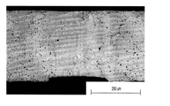
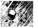
溶接部横断面の光学顕微鏡写真を撮影した。溶接部は、パルスNd:YAG処理時のそれぞれの熱サイクルの間に生成された典型的なバンド構造を示した。溶接部表面近傍に集中して現れた分離相の定義に、偏光の利用が役立った。パルスNd:YAG溶接処理の間、ワークピースの鉛直面に沿った冷却速度の可能な相違によって、頂面が最後まで凝固しない領域になり得る。これは次に、溶接部頂面近傍での金属間相形成を促進し得る。しかしながら、冷却速度勾配の存在およびその大きさを決定するためには、詳細な熱分析が必要である。 An optical micrograph of the cross section of the weld was taken. The welds showed a typical band structure generated during each thermal cycle during pulse Nd: YAG treatment. The use of polarized light helped to define the separated phase that appeared concentrated near the surface of the weld. Pulse Nd: During the YAG welding process, possible differences in cooling rates along the vertical plane of the workpiece can result in a region where the top surface does not solidify to the end. This can then promote metal-metal phase formation near the top surface of the weld. However, detailed thermal analysis is required to determine the existence and magnitude of the cooling rate gradient.
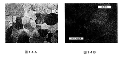
ベース金属のミクロ構造と融合境界のそれとを、それぞれ図14Aおよび図14Bに示す。予想通りに、アニーリングプロセスによって、室温におけるオーステナイトNiTiであることがDSC結果から示された、より大きな粒子が生成した。図14Bは、再融解材と基材の界面に位置する、0.9kW×10pps溶接での代表的な融合境界ミクロ構造を示す。円柱状の樹枝状成長が融合境界近傍で見られた。狭小な熱影響域(HAZ)は、その小さな熱入力のために、パルスNd:YAG処理に固有のものであり、その結果として、HAZは図14Bでは定義できない。 The microstructure of the base metal and that of the fusion boundary are shown in FIGS. 14A and 14B, respectively. As expected, the annealing process produced larger particles, which DSC results showed to be austenite NiTi at room temperature. FIG. 14B shows a typical fusion boundary microstructure in 0.9 kW × 10 pps welding located at the interface between the remelt material and the substrate. Columnar dendritic growth was observed near the fusion boundary. The narrow heat-affected zone (HAZ) is unique to pulse Nd: YAG processing due to its small heat input, and as a result, HAZ cannot be defined in FIG. 14B.
各溶接条件での融合部ミクロ構造も見られた。各条件ではそれぞれ、異なる量の連続的なサブミクロンレベルの分離が存在した。0.6kW×10pps溶接では、高濃度の連続的な粒子間分離が示された。対照的に、0.6kW×1pps溶接では、比較的低濃度の同様な分離が示された。しかしながら、0.9kW×10pps溶接では、断続的な第2の位相分布が見られた。融合部の分離相は、破断が開始あるいは伝播する優先部位として作用する。該異なる量の分離は、図7および図8に示した溶接部の機械的性能に相互に関連する。高濃度に分離した0.6kW×10pps溶接では、機械的性能が最も劣り、断続的に分離した0.9kW×10pps溶接では、比較的良好な性能を有することが示された。 A microstructure of the fusion part was also seen under each welding condition. Under each condition, there were different amounts of continuous submicron level separation. At 0.6 kW x 10 pps weld, a high concentration of continuous interparticle separation was shown. In contrast, 0.6 kW x 1 pps welds showed similar separations at relatively low concentrations. However, in 0.9 kW × 10 pps welding, an intermittent second phase distribution was observed. The separated phase of the fusion section acts as a priority site where fracture begins or propagates. The different amounts of separation correlate with the mechanical performance of the welds shown in FIGS. 7 and 8. It was shown that the 0.6 kW × 10 pps welded with high concentration had the worst mechanical performance, and the 0.9 kW × 10 pps welded with intermittent separation had relatively good performance.
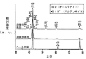
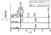
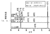
すべての条件でのベース金属、溶接部表面、溶接部底部に対してインデックスを付けたピークを示す室温XRDデータを図15A、図15B、および図15Cに示す。図13のBM DSCから予想されるように、ベース金属ピークは、オーステナイトの唯一の存在を明確に特定した。すべての溶接条件で、高濃度の分離相が存在する溶接部表面には、オーステナイト相とマルテンサイト相の両方の兆候が示された。各溶接部の底部は、異なる相タイプとその相対的な量を示した。0.6kW×10pps溶接部は単にオーステナイト相を示し、0.6kW×1pps溶接部はオーステナイトと幾らかのマルテンサイト兆候を示した。しかしながら、0.9kW×10pps溶接部は、頂面と同様にオーステナイト相とマルテンサイト相の両方を示し、それによって、0.9kW×10ppsにおける硬度傾向がさらに裏付けられた。従って、溶接パラメータによって、溶接部それぞれの頂部および底部において違った相が生成されることがこれらの結果から示唆される。 Room temperature XRD data showing indexed peaks for the base metal, weld surface, and weld bottom under all conditions are shown in FIGS. 15A, 15B, and 15C. As expected from the BM DSC in FIG. 13, the base metal peak clearly identified the sole presence of austenite. Under all welding conditions, the surface of the weld, where a high concentration of separated phases was present, showed signs of both austenite and martensite phases. The bottom of each weld showed different phase types and their relative quantities. The 0.6 kW x 10 pps weld simply showed the austenite phase and the 0.6 kW x 1 pps weld showed some martensite signs with austenite. However, the 0.9 kW x 10 pps weld showed both austenite and martensite phases as well as the top surface, further supporting the hardness tendency at 0.9 kW x 10 pps. Therefore, these results suggest that the weld parameters produce different phases at the top and bottom of each weld.
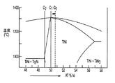
溶接サンプル内で見られた高温DSCピークは、XRD結果に見られたマルテンサイト相に関連し得る。表2に示したピーク開始温度から、この相のMs温度範囲は60〜67℃であることが示唆される。従って、溶接部金属中に見られたマルテンサイト相の化学的性質は、等原子比またはTiリッチな化学的性質に由来し得る。このことは次に、融合部の観察された分離相は、恐らく、Ti2Niが主に観察されるTiリッチな金属間化合物であることが暗示される。しかしながら、検出可能なXRD信号の生成に必要な粒子群が恐らくはなかったために、XRD分析では、これらの金属間化合物の存在を検出することはできなかった。従って、溶接部金属内のサブミクロンオーダの分離相を特定し特徴付けるためには、詳細なミクロ構造観察(TEMを含めて)が必要である。 The hot DSC peaks seen in the weld sample may be related to the martensite phase seen in the XRD results. The peak start temperature shown in Table 2 suggests that the Ms temperature range for this phase is 60-67 ° C. Therefore, the chemistries of the martensite phase found in the weld metal can be derived from isoatomic ratio or Ti-rich chemistries. This in turn implies that the observed separation phase of the fusion is probably a Ti-rich intermetallic compound in which Ti 2 Ni is predominantly observed. However, XRD analysis was unable to detect the presence of these intermetallic compounds, probably because the group of particles required to generate a detectable XRD signal was not present. Therefore, detailed microstructure observations (including TEM) are required to identify and characterize submicron-order separated phases in weld metals.
パルスNd:YAGレーザ処理したニチノールの機械的特性を実験によって調査した。異なるパラメータでの溶接強度、擬弾性特性および繰り返し載荷特性を基材と比較し、破断表面を分析した。また、硬度試験、DSCスキャン、金属組織学的検査およびXRD分析を用いて、選択した溶接条件を分析した。主要な観察結果は以下の通りであった。1)加工パラメータ(ピーク電力とパルス周波数)は、ミクロレーザ処理したNiTi合金の機械的特性(引張り強度および延性)に強く影響することが示された。ピーク電力が高いほどまたパルス周波数が低いほど、機械的性能が向上した。2)溶接試験片では、横引張り載荷中に初期降伏の兆候が見られた。降伏は、引張り変形時に溶接部領域で起こる非双晶化によるものであった(溶接部金属およびベース金属)。3)レーザ処理サンプルでは基材と比較して、永久残留歪みが大きく、初期の5サイクルの間のエネルギ蓄積効率がわずかに高かった。4)融合部DSCスキャンで、複数の相転移が見られた。これらの転移は、低温(室温未満)および高温(室温超)で起こった。5)ミクロ構造観察により、アニール処理した基材には大きなオーステナイト粒子が見られ、融合部境界では円柱状の樹枝状成長が存在した。0.6kW×10pps処理では、多量の分離が発生し、擬弾性領域前に破断した。対照的に、0.6kW×1pps溶接は、断続的な分離を示し、良好な機械的性能を示した。6)XRD結果から、溶接部金属は、すべての条件でその表面にオーステナイト相とマルテンサイト相の両方を含んでいた。しかしながら、溶接部底部では、溶接条件に依存して異なる量のマルテンサイト相が見られた。 The mechanical properties of pulsed Nd: YAG laser treated nitinol were investigated experimentally. Weld strength, pseudoelastic properties and repetitive loading properties under different parameters were compared with the substrate and the fracture surface was analyzed. Selected welding conditions were also analyzed using hardness tests, DSC scans, metallographic examinations and XRD analysis. The main observation results were as follows. 1) Machining parameters (peak power and pulse frequency) have been shown to have a strong effect on the mechanical properties (tensile strength and ductility) of the microlaser-treated NiTi alloy. The higher the peak power and the lower the pulse frequency, the better the mechanical performance. 2) Weld test pieces showed signs of initial yield during lateral tension loading. The yield was due to the non-twinning that occurred in the weld region during tensile deformation (weld metal and base metal). 3) The laser-treated sample had a larger permanent residual strain and a slightly higher energy storage efficiency during the initial 5 cycles than the substrate. 4) Multiple phase transitions were observed on the fusion DSC scan. These transitions occurred at low temperatures (below room temperature) and at high temperatures (above room temperature). 5) By microstructure observation, large austenite particles were observed on the annealed substrate, and columnar dendritic growth was present at the boundary of the fusion site. In the 0.6 kW × 10 pps treatment, a large amount of separation occurred and the fracture occurred before the pseudoelastic region. In contrast, 0.6 kW x 1 pps weld showed intermittent separation and good mechanical performance. 6) From the XRD results, the weld metal contained both an austenite phase and a martensite phase on its surface under all conditions. However, at the bottom of the weld, different amounts of martensite phase were found depending on the weld conditions.
上記の実験ではパルスNd:YAGレーザを用いたが、他の局所的なエネルギ/熱源を用いても同様な結果が得られることは理解されるであろう。レーザの場合、パルスレーザに替えて連続波レーザを適用してもよい。これには、これに限定されないが、ダイオードレーザ、ファイバレーザおよび炭酸ガスレーザが含まれ得る。 Although the pulsed Nd: YAG laser was used in the above experiments, it will be appreciated that similar results can be obtained with other local energy / heat sources. In the case of a laser, a continuous wave laser may be applied instead of the pulse laser. This may include, but is not limited to, diode lasers, fiber lasers and carbon dioxide lasers.
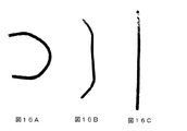
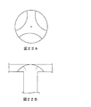
図16A、図16B、図16Cは、上記の実験の結果として、単一のニチノールリボンに仕込まれた2つの別個の記憶を示す。図16Aは、加熱により図16Bに示す第1の記憶形状に転移可能な「C」の変形形状を示し、さらに加熱して完全に転移させて、図16Cに示す最終の記憶形状が得られる。 16A, 16B and 16C show two separate memories loaded into a single nitinol ribbon as a result of the above experiments. FIG. 16A shows a deformed shape of “C” that can be transferred to the first memory shape shown in FIG. 16B by heating, and further heated to completely transfer the shape to obtain the final memory shape shown in FIG. 16C.
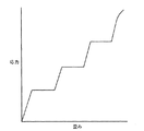
図17Aおよび図17Bは、複数の変態点の2次元構成(図17A)および3次元構成(図17B)への潜在的な適用を示す。これらの実施例では、異なる変態点域は、違ったハッチングで示す。これらの異なる変態点を利用することによって、種々の形状が得られることは理解されるであろう。特に、温度範囲は、所望のものと使用材料によって決定され、例えば、NiTiでは約−150〜150℃であり、他の合金ではそれより高いかあるいは低い。 17A and 17B show potential applications of multiple transformation points to a two-dimensional configuration (FIG. 17A) and a three-dimensional configuration (FIG. 17B). In these examples, different transformation point regions are shown with different hatching. It will be understood that various shapes can be obtained by utilizing these different transformation points. In particular, the temperature range is determined by what is desired and the materials used, for example, for NiTi it is about -150-150 ° C and for other alloys it is higher or lower.
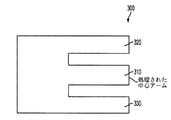
図18は、アクチュエータ装置300に対する異なる変態点の潜在的な適用を示す。この実施例では、3−アームアクチュエータ装置300の内、中央アーム310を処理して、外側のアーム320および330とは異なる変態点を持たせられる。これらの異なる変態点によって、アクチュエータ装置300を2段階作動で使用可能になる。上記の方法のさらなる実施形態では、局所的な構造や化学的性質を変えて中央アーム310に沿ってNi濃度勾配を形成し、これによって中央アーム310に沿って変態点勾配を設けるために、アクチュエータ装置300をさらに熱処理(アニーリングなど)してもよい。概略の実施例として、Ni濃度が51原子%になるようにまた第1の変態点を有するように、アクチュエータ装置300を最初に処理する場合、Ni濃度が49原子%になるようにまた第2の変態点を有するように、中央アームを処理してもよい。以降の熱処理によって、Ni原子を中央アームに拡散させて、中央アーム310に沿った濃度勾配と従って変態点勾配を設けることができ、スムーズな作動が提供できる。
FIG. 18 shows the potential application of different transformation points to the
材料に付与された付加的な変態点は、開始パラメータとプロセスパラメータに依存することは理解されるであろう。そのため、開始パラメータおよびプロセスパラメータ(例えば、必要となる局所加熱/溶解の範囲)は、変態点を調整するために変更できる。利用可能な変態点は、医療機器などに使用されるものに限定されず、使用される形状記憶材料の特性によってのみ限定される。 It will be appreciated that the additional transformation points conferred on the material depend on the initiation and process parameters. Therefore, the initiation and process parameters (eg, the required local heating / melting range) can be modified to adjust the transformation point. The available transformation points are not limited to those used in medical devices and the like, but only by the properties of the shape memory materials used.
変態点や域/領域を細かく調整するために、付加的な技術も用いることができ、あるいは局所的な構造や化学的性質の変更を支援し得ると予想される。これには、レーザ再溶解、ミクロ−アーク再溶解、抵抗溶解などの、溶解を起こす種々の熱処理の利用が含まれ、個別でもあるいは一部組み合わせでも用いられる。特に、局所的な構造や化学的性質を調整するために材料に印加されるエネルギ源を調整できる。 Additional techniques can also be used to fine-tune transformation points and regions / regions, or it is expected that local structural and chemical properties changes can be assisted. This includes the use of various heat treatments that cause dissolution, such as laser remelting, micro-arc remelting, resistance melting, etc., which can be used individually or in combination. In particular, the energy source applied to the material can be adjusted to adjust the local structure and chemistry.
代替となる技術は、種々の組成を有し、次にレーザ処理の一部としての材料に配合される追加の材料、第2の材料、あるいは充填材などの利用や結合技術の利用などを含んでいてもよい。充填材としては、純ニッケル、純チタン、パラジウムおよびプラチナなどが挙げられる。
結合方法としては、固相拡散結合/ろう付け、レーザ溶接、アーク溶接、抵抗溶接などが挙げられる。ある場合には、エネルギを添加して(例えば、本明細書に記載のプロセスを用いて)、異なる変態点を有する形状記憶材料を互いに結合し、例えば、結合部位に第3の変態点を有するモノリスな形状記憶成分を生成することも期待される。
Alternative techniques include the use of additional materials, second materials, or fillers, etc., which have a variety of compositions and are then incorporated into the material as part of the laser treatment, the use of bonding techniques, and the like. You may be. Examples of the filler include pure nickel, pure titanium, palladium and platinum.
Examples of the bonding method include solid phase diffusion bonding / brazing, laser welding, arc welding, and resistance welding. In some cases, energy is applied (eg, using the process described herein) to bond shape memory materials with different transformation points to each other, eg, having a third transformation point at the binding site. It is also expected to generate a monolithic shape memory component.
局所的な化学的性質を変えて、複数の変態点(記憶)を形容記憶材料に提供する別の態様は、これによって、該材料が複数の擬弾性領域を反映する応力−歪み曲線を有することである。図19は、長さ方向に複数の変態点を有する形状記憶材料片に期待される応力−歪み曲線のタイプを示す。図示のように、載荷曲線に対して、材料は、弾性変形の後に擬弾性変形の水平域が続く、複数のシーケンスを示すものと期待される。除荷曲線は同様に影響されるものと期待される。 Another aspect of providing multiple transformation points (memory) to a description memory material by altering local chemistry is that the material has a stress-strain curve that reflects multiple pseudoelastic regions. Is. FIG. 19 shows the type of stress-strain curve expected for a shape memory material piece having a plurality of transformation points in the longitudinal direction. As shown, with respect to the loading curve, the material is expected to exhibit multiple sequences of elastic deformation followed by a horizontal region of pseudoelastic deformation. The unloading curve is expected to be affected as well.
当業者であれば、本明細書に記載のプロセスおよび装置は、適切に改質された他のSMAおよびSMPに適用できることは理解するであろう。例えば、SMPの場合、必要とされる温度範囲や時間(すなわち、パルス周波数など)が異なり、代替のエネルギ源あるいは技術を用いてSMPの局所領域の局所的な構造や化学的性質を調整し、同様な効果を提供してもよい。 Those skilled in the art will appreciate that the processes and equipment described herein are applicable to other appropriately modified SMAs and SMPs. For example, in the case of SMP, the required temperature range and time (ie, pulse frequency, etc.) are different, and alternative energy sources or techniques are used to adjust the local structure and chemistry of the local region of SMP. Similar effects may be provided.
本明細書に記載の方法と装置は、種々の産業用途に適用でき、特定の用途に取り組むためにユニークな解決法を実行することができる。現在の用途の一例としては、SMAアクチュエータがある。現在のSMAアクチュエータでは典型的に、SMA材を当初の位置に引っ込めるためにバイアスを必要とする。該バイアスは一般に、従来のスプリングを用いて容易化されている。しかしながら、複数の変態点を有するSMAが使用されれば、バイアスの使用は削除され得る。 The methods and devices described herein can be applied in a variety of industrial applications and can implement unique solutions to address specific applications. An example of current applications is the SMA actuator. Current SMA actuators typically require a bias to retract the SMA material to its original position. The bias is generally facilitated with conventional springs. However, if an SMA with multiple transformation points is used, the use of bias can be eliminated.
複数の変態点を有する形状記憶材料は、対象物が違った温度で反応する必要がある用途およびまたは対象物の形状を徐々に調整する必要がある用途などの、種々の用途に使用できる。特に、複数の変態点によって、特定の金属の唯一の開形状または閉形状ではなく、該対象物に加えられる温度に基づいて徐々に開放または閉鎖されるような用途が可能になる。そうした用途としては、フラッパ弁などのバルブ、医療用途または産業用途のダイヤフラム、温度センサまたは複数の変態点を有するモノリスアクチュエータセンサ、マイクログリッパ、ステントおよび微小電子機械システム(MEMS)などが挙げられる。ある特定の実施例として、複数の変態点によって、加熱により延長できてその後接続可能なチューブ構造が可能になるであろう。別のチューブ部材に接続するために、該チューブの一端を大きくし、次に加熱して小さな記憶形状に収縮させることが可能であろう。 Shape memory materials with multiple transformation points can be used in a variety of applications, such as applications where the object needs to react at different temperatures and / or where the shape of the object needs to be gradually adjusted. In particular, multiple transformation points allow applications such that the metal is not the only open or closed shape, but is gradually opened or closed based on the temperature applied to the object. Such applications include valves such as flapper valves, medical or industrial diaphragms, temperature sensors or monolithic actuator sensors with multiple transformation points, micro grippers, stents and microelectromechanical systems (MEMS). In one particular embodiment, multiple transformation points will allow for a tube structure that can be extended by heating and then connected. In order to connect to another tube member, one end of the tube could be enlarged and then heated to shrink into a small memory shape.
さらに、本方法と装置によって、付加的な変態点を加えるためのプレハブ式の市販部分の加工が可能となり、これによって、全く新規の部品を製作しなければならないテープ成形やLENSなどの技術と比較すると、製作コストを低減できる。さらに、本プロセスではチタン成分が不要なため、チタン酸化も回避できる。さらに、最終製品は一般的に多孔性がなく、変態点が一つのモノリス形状記憶材と本質的に同等の機械的性能を有する。さらに、製品重量を軽くすることもでき得る。 In addition, the method and equipment allow the processing of prefabricated commercial parts to add additional transformation points, which compares with technologies such as tape forming and LENS, which require the production of completely new parts. Then, the manufacturing cost can be reduced. Furthermore, since the titanium component is not required in this process, titanium oxidation can be avoided. In addition, the final product is generally non-porous and has essentially the same mechanical performance as a monolithic shape storage material with a single transformation point. In addition, the product weight can be reduced.
図20は、複数の変態点を有する形状記憶材の応用実施例を示す。図20は、種々の用途に使用可能なあるタイプのダイヤフラムを示す。この実施例において、中央領域400は、室温より高く、支持フレーム410とは異なる変態点を有する。これによって、中央領域400は室温で、ダイヤフラム形状を形成する支持フレーム410とは別に変形することができる。支持フレーム410は非弾性状態でありながら、中央領域400を弾性状態あるいは擬弾性状態とすることを可能にするために、複数の変態点がこの状況では重要である。
FIG. 20 shows an application example of a shape storage material having a plurality of transformation points. FIG. 20 shows a type of diaphragm that can be used for various purposes. In this example, the
図21、図22Aおよび図22Bは、複数の変態点を有する形状記憶材の産業用途における他の実施例を示す。この場合、該用途はバルブである。図21は、入口または出口の端部に搭載され、異なる2(以上)レベルでの流路の開口に該複数の変態点が使用可能な第1の実施例のバルブを示す。より具体的には、該バルブは、複数の記憶が仕込まれたフラッパアームを備えている。該フラッパアームは一端に確保されており、他端は、液流路を被覆するように配置されている。該フラッパアームは第1の位置で、すべてあるいは大部分の液が液流路を流れないように制限する。このフラッパアームは、形状を変えることによってこれらの複数の記憶に応答し、ある温度での所望の応答に応じて,多くのあるいは少量の液を流すことができる。このフラッパアーム配置を熱交換に用いて、液温に基づいて液制御を調節してもよい。 21, 22A and 22B show other embodiments of shape storage materials with multiple transformation points in industrial applications. In this case, the application is a valve. FIG. 21 shows a valve of a first embodiment mounted at the end of an inlet or outlet where the plurality of transformation points can be used for opening the flow path at two (or more) different levels. More specifically, the valve comprises a flapper arm loaded with a plurality of memories. The flapper arm is secured at one end, and the other end is arranged so as to cover the liquid flow path. The flapper arm is in the first position to limit all or most of the liquid from flowing through the liquid flow path. The flapper arm responds to these multiple memories by changing its shape and can flow more or less liquid depending on the desired response at a certain temperature. This flapper arm arrangement may be used for heat exchange to adjust the liquid control based on the liquid temperature.
図22Aおよび図22Bは、ドーム状に形成され、該ドーム部分は、開くとバルブ内の種々の方向に流れるように形成されたバルブの実施例である。該ドーム部分は、典型的には異なった変態点で形成されるが、これは要求される流れパターン/流路に依存してもよい。該ドームは、摩擦(すなわち、プレート間あるいはチューブなどの内に挟まれて)、結合、留め具などを含む種々の方法で、流路内に搭載されることは理解されるであろう。バルブは、産業全体で多くの用途で利用される。ある具体的な実施例としては、自動車産業においてエンジン冷却液の流れを変えるバルブの利用がある。例えば、エンジンが始動すると、エンジンが十分高温になって冷却が必要になるまで、エンジン冷却液は熱交換器内を流れてはならない。そのために、温度作動性のバルブは、エンジン冷却液の流れ変換に非常に便利であり得る。 22A and 22B are examples of valves formed in a dome shape, the dome portion of which is formed to flow in various directions within the valve when opened. The dome portion is typically formed at different transformation points, which may depend on the required flow pattern / flow path. It will be appreciated that the dome is mounted in the flow path in a variety of ways, including friction (ie, sandwiched between plates or within tubes, etc.), coupling, fasteners, and the like. Valves are used in many applications throughout the industry. One specific embodiment is the use of valves that alter the flow of engine coolant in the automotive industry. For example, once the engine is started, the engine coolant must not flow through the heat exchanger until the engine is hot enough and needs to be cooled. Therefore, temperature actuated valves can be very convenient for flow conversion of engine coolant.
本明細書に記載のプロセスと装置に関する進行中の研究において、その他の態様も明らかになってきた。例えば、処理される材料の組成の局所的変化によって、耐食性が向上することも期待される。強固な酸化被膜は耐食性の達成において重要であり、酸化物安定化成分が存在するときに、強固な酸化被膜が得られる。NiTiの場合には、チタンリッチな合金ほど酸化に対して高い親和性を有するが、しかしながら、過剰なニッケルの存在下では、酸化被膜を形成しそうにない。例えば、TiO2(あるいはNiTi2O4であっても)酸化物は、十分なチタンが存在する場合にできるが、典型的なNiTi系では、近等原子比組成物は、室温アーステナイト相の擬弾性特性を利用するためにはわずかにNiリッチであることが多い。さらに、この擬弾性は、医療機器用途で開発された主要な機能特性である。その結果、Niリッチなニチノールの腐食特性について理解を進展させる研究が現在進められている。 Other aspects have also become apparent in ongoing research on the processes and devices described herein. For example, local changes in the composition of the material to be treated are also expected to improve corrosion resistance. A strong oxide film is important in achieving corrosion resistance, and a strong oxide film is obtained in the presence of an oxide stabilizing component. In the case of NiTi, titanium-rich alloys have a higher affinity for oxidation, however, in the presence of excess nickel, they are unlikely to form an oxide film. For example, a TiO 2 (or even NiTi 2 O 4 ) oxide can be formed in the presence of sufficient titanium, but in a typical NiTi system, the near atomic ratio composition will be in the room temperature asterite phase. It is often slightly Ni-rich to take advantage of its pseudoelastic properties. In addition, this pseudoelasticity is a major functional property developed for medical device applications. As a result, research is currently underway to advance understanding of the corrosive properties of Ni-rich nitinol.
本明細書に記載の形状記憶材料プロセスは、その化学組成を局所的に改質するので、これによって局所耐食性特性も変化させ得る。より具体的には、ニチノールワークピース表面でのNi濃度の低下(従ってTi濃度は上昇)によって、より強固な酸化被膜と向上した耐食性が形成される。耐食性のために形状記憶材料プロセスを適用する利点の一部としては、これに限定されないが、下記のものがある。1)表面のみを改質して向上した腐食性能を得るので、バルク材の特性は同じままにできる。例えば、NiリッチなNiTiの表面がTiリッチ合金と同様な特性を示しながら、該NiTiの擬弾性特性を保持できる。2)ワークピースの選択した場所を処理できる。例えば、他の成分との流電結合が成形でき得る場合、加工を行って抵抗界面を作ることができる。3)レーザパルス周波数と処理時間を調整することによって、突入深さを正確に制御でき、コーティング技術と比較して、はるかに強固な保護皮膜を形成できる可能性がある。突入深さは、レーザ出力密度に依存し得、それについては業界で進められている。深さ50mmの現在の技術でそれは達成可能である。それ以上および最低数十ミクロンの深さは実現できそうになくとも、ナノメートル範囲のより小さな最小値も可能であり得る。 The shape memory material process described herein locally modifies its chemical composition, which can also alter local corrosion resistance properties. More specifically, a decrease in Ni concentration (and thus an increase in Ti concentration) on the surface of the Nitinol workpiece results in a stronger oxide film and improved corrosion resistance. Some of the benefits of applying a shape memory material process for corrosion resistance include, but are not limited to: 1) Since only the surface is modified to obtain improved corrosive performance, the characteristics of the bulk material can be kept the same. For example, the NiTi-rich NiTi surface can retain the pseudoelastic properties of the NiTi while exhibiting properties similar to those of the Ti-rich alloy. 2) Can process the selected location of the workpiece. For example, if a galvanic bond with another component can be formed, it can be processed to create a resistance interface. 3) By adjusting the laser pulse frequency and processing time, the intrusion depth can be accurately controlled, and there is a possibility that a much stronger protective film can be formed as compared with the coating technology. The inrush depth can depend on the laser output density, which is being promoted in the industry. It is achievable with current technology at a depth of 50 mm. Smaller minimums in the nanometer range are possible, even though depths above and at least tens of microns are unlikely to be feasible.
特に、蒸気圧がより高い成分は、上記の加工方法で気化させて除去でき、表面の他の成分の濃度を上昇させて、材料表面の局所的な化学的性質を調節できる。また、処理深さを調節して表面の酸化物レベルの厚みを調節することによって、当分野で既知のプロセスである電界研磨を用いてその光学的特性も操作し得る。NiTi材料の観点から記載したが、本プロセスは、その中に複数の成分が存在し、従って成分間の蒸気圧差が存在する他の材料にも適用し得ることは理解されるべきである。 In particular, components with higher vapor pressure can be vaporized and removed by the above processing methods, increasing the concentration of other components on the surface and adjusting the local chemical properties of the material surface. The optical properties can also be manipulated using electropolishing, a process known in the art, by adjusting the treatment depth to adjust the thickness of the oxide level on the surface. Although described in terms of NiTi materials, it should be understood that this process can also be applied to other materials in which there are multiple components and therefore vapor pressure differences between the components.
上記のように、加工中にピーク温度が融点を越え、冷却時に凝固が起こる。この際の凝固速度に基づいて表面形態が制御できる。表面テクスチャ(あるいは粗度も)としては、平滑さ(遅い冷却速度で達成)、波状(中間の冷却速度)、あるいは多孔性(急速な冷却速度のために取り込まれる)がある。さらに、種々の熱サイクルの相互作用によって表面形態をさらに改良して、所望のテクスチャを得ることができる。これに関連した利点の一部としては下記のものがある。1)局所化された加工では、所望の領域だけを処理することができる。さらに、単一の成分中に、複数の表面テクスチャあるいは表面テクスチャ勾配さえも仕込める。2)変更された表面テクスチャと他のプロセス結果(すなわち、耐食性、形状記憶)とを組み合わせると、該局所領域をさらに調整することができ、例えば、表面は、多孔性に加えて、より柔らかくより耐食性になるであろう。3)加工深さは、バルク材に対する影響を最小にしながら、比較的正確に(推測では、数十ミクロン〜cmの範囲で)制御できる。これらの改質による利点の1つは、医療機器用途における骨あるいは細胞成長用の改良表面であり得る。 As described above, the peak temperature exceeds the melting point during processing and solidification occurs during cooling. The surface morphology can be controlled based on the solidification rate at this time. Surface textures (or roughness) can be smooth (achieved at slow cooling rates), wavy (intermediate cooling rates), or porous (incorporated due to rapid cooling rates). In addition, the surface morphology can be further improved by the interaction of various thermal cycles to obtain the desired texture. Some of the benefits associated with this are: 1) In localized processing, only the desired region can be processed. In addition, multiple surface textures or even surface texture gradients can be placed in a single component. 2) Combining modified surface textures with other process results (ie, corrosion resistance, shape memory) can further adjust the local area, for example, the surface is softer and more soft in addition to porosity. It will be corrosion resistant. 3) The machining depth can be controlled relatively accurately (estimated in the range of tens of microns to cm) while minimizing the effect on the bulk material. One of the benefits of these modifications can be an improved surface for bone or cell growth in medical device applications.
本明細書に記載のプロセスと装置の別の態様は、材料からの汚染物質の除去に関する。材料、特に合金の製造中、汚染物質が原料中に存在するか、あるいは材料中に進入し得る。例えば、NiTi合金は、炭素あるいは他の汚染物質を含み得る。また、ある場合には、この汚染物質によって、バルク材から成分を消費し全体の化学的比率を変化させ得る金属間化合物(例えばTiC)を生成し得る。こうして、汚染物によって、所望の変態点が得られ難くなり得る。さらに、機械的性能の低下(すなわち、応力上昇により経験する疲労)が起こり得る。ここに記載の加工装置と方法を用いることによって、汚染物質を首尾よく除去し、処理領域でより純粋な合金を得ることができる。該形状記憶材料プロセスを用いてNiTiに付加的な記憶を仕込んだ時に、この結果が見られた。図23は、処理領域の中心およびバルク材端部の横断面を示す。この実施例において、バルク材中の黒点は、TiCまたは他の汚染物質と考えられる。図23に示すように、加工後、この汚染物質は削減あるいは除去される。この汚染物質はこのプロセスの間に蒸発し、より純粋な材料ができるものと考えられる。汚染物質が、図23に示すように除去されるにつれて、バルク材の体積はわずかな変化し得る。NiTi合金を実施例として用いたが、しかしながら、他の適切な材料に対して、本明細書における方法と装置を用いて同様な結果が得られることは再度理解されるべきである。 Another aspect of the process and equipment described herein relates to the removal of contaminants from materials. During the production of materials, especially alloys, contaminants may be present in or enter the material. For example, NiTi alloys can contain carbon or other contaminants. In some cases, the contaminant can also produce intermetallic compounds (eg TiC) that can consume components from the bulk material and change the overall chemical ratio. Thus, contaminants can make it difficult to obtain the desired transformation point. In addition, reduced mechanical performance (ie, fatigue experienced by increased stress) can occur. By using the processing equipment and methods described herein, contaminants can be successfully removed and a purer alloy can be obtained in the treated area. This result was seen when additional memory was applied to NiTi using the shape memory material process. FIG. 23 shows a cross section of the center of the treated area and the end of the bulk material. In this example, black spots in the bulk material are considered TiC or other contaminants. As shown in FIG. 23, after processing, this contaminant is reduced or removed. It is believed that this contaminant evaporates during this process, resulting in a purer material. As the contaminants are removed as shown in FIG. 23, the volume of bulk material can change slightly. Although the NiTi alloy was used as an example, it should be understood again that similar results can be obtained using the methods and equipment herein for other suitable materials.
耐食性処理と汚染物質除去の両方において、材料が処理され得る深さは一般的に、レーザに関連する電力および材料の化学的特性とその成分などに依存し得る。NiTiでは約50mmの深さまで処理できることが電流試験で示されたが、この深さは他の材料では違ってくる可能性があり、より強力なレーザが用いられ、あるいは利用可能になるとともに、上昇し得る。 In both corrosion resistance treatment and contaminant removal, the depth at which a material can be processed can generally depend on the power associated with the laser and the chemistry of the material and its components and the like. Current tests have shown that NiTi can process to a depth of about 50 mm, but this depth can vary with other materials and rises as more powerful lasers are used or become available. Can be done.
本明細書における方法と装置のさらに別の態様では、該プロセスを用いてある種類の材料の強化ができることが決定できた。特に、NiTi合金の場合には、本明細書におけるプロセスを用いてニッケルを除去した後に、第2相(Ti2Ni)の小粒子の形成が観察された。図24は、直径が約100〜150nmの一対の粒子の透過型電子顕微鏡(TEM)写真である。図24には、マルテンサイト相双晶構造を有する基材も見られる。これらの第2相粒子によって、NiTi合金および他の形状記憶材料の特性は、多数の核形成サイトの生成によりさらに強化されると考えられる。特性の強化を支援すると考えられるメカニズムは少なくとも2つあり、それらを下記する。1)複合材料が複合する材料(または2相鋼であっても)を強化するのと酷似して、第2相粒子は、析出強化点として作用し得ること、および2)これらの第2相粒子は、凝固中に、粒子の核形成を促進する接種材料として作用することができ、より微細な粒子構造が形成され得る(材料をより強くする)こと、である。 In yet another aspect of the methods and devices herein, it has been determined that the process can be used to fortify certain types of materials. In particular, in the case of NiTi alloys, the formation of small particles of the second phase (Ti 2 Ni) was observed after removing nickel using the process herein. FIG. 24 is a transmission electron microscope (TEM) photograph of a pair of particles with a diameter of about 100-150 nm. In FIG. 24, a substrate having a martensite phase twin structure is also seen. It is believed that these second phase particles further enhance the properties of NiTi alloys and other shape memory materials by the formation of numerous nucleation sites. There are at least two mechanisms that may help enhance traits, which are described below. 1) The second phase particles can act as precipitation strengthening points, much like the composite material reinforces the composite material (or even two-phase steel), and 2) these second phases. During solidification, the particles can act as an inoculum to promote the nucleation of the particles, allowing the formation of finer particle structures (making the material stronger).
より小さな粒子構造の証拠を図25A〜図25Dに示す。これらの図では、用いた腐食液が粒界を攻撃し、より暗い領域は、小粒子領域における粒界への優先的攻撃を示すことに留意する必要がある。また、印加したレーザパルス数の上昇と共に、除去されるニッケル量も上昇している。図25Aは最初のパルス後の状況を示し、粒径の顕著な変化は見られないが、2回目のパルス後(図25B)および3回目のパルス後(図25C)では、この構造には、益々微細な粒子構造が含まれ得る。10回のパルスサンプル(図25D)をより詳しく検査すると、Ti2Ni相が見られた。さらに、凝固中に行った急速冷却によって、粒子成長が阻止され得る。従って、第2相粒子の形成によって、処理領域に微細な粒子構造が促進され得る。用いたプロセスによって、質量変化もある程度起こり得るが、10質量%を超える可能性はない。多くの材料で、原子質量変化は2質量%を超える可能性はない。 Evidence of smaller particle structures is shown in FIGS. 25A-25D. It should be noted that in these figures, the corrosive liquid used attacks the grain boundaries, and the darker regions indicate preferential attacks on the grain boundaries in the small particle regions. In addition, as the number of applied laser pulses increases, so does the amount of nickel removed. FIG. 25A shows the situation after the first pulse and no significant change in particle size is seen, but after the second pulse (FIG. 25B) and after the third pulse (FIG. 25C), this structure has Increasingly fine particle structures may be included. A more detailed examination of the 10 pulse samples (FIG. 25D) revealed a Ti 2 Ni phase. In addition, rapid cooling performed during solidification can prevent particle growth. Therefore, the formation of the second phase particles can promote a fine particle structure in the treated area. Depending on the process used, some mass changes may occur, but not more than 10% by weight. For many materials, the change in atomic mass cannot exceed 2% by mass.
組成変化(例えば、よりTiリッチになる)のミクロ構造に与える効果は、図26に示すように、近原子比領域近傍の部分的なNi−Ti二元状態図を調べることによって予測できる。C0でラベル化された冷却経路が合金(約50.7原子%)の初期バルク組成を代表すると仮定すると、組成がチタンリッチになるにつれて、凝固範囲は、一致凝固が等原子比組成(C1)で得られるまで減少する。さらに、C1からC2へのNiの減少によって、凝固範囲は、共融転移が984℃で起こるまで急激に上昇する(0℃から約300℃に)。Ni含量がC2未満の組成は安定して、NiTiおよびTi2Niを含む二相構造または多相構造になる。形状記憶材料プロセスから経験される急速冷却によって、Ti2Ni核形成サイトが増加し、図26に見られるように、より微細な粒子が形成され得る。この結果は他の合金系にも起こり得るが、それはNiTiに限定されるものではないことは再度理解されるべきである。 The effect of compositional changes (eg, becoming more Ti-rich) on the microstructure can be predicted by examining a partial Ni—Ti phase diagram near the near-atomic ratio region, as shown in FIG. Assuming that the C 0 labeled cooling path represents the initial bulk composition of the alloy (about 50.7 atomic%), as the composition becomes titanium rich, the solidification range will be consistent solidification with equiatomic ratio composition (C). Decrease until obtained in 1). In addition, the reduction of Ni from C 1 to C 2 causes the solidification range to rise sharply (from 0 ° C to about 300 ° C) until a eutectic transition occurs at 984 ° C. Compositions with a Ni content less than C 2 are stable and have a two-phase or polyphase structure containing Ni Ti and Ti 2 Ni. The rapid cooling experienced from the shape memory material process can increase Ti 2 Ni nucleation sites and form finer particles, as seen in FIG. It should be understood again that this result can occur in other alloy systems, but it is not limited to NiTi.
本明細書における装置と方法の実施形態を適用するに当たって、種々の組合せが用いられ得ることは理解されるであろう。記憶を追加するために、あるいは材料表面を処理するためなどで、該材料の所定部分を処理することが適切であり得る場合もあり、例えば、材料から汚染物質を除去する場合に、該材料のすべてを含む所定部分を処理することが適切であり得る場合もある。さらに、本明細書における実施形態を用いて、単一の材料の処理、あるいは1つまたは複数の材料を、その結合部位の局所的な化学的性質を制御しながら結合してもよい。 It will be appreciated that various combinations may be used in applying embodiments of the devices and methods herein. It may be appropriate to treat a predetermined portion of the material, for example to add memory or to treat the surface of the material, eg, when removing contaminants from the material. In some cases it may be appropriate to process a given portion, including all. In addition, the embodiments herein may be used to treat a single material, or to bond one or more materials while controlling the local chemistry of the binding site.
上記のように、マルチメモリ形状記憶合金、特に、本明細書におけるプロセスを用いて作られたものは、向上した機能性を既存のデバイスに提供する用途や、ある場合には、従来の技術では不可能なデバイスの開発を可能にする用途などを含む様々な分野における用途を有し得る。いくつかの実施例を提供するために、マルチメモリ形状記憶材料技術から便益を得られる現在のデバイスには、これに限定されないが、下記のものが含まれる。1)ダイヤフラム:形状記憶材料に仕込まれ得る複数の別個の記憶を利用して、今や、多段ダイヤフラムが構築され得る。ダイヤフラムは、例えば航空宇宙用途で使用され得る。2)アクチュエータ:モノリスなアクチュエータは、共にマルチメモリ形状記憶材料技術を用いてモノリスなニチノールデバイスに付与可能な形状記憶特性と擬弾性特性を利用し得る。MEMS用途では、これらのアクチュエータが求められている。3)自動車テンショナ:自動車テンショナは、タイミングベルトの張力を動的に変えて、エンジンの温度上昇に伴う滑りや電力損失を防ぎ得る。この用途によって、クランクシャフトとカムシャフトが広い温度範囲で正確に計時されることが保証されるであろう。4)バルブ:上記で説明した温度条件に準拠して、液流を正確に制御できる多段バルブ。5)多段ステント:医療用の多段ステントも設計可能である。これによって向上した機能性が提供され、ある場合には、ステントの拡張が、恐らく超音波加熱などにより遠隔でも制御し得る。多段ステントについては、形状記憶効果を引き起こすために、形状記憶合金における冷却と加熱間の周知のヒステリシス関係が利用され得ることが想定される。例えば、形状記憶合金は、NiTiの場合には50℃までであり得る、加熱変態点と冷却変態点間のオフセットを有することが多い。埋め込み可能なステントの場合、操作環境は体温(すなわち37℃)に近い。従って、外部エネルギ源を用いてわずかに体温以上(すなわち39℃)に遠隔的に加熱することによって、徐々に開く多段ステントを作ることができる。この熱は、患者を傷つけないように一時的に印加されるであろう。熱を取り除くと、温度が実質的に低下(NiTiで10〜50℃)しない限りステントは閉じない。そのように温度が低下する場合は、温度変化は患者にとっては致命的であろう。同様に、磁性SMAを用いる場合、付与された複数の記憶および同様の結果を得るために印加された磁界により、ステントを実現し得る。 As mentioned above, multi-memory shape memory alloys, especially those made using the processes herein, have applications that provide improved functionality to existing devices and, in some cases, conventional techniques. It may have applications in various fields, including applications that enable the development of impossible devices. Current devices that benefit from multi-memory shape memory material technology to provide some examples include, but are not limited to,: 1) Diaphragm: A multi-stage diaphragm can now be constructed using multiple separate memories that can be charged into a shape memory material. The diaphragm can be used, for example, in aerospace applications. 2) Actuators: Both monolithic actuators can take advantage of the shape memory and pseudoelastic properties that can be imparted to a monolithic nitinol device using multi-memory shape memory material technology. These actuators are required for MEMS applications. 3) Automotive tensioner: The automotive tensioner can dynamically change the tension of the timing belt to prevent slippage and power loss due to the temperature rise of the engine. This application will ensure that the crankshaft and camshaft are accurately timed over a wide temperature range. 4) Valve: A multi-stage valve that can accurately control the liquid flow in accordance with the temperature conditions described above. 5) Multi-stage stent: A multi-stage stent for medical use can also be designed. This provides improved functionality and, in some cases, the expansion of the stent can be controlled remotely, perhaps by ultrasonic heating or the like. For multistage stents, it is envisioned that a well-known hysteresis relationship between cooling and heating in shape memory alloys can be utilized to cause the shape memory effect. For example, shape memory alloys often have an offset between a heating transformation point and a cooling transformation point, which in the case of NiTi can be up to 50 ° C. For implantable stents, the operating environment is close to body temperature (ie 37 ° C). Therefore, by remotely heating to slightly above body temperature (ie, 39 ° C.) using an external energy source, a gradually opening multistage stent can be made. This heat will be applied temporarily so as not to hurt the patient. When the heat is removed, the stent will not close unless the temperature drops substantially (10-50 ° C with NiTi). If the temperature drops in such a way, the temperature change will be fatal to the patient. Similarly, when using magnetic SMA, the stent can be realized by the multiple memories imparted and the magnetic field applied to obtain similar results.
前述のデバイス類は、本明細書に記載の方法と装置を利用し得ると想定される用途タイプの単なるサンプリングである。 The devices described above are merely samplings of the application type for which the methods and devices described herein are expected to be available.
当業者には理解されるように、本明細書に記載あるいは図示した実施形態例に、種々の変更が可能であることは理解されるべきである。 It should be understood that various modifications can be made to the embodiments described or illustrated herein, as will be appreciated by those skilled in the art.
Claims (4)
前記モノリスニチノール合金の固有の性質に基づく第1の変態点を有し、
前記モノリスニチノール合金の残りの第1の変態点と異なる少なくとも第2の変態点を有し、前記少なくとも第2の変態点は、前記モノリスニチノール合金の所定部分のニチノールが相変化し、前記所定部分の局所の組成が変化していることによって付加されていることを特徴とするモノリスニチノール合金。 A monolith nitinol alloy having at least two transformation points
It has a first transformation point based on the unique properties of the monolith nitinol alloy.
It has at least a second transformation point that is different from the remaining first transformation point of the monolithinitinol alloy, at least the second transformation point where the nitinol in a predetermined portion of the monolithinitinol alloy undergoes a phase change and the predetermined portion monolith nitinol alloy to appended characterized Tei Rukoto by the composition of the local is changing.
Applications Claiming Priority (5)
| Application Number | Priority Date | Filing Date | Title |
|---|---|---|---|
| US23224309P | 2009-08-07 | 2009-08-07 | |
| US61/232,243 | 2009-08-07 | ||
| US29236710P | 2010-01-05 | 2010-01-05 | |
| US61/292,367 | 2010-01-05 | ||
| JP2012523172A JP6245805B2 (en) | 2009-08-07 | 2010-08-06 | Shape memory material processing method and shape memory material processing apparatus |
Related Parent Applications (1)
| Application Number | Title | Priority Date | Filing Date |
|---|---|---|---|
| JP2012523172A Division JP6245805B2 (en) | 2009-08-07 | 2010-08-06 | Shape memory material processing method and shape memory material processing apparatus |
Related Child Applications (1)
| Application Number | Title | Priority Date | Filing Date |
|---|---|---|---|
| JP2020016009A Division JP2020097790A (en) | 2009-08-07 | 2020-02-03 | Shape memory material |
Publications (2)
| Publication Number | Publication Date |
|---|---|
| JP2018053362A JP2018053362A (en) | 2018-04-05 |
| JP6923402B2 true JP6923402B2 (en) | 2021-08-18 |
Family
ID=43543852
Family Applications (4)
| Application Number | Title | Priority Date | Filing Date |
|---|---|---|---|
| JP2012523172A Active JP6245805B2 (en) | 2009-08-07 | 2010-08-06 | Shape memory material processing method and shape memory material processing apparatus |
| JP2015156747A Active JP6527780B2 (en) | 2009-08-07 | 2015-08-07 | Method of processing one-piece shape memory material, apparatus for processing material, and method of processing material |
| JP2017179861A Active JP6923402B2 (en) | 2009-08-07 | 2017-09-20 | Monolith nitinol alloy |
| JP2020016009A Pending JP2020097790A (en) | 2009-08-07 | 2020-02-03 | Shape memory material |
Family Applications Before (2)
| Application Number | Title | Priority Date | Filing Date |
|---|---|---|---|
| JP2012523172A Active JP6245805B2 (en) | 2009-08-07 | 2010-08-06 | Shape memory material processing method and shape memory material processing apparatus |
| JP2015156747A Active JP6527780B2 (en) | 2009-08-07 | 2015-08-07 | Method of processing one-piece shape memory material, apparatus for processing material, and method of processing material |
Family Applications After (1)
| Application Number | Title | Priority Date | Filing Date |
|---|---|---|---|
| JP2020016009A Pending JP2020097790A (en) | 2009-08-07 | 2020-02-03 | Shape memory material |
Country Status (8)
| Country | Link |
|---|---|
| US (3) | US9186853B2 (en) |
| EP (1) | EP2461900A4 (en) |
| JP (4) | JP6245805B2 (en) |
| CN (1) | CN102665891B (en) |
| CA (2) | CA3016976C (en) |
| IL (4) | IL217973A (en) |
| IN (1) | IN2012DN01421A (en) |
| WO (1) | WO2011014962A1 (en) |
Families Citing this family (58)
| Publication number | Priority date | Publication date | Assignee | Title |
|---|---|---|---|---|
| WO2005074367A2 (en) | 2004-02-03 | 2005-08-18 | Atria Medical Inc. | Device and method for controlling in-vivo pressure |
| US9681948B2 (en) | 2006-01-23 | 2017-06-20 | V-Wave Ltd. | Heart anchor device |
| US12453626B2 (en) | 2009-05-04 | 2025-10-28 | V-Wave Ltd. | Shunt for redistributing atrial blood volume |
| EP2427143B1 (en) | 2009-05-04 | 2017-08-02 | V-Wave Ltd. | Device for regulating pressure in a heart chamber |
| US12186176B2 (en) | 2009-05-04 | 2025-01-07 | V-Wave Ltd. | Shunt for redistributing atrial blood volume |
| US9034034B2 (en) | 2010-12-22 | 2015-05-19 | V-Wave Ltd. | Devices for reducing left atrial pressure, and methods of making and using same |
| EP2461900A4 (en) * | 2009-08-07 | 2017-08-02 | Innovative Processing Technologies Inc. | Methods and systems for processing materials, including shape memory materials |
| US11135054B2 (en) | 2011-07-28 | 2021-10-05 | V-Wave Ltd. | Interatrial shunts having biodegradable material, and methods of making and using same |
| JP5910036B2 (en) * | 2011-11-30 | 2016-04-27 | 株式会社ジェイテクト | Manufacturing method of rotor for rotating machine |
| DE102011121545B4 (en) * | 2011-12-20 | 2013-07-11 | Eads Deutschland Gmbh | Process for structuring and chemical modification of a surface of a workpiece |
| US20130240096A1 (en) * | 2012-03-16 | 2013-09-19 | Gm Global Technology Operations Llc. | Phase change graded sma actuators |
| US9095891B2 (en) | 2013-02-21 | 2015-08-04 | Dusan Milicevic | Method of eliminating the heat affected zone in a welded crankshaft |
| DE102013008396B4 (en) * | 2013-05-17 | 2015-04-02 | G. Rau Gmbh & Co. Kg | Method and device for remelting and / or remelting of metallic materials, in particular nitinol |
| US9713696B2 (en) | 2013-05-21 | 2017-07-25 | V-Wave Ltd. | Apparatus and methods for delivering devices for reducing left atrial pressure |
| JP6898098B2 (en) * | 2013-09-06 | 2021-07-07 | オルムコ コーポレイション | Orthodontic appliances and how to make and use them |
| JP2017527694A (en) * | 2014-07-14 | 2017-09-21 | スマーター アロイズ インコーポレーテッド | Double memory material, system, method and application |
| JP5911939B1 (en) * | 2014-10-14 | 2016-04-27 | ファナック株式会社 | Numerical controller with overlap function between arbitrary blocks by common acceleration / deceleration control unit |
| CA2905856A1 (en) * | 2015-02-10 | 2016-08-10 | Bauer Hockey Corp. | Footbed and other wearable articles |
| US20170224444A1 (en) * | 2015-04-06 | 2017-08-10 | Smarter Alloys Inc. | Systems and methods for orthodontic archwires for malocclusions |
| WO2016178171A1 (en) | 2015-05-07 | 2016-11-10 | The Medical Research Infrastructure And Health Services Fund Of The Tel-Aviv Medical Center | Temporary interatrial shunts |
| US20160368078A1 (en) * | 2015-06-18 | 2016-12-22 | Ford Global Technologies, Llc | Method of welding workpieces together while minimizing distortion |
| US10835394B2 (en) | 2016-05-31 | 2020-11-17 | V-Wave, Ltd. | Systems and methods for making encapsulated hourglass shaped stents |
| US20170340460A1 (en) | 2016-05-31 | 2017-11-30 | V-Wave Ltd. | Systems and methods for making encapsulated hourglass shaped stents |
| CN106191480B (en) * | 2016-07-05 | 2018-05-04 | 大连大学 | A kind of method that NiMnGa polycrystalline alloys surface is modified |
| US10426267B2 (en) | 2016-09-09 | 2019-10-01 | Steelcase Inc. | Office systems with shape memory materials |
| CN114562435B (en) * | 2016-09-14 | 2025-10-28 | 智能合金有限公司 | Shape memory alloy actuator with strain gauge sensor and position estimation and method of manufacturing the same |
| EP3343078A1 (en) | 2016-12-29 | 2018-07-04 | L&P Property Management Company | Valve with shape memory alloy wire |
| US11291807B2 (en) | 2017-03-03 | 2022-04-05 | V-Wave Ltd. | Asymmetric shunt for redistributing atrial blood volume |
| EP3589238A1 (en) | 2017-03-03 | 2020-01-08 | V-Wave Ltd. | Shunt for redistributing atrial blood volume |
| US20220211523A1 (en) * | 2017-03-23 | 2022-07-07 | University Of North Texas | Laser dimpled stent for prevention of restenosis |
| US10596016B2 (en) | 2017-09-08 | 2020-03-24 | Cook Medical Technologies Llc | Endovascular device configured for sequenced shape memory deployment in a body vessel |
| RU2677033C1 (en) * | 2017-12-27 | 2019-01-15 | Станислав Викторович Евсеев | Method for treating of titanium nickelide alloy surface |
| US11458287B2 (en) | 2018-01-20 | 2022-10-04 | V-Wave Ltd. | Devices with dimensions that can be reduced and increased in vivo, and methods of making and using the same |
| US10898698B1 (en) | 2020-05-04 | 2021-01-26 | V-Wave Ltd. | Devices with dimensions that can be reduced and increased in vivo, and methods of making and using the same |
| EP3740163A1 (en) | 2018-01-20 | 2020-11-25 | V-Wave Ltd. | Devices and methods for providing passage between heart chambers |
| JP7300455B2 (en) | 2018-02-09 | 2023-06-29 | ザ プロボースト,フェローズ,ファンデーション スカラーズ,アンド ジ アザー メンバーズ オブ ボード,オブ ザ カレッジ オブ ザ ホーリー アンド アンディバイデッド トリニティ オブ クイーン エリザベス ニア ダブリン | heart valve therapy device |
| WO2019218072A1 (en) | 2018-05-16 | 2019-11-21 | Smarter Alloys Inc. | Shape memory alloy valve and method for fabrication thereof |
| DE102018133553A1 (en) * | 2018-12-21 | 2020-06-25 | Fraunhofer-Gesellschaft zur Förderung der angewandten Forschung eingetragener Verein | Object with a metal substrate and a channel in the metal substrate and method for its production |
| CN109648082B (en) * | 2019-01-24 | 2021-08-06 | 华南理工大学 | A 4D printing method and application of titanium-nickel shape memory alloy |
| EP3699466B1 (en) | 2019-02-19 | 2022-07-13 | Schukra Gerätebau GmbH | Fluid valve system with modules and method of producing the same |
| US11612385B2 (en) | 2019-04-03 | 2023-03-28 | V-Wave Ltd. | Systems and methods for delivering implantable devices across an atrial septum |
| US12226602B2 (en) | 2019-04-03 | 2025-02-18 | V-Wave Ltd. | Systems for delivering implantable devices across an atrial septum |
| WO2020234751A1 (en) | 2019-05-20 | 2020-11-26 | V-Wave Ltd. | Systems and methods for creating an interatrial shunt |
| EP3990813A4 (en) | 2019-06-28 | 2023-08-02 | Leggett & Platt Canada Co. | Fluid management system |
| CA3148739A1 (en) | 2019-08-05 | 2021-02-11 | Croivalve Ltd. | Apparatus and methods for treating a defective cardiac valve |
| WO2021026630A1 (en) | 2019-08-09 | 2021-02-18 | Leggett & Platt Canada Co. | Latching valve |
| WO2021081622A1 (en) | 2019-11-01 | 2021-05-06 | Leggett & Platt Canada Co. | Pump noise attenuator and method thereof |
| US12247562B2 (en) | 2019-11-01 | 2025-03-11 | Leggett & Platt Canada Co. | Pump noise attenuator and method thereof |
| EP3869074B1 (en) | 2020-02-24 | 2023-06-21 | Schukra Berndorf GmbH | Electrically actuated valves |
| US12599756B2 (en) | 2020-05-04 | 2026-04-14 | V-Wave Ltd. | Devices with dimensions that can be reduced and increased In Vivo |
| US11234702B1 (en) | 2020-11-13 | 2022-02-01 | V-Wave Ltd. | Interatrial shunt having physiologic sensor |
| US11808374B2 (en) | 2020-12-30 | 2023-11-07 | Leggett & Platt Canada Co. | Fluid management system |
| CA3218120A1 (en) | 2021-05-07 | 2022-11-10 | Mohammad Ibrahem KHAN | Heat engine system and method |
| CA3220387A1 (en) * | 2021-05-28 | 2022-12-01 | Mohammad Ibrahem KHAN | Surgical devices using shape memory materials |
| CN115703153B (en) * | 2021-08-17 | 2024-10-01 | 中国科学院福建物质结构研究所 | A method for optimizing nickel-titanium alloy performance based on laser selective melting |
| EP4419042A1 (en) * | 2021-11-16 | 2024-08-28 | Theodosios Alexander | Collapsing and expanding structures with shape memory materials at multiple temperatures |
| AU2023252664A1 (en) | 2022-04-14 | 2024-10-17 | V-Wave Ltd. | Interatrial shunt with expanded neck region |
| AU2024363044A1 (en) | 2023-10-18 | 2026-04-16 | V-Wave Ltd. | Hybrid devices with dimensions that can be adjusted in vivo and methods of manufacturing thereof |
Family Cites Families (68)
| Publication number | Priority date | Publication date | Assignee | Title |
|---|---|---|---|---|
| US3615345A (en) * | 1968-08-28 | 1971-10-26 | Westinghouse Electric Corp | Method for producing ultra-high purity metal |
| US3909246A (en) * | 1972-12-20 | 1975-09-30 | Hughes Aircraft Co | Process for removing impurities from zone refined materials |
| JPS58151445A (en) * | 1982-02-27 | 1983-09-08 | Tohoku Metal Ind Ltd | Titanium-nickel alloy having reversible shape storage effect and its manufacture |
| JPS6059054A (en) | 1983-09-13 | 1985-04-05 | Toshiba Corp | Thermal response element |
| JPS6146201A (en) | 1984-08-13 | 1986-03-06 | Mitsubishi Heavy Ind Ltd | Steam-recompressing type evaporator |
| JPS6196025A (en) | 1984-10-15 | 1986-05-14 | Mitsubishi Heavy Ind Ltd | Method for unsensitizing member |
| US5171383A (en) | 1987-01-07 | 1992-12-15 | Terumo Kabushiki Kaisha | Method of manufacturing a differentially heat treated catheter guide wire |
| US4857699A (en) * | 1987-01-30 | 1989-08-15 | Duley Walter W | Means of enhancing laser processing efficiency of metals |
| JPS63212083A (en) * | 1987-02-27 | 1988-09-05 | Toshiba Corp | Method for welding shape memory alloy members and welded product of shape memory alloy members |
| JP2640461B2 (en) * | 1987-03-12 | 1997-08-13 | 株式会社トーキン | Medical guidewire and medical catheter |
| US4777799A (en) * | 1987-10-02 | 1988-10-18 | Catheter Research, Inc. | Memory element |
| US4888051A (en) * | 1988-08-19 | 1989-12-19 | Cominco Ltd. | Method for the zone refining of gallium |
| US4984581A (en) * | 1988-10-12 | 1991-01-15 | Flexmedics Corporation | Flexible guide having two-way shape memory alloy |
| US5061914A (en) * | 1989-06-27 | 1991-10-29 | Tini Alloy Company | Shape-memory alloy micro-actuator |
| JPH0368721A (en) * | 1989-08-08 | 1991-03-25 | Mitsubishi Heavy Ind Ltd | Manufacture of gradient material |
| EP0585782A3 (en) * | 1992-08-31 | 1994-05-18 | Aichi Steel Works Ltd | Composite magnetic component and method of manufacturing the same |
| US5449536A (en) * | 1992-12-18 | 1995-09-12 | United Technologies Corporation | Method for the application of coatings of oxide dispersion strengthened metals by laser powder injection |
| RU2083272C1 (en) | 1995-06-07 | 1997-07-10 | Физический институт им.П.Н.Лебедева РАН | Method of growing diamond from graphite |
| JP2724815B2 (en) * | 1996-03-25 | 1998-03-09 | 株式会社トーキン | Shape memory alloy coil spring and method of manufacturing the same |
| JP3691579B2 (en) * | 1996-04-26 | 2005-09-07 | 古河電気工業株式会社 | Shape memory alloy member and manufacturing method thereof |
| JPH1017960A (en) * | 1996-07-01 | 1998-01-20 | Fujikura Ltd | Super elastic alloy tape |
| US5846247A (en) | 1996-11-15 | 1998-12-08 | Unsworth; John D. | Shape memory tubular deployment system |
| JP2799992B2 (en) * | 1996-12-13 | 1998-09-21 | 株式会社トーキン | Shape memory alloy wire for clothing |
| JPH1179791A (en) * | 1997-09-01 | 1999-03-23 | Ngk Insulators Ltd | Laser texture treatment of glass substrate |
| JPH11197498A (en) | 1998-01-13 | 1999-07-27 | Japan Science & Technology Corp | Method for selectively modifying the inside of inorganic material and inorganic material in which the inside is selectively modified |
| JPH11329141A (en) * | 1998-05-15 | 1999-11-30 | Omron Corp | Method of forming oxide film for contact |
| JP2000088146A (en) * | 1998-09-18 | 2000-03-31 | Aichi Prefecture | Liquid supply piping and pipe members |
| FR2786790B1 (en) * | 1998-12-04 | 2001-02-23 | Ecole Polytech | LASER PROCESSING OF AN OBJECT OF SHAPE MEMORY MATERIAL |
| US6427712B1 (en) * | 1999-06-09 | 2002-08-06 | Robertshaw Controls Company | Ambient temperature shape memory alloy actuator |
| US6485507B1 (en) | 1999-07-28 | 2002-11-26 | Scimed Life Systems | Multi-property nitinol by heat treatment |
| JP2001157765A (en) | 1999-12-02 | 2001-06-12 | Kyoraku Sangyo | Case for control circuit board in pachinko machine |
| WO2001053559A1 (en) | 2000-01-24 | 2001-07-26 | Smart Therapeutics, Inc. | Thin-film shape memory alloy device and method |
| JP2002151773A (en) | 2000-06-29 | 2002-05-24 | General Electric Co <Ge> | Laser and material processing method |
| US6548013B2 (en) | 2001-01-24 | 2003-04-15 | Scimed Life Systems, Inc. | Processing of particulate Ni-Ti alloy to achieve desired shape and properties |
| JP2003068721A (en) | 2001-08-29 | 2003-03-07 | Sekisui Chem Co Ltd | Discharge plasma processing equipment |
| US6923829B2 (en) | 2002-11-25 | 2005-08-02 | Advanced Bio Prosthetic Surfaces, Ltd. | Implantable expandable medical devices having regions of differential mechanical properties and methods of making same |
| JP2004311906A (en) * | 2003-04-10 | 2004-11-04 | Phoeton Corp | Laser processing apparatus and laser processing method |
| US7192496B2 (en) * | 2003-05-01 | 2007-03-20 | Ati Properties, Inc. | Methods of processing nickel-titanium alloys |
| US7301123B2 (en) | 2004-04-29 | 2007-11-27 | U.I.T., L.L.C. | Method for modifying or producing materials and joints with specific properties by generating and applying adaptive impulses a normalizing energy thereof and pauses therebetween |
| CN104294233A (en) * | 2005-01-13 | 2015-01-21 | 港大科桥有限公司 | Surface-treated shape memory material and manufacturing method thereof |
| US7357815B2 (en) * | 2005-04-21 | 2008-04-15 | Micardia Corporation | Dynamically adjustable implants and methods for reshaping tissue |
| JP4737518B2 (en) * | 2005-05-23 | 2011-08-03 | Necトーキン株式会社 | Ti-Ni-Nb alloy element |
| DE202005021296U1 (en) * | 2005-05-27 | 2007-10-04 | Emag Laser Tec Gmbh | Device for the treatment of workpiece surfaces |
| TWI310326B (en) * | 2005-10-11 | 2009-06-01 | Gsi Group Corp | Optical metrological scale and laser-based manufacturing method therefor |
| US20070079911A1 (en) * | 2005-10-12 | 2007-04-12 | Browne Alan L | Method for erasing stored data and restoring data |
| WO2007045000A2 (en) * | 2005-10-14 | 2007-04-19 | Vantus Technology Corporation | Personal fit medical implants and orthopedic surgical instruments and methods for making |
| CN101054467B (en) * | 2006-04-14 | 2010-05-26 | 清华大学 | Carbon nanotube composite material and preparation method thereof |
| JP2008119735A (en) * | 2006-11-14 | 2008-05-29 | Nagaoka Univ Of Technology | High hardness material processing method |
| US8191220B2 (en) * | 2006-12-04 | 2012-06-05 | Cook Medical Technologies Llc | Method for loading a medical device into a delivery system |
| US20080128053A1 (en) * | 2006-12-05 | 2008-06-05 | Noble Advanced Technologies | Method of manufacturing a welded metal panel having a high quality surface finish |
| JP2008156706A (en) * | 2006-12-25 | 2008-07-10 | Nissan Motor Co Ltd | Manufacturing method of shape memory member |
| US7599048B2 (en) * | 2007-02-09 | 2009-10-06 | Wafermasters, Inc. | Optical emission spectroscopy process monitoring and material characterization |
| JP2008232054A (en) | 2007-03-22 | 2008-10-02 | Denso Corp | Automatic starter for internal combustion engine |
| US20080304998A1 (en) * | 2007-06-05 | 2008-12-11 | Goodman Christopher R | Method of hardening titanium and titanium alloys |
| US20090043228A1 (en) * | 2007-08-06 | 2009-02-12 | Boston Scientific Scimed, Inc. | Laser shock peening of medical devices |
| US8231612B2 (en) * | 2007-11-19 | 2012-07-31 | Amo Development Llc. | Method of making sub-surface photoalterations in a material |
| US8398789B2 (en) * | 2007-11-30 | 2013-03-19 | Abbott Laboratories | Fatigue-resistant nickel-titanium alloys and medical devices using same |
| JP2009291347A (en) | 2008-06-04 | 2009-12-17 | Fujifilm Corp | Light source unit and endoscope system using it |
| JP5315823B2 (en) | 2008-07-11 | 2013-10-16 | 岩崎電気株式会社 | UV irradiator |
| US8808294B2 (en) * | 2008-09-09 | 2014-08-19 | William Casey Fox | Method and apparatus for a multiple transition temperature implant |
| US8480654B2 (en) * | 2009-05-26 | 2013-07-09 | Cook Medical Technologies Llc | Catheter with expandable flow area |
| EP2461900A4 (en) * | 2009-08-07 | 2017-08-02 | Innovative Processing Technologies Inc. | Methods and systems for processing materials, including shape memory materials |
| US8266938B2 (en) * | 2009-08-25 | 2012-09-18 | GM Global Technology Operations LLC | Embossed shape memory sheet metal article |
| JP2011079791A (en) | 2009-10-09 | 2011-04-21 | Fujifilm Corp | Skin disinfection preparation for external use |
| US11211741B2 (en) * | 2011-06-03 | 2021-12-28 | Greatbatch Ltd. | Removable terminal pin connector for an active electronics circuit board for use in an implantable medical device |
| WO2015168311A1 (en) * | 2011-09-22 | 2015-11-05 | Mx Orthopedics, Corp | Controlling the unloading stress of nitinol devices and/or other shape memory material devices |
| JP6551317B2 (en) * | 2016-06-14 | 2019-07-31 | トヨタ自動車株式会社 | Exhaust temperature estimation device for internal combustion engine |
| US11672883B2 (en) * | 2017-04-28 | 2023-06-13 | Medtronic, Inc. | Shape memory articles and methods for controlling properties |
-
2010
- 2010-08-06 EP EP10805921.3A patent/EP2461900A4/en active Pending
- 2010-08-06 CA CA3016976A patent/CA3016976C/en active Active
- 2010-08-06 WO PCT/CA2010/001219 patent/WO2011014962A1/en not_active Ceased
- 2010-08-06 JP JP2012523172A patent/JP6245805B2/en active Active
- 2010-08-06 US US13/389,335 patent/US9186853B2/en active Active
- 2010-08-06 CA CA2770122A patent/CA2770122C/en active Active
- 2010-08-06 IN IN1421DEN2012 patent/IN2012DN01421A/en unknown
- 2010-08-06 CN CN201080039151.8A patent/CN102665891B/en active Active
-
2012
- 2012-02-06 IL IL217973A patent/IL217973A/en active IP Right Grant
-
2015
- 2015-08-07 JP JP2015156747A patent/JP6527780B2/en active Active
- 2015-11-13 US US14/940,351 patent/US10047421B2/en active Active
-
2017
- 2017-09-20 JP JP2017179861A patent/JP6923402B2/en active Active
- 2017-09-28 IL IL254789A patent/IL254789B/en active IP Right Grant
-
2018
- 2018-08-07 US US16/056,760 patent/US12305268B2/en active Active
- 2018-12-02 IL IL263408A patent/IL263408B/en active IP Right Grant
-
2020
- 2020-02-03 JP JP2020016009A patent/JP2020097790A/en active Pending
- 2020-08-27 IL IL276967A patent/IL276967B/en unknown
Also Published As
| Publication number | Publication date |
|---|---|
| US9186853B2 (en) | 2015-11-17 |
| US20180347020A1 (en) | 2018-12-06 |
| IL263408A (en) | 2018-12-31 |
| JP2018053362A (en) | 2018-04-05 |
| IL217973A0 (en) | 2012-03-29 |
| EP2461900A4 (en) | 2017-08-02 |
| CA3016976A1 (en) | 2011-02-10 |
| US12305268B2 (en) | 2025-05-20 |
| CA2770122A1 (en) | 2011-02-10 |
| JP2020097790A (en) | 2020-06-25 |
| JP2013500864A (en) | 2013-01-10 |
| IN2012DN01421A (en) | 2015-06-05 |
| JP2016028175A (en) | 2016-02-25 |
| CN102665891A (en) | 2012-09-12 |
| IL254789A0 (en) | 2017-12-31 |
| JP6527780B2 (en) | 2019-06-05 |
| CA2770122C (en) | 2021-06-29 |
| IL276967B (en) | 2022-05-01 |
| JP6245805B2 (en) | 2017-12-13 |
| IL217973A (en) | 2017-10-31 |
| US20120192999A1 (en) | 2012-08-02 |
| IL263408B (en) | 2020-09-30 |
| EP2461900A1 (en) | 2012-06-13 |
| CA3016976C (en) | 2021-05-25 |
| CN102665891B (en) | 2015-11-25 |
| WO2011014962A1 (en) | 2011-02-10 |
| IL254789B (en) | 2018-12-31 |
| IL276967A (en) | 2020-10-29 |
| US20160068938A1 (en) | 2016-03-10 |
| US10047421B2 (en) | 2018-08-14 |
Similar Documents
| Publication | Publication Date | Title |
|---|---|---|
| JP6923402B2 (en) | Monolith nitinol alloy | |
| Mohamed et al. | Nickel-titanium shape memory alloys made by selective laser melting: a review on process optimisation | |
| Saedi et al. | The influence of heat treatment on the thermomechanical response of Ni-rich NiTi alloys manufactured by selective laser melting | |
| Zeng et al. | Laser welding of NiTi shape memory alloy wires and tubes for multi-functional design applications | |
| Zeng et al. | Functional fatigue behavior of NiTi-Cu dissimilar laser welds | |
| Mehrpouya et al. | Laser welding of NiTi shape memory sheets using a diode laser | |
| Tam et al. | Mechanical and functional properties of laser-welded Ti-55.8 Wt Pct Ni nitinol wires | |
| Deepan Bharathi Kannan et al. | A review of similar and dissimilar micro-joining of nitinol | |
| Dong et al. | Microstructural characterization of laser micro-welded Nitinol wires | |
| Panton et al. | Thermomechanical fatigue of post-weld heat treated NiTi shape memory alloy wires | |
| Otto et al. | Nickel–titanium alloy laser micromachining: a review of nitinol laser processes and optimization for high‐speed laser cutting | |
| Bahador et al. | Mechanical and superelastic properties of laser welded Ti–Ni shape-memory alloys produced by powder metallurgy | |
| Rasouli et al. | The effect of Nd: YAG laser pulse duration and post-weld heat treatment on the microstructure and mechanical properties of laser-welded NiTi shape memory alloy | |
| Mehrpouya et al. | Laser welding of nickel-titanium (NiTi) shape memory alloys | |
| Ge et al. | Study on the effect of double-sided laser welding of NiTi shape memory alloys wire | |
| US20250277293A1 (en) | Methods and systems for processing materials, including shape memory materials | |
| Panton | Laser processing, thermomechanical processing, and thermomechanical fatigue of NiTi shape memory alloys | |
| Khan | Pulsed Nd: YAG laser processing of nitinol | |
| Kannan et al. | 23 Laser Welding of NiTinol Shape Memory Alloy | |
| Wang | Multiple memory material processing for augmentation of local pseudoelasticity and corrosion resistance of niti-based shape memory alloys | |
| Satoh | Modification and integration of shape memory alloys through thermal treatments and dissimilar metal joining | |
| Michael | Laser processing and modelling of multiple memory shape memory alloys | |
| Agarwal | Additive manufacturing of Ni-rich nitinol for superelastic properties for stent application | |
| de Oliveira Araújo et al. | Four-Point Bending Cyclic Behavior of NiTi Superelastic Wires Micro-Welded by GTAW Double Pulses | |
| Maximiuk | Reactive eutectic brazing of high temperature shape memory alloy Nickel-Titanium-Hafnium |
Legal Events
| Date | Code | Title | Description |
|---|---|---|---|
| A621 | Written request for application examination |
Free format text: JAPANESE INTERMEDIATE CODE: A621 Effective date: 20171005 |
|
| A977 | Report on retrieval |
Free format text: JAPANESE INTERMEDIATE CODE: A971007 Effective date: 20181012 |
|
| A131 | Notification of reasons for refusal |
Free format text: JAPANESE INTERMEDIATE CODE: A131 Effective date: 20181023 |
|
| A601 | Written request for extension of time |
Free format text: JAPANESE INTERMEDIATE CODE: A601 Effective date: 20190121 |
|
| A521 | Request for written amendment filed |
Free format text: JAPANESE INTERMEDIATE CODE: A523 Effective date: 20190419 |
|
| A02 | Decision of refusal |
Free format text: JAPANESE INTERMEDIATE CODE: A02 Effective date: 20191001 |
|
| A521 | Request for written amendment filed |
Free format text: JAPANESE INTERMEDIATE CODE: A523 Effective date: 20200203 |
|
| C60 | Trial request (containing other claim documents, opposition documents) |
Free format text: JAPANESE INTERMEDIATE CODE: C60 Effective date: 20200203 |
|
| A911 | Transfer to examiner for re-examination before appeal (zenchi) |
Free format text: JAPANESE INTERMEDIATE CODE: A911 Effective date: 20200210 |
|
| C21 | Notice of transfer of a case for reconsideration by examiners before appeal proceedings |
Free format text: JAPANESE INTERMEDIATE CODE: C21 Effective date: 20200212 |
|
| A912 | Re-examination (zenchi) completed and case transferred to appeal board |
Free format text: JAPANESE INTERMEDIATE CODE: A912 Effective date: 20200410 |
|
| C211 | Notice of termination of reconsideration by examiners before appeal proceedings |
Free format text: JAPANESE INTERMEDIATE CODE: C211 Effective date: 20200414 |
|
| C22 | Notice of designation (change) of administrative judge |
Free format text: JAPANESE INTERMEDIATE CODE: C22 Effective date: 20201208 |
|
| C13 | Notice of reasons for refusal |
Free format text: JAPANESE INTERMEDIATE CODE: C13 Effective date: 20210202 |
|
| C22 | Notice of designation (change) of administrative judge |
Free format text: JAPANESE INTERMEDIATE CODE: C22 Effective date: 20210406 |
|
| A521 | Request for written amendment filed |
Free format text: JAPANESE INTERMEDIATE CODE: A523 Effective date: 20210426 |
|
| C23 | Notice of termination of proceedings |
Free format text: JAPANESE INTERMEDIATE CODE: C23 Effective date: 20210608 |
|
| C03 | Trial/appeal decision taken |
Free format text: JAPANESE INTERMEDIATE CODE: C03 Effective date: 20210706 |
|
| C30A | Notification sent |
Free format text: JAPANESE INTERMEDIATE CODE: C3012 Effective date: 20210706 |
|
| A61 | First payment of annual fees (during grant procedure) |
Free format text: JAPANESE INTERMEDIATE CODE: A61 Effective date: 20210729 |
|
| R150 | Certificate of patent or registration of utility model |
Ref document number: 6923402 Country of ref document: JP Free format text: JAPANESE INTERMEDIATE CODE: R150 |
|
| R250 | Receipt of annual fees |
Free format text: JAPANESE INTERMEDIATE CODE: R250 |
|
| R250 | Receipt of annual fees |
Free format text: JAPANESE INTERMEDIATE CODE: R250 |