JP6919617B2 - Pachinko machine - Google Patents
Pachinko machine Download PDFInfo
- Publication number
- JP6919617B2 JP6919617B2 JP2018070331A JP2018070331A JP6919617B2 JP 6919617 B2 JP6919617 B2 JP 6919617B2 JP 2018070331 A JP2018070331 A JP 2018070331A JP 2018070331 A JP2018070331 A JP 2018070331A JP 6919617 B2 JP6919617 B2 JP 6919617B2
- Authority
- JP
- Japan
- Prior art keywords
- view
- state
- displacement
- unit
- transmission
- Prior art date
- Legal status (The legal status is an assumption and is not a legal conclusion. Google has not performed a legal analysis and makes no representation as to the accuracy of the status listed.)
- Active
Links
Images


Classifications
-
- Y—GENERAL TAGGING OF NEW TECHNOLOGICAL DEVELOPMENTS; GENERAL TAGGING OF CROSS-SECTIONAL TECHNOLOGIES SPANNING OVER SEVERAL SECTIONS OF THE IPC; TECHNICAL SUBJECTS COVERED BY FORMER USPC CROSS-REFERENCE ART COLLECTIONS [XRACs] AND DIGESTS
- Y02—TECHNOLOGIES OR APPLICATIONS FOR MITIGATION OR ADAPTATION AGAINST CLIMATE CHANGE
- Y02E—REDUCTION OF GREENHOUSE GAS [GHG] EMISSIONS, RELATED TO ENERGY GENERATION, TRANSMISSION OR DISTRIBUTION
- Y02E60/00—Enabling technologies; Technologies with a potential or indirect contribution to GHG emissions mitigation
- Y02E60/10—Energy storage using batteries
Description
本発明は、パチンコ機などの遊技機に関するものである。 The present invention relates to a gaming machine such as a pachinko machine.
被収容物を収容する収容体を備えた遊技機が知られている(特許文献1)。 Gaming machine having a container for accommodating the contained object is that known (Patent Document 1).
しかしながら、上述した従来の遊技機では、被収容物に配設された操作手段の操作について改良の余地があった。本発明は、上記例示した問題点を解決するためになされたものであり、操作手段を好適に操作できる遊技機を提供することを目的とする。 However, in the conventional gaming machine described above, there is room for improvement in the operation of the operating means arranged on the object to be contained. The present invention has been made to solve the above-exemplified problems, and an object of the present invention is to provide a gaming machine capable of suitably operating the operating means.
この目的を達成するために請求項1記載の遊技機は、被収容物を収容し所定の枠部材に対して相対変位可能に構成される収容体を備えたものであり、前記被収容物に配設され操作可能に構成される操作手段と、その操作手段の操作に関する情報を遊技機前面側へ向けて報知可能とされ遊技機前面側に配設される報知手段と、第1の電気的接続線により前記被収容物に接続され前記報知手段を制御する制御手段と、第2の電気的接続線により前記被収容物に接続される電源手段と、前記操作手段の配設位置に対応して形成される形成部と、を備え、前記被収容物には、前記第1の電気的接続線と、前記第2の電気的接続線と、1又は複数の他の電気的接続線とが接続され、前記電気的接続線の内の少なくとも前記第1の電気的接続線および前記第2の電気的接続線が前記被収容物に接続され、少なくとも1の前記他の電気的接続線が非接続とされた状態において、前記操作手段の操作に関する情報が報知可能に構成され、前記第1の電気的接続線および前記第2の電気的接続線は、遊技機背面側から前記被収容物に接続され、前記操作手段は、前記操作手段の操作方向と反対側における前記形成部の端部よりも前記操作手段の操作方向側に操作可能に構成され、前記収容体は、前記遊技機の前面視において前記所定の枠部材に前記操作手段が重ならない位置まで前記所定の枠部材に対して相対変位可能とされ、前記報知手段は、前記第1の電気的接続線、前記第2の電気的接続線、及び、前記他の電気的接続線が前記被収容物に接続される状態において、遊技に関する情報が報知可能に構成される。
In order to achieve this object, the gaming machine according to
請求項1記載の遊技機によれば、操作手段を好適に操作できる。
According to the gaming machine according to
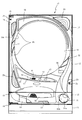
以下、本発明の実施形態について、添付図面を参照して説明する。まず、図1から図97を参照し、第1実施形態として、本発明をパチンコ遊技機(以下、単に「パチンコ機」という)10に適用した場合の一実施形態について説明する。図1は、第1実施形態におけるパチンコ機10の正面図であり、図2はパチンコ機10の遊技盤13の正面図であり、図3はパチンコ機10の背面図である。
Hereinafter, embodiments of the present invention will be described with reference to the accompanying drawings. First, with reference to FIGS. 1 to 97, as a first embodiment, an embodiment when the present invention is applied to a pachinko gaming machine (hereinafter, simply referred to as “pachinko machine”) 10 will be described. FIG. 1 is a front view of the
なお、以下の説明では、図1に示す状態のパチンコ機10に対して、紙面手前側を前方(正面)側として、紙面奥側を後方(背面)側として説明する。また、図1に示す状態のパチンコ機10に対して、上側を上方(上)側として、下側を下方(下)側として、右側を右方(右)側として、左側を左方(左)側としてそれぞれ説明する。さらに、図中(例えば、図2参照)の矢印U−D,L−R,F−Bは、パチンコ機10の上下方向,左右方向,前後方向をそれぞれ示している。
In the following description, with respect to the
図1に示すように、パチンコ機10は、略矩形状に組み合わせた木枠により外殻が形成される外枠11と、その外枠11と略同一の外形形状に形成され外枠11に対して開閉可能に支持された内枠12とを備えている。外枠11には、内枠12を支持するために正面視(図1参照)左側の上下2カ所に金属製のヒンジ18が取り付けられ、そのヒンジ18が設けられた側を開閉の軸として内枠12が正面手前側へ開閉可能に支持されている。
As shown in FIG. 1, the
内枠12には、多数の釘や入賞口63,64等を有する遊技盤13(図2参照)が裏面側から着脱可能に装着される。この遊技盤13の正面を球(遊技球)が流下することにより弾球遊技が行われる。なお、内枠12には、球を遊技盤13の正面領域に発射する球発射ユニット112a(図4参照)やその球発射ユニット112aから発射された球を遊技盤13の正面領域まで誘導する発射レール(図示せず)等が取り付けられている。
A game board 13 (see FIG. 2) having a large number of nails, winning
内枠12の正面側には、その正面上側を覆う正面枠14と、その下側を覆う下皿ユニット15とが設けられている。正面枠14及び下皿ユニット15を支持するために正面視(図1参照)左側の上下2カ所に金属製のヒンジ19が取り付けられ、そのヒンジ19が設けられた側を開閉の軸として正面枠14及び下皿ユニット15が正面手前側へ開閉可能に支持されている。なお、内枠12の施錠と正面枠14の施錠とは、シリンダ錠20の鍵穴21に専用の鍵を差し込んで所定の操作を行うことでそれぞれ解除される。
On the front side of the
正面枠14は、装飾用の樹脂部品や電気部品等を組み付けたものであり、その略中央部には略楕円形状に開口形成された窓部14cが設けられている。正面枠14の裏面側には2枚の板ガラスを有するガラスユニット16が配設され、そのガラスユニット16を介して遊技盤13の正面がパチンコ機10の正面側に視認可能となっている。
The
正面枠14には、球を貯留する上皿17が正面側へ張り出して上面を開放した略箱状に形成されており、この上皿17に賞球や貸出球などが排出される。上皿17の底面は正面視(図1参照)右側に下降傾斜して形成され、その傾斜により上皿17に投入された球が球発射ユニット112a(図4参照)へと案内される。また、上皿17の上面には、枠ボタン22が設けられている。この枠ボタン22は、例えば、第3図柄表示装置81(図2参照)で表示される演出のステージを変更したり、スーパーリーチの演出内容を変更したりする場合などに、遊技者により操作される。
In the
正面枠14には、その周囲(例えばコーナー部分)に各種ランプ等の発光手段が設けられている。これら発光手段は、大当たり時や所定のリーチ時等における遊技状態の変化に応じて、点灯又は点滅することにより発光態様が変更制御され、遊技中の演出効果を高める役割を果たす。窓部14cの周縁には、LED等の発光手段を内蔵した電飾部29〜33が設けられている。パチンコ機10においては、これら電飾部29〜33が大当たりランプ等の演出ランプとして機能し、大当たり時やリーチ演出時等には内蔵するLEDの点灯や点滅によって各電飾部29〜33が点灯または点滅して、大当たり中である旨、或いは大当たり一歩手前のリーチ中である旨が報知される。また、正面枠14の正面視(図1参照)左上部には、LED等の発光手段が内蔵され賞球の払い出し中とエラー発生時とを表示可能な表示ランプ34が設けられている。
The
また、右側の電飾部32下側には、正面枠14の裏面側を視認できるように裏面側より透明樹脂を取り付けて小窓35が形成され、遊技盤13正面の貼着スペースK1(図2参照)に貼付される証紙等がパチンコ機10の正面から視認可能とされている。また、パチンコ機10においては、より煌びやかさを醸し出すために、電飾部29〜33の周りの領域にクロムメッキを施したABS樹脂製のメッキ部材36が取り付けられている。
Further, on the lower side of the illuminated
窓部14cの下方には、貸球操作部40が配設されている。貸球操作部40には、度数表示部41と、球貸しボタン42と、返却ボタン43とが設けられている。パチンコ機10の側方に配置されるカードユニット(球貸しユニット)(図示せず)に紙幣やカード等を投入した状態で貸球操作部40が操作されると、その操作に応じて球の貸出が行われる。具体的には、度数表示部41はカード等の残額情報が表示される領域であり、内蔵されたLEDが点灯して残額情報として残額が数字で表示される。球貸しボタン42は、カード等(記録媒体)に記録された情報に基づいて貸出球を得るために操作されるものであり、カード等に残額が存在する限りにおいて貸出球が上皿17に供給される。返却ボタン43は、カードユニットに挿入されたカード等の返却を求める際に操作される。なお、カードユニットを介さずに球貸し装置等から上皿17に球が直接貸し出されるパチンコ機、いわゆる現金機では貸球操作部40が不要となるが、この場合には、貸球操作部40の設置部分に飾りシール等を付加して部品構成は共通のものとしても良い。カードユニットを用いたパチンコ機と現金機との共通化を図ることができる。
A ball
上皿17の下側に位置する下皿ユニット15には、その左側部に上皿17に貯留しきれなかった球を貯留するための下皿50が上面を開放した略箱状に形成されている。下皿50の右側には、球を遊技盤13の正面へ打ち込むために遊技者によって操作される操作ハンドル51が配設される。
In the
操作ハンドル51の内部には、球発射ユニット112aの駆動を許可するためのタッチセンサ51aと、押下操作している期間中には球の発射を停止する発射停止スイッチ51bと、操作ハンドル51の回動操作量(回動位置)を電気抵抗の変化により検出する可変抵抗器(図示せず)などが内蔵されている。操作ハンドル51が遊技者によって右回りに回動操作されると、タッチセンサ51aがオンされると共に可変抵抗器の抵抗値が回動操作量に対応して変化し、その可変抵抗器の抵抗値に対応した強さ(発射強度)で球が発射され、これにより遊技者の操作に対応した飛び量で遊技盤13の正面へ球が打ち込まれる。また、操作ハンドル51が遊技者により操作されていない状態においては、タッチセンサ51aおよび発射停止スイッチ51bがオフとなっている。
Inside the
下皿50の正面下方部には、下皿50に貯留された球を下方へ排出する際に操作するための球抜きレバー52が設けられている。この球抜きレバー52は、常時、右方向に付勢されており、その付勢に抗して左方向へスライドさせることにより、下皿50の底面に形成された底面口が開口して、その底面口から球が自然落下して排出される。この球抜きレバー52の操作は、通常、下皿50の下方に下皿50から排出された球を受け取る箱(一般に「千両箱」と称される)を置いた状態で行われる。下皿50の右方には、上述したように操作ハンドル51が配設され、下皿50の左方には灰皿53が取り付けられている。
A
図2に示すように、遊技盤13は、正面視略正方形状に切削加工したベース板60に、球案内用の多数の釘(図示せず)や風車(図示せず)の他、レール61,62、一般入賞口63、第1入賞口64、第2入賞口640、可変入賞装置65、スルーゲート67、可変表示装置ユニット80等を組み付けて構成され、その周縁部が内枠12(図1参照)の裏面側(又は表面側)に取り付けられる。
As shown in FIG. 2, the
ベース板60は、木製の板部材から形成される。一般入賞口63、第1入賞口64、第2入賞口640、可変表示装置ユニット80は、ルータ加工によってベース板60に形成された貫通穴(例えば、図5参照)に配設され、遊技盤13の正面側からタッピングネジ等により固定されている。なお、ベース板60を光透過性の樹脂材料から構成しても良い。この場合、その正面側からベース板60の背面側に配設された各種構造体を遊技者に視認させることが可能となる。
The
遊技盤13の正面中央部分は、正面枠14の窓部14c(図1参照)を通じて内枠12の正面側から視認することができる。以下に、主に図2を参照して、遊技盤13の構成について説明する。
The front central portion of the
遊技盤13の正面には、帯状の金属板を略円弧状に屈曲加工して形成した外レール62が植立され、その外レール62の内側位置には外レール62と同様に帯状の金属板で形成した円弧状の内レール61が植立される。この内レール61と外レール62とにより遊技盤13の正面外周が囲まれ、遊技盤13とガラスユニット16(図1参照)とにより前後が囲まれることにより、遊技盤13の正面には、球の挙動により遊技が行われる遊技領域が形成される。遊技領域は、遊技盤13の正面であって2本のレール61,62とレール間を繋ぐ樹脂製の外縁部材73とにより区画して形成される領域(入賞口等が配設され、発射された球が流下する領域)である。
An
2本のレール61,62は、球発射ユニット112a(図4参照)から発射された球を遊技盤13上部へ案内するために設けられたものである。内レール61の先端部分(図2の左上部)には戻り球防止部材68が取り付けられ、一旦、遊技盤13の上部へ案内された球が再度球案内通路内に戻ってしまうといった事態が防止される。外レール62の先端部(図2の右上部)には、球の最大飛翔部分に対応する位置に返しゴム69が取り付けられ、所定以上の勢いで発射された球は、返しゴム69に当たって、勢いが減衰されつつ中央部側へ跳ね返される。
The two
遊技領域の正面視左側下部(図2の左側下部)には、発光手段である複数のLED及び7セグメント表示器を備える第1図柄表示装置37A,37Bが配設されている。第1図柄表示装置37A,37Bは、主制御装置110(図4参照)で行われる各制御に応じた表示がなされるものであり、主にパチンコ機10の遊技状態の表示が行われる。本実施形態では、第1図柄表示装置37A,37Bは、球が、第1入賞口64へ入賞したか、第2入賞口640へ入賞したかに応じて使い分けられるように構成されている。具体的には、球が、第1入賞口64へ入賞した場合には、第1図柄表示装置37Aが作動し、一方で、球が、第2入賞口640へ入賞した場合には、第1図柄表示装置37Bが作動するように構成されている。
In the lower left side of the front view (lower left side of FIG. 2) of the game area, first
また、第1図柄表示装置37A,37Bは、LEDにより、パチンコ機10が確変中か時短中か通常中であるかを点灯状態により示したり、変動中であるか否かを点灯状態により示したり、停止図柄が確変大当たりに対応した図柄か普通大当たりに対応した図柄か外れ図柄であるかを点灯状態により示したり、保留球数を点灯状態により示すと共に、7セグメント表示装置により、大当たり中のラウンド数やエラー表示を行う。なお、複数のLEDは、それぞれのLEDの発光色(例えば、赤、緑、青)が異なるよう構成され、その発光色の組み合わせにより、少ないLEDでパチンコ機10の各種遊技状態を示唆することができる。
Further, the first
尚、本パチンコ機10では、第1入賞口64及び第2入賞口640へ入賞があったことを契機として抽選が行われる。パチンコ機10は、その抽選において、大当たりか否かの当否判定(大当たり抽選)を行うと共に、大当たりと判定した場合はその大当たり種別の判定も行う。ここで判定される大当たり種別としては、15R確変大当たり、4R確変大当たり、15R通常大当たりが用意されている。第1図柄表示装置37A,37Bには、変動終了後の停止図柄として抽選の結果が大当たりであるか否かが示されるだけでなく、大当たりである場合はその大当たり種別に応じた図柄が示される。
In the
ここで、「15R確変大当たり」とは、最大ラウンド数が15ラウンドの大当たりの後に高確率状態へ移行する確変大当たりのことであり、「4R確変大当たり」とは、最大ラウンド数が4ラウンドの大当たりの後に高確率状態へ移行する確変大当たりのことである。また、「15R通常大当たり」は、最大ラウンド数が15ラウンドの大当たりの後に、低確率状態へ移行すると共に、所定の変動回数の間(例えば、100変動回数)は時短状態となる大当たりのことである。 Here, the "15R probability variation jackpot" is a probability variation jackpot in which the maximum number of rounds shifts to a high probability state after the jackpot of 15 rounds, and the "4R probability variation jackpot" is a jackpot with a maximum number of rounds of 4 rounds. It is a probabilistic jackpot that shifts to a high probability state after. Further, "15R normal jackpot" is a jackpot in which the maximum number of rounds is 15 rounds, and then the probability shifts to a low probability state, and the time is shortened during a predetermined number of fluctuations (for example, 100 fluctuations). be.
また、「高確率状態」とは、大当たり終了後に付加価値としてその後の大当たり確率がアップした状態、いわゆる確率変動中(確変中)の時をいい、換言すれば、特別遊技状態へ移行し易い遊技の状態のことである。本実施形態における高確率状態(確変中)は、後述する第2図柄の当たり確率がアップして第2入賞口640へ球が入賞し易い遊技の状態を含む。「低確率状態」とは、確変中でない時をいい、大当たり確率が通常の状態、即ち、確変の時より大当たり確率が低い状態をいう。また、「低確率状態」のうちの時短状態(時短中)とは、大当たり確率が通常の状態であると共に、大当たり確率がそのままで第2図柄の当たり確率のみがアップして第2入賞口640へ球が入賞し易い遊技の状態のことをいう。一方、パチンコ機10が通常中とは、確変中でも時短中でもない遊技の状態(大当たり確率も第2図柄の当たり確率もアップしていない状態)である。
In addition, the "high probability state" refers to a state in which the probability of a jackpot is increased as an added value after the end of the jackpot, that is, during a so-called probability fluctuation (probability change), in other words, a game in which it is easy to shift to a special gaming state. It is the state of. The high-probability state (during probabilistic change) in the present embodiment includes a game state in which the winning probability of the second symbol, which will be described later, is increased and the ball is likely to win the second winning
確変中や時短中は、第2図柄の当たり確率がアップするだけではなく、第2入賞口640に付随する電動役物640aが開放される時間も変更され、通常中と比して長い時間が設定される。電動役物640aが開放された状態(開放状態)にある場合は、その電動役物640aが閉鎖された状態(閉鎖状態)にある場合と比して、第2入賞口640へ球が入賞しやすい状態となる。よって、確変中や時短中は、第2入賞口640へ球が入賞し易い状態となり、大当たり抽選が行われる回数を増やすことができる。
During the probability change and the time reduction, not only the probability of hitting the second symbol increases, but also the time when the
電動役物640aの開放状態と閉鎖状態との状態変化は、下端部に回転軸を備え、遊技領域側へ傾倒または起立する態様で回転変位する開閉板の開閉動作により生じる。電動役物640aが開放状態の時は、開閉板の上面を伝って球が第2入賞口640に案内され易く構成され、電動役物640aが閉鎖状態の時は、開閉板が遊技領域と第2入賞口640との間を塞ぐことで球が第2入賞口640に入球し難くなるように構成している。
The state change between the open state and the closed state of the
なお、確変中や時短中において、第2入賞口640に付随する電動役物640aの開放時間を変更するのではなく、または、その開放時間を変更することに加えて、1回の当たりで電動役物640aが開放する回数を通常中よりも増やす変更を行うものとしてもよい。また、確変中や時短中において、第2図柄の当たり確率は変更せず、第2入賞口640に付随する電動役物640aが開放される時間および1回の当たりで電動役物640aが開放する回数の少なくとも一方を変更するものとしてもよい。また、確変中や時短中において、第2入賞口640に付随する電動役物640aが開放される時間や、1回の当たりで電動役物640aを開放する回数は変更せず、第2図柄の当たり確率だけを、通常中と比してアップするよう変更するものであってもよい。
In addition, during the probability change or the time reduction, the opening time of the
遊技領域には、球が入賞することにより5個から15個の球が賞球として払い出される複数の一般入賞口63が配設されている。また、遊技領域の中央部分を通して視認可能な位置(ベース板60の窓部の後方)に、可変表示装置ユニット80が配設されている。可変表示装置ユニット80には、第1入賞口64及び第2入賞口640への入賞(始動入賞)をトリガとして、第1図柄表示装置37A,37Bにおける変動表示と同期させながら、第3図柄の変動表示を行う液晶ディスプレイ(以下単に「表示装置」と略す)で構成された第3図柄表示装置81と、スルーゲート67の球の通過をトリガとして第2図柄を変動表示するLEDで構成される第2図柄表示装置(図示せず)とが設けられている。また、ベース板60には、第3図柄表示装置81を正面視で囲むようにして、センターフレーム86が配設されている。
In the game area, a plurality of general winning
第3図柄表示装置81は9インチサイズから19インチサイズ程度の大型の液晶ディスプレイで構成されるものであり、表示制御装置114(図4参照)によって表示内容が制御されることにより、例えば上、中及び下の3つの図柄列が表示される。各図柄列は複数の図柄(第3図柄)によって構成され、これらの第3図柄が図柄列毎に横スクロールして第3図柄表示装置81の表示画面上にて第3図柄が可変表示されるようになっている。本実施形態の第3図柄表示装置81は、主制御装置110(図4参照)の制御に伴った遊技状態の表示が第1図柄表示装置37A,37Bで行われるのに対して、その第1図柄表示装置37A,37Bの表示に応じた装飾的な表示を行うものである。なお、表示装置に代えて、例えばリール等を用いて第3図柄表示装置81を構成するようにしても良い。
The third
第2図柄表示装置は、球がスルーゲート67を通過する毎に表示図柄(第2図柄(図示せず))としての「○」の図柄と「×」の図柄とを所定時間交互に点灯させる変動表示を行うものである。パチンコ機10では、球がスルーゲート67を通過したことが検出されると、当たり抽選が行われる。その当たり抽選の結果、当たりであれば、第2図柄表示装置において、第2図柄の変動表示後に「○」の図柄が停止表示される。また、当たり抽選の結果、外れであれば、第2図柄表示装置において、第3図柄の変動表示後に「×」の図柄が停止表示される。
The second symbol display device alternately lights the “○” symbol and the “×” symbol as the display symbol (second symbol (not shown)) each time the sphere passes through the through
パチンコ機10は、第2図柄表示装置における変動表示が所定図柄(本実施形態においては「○」の図柄)で停止した場合に、第2入賞口640に付随された電動役物640aが所定時間だけ作動状態となる(開放される)よう構成されている。
In the
第2図柄の変動表示にかかる時間は、遊技状態が通常中の場合よりも、確変中または時短中の方が短くなるように設定される。これにより、確変中および時短中は、第2図柄の変動表示が短い時間で行われるので、当たり抽選を通常中よりも多く行うことができる。よって、当たり抽選において当たりとなる機会が増えるので、第2入賞口640の電動役物640aが開放状態となる機会を遊技者に多く与えることができる。よって、確変中および時短中は、第2入賞口640へ球が入賞しやすい状態とすることができる。
The time required for the variation display of the second symbol is set to be shorter during the probability change or the time reduction than when the game state is normal. As a result, during the probability change and the time reduction, the variation display of the second symbol is performed in a short time, so that the winning lottery can be performed more than during the normal time. Therefore, since the chances of winning in the winning lottery increase, it is possible to give the player many opportunities to open the
なお、確変中または時短中において、当たり確率を高める、1回の当たりに対する電動役物640aの開放時間や開放回数を増やすなど、その他の方法によっても、確変中または時短中に第2入賞口640へ球が入賞しやすい状態としている場合は、第2図柄の変動表示にかかる時間を遊技状態にかかわらず一定としてもよい。一方、第2図柄の変動表示にかかる時間を、確変中または時短中において通常中よりも短く設定する場合は、当たり確率を遊技状態にかかわらず一定にしてもよいし、また、1回の当たりに対する電動役物640aの開放時間や開放回数を遊技状態にかかわらず一定にしてもよい。
It should be noted that, during the probability change or the time reduction, the second winning
スルーゲート67は、可変表示装置ユニット80の右側の領域において遊技盤13に組み付けられ、遊技盤13に発射された球の一部が通過可能に構成されている。スルーゲート67を球が通過すると、第2図柄の当たり抽選が行われる。当たり抽選の後、第2図柄表示装置にて変動表示を行い、当たり抽選の結果が当たりであれば、変動表示の停止図柄として「○」の図柄を表示し、当たり抽選の結果が外れであれば、変動表示の停止図柄として「×」の図柄を表示する。
The through
球のスルーゲート67の通過回数は、合計で最大4回まで保留され、その保留球数が上述した第1図柄表示装置37A,37Bにより表示されると共に第2図柄保留ランプ(図示せず)においても点灯表示される。第2図柄保留ランプは、最大保留数分の4つ設けられ、第3図柄表示装置81の下方に左右対称に配設されている。
The number of times the ball has passed through the through
なお、第2図柄の変動表示は、本実施形態のように、第2図柄表示装置において複数のランプの点灯と非点灯を切り換えることにより行うものの他、第1図柄表示装置37A,37B及び第3図柄表示装置81の一部を使用して行うようにしても良い。同様に、第2図柄保留ランプの点灯を第3図柄表示装置81の一部で行うようにしても良い。
The variation display of the second symbol is performed by switching the lighting and non-lighting of a plurality of lamps in the second symbol display device as in the present embodiment, as well as the first
また、スルーゲート67の球の通過に対する最大保留球数は4回に限定されるものでなく、3回以下、又は、5回以上の回数(例えば、8回)に設定しても良い。また、スルーゲート67の組み付け数は1つに限定されるものではなく、例えば2つであっても良い。
Further, the maximum number of reserved balls for the passage of the balls of the through
また、スルーゲート67の組み付け位置は可変表示装置ユニット80の右側に限定されるものではなく、例えば、可変表示装置ユニット80の左右や、下方でも良い。また、第1図柄表示装置37A,37Bにより保留球数が示されるので、第2図柄保留ランプにより点灯表示を行わないものとしてもよい。
Further, the assembly position of the through
可変表示装置ユニット80の下方には、球が入賞し得る第1入賞口64が配設されている。この第1入賞口64へ球が入賞すると遊技盤13の裏面側に設けられる第1入賞口スイッチ(図示せず)がオンとなり、その第1入賞口スイッチのオンに起因して主制御装置110(図4参照)で大当たりの抽選がなされ、その抽選結果に応じた表示が第1図柄表示装置37Aで示される。
Below the variable
一方、スルーゲート67の正面視右下側には、球が入賞し得る第2入賞口640が配設されている。この第2入賞口640へ球が入賞すると遊技盤13の裏面側に設けられる第2入賞口スイッチ(図示せず)がオンとなり、その第2入賞口スイッチのオンに起因して主制御装置110(図4参照)で大当たりの抽選がなされ、その抽選結果に応じた表示が第1図柄表示装置37Bで示される。なお、第2入賞口640の配置は、これに限られるものではない。例えば、第1入賞口64の正面視下方でも良いし、遊技領域の左右中央よりも左側でも良い。
On the other hand, on the lower right side of the through
また、第1入賞口64および第2入賞口640は、それぞれ、球が入賞すると5個の球が賞球として払い出される入賞口の1つにもなっている。なお、本実施形態においては、第1入賞口64へ球が入賞した場合に払い出される賞球数と第2入賞口640へ球が入賞した場合に払い出される賞球数とを同じに構成したが、第1入賞口64へ球が入賞した場合に払い出される賞球数と第2入賞口640へ球が入賞した場合に払い出される賞球数とを異なる数、例えば、第1入賞口64へ球が入賞した場合に払い出される賞球数を3個とし、第2入賞口640へ球が入賞した場合に払い出される賞球数を5個として構成してもよい。
Further, each of the first winning
第2入賞口640には電動役物640aが付随されている。この電動役物640aは開閉可能に構成されており、通常は電動役物640aが閉鎖状態(縮小状態)となって、球が第2入賞口640へ入賞しにくい状態となっている。一方、スルーゲート67への球の通過を契機として行われる第2図柄の変動表示の結果、「○」の図柄が第2図柄表示装置に表示された場合、電動役物640aが開放状態(拡大状態)となり、球が第2入賞口640へ入賞しやすい状態となる。
An
上述した通り、確変中および時短中は、通常中と比して第2図柄の当たり確率が高く、また、第2図柄の変動表示にかかる時間も短いので、第2図柄の変動表示において「○」の図柄が表示され易くなって、電動役物640aが開放状態(拡大状態)となる回数が増える。更に、確変中および時短中は、電動役物640aが開放される時間も、通常中より長くなる。よって、確変中および時短中は、通常時と比して、第2入賞口640へ球が入賞しやすい状態を作ることができる。
As described above, during the probability change and the time reduction, the probability of hitting the second symbol is higher than during the normal time, and the time required for the variation display of the second symbol is short. ”Is easy to display, and the number of times the
ここで、第1入賞口64に球が入賞した場合と第2入賞口640へ球が入賞した場合とで、大当たりとなる確率は、低確率状態であっても高確率状態でも同一である。しかしながら、大当たりとなった場合に選定される大当たりの種別として15R確変大当たりとなる確率は、第2入賞口640へ球が入賞した場合のほうが第1入賞口64へ球が入賞した場合よりも高く設定されている。一方、第1入賞口64は、第2入賞口640にあるような電動役物640aは有しておらず、球が常時入賞可能な状態となっている。
Here, the probability of winning a jackpot is the same in both the low probability state and the high probability state when the ball wins in the first winning
よって、通常中においては、第2入賞口640に付随する電動役物640aが閉鎖状態にある場合が多く、第2入賞口640に入賞しづらいので、電動役物640aのない第1入賞口64へ向けて、可変表示装置ユニット80の左方を球が通過するように球を発射し(所謂「左打ち」)、第1入賞口64への入賞によって大当たり抽選の機会を多く得て、大当たりとなることを狙った方が、遊技者にとって有利となる。
Therefore, in normal times, the
一方、確変中や時短中は、スルーゲート67に球を通過させることで、第2入賞口640に付随する電動役物640aが開放状態となりやすく、第2入賞口640に入賞しやすい状態であるので、第2入賞口640へ向けて、可変表示装置80の右方を球が通過するように球を発射し(所謂「右打ち」)、スルーゲート67を通過させて電動役物640aを開放状態にすると共に、第2入賞口640への入賞によって15R確変大当たりとなることを狙った方が、遊技者にとって有利となる。
On the other hand, during the probability change or the time reduction, by passing the ball through the through
なお、本実施形態におけるパチンコ機10とは異なり、遊技盤13の構成が左右対称とされる場合には、「右打ち」で第1入賞口64を狙うことも、「左打ち」で第2入賞口640を狙うこともできる。そのため、本実施形態のパチンコ機10は、パチンコ機10の遊技状態(確変中であるか、時短中であるか、通常中であるか)に応じて、遊技者に対し、球の発射の仕方を「左打ち」と「右打ち」とに変えさせることを不要にできる。よって、球の打ち方を変化させる煩わしさを解消することができる。
In addition, unlike the
一方で、本実施形態におけるパチンコ機10では、「右打ち」では第1入賞口64を狙うことはできないように構成され、「左打ち」で発射された球はスルーゲート67を通過しないように構成されている。そのため、本実施形態のパチンコ機10は、パチンコ機10の遊技状態(確変中であるか、時短中であるか、通常中であるか)に応じて、遊技者に対し、球の発射の仕方を「左打ち」と「右打ち」とに変えることを要求することができる。よって、球の打ち方を変化させる遊技性を付加することで遊技が緩慢となることを防止することができる。
On the other hand, the
第1入賞口64の右方には可変入賞装置65(図2参照)が配設されており、その略中央部分に特定入賞口65aが設けられている。パチンコ機10においては、第1入賞口64又は第2入賞口640への入賞に起因して行われた大当たり抽選が大当たりとなると、所定時間(変動時間)が経過した後に、大当たりの停止図柄となるよう第1図柄表示装置37A又は第1図柄表示装置37Bを点灯させると共に、その大当たりに対応した停止図柄を第3図柄表示装置81に表示させて、大当たりの発生が示される。その後、球が入賞し易い特別遊技状態(大当たり)に遊技状態が遷移する。この特別遊技状態として、通常時には閉鎖されている特定入賞口65aが、所定時間(例えば、30秒経過するまで、或いは、球が10個入賞するまで)開放される。
A variable winning device 65 (see FIG. 2) is arranged on the right side of the first winning
この特定入賞口65aは、所定時間が経過すると閉鎖され、その閉鎖後、再度、その特定入賞口65aが所定時間開放される。この特定入賞口65aの開閉動作は、最高で例えば15回(15ラウンド)繰り返し可能にされている。この開閉動作が行われている状態が、遊技者にとって有利な特別遊技状態の一形態であり、遊技者には、遊技上の価値(遊技価値)の付与として通常時より多量の賞球の払い出しが行われる。
The
なお、上記した形態に特別遊技状態は限定されるものではない。特定入賞口65aとは別に開閉される大開放口を遊技領域に設け、第1図柄表示装置37A,37Bにおいて大当たりに対応したLEDが点灯した場合に、特定入賞口65aが所定時間開放され、その特定入賞口65aの開放中に、球が特定入賞口65a内へ入賞することを契機として特定入賞口65aとは別に設けられた大開放口が所定時間、所定回数開放される遊技状態を特別遊技状態として形成するようにしても良い。また、特定入賞口65aは1つに限るものではなく、1つ若しくは2以上の複数(例えば3つ)を配置しても良く、また配置位置も第1入賞口64の右方に限らず、例えば、第1入賞口64の下方右側や、第1入賞口64の下方左側や、可変表示装置ユニット80の左方または右方や、上方でも良い。
The special gaming state is not limited to the above-described form. A large opening that opens and closes separately from the specific winning
遊技盤13の下側における右隅部には、証紙や識別ラベル等を貼着するための貼着スペースK1が設けられ、貼着スペースK1に貼られた証紙等は、正面枠14の小窓35(図1参照)を通じて視認することができる。
In the right corner on the lower side of the
遊技盤13には、アウト口71が設けられている。遊技領域を流下する球であって、いずれの入賞口63,64,65a,640にも入賞しなかった球は、アウト口71を通って図示しない球排出路へと案内される。
The
遊技盤13には、球の落下方向を適宜分散、調整等するために多数の釘が植設されているとともに、風車等の各種部材(役物)とが配設されている。
A large number of nails are planted on the
図3に示すように、パチンコ機10の背面側には、制御基板ユニット90,91と、裏パックユニット94とが主に備えられている。制御基板ユニット90は、主基板(主制御装置110)と音声ランプ制御基板(音声ランプ制御装置113)と表示制御基板(表示制御装置114)とが搭載されてユニット化されている。制御基板ユニット91は、払出制御基板(払出制御装置111)と発射制御基板(発射制御装置112)と電源基板(電源装置115)とカードユニット接続基板116とが搭載されてユニット化されている。
As shown in FIG. 3, the
裏パックユニット94は、保護カバー部を形成する裏パック92と払出ユニット93とがユニット化されている。また、各制御基板には、各制御を司る1チップマイコンとしてのMPU、各種機器との連絡をとるポート、各種抽選の際に用いられる乱数発生器、時間計数や同期を図る場合などに使用されるクロックパルス発生回路等が、必要に応じて搭載されている。
In the
なお、主制御装置110、音声ランプ制御装置113及び表示制御装置114、払出制御装置111及び発射制御装置112、電源装置115、カードユニット接続基板116は、それぞれ基板ボックス100〜104に収納されている。基板ボックス100〜104は、ボックスベースと該ボックスベースの開口部を覆うボックスカバーとを備えており、そのボックスベースとボックスカバーとが互いに連結されて、各制御装置や各基板が収納される。
The
また、基板ボックス100(主制御装置110)及び基板ボックス102(払出制御装置111及び発射制御装置112)は、ボックスベースとボックスカバーとを封印ユニット(図示せず)によって開封不能に連結(かしめ構造による連結)している。また、ボックスベースとボックスカバーとの連結部には、ボックスベースとボックスカバーとに亘って封印シール(図示せず)が貼着されている。この封印シールは、脆性な素材で構成されており、基板ボックス100,102を開封するために封印シールを剥がそうとしたり、基板ボックス100,102を無理に開封しようとすると、ボックスベース側とボックスカバー側とに切断される。よって、封印ユニット又は封印シールを確認することで、基板ボックス100,102が開封されたかどうかを知ることができる。
Further, in the board box 100 (main control device 110) and the board box 102 (
払出ユニット93は、裏パックユニット94の最上部に位置して上方に開口したタンク130と、タンク130の下方に連結され下流側に向けて緩やかに傾斜するタンクレール131と、タンクレール131の下流側に縦向きに連結されるケースレール132と、ケースレール132の最下流部に設けられ、払出モータ216(図4参照)の所定の電気的構成により球の払出を行う払出装置133とを備えている。タンク130には、遊技ホールの島設備から供給される球が逐次補給され、払出装置133により必要個数の球の払い出しが適宜行われる。タンクレール131には、当該タンクレール131に振動を付加するためのバイブレータ134が取り付けられている。
The
また、払出制御装置111には状態復帰スイッチ120が設けられ、発射制御装置112には可変抵抗器の操作つまみ121が設けられ、電源装置115にはRAM消去スイッチ122が設けられている。状態復帰スイッチ120は、例えば、払出モータ216(図4参照)部の球詰まり等、払出エラーの発生時に球詰まりを解消(正常状態への復帰)するために操作される。操作つまみ121は、発射ソレノイドの発射力を調整するために操作される。RAM消去スイッチ122は、パチンコ機10を初期状態に戻したい場合に電源投入時に操作される。
Further, the
次に、図4を参照して、本パチンコ機10の電気的構成について説明する。図4は、パチンコ機10の電気的構成を示すブロック図である。
Next, the electrical configuration of the
主制御装置110には、演算装置である1チップマイコンとしてのMPU201が搭載されている。MPU201には、該MPU201により実行される各種の制御プログラムや固定値データを記憶したROM202と、そのROM202内に記憶される制御プログラムの実行に際して各種のデータ等を一時的に記憶するためのメモリであるRAM203と、そのほか、割込回路やタイマ回路、データ送受信回路などの各種回路が内蔵されている。主制御装置110では、MPU201によって、大当たり抽選や第1図柄表示装置37A,37B及び第3図柄表示装置81における表示の設定、第2図柄表示装置における表示結果の抽選といったパチンコ機10の主要な処理を実行する。
The
なお、払出制御装置111や音声ランプ制御装置113などのサブ制御装置に対して動作を指示するために、主制御装置110から該サブ制御装置へ各種のコマンドがデータ送受信回路によって送信されるが、かかるコマンドは、主制御装置110からサブ制御装置へ一方向にのみ送信される。
In order to instruct the operation of the sub control device such as the
RAM203は、各種エリア、カウンタ、フラグのほか、MPU201の内部レジスタの内容やMPU201により実行される制御プログラムの戻り先番地などが記憶されるスタックエリアと、各種のフラグおよびカウンタ、I/O等の値が記憶される作業エリア(作業領域)とを有している。なお、RAM203は、パチンコ機10の電源の遮断後においても電源装置115からバックアップ電圧が供給されてデータを保持(バックアップ)できる構成となっており、RAM203に記憶されるデータは、すべてバックアップされる。
The
停電などの発生により電源が遮断されると、その電源遮断時(停電発生時を含む。以下同様)のスタックポインタや、各レジスタの値がRAM203に記憶される。一方、電源投入時(停電解消による電源投入を含む。以下同様)には、RAM203に記憶される情報に基づいて、パチンコ機10の状態が電源遮断前の状態に復帰される。RAM203への書き込みはメイン処理(図示せず)によって電源遮断時に実行され、RAM203に書き込まれた各値の復帰は電源投入時の立ち上げ処理(図示せず)において実行される。なお、MPU201のNMI端子(ノンマスカブル割込端子)には、停電等の発生による電源遮断時に、停電監視回路252からの停電信号SG1が入力されるように構成されており、その停電信号SG1がMPU201へ入力されると、停電時処理としてのNMI割込処理(図示せず)が即座に実行される。
When the power supply is cut off due to the occurrence of a power failure or the like, the stack pointer at the time of the power failure (including the time when the power failure occurs; the same applies hereinafter) and the value of each register are stored in the
主制御装置110のMPU201には、アドレスバス及びデータバスで構成されるバスライン204を介して入出力ポート205が接続されている。入出力ポート205には、払出制御装置111、音声ランプ制御装置113、第1図柄表示装置37A,37B、第2図柄表示装置、第2図柄保留ランプ、特定入賞口65aの開閉板を前後方向に開閉駆動するための大開放口ソレノイドや電動役物640aを駆動するためのソレノイドなどからなるソレノイド209が接続され、MPU201は、入出力ポート205を介してこれらに対し各種コマンドや制御信号を送信する。
An input /
また、入出力ポート205には、図示しないスイッチ群およびスライド位置検出センサSや回転位置検出センサRを含むセンサ群などからなる各種スイッチ208、電源装置115に設けられた後述のRAM消去スイッチ回路253が接続され、MPU201は各種スイッチ208から出力される信号や、RAM消去スイッチ回路253より出力されるRAM消去信号SG2に基づいて各種処理を実行する。
Further, the input /
払出制御装置111は、払出モータ216を駆動させて賞球や貸出球の払出制御を行うものである。演算装置であるMPU211は、そのMPU211により実行される制御プログラムや固定値データ等を記憶したROM212と、ワークメモリ等として使用されるRAM213とを有している。
The
払出制御装置111のRAM213は、主制御装置110のRAM203と同様に、MPU211の内部レジスタの内容やMPU211により実行される制御プログラムの戻り先番地などが記憶されるスタックエリアと、各種のフラグおよびカウンタ、I/O等の値が記憶される作業エリア(作業領域)とを有している。RAM213は、パチンコ機10の電源の遮断後においても電源装置115からバックアップ電圧が供給されてデータを保持(バックアップ)できる構成となっており、RAM213に記憶されるデータは、すべてバックアップされる。なお、主制御装置110のMPU201と同様、MPU211のNMI端子にも、停電等の発生による電源遮断時に停電監視回路252から停電信号SG1が入力されるように構成されており、その停電信号SG1がMPU211へ入力されると、停電時処理としてのNMI割込処理(図示せず)が即座に実行される。
The RAM 213 of the
払出制御装置111のMPU211には、アドレスバス及びデータバスで構成されるバスライン214を介して入出力ポート215が接続されている。入出力ポート215には、主制御装置110や払出モータ216、発射制御装置112などがそれぞれ接続されている。また、図示はしないが、払出制御装置111には、払い出された賞球を検出するための賞球検出スイッチが接続されている。なお、該賞球検出スイッチは、払出制御装置111に接続されるが、主制御装置110には接続されていない。
An input /
発射制御装置112は、主制御装置110により球の発射の指示がなされた場合に、操作ハンドル51の回動操作量に応じた球の打ち出し強さとなるよう球発射ユニット112aを制御するものである。球発射ユニット112aは、図示しない発射ソレノイドおよび電磁石を備えており、その発射ソレノイドおよび電磁石は、所定条件が整っている場合に駆動が許可される。具体的には、遊技者が操作ハンドル51に触れていることをタッチセンサ51aにより検出し、球の発射を停止させるための発射停止スイッチ51bがオフ(操作されていないこと)を条件に、操作ハンドル51の回動操作量(回動位置)に対応して発射ソレノイドが励磁され、操作ハンドル51の操作量に応じた強さで球が発射される。
The
音声ランプ制御装置113は、音声出力装置(図示しないスピーカなど)226における音声の出力、ランプ表示装置(電飾部29〜33、表示ランプ34など)227における点灯および消灯の出力、変動演出(変動表示)や予告演出といった表示制御装置114で行われる第3図柄表示装置81の表示態様の設定などを制御するものである。演算装置であるMPU221は、そのMPU221により実行される制御プログラムや固定値データ等を記憶したROM222と、ワークメモリ等として使用されるRAM223とを有している。
The audio
音声ランプ制御装置113のMPU221には、アドレスバス及びデータバスで構成されるバスライン224を介して入出力ポート225が接続されている。入出力ポート225には、主制御装置110、表示制御装置114、音声出力装置226、ランプ表示装置227、その他装置228、枠ボタン22などがそれぞれ接続されている。その他装置228には駆動モータMT1,MT2,MT3,MT4,MT5等が含まれる。
An input /
音声ランプ制御装置113は、主制御装置110から受信した各種のコマンド(変動パターンコマンド、停止種別コマンド等)に基づいて、第3図柄表示装置81の表示態様を決定し、決定した表示態様をコマンド(表示用変動パターンコマンド、表示用停止種別コマンド等)によって表示制御装置114へ通知する。また、音声ランプ制御装置113は、枠ボタン22からの入力を監視し、遊技者によって枠ボタン22が操作された場合は、第3図柄表示装置81で表示されるステージを変更したり、スーパーリーチ時の演出内容を変更したりするように、表示制御装置114へ指示する。ステージが変更される場合は、変更後のステージに応じた背面画像を第3図柄表示装置81に表示させるべく、変更後のステージに関する情報を含めた背面画像変更コマンドを表示制御装置114へ送信する。ここで、背面画像とは、第3図柄表示装置81に表示させる主要な画像である第3図柄の背面側に表示される画像のことである。表示制御装置114は、この音声ランプ制御装置113から送信されるコマンドに従って、第3図柄表示装置81に各種の画像を表示する。
The voice
また、音声ランプ制御装置113は、表示制御装置114から第3図柄表示装置81の表示内容を表すコマンド(表示コマンド)を受信する。音声ランプ制御装置113では、表示制御装置114から受信した表示コマンドに基づき、第3図柄表示装置81の表示内容に合わせて、その表示内容に対応する音声を音声出力装置226から出力し、また、その表示内容に対応させてランプ表示装置227の点灯および消灯を制御する。
Further, the voice
表示制御装置114は、音声ランプ制御装置113及び第3図柄表示装置81が接続され、音声ランプ制御装置113より受信したコマンドに基づいて、第3図柄表示装置81における第3図柄の変動演出などの表示を制御するものである。また、表示制御装置114は、第3図柄表示装置81の表示内容を通知する表示コマンドを適宜音声ランプ制御装置113へ送信する。音声ランプ制御装置113は、この表示コマンドによって示される表示内容にあわせて音声出力装置226から音声を出力することで、第3図柄表示装置81の表示と音声出力装置226からの音声出力とをあわせることができる。
In the
電源装置115は、パチンコ機10の各部に電源を供給するための電源部251と、停電等による電源遮断を監視する停電監視回路252と、RAM消去スイッチ122(図3参照)が設けられたRAM消去スイッチ回路253とを有している。電源部251は、図示しない電源経路を通じて、各制御装置110〜114等に対して各々に必要な動作電圧を供給する装置である。その概要としては、電源部251は、外部より供給される交流24ボルトの電圧を取り込み、各種スイッチ208などの各種スイッチや、ソレノイド209などのソレノイド、モータ等を駆動するための12ボルトの電圧、ロジック用の5ボルトの電圧、RAMバックアップ用のバックアップ電圧などを生成し、これら12ボルトの電圧、5ボルトの電圧及びバックアップ電圧を各制御装置110〜114等に対して必要な電圧を供給する。
The
停電監視回路252は、停電等の発生による電源遮断時に、主制御装置110のMPU201及び払出制御装置111のMPU211の各NMI端子へ停電信号SG1を出力するための回路である。停電監視回路252は、電源部251から出力される最大電圧である直流安定24ボルトの電圧を監視し、この電圧が22ボルト未満になった場合に停電(電源断、電源遮断)の発生と判断して、停電信号SG1を主制御装置110及び払出制御装置111へ出力する。停電信号SG1の出力によって、主制御装置110及び払出制御装置111は、停電の発生を認識し、NMI割込処理を実行する。なお、電源部251は、直流安定24ボルトの電圧が22ボルト未満になった後においても、NMI割込処理の実行に充分な時間の間、制御系の駆動電圧である5ボルトの電圧の出力を正常値に維持するように構成されている。よって、主制御装置110及び払出制御装置111は、NMI割込処理(図示せず)を正常に実行し完了することができる。
The power
RAM消去スイッチ回路253は、RAM消去スイッチ122(図3参照)が押下された場合に、主制御装置110へ、バックアップデータをクリアさせるためのRAM消去信号SG2を出力するための回路である。主制御装置110は、パチンコ機10の電源投入時に、RAM消去信号SG2を入力した場合に、バックアップデータをクリアすると共に、払出制御装置111においてバックアップデータをクリアさせるための払出初期化コマンドを払出制御装置111に対して送信する。
The RAM erase
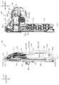
次いで、遊技盤13及び動作ユニット500の構造について説明する。図5は、遊技盤13及び動作ユニット500の分解正面斜視図であり、図6は、遊技盤13及び動作ユニット500の分解背面斜視図である。なお、図5及び図6では、背面ケース510の開口511aに配設される液晶表示装置(可変表示装置ユニット80)の図示が省略され、開口511aを通して奥側を視認可能に図示される。また、図5及び図6の説明においては、図2を適宜参照する。
Next, the structures of the
動作ユニット500は、底壁部511と、その底壁部511の外縁から立設される外壁部512とから正面側が開放された箱状に形成される背面ケース510を備える。背面ケース510は、底壁部511の中央に矩形状の開口511aが開口形成されることで、正面視矩形の枠状に形成される。開口511aは、第3図柄表示装置81の表示領域の外形(外縁)に対応した(即ち、第3図柄表示装置81の表示領域を正面視で区切ることが可能な)大きさに形成される。
The
背面ケース510は、外壁部512の正面側端部に遊技盤13の背面に沿う(例えば、平行に配置される)平面板として延設され、組立状態(図2参照)において遊技盤13を面支持する支持板部513を備える。
The
支持板部513は、遊技盤13のベース板60に形成される嵌合凹部(図示せず)と嵌合可能な形状で正面側へ向けて突設される位置決め凸部513aと、ベース板60に締結される締結ネジを挿通可能に穿設される複数の挿通孔513bとを備える。
The
ベース板60の嵌合凹部に位置決め凸部513aを嵌合させることによりベース板60に対して背面ケース510を位置決めし、締結ネジを挿通孔513bに挿通し、ベース板60に螺入することにより、遊技盤13と動作ユニット500とを一体的に固定することができるので、遊技盤13及び動作ユニット500の全体としての剛性の向上を図ることができる。
By fitting the positioning
なお、位置決め凸部513aの形状は何ら限定されるものではなく、種々の態様が例示される。例えば、ベース板60の嵌合凹部の内形(本実施形態では、円形または長円形)よりも若干小さな外形の凸部でも良いし、組み付け時の作業性を考慮して、嵌合隙間が大きくなるような形状(更に小さな外形)の突部でも良い。また、嵌合凹部の内形が矩形状に形成される場合には、それに対応して位置決め凸部513aの形状も矩形状とされることは当然想定される。
The shape of the positioning
遊技盤13は、上述のように、正面視略正方形状に切削加工したベース板60に、球案内用の多数の釘(図示せず)や風車(図示せず)の他、レール61,62、一般入賞口63、第1入賞口64、第2入賞口640、スルーゲート67、可変入賞装置65、ベース板60に開口される窓部60a(図90参照)に正面側から嵌合可能な形状で構成されるセンターフレーム86、遊技領域から排出された球が流下可能に構成される球流下ユニット150、第3図柄表示装置81の正面側へ向けて粒状部材320(図54参照)を発射可能に構成される発射演出ユニット300等を組み付けて構成され、その周縁部が内枠12(図1参照)の表面と対向配置され固定される態様で内枠12に取り付けられる。
As described above, the
ベース板60は、光透過性の樹脂材料から板状に形成されており、正面側からベース板60の背面側に配設された各種構造体を遊技者に視認させ易いように構成される。これにより、ベース板60の形状や配置に関わらず、その背面側に配設される構造体を視認させ、各種演出に利用することができる。
The
例えば、ベース板60の背面側に球流下ユニット150を配設する場合であっても、ベース板60が透けて奥側が見えるので、球流下ユニット150を流下している球を視認させることができる。本実施形態では、球流下ユニット150が、視認される球により奏する効果を考慮して設計されているが、詳細は後述する。
For example, even when the ball flow-down
なお、遊技者に対して見せたくない箇所がある場合には、光透過性の低い(又は光不透過の)シール部材を貼り付ける等して対処すれば良い。 If there is a part that the player does not want to see, a seal member having low light transmission (or light transmission) may be attached.
センターフレーム86は、ルータ加工によってベース板60に形成された貫通穴に配設され、遊技盤13の正面側からタッピングネジ等によりベース板60に固定される。
The
発射演出ユニット300は、粒状部材320(図54参照)を受け入れ、粒状部材320が飛散可能な範囲を区画する区画部材310がセンターフレーム86の内側に配置されることで、粒状部材320をセンターフレーム86の内側へ向けて発射可能とされる。そのため、センターフレーム86の内側窓部を通して第3図柄表示装置81の表示を視認する遊技者に対して、第3図柄表示装置81の正面側で飛散する粒状部材320を効果的に視認させることができる。なお、発射演出ユニット300の詳細については後述する。
The firing
動作ユニット500は、遊技盤13の背面側に配置され、各種発光手段や、各種動作ユニットが内部に配設されている。即ち、動作ユニット500は、背面ケース510と、その背面ケース510の内側上部に配設される拡大縮小ユニット600と、背面ケース510の内側左右部に左右対称で配設される変位回転ユニット800とを備える。
The
具体的には、拡大縮小ユニット600は、開口511aの上方位置において、変位回転ユニット800は、開口511aの左右位置において、それぞれ背面ケース510の底壁部511に配設される。まず、この動作ユニット500の動作制御の概要について説明する。
Specifically, the enlargement /
図7から図11は、動作ユニット500の動作制御の一例を時系列で示す動作ユニット500の正面図である。なお、図7では、演出待機状態の拡大縮小ユニット600及び変位回転ユニット800が図示され、図8では、張出状態の拡大縮小ユニット600と、演出待機状態の変位回転ユニット800とが図示され、図9では、拡大状態の拡大縮小ユニット600と、演出待機状態の変位回転ユニット800とが図示される。
7 to 11 are front views of the
また、図10では、演出待機状態の拡大縮小ユニット600と、演出上端状態の変位回転ユニット800とが図示され、図11では、左側の変位回転ユニット800は演出上端状態とされ、右側の変位回転ユニット800は演出下端状態とされる。
Further, in FIG. 10, the enlargement /
図7から図11に図示されるように、拡大縮小ユニット600の変位軌跡と変位回転ユニット800の変位軌跡とは正面視で部分的に重なる。そのため、例えば、変位回転ユニット800が演出上端状態(図10参照)の時に、拡大縮小ユニット600が演出待機状態から状態変化すると、衝突する可能性がある。
As shown in FIGS. 7 to 11, the displacement locus of the enlargement /
これに対して、本実施形態では、拡大縮小ユニット600の演出待機状態からの状態変化を、変位回転ユニット800が演出待機状態であることを条件として実行可能に制御したり、変位回転ユニット800の演出待機状態からの状態変化を、拡大縮小ユニット600が演出待機状態であることを条件として実行可能に制御したりすることで、拡大縮小ユニット600と変位回転ユニット800とが正面視で重なることを避けることができる。従って、拡大縮小ユニット600及び変位回転ユニット800の配置自由度を向上することができる(前後位置が重なることを許容できる)。
On the other hand, in the present embodiment, the state change of the enlargement /
図7から図9に示すように、拡大縮小ユニット600は、演出部材700が一箇所に集合配置された状態で下降変位可能に構成され、下降変位後に第3図柄表示装置81の表示領域の前方に配置された状態で演出部材700の構成部材が互いに離散して、正面視で視認される面積が大きくなるよう動作制御される(図9参照)。
As shown in FIGS. 7 to 9, the enlargement /
その後、拡大縮小ユニット600は、演出部材700が再び集合し(図8参照)、一箇所に集合配置された状態で上昇変位し、図7に示す演出待機状態に復帰するよう制御される。
After that, the enlargement /
図10及び図11に示す状態変化は、拡大縮小ユニット600が演出待機状態の時に実行される。図7、図10及び図11に示すように、変位回転ユニット800は、横スライド部材840が演出待機状態から、上下方向成分のみでは無く、左右方向成分を有する方向で変位可能に構成される。
The state change shown in FIGS. 10 and 11 is executed when the enlargement /
本実施形態では、後述の機構により設定される経路曲線S1に沿って横スライド部材840が変位する。経路曲線S1は、各中心点C1を中心とする円弧形状からなる共通円弧部S1aと、その共通円弧部S1aの下端から左右外側下方へ延びる進退経路部S1bとを備える。
In the present embodiment, the
図10では、左右一対の横スライド部材840が共通円弧部S1aの上端位置に配置されており、図11では、左側の横スライド部材840は共通円弧部S1aの上端位置に配置される一方、右側の横スライド部材840は共通円弧部S1aの下端位置よりも上側の位置に配置される。
In FIG. 10, a pair of left and right
そのため、図11に示す状態から、左側の横スライド部材840を下側へ変位させ、右側の横スライド部材840を上側へ変位させるよう制御すると、あたかも横スライド部材840が第3図柄表示装置81の中心寄りに配置される中心点C1を中心に回転変位しているかのように遊技者に視認させることができる。
Therefore, when the left
即ち、横スライド部材840を第3図柄表示装置81の表示領域と同等の大きさの回転演出体の一部として視認させることができ、横スライド部材840を利用した演出の演出自由度を向上することができる。
That is, the
図12(a)及び図12(b)は、図7のXIIa−XIIa線における遊技盤13及び動作ユニット500の断面図であり、図13(a)及び図13(b)は、図9のXIIIa−XIIIa線における遊技盤13及び動作ユニット500の断面図であり、図14は、図9のXIV−XIV線における遊技盤13及び動作ユニット500の断面図である。
12 (a) and 12 (b) are cross-sectional views of the
なお、図7及び図9では遊技盤13は図示されていないが、図12から図14では、遊技盤13が動作ユニット500の正面側に組み付いた状態(図2参照)が図示される。
Although the
また、図12(a)及び図13(a)では、粒状部材320が下方に滞留した状態の一例が図示され、図12(b)及び図13(b)では、粒状部材320が発射され飛散した状態の一例が図示される。
Further, FIGS. 12 (a) and 13 (a) show an example of a state in which the
拡大縮小ユニット600の演出部材700は、図12(a)及び図12(b)に示す演出待機状態では集合配置の中央部分が発射演出ユニット300の区画部材310よりも上側に配置され、区画部材310を通して第3図柄表示装置81の表示領域の大部分を視認可能に構成される。
In the effect standby state shown in FIGS. 12 (a) and 12 (b), the central portion of the collective arrangement of the
一方、図13(a)及び図13(b)に示す拡大状態では発射演出ユニット300の区画部材310の背後に演出部材700が近接配置され、演出部材700に目隠しされることで(図9参照)、第3図柄表示装置81の表示領域の大部分が視認不能に遮蔽される。
On the other hand, in the enlarged state shown in FIGS. 13 (a) and 13 (b), the
拡大縮小ユニット600の変位軌跡と、区画部材310とは干渉しないので、拡大縮小ユニット600の配置に関わらず、区画部材310に粒状部材320を発射する動作演出を実行するように発射演出ユニット300を制御することが可能である。
Since the displacement locus of the enlargement /
図12(a)に示すように、粒状部材320は第3図柄表示装置81の表示領域の下縁よりも下側に配置されており、前方へ向かうほど上昇傾斜する経路で発射されることで、区画部材310の前壁部に打ち付けられ、区画部材310により形成される範囲で跳ね返りながら上昇する。
As shown in FIG. 12A, the
これにより、遊技者に対して、粒状部材320が、あたかも自分の側へ向かって来るかのように見せることができるので、粒状部材320を利用した演出に対する注目力を向上することができる。
As a result, the
また、このように構成することにより、粒状部材320を飛散させる範囲を遊技者側へ寄せることができると共に、第1入賞口64(図2参照)等、遊技領域に配設される構成部材の配置自由度が低くなることを避けることができる。
Further, by configuring in this way, the range in which the
換言すれば、本実施形態の区画部材310へ向けて発射される粒状部材320の待機位置として、区画部材310の真下の位置や、前寄りの位置を採用することもできる。しかし、この場合、第1入賞口64の背面側のスペースに発射演出ユニット300が配設されるので、第1入賞口64に入球した球を流す案内経路の配設スペースを確保することが難しくなり、第1入賞口64の位置を移動させて対処することが必要となる虞がある。
In other words, as the standby position of the
これに対し、本実施形態では、区画部材310は最前面位置に配置し、粒状部材320の待機位置を斜め後方に配置することで、第1入賞口64の背面側のスペースを確保できるので、球の案内経路を問題なく配設することができ、第1入賞口64を自由に配置できないという事態が生じることを未然に防ぐことができる。
On the other hand, in the present embodiment, the
図12(a)に示す状態で、粒状部材320を発射する制御を行うと、図12(b)に示すように、区画部材310の内部で飛散する粒状部材320と第3図柄表示装置81の表示領域における表示とを合わせて遊技者に見せることができる。これにより、平面的な表示と、三次元的に変位する粒状部材320の動きとを組み合わせて遊技者に視認させることができる。
When the control for firing the
図13(a)に示す状態で、粒状部材320を発射する制御を行うと、図13(b)に示すように、区画部材310の内部における粒状部材320の飛散と、拡大縮小ユニット600の状態変化とを合わせて遊技者に見せることができる。この場合、例えば、粒状部材320の飛散のタイミングと、拡大縮小ユニット600の演出部材700が離散する態様で変位するタイミングとを合わせることで、状態変化する拡大縮小ユニット600の正面側で粒状部材320が飛び散る様子を視認させることができ、拡大縮小ユニット600の状態変化の迫力を強化することができる。
When the control for firing the
ここで、拡大縮小ユニット600の状態変化と合わせて演出する方法として、第3図柄表示装置81の表示を拡大縮小ユニット600の状態変化と合わせて切り替える方法も考えられる。
Here, as a method of producing the effect together with the state change of the enlargement /
しかし、本実施形態のように、第3図柄表示装置81が拡大縮小ユニット600の背面側に配置され、拡大縮小ユニット600により第3図柄表示装置81の表示領域の大部分が遮蔽される状況では、第3図柄表示装置81の表示を切り替えたとしても、その表示を見せ難く、効果的に演出することは困難であると考えられる。
However, as in the present embodiment, in a situation where the third
これに対し、本実施形態では、拡大縮小ユニット600の状態変化と合わせて動作演出する粒状部材320が飛散する範囲を形成する区画部材310の位置を、拡大縮小ユニット600の正面側に設けているので、拡大縮小ユニット600が第3図柄表示装置81の表示領域の大部分を遮蔽する状況においても、粒状部材320を遊技者に見せ難いということは無い。
On the other hand, in the present embodiment, the position of the
更に、粒状部材320を小形の部材で構成することにより、粒状部材320を大形の部材で構成する場合に比較して、拡大縮小ユニット600が、かえって見え難くなることを防止することができる。
Further, by forming the
従って、拡大縮小ユニット600により第3図柄表示装置81の表示領域の大部分が遮蔽されている状態においても、拡大縮小ユニット600の演出効果を向上させることができる。
Therefore, even when most of the display area of the third
また、粒状部材320の飛散を、拡大縮小ユニット600と組み合わせて視認させる演出は、そのまま粒状部材320の飛散を変位回転ユニット800と組み合わせて視認させる演出に利用できる。
Further, the effect of visually recognizing the scattering of the
即ち、変位回転ユニット800は、拡大縮小ユニット600と同様に、横スライド部材840が第3図柄表示装置81の表示領域から退避して配置される状態(演出待機状態、図7参照)と、横スライド部材840が第3図柄表示装置81の表示領域の正面側に配置される状態(演出下端状態、演出上端状態、図10及び図11参照)とで状態変化できるので、その状態に対応して、飛散する粒状部材320と第3図柄表示装置81の表示とを組み合わせて視認させる演出と、飛散する粒状部材320と変位回転ユニット800の横スライド部材840とを組み合わせて視認させる演出とを実行することができる。
That is, the
この場合、拡大縮小ユニット600では、演出部材700を離散させる態様の変位に合わせて粒状部材320を飛散させることで効果的に演出することができると説明したが、変位回転ユニット800では、回転可能に配設される羽状部材854の回転に合わせて粒状部材320を飛散させることで、羽状部材854の回転により空気の流れが生じている(空気の流れが生じるほどに羽状部材854が高速回転している)かのように視認させることができ、変位回転ユニット800の演出効果を向上することができる。
In this case, it has been explained that the enlargement /
このように、本実施形態によれば、粒状部材320の飛散を、第3図柄表示装置81の表示領域と組み合わせて視認させる演出と、拡大縮小ユニット600又は変位回転ユニット800と組み合わせて視認させる演出とに兼用することができる。
As described above, according to the present embodiment, the effect of visually recognizing the scattering of the
図14に示すように、発射演出ユニット300の一部であって変位回転ユニット800の横スライド部材840の真上に配置される第1光照射装置330の後端ラインBL1は、図14に示す断面上における変位回転ユニット800の前端ラインFL1よりも背面側に配置される。そのため、変位回転ユニット800の横スライド部材840の変位軌跡によっては(例えば、図14に示す状態から横スライド部材840が真上への変位を継続すると)、第1光照射装置330と変位回転ユニット800とが衝突する可能性がある。
As shown in FIG. 14, the rear end line BL1 of the first
これに対し、本実施形態では、進退経路部S1bを発射演出ユニット300と変位回転ユニット800との衝突を回避可能な経路として設定している。即ち、発射演出ユニット300の射出装置400と第1光照射装置330との間に斜め方向で設けられる隙間を通る経路として進退経路部S1bを設定することで、後端ラインBL1及び前端ラインFL1の設定自由度を向上することができると共に、後端ラインBL1を設定する第1光照射装置330を超えて上昇変位可能に構成されており、変位回転ユニット800の変位幅を大きく確保することができる。
On the other hand, in the present embodiment, the advance / retreat path portion S1b is set as a path that can avoid the collision between the
図13に示すように、演出部材700の変位時、演出部材700と区画部材310とは前後方向で近接配置される。遊技可能状態においては、演出部材700と区画部材310との間で間隔を確保できる程度に配置しているが、搬送時においてまで演出部材700と区画部材310との間に間隔を確保することまで考慮しているものでは無い。そのため、搬送時においては、演出部材700を変位範囲の上側終端位置に維持し、区画部材310と演出部材700とが近接配置されないように規制することが望ましい。
As shown in FIG. 13, when the
図6に戻って説明する。動作ユニット500は、背面ケース510に締結固定される変位規制装置180を備える。変位規制装置180は、背面ケース510の背面からの手動操作で状態変化可能に構成されており、規制状態において、拡大縮小ユニット600が演出待機状態から下降変位することを規制する。
It will be described back to FIG. The
変位規制装置180を採用することにより、本実施形態のように、ベース板60の中央の開口が閉塞される場合であっても、パチンコ機10の出荷や搬送を容易とすることができる。
By adopting the
詳述すると、従来、可動役物が変位する範囲に緩衝材(わた等のクッション部材)を詰めるなどして可動役物の変位を抑制し、遊技ホールに到着した後で緩衝材を抜き取るという手段により、出荷時や搬送時に可動役物が変位することを防止する場合があった。しかし、ベース板60の中央の開口部が本実施形態のように閉塞されていると(図12(a)参照)、緩衝材を抜き取るための貫通箇所が無いため、遊技盤13と背面ケース510とを分解しないと緩衝材を抜き取ることができず、遊技ホールの負担が多大となる可能性がある。
More specifically, conventionally, the cushioning material (cushion member such as cotton) is packed in the displacement range of the movable accessory to suppress the displacement of the movable accessory, and the cushioning material is removed after arriving at the game hall. As a result, it may be possible to prevent the movable accessory from being displaced at the time of shipment or transportation. However, if the central opening of the
この対策として、本実施形態では変位形成装置180を採用している。これにより、遊技盤13及び背面ケース510の固定を解除することなく、拡大縮小ユニット600の昇降変位を規制する規制状態と、その規制が解除される規制解除状態とで変位規制装置180の状態を切り替えることができる。以下、まず変位形成装置180の構成の詳細を説明し、その後で状態変化の詳細について説明する。
As a countermeasure, the
図15(a)は、変位規制装置180の背面斜視図であり、図15(b)は、変位規制装置180の正面斜視図であり、図15(c)は、変位規制装置180の正面斜視図である。
15 (a) is a rear perspective view of the
なお、図15(a)及び図15(b)では、規制解除状態の変位規制装置180が図示され、図15(c)では、規制状態の変位規制装置180が図示される。図15(a)から図15(c)で示すように、変位規制装置180は、当接部材181から円筒部183dが出没することにより、規制状態と規制解除状態とが切り替えられる。変位規制装置180の規制状態において、円筒部183dは、背面ケース510の内側まで張り出し、拡大縮小ユニット600の被規制孔657と係合可能に構成されるが、詳細は後述する。
In addition, FIG. 15A and FIG. 15B show the
図16は、変位規制装置180の分解背面斜視図であり、図17は、変位規制装置180の分解正面斜視図であり、図18(a)は、当接部材181の背面図であり、図18(b)は、案内部材182の正面図であり、図18(c)は、操作部材183の正面図である。
16 is an exploded rear perspective view of the
図16から図18に示すように、変位規制装置180は、背面ケース510(図6参照)に当接配置される当接部材181と、その当接部材181の背面側に配置され当接部材181に締結固定されると共に操作部材183を前後方向に案内する案内部材182と、その案内部材182に変位を案内される操作部材183と、その操作部材183と当接部材181との間に配設され操作部材181に背面側へ向く付勢力を付与可能に構成されるコイルスプリング184とを主に備える。
As shown in FIGS. 16 to 18, the
操作部材183が背面視で左右に長尺の略楕円形状から形成されることに伴い、操作部材183を収容する当接部材181や案内部材182も背面視で左右に長尺の略楕円形状から形成されるので、変位規制装置180の外観形状は、背面視で左右に長尺の略楕円形状となる。
As the operating
当接部材181は、背面ケース510との接触面積を大きくすることで保持力を高めるよう主に板状で設計されており、その板端から背面側へ向けて案内部材182を保持するための壁部が延設されており、左右端部において穿設され背面ケース510から突出する締結部が挿通される挿通孔181aと、コイルスプリング184を隙間に配置可能な形状の二重筒状で背面側へ突設される筒状保持部181bと、操作部材183との関係で周知のラッチ機構を構成し操作部材183と係合可能に構成される被係合部181cとを備える。
The
案内部材182は、当接部材181の外周に沿う楕円の環状で前後方向に延設される本体部182aと、挿通孔181aに挿通される締結部に螺入される締結ネジが挿通されるネジ挿通部182bと、当接部材181に挿通される締結ネジが螺入される締結部182cと、本体部182aの背面側端部において径方向内側に張り出す抜け止め部182dと、本体部182aの上下内側部において前後方向に亘って径方向内側に突設される突条182eとを備える。
The
本構成から、当接部材181と案内部材182とを締結固定することで、当接部材181と案内部材182との間に操作部材183を配置し、脱落不能に保持することができるが、本実施形態では、その締結方向の設定により、当接部材181と案内部材182とを分解可能な状況を限定している。
From this configuration, by fastening and fixing the
換言すれば、本実施形態では、当接部材181と案内部材182とを締結固定するための締結ネジを、当接部材182の正面側(背面ケース510により覆われる側)から挿通させる構成としているので、背面ケース510に変位規制装置180が組み付けられている状態では、締結ネジに触れることができない。従って、変位規制装置180を背面ケース510から取り外した状態でのみ当接部材181と案内部材182とを分解することができる。
In other words, in the present embodiment, the fastening screw for fastening and fixing the
なお、変位規制装置180を背面ケース510に締結固定するための締結ネジは、案内部材182の背面側からネジ挿通部182bに挿通されているので、背面ケース510の背面側が露出する状態(図19参照)において容易に触れることができ、変位規制装置180を背面ケース510から取り外すことを容易とすることができる。
Since the fastening screw for fastening and fixing the
操作部材183は、案内部材182の抜け止め部182dよりも若干小さな楕円形で背面視外形が形成され正面側が開放されるカップ状に形成される本体部183aと、その本体部183aの前縁部から径方向外方へ張り出すフランジ部183bと、そのフランジ部183bに凹設される溝部183cと、本体部183aの底部中央から正面側へ円筒状に突設される円筒部183dと、その円筒部183dを中心としてコイルスプリング184の外径よりも大径の円弧形状で正面側に突設される円弧形状突条部183eと、当接部材181の被係合部181cに係合可能な位置に突設され、被係合部181cとの関係で周知のラッチ機構を構成可能とされる係合部183fとを備える。
The
操作部材183の板背面には、楕円形状のシールが貼り付けられている。このシールは、短手方向の端部の一方に凹形状が形成されており(図15(a)参照)、この凹形状を上向きに配置することで、組み付け時における上下姿勢間違いを容易に防止することができる。
An oval-shaped sticker is attached to the back surface of the plate of the operating
本体部183aを楕円形とすることにより、操作部材183が回転変位することを容易に防止することができる。即ち、操作部材183が回転変位しそうになっても、案内部材182の本体部182aと当接することで回転が規制される。
By making the
フランジ部183bは、案内部材182の抜け止め部182dよりも背面視で大きく形成されており、これにより操作部材183が案内部材182から抜け落ちることを防止することができる。即ち、操作部材183は、フランジ部183bが当接部材181と案内部材182との間に保持された状態において前後方向に変位可能とされる。
The
溝部183cは、案内部材182の突条182eと対応する位置に形成されており、操作部材183の前後変位を滑らかに行わせる役割がある。なお、本実施形態では、突条182eが上側に2箇所、下側に1箇所で形成されていることに伴い、溝部183cも上側に2箇所、下側に1箇所で形成される。これにより、操作部材183の上下を間違えて行う誤組立を防止することができる。
The
円筒部183dは、コイルスプリング184の巻き中心に挿通される部分であって、当接部材181の筒状保持部181bの中央開口に挿通可能に構成される。円筒部183dが当接部材181の中央開口から張り出した状態では、後述するように、円筒部183dは拡大縮小ユニット600の被規制孔657と係合し、演出部材700の昇降変位を規制する。
The
即ち、本実施形態では、円筒部183dを、拡大縮小ユニット600の演出部材700の昇降変位を規制する部分と、コイルスプリング184を支持する部分とで兼用することができる。
That is, in the present embodiment, the
円弧形状突条部183eは、コイルスプリング184の外径側と対向配置可能に配設され、当接部材181の筒状保持部181bの大径側筒状部と前後方向で対向配置される。操作部材183が押し込み操作される際には、他の部分に先行して円弧形状突条部183eと筒状保持部181bとが当接するので、負荷発生面積を増やすことができ、局所的に大負荷が生じることを防止することができる。
The arc-shaped
円弧形状突条部183eは、円状では無く、円が途切れた円弧状に形成され、その途切れた位置において係合部183fが配設される。これにより、係合部183fと、円筒部183d及びコイルスプリング184とが離れすぎることを回避することができる。
The arc-shaped
操作部材183の状態変化について説明する。操作部材183には、コイルスプリング184により背面側へ付勢されているところ、この付勢力に抗して操作部材183を正面側へ押し込むと、係合部183fと被係合部181cとで構成されるラッチ機構が作用し、ラッチ機構が作用する最小ストローク以上で押し込む度に、上述した規制状態と、規制解除状態とで交互に切り替えられる。
The state change of the operating
このように、ラッチ機構により状態変化可能に構成されているので、操作部材183が意図的に操作された場合に限らず、パチンコ機10に大きな外力が与えられることで操作部材183が上述の最小ストローク分だけ変位してしまうと、意図せず変位規制装置180が状態変化する虞がある。
As described above, since the state can be changed by the latch mechanism, the operating
例えば、変位規制装置180の規制状態において、出荷時の衝撃や、搬送時の振動で、意図せずに変位規制装置180に状態変化が生じると、拡大縮小ユニット600が演出待機状態(演出部材700が上側変位終端に配置される状態)から変位する可能性がある。演出待機状態から変位した演出部材700が区画部材310に近接配置された状態(図13参照)で、出荷時の衝撃や搬送時の振動を受けると、演出部材700が発射演出ユニット300の区画部材310に衝突する虞があり、演出部材700や区画部材310が破損する虞がある。
For example, in the regulated state of the
これに対し、本実施形態では、操作部材183に対して付勢力が加えられる位置(中央位置)から離れた位置(右側に偏心した位置)に係合部183fが配置されていると共に、操作部材183の溝部183cと案内部材182の突条182eとの隙間寸法が大きく設定され、操作部材183の姿勢維持能力を敢えて下げて構成される。
On the other hand, in the present embodiment, the engaging
これにより、案内部材182に対する操作部材183の姿勢を予め傾斜させておくことができることから、操作部材183の変位抵抗を増加させておくことができる。従って、意図しない外力により操作部材183が前後方向に変位する変位量を抑制することができる。
As a result, the posture of the operating
変位規制装置180の動作ユニット500との関係について説明する。図19は、正面枠14を開放した状態におけるパチンコ機10の正面斜視図であり、図20は、遊技盤13及び動作ユニット500の背面図であり、図21(a)及び図21(b)は、図20のXXIa−XXIa線における遊技盤13及び動作ユニット500の断面図である。
The relationship between the
なお、図21(a)では、変位規制装置180の規制状態が図示され、図21(b)では、変位規制装置180の規制解除状態が図示される。
Note that FIG. 21 (a) shows the regulated state of the
図19に示すように、変位規制装置180は、内枠12の開閉基端側(左側)に配置されており、裏パック92を内枠12に対して開放することにより作業者が手を延ばせば触れられるよう構成される。この位置は、内枠12を開放して作業を行う作業者が進入する側(開閉先端側、右側)の反対側であるので、内枠12の開放時に、作業者が意図せず変位規制装置180に触れることを回避することができる。
As shown in FIG. 19, the
図21(a)及び図21(b)に示すように、上述のラッチ機構を構成する係合部183f及び被係合部181cは、変位規制装置180の右側部に形成されている。操作部材183は緩い支持とされているので、操作部材183を押しこむ負荷の全てが操作部材183の前後移動に使用されるものでは無く、操作部材183の姿勢変化にも使用される。
As shown in FIGS. 21 (a) and 21 (b), the engaging
例えば、操作部材183の右側を押し込んだ場合に、右側部は十分に前後移動するとしても、操作部材183が姿勢変化して、左側部が十分に押し込まれないという事態が十分生じ得る。
For example, when the right side of the operating
そのため、変位規制装置180を押し込んで状態の切り替えを行う目的からすれば、作業者は、ラッチ機構の形成部をピンポイントで押し込む方が、変位規制装置180に必要な変位を生じさせ易く、変位規制装置180の状態切り替えに成功し易いといえる。
Therefore, for the purpose of pushing the
本実施形態では、上述のように、ラッチ機構を構成する係合部183f及び被係合部181cは、変位規制装置180の右側部に形成されており、作業者は右側から進入して変位規制装置180を操作するので、作業者は最小限の動作で変位規制装置180に到達することができる。従って、作業者は、ラッチ機構の形成部をピンポイントで押し込む操作を容易に実行することができる。
In the present embodiment, as described above, the engaging
また、操作部材183を押し込む際の姿勢変化は、押し込まれる側へ押圧面(円筒部183dの基端側に形成される面)を向ける態様で生じる。従って、押し込み量が大きくなるにしたがって、作業者の押し込み負荷が操作部材183に伝達され易く構成することができる。
Further, the posture change when the operating
図21(a)に示す規制状態では、操作部材183の円筒部183dが、伝達ギア650の被規制孔657に挿通され、伝達ギア650の変位を規制している。これにより、拡大縮小ユニット600の状態が変化することを防止することができる。
In the regulated state shown in FIG. 21A, the
伝達ギア650の変位方向(前後方向軸を中心とした回転方向)と、操作部材183の変位方向(前後方向)とは直交しているので、伝達ギア650から操作部材183が変位方向の負荷を受けることを防止することができる。これにより、ラッチ機構の形成部を強固な構成とせずとも、伝達ギア650の変位を有効に規制することができる。
Since the displacement direction of the transmission gear 650 (rotational direction centered on the front-rear axis) and the displacement direction of the operation member 183 (front-rear direction) are orthogonal to each other, the
このように、変位規制装置180を規制状態とすることで、拡大縮小ユニット600の状態を維持することができることから、変位規制装置180の用途は、搬送時に限られるものでは無い。例えば、遊技機店に設置後、メンテナンス時において、変位規制装置180を規制状態として拡大縮小ユニット600の状態を維持することで、後述する変位回転ユニット800のメンテナンスを安全簡易に行うことができる。
As described above, by setting the
即ち、本実施形態のように、拡大縮小ユニット600の変位軌跡と、変位回転ユニット800の変位軌跡とが部分的に重なる場合において、変位回転ユニット800のメンテナンス作業中に拡大縮小ユニット600の駆動モータMT2を誤動作させてしまったとしても、変位規制装置180により拡大縮小ユニット600の状態(配置)を維持することができるので、拡大縮小ユニット600と変位回転ユニット800とが衝突することを防止することができる。
That is, when the displacement locus of the enlargement /
パチンコ機10に電源が投入される前において、変位規制装置180が規制状態である場合には、変位規制装置180の操作部材183を押し込み操作することで、変位規制装置180が規制解除状態に切り替えられる(図21(b)参照)。これにより、伝達ギア650は変位可能となり、拡大縮小ユニット600に状態変化を伴う演出動作を実行させることができる。
If the
ここで、電源投入前に、正面枠14及び内枠12を外枠11に対してわずかに開放し、開放先端側(右側)から覗き込むことで、変位規制装置180が規制解除状態となっているかを確認可能に構成されることについて説明する。
Here, before the power is turned on, the
図21(a)に示すように、変位規制装置180の規制状態では、操作部材183が背面ケース510の底壁部511の形状部よりも前側に配置されているので、右側から覗き込む方向視において、操作部材183が底壁部511の形状部に隠される。
As shown in FIG. 21 (a), in the regulated state of the
一方、図21(b)に示すように、変位規制装置180の規制解除状態では、操作部材183が背面ケース510の底壁部511の形状部よりも背面側に張り出して配置されているので、右側から覗き込む方向視において、操作部材183が底壁部511からはみ出す位置に視認される。
On the other hand, as shown in FIG. 21B, in the deregulated state of the
従って、作業者は、電源投入前の確認作業として、正面枠14及び内枠12を外枠11に対して全開にしなくても、正面枠14及び内枠12を外枠11に対してわずかに開放し、右側から覗き込む方向視において、操作部材183が底壁部511からはみ出していることを視認することで、変位規制装置180が規制解除状態となっていることを確認することができる。
Therefore, as a confirmation work before turning on the power, the operator does not have to fully open the
なお、本実施形態では、背面ケース510が無色透明の樹脂材料から形成され、操作部材183が赤色透明の樹脂材料から形成されているので、操作部材183の視認性を向上することができる。
In the present embodiment, since the
ここで、変位規制装置180の規制状態において拡大縮小ユニット600の伝達ギア650の被規制孔657に円筒部183dが挿通されたまま(図21(a)参照)、電源投入された場合について説明する。本実施形態では、変位規制装置180が規制状態のままパチンコ機10の電源が投入された場合、電源導入時動作において拡大縮小ユニット600が状態変化していないことが検出センサSC7(図52参照)の出力から判定され、この判定に伴う位置検出エラー表示が第3図柄表示装置81により表示される。
Here, a case where the power is turned on with the
この位置検出エラー表示を遊技機店の店員に見せることで、変位規制装置180の状態を変化させていないかもしれないことに気付かせることができる。なお、このエラー表示は、拡大縮小ユニット600の状態変化の有無の検出により表示されるものであり、変位規制装置180の状態を検出したものでは無い。
By showing this position detection error display to the clerk of the gaming machine store, it is possible to notice that the state of the
即ち、本実施形態では、追加のエラー表示のためのプログラムや、表示素材を用意することなく、拡大縮小ユニット600に通常備えられる位置検出エラー表示を利用して変位規制装置180の状態に関する警報を出力することができる。これにより、設計コストの低減を図ることができる。
That is, in the present embodiment, an alarm regarding the state of the
なお、本実施形態では、変位規制装置180の規制状態において拡大縮小ユニット600の伝達ギア650の被規制孔657に円筒部183dが挿通されたまま(図21(a)参照)、電源を投入した場合に、電源投入中は操作部材183の押し込み操作を不能に構成され、一端電源をオフすることを要求されるが、必ずしもこれに限られるものではない。例えば、電源投入中においても操作部材183の操作が可能に構成されても良い。
In the present embodiment, the power is turned on while the
また、操作部材183の押し込み操作を不能にする構成は任意に設定可能である。例えば、伝達ギア650と操作部材183との間で生じる摩擦により押し込み操作を不能とする構成でも良いし、操作部材183の円筒部183dの基端側に大径部を設け、伝達ギア650の変位中においては、伝達ギア650の板背面と、円筒部183dの大径部とが前後で係合し、操作部材183の変位を制限するように構成しても良い。
Further, the configuration for disabling the pushing operation of the operating
異なるシチュエーションとして、遊技機店でのメンテナンス中に変位規制装置180の操作部材183を押し込み操作する場合の一例について説明する。本実施形態では、操作部材183の押し込み操作は、拡大縮小ユニット600の被規制孔657が円筒部183dと前後で合致する場合においてのみ可能であるものではない。
As a different situation, an example will be described in which the operating
例えば、メンテナンスの際に、拡大縮小ユニット600を張出状態(図8参照)としながら操作部材183を押し込み操作した場合でも、変位規制装置180は規制状態に状態変化する。この場合、拡大縮小ユニット600の伝達ギア650の変位軌跡上に円筒部183dが配置されることになるので、メンテナンス終了後に駆動力が生じ伝達ギア650が変位する場合に、その変位が円筒部183dに制限される。
For example, even when the
本実施形態では、伝達ギア650の変位が制限されていることを判定可能に構成されており、この判定に基づきエラー表示(異常の報知)を行うことで、変位規制装置180が規制状態のままであることを遊技機店の店員に報知することができるが、詳細は後述する。
In the present embodiment, it is possible to determine that the displacement of the
これにより、変位規制装置180の状態を検出する装置を別途設けなくても、拡大縮小ユニット600の状態を検出する装置を流用して変位規制装置180の状態を判定することができる。
Thereby, even if a device for detecting the state of the
なお、変位規制装置180の操作は、遊技盤13及び動作ユニット500を内枠12に組み付ける前でも、組み付けた後でも実行可能である。内枠12に組み付けた後においては、内枠12を開放するだけでなく、裏パック92を内枠12に対して開放する作業を要するので、可能であれば内枠12に組み付ける前に変位規制装置180の操作を行っておくことが好ましい。
The operation of the
図5及び図6に戻って説明する。本実施形態では、第3図柄表示装置81の他に、遊技を盛り上げる演出装置として、上述の発射演出ユニット300、拡大縮小ユニット600及び変位回転ユニット800が配設される。これら演出装置について、発射演出ユニット300から順に説明する。
A description will be given by returning to FIGS. 5 and 6. In the present embodiment, in addition to the third
図22は、遊技盤13及び発射演出ユニット300の分解正面斜視図であり、図23は、遊技盤13及び発射演出ユニット300の分解背面斜視図である。図22及び図23に示すように、発射演出ユニット300は組立状態において、区画部材310が導光板161に対向配置される。即ち、遊技者に対して、導光板161と区画部材310とを重ねて視認させる演出を実行することができる。
FIG. 22 is an exploded front perspective view of the
区画部材310は、無色で光透過性の樹脂材料から形成されているので内部で飛散する粒状部材320を遊技者に視認させることができ、センターフレーム86で囲まれる範囲を視認する遊技者に対して、導光板161と飛散する粒状部材320とを重ねて視認させる演出を実行することができる。
Since the
図24は、発射演出ユニット300の分解正面斜視図であり、図25は、発射演出ユニット300の分解背面斜視図である。図24及び図25では、区画部材310が分解して図示される。
FIG. 24 is an exploded front perspective view of the firing
図24及び図25に示すように、発射演出ユニット300は、センターフレーム86(図22及び図23参照)の内方に配置され下側が開放された箱形状を形成する区画部材310と、その区画部材310の内部を変位可能に配置される複数の粒状部材320と、その粒状部材320が区画部材310から脱落しないよう下側の開放部分を塞ぐ態様で配設される射出装置400と、区画部材310の右側に配設される第1光照射装置330と、区画部材310の左側に配設される第2光照射装置340と、を備える。
As shown in FIGS. 24 and 25, the firing
区画部材310は、光透過性の樹脂材料から形成され、最前面に配置される板状部である前面板部311と、その前面板部311の下方に一体的に形成される湾曲板部312と、前面板部311の背面側に前面板部311と平行な関係の底板部が対向配置され、その底板部の左右および上部から空隙を塞ぐように前面側へ延設される閉塞壁を有する背面区画部313と、その背面区画部313の下方に一体的に形成され、前面板部311と背面区画部313との間に構成される内部空間IE1(図12(a)参照)に連通する経路を湾曲板部312との間で構成可能とされる背面区画下部314と、その背面区画下部314に貫通形成される異形貫通部315と、を備える。
The
区画部材310の大きさは何ら限定されるものでは無いが、本実施形態では、センターフレーム86の内側において導光板161を囲む窓部の大きさと、区画部材310の正面視の大きさとが同程度となるように形成される。即ち、導光板161と前面板部311とが略同一形状となるように形成される。
The size of the
これにより、導光板161の縁部を隠すための構成部材を、区画部材310の縁部を隠す用途で兼用することができる。区画部材310の縁部を隠すための専用の構成部材を不要とし、部材個数の削減を図りながら、区画部材310の縁部が第3図柄表示装置81による表示に重なって視認されることにより表示が分断される事態の発生を避けることができるので、第3図柄表示装置81による表示の視認性を維持することができる。
As a result, the constituent member for hiding the edge portion of the
内部空間IE1は、粒状部材320が飛散可能な範囲としての役割を持つが、この空間が広すぎると、粒状部材320が散らばりすぎて、迫力のある演出のために粒状部材320の個数を非常に多くする必要が生じる。そのため、ある程度狭い空間として形成するほうが、少数の粒状部材320を密度高く視認させることで迫力のある演出を実行できる。
The internal space IE1 has a role as a range in which the
一方で、空間を狭くし過ぎると、粒状部材320の詰まりを生じる虞がある。これに対し、本実施形態では、内部空間IE1の前後幅は、湾曲板部312の左右中央部312bと背面区画下部314との間の前後幅と同程度で確保される。そのため、前後幅が短縮される場合に比較して、内部空間IE1における粒状部材320の詰まりや、射出時の急激な減速を回避することができる。
On the other hand, if the space is made too narrow, the
更に、湾曲板部312の左右部312aが左右中央部312bよりも背面区画下部314に近接配置されることから、左右中央部312b付近における粒状部材320の移動経路に比較して、左右部312b付近における粒状部材320の移動経路を狭くすることができる。
Further, since the left and
即ち、射出装置400により粒状部材320が内部空間IE1へ射出される場合に、粒状部材320の移動経路が左右中央部312b付近に集中するようにすることができ、粒状部材320が内部空間IE1の中央部付近に到達し易くすることができる。これにより、粒状部材320を遊技者に視認させ易くすることができる。
That is, when the
加えて、粒状部材320が内部空間IE1の中央部付近に到達した後は、粒状部材320は前面板部311と衝突し、内部空間IE1を飛散する。これにより、遊技者に対して、あたかも内部空間IE1の中央部付近から粒状部材320が爆発して四方八方に飛散しているかのように視認させることができるので、粒状部材320の動作演出の迫力を向上することができる。
In addition, after the
湾曲板部312は、内部空間IE1に射出された粒状部材320が落下する際に、その粒状部材320を受け止める部分とし機能する。この観点で、湾曲板部312は、本実施形態では、背面側へ向かうほど下降傾斜し、左右中央へ向かうほど下降傾斜するように設計される。
The
これにより、粒状部材320が内部空間IE1のどこに配置されたかに関わらず、自重で下降変位する粒状部材320を左右中央側へ寄せつつ、背面側下方へ向けて変位させることができる。
As a result, regardless of where the
更に、湾曲板部312の左右部312aにおける下降傾斜の度合いは、背面側へ向けた下降傾斜に比較して、左右中央側へ向けた下降傾斜の方が急激となるように構成されている。これにより、粒状部材320の下降変位の傾向として、背面側へ向かう変位に優先して左右中央側へ向かう変位を生じさせることができる。そのため、後述する射出装置400の構成から粒状部材320が密集し易い左右端位置において粒状部材320が一斉に背面側へ変位しようとして、粒状部材320が下降変位の途中で滞留する(詰まる)という事態の発生を回避することができる。
Further, the degree of downward inclination of the
加えて、湾曲板部312の左右中央部312bにおける背面側へ向けた下降傾斜の度合いは、湾曲板部312の左右部312aにおける左右中央側へ向けた下降傾斜の度合いに比較して急激となるように構成されている。これにより、粒状部材320が流下途中で密集することを避け易くすることができる。
In addition, the degree of downward inclination of the
これに対し、背面区画下部314は、湾曲板部312の背面側に対向配置される板部が、湾曲板部312の左右中央部312bと側面視(図12(a)参照)で同程度(若干、正面側へ向かう程に左右中央部312bとの間隔が広くなる態様、即ち、水平方向に対する角度が大)の傾斜角度の平板状に形成される。
On the other hand, in the rear compartment
本実施形態では、背面区画下部314の上下方向に対する傾斜角度は、粒状部材320を射出する衝突部材420の変位方向の上下方向に対する傾斜角度と同等(若干、大きい角度)とされる。
In the present embodiment, the inclination angle of the
そのため、左右に変化し得る粒状部材320の射出方向に寄らず、背面区画下部314に対する粒状部材320の入射角が同じになるので、背面区画下部314から粒状部材320に与えられる抵抗をほぼ均一とすることができる。
Therefore, the incident angle of the
異形貫通部315は、蓋部材480を挿入可能な形状で形成されており、左右両端において上下に延びる短尺部と、その短尺部の上端同士を結ぶ態様で左右に湾曲して延びる長尺部とを備える。貫通方向は、背面区画下部314の板面に対し背面側から正面側へ向かうにつれて斜め上向きに傾斜して形成される(図12(a)参照)。これにより、異形貫通部315を構成する背面区画下部314の鋭角部分(図12(a)において、異形貫通部315の下側部分)は、粒状部材320の射出方向と対向配置されない。
The deformed penetrating
これにより、粒状部材320の射出時に、粒状部材320が鋭角部分に衝突する可能性を低くすることができるので、粒状部材320や背面区画下部314に局所的な負荷が生じることを回避でき、粒状部材320や背面区画下部314に割れや欠けが生じることを防ぐことができる。
As a result, it is possible to reduce the possibility that the
粒状部材320は、図24及び図25に拡大して図示されるように、比較的柔軟(少なくとも区画部材310を形成する樹脂材料よりも柔軟)な樹脂材料から略サッカーボール形状(12の正五角形と20の正六角形からなる32面体であり、準正多面体)に形成され、互いに平行な複数の直線に沿って非貫通で凹設される非貫通凹部321を備える。
The
この非貫通凹部321により、粒状部材320の軽量化を図ることができると共に、粒状部材320の重心を形状的な中心位置から偏らせることができる。即ち、非貫通凹部321が形成される直線方向において、非貫通凹部321が形成されていない側には肉部が残るので、非貫通凹部321が形成されていない側に重心を偏らせることができる。
The
これにより、粒状部材320の待機姿勢を調整することができる。即ち、粒状部材320の待機姿勢を、非貫通凹部321が上方を向く姿勢に調整することができる(図24参照)。
Thereby, the standby posture of the
この場合、射出装置400からの負荷を、非貫通凹部321が形成されていない側の面(図25参照)で受けることができるので、粒状部材320の破損や欠けを回避し易くすることができる。更に、射出装置400から負荷を受けて射出される際の射出方向側に非貫通凹部321を向けることになるので、非貫通凹部321が形成される側の面を前面板部311に衝突させることができる。これにより、前面板部311との衝突時の負荷を粒状部材320の変形により吸収し易くすることができ、前面板部311を傷付ける可能性を低くすることができる。
In this case, since the load from the
第1光照射部330は、背面区画部313の背面側に締結固定される固定板部331と、その固定板部331の右側に締結固定される電飾基板332と、その電飾基板332の右側に配設され固定板部331に締結固定され固定板部331との間に電飾基板332を収容可能に形成される蓋部333と、を備える。
The first
電飾基板332は、左右両面にLED等の光照射部332aが配設され、光照射部332aから左右方向へ光軸を有する光が照射される。固定板部331及び蓋部333は、光透過性の低い樹脂材料から形成され、光照射部332aに対応する位置に貫通孔331a,333aが穿設される。これにより、粒状に分割された光として視認させることができる。
The
電飾基板332から照射される光の内、右側へ照射される光は、スルーゲート67等(図2参照)が配設される遊技領域の右側経路(右打ち流路)を照らすことが一つの目的となる。左側へ照射される光については後述する。
Of the light emitted from the illuminated
固定板部331及び蓋部333は、光透過性の低い(又は光不透過の)樹脂材料から形成され、光照射部332aに対応する位置に貫通孔331a,333aが穿設される。これにより、光照射部332aから照射される光を、粒状に分割された光として視認させることができると共に、光照射部332aから離れた範囲において電飾基板332が固定板部331及び蓋部333により遮蔽され、視認されることを避けることができる。
The fixing
第2光照射部340は、背面区画部313の背面側に締結固定される固定板部341と、その固定板部341の左側に締結固定される電飾基板342と、その電飾基板342の左側に配設され固定板部341に締結固定され固定板部341との間に電飾基板342を収容可能に形成される蓋部343と、を備える。
The second
固定板部341は光透過性の低い(又は光不透過の)樹脂材料から形成される一方で、蓋部343は、無色で光透過性の樹脂材料から形成される。そのため、左方向から視認すると電飾基板342が見えてしまう構成であるが、本実施形態では、センターフレーム86(図2参照)の左側部が左方へ長く張り出して構成される。これにより、遊技者の視界を予め狭めることができ、正面視で電飾基板342の左側面が視認されることを避けることができる。
The fixing
これにより、電飾基板342が視認されることは避けながら、透明な蓋部343を通して光を照射することができる。
As a result, light can be emitted through the
電飾基板342は、左右両面にLED等の光照射部342aが配設される。左側面に配設される光照射部342aからは、前方向へ向く光軸を有する光が照射される。この光は、遊技領域の左側経路を照らさないようにしつつ、センターフレーム86の左側部を照らすことが一つの目的となる。
The illuminated
ここで、右側の電飾基板332の光照射部342aから照射される光を遊技領域に積極的に向ける構成と違う構成を採用しているのは、本パチンコ機10の遊技性(通常時は左打ちで遊技を行い、確変中、時短中および大当たり遊技中は右打ちで遊技を行うこと)を考慮したものである。これについて以下で説明する。
Here, it is the playability of the pachinko machine 10 (normally, that is different from the configuration in which the light emitted from the
本パチンコ機10の遊技領域は、遊技領域の左側部における球の流下経路の自由度は高いので、通常時の遊技中には、好みの経路で球が流下するように球の発射強度を調整するという操作が遊技者により行われる。そのため、遊技領域の左側部における発光強度を高くし過ぎると、球の視認性が悪くなり、球の発射強度調整に支障をきたし、遊技者の不満の原因となる虞がある。
In the game area of the
一方で、遊技領域の右側部へ球を発射する際、基本的には、遊技者は球を最大の発射強度で打ち出す。発射された球は、返しゴム69で勢いが抑えられ、その下流側での球の流下経路の選択自由度は著しく低くなり、専ら同様の経路を通るようになる。
On the other hand, when launching a ball to the right side of the game area, the player basically launches the ball with the maximum firing intensity. The momentum of the launched ball is suppressed by the
詳述すると、本実施形態では、第2入賞口640よりも下流側において球が1個通る幅で単一の案内経路DL1(図2参照)が形成されており、第2入賞口640に入球しなかった球は全て案内経路DL1を通り、その下流側に配置される可変入賞装置65や一般入賞口63へ向かうことになる。
More specifically, in the present embodiment, a single guide path DL1 (see FIG. 2) is formed with a width through which one ball passes on the downstream side of the second winning
このように、球の発射強度を調整する必要性が乏しいことから、遊技領域の右側部(特に、案内経路DL1が形成される箇所)において球の視認性が悪くなったとしても遊技に支障をきたす可能性が低いので、この範囲においては発光強度の高い演出を実行可能となる。 In this way, since there is little need to adjust the firing intensity of the ball, even if the visibility of the ball deteriorates in the right side of the game area (particularly, the place where the guide path DL1 is formed), the game is hindered. Since it is unlikely to occur, it is possible to perform an effect with high emission intensity in this range.
このような事情から、本実施形態では、右側に配置される電飾基板332では、遊技領域に光を向けるように光照射部332aを配設する一方で、左側に配置される電飾基板342では、遊技領域に光を向けないように光照射部342aを配設するようにしている。これにより、遊技者の不満の発生を抑えながら、効果的な発光演出を実行することができる。
Under these circumstances, in the present embodiment, in the illuminated
右側面に配設される光照射部342aからは、右方へ向く光軸を有する光が照射される。固定板部341には、光照射部342aに対応する位置に貫通孔341aが穿設される。これにより、光照射部342aから照射される光を、粒状に分割された光として視認させることができると共に、光照射部342aから離れた範囲において電飾基板342が固定板部341により遮蔽され、視認されることを避けることができる。なお、右側面に配設される光照射部342aにより照らされる対象については後述する。
Light having an optical axis pointing to the right is emitted from the
図26(a)は、図25の矢印R方向視における第1光照射装置330の側面図であり、図26(b)は、図25の矢印L方向視における第2光照射装置340の側面図である。図26(a)及び図26(b)では、区画部材310の外形が想像線で図示される。
26 (a) is a side view of the first
図26(a)に示すように、第1光照射装置330の左面側に配設される光照射部332aは、区画部材310を光軸が通過するLEDと、区画部材310の背面側を光軸が通過するLEDとを備える。
As shown in FIG. 26A, the
これにより、区画部材310の内部で粒状部材320に光を照射する演出だけでなく、区画部材310の背面側に配置される他の可動手段(拡大縮小ユニット600や変位回転ユニット800)に光を照射する演出を実行することができる。
As a result, not only the effect of irradiating the
図26(b)に示すように、第2光照射装置340の右面側に配設される光照射部342aは、区画部材310を光軸が通過するLEDは無く、区画部材310の背面側を光軸が通過するLEDのみにより構成される。
As shown in FIG. 26B, the
これにより、区画部材310の内部への発光強度を抑制しながら、区画部材310の背面側に配置される他の可動手段(拡大縮小ユニット600や変位回転ユニット800)へ向けた光の照射強度を向上させることができる。
As a result, while suppressing the intensity of light emission to the inside of the
第2照射装置340において、区画部材310の内部への発光強度を抑制することにより、通常状態での遊技の快適性を向上することができる。即ち、通常状態での遊技において、遊技者の視線は固定されるものではないが、主に遊技領域の左側や、第3図柄表示装置81の表示または第1入賞口64付近に向けられるので、遊技領域の中央から左側の範囲を見ていることが多い。
In the
この場合において、第2照射装置340から区画部材310の内部へ光が照射されると、遊技領域と同程度に前寄りの位置で光ることから、遊技領域の左側を視認する遊技者にとっては逆光となり、遊技者にとって遊技領域の視認性が悪くなる虞がある。
In this case, when the inside of the
これに対し、本実施形態では、第2照射装置340の光照射部342aの配置を背面側に寄せ、遊技領域と光照射部342aとを離しているので、光照射部342aから照射される光が遊技領域の視認性に与える影響の度合いを弱めることができる。
On the other hand, in the present embodiment, since the arrangement of the
このように、本実施形態によれば、第2照射装置340の光照射部342aから照射された光が遊技領域を光らせる度合いを下げながら、正面視におけるセンターフレーム86の内側を高強度に光らせる発光演出を実行することができる。従って、遊技領域の視認性を下げることなく、拡大縮小ユニット600や変位回転ユニット800(図5参照)を光らせる演出を実行することができる。
As described above, according to the present embodiment, the light emitted from the
図27は、図2のXXVII−XXVII線における遊技盤13及び発射ユニット300の断面図である。即ち、図27では、遊技盤13及び発射ユニット300が図示され、動作ユニット500の図示は省略されている。また、第1光照射装置330や第2光照射装置340から照射される光の方向が模式的に矢印で図示される。
FIG. 27 is a cross-sectional view of the
図27に示すように、第2光照射装置340は、導光板161へ光を照射する後述する縦置き基板ユニット167を避けて、縦置き基板ユニット167の左側かつ背面側に配置されている。これにより、導光板161に光照射部342aからの光が入射することを避けて発光演出を行うことができるので、光照射部342aから照射される光で行う光演出と、導光板161を光らせる演出とを切り分けることができる。
As shown in FIG. 27, the second
本実施形態のように導光板161を採用する場合、光の照射経路によっては、意図せず導光板161が発光してしまい、演出効果を下げる虞がある。特に、導光板161周辺(例えば、センターフレーム86の前側)に照射された光は導光板161を光らせやすいことから、発光強度を抑える必要性が生じる虞があり、演出自由度を下げる原因になっていた。
When the
これに対し、本実施形態によれば、光照射部342aからの光が導光板161を避けて進行するよう構成されるので、光照射部342aからの光の照射強度の設定自由度を向上することができる。これにより、導光板161周辺の発光演出の自由度を向上することができる。
On the other hand, according to the present embodiment, since the light from the
図24及び図25に戻って説明する。射出装置400は、区画部材310の下側に配設され、区画部材310の内部空間IE1(図12(a)参照)から下方へ流下した粒状部材320が乗る装置である。
The explanation will be returned to FIGS. 24 and 25. The
図28、図29及び図30は、射出装置400の正面分解斜視図であり、図31、図32及び図33は、射出装置400の背面分解斜視図である。なお、図28及び図31には、射出装置400の構成が概要として図示され、図29及び図32には、正面側寄りに配置される射出装置400の一部の構成の詳細が図示され、図30及び図33には、背面側寄りに配置される射出装置400の一部の構成の詳細が図示される。また、図28から図33の説明においては、図24及び図25を適宜参照する。
28, 29 and 30 are front exploded perspective views of the
図28から図33に示すように、射出装置400は、固定される部材として、区画部材310(図24参照)に締結固定される固定部材350と、その固定部材350の背面側において締結固定され固定部材350との間に他の可動部材を収容可能な空間を形成可能に構成される空間形成部材360と、その空間形成部材360の背面側において締結固定され後述する電気配線や伝達アーム部材470の前後方向の変位を制限する制限部材370と、固定部材350と空間形成部材360との間に配設され中央部に鍵穴形状の開口402が穿設される中間部材401と、を備える。
As shown in FIGS. 28 to 33, the
区画部材310への固定部材350の締結固定に利用される締結ネジは、区画部材310に正面側から挿通される。そのため、区画部材310から固定部材350を取り外す場合には、この締結ネジをドライバーで緩めて取り外す必要があるが、遊技盤13と発射ユニット300とが組み付いた状態(図12(a)参照)では、固定部材350の正面側にベース板60が配置されており、締結ネジにドライバーを差しこむことができないように構成される。
The fastening screw used for fastening and fixing the fixing
そのため、区画部材310から固定部材350を取り外す前準備として、発射ユニット300を遊技盤13から取り外す作業を行わせることができる。これにより、発射ユニット300が遊技盤13に組み付いた状態で、誤って固定部材350を区画部材310から取り外してしまい粒状部材320が固定部材310から排出される事態が発生することを未然に防ぐことができる。
Therefore, as a preparation for removing the fixing
射出装置400は、中間部材401と固定部材350との間に変位可能に配置される部材として、中間部材401の前面側に固定される複数の金属棒MB1が挿通され直動変位可能に構成される直動部材410と、その直動部材410の上側に配置され、直動部材410の変位方向に沿って変位可能に支持されると共に上部にアーチ形状の衝突面を有する衝突部材420と、直動部材410の下側に配置され、直動部材410の変位方向で当接可能な状態と当接不能な状態とで状態変化可能に構成される当接部材430と、を備える。
The
射出装置400は、中間部材401と空間形成部材360との間に変位可能に配置される部材として、直動部材410及び当接部材430に負荷を伝達可能に形成され空間形成部材360に回転可能に軸支されると共に外周面にギア歯が形成される前側伝達部材440と、固定部材350に締結固定される駆動モータMT1の駆動軸に固定され前側伝達部材440のギア歯に歯合する駆動ギア450と、その駆動ギア450に対して前側伝達部材440のフランジ部444の反対側に配設され、回転伝達部材440に締結固定される後側伝達部材460と、を備える。
The
射出装置400は、空間形成部材360の背面側で変位可能に配置される部材として、前側伝達部材440の回転軸と平行な回転軸で回転変位可能に軸支され、後側伝達部材460からの作用で変位可能に構成される伝達アーム部材470と、左右方向を向く直線を回転軸として回転変位可能に軸支され、伝達アーム部材470から受ける負荷により変位する蓋部材480と、を備える。
The
上述の構成を備える射出装置400の、設計思想について説明する。射出装置400では、固定の中間部材401と空間形成部材360とによって、空間形成部材360から突設される軸部362の突設方向に沿って、構成部材の配置範囲が3つに区切られる。このように区切られた配置範囲の内、駆動モータMT1の駆動力で回転する駆動ギア450が配置される中間の範囲に駆動モータMT1の駆動力が生じ、その駆動力が前側の範囲および後側の範囲にそれぞれ伝達されることで、前側の範囲および後側の範囲で各構成部材の変位が生じる。
The design concept of the
このような設計思想から、中間部材401及び空間形成部材360には、それぞれ駆動力伝達用の開口部が穿設される。即ち、中間部401は、鍵穴形状で穿設される開口402を備え、空間形成部材360は、レモン形状(略楕円形状)で穿設される開口361を備える。
Based on such a design concept, openings for transmitting driving force are bored in the
駆動力の伝達は、中間部401の前側の範囲、空間形成部材360の後側の範囲でそれぞれ完結するので、以下、前側の範囲、後側の範囲の順で構成の詳細を説明し、その後、中間の範囲の構成の詳細を説明し、動作態様について説明する。
Since the transmission of the driving force is completed in the range on the front side of the
まず、前側の範囲に着目して説明する。図29及び図32図示されるように、中間部材401は、上述の開口402と、上端部から正面側へ円柱状に突設される複数の円柱状突部403と、その円柱状突部403に上端部が支持される複数のコイルスプリングSP1と、複数の金属棒MB1を固定可能に左右対称位置で配置される複数の棒固定部404と、下端部付近において正面側へ円柱状に突設される支持柱部405と、を備えており、コイルスプリングSP1の下端部が直動部材410の下端部に形成される複数の爪部411のそれぞれ引っかけられている。
First, the front range will be focused on. As shown in FIGS. 29 and 32, the
コイルスプリングSP1の自然長は、直動部材410が上端位置に配置された状態において、円柱状突部403と爪部411との間の距離よりも短くなるように形成される。従って、直動部材410は、コイルスプリングSP1により常時付勢されることになり、中間の範囲からの駆動力伝達前において、直動部材410は付勢力により上端位置に配置される。コイルスプリングSP1は、直動部材410の斜め下側に配置されているが、これには、粒状部材320の溜まり易い側にコイルスプリングSP1の付勢力を集中させる狙いもある。
The natural length of the coil spring SP1 is formed so as to be shorter than the distance between the
直動部材410は、上述の爪部411と、金属棒MB1を挿通可能に形成される複数の挿通部412と、左右中央における上端部から台形形状に突設される台形突設部413と、背面側において上下幅方向略中央位置で左右方向に延びる直線状の突条部414と、その突条部414の下側において突条部414よりも短い突条として形成される下側突条部415と、左右中央における下端部から正面側へ向けて突設される変位規制部416と、を備える。
The
台形突設部413は、直動部材410が上端位置に配置された状態で衝突部材420と当接可能に形成される。換言すると、直動部材410は、台形突設部413のみが衝突部材420と当接可能とされ、台形突設部413を除く部分は、衝突部材420とは非当接となるように形成される。
The
突条部414及び下側突条部415は、負荷伝達の際に他の構成部材から負荷を受ける部分であるが、詳細は後述する。
The
変位規制部416は、固定部材350の緩衝部材352と変位方向で当接する部分であり、この当接により直動部材410の変位が規制される(上昇側変位終端が設定される)。
The
衝突部材420は、アーチ形状の衝突面を形成する湾曲板部421と、その湾曲板部421の背面側端部から直動部材410の変位する平面に対して平行に延設される平板状の板部422と、その板部422の延設方向に沿って延びる長孔形状で穿設される複数の案内孔423と、板部422の左右中央部下端において台形突設部413の変位方向で対向配置される位置に固定され、台形突設部413と当接可能に配置される緩衝部材424と、を備える。
The
案内孔423には、円柱状突部403が挿通される。即ち、円柱状突部403は、コイルスプリングSP1の上端部を支持する部分と、衝突部材420の変位を案内する部分とに兼用される。
A
緩衝部材424は、耐久性が高く、柔軟性の高い樹脂材料から外形正方形の小片として形成される。特に限定されるものでは無いが、例えば、ナイロン樹脂や、ウレタン樹脂等を利用することができる。この場合、緩衝部材424と直動部材410の台形突設部413とが当接した場合の負荷や衝撃を樹脂材料の特性により和らげることができ、台形突設部413の破損や欠けの発生を抑制することができる。
The cushioning
当接部材430は、略三角形の長尺板状に形成され、その長尺板の一端において支持柱部405を挿通可能な円形開口として穿設される支持孔431と、長尺板の他端において背面側へ断面円形で突設される突設部432と、支持孔431と突設部432との間の位置において断面鉤状で正面側へ突設される鉤状突部433と、を備える。
The abutting
支持孔431は、支持柱部405が挿通される開口部であり、これにより、当接部材430は支持柱部405に回転変位可能に軸支される。
The
突設部432及び鉤状突部433は、負荷伝達の際に他の構成部材から負荷を受ける部分であるが、詳細は後述する。
The projecting
固定部材350は、上述の駆動モータMT1が配設固定されるモータ固定部351と、変位規制部416と当接可能に配置される緩衝部材352と、円形状突部403の先端を受け入れ可能な凹部として形成され、その内側の貫通孔に正面側から挿通された締結ネジを円形状突部403に形成される雌ネジに螺入し締結固定可能に構成される複数の締結用凹部353と、正面側および左右の三方向からすぼまる態様の傾斜面から構成され粒状部材320(図24参照)の変位を案内する案内部354と、を備える。
The fixing
緩衝部材352は、耐久性が高く、柔軟性の高い樹脂材料から外形正方形の小片として形成される。特に限定されるものでは無いが、例えば、ナイロン樹脂や、ウレタン樹脂等を利用することができる。この場合、緩衝部材352と直動部材410の変位規制部416とが当接した場合の負荷や衝撃を樹脂材料の特性により和らげることができ、変位規制部416の破損や欠けの発生を抑制することができる。
The cushioning
このように、本実施形態では、直動部材410が付勢方向の変位終端で当接する複数箇所に緩衝部材352,424が配設されている。これにより、後述するように、直動部材410がコイルスプリングSP1の付勢力により高速で上昇変位し、急停止するような変位態様であっても、急停止の際に直動部材410が受ける負荷を緩衝部材352,424の変形で吸収することができると共に、その負荷を複数箇所に分散させることができる。
As described above, in the present embodiment, the
締結用凹部353を介して、円柱状突部403と固定部材350とが連結され、この連結を解除するには、連結用凹部353に挿通される締結ネジを回して取り外す必要がある。一方で、この締結ネジは固定部材350の正面側から挿通されているので、遊技盤13と発射演出ユニット300とが組み付けられている状態(図12参照)では、締結ネジにドライバーを差すことができないように構成される。
The
これにより、遊技盤13と発射演出ユニット300とが組み付けられている状態で、誤って締結ネジが緩められ、固定部材350と中間部材401との締結が緩む事態が発生することを未然に防ぐことができる。
As a result, it is possible to prevent a situation in which the fastening screw is accidentally loosened and the fixing
次に、後側の範囲に着目して説明する。図30及び図33に図示されるように、空間形成部材360は、上述の開口361と、背面板部の略中央位置から正面側へ向けて円柱状に突設される軸部362と、背面板部の上端位置左右端部において正面側へ延設される板状部の上面に傾斜面として形成される左右一対の案内傾斜面363と、それら案内傾斜面363の左右内側の下方に配設され背面板部から正面側に突設される左右一対の突設支持部364と、左右両端部において円筒状に形成され同一線上に配置され蓋部材480を軸支可能な大きさで形成される複数の支持柱部365と、左側の支持柱部364に巻きつけられ蓋部材480を退避させる側へ付勢力を発生させるトーションスプリングSP2と、開口361の左上部において背面側に円柱状に突設される円柱状突部366と、を備える。
Next, the description will be given focusing on the rear range. As shown in FIGS. 30 and 33, the
軸部362は、後述するように前側伝達部材440及び後側伝達部材460を回転可能に軸支する部分である。これに合わせて、軸部362を中心とした円弧形状の内面を有する壁部が、空間形成部材360の背面板部から正面側へ延設されている。この壁部によって、内部の前側伝達部材440及び後側伝達部材460をカバーすることができる。
The
案内傾斜面363は、左右内側面の傾斜が案内部354(図32参照)の左右内ぐぁ面と面一となるように構成され、流下する粒状部材320を衝突部材420側(左右中央側)へ向けて案内可能に形成される。
The guide inclined
突設支持部364は、突設先端が中間部材401の背面と当接し、上面が中間部材401と面一となるように形成される。この面一の上面で、衝突部材420が下端位置に配置された状態において湾曲板部421の左右端を下支えする。
The
支持柱部365は、左右で形状が異なる。即ち、右側では、左右外側へ向けて突設される小径筒状に形成され、左側では、左カバー部材489の筒状部を受け入れ可能な内径を備える筒状に形成される。
The shape of the
円柱状突部366は、伝達アーム470に挿通されることで伝達アーム470を回転可能に軸支する部分である。円柱状突部366の先端に形成される雌ネジに頭部大径のネジが固定されることで、伝達アーム470が脱落不能に支持される。
The
伝達アーム部材470は、外観略への字状に形成される長尺部材であって、円柱状突部366の外径よりも若干大きな直径で穿設され円柱状突部366が挿通される支持孔471と、長尺方向の一端から正面側へ向けて支持孔471の軸方向と平行に突設される円柱状突部472と、長尺方向の他端から支持孔471の軸と直交する平面に沿って円柱状に突設される伝達突部473と、を備える。
The
円柱状突部472は、空間形成部材360の開口361を通り正面側へ張り出し、後側伝達部材460と係合可能に形成される。本実施形態では、後側伝達部材460の姿勢変化に伴い、円柱状突部472の配置が変化して、伝達アーム部材470の姿勢が変化するように構成されるが、詳細は後述する。
The
円柱状突部472の背面側には、制限部材370が配設される。即ち、制限部材370は、空間形成部材360の背面側に締結固定される板状部材であって、円柱状突部472の移動経路を背面側から覆う覆設板部371と、電気配線を押さえる又は束ねる目的で爪状に形成される複数の押さえ爪部372と、を備える。
A limiting
覆設板部371は、伝達アーム部材470の背面側に近接配置され、円柱状突部472の背面側(伝達アーム部材470の回転軸方向背面側)への変位を規制する。これにより、円柱状突部472が後側伝達部材460から離れることを防止することができるので、円柱状突部472と後側伝達部材460との係合が解除されることを防止することができる。
The
押さえ爪部372は、駆動モータMT1や検出センサSC4に接続される電気配線を空間形成部材360の背面側板との間で仮留めする部分である。これにより、電気配線の配置揺れ(例えば、振動等で電気配線の配置が変化すること)が生じることを防ぐことができ、他の構成部材の進入経路を確保できるので、上述のように、射出装置400に近接する位置を含む経路で変位回転ユニット800の横スライド部材840及び羽状部材854(図10及び図12参照)を変位させるよう構成することができる。
The
伝達突部473は、蓋部材480に挿通され、蓋部材480へ駆動力を伝達するための部分である。
The
蓋部材480は、区画部材310の異形貫通部315(図12(a)参照)を通して、区画部材310の内外へ進退変位可能に構成される部材であって、湾曲板状に形成される進退部481と、その進退部481の左右両端部から同方向に延設される複数の延設板部485と、その延設板部485の延設端部において支持柱部365と同軸に受け入れられる複数の受入部486と、左側の延設板部485において湾曲した長孔形状で穿設され伝達アーム部材470の伝達突部473が挿通される伝達孔487と、右側の受入部486を囲む筒状部を有する円板状に形成され、受入部486を囲んだ状態で、支持柱部365の先端に形成される雌ネジに締結される締結ネジを挿通可能な挿通孔を有し、その締結ネジにより抜け止めされる右カバー部材488と、左側の受入部486に挿通される筒状部と、伝達孔487に連続的に連なる長孔形状部とを有する左カバー部材489と、を備える。
The
左カバー部材489には、軸方向に沿ってドリル孔のように穿設されるのではなく、機能的に形成される当接面489a〜489cが形成されるが、詳細は後述する。
The
蓋部材480の進退部481の断面形状は、受入部486に想定される回転軸を中心とした円弧状とされることにより、外径側からの負荷(粒状部材320から与えられる負荷)が回転軸へ向かうように構成されるが、単純にパイプを分割した形状では無く、左右位置に対応して円弧の半径や、形成長さを変化させている。この設計意図について説明する。
The cross-sectional shape of the advancing / retreating
第1に、進退部481は、左右中央位置において進入側に出張る張出部482を備える。張出部482は、左右外側へ向かうほど張出幅が短くなるように形成されており、進入側の端面は、左右外側へ向けて傾斜形成される。これにより、張出部482と他の構成部材(本実施形態では、粒状部材320(図24参照)が想定される)とが当接した場合に、その構成部材に対して左右外側へ向く負荷を与えることができ、構成部材を左右外側へ追いやることができる。
First, the advancing / retreating
第2に、進退部481は、上述のように、区画部材310の異形貫通部315(図25参照)を通して、区画部材310に進入可能に構成されるところ、張出部482が先行して区画部材310に進入することから、張出部482が形成される左右中央位置において進退部481の円弧半径を短くしている。
Secondly, as described above, the advancing / retreating
これにより、異形貫通部315に進入し始める箇所(張出部482の左右中央)に生じ得る位置ずれを小さく抑えることができるので、進退部481が異形貫通部315に進入不能となる不具合の発生を抑えることができる。
As a result, the positional deviation that may occur at the position where the deformed penetrating
第3に、張出部482の左右中央位置とは反対に、進退部481の左右外側付近において円弧半径を長くしている。これは、粒状部材320との接触を避けることが主な目的である。即ち、本実施形態では、衝突部材420の上面に配置される粒状部材320(図12(a)参照)は、湾曲板部421の形状により左右外側に寄って滞留する。
Thirdly, the arc radius is lengthened in the vicinity of the left and right outer sides of the advancing / retreating
この滞留の仕方は、完全に左右均一となるわけでは無く、左右不均一となる可能性がある。例えば、右側に極端に多くの粒状部材320が滞留する可能性もあり、十分なスペースが確保されていない場合には、偏って滞留した粒状部材320と進退部481とが衝突する可能性がある。
This way of staying is not completely uniform on the left and right, and may be non-uniform on the left and right. For example, an extremely large number of
これに対し、本実施形態では、粒状部材320が多く滞留し易い左右外側部付近において、進退部481の円弧半径を長くしている。これにより、予め進退部481と湾曲板部421との間隔を十分長く確保することができるので、粒状部材320の滞留の仕方が不均一となった場合でも、粒状部材320と進退部481とが衝突することを避けることができる。
On the other hand, in the present embodiment, the arc radius of the advancing / retreating
他の設計思想について説明する。延設板部485は蓋部材480の回転軸に直交する平面上に形成されるところ、進入側の端面が退避側へ向けて凹設形成される。これにより、延設板部485が、滞留している粒状部材320に衝突することを避けることができる。
Other design concepts will be explained. The
加えて、粒状部材320が流下しきる前に蓋部材480を進入側の変位終端に配置した場合であっても、粒状部材320を、延設板部485の凹設形成部と区画部材310の湾曲板部312(図25参照)との間の隙間を通過可能な程度の大きさで構成することにより、粒状部材320を衝突部材420の上部に集めることができる。
In addition, even when the
受入部486は、左右で形状が異なる。即ち、左側の左受入部486aは、円形筒状に形成され、右側の右受入部486bは半円筒状(ハーフパイプ形状)に形成されるが、これは、組み付けを考慮した設計である。
The receiving
図28及び図31に戻って説明する。蓋部材480を支持する支持柱部365は、特に右側において左右方向外側へ延びているので、蓋部材480の受入部486が両方とも円形筒状で形成される場合には、蓋部材480を支持柱部365に組み付けるために進退部481を分割する必要がある。
A description will be given by returning to FIGS. 28 and 31. Since the
上述のように、本実施形態において蓋部材480は異形貫通部315(図25参照)を通り進退変位する。異形貫通部315は、区画部材310に蓋部材480を進退変位可能に構成される一方で、粒状部材320の区画部材310からの排出を防止可能に構成される必要がある。即ち、異形貫通部315を無制限に大きくすることはできず、異形貫通部315の設計自由度は限定的となる。
As described above, in the present embodiment, the
ここで、蓋部材480が異形貫通部315を通過できない程度に形状が崩れてしまうと進退変位が不能となることから、形状に精度が求められる。一方、蓋部材480の進退部481を複数部材の結合により構成する場合には、組み付け誤差等の要因により形状が崩れる可能性がある。
Here, if the shape of the
これに対し、本実施形態では、受入部486の形状を左右で異ならせ、進退部481の分割が不要となるように構成している。組み付け過程としては、まず支持柱部365の軸方向外側(左側)に左受入部486aを配置し、左受入部486aに左カバー部材489の筒状部を挿通させつつ支持柱部365に挿通することで、左受入部486aを支持柱部365と同軸に配置することができる。
On the other hand, in the present embodiment, the shape of the receiving
この時、右受入部486bは半筒の開放側に支持柱部365が対向配置されることになる。左カバー部材489に複数形成されるネジ挿通孔を通して締結ネジを挿通し、蓋部材480の左側の延設板部485に螺入することで、左カバー部材489を延設板部485に締結固定することができる。
At this time, in the
この後、軸方向外側から右カバー部材488を取り付け、右側の支持柱部365の先端に形成される雌ネジに螺入される締結ネジのネジ頭で脱落不能に支持すれば蓋部材480を空間形成部材360に対して回転可能に支持することができる。
After that, if the
図34から図36を参照して、伝達アーム部材470の伝達突部473と左カバー部材489との設計思想について説明する。図34から図36では、伝達アーム部材470及び蓋部材480の変位が時系列で図示される。
The design concept of the
図34(a)は、図28の矢印XXXIVa方向視における伝達アーム部材470及び蓋部材480の平面図であり、図34(b)は、図34(a)の矢印XXXIVb方向視における伝達アーム部材470及び蓋部材480の側面図であり、図34(c)は、図34(b)のXXXIVc−XXXIVc線における伝達アーム部材470及び蓋部材480の部分断面図である。
34 (a) is a plan view of the
図35(a)は、図28の矢印XXXIVa方向視における伝達アーム部材470及び蓋部材480の平面図であり、図35(b)は、図35(a)の矢印XXXVb方向視における伝達アーム部材470及び蓋部材480の側面図であり、図35(c)は、図35(b)のXXXVc−XXXVc線における伝達アーム部材470及び蓋部材480の部分断面図である。
35 (a) is a plan view of the
図36(a)は、図28の矢印XXXIVa方向視における伝達アーム部材470及び蓋部材480の平面図であり、図36(b)は、図36(a)の矢印XXXVIb方向視における伝達アーム部材470及び蓋部材480の側面図であり、図36(c)は、図36(b)のXXXVIc−XXXVIc線における伝達アーム部材470及び蓋部材480の部分断面図である。
36 (a) is a plan view of the
図35及び図36では、図34に示す状態から伝達アーム部材470の伝達突部473が上昇変位し、蓋部材480の進退部481が進入側に変位する過程が図示される。詳細には、図36では、蓋部材480が、変位範囲の内の進入側端部に配置された状態が図示され、図34では、蓋部材480が、変位範囲の内の退避側端部に配置された状態が図示され、図35では、蓋部材480が、変位範囲の中間位置に配置された状態が図示される。
In FIGS. 35 and 36, a process is shown in which the
図34から図36に示すように、本実施形態では、伝達アーム部材470の回転軸と、蓋部材480の回転軸とが平行ではない。詳述すると、伝達アーム部材470の回転軸と直交する平面(図34(a)に図示される平面)と、蓋部材480の回転軸と直交する平面(図34(b)に図示される平面)とが直交する。
As shown in FIGS. 34 to 36, in the present embodiment, the rotation axis of the
そのため、対策なしでは、左カバー部材489と当接する伝達突部473の姿勢が変化することに伴い、その当接面積が変化することが通常である。例えば、左カバー部材489の開口の内側面が蓋部材480の軸方向と平行に延びる面で形成される場合、図34(a)に示すように伝達突部473の長尺方向が左右方向に対して傾斜している状態では、伝達突部473の上側面が左カバー部材489の右寄り(伝達アーム部材470の支持孔471寄り)位置で当接すると考えられる。
Therefore, without countermeasures, the contact area usually changes as the posture of the
一方、図36(a)に示すように伝達突部473の長尺方向が左右方向に沿う状態では、伝達突部473の上側面が、左カバー部材489の幅方向に亘って当接すると考えられる。
On the other hand, as shown in FIG. 36A, when the longitudinal direction of the
これに対し、本実施形態では、図34(c)、図35(c)及び図36(c)に示すように、伝達突部473の姿勢変化に対応して、伝達突部473の上側面と左カバー部材489の開口上側面とが左右幅方向に亘って当接可能となる形状で左カバー部材489が設計される。
On the other hand, in the present embodiment, as shown in FIGS. 34 (c), 35 (c) and 36 (c), the upper side surface of the
即ち、左カバー部材489は、蓋部材480が退避側の変位終端位置に配置される状態で伝達突部473と当接する第1当接面489aと、その第1当接面489aに比較して左右方向に対する傾斜が小さく形成される第2当接面489bと、その第2当接面489bに比較して左右方向に対する傾斜が小さく形成され蓋部材480が進入側の変位終端位置に配置される状態で伝達突部473と当接する第3当接面489cと、を備える。
That is, the
このように、本実施形態では、左カバー部材489の開口上側面の形状における左右方向に対する傾斜が、第1当接面489aを最大として、蓋部材480の回転軸に近づくにつれて徐々に減少するように設計される。
As described above, in the present embodiment, the inclination of the
詳述すれば、伝達アーム部材470の回転に伴い伝達突部473と左カバー部材489の開口上側面との当接位置が蓋部材480の軸径方向に変化することから、伝達突部473と左カバー部材489の開口上側面との当接位置における傾斜を、その当接状態の伝達突部473の上面に沿う傾斜角度で設計するようにしている。
More specifically, as the
これにより、伝達アーム部材470と左カバー部材489との当接状態において、伝達アーム部材470の姿勢に依存せず、常に伝達突部473と左カバー部材489との当接面積を確保することができるので、伝達突部473に左カバー部材489から局所的な負荷(過負荷)が与えられることを防止することができる。
As a result, in the contact state between the
更に、本実施形態では、蓋部材480を重力に対抗して変位させ始めるタイミングという、大きな負荷が生じるタイミングにおいて、伝達突部473の傾斜角度が左右方向(左カバー部材489の幅方向)に対して最大とされているので、伝達突部473と左カバー部材489との当接面積(当接長さ)を最大とすることができる。
Further, in the present embodiment, the inclination angle of the
これにより、伝達突部473にかけられる負荷を受け持つ面積を大きくすることができ、単位面積あたりにかけられる負荷を小さくすることができるので、伝達突部473の耐久性を向上することができる。
As a result, the area responsible for the load applied to the
一方、本実施形態によれば、蓋部材480が進入側の変位終端に配置された状態において、伝達突部473の傾斜角度が左右方向(左カバー部材489の幅方向)に沿うので、伝達突部473と左カバー部材489との当接面積(当接長さ)が小さくなることに加え、トーションスプリングSP2の付勢力は最大となっており、伝達突部473に過負荷が生じる可能性がある。
On the other hand, according to the present embodiment, in a state where the
この対策として、本実施形態では、蓋部材480が進入側の変位終端位置に配置された状態において、蓋部材480の自重の内、伝達突部473に負荷される割合が小さくなるように構成している。
As a countermeasure for this, in the present embodiment, when the
即ち、図36(b)に示すように、蓋部材480が進入側の変位終端位置に配置された状態において、蓋部材の480の自重の大半を占める進退部481は、蓋部材480の回転軸O1に対して前後方向における伝達突部473の反対側(正面側)に配置される。そのため、蓋部材480の自重の大半は、蓋部材480を進入側へ変位させる方向に生じることになり、伝達突部473に与えられる負荷を低減することができる。
That is, as shown in FIG. 36B, when the
この場合において、蓋部材480にかけられるトーションスプリングSP2の付勢力は最大となっているが、蓋部材480の自重の大半がトーションスプリングSP2の付勢力に対抗して生じているので、付勢力の少なくとも一部を蓋部材480の自重によって相殺することができる。
In this case, the urging force of the torsion spring SP2 applied to the
これにより、蓋部材480が進入側の変位終端位置に配置された状態においてトーションスプリングSP2の付勢力の大半が伝達突部473に伝達される場合に比較して、伝達突部473に与えられる負荷を低減することができる。
As a result, the load applied to the
また、上述のように、本実施形態では伝達突部473と左カバー部材489との当接位置は、蓋部材480の回転軸O1の軸径方向に変化する。詳述すると、蓋部材480を退避側の位置から、進入側の位置へ変位させる過程における伝達突部473と左カバー部材489との当接位置と蓋部材480の回転軸との距離は、蓋部材480が退避側の変位終端位置に配置される場合に最長となるように構成される。
Further, as described above, in the present embodiment, the contact position between the
加えて、第1当接面489aは、蓋部材480の回転軸O1と直交する平面において伝達突部473との当接位置における法線が、蓋部材480の回転軸O1を中心とする円弧に沿う(傾斜角度が小さくなる)ように第1当接面489aの傾斜が設計されるので、伝達突部473から蓋部材480へ伝達される負荷を、蓋部材480の回転軸O1を中心とする円弧に沿って生じさせることができる。
In addition, the
これにより、伝達突部473から蓋部材480へ負荷が伝達され始める際に、蓋部材480に生じるモーメントの腕長さが長くなることで、蓋部材480を回転させるのに必要となる負荷を低減することができる。
As a result, when the load starts to be transmitted from the
伝達突部473自体の形状の工夫としては、図34(c)に示すように、伝達突部473は、長手方向に沿って形成される溝部473aを備える。即ち、伝達突部473には、長手方向に沿う溝部473aが、正面側から背面側へ向けて幅方向中心を超える位置まで形成される。
As an ingenuity in the shape of the
これにより、伝達突部473は、左カバー部材489との当接方向で圧縮変形可能とされるので、当接時の負荷を変形により逃がすことができると共に、変形により当接面積を増加させ易くすることができる。
As a result, the
図34(b)、図35(b)及び図36(b)に示すように、蓋部材480の進退部481と対向配置される湾曲板部312は、左右に亘り同一平面に沿う形状で形成される。そのため、進退部481及び張出部482の形状から、蓋部材480と湾曲板部312との間隔が左右方向中央側に行くほど短くなる。
As shown in FIGS. 34 (b), 35 (b) and 36 (b), the
なお、蓋部材480の張出部482の左右中央位置における半径は、回転軸O1から湾曲板部312までの距離(長さ)未満となるように設計される。これにより、進入幅が最大となる張出部482が湾曲板部312と衝突することを回避することができるので、蓋部材480に若干(部材ごとの設計誤差により生じる程度)の過回転が生じた場合に、蓋部材480と湾曲板部312とが衝突し破損することを避けることができる。
The radius of the overhanging
図28及び図31に戻り、中間の範囲に着目して説明する。駆動ギア450は前側伝達部材440と歯合され、その前側伝達部材440には後側伝達部材460が締結固定されるので、結果として、駆動ギア450の回転に伴い、前側伝達部材440及び後側伝達部材460が一体で空間形成部材360の軸部362を中心として回転する。なお、以下において、正面視(前側伝達部材440側視)で反時計回り方向の回転を正回転として、説明する。
Returning to FIGS. 28 and 31, the description will be given focusing on the intermediate range. The
前側伝達部材440及び後側伝達部材460は、互いに対向配置される側には互いの相対位置確保および剛性確保のための構成が形成されており、反対側の面に駆動力伝達に利用される形状部が形成されている。この駆動力伝達に利用される形状部の詳細について以下で説明する。
The
図37(a)は、図28の矢印XXXVIIa方向視における前側伝達部材440の平面図であり、図37(b)は、図28の矢印XXXVIIb方向視における後側伝達部材460の平面図である。なお、矢印XXXVIIa方向および矢印XXXVIIb方向は、前側伝達部材440及び後側伝達部材460の回転軸と平行な方向として設定される。
37 (a) is a plan view of the
図37(a)に示すように、前側伝達部材440は、略円板形状の本体板部441と、その本体板部441の縁部よりも中央側において軸方向に張り出し、その内側に溝が凹設される溝形成部442と、本体板部441の中心部において軸部362を挿通可能な大きさに穿設される円形開口である支持孔443と、本体板部441に形成されるギア歯に覆設されるフランジ部444と、そのフランジ部444から径方向外方へ延設され検出センサSC4(図32参照)の検出溝に進入可能に形成される被検出部445と、溝形成部442に形成される溝よりも支持孔443側において支持孔443に対して偏心した位置から回転軸と平行に突設される伝達突部446と、を備える。
As shown in FIG. 37 (a), the
溝形成部442は、当接部材430(図28参照)の突設部432が進入可能となるように突設部432の直径よりも若干長い溝幅で形成される溝が凹設され、その溝は、第1の円弧形状に沿って形成される第1溝部442aと、その第1溝部442aに当接部材430の突設部432が配置された状態で前側伝達部材440が正回転することで突設部432が案内される第2溝部442bと、その第2溝部442bに対して第1溝部442aの反対側に形成され、第1溝部442aの基準となる円弧よりも大径の円弧形状に沿って形成される第3溝部442cと、その第3溝部442cと第1溝部442aとを連結する第4溝部442dと、を備える。
In the
第2溝部442b及び第4溝部442dは、第1溝部442aと第3溝部442cとの間を連結するという共通の役割を有する一方で、その形成角度範囲は共通では無い。即ち、第2溝部442bに比較して、第4溝部442dの方が小さな形成角度範囲とされており、前側伝達部材440の回転角度に対する溝と支持孔443との間の距離の変化が急激となるように設計される。
While the
伝達突部446は、単純な円筒形状とされているのではなく、中央部と外径側の一点とを結ぶ直線状に突設方向に沿って形成される溝部446aを備える。これにより、径方向から入力される負荷に対する伝達突部446の変形の度合いを、負荷の入力角度に対応して変化させることができる。即ち、溝部446aの基準となる直線と直交する方向から負荷が入力される場合に変形度合いが最大となるように伝達突部446を形成することができる。
The
図37(b)に示すように、後側伝達部材460は、前側伝達部材440のフランジ部444と同程度の直径で略円板形状に形成される本体板部461と、その本体板部461の軸方向に張り出し、その内側に溝が凹設される溝形成部462と、本体板部461の中心部において軸部362の土台側外径よりも十分大きな内径で穿設され軸部362との接触を避けるように形成される非接触開放部463と、を備える。
As shown in FIG. 37 (b), the
本体板部461は、凹設される溝部が溝形成部462に形成されておらず、溝としては機能していない範囲において径方向に拡大形成される錘部461aを備える。錘部461aは、回転変位する後側伝達部材460の重心の回転軸からのずれ量を修正する目的で形成される調整部である。
The main
本実施形態では、一体で回転変位する後側伝達部材460及び前側伝達部材440を一体物としてみた場合の重心を計算し、その重心を回転軸状に修正する目的で、錘部461aの配置および重量を計算し、後側伝達部材460に一体的に形成している。これにより、前側伝達部材440及び後側伝達部材460の重心を回転軸に一致させるよう図ることができるので、前側伝達部材440及び後側伝達部材460の回転軸に対する姿勢変化を抑制することができる。
In the present embodiment, the center of gravity of the
溝形成部462は、伝達アーム部材470(図28参照)の円柱状突部472が進入可能となるように円柱状突部472の直径よりも若干長い溝幅で形成される溝が凹設され、その溝は、第1の円弧形状に沿って形成される第1溝部462aと、その第1溝部462aに伝達アーム部材470の円柱状突部472が配置された状態で後側伝達部材460が正回転(背面視時計回り方向回転)することで円柱状突部472が案内される第2溝部462bと、その第2溝部462bに対して第1溝部462aの反対側に形成され、第1溝部462aの基準となる円弧よりも大径の円弧形状に沿って形成される第3溝部462cと、その第3溝部462cと第1溝部462aとを連結する第4溝部462dと、を備える。
The
第2溝部462b及び第4溝部462dは、第1溝部462aと第3溝部462cとの間を連結するという共通の役割を有する一方で、その形成角度範囲は共通では無い。即ち、第2溝部462bに比較して、第4溝部462dの方が著しく大きな形成角度範囲(約180度)とされており、後側伝達部材460の回転角度に対する溝と非接触開放部463との間の距離の変化が緩慢となるように設計される。
While the
以下、射出装置400により可能とされる変位態様の一例について説明する。まず、射出装置400の変位態様の概要について説明する。
Hereinafter, an example of the displacement mode enabled by the
図38、図39、図40及び図41は、図28の矢印XXXVIIa方向視における射出装置400の平面図である。なお、図38、図39、図40及び図41では、固定部材350の図示が省略され、射出装置400の内部構造を視認可能とされる。また、理解を容易とするために、コイルスプリングSP1については、長さの変化が把握可能な程度の模式図として想像線で図示される。
38, 39, 40 and 41 are plan views of the
図38から図41では、射出装置400の変位が時系列に沿って図示される。即ち、図38には、粒状部材320が衝突部材420へ向けて流下し停止した直後の状態が図示され、図39には、射出装置400の演出待機状態が図示され、図40には、射出装置400の発射タイミング待ちの状態である発射待機状態が図示され、図41には、射出装置400が発射演出を実行した直後の状態である発射状態が図示される。なお、図41では、粒状部材320が依然として衝突部材420に乗っている状態が図示されるが、粒状部材320は、この直後、湾曲板部421の法線方向に飛散する。
In FIGS. 38 to 41, the displacement of the
図38に示す状態では、衝突部材420は直動部材410に下支えされ、蓋部材480は退避側の変位終端位置に配置されている。なお、図38に示す状態から、蓋部材480が進入側変位終端まで変位した状態を射出装置400の演出待機状態(図39参照)として説明する。
In the state shown in FIG. 38, the
図39に示す演出待機状態では、蓋部材480が進入側の変位終端位置に配置されているので、蓋部材480により、遊技者の粒状部材320への視線を部分的に遮ることができる。これにより、粒状部材320に対する遊技者の注目力を下げることができるので、その後の粒状部材320や、その下側に配置される衝突部材420の変位から遊技者の目を離させることができる。
In the effect standby state shown in FIG. 39, since the
図40に示す発射待機状態では、衝突部材420は、円柱状突部403が案内孔423の上側内面と当接する態様で吊り下げられ、蓋部材480は退避側の変位終端位置に配置されている。加えて、後述するように、直動部材410は当接部材430に変位を規制され、コイルスプリングSP1の付勢力が蓄積されている。
In the launch standby state shown in FIG. 40, the
図41に示す発射状態では、蓋部材480の配置は退避側の変位終端位置に維持されており、衝突部材420は、直動部材410に跳ね飛ばされ上昇し、円柱状突部403が案内孔423の下側内面と当接する位置で止まる。その後、自重または粒状部材320の重みで衝突部材420は下降変位し、図38に示す配置まで戻る。
In the firing state shown in FIG. 41, the arrangement of the
衝突部材420に跳ね飛ばされ飛散した粒状部材320の流下は、区画部材310の湾曲板部312(図25参照)の形状により、左右中央側に寄せられた後で、衝突部材420側へ案内される(図38に模式的に示す矢印参照)。
The flow of the
本実施形態では、粒状部材320が衝突部材420側へ案内される際に、衝突部材420が比較的上方に配置されることから、固定部材350の案内部354(図32参照)と衝突部材420の湾曲板部421の上面とで構成される受け皿形状の深さが浅く設定されている。
In the present embodiment, when the
そのため、形状的に、複数の粒状部材320を偏って受けきることができない可能性がある。本実施形態では、偏って受けきることができない数の粒状部材320を区画部材310に収容するようにしている。
Therefore, in terms of shape, it may not be possible to receive the plurality of
これにより、例えば、粒状部材320が衝突部材420の右側に多数偏って戻り始めた場合であっても、その後から粒状部材320が戻る際には、先に戻った粒状部材320によって衝突部材420の右側部に左側へ向かう程下降傾斜する坂が構成されることになるので、後から戻った粒状部材320は、この坂に沿って左側へ流れることになる。即ち、粒状部材320の上に乗って流れる態様で左側へ流れることになる。
As a result, for example, even if a large number of
これにより、衝突部材420の湾曲板部421の上面に溜まる粒状部材320の左右の偏りを少なくすることができるので、毎回の発射演出における粒状部材320の配置の偏り(飛散態様の違い)を少なくすることができる。
As a result, the left-right bias of the
また、粒状部材320が衝突部材420側へ案内される際に、衝突部材420は、変位区間の途中位置に配置されており、下側の直動部材410とは台形突設部413との一点で当接しているだけである。そのため、衝突部材420は、円柱状突部403と案内孔423との間に生じる隙間分だけ姿勢変化することが許容される。即ち、一方の円柱状突部403の軸と平行な軸を中心として回転する態様で姿勢変化することが許容される。
Further, when the
上述の説明のように、例えば、粒状部材320が衝突部材420の右側に多数偏って戻り始めた場合、衝突部材420は右側部が左側部に比較して下降する態様で姿勢変化することになるが、この場合、湾曲板部421の最上部が、相対的に右側に変位することになる。
As described above, for example, when a large number of
そのため、案内部354(図32参照)の左右中央位置付近を流下して衝突部材420側に戻る粒状部材320を、左側に案内し易くなる。例えば、衝突部材420が姿勢変化する前であれば、案内部354の左右中央位置と湾曲板部421の最上部の位置とは正面視で一致しており、案内部354の調度左右中央位置を流下する粒状部材320が左右いずれに流下するかは粒状部材320と湾曲板部421との当たり所の違いにより、ほぼ均一に左右に振り分けられることになると考えられる。
Therefore, it becomes easy to guide the
一方、衝突部材420が姿勢変化していると、案内部354の左右中央位置に対して湾曲板部421の最上部の位置が右側にずれており、案内部354の調度左右中央位置を流下する粒状部材320は湾曲板部421の傾斜に沿って左側に案内されると考えられる。これにより、滞留している粒状部材320が少ない側に、後から戻った粒状部材320を流下させ易くなるので、粒状部材320を略左右均等に振分易くすることができる。
On the other hand, when the
なお、衝突部材420の姿勢変化は、常時同様に許容されるものでは無い。例えば、射出装置400の発射待機状態(図40参照)では、一対の案内孔423の双方の上端位置に円柱状突部403がそれぞれ配置され、衝突部材420が左右対称の2点で吊り下げられることになるので、射出装置400の演出待機状態に比較して衝突部材420の姿勢変化が抑制される。
It should be noted that the attitude change of the
また、例えば、射出装置400の発射状態(図41参照)では、一対の案内孔423の双方の下端位置に円柱状突部403がそれぞれ配置され、衝突部材420が左右対称の2点で上方への変位を規制されることから、射出装置400の演出待機状態に比較して衝突部材420の姿勢変化が抑制される。
Further, for example, in the firing state of the injection device 400 (see FIG. 41),
加えて、衝突部材420が直動部材410から負荷を受ける際、その負荷は、一対の案内孔423の長尺方向と平行な方向に伸縮する一対のコイルスプリングSP1により生じる付勢力であるため、衝突部材420の姿勢は安定し易い。
In addition, when the
従って、発射待機状態から発射状態へ至るまでの間における衝突部材420の姿勢変化の抑制を図ることができる。これにより、粒状部材320の滞留状態(粒の個数の左右の偏り)が同等の場合において、衝突部材420から負荷を受けて飛散する粒状部材320の飛び散り方を安定させることができる。
Therefore, it is possible to suppress the posture change of the
上述のように、射出装置400が発射演出を実行することにより、粒状部材320が飛散した後、区画部材310(図25参照)の内部形状に沿って流下し、衝突部材420の湾曲板部421の上面に戻り、再び演出待機状態に戻る。即ち、本実施形態では、射出装置400は、図38から図41の状態変化を繰り返し実行可能に構成される。この状態変化を実行可能とするための射出装置400の構造間の関係について、以下で詳細に説明する。
As described above, when the
図42(a)から図42(f)及び図43(a)から図43(e)は、図28の矢印XXXVIIa方向視における直動部材410、衝突部材420、当接部材430及び前側伝達部材440の平面図である。
42 (a) to 42 (f) and 43 (a) to 43 (e) show the
なお、図42(a)から図42(f)及び図43(a)から図43(e)では、直動部材410、衝突部材420及び当接部材430の外形が想像線で図示され、外形を除き互いの負荷伝達に関わる部分として、直動部材410の突条部414及び下側突条部415と、衝突部材420の緩衝部材424と、当接部材430の突設部432及び鉤状突部433と、の外形が実線で図示され、その内部が透明に図示され、その背面側に配置される前側伝達部材440が隠されることなく図示される。
In addition, in FIGS. 42 (a) to 42 (f) and 43 (a) to 43 (e), the outer shapes of the
また、衝突部材420の変位可能区間の理解を容易とするために、円柱状突部403の外形が実線で図示され、その内部が透明に図示され、その背面側に配置される前側伝達部材440が隠されることなく図示される。
Further, in order to facilitate understanding of the displaceable section of the
また、駆動制御との関連の理解を容易とするために、検出センサSC4の配置が想像線で図示される。 Further, in order to facilitate understanding of the relationship with the drive control, the arrangement of the detection sensor SC4 is illustrated by an imaginary line.
図42及び図43では、前側伝達部材440が正回転することに伴う直動部材410、衝突部材420及び当接部材430(以下、図42及び図43の説明において、「各構成部材」とも称す)の配置の変化が時系列で図示される。以下、順に説明する。
In FIGS. 42 and 43, the
図42(a)では、射出装置400の演出待機状態における各構成部材の配置が図示される。図42(a)に示すように、射出装置400の演出待機状態では、検出センサSC4の検出溝に前側伝達部材440の被検出部445が進入し始める。
In FIG. 42A, the arrangement of each component member in the effect standby state of the
そのため、本実施形態では、音声ランプ制御装置113のMPU221(図4参照)は、駆動モータMT1が正回転で駆動制御されている状態において、検出センサSC4の検出溝に前側伝達部材440の被検出部445が配置されていない状態から、被検出部445が進入される状態への切り替わりを検出することで、射出装置400が演出待機状態であると判定できる。
Therefore, in the present embodiment, the MPU 221 (see FIG. 4) of the voice
図42(b)では、前側伝達部材440の伝達突部446が直動部材410の突条部414に当接し直動部材410を押し下げ開始する状態における各構成部材の配置が図示される。図42(b)に示す状態から、前側伝達部材440がコイルスプリングSP1(図38参照)の付勢力に対抗して直動部材410を押し下げ開始する。
FIG. 42B shows the arrangement of each component member in a state where the
従って、図42(a)から図42(b)までの間は、直動部材410と前側伝達部材440とが当接していないので、部材間の直接的な負荷伝達は遮断される。そのため、例えば、粒状部材320(図38参照)が流下し、衝突部材420に衝突することで衝突部材420が微振動したとしても、その振動や負荷が前側伝達部材440に直接的に伝達することは遮断可能に構成される。
Therefore, between FIGS. 42 (a) and 42 (b), since the
図42(c)では、衝突部材420が変位範囲の下側終端位置に配置され、直動部材410と衝突部材420との当接が解除され始める状態における各構成部材の配置が図示される。
FIG. 42 (c) illustrates the arrangement of each component in a state where the
図42(b)に示す状態から図42(c)に示す状態までにおいて、直動部材410と衝突部材420とが一体的に下降変位する。この状態では、衝突部材420と直動部材410とが当接し、直動部材410と前側伝達部材440とが当接しているので、粒状部材320が衝突部材420に衝突して生じる振動や負荷が、間接的に前側伝達部材440に伝達し得る。
From the state shown in FIG. 42 (b) to the state shown in FIG. 42 (c), the
一方で、粒状部材320が衝突部材420に衝突することで生じる負荷は、直動部材410を押し下げる方向の負荷であり、これは直動部材410を、伝達部材440との当接箇所である伝達突部446から離す方向である。そのため、前側伝達部材440に伝達される負荷や振動が、伝達部材440の正回転変位に与える影響を低減することができる。
On the other hand, the load generated when the
なお、正回転変位に与える影響としては、何ら限定されるものでは無い。例えば、回転変位として駆動制御される速度と実際の速度とを異ならせるような影響や、回転変位を妨げ、駆動モータMT1(図38参照)を発熱させるような影響が例示される。 The effect on the forward rotation displacement is not limited at all. For example, an effect that causes the speed that is driven and controlled as a rotational displacement to differ from the actual speed, and an effect that hinders the rotational displacement and causes the drive motor MT1 (see FIG. 38) to generate heat are exemplified.
図42(d)では、当接部材430の突設部432が前側伝達部材440の第1溝部442aの終端位置に配置され、当接部材430が傾倒し始める状態における各構成部材の配置が図示される。
In FIG. 42D, the
当接部材430は、他の付勢手段から付勢力を与えられているわけでは無く、溝形成部442の形状に従い姿勢変化する部材である。図42(d)以降は、前側伝達部材440が変位させる部材の個数が、直動部材410及び当接部材430の2個に増えるが、当接部材430の変位方向は自重で変位する方向と同様なので、実質的には、前側伝達部材440が受ける負荷の状態は、直動部材410のみを変位させていた図42(d)以前の状態に対して変化は少ない。
The
図42(e)では、直動部材410が変位範囲の下側終端位置に配置された状態における各構成部材の配置が図示される。図42(e)に示すように、直動部材410が下側終端位置に配置された状態では、依然として、直動部材410と当接部材430とは離れて配置される。
In FIG. 42 (e), the arrangement of each constituent member in a state where the
図42(e)に示す状態以降は、前側伝達部材440の伝達突部446は上側へ向けた変位を開始する。そのため、直動部材410に与えられるコイルスプリングSP1(図38参照)の付勢力が伝達突部446を押進する方向に生じることになるので、前側伝達部材440の回転と、当接部材430の姿勢変化とに必要となる負荷を、コイルスプリングSP1の付勢力で補助することができる。これにより、駆動モータMT1(図38参照)の負担を軽くすることができる。
After the state shown in FIG. 42 (e), the
図42(f)では、当接部材430の突設部432が前側伝達部材440の第2溝部442bの終端位置に配置され、当接部材430が傾倒し終える状態における各構成部材の配置が図示される。
In FIG. 42 (f), the
図42(f)に示すように、直動部材410と当接部材430とは依然として離れて配置されているが、図42(f)に示す状態以降は、当接部材430の突設部432が第3溝部442cに配置される状態において、当接部材430の姿勢は維持される(姿勢変化が防止される)。
As shown in FIG. 42 (f), the
従って、この後の直動部材410と当接部材430との当接に関して、直動部材410及び当接部材430が向かい合う方向への速度を有して当接する場合に比較して、当接の態様を柔らかくすることができる。
Therefore, with respect to the subsequent contact between the
図43(a)では、理解を容易にするために、図42(f)と同じ状態の図が図示される。図43(b)では、前側伝達部材440の伝達突部446が上側へ向けて変位することに伴い直動部材410が上昇変位し、直動部材410の下側突条部415と当接部材430の鉤状突部433とが当接開始した状態における各構成部材の配置が図示される。
In FIG. 43 (a), a diagram in the same state as in FIG. 42 (f) is shown for ease of understanding. In FIG. 43 (b), as the
なお、図43(a)に示す状態から図43(d)に示す状態の直前までが、発射待機状態(例えば、図40参照)に対応する。 The state shown in FIG. 43 (a) to immediately before the state shown in FIG. 43 (d) corresponds to the launch standby state (see, for example, FIG. 40).
下側突条部415及び鉤状突部433には、互いに対向する側の先端部に、互いに対向する側へ向けて張り出す張出部を備える。これにより、下側突条部415と鉤状突部433との当接位置において滑りが生じることを抑制することができ、安定して下側突条部415と鉤状突部433とを当接させることができる。
The
図43(b)に示す状態では、前側伝達部材440の被検出部445の終端位置が検出センサSC4の検出溝に配置される。そのため、図43(b)に示す状態から前側伝達部材440が正回転すると、被検出部445は検出センサSC4の検出溝から退避することになり、この状態の切り替わりがMPU221(図4参照)に出力される。
In the state shown in FIG. 43B, the terminal position of the detected
即ち、本実施形態では、音声ランプ制御装置113のMPU221(図4参照)は、駆動モータMT1が正回転で駆動制御されている状態において、検出センサSC4の検出溝に前側伝達部材440の被検出部445が配置されている状態から、被検出部445が検出センサSC4の検出溝から退避する状態への切り替わりを検出することで、射出装置400が発射待機状態へ移行したと判定するように制御される。
That is, in the present embodiment, the MPU 221 (see FIG. 4) of the voice
図43(b)に示す状態以降は、直動部材410の変位が当接部材430により規制される。直動部材410にはコイルスプリングSP1(図38参照)による付勢力が生じており、当接部材430を起立させる方向の負荷を当接部材430に与えるが、当接部材430の変位は、突設部432の変位が溝形成部442に妨げられることにより規制される。
After the state shown in FIG. 43B, the displacement of the
突設部432と溝形成部442との当接は、円形に湾曲する面(突設部432の外側面)と円弧状面(第3溝部442cの内側面)との当接になるので、その際に生じる負荷は、円の中心へ向く。
The contact between the projecting
即ち、図43(b)に示す状態において、突設部432から溝形成部442に与えられる負荷は、前側伝達部材440の回転軸へ向けて生じるので、突設部432から与えられる負荷が前側伝達部材440の回転に影響を与えることを防止することができると共に、前側伝達部材440の駆動状態に関わらず、突設部432の変位を規制することができる。
That is, in the state shown in FIG. 43B, the load applied from the
そのため、図43(b)に示す発射待機状態において、駆動モータMT1(図38参照)の通電を解除した後も、図43(b)に示す状態を維持可能に構成される。これにより、例えば、発射待機状態において常に駆動モータMT1を通電させておく必要がある構成に比較して、駆動モータMT1の発熱を抑えることができるので、駆動モータMT1の駆動制御の設定自由度を向上させることができる。 Therefore, in the launch standby state shown in FIG. 43 (b), the state shown in FIG. 43 (b) can be maintained even after the energization of the drive motor MT1 (see FIG. 38) is de-energized. As a result, for example, the heat generation of the drive motor MT1 can be suppressed as compared with the configuration in which the drive motor MT1 must always be energized in the launch standby state, so that the degree of freedom in setting the drive control of the drive motor MT1 can be increased. Can be improved.
これは、例えば、第3図柄表示装置81における表示演出と連動して射出装置400を駆動制御させる場合に、発射待機状態となってから発射状態となるまでの表示演出の長さの設定に対する制限が駆動モータMT1の発熱の観点からは生じないという点で、有利である。
This is, for example, a limitation on the setting of the length of the display effect from the launch standby state to the launch state when the
図43(c)では、当接部材430の突設部432が前側伝達部材440の第3溝部442cの終端位置に配置され、当接部材430が起立し始める状態における各構成部材の配置が図示される。
In FIG. 43 (c), the
図43(c)の状態以降は、突設部432と当接する溝形成部442の位置が第3溝部442cから変わるので、突設部432から溝形成部442へ与えられる負荷の方向が前側伝達部材440の回転軸からずれることになる。
After the state shown in FIG. 43 (c), the position of the
従って、駆動モータMT1(図38参照)の通電を解除して発射待機状態で維持するためには、図43(b)で示す状態から図43(c)で示す状態となる前に駆動モータMT1の通電を解除する必要がある。 Therefore, in order to de-energize the drive motor MT1 (see FIG. 38) and maintain the launch standby state, the drive motor MT1 is changed from the state shown in FIG. 43 (b) to the state shown in FIG. 43 (c). It is necessary to de-energize.
図43(d)では、直動部材410の下側突条部415の変位軌跡から当接部材430の鉤状突部433が退避することで、直動部材410の上昇変位の規制が解除され、コイルスプリングSP1(図38参照)に蓄積された付勢力により直動部材410が上昇変位し、衝突部材420が上側へ跳ね飛ばされた状態における各構成部材の配置が図示される。図43(d)に示す状態が、発射状態(図41参照)に対応する。
In FIG. 43 (d), the
当接部材430の起立方向の変位は、基本的には前側伝達部材440の溝形成部442の形状に沿って生じることから、その駆動力は駆動モータMT1(図38参照)から発生している。一方で、直動部材410の変位が前側伝達部材440の伝達突部446に規制されている状態には無いことから、直動部材410を介して当接部材430に伝達されているコイルスプリングSP1(図38参照)の付勢力も、当接部材430の起立方向の変位を補助するように働く。
Since the displacement of the
本実施形態では、駆動モータMT1の駆動力により生じる当接部材430の変位方向と、直動部材410を介して与えられるコイルスプリングSP1の付勢力により生じる当接部材430の変位方向とが、共に起立する方向で同じに構成されるので、当接部材430に対して与えられる駆動力と付勢力とを互いに補助し合う態様で発生させることができる。
In the present embodiment, both the displacement direction of the
図43(e)では、当接部材430の突設部432が前側伝達部材440の第4溝部442dの終端位置に配置され、当接部材430が起立し終える状態における各構成部材の配置が図示される。
In FIG. 43 (e), the
図43(e)に示す状態以降では、当接部材430の突設部432と当接する溝形成部442の位置は、第1溝部442aになる。これにより、突設部432から溝形成部442へ与えられる負荷が前側伝達部材440の回転軸へ向かうことになるので、突設部432から溝形成部442へ与えられる負荷が前側伝達部材440の回転に与える影響を低減することができる。
After the state shown in FIG. 43 (e), the position of the
例えば、本実施形態では、図43(d)に示す状態の直前まで、コイルスプリングSP1(図38参照)に蓄積される付勢力が当接部材430に負荷されていたことから、図43(d)以降の変位において当接部材430を起立させる方向に生じる負荷も、大きくなることが予想される。そのため、対策なしでは、当接部材430が起立する変位により、前側伝達部材440の回転が阻害される虞がある。
For example, in the present embodiment, since the urging force accumulated in the coil spring SP1 (see FIG. 38) was applied to the
これに対し、本実施形態では、当接部材430が起立し終えるや否や、当接部材430の突設部432を第1溝部442aに配置し、突設部432を介して当接部材430から前側伝達部材440へ与えられる負荷が前側伝達部材440の回転軸へ向くように構成している。これにより、当接部材430が起立する変位により前側伝達部材440の回転が阻害されることを回避し易くすることができる。
On the other hand, in the present embodiment, as soon as the
図43(e)に示す状態から、前側伝達部材440を正回転させる方向に駆動モータMT1(図38参照)を駆動させ、被検出部445が検出センサSC4の検出溝に進入したことを検出したら、駆動モータMT1を停止させるよう制御することで、射出装置400を演出待機状態に戻すことができ、図42及び図43に示す状態変化が、一連の発射演出として制御可能となるようにMPU221(図4参照)の制御プログラムが設計されている。
When the drive motor MT1 (see FIG. 38) is driven in the direction of rotating the
図42及び図43を参照した上述の説明では、射出装置400の制御の一例として、射出装置400の演出待機状態から前側伝達部材440を正回転方向に1回転させる発射実行制御を説明した。発射実行制御では、発射状態において、コイルスプリングSP1の付勢力で上昇する直動部材410により衝突部材420が跳ね飛ばされ、粒状部材320が飛散する演出が実行される。
In the above description with reference to FIGS. 42 and 43, as an example of the control of the
この演出は、遊技者の視界に粒状部材320を飛散させることから、派手で、遊技者の注目力を向上させることができるので、例えば、大当たりか否か遊技者に分からせない状態で数分続くロングリーチの終盤付近のタイミングで、もしも大当たりであれば、発射状態に移行し粒状部材320を飛散させて演出することで、遊技者の興趣を向上させることができる。
In this production, the
一方で、もしも大当たりではなければ(はずれであれば)、粒状部材320を飛散させる演出を実行すると、遊技者に対して大当たりであると勘違いさせる虞があり、好ましくない。
On the other hand, if it is not a big hit (if it is off), executing the effect of scattering the
また、発射状態に移行しない場合(はずれの場合)に、射出装置400の駆動モータMT1(図38参照)を全く駆動させないと、駆動モータMT1の駆動音から、実行中のロングリーチの結果、大当たりとなるのか、はずれとなるのかを遊技者が把握できてしまうことになり、遊技者の興趣を下げる虞がある。
Further, if the drive motor MT1 (see FIG. 38) of the
これに対し、本実施形態では、はずれの場合に、射出装置400を発射待機状態とした後で、前側伝達部材440を逆回転させる方向に駆動モータMT1を駆動制御することにより、射出装置400の発射状態を経由せずに射出装置400の演出待機状態に復帰可能に構成される。
On the other hand, in the present embodiment, in the case of disconnection, after the
つまり、例えば図43(c)に示す状態から、前側伝達部材440を逆回転(時計回り)させる方向に駆動モータMT1を駆動制御することにより、上述の時系列の逆方向で各構成部材を変位させることができる。
That is, for example, by driving and controlling the drive motor MT1 in the direction of rotating (clockwise) the
この場合において、当接部材430が起立する方向へ変位開始する(図42(e)参照)よりも前に、直動部材410を押し下げて、直動部材410と当接部材430との当接を解除していることにより(図42(f)参照)、直動部材410と当接部材430との間で当接を解除する際に擦れが生じることを回避することができる。
In this case, before the
また、図42(e)以降は、直動部材410を介して前側伝達突部440の伝達突部446に与えられるコイルスプリングSP1(図38参照)の付勢力が前側伝達突部440の回転を補助する向きで働くので、駆動モータMT1(図38参照)に要求される駆動力の大きさを低減することができる。
Further, after FIG. 42 (e), the urging force of the coil spring SP1 (see FIG. 38) applied to the
この場合における直動部材410の上昇変位は、コイルスプリングSP1(図38参照)の弾性復帰に基づく瞬間的なものでは無く、伝達突部446の変位に伴う緩やかな変位として構成される。
In this case, the ascending displacement of the
これにより、直動部材410が衝突部材420を跳ね飛ばすことを回避することができるので、粒状部材320が飛散する演出を実行しないで、射出装置400を演出待機状態(図42(a)参照)に復帰させることができる。
As a result, it is possible to prevent the
なお、前側伝達部材440の逆回転の後、図42(a)に示す状態とするためには、検出センサSC4の検出溝から被検出部445が退避したことを検出した後で、検出センサSC4の検出溝に被検出溝445が再び進入したと検出されるまで前側伝達部材440を正回転させるよう駆動モータMT1(図38参照)を駆動制御すれば良い。
In order to obtain the state shown in FIG. 42A after the reverse rotation of the
これにより、粒状部材320を飛散させる演出制御と、粒状部材320を飛散させない演出制御の双方を、駆動モータMT1の駆動に伴う予備動作を同じとして実行することができる。従って、大当たりかはずれかを遊技者が分かり易いように演出することができると共に、駆動音の違いにより遊技者が当否結果を予測可能となることを回避することができる。
As a result, both the effect control for scattering the
特に、本実施形態によれば、発射待機状態(図43(c)参照)において、駆動モータMT1(図38参照)の通電を解除して、駆動モータMT1の駆動音を一端消失させることができる。これにより、駆動モータMT1の駆動を継続した状態から駆動方向を切り替える制御を行う場合に比較して、駆動方向が同じなのか、逆方向となったのかを駆動音から把握し難くすることができる。 In particular, according to the present embodiment, in the launch standby state (see FIG. 43 (c)), the drive motor MT1 (see FIG. 38) can be de-energized to temporarily eliminate the drive sound of the drive motor MT1. .. As a result, it is possible to make it difficult to grasp from the drive sound whether the drive direction is the same or the opposite direction as compared with the case where the drive direction is switched from the state where the drive motor MT1 is continuously driven. ..
そのため、演出における当否報知タイミングに先行して駆動モータMT1を駆動制御し、駆動音が生じたとしても、その駆動方向を判定し難いことから、遊技者に当否結果を把握される事態を回避することができる。 Therefore, the drive motor MT1 is driven and controlled prior to the hit / miss notification timing in the production, and even if a drive sound is generated, it is difficult to determine the drive direction. be able to.
これにより、遊技者に駆動音で当否結果を把握される危険を冒すことなく、当否報知タイミングに先行して駆動モータMT1の駆動制御を開始することができるので、発射待機状態における駆動モータMT1の停止タイミングに幅を持たせることができる。換言すれば、発射状態の直前の状態で駆動モータMT1を停止させることを不要とすることができ、発射状態の十分前の状態で駆動モータMT1を停止してもその後の演出に支障をきたさないので、制御に反して駆動モータMT1が過回転し意図せず発射状態となる事態を回避することができる。 As a result, the drive control of the drive motor MT1 can be started prior to the hit / miss notification timing without risking the player to grasp the hit / fail result by the drive sound, so that the drive motor MT1 in the launch standby state can be started. The stop timing can be varied. In other words, it is not necessary to stop the drive motor MT1 in the state immediately before the launch state, and even if the drive motor MT1 is stopped in the state sufficiently before the launch state, the subsequent production is not hindered. Therefore, it is possible to avoid a situation in which the drive motor MT1 over-rotates against control and unintentionally enters a firing state.
図44(a)から図44(f)は、図28の矢印XXXVIIb方向視における後側伝達部材460、伝達アーム部材470及び蓋部材480の平面図である。
44 (a) to 44 (f) are plan views of the
図44では、後側伝達部材460が正回転(時計回り)することに伴う伝達アーム部材470及び蓋部材480(以下、図44の説明において、「各構成部材」とも称す)の配置の変化が時系列で図示される。以下、順に説明する。
In FIG. 44, the arrangement of the
図44(a)では、射出装置400の演出待機状態(図42(a)参照)における各構成部材の配置が図示される。図44(a)に示すように、射出装置400の演出待機状態では、伝達アーム部材470の円柱状突部472が後側伝達部材460の第3溝部462cの終端位置に配置され、蓋部材480が進入側の変位終端位置に配置される。
In FIG. 44 (a), the arrangement of each component member in the effect standby state (see FIG. 42 (a)) of the
蓋部材480は、トーションスプリングSP2(図33参照)から退避側へ向かう付勢力を受けるため、蓋部材480を介して伝達アーム部材470の伝達突部473を押し下げる方向の負荷が生じ、この負荷が後側伝達部材460に伝達されることで、対策なしでは、後側伝達部材460の回転に影響を与える虞がある。
Since the
これに対し、本実施形態では、図44(a)以降の状態において、伝達アーム部材470の円柱状突部472が、溝形成部462の第3溝部462cと当接し、その当接点を介して後側伝達部材460に負荷が与えられるところ、円形状の湾曲面と円弧形状面との当接なので、当接により生じる負荷は円の中心へ向かう。
On the other hand, in the present embodiment, in the state after FIG. 44A, the
従って、円柱状突部472を介して溝形成部462に与えられる負荷は、後側伝達部材460の回転軸へ向かうので、円柱状突部472を介して溝形成部462に与えられる負荷が後側伝達部材460の回転に与える影響を少なくすることができる。
Therefore, the load applied to the
図44(b)では、伝達アーム部材470の円柱状突部472が後側伝達部材460の第3溝部462cの終端位置に配置され、蓋部材480が進入側の変位終端位置に依然として配置される状態における各構成部材の配置が図示される。
In FIG. 44 (b), the
図44(c)では、伝達アーム部材470の円柱状突部472が後側伝達部材460の第4溝部462dの中間位置に配置され、蓋部材480が変位範囲の略中間位置に配置される状態における各構成部材の配置が図示される。
In FIG. 44 (c), the
伝達アーム部材470の姿勢変化は、基本的には後側伝達部材460の溝形成部462の形状に沿って生じることから、その姿勢変化のための駆動力は後側伝達部材460を回転駆動する駆動モータMT1(図38参照)から発生している。
Since the posture change of the
一方で、トーションスプリングSP2(図33参照)の付勢力が、蓋部材480を介して伝達アーム部材470の伝達突部473を押し下げる方向に働き、同時に、この付勢力は円柱状突部472を上側へ変位させる方向に働くことから、トーションスプリングSP2の付勢力も、伝達アーム部材470の姿勢変化を補助するように働く。
On the other hand, the urging force of the torsion spring SP2 (see FIG. 33) acts in the direction of pushing down the
本実施形態では、駆動モータMT1の駆動力により生じる伝達アーム部材470の姿勢変化方向と、蓋部材480を介して与えられるトーションスプリングSP2の付勢力により生じる伝達アーム部材470の姿勢変化方向とが、共に時計回り方向で同じに構成されるので、伝達アーム部材470に対して与えられる駆動力と付勢力とを互いに補助し合う態様で発生させることができる。
In the present embodiment, the posture change direction of the
図44(d)では、伝達アーム部材470の円柱状突部472が後側伝達部材460の第4溝部462dの終端位置に配置され、蓋部材480が退避側の変位終端位置に配置される状態における各構成部材の配置が図示される。
In FIG. 44 (d), the
図44(d)に示す状態において、蓋部材480はトーションスプリングSP2(図33参照)の付勢力により退避側の変位終端に維持される。また、伝達アーム部材470の伝達突部473と左カバー部材489とは非当接で配置される。
In the state shown in FIG. 44 (d), the
これにより、蓋部材480を進入側へ変位させる必要が無い場合にまで伝達突部473に負荷が与えられることを回避することができ、伝達アーム部材470への疲労の蓄積度合いを和らげることができる。
As a result, it is possible to avoid applying a load to the
図44(e)では、伝達アーム部材470の円柱状突部472が後側伝達部材460の第1溝部462aの途中位置に配置され、蓋部材480が依然として退避側の変位終端に配置される状態における各構成部材の配置が図示される。
In FIG. 44 (e), the
図44(e)に示す状態以降、発射待機状態(図43(b)参照)が構成される。発射待機状態から発射状態に亘り、蓋部材480は退避側の変位終端に配置され、射出される粒状部材320(図41参照)との衝突を回避可能に構成される。
After the state shown in FIG. 44 (e), a launch standby state (see FIG. 43 (b)) is configured. From the launch standby state to the launch state, the
図44(f)では、伝達アーム部材470の円柱状突部472が後側伝達部材460の第1溝部462aの終端位置に配置され、蓋部材480が依然として退避側の変位終端位置に配置される状態における各構成部材の配置が図示される。
In FIG. 44 (f), the
図44(e)に示す状態から図44(f)に示す状態までに、射出装置400は発射状態(図41参照)を経由する。そして、図44(f)に示す状態から正回転を継続することで、蓋部材480が進入側の変位終端位置に配置され、演出待機状態へ復帰する(図44(a)参照)。
From the state shown in FIG. 44 (e) to the state shown in FIG. 44 (f), the
ここで、図44(f)に示す状態は、発射演出実行後の状態であるので、直動部材410又は当接部材430からの前側伝達部材440への負荷伝達は無い(例えば、図43(e)参照)。従って、駆動モータMT1(図38参照)の駆動力の内、前側伝達部材440側へ振り分ける分量を非常に少なくすることができる。
Here, since the state shown in FIG. 44F is the state after the firing effect is executed, there is no load transmission from the
これにより、蓋部材480の変位の方向が、トーションスプリングSP2(図33参照)の付勢力に対抗する方向であるために大きな駆動力が必要となる場合であっても、駆動モータMT1の駆動力の大半を、後側伝達部材460に当接する他の構成部材を回転させるための駆動力として利用することができるので、十分な駆動力を確保することができる。
As a result, even when a large driving force is required because the displacement direction of the
図45は、図28の矢印XXXVIIa方向視における射出装置400の平面図である。なお、図45では、固定部材350の図示が省略され、射出装置400の内部構造を視認可能とされる。
FIG. 45 is a plan view of the
図45では、直動部材410、衝突部材420及び当接部材430が、図42及び図43での説明と同様の態様で図示される。また、衝突部材420の変位可能区間の理解を容易とするために、円柱状突部403の外形が実線で図示され、その内部が透明に図示され、その背面側に配置される前側伝達部材440が隠されることなく図示される。
In FIG. 45, the
図45では、直動部材410が上昇側の変位終端位置に配置された状態(例えば、演出待機状態、図42(a)参照)で、前側伝達部材440が逆回転方向に駆動され、前側伝達部材440の伝達突部446が直動部材410の下側突条部415に下側から当接し、それ以上の回転変位を規制される状態が図示される。
In FIG. 45, in a state where the
このように、本実施形態では、前側伝達部材440に許容される変位態様に限界が設定される。即ち、正回転方向の駆動では、図42及び図43に示すように、前側伝達部材440の変位が規制されることなく継続的に駆動可能であるのに対して、逆回転方向の駆動では、変位角度が許容角度を超えると、直動部材410に伝達突部446が変位を規制され、それ以上の継続駆動が規制される。
As described above, in the present embodiment, the limit is set in the displacement mode allowed for the
変位が規制された状態で駆動モータMT1の駆動を継続する場合、駆動モータMT1が発熱し、損傷する虞があるので、本実施形態では、前側伝達部材440を逆回転させる方向の駆動制御に制限を設けることで、駆動モータMT1の損傷を回避しているが、詳細は後述する。
If the drive motor MT1 is continuously driven in a state where the displacement is regulated, the drive motor MT1 may generate heat and be damaged. Therefore, in the present embodiment, the drive control in the direction in which the
図46は、前側伝達部材440及び後側伝達部材460の回転に伴う、検出センサSC4の出力状態、直動部材410の配置、衝突部材420の配置、当接部材430の突設部432の配置および伝達アーム部材470の円柱状突部472の配置の計時変化を示した図である。
FIG. 46 shows the output state of the detection sensor SC4, the arrangement of the
なお、図46では、各構成の配置変化の変化幅同士での相対関係が記載されているわけではなく、配置変化が生じるタイミングの相対関係の目安が示される。また、直動部材410の配置変化は、コイルスプリングSP1に蓄積される付勢力の変化に対応する。
Note that FIG. 46 does not show the relative relationship between the change widths of the arrangement changes of each configuration, but shows a guideline of the relative relationship of the timing at which the arrangement changes occur. Further, the change in the arrangement of the
また、図46では、演出待機状態(図42(a)及び図44(a))からの正回転の回転角度の目安が横軸に図示される。即ち、0度は図42(a)に対応し、66度は図42(b)に対応し、125度は図42(c)に対応し、162度は図42(d)に対応し、202度は図42(e)に対応し、219度は図42(f)及び図43(a)に対応し、228度は図43(b)に対応し、266度は図43(c)に対応し、287度は図43(d)に対応し、295度は図43(e)に対応する。 Further, in FIG. 46, a guideline for the rotation angle of the forward rotation from the effect standby state (FIGS. 42 (a) and 44 (a)) is shown on the horizontal axis. That is, 0 degrees corresponds to FIG. 42 (a), 66 degrees corresponds to FIG. 42 (b), 125 degrees corresponds to FIG. 42 (c), 162 degrees corresponds to FIG. 42 (d), and so on. 202 degrees corresponds to FIG. 42 (e), 219 degrees corresponds to FIGS. 42 (f) and 43 (a), 228 degrees corresponds to FIG. 43 (b), and 266 degrees corresponds to FIG. 43 (c). 287 degrees corresponds to FIG. 43 (d), and 295 degrees corresponds to FIG. 43 (e).
また、図46では、0度は図44(a)に対応し、21度は図44(b)に対応し、96度は図44(c)に対応し、173度は図44(d)に対応し、304度は図44(e)に対応し、360度は図44(f)に対応する。 Further, in FIG. 46, 0 degrees corresponds to FIG. 44 (a), 21 degrees corresponds to FIG. 44 (b), 96 degrees corresponds to FIG. 44 (c), and 173 degrees corresponds to FIG. 44 (d). 304 degrees corresponds to FIG. 44 (e) and 360 degrees corresponds to FIG. 44 (f).
図46では、演出待機状態を基準(角度が0度)として、前側伝達部材440及び後側伝達部材460の正回転の回転角度が横軸に記載され、その角度に対応する上述の各構成部材における状態変化について記載される。なお、正回転での駆動制御による各構成の配置変化は、図46の右方向へ向けた変化に対応し、逆回転での駆動制御による各構成の配置変化は、図46の左方向へ向けた変化に対応する。
In FIG. 46, the rotation angles of the forward rotation of the
図46に示すように、発射状態(角度が287度)になる前に、前側伝達部材440及び後側伝達部材460を逆回転させることにより、衝突部材420を上昇変位させる場合の変位速度は、発射状態に到達して衝突部材420が上昇変位する場合の変位速度に比較して遅くなる。即ち、本実施形態では、衝突部材420の上昇変位の速度を複数通りで構成することができる。
As shown in FIG. 46, the displacement speed when the
なお、発射状態を超えた後は、既に衝突部材420が上昇してしまっているので、前側伝達部材440及び後側伝達部材460の逆回転は途中で規制される(図45参照)。一方、前側伝達部材440及び後側伝達部材460の配置が発射状態(角度が287度)から演出待機状態(角度が360度)の間にあるかは、検出センサSC4の出力状態のみからは判定できない。
Since the
例えば、前側伝達部材440及び後側伝達部材460の配置が発射状態(角度が287度)から演出待機状態(角度が360度)の間である場合に、パチンコ機10の電源が再投入されたとしても、MPU221(図4参照)は、前側伝達部材440及び後側伝達部材460の逆回転が規制される配置か、否かを判定することができない。
For example, when the arrangement of the
これに対し、本実施形態では、電源再投入時に、前側伝達部材440及び後側伝達部材460の配置が発射状態(角度が287度)から演出待機状態(角度が360度)の間である疑いがある場合、即ち、検出センサSC4に被検出部445が配置されていない場合(検出センサSC4の出力OFFの場合)には、前側伝達部材440及び後側伝達部材460を正回転させる方向に駆動モータMT1が回転するよう制御される。
On the other hand, in the present embodiment, it is suspected that the arrangement of the
この回転により射出装置400を、一端、演出待機状態に復帰し、その後で各演出の実行制御を行うよう構成される。これにより、電源再投入時等、制御が途切れる事態の後において、意図せず前側伝達部材440及び後側伝達部材460の回転が規制され、駆動モータMT1が発熱する事態が生じることを防止することができる。
By this rotation, the
本実施形態では、発射状態(角度が287度)から伝達アーム部材470の円柱状突部472の配置が変化し始める状態(角度が304度)までに、粒状部材320(図38参照)の配置が安定するような回転速度で、前側伝達部材440及び後側伝達部材460が回転駆動される。
In the present embodiment, the arrangement of the granular member 320 (see FIG. 38) is performed from the firing state (angle is 287 degrees) to the state where the arrangement of the
例えば、発射から2秒で配置が安定するのであれば、毎秒8度(45秒/回転)で前側伝達部材440及び後側伝達部材460が回転するように駆動制御することで、流下途中の粒状部材320が蓋部材480(図38参照)に噛み込まれる事態が発生することを回避できる。
For example, if the arrangement is stable in 2 seconds from the launch, the
なお、前側伝達部材440及び後側伝達部材460の回転速度は、これに限られるものでは無く、任意に設定可能である。例えば、4倍速で回転させても良い。この場合、粒状部材320が流下開始する程度のタイミングで蓋部材480を進入側に変位開始させることができる。この場合、粒状部材320が蓋部材480の進行方向に配置される前に蓋部材480を変位完了することができる。
The rotation speeds of the
この状態で、演出待機状態で駆動を停止することで、蓋部材480の上方に粒状部材320を堆積させることができるので、蓋部材480の形状に沿って粒状部材320を左右中央側へ集めることができる。その後、前側伝達部材440及び後側伝達部材460を正回転方向に駆動制御することで、蓋部材480が退避側へ変位することに伴って粒状部材320が蓋部材480から落下し衝突部材420の上に乗る。
In this state, by stopping the drive in the effect standby state, the
このように、前側伝達部材440及び後側伝達部材460の回転速度を異なるように制御することで、粒状部材320が衝突部材420に到達するまでの態様を複数種類構成することができる。
In this way, by controlling the rotational speeds of the
これにより、発射実行制御ごとに、各粒状部材320(各球状部材)の衝突部材420に対する相対位置を変化させることができる。そのため、例えば、形状や色の異なる複数の球状部材で粒状部材320を構成することで、発射される粒状部材320の見え方(各粒状部材320の配置や変位方向)を異ならせることができるので、演出効果を向上させることができる。
Thereby, the relative position of each granular member 320 (each spherical member) with respect to the
図5及び図6に戻って説明する。本実施形態では、第3図柄表示装置81の他に、遊技を盛り上げる演出装置として、上述の発射演出ユニット300、拡大縮小ユニット600及び変位回転ユニット800が配設される。次いで、拡大縮小ユニット600について説明する。
A description will be given by returning to FIGS. 5 and 6. In the present embodiment, in addition to the third
図47及び図48は、拡大縮小ユニット600の正面斜視図であり、図49及び図50は、拡大縮小ユニット600の背面斜視図である。図47及び図49では、拡大縮小ユニット600の演出待機状態が図示され、図48及び図50では、拡大縮小ユニット600の張出状態が図示される。
47 and 48 are front perspective views of the enlargement /
図47から図50に示すように、拡大縮小ユニット600は、左右方向中央位置を昇降変位可能であり発光演出可能に構成される演出部材700と、その左右に離れて固定配置される半球状照明装置613とを備える。
As shown in FIGS. 47 to 50, the enlargement /
演出部材700及び半球状照明装置613により発光演出を行うことで、第3図柄表示装置81(図7参照)の手前側から遊技者に対して光を出射し、煌びやかに視認させる演出を実行することができる。
By performing a light emitting effect by the
図51は、拡大縮小ユニット600の正面分解斜視図であり、図52は、拡大縮小ユニット600の背面分解斜視図である。図51及び図52では、演出部材700は組立状態で図示される。なお、図47及び図49に示すように、組立状態において、演出部材700と連結される下アーム部材630の先端部は後板部611の正面側に配置されるが、図51及び図52では、便宜的に後板部611の背面側に配置する。
FIG. 51 is a front exploded perspective view of the enlargement /
図51及び図52に示すように、拡大縮小ユニット600は、背面ケース510(図5参照)の底壁部511に締結固定される左右長尺形状の本体部材601と、その本体部材601の正面側に配置され意匠面を有する正面カバー部材610と、本体部材601の円柱軸部603に回転可能に軸支され歯合関係で連動する一対の上アーム部材620と、その上アーム部材620と中間部で連結されており上アーム部材620の回転に伴い姿勢変化する一対の下アーム部材630と、本体部材601の背面側に締結固定される駆動モータMT2と、その駆動モータMT2の駆動ギアと歯合され、左側の上アーム部材620に駆動モータMT2の駆動力を伝達可能に係合し、本体部材601に回転可能に軸支される伝達ギア650と、本体部材601に環状部が組み付けられ、上アーム部材620に上昇方向の付勢力を負荷するトーションスプリングSP3と、下アーム部材630の先端部に連結される演出部材700と、を備える。
As shown in FIGS. 51 and 52, the enlargement /
本体部材601は、左右長尺の板状に形成され、左右一直線上に配置される左右一対の長孔である案内孔602と、左右対称位置から前後両方向へ円柱状に突設される一対の円柱軸部603と、その円柱軸部603を中心軸とした円弧状に穿設される一対の円弧状孔604と、左側部から背面側へ円柱状に突設される円柱軸部605と、その円柱軸部605を中心軸とした円弧状に穿設される円弧状孔606と、円柱軸部605を中心とした円状において検出溝を円柱軸部605側に向けた姿勢で背面側に締結固定される検出センサ607と、を備える。
The
案内孔602は、下アーム部材630の円柱状突部632の外径よりも若干長い上下幅で形成される。案内孔602は、下アーム部材630の円柱状突部632が挿通されることにより、下アーム部材630の変位を案内する長孔として機能する。
The
円柱軸部603は、正面側に突設される部分が、上アーム部材620の支持孔621に挿通され、上アーム部材620を回転可能に支持する。円柱軸部603の先端に形成される雌ネジに頭部大径のネジが螺入されることにより、上アーム部材620が、脱落不能に支持される。
The portion of the
円柱軸部603は、背面側に突設される部分が、トーションスプリングSP3の巻き状本体部に挿通され、これにより、トーションスプリングSP3の配置が安定する。
The portion of the
トーションスプリングSP3の一方の腕部は、本体部材601の背面側からく字状に張り出す張出部601aに上側から押さえられ、他方の腕部は、上アーム部材620の被付勢部625に係合される。これにより、トーションスプリングSP3の弾性回復力が被付勢部625を押し下げる方向に機能するので、上アーム部材620は、連結部623が上昇変位する方向に付勢される。
One arm of the torsion spring SP3 is pressed from above by an overhanging
円弧状孔604は、上アーム部材620の被付勢部625を本体部材601の背面側へ通すための貫通孔である。これにより、上アーム部材620の被付勢部625とトーションスプリングSP3とを係合可能に構成することができる。
The
円柱軸部605は、伝達ギア650の支持孔653に挿通され、伝達ギア650を回転可能に支持する。円柱軸部605の先端に形成される雌ネジに頭部大径のネジが螺入されることにより、伝達ギア650が脱落不能に支持される。
The
円弧状孔606は、伝達ギア650の円柱状突部654を本体部材601の正面側へ通すための貫通孔である。これにより、上アーム部材620の伝達孔624と伝達ギア650とを係合可能に構成することができる。伝達ギア650の円柱状突部654の先端に形成される雌ネジに頭部大径のネジが螺入されることにより、伝達ギア650に上アーム部材620が脱落不能に支持される。
The
検出センサ607は、伝達ギア650の被検出板部655が進入可能な検出溝を備え、伝達ギア650が拡大縮小ユニット600を演出待機状態とする位置に配置されているか、それ以外の位置に配置されているかを判定可能に構成される。
The
正面カバー部材610は、光透過性の低い樹脂材料から形成され、本体部材601に締結固定される薄肉の部材であって、左右中央部に形成される後板部611と、その後板部611の左右上端部との連結位置から左右外側に形成され、後板部611よりも正面側に張り出して形成される前板部612と、その前板部612の正面側に締結固定され発光可能に構成される半球状照明装置613と、を備える。
The
後板部611は、本体部材601の円柱軸部603の正面側に配設され、円柱軸部603が視認されないように視界を遮蔽する。後板部611の背面側には、上アーム部材620のギア部622の移動軌跡を避けて、そのギア部622の前後幅よりも若干長い寸法で背面側へ張り出し、本体部材601と面で当接する張出当接部611aを備える。
The
これにより、後板部611の本体部材601に対する締結状態の安定を図ることができると共に、後板部611と本体部材601とにより区分けされる空間において上アーム部材620を変位させるよう構成することができる。換言すれば、上アーム部材620の姿勢変化(例えば、回転軸に対して撓むような姿勢変化)を、軸方向両側で抑制することができるので、上アーム部材620の状態を安定させることができる。
As a result, the fastening state of the
前板部612は、上アーム部材620や下アーム部材630の正面側に配置され、これら部材の構造的な部分を遊技者に視認させないように構成される板状部であって、本体部材601の正面板部に対して平行な平面として左右一対で形成される摺動面612aと、左側上端部から背面へ向けて張り出す板部において、背面側へ開放される凹部として形成される配線通し凹部612bと、を備える。
The
摺動面612aは、下アーム部材630に正面側から組み付けられ締結固定され、その形状および材料から低摩擦に形成される押圧部材PC1が摺動可能な平面として構成される。即ち、下アーム部材630の長尺方向の途中に固定される押圧部材PC1が、下アーム部材630の変位に伴い変位する軌跡に沿って形成される平面状板面である。
The sliding
押圧部材PC1の摺動面612aに対向する側の形状は、摺動面612a側に突き出た略半円形状とされ、押圧部材PC1と摺動面612aとが接触した場合の状態は、点接触となるように構成される。これにより、押圧部材PC1と摺動面612aとの間で生じる抵抗を低減することができ、下アーム部材630を滑らかに変位させ易くすることができる。
The shape of the pressing member PC1 facing the sliding
摺動面612aと押圧部材PC1とは常時接触しているものでは無く、隙間が設けられている。一方で、下アーム部材630が正面側に変位する量が許容量を超える前に、摺動面612aと押圧部材PC1が当接し下アーム部材630の正面側への変位を制限するように構成される。
The sliding
本実施形態では、下アーム部材630の正面側への変位量の許容量は、区画部材310(図13(a)参照)の背面側板部と演出部材700との寸法関係により設定される。即ち、下アーム部材630の配置から想定される配置の演出部材700が、区画部材310と当接しない程度の寸法で、下アーム部材630の正面側への変位量の許容量が設定される。
In the present embodiment, the allowable amount of displacement of the
即ち、本実施形態によれば、摺動面612aが押圧部材PC1と当接し、下アーム部材630の正面側への変位を制限することにより、拡大縮小ユニット600の演出部材700が区画部材310と当接することを防止することができる。
That is, according to the present embodiment, the sliding
なお、右側に配置される摺動部612aは押圧部材PC1の軌跡に沿った円弧形状で形成されるが、左側に配置される摺動部612aは、押圧部材PC1の軌跡としての円弧形状を含む大きな平面として形成されているが、左右の摺動部612aの機能は共通である。即ち、少なくとも押圧部材PC1の軌跡としての円弧形状が平面状に形成されていれば良く、それ以外の部分における形状は任意に設定可能である。例えば、本実施形態の右側部分のように、摺動部612aが押圧部材PC1の軌跡としての円弧形状に限定して形成され、それ以外の部分において背面側に張り出す(正面側の意匠部分が背面側寄りに配置される影響で背面側に張り出す)ように構成しても良いし、本実施形態の左側部分のように、摺動部612aの周囲も同様の平面形状で構成しても良い。
The sliding
なお、下アーム部材630の前方への変位が押圧部材PC1と摺動部612aとの当接により制限されることに加え、上アーム部材620は、トーションスプリングSP3と、円柱状突部654に締結固定される締結ネジとにより前方への変位が規制される。即ち、下アーム部材630の前方への変位の制限に加えて、上アーム部材620の変位の制限も行っていることにより、局所的に大きな負荷が生じることを避けることができる。
The forward displacement of the
配線通し凹部612bは、下アーム部材630の基端側貫通孔635aを通される電気配線の通り道として機能する凹部である。即ち、背面ケース510と拡大縮小ユニット600との間に到達した電気配線は、配線通し凹部612bを通り、下アーム部材630の基端側貫通孔635a通ったのち、下アーム部材630の先端側へ案内され、演出部材700に通される。
The wiring through
このように、拡大縮小ユニット600の内部への電気配線の挿通経路を上側からとすることで、演出部材700と連結される長尺の下アーム部材630が、変位に伴い左右方向に大きく変位する(本実施形態では、背面ケース510の左右幅の約半分の距離を変位する)場合であっても、電気配線が弛んで下方に垂れる事態の発生を防止し易くすることができる。
In this way, by setting the insertion path of the electric wiring into the inside of the enlargement /
半球状照明装置613は、半球状のレンズ部材を備え、その背面側に配設されるLED等の発光手段から照射される光を半球状のレンズ部材を通して正面側へ照射させるための装置である。本実施形態では、発光手段から照射される光の光軸が、左右方向中央側下方へ傾斜するよう構成されている。
The
これにより、半球状照明装置613から照射される光の光軸が前後方向を向く場合に比較して、半球状照明装置613から照射される光に対する遊技者の注目力を向上させ易くすることができる。例えば、第3図柄表示装置81の中央を視認している遊技者の視界に光を入れ易くしたり、張出状態または拡大状態の演出部材700に光を照射することで光に気付かせ易くしたりすることができる。
This makes it easier for the player to improve the player's attention to the light emitted from the
上アーム部材620は、長尺板状に形成され、円柱軸部603の外径よりも若干大径の円形孔として形成されることで円柱軸部603を挿通可能に構成される支持孔621と、その支持孔621を中心とした円弧上に形成され、一対の上アーム部材620で互いに歯合可能に構成されるギア部622と、長尺方向端部に円形に穿設され下アーム部材630の円柱状突部631を挿通可能に構成される連結部623と、左側の上アーム部材620にのみ形成され、伝達ギア650の円柱状突部654の外径よりも若干長い幅の長孔として形成される伝達孔624と、上アーム部材620の背面側から突設され先端部が鉤状に形成される被付勢部625と、を備える。
The
伝達孔624は、支持孔621の中心を通る直線に沿って形成される伝達部624aと、伝達ギア650の回転軸を中心とする円弧に沿って伝達部624aの一端から連続的に延ばされる余裕部624bと、を備える。
The
伝達部624aは、伝達ギア650を介して伝達される駆動力を受ける部分として機能し、余裕部624bは、駆動力伝達を遮断するための部分として機能するが、詳細は後述する。
The
被付勢部625は、トーションスプリングSP3の腕部の一端が係合される部分であり、この被付勢部625を介して上アーム部材620の左右外側を上昇変位させる方向の付勢力を上アーム部材620は受ける。
The urging
また、被付勢部625の先端鉤状部とトーションスプリングSP3の係合により、上アーム部材620の前方への変位を規制することができる(図49参照)。
Further, the displacement of the
下アーム部材630は、左側のアームが電気配線を通す経路を有することを除き、長尺板部材から略左右対称に構成され、長尺方向中間位置から背面側に円柱状に突設される円柱状突部631と、その円柱状突部631に対して左右外側位置から背面側に円柱状に突設される円柱状突部632と、円柱状突部631に対して左右内側位置において前後方向に円形に穿設される支持孔633と、その支持孔633を中心とする一対の円弧に沿って貫通形成される複数の円弧状孔634と、を備える。
The
円柱状突部631は、上アーム部材620の連結部623に挿通され、円柱状突部631の先端に形成される雌ネジに背面側から頭部大径のネジが螺入されることで、下アーム部材630が上アーム部材620に対して脱落不能に支持される。
The
円柱状突部632は、抵抗低減用として円筒形状に形成されるカラー部材C1を介して本体部材601の案内孔602に挿通され、円柱状突部632の先端に形成される雌ネジに背面側から頭部大径のネジが螺入されることで、下アーム部材630が本体部材601に対して脱落不能に支持される。
The
支持孔633及び円弧状孔634は、演出部材700との連結に利用される。後述する配置用部635との関係により、円弧状孔634が形成される箇所の肉厚が、上側部に比較して下側部の方が分厚く構成されている。これにより、演出部材700が下端位置に配置されて場合に、分厚い箇所で演出部材700を左右から抱え込むように支持することができるので、演出部材700が前傾姿勢に姿勢変化することを効果的に規制することができる。
The
また、左側の下アーム部材630は、アーム本体の長尺方向に亘り電気配線を通すための空間を形成するために背面側へ開放形成される配置用部635と、その配置用部635の背面側に配設され配置用部635の蓋として機能する薄肉蓋部636と、を備える。
Further, the
配置用部635は、円柱状突部632側端部で前後方向に穿設される基端側貫通孔635aを備える。
The
基端側貫通孔635aは、配置用部635に配置される電気配線を前後方向に通すための貫通孔である。即ち、配置用部635に配置される電気配線は、基端側貫通孔635aを正面側から通り配置用部635に案内され、配置用部635から下アーム部材630の先端側へ抜ける。
The base end side through
下アーム部材630は、下アーム部材630の長尺方向に沿う境界を有し、演出待機状態において、その境界よりも下側に配設される下側肉部637が、背面側に奥まって形成される。換言すれば、接線を境界として上側が、薄肉の板部として形成される。
The
この下側肉部637は、右側の下アーム部材630においては、短手方向に延設される複数のリブにより補強される。また、下側肉部637は、左側の下アーム部材630においては、配置用部635の上側壁部を構成し、内部に電気配線を案内可能に構成され、その案内経路に蓋として配設される薄肉蓋部636が締結固定されることで補強される。
The
電気配線は、下アーム部材630の内部(配置用部635と薄肉蓋部636との間)を通り演出部材700側へ案内されるので、下アーム部材630の前後に配置される部材(例えば、上アーム部材620)と電気配線とが当接することを防止することができる。これにより、これらの部材に電気配線が絡まったり、擦れたりして電気配線が損傷することを避けることができる。
Since the electrical wiring passes through the inside of the lower arm member 630 (between the
下アーム部材630は、正面側から組み付けられる上述の押圧部材PC1の他に、同一部材から構成され背面側から組み付けられる押圧部材PC1を備える。この押圧部材PC1を介して、下アーム部材630は、本体部材601の本体板状部と前後で当接可能に構成される。なお、本体部材601と押圧部材PC1とは、常時接触しているものでは無く若干の隙間を有しており、下アーム部材630が背面側へ変位した場合に当接し、その変位を制限するように機能することは、前側の押圧部材PC1の場合と同様である。
The
即ち、下アーム部材630は、前後両側に押圧部材PC1が組み付けられ、その押圧部材PC1を介して本体部材601又は正面カバー部材610と当接可能に構成されるので、前後方向に変位した場合の変位の制限を容易とし、変位制限時に昇降変位に対して生じる抵抗を低減し易くすることができる。
That is, since the
背面側から組み付けられる押圧部材PC1の背面側への張り出し先端は、上アーム部材620の背面側端部よりも背面側寄りに配置される。これにより、押圧部材PC1の先端が本体部材601に当接する程度に背面側へ変位した場合においても、上アーム部材620が本体部材601と当接することを回避することができる。従って、本実施形態によれば、上アーム部材620が、前後に配置される本体部材601又は正面カバー部材610と当接することを防止することができる。
The overhanging tip of the pressing member PC1 assembled from the back side to the back side is arranged closer to the back side than the back side end portion of the
この構成は、下アーム部材630が意図せず前後方向に変位し易い場合に特に有効である。例えば、本実施形態では、下アーム部材630の先端部が演出部材700の後端面付近に配置されており、演出部材700の重心と、演出部材700と下アーム部材630との連結位置とが前後方向に位置ずれしているので、下アーム部材630に前後方向変位が生じやすい構成と言える。他にも、下アーム部材630の変位態様や、演出部材700自体の駆動変位により、下アーム部材630の前後方向変位が生じやすい構成とされている。
This configuration is particularly effective when the
伝達ギア650は、略半円形状の板状に形成される半円本体部651と、その半円本体部651の径方向外側にギア状に刻設されるギア部652と、半円本体部651の半円形状の中心軸上に円柱軸部605を挿通可能な円形孔として貫通形成される支持孔653と、半円本体部651の外径端部から正面側へ円柱形状で突設される円柱状突部654と、半円本体部651の周方向端部に検出センサ607の検出溝に進入可能な薄さの板状に形成される被検出板部655と、その被検出板部655と支持孔653との間に亘り増厚形成される増厚部656と、その増厚部656の支持孔653側の位置において前後方向に貫通形成される被規制孔657と、を備える。
The
ギア部652は、駆動モータMT2の駆動ギアと歯合した状態で配設され、駆動モータMT2の駆動力が直接的に伝達される。
The
円柱状突部654は、本体部材601の円弧状孔606を通り、上アーム部材620の伝達孔624の内側に配置される。これにより、伝達ギア650の回転に伴い、円柱状突部654を介して、駆動力が上アーム部材620に伝達可能とされる。円柱状突部654は、伝達孔624の幅よりも外径が若干短いカラー部材に挿通され、円柱状突部654の突設先端に形成される雌ネジ部に頭部大径の締結ネジが螺入されることにより、カラー部材および上アーム部材620が脱落不能に支持され、上アーム部材620の前方への変位が規制される。
The
増厚部656及び被規制孔657は、上述の変位規制装置180(図6参照)と係合可能に構成される部分である。被規制孔657が支持孔653側(支持孔653寄りの位置)に配設されることで、変位規制装置180の規制状態(図21(a)参照)において伝達ギア650から変位規制装置180に伝達される負荷(モーメント)が低減されるよう構成される。
The thickened
また、伝達ギア650の厚みの設計思想として、変位規制装置180との係合により生じる負荷に耐えられることが必要な箇所として増厚部656を設定している。即ち、変位規制装置180との係合が生じ得ない箇所は薄肉で形成することで、伝達ギア650に要する材料費用の低減を図ることができる。
Further, as a design concept of the thickness of the
図53は、演出部材700の正面分解斜視図であり、図54は、演出部材700の背面分解斜視図である。なお、図53及び図54の説明では、図51及び図52を適宜参照する。
FIG. 53 is a front exploded perspective view of the
図53及び図54に示すように、演出部材700は、下アーム部材630の先端部に連結される板状本体710と、その板状本体710の正面側に締結固定される機能板部720と、その機能板部720と板状本体710との間に配設され機能板部720に対して回転変位可能に支持される回転板730と、その回転板730と機能板部720との間に配設され回転板730の回転に連動してマジックハンドと同様の変位を可能に構成される伸縮変位部材740と、機能板部720の正面側に締結固定され駆動ギアMG3が機能板部720の背面側に配置される駆動モータMT3と、機能板部720の正面側に締結固定され発光演出を実行する発光演出装置750と、複数の伸縮変位部材740の先端部にそれぞれ締結固定され演出待機状態において発光演出装置750の正面側における光の通過を遮蔽するように組み合わせられる複数の遮蔽意匠部材760と、を備える。
As shown in FIGS. 53 and 54, the
板状本体710は、左右対称な位置から背面側に下アーム部材630の支持孔633の内径よりも若干短い外径の円柱形状で突設される一対の円柱突部711と、その円柱突部711を中心とした円弧上位置から背面側に下アーム部材630の円弧上孔634の幅よりも若干短い外径の円柱形状で突設される複数の補助突部712と、一対の円柱突部711の間の位置において前後方向に穿設される通し孔713と、その通し孔713の下側に配設され正面側のみが開放される配線案内部材714と、板背面に配設される押圧部材PC1と、を備える。
The plate-shaped
通し孔713は、下アーム部材630を通り、配置用部635と薄肉蓋部636との間を下アーム部材630の先端側へ案内された電気配線DK1を正面側へ通すための貫通孔である。下アーム部材630の先端から通し孔713までの区間は、電気配線DK1は配線案内部材714により案内される。これにより、下アーム部材630から通し孔713までの限られた区間においても、電気配線DK1が他の部材と当接したり、遊技者から視認されたりする可能性を無くすことができる。
The through
配線案内部材714は、電気配線DK1を案内する機能の他に、上面が背面側へ向かうほど下降傾斜する傾斜面で形成されていることから、正面カバー部材610の後板部611の下端部との当接を和らげる機能を併せ持つ。
In addition to the function of guiding the electric wiring DK1, the
即ち、配線案内部材714の上側面は、演出部材700が上昇変位する際に、正面カバー部材610の後板部611と対向配置されており、演出部材700が背面側に位置ずれしている場合であっても、配線案内部材714が後板部611に当接することで、配線案内部材714の上面の傾斜に沿って上昇変位途中で演出部材700を正面側へ戻すことができる。
That is, when the upper side surface of the
押圧部材PC1も配線案内部材714と同様に、正面カバー部材610の後板部611と摺動可能に配設される。即ち、本実施形態では、演出部材700の上昇変位の過程において、上端部に配置される押圧部材PC1及び下部に配置される配線案内部材714を正面カバー部材610の後板部611と当接可能に構成することで、演出部材700の姿勢維持のための負荷の発生位置を分けることができる。
Like the
図55は、機能板部720の正面図である。なお、図55の説明では、図53及び図54を適宜参照する。
FIG. 55 is a front view of the
機能板部720は、樹脂材料から略板状に形成され、中心部において背面側へ筒状に突設され筒内部が貫通形成される筒状部721と、その筒状部721の中心軸と同軸の円弧形状に沿って穿設される円弧形状孔722と、その円弧形状孔722の一端に検出センサSC7を配置可能に形成されるセンサ配置部723と、駆動モータMT3の駆動軸を挿通可能な開口部を有し駆動モータMT3を締結固定可能に形成されるモータ固定部724と、筒状部721の中心軸を通る直線に沿う径方向長孔725aと、その径方向長孔725aに対して直角に交差する一対の交差長孔725bとから構成される複数(本実施形態では、5組)の案内孔725と、径方向長孔725aの延長線上において径方向外方へ延設される複数(本実施形態では、5箇所)の延設板部726と、その延設板部726の延設基端に配置される平面部の背面側端部から延設板部726の幅方向両端において突設される一対(本実施形態では、延設板部726それぞれに一対)の補助突部727と、径外方向端部付近から背面側へ柱状に突設される一対の柱状突設部728と、を備える。
The
筒状部721は、背面側端部が板状本体710と当接するように配置され、内部の貫通孔が板状本体710の通し孔713と連通している状態で板状本体710と締結固定される。この際、締結ネジは板状本体710の背面側から板状本体710に挿通され、ネジ部が、筒状部721の背面側端部に形成される雌ネジに螺入される。
The
これにより、機能板部720は板状本体710に締結固定され、その中央部に貫通孔が形成されることになり、本実施形態では、この貫通孔を通して電気配線DK1が正面側へ案内される。
As a result, the
正面側に案内された電気配線DK1(図76参照)は、センサ配置部723に締結固定される検出センサSC7や、モータ固定部724に締結固定される駆動モータMT3に接続される。これにより、検出センサSC7及び駆動モータMT3を通電状態にすることができる。
The electrical wiring DK1 (see FIG. 76) guided to the front side is connected to the detection sensor SC7 which is fastened and fixed to the
円弧形状孔722は、回転板730の被検出部731aを正面側に張り出し可能とするための貫通孔であり、この被検出部731aが検出センサSC7の検出溝に進入することで回転板730の姿勢を判定可能としている。
The arc-shaped
案内孔725は、伸縮変位部材740の被案内突部741b,741c,742aを配置可能な幅で形成される貫通孔群であり、筒状部721の中心軸から径方向に延びる直線に沿って形成される長孔状の径方向長孔725aと、その径方向長孔725aの外径側端部の両側において径方向長孔725aの基準となった直線と直交する直線に沿って長孔状に形成される一対の交差長孔725bと、を備える。
The
径方向長孔725a及び交差長孔725bは、伸縮変位部材740の変位を制限するように機能し、延設板部726及び補助突部727は、伸縮変位部材740の集合配置状態における姿勢を修正するように機能するが、詳細は後述する。
The radial
柱状突設部728は、背面側先端が板状本体710と当接可能に構成されている。当接状態において、柱状突設部728の先端側に形成される雌ネジに、板状本体710に背面側から挿通される締結ネジが螺入されることで、機能板部720は板状本体710に締結固定される。
The
組立状態では、柱状突設部728は、回転板730の円弧形状孔732に挿通され、回転板730の回転角度を制限する。即ち、柱状突設部728は、機能板部720を板状本体710に締結固定する部分と、回転板730の回転角度を制限する部分とで兼用される。
In the assembled state, the
図56は、回転板730の正面図であり、図57は、回転板730の側面図である。図56及び図57の説明では、図53及び図54を適宜参照する。
FIG. 56 is a front view of the
回転板730は、樹脂材料から略円板形状に形成され、中心部において正面側へ筒状に突設され筒内部が貫通形成される筒状部731と、その筒状部731の中心軸と同軸の円弧形状に沿って穿設される複数の円弧形状孔732と、筒状部731よりも外径側であり円弧形状孔732よりも内径側である位置に長尺の貫通孔として形成される複数(本実施形態では5箇所)の案内孔733と、その案内孔733と対応する位置において径外方向へ爪状に延設される延設爪部734と、を備える。
The
筒状部731は、内径が機能板部720の筒状部721の外径よりも若干長く設計され、正面側先端から正面側へ延設され機能板部720の円弧形状孔722を通して検出センサSC7の被検出溝に進入可能に形成される被検出部731aと、駆動モータMT3の駆動ギアMG3と歯合可能なギア状に外周側に形成されるギア部731bと、を備える。
The
円弧形状孔732は、機能板部720の柱状突設部728が配置される開口部であり、回転板730の回転角度を約120度弱で確保可能な長さで形成される。
The arc-shaped
案内孔733は、それぞれ同形状で形成されており、筒状部731の中心軸を中心とする円弧形状で形成される小径円弧部733aと、その小径円弧部733aよりも筒状部731の中心軸からの長さが長い大径円弧部733bと、その大径円弧部733b及び小径円弧部733aを連結する連結部733cと、を備える。
The guide holes 733 are each formed to have the same shape, and the small-
連結部733cの態様は何ら限定されるものでは無いが、本実施形態では、単位角度あたりにおける筒状部731の中心軸からの長さの変化が、位置に対応して変化するように形成される。特に、本実施形態では、小径円弧部733aや大径円弧部733b付近における単位角度あたりの筒状部731の中心軸からの長さの変化が比較的小さく設計される。
The mode of the connecting
これにより、伸縮変位部材740への負荷伝達の際に生じる抵抗を低減することができると共に、伸縮変位部材740の変位速度を不均一とすることにより演出効果を向上することができる。
As a result, the resistance generated when the load is transmitted to the
延設爪部734は、正面視時計回りの向きへ張り出す爪状に形成され、正面側に配置される伸縮変位部材740と係合可能に構成され、厚み方向背面側に寄って形成される背面側爪部734aと、その背面側爪部734aよりも正面側に形成される正面側爪部734bと、を備える。本実施形態では、延設爪部734の厚み寸法の略中間位置で、背面側爪部734aと正面側爪部734bとが区分けされる。
The
延設爪部734は、伸縮変位部材740の第1被案内突部743b及び第2被案内突部744bと係合する部分として機能する。伸縮変位部材740からの突設先端位置が前後で異なる第2被案内突部744bと第1被案内突部743bとに、それぞれ正面側爪部734bと背面側爪部734aとが対応し、順に径方向内側へ案内するが、詳細は後述する。
The
本実施形態では、延設爪部734は、上側に配置される延設爪部734に比較して、下側に配置される延設爪部734の方が、延設長さが長くなるように形成される。本実施形態では、周方向および径方向の両方向で延設長さが長くされる。これにより、重力の影響を緩和することができる。
In the present embodiment, the
即ち、伸縮変位部材740が同一形状で構成されるとしても、変位可能な方向と重力方向との関係が異なるので、重力の作用により生じる変位は伸縮変位部材740ごとに異なる。例えば、下側に配設される伸縮変位部材740は、自重により垂れ下がり、回転板730の回転軸から離れる方向へ変位するので、対策なしでは、延設爪部734の径方向外側に伸縮変位部材740の第1被案内突部743bが配置されてしまい、延設爪部734による径方向内側への案内が失敗する可能性がある。
That is, even if the
これに対し、本実施形態では、下側に配置される延設爪部734の延設長さを、伸縮変位部材740の垂れ下がりを考慮して、十分に長く設計しているので、延設爪部734による径方向内側への案内を安定して実行することができる。
On the other hand, in the present embodiment, the extended length of the
一方で、上側に配置される伸縮変位部材740が自重の影響で変位したとしても、その変位は回転板730の回転軸に近寄る方向の変位なので、延設爪部734の径方向内側への案内が失敗する可能性は低い。そのため、上側に配置される延設爪部734については、必要以上に長く延設することはせず、短く形成することで、材料コストの低減と、回転板730の小型化と、を図ることができる。
On the other hand, even if the
図58及び図59を参照して、伸縮変位部材740及び遮蔽意匠部材760について説明する。なお、図58及び図59の説明では、図53及び図54を適宜参照する。
The
図58(a)は、伸縮変位部材740及び遮蔽意匠部材760の正面斜視図であり、図58(b)は、伸縮変位部材740及び遮蔽意匠部材760の背面斜視図であり、図59(a)は、伸縮変位部材740及び遮蔽意匠部材760の正面斜視図であり、図59(b)は、伸縮変位部材740及び遮蔽意匠部材760の背面斜視図である。
FIG. 58 (a) is a front perspective view of the
図58(a)及び図58(b)では、5組の伸縮変位部材740及び遮蔽意匠部材760の内、最上部に配置される一組が、集合配置される場合の状態で図示され、図59(a)及び図59(b)では、同じ一組が、離散される場合の状態で図示される。
In FIGS. 58 (a) and 58 (b), of the five sets of
伸縮変位部材740は、前後2層に配置される複数の長尺部材により構成されるリンク機構を構成する部材であるので、以下の説明において、伸縮変位部材740の内、前側に配置される複数の長尺部材が変位可能な平面を前層平面、後側に配置される複数の長尺部材が変位可能な平面を後層平面とも称する。
Since the
伸縮変位部材740は、前後2層に配置され下端部で相対回転可能に軸支される一対の基端側部材741と、その基端側部材741の上端部において相対回転可能に軸支される一対の第1長尺部材742と、その第1長尺部材742の上端部において相対回転可能に軸支される一対の第2長尺部材743と、その第2長尺部材742の上端部を案内可能に直線状に延設される案内長孔744aを有する先端調整部材744と、を備える。
The
前後一対で構成される基端側部材741、第1長尺部材742及び第2長尺部材743は、長尺方向の長さ及び支持位置が、一対で互いに同一で設計される。
The base
基端側部材741は、後層平面側の部材の下端部から背面側へ円柱状に突設される被伝達突部741aと、その円柱突部741aが突設される裏面から正面側へ円柱状に突設され前層平面側の部材に挿通される被案内突部741bと、後層平面側の部材の上端部から正面側へ円柱状に突設され第1長尺部材742の下端部に穿設される貫通孔に挿通される被案内突部741cと、を備える。
The base
被伝達突部741aは、回転板730の案内孔733(図56参照)に配置され回転板730の回転に伴い径方向に変位するよう構成される。
The transmitted
被案内突部741b及び被案内突部741cは、機能板部725の案内孔725に配置され、その長尺方向に案内される。なお、被案内突部741bは径方向長孔725aに配置され、被案内突部741cは交差長孔725bに配置される(図55参照)。
The guided
第1長尺部材742は、長尺方向の略中間位置において前後方向軸で相対回転可能に軸支され、後層平面側の部材の下端部から正面側へ円柱状に突設され前層平面側の基端側部材741の上端部に挿通される被案内突部742aを備える。
The first
被案内突部742aは、機能板部725の交差長孔725bに配置され、その長尺方向に案内される(図55参照)。
The guided
第2長尺部材743は、長尺方向の略中間位置において前後方向軸で相対回転可能に軸支され、前層平面側の部材の上端部からは正面側へ円柱状に突設され、後層平面側の部材の上端部からは部材幅程度の径で前層平面側の部材の前端面と面一まで突設され、その突設先端から正面側へ円柱状に突設される一対の支持突部743aと、後層平面側の部材の略中間位置から背面側へ円柱状に突設される第1被案内突部743bと、を備える。
The second
第1被案内突部743bは、回転板730の延設爪部734の背面側爪部734aに案内され、この案内により径方向内側へ向けた負荷を受ける(図56参照)。
The first guided
先端調整部材744は、正面側に遮蔽意匠部材760が締結固定される部材であって、第2長尺部材743の支持突部743aを挿通可能な幅で直線方向に沿って延設される長孔形状で穿設される一対の案内長孔744aと、長尺方向の中央位置から背面側へ円柱状に突設される第2被案内突部744bと、を備える。
The
第2被案内突部744bは、突設先端が第1被案内突部743bの突設先端よりも前側に配置され、回転板730の延設爪部734の正面側爪部734bに案内され、この案内により径方向内側へ向けた負荷を受ける(図57参照)。
The protruding tip of the second guided
第2被案内突部744bは、突設先端の形状が円形では無く、被伝達突部741a側に回転中心を備える回転板730が背面視反時計回り方向に回転変位することに伴い近接する傾斜面734c(図57参照)に対向配置する側の面(図59(b)の左側の面)が、面取りされる態様の傾斜面を備える。
The shape of the tip of the second guided
この傾斜面により、伸縮変位部材740の配置が前後方向に多少ずれている場合であっても、回転板730の延設爪部734との当接時の抵抗が過大となることを回避することができる。
Due to this inclined surface, even if the arrangement of the
図58(b)及び図59(b)に示すように、伸縮変位部材740が集合配置される場合および離散される場合では、伸縮変位部材740の第2長尺部材743の先端に配置される支持突部743aが、先端調整部材744の案内長孔744aの外側両端部または内側両端部に配置される。これにより、一対の支持突部743aに対する先端調整部材744の配置(長尺方向の配置)を安定させることができる。
As shown in FIGS. 58 (b) and 59 (b), when the
遮蔽意匠部材760は、先端調整部材744の正面側に締結固定され、その締結部を端として正面側へ延設され、その延設先端から正面側へ向かう程に伸縮変位部材740を覆う側へ向けて傾斜して延設され、その延設先端から伸縮変位部材740が変位する平面(前層平面または後層平面)と平行に延設される形状部を有する正面視略三角形状の部材である。
The shielding
遮蔽意匠部材760は、表裏に有色(本実施形態では赤色)の反射シートが貼り付けられることで背面側の装飾部材752を視認不能に遮蔽するよう構成され、右側端部において、部材背面に沿って板表面が形成される態様で右側へ板状に延設される延設板部761を備える。
The shielding
延設板部761は、遮蔽意匠部材760の本体部と同様に表裏に有色(本実施形態では赤色)の反射シートが貼り付けられ、正面視右隣(時計回り方向隣)に配置される遮蔽意匠部材760の左側端部の背面側と対向配置され、その遮蔽意匠部材760が背面側へ位置ずれする場合に当接し、その位置ずれを抑制可能に構成される。
Similar to the main body of the shielding
延設板部761の配置は、必ずしもこれに限定されるものではない。例えば、板正面が、遮蔽意匠部材760の本体部の背面よりも背面側にずれて配置されても良い。この場合、複数の遮蔽意匠部材760が集合配置位置に変位する際に、遮蔽意匠部材760の本体部と延設板部761とが遮蔽意匠部材760又は伸縮変位部材740の変位方向(変位平面)に沿って当接(衝突)することを避けることができる。
The arrangement of the
この作用は、延設板部761の配置を遮蔽意匠部材760の本体部から離すほど顕著になるが、少なくとも、遮蔽意匠部材760の前後方向の位置ずれとして遮蔽意匠部材760に許容される寸法分は離して延設板部761を配置することにより、延設板部761と遮蔽意匠部材760の本体部とが遮蔽意匠部材760又は伸縮変位部材740の変位方向(変位平面)に沿って当接(衝突)することを避けることができる。
This action becomes more remarkable as the arrangement of the
また、延設板部761の前面の形状は、傾斜面として形成しても良いし、法線を前後方向に向ける平面として形成しても良い。本実施形態では、遮蔽意匠部材760から離れるほど背面側へ寄る態様の傾斜面として構成される。
Further, the shape of the front surface of the extending
これにより、例えば、最上部の遮蔽意匠部材760に対して、最上部の遮蔽意匠部材760の正面視右隣りの遮蔽意匠部材760が背面側に若干位置ずれした状態で、遮蔽意匠部材760が集合配置(図63参照)位置へ変位する場合であっても、最上部の遮蔽意匠部材760の延設板部761の前面傾斜に沿って、正面視右隣りの遮蔽意匠部材760の前後方向の位置ずれを修正することができる。これにより、隣り合う遮蔽意匠部材760の相対的な前後方向位置を合わせ易くすることができる。
As a result, for example, the shielding
また、図58(b)に示すように、遮蔽意匠部材760を支持する伸縮変位部材740の第2長尺部材743は、遮蔽意匠部材760の右側部を支持する部材が後層平面に配置され、遮蔽意匠部材760の左側部を支持する部材が前層平面に配置され、これら一対の第2長尺部材743の中間部が前後に重ねられる態様で交差することで、左側部が右側部に比較して前側へ配置される姿勢に遮蔽意匠部材760を傾かせ易いよう構成される。
Further, as shown in FIG. 58B, in the second
遮蔽意匠部材760を支持する伸縮変位部材740の構成は5組とも共通とされるので、各遮蔽意匠部材760は共通で、左側部が右側部(延設板部761が形成される側)に比較して前側へ配置される姿勢に傾き易いよう構成される。
Since the configuration of the
この遮蔽意匠部材760の姿勢の傾斜により、延設板部761を、その延設板部761側に対向配置される遮蔽意匠部材760の背面側から離して位置させることができる。この状態で遮蔽意匠部材760が集合配置の位置へ変位することにより、遮蔽意匠部材760の本体部と、延設板部761とが、遮蔽意匠部材760又は伸縮変位部材740の変位方向(変位平面)に沿って当接(衝突)することを避けることができる。
Due to the inclination of the posture of the shielding
5組の遮蔽意匠部材760が集合配置した状態(図53参照)では、遮蔽意匠部材760が円状に配置され、全ての遮蔽意匠部材760が、左隣(正面視反時計回り方向隣)の遮蔽意匠部材760の延設板部761に背面側への位置ずれを抑制される。
In the state where the five sets of the shielding
この構成によれば、遮蔽意匠部材760は、延設板部761が右隣(正面視時計回り方向隣)の遮蔽意匠部材760に当接することで正面側への位置ずれを抑制される。そのため、5組の遮蔽意匠部材760が互いに前後方向で対向配置されることで、5組の遮蔽意匠部材760それぞれについて、前後方向の位置ずれを抑制することができる。
According to this configuration, the shielding
図60及び図61を参照して、回転板730と伸縮変位部材740との連動について説明する。図60及び図61は、機能板部720の正面図である。図60及び図61では、回転板730の案内孔733が想像線で図示され、伸縮変位部材740の被伝達突部741a、被案内突部741b,741c,742aの外形の配置の一例が図示される。
The interlocking of the
図60では、伸縮変位部材740が集合配置される状態(図58参照)が図示され、図61では、回転板730が正面視反時計回りに約120度回転し、伸縮変位部材740が離散される状態(図59参照)が図示される。
FIG. 60 shows a state in which the
本実施形態では、被案内突部741b,741c,742aが案内孔725に沿って案内されると共に、回転板730の回転に伴い案内孔733に配置される被伝達突部741aの配置が回転板730の回転軸側へ近接する方向に変位することで、伸縮変位部材740の状態が変化する。
In the present embodiment, the guided
この状態変化において、被案内突部741c,742aが依然として機能板部720の外径側に維持されるので、被案内突部741c,742aの位置を基準として遮蔽意匠部材760が外径側へ張り出すように変位可能に構成されるが、詳細は後述する。
In this state change, the guided
図53及び図54に戻って説明する。発光演出装置750は、中央部に開口を有する電飾基板751と、その電飾基板751の正面側に配設され光透過性の樹脂材料から形成される装飾部材752と、を備える。電飾基板751の中央部には開口が形成され、装飾部材752は正面側に張り出すドーム状に形成されているので、駆動モータMT3の配設領域を確保することができる。
It will be described back to FIG. 53 and FIG. 54. The light emitting
電飾基板751は、中央部に開口751aが形成される。開口751aの内側には、駆動モータMT3と、下アーム部材630を通り案内された電気配線とが配置される。開口751aが大きくなるほど、駆動モータMT3や電気配線を楽に配置可能となるが、発光手段としてのLEDの配置領域が制限されることになるので、発光演出の観点からは、開口751aは小さい方が望ましい。
An
開口751aには、LEDを配設することができないので、その正面側が暗く視認され易い。これに対し、本実施形態では、装飾部材752の構成を2分割することにより対処している。
Since the LED cannot be arranged in the
即ち、装飾部材752は、無色で光透過性の樹脂材料から形成される光透過部材752aと、その光透過部材752aに正面側から組み付けられ視認面が鏡面状の(例えば、銀メッキ塗装が施される)鏡面部材752bと、を備える。
That is, the
光透過部材752aの中央部に開口が形成されており、鏡面部材752bは中央部が閉塞されていることにより、正面視において駆動モータMT3が配置される位置に鏡面部材752bを配置することができる。これにより、背面側からのLEDからの光照射が無くても、他の方向からの光照射(例えば、半球状照明装置613からの光照射)による反射光を遊技者に視認させることができるので、開口751aの正面側部分が暗く視認されることを防ぐことができる。
Since an opening is formed in the central portion of the
拡大縮小ユニット600の演出部材700の上下変位について説明する。図62から図64は、演出部材700の下降変位を時系列で示す拡大縮小ユニット600の正面図である。なお、図62から図64では、理解を容易とするために、正面カバー部材610の図示が省略される。
The vertical displacement of the
図62では、拡大縮小ユニット600の演出待機状態が図示され、図63では、演出待機状態から演出部材700が下降した下降途中状態が図示され、図64では、拡大縮小ユニット600の張出状態が図示される。
FIG. 62 shows the effect standby state of the enlargement /
なお、図63に示す下降途中状態は、下アーム部材630の回転角度が演出待機状態から張出状態までの下アーム部材630の回転角度の半分となる状態として図示される。本実施形態では、上アーム部材620の回転角度も同様に半分となっている。
The
図62に示すように、拡大縮小ユニット600の演出待機状態では、円柱状突部654が、上アーム部材620の伝達部624aと余裕部624bとの境界位置に配置される。即ち、円柱状突部654が即座に伝達部624aに進入し、演出部材700の下降変位を開始可能な位置に配置される状態が、拡大縮小ユニット600の演出待機状態とされる。
As shown in FIG. 62, in the effect standby state of the enlargement /
この演出待機状態は、例えば、パチンコ機10に配設される第3図柄表示装置81(図7参照)も含めた演出用部材により、拡大縮小ユニット600の演出部材700が下降変位することを示唆する演出の実行に合わせて切り替えられる状態であり、その示唆演出が実行される前においては、円柱状突部654は余裕部624b側に配置される。
This effect standby state suggests that the
余裕部624bは、上述のように、伝達ギア650の回転軸を中心とする円弧に沿って伝達部624aの一端から連続的に延ばされる形状部であり、図62に示す状態において、円弧状孔606と前後方向で重なる位置に配置される。
As described above, the
そのため、上アーム部材620の伝達孔624を介して円柱状突部654に与えられる負荷は、伝達ギア650の回転軸へ向かうことになり、伝達ギア650を回転させる負荷としては機能しない。従って、駆動モータMT2(図51参照)の通電の有無に関わらず、上アーム部材620の変位を規制することができ、これにより、上アーム部材620に連結される下アーム部材630に連結される演出部材700の変位を規制することができる。
Therefore, the load applied to the
なお、上述の、演出部材700が下降変位することを示唆する演出が、最終的に演出部材700が下降変位しない演出態様であったとしても、本実施形態では、拡大縮小ユニット600を演出待機状態へ状態変化させるよう制御される。
Even if the above-mentioned effect suggesting that the
この場合、演出部材700が下降変位しないことが遊技者に報知された直後に、円柱状突部654を余裕部624b側へ戻すために、伝達ギア650が正面視反時計回りに回転する方向で駆動モータMT2(図51参照)が駆動される。
In this case, immediately after the player is notified that the
これにより、演出部材700が下降変位することを示唆する演出が実行された場合に、駆動モータMT2の駆動音の違いにより、その後の演出部材700に関する演出が予測されることを回避することができる。
As a result, when an effect suggesting that the
余裕部624bには、演出部材700を上昇させる方向に駆動モータMT2を回転駆動させる際の、駆動停止位置に要求される精度を低くする機能もある。即ち、演出部材700を上昇させる駆動態様の際、図62に示す状態で演出部材700は既に上端側の変位終端位置に配置されており、この後の円柱状突部654の変位は、余裕部624bに沿って摺動するだけの変位となる。
The
そして、円柱状突部654が余裕部624bのどの位置に配置されていても、上アーム部材620の変位を規制するという機能に差が生じることは無い。そのため、円柱状突部654の停止位置の設定精度が低くなることが許容されるので、検出センサ607(図52参照)に被検出板部655が進入したら即座に伝達ギア650を停止可能な回転速度に限定されず、演出部材700を上昇変位させる際の駆動モータMT2(図51参照)の回転速度を大きく設定することができる。これにより、演出部材700の上昇速度を大きく設定することができる。
Further, no matter where the
加えて、上昇速度が過大であっても、上アーム部材620が円柱状突部654と当接した場合に、円柱状突部654へ与えられる負荷は、伝達ギア650の径方向へ向かうことになるので、円柱状突部654を回転方向へ変位させるようには機能しない。従って、上昇速度が過大であっても、上アーム部材620の変位を、円柱状突部654と当接する位置で規制することができる。
In addition, even if the ascending speed is excessive, when the
更に、上昇速度が過大であっても、下アーム部材630は上アーム部材620に上昇変位を規制されることになるが、詳細は後述する。
Further, even if the ascending speed is excessive, the ascending displacement of the
図62から図64に示すように、一対の下アーム部材630の端部間の左右距離(本体部材601の案内孔602に配置される端部間の左右距離)の変化は、演出待機状態から下降途中状態までに比較して、下降途中状態から張出状態までの方が大きく設定される。 As shown in FIGS. 62 to 64, the change in the left-right distance between the ends of the pair of lower arm members 630 (the left-right distance between the ends arranged in the guide holes 602 of the main body member 601) is changed from the effect standby state. Compared to the state in the middle of descent, the state from the state in the middle of descent to the overhanging state is set to be larger.
このように、演出部材700の下降変位に伴う一対の下アーム部材630の端部間の変位速度を増速させることで、演出部材700を支えている下アーム部材630が幅方向に激しく変位しているように視認させることができ、遊技者に対して、あたかも、演出部材700の変位速度が激しく増速しているかのように視認させることができ、演出部材700の昇降変位の演出効果を向上させることができる。
In this way, by increasing the displacement speed between the ends of the pair of
図65から図67は、演出部材700の下降変位を時系列で示す拡大縮小ユニット600の背面図である。なお、図65では、理解を容易とするために、本体部材601及び正面カバー部材610の図示が省略された図として図65(b)が併記される。
65 to 67 are rear views of the enlargement /
図65(a)及び図65(b)では、拡大縮小ユニット600の演出待機状態が図示され、図66では、演出待機状態から演出部材700が下降した下降途中状態が図示され、図67では、拡大縮小ユニット600の張出状態が図示される。
In FIGS. 65A and 65B, the effect standby state of the enlargement /
図65(a)に示すように、拡大縮小ユニット600の演出待機状態において、伝達ギア650の被検出板部655は検出センサ607の検出溝から退避している。即ち、本実施形態では、演出部材700が下降変位することを示唆する演出の実行前は、被検出板部655が検出センサ607の検出溝に配置されている状態において駆動モータMT2が停止されているところ、上述の示唆演出の実行に伴い駆動モータMT2が駆動制御され、被検出板部655が検出センサ607の検出溝から退避したと判定される位置で駆動モータMT2を一端停止させることで、拡大縮小ユニット600を演出待機状態に状態変化させるよう制御されている。
As shown in FIG. 65A, the detected
逆に、演出部材700を上昇変位させる側へ伝達ギア650を回転駆動させる場合には、被検出板部655が検出センサ607の検出溝に進入したと判定された場合に、駆動モータMT2の通電を解除するよう制御することで、演出待機状態における円柱状突部654の位置から余裕部624bに若干でも進入した位置で伝達ギア650を停止させることができ、上述のように、上アーム部材620、下アーム部材630及び演出部材700の変位を規制することができる。
On the contrary, when the
本実施形態では、被検出板部655が検出センサ607の検出溝に進入したと判定されたら駆動モータMT2の駆動を即座に停止させるのではなく、駆動速度を保つか減速するかに関わらず、円柱状突部654の位置が余裕部624bの端部に配置されるのに十分な時間の時間遅れの後で駆動モータMT2の駆動を停止するよう制御している。
In the present embodiment, when it is determined that the detected
これにより、伝達ギア650の停止位置を円柱状突部654の位置が余裕部624bの端部に配置される位置とすることができる。この位置において、変位規制装置180の円筒部183が、伝達ギア650の被規制孔657に挿通可能とされる(図21(a)参照)。なお、伝達ギア650の停止位置が若干ずれた場合でも、円筒部183の先端にテーパ面が形成されているので(図15(c)参照)、円筒部183を被規制孔657に容易に挿通することができる。
As a result, the stop position of the
なお、円筒部183が挿通可能な時の被規制孔657の位置は、図65(a)に示す状態から背面視で時計回りに若干回転移動した位置であり、図65(a)に示す被規制孔657と部分的に重なる位置に設定される。
The position of the
そのため、例えば、図66又は図67に示す状態において変位規制装置180の操作部材183を押し込み操作して変位規制装置180を規制状態(図15(c)参照)とした後で、伝達ギア650を駆動制御して演出部材700を上昇変位させる方向に伝達ギア650を回転制御したとしても、円筒部183に伝達ギア650の変位が妨害され、図65(a)に示す状態まで至らない。
Therefore, for example, in the state shown in FIG. 66 or FIG. 67, the operating
駆動モータMT2の駆動を継続しているにも関わらず被検出板部655が検出センサ607の検出溝に進入しないことで、MPU221(図4参照)は、伝達ギア650の変位不良を判定することができる。
The MPU 221 (see FIG. 4) determines the displacement defect of the
この判定を基に、第3図柄表示装置81(図4参照)に拡大縮小ユニット600の変位不良のエラー表示を行う等の方法で、異常を報知することができ、この報知により、遊技機店の店員に、変位規制装置180が規制状態のままであるかもしれないことを把握させることができる。
Based on this determination, an abnormality can be notified by a method such as displaying an error display of a displacement defect of the enlargement /
これにより、拡大縮小ユニット600の変位に関するエラー表示等の報知を流用して、変位規制装置180の状態に関する情報を遊技機店の店員に伝えることができる。そのため、変位規制装置180の状態を検出する装置を別途設けることを不要とすることができる。
Thereby, the notification such as the error display regarding the displacement of the enlargement /
ここで、伝達ギア650の停止位置は、伝達孔624の余裕部624bの長さ分の余裕があるので、伝達ギア650の回転速度を大きく設定することが可能に構成されているところ、演出部材700を上昇変位させる際の伝達ギア650の回転速度が過大であると、上アーム部材620に吊り下げられている下アーム部材630の上昇速度が過大となり、下アーム部材630が上アーム部材620に衝突する可能性がある。
Here, since the stop position of the
これに対し、本実施形態では、演出部材700を演出待機状態へ向けて変位させる方向が重力方向と逆方向(上方向)で設定されているので、下アーム部材630に常に下向きの加速度を付加することができ、下アーム部材630が上アーム部材620に衝突した場合の当接位置における上下方向負荷を低減することができる。
On the other hand, in the present embodiment, since the direction in which the
加えて、図65(b)に示すように、下アーム部材630の下側肉部637の上側面形状が、上アーム部材620の下側面形状に沿って形成されているので、下アーム部材630が上アーム部材620に衝突した場合の当接面積を増大させることができる。これにより、上アーム部材620及び下アーム部材630に局所的に大きな負荷が生じることを回避することができ、上アーム部材620又は下アーム部材630の破損や折れの発生を防止することができる。
In addition, as shown in FIG. 65B, since the upper side surface shape of the
このように、下アーム部材630は上アーム部材620の下面に十分に広い当接面積で当接可能に構成されているので、演出部材700を上昇変位させる際の伝達ギア650の回転速度が過大であり、上アーム部材620に吊り下げられている下アーム部材630の上昇速度が過大となっても、上述のように円柱状突部654により変位を規制される上アーム部材620によって、下アーム部材630の上昇変位を規制することができる。これにより、演出部材700が、演出待機状態における配置を超えて上側へ変位することを防止することができる。
As described above, since the
図66及び図67で示される状態は、駆動モータMT2の駆動力によりトーションスプリングSP3の付勢力に対抗して、上アーム部材620、下アーム部材630及び演出部材700を演出待機状態から下降変位させた状態に対応する。
In the state shown in FIGS. 66 and 67, the
図66に示す状態では、演出部材700の補助突部712が下アーム部材630の円弧状孔634の中間位置に配置され、図67に示す状態では、図65に示す状態と同様に、演出部材700の補助突部712が下アーム部材630の円弧状孔634の端部に配置される。
In the state shown in FIG. 66, the
これにより、下アーム部材630が演出部材700を保持する程度(姿勢を安定させる程度)を変化させることができる。即ち、下降途中状態に比較して、演出待機状態や張出状態の方が、下アーム部材630が演出部材700を保持する程度を高くすることができる。
Thereby, the degree to which the
換言すれば、演出部材700が円柱突部711を中心として回転する方向に姿勢変化することを防止し易くすることができる。例えば、補助突部712が円弧形状孔732の中間位置に配置され回転方向の変位を規制されていない場合(図66参照)、右側の円柱状突部711を中心として演出部材700が回転方向に姿勢変化する可能性がある。
In other words, it is possible to easily prevent the
本実施形態では、演出部材700は左側の円柱状突部711も含めた2点で左右一対の下アーム部材630に支持されているが、右側の円柱状突部711を中心として回転する方向に演出部材700が姿勢変化する場合の左側の円柱状突部711の変位方向は、下アーム部材630の短手方向、即ち下アーム部材630を変位させる方向を向く。そのため、演出部材700の姿勢変化が下アーム部材630に規制されずに、目に見えて生じる可能性があり、遊技者に対して違和感を与える可能性がある。
In the present embodiment, the
これに対し、本実施形態では、張出状態において、右側の円柱状突部711を中心として回転する方向に演出部材700が姿勢変化する場合の左側の円柱状突部711の変位方向は、下アーム部材630の長手方向に沿うように下アーム部材630が配置される。これにより、演出部材700の姿勢変化を下アーム部材630により有効に制限することができ、演出部材700が判別可能な程度に姿勢変化することを防止することができる。
On the other hand, in the present embodiment, the displacement direction of the left
加えて、張出状態において、右側に配置される一対の補助突部712が円弧形状孔732の終端位置に配置されているので、補助突部712と円弧形状孔732との当接により、右側の円柱状突部711を中心として演出部材700が背面視時計回り方向に姿勢変化することを防止することができる。なお、背面視反時計回り方向に姿勢変化することは、上述のように、左側の円柱状突部711の変位方向が左側の下アーム部材630の長手方向に沿うことにより制限される。
In addition, since the pair of
同様に、張出状態において、左側に配置される一対の補助突部712が円弧形状孔732の終端位置に配置されているので、補助突部712と円弧形状孔732との当接により、左側の円柱状突部711を中心として演出部材700が背面視反時計回り方向に姿勢変化することを防止することができる。なお、背面視時計回り方向に姿勢変化することは、上述のように、右側の円柱状突部711の変位方向が右側の下アーム部材630の長手方向に沿うことにより制限される。
Similarly, in the overhanging state, the pair of
更に、補助突部712は、演出部材700の回転方向(前後方向にのびる軸を中心とする回転方向)の姿勢変化のみでなく、傾倒方向(左右方向にのびる軸を中心とする回転方向)の姿勢変化や、横振り方向(上下方向にのびる軸を中心とする回転方向)の姿勢変化も抑制するよう機能する。
Further, the
例えば、下アーム部材630と演出部材700とが、左右一対の円柱突部711のみで連結されるのではなく、円柱突部711の上側に配置される補助突部712や、円柱突部711の左右外側下方に配置される補助突部712によっても連結されることにより、下アーム部材630と演出部材700とを上下3位置で連結することができるので、演出部材700の傾倒方向の姿勢変化を抑制することができる。
For example, the
加えて、円柱突部711の上側に配置される補助突部712は、下アーム部材630の長尺本体部の途中(円弧状孔634の根元側)に配置されるので、演出部材700の傾倒方向の姿勢変化により生じる負荷を下アーム部材630の長尺本体部で耐えることができる。
In addition, the
更に、下アーム部材630の長尺本体部には上述のように押圧部材PC1が配設され(図64及び図67参照)、その押圧部材PC1を介して本体部材601又は正面カバー部材610により下アーム部材630の前後方向変位が規制される。
Further, a pressing member PC1 is arranged on the long main body portion of the
このように、演出部材700の姿勢変化による負荷が下アーム部材630の長尺本体部に与えられ、下アーム部材630が長尺方向に沿った撓み方向に負荷を受ける場合、下アーム部材630の変位を規制する構成を利用して、演出部材700の姿勢変化を強固に防止することができる。
In this way, when the load due to the posture change of the
また、上述のように円柱突部711の左右外側(下方)に配置される補助突部712により、下アーム部材630と演出部材700との連結位置を増加させることができ、演出部材700が下アーム部材630に対して横振り方向に姿勢変化することを抑制することができる。
Further, as described above, the
本実施形態では、下アーム部材630と演出部材700との連結位置が、演出部材700の板状本体710の上下中心を通る水平面上に配置される。なお、本実施形態では、同一の水平面上に演出部材700の重心が配置される。
In the present embodiment, the connection position between the
これにより、下アーム部材630との連結部分を中心に演出部材700が前倒れする態様で姿勢変化した場合における前後方向への変位量を最小限に抑えることができると共に、下アーム部材630との連結部分を中心に演出部材700が後倒れする態様で姿勢変化した場合における前後方向への変位量を最小限に抑えることができる。
As a result, it is possible to minimize the amount of displacement in the front-rear direction when the
即ち、演出部材700に複数種類の姿勢変化が生じる可能性がある場合であっても、それら複数の姿勢変化のいずれの姿勢変化が生じた場合であっても演出部材700の前後方向変位を抑制できるので、いずれの姿勢変化にも対応することができる。
That is, even if there is a possibility that a plurality of types of posture changes occur in the
これにより、演出部材700と区画部材310(図13(a)参照)との前後間隔を狭めて配置する場合であっても、演出部材700が区画部材310に擦れたり、衝突したりすることを回避することができるので、演出部材700の破損や意匠部分の劣化、区画部材310の損傷や擦れ傷による視認性の低下(透過性の低下)等が生じ難くすることができる。
As a result, even when the
演出部材700が下側終端位置に配置された状態において、伝達ギア650は、回転方向で本体部材601の形状部と当接し、それ以上の回転を規制される。従って、駆動モータMT2の駆動を継続しても、伝達ギア650に駆動力を蓄積するだけで上アーム部材620、下アーム部材630及び演出部材700が過度に変位することを防止することができる。
In the state where the
本実施形態では、図67に示す張出状態において、トーションスプリングSP3の付勢力を若干超える程度の駆動力を継続的に与え続け、演出部材700が上昇側に跳ね返り変位することを防止するように制御している。
In the present embodiment, in the overhanging state shown in FIG. 67, a driving force slightly exceeding the urging force of the torsion spring SP3 is continuously applied to prevent the
これにより、トーションスプリングSP3の付勢力を大きめ(例えば、演出部材700を持ち上げ可能な程度の大きさ)に設定しながら、演出部材700を下側終端位置で安定して停止させることができる。
As a result, the
一方で、演出部材700を上側へ変位開始させる場合には、トーションスプリングSP3の付勢力を利用することができるので、駆動モータMT2に過大な負荷が生じることを回避することができる。
On the other hand, when the
例えば、上側へ変位開始させる場合には、演出部材700を下側終端位置に安定配置させるための駆動力を解除した後で、トーションスプリングSP3の付勢力により演出部材700が上昇変位し始めるのを待ってから駆動モータMT2の駆動力を発生させることにより(駆動モータMT2の駆動開始までの待ち時間を設けることにより)、変位開始した後の演出部材700に対して駆動力を与えることができる。
For example, when starting the displacement to the upper side, after releasing the driving force for stably arranging the
これにより、停止状態の演出部材700を上昇変位させる場合に比較して、駆動モータMT2にかけられる負担を低減することができる。
As a result, the load on the drive motor MT2 can be reduced as compared with the case where the
図65から図67では、下アーム部材630に通される電気配線DK1の配置の変化が想像線で図示され、その電気配線DK1を案内するための配線案内部材714の内側面形状が隠れ線で図示される。
In FIGS. 65 to 67, the change in the arrangement of the electric wiring DK1 passed through the
図65(b)に示すように、電気配線DK1は、下アーム部材630の薄肉蓋部636の正面側を通り、円弧状孔634の内径側を抜けて配線案内部材714の内側へ案内され、通し孔713を通り正面側へ通される。
As shown in FIG. 65 (b), the electric wiring DK1 passes through the front side of the thin-
図65から図67に示すように、下アーム部材630の演出部材700に対する相対変位により生じ得る電気配線DK1の張りを、配線案内部材714の内部に予め配置する電気配線DK1の余分長さにより相殺するようにしている。これにより、電気配線DK1の変位を、配線案内部材714付近で完結させることができるので、通し孔713の正面側や、下アーム部材630の内部における電気配線DK1の変位を抑制することができる。
As shown in FIGS. 65 to 67, the tension of the electric wiring DK1 which may be caused by the relative displacement of the
配線案内部材714の内側面の形状は、電気配線DK1側に中心を持つ円弧形状から形成される。これにより、電気配線DK1が配線案内部材714から受ける負荷を低減することができる。
The shape of the inner surface of the
加えて、下アーム部材630の円弧状孔634が形成される形状部が、電気配線DK1の変位を案内するように機能する。例えば、拡大縮小ユニット600の張出状態(図67参照)から演出部材700を上昇変位させる場合、電気配線DK1に対して、下アーム部材630の円弧状孔634が形成される形状部が電気配線DK1を配線案内部材714側へ押し込み可能な配置で構成される。
In addition, the shaped portion of the
これにより、電気配線DK1を安定的に配線案内部材714から出し入れすることができ、拡大縮小ユニット600の状態変化を安定して生じさせることができる。
As a result, the electrical wiring DK1 can be stably moved in and out of the
図65から図67に示すように、薄肉蓋部636の正面側に配置され薄肉蓋部636に大部分が隠されている円弧状孔634に配置される補助突部712は、張出状態でのみ背面視で視認可能な位置に配置される(図67参照)。
As shown in FIGS. 65 to 67, the
補助突部712は、円弧状孔634に案内される部分であると同時に、下アーム部材630と演出部材700との連結に利用される締結部である。従って、下アーム部材630と演出部材700とを組み立てる(又は、分解する)には、補助突部712に締結ネジを螺入する(又は、取り外す)必要がある。
The
そのため、本実施形態では、下アーム部材630と演出部材700とを組み立てる状態(又は、分解する状態)を、拡大縮小ユニット600の張出状態に限定することができる。これにより、組立効率や、メンテナンス効率を向上することができる。また、演出部材700が中途半端な位置に配置される状態で組立やメンテナンスを行う結果、演出部材700や他の構成部材に損傷を与える事態が発生することを防止することができる。
Therefore, in the present embodiment, the state in which the
次いで、演出部材700の伸縮変位部材740の状態変化に伴う変位(拡大縮小変位)について説明する。本実施形態では、演出部材700の拡大縮小変位の度合いを、演出部材700の配置によって変化可能に制御している。
Next, the displacement (enlargement / reduction displacement) of the expansion /
図68は、拡大縮小ユニット600の正面図であり、図69は、拡大縮小ユニット600の背面図である。図68及び図69では、理解を容易とするために、正面カバー部材610の図示が省略される。
FIG. 68 is a front view of the enlargement /
図68及び図69では、拡大縮小ユニット600の下降途中状態が図示される。図68及び図69に示すように、拡大縮小ユニット600の下降途中状態では、伸縮変位部材740が最大径で離散するまでは演出部材700が拡大変位するようには制御されず、途中位置までの拡大変位を許容するように制御している。
In FIGS. 68 and 69, the descending state of the enlargement /
換言すれば、駆動モータMT3(図53参照)の駆動時間を短くすることで回転板730の回転角度を制限している。そのため、演出部材700の正面視での大きさが過大となることを回避できるので、区画部材310(図22参照)との当接を回避するという観点で演出部材700に許容される姿勢変化量を大きくすることができる。
In other words, the rotation angle of the
演出部材700の拡大変位の途中位置において、装飾部材752は部分的に遮蔽意匠部材760に覆われる(外径側部分が覆われる)。正面視における装飾部材752の配置として、光透過部材752aは、演出部材700に覆われない位置(隙間位置)に配置され、鏡面部材752bは、演出部材700に覆われる位置も含め、光透過部材752aが視認される位置以外の位置に配置される。
At a position in the middle of the expansion and displacement of the
これにより、電飾基板751(図53参照)に配置されるLED等から光透過部材752aを通り照射される光の視認性を向上することができると共に、光透過部材752aを透過して遮蔽意匠部材760の背面側で反射した光を鏡面部材752bで反射させることで、鏡面部材752bの演出効果を向上することができる。
As a result, the visibility of the light emitted from the LED or the like arranged on the illuminated substrate 751 (see FIG. 53) through the
例えば、鏡面部材752bの演出態様として、電飾基板751(図53参照)のLEDから光を照射しない場合には、鏡面部材752bに遮蔽意匠部材760の地の色(本実施形態では、赤色)を反射して遊技者に視認させることができる。
For example, as an effect mode of the
一方、電飾基板751のLEDから光を照射する場合には、鏡面部材752bから反射して視認される色を、遮蔽意匠部材760の地の色と、LEDから照射した光の色とが混ざった色とすることができる。従って、鏡面部材752bの見え方を、鏡面部材752以外の部分(例えば、光透過部材752a)を通る光により変化させることができる。
On the other hand, when irradiating light from the LED of the
なお、制御態様としては、何ら限定されるものでは無い。例えば、図68に示す状態で遮蔽意匠部材760を停止させた後、集合配置状態に戻すように制御しても良いし、図68に示す状態から駆動モータMT3(図53参照)の駆動方向を正逆に小刻みに切り替えることで、遮蔽意匠部材760を径方向に振動させるように制御しても良い。
The control mode is not limited in any way. For example, the shielding
遮蔽意匠部材760を振動させるように制御する場合、更に遮蔽意匠部材760の変位を複雑にすることができる。本実施形態では、途中位置までの拡大変位の状態において、図69に示すように、伸縮変位部材740の第2長尺部材743の先端に配置される支持突部743aの位置が、先端調整部材744の案内長孔744aの中間位置とされる。これにより、先端調整部材744が案内長孔744aの長尺方向に変位可能となるので、遮蔽意匠部材760を、径方向だけでなく、周方向にも変位させることができる。
When the shielding
このような変位を達成可能としながら、遮蔽意匠部材760が集合配置される場合や、径方向に最大まで拡大変位する場合には、第2長尺部材743の先端に配置される支持突部743aの位置が、先端調整部材744の案内長孔744aの両端位置に配置されることで、遮蔽意匠部材760の周方向の配置を戻すことができる(図58(b)及び図59(b)参照)。
While such displacement can be achieved, when the shielding
また、演出部材700の拡大変位として許容される途中位置は、図69に示される位置に限るものではなく、任意に設定可能である。例えば、集合配置状態から、わずかにずれた位置でも良いし、最大に拡大変位する位置の若干手前の位置でも良い。
Further, the intermediate position allowed as the enlarged displacement of the
ここで、集合配置状態からわずかにずれた位置(例えば、正面視で延設板部761が対向配置される遮蔽意匠部材760と重なって視認される位置)に拡大変位した状態では、延設板部761が遮蔽意匠部材760間の隙間を埋める役割を果たすので、遊技者に対して、集合配置状態を維持しているように視認させることができる。
Here, in a state of being expanded and displaced to a position slightly deviated from the collective arrangement state (for example, a position where the
本実施形態では、遮蔽意匠部材760の本体部と同様に、延設板部761に赤色の反射シートが貼り付けられるので、遮蔽意匠部材760の間の隙間に延設板部761の赤色が視認された場合であっても、その赤色が延設板部761の色なのか、遮蔽意匠部材760の色なのかを判別し難く構成することができる。
In the present embodiment, since the red reflective sheet is attached to the extending
なお、本実施形態とは異なり、延設板部761を他の色(例えば、金色)で塗装する等の手段により、演出部材700が集合配置状態からわずかにずれた位置に拡大変位した状態において遮蔽意匠部材760の間の隙間に視認される延設板部761を目立たせるようにしても良い。
In addition, unlike the present embodiment, in a state where the
本実施形態では、光透過部材752aが無色で光透過性の樹脂材料から形成される場合を説明したが、必ずしもこれに限られるものではない。例えば、赤色の樹脂材料から形成しても良い。
In the present embodiment, the case where the
この場合、集合配置状態から、遮蔽意匠部材760が延設板部761との重なり代を超えて変位した場合であっても、遮蔽意匠部材760間の隙間に視認される光透過部材752aが遮蔽意匠部材760と同様に赤色で視認されるので、遊技者に対して、遮蔽意匠部材760同士が少なくとも部分的に連なっているように視認させることができる。
In this case, even if the shielding
一方で、電飾基板751(図53参照)のLEDから光を照射する場合には、遮蔽意匠部材760間の隙間に視認される光透過部材752aを発光させて目立たせることができ、発光演出の演出効果を向上させることができる。
On the other hand, when irradiating light from the LED of the illuminated substrate 751 (see FIG. 53), the
図70は、拡大縮小ユニット600の正面図であり、図71は、拡大縮小ユニット600の背面図である。図70及び図71では、理解を容易とするために、正面カバー部材610の図示が省略される。
FIG. 70 is a front view of the enlargement /
図70及び図71では、拡大縮小ユニット600の張出状態かつ演出部材700の拡大状態が図示される。図70及び図71に示すように、拡大縮小ユニット600の張出状態では、伸縮変位部材740が最大径で離散するまで演出部材700が拡大変位可能に制御される。
In FIGS. 70 and 71, the overhanging state of the enlargement /
そのため、演出部材700の正面視での大きさが最大となり、区画部材310(図22参照)との当接を回避するという観点で演出部材700に許容される姿勢変化量は最小となる。なお、演出部材700の姿勢変化を抑制する工夫は、上述の通りである。
Therefore, the size of the
演出部材700の拡大状態では、遮蔽意匠部材760は正面視で装飾部材752から退避して配置される。そのため、電飾基板751(図53参照)のLEDから光を照射した場合に鏡面部材752bに写る態様を、演出部材700が拡大変位の途中位置に配置される場合と変更することができる。
In the enlarged state of the
即ち、遮蔽意匠部材760の地の色の反射を抑え、鏡面部材752bの地の色(本実施形態では、銀色)が遊技者に視認され易いようにすることができる。そのため、伸縮変位部材740が変位して遮蔽意匠部材760が拡大変位する場合に、電飾基板751(図53参照)のLEDから同色の光を照射し続ける制御態様においても、装飾部材752を視認する遊技者に視認させる光の色味を時系列で変化させることができる。
That is, it is possible to suppress the reflection of the ground color of the shielding
詳述すれば、例えば、電飾基板751から白色光を照射する場合において、拡大開始付近では、遮蔽意匠部材760の地の色(赤色)が視認される一方で、拡大変位に伴い遮蔽意匠部材760の字の色が弱まり(範囲が狭まり)、拡大変位の終端位置では鏡面部材752bの地の色(銀色)が視認され易くなる。これにより、発光色を変化させることなく、遊技者が視認する光の色味を変化させることができる。
More specifically, for example, when irradiating white light from the illuminated
なお、本実施形態では、図68及び図69に示す拡大変位と、図70及び図71に示す拡大変位とが連続的に生じる制御態様では無く、あくまで演出部材700の上下位置を固定した状態で、演出部材700の拡大変位を実行するように制御される。
It should be noted that the present embodiment is not a control mode in which the enlarged displacement shown in FIGS. 68 and 69 and the enlarged displacement shown in FIGS. 70 and 71 occur continuously, but in a state where the vertical position of the
即ち、演出部材700の上下変位は演出部材700が集合配置された状態でのみ実行可能に制御される。これにより、遮蔽意匠部材760が半球状正面装置613(図47参照)等の他の構成部材と衝突することを防止することができる。
That is, the vertical displacement of the
なお、他の構成部材との衝突の回避を考慮したり、他の構成部材との衝突により変位に問題が生じないように構成したりした上で、演出部材700の上下変位の途中で拡大変位可能に制御しても良い。
In addition, after considering avoidance of collision with other constituent members and configuring so that the displacement does not cause a problem due to collision with other constituent members, the
図72から図75を参照して、遮蔽意匠部材760の径方向縮小変位について説明する。図72(a)、図72(b)、図73、図74(a)及び図75(a)は、演出部材700の縮小変位を時系列で示す演出部材700の背面図である。図74(b)は、図74(a)の矢印LXXIVb方向視における演出部材700の上面図であり、図75(b)は、図75(a)の矢印LXXVb方向視における演出部材700の上面図である。
The radial reduction displacement of the shielding
図72(a)、図72(b)、図73、図74(a)及び図75(a)では、理解を容易とするために、板状本体710の図示が省略され、図72を基準として、回転板730が背面視反時計回りに回転する様子が図示される。図74(b)及び図75(b)では、更に、回転板730bの図示が省略される。
In FIGS. 72 (a), 72 (b), 73, 74 (a) and 75 (a), the plate-shaped
図72(a)では、演出部材700の遮蔽意匠部材760が最大径で離散した状態(図70及び図71参照)が図示され、図72(b)では、演出部材700の遮蔽意匠部材760が途中位置まで拡大変位した状態(図68及び図69参照)が図示される。
FIG. 72 (a) shows a state in which the shielding
図72(a)に示す状態では、伸縮変位部材740の被伝達突部741aが回転板730の小径円弧部733aと連結部733cとの境界位置に配置され、図72(b)に示す状態では、伸縮変位部材740の被伝達突部741aが回転板730の連結部733cの途中位置に配置される。
In the state shown in FIG. 72 (a), the transmitted
図73では、下側に配置される伸縮変位部材740の第1被案内突部743bが回転板730の背面側爪部734aと当接開始した状態が図示され、図74では、下側に配置される伸縮変位部材740の第1被案内突部743bが回転板730の背面側爪部734aに案内され、集合配置状態の直前位置に到達した状態が図示される。
FIG. 73 shows a state in which the first guided
上側に配置される部材と下側に配置される部材とで重力の影響が異なることにより、伸縮変位部材740及び遮蔽意匠部材760の変位態様が上側に配置される部材と下側に配置される部材とで異なる。
Since the influence of gravity is different between the member arranged on the upper side and the member arranged on the lower side, the displacement modes of the
図73に示すように、上側に配置される伸縮変位部材740及び遮蔽意匠部材760は自重で回転板730側に近接配置される状態において、下側に配置される伸縮変位部材740は自重が回転板730から離れる方向に作用するので、案内孔733と被伝達突部741aとの隙間に許容される程度、回転板730から離れる方向へ垂れ下がる。
As shown in FIG. 73, the
この垂れ下がり分が、回転板730の延設爪部734からの負荷により持ち上げられ、下側の伸縮変位部材740及び遮蔽意匠部材760は集合配置状態の位置に到達することになる。従って、遮蔽意匠部材760が集合配置状態に到達するタイミングは5個で同時では無く、少なくとも、上側3個の方が、下側2個に比較して、早い。
This hanging portion is lifted by the load from the
これにより、演出部材700の集合配置状態への変位を安定して行わせることができる。即ち、下側の伸縮変位部材740及び遮蔽意匠部材760が先に配置される場合、上側の伸縮変位部材740及び遮蔽意匠部材760が勢いよく集合配置状態へ到達することで下側の伸縮変位部材740及び遮蔽意匠部材760に衝突すると、下側の伸縮変位部材740及び遮蔽意匠部材760に疲労が蓄積し、早期の破損の原因になる虞がある。
As a result, the displacement of the
これに対し、本実施形態のように上側の伸縮変位部材740及び遮蔽意匠部材760が先に配置され、その後から下側の伸縮変位部材740及び遮蔽意匠部材760を集合配置状態に配置する場合には、自重が下側の伸縮変位部材740及び遮蔽意匠部材760の変位に対抗する向きで生じるので、上側の伸縮変位部材740及び遮蔽意匠部材760に衝突する勢いを抑えることができる。これにより、伸縮変位部材740及び遮蔽意匠部材760の衝突による疲労の蓄積を抑えることができる。
On the other hand, when the upper
図74では、伸縮変位部材740の被伝達突部741aが回転板730の大径円弧部733bと連結部733cとの境界位置に配置される。この直後、伸縮変位部材740は背面側爪部734aに押され切り、集合配置状態とされる。一方で、先端調整部材744の第2被案内突部744bは、正面側爪部734bとは離れて配置される。
In FIG. 74, the transmitted
図75では、演出部材700の集合配置状態が図示される。即ち、回転板730の円弧形状孔732の端部に機能板部720の柱状突設部728が配置される終端位置まで、回転板730が背面視反時計回りに回転した状態が図示される。
In FIG. 75, the collective arrangement state of the
図76は、図75のLXXVI−LXXVI線における演出部材700の断面図である。図76に示すように、演出部材700の集合配置状態では、伸縮変位部材740の第1被案内突部743bに背面側爪部734aの中心軸側の面が当接し、伸縮変位部材740の径方向外側への変位が規制される。
FIG. 76 is a cross-sectional view of the
加えて、伸縮変位部材740の第2被案内突部744bに正面側爪部734bの中心軸側の面が当接し、伸縮変位部材740の径方向外側への変位が規制される。この時、第2被案内突部744bと第1被案内突部743bとが、突設方向の前後幅をもって径方向で当接することで、第2長尺部材743及び先端調整部材744の配置および姿勢を安定させることができる。
In addition, the surface of the front
更に、先端調整部材744の前面は、延設板部726の背面に摺動可能に構成される。この摺動の過程において、伸縮変位部材740の第2被案内突部744bの突設先端は回転板730の傾斜面734cと前後方向で当接するところ、傾斜面734cが回転方向に傾斜している(集合配置状態に近づくほど、正面側へ張り出す態様で傾斜している)ので、傾斜面734cにより、第2被案内突部744bに対して正面側への負荷を与えることができる。
Further, the front surface of the
これにより、先端調整部材744を機能板部720の延設板部726と回転板730の傾斜面734cとで挟む構成において、回転板730が回転し演出部材700が集合配置状態に近づくにつれて、先端調整部材744を延設板部726に徐々に密着させる態様で、先端調整部材744を正面側へ向けて変位させることができる。
As a result, in a configuration in which the
従って、回転板730の回転により生じる抵抗が過度に増大することを防止しながら、先端調整部材744に対して前後方向で挟む負荷を漸増させる態様で与え、先端調整部材744の前後方向位置および姿勢の安定化を図ることができるので、遮蔽意匠部材760の前後方向位置および姿勢の安定化を図ることができると共に、集合配置状態において遮蔽意匠部材760を隙間なく密着配置させることができる。
Therefore, while preventing the resistance generated by the rotation of the
図74(b)及び図75(b)を参照して、第2被案内突部744bに与えられる負荷により、遮蔽意匠部材760の姿勢傾斜を修正可能とされることについて説明する。遮蔽意匠部材760の構成はいずれも共通とされており、遮蔽意匠部材760を変位させる伸縮変位部材740の構成も共通とされている。
With reference to FIGS. 74 (b) and 75 (b), it will be described that the posture inclination of the shielding
遮蔽意匠部材760は、上述のように、幅方向で延設板部761(図59(a)参照)が形成される側(最上部に配置される遮蔽意匠部材760の場合は右側、図74(b)参照)が反対側に比較して後側へ配置されるように姿勢傾斜し易く構成される。
As described above, the shielding
これは、第2長尺部材743の形成態様に起因するものであり、この姿勢傾斜は、遮蔽意匠部材760が締結固定される先端調整部材744にも同様に生じる。この先端調整部材744の姿勢の傾斜により、第2被案内突部744bの先端位置は、第1被案内突部743bの先端位置(突設方向が前後方向に沿うもの)に比較して、背面視時計回り方向側(最上部に配置される遮蔽意匠部材760の場合は左側、図74(b)参照)に位置ずれし易い。
This is due to the formation mode of the second
一方で、回転板730は、延設爪部734が第2被案内突部744bの背面視時計回り方向側に対向配置され、第2被案内突部744bに対して背面視反時計回り方向の負荷を付与可能に回転変位する。
On the other hand, in the
即ち、例えば、正面側爪部734bの内径側面や、傾斜面734cの正面側面(図56及び図57参照)が第2被案内突部744bと当接することにより、第2被案内突部744bの先端位置を背面視反時計回り方向側に戻すことができるので、先端調整部材744及び遮蔽意匠部材760の姿勢の傾斜度合いを緩めることができる(傾斜を解消することができる)。これにより、演出部材700の集合配置の位置における遮蔽意匠部材760の姿勢傾斜を解消し易くすることができる。
That is, for example, the inner diameter side surface of the front
この第2被案内突部744bに対する負荷は、図74に示す状態から図75に示す状態までで生じるように構成される。そのため、図72から図75に時系列で示す演出部材700の状態変化の過程において、変位許容範囲の小径側終端(縮小側終端)に遮蔽意匠部材760が配置されるまでは(図74参照)、先端調整部材744及び遮蔽意匠部材760の姿勢傾斜が維持され、その後で先端調整部材744及び遮蔽意匠部材760の姿勢傾斜を解消(修正)するような姿勢変化を生じさせることができる。
The load on the second guided
即ち、遮蔽意匠部材760同士が互いに接近する間は先端調整部材744及び遮蔽意匠部材760の姿勢傾斜を維持することで、遮蔽意匠部材760の本体部と延設板部761とが当接(衝突)することを回避し易くすることができる一方で、遮蔽意匠部材760同士の接近が完了した後は先端調整部材744及び遮蔽意匠部材760の姿勢傾斜を解消(修正)することで、遮蔽意匠部材760の最前面に配置される板部を面一に配置することができ、集合配置状態における遮蔽意匠部材760の一体感を演出し易くすることができる。
That is, while the shielding
なお、図74(b)に示す状態は、遮蔽意匠部材760の姿勢ずれが最大に生じた状態として図示されている。また、図74(b)の姿勢ずれの逆側の姿勢ずれは、第2長尺部材743の前後配置構成から、生じ難いように構成される。これにより、延設板部761が、対向配置される遮蔽意匠部材760の本体部と衝突することを回避し易くすることができる。
The state shown in FIG. 74 (b) is shown as a state in which the posture deviation of the shielding
また、延設板部726の反対側に配置される補助突部727(図54参照)が、先端調整部材744の拡大縮小変位における縮小側壁部に当接可能に構成される。補助突部727が延設板部726の左右側に一対で形成されることから、変位範囲の縮小側端部に到達した先端調整部材744の左右端部に当接することで先端調整部材744の姿勢ずれを修正することができる。
Further, the auxiliary protrusion 727 (see FIG. 54) arranged on the opposite side of the extending
これにより、他の遮蔽意匠部材760との係合により姿勢を修正するだけでなく、先端調整部材744の単品で、変位範囲の縮小側端部に到達した際の姿勢の安定化を図ることができる。
As a result, not only the posture is corrected by engaging with other shielding
図5及び図6に戻って説明する。本実施形態では、第3図柄表示装置81の他に、遊技を盛り上げる演出装置として、上述の発射演出ユニット300、拡大縮小ユニット600及び変位回転ユニット800が配設される。次いで、変位回転ユニット800について説明する。
A description will be given by returning to FIGS. 5 and 6. In the present embodiment, in addition to the third
変位回転ユニット800は一対のユニットが左右対称に配置され、互いに左右対称の形状から構成されるので、以下では、左側の変位回転ユニット800の構成について説明し、右側の変位回転ユニット800の説明は省略する。なお、以下の説明では、図5を適宜参照する。
Since a pair of units of the
図77は、変位回転ユニット800の正面斜視図であり、図78は、変位回転ユニット800の背面斜視図である。図77及び図78では、変位回転ユニット800の演出待機状態が図示される。
FIG. 77 is a front perspective view of the
図79は、変位回転ユニット800の正面分解斜視図であり、図80は、変位回転ユニット800の背面分解斜視図である。なお、図79及び図80では、横スライド部材840は組立状態のまま図示される。
FIG. 79 is a front exploded perspective view of the
図79及び図80に示すように、変位回転ユニット800は、背面ケース510の底壁部511に締結固定されるベース板部810と、そのベース板部810にネジ等の部材で固定される金属棒MB2と、その金属棒MB2が挿通され上下方向にスライド変位可能に構成される縦スライド部材820と、その縦スライド部材820の背面側に締結固定され、ベース板部810に締結固定される駆動モータMT4の駆動力が伝達可能に構成される伝達部材830と、縦スライド部材820にネジ等の部材で固定される金属棒MB3と、その金属棒MB3が挿通され左右方向にスライド変位可能に構成される横スライド部材840と、縦スライド部材820の上下方向変位に伴い、駆動モータMT4の駆動力を、縦スライド部材820を介して横スライド部材840に伝達可能に構成される伝達手段860と、縦スライド部材820の金属棒MB2側上端位置において縦スライド部材820に回転変位可能に締結固定される配線アーム部材870と、その配線アーム部材870及び電気配線を案内する配線案内部材880と、を備える。
As shown in FIGS. 79 and 80, the
ベース板部810は、金属棒MB2が配設される一対の両端固定部811と、正面側に配設される伝達部材830を案内可能に形成されるスライド案内部812と、背面側に長尺溝状に形成され伝達手段860の円柱状突部862bを案内可能に形成される伝達案内部813と、背面側に締結固定される駆動モータMT4と、伝達案内部813に案内されるラック部材862の脱落を防止するために背面側に配設される脱落防止板814と、を備える。
The
縦スライド部材820は、平面板部821と、その平面板部821の縁部から背面側へ延設される壁部822と、その壁部822により囲まれる領域の略中央位置から背面側へ円柱状に突設される円柱状突部823と、電気配線のコネクタ部を挿通可能な程度の大きさで壁部の形成が省略される省略部824a,824bと、平面板部821の左端部において金属棒MB2を挿通可能な筒状に形成(又は、筒状部材が配設)される上下一対の金属棒挿通部825と、平面板部821の上下中央部において金属棒MB3を挿通可能な通常に形成(又は、筒状部材が配設)される左右一対の金属棒挿通部826と、その金属棒挿通部826の端部付近で平面板部821に締結固定され金属棒MB3の脱落を防止可能に構成される脱落防止部材827と、平面板部821の背面側に柱状に突設形成され2段ピニオン861を軸支可能に形成される軸支部828と、上端部から水平方向左右外側(図79左方)へ向けて円筒状に突設される支持突部829と、を備える。
The
壁部822は、配線アーム部材870と横スライド部材840との間に配置される電気配線が変位可能な領域を内側に構成し、電気配線の耐久性を確保するための部分である。壁部822の途絶える部分として形成される省略部824a,824bは、開口形成される第1省略部824aと、背面側に開放される凹部として形成される第2省略部824bとから構成される。
The
金属棒挿通部825は、その上側部において背面側に板状に延設され、ベース部材810の正面側に検出溝を向ける姿勢でベース部材810に締結固定される上側検出センサSC8及び下側検出センサSC9の検出溝に配置可能に構成される被検出板部825aを備える。
The metal
伝達部材830は、上下方向に長尺の板状に形成される本体部831と、その本体部831の上側部において、縦スライド部材820の円柱状突部823の先端部に形成される雌ネジに螺入可能な締結ネジを挿通可能に開口形成される挿通孔832と、その挿通孔832が穿設される板部であって、縦スライド部材820の壁部822により構成される領域に背面側から蓋をする蓋形状部833と、本体部831の左側面に上下方向に直線的にギア歯が形成される直線状ギア部834と、を備える。
The
円柱状突部823は、上述の挿通孔832に挿通される締結ネジが螺入される部分としての役割と、後述するように、電気配線の巻き中心としての役割を併せ持つ。
The
直線状ギア部834は、駆動モータMT4の駆動ギアMG4と歯合される。即ち、駆動モータMT4が回転駆動制御されることに伴って、伝達部材830は上下方向に昇降変位する。これにより、縦スライド部材820が昇降変位する。
The
図81は、横スライド部材840の分解正面斜視図であり、図82は、横スライド部材840の分解背面斜視図である。図81及び図82に示すように、横スライド部材840は、略円形板状に形成され金属棒MB3が挿通され左右方向に変位を制限される本体板部材841と、その本体板部841の背面側上部に締結固定され電気配線の案内経路を構成する配線案内部材844と、本体板部材841の正面側に配設され正面視円形の板状に形成される円形部材847と、その円形部材847と本体板部材841との間に配設される電飾基板850と、円形部材847の正面側に締結固定される円環状の装飾部材853と、円筒状のカラー部材C8を介して円形部材847に回転可能に軸支される羽状部材854と、その羽状部材854の中心開口径をカラー部材C8の開口径に合わせるために羽状部材854の開口に正面側から嵌め込まれる仲介部材857と、その仲介部材857の中心開口に挿通可能な外径の柱状部材が背面側に突設される中央意匠部材858と、を備える。
FIG. 81 is an exploded front perspective view of the
本体板部材841は、駆動モータMT5が背面側に締結固定され、その駆動ギアMG5が正面側に配置され、金属棒MB3が配置される棒配置部842と、その棒配置部842の下側において左右方向に沿ってギア歯が刻設されるラックギア部843と、を備える。
In the main
配線案内部材844は、電気配線の左右方向変位を案内するための部材であって、電気配線を迂回させる形状から形成される。これにより、電気配線が他の構成部材と擦れることを回避することができるが、詳細は後述する。
The
円形部材847は、光透過性の樹脂材料から形成され、互いに歯合可能に形成される羽状部材854と駆動ギアMG5とが、前後異なる方向から組み付けられる態様で構成される。
The
円形部材847は、羽状部材854を受け入れ可能な大きさのカップ状に背面側へ向けて凹設形成される受入部848と、その受入部848の中心部から正面側へ円筒状に突設される円筒状突部849と、を備える。
The
受入部848は、駆動モータMT5の駆動軸を中心とした円柱と重なる形状が切り取られる態様で貫通形成される貫通孔部848aを備え、この貫通孔部848aを通して羽状部材854のギア部855が背面視で視認可能な位置まで露出する。
The receiving
このように、ギア部855の露出する部分が、駆動ギアMG5と歯合可能とされ、駆動モータMT5の回転に伴い、駆動力伝達がされ、羽状部材854が回転制御される。この羽状部材854の回転駆動は、変位回転ユニット800の状態によらず可能とされる。即ち、演出待機状態においても可能となるように、経路形成部材882の壁部882aの形状が設計される。
In this way, the exposed portion of the
円筒状突部849は、先端部に線状の切り欠き849aが形成される。これは、中央意匠部材858の径方向突設部858bが配置されることで、中央意匠部材858の姿勢維持を容易とするための形状部であるが、詳細は後述する。
A
図83は、図7のLXXXIII−LXXXIII線における変位回転ユニット800の部分断面図である。図83の説明では、図81及び図82を適宜参照する。
FIG. 83 is a partial cross-sectional view of the
電飾基板850は、円形部材847の受入部848の外径よりも若干大きな内径で穿設される円形開口と、その上方に延長される長尺開口により形成される異形開口851と、その異形開口851付近において正面側に配設される複数のLED等から構成される正面側発光手段852aと、電飾基板850の外径端部において背面側に配設される複数のLED等から構成される背面側発光手段852bと、を備える。
The illuminated
異形開口851は、開口内側に円形部材847の受入部848を配置可能とされ、組立状態において、羽状部材854のギア部855は異形開口851の背面側に配置される。
In the
異形開口851の上方に延びる長孔形状部は、駆動ギアMG5の回転軸との当接を避ける目的で形成されている。これにより、駆動ギアMG5を電飾基板850に寄せることができ、羽状部材854のギア部855と駆動ギアMG5とを歯合させ易くすることができる。
The elongated hole-shaped portion extending above the
正面側発光手段852aは、光軸が前後方向を向くLED等から構成される。これにより、羽状部材854の回転軸付近において矢印D8aに沿って光を正面側へ照射することができる。
The front side
背面側発光手段852bは、光軸が径方向外側を向くLED等から構成される。これにより、矢印D8bに沿って円形部材847の外径側へ向けて光を照射することができる。この光を、円形部材847の板背面に形成される凹凸形状により正面側へ反射(屈折)させることにより、羽状部材854の回転軸から遠い位置において光を正面側へ進行させることができる。なお、本実施形態では、円形部材847の板背面には、羽状部材854の回転軸と同心円の円弧に沿って形成される複数の長尺凹凸形状が密に形成されているので、遊技者に対して、正面視で円弧状(又は円状)の光を視認させることができる。
The rear side
即ち、本実施形態によれば、電飾基板850の正面側に、羽状部材854の回転軸から遠い位置において光軸が前後方向を向くLED等を配置することをせずとも、遊技者から光が視認される位置を径外方向に寄せることができる。換言すれば、羽状部材854の最外径よりも小径の電飾基板850を利用しながら、電飾基板850が形成される面の外側、即ち、羽状部材854の最外径よりも外側において光を視認させることができる(図14参照)。
That is, according to the present embodiment, the player does not need to arrange an LED or the like whose optical axis faces the front-rear direction at a position far from the rotation axis of the
これにより、電飾基板850を大型化しなくても、羽状部材854の径方向外側に光を視認させる演出を実行することができる。本実施形態では、後述のように、羽状部材854が高速回転する際、羽状部材854の背面側が影になり、この範囲における発光演出を効果的に行うことが困難となる虞があった。これを解消するためには、羽状部材854の回転軌跡の径方向外側から光を照射することが効果的と考えられるが、そのためには、LED等の配置面積を増大させる必要がある。換言すれば、電飾基板の面積を増大させる必要が生じるので、基板の製造コストが増大する。
As a result, it is possible to perform an effect of visually recognizing the light on the radial outside of the
これに対し、本実施形態では、電飾基板850の大きさを羽状部材854の回転軌跡よりも小さく維持したまま、光の視認位置のみを羽状部材854の回転軌跡よりも径外方向に変位させることができる。これにより、製造コストを増大させずに、発光演出の演出効果を向上させることができる。
On the other hand, in the present embodiment, while maintaining the size of the illuminated
図81及び図82に戻って説明する。装飾部材853は、光不透過性の樹脂材料から形成され、円形部材847の正面側に同軸で締結固定される部材である。そのため、円形部材847を通る光は、装飾部材853により区切られるので、装飾部材853を境界として、その内側と外側とで光の見え方を変える演出を効果的に行うことができる。
A description will be given by returning to FIGS. 81 and 82. The
例えば、正面側発光手段852aからは青色の光を照射する一方、後側発光手段852bからは赤色の光を照射することで、青色に発光して見える領域と、赤色に発光して見える領域とを装飾部材853で明確に区切ることができる。
For example, by irradiating blue light from the front side light emitting means 852a and irradiating red light from the rear side light emitting means 852b, there are a region that appears to emit blue light and a region that appears to emit red light. Can be clearly separated by the
羽状部材854は、光透過性の樹脂材料から形成され、中央部において前後方向に穿設される円形開口854aと、その円形開口854aを中心として周方向等間隔で径外方向に延設される複数の羽根部854bと、背面側において円形開口854aと同軸のギア形状に形成されるギア部855と、隣り合う羽根部854bの中間位置において背面側に凹設される複数の凹設部856と、を備える。
The
円形開口854aは、その内径がカラー部材C8の外径よりも若干長い直径で形成される。
The
羽状部材854は、駆動モータMT5により回転駆動される駆動ギアMG5を介して回転可能に構成されるところ、羽状部材854の姿勢を検出する検出センサは配設されておらず、駆動モータMT5の駆動時間の長短によって羽状部材854の姿勢を管理している。この構成において、羽状部材854は回転軸と重心位置とが一致するように構成されており、駆動モータMT5への通電解除後の空回りを最小限とするようにしていることで、駆動モータMT5の駆動時間により想定される羽状部材854の姿勢と、羽状部材854の実際の姿勢とのずれが小さくなるように図ることができる。なお、駆動モータMT5をステッピングモータで構成することで、羽状部材854の姿勢を検出可能に構成しても良い。
The
仲介部材857は、円形開口854aの正面側開口部に嵌合可能に形成され、開口部857aの内径は円形部材847の円筒状突部849の外径よりも若干長く形成される。これにより、仲介部材857が円筒状突部849を中心に回転可能とすることができる。
The mediating
中央意匠部材858は、中央部から背面側に円柱状に突設される中央突部858aと、その中央突部858aの径外方向に突設される径方向突設部858bと、円形本体部から上方に突設される意匠突条部858cと、を備える。
The
中央突部858aは、径方向突設部858bを切り欠き849aに進入させる姿勢で円筒状突部849に挿通される部分であり、先端部に形成される雌ネジに円形部材847の背面側から挿通される締結ネジが螺入されることで、中央意匠部材858が円形部材847に締結固定される。
The
意匠突条部858cは、意匠部分としての機能の他に、羽状部材854と当接し、羽状部材854の回転態様を調整するよう機能させることができる。即ち、意匠突条部858cの背面と羽状部材854の前面とが擦れる程度に近接配置される場合に、この擦れ時の抵抗増加を利用して、羽状部材854の停止姿勢の安定化を図ることができる。
In addition to the function as the design portion, the
これにより、羽状部材854の駆動制御態様として、長時間に亘り回転を継続する駆動態様と、一回転程度の回転を断続的に生じさせる駆動態様(回転し始めの不規則な動作を演出する駆動態様)とがある場合に、後者の駆動態様における羽状部材854の断続的な停止姿勢の安定化を図ることができる。
As a result, as the drive control mode of the
図79及び図80に戻って説明する。伝達手段860は、縦スライド部材820に回転可能に軸支される2段ピニオン861と、その2段ピニオン861の小径ピニオン861aと歯合し左右方向にスライド変位可能に縦スライド部材820に支持されるラック部材862と、そのラック部材862の縦スライド部材820からの脱落を防ぐ脱落防止部材863と、を備える。
It will be described back to FIG. 79 and FIG. 80. The transmission means 860 is supported by the
2段ピニオン861は、ラック部材862のギア歯と歯合する小径ピニオン861aと、その小径ピニオン861aよりもピッチ円半径が長いピニオンとして形成され、横スライド部材840のラックギア部843のギア歯と歯合する大径ピニオン861bと、を備え、小径ピニオン861aと大径ピニオン861bとが一体形成される。
The two-
ラック部材862は、左右長尺に形成され、2段ピニオン861の小径ピニオン861aと歯合可能なラックギアとして形成されるギア部862aと、そのギア部862aの形成位置に対して長尺方向反対側端部から正面側に円柱状に突設される円柱状突部862bと、を備える。
The
本実施形態では、ラック部材862のギア部862aのギア歯と、横スライド部材840のラックギア部843のギア歯とが、同一形状のギア歯で構成されており、小径ピニオン861aのピッチ円半径と、大径ピニオン861bのピッチ円半径との比が9:16で設計される。従って、ラック部材862の左右方向の変位量と、横スライド部材840の左右方向の変位量との比は、9:16で維持される。
In the present embodiment, the gear teeth of the
円柱状突部862bは、ベース部材810の伝達案内部813の内側に配置可能な外径で形成される。また、ラック部材862の、円柱状突部862bが形成される側の板厚は、円柱状突部862bが伝達案内部813に配置された状態において、ラック部材862の背面側端部が脱落防止板814と当接するまで背面側に寄ったとしても、円柱状突部862bが伝達案内部813から脱落しないような板厚とされる。
The
これにより、脱落防止板814が組立状態にある場合において、ラック部材862が伝達案内部813から脱落することを防止することができる。
As a result, it is possible to prevent the
本実施形態では、ギア部862aのギア歯と、横スライド部材840のラックギア部843のギア歯とが同一形状のギア歯として形成されるので、ラック部材862の変位量に、小径ピニオン861aと大径ピニオン861bとのギア比を掛け合わせて算出される変位量で横スライド部材840が左右方向に変位する。
In the present embodiment, the gear teeth of the
そのため、ラック部材862の変位量に比較して、横スライド部材840の変位量を増大させることができる。これにより、伝達案内部813の左右幅を小さく抑えながら、横スライド部材840の左右方向変位幅を大きく確保することができるが、詳細は後述する。
Therefore, the displacement amount of the
図84は、配線アーム部材870の斜視図であり、図85は、配線案内部材880の経路形成部材882の斜視図である。なお、図84及び図85の説明では、図79及び図80を適宜参照する。
FIG. 84 is a perspective view of the
図84に示すように、配線アーム部材870は、樹脂材料から形成される長尺部材であり、長尺湾曲形状で形成され一側が開放される長尺本体部871と、その長尺本体部871の長尺方向における一方の端部に円形で穿設される支持孔872と、その支持孔872と近接配置されると共に同方向に穿設され電気配線が配置可能とされる配線配置孔873と、長尺本体部871の開放側端部において一方の壁部から他方の壁部へ向けて延設される複数の爪部874と、その爪部874を形成するための樹脂型を抜き取り可能とするための貫通孔875と、長尺本体部871の長尺方向における他方の端部付近から支持孔872の軸方向と平行に断面円形で突設される円形突設部876と、を備える。
As shown in FIG. 84, the
長尺本体部871は、配線配置孔873を通り開放側部に案内された電気配線が配置される部分であり、その中間部に幅長さが短くなる絞り部871aを備える。電気配線は、長尺本体部871の長尺方向に沿って配置され、長尺方向における他方の端部(支持孔872が形成される側の反対側の端部)から外部へ案内される。
The long
絞り部871aは、長尺本体部871の開放側部に配置される電気配線を断線が生じない程度に緩く挟み込み、電気配線の配置が過度にずれないようにする部分として機能する。絞り部871aにより、長尺本体部871の開放側部に配置される電気配線が絞り部871aを超えて位置ずれすることを防止することができる。
The
支持孔872は、縦スライド部材820(図79参照)の支持突部829が挿通可能な大きさで形成され、これにより、配線アーム部材870は縦スライド部820に回転可能に軸支される。
The
配線配置孔873は、配線アーム部材870に配置される電気配線が縦スライド部材820へ渡る際に通る貫通孔である。本実施形態では、配線配置孔873が支持孔872に近接配置されているので、配線アーム部材870が回転した場合の配線配置孔873の位置ずれ量を低減することができる。これにより、配線アーム部材870の回転に伴い電気配線にかけられる負荷を低減することができる。
The
爪部874は、長尺本体部871の開放部側に収容される態様で配置される電気配線が長尺本体部871から脱落することを防止する。また、爪部874の形成に必要とされる樹脂型の抜き取りのための空間は、最小限の面積の貫通孔875により確保されるので、電気配線が長尺本体部871の開放部側の反対側(本実施形態において貫通孔875が形成される側)から外方へ抜け出ることを防止することができる。
The
円形突設部876は、配線案内部880(図79参照)の案内凹部886に配置可能な外径および突設長さで形成される。本実施形態では、配線案内部880の案内凹部886は、配線アーム部材870の変位を適切に生じさせるという観点から設計される。
The
図79に示すように、配線案内部材880は、配線アーム部材870の案内凹部886からの脱落を防止するための防止板881と、その防止板881が締結固定されることで内部経路を構成する部材であって、ベース部材810に締結固定される経路形成部材882と、を備える。
As shown in FIG. 79, the
図85に示すように、経路形成部材882は、一側が開放される箱状に形成され、その開放部分に防止板881が締結固定されることで、上下方向に離れた位置において背面側へ開放される上開放部883及び下開放部884を通る経路を構成する。
As shown in FIG. 85, the
即ち、経路形成部材882は、縁部において一側に張り出す壁部882aを備え、その壁部882aが欠けることで経路の上側開放部を構成する上開放部883と、経路形成部材882の下端部において電気配線のコネクタを挿通可能な大きさで壁部882aに穿設される下開放部884と、左右方向視で防止板881と重ならない範囲で壁部882aから上開放部883へ向けて延設される延設部885と、左右方向視で延設部885と重ならない範囲で長尺溝状に凹設される案内凹部886と、その案内凹部886の下縁部よりも下側において防止板881側に円柱状に突設され、先端に形成される雌ネジに防止板881に挿通された締結ネジが螺入される円柱突設部887と、を備える。
That is, the
経路形成部材882の背面側には、縦スライド部材820が上下方向変位可能な空間が形成され、その変位に伴い左右方向に変位する横スライド部材840は、壁部882aが最も正面側に寄って配置される位置(変位下端付近の位置)において壁部882aの背面側に進入する(図86(a)参照)。
A space is formed on the back surface side of the
即ち、横スライド部材840は、変位下端付近の位置において、電気配線が案内される経路を構成する配線案内部材880の背面側に配置される。これにより、正面視における電気配線と横スライド部材840の配置の重なりを許容しながら、電気配線が横スライド部材840と当接したり、擦れたりすることを防止することができる。
That is, the
組立状態では、上開放部883を通して配線アーム部材870が配線案内部材880の経路に案内され、配線アーム部材870の変位の内、配線案内部材880の経路の幅方向の変位は、延設部885及び防止板881に規制される。更に、配線案内部材880の経路の幅方向長さは、配線アーム部材870の長尺本体部871と円形突設部876との幅方向長さの合計よりも短く設計される。これにより、組立状態において、配線アーム部材870の円形突設部876が案内凹部886から脱落することを規制することができる。
In the assembled state, the
下開放部884は、円柱突設部887の周囲に巻かれるように配設される電気配線を背面側へ通す配線通し孔として機能する。
The
案内凹部886は、下端から鉛直上方へ延びる前側鉛直凹部886aと、上端から鉛直下方へ延びる後側鉛直凹部886bと、その後側鉛直凹部886bの下端と前側鉛直凹部886aの上端とをつなぐ連結凹部886cとを備える。
The
円柱突設部887は、電気配線の変位を制限する制限部としての役割と、防止板881を経路形成部材882に固定するための締結部としての役割と、を備える。
The
図86から図89を参照して、変位回転ユニット800の変位態様について説明する。図86から図89では、変位回転ユニット800が演出待機状態から演出上端状態まで状態変化するする様子が時系列で図示される。
The displacement mode of the
図86(a)は、図77の矢印L方向視における変位回転ユニット800の側面図であり、図86(b)は、図86(a)のLXXXVIb−LXXXVIb線における変位回転ユニット800の断面図であり、図87(a)は、図77の矢印L方向視における変位回転ユニット800の側面図であり、図87(b)は、図87(a)のLXXXVIIb−LXXXVIIb線における変位回転ユニット800の断面図であり、図88(a)は、図77の矢印L方向視における変位回転ユニット800の側面図であり、図88(b)は、図88(a)のLXXXVIIIb−LXXXVIIIb線における変位回転ユニット800の断面図であり、図89(a)は、図77の矢印L方向視における変位回転ユニット800の側面図であり、図89(b)は、図89(a)のLXXXIXb−LXXXIXb線における変位回転ユニット800の断面図である。
FIG. 86 (a) is a side view of the
図86では、変位回転ユニット800の演出待機状態が図示され、図87では、縦スライド部材820の被検出板部825a(図80参照)が上側検出センサSC8に配置され横スライド部材840が変位経路の右端に配置される途中右端状態が図示され、図88では、縦スライド部材820が途中右端状態と演出上端状態との中間位置に配置され、横スライド部材840が途中右端状態と演出上端状態との間における変位経路の左端に配置される途中左端状態が図示され、図89では、変位回転ユニット800の演出上端状態が図示される。
In FIG. 86, the effect standby state of the
図86(a)、図87(a)、図88(a)及び図89(a)では、理解を容易とするために、配線案内部材880は、壁部882a、案内凹部886及び円柱突設部887の外形が想像線で図示され、その他の形状部の図示が省略されることで配線アーム部材870や横スライド部材840を視認可能としている。また、ベース板810の上端部付近の形状部を一部破断することで、昇降変位中に縦スライド部材820が隠れることを防止している。
In FIGS. 86 (a), 87 (a), 88 (a) and 89 (a), in order to facilitate understanding, the
図86(b)、図87(b)、図88(b)及び図89(b)では、ベース部材810の伝達案内部813の形状線が想像線で図示され、横スライド部材840については、左右方向変位幅のみを図示する目的で本体板部材841の外形に沿う円形状の想像線で図示される。
In FIGS. 86 (b), 87 (b), 88 (b) and 89 (b), the shape line of the
また、図86から図89では、駆動モータMT5に接続される電気配線DK2の、変位回転ユニット800の状態変化に伴う変位の様子が想像線で図示される。電気配線DK2は、配線案内部材880の下開放部884(図85参照)から配線案内部材880の内部に案内され、配線アーム部材870の内部を通った後、縦スライド部材820の壁部822に囲まれる空間を通り横スライド部材840へ案内されるが、変位の詳細は後述する。
Further, in FIGS. 86 to 89, the state of displacement of the electric wiring DK2 connected to the drive motor MT5 due to the state change of the
変位回転ユニット800は、縦スライド部材820が上下方向に往復変位可能に構成される。まず、縦スライド部材820及び横スライド部材840の上昇変位について説明する。
The
本実施形態では、演出待機状態において、縦スライド部材820が上下方向の下端位置に配置される(図86参照)。演出待機状態において、縦スライド部材820の被検出板部825aが下側検出センサSC9の検出溝に配置されるので、下側検出センサSC9の出力により変位回転ユニット800が演出待機状態とされていることを、MPU221(図4参照)は判定することができる。
In the present embodiment, the
また、演出待機状態において、横スライド部材840が変位経路の左端(左右外側端部)に配置される一方で、配線アーム部材870の下端側が正面側に配置される。即ち、配線アーム部材870を横スライド部材840の変位軌跡から退避させるように前側に配置することで、配線アーム部材870の左右位置に、横スライド部材840の左右方向変位が制限されることを回避することができる。従って、左右外側一杯まで、横スライド部材840を変位させることができる。
Further, in the effect standby state, the
演出待機状態から、縦スライド部材820を上昇変位させる方向に駆動モータMT4を駆動制御し、被検出板部825aが上側検出センサSC8に配置された状態が、途中右端状態に対応する(図87参照)。従って、上側検出センサSC8の出力により変位回転ユニット800が途中右端状態とされていることを、MPU221(図4参照)は判定することができる。
The state in which the drive motor MT4 is driven and controlled in the direction in which the
途中右端状態では、演出待機状態から横スライド部材840が上昇方向および右方向へ変位している一方で、配線アーム部材870は上昇方向の変位が生じているのみで、姿勢は維持されている。
In the right end state on the way, the
即ち、途中右端状態では、配線アーム部材870の円形突設部876(図84参照)が、依然として案内凹部886の前側鉛直凹部886aに配置されているので、配線アーム部材870の支持点としての支持突部829と、配線アーム部材870の円形突設部876(図84参照)との前後方向距離が、演出待機状態から維持される。
That is, in the right end state on the way, the circular protrusion 876 (see FIG. 84) of the
このように、本実施形態では、演出待機状態から途中右端状態までの縦スライド部材820の上昇変位に伴う、横スライド部材840の右方への変位が、配線アーム部材870の姿勢変化無く実行される。これにより、横スライド部材840と配線アーム部材870を共に変位させる場合に生じがちな、変位タイミングのずれによる部材同士の衝突を避けることができる。
As described above, in the present embodiment, the displacement of the
図86(b)及び図87(b)に示すように、縦スライド部材820の上昇変位に伴い、横スライド部材840は左右方向へ変位する。この変位では、伝達案内部813の形状に沿って変位方向が切り替えられるが、伝達案内部813の左右幅を超えて左右方向へ変位する。
As shown in FIGS. 86 (b) and 87 (b), the
これは、横スライド部材840の変位が、2段ピニオン861を介して伝達されるためである。即ち、伝達案内部813を案内されるのは、伝達手段860のラック部材862であり、2段ピニオン861には、ラック部材862のギア部862aと、横スライド部材840のラックギア部843とが歯合される。そのため、2段ピニオン861のピッチ円半径の比が、ラック部材862の変位幅と、横スライド部材864の変位幅との比に対応する。
This is because the displacement of the
本実施形態では、2段ピニオン861(図80参照)の小径ピニオン861aのピッチ円半径と大径ピニオン861bのピッチ円半径との比が9:16とされるので、伝達案内部813の左右位置の変化量に、定数(即ち、16/9=約1.78)を掛け合わせた左右幅で横スライド部材864が左右方向に変位する。
In the present embodiment, the ratio of the pitch circular radius of the small-
図88(b)に示すように、途中左端状態では、横スライド部材840は演出待機状態ほどには左右外方へ変位しない。換言すれば、横スライド部材840が配線アーム部材870と前後方向視で重なる位置までは変位しない。
As shown in FIG. 88 (b), the
このような配置において、図88(a)に示すように、配線アーム部材870の姿勢変化が生じる。即ち、途中右端状態から途中左端状態に至る過程において、配線アーム部材870の円形突設部876(図84参照)が、案内凹部886の前側鉛直凹部よりも背面側に形成される連結凹部886cに配置され、配線アーム部材870の支持点としての支持突部829と、配線アーム部材870の円形突設部876(図84参照)との前後方向距離が、演出待機状態に比較して縮められる。
In such an arrangement, as shown in FIG. 88A, the posture of the
従って、本実施形態では、横スライド部材840が前後方向視で配線アーム部材870と重ならない状態となってから、配線アーム部材870の姿勢変化が生じるように構成される。また、下降変位時には、逆(配線アーム部材870の姿勢変化が生じないようになってから、横スライド部材840が前後方向視で配線アーム部材870と重なる位置に配置される)が成立する。
Therefore, in the present embodiment, the posture of the
これにより、横スライド部材840の変位タイミングと配線アーム部材870の変位タイミングとにずれが生じても、横スライド部材840と配線アーム部材870とが衝突する事態となることを避けることができる。
As a result, even if the displacement timing of the
配線アーム部材870は、変位回転ユニット800の左端部(左右方向外側端部)に配置され、変位は、昇降変位と、前後方向の姿勢変化のみとされる。即ち、変位回転ユニット800の状態に関わらず、配線アーム部材870を遊技者に注目されにくい左右外側端部に配置し続けることができるので、配線アーム部材870及びその配線アーム部材870に案内される電気配線DK2が遊技者の視界に入り込むことを回避することができる。
The
図89(a)及び図89(b)に示すように、変位回転ユニット800の演出上端状態に到達するまでの期間においては、配線アーム部材870の円形突設部876(図84参照)が、案内凹部886の連結凹部886cよりも背面側に形成される後側鉛直凹部886bに配置され、配線アーム部材870の支持点としての支持突部829と、配線アーム部材870の円形突設部876(図84参照)との前後方向距離が、最小の状態で維持される。
As shown in FIGS. 89 (a) and 89 (b), in the period until the
このように、本実施形態では、縦スライド部材820の昇降変位に伴い姿勢変化可能に構成される配線アーム部材870を利用して、電気配線DK2を、上下位置に対応して異なる前後位置に配置可能に構成することで、構成部材の配置スペースを確保することができるという有利な効果を奏する。
As described above, in the present embodiment, the electrical wiring DK2 is arranged at different front-rear positions corresponding to the vertical positions by using the
例えば、電気配線DK2を、後寄りの位置に配置する場合、横スライド部材840の左右方向変位が制限される。詳述すれば、電気配線DK2との接触を避けるために、演出待機状態における横スライド部材840の配置が右寄り(左右内側寄り)に設定される。本実施形態では、横スライド部材840の右寄り(左右内側寄り)の位置には、射出装置400(図6参照)が配置されているので、接触を避けるために変位回転ユニット800を小形化させるなどの対処が必要となる虞がある。即ち、変位回転ユニット800の設計自由度が低下する。
For example, when the electrical wiring DK2 is arranged at a rearward position, the lateral displacement of the
また、例えば、電気配線DK2を、前寄りの位置に配置する場合、横スライド部材840の左右方向変位は十分確保することができる一方で、変位回転ユニット800の正面側に配置される遊技盤13の裏側の構成部材の配置自由度が低下する。
Further, for example, when the electric wiring DK2 is arranged at a position closer to the front, the
本実施形態では、変位回転ユニット800が左右対称で配置されているので、特に遊技盤13の右側領域に配設される第2入賞口640の電動役物640a(図2参照)を駆動するためのソレノイド等の構成の設計自由度が低くなり易い。
In the present embodiment, since the
これに対し、本実施形態では、配線アーム部材870により電気配線DK2の配置を前後方向で変位可能に構成することで、横スライド部材840の左右方向変位が制限されることを回避しながら、遊技盤13の裏側の構成部材の配置自由度が低下することを回避できる。
On the other hand, in the present embodiment, the
即ち、横スライド部材840を左右外側に退避させたい下端位置においては、配線アーム部材870の下端部を前側へ配置することで電気配線DK2を横スライド部材840の前側に配置し、横スライド部材840の変位が電気配線DK2により制限されることを回避している。
That is, at the lower end position where the
加えて、横スライド部材840は左右内側へ変位し、第2入賞口640(図2参照)を配置したい上側位置においては、配線アーム部材870の下端部を後側へ配置することで、電気配線DK2を後ろ寄りに配置し、前側のスペースを空けている。これにより、第2入賞口640の電動役物640a(図2参照)を駆動するためのソレノイド等の構成として遊技盤13に配設される部材の配置自由度を向上させることができる。
In addition, the
図86から図89に示す状態変化における、電気配線DK2の状態変化について説明する。なお、ここでいう電気配線DK2の状態変化とは、柱を中心に電気配線DK2が巻かれている状態における、電気配線DK2の巻き状態の変化のことを意味する。 The state change of the electric wiring DK2 in the state change shown in FIGS. 86 to 89 will be described. The state change of the electric wiring DK2 referred to here means a change of the winding state of the electric wiring DK2 in the state where the electric wiring DK2 is wound around the pillar.
電気配線DK2において、下側巻き部DK2bの上側部(配線アーム部材870に近い側)は、専ら上下に延び、湾曲することを好まれない。特に、下降変位時には、電気配線DK2を円柱突設部887の前側に滑り込ませる(図86(a)参照)ことが必要となるので、下側巻き部DK2bの巻き変位する部分に比較して剛性が高い方が好ましい。 In the electrical wiring DK2, the upper portion (the side closer to the wiring arm member 870) of the lower winding portion DK2b is not preferred to extend and bend exclusively up and down. In particular, at the time of downward displacement, it is necessary to slide the electric wiring DK2 to the front side of the cylindrical projecting portion 887 (see FIG. 86 (a)), so that the rigidity is higher than that of the winding displacement portion of the lower winding portion DK2b. Is preferable.
そこで、本実施形態では、下側巻き部DK2bの上側部に樹脂製のケーブルチューブを巻き付け、巻き変位する部分に比較して剛性が高いような挙動を示すようにしている。 Therefore, in the present embodiment, the resin cable tube is wound around the upper portion of the lower winding portion DK2b so as to exhibit a behavior in which the rigidity is higher than that of the winding displacement portion.
図89(a)に示す状態では、そのケーブルチューブが壁部882aと電気配線DK2との間に配置されることで、電気配線DK2と壁部882aとの間で擦れが生じることを回避している。
In the state shown in FIG. 89A, the cable tube is arranged between the
また、配線アーム部材870の下端開放向きが鉛直下方へ向くように構成しているので、下降変位開始時の電気配線DK2の変位方向を、鉛直下方へ向けることができる。これにより、電気配線DK2に不要な湾曲変形が生じることを回避することができる。
Further, since the
図86から図89に示すように、電気配線DK2は、上側巻き部DK2aが配線アーム部材870と横スライド部材840との間において円柱状突部823の周りに巻かれるように配置され、下側巻き部DK2bが配線アーム部材870の下方において円柱突設部887の周りに巻かれるように配置される。
As shown in FIGS. 86 to 89, the electrical wiring DK2 is arranged such that the upper winding portion DK2a is wound around the
電気配線DK2の内、円柱状突部823に巻かれるように配置される上側巻き部DK2aは、円柱状突部823の中心軸と直交する平面に沿って径方向に拡大縮小する態様で変位可能に構成される。
Of the electrical wiring DK2, the upper winding portion DK2a arranged so as to be wound around the
電気配線DK2の内、円柱突設部887に巻かれるように配置される下側巻き部DK2bは、円柱突設部887の中心軸と直交する平面に沿って径方向に拡大縮小する態様で変位可能に構成される。
Of the electrical wiring DK2, the lower winding portion DK2b arranged so as to be wound around the
即ち、配線アーム部材870と横スライド部材840との間における電気配線DK2の変位が生じる平面と、配線アーム部材870の下方における電気配線DK2の変位が生じる平面とは、異なるよう構成される。なお、本実施形態では、各平面が直交し、配線アーム部材870と横スライド部材840との間における電気配線DK2の変位が生じる平面が第1省略部824a、第2省略部824b及び配線配置孔873を通るように構成される。
That is, the plane in which the electric wiring DK2 is displaced between the
電気配線DK2は、配線アーム部材870の長尺本体部871の内側に配置される部分が、上述のように絞り部871aに挟まれることで変位を抑制される。そのため、配線アーム部材870に対する電気配線DK2の相対変位は抑制される。
Displacement of the electric wiring DK2 is suppressed by having a portion of the
ここから、本実施形態では、変位回転ユニット800の状態変化に伴い電気配線DK2に必要となる変位が、上側巻き部DK2aと下側巻き部DK2bとのそれぞれで独立して完結するように構成されるので、以下では、別々に説明する。
From here, in the present embodiment, the displacement required for the electric wiring DK2 due to the state change of the
まず、上側巻き部DK2aの変位について説明する。上側巻き部DK2aは、配線アーム部材870の配線配置孔873を右側へ通過した箇所から、円柱状突部823を中心に正面視反時計回りに巻きつけられる部分を含み、配線案内部材844の左側先端部に案内される箇所までの部分を意味する。
First, the displacement of the upper winding portion DK2a will be described. The upper winding portion DK2a includes a portion that is wound counterclockwise from the front view centering on the
上側巻き部DK2aは、壁部822に囲まれる空間を限界として円柱状突部823中心の径方向に変位可能に構成されるところ、径方向に最も広がる演出待機状態(図86(b)参照)において、無負荷で配置される電気配線DK2の配置に沿う位置(又は、若干の隙間が空く位置)に壁部822が形成される。これにより、演出待機状態において壁部822から電気配線DK2に与えられる負荷を低減することができる。
The upper winding portion DK2a is configured to be displaceable in the radial direction at the center of the
演出待機状態から、横スライド部材840が右側へ変位すると、配線案内部材844に案内される側が右側へ変位することで上側巻き部DK2aが引かれ、円柱状突部823を中心とする径方向内側に上側巻き部DK2aが変位することにより生じる余剰長さによって、横スライド部材840の変位長さが補完される。これにより、電気配線DK2に引張力が与えられることを回避することができる。
When the
一方、横スライド部材840が左側へ変位すると、配線案内部材844に案内される側が左側へ変位することで上側巻き部DK2aが押され、円柱状突部823を中心とする径方向外側へ上側巻き部DK2aが変位する。この際、配線案内部材844の左端部から、左方へ向かうほど下降傾斜する案内片844aが突設されていることにより、上側巻き部DK2aが外方(縦スライド部材820と配線案内部材844との間を上方)へはみ出すことを防止することができ、上側巻き部DK2aを壁部822の形状に沿って適切に押し込むことができる。
On the other hand, when the
次に、下側巻き部DK2bの変位について説明する。下側巻き部DK2bは、配線アーム部材870から下方へ垂れる箇所から、円柱突設部887を中心に左面視(左右外側からの方向視)で時計回りに巻きつけられる(円柱突設部887の前側を通り前転方向に巻きつけられる)部分を含み、下開放部884(図85参照)に配置される箇所までの部分を意味する。
Next, the displacement of the lower winding portion DK2b will be described. The lower winding portion DK2b is wound clockwise from the portion hanging downward from the
下側巻き部DK2bは、壁部882aに囲まれる空間を限界として円柱突設部887中心の径方向に変位可能に構成されるところ、径方向に最も広がる演出待機状態(図86(a)参照)において、無負荷で配置される電気配線DK2の配置に沿う位置(又は、若干の隙間が空く位置)に壁部882aが形成される。これにより、演出待機状態において壁部882aから電気配線DK2に与えられる負荷を低減することができる。
The lower winding portion DK2b is configured to be displaceable in the radial direction at the center of the
演出待機状態から、縦スライド部材820が上昇変位することに伴い配線アーム部材870が上昇変位すると、配線アーム部材870に案内される側が上方へ変位することで下側巻き部DK2bが上方へ引かれ、円柱突設部887を中心とする径方向内側に下側巻き部DK2bが変位することにより生じる余剰長さによって、配線アーム部材870の変位長さが補完される。これにより、電気配線DK2に引張力が与えられることを回避することができる。
When the
一方、配線アーム部材870が下方へ変位すると、配線アーム部材870に配置される側が下方へ変位することで下側巻き部DK2bが押され、円柱突設部887を中心とする径方向外側へ下側巻き部DK2bが変位する。この際、配線アーム部材870の下端部が、下方へ向かうほど正面側へ向かう傾斜方向に開口していることにより、下側巻き部DK2bが円柱突設部887と壁部882aとの間(円柱突設部887の上方)に入り込むことを防止することができ、下側巻き部DK2bを壁部882aの形状に沿って適切に押し込むことができる。
On the other hand, when the
なお、本実施形態では、下側巻き部DK2bが配置される空間を、横スライド部材840の変位範囲下端位置よりも下側に配置している。これにより、下側巻き部DK2bが径方向に変位する空間の大きさが横スライド部材840の配置により制限されることを回避することができるので、下側巻き部DK2bを背面ケース510(図5参照)の前後幅を一杯まで利用して変位させることができる。
In the present embodiment, the space in which the lower winding portion DK2b is arranged is arranged below the lower end position of the displacement range of the
従って、配線アーム部材870の下方において下側巻き部DK2bを収容可能なスペースを大きく確保することができるので、下側巻き部DK2bの長さを十分長くすることができると共に、配線アーム部材870に許容される上下変位量を長くすることができる。
Therefore, since a large space capable of accommodating the lower winding portion DK2b can be secured below the
図90は、遊技盤13の分解正面斜視図であり、図91は、遊技盤13の分解背面斜視図である。図90及び図91に示すように、遊技盤13は、ベース板60に開口形成される窓部60aの正面側に配設されるセンターフレーム86と、樹脂部材から正面側が開放される複数の流路形状で形成されベース板60の背面側下部に配設される球流下ユニット150と、を備える。
90 is an exploded front perspective view of the
球流下ユニット150は、ベース板60に締結固定される固定板部151の上端部付近において第2入賞口640に入球した遊技球の流路下端LB1を流下した球を受け入れ可能に形成される第1受入流路152と、正面側が開放される長尺の箱状部材であって受入流路151の下流側に連結される態様で固定板部151に背面側から締結固定される第2受入流路部材153と、その第2受入流路部材153の左右壁内側部から球の流下方向と直交する方向に亘って内方へ突設される複数の突条部154と、を備える。
The ball flow-down
複数の突条部154は、左右の壁部ごとに球の直径程度の間隔を空けて、左右互い違いに配置される。これにより、第2受入流路部材153を流下する球の流下を減速させることができる。
The plurality of
第1受入流路152及び第2受入流路部材153の機能について説明する。第1受入流路152及び第2受入流路部材153には、第2入賞口640に入球した遊技球を図示しない球排出路へ案内する機能の他に、第2入賞口640に入球後の遊技球を、遊技者に視認可能とすることで演出効果を向上する機能がある。なお、以下の説明では、図2を適宜参照する。
The functions of the first
第2入賞口640は、図90に示す下縁付近に球通過検出用の検出センサが配設される。これにより、賞球の払い出しや第3図柄表示装置81における保留表示を即座に実行することができ、快適な遊技を遊技者に提供することができる。第2入賞口640への入球を見ていなくても、第1受入流路152を流下する球を視認することで第2入賞口640への入球に遊技者が気づくことができるので、例えば、遊技機店側の不具合で払い出しが行われていない事態に気付き易くすることができる。
In the second winning
なお、以下で説明するように、中間流路LM1を流下する球を視認させることで第2入賞口640に球が入球したことは明らかなので、検出センサの位置を中間流路LM1の下流等に配設するようにして、賞球の払い出しのタイミングや保留表示のタイミングを遅らせるようにしても良い。
As will be described below, it is clear that the ball has entered the second winning
第2入賞口640に入球した遊技球は、第2入賞口640から逸れた球が流下する案内経路DL1の、左右方向内側に正面視で視認可能に配設される中間流路LM1(図27参照)を流下する。
The game ball that has entered the second winning
中間流路LM1は、案内流路DL1と同様に、球を左右にジグザグに変位させつつ鉛直下方へ向けて案内可能に形成される。即ち、中間流路LM1を流下する球と、案内流路DL1を流下する球とは、流下態様が同じに見えることから、右打ち遊技の際に第3図柄表示装置81の右側の経路における球を視認しても、球が中間流路LM1を流下しているのか、案内流路DL1を流下しているのか、判別し難くすることができる。
Similar to the guide flow path DL1, the intermediate flow path LM1 is formed so that the sphere can be guided vertically downward while being displaced in a zigzag manner to the left and right. That is, since the ball flowing down the intermediate flow path LM1 and the ball flowing down the guide flow path DL1 look the same in the flow mode, the ball in the path on the right side of the third
ここで、右打ち遊技の際に球がどの流路を流下しているのかの情報は、遊技者の利益に直結する情報であり、ベース板60に植設される釘(図示せず)の状態に対応して、パチンコ機10の個体差が生じる部分である。
Here, the information on which flow path the ball is flowing down during the right-handed game is information that is directly linked to the interests of the player, and is the information of the nail (not shown) planted on the
本実施形態では、ベース板60の肉部がスルーゲート付近67に残されており、この位置にスルーゲート67を通過する前の球が衝突したり、第2入賞口640に入球する前の球が衝突したりする釘が植設されていることから、右打ち遊技の際に球が中間流路LM1を流下し易いか、案内流路DL1を流下し易いかは、パチンコ機10ごとに異なる。
In the present embodiment, the meat portion of the
右打ち遊技を行う確変中か時短中において、第2入賞口640に入球しなかった球は、案内経路DL1を流下し、その下流側に配置される一般入賞口63に入球しない限り、アウト口71を通り遊技領域から排出され遊技者の利益にはならない(無駄球となる)。
A ball that does not enter the second winning
ここから、第2入賞口640に入球するか否かと、球が案内経路DL1を流下するか否かとは、一義的に対応する。そして、第2入賞口640のみに注目する場合に比較して、案内経路DL1に注目する場合の方が、注目位置の自由度が高くなることは案内経路DL1が上下方向に延びていることから明確である。
From here, whether or not the ball enters the second winning
そのため、遊技者によっては、案内経路DL1を球が流下する頻度を確認して、第2入賞口640への球の入球頻度や、右打ち遊技における無駄球の発生頻度等を算定し、これを加味して、遊技を継続するか否かを考えるものと予想される。
Therefore, depending on the player, the frequency of the ball flowing down the guide path DL1 is confirmed, the frequency of the ball entering the second winning
これに対し、本実施形態によれば、案内経路DL1を流下する球と、第2入賞口640に入球し中間流路LM1を流下する球との見分けを付け難くすることができる。これにより、あたかも第2入賞口640への入球頻度が高いように思わせることができ、遊技継続を促すことができる。
On the other hand, according to the present embodiment, it is possible to make it difficult to distinguish between a ball that flows down the guide path DL1 and a ball that enters the second winning
一方で、中間流路LM1を流下している球は、既に第2入賞口640に入球し、遊技領域から排出されている球なので、そのまま鉛直下方に流下し、正面視で特定入賞口65aと重なる位置まで流下すると、実際に特定入賞口65aに入球し得る球と区別し難く、遊技に支障をきたす虞がある。
On the other hand, the ball flowing down the intermediate flow path LM1 has already entered the second winning
そのため、本実施形態では、特定入賞口65aよりも上方において、第1受入流路152により左右内側へ球を流下させることで、球が正面視で特定入賞口65aと重なる位置まで到達することを防止している(図2参照)。これにより、実際に特定入賞口65aに入球し得る球と、既に第2入賞口640に入球しており、特定入賞口65aに入球し得ない球とを区別し易くすることができる。
Therefore, in the present embodiment, by letting the ball flow down to the left and right inward by the first
第1受入流路152は、正面視における第3図柄表示装置81(図7参照)の表示領域の右側から、正面視における第3図柄表示装置81の表示領域の下縁付近を通り、表示領域の左右中央位置側へ球を流下させる。即ち、第1受入流路152に案内される球は、第3図柄表示装置81の表示に注目している遊技者の視界に進入するので、第3図柄表示装置81の表示に注目しており、右打ち経路に注目していない遊技者に対して、第2入賞口640への入球の有無を認識させることができる。
The first
これにより、第3図柄表示装置81に注目したまま視界を動かさずとも、第2入賞口640への入球の有無を遊技者に認識させることができる。そのため、第2入賞口640を見るための第3図柄表示装置81から目を逸らした時に重要な表示が実行され、遊技者がその表示を見逃すという事態の発生を避けることができ、快適な遊技を提供することができる。
As a result, the player can be made to recognize whether or not the ball has entered the second winning
第2受入流路部材153を流下する球は、正面視で第1入賞口64の右側において左斜め下方へ向けて流下する。この球は、突条部154により減速されるので、流下する球の滞在時間を延ばすことができる。これにより、正面視において、遊技領域に視認される遊技球の個数を増大させ易くすることができる。
The ball flowing down the second receiving
また、球の流下経路の左右幅を長く確保することにより、第3図柄表示装置81の表示領域へ向けられる視線と、第2受入流路部材153の流下経路とが交差し易くなる。これにより、第2受入流路部材153の内側を流下する球が遊技者の視界に入り易くすることができる。
Further, by ensuring a long left-right width of the flow path of the sphere, the line of sight directed to the display area of the third
図92及び図93は、センターフレーム86、導光板演出手段160及び装飾手段170の分解正面斜視図であり、図94及び図95は、センターフレーム86、導光板演出手段160及び装飾手段170の分解背面斜視図である。
92 and 93 are exploded front perspective views of the
図92から図95に示すように、導光板演出手段160は、導光板161と、センターフレーム86に背面側から締結固定され、導光板161の正面側および上面側と当接可能に構成される不透過性の樹脂材料から形成され、導光板161を位置合わせする上側支持部材162と、光透過性の樹脂材料から形成され導光板161の下側部を背面側から押さえる態様でセンターフレーム86に締結固定可能に構成される下側支持部材163と、その下側支持部材163に締結固定され光透過性の樹脂材料から形成され球流路を構成する球流路構成部材164と、光透過性の樹脂材料から形成され導光板161の左右両側部を背面側から押さえる態様でセンターフレーム86に締結固定可能に構成される複数の左右側支持部材165と、左右長尺形状に形成され、上側支持部材162の上側を通りセンターフレーム86の前側まで張り出した状態でセンターフレーム86に締結固定される横置き基板ユニット166と、上下長尺形状に形成され、センターフレーム86の正面側からセンターフレーム86の左側内壁に沿って配置され締結固定される縦置き基板ユニット167と、を備える。
As shown in FIGS. 92 to 95, the light guide plate effect means 160 is fastened and fixed to the
装飾手段170は、光透過性の樹脂材料から形成されセンターフレーム86の上部付近左右中央位置に配置される第1装飾部材171と、光透過性の樹脂材料から形成され第1装飾部材171の左側においてセンターフレーム86の左側枠部の正面側に配置される第2装飾部材174と、光透過性の樹脂材料から形成され第1装飾部材171の右側においてセンターフレーム86の右側枠部の正面側に配置される第3装飾部材177と、を備える。
The decorative means 170 includes a first
第1装飾部材171は、その中央部に締結固定可能に構成される横長矩形の中央装飾部材172と、パチンコ機10を代表するタイトル等の余白部分として別部材から構成される余白部材173と、を備える。
The first
第1装飾部材171は、図E4に示すように、背面側に横長溝状の横長溝部171aが凹設される。横長溝部171aは、導光板演出手段160の横置き基板ユニット166の電飾基板を配置可能な溝幅で形成される。
As shown in FIG. E4, the first
第1装飾部材171は、センターフレーム86の上部において前後方向に穿設される開口部86aの下側に若干重なる位置で配設される。本実施形態では、開口部86aを通して、演出待機状態における演出部材700を視認可能に構成される(図2参照)。
The first
このように、本実施形態では、センターフレーム86の内方において、第3図柄表示装置81の前側位置は導光板161で閉塞されている一方で、演出待機状態における演出部材700の前側位置は開口部86aにより開放されている。そのため、演出待機状態における演出部材700による発光演出を、導光板161に遮蔽されることなく遊技者に視認させることができる。
As described above, in the present embodiment, the front position of the third
図96を参照して、横長溝部171aと横置き基板ユニット166との関係について説明する。図96は、図2のXCVI−XCVI線における遊技盤13及び動作ユニット500の断面図である。なお、図96では、横長溝部171a付近が別途拡大図として図示される。また、図96の説明では、図92から図95を適宜参照する。
The relationship between the horizontally
本実施形態では、横置き基板ユニット166の電飾基板の先端側において表裏にLED等の発光手段166aが配設され、上下方向に矢印D1a,D1bに沿って光が照射されることで、第1装飾部材171の背面側において横長溝部171aの上下側に横長の楔状に形成される反射形状部171bに到達した光を際立って視認させることができる。
In the present embodiment, light emitting means 166a such as LEDs are arranged on the front and back sides of the illuminated substrate of the
これにより、発光手段の配置を横置き基板ユニット166に集中させた状態においても、反射形状部171bの形成範囲または形成形状によって、遊技者に視認される発光演出の態様(発光範囲または発光形状)を異ならせて視認させることができる。
As a result, even when the arrangement of the light emitting means is concentrated on the horizontally placed
なお、本実施形態では、横置き基板ユニット166の上面には、LED等の発光手段166aが横1列に並べられ、下面には、LED等の発光手段166aが上面においてLEDが並べられる列に上下で対応する列と、その列と平行な列であって背面側に形成される列との横2列に並べられる。これら発光手段166aとしてのLEDが並べられる列の内、上面の列と、下面の前列とが横長溝部171aの内側に配置され、下面の後列が横長溝部171aの外側に配置される。
In the present embodiment, the light emitting means 166a such as LEDs are arranged in a horizontal row on the upper surface of the
このように構成することで、上面の列と、下面の前列とに配置されるLEDで反射形状部171bに光を照射することができ、下面の後列に配置されるLEDで別の発光対象に光を照射することができる。
With this configuration, the LEDs arranged in the upper row and the front row of the lower surface can irradiate the
本実施形態では、下面の後列に配置されるLED等の発光手段166bは、導光板161の上方に配置されており、照射されるLED光は導光板161のエッジから入射される。即ち、横置き基板ユニット166の下面の後列に配置されるLED等の発光手段166bは導光板161を光らせるために利用される。
In the present embodiment, the light emitting means 166b such as an LED arranged in the rear row of the lower surface is arranged above the
なお、横置き基板ユニット166の下面に配置されるLEDは、前後2列の間に上側支持部材162が配置される。これにより、前後2列のLEDから照射される光を上側支持部材162により分けることができる。
In the LED arranged on the lower surface of the
横置き基板ユニット166は、導光板161の上縁の真上、即ち、正面視における第3図柄表示装置81の表示領域の上縁付近に配置される。換言すれば、正面視における表示領域と遊技領域との境界位置に配置される。これにより、表示領域側へ照射する光と、表示領域側へは照射せずに遊技領域側へ照射する光とを明確に分けることができる。
The
中央装飾部材172は、反射形状部171bと同様の前後位置に配置される一方で、前後面が平坦面で形成される。これにより、横置き基板ユニット166から光が照射された場合であっても、強度に光が反射することを回避することができ、視認性を維持することができる。
The central
本実施形態では、中央装飾部材172の前面に星形状などの模様が描かれており、この星形状の個数によりパチンコ機10の性能の種類(例えば、スペックの種類。所謂、別スペック)を表示できるように構成している。この中央装飾部材172を第1装飾部材171とは別部材として構成することで、性能の種類を異ならせたパチンコ機10を製造する場合において、中央装飾部材172のみを取り替えることでパチンコ機10を構成することができる。
In the present embodiment, a pattern such as a star shape is drawn on the front surface of the central
余白部材173は、第1装飾部材171とは別部材として構成されており、板前後面の形状として、反射形状部171bに形成される形状とは異なる形状(本実施形態では、縞状の溝)が形成されることで、反射する光の見え方が反射形状部171bと異なるように構成される。
The
図97は、図2の範囲XCVIIにおける第1装飾部材171の部分正面拡大図である。本実施形態では、矢印D1a,D1bに沿って横置き基板ユニット166の上下方向へ光が照射された場合に、反射形状部171bに到達した光は、反射や屈折により正面側へ進行し、煌びやかに視認される一方で、余白部材173に到達した光は、反射が主では無く、大部分が透過してそのまま進行するように構成されるので、若干暗く視認される。
FIG. 97 is a partially front enlarged view of the first
これにより、横置き基板ユニット166から照射された光を上下方向に進行させるという構成を採用しながら、余白部材173の形状を影として視認させることができるので、正面視において任意形状で発光しているように視認させることができる。換言すれば、あたかも、背面側にLEDを配置して発光演出を行っているように視認させることができる。
As a result, the shape of the
第2装飾部材174は、透過性の低い薄板部材(シート状部材)に任意の態様で着色がされた遮蔽部材175を備え、その遮蔽部材175が第2装飾部材174の背面側に固定される。これにより、第2装飾部材174の背面側を視認し難く構成することができる。
The second
これにより、ベース板60の正面側に形成される遊技領域(特に左側部)と、正面視における導光板161の形成領域(第3図柄表示装置81の表示領域と前後で重なる領域を含む)とを明確に分けることができる。従って、導光板161の演出に伴う光や、第3図柄表示装置81から照射される光により遊技領域を流下する球の視認性が低下することを防止することができる。
As a result, the gaming area (particularly the left side portion) formed on the front side of the
第3装飾部材177は、正面側に六角形の装飾模様が立体的に複数形成され、その背面側に、前後に位置ずれして配設される複数の六角形形状部が組み合わせられる態様で立体的に形成される複数の立体装飾部材178を備える。
The third
立体装飾部材178は、第3装飾部材177と同様に、光透過性の樹脂材料から形成され、センターフレーム86における導光板161配置部分と案内経路DL1との間に配置される空間に配設される。
Like the third
これにより、導光板161配置部分と案内経路DL1との間において平面的に視認される光演出では無く、立体的に視認させる光演出を実行することができる。即ち、正面視において、奥行きのある発光演出を実行することができる。
As a result, it is possible to execute a light effect that is visually recognized three-dimensionally, instead of a light effect that is visually recognized in a plane between the
例えば、立体装飾部材178へ背面側から光が照射される場合、その光が正面視における立体装飾部材178のどの位置に照射されるかにより、立体装飾部材178の前後方向位置のいずれの位置が明るくなるかが変化する。そのため、遊技者目線で、手前側を光らせて見せたり、奥側を光らせて見せたりする光演出を実行することができる。
For example, when the three-dimensional
本実施形態では、立体装飾部材178に背面側から光を照射する手段として、第3図柄表示装置81や、変位回転ユニット800の正面側発光手段852a等(図81参照)が想定されることから、光の出射位置は変化可能とされる。そのため、固定配置されるLED等の発光手段から立体装飾部材178へ向けて光を照射する場合に比較して、光演出の種類を容易に増やすことができる。
In the present embodiment, as a means for irradiating the three-dimensional
また、例えば、立体装飾部材178へ左右方向または上下方向から光が照射される場合、その光が正面視における立体装飾部材178のどの位置に照射されるかにより、立体装飾部材178の前後方向位置のいずれの位置が明るくなるかが変化する。そのため、遊技者目線で、手前側を光らせて見せたり、奥側を光らせて見せたりする光演出を実行することができる。
Further, for example, when the three-dimensional
本実施形態では、立体装飾部材178に左右方向から光を照射する手段として、発射演出ユニット300の第1光照射装置330が想定される(図27参照)。第1光照射装置330は、その配置から、第3図柄表示装置81の表示領域から照射される光の内、立体装飾部材178へ向かう光の少なくとも一部を遮蔽するように機能する。
In the present embodiment, the first
これにより、立体装飾部材178を介して視認される光の態様が、第3図柄表示装置81の表示演出態様に依存する程度を抑えることができる。例えば、第3図柄表示装置81から照射される光の色が青である場合に、第1光照射装置330から出射される光の色が赤であっても、立体装飾部材178を介して遊技者が視認する光の色が紫(青色の光と赤色の光とが混じった色)となることを回避し易くすることができる。即ち、立体装飾部材178を介して視認される光を、第3図柄表示装置81の表示とは独立して視認させ易くすることができる。
As a result, it is possible to suppress the degree to which the mode of light visually recognized through the three-dimensional
図98を参照して、第2実施形態について説明する。第1実施形態では、球流下ユニット150を流下する球が正面視で視認可能に構成され、全球が同一経路で流下するように構成される場合を説明したが、第2実施形態の球流下ユニット2150では、流下する球が複数の経路の内のいずれかを流下するように構成される。なお、上述した各実施形態と同一の部分には同一の符号を付して、その説明は省略する。
A second embodiment will be described with reference to FIG. 98. In the first embodiment, the case where the sphere flowing down the ball flow-down
図98は、第2実施形態における遊技盤2013の正面図である。図98では、発射直後の粒状部材320の見え方の一例が図示される。図98に示すように、球流下ユニット2150は、第1実施形態で説明した球流下ユニット150との相違点として、第1受入流路152の下端から左方へ向けて下降傾斜して形成される流路であって、球が流下可能な大きさで形成される第3受入流路2155を備える。
FIG. 98 is a front view of the
第3受入流路2155は、上流側に形成され第1受入流路152よりも傾斜角度が緩く設定され、下端(左端)が第1入賞口64の正面視左側に設定される傾斜部2155aと、その傾斜部2155aの下端(左側)から正面視鉛直下方へ延設される排出部2155bと、を備える。
The third
傾斜部2155aを流下する球の流下速度は、その傾斜角度の浅さから、第1受入流路152における球の流下速度よりも遅くなる。傾斜部2155aを流下する球は遊技者が視認可能となるように構成されており、傾斜部2155aの配置は正面視において導光板161の下縁付近とされる。そのため、傾斜部2155aを流下する球を長時間に亘り遊技者の視界に入れることができる。
The flow speed of the sphere flowing down the
これにより、傾斜部2155aを流下する球が、導光板161を通して第3図柄表示装置81(図12(a)参照)を視認しながら遊技を行う遊技者の視界に入るように構成することができる。換言すれば、傾斜部2155aを流下する球に対する注目力を、違和感なく向上させることができる。
As a result, the sphere flowing down the
傾斜部2155aへの球の案内について説明する。本実施形態では、第2入賞口640に入球した球は第1受入流路152の下端までは同様に流下し、第1受入流路152の下端において第2受入流路部材153に沿って流下する第1方向D21で流下するか、第3受入流路2155に沿って流下する第2方向D22で流下するかが切替手段によって切り替えられる。
Guidance of the ball to the
本実施形態では、第2受入流路部材153に形成される突条部154(図90参照)により第2受入流路部材153を流れる球の流下抵抗を増大させている。そのため、第2受入流路部材153を球が流下する最中に次の球が第1受入流路152の下端に到達した場合、その球は第3受入流路2155に案内されることになる。
In the present embodiment, the ridge portion 154 (see FIG. 90) formed in the second receiving
このような状況は、例えば、第2入賞口640に複数の球が連なって入球する等、短期間に複数の球が連続して入球した場合に生じやすい。そのため、第3受入流路2155を球が流下する状況を視認することで、遊技者は、第2入賞口640に複数の球が連なって入球したことを把握することができる。
Such a situation is likely to occur when a plurality of balls are continuously entered in a short period of time, for example, a plurality of balls are continuously entered into the second winning
なお、切替手段の態様は、何ら限定されるものでは無い。例えば、第1方向D21への球の流下を許容する状態と、規制する状態とを、ソレノイド等の駆動手段を利用して切り替え可能に構成される開閉板を球流下ユニット2150に配設しても良いし、第1方向D21と第2方向D22との分岐点において磁力を発生可能に配設される電磁石を配設し、その発生する磁力を引っ張り力または斥力として利用することで球の流下経路を切り替えるようにしても良い。
The mode of the switching means is not limited at all. For example, the
これらの方法によれば、球の流下経路を第1方向D21又は第2方向D22に切り替えるだけでなく、球を停留させたり、球を逆戻りさせたりすることができる。遊技領域を流下する球と異なり、第2入賞口640に入球した球の流下経路を変化させても、その後の遊技結果に影響を及ぼすものではないので、上述のように磁力を用いた球の流下経路を切替を実行することが可能となる。
According to these methods, not only the flow path of the ball can be switched to the first direction D21 or the second direction D22, but also the ball can be stopped or the ball can be turned back. Unlike a ball that flows down in the game area, changing the flow path of the ball that has entered the second winning
上述のように、電気を利用した装置で球の流下経路を切り替える場合、球が第1方向D21に流下するか、第2方向D22に流下するかをMPU221(図4参照)で制御することができる。そのため、第2入賞口640への入球による抽選の結果と、その球が第1方向D21で流下するか第2方向D22で流下するかの切替とを関連付けることができる。
As described above, when the flow path of the sphere is switched by the device using electricity, it is possible to control whether the sphere flows down in the first direction D21 or the second direction D22 by MPU221 (see FIG. 4). can. Therefore, it is possible to associate the result of the lottery by entering the second winning
例えば、第2入賞口640への入球による抽選が大当たりの場合の60%で、球が第3受入流路2155を流下するように切替手段を制御するようにすれば、第3受入流路2155を球が流下しているのを視認した遊技者の大当たりに対する期待感を向上させることができる。
For example, if the switching means is controlled so that the ball flows down the third
この場合、第3受入流路2155への案内路となる第1受入流路152の下端位置に遊技者の視線を最も集め易くなり、結果的に、球流下ユニット2150を流下する排出球(遊技領域から既に排出された球)への注目力を向上させることができる。
In this case, it is easiest to gather the player's line of sight at the lower end position of the first
上述のように、第3受入流路2155を球が流下することは、第2入賞口640への入球頻度が高い場合や、第2入賞口640への入球による抽選の大当たりの期待値が高い場合を示唆している。
As described above, the fact that the ball flows down the third
そこで、本実施形態では、排出部2155bの途中に球の通過を検出可能な検出センサSC21を配設し、球の通過が判定された場合に、粒状部材320を発射するように制御している。
Therefore, in the present embodiment, a detection sensor SC21 capable of detecting the passage of a sphere is arranged in the middle of the
なお、上述のように、粒状部材320の発射のためには、予め射出装置400を演出待機状態(図38参照)から、発射待機状態(図40)に状態変化させる必要があるので、ある程度の時間がかかる。一方で、第2入賞口640に球が入球したタイミングで粒状部材320の発射を実行するか否かが決まり、そこから球が排出部2155bへ到達するまでにもある程度の時間がかかるので、この流下時間を利用して射出装置400を状態変化させるように制御している。
As described above, in order to launch the
これにより、球の通過が検出センサSC21に判定されると同時に、粒状部材320を発射するように制御することができる。このように制御することにより、第2入賞口640に入球してから球が第3受入流路2155を流下するのに要すると予想される一定の時間遅れの後に粒状部材320を発射するように制御する場合に比較して、球の流下と粒状部材320の発射タイミングとを合わせ易くすることができる。
As a result, the passage of the sphere is determined by the detection sensor SC21, and at the same time, the
例えば、球に付着した油が第1受入流路152に付着することにより球の流下速度の低下が生じている場合があり、この場合に一定の時間遅れ分だけ待って粒状部材320を発射するように制御すると、球が第3受入流路2155に到達する前に粒状部材320の発射が実行されてしまい、演出効果が低下する可能性がある。
For example, the oil adhering to the sphere may adhere to the first
これに対し、球の通過が検出センサSC21に判定されると同時に、粒状部材320を発射するように制御することで、球が第3受入流路2155に到達するのを見届けさせるまで遊技者の注目力を第3受入流路2155に集中させた後で、粒状部材320の発射により導光板161の面積程度に広がる迫力のある演出を実行するという、一連の演出の演出効果を向上することができる。
On the other hand, at the same time that the detection sensor SC21 determines the passage of the sphere, by controlling the
なお、球が流下する第3受入流路2155の配置と、導光板161を通して視認される第3図柄表示装置81(図12(a)参照)の表示領域の配置とは、正面視で部分的に重なるので、遊技者に視線の変化を要求することなく、上述の一連の演出を視認させることができる。
The arrangement of the third
なお、検出センサSC21を球が通過した場合に粒状部材320を発射しない制御も組み合わせるようにしても良い。例えば、粒状部材320の発射が実行されない場合に大当たりとなると、上述の確変大当たりの可能性が高くなるように制御しても良い。
It should be noted that a control that does not fire the
この場合、第3受入流路2155に球が案内された後の演出の種類を増やすことができるので、第3受入流路2155に球が案内された段階で第3受入流路2155に対する遊技者の注目力が低下することを避けることができる。
In this case, since it is possible to increase the types of effects after the ball is guided to the third
加えて、粒状部材320の発射が実行されなかった場合に、その後の第3図柄表示装置81での表示演出に対する注目力を向上させることができる。
In addition, when the
なお、検出センサSC21の機能と同様の機能を有する検出センサを、他の箇所に配置するようにしても良い。例えば、特定入賞口65aに入球した球が通過可能な箇所に配置しても良い。この場合、特定入賞口65aに入球した球の通過タイミングで、粒状部材320を発射する演出を実行することができる。この場合に、検出センサSC21を、遊技球が通過することで遊技者に付与する利益がより有利なものとなる特定領域に配設するようにしても良い。
A detection sensor having the same function as that of the detection sensor SC21 may be arranged at another location. For example, it may be arranged at a place where a ball that has entered the specific winning
図99及び図100を参照して、第3実施形態について説明する。第1実施形態では、拡大縮小ユニット600の演出部材700が、左右対称で離散するように径方向に拡大縮小変位するように構成される場合を説明したが、第3実施形態の演出部材3700では、径方向の拡大縮小変位において、左右対称では無い区間を形成可能に構成される。なお、上述した各実施形態と同一の部分には同一の符号を付して、その説明は省略する。
A third embodiment will be described with reference to FIGS. 99 and 100. In the first embodiment, the case where the
図99は、第3実施形態における拡大縮小ユニット3600の正面図である。なお、拡大縮小ユニット3600の第1実施形態との相違点は、演出部材3700にのみあり、本体部材601、正面カバー部材610、上アーム部材620、下アーム部材630及び伝達ギア650の構成は共通であるので、説明は省略する。
FIG. 99 is a front view of the enlargement /
図99では、演出部材3700の遮蔽意匠部材760が径方向の拡大縮小変位の途中位置(中間位置)に配置された状態が図示される。図99に示すように、本実施形態では、5枚の遮蔽意匠部材760を採用していることは第1実施形態と同様であるが、遮蔽意匠部材760の内、下側2枚および左上1枚が同様の長さで径方向拡大変位している一方で、上側1枚および右上1枚は依然として集合配置状態とされている(径方向拡大変位していない)。この変位を実現するための構成について説明する。
FIG. 99 shows a state in which the shielding
図100は、回転板3730の正面図である。回転板3730は、第1実施形態で説明した回転板730に対して、一部の案内孔733が別案内孔3733に変化していることを除き、共通の構成を備える。
FIG. 100 is a front view of the
図100に示すように、回転板730は、正面視で上側および右上側の案内孔733の代わりとして、別案内孔3733を備える。別案内孔3733は、上述の小径円弧部733aと、大径円弧部733bと、それら小径円弧部733a及び大径円弧部733bを連結する調整連結部3733cと、を備える。
As shown in FIG. 100, the
調整連結部3733cは、大径円弧部733bとの連結部から中間位置付近まで同一円弧形状に沿って延び、大径円弧部733bの反対側において(右回り方向に隣設される案内孔733又は別案内孔3733に近接する位置において)小径円弧部733a側へ向けて急激に近づくよう形成される。
The
即ち、伸縮変位部材740を集合配置状態(図63参照)から変位させる変位態様において、連結部733cに案内される伸縮変位部材740は早い段階から径方向に拡大変位する一方で、調整連結部3733cに案内される伸縮変位部材740は、大径円弧部733bと同一円弧形状に案内されている間は径方向の拡大変位が生じない。そのため、図99に示すように、遮蔽意匠部材760の配置にずれを生じさせることができる。遮蔽意匠部材760の配置ずれにより生じる作用について説明する。
That is, in the displacement mode in which the
図99に示すように、遮蔽意匠部材760の配置を左右非対称とすることで、演出部材3700の重心位置を左右方向中心や、上下方向中心からずらすことができる。特に、図99に示す状態では、右上位置に配置される遮蔽意匠部材760が集合配置状態に依然として留まっていることから、その分だけ、演出部材3700の重心G31が左下位置にずれる。
As shown in FIG. 99, by making the arrangement of the shielding
この結果、演出部材3700には、重心G31のずれを修正する方向の負荷、即ち、正面視反時計回り方向の負荷が自重により生じる。この負荷により、演出部材3700に、前後方向軸中心の回転方向の姿勢変化を生じさせることができるので、遮蔽意匠部材760を、演出部材3700の回転軸を中心とした径方向と、回転方向とを組み合わせた方向に変位させることができる。
As a result, the
これにより、遮蔽意匠部材760を変位させるための部材である機能板部720(図55参照)、回転板3730及び伸縮変位部材740(図59参照)の形状のみからは予定されていない方向(即ち、回転方向)に遮蔽意匠部材760を変位させることができる。
As a result, the direction (that is, unplanned) is not planned only from the shapes of the functional plate portion 720 (see FIG. 55), the
本実施形態では、連結部733cと調整連結部3733cとが異なるだけで、それ以外の部分については、案内孔733と別案内孔3733との形状は同じであり、小径円弧部733a及び大径円弧部733bの配置は案内孔733と別案内孔3733とで同じである。
In the present embodiment, only the connecting
そのため、図99に示す状態で重心G31の位置がずれた後、遮蔽意匠部材760が集合配置状態とされるか、径方向の拡大変位終端位置に配置されることで、遮蔽意匠部材760は左右対称に配置されることになるので、再び重心G31は演出部材3700の左右中心位置および上下中心位置に戻る。これにより、重心G31の位置がずれたまま維持され不具合の発生を防止することができる。
Therefore, after the position of the center of gravity G31 is displaced in the state shown in FIG. 99, the shielding
この重心G31の戻りを利用した演出例について説明する。第1実施形態では、演出部材700の上下変位と径方向変位とが同時に行われることは無く、個別に実行される場合を説明したが、この目的は他の構成との衝突を避けることである。
An example of production using the return of the center of gravity G31 will be described. In the first embodiment, the case where the vertical displacement and the radial displacement of the
本実施形態では、他の構成との衝突を避ける工夫を採用した上で、演出部材3700の上下変位と径方向変位とを同時に実行可能に制御される。即ち、図99に示す状態から、演出部材3700を下降変位させながら、遮蔽意匠部材760を径方向に拡大変位させることが可能に構成される。
In the present embodiment, after adopting a device for avoiding collision with other configurations, the vertical displacement and the radial displacement of the
この場合、演出部材3700の下降変位と、遮蔽意匠部材760の径方向の拡大変位とに加えて、演出部材3700の重心G31の戻りが生じることになるので、演出部材3700に、図99に示す状態から想定される回転方向(正面視反時計回り)とは逆回転の姿勢変化を生じさせることができる。
In this case, in addition to the downward displacement of the
このように、演出部材3700の径方向の拡大変位に対して、正逆方向の回転変位を加えることができるので、遮蔽意匠部材760を径方向に拡大縮小変位させることに特化した簡易な構成を採用しながら、結果として回転方向の変位も加わった複雑な動きとすることができる。これにより、演出部材3700による演出効果を向上することができる。
In this way, it is possible to apply rotational displacement in the forward and reverse directions to the radial expansion and displacement of the
図101を参照して、第4実施形態について説明する。第1実施形態では、演出待機状態から駆動モータM1が正回転方向に駆動されることで、直動部材410と伝達アーム部材470とが同時に変位する場合を説明したが、第4実施形態では、後側伝達部材460の溝形成部462の形状が変化され、直動部材410の変位に先立って伝達アーム部材470の変位、即ち蓋部材480の変位が完了する。なお、上述した各実施形態と同一の部分には同一の符号を付して、その説明は省略する。
A fourth embodiment will be described with reference to FIG. 101. In the first embodiment, the case where the
図101は、第4実施形態における前側伝達部材440及び後側伝達部材460の回転に伴う、検出センサSC4の出力状態、直動部材410の配置、衝突部材420の配置、当接部材430の突設部432の配置および伝達アーム部材470の円柱状突部472の配置の計時変化を示した図である。
FIG. 101 shows the output state of the detection sensor SC4, the arrangement of the
なお、図101では、各構成の配置変化の変化幅同士での相対関係が記載されているわけではなく、配置変化が生じるタイミングの相対関係の目安が示される。また、直動部材410の配置変化は、コイルスプリングSP1に蓄積される付勢力の変化に対応する。
Note that FIG. 101 does not show the relative relationship between the change widths of the arrangement changes of each configuration, but shows a guideline of the relative relationship of the timing at which the arrangement changes occur. Further, the change in the arrangement of the
図101に示すように、第4実施形態では、直動部材410及び衝突部材420の変位に先立って伝達アーム部材470の変位が完了する。そのため、蓋部材480が退避側の変位終端位置に配置された状態で直動部材410及び衝突部材420の下降変位が開始されるので、遊技者は、蓋部材480に視線を遮られることなく、衝突部材420の下降変位に伴う粒状部材の変位を視認することができる(図12(a)、図38参照)。
As shown in FIG. 101, in the fourth embodiment, the displacement of the
この状況において、図101に示す角度66度から角度125度の間において直動部材410を往復動作させることで、粒状部材320を振動(微小変位)させて遊技者に視認させることができる。
In this situation, by reciprocating the
本実施形態では、コイルスプリングSP1の付勢力が強力なので、駆動モータM1の駆動を解消すると、コイルスプリングSP1の付勢力で直動部材410及び衝突部材420が上昇変位する。
In the present embodiment, since the urging force of the coil spring SP1 is strong, when the drive of the drive motor M1 is canceled, the
そのため、駆動モータMT1に断続的に通電することで、直動部材410を往復動作させることができる。これにより、駆動モータMT1の駆動方向を切り替えることを不要とすることができるので、制御を容易とすることができる。
Therefore, by intermittently energizing the drive motor MT1, the
また、このように粒状部材320を振動(微小変位)させて遊技者に視認させる態様において、蓋部材480が共に変位する場合に比較して、トーションスプリングSP2が受ける負荷(疲労)を低減することができる。
Further, in the embodiment in which the
なお、粒状部材320を振動(微小変位)させるために衝突部材420を変位させる態様はこれに限るものではない。例えば、他の振動装置から衝突部材420へ振動を伝達して、衝突部材420を振動させるようにしても良い。この場合、他の振動装置は衝突部材420の変位方向下側に配置されることが好ましい。これにより、コイルスプリングSP1の付勢力による衝突部材420の変位時に他の振動装置が負荷を受けることを回避することができる。
The mode in which the
図102を参照して、第5実施形態について説明する。第1実施形態では、演出待機状態から駆動モータM1が正回転方向に駆動されることで、直動部材410と伝達アーム部材470とが同時に変位する場合を説明したが、第5実施形態では、後側伝達部材460の溝形成部462の形状が変化され、直動部材410の変位が完了した後で伝達アーム部材470の変位、即ち蓋部材480の変位が開始する。なお、上述した各実施形態と同一の部分には同一の符号を付して、その説明は省略する。
A fifth embodiment will be described with reference to FIG. 102. In the first embodiment, the case where the
図102は、第5実施形態における前側伝達部材440及び後側伝達部材460の回転に伴う、検出センサSC4の出力状態、直動部材410の配置、衝突部材420の配置、当接部材430の突設部432の配置および伝達アーム部材470の円柱状突部472の配置の計時変化を示した図である。
FIG. 102 shows the output state of the detection sensor SC4, the arrangement of the
なお、図102では、各構成の配置変化の変化幅同士での相対関係が記載されているわけではなく、配置変化が生じるタイミングの相対関係の目安が示される。また、直動部材410の配置変化は、コイルスプリングSP1に蓄積される付勢力の変化に対応する。
Note that FIG. 102 does not show the relative relationship between the change widths of the arrangement changes of each configuration, but shows a guideline of the relative relationship of the timing at which the arrangement change occurs. Further, the change in the arrangement of the
図102に示すように、第5実施形態では、直動部材410及び衝突部材420の変位が完了した後で伝達アーム部材470の変位が開始する。更に、粒状部材320の発射後、粒状部材320が衝突部材420に到達する前に蓋部材480の変位が完了するように構成される(角度290度付近を参照)。
As shown in FIG. 102, in the fifth embodiment, the displacement of the
そのため、粒状部材320の少なくとも一部を蓋部材480の上側に乗せ、滞留させることができる。粒状部材320が蓋部材480に衝突することで蓋部材480の回転を阻害する可能性も考えられるが、本実施形態では蓋部材480の進退部481が回転軸を中心とする円弧形状から形成されるので、粒状部材320から受ける負荷を回転軸側へ向けることができる。これにより、蓋部材480の回転を阻害し難くすることができる。
Therefore, at least a part of the
蓋部材480の上に粒状部材320が乗ったまま、駆動モータMT1の正回転方向の駆動を継続すると、伝達アーム部材470が退避側(図102小径側)へ変位することにより粒状部材320は衝突部材420の上に落ちる。
When the drive motor MT1 is continuously driven in the forward rotation direction while the
一方、このタイミングでは衝突部材420と直動部材410との接触は解けているので、粒状部材320から衝突部材420に伝達される負荷が直動部材410まで伝達されることを回避することができる。
On the other hand, since the contact between the
また、発射待機状態から駆動モータMT1は逆回転方向に回転駆動させる場合に、高速とすると直動部材410及び衝突部材420の上昇速度を向上させることができ粒状部材320を発射することができる。
Further, when the drive motor MT1 is rotationally driven in the reverse rotation direction from the launch standby state, the ascending speed of the
この場合において、発射時に、蓋部材480は進入側の変位終端位置に配置されているので、張出部482が配置される左右中央部において粒状部材320の発射が阻害され、左右方向への発射た主になるように視認させることができる。
In this case, since the
即ち、駆動モータMT1を正回転させる場合の発射態様と、逆回転させる場合の発射態様とで、粒状部材320が打ち出される方向を変化させることができる。これにより、粒状部材320の発射方向にバリエーションを持たせることができ、演出効果を向上することができる。
That is, the direction in which the
図103を参照して、第6実施形態について説明する。第1実施形態では、第1光照射装置330や第2光照射装置340が平板状の基板を備え、前後方向や左右方向に光を照射する場合を説明したが、第6実施形態では、第1光照射装置6330や第2光照射装置6340が折れ曲がり配置される電飾基板を備える。なお、上述した各実施形態と同一の部分には同一の符号を付して、その説明は省略する。
A sixth embodiment will be described with reference to FIG. 103. In the first embodiment, the case where the first
図103は、図2のXXVII−XXVII線に対応する線における第6実施形態における遊技盤13及び発射ユニット6300の断面図である。即ち、図103では、遊技盤13及び発射ユニット6300が図示され、動作ユニット500の図示は省略されている。また、第1光照射装置6330や第2光照射装置6340から照射される光の方向が模式的に矢印で図示される。
FIG. 103 is a cross-sectional view of the
図103に示すように、第1光照射装置6330は、電飾基板332に加えて、その電飾基板332の正面側端部に正面側端部が近接し、背面側端部が電飾基板332から離れる姿勢で傾斜配置される第2電飾基板6334を備える。
As shown in FIG. 103, in the first
第2電飾基板6334は、少なくとも正面側面から光を照射可能に配設されるLED等の発光手段を備えている。この発光手段により、区画部材310へ光を向け易くなり、区画部材310の内部空間IE1を飛散する粒状部材320を光らせる演出の演出効果を向上させることができる。
The
第2光照射装置6340は、電飾基板342に加えて、その電飾基板342の背面側端部に背面側端部が近接し、正面側端部が電飾基板342から離れる姿勢で傾斜配置される第2電飾基板6344を備える。
In addition to the illuminated
第2電飾基板6344は、少なくとも背面側面から光を照射可能に配設されるLED等の発光手段を備えている。この発光手段により、発射ユニット6300の背面側に配置される拡大縮小ユニット600の演出部材700や変位回転ユニット800等に光を向け易くなり、発光演出の演出効果を向上させることができる。
The
なお、電飾基板の配置はこれに限るものでは無い。例えば、第2電飾基板6334,6344のみ採用し、電飾基板332,342を省略しても良いし、その他の組み合わせを採用しても良い。また、第2電飾基板6334,6344において発光手段を配置しなかった側に発光手段を配置するようにしても良いし、両面から光を照射可能に構成しても良い。
The arrangement of the illumination board is not limited to this. For example, only the second
また、光照射の方向を斜めにするという目的からすれば、電飾基板を増やすという方法をとらずに、発光手段の姿勢を変化可能な装置を構成するようにしてもいい。また、電飾基板332,342と第2電飾基板6334,6344の交差位置に発光手段を配置し、光照射可能に構成しても良い。
Further, for the purpose of tilting the direction of light irradiation, a device capable of changing the posture of the light emitting means may be configured without taking the method of increasing the number of illuminated substrates. Further, the light emitting means may be arranged at the intersection of the illuminated substrate 332,342 and the second
図104から図120を参照して、本発明の第7実施形態における基板ボックスA100について説明する。まず、図104から図107を参照して、基板ボックスA100の概略構成について説明する。なお、上述した各実施形態と同一の部分には同一の符号を付してその説明を省略する。 The substrate box A100 according to the seventh embodiment of the present invention will be described with reference to FIGS. 104 to 120. First, a schematic configuration of the substrate box A100 will be described with reference to FIGS. 104 to 107. The same parts as those of the above-described embodiments are designated by the same reference numerals, and the description thereof will be omitted.
図104は、第7実施形態におけるパチンコ機A10の背面図であり、図105は、第7実施形態における基板ボックスA100の正面斜視図であり、図106は、基板ボックスA100の背面斜視図であり、図107(a)は、基板ボックスA100の正面図であり、図107(b)は、基板ボックスA100の側面図である。 FIG. 104 is a rear view of the pachinko machine A10 according to the seventh embodiment, FIG. 105 is a front perspective view of the substrate box A100 according to the seventh embodiment, and FIG. 106 is a rear perspective view of the substrate box A100. 107 (a) is a front view of the substrate box A100, and FIG. 107 (b) is a side view of the substrate box A100.
なお、図105から図107における矢印F,B、矢印L,R及び矢印U,Dは、基板ボックスA100の前後方向、左右方向および上下方向をそれぞれ示している。なお、以下の各図においても同様であるので、その説明は省略する。 The arrows F, B, L, R, and U, D in FIGS. 105 to 107 indicate the front-rear direction, the left-right direction, and the up-down direction of the substrate box A100, respectively. Since the same applies to the following figures, the description thereof will be omitted.
また、第7実施形態におけるパチンコ機A10は、第1実施形態におけるパチンコ機10に対し、基板ボックスA100を除き、その他の構成は同一とされる。よって、その他の説明は省略する。
Further, the pachinko machine A10 in the seventh embodiment has the same configuration as the
図104から図107に示すように、基板ボックスA100は、ボックスカバーA200と、そのボックスカバーA200により開口が覆われるボックスベースA300と、それらボックスカバーA200及びボックスベースA300を開封不能に連結(かしめ構造による連結)する封印ユニットA400と、その封印ユニットA400により連結されたボックスカバーA200及びボックスベースA300の封印ユニットA400とは反対側の端部に配設されるサブカバーA500とを備え、主制御装置A110(図112参照)が収納される。 As shown in FIGS. 104 to 107, the substrate box A100 connects the box cover A200, the box base A300 whose opening is covered by the box cover A200, and the box cover A200 and the box base A300 so as not to be opened (caulking structure). The main control device includes a sealing unit A400 to be connected by the sealing unit A400, and a sub-cover A500 arranged at an end opposite to the sealing unit A400 of the box cover A200 and the box base A300 connected by the sealing unit A400. A110 (see FIG. 112) is stored.
封印ユニットA400には、回転軸A410が形成される。回転軸A410は、基板ボックスA100を内枠12の背面側に回転可能に軸支するための軸であり(図120参照)、基板ボックスA100(ボックスカバーA200)の短手方向(矢印U,D方向)に平行、且つ、基板ボックスA100(ボックスカバーA200)の長手方向(矢印L,R方向)に直交する軸として形成される。 A rotation shaft A410 is formed on the sealing unit A400. The rotating shaft A410 is a shaft for rotatably supporting the board box A100 on the back side of the inner frame 12 (see FIG. 120), and is in the lateral direction (arrows U, D) of the board box A100 (box cover A200). It is formed as an axis parallel to the direction) and orthogonal to the longitudinal direction (arrows L and R directions) of the substrate box A100 (box cover A200).
また、回転軸A410は、正面視(矢印B方向視)において、基板ボックスA100(ボックスカバーA200)の長手方向一側(後述する被覆部A270を挟んで第1接続壁部A220と反対側、矢印R方向側)に配設される。なお、回転軸A410を基板ボックスA100(ボックスカバーA200)の長手方向一側と反対側となる長手方向他側(矢印L方向側)に配設しても良い。 Further, the rotating shaft A410 is located on one side in the longitudinal direction of the substrate box A100 (box cover A200) in the front view (viewed in the direction of arrow B) (the side opposite to the first connecting wall portion A220 with the covering portion A270 to be described later). It is arranged on the R direction side). The rotating shaft A410 may be arranged on the other side (arrow L direction side) of the substrate box A100 (box cover A200), which is opposite to one side in the longitudinal direction.
主制御装置A110には、スイッチ装置A120とキー装置A130とが配設(搭載)される。なお、主制御装置A110は、第1実施形態における主制御装置110に対し、スイッチ装置A120及びキー装置A130が更に配設(搭載)されて構成される。即ち、主制御装置A110と第1実施形態における主制御装置110とは、スイッチ装置A120及びキー装置A130の有無を除き、その他の構成は同一とされる。よって、その他の説明は省略する。
A switch device A120 and a key device A130 are arranged (mounted) on the main control device A110. The main control device A110 is configured by further disposing (mounting) the switch device A120 and the key device A130 with respect to the
スイッチ装置A120は、操作部A122が初期位置から押し込まれることにより動作(オン)されると共に押し込みが解除されることによりオフされる(操作部A122が初期位置へ復帰される)モーメンタリ式の押ボタンスイッチとして構成され、主制御装置A110への入力に利用される。なお、スイッチ装置A120及びキー装置A130は、主制御装置A110(主制御装置110)における各種スイッチ208(図4参照)の一部に相当する。 The switch device A120 is operated (on) when the operation unit A122 is pushed from the initial position and is turned off when the push is released (the operation unit A122 is returned to the initial position). It is configured as a switch and is used for input to the main control device A110. The switch device A120 and the key device A130 correspond to a part of various switches 208 (see FIG. 4) in the main control device A110 (main control device 110).
スイッチ装置A120は、操作部A122が動作位置(オンされる位置)まで押し込まれる際に、所定のクリック感(押し込み力の変化)が発生するように構成され、かかるクリック感に基づいて、主制御装置A110への入力の完了を操作者が検知可能とされる。よって、操作部A122を視認できない状況で操作する必要がある場合に有効となる。 The switch device A120 is configured to generate a predetermined click feeling (change in pushing force) when the operation unit A122 is pushed to the operating position (turned on position), and the main control is based on the click feeling. The operator can detect the completion of the input to the device A110. Therefore, it is effective when it is necessary to operate the operation unit A122 in a situation where it cannot be visually recognized.
キー装置A130は、初期位置(以下「オフ位置」と称す)において鍵A140が挿抜可能とされ、オフ位置において差し込まれた鍵A140が回転(本実施形態では右回転)され所定位置(以下「オン位置」と称す)に配置されることにより動作(オン)されると共に鍵A140が回転(本実施形態では左回転)されオフ位置に配置されることによりオフされる鍵操作式のセレクタスイッチ(モード切替スイッチ)として構成される。 In the key device A130, the key A140 can be inserted and removed at the initial position (hereinafter referred to as "off position"), and the key A140 inserted at the off position is rotated (rotated clockwise in the present embodiment) to a predetermined position (hereinafter "on"). A key-operated selector switch (mode) that is operated (on) by being placed in a position (referred to as "position") and is turned off by rotating the key A140 (rotating counterclockwise in this embodiment) and being placed in an off position. It is configured as a changeover switch).
なお、本実施形態では、オフ位置とオン位置との位相差は略90度に設定される。また、キー装置A130は、オフ位置においては、鍵A140の挿抜が可能とされる一方、オン位置においては、鍵A140の抜き取りが不能とされる。 In the present embodiment, the phase difference between the off position and the on position is set to about 90 degrees. Further, in the key device A130, the key A140 can be inserted and removed in the off position, while the key A140 cannot be removed in the on position.
また、キー装置A130のオン・オフの状態に応じて、スイッチ装置A120の機能を切り替えられる。例えば、本実施形態では、キー装置A130がオフされている状態では、スイッチ装置A120は、主制御装置A110を初期化(RAM消去を実行)するリセットスイッチ(RAMクリアスイッチ)として機能し、キー装置A130がオンされている状態では、スイッチ装置A120は、後述するように、抽選における当たり確率の値を変更(以下「設定変更」と称す)するための設定変更スイッチとして機能する形態が例示される。 Further, the function of the switch device A120 can be switched according to the on / off state of the key device A130. For example, in the present embodiment, when the key device A130 is turned off, the switch device A120 functions as a reset switch (RAM clear switch) that initializes the main control device A110 (executes RAM erasure), and is a key device. In a state where the A130 is turned on, as will be described later, a mode in which the switch device A120 functions as a setting change switch for changing the value of the winning probability in the lottery (hereinafter referred to as “setting change”) is exemplified. ..
ここで、上述のように、基板ボックスA100(ボックスカバーA200及びボックスベースA300)は開封不能に連結されるため、主制御装置A110(例えば、スイッチ装置A120やキー装置A130)の操作を行うためには、基板ボックスA100を開封する必要があり、手間がかかる。 Here, as described above, since the board boxes A100 (box cover A200 and box base A300) are connected so as not to be opened, in order to operate the main control device A110 (for example, the switch device A120 and the key device A130). Needs to open the board box A100, which is troublesome.
これに対し、本実施形態における基板ボックスA100によれば、ボックスカバーA200に開口A250,A260が形成され、それら開口A250,A260を介して、スイッチ装置A120やキー装置A130を操作可能とされる。即ち、基板ボックスA100の開封を不要として、手間を抑制できる。詳細については後述する。 On the other hand, according to the substrate box A100 in the present embodiment, openings A250 and A260 are formed in the box cover A200, and the switch device A120 and the key device A130 can be operated through the openings A250 and A260. That is, it is possible to save time and effort by eliminating the need to open the substrate box A100. Details will be described later.
スイッチ装置A120及びキー装置A130の背面側(操作部A122の押し込み方向側、鍵A140の差し込み方向側、矢印B方向側)には、脚A121,A131(電気的接続端子、図114参照))が突出され、それら脚A121,A131が、主制御装置A110(プリント基板A119)に開口する孔に正面側から挿通されて背面側に突出した部分がはんだ付けされることで、スイッチ装置A120及びキー装置A130は、主制御装置A110(プリント基板A119)の正面側に配設される。 Legs A121 and A131 (electrical connection terminals, see FIG. 114) are located on the back side of the switch device A120 and the key device A130 (the pushing direction side of the operation unit A122, the insertion direction side of the key A140, and the arrow B direction side). The legs A121 and A131 are projected, and the legs A121 and A131 are inserted into the holes opened in the main control device A110 (printed circuit board A119) from the front side, and the protruding portion is soldered to the switch device A120 and the key device. The A130 is arranged on the front side of the main control device A110 (printed circuit board A119).
この場合、スイッチ装置A120及びキー装置A130に外力(例えば、操作部A122や鍵A140を押し込み方向(差し込み方向)と直交する方向へ変位させる力、矢印U,D及び矢印L,Rを含む平面に平行な方向の力)が作用され、主制御装置A110(プリント基板A119)に対して傾倒されると、スイッチ装置A120及びキー装置A130の一側(傾倒によりプリント基板A119から持ち上げられる側)の脚A121,A131に引張力が作用される一方、他側(傾倒によりプリント基板A119に押さえ付けられる側)の脚A121,A131に圧縮力が作用される。そのため、脚A121,A131の破断や屈曲、孔からの脚A121,A131の抜け、はんだの剥がれが発生し、断線や接触不良を招く虞がある。これに対し、基板ボックスA100には、かかる問題点を解決する手段が採用される。詳細については後述する。 In this case, on a plane including an external force (for example, a force that displaces the operation unit A122 or the key A140 in a direction orthogonal to the pushing direction (insertion direction), arrows U, D, and arrows L, R) on the switch device A120 and the key device A130. When a force in the parallel direction) is applied and tilted with respect to the main control device A110 (printed board A119), the leg on one side of the switch device A120 and the key device A130 (the side lifted from the printed board A119 by tilting). While a tensile force is applied to A121 and A131, a compressive force is applied to the legs A121 and A131 on the other side (the side pressed against the printed substrate A119 by tilting). Therefore, the legs A121 and A131 may be broken or bent, the legs A121 and A131 may come off from the holes, and the solder may be peeled off, resulting in disconnection or poor contact. On the other hand, in the substrate box A100, a means for solving such a problem is adopted. Details will be described later.
主制御装置100は、複数(本実施形態では4個)の7セグメント表示器(図示せず)を備え、かかる7セグメント表示器がプリント基板A119に搭載される。なお、ボックスカバーA200が光透過性の樹脂材料から構成されるため、作業者は、7セグメント表示器の表示を、ボックスカバーA200を介して、視認できる。
The
ここで、スイッチ装置A120及びキー装置A130を用いた設定変更の方法について説明する。 Here, a method of changing the setting using the switch device A120 and the key device A130 will be described.
まず、パチンコ機A10の電源がオフされた状態において、キー装置A130に差し込まれている鍵A140をオン位置に配置した上で、スイッチ装置A120の操作部A122を動作位置まで押し込みつつ、パチンコ機A10の電源をオンする。これにより、設定変更モードとして起動され、スイッチ装置A120の操作部A122が押し込み操作される毎に、設定が変更される。 First, in a state where the power of the pachinko machine A10 is turned off, the key A140 inserted in the key device A130 is placed in the on position, and then the operation unit A122 of the switch device A120 is pushed to the operating position while the pachinko machine A10. Turn on the power of. As a result, the setting change mode is activated, and the setting is changed each time the operation unit A122 of the switch device A120 is pushed in.
本実施形態では、設定値として、第1から第6の6値が規定されており、これらの値が循環される(例えば、操作部A122の押し込み操作により、設定値が第1の値から第6の値へ順に進み、第6の値に設定された状態から操作部A122が押し込み操作されると、設定値が第1の値に進む)。 In the present embodiment, the first to sixth six values are defined as the set values, and these values are circulated (for example, the set values are changed from the first value to the first value by the pushing operation of the operation unit A122). When the operation unit A122 is pushed in from the state set to the sixth value, the set value advances to the first value).
設定値は、液晶ディスプレイ(表示装置)である第3図柄表示装置81に表示され、スイッチ装置A120の操作部A122が押し込み操作されると(設定値が変更されると)、第3図柄表示装置81に表示される設定値も変更される。本実施形態では、設定値が7セグメント表示器にも表示される。
The set value is displayed on the third
なお、第3図柄表示装置81に表示される設定変更に関する情報は、設定値に限られず、他の情報を含むものであっても良い。他の情報としては、現在のモード(設定変更モード、設定確認モード)、前回の設定値などが例示される。このように、第3図柄表示装置81を利用することで、例えば、7セグメント表示器を利用する場合と比較して、表示できる情報量を確保(多く)できる。その結果、操作状態を把握し易くなり、操作性の向上と操作間違いの抑制とを図ることができる。また、遊技に関する情報を表示する装置(第3図柄表示装置81)を兼用することで、その分、製品コストを低減できる。
The information regarding the setting change displayed on the third
また、設定値の表示は、第3図柄表示装置81又は7セグメント表示器の一方のみに表示され、他方には表示されない形態でも良い。或いは、第3図柄表示装置81及び7セグメント表示器の両者ともに表示されない形態であっても良い。
Further, the display of the set value may be displayed only on one of the third
所望の設定値を変更した後は、キー装置A130に差し込まれている鍵A140をオフ位置に配置する。これにより、設定変更モードが終了される(設定値が確定される)。この場合、キー装置A130のオフエッジが検出され、その検出を契機に復電処理が実行され、設定(変更)した設定値での通常モードが起動される。 After changing the desired set value, the key A140 inserted in the key device A130 is placed in the off position. As a result, the setting change mode is terminated (the setting value is confirmed). In this case, the off-edge of the key device A130 is detected, the power recovery process is executed with the detection, and the normal mode with the set value set (changed) is activated.
なお、所望の設定値を変更した後、キー装置A130に差し込まれている鍵A140をオフ位置に配置せず(即ち、オン位置に配置された状態のままで)、パチンコ機A10の電源をオフし、キー装置A130の鍵A140がオフ位置に配置された状態で、パチンコ機A10の電源をオンすることによっても、設定(変更)した設定値での通常モードが起動される。 After changing the desired set value, the power of the pachinko machine A10 is turned off without arranging the key A140 inserted in the key device A130 in the off position (that is, in the state of being arranged in the on position). Then, when the power of the pachinko machine A10 is turned on while the key A140 of the key device A130 is arranged in the off position, the normal mode with the set value set (changed) is also activated.
また、設定変更モードでは、RAM消去が実行される。かかるRAM消去は、キー装置A130に差し込まれている鍵A140がオフ位置に配置されることで確定される。なお、RAM消去を実行するタイミングとしては、パチンコ機A10の電源がオンされたタイミング、そのタイミングから所定時間が経過したタイミング、鍵A140がオフ位置に配置されたタイミングなどが例示される。即ち、RAM消去を実行するタイミングは適宜設定できる。 Further, in the setting change mode, RAM erasing is executed. Such RAM erasure is confirmed by arranging the key A140 inserted in the key device A130 in the off position. Examples of the timing for executing the RAM erasure include the timing when the power of the pachinko machine A10 is turned on, the timing when a predetermined time elapses from that timing, and the timing when the key A140 is arranged at the off position. That is, the timing for executing the RAM erase can be set as appropriate.
また、設定変更モード中(即ち、スイッチ装置A120の操作部A122の押し込み操作により設定値の変更が可能となった状態において、キー装置A130に差し込まれている鍵A140をオフ位置に配置せず(即ち、オン位置に配置された状態のままで)、パチンコ機A10の電源をオフした場合、キー装置A130から鍵A140が抜き取られた状態で、又は、キー装置A130に差し込まれている鍵A140がオフ位置に配置された状態で、パチンコ機A10の電源がオンされると、通常モードでの起動が行われず、エラー状態とされ、第3図柄表示装置81にエラー表示が表示される。なお、第3図柄表示装置81と同時に、又は、これに代えて、7セグメント表示器にエラー表示を表示しても良い。
Further, in the setting change mode (that is, in a state where the set value can be changed by pushing the operation unit A122 of the switch device A120), the key A140 inserted in the key device A130 is not placed in the off position (that is, the key A140 inserted in the key device A130 is not placed in the off position. That is, when the power of the pachinko machine A10 is turned off (while it is placed in the on position), the key A140 is removed from the key device A130 or the key A140 inserted into the key device A130 is inserted. If the power of the pachinko machine A10 is turned on while it is placed in the off position, it will not be started in the normal mode and will be in an error state, and an error display will be displayed on the third
次いで、設定変更モードで設定された設定値の確認は、まず、パチンコ機A10の電源をオフし、キー装置A130に差し込まれている鍵A140をオン位置に配置した上で、パチンコ機A10の電源をオンする。これにより、設定値を確認するための設定確認モードが起動され、その時点で設定されている設定値が第3図柄表示装置81及び7セグメント表示器に表示される。
Next, to confirm the set value set in the setting change mode, first, the power of the pachinko machine A10 is turned off, the key A140 inserted in the key device A130 is placed in the on position, and then the power of the pachinko machine A10 is confirmed. Turn on. As a result, the setting confirmation mode for confirming the set value is activated, and the set value set at that time is displayed on the third
なお、設定確認モードでの設定値の表示は、第3図柄表示装置81又は7セグメント表示器の一方のみに表示され、他方には表示されない形態でも良い。或いは、第3図柄表示装置81及び7セグメント表示器の両者ともに表示されない形態であっても良い。
The display of the set value in the setting confirmation mode may be displayed only on one of the third
この設定確認モードにおいて、キー装置A130に差し込まれている鍵A140をオフ位置に配置する。これにより、設定確認モードが終了される。また、キー装置A130のオフエッジが検出され、その検出を契機に復電処理が実行され、その時点で設定されている設定値での通常モードが起動される。 In this setting confirmation mode, the key A140 inserted in the key device A130 is placed in the off position. As a result, the setting confirmation mode is terminated. Further, the off-edge of the key device A130 is detected, the power recovery process is executed with the detection, and the normal mode with the set value set at that time is activated.
なお、設定確認モードにおいて、パチンコ機A10の電源をオフし、キー装置A130に差し込まれている鍵A140をオフ位置に配置した状態で、パチンコ機A10の電源をオンすることによっても、その時点で設定されている設定値での通常モードが起動される。 In the setting confirmation mode, the power of the pachinko machine A10 can be turned off, and the power of the pachinko machine A10 can be turned on with the key A140 inserted in the key device A130 placed in the off position. The normal mode with the set value is activated.
本実施形態では、設定変更モードでの設定値の変更が完了(確定)すると、7セグメント表示器が所定の態様で発行される。所定の態様としては、例えば、所定の表示(例えば、「7」)が一定の時間間隔で点滅される態様が例示される。 In the present embodiment, when the change of the set value in the setting change mode is completed (confirmed), the 7-segment display is issued in a predetermined mode. As a predetermined mode, for example, a mode in which a predetermined display (for example, “7”) blinks at regular time intervals is exemplified.
また、7セグメント表示器は、4個が並設されることで、4桁の表示が可能とされ、前半の2桁(2個)によりモードが表示され(例えば、設定変更モードでは「01」が、設定確認モードでは「02」が、それぞれ表示され)、後半の2桁(2個)により設定値が表示される(例えば、第1の値は「01」が、第2の値は「02」が、・・、第6の値は「06」が、それぞれ表示され)。 In addition, four 7-segment displays are arranged side by side to enable 4-digit display, and the mode is displayed by the first two digits (2) (for example, "01" in the setting change mode. However, in the setting confirmation mode, "02" is displayed respectively), and the set value is displayed by the latter two digits (two) (for example, the first value is "01" and the second value is "". "02" is displayed, and "06" is displayed as the sixth value).
次いで、図108から図114を参照して、基板ボックスA100を構成する各部品(ボックスカバーA200、ボックスベースA300及び主制御装置A110)について順に説明する。まず、図108から図110を参照して、ボックスカバーA200について説明する。 Next, with reference to FIGS. 108 to 114, each component (box cover A200, box base A300, and main control device A110) constituting the board box A100 will be described in order. First, the box cover A200 will be described with reference to FIGS. 108 to 110.
図108は、ボックスカバーA200の正面斜視図であり、図109は、ボックスカバーA200の背面斜視図であり、図110(a)は、図108の矢印CXa方向視におけるボックスカバーA200の部分拡大正面図であり、図110(b)は、図109の矢印CXb方向視におけるボックスカバーA200の部分拡大背面図である。 FIG. 108 is a front perspective view of the box cover A200, FIG. 109 is a rear perspective view of the box cover A200, and FIG. 110 (a) is a partially enlarged front view of the box cover A200 in the direction of arrow CXa of FIG. FIG. 110 (b) is a partially enlarged rear view of the box cover A200 in the direction of the arrow CXb of FIG. 109.
図108から図110に示すように、ボックスカバーA200は、正面視略横長矩形の板状に形成される正面壁部A201と、その正面壁部A201の4辺から背面側(矢印B方向)へ向けて立設され板状に形成される壁部(上壁部A202、下壁部A203、それら上壁部A202及び下壁部A203を連結する左壁部A204及び右壁部A205)とを主に備え、これら各壁部A201〜A205により背面側が開放された箱状に形成される。なお、ボックスカバーA200は、光透過性の樹脂材料を素材とし、樹脂成形型を用いて成形される。 As shown in FIGS. 108 to 110, the box cover A200 has a front wall portion A201 formed in a substantially horizontally long rectangular plate shape in front view, and from four sides of the front wall portion A201 to the back side (direction of arrow B). Mainly the wall portions (upper wall portion A202, lower wall portion A203, left wall portion A204 and right wall portion A205 connecting the upper wall portion A202 and the lower wall portion A203) that are erected toward the surface and formed in a plate shape. In preparation for the above, each of the wall portions A201 to A205 is formed in a box shape with the back surface open. The box cover A200 is made of a light-transmitting resin material and is molded using a resin molding die.
上壁部A202、下壁部A203、左壁部A204及び右壁部A205の立設先端面(矢印B方向側の面)には、2段の段差が形成される。段差は、基板ボックスA100(ボックスカバーA200)の内部空間側に第1の面(第1の段)が形成され、その第1の面の外方側(内部空間と反対側)に第2の面(第1の段)が形成される。第1の面は、第2の面よりも低く(正面壁部A201からの立設高さが小さく)され、主制御装置A110(プリント基板A119)を載置する面(以下「座面A206」と称す)として形成される。 Two steps are formed on the upright tip surface (the surface on the arrow B direction side) of the upper wall portion A202, the lower wall portion A203, the left wall portion A204, and the right wall portion A205. As for the step, the first surface (first step) is formed on the internal space side of the substrate box A100 (box cover A200), and the second surface is formed on the outer side (opposite side of the internal space) of the first surface. A surface (first step) is formed. The first surface is lower than the second surface (the height of standing from the front wall portion A201 is small), and the surface on which the main control device A110 (printed circuit board A119) is placed (hereinafter, "seat surface A206"). Is formed as).
座面A206は、各壁部A201〜A205の面(第1の面)が連続した正面視略矩形枠状に形成され、正面壁部A201と平行な面として形成される。座面A206の4箇所の角部分(各壁部A201〜A205の面(第1の面)どうしが連結される部分)には、内周にめねじが螺刻された締結孔A206aが凹設される。 The seat surface A206 is formed so that the surfaces (first surface) of the wall portions A201 to A205 are continuous in a substantially rectangular frame shape in front view, and are formed as surfaces parallel to the front wall portion A201. Fastening holes A206a with female threads screwed on the inner circumference are recessed in the four corners of the seat surface A206 (the parts where the surfaces (first surfaces) of the wall portions A201 to A205 are connected to each other). Will be done.
よって、主制御装置A110(プリント基板A119)は、その正面のうちの外縁側を座面A206に当接させ、主制御装置A110(プリント基板A119)の挿通孔A112に挿通されたねじASC(図117(b)及び図118(b)参照)が締結孔A206aに螺合されることで、正面壁部A201と平行な姿勢でボックスカバーA200(座面A206)に締結固定され、基板ボックスA100に収納される。 Therefore, in the main control device A110 (printed circuit board A119), the outer edge side of the front surface thereof is brought into contact with the seat surface A206, and the screw ASC (FIG. 117 (b) and (see FIG. 118 (b)) are screwed into the fastening hole A206a to be fastened and fixed to the box cover A200 (seat surface A206) in a posture parallel to the front wall portion A201, and to the substrate box A100. It is stored.
上壁部A202及び下壁部A203には、複数の係合片A207が所定間隔を隔てて並設される。係合片A207は、上壁部A202及び下壁部A203から背面側(矢印B方向)へ立設される基部と、その基部の立設先端から一方向(矢印R方向)へ延設される延設部とから略L字状に屈曲した形状に形成され、後述するように、ボックスベースA300の被係合部A307に係合される。 A plurality of engaging pieces A207 are arranged side by side on the upper wall portion A202 and the lower wall portion A203 at predetermined intervals. The engaging piece A207 extends in one direction (arrow R direction) from the base portion erected from the upper wall portion A202 and the lower wall portion A203 toward the back surface side (arrow B direction) and the erection tip of the base portion. It is formed in a shape bent in a substantially L shape from the extending portion, and is engaged with the engaged portion A307 of the box base A300 as described later.
正面壁部A201には、その一部に背面側(矢印B方向)へ向けて凹設される部分が形成される。かかる凹設部分は、正面壁部A201よりも背面側(主制御装置110側)へ後退して位置する板状の操作用壁部A210と、その操作用壁部A210の各辺を正面壁部A201に接続する板状の壁部(第1接続壁部A220、第2接続壁部A230及び第3接続壁部A240)とによって正面壁部A201に形成される。
The front wall portion A201 is formed with a portion recessed in a portion thereof toward the back surface side (direction of arrow B). Such a recessed portion includes a plate-shaped operating wall portion A210 located retracted to the back side (
即ち、基板ボックスA100の正面側の外面(矢印F方向側の面)は、正面壁部A201により形成される第1領域と、その第1領域よりも主制御装置A110に近い側に位置し操作用壁部A210により形成される第2領域とから形成される。 That is, the outer surface on the front side of the substrate box A100 (the surface on the side in the direction of arrow F) is located on the first region formed by the front wall portion A201 and the side closer to the main control device A110 than the first region for operation. It is formed from a second region formed by the wall portion A210.
操作用壁部A210は、スイッチ装置A120やキー装置A130の操作面を形成する部位であり、正面視略横長矩形(矢印U,D方向における長さ寸法に対して矢印L,R方向における長さ寸法が長くされる長方形状)に形成され、正面壁部A201と略平行な姿勢で配設される。 The operation wall portion A210 is a portion that forms an operation surface of the switch device A120 and the key device A130, and is a substantially horizontally long rectangle in front view (the length in the arrow L and R directions with respect to the length dimension in the arrow U and D directions). It is formed in a rectangular shape whose dimensions are lengthened), and is arranged in a posture substantially parallel to the front wall portion A201.
なお、操作用壁部A210は、正面視(矢印B方向視)において、ボックスカバーA200の長手方向中央よりも一側(封印ユニットA400の回転軸A410側)に配設される。 The operation wall portion A210 is arranged on one side (rotation axis A410 side of the sealing unit A400) from the center in the longitudinal direction of the box cover A200 in the front view (arrow B direction view).
第1接続壁部A220は、操作用壁部A210の長手方向一側(矢印L方向側)における一辺を正面壁部A201に接続する壁部であり、正面壁部A201から操作用壁部A210へ向かうに従って主制御装置A110へ近接する方向に傾斜(下降傾斜)して形成される。よって、第1接続壁部A220の正面側(矢印F方向側)に、操作用壁部A210の正面側(矢印F方向側)の空間に連なる空間を形成でき、それら第1接続壁部A220及び操作用壁部A210の正面側の空間を合せた空間として、全体としての空間(キー装置A130の操作の際に使用できる空間)を拡大できる。 The first connection wall portion A220 is a wall portion that connects one side of the operation wall portion A210 on one side in the longitudinal direction (arrow L direction side) to the front wall portion A201, and from the front wall portion A201 to the operation wall portion A210. It is formed so as to be inclined (downwardly inclined) in a direction closer to the main control device A110 as it is directed. Therefore, on the front side (arrow F direction side) of the first connection wall portion A220, a space connected to the space on the front side (arrow F direction side) of the operation wall portion A210 can be formed, and the first connection wall portion A220 and the first connection wall portion A220 and the space can be formed. The space as a whole (the space that can be used when operating the key device A130) can be expanded as a space that combines the space on the front side of the operation wall portion A210.
なお、本実施形態では、正面壁部A201及び操作用壁部A210に対する第1接続壁部A220の傾斜角度が略45度に設定される。これにより、操作用壁部A210の正面側(矢印F方向側)における空間の拡大と、基板ボックスA100の内部における空間の確保との両立を図ることができる。 In the present embodiment, the inclination angle of the first connection wall portion A220 with respect to the front wall portion A201 and the operation wall portion A210 is set to approximately 45 degrees. As a result, it is possible to achieve both the expansion of the space on the front side (arrow F direction side) of the operation wall portion A210 and the securing of the space inside the substrate box A100.
第2接続壁部A230は、操作用壁部A210の短手方向一側(矢印U方向側)における一辺を、第3接続壁部A240は、操作用壁部A210の長手方向他側(矢印R方向側)における一辺を、それぞれ正面壁部A201に接続する壁部であり、正面壁部A201及び操作用壁部A210に略直交する姿勢で配設される。 The second connection wall portion A230 is on one side of the operation wall portion A210 in the lateral direction (arrow U direction side), and the third connection wall portion A240 is on the other side in the longitudinal direction of the operation wall portion A210 (arrow R). One side on the direction side) is a wall portion connected to the front wall portion A201, respectively, and is arranged in a posture substantially orthogonal to the front wall portion A201 and the operation wall portion A210.
操作用壁部A210には、操作部A122を基板ボックスA100の外部へ突出させるための開口A250と、鍵A140のキー装置A130への挿抜を可能とするための開口A260と、主制御装置A110(プリント基板A119)に搭載されるコネクタ(図示せず)への接続を可能とするための開口AOP1〜AOP8とがそれぞれ形成される。 The operation wall portion A210 has an opening A250 for projecting the operation portion A122 to the outside of the board box A100, an opening A260 for allowing the key A140 to be inserted and removed from the key device A130, and a main control device A110 ( Openings AOP1 to AOP8 are formed to enable connection to a connector (not shown) mounted on the printed circuit board A119).
開口A250は、その正面視形状が、操作部A122の外形に対応する形状(本実施形態では正面視略正方形)に形成され、操作用壁部A210の長手方向(矢印L,R方向)における略中央に配置される。開口A250の周囲には、操作用壁部A210の正面(外面、矢印F方向側の面)からガイド壁A251が立設される。 The front view shape of the opening A250 is formed in a shape corresponding to the outer shape of the operation portion A122 (a substantially square front view in the present embodiment), and is substantially square in the longitudinal direction (arrows L and R directions) of the operation wall portion A210. Located in the center. A guide wall A251 is erected around the opening A250 from the front surface (outer surface, surface on the side of the arrow F direction) of the operation wall portion A210.
ガイド壁A251は、操作部A122の押し込み方向(矢印B方向)への変位をガイドすると共に押し込み方向と直交する方向(矢印U,D及び矢印L,Rを含む平面に平行な方向)への変位(倒れ)を規制するための部位であり、開口A250を取り囲む正面視略正方形の額縁状に形成され、その内周面が開口A250の内周面に滑らかに連なって形成される。 The guide wall A251 guides the displacement of the operation unit A122 in the pushing direction (arrow B direction) and is displaced in a direction orthogonal to the pushing direction (direction parallel to the plane including arrows U, D and arrows L, R). It is a part for controlling (falling down), and is formed in the shape of a frame having a substantially square front view surrounding the opening A250, and the inner peripheral surface thereof is smoothly connected to the inner peripheral surface of the opening A250.
ガイド壁A251の操作用壁部A210からの立設高さは、本実施形態では、動作位置(オンされる位置)まで押し込まれた操作部A122の先端よりも操作用壁部A210からの立設先端が低い位置となる(操作部A122の先端がガイド壁A251の立設先端よりも外方(矢印F方向側)へ突出される)寸法に設定される。これにより、操作部A122の押し込み操作がガイド壁A251によって阻害されることを回避でき、操作部A122の操作性の向上を図ることができる。 In this embodiment, the height of the guide wall A251 standing from the operating wall portion A210 is higher than the tip of the operating portion A122 pushed to the operating position (turned on position) from the operating wall portion A210. The dimension is set so that the tip is at a low position (the tip of the operation unit A122 projects outward (toward the arrow F direction) from the standing tip of the guide wall A251). As a result, it is possible to prevent the pushing operation of the operation unit A122 from being hindered by the guide wall A251, and it is possible to improve the operability of the operation unit A122.
但し、ガイド壁A251の操作用壁部A210からの立設高さを、動作位置(オンされる位置)まで押し込まれた操作部A122の先端よりも操作用壁部A210からの立設先端が高い位置となる(操作部A122の先端がガイド壁A251の立設先端よりも内方(矢印B方向側)へ没入される)寸法に設定しても良い。これにより、作業者の不用意な操作や他の部材との当接(干渉)によって操作部A122が意図せずに動作位置へ押し込まれる(オンされる)ことを抑制できる。 However, the vertical height of the guide wall A251 from the operating wall A210 is higher than the tip of the operating wall A122 pushed to the operating position (turned on position). It may be set to a position (the tip of the operation unit A122 is immersed inward (toward the arrow B direction) from the vertical tip of the guide wall A251). As a result, it is possible to prevent the operation unit A122 from being unintentionally pushed (turned on) to the operating position due to careless operation by the operator or contact (interference) with other members.
また、ガイド壁A251の操作用壁部A210からの立設高さを、動作位置(オンされる位置)まで押し込まれた操作部A122の先端が、操作用壁部A210からの立設先端と略同一の高さ位置となる寸法に設定しても良い。操作部A122を押し込む際に、手指がガイド壁A251の立設先端に当接されるので、かかる当接を基準として、操作部A122を動作位置まで押し込んだことを作業者に認識させることができる。操作部A122を視認できない状況で操作する必要がある場合に有効となる。 Further, the tip of the operation unit A122 in which the height of the guide wall A251 from the operation wall portion A210 is pushed to the operating position (turned on position) is abbreviated as the erection tip from the operation wall portion A210. It may be set to the same height position. When the operation unit A122 is pushed in, the fingers are brought into contact with the vertical tip of the guide wall A251, so that the operator can recognize that the operation unit A122 has been pushed to the operating position based on such contact. .. This is effective when it is necessary to operate the operation unit A122 in a situation where it cannot be visually recognized.
操作用壁部A210には、その正面(外面、矢印F方向側の面)から被覆部A270が突設される。被覆部A270は、キー装置A130(図112(a)参照)の先端側(矢印F方向側)の一部に被さる部位であり、操作用壁部A210から立設され円筒状に形成される周壁部A271と、その周壁部A271の突設先端を塞ぐ(端面を形成する)板状の端面壁部A272とを主に備え、その内部の空間にキー装置A130の先端側の一部が収納される。 A covering portion A270 is projected from the front surface (outer surface, surface on the side of the arrow F direction) of the operating wall portion A210. The covering portion A270 is a portion that covers a part of the tip end side (arrow F direction side) of the key device A130 (see FIG. 112A), and is a peripheral wall that is erected from the operating wall portion A210 and is formed in a cylindrical shape. A portion A271 and a plate-shaped end face wall portion A272 that closes (forms an end face) the protruding tip of the peripheral wall portion A271 are mainly provided, and a part of the tip side of the key device A130 is housed in the space inside the portion A271. NS.
周壁部A271は、断面略円形の筒状に形成される基部A271aと、その基部A271aの対向する2箇所(位相を略180度異ならせた位置)から径方向外方へ突出される一対の突部A271bとを備える。周壁部A271(基部A271a及び突部A271b)は、軸方向(矢印F,B方向)に沿って全体が略同一の断面形状に形成される。よって、操作用壁部A210には、周壁部A271(基部A271a及び突部A271b)の断面形状(即ち、円形のうちの対向する2箇所を径方向外方へ突出させた形状)と略同形状の開口が形成される(図110(b)参照)。 The peripheral wall portion A271 is a pair of protrusions protruding outward in the radial direction from a base portion A271a formed in a cylindrical shape having a substantially circular cross section and two opposing positions (positions in which the phases are substantially 180 degrees out of phase) of the base portion A271a. It includes a part A271b. The peripheral wall portion A271 (base portion A271a and protrusion A271b) is formed to have substantially the same cross-sectional shape as a whole along the axial direction (arrows F and B directions). Therefore, the operation wall portion A210 has substantially the same cross-sectional shape as the peripheral wall portion A271 (base portion A271a and protrusion A271b) (that is, a shape in which two opposing portions of the circle are projected outward in the radial direction). An opening is formed (see FIG. 110 (b)).
開口A260は、被覆部A270の突設先端面、即ち、端面壁部A272に形成される。これにより、端面壁部A272は、周壁部A271の突設先端の内周面から径方向内方へ延設される板状に形成される。即ち、端面壁部A272は、基端が周壁部A271の内周面に固定され、一端(開口A260側)が自由な状態の板状(片持ち梁)として形成される。 The opening A260 is formed in the projecting tip surface of the covering portion A270, that is, the end face wall portion A272. As a result, the end face wall portion A272 is formed in a plate shape extending inward in the radial direction from the inner peripheral surface of the protruding tip of the peripheral wall portion A271. That is, the end face wall portion A272 is formed as a plate-like (cantilever) in which the base end is fixed to the inner peripheral surface of the peripheral wall portion A271 and one end (opening A260 side) is free.
ここで、開口A260は、鍵A140がオフ位置とオン位置との間で変位(回転)される際のその鍵A140の変位軌跡に対応する領域(変位を許容するために必要な領域)のみに形成される。詳細には、開口A260は、鍵A140の回転中心よりも一側の部分の変位を許容するための中心角略90度の第1の扇形状の開口と、鍵A140の回転中心よりも他側(一側と反対側)の部分の変位を許容するための中心角略90度の第2の扇形状の開口とが、位相を略180度異ならせて結合された形状に形成される。 Here, the opening A260 is limited to the region corresponding to the displacement locus of the key A140 when the key A140 is displaced (rotated) between the off position and the on position (the region required to allow the displacement). It is formed. Specifically, the opening A260 has a first fan-shaped opening having a central angle of approximately 90 degrees to allow displacement of a portion of the key A140 on one side of the center of rotation, and the opening A260 on the other side of the center of rotation of the key A140. A second fan-shaped opening with a central angle of approximately 90 degrees for allowing displacement of the portion (on one side and the opposite side) is formed in a combined shape with a phase difference of approximately 180 degrees.
これにより、端面壁部A272には、周壁部A271の突設先端の内周面から径方向内方へ延設され正面視(矢印B方向視)略円環形状に形成される円環部A272aと、その円環部A272aの内縁から径方向内方へ延設され正面視(矢印B方向視)略三角形状に形成される角形部A272bとが形成される。角形部A272bは、正面視(矢印B方向視)において、径方向内方へ向けて先細となる姿勢で配設され、位相を略180度異ならせた2箇所に形成される。 As a result, the end face wall portion A272 extends inward in the radial direction from the inner peripheral surface of the protruding tip of the peripheral wall portion A271 and is formed in a substantially annular shape in the front view (arrow B direction view). And a square portion A272b extending inward in the radial direction from the inner edge of the annular portion A272a and formed in a substantially triangular shape in the front view (arrow B direction view). The square portions A272b are arranged in a posture of tapering inward in the radial direction in the front view (viewing in the direction of arrow B), and are formed at two positions having a phase difference of approximately 180 degrees.
なお、鍵A140は、回転中心よりも一側の部分の回転半径と、回転中心よりも他側の部分の回転半径とが異なる寸法とされる。よって、開口A260は、第1の扇形状の開口と第2の扇形状の開口とが異なる大きさ(半径)の開口とされる。 The key A140 has dimensions such that the radius of gyration of a portion on one side of the center of rotation and the radius of gyration of a portion on the other side of the center of rotation are different. Therefore, the opening A260 is an opening having a size (radius) different from that of the first fan-shaped opening and the second fan-shaped opening.
操作用壁部A210の正面(外面、矢印F方向側の面)には、第1突条A211及び第2突条A212が突設される。これら第1突条A211及び第2突条A212は、略矩形の断面形状を維持しつつすじ状に延設される突条であり、一端が被覆部A270の外周面(外面)に連結される。 The first ridge A211 and the second ridge A212 are projected from the front surface (outer surface, surface on the side of the arrow F direction) of the operation wall portion A210. The first ridge A211 and the second ridge A212 are ridges extending in a streak shape while maintaining a substantially rectangular cross-sectional shape, and one end thereof is connected to the outer peripheral surface (outer surface) of the covering portion A270. ..
詳細には、第1突条A211の一端は、オフ位置にある鍵A140の縁部と対向する位置(位相)において、周壁部A271の突部A271bの外周面(外面)に連結され、第2突条A212の一端は、オン位置にある鍵A140の縁部と対向する位置(位相)において、周壁部A271の基部A271aの外周面(外面)に連結される。即ち、第1突条A211の一端と第2突条A212の一端とは、位相を略180度異ならせた位置において、それぞれ被覆部A270の外周面(外面)に連結される。 Specifically, one end of the first protrusion A211 is connected to the outer peripheral surface (outer surface) of the protrusion A271b of the peripheral wall portion A271 at a position (phase) facing the edge of the key A140 in the off position, and the second One end of the ridge A212 is connected to the outer peripheral surface (outer surface) of the base portion A271a of the peripheral wall portion A271 at a position (phase) facing the edge portion of the key A140 in the on position. That is, one end of the first ridge A211 and one end of the second ridge A212 are connected to the outer peripheral surface (outer surface) of the covering portion A270 at positions that are substantially 180 degrees out of phase with each other.
また、操作用壁部A210の正面(外面、矢印F方向側の面)には、第1突条A211及び第2突条A212の他端に隣接する位置(他端の延長線上)に表示部がそれぞれ形成される。表示部は、鍵A140の操作位置(回転位置)の情報を示す部位であり、「OFF」及び「ON」が表示される。即ち、縁部を第1突条A211の一端へ向けた姿勢の鍵A140はオフ位置に配置され(図115(a)参照)、縁部を第2突条A212の一端へ向けた姿勢の鍵A140はオン位置に配置される(図115(b)参照)。 Further, on the front surface (outer surface, surface on the arrow F direction side) of the operation wall portion A210, a display unit is located at a position adjacent to the other ends of the first ridge A211 and the second ridge A212 (on the extension line of the other end). Are formed respectively. The display unit is a portion that shows information on the operation position (rotation position) of the key A140, and "OFF" and "ON" are displayed. That is, the key A140 in a posture in which the edge is directed toward one end of the first ridge A211 is placed in the off position (see FIG. 115 (a)), and the key in a posture in which the edge is directed toward one end of the second ridge A212. The A140 is placed in the on position (see FIG. 115 (b)).
開口AOP1は、操作用壁部A210に形成され、開口AOP2〜AOP8は、正面壁部A201の縁部に沿って直列(一列)に形成(並設)される。 The opening AOP1 is formed in the operation wall portion A210, and the openings AOP2 to AOP8 are formed (parallel arrangement) in series (in a row) along the edge portion of the front wall portion A201.
操作用壁部A210の背面(内面、矢印B方向側の面)には、立設壁A280,A290が立設される。立設壁A280は、第1立設壁A281、第2立設壁A282、第3立設壁A283及び第4立設壁A284を備え、これら各立設壁A281,A282,A283,A284により開口A250が取り囲まれる(図110(b)参照)。よって、基板ボックスA100に主制御装置A110が収納された状態では、スイッチ装置A120が立設壁A280により取り囲まれる。 Standing walls A280 and A290 are erected on the back surface (inner surface, surface on the side of the arrow B) of the operation wall portion A210. The erection wall A280 includes a first erection wall A281, a second erection wall A282, a third erection wall A283, and a fourth erection wall A284, and is opened by each of these erection walls A281, A282, A283, and A284. A250 is surrounded (see FIG. 110 (b)). Therefore, when the main control device A110 is housed in the board box A100, the switch device A120 is surrounded by the erection wall A280.
第1立設壁A281は、開口A250と第2接続壁部A230との間に配置され、第2接続壁部A230及び下壁部A203のそれぞれと略平行な板状に形成される。第2立設壁A282及び第3立設壁A283は、開口A250を挟んで対向配置され、第1立設壁A281と略直交する板状に形成される。第4立設壁A284は、開口A250と下壁部A203との間に配置され、第1立設壁A281と略平行な板状に形成される。 The first erection wall A281 is arranged between the opening A250 and the second connection wall portion A230, and is formed in a plate shape substantially parallel to each of the second connection wall portion A230 and the lower wall portion A203. The second erection wall A282 and the third erection wall A283 are arranged to face each other with the opening A250 interposed therebetween, and are formed in a plate shape substantially orthogonal to the first erection wall A281. The fourth erection wall A284 is arranged between the opening A250 and the lower wall portion A203, and is formed in a plate shape substantially parallel to the first erection wall A281.
第2立設壁A282及び第3立設壁A283は、一側が第1立設壁A281に、他側が下壁部A203に、それぞれ連結される。即ち、第1立設壁A281は、第2立設壁A282及び第3立設壁A283を介して、下壁部A203に連結される。また、第4立設壁A284は、一側が第2立設壁A282に、他側が第3立設壁A283に、それぞれ連結される。 The second erection wall A282 and the third erection wall A283 are connected to the first erection wall A281 on one side and to the lower wall portion A203 on the other side. That is, the first erection wall A281 is connected to the lower wall portion A203 via the second erection wall A282 and the third erection wall A283. Further, the fourth erection wall A284 is connected to the second erection wall A282 on one side and to the third erection wall A283 on the other side.
また、立設壁A290は、第1立設壁A291、第2立設壁A292及び第3立設壁A293を備え、これら各立設壁A291,A292,A293により開口A260が取り囲まれる(図110(b)参照)。よって、基板ボックスA100に主制御装置A110が収納された状態では、キー装置A130が立設壁A290により取り囲まれる。 Further, the erection wall A290 includes a first erection wall A291, a second erection wall A292, and a third erection wall A293, and the opening A260 is surrounded by each of these erection walls A291, A292, and A293 (FIG. 110). See (b)). Therefore, when the main control device A110 is housed in the board box A100, the key device A130 is surrounded by the erection wall A290.
第1立設壁A291は、開口A260と第2接続壁部A230との間に配置され、第2接続壁部A230及び下壁部A203のそれぞれと略平行な板状に形成される。第2立設壁A292及び第3立設壁A293は、開口A260を挟んで対向配置され、第1立設壁A291と略直交する板状に形成される。 The first erection wall A291 is arranged between the opening A260 and the second connection wall portion A230, and is formed in a plate shape substantially parallel to each of the second connection wall portion A230 and the lower wall portion A203. The second erection wall A292 and the third erection wall A293 are arranged to face each other with the opening A260 in between, and are formed in a plate shape substantially orthogonal to the first erection wall A291.
第2立設壁A292及び第3立設壁A293は、一側が第1立設壁A291に、他側が下壁部A203に、それぞれ連結される。即ち、第1立設壁A291は、第2立設壁A292及び第3立設壁A293を介して、下壁部A203に連結される。また、第4立設壁A284は、一側が第2立設壁A292に、他側が第3立設壁A293に、それぞれ連結される。 The second erection wall A292 and the third erection wall A293 are connected to the first erection wall A291 on one side and to the lower wall portion A203 on the other side. That is, the first erection wall A291 is connected to the lower wall portion A203 via the second erection wall A292 and the third erection wall A293. Further, the fourth erection wall A284 is connected to the second erection wall A292 on one side and to the third erection wall A293 on the other side.
立設壁A290は、正面視(矢印B方向視)において、被覆部A270の周囲を取り囲む大きさ(被覆部A270よりも外方となる位置)に形成される。詳細には、正面視(矢印B方向視)において、被覆部A270の周壁部A271における基部A271aの外面(円弧)が、第2立設壁A292及び第3立設壁A293の内面(直線)にそれぞれ内接され、被覆部A270の周壁部A271における突部A271bの外面(円弧)が、第1立設壁A291及び下壁部A203の内面(直線)にそれぞれ内接される。 The erection wall A290 is formed in a size surrounding the periphery of the covering portion A270 (a position outside the covering portion A270) in the front view (viewed in the direction of arrow B). Specifically, in the front view (arrow B direction view), the outer surface (arc) of the base portion A271a in the peripheral wall portion A271 of the covering portion A270 becomes the inner surface (straight line) of the second erection wall A292 and the third erection wall A293. Each is inscribed, and the outer surface (arc) of the protrusion A271b in the peripheral wall portion A271 of the covering portion A270 is inscribed on the inner surface (straight line) of the first standing wall A291 and the lower wall portion A203, respectively.
立設壁A280,A290における第1立設壁A281,A291、第2立設壁A282,A292及び第3立設壁A283,A293は、操作用壁部A210の背面(内面、矢印B方向側の面)からの立設高さがそれぞれ同じ寸法とされると共に、それら各立設壁A281,A291,A282,A292,A283,A293の立設先端面(矢印B方向側の面)が座面A206と同じ高さ位置に配置される。 The first standing walls A281 and A291, the second standing walls A282 and A292, and the third standing walls A283 and A293 in the standing walls A280 and A290 are the back surfaces (inner surface, on the arrow B direction side) of the operating wall portion A210. The height of the erection from the surface) is the same, and the erection tip surface (the surface on the arrow B direction side) of each of the erection walls A281, A291, A282, A292, A283, and A293 is the seat surface A206. It is placed at the same height as.
よって、立設壁A280,A290は、第2立設壁A282,A292及び第3立設壁A283,A293の立設先端面が座面A206に連なり、座面A206と各立設壁A281,A293,A282,A292,A283,A293の立設先端面とが同一の平面状に位置する(同一平面を形成する)。これにより、主制御装置A110(プリント基板A119)がボックスカバーA200(座面A206)に締結固定されると、第1立設壁A281,A291、第2立設壁A282,A292及び第3立設壁A283,A293の立設先端面(矢印B方向側の面)が主制御装置A110(プリント基板A119)の正面(矢印F方向側の面)に当接される。 Therefore, in the erection walls A280 and A290, the erection tip surfaces of the second erection wall A282 and A292 and the third erection wall A283 and A293 are connected to the seat surface A206, and the seat surface A206 and each erection wall A281 and A293 are connected. , A282, A292, A283, A293 are located on the same plane as the standing tip surface (forms the same plane). As a result, when the main control device A110 (printed circuit board A119) is fastened and fixed to the box cover A200 (seat surface A206), the first standing walls A281, A291, the second standing walls A282, A292 and the third standing wall A281 are erected. The standing tip surface (the surface on the arrow B direction side) of the walls A283 and A293 is in contact with the front surface (the surface on the arrow F direction side) of the main control device A110 (printed circuit board A119).
ここで、立設壁A280では、第2立設壁A282及び第3立設壁A283の長さ寸法(矢印U,D方向寸法)が、第1立設壁A281の長さ寸法(矢印L,R方向寸法)よりも大きな値とされる。そのため、後述するように、傾倒されたスイッチ装置A120の外面が立設壁A280(第2立設壁A282及び第3立設壁A283)の内面に当接された際に、第2立設壁A282及び第3立設壁A283が変形して、スイッチ装置A120の傾倒を抑制できない虞がある。 Here, in the erection wall A280, the length dimension of the second erection wall A282 and the third erection wall A283 (dimensions in the directions of arrows U and D) is the length dimension of the first erection wall A281 (arrow L, The value is larger than the R direction dimension). Therefore, as will be described later, when the outer surface of the tilted switch device A120 comes into contact with the inner surface of the erection wall A280 (the second erection wall A282 and the third erection wall A283), the second erection wall There is a possibility that the A282 and the third erection wall A283 are deformed and the tilt of the switch device A120 cannot be suppressed.
これに対し、本実施形態では、第2立設壁A282及び第3立設壁A283の対向間が第4立設壁A284により連結されるので、第2立設壁A282及び第3立設壁A283の変形を抑制できる。その結果、スイッチ装置A120の傾倒を抑制できる。 On the other hand, in the present embodiment, since the facing space between the second erection wall A282 and the third erection wall A283 is connected by the fourth erection wall A284, the second erection wall A282 and the third erection wall A282 and the third erection wall are connected. Deformation of A283 can be suppressed. As a result, the tilt of the switch device A120 can be suppressed.
一方で、第4立設壁A284が下壁部A203と近接した位置に配置されることで、かかる第4立設壁A284近傍の材料ボリュームが大きくなる。これは、板厚寸法の大きな部位が部分的に形成されることに相当し、他の部位との収縮率の差に伴い、部分的に板厚寸法が大きい部位およびその近傍での成形不良を生じさせる。 On the other hand, by arranging the fourth erection wall A284 at a position close to the lower wall portion A203, the material volume in the vicinity of the fourth erection wall A284 becomes large. This corresponds to the partial formation of a portion having a large plate thickness dimension, and due to the difference in shrinkage rate from other portions, molding defects in the portion having a partially large plate thickness dimension and its vicinity are caused. Give rise.
これに対し、第4立設壁A284の立設高さは、第1立設壁A281、第2立設壁A282及び第3立設壁A283の立設高さよりも小さく(低く)される。これにより、第2立設壁A282及び第3立設壁A283の変形を抑制する機能は確保しつつ、第4立設壁A284近傍の材料ボリュームを小さくして、収縮率の差に伴う成形不良を抑制できる。 On the other hand, the erection height of the fourth erection wall A284 is smaller (lower) than the erection height of the first erection wall A281, the second erection wall A282, and the third erection wall A283. As a result, while ensuring the function of suppressing the deformation of the second erection wall A282 and the third erection wall A283, the material volume in the vicinity of the fourth erection wall A284 is reduced, and molding defects due to the difference in shrinkage rate are obtained. Can be suppressed.
また、下壁部A203よりも開口A250に近接する位置に第4立設壁A284が設けられていることで、後述するように、スイッチ装置A120の矢印D方向側への傾倒に対し、かかるスイッチ装置A120の外面を第4立設壁A284の内面に当接させ、その傾倒を適切な範囲で(即ち、下壁部A203に当接させる場合よりも小さい角度の傾倒に)抑制させることができる。 Further, since the fourth standing wall A284 is provided at a position closer to the opening A250 than the lower wall portion A203, as will be described later, the switch device A120 is tilted toward the arrow D direction. The outer surface of the device A120 can be brought into contact with the inner surface of the fourth erection wall A284, and its inclination can be suppressed within an appropriate range (that is, the inclination is smaller than when it is brought into contact with the lower wall portion A203). ..
立設壁A280,A290における第1立設壁A281,A291、第2立設壁A282,A292及び第3立設壁A283,A293の立設先端側の内面には、立設先端側(矢印B方向)へ向かうに従って外面側へ近接する傾斜面であるテーパ面A280a,A290aがそれぞれ形成される。これにより、各立設壁A281,A291,A282,A292,A283,A293の立設先端における厚み寸法(板厚寸法)が立設先端側へ向かうに従って漸次小さくされ、その分、各立設壁A281,A291,A282,A292,A283,A293の立設先端面(矢印B方向側の面)の面積が小さくされる。 On the inner surface of the first standing walls A281 and A291, the second standing walls A282 and A292, and the third standing walls A283 and A293 on the standing tip side of the standing walls A280 and A290, the standing tip side (arrow B). Tapered surfaces A280a and A290a, which are inclined surfaces that approach the outer surface side toward the outer surface side, are formed, respectively. As a result, the thickness dimension (plate thickness dimension) at the erection tip of each erection wall A281, A291, A282, A292, A283, A293 is gradually reduced toward the erection tip side, and each erection wall A281 is correspondingly reduced. , A291, A282, A292, A283, A293, the area of the vertical tip surface (the surface on the arrow B direction side) is reduced.
なお、テーパ面A280a,A290aを省略しても良い。また、テーパ面A280a,A290aを、立設壁A280,A290における第1立設壁A281,A291、第2立設壁A282,A292及び第3立設壁A283,A293の立設先端側の外面に設けても良い。 The tapered surfaces A280a and A290a may be omitted. Further, the tapered surfaces A280a and A290a are formed on the outer surfaces of the first standing walls A281 and A291, the second standing walls A282 and A292, and the third standing walls A283 and A293 on the standing walls A280 and A290. It may be provided.
正面壁部A201の背面(内面、矢印B方向側の面)には、立設壁A208が立設される。また、操作用壁部A210の背面(内面、矢印B方向側の面)には、上述した立設壁A280,A290の他に、立設壁A209が立設される。 An erection wall A208 is erected on the back surface (inner surface, the surface on the side of the arrow B) of the front wall portion A201. Further, in addition to the above-mentioned erection walls A280 and A290, an erection wall A209 is erected on the back surface (inner surface, the surface on the arrow B direction side) of the operation wall portion A210.
立設壁A208は、4辺の板状体を連結し正面壁部A201と反対側が開放される箱状に形成され、主制御装置A110(プリント基板A119)に搭載される演算装置(MPU201、図4参照)に対応する位置に形成される。また、立設壁A209は、開口AOP1に対応する内形を有し、操作用壁部A210と反対側が開放される箱状に形成され、主制御装置A110(プリント基板A119)に搭載されるコネクタに対応する位置に形成される。よって、基板ボックスA100に主制御装置A110が収納された状態では、演算装置(MPU201)が立設壁A208により、コネクタが立設壁A209により、それぞれ取り囲まれる。 The erection wall A208 is formed in a box shape in which plate-like bodies on four sides are connected and the side opposite to the front wall portion A201 is opened, and is mounted on the main control device A110 (printed circuit board A119). 4) is formed at the position corresponding to). Further, the erection wall A209 has an inner shape corresponding to the opening AOP1, is formed in a box shape in which the side opposite to the operation wall portion A210 is opened, and is a connector mounted on the main control device A110 (printed circuit board A119). It is formed at the position corresponding to. Therefore, in the state where the main control device A110 is housed in the board box A100, the arithmetic unit (MPU201) is surrounded by the erection wall A208, and the connector is surrounded by the erection wall A209.
ここで、複数の対象物をそれぞれ取り囲む複数の立設壁A208,A209,A280,A290は、1又は複数の立設壁の立設先端面の高さ位置が、残りの立設壁の立設先端面の高さ位置と異なる高さ位置に設定される。本実施形態では、立設壁A209の立設先端面の高さ位置が、立設壁A208,A280,A290の立設先端面の高さ位置よりも後退される(即ち、プリント基板A119から離間する側に位置する)。これにより、立設壁A208,A209,A280,A290の寸法公差、プリント基板A119のボックスカバーA200への取付公差、或いは、プリント基板A119の寸法公差(例えば、平面度のばらつき)が存在する場合でも、立設壁A209に比較して、立設壁A208,A280,A290の立設先端面をプリント基板A119に密着させやすくできる。即ち、重要度の高い対象物を取り囲む立設壁のプリント基板A119への密着を確保できる。 Here, in the plurality of erection walls A208, A209, A280, and A290 that surround the plurality of objects, the height position of the erection tip surface of one or more erection walls is the erection of the remaining erection walls. It is set to a height position different from the height position of the tip surface. In the present embodiment, the height position of the erection tip surface of the erection wall A209 is set back from the height position of the erection tip surface of the erection walls A208, A280, A290 (that is, separated from the printed circuit board A119). Located on the side to do). As a result, even if there is a dimensional tolerance of the standing walls A208, A209, A280, A290, a mounting tolerance of the printed circuit board A119 on the box cover A200, or a dimensional tolerance of the printed circuit board A119 (for example, variation in flatness). As compared with the standing wall A209, the standing tip surfaces of the standing walls A208, A280, and A290 can be easily brought into close contact with the printed circuit board A119. That is, it is possible to secure the adhesion of the vertical wall surrounding the object of high importance to the printed circuit board A119.
次いで、図111を参照して、ボックスベースA300について説明する。図111(a)は、ボックスベースA300の正面斜視図であり、図111(b)は、ボックスベースA300の背面斜視図である。 Next, the box base A300 will be described with reference to FIG. 111. FIG. 111A is a front perspective view of the box base A300, and FIG. 111B is a rear perspective view of the box base A300.
図111に示すように、ボックスベースA300は、正面視略横長矩形の板状に形成される背面壁部A301と、その背面壁部A301の4辺から正面側(矢印F方向)へ向けて立設され板状に形成される壁部(上壁部A302、下壁部A303、それら上壁部A302及び下壁部A303を連結する左壁部A304及び右壁部A305)とを主に備え、これら各壁部A301〜A305により正面側が開放された箱状に形成される。なお、ボックスベースA300は、樹脂材料を素材とし、樹脂成形型を用いて成形される。 As shown in FIG. 111, the box base A300 stands from the back wall portion A301 formed in a substantially horizontally long rectangular plate shape in front view and the four sides of the back wall portion A301 toward the front side (arrow F direction). Mainly provided with wall portions (upper wall portion A302, lower wall portion A303, left wall portion A304 and right wall portion A305 connecting the upper wall portion A302 and the lower wall portion A303) provided and formed in a plate shape. Each of these wall portions A301 to A305 forms a box shape with the front side open. The box base A300 is made of a resin material and is molded using a resin molding die.
上壁部A302及び下壁部A303には、複数の被係合部A307が所定間隔を隔てて並設される。被係合部A307は、ボックスカバーA200の係合片A207が係合される部位であり、下方側(矢印D方向側)へ張り出して形成される。 A plurality of engaged portions A307 are arranged side by side on the upper wall portion A302 and the lower wall portion A303 at predetermined intervals. The engaged portion A307 is a portion where the engaging piece A207 of the box cover A200 is engaged, and is formed so as to project downward (toward the arrow D direction).
ボックスベースA300とボックスカバーA200との連結は、まず、係合片A207における延設部の延設方向と反対側(矢印L方向側)にその延設部の延設長さの分だけ位相をずらした位置で対面させ、ボックスカバーA200をボックスベースA300へ向けて押し込む。これにより、隣り合う被係合部A307どうしの間の空間に係合片A207が入り込むので、次いで、ボックスベースA300に対してボックスカバーA200を、係合片A207における延設部の延設方向(矢印R方向)へ向けてスライド変位させる。これにより、係合片A207が被係合部A307の背面側(矢印B方向側)へ入り込み、両者が係合(矢印F方向へのボックスカバーA200の変位が規制)される。 In the connection between the box base A300 and the box cover A200, first, the phase of the engaging piece A207 is set on the opposite side (arrow L direction side) of the extension portion by the extension length of the extension portion. Face each other at a shifted position, and push the box cover A200 toward the box base A300. As a result, the engaging piece A207 enters the space between the adjacent engaged portions A307. Next, the box cover A200 is attached to the box base A300 in the extending direction of the extending portion in the engaging piece A207. Slide and displace in the direction of arrow R). As a result, the engaging piece A207 enters the back surface side (arrow B direction side) of the engaged portion A307, and both are engaged (displacement of the box cover A200 in the arrow F direction is restricted).
次いで、図112から図114を参照して、主制御装置A110について説明する。図112(a)は、主制御装置A110の正面斜視図であり、図112(b)は、主制御装置A110の背面斜視図であり、図113は、図112(a)の部分CXIIIにおける主制御装置A110の部分拡大正面斜視図である。 Next, the main control device A110 will be described with reference to FIGS. 112 to 114. 112 (a) is a front perspective view of the main control device A110, FIG. 112 (b) is a rear perspective view of the main control device A110, and FIG. 113 is a main view in the partial CXIII of FIG. 112 (a). It is a partially enlarged front perspective view of the control device A110.
図114(a)は、図112(a)の矢印CXIVa方向視における主制御装置A110の正面図であり、図114(b)は、図114(a)の矢印CXIVb方向視における主制御装置A110の側面図であり、図114(c)は、図114(a)の矢印CXIVc方向視における主制御装置A110の側面図である。 114 (a) is a front view of the main control device A110 in the direction of arrow CXIVa of FIG. 112 (a), and FIG. 114 (b) is a main control device A110 in the direction of arrow CXIVb of FIG. 114 (a). 114 (c) is a side view of the main control device A110 in the direction of the arrow CXIVc of FIG. 114 (a).
なお、図112から図114では、図面を簡素化して、理解を容易とするために、プリント基板A119に搭載される各種電子部品のうちの主要なもののみを図示し、その他の図示を省略する。 In addition, in FIGS. 112 to 114, in order to simplify the drawings and facilitate understanding, only the main ones among the various electronic components mounted on the printed circuit board A119 are illustrated, and the other illustrations are omitted. ..
図112から図114に示すように、主制御装置A110は、プリント基板A119と、そのプリント基板A119に搭載されるスイッチ装置A120及びキー装置A130とを備える。プリント基板A119は、絶縁性の樹脂材料からなる板に各種電子部品(IC、抵抗器、コンデンサやトランジスタ)を搭載し、それら電子部品の間を接続する回路(パターン)が銅箔などの導電体で形成して構成され、4箇所の角部分に挿通孔A112が穿設される。 As shown in FIGS. 112 to 114, the main control device A110 includes a printed circuit board A119, and a switch device A120 and a key device A130 mounted on the printed circuit board A119. In the printed circuit board A119, various electronic components (ICs, resistors, capacitors and transistors) are mounted on a plate made of an insulating resin material, and the circuit (pattern) connecting these electronic components is a conductor such as copper foil. The insertion holes A112 are formed at four corners.
プリント基板A119は、正面(スイッチ装置A120及びキー装置A130が搭載される側の面、矢印F方向側の面)をボックスカバーA200(正面壁部A201)の背面に対面させた姿勢で基板ボックスA100に収納される。 The printed circuit board A119 has a substrate box A100 in a posture in which the front surface (the surface on which the switch device A120 and the key device A130 are mounted, the surface on the side in the direction of arrow F) faces the back surface of the box cover A200 (front wall portion A201). It is stored in.
この場合、プリント基板A119の正面のうちの少なくともボックスカバーA200における立設壁A280,A290の立設先端面および下壁部A203の座面A206が当接される領域AS1,AS2には(図114(a)参照)、電子部品が搭載または回路が形成されず、かかる領域AS1,AS2が平坦な面として形成される。なお、図114(a)では、座面A206が当接される領域のうちの立設壁A280,A290に連なる部分のみが図示される。 In this case, at least in the front surface of the printed circuit board A119, the regions AS1 and AS2 where the standing tip surfaces of the standing walls A280 and A290 and the seating surface A206 of the lower wall portion A203 in the box cover A200 are in contact with each other (FIG. 114). (See (a)), electronic components are not mounted or circuits are not formed, and such regions AS1 and AS2 are formed as flat surfaces. Note that in FIG. 114 (a), only the portion of the region where the seat surface A206 is in contact with the standing walls A280 and A290 is shown.
スイッチ装置A120は、操作部A122を変位(押し込み操作)可能に保持する本体A123と、その本体A123の内部に配設され操作部A122に初期位置へ復帰するための付勢力を付与するコイルスプリング(付勢手段、図示せず)と、本体A123の内部に配設され操作部A122の変位に伴い接触が切り替えられる接点(図示せず)と、その接点に電気的に接続される脚A121とを備える。 The switch device A120 includes a main body A123 that holds the operation unit A122 so that it can be displaced (pushed in), and a coil spring that is arranged inside the main body A123 and applies an urging force to the operation unit A122 to return to the initial position. The urging means (not shown), the contact (not shown) that is arranged inside the main body A123 and whose contact is switched according to the displacement of the operation unit A122, and the leg A121 that is electrically connected to the contact. Be prepared.
本体A123は、略立方体形状に形成されプリント基板A119の正面に搭載される基部A123aと、その基部A123aの正面(矢印F方向側の面)から突出される円柱状の突部A123bとを備え、突部A123bの外径寸法は、開口A250(ガイド壁A251の内縁)の最大の寸法(対角線の長さ)よりも大きくされる。基板ボックスA100に主制御装置A110が収納された状態では、突部A123bの正面と操作用壁部A210の背面(矢印B方向側の面)とが対面される。 The main body A123 includes a base portion A123a formed in a substantially cubic shape and mounted on the front surface of the printed circuit board A119, and a columnar protrusion A123b protruding from the front surface (the surface on the arrow F direction side) of the base portion A123a. The outer diameter dimension of the protrusion A123b is made larger than the maximum dimension (diagonal length) of the opening A250 (inner edge of the guide wall A251). When the main control device A110 is housed in the board box A100, the front surface of the protrusion A123b and the back surface of the operation wall portion A210 (the surface on the arrow B direction side) face each other.
なお、本実施形態では、基部A123aの底面から突出される部分(基部A123aの底面の一部であって脚A121が突出される部位)がプリント基板A119の正面に当接される。但し、基部A123aの底面(基部A123aの底面の一部であって脚A121が突出される部位)とプリント基板A119の正面との間に隙間が形成されても良い。即ち、脚A121によりプリント基板A119の正面から基部A123aが嵩上げされて配設されていても良い。 In the present embodiment, a portion protruding from the bottom surface of the base portion A123a (a portion of the bottom surface of the base portion A123a and a portion where the leg A121 protrudes) is brought into contact with the front surface of the printed circuit board A119. However, a gap may be formed between the bottom surface of the base portion A123a (a portion of the bottom surface of the base portion A123a where the legs A121 project) and the front surface of the printed circuit board A119. That is, the base portion A123a may be raised and arranged from the front surface of the printed circuit board A119 by the legs A121.
また、本実施形態では、突部A123bの正面と操作用壁部A210の背面(矢印B方向側の面)との間に所定の隙間が形成される。但し、突部A123bの正面と操作用壁部A210の背面(矢印B方向側の面)とが当接するように構成しても良い。 Further, in the present embodiment, a predetermined gap is formed between the front surface of the protrusion A123b and the back surface (the surface on the arrow B direction side) of the operation wall portion A210. However, the front surface of the protrusion A123b and the back surface of the operation wall portion A210 (the surface on the side in the direction of arrow B) may be in contact with each other.
脚A121は、本体A123における基部A123aの背面(矢印B方向側の面、プリント基板A119との対向面)から突出され、上述したように、プリント基板A119に開口する孔に正面側から挿通されて背面側に突出した部分がはんだ付けされる。これにより、スイッチ装置A120がプリント基板A119の正面側に配設(搭載)される。 The legs A121 are projected from the back surface (the surface in the direction of arrow B, the surface facing the printed circuit board A119) of the base A123a in the main body A123, and are inserted into the holes opened in the printed circuit board A119 from the front side as described above. The part protruding to the back side is soldered. As a result, the switch device A120 is arranged (mounted) on the front side of the printed circuit board A119.
キー装置A130は、適合する鍵A140が内筒A132aに差し込まれた場合に外筒A132bに対する内筒A132aの回転を許容する錠前として形成されるシリンダ部A132と、そのシリンダ部A132を内部に配設して保持する本体A133と、その本体A133の外周面(外面)を支持する支持体A134と、シリンダ部A132の状態(外筒A132bに対する内筒A132aの回転位置)に応じて接触が切り替えられる接点(図示せず)と、その接点に電気的に接続される脚A131とを備える。 The key device A130 internally arranges a cylinder portion A132 formed as a lock that allows the inner cylinder A132a to rotate with respect to the outer cylinder A132b when a matching key A140 is inserted into the inner cylinder A132a, and the cylinder portion A132 thereof. A contact that can be contacted according to the state of the main body A133, the support A134 that supports the outer peripheral surface (outer surface) of the main body A133, and the state of the cylinder portion A132 (the rotational position of the inner cylinder A132a with respect to the outer cylinder A132b). (Not shown) and a leg A131 electrically connected to the contact point.
本体A133は、略円筒状に形成されその内周側(内部)にシリンダ部A132を保持する基部A133aと、その基部A133aの外周面(外面)における2箇所(位相を略180度異ならせた位置)から径方向外方へ突出される一対の突部A133bと、基部A133aの先端側(矢印F方向側)の端面を形成する端部A133cとを備える。 The main body A133 has a base portion A133a which is formed in a substantially cylindrical shape and holds a cylinder portion A132 on the inner peripheral side (inside) thereof, and two locations (positions where the phases are substantially different from each other by 180 degrees) on the outer peripheral surface (outer surface) of the base portion A133a. ), A pair of protrusions A133b protruding outward in the radial direction, and an end portion A133c forming an end surface on the tip end side (arrow F direction side) of the base portion A133a.
なお、本実施形態では、本体A133の底面から突出される部分(本体A133の底面の一部であって脚A131が突出される部位)がプリント基板A119の正面に当接される。但し、本体A133の底面(本体A133の底面の一部であって脚A131が突出される部位)とプリント基板A119の正面との間に隙間が形成されても良い。即ち、脚A131によりプリント基板A119の正面から本体A133が嵩上げされて配設されていても良い。 In the present embodiment, a portion protruding from the bottom surface of the main body A133 (a part of the bottom surface of the main body A133 and a portion protruding from the leg A131) is brought into contact with the front surface of the printed circuit board A119. However, a gap may be formed between the bottom surface of the main body A133 (a portion of the bottom surface of the main body A133 where the legs A131 project) and the front surface of the printed circuit board A119. That is, the main body A133 may be raised and arranged from the front surface of the printed circuit board A119 by the legs A131.
突部A133bの矢印F方向側の端面は、端部A133cにより形成される端面(矢印F方向側の面)から一段低い位置(矢印B方向側)に形成される。端部A133cには、基部A133aと略同芯となる位置に正面視円形の開口が形成され、かかる開口を介して、シリンダ部A132(内筒A132a)への鍵A140の挿抜が可能とされる。 The end surface of the protrusion A133b on the arrow F direction side is formed at a position one step lower (arrow B direction side) than the end surface (the surface on the arrow F direction side) formed by the end portion A133c. A circular opening in front view is formed in the end portion A133c at a position substantially concentric with the base portion A133a, and the key A140 can be inserted and removed from the cylinder portion A132 (inner cylinder A132a) through such an opening. ..
基板ボックスA100に主制御装置A110が収納された状態では、本体A133の先端側(矢印F方向側)の一部が被覆部A270の内部空間に収納される。 When the main control device A110 is housed in the board box A100, a part of the tip side (arrow F direction side) of the main body A133 is housed in the internal space of the covering portion A270.
詳細には、本体A133の基部A133aの外径が、被覆部A270の周壁部A271における基部A271aの内径と同等または若干小さい値に設定されると共に、本体A133の突部A133bの突出形状が、被覆部A270における周壁部A271の突部A271bの凹設形状と同等または若干小さい大きさに形成され、これにより、本体A133の基部A133aが周壁部A271の基部A271aの内周側(内側)に、本体A133の突部A133bが周壁部A271の突部A271bの内周側(内側)に、それぞれ収納される。 Specifically, the outer diameter of the base portion A133a of the main body A133 is set to a value equal to or slightly smaller than the inner diameter of the base portion A271a in the peripheral wall portion A271 of the covering portion A270, and the protruding shape of the protruding portion A133b of the main body A133 is covered. The size of the concave portion A271b of the peripheral wall portion A271 of the peripheral wall portion A270 is formed to be the same as or slightly smaller than that of the concave portion A271b. The protrusion A133b of A133 is housed on the inner peripheral side (inside) of the protrusion A271b of the peripheral wall portion A271, respectively.
また、この場合、本体A133の端部A133cの正面(端面、矢印F方向側の面)と被覆部A270における端面壁部A272の背面(矢印B方向側の面)との間に所定の隙間が形成される。なお、端部A133cの正面と端面壁部A272の背面とが当接するように構成しても良い。 Further, in this case, a predetermined gap is formed between the front surface (end surface, the surface on the arrow F direction side) of the end portion A133c of the main body A133 and the back surface (the surface on the arrow B direction side) of the end surface wall portion A272 in the covering portion A270. It is formed. The front surface of the end portion A133c and the back surface of the end face wall portion A272 may be configured to come into contact with each other.
脚A131は、本体A133における基部A133aの背面(矢印B方向側の面、プリント基板A119との対向面)から突出され、上述したように、プリント基板A119に開口する孔に正面側から挿通されて背面側に突出した部分がはんだ付けされる。これにより、キー装置A130がプリント基板A119の正面側に配設(搭載)される。 The leg A131 protrudes from the back surface (the surface on the arrow B direction side, the surface facing the printed circuit board A119) of the base portion A133a in the main body A133, and is inserted into the hole opened in the printed circuit board A119 from the front side as described above. The part protruding to the back side is soldered. As a result, the key device A130 is arranged (mounted) on the front side of the printed circuit board A119.
支持体A134は、略中央に開口が形成されその開口に本体A133(基部A133a及び突部A133b)が挿通されるベース部A134aと、そのベース部A134aの対向する2辺からプリント基板A119へ向けて延設される一対の延設部A134bと、ベース部A134aの残りの2辺からプリント基板A119へ向けて延設される一対の補強部A134cとを備え、金属製の板状体を折り曲げて一体に形成される。 The support A134 has an opening formed substantially in the center, and the base portion A134a through which the main body A133 (base portion A133a and protrusion A133b) is inserted, and the two opposite sides of the base portion A134a toward the printed circuit board A119. A pair of extending portions A134b to be extended and a pair of reinforcing portions A134c extending from the remaining two sides of the base portion A134a toward the printed circuit board A119 are provided, and a metal plate-like body is bent and integrated. Is formed in.
延設部A134bのベース部A134aからの延設長さは、補強部A134cのベース部A134aからの延設長さよりも大きくされ、延設部A134bの延設先端面(矢印B方向側の面)がプリント基板A119の正面(矢印F方向側の面)に当接される。また、延設部A134bの延設先端面には、脚A134b1が突設される。支持体A134は、脚A134b1がプリント基板A119に開口する孔に正面側から挿通されて背面側に突出した部分がはんだ付けされることで、プリント基板A119の正面側に配設され自立される。その結果、本体A133を支持体A134により支持して、かかる本体A133がプリント基板A119に対して傾倒することを支持体A134により抑制することができる。 The extension length of the extension portion A134b from the base portion A134a is made larger than the extension length of the reinforcement portion A134c from the base portion A134a, and the extension tip surface of the extension portion A134b (the surface on the side in the direction of arrow B). Is in contact with the front surface (the surface on the side of the arrow F direction) of the printed circuit board A119. Further, the leg A134b1 is projected from the extension tip surface of the extension portion A134b. The support A134 is arranged on the front side of the printed circuit board A119 and becomes self-supporting by inserting the leg A134b1 into the hole opened in the printed circuit board A119 from the front side and soldering the portion protruding to the back side. As a result, the main body A133 can be supported by the support A134, and the support A134 can prevent the main body A133 from tilting with respect to the printed circuit board A119.
なお、延設部A134bの延設先端面(矢印B方向側の面)とプリント基板A119の正面(矢印F方向側の面)との間に隙間を設けても良い。即ち、脚A131によりプリント基板A119の正面から支持体A134が嵩上げされて配設されていても良い。この場合には、隙間の分、キー装置A130の放熱性を高めることができる。 A gap may be provided between the extension tip surface (the surface on the arrow B direction side) of the extension portion A134b and the front surface (the surface on the arrow F direction side) of the printed circuit board A119. That is, the support A134 may be raised and arranged from the front surface of the printed circuit board A119 by the legs A131. In this case, the heat dissipation of the key device A130 can be improved by the amount of the gap.
一方、延設部A134bのベース部A134aからの延設長さと、補強部A134cからの延設長さとを同じ寸法としても良い。即ち、補強部A134cの延設先端面(矢印B方向側の面)もプリント基板A119の正面(矢印F方向側の面)に当接されるように構成しても良い。この場合には、本体A133を、延設部A134b及び補強部A134cの両者により支持して、かかる本体A133がプリント基板A119に対して傾倒することをより強固に抑制できる。また、針金等の異物がキー装置A130の脚A131側へ侵入されることを抑制できる。 On the other hand, the extension length of the extension portion A134b from the base portion A134a and the extension length from the reinforcement portion A134c may have the same dimensions. That is, the extended tip surface (the surface on the arrow B direction side) of the reinforcing portion A134c may also be configured to be in contact with the front surface (the surface on the arrow F direction side) of the printed circuit board A119. In this case, the main body A133 can be supported by both the extending portion A134b and the reinforcing portion A134c, and the main body A133 can be more strongly suppressed from tilting with respect to the printed circuit board A119. Further, it is possible to prevent foreign matter such as a wire from entering the leg A131 side of the key device A130.
また、脚A134b1のはんだ付けを省略し、脚A134b1を略くの字状や略S字状に屈曲させた断面形状に形成し、弾性変形させた状態でプリント基板A119の孔に脚A134b1を挿通する構成としても良い。即ち、脚A134b1の弾性回復力を利用して、脚A134b1をプリント基板A119の孔の内周面(内面)に弾性的に係合させても良い。はんだ付けを省略できる分、製造コストを低減できる。或いは、かかる脚A134b1の孔への弾性的な係合に加え、はんだ付けも行う構成であっても良い。脚A134b1が孔から抜ける出ることをより強固に抑制できる。よって、本体A133の傾倒を支持する支持体A134の機能をより高めることができる。 Further, the leg A134b1 is not soldered, the leg A134b1 is formed into an abbreviated shape or a substantially S-shaped cross section, and the leg A134b1 is inserted into the hole of the printed circuit board A119 in a state of being elastically deformed. It may be configured to be used. That is, the leg A134b1 may be elastically engaged with the inner peripheral surface (inner surface) of the hole of the printed circuit board A119 by utilizing the elastic recovery force of the leg A134b1. Since soldering can be omitted, the manufacturing cost can be reduced. Alternatively, in addition to the elastic engagement of the leg A134b1 with the hole, soldering may be performed. It is possible to more firmly prevent the leg A134b1 from coming out of the hole. Therefore, the function of the support A134 that supports the tilt of the main body A133 can be further enhanced.
脚A134b1は、支持体A134を構成する板状体の厚み寸法よりも幅寸法(矢印L,B方向寸法、図114(b)左右方向寸法)が大きな値に設定され(即ち、脚A134b1の断面形状の長方形状とし)、かかる脚A134b1が挿通されるプリント基板A119の孔が長方形状に形成される。これにより、脚A134b1の剛性を高めて、本体A133の傾倒を支持体A134により支持する際に、脚A134b1の基部(延設部A134bとの連結部分)が変形や破断することを抑制できる。 The width dimension (arrow L, B direction dimension, FIG. 114 (b) left-right direction dimension) of the leg A134b1 is set to a larger value than the thickness dimension of the plate-shaped body constituting the support A134 (that is, the cross section of the leg A134b1). The hole of the printed substrate A119 through which the leg A134b1 is inserted is formed in a rectangular shape. As a result, the rigidity of the leg A134b1 can be increased, and when the tilt of the main body A133 is supported by the support A134, the base portion of the leg A134b1 (the connecting portion with the extension portion A134b) can be prevented from being deformed or broken.
但し、脚A134b1の幅寸法を、厚み寸法と略同一の寸法としても良い。即ち、脚A134b1の断面形状を正方形状としても良い。 However, the width dimension of the leg A134b1 may be substantially the same as the thickness dimension. That is, the cross-sectional shape of the leg A134b1 may be square.
また、支持体A134の対向する2辺に補強部A134cが形成されることで、ベース部A134aの撓みやねじれを規制することができる。これにより、支持体A134全体としての剛性を高めて、本体A133を支持する機能を高められるので、本体A133のプリント基板A119に対する傾倒をより強固に規制(抑制)することができる。 Further, by forming the reinforcing portion A134c on the two opposite sides of the support A134, it is possible to regulate the bending and twisting of the base portion A134a. As a result, the rigidity of the support A134 as a whole can be increased and the function of supporting the main body A133 can be enhanced, so that the inclination of the main body A133 with respect to the printed circuit board A119 can be more strongly regulated (suppressed).
次いで、図115から図119を参照して、基板ボックスA100の詳細構成について説明する。 Next, the detailed configuration of the substrate box A100 will be described with reference to FIGS. 115 to 119.
図115(a)は、鍵A140がオフ位置に操作された状態における基板ボックスA100の部分拡大正面図であり、図115(b)は、鍵A140がオン位置に操作された状態における基板ボックスA100の部分拡大正面図であり、図116(a)は、図115(a)の矢印CXVIa方向視における基板ボックスA100の部分拡大側面図であり、図116(b)は、図115(b)の矢印CXVIb方向視における基板ボックスA100の部分拡大側面図である。 FIG. 115 (a) is a partially enlarged front view of the board box A100 when the key A140 is operated in the off position, and FIG. 115 (b) is a partially enlarged front view of the board box A100 when the key A140 is operated in the on position. 116 (a) is a partially enlarged side view of the substrate box A100 in the direction of the arrow CXVIa of FIG. 115 (a), and FIG. 116 (b) is a partially enlarged side view of FIG. 115 (b). It is a partially enlarged side view of the substrate box A100 in the direction view of arrow CXVIb.
図117(a)は、図115(a)の切断線CXVIIa−CXVIIaにおける基板ボックスA100の部分拡大断面図であり、図117(b)は、図115(a)の切断線CXVIIb−CXVIIbにおける基板ボックスA100の部分拡大断面図であり、図118(a)は、図115(a)の切断線CXVIIIa−CXVIIIaにおける基板ボックスA100の部分拡大断面図であり、図118(b)は、図115(a)の切断線CXVIIIb−CXVIIIbにおける基板ボックスA100の部分拡大断面図である。 117 (a) is a partially enlarged cross-sectional view of the substrate box A100 in the cutting line CXVIIa-CXVIIa of FIG. 115 (a), and FIG. 117 (b) is a substrate in the cutting line CXVIIb-CXVIIb of FIG. 115 (a). FIG. 118 (a) is a partially enlarged cross-sectional view of the box A100, FIG. 118 (a) is a partially enlarged cross-sectional view of the substrate box A100 in the cutting line CXVIIIa-CXVIIIa of FIG. 115 (a), and FIG. 118 (b) is a partially enlarged cross-sectional view of FIG. 115 (b). It is a partially enlarged sectional view of the substrate box A100 in the cutting line CXVIIIb-CXVIIIb of a).
図119(a)は、図116(a)の切断線CXIXa−CXIXaにおける基板ボックスA100の部分拡大断面図であり、図119(b)は、図116(a)の切断線CXIXb−CXIXbにおける基板ボックスA100の部分拡大断面図である。 119 (a) is a partially enlarged cross-sectional view of the substrate box A100 in the cutting line CXIXa-CXIXa of FIG. 116 (a), and FIG. 119 (b) is a substrate in the cutting line CXIXb-CXIXb of FIG. 116 (a). It is a partially enlarged sectional view of the box A100.
なお、図117から図119では、図面を簡素化して、理解を容易とするために、内部構造を図示せず、断面に単一のハッチングを付して、スイッチ装置A120及びキー装置A130を模式的に図示する。 In addition, in FIGS. 117 to 119, in order to simplify the drawing and facilitate understanding, the internal structure is not shown, and a single hatch is attached to the cross section to model the switch device A120 and the key device A130. Illustrated.
図115から図118に示すように、基板ボックスA100は、ボックスカバーA200の操作用壁部A210の正面(矢印F方向側の面)から被覆部A270が突設され、その被覆部A270の突設先端面(矢印F方向側の面)を形成する端面壁部A272に開口A260が形成される。これにより、針金等の異物の先端を開口A260へ到達させ難くできる。 As shown in FIGS. 115 to 118, in the substrate box A100, the covering portion A270 is projected from the front surface (the surface on the side in the direction of arrow F) of the operating wall portion A210 of the box cover A200, and the covering portion A270 is projected. An opening A260 is formed in the end face wall portion A272 forming the tip surface (the surface on the side in the direction of arrow F). This makes it difficult for the tip of a foreign substance such as a wire to reach the opening A260.
例えば、不正を行う者から開口A260が遮蔽物などにより視認できず、針金等の異物の先端を開口A260へ直接挿入することが困難な場合、針金等の異物の先端をボックスカバーA200(操作用壁部A210)の正面(外面、矢印F方向側の面)で摺動させて開口A260へ到達させる方法が行われる。 For example, when the opening A260 cannot be visually recognized by a cheating person due to a shield or the like and it is difficult to insert the tip of a foreign object such as a wire directly into the opening A260, the tip of the foreign substance such as a wire is inserted into the box cover A200 (for operation). A method is performed in which the wall portion A210) is slid on the front surface (outer surface, the surface on the side of the arrow F direction) to reach the opening A260.
これに対し、被覆部A270が操作用壁部A210の正面(外面)から突設されていることで、針金等の異物の先端を操作用壁部A210の正面(外面)で摺動させた場合、その針金等の異物の先端を被覆部A270の外面(周壁部A271の外周面)に突き当たらせて、それ以上の進行(摺動)を止めることができる。即ち、被覆部A270(周壁部A271)の外面を、針金等の異物の摺動を規制する壁として機能させることができる。その結果、開口A260から針金等の異物が挿入されることを抑制できる。 On the other hand, when the covering portion A270 is projected from the front surface (outer surface) of the operation wall portion A210 and the tip of a foreign substance such as a wire is slid on the front surface (outer surface) of the operation wall portion A210. , The tip of a foreign substance such as a wire can be brought into contact with the outer surface of the covering portion A270 (the outer peripheral surface of the peripheral wall portion A271) to stop further progress (sliding). That is, the outer surface of the covering portion A270 (peripheral wall portion A271) can function as a wall that regulates the sliding of foreign matter such as a wire. As a result, it is possible to prevent foreign matter such as a wire from being inserted through the opening A260.
被覆部A270は、内部空間を有し、その内部空間に主制御装置A110のキー装置A130の先端側(一端側、矢印F方向側)の一部が収納される。即ち、キー装置A130の先端側の一部に被覆部A270が被さる。 The covering portion A270 has an internal space, and a part of the tip side (one end side, arrow F direction side) of the key device A130 of the main control device A110 is housed in the internal space. That is, the covering portion A270 covers a part of the tip side of the key device A130.
これにより、被覆部A270の内面とキー装置A130の外面との間の隙間を屈曲させることができる。即ち、開口A260から基板ボックスA100内へ針金等の異物が挿入された場合に、その針金等の異物が通過する経路(端面壁部A272と端部A133cとの間の隙間、及び、周壁部A271と基部A133a及び突部A133bとの間の隙間により形成される経路)を屈曲させ、針金等の異物の先端が突き当たる壁(端面壁部A272と端部A133cとの間の隙間を通過する針金等の異物の先端が突き当たる壁、即ち、周壁部A271の内面)を経路中に形成することができる。よって、挿入された針金等の異物により主制御装置A110に不正が加えられることを抑制できる(図117(a)及び図117(b)参照)。 As a result, the gap between the inner surface of the covering portion A270 and the outer surface of the key device A130 can be bent. That is, when a foreign substance such as a wire is inserted into the substrate box A100 from the opening A260, the path through which the foreign substance such as the wire passes (the gap between the end face wall portion A272 and the end portion A133c, and the peripheral wall portion A271). The path formed by the gap between the base portion A133a and the protrusion portion A133b) is bent, and the wall (the wire passing through the gap between the end face wall portion A272 and the end portion A133c) where the tip of a foreign substance such as a wire abuts is bent. A wall to which the tip of the foreign matter abuts, that is, an inner surface of the peripheral wall portion A271) can be formed in the path. Therefore, it is possible to prevent the main control device A110 from being illegally applied by foreign matter such as the inserted wire (see FIGS. 117 (a) and 117 (b)).
キー装置A130は、略円柱形状の本体A133が、略直方体形状の外形を有する支持体A134に挿通されて形成される。この場合、支持体A134の幅寸法(図117(a)及び図117(b)の左右方向寸法)が被覆部A270(周壁部A271)の内径寸法(図117(a)及び図117(b)の左右方向寸法)よりも大きな値に設定される。 The key device A130 is formed by inserting a substantially cylindrical main body A133 through a support A134 having a substantially rectangular parallelepiped outer shape. In this case, the width dimension of the support A134 (the left-right dimension of FIGS. 117 (a) and 117 (b)) is the inner diameter dimension of the covering portion A270 (peripheral wall portion A271) (FIGS. 117 (a) and 117 (b)). It is set to a value larger than (horizontal dimension of).
これにより、支持体A134の上面(矢印F方向側の面)を操作用壁部A210の内面(矢印B方向側の面)に対面させることができる。よって、被覆部A270の内面とキー装置A130の外面との間の隙間を屈曲させることができる。 As a result, the upper surface of the support A134 (the surface on the arrow F direction side) can be made to face the inner surface of the operation wall portion A210 (the surface on the arrow B direction side). Therefore, the gap between the inner surface of the covering portion A270 and the outer surface of the key device A130 can be bent.
即ち、開口A260から基板ボックスA100内へ針金等の異物が挿入された場合に、その針金等の異物が通過する経路(周壁部A271と基部A133a及び突部A133bとの間の隙間により形成される経路)を屈曲させ、針金等の異物の先端が突き当たる壁(周壁部A271と基部A133a及び突部A133bとの間の隙間を通過する針金等の異物の先端が突き当たる壁、即ち、支持体A134の上面。また、支持体A134の上面に突き当たって進行方向が変更された針金等の異物に対しては、各立設壁A291,A292,A293及び下壁部A203の内面)を経路中に形成することができる。よって、挿入された針金等の異物により主制御装置A110に不正が加えられることを抑制できる(図117(a)及び図117(b)参照)。 That is, when a foreign substance such as a wire is inserted into the substrate box A100 from the opening A260, it is formed by a gap between the peripheral wall portion A271 and the base portion A133a and the protrusion portion A133b. The wall (path) is bent and the tip of the foreign matter such as a wire abuts the wall (the wall where the tip of the foreign matter such as the wire passes through the gap between the peripheral wall portion A271 and the base A133a and the protrusion A133b, that is, the support A134. The upper surface. Further, for foreign matter such as a wire whose traveling direction is changed by hitting the upper surface of the support A134, each vertical wall A291, A292, A293 and the inner surface of the lower wall portion A203) are formed in the path. be able to. Therefore, it is possible to prevent the main control device A110 from being illegally applied by foreign matter such as the inserted wire (see FIGS. 117 (a) and 117 (b)).
被覆部A270の周壁部A271には、突部A271bが形成され、本体A133には、突部A133bが形成され、本体A133の基部A133aが周壁部A271の基部A271aの内周側(内側)に、本体A133の突部A133bが周壁部A271の突部A271bの内周側(内側)に、それぞれ収納される。 A protrusion A271b is formed on the peripheral wall portion A271 of the covering portion A270, a protrusion A133b is formed on the main body A133, and the base portion A133a of the main body A133 is formed on the inner peripheral side (inside) of the base portion A271a of the peripheral wall portion A271. The protrusion A133b of the main body A133 is housed on the inner peripheral side (inside) of the protrusion A271b of the peripheral wall portion A271, respectively.
これにより、突部A133bの周方向の外面(矢印L,R方向側の面)と突部A271bの周方向の内面(矢印L,R方向側の面)とを対面させることができる。よって、被覆部A270の内面とキー装置A130の外面との間の隙間を屈曲させることができる。 As a result, the outer surface of the protrusion A133b in the circumferential direction (the surface on the side of the arrows L and R) and the inner surface of the protrusion A271b in the circumferential direction (the surface on the side of the arrows L and R) can face each other. Therefore, the gap between the inner surface of the covering portion A270 and the outer surface of the key device A130 can be bent.
即ち、開口A260から基板ボックスA100内へ針金等の異物が挿入された場合に、その針金等の異物が通過する経路(周壁部A271と基部A133a及び突部A133bとの間の隙間により周方向に沿って形成される経路)を屈曲させ、針金等の異物の先端が突き当たる壁(周壁部A271と基部A133a及び突部A133bとの間の隙間を周方向に沿って通過する針金等の異物の先端が突き当たる壁、即ち、突部A133bの周方向の外面、及び、突部A271bの周方向の内面)を経路中に形成することができる。よって、挿入された針金等の異物により主制御装置A110に不正が加えられることを抑制できる(図118(a)参照)。 That is, when a foreign substance such as a wire is inserted into the substrate box A100 from the opening A260, the path through which the foreign substance such as the wire passes (in the circumferential direction due to the gap between the peripheral wall portion A271 and the base portion A133a and the protrusion portion A133b). The tip of the foreign matter such as a wire that passes along the gap between the peripheral wall portion A271 and the base A133a and the protrusion A133b with which the tip of the foreign matter such as a wire abuts by bending the path formed along the route). The wall with which the protrusion A133b abuts, that is, the outer surface in the circumferential direction of the protrusion A133b and the inner surface in the circumferential direction of the protrusion A271b) can be formed in the path. Therefore, it is possible to prevent the main control device A110 from being illegally applied by a foreign substance such as an inserted wire (see FIG. 118 (a)).
スイッチ装置A120は、突部A123bの外径寸法が、開口A250(ガイド壁A251の内縁)の最大の寸法(対角線の長さ)よりも大きくな値に設定される。これにより、突部A123bの上面(矢印F方向側の面)を操作用壁部A210の内面(矢印B方向側の面)に対面させることができる。よって、ガイド壁A251及び操作用壁部A210の内面とスイッチ装置A120の外面との間の隙間を屈曲させることができる。 In the switch device A120, the outer diameter dimension of the protrusion A123b is set to a value larger than the maximum dimension (diagonal length) of the opening A250 (inner edge of the guide wall A251). As a result, the upper surface of the protrusion A123b (the surface on the arrow F direction side) can be made to face the inner surface of the operation wall portion A210 (the surface on the arrow B direction side). Therefore, the gap between the inner surface of the guide wall A251 and the operation wall portion A210 and the outer surface of the switch device A120 can be bent.
即ち、開口A250から基板ボックスA100内へ針金等の異物が挿入された場合に、その針金等の異物が通過する経路(ガイド壁A251及び操作用壁部A210と操作部A122及び突部A123bとの間の隙間により形成される経路)を屈曲させ、針金等の異物の先端が突き当たる壁(ガイド壁A251と操作部A122との間の隙間を通過する針金等の異物の先端が突き当たる壁、即ち、突部A123bの上面。また、突部A123bの上面に突き当たって進行方向が変更された針金等の異物に対しては、各立設壁A281,A282,A283及び下壁部A203の内面)を経路中に形成することができる。よって、挿入された針金等の異物により主制御装置A110に不正が加えられることを抑制できる(図118(a)及び図118(b)参照)。 That is, when a foreign substance such as a wire is inserted into the substrate box A100 from the opening A250, the path through which the foreign substance such as the wire passes (the guide wall A251, the operating wall portion A210, the operating portion A122, and the protruding portion A123b). The wall (path formed by the gap between them) is bent and the tip of the foreign matter such as the wire abuts (the wall where the tip of the foreign matter such as the wire passing through the gap between the guide wall A251 and the operation unit A122 abuts, that is, The upper surface of the protrusion A123b. For foreign matter such as a wire that hits the upper surface of the protrusion A123b and whose traveling direction is changed, the route is (the inner surface of each of the standing walls A281, A282, A283 and the lower wall A203). Can be formed inside. Therefore, it is possible to prevent the main control device A110 from being illegally applied by a foreign substance such as an inserted wire (see FIGS. 118 (a) and 118 (b)).
上述したように、被覆部A270は、内部空間を有し、その内部空間に主制御装置A110のキー装置A130の先端側(一端側、矢印F方向側)の一部が収納される。即ち、キー装置A130の先端側の一部に被覆部A270が被さる。 As described above, the covering portion A270 has an internal space, and a part of the tip side (one end side, arrow F direction side) of the key device A130 of the main control device A110 is housed in the internal space. That is, the covering portion A270 covers a part of the tip side of the key device A130.
これにより、被覆部A270の内面とキー装置A130の外面とを鍵A140の差し込み方向と直交する方向(矢印U,D及び矢印L,Rを含む平面に平行な方向)で対面させることができる。よって、例えば、キー装置A130に差し込まれた鍵A140に対する作業者の不用意な操作や乱暴な操作、外枠11に対する内枠12の開放動作時における鍵A140への他の部材の衝突などにより、鍵A140にその差し込み方向と直交する方向の外力が作用された場合に、被覆部170の内面にキー装置A130の外面を当接させて、キー装置A130の傾倒を抑制(規制)できる。
As a result, the inner surface of the covering portion A270 and the outer surface of the key device A130 can be made to face each other in a direction orthogonal to the insertion direction of the key A140 (a direction parallel to the plane including the arrows U and D and the arrows L and R). Therefore, for example, due to an operator's careless or violent operation on the key A140 inserted into the key device A130, or a collision of another member with the key A140 when the
よって、上述したように、脚A131の破断や屈曲、プリント基板A119の孔からの脚A131の抜け、はんだの剥がれが発生することを抑制できる。その結果、キー装置A130が主制御装置A110(プリント基板A119)から脱落することや、キー装置A130(脚A131)の断線や接触不良が発生することを抑制できる。 Therefore, as described above, it is possible to suppress breakage or bending of the leg A131, removal of the leg A131 from the hole of the printed circuit board A119, and peeling of the solder. As a result, it is possible to prevent the key device A130 from falling off from the main control device A110 (printed circuit board A119), and to prevent the key device A130 (leg A131) from being disconnected or having poor contact.
被覆部A270には、その突設先端(矢印F方向側)に端面壁部A272が形成され、この端面壁部A272がキー装置A130の端部A133cに対面される。これにより、開口A260の面積(正面視(矢印B方向視)における開口A260の面積に加え、針金等の異物が通過する経路の断面積)を小さくできる。よって、針金等の異物が基板ボックスA100内へ挿入されて、主制御装置A110に不正が加えられることを抑制できる。 An end face wall portion A272 is formed on the covering portion A270 at the protruding tip (side in the direction of arrow F), and the end face wall portion A272 faces the end portion A133c of the key device A130. As a result, the area of the opening A260 (in addition to the area of the opening A260 in the front view (arrow B direction view), the cross-sectional area of the path through which foreign matter such as a wire passes) can be reduced. Therefore, it is possible to prevent foreign matter such as a wire from being inserted into the substrate box A100 and being illegally applied to the main control device A110.
特に、被覆部A270の端面壁部A272は、円環部A272aの内縁の2箇所から角形部A272bが径方向内方へ延設される。即ち、被覆部A270の突設先端面(矢印F方向側の面)は、鍵A140の変位を許容する領域(鍵A140の変位軌跡に対応する領域)のみが開口し、被覆部A270の突設先端面(矢印F方向側の面)のうちの他の領域が全て端面壁部A272とされる。よって、開口A260の面積を最小として、針金等の異物を開口A260へ挿入し難くできる。また、端面壁部A272の内面とキー装置A130(端部A133c)の外面との対向面積を最大とできるので、開口A260から針金等の異物が挿入されたとしても、その針金等の異物を通過し難くできる。 In particular, in the end face wall portion A272 of the covering portion A270, the square portion A272b extends inward in the radial direction from two locations on the inner edge of the annular portion A272a. That is, only the region that allows the displacement of the key A140 (the region corresponding to the displacement locus of the key A140) is opened in the protruding tip surface (the surface on the arrow F direction side) of the covering portion A270, and the protruding portion A270 is projected. All other regions of the tip surface (the surface on the side in the direction of arrow F) are referred to as end face wall portions A272. Therefore, it is possible to minimize the area of the opening A260 and make it difficult to insert a foreign substance such as a wire into the opening A260. Further, since the facing area between the inner surface of the end face wall portion A272 and the outer surface of the key device A130 (end portion A133c) can be maximized, even if a foreign matter such as a wire is inserted from the opening A260, the foreign matter such as the wire passes through. It can be difficult to do.
このように、開口A260を異形(一対の扇形状を対向させて組み合わせた形状)とするために、端面壁部A272が、円環部A272aの内縁から一対の角形部A272bが張り出す比較的複雑な形状に形成される。この場合、端面壁部A272(円環部A272a及び角形部A272b)は、厚み寸法が一定の板状(基端が周壁部A271に固定され一端(延設先端)が自由な状態の片持ち梁状)に形成されるので、形状を簡素化して、その成形性を確保できる。その結果、歩留まりを向上させ、製品コストを低減できる。 In this way, in order to make the opening A260 irregular (a shape in which a pair of fan shapes are combined so as to face each other), the end face wall portion A272 is relatively complicated so that the pair of square portions A272b project from the inner edge of the annular portion A272a. Formed into a unique shape. In this case, the end face wall portion A272 (annular portion A272a and square portion A272b) is a cantilever beam having a constant thickness dimension (the base end is fixed to the peripheral wall portion A271 and one end (extended tip) is free. Since it is formed in a shape), the shape can be simplified and its moldability can be ensured. As a result, the yield can be improved and the product cost can be reduced.
ここで、被覆部A270に周壁部A271のみが形成され、端面壁部A272が形成されていない構成(即ち、周壁部A271の突設先端側(矢印F方向側)の内縁が開口A260とされる構成)であっても、鍵A140にその差し込み方向と直交する方向の外力が作用された場合に、周壁部A271の内面にキー装置A130の外面を当接させて、キー装置A130の傾倒を抑制(規制)できる。 Here, only the peripheral wall portion A271 is formed in the covering portion A270, and the end face wall portion A272 is not formed (that is, the inner edge of the peripheral wall portion A271 on the protruding tip side (arrow F direction side) is the opening A260. Even in the case of the configuration), when an external force in a direction orthogonal to the insertion direction is applied to the key A140, the outer surface of the key device A130 is brought into contact with the inner surface of the peripheral wall portion A271 to suppress the tilt of the key device A130. (Regulation) Can be done.
これに対し、本実施形態では、被覆部A270の突設先端側(矢印F方向側)に端面壁部A272が形成され、その端面壁部A272の内縁(開口A260を形成する部分)に鍵A140を当接させることができる。即ち、上述した外力の作用によりキー装置A130が傾倒する際の支点(脚A131)からより遠い位置(鍵A140)を端面壁部A272に当接させることができる。その結果、キー装置A130の傾倒を抑制(規制)できると共に、ボックスカバーA200(被覆部A270)の破損を抑制できる。 On the other hand, in the present embodiment, the end face wall portion A272 is formed on the protruding tip side (arrow F direction side) of the covering portion A270, and the key A140 is formed on the inner edge (the portion forming the opening A260) of the end face wall portion A272. Can be brought into contact with each other. That is, a position (key A140) farther from the fulcrum (leg A131) when the key device A130 is tilted by the action of the above-mentioned external force can be brought into contact with the end face wall portion A272. As a result, tilting of the key device A130 can be suppressed (regulated), and damage to the box cover A200 (covered portion A270) can be suppressed.
また、本体A133の突部A133bと周壁部A271の突部A271bとが周方向に部分的に形成され、本体A133の突部A133bが周壁部A271の突部A271bの内周側(内側)に収納されるので、上述したように、突部A133bの周方向の外面(矢印L,R方向側の面)と突部A271bの周方向の内面(矢印L,R方向側の面)とを対面させることができる(図118(a)参照)。 Further, the protrusion A133b of the main body A133 and the protrusion A271b of the peripheral wall portion A271 are partially formed in the circumferential direction, and the protrusion A133b of the main body A133 is housed on the inner peripheral side (inside) of the protrusion A271b of the peripheral wall portion A271. Therefore, as described above, the outer surface of the protrusion A133b in the circumferential direction (the surface on the side of the arrows L and R) and the inner surface of the protrusion A271b in the circumferential direction (the surface on the side of the arrows L and R) face each other. Can be done (see FIG. 118 (a)).
よって、例えば、キー装置A130に差し込まれた鍵A140に対する作業者の不用意な操作や乱暴な操作、外枠11に対する内枠12の開放動作時における鍵A140への他の部材の衝突などにより、鍵A140に回転方向の外力が作用された場合に、突部A133bの周方向の外面(矢印L,R方向側の面)を突部A271bの周方向の内面(矢印L,R方向側の面)に当接させて、キー装置A130の回転(周方向の変位)を規制できる。
Therefore, for example, due to an operator's careless or violent operation on the key A140 inserted into the key device A130, or a collision of another member with the key A140 when the
よって、上述したように、脚A131の破断や屈曲、プリント基板A119の孔からの脚A131の抜け、はんだの剥がれが発生することを抑制できる。その結果、キー装置A130が主制御装置A110(プリント基板A119)から脱落することや、キー装置A130(脚A131)の断線や接触不良が発生することを抑制できる。 Therefore, as described above, it is possible to suppress breakage or bending of the leg A131, removal of the leg A131 from the hole of the printed circuit board A119, and peeling of the solder. As a result, it is possible to prevent the key device A130 from falling off from the main control device A110 (printed circuit board A119), and to prevent the key device A130 (leg A131) from being disconnected or having poor contact.
ここで、例えば、スイッチ装置A120の操作部A122又はキー装置A130に差し込まれた鍵A140に対する作業者の不用意な操作や乱暴な操作、外枠11に対する内枠12の開放動作時における操作部A122又は鍵A140への他の部材の衝突などにより、操作部A122又は鍵A140に押し込み方向または差し込み方向と直交する方向(矢印U,D及び矢印L,Rを含む平面に平行な方向)の外力が作用された場合、スイッチ装置A120、キー装置A130或いは鍵A140が傾倒し、それらの当接により、ボックスカバーA200(特に、操作用壁部A210や被覆部A270)が変形して破損する虞がある。
Here, for example, the operation unit A122 when the operator carelessly or violently operates the operation unit A122 of the switch device A120 or the key A140 inserted into the key device A130, or opens the
これに対し、操作用壁部A210の背面(内面、矢印B方向側の面)には、立設壁A280,A290が立設され、これら立設壁A280,A290は、その立設先端面(矢印B方向側の面)がプリント基板A119の正面(矢印F方向側の面)に当接される(図117(a)及び図117(b)参照)。 On the other hand, erection walls A280 and A290 are erected on the back surface (inner surface, the surface on the arrow B direction side) of the operation wall portion A210, and these erection walls A280 and A290 are the erection tip surfaces (inner surface, the surface on the side in the direction of arrow B). The surface on the side of the arrow B is in contact with the front surface of the printed circuit board A119 (the surface on the side of the arrow F) (see FIGS. 117 (a) and 117 (b)).
これにより、立設壁A280,A290が立設される(リブとして機能する)ことによる操作用壁部A210の剛性の向上に加え、操作用壁部A210や被覆部A270を支える支持部(変形抑制手段)として立設壁A280,A290を機能させることができる。その結果、ボックスカバーA200(特に、操作用壁部A210や被覆部A270)の変形を抑制して、その破損を抑制できる。 As a result, in addition to improving the rigidity of the operating wall portion A210 by erection of the standing walls A280 and A290 (functioning as ribs), the support portion (deformation suppression) that supports the operating wall portion A210 and the covering portion A270 is suppressed. As a means), the standing walls A280 and A290 can function. As a result, the deformation of the box cover A200 (particularly, the operating wall portion A210 and the covering portion A270) can be suppressed, and the damage thereof can be suppressed.
また、外力の作用によりスイッチ装置A120又はキー装置A130が傾倒された場合には、それらスイッチ装置A120又はキー装置A130の外面を立設壁A280,A290の内面に当接させて、スイッチ装置A120又はキー装置A130の傾倒を抑制(規制)することができる。即ち、スイッチ装置A120又はキー装置A130に当接してその傾倒を抑制する部分を、操作用壁部A210又は被覆部A270だけでなく、立設壁A280,A290にも分担させ、その分、荷重を分散させることができる。この点からもボックスカバーA200の破損を抑制できる。 When the switch device A120 or the key device A130 is tilted by the action of an external force, the outer surface of the switch device A120 or the key device A130 is brought into contact with the inner surfaces of the erection walls A280 and A290 to bring the switch device A120 or the key device A130 into contact with each other. The tilt of the key device A130 can be suppressed (regulated). That is, the portion that comes into contact with the switch device A120 or the key device A130 and suppresses its inclination is shared not only with the operating wall portion A210 or the covering portion A270 but also with the standing walls A280 and A290, and the load is applied accordingly. Can be dispersed. From this point as well, damage to the box cover A200 can be suppressed.
更に、立設壁A280,A290の立設先端面がプリント基板A119の正面に当接されていることで、開口A250,A260から挿入された針金等の異物がプリント基板A119まで達したとしても、かかる針金等の異物の先端が突き当たる壁(それ以上の進行を規制する壁)として立設壁A280,A290を機能させることができる。これにより、主制御装置A110(プリント基板A119)に不正が加えられることを抑制できる。 Further, since the erection tip surfaces of the erection walls A280 and A290 are in contact with the front surface of the printed circuit board A119, even if foreign matter such as a wire inserted from the openings A250 and A260 reaches the printed circuit board A119. The erection walls A280 and A290 can function as a wall (a wall that regulates further progress) to which the tip of a foreign substance such as a wire abuts. As a result, it is possible to prevent the main control device A110 (printed circuit board A119) from being fraudulently applied.
立設壁A280,A290は、下壁部A203と共に、スイッチ装置A120及びキー装置A130の周囲を取り囲む形態に形成される(図118(b)参照)。即ち、立設壁A280,A290の立設先端面(矢印B方向側の面)及び下壁部A203の座面A206とプリント基板A119の正面(矢印F方向側の面)とが当接する領域AS1,AS2は、略矩形枠状であって、無端の連続した形状(閉じた形状)として形成される(図114(a)参照)。 The erection walls A280 and A290 are formed together with the lower wall portion A203 so as to surround the surroundings of the switch device A120 and the key device A130 (see FIG. 118 (b)). That is, the region AS1 in which the erection tip surfaces (the surface on the arrow B direction side) of the erection walls A280 and A290 and the seat surface A206 of the lower wall portion A203 and the front surface (the surface on the arrow F direction side) of the printed circuit board A119 come into contact with each other. , AS2 has a substantially rectangular frame shape and is formed as an endless continuous shape (closed shape) (see FIG. 114 (a)).
よって、針金等の異物が基板ボックスA100の内部へ侵入するための経路を立設壁A280,A290により遮断(分断)することができる。即ち、開口A250,A260から挿入された針金等の異物がプリント基板A119まで達したとしても、立設壁A280,A290及び下壁部A203により囲まれた空間よりも外への進行を規制することができる。これにより、主制御装置A110(プリント基板A119)に不正が加えられることを抑制できる。 Therefore, the path for foreign matter such as a wire to enter the inside of the substrate box A100 can be blocked (divided) by the erection walls A280 and A290. That is, even if a foreign substance such as a wire inserted through the openings A250 and A260 reaches the printed circuit board A119, the movement to the outside of the space surrounded by the standing walls A280 and A290 and the lower wall portion A203 is restricted. Can be done. As a result, it is possible to prevent the main control device A110 (printed circuit board A119) from being fraudulently applied.
また、立設壁A280,A290が、下壁部A203と共に、スイッチ装置A120及びキー装置A130の周囲を取り囲む形態で形成されることで、立設壁A280,A290が立設される(リブとして機能する)ことによる操作用壁部A210の剛性をより向上させることができるだけでなく、操作部A122又は鍵A140に作用される外力の方向によらず(即ち、矢印U,D及び矢印L,Rを含む平面内のいずれの方向の外力が作用した場合であっても)、操作用壁部A210や被覆部A270を支える支持部(変形抑制手段)としての機能を確実に発揮させることができる。その結果、ボックスカバーA200(特に、操作用壁部A210や被覆部A270)の変形を抑制して、その破損を抑制できる。 Further, the erection walls A280 and A290 are formed together with the lower wall portion A203 so as to surround the periphery of the switch device A120 and the key device A130, so that the erection walls A280 and A290 are erected (function as ribs). Not only can the rigidity of the operating wall portion A210 be further improved, but also the arrows U, D and arrows L, R can be changed regardless of the direction of the external force acting on the operating portion A122 or the key A140. Regardless of which direction of external force acts in the including plane), the function as a support portion (deformation suppressing means) for supporting the operating wall portion A210 and the covering portion A270 can be reliably exerted. As a result, the deformation of the box cover A200 (particularly, the operating wall portion A210 and the covering portion A270) can be suppressed, and the damage thereof can be suppressed.
なお、第1立設壁A291は、オフ位置にある鍵A140に対しては直交し、オン位置にある鍵A140に対しては平行となる姿勢で配設され、第2立設壁A292及び第3立設壁A293は、オン位置にある鍵A140に対しては直交し、オフ位置にある鍵A140に対しては平行となる姿勢で配設される。よって、操作用壁部A210や被覆部A270を支える支持部(変形抑制手段)としての機能を立設壁A290に能率的に発揮させることができる。 The first standing wall A291 is arranged so as to be orthogonal to the key A140 in the off position and parallel to the key A140 in the on position, and the second standing wall A292 and the second standing wall A291. The three standing walls A293 are arranged in such a posture that they are orthogonal to the key A140 in the on position and parallel to the key A140 in the off position. Therefore, the function as a support portion (deformation suppressing means) for supporting the operation wall portion A210 and the covering portion A270 can be efficiently exerted on the erection wall A290.
即ち、矢印U,D及び矢印L,Rを含む平面に平行な方向への外力のうち、矢印U,D方向または矢印L,R方向の外力が鍵A140に作用される場合に、立設壁A290の受ける荷重(立設壁A290が支持部として発揮すべき耐荷重)が最大となる一方、矢印U,D方向または矢印L,R方向と所定の角度だけ傾斜する方向の外力が作用される場合には、その外力の作用方向の傾斜により、鍵A140が回転される可能性が高く、その回転で外力が逃げる分、立設壁A290の受ける荷重(立設壁A290が支持部として発揮すべき耐荷重)は低くなる。その結果、立設壁A290の姿勢を上述の配置とすることで、操作用壁部A210や被覆部A270を支える支持部(変形抑制手段)としての機能を立設壁A290に能率的に発揮させることができる。 That is, when the external force in the direction parallel to the plane including the arrows U, D and the arrows L, R is applied to the key A140, the external force in the direction of the arrows U, D or the arrow L, R is applied to the erection wall. While the load received by A290 (the load capacity that the erection wall A290 should exert as a support part) is maximized, an external force is applied in the direction of arrow U, D or the direction of arrow L, R and the direction of inclination by a predetermined angle. In that case, there is a high possibility that the key A140 will be rotated due to the inclination of the external force in the acting direction, and the load received by the erection wall A290 (the erection wall A290 exerts as a support portion) by the amount that the external force escapes due to the rotation. Should load capacity) is low. As a result, by arranging the posture of the erection wall A290 as described above, the erection wall A290 can efficiently exert its function as a support portion (deformation suppressing means) for supporting the operation wall portion A210 and the covering portion A270. be able to.
立設壁A280,A290(第2立設壁A282,A292及び第3立設壁A283,A293)は、下壁部A203に連結されるので、ボックスカバーA200の剛性を利用して、立設壁A280,A290の剛性を高めることができると共に、立設壁A280,A290を介した操作用壁部A210及び下壁部A203の内面どうしの連結により、ボックスカバーA200全体の剛性を高めることができる。よって、操作用壁部A210や被覆部A270を支える支持部(変形抑制手段)としての立設壁A280,A290の機能を高めることができる。その結果、ボックスカバーA200の破損を抑制できる。 Since the erection walls A280 and A290 (the second erection wall A282, A292 and the third erection wall A283, A293) are connected to the lower wall portion A203, the rigidity of the box cover A200 is used to utilize the erection wall. The rigidity of the A280 and A290 can be increased, and the rigidity of the entire box cover A200 can be increased by connecting the inner surfaces of the operation wall portion A210 and the lower wall portion A203 via the standing walls A280 and A290. Therefore, the functions of the standing walls A280 and A290 as support portions (deformation suppressing means) for supporting the operation wall portion A210 and the covering portion A270 can be enhanced. As a result, damage to the box cover A200 can be suppressed.
プリント基板A119は、電子部品をはんだにより接続する面が、ボックスベースA300に対面する側(スイッチ装置A120やキー装置A130が搭載される面と反対側)の面とされ、また、立設壁A280,A290の立設先端面および下壁部A203の座面A206が当接される領域AS1,AS2には(図114(a)参照)、電子部品が搭載または回路が形成されず、かかる領域AS1,AS2が平坦な面として形成される。 In the printed circuit board A119, the surface to which the electronic components are connected by solder is the surface facing the box base A300 (the side opposite to the surface on which the switch device A120 and the key device A130 are mounted), and the standing wall A280. , Areas AS1 and AS2 (see FIG. 114 (a)) where the vertical tip surface of A290 and the seating surface A206 of the lower wall portion A203 are in contact with each other (see FIG. 114 (a)), where electronic components are not mounted or a circuit is not formed, and such area AS1 , AS2 is formed as a flat surface.
よって、立設壁A280,A290の立設先端面(矢印B方向側の面)をプリント基板A119の正面(矢印F方向側の面)に密着させやすくして、それら立設壁A280,A290とプリント基板A119との間に隙間が形成されることを抑制できる。よって、立設壁A280,A290を、開口A250,A260から挿入された針金等の異物の先端が突き当たる壁として確実に機能させることができる。 Therefore, the erection tip surfaces (the surface on the arrow B direction side) of the erection walls A280 and A290 can be easily brought into close contact with the front surface (the surface on the arrow F direction side) of the printed circuit board A119, and the erection walls A280 and A290 are combined with the erection walls A280 and A290. It is possible to suppress the formation of a gap between the printed circuit board A119 and the printed circuit board A119. Therefore, the standing walls A280 and A290 can be reliably functioned as a wall to which the tip of a foreign substance such as a wire inserted through the openings A250 and A260 abuts.
立設壁A280,A290における第1立設壁A281,A291、第2立設壁A282,A292及び第3立設壁A283,A293は、テーパ面A280a,A290aが形成されることで、立設先端面(矢印B方向側の面)の面積が小さくされる(図117及び図118参照)。これにより、プリント基板A119へ当接させた立設先端面における面圧を高めて、プリント基板A119と立設壁A280,A290との間から針金等の異物が挿入されることを抑制できる。 The first erection walls A281, A291, the second erection walls A282, A292 and the third erection walls A283, A293 in the erection walls A280 and A290 have tapered surfaces A280a and A290a, so that the erection tips are formed. The area of the surface (the surface on the side in the direction of arrow B) is reduced (see FIGS. 117 and 118). As a result, it is possible to increase the surface pressure on the standing tip surface in contact with the printed circuit board A119 and prevent foreign matter such as a wire from being inserted between the printed circuit board A119 and the standing walls A280 and A290.
この場合、テーパ面A280a,A290aは、立設壁A280,A290の立設先端側の内面(スイッチ装置A120やキー装置A130に対面する側の面)に形成されるので、成形性の向上を図りつつ、基板ボックスA100の内部へ針金等の異物が挿入されることを抑制できる。 In this case, the tapered surfaces A280a and A290a are formed on the inner surface (the surface facing the switch device A120 and the key device A130) on the erection tip side of the erection walls A280 and A290, so that the moldability is improved. At the same time, it is possible to prevent foreign matter such as a wire from being inserted into the substrate box A100.
即ち、立設先端側(矢印B方向)へ向かうに従って外面側へ漸次近接する傾斜面(テーパ面A280a,A290a)により立設先端面の面積を小さくすることで、立設壁A280,A290の形状変化を緩やかとして、成形型内での樹脂の流動性を確保できる。よって、成形性を向上できる。 That is, the shapes of the erection walls A280 and A290 are formed by reducing the area of the erection tip surface by the inclined surfaces (tapered surfaces A280a and A290a) that gradually approach the outer surface side toward the erection tip side (arrow B direction). The change is gradual, and the fluidity of the resin in the molding mold can be ensured. Therefore, the moldability can be improved.
更に、立設壁A280,A290の立設先端面がプリント基板A119の正面に当接されると、テーパ面A280a,A290aとプリント基板A119の正面とにより断面略V字状の溝を形成できる(図117(a)及び図117(b)参照)。よって、開口A250,A260から挿入された針金等の異物の先端を、上述した溝に沿って移動(誘導)することができる。即ち、立設壁A280,A290の立設先端面とプリント基板A119の正面との間を通過(間に侵入)させ難くできる。よって、基板ボックスA100の内部へ針金等の異物が挿入されることを抑制できる。 Further, when the erection tip surfaces of the erection walls A280 and A290 are in contact with the front surface of the printed circuit board A119, a groove having a substantially V-shaped cross section can be formed by the tapered surfaces A280a and A290a and the front surface of the printed circuit board A119. See FIGS. 117 (a) and 117 (b)). Therefore, the tip of a foreign substance such as a wire inserted through the openings A250 and A260 can be moved (guided) along the above-mentioned groove. That is, it is possible to make it difficult for the erection walls A280 and A290 to pass between the erection tip surfaces of the erection walls A280 and A290 and the front surface of the printed circuit board A119. Therefore, it is possible to prevent foreign matter such as a wire from being inserted into the substrate box A100.
操作用壁部A210の正面(外面、矢印F方向側の面)には、第1突条A211及び第2突条A212が突設される。これら第1突条A211及び第2突条A212の一端が被覆部A270(周壁部A271の基部A271a又は突部A271b)の外周面(外面)に連結される(図115(a)及び図115(b)参照)。 The first ridge A211 and the second ridge A212 are projected from the front surface (outer surface, surface on the side of the arrow F direction) of the operation wall portion A210. One end of the first ridge A211 and the second ridge A212 is connected to the outer peripheral surface (outer surface) of the covering portion A270 (base A271a or protrusion A271b of the peripheral wall portion A271) (FIGS. 115 (a) and 115 (FIG. 115). b) See).
これにより、第1突条A211及び第2突条A212を剛性を高めるためのリブとして機能させて、被覆部A270を第1突条A211及び第2突条A212により支えることができる。その結果、スイッチ装置A120やキー装置A130の外面が被覆部A270の内面に当接された際に、各突条A211,222の剛性を利用して、スイッチ装置A120やキー装置A130の傾倒をより確実に抑制できると共に、被覆部A270の破損を抑制できる。 As a result, the first ridge A211 and the second ridge A212 can function as ribs for increasing the rigidity, and the covering portion A270 can be supported by the first ridge A211 and the second ridge A212. As a result, when the outer surface of the switch device A120 or the key device A130 comes into contact with the inner surface of the covering portion A270, the rigidity of each of the protrusions A211,222 is utilized to further tilt the switch device A120 or the key device A130. It can be reliably suppressed and damage to the covering portion A270 can be suppressed.
また、操作用壁部A210の正面(外面、矢印F方向側の面)には、第1突条A211及び第2突条A212の他端に隣接する位置(他端の延長線上)に表示部(「ON」及び「OFF」)がそれぞれ形成される。これにより、表示部が表示する所定の情報に対応する位置を指し示すための指示線としての機能を第1突条A211及び第2突条A212に兼用させることができる。よって、その分、製品コストを低減できる。 Further, on the front surface (outer surface, surface on the arrow F direction side) of the operation wall portion A210, a display unit is located at a position adjacent to the other ends of the first ridge A211 and the second ridge A212 (on the extension line of the other end). ("ON" and "OFF") are formed, respectively. As a result, the first ridge A211 and the second ridge A212 can be combined with the function as an instruction line for indicating the position corresponding to the predetermined information displayed by the display unit. Therefore, the product cost can be reduced accordingly.
この場合、第1突条A211の一端が被覆部A270(周壁部A271の突部A271b)の外周面(外面)に連結される位置は、オフ位置にある鍵A140の端面(指で把持する面の外縁に沿う細幅の面)と同じ位相位置(鍵A140の端面と対向する位置)とされ(図115(a)参照)、第2突条A212の一端が被覆部A270(周壁部A271の基部A271a)の外周面(外面)に連結される位置は、オン位置にある鍵A140の端面と同じ位相位置とされる(図115(b)参照)。 In this case, the position where one end of the first protrusion A211 is connected to the outer peripheral surface (outer surface) of the covering portion A270 (the protrusion A271b of the peripheral wall portion A271) is the end surface (the surface gripped by the finger) of the key A140 in the off position. It is set to the same phase position (position facing the end surface of the key A140) as the narrow surface along the outer edge of the key (see FIG. 115 (a)), and one end of the second ridge A212 is the covering portion A270 (peripheral wall portion A271). The position connected to the outer peripheral surface (outer surface) of the base portion A271a) is set to the same phase position as the end surface of the key A140 in the on position (see FIG. 115 (b)).
これにより、オフ位置にある鍵A140に外力が作用して、その鍵A140が矢印U方向側の端面(指で把持する面の外縁に沿う細幅の面)を被覆部A270(端面壁部A272)へ当接させる方向(矢印U方向)へ傾倒される際には、その鍵A140から入力される荷重の延長線上に第1突条A211が位置し(図115(a)参照)、オン位置にある鍵A140に外力が作用して、その鍵A140が矢印L方向側の端面を被覆部A270(端面壁部A272)へ当接させる方向(矢印L方向)へ傾倒される際には、その鍵A140から入力される荷重の延長線上に第2突条A212が位置する(図115(b)参照)。 As a result, an external force acts on the key A140 in the off position, and the key A140 covers the end surface (a narrow surface along the outer edge of the surface gripped by the finger) on the arrow U direction side as the covering portion A270 (end surface wall portion A272). ) Is tilted in the direction of contact (arrow U direction), the first ridge A211 is located on the extension line of the load input from the key A140 (see FIG. 115 (a)), and is in the on position. When an external force acts on the key A140 in the key A140 and the key A140 is tilted in the direction (arrow L direction) in which the end face on the arrow L direction side is brought into contact with the covering portion A270 (end face wall portion A272), the key A140 is tilted. The second ridge A212 is located on the extension of the load input from the key A140 (see FIG. 115 (b)).
その結果、外力の作用によりキー装置A130が傾倒される際に鍵A140の端面(指で把持する面の外縁に沿う細幅の面)から荷重が入力される部分(鍵A140の端面が当接される部分)を第1突条A211及び第2突条A212により効率的に補強することができる。その結果、被覆部A270の破損を抑制できる。 As a result, when the key device A130 is tilted by the action of an external force, a load is input from the end surface of the key A140 (a narrow surface along the outer edge of the surface gripped by the finger) (the end surface of the key A140 comes into contact with the end surface). The portion to be formed) can be efficiently reinforced by the first ridge A211 and the second ridge A212. As a result, damage to the covering portion A270 can be suppressed.
なお、オフ位置にある鍵A140に上述した場合と逆方向への外力(鍵A140を矢印D方向へ変位させる力)が作用することは、第2接続壁部A230により抑制でき(図115(a)参照)、オン位置にある鍵A140に上述した場合と逆方向への外力(鍵A140を矢印R方向へ変位させる力)が作用することは、第1接続壁部A220により抑制でき(図115(b)参照)。 The second connection wall portion A230 can suppress the action of an external force (a force that displaces the key A140 in the direction of arrow D) on the key A140 in the off position in the direction opposite to that described above (FIG. 115 (a)). ), The action of an external force (force that displaces the key A140 in the direction of arrow R) in the opposite direction to the above-mentioned case can be suppressed by the first connection wall portion A220 (FIG. 115). See (b)).
即ち、後述するように、操作用壁部A210が正面視横長の長方形に形成され、かかる操作用壁部A210(第2領域)における短手方向(矢印U,D方向)の他側(矢印D方向側)が開放(接続壁が非形成)とされる。また、キー装置A130が操作用壁部A210(第2領域)の長手方向(矢印L,R方向)中央よりも一側(第1接続壁部A220側)に位置され、キー装置A130から第3接続壁部A240までの距離が大きくされる。 That is, as will be described later, the operation wall portion A210 is formed in a horizontally long rectangular shape in front view, and the other side (arrow D) of the operation wall portion A210 (second region) in the lateral direction (arrows U and D directions). The direction side) is open (the connection wall is not formed). Further, the key device A130 is located on one side (first connection wall portion A220 side) from the center in the longitudinal direction (arrows L and R directions) of the operation wall portion A210 (second region), and is located on the third side from the key device A130. The distance to the connection wall portion A240 is increased.
そのため、開放側の空間、及び、第3接続壁部A240側の空間があることで、それらの空間側にある作業者の手や他の構成が鍵A140に衝突して、鍵A140を矢印D方向または矢印L方向へ変位させる外力が作用されやすい。よって、かかる外力に対してのキー装置A130の傾倒を抑制する側(受け止める側)に第1突条A211及び第2突条A212を形成することで、材料コストの低減と、剛性の確保とを効率的に行うことができる。 Therefore, since there is a space on the open side and a space on the third connection wall portion A240 side, the operator's hand or other configuration on the space side collides with the key A140, and the key A140 is pointed at the arrow D. An external force that displaces in the direction or the direction of the arrow L is likely to be applied. Therefore, by forming the first ridge A211 and the second ridge A212 on the side that suppresses the tilt of the key device A130 with respect to such an external force (the side that receives it), it is possible to reduce the material cost and secure the rigidity. It can be done efficiently.
端面壁部A272の角形部A272bは、上述したように、位相を略180度異ならせた2箇所に配設され、正面視(矢印B方向視)略三角形状に形成される。この場合、角形部A272bの三角形状における2辺(外縁、開口A260を形成する縁部)の長さ寸法が異なる値に設定される(即ち、正面視形状が不等辺三角形として形成される)。 As described above, the square portion A272b of the end face wall portion A272 is arranged at two locations having a phase difference of substantially 180 degrees, and is formed in a substantially triangular shape in front view (arrow B direction view). In this case, the length dimensions of the two sides (outer edge, edge portion forming the opening A260) in the triangular shape of the square portion A272b are set to different values (that is, the front view shape is formed as an unequal side triangle).
詳細には、オフ位置にある鍵A140に対し、第1接続壁部A220に近い側にある角形部A272bは、鍵A140の把持面(指で把持する面)に対面する側の辺(外縁)の長さ寸法が長く(大きく)され、オフ位置にある鍵A140に対し、第1接続壁部A220から遠い側(鍵A140を挟んで反対側)にある角形部A272bは、鍵A140の把持面に対面する側の辺(外縁)の長さ寸法が短く(小さく)される(図115(a)参照)。 Specifically, the square portion A272b on the side closer to the first connection wall portion A220 with respect to the key A140 in the off position is the side (outer edge) on the side facing the gripping surface (the surface gripped by the finger) of the key A140. The square portion A272b on the side farther from the first connection wall portion A220 (opposite side across the key A140) is the gripping surface of the key A140 with respect to the key A140 in the off position. The length dimension of the side (outer edge) facing the surface is shortened (reduced) (see FIG. 115 (a)).
よって、言い換えると、第1接続壁部A220に近い側にある角形部A272bは、オン位置にある鍵A140の把持面(指で把持する面)に対面する側の辺(外縁)の長さ寸法が短く(小さく)され、第1接続壁部A220から遠い側にある角形部A272bは、オン位置にある鍵A140の把持面に対面する側の辺(外縁)の長さ寸法が長く(大きく)される(図115(b)参照)。 Therefore, in other words, the square portion A272b on the side closer to the first connection wall portion A220 is the length dimension of the side (outer edge) facing the gripping surface (the surface gripped by the finger) of the key A140 in the on position. Is shortened (smaller), and the square portion A272b on the side farther from the first connection wall portion A220 has a longer (larger) side (outer edge) on the side facing the gripping surface of the key A140 in the on position. (See FIG. 115 (b)).
上述したように、開放側の空間、及び、第3接続壁部A240側の空間があることで、それらの空間側にある作業者の手や他の構成が鍵A140に衝突して、鍵A140を矢印D方向または矢印L方向へ変位させる外力が作用されやすいところ、本実施形態における角形部A272bによれば、かかる矢印D方向または矢印F方向の外力が作用された鍵A140を受け止める側の辺(外縁)の長さ寸法が長くされるので、角形部A272bの剛性を効率的に高め、鍵A140(キー装置A130)の傾倒を確実に抑制できる。また、面圧を抑制して、角形部A272bの破損を抑制できる。 As described above, since there is a space on the open side and a space on the third connection wall portion A240 side, the operator's hand or other configuration on the space side collides with the key A140, and the key A140. Where an external force is likely to be applied to displace the object in the arrow D direction or the arrow L direction, according to the square portion A272b in the present embodiment, the side on the side that receives the key A140 on which the external force in the arrow D direction or the arrow F direction is applied. Since the length dimension of the (outer edge) is lengthened, the rigidity of the square portion A272b can be efficiently increased, and the tilting of the key A140 (key device A130) can be reliably suppressed. Further, the surface pressure can be suppressed, and the damage of the square portion A272b can be suppressed.
基板ボックスA100の正面側の外面(矢印F方向側の面)は、正面壁部A201により形成される第1領域と、その第1領域よりも主制御装置A110に近い側に位置し操作用壁部A210により形成される第2領域とから形成され、第2領域に開口A250,A260が形成される。 The outer surface on the front side of the board box A100 (the surface on the side in the direction of arrow F) is located on the first region formed by the front wall portion A201 and the side closer to the main control device A110 than the first region, and is an operation wall. It is formed from a second region formed by the portion A210, and openings A250 and A260 are formed in the second region.
これにより、基板ボックスA100(ボックスカバーA200)の外面(正面壁部A201により形成される第1領域)から奥まった位置に開口A250,A260を配置すると共に、第1領域と第2領域とを接続する段差(第1接続壁部A220、第2接続壁部A230及び第3接続壁部A240)を開口A250,A260の周りに配置することができる。これにより、正面壁部A201(第1領域)に開口A250,A260が形成される場合と比較して、不正を行う者に対して、開口A250,A260までの距離を遠くすることができると共に、開口A250,A260を視認し難くして、針金等の異物の先端を開口A260へ直接挿入することを困難とできる。 As a result, the openings A250 and A260 are arranged at positions recessed from the outer surface (first region formed by the front wall portion A201) of the substrate box A100 (box cover A200), and the first region and the second region are connected. Steps (first connection wall portion A220, second connection wall portion A230, and third connection wall portion A240) can be arranged around the openings A250 and A260. As a result, the distance to the openings A250 and A260 can be increased from the person who commits the fraud as compared with the case where the openings A250 and A260 are formed in the front wall portion A201 (first region). The openings A250 and A260 can be made difficult to see, and it can be difficult to insert the tip of a foreign substance such as a wire directly into the opening A260.
ここで、基板ボックスA100は、主制御装置A110からの放熱を考慮すると、主制御装置A110との間の距離(例えば、プリント基板A119の正面とボックスカバーA200の内面との間の距離(内部空間))を確保する必要がある。一方で、スイッチ装置A120やキー装置A130から開口A250,A260が離れすぎると、操作性が悪化する。 Here, the board box A100 is the distance between the main control device A110 and the main control device A110 (for example, the distance between the front surface of the printed circuit board A119 and the inner surface of the box cover A200 (internal space) in consideration of heat dissipation from the main control device A110. )) It is necessary to secure. On the other hand, if the openings A250 and A260 are too far from the switch device A120 and the key device A130, the operability deteriorates.
この場合、操作用壁部A210(第2領域)に開口A250,A260が形成されることで、スイッチ装置A120やキー装置A130の操作性を確保しやすくできると共に、上述したように、開口A250,A260から基板ボックスA100の内部へ針金等の異物が挿入されることを抑制できる。しかしながら、スイッチ装置A120やキー装置A130を操作する際に第1領域と第2領域とを接続する段差(第1接続壁部A220、第2接続壁部A230及び第3接続壁部A240)に作業者(操作者)の手が干渉して操作の邪魔になる。そのため、スイッチ装置A120やキー装置A130を操作する際の操作性が悪化する。 In this case, by forming the openings A250 and A260 in the operation wall portion A210 (second region), it is possible to easily secure the operability of the switch device A120 and the key device A130, and as described above, the openings A250, It is possible to prevent foreign matter such as a wire from being inserted from A260 into the substrate box A100. However, when operating the switch device A120 or the key device A130, work is performed on the steps (first connection wall portion A220, second connection wall portion A230, and third connection wall portion A240) connecting the first region and the second region. The hand of the person (operator) interferes and interferes with the operation. Therefore, the operability when operating the switch device A120 and the key device A130 deteriorates.
これに対し、本実施形態では、第1接続壁部A220が、正面壁部A201から操作用壁部A210へ向かうに従って主制御装置A110へ近接する方向に傾斜(下降傾斜)して形成されるので、かかる傾斜の分(第1接続壁部A220の正面側の空間の分)、操作用壁部A210の正面側(矢印F方向側)の空間を拡大できる。その結果、スイッチ装置A120やキー装置A130を操作する際の操作性を向上できる。 On the other hand, in the present embodiment, the first connection wall portion A220 is formed so as to be inclined (downwardly inclined) in a direction closer to the main control device A110 as the front wall portion A201 is directed toward the operation wall portion A210. The space on the front side (arrow F direction side) of the operation wall portion A210 can be expanded by the amount of such inclination (the space on the front side of the first connection wall portion A220). As a result, the operability when operating the switch device A120 and the key device A130 can be improved.
操作用壁部A210(第2領域)は、正面視(矢印B方向視)において、一方向(矢印L,R方向)に沿う長さ寸法が、一方向に直交する他方向(矢印U,D方向)に沿う長さ寸法よりも大きい正面視略矩形(横長の長方形)の領域として形成される(図115(a)及び図115(b)参照)。 In the front view (arrow B direction view), the operation wall portion A210 (second region) has a length dimension along one direction (arrow L, R direction) perpendicular to one direction (arrows U, D). It is formed as a region of a substantially rectangular shape (horizontally long rectangle) larger than the length dimension along the direction) (see FIGS. 115 (a) and 115 (b)).
キー装置A130は、オフ位置にある鍵A140の姿勢が、上述した他方向(矢印U,D方向)に沿う姿勢となるように配置される(図115(a)参照)。即ち、オフ位置にある鍵A140は、指で把持する面が操作用壁部A210(第2領域)の長手方向(矢印L,R方向)に臨み、正面視(矢印B方向視)における鍵A140の長手方向が操作用壁部A210(第2領域)の短手方向(矢印U,D方向)に沿う姿勢とされる。 The key device A130 is arranged so that the posture of the key A140 in the off position is along the other directions (arrows U and D directions) described above (see FIG. 115A). That is, the key A140 in the off position faces the surface to be gripped by the finger in the longitudinal direction (arrows L and R directions) of the operation wall portion A210 (second region), and the key A140 in the front view (arrow B direction view). The longitudinal direction of is taken along the lateral direction (arrows U and D directions) of the operating wall portion A210 (second region).
これにより、オフ位置にある鍵A140の指で把持する面が望む側(図115(a)の右側および左側)に空間を確保することができる。よって、鍵A140をキー装置A130に差し込む又はキー装置A130から引き抜く際に、鍵A140を把持する手指(例えば、親指と人差し指)が第1領域と第2領域とを接続する段差(第1接続壁部A220、第2接続壁部A230及び第3接続壁部A240)に干渉することを抑制できる。その結果、キー装置A130を操作する際の操作性を向上できる。 As a result, it is possible to secure a space on the side (right side and left side of FIG. 115A) where the surface to be gripped by the finger of the key A140 in the off position is desired. Therefore, when the key A140 is inserted into or pulled out from the key device A130, a step (first connection wall) in which a finger (for example, a thumb and an index finger) holding the key A140 connects the first region and the second region. Interference with the portion A220, the second connection wall portion A230, and the third connection wall portion A240) can be suppressed. As a result, operability when operating the key device A130 can be improved.
この場合、キー装置A130は、操作用壁部A210(第2領域)の長手方向(矢印L,R方向)中央よりも一側(第1接続壁部A220側)に位置されるところ、上述した通り、第1接続壁部A220が下降傾斜して形成されるので、鍵A140を手指で把持して操作(オフ位置からオン位置へ回転、又は、その逆へ回転)させる際に、鍵A140を把持する手指とは異なる手指が第1領域と第2領域とを接続する段差(第1接続壁部A220、第2接続壁部A230及び第3接続壁部A240)に干渉することを抑制できる。その結果、キー装置A130を操作する際の操作性を向上できる。 In this case, the key device A130 is located on one side (first connection wall portion A220 side) of the operation wall portion A210 (second region) in the longitudinal direction (arrows L and R directions), as described above. As the first connection wall portion A220 is formed so as to be inclined downward, the key A140 is operated by grasping the key A140 with fingers (rotating from the off position to the on position or vice versa). It is possible to prevent a finger different from the gripping finger from interfering with a step connecting the first region and the second region (first connection wall portion A220, second connection wall portion A230, and third connection wall portion A240). As a result, operability when operating the key device A130 can be improved.
例えば、オフ位置にある鍵A140を人差し指と親指で把持する際には、小指や薬指を、第1接続壁部A220の下降傾斜により確保された空間を利用して配置でき、オフ位置からオン位置へ鍵A140を操作(回転)させる際には、小指や薬指を、第1接続壁部A220の下降傾斜により確保された空間を利用して変位(移動)させることができる。 For example, when grasping the key A140 in the off position with the index finger and the thumb, the little finger and the ring finger can be arranged by utilizing the space secured by the downward inclination of the first connection wall portion A220, and the key A140 can be arranged from the off position to the on position. When operating (rotating) the key A140, the little finger or ring finger can be displaced (moved) using the space secured by the downward inclination of the first connecting wall portion A220.
また、オン位置にある鍵A140を人差し指と親指で把持する際には、小指や薬指を、操作用壁部A210(第2領域)を正面視横長の長方形に形成すると共にキー装置A130を操作用壁部A210(第2領域)の長手方向中央よりも一側に位置させることにより操作用壁部A210の正面側に確保された長手方向他側(矢印R方向側)の空間を利用して配置でき、オフ位置からオン位置へ鍵A140を操作(回転)させる際には、小指や薬指を、上述した長手方向他側(矢印R方向側)の空間を利用して変位(移動)させることができる。 Further, when the key A140 in the on position is gripped by the index finger and the thumb, the small finger and the ring finger are formed, and the operation wall portion A210 (second area) is formed into a horizontally long rectangular shape in the front view, and the key device A130 is used for operation. Arranged using the space on the other side (arrow R direction side) secured on the front side of the operation wall part A210 by locating the wall part A210 (second region) on one side from the center in the longitudinal direction. When operating (rotating) the key A140 from the off position to the on position, the small finger and ring finger can be displaced (moved) using the space on the other side (arrow R direction side) in the longitudinal direction described above. can.
なお、スイッチ装置A120は、初期位置にある操作部A122の突設先端面(矢印F方向側の面)の位置(操作用壁部A210からの立設高さ)が、被覆部A270の突設先端面(端面壁部A272の正面、矢印F方向側の面)の位置(操作用壁部A210からの立設高さ)よりも低い位置(小さい寸法)に設定される。よって、鍵A140を操作する際の操作部A122と手指との干渉を抑制できる。 In the switch device A120, the position (standing height from the operating wall portion A210) of the protruding tip surface (the surface on the arrow F direction side) of the operating portion A122 at the initial position is the protruding portion of the covering portion A270. It is set to a position (smaller dimension) lower than the position of the tip surface (front surface of the end surface wall portion A272, the surface on the side in the direction of arrow F) (standing height from the operation wall portion A210). Therefore, it is possible to suppress the interference between the operation unit A122 and the fingers when operating the key A140.
操作用壁部A210(第2領域)には、長手方向の一側(矢印L方向側)及び他側(矢印R方向側9の両側に接続面(第1接続壁部A220及び第3接続壁部A240)が形成され、短手方向の一側(矢印U方向側)には接続面(第2接続壁部A230)が形成される一方、短手方向の他側(矢印D方向側)には接続面が非形成とされる。 The operation wall portion A210 (second region) has connection surfaces (first connection wall portion A220 and third connection wall) on one side (arrow L direction side) and the other side (arrow R direction side 9) in the longitudinal direction. Part A240) is formed, and a connection surface (second connection wall part A230) is formed on one side in the lateral direction (arrow U direction side), while the other side in the lateral direction (arrow D direction side) is formed. The connection surface is not formed.
これにより、操作用壁部A210(第2領域)における短手方向の他側(矢印D方向側)を開放させることができる。即ち、かかる開放により、操作用壁部A210(第2領域)の正面側の空間と外部の空間と連通させることができる。よって、鍵A140を手指で把持して操作(キー装置A130への差し込み、キー装置A130からの引き抜き、オフ位置からオン位置への回転、又は、その逆の回転)を行う際に、鍵A140を把持した手指(例えば、親指と人差し指)とは異なる手指(小指や薬指)を配置すると共に変位(移動)させるための空間として、上述した開放に連通された空間(外部の空間)を利用することができる。その結果、キー装置A130を操作する際の操作性を向上できる。 As a result, the other side (arrow D direction side) in the lateral direction of the operating wall portion A210 (second region) can be opened. That is, by such opening, the space on the front side of the operation wall portion A210 (second region) can be communicated with the external space. Therefore, when the key A140 is gripped by the fingers and operated (insertion into the key device A130, withdrawal from the key device A130, rotation from the off position to the on position, or vice versa), the key A140 is pressed. Use the space (external space) communicated with the above-mentioned opening as a space for arranging and displacing (moving) the fingers (pinkie finger and ring finger) different from the grasped fingers (for example, thumb and index finger). Can be done. As a result, operability when operating the key device A130 can be improved.
ここで、上述したように、基板ボックスA100は、主制御装置A110からの放熱を考慮すると、主制御装置A110との間の距離(例えば、プリント基板A119の正面とボックスカバーA200の内面との間の距離(内部空間))を確保する必要がある。 Here, as described above, the board box A100 is located at a distance from the main control device A110 (for example, between the front surface of the printed circuit board A119 and the inner surface of the box cover A200) in consideration of heat dissipation from the main control device A110. Distance (internal space)) must be secured.
この場合、正面壁部A201(第1領域)と操作用壁部A210(第2領域)とを接続する段差(第1接続壁部A220、第2接続壁部A230及び第3接続壁部A240)は、第1接続壁部A220が第1領域から第2領域へ向けて下降傾斜される一方、第2接続壁部A230及び第3接続壁部A240は、正面壁部A201(第1領域)及び操作用壁部A210(第2領域)に対して略直交する形態に形成される。 In this case, a step connecting the front wall portion A201 (first region) and the operation wall portion A210 (second region) (first connection wall portion A220, second connection wall portion A230, and third connection wall portion A240). The first connection wall portion A220 is tilted downward from the first region to the second region, while the second connection wall portion A230 and the third connection wall portion A240 are the front wall portion A201 (first region) and It is formed in a form substantially orthogonal to the operation wall portion A210 (second region).
即ち、第1接続壁部A220を下降傾斜させることにより、手指との干渉を抑制して、キー装置A130の操作性の向上を図りつつ、第2接続壁部A230及び第3接続壁部A240を非傾斜とすることで(下降傾斜させるものを第1接続壁部A220のみとすることで)、主制御装置A110からの放熱に対応するための基板ボックスA100の内部空間の体積を確保できる。 That is, by tilting the first connection wall portion A220 downward, interference with the fingers is suppressed and the operability of the key device A130 is improved, while the second connection wall portion A230 and the third connection wall portion A240 are moved. By making it non-tilted (only the first connecting wall portion A220 is tilted downward), it is possible to secure the volume of the internal space of the substrate box A100 for heat dissipation from the main control device A110.
このように、第1接続壁部A220のみを下降傾斜させ、他(第2接続壁部A230及び第3接続壁部A240)を非傾斜としても、手指との干渉を抑制することができたのは、操作用壁部A210(第2領域)を正面視横長の長方形状とし、且つ、その操作用壁部A210(第2領域)の長手方向中央よりも一側(第1接続壁部A220側)にキー装置A130を近接させて配置する構成の採用による。 In this way, even if only the first connection wall portion A220 is tilted downward and the others (second connection wall portion A230 and third connection wall portion A240) are not tilted, interference with the fingers can be suppressed. Makes the operation wall portion A210 (second region) a horizontally long rectangular shape in front view, and one side (first connection wall portion A220 side) of the operation wall portion A210 (second region) from the center in the longitudinal direction. ) By adopting a configuration in which the key device A130 is arranged close to each other.
なお、操作用壁部A210(第2領域)の長手方向他側(第1接続壁部A220と反対側)に第3接続壁部A240が形成されることで、かかる第3接続壁部A240によりスイッチ装置A120やキー装置A130(鍵A140)を保護することができる。例えば、製造時に基板ボックスA100をハンドリングするロボットアームがスイッチ装置A120やキー装置A130に衝突することを抑制できる。 By forming the third connection wall portion A240 on the other side (opposite side of the first connection wall portion A220) in the longitudinal direction of the operation wall portion A210 (second region), the third connection wall portion A240 causes the third connection wall portion A240. The switch device A120 and the key device A130 (key A140) can be protected. For example, it is possible to prevent the robot arm that handles the substrate box A100 from colliding with the switch device A120 or the key device A130 during manufacturing.
図120は、パチンコ機A10の正面斜視図であり、外枠11に対して内枠12を開放した状態が図示される。なお、図120では、図面を簡素化して、理解を容易とするために、構成の一部(例えば、主制御装置A110に接続される各種の電気的接続線)の図示が省略されると共に、主要な構成のみに符号が図示される。
FIG. 120 is a front perspective view of the pachinko machine A10, showing a state in which the
図120に示すように、パチンコ機A10は、上述したように、内枠12を外枠11に支持するためのヒンジ18(回転軸)が正面視左側の上下2カ所に取り付けられ、そのヒンジ18が設けられた側を開閉の軸として内枠12が正面手前側へ開閉可能に外枠11に支持される。
As shown in FIG. 120, in the pachinko machine A10, as described above, hinges 18 (rotating shafts) for supporting the
ここで、ヒンジ18を開閉の軸として内枠12が正面手前側に開放された状態において、その解放角度を十分に大きくすることができる場合(例えば、図120に示すように、略90度程度の開放角度を確保できる場合)には、作業者は、基板ボックスA100の正面に対面する位置に立つことで、上述した要領(図115から図119で説明した要領)でスイッチ装置A120やキー装置A130を操作でき、その操作性を確保できる。
Here, in a state where the
一方、その解放角度を十分に大きくすることができない場合(例えば、開放角度が略45度程度しか確保できず、その開放により内枠12の背面側に形成された空間へ外枠11と内枠12との間から手を差し入れて、キー装置A130を操作する必要がある場合)であっても、スイッチ装置A120やキー装置A130の操作性が確保される。
On the other hand, when the release angle cannot be sufficiently increased (for example, the opening angle can be secured only about 45 degrees, and the
即ち、基板ボックスA100は、操作用壁部A210(第2領域)の長手方向(例えば、図115(a)における矢印R,L方向)をヒンジ18(回転軸)の軸方向と略直交する方向へ向けると共に短手方向(図115(a)における矢印U,D方向)をヒンジ18(回転軸)の軸方向と略平行となる方向へ向け、長手方向一側(図115(a)の矢印L方向側)をヒンジ18側に位置させる姿勢で配設される。よって、キー装置A130よりもヒンジ18に近い側に第1接続壁部A220が、キー装置A130よりもヒンジ18から遠い側にスイッチ装置A120が、それぞれ配置される。
That is, the substrate box A100 has a direction in which the longitudinal direction of the operation wall portion A210 (second region) (for example, the arrow R and L directions in FIG. 115 (a)) is substantially orthogonal to the axial direction of the hinge 18 (rotation axis). Along with facing, the lateral direction (arrows U and D in FIG. 115 (a)) is directed in a direction substantially parallel to the axial direction of the hinge 18 (rotation axis), and one side in the longitudinal direction (arrow in FIG. 115 (a)). It is arranged in a posture in which the L direction side) is positioned on the
これにより、操作用壁部A210(第2領域)と同じ高さ位置において、外枠11と内枠12との間から内枠12の背面(基板ボックスA100の正面)へ手を差し入れると、親指および親指の付け根付近の手のひらを、キー装置A130と第3接続壁部A240との間の空間(即ち、操作用壁部A210(第2領域)を正面視横長の長方形に形成すると共にキー装置A130を操作用壁部A210(第2領域)の長手方向中央よりも一側に位置させることにより操作用壁部A210の正面側に確保された長手方向他側(矢印R方向側)の空間)を利用して配置できる。
As a result, when a hand is inserted from between the
このように配置した状態であれば、スイッチ装置A120に対しては、親指または人差し指で操作部A122を操作する(押し込む)ことができ、キー装置A130に対しては、鍵A140を回転させる際に、鍵A140を把持する親指および人差し指を変位(移動)させる空間として、第1接続壁部A220を下降傾斜させて確保された空間を利用できる。その結果、スイッチ装置A120やキー装置A130の操作性を確保できる。 In this arrangement, the operation unit A122 can be operated (pushed) with the thumb or index finger with respect to the switch device A120, and the key A140 can be operated with respect to the key device A130 when rotating the key A140. As a space for displacing (moving) the thumb and index finger holding the key A140, the space secured by tilting the first connecting wall portion A220 downward can be used. As a result, the operability of the switch device A120 and the key device A130 can be ensured.
なお、基板ボックスA100を、図120に示す状態から回転軸A410を回転中心として回転させた状態で、上述した設定変更(スイッチ装置A120及びキー装置A130の操作)を行っても良い。スイッチ装置A120及びキー装置A130をより前面側(外枠11の正面側)に位置させることができるので、これらスイッチ装置A120及びキー装置A130の操作性を向上できる。 The above-mentioned setting change (operation of the switch device A120 and the key device A130) may be performed while the board box A100 is rotated around the rotation axis A410 from the state shown in FIG. 120. Since the switch device A120 and the key device A130 can be positioned on the front side (front side of the outer frame 11), the operability of the switch device A120 and the key device A130 can be improved.
ヒンジ18を開閉の軸として内枠12が正面手前側に開放された状態において、更に、基板ボックスA100を、回転軸A410を開閉の軸として正面手前側(図120紙面手前側)に開放させても良い。これにより、作業者が、外枠11と干渉しない位置において、基板ボックスA100の正面に対面する位置に立つことができ、上述した要領(図115から図119で説明した要領)でスイッチ装置A120やキー装置A130を操作でき、その操作性を確保できる。
In a state where the
この場合、主制御装置A110(入出力ポート205)には、開口AOP1〜AOP8を介して、各種装置(電源装置115、払出制御装置111、音声ランプ制御装置113、各種スイッチ208、ソレノイド209、第1図柄表示装置37、第2図柄表示装置83、第2図柄保留ランプ84、図4参照)に一端が接続される電気的接続線の他端(コネクタ)がそれぞれ接続される。
In this case, the main control device A110 (input / output port 205) has various devices (
ここで、これら電気的接続線の主制御装置A110への接続状態に関わらず、スイッチ装置A120及びキー装置A130の操作を許容すれば、スイッチ装置A120及びキー装置A130が不正に操作されやすくなる虞がある一方、複数の電気的接続線の接続状態に関わらずスイッチ装置A120及びキー装置A130の操作を一律に禁止すれば、スイッチ装置A120及びキー装置A130の操作に伴う作業(設定変更)の作業性の悪化を招く虞がある。 Here, if the operation of the switch device A120 and the key device A130 is allowed regardless of the connection state of these electrical connection lines to the main control device A110, there is a possibility that the switch device A120 and the key device A130 are likely to be operated illegally. On the other hand, if the operation of the switch device A120 and the key device A130 is uniformly prohibited regardless of the connection state of a plurality of electrical connection lines, the work (setting change) associated with the operation of the switch device A120 and the key device A130 is performed. There is a risk of sexual deterioration.
これに対し、本実施形態では、電気的接続線の主制御装置A110との接続状態に応じてスイッチ装置A120及びキー装置A130の操作可否が変更される。これにより、不正の抑制と作業性の向上とを図ることができる。 On the other hand, in the present embodiment, the operability of the switch device A120 and the key device A130 is changed according to the connection state of the electrical connection line with the main control device A110. As a result, fraud can be suppressed and workability can be improved.
具体的には、本実施形態では、複数の電気的接続線の内の少なくとも電源装置115及び音声ランプ制御装置113に一端が接続される電気的接続線の他端(コネクタ)が主制御装置A110(入出力ポート205)に接続されていれば、他の電気的接続線の接続状態に関わらず(即ち、接続されていても、解除されていても、接続と解除とが混在していても)、スイッチ装置A120及びキー装置A130の操作が許容される。これにより、不正の抑制と作業性の向上とを図ることができる。
Specifically, in the present embodiment, at least the other end (connector) of the electrical connection line to which at least one end is connected to the
即ち、所定の電気的接続線(電源装置115及び音声ランプ制御装置113を主制御装置A110に接続する電気的接続線)が主制御装置A110に接続されていなければ、スイッチ装置A120及びキー装置A130の操作が禁止されるので、これらスイッチ装置A120及びキー装置A130の操作が不正に操作されることを抑制できる。
That is, if the predetermined electrical connection line (the electrical connection line that connects the
一方で、所定の電気的接続線(電源装置115及び音声ランプ制御装置113を主制御装置A110に接続する電気的接続線)の主制御装置A110への接続が確保され、不正が抑制できる場合には、その他の電気的接続線(払出制御装置111、各種スイッチ208、ソレノイド209、第1図柄表示装置37、第2図柄表示装置83、及び、第2図柄保留ランプ84を主制御装置A110に接続する電気的接続線)が主制御装置A110から解除されて(抜かれて)いても、スイッチ装置A120及びキー装置A130の操作(設定変更)を許容することで、作業性の向上(汎用性の確保)を図ることができる。
On the other hand, when the connection of the predetermined electrical connection line (the electrical connection line connecting the
即ち、主制御装置A110を、回転軸A410を開閉の軸として正面手前側(図120紙面手前側)に開放させる場合には、主制御装置A110を回転させるために(電気的接続線に主制御装置A110の回転が制限されないように)、電気的接続線を解除する(抜き取る)必要がある。 That is, when the main control device A110 is opened to the front side (the front side of the paper in FIG. 120) with the rotation shaft A410 as the axis for opening and closing, in order to rotate the main control device A110 (main control to the electrical connection line). It is necessary to disconnect (pull out) the electrical connection line so that the rotation of the device A110 is not restricted).
そのため、全ての電気的接続線が主制御装置A110に接続されていなければ、スイッチ装置A120及びキー装置A130の操作(設定の変更)が許容されない構成では、主制御装置A110を所定位置(スイッチ装置A120及びキー装置A130の操作が行い易い位置)まで回転させて後に、主制御装置A110から解除した(抜いた)電気的接続線を、主制御装置A110に接続し直す必要がある。 Therefore, in a configuration in which the operation (change of setting) of the switch device A120 and the key device A130 is not allowed unless all the electrical connection lines are connected to the main control device A110, the main control device A110 is placed in a predetermined position (switch device). It is necessary to rotate the A120 and the key device A130 to a position where they can be easily operated), and then reconnect the electrical connection line released (pulled out) from the main control device A110 to the main control device A110.
特に、主制御装置A110が変位(回転)により内枠12の背面から離間されており、電気的接続線の長さが不足する場合には、延長線を介在させて、解除した(抜いた)電気的接続線を、主制御装置A110に接続し直す必要があり、手間が嵩む。
In particular, when the main control device A110 is separated from the back surface of the
これに対し、本実施形態では、所定の電気的接続線(電源装置115及び音声ランプ制御装置113を主制御装置A110に接続する電気的接続線)が主制御装置A110に接続されていれば、スイッチ装置A120及びキー装置A130の操作(設定の変更)が許容されるので、他の電気的接続線(払出制御装置111、各種スイッチ208、ソレノイド209、第1図柄表示装置37、第2図柄表示装置83、及び、第2図柄保留ランプ84を主制御装置A110に接続する電気的接続線)を、延長線を介在させて、接続し直す(再接続する)ことを不要とできる。
On the other hand, in the present embodiment, if a predetermined electrical connection line (electrical connection line connecting the
その結果、スイッチ装置A120及びキー装置A130の操作がし易い位置へ主制御装置A110を配置可能としつつ、手間を抑制して、スイッチ装置A120及びキー装置A130の操作(設定変更)に伴う作業性を向上できる。 As a result, the main control device A110 can be arranged at a position where the switch device A120 and the key device A130 can be easily operated, and the labor is suppressed, and the workability associated with the operation (setting change) of the switch device A120 and the key device A130 is reduced. Can be improved.
次いで、図121を参照して、第8実施形態における基板ボックスA2100について説明する。第7実施形態では、端面壁部A272の背面全体が平坦面として形成される場合を説明したが、第8実施形態における端面壁部A2272には、その背面から突条A2273が突設される。なお、上述した各実施形態と同一の部分には同一の符号を付してその説明を省略する。 Next, the substrate box A2100 according to the eighth embodiment will be described with reference to FIG. 121. In the seventh embodiment, the case where the entire back surface of the end face wall portion A272 is formed as a flat surface has been described, but the end face wall portion A2272 in the eighth embodiment has a ridge A2273 projecting from the back surface. The same parts as those of the above-described embodiments are designated by the same reference numerals, and the description thereof will be omitted.
図121(a)は、第8実施形態における基板ボックスA2100の部分拡大背面図であり、図121(b)は、図121(a)の切断線CXXIb−CXXIbにおける基板ボックスA2100の部分拡大断面図である。 121 (a) is a partially enlarged rear view of the substrate box A2100 according to the eighth embodiment, and FIG. 121 (b) is a partially enlarged cross-sectional view of the substrate box A2100 in the cutting line CXXXIb-CXXXIb of FIG. 121 (a). Is.
なお、図121(a)は、図110(b)に対応する。また、図121(b)では、図面を簡素化して、理解を容易とするために、断面視される部位のみが図示される。 Note that FIG. 121 (a) corresponds to FIG. 110 (b). Further, in FIG. 121 (b), only the portion to be cross-sectionally viewed is shown in order to simplify the drawing and facilitate understanding.
図121に示すように、第8実施形態の被覆部A2270における端面壁部A2272には、その背面(内面、矢印B方向側の面)から突条A2273が突設される。突条A2273は、略半円の断面形状を維持しつつすじ状に延設される部位(突条)であり、端面壁部A2272の外縁(周壁部A271から径方向内側へ張り出す張り出し方向先端側の縁部)に沿って所定の範囲に形成される。 As shown in FIG. 121, a ridge A2273 is projected from the back surface (inner surface, surface on the arrow B direction side) of the end face wall portion A2272 of the covering portion A2270 of the eighth embodiment. The ridge A2273 is a portion (ridge) extending in a streak shape while maintaining a substantially semicircular cross-sectional shape, and is an outer edge of the end face wall portion A2272 (the tip in the overhang direction protruding radially inward from the peripheral wall portion A271). It is formed in a predetermined range along the side edge).
詳細には、突条A2273が形成される範囲は、キー装置A130の本体A133における端部A133c(図113参照)に対面(対向)する位置であって、角形部A272bの外縁に沿う範囲(位置AP2を含む位置AP1と位置AP3との間の範囲、及び、位置AP5を含む位置AP4と位置AP6との間の範囲)と、角形部A272bを挟んで一方側(周壁部A271から径方向内方への張り出し寸法が大きい側)の円環部A272aの内縁に沿う範囲(位置AP3と位置AP4との間の範囲)とに設定され、この範囲(位置AP1と位置AP6との間の範囲)で連続して形成される。 Specifically, the range in which the ridge A2273 is formed is a position facing (opposing) the end portion A133c (see FIG. 113) of the main body A133 of the key device A130, and a range (position) along the outer edge of the square portion A272b. The range between the position AP1 and the position AP3 including the AP2 and the range between the position AP4 and the position AP6 including the position AP5) and one side (diameterally inward from the peripheral wall portion A271) with the square portion A272b in between. It is set to the range along the inner edge of the ring portion A272a (the range between the position AP3 and the position AP4) on the side where the overhanging dimension is large), and in this range (the range between the position AP1 and the position AP6). It is formed continuously.
突条A2273の端面壁部A2272(円環部A272a及び角形部A272b)の背面からの突設寸法は、位置AP3と位置AP4との間の範囲で一定の値に設定され、位置AP3から位置AP2へ向かうに従って漸次大きな値に変化されると共に、位置AP2から位置AP1へ向かうに従って漸次小さな値に変化され、位置AP2では位置AP3と同じ値に設定される。同様に、かかる突設寸法は、位置AP4から位置AP5へ向かうに従って漸次大きな値に変化されると共に、位置AP5から位置AP6へ向かうに従って漸次小さな値に変化され、位置AP6では位置AP4と同じ値に設定される。また、位置AP2と位置AP5とは同じ値(突設寸法)に設定される。 The protrusion dimension from the back surface of the end face wall portion A2272 (annular portion A272a and square portion A272b) of the ridge A2273 is set to a constant value in the range between the position AP3 and the position AP4, and the position AP3 to the position AP2 The value is gradually changed to a larger value toward the position AP2, and is gradually changed to a smaller value from the position AP2 toward the position AP1, and is set to the same value as the position AP3 at the position AP2. Similarly, the protrusion dimension is gradually changed to a larger value from the position AP4 to the position AP5, and is gradually changed to a smaller value from the position AP5 to the position AP6, and is the same value as the position AP4 at the position AP6. Set. Further, the position AP2 and the position AP5 are set to the same value (protruding dimension).
このように、端面壁部A2272に突条A2273が突設されることで、端面壁部A2272の剛性を高めることができる。よって、キー装置A130に差し込まれた鍵A140にその差し込み方向と直交する方向(矢印U,D及び矢印L,Rを含む平面に平行な方向)の力が作用され、キー装置A130の傾倒に伴い、鍵A140が端面壁部A2272の内縁に当接される際に、端面壁部A2272が破損することを抑制できる。 By projecting the ridge A2273 from the end face wall portion A2272 in this way, the rigidity of the end face wall portion A2272 can be increased. Therefore, a force is applied to the key A140 inserted into the key device A130 in a direction orthogonal to the insertion direction (direction parallel to the plane including the arrows U, D and arrows L, R), and the key device A130 is tilted. , It is possible to prevent the end face wall portion A2272 from being damaged when the key A140 is brought into contact with the inner edge of the end face wall portion A2272.
突条A2273は、キー装置A130の本体A133における端部A133c(図113参照)に対面(対向)する位置に形成されるので、端面壁部A2272の背面とキー装置A130(本体A133の端部A133c)の正面との間の隙間を小さくして、かかる隙間から針金等の異物が基板ボックスA2100の内部へ挿入されることを抑制できる。 Since the ridge A2273 is formed at a position facing (opposing) the end portion A133c (see FIG. 113) of the main body A133 of the key device A130, the back surface of the end face wall portion A2272 and the key device A130 (the end portion A133c of the main body A133) are formed. ), The gap between the front surface and the front surface of the substrate box A2100 can be reduced to prevent foreign matter such as a wire from being inserted into the substrate box A2100.
ここで、本実施形態では、突条A2273は、位置AP3と位置AP4との間の範囲における突設寸法が、端面壁部A2272の背面とキー装置A130の本体A133における端部A133cの正面との間の対向間隔と略同等の値に設定される。よって、突条A2273の突設先端(矢印B方向側)が、キー装置A130の本体A133における端部A133c(図113参照)の正面に当接される。 Here, in the present embodiment, the protrusion A2273 has a protrusion dimension in the range between the position AP3 and the position AP4, which is the back surface of the end face wall portion A2272 and the front surface of the end portion A133c in the main body A133 of the key device A130. It is set to a value that is approximately the same as the facing interval between them. Therefore, the protruding tip of the ridge A2273 (on the side in the direction of arrow B) is brought into contact with the front of the end A133c (see FIG. 113) of the main body A133 of the key device A130.
これにより、端面壁部A2272の背面とキー装置A130(本体A133の端部A133c)の正面との間の隙間を無くして、かかる隙間から針金等の異物が基板ボックスA2100の内部へ挿入されることを抑制できる。 As a result, the gap between the back surface of the end face wall portion A2272 and the front surface of the key device A130 (the end portion A133c of the main body A133) is eliminated, and foreign matter such as a wire is inserted into the substrate box A2100 through such a gap. Can be suppressed.
特に、位置AP2,AP5では、突条A2273の突設寸法が大きな値に設定されるので、外縁側が自由な状態の板状(片持ち梁)として形成される角形部A272bの弾性変形を利用して、位置AP1から位置AP3の範囲、及び、位置AP4から位置AP6の範囲における突条A2273をキー装置A130(本体A133の端部A133c)の正面に強固に密着させることができる。これにより、端面壁部A2272の背面とキー装置A130(本体A133の端部A133c)の正面との間の隙間から針金等の異物が基板ボックスA2100の内部へ挿入されることをより確実に抑制できる。 In particular, at positions AP2 and AP5, since the protrusion dimension of the protrusion A2273 is set to a large value, the elastic deformation of the square portion A272b formed as a plate shape (cantilever) with the outer edge side free is used. Then, the ridge A2273 in the range from the position AP1 to the position AP3 and the range from the position AP4 to the position AP6 can be firmly brought into close contact with the front surface of the key device A130 (the end portion A133c of the main body A133). As a result, it is possible to more reliably prevent foreign matter such as a wire from being inserted into the substrate box A2100 from the gap between the back surface of the end face wall portion A2272 and the front surface of the key device A130 (the end portion A133c of the main body A133). ..
また、このように、突条A2273の突設先端(矢印B方向側)が、キー装置A130の本体A133における端部A133c(図113参照)の正面に当接されていることで、キー装置A130に鍵A140を差し込む際に、誤って端面壁部A2272が鍵A140によって差し込み方向へ押されても、その差し込み方向へ端面壁部A2272が変形することを抑制できる。よって、端面壁部A2272の基端側(周壁部A271に連結される側)が破損することを抑制できる。 Further, in this way, the protruding tip of the ridge A2273 (on the side in the direction of arrow B) is in contact with the front of the end A133c (see FIG. 113) of the main body A133 of the key device A130, so that the key device A130 Even if the end face wall portion A2272 is accidentally pushed in the insertion direction by the key A140 when the key A140 is inserted into the key A140, it is possible to prevent the end face wall portion A2272 from being deformed in the insertion direction. Therefore, it is possible to prevent the base end side (the side connected to the peripheral wall portion A271) of the end face wall portion A2272 from being damaged.
次いで、図122を参照して、第9実施形態における基板ボックスA3100について説明する。第7実施形態では、基板ボックスA100(ボックスカバーA200)の長手方向(矢印L,R方向)中央よりも回転軸A410に近い側(矢印R方向側)にスイッチ装置A120及びキー装置A130が配設される場合を説明したが、第9実施形態におけるスイッチ装置A120及びキー装置A130は、基板ボックスA3100(ボックスカバーA3200)の長手方向中央よりも回転軸A410から遠い側に配設される。なお、上述した各実施形態と同一の部分には同一の符号を付してその説明を省略する。 Next, the substrate box A3100 according to the ninth embodiment will be described with reference to FIG. 122. In the seventh embodiment, the switch device A120 and the key device A130 are arranged on the side closer to the rotation axis A410 (arrow R direction side) than the center in the longitudinal direction (arrow L, R direction) of the substrate box A100 (box cover A200). However, the switch device A120 and the key device A130 in the ninth embodiment are arranged on the side of the substrate box A3100 (box cover A3200) farther from the rotation axis A410 than the center in the longitudinal direction. The same parts as those of the above-described embodiments are designated by the same reference numerals, and the description thereof will be omitted.
図122(a)は、第9実施形態における基板ボックスA3100の正面図であり、図122(b)は、パチンコ機A3010の正面模式図である。なお、図122(b)では、基板ボックスA3100を可動範囲(回転可能範囲)のうちの最大可動位置(第2の位置)まで変位(回転)させた状態が図示される。また、図122(b)では、図面を簡素化して、理解を容易とするために、主要な構成のみが模式的に図示される。 FIG. 122A is a front view of the substrate box A3100 according to the ninth embodiment, and FIG. 122B is a schematic front view of the pachinko machine A3010. Note that FIG. 122B shows a state in which the substrate box A3100 is displaced (rotated) to the maximum movable position (second position) in the movable range (rotatable range). Also, in FIG. 122 (b), only the main configurations are schematically shown in order to simplify the drawings and facilitate understanding.
ここで、第9実施形態における基板ボックスA3100は、第7実施形態における基板ボックスA100に対し、操作用壁部A210の形成位置、及び、その操作用壁部A210における開口A260(被覆部A270、キー装置A130)及び開口A250(ガイド壁A251、スイッチ装置A120)の配置が異なる一方、その他の構成は同一であるので、その説明は省略する。 Here, the substrate box A3100 in the ninth embodiment has a forming position of the operation wall portion A210 and an opening A260 (cover portion A270, key) in the operation wall portion A210 with respect to the substrate box A100 in the seventh embodiment. Since the arrangement of the device A130) and the opening A250 (guide wall A251, switch device A120) is different, the other configurations are the same, and the description thereof will be omitted.
図122に示すように、第9実施形態における基板ボックスA3100は、操作用壁部A210がボックスカバーA3200の長手方向中央よりも回転軸A410から遠い側(矢印L方向側)に形成され、その操作用壁部A210の3辺が、第1接続壁部A220、第2接続壁部A230及び第3接続壁部A240により正面壁部A201に接続される。 As shown in FIG. 122, in the substrate box A3100 according to the ninth embodiment, the operation wall portion A210 is formed on the side (arrow L direction side) farther from the rotation axis A410 than the center in the longitudinal direction of the box cover A3200, and the operation thereof is performed. The three sides of the wall portion A210 are connected to the front wall portion A201 by the first connection wall portion A220, the second connection wall portion A230, and the third connection wall portion A240.
操作用壁部A210には、開口AOP1、開口A260(被覆部A270)及び開口A250(ガイド壁A251)が形成され、それら開口A250,A260を介して、スイッチ装置A120及びキー装置A130が操作可能とされる。 An opening AOP1, an opening A260 (covered portion A270) and an opening A250 (guide wall A251) are formed in the operation wall portion A210, and the switch device A120 and the key device A130 can be operated through the openings A250 and A260. Will be done.
この場合、本実施形態では、スイッチ装置A120が、キー装置A130よりも、回転軸A410から遠い側(第1接続壁部A220に近い側、矢印L方向側)に配置される。即ち、第7実施形態における配置と逆の配置とされる。 In this case, in the present embodiment, the switch device A120 is arranged on the side farther from the rotation axis A410 (the side closer to the first connection wall portion A220, the side in the arrow L direction) than the key device A130. That is, the arrangement is the reverse of the arrangement in the seventh embodiment.
ここで、基板ボックスA3100は、回転軸A410を回転中心として回転される際の可動範囲(回転可能範囲)が、内枠12の背面側に配置される第1の位置(遊技時に配設される位置、図120参照)から、内枠12の背面から離間する方向へ変位(回転)され、ボックスカバーA3200(操作用壁部A210)の正面がパチンコ機A3010の正面側を向く第2の位置(即ち、第3図柄表示装置81の表示面と同じ側を向く位置、図122(b)参照)までの略180°の範囲に設定される。
Here, the substrate box A3100 has a movable range (rotatable range) when it is rotated about the rotation axis A410 as a rotation center, and is arranged at a first position (arranged during a game) on the back side of the
これにより、第3図柄表示装置81に表示される情報(例えば、設定変更に関する情報、設定値)を視認しながらスイッチ装置A120及びキー装置A130を操作できる位置に基板ボックスA3100を配置する(変位させる)ことができる。その結果、表示(情報)を確認しながら操作できるので、表示(情報)に基づいて、スイッチ装置A120及びキー装置A130の操作状態を把握しやすくできる。その結果、操作性を向上できると共に、操作間違いを抑制できる。 As a result, the board box A3100 is arranged (displaced) at a position where the switch device A120 and the key device A130 can be operated while visually recognizing the information displayed on the third symbol display device 81 (for example, information on setting change, set value). )be able to. As a result, since the operation can be performed while checking the display (information), it is possible to easily grasp the operation state of the switch device A120 and the key device A130 based on the display (information). As a result, operability can be improved and operation mistakes can be suppressed.
一方、スイッチ装置A120及びキー装置A130の操作を行わない状態では、パチンコ機A3010(内枠12)の背面側(即ち、外部から視認され難い位置、図120参照)に配置できるので、不正が施される(スイッチ装置A120及びキー装置A130が不正に操作される)ことを抑制できる。 On the other hand, when the switch device A120 and the key device A130 are not operated, they can be placed on the back side of the pachinko machine A3010 (inner frame 12) (that is, a position that is difficult to see from the outside, see FIG. 120), so that fraud is performed. (The switch device A120 and the key device A130 are illegally operated) can be suppressed.
特に、本実施形態では、基板ボックスA3100のスイッチ装置A120及びキー装置A130が配設される面(操作用壁部A210の正面)と、第3図柄表示装置81の表示面とが同じ方向(矢印B方向)を望む姿勢(本実施形態では、両面が略平行となる姿勢)となる位置に基板ボックスA3100を変位(回転)させることができる。なお、操作用壁部A210の正面と、第3図柄表示装置81の表示面とがなす角度は、略0°から略45°の範囲に設定されることが好ましい。
In particular, in the present embodiment, the surface on which the switch device A120 and the key device A130 of the board box A3100 are arranged (the front surface of the operation wall portion A210) and the display surface of the third
即ち、基板ボックスA3100のスイッチ装置A120及びキー装置A130が配設される面(操作用壁部A210の正面)と、第3図柄表示装置81の表示面とを同時に視認可能となる位置に、基板ボックスA3100を変位(回転)させることができる。その結果、第3図柄表示装置81を視認しつつ、スイッチ装置A120やキー装置A130を操作するために、手をパチンコ機A3010の背面側に回り込ませるといった無理な姿勢を取る必要を無くすことができる。
That is, the substrate is located at a position where the surface on which the switch device A120 and the key device A130 of the substrate box A3100 are arranged (the front surface of the operation wall portion A210) and the display surface of the third
その結果、第3図柄表示装置81に表示される情報(例えば、設定変更に関する情報)を確認しながらスイッチ装置A120及びキー装置A130を操作する作業をより行い易くでき、操作性の向上と操作間違いの抑制とをより確実に達成できる。 As a result, the work of operating the switch device A120 and the key device A130 while checking the information displayed on the third symbol display device 81 (for example, the information related to the setting change) can be made easier, and the operability is improved and the operation error is made. Can be achieved more reliably.
また、上述したように、操作用壁部A210がボックスカバーA3200の長手方向中央よりも回転軸A410から遠い側(矢印L方向側)に形成され、その操作用壁部A210にスイッチ装置A120及びキー装置A130が配設される。 Further, as described above, the operation wall portion A210 is formed on the side (arrow L direction side) farther from the rotation axis A410 than the center in the longitudinal direction of the box cover A3200, and the switch device A120 and the key are formed on the operation wall portion A210. The device A130 is arranged.
これにより、基板ボックスA3100のスイッチ装置A120及びキー装置A130が配設される面(操作用壁部A210の正面)と、第3図柄表示装置81の表示面とを同時に視認可能となる位置に基板ボックスA3100を変位(回転)させた状態において(図122(b)参照)、スイッチ装置A120及びキー装置A130をパチンコ機A10(内枠12)の外縁からより遠い位置(図122(b)右側)に配置できる。よって、スイッチ装置A120(操作部A122)及びキー装置A130(鍵A140)を操作する手指がパチンコ機A10(内枠12)の外縁と干渉することを抑制できる。その結果、操作性を向上できる。
As a result, the substrate is positioned so that the surface on which the switch device A120 and the key device A130 of the substrate box A3100 are arranged (the front surface of the operation wall portion A210) and the display surface of the third
ここで、設定変更モードでは、スイッチ装置A120(操作部A122)の押し込み動作を繰り返し行う必要があり、キー装置A130よりもスイッチ装置A120の操作頻度が高くされる。 Here, in the setting change mode, it is necessary to repeatedly push the switch device A120 (operation unit A122), and the operation frequency of the switch device A120 is higher than that of the key device A130.
これに対し、本実施形態では、キー装置A130と比較して操作頻度が高いスイッチ装置A120が、キー装置A130よりも回転軸A410から遠い側(即ち、第1接続壁部A220に近い側)に配設される。これにより、操作頻度の高いスイッチ装置A120をパチンコ機A10(内枠12)の外縁からより遠い位置(図122(b)右側)に配置できる。よって、スイッチ装置A120(操作部A122)を操作する手指がパチンコ機A10(内枠12)の外縁と干渉することをより確実に抑制できる。その結果、操作性を向上できる。 On the other hand, in the present embodiment, the switch device A120, which is operated more frequently than the key device A130, is located on the side farther from the rotation axis A410 (that is, on the side closer to the first connection wall portion A220) than the key device A130. Arranged. As a result, the frequently operated switch device A120 can be arranged at a position farther from the outer edge of the pachinko machine A10 (inner frame 12) (on the right side in FIG. 122B). Therefore, it is possible to more reliably prevent the fingers operating the switch device A120 (operation unit A122) from interfering with the outer edge of the pachinko machine A10 (inner frame 12). As a result, operability can be improved.
更に、スイッチ装置A120が第1接続壁部A220に隣接して配設されるので、第1接続壁部A220の傾斜により形成される空間も、スイッチ装置A120(操作部A122)を操作する際の空間(手指とボックスカバーA3200との干渉を避けるための空間)として利用できる。その結果、この点からも操作性を向上できる。 Further, since the switch device A120 is arranged adjacent to the first connection wall portion A220, the space formed by the inclination of the first connection wall portion A220 is also used when operating the switch device A120 (operation unit A122). It can be used as a space (a space for avoiding interference between the fingers and the box cover A3200). As a result, operability can be improved from this point as well.
ここで、第9実施形態におけるパチンコ機A3010は、基板ボックスA3100が上述した第2の位置(操作用壁部A210の正面がパチンコ機A3010の正面側を向く位置、図122(b)参照)まで変位(回転)されると、基板ボックスA3100に係合して、かかる基板ボックスA3100の第1の位置へ向かう方向への変位(回転)を規制(即ち、基板ボックスA3100を第2の位置に固定)する規制手段を備える。これにより、スイッチ装置A120及びキー装置A130を操作する際に、基板ボックスA3100を手で保持する必要がないので、操作性を向上できる。 Here, the pachinko machine A3010 according to the ninth embodiment is up to the second position described above by the substrate box A3100 (a position where the front surface of the operation wall portion A210 faces the front side of the pachinko machine A3010, see FIG. 122 (b)). When displaced (rotated), it engages with the substrate box A3100 to regulate the displacement (rotation) of the substrate box A3100 in the direction toward the first position (that is, fix the substrate box A3100 to the second position). ) Provide regulatory measures. As a result, when operating the switch device A120 and the key device A130, it is not necessary to hold the board box A3100 by hand, so that the operability can be improved.
なお、規制手段としては、磁石の磁力(吸着力)を利用して、基板ボックスA3100を第2の位置に固定(保持)するもの(吸着力を越える力が作用されることで、第1の位置へ向かう方向への変位(回転)が許容されるもの)、弾性変形された付勢手段(例えば、コイルばね)の弾性回復力により突出位置に配置される突出部材を備え、突出位置に配置された突出部材が、第2の位置に配置された基板ボックスA3100に係合し、基板ボックスA3100の第1の位置へ向かう方向への変位(回転)を規制するもの(突出位置から付勢手段の付勢力に抗して突出部材を没入させると、基板ボックスA3100の第1の位置へ向かう方向への変位(回転)が許容されるもの)などが例示される。 As the regulating means, the substrate box A3100 is fixed (held) at the second position by using the magnetic force (adhesive force) of the magnet (a force exceeding the attractive force is applied to the first one. It is provided with a protruding member that is placed in the protruding position by the elastic recovery force of the elastically deformed urging means (for example, coil spring), which allows displacement (rotation) in the direction toward the position), and is placed in the protruding position. The protruding member engages with the substrate box A3100 arranged at the second position and regulates the displacement (rotation) of the substrate box A3100 in the direction toward the first position (the urging means from the protruding position). When the projecting member is immersed against the urging force of the substrate box A3100, displacement (rotation) in the direction toward the first position of the substrate box A3100 is allowed) and the like are exemplified.
次いで、図123を参照して、第10実施形態における基板ボックスA4100について説明する。第7実施形態では、基板ボックスA100の回転軸A410がパチンコ機A10の上下方向(矢印U,D方向)に沿う姿勢で配置される場合を説明したが、第10実施形態における回転軸A4410は、パチンコ機A4010の幅方向(左右方向、矢印L,R方向)に沿う姿勢で配置される。なお、上述した各実施形態と同一の部分には同一の符号を付してその説明を省略する。 Next, the substrate box A4100 according to the tenth embodiment will be described with reference to FIG. 123. In the seventh embodiment, the case where the rotating shaft A410 of the substrate box A100 is arranged in a posture along the vertical direction (arrows U and D directions) of the pachinko machine A10 has been described, but the rotating shaft A4410 in the tenth embodiment has been described. It is arranged in a posture along the width direction (horizontal direction, arrow L, R direction) of the pachinko machine A4010. The same parts as those of the above-described embodiments are designated by the same reference numerals, and the description thereof will be omitted.
図123(a)は、第10実施形態における基板ボックスA4100の正面図であり、図123(b)は、パチンコ機A4010の正面模式図である。なお、図123(b)では、基板ボックスA4100を可動範囲(回転可能範囲)のうちの最大可動位置(第2の位置)まで変位(回転)させた状態が図示され、第1の位置に変位(回転)された基板ボックスA4100が破線で図示される。また、図123(b)では、図面を簡素化して、理解を容易とするために、主要な構成のみが模式的に図示される。 FIG. 123 (a) is a front view of the substrate box A4100 according to the tenth embodiment, and FIG. 123 (b) is a front schematic view of the pachinko machine A4010. Note that FIG. 123 (b) shows a state in which the substrate box A4100 is displaced (rotated) to the maximum movable position (second position) in the movable range (rotatable range), and is displaced to the first position. The (rotated) substrate box A4100 is shown by a broken line. Further, in FIG. 123 (b), only the main configuration is schematically illustrated in order to simplify the drawing and facilitate understanding.
ここで、第10実施形態における基板ボックスA4100は、第7実施形態における基板ボックスA100に対し、回転軸A4410の配置(配設位置および向き)と配設数とが異なる一方、その他の構成は同一であるので、その説明は省略する。 Here, the substrate box A4100 in the tenth embodiment is different from the substrate box A100 in the seventh embodiment in the arrangement (arrangement position and orientation) of the rotation shaft A4410 and the number of arrangements, but the other configurations are the same. Therefore, the description thereof will be omitted.
図123に示すように、第10実施形態における基板ボックスA4100は、封印ユニットA400及びサブカバーA500のそれぞれから互いに離間する方向へ突設される一対の回転軸A4410を備える。一対の回転軸A4410は、基板ボックスA4100の短手方向(矢印U,D方向)一側(操作用壁部A210と反対側、矢印U方向側)に位置し、基板ボックスA4100の長手方向(矢印L,R方向)両端からその基板ボックスA4100の長手方向に沿って外方へ突出する姿勢で形成される。また、一対の回転軸A4410は同軸上に配置される。 As shown in FIG. 123, the substrate box A4100 in the tenth embodiment includes a pair of rotating shafts A4410 projecting from each of the sealing unit A400 and the sub-cover A500 in a direction away from each other. The pair of rotation axes A4410 are located on one side of the substrate box A4100 in the lateral direction (arrows U and D directions) (opposite to the operating wall portion A210 and in the arrow U direction), and are located in the longitudinal direction of the substrate box A4100 (arrows). It is formed in a posture of projecting outward from both ends along the longitudinal direction of the substrate box A4100 (L, R directions). Further, the pair of rotation axes A4410 are arranged coaxially.
ここで、基板ボックスA4100は、回転軸A4410を回転中心として回転される際の可動範囲(回転可能範囲)が、内枠12の背面側に配置される第1の位置(遊技時に配設される位置、図123(b)に破線で示す位置)から、内枠12の背面から離間する方向(矢印B方向)へ変位(回転)され、ボックスカバー4200(操作用壁部A210)の正面が鉛直方向上方(矢印U方向)を向く第2の位置(即ち、基板ボックスA4100が内枠12の背面側へ最も張り出す位置、図123(b)参照)までの略90°の範囲に設定される。
Here, the substrate box A4100 has a movable range (rotatable range) when it is rotated around the rotation axis A4410 at a first position (arranged during a game) arranged on the back side of the
これにより、第2の位置においては、操作用壁部A210を上方へ向けると共に、その解放側(第2接続壁部A230と反対側)を作業者が居る側へ向けることができ、スイッチ装置A120及びキー装置A130の操作性を向上できる。 As a result, at the second position, the operation wall portion A210 can be directed upward, and the release side thereof (the side opposite to the second connection wall portion A230) can be directed to the side where the operator is present, and the switch device A120. And the operability of the key device A130 can be improved.
一方、第1の位置においては、操作用壁部A210の正面を、内枠12に配設される別部品の背面に対面させることができる。よって、スイッチ装置A120及びキー装置A130に別部品を対面させ、これらスイッチ装置A120及びキー装置A130を操作し難い位置に配置できる。その結果、不正が施される(スイッチ装置A120及びキー装置A130が不正に操作される)ことを抑制できる。
On the other hand, in the first position, the front surface of the operating wall portion A210 can face the back surface of another component arranged on the
また、本実施形態では、キー装置A130に鍵A140が差し込まれた状態では、基板ボックスA4100が第1の位置へ向けて変位(回転)されても、内枠12の別部材に鍵A140が当接されることで、基板ボックスA4100を第1の位置に配置不能に形成される。これにより、鍵A140の抜き忘れを抑制できる。よって、抜き忘れた鍵A140が不正に取得されることを抑制できる。
Further, in the present embodiment, in the state where the key A140 is inserted into the key device A130, even if the board box A4100 is displaced (rotated) toward the first position, the key A140 is applied to another member of the
特に、本実施形態では、基板ボックスA4100は、第2の位置が第1の位置よりも重力方向(鉛直方向)下方に位置されるため、上述のように、キー装置A130に鍵A140が差し込まれた状態で、基板ボックスA4100が第1の位置へ向けて変位(回転)された場合には、その後、基板ボックスA4100をその自重により第2の位置へ変位(回転)させることができる。よって、作業者に、基板ボックスA4100が第1の位置へ配置不能な状態にあることを認識させやすくできる。 In particular, in the present embodiment, since the second position of the substrate box A4100 is located below the first position in the direction of gravity (vertical direction), the key A140 is inserted into the key device A130 as described above. When the substrate box A4100 is displaced (rotated) toward the first position in this state, the substrate box A4100 can be subsequently displaced (rotated) to the second position by its own weight. Therefore, it is possible to make it easier for the operator to recognize that the substrate box A4100 cannot be placed in the first position.
なお、別部材は、基板ボックスA4100が第1の位置に変位(回転)された状態において、その別部材の一部が、ボックスカバー4200の正面壁部A201よりも操作用壁部A210の正面側へ入り込む形状とされることが好ましい。これにより、操作用壁部A210の正面側に形成される空間を小さくして、スイッチ装置A120及びキー装置A130が不正に操作されることを抑制できる。 As for the separate member, when the substrate box A4100 is displaced (rotated) to the first position, a part of the separate member is on the front side of the operating wall portion A210 rather than the front wall portion A201 of the box cover 4200. It is preferable that the shape penetrates into. As a result, the space formed on the front side of the operation wall portion A210 can be reduced to prevent the switch device A120 and the key device A130 from being illegally operated.
図124から図143を参照して、第11実施形態について説明する。第1実施形態では、遊技領域に配設される可変入賞装置65が特別遊技状態において開放され、遊技球が入球し易くなる入賞口(特定入賞口65)が1個である場合を説明したが、第11実施形態の可変入賞装置B1000では、特別遊技状態において遊技球が入球し易くなる入賞口が複数配設される。なお、上述した各実施形態と同一の部分には同一の符号を付して、その説明は省略する。
The eleventh embodiment will be described with reference to FIGS. 124 to 143. In the first embodiment, a case has been described in which the variable winning
図124は、第11実施形態における遊技盤13の正面図である。遊技盤13の正面を球(以下、遊技球やパチンコ球とも称す)が流下することにより弾球遊技が行われる。
FIG. 124 is a front view of the
遊技盤13は、正面視略正方形状に切削加工したベース板60に、球案内用の多数の釘や風車の他、レール61,62、一般入賞口63、第1入賞口64、第2入賞口640、可変入賞装置B1000普通入賞口(スルーゲート)67、可変表示装置ユニット80等を組み付けて構成され、その周縁部が内枠12(図1参照)の裏面側に取り付けられる。
The
ベース板60は光透過性の樹脂材料からなり、その正面側からベース板60の背面側に配設された各種構造体を遊技者に視認させることが可能に形成される。一般入賞口63、第1入賞口64、第2入賞口640、可変入賞装置B1000、可変表示装置ユニット80は、ルータ加工によってベース板60に形成された貫通穴に配設され、遊技盤13の正面側からタッピングネジ等により固定されている。
The
遊技盤13の正面中央部分は、正面枠14の窓部14c(図1参照)を通じて内枠12の正面側から視認することができる。以下に、主に図124を参照して、遊技盤13の構成について説明する。
The front central portion of the
遊技盤13の正面には、帯状の金属板を略円弧状に屈曲加工して形成した外レール62が植立され、その外レール62の内側位置には外レール62と同様に帯状の金属板で形成した円弧状の内レール61が植立される。この内レール61と外レール62とにより遊技盤13の正面外周が囲まれ、遊技盤13とガラスユニット16(図1参照)とにより前後が囲まれることにより、遊技盤13の正面には、球の挙動により遊技が行われる遊技領域が形成される。遊技領域は、遊技盤13の正面であって2本のレール61,62とレール間を繋ぐ樹脂製の円弧部材70とにより区画して形成される領域(入賞口等が配設され、発射された球が流下する領域)である。
An
2本のレール61,62は、球発射ユニット112a(図4参照)から発射された球を遊技盤13上部へ案内するために設けられたものである。内レール61の先端部分(図124の左上部)には戻り球防止部材68が取り付けられ、一旦、遊技盤13の上部へ案内された球が再度球案内通路内に戻ってしまうといった事態が防止される。外レール62の先端部(図2の右上部)には、球の最大飛翔部分に対応する位置に返しゴム69が取り付けられ、所定以上の勢いで発射された球は、返しゴム69に当たって、勢いが減衰されつつ中央部側へ跳ね返される。また、内レール61の右下側の先端部と外レール62の右上側の先端部との間には、レール間を繋ぐ円弧を内面側に設けて形成された樹脂製の円弧部材70がベース板60に打ち込んで固定されている。
The two
以下、入賞に基づく抽選について詳しく説明する。本実施形態におけるパチンコ機10では、第1入賞口64、および第2入賞口640へ入賞(遊技者に対して何らかの利益(例えば、賞球の払い出し、抽選の実行、更に有利な状態への移行の利益等)の付与が期待できる入球)があったことを契機として特別図柄(第1図柄)の抽選が行われ、球が普通入賞口67を通過した場合に普通図柄(第2図柄)の抽選が行われる。第1入賞口64、および第2入賞口640への入球に対して行われる特別図柄の抽選では、特別図柄の大当たりか否かの当否判定が行われると共に、特別図柄の大当たりと判定された場合にはその大当たり種別の判定も行われる。
The lottery based on winning will be described in detail below. In the
なお、本パチンコ機10では、特別図柄の低確率状態では、例えば、320分の1の確率で特別図柄の大当たりと判定され、特別図柄の高確率状態(特別図柄の確変状態とも称する)では、例えば、60分の1の確率で特別図柄の大当たりと判定される。なお、説明の便宜上、第1入賞口64への入球に対して行われる特別図柄の抽選を「特別図柄1の抽選」と称し、第2入賞口640への入球に対して行われる特別図柄の抽選を「特別図柄2の抽選」と称する。
In the
特別図柄の大当たりになると、パチンコ機10が特別遊技状態へ移行すると共に、通常時には閉鎖されている第1特定入賞口B1001又は第2特定入賞口B1002が所定時間(例えば、30秒経過するまで、或いは、球が10個(規定個数)入賞するまで)開放される動作が最大15回(15ラウンド)繰り返される。その結果、その第1特定入賞口B1001又は第2特定入賞口B1002に多量の球が入賞するので、通常時より多量の賞球の払い出しが行われる。なお、第1特定入賞口B1001及び第2特定入賞口B1002への入球に伴い賞球の払い出しがあることや、払い出し個数については後述する。
When the jackpot of the special symbol is reached, the
なお、特別図柄の大当たり種別としては、「大当たりA」、「大当たりB」、「大当たりC」、「大当たりa」、「大当たりb」、「大当たりc」の6種類が設けられている。詳細については後述するが、大当たり種別によって、第1特定入賞口B1001及び第2特定入賞口B1002の開放パターンが異なって構成される。 As the jackpot type of the special symbol, six types of "big hit A", "big hit B", "big hit C", "big hit a", "big hit b", and "big hit c" are provided. Details will be described later, but the opening patterns of the first specific winning opening B1001 and the second specific winning opening B1002 are configured differently depending on the jackpot type.
特別図柄(第1図柄)の抽選が行われると、第1図柄表示装置37において特別図柄の変動表示が開始されて、所定時間(例えば、11秒〜60秒など)が経過した後に、抽選結果を示す特別図柄が停止表示される。第1図柄表示装置37において変動表示が行われている間に球が第1入賞口64、または第2入賞口640へと入球すると、その入球回数は入賞口の種別毎にそれぞれ最大4回まで保留され、その保留球数が第1図柄表示装置37により示されると共に、第3図柄表示装置81においても示される。第1図柄表示装置37において変動表示が終了した場合に、第1入賞口64についての保留球数(特別図柄1の保留球数)、または第2入賞口640についての保留球数(特別図柄2の保留球数)が残っていれば、次の特別図柄の抽選が行われると共に、その抽選に応じた変動表示が開始される。なお、特別図柄1の保留球数と特別図柄2の保留球数が共に残っている場合は、特別図柄2の保留球に基づく抽選が優先的に実行される。
When the lottery of the special symbol (first symbol) is performed, the variable display of the special symbol is started on the first
なお、本実施形態では、特別図柄1の保留球数と特別図柄2の保留球数が共に残っている場合は、特別図柄2の保留球に基づく抽選が優先的に実行されるように構成したが、これに限られるものではなく、例えば、特別図柄の取得順(入球順)に優先的に抽選を実行しても良いし、特別図柄1と特別図柄2とで交互に抽選を実行しても良いし、特別図柄1と特別図柄2とで同時に抽選を実行しても良い。
In the present embodiment, when both the number of reserved balls of the
普通図柄(第2図柄)の抽選では、普通図柄の当たりか否かの当否判定が行われる。普通図柄の当たりになると、所定時間(例えば、0.2秒または1秒)だけ第2入賞口640に付随する電動役物640aが開放され、第2入賞口640へ球が入球し易い状態になる。つまり、普通図柄の当たりになると、球が第2入賞口640へ入球し易くなり、その結果、特別図柄の抽選が行われ易くなる。
In the lottery of the normal symbol (second symbol), it is determined whether or not the normal symbol is a hit. When the normal symbol hits, the
また、普通図柄(第2図柄)の抽選が行われると、第2図柄表示装置83において普通図柄の変動表示が開始されて、所定時間(例えば、3秒や30秒など)が経過した後に、抽選結果を示す普通図柄が停止表示される。第2図柄表示装置83において変動表示が行われている間に球が普通入賞口67を通過すると、その通過回数は最大4回まで保留され、その保留球数が第1図柄表示装置37により表示されると共に、第2図柄保留ランプ84においても示される。第2図柄表示装置83において変動表示が終了した場合に、普通入賞口67についての保留球数が残っていれば、次の普通図柄の抽選が行われると共に、その抽選に応じた変動表示が開始される。
Further, when the lottery of the normal symbol (second symbol) is performed, the variable display of the normal symbol is started on the second
本実施形態では、大当たり終了後の付加価値として、特別遊技状態が終了してから特別図柄の抽選が100回終了するまで特別図柄の確変状態(高確率状態)が付与され、特別図柄の抽選が100回終了して以降は通常状態に設定されるように構成される。
In the present embodiment, as an added value after the end of the jackpot, a probabilistic state (high probability state) of the special symbol is given from the end of the special game state to the end of the lottery of the
なお、本実施形態では、特別遊技状態の終了後に特別図柄の確変状態が付与される場合に、その特別図柄の確変状態が特別図柄の抽選の回数に応じて終了するように構成したが、これに限られるものではなく、例えば、所定の大当たり種別(例えば、後述する大当たりA、大当たりB、大当たりa)の大当たり遊技の後に、その大当たり終了後から次に大当たりとなるまでの間、パチンコ機10が特別図柄の高確率状態(特別図柄の確変中)へ移行するようにしても良い。この場合、他の大当たり種別(例えば、後述する大当たりC、大当たりb、大当たりc)の大当たり遊技の後に、特別図柄の抽選が100回終了するまで普通図柄の時短状態となるように構成しても良い。
In the present embodiment, when the probabilistic state of the special symbol is given after the end of the special gaming state, the probabilistic state of the special symbol is configured to end according to the number of lottery of the special symbol. The
なお、上述した特別図柄の確変状態(高確率状態)が付与される特別図柄の抽選回数は、100回に限られるものではない。例えば、50回でも良いし、200回でも良い。 The number of lottery of the special symbol to which the above-mentioned probability variation state (high probability state) of the special symbol is given is not limited to 100 times. For example, it may be 50 times or 200 times.
また、上述した普通図柄の時短状態となる特別図柄の抽選回数は、100回に限られる物ではない。例えば、50回でも良いし、5回でも良いし、0回でも良い。 Further, the number of times of lottery for the special symbol in which the above-mentioned normal symbol is shortened is not limited to 100 times. For example, it may be 50 times, 5 times, or 0 times.
ここで、「特別図柄の高確率状態」とは、大当たり終了後に付加価値としてその後の大当たり確率がアップした状態、いわゆる確率変動中(確変中)の時をいい、換言すれば、特別遊技状態へ移行し易い遊技の状態のことである。本実施形態における特別図柄の高確率状態(特別図柄の確変中)は、普通図柄(第2図柄)の当たり確率がアップして第2入賞口640へ球が入賞し易い遊技の状態を含む。一方、「特別図柄の低確率状態」とは、特別図柄の確変中でない時をいい、大当たり確率が通常の状態、即ち、特別図柄の確変中よりも大当たり確率が低い状態をいう。
Here, the "high probability state of the special symbol" refers to the state in which the probability of the subsequent jackpot is increased as an added value after the end of the jackpot, that is, during the so-called probability fluctuation (probability change), in other words, to the special gaming state. It is a state of the game that is easy to shift. The high-probability state of the special symbol (during the probability change of the special symbol) in the present embodiment includes a game state in which the hit probability of the normal symbol (second symbol) is increased and the ball is likely to win the second winning
また、「普通図柄の時短状態(時短中)」とは、普通図柄の当たり確率がアップして第2入賞口640へ球が入賞し易い遊技の状態のことをいう。また、「通常状態」とは、特別図柄の確変中でも普通図柄の時短中でもない遊技の状態(大当たり確率も普通図柄(第2図柄)の当たり確率もアップしていない状態)のことをいう。
In addition, the "normal symbol time saving state (time saving medium)" refers to a game state in which the probability of hitting the normal symbol is increased and the ball is likely to win the second winning
特別図柄の確変中や、普通図柄の時短中では、普通図柄の当たり確率がアップするだけではなく、第2入賞口640に付随する電動役物640aが開放される時間も変更され、通常状態に比較して長い時間が設定される。電動役物640aが開放された状態(開放状態、下端部を軸に回転先端が右側へ移動し傾倒姿勢とされる状態)にある場合は、その電動役物640aが閉鎖された状態(閉鎖状態、回転先端が第2入賞口640側(左側)に寄って起立している状態)にある場合と比較して、第2入賞口640へ球が入賞しやすい状態となる。よって、特別図柄の確変中や普通図柄の時短中は、第2入賞口640へ球が入球し易い状態となる。即ち、特別図柄の抽選が行われやすくなる。
During the probability change of the special symbol or the time reduction of the normal symbol, not only the hit probability of the normal symbol increases, but also the time when the
なお、特別図柄の確変中や普通図柄の時短中において、第2入賞口640に付随する電動役物640aの開放時間を変更するのではなく、または、その開放時間を変更することに加えて、普通図柄の当たりとなった場合における電動役物640aの開放回数を、通常状態よりも増やすように構成してもよい。
In addition, during the probability change of the special symbol or the time reduction of the normal symbol, the opening time of the
また、特別図柄の確変中や普通図柄の時短中において、普通図柄(第2図柄)の当たり確率は変更せず、第2入賞口640に付随する電動役物640aが開放される時間、および電動役物640aの開放回数のうち少なくとも一方を変更するものとしてもよい。
In addition, the probability of hitting the normal symbol (second symbol) does not change during the probability change of the special symbol or the time reduction of the normal symbol, the time when the
また、特別図柄の確変中や普通図柄の時短中において、第2入賞口640に付随する電動役物640aが開放される時間や、電動役物640aの開放回数は変更せず、普通図柄(第2図柄)の当たり確率だけを、通常状態に比較してアップするように構成してもよい。
In addition, during the probability change of the special symbol or the time reduction of the normal symbol, the time when the
遊技領域の正面視右側上部(図124の右側上部)には、発光手段である複数の発光ダイオード(以下、「LED」と略す)37aと7セグメント表示器37bとが設けられた第1図柄表示装置37が配設されている。第1図柄表示装置37は、主制御装置110(図4参照)で行われる各制御に応じた表示がなされるものであり、主にパチンコ機10の遊技状態の表示が行われる。
A first symbol display provided with a plurality of light emitting diodes (hereinafter abbreviated as "LED") 37a and a 7-
複数のLED37aは、第1入賞口64、または第2入賞口640への入球(始動入賞)に伴って行われる特別図柄の抽選が実行中であるか否かを点灯状態により示すことによって変動表示を行ったり、変動終了後の停止図柄として、その特別図柄の抽選結果に応じた特別図柄(第1図柄)を点灯状態により示したり、第1入賞口64に入球された球のうち変動が未実行である球(保留球)の数である保留球数を点灯状態により示すものである。
The plurality of
この第1図柄表示装置37において特別図柄(第1図柄)の変動表示が行われている間に球が第1入賞口64、または第2入賞口640へと入球した場合、その入球回数は入賞口の種別毎にそれぞれ最大4回まで保留され、その保留球数は第1図柄表示装置37により示されると共に、第3図柄表示装置81においても示される。なお、本実施形態においては、第1入賞口64、および第2入賞口640への入球は、それぞれ最大4回まで保留されるように構成したが、最大保留回数は4回に限定されるものでなく、3回以下、又は、5回以上の回数(例えば、8回)に設定しても良い。
When a ball enters the first winning
7セグメント表示器37bは、大当たり中のラウンド数やエラー表示を行うものである。なお、LED37aは、それぞれのLEDの発光色(例えば、赤、緑、青)が異なるよう構成され、その発光色の組み合わせにより、少ないLEDでパチンコ機10の各種遊技状態(特別図柄の高確率状態や、普通図柄の時短中など)を表示することができる。また、LED37aには、変動終了後の停止図柄として特別図柄の抽選結果が大当たりであるか否かが示されるだけでなく、大当たりである場合はその大当たり種別(大当たりA、大当たりB、大当たりC、大当たりa、大当たりb、大当たりc)に応じた特別図柄(第1図柄)が示される。
The 7-
遊技領域には、球が入賞することにより5個から15個の球が賞球として払い出される複数の一般入賞口63が配設されている。また、遊技領域の中央部分には、可変表示装置ユニット80が配設されている。
In the game area, a plurality of general winning
可変表示装置ユニット80には、第1入賞口64及び第2入賞口640への入賞(始動入賞)をトリガとして、第1図柄表示装置37における変動表示と同期させながら、第3図柄の変動表示を行う液晶ディスプレイ(以下単に「表示装置」とも称す)で構成された第3図柄表示装置81と、普通入賞口(スルーゲート)67の球の通過をトリガとして第2図柄を変動表示するLEDで構成される第2図柄表示装置83と、普通入賞口67を遊技球が通過した回数に対応する保留球数を点灯状態により示す第2図柄保留ランプ84と、が設けられている。この可変表示装置ユニット80には、第3図柄表示装置81の外周を囲むようにして、センターフレーム86が配設されている。
The variable
第3図柄表示装置81は9インチサイズの大型の液晶ディスプレイで構成されるものであり、表示制御装置114(図4参照)によって表示内容が制御されることにより、例えば上、中及び下の3つの図柄列が表示される。各図柄列は複数の図柄(第3図柄)によって構成され、これらの第3図柄が図柄列毎に横スクロールして第3図柄表示装置81の表示画面上にて第3図柄が可変表示されるようになっている。
The third
本実施形態の第3図柄表示装置81は、主制御装置110(図4参照)の制御に伴った遊技状態の表示が第1図柄表示装置37で行われるのに対して、その第1図柄表示装置37の表示に応じた装飾的な表示を行うものである。なお、表示装置は液晶ディスプレイを備える装置に限られるものではなく、例えば、リール等を用いて第3図柄表示装置81を構成するようにしても良い。
In the third
本実施形態では、第3図柄は、「0」から「9」の数字を付した10種類の主図柄により構成されている。本実施形態のパチンコ機10においては、後述する主制御装置110(図4参照)により行われる特別図柄の抽選結果が大当たりであった場合に、同一の主図柄が揃う変動表示(同一の主図柄が揃った状態で最終的に停止する変動表示)が行われ、その変動表示が終わった後に大当たりが発生(特別遊技状態への移行が開始)するよう構成されている。一方、特別図柄の抽選結果が外れであった場合は、同一の主図柄が揃わない変動表示(揃わない状態で最終的に停止する変動表示)が行われる。
In the present embodiment, the third symbol is composed of 10 types of main symbols having numbers from "0" to "9". In the
例えば、特別図柄の抽選結果が「大当たりB」、「大当たりC」、「大当たりb」、「大当たりc」であれば、偶数番号である「0,2,4,6,8」が付加された主図柄が揃う変動表示が行われる。一方、「大当たりA」、「大当たりa」であれば、奇数番号も加えたすべての番号「0,1,2,3,4,5,6,7,8,9」のうちいずれかの番号が付加された主図柄が揃う変動表示が行われる。一方、特別図柄の抽選結果が外れであれば、同一番号の主図柄が揃わない変動表示が行われる。 For example, if the lottery result of the special symbol is "big hit B", "big hit C", "big hit b", "big hit c", even numbers "0,2,4,6,8" are added. A variable display is performed in which the main symbols are aligned. On the other hand, if it is "big hit A" or "big hit a", it is one of all the numbers "0,1,2,3,4,5,6,7,8,9" including odd numbers. A variable display is performed in which the main symbols with the addition of are aligned. On the other hand, if the lottery result of the special symbol is out of order, a variable display is performed in which the main symbols having the same number are not aligned.
次に、第3図柄表示装置81に表示される、遊技盤13の右側の経路(流路)を狙って球を打ち出すように促す表示(右打ちナビ)について説明する。
Next, a display (right-handed navigation) displayed on the third
上述した通り、本実施形態のパチンコ機10では、特別図柄の確変状態や、普通図柄の時短状態となった場合に、電動役物640aが開放しやすくなるので、遊技盤13の右側へと球を打ち出す(右打ちする)ことにより、第2入賞口640へと球を入球させやすくなる。また、詳細については後述するが、第2入賞口640へと球が入球したことに基づいて行われる特別図柄の抽選(特別図柄2の抽選)により大当たりとなると、第1入賞口64へと球が入球したことに基づいて行われる特別図柄の抽選(特別図柄1の抽選)により大当たりとなる場合に比較して、最大の利益を獲得できる大当たり(大当たりa)となりやすい。
As described above, in the
よって、大当たりの終了後に付与される特別図柄の確変状態や、普通図柄の時短状態では、右打ちを実行することにより、遊技者にとって有利となる。換言すれば、特別図柄の確変状態や、普通図柄の時短状態に設定されたとしても、遊技者が右打ちしなければ第2入賞口640へと球を入球させることができないため、特別図柄の確変状態や、普通図柄の時短状態の恩恵を遊技者が十分に受けることができなくなってしまう。
Therefore, in the probabilistic state of the special symbol given after the end of the jackpot and the time saving state of the normal symbol, right-handed hitting is advantageous for the player. In other words, even if the special symbol is set to the probabilistic state or the normal symbol is set to the time saving state, the ball cannot be put into the second winning
そこで、本実施形態では、特別図柄の確変状態や、普通図柄の時短状態においては、特定の画像(右打ちナビ)を表示させることにより、遊技者が特別図柄の確変状態や普通図柄の時短状態となることによる恩恵を確実に得られるように構成している。 Therefore, in the present embodiment, in the probabilistic state of the special symbol or the time saving state of the normal symbol, by displaying a specific image (right-handed navigation), the player can perform the probabilistic state of the special symbol or the time saving state of the normal symbol. It is structured so that the benefits of becoming can be surely obtained.
右打ちナビでは、第3図柄表示装置81に「右を狙え!!」との文字が表示されると共に、その文字の上下に右向きの矢印が3つずつ表示される。これらの文字、および矢印が表示されることにより、遊技者に対して球を遊技盤13の右側に設けられた経路(流路)へと打ち出すべきであると感じさせることができる。よって、遊技者に対して、特別図柄の確変状態、および普通図柄の時短状態となることによる恩恵を確実に獲得させることができる。
In the right-handed navigation system, the character "Aim to the right !!" is displayed on the third
次に、本実施形態のパチンコ機10において第3図柄表示装置81に対して表示される警告画像の一例について説明する。この警告画像は、遊技者が遊技盤13の右側に設けられた経路(流路)へと球を打ち出す(右打ちする)べき期間でないにもかかわらず、右打ちを実行していると判別された場合に第3図柄表示装置81に対して表示される画像(右打ち警告画像)である。より具体的には、通常状態(特別図柄の確変状態でも、普通図柄の時短状態でもない状態)において、遊技者が右打ちを行っていると判別した場合に表示される。
Next, an example of a warning image displayed on the third
本実施形態のパチンコ機10では、通常状態において電動役物640aが開放されにくくなるように制御される(右打ちを行ったとしても第2入賞口640へと球を入球させにくい)。このため、通常状態において右打ちを行うと、左打ちにより第1入賞口64を狙って球を打ち出す場合に比較して、特別図柄の抽選を受ける機会が少なくなってしまう。即ち、通常状態において右打ちを行うと、大当たりとなりにくくなるので、遊技者にとって損となってしまう。よって、右打ち警告画像を表示させて左打ちを促すことにより、遊技者が損をしてしまうことを防止(抑制)できるように構成している。
In the
通常状態において遊技者が右打ちを行っていると判別した場合には、第3図柄表示装置81に対して、「警告」との文字と、「左打ちで遊技してね!!」との文字とが表示される。これらの文字が表示されることにより、遊技者に対して右打ちをすべきではない(左打ちを行うべきである)と気付かせることができる。また、ホールの店員も右打ち警告画面の有無を確認することにより、通常状態において右打ちを行う変則的な遊技方法を実行している遊技者がいるか否かを容易に判別することができる。
When it is determined that the player is hitting right in the normal state, the characters "warning" and "play left-handed !!" are displayed on the third
本実施形態では、右打ちを行っているか否かの判断方法として、右打ちを行った場合に球が流入し得る普通入賞口(スルーゲート)67(図124参照)に対して球が入球したか否かによって判断する。 In the present embodiment, as a method of determining whether or not a player is hitting right, the ball enters the normal winning opening (through gate) 67 (see FIG. 124) where the ball can flow in when hitting right. Judge by whether or not you did.
本実施形態では、通常状態において普通入賞口(スルーゲート)67(図124参照)に球が入球したことを検出した場合に、右打ち警告画像を表示させるように構成していたが、これに限られるものではない。例えば、特別遊技状態(大当たり状態)以外の状態において、第1特定入賞口B1001又は第2特定入賞口B1002へと球が入賞(入球)したことを検出した場合に、不正遊技(右打ち遊技に限らず、例えば、可変入賞装置B1000に負荷を与えて第1特定入賞口B1001又は第2特定入賞口B1002を開放させ、遊技球を無理やり入球させる遊技態様も含む)が行われていると判別して、右打ち警告画像を表示させるように構成してもよい。これにより、ホールの店員は右打ち警告画像の有無を確認するだけで容易に不正の有無を判別することができる。 In the present embodiment, when it is detected that a ball has entered the normal winning opening (through gate) 67 (see FIG. 124) in the normal state, a right-handed warning image is displayed. It is not limited to. For example, when it is detected that a ball has won (winned) into the first specific winning opening B1001 or the second specific winning opening B1002 in a state other than the special gaming state (big hit state), an illegal game (right-handed game) For example, a game mode in which a load is applied to the variable winning device B1000 to open the first specific winning opening B1001 or the second specific winning opening B1002 and the game ball is forcibly entered) is performed. It may be configured to discriminate and display a right-handed warning image. As a result, the clerk in the hall can easily determine the presence or absence of fraud simply by checking the presence or absence of the right-handed warning image.
また、例えば、特別遊技状態(大当たり状態)以外の状態において、第1特定入賞口B1001又は第2特定入賞口B1002へと球が入球したことを検出した場合に、ホールコンピュータに対して不正が行われていることを示す信号を出力するように構成してもよい。これにより、ホールコンピュータの操作者は容易に不正が行われている可能性の有無、および不正行為が行われているパチンコ機10の台番号(位置)を判断することができる。
Further, for example, when it is detected that a ball has entered the first specific winning opening B1001 or the second specific winning opening B1002 in a state other than the special gaming state (big hit state), the hall computer is fraudulent. It may be configured to output a signal indicating that it is being performed. As a result, the operator of the hall computer can easily determine whether or not there is a possibility of fraudulent activity and the machine number (position) of the
また、例えば、可変表示装置ユニット80の右側流路を狭めることで、遊技球が通過せざるを得ない範囲を構成し、その範囲に、遊技球の通過を検出可能な検出センサを配設するようにしても良い。この場合、その検出センサにより遊技球の通過が検出されたことに基づいて、右打ちが行われていると判断することができる。
Further, for example, by narrowing the right flow path of the variable
また、例えば、可変表示装置ユニット80の最上位置(図124における左右中心位置に相当)よりも左側に配置される可動部材(例えば、風車)の変位を検出可能な検出センサを配設しても良い。この場合、遊技球の打ち出しが行われている場合に、予想される動作タイミングを過ぎても可動部材の変位が検出されないことに基づいて、右打ちが行われていると判断することができる。
Further, for example, a detection sensor capable of detecting the displacement of a movable member (for example, a wind turbine) arranged on the left side of the uppermost position (corresponding to the left and right center position in FIG. 124) of the variable
次に、可変入賞装置B1000において異常が発生していることを検知した場合に表示される警告画像について説明する。ここで、可変入賞装置B1000の異常とは、例えば、特別遊技状態(大当たり状態)でないにもかかわらず第1特定入賞口B1001又は第2特定入賞口B1002への入球を検出した場合などが例示される。 Next, a warning image displayed when it is detected that an abnormality has occurred in the variable winning device B1000 will be described. Here, the abnormality of the variable winning device B1000 is exemplified by, for example, the case where a ball is detected in the first specific winning opening B1001 or the second specific winning opening B1002 even though it is not in the special gaming state (big hit state). Will be done.
可変入賞装置B1000において異常が発生していると判別した場合は、第3図柄表示装置81の中央部分に「警告」との文字が大きく表示される。また、その下部には、「ゲートエラー係員を呼んで下さい」との文字が表示される。これらの文字により、遊技者は、パチンコ機10においてエラーが発生していると判別することができるので、ホールの店員等に対して迅速に修理等を依頼することができる。
When it is determined that an abnormality has occurred in the variable winning device B1000, the word "warning" is displayed in large size in the central portion of the third
第2図柄表示装置83は、球が普通入賞口(スルーゲート)67を通過する毎に表示図柄(第2図柄(図示せず))としての「○」の図柄と「×」の図柄とを所定時間交互に点灯させる変動表示を行うものである。パチンコ機10では、球が普通入賞口(スルーゲート)67を通過したことが検出されると、第2図柄の当たり抽選が行われる。その当たり抽選の結果、当たりであれば、第2図柄表示装置83において、第2図柄の変動表示後に「○」の図柄が停止表示される。また、当たり抽選の結果、外れであれば、第2図柄表示装置83において、第2図柄の変動表示後に「×」の図柄が停止表示される。
The second
パチンコ機10は、第2図柄表示装置83における変動表示が所定図柄(本実施形態においては「○」の図柄)で停止した場合に、第2入賞口640に付随された電動役物640aが所定時間だけ作動状態となる(開放される)よう構成されている。
In the
第2図柄の変動表示にかかる時間(変動時間)は、遊技状態が通常状態中よりも、特別図柄の確変中、または普通図柄の時短中の方が短くなるように設定される。これにより、特別図柄の確変中、および普通図柄の時短中は、第2図柄の変動表示が短い時間で行われるので、普通図柄(第2図柄)の抽選を通常状態中よりも多く行うことができる。よって、普通図柄の当たりとなる機会が増えるので、第2入賞口640の電動役物640aが開放状態となる機会を遊技者に多く与えることができる。従って、特別図柄の確変中、および普通図柄の時短中は、第2入賞口640へ球が入賞しやすい状態とすることができる。
The time (variation time) required for the variation display of the second symbol is set so that the game state is shorter during the probability variation of the special symbol or during the time reduction of the normal symbol than during the normal state. As a result, during the probability change of the special symbol and during the time reduction of the normal symbol, the variation display of the second symbol is performed in a short time, so that the lottery of the normal symbol (second symbol) can be performed more than in the normal state. can. Therefore, since the chances of hitting the normal symbol increase, it is possible to give the player many chances that the
なお、特別図柄の確変中、または普通図柄の時短中において、当たり確率をアップさせたり、電動役物640aの開放時間や開放回数を増やしたりするなど、その他の方法によって第2入賞口640へ球が入賞しやすい状態としている場合は、第2図柄の変動表示にかかる時間を遊技状態にかかわらず一定としてもよい。一方、第2図柄の変動表示にかかる時間を、特別図柄の確変中、または普通図柄の時短中において、通常状態中よりも短く設定する場合は、普通図柄の当たり確率を遊技状態にかかわらず一定にしてもよいし、1回の普通図柄の当たりに対する電動役物640aの開放時間や開放回数を遊技状態にかかわらず一定にしてもよい。
In addition, during the probability change of the special symbol or the time reduction of the normal symbol, the ball to the second winning
普通入賞口(スルーゲート)67は、可変表示装置ユニット80の右側において遊技盤に組み付けられ、遊技盤に発射された球のうち、遊技盤の右方を流下する球の一部が通過可能に構成されている。
The normal winning opening (through gate) 67 is assembled to the game board on the right side of the variable
球の普通入賞口(スルーゲート)67の通過回数は、合計で最大4回まで保留され、その保留球数が上述した第1図柄表示装置37により表示されると共に第2図柄保留ランプ84においても点灯表示される。第2図柄保留ランプ84は、最大保留数分の4つ設けられ、第3図柄表示装置81の下方に左右対称に配設されている。
The number of times the ball has passed through the normal winning opening (through gate) 67 is held up to a total of 4 times, and the number of held balls is displayed by the above-mentioned first
なお、第2図柄の変動表示は、本実施形態のように、第2図柄表示装置83において複数のランプの点灯と非点灯を切り換えることにより行うものの他、第1図柄表示装置37及び第3図柄表示装置81の一部を使用して行うようにしても良い。同様に、第2図柄保留ランプ84の点灯を第3図柄表示装置81の一部で行うようにしても良い。
The variation display of the second symbol is performed by switching the lighting and non-lighting of a plurality of lamps in the second
また、普通入賞口(スルーゲート)67の球の通過に対する最大保留球数は4回に限定されるものでなく、3回以下、又は、5回以上の回数(例えば、8回)に設定しても良い。また、普通入賞口(スルーゲート)67の組み付け数は1つに限定されるものではなく、複数(例えば、2つ)であっても良い。また、普通入賞口(スルーゲート)67の組み付け位置は可変表示装置ユニット80の右方に限定されるものではなく、例えば、可変表示装置ユニット80の左方でも良い。また、第1図柄表示装置37により保留球数が示されるので、第2図柄保留ランプ84により点灯表示を行わないものとしてもよい。
Further, the maximum number of reserved balls for the passage of the balls of the ordinary winning opening (through gate) 67 is not limited to 4, but is set to 3 times or less, or 5 times or more (for example, 8 times). You may. Further, the number of assembled normal winning openings (through gates) 67 is not limited to one, and may be a plurality (for example, two). Further, the assembly position of the ordinary winning opening (through gate) 67 is not limited to the right side of the variable
可変表示装置ユニット80の下方には、球が入賞し得る第1入賞口64が配設されている。この第1入賞口64へ球が入賞すると遊技盤13の裏面側に設けられる第1入賞口スイッチ(図示せず)がオンとなり、その第1入賞口スイッチのオンに起因して主制御装置110(図4参照)で大当たりの抽選がなされ、その抽選結果に応じた表示が第1図柄表示装置37で示される。
Below the variable
一方、第1入賞口64の正面視右方には、球が入賞し得る第2入賞口640が配設されている。この第2入賞口640へ球が入賞すると遊技盤13の裏面側に設けられる第2入賞口スイッチ(図示せず)がオンとなり、その第2入賞口スイッチのオンに起因して主制御装置110(図4参照)で大当たりの抽選がなされ、その抽選結果に応じた表示が第1図柄表示装置37で示される。
On the other hand, on the right side of the front view of the first winning
また、第1入賞口64および第2入賞口640は、それぞれ、球が入賞すると5個の球が賞球として払い出される入賞口(賞球口)の1つにもなっている。なお、本実施形態においては、第1入賞口64へ球が入賞した場合に払い出される賞球数と第2入賞口640へ球が入賞した場合に払い出される賞球数とを同じに構成したが、第1入賞口64へ球が入賞した場合に払い出される賞球数と第2入賞口640へ球が入賞した場合に払い出される賞球数とを異なる数、例えば、第1入賞口64へ球が入賞した場合に払い出される賞球数を3個とし、第2入賞口640へ球が入賞した場合に払い出される賞球数を5個として構成してもよい。また、賞球数の関係をその逆にしても良い。
Further, each of the first winning
第2入賞口640には電動役物640aが付随されている。この電動役物640aは開閉可能に構成されており、通常は電動役物640aが閉鎖状態(縮小状態)となって、球が第2入賞口640へ入賞しにくい状態となっている。一方、普通入賞口(スルーゲート)67への球の通過を契機として行われる第2図柄の変動表示の結果、「○」の図柄が第2図柄表示装置83に表示された場合、電動役物640aが開放状態(拡大状態)となり、球が第2入賞口640へ入賞しやすい状態となる。
An
上述した通り、特別図柄の確変中および普通図柄の時短中は、通常状態中に比較して普通図柄の当たり確率が高く、また、普通図柄の変動表示にかかる時間も短いので、普通図柄の変動表示において「○」の図柄が表示され易くなる。よって、電動役物640aが開放状態(拡大状態)となる回数が増える。更に、特別図柄の確変中および普通図柄の時短中は、電動役物640aが開放される時間も、通常状態中より長くなる。
As described above, during the probability change of the special symbol and during the time reduction of the normal symbol, the probability of hitting the normal symbol is higher than that in the normal state, and the time required for displaying the fluctuation of the normal symbol is short, so that the fluctuation of the normal symbol is short. The "○" symbol is easily displayed on the display. Therefore, the number of times that the
よって、特別図柄の確変中および普通図柄の時短中は、通常状態に比較して、第2入賞口640へ球が入賞しやすい状態を作ることができる。一方、第1入賞口64は、第2入賞口640に設けられているような電動役物は有しておらず、球が常時入賞可能な状態となっている。
Therefore, it is possible to create a state in which the ball is more likely to win the second winning
ここで、第1入賞口64に球が入賞した場合と第2入賞口640へ球が入賞した場合とで、大当たりとなる確率は、低確率状態であっても高確率状態でも同一である。しかしながら、大当たりとなった場合に選定される大当たりの種別として最大の利益(出球)が得られる大当たり(大当たりA、大当たりa)となる確率は、第2入賞口640へ球が入賞した場合のほうが第1入賞口64へ球が入賞した場合よりも高く設定されている。
Here, the probability of winning a jackpot is the same in both the low probability state and the high probability state when the ball wins in the first winning
通常中においては、第2入賞口640に付随する電動役物が閉鎖状態にある場合が多く、第2入賞口640に入賞しづらいので、電動役物のない第1入賞口64へ向けて、可変表示装置ユニット80の左方を球が通過するように球を発射し(所謂「左打ち」)、第1入賞口64への入賞によって大当たり抽選の機会を多く得て、大当たりとなることを狙った方が、遊技者にとって有利となる。
Under normal circumstances, the electric accessory attached to the second winning
一方、特別図柄の確変中や普通図柄の時短中は、普通入賞口(スルーゲート)67に球を通過させることで、第2入賞口640に付随する電動役物640aが開放状態となりやすく、第2入賞口640に入賞しやすい状態であるので、第2入賞口640へ向けて、可変表示装置80の右方を球が通過するように球を発射し(所謂「右打ち」)、普通入賞口(スルーゲート)67を通過させて電動役物640aを開放状態にすると共に、第2入賞口640への入賞によって大当たりとなることを狙った方が、遊技者にとって有利となる。
On the other hand, during the probability change of the special symbol or the time reduction of the ordinary symbol, the
このように、本実施形態のパチンコ機10は、パチンコ機10の遊技状態(確変中であるか、時短中であるか、通常中であるか)に応じて、遊技者に対し、球の発射の仕方を「左打ち」と「右打ち」とに変えさせることができる。よって、遊技者に対して、球の打ち方に変化をもたらすことができるので、遊技を楽しませることができる。
As described above, the
第1入賞口64の下方右側(第2入賞口640の下方左側)には、可変入賞装置B1000が配設されており、その略上下中央部分に左右方向に開口される第1特定入賞口B1001及び第2特定入賞口B1002が設けられている。 A variable winning device B1000 is arranged on the lower right side of the first winning opening 64 (lower left side of the second winning opening 640), and the first specific winning opening B1001 is opened in the substantially upper and lower central portion in the left-right direction. And the second specific winning opening B1002 is provided.
パチンコ機10においては、第1入賞口64、または第2入賞口640への入賞に起因して行われた特別図柄の抽選で大当たりになると、所定時間(変動時間)が経過した後に、大当たりの停止図柄となるよう第1図柄表示装置37を点灯させる。加えて、大当たりに対応した停止図柄を第3図柄表示装置81に表示させて、大当たりの発生が報知される。その後、球が入賞し易い特別遊技状態(大当たり)に遊技状態が遷移する。この特別遊技状態として、通常時には閉鎖されている第1特定入賞口B1001又は第2特定入賞口B1002が、所定時間(例えば、30秒経過するまで、或いは、球が10個(規定個数)入賞するまで)開放される。
In the
この第1特定入賞口B1001又は第2特定入賞口B1002は、所定時間が経過すると閉鎖され、その閉鎖後、再度、第1特定入賞口B1001又は第2特定入賞口B1002が所定時間開放される。この第1特定入賞口B1001又は第2特定入賞口B1002の開閉動作は、最高で例えば15回(15ラウンド)繰り返し可能にされている。この開閉動作が行われている状態が、遊技者にとって有利な特別遊技状態の一形態であり、遊技者には、遊技上の価値(遊技価値)の付与として通常時より多量(本実施形態では、1個の球の入賞に基づき15個)の賞球の払い出しが行われる。 The first specific winning opening B1001 or the second specific winning opening B1002 is closed after a predetermined time elapses, and after the closing, the first specific winning opening B1001 or the second specific winning opening B1002 is opened again for a predetermined time. The opening / closing operation of the first specific winning opening B1001 or the second specific winning opening B1002 can be repeated up to, for example, 15 times (15 rounds). The state in which this opening / closing operation is performed is one form of a special gaming state that is advantageous to the player, and the player is given a game value (game value) in a larger amount than usual (in the present embodiment). Based on the winning of one ball, 15) prize balls will be paid out.
遊技盤13には、第1入賞口64の下方にアウト口66が設けられている。遊技領域を流下する球であって、いずれの入賞口63,64,640,B1001,B1002にも入賞しなかった球は、アウト口66を通って図示しない球排出路へと案内される。遊技盤13には、球の落下方向を適宜分散、調整等するために多数の釘が植設されているとともに、風車等の各種部材(役物)とが配設されている。
The
可変入賞装置B1000は、具体的には、前後方向のスライド移動により球を第1特定入賞口B1001へ案内する開放状態を構成する第1案内板B1300と、その第1案内板B1300を動作させる第1ソレノイドB1410と、前後方向のスライド移動により球を第2特定入賞口B1002へ案内する開放状態を構成する第2案内板B1500と、その第2案内板B1500を動作させる第2ソレノイドB1610と、を備えている。 Specifically, the variable winning device B1000 operates a first guide plate B1300 constituting an open state for guiding a ball to the first specific winning opening B1001 by sliding movement in the front-rear direction, and a first guide plate B1300 thereof. 1 Solenoid B1410, a second guide plate B1500 constituting an open state for guiding a ball to a second specific winning opening B1002 by sliding movement in the front-rear direction, and a second solenoid B1610 for operating the second guide plate B1500. I have.
第1特定入賞口B1001及び第2特定入賞口B1002は、通常時は、球が入賞できないか又は入賞し難い閉鎖状態になっている。大当たりの際には、第1ソレノイドB1410又は第2ソレノイドB1610を駆動して第1案内板B1300又は第2案内板B1500を前後方向にスライド移動させ、球が第1特定入賞口B1001又は第2特定入賞口B1002に入賞しやすい開放状態を一時的に形成し、その開放状態と通常時の閉鎖状態とを交互に繰り返すように作動する。 The first specific winning opening B1001 and the second specific winning opening B1002 are normally in a closed state in which the ball cannot or is difficult to win. At the time of a big hit, the first solenoid B1410 or the second solenoid B1610 is driven to slide the first guide plate B1300 or the second guide plate B1500 in the front-rear direction, and the ball is the first specified winning opening B1001 or the second specified. An open state in which a prize is easily won is temporarily formed in the winning opening B1002, and the open state and the normally closed state are alternately repeated.
次いで、可変入賞装置B1000について説明する。図125、図126及び図127は、可変入賞装置B1000の正面斜視図である。図125では、案内板B1300,B1500の閉鎖状態が図示され、図126では、第1案内板B1300の閉鎖状態および第2案内板B1500の開放状態が図示され、図127では、第1案内板B1300の開放状態および第2案内板B1500の閉鎖状態が図示される。 Next, the variable winning device B1000 will be described. 125, 126 and 127 are front perspective views of the variable winning device B1000. In FIG. 125, the closed state of the guide plates B1300 and B1500 is shown, in FIG. 126, the closed state of the first guide plate B1300 and the open state of the second guide plate B1500 are shown, and in FIG. 127, the first guide plate B1300 is shown. The open state and the closed state of the second guide plate B1500 are shown.
なお、図125、図126及び図127では、視認性を良くして理解を容易とするために、覆設部材B1200の本体部材B1210が外形を除き透明に図示され、その背面側の形状を視認可能に図示される。 In addition, in FIGS. 125, 126 and 127, in order to improve visibility and facilitate understanding, the main body member B1210 of the lining member B1200 is shown transparently except for the outer shape, and the shape on the back side thereof is visually recognized. Illustrated as possible.
可変入賞装置B1000は、遊技者が右打ちを行うことで可変表時装置ユニット80の右方を流下する球の内、上面に備える傾斜面B1223,B1243に到達した球のほぼ全てを第1特定入賞口B1001と第2特定入賞口B1002との間の範囲(流路構成範囲、入球前範囲とも称す)に案内可能に構成される。
The variable winning device B1000 first identifies almost all of the balls that flow down to the right of the variable table
図128は、可変入賞装置B1000の分解正面斜視図であり、図129は、可変入賞装置B1000の分解背面斜視図である。可変入賞装置B1000は、横長矩形の板形状から構成され、ベース板60に固定される基礎部材B1100と、その基礎部材B1100に正面側から締結固定され流路構成範囲(入球前範囲)を前側から覆う覆設部材B1200と、基礎部材B1100の背面側から前方にスライド移動可能に構成される第1案内板B1300と、その第1案内板B1300を駆動する第1駆動装置B1400と、基礎部材B1100の背面側から前方にスライド移動可能に構成される第2案内板B1500と、その第2案内板B1500を駆動する第2駆動装置B1600と、基礎部材B1100に背面側から組み付けられ、第1案内板B1300、第1駆動装置B1400、第2案内板B1500及び第2駆動装置B1600を背面側から覆うように構成される後カバー部材B1700と、を主に備える。
FIG. 128 is an exploded front perspective view of the variable winning device B1000, and FIG. 129 is an exploded rear perspective view of the variable winning device B1000. The variable winning device B1000 is composed of a horizontally long rectangular plate shape, and is fastened and fixed to the base member B1100 fixed to the
基礎部材B1100は、遊技盤の正面側に配置される横長矩形の薄板から形成される薄板部材B1110と、その薄板部材B1110の略中央部において第1案内板B1300及び第2案内板B1500の形状に沿って(若干大きな形状で)貫通形成される貫通形成部B1120と、その貫通形成部B1120の左右両側において一対の検出センサB1230,B1250が嵌挿される貫通孔である一対の保持孔B1130と、薄板部材B1110の正面側において球の流下経路に向けて正面側へ突設される複数の突設部B1140と、薄板部材B1110の正面側から背面側へ球を排出する一対の排出口B1150と、一対の保持孔B1130の左右方向内側において薄板部材B1110に配置され正面側から背面側へ球を案内する案内口B1160と、その案内口B1160を通過した球を案内する迂回経路B1170と、を主に備える。 The base member B1100 has a thin plate member B1110 formed of a horizontally long rectangular thin plate arranged on the front side of the game board, and the shape of the first guide plate B1300 and the second guide plate B1500 at a substantially central portion of the thin plate member B1110. A through-forming portion B1120 that is formed through (with a slightly larger shape) along the line, a pair of holding holes B1130 that are through-holes into which a pair of detection sensors B1230 and B1250 are inserted on both left and right sides of the through-forming portion B1120, and a thin plate. A pair of projecting portions B1140 projecting from the front side of the member B1110 toward the front side toward the flow path of the ball, and a pair of discharge ports B1150 for discharging the ball from the front side to the back side of the thin plate member B1110. Mainly includes a guide port B1160 arranged on the thin plate member B1110 inside the holding hole B1130 in the left-right direction to guide the ball from the front side to the back side, and a detour route B1170 for guiding the ball passing through the guide port B1160. ..
貫通形成部B1120は、第1案内板B1300及び第2案内板B1500の双方を別々のタイミングで案内する案内手段として機能すると共に、覆設部材B1200の延設支持部B1212を支持する支持孔としても機能する。 The penetration forming portion B1120 functions as a guide means for guiding both the first guide plate B1300 and the second guide plate B1500 at different timings, and also as a support hole for supporting the extended support portion B1212 of the lining member B1200. Function.
貫通形成部B1120は、左右対称形状の貫通孔として形成されており、横長直線状に延びる平面状に形成される下平面B1121と、その下平面B1121と上下方向で対向配置され左右中央へ向けて下降傾斜するよう構成される天井面B1122と、それら下平面B1121及び天井面B1122の間の範囲に左右端部から左右内側へ向けて突設される左右一対の支持突部B1123と、それら一対の支持突部B1123の下方において下平面B1121から上方へ突設される左右一対の補助突部B1124と、を備える。 The penetration forming portion B1120 is formed as a symmetrical through hole, and is arranged so as to face the lower plane B1121 formed in a horizontally long linear shape and the lower plane B1121 in the vertical direction toward the center of the left and right. A ceiling surface B1122 configured to be inclined downward, a pair of left and right support protrusions B1123 projecting from the left and right ends toward the left and right inward in a range between the lower plane B1121 and the ceiling surface B1122, and a pair of them. A pair of left and right auxiliary protrusions B1124 projecting upward from the lower plane B1121 below the support protrusion B1123 are provided.
天井面B1122は、第1案内板B1300の転動面B1321や、第2案内板B1500の転動面B1521と対向配置される面であり、その傾斜角度は転動面B1321,B1521に沿うように形成される。即ち、水平面に対する傾斜角度が7度で左右中央側へ向けて下降傾斜するように形成される。 The ceiling surface B1122 is a surface that is arranged to face the rolling surface B1321 of the first guide plate B1300 and the rolling surface B1521 of the second guide plate B1500, and its inclination angle is along the rolling surfaces B1321 and B1521. It is formed. That is, it is formed so that the inclination angle with respect to the horizontal plane is 7 degrees and the inclination is downward toward the center side of the left and right.
支持突部B1123は、第1案内板B1300や第2案内板B1500と上下方向で対向する位置まで突設されており、対向配置される面が第1案内板B1300や第2案内板B1500の対向面と沿う(本実施形態では、平行となる)ように設計される。 The support protrusion B1123 is projected to a position facing the first guide plate B1300 and the second guide plate B1500 in the vertical direction, and the surfaces arranged to face each other face the first guide plate B1300 and the second guide plate B1500. It is designed to be along the surface (parallel in this embodiment).
即ち、支持突部B1123の上側面は、水平面に対する傾斜角度が7度で貫通形成部B1120の左右中央部側へ向けて下降傾斜するように構成される傾斜平面であり、支持突部B1123の下側面は、水平面に対する傾斜角度が7度で貫通形成部B1120の左右中央部側へ向けて上昇傾斜するように構成される傾斜平面である。これにより、案内板B1300,B1500の左右端部であって支持突部B1123と上下方向で対向配置される部分と支持突部B1123とが面で当接可能となるので、案内板B1300,B1500の支持安定性を高めることができる。 That is, the upper side surface of the support protrusion B1123 is an inclined plane configured so that the inclination angle with respect to the horizontal plane is 7 degrees and the penetration forming portion B1120 is inclined downward toward the left and right central portions, and is below the support protrusion B1123. The side surface is an inclined plane configured so that the inclination angle with respect to the horizontal plane is 7 degrees and the penetration forming portion B1120 is inclined upward toward the left and right central portions. As a result, the left and right ends of the guide plates B1300 and B1500, which are arranged so as to face each other in the vertical direction, and the support protrusion B1123 can be brought into contact with each other on the surface of the guide plates B1300 and B1500. Support stability can be improved.
補助突部B1124は、上述の支持突部B1123の突設長さと同様の左右幅を有しており、その機能も支持突部B1123の機能として上述したものと同様である。即ち、補助突部B1124の上側面は、水平面に対する傾斜角度が7度で貫通形成部B1120の左右中央部側へ向けて上昇傾斜する傾斜平面として構成され、案内部材B1310,B1510の左右外側端部(下流側端部)と上下方向で対向配置される。 The auxiliary protrusion B1124 has the same left-right width as the protrusion length of the support protrusion B1123 described above, and its function is also the same as that described above as the function of the support protrusion B1123. That is, the upper side surface of the auxiliary protrusion B1124 is configured as an inclined plane having an inclination angle of 7 degrees with respect to the horizontal plane and ascending toward the left and right central portions of the penetration forming portion B1120, and the left and right outer ends of the guide members B1310 and B1510. It is arranged so as to face (downstream end) in the vertical direction.
これにより、案内部材B1310,B1510の左右外側端部(下流側端部)と補助突部B1124とが面で当接可能となるので、案内板B1300,B1500の支持安定性を高めることができる。 As a result, the left and right outer end portions (downstream side end portions) of the guide members B1310 and B1510 and the auxiliary protrusion B1124 can be brought into contact with each other on the surface, so that the support stability of the guide plates B1300 and B1500 can be improved.
特に、案内部材B1310,B1510の左右外側端部(下流側端部)は、球が検出センサB1230,B1250の開口へ橋渡しされる部分であるので、位置安定性が要求される。これに対し、本実施形態では、案内部材B1310,B1510の左右外側端部(下流側端部)の上方変位は支持突部B1123に抑制され、下方変位は補助突部B1124に抑制されることになるので、案内部材B1310,B1510の左右外側端部(下流側端部)の位置安定性を向上させることができる。 In particular, the left and right outer ends (downstream end) of the guide members B1310 and B1510 are portions where the sphere is bridged to the openings of the detection sensors B1230 and B1250, so that position stability is required. On the other hand, in the present embodiment, the upward displacement of the left and right outer ends (downstream side ends) of the guide members B1310 and B1510 is suppressed by the support protrusion B1123, and the downward displacement is suppressed by the auxiliary protrusion B1124. Therefore, the positional stability of the left and right outer end portions (downstream side end portions) of the guide members B1310 and B1510 can be improved.
突設部B1140は、球の半径程度の長さで上下方向に延設される突条であり、開放状態の第1案内板B1300又は開放状態の第2案内板B1500に案内され流下する球の流下経路に沿って配置され、流下する球に当接可能な位置まで突設される。これにより、開放状態の第1案内板B1300又は開放状態の第2案内板B1500に案内され流下する球は、突設部B1140と当接することにより減速される。 The projecting portion B1140 is a ridge extending in the vertical direction with a length of about the radius of the sphere, and is guided by the first guide plate B1300 in the open state or the second guide plate B1500 in the open state and flows down. It is arranged along the flow path and is projected to a position where it can come into contact with the flowing ball. As a result, the ball guided by the first guide plate B1300 in the open state or the second guide plate B1500 in the open state and flows down is decelerated by coming into contact with the projecting portion B1140.
迂回経路B1170は、案内口B1160を通過した球の流下経路を囲むように背面側へ延設される区画壁部B1171と、その区画壁部B1171の背面側開口を閉塞する閉塞板部B1172と、を備える。 The detour route B1170 includes a partition wall portion B1171 extending to the back side so as to surround the flow path of the ball passing through the guide port B1160, and a closing plate portion B1172 that closes the back side opening of the partition wall portion B1171. To be equipped.
区画壁部B1171は背面視逆L字状に形成されており、球の流下経路の下流側端部において下方へ球が通過可能な開口が形成される。その開口から、迂回経路B1170を流下した球が排出される。なお、区画壁部B1171により形成される流下経路は、左側の排出口B1150から背面側へ通過する球の流下経路と合流するように構成されている。従って、左側の排出口B1150を背面側へ通過した球も、区画壁部B1171に形成される開口を通して下方へ排出される。 The partition wall portion B1171 is formed in an inverted L shape when viewed from the back, and an opening through which the sphere can pass is formed at the downstream end of the flow path of the sphere. A ball that has flowed down the detour route B1170 is discharged from the opening. The flow path formed by the partition wall portion B1171 is configured to merge with the flow path of the ball passing from the discharge port B1150 on the left side to the back side. Therefore, the ball that has passed through the left discharge port B1150 to the back side is also discharged downward through the opening formed in the partition wall portion B1171.
本実施形態では、第1案内板B1300又は第2案内板B1500に乗る球が、左右中央位置よりも上流側を転動している場合に突設部B1140と当接可能とされ、左右中央位置よりも下流側を転動している場合には突設部B1140と当接しないように、突設部B1140の突設範囲が設定されているが、詳細は後述する。 In the present embodiment, when the ball riding on the first guide plate B1300 or the second guide plate B1500 is rolling on the upstream side of the left and right center position, it can come into contact with the projecting portion B1140, and the left and right center position. The protrusion range of the protrusion B1140 is set so as not to come into contact with the protrusion B1140 when rolling on the downstream side of the protrusion, but the details will be described later.
なお、覆設部材B1200にも、同様の突設部B1211が、突設部B1140と前後方向視で重ならない位置に配設される(球の直径程度の間隔を空けて前後に互い違いで配設される)。 It should be noted that the same projecting portion B1211 is also arranged on the lining member B1200 at a position where it does not overlap with the projecting portion B1140 in the front-rear direction (alternately arranged in the front-rear direction at intervals of about the diameter of the sphere). Will be).
覆設部材B1200は、基礎部材B1100の薄板部材B1110から正面側に所定距離離れて配設される板状の本体部材B1210と、その本体部材B1210の右側部から背面側へ向けて枠形状で延設される右側延設部B1220と、その右側延設部B1220に配設固定される第1検出センサB1230と、本体部材B1210の左側部から背面側へ向けて枠形状で延設される左側延設部B1240と、その左側延設部B1240に配設固定される第2検出センサB1250と、本体部材B1210に配設され案内口B1160へ球を案内する球案内受部B1260と、を主に備える。 The lining member B1200 is a plate-shaped main body member B1210 arranged on the front side of the base member B1100 at a predetermined distance from the thin plate member B1110, and extends in a frame shape from the right side portion of the main body member B1210 toward the back side. The right extension portion B1220 to be provided, the first detection sensor B1230 arranged and fixed to the right extension portion B1220, and the left extension portion extending in a frame shape from the left side portion of the main body member B1210 toward the back side. It mainly includes a setting portion B1240, a second detection sensor B1250 arranged and fixed to the left extending portion B1240, and a ball guide receiving portion B1260 arranged on the main body member B1210 to guide the ball to the guide port B1160. ..
なお、本実施形態では、右側延設部B1220と左側延設部B1240とは、左右対称形状で構成され、第1検出センサB1230及び第2検出センサB1250は同一形状の検出センサが採用されている。 In the present embodiment, the right extension portion B1220 and the left extension portion B1240 are configured to have a symmetrical shape, and the first detection sensor B1230 and the second detection sensor B1250 employ detection sensors having the same shape. ..
本体部材B1210と、右側延設部B1220の正面視左側壁部と、左側延設部B1240の正面視右側壁部と、基礎部材B1100の薄板部材B1110と、で囲まれる範囲を球が流下可能に構成される。以下では、この範囲を「入球前範囲」とも称する。 A sphere can flow down in a range surrounded by the main body member B1210, the front left wall portion of the right extension portion B1220, the front view right wall portion of the left extension portion B1240, and the thin plate member B1110 of the foundation member B1100. It is composed. Hereinafter, this range is also referred to as a “pre-entry range”.
本体部材B1210は、背面側において球の流下経路に向けて背面側へ突設される複数の突設部B1211と、基礎部材B1100の貫通形成部B1120の中央部に挿通可能な配置および断面形状で背面側へ延設される延設支持部B1212と、を備える。 The main body member B1210 has a plurality of projecting portions B1211 projecting toward the back surface side toward the flow path of the sphere on the back surface side, and an arrangement and a cross-sectional shape that can be inserted into the central portion of the penetration forming portion B1120 of the foundation member B1100. An extension support portion B1212 extending to the back side is provided.
なお、突設部B1211の配置による作用と、延設支持部B1212の形状による作用については後述する。 The action of the arrangement of the projecting portion B1211 and the action of the shape of the extending support portion B1212 will be described later.
本体部材B1210は、光透過性の材料から形成される。従って、遊技者は、入球前範囲を流下する球を視認可能となる。なお、本体部材B1210の態様はこれに限られるものでは無く、部分的に不透過に構成されても良い。 The main body member B1210 is formed of a light-transmitting material. Therefore, the player can visually recognize the ball flowing down the range before entering the ball. The mode of the main body member B1210 is not limited to this, and may be partially opaque.
特に、第1特定入賞口B1001の付近および第2特定入賞口B1002の付近や、それら第1特定入賞口B1001、第2特定入賞口B1002へ球を案内する直線経路付近や、第1特定入賞口B1001又は第2特定入賞口B1002を通過した球が流下する案内部B1222,B1242付近等を除く範囲を不透過に構成した場合であっても、球の視認性に大きな影響を及ぼさない。そのため、これらの範囲以外の範囲を覆う形状のシール部材を用意して貼り付けるようにしても良く、そのシール部材の表面側に図形や模様などが印刷された意匠面を構成するようにして演出性を向上させても良い。 In particular, the vicinity of the first specific winning opening B1001 and the vicinity of the second specific winning opening B1002, the vicinity of the straight route for guiding the ball to the first specific winning opening B1001 and the second specific winning opening B1002, and the vicinity of the first specific winning opening Even if the range other than the vicinity of the guide portions B1222 and B1242 through which the ball passing through the B1001 or the second specific winning opening B1002 flows down is configured to be opaque, the visibility of the ball is not significantly affected. Therefore, a seal member having a shape that covers a range other than these ranges may be prepared and attached, and a design surface on which a figure or a pattern is printed may be formed on the surface side of the seal member. You may improve the sex.
また、本体部材B1210の背面側に正面側へ光を照射するLED等の発光手段を配置し、本体部材B1210の光透過の程度が変化するように構成しても良い(例えば、透過液晶)。 Further, a light emitting means such as an LED that irradiates light to the front side may be arranged on the back side of the main body member B1210 so that the degree of light transmission of the main body member B1210 changes (for example, a transmissive liquid crystal display).
延設支持部B1212は、組立状態(図125参照)において、基礎部材B1100の貫通形成部B1120に挿通され、その下側部が貫通形成部B1120の下平面B1121に乗るように配置される。即ち、延設支持部B1212は、延設端側が貫通形成部B1120に支持されており、基端側の本体部材B1210と基礎部材B1100の薄板部材B1110に両持ちで支持されている。これにより、延設支持部B1212に球の重みが負荷される構成としながら、延設支持部B1212の位置安定性を高くすることができる。 The extended support portion B1212 is inserted into the penetration forming portion B1120 of the foundation member B1100 in the assembled state (see FIG. 125), and the lower portion thereof is arranged so as to ride on the lower plane B1121 of the penetration forming portion B1120. That is, the extension support portion B1212 is supported by the penetration forming portion B1120 on the extension end side, and is supported by both the main body member B1210 on the base end side and the thin plate member B1110 of the foundation member B1100. As a result, the position stability of the extended support portion B1212 can be improved while the weight of the sphere is loaded on the extended support portion B1212.
延設支持部B1212は、組立状態(図125参照)において、貫通形成部B1120に留まらず、更に後方へ延設され、第1案内板B1300の摺動部B1313,B1323や、第2案内板B1500の摺動部B1513,B1523と、案内板B1300,B1500の配置に関わらず常に対向配置(当接)するように構成される。これにより、案内板B1300,B1500を安定して前後方向に案内することができる。 In the assembled state (see FIG. 125), the extended support portion B1212 is not limited to the penetration forming portion B1120 but is further extended rearward, and the sliding portions B1313 and B1323 of the first guide plate B1300 and the second guide plate B1500 are provided. The sliding portions B1513 and B1523 are always opposed to each other (contact) regardless of the arrangement of the guide plates B1300 and B1500. As a result, the guide plates B1300 and B1500 can be stably guided in the front-rear direction.
右側延設部B1220は、左端部において第1検出センサB1230を支持可能に形成されるセンサ支持部B1221と、そのセンサ支持部B1221に支持された第1検出センサB1230を通過した球を背面側の排出口B1150へ案内可能に形成される案内部B1222と、天井部において正面視左方へ向かうほど下降傾斜するように形成される傾斜面B1223と、左側面から左方へ向けて突設される突条部B1224と、その突条部B1224の下方において左方へ向けて突設される突条支持部B1225と、を備える。 The right extension portion B1220 has a sensor support portion B1221 formed so as to support the first detection sensor B1230 at the left end portion and a ball that has passed through the first detection sensor B1230 supported by the sensor support portion B1221 on the back side. A guide portion B1222 that can be guided to the discharge port B1150, an inclined surface B1223 that is formed so as to incline downward toward the left side of the front view at the ceiling portion, and a protrusion from the left side surface to the left side. A ridge portion B1224 and a ridge support portion B1225 projecting to the left below the ridge portion B1224 are provided.
突条部B1224は、第1検出センサB1230の上端部付近から傾斜面B1243の傾斜方向と略平行に突設されることにより、第1検出センサB1230への球の進入経路を狭める作用がある。 The ridge portion B1224 projects from the vicinity of the upper end portion of the first detection sensor B1230 substantially parallel to the inclination direction of the inclined surface B1243, and thus has an effect of narrowing the approach path of the ball to the first detection sensor B1230.
突条支持部B1225は、第1検出センサB1230の下端部付近から第1特定入賞口B1001の開口方向と略平行に突設されることにより、後述する第1案内板B1300のスライド変位を案内する作用がある。 The ridge support portion B1225 is projected from the vicinity of the lower end portion of the first detection sensor B1230 substantially parallel to the opening direction of the first specific winning opening B1001 to guide the slide displacement of the first guide plate B1300 described later. It works.
第1検出センサB1230は、第1特定入賞口B1001としての貫通孔を備える。第1特定入賞口B1001を球が通過することにより、その通過を第1検出センサB1230が検出し、信号がMPU201(図4参照)に送信され、入賞個数のカウントが行われる。 The first detection sensor B1230 includes a through hole as the first specific winning opening B1001. When the ball passes through the first specific winning opening B1001, the first detection sensor B1230 detects the passage, a signal is transmitted to the MPU 201 (see FIG. 4), and the number of winnings is counted.
左側延設部B1240は、右端部において第2検出センサB1250を支持可能に形成されるセンサ支持部B1241と、そのセンサ支持部B1241に支持された第2検出センサB1250を通過した球を背面側の排出口B1150へ案内可能に形成される案内部B1242と、天井部において正面視右方へ向かうほど下降傾斜するように形成される傾斜面B1243と、右側面から右方へ向けて突設される複数の突条部B1244と、その突条部B1244の下方において右方へ向けて突設される突条支持部B1245と、を備える。 The left extension portion B1240 has a sensor support portion B1241 formed so as to support the second detection sensor B1250 at the right end portion and a ball that has passed through the second detection sensor B1250 supported by the sensor support portion B1241 on the back side. A guide portion B1242 formed so as to be able to guide to the discharge port B1150, an inclined surface B1243 formed so as to incline downward toward the right side of the front view at the ceiling portion, and a protrusion from the right side surface to the right side. A plurality of ridge portions B1244 and a ridge support portion B1245 projecting to the right below the ridge portion B1244 are provided.
突条部B1244は、第2検出センサB1250の上端部付近から傾斜面B1243の傾斜方向と略平行に突設されることにより、第2検出センサB1250への球の進入経路を狭める作用がある。 The ridge portion B1244 projects from the vicinity of the upper end portion of the second detection sensor B1250 substantially parallel to the inclination direction of the inclined surface B1243, thereby narrowing the approach path of the ball to the second detection sensor B1250.
突条支持部B1245は、第2検出センサB1250の下端部付近から第2特定入賞口B1002の開口方向と略平行に突設されることにより、後述する第2案内板B1500のスライド変位を案内する作用がある。 The ridge support portion B1245 is projected from the vicinity of the lower end portion of the second detection sensor B1250 substantially parallel to the opening direction of the second specific winning opening B1002 to guide the slide displacement of the second guide plate B1500, which will be described later. It works.
第2検出センサB1250は、第2特定入賞口B1002としての貫通孔を備える。第2特定入賞口B1002を球が通過することにより、その通過を第2検出センサB1250が検出し、信号がMPU201(図4参照)に送信され、入賞個数のカウントが行われる。 The second detection sensor B1250 includes a through hole as the second specific winning opening B1002. When the ball passes through the second specific winning opening B1002, the second detection sensor B1250 detects the passage, a signal is transmitted to the MPU201 (see FIG. 4), and the number of winnings is counted.
球案内受部B1260は、内側に入球した球が、背面側の案内口B1160へ案内され、薄板部材B1110の背面側へ排出されるように構成および配設される。 The ball guide receiving portion B1260 is configured and arranged so that the ball entering the inside is guided to the guide port B1160 on the back side and discharged to the back side of the thin plate member B1110.
第1案内板B1300は、前後にスライド変位可能に支持され、薄板部材B1110の前側へ張り出した状態であって、球を第1特定入賞口B1001へ向けて案内する(転動させる)ことが可能な開放状態と、その開放状態よりも後側へ引き込んだ状態であって、球を落下させる閉鎖状態と、で状態を切替可能に構成される部材であって、第1特定入賞口B1001へ球を案内可能に配設される案内部材B1310と、その案内部材B1310の上流側に配置され案内部材B1310へ球を案内可能に配設される上流側部材B1320と、案内部材B1310及び上流側部材B1320が固定される連結固定部材B1330と、その連結固定部材B1330に開口形成され第1駆動装置B1400からの駆動力の伝達に関わる伝達孔B1340と、を備える。 The first guide plate B1300 is supported so as to be slidable back and forth, and is in a state of projecting to the front side of the thin plate member B1110, and can guide (roll) the ball toward the first specific winning opening B1001. It is a member that can switch between the open state and the closed state in which the ball is pulled backward from the open state and the ball is dropped, and the ball is connected to the first specific winning opening B1001. The guide member B1310 is arranged so as to be able to guide the ball, the upstream member B1320 is arranged on the upstream side of the guide member B1310 and is arranged so as to be able to guide the ball to the guide member B1310, and the guide member B1310 and the upstream member B1320. It is provided with a connecting / fixing member B1330 to which the is fixed, and a transmission hole B1340 formed in the connecting / fixing member B1330 to be involved in the transmission of a driving force from the first driving device B1400.
案内部材B1310及び上流側部材B1320は、組立時には基礎部材B1100に対して正面側から挿通される部分であるが、理解を容易とするために、基礎部材B1100の背面側に配置した状態(連結固定部材B1330に組み付けられた状態)で図示される。なお、組立方法の詳細については後述する。 The guide member B1310 and the upstream member B1320 are portions that are inserted from the front side with respect to the foundation member B1100 at the time of assembly, but are arranged on the back side of the foundation member B1100 for easy understanding (connection and fixing). It is shown in the state of being assembled to the member B1330). The details of the assembly method will be described later.
案内部材B1310は、左右長尺の板状部を含む部材であって、短手方向幅が球の直径程度の長さで構成され、長手方向の右端部が第1検出センサB1230に近接配置可能に構成されており、球が転動する傾斜面として上面に形成される転動面B1311と、右端側前端から斜め上方へ向けて延設される上方延設部B1312と、左側部であって延設支持部B1212に摺動可能とされる摺動部B1313と、板状部の背面側へ延設され連結固定部材B1330に連結される連結用延設部B1314と、を備える。 The guide member B1310 is a member including left and right long plate-shaped portions, the width in the lateral direction is about the diameter of a sphere, and the right end portion in the longitudinal direction can be arranged close to the first detection sensor B1230. A rolling surface B1311 formed on the upper surface as an inclined surface on which the sphere rolls, an upward extending portion B1312 extending diagonally upward from the front end on the right end side, and a left side portion. A sliding portion B1313 that is slidable on the extension support portion B1212 and a connecting extension portion B1314 that extends to the back surface side of the plate-shaped portion and is connected to the connection fixing member B1330 are provided.
なお、転動面B1311は、水平に対して正面視で右下がりに7度傾斜する傾斜面として形成されている。 The rolling surface B1311 is formed as an inclined surface that is inclined 7 degrees downward to the right when viewed from the horizontal.
上方延設部B1312は、第1特定入賞口B1001への予期せぬ入球を妨害するための部分である。即ち、上方延設部B1312が、第1特定入賞口B1001の開口方向視で、第1案内板B1310の閉鎖状態においては第1特定入賞口B1001を構成する開口の内側に配置されることで、球が第1特定入賞口B1001へ入球することを妨害することができる。 The upward extension portion B1312 is a portion for preventing an unexpected entry of a ball into the first specific winning opening B1001. That is, the upward extension portion B1312 is arranged inside the opening constituting the first specific winning opening B1001 in the closed state of the first guide plate B1310 in the opening direction view of the first specific winning opening B1001. It is possible to prevent the ball from entering the first specific winning opening B1001.
一方、第1案内板B1310の開放状態においては第1特定入賞口B1001を構成する開口の外側に配置されることで、第1特定入賞口B1001への入球を阻害することを回避することができる。 On the other hand, in the open state of the first guide plate B1310, by arranging the first guide plate B1310 outside the opening constituting the first specific winning opening B1001, it is possible to avoid obstructing the entry of the ball into the first specific winning opening B1001. can.
また、上方延設部B1312は、第1案内板B1300の開放状態において、覆設部材B1200の本体部材B1210と当接する寸法で形成される。これにより、第1案内板B1300の開放状態において、上方延設部B1312の前側面と本体部材B1210との間で生じる摩擦抵抗を増大させることができる。 Further, the upward extending portion B1312 is formed so as to be in contact with the main body member B1210 of the covering member B1200 in the open state of the first guide plate B1300. Thereby, in the open state of the first guide plate B1300, the frictional resistance generated between the front side surface of the upward extending portion B1312 and the main body member B1210 can be increased.
これにより、案内部材B1310の下流側端部の上下位置を安定させることができる。即ち、案内部材B1310の下流側端部が下降変位(沈み込み変位)することや、上昇変位(例えば、球のバウンドの衝撃により生じる跳ね上がり変位)することを防止することができる。 As a result, the vertical position of the downstream end of the guide member B1310 can be stabilized. That is, it is possible to prevent the downstream end portion of the guide member B1310 from being downwardly displaced (subducting displacement) or being upwardly displaced (for example, bouncing displacement caused by the impact of the bouncing of a sphere).
本実施形態では、上方延設部B1312が転動面B1311,B1321の正面側端部よりも正面側へ張り出し形成されており、転動面B1311,B1321の正面側端部の形成は覆設部材B1200の本体部材B1210との隙間が球の半径未満となる程度の位置までで留まる。これにより、上述のように案内部材B1310の上下位置を安定させる効果を維持しながら、転動面B1311,B1321の形成幅を短く抑え材料コストの削減を図ることができる。加えて、隙間が球の半径未満であることから、第1案内板B1300が開放状態とされる場合に球の下端部を転動面B1311,B1321に乗せることができるので、転動面B1311,B1321を転動する球を前後に蛇行させることを容易とすることができる。 In the present embodiment, the upward extending portion B1312 is formed so as to project from the front side end portion of the rolling surfaces B1311 and B1321 to the front side, and the front side end portion of the rolling surfaces B1311 and B1321 is formed by the covering member. It stays at a position where the gap between the B1200 and the main body member B1210 is less than the radius of the sphere. As a result, the formation width of the rolling surfaces B1311 and B1321 can be shortened and the material cost can be reduced while maintaining the effect of stabilizing the vertical position of the guide member B1310 as described above. In addition, since the gap is less than the radius of the sphere, the lower end of the sphere can be placed on the rolling surface B1311, B1321 when the first guide plate B1300 is opened, so that the rolling surface B1311, It is possible to easily meander the ball that rolls B1321 back and forth.
更に、上方延設部B1312は、第1検出センサB1230の反対側に傾斜面B1312aが形成される。傾斜面B1312aは、第1案内板B1300の開放状態においては当接する球を背面側へ寄せることができるように形成されることで球を第1検出センサB1230側へ案内するように機能する。 Further, the upward extending portion B1312 has an inclined surface B1312a formed on the opposite side of the first detection sensor B1230. The inclined surface B1312a functions to guide the sphere to the first detection sensor B1230 side by being formed so that the sphere in contact with the first guide plate B1300 can be brought toward the back side in the open state.
加えて、傾斜面B1312aは、第1案内板B1300が開放状態から閉鎖状態へ切り替えられる際には当接する球を第1検出センサB1230の左右方向反対側へ寄せることができるように形成されることで球を第1検出センサB1230から離し、超過入球を防止する(断ち切る)ように機能する。 In addition, the inclined surface B1312a is formed so that when the first guide plate B1300 is switched from the open state to the closed state, the abutting sphere can be moved to the opposite side in the left-right direction of the first detection sensor B1230. The ball is separated from the first detection sensor B1230 and functions to prevent (cut off) the excessive ball.
これにより、傾斜面B1312aにより、第1検出センサB1230への入球を滑らかに発生させつつ、規定個数を超える入球を生じ難くすることができる。 As a result, the inclined surface B1312a can smoothly generate the balls entering the first detection sensor B1230, and it is possible to prevent the number of balls entering the first detection sensor B1230 from exceeding the specified number.
摺動部B1313の形状は、延設支持部B1212の右下配置側面B1215及び右中配置傾斜面B1217に対向配置される側面が、対向する側面に平行な平面状とされる。なお、延設支持部B1212との関係については後述する。 The shape of the sliding portion B1313 is such that the side surface arranged to face the lower right arrangement side surface B1215 and the right middle arrangement inclined surface B1217 of the extension support portion B1212 is a flat surface parallel to the opposite side surface. The relationship with the extended support portion B1212 will be described later.
連結用延設部B1314は、案内部材B1310の長手方向中間位置から左側寄り(上流側部材B1320寄り)で配置される。 The connecting extension portion B1314 is arranged closer to the left side (closer to the upstream side member B1320) from the intermediate position in the longitudinal direction of the guide member B1310.
上流側部材B1320は、左右長尺の板状部を含む部材であって、短手方向幅が球の直径程度の長さで構成され、長手方向の左端部が突条部B1244の下方位置まで延びており、球が転動する傾斜面として上面に形成される転動面B1321と、右側部であって延設支持部B1212に摺動可能とされる摺動部B1323と、板状部の背面側へ延設され連結固定部材B1330に連結される連結用延設部B1324と、転動面B1321の上端側において背面側端部を残し正面側部分が除去されるように形成される形成部B1325と、を備える。なお、転動面B1321の傾斜の詳細については後述する。 The upstream member B1320 is a member including left and right long plate-shaped portions, the width in the lateral direction is about the diameter of a sphere, and the left end portion in the longitudinal direction extends to a position below the ridge portion B1244. A rolling surface B1321 that extends and is formed on the upper surface as an inclined surface on which the sphere rolls, a sliding portion B1323 that is on the right side and is slidable on the extended support portion B1212, and a plate-shaped portion. A connecting extension portion B1324 extending to the back side and being connected to the connecting fixing member B1330, and a forming portion formed so that the front side portion is removed while leaving the back side end portion on the upper end side of the rolling surface B1321. B1325 and. The details of the inclination of the rolling surface B1321 will be described later.
摺動部B1323の形状は、延設支持部B1212の左上配置傾斜面B1214に対向配置される側面が、対向する側面に平行な平面状とされる。なお、延設支持部B1212との関係については後述する。 The shape of the sliding portion B1323 is such that the side surface of the extended support portion B1212 which is arranged to face the upper left arranged inclined surface B1214 is a flat surface parallel to the facing side surface. The relationship with the extended support portion B1212 will be described later.
連結用延設部B1324は、上流側部材B1320の長手方向中間位置から右側寄り(案内部材B1310寄り)で配置される。 The connecting extension portion B1324 is arranged closer to the right side (closer to the guide member B1310) from the intermediate position in the longitudinal direction of the upstream side member B1320.
形成部B1325は、第1案内板B1300の変位時における第2案内板B1500の上方延設部B1512との衝突を避ける目的で切りかかれる部分である。即ち、上方延設部B1512との衝突を避けるために、十分な左右幅で形成部B1325が形成される。 The forming portion B1325 is a portion cut for the purpose of avoiding a collision with the upward extending portion B1512 of the second guide plate B1500 when the first guide plate B1300 is displaced. That is, the forming portion B1325 is formed with a sufficient left-right width in order to avoid a collision with the upward extending portion B1512.
一方で、形成部B1325の切欠きの後端部(上方延設部B1512と対向配置される部分)は、第1案内板B1300が前側位置に配置される状態(開放状態)において当接可能に形成される。これにより、第1案内板B1300の開放状態における上流側部材B1320と上方延設部B1512との間で摩擦抵抗を生じさせることができるので、上流側部材B1320の位置安定性を向上させることができる。 On the other hand, the rear end portion of the notch of the forming portion B1325 (the portion arranged facing the upward extending portion B1512) can be brought into contact with the first guide plate B1300 in a state of being arranged in the front position (open state). It is formed. As a result, frictional resistance can be generated between the upstream member B1320 and the upward extending portion B1512 in the open state of the first guide plate B1300, so that the positional stability of the upstream member B1320 can be improved. ..
連結固定部材B1330は、上下厚さの薄い略直方体形状に形成され、連結用延設部B1314,B1324を受け入れ可能に形成される複数の受入部B1331を備える。 The connecting fixing member B1330 includes a plurality of receiving portions B1331 which are formed in a substantially rectangular parallelepiped shape having a thin vertical thickness and which are formed so as to be able to accept the connecting extending portions B1314 and B1324.
本実施形態では、受入部B1331は、連結用延設部B1314,B1324の後端部と対応する形状で凹設される凹部として形成され、この凹部が、連結用延設部B1314,B1324の後端部と係合することで、連結固定部材B1330に対する連結用延設部B1314,B1324の位置ずれを防止している。 In the present embodiment, the receiving portion B1331 is formed as a recess that is recessed in a shape corresponding to the rear end portion of the connecting extension portions B1314 and B1324, and this recess is formed after the connecting extension portion B1314 and B1324. By engaging with the end portion, the positional deviation of the connecting extension portions B1314 and B1324 with respect to the connecting fixing member B1330 is prevented.
加えて、連結用延設部B1314,B1324に上下方向に穿設される挿通孔(図示せず)に締結ネジが挿通され、その挿通された締結ネジが連結固定部材B1330に上下方向で形成されている雌ネジに螺入されることで、連結用延設部B1314,B1324が連結固定部材B1330に締結固定されるように構成されている。 In addition, a fastening screw is inserted into an insertion hole (not shown) formed in the extension portions B1314 and B1324 for connection in the vertical direction, and the inserted fastening screw is formed in the connection fixing member B1330 in the vertical direction. By being screwed into the female screw, the connecting extension portions B1314 and B1324 are fastened and fixed to the connecting fixing member B1330.
伝達孔B1340は、左右方向に直線状に延びる直線部B1341と、その直線部B1341の右端から第1駆動装置B1400の突設軸部B1432を中心とする円弧に沿って延びる曲線部B1342とを備える貫通孔として構成されているが、その機能については後述する。 The transmission hole B1340 includes a straight portion B1341 extending linearly in the left-right direction and a curved portion B1342 extending along an arc centered on a protruding shaft portion B1432 of the first drive device B1400 from the right end of the straight portion B1341. Although it is configured as a through hole, its function will be described later.
第1駆動装置B1400は、励磁の切替により可動部材を直線動作させる第1ソレノイドB1410と、その第1ソレノイドB1410のプランジャー(直動棒)の先端に固定される直動部材B1420と、その直動部材B1420に短手突設部B1434が連結され突設軸部B1432を中心に回転可能に支持される回転部材B1430と、を備える。 The first drive device B1400 includes a first solenoid B1410 that linearly operates a movable member by switching excitation, a linear motion member B1420 fixed to the tip of a plunger (linear motion rod) of the first solenoid B1410, and a linear motion member B1420 thereof. A rotating member B1430 in which a short projecting portion B1434 is connected to the moving member B1420 and is rotatably supported around the projecting shaft portion B1432 is provided.
直動部材B1420は、第1ソレノイドB1410に固定される側の反対側部に貫通孔B1421が穿設されている。貫通孔B1421は、回転部材B1430の短手突設部B1434の変位を受け入れられるように、前後に長尺の長孔として形成される。 The linear motion member B1420 has a through hole B1421 formed in a portion opposite to the side fixed to the first solenoid B1410. The through hole B1421 is formed as a long hole in the front-rear direction so as to accept the displacement of the short protrusion portion B1434 of the rotating member B1430.
回転部材B1430は、屈曲棒状の本体部B1431と、その本体部B1431の屈曲部分付近から上下方向に円柱形状で突設される突設軸部B1432と、本体部B1431の端部であって突設軸部B1432よりも左側に配置される端部(第1の端部)から突設軸部B1432と平行な方向に円柱形状で突設される長手突設部B1433と、本体部B1431の端部であって突設軸部B1432よりも右側に配置され得る端部(第2の端部)から突設軸部B1432と平行な方向に円柱形状で突設される短手突設部B1434と、を備える。 The rotating member B1430 is a bent rod-shaped main body portion B1431, a protruding shaft portion B1432 projecting in a cylindrical shape in the vertical direction from the vicinity of the bent portion of the main body portion B1431, and an end portion of the main body portion B1431. A longitudinal projecting portion B1433 projecting in a cylindrical shape in a direction parallel to the projecting shaft portion B1432 from an end portion (first end portion) arranged on the left side of the shaft portion B1432, and an end portion of the main body portion B1431. A short projecting portion B1434 projecting in a cylindrical shape in a direction parallel to the projecting shaft portion B1432 from an end portion (second end portion) that can be arranged on the right side of the projecting shaft portion B1432. To be equipped.
突設軸部B1432は、後カバー部材B1700に支持されるが、詳細は後述する。 The protruding shaft portion B1432 is supported by the rear cover member B1700, and the details will be described later.
長手突設部B1433は、伝達孔B1340に挿通されているので、回転部材B1430が回転移動することにより長手突設部B1433が突設軸部B1432を中心とする円弧軌跡に沿って変位することに伴って第1案内板B1300が前後方向に変位する。 Since the longitudinal projecting portion B1433 is inserted through the transmission hole B1340, the longitudinal projecting portion B1433 is displaced along the arc locus centered on the projecting shaft portion B1432 due to the rotational movement of the rotating member B1430. Along with this, the first guide plate B1300 is displaced in the front-rear direction.
短手突設部B1434は、貫通孔B1421に挿通されており、第1ソレノイドB1410の励磁状態の切り替えにより直動部材B1420が直動変位することで貫通孔B1421が変位することに伴って変位する。 The short projecting portion B1434 is inserted through the through hole B1421, and the linear moving member B1420 is displaced by the switching of the excitation state of the first solenoid B1410, so that the through hole B1421 is displaced. ..
短手突設部B1434の変位は突設軸部B1432を中心とした回転変位である。短手突設部B1434と長手突設部B1433とは本体部B1431を介して一体に形成されているので、短手突設部B1434の変位に対応して長手突設部B1433も回転変位する。 The displacement of the short protruding portion B1434 is a rotational displacement centered on the protruding shaft portion B1432. Since the short projecting portion B1434 and the longitudinal projecting portion B1433 are integrally formed via the main body portion B1431, the longitudinal projecting portion B1433 is also rotationally displaced in response to the displacement of the short projecting portion B1434.
本実施形態では、伝達孔B1340の曲線部B1342の形状が、突設軸部B1432を中心とする円弧であって、半径が突設軸部B1432と長手突設部B1433との距離と等しい円弧に沿う形状とされる。 In the present embodiment, the shape of the curved portion B1342 of the transmission hole B1340 is an arc centered on the projecting shaft portion B1432, and the radius is equal to the distance between the projecting shaft portion B1432 and the longitudinal projecting portion B1433. The shape is along.
これにより、第1案内板B1300の変位を生じさせるための長手突設部B1433の変位量に要求される精度を低くすることができる。この効果は、長手突設部B1433の変位量と、伝達孔B1340の変位に伴う第1案内板B1300の変位量とをずらすことにより奏する効果である。 As a result, the accuracy required for the amount of displacement of the longitudinal projecting portion B1433 for causing the displacement of the first guide plate B1300 can be reduced. This effect is achieved by shifting the displacement amount of the longitudinal projecting portion B1433 and the displacement amount of the first guide plate B1300 due to the displacement of the transmission hole B1340.
詳述すると、第1案内板B1300の変位は、長手突設部B1433が直線部B1341を変位する場合に生じる。一方で、長手突設部B1433が曲線部B1342に配置されている場合には、長手突設部B1433は曲線部B1342に沿って変位するだけであり、長手突設部B1433が伝達孔B1340の内壁を前後方向に押す作用が生じないので、第1案内板B1300の変位は生じない。 More specifically, the displacement of the first guide plate B1300 occurs when the longitudinal projecting portion B1433 displaces the straight portion B1341. On the other hand, when the longitudinal protrusion B1433 is arranged in the curved portion B1342, the longitudinal protrusion B1433 is only displaced along the curved portion B1342, and the longitudinal protrusion B1433 is the inner wall of the transmission hole B1340. Since the action of pushing the first guide plate B1300 does not occur in the front-rear direction, the first guide plate B1300 does not displace.
従って、長手突設部B1433が曲線部B1342に配置されてさえいれば、長手突設部B1433が曲線部B1342の内のどの位置に配置されているかに関わらず、第1案内板B1300の変位量を一定に保つことができる。 Therefore, as long as the longitudinal projecting portion B1433 is arranged in the curved portion B1342, the displacement amount of the first guide plate B1300 does not matter at which position in the curved portion B1342 the longitudinal projecting portion B1433 is arranged. Can be kept constant.
換言すれば、曲線部B1342を長手突設部B1433の変位量の誤差を吸収する部分として利用することができる。そのため、例えば、経年劣化によって貫通孔B1421の形状が変形したり、励磁状態における第1ソレノイドB1410のプランジャの変位量が不足したりして、回転部材B1430の変位量が不足したとしても、その不足分を曲線部B1342によって吸収することができ、第1案内板B1300の変位量を一定に保つことができる。 In other words, the curved portion B1342 can be used as a portion that absorbs the error of the displacement amount of the longitudinal projecting portion B1433. Therefore, for example, even if the shape of the through hole B1421 is deformed due to aged deterioration or the displacement amount of the plunger of the first solenoid B1410 in the excited state is insufficient and the displacement amount of the rotating member B1430 is insufficient, the displacement amount is insufficient. Minutes can be absorbed by the curved portion B1342, and the displacement amount of the first guide plate B1300 can be kept constant.
長手突設部B1433と突設軸部B1432との間の距離は、短手突設部B1434と突設軸部B1432との間の距離よりも長く設計される。これにより、直動部材B1420の変位量(第1ソレノイドB1410のプランジャの変位量)を小さく抑えながら、第1案内板B1300の変位量を確保することができる。 The distance between the longitudinal protrusion B1433 and the protrusion shaft B1432 is designed to be longer than the distance between the short protrusion B1434 and the protrusion shaft B1432. As a result, the displacement amount of the first guide plate B1300 can be secured while keeping the displacement amount of the linear motion member B1420 (the displacement amount of the plunger of the first solenoid B1410) small.
第2案内板B1500は、第1案内板B1300を左右対称に反転した形状を基本として構成されているので、その機能は、左右方向で反対になることを除き共通とされる。 Since the second guide plate B1500 is basically configured by reversing the first guide plate B1300 symmetrically, its functions are common except that they are opposite in the left-right direction.
即ち、第2案内板B1500は、前後にスライド変位可能に支持され、薄板部材B1110の前側へ張り出した状態であって、球を第2特定入賞口B1002へ向けて案内する(転動させる)ことが可能な開放状態と、その開放状態よりも後側へ引き込んだ状態であって、球を落下させる閉鎖状態と、で状態を切替可能に構成される部材であって、第2特定入賞口B1002へ球を案内可能に配設される案内部材B1510と、その案内部材B1510の上流側に配置され案内部材B1510へ球を案内可能に配設される上流側部材B1520と、案内部材B1510及び上流側部材B1520が固定される連結固定部材B1530と、その連結固定部材B1530に開口形成され第2駆動装置B1600からの駆動力の伝達に関わる伝達孔B1540と、を備える。 That is, the second guide plate B1500 is supported so as to be slidable back and forth, and is in a state of projecting to the front side of the thin plate member B1110, and guides (rolls) the ball toward the second specific winning opening B1002. The second specific winning opening B1002 is a member that can be switched between an open state in which the ball can be opened and a closed state in which the ball is pulled backward from the open state and the ball is dropped. A guide member B1510 arranged so as to guide the ball to the guide member B1510, an upstream member B1520 arranged on the upstream side of the guide member B1510 and arranged so as to guide the ball to the guide member B1510, the guide member B1510 and the upstream side. It is provided with a connecting fixing member B1530 to which the member B1520 is fixed, and a transmission hole B1540 formed in the connecting fixing member B1530 so as to be involved in the transmission of a driving force from the second driving device B1600.
案内部材B1510及び上流側部材B1520は、組立時には基礎部材B1100に対して正面側から挿通される部分であるが、理解を容易とするために、基礎部材B1100の背面側に配置した状態(連結固定部材B1530に組み付けられた状態)で図示される。なお、組立方法の詳細については後述する。 The guide member B1510 and the upstream member B1520 are portions that are inserted from the front side with respect to the foundation member B1100 at the time of assembly, but are arranged on the back side of the foundation member B1100 for easy understanding (connection and fixing). (Assembled to member B1530). The details of the assembly method will be described later.
案内部材B1510は、左右長尺の板状部を含む部材であって、短手方向幅が球の直径程度の長さで構成され、長手方向の左端部が第2検出センサB1250に近接配置可能に構成されており、球が転動する傾斜面として上面に形成される転動面B1511と、左端側前端から斜め上方へ向けて延設される上方延設部B1512と、右側部であって延設支持部B1212に摺動可能とされる摺動部B1513と、板状部の背面側へ延設され連結固定部材B1530に連結される連結用延設部B1514と、を備える。 The guide member B1510 is a member including left and right long plate-shaped portions, the width in the lateral direction is about the diameter of a sphere, and the left end portion in the longitudinal direction can be arranged close to the second detection sensor B1250. A rolling surface B1511 formed on the upper surface as an inclined surface on which the sphere rolls, an upward extending portion B1512 extending diagonally upward from the front end on the left end side, and a right portion. It includes a sliding portion B1513 that is slidable on the extension support portion B1212, and a connecting extension portion B1514 that extends to the back surface side of the plate-shaped portion and is connected to the connection fixing member B1530.
なお、転動面B1511は、水平に対して正面視で左下がりに7度傾斜する傾斜面として形成されている。 The rolling surface B1511 is formed as an inclined surface that is inclined 7 degrees downward to the left when viewed from the horizontal.
上方延設部B1512は、第2特定入賞口B1002への予期せぬ入球を妨害するための部分である。即ち、上方延設部B1512が、第2特定入賞口B1002の開口方向視で、第2案内板B1510の閉鎖状態においては第2特定入賞口B1002を構成する開口の内側に配置されているので、球が第2特定入賞口B1002へ入球することを妨害することができる。 The upward extension portion B1512 is a portion for preventing an unexpected entry into the second specific winning opening B1002. That is, since the upward extension portion B1512 is arranged inside the opening constituting the second specific winning opening B1002 in the closed state of the second guide plate B1510 in the opening direction view of the second specific winning opening B1002. It is possible to prevent the ball from entering the second specific winning opening B1002.
一方、第2案内板B1510の開放状態においては第2特定入賞口B1002を構成する開口の外側に配置されることで、第2特定入賞口B1002への入球を阻害することを回避することができる。 On the other hand, in the open state of the second guide plate B1510, by arranging the second guide plate B1510 outside the opening constituting the second specific winning opening B1002, it is possible to avoid obstructing the entry of the ball into the second specific winning opening B1002. can.
また、上方延設部B1512は、第2案内板B1500の開放状態において、覆設部材B1200の本体部材B1210と当接する寸法で形成される。これにより、第2案内板B1500の開放状態において、上方延設部B1512の前側面と本体部材B1210との間で生じる摩擦抵抗を増大させることができる。 Further, the upward extending portion B1512 is formed so as to be in contact with the main body member B1210 of the covering member B1200 in the open state of the second guide plate B1500. Thereby, in the open state of the second guide plate B1500, the frictional resistance generated between the front side surface of the upward extending portion B1512 and the main body member B1210 can be increased.
これにより、案内部材B1510の下流側端部の上下位置を安定させることができる。即ち、案内部材B1510の下流側端部が下降変位(沈み込み変位)することや、上昇変位(例えば、球のバウンドの衝撃により生じる跳ね上がり変位)することを防止することができる。 As a result, the vertical position of the downstream end of the guide member B1510 can be stabilized. That is, it is possible to prevent the downstream end portion of the guide member B1510 from being downwardly displaced (subducting displacement) or being upwardly displaced (for example, bouncing displacement caused by the impact of the bouncing of a sphere).
本実施形態では、上方延設部B1512が転動面B1511,B1521の正面側端部よりも正面側へ張り出し形成されており、転動面B1511,B1521の正面側端部の形成は覆設部材B1200の本体部材B1210との隙間が球の半径未満となる程度の位置までで留まる。これにより、上述のように案内部材B1510の上下位置を安定させる効果を維持しながら、転動面B1511,B1521の形成幅を短く抑え材料コストの削減を図ることができる。加えて、隙間が球の半径未満であることから、第2案内板B1500が開放状態とされる場合に球の下端部を転動面B1511,B1521に乗せることができるので、転動面B1511,B1521を転動する球を前後に蛇行させることを容易とすることができる。 In the present embodiment, the upward extending portion B1512 is formed so as to project from the front side end portions of the rolling surfaces B1511, B1521 to the front side, and the front side end portions of the rolling surfaces B1511, B1521 are formed by the covering member. It stays at a position where the gap between the B1200 and the main body member B1210 is less than the radius of the sphere. As a result, while maintaining the effect of stabilizing the vertical position of the guide member B1510 as described above, the formation width of the rolling surfaces B1511, B1521 can be shortened and the material cost can be reduced. In addition, since the gap is less than the radius of the sphere, the lower end of the sphere can be placed on the rolling surfaces B1511, B1521 when the second guide plate B1500 is opened, so that the rolling surface B1511, It is possible to easily meander the ball that rolls the B1521 back and forth.
更に、上方延設部B1512は、第2検出センサB1250の反対側に傾斜面B1512aが形成される。傾斜面B1512aは、第2案内板B1500の開放状態においては当接する球を背面側へ寄せることができるように形成されることで球を第2検出センサB1250側へ案内するように機能する。 Further, the upward extending portion B1512 has an inclined surface B1512a formed on the opposite side of the second detection sensor B1250. The inclined surface B1512a functions to guide the sphere to the second detection sensor B1250 side by being formed so that the sphere in contact with the second guide plate B1500 can be brought toward the back side in the open state.
加えて、傾斜面B1512aは、第2案内板B1500が開放状態から閉鎖状態へ切り替えられる際には当接する球を第2検出センサB1250の左右方向反対側へ寄せることができるように形成されることで球を第2検出センサB1250から離し、超過入球を防止する(断ち切る)ように機能する。 In addition, the inclined surface B1512a is formed so that when the second guide plate B1500 is switched from the open state to the closed state, the abutting sphere can be moved to the opposite side in the left-right direction of the second detection sensor B1250. The ball is separated from the second detection sensor B1250 and functions to prevent (cut off) the excessive ball.
これにより、傾斜面B1512aにより、第2検出センサB1250への入球を滑らかに発生させつつ、規定個数を超える入球を生じ難くすることができる。 As a result, the inclined surface B1512a can smoothly generate the balls entering the second detection sensor B1250, and it is possible to prevent the number of balls entering the second detection sensor B1250 from exceeding the specified number.
摺動部B1513の形状は、延設支持部B1212の左下配置側面B1216及び左中配置傾斜面B1218に対向配置される側面が、対向する側面に平行な平面状とされる。なお、延設支持部B1212との関係については後述する。 The shape of the sliding portion B1513 is such that the side surface of the extended support portion B1212 which is arranged to face the lower left side surface B1216 and the left middle arrangement inclined surface B1218 is a flat surface parallel to the opposite side surface. The relationship with the extended support portion B1212 will be described later.
連結用延設部B1514は、案内部材B1510の長手方向中間位置から左側寄り(上流側部材B1520の反対側寄り)で配置される。 The connecting extension portion B1514 is arranged closer to the left side (closer to the opposite side of the upstream side member B1520) from the intermediate position in the longitudinal direction of the guide member B1510.
上流側部材B1520は、左右長尺の板状部を含む部材であって、短手方向幅が球の直径程度の長さで構成され、長手方向の右端部が突条部B1224の下方位置まで延びており、球が転動する傾斜面として上面に形成される転動面B1521と、左側部であって延設支持部B1212に摺動可能とされる摺動部B1523と、板状部の背面側へ延設され連結固定部材B1530に連結される連結用延設部B1524と、転動面B1521の上端側において背面側端部を残し正面側部分が除去されるように形成される形成部B1525と、を備える。なお、転動面B1521の傾斜の詳細については後述する。 The upstream member B1520 is a member including left and right long plate-shaped portions, the width in the lateral direction is about the diameter of a sphere, and the right end portion in the longitudinal direction extends to the position below the ridge portion B1224. A rolling surface B1521 that extends and is formed on the upper surface as an inclined surface on which the sphere rolls, a sliding portion B1523 that is on the left side and is slidable on the extended support portion B1212, and a plate-shaped portion. A connecting extension portion B1524 extending to the back side and being connected to the connecting fixing member B1530, and a forming portion formed so that the front side portion is removed while leaving the back side end portion on the upper end side of the rolling surface B1521. B1525 and. The details of the inclination of the rolling surface B1521 will be described later.
摺動部B1523の形状は、延設支持部B1212の右上配置傾斜面B1213に対向配置される側面が、対向する側面に平行な平面状とされる。なお、延設支持部B1212との関係については後述する。 The shape of the sliding portion B1523 is such that the side surface of the extended support portion B1212 which is arranged to face the upper right arranged inclined surface B1213 is a flat surface parallel to the facing side surface. The relationship with the extended support portion B1212 will be described later.
連結用延設部B1524は、上流側部材B1520の長手方向中間位置から右側寄り(案内部材B1510の反対側寄り)で配置される。 The connecting extension portion B1524 is arranged closer to the right side (closer to the opposite side of the guide member B1510) from the intermediate position in the longitudinal direction of the upstream side member B1520.
形成部B1525は、第2案内板B1500の変位時における第1案内板B1300の上方延設部B1312との衝突を避ける目的で切りかかれる部分である。即ち、上方延設部B1312との衝突を避けるために、十分な左右幅で形成部B1525が形成される。 The forming portion B1525 is a portion cut for the purpose of avoiding a collision with the upward extending portion B1312 of the first guide plate B1300 when the second guide plate B1500 is displaced. That is, the forming portion B1525 is formed with a sufficient left-right width in order to avoid a collision with the upward extending portion B1312.
一方で、形成部B1525の切欠きの後端部(上方延設部B1312と対向配置される部分)は、第2案内板B1500が前側位置に配置される状態(開放状態)において当接可能に形成される。これにより、第2案内板B1500の開放状態における上流側部材B1520と上方延設部B1312との間で摩擦抵抗を生じさせることができるので、上流側部材B1520の位置安定性を向上させることができる。 On the other hand, the rear end portion of the notch of the forming portion B1525 (the portion arranged facing the upward extending portion B1312) can be brought into contact with the second guide plate B1500 in a state of being arranged in the front position (open state). It is formed. As a result, frictional resistance can be generated between the upstream member B1520 and the upward extending portion B1312 in the open state of the second guide plate B1500, so that the positional stability of the upstream member B1520 can be improved. ..
連結固定部材B1530は、上下厚さの薄い略直方体形状に形成され、連結用延設部B1514,B1524を受け入れ可能に形成される複数の受入部B1531を備える。 The connecting fixing member B1530 is formed in a substantially rectangular parallelepiped shape having a thin vertical thickness, and includes a plurality of receiving portions B1531 formed so as to be able to accept the connecting extending portions B1514 and B1524.
本実施形態では、受入部B1531は、連結用延設部B1514,B1524の後端部と対応する形状で凹設される凹部として形成され、この凹部が、連結用延設部B1514,B1524の後端部と係合することで、連結固定部材B1530に対する連結用延設部B1514,B1524の位置ずれを防止している。 In the present embodiment, the receiving portion B1531 is formed as a recess recessed in a shape corresponding to the rear end portion of the connecting extension portions B1514 and B1524, and this recess is formed after the connecting extension portions B1514 and B1524. By engaging with the end portion, the positional deviation of the connecting extension portions B1514 and B1524 with respect to the connecting fixing member B1530 is prevented.
加えて、連結用延設部B1514,B1524に上下方向に穿設される挿通孔(図示せず)に締結ネジが挿通され、その挿通された締結ネジが連結固定部材B1530に上下方向で形成されている雌ネジに螺入されることで、連結用延設部B1514,B1524が連結固定部材B1530に締結固定されるように構成されている。 In addition, a fastening screw is inserted into an insertion hole (not shown) formed in the extension portions B1514 and B1524 for connection in the vertical direction, and the inserted fastening screw is formed in the connection fixing member B1530 in the vertical direction. By being screwed into the female screw, the connecting extension portions B1514 and B1524 are configured to be fastened and fixed to the connecting fixing member B1530.
伝達孔B1540は、左右方向に直線状に延びる直線部B1541と、その直線部B1541の右端から第2駆動装置B1600の突設軸部B1632を中心とする円弧に沿って延びる曲線部B1542とを備える貫通孔として構成されているが、その機能については後述する。 The transmission hole B1540 includes a straight portion B1541 extending linearly in the left-right direction and a curved portion B1542 extending from the right end of the straight portion B1541 along an arc centered on a protruding shaft portion B1632 of the second drive device B1600. Although it is configured as a through hole, its function will be described later.
上述のように、第1案内板B1300と第2案内板B1500とは、略同等の構成を備えているが、形状や配置が異なる部分がある。特に、第1案内板B1300の連結固定部材B1330の形状および配置と、第2案内板B1500の連結固定部材B1530の形状および配置とが異なり、それに伴い、第1案内板B1300の連結用延設部B1314,B1324の配置および延設長さと、第2案内板B1500の連結用延設部B1514,B1524の配置および延設長さとが異なる。 As described above, the first guide plate B1300 and the second guide plate B1500 have substantially the same configuration, but there are parts having different shapes and arrangements. In particular, the shape and arrangement of the connecting and fixing member B1330 of the first guide plate B1300 and the shape and arrangement of the connecting and fixing member B1530 of the second guide plate B1500 are different. The arrangement and extension length of B1314 and B1324 are different from the arrangement and extension length of the connecting extension portions B1514 and B1524 of the second guide plate B1500.
詳細には、連結固定部材B1330は、連結固定部材B1530に比較して、左右長さが短く形成されており、正面側に配置されている。これに伴い、連結用延設部B1314,B1324は、連結用延設部B1514,B1524に比較して、前後方向の延設長さが短く形成されており、左右内側に配置されている。これにより、第1案内板B1300と第2案内板B1500とが衝突することを回避することができるが、詳細は後述する。 Specifically, the connecting / fixing member B1330 is formed to have a shorter left-right length as compared with the connecting / fixing member B1530, and is arranged on the front side. Along with this, the connecting extension portions B1314 and B1324 are formed to have a shorter extension length in the front-rear direction than the connection extension portions B1514 and B1524, and are arranged on the left and right inside. As a result, it is possible to prevent the first guide plate B1300 and the second guide plate B1500 from colliding with each other, but the details will be described later.
第2駆動装置B1600は、励磁の切替により可動部材を直線動作させる第2ソレノイドB1610と、その第2ソレノイドB1610のプランジャー(直動棒)の先端に固定される直動部材B1620と、その直動部材B1620に短手突設部B1634が連結され突設軸部B1632を中心に回転可能に支持される回転部材B1630と、を備える。 The second drive device B1600 includes a second solenoid B1610 that linearly operates a movable member by switching excitation, a linear motion member B1620 fixed to the tip of a plunger (linear motion rod) of the second solenoid B1610, and a direct motion member B1620 thereof. A rotating member B1630, in which a short projecting portion B1634 is connected to the moving member B1620 and is rotatably supported around the projecting shaft portion B1632, is provided.
直動部材B1620は、第2ソレノイドB1610に固定される側の反対側部に貫通孔B1621が穿設されている。貫通孔B1621は、回転部材B1630の短手突設部B1634の変位を受け入れられるように、前後に長尺の長孔として形成される。 The linear motion member B1620 has a through hole B1621 formed in a portion opposite to the side fixed to the second solenoid B1610. The through hole B1621 is formed as a long hole in the front-rear direction so as to accept the displacement of the short protruding portion B1634 of the rotating member B1630.
回転部材B1630は、屈曲棒状の本体部B1631と、その本体部B1631の屈曲部分付近から上下方向に円柱形状で突設される突設軸部B1632と、本体部B1631の端部であって突設軸部B1632よりも左側に配置される端部(第1の端部)から突設軸部B1632と平行な方向に円柱形状で突設される長手突設部B1633と、本体部B1631の端部であって突設軸部B1632よりも右側に配置され得る端部(第2の端部)から突設軸部B1632と平行な方向に円柱形状で突設される短手突設部B1634と、を備える。 The rotating member B1630 is a bent rod-shaped main body portion B1631, a protruding shaft portion B1632 projecting in a cylindrical shape in the vertical direction from the vicinity of the bent portion of the main body portion B1631, and an end portion of the main body portion B1631. A longitudinal projecting portion B1633 projecting in a cylindrical shape in a direction parallel to the projecting shaft portion B1632 from an end portion (first end portion) arranged on the left side of the shaft portion B1632, and an end portion of the main body portion B1631. A short projecting portion B1634 projecting in a cylindrical shape in a direction parallel to the projecting shaft portion B1632 from an end portion (second end portion) that can be arranged on the right side of the projecting shaft portion B1632. To be equipped.
突設軸部B1632は、後カバー部材B1700に支持されるが、詳細は後述する。 The protruding shaft portion B1632 is supported by the rear cover member B1700, and the details will be described later.
長手突設部B1633は、伝達孔B1540に挿通されているので、回転部材B1630が回転移動することにより長手突設部B1633が突設軸部B1632を中心とする円弧軌跡に沿って変位することに伴って第2案内板B1500が前後方向に変位する。 Since the longitudinal projecting portion B1633 is inserted through the transmission hole B1540, the longitudinal projecting portion B1633 is displaced along the arc locus centered on the projecting shaft portion B1632 by the rotational movement of the rotating member B1630. Along with this, the second guide plate B1500 is displaced in the front-rear direction.
短手突設部B1634は、貫通孔B1621に挿通されており、第2ソレノイドB1610の励磁状態の切り替えにより直動部材B1620が直動変位することで貫通孔B1621が変位することに伴って変位する。 The short projecting portion B1634 is inserted through the through hole B1621, and the linear moving member B1620 is displaced by the switching of the excitation state of the second solenoid B1610, so that the through hole B1621 is displaced. ..
短手突設部B1634の変位は突設軸部B1632を中心とした回転変位である。短手突設部B1634と長手突設部B1633とは本体部B1631を介して一体に形成されているので、短手突設部B1634の変位に対応して長手突設部B1633も回転変位する。 The displacement of the short protruding portion B1634 is a rotational displacement centered on the protruding shaft portion B1632. Since the short projecting portion B1634 and the longitudinal projecting portion B1633 are integrally formed via the main body portion B1631, the longitudinal projecting portion B1633 is also rotationally displaced in response to the displacement of the short projecting portion B1634.
本実施形態では、伝達孔B1540の曲線部B1542の形状が、突設軸部B1632を中心とする円弧であって、半径が突設軸部B1632と長手突設部B1633との距離と等しい円弧に沿う形状とされる。 In the present embodiment, the shape of the curved portion B1542 of the transmission hole B1540 is an arc centered on the projecting shaft portion B1632, and the radius is equal to the distance between the projecting shaft portion B1632 and the longitudinal projecting portion B1633. The shape is along.
これにより、第2案内板B1500の変位を生じさせるための長手突設部B1633の変位量に要求される精度を低くすることができる。この効果は、長手突設部B1633の変位量と、伝達孔B1540の変位に伴う第2案内板B1500の変位量とをずらすことにより奏する効果である。 As a result, the accuracy required for the displacement amount of the longitudinal projecting portion B1633 for causing the displacement of the second guide plate B1500 can be lowered. This effect is achieved by shifting the displacement amount of the longitudinal projecting portion B1633 and the displacement amount of the second guide plate B1500 due to the displacement of the transmission hole B1540.
詳述すると、第2案内板B1500の変位は、長手突設部B1633が直線部B1541を変位する場合に生じる。一方で、長手突設部B1633が曲線部B1542に配置されている場合には、長手突設部B1633は曲線部B1542に沿って変位するだけであり、長手突設部B1633が伝達孔B1540の内壁を前後方向に押す作用が生じないので、第2案内板B1500の変位は生じない。 More specifically, the displacement of the second guide plate B1500 occurs when the longitudinal projecting portion B1633 displaces the straight portion B1541. On the other hand, when the longitudinal protrusion B1633 is arranged in the curved portion B1542, the longitudinal protrusion B1633 is only displaced along the curved portion B1542, and the longitudinal protrusion B1633 is the inner wall of the transmission hole B1540. Since the action of pushing the second guide plate B1500 in the front-rear direction does not occur, the displacement of the second guide plate B1500 does not occur.
従って、長手突設部B1633が曲線部B1542に配置されてさえいれば、長手突設部B1633が曲線部B1542の内のどの位置に配置されているかに関わらず、第2案内板B1500の変位量を一定に保つことができる。 Therefore, as long as the longitudinal protrusion B1633 is arranged in the curved portion B1542, the displacement amount of the second guide plate B1500 is not limited to the position of the longitudinal protrusion B1633 in the curved portion B1542. Can be kept constant.
換言すれば、曲線部B1542を長手突設部B1633の変位量の誤差を吸収する部分として利用することができる。そのため、例えば、経年劣化によって貫通孔B1621の形状が変形したり、励磁状態における第2ソレノイドB1610のプランジャの変位量が不足したりして、回転部材B1630の変位量が不足したとしても、その不足分を曲線部B1542によって吸収することができ、第2案内板B1500の変位量を一定に保つことができる。 In other words, the curved portion B1542 can be used as a portion that absorbs the error of the displacement amount of the longitudinal projecting portion B1633. Therefore, for example, even if the shape of the through hole B1621 is deformed due to aged deterioration or the displacement amount of the plunger of the second solenoid B1610 in the excited state is insufficient and the displacement amount of the rotating member B1630 is insufficient, the displacement amount is insufficient. Minutes can be absorbed by the curved portion B1542, and the displacement amount of the second guide plate B1500 can be kept constant.
長手突設部B1633と突設軸部B1632との間の距離は、短手突設部B1634と突設軸部B1632との間の距離よりも長く設計される。これにより、直動部材B1620の変位量(第2ソレノイドB1610のプランジャの変位量)を小さく抑えながら、第2案内板B1500の変位量を確保することができる。 The distance between the longitudinal protrusion B1633 and the protrusion shaft B1632 is designed to be longer than the distance between the short protrusion B1634 and the protrusion shaft B1632. As a result, the displacement amount of the second guide plate B1500 can be secured while keeping the displacement amount of the linear motion member B1620 (the displacement amount of the plunger of the second solenoid B1610) small.
後カバー部材B1700は、断面コ字形状の本体部B1710と、その本体部B1710の先端部から左右外側へ延設され薄板部材B1110との結合面を構成する左右一対の結合板部B1720と、本体部B1710の左右内側下端位置に配設され第1ソレノイドB1410を上面側に支持可能に構成される第1支持板B1730と、その第1支持板B1730の上方に配置され第1案内板B1300の連結固定部材B1330の下面に上面が当接するように配設される第2支持板B1740と、その第2支持板B1740の上方に配置され第2案内板B1500の連結固定部材B1530の上面に下面が当接するように配設される第3支持板B1750と、その第3支持板B1750の上方であり且つ本体部B1710の左右内側上端位置に配設され第2ソレノイドB1610を下面側に支持可能に構成差される第4支持板B1760と、を備える。 The rear cover member B1700 includes a main body portion B1710 having a U-shaped cross section, a pair of left and right connecting plate portions B1720 extending outward from the tip portion of the main body portion B1710 to the left and right outside to form a connecting surface with the thin plate member B1110, and a main body. A connection between a first support plate B1730 arranged at the lower left and right inner lower ends of the portion B1710 and capable of supporting the first solenoid B1410 on the upper surface side, and a first guide plate B1300 arranged above the first support plate B1730. The lower surface is in contact with the upper surface of the second support plate B1740 arranged so that the upper surface is in contact with the lower surface of the fixing member B1330 and the connecting fixing member B1530 of the second guide plate B1500 arranged above the second support plate B1740. A configuration difference between the third support plate B1750 arranged so as to be in contact with the third support plate B1750 and the second solenoid B1610 arranged above the third support plate B1750 and at the upper left and right inner upper ends of the main body B1710 so as to be able to support the second solenoid B1610 on the lower surface side. A fourth support plate B1760 is provided.
本体部B1710は、第1支持板B1730を下方に、第4支持板B1760を上方に、それぞれ分解可能に構成される。即ち、第1支持板B1730に支持される第1ソレノイドB1410を含む第1駆動装置B1400と、第4支持板B1760に支持される第2ソレノイドB1610を含む第2駆動装置B1600とは、本体部B1710から上下方向に取り外し可能とされる。 The main body B1710 is configured so that the first support plate B1730 can be disassembled downward and the fourth support plate B1760 can be disassembled upward. That is, the first drive device B1400 including the first solenoid B1410 supported by the first support plate B1730 and the second drive device B1600 including the second solenoid B1610 supported by the fourth support plate B1760 are the main body B1710. It is removable from the top and bottom.
結合板部B1720は、締結ネジのネジ部を挿通可能な受部B1721を備える。その受部B1721に挿通された締結ネジが薄板部材B1110の雌ネジ部に螺入されることにより、後カバー部材B1700が薄板部材B1110に締結固定される。 The joint plate portion B1720 includes a receiving portion B1721 into which the threaded portion of the fastening screw can be inserted. The fastening screw inserted through the receiving portion B1721 is screwed into the female screw portion of the thin plate member B1110, whereby the rear cover member B1700 is fastened and fixed to the thin plate member B1110.
第1支持板B1730は、結合板部B1720の前端位置よりも後側に配置されることで、薄板部材B1110との間に隙間を構成するための排出部B1731を備える。 The first support plate B1730 is arranged on the rear side of the front end position of the coupling plate portion B1720, and thus includes a discharge portion B1731 for forming a gap with the thin plate member B1110.
排出部B1731は、薄板部材B1110との間において排出口B1150から排出された球が通過する貫通孔を形成する。この貫通孔から排出された球(排出口B1150や、迂回経路B1170から排出された球)は、図示しない球排出路へと案内される。 The discharge unit B1731 forms a through hole with the thin plate member B1110 through which a ball discharged from the discharge port B1150 passes. The balls discharged from the through hole (the balls discharged from the discharge port B1150 and the detour route B1170) are guided to a ball discharge path (not shown).
第2支持板B1740は、第1駆動装置B1400の長手突設部B1433の上下方向への通過を許容するための凹設部B1741を備えている。凹設部B1741の形成範囲は、長手突設部B1433の移動軌跡を含む範囲であることを前提として、極力小さな範囲で形成される。これにより、凹設部B1741以外の平面部を確保することができ、第1案内板B1300の連結固定部材B1330を安定的に下支えすることができる。 The second support plate B1740 includes a recessed portion B1741 for allowing the longitudinal protruding portion B1433 of the first driving device B1400 to pass in the vertical direction. The forming range of the recessed portion B1741 is formed in a range as small as possible on the premise that the forming range includes the movement locus of the longitudinal projecting portion B1433. As a result, a flat surface portion other than the recessed portion B1741 can be secured, and the connecting and fixing member B1330 of the first guide plate B1300 can be stably supported.
第3支持板B1750は、第2駆動装置B1600の長手突設部B1633の上下方向への通過を許容するための凹設部B1751を備えている。凹設部B1751の形成範囲は、長手突設部B1633の移動軌跡を含む範囲であることを前提として、極力小さな範囲で形成される。これにより、凹設部B1751以外の平面部を確保することができ、第2案内板B1500の連結固定部材B1530を上面側から安定的に面支持することができる。 The third support plate B1750 includes a recessed portion B1751 for allowing the longitudinal protruding portion B1633 of the second driving device B1600 to pass in the vertical direction. The forming range of the recessed portion B1751 is formed in a range as small as possible on the premise that the forming range includes the movement locus of the longitudinal projecting portion B1633. As a result, a flat surface portion other than the recessed portion B1751 can be secured, and the connecting and fixing member B1530 of the second guide plate B1500 can be stably surface-supported from the upper surface side.
ここで、可変入賞装置B1000の組立方法およびベース板60への組み付け方法の一例について説明する。薄板部材B1110に対して、前側から組み付けられるのは、覆設部材B1200と、案内板B1300,B1500の案内部材B1310,B1510及び上流側部材B1320,B1520のみであり、その他は後側から組み付けられる。
Here, an example of an assembling method of the variable winning device B1000 and an assembling method to the
可変入賞装置B1000の組立にあたっては、まず、薄板部材B1110に対して前側から案内部材B1310,B1510及び上流側部材B1320,B1520を貫通形成部B1120に挿通し、薄板部材B1110の背面側において連結固定部材B1330,B1530と締結固定する。 In assembling the variable winning device B1000, first, the guide members B1310 and B1510 and the upstream members B1320 and B1520 are inserted into the penetration forming portion B1120 from the front side of the thin plate member B1110, and the connecting and fixing member is connected and fixed on the back side of the thin plate member B1110. Fasten and fix with B1330 and B1530.
次に、第1支持板B1730及び第4支持板B1760が取り外された状態の後カバー部材B1700を薄板部材B1110に締結固定する。この際、連結固定部材B1330,B1530は第2支持板B1740及び第3支持板B1750の上下方向内側に収められる。 Next, the rear cover member B1700 with the first support plate B1730 and the fourth support plate B1760 removed is fastened and fixed to the thin plate member B1110. At this time, the connecting and fixing members B1330 and B1530 are housed inside the second support plate B1740 and the third support plate B1750 in the vertical direction.
次に、第1駆動装置B1400が組み付けられた第1支持板B1730を、長手突設部B1433を第1案内板B1300の伝達孔B1340に挿通しながら本体部B1710に組み付ける。同様に、第2駆動装置B1600が組み付けられた第4支持板B1760を、長手突設部B1633を第2案内板B1500の伝達孔B1540に挿通しながら本体部B1710に組み付ける。 Next, the first support plate B1730 to which the first drive device B1400 is assembled is assembled to the main body portion B1710 while inserting the longitudinal projecting portion B1433 into the transmission hole B1340 of the first guide plate B1300. Similarly, the fourth support plate B1760 to which the second drive device B1600 is assembled is assembled to the main body portion B1710 while inserting the longitudinal projecting portion B1633 into the transmission hole B1540 of the second guide plate B1500.
そして、薄板部材B1110に覆設部材B1200を締結固定した後で、可変入賞装置B1000をベース板60に正面側から組み付け、締結固定することで可変入賞装置B1000をベース板60に組み付けることができる。
Then, after the covering member B1200 is fastened and fixed to the thin plate member B1110, the variable winning device B1000 is assembled to the
図130及び図131を参照して、第2案内板B1500の閉鎖状態について説明する。図130は、可変入賞装置B1000の正面図であり、図131は、図130のCXXXI−CXXXI線における可変入賞装置B1000の断面図である。なお、図130及び図131では、第1案内板B1300及び第2案内板B1500が閉鎖状態とされ、図130では、覆設部材B1200の本体部材B1210が透明に図示されており、その背面側の形状を視認可能とされる。 The closed state of the second guide plate B1500 will be described with reference to FIGS. 130 and 131. FIG. 130 is a front view of the variable winning device B1000, and FIG. 131 is a cross-sectional view of the variable winning device B1000 in the CXXXI-CXXXI line of FIG. 130. In addition, in FIGS. 130 and 131, the first guide plate B1300 and the second guide plate B1500 are in a closed state, and in FIG. 130, the main body member B1210 of the lining member B1200 is transparently shown on the back side thereof. The shape is visible.
なお、図130では、入球前範囲において、球が通過不能な範囲の少なくとも一部に補助的に水玉模様(ドット)が付されている。即ち、図130において水玉模様(ドット)が付されている範囲のうち、延設支持部B1212は、基礎部材B1100と覆設部材B1200との間の範囲に亘って形成されていることで球を通過不能に構成され、上方延設部B1312,B1512は、基礎部材B1100と覆設部材B1200との略中間位置に配置されることで球を通過不能に構成される。 In addition, in FIG. 130, in the range before entering the ball, at least a part of the range through which the ball cannot pass is supplementarily provided with a polka dot pattern (dot). That is, in the range in which the polka dots (dots) are attached in FIG. 130, the extension support portion B1212 is formed over the range between the foundation member B1100 and the lining member B1200 to form a sphere. The upper extension portions B1312 and B1512 are arranged so as not to pass through, and are arranged at substantially intermediate positions between the foundation member B1100 and the lining member B1200, so that the ball cannot pass through.
図130及び図131に示すように、第2案内板B1500が閉鎖状態にされると、案内部材B1510及び上流側部材B1520が貫通形成部B1120に案内され薄板部材B1110の前板面よりも背面側に配置されることにより、基礎部材B1100の薄板部材B1110と覆設部材B1200の本体部材B1210との間の間隔を狭めることなく維持することができる。 As shown in FIGS. 130 and 131, when the second guide plate B1500 is closed, the guide member B1510 and the upstream member B1520 are guided by the penetration forming portion B1120 and are on the back side of the front plate surface of the thin plate member B1110. It is possible to maintain the space between the thin plate member B1110 of the base member B1100 and the main body member B1210 of the lining member B1200 without narrowing the distance between them.
基礎部材B1100の薄板部材B1110と覆設部材B1200の本体部材B1210とは、球が通過可能な間隔で並設されており、図130及び図131に示す状態において、右側延設部B1220と左側延設部B1240との間に到達した球を可変入賞装置B1000の下方に落下させることができる。 The thin plate member B1110 of the foundation member B1100 and the main body member B1210 of the lining member B1200 are arranged side by side at intervals through which spheres can pass. The ball that has reached between the setting portion B1240 and the setting portion B1240 can be dropped below the variable winning device B1000.
図131に示すように、第2案内板B1500の閉鎖状態では、上方延設部B1512が第2検出センサB1250の開口を部分的に塞ぐように配置される。そのため、球が第2特定入賞口B1002を通過することを物理的に防止することができる。 As shown in FIG. 131, in the closed state of the second guide plate B1500, the upward extending portion B1512 is arranged so as to partially close the opening of the second detection sensor B1250. Therefore, it is possible to physically prevent the ball from passing through the second specific winning opening B1002.
そのため、イレギュラー入賞(例えば、第2案内板B1500に案内されずとも、他の構成部分などにぶつかった球が横方向に飛ばされ第2特定入賞口B1002に入球すること)や、不正行為(例えば、磁石で球を引き付けて入賞させる行為や、糸が接着された状態で打ち出された球の反対側の糸端部を引っ張ったり振ったりして球の位置を操って入賞させる行為等)による入賞を防止することができる。 Therefore, irregular winning (for example, even if the ball is not guided by the second guide plate B1500, the ball that hits other components is thrown laterally and enters the second specific winning opening B1002) or cheating. (For example, the act of attracting a ball with a magnet to win a prize, or the act of pulling or shaking the thread end on the opposite side of the ball launched with the thread adhered to manipulate the position of the ball to win a prize, etc.) It is possible to prevent winning a prize.
図132及び図133を参照して、第2案内板B1500の開放状態について説明する。図132(a)は、可変入賞装置B1000の正面図であり、図132(b)は、図132(a)の範囲CXXXIIbにおける可変入賞装置B1000の部分正面拡大図であり、図133は、図132(a)のCXXXIII−CXXXIII線における可変入賞装置B1000の断面図である。 The open state of the second guide plate B1500 will be described with reference to FIGS. 132 and 133. 132 (a) is a front view of the variable winning device B1000, FIG. 132 (b) is a partially front enlarged view of the variable winning device B1000 in the range CXXXIIb of FIG. 132 (a), and FIG. 133 is a view. It is sectional drawing of the variable winning apparatus B1000 in the CXXXIII-CXXXIII line of 132 (a).
なお、図132(a)、図132(b)及び図133では、第1案内板B1300が閉鎖状態とされ、第2案内板B1500が開放状態とされ、図132(a)及び図132(b)では、覆設部材B1200の本体部材B1210が透明に図示されており、その背面側の形状を視認可能とされる。また、図132(a)では、流下する球の一例として第2検出センサB1250を通過している球が図示され、図133では、球の大きさを把握するために球の外形が想像線で図示される。 In addition, in FIG. 132 (a), FIG. 132 (b) and FIG. 133, the first guide plate B1300 is in the closed state, the second guide plate B1500 is in the open state, and FIGS. 132 (a) and 132 (b). ), The main body member B1210 of the lining member B1200 is shown transparently so that the shape of the back surface side thereof can be visually recognized. Further, in FIG. 132 (a), a sphere passing through the second detection sensor B1250 is shown as an example of a flowing sphere, and in FIG. 133, the outer shape of the sphere is an imaginary line in order to grasp the size of the sphere. Illustrated.
なお、図132(a)及び図132(b)では、入球前範囲において、球が通過不能な範囲の少なくとも一部に補助的に水玉模様(ドット)が付されている。図132(a)及び図132(b)において水玉模様(ドット)が付されている範囲は、図130において上述した範囲に対して、案内部材B1510及び上流側部材B1520の板状部が追加される一方、上方延設部B1512からは水玉模様(ドット)が消されている。 In addition, in FIG. 132 (a) and FIG. 132 (b), in the range before entering the ball, at least a part of the range through which the ball cannot pass is supplementarily provided with a polka dot pattern (dot). In the range in which the polka dots (dots) are attached in FIGS. 132 (a) and 132 (b), the plate-shaped portions of the guide member B1510 and the upstream member B1520 are added to the range described above in FIG. 130. On the other hand, the polka dot pattern (dot) is erased from the upper extension portion B1512.
即ち、第2案内板B1500の開放状態では、第2案内板B1500が正面側へスライド変位されることで、案内部材B1510の板状部および上流側部材B1520と覆設部材B1200の本体部材B1210との間の隙間が球の直径未満とされ、球が第2案内板B1500の正面側を下方へ通過不能に構成される。 That is, in the open state of the second guide plate B1500, the second guide plate B1500 is slidably displaced toward the front side, so that the plate-shaped portion of the guide member B1510, the upstream side member B1520, and the main body member B1210 of the covering member B1200 The gap between them is set to be smaller than the diameter of the sphere so that the sphere cannot pass downward on the front side of the second guide plate B1500.
一方、第2案内板B1500の開放状態では、上方延設部B1512は、覆設部材B1200に近接配置されることで、第2特定入賞口B1002への入球を妨害しないように構成される。 On the other hand, in the open state of the second guide plate B1500, the upward extending portion B1512 is arranged close to the lining member B1200 so as not to interfere with the entry into the second specific winning opening B1002.
図132(a)、図132(b)及び図133に示すように、第2案内板B1500が開放状態にされると、案内部材B1510及び上流側部材B1520が貫通形成部B1120に案内され薄板部材B1110の前板面よりも正面側へ張り出し、案内部材B1510の板状部および上流側部材B1520と覆設部材B1200の本体部材B1210との間隔が球の直径未満とされることにより、右側延設部B1220と左側延設部B1240との間に到達した球の落下が防止される。 As shown in FIGS. 132 (a), 132 (b) and 133, when the second guide plate B1500 is opened, the guide member B1510 and the upstream member B1520 are guided by the penetration forming portion B1120 to form a thin plate member. It projects to the front side from the front plate surface of B1110, and extends to the right side because the distance between the plate-shaped part of the guide member B1510 and the upstream member B1520 and the main body member B1210 of the covering member B1200 is smaller than the diameter of the sphere. The ball that has reached between the portion B1220 and the left extension portion B1240 is prevented from falling.
なお、本実施形態では、案内部材B1510の板状部および上流側部材B1520と覆設部材B1200の本体部材B1210との間隔が球の半径未満とされているので、球の下端部は転動面B1311,B1321に乗る。これにより、転動面B1311,B1321を転動する球の前後方向へ容易に蛇行させることができる。 In the present embodiment, since the distance between the plate-shaped portion of the guide member B1510 and the upstream member B1520 and the main body member B1210 of the covering member B1200 is less than the radius of the sphere, the lower end portion of the sphere is a rolling surface. Take B1311 and B1321. As a result, the rolling surfaces B1311 and B1321 can be easily meandered in the front-rear direction of the rolling sphere.
図133に示すように、第2案内板B1500の開放状態では、上方延設部B1512が第2検出センサB1250の開口を塞がない位置に配置される。具体的には、第2検出センサB1250の開口を形成する枠部と重なる位置まで移動される。そのため、球が第2特定入賞口B1002を通過可能とすることができる。 As shown in FIG. 133, in the open state of the second guide plate B1500, the upward extending portion B1512 is arranged at a position where the opening of the second detection sensor B1250 is not blocked. Specifically, it is moved to a position where it overlaps with the frame portion forming the opening of the second detection sensor B1250. Therefore, the ball can pass through the second specific winning opening B1002.
第2案内板B1500の開放状態において右側延設部B1220と左側延設部B1240との間に到達した球は、第2案内板B1500の転動面B1511,B1521を傾斜に沿って転動し、その左端から第2検出センサB1250を通過する。 The ball that reaches between the right extension portion B1220 and the left extension portion B1240 in the open state of the second guide plate B1500 rolls on the rolling surfaces B1511, B1521 of the second guide plate B1500 along the inclination. It passes through the second detection sensor B1250 from its left end.
なお、第2案内板B1500の開放状態において、案内部材B1510の板状部および上流側部材B1520と覆設部材B1200の本体部材B1210との間には球の半径よりも短い隙間が空けられる。これにより、案内部材B1510の板状部および上流側部材B1520が本体部材B1210に当接する程度にまで大幅で形成される場合に比較して必要な材料を少なくできたり、当接する場合に比較して負荷の発生を防止できることから第2案内板B1500の耐久性を向上することができたりするという有利な効果を奏し得る。 In the open state of the second guide plate B1500, a gap shorter than the radius of the sphere is provided between the plate-shaped portion of the guide member B1510 and the upstream member B1520 and the main body member B1210 of the covering member B1200. As a result, the amount of material required can be reduced as compared with the case where the plate-shaped portion of the guide member B1510 and the upstream member B1520 are formed to the extent that they come into contact with the main body member B1210, or as compared with the case where they come into contact with each other. Since the occurrence of a load can be prevented, the durability of the second guide plate B1500 can be improved, which is an advantageous effect.
ここで、図132(b)を参照して、第2案内板B1500の前後スライド変位に対する、延設支持部B1212の作用について説明する。上述のように、延設支持部B1212は貫通形成部B1120よりも後方まで延設され、第2案内板B1500の配置によらず第2案内板B1500と上下方向で当接可能とされる。 Here, with reference to FIG. 132 (b), the action of the extension support portion B1212 on the front-rear slide displacement of the second guide plate B1500 will be described. As described above, the extension support portion B1212 extends to the rear of the penetration forming portion B1120 so that it can come into contact with the second guide plate B1500 in the vertical direction regardless of the arrangement of the second guide plate B1500.
図132(b)に示すように、延設支持部B1212は、断面が横に長尺の菱形状に形成される本体部と、その本体部の下端部に連結され、断面が横長の長方形の上側に三角形を乗せた五角形状に形成される下側支持部と、を備え、本体部と下側支持部との間が左右内側へ括れるように構成されている。 As shown in FIG. 132 (b), the extended support portion B1212 is connected to a main body portion having a horizontally long rhombic cross section and a lower end portion of the main body portion, and has a horizontally long rectangular cross section. It is provided with a lower support portion formed in a pentagonal shape with a triangle placed on the upper side, and is configured so that the space between the main body portion and the lower support portion can be narrowed inward to the left and right.
延設支持部B1212の本体部は、その上面に、突設部B1211の左右方向中心と一致する左右中心位置を頂点として、左右外側へ向かって下降傾斜する傾斜面として形成される右上配置傾斜面B1213及び左上配置傾斜面B1214と、下側支持部との間に形成される括れの上側面を構成する右下配置側面B1215及び左下配置側面B1216と、を備える。 The main body of the extension support portion B1212 is formed on the upper surface of the extension support portion B1212 as an inclined surface arranged downward on the left and right sides with the left and right center positions corresponding to the left and right center of the protruding portion B1211 as vertices. A lower right arrangement side surface B1215 and a lower left arrangement side surface B1216 forming an upper side surface of the constriction formed between the B1213 and the upper left arrangement inclined surface B1214 and the lower support portion are provided.
延設支持部B1212の下側支持部は、その上面に、突設部B1211の左右方向中心と一致する左右中心位置を頂点として、左右外側へ向かって下降傾斜する傾斜面として形成される右中配置傾斜面B1217及び左中配置傾斜面B1218を備える。 The lower support portion of the extension support portion B1212 is formed on the upper surface of the extension support portion B1211 as an inclined surface that inclines downward to the left and right outwards with the left and right center positions that coincide with the left and right center of the protrusion B1211 as vertices. The arrangement inclined surface B1217 and the left middle arrangement inclined surface B1218 are provided.
右上配置傾斜面B1213は、摺動部B1523の下側面と対向配置され、摺動部B1523の下側面に対応する形状(本実施形態では、摺動部B1523の下側平面に平行な平面状)とされ面接触可能に構成される。これにより、摺動部B1523の下降変位を抑えながら、摺動部B1523の前後方向変位を安定して案内することができる。 The upper right arrangement inclined surface B1213 is arranged so as to face the lower side surface of the sliding portion B1523, and has a shape corresponding to the lower side surface of the sliding portion B1523 (in this embodiment, a planar shape parallel to the lower plane of the sliding portion B1523). It is configured so that it can be contacted with a surface. As a result, the displacement of the sliding portion B1523 in the front-rear direction can be stably guided while suppressing the downward displacement of the sliding portion B1523.
左上配置傾斜面B1214は、摺動部B1323の下側面と対向配置され、摺動部B1323の下側面に対応する形状(本実施形態では、摺動部B1323の下側平面に平行な平面状)とされ面接触可能に構成される。これにより、摺動部B1523の下降変位を抑えながら、摺動部B1323の前後方向変位を安定して案内することができる。 The upper left arrangement inclined surface B1214 is arranged so as to face the lower side surface of the sliding portion B1323 and has a shape corresponding to the lower side surface of the sliding portion B1323 (in this embodiment, a planar shape parallel to the lower plane of the sliding portion B1323). It is configured so that it can be contacted with a surface. As a result, the displacement of the sliding portion B1323 in the front-rear direction can be stably guided while suppressing the downward displacement of the sliding portion B1523.
右下配置側面B1215は、摺動部B1313の上側面と対向配置され、摺動部B1313の上側面に対応する形状(本実施形態では、摺動部B1313の上側平面に平行な平面状)とされ面接触可能に構成される。また、右中配置傾斜面B1217は、摺動部B1313の下側面と対向配置され、摺動部B1313の下側面に対応する形状(本実施形態では、摺動部B1313の下側平面に平行な平面状)とされ面接触可能に構成される。これにより、摺動部B1313の上下方向変位を抑えながら、摺動部B1313の前後方向変位を安定して案内することができる。 The lower right arrangement side surface B1215 is arranged so as to face the upper side surface of the sliding portion B1313, and has a shape corresponding to the upper side surface of the sliding portion B1313 (in this embodiment, a planar shape parallel to the upper plane of the sliding portion B1313). It is configured so that it can be contacted with a surface. Further, the right middle arrangement inclined surface B1217 is arranged so as to face the lower side surface of the sliding portion B1313, and has a shape corresponding to the lower side surface of the sliding portion B1313 (in this embodiment, it is parallel to the lower plane of the sliding portion B1313). It is made flat) and is configured to be surface-contactable. As a result, it is possible to stably guide the displacement of the sliding portion B1313 in the front-rear direction while suppressing the vertical displacement of the sliding portion B1313.
左下配置側面B1216は、摺動部B1513の上側面と対向配置され、摺動部B1513の上側面に対応する形状(本実施形態では、摺動部B1513の上側平面に平行な平面状)とされ面接触可能に構成される。また、左中配置傾斜面B1218は、摺動部B1513の下側面と対向配置され、摺動部B1513の下側面に対応する形状(本実施形態では、摺動部B1513の下側平面に平行な平面状)とされ面接触可能に構成される。これにより、摺動部B1513の上下方向変位を抑えながら、摺動部B1513の前後方向変位を安定して案内することができる。 The lower left arrangement side surface B1216 is arranged so as to face the upper side surface of the sliding portion B1513, and has a shape corresponding to the upper side surface of the sliding portion B1513 (in this embodiment, a planar shape parallel to the upper plane of the sliding portion B1513). It is configured to be surface-contactable. Further, the left middle arrangement inclined surface B1218 is arranged so as to face the lower side surface of the sliding portion B1513, and has a shape corresponding to the lower side surface of the sliding portion B1513 (in this embodiment, it is parallel to the lower plane of the sliding portion B1513). It is made flat) and is configured to be surface-contactable. As a result, it is possible to stably guide the displacement of the sliding portion B1513 in the front-rear direction while suppressing the vertical displacement of the sliding portion B1513.
なお、本実施形態では説明の便宜上、図132(b)に示すように、右上配置傾斜面B1213は転動面B1311,B1321が配置される平面と同一平面に形成され、左上配置傾斜面B1214は転動面B1511,B1521が配置される平面と同一平面に形成され、右下配置側面B1215及び左中配置傾斜面B1218は案内部材B1510及び上流側部材B1520の下側面が配置される平面と同一平面に形成され、左下配置側面B1216及び右中配置傾斜面B1217は案内部材B1310及び上流側部材B1320の下側面が配置される平面と同一平面に形成されるものとして、設計した。 In this embodiment, for convenience of explanation, as shown in FIG. 132B, the upper right arranged inclined surface B1213 is formed on the same plane as the plane on which the rolling surfaces B1311 and B1321 are arranged, and the upper left arranged inclined surface B1214 is formed. The rolling surfaces B1511 and B1521 are formed on the same plane as the plane on which the rolling surfaces B1511 and B1521 are arranged, and the lower right arrangement side surface B1215 and the left middle arrangement inclined surface B1218 are on the same plane as the plane on which the lower side surfaces of the guide member B1510 and the upstream side member B1520 are arranged. The lower left arrangement side surface B1216 and the right middle arrangement inclined surface B1217 were designed to be formed on the same plane as the plane on which the lower left side surface of the guide member B1310 and the upstream side member B1320 is arranged.
一方で、必ずしもこれに限るものではない。例えば、延設支持部B1212に形成される各面を、平面のみでは無く、他の形状(曲面形状や、凹凸形状や、のこぎり刃形状など)を含む形状から採用することは当然考えられる。 On the other hand, it is not necessarily limited to this. For example, it is naturally conceivable to adopt each surface formed on the extended support portion B1212 not only from a flat surface but also from a shape including other shapes (curved surface shape, uneven shape, saw blade shape, etc.).
特に、球の転動面としての機能を有する右上配置傾斜面B1213及び左上配置傾斜面B1214が平面状に形成されることに機能上の意味があることに対して、他の部分については、摺動部B1313,B1323,B1513,B1523の形状に対応させることで上述の作用を生じさせることができる。 In particular, while it is functionally significant that the upper right arranged inclined surface B1213 and the upper left arranged inclined surface B1214 having a function as a rolling surface of the sphere are formed in a plane shape, the other parts are slid. The above-mentioned action can be produced by matching the shapes of the moving portions B1313, B1323, B1513, and B1523.
その場合の設計思想として、線での接触に比較して面での接触の方が変位を案内する作用は向上する一方で、摩擦抵抗は大きくなることは共通する事項であると考えられる。本実施形態では、変位を案内する作用は確保しながら、摩擦抵抗を低減できるように延設支持部B1212の左右幅を設計している。 As a design concept in that case, it is considered that it is a common matter that the contact on the surface improves the action of guiding the displacement as compared with the contact on the line, but the frictional resistance becomes large. In the present embodiment, the left-right width of the extended support portion B1212 is designed so that the frictional resistance can be reduced while ensuring the action of guiding the displacement.
なお、摺動部B1313,B1323,B1513,B1523は、延設支持部B1212を省略するような構成においても、球の案内が可能な形状とされている。即ち、第1案内板B1300の摺動部B1313,B1323も、第2案内板B1500の摺動部B1513,B1523も、左右方向の隙間を狭めるように左右内方へ張り出している。これにより、延設支持部B1212の状態を問わず(例えば、破損している場合であっても)、案内板B1300,B1500の上面に球を転動させることにより、特定入賞口B1001,B1002へ球を案内することができる。 The sliding portions B1313, B1323, B1513, and B1523 are shaped so that the ball can be guided even in a configuration in which the extended support portion B1212 is omitted. That is, both the sliding portions B1313 and B1323 of the first guide plate B1300 and the sliding portions B1513 and B1523 of the second guide plate B1500 project inward to the left and right so as to narrow the gap in the left-right direction. As a result, regardless of the state of the extended support portion B1212 (for example, even if it is damaged), the ball is rolled on the upper surfaces of the guide plates B1300 and B1500 to reach the specific winning openings B1001 and B1002. You can guide the ball.
図134から図136は、可変入賞装置B1000の上面図である。図134では、第1案内板B1300及び第2案内板B1500が閉鎖状態である場合が図示され、図135では、第1案内板B1300が開放状態とされ第2案内板B1500が閉鎖状態とされる場合が図示され、図136では、第1案内板B1300が閉鎖状態とされ第2案内板B1500が開放状態とされる場合が図示される。 134 to 136 are top views of the variable winning device B1000. FIG. 134 illustrates the case where the first guide plate B1300 and the second guide plate B1500 are in the closed state, and in FIG. 135, the first guide plate B1300 is in the open state and the second guide plate B1500 is in the closed state. A case is illustrated, and FIG. 136 illustrates a case where the first guide plate B1300 is in the closed state and the second guide plate B1500 is in the open state.
以下、ソレノイドの励磁の切り替えについて説明する。図134では、第1ソレノイドB1410及び第2ソレノイドB1610の双方共に通電されておらず、非励磁の状態とされている。これが、可変入賞装置B1000の待機状態であり、遊技開始前や、通常状態で維持される状態であり、可変入賞装置B1000は稼働時間における大半をこの状態で維持される。 Hereinafter, switching of solenoid excitation will be described. In FIG. 134, both the first solenoid B1410 and the second solenoid B1610 are not energized and are in a non-excited state. This is the standby state of the variable winning device B1000, which is maintained before the start of the game or in the normal state, and the variable winning device B1000 is maintained in this state for most of the operating time.
主に特別遊技状態において、図135や図136に示すように、第1ソレノイドB1410又は第2ソレノイドB1610に通電され、励磁されることで、第1案内板B1300又は第2案内板B1500の状態が切り替えられる。 Mainly in the special gaming state, as shown in FIGS. 135 and 136, the state of the first guide plate B1300 or the second guide plate B1500 is changed by energizing and exciting the first solenoid B1410 or the second solenoid B1610. Can be switched.
図135に示すように、第2ソレノイドB1610は非励磁で維持され、第1ソレノイドB1410が励磁されると、第1案内板B1300が開放状態に切り替えられ、第1検出センサB1230の第1特定入賞口B1001へ球を案内可能となる。 As shown in FIG. 135, the second solenoid B1610 is maintained in a non-excited state, and when the first solenoid B1410 is excited, the first guide plate B1300 is switched to the open state, and the first specific prize of the first detection sensor B1230 is obtained. The ball can be guided to the mouth B1001.
第1案内板B1300の状態切り替えは、前後スライド変位により行われるが、第1案内板B1300の案内部材B1310及び上流側部材B1320の前後方向変位は、覆設部材B1200により支持されることで滑らかに行われる。 The state switching of the first guide plate B1300 is performed by the front-rear slide displacement, but the front-rear direction displacement of the guide member B1310 and the upstream side member B1320 of the first guide plate B1300 is smoothly supported by the lining member B1200. Will be done.
案内部材B1310の下流側端部(右側端部)は、突条支持部B1225により下支えされており、案内部材B1310の上流側端部(左側端部)は、延設支持部B1212の右下配置側面B1215及び右中配置傾斜面B1217により上下方向から挟み込まれて支持される(図132(b)参照)。 The downstream end (right end) of the guide member B1310 is supported by the ridge support B1225, and the upstream end (left end) of the guide member B1310 is arranged at the lower right of the extended support B1212. It is sandwiched and supported from the vertical direction by the side surface B1215 and the right middle arrangement inclined surface B1217 (see FIG. 132 (b)).
これにより、第1に、案内部材B1310に球が複数個乗った場合であっても、案内部材B1310が沈み込み変位することを回避することができ、第1特定入賞口B1001への球の入球を滑らかに行わせることができる。 As a result, first, even when a plurality of balls are placed on the guide member B1310, it is possible to prevent the guide member B1310 from sinking and being displaced, and the ball enters the first specific winning opening B1001. The sphere can be made smooth.
第2に、延設支持部B1212の上面と、案内部材B1310の上面と、の位置ずれを抑制できるので、延設支持部B1212の上面から案内部材B1310の上面への球の流下を滑らかにすることができる。 Secondly, since the positional deviation between the upper surface of the extension support portion B1212 and the upper surface of the guide member B1310 can be suppressed, the flow of the sphere from the upper surface of the extension support portion B1212 to the upper surface of the guide member B1310 is smoothed. be able to.
なお、突条支持部B1225及び延設支持部B1212は、案内部材B1310の長さ方向(左右方向)に亘って形成することもできるが、本実施形態では、案内部材B1310の左右端部付近にのみ形成するに留めている。これにより、第1案内板B1300の変位抵抗(摩擦抵抗)を低減することができる。 The ridge support portion B1225 and the extension support portion B1212 may be formed over the length direction (left-right direction) of the guide member B1310, but in the present embodiment, the ridge support portion B1225 and the extension support portion B1212 may be formed near the left and right ends of the guide member B1310. Only form. As a result, the displacement resistance (friction resistance) of the first guide plate B1300 can be reduced.
上流側部材B1320の下流側端部(右側端部)は、延設支持部B1212により下支えされる。これにより、上流側部材B1320に球が複数個乗った場合であっても、上流側部材B1320が沈み込み変位することを回避することができ、延設支持部B1212への球の入球を滑らかに行わせることができる。 The downstream end (right end) of the upstream member B1320 is supported by the extension support B1212. As a result, even when a plurality of balls are placed on the upstream member B1320, it is possible to prevent the upstream member B1320 from sinking and being displaced, and the balls can smoothly enter the extension support portion B1212. Can be done.
本実施形態では、上流側部材B1320の転動面B1321と、延設支持部B1212の右下がり傾斜の上面と、案内部材B1310の転動面B1311とが、面一となると共に、同一の傾斜角度となるように設計される。これにより、球の流下経路から上下方向の段を取り払うことができ、第1特定入賞口B1001への球の流下を滑らかにすることができる。 In the present embodiment, the rolling surface B1321 of the upstream member B1320, the upper surface of the extending support portion B1212 with a downward slope, and the rolling surface B1311 of the guide member B1310 are flush with each other and have the same inclination angle. It is designed to be. As a result, the steps in the vertical direction can be removed from the flow path of the ball, and the flow of the ball to the first specific winning opening B1001 can be smoothed.
図136に示すように、第1ソレノイドB1410は非励磁で維持され、第2ソレノイドB1610が励磁されると、第2案内板B1500が開放状態に切り替えられ、第2検出センサB1250の第2特定入賞口B1002へ球を案内可能となる。 As shown in FIG. 136, the first solenoid B1410 is maintained in a non-excited state, and when the second solenoid B1610 is excited, the second guide plate B1500 is switched to the open state, and the second specific prize of the second detection sensor B1250 is obtained. The ball can be guided to the mouth B1002.
第2案内板B1500の状態切り替えは、前後スライド変位により行われるが、第2案内板B1500の案内部材B1510及び上流側部材B1520の前後方向変位は、覆設部材B1200により支持されることで滑らかに行われる。 The state switching of the second guide plate B1500 is performed by the front-rear slide displacement, but the front-rear direction displacement of the guide member B1510 and the upstream side member B1520 of the second guide plate B1500 is smoothly supported by the lining member B1200. Will be done.
案内部材B1510の下流側端部(左側端部)は、突条支持部B1245により下支えされており、案内部材B1510の上流側端部(右側端部)は、延設支持部B1212の左下配置側面B1216及び左中配置傾斜面B1218により上下方向から挟み込まれて支持される(図132(b)参照)。 The downstream end (left end) of the guide member B1510 is supported by the ridge support B1245, and the upstream end (right end) of the guide member B1510 is the lower left side surface of the extended support B1212. It is sandwiched and supported from the vertical direction by B1216 and the left middle arrangement inclined surface B1218 (see FIG. 132 (b)).
これにより、第1に、案内部材B1510に球が複数個乗った場合であっても、案内部材B1510が沈み込み変位することを回避することができ、第2特定入賞口B1002への球の入球を滑らかに行わせることができる。 As a result, first, even when a plurality of balls are placed on the guide member B1510, it is possible to prevent the guide member B1510 from sinking and being displaced, and the ball enters the second specific winning opening B1002. The sphere can be made smooth.
第2に、延設支持部B1212の上面と、案内部材B1510の上面と、の位置ずれを抑制できるので、延設支持部B1212の上面から案内部材B1510の上面への球の流下を滑らかにすることができる。 Secondly, since the positional deviation between the upper surface of the extension support portion B1212 and the upper surface of the guide member B1510 can be suppressed, the flow of the sphere from the upper surface of the extension support portion B1212 to the upper surface of the guide member B1510 is smoothed. be able to.
なお、突条支持部B1245及び延設支持部B1212は、案内部材B1510の長さ方向(左右方向)に亘って形成することもできるが、本実施形態では、案内部材B1510の左右端部付近にのみ形成するに留めている。これにより、第2案内板B1500の変位抵抗(摩擦抵抗)を低減することができる。 The ridge support portion B1245 and the extension support portion B1212 may be formed over the length direction (left-right direction) of the guide member B1510, but in the present embodiment, the ridge support portion B1245 and the extension support portion B1212 may be formed near the left and right ends of the guide member B1510. Only form. Thereby, the displacement resistance (friction resistance) of the second guide plate B1500 can be reduced.
上流側部材B1520の下流側端部(左側端部)は、延設支持部B1212により下支えされる。これにより、上流側部材B1520に球が複数個乗った場合であっても、上流側部材B1520が沈み込み変位することを回避することができ、延設支持部B1212への球の流下を滑らかに行わせることができる。 The downstream end (left end) of the upstream member B1520 is supported by the extension support B1212. As a result, even when a plurality of balls are placed on the upstream member B1520, it is possible to prevent the upstream member B1520 from sinking and being displaced, and the balls can smoothly flow down to the extension support portion B1212. Can be done.
本実施形態では、上流側部材B1520の転動面B1521と、延設支持部B1212の右下がり傾斜の上面と、案内部材B1510の転動面B1511とが、面一となると共に、同一の傾斜角度となるように設計される。これにより、球の流下経路から上下方向の段を取り払うことができ、第2特定入賞口B1002への球の流下を滑らかにすることができる。 In the present embodiment, the rolling surface B1521 of the upstream member B1520, the upper surface of the extending support portion B1212 with a downward slope, and the rolling surface B1511 of the guide member B1510 are flush with each other and have the same inclination angle. It is designed to be. As a result, the steps in the vertical direction can be removed from the flow path of the ball, and the flow of the ball to the second specific winning opening B1002 can be smoothed.
次いで、球の流下態様の一例について説明する。図137(a)は、可変入賞装置B1000の正面図であり、図137(b)は、図137(a)の矢印CXXXVIIb方向視における可変入賞装置B1000の上面図であり、図138(a)は、図137(a)のCXXXVIIIa−CXXXVIIIa線における可変入賞装置B1000の断面図であり、図138(b)は、図137(a)のCXXXVIIIb−CXXXVIIIb線における可変入賞装置B1000の断面図である。 Next, an example of the flow-down mode of the sphere will be described. 137 (a) is a front view of the variable winning device B1000, and FIG. 137 (b) is a top view of the variable winning device B1000 in the direction of the arrow CXXXVIIb of FIG. 137 (a). 137 (a) is a cross-sectional view of the variable winning device B1000 on the CXXXVIIIa-CXXXVIIIa line, and FIG. 138 (b) is a cross-sectional view of the variable winning device B1000 on the CXXXVIIIb-CXXXVIIIb line of FIG. 137 (a). ..
図137及び図138では、第1案内板B1300が閉鎖状態とされる一方、第2案内板B1500が開放状態とされ、複数の球が第1案内板B1500の上面を転動している状態が図示される。 In FIGS. 137 and 138, the first guide plate B1300 is in the closed state, the second guide plate B1500 is in the open state, and a plurality of balls are rolling on the upper surface of the first guide plate B1500. Illustrated.
図137では、第2案内板B1500の上面に球が3個乗っている状態が図示されているが、第2案内板B1500は、球を同時に5個までは乗せることができる左右長さで構成されている。なお、上流側で連なっている球は、理解を容易にするために、突設部B1140の中心を通る断面(図138(b)参照)または突設部B1211の中心を通る断面(図138(a)参照)に、球の中心が位置するように配置される。 FIG. 137 shows a state in which three balls are mounted on the upper surface of the second guide plate B1500, but the second guide plate B1500 is configured to have a left-right length capable of mounting up to five balls at the same time. Has been done. In addition, in order to facilitate understanding, the spheres connected on the upstream side have a cross section passing through the center of the projecting portion B1140 (see FIG. 138 (b)) or a cross section passing through the center of the projecting portion B1211 (FIG. 138 (FIG. 138). See a)) so that the center of the sphere is located.
突設部B1140,B1211は、基礎部材B1100に形成されるか覆設部材B1200に形成されるかの違いはあるが、入球前範囲に到達した球の経路側に突設され、球の流下に影響を与えるという共通の目的から設計されている。 The projecting portions B1140 and B1211 are projected on the path side of the ball that has reached the pre-entry range, and the ball flows down, although there is a difference whether it is formed on the foundation member B1100 or the covering member B1200. It is designed for the common purpose of influencing.
本実施形態では、突設部B1140,B1211は、延設支持部B1212の左右中心位置を基準として、下流側を転動する球には影響を与えないようにする一方、上流側を転動する球には影響を与えるように設計される。 In the present embodiment, the projecting portions B1140 and B1211 do not affect the ball rolling on the downstream side with reference to the left and right center positions of the extended support portion B1212, while rolling on the upstream side. Designed to affect the sphere.
即ち、延設支持部B1212の左右中心位置の真上に形成される突設部B1211よりも下流側(第2案内板B1500の開放状態においては左側、以下単に「入球前範囲下部」とも称す。)に配置される突設部B1140,B1211は、球の転動軌跡よりも上方に配置される。そのため、球が第2案内板B1500を転動する場合には、入球前範囲下部に配置される突設部B1140,B1211に球が衝突することは無い。 That is, it is on the downstream side of the projecting portion B1211 formed directly above the left and right center positions of the extended support portion B1212 (on the left side in the open state of the second guide plate B1500, hereinafter simply referred to as "lower part of the range before entering the ball". The projecting portions B1140 and B1211 arranged at.) Are arranged above the rolling locus of the sphere. Therefore, when the ball rolls on the second guide plate B1500, the ball does not collide with the projecting portions B1140 and B1211 arranged in the lower part of the range before entering the ball.
一方、延設支持部B1212の左右中心位置の真上に形成される突設部B1211よりも上流側(第2案内板B1500の開放状態においては右側、以下単に「入球前範囲上部」とも称す。)に配置される突設部B1140,B1211は、球の転動軌跡の内側に少なくとも一部が配置される。 On the other hand, on the upstream side of the projecting portion B1211 formed directly above the left and right center positions of the extended support portion B1212 (on the right side when the second guide plate B1500 is open, it is also simply referred to as "the upper part of the range before entering the ball". At least a part of the projecting portions B1140 and B1211 arranged in.) Is arranged inside the rolling locus of the sphere.
入球前範囲に到達し流下する球に対する突設部B1140,B1211の配置について説明する。本実施形態では、右打ちで球を発射した場合に、第2入賞口640(図124参照)に入球しなかった球が可変入賞装置B1000の傾斜面B1223に到達すると、その傾斜に沿って左方へ流下し、入球前範囲に到達することになる。 The arrangement of the projecting portions B1140 and B1211 with respect to the ball that reaches the pre-entry range and flows down will be described. In the present embodiment, when a ball is launched by hitting right, when a ball that has not entered the second winning opening 640 (see FIG. 124) reaches the inclined surface B1223 of the variable winning device B1000, the ball is along the inclination. It will flow down to the left and reach the range before entering the ball.
この場合において、球がベース板60に近接する側(流下経路の後側部)を流下するのか、ガラスユニット16(図1参照)側(流下経路の前側部)を流下するのかは不明であるが、球は少なくとも2回以上、突設部B1140,B1211に当たるように構成されている。 In this case, it is unclear whether the sphere flows down the side close to the base plate 60 (rear side of the flow path) or the glass unit 16 (see FIG. 1) side (front side of the flow path). However, the ball is configured to hit the projecting portions B1140 and B1211 at least twice.
例えば、球が流下経路の前側部を流下する場合、図138(a)に示すように、球は突設部B1211に当接し、流下経路の後側部へ変位しながら流下することになる。以降は、突設部B1140,B1211が前後互い違いに配置されているので、入球前範囲下部に到達するまでに突設部B1140,B1211に3回当接することになり、球の流下速度が減速される。 For example, when the sphere flows down the front side of the flow path, as shown in FIG. 138 (a), the sphere comes into contact with the projecting portion B1211 and flows down while being displaced to the rear side of the flow path. After that, since the projecting portions B1140 and B1211 are arranged alternately in the front and rear, the projecting portions B1140 and B1211 will be in contact with the projecting portions B1140 and B1211 three times before reaching the lower part of the range before entering the ball, and the flow velocity of the ball will be reduced. Will be done.
また、例えば、球が流下経路の後側部を流下する場合、最上流に配置される突設部B1211には当接しないものの、図138(b)に示すように、球は突設部B1140に当接し、流下経路の前側部へ変位しながら流下することになる。以降は、延設支持部B1212の真上に配置されている突設部B1211に当接することになるので、入球前範囲下部に到達するまでに突設部B1140,B1211に2回当接することになり、球の流下速度が減速される。 Further, for example, when the ball flows down the rear side of the flow path, the ball does not come into contact with the protrusion B1211 arranged in the uppermost stream, but as shown in FIG. 138 (b), the ball flows down the protrusion B1140. It will flow down while being displaced to the front side of the flow path. After that, since it will come into contact with the projecting portion B1211 arranged directly above the extended support portion B1212, it will come into contact with the projecting portions B1140 and B1211 twice before reaching the lower part of the range before entering the ball. And the flow speed of the ball is reduced.
ここで、第1案内板B1300の転動面B1311を転動する球の移動軌跡の外側に突設部B1140と、左右に配置される突設部B1211を配置する関係上、それらの下端位置が異なるように設計されていることに伴い、当接する球の位置(当接高さ)が異なる。そのため、対策なしでは、球の湾曲の分だけ球が突設部B1140,B1211から逃げてしまい、減速作用が弱まる可能性がある。 Here, because the projecting portion B1140 and the projecting portions B1211 arranged on the left and right are arranged outside the movement locus of the ball rolling on the rolling surface B1311 of the first guide plate B1300, the lower end positions thereof are located. Due to the different designs, the positions (contact heights) of the spheres that come into contact with each other are different. Therefore, without countermeasures, the sphere may escape from the projecting portions B1140 and B1211 by the amount of curvature of the sphere, and the deceleration action may be weakened.
これに対し、本実施形態では、突設部B1140の突設長さを、左右に配置される突設部B1211の突設長さよりも長くすることにより、突設部B1140が球に与える減速の作用と、左右に配置される突設部B1211が球に与える減速の作用とを、同等に維持できるように構成している。以下、詳しく説明する。 On the other hand, in the present embodiment, by making the protrusion length of the protrusion B1140 longer than the protrusion length of the protrusions B1211 arranged on the left and right, the deceleration given to the ball by the protrusion B1140 is reduced. It is configured so that the action and the action of deceleration given to the ball by the projecting portions B1211 arranged on the left and right can be maintained equally. The details will be described below.
図138(a)に示すように、右端の突設部B1211と前後方向で当接する球BP2の位置(当接高さ)は、球の中心BCPから上方に長さBH1だけ離れた位置となる。これに対し、図138(b)に示すように、突設部B1140と前後方向で当接する球BP1の位置(当接高さ)は、球の中心BCPから上方に長さBH2だけ離れた位置となる。 As shown in FIG. 138 (a), the position (contact height) of the sphere BP2 that abuts in the front-rear direction with the projecting portion B1211 at the right end is a position separated from the center BCP of the sphere by a length BH1. .. On the other hand, as shown in FIG. 138 (b), the position (contact height) of the sphere BP1 that abuts on the projecting portion B1140 in the front-rear direction is a position separated from the center BCP of the sphere by a length BH2. It becomes.
ここで、長さBH2の方が、長さBH1よりも長いので(BH2>BH1)、突設部B1140,B1211の突設長さが同じであれば、球BP1,BP2が突設部B1140,B1211の基端側の板部材(薄板部材B1110又は本体部材B1210)に当接した状態で上流側部材B1520の転動面B1521を転動する場合において、突設部B1140,B1211を避けるために球BP1,BP2に要求される前後方向の変位量は、右端の突設部B1211を避ける場合の変位量の方が、突設部B1140を避ける場合の変位量に比較して大きくなる。 Here, since the length BH2 is longer than the length BH1 (BH2> BH1), if the protrusion lengths of the protrusions B1140 and B1211 are the same, the balls BP1 and BP2 are the protrusions B1140, When rolling the rolling surface B1521 of the upstream member B1520 in a state of being in contact with the plate member (thin plate member B1110 or main body member B1210) on the base end side of the B1211, a ball is used to avoid the protrusions B1140 and B1211. As for the displacement amount in the front-rear direction required for BP1 and BP2, the displacement amount when avoiding the projecting portion B1211 at the right end is larger than the displacement amount when avoiding the projecting portion B1140.
換言すれば、突設部B1140,B1211によって球BP1,BP2に生じる前後方向変位が、前後均等では無く、前側への変位に比較して後側への変位の方が大とされ、球の流下経路が前後非対称の屈曲(湾曲)線状となるので、突設部B1140,B1211と前後方向で当接する球BP1,BP2の位置(当接高さ)が球の中心BCPである場合に比較して、球BP1,BP2を減速させる作用が若干弱まる。 In other words, the displacement in the anteroposterior direction caused by the projecting portions B1140 and B1211 on the spheres BP1 and BP2 is not uniform in the anteroposterior direction, and the displacement in the posterior side is larger than the displacement in the anterior side, and the sphere flows down. Since the path has a bent (curved) linear shape that is asymmetrical in the front-rear direction, the positions (contact heights) of the spheres BP1 and BP2 that abut in the front-rear direction with the protruding portions B1140 and B1211 are compared with the case where the center BCP of the sphere is used. Therefore, the action of decelerating the spheres BP1 and BP2 is slightly weakened.
これに対し、本実施形態では、突設部B1140の突設長さを左右の突設部B1211の突設長さよりも長く形成し、球BP1,BP2が突設部B1140,B1211の基端側の板部材(薄板部材B1110又は本体部材B1210)に当接した状態で上流側部材B1520の転動面B1521を転動する場合において、突設部B1140,B1211を避けるために球BP1,BP2に要求される前後方向の変位量が同等となるように構成されている。これにより、突設部B1140,B1211と転動球との当接による減速作用を十分に発揮させることができる。 On the other hand, in the present embodiment, the protrusion length of the protrusion B1140 is formed longer than the protrusion length of the left and right protrusions B1211, and the balls BP1 and BP2 are on the base end side of the protrusions B1140 and B1211. When rolling the rolling surface B1521 of the upstream member B1520 in a state of being in contact with the plate member (thin plate member B1110 or main body member B1210), the balls BP1 and BP2 are required to avoid the protrusions B1140 and B1211. It is configured so that the amount of displacement in the front-rear direction is the same. As a result, the deceleration action due to the contact between the projecting portions B1140 and B1211 and the rolling ball can be sufficiently exerted.
なお、突設部B1140の突設長さを長くしてはいるが、この設計変更は、球BP1,BP2の転動経路を、突設部B1140,B1211と前後方向で当接する球BP1,BP2の位置(当接高さ)が球の中心BCPである場合の転動経路と同等にするための設計変更に過ぎず、突設部B1140,B1211に対向配置される板部材(薄板部材B1110又は本体部材B1210)に当接した状態における球BP1,BP2と突設部B1140,B1211との隙間幅BCL1,BCL2を狭めるような設計変更ではない。 Although the projecting length of the projecting portion B1140 is increased, this design change is made to contact the rolling paths of the balls BP1 and BP2 with the projecting portions B1140 and B1211 in the front-rear direction. This is just a design change to make the position (contact height) of the ball equivalent to the rolling path when it is the center BCP of the sphere, and the plate member (thin plate member B1110 or It is not a design change that narrows the gap widths BCL1 and BCL2 between the spheres BP1 and BP2 and the projecting portions B1140 and B1211 in the state of being in contact with the main body member B1210).
即ち、上流側部材B1520を転動する球BP2が薄板部材B1110に当接する状態における突設部B1211との間の隙間幅BCL1(図138(a)参照)と、上流側部材B1520を転動する球BP1が本体部材B1210に当接する状態における突設部B1140との間の隙間幅BCL2(図138(b)参照)とは同等となる(BCL1=BCL2)。従って、突設部B1140の突設長さは増大させながら、球BP1の詰まりの発生は防止することができる。 That is, the gap width BCL1 (see FIG. 138 (a)) between the ball BP2 that rolls the upstream member B1520 and the projecting portion B1211 in a state where the ball BP2 is in contact with the thin plate member B1110 and the upstream member B1520 are rolled. The gap width BCL2 (see FIG. 138 (b)) between the sphere BP1 and the projecting portion B1140 in a state where the sphere BP1 is in contact with the main body member B1210 is equivalent to (BCL1 = BCL2). Therefore, it is possible to prevent the ball BP1 from being clogged while increasing the projecting length of the projecting portion B1140.
このように、本実施形態では、突設部B1140,B1211の形成範囲について、流下経路において球の減速を生じさせたい位置に限るという設計思想を採用している。これにより、入球前範囲上部を流下する球の流下速度と、入球前範囲下部を流下する球の流下速度とを異ならせることができる。 As described above, in the present embodiment, the design concept that the forming range of the projecting portions B1140 and B1211 is limited to the position where the deceleration of the ball is desired to occur in the flow path is adopted. As a result, the flow velocity of the ball flowing down the upper part of the pre-entry range can be made different from the flow velocity of the ball flowing down the lower part of the pre-entry range.
本実施形態では、突設部B1211の突設長さは左右3箇所で同等となるように設計されている。即ち、左右に配置される突設部B1211の突設長さと、延設支持部B1212の真上に配置される突設部B1211の突設長さとが同等とされている。 In the present embodiment, the protrusion lengths of the protrusion B1211 are designed to be the same at three locations on the left and right. That is, the protruding length of the protruding portion B1211 arranged on the left and right is equal to the protruding length of the protruding portion B1211 arranged directly above the extended support portion B1212.
左右中央に配置される突設部B1211の形成高さは球の転動軌跡の上下幅全域に亘っているので、左右中央に配置される突設部B1211と当接する球の位置(当接高さ)は、球の中心BCPと同等となる。 Since the formation height of the projecting portion B1211 arranged in the center of the left and right covers the entire vertical width of the rolling locus of the sphere, the position of the sphere in contact with the projecting portion B1211 arranged in the center of the left and right (contact height). S) is equivalent to the central BCP of the sphere.
そのため、球BP1,BP2が突設部B1211の基端側の板部材(本体部材B1210)に当接した状態で上流側部材B1520の転動面B1521を転動する場合において、左右中央に配置される突設部B1211を避けるために球BP1,BP2に要求される前後方向の変位量は、右端の突設部B1211を避ける場合の変位量に比較して大きくなる。 Therefore, when the spheres BP1 and BP2 roll on the rolling surface B1521 of the upstream member B1520 in a state where the balls BP1 and BP2 are in contact with the plate member (main body member B1210) on the base end side of the projecting portion B1211, they are arranged at the center on the left and right. The amount of displacement in the front-rear direction required for the spheres BP1 and BP2 in order to avoid the protruding portion B1211 is larger than the amount of displacement when avoiding the protruding portion B1211 at the right end.
従って、本実施形態では、左右中央に配置される突設部B1211による球の減速作用が、他の突設部B1140,B1211による球の減速作用に比較して大きくなるように構成される(最大となるように構成される)。これにより、左右中央の突設部B1211を境界として、案内板B1300,B1500の上面を転動する球を切り分け易くする(分断し易くする)ことができる。 Therefore, in the present embodiment, the deceleration action of the sphere by the projecting portions B1211 arranged at the center of the left and right is configured to be larger than the deceleration action of the sphere by the other projecting portions B1140 and B1211 (maximum). Is configured to be). As a result, it is possible to easily separate (make it easy to divide) the sphere that rolls on the upper surfaces of the guide plates B1300 and B1500 with the protruding portion B1211 in the center of the left and right as a boundary.
図138(b)に示すように、突設部B1140と本体部材B1210との隙間は球の直径未満となっている。そのため、突設部B1140の鉛直上方から球が流下する構成とすると、突設部B1140と本体部材B1210との間を球の中心が通過できず、左右片方へ寄って流下することになるが、寄った側に別の球が配置されていると、その配置されていた球によって球の流下が阻害され、球の流れが悪くなる虞がある。加えて、球が詰まって流れない状態(滞留する状態)となると、遊技を継続することができなくなり問題である。 As shown in FIG. 138 (b), the gap between the projecting portion B1140 and the main body member B1210 is smaller than the diameter of the sphere. Therefore, if the sphere is configured to flow down from vertically above the projecting portion B1140, the center of the sphere cannot pass between the projecting portion B1140 and the main body member B1210, and the sphere will flow down to one of the left and right sides. If another sphere is placed on the closer side, the sphere that has been placed may hinder the flow of the sphere, resulting in poor flow of the sphere. In addition, if the ball is clogged and does not flow (residence state), the game cannot be continued, which is a problem.
これに対し、本実施形態では、突設部B1140の鉛直上方からの球の流下を阻害可能な位置に球案内受部B1260が配設される。これにより、突設部B1140の鉛直上方から球が流下する事態が生じることを防止することができるので、球の流れを良好に保ち易くすることができる。 On the other hand, in the present embodiment, the ball guide receiving portion B1260 is arranged at a position capable of hindering the flow of the ball from vertically above the protruding portion B1140. As a result, it is possible to prevent a situation in which the ball flows down from vertically above the projecting portion B1140, so that the flow of the ball can be easily maintained.
球の流下速度について、本実施形態では、入球前範囲上部では、突設部B1140,B1211の左右間隔を流下するのに約0.5秒を要するように構成され(約60[mm/秒])、入球前範囲下部では、延設支持部B1212から第2検出センサB1250の中心(球の通過が検出される位置を想定)までの距離を流下するのに約0.5秒を要するように構成される(約22[mm/秒])。即ち、入球前範囲下部における流下速度が入球前範囲上部における流下速度の約3倍となるように構成される。 Regarding the flow velocity of the ball, in the present embodiment, it is configured so that it takes about 0.5 seconds to flow down the left-right distance between the projecting portions B1140 and B1211 in the upper part of the range before entering the ball (about 60 [mm / sec). ]), In the lower part of the range before entering the ball, it takes about 0.5 seconds to flow down the distance from the extended support portion B1212 to the center of the second detection sensor B1250 (assuming the position where the passage of the ball is detected). (Approximately 22 [mm / sec]). That is, the flow velocity in the lower part of the pre-entry range is configured to be about three times the flow velocity in the upper part of the pre-entry range.
この速度設定は、入球前範囲下部における球の滞在個数を少なくする目的でも設定されている。この速度設定によれば、例えば、連なって流下する複数個の球BP1,BP2が第1案内板B1300に乗り転動する場合に(図137(a)参照)、下流側の球BP1が延設支持部B1212の真上に配置される突設部B1212を過ぎて第2検出センサB1250に通過を検出されるまでの間に、上流側の球BP2が延設支持部B1212の真上に配置される突設部B1212を通過することは無い。 This speed setting is also set for the purpose of reducing the number of balls staying in the lower part of the range before entering the ball. According to this speed setting, for example, when a plurality of balls BP1 and BP2 flowing down in succession roll on the first guide plate B1300 (see FIG. 137 (a)), the downstream ball BP1 is extended. The ball BP2 on the upstream side is arranged directly above the extended support portion B1212 until the passage is detected by the second detection sensor B1250 after passing the protruding portion B1212 arranged directly above the support portion B1212. It does not pass through the protruding portion B1212.
即ち、入球前範囲上部を複数個の球BP1,BP2が連なって流下する場合であっても、入球前範囲下部に滞在する球の個数を1個に限定することができる。これにより、規定個数目の球が第2特定入賞口B1002に入球することに伴い第2案内板B1500が閉鎖状態に切り替えられる時に、案内部材B1510の転動面B1511から球が落下する事態が発生することを避けることができる。 That is, even when a plurality of balls BP1 and BP2 flow down in succession in the upper part of the pre-entry range, the number of balls staying in the lower part of the pre-entry range can be limited to one. As a result, when the second guide plate B1500 is switched to the closed state as the specified number of balls enter the second specific winning opening B1002, the balls may fall from the rolling surface B1511 of the guide member B1510. It can be avoided to occur.
このように、入球前範囲上部は、入球前範囲下部に比較して、少なくとも球が落下する事態の発生頻度を下げられるという意味で有利側の区間であるといえる。本実施形態では、第1案内板B1300に乗り転動する球が、入球前範囲上部に配置されている場合と、入球前範囲下部に配置されている場合とで、球の流下速度が異なるように構成されている。 As described above, it can be said that the upper part of the pre-entry range is an advantageous section in the sense that at least the frequency of occurrence of the ball falling can be reduced as compared with the lower part of the pre-entry range. In the present embodiment, the flow velocity of the ball is different depending on whether the ball that rolls on the first guide plate B1300 is arranged in the upper part of the pre-entry range or the lower part of the pre-entry range. It is configured differently.
これにより、一定速度で球が流下する場合に比較して球を視認している遊技者の注目を集め易いという効果や、球が入球前範囲上部(有利側の区間)に配置されているのか入球前範囲下部に配置されているのかを容易に見分けることができるという効果を奏する。 This has the effect that it is easier to attract the attention of the player who is visually recognizing the ball compared to the case where the ball flows down at a constant speed, and the ball is arranged in the upper part of the pre-entry range (the section on the advantageous side). It has the effect of being able to easily distinguish whether it is located at the bottom of the range before entering the ball.
加えて、第2案内板B1500と入れ替わりで開放状態に切り替えられる第1案内板B1300の上面側に球を乗せやすくすることができる。 In addition, the ball can be easily placed on the upper surface side of the first guide plate B1300 which can be switched to the open state by replacing the second guide plate B1500.
図139は、可変入賞装置B1000の正面図である。図139では、第1案内板B1300が開放状態とされる一方、第2案内板B1500が閉鎖状態とされる。また、図137(a)で図示した球BP1,BP2を流用して図示する。なお、図139の説明では、図137(a)を適宜参照する。 FIG. 139 is a front view of the variable winning device B1000. In FIG. 139, the first guide plate B1300 is in the open state, while the second guide plate B1500 is in the closed state. Further, the spheres BP1 and BP2 shown in FIG. 137 (a) are diverted and shown. In the description of FIG. 139, FIG. 137 (a) will be referred to as appropriate.
図137(a)に示す状態から、球BP1が規定個数目の入球として検出されたことに伴い第2案内板B1500が閉鎖状態に切り替えられ、第1案内板B1300が開放状態に切り替えられた場合(図139参照)、第1案内板B1300が開放状態に切り替えられるまでに球BP2が延設支持部B1212の傾斜上面に乗っている限り(例えば、ラウンド間インターバルが0.04秒間で設定される場合)、球BP2は第1案内板B1300の上流側部材B1320の転動面B1321に乗り上げる。 From the state shown in FIG. 137 (a), the second guide plate B1500 was switched to the closed state and the first guide plate B1300 was switched to the open state when the ball BP1 was detected as the specified number of balls. In the case (see FIG. 139), as long as the ball BP2 is on the inclined upper surface of the extension support portion B1212 by the time the first guide plate B1300 is switched to the open state (for example, the interval between rounds is set to 0.04 seconds). The ball BP2 rides on the rolling surface B1321 of the upstream member B1320 of the first guide plate B1300.
詳述すると、図137(a)に示す状態においては、球BP2は、球BP1が延設支持部B1212の真上に配置される突設部B1211を通過した後、延設支持部B1212の左側傾斜上面を流下し得るが、流下しきる前に第1案内板B1300が開放状態とされる場合、上流側部材B1320が球BP2の中心よりも下側に潜り込み、球BP2を下から支える。 More specifically, in the state shown in FIG. 137 (a), the sphere BP2 is left side of the extension support portion B1212 after the sphere BP1 has passed through the protrusion portion B1211 arranged directly above the extension support portion B1212. If the first guide plate B1300 is opened before it can flow down the inclined upper surface, the upstream member B1320 sneaks below the center of the sphere BP2 and supports the sphere BP2 from below.
これにより、球BP2は、第1案内板B1300の転動面B1311を転動し、第1特定入賞口B1001を通過可能となる。このように、本実施形態では、開放状態の第2案内板B1500に途中まで案内されていた球BP2が第2特定入賞口B1002を通過する前に第2案内板B1500が閉鎖状態に切り替えられた場合であっても、その球BP2が第1案内板B1300に乗り易いように構成されている。 As a result, the ball BP2 rolls on the rolling surface B1311 of the first guide plate B1300 and can pass through the first specific winning opening B1001. As described above, in the present embodiment, the second guide plate B1500 is switched to the closed state before the ball BP2, which has been guided halfway to the open second guide plate B1500, passes through the second specific winning opening B1002. Even in the case, the ball BP2 is configured so as to easily get on the first guide plate B1300.
そのため、球BP2は、当初案内されていた第2特定入賞口B1002とは異なるが、第1特定入賞口B1001に入球することになるので、特別遊技状態において入球前範囲に到達した球からアウト口66(図124参照)へ向かう球(以下、「零れ球」とも称す。)が発生することを抑制することができる。 Therefore, the ball BP2 is different from the second specific winning opening B1002 that was initially guided, but since the ball enters the first specific winning opening B1001, the ball that has reached the pre-entry range in the special gaming state It is possible to suppress the generation of a sphere (hereinafter, also referred to as a “spill sphere”) toward the out port 66 (see FIG. 124).
加えて、球BP2よりも後で傾斜面B1223から落下する球は、球BP2よりも上方(入球前範囲上部)に配置されている状態で第1案内板B1300が開放状態に切り替えられるので、球BP2よりも第1案内板B1300に救われ易い。これにより、第1案内板B1300の状態と第2案内板B1500の状態とを切り替える際に球が第1案内板B1300及び第2案内板B1500の下方に零れる事態が発生する可能性を低減することができる。 In addition, since the first guide plate B1300 is switched to the open state in the state where the ball falling from the inclined surface B1223 after the ball BP2 is arranged above the ball BP2 (upper part of the range before entering the ball). It is easier to be saved by the first guide plate B1300 than the ball BP2. This reduces the possibility that the ball will spill below the first guide plate B1300 and the second guide plate B1500 when switching between the state of the first guide plate B1300 and the state of the second guide plate B1500. Can be done.
なお、ラウンド間インターバルの定義付けについては、種々の態様が例示される。例えば、開放状態とされていた案内板B1300,B1500が閉鎖状態へ切り替えられてから、次に案内板B1300,B1500が開放状態に切り替えられるまでの期間としても良いし、案内板B1300,B1500を駆動するためのソレノイドB1400,B1600に着目し、励磁されていたソレノイドB1400,B1600が非励磁に切り替えられて殻、次にソレノイドB1400,B1600が励磁状態に切り替えられるまでの期間としても良い。 Various aspects are exemplified for the definition of the interval between rounds. For example, it may be a period from when the guide plates B1300 and B1500 that have been in the open state are switched to the closed state and then until the guide plates B1300 and B1500 are switched to the open state, or the guide plates B1300 and B1500 are driven. Focusing on the solenoids B1400 and B1600 for this purpose, the period until the excited solenoids B1400 and B1600 are switched to the non-excited shell and then the solenoids B1400 and B1600 are switched to the excited state may be set.
本実施形態では、上述のように、零れ球を抑制可能な長さでラウンド間インターバルが設定される。そのため、ラウンド間インターバルに合わせて球の発射を停止させる遊技態様と、球の発射を停止させずに継続する遊技態様とで、生じる零れ球の数の差を小さくすることができる。従って、遊技者が得られる利益の平等性を高めることができる。 In the present embodiment, as described above, the interval between rounds is set with a length that can suppress the spilling sphere. Therefore, it is possible to reduce the difference in the number of spilled balls generated between the game mode in which the firing of the ball is stopped according to the interval between rounds and the game mode in which the firing of the ball is continued without stopping. Therefore, it is possible to increase the equality of the profits that the player can obtain.
図139において、球BP2以外にも、後発で到達する球が傾斜面B1223から第1案内板B1300に落下する。ここで、突設部B1140,B1211は、上述のように第1案内板B1300の上面を転動する球には当接しないように設計されているが、第1案内板B1300に到達するまで(落下中)には球が突設部B1140,B1211に衝突し得る。 In FIG. 139, in addition to the ball BP2, a ball arriving later falls from the inclined surface B1223 to the first guide plate B1300. Here, the projecting portions B1140 and B1211 are designed so as not to come into contact with the ball rolling on the upper surface of the first guide plate B1300 as described above, but until they reach the first guide plate B1300 ( During the fall), the ball may collide with the projecting portions B1140 and B1211.
落下中の球と突設部B1140,B1211との衝突により生じる作用について説明する。落下中の球が、ベース板60に近接する側(流下経路の後側部)に配置されるのか、ガラスユニット16(図1参照)側(流下経路の前側部)に配置されるのかは不明であるが、流下経路の前側部に配置される場合の方が、傾斜面B1223に近接配置される突設部B1211と当接し易い。 The action caused by the collision between the falling ball and the projecting portions B1140 and B1211 will be described. It is unknown whether the falling sphere is placed on the side close to the base plate 60 (rear side of the flow path) or on the glass unit 16 (see FIG. 1) side (front side of the flow path). However, when it is arranged on the front side of the flow path, it is easier to come into contact with the projecting portion B1211 which is arranged close to the inclined surface B1223.
一方で、球が流下経路の後側部に配置される場合には突設部B1140と当接する可能性が無いわけでは無い。例えば、傾斜面B1223において球同士が衝突し、球の流下速度の左右方向成分が増大した状態で落下する場合には、球は傾斜面B1223から若干離れて配置される突設部B1140とも当接し得る。 On the other hand, when the ball is arranged at the rear side of the flow path, it is not without the possibility of contacting the projecting portion B1140. For example, when the spheres collide with each other on the inclined surface B1223 and fall in a state where the left-right component of the flow velocity of the spheres is increased, the spheres also come into contact with the projecting portion B1140 arranged slightly away from the inclined surface B1223. obtain.
このように、落下中の球の前後配置に関わらず、球は突設部B1140,B1211と衝突し得る。突設部B1140,B1211に衝突した球は、突設部B1140,B1211の先端の湾曲に沿って前後方向に変位し反対側の壁面と衝突して跳ねて突設部B1140,B1211に再度衝突し、前後での衝突を複数回繰り返すことになる。 In this way, the ball can collide with the projecting portions B1140 and B1211 regardless of the front-back arrangement of the falling ball. The sphere that collided with the projecting portions B1140 and B1211 is displaced in the front-rear direction along the curvature of the tips of the projecting portions B1140 and B1211, collides with the wall surface on the opposite side and bounces, and collides with the projecting portions B1140 and B1211 again. , The front and rear collisions will be repeated multiple times.
この衝突により球の左右方向の速度が落ち、球の速度は落下方向の成分が主となる。そのため、傾斜面B1223の傾斜方向とは傾斜方向が反対となる案内部材B1310の転動面B1311又は上流側部材B1320の転動面B1321に球が乗って転動する場合であっても、第1特定入賞口B1001へ球が入球されるまでの時間を短くすることができる。 Due to this collision, the velocity of the sphere in the left-right direction decreases, and the velocity of the sphere is mainly composed of the components in the falling direction. Therefore, even when the ball rides on the rolling surface B1311 of the guide member B1310 or the rolling surface B1321 of the upstream member B1320 whose inclination direction is opposite to that of the inclined surface B1223, the first one is rolled. It is possible to shorten the time until the ball is inserted into the specific winning opening B1001.
詳述すると、突設部B1140,B1211が省略される場合、傾斜面B1223を通過して第1案内板B1300に乗った球は、転動面B1311又は転動面B1321の傾斜に沿って転動する過程で減速した後、反対側(第1特定入賞口B1001側)へ流下する。 More specifically, when the projecting portions B1140 and B1211 are omitted, the ball passing through the inclined surface B1223 and riding on the first guide plate B1300 rolls along the inclination of the rolling surface B1311 or the rolling surface B1321. After decelerating in the process of doing so, it flows down to the opposite side (first specific winning opening B1001 side).
この場合、球は転動面B1311又は転動面B1321に着地してから減速され切るまでの間に第1特定入賞口B1001から遠ざかり、その後、遠ざかった分の距離も含めて流下した後で第1特定入賞口B1001を通過することになる。そのため、傾斜面B1223から落下した球が第1特定入賞口B1001を通過するまでの期間が長くなり易く、特別遊技状態を短時間で消化することが難しかった。 In this case, the ball moves away from the first specific winning opening B1001 between the time it lands on the rolling surface B1311 or the rolling surface B1321 and the time it is decelerated, and then the ball flows down including the distance. 1 It will pass through the specific winning opening B1001. Therefore, the period until the ball dropped from the inclined surface B1223 passes through the first specific winning opening B1001 tends to be long, and it is difficult to digest the special gaming state in a short time.
加えて、転動面B1311又は転動面B1321に先に着地した球が第1特定入賞口B1001へ向けて転動する間に、その球の後で傾斜面B1223から落下した球が、先に着地していた球と第1特定入賞口B1001との間に着地する事態が生じ易く、球同士が衝突し、連なって第1特定入賞口B1001に案内され易いので、超過入賞が生じやすかった。 In addition, while the ball that first landed on the rolling surface B1311 or the rolling surface B1321 rolls toward the first specific winning opening B1001, the ball that has fallen from the inclined surface B1223 after the ball first Since it is easy for the ball to land between the landing ball and the first specific winning opening B1001, the balls collide with each other and are easily guided to the first specific winning opening B1001, so that an excess winning is likely to occur.
これに対し、突設部B1140,B1211は、球が第1案内板B1300に着地する前に球に当接することで球の左右方向の速度成分を低下させることができるので、球の第1特定入賞口B1001への流下経路を短くすることができると共に、球同士の衝突の発生を抑え、超過入賞の発生を抑えることができる。 On the other hand, the projecting portions B1140 and B1211 can reduce the velocity component in the left-right direction of the sphere by contacting the sphere before the sphere lands on the first guide plate B1300. The flow path to the winning opening B1001 can be shortened, the occurrence of collision between balls can be suppressed, and the occurrence of excess winning can be suppressed.
このように、突設部B1140,B1211は、可変入賞装置B1000の状態に応じて異なった効果を奏する。即ち、球が傾斜面B1223側から流下するという前提の基で、その傾斜面B1223の傾斜と左右同じ側の傾斜を有する第2案内板B1500の開放状態では、第2案内板B1500に乗り転動する球の流下速度(転動速度)を低下させる減速手段として機能する一方、傾斜面B1223の傾斜と左右反対側の傾斜を有する第1案内板B1300の開放状態では、第1案内板B1300に乗る前の球の流下速度の左右方向成分を低減させ、球の落下方向を鉛直方向に寄せる落下方向調整手段として機能する。 As described above, the projecting portions B1140 and B1211 have different effects depending on the state of the variable winning device B1000. That is, on the premise that the ball flows down from the inclined surface B1223 side, in the open state of the second guide plate B1500 having the same inclination on the left and right as the inclination of the inclined surface B1223, the ball rides on the second guide plate B1500 and rolls. While functioning as a deceleration means for reducing the flow speed (rolling speed) of the sphere, the first guide plate B1300 having an inclination on the opposite side to the inclination of the inclined surface B1223 rides on the first guide plate B1300 in the open state. It functions as a falling direction adjusting means that reduces the left-right component of the flow velocity of the previous ball and moves the falling direction of the ball in the vertical direction.
図140を参照して、入球前範囲に到達し転動面B1311,B1321,B1511,B1521を転動する球の流下態様について説明する。 With reference to FIG. 140, a flow mode of a ball that reaches the range before entering the ball and rolls on the rolling surfaces B1311, B1321, B1511, and B1521 will be described.
図140(a)及び図140(b)は、入球前範囲において転動する球の移動軌跡を模式的に示す転動面B1311,B1321,B1511,B1521、右上配置傾斜面B1213及び左上配置傾斜面B1214の正面模式図である。 14 (a) and 140 (b) show the rolling surfaces B1311, B1321, B1511, B1521, the upper right arrangement inclined surface B1213 and the upper left arrangement inclination which schematically show the movement locus of the ball rolling in the range before entering the ball. It is a front schematic diagram of the surface B1214.
なお、転動面B1311,B1321,B1511,B1521は、入球前範囲に張り出して配置され球を受け止め可能な状態が実線で図示され、入球前範囲の外側(後側)に配置され球を受け止め不能な状態が想像線で図示される。 The rolling surfaces B1311, B1321, B1511, and B1521 are arranged so as to project over the pre-entry range, and the state in which the ball can be received is shown by a solid line. The unacceptable state is illustrated by an imaginary line.
即ち、図140(a)では、第2案内板B1500の開放状態(図137参照)が図示され、図140(b)では、第1案内板B1300の開放状態(図139参照)が図示される。 That is, FIG. 140 (a) shows the open state of the second guide plate B1500 (see FIG. 137), and FIG. 140 (b) shows the open state of the first guide plate B1300 (see FIG. 139). ..
図140(a)及び図140(b)では、転動面B1311,B1321,B1511,B1521を転動する球の移動軌跡の説明のために、球の中心BCPの移動軌跡が図示される。即ち、第2案内板B1500の開放状態において転動面B1511,B1521及び左上配置傾斜面B1214を転動する球の中心BCPの移動軌跡が左傾斜軌跡BKL1として左下がりの直線で図示され(図140(a)参照)、第1案内板B1300の開放状態において転動面B1311,B1321及び右上配置傾斜面B1213を転動する球の中心BCPの移動軌跡が右傾斜軌跡BKL2として右下がりの直線で図示される(図140(b)参照)。 In FIGS. 140 (a) and 140 (b), the movement locus of the center BCP of the sphere is illustrated for the purpose of explaining the movement locus of the sphere rolling on the rolling surfaces B1311, B1321, B1511, and B1521. That is, the movement locus of the center BCP of the sphere that rolls on the rolling surfaces B1511, B1521 and the upper left arranged inclined surface B1214 in the open state of the second guide plate B1500 is illustrated as a left inclined locus BKL1 by a straight line downward to the left (FIG. 140). (See (a)), the movement locus of the center BCP of the sphere rolling on the rolling surfaces B1311 and B1321 and the upper right arranged inclined surface B1213 in the open state of the first guide plate B1300 is shown as a right inclined locus BKL2 by a straight line descending to the right. (See FIG. 140 (b)).
ここで、開放状態の第2案内板B1500が閉鎖状態に切り替えられ、ラウンド間インターバル(本実施形態では、0.04秒)を空けて第1案内板B1300が開放状態に切り替えられる場合、その間に球の中心BCPは下降変位し得る。その下降変位した後の中心BCPが転動面B1311,B1321及び右上配置傾斜面B1213よりも上側にあれば、開放状態に切り替えられる第1案内板B1300の転動面B1311,B1321の正面側端部を球の下半球部分に潜り込ませることで球を救い上げることができる。そのため、下降変位した後の球の中心BCPの配置と、転動面B1311,B1321との上下関係が重要となる。 Here, when the second guide plate B1500 in the open state is switched to the closed state and the first guide plate B1300 is switched to the open state with an interval between rounds (0.04 seconds in the present embodiment), during that time. The central BCP of the sphere can be displaced downward. If the center BCP after the downward displacement is above the rolling surface B1311, B1321 and the upper right arrangement inclined surface B1213, the front end of the rolling surface B1311, B1321 of the first guide plate B1300 that can be switched to the open state. Can be rescued by sneaking into the lower hemisphere of the sphere. Therefore, the arrangement of the center BCP of the sphere after the downward displacement and the vertical relationship between the rolling surfaces B1311 and B1321 are important.
ラウンド間インターバル(本実施形態では、0.04秒)における球の下降変位を自由落下として算出し(本実施形態では、約7.84mm)、その分だけ左傾斜軌跡BKL1から下降変位した球の中心BCPが配置され得る軌跡を下降後軌跡BKD1として図示する(図140(a)参照)。同様に、右傾斜軌跡BKL2から下降変位した球の中心BCPが配置され得る軌跡を下降後軌跡BKD2として図示する。 The descending displacement of the sphere at the interval between rounds (0.04 seconds in this embodiment) is calculated as free fall (about 7.84 mm in this embodiment), and the sphere displaced downward from the left tilt locus BKL1 by that amount. The locus on which the central BCP can be arranged is illustrated as a post-descent locus BKD1 (see FIG. 140 (a)). Similarly, a locus in which the center BCP of the sphere displaced downward from the right tilt locus BKL2 can be arranged is shown as a post-descent locus BKD2.
下降後軌跡BKD1,BKD2は、自由落下後の球の中心BCPが配置され得る点を結んだ線として図示される。そのため、自由落下が妨害される範囲である右上配置傾斜面B1213又は左上配置傾斜面B1214の上方と、それ以外の範囲とでは線の態様が異なる。 The descending loci BKD1 and BKD2 are shown as lines connecting points where the center BCP of the sphere after free fall can be arranged. Therefore, the mode of the line is different between the upper part of the upper right arranged inclined surface B1213 or the upper left arranged inclined surface B1214, which is the range in which free fall is hindered, and the other range.
即ち、下降後軌跡BKD1,BKD2は、右上配置傾斜面B1213又は左上配置傾斜面B1214の上方においては右上配置傾斜面B1213又は左上配置傾斜面B1214と平行に図示され、右上配置傾斜面B1213又は左上配置傾斜面B1214の左右外側においては、若干の連結範囲を挟んで、左傾斜軌跡BKL1又は右傾斜軌跡BKL2から下方にオフセットされた線(本実施形態では、平行な直線)として図示される。 That is, the descending post-descending loci BKD1 and BKD2 are shown in parallel with the upper right arrangement inclined surface B1213 or the upper left arrangement inclined surface B1214 above the upper right arrangement inclined surface B1213 or the upper left arrangement inclined surface B1214, and are shown in parallel with the upper right arrangement inclined surface B1213 or the upper left arrangement inclined surface B1213 or the upper left arrangement. On the left and right outer sides of the inclined surface B1214, a line offset downward from the left inclined locus BKL1 or the right inclined locus BKL2 (parallel straight lines in the present embodiment) is shown with a slight connection range in between.
第2案内板B1500が閉鎖状態となってから第1案内板B1300が開放状態とされる状態の切り替えの際、転動面B1311,B1321が球の中心BCPよりも下側に配置される状態で切り替えが行われれば、転動面B1311,B1321の正面側端部を球の下半球部に潜り込ませることができ、球を救い上げることができる。 When switching between the states in which the first guide plate B1300 is opened after the second guide plate B1500 is closed, the rolling surfaces B1311 and B1321 are arranged below the center BCP of the sphere. If the switching is performed, the front end portions of the rolling surfaces B1311 and B1321 can be slipped into the lower hemisphere portion of the sphere, and the sphere can be rescued.
換言すれば、下降後軌跡BKD1が、転動面B1311,B1321よりも上側に配置されている左右方向配置において、転動面B1511,B1521から落下した球は転動面B1311,B1321に救われ得る。 In other words, in the left-right arrangement in which the descending locus BKD1 is arranged above the rolling surfaces B1311 and B1321, the balls that have fallen from the rolling surfaces B1511 and B1521 can be saved by the rolling surfaces B1311 and B1321. ..
そのため、本実施形態では、入球前範囲上部(図140(a)において、右上配置傾斜面B1213と左上配置傾斜面B1214との頂点位置よりも右側)に配置される球は漏れなく救い上げ可能とされる一方、入球前範囲下部(図140(a)において、右上配置傾斜面B1213と左上配置傾斜面B1214との頂点位置よりも左側)に配置される球の内、下降後軌跡BKD1と転動面B1321との交差位置よりも左側に配置される球は零れ球になり易い。 Therefore, in the present embodiment, the ball arranged in the upper part of the pre-entry range (on the right side of the apex position of the upper right arranged inclined surface B1213 and the upper left arranged inclined surface B1214 in FIG. 140 (a)) can be rescued without omission. On the other hand, among the spheres arranged in the lower part of the pre-entry range (on the left side of the apex positions of the upper right arranged inclined surface B1213 and the upper left arranged inclined surface B1214 in FIG. The sphere arranged on the left side of the intersection with the rolling surface B1321 tends to be a spilling sphere.
特に、入球前範囲において転動する球は左右方向の速度成分を有しているので、第2案内板B1500が閉鎖状態となった後の落下態様は、鉛直方向では無く、鉛直方向の変位と左右方向の変位とが合成された放物線に沿う落下となる。そのため、ラウンド間インターバルにおける下降変位量は上述の通り(本実施形態では、約7.84mm)であるとしても、左右方向の位置は球が転動していた転動面B1511,B1521の傾斜に伴う転動方向(本実施形態では、左方向)に寄るので、鉛直方向で自由落下する場合に比較して、球の中心BCPに対する転動面B1311,B1321の配置は上側に寄ることになり、零れ球が発生し易くなる。 In particular, since the ball that rolls in the pre-entry range has a velocity component in the left-right direction, the falling mode after the second guide plate B1500 is closed is not the vertical direction but the vertical displacement. And the displacement in the left-right direction are combined to make a fall along the parabola. Therefore, even if the amount of downward displacement in the interval between rounds is as described above (about 7.84 mm in this embodiment), the position in the left-right direction is the inclination of the rolling surfaces B1511 and B1521 on which the sphere was rolling. Since it is closer to the accompanying rolling direction (in the present embodiment, the left direction), the arrangement of the rolling surfaces B1311 and B1321 with respect to the center BCP of the sphere is closer to the upper side as compared with the case of free fall in the vertical direction. A spill ball is likely to occur.
これに対し、本実施形態では上述のように、球が入球前範囲下部に複数個配置されることを防止するよう構成されるので、入球前範囲下部からの球の落下の発生を抑制することができる。これにより、零れ球の発生を抑制することができる。 On the other hand, in the present embodiment, as described above, since it is configured to prevent a plurality of balls from being arranged in the lower part of the pre-entry range, the occurrence of the ball falling from the lower part of the pre-entry range is suppressed. can do. As a result, the generation of spilling spheres can be suppressed.
なお、図140で説明した、約7.84mmだけ下降変位する下降後軌跡BKD1,BKD2は、本実施形態におけるラウンド間インターバルに対応したものであり、ラウンド間インターバルの長短に対応して、変更される。 The post-descent loci BKD1 and BKD2, which are displaced downward by about 7.84 mm, described in FIG. 140, correspond to the inter-round interval in the present embodiment, and are changed according to the length of the inter-round interval. NS.
また、本実施形態では転動面B1511,B1521が正面視で同一直線上に配置されるよう構成したが、必ずしもこれに限られるものでは無い。ラウンド間インターバルに対応して変更した下降後軌跡を基に案内板B1300,B1500の設計を変更することで、零れ球がより少ない可変入賞装置を製造することができる。 Further, in the present embodiment, the rolling surfaces B1511 and B1521 are configured to be arranged on the same straight line when viewed from the front, but the present invention is not necessarily limited to this. By changing the design of the guide plates B1300 and B1500 based on the descending locus changed according to the interval between rounds, it is possible to manufacture a variable winning device having fewer spilling balls.
例えば、ラウンド間インターバルが本実施形態での値(0.04秒)よりも長くなる場合には、下のラインが案内部材B1310,B1510の転動面B1311,B1511よりも下側に配置される可能性があるが、上流側部材B1320,B1520に対する案内部材B1310,B1510の配置を下方にずらすように設計変更する(上流側部材B1320,B1520の下流側端部と、案内部材B1310,B1510の上流側端部との間に段が形成されるようにする)ことで、本実施形態と同様に零れ球を防止する効果を奏する構造とすることができる。 For example, when the interval between rounds is longer than the value (0.04 seconds) in the present embodiment, the lower line is arranged below the rolling surfaces B1311 and B1511 of the guide members B1310 and B1510. Although there is a possibility, the design is changed so that the arrangement of the guide members B1310 and B1510 with respect to the upstream members B1320 and B1520 is shifted downward (the downstream ends of the upstream members B1320 and B1520 and the upstream of the guide members B1310 and B1510). By forming a step between the side end portion), a structure having an effect of preventing a spilling ball can be obtained as in the present embodiment.
なお、案内部材B1300,B1500の張出側先端部が肉厚に形成されるように図示されているが、正面側へ張り出し変位する際の張出側先端部と球との前後方向当接面積が小さくなるように構成しても良い。これにより、案内部材B1300,B1500と覆設部材B1200の本体部材B1210との間に球が挟み込まれ、停留する事態が発生することを防止し易くすることができる。また、この場合において、図14−2に図示される転動面B1311,B1321,B1511,B1521の配置が、張出側先端部の上縁に対応する。 Although the guide members B1300 and B1500 are shown so that the tip portions on the overhang side are formed to be thick, the contact area between the tip end portion on the overhang side and the sphere when the guide members B1300 and B1500 are overhanged and displaced to the front side is formed in the front-rear direction. May be configured so that As a result, it is possible to easily prevent a ball from being sandwiched between the guide members B1300 and B1500 and the main body member B1210 of the lining member B1200 and stopping. Further, in this case, the arrangement of the rolling surfaces B1311, B1321, B1511, and B1521 shown in FIG. 14-2 corresponds to the upper edge of the overhanging side tip portion.
なお、本実施形態では、零れ球を防止する目的から、ラウンド間インターバルを短く設定したが、零れ球の発生を許容してラウンド間インターバルを長く(例えば、2秒)設定しても良い。また、ラウンド間インターバルが長いラウンド間と、ラウンド間インターバルが短いラウンド間を任意に設定しても良い。 In the present embodiment, the interval between rounds is set short for the purpose of preventing spilling spheres, but the interval between rounds may be set long (for example, 2 seconds) to allow the occurrence of spilling spheres. Further, the interval between rounds with a long interval between rounds and the interval between rounds with a short interval between rounds may be arbitrarily set.
図141は、可変入賞装置B1000付近を示す遊技盤13の部分正面拡大図である。図141に示すように、可変入賞装置B1000の上方には、可変入賞装置B1000と連動して動作可能に構成される振分装置B1800が配置される。可変入賞装置B1000の構成から生じる効果により、振分装置B1800の配置範囲が捻出されている。
FIG. 141 is a partially front enlarged view of the
即ち、従来でも、第2入賞口640の下方に複数の可変入賞装置を配置することは行われていた。しかし、この場合、複数の可変入賞装置の配置に要する範囲が上下方向に大きくなりがちであり、振分装置B1800のような球の流下に作用する可動機構を配置する範囲を捻出することが難しかった。なお、第2入賞口640を上方に配置して範囲を捻出することも考えられるが、それに伴い、スルーゲート67や、その上流側の釘などの構成の配設自由度の低下を招くことになるので、好ましくはなかった。
That is, even in the past, a plurality of variable winning devices have been arranged below the second winning
これに対し、本実施形態の可変入賞装置B1000は、第1特定入賞口B1001及び第2特定入賞口B1002を上下に積むのではなく左右に配置される構成を採用すると共に、第1特定入賞口B1001へ球を案内する右傾斜軌跡BKL2の上下高さと第2特定入賞口B1002へ球を案内する左傾斜軌跡BKL1の上下高さとが同等となる構成を採用することで、複数の特定入賞口B1001,B1002を備える可変入賞装置B1000の上下寸法を抑制することができる。 On the other hand, the variable winning device B1000 of the present embodiment adopts a configuration in which the first specific winning opening B1001 and the second specific winning opening B1002 are arranged on the left and right instead of being stacked vertically, and the first specific winning opening is arranged. By adopting a configuration in which the vertical height of the right-tilt locus BKL2 that guides the ball to B1001 and the vertical height of the left-tilt locus BKL1 that guides the ball to the second specific winning opening B1002 are equal, a plurality of specific winning openings B1001 , The vertical dimension of the variable winning device B1000 including B1002 can be suppressed.
更に、右傾斜軌跡BKL2と左傾斜軌跡BKL1とが交差し、球の軌跡が部分的に重なるように構成することで、ベース板60(図124参照)とガラスユニット16(図1参照)との間の隙間幅という球1個が通れる程度の前後幅(本実施形態では、約19mm)に遊技領域の少なくとも一部を限定して構成する場合であっても、右傾斜軌跡BKL2及び左傾斜軌跡BKL1の双方の左右方向長さを十分に確保することができる。 Further, the base plate 60 (see FIG. 124) and the glass unit 16 (see FIG. 1) are formed by configuring the right-tilt locus BKL2 and the left-tilt locus BKL1 so as to intersect and partially overlap the loci of the spheres. Even when at least a part of the game area is limited to the front-rear width (about 19 mm in the present embodiment), which is the gap width between the balls, the right-sloping locus BKL2 and the left-sloping locus. Sufficient left-right length of both BKL1 can be secured.
なお、本実施形態では、右傾斜軌跡BKL2の上下高さと、左傾斜軌跡BKL1の上下高さとが全域に亘って同等となることで、複数の特定入賞口B1001,B1002を備える可変入賞装置B1000の上下寸法を抑制することができる場合を説明したが、必ずしもこれに限られるものではない。例えば、右傾斜軌跡BKL2の少なくとも一部の上下高さと、左傾斜軌跡BKL1の少なくとも一部の上下高さとが同等となるように構成しても良い。即ち、右傾斜軌跡BKL2と、左傾斜軌跡BKL1とが左右非対称な位置で交差しても良いし、右傾斜軌跡BKL2の長さと、左傾斜軌跡BKL1の長さとが異なるように構成しても良い。 In the present embodiment, the vertical height of the right-tilt locus BKL2 and the vertical height of the left-tilt locus BKL1 are equal over the entire area, so that the variable winning device B1000 including a plurality of specific winning openings B1001 and B1002 Although the case where the vertical dimension can be suppressed has been described, the case is not necessarily limited to this. For example, the vertical height of at least a part of the right inclined locus BKL2 may be equal to the vertical height of at least a part of the left inclined locus BKL1. That is, the right inclination locus BKL2 and the left inclination locus BKL1 may intersect at a position asymmetrical to the left and right, or the length of the right inclination locus BKL2 and the length of the left inclination locus BKL1 may be different from each other. ..
振分装置B1800は、左端部がベース板60に回転可能に軸支される板状部材を備え、不図示の機構によって、第2駆動装置B1600(図134参照)の状態切り替えに連動して姿勢変化するように構成される。即ち、第2駆動装置B1600の第2ソレノイドB1610が励磁されると右下がり傾斜の姿勢とされ(図141の想像線部分参照)、第2ソレノイドB1610が非励磁の状態では左下がり傾斜の姿勢とされる(図141の実線部分参照)。
The distribution device B1800 includes a plate-shaped member whose left end is rotatably supported by the
なお、振分装置B1800に第2駆動装置B1600の駆動力を伝達する機構としては、種々の態様が例示されるが、例えば、振分装置B1800の回動先端部からベース板60の背側面を超えて棒状部が突設され、その棒状部と係合する係合部材がベース板60の背面側に左右方向変位可能に配設され、その係合部材が第2駆動装置B1600の直動部材B1620に連結するようにしても良い。この場合において、係合部材が右方に変位するのに伴い、棒状部との係合位置が下方に変位するよう形成される(例えば、正面視左下がりに傾斜する形状から形成される)ことで、第2駆動装置B1600で生じる駆動力により振分装置B1800の姿勢を変化させることができる。
Various modes are exemplified as the mechanism for transmitting the driving force of the second driving device B1600 to the sorting device B1800. For example, the back side surface of the
振分装置B1800で分岐する球の流下経路BL1,BL2について説明する。第2駆動装置B1600(図134参照)が非励磁の状態の場合、振分装置B1800が左下がり傾斜の姿勢で維持されるので、球は左側流下経路BL1で流下し易い。 The flow paths BL1 and BL2 of the spheres branched by the distribution device B1800 will be described. When the second drive device B1600 (see FIG. 134) is in a non-excited state, the distribution device B1800 is maintained in a downward-sloping posture, so that the sphere easily flows down in the left-side flow path BL1.
左側流下経路BL1で流下する球は、振分装置B1800よりも左側の範囲に植設される釘を伝って左方へ流下し、釘により設定される分岐点で、球案内受部B1260に入球可能な流路と、傾斜面B1243に到達する流路とに分岐される。 The ball flowing down in the left flow path BL1 flows down to the left along the nail planted in the range on the left side of the sorting device B1800, and enters the ball guide receiving portion B1260 at the branch point set by the nail. It is branched into a ball-capable flow path and a flow path that reaches the inclined surface B1243.
そのため、振分装置B1800よりも左側に植設される釘の配置態様によって、球案内受部B1260への球の向かい易さを設定することができる。なお、本実施形態では、約2:1の比で、傾斜面B1243に到達する流路へ分岐される球と、球案内受部B1260に入球可能な流路へ分岐される球とが振り分けられるように釘の配置態様が設定されている。 Therefore, the ease of heading the ball to the ball guide receiving portion B1260 can be set depending on the arrangement mode of the nails planted on the left side of the sorting device B1800. In the present embodiment, the sphere branched into the flow path reaching the inclined surface B1243 and the sphere branched into the flow path capable of entering the ball guide receiving portion B1260 are distributed at a ratio of about 2: 1. The arrangement mode of the nails is set so that the nails can be arranged.
従って、本実施形態で例示されるように、球案内受部B1260が、一般入賞口63として構成され賞球個数が3個に設定される場合には、時短中や確変中に振分装置B1800に到達し左側流下経路BL1で3個の球が流下する度に、その内の1個の球が球案内受部B1260に入球し賞球として3個の球が払い出されるので、時短中や確変中における球減りを抑制することができる。
Therefore, as illustrated in the present embodiment, when the ball guide receiving unit B1260 is configured as the general winning
一方、第2駆動装置B1600が励磁されると、振分装置B1800が右下がり傾斜の姿勢とされるので、球は右側流下経路BL2で流下し易い。右側流下経路BL2で流下する球は、傾斜面B1223に到達する。 On the other hand, when the second driving device B1600 is excited, the sorting device B1800 is in a downward-sloping posture, so that the ball easily flows down in the right-side flow path BL2. The sphere that flows down in the right-side flow path BL2 reaches the inclined surface B1223.
ここで、可変入賞装置B1000を利用した特別遊技状態の進行について説明する。特別遊技状態では、上述のように、通常時には閉鎖されている第1特定入賞口B1001又は第2特定入賞口B1002が所定時間(例えば、30秒経過するまで、或いは、球が10個(規定個数)入賞するまで)開放される動作が最大15回(15ラウンド)繰り返されるが、各ラウンドで第1特定入賞口B1001又は第2特定入賞口B1002のどちらが開放されるかを種々の態様で設定することができる。なお、以下の説明において、第1特定入賞口B1001又は第2特定入賞口B1002が開放される状態を、単に「ラウンド」とも称する。 Here, the progress of the special gaming state using the variable winning device B1000 will be described. In the special gaming state, as described above, the first specific winning opening B1001 or the second specific winning opening B1002, which is normally closed, has a predetermined time (for example, until 30 seconds have passed, or 10 balls (specified number of balls). ) The opening operation is repeated up to 15 times (15 rounds), and it is set in various ways whether the first specific winning opening B1001 or the second specific winning opening B1002 is opened in each round. be able to. In the following description, the state in which the first specific winning opening B1001 or the second specific winning opening B1002 is opened is also simply referred to as a "round".
例えば、全てのラウンドにおいて第1特定入賞口B1001が開放されるように設定することも可能であるし、全てのラウンドにおいて第2特定入賞口B1002が開放されるように設定することも可能であるし、第1特定入賞口B1001が開放されるラウンドと第2特定入賞口B1002が開放されるラウンドとを織り交ぜることも可能である。なお、本実施形態では、ラウンドと開放される特定入賞口B1001,B1002との関係が、後述する大当たり種別ごとに予め設定される。 For example, it is possible to set the first specific winning opening B1001 to be open in all rounds, or to set the second specific winning opening B1002 to be open in all rounds. However, it is also possible to interweave a round in which the first specific winning opening B1001 is opened and a round in which the second specific winning opening B1002 is opened. In the present embodiment, the relationship between the round and the specific winning openings B1001 and B1002 to be opened is set in advance for each jackpot type described later.
本実施形態では、大当たり種別が後述する大当たりA、大当たりB、大当たりC又は大当たりaである場合、奇数ラウンドにおいて第2特定入賞口B1002が開放され、偶数ラウンドにおいて第1特定入賞口B1001が開放されるように設定される(第1の作動パターン)。即ち、ラウンドが進行するごとに、開放される特定入賞口B1001,B1002が交互に切り替えられる。 In the present embodiment, when the jackpot type is jackpot A, jackpot B, jackpot C, or jackpot a, which will be described later, the second specific winning opening B1002 is opened in the odd-numbered round, and the first specific winning opening B1001 is opened in the even-numbered round. Is set (first operation pattern). That is, as the round progresses, the opening specific winning openings B1001 and B1002 are alternately switched.
この場合、第1の特徴として、遊技状態が特別遊技状態に移行すると、第2ソレノイドB1610が励磁されることで、第2案内板B1500が開放状態に切り替えられると共に、振分装置B1800が傾倒変位する。 In this case, as a first feature, when the gaming state shifts to the special gaming state, the second solenoid B1610 is excited to switch the second guide plate B1500 to the open state, and the distribution device B1800 is tilted and displaced. do.
そのため、前後スライド変位という正面視での状態の変化が乏しく状態の切り替えを見逃しやすい変位態様で第2案内板B1500が変位する場合であっても、振分装置B1800が正面視での状態の変化が大きい変位態様で第2案内板B1500の変位と同時に変位することにより、振分装置B1800の状態の切り替えを視認することで、第2案内板B1500が開放状態に切り替えられたタイミングを見逃す事態の発生を防止し易くすることができる。 Therefore, even when the second guide plate B1500 is displaced in a displacement mode in which the change in the state in the front view is small and it is easy to overlook the switching of the state, which is the front-back slide displacement, the change in the state in the front view of the sorting device B1800. By displacing the second guide plate B1500 at the same time as the displacement of the second guide plate B1500 in a large displacement mode, the timing at which the second guide plate B1500 is switched to the open state can be overlooked by visually recognizing the switching of the state of the distribution device B1800. It is possible to easily prevent the occurrence.
第2の特徴として、可変入賞装置B1000へ球が案内される経路が切り替えられることで、第1案内板B1300又は第2案内板B1500の内、開放状態となっている側の上流に配置される傾斜面B1223,B1243に球を着地させることができる。これにより、第1案内板B1300及び第2案内板B1500の開閉の状態切り替えの際に球の落下を抑制する仕組み(図137及び図139参照)を、毎ラウンドで生じさせることができる。 The second feature is that the route through which the ball is guided to the variable winning device B1000 is switched so that the ball is arranged upstream of the first guide plate B1300 or the second guide plate B1500 on the open side. A ball can be landed on the inclined surfaces B1223 and B1243. As a result, a mechanism (see FIGS. 137 and 139) for suppressing the falling of the ball when the opening / closing state of the first guide plate B1300 and the second guide plate B1500 is switched can be generated in each round.
換言すれば、例えば、複数の連続したラウンドにおいて、傾斜面B1223又は傾斜面B1243の内の片方(例えば、傾斜面B1223)に球が着地する場合、球の入球前範囲上部に球を受け入れる案内板(第2案内板B1500に相当)が開放状態から閉鎖状態に切り替えられ、反対側の案内板(第1案内板B1300に相当)が閉鎖状態から開放状態に切り替えられ開始される大当たりラウンドの開始時には球の落下を防止し易い。 In other words, for example, in a plurality of consecutive rounds, when the ball lands on one of the inclined surface B1223 or the inclined surface B1243 (for example, the inclined surface B1223), the guidance for accepting the ball in the upper part of the pre-entry range of the ball. The board (corresponding to the second guide plate B1500) is switched from the open state to the closed state, and the guide plate on the opposite side (corresponding to the first guide plate B1300) is switched from the closed state to the open state to start the jackpot round. Sometimes it is easy to prevent the ball from falling.
一方、その次のラウンドは、入球前範囲下部に球を受け入れる案内板(第1案内板B1300に相当)が開放状態から閉鎖状態に切り替えられ、反対側の案内板(第2案内板B1500に相当)が閉鎖状態から開放状態に切り替えられ開始されるが、開放状態に切り替えられる案内板が球の下方に配置されているわけでは無いので、球の落下を防止し難い。従って、球の落下を抑制する効果を毎ラウンドで生じさせることは難しい。 On the other hand, in the next round, the guide plate (corresponding to the first guide plate B1300) that receives the ball is switched from the open state to the closed state at the lower part of the range before entering the ball, and the guide plate on the opposite side (the second guide plate B1500). (Equivalent) is switched from the closed state to the open state and started, but since the guide plate that can be switched to the open state is not arranged below the ball, it is difficult to prevent the ball from falling. Therefore, it is difficult to produce the effect of suppressing the fall of the ball every round.
これに対し、後述する大当たりA、大当たりB、大当たりC又は大当たりaでは、球の流下経路をラウンド毎に左側流下経路BL1と右側流下経路BL2とで交互に切り替えることで、球が着地する傾斜面B1223,B1243をラウンド毎に交互に切り替えることができ、球の落下の抑制効果を毎ラウンドで生じさせることができる。 On the other hand, in the jackpot A, jackpot B, jackpot C or jackpot a, which will be described later, the flow path of the ball is alternately switched between the left flow path BL1 and the right flow path BL2 for each round, so that the inclined surface on which the ball lands. B1223 and B1243 can be switched alternately for each round, and the effect of suppressing the fall of the ball can be generated in each round.
第3の特徴として、球案内受部B1260に球が案内され得るラウンドと球案内受部B1260に球が案内されないラウンドとを交互に生じさせ、時間が長くなり易いが特定入賞口B1001への入球の他に球案内受部B1260への入球による賞球の払い出しを期待できるラウンドと時間が短くなり易いが球案内受部B1260への入球による賞球の払い出しは期待できないラウンドとを交互に生じさせることができる。 As a third feature, a round in which the ball can be guided by the ball guide receiving portion B1260 and a round in which the ball is not guided by the ball guide receiving portion B1260 are alternately generated, and although the time tends to be long, entry into the specific winning opening B1001 In addition to the ball, there are alternating rounds where you can expect the prize ball to be paid out by entering the ball guide receiving part B1260 and rounds where you can not expect the prize ball to be paid out by entering the ball guide receiving part B1260 although the time tends to be short. Can occur in.
ここで、ラウンド遊技は、規定個数(本実施形態では、10個)の球が第1特定入賞口B1001又は第2特定入賞口B1002に入球することで終了する。球の発射間隔の最短時間は一定に制限されており(本実施形態では、0.6秒間隔)、これにより可変入賞装置B1000に規定個数の球が到達し得る最短時間も制限されている。 Here, the round game ends when a specified number of balls (10 in the present embodiment) enter the first specific winning opening B1001 or the second specific winning opening B1002. The minimum time of the firing interval of the balls is limited to a certain value (in this embodiment, the interval of 0.6 seconds), which also limits the minimum time that a predetermined number of balls can reach the variable winning device B1000.
球が右側流下経路BL2を流下して可変入賞装置B1000に到達する場合、振分装置B1800よりも下流側に流下した球が全て可変入賞装置B1000に到達するので、発射した球を全て第2特定入賞口B1002へ入球させることが可能である。従って、球の発射からラウンド遊技の終了までに要する時間は、第2特定入賞口B1002に入球し得る1個目の球の発射開始から10個目の球が第2特定入賞口B1002に入球するまでの時間となる。 When a ball flows down the right flow path BL2 and reaches the variable winning device B1000, all the balls flowing downstream from the distribution device B1800 reach the variable winning device B1000, so all the launched balls are specified second. It is possible to enter the ball into the winning opening B1002. Therefore, the time required from the launch of the ball to the end of the round game is such that the tenth ball from the start of launch of the first ball that can enter the second specific winning opening B1002 enters the second specific winning opening B1002. It will be the time to ball.
一方、球が左側流下経路BL1を流下して可変入賞装置B1000に到達する場合、振分装置B1800よりも下流側に流下した球が全て可変入賞装置B1000に到達するのではなく、3個に1個の割合で球案内受部B1260に入球し、可変入賞装置B1000の第1特定入賞口B1001には到達しない。 On the other hand, when the balls flow down the left flow path BL1 and reach the variable winning device B1000, all the balls flowing downstream from the distribution device B1800 do not reach the variable winning device B1000, but one in three. The ball enters the ball guide receiving unit B1260 at a rate of the number of balls, and does not reach the first specific winning opening B1001 of the variable winning device B1000.
この場合、発射した球を全て第1特定入賞口B1001へ入球させることはできず、規定個数の球を第1特定入賞口B1001に入球させるためには規定個数よりも多くの球を発射することを要する。詳述すれば、規定個数の1.5倍の個数の球を発射することを要する。 In this case, it is not possible to put all the fired balls into the first specific winning opening B1001, and in order to put a specified number of balls into the first specified winning opening B1001, more balls than the specified number are fired. Need to do. More specifically, it is necessary to launch 1.5 times the specified number of balls.
従って、球の発射からラウンド遊技の終了までに要する時間は、第1特定入賞口B1001に入球し得る1個目の球の発射開始から15個目の球が第1特定入賞口B1001に入球するまでの時間となる。 Therefore, the time required from the launch of the ball to the end of the round game is such that the 15th ball from the start of launch of the first ball that can enter the first specific winning opening B1001 enters the first specific winning opening B1001. It will be the time to ball.
このように、規定個数の球を可変入賞装置B1000に到達させるために要する発射球数を、連続するラウンド間で1.5倍異ならせることができるので、ラウンド遊技に要する時間が短いラウンドとラウンド遊技に要する時間が長いラウンドとを生じさせることができる。これにより、大当たり遊技の実行(消化)に要する時間を調整する制御を行い易くすることができる。 In this way, the number of shot balls required to reach the variable winning device B1000 with a specified number of balls can be different by 1.5 times between consecutive rounds, so that the rounds and rounds in which the time required for the round game is short can be different. It is possible to generate a round in which the time required for the game is long. This makes it easier to control the time required to execute (digest) the jackpot game.
また、ラウンド遊技に要する時間が短いラウンドとラウンド遊技に要する時間が長いラウンドとが交互に生じるので、遊技者に対して大当たり遊技が間延びしている印象を与えることを避け易くすることができる。 Further, since the rounds required for the round game and the rounds required for the round game are alternately generated, it is possible to easily avoid giving the player the impression that the jackpot game is delayed.
なお、球案内受部B1260への入球確率は、釘の配設位置の設計変更等により容易に変更することができる。例えば、2球に1球が球案内受部B1260に案内される設計とすれば、左側流下経路BL1で球が流下するラウンド遊技に要する時間を更に延ばすことができる。また、例えば、10球以上に1球が球案内受部B1260に案内される設計とすれば、左側流下経路BL1で球が流下するラウンド遊技に要する時間と右側流下経路BL2で球が流下するラウンド遊技に要する時間との違いを小さくすることができる。 The probability of entering the ball guide receiving portion B1260 can be easily changed by changing the design of the nail arrangement position or the like. For example, if one out of every two balls is designed to be guided by the ball guide receiving portion B1260, the time required for the round game in which the ball flows down on the left side flow path BL1 can be further extended. Further, for example, if one ball is guided to the ball guide receiving portion B1260 for 10 or more balls, the time required for the round game in which the ball flows down on the left flow path BL1 and the round in which the ball flows down on the right flow path BL2. The difference from the time required for the game can be reduced.
第4の特徴として、球の入球間隔を、第1案内板B1300又は第2案内板B1500が開放状態で維持されている間と、第1案内板B1300及び第2案内板B1500の状態の切り替えのタイミングと、で変化させ易くすることができる。これにより、大当たり遊技における入球態様が単調になることを防ぐことができると共に、球の払い出しが途切れやすいラウンド間インターバルの前後(本実施形態では直後)に払い出される賞球個数を多くし易くすることができるように構成することができる。 As a fourth feature, the ball entry interval is switched between the state where the first guide plate B1300 or the second guide plate B1500 is maintained in the open state and the state of the first guide plate B1300 and the second guide plate B1500. It can be easily changed by the timing of. As a result, it is possible to prevent the ball entry mode in the jackpot game from becoming monotonous, and it is easy to increase the number of prize balls to be paid out before and after the inter-round interval (immediately after in the present embodiment) in which the payout of balls is likely to be interrupted. It can be configured to be able to.
これについて、第2案内板B1500が開放状態で維持され、第2特定入賞口B1002へ球が案内されている状態を例に説明する。この場合、振分装置B1800まで到達した球は、振分装置B1800の傾斜に沿って可変入賞装置B1000の傾斜面B1223に着地し、傾斜面B1223の傾斜に沿って第2特定入賞口B1002へ向けて転動する。 This will be described by taking as an example a state in which the second guide plate B1500 is maintained in an open state and the ball is guided to the second specific winning opening B1002. In this case, the ball that has reached the distribution device B1800 lands on the inclined surface B1223 of the variable winning device B1000 along the inclination of the distribution device B1800, and faces the second specific winning opening B1002 along the inclination of the inclined surface B1223. And roll.
図141に示すように、続々と発射される球は傾斜面B1223の傾斜に沿って第2案内板B1500の上面に着地する。上述のように、第2案内板B1500の開放状態において入球前範囲の内、入球前範囲下部(延設支持部B1212を基準とする下流側部)の流下経路を球が通過するのに0.5秒を要し、入球前範囲上部(延設支持部B1212を基準とする上流側部)の流下経路を通過する場合に突設部間の通過に0.5秒を要するところ突設部B1140,B1211が3本あることから1.0秒を要する。 As shown in FIG. 141, the balls launched one after another land on the upper surface of the second guide plate B1500 along the inclination of the inclined surface B1223. As described above, in the open state of the second guide plate B1500, the ball passes through the flow path of the lower part of the pre-entry range (downstream side with respect to the extended support portion B1212) in the pre-entry range. It takes 0.5 seconds, and when passing through the flow path of the upper part of the pre-entry range (upstream side with reference to the extended support part B1212), it takes 0.5 seconds to pass between the protrusions. It takes 1.0 seconds because there are three installation parts B1140 and B1211.
そのため、図141に示すように、球BP3が第2案内板B1500に乗ってから第2検出センサB1250の開口に到達するまでに(約1.5秒間)、後から発射された2個の球BP4,BP5が第2案内板B1500に容易に乗り得る(発射間隔が0.6秒なので、3個の球BP3,BP4,BP5を発射するのに要する時間は約1.2秒)。また、第2案内板B1500に到達しないまでも、振分装置B1800を超えて傾斜面B1223に到達する球BP6もある。 Therefore, as shown in FIG. 141, the two spheres fired after the sphere BP3 got on the second guide plate B1500 until it reached the opening of the second detection sensor B1250 (about 1.5 seconds). The BP4 and BP5 can easily get on the second guide plate B1500 (since the firing interval is 0.6 seconds, the time required to launch the three balls BP3, BP4 and BP5 is about 1.2 seconds). Further, there is also a sphere BP6 that exceeds the distribution device B1800 and reaches the inclined surface B1223 even if it does not reach the second guide plate B1500.
図141に示す球BP3が、第2案内板B1500の開放状態により構成される大当たりラウンドの規定個数目の入球として第2検出センサB1250に検出された場合、第2案内板B1500は閉鎖状態へ切り替えられ、その後、ラウンド間インターバル(本実施形態では、約0.04秒間)を空けて第1案内板B1300が開放状態へ切り替えられる。 When the ball BP3 shown in FIG. 141 is detected by the second detection sensor B1250 as the specified number of balls in the jackpot round composed of the open state of the second guide plate B1500, the second guide plate B1500 is closed. After that, the first guide plate B1300 is switched to the open state at intervals between rounds (about 0.04 seconds in this embodiment).
この場合、球BP4,BP5の中心BCPは共に第1案内板B1300よりも上方に配置されているので、第1案内板B1300が開放状態を構成する前に第1案内板B1300の下方に落下することを回避することができる(図140(a)、図140(b)参照)。 In this case, since the central BCPs of the spheres BP4 and BP5 are both arranged above the first guide plate B1300, the first guide plate B1300 falls below the first guide plate B1300 before forming the open state. This can be avoided (see FIGS. 140 (a) and 140 (b)).
第1案内板B1300が開放状態に切り替えられると、球BP4,BP5が第1案内板B1300の傾斜に沿って第1特定入賞口B1001へ向けて流下する。上述した通り、入球前範囲の内、入球前範囲下部(延設支持部B1212よりも下流側)を転動する球との関係においては、突設部B1140及び左右に配置される突設部B1211は、球と当接しないように構成されているので、球BP4,BP5は突設部B1140及び左右に配置される突設部B1211により減速されることなく第1特定入賞口B1001に案内される。 When the first guide plate B1300 is switched to the open state, the balls BP4 and BP5 flow down toward the first specific winning opening B1001 along the inclination of the first guide plate B1300. As described above, in relation to the ball that rolls in the lower part of the pre-entry range (downstream from the extended support portion B1212) in the pre-entry range, the protrusion B1140 and the protrusions arranged on the left and right are arranged. Since the portion B1211 is configured so as not to come into contact with the ball, the balls BP4 and BP5 are guided to the first specific winning opening B1001 without being decelerated by the projecting portion B1140 and the projecting portions B1211 arranged on the left and right. Will be done.
その際、球BP5、球BP4の順で第1特定入賞口B1001を通過する。即ち、第2特定入賞口B1002に近い側の球BP4の方が、第2特定入賞口B1002から離れて配置される球BP5よりも後で第1特定入賞口B1001を通過する。 At that time, the ball BP5 and the ball BP4 pass through the first specific winning opening B1001 in this order. That is, the ball BP4 on the side closer to the second specific winning opening B1002 passes through the first specific winning opening B1001 after the ball BP5 arranged away from the second specific winning opening B1002.
また、球BP6も、突設部B1140及び左右に配置される突設部B1211と当接することで左右方向の速度成分が低減されるので、第1案内板B1300に着地した後、速やかに第1特定入賞口B1001に入球する。 Further, since the ball BP6 also comes into contact with the projecting portion B1140 and the projecting portions B1211 arranged on the left and right to reduce the velocity component in the left-right direction, the first guide plate B1300 is immediately landed on the first guide plate B1300. Enter the specific winning opening B1001.
このように、第2案内板B1500の開放状態から、第1案内板B1300の開放状態に状態が切り替えられた直後において、球BP4,BP5,BP6が短時間で連続して第1特定入賞口B1001に入球し、多量の賞球の払い出しが発生する。 In this way, immediately after the state is switched from the open state of the second guide plate B1500 to the open state of the first guide plate B1300, the balls BP4, BP5, and BP6 are continuously connected to the first specific winning opening B1001 in a short time. A large amount of prize balls are paid out.
即ち、第2案内板B1500が開放状態で維持されている間は約0.5秒に1個の間隔で球の入球が生じていたが、第2案内板B1500が閉鎖状態に切り替えられ、第1案内板B1300が開放状態に切り替えられた直後においては、約0.5秒以内に3個の球BP4,BP5,BP6が第1特定入賞口に入球する。これにより、大当たり遊技において球の入球間隔が一定となることに起因する、入球態様や、入球に伴う演出(例えば、第3図柄表示装置81において表示される賞球の払い出し個数を報知する表示演出や、同様の目的で出力される音声出力演出)の単調さを低減し、入球態様や演出に対する遊技者の注目力を向上させることができる。 That is, while the second guide plate B1500 was maintained in the open state, balls entered at intervals of about 0.5 seconds, but the second guide plate B1500 was switched to the closed state. Immediately after the first guide plate B1300 is switched to the open state, three balls BP4, BP5, and BP6 enter the first specific winning opening within about 0.5 seconds. As a result, the ball entry mode and the effect associated with the ball entry (for example, the number of prize balls to be paid out displayed on the third symbol display device 81) are notified due to the constant ball entry interval in the jackpot game. It is possible to reduce the monotony of the display effect to be performed and the audio output effect output for the same purpose, and improve the player's attention to the ball entry mode and the effect.
また、本実施形態では、第1案内板B1300の状態が切り替えられると共に振分装置B1800の姿勢が切り替えられ、球の流下経路が左側流下経路BL1に切り替えられるので、第1案内板B1300の状態が切り替えられてから振分装置B1800に到達した球が第1案内板B1300に到達するまでに時間が空き易い構成である。 Further, in the present embodiment, the state of the first guide plate B1300 is switched, the posture of the distribution device B1800 is switched, and the flow path of the sphere is switched to the left flow path BL1, so that the state of the first guide plate B1300 is changed. The configuration is such that it is easy for the ball that has reached the distribution device B1800 to reach the first guide plate B1300 after being switched.
そのため、対策なしでは、賞球の払い出しが途切れ易く、遊技者が、大当たり遊技で得られる賞球が少ないと感じたり、大当たり遊技が間延びしていると感じたりしやすく、遊技者の興趣の低下を招く虞がある。 Therefore, without countermeasures, the payout of prize balls is likely to be interrupted, and the player tends to feel that the number of prize balls obtained in the jackpot game is small or that the jackpot game is delayed, which reduces the interest of the player. May lead to.
これに対し、本実施形態によれば、上述のように、第1案内板B1300が開放状態に切り替えられた直後に複数個の球BP4,BP5,BP6が第1特定入賞口B1001に入球されることで、払い出しが予定(予約)される賞球個数を確保している。 On the other hand, according to the present embodiment, as described above, a plurality of balls BP4, BP5, BP6 are entered into the first specific winning opening B1001 immediately after the first guide plate B1300 is switched to the open state. By doing so, the number of prize balls scheduled to be paid out (reserved) is secured.
そのため、第1案内板B1300の状態が切り替えられてから振分装置B1800に到達した球が第1特定入賞口B1001に入球するまでに払い出される賞球を、球BP4,BP5,BP6の第1特定入賞口B1001への入球に伴う賞球で賄うことができるので、本実施形態のように球の流下経路が長く構成される場合であっても、賞球の払い出しが途切れることを防止することができる。これにより、遊技者が大当たり遊技で得られる賞球が少ないと感じたり、大当たり遊技が間延びしていると感じたりすることを防止することができる。 Therefore, the prize balls that are paid out from the time when the state of the first guide plate B1300 is switched until the balls that reach the distribution device B1800 enter the first specific winning opening B1001 are the first of the balls BP4, BP5, and BP6. Since the prize ball accompanying the entry into the specific winning opening B1001 can be covered, even when the flow path of the ball is long as in the present embodiment, it is possible to prevent the payout of the prize ball from being interrupted. be able to. This makes it possible to prevent the player from feeling that the prize balls obtained in the jackpot game are small or that the jackpot game is delayed.
なお、第1案内板B1300が開放状態とされ、球が左側流下経路BL1を流下する場合、一部の球が球案内受部B1260に入ることになる結果、第1案内板B1300の上面に形成される球の入球前範囲上部に配置される球の個数が2個よりも少ない場合が多くなるので、第1案内板B1300が閉鎖状態に切り替えられた後、第2案内板B1500が開放状態に切り替えられた直後に生じ得る第2特定入賞口B1002への入球に伴う払い出しの増加程度は、球BP4,BP5,BP6等で上述したもの(即ち、第2開閉板B1500が閉鎖状態へ切り替えられた後で、第1開閉板B1300が開放状態に切り替えられた直後に生じ得る第1特定入賞口B1001への入球に伴う払い出しの増加程度)に比較して緩やかになる。 When the first guide plate B1300 is opened and the ball flows down the left side flow path BL1, some of the balls enter the ball guide receiving portion B1260, and as a result, the first guide plate B1300 is formed on the upper surface. Since the number of balls arranged in the upper part of the pre-entry range of the balls to be played is often less than two, the second guide plate B1500 is in the open state after the first guide plate B1300 is switched to the closed state. The degree of increase in payout accompanying the entry of the ball into the second specific winning opening B1002, which may occur immediately after the switch to, is the one described above for the balls BP4, BP5, BP6, etc. (that is, the second opening / closing plate B1500 is switched to the closed state. It becomes gradual as compared with the increase in payout accompanying the entry of the ball into the first specific winning opening B1001 which may occur immediately after the first opening / closing plate B1300 is switched to the open state.
一方で、特定入賞口B1001,B1002の開閉に関わらず、球案内受部B1260への入球が生じ得る。この入球によっても球の払い出しが生じるので、そもそもの課題とした、払い出しの単調さや、ラウンド間インターバルでの球の払い出しの途切れが発生しにくい。 On the other hand, regardless of the opening and closing of the specific winning openings B1001 and B1002, the ball may enter the ball guide receiving portion B1260. Since the ball is paid out even by this entry, the monotonous payout and the interruption of the ball payout at the interval between rounds, which are the problems in the first place, are unlikely to occur.
図142を参照して、第11実施形態の第1制御例におけるROM202(図4参照)の内容について説明する。図142(a)は、主制御装置110内のROM202の電気的構成を示すブロック図であり、図142(b)は、第1当たり種別カウンタC2と特別図柄における大当たり種別との対応関係を模式的に示した模式図であり、図142(c)は、第2当たり乱数カウンタC4と普通図柄における当たりとの対応関係を模式的に示した模式図である。
The contents of ROM 202 (see FIG. 4) in the first control example of the eleventh embodiment will be described with reference to FIG. 142. FIG. 142 (a) is a block diagram showing the electrical configuration of the
図142(a)に示すように、主制御装置110のROM202には、上記した固定値データの一部として、第1当たり乱数テーブル202a、第1当たり種別選択テーブル202b、第2当たり乱数テーブル202c、および変動パターン選択テーブル202dが少なくとも記憶されている。
As shown in FIG. 142 (a), the
第1当たり乱数テーブル202aは、定期的(例えば、2msecごと)に更新される第1当たり乱数カウンタの大当たり判定値が記憶されているデータテーブルである。始動入賞に基づいて取得した第1当たり乱数カウンタの値が、第1当たり乱数テーブル202aに規定されているいずれかの判定値と一致した場合に、特別図柄の大当たりであると判別される。 The first hit random number table 202a is a data table in which the jackpot determination value of the first hit random number counter, which is updated periodically (for example, every 2 msec), is stored. When the value of the first random number counter acquired based on the starting prize matches any of the determination values defined in the first random number table 202a, it is determined that the special symbol is a big hit.
第1当たり種別選択テーブル202b(図142(b)参照)は、大当たり種別を決定するための判定値が記憶されているデータテーブルであり、第1当たり種別カウンタC2の判定値が、各大当たり種別、および特別図柄の抽選契機となった入球口の種別に対応付けて規定されている。本実施形態のパチンコ機10では特別図柄の大当たりと判定された場合に、始動入賞に基づいて取得した第1当たり種別カウンタC2の値と、第1当たり種別選択テーブル202bとが比較され、第1当たり種別カウンタC2の値に対応する大当たり種別が選択される。
The first hit type selection table 202b (see FIG. 142 (b)) is a data table in which judgment values for determining the jackpot type are stored, and the judgment value of the first hit type counter C2 is each jackpot type. , And the type of entrance that triggered the lottery of special symbols. In the
具体的には、特別図柄1の抽選(第1入球口64への入球に基づく抽選)で大当たりとなった場合には、第1当たり種別カウンタC2の値が「0〜19」の範囲には、大当たりAが対応付けられて規定されている(図142(b)の202b1参照)。 Specifically, when a big hit is obtained in the lottery of the special symbol 1 (lottery based on the entry into the first entry port 64), the value of the first hit type counter C2 is in the range of "0 to 19". Is defined in association with the jackpot A (see 202b1 in FIG. 142 (b)).
大当たりAとなった場合は、15ラウンドの大当たり遊技が、可変入賞装置B1000の第1の作動パターン(詳細は後述する)で実行される。この場合、遊技者は、発射分の球を差し引いた増加分として約2170個の賞球の払い出しを受けることができる。 When the jackpot A is obtained, the jackpot game of 15 rounds is executed in the first operation pattern (details will be described later) of the variable winning device B1000. In this case, the player can receive a payout of about 2170 prize balls as an increase obtained by subtracting the fired balls.
第1当たり種別カウンタC2の値が「20〜49」の範囲には、大当たりBが対応付けられて規定されている(図142(b)の202b2参照)。 The jackpot B is associated with the range in which the value of the first hit type counter C2 is "20 to 49" (see 202b2 in FIG. 142 (b)).
大当たりBとなった場合は、8ラウンドの大当たり遊技が、可変入賞装置B1000の第1の作動パターンで実行される。この場合、遊技者は、発射分の球を差し引いた増加分として約1160個の賞球の払い出しを受けることができる。 When the jackpot B is obtained, the jackpot game of 8 rounds is executed in the first operation pattern of the variable winning device B1000. In this case, the player can receive a payout of about 1160 prize balls as an increase obtained by subtracting the fired balls.
第1当たり種別カウンタC2の値が「50〜99」の範囲には、大当たりCが対応付けられて規定されている(図142(b)の202b3参照)。 The jackpot C is associated with the range in which the value of the first hit type counter C2 is "50 to 99" (see 202b3 in FIG. 142 (b)).
大当たりCとなった場合は、4ラウンドの大当たり遊技が、可変入賞装置B1000の第1の作動パターンで実行される。この場合、遊技者は、発射分の球を差し引いた増加分として約580個の賞球の払い出しを受けることができる。 When the jackpot C is reached, the jackpot game of four rounds is executed in the first operation pattern of the variable winning device B1000. In this case, the player can receive a payout of about 580 prize balls as an increase obtained by subtracting the fired balls.
上述したように、特別図柄1の抽選(第1入球口64への入球に基づく抽選)で大当たりとなると、いずれの場合であっても、可変入賞装置B1000は第1の作動パターンで動作する。従って、遊技者が獲得できる賞球の払い出し個数の差はラウンド数による差として表れ、ラウンド数が多くなるほど、払い出しの賞球個数が多くなると共に、大当たり遊技にかかる時間も長くなる。 As described above, when a big hit is obtained in the lottery of the special symbol 1 (lottery based on the entry into the first entry port 64), the variable winning device B1000 operates in the first operation pattern in any case. do. Therefore, the difference in the number of prize balls paid out by the player appears as a difference depending on the number of rounds, and as the number of rounds increases, the number of prize balls paid out increases and the time required for the jackpot game also increases.
特別図柄1の抽選(第1入球口64への入球に基づく抽選)に基づく大当たりでは、20%の確率で15ラウンドの大当たりを獲得できる一方、50%の確率で4ラウンドの大当たりとなるので、基本的には、大量の賞球を期待することはできない。一方で、4ラウンドの大当たり遊技は、15ラウンドの大当たり遊技に比較して短時間で終了するので、その後の大当たりの獲得を狙うための球の打ち出しを、早期に開始することができる。
In the jackpot based on the
一方、特別図柄2の抽選(第2入球口640への入球に基づく抽選)で大当たりとなった場合には、第1当たり種別カウンタC2の値が「0〜79」の範囲には、大当たりaが対応付けられて規定されている(図142(b)の202b4参照)。
On the other hand, when a big hit is obtained in the
大当たりaとなった場合は、大当たりAの時と同様に、15ラウンドの大当たり遊技が、可変入賞装置B1000の第1の作動パターンで実行される。この場合、遊技者は、発射分の球を差し引いた増加分として約2170個の賞球の払い出しを受けることができる。 When the jackpot a is reached, a 15-round jackpot game is executed in the first operation pattern of the variable winning device B1000, as in the case of the jackpot A. In this case, the player can receive a payout of about 2170 prize balls as an increase obtained by subtracting the fired balls.
第1当たり種別カウンタC2の値が「80〜89」の範囲には、大当たりbが対応付けられて規定されている(図142(b)の202b5参照)。 In the range where the value of the first hit type counter C2 is "80 to 89", the jackpot b is associated and defined (see 202b5 in FIG. 142 (b)).
大当たりbとなった場合は、15ラウンドの大当たり遊技が、可変入賞装置B1000の第2の作動パターン(詳細は後述する)で実行される。この場合、遊技者に払い出される賞球は、発射分の球を差し引いた増加分として約2100個とされ、大当たり遊技にかかる時間が大当たりaにかかる時間よりも短くなり易くなる。 When the jackpot b is reached, a 15-round jackpot game is executed in the second operation pattern (details will be described later) of the variable winning device B1000. In this case, the number of prize balls paid out to the player is about 2100 as an increase obtained by subtracting the balls to be launched, and the time required for the jackpot game tends to be shorter than the time required for the jackpot a.
第1当たり種別カウンタC2の値が「90〜99」の範囲には、大当たりcが対応付けられて規定されている(図142(b)の202b6参照)。 The jackpot c is associated with the range in which the value of the first hit type counter C2 is "90 to 99" (see 202b6 in FIG. 142 (b)).
大当たりcとなった場合は、15ラウンドの大当たり遊技が、可変入賞装置B1000の第3の作動パターン(詳細は後述する)で実行される。この場合、遊技者に払い出される賞球は、発射分の球を差し引いた増加分として約2250個とされ、大当たり遊技にかかる時間が大当たりaにかかる時間よりも長くなり易くなる。 When the jackpot c is reached, the jackpot game of 15 rounds is executed in the third operation pattern (details will be described later) of the variable winning device B1000. In this case, the number of prize balls paid out to the player is about 2250 as an increase obtained by subtracting the shot balls, and the time required for the jackpot game tends to be longer than the time required for the jackpot a.
上述したように、特別図柄2の抽選(第2入球口640への入球に基づく抽選)で大当たりとなると、大当たり種別に応じて、可変入賞装置B1000の作動パターンが変化する。この作動パターンの違いにより、大当たりラウンド数を不変とする一方で、払い出し個数と、可変入賞装置B1000に到達したものの第1特定入賞口B1001にも第2特定入賞口B1002にも入球せずにアウト口66へ向かう球(以下、「零れ球」とも称す)の発生頻度と、大当たり遊技に要する時間と、に差を設けることができる。 As described above, when a big hit is obtained in the lottery of the special symbol 2 (lottery based on the entry into the second entrance 640), the operation pattern of the variable winning device B1000 changes according to the big hit type. Due to this difference in operation pattern, the number of jackpot rounds remains unchanged, while the number of payouts and the number of balls that have reached the variable winning device B1000 but do not enter the first specific winning opening B1001 or the second specific winning opening B1002. A difference can be provided between the frequency of occurrence of balls heading to the out port 66 (hereinafter, also referred to as “spilling balls”) and the time required for the jackpot game.
詳述すれば、球案内受部B1260への入球の有無で賞球個数に差を設けたり、大当たり遊技に要する時間を強制的に長期化したりすることに加え、ラウンド間インターバルにおける零れ球の発生確率に差を設けることができるので、大当たり種別の違いによって大当たり遊技により遊技者が得られる単位時間あたりの利益(時間効率を含めた払い出し個数、遊技効率)に差を設けることができる。 More specifically, in addition to making a difference in the number of prize balls depending on whether or not the ball has entered the ball guide receiving portion B1260, forcibly prolonging the time required for the jackpot game, and forcibly prolonging the time required for the jackpot game, the spilled ball in the inter-round interval Since a difference can be provided in the probability of occurrence, it is possible to provide a difference in the profit per unit time (the number of payouts including time efficiency, the game efficiency) that the player can obtain by the jackpot game depending on the difference in the jackpot type.
これにより、特別図柄2の抽選(第2入球口640への入球に基づく抽選)での大当たりの内訳に、時間効率よく多量の払い出しを受けられる大当たり(大当たりa)と、時間効率または払い出し個数の少なくとも一方が劣化する大当たり(大当たりb、大当たりc)とを設ける事ができ、大当たりaを獲得した場合に得られる遊技者の利益バランスを良化させることができる。これにより、大当たりaを獲得する確率を大きく維持しても、小さな確率で利益バランスの劣化した大当たりb,cを獲得することになるので、所定時間継続して遊技をする場合の利益バランスの振り幅が大きい遊技機を構成することができる。
As a result, the breakdown of the jackpot in the
上述した通り、特別図柄の確変中は、普通図柄の当たり確率がアップし、普通図柄の変動時間が短くなり(3秒)、普通図柄の当たりとなった場合における電動役物640aの開放時間が長くなる(1秒×2回)ように設定される。よって、第2入球口640へと球を入球させやすくなるので、特別図柄2の抽選が行われやすくなる。従って、一旦特別図柄の確変状態へと移行させることができれば、特別図柄の大当たりとなりやすく、且つ、大当たりとなった場合に大当たりa(利益バランスの良い大当たり)となりやすい特別図柄の確変状態が繰り返されやすくなるので、遊技者が多量の賞球を獲得し易くなる。これにより、遊技者に対して特別図柄の確変状態へと移行させることを強く期待させながら遊技を行わせることができるので、遊技者の遊技に対する興趣を向上させることができる。
As described above, during the probability change of the special symbol, the hit probability of the normal symbol is increased, the fluctuation time of the normal symbol is shortened (3 seconds), and the opening time of the
第2当たり乱数テーブル202c(図142(c)参照)は、普通図柄の当たり判定値が記憶されているデータテーブルである。具体的には、普通図柄の通常状態において、普通図柄の当たりとなる判定値として、「5〜28」が規定されている(図142(c)の202c1参照)。また、普通図柄の高確率状態において、普通図柄の当たりとなる判定値として、「5〜204」が規定されている(図142(c)の202c2参照)。本実施形態のパチンコ機10では、普通入球口67を球が通過することに基づいて取得される第2当たり乱数カウンタC4の値と、第2当たり乱数テーブル202cとを参照し、普通図柄の当たりであるか否かを判定している。変動パターン選択テーブル202dは、変動パターンの表示態様を決定するための変動種別カウンタの判定値が表示態様毎にそれぞれ規定されているデータテーブルである。
The second hit random number table 202c (see FIG. 142 (c)) is a data table in which hit determination values of ordinary symbols are stored. Specifically, in the normal state of the normal symbol, "5-28" is defined as a determination value for hitting the normal symbol (see 202c1 in FIG. 142 (c)). Further, in the high probability state of the normal symbol, "5-204" is defined as a determination value for hitting the normal symbol (see 202c2 in FIG. 142 (c)). In the
次いで、図143を参照して、第11実施形態の第1制御例における第1特定入賞口B1001及び第2特定入賞口B1002の開放パターンについて説明する。図143(a)は、第1の作動パターンの、ラウンドに対応した第1特定入賞口B1001及び第2特定入賞口B1002の開閉パターンと、払い出し個数と、遊技効率と、を示した図であり、図143(b)は、第2の作動パターンの、ラウンドに対応した第1特定入賞口B1001及び第2特定入賞口B1002の開閉パターンと、払い出し個数と、遊技効率と、を示した図であり、図143(c)は、第3の作動パターンの、ラウンドに対応した第1特定入賞口B1001及び第2特定入賞口B1002の開閉パターンと、払い出し個数と、遊技効率と、を示した図である。 Next, with reference to FIG. 143, the opening patterns of the first specific winning opening B1001 and the second specific winning opening B1002 in the first control example of the eleventh embodiment will be described. FIG. 143 (a) is a diagram showing an opening / closing pattern of the first specific winning opening B1001 and the second specific winning opening B1002 corresponding to the round, the number of payouts, and the game efficiency of the first operation pattern. 143 (b) is a diagram showing the opening / closing pattern of the first specific winning opening B1001 and the second specific winning opening B1002 corresponding to the round, the number of payouts, and the game efficiency of the second operation pattern. FIG. 143 (c) shows the opening / closing patterns of the first specific winning opening B1001 and the second specific winning opening B1002 corresponding to the rounds, the number of payouts, and the game efficiency of the third operation pattern. Is.
図143(a)に示すように、第1の作動パターンでは、ラウンドが切り替わるごとに開放される特定入賞口B1001,B1002が交互に切り替えられる。即ち、第2ソレノイドB1610が励磁されるラウンドと第1ソレノイドB1410が励磁されるラウンドとが交互に生じ、球が右側流下経路BL2を流下するラウンドと球が左側流下経路BL1を流下するラウンドとが交互に生じる。 As shown in FIG. 143 (a), in the first operation pattern, the specific winning openings B1001 and B1002 that are opened each time the round is switched are alternately switched. That is, a round in which the second solenoid B1610 is excited and a round in which the first solenoid B1410 is excited occur alternately, and a round in which the sphere flows down the right flow path BL2 and a round in which the sphere flows down the left flow path BL1 It occurs alternately.
15ラウンドの大当たりにおいて、払い出しにより増加が期待される賞球の個数について説明する。なお、第1特定入賞口B1001又は第2特定入賞口B1002での超過入賞による払い出し(10個を超える球が入球した場合における超過分の払い出し)個数は考慮しない。 The number of prize balls that are expected to increase due to payout in the jackpot of 15 rounds will be described. It should be noted that the number of payouts due to excess winning at the first specific winning opening B1001 or the second specific winning opening B1002 (payment of excess when more than 10 balls enter) is not considered.
まず、第1特定入賞口B1001又は第2特定入賞口B1002への入球により15個の賞球の払い出しがあり、各ラウンドの規定個数が10個となっているので、第1特定入賞口B1001又は第2特定入賞口B1002への入球に関して、発射球分を差し引いた増加個数は、2100個(=(ラウンド数×規定個数×(払い出し個数−1))=(15×10×(15−1)))となる。 First, 15 prize balls are paid out by entering the 1st specific winning opening B1001 or the 2nd specific winning opening B1002, and the specified number of each round is 10, so the 1st specific winning opening B1001 Or, regarding the entry into the second specific winning opening B1002, the number of increased balls after deducting the number of launched balls is 2100 (= (number of rounds x specified number x (number of payouts-1)) = (15 x 10 x (15-). 1))).
次に、偶数ラウンドでは、球案内受部B1260への入球により3個の賞球の払い出しがあり、各ラウンドの規定個数である10個の球が第1特定入賞口B1001又は第2特定入賞口B1002へ入球することに対して、球案内受部B1260へは5個の球の入球が期待できるので、球案内受部B1260への入球に関して、発射球分を差し引いた増加個数は、70個(=(ラウンド数×期待個数×(払い出し個数−1))=(7×5×(3−1)))となる。 Next, in even-numbered rounds, three prize balls are paid out by entering the ball guide receiving unit B1260, and ten balls, which is the specified number in each round, are the first specific winning opening B1001 or the second specific winning. Since 5 balls can be expected to enter the ball guide receiving portion B1260 with respect to entering the mouth B1002, the increased number of balls entering the ball guide receiving portion B1260 after deducting the launch ball amount is , 70 (= (number of rounds x expected number x (number of payouts-1)) = (7 x 5 x (3-1))).
そのため、第1の作動パターンで第1特定入賞口B1001又は第2特定入賞口B1002が開閉する15ラウンドの大当たりにおいて、払い出しにより増加が期待される賞球の個数は2170個となる。 Therefore, in the 15-round jackpot where the first specific winning opening B1001 or the second specific winning opening B1002 opens and closes in the first operation pattern, the number of prize balls expected to increase due to payout is 2170.
15ラウンドの大当たりを終了するまでにかかる遊技時間について、発射球数を基に説明する。なお、0.6秒間隔で球を発射し続ける遊技態様を前提とする。 The game time required to complete the jackpot of 15 rounds will be described based on the number of launched balls. It is assumed that the game mode is such that the ball is continuously fired at intervals of 0.6 seconds.
奇数ラウンドでは、発射した球が全て第2特定入賞口B1002へ入球することが期待できるので、規定個数(本実施形態では、10個)の球を発射すれば大当たり遊技を終了させることができる。そのため、発射球数を基に必要となる遊技時間は、6秒(=球数×発射間隔=10×0.6)となる。 In odd-numbered rounds, it can be expected that all the launched balls will enter the second specific winning opening B1002, so if a specified number of balls (10 in this embodiment) are launched, the jackpot game can be completed. .. Therefore, the game time required based on the number of shot balls is 6 seconds (= number of balls x firing interval = 10 x 0.6).
一方、偶数ラウンドでは、発射した球の内、3球に2球が第1特定入賞口B1001へ入球することが期待できるので、15個(=規定個数×3/2=10×3/2)の球を発射すれば大当たり遊技を終了させることができる。そのため、発射球数を基に必要となる遊技時間は、9秒(=球数×発射間隔=15×0.6)となる。 On the other hand, in even-numbered rounds, it can be expected that 2 out of 3 shot balls will enter the 1st specified winning opening B1001, so 15 balls (= specified number x 3/2 = 10 x 3/2). ) Can be fired to end the jackpot game. Therefore, the game time required based on the number of shot balls is 9 seconds (= number of balls x firing interval = 15 x 0.6).
ここから、15ラウンドの大当たりを終了するまでにかかる遊技時間が111秒(=奇数ラウンドの数×6+偶数ラウンドの数×9=8×6+7×9)と算出される。 From this, it is calculated that the game time required to complete the jackpot of 15 rounds is 111 seconds (= number of odd rounds × 6 + number of even rounds × 9 = 8 × 6 + 7 × 9).
第1の作動パターンによれば、上述の説明から、零れ球の発生は0個に抑えられるので、遊技効率を、約19.5[個/秒](=(賞球個数−零れ球数)/遊技時間=(2170−0)/111)と算出することができる。 According to the first operation pattern, from the above description, the generation of spilling balls is suppressed to 0, so that the game efficiency is reduced to about 19.5 [pieces / second] (= (number of prize balls-number of spilling balls). / Game time = (2170-0) / 111) can be calculated.
図143(b)に示すように、第2の作動パターンでは、ラウンド遊技において開放されるのが、第2特定入賞口B1002に固定される。即ち、第2ソレノイドB1610が励磁されるラウンドのみで構成され第1ソレノイドB1410は非励磁の状態で維持されるので、球が右側流下経路BL2を流下するラウンドのみが生じ、球が左側流下経路BL1を流下するラウンドが生じない。 As shown in FIG. 143 (b), in the second operation pattern, what is opened in the round game is fixed to the second specific winning opening B1002. That is, since the second solenoid B1610 is composed only of the rounds in which the second solenoid B1610 is excited and the first solenoid B1410 is maintained in the non-excited state, only the round in which the sphere flows down the right flow path BL2 occurs, and the sphere flows down the left flow path BL1. There is no round to flow down.
15ラウンドの大当たりにおいて、払い出しにより増加が期待される賞球の個数について説明する。なお、第1特定入賞口B1001又は第2特定入賞口B1002での超過入賞による払い出し(10個を超える球が入球した場合における超過分の払い出し)個数は考慮しない。 The number of prize balls that are expected to increase due to payout in the jackpot of 15 rounds will be described. It should be noted that the number of payouts due to excess winning at the first specific winning opening B1001 or the second specific winning opening B1002 (payment of excess when more than 10 balls enter) is not considered.
まず、第2特定入賞口B1002への入球により15個の賞球の払い出しがあり、各ラウンドの規定個数が10個となっているので、第2特定入賞口B1002への入球に関して、発射球分を差し引いた増加個数は、2100個(=(ラウンド数×規定個数×(払い出し個数−1))=(15×10×(15−1)))となる。 First, 15 prize balls are paid out by entering the 2nd specific prize opening B1002, and the specified number of each round is 10, so the ball is launched regarding the entry into the 2nd specific winning opening B1002. The increased number after deducting the number of balls is 2100 (= (number of rounds x specified number x (number of payouts-1)) = (15 x 10 x (15-1))).
次に、球の流下が右側流下経路BL2に限定される関係上、球案内受部B1260への入球は生じない。従って、球案内受部B1260の入球に関する球の増加個数は0個である。 Next, since the flow of the ball is limited to the right flow path BL2, the ball does not enter the ball guide receiving portion B1260. Therefore, the number of balls to be increased with respect to the entry of the ball guide receiving portion B1260 is 0.
そのため、第2の作動パターンで第2特定入賞口B1002が開閉する15ラウンドの大当たりにおいて、払い出しにより増加が期待される賞球の個数は2100個となる。 Therefore, in the 15-round jackpot that the second specific winning opening B1002 opens and closes in the second operation pattern, the number of prize balls that are expected to increase due to payout is 2100.
15ラウンドの大当たりを終了するまでにかかる遊技時間について、発射球数を基に説明する。なお、0.6秒間隔で球を発射し続ける遊技態様を前提とする。 The game time required to complete the jackpot of 15 rounds will be described based on the number of launched balls. It is assumed that the game mode is such that the ball is continuously fired at intervals of 0.6 seconds.
第2の作動パターンでは、球が球案内受部B1260に入球しないので、発射した球が全て第2特定入賞口B1002へ入球することが期待できるので、規定個数(本実施形態では、10個)の球を発射すれば大当たり遊技を終了させることができる。そのため、発射球数を基に必要となる遊技時間は、6秒(=球数×発射間隔=10×0.6)となる。 In the second operation pattern, since the balls do not enter the ball guide receiving portion B1260, it can be expected that all the launched balls will enter the second specific winning opening B1002, so that the specified number (10 in this embodiment). You can end the jackpot game by firing (pieces) balls. Therefore, the game time required based on the number of shot balls is 6 seconds (= number of balls x firing interval = 10 x 0.6).
ここから、15ラウンドの大当たりを終了するまでにかかる遊技時間が90秒(=ラウンドの数×6=15×6)と算出される。 From this, it is calculated that the game time required to complete the jackpot of 15 rounds is 90 seconds (= number of rounds × 6 = 15 × 6).
第2の作動パターンによれば、零れ球の発生を無くすことは困難である。仮に、ラウンド間で平均2個の零れ球が発生すると想定すると、零れ球の総数は28[個](=2×14)となる。この場合、遊技効率を、約23.0[個/秒](=(賞球個数−零れ球数)/遊技時間=(2100−28)/90)と算出することができる。 According to the second operation pattern, it is difficult to eliminate the generation of spilling spheres. Assuming that an average of two spilling spheres are generated between rounds, the total number of spilling spheres is 28 [pieces] (= 2 × 14). In this case, the game efficiency can be calculated as about 23.0 [pieces / second] (= (number of prize balls-number of spilled balls) / game time = (2100-28) / 90).
図143(c)に示すように、第3の作動パターンでは、ラウンド遊技により開放されるのが第1特定入賞口B1001に固定される。即ち、第1ソレノイドB1410が励磁されるラウンドのみで構成され第2ソレノイドB1610は非励磁の状態で維持されるので、球が左側流下経路BL1を流下するラウンドのみが生じ、球が右側流下経路BL2を流下するラウンドが生じない。 As shown in FIG. 143 (c), in the third operation pattern, the opening by the round game is fixed to the first specific winning opening B1001. That is, since the first solenoid B1410 is composed only of the rounds in which the first solenoid B1410 is excited and the second solenoid B1610 is maintained in the non-excited state, only the round in which the sphere flows down the left flow path BL1 occurs, and the sphere flows down the right flow path BL2. There is no round to flow down.
15ラウンドの大当たりにおいて、払い出しにより増加が期待される賞球の個数について説明する。なお、第1特定入賞口B1001又は第2特定入賞口B1002での超過入賞による払い出し(10個を超える球が入球した場合における超過分の払い出し)個数は考慮しない。 The number of prize balls that are expected to increase due to payout in the jackpot of 15 rounds will be described. It should be noted that the number of payouts due to excess winning at the first specific winning opening B1001 or the second specific winning opening B1002 (payment of excess when more than 10 balls enter) is not considered.
まず、第1特定入賞口B1001への入球により15個の賞球の払い出しがあり、各ラウンドの規定個数が10個となっているので、第1特定入賞口B1001への入球に関して、発射球分を差し引いた増加個数は、2100個(=(ラウンド数×規定個数×(払い出し個数−1))=(15×10×(15−1)))となる。 First, 15 prize balls are paid out by entering the first specific prize opening B1001, and the specified number of each round is 10, so the ball is launched regarding the entry into the first specific winning opening B1001. The increased number after deducting the number of balls is 2100 (= (number of rounds x specified number x (number of payouts-1)) = (15 x 10 x (15-1))).
次に、球案内受部B1260への入球により3個の賞球の払い出しがあり、各ラウンドの規定個数である10個の球が第1特定入賞口B1001へ入球することに対して、球案内受部B1260へは5個の球の入球が期待できるので、球案内受部B1260への入球に関して、発射球分を差し引いた増加個数は、150個(=(ラウンド数×期待個数×(払い出し個数−1))=(15×5×(3−1)))となる。 Next, three prize balls are paid out by entering the ball guide receiving unit B1260, and 10 balls, which is the specified number of each round, enter the first specific winning opening B1001. Since five balls can be expected to enter the ball guide receiving portion B1260, the number of balls to be added to the ball guide receiving portion B1260 after deducting the number of launched balls is 150 (= (number of rounds x expected number). X (number of payouts-1)) = (15 × 5 × (3-1))).
そのため、第3の作動パターンで第1特定入賞口B1001が開閉する15ラウンドの大当たりにおいて、払い出しにより増加が期待される賞球の個数は2250個となる。 Therefore, in the 15-round jackpot where the first specific winning opening B1001 opens and closes in the third operation pattern, the number of prize balls expected to increase due to payout is 2250.
15ラウンドの大当たりを終了するまでにかかる遊技時間について、発射球数を基に説明する。なお、0.6秒間隔で球を発射し続ける遊技態様を前提とする。 The game time required to complete the jackpot of 15 rounds will be described based on the number of launched balls. It is assumed that the game mode is such that the ball is continuously fired at intervals of 0.6 seconds.
各ラウンドにおいて、発射した球の内、3球に2球が第1特定入賞口B1001へ入球することが期待できるので、15個(=規定個数×3/2=10×3/2)の球を発射すれば大当たり遊技を終了させることができる。そのため、発射球数を基に必要となる遊技時間は、9秒(=球数×発射間隔=15×0.6)となる。 In each round, it can be expected that 2 out of 3 shot balls will enter the 1st specified winning opening B1001, so 15 balls (= specified number x 3/2 = 10 x 3/2) You can end the jackpot game by firing a ball. Therefore, the game time required based on the number of shot balls is 9 seconds (= number of balls x firing interval = 15 x 0.6).
ここから、15ラウンドの大当たりを終了するまでにかかる遊技時間が135秒(=ラウンドの数×9=15×9)と算出される。 From this, it is calculated that the game time required to complete the jackpot of 15 rounds is 135 seconds (= number of rounds × 9 = 15 × 9).
第3の作動パターンによれば、零れ球の発生を無くすことは困難である。仮に、ラウンド間で平均2個の零れ球が発生すると想定すると、零れ球の総数は28[個](=2×14)となる。この場合、遊技効率を、約16.5[個/秒](=(賞球個数−零れ球数)/遊技時間=(2250−28)/135)と算出することができる。 According to the third operation pattern, it is difficult to eliminate the generation of spilling spheres. Assuming that an average of two spilling spheres are generated between rounds, the total number of spilling spheres is 28 [pieces] (= 2 × 14). In this case, the game efficiency can be calculated as about 16.5 [pieces / second] (= (number of prize balls-number of spilled balls) / game time = (2250-28) / 135).
従って、15ラウンドの大当たり遊技を実行する場合であっても、それに要する時間や、払い出し賞球個数が異なる。即ち、大当たり遊技が第3の作動パターンで実行される場合の方が、第1の作動パターンで実行されるよりも大当たり遊技に必要な遊技時間が長くなり、第1の作動パターンで実行される場合の方が、第2の作動パターンで実行されるよりも大当たり遊技に必要な遊技時間が長くなる。 Therefore, even when the jackpot game of 15 rounds is executed, the time required for it and the number of prize balls to be paid out are different. That is, when the jackpot game is executed in the third operation pattern, the game time required for the jackpot game is longer than when it is executed in the first operation pattern, and it is executed in the first operation pattern. In the case, the game time required for the jackpot game is longer than that executed in the second operation pattern.
また、大当たり遊技が第3の作動パターンで実行される場合の方が、第1の作動パターンで実行されるよりも払い出し賞球個数が多くなり、第1の作動パターンで実行される場合の方が、第2の作動パターンで実行されるよりも払い出し賞球個数が多くなる。 In addition, when the jackpot game is executed in the third operation pattern, the number of payout prize balls is larger than when it is executed in the first operation pattern, and it is executed in the first operation pattern. However, the number of payout prize balls is larger than that executed in the second operation pattern.
更に、上記定義における遊技効率に着目すると、大当たり遊技が第2の作動パターンで実行される場合の方が、第1の作動パターンで実行されるよりも遊技効率が高くなり(23.0>19.5)、第1の作動パターンで実行される場合の方が、第3の作動パターンで実行されるよりも遊技効率が高くなる(19.5>16.5)。 Further, focusing on the game efficiency in the above definition, the game efficiency is higher when the jackpot game is executed in the second operation pattern than in the case where the jackpot game is executed in the first operation pattern (23.0> 19). .5) The game efficiency is higher when the game is executed in the first operation pattern than when it is executed in the third operation pattern (19.5> 16.5).
このように、本実施形態によれば、特別図柄2の大当たりのラウンド数は同等としながら、賞球個数や遊技時間が異なるように設定することができる。遊技効率も含めた対比によれば、第1の作動パターンが、第2,第3の作動パターンとの比較において、常に中位の性能を発揮する、バランスの取れた作動パターンであるといえる。
As described above, according to the present embodiment, the number of big hit rounds of the
本実施形態によれば、特別図柄1の大当たりでは、大当たり種別に関わらず可変入賞装置B1000が第1の作動パターンで制御されるので、零れ球の発生を極力抑えることができる。特別図柄1の大当たりの時は、遊技者の持ち球が少ないため、遊技者は1個でも球を増加させたいと欲している。零れ球は、確実に無駄球になる球であるので、特別図柄1の大当たりにおける零れ球の発生は、特に遊技者を落胆させる。一方で、本実施形態によれば、特別図柄1の大当たりにおける零れ球の発生を極力抑えることができるので、遊技者の興趣の向上を図ることができる。
According to the present embodiment, in the jackpot of the
一方、特別図柄2の大当たりでは、第1の作動パターンの他に、第1の作動パターンに比較して大当たり遊技に要する時間が短くなる第2の作動パターンと、第1の作動パターンに比較して賞球個数が多くなる第3の作動パターンと、が追加される。
On the other hand, in the jackpot of the
これにより、獲得した大当たりの大当たり種別ごとに得られる利益を若干変更させることができるので、大当たり種別に関わらず作動パターンが変化しない場合に比較して大当たり遊技が単調になることを回避することができる。 As a result, the profit obtained for each type of jackpot acquired can be slightly changed, so that it is possible to avoid the jackpot game becoming monotonous as compared with the case where the operation pattern does not change regardless of the jackpot type. can.
第2の作動パターン及び第3の作動パターンでは、零れ球の発生を抑えることは難しいが、特別図柄2の大当たりは、特別図柄1の大当たりを経て獲得するものであるので、遊技者は既にまとまった賞球の払い出しを得ている。そのため、零れ球の発生に対する落胆の程度を下げることができ、零れ球の発生により遊技者の興趣が下がる程度を低減することができる。
In the second operation pattern and the third operation pattern, it is difficult to suppress the occurrence of the spilling ball, but since the jackpot of the
図144から図157を参照して、第12実施形態について説明する。第11実施形態では、可変入賞装置B1000の案内板B1300,B1500が前後方向にスライド移動して開放状態を構成する場合を説明したが、第12実施形態における可変入賞装置B2000は、開閉板B2300及び開閉棒B2500が所定の回転軸を中心に回転移動して開放状態を構成可能である。なお、上述した各実施形態と同一の部分には同一の符号を付して、その説明は省略する。 A twelfth embodiment will be described with reference to FIGS. 144 to 157. In the eleventh embodiment, the case where the guide plates B1300 and B1500 of the variable winning device B1000 slide in the front-rear direction to form an open state has been described, but the variable winning device B2000 in the twelfth embodiment includes the opening / closing plate B2300 and the opening / closing plate B2300. The opening / closing rod B2500 can be rotated around a predetermined rotation axis to configure an open state. The same parts as those of the above-described embodiments are designated by the same reference numerals, and the description thereof will be omitted.
図144は、第12実施形態における遊技盤13の正面図である。第12実施形態では、遊技領域の構成部が左右対称に構成され、遊技者は、常時、左打ち遊技を行うか、右打ち遊技を行うかを、任意に選択可能とされ、その選択により生じる不利益が少なくなるように構成されている。可変入賞装置B2000は、遊技領域の左右中央下部に配置される。
FIG. 144 is a front view of the
図145、図146及び図147は、可変入賞装置B2000の正面斜視図である。図145では、開閉板B2300及び開閉棒B2500の閉鎖状態が図示され、図146では、開閉棒B2500の閉鎖状態および開閉板B2300の開放状態が図示され、図147では、開閉棒B2500の開放状態および開閉板B2300の閉鎖状態が図示される。 145, 146 and 147 are front perspective views of the variable winning device B2000. FIG. 145 shows the closed state of the opening / closing plate B2300 and the opening / closing rod B2500, FIG. 146 shows the closed state of the opening / closing rod B2500 and the open state of the opening / closing plate B2300, and FIG. The closed state of the opening / closing plate B2300 is shown.
なお、図145、図146及び図147では、視認性を良くして理解を容易とするために、覆設部材B2200の本体部材B2210が外形を除き透明に図示され、その背面側の形状を視認可能に図示される。 In addition, in FIGS. 145, 146 and 147, in order to improve visibility and facilitate understanding, the main body member B2210 of the covering member B2200 is shown transparently except for the outer shape, and the shape on the back side thereof is visually recognized. Illustrated as possible.
可変入賞装置B2000は、発射され可変表時装置ユニット80の左右側を流下する球の内、上面に備える傾斜面B1223,B1243に到達した球のほぼ全てを第1特定入賞口B1001と第2特定入賞口B1002との間の範囲(流路構成範囲、入球前範囲)に案内可能に構成される。
In the variable winning device B2000, among the balls that are launched and flow down on the left and right sides of the variable table
図148は、可変入賞装置B2000の分解正面斜視図であり、図149は、可変入賞装置B2000の分解背面斜視図である。可変入賞装置B2000は、横長矩形の板形状から構成され、ベース板60に固定される基礎部材B2100と、その基礎部材B2100に正面側から締結固定され流路構成範囲(入球前範囲)を前側から覆う覆設部材B2200と、それら本体部材B2100と覆設部材B2200との間に挟まれることで軸支される開閉板B2300と、その開閉板B2300を駆動する第1駆動装置B2400と、本体部材B2100と覆設部材B2200との間に挟まれることで軸支される開閉棒B2500と、その開閉棒B2500を駆動する第2駆動装置B2600と、基礎部材B2100に背面側から組み付けられ第1駆動装置B2400及び第2駆動装置B2600を背面側から覆うように構成される後カバー部材(図示せず)と、を主に備える。後カバー部材は、排出口B1150から排出された球が通過する貫通孔である排出部を備え、その排出部から排出された球は、図示しない球排出路へと案内される。
FIG. 148 is an exploded front perspective view of the variable winning device B2000, and FIG. 149 is an exploded rear perspective view of the variable winning device B2000. The variable winning device B2000 is composed of a horizontally long rectangular plate shape, and is fastened and fixed to the base member B2100 fixed to the
基礎部材B2100は、第1実施形態で説明した基礎部材B1100と比較して貫通形成部B1120及び案内口B1160を備えていない代わりに、他の構成部を備える。即ち、基礎部材B2100は、詳細については上述した部分として、一対の保持孔B1130と、複数の突設部B1140と、一対の排出口B1150と、を備える。 The foundation member B2100 is not provided with the penetration forming portion B1120 and the guide port B1160 as compared with the foundation member B1100 described in the first embodiment, but is provided with other constituent portions. That is, the foundation member B2100 includes a pair of holding holes B1130, a plurality of projecting portions B1140, and a pair of discharge ports B1150 as the portions described in detail.
また、基礎部材B2100は、新たに説明する部分として、遊技盤の正面側に配置される横長矩形の薄板から形成される薄板部材B2110と、その薄板部材B2110に正面から背面側へ向けて凹設され開閉板B2300の軸部B2320を収容し部分的に貫通形成される第1収容部B2111と、薄板部材B2110に正面から背面側へ向けて凹設され開閉棒B2500の軸部B2511,B2521を収容し部分的に貫通形成される第2収容部B2115と、薄板部材B2110の背面側へ突設され第1駆動装置B2400の動力伝達部材B2430を支持する回転支持部B2170と、薄板部材B2110の背面側に形成され第2駆動装置B2600の従動回転部材B2630及び伝達下流部材B2640の変位を案内する案内支持部B2180と、を主に備える。 Further, as a part to be newly explained, the foundation member B2100 is recessed in the thin plate member B2110 formed from a horizontally long rectangular thin plate arranged on the front side of the game board and the thin plate member B2110 from the front to the back side. The first accommodating portion B2111 which accommodates the shaft portion B2320 of the opening / closing plate B2300 and is partially formed through the opening / closing plate B2300, and the shaft portions B2511, B2521 of the opening / closing rod B2500 which are recessed from the front to the back side in the thin plate member B2110. The second accommodating portion B2115 which is partially formed through, the rotary support portion B2170 which is projected toward the back side of the thin plate member B2110 and supports the power transmission member B2430 of the first drive device B2400, and the back side of the thin plate member B2110. Mainly includes a driven rotating member B2630 of the second driving device B2600 and a guide support portion B2180 for guiding the displacement of the transmission downstream member B2640.
第1収容部B2111は、開閉板B2300の軸部B2320が収容される左右一組の支持凹部B2112と、その支持凹部B2112の間を繋ぐ直線の下方において矩形状に凹設される矩形凹部B2113と、その矩形凹部B2113の右端に沿って動作する開閉板B2300の被荷重部B2330を薄板部材B2110の前後に移動させるために一対の支持凹部B2112を繋ぐ直線に対して垂直な方向に沿う矩形形状で貫通形成される貫通孔B2114と、を主に備える。 The first accommodating portion B2111 includes a pair of left and right support recesses B2112 in which the shaft portion B2320 of the opening / closing plate B2300 is accommodated, and a rectangular recess B2113 recessed in a rectangular shape below a straight line connecting the support recesses B2112. , In a rectangular shape along the direction perpendicular to the straight line connecting the pair of support recesses B2112 in order to move the loaded portion B2330 of the opening / closing plate B2300 that operates along the right end of the rectangular recess B2113 back and forth of the thin plate member B2110. It mainly includes a through hole B2114 to be formed through.
支持凹部B2112は、左右で構造が異なる。右側の支持凹部B2112は、開閉板B2300の軸部B2320よりも若干大きな幅で正面側から背面側へ向けて凹設形成され、組立状態において、開閉板B2300の軸部B2320が収容され、覆設部材B2200の背面によって凹設開口が閉鎖される。即ち、支持凹部B2112と覆設部材B2200の背面とで開閉板B2300が軸支される。 The structure of the support recess B2112 is different on the left and right. The support recess B2112 on the right side is formed to be recessed from the front side to the back side with a width slightly larger than the shaft portion B2320 of the opening / closing plate B2300. The back surface of member B2200 closes the recessed opening. That is, the opening / closing plate B2300 is pivotally supported by the support recess B2112 and the back surface of the covering member B2200.
これに対し、左側の支持凹部B2112は、開閉板B2300の軸部B2320よりも若干大きな幅で背面側から正面側へ向けて凹設形成され、組立の際には、開閉板B2300の軸部B2320が矩形凹部B2113側から斜めに差し込まれる態様で収容される。即ち、支持凹部B2112の正面側底部と、矩形凹部B2113の端部とで開閉板B2300が軸支される。 On the other hand, the support recess B2112 on the left side is formed to be recessed from the back side to the front side with a width slightly larger than the shaft portion B2320 of the opening / closing plate B2300, and at the time of assembly, the shaft portion B2320 of the opening / closing plate B2300 is formed. Is accommodated in a manner of being inserted diagonally from the rectangular recess B2113 side. That is, the opening / closing plate B2300 is pivotally supported by the front bottom portion of the support recess B2112 and the end portion of the rectangular recess B2113.
矩形凹部B2113は、開閉板B2300の板部B2310よりも表面積が大きくされ、その凹設長さは板部B2310の板厚よりも若干長くされる。これにより、開閉板B2300が傾倒する姿勢(閉鎖状態)において、板部B2310を完全に矩形凹部B2113に収容でき、薄板部材B2110の正面側に開閉板B2300が張り出すことを防止できる。 The surface area of the rectangular recess B2113 is larger than that of the plate portion B2310 of the opening / closing plate B2300, and the recess length thereof is slightly longer than the plate thickness of the plate portion B2310. As a result, the plate portion B2310 can be completely accommodated in the rectangular recess B2113 in the tilted posture (closed state) of the opening / closing plate B2300, and the opening / closing plate B2300 can be prevented from protruding to the front side of the thin plate member B2110.
第2収容部B2115は、開閉棒B2500の軸部B2511,B2521が収容される左右一対の支持凹部B2116と、その支持凹部B2116の左右内側において開閉棒B2500の軸部B2511,B2521の軸方向に直交する平面に沿う長孔状に開口形成される開口部B2117と、を主に備える。 The second accommodating portion B2115 is orthogonal to the axial direction of the pair of left and right support recesses B2116 in which the shaft portions B2511, B2521 of the opening / closing rod B2500 are accommodated, and the shaft portions B2511, B2521 of the opening / closing rod B2500 on the left and right inside of the support recess B2116. Mainly includes an opening B2117 in which an opening is formed in the shape of an elongated hole along a plane to be formed.
支持凹部B2116は、非貫通凹部として形成され、開閉棒B2500の軸部B2511,B2521よりも幅が若干大きく形成され、組立状態において、開閉棒B2500の軸部B2511,B2521が収容され、覆設部材B2200の背面によって凹設開口が閉鎖される。即ち、支持凹部B2116と覆設部材B2200の背面とで開閉棒B2500が軸支される。 The support recess B2116 is formed as a non-penetrating recess and has a width slightly larger than the shaft portions B2511, B2521 of the opening / closing rod B2500. The back surface of the B2200 closes the recessed opening. That is, the opening / closing rod B2500 is pivotally supported by the support recess B2116 and the back surface of the lining member B2200.
詳述すれば、左アーム部B2510の軸部B2511は左側延設部B1240の背側面と支持凹部B2116とにより軸支され、右アーム部B2520の軸部B2521は右側延設部B1220に配設される庇部B2271の背側面と支持凹部B2116とにより軸支される。 More specifically, the shaft portion B2511 of the left arm portion B2510 is pivotally supported by the back side surface of the left extension portion B1240 and the support recess B2116, and the shaft portion B2521 of the right arm portion B2520 is arranged in the right extension portion B1220. It is pivotally supported by the back side surface of the eaves portion B2271 and the support recess B2116.
開口部B2117は、開閉棒B2500の開閉部B2513の短手方向幅よりも短手方向幅が若干長く形成され、開閉棒B2500の開放状態において開閉部B2513が進入可能となるように構成される。本実施形態では、開閉棒B2500の開放状態(下降位置の状態)において、開閉部B2513を完全に開口部B2117に収容できることで、開閉棒B2500の回動角度を大きく確保し易くすることができる。なお、縦長の開口の途中位置から支持凹部B2116の反対側へ延びる切り欠きは左アーム部B2510の作用部B2512を背面側へ通す開口部として機能する。 The opening B2117 is formed so that the width in the lateral direction is slightly longer than the width in the lateral direction of the opening / closing portion B2513 of the opening / closing rod B2500, and the opening / closing portion B2513 can enter in the open state of the opening / closing rod B2500. In the present embodiment, since the opening / closing portion B2513 can be completely accommodated in the opening B2117 in the open state (lowering position state) of the opening / closing rod B2500, it is possible to easily secure a large rotation angle of the opening / closing rod B2500. The notch extending from the middle position of the vertically long opening to the opposite side of the support recess B2116 functions as an opening through which the working portion B2512 of the left arm portion B2510 is passed to the back side.
回転支持部B2170は、動力伝達部材B2430を回転可能に軸支する軸部B2171と、その軸部B2171と同軸の円形状または円弧形状に沿って薄板部材B2110の背面側へ均等な突設高さのリブ状に形成される円形リブB2172と、を主に備える。 The rotation support portion B2170 has a shaft portion B2171 that rotatably supports the power transmission member B2430 and a projecting height that is evenly projected toward the back surface side of the thin plate member B2110 along a circular shape or an arc shape coaxial with the shaft portion B2171. A circular rib B2172 formed in the shape of a rib is mainly provided.
円形リブB2172は、動力伝達部材B2430の回転先端部B2436と、薄板部材B2110の背面との間隔を一定距離以上に維持する。即ち、動力伝達部材B2430の動作中において、回転先端部B2436と当接する全角度範囲において、円形リブB2172が形成される。 The circular rib B2172 maintains a distance between the rotating tip portion B2436 of the power transmission member B2430 and the back surface of the thin plate member B2110 at a certain distance or more. That is, during the operation of the power transmission member B2430, the circular rib B2172 is formed in the entire angle range in contact with the rotating tip portion B2436.
案内支持部B2180は、軸部B2171と平行かつ同様の形状で突設され第2駆動装置B2600の従動回転部材B2630を回転可能に軸支する軸部B2181と、その軸部B22181の左側において上下方向に長尺の突条として形成される一対の案内突条B2182と、を備える。案内突条B2182は、一対が平行に並設されており、後述する伝達下流部材B2640の上下変位を案内可能に構成されている。 The guide support portion B2180 projects vertically in parallel with the shaft portion B2171 and has a similar shape to the shaft portion B2181 that rotatably supports the driven rotating member B2630 of the second drive device B2600, and the vertical direction on the left side of the shaft portion B22181. It is provided with a pair of guide ridges B2182 formed as long ridges. A pair of guide ridges B2182 are arranged in parallel in parallel, and are configured to be able to guide the vertical displacement of the transmission downstream member B2640 described later.
覆設部材B2200は、第1実施形態で説明した覆設部材B1200と比較して球案内受部B1260を備えていない代わりに、他の構成部を備える。即ち、覆設部材B2200は、詳細については上述した部分として、右側延設部B1220と、第1検出センサB1230と、左側延設部B1240と、第2検出センサB1250と、を備える。 The lining member B2200 is not provided with the ball guide receiving portion B1260 as compared with the lining member B1200 described in the first embodiment, but is provided with other components. That is, the lining member B2200 includes a right extension portion B1220, a first detection sensor B1230, a left extension portion B1240, and a second detection sensor B1250 as the portions described in detail above.
また、覆設部材B2200は、新たに説明する部分として、基礎部材B2100の薄板部材B2110から正面側に所定距離離れて配設される板状の本体部材B2210と、右側延設部B1220の延設先端部から左側延設部B1240側へ突条状に延びる蓋板部B2270と、を主に備える。 Further, as a part to be newly explained, the lining member B2200 is a plate-shaped main body member B2210 arranged on the front side at a predetermined distance from the thin plate member B2110 of the foundation member B2100, and an extension of the right extension portion B1220. It mainly includes a lid plate portion B2270 extending in a ridge shape from the tip portion to the left extension portion B1240 side.
本体部材B2210と、右側延設部B1220の正面視左側壁部と、左側延設部B1240の正面視右側壁部と、基礎部材B2100の薄板部材B2110と、で囲まれる範囲(入球前範囲)を球が流下可能に構成される。 A range surrounded by the main body member B2210, the front left wall portion of the right extension portion B1220, the front view right wall portion of the left extension portion B1240, and the thin plate member B2110 of the foundation member B2100 (range before entering the ball). The ball is configured to flow down.
本体部材B2210は、背面側において球の流下経路に向けて背面側へ突設される複数の突設部B2211と、開閉棒B2500の回転軸線の傾斜に沿う長尺矩形状に開口形成される長尺開口部B2215と、を備える。 The main body member B2210 has a plurality of projecting portions B2211 projecting toward the back side toward the flow path of the sphere on the back surface side, and a length formed by forming an opening in a long rectangular shape along the inclination of the rotation axis of the opening / closing rod B2500. It is provided with a scale opening B2215.
突設部B2211は、機能としては上記各実施形態で記載の突設部B1211と同様であるが、本実施形態では、長尺開口部B2215からは突設形成することができないことと、開閉棒B2500との衝突を回避する必要性とに起因して、形状が異なる。 The projecting portion B2211 is functionally the same as the projecting portion B1211 described in each of the above embodiments, but in the present embodiment, the projecting portion B2211 cannot be formed as projecting from the long opening B2215, and the opening / closing bar. The shape is different due to the need to avoid collision with the B2500.
即ち、突設部B2211は、球の流下経路側を向く側面の外形が、突設部B1140の形状と同等とすることで球を減速させる効果を維持しながら、長尺開口部B2215側を向く側面に、連結部B2530の変位軌跡から若干離れて形成される湾曲面B2212が形成され、長尺開口部B2215よりも上側の部分から下方へ延びる下方延設部B2213が形成される。 That is, the protrusion B2211 faces the long opening B2215 side while maintaining the effect of decelerating the ball by making the outer shape of the side surface of the ball facing the flow path side the same as the shape of the protrusion B1140. A curved surface B2212 formed slightly away from the displacement locus of the connecting portion B2530 is formed on the side surface, and a downward extending portion B2213 extending downward from a portion above the long opening B2215 is formed.
突設部B2211の突設長さは、突設部B1140の突設長さと同等とされる。また、開放状態における開閉板B2300又は開閉棒B2500を転動する球の中心からの下端部の高さ位置は、突設部B1140と突設部B2211とで同等とされる。従って、開閉板B2300又は開閉棒B2500を転動する球の前後方向の蛇行程度を同程度とすることができるので、高い減速効果を生じさせることができる。 The protrusion length of the protrusion B2211 is the same as the protrusion length of the protrusion B1140. Further, the height position of the lower end portion from the center of the ball that rolls the opening / closing plate B2300 or the opening / closing rod B2500 in the open state is the same in the protruding portion B1140 and the protruding portion B2211. Therefore, since the meandering degree of the ball that rolls the opening / closing plate B2300 or the opening / closing rod B2500 in the front-rear direction can be made the same, a high deceleration effect can be produced.
このように、当接位置を球の中心からずらし、突設部B2211の前後方向の突設長さを長くすると共に上下方向の形成長さを短くすることによって、連結部B2530の変位軌跡の外側に突設部B2211を形成し易くすることができる。 In this way, by shifting the contact position from the center of the sphere, increasing the protrusion length of the protrusion B2211 in the front-rear direction and shortening the formation length in the vertical direction, the outside of the displacement locus of the connection portion B2530 is shortened. It is possible to easily form the projecting portion B2211.
本実施形態では、湾曲面B2212を連結部B2530の変位軌跡から離すための逃げとして構成し、若干隙間を空けたが、連結部B2530と当接可能となるように湾曲面B2212を形成しても良い。即ち、連結部B2530の変位軌跡の後縁部に沿って湾曲面B2212を形成するように設計しても良い。 In the present embodiment, the curved surface B2212 is configured as a relief for separating from the displacement locus of the connecting portion B2530, and although a slight gap is provided, even if the curved surface B2212 is formed so as to be able to come into contact with the connecting portion B2530. good. That is, it may be designed to form the curved surface B2212 along the trailing edge of the displacement locus of the connecting portion B2530.
この場合、湾曲面B2212により連結部B2530の変位を案内することができ、連結部B2530の変位を安定化させることができると共に、開閉棒B2500の閉鎖状態における連結部B2530の後方への変位を湾曲面B2212により規制することができる。 In this case, the curved surface B2212 can guide the displacement of the connecting portion B2530, stabilize the displacement of the connecting portion B2530, and bend the rearward displacement of the connecting portion B2530 in the closed state of the opening / closing rod B2500. It can be regulated by surface B2212.
従って、例えば、支持位置において隙間が大きくなっており開閉棒B2500の配置が不安定な場合であっても、開閉棒B2500が閉鎖状態の場合に連結部B2530が後方へ変位し、入球前範囲に張り出すことを防止することができる。これにより、球の流下が阻害されることを防止することができる。 Therefore, for example, even when the gap is large at the support position and the arrangement of the opening / closing rod B2500 is unstable, the connecting portion B2530 is displaced rearward when the opening / closing rod B2500 is in the closed state, and the range before entering the ball. It is possible to prevent it from overhanging. This makes it possible to prevent the flow of the sphere from being hindered.
下方延設部B2213は、長尺開口部B2215の外側に突設部B2211の基端部を形成するための部分として機能しており、下方延設部B2213により、突設部B2211を正面視で長尺開口部B2215の内側まで張り出させることができる。 The downward extension portion B2213 functions as a portion for forming the base end portion of the protrusion portion B2211 on the outside of the long opening portion B2215, and the downward extension portion B2213 allows the protrusion portion B2211 to be viewed from the front. It can be extended to the inside of the long opening B2215.
下方延設部B2213は、長尺開口部B2215の上方から垂れる形状とされ、開閉棒B2500の閉鎖状態における連結部B2530の上方および後方を部分的に塞ぐよう構成される。そのため、連結部B2530に球が流下する場合であっても、連結部B2530に衝突する前に下方延設部B2213に衝突させることで、連結部B2530に負荷が与えられることを防止することができる。 The downward extension portion B2213 has a shape that hangs from above the long opening portion B2215, and is configured to partially close the upper side and the rear portion of the connecting portion B2530 in the closed state of the opening / closing rod B2500. Therefore, even when the ball flows down to the connecting portion B2530, it is possible to prevent the connecting portion B2530 from being loaded by colliding with the downward extending portion B2213 before colliding with the connecting portion B2530. ..
なお、図145に示す構成に加えて、下方延設部B2213の形状部のみを長尺開口部B2215の上部に左右に密に並ぶように配置しても良い。これにより、減速の程度は維持しながら、連結部B2530への球の衝突を防止するための下方延設部B2213の形成範囲を広げることができるので、連結部B2530に負荷が与えられることを高確率で防止することができる。 In addition to the configuration shown in FIG. 145, only the shape portion of the downward extending portion B2213 may be arranged so as to be densely arranged on the left and right above the long opening portion B2215. As a result, the range of formation of the downward extending portion B2213 for preventing the ball from colliding with the connecting portion B2530 can be expanded while maintaining the degree of deceleration, so that the load is applied to the connecting portion B2530. It can be prevented with a probability.
長尺開口部B2215は、開閉棒B2500の連結部B2530が進入可能な形状から形成される。即ち、開閉棒B2500の連結部B2530の移動軌跡を避ける形で開口の形状が設計されている。 The long opening B2215 is formed in a shape that allows the connecting portion B2530 of the opening / closing rod B2500 to enter. That is, the shape of the opening is designed so as to avoid the movement locus of the connecting portion B2530 of the opening / closing rod B2500.
本体部材B2210は、光透過性の材料から形成される。従って、遊技者は、入球前範囲を流下する球を視認可能となる。なお、本体部材B2210の態様はこれに限られるものでは無く、部分的に不透過に構成されても良く、その他、上述した本体部材B1210と同様の工夫を施しても良い。 The main body member B2210 is formed of a light-transmitting material. Therefore, the player can visually recognize the ball flowing down the range before entering the ball. The mode of the main body member B2210 is not limited to this, and may be partially opaque, and other measures similar to those of the main body member B1210 described above may be applied.
また、本実施形態によれば、長尺開口部B2215を通して本体部材B2210の背面側を視認することができるので、本体部材B2210が光不透過に構成されていても、入球前範囲を流下する球を視認し易くすることができる。 Further, according to the present embodiment, since the back side of the main body member B2210 can be visually recognized through the long opening B2215, even if the main body member B2210 is configured to be light opaque, it flows down the range before entering the ball. The sphere can be easily seen.
右側延設部B1220は、第1実施形態とほぼ同等の構成を備えているが、開閉板B2300の動作実現のために、突条支持部B1225は形成していない(省略している)。左側延設部B1240は、第1実施形態とほぼ同等の構成を備えているが、突条支持部B1245は形成していない(省略している)。 The right extension portion B1220 has almost the same configuration as that of the first embodiment, but the ridge support portion B1225 is not formed (omitted) in order to realize the operation of the opening / closing plate B2300. The left extension portion B1240 has substantially the same configuration as that of the first embodiment, but the ridge support portion B1245 is not formed (omitted).
蓋板部B2270は、基礎部材B2100の支持凹部B2116を正面側から閉塞可能となる位置に形成され、開閉棒B2500の軸部B2521の脱落を防止する部分である。即ち、開閉棒B2500の軸部B2521は、支持凹部B2116と蓋部材B2270によって支持される。 The lid plate portion B2270 is formed at a position where the support recess B2116 of the foundation member B2100 can be closed from the front side, and is a portion for preventing the shaft portion B2521 of the opening / closing rod B2500 from falling off. That is, the shaft portion B2521 of the opening / closing rod B2500 is supported by the support recess B2116 and the lid member B2270.
開閉板B2300は、姿勢の違いにより、球を第1検出センサB1230へ向けて転動させる場合と、球と当接せず下方へ落下させる場合とを切り替える部材であって、横長矩形状の板部B2310と、その板部B2310の短手方向端部から長手方向に沿って突設される一対の軸部B2320と、正面視右側の軸部B2320の根本において軸部B2320と直角な平面に沿って延設される被荷重部B2330と、を主に備える。 The opening / closing plate B2300 is a member that switches between a case where the ball is rolled toward the first detection sensor B1230 and a case where the ball is dropped downward without contacting the ball, depending on the difference in posture, and is a horizontally long rectangular plate. Along a plane perpendicular to the shaft portion B2320 at the root of the portion B2310, a pair of shaft portions B2320 projecting from the lateral end of the plate portion B2310 along the longitudinal direction, and the shaft portion B2320 on the right side of the front view. It is mainly provided with a load-bearing portion B2330 which is extended.
板部B2310は、上昇姿勢(開放状態、図146参照)において球が転動する転動面B2311を備え、短手方向の長さが、短手方向を前後方向に沿わせる上昇姿勢(開放状態)において覆設部材B2200との間隔が球の半径以下となる長さとされ、長手方向の右端部が、第1検出センサB1230と近接する態様とされる。 The plate portion B2310 includes a rolling surface B2311 on which the ball rolls in an ascending posture (open state, see FIG. 146), and the length in the lateral direction is in the ascending posture (open state) in which the length in the lateral direction is along the front-rear direction. ), The distance from the covering member B2200 is set to be equal to or less than the radius of the sphere, and the right end portion in the longitudinal direction is set to be close to the first detection sensor B1230.
また、板部B2310は、軸部B2320の反対側の端部の、上昇姿勢(開放状態)における上側の角部に断面円弧形状に面取りされる面取り部B2312を備える。 Further, the plate portion B2310 includes a chamfered portion B2312 chamfered in an arc shape in cross section at the upper corner portion of the end portion on the opposite side of the shaft portion B2320 in the ascending posture (open state).
板部B2310は、左右方向に長尺の平板状に形成され、球を横並びで5個まで載置可能な長さとされる。 The plate portion B2310 is formed in a long flat plate shape in the left-right direction, and has a length capable of placing up to five balls side by side.
被荷重部B2330は、転動面B2311の正面側に延設される円弧形状の入球防止部B2331と、その入球防止部B2331の軸部B2320側端部から延設される介在伝達部B2332と、その介在伝達部B2332から背面視右側(動力伝達部材B2430が配設される側)に突設される係合部B2333と、を主に備える。 The loaded portion B2330 includes an arc-shaped ball entry prevention portion B2331 extending on the front side of the rolling surface B2311 and an intervening transmission portion B2332 extending from the shaft portion B2320 side end of the ball entry prevention portion B2331. And an engaging portion B2333 that protrudes from the intervening transmission portion B2332 on the right side of the rear view (the side on which the power transmission member B2430 is arranged).
係合部B2333は、動力伝達部材B2430の動作軌跡に進入する位置まで延設され、上面部に円弧形状に面取りされる面取り部B2333aを備える。動力伝達部材B2430との当接時には、角部ではなく面取り部B2333aが動力伝達部材B2430と当接するので、係合部B2333と動力伝達部材B2430との当接時における応力の集中を避けることができる。 The engaging portion B2333 is extended to a position where it enters the operation locus of the power transmission member B2430, and has a chamfered portion B2333a chamfered in an arc shape on the upper surface portion. At the time of contact with the power transmission member B2430, the chamfered portion B2333a abuts with the power transmission member B2430 instead of the corner portion, so that stress concentration at the time of contact between the engaging portion B2333 and the power transmission member B2430 can be avoided. ..
第1駆動装置B2400は、励磁の切替により可動部材を直線動作させる第1ソレノイドB2410と、その第1ソレノイドB2410の可動部材の先端に配設される正面視H形状(上下にそれぞれ凹部を備える形状)の先端部材B2420と、基礎部材B2100の軸部B2171に回転可能に軸支され回転により開閉板B2300に負荷を与える動力伝達部材B2430と、を主に備える。 The first drive device B2400 has a first solenoid B2410 that linearly operates a movable member by switching excitation, and a front view H shape (a shape having recesses on the upper and lower sides, respectively) arranged at the tip of the movable member of the first solenoid B2410. ), And a power transmission member B2430 that is rotatably supported by the shaft portion B2171 of the base member B2100 and applies a load to the opening / closing plate B2300 by rotation.
先端部材B2420は、その上側の凹部が、動力伝達部材B2430の突設ピンB2433を収容可能な形状で構成される。詳細には、動力伝達部材B2430が回転動作する間中、突設ピンB2433を内側に収容したままにする形状で凹部が形成される(図151(c)参照)。 The tip member B2420 has a concave portion on the upper side having a shape capable of accommodating the protrusion pin B2433 of the power transmission member B2430. Specifically, a recess is formed in a shape that keeps the protrusion pin B2433 inside while the power transmission member B2430 rotates (see FIG. 151 (c)).
動力伝達部材B2430は、円板形状の本体部B2431と、その本体部B2431から軸径方向に延設される延設部B2435と、を主に備える。 The power transmission member B2430 mainly includes a disk-shaped main body portion B2431 and an extension portion B2435 extending in the axial direction from the main body portion B2431.
本体部B2431は、軸部B2171が挿通される支持孔B2432と、外周部付近から支持孔B2432の穿設方向と平行に突設される突設ピンB2433と、を主に備える。 The main body portion B2431 mainly includes a support hole B2432 into which the shaft portion B2171 is inserted, and a protrusion pin B2433 projecting from the vicinity of the outer peripheral portion in parallel with the drilling direction of the support hole B2432.
突設ピンB2433は、先端部材B2420に係合する部分であり、第1ソレノイドB2410の励磁の切替により先端部材B2420が直線動作することに伴い、突設ピンB2433が変位し、動力伝達部材B2430が回転動作する。 The protrusion pin B2433 is a portion that engages with the tip member B2420, and as the tip member B2420 operates linearly due to switching of excitation of the first solenoid B2410, the protrusion pin B2433 is displaced and the power transmission member B2430 is displaced. It operates in rotation.
延設部B2435は、延設先端部分に支持孔B2432の中心と同軸の円弧形状から形成される回転先端部B2436と、その回転先端部B2436から正面側に突設される押込部B2437と、を備える。 The extension portion B2435 includes a rotation tip portion B2436 formed in the extension tip portion from an arc shape coaxial with the center of the support hole B2432, and a push-in portion B2437 projecting from the rotation tip portion B2436 to the front side. Be prepared.
開閉棒B2500は、基礎部材B2100の薄板部材B2110に対して一方端部が揺動可能に支持されると共に前面側において左右方向に離間する左右一対のアーム部B2510,B2520と、それら一対のアーム部B2510,B2520の枢支端部と反対側に位置する他方端部とを連結する連結部B2530と、を備え、略コ字状に形成される。 The opening / closing rod B2500 has a pair of left and right arm portions B2510 and B2520 that are swingably supported at one end with respect to the thin plate member B2110 of the foundation member B2100 and separated in the left-right direction on the front side, and a pair of arm portions thereof. It is provided with a connecting portion B2530 that connects the pivot end portion of B2510 and B2520 and the other end portion located on the opposite side, and is formed in a substantially U shape.
開閉棒B2500は、アーム部B2510,B2520が揺動した際に、薄板部材B2110の前面側において連結部B2530が薄板部材B2110に対して近接および離間するように構成され、アーム部B2510,B2520は、開閉棒B2500の開放状態において薄板部材B2110側に位置する上端部(一方端部)に、相互に離間する方向へ突出するよう左右の軸部B2511,B2521が形成されて、軸線が正面視左下がりに傾く姿勢で左右の軸部B2511,B2521が薄板部材B2110の支持凹部B2116(図148参照)に支持されている。 The opening / closing rod B2500 is configured such that when the arm portions B2510 and B2520 swing, the connecting portion B2530 is close to and separated from the thin plate member B2110 on the front side of the thin plate member B2110, and the arm portions B2510 and B2520 are arranged. The left and right shaft portions B2511, B2521 are formed at the upper end portion (one end portion) located on the thin plate member B2110 side in the open state of the opening / closing rod B2500 so as to project in a direction away from each other, and the axis line descends to the left in the front view. The left and right shaft portions B2511, B2521 are supported by the support recesses B2116 (see FIG. 148) of the thin plate member B2110 in an inclined posture.
連結部B2530は、一対のアーム部B2510,B2520の枢支端部側(薄板部材B2110に枢支される一方端部側)を向く面に、長手方向に沿って延在するように設けられる転動面B2531を備える。 The connecting portion B2530 is provided so as to extend along the longitudinal direction on the surface of the pair of arm portions B2510 and B2520 facing the pivot end side (one end side pivotally supported by the thin plate member B2110). A moving surface B2531 is provided.
なお、以下の説明では、左側のアーム部を左アーム部B2510と称し、右側のアーム部を右アーム部B2520と称して、区別する場合がある。 In the following description, the left arm portion may be referred to as a left arm portion B2510, and the right arm portion may be referred to as a right arm portion B2520 for distinction.
左アーム部B2510は、図145に示すように、第2特別入賞口B1002の開口縁に隣接して位置するように設けられ、薄板部材B2110の開口部B2117を通して左アーム部B2510の後端部が薄板部材B2110の後側に突出するよう構成されている。 As shown in FIG. 145, the left arm portion B2510 is provided so as to be adjacent to the opening edge of the second special winning opening B1002, and the rear end portion of the left arm portion B2510 passes through the opening B2117 of the thin plate member B2110. It is configured to project to the rear side of the thin plate member B2110.
左アーム部B2510において薄板部材B2110の後側に突出する位置に作用部B2512が設けられており、その作用部B2512が第2駆動装置B2600の伝達下流部材B2640に前側から差し込み可能に構成されている。 An acting portion B2512 is provided at a position of the left arm portion B2510 protruding to the rear side of the thin plate member B2110, and the acting portion B2512 is configured to be insertable from the front side into the transmission downstream member B2640 of the second drive device B2600. ..
これにより、第2ソレノイドB2610の駆動(励磁)に伴って開閉棒B2500が開放状態および閉鎖状態に変位可能(揺動可能)に構成されている。なお、開閉棒B2500の開放状態および開閉状態の詳細については後述する。 As a result, the opening / closing rod B2500 is configured to be displaceable (swingable) in the open state and the closed state as the second solenoid B2610 is driven (excited). The details of the open state and the open / closed state of the opening / closing rod B2500 will be described later.
ここで、開閉棒B2500が閉鎖状態から開放状態に揺動する際には、軸部B2511,B2521を中心として連結部B2530が下方へ移動しつつ薄板部材B2110に近接移動し、反対に開放状態から閉鎖状態に揺動する際には、軸部B2511,B2521を中心として連結部B2530が薄板部材B2110から離間しつつ上方へ移動するようになっている(図154及び図155参照)。即ち、開閉棒B2500は、開放状態から閉鎖状態に変位する際に、転動面B2531に乗っていた球を下方へ通過させるように揺動するよう構成されている。 Here, when the opening / closing rod B2500 swings from the closed state to the open state, the connecting portion B2530 moves downward with the shaft portions B2511, B2521 as the center, and moves closer to the thin plate member B2110, and conversely from the open state. When swinging in the closed state, the connecting portion B2530 moves upward while being separated from the thin plate member B2110 around the shaft portions B2511, B2521 (see FIGS. 154 and 155). That is, the opening / closing rod B2500 is configured to swing so as to allow the ball on the rolling surface B2531 to pass downward when the opening / closing rod B2500 is displaced from the open state to the closed state.
ここで、図151(b)及び図152(b)に示すように、一対のアーム部B2510,B2520は、それら一対のアーム部B2510,B2520及び連結部B2530で囲まれる領域を球が通過し得るよう、連結部B2530を薄板部材B2110から離間させ得る長さ寸法で形成されている。 Here, as shown in FIGS. 151 (b) and 152 (b), in the pair of arm portions B2510 and B2520, a sphere can pass through a region surrounded by the pair of arm portions B2510 and B2520 and the connecting portion B2530. As described above, the connecting portion B2530 is formed with a length dimension that can be separated from the thin plate member B2110.
そして、閉鎖状態では、薄板部材B2110との間を球が通過し得るよう連結部B2530を薄板部材B2110から前方へ離間させる一方、開放状態では、薄板部材B2110との間を球が通過不能となるよう連結部B2530を閉鎖状態よりも薄板部材B2110の前方へ近接させるよう構成されている。 Then, in the closed state, the connecting portion B2530 is separated forward from the thin plate member B2110 so that the sphere can pass between the thin plate member B2110, while in the open state, the sphere cannot pass between the thin plate member B2110. The connecting portion B2530 is configured to be closer to the front of the thin plate member B2110 than in the closed state.
即ち、開閉棒B2500は、一対のアーム部B2510,B2520の揺動に伴って連結部B2530が薄板部材B2110の前面側で前後動することで閉鎖状態と開放状態とが切り替えられ、閉鎖状態において、薄板部材B2110との間を球が通過し得るよう連結部B2530が薄板部材B2110の前方に離間して、一対のアーム部B2510,B2520及び連結部B2530により囲まれる領域を球が下方へ通過することを許容する一方、開放状態において、薄板部材B2110との間を球が通過不能となるよう連結部B2530が薄板部材B2110の前方に位置して球を受け止めるよう構成されている。 That is, the opening / closing rod B2500 is switched between the closed state and the open state by the connecting portion B2530 moving back and forth on the front side of the thin plate member B2110 as the pair of arm portions B2510 and B2520 swing. The connecting portion B2530 is separated in front of the thin plate member B2110 so that the sphere can pass between the thin plate member B2110, and the sphere passes downward through the region surrounded by the pair of arm portions B2510 and B2520 and the connecting portion B2530. In the open state, the connecting portion B2530 is positioned in front of the thin plate member B2110 to receive the ball so that the ball cannot pass between the thin plate member B2110 and the thin plate member B2110.
また、図145に示すように、開閉棒B2500が閉鎖状態にある場合には、第2特定入賞口B1002の開口右側に左アーム部B2510の一部が位置して第2特定入賞口B1002への球の入球を防止すると共に、開閉棒B2530が開放状態にある場合には、第2特定入賞口B1002の開口右側から後方へ左アーム部B2510が退避して第2特定入賞口B1002への球の入球を許容するよう構成されている。 Further, as shown in FIG. 145, when the opening / closing rod B2500 is in the closed state, a part of the left arm portion B2510 is located on the right side of the opening of the second specific winning opening B1002 to the second specific winning opening B1002. While preventing the ball from entering, when the opening / closing bar B2530 is in the open state, the left arm portion B2510 retracts from the right side of the opening of the second specific winning opening B1002 to the rear, and the ball enters the second specific winning opening B1002. It is configured to allow the ball to enter.
即ち、開閉棒B2500が閉鎖状態および開放状態に切り替えられるのに伴い、第2特定入賞口B1002は、左アーム部B2510により開閉されるようになっている。そこで、以下の説明では、左アーム部B2510において第2特定入賞口B1002を開閉する部分を開閉部B2513と称する。 That is, as the opening / closing rod B2500 is switched between the closed state and the open state, the second specific winning opening B1002 is opened / closed by the left arm portion B2510. Therefore, in the following description, the portion of the left arm portion B2510 that opens and closes the second specific winning opening B1002 is referred to as an opening / closing portion B2513.
即ち、開閉棒B2500は、第2特定入賞口B1002に球を入球不能に閉鎖する開閉部B2513を転動面B2531の左右方向の傾斜下端側に備え、開閉棒B2500が上昇位置に配置される閉鎖状態において、開閉部B2513が第2特定入賞口B1002を閉鎖し、開閉棒B2500が下降位置に配置される開放状態において、開閉部B2513が第2特定入賞口B1002を開放するよう構成されている。 That is, the opening / closing rod B2500 is provided with an opening / closing portion B2513 for closing the ball in the second specific winning opening B1002 so as not to be able to enter the ball on the lower end side of the rolling surface B2531 in the left-right direction, and the opening / closing rod B2500 is arranged at an ascending position. In the closed state, the opening / closing portion B2513 closes the second specific winning opening B1002, and in the open state in which the opening / closing bar B2500 is arranged in the descending position, the opening / closing portion B2513 is configured to open the second specific winning opening B1002. ..
本実施形態では、開閉部B2513を後方に向かって凹となる湾曲形状(断面J字形状)に形成することで、開放状態において第2特定入賞口B1002の開口と重ならないよう、左アーム部B2510が後方へ退避するよう構成されている。 In the present embodiment, by forming the opening / closing portion B2513 into a curved shape (J-shaped cross section) that is concave toward the rear, the left arm portion B2510 does not overlap with the opening of the second specific winning opening B1002 in the open state. Is configured to evacuate backwards.
なお、開閉部B2513により第2特定入賞口B1002が閉鎖された状態において、球が入球し得ない開口幅で第2特定入賞口B1002の一部は開口する(開口方向から隠されない)よう構成してあるが、必ずしもこれに限られるものではない。例えば、第2特定入賞口B1002の開口右側が開閉部B2513で完全にふさがれる構成としても良い。 In the state where the second specific winning opening B1002 is closed by the opening / closing portion B2513, a part of the second specific winning opening B1002 is opened (not hidden from the opening direction) with an opening width at which the ball cannot enter. However, it is not necessarily limited to this. For example, the right side of the opening of the second specific winning opening B1002 may be completely blocked by the opening / closing portion B2513.
また、開閉部B2513は、第2特定入賞口B1002と反対側を向く右側面が前縁側に近づくにつれて第2特定入賞口B1002側に傾斜する傾斜面状に形成されて、開閉棒B2500が開放状態から閉鎖状態に状態切り替えした際に、第2特定入賞口B1002の開口に近接する位置で、第2特定入賞口B1002と転動面B2531上の球との間に開閉部B2513を差し込ませ得るようになっている。 Further, the opening / closing portion B2513 is formed in an inclined surface shape that inclines toward the second specific winning opening B1002 as the right side facing the opposite side to the second specified winning opening B1002 approaches the front edge side, and the opening / closing bar B2500 is in an open state. When the state is switched to the closed state, the opening / closing portion B2513 can be inserted between the second specific winning opening B1002 and the ball on the rolling surface B2531 at a position close to the opening of the second specific winning opening B1002. It has become.
即ち、前記開閉部B2513を傾斜面状に形成することで、第2特定入賞口B1002に入球する間際の球(第2検出センサB1250で検出される間際の球)を第2特定入賞口B1002から押し戻し得るようになっている。 That is, by forming the opening / closing portion B2513 in an inclined surface shape, the ball just before entering the second specific winning opening B1002 (the ball just before entering the second specific winning opening B1002) (the ball just before being detected by the second detection sensor B1250) is the second specific winning opening B1002. It can be pushed back from.
また、開閉棒B2500が開放状態にある場合に、開閉部B2513の一部が薄板部材B2110の前側に突出すると共に、転動面B2531より上方に位置するよう構成されており(図153(d)参照)、薄板部材B2110に接した状態で転動面B2531を転動する球が開閉部B2513に接触するようになっている。 Further, when the opening / closing rod B2500 is in the open state, a part of the opening / closing portion B2513 protrudes to the front side of the thin plate member B2110 and is configured to be located above the rolling surface B2531 (FIG. 153 (d)). (See), a ball that rolls on the rolling surface B2531 in contact with the thin plate member B2110 comes into contact with the opening / closing portion B2513.
従って、薄板部材B2110に接した状態で転動面B2531を転動する球が、転動面B2531の左右方向の傾斜下端部において開閉部B2513に接触することで、開閉部B2513の傾斜に沿って球を薄板部材B2110から離間させて、第2特定入賞口B1002の開口の中心に球を誘導し得るようになっている。 Therefore, the sphere that rolls on the rolling surface B2531 in contact with the thin plate member B2110 comes into contact with the opening / closing portion B2513 at the lower end portion of the rolling surface B2531 that is inclined in the left-right direction, so that the ball follows the inclination of the opening / closing portion B2513. The ball can be guided to the center of the opening of the second specific winning opening B1002 by separating the ball from the thin plate member B2110.
このように、開閉部B2513は、第2特定入賞口B1002に入球する間際の球を押し戻すように機能している一方で、転動面B2531を転動する球を薄板部材B2110から離間させて第2特定入賞口B1002に誘導する誘導面としても機能している。 In this way, the opening / closing portion B2513 functions to push back the ball just before entering the second specific winning opening B1002, while the ball rolling on the rolling surface B2531 is separated from the thin plate member B2110. It also functions as a guiding surface for guiding to the second specific winning opening B1002.
右アーム部B2520は、左アーム部B2510と略同等の湾曲形状(J字形状)で形成されており、連結部B2530との接続端部(他方端部)に錘部B2522が設けられており、開閉棒B2500を閉鎖状態から開放状態へ向けて付勢するように構成されている。 The right arm portion B2520 is formed in a curved shape (J-shape) substantially equivalent to that of the left arm portion B2510, and a weight portion B2522 is provided at a connecting end portion (the other end portion) with the connecting portion B2530. The opening / closing rod B2500 is configured to urge the opening / closing rod B2500 from the closed state to the open state.
即ち、開閉棒B2500において、薄板部材B2110に枢支される軸部B2511,B2521から離間する端部側に錘部B2522を設けることで、開閉棒B2500を閉鎖状態から開放状態へ速やかに変位させ得ると共に、開放状態における開閉棒B2500の安定性を錘部B2522により高めて、到達した球が転動面B2531に接触した際の衝撃により開閉棒B2500が開放状態から閉鎖状態へ向けて変位するのを防止(抑制)し得るよう構成されている。 That is, in the opening / closing rod B2500, the opening / closing rod B2500 can be quickly displaced from the closed state to the open state by providing the weight portion B2522 on the end side separated from the shaft portions B2511 and B2521 pivotally supported by the thin plate member B2110. At the same time, the stability of the opening / closing rod B2500 in the open state is enhanced by the weight portion B2522, so that the opening / closing rod B2500 is displaced from the open state to the closed state due to the impact when the reached ball comes into contact with the rolling surface B2531. It is configured to be preventable (suppressed).
錘部B2522は、図148に示すように、右側方へ開口する円筒状の錘固定部B2522aの側方開口から金属製の錘部材B2523を嵌入固定することで形成されている。 As shown in FIG. 148, the weight portion B2522 is formed by fitting and fixing a metal weight member B2523 from the side opening of the cylindrical weight fixing portion B2522a that opens to the right.
錘部B2522は、開閉棒B2500の閉鎖状態において覆設部材B2200の長尺開口部B2215の上縁よりも下方に配置され、本体部材B2210の後側面よりも前側に位置するよう設けられ、更に、蓋板部B2270の庇部B2271の下方に位置するよう設けられており、流下する球が錘部B2522に接触するのを防止している。 The weight portion B2522 is arranged below the upper edge of the long opening B2215 of the covering member B2200 in the closed state of the opening / closing rod B2500, and is provided so as to be located on the front side of the rear side surface of the main body member B2210. It is provided so as to be located below the eaves portion B2271 of the lid plate portion B2270, and prevents the flowing ball from coming into contact with the weight portion B2522.
即ち、覆設部材B2200には、薄板部材B2110の前面側で錘部B2522の移動範囲の上方に、錘部B2522に対する球の接触を防止する庇部B2271が設けられており、流下する球が錘部B2522に接触して開閉棒B2500が閉鎖状態から開放状態へ向けて付勢されるのを防ぐようになっている。 That is, the lining member B2200 is provided with an eaves portion B2271 on the front side of the thin plate member B2110 above the moving range of the weight portion B2522 to prevent the ball from coming into contact with the weight portion B2522, and the flowing ball is a weight. It is designed to prevent the opening / closing rod B2500 from being urged from the closed state to the open state by contacting the portion B2522.
連結部B2530は、軸部B2511,B2521の軸線と平行に延在する棒状に形成されており(図148参照)、開閉棒B2500が基礎部材B2100に支持された状態で、連結部B2530の左端部が右端部より下側に位置して左下がりに傾斜するよう構成されている。 The connecting portion B2530 is formed in a rod shape extending parallel to the axes of the shaft portions B2511, B2521 (see FIG. 148), and the opening / closing rod B2500 is supported by the foundation member B2100, and the left end portion of the connecting portion B2530. Is located below the right end and is configured to tilt downward to the left.
そして、連結部B2530において、一対のアーム部B2510,B2520の枢支端側を向く面(開放状態において上側を向く面)に転動面B2531が形成されており、開閉棒B2500の開放状態において連結棒B2530に受け止められた球を、左右方向の傾斜下端となる左端部へ向けて転動させ得るようになっている。 Then, in the connecting portion B2530, the rolling surface B2531 is formed on the surface of the pair of arm portions B2510 and B2520 facing the pivot end side (the surface facing upward in the open state), and the opening / closing rod B2500 is connected in the open state. The ball received by the rod B2530 can be rolled toward the left end portion, which is the lower end of the inclination in the left-right direction.
ここで、開閉棒B2500の開放状態において転動面B2531の左端部は、第2特定入賞口B1002の開口下端部と略整合する高さ位置に位置するよう構成されており、転動面B2531上の球を第2特定入賞口B1002へ向けて転動させ得るよう構成されている。 Here, in the open state of the opening / closing bar B2500, the left end portion of the rolling surface B2531 is configured to be located at a height position substantially consistent with the lower end portion of the opening of the second specific winning opening B1002, and is located on the rolling surface B2531. The ball can be rolled toward the second specific winning opening B1002.
即ち、転動面B2531は、開閉棒B2500の開放状態において第2特定入賞口B1002へ向かう球の流路の下流側へ下方傾斜するよう開閉棒B2500に設けられており、下方への通過を連結部B2530で規制された球を第2特定入賞口B1002へ向けて転動させるようになっている。 That is, the rolling surface B2531 is provided on the opening / closing rod B2500 so as to incline downward to the downstream side of the flow path of the ball toward the second specified winning opening B1002 in the open state of the opening / closing rod B2500, and connects the passage downward. The ball regulated by the part B2530 is rolled toward the second specific winning opening B1002.
また、開放状態において、連結部B2530は球の直径より狭い間隔で薄板部材B2110の前側に離間するよう構成されており(図152(b)参照)、開閉棒B2500を閉鎖状態へ向けて変位させることで、連結棒B2530と薄板部材B2110との間の間隔を球の直径以上の間隔に速やかに拡大して転動面B2531上の球を下方へ落下させ得るようになっている。 Further, in the open state, the connecting portion B2530 is configured to be separated from the front side of the thin plate member B2110 at a distance narrower than the diameter of the sphere (see FIG. 152 (b)), and the opening / closing rod B2500 is displaced toward the closed state. As a result, the distance between the connecting rod B2530 and the thin plate member B2110 can be rapidly increased to a distance equal to or larger than the diameter of the sphere so that the sphere on the rolling surface B2531 can be dropped downward.
また、図145に示すように、開閉棒B2500が閉鎖状態にある場合には、覆設部材B2200の長尺開口部B2215の上縁を形成する上縁部B2216に連結部B2530が当接するよう構成されており、閉鎖状態での転動面B2531の少なくとも一部が上縁部B2216に対向するようになっている。 Further, as shown in FIG. 145, when the opening / closing rod B2500 is in the closed state, the connecting portion B2530 abuts on the upper edge portion B2216 forming the upper edge of the long opening portion B2215 of the covering member B2200. At least a part of the rolling surface B2531 in the closed state faces the upper edge portion B2216.
本実施形態では、閉鎖状態において連結部B2530の全長が上縁部B2216に当接するよう構成されている。即ち、閉鎖状態における転動面B2531に対して上方から流下する球が接触しないよう構成されており、球との接触により開閉棒B2500が閉鎖状態から開放状態に変位されるのを防止している。 In the present embodiment, the total length of the connecting portion B2530 is configured to come into contact with the upper edge portion B2216 in the closed state. That is, the ball flowing down from above does not come into contact with the rolling surface B2531 in the closed state, and the opening / closing rod B2500 is prevented from being displaced from the closed state to the open state by contact with the ball. ..
また、図152(a)に示すように、転動面B2531は、開放状態において第2特定入賞口B1002へ向けて下方傾斜する一方、前後方向には水平となるように構成されている(前後方向には非傾斜で構成されている)。これにより、転動面B2531上を転動する球を前後に変位させ易くすることができるので、突設部B1140,B2211との当接による減速作用を有効に生じさせることができる。 Further, as shown in FIG. 152 (a), the rolling surface B2531 is configured to be inclined downward toward the second specific winning opening B1002 in the open state, while being horizontal in the front-rear direction (front-back direction). It is composed of non-tilts in the direction). As a result, the ball rolling on the rolling surface B2531 can be easily displaced back and forth, so that the deceleration action due to the contact with the projecting portions B1140 and B2211 can be effectively generated.
また、転動面B2531は、左右方向における傾斜上端側と傾斜下端側とで幅寸法が異なるように形成されている。具体的に、転動面B2531は、左右方向の傾斜上端側に位置する帯状の第1の転動面部B2532と、その第1の転動面部B2532における左右方向の傾斜下端に連設して第1の転動面部B2532より幅寸法が大きな第2の転動面部B2533とを備えている。 Further, the rolling surface B2531 is formed so that the width dimension is different between the inclined upper end side and the inclined lower end side in the left-right direction. Specifically, the rolling surface B2531 is connected to a strip-shaped first rolling surface portion B2532 located on the left-right inclined upper end side and the left-right inclined lower end portion of the first rolling surface portion B2532. It is provided with a second rolling surface portion B2533 having a width dimension larger than that of the rolling surface portion B2532 of 1.
第1の転動面部B2532及び第2の転動面部B2533は、開放状態において薄板部材B2110に対向する後端部が両転動面部B2532,B2533の形成部位に亘って連続した直線状に形成されている。 In the first rolling surface portion B2532 and the second rolling surface portion B2533, the rear end portions facing the thin plate member B2110 in the open state are formed in a continuous linear shape over the forming portions of both rolling surface portions B2532 and B2533. ing.
一方、第2の転動面部B2533における覆設部材B2200の本体部材B2210側に位置する前端部は、第1の転動面部B2532における本体部材B2210側に位置する前端部よりも前方へ位置するように形成されている。 On the other hand, the front end portion of the second rolling surface portion B2533 located on the main body member B2210 side of the covering member B2200 is located forward of the front end portion of the first rolling surface portion B2532 located on the main body member B2210 side. Is formed in.
即ち、開閉棒B2500には、転動面B2531の前願部に、両転動面部B2532,B2533の連設部に対応して段部B2534が形成されている。この段部B2534は、開閉棒B2500が閉鎖状態にある場合に、覆設部材B2200の長尺開口部B2215の左端側上縁部から上方に凹設される係合凹部B2217に下方から係合するように構成され、開閉棒B2500の軸線方向への位置ずれを防止(修正)している。 That is, in the opening / closing rod B2500, a step portion B2534 is formed on the front application portion of the rolling surface B2531 corresponding to the continuous portion of both rolling surface portions B2532 and B2533. When the opening / closing rod B2500 is in the closed state, the step portion B2534 engages with the engaging recess B2217 recessed upward from the left end side upper edge portion of the long opening B2215 of the covering member B2200 from below. The opening / closing rod B2500 is prevented (corrected) from being displaced in the axial direction.
このように、転動面B2531において、開閉部B2513が形成された傾斜下端部に対応して第2の転動面部B2533を幅広にすることで、開閉部B2513の傾斜に沿って転動面B2531を転動する球が前方へ誘導されたとしても、第2の転動面部B2533上を転動させ得るから、球を安定して転動面B2531上を転動させることができる。なお、第2の転動面部B2533は、開閉部B2513の右端部(左アーム部B2510の右側面)から、球の直径を超える左右幅で形成してある。 In this way, in the rolling surface B2531, the second rolling surface portion B2533 is widened corresponding to the inclined lower end portion on which the opening / closing portion B2513 is formed, so that the rolling surface B2531 is along the inclination of the opening / closing portion B2513. Even if the ball that rolls is guided forward, it can roll on the second rolling surface portion B2533, so that the ball can be stably rolled on the rolling surface B2531. The second rolling surface portion B2533 is formed from the right end portion of the opening / closing portion B2513 (the right surface of the left arm portion B2510) with a left-right width exceeding the diameter of the sphere.
第2駆動装置B2600は、励磁の切替により可動部材を直線動作させる第2ソレノイドB2610と、その第2ソレノイドB2610の可動部材の先端に配設される正面視H形状(上下にそれぞれ凹部を備える形状)の先端部材B2620と、その先端部材B2620の左右方向変位に伴い回転可能となるように軸部B2181に枢支(軸支)される従動回転部材B2630と、その従動回転部材B2630の回転変位に伴い変位可能とされ案内突条B2182によって上下方向に案内される伝達下流部材B2640と、を備える。 The second drive device B2600 has a second solenoid B2610 that linearly operates a movable member by switching excitation, and a front view H shape (a shape having recesses at the top and bottom, respectively) arranged at the tip of the movable member of the second solenoid B2610. ), The driven rotating member B2630 pivotally supported by the shaft portion B2181 so as to be rotatable with the lateral displacement of the tip member B2620, and the rotational displacement of the driven rotating member B2630. A transmission downstream member B2640, which is displaceable and is guided in the vertical direction by the guide ridge B2182, is provided.
先端部材B2620は、その下側の凹部が、従動回転部材B2630の突設ピンB2633を収容可能な形状で構成される。詳細には、従動回転部材B2630が回転動作する間中、突設ピンB2633を内側に収容したままにする形状で凹部が形成される(図150(c)、図152(c)参照)。 The tip member B2620 has a concave portion on the lower side thereof that can accommodate the projecting pin B2633 of the driven rotating member B2630. Specifically, a recess is formed in a shape that keeps the projecting pin B2633 inside while the driven rotating member B2630 rotates (see FIGS. 150 (c) and 152 (c)).
従動回転部材B2630は、円板形状の本体部B2631と、その本体部B2631に軸部B2181を挿通可能な直径(若干大径)で穿設される支持孔B2632と、本体部B2631から外径側へ延設される延設腕部から支持孔B2632の穿設方向と平行に円柱形状で突設される突設ピンB2633と、本体部B2631から軸径方向に延設される延設部B2635と、その延設部B2635の延設先端部分に支持孔B2632の穿設方向と平行に円柱形状で突設される突設ピンB2636と、を主に備える。 The driven rotating member B2630 has a disk-shaped main body portion B2631, a support hole B2632 formed in the main body portion B2631 with a diameter (slightly large diameter) through which the shaft portion B2181 can be inserted, and an outer diameter side from the main body portion B2631. A projecting pin B2633 projecting in a cylindrical shape parallel to the drilling direction of the support hole B2632 from the extending arm portion extending to, and an extending portion B2635 extending in the axial direction from the main body portion B2631. , A projecting pin B2636 protruding in a cylindrical shape parallel to the drilling direction of the support hole B2632 is mainly provided at the extending tip portion of the extending portion B2635.
突設ピンB2633は、先端部材B2620に係合する部分であり、第2ソレノイドB2610の励磁の切替により先端部材B2620が直線動作することに伴い、突設ピンB2633が変位し、従動回転部材B2630が回転動作する。 The protrusion pin B2633 is a portion that engages with the tip member B2620, and as the tip member B2620 operates linearly by switching the excitation of the second solenoid B2610, the protrusion pin B2633 is displaced and the driven rotating member B2630 moves. It operates in rotation.
突設ピンB2636は、伝達下流部材B2640の本体板部B2641側へ突設され、長孔B2643に挿通可能とされる。突設ピンB2636と支持孔B2632との間の距離は、突設ピンB2633と支持孔B2632との間の距離よりも長く構成される。突設ピンB2636の先端部には、その突設方向に対して垂直な方向に抜け止め突設部が形成される。 The protrusion pin B2636 is projected toward the main body plate portion B2641 side of the transmission downstream member B2640, and can be inserted into the elongated hole B2643. The distance between the projecting pin B2636 and the support hole B2632 is configured to be longer than the distance between the projecting pin B2633 and the support hole B2632. At the tip of the protrusion pin B2636, a retaining protrusion is formed in a direction perpendicular to the protrusion direction.
抜け止め突設部は、長尺方向を揃えた場合に長孔B2643に挿通可能な形状に形成されており、組み付け時に挿通可能とされる一方、組立完了後においては、抜け止め突設部の長尺方向と長孔B2643の長尺方向とが揃わないように構成されている。これにより、伝達下流部材B2640が前後方向に変位する場合に、突設ピンB2636から脱落することを防止することができる。 The retaining protrusion is formed in a shape that allows it to be inserted into the elongated hole B2643 when the long directions are aligned, and can be inserted at the time of assembly. On the other hand, after the assembly is completed, the retaining protrusion of the retaining protrusion It is configured so that the elongated direction and the elongated direction of the elongated hole B2643 are not aligned with each other. Thereby, when the transmission downstream member B2640 is displaced in the front-rear direction, it can be prevented from falling off from the projecting pin B2636.
伝達下流部材B2640は、薄板部材B2110の背面側に対向配置される板状の本体板部B2641と、その本体板部B2641の左側部から上下に長尺の突条として正面側に突設される被案内突条B2642と、本体板部B2641に左右長尺形状で穿設される長孔B2643と、本体板部B2641の左側において前後方向に幅広の板部として上下に並設される一対の板部B2644と、を備える。 The transmission downstream member B2640 is projected from the plate-shaped main body plate portion B2641 arranged to face the back side of the thin plate member B2110 and the left side portion of the main body plate portion B2641 to the front side as long ridges vertically. A pair of plates arranged side by side as a wide plate portion in the front-rear direction on the left side of the guided ridge B2642, the elongated hole B2643 drilled in the main body plate portion B2641 in a long left-right shape, and the main body plate portion B2641. A unit B2644 is provided.
被案内突条B2642は、左右幅が、一対の案内突状B2182の隙間寸法よりも若干短い寸法で形成される。これにより、被案内突条B2642を案内突条B2182により案内することができるので、伝達下流部材B2640の姿勢を安定させることができると共に、伝達下流部材B2640の変位方向を上下方向に安定させることができる。 The guided protrusion B2642 is formed so that the left-right width is slightly shorter than the gap size of the pair of guide protrusions B2182. As a result, the guided ridge B2642 can be guided by the guide ridge B2182, so that the posture of the transmission downstream member B2640 can be stabilized and the displacement direction of the transmission downstream member B2640 can be stabilized in the vertical direction. can.
長孔B2643は、従動回転部材B2630の突設ピンB2636が挿通される貫通孔であって、上下幅が突設ピンB2636の直径よりも若干長くされていることから、突設ピンB2636の上下方向の変位に対する伝達下流部材B2640の追従性を向上させることができる。また、長孔B2643は、左右幅が上下幅よりも長く形成されることで突設ピンB2636の左右方向の位置ずれを許容できるように構成されている。 The elongated hole B2643 is a through hole through which the protrusion pin B2636 of the driven rotating member B2630 is inserted, and since the vertical width is slightly longer than the diameter of the protrusion pin B2636, the vertical direction of the protrusion pin B2636 It is possible to improve the followability of the transmission downstream member B2640 to the displacement of. Further, the elongated hole B2643 is configured so that the left-right width is formed longer than the vertical width so that the position shift of the projecting pin B2636 in the left-right direction can be tolerated.
板部B2644は、開閉棒B2500の作用部B2512を上下方向で挟むように配置される。これにより、伝達下流部材B2640の上下方向変位に伴って、板部B2644から作用部B2512に対して上下方向の負荷が生じ、開閉棒B2500を変位させることができるように構成されている。 The plate portion B2644 is arranged so as to sandwich the acting portion B2512 of the opening / closing rod B2500 in the vertical direction. As a result, a load is generated from the plate portion B2644 to the working portion B2512 in the vertical direction with the vertical displacement of the transmission downstream member B2640, so that the opening / closing rod B2500 can be displaced.
開閉棒B2500の変位態様は、上述のように、軸部B2511,B2521を中心とした回動変位であるので、作用部B2512は、上下方向だけでなく前後方向にも変位することになるが、作用部B2512が前後方向のいずれの位置に配置される場合においても板部B2644が作用部B2512を上下方向で挟む位置関係となるように、板部B2644の前後長さが設定される。従って、開閉棒B2500の配置に関わらず、開閉棒B2500の変位の許容幅を板部B2644の配置により規制することができる。 As described above, the displacement mode of the opening / closing rod B2500 is a rotational displacement centered on the shaft portions B2511, B2521. Therefore, the acting portion B2512 is displaced not only in the vertical direction but also in the front-rear direction. The front-rear length of the plate portion B2644 is set so that the plate portion B2644 sandwiches the acting portion B2512 in the vertical direction regardless of the position of the working portion B2512 in the front-rear direction. Therefore, regardless of the arrangement of the opening / closing rod B2500, the allowable displacement width of the opening / closing rod B2500 can be regulated by the arrangement of the plate portion B2644.
許容幅について、更に詳しく説明する。まず、板部B2644は、開閉棒B2500の状態を開放状態と閉鎖状態とで切り替えることのみを考えるのであれば、上側の一枚のみでも良い。上側の板部B2644aが有りさえすれば、第2ソレノイドB2610が非励磁とされ先端部材B2620が左方へ変位した状態で板部B2644aにより作用部B2512が押し下げられることにより、開閉棒B2500は閉鎖状態を構成する(図150(a)、図150(c)参照)。 The allowable width will be described in more detail. First, the plate portion B2644 may be only one on the upper side if only the state of the opening / closing rod B2500 is to be switched between the open state and the closed state. As long as there is an upper plate portion B2644a, the opening / closing rod B2500 is closed by pushing down the acting portion B2512 by the plate portion B2644a in a state where the second solenoid B2610 is de-energized and the tip member B2620 is displaced to the left. (See FIG. 150 (a) and FIG. 150 (c)).
この閉鎖状態において、開閉棒B2500の重心は錘部B2522側(軸部B2511,B2521よりも正面側)に配置されることになるので、開閉棒B2500単体では錘部B2522が下方へ向かう回転方向(前下方向とも称す)に付勢されている。 In this closed state, the center of gravity of the opening / closing rod B2500 is arranged on the weight portion B2522 side (front side of the shaft portions B2511, B2521). It is also urged in the front-down direction).
板部B2644aは、開閉棒B2500に対して前下方向の逆方向である回転方向(前上方向とも称す)の負荷を与えており、本実施形態では、前上方向の負荷が前下方向の負荷を上回っていることにより、開閉棒B2500が閉鎖状態で維持される。 The plate portion B2644a applies a load to the opening / closing rod B2500 in the rotation direction (also referred to as a front-up direction), which is the opposite direction of the front-down direction. By exceeding the load, the opening / closing rod B2500 is maintained in the closed state.
第2ソレノイドB2610が励磁され先端部材B2620が右方へ変位されると、板部B2644aが上方へ変位することにより、板部B2644aから作用部B2512を押し下げる方向の負荷が一時的に弱まる。本実施形態では、板部B2644aが作用部B2512の配置範囲よりも上方に退避することで、作用部B2512に対する負荷が無くなるように構成される。 When the second solenoid B2610 is excited and the tip member B2620 is displaced to the right, the plate portion B2644a is displaced upward, so that the load in the direction of pushing down the acting portion B2512 from the plate portion B2644a is temporarily weakened. In the present embodiment, the plate portion B2644a is retracted above the arrangement range of the acting portion B2512 so that the load on the acting portion B2512 is eliminated.
これにより、開閉棒B2500は、錘部B2522による付勢により前下方向に変位可能となり、開放状態に切り替えられる。この状態から第2ソレノイドB2610を非励磁とすれば、再び板部B2644aが作用部B2512を押し下げ、閉鎖状態を構成することができる。このように、開閉棒B2500の状態を開放状態と閉鎖状態とで切り替えることのみを考えるのであれば、板部B2644aのみが必須であり、下側の板部B2644bは不要である。 As a result, the opening / closing rod B2500 can be displaced in the front-down direction by the urging by the weight portion B2522, and can be switched to the open state. If the second solenoid B2610 is de-energized from this state, the plate portion B2644a pushes down the acting portion B2512 again to form a closed state. As described above, if only the state of the opening / closing rod B2500 is to be switched between the open state and the closed state, only the plate portion B2644a is indispensable, and the lower plate portion B2644b is unnecessary.
一方、板部B2644aのみでは、開閉棒B2500の開放状態における開閉棒B2500の姿勢の安定性に問題が生じる虞がある。例えば、開閉棒B2500の開放状態において、球が開閉棒B2500に衝突することにより開閉棒B2500が変位することは容易に想定可能であるところ、板部B2644aのみでは開閉棒B2500の前上方向の変位を規制できない。 On the other hand, if only the plate portion B2644a is used, there is a possibility that a problem may occur in the posture stability of the opening / closing rod B2500 in the open state of the opening / closing rod B2500. For example, in the open state of the opening / closing rod B2500, it can be easily assumed that the opening / closing rod B2500 is displaced due to the ball colliding with the opening / closing rod B2500. Cannot be regulated.
そのため、第2ソレノイドB2610は励磁されており開閉棒B2500を開放状態に維持するよう制御されているにも関わらず、球の衝突の衝撃により開閉棒B2500が前上方向に変位し、閉鎖状態を構成するという不具合を生じ得る。 Therefore, although the second solenoid B2610 is excited and controlled to maintain the opening / closing rod B2500 in the open state, the opening / closing rod B2500 is displaced forward and upward due to the impact of the collision of the spheres, and the closed state is maintained. It can cause a problem of configuration.
これに対し、本実施形態では、板部B2644aの下側に板部B2644bを配置することで、開放状態の開閉棒B2500の前上方向の変位を規制している。これにより、開放状態の開閉棒B2500が、球の衝撃や、その他の外乱(例えば、遊技者がパチンコ機10に負荷を与え動かすことや、可動役物の変位に伴い生じる負荷や、遊技領域内外から加えられる負荷等)によって変位し、閉鎖状態を構成する不具合を回避することができる。
On the other hand, in the present embodiment, by arranging the plate portion B2644b below the plate portion B2644a, the displacement of the open / close bar B2500 in the open state in the front-up direction is regulated. As a result, the open / close bar B2500 in the open state causes the impact of the ball and other disturbances (for example, the player applies a load to the
次いで、可変入賞装置B2000の状態切り替えについて説明する。図150(a)は、可変入賞装置B2000の正面図であり、図150(b)は、図150(a)の矢印CLb方向視における可変入賞装置B2000の上面図であり、図150(c)は、図150(b)の矢印CLc方向視における可変入賞装置B2000の背面図である。 Next, the state switching of the variable winning device B2000 will be described. FIG. 150 (a) is a front view of the variable winning device B2000, and FIG. 150 (b) is a top view of the variable winning device B2000 in the direction of the arrow CLb of FIG. 150 (a). Is a rear view of the variable winning device B2000 in the direction of arrow CLc in FIG. 150 (b).
図151(a)は、可変入賞装置B2000の正面図であり、図151(b)は、図151(a)の矢印CLIb方向視における可変入賞装置B2000の上面図であり、図151(c)は、図151(b)の矢印CLIc方向視における可変入賞装置B2000の背面図である。 FIG. 151 (a) is a front view of the variable winning device B2000, and FIG. 151 (b) is a top view of the variable winning device B2000 in the direction of the arrow CLIb of FIG. 151 (a). Is a rear view of the variable winning device B2000 in the direction of arrow CLIc in FIG. 151 (b).
図152(a)は、可変入賞装置B2000の正面図であり、図152(b)は、図152(a)の矢印CLIIb方向視における可変入賞装置B2000の上面図であり、図152(c)は、図152(b)の矢印CLIIc方向視における可変入賞装置B2000の背面図である。 FIG. 152 (a) is a front view of the variable winning device B2000, and FIG. 152 (b) is a top view of the variable winning device B2000 in the direction of the arrow CLIIB of FIG. 152 (a). Is a rear view of the variable winning device B2000 in the direction of arrow CLIIC in FIG. 152 (b).
図153(a)は、図150(a)のCLIIIa−CLIIIa線における可変入賞装置B2000の断面図であり、図153(b)は、図150(a)のCLIIIb−CLIIIb線における可変入賞装置B2000の断面図であり、図153(c)は、図151(a)のCLIIIc−CLIIIc線における可変入賞装置B2000の断面図であり、図153(d)は、図152(a)のCLIIId−CLIIId線における可変入賞装置B2000の断面図である。 153 (a) is a cross-sectional view of the variable winning device B2000 on the CLIIIa-CLIIIa line of FIG. 150 (a), and FIG. 153 (b) is a variable winning device B2000 on the CLIIIb-CLIIIb line of FIG. 150 (a). 153 (c) is a cross-sectional view of the variable winning device B2000 on the CLIIIc-CLIIIc line of FIG. 151 (a), and FIG. 153 (d) is a cross-sectional view of CLIIId-CLIIId of FIG. 152 (a). It is sectional drawing of the variable winning apparatus B2000 in line.
なお、図150では、開閉板B2300の閉鎖状態および開閉棒B2500の閉鎖状態が図示され、図151では、開閉板B2300の開放状態および開閉棒B2500の閉鎖状態が図示され、図152では、開閉板B2300の閉鎖状態および開閉棒B2500の開放状態が図示される。また、図150から図152では、覆設部材B2200の本体部材B2210が透明に図示されており、その背面側の形状を視認可能とされる。 Note that FIG. 150 shows a closed state of the opening / closing plate B2300 and a closed state of the opening / closing rod B2500, FIG. 151 shows an open state of the opening / closing plate B2300 and a closed state of the opening / closing rod B2500, and FIG. 152 shows an opening / closing plate. The closed state of the B2300 and the open state of the opening / closing bar B2500 are shown. Further, in FIGS. 150 to 152, the main body member B2210 of the lining member B2200 is transparently illustrated, and the shape on the back surface side thereof can be visually recognized.
図150(a)、図151(a)及び図152(a)では、入球前範囲において、球が通過不能な範囲の少なくとも一部に補助的に水玉模様(ドット)が付されている。 In FIGS. 150 (a), 151 (a), and 152 (a), polka dots (dots) are supplementarily added to at least a part of the range in which the ball cannot pass in the range before entering the ball.
図150(a)において水玉模様(ドット)が付されているように、開閉板B2300の閉鎖状態においては、入球防止部B2331が第1特定入賞口B1001の開口左側に配置され、図153(a)に示すように、第1特定入賞口B1001が部分的に塞がれることで球の入球が防止される。また、開閉棒B2500の閉鎖状態においては、開閉部B2513が第2特定入賞口B1002の開口右側に配置され、図153(b)に示すように、第2特定入賞口B1002が部分的に塞がれることで球の入球が防止される。 As shown by the polka dots (dots) in FIG. 150 (a), in the closed state of the opening / closing plate B2300, the ball entry prevention portion B2331 is arranged on the left side of the opening of the first specific winning opening B1001. As shown in a), the first specific winning opening B1001 is partially closed to prevent the ball from entering. Further, in the closed state of the opening / closing bar B2500, the opening / closing portion B2513 is arranged on the right side of the opening of the second specific winning opening B1002, and as shown in FIG. 153 (b), the second specific winning opening B1002 is partially closed. This prevents the ball from entering the ball.
このように、図150(a)に示す状態において入球前範囲を流下する球は、第1特定入賞口B1001にも第2特定入賞口B1002にも入球せずに下方へ落下することになる。即ち、開閉板B2300の閉鎖状態では、入球防止部B2331が第1検出センサB1230の開口を部分的に塞ぐように配置され、開閉棒B2500の閉鎖状態では、開閉部B2513が第2検出センサB1250の開口を部分的に塞ぐように配置される。そのため、球が第1特定入賞口B1001又は第2特定入賞口B1002を通過することを物理的に防止することができる。 In this way, in the state shown in FIG. 150A, the ball flowing down the pre-entry range falls downward without entering the first specific winning opening B1001 or the second specific winning opening B1002. Become. That is, in the closed state of the opening / closing plate B2300, the ball entry prevention unit B2331 is arranged so as to partially close the opening of the first detection sensor B1230, and in the closed state of the opening / closing rod B2500, the opening / closing unit B2513 is the second detection sensor B1250. It is arranged so as to partially close the opening of the. Therefore, it is possible to physically prevent the ball from passing through the first specific winning opening B1001 or the second specific winning opening B1002.
そのため、イレギュラー入賞(例えば、開閉板B2300や開閉棒B2500に案内されずとも、他の構成部分などにぶつかった球が横方向に飛ばされ第1特定入賞口B1001又は第2特定入賞口B1002に入球すること)や、不正行為(例えば、磁石で球を引き付けて入賞させる行為や、糸が接着された状態で打ち出された球の反対側の糸端部を引っ張ったり振ったりして球の位置を操って入賞させる行為等)による入賞を防止することができる。 Therefore, an irregular prize (for example, even if the ball is not guided by the opening / closing plate B2300 or the opening / closing rod B2500, the ball that hits other components is blown laterally to the first specific winning opening B1001 or the second specific winning opening B1002. (Entering the ball), cheating (for example, attracting the ball with a magnet to win a prize, or pulling or shaking the thread end on the opposite side of the ball launched with the thread adhered) It is possible to prevent winning due to the act of manipulating the position to win a prize.
また、図151(a)において水玉模様(ドット)が付されている範囲は、図150(a)において上述した範囲に対して、開閉板B2300の板部B2310が追加される一方、入球防止部B2331からは水玉模様(ドット)が消されている。 Further, in the range in which the polka dot pattern (dot) is attached in FIG. 151 (a), the plate portion B2310 of the opening / closing plate B2300 is added to the range described in FIG. 150 (a), while the ball entry prevention. The polka dot pattern (dot) is erased from the part B2331.
即ち、第1ソレノイドB2410が励磁され開閉板B2300が開放状態に切り替えられたことで、板部B2310と覆設部材B2200の本体部材B2210との間の隙間が球の直径未満とされ、球が開閉板B2300の正面側を下方へ通過不能に構成される。 That is, since the first solenoid B2410 is excited and the opening / closing plate B2300 is switched to the open state, the gap between the plate portion B2310 and the main body member B2210 of the covering member B2200 is made smaller than the diameter of the sphere, and the sphere opens / closes. It is configured so that it cannot pass downward on the front side of the plate B2300.
一方、図153(c)に示すように、開閉板B2300の開放状態では、入球防止部B2331は貫通孔B2114に進入し薄板部材B2110の前側面よりも(少なくとも、第1特定入賞口B1001の開口範囲よりも)背面側に退避することで、第1検出センサB1230の開口を塞がない位置に配置され、第1特定入賞口B1001への入球を妨害しないように構成される。 On the other hand, as shown in FIG. 153 (c), in the open state of the opening / closing plate B2300, the ball entry prevention portion B2331 enters the through hole B2114 and is more than the front side surface of the thin plate member B2110 (at least, the first specific winning opening B1001). By retracting to the back side (from the opening range), the opening of the first detection sensor B1230 is arranged at a position where it is not blocked, and is configured so as not to interfere with the entry of the ball into the first specific winning opening B1001.
そのため、図151(a)に示す状態において入球前範囲を流下する球は、第1特定入賞口B1001側へ案内され、第1特定入賞口B1001に入球可能に構成される。 Therefore, in the state shown in FIG. 151 (a), the ball flowing down the pre-entry range is guided to the first specific winning opening B1001 side, and is configured to be able to enter the first specific winning opening B1001.
また、図152(a)において水玉模様(ドット)が付されている範囲は、図150(a)において上述した範囲に対して、開閉棒B2500の連結部B2530が追加される一方、開閉部B2513からは水玉模様(ドット)が消されている。 Further, in the range in which the polka dot pattern (dot) is attached in FIG. 152 (a), the connecting portion B2530 of the opening / closing rod B2500 is added to the range described in FIG. 150 (a), while the opening / closing portion B2513. The polka dot pattern (dot) has been erased from.
即ち、第2ソレノイドB2610が励磁され開閉棒B2500が開放状態に切り替えられたことで、連結部B2530と基礎部材B2100の薄板部材B2110との間の隙間が球の直径未満とされると共に、連結部B2530と覆設部材B2200の本体部材B2210との間の隙間が球の直径未満とされることで、球が開閉棒B2500の前後を下方へ通過不能に構成される。 That is, since the second solenoid B2610 is excited and the opening / closing rod B2500 is switched to the open state, the gap between the connecting portion B2530 and the thin plate member B2110 of the foundation member B2100 is made smaller than the diameter of the sphere, and the connecting portion is formed. Since the gap between the B2530 and the main body member B2210 of the lining member B2200 is smaller than the diameter of the sphere, the sphere is configured so as not to pass downward in front of and behind the opening / closing rod B2500.
一方、図153(d)に示すように、開閉棒B2500の開放状態では、開閉部B2513は開口部B2117に進入し薄板部材B2110の前側面よりも背面側(少なくとも、第2特定入賞口B1002の開口範囲の外方側)に退避することで、第2検出センサB1250の開口を塞がない位置に配置され、第2特定入賞口B1002への入球を妨害しないように構成される。 On the other hand, as shown in FIG. 153 (d), in the open state of the opening / closing rod B2500, the opening / closing portion B2513 enters the opening B2117 and is on the back side (at least, on the second specific winning opening B1002) of the front side surface of the thin plate member B2110. By retracting to the outer side of the opening range), the opening of the second detection sensor B1250 is arranged at a position where it is not blocked, and is configured so as not to interfere with the entry of the ball into the second specific winning opening B1002.
そのため、図152(a)に示す状態において入球前範囲を流下する球は、第2特定入賞口B1002側へ案内され、第2特定入賞口B1002に入球可能に構成される。第1特定入賞口B1001への入球は、第1特定入賞口B1001が開閉板B2300の入球防止部B2331に塞がれることに加え、開閉棒B2500の右アーム部B2520及び連結部B2530が第1特定入賞口B1001の開口方向に配置されることによって防止されている。 Therefore, in the state shown in FIG. 152 (a), the ball flowing down the pre-entry range is guided to the second specific winning opening B1002 and is configured to be able to enter the second specific winning opening B1002. When entering the first specific winning opening B1001, the first specific winning opening B1001 is blocked by the ball entry prevention portion B2331 of the opening / closing plate B2300, and the right arm portion B2520 and the connecting portion B2530 of the opening / closing rod B2500 are the first. 1 It is prevented by being arranged in the opening direction of the specific winning opening B1001.
以下、ソレノイドの励磁の切り替えについて説明する。図150(c)では、第1ソレノイドB2410及び第2ソレノイドB2610の双方共に通電されておらず、非励磁の状態とされている。これが、可変入賞装置B2000の待機状態であり、遊技開始前や、通常状態で維持される状態であり、可変入賞装置B2000は稼働時間における大半をこの状態で維持される。 Hereinafter, switching of solenoid excitation will be described. In FIG. 150 (c), both the first solenoid B2410 and the second solenoid B2610 are not energized and are in a non-excited state. This is the standby state of the variable winning device B2000, which is maintained before the start of the game or in the normal state, and the variable winning device B2000 is maintained in this state for most of the operating time.
主に特別遊技状態において、図151(c)や図152(c)に示すように、第1ソレノイドB2410又は第2ソレノイドB2610に通電され、励磁されることで、開閉板B2300又は開閉棒B2500の状態が切り替えられる。 Mainly in the special gaming state, as shown in FIGS. 151 (c) and 152 (c), the opening / closing plate B2300 or the opening / closing rod B2500 is energized and excited by the first solenoid B2410 or the second solenoid B2610. The state can be switched.
図151(c)に示すように、第2ソレノイドB2610は非励磁で維持され、第1ソレノイドB2410が励磁されると、開閉板B2300が開放状態に切り替えられ、第1検出センサB1230の第1特定入賞口B1001へ球を案内可能となる。 As shown in FIG. 151 (c), the second solenoid B2610 is maintained in a non-excited state, and when the first solenoid B2410 is excited, the opening / closing plate B2300 is switched to the open state, and the first identification of the first detection sensor B1230 is performed. The ball can be guided to the winning opening B1001.
開閉板B2300は、開放状態への状態切り替えにおいて、動力伝達部材B2430から係合部B2333が押し下げられることにより、軸部B2320(図153(a)参照)の軸線を中心として回動変位される。この開閉板B2300の状態切り替え及び開放状態の詳細について説明する。即ち、図153(a)の紙面に直交する軸線を中心として回動変位される。 The opening / closing plate B2300 is rotationally displaced about the axis of the shaft portion B2320 (see FIG. 153 (a)) by pushing down the engaging portion B2333 from the power transmission member B2430 when the state is switched to the open state. The details of the state switching and the open state of the opening / closing plate B2300 will be described. That is, it is rotationally displaced about an axis orthogonal to the paper surface of FIG. 153 (a).
開閉板B2300が開放状態のとき、第1ソレノイドB2410は励磁された状態であり、動力伝達部材B2430の回転先端部B2436が背面視反時計回りに変位し、開閉板B2300の係合部B2333が押込部B2437(図148参照)に押し込まれる。 When the opening / closing plate B2300 is in the open state, the first solenoid B2410 is in the excited state, the rotating tip portion B2436 of the power transmission member B2430 is displaced counterclockwise when viewed from the rear, and the engaging portion B2333 of the opening / closing plate B2300 is pushed in. It is pushed into the portion B2437 (see FIG. 148).
本実施形態では、図153(a)及び図153(c)に示すように、開閉板B2300の係合部B2333は、開閉板B2300が閉鎖状態から動作開始する際には動力伝達部材B2430の動作軌跡BE1上に配置される一方で、開閉板B2300が開放状態に切り替わると、動力伝達部材B2430の回転軸方向に沿って動作軌跡BE1の外方(前側)へ押しやられる。なお、動作軌跡BE1は、押込部B2437を含む部分の移動軌跡の外形として図示される。 In the present embodiment, as shown in FIGS. 153 (a) and 153 (c), the engaging portion B2333 of the opening / closing plate B2300 operates the power transmission member B2430 when the opening / closing plate B2300 starts operating from the closed state. When the opening / closing plate B2300 is switched to the open state while being arranged on the locus BE1, it is pushed outward (front side) of the operation locus BE1 along the rotation axis direction of the power transmission member B2430. The operation locus BE1 is shown as an outer shape of the movement locus of the portion including the pushing portion B2437.
従って、開閉板B2300が開放状態に切り替えられた後で開閉板B2300から動力伝達部材B2430に伝達される負荷は、動力伝達部材B2430の動作方向(回転方向)では無く、その回転方向を形成する面と垂直方向である軸方向にかけられる。そのため、開閉板B2300にかけられる軸部B2320(図153(a)参照)回りの負荷が動力伝達部材B2430を介して第1ソレノイドB2410に伝達されることを防止することができる。 Therefore, the load transmitted from the opening / closing plate B2300 to the power transmission member B2430 after the opening / closing plate B2300 is switched to the open state is not the operating direction (rotational direction) of the power transmitting member B2430, but the surface forming the rotation direction thereof. Is hung in the axial direction, which is the vertical direction. Therefore, it is possible to prevent the load around the shaft portion B2320 (see FIG. 153 (a)) applied to the opening / closing plate B2300 from being transmitted to the first solenoid B2410 via the power transmission member B2430.
これにより、開閉板B2300を一度開放状態に切り替えてしまえば、開閉板B2300を開放状態で維持するための第1ソレノイドB2410の駆動力が、開閉板B2300にかけられる負荷により変動することを防止することができる。従って、第1ソレノイドB2410に印加する電圧を開閉板B2300に最大値でかけ続けることを不要とできる。 As a result, once the opening / closing plate B2300 is switched to the open state, the driving force of the first solenoid B2410 for maintaining the opening / closing plate B2300 in the open state is prevented from fluctuating due to the load applied to the opening / closing plate B2300. Can be done. Therefore, it is not necessary to keep applying the voltage applied to the first solenoid B2410 to the switching plate B2300 at the maximum value.
このように、開閉板B2300に変動する負荷がかけられたとしても、その負荷に影響されず、開閉板B2300を開放状態に維持することができる。なお、開閉板B2300にかけられる変動する負荷としては、球の重みにより与えられる負荷が例示される。即ち、例えば、開閉板B2300は、転動面B2311に球が着地する構成であるので、球が着地した際に球の重みによる負荷を受けるところ、その球の数は一定では無く変化し得るので、開閉板B2300に与えられる負荷は変動し得るといえる。 In this way, even if a fluctuating load is applied to the opening / closing plate B2300, the opening / closing plate B2300 can be maintained in an open state without being affected by the load. As the fluctuating load applied to the opening / closing plate B2300, a load given by the weight of the sphere is exemplified. That is, for example, since the opening / closing plate B2300 has a configuration in which a ball lands on the rolling surface B2311, the number of the spheres is not constant and may change when the sphere is loaded by the weight of the sphere when the sphere lands. It can be said that the load applied to the opening / closing plate B2300 can fluctuate.
第1ソレノイドB2410が非励磁の状態になると、動力伝達部材B2430の延設部B2435が上昇変位し、開閉板B2300への負荷が解消され、開閉板B2300は板部B2310が下降変位する態様で回動変位する。この回動変位により入球防止部B2331が第1特定入賞口B1001を塞ぐように張り出す(図153(a)参照)。 When the first solenoid B2410 is in a non-excited state, the extension portion B2435 of the power transmission member B2430 is displaced ascending, the load on the opening / closing plate B2300 is released, and the opening / closing plate B2300 is rotated in such a manner that the plate portion B2310 is displaced downward. Dynamic displacement. Due to this rotational displacement, the ball entry prevention unit B2331 projects so as to close the first specific winning opening B1001 (see FIG. 153 (a)).
即ち、入球防止部B2331は、第1特定入賞口B1001の開口を背面側縁から狭める態様で閉塞する。本実施形態では、第1特定入賞口B1001の背面側内面が基礎部材B2100の薄板部材B2110の前側面と面一で構成されているので、入球防止部B2331の変位開始と同時に第1特定入賞口B1001の開口を狭め始めることができる。これにより、第1特定入賞口B1001を速やかに閉塞することができる。 That is, the ball entry prevention unit B2331 closes the opening of the first specific winning opening B1001 in a manner of narrowing the opening from the back side edge. In the present embodiment, since the inner surface on the back side of the first specific winning opening B1001 is flush with the front side surface of the thin plate member B2110 of the foundation member B2100, the first specific winning is given at the same time as the displacement of the ball entry prevention portion B2331 is started. The opening of the mouth B1001 can be started to be narrowed. As a result, the first specific winning opening B1001 can be quickly closed.
図152(c)に示すように、第1ソレノイドB2410は非励磁で維持され、第2ソレノイドB2610が励磁されると、開閉棒B2500が開放状態に切り替えられ、第2検出センサB1250の第2特定入賞口B1002へ球を案内可能となる。 As shown in FIG. 152 (c), the first solenoid B2410 is maintained in a non-excited state, and when the second solenoid B2610 is excited, the opening / closing rod B2500 is switched to the open state, and the second identification of the second detection sensor B1250 is performed. The ball can be guided to the winning opening B1002.
開閉棒B2500は、開放状態への状態切り替えにおいて、板部B2644が上昇変位して開閉棒B2500の作用部B2512にかけられていた押し下げ方向の負荷が解除されることにより、軸部B2511,B2521(図153(b)参照)の軸線を中心として回動変位される。即ち、図153(b)の紙面に垂直な軸線を中心として回動変位される。この開閉棒B2500の状態切り替え及び開放状態の詳細について説明する。 In the opening / closing rod B2500, when the state is switched to the open state, the plate portion B2644 is displaced upward and the load applied to the working portion B2512 of the opening / closing rod B2500 is released, so that the shaft portions B2511, B2521 (FIG. It is rotationally displaced about the axis of 153 (b)). That is, it is rotationally displaced about the axis perpendicular to the paper surface of FIG. 153 (b). The details of the state switching and the open state of the opening / closing bar B2500 will be described.
開閉棒B2500が開放状態のとき、第2ソレノイドB2610は励磁された状態である。即ち、第2ソレノイドB2610に通電され励磁状態となることで、従動回転部材B2630が背面視反時計回りに変位することに伴い、伝達下流部材B2640が上昇変位することで開閉棒B2500に与えられていた負荷が解除され、開閉棒B2500が開放状態に切り替えられる。 When the opening / closing rod B2500 is in the open state, the second solenoid B2610 is in the excited state. That is, when the second solenoid B2610 is energized and becomes excited, the driven rotating member B2630 is displaced counterclockwise when viewed from the rear, and the transmission downstream member B2640 is displaced upward and is given to the opening / closing rod B2500. The load is released and the opening / closing rod B2500 is switched to the open state.
第2ソレノイドB2610の励磁状態において、板部B2644bが開閉棒B2500の作用部B2512の下側に配置され、開閉棒B2500の前上方向の回転を規制している。これにより、開閉棒B2500に球が衝突すること等で生じ得る衝撃によって開閉棒B2500が閉鎖状態へ向けて状態変化することを防止することができる。 In the excited state of the second solenoid B2610, the plate portion B2644b is arranged below the acting portion B2512 of the opening / closing rod B2500 to regulate the forward and upward rotation of the opening / closing rod B2500. As a result, it is possible to prevent the opening / closing rod B2500 from changing its state toward the closed state due to an impact that may occur when a ball collides with the opening / closing rod B2500.
なお、開閉棒B2500の閉鎖状態から開放状態へ向けた変位は下降変位であり、左アーム部B2510から軸線方向と平行に突設される変位規制突部B2514(図149参照)が基礎部材B2100に当接する位置で開放状態を形成する。そのため、開閉棒B2500の転動面B2531に乗る球の自重による負荷が増大することによって開閉棒B2500が閉鎖状態に状態切り替えされる可能性は低く、むしろ開放状態で維持され易い。 The displacement of the opening / closing rod B2500 from the closed state to the open state is a downward displacement, and a displacement regulating protrusion B2514 (see FIG. 149) projecting from the left arm portion B2510 in parallel with the axial direction is attached to the base member B2100. An open state is formed at the abutting position. Therefore, it is unlikely that the opening / closing rod B2500 will be switched to the closed state due to an increase in the load due to the weight of the ball riding on the rolling surface B2531 of the opening / closing rod B2500, but rather it is likely to be maintained in the open state.
そのため、開閉棒B2500を一度開放状態に切り替えてしまえば、開閉棒B2500を開放状態で維持するための第2ソレノイドB2610の駆動力が開閉棒B2500にかけられる負荷により変動することを防止することができる(そもそも、開閉棒B2500は駆動力によって開放状態に維持されている関係にない)。従って、第2ソレノイドB2610に印加する電圧を最大値でかけ続けることを不要とできる。 Therefore, once the opening / closing rod B2500 is switched to the open state, it is possible to prevent the driving force of the second solenoid B2610 for maintaining the opening / closing rod B2500 in the open state from fluctuating due to the load applied to the opening / closing rod B2500. (In the first place, the opening / closing rod B2500 is not maintained in the open state by the driving force). Therefore, it is not necessary to keep applying the voltage applied to the second solenoid B2610 at the maximum value.
このように、開閉棒B2500に変動する負荷がかけられたとしても、その負荷に影響されず、開閉棒B2500を開放状態に維持することができる。なお、開閉棒B2500にかけられる変動する負荷としては、球の重みにより与えられる負荷が例示される。即ち、例えば、開閉棒B2500は、転動面B2531に球が着地する構成であるので、球が着地した際に球の重みによる負荷を受けるところ、その球の数は一定では無く変化し得るので、開閉棒B2500に与えられる負荷は変動し得るといえる。 In this way, even if a fluctuating load is applied to the opening / closing rod B2500, the opening / closing rod B2500 can be maintained in the open state without being affected by the load. As the fluctuating load applied to the opening / closing rod B2500, a load given by the weight of the sphere is exemplified. That is, for example, since the opening / closing rod B2500 has a configuration in which a ball lands on the rolling surface B2531, the number of the spheres is not constant and may change when the sphere is loaded by the weight of the sphere when the sphere lands. It can be said that the load applied to the opening / closing rod B2500 can fluctuate.
第2ソレノイドB2610が非励磁の状態になると、伝達下流部材B2640の板部B2644が下降変位し、開閉棒B2500の作用部B2512を押し下げる方向の負荷が生じ、開閉棒B2500は一対のアーム部B2510,B2520及び連結部B2530が上昇変位する態様で回動変位する。この回動変位により開閉部B2513が第2特定入賞口B1002を塞ぐように張り出す(図153(b)参照)。 When the second solenoid B2610 is in a non-excited state, the plate portion B2644 of the transmission downstream member B2640 is displaced downward, and a load is generated in the direction of pushing down the acting portion B2512 of the opening / closing rod B2500. The B2520 and the connecting portion B2530 are rotationally displaced in a manner of upward displacement. Due to this rotational displacement, the opening / closing portion B2513 projects so as to close the second specific winning opening B1002 (see FIG. 153 (b)).
即ち、開閉部B2513は、第2特定入賞口B1002の開口を背面側縁から狭める態様で閉塞する。本実施形態では、第2特定入賞口B1002の背面側内面が基礎部材B2100の薄板部材B2110の前側面と面一で構成されているので、開閉部B2513の変位開始と同時に第2特定入賞口B1002の開口を狭め始めることができる。これにより、第2特定入賞口B1002を速やかに閉塞することができる。 That is, the opening / closing portion B2513 closes the opening of the second specific winning opening B1002 in a manner of narrowing the opening from the back side edge. In the present embodiment, since the inner surface on the back side of the second specific winning opening B1002 is flush with the front side surface of the thin plate member B2110 of the foundation member B2100, the second specific winning opening B1002 is formed at the same time as the displacement of the opening / closing portion B2513 is started. You can start narrowing the opening of. As a result, the second specific winning opening B1002 can be quickly closed.
次いで、図154及び図155を参照して、流下する球に対する開閉板B2300及び開閉棒B2500の作用について説明する。 Next, the action of the opening / closing plate B2300 and the opening / closing rod B2500 on the flowing sphere will be described with reference to FIGS. 154 and 155.
図154(a)は、図151(a)のCLIVa−CLIVa線における可変入賞装置B2000の断面図であり、図154(b)は、図151(a)のCLIVb−CLIVb線における可変入賞装置B2000の断面図であり、図154(c)は、図151(a)のCLIVc−CLIVc線における可変入賞装置B2000の断面図である。 FIG. 154 (a) is a cross-sectional view of the variable winning device B2000 on the CLIVA-CLIVa line of FIG. 151 (a), and FIG. 154 (b) is a variable winning device B2000 on the CLIVb-CLIVb line of FIG. 151 (a). 154 (c) is a cross-sectional view of the variable winning device B2000 in the CLIVc-CLIVc line of FIG. 151 (a).
また、図155(a)は、図152(a)のCLVa−CLVa線における可変入賞装置B2000の断面図であり、図155(b)は、図152(a)のCLVb−CLVb線における可変入賞装置B2000の断面図であり、図155(c)は、図152(a)のCLVc−CLVc線における可変入賞装置B2000の断面図である。 Further, FIG. 155 (a) is a cross-sectional view of the variable winning device B2000 in the CLVa-CLVa line of FIG. 152 (a), and FIG. 155 (b) is a variable winning device in the CLVb-CLVb line of FIG. 152 (a). FIG. 155 (c) is a cross-sectional view of the device B2000, which is a cross-sectional view of the variable winning device B2000 in the CLVc-CLVc line of FIG. 152 (a).
なお、図154及び図155では、理解を容易とするために、球の外径が想像線で図示される。また、図154及び図155では、第1駆動装置B2400及び第2駆動装置B2600の記載が省略される。 In FIGS. 154 and 155, the outer diameter of the sphere is illustrated by an imaginary line for ease of understanding. Further, in FIGS. 154 and 155, the description of the first drive device B2400 and the second drive device B2600 is omitted.
特別遊技状態では、図154に示す状態と、図155に示す状態とが、交互に切り替えられる。その際、開閉板B2300又は開閉棒B2500の内、開放状態にある側を閉鎖状態に切り替えた後で、予め時間長さが規定されるラウンド間インターバルを空けて閉鎖状態にある側を開放状態に切り替えるが、この切り替えの間隔を球が落下するよりも短くする(例えば、0.04秒とする)ことで、零れ球の発生を防止することができる。 In the special gaming state, the state shown in FIG. 154 and the state shown in FIG. 155 are alternately switched. At that time, after switching the open side of the opening / closing plate B2300 or the opening / closing rod B2500 to the closed state, the closed side is opened after an interval between rounds in which the time length is predetermined. Although switching is performed, the occurrence of a spilling ball can be prevented by making the switching interval shorter than the ball falling (for example, 0.04 seconds).
ここで、開閉板B2300又は開閉棒B2500の内、開放状態から閉鎖状態に切り替えられた側に乗っていた球が、閉鎖状態から開放状態に切り替えられる側よりも上方に配置されている場合の方が零れ球の発生を防止し易いことは上記各実施形態で説明した通りである。これに対し、本実施形態では、零れ球の発生を防止するための他の有効な構成を採用している。これについて順に説明する。 Here, in the case where the ball on the opening / closing plate B2300 or the opening / closing rod B2500 on the side switched from the open state to the closed state is arranged above the side switched from the closed state to the open state. Is easy to prevent the generation of spilling spheres, as described in each of the above embodiments. On the other hand, in the present embodiment, another effective configuration for preventing the generation of spilling spheres is adopted. This will be described in order.
第1に、開閉板B2300が開放状態から閉鎖状態へ向かう変位が、後端部を軸とした前下がりの回動変位であるので、開閉板B2300に乗っていた球は前側へ寄せられながら流下するところ、開閉棒B2500が閉鎖状態から開放状態へ向かう際の連結部B2530の変位方向が背面側下方へ潜り込む態様の、後端部を中心軸とした円弧方向に沿う。即ち、連結部B2530の変位方向は、球の流下方向と前後方向で対向する。 First, since the displacement of the opening / closing plate B2300 from the open state to the closed state is the rotational displacement of the opening / closing plate B2300 that descends forward with the rear end as the axis, the ball on the opening / closing plate B2300 flows down while being pulled toward the front side. As a result, the displacement direction of the connecting portion B2530 when the opening / closing rod B2500 moves from the closed state to the open state is along the arc direction centered on the rear end portion in a mode in which the displacement direction is recessed downward on the back surface side. That is, the displacement direction of the connecting portion B2530 faces the flow direction of the sphere in the front-rear direction.
同様に、開閉棒B2500の連結部B2530が開放状態から閉鎖状態へ向かう変位が、正面側上方へ上る態様の、後端部を中心軸とした円弧方向に沿うので、連結部B2530に乗っていた球は後側へ寄せられながら流下するところ、開閉板B2300が閉鎖状態から開放状態へ向かう際の変位方向が後端部を軸とした前上がりの回動変位となる。即ち、開閉板B2300の変位方向は、球の流下方向と前後方向で対向する。 Similarly, since the displacement of the connecting portion B2530 of the opening / closing rod B2500 from the open state to the closed state is along the arc direction centered on the rear end portion in the manner of rising upward on the front side, the connecting portion B2530 is on the connecting portion B2530. When the sphere flows down while being moved toward the rear side, the displacement direction when the opening / closing plate B2300 moves from the closed state to the open state is a forward upward rotational displacement with the rear end as an axis. That is, the displacement direction of the opening / closing plate B2300 faces the flow direction of the sphere in the front-rear direction.
そのため、球が鉛直下方に流下する場合に比較して、開閉状態に切り替えられ球を受け止め開始するまでの開閉板B2300や連結部B2530の変位量を低減することができるので、零れ球を回避し易くすることができる。 Therefore, as compared with the case where the ball flows vertically downward, the displacement amount of the opening / closing plate B2300 and the connecting portion B2530 until the ball is switched to the open / closed state and starts receiving the ball can be reduced, so that the spilling ball can be avoided. It can be made easier.
第2に、図154及び図155に示すように、開閉板B2300の板部B2310の変位軌跡BE11と、開閉棒B2500の連結部B2530の変位軌跡BE12とは、少なくとも一部が、相手部材(開閉板B2300又は開閉棒B2500)に乗っている球の球中心よりも下方に位置する。従って、相手部材が閉鎖状態に切り替えられ、球が落下を開始したとしても、球が変位軌跡BE11,BE12に入っている間に開放状態を構成することにより零れ球の発生を防止することができる。 Secondly, as shown in FIGS. 154 and 155, at least a part of the displacement locus BE11 of the plate portion B2310 of the opening / closing plate B2300 and the displacement locus BE12 of the connecting portion B2530 of the opening / closing rod B2500 is a mating member (opening / closing). It is located below the center of the ball on the plate B2300 or the opening / closing bar B2500). Therefore, even if the mating member is switched to the closed state and the ball starts to fall, the occurrence of the spilling ball can be prevented by forming the open state while the ball is in the displacement loci BE11 and BE12. ..
特に、図154(c)に示すように、開閉板B2300を転動する球の入球前範囲下部に乗った球は変位軌跡BE12の下方にはみ出しており、零れ球が生じやすいが、本実施形態では、連結部B2530の右アーム部B2520付近から延設される零れ防止部B2524により球を救い上げやすくなるように構成されている。 In particular, as shown in FIG. 154 (c), the ball on the lower part of the pre-entry range of the ball rolling on the opening / closing plate B2300 protrudes below the displacement locus BE12, and a spilling ball is likely to occur. In the form, the spill prevention portion B2524 extending from the vicinity of the right arm portion B2520 of the connecting portion B2530 is configured to facilitate the rescue of the ball.
零れ防止部B2524は、右アーム部B2520の回動先端部から、開閉棒B2500の閉鎖状態の姿勢における下方へ向けて湾曲する薄板状に延設される。この薄板は軸方向断面での断面形状が一定とされ、湾曲形状の曲率半径は、軸方向視で球の半径よりも大きくなるように構成される。これにより、零れ防止部B2524と球との当接を一点での当接とすることができる。 The spill prevention portion B2524 extends from the rotating tip portion of the right arm portion B2520 in a thin plate shape that curves downward in the closed posture of the opening / closing rod B2500. The cross-sectional shape of this thin plate is constant in the axial cross section, and the radius of curvature of the curved shape is configured to be larger than the radius of the sphere in the axial view. As a result, the contact between the spill prevention portion B2524 and the sphere can be made a contact at one point.
零れ防止部B2524の延設先端は、軸方向断面形状において先細りするように形成されている。これにより、零れ防止部B2524が球に近接変位する場合の球との当接面積を抑えることができるので、零れ防止部B2524を球の下半球部に潜り込ませ易くすることができる。 The extended tip of the spill prevention portion B2524 is formed so as to taper in the axial cross-sectional shape. As a result, the contact area with the sphere when the spill prevention portion B2524 is displaced close to the sphere can be suppressed, so that the spill prevention portion B2524 can be easily slipped into the lower hemisphere portion of the sphere.
ここで、上記案内板B1300,B1500のように、前後方向変位する部材の先端に前垂れする部分を付けて球の救い上げを行おうとすると、救い上げを行う部分の正面視での面積が広がってしまうし、負荷の方向が前側面と直交するので球を介する負荷の逃げ場が無くなり易く、案内板B1300,B1500が停止し易い。 Here, if an attempt is made to rescue the ball by attaching a portion that hangs forward to the tip of a member that is displaced in the front-rear direction, such as the guide plates B1300 and B1500, the area of the portion to be rescued increases in the front view. Since the direction of the load is orthogonal to the front side surface, there is easily no escape place for the load via the sphere, and the guide plates B1300 and B1500 are likely to stop.
一方、零れ防止部B2524の変位は、上下方向の変位を含むので、先端を細くしても球に接する面を多くできる。加えて、負荷の方向が前後側面に対して傾斜するので、負荷を好適に逃がすことができる。これにより開閉棒B2500が停止する事態の発生を回避し易くすることができる。 On the other hand, since the displacement of the spill prevention portion B2524 includes the displacement in the vertical direction, it is possible to increase the number of surfaces in contact with the sphere even if the tip is thinned. In addition, since the direction of the load is inclined with respect to the front and rear side surfaces, the load can be suitably released. As a result, it is possible to easily avoid the occurrence of a situation in which the opening / closing rod B2500 is stopped.
本実施形態では、零れ防止部B2524が連結部B2530の軸方向長さの半分の幅で下流側端部から形成されているので、開閉板B2300を転動する球の入球前範囲下部に球が乗っている場合に開閉板B2300が閉鎖状態に切り替えられたとしても、その後で開閉棒B2500が開放状態とされることで球を零れ防止部B2524によって救い上げ易くすることができる。これにより、零れ球を発生し難くすることができる。 In the present embodiment, since the spill prevention portion B2524 is formed from the downstream end portion with a width of half the axial length of the connecting portion B2530, the opening / closing plate B2300 is formed in the lower part of the pre-entry range of the rolling ball. Even if the opening / closing plate B2300 is switched to the closed state when the opening / closing plate B2300 is placed, the opening / closing rod B2500 is subsequently opened to the open state, so that the ball can be easily rescued by the spill prevention unit B2524. As a result, it is possible to make it difficult for a spill ball to be generated.
一方で、開閉棒B2500を転動する球に着目すると、開閉棒B2500に乗って流下する球の流下経路の全域において、球は変位軌跡BE11の下縁よりも上側に配置される。そのため、零れ防止部B2524に対応する部分を開閉板B2300に形成せずとも、板部B2310の短手方向幅を利用して球を救い上げ易くすることができる。これにより、零れ球を発生し難くすることができる。 On the other hand, focusing on the sphere that rolls the opening / closing rod B2500, the sphere is arranged above the lower edge of the displacement locus BE11 in the entire flow path of the sphere that flows down on the opening / closing rod B2500. Therefore, even if the portion corresponding to the spill prevention portion B2524 is not formed on the opening / closing plate B2300, it is possible to easily rescue the ball by utilizing the width in the lateral direction of the plate portion B2310. As a result, it is possible to make it difficult for a spill ball to be generated.
図154及び図155に示すように、開閉板B2300は、閉鎖状態から開放状態へ向けて変位する場合、上方へ向けて変位するので、球を挟んで突設部B1140,B2211と上下方向で対向する。そのため、対策なしでは、開閉板B2300と突設部B1140,B2211との間に球が固定されてしまい、開閉板B2300の動作が阻害される虞がある。 As shown in FIGS. 154 and 155, when the opening / closing plate B2300 is displaced from the closed state to the open state, the opening / closing plate B2300 is displaced upward. do. Therefore, without countermeasures, the ball may be fixed between the opening / closing plate B2300 and the projecting portions B1140 and B2211, and the operation of the opening / closing plate B2300 may be hindered.
これに対し、本実施形態では、突設部B1140,B2211が左右に位置ずれして配置され、各突設長さが球の半径よりも短くされる(本実施形態では、2.7mm)ので、開閉板B2300の動作時に球が突設部B1140,B2211に当接した場合、球の湾曲を利用して、球を左右方向に変位させることができる。また、突設部B1140,B2211の下端部は、開閉板B2300を転動する球の中心位置よりも上側に配置されるので、球の湾曲を利用して、球を前後方向に変位させることができる。これにより、球が固定されることを回避することができるので、開閉板B2300の動作を良好に保つことができる。 On the other hand, in the present embodiment, the protrusions B1140 and B2211 are arranged so as to be displaced to the left and right, and the length of each protrusion is shorter than the radius of the sphere (2.7 mm in the present embodiment). When the sphere comes into contact with the projecting portions B1140 and B2211 during the operation of the opening / closing plate B2300, the sphere can be displaced in the left-right direction by utilizing the curvature of the sphere. Further, since the lower end portions of the projecting portions B1140 and B2211 are arranged above the center position of the sphere that rolls the opening / closing plate B2300, the sphere can be displaced in the front-rear direction by utilizing the curvature of the sphere. can. As a result, it is possible to prevent the ball from being fixed, so that the operation of the opening / closing plate B2300 can be kept good.
開閉棒B2500は、開放状態から閉鎖状態へ向けて変位する場合、上方へ向けて変位するので、球を挟んで突設部B1140,B2211と上下方向で対向する。そのため、対策なしでは、開閉棒B2500と突設部B1140,B2211との間に球が固定されてしまい、開閉棒B2500の動作が阻害される虞がある。 When the opening / closing rod B2500 is displaced from the open state to the closed state, the opening / closing rod B2500 is displaced upward, so that the opening / closing rod B2500 faces the projecting portions B1140 and B2211 in the vertical direction with the ball in between. Therefore, without countermeasures, the ball may be fixed between the opening / closing rod B2500 and the projecting portions B1140 and B2211, and the operation of the opening / closing rod B2500 may be hindered.
これに対し、本実施形態では、連結部B2530の変位軌跡の半径が、球の半径よりも大きく設定されるので、連結部B2530が球の外側に回り込むように移動するよう構成することができる。これにより、開閉棒B2500の連結部B2530と突設部B1140,B2211との間に球が固定される事態の発生を回避し易くすることができる。 On the other hand, in the present embodiment, since the radius of the displacement locus of the connecting portion B2530 is set to be larger than the radius of the sphere, the connecting portion B2530 can be configured to move so as to wrap around the outside of the sphere. As a result, it is possible to easily avoid the occurrence of a situation in which the ball is fixed between the connecting portion B2530 of the opening / closing rod B2500 and the projecting portions B1140 and B2211.
また、開閉棒B2500が閉鎖状態へ向けて変位する際、連結部B2530は覆設部材B2200側(前側)へ変位する一方で、連結部B2530に乗っている球は、開閉棒B2500の変位に伴い転動面B2531が後下がり方向に傾斜していくことで基礎部材B2100側(後側)へ変位する。 Further, when the opening / closing rod B2500 is displaced toward the closed state, the connecting portion B2530 is displaced toward the lining member B2200 side (front side), while the ball on the connecting portion B2530 is displaced due to the displacement of the opening / closing rod B2500. The rolling surface B2531 is displaced toward the base member B2100 side (rear side) by inclining in the backward downward direction.
即ち、連結部B2530に乗っている球は、連結部B2530の上側を、連結部B2530の変位を妨害しない側へ寄るように構成される。これにより、連結部B2530の変位が球により阻害されることを回避し易くすることができるので、開閉棒B2500の連結部B2530と突設部B1140,B2211との間に球が固定される事態の発生を回避し易くすることができる。 That is, the ball riding on the connecting portion B2530 is configured so that the upper side of the connecting portion B2530 is closer to the side that does not interfere with the displacement of the connecting portion B2530. As a result, it is possible to prevent the displacement of the connecting portion B2530 from being hindered by the sphere, so that the sphere is fixed between the connecting portion B2530 of the opening / closing rod B2500 and the projecting portions B1140 and B2211. It is possible to easily avoid the occurrence.
図156を参照して、可変入賞装置B2000への球の入球態様について説明する。図156(a)及び図156(b)は、第1入賞口64、第2入賞口640及び可変入賞装置B2000の正面図である。
A mode of entering the ball into the variable winning device B2000 will be described with reference to FIG. 156. 156 (a) and 156 (b) are front views of the first winning
なお、図156(a)では、開閉板B2300が開放状態とされ、開閉棒B2500が閉鎖状態とされており、図156(b)では、開閉板B2300が閉鎖状態とされ、開閉棒B2500が開放状態とされる。 In FIG. 156 (a), the opening / closing plate B2300 is in the open state and the opening / closing rod B2500 is in the closed state. In FIG. 156 (b), the opening / closing plate B2300 is in the closed state and the opening / closing rod B2500 is opened. Be in a state.
本実施形態では、図144で上述したように、可変入賞装置B2000は遊技領域の左右中央下部(第1入賞口64の下方)に配置されているので、左打ち遊技でも、右打ち遊技でも、可変入賞装置B2000へ球を到達させることができる。加えて、遊技領域が略左右対称形状で構成されているので、左打ち遊技か右打ち遊技かで、発射された球が可変入賞装置B2000に到達するまでの時間に大差は無い。 In the present embodiment, as described above in FIG. 144, the variable winning device B2000 is arranged at the lower left and right center of the game area (below the first winning opening 64), so that both the left-handed game and the right-handed game can be played. The ball can reach the variable winning device B2000. In addition, since the game area is configured to have a substantially symmetrical shape, there is no big difference in the time it takes for the launched ball to reach the variable winning device B2000 depending on whether it is a left-handed game or a right-handed game.
このような遊技機において、例えば、可変入賞装置の開閉板が、下辺を軸として遊技者の手前側に傾倒変位することで開放されるように構成され、その開閉板の奥に検出センサが左右対称で配置される場合には、左打ち遊技でも、右打ち遊技でも、可変入賞装置に到達した後に球が検出センサを通過するまでの時間に大差はないと考えられる。 In such a gaming machine, for example, the opening / closing plate of the variable winning device is configured to be opened by tilting and displacementing toward the front side of the player with the lower side as an axis, and detection sensors are left and right behind the opening / closing plate. When arranged symmetrically, it is considered that there is no big difference in the time until the ball passes through the detection sensor after reaching the variable winning device in both the left-handed game and the right-handed game.
これに対し、本実施形態の可変入賞装置B2000では、入球前範囲に到達した後に球が検出センサB1230,B1250を通過するまでの時間に、左打ち遊技か、右打ち遊技かで大きな差が生じる。 On the other hand, in the variable winning device B2000 of the present embodiment, there is a large difference between the left-handed game and the right-handed game in the time until the ball passes through the detection sensors B1230 and B1250 after reaching the pre-ball entry range. Occurs.
第1に、到達してから入球までの時間に差が生じることについて説明する。例えば、左打ちで遊技を行う場合、発射強度が強く第1入賞口64の上方を右側へ逸れた球を除き、多くの球が左打ち流下経路BL21に沿って可変入賞装置B2000の入球前範囲へ向かう。
First, it will be explained that there is a difference in the time from arrival to entry. For example, when playing a game with a left-handed hit, many balls are before the entry of the variable winning device B2000 along the left-handed flow path BL21, except for a ball that has a strong firing intensity and deviates to the right above the first winning
この場合、開閉板B2300が開放状態とされる場合には(図156(a)参照)、球が開閉板B2300の左側部(上流側部)に乗り、第1特定入賞口B1001へ向けて流下する。そのため、球が開閉板B2300に乗ってから、第1特定入賞口B1001を通過するまでに、球が開閉板B2300の左右長さの半分を流下するのに要する時間以上の時間がかかる。 In this case, when the opening / closing plate B2300 is opened (see FIG. 156 (a)), the ball rides on the left side (upstream side) of the opening / closing plate B2300 and flows down toward the first specific winning opening B1001. do. Therefore, it takes more time than the time required for the ball to flow down half of the left-right length of the opening / closing plate B2300 from the time when the ball gets on the opening / closing plate B2300 to the time when the ball passes through the first specific winning opening B1001.
一方で、開閉棒B2500が開放状態とされる場合には(図156(b)参照)、球が開閉棒B2500の左側部(下流側部)に乗り、第2特定入賞口B1002へ向けて流下する。そのため、球が開閉棒B2500に乗ってから、第2特定入賞口B1002を通過するまでに要する時間が、球が開閉棒B2500の左右長さの半分を流下するのに要する時間未満に収まる。 On the other hand, when the opening / closing bar B2500 is opened (see FIG. 156 (b)), the ball rides on the left side (downstream side) of the opening / closing bar B2500 and flows down toward the second specific winning opening B1002. do. Therefore, the time required for the ball to pass through the second specific winning opening B1002 after riding on the opening / closing bar B2500 is less than the time required for the ball to flow down half the left-right length of the opening / closing bar B2500.
また、例えば、右打ちで遊技を行う場合、第1入賞口64の上方を左側へ逸れた球を除き、多くの球が右打ち流下経路BL22に沿って可変入賞装置B2000の入球前範囲へ向かう。
Further, for example, when playing a game with a right-handed hit, many balls go to the pre-entry range of the variable winning device B2000 along the right-handed flow path BL22, except for the balls that deviate to the left above the first winning
この場合、開閉板B2300が開放状態とされる場合には(図156(a)参照)、球が開閉板B2300の右側部(下流側部)に乗り、第1特定入賞口B1001へ向けて流下する。そのため、球が開閉板B2300に乗ってから、第1特定入賞口B1001を通過するまでに要する時間が、球が開閉板B2300の左右長さの半分を流下するのに要する時間未満に収まる。 In this case, when the opening / closing plate B2300 is opened (see FIG. 156 (a)), the ball rides on the right side (downstream side) of the opening / closing plate B2300 and flows down toward the first specific winning opening B1001. do. Therefore, the time required for the ball to pass through the first specific winning opening B1001 after riding on the opening / closing plate B2300 is less than the time required for the ball to flow down half the left-right length of the opening / closing plate B2300.
一方で、開閉棒B2500が開放状態とされる場合には(図156(b)参照)、球が開閉棒B2500の右側部(上流側部)に乗り、第2特定入賞口B1002へ向けて流下する。そのため、球が開閉棒B2500に乗ってから、第2特定入賞口B1002を通過するまでに、球が開閉棒B2500の左右長さの半分を流下するのに要する時間以上の時間がかかる。 On the other hand, when the opening / closing bar B2500 is opened (see FIG. 156 (b)), the ball rides on the right side (upstream side) of the opening / closing bar B2500 and flows down toward the second specific winning opening B1002. do. Therefore, it takes more time than the time required for the ball to flow down half of the left-right length of the opening / closing bar B2500 from the time when the ball gets on the opening / closing bar B2500 to the time when the ball passes through the second specific winning opening B1002.
このように、可変入賞装置B2000では、左打ち流下経路BL21(又は右打ち流下経路BL22)から第1検出センサB1230までの距離と、左打ち流下経路BL21(又は右打ち流下経路BL22)から第2検出センサB1250までの距離が異なるように配置されるので、入球前範囲に到達した球が第1特定入賞口B1001又は第2特定入賞口B1002を通過するまでの期間を、左打ち遊技か右打ち遊技かで変化させることができる。 As described above, in the variable winning device B2000, the distance from the left-handed flow path BL21 (or right-handed flow path BL22) to the first detection sensor B1230 and the second from the left-handed flow path BL21 (or right-handed flow path BL22). Since the distances to the detection sensor B1250 are arranged so as to be different, the period until the ball that has reached the pre-entry range passes through the first specific winning opening B1001 or the second specific winning opening B1002 can be left-handed or right-handed. It can be changed by hitting a game.
そのため、球の発射態様の選択(左打ち遊技か右打ち遊技かの選択)を、大当たり遊技の消化速度に対応づけることができるので、大当たり遊技において遊技者に球の発射態様の切り替えを要求することができる。これにより、大当たり遊技への遊技者の参加意欲を向上させることができる。 Therefore, since the selection of the ball launch mode (selection of left-handed game or right-handed game) can be associated with the digestion speed of the jackpot game, the player is required to switch the ball launch mode in the jackpot game. be able to. As a result, the player's willingness to participate in the jackpot game can be improved.
大当たり遊技の消化速度が遊技者に有利になる(例えば、迅速になる)発射態様について示唆する報知を、表示装置や音声出力により実行するようにしても良い。例えば、開閉板B2300が開放状態となるラウンド遊技の実行に合わせて「右打ち」と表示したり、音声出力を行ったりする一方、開閉棒B2500が開放状態となるラウンド遊技の実行に合わせて「左打ち」と表示したり、音声出力を行ったりしても良い。この場合、遊技者は、報知に従って球の発射態様を切り替えることにより、大当たり遊技の進行を迅速にすることができる。 Notifications suggesting a launch mode in which the digestion speed of the jackpot game is advantageous (for example, rapid) to the player may be executed by a display device or voice output. For example, "right-handed" is displayed or audio is output according to the execution of the round game in which the opening / closing plate B2300 is in the open state, while "" is displayed in accordance with the execution of the round game in which the opening / closing bar B2500 is in the open state. You may display "left-handed" or output audio. In this case, the player can speed up the progress of the jackpot game by switching the firing mode of the ball according to the notification.
第2に、零れ球の生じ易さに差が生じることについて説明する。例えば、開閉板B2300が開放状態とされるラウンドにおいて(図156(a)参照)、左打ち遊技を行う場合には、突設部B1140,B2211の作用によって、転動面B2311を転動する球の内、左右中央の突設部B2211よりも下流側(図156(a)において右側、入球前範囲下部)に配置される球を1個に限定することができる。 Secondly, it will be described that there is a difference in the likelihood of spilling spheres. For example, in a round in which the opening / closing plate B2300 is in an open state (see FIG. 156 (a)), when a left-handed game is performed, a ball that rolls on the rolling surface B2311 by the action of the projecting portions B1140 and B2211. Of these, the number of balls arranged on the downstream side (on the right side in FIG. 156 (a), the lower part of the pre-entry range) from the protruding portion B2211 in the center of the left and right can be limited to one.
そのため、入球前範囲下部から規定個数目の球が第1特定入賞口B1001に入球し、開閉板B2300が閉鎖状態に切り替えられたとしても、転動面B2311を転動する球は、左右中央の突設部B2211よりも上流側(図156(a)において左側、入球前範囲上部)にのみ配置されているので、直後に開放状態に切り替えられる開閉棒B2500によって救うことができる。これにより、零れ球の発生個数を低減することができる。 Therefore, even if the specified number of balls from the lower part of the pre-entry range enters the first specific winning opening B1001 and the opening / closing plate B2300 is switched to the closed state, the balls rolling on the rolling surface B2311 are left and right. Since it is arranged only on the upstream side (left side in FIG. 156 (a), upper part of the range before entering the ball) from the central projecting portion B2211, it can be saved by the opening / closing rod B2500 that can be switched to the open state immediately afterwards. As a result, the number of spilling spheres generated can be reduced.
一方、開閉板B2300が開放状態とされるラウンドにおいて(図156(a)参照)、右打ち遊技を行う場合には、突設部B1140,B2211の作用によって、転動面B2311に到達した球は速やかに第1特定入賞口B1001に案内されるが、入球前範囲下部に配置される球の個数は1個に限定されるものではない。 On the other hand, in the round in which the opening / closing plate B2300 is in the open state (see FIG. 156 (a)), when the right-handed game is performed, the ball that has reached the rolling surface B2311 due to the action of the projecting portions B1140 and B2211 Although the player is promptly guided to the first specific winning opening B1001, the number of balls arranged in the lower part of the pre-entry range is not limited to one.
そのため、入球前範囲下部から規定個数目の球が第1特定入賞口B1001に入球し、開閉板B2300が閉鎖状態に切り替えられた場合に、入球前範囲下部において開閉板B2300から球が滑落し得る。直後に開放状態に切り替えられる開閉棒B2500の連結部B2530は、球の下側に配置される構成にないので、零れ球が生じ得る。従って、開閉板B2300が開放状態とされるラウンドでは、左打ち遊技を行う方が、右打ち遊技を行う場合に比較して、零れ球の発生個数を低減し易い構成とされる。 Therefore, when the specified number of balls from the lower part of the pre-entry range enters the first specific winning opening B1001 and the opening / closing plate B2300 is switched to the closed state, the balls are released from the opening / closing plate B2300 at the lower part of the pre-entry range. Can slide down. Since the connecting portion B2530 of the opening / closing rod B2500 that is switched to the open state immediately afterwards is not configured to be arranged under the sphere, a spilling sphere may occur. Therefore, in the round in which the opening / closing plate B2300 is in the open state, it is easier to reduce the number of spilled balls generated by performing the left-handed game as compared with the case of performing the right-handed game.
また、例えば、開閉棒B2500が開放状態とされるラウンドにおいて(図156(b)参照)、右打ち遊技を行う場合には、突設部B1140,B2211の作用によって、転動面B2531を転動する球の内、左右中央の突設部B2211よりも下流側(図156(b)において左側、入球前範囲下部)に配置される球を1個に限定することができる。 Further, for example, in a round in which the opening / closing rod B2500 is in an open state (see FIG. 156 (b)), when a right-handed game is performed, the rolling surface B2531 is rolled by the action of the projecting portions B1140 and B2211. It is possible to limit the number of balls to be arranged on the downstream side (left side in FIG. 156 (b), lower part of the range before entering the ball) from the protruding portion B2211 in the center of the left and right.
そのため、入球前範囲下部から規定個数目の球が第2特定入賞口B1002に入球し、開閉棒B2500が閉鎖状態に切り替えられたとしても、転動面B2531を転動する球は、左右中央の突設部B2211よりも上流側(図156(b)において右側、入球前範囲上部)にのみ配置されているので、直後に開放状態に切り替えられる開閉板B2300によって救うことができる。これにより、零れ球の発生個数を低減することができる。 Therefore, even if the specified number of balls from the lower part of the pre-entry range enters the second specific winning opening B1002 and the opening / closing bar B2500 is switched to the closed state, the balls rolling on the rolling surface B2531 are left and right. Since it is arranged only on the upstream side (right side in FIG. 156 (b), the upper part of the range before entering the ball) from the central projecting portion B2211, it can be saved by the opening / closing plate B2300 that can be switched to the open state immediately afterwards. As a result, the number of spilling spheres generated can be reduced.
一方、開閉棒B2500が開放状態とされるラウンドにおいて(図156(b)参照)、左打ち遊技を行う場合には、突設部B1140,B2211の作用によって、転動面B2531に到達した球は速やかに第2特定入賞口B1002に案内されるが、入球前範囲下部に配置される球の個数は1個に限定されるものではない。 On the other hand, in the round in which the opening / closing rod B2500 is in the open state (see FIG. 156 (b)), when the left-handed game is performed, the ball that has reached the rolling surface B2531 due to the action of the projecting portions B1140 and B2211 Although the player is promptly guided to the second specific winning opening B1002, the number of balls arranged in the lower part of the pre-entry range is not limited to one.
そのため、入球前範囲下部から規定個数目の球が第2特定入賞口B1002に入球し、開閉棒B2500が閉鎖状態に切り替えられた場合に、入球前範囲下部において開閉棒B2500から球が滑落し得る。直後に開放状態に切り替えられる開閉板B2300の変位軌跡BE11(図155(a)参照)は入球前範囲下部において開閉棒B2500に乗っていた球の下側にまで及ぶものの、開閉板B2300と球とが前後で重なる位置に配置されているので、零れ球が生じ得る。従って、開閉棒B2500が開放状態とされるラウンドでは、右打ち遊技を行う方が、左打ち遊技を行う場合に比較して、零れ球の発生個数を低減し易い構成とされる。 Therefore, when the specified number of balls from the lower part of the pre-entry range enters the second specific winning opening B1002 and the opening / closing bar B2500 is switched to the closed state, the balls are released from the opening / closing bar B2500 at the lower part of the pre-entry range. Can slide down. Immediately after, the displacement locus BE11 of the opening / closing plate B2300 (see FIG. 155 (a)), which is switched to the open state, extends to the lower side of the ball on the opening / closing rod B2500 in the lower part of the range before entering the ball, but the opening / closing plate B2300 and the ball. Since and are arranged at overlapping positions in the front and back, a spilling sphere can occur. Therefore, in the round in which the opening / closing bar B2500 is in the open state, it is easier to reduce the number of spilled balls generated by performing the right-handed game as compared with the case of performing the left-handed game.
このように、本実施形態では、開閉板B2300が開放状態とされているか、開閉棒B2500が開放状態とされているかで、零れ球の発生個数を低減する目的で有利な発射の仕方が右打ちか左打ちかで異なる。そのため、開閉板B2300が開放状態とされているか、又は開閉棒B2500が開放状態とされているかに対応して、有利な打ち出し方向を報知するように制御しても良い。 As described above, in the present embodiment, depending on whether the opening / closing plate B2300 is in the open state or the opening / closing rod B2500 is in the open state, an advantageous firing method for the purpose of reducing the number of spilled spheres is right-handed. It depends on whether it is left-handed or left-handed. Therefore, it may be controlled so as to notify an advantageous launch direction depending on whether the opening / closing plate B2300 is in the open state or the opening / closing rod B2500 is in the open state.
例えば、第3図柄表示装置81において、遊技者にとって有利な打ち出し方向を、「右を狙え」や「左を狙え」等の表示をすることで、報知しても良い。この場合、例えば、開閉板B2300が開放状態とされるラウンド中に「左を狙え」と表示し、開閉棒B2500が開放状態とされるラウンド中に「右を狙え」と表示すればいい。遊技者は、報知に従い球を発射することで、零れ球の少なくなる打ち出し方向で球を発射することができる。
For example, in the third
なお、同様の報知を、音声出力や、遊技領域への発光により行うようにしても良い。例えば、発光で行う場合には、遊技領域を照射するLED等の発光手段により、発射された球の進行経路を筋状に光らせることで、遊技者に球の打ち出し方向を報知することができる。 It should be noted that the same notification may be performed by voice output or light emission to the game area. For example, in the case of light emission, the player can be notified of the launching direction of the ball by illuminating the traveling path of the launched ball in a streak pattern by a light emitting means such as an LED that illuminates the game area.
なお、可変入賞装置B2000について、上述の説明では、開閉板B2300及び開閉棒B2500が交互に開閉する場合を想定して説明したが、必ずしもこれに限られるものではない。例えば、開閉板B2300のみが開閉する場合があっても良いし、開閉棒B2500のみが開閉する場合があっても良いし、開閉板B2300又は開閉棒B2500の同じ部材が繰り返し開閉するラウンド区間と開閉板B2300及び開閉棒B2500が交互に開閉するラウンド区間とが混合されていても良い。 In the above description, the variable winning device B2000 has been described assuming that the opening / closing plate B2300 and the opening / closing bar B2500 are alternately opened and closed, but the present invention is not necessarily limited to this. For example, only the opening / closing plate B2300 may be opened / closed, only the opening / closing rod B2500 may be opened / closed, or the same member of the opening / closing plate B2300 or the opening / closing rod B2500 may be repeatedly opened / closed and opened / closed. A round section in which the plate B2300 and the opening / closing bar B2500 alternately open and close may be mixed.
開閉板B2300又は開閉棒B2500の同じ部材が繰り返し開閉するラウンド区間を備えるようにすることで零れ球を抑制する効果は弱まるが、可変入賞装置B2000の構成から奏する、入球前範囲に到達した球が第1特定入賞口B1001へ入球する場合と、第2特定入賞口B1002へ入球する場合と、を両立できるという効果は依然として有する。 The effect of suppressing the spilling ball is weakened by providing a round section in which the same member of the opening / closing plate B2300 or the opening / closing bar B2500 repeatedly opens and closes, but the ball that has reached the pre-entry range, which is achieved by the configuration of the variable winning device B2000. Still has the effect of being able to achieve both the case of entering the first specific winning opening B1001 and the case of entering the second specific winning opening B1002.
図157は、第12実施形態の第1制御例における可変入賞装置B2000の性能の一例を模式的に示した模式図である。図157に示すように、第1特定入賞口B1001と第2特定入賞口B1002とは、払い出し賞球個数が異なるように設定され、更に、特別遊技状態におけるラウンド遊技における規定個数が異なるように設定される。 FIG. 157 is a schematic diagram schematically showing an example of the performance of the variable winning device B2000 in the first control example of the twelfth embodiment. As shown in FIG. 157, the first specific winning opening B1001 and the second specific winning opening B1002 are set so that the number of payout prize balls is different, and further, the specified number in the round game in the special gaming state is set to be different. Will be done.
本実施形態では、入球前範囲に開閉板B2300を転動する球の流下経路と、開閉棒B2500を転動する球の流下経路とが含まれるので、開閉板B2300が開放状態か、開閉棒B2500が開放状態かに関わらず、共通の発射態様(例えば、右打ち)で球を発射することで、大当たり遊技を進行させることができる。 In the present embodiment, since the flow path of the ball that rolls the opening / closing plate B2300 and the flow path of the ball that rolls the opening / closing rod B2500 are included in the range before entering the ball, the opening / closing plate B2300 is in the open state or the opening / closing rod. Regardless of whether the B2500 is in the open state, the jackpot game can be advanced by firing the ball in a common firing mode (for example, right-handed).
換言すれば、大当たり遊技において、開閉板B2300が開放状態とされ第1特定入賞口B1001が開放されている場合であっても、開閉棒B2500が開放状態とされ第2特定入賞口B1002が開放されている場合であっても、共通の範囲(入球前範囲)を狙って球を発射することで遊技を行うことができるので、大当たり種別の違いを遊技者に感じさせないようにすることができる。これにより、大当たり遊技を行う遊技者の興趣の低下を抑制することができる。 In other words, in the jackpot game, even when the opening / closing plate B2300 is opened and the first specific winning opening B1001 is opened, the opening / closing bar B2500 is opened and the second specific winning opening B1002 is opened. Even if you do, you can play the game by firing the ball aiming at the common range (range before entering the ball), so you can prevent the player from feeling the difference in the jackpot type. .. As a result, it is possible to suppress a decrease in the interest of the player who plays the jackpot game.
一方で、本制御例では、図157に示すように、第1特定入賞口B1001の性能と第2特定入賞口B1002の性能とが異なるように設定される。これにより、大当たり種別の違いに伴う払い出し賞球個数に差を生じさせることができる。 On the other hand, in this control example, as shown in FIG. 157, the performance of the first specific winning opening B1001 and the performance of the second specific winning opening B1002 are set to be different. As a result, it is possible to make a difference in the number of prize balls to be paid out due to the difference in the jackpot type.
例えば、同じラウンド数(例えば、15ラウンド)の大当たりであっても、一方の大当たり種別の大当たりでは、開閉板B2300のみが繰り返し開放状態を構成し第1特定入賞口B1001に入球可能に設定され(払い出し賞球個数は2250個(=15×10×15))、他方の大当たり種別の大当たりでは、開閉棒B2500のみが繰り返し開放状態を構成し第2特定入賞口B1002に入球可能に設定される場合(払い出し賞球個数は375個(=5×5×15))、その払い出し賞球個数の差は約1875個となる。更に、大当たり種別を多く設定し、異なるラウンド数の大当たりも設定することで、払い出し賞球個数の種類を多くすることができる。 For example, even if the jackpot has the same number of rounds (for example, 15 rounds), in the jackpot of one jackpot type, only the opening / closing plate B2300 is set to repeatedly open and can enter the first specific winning opening B1001. (The number of payout prize balls is 2250 (= 15 × 10 × 15)), and in the other jackpot type jackpot, only the opening / closing bar B2500 is repeatedly opened and is set to be able to enter the second specific winning opening B1002. (The number of prize balls to be paid out is 375 (= 5 × 5 × 15)), and the difference in the number of prize balls to be paid out is about 1875. Furthermore, by setting a large number of jackpot types and setting jackpots with different numbers of rounds, it is possible to increase the types of payout prize balls.
これにより、賞球個数が最少の大当たりと、賞球個数が最多の大当たりとの、賞球個数の差を大きくすることができる。加えて、このような出球性能の向上を省スペースで実現することができる。 As a result, the difference in the number of prize balls between the jackpot with the smallest number of prize balls and the jackpot with the largest number of prize balls can be increased. In addition, such improvement in ball ejection performance can be realized in a small space.
即ち、従来でも、遊技領域に複数の可変入賞装置を配置し、それらの賞球個数や規定個数を異なるように設定することで出球性能の向上を図ることは可能であった。しかし、この場合、複数の可変入賞装置の配置に要する範囲が大きくなりがちであった。 That is, even in the past, it has been possible to improve the ball ejection performance by arranging a plurality of variable winning devices in the game area and setting the number of prize balls and the specified number of them so as to be different. However, in this case, the range required for arranging the plurality of variable winning devices tends to be large.
特に、本実施形態のように遊技領域を左右対称とする場合には、複数の可変入賞装置を左右に配置すると、配置範囲が大きくなるばかりでなく、開放される可変入賞装置に応じて、左打ち遊技または右打ち遊技のうち適切な方で遊技することが要求され、左右に自由に打ち分けられるという左右対称の遊技領域の利点が阻害される。 In particular, when the game area is symmetrical as in the present embodiment, if a plurality of variable winning devices are arranged left and right, not only the arrangement range becomes large, but also the left side depends on the variable winning device to be opened. It is required to play in the appropriate one of the hitting game and the right-handing game, and the advantage of the symmetrical game area that the player can be freely hit to the left and right is hindered.
また、複数の可変入賞装置を上下に配置すると、複数の特定入賞口の高さが上下に積まれることになり可変入賞装置の上下幅が長くなり配置範囲が大きくなるばかりでなく、それに伴って、第3図柄表示装置81、第1入賞口64及び第2入賞口640の配置の自由度が低下するという問題点が生じ易かった。
Further, when a plurality of variable winning devices are arranged vertically, the heights of the plurality of specific winning openings are stacked vertically, so that the vertical width of the variable winning devices becomes long and the arrangement range becomes large, and the arrangement range is increased accordingly. , The problem that the degree of freedom of arrangement of the third
これに対し、本実施形態の可変入賞装置B2000は、第1特定入賞口B1001及び第2特定入賞口B1002が左右に配置される構成を採用することで可変入賞装置B2000の上下寸法を抑えながら、部分的に重なることで上下幅が抑えられる複数の経路を入球前範囲において構成することによって左右の打ち分けを不要とすることができる。 On the other hand, the variable winning device B2000 of the present embodiment adopts a configuration in which the first specific winning opening B1001 and the second specific winning opening B1002 are arranged on the left and right, thereby suppressing the vertical dimension of the variable winning device B2000. By constructing a plurality of paths in which the vertical width is suppressed by partially overlapping in the range before entering the ball, it is possible to eliminate the need for left and right strikes.
なお、本実施形態では、特別遊技状態において片方の特定入賞口B1001,B1002が連続して開放状態を構成するように説明したが、上記第1の作動パターン(図143(a)参照)のように、左右交互に開放状態を構成するように制御しても良い。 In the present embodiment, it has been described that one of the specific winning openings B1001 and B1002 is continuously open in the special gaming state, but as in the first operation pattern (see FIG. 143 (a)). In addition, it may be controlled so as to form an open state alternately on the left and right.
この場合において、奇数ラウンドから偶数ラウンドへ移行するラウンド間インターバル(以下、「ラウンド間インターバルA」とも称す)と、偶数ラウンドから奇数ラウンドへ移行するラウンド間インターバル(以下、「ラウンド間インターバルB」とも称す)の長短を異ならせるように設定しても良い。 In this case, the inter-round interval for transitioning from an odd-numbered round to an even-numbered round (hereinafter, also referred to as "inter-round interval A") and the inter-round interval for transitioning from an even-numbered round to an odd-numbered round (hereinafter, also referred to as "inter-round interval B"). It may be set so that the length of (referred to) is different.
例えば、ラウンド間インターバルAを短く(例えば、0.04秒)で設定し、ラウンド間インターバルBを長く(例えば、2秒)で設定する場合を説明する。この場合、ラウンド間インターバルBでは、入球前範囲に乗っていた球は全球零れ球となるので、ラウンド間インターバルAでの零れ球の発生の防止を狙って球を発射することで、遊技者の利益を高めることができる。 For example, a case where the inter-round interval A is set short (for example, 0.04 seconds) and the inter-round interval B is set long (for example, 2 seconds) will be described. In this case, in the inter-round interval B, the ball that was in the range before entering the ball becomes a global spill ball, so the player can shoot the ball aiming at preventing the spill ball from occurring in the inter-round interval A. Can increase profits.
ラウンド間インターバルBの直前では、第1特定入賞口B1001が開放しており、多量の賞球個数を獲得できるので、遊技者は規定個数以上の球の入球を狙って球を多めに発射し易い傾向がある。一方で、本実施形態でのラウンド間インターバルBの長さ設定では、それら多めに発射した球が全て零れ球となり得ることから、遊技者の獲得できる利益を間引くことができる。即ち、オーバー入賞狙いで多めに発射した球が、零れ球となる可能性を高めるように構成される。 Immediately before the interval B between rounds, the first specific winning opening B1001 is open and a large number of prize balls can be obtained. Therefore, the player shoots a large number of balls aiming at entering more than the specified number of balls. It tends to be easy. On the other hand, in the length setting of the inter-round interval B in the present embodiment, since all the balls fired a lot can become spilled balls, the profit that the player can obtain can be thinned out. That is, it is configured to increase the possibility that a ball fired a lot with the aim of over-winning becomes a spilling ball.
奇数ラウンド(入球前範囲において左下方へ向けて球が案内されるラウンド)から偶数ラウンド(入球前範囲において右下方へ向けて球が案内されるラウンド)への移行の際に零れ球を減らすためには、奇数ラウンドにおける上流側(入球前範囲上部)である右側へ向けて球を発射すれば良いので、遊技領域の右側へ向けて球を発射することで零れ球を低減することができる。 When transitioning from an odd round (a round in which the ball is guided toward the lower left in the pre-entry range) to an even round (a round in which the ball is guided toward the lower right in the pre-entry range) In order to reduce it, it is sufficient to shoot the ball toward the right side, which is the upstream side (upper part of the pre-entry range) in the odd round, so reduce the spilled ball by firing the ball toward the right side of the game area. Can be done.
ラウンド間インターバルAの直前では、第2特定入賞口B1002への入球が可能であるが、そもそもの賞球個数が少ないので、オーバー入賞狙いで球を多めに発射することが普通である。その際に、多めの球を全て零れ球とするのは、遊技者の損失が大きく、興趣を著しく低下させる虞も考えられる。そこで、本実施形態では、第2特定入賞口B1002への入球を狙って多めに発射された球については、零れ球とはしないように、ラウンド間インターバルAを短く設定するようにしている。 Immediately before the interval A between rounds, it is possible to enter the second specific winning opening B1002, but since the number of winning balls is small in the first place, it is usual to shoot a large number of balls aiming at over winning. At that time, if all the large number of balls are spilled balls, the loss of the player is large, and there is a possibility that the interest is significantly reduced. Therefore, in the present embodiment, the interval A between rounds is set short so that a ball that is launched in large numbers aiming at entering the second specific winning opening B1002 is not a spilled ball.
このように、ラウンド間インターバルの長さを長短異ならせて設定することで、例えば、オーバー入賞の生じやすい可変入賞装置とすることも可能である。即ち、ラウンド間インターバルを短く設定し、零れ球を低減する機構では、ラウンド間インターバルの直後に特定入賞口B1001,B1002にまとまった個数の球が入球し易いことは上記の通りであるが、例えば、特定入賞口B1001,B1002の規定個数を1個で設定する場合、2個目以降の球の入球は、全てオーバー入賞(ラウンド遊技の規定個数を超える個数の球が特定入賞口B1001,B1002に入球すること)となる。従って、規定個数の設定次第では、オーバー入賞を多く発生させられるよう構成することができる。 In this way, by setting the length of the interval between rounds to be different, for example, it is possible to obtain a variable winning device in which over-winning is likely to occur. That is, as described above, in the mechanism that sets the interval between rounds short and reduces the number of spilled balls, it is easy for a large number of balls to enter the specific winning openings B1001 and B1002 immediately after the interval between rounds. For example, when the specified number of specific winning openings B1001 and B1002 is set to one, all the balls of the second and subsequent balls are over-winning (the number of balls exceeding the specified number of round games is the specified winning opening B1001, (Entering B1002). Therefore, depending on the setting of the specified number, it is possible to configure so that a large number of over prizes can be generated.
なお、ラウンド間インターバルの長短の設定は、任意に可能である。ラウンド間インターバルA,Bの長短を上記の逆で設定しても良いし、一部のラウンド間インターバルのみ長短を設定し、その他のラウンド間インターバルはラウンド間インターバルA,Bの違いなく一定の長さとしても良いし、全てのラウンド間インターバルを異なる長さとしても良い。 The length of the interval between rounds can be set arbitrarily. The length of the inter-round intervals A and B may be set in the reverse of the above, or the length may be set only for some inter-round intervals, and the other inter-round intervals have a constant length regardless of the difference between the inter-round intervals A and B. This may be the case, or all round-to-round intervals may be of different lengths.
次いで、図158から図162を参照して、第13実施形態について説明する。第11実施形態では、可変入賞装置B1000の開放状態が案内板B1300,B1500単品が前後方向にスライド移動することにより構成される場合を説明したが、第13実施形態における可変入賞装置B3000は、変位によって開放状態を構成する部材が複数個で構成される。なお、上述した各実施形態と同一の部分には同一の符号を付して、その説明は省略する。 Next, the thirteenth embodiment will be described with reference to FIGS. 158 to 162. In the eleventh embodiment, the case where the open state of the variable winning device B1000 is configured by sliding the guide plates B1300 and B1500 in the front-rear direction is described, but the variable winning device B3000 in the thirteenth embodiment is displaced. The members constituting the open state are composed of a plurality of members. The same parts as those of the above-described embodiments are designated by the same reference numerals, and the description thereof will be omitted.
図158は、第13実施形態における可変入賞装置B3000の正面図である。図158では、入球前範囲を視認可能とするために、覆設部材B1200の本体部材B1210の図示を省略し、その背面側を視認可能としている。 FIG. 158 is a front view of the variable winning device B3000 according to the thirteenth embodiment. In FIG. 158, in order to make the range before entering the ball visible, the illustration of the main body member B1210 of the lining member B1200 is omitted, and the back side thereof is visible.
図158に示すように、可変入賞装置B3000は、突設部B1211及び延設支持部B1212が省略された状態における覆設部材B1200を備え、その覆設部材B1200の背面側に基礎部材B3100が配設され、第1案内板B3300と、第2案内板B3500と、第1案内板B3300に近接するように回動変位することで球の案内経路を構成する第1回動部材B3700と、第2案内板B3500に近接するように回動変位することで球の案内経路を構成する第2回動部材B3900と、を備える。 As shown in FIG. 158, the variable winning device B3000 includes an lining member B1200 in a state where the projecting portion B1211 and the extension support portion B1212 are omitted, and the foundation member B3100 is arranged on the back side of the lining member B1200. The first guide plate B3300, the second guide plate B3500, the first rotating member B3700 and the second rotating member B3700 which form the guide path of the sphere by being rotationally displaced so as to be close to the first guide plate B3300. A second rotating member B3900, which constitutes a guide path for the sphere by being rotationally displaced so as to be close to the guide plate B3500, is provided.
基礎部材B3100は、基礎部材B1100(図128参照)と同様に、薄板部材B1100と、保持孔B1130と、排出口B1150とを備える一方、突設部B1140及び案内口B1160は省略され、新たに、薄板部材B1110の略中央部において上流側部材B3320及び上流側部材B3520の形状に沿って(若干大きな形状で)貫通形成される貫通形成部B3120と、回動部材B3700,B3900を軸支可能に円柱状に突設される左右一対の突設軸部B3171と、その突設軸部B3171を中心とした円弧に沿って穿設され突設部B3711,B3911の変位を案内する円弧状孔B3172と、を備える。 Like the foundation member B1100 (see FIG. 128), the foundation member B3100 includes a thin plate member B1100, a holding hole B1130, and a discharge port B1150, while the projecting portion B1140 and the guide port B1160 are omitted and newly added. A through-forming portion B3120 formed through the upstream member B3320 and the upstream member B3520 (in a slightly larger shape) at a substantially central portion of the thin plate member B1110, and rotating members B3700 and B3900 can be pivotally supported in a circle. A pair of left and right protruding shaft portions B3171 projecting in a columnar shape, and arcuate holes B3172 formed along an arc centered on the protruding shaft portion B3171 to guide the displacement of the protruding portions B3711 and B3911. To be equipped.
貫通形成部B3120は、正面視で略V字状に形成され、左右端部の上下幅に比較して中央部の上下幅が若干長く形成される。 The penetration forming portion B3120 is formed in a substantially V shape when viewed from the front, and the vertical width of the central portion is formed slightly longer than the vertical width of the left and right end portions.
第1案内板B3300は、貫通形成部B3120の左半部に挿通され、前後スライド変位可能に形成される上流側部材B3320を備える。上流側部材B3320は、入球前範囲の左右中央側(右側)へ向けて下降傾斜する板状に形成され、遊技球を乗せ得るように上面側に形成される転動面B3321と、右側下端部から右方へ延設され第1回動部材B3700と当接可能に構成される延設受部B3322と、を備える。 The first guide plate B3300 includes an upstream member B3320 which is inserted through the left half of the penetration forming portion B3120 and is formed so as to be slidable back and forth. The upstream member B3320 is formed in a plate shape that is inclined downward toward the left and right center side (right side) of the range before entering the ball, and has a rolling surface B3321 formed on the upper surface side so that a game ball can be placed and a lower right lower end. An extension receiving portion B3322 extending from the portion to the right and being able to come into contact with the first rotating member B3700 is provided.
転動面B3321は、水平面に対する傾斜角度が3度で形成される。即ち、上記実施形態で説明した第1案内板B1300(図139参照)の転動面B1321の傾斜角度(7度)よりも、小さな傾斜角度で形成される。これにより、突設部B1140,B1211の形成が省略される本実施形態においても、転動面B3321の傾斜角度を小さくすることによって減速作用を生じさせることができる。 The rolling surface B3321 is formed at an inclination angle of 3 degrees with respect to the horizontal plane. That is, it is formed at an inclination angle smaller than the inclination angle (7 degrees) of the rolling surface B1321 of the first guide plate B1300 (see FIG. 139) described in the above embodiment. As a result, even in the present embodiment in which the formation of the projecting portions B1140 and B1211 is omitted, the deceleration action can be generated by reducing the inclination angle of the rolling surface B3321.
なお、本実施形態では、上流側部材B3320を左右で厚みが均一とされる板状に構成したが、必ずしもこれに限られるものではない。例えば、下面は水平とし、上面のみ傾斜させる楔状に形成しても良い。この場合でも、転動面B3321の傾斜状態を維持することができる。 In the present embodiment, the upstream member B3320 is configured in a plate shape having a uniform thickness on the left and right sides, but the present invention is not necessarily limited to this. For example, the lower surface may be horizontal and may be formed in a wedge shape in which only the upper surface is inclined. Even in this case, the inclined state of the rolling surface B3321 can be maintained.
第1回動部材B3700は、第1特定入賞口B1001への球の入球を防止する閉鎖状態(図158参照)と、第1案内板B3300との隙間を埋めるように回動変位され第1特定入賞口B1001へ球を案内可能とされる開放状態とで状態が切替可能に構成され、右側の突設軸部B3171に回動変位可能に軸支される本体部B3710と、その本体部B3710の径方向に沿って延設される延設板部B3720と、を備える。 The first rotating member B3700 is rotationally displaced so as to fill the gap between the closed state (see FIG. 158) that prevents the ball from entering the first specific winning opening B1001 and the first guide plate B3300. The main body B3710 and its main body B3710, which are configured to be switchable between the open state where the ball can be guided to the specific winning opening B1001 and are rotatably and displaceably supported by the right protruding shaft B3171. It is provided with an extension plate portion B3720 extending along the radial direction of the above.
本体部B3710は、突設軸部B3171よりも左右内側(左側)位置から回転軸線と平行に背面側へ突設される突設部B3711を備える。突設部B3711は、円弧状孔B3172を通って薄板部材B1110の背面側へ張り出している。 The main body portion B3710 includes a projecting portion B3711 projecting from a position on the left and right inside (left side) of the projecting shaft portion B3171 to the back surface side in parallel with the rotation axis. The projecting portion B3711 projects to the back surface side of the thin plate member B1110 through the arcuate hole B3172.
延設板部B3720は、前後方向で同一断面形状とされ、正面視で延設先端側へ向かう程に先細りするように形成され、遊技球を乗せ得る転動面B3721と、延設先端における転動面B3721の逆側に湾曲形状に面取り形成される湾曲部B3722と、を備える。 The extension plate portion B3720 has the same cross-sectional shape in the front-rear direction, is formed so as to taper toward the extension tip side in the front view, and has a rolling surface B3721 on which a game ball can be placed and rolling at the extension tip. A curved portion B3722 formed by chamfering in a curved shape is provided on the opposite side of the moving surface B3721.
転動面B3721は、球を案内する開放状態における水平面に対する傾斜角度が7度に設定される。即ち、転動面B3321の傾斜角度に比較して、転動面B3721の傾斜角度の方が大きく形成されており、転動面B3321,B3721を転動する球は、転動面B3321,B3721の境界位置を第1特定入賞口B1001側へ進入することに伴い減速の程度が弱まるよう構成される。 The rolling surface B3721 is set at an inclination angle of 7 degrees with respect to the horizontal plane in the open state for guiding the sphere. That is, the inclination angle of the rolling surface B3721 is formed larger than the inclination angle of the rolling surface B3321, and the sphere rolling on the rolling surfaces B3321 and B3721 is the rolling surface B3321 and B3721. It is configured so that the degree of deceleration weakens as the boundary position enters the first specific winning opening B1001 side.
湾曲部B3722は、第1案内板B3300の延設受部B3322の右上面形状に合わせた形状とされる。即ち、湾曲部B3722の形状を延設受部B3322の右上面形状に合わせて形成することにより、第1回動部材B3700の開放状態において第1回動部材B3700を延設受部B3322の湾曲面で面支持することができるので、第1回動部材B3700の姿勢を安定させることができる。 The curved portion B3722 has a shape that matches the shape of the upper right surface of the extended receiving portion B3322 of the first guide plate B3300. That is, by forming the shape of the curved portion B3722 to match the shape of the upper right surface of the extended receiving portion B3322, the first rotating member B3700 is placed on the curved surface of the extended receiving portion B3322 in the open state of the first rotating member B3700. Since the surface can be supported by, the posture of the first rotating member B3700 can be stabilized.
第2案内板B3500は、貫通形成部B3120の右半部に挿通され、前後スライド変位可能に形成される上流側部材B3520を備える。上流側部材B3520は、上流側部材B3320と左右対称形状で入球前範囲の左右中央側(左側)へ向けて下降傾斜する板状に形成され、遊技球を乗せ得るように上面側に形成される転動面B3521と、左側下端部から左方へ延設され第2回動部材B3900と当接可能に構成される延設受部B3522と、を備える。 The second guide plate B3500 includes an upstream member B3520 which is inserted through the right half of the penetration forming portion B3120 and is formed so as to be slidable back and forth. The upstream member B3520 is symmetrical with the upstream member B3320 and is formed in a plate shape that is inclined downward toward the left and right center side (left side) of the range before entering the ball, and is formed on the upper surface side so that a game ball can be placed. A rolling surface B3521 and an extended receiving portion B3522 extending from the lower left end portion to the left so as to be in contact with the second rotating member B3900 are provided.
転動面B3521は、水平面に対する傾斜角度が3度で形成される。即ち、上記実施形態で説明した第2案内板B1500(図137参照)の転動面B1521の傾斜角度(7度)よりも、小さな傾斜角度で形成される。これにより、突設部B1140,B1211の形成が省略される本実施形態においても、転動面B3521の傾斜角度を小さくすることによって減速作用を生じさせることができる。 The rolling surface B3521 is formed at an inclination angle of 3 degrees with respect to the horizontal plane. That is, it is formed at an inclination angle smaller than the inclination angle (7 degrees) of the rolling surface B1521 of the second guide plate B1500 (see FIG. 137) described in the above embodiment. As a result, even in the present embodiment in which the formation of the projecting portions B1140 and B1211 is omitted, the deceleration action can be generated by reducing the inclination angle of the rolling surface B3521.
なお、本実施形態では、上流側部材B3520を左右で厚みが均一とされる板状に構成したが、必ずしもこれに限られるものではない。例えば、下面は水平とし、上面のみ傾斜させる楔状に形成しても良い。この場合でも、転動面B3521の傾斜状態を維持することができる。 In the present embodiment, the upstream member B3520 is formed in a plate shape having a uniform thickness on the left and right sides, but the present invention is not necessarily limited to this. For example, the lower surface may be horizontal and may be formed in a wedge shape in which only the upper surface is inclined. Even in this case, the inclined state of the rolling surface B3521 can be maintained.
第2回動部材B3900は、第2特定入賞口B1002への球の入球を防止する閉鎖状態(図158参照)と、第2案内板B3500との隙間を埋めるように回動変位され第2特定入賞口B1002へ球を案内可能とされる開放状態とで状態が切替可能に構成され、左側の突設軸部B3171に回動変位可能に軸支される本体部B3910と、その本体部B3910の径方向に沿って延設される延設板部B3920と、を備える。 The second rotating member B3900 is rotationally displaced so as to fill the gap between the closed state (see FIG. 158) that prevents the ball from entering the second specific winning opening B1002 and the second guide plate B3500. The main body B3910 and its main body B3910, which are configured to be switchable between the open state where the ball can be guided to the specific winning opening B1002 and are rotatably and displaceably supported by the left protruding shaft B3171. It is provided with an extension plate portion B3920 extending along the radial direction of the above.
本体部B3910は、突設軸部B3171よりも左右内側(右側)位置から回転軸線と平行に背面側へ突設される突設部B3911を備える。突設部B3911は、円弧状孔B3172を通って薄板部材B1110の背面側へ張り出している。 The main body portion B3910 includes a projecting portion B3911 projecting from a position on the left and right inside (right side) of the projecting shaft portion B3171 to the back surface side in parallel with the rotation axis. The projecting portion B3911 projects to the back surface side of the thin plate member B1110 through the arcuate hole B3172.
延設板部B3920は、前後方向で同一断面形状とされ、正面視で延設先端側へ向かう程に先細りするように形成され、遊技球を乗せ得る転動面B3921と、延設先端における転動面B3921の逆側に湾曲形状に面取り形成される湾曲部B3922と、を備える。 The extension plate portion B3920 has the same cross-sectional shape in the front-rear direction, is formed so as to taper toward the extension tip side in the front view, and has a rolling surface B3921 on which a game ball can be placed and rolling at the extension tip. A curved portion B3922 formed by chamfering in a curved shape is provided on the opposite side of the moving surface B3921.
転動面B3921は、球を案内する開放状態における水平面に対する傾斜角度が7度に設定される。即ち、転動面B3521の傾斜角度に比較して、転動面B3921の傾斜角度の方が大きく形成されており、転動面B3521,B3921を転動する球は、転動面B3521,B3921の境界位置を第2特定入賞口B1002側へ進入することに伴い減速の程度が弱まるよう構成される。 The rolling surface B3921 is set at an inclination angle of 7 degrees with respect to the horizontal plane in the open state for guiding the sphere. That is, the inclination angle of the rolling surface B3921 is formed to be larger than the inclination angle of the rolling surface B3521, and the spheres that roll on the rolling surfaces B3521 and B3921 are the rolling surfaces B3521 and B3921. It is configured so that the degree of deceleration weakens as the boundary position enters the second specific winning opening B1002 side.
湾曲部B3922は、第2案内板B3500の延設受部B3522の左上面形状に合わせた形状とされる。即ち、湾曲部B3922の形状を延設受部B3522の左上面形状に合わせて形成することにより、第2回動部材B3900の開放状態において第2回動部材B3900を延設受部B3522の湾曲面で面支持することができるので、第2回動部材B3900の姿勢を安定させることができる。 The curved portion B3922 has a shape that matches the shape of the upper left surface of the extended receiving portion B3522 of the second guide plate B3500. That is, by forming the shape of the curved portion B3922 according to the shape of the upper left surface of the extended receiving portion B3522, the second rotating member B3900 is placed on the curved surface of the extended receiving portion B3522 in the open state of the second rotating member B3900. Since the surface can be supported by, the posture of the second rotating member B3900 can be stabilized.
このように、本実施形態によれば、第1案内板B3300及び第1回動部材B3700、又は第2案内板B3500及び第2回動部材B3900が、互いに作用し合いながら閉鎖状態または開放状態を構成する。この場合において、第1案内板B3300及び第1回動部材B3700は第1駆動装置B1400により駆動され、第2案内板B3500及び第2回動部材B3900は第2駆動装置B1600により駆動される。 As described above, according to the present embodiment, the first guide plate B3300 and the first rotating member B3700, or the second guide plate B3500 and the second rotating member B3900 are in a closed state or an open state while interacting with each other. Constitute. In this case, the first guide plate B3300 and the first rotating member B3700 are driven by the first driving device B1400, and the second guide plate B3500 and the second rotating member B3900 are driven by the second driving device B1600.
図159は、可変入賞装置B3000の上面図であり、図160は、第2回動部材B3900及び伝達部材B3640の正面斜視図であり、図161(a)及び図161(b)は、図158の矢印CLXIa方向視における第2回動部材B3900及び伝達部材B3640の右側側面図である。 159 is a top view of the variable winning device B3000, FIG. 160 is a front perspective view of the second rotating member B3900 and the transmission member B3640, and FIGS. 161 (a) and 161 (b) are FIGS. 158. It is a right side view of the 2nd rotating member B3900 and the transmission member B3640 in the direction view of the arrow CLXIa.
なお、図161(a)及び図161(b)では、理解を容易とするために、第2回動部材B3900、伝達部材B3640及び伝達用延設部B3550のみが図示され、これら部材を保持する他の構成についての図示を省略している。また、図161(a)では、第2回動部材B3900の閉鎖状態(第2ソレノイドB1610が非励磁の状態)が図示され、図161(b)では、第2回動部材B3900の開放状態(第2ソレノイドB1610が励磁された状態)が図示される。 In addition, in FIG. 161 (a) and FIG. 161 (b), only the second rotating member B3900, the transmission member B3640, and the transmission extension portion B3550 are shown for easy understanding, and these members are held. Illustrations of other configurations are omitted. Further, FIG. 161 (a) shows a closed state of the second rotating member B3900 (a state in which the second solenoid B1610 is not excited), and FIG. 161 (b) shows an open state of the second rotating member B3900 (a state). The state in which the second solenoid B1610 is excited) is shown.
即ち、第2ソレノイドB1610が非励磁の状態とされ、伝達用延設部B3550が背面側に配置されると、第2回動部材B3900は起き上がり姿勢とされ(図161(a)参照)、第2ソレノイドB1610が励磁状態とされ、伝達用延設部B3550が正面側に配置されると、第2回動部材B3900は傾斜姿勢とされる(図161(b)参照)。 That is, when the second solenoid B1610 is in a non-excited state and the transmission extension portion B3550 is arranged on the back side, the second rotating member B3900 is in a raised posture (see FIG. 161 (a)). When the two solenoids B1610 are excited and the transmission extension portion B3550 is arranged on the front side, the second rotating member B3900 is in an inclined posture (see FIG. 161 (b)).
図159に示すように、本実施形態では、上記可変入賞装置B1000と同様の駆動装置B1400,B1600を採用しながら、各回動部材B3700,B3900に駆動力を伝達可能な伝達部材B3440,B3640を、案内板B3300,B3500と回動部材B3700,B3900との間に介在させることにより、案内板B3300,B3500及び回動部材B3700,B3900を一度に変位可能に構成している。 As shown in FIG. 159, in the present embodiment, the transmission members B3440 and B3640 capable of transmitting the driving force to the rotating members B3700 and B3900 while adopting the same driving devices B1400 and B1600 as the variable winning device B1000. By interposing between the guide plates B3300 and B3500 and the rotating members B3700 and B3900, the guide plates B3300 and B3500 and the rotating members B3700 and B3900 can be displaced at one time.
即ち、薄板部材B1110の背面側へU字形状に突設される一対の支持爪部B3111が、左右両側に配設され、各支持爪部B3111に伝達部材B3440,B3640が回転可能に枢支される。 That is, a pair of support claw portions B3111 projecting in a U shape toward the back surface side of the thin plate member B1110 are arranged on both the left and right sides, and the transmission members B3440 and B3640 are rotatably pivotally supported by the support claw portions B3111. NS.
伝達部材B3440,B3640は、自らの回転変位を回動部材B3700,B3900の変位に変化可能に構成される。伝達部材B3440,B3640には、案内板B3300,B3500と一体的に形成される伝達用延設部B3350,B3550が当接可能とされ、案内板B3300,B3500の前後方向変位に起因して伝達部材B3440,B3640が回転変位するように構成されている。 The transmission members B3440 and B3640 are configured so that their rotational displacement can be changed to the displacements of the rotating members B3700 and B3900. The transmission extension portions B3350 and B3550, which are integrally formed with the guide plates B3300 and B3500, can be brought into contact with the transmission members B3440 and B3640, and the transmission members are caused by the displacement of the guide plates B3300 and B3500 in the front-rear direction. B3440 and B3640 are configured to be rotationally displaced.
詳述すると、第1案内板B3300は、上述の上流側部材B3320と、その上流側部材B3320を支持する連結固定部材B1330と、伝達孔B1340と、を備えることに加え、連結固定部材B1330の右下部から正面側へ伝達部材B3440に当接可能な位置まで延設される伝達用延設部B3350を備える。 More specifically, the first guide plate B3300 includes the above-mentioned upstream member B3320, a connecting fixing member B1330 for supporting the upstream member B3320, and a transmission hole B1340, and is right of the connecting fixing member B1330. A transmission extension portion B3350 is provided which extends from the lower portion to the front side to a position where it can come into contact with the transmission member B3440.
また、第2案内板B3500は、上述の上流側部材B3520と、その上流側部材B3520を支持する連結固定部材B1530と、伝達孔B1540と、を備えることに加え、連結固定部材B1530の左下部から正面側へ伝達部材B3640に当接可能な位置まで延設される伝達用延設部B3550を備える。 Further, the second guide plate B3500 includes the above-mentioned upstream member B3520, a connecting fixing member B1530 supporting the upstream member B3520, and a transmission hole B1540, and from the lower left of the connecting fixing member B1530. A transmission extension portion B3550 is provided so as to extend to the front side to a position where it can come into contact with the transmission member B3640.
図160及び図161では、第2回動部材B3900への駆動力伝達の仕組みが図示される。なお、左右の回動部材B3700,B3900への駆動力伝達の仕組みは同一なので、第2回動部材B3900への駆動力伝達について説明し、第1回動部材B3700への駆動力伝達の説明を省略する。 In FIGS. 160 and 161 the mechanism for transmitting the driving force to the second rotating member B3900 is illustrated. Since the mechanism of driving force transmission to the left and right rotating members B3700 and B3900 is the same, the driving force transmission to the second rotating member B3900 will be described, and the driving force transmission to the first rotating member B3700 will be described. Omit.
伝達部材B3640は、薄板部材B1110の背面側に回転可能に軸支され伝達用延設部B3550と係合する部材であって、回転先端部に配置される爪状部B3642と突設部B3911とが係合するように構成される。これにより、伝達部材B3640の姿勢の変化に伴って、第2回動部材B3900の状態(開放状態または閉鎖状態)の変化が生じるように構成される。 The transmission member B3640 is a member that is rotatably supported on the back surface side of the thin plate member B1110 and engages with the transmission extension portion B3550. Are configured to engage. As a result, the state of the second rotating member B3900 (open state or closed state) changes with the change in the posture of the transmission member B3640.
伝達部材B3640は、可撓性を有する樹脂材料から形成され、回転軸BJ1と交差(直交)する板状部から構成される回転腕部B3641と、その回転腕部B3641の回転先端にC字の爪状に形成される爪状部B3642と、回転軸BJ1を中心とする円柱状に回転腕部B3641から突設される一対の突設軸部B3643と、回転腕部B3641の回転基端側から径方向に延設される基端側延設部B3644と、回転腕部B3641の回転先端側から基端側延設部B3644と平行な方向に延設される先端側延設部B3645と、を備える。 The transmission member B3640 is formed of a flexible resin material, has a rotating arm portion B3641 formed of a plate-shaped portion intersecting (orthogonal) with the rotating shaft BJ1, and a C-shaped rotating tip of the rotating arm portion B3641. From the claw-shaped portion B3642 formed in a claw shape, a pair of protruding shaft portions B3643 projecting from the rotating arm portion B3641 in a columnar shape centered on the rotating shaft BJ1, and the rotating base end side of the rotating arm portion B3641. A base end side extension portion B3644 extending in the radial direction and a tip end side extension portion B3645 extending in a direction parallel to the base end side extension portion B3644 from the rotation tip side of the rotating arm portion B3641. Be prepared.
伝達部材B3640は、突設軸部B3643が、支持爪部B3111に先端側から嵌め入れられることで、薄板部材B1110に支持される。この際、支持爪部B3111を弾性変形させつつ嵌め入れる形状関係(支持爪部B3111の先端側の隙間が突設軸部B3643の直径未満の形状関係)とすることで、伝達部材B3640の支持爪部B3111からの脱落防止を図っている。 The transmission member B3640 is supported by the thin plate member B1110 by fitting the projecting shaft portion B3643 into the support claw portion B3111 from the tip side. At this time, the support claw of the transmission member B3640 is fitted by elastically deforming the support claw portion B3111 (the gap on the tip side of the support claw portion B3111 is smaller than the diameter of the protruding shaft portion B3643). It is intended to prevent the portion B3111 from falling off.
第2回動部材B3900への駆動力伝達について説明する。図161(a)に示すように、第2駆動装置B1600の第2ソレノイドB1610の非励磁の状態において、伝達用延設部B3550の先端側下端部が、伝達部材B3640の基端側延設部B3644と当接している。伝達用延設部B3550は第2ソレノイドB1610の戻りバネによって背面側へ付勢されており、この付勢力により背面側へ押し込まれる態様で伝達部材B3640の姿勢が維持されている。これにより第2回動部材B3900の閉鎖状態が維持される。 The driving force transmission to the second rotating member B3900 will be described. As shown in FIG. 161 (a), in the non-excited state of the second solenoid B1610 of the second drive device B1600, the lower end portion on the tip end side of the extension portion B3550 for transmission is the extension portion on the base end side of the transmission member B3640. It is in contact with B3644. The transmission extension portion B3550 is urged to the back side by the return spring of the second solenoid B1610, and the posture of the transmission member B3640 is maintained in a manner of being pushed toward the back side by this urging force. As a result, the closed state of the second rotating member B3900 is maintained.
図161(b)に示すように、第2駆動装置B1600の第2ソレノイドB1610の励磁状態では、伝達用延設部B3550の先端側下端部が伝達部材B3640の先端側延設部B3645と当接している。伝達用延設部B3550は第2ソレノイドB1610の駆動力によって正面側へ付勢されており、この駆動力により背面側へ押し込まれる態様で伝達部材B3640の姿勢が維持されている。これにより、第2回動部材B3900の開放状態が維持される。 As shown in FIG. 161 (b), in the excited state of the second solenoid B1610 of the second drive device B1600, the tip end side lower end portion of the transmission extension portion B3550 comes into contact with the tip end side extension portion B3645 of the transmission member B3640. ing. The transmission extension portion B3550 is urged to the front side by the driving force of the second solenoid B1610, and the posture of the transmission member B3640 is maintained in a manner of being pushed toward the back side by this driving force. As a result, the open state of the second rotating member B3900 is maintained.
図162(a)から図162(c)は、図158の範囲CLXIIaにおける入球前範囲の正面図である。図162(a)から図162(c)では、第2特定入賞口B1002の状態が、閉鎖状態から開放状態に切り替えられる様子が時系列で図示される。 162 (a) to 162 (c) are front views of the pre-ball entry range in the range CLXIIa of FIG. 158. In FIGS. 162 (a) to 162 (c), a state in which the state of the second specific winning opening B1002 is switched from the closed state to the open state is illustrated in chronological order.
即ち、可変入賞装置B3000では、上流側部材B3520の正面側先端と覆設部材B1200との前後間隔が球の直径未満となった後で(図162(b)参照)、第2回動部材B3900が回動終端まで変位するという順序で変位が生じるように、伝達用延設部B3550、伝達部材B3640及び第2回動部材B3900が設計される。 That is, in the variable winning device B3000, after the front-rear distance between the front end of the upstream member B3520 and the covering member B1200 is less than the diameter of the sphere (see FIG. 162 (b)), the second rotating member B3900 The transmission extension portion B3550, the transmission member B3640, and the second rotation member B3900 are designed so that the displacement occurs in the order of displacement to the end of rotation.
また、開放状態から閉鎖状態へ切り替えられる際には、第2回動部材B3900が遅れなく変位開始するように、伝達用延設部B3550と基端側延設部B3644との隙間が極力小さくなるように形成されており(図161(b)参照)、上流側部材B3520がスライド変位を開始する前に第2回動部材B3900と上流側部材B3520との当接を解除可能に構成される。これにより、第2回動部材B3900と上流側部材B3520との間での擦れの発生を抑制することができる。 Further, when switching from the open state to the closed state, the gap between the transmission extension portion B3550 and the proximal end side extension portion B3644 is minimized so that the second rotating member B3900 starts to be displaced without delay. (See FIG. 161 (b)), the contact between the second rotating member B3900 and the upstream member B3520 can be released before the upstream member B3520 starts the slide displacement. As a result, it is possible to suppress the occurrence of rubbing between the second rotating member B3900 and the upstream member B3520.
このように、開放状態への状態切り替えにおいて、第2回動部材B3900は第2案内板B3500の上流側部材B3520の変位方向である前後方向と直角に交差する方向(非平行方向)に変位するので、第2回動部材B3900と上流側部材B3520との間の隙間を変位により狭めることができる。 In this way, when the state is switched to the open state, the second rotating member B3900 is displaced in a direction (non-parallel direction) intersecting the front-rear direction, which is the displacement direction of the upstream member B3520 of the second guide plate B3500. Therefore, the gap between the second rotating member B3900 and the upstream member B3520 can be narrowed by displacement.
第2特定入賞口B1002の開放状態から閉鎖状態への切り替えは、図162(a)から図162(c)を逆にたどるように生じる。この場合において、転動面B3921は第2特定入賞口B1002へ近接するように上昇変位するので、転動面B3921に球が乗っていた場合には、その球が第2特定入賞口B1002に案内され易い構成となる。即ち、本実施形態によれば、オーバー入賞(ラウンド遊技の規定個数を超える個数の球が第2特定入賞口B1002に入球すること)を発生させ易くすることができる。 The switching from the open state to the closed state of the second specific winning opening B1002 occurs so as to follow FIG. 162 (a) to FIG. 162 (c) in reverse. In this case, the rolling surface B3921 is upwardly displaced so as to be close to the second specific winning opening B1002. Therefore, when a ball is on the rolling surface B3921, the ball is guided to the second specific winning opening B1002. The configuration is easy to displace. That is, according to the present embodiment, it is possible to easily generate an over-winning (a number of balls exceeding the specified number of round games enters the second specific winning opening B1002).
次いで、図163から図171を参照して、第14実施形態について説明する。第11実施形態では、可変入賞装置B1000の開放状態が案内板B1300,B1500が正面側へ変位することにより構成される場合を説明したが、第14実施形態における可変入賞装置B4000は、正面側へ変位する案内板B4300と背面側へ変位する開閉棒B2500とによって開放状態を構成する。なお、上述した各実施形態と同一の部分には同一の符号を付して、その説明は省略する。 Next, the 14th embodiment will be described with reference to FIGS. 163 to 171. In the eleventh embodiment, the case where the open state of the variable winning device B1000 is configured by the displacement of the guide plates B1300 and B1500 to the front side has been described, but the variable winning device B4000 in the fourteenth embodiment moves to the front side. An open state is formed by a guide plate B4300 that is displaced and an opening / closing rod B2500 that is displaced toward the back side. The same parts as those of the above-described embodiments are designated by the same reference numerals, and the description thereof will be omitted.
図163は、第14実施形態における遊技盤13の正面図である。図163に示すように、本実施形態における遊技領域では、図144で上述した遊技領域において可変入賞装置B2000と第3図柄表示装置81との間に配置されていた第1入賞口64及び第2入賞口640が省略されており、これらの機能を可変入賞装置B4000に配設される構成で補うようにしている。
FIG. 163 is a front view of the
即ち、本実施形態では、図163に示す構成の内、第1入賞口64(図144参照)の機能は案内口B4160に移され、第2入賞口640(図144参照)の機能は第2検出センサB1250に移され、電動役物640a(図144参照)の機能は開閉棒B2500に移されている。第1検出センサB1230は第1特定入賞口B1001として利用されることは上述と同様である。
That is, in the present embodiment, among the configurations shown in FIG. 163, the function of the first winning opening 64 (see FIG. 144) is transferred to the guide port B4160, and the function of the second winning opening 640 (see FIG. 144) is the second. The function of the
このように構成することで、レール61,62で囲まれる領域(遊技領域を含む領域)の設計自由度を向上することができる。例えば、第1入賞口64及び第2入賞口640を省略することにより生じた範囲を利用して第3図柄表示装置81の表示領域を拡大するように構成しても良いし、第1入賞口64及び第2入賞口640を省略することにより生じた範囲に別の振分機構(例えば、到達した球を交互に左右に振り分ける機構や、常時一定動作で駆動され球の流下経路を変化させる駆動機構等)を配置して、球の流下態様のバリエーションを増やすようにしても良い。
With this configuration, the degree of freedom in designing the area surrounded by the
図164、図165及び図166は、可変入賞装置B4000の正面斜視図である。図164では、案内板B4300及び開閉棒B2500の閉鎖状態が図示され、図165では、案内板B4300の開放状態および開閉棒B2500の閉鎖状態が図示され、図166では、案内板B4300の閉鎖状態および開閉棒B2500の開放状態が図示される。 164, 165 and 166 are front perspective views of the variable winning device B4000. FIG. 164 shows the closed state of the guide plate B4300 and the opening / closing rod B2500, FIG. 165 shows the open state of the guide plate B4300 and the closed state of the opening / closing rod B2500, and FIG. 166 shows the closed state of the guide plate B4300 and the closed state. The open state of the opening / closing bar B2500 is shown.
図164から図166に示すように、可変入賞装置B4000では、可変入賞装置B1000よりも駆動装置の前後幅を縮小でき配置スペースを抑制することができると共に、可変入賞装置B2000よりも入球前範囲における球の案内経路の下方の領域を空けることができることから、球案内受部B4260を配設することができる。 As shown in FIGS. 164 to 166, in the variable winning device B4000, the front-rear width of the drive device can be reduced as compared with the variable winning device B1000, the arrangement space can be suppressed, and the range before entering the ball is larger than that of the variable winning device B2000. Since the area below the guide path of the ball in the above can be vacated, the ball guide receiving portion B4260 can be arranged.
図167は、可変入賞装置B4000の分解正面斜視図であり、図168は、可変入賞装置B4000の分解背面斜視図である。図167及び図168に示すように、可変入賞装置B4000の各構成は、上述した可変入賞装置B1000,B2000の構成が部分的に流用され、組み合わされている。以下、それについて説明する。 FIG. 167 is an exploded front perspective view of the variable winning device B4000, and FIG. 168 is an exploded rear perspective view of the variable winning device B4000. As shown in FIGS. 167 and 168, each configuration of the variable winning device B4000 is a combination of the configurations of the variable winning devices B1000 and B2000 described above, which are partially diverted. This will be described below.
可変入賞装置B4000は、横長矩形の板形状から構成され、ベース板60に固定される基礎部材B4100と、その基礎部材B4100に正面側から締結固定され流路構成範囲(入球前範囲)を前側から覆う覆設部材B4200と、基礎部材B4100の背面側から前方にスライド移動可能に構成される案内板B4300と、その案内板B4300を駆動する上述の第1駆動装置B1400と、上述の開閉棒B2500と、上述の第2駆動装置B2600と、基礎部材B4100に背面側から組み付けられ、案内板B4300及び第1駆動装置B1400を背面側から覆うように構成される後カバー部材B4700と、を主に備える。
The variable winning device B4000 is composed of a horizontally long rectangular plate shape, and is fastened and fixed to the base member B4100 fixed to the
基礎部材B4100は、上述の基礎部材B1100と同様に、薄板部材B1110、保持孔B1130、突設部B1140及び排出口B1150を備えることに加え、上述の基礎部材B2100と同様に、第2収容部B2115及び案内支持部B2180を備える。 Like the above-mentioned foundation member B1100, the foundation member B4100 includes a thin plate member B1110, a holding hole B1130, a projecting portion B1140, and a discharge port B1150. And a guide support portion B2180 is provided.
更に、基礎部材B4100は、上述の貫通形成部B1120が挿通される案内板B4300に適した形状に設計変更される貫通形成部B4120と、突設部B1140の上端部から左右外側へ延設される補助突部B4141と、貫通形成部B4120の下方において正面側から背面側へ球を案内可能に穿設される案内口B4160と、その案内口B4160を通過した球を案内する迂回経路B4170と、薄板部材B1110の右側部から覆設部材B4200の右側延設部B1220に被さるように正面側へ張り出し形成される張出部B4190と、を備える。貫通形成部B4120は、正面視で右下がり傾斜の長尺矩形の開口として形成される。 Further, the foundation member B4100 is extended to the left and right outside from the penetration forming portion B4120 whose design is changed to a shape suitable for the guide plate B4300 through which the penetration forming portion B1120 is inserted and the upper end portion of the projecting portion B1140. Auxiliary protrusion B4141, a guide port B4160 that is bored below the penetration forming part B4120 so that the ball can be guided from the front side to the back side, a detour route B4170 that guides the ball that has passed through the guide port B4160, and a thin plate. The overhanging portion B4190 is formed so as to extend from the right side portion of the member B1110 to the front side so as to cover the right extending portion B1220 of the covering member B4200. The penetration forming portion B4120 is formed as a long rectangular opening inclined downward to the right when viewed from the front.
補助突部B4141は、突設部B1140と同様の断面形状で左右外側へ向けて上昇傾斜する方向に延びる。この構成により、補助突部B4141は、球び流下を補助する部分としての機能を有するが、詳細は後述する。 The auxiliary protrusion B4141 has the same cross-sectional shape as the protrusion B1140 and extends in a direction of ascending and tilting toward the left and right outside. With this configuration, the auxiliary protrusion B4141 has a function as a portion for assisting the ball flow, which will be described in detail later.
張出部B4190は、右側延設部B1220の傾斜面B1223と同様の角度で正面視左下がりに傾斜するように形成され、組立状態(図164参照)において下側面が右側延設部B1220の傾斜面B1223に面で当接するように構成される。上側面を構成する転動面B4191は、正面側へ向かう程に下降傾斜する傾斜面として形成される。 The overhanging portion B4190 is formed so as to be inclined downward to the left in the front view at the same angle as the inclined surface B1223 of the right extending portion B1220, and the lower side surface is inclined to the right extending portion B1220 in the assembled state (see FIG. 164). It is configured to abut on surface B1223 on a surface. The rolling surface B4191 constituting the upper side surface is formed as an inclined surface that inclines downward toward the front side.
転動面B4191は、球が転動し得る平面状に形成されている。転動面B4191を転動する球は、その傾斜に沿って、正面側へ寄せられた状態で入球前範囲へ流入する。これにより、転動面B4191を転動して入球前範囲へ流入する球が突設部B1140を避けて流下し易くすることができるので、球に与えられる減速作用を弱めることができる。 The rolling surface B4191 is formed in a plane on which the sphere can roll. The ball rolling on the rolling surface B4191 flows into the pre-entry range in a state of being brought toward the front side along the inclination of the ball. As a result, the ball that rolls on the rolling surface B4191 and flows into the range before entering the ball can easily flow down while avoiding the projecting portion B1140, so that the deceleration action given to the ball can be weakened.
覆設部材B4200は、上述の覆設部材B2200と同様に、本体部材B2210、右側延設部B1220、第1検出センサB1230、左側延設部B1240、第2検出センサB1250及び蓋板部B2270を備えることに加え、本体部材B2210に配設され案内口B4160へ球を案内する球案内受部B4260を備える。 The lining member B4200 includes a main body member B2210, a right extension portion B1220, a first detection sensor B1230, a left extension portion B1240, a second detection sensor B1250, and a lid plate portion B2270, similarly to the above-mentioned lining member B2200. In addition, a ball guide receiving portion B4260, which is arranged on the main body member B2210 and guides the ball to the guide port B4160, is provided.
なお、本体部材B2210に配設されていた突設部B2211は、覆設部材B4200では省略されている。これにより、後述する球案内受部B4260へ向けて流下する球が突設部B2211に衝突して球案内受部B4260から逸れる事態が発生することを避けることができる。また、左右の突設部B2211により球が減速される事態の発生を避けることができる。 The projecting portion B2211 arranged on the main body member B2210 is omitted in the lining member B4200. As a result, it is possible to prevent a situation in which a ball flowing down toward the ball guide receiving portion B4260, which will be described later, collides with the projecting portion B2211 and deviates from the ball guide receiving portion B4260. In addition, it is possible to avoid the occurrence of a situation in which the ball is decelerated by the left and right projecting portions B2211.
右側延設部B1220には、上述の可変入賞装置B1000と同様に突条支持部B1225が形成されており、案内板B4300の案内部材B1310の前後方向変位が案内される。また、左側延設部B1240は、上述の可変入賞装置B2000と同様に突条支持部B1245の形成が省略される。 The right extending portion B1220 is formed with a ridge support portion B1225 similar to the above-mentioned variable winning device B1000, and guides the displacement of the guide member B1310 of the guide plate B4300 in the front-rear direction. Further, in the left extension portion B1240, the formation of the ridge support portion B1245 is omitted as in the variable winning device B2000 described above.
案内板B4300は、上述の第1案内板B1300と同様の構成を備え、案内部材B1310と上流側部材B1320との隙間を無くすよう形成され転動面B1311と転動面B1321とを面一で連結する隙間閉塞部B4350と、案内部材B1310と上流側部材B1320との間の位置の前端部から上方へ突設される前側突設部B4360と、を備える。 The guide plate B4300 has the same configuration as the first guide plate B1300 described above, is formed so as to eliminate a gap between the guide member B1310 and the upstream member B1320, and connects the rolling surface B1311 and the rolling surface B1321 flush with each other. A gap closing portion B4350 is provided, and a front projecting portion B4360 projecting upward from the front end portion at a position between the guide member B1310 and the upstream member B1320.
前側突設部B4360は、前側面B4361が正面視で案内口B4160の中心位置の鉛直上方に上側の頂点を有し左右対称に傾斜する三角形状に形成され、上側面B4362が正面側へ向けて上昇傾斜する傾斜面として形成される。 The front side projecting portion B4360 is formed in a triangular shape in which the front side surface B4361 has an upper apex vertically above the center position of the guide port B4160 and is inclined symmetrically, and the upper side surface B4362 faces the front side. It is formed as an ascending inclined surface.
このように構成することで、前側突設部B4360は、案内板B4300の開放状態において転動面B1321を転動する球が覆設部材B4200の本体部材B2210側(正面側)に寄って流下する場合に、その球に当接することで、球の流下経路が背面側に寄るように図ることができる。即ち、前側突設部B4360は、案内板B4300の開放状態において本体部材B2210側に寄って入球前範囲を流下する球に当接可能に形成され、その当接により球を薄板部材B1110と当接する側、即ち、検出センサB1230,B1250の開口の内側面と面一の関係とされることで入球の抵抗が少ない側(図126参照)に案内することができる。 With this configuration, in the front projecting portion B4360, a ball that rolls on the rolling surface B1321 flows down toward the main body member B2210 side (front side) of the covering member B4200 in the open state of the guide plate B4300. In this case, by contacting the sphere, the flow path of the sphere can be made closer to the back side. That is, the front projecting portion B4360 is formed so as to be able to come into contact with a ball that approaches the main body member B2210 side and flows down the range before entering the ball in the open state of the guide plate B4300, and the ball hits the thin plate member B1110 by the contact. By making the relationship flush with the inner surface of the openings of the detection sensors B1230 and B1250, that is, the side in contact with the ball can be guided to the side with less resistance to entering the ball (see FIG. 126).
また、案内板B4300の閉鎖状態においては、前側突設部B4360が貫通形成部B4120に入り込み、薄板部材B1110の前側面から張り出さないように構成される。これにより、案内板B4300の閉鎖状態において前側突設部B4360が球と当接する事態の発生を回避することができる。 Further, in the closed state of the guide plate B4300, the front projecting portion B4360 enters the penetration forming portion B4120 and is configured so as not to project from the front side surface of the thin plate member B1110. As a result, it is possible to avoid the occurrence of a situation in which the front projecting portion B4360 comes into contact with the ball in the closed state of the guide plate B4300.
なお、案内板B4300が開放状態から閉鎖状態へ切り替えられる際には、前側突設部B4360は球と当接し得る。この当接により、球の球案内受部B4260への入球を抑制できるように図っているが、詳細は後述する。 When the guide plate B4300 is switched from the open state to the closed state, the front projecting portion B4360 may come into contact with the ball. This contact is intended to prevent the ball from entering the ball guide receiving portion B4260, but the details will be described later.
なお、前側突設部B4360の態様は本実施形態の態様に限られるものではない。例えば、案内板B4300の閉鎖状態において薄板部材B1110の前側面から正面側へ張り出すように構成しても良い。この場合、案内板B4300の閉鎖状態において前側突設部B4360が球と当接し得ることから、球の流下態様を異ならせることができる。 The aspect of the front projecting portion B4360 is not limited to the aspect of the present embodiment. For example, the guide plate B4300 may be configured to project from the front side surface to the front side of the thin plate member B1110 in the closed state. In this case, since the front projecting portion B4360 can come into contact with the ball in the closed state of the guide plate B4300, the flow mode of the ball can be changed.
後カバー部材B4700は、上述の後カバー部材B1700から、第2駆動装置B1600が省略されることにより不要となった第3支持板B1750及び第4支持板B1760の形成を省略し、本体部B1710の上下寸法および前後寸法を縮小するようにして形成される。 In the rear cover member B4700, the formation of the third support plate B1750 and the fourth support plate B1760, which became unnecessary due to the omission of the second drive device B1600, was omitted from the above-mentioned rear cover member B1700, and the main body portion B1710 It is formed so as to reduce the vertical dimension and the front-rear dimension.
即ち、後カバー部材B4700が上述の後カバー部材B1700に比較して小型に形成されているので、可変入賞装置B4000は、上述の可変入賞装置B1000と同様に前後スライド変位する案内板B4300を含む構成ながら、駆動装置B1400,B2600を配置させるために遊技領域の背面側に必要となるスペースを(特に前後に)低減することができる。 That is, since the rear cover member B4700 is formed smaller than the rear cover member B1700 described above, the variable winning device B4000 includes a guide plate B4300 that slides back and forth and displaces like the variable winning device B1000 described above. However, the space required on the back side of the game area for arranging the drive devices B1400 and B2600 can be reduced (particularly in the front-rear direction).
図169から図171を参照して、可変入賞装置B4000の状態の切り替えについて説明する。図169、図170及び図171は、可変入賞装置B4000の正面図である。なお、図169では、案内板B4300及び開閉棒B2500が閉鎖状態とされ、図170では、案内板B4300が開放状態とされ開閉棒B2500が閉鎖状態とされ、図171では、案内板B4300が閉鎖状態とされ開閉棒B2500が開放状態とされる。 Switching the state of the variable winning device B4000 will be described with reference to FIGS. 169 to 171. 169, 170 and 171 are front views of the variable winning device B4000. In addition, in FIG. 169, the guide plate B4300 and the opening / closing rod B2500 are in the closed state, in FIG. 170, the guide plate B4300 is in the open state and the opening / closing rod B2500 is in the closed state, and in FIG. 171 the guide plate B4300 is in the closed state. The opening / closing rod B2500 is opened.
また、図169から図171では、覆設部材B4200の本体部材B2210が透明に図示されており、その背面側の形状を視認可能とされる。また、入球前範囲において、球が通過不能な範囲の少なくとも一部に補助的に水玉模様(ドット)が付されている。また、図169から図171の説明では、図163を適宜参照する。 Further, in FIGS. 169 to 171 the main body member B2210 of the lining member B4200 is transparently illustrated, and the shape on the back surface side thereof can be visually recognized. Further, in the range before entering the ball, a polka dot pattern (dot) is additionally attached to at least a part of the range where the ball cannot pass. Further, in the description of FIGS. 169 to 171, FIG. 163 will be referred to as appropriate.
まず、本実施形態におけるパチンコ機10の遊技進行の概要について説明する。遊技の進行は、第11実施形態で説明した内容を基本とする。即ち、通常中は、特別図柄1の抽選による大当たりを目指して、左打ちで案内口B4160へ球を入球させる。
First, an outline of the game progress of the
大当たり終了後の付加価値として、特別遊技状態が終了してから特別図柄の抽選が100回終了するまで特別図柄の確変状態(高確率状態)が付与され、特別図柄2の抽選を受けやすい状態が続くようになり、特別図柄の抽選が100回終了して以降は通常状態に設定されるように構成される。
As an added value after the jackpot ends, a probabilistic state (high probability state) of the special symbol is given from the end of the special game state to the end of the lottery of the
そのため、大当たり終了後は、特別遊技状態が終了してから特別図柄の抽選が100回終了するまでは、第2検出センサB1250の開口に入球させることを狙って球を発射する。特別遊技状態では、第1検出センサB1230の開口に入球させることで賞球の払い出しが行われる。
Therefore, after the jackpot ends, the ball is fired with the aim of entering the opening of the second detection sensor B1250 from the end of the special game state to the end of the lottery of the
次に、遊技進行の各部を詳細について説明する。本実施形態における遊技領域は、左右対称の構成を基本としており、左右どちらへ打ち出した球でも、可変入賞装置B4000に到達可能に構成される。一方で、追加される構成の影響により、特別図柄1の大当たりの獲得を目指す通常状態においては左打ちで遊技することが推奨される。
Next, each part of the game progress will be described in detail. The game area in the present embodiment is basically a symmetrical configuration, and is configured so that the variable winning device B4000 can be reached by a ball launched to either the left or right. On the other hand, due to the influence of the added configuration, it is recommended to play left-handed in the normal state aiming to acquire the jackpot of the
遊技盤13には、左右対称には構成していない部分として、センターフレーム86の下側においてベース板60の正面側に張り出すように固定され、球の通過を妨害する張出壁B4010と、左側のスルーゲート67の上方においてベース板60の正面側に逆ハの字形状で張り出すように固定される球集合壁B4020と、が追加されている。
As a portion that is not symmetrically configured on the
張出壁B4010は、センターフレーム86の左右中央よりも右側位置において上下方向に延びる壁部であって、左右への球の通過を妨害する。これにより、センターフレーム86の真下に配設される道釘によってセンターフレーム86の左右中央真下まで案内可能な球を、左打ちの球に限定することができる。
The overhanging wall B4010 is a wall portion extending in the vertical direction at a position on the right side of the center of the
即ち、左打ちされた球は、道釘によってセンターフレーム86の左右中央真下まで案内された後、センターフレーム86の左右中心に沿って鉛直方向に延びる流下経路BL41で落下すれば案内口B4160に入球可能とされるので、特別図柄1の抽選を獲得し易い。
That is, the ball hit to the left enters the guide port B4160 if it is guided to just below the center of the left and right of the
更に、流下経路BL41の左右に突設部B1140が配設されているので、球が流下経路BL41から左右に逸れた場合であっても、突設部B1140が球に当接することにより、球を流下経路BL41側へ戻すことができる。これにより、案内口B4160への入球確率を向上することができる。 Further, since the projecting portions B1140 are arranged on the left and right sides of the flow path BL41, even when the ball deviates from the flow path BL41 to the left and right, the projecting portion B1140 abuts on the ball to cause the ball to come into contact with the ball. It can be returned to the flow path BL41 side. As a result, the probability of entering the guide port B4160 can be improved.
一方で、右打ちされた球は、張出壁B4010に左右への通過を阻害されるので、道釘によってセンターフレーム86の左右中央真下まで案内されることはなく、可変入賞装置B4000へ到達する場合も、転動面B4191に着地することになり、転動面B4191に沿って流下経路BL42で流下する。
On the other hand, since the right-handed ball is blocked from passing to the left and right by the overhanging wall B4010, it is not guided to just below the center of the left and right of the
転動面B4191は、正面側へ向けて下降傾斜する傾斜面として形成されているので、流下経路BL42で転動面B4191を転動する球は、手前寄りの経路を通る。そのため、突設部B1140との当接により減速される程度を少なくすることができる。 Since the rolling surface B4191 is formed as an inclined surface that inclines downward toward the front side, the ball that rolls on the rolling surface B4191 in the flow path BL42 passes through a path closer to the front. Therefore, the degree of deceleration due to contact with the projecting portion B1140 can be reduced.
転動面B4191の左端を通り過ぎた球は、補助突部B4141の上面を伝って案内口B4160の上側を右から左へ通過するように構成される。特に、右側延設部B1220には蓋板部B2270が配設されており、球を案内する転動面B4191が左側よりも中央側へ張り出しているので、球を補助突部B4141の上面に容易に乗せることができる。これにより、案内口B4160への入球確率を下げることができる。 The ball that has passed the left end of the rolling surface B4191 is configured to pass on the upper surface of the auxiliary protrusion B4141 and pass above the guide port B4160 from right to left. In particular, the right extending portion B1220 is provided with a lid plate portion B2270, and the rolling surface B4191 for guiding the ball projects toward the center side from the left side, so that the ball can be easily placed on the upper surface of the auxiliary protrusion B4141. Can be put on. As a result, the probability of entering the guide port B4160 can be reduced.
このように、本実施形態によれば、左右どちらへ打ち出した球でも、可変入賞装置B4000に到達可能に構成されるが、右打ちで発射された球に比較して、左打ちで発射された球の方が案内口B4160への入球確率が高くなるように構成されている。従って、特別図柄1の大当たりの獲得を目指す通常状態においては左打ちで遊技することが推奨される。
As described above, according to the present embodiment, the ball launched to the left or right can reach the variable winning device B4000, but the ball is launched left-handed as compared with the ball launched right-handed. The ball is configured to have a higher probability of entering the guide port B4160. Therefore, it is recommended to play left-handed in the normal state aiming to win the jackpot of the
確変状態では、左打ちで遊技するか、右打ちで遊技するかを、遊技者の好みで選択させるように構成される。この際、遊技者は、得られる利益と不利益とを検討し、左打ちで遊技するか、右打ちで遊技するかを選択することになる。これについて、以下で説明する。 In the probabilistic state, the player is configured to select whether to play left-handed or right-handed according to the player's preference. At this time, the player considers the advantages and disadvantages that can be obtained, and selects whether to play left-handed or right-handed. This will be described below.
確変状態では、スルーゲート67に球を通過させ、その抽選の結果によって開閉棒B2500が開放状態に切り替えられ、第2検出センサB1250の開口へ入球可能となる。スルーゲート67は左右に配設されているので、左右どちらへ打ち出した球でもスルーゲート67を通過し得るが、左右のスルーゲート67への入球確率が、球集合壁B4020によって異ならされている。
In the probabilistic state, the ball is passed through the through
即ち、右側のスルーゲート67では、その上流側に配設される釘との衝突により経路が変化され、スルーゲート67に到達した球のみがスルーゲート67を通過する一方で、左側のスルーゲート67では、釘との衝突により経路が変化された球に加え、球集合壁B4020の上面を転動した球がスルーゲート67を通過し得る。
That is, in the through
球集合壁B4020は、スルーゲート67の上方に球の直径程度の隙間を空けて配設される一対の板状壁部から構成される。左側の板状壁部は、内レール61との隙間が球の半径未満とされており、右側の板状壁部は、センターフレーム86との隙間が球の直径よりも若干長くされている。
The sphere collecting wall B4020 is composed of a pair of plate-shaped wall portions arranged above the through
一対の板状壁部の下端部間は球の直径よりも若干長い隙間を空けて配置されており、その隙間の中央位置がスルーゲート67の中央の鉛直上方に位置する。そのため、球集合壁B4020の隙間を流れた球は(右打ちされた球が右側のスルーゲート67を通過する確率よりも)高確率でスルーゲート67を通過する。従って、スルーゲート67へ球を通過させることに着目すると、左打ちで球を発射する方が、遊技者にとって有利である。
The lower ends of the pair of plate-shaped wall portions are arranged with a gap slightly longer than the diameter of the sphere, and the central position of the gap is located vertically above the center of the through
一方、上述の通り、特別図柄1の抽選が行われる案内口B4160へは、右打ちされた球よりも、左打ちされた球の方が、高確率で入球する。特別図柄1の抽選が、特別図柄2の抽選に比較して、抽選結果が大当たりであった場合に遊技者が得られる利益が低くなるように設定されている場合には(例えば、図142(b)参照)、特別図柄2の抽選が行われ易い状況においては、特別図柄1の抽選が行われないように遊技を進行させる方が、遊技者の利益が大きくなる場合がある。
On the other hand, as described above, the left-handed ball has a higher probability of entering the guide port B4160 where the
従って、案内口B4160に球を入球させないように(特別図柄1の抽選が行われないように)遊技を進行させることに着目すると、右打ちで球を発射する方が遊技者にとって有利である。
Therefore, focusing on advancing the game so that the ball does not enter the guide port B4160 (so that the lottery of the
このように、本実施形態によれば、確変状態の遊技を、スルーゲート67を球が通過し易い点で有利な一方で、案内口B4160への入球が生じ易い点で不利な左打ちで行うか、スルーゲート67への球の通過確率が劣る点で不利な一方で、案内口B4160への入球が生じ難い点で有利な右打ちで行うか、遊技者の選択にゆだねることができる。
As described above, according to the present embodiment, the game in the probabilistic state is advantageous in that the ball easily passes through the through
特別遊技状態(大当たり状態)では、ラウンド進行に合わせて案内板B4300が開放状態を構成するように制御される。この場合において、案内口B4160への入球確率を下げるという目的から、右打ち遊技が推奨される。 In the special game state (big hit state), the guide plate B4300 is controlled to form an open state according to the progress of the round. In this case, a right-handed game is recommended for the purpose of reducing the probability of entering the guide port B4160.
即ち、左打ち遊技では、開閉板B4300が閉鎖状態の時に流下経路BL41で球が流下すると、球は案内口B4160に入球することになるので、これを避けるために右打ち遊技が推奨される。右打ちされた球は、開閉板B4300の閉鎖状態においても流下経路BL42に沿って入球前範囲に流入するので、球は案内口B4160の上方を右から左へ通過するので、案内口B4160への入球が生じ難い。 That is, in the left-handed game, if the ball flows down in the flow path BL41 when the opening / closing plate B4300 is closed, the ball enters the guide port B4160. Therefore, in the left-handed game, the right-handed game is recommended to avoid this. .. The ball hit to the right flows into the pre-entry range along the flow path BL42 even when the opening / closing plate B4300 is closed, so that the ball passes above the guide port B4160 from right to left, and thus goes to the guide port B4160. It is difficult for the ball to enter.
一方、右打ちされた球は流下経路BL42に沿って入球前範囲に流入するので、第1検出口B1230へ向かうまでの間に、案内口B4160の真上を通過する。そのため、対策なしでは、開閉板B4300から滑落した球が案内口B4160に入球し得る。これに対し、本実施形態では、前側突設部B4360の作用によって、案内口B4160への入球を回避することができる。 On the other hand, since the ball hit to the right flows into the pre-entry range along the flow path BL42, it passes directly above the guide port B4160 before heading to the first detection port B1230. Therefore, without countermeasures, a ball that has slipped down from the opening / closing plate B4300 can enter the guide port B4160. On the other hand, in the present embodiment, it is possible to prevent the ball from entering the guide port B4160 by the action of the front projecting portion B4360.
即ち、開閉板B4300からの球の滑落は開閉板B4300が開放状態から閉鎖状態へ切り替えられる際に生じるが、この際の開閉板B4300の変位によって、前側突設部B4360が球の転動軌跡の下部を背面側へ通過する。そのため、前側突設部B4360の後方に球が配置されていた場合、その球は前側突設部B4360の上側面B4362に押され、前側面B4361の形状の作用で左右外側へ寄せられた状態で滑落する。そのため、球が案内口B4160に入球する事態を回避し易くすることができる。 That is, the sliding of the ball from the opening / closing plate B4300 occurs when the opening / closing plate B4300 is switched from the open state to the closed state. Pass the lower part to the back side. Therefore, when a ball is arranged behind the front projecting portion B4360, the ball is pushed by the upper side surface B4362 of the front projecting portion B4360 and is moved to the left and right outside by the action of the shape of the front side surface B4361. Sliding down. Therefore, it is possible to easily avoid the situation where the ball enters the guide port B4160.
ここで、上述の開閉板B2300に同形状の部分を設けることでも、閉鎖状態へ切り替えられた後の球の流下経路を制御することは可能であるが、開閉板B2300の傾倒変位の変位方向と、球の落下方向とが、両方とも下方向であるので、球を置き去りにした変位が生じやすい。そのため、球を押す程度が弱くなり易い。また、閉鎖状態においても入球前範囲に張り出したままとすると、入球前範囲を流下する球に悪影響を及ぼす虞がある。 Here, it is possible to control the flow path of the sphere after the opening / closing plate B2300 is switched to the closed state by providing the opening / closing plate B2300 with a portion having the same shape. , Since the falling direction of the sphere is both downward, the displacement that leaves the sphere behind is likely to occur. Therefore, the degree of pushing the ball tends to be weak. Further, if the ball remains overhanging in the pre-entry range even in the closed state, there is a risk of adversely affecting the ball flowing down the pre-entry range.
これに対し、本実施形態では、球の落下方向と、前側突設部B4360の移動方向とが交差する(直交する)ことに加え、前側突設部B4360が球と当接する程度に案内板B4300が後方へ変位した後でしか球は案内板B4300から滑落しないので、前側突設部B4360が球を押す程度が強くなり易くすることができる。そのため、開閉板B2300で構成する場合に比較して、球を左右外側へ大幅に寄せることができるので、球が案内口B4160に入球する事態を回避し易くすることができる。 On the other hand, in the present embodiment, in addition to the falling direction of the sphere and the moving direction of the front projecting portion B4360 intersecting (orthogonally), the guide plate B4300 to the extent that the front projecting portion B4360 comes into contact with the sphere. Since the ball slides down from the guide plate B4300 only after the ball is displaced rearward, the degree to which the front projecting portion B4360 pushes the ball can be easily increased. Therefore, as compared with the case where the opening / closing plate B2300 is used, the ball can be moved to the left and right outside significantly, so that it is possible to easily avoid the situation where the ball enters the guide port B4160.
このような構成から、上述の遊技性を保ちながら、案内口B4160を、案内板B4300の真下において案内口B4160に近接する位置に配置することができる。この場合において、本実施形態よりも案内口B4160を上方に配置しても良い。例えば、案内板B4300の下端部の上下位置(及び開閉棒B2500の下端部の上下位置)よりも、案内口B4160の上縁部の上下位置の方が高い位置に配置されるようにしても良い。この場合、入球口としての案内口B4160及び検出センサB1230,B1250の開口を配置するための上下幅を狭めることができる。 From such a configuration, the guide port B4160 can be arranged at a position close to the guide port B4160 directly under the guide plate B4300 while maintaining the above-mentioned playability. In this case, the guide port B4160 may be arranged above the present embodiment. For example, the vertical position of the upper edge of the guide port B4160 may be higher than the vertical position of the lower end of the guide plate B4300 (and the vertical position of the lower end of the opening / closing bar B2500). .. In this case, the vertical width for arranging the openings of the guide port B4160 and the detection sensors B1230 and B1250 as the ball entry port can be narrowed.
このように構成するためには、開閉板B2300よりも、案内板B4300の方が有利である。即ち、開閉板B2300では、閉鎖状態において板部B2310(図150(a)参照)が下方に垂れて配置される範囲には案内口B4160を配置することができないが、本実施形態によれば、案内板B4300は閉鎖状態において下方に垂れる構成ではないので、より上方の位置に案内口B4160を配設することができる。 In order to make such a configuration, the guide plate B4300 is more advantageous than the opening / closing plate B2300. That is, in the opening / closing plate B2300, the guide port B4160 cannot be arranged in the range in which the plate portion B2310 (see FIG. 150 (a)) is arranged so as to hang downward in the closed state. Since the guide plate B4300 is not configured to hang downward in the closed state, the guide port B4160 can be arranged at a higher position.
このように、本実施形態によれば、第1入賞口64、第2入賞口640及び特定入賞口65a(図2参照)に相当する入球口を可変入賞装置B4000に集合配置することができる。その上で、通常状態では左打ちを推奨し、特別遊技状態(大当たり状態)では右打ちを推奨し、確変状態においては、遊技者の好みによって左打ち遊技か右打ち遊技かを選択させる遊技性を構成することができる。
As described above, according to the present embodiment, the first winning
また、第1入賞口64に相当する案内口B4160を、入球前範囲における転動経路よりも下方に配置する構成ながら、左打ち遊技か右打ち遊技かで、案内口B4160への入球確率を異ならせることで、特別図柄1の抽選を行わせないように遊技を進行させることができる。
Further, while the guide port B4160 corresponding to the first winning
次いで、図172から図176を参照して、第15実施形態について説明する。第12実施形態では、開閉板B2300を入球前範囲の背面側に配置する場合を説明したが、第15実施形態における可変入賞装置B5000は、正面側へ変位する開閉板B2300と、その開閉板B2300と同様の変位で背面側へ変位する第2開閉板B5500とによって開放状態を構成する。なお、上述した各実施形態と同一の部分には同一の符号を付して、その説明は省略する。 Next, the fifteenth embodiment will be described with reference to FIGS. 172 to 176. In the twelfth embodiment, the case where the opening / closing plate B2300 is arranged on the back side of the range before entering the ball has been described, but the variable winning device B5000 in the fifteenth embodiment includes the opening / closing plate B2300 that is displaced to the front side and the opening / closing plate thereof. The open state is configured by the second opening / closing plate B5500 which is displaced to the back side with the same displacement as B2300. The same parts as those of the above-described embodiments are designated by the same reference numerals, and the description thereof will be omitted.
図172は、第15実施形態における可変入賞装置B5000の正面図であり、図173は、可変入賞装置B5000の背面図である。なお、図172では、開閉板B2300及び第2開閉板B5500が閉鎖状態とされており、覆設部材B5200の本体部材B1210が透明に図示されており、その背面側の形状を視認可能とされる。また、入球前範囲において、球が通過不能な範囲の少なくとも一部に補助的に水玉模様(ドット)が付されている。 FIG. 172 is a front view of the variable winning device B5000 according to the fifteenth embodiment, and FIG. 173 is a rear view of the variable winning device B5000. In FIG. 172, the opening / closing plate B2300 and the second opening / closing plate B5500 are in a closed state, and the main body member B1210 of the covering member B5200 is transparently shown so that the shape of the back surface side thereof can be visually recognized. .. Further, in the range before entering the ball, a polka dot pattern (dot) is additionally attached to at least a part of the range where the ball cannot pass.
また、図173では、第1駆動装置B2400が図示される一方で、第2開閉板B5500の開閉させる駆動力を発生する第2駆動装置B5600が想像線で図示される。 Further, in FIG. 173, while the first driving device B2400 is shown, the second driving device B5600 that generates a driving force for opening and closing the second opening / closing plate B5500 is shown by an imaginary line.
可変入賞装置B5000は、横長矩形の板形状から構成され、ベース板60に固定される基礎部材B5100と、その基礎部材B5100に正面側から締結固定され流路構成範囲(入球前範囲)を前側から覆う覆設部材B5200と、上述の開閉板B2300と、上述の第1駆動装置B2400と、覆設部材B5200に回転可能に支持される第2開閉板B5500と、その第2開閉板B5500を駆動する駆動力を発生させる第2駆動装置B5600と、基礎部材B5100に背面側から組み付けられ第1駆動装置B2400及び第2駆動装置B5600を背面側から覆うように構成される後カバー部材(図示せず)と、を主に備える。後カバー部材は、排出口B1150から排出された球が通過する貫通孔である排出部を備え、その排出部から排出された球は、図示しない球排出路へと案内される。
The variable winning device B5000 is composed of a horizontally long rectangular plate shape, and is fastened and fixed to the base member B5100 fixed to the
基礎部材B5100は、上述の基礎部材B2100と同様に、薄板部材B2110、保持孔B1130、突設部B1140、排出口B1150及び回転支持部B2170を備えることに加え、薄板部材B2110に穿設され第2駆動装置B5600のスライド棒B5610を挿通可能に形成されるスライド案内孔B5180を備える。 Similar to the above-mentioned foundation member B2100, the foundation member B5100 includes a thin plate member B2110, a holding hole B1130, a projecting portion B1140, a discharge port B1150, and a rotation support portion B2170, and is bored in the thin plate member B2110. It is provided with a slide guide hole B5180 formed so that the slide rod B5610 of the drive device B5600 can be inserted.
スライド案内孔B5180は、貫通孔B2114と動力伝達部材B2430(の動作軌跡BE1)との間の隙間に穿設される。なお、本実施形態では、第12実施形態で上述した動力伝達部材B2430に比較して、延設部B2435が若干短く形成されており、スライド案内孔B5180を形成する隙間が捻出されている。 The slide guide hole B5180 is bored in the gap between the through hole B2114 and the power transmission member B2430 (operation locus BE1). In the present embodiment, the extension portion B2435 is formed slightly shorter than the power transmission member B2430 described in the twelfth embodiment, and a gap forming the slide guide hole B5180 is formed.
覆設部材B5200は、上述の覆設部材B1200と同様に、本体部材B1210、右側延設部B1220、第1検出センサB1230、左側延設部B1240及び第2検出センサB1250を備える一方、延設支持部B1212、突条支持部B1225,B1245及び球案内受部B1260は省略される。 Like the above-mentioned lining member B1200, the lining member B5200 includes a main body member B1210, a right extension portion B1220, a first detection sensor B1230, a left extension portion B1240, and a second detection sensor B1250, while extending support. The portion B1212, the ridge support portion B1225, B1245, and the ball guide receiving portion B1260 are omitted.
更に、覆設部材B5200は、本体部材B1210に背面から正面側へ向けて凹設され第2開閉板B5500の軸部B5520を収容し部分的に貫通形成される収容部B5270を備える。 Further, the lining member B5200 includes a housing portion B5270 which is recessed in the main body member B1210 from the back surface to the front side and accommodates the shaft portion B 5520 of the second opening / closing plate B 5500 and is partially formed through.
収容部B5270は、第2開閉板B5500の軸部B5520が収容される左右一対の支持凹部と、その支持凹部の間を繋ぐ直線の下方において矩形状に凹設(貫通形成)される矩形凹部B5272と、その矩形凹部B5272の右端に沿って動作する第2開閉板B5500の小形被荷重部B5530を本体部材B1210の前後幅内側に進入するように移動させるために一対の支持凹部を繋ぐ直線に対して垂直な方向に沿う矩形形状で貫通形成される貫通孔B5273と、を主に備える。 The accommodating portion B5270 is a rectangular recess B5272 that is recessed (penetrated) in a rectangular shape below a pair of left and right support recesses in which the shaft portion B5520 of the second opening / closing plate B5500 is accommodated and a straight line connecting the support recesses. With respect to the straight line connecting the pair of support recesses in order to move the small load-bearing portion B5530 of the second opening / closing plate B5500 that operates along the right end of the rectangular recess B5272 so as to enter the inside of the front-rear width of the main body member B1210. Mainly includes a through hole B5273 which is formed through a rectangular shape along a vertical direction.
支持凹部は、第2開閉板B5500の軸部B5520の直径よりも若干大きな幅で正面側から背面側へ凹設形成され、組立状態において、第2開閉板B5500の軸部B5520が収容される。この支持凹部を塞ぐように正面側から矩形状の蓋板B5273(図174参照)が固定されることで、軸部B5520が支持凹部から脱落することが防止されている。 The support recess is formed to be recessed from the front side to the back side with a width slightly larger than the diameter of the shaft portion B5520 of the second opening / closing plate B5500, and the shaft portion B5520 of the second opening / closing plate B5500 is accommodated in the assembled state. By fixing the rectangular lid plate B5273 (see FIG. 174) from the front side so as to close the support recess, the shaft portion B5520 is prevented from falling off from the support recess.
矩形凹部B5273は、第2開閉板B5500の板部B5510よりも表面積が大きくされ、その凹設長さは板部B5510の板厚よりも若干長くされる。これにより、第2開閉板B5500が傾倒する姿勢(閉鎖状態)において、板部B5510を完全に矩形凹部B5272に収容でき、本体部材B1210の背面側に開閉板B5500が張り出すことを防止できる。 The rectangular recess B5273 has a larger surface area than the plate portion B5510 of the second opening / closing plate B5500, and the recess length thereof is slightly longer than the plate thickness of the plate portion B5510. As a result, the plate portion B5510 can be completely accommodated in the rectangular recess B5272 in the tilted posture (closed state) of the second opening / closing plate B5500, and the opening / closing plate B5500 can be prevented from protruding to the back side of the main body member B1210.
第2開閉板B5500は、姿勢の違いにより、球を第2検出センサB1250へ向けて転動させる場合と、球と当接せず下方へ落下させる場合とを切り替える部材であって、上述の開閉板B2300と同様の大きさで形成される横長矩形状の板部B5510及びその板部B5510の短手方向端部から長手方向に沿って突設される一対の軸部B5520を備え、新たに説明する部分として、正面視右側の軸部B5520の根本において軸部B5520と直角な平面に沿って延設される小形被荷重部B5530と、正面視左側の軸部B5520の根本において軸部5520と直角な平面に沿って延設され閉鎖状態における第2検出センサB1250の開口への入球を防止可能に開口を(部分的に)閉塞する入球防止部B5540と、を主に備える。 The second opening / closing plate B5500 is a member that switches between a case where the ball is rolled toward the second detection sensor B1250 and a case where the ball is dropped downward without contacting the ball, depending on the difference in posture. A horizontally long rectangular plate portion B5510 formed to have the same size as the plate B2300 and a pair of shaft portions B5520 projecting from the lateral end portion of the plate portion B5510 along the longitudinal direction are newly described. The small load-bearing portion B5530 extending along a plane perpendicular to the shaft portion B5520 at the root of the shaft portion B5520 on the right side of the front view and the shaft portion 5520 at the root of the shaft portion B5520 on the left side of the front view are perpendicular to the shaft portion 5520. A ball entry prevention unit B5540 that (partially) closes the opening of the second detection sensor B1250 in a closed state is mainly provided.
板部B5510は、上昇姿勢(開放状態)において球が転動する転動面B5511を備え、短手方向の長さが、短手方向を前後方向に沿わせる上昇姿勢(開放状態)において基礎部材B5100との間隔が球の半径以下となる長さとされ、長手方向の左端部が、第2検出センサB1250と近接する態様とされる。 The plate portion B5510 includes a rolling surface B5511 in which the ball rolls in the ascending posture (open state), and the base member is in the ascending posture (open state) in which the length in the lateral direction is along the front-rear direction in the lateral direction. The distance from the B5100 is set to be equal to or less than the radius of the sphere, and the left end portion in the longitudinal direction is set to be close to the second detection sensor B1250.
また、板部B5510は、軸部B5520の反対側の端部の、上昇姿勢(開放状態)における上側の角部に断面円弧形状に面取りされる面取り部B5512を備える。 Further, the plate portion B5510 includes a chamfered portion B5512 chamfered in a cross-sectional arc shape at the upper corner portion of the end portion on the opposite side of the shaft portion B5520 in the ascending posture (open state).
板部B5510は、左右方向に長尺の平板状に形成され、球を横並びで5個まで載置可能な長さとされる。 The plate portion B5510 is formed in a long flat plate shape in the left-right direction, and has a length capable of placing up to five balls side by side.
小形被荷重部B5530は、軸部B5520を基準として転動面B5511の反対側に突設され、軸方向視断面が円形状の一部を構成する形状とされる、第2駆動装置B5600からの駆動力伝達を受ける部分である。 The small load-bearing portion B5530 is projected from the opposite side of the rolling surface B5511 with reference to the shaft portion B5520, and has a shape in which the axial cross section forms a part of a circular shape, from the second drive device B5600. This is the part that receives the driving force transmission.
入球防止部B5540は、転動面B5511の正面側に軸方向視断面が平行四辺形で延設され、第2検出センサB1250の開口の少なくとも一部を塞ぐ位置まで延設され、閉鎖状態において球が第2特定入賞口B1002に入球することを防止可能に構成される部分である。 The ball entry prevention portion B5540 is extended to the front side of the rolling surface B5511 with a parallelogram in the axial cross section, and is extended to a position where at least a part of the opening of the second detection sensor B1250 is closed. It is a part configured to prevent the ball from entering the second specific winning opening B1002.
図174(a)及び図174(b)は、図173のCLXXIVa−CLXXIVa線における可変入賞装置B5000の断面図である。図174(a)では、第2開閉板B5500の閉鎖状態が図示され、図174(b)では、第2開閉板B5500の開放状態が図示される。 174 (a) and 174 (b) are cross-sectional views of the variable winning device B5000 on the CLXXIVa-CLXXIVa line of FIG. 173. FIG. 174 (a) shows a closed state of the second opening / closing plate B5500, and FIG. 174 (b) shows an open state of the second opening / closing plate B5500.
第2駆動装置B5600は、スライド案内孔B5180に挿通され、不図示の第2ソレノイドの動作に伴って前後変位するよう構成されるスライド棒B5610を備える。スライド棒B5610は、第2ソレノイドが非励磁の状態においては薄板部材B2110の前側面よりも背面側に引き込まれて配置され(図174(a)参照)、第2ソレノイドが励磁された状態においては薄板部材B2110の正面側へ張り出し、小形被荷重部B5530を押進可能に構成される(図174(b)参照)。 The second drive device B5600 includes a slide rod B5610 which is inserted through the slide guide hole B5180 and is configured to be displaced back and forth with the operation of a second solenoid (not shown). The slide rod B5610 is arranged so as to be pulled toward the back side of the thin plate member B2110 from the front side surface when the second solenoid is not excited (see FIG. 174 (a)), and when the second solenoid is excited. It is configured so as to project to the front side of the thin plate member B2110 and push the small load-bearing portion B5530 (see FIG. 174 (b)).
図174(b)に示すように、第2開閉板B5500の開放状態では、貫通孔B5273の上縁と小形被荷重部B5530との間にスライド棒B5610が入り込む。この状態において、第2開閉板B5500の転動面B5511に球が乗ると、球の重みにより第2開閉板B5500が閉鎖状態(傾倒状態)へ付勢される。一方、小形被荷重部B5530の変位軌跡内にスライド棒B5610が進入しているので、第2開閉板B5500が閉鎖状態へ向けて変位する際にスライド棒B5610が小形被荷重部B5530に押進される(上方変位する)ことになるが、スライド棒B5610は貫通孔B5273の上側面に上方変位を規制されている。これにより、小形被荷重部B5530の変位を規制することができるので、第2開閉板B5500を開放状態で維持することができる。 As shown in FIG. 174 (b), in the open state of the second opening / closing plate B5500, the slide rod B5610 is inserted between the upper edge of the through hole B5273 and the small load-bearing portion B5530. In this state, when a ball rides on the rolling surface B5511 of the second opening / closing plate B5500, the weight of the ball urges the second opening / closing plate B5500 to a closed state (tilted state). On the other hand, since the slide rod B5610 has entered the displacement locus of the small load-bearing portion B5530, the slide rod B5610 is pushed by the small load-bearing portion B5530 when the second opening / closing plate B5500 is displaced toward the closed state. However, the slide rod B5610 is restricted from being displaced upward on the upper side surface of the through hole B5273. As a result, the displacement of the small load-bearing portion B5530 can be regulated, so that the second opening / closing plate B5500 can be maintained in the open state.
本実施形態では、第2開閉板B5500の開放状態においてスライド棒B5610が入球前範囲に張り出す構成を採用している。そのため、対策なしでは、入球前範囲を流下する球がスライド棒B5610に流下を妨害される事態が発生する可能性がある。例えば、第2開閉板B5500の左側の軸部B5520付近から正面側へ張り出すように配置すると、スライド棒B5610が第2検出センサB1250の開口の右側に配置されることで、球の流下を妨害する可能性がある。 In the present embodiment, the slide rod B5610 projects into the range before entering the ball in the open state of the second opening / closing plate B5500. Therefore, without countermeasures, there is a possibility that the ball flowing down in the pre-entry range may be obstructed by the slide rod B5610. For example, if the slide rod B5610 is arranged so as to project from the vicinity of the shaft portion B5520 on the left side of the second opening / closing plate B5500 to the front side, the slide rod B5610 is arranged on the right side of the opening of the second detection sensor B1250, thereby obstructing the flow of the ball. there's a possibility that.
これに対し、本実施形態では、スライド棒B5610を第2開閉板B5500の右側の軸部B5520付近、即ち、第2検出センサB1250の反対側に配置している。これにより、第2検出センサB1250の開口へ向かう球の流下がスライド棒B5610に妨害されることを回避することができる。 On the other hand, in the present embodiment, the slide rod B5610 is arranged near the shaft portion B5520 on the right side of the second opening / closing plate B5500, that is, on the opposite side of the second detection sensor B1250. As a result, it is possible to prevent the flow of the sphere toward the opening of the second detection sensor B1250 from being obstructed by the slide rod B5610.
図175(a)は、図172のCLXXVa−CLXXVa線に対応する線における可変入賞装置B5000の断面図であり、図175(b)は、図172のCLXXVb−CLXXVb線に対応する線における可変入賞装置B5000の断面図であり、図175(c)は、図172のCLXXVc−CLXXVc線に対応する線における可変入賞装置B5000の断面図である。なお、図175(a)から図175(c)では、開閉板B2300の開放状態および第2開閉板B5500の閉鎖状態が図示される。 FIG. 175 (a) is a cross-sectional view of the variable winning device B5000 in the line corresponding to the CLXXVa-CLXXVa line of FIG. 172, and FIG. 175 (b) is a variable winning device in the line corresponding to the CLXXVb-CLXXVb line of FIG. FIG. 175 (c) is a cross-sectional view of the device B5000, which is a cross-sectional view of the variable winning device B5000 in a line corresponding to the CLXXVc-CLXXXVc line of FIG. 172. In addition, in FIGS. 175 (a) to 175 (c), the open state of the opening / closing plate B2300 and the closed state of the second opening / closing plate B5500 are shown.
同様に、図176(a)は、図172のCLXXVa−CLXXVa線に対応する線における可変入賞装置B5000の断面図であり、図176(b)は、図172のCLXXVb−CLXXVb線に対応する線における可変入賞装置B5000の断面図であり、図176(c)は、図172のCLXXVc−CLXXVc線に対応する線における可変入賞装置B5000の断面図である。なお、図176(a)から図176(c)では、開閉板B2300の閉鎖状態および第2開閉板B5500の開放状態が図示される。 Similarly, FIG. 176 (a) is a cross-sectional view of the variable winning device B5000 in the line corresponding to the CLXXVa-CLXXVa line of FIG. 172, and FIG. 176 (b) is a line corresponding to the CLXXVb-CLXXVb line of FIG. 172. 176 (c) is a cross-sectional view of the variable winning device B5000 in FIG. 172, which is a line corresponding to the CLXXVc-CLXXVc line of FIG. 172. In addition, in FIGS. 176 (a) to 176 (c), the closed state of the opening / closing plate B2300 and the open state of the second opening / closing plate B5500 are shown.
図176(a)から図176(c)に図示されるように、開閉板B2300の左右方向の配置に関わらず、開閉板B2300が閉鎖状態に切り替えられる際の、開閉板B2300に乗っていた球の滑落開始位置の下側を通るようにして、第2開閉板B5500が開放状態へ向かって変位するよう構成される。これは、第2開閉板B5500が閉鎖状態に切り替えられる際における開閉板B2300の変位についても同様である。 As shown in FIGS. 176 (a) to 176 (c), the ball on the opening / closing plate B2300 when the opening / closing plate B2300 is switched to the closed state regardless of the arrangement of the opening / closing plate B2300 in the left-right direction. The second opening / closing plate B5500 is configured to be displaced toward the open state so as to pass under the sliding start position of the above. This also applies to the displacement of the opening / closing plate B2300 when the second opening / closing plate B5500 is switched to the closed state.
これにより、開閉板B2300及び第2開閉板B5500の開閉において、開閉の順序や、開閉板B2300,B5500に対する球の配置に関わらず、零れ球の発生個数を低減する効果を生じさせることができる。 Thereby, in opening and closing the opening / closing plate B2300 and the second opening / closing plate B5500, the effect of reducing the number of spilled spheres can be produced regardless of the order of opening / closing and the arrangement of the spheres with respect to the opening / closing plates B2300 and B5500.
なお、この効果は、入球前範囲上部に配置されていた球が滑落する際(図176(a)参照)に特に大きくなる。即ち、開閉板B2300から球が滑落する際に、開放状態における転動面B2311,B5511間の上下距離に加えて、第2開閉板B5500の板部B5510の短手方向幅長さ分下側から転動面B5511を上昇変位(上方へ回動変位)させることができるので、球を救い上げ易くすることができる。 It should be noted that this effect is particularly large when the ball arranged in the upper part of the pre-entry range slides down (see FIG. 176 (a)). That is, when the ball slides down from the opening / closing plate B2300, in addition to the vertical distance between the rolling surfaces B2311 and B5511 in the open state, from the lower side of the plate portion B5510 of the second opening / closing plate B5500 in the lateral direction. Since the rolling surface B5511 can be displaced upward (rotated upward), the ball can be easily rescued.
本実施形態では、例えば、特別遊技状態において、開閉板B2300が開放状態(図175参照)で維持されるラウンドが終了し開閉板B2300が閉鎖状態に切り替えられた後で、第2開閉板B5500が閉鎖状態から開放状態(図176参照)へ切り替えられる場合に、開閉板B2300から滑落しかけた球を第2開閉板B5500で救い上げやすく構成することができる。 In the present embodiment, for example, in the special gaming state, after the round in which the opening / closing plate B2300 is maintained in the open state (see FIG. 175) is completed and the opening / closing plate B2300 is switched to the closed state, the second opening / closing plate B5500 is When switching from the closed state to the open state (see FIG. 176), the ball that is about to slide down from the opening / closing plate B2300 can be easily rescued by the second opening / closing plate B5500.
従って、特別遊技状態において、上述の第1の作動パターンのように、開閉板B2300と第2開閉板B5500とをラウンド進行に合わせて交互に開閉するように制御することで、全てのラウンド間インターバルにおいて零れ球の発生を抑制する作用を生じさせることができる。 Therefore, in the special gaming state, by controlling the opening / closing plate B2300 and the second opening / closing plate B5500 to be opened and closed alternately according to the progress of the round, as in the first operation pattern described above, the interval between all rounds is reached. It is possible to generate an action of suppressing the generation of spilling spheres.
零れ球の発生の抑制のためにはラウンド間インターバルを短くすることが求められるところ、本実施形態では、閉鎖状態へ向けた開閉板B2300,B5500の変位方向と、開放状態へ向けた開閉板B5500,B2300の変位方向とが上下方向で対向し、変位軌跡が部分的に重なっている。そのため、開閉板B2300,B5500の閉鎖状態への変位が遅れると、開放状態へ向けて変位する開閉板B5500,B2300と衝突する虞がある。 In order to suppress the generation of spilling spheres, it is required to shorten the interval between rounds. In this embodiment, the displacement directions of the opening / closing plates B2300 and B5500 toward the closed state and the opening / closing plate B5500 toward the open state are required. , B2300 is opposed to the displacement direction in the vertical direction, and the displacement trajectories partially overlap. Therefore, if the displacement of the opening / closing plates B2300 and B5500 to the closed state is delayed, there is a risk of collision with the opening / closing plates B5500 and B2300 that are displaced toward the open state.
ここで、例えば、上述の第1回動部材B3700のように、閉鎖状態への変位方向が球を救い上げる方向である場合には、球の個数によって変位抵抗が異なるため、閉鎖状態への変位が遅れる可能性がある。 Here, for example, when the displacement direction to the closed state is the direction to rescue the spheres as in the above-mentioned first rotating member B3700, the displacement resistance differs depending on the number of spheres, so that the displacement to the closed state May be delayed.
これに対し、本実施形態における開閉板B2300,B5500の閉鎖状態への変位方向は、下方へ傾倒する方向なので、球の個数によって変位抵抗は変化しない。更に、球の個数が増えれば、球の自重が開閉板B2300,B5500の変位方向へ向けて付勢する程度が大きくなるので、閉鎖状態への変位の迅速さを向上させることができる。 On the other hand, since the displacement directions of the opening / closing plates B2300 and B5500 in the present embodiment in the closed state are the directions of tilting downward, the displacement resistance does not change depending on the number of spheres. Further, as the number of spheres increases, the degree to which the weight of the spheres urges the opening / closing plates B2300 and B5500 in the displacement direction increases, so that the speed of displacement to the closed state can be improved.
従って、開閉板B2300,B5500の閉鎖状態への変位の遅れが生じることを防止することができるので、閉鎖状態へ向けて変位する開閉板B2300,B5500と開放状態へ向けて変位する開閉板B5500,B2300との衝突を避けることができる。 Therefore, since it is possible to prevent the opening / closing plates B2300 and B5500 from being delayed in displacement to the closed state, the opening / closing plates B2300 and B5500 that are displaced toward the closed state and the opening / closing plates B5500 that are displaced toward the open state, Collision with B2300 can be avoided.
次いで、第16実施形態について説明する。第12実施形態では、第1特定入賞口B1001と第2特定入賞口B1002とが60mm程度の間隔を空けて配設される場合を説明したが、第16実施形態における可変入賞装置B6000は、第1特定入賞口B1001と第2特定入賞口B1002との間隔が長くされている。なお、上述した各実施形態と同一の部分には同一の符号を付して、その説明は省略する。 Next, the 16th embodiment will be described. In the twelfth embodiment, the case where the first specific winning opening B1001 and the second specific winning opening B1002 are arranged at an interval of about 60 mm has been described, but the variable winning device B6000 in the sixteenth embodiment is the first. The interval between the 1 specific winning opening B1001 and the 2nd specific winning opening B1002 is lengthened. The same parts as those of the above-described embodiments are designated by the same reference numerals, and the description thereof will be omitted.
図177は、第16実施形態における遊技盤13及び可変入賞装置B6000の正面図である。図177に示すように、第1特定入賞口B1001及び第2特定入賞口B1002の配置が左右外側にずらされており、間隔が長くなっている。
FIG. 177 is a front view of the
本実施形態では、第1特定入賞口B1001は、電動役物640aとの左右間隔が65mmとなる位置に配置され、第2特定入賞口B1002は、電動役物640aとの左右間隔が65mmとなる位置に配置されている。閉鎖状態における電動役物640aの外幅が約30mmなので、第1特定入賞口B1001と第2特定入賞口B1002との間隔は、約160mmとされる。なお、この場合において、入球前範囲に球が流入可能な左右長さは、電動役物640aの外幅の長さを差し引いて、約130mmとされる。
In the present embodiment, the first specific winning opening B1001 is arranged at a position where the left-right distance from the
なお、電動役物640aは、下端部に配置される回動軸を中心に互いに離れる方向へ傾倒することで開放状態を構成し、互いに近づく方向へ起き上がることで閉鎖状態を構成する。
The
入球前範囲において開閉変位する部材の構成は、上述したものを設計変更して流用することができる。例えば、第1特定入賞口B1001と第2特定入賞口B1002との間隔に合わせて、上述の案内部材B1310,B1510及び上流側部材B1320,B1520を長尺方向に延長して案内板B1300,B1500を構成することで、入球前範囲に到達した球を第1特定入賞口B1001又は第2特定入賞口B1002に入球させるように可変入賞装置B6000を構成することができる。 As for the configuration of the member that opens and closes and displaces in the range before entering the ball, the above-mentioned one can be redesigned and diverted. For example, the guide members B1310 and B1510 and the upstream members B1320 and B1520 are extended in the elongated direction to extend the guide plates B1300 and B1500 in accordance with the distance between the first specific winning opening B1001 and the second specific winning opening B1002. By configuring the variable winning device B6000, the variable winning device B6000 can be configured so that the ball that has reached the pre-entry range is entered into the first specific winning opening B1001 or the second specific winning opening B1002.
案内部材B1310,B1510及び上流側部材B1320,B1520の傾斜角度は、上述のように、水平面に対して7度で構成される。この場合、上流側部材B1320,B1520の上端部と、その下方に配置される案内部材B1510,B1310の下端部との上下方向長さは約19.6mm(=160×tan(7度))となる。そのため、上述したよりもラウンド間インターバルを長めに設定したとしても、零れ球の発生を抑制することができる。 As described above, the inclination angles of the guide members B1310 and B1510 and the upstream members B1320 and B1520 are 7 degrees with respect to the horizontal plane. In this case, the vertical length of the upper ends of the upstream members B1320 and B1520 and the lower ends of the guide members B1510 and B1310 arranged below them is about 19.6 mm (= 160 × tan (7 degrees)). Become. Therefore, even if the interval between rounds is set longer than that described above, the generation of spilling spheres can be suppressed.
なお、本実施形態では、案内部材B1310,B1510及び上流側部材B1320,B1520の傾斜角度が7度の場合について説明したが、必ずしもこれに限られるものではない。例えば、傾斜角度を45度で設定しても良い。この場合、上流側部材B1320,B1520の上端部と、その下方に配置される案内部材B1510,B1310の下端部との上下方向長さを更に長くすることができるので、ラウンド間インターバルを更に長めに設定したとしても、零れ球の発生を抑制することができる。 In the present embodiment, the case where the guide members B1310 and B1510 and the upstream members B1320 and B1520 have an inclination angle of 7 degrees has been described, but the present invention is not necessarily limited to this. For example, the tilt angle may be set at 45 degrees. In this case, the vertical lengths of the upper ends of the upstream members B1320 and B1520 and the lower ends of the guide members B1510 and B1310 arranged below the upper ends can be further lengthened, so that the interval between rounds can be further lengthened. Even if it is set, the generation of spilling spheres can be suppressed.
更に、上流側部材B1320,B1520の上端部と、その下方に配置される案内部材B1510,B1310の下端部との間に、球が横から進入可能な程度の空間が形成される。そのため、上流側部材B1320,B1520に案内されず、その左右外側へ流下した球が、その下流側で他の部材(釘や、樹脂部材)に衝突した後で、上述の空間を通って案内部材B1510,B1310に到達するような事態を生じさせることができる。 Further, a space is formed between the upper ends of the upstream members B1320 and B1520 and the lower ends of the guide members B1510 and B1310 arranged below the upper ends so that the sphere can enter from the side. Therefore, the spheres that are not guided by the upstream members B1320 and B1520 and flow down to the left and right outside of the spheres collide with other members (nails and resin members) on the downstream side, and then pass through the above-mentioned space to guide the members. It is possible to cause a situation in which B1510 and B1310 are reached.
これは、入球前範囲下部を狙って右打ち又は左打ちするか、入球前範囲上部を狙って左打ち又は右打ちするかを遊技者が選択する際の判断材料になる。なお、第1特定入賞口B1001へ球を案内可能な状況においては、左打ちによって入球前範囲上部を狙うことができ、右打ちによって入球前範囲下部を狙うことができる。一方、第2特定入賞口B1002へ球を案内可能な状況においては、右打ちによって入球前範囲上部を狙うことができ、左打ちによって入球前範囲下部を狙うことができるというように、発射態様と狙いとの関係は球を案内可能な特定入賞口B1001,B1002が変わると反転するので、遊技者を遊技に集中させることができる。 This is a judgment material when the player selects whether to hit right or left aiming at the lower part of the pre-entry range or left or right aiming at the upper part of the pre-entry range. In the situation where the ball can be guided to the first specific winning opening B1001, the upper part of the pre-entry range can be aimed by the left-handed hit, and the lower part of the pre-entry range can be aimed by the right-handed hit. On the other hand, in a situation where the ball can be guided to the second specific winning opening B1002, it is possible to aim at the upper part of the pre-entry range by hitting right, and it is possible to aim at the lower part of the pre-entry range by hitting left. Since the relationship between the mode and the aim is reversed when the specific winning openings B1001 and B1002 that can guide the ball change, the player can concentrate on the game.
入球前範囲上部を狙って球を打ち出す場合、上記各実施形態で説明した突設部B1140等による減速作用によって、入球前範囲下部に複数の球が配置されることを回避することができ、零れ球の発生個数を低減することができるという点で有利である。一方で、上流側部材B1320,B1520の上端部と、その下方に配置される案内部材B1510,B1310の下端部との間の空間から入球前範囲に球が進入したとしても、その球はアウト口71へ向けて流下し易いという点で不利である。
When launching a ball aiming at the upper part of the pre-entry range, it is possible to avoid arranging a plurality of balls in the lower part of the pre-entry range due to the deceleration action by the projecting portion B1140 or the like described in each of the above embodiments. , It is advantageous in that the number of spilling spheres can be reduced. On the other hand, even if the ball enters the pre-entry range from the space between the upper ends of the upstream members B1320 and B1520 and the lower ends of the guide members B1510 and B1310 arranged below the upper ends, the ball is out. It is disadvantageous in that it easily flows down toward the
一方、入球前範囲下部を狙って球を打ち出す場合、減速作用に期待することはできないので、入球前範囲下部に複数の球が配置されることになり、零れ球の発生個数が多くなり易いという点で不利である。一方で、上流側部材B1320,B1520の上端部と、その下方に配置される案内部材B1510,B1310の下端部との間の空間から入球前範囲に進入した球は、入球前範囲下部に到達し、特定入賞口B1001,B1002に案内され得るという点で有利である。 On the other hand, when launching a ball aiming at the lower part of the pre-entry range, a deceleration effect cannot be expected, so a plurality of balls are arranged in the lower part of the pre-entry range, and the number of spilled balls increases. It is disadvantageous in that it is easy. On the other hand, the ball that has entered the pre-entry range from the space between the upper ends of the upstream members B1320 and B1520 and the lower ends of the guide members B1510 and B1310 arranged below the upper end is located in the lower part of the pre-entry range. It is advantageous in that it can reach and be guided to the specific winning openings B1001 and B1002.
簡潔に言えば、入球前範囲上部を狙って球を打ち出す場合、可変入賞装置B6000の上方から落下した後の球が零れ球となる可能性は低いが、横から入球前範囲に進入した球が零れ球となる可能性が高い。これに対し、入球前範囲下部を狙って球を打ち出す場合、可変入賞装置B6000の上方から落下した後の球であっても零れ球となることが十分に考えられるが、横から入球前範囲に進入した球であっても零れ球とならずに特定入賞口B1001,B1002へ案内される可能性がある。 Simply put, when launching a ball aiming at the upper part of the pre-entry range, it is unlikely that the ball after falling from above the variable winning device B6000 will become a spilling ball, but it entered the pre-entry range from the side. There is a high possibility that the sphere will become a spilling sphere. On the other hand, when launching a ball aiming at the lower part of the pre-entry range, it is fully conceivable that even a ball after falling from above the variable winning device B6000 will become a spilling ball, but before entering the ball from the side. Even a ball that has entered the range may be guided to the specific winning openings B1001 and B1002 without becoming a spilling ball.
このように、本実施形態では、可変入賞装置B6000へ向かう球の流下経路が違う場合に遊技者が得られる利益にバランスが設定されているので、遊技者は、好みの利益バランスを選択して、球の発射態様を選択することができる。 As described above, in the present embodiment, the profit obtained by the player when the flow path of the ball to the variable winning device B6000 is different is set, so that the player selects the desired profit balance. , The firing mode of the ball can be selected.
また、本実施形態では、可変入賞装置B6000と同様の駆動態様で、球が右下がりに案内される状態と、球が左下がりに案内される状態と、球を案内しない状態とで状態が切り替え可能に構成される可変装置B6001,B6002が、遊技領域に配設される。なお、状態切り替えのタイミングは何ら限定されるものではないが、本実施形態では、電源投入から一定パターンで状態が切り替えられる(一定の状態切り替えのパターンが繰り返し実行される、又は、一定の間隔で状態が切り替えられる)。 Further, in the present embodiment, in the same driving mode as the variable winning device B6000, the state is switched between a state in which the ball is guided downward to the right, a state in which the ball is guided downward to the left, and a state in which the ball is not guided. Variable devices B6001 and B6002, which are configured to be possible, are arranged in the game area. The timing of state switching is not limited at all, but in the present embodiment, the state is switched in a fixed pattern from the power-on (a fixed state switching pattern is repeatedly executed, or at regular intervals. The state can be switched).
第1可変装置B6001は、左側のスルーゲート67の真下に配置されている。左下がりに球を案内する状態では、球を案内する板の下端と、内レール61との間隔が球の直径未満とされていることから、球が一時的に滞留される。これにより、等間隔で発射される球の配置間隔を故意に異ならせるよう制御することができる。
The first variable device B6001 is arranged directly below the through
また、右下がりに球を案内する状態では、案内される球がセンターフレーム86の内部流路86aへ案内される。内部流路86aに入球した球は、センターフレーム86の内部を通り、第1入賞口64の真上位置付近からベース板60側(正面側)へ案内され、ベース板60とガラスユニット16(図1参照)との間を落下することになる。そのため、第1入賞口64へ入球し易くすることができる。
Further, in the state of guiding the sphere downward to the right, the guided sphere is guided to the
なお、遊技領域の右側には第1可変装置B6001は配設されていない。そのため、センターフレーム86の左側へ狙って球を打つ場合と、センターフレーム86の右側へ狙って球を打つ場合とで、内部流路86aへの入り易さを変えることができ、第1入賞口64への入球し易さを変化させることができる。
The first variable device B6001 is not arranged on the right side of the game area. Therefore, the ease of entering the
第2可変装置B6002は、センターフレーム86の真上に配置され、案内経路の交差位置がセンターフレーム86の左右中心位置と一致するように配設されており、外レール62との間で球が十分に通過できる間隔を空けて配置されている。
The second variable device B6002 is arranged directly above the
第2可変装置B6002により、センターフレーム86の上端部に着地する程度の強度で発射された球を、遊技領域の左側へ流す状態と、遊技領域の右側へ流す状態とで切り替えることができる。これにより、左右に均等に球が流下する事態を回避して、左側または右側にまとまった個数の球を流下させることができる。
The second variable device B6002 can switch between a state in which the ball launched with a strength sufficient to land on the upper end portion of the
これにより、第2可変装置B6002の状態を把握して球を発射することで、遊技領域の狙いの範囲に球を案内し易くすることができるので、第2可変装置B6002への遊技者の注目力を向上することができる。 As a result, by grasping the state of the second variable device B6002 and firing the ball, it is possible to easily guide the ball to the target range of the game area, so that the player pays attention to the second variable device B6002. Power can be improved.
次いで、第17実施形態について説明する。第11実施形態では、第1案内板B1300及び第2案内板B1500が別々の駆動装置B1400,B1600で駆動される場合を説明したが、第17実施形態における可変入賞装置B7000は、第1案内板B1300及び第2案内板B1500の変位に兼用される兼用駆動装置B7700を備える。なお、上述した各実施形態と同一の部分には同一の符号を付して、その説明は省略する。 Next, the 17th embodiment will be described. In the eleventh embodiment, the case where the first guide plate B1300 and the second guide plate B1500 are driven by separate drive devices B1400 and B1600 has been described, but the variable winning device B7000 in the seventeenth embodiment is the first guide plate. A dual-purpose drive device B7700 that is also used for displacement of the B1300 and the second guide plate B1500 is provided. The same parts as those of the above-described embodiments are designated by the same reference numerals, and the description thereof will be omitted.
図178は、第17実施形態における可変入賞装置B7000の上面図である。図178に示すように、可変入賞装置B7000は、上述の可変入賞装置B1000の構成に加え、背面側に配設される兼用駆動装置B7700と、その兼用駆動装置B7700へ向かって、直動部材B1420から背面側へ延設され延設先端で屈曲し上方へ延設される伝達棒B7422と、直動部材B1620から背面側へ延設され延設先端で屈曲し下方へ延設される伝達棒B7622と、を備える。 FIG. 178 is a top view of the variable winning device B7000 according to the 17th embodiment. As shown in FIG. 178, in the variable winning device B7000, in addition to the configuration of the variable winning device B1000 described above, the linear moving member B1420 is directed toward the combined drive device B7700 arranged on the back side and the combined drive device B7700. Transmission rod B7422 extending from the back side to the back side and bending at the extending tip and extending upward, and transmission rod B7622 extending from the linear motion member B1620 to the back side and bending at the extending tip and extending downward. And.
伝達棒B7422,B7622を通して、兼用駆動装置B7700で発生した駆動力が直動部材B1420,B1620へ伝達され、案内板B1300,B1500が変位可能に構成されている。 The driving force generated by the combined drive device B7700 is transmitted to the linear motion members B1420 and B1620 through the transmission rods B7422 and B7622, and the guide plates B1300 and B1500 are configured to be displaceable.
兼用駆動装置B7700は、回転駆動される駆動モータB7710と、その駆動モータB7710の回転力により、左右方向(水平方向)を向くように固定された軸を中心として回転変位することで伝達棒B7422,B7622に駆動力を伝達可能に構成される伝達回転体B7720と、を備える。 The dual-purpose drive device B7700 is rotated and displaced around a fixed axis so as to face in the left-right direction (horizontal direction) by the rotational force of the drive motor B7710 that is rotationally driven and the drive motor B7710. A transmission rotating body B7720 configured to be able to transmit a driving force to the B7622 is provided.
伝達棒B7422,B7622は、延設先端側が伝達回転体B7720の軸線の鉛直上下方向に沿って延設されている。そして、伝達棒B7422,B7622の延設先端は伝達回転体B7720の上下位置(軸中心に180度離れた位置、図179(a)参照)において伝達回転体B7720と係合するように構成されている。以下、伝達回転体B7720の構成を詳細に説明し、伝達棒B7422,B7622への駆動力伝達の態様を説明する。 The extension tips of the transmission rods B7422 and B7622 are extended along the vertical vertical direction of the axis of the transmission rotating body B7720. The extended tips of the transmission rods B7422 and B7622 are configured to engage with the transmission rotating body B7720 at the vertical position (position 180 degrees away from the axis center, see FIG. 179 (a)) of the transmission rotating body B7720. There is. Hereinafter, the configuration of the transmission rotating body B7720 will be described in detail, and the mode of transmitting the driving force to the transmission rods B7422 and B7622 will be described.
図179(a)は、伝達回転体B7720の正面図であり、図179(b)は、図179(a)の矢印CLXXIXb方向視における伝達回転体B7720の側面図であり、図179(c)は、伝達回転体B7720の円周面を展開した展開図である。 179 (a) is a front view of the transmission rotating body B7720, and FIG. 179 (b) is a side view of the transmission rotating body B7720 in the direction of the arrow CLXXIXb of FIG. 179 (a). Is a developed view of the circumferential surface of the transmission rotating body B7720.
図179(a)から図179(c)に示すように、伝達回転体B7720は、円形板状に形成される部材であって、駆動モータB7710の軸部が固着される中心孔B7721と、外周面から径方向内側へ向けて凹設され円周方向に沿って連続的に形成される被進入溝部B7730と、を備える。 As shown in FIGS. 179 (a) to 179 (c), the transmission rotating body B7720 is a member formed in a circular plate shape, and has a central hole B7721 to which the shaft portion of the drive motor B7710 is fixed and an outer circumference. A groove portion B7730 to be entered, which is recessed inward in the radial direction from the surface and is continuously formed along the circumferential direction, is provided.
図179(a)に示すように、伝達棒B7422,B7622は、被進入溝部B7730に入り込むように配置される。被進入溝部B7730は、最小の溝幅Wminが、伝達棒B7422,B7622の先端太さよりも若干長くなる寸法で構成されているので、被進入溝部B7730に伝達棒B7422,B7622が入り込んだ状態で伝達回転体B7720を360度以上回転させることが可能である。 As shown in FIG. 179 (a), the transmission rods B7422 and B7622 are arranged so as to enter the approached groove portion B7730. Since the minimum groove width Wmin of the approached groove portion B7730 is configured to be slightly longer than the tip thickness of the transmission rods B7422 and B7622, the transmission rods B7422 and B7622 are transmitted in the approached groove portion B7730. It is possible to rotate the rotating body B7720 by 360 degrees or more.
被進入溝部B7730は、ほとんどの角度範囲において溝幅Wminで形成されており、特定の角度範囲において溝幅が最大の溝幅Wmaxまで拡大されている。溝幅Wmaxは、ソレノイドB1410,B1610により許容されている伝達棒B7422,B7622の変位を制限しない十分長い幅として設定される。 The approached groove portion B7730 is formed with a groove width Wmin in most of the angle ranges, and the groove width is expanded to the maximum groove width Wmax in a specific angle range. The groove width Wmax is set as a sufficiently long width that does not limit the displacement of the transmission rods B7422 and B7622 allowed by the solenoids B1410 and B1610.
被進入溝部B7730は、溝幅Wminで形成される範囲が、回転軸に垂直な2つの平面BS71,BS72の内の片方に沿って延びる区間と、2つの平面BS71,BS72を回転軸線に対して傾斜する線に沿って結ぶ区間とにより構成される。 The approached groove portion B7730 has a section in which the range formed by the groove width Wmin extends along one of the two planes BS71 and BS72 perpendicular to the rotation axis, and the two planes BS71 and BS72 with respect to the rotation axis. It consists of a section connecting along a sloping line.
2つの平面BS71,BS72は、伝達棒B7422,B7622の左右位置に対応する。本実施形態では、2つの平面BS71,BS72の間の間隔が、ソレノイドB1410,B1610の直動部材B1420,B1620の変位幅に対応するように設定される。 The two planes BS71 and BS72 correspond to the left and right positions of the transmission rods B7422 and B7622. In the present embodiment, the distance between the two planes BS71 and BS72 is set so as to correspond to the displacement width of the linear motion members B1420 and B1620 of the solenoids B1410 and B1610.
即ち、伝達棒B7422が第1の平面BS71上に配置されている場合には、直動部材B1420は第1ソレノイドB1410の非励磁の状態における位置に配置されるので、第1案内板B1300は閉鎖状態とされる。一方、伝達棒B7422が第2の平面BS72上に配置されている場合には、直動部材B1420は第1ソレノイドB1410の励磁状態における位置に配置されるので、第1案内板B1300は開放状態とされる。 That is, when the transmission rod B7422 is arranged on the first flat surface BS71, the linear motion member B1420 is arranged at the position in the non-excited state of the first solenoid B1410, so that the first guide plate B1300 is closed. It is considered to be in a state. On the other hand, when the transmission rod B7422 is arranged on the second flat surface BS72, the linear motion member B1420 is arranged at the position in the excited state of the first solenoid B1410, so that the first guide plate B1300 is in the open state. Will be done.
また、伝達棒B7622が第1の平面BS71上に配置されている場合には、直動部材B1620は第2ソレノイドB1610の非励磁の状態における位置に配置されるので、第2案内板B1500は閉鎖状態とされる。一方、伝達棒B7622が第2の平面BS72上に配置されている場合には、直動部材B1620は第2ソレノイドB1610の励磁状態における位置に配置されるので、第2案内板B1500は開放状態とされる。 Further, when the transmission rod B7622 is arranged on the first flat surface BS71, the linear motion member B1620 is arranged at the position in the non-excited state of the second solenoid B1610, so that the second guide plate B1500 is closed. It is considered to be in a state. On the other hand, when the transmission rod B7622 is arranged on the second flat surface BS72, the linear motion member B1620 is arranged at the position in the excited state of the second solenoid B1610, so that the second guide plate B1500 is in the open state. Will be done.
従って、被進入溝部B7730を適切に設計することによって、伝達回転体B7720の回転と同期して案内板B1300,B1500の状態を切り替えることができる。以下、被進入溝部B7730の形状の詳細について説明する。 Therefore, by appropriately designing the approach groove portion B7730, the states of the guide plates B1300 and B1500 can be switched in synchronization with the rotation of the transmission rotating body B7720. Hereinafter, the details of the shape of the groove portion B7730 to be entered will be described.
被進入溝部B7730は、境界位置BCL71を基準として、上側の溝部に伝達棒B7622が案内され、下側の溝部に伝達棒B7422が案内されるよう構成されており、境界位置BCL71の上下にそれぞれ、同様の角度範囲および順序で、非駆動区間B7731、駆動区間B7740,B7750及び演出区間B7760が構成される。 The approached groove portion B7730 is configured such that the transmission rod B7622 is guided to the upper groove portion and the transmission rod B7422 is guided to the lower groove portion with reference to the boundary position BCL71. The non-driving section B7731, the driving section B7740, B7750, and the effect section B7760 are configured in the same angle range and order.
非駆動区間B7731は、約30度の区間が180度間隔で2箇所に配置され、角度方向中央部が溝幅Wmaxとされている。この溝幅Wmaxの部分に伝達棒B7422,B7622が進入する状態では、伝達棒B7422,B7622の変位が被進入溝部B7730に制限されない。そのため、ソレノイドB1410,B1610を駆動制御することにより、案内板B1300,B1500の状態を閉鎖状態や開放状態に切り替えることができる。 In the non-driving section B7731, sections of about 30 degrees are arranged at two positions at intervals of 180 degrees, and the central portion in the angular direction has a groove width Wmax. In the state where the transmission rods B7422 and B7622 enter the portion of the groove width Wmax, the displacement of the transmission rods B7422 and B7622 is not limited to the approached groove portion B7730. Therefore, by driving and controlling the solenoids B1410 and B1610, the states of the guide plates B1300 and B1500 can be switched between the closed state and the open state.
駆動区間B7740,B7750は、非駆動区間B7731の端から105度の区間で連続的に形成されるが、境界位置BCL71を挟んで形状が異なるので、順に説明する。 The driving sections B7740 and B7750 are continuously formed in a section of 105 degrees from the end of the non-driving section B7731, but the shapes are different with the boundary position BCL71 in between, so they will be described in order.
図179(c)で境界位置BCL71よりも下側に配置されている第1駆動区間B7740は、伝達棒B7422の変位に関係する区間であって、約15度にわたって形成される第1溝部B7741と、その第1溝部B7741から約45度にわたって連続的に形成される第2溝部B7742と、その第2溝部B7742から約45度にわたって連続的に形成される第3溝部B7743と、を備える。 The first drive section B7740 arranged below the boundary position BCL71 in FIG. 179 (c) is a section related to the displacement of the transmission rod B7422 and is formed with the first groove portion B7741 over about 15 degrees. A second groove portion B7742 formed continuously from the first groove portion B7741 over about 45 degrees, and a third groove portion B7743 formed continuously from the second groove portion B7742 over about 45 degrees.
第1溝部B7741及び第2溝部B7742は、第1の平面BS71上に配置され、第3溝部B7743は、第1の平面BS71から第2の平面BS72上に配置が移る。 The first groove portion B7741 and the second groove portion B7742 are arranged on the first plane BS71, and the third groove portion B7743 is displaced from the first plane BS71 to the second plane BS72.
図179(c)で境界位置BCL71よりも上側に配置されている第2駆動区間B7750は、伝達棒B7622の変位に関係する区間であって、約15度にわたって形成される第1溝部B7751と、その第1溝部B7751から約45度にわたって連続的に形成される第2溝部B7752と、その第2溝部B7752から約45度にわたって連続的に形成される第3溝部B7753と、を備える。 The second drive section B7750 arranged above the boundary position BCL71 in FIG. 179 (c) is a section related to the displacement of the transmission rod B7622, and includes the first groove portion B7751 formed over about 15 degrees. It includes a second groove portion B7752 that is continuously formed from the first groove portion B7751 over about 45 degrees, and a third groove portion B7753 that is continuously formed from the second groove portion B7752 over about 45 degrees.
第1溝部B7751及び第3溝部B7753は、第1の平面BS71上に配置され、第2溝部B7752は、第1の平面BS71から第2の平面BS72上に配置が移る。 The first groove portion B7751 and the third groove portion B7753 are arranged on the first plane BS71, and the second groove portion B7752 is relocated from the first plane BS71 to the second plane BS72.
そのため、駆動区間B7740,B7750に伝達棒B7422,B7622が進入する状態では、伝達棒B7422,B7622が被進入溝部B7730の形状に沿って変位される。従って、伝達回転体B7720の回転によって、案内板B1300,B1500を閉鎖状態および開放状態で切り替えることができる。 Therefore, when the transmission rods B7422 and B7622 enter the drive sections B7740 and B7750, the transmission rods B7422 and B7622 are displaced along the shape of the approached groove portion B7730. Therefore, the guide plates B1300 and B1500 can be switched between the closed state and the open state by the rotation of the transmission rotating body B7720.
図179(d)は、伝達回転体B7720の回転方向と第1案内板B1300及び第2案内板B1500の状態との関係を模式的に示す模式図である。図179(d)では、駆動区間B7740,B7750に伝達棒B7422,B7622が進入している状態を前提としている。 FIG. 179 (d) is a schematic view schematically showing the relationship between the rotation direction of the transmission rotating body B7720 and the states of the first guide plate B1300 and the second guide plate B1500. In FIG. 179 (d), it is assumed that the transmission rods B7422 and B7622 have entered the drive sections B7740 and B7750.
図179(d)によれば、駆動モータB7710の回転方向を適切に切り替えることで、第1案内板B1300のみを開閉する作動パターンも、第2案内板B1500のみを開閉する作動パターンも、案内板B1300,B1500を交互に開閉する作動パターンも、実行可能とされる。 According to FIG. 179 (d), the operation pattern for opening and closing only the first guide plate B1300 and the operation pattern for opening and closing only the second guide plate B1500 by appropriately switching the rotation direction of the drive motor B7710 are the guide plates. An operation pattern that alternately opens and closes B1300 and B1500 is also feasible.
待機状態で伝達棒B7422,B7622が第1溝部B7741,B7751に配置される場合には、第2案内板B1500のみを開閉する作動パターンを開始する場合であっても、第2案内板B1500の開放状態を構成する前に、第1案内板B1300の開放状態を経由する必要が生じるが、駆動モータB7710の回転速度を上げることで、第1案内板B1300を即座に閉鎖状態に切り替えることができるので、実用上は問題となりにくい。 When the transmission rods B7422 and B7622 are arranged in the first groove portions B7741 and B7751 in the standby state, the second guide plate B1500 is opened even when the operation pattern for opening and closing only the second guide plate B1500 is started. Before configuring the state, it is necessary to go through the open state of the first guide plate B1300, but by increasing the rotation speed of the drive motor B7710, the first guide plate B1300 can be immediately switched to the closed state. , Practically less likely to be a problem.
また、最終ラウンドで第2案内板B1500が開放される場合には、ラウンド終了時に伝達棒B7422,B7622を第1溝部B7741,B7751に配置する状態に戻すには第2溝部B7742,B7752を経由する必要があり、第1案内板B1300が開放されてしまうという問題が生じるとも思われる。 When the second guide plate B1500 is opened in the final round, the transmission rods B7422 and B7622 pass through the second groove portions B7742 and B7752 to return to the state of being arranged in the first groove portions B7741 and B7751 at the end of the round. It is necessary, and it seems that there is a problem that the first guide plate B1300 is opened.
一方で、実際は、上述のように駆動モータB7710の回転速度を上げることで対応したり、伝達棒B7422,B7622を第2溝部B7742,B7752と第3溝部B7743,B7753との境界位置に配置することで案内板B1300,B1500の両方を閉鎖状態とすることで対応したりできるので、実用上は問題となりにくい。 On the other hand, in reality, as described above, the rotation speed of the drive motor B7710 may be increased, or the transmission rods B7422 and B7622 may be arranged at the boundary position between the second groove portions B7742 and B7752 and the third groove portions B7743 and B7753. Since it can be dealt with by closing both the guide plates B1300 and B1500, it is unlikely to cause a problem in practical use.
伝達棒B7422,B7622を第2溝部B7742,B7752と第3溝部B7743,B7753との境界位置に配置することで案内板B1300,B1500の両方を閉鎖状態として特別遊技状態を終えた場合であっても、伝達棒B7422,B7622の配置を次の特別遊技状態の開始時まで記憶しておけば、(即ち、伝達棒B7422,B7622が第2溝部B7742,B7752と第3溝部B7743,B7753との境界位置から開始されることを記憶しておけば)、初回のラウンドで第1案内板B1300を開放状態にする場合にも、第2案内板B1500を開放状態する場合にも対応することができる。 Even when the special gaming state is completed with both the guide plates B1300 and B1500 closed by arranging the transmission rods B7422 and B7622 at the boundary positions between the second groove portions B7742 and B7752 and the third groove portions B7743 and B7753. If the arrangement of the transmission rods B7422 and B7622 is stored until the start of the next special gaming state (that is, the transmission rods B7422 and B7622 are the boundary positions between the second groove portions B7742 and B7752 and the third groove portions B7743 and B7753). (Remembering that it starts from), it is possible to deal with both the case where the first guide plate B1300 is opened and the case where the second guide plate B1500 is opened in the first round.
伝達回転体B7720の回転によって案内板B1300,B1500を変位させる場合の利点として、伝達回転体B7720を回転駆動するのみで、案内板B1300,B1500の動作順序を機械的に規定することができることがあげられる。 As an advantage when the guide plates B1300 and B1500 are displaced by the rotation of the transmission rotating body B7720, the operation order of the guide plates B1300 and B1500 can be mechanically defined only by rotationally driving the transmission rotating body B7720. Be done.
そのため、案内板B1300,B1500を別々の駆動装置で駆動する場合に必要となる複雑な制御プログラムは不要であり、伝達回転体B7720の速度に関わらず、案内板B1300,B1500を適切な順序で連動させることができる。 Therefore, the complicated control program required when driving the guide plates B1300 and B1500 by separate drive devices is unnecessary, and the guide plates B1300 and B1500 are interlocked in an appropriate order regardless of the speed of the transmission rotating body B7720. Can be made to.
この場合、駆動モータB7710の回転速度を増加させ、伝達回転体B7720を高速で回転させれば、ラウンド間インターバルを短縮することができる。また、第1案内板B1300と第2案内板B1500とで、閉鎖状態と開放状態とを入れ替えるように駆動する際に、駆動モータB7710の回転方向を反転させる必要が無いので、ラウンド間インターバルを短縮し易くすることができる。 In this case, if the rotation speed of the drive motor B7710 is increased and the transmission rotating body B7720 is rotated at high speed, the interval between rounds can be shortened. Further, when the first guide plate B1300 and the second guide plate B1500 are driven so as to switch between the closed state and the open state, it is not necessary to reverse the rotation direction of the drive motor B7710, so that the interval between rounds is shortened. It can be made easier.
演出区間B7760は、非駆動区間B7731と駆動区間B7740,B7750との間を連結するように、約45度の区間が180度間隔で2箇所に配置され、第1の平面BS71から第2の平面BS72上に配置が移るように形成されている。即ち、伝達棒B7422,B7622が演出区間B7760に入り込む状態においては、案内板B1300,B1500の双方が開放状態に切り替えられる。 In the production section B7760, sections of about 45 degrees are arranged at two locations at 180 degree intervals so as to connect the non-driving section B7731 and the driving sections B7740 and B7750, and the first plane BS71 to the second plane It is formed so that the arrangement shifts on the BS72. That is, in the state where the transmission rods B7422 and B7622 enter the effect section B7760, both the guide plates B1300 and B1500 are switched to the open state.
図180は、可変入賞装置B7000の正面図である。図180では、伝達棒B7422,B7622が演出区間B7760に入り込んだ状態が図示されている。即ち、案内板B1300,B1500の双方が開放状態に切り替えられた状態が図示されている。 FIG. 180 is a front view of the variable winning device B7000. In FIG. 180, a state in which the transmission rods B7422 and B7622 have entered the effect section B7760 is shown. That is, the state in which both the guide plates B1300 and B1500 are switched to the open state is shown.
図180に示すように、案内板B1300,B1500の双方が開放状態とされると、第1特定入賞口B1001への入球は上流側部材B1520により妨害され、第2特定入賞口B1002への入球は上流側部材B1320により妨害される。また、入球前範囲に到達した球は案内板B1300,B1500の交差位置に集められ、案内板B1300,B1500が閉鎖状態へ変位することで下方へ落下する。 As shown in FIG. 180, when both the guide plates B1300 and B1500 are opened, entry into the first specific winning opening B1001 is hindered by the upstream member B1520, and entry into the second specific winning opening B1002. The sphere is obstructed by the upstream member B1320. In addition, the balls that have reached the pre-entry range are collected at the intersections of the guide plates B1300 and B1500, and the guide plates B1300 and B1500 are displaced to the closed state and fall downward.
即ち、図180に示す状態では、案内板B1300,B1500の双方が開放状態とされながら、双方の特定入賞口B1001,B1002への入球を防止することができる。そのため、案内板B1300,B1500を開閉させることで遊技者の注目を集めながら、球が特定入賞口B1001,B1002へ入球することを防止することができる。 That is, in the state shown in FIG. 180, while both the guide plates B1300 and B1500 are in the open state, it is possible to prevent the balls from entering the specific winning openings B1001 and B1002. Therefore, by opening and closing the guide plates B1300 and B1500, it is possible to prevent the ball from entering the specific winning openings B1001 and B1002 while attracting the attention of the player.
図180に示す状態は、案内板B1300,B1500の状態が変化しているものの、特定入賞口B1001,B1002への入球が防止されるので、厳密には開放状態ではない。そのため、例えば、音声ランプ制御装置113のMPU221(図4参照)からの出力により駆動モータB7710を回転駆動可能に構成し、通常状態における演出動作として、図180に示す状態を構成するように制御しても良い。また、大当たり遊技の開始に伴わないで案内板B1300,B1500が開放状態を構成する場合(例えば、小当たり)を、図180に示す態様で構成しても良い。
Although the states of the guide plates B1300 and B1500 have changed, the state shown in FIG. 180 is not strictly an open state because the balls are prevented from entering the specific winning openings B1001 and B1002. Therefore, for example, the drive motor B7710 is configured to be rotationally driveable by the output from the MPU 221 (see FIG. 4) of the voice
また、案内板B1300,B1500の閉鎖状態として、案内板B1300,B1500の双方が背面側に配置されている状態と、案内板B1300,B1500の双方が正面側に配置されている状態との両方で構成可能としても良い。双方が正面側に配置されている状態では、案内板B1300,B1500のどちらか一方を背面側へ変位させることで、特定入賞口B1001,B1002のいずれかに球を入球可能となり、開放状態を構成可能となる。 Further, as the guide plates B1300 and B1500 are closed, both the guide plates B1300 and B1500 are arranged on the back side and the guide plates B1300 and B1500 are both arranged on the front side. It may be configurable. In the state where both are arranged on the front side, by displacing either one of the guide plates B1300 and B1500 to the back side, the ball can be inserted into either of the specific winning openings B1001 and B1002, and the open state is opened. It becomes configurable.
本実施形態では、案内板B1300,B1500の交差位置から球を背面側へ排出可能な排出口B7160が穿設される。これにより、案内板B1300,B1500の交差位置に球が溜まることを回避することができる。 In the present embodiment, a discharge port B7160 capable of discharging the ball to the back side from the intersection position of the guide plates B1300 and B1500 is bored. As a result, it is possible to prevent the balls from accumulating at the intersections of the guide plates B1300 and B1500.
なお、排出口B7160を通過した球をアウト球として扱っても良いし、排出口B7160から連通する迂回流路を介して再度遊技領域に戻るように構成して、その戻り球が入球口に入り得るように構成しても良い。 A ball that has passed through the discharge port B7160 may be treated as an out ball, or the ball may be configured to return to the game area again via a detour flow path communicating from the discharge port B7160, and the return ball may be used as an entry port. It may be configured so that it can enter.
本実施形態では、ソレノイドB1410,B1610に追加して駆動モータB7710を配設したが、必ずしもこれに限られるものではない。例えば、ソレノイドB1410,B1610を省略し、駆動モータB7710のみで案内板B1300,B1500を駆動するようにしても良い。 In the present embodiment, the drive motor B7710 is provided in addition to the solenoids B1410 and B1610, but the present invention is not necessarily limited to this. For example, the solenoids B1410 and B1610 may be omitted, and the guide plates B1300 and B1500 may be driven only by the drive motor B7710.
また、特別遊技状態における案内板B1300,B1500の駆動を、第1状態においてはソレノイドB1410,B1610の駆動力で実行し、第1状態とは異なる第2状態においては駆動モータB7710の駆動力で実行するようにしても良い。 Further, the guide plates B1300 and B1500 in the special gaming state are driven by the driving force of the solenoids B1410 and B1610 in the first state, and by the driving force of the drive motor B7710 in the second state different from the first state. You may try to do it.
また、特別遊技状態はソレノイドB1410,B1610の駆動力で実行し、駆動モータB7710は音声ランプ制御装置113のMPU221により制御が実行されるようにしても良い。この場合、特別遊技状態においては、非駆動区間B7731に伝達棒B7422,B7622が進入する状態とすればよい。
Further, the special gaming state may be executed by the driving force of the solenoids B1410 and B1610, and the drive motor B7710 may be controlled by the MPU221 of the voice
次いで、第18実施形態について説明する。この実施形態は、第11実施形態の別制御例に対応する。第11実施形態では、第1検出センサB1230及び第2検出センサB1250が、双方共に特別入賞口B1001,B1002を構成する場合を説明したが、第18実施形態における可変入賞装置B1000は、第1案内板B1300及び第2案内板B1500が同時に変位することが許容され、第1検出センサB1230は第1特定入賞口B1001を構成する一方で、第2検出センサB1250は、特定領域として機能するよう構成される。なお、上述した各実施形態と同一の部分には同一の符号を付して、その説明は省略する。 Next, the eighteenth embodiment will be described. This embodiment corresponds to another control example of the eleventh embodiment. In the eleventh embodiment, the case where the first detection sensor B1230 and the second detection sensor B1250 both form the special winning openings B1001 and B1002 has been described, but the variable winning device B1000 in the eighteenth embodiment is the first guide. The plate B1300 and the second guide plate B1500 are allowed to be displaced at the same time, the first detection sensor B1230 constitutes the first specific winning opening B1001, while the second detection sensor B1250 is configured to function as a specific region. NS. The same parts as those of the above-described embodiments are designated by the same reference numerals, and the description thereof will be omitted.
図181(a)は、第4の作動パターンにおける第1案内板B1300及び第2案内板B1500の計時変化を示した図であり、図181(b)は、第5の作動パターンにおける第1案内板B1300及び第2案内板B1500の計時変化を示した図である。なお、図181の説明では、図130、図132及び図137を参照する。 FIG. 181 (a) is a diagram showing the time timing change of the first guide plate B1300 and the second guide plate B1500 in the fourth operation pattern, and FIG. 181 (b) is the first guide in the fifth operation pattern. It is a figure which showed the timekeeping change of the plate B1300 and the 2nd guide plate B1500. In the description of FIG. 181, reference is made to FIG. 130, FIG. 132, and FIG. 137.
本実施形態では、第2案内板B1500及び第2検出センサB1250が、確率変動判定部として機能する。即ち、第2検出センサB1250は、特定領域の球の通過を検出するセンサとして機能する。 In the present embodiment, the second guide plate B1500 and the second detection sensor B1250 function as a probability fluctuation determination unit. That is, the second detection sensor B1250 functions as a sensor that detects the passage of a sphere in a specific region.
即ち、本実施形態では、特別遊技状態において、第2検出センサB1250を球が通過すると、その大当たり遊技の終了後、特別図柄の確変状態(高確率状態)へ移行するように制御される。 That is, in the present embodiment, when the ball passes through the second detection sensor B1250 in the special game state, it is controlled to shift to the probabilistic state (high probability state) of the special symbol after the end of the jackpot game.
主制御装置110のMPU201(図4参照)が特別図柄の確変状態(高確率状態)への移行の権利取得に関する判定を行うのは、大当たり遊技中の特別ラウンド(この実施形態では第1ラウンド目)においてのみとされる。以下では、この特別ラウンドの作動パターンについて詳しく説明する。
The MPU 201 (see FIG. 4) of the
本実施形態では、特別図柄の大当たり種別として、大当たりDと大当たりEとの2種類が設けられている。大当たり種別によって、第1案内板B1300及び第2案内板B1500の作動パターンが異なって構成されており、入球に伴う払い出し賞球の個数や、特別図柄の確変状態(高確率状態)への移行の権利を取得する確率を変化させるように構成される。 In the present embodiment, there are two types of jackpots of the special symbol, jackpot D and jackpot E. The operation patterns of the first guide plate B1300 and the second guide plate B1500 are configured differently depending on the jackpot type, and the number of payout prize balls accompanying the entry of balls and the transition to the probabilistic state (high probability state) of the special symbol. It is configured to change the probability of acquiring the right to.
大当たりDとなった場合は、1ラウンド目の大当たり遊技が、第4の作動パターンで実行される。この場合、遊技者は、ほぼ確実に特別図柄の確変状態(高確率状態)への移行の権利を取得することができるが、賞球の払い出しをほとんど受けることができないように構成される。 When the jackpot D is reached, the jackpot game of the first round is executed in the fourth operation pattern. In this case, the player can almost certainly acquire the right to shift to the probabilistic state (high probability state) of the special symbol, but is configured so that the prize ball is hardly paid out.
大当たりEとなった場合は、1ラウンド目の大当たり遊技が、第5の作動パターンで実行される。この場合、遊技者は、約150個の賞球の払い出しを受けることができると共に、特別図柄の確変状態(高確率状態)への移行の権利をほとんどの場合に取得することができない。 When the jackpot E is reached, the jackpot game of the first round is executed in the fifth operation pattern. In this case, the player can receive the payout of about 150 prize balls, and in most cases, cannot acquire the right to move the special symbol to the probabilistic state (high probability state).
MPU201(図4参照)は、前記特図当り決定において大当りを決定した場合には、特図変動表示(図柄変動演出)の終了後に、決定した種類の大当り遊技の制御を開始する。以下、大当り遊技が付与される場合に行われる第1案内板B1300及び第2案内板B1500の作動制御について説明する。 When the jackpot is determined in the special figure hit determination, the MPU 201 (see FIG. 4) starts controlling the determined type of jackpot game after the end of the special figure variation display (design variation effect). Hereinafter, the operation control of the first guide plate B1300 and the second guide plate B1500, which is performed when the big hit game is given, will be described.
<第4の作動パターンで動作する場合>
大当たり種別が、大当たりDの大当たり遊技の場合には、前記第4の作動パターンに基づいて案内板B1300,B1500が動作するようMPU201がソレノイドB1410,B1610を駆動制御する。
<When operating with the 4th operation pattern>
In the case of a jackpot game in which the jackpot type is jackpot D, the
MPU201は、特図変動表示(図柄変動演出)が終了すると、タイマ手段(図示せず)が所定のオープニング時間OP(10秒)が経過するまで案内板B1300,B1500を閉状態に保持するようソレノイドB1410,B1610を駆動制御し、オープニング時間OPの経過後に、1ラウンド目のラウンド遊技Rを開始する。
The
すなわち、第1の作動時間T1(最大30秒)をタイマ手段で計測を開始すると共に第1案内板B1300を閉鎖状態から開放状態へ変位させて第1特定入賞口B1001を開放するよう第1ソレノイドB1410を駆動制御する。第1ソレノイドB1410の駆動は3秒間隔で切り替えられるよう制御されており、第1案内板B1300は3秒間隔で開放状態と閉鎖状態とを切り替えられる。 That is, the first solenoid opens the first specific winning opening B1001 by starting the measurement of the first operating time T1 (maximum 30 seconds) by the timer means and displacing the first guide plate B1300 from the closed state to the open state. The B1410 is driven and controlled. The drive of the first solenoid B1410 is controlled so as to be switched at intervals of 3 seconds, and the first guide plate B1300 can be switched between an open state and a closed state at intervals of 3 seconds.
第2案内板B1500は、第1ソレノイドB1410の初回の駆動タイミングから、2秒後に第2ソレノイドB1610が駆動制御されることで、開放状態に切り替えられる。第2ソレノイドB1610は、以降28秒間駆動を維持される。そのため、第2案内板B1500は開放状態で維持される。
The second guide plate B1500 is switched to the open state by driving and controlling the
そして、1ラウンド目のラウンド遊技Rにおいてラウンド終了条件(ラウンド遊技時間(第1の作動時間T1の最大値である30秒間)の経過または規定個数(本実施絵形態では10個)のパチンコ球の入賞)が満たされた場合に、第1案内板B1300を閉鎖状態へ変位させて第1特定入賞口B1001を閉鎖するよう第1ソレノイドB1410を駆動制御して、1ラウンド目のラウンド遊技Rが終了する。 Then, in the first round game R, the lapse of the round end condition (round game time (30 seconds, which is the maximum value of the first operating time T1) or the specified number (10 in the present embodiment) of the pachinko balls When the winning) is satisfied, the first solenoid B1410 is driven and controlled so as to displace the first guide plate B1300 to the closed state and close the first specific winning opening B1001, and the first round game R is completed. do.
上述の第4の作動パターンによれば、第1案内板B1300が開放状態を構成してから2秒間は、第1特定入賞口B1001へ入球させることが可能となるが、2秒経過後は、第2案内板B1500が開放状態とされることで第2検出センサB1250の特定領域に入球させることができる一方、第2案内板B1500により第1特定入賞口B1001が閉鎖されるので、規定個数の入球を実現することができない。 According to the fourth operation pattern described above, it is possible to enter the ball into the first specific winning opening B1001 for 2 seconds after the first guide plate B1300 is in the open state, but after 2 seconds have passed. , The second guide plate B1500 is opened so that the ball can enter the specific area of the second detection sensor B1250, while the second guide plate B1500 closes the first specific winning opening B1001. It is not possible to realize the number of balls.
これにより、1ラウンド目の特別遊技において、遊技者は特別図柄の確変状態(高確率状態)への移行の権利を取得することができるが、規定時間の経過を待つ必要があるように制御することができる。 As a result, in the special game of the first round, the player can acquire the right to shift to the probabilistic state (high probability state) of the special symbol, but controls so that it is necessary to wait for the lapse of the specified time. be able to.
<第5の作動パターンで動作する場合>
大当たり種別が、大当たりEの大当たり遊技の場合には、前記第5の作動パターンに基づいて案内板B1300,B1500が動作するようMPU201がソレノイドB1410,B1610を駆動制御する。
<When operating with the fifth operation pattern>
In the case of a jackpot game in which the jackpot type is jackpot E, the
MPU201は、特図変動表示(図柄変動演出)が終了すると、タイマ手段(図示せず)が所定のオープニング時間OP(10秒)が経過するまで案内板B1300,B1500を閉状態に保持するようソレノイドB1410,B1610を駆動制御し、オープニング時間OPの経過後に、1ラウンド目のラウンド遊技Rを開始する。
The
すなわち、第1の作動時間T1(最大30秒)をタイマ手段で計測を開始すると共に第1案内板B1300を閉鎖状態から開放状態へ変位させて第1特定入賞口B1001を開放するよう第1ソレノイドB1410を駆動制御する。第1ソレノイドB1410の駆動は第1案内板B1300が開放状態で維持されるよう制御されており、第1案内板B1300はラウンド終了まで開放状態が維持される。 That is, the first solenoid opens the first specific winning opening B1001 by starting the measurement of the first operating time T1 (maximum 30 seconds) by the timer means and displacing the first guide plate B1300 from the closed state to the open state. The B1410 is driven and controlled. The drive of the first solenoid B1410 is controlled so that the first guide plate B1300 is maintained in the open state, and the first guide plate B1300 is maintained in the open state until the end of the round.
第2案内板B1500は、第1ソレノイドB1410の初回の駆動タイミングから、2秒後に第2ソレノイドB1610が駆動制御されることで、開放状態に切り替えられる。第2ソレノイドB1610は、0.5秒後に駆動が解除されるので、第2案内板B1500は閉鎖状態に戻る。
The second guide plate B1500 is switched to the open state by driving and controlling the
そして、1ラウンド目のラウンド遊技Rにおいてラウンド終了条件(ラウンド遊技時間(第1の作動時間T1の最大値である30秒間)の経過または規定個数(本実施絵形態では10個)のパチンコ球の入賞)が満たされた場合に、第1案内板B1300を閉鎖状態へ変位させて第1特定入賞口B1001を閉鎖するよう第1ソレノイドB1410を駆動制御して、1ラウンド目のラウンド遊技Rが終了する。 Then, in the first round game R, the lapse of the round end condition (round game time (30 seconds, which is the maximum value of the first operating time T1) or the specified number (10 in the present embodiment) of the pachinko balls When the winning) is satisfied, the first solenoid B1410 is driven and controlled so as to displace the first guide plate B1300 to the closed state and close the first specific winning opening B1001, and the first round game R is completed. do.
上述の第5の作動パターンによれば、第1案内板B1300が開放状態を構成してから、第1特定入賞口B1001へ入球させることが可能となる。2秒経過後に第2案内板B1500が開放状態とされるが、即座に閉鎖状態に切り替えられるので、第1特定入賞口B1001への入球の障害にはならない。一方、第2案内板B1500が開放状態となる期間に亘って、第1案内板B1300が開放状態で維持されるので、第2検出センサB1250は第1案内板B1300により塞がれることになる。そのため、球が特定領域を通過することはない。 According to the above-mentioned fifth operation pattern, it is possible to enter the ball into the first specific winning opening B1001 after the first guide plate B1300 is configured in the open state. The second guide plate B1500 is opened after 2 seconds, but it is immediately switched to the closed state, so that it does not hinder the entry of the ball into the first specific winning opening B1001. On the other hand, since the first guide plate B1300 is maintained in the open state for the period in which the second guide plate B1500 is in the open state, the second detection sensor B1250 is blocked by the first guide plate B1300. Therefore, the sphere does not pass through the specific area.
これにより、1ラウンド目の特別遊技において、遊技者は特別図柄の確変状態(高確率状態)への移行の権利を取得することができないが、規定時間の経過を待たずに、第1特定入賞口B1001へ規定個数の球を入球させることで1ラウンド目の特別遊技を終えることができる。 As a result, in the special game of the first round, the player cannot acquire the right to shift to the probabilistic state (high probability state) of the special symbol, but the first specific prize is won without waiting for the lapse of the specified time. The special game of the first round can be completed by inserting a specified number of balls into the mouth B1001.
このように、本実施形態によれば、可変入賞装置B1000では、1ラウンド目の制御として異なる作動パターンを設けることにより、ラウンド遊技における賞球の払い出しはほとんど許容せず、特別図柄の確変状態(高確率状態)への移行の権利を取得させるラウンドを構成することができる。 As described above, according to the present embodiment, in the variable winning device B1000, by providing a different operation pattern as the control of the first round, the payout of the prize ball in the round game is hardly allowed, and the probability change state of the special symbol ( You can configure a round to get the right to move to a high probability state).
ここで、従来技術と異なり、第4の作動パターン及び第5の作動パターンでは、1ラウンド目のラウンド遊技において第2案内板B1500が動作前に閉鎖状態とされている間において第1案内板B1300を閉鎖状態とする必要がないので、第1案内板B1300に到達した球が零れることを防止し易くすることができる。以下、このことについて説明する。 Here, unlike the prior art, in the fourth operation pattern and the fifth operation pattern, the first guide plate B1300 is closed while the second guide plate B1500 is closed before the operation in the first round game. Since it is not necessary to close the above, it is possible to easily prevent the ball that has reached the first guide plate B1300 from spilling. This will be described below.
従来技術では、特定領域の開閉を行う動作部材の動作開始前に第1特定入賞口B1001に規定個数の球が入賞してラウンド遊技が終了してしまうと、動作部材は開放状態となっているのに第1特定入賞口B1001に球を入賞させられず、遊技者が特別図柄の確変状態(高確率状態)への移行の権利を取得することができないという不具合が生じる虞があることから、それを防止するために、ラウンド開始後において第1特定入賞口B1001を開閉する開閉部材を閉鎖状態で数秒維持するように制御していた。 In the prior art, if a predetermined number of balls win a prize in the first specific winning opening B1001 and the round game ends before the operation of the operating member that opens and closes the specific area starts, the operating member is in the open state. However, there is a risk that the ball cannot be won in the first specific winning opening B1001 and the player cannot acquire the right to shift to the probabilistic state (high probability state) of the special symbol. In order to prevent this, the opening / closing member that opens / closes the first specific winning opening B1001 is controlled to be maintained in the closed state for several seconds after the start of the round.
そのため、ラウンド開始後に流下し、第1特定入賞口B1001に入球し得るタイミングで開閉部材に到達した球が、開閉部材が閉鎖状態で維持されるために零れてしまい、遊技者の残念感が増す虞があった。 Therefore, the ball that flows down after the start of the round and reaches the opening / closing member at the timing when the ball can enter the first specific winning opening B1001 spills because the opening / closing member is maintained in the closed state, which makes the player feel sorry. There was a risk of an increase.
これに対し、本実施形態では、第2検出センサB1250が第1特定入賞口B1001の下流に配設される構成ではないので、第1案内板B1300が閉鎖状態を構成し第1特定入賞口B1001に球が入球不可能な状態となったとしても、第2案内板B1500が開放状態となりさえすれば、問題無く遊技者が特別図柄の確変状態(高確率状態)への移行の権利を取得することができる。 On the other hand, in the present embodiment, since the second detection sensor B1250 is not arranged downstream of the first specific winning opening B1001, the first guide plate B1300 constitutes a closed state and the first specific winning opening B1001. Even if the ball cannot enter the ball, as long as the second guide plate B1500 is in the open state, the player can obtain the right to shift to the probabilistic state (high probability state) of the special symbol without any problem. can do.
また、駆動開始までの時間を2秒とすることで、第1特定入賞口B1001への規定個数(本実施形態では、10個)の入球が生じる前に第2案内板B1500を開放状態に切り替えるようにしている。 Further, by setting the time until the start of driving to 2 seconds, the second guide plate B1500 is opened before the specified number (10 in this embodiment) of balls is entered into the first specific winning opening B1001. I try to switch.
そのため、本作動パターンでは、1ラウンド目のラウンド遊技において第2案内板B1500が動作前に閉鎖状態とされている間においても、第1案内板B1300を開放状態で維持することで第1案内板B1300の動作に対して遊技者が違和感を抱くことを防止しつつ、入賞の態様により遊技者が特別図柄の確変状態(高確率状態)への移行の権利を取得することができなくなるという不具合が生じることを防止することができる。 Therefore, in this operation pattern, the first guide plate B1300 is maintained in the open state even while the second guide plate B1500 is closed before the operation in the first round game. While preventing the player from feeling uncomfortable with the movement of the B1300, there is a problem that the player cannot acquire the right to shift to the probabilistic state (high probability state) of the special symbol depending on the winning mode. It can be prevented from occurring.
更に、第5の作動パターンにおいては、第1案内板B1300を開放状態で維持し、閉鎖状態へ変化しないので、従来技術として上述したように開閉部材が閉鎖状態で数秒維持される場合に比較して、第1ラウンド目の遊技中の零れ球の発生個数を低減することができる。 Further, in the fifth operation pattern, the first guide plate B1300 is maintained in the open state and does not change to the closed state. Therefore, as compared with the case where the opening / closing member is maintained in the closed state for several seconds as described above in the prior art. Therefore, the number of spilled balls generated during the game of the first round can be reduced.
なお、特別ラウンドの態様は、上記の説明に限られるものではない。例えば、1ラウンド目ではなく、2ラウンド目に構成しても良いし、最終ラウンドに構成しても良く、何ラウンド目に構成するかは任意である。また、特別ラウンドを複数構成しても良い。 The mode of the special round is not limited to the above description. For example, it may be configured in the second round instead of the first round, it may be configured in the final round, and the number of rounds it is configured is arbitrary. In addition, a plurality of special rounds may be configured.
なお、大当たりD及び大当たりEの2ラウンド目以降の作動パターンについては、特に説明しないが、共通で構成しても良い。例えば、第1開閉板B1300がラウンド中に開放状態を維持し、第2開閉板B1500は常時閉鎖状態で維持される。 The operation patterns of the jackpot D and the jackpot E from the second round onward will not be described in particular, but may be configured in common. For example, the first opening / closing plate B1300 is maintained in the open state during the round, and the second opening / closing plate B1500 is maintained in the closed state at all times.
次いで、第19実施形態について説明する。第14実施形態では、案内板B4300を転動した球が球案内受部B4260に入球し難くなるように構成される場合を説明したが、第19実施形態における可変入賞装置B9000は、球案内受部B4260への入球が容易になるように構成される。なお、上述した各実施形態と同一の部分には同一の符号を付して、その説明は省略する。 Next, the 19th embodiment will be described. In the 14th embodiment, the case where the ball that has rolled the guide plate B4300 is configured to be difficult to enter the ball guide receiving portion B4260 has been described, but the variable winning device B9000 in the 19th embodiment has the ball guide. It is configured to facilitate entry into the receiving portion B4260. The same parts as those of the above-described embodiments are designated by the same reference numerals, and the description thereof will be omitted.
また、球案内受部B4260への入球が遊技者にどのような利益を付与するかは、任意に設定可能である。例えば、特別図柄の抽選や、賞球の払い出しや、確変状態の付与などの有利なものでも良いし、転落抽選などの不利なものでも良い。 In addition, what kind of benefit the player receives when entering the ball guidance receiving unit B4260 can be arbitrarily set. For example, it may be an advantageous one such as a lottery of a special symbol, a payout of a prize ball, a grant of a probabilistic state, or a disadvantageous one such as a fall lottery.
図182は、第19実施形態における可変入賞装置B9000の正面図である。図182に示すように、可変入賞装置B9000では、左側延設部B1240の形成が省略され、基礎部材B9100に穿設される貫通形成部B9120が、上述の貫通形成部B4120の左端部から傾斜を維持して左方へ延長される形状とされ、それと同様に、第1検出センサB1230の開口へ球を案内可能な開放状態と、球を案内不能な閉鎖状態とで状態を切り替えるように前後方向にスライド変位可能に構成される案内板B9300が、上述の案内板B4300の左端部から傾斜を維持して左方へ延長される形状とされる。 FIG. 182 is a front view of the variable winning device B9000 according to the 19th embodiment. As shown in FIG. 182, in the variable winning device B9000, the formation of the left extending portion B1240 is omitted, and the penetration forming portion B9120 bored in the foundation member B9100 is inclined from the left end portion of the above-mentioned penetration forming portion B4120. The shape is maintained and extended to the left, and similarly, the front-back direction is switched between an open state in which the ball can be guided to the opening of the first detection sensor B1230 and a closed state in which the ball cannot be guided. The guide plate B9300, which is configured to be slidable and displaceable, has a shape that extends to the left while maintaining an inclination from the left end portion of the above-mentioned guide plate B4300.
即ち、可変入賞装置B9000は、第1検出センサB1230の開口へ向けて球を案内する右下がりの案内経路のみを形成し、上記各実施形態とは異なり、左下がりの案内経路の形成を省略している。 That is, the variable winning device B9000 forms only a downward-sloping guide path for guiding the ball toward the opening of the first detection sensor B1230, and unlike each of the above embodiments, the formation of the downward-sloping guide path is omitted. ing.
案内板B9300が開放状態の時に、案内板B9300への球の到達の態様としては、種々の態様が例示される。例えば、案内板B9300の上方から球が落下する態様や、案内板B9300の左方(上流側)において案内板B9300へ球を案内可能な配設態様(傾斜態様)でベース板60(図124参照)に植設される釘BKG91に衝突した球が案内板B9300の左側部に到達する態様等が例示される。 When the guide plate B9300 is in the open state, various modes are exemplified as the mode of reaching the guide plate B9300 by the ball. For example, the base plate 60 (see FIG. 124) has a mode in which the ball falls from above the guide plate B9300 and an arrangement mode (inclination mode) in which the ball can be guided to the guide plate B9300 on the left side (upstream side) of the guide plate B9300. ), The mode in which the ball colliding with the nail BKG91 to be planted reaches the left side of the guide plate B9300 is exemplified.
基礎部材B9100は、開放状態の案内板B9300の転動面9311を転動する球に作用する複数の突設部B9140を備える。複数の突設部B9140は、鉛直方向に長尺の柱状に形成されており、案内板B9300を転動する球に当接可能となる長さで突設形成されるが、その形成位置がそれぞれ異なる。 The foundation member B9100 includes a plurality of projecting portions B9140 that act on a ball that rolls on the rolling surface 9311 of the guide plate B9300 in the open state. The plurality of projecting portions B9140 are formed in a long columnar shape in the vertical direction, and are formed in a projecting manner with a length that allows the guide plate B9300 to come into contact with a rolling sphere. different.
即ち、左端に配設される第1突設部B9141は、転動面B9311と球の直径程度の間隔を空けて配設されており、第1突設部B9141の右隣に球の直径の2倍長さ程度の左右間隔で配設される第2突設部B9142は、転動面B9311と球の直径の5/6程度の間隔を空けて配設されている。 That is, the first projecting portion B9141 arranged at the left end is arranged at a distance of about the diameter of the sphere from the rolling surface B9311, and is arranged to the right of the first projecting portion B9141 with the diameter of the sphere. The second projecting portion B9142, which is arranged at a left-right interval of about twice the length, is arranged at an interval of about 5/6 of the diameter of the sphere from the rolling surface B9311.
第2突設部B9142の右隣に球の直径程度の左右間隔で配設される第3突設部B9143は、転動面B9311と球の直径の4/6(=2/3)程度の間隔を空けて配設されており、第3突設部B9143の右隣に球の直径程度の左右間隔で配設される第4突設部B9144は、転動面B9311と球の半径程度の間隔を空けて配設されている。第4突設部B9144は、球案内受部B4260の真上から、若干左に位置ずれした位置に形成される。 The third projecting portion B9143, which is arranged to the right of the second projecting portion B9142 at a left-right interval of about the diameter of the sphere, is about 4/6 (= 2/3) of the rolling surface B9311 and the diameter of the sphere. The fourth projecting portion B9144, which is arranged at intervals and is arranged on the right side of the third projecting portion B9143 at a left-right interval of about the diameter of the sphere, is about the radius of the rolling surface B9311 and the sphere. They are arranged at intervals. The fourth projecting portion B9144 is formed at a position slightly shifted to the left from directly above the ball guide receiving portion B4260.
即ち、突設部B9140は、第1突設部B9141から第4突設部B9144へ向かうほど、転動面B9311を転動する球との当接位置が球の中心へ近づくことになるので、球を減速させる作用が徐々に増大する。従って、突設部B9140により、転動面B9311を転動する球の減速の程度を下流へ向かう程に大きくすることができる。 That is, as the protrusion B9140 moves from the first protrusion B9141 to the fourth protrusion B9144, the contact position of the rolling surface B9311 with the rolling sphere becomes closer to the center of the sphere. The action of decelerating the sphere gradually increases. Therefore, the protrusion B9140 can increase the degree of deceleration of the ball rolling on the rolling surface B9311 toward the downstream.
これにより、転動面B9311の位置ごとの転動球の滞在時間に差を持たせることができる。特に、第4突設部B9141付近における球の滞在時間を相対的に長くすることができるので、案内板B9300が閉鎖状態に切り替えられる際に球が球案内受部B4260へ向けて流下する確率を上げることができる。 As a result, it is possible to make a difference in the staying time of the rolling ball for each position of the rolling surface B9311. In particular, since the staying time of the ball in the vicinity of the fourth projecting portion B9141 can be relatively lengthened, the probability that the ball will flow down toward the ball guide receiving portion B4260 when the guide plate B9300 is switched to the closed state can be determined. Can be raised.
第4突設部B9144の右隣に球の直径の1.5倍程度の左右間隔で配設される第5突設部B9145は、転動面B9311と球の直径の4/6(=2/3)程度の間隔を空けて配設されており、第5突設部B9145の右隣に球の直径程度の左右間隔で配設される第6突設部B9146は、転動面B9311と球の直径の5/6程度の間隔を空けて配設されている。 The fifth projecting portion B9145, which is arranged to the right of the fourth projecting portion B9144 at a left-right spacing of about 1.5 times the diameter of the sphere, is 4/6 (= 2) of the rolling surface B9311 and the diameter of the sphere. The sixth projecting portion B9146, which is arranged at an interval of about / 3) and is arranged on the right side of the fifth projecting portion B9145 at a left-right interval of about the diameter of the sphere, is arranged with the rolling surface B9311. They are arranged at intervals of about 5/6 of the diameter of the sphere.
即ち、突設部B9140は、第4突設部B9144から第6突設部B9146へ向かうほど、転動面B9311を転動する球との当接位置が球の中心から離れることになるので、球を減速させる作用が徐々に減少する。従って、突設部B9140により、転動面B9311を転動する球の加速の程度を下流へ向かう程に大きくすることができる。 That is, as the protrusion B9140 moves from the fourth protrusion B9144 to the sixth protrusion B9146, the contact position of the rolling surface B9311 with the rolling sphere becomes farther from the center of the sphere. The action of decelerating the ball gradually decreases. Therefore, the protrusion B9140 can increase the degree of acceleration of the ball rolling on the rolling surface B9311 toward the downstream.
これにより、転動面B9311の位置ごとの転動球の滞在時間に差を持たせることができる。特に、第1検出センサB1230の直前位置における球の滞在時間を相対的に短くすることができるので、案内板B9300が閉鎖状態に切り替えられるよりも前に第1検出センサB1230へ球を入球させ易くすることができる。これにより、第1検出センサB1230の開口への入球効率を向上させることができ、零れ球の個数を低減することができる。 As a result, it is possible to make a difference in the staying time of the rolling ball for each position of the rolling surface B9311. In particular, since the staying time of the ball at the position immediately before the first detection sensor B1230 can be relatively shortened, the ball is inserted into the first detection sensor B1230 before the guide plate B9300 is switched to the closed state. It can be made easier. As a result, the efficiency of entering the first detection sensor B1230 into the opening can be improved, and the number of spilled balls can be reduced.
また、本実施形態のように、球との当接位置を上下で異ならせることにより、球に対して上下方向の負荷がかかり易くなる。そのため、球が転動面B9311に常に密着して転動する場合のみでなく、跳ねながら流下する(暴れる)場合も生じ得る。これにより、案内板B9300に案内される球の流下態様に種類を持たせることができ、球に注目する遊技者を飽きさせることがない。 Further, as in the present embodiment, by making the contact position with the sphere different in the vertical direction, a load in the vertical direction is likely to be applied to the sphere. Therefore, not only the case where the ball always comes into close contact with the rolling surface B9311 and rolls, but also the case where the ball flows down (ramps) while bouncing may occur. As a result, it is possible to give a variety of flow modes of the ball guided by the guide plate B9300, and the player who pays attention to the ball does not get bored.
なお、突設部B9140は、鉛直方向に長尺の棒状として説明したが、必ずしもこれに限られるものではない。例えば、鉛直方向に対して、長尺方向が傾斜しても良い。例えば、左側へ向けて下降傾斜する方向に長尺方向が一致するようにしても良い。この場合、転動面B9311を転動する球の速度によって、球の減速の程度に差を生じさせることができる。例えば、球が高速で転動する場合には、突設部B9140の傾斜に乗り上げやすく、減速の程度が小さくなる一方で、球の転動速度が遅い場合には、乗り上げを生じさせず、十分に減速させることができるように構成することができる。この場合、球の転動速度の大小の違いによって、突設部B9140に寄る球の減速の程度を異ならせることができる。 The projecting portion B9140 has been described as having a long rod shape in the vertical direction, but the present invention is not necessarily limited to this. For example, the long direction may be inclined with respect to the vertical direction. For example, the long direction may coincide with the direction of downward inclination toward the left side. In this case, the degree of deceleration of the sphere can be different depending on the speed of the sphere rolling on the rolling surface B9311. For example, when the ball rolls at high speed, it is easy to ride on the inclination of the projecting portion B9140 and the degree of deceleration becomes small, but when the rolling speed of the ball is slow, it does not cause riding and is sufficient. It can be configured so that it can be decelerated to. In this case, the degree of deceleration of the ball approaching the projecting portion B9140 can be different depending on the difference in the rolling speed of the ball.
なお、本実施形態における徐々に減速の程度が増大する区間(第1突設部B9141から第4突設部B9144までの区間)に、徐々に加速する区間を設けても良いし、徐々に加速の程度が増大する区間(第4突設部B9144から第6突設部B9146までの区間)に、徐々に減速する区間を設けても良い。 In the section where the degree of deceleration gradually increases in the present embodiment (the section from the first projecting portion B9141 to the fourth projecting portion B9144), a section for gradually accelerating may be provided, or a section for gradually accelerating may be provided. A section for gradually decelerating may be provided in a section in which the degree of the above increases (a section from the fourth protruding portion B9144 to the sixth protruding portion B9146).
なお、本実施形態の構成を、上記各実施形態で説明した案内経路が交差する装置に採用しても良い。また、突設部B9140は基礎部材B9100に固定される場合に限定されるものではない。 The configuration of this embodiment may be adopted for a device in which the guide paths described in each of the above embodiments intersect. Further, the projecting portion B9140 is not limited to the case where it is fixed to the foundation member B9100.
例えば、案内板B9300に一体的に形成され、基礎部材B9100に形成される開口を通して、案内板B9300と連動して入球前範囲に突出する状態と、入球前範囲から埋没する状態とで切り替え可能に構成しても良い。この場合、閉鎖状態において突設部B9140に球が衝突する事態が発生することを回避することができる。この場合において、全ての突設部B9140が案内板B9300と連動するように構成しても良いし、一部の突設部B9140が案内板B9300と連動し、他の突設部B9140は基礎部材B9100に固定されるようにしても良い。 For example, through an opening integrally formed with the guide plate B9300 and formed in the foundation member B9100, the state is switched between a state in which the ball protrudes into the pre-entry range in conjunction with the guide plate B9300 and a state in which the ball is buried from the pre-entry range. It may be configured as possible. In this case, it is possible to avoid a situation in which the ball collides with the projecting portion B9140 in the closed state. In this case, all the projecting portions B9140 may be configured to be interlocked with the guide plate B9300, a part of the projecting portions B9140 may be interlocked with the guide plate B9300, and the other projecting portions B9140 are basic members. It may be fixed to B9100.
なお、球案内受部B4260は、案内板B9300の下端よりも下側に離れて配置されることに限定されるものではない。例えば、案内板B9300に近接配置され、案内板B9300の下端部(突条支持部B1225と当接する部分)よりも上側に入り込んで配置されても良い。この場合、案内板B9300と球案内受部B4260との上下間隔を狭めることで、案内板B9300から滑落した球が球案内受部B4260に入球する事態を生じ易くすることができる。 The ball guide receiving portion B4260 is not limited to being arranged below the lower end of the guide plate B9300. For example, the guide plate B9300 may be arranged close to the guide plate B9300 and may be arranged so as to enter above the lower end portion (the portion in contact with the ridge support portion B1225) of the guide plate B9300. In this case, by narrowing the vertical distance between the guide plate B9300 and the ball guide receiving portion B4260, it is possible to easily cause a situation in which a ball sliding down from the guide plate B9300 enters the ball guide receiving portion B4260.
次いで、第20実施形態について説明する。第13実施形態では、回動部材B3700,B3900が下側へ回動変位することで開放状態となるように構成される場合を説明したが、第20実施形態における可変入賞装置B20000は、上側へ回動変位することで開放状態となるように構成される。なお、上述した各実施形態と同一の部分には同一の符号を付して、その説明は省略する。 Next, the twentieth embodiment will be described. In the thirteenth embodiment, the case where the rotating members B3700 and B3900 are configured to be in the open state by being rotationally displaced downward has been described, but the variable winning device B20000 in the twentieth embodiment is moved upward. It is configured to be in an open state by being rotationally displaced. The same parts as those of the above-described embodiments are designated by the same reference numerals, and the description thereof will be omitted.
図183(a)及び図183(b)は、図158の範囲CLXIIaに対応する範囲における第20実施形態における可変入賞装置B20000の部分正面図であり、図183(c)は、図183(a)の矢印CLXXXIIIc方向視における可変入賞装置B20000の部分上面図である。 183 (a) and 183 (b) are partial front views of the variable winning device B20000 in the 20th embodiment in the range corresponding to the range CLXIIa of FIG. 158, and FIG. 183 (c) is a partial front view of FIG. 183 (a). ) Is a partial top view of the variable winning device B20000 in the direction of the arrow CLXXXIIIc.
図183(a)及び図183(c)では、可変入賞装置B20000の閉鎖状態が図示され、図183(b)では、第2回動部材B20900の開放状態が図示される。図183に示すように、可変入賞装置B20000は、回動変位することで球の案内経路を構成する第1回動部材B20700と、回動変位することで球の案内経路を構成する第2回動部材B20900と、を備える。 183 (a) and 183 (c) show the closed state of the variable winning device B20000, and FIG. 183 (b) shows the open state of the second rotating member B20900. As shown in FIG. 183, the variable winning device B20000 includes a first rotating member B20700 that constitutes a ball guide path by rotational displacement, and a second rotation member B20700 that constitutes a ball guide path by rotational displacement. It includes a moving member B20900.
回動部材B20700,B20900を支持する支持部材には、上述の突設軸部B3171と、その突設軸部B3171を中心とした円弧に沿って穿設され突設部B20711,B20911の変位を案内する円弧状孔B20172とが形成される。 The support members that support the rotating members B20700 and B20900 are bored along the above-mentioned protruding shaft portion B3171 and an arc centered on the protruding shaft portion B3171 to guide the displacement of the protruding portions B20711 and B2091. The arcuate hole B20172 is formed.
第1回動部材B20700と第2回動部材B20900とは、略対称の形状から形成されるので、第1回動部材B20700について説明し、第2回動部材B20900の説明を省略する。 Since the first rotating member B20700 and the second rotating member B20900 are formed in a substantially symmetrical shape, the first rotating member B20700 will be described, and the description of the second rotating member B20900 will be omitted.
第1回動部材B20700は、第1特定入賞口B1001への球の入球を防止する閉鎖状態(図183(a)参照)と、起き上がり方向に回動変位され第1特定入賞口B1001へ球を案内可能とされる開放状態(第2回動部材B20900についての図183(b)参照)とで状態が切替可能に構成され、右側の突設軸部B3171に回動変位可能に軸支される本体部B20710と、その本体部B20710の径方向に沿って延設される延設板部B20720と、を備える。 The first rotating member B20700 is in a closed state (see FIG. 183 (a)) for preventing the ball from entering the first specific winning opening B1001, and is rotationally displaced in the rising direction to the first specific winning opening B1001. The state can be switched between the open state (see FIG. 183 (b) for the second rotating member B20900) and the projecting shaft portion B3171 on the right side so as to be rotatable and displaceable. A main body portion B20710 and an extension plate portion B20720 extending along the radial direction of the main body portion B20710 are provided.
本体部B20710は、突設軸部B3171よりも左右内側(左側)位置から回転軸線と平行に背面側へ突設される突設部B20711を備える。突設部B20711は、円弧状孔B20172を通って背面側へ張り出している。 The main body portion B20710 includes a protrusion portion B20711 projecting from a position on the left and right inside (left side) of the protrusion shaft portion B3171 to the back surface side in parallel with the rotation axis. The projecting portion B20711 projects to the back side through the arcuate hole B20172.
また、本体部B20710は、径方向に沿って張り出す板部B20712を備える。板部B20712は、第1検出センサB1230の開口側へ張り出しており、閉鎖状態において第1検出センサB1230の開口へ球が入球することを防止可能とされる。一方、開放状態(先端が上昇した状態)において、板部B20712と第1検出センサB1230の開口の下縁とが、なだらかに繋がる形状とされており、開放状態において第1検出センサB1230の開口へ球を入球させることができる。 Further, the main body portion B20710 includes a plate portion B20712 projecting along the radial direction. The plate portion B20712 projects toward the opening side of the first detection sensor B1230, and can prevent a ball from entering the opening of the first detection sensor B1230 in the closed state. On the other hand, in the open state (the tip is raised), the plate portion B20712 and the lower edge of the opening of the first detection sensor B1230 are gently connected to each other, and in the open state, the opening of the first detection sensor B1230 is reached. The ball can be put in.
延設板部B20720は、正面視で延設先端側へ向かう程に先細りするように形成され、遊技球を乗せ得る転動面B20721と、回転軸方向と垂直な平面に沿って凹設される凹設部B20722と、を備える。 The extension plate portion B20720 is formed so as to taper toward the extension tip side in front view, and is recessed along a plane perpendicular to the rotation axis direction with a rolling surface B20721 on which a game ball can be placed. A recessed portion B20722 is provided.
凹設部B20722は、第2回動部材B20900との干渉を避けるために正面視における第2回動部材B20900の移動軌跡から退避する位置まで形成される凹設部であり、対応する凹設部B20922が第2回動部材B20900にも形成される。 The recessed portion B20722 is a recessed portion formed from the movement locus of the second rotating member B20900 to a position retracted from the movement locus of the second rotating member B20900 in the front view in order to avoid interference with the second rotating member B20900, and is a corresponding recessed portion. B20922 is also formed on the second rotating member B20900.
凹設部B20722と、凹設部B20922とが、軸線方向で互い違いに形成されている。これにより、第1回動部材B20700及び第2回動部材B20900の衝突を避けながら、転動面B20721,B20921の形成面積を確保するようにしている。 The recessed portion B20722 and the recessed portion B20922 are formed alternately in the axial direction. As a result, the formation area of the rolling surfaces B20721 and B20921 is secured while avoiding the collision of the first rotating member B20700 and the second rotating member B20900.
転動面B20721,B20921には、回動部材B20700,B20900の状態に関わらず球は当接可能とされる。そのため、例えば、閉鎖状態の転動面B20721に案内されて中央位置付近に到達した直後に転動面B20921が開放状態となり第2検出センサB1250の開口へ球を案内する事態を生じさせることができる。即ち、双方の回動部材B20700,B20900が、同じ検出センサ(例えば、第2検出センサB1250)の開口へ球を近づけるように機能する場合がある。 The ball can come into contact with the rolling surfaces B20721 and B20921 regardless of the state of the rotating members B20700 and B20900. Therefore, for example, it is possible to cause a situation in which the rolling surface B20921 is opened immediately after being guided by the closed rolling surface B20721 and reaching the vicinity of the center position, and the ball is guided to the opening of the second detection sensor B1250. .. That is, both rotating members B20700 and B20900 may function to bring the sphere closer to the opening of the same detection sensor (for example, the second detection sensor B1250).
図183(a)に示す閉鎖状態では、回動部材B20700,B20900の転動面B20721,B20921が交差し、そのままでは球が溜まってしまう。これに対し、本実施形態では、転動面B20721,B20921の交差位置に至った球を背面側へ排出するための排出口B20001が形成される。これにより、閉鎖状態において転動面B20721,B20921の交差位置に球が溜まることを回避することができる。 In the closed state shown in FIG. 183 (a), the rolling surfaces B20721 and B20921 of the rotating members B20700 and B20900 intersect, and the balls are accumulated as they are. On the other hand, in the present embodiment, the discharge port B20001 for discharging the ball reaching the intersection position of the rolling surfaces B20721 and B20921 to the back surface side is formed. As a result, it is possible to prevent the balls from accumulating at the intersections of the rolling surfaces B20721 and B20921 in the closed state.
なお、排出口B20001に入球した球により遊技者に与えられる利益は、何ら限定されるものではない。例えば、排出口B20001をアウト口として構成し何ら利益を与えないように構成しても良いし、排出口B20001への入球により賞球の払い出しが生じるようにしても良いし、排出口B20001に入球した球が再度遊技領域に戻るように構成しても良いし、その場合において戻り位置がいずれかの入賞口に入球し易い位置として構成されても良い。 The profit given to the player by the ball entering the discharge port B2001 is not limited in any way. For example, the discharge port B2001 may be configured as an out port so as not to give any profit, the prize ball may be paid out by entering the discharge port B2001, or the discharge port B2001 may be used. The ball that has entered may be configured to return to the game area again, or in that case, the return position may be configured to be a position where it is easy to enter any winning opening.
次いで、第21実施形態について説明する。第11実施形態では、球案内受部B1260が固定される場合を説明したが、第21実施形態における可変入賞装置B21000は、球案内受部B21260が、回動変位可能に構成される。なお、上述した各実施形態と同一の部分には同一の符号を付して、その説明は省略する。 Next, the 21st embodiment will be described. In the eleventh embodiment, the case where the ball guide receiving portion B1260 is fixed has been described, but in the variable winning device B21000 in the 21st embodiment, the ball guide receiving portion B21260 is configured to be rotatable and displaceable. The same parts as those of the above-described embodiments are designated by the same reference numerals, and the description thereof will be omitted.
図184は、第21実施形態における遊技盤13の部分正面図である。図184に示すように、本実施形態における可変入賞装置B21000では、案内板B1300,B1500の交差位置の鉛直上方に、球を1個受け止め可能な凹部を備えるように形成される球案内受部B21260が配設される。
FIG. 184 is a partial front view of the
球案内受部B21260は、凹部が上側を向く受け止め姿勢において1個の球を受け止め可能とされ、その受け止められた球は受け止め姿勢が維持される限り球案内受部B21260に保持される。球案内受部B21260に球が受け止められた状態で更に別の球が球案内受部B21260に到達した場合には、その球は球案内受部B21260に保持されている球に衝突して球案内受部B21260の左右外側を流れて流下する。 The ball guide receiving portion B21260 is capable of receiving one ball in a receiving posture in which the recess faces upward, and the received ball is held by the ball guide receiving portion B21260 as long as the receiving posture is maintained. When another ball reaches the ball guide receiving portion B21260 while the ball is received by the ball guide receiving portion B21260, the ball collides with the ball held by the ball guide receiving portion B21260 to guide the ball. It flows down the left and right outside of the receiving portion B21260.
球案内受部B21260は、回動軸B21261を回転軸として時計回りに回転されることで凹部が右斜め下方を向く排出姿勢に切り替え可能とされており、この排出姿勢となることで、受け止められていた球を下方へ排出可能に構成される。排出姿勢から反時計回りに回転変位されることで、球案内受部B21260は、受け止め姿勢に戻るよう構成される。 The ball guide receiving portion B21260 can be switched to a discharge posture in which the concave portion faces diagonally downward to the right by rotating clockwise around the rotation shaft B21261, and is received by this discharge posture. It is configured so that the existing ball can be discharged downward. The ball guide receiving portion B21260 is configured to return to the receiving posture by being rotationally displaced counterclockwise from the discharging posture.
これにより、左側流下経路BL1で流下する球を球案内受部B21260で1個まで保持可能となるので、入球前範囲に球案内受部B21260が含まれるとする場合に、入球前範囲に到達した球が検出センサB1230,B1250に入球されるまでの期間を球案内受部B21260によって異ならせることができる。 As a result, up to one ball flowing down in the left flow path BL1 can be held by the ball guide receiving portion B21260. Therefore, when the ball guide receiving portion B21260 is included in the pre-entry range, the pre-entry range The period until the reached ball enters the detection sensors B1230 and B1250 can be made different by the ball guide receiving unit B21260.
なお、球案内受部B21260の姿勢が変化するタイミングは、何ら限定されるものではない。例えば、電源投入から一定の間隔で姿勢が変化しても良いし、排出姿勢へは球の衝突の負荷により姿勢変化し受け止め姿勢へはバネ等の付勢手段によって姿勢が戻るようにしても良いし、案内板B1300,B1500を駆動させるソレノイドと連動して姿勢変化するように構成しても良い。 The timing at which the posture of the ball guide receiving portion B21260 changes is not limited at all. For example, the posture may be changed at regular intervals after the power is turned on, or the posture may be changed by the load of the collision of the ball to the discharge posture, and the posture may be returned to the receiving posture by an urging means such as a spring. However, the posture may be changed in conjunction with the solenoid that drives the guide plates B1300 and B1500.
ソレノイドと連動する場合において、案内板B1300,B1500が開放状態に切り替えられるタイミングで、毎回、球案内受部B21260が受け止め姿勢から排出姿勢に切り替えられる一方、閉鎖状態に切り替えられるタイミングで球案内受部B21260が受け止め姿勢に戻るようにすることで、閉鎖状態において入球前範囲を通過する可能性のある球を球案内受部B21260で一時的に滞留させることができるので、アウト球の発生個数を低減することができる。 When interlocking with the solenoid, the ball guide receiving unit B21260 is switched from the receiving posture to the discharging posture each time when the guide plates B1300 and B1500 are switched to the open state, while the ball guide receiving unit is switched to the closed state. By returning the B21260 to the receiving posture, the ball that may pass through the pre-entry range in the closed state can be temporarily retained by the ball guide receiving portion B21260, so that the number of out-balls generated can be increased. It can be reduced.
また、球案内受部B21260の変位を、凹部が回転軸B21261の右側を往復動作する変位として説明したが、必ずしもこれに限られるものではない。例えば、球案内受部B21260が一回転以上で同一方向に変位することで、受け止め姿勢から排出姿勢を経て、再度受け止め姿勢に戻るよう構成しても良い。 Further, the displacement of the ball guide receiving portion B21260 has been described as a displacement in which the recess reciprocates on the right side of the rotation shaft B21261, but the displacement is not necessarily limited to this. For example, the ball guide receiving portion B21260 may be displaced in the same direction by one or more rotations so as to return to the receiving posture after passing through the receiving posture and the discharging posture.
図185を参照して、第22実施形態について説明する。第11実施形態では、可変入賞装置B1000の案内板B1300,B1500が個別に変位する前提で説明したが、第22実施形態における可変入賞装置B22000は、第1案内板B22300及び第2案内板B22500が同時に変位し得ることを考慮して構成される。なお、上述した各実施形態と同一の部分には同一の符号を付して、その説明は省略する。 The 22nd embodiment will be described with reference to FIG. 185. In the eleventh embodiment, the guide plates B1300 and B1500 of the variable winning device B1000 have been described on the premise that the guide plates B1300 and B1500 are individually displaced. It is configured considering that it can be displaced at the same time. The same parts as those of the above-described embodiments are designated by the same reference numerals, and the description thereof will be omitted.
図185(a)は、第22実施形態における可変入賞装置B22000の上面図であり、図185(b)は、図185(a)のCLXXXVb−CLXXXVb線における可変入賞装置B22000の断面図であり、図185(c)は、図185(b)の矢印CLXXXVc方向視における可変入賞装置B22000の部分側面図である。 FIG. 185 (a) is a top view of the variable winning device B22000 according to the 22nd embodiment, and FIG. 185 (b) is a cross-sectional view of the variable winning device B22000 in the CLXXXVb-CLXXXVb line of FIG. 185 (a). FIG. 185 (c) is a partial side view of the variable winning device B22000 in the direction of the arrow CLXXXVc shown in FIG. 185 (b).
本実施形態では、各ソレノイドB1410,B1610を励磁するための回路がそれぞれ複数用意される。即ち、戻りバネの付勢力に反する方向にプランジャーを変位させるように通電し、励磁するための正方向回路が各ソレノイドB1410,B1610に用意され、戻りバネの付勢力に沿う方向にプランジャーを変位させるように通電し、励磁するための逆方向回路が各ソレノイドB1410,B1610に用意される。なお、このような回路を他の実施形態において追加することは、当然可能である。 In this embodiment, a plurality of circuits for exciting the solenoids B1410 and B1610 are prepared. That is, a forward circuit for energizing and exciting the plunger in a direction opposite to the urging force of the return spring is prepared in each solenoid B1410 and B1610, and the plunger is provided in the direction along the urging force of the return spring. A reverse circuit for energizing and exciting so as to displace is prepared in each solenoid B1410 and B1610. Of course, it is possible to add such a circuit in other embodiments.
図185(a)から図185(c)に示すように、可変入賞装置B22000の第2案内板B22500は、連結固定部材B22530が、第11実施形態における第2案内板B1500の連結固定部B1530から、第1案内板B22300の連結固定部材B1330を前後方向に投影した形状部が除かれるように正面視L字形状に形成される。 As shown in FIGS. 185 (a) to 185 (c), in the second guide plate B22,500 of the variable winning device B22000, the connecting fixing member B22530 is connected to the connecting fixing portion B1530 of the second guide plate B1500 in the eleventh embodiment. , The connecting fixing member B1330 of the first guide plate B22300 is formed in an L-shape in front view so as to remove the shape portion projected in the front-rear direction.
これにより、連結固定部材B22530は、第1案内板B22300の連結固定部材B1330と同じ前後位置で配置可能とされるので、第1案内板B22300及び第2案内板B22500を配置するのに要する前後幅を低減することができる。 As a result, the connecting fixing member B22530 can be arranged at the same front-rear position as the connecting-fixing member B1330 of the first guide plate B22300, so that the front-rear width required for arranging the first guide plate B22300 and the second guide plate B22500 Can be reduced.
一方、上記各実施形態のように複数の可動部材(案内板B1300,B1500等)を密に配置する場合や、本実施形態のように構成する場合には、例えば、第1ソレノイドB1410を励磁させて第1案内板B22300のみを開閉動作させる場合に、連結固定部材B1330と連結固定部材B22530との間で生じる摩擦力の作用によって第2案内板B22500が連動する可能性が考えられる。 On the other hand, when a plurality of movable members (guide plates B1300, B1500, etc.) are densely arranged as in each of the above embodiments, or when they are configured as in this embodiment, for example, the first solenoid B1410 is excited. When only the first guide plate B22300 is opened and closed, it is conceivable that the second guide plate B2500 may be interlocked by the action of the frictional force generated between the connecting fixing member B1330 and the connecting fixing member B22530.
なお、連結固定部材B1330と連結固定部材B22530との間で摩擦力が生じる状況は、設計が故意であるか否かを問題とするものでは無い。例えば、設計段階では連結固定部材B1330と連結固定部材B22530との間に隙間を空けて摩擦力が発生しないようにしていたとしても、経年変化により連結固定部材B1330,B22530の配置がずれたり、隙間に埃が溜まったり、隙間に進入した他の液体や流体等が連結固定部材B1330,B22530と固着したりする等の理由によって連結固定部材B1330と連結固定部材B22530との間の隙間が塞がり、摩擦力が生じる可能性がある。 It should be noted that the situation in which a frictional force is generated between the connection fixing member B1330 and the connection fixing member B22530 does not matter whether the design is intentional or not. For example, even if a gap is provided between the connecting / fixing member B1330 and the connecting / fixing member B22530 at the design stage so that frictional force is not generated, the arrangement of the connecting / fixing members B1330 and B22530 may shift due to aging, or a gap may occur. The gap between the connecting fixing member B1330 and the connecting fixing member B22530 is closed due to the accumulation of dust in the space or other liquids or fluids that have entered the gap and sticking to the connecting fixing members B1330 and B22530, resulting in friction. Force can be generated.
なお、本実施形態では、隙間を空けるように設計している。後カバー部材B23700を、案内板B22300,B22500の一部であって互いに近接配置される連結固定部材B1330,B22530を上から覆うような形状で形成することで、連結固定部材B1330,B22530への埃の到達を抑制することができる。また、後述するように、大当たり遊技への移行前から、小当たりが高頻度で発生することで、連結固定部材B1330,B22530の間に配置された埃を散らすことができる。これにより、埃の堆積を抑制し、埃の堆積によって生じる誤動作の防止を図ることができる。 In this embodiment, it is designed to have a gap. By forming the rear cover member B23700 in a shape that covers the connecting and fixing members B1330 and B22530 that are a part of the guide plates B22300 and B22500 and are arranged close to each other from above, dust on the connecting and fixing members B1330 and B22530 is formed. Can be suppressed from reaching. Further, as will be described later, even before the transition to the big hit game, the small hits occur frequently, so that the dust arranged between the connecting fixing members B1330 and B22530 can be scattered. As a result, it is possible to suppress the accumulation of dust and prevent malfunctions caused by the accumulation of dust.
また、例えば、設計段階から連結固定部材B1330と連結固定部材B22530との間の隙間を塞ぐことで、一方の連結固定部材B1330,B22530が他方の連結固定部材B22530,B1330の変位を案内する効果を期待する設計をしても良い。 Further, for example, by closing the gap between the connecting / fixing member B1330 and the connecting / fixing member B22530 from the design stage, the effect that one connecting / fixing member B1330, B22530 guides the displacement of the other connecting / fixing member B22530, B1330 can be obtained. You may design as expected.
この場合には、第1案内板B22300又は第2案内板B22500の一方が駆動される場合に、他方に摩擦力を与える前提があるので、他方の変位を防止するための負荷(例えば、ソレノイドB1410,B1610の付勢バネの付勢力)が生じるように構成すれば良い。 In this case, when one of the first guide plate B22300 or the second guide plate B22500 is driven, it is premised that a frictional force is applied to the other, so a load for preventing the displacement of the other (for example, solenoid B1410). , The urging force of the urging spring of B1610) may be generated.
この場合であっても、埃の進入などで摩擦力が増大したり、他の液体や流体等が固着したり、変位を防止するための負荷が経年劣化によって衰えたりする等の理由によって、第1案内板B22300と第2案内板B22500とが、一方の変位に伴い他方の変位が生じる可能性がある。 Even in this case, the frictional force increases due to the ingress of dust, other liquids and fluids stick to each other, and the load for preventing displacement decreases due to aged deterioration. There is a possibility that the displacement of one of the guide plate B22300 and the second guide plate B22500 causes the displacement of the other.
ここで、第1実施形態と同様に、第1案内板B22300及び第2案内板B22500は、前側へ変位することで、対応する特定入賞口B1001,B1002の開放状態を構成するが、第1案内板B22300と第2案内板B22500とが共に前側へ変位する状態では、第1特定入賞口B1001及び第2特定入賞口B1002の双方への入球が防止される(図180参照)。 Here, as in the first embodiment, the first guide plate B22300 and the second guide plate B22500 are displaced to the front side to form the corresponding specific winning openings B1001 and B1002 in an open state, but the first guide In a state where both the plate B22300 and the second guide plate B22500 are displaced forward, entry into both the first specific winning opening B1001 and the second specific winning opening B1002 is prevented (see FIG. 180).
そのため、第1ソレノイドB1410又は第2ソレノイドB1610に通電され、励磁された場合に、励磁されたソレノイドB1410,B1610によって変位されるべき案内板B22300,B22500とは違う案内板B22500,B22300が、第1案内板B22300と第2案内板B22500との間で生じる摩擦力によって動かされた状態で放置されると、問題である。 Therefore, when the first solenoid B1410 or the second solenoid B1610 is energized and excited, the guide plates B22500 and B22300, which are different from the guide plates B22300 and B22500 that should be displaced by the excited solenoids B1410 and B1610, are the first. It is a problem if it is left in a state of being moved by the frictional force generated between the guide plate B22300 and the second guide plate B22500.
即ち、ラウンド遊技として、主制御装置110のMPU201(図4参照)が第1特定入賞口B1001又は第2特定入賞口B1002への入球が可能な状態を構成するように制御されているのにも関わらず、特定入賞口B1001,B1002へ球を入球させることができないことになり、正常な遊技を継続することができなくなる。
That is, as a round game, the MPU 201 (see FIG. 4) of the
換言すれば、ラウンド遊技として、発射球が特定入賞口B1001,B1002のいずれかに入球し易く、多量の賞球の払い出しが期待できる状態に切り替えられるように制御されており、第3図柄表示装置81(図124参照)等の表示も多量の賞球が期待できる前提の設計とされ球の発射を促すものになっているのに、球をいくら発射しても賞球の払い出しを得られず遊技者を困惑させることになる。この場合、遊技者の興趣を著しく低下させる可能性がある。 In other words, as a round game, the launch ball is controlled so that it can easily enter either of the specific prize openings B1001 and B1002 and can be switched to a state where a large amount of prize balls can be expected to be paid out. The display of the device 81 (see FIG. 124) is designed on the premise that a large number of prize balls can be expected, and the prize balls are paid out no matter how many balls are fired. It will be confusing to the player. In this case, the interest of the player may be significantly reduced.
これに対し、本実施形態では、第1案内板B22300の配置と、第2案内板B22500の配置とを検出可能に構成し、第1案内板B22300及び第2案内板B22500の誤動作を早期に把握可能としている。 On the other hand, in the present embodiment, the arrangement of the first guide plate B22300 and the arrangement of the second guide plate B22500 can be detected, and the malfunction of the first guide plate B22300 and the second guide plate B22500 can be grasped at an early stage. It is possible.
詳述すると、可変入賞装置B22000には、第1検出センサBSC221と第2検出センサBSC222とが配設され、第1案内板B22300及び第2案内板B22500には、検出センサBSC221,BSC222の検出溝に配置可能な板状の被検出部B22350,B22550がそれぞれ形成される。なお、被検出部B22350,B22550の形成位置は何ら限定されるものでは無いが、本実施形態では、案内板B22300,B22500の閉鎖状態では検出溝に配置されず、案内板B22300,B22500の開放状態では検出溝に配置されるように形成される。 More specifically, the variable winning device B22000 is provided with the first detection sensor BSC221 and the second detection sensor BSC222, and the first guide plate B22300 and the second guide plate B22500 are provided with detection grooves of the detection sensors BSC221 and BSC222. Plate-shaped detected portions B22350 and B22550 that can be arranged in the above are formed, respectively. The formation positions of the detected portions B22350 and B22550 are not limited in any way, but in the present embodiment, the guide plates B22300 and B22500 are not arranged in the detection groove in the closed state, and the guide plates B22300 and B22500 are in the open state. Is formed so as to be arranged in the detection groove.
検出センサBSC221,BSC222は、案内板B22300,B22500の位置を検出するフォトカプラ形式のセンサである。フォトカプラ形式のセンサとは、光を投光する投光部と、この投光部からの光を受光する受光部とを備え、検出する部分(被検出部B22350,B22550)を挿入可能な隙間(スリット、検出溝)を備えて略コ字状に配置されるセンサを意味する。 The detection sensors BSC221 and BSC222 are photocoupler type sensors that detect the positions of the guide plates B22300 and B22500. The photocoupler type sensor includes a light projecting unit that emits light and a light receiving unit that receives light from the light projecting unit, and a gap into which a detection portion (detected unit B22350, B22550) can be inserted. It means a sensor provided with (slit, detection groove) and arranged in a substantially U shape.
即ち、上記構成によって、主制御装置110のMPU201(図4参照)は、検出センサBSC221,BSC222の出力から、案内板B22300,B22500の配置を判定することができるので、その配置が誤動作に基づくものであれば、正常な配置に戻るように制御する等の種々の方法によって対策することができる。以下、いくつかの対策例について具体例を挙げて説明する。
That is, according to the above configuration, the MPU 201 (see FIG. 4) of the
まず、第1の対策例について説明する。第1案内板B22300を開放状態とするために第1ソレノイドB1410に通電し、励磁した場合、正常に動作すれば、第1検出センサBSC221には被検出部B22350が配置されると共に、第2検出センサBSC222には被検出部B22550が配置されない状況となるはずである。 First, an example of the first countermeasure will be described. When the first solenoid B1410 is energized and excited to open the first guide plate B22300, if it operates normally, the detected portion B22350 is arranged on the first detection sensor BSC221 and the second detection is performed. The detected unit B22550 should not be arranged on the sensor BSC222.
ここで、第1の対策例では、第2検出センサBSC222に被検出部B22550が配置されたことが検出された場合には、主制御装置110のMPU201(図4参照)において、案内板B22300,B22500に誤動作が生じていると判定される。
Here, in the first countermeasure example, when it is detected that the detected unit B22550 is arranged in the second detection sensor BSC222, the guide plate B22300, in the MPU201 (see FIG. 4) of the
即ち、第2ソレノイドB1610が励磁されていないにも関わらず、第1案内板B22300から第2案内板B22500へ伝達される負荷によって、第2案内板B22500が前側へ変位すると共に、直動部材B1620が左側へ変位して、第2ソレノイドB1610のプランジャーが左方へ押し込まれている状況が生じていると判定される。 That is, even though the second solenoid B1610 is not excited, the load transmitted from the first guide plate B22300 to the second guide plate B22500 causes the second guide plate B2500 to be displaced forward and the linear motion member B1620. Is displaced to the left, and it is determined that a situation has occurred in which the plunger of the second solenoid B1610 is pushed to the left.
この場合、主制御装置110のMPU201(図4参照)の制御プログラムを、直動部材B1620を右側(通常とは逆側)へ変位させるように第2ソレノイドB1610を励磁する駆動回路を通して第2ソレノイドB1610を励磁するように構成することで、第2案内板B22500を後ろ側へ退避させる(修復するように制御させる)ことができる。これにより、一時的に案内板B22300,B22500が連動する態様で誤動作した場合であっても、その連動を解消することができるので、遊技を継続可能とすることができる。
In this case, the control program of the MPU 201 (see FIG. 4) of the
次に、第2の対策例について説明する。第1案内板B22300を開放状態とするために第1ソレノイドB1410に通電し、励磁した場合には、第1検出センサBSC221には被検出部B22350が配置されると共に、第2検出センサBSC222には被検出部B22550が配置されない状況となり、その後で第1ソレノイドB1410の通電が解除されれば、第1検出センサBSC221には被検出部B22350が配置されない状況となるはずである。 Next, an example of the second countermeasure will be described. When the first solenoid B1410 is energized and excited to open the first guide plate B22300, the detected portion B22350 is arranged on the first detection sensor BSC221 and the second detection sensor BSC222 is equipped with the detected unit B22350. If the detected unit B22550 is not arranged and then the energization of the first solenoid B1410 is released, the detected unit B22350 should not be arranged on the first detection sensor BSC221.
ここで、第2の対策例では、第1ソレノイドB1410の通電が解除された後も第1検出センサBSC221に被検出部B22350が配置されたままとされる場合には、主制御装置110のMPU201(図4参照)において、案内板B22300,B22500に誤動作が生じていると判定される。
Here, in the second countermeasure example, when the detected unit B22350 is left arranged on the first detection sensor BSC221 even after the energization of the first solenoid B1410 is released, the MPU201 of the
即ち、第1ソレノイドB1410の励磁が解消されているにも関わらず、上記例示した事情により第2案内板B22500と第1案内板B22300との間で生じる変位抵抗が増加したり、予期せぬ事情(例えば、不正に第1案内板B22300の変位を妨害する不正行為がされている等の事情)によって第1案内板B22300の変位が妨害されたりすることによって、直動部材B1420が左側位置で維持され、第1案内板B22300が開放状態の位置で維持される状況が生じていると判定される。 That is, even though the excitation of the first solenoid B1410 has been eliminated, the displacement resistance generated between the second guide plate B22500 and the first guide plate B22300 increases due to the above-exemplified circumstances, or an unexpected situation occurs. The linear motion member B1420 is maintained at the left position due to the displacement of the first guide plate B22300 being obstructed due to (for example, an illegal act of obstructing the displacement of the first guide plate B22300). It is determined that the first guide plate B22300 is maintained in the open position.
この場合、主制御装置110のMPU201(図4参照)の制御プログラムを、直動部材B1420を右側(通常とは逆側)へ変位させるように第1ソレノイドB1410を励磁する駆動回路を通して第1ソレノイドB1410を励磁するように構成することで、第1案内板B22300を後ろ側へ退避させることができる。これにより、案内板B22300,B22500の退避に不具合が生じる態様で誤動作した場合であっても、ソレノイドB1410,B1610の駆動力を利用することで不具合を解消することができるので、遊技を継続可能とすることができる。
In this case, the control program of the MPU 201 (see FIG. 4) of the
次に、第3の対策例について説明する。第1ソレノイドB1410及び第2ソレノイドB1610が非励磁の状態で維持されている場合には、いずれの検出センサBSC221,BSC222にも被検出部B22350,B22550が配置されることは無いはずである。 Next, a third example of countermeasures will be described. When the first solenoid B1410 and the second solenoid B1610 are maintained in a non-excited state, the detected portions B22350 and B22550 should not be arranged in any of the detection sensors BSC221 and BSC222.
ここで、第3の対策例では、第1ソレノイドB1410及び第2ソレノイドB1610が非励磁の状態で維持されているにも関わらず第1検出センサBSC221に被検出部B22350が配置されるか、又は、第2検出センサBSC222に被検出部B22550が配置される場合には、主制御装置110のMPU201(図4参照)において、案内板B22300又はB22500に誤動作が生じていると判定される。
Here, in the third countermeasure example, the detected portion B22350 is arranged on the first detection sensor BSC221 even though the first solenoid B1410 and the second solenoid B1610 are maintained in a non-excited state. When the detected unit B22550 is arranged on the second detection sensor BSC222, it is determined that the guide plate B22300 or B22500 is malfunctioning in the MPU201 (see FIG. 4) of the
即ち、不正行為(例えば、遊技領域と下皿50(図1参照)とをつなぐファール球通路などの貫通路を通して遊技領域にピアノ線などの細線を進入させ、そのピアノ線を介して案内板B22300,B22500等の可動部材に遊技領域の外方から負荷を与えて案内板B22300,B22500等の可動部材の状態を変化させる不正行為)を行う遊技者によって、案内板B22300又はB22500が不正に開放されている状況が生じていると判定される。 That is, a fine wire such as a piano wire is made to enter the game area through a gangway such as a foul ball passage connecting the game area and the lower plate 50 (see FIG. 1), and the guide plate B22300 is passed through the piano wire. The guide plate B22300 or B22500 is illegally opened by a player who performs a fraudulent act of applying a load to a movable member such as B22500 from the outside of the game area to change the state of the movable member such as the guide plates B22300 and B22500. It is determined that the situation is occurring.
この場合、主制御装置110のMPU201(図4参照)の制御プログラムを、少なくとも検出センサBSC221,BSC222に検出されていない被検出部B22350,B22550を有している側の案内板B22300,B22500を駆動させる側のソレノイドB1410,B1610に通電し、双方の案内板B22300,B22500が開放状態となるように構成し、エラー報知を実行することで、特定入賞口B1001,B1002の閉鎖を維持した状態(図180参照)でエラー報知することができる。
In this case, the control program of the MPU 201 (see FIG. 4) of the
なお、本実施形態では、より確実に特定入賞口B1001,B1002の閉鎖状態を構成するために、ソレノイドB1410,B1610の両方共に通電し、双方の案内板B22300,B22500が開放状態となるように構成される。 In the present embodiment, in order to more reliably configure the specified winning openings B1001 and B1002 in the closed state, both the solenoids B1410 and B1610 are energized so that both the guide plates B22300 and B22500 are in the open state. Will be done.
これにより、案内板B22300,B22500を不正に開放させる不正行為が行われた場合に、入賞に伴う払い出しを生じさせることなくエラー報知を実行することができる。 As a result, when a fraudulent act of illegally opening the guide plates B22300 and B22500 is performed, the error notification can be executed without causing the payout accompanying the winning.
即ち、従来であれば、可変入賞装置B22000を不正に開放させる不正行為に対しては、例えば、閉鎖状態で制御される場合(例えば、ラウンド遊技の実行前や、通常遊技中等)において特定入賞口B1001,B1002への入球が検出された場合にはエラー報知がされるよう制御される場合があった。 That is, conventionally, for fraudulent acts of illegally opening the variable winning device B22000, for example, when the variable winning device B22000 is controlled in a closed state (for example, before the execution of a round game, during a normal game, etc.), a specific winning opening is used. When a ball entering B1001 and B1002 is detected, it may be controlled to notify an error.
しかし、この場合、入球に伴う賞球の払い出しが生じる可能性があり、不正行為者が不正の利益(払い出し賞球)を得られる可能性があると考えられる。例えば、不正行為者は、エラー報知からそのエラー報知に対する対処が行われるまでの間に、まとまった個数の球を特定入賞口B1001,B1002に入球させ、払い出し賞球を獲得することが可能な場合があると考えられ、問題である。 However, in this case, there is a possibility that the prize ball will be paid out due to the entry of the ball, and it is considered that the fraudster may obtain a fraudulent profit (payout prize ball). For example, a cheating person can get a payout prize ball by putting a large number of balls into the specific winning openings B1001 and B1002 between the time when the error notification is made and the time when the error notification is dealt with. It is considered that there are cases, and it is a problem.
これに対し、本実施形態によれば、特定入賞口B1001,B1002への入球を待たずに案内板B22300,B22500の双方を開放状態とすることで、特定入賞口B1001,B1002への入球が不可能な状態を構成し(図180参照)、その状態を維持しながらエラー報知を実行することができるので、入賞に伴う払い出しを生じさせることなくエラー報知を実行することができる。 On the other hand, according to the present embodiment, by opening both the guide plates B22300 and B22500 without waiting for the ball to enter the specific winning openings B1001 and B1002, the ball enters the specific winning openings B1001 and B1002. (See FIG. 180), and error notification can be executed while maintaining that state, so that error notification can be executed without causing payouts associated with winning.
なお、対策の方法は、上記第1の対策例から第3の対策例に限定されるものではなく、種々の態様が例示される。 The method of countermeasures is not limited to the above-mentioned first countermeasure example to the third countermeasure example, and various aspects are exemplified.
総括すれば、ソレノイドB1410,B1610の駆動態様から出力が変化されるべき検出センサBSC221,BSC222を設定し、予想した変化が生じないか、予想しなかった変化が生じるという不具合が発生した場合に、その不具合を解消するか、エラー報知するように制御される。 In summary, when the detection sensors BSC221 and BSC222 whose output should be changed from the driving mode of the solenoids B1410 and B1610 are set and a problem occurs in which the expected change does not occur or the unexpected change occurs. It is controlled to solve the problem or notify an error.
なお、検出センサB1230,B1250や、検出センサBSC221,BSC222の検出を、電磁波照射により賞球を得ようとする不正(電磁波照射不正)の対策に利用しても良い。この電磁波照射不正は、専用の装置を利用して遊技盤13に向けて電磁波を発射することで、検出センサB1230,B1250に球が通過したものと誤検知させる不正行為である。検出センサB1230,B1250が賞球センサである場合には賞球の払い出しによる不正の利益が生じ得るし、検出センサB1230,B1250が入球により抽選(例えば、特別図柄の抽選)が実行されるセンサである場合には不正の抽選に基づく利益が生じ得るため、電磁波照射不正の早期発見、防止が望まれる。
The detection sensors B1230 and B1250 and the detection sensors BSC221 and BSC222 may be used as a countermeasure against fraud (electromagnetic wave irradiation fraud) in which a prize ball is obtained by electromagnetic wave irradiation. This electromagnetic wave irradiation fraud is a fraudulent act in which the detection sensors B1230 and B1250 erroneously detect that a ball has passed by emitting an electromagnetic wave toward the
ここで、検出センサB1230,B1250は、可変入賞装置B22000に収まるように近接して配置されているので、強力な電磁波が照射された場合に、第1検出センサB1230で誤検知が生じる場合には、同時に第2検出センサB1250でも誤検知が生じるものと考えられる。一方、構造上、第1検出センサB1230への入球と、第2検出センサB1250への入球とが同時に生じることは防止される。 Here, since the detection sensors B1230 and B1250 are arranged close to each other so as to fit in the variable winning device B22000, if a false detection occurs in the first detection sensor B1230 when a strong electromagnetic wave is irradiated. At the same time, it is considered that erroneous detection also occurs in the second detection sensor B1250. On the other hand, due to the structure, it is prevented that the ball entering the first detection sensor B1230 and the ball entering the second detection sensor B1250 occur at the same time.
従って、検出センサB1230,B1250で同時に入球が検出された場合に、電磁波照射不正が行われている可能性が高いとして、エラー報知を実行することにより、電磁波照射不正を早期に発見することができる。 Therefore, when the detection sensors B1230 and B1250 detect the incoming ball at the same time, it is highly possible that the electromagnetic wave irradiation fraud is performed, and the electromagnetic wave irradiation fraud can be detected at an early stage by executing the error notification. can.
また、検出センサBSC221,BSC222は、可変入賞装置B22000に収まるように近接して配置されているので、強力な電磁波が照射された場合に、第1検出センサBSC221で誤検知が生じる場合には、同時に第2検出センサBSC222でも誤検知が生じるものと考えられる。 Further, since the detection sensors BSC221 and BSC222 are arranged close to each other so as to fit in the variable winning device B22000, if a false detection occurs in the first detection sensor BSC221 when a strong electromagnetic wave is irradiated, the detection sensors BSC221 and BSC222 are arranged close to each other. At the same time, it is considered that erroneous detection also occurs in the second detection sensor BSC222.
従って、検出センサBSC221,BSC222で同時に検出された場合に、電磁波照射不正が行われている可能性が高いとして、エラー報知を実行することにより、電磁波照射不正を早期に発見することができる。 Therefore, when the detection sensors BSC221 and BSC222 detect at the same time, it is highly possible that the electromagnetic wave irradiation fraud has been performed, and by executing the error notification, the electromagnetic wave irradiation fraud can be detected at an early stage.
なお、正常な制御において第1検出センサBSC221での被検出部B22350の検出と、第2検出センサBSC222での被検出部B22550の検出とが同時に生じ得る場合には、その場合に限って、上述のようなエラー報知を実行しないように制御するようにすることが好ましい。 If the detection of the detected unit B22350 by the first detection sensor BSC221 and the detection of the detected unit B22550 by the second detection sensor BSC222 can occur at the same time in normal control, the above-mentioned only in that case will be described above. It is preferable to control so that the error notification such as is not executed.
ここで、エラー報知の実行の態様としては、種々の態様が例示される。例えば、エラー報知と同時に遊技不能とする(例えば、払出制御装置111(図4参照)の動作を停止する)ように制御しても良いし、エラー報知と同時に一部の入賞口への入球を不能とする(例えば、両ソレノイドB1410,B1610を励磁し、両特定入賞口B1001,B1002を閉鎖状態とする)ように制御しても良いし、エラー報知の実行中も遊技自体は可能とし所定時間経過してもエラー報知が継続されていた場合には遊技不能とするように制御しても良いし、エラー報知が特別遊技状態において実行された場合に、その特別遊技状態が終了するまでは遊技を継続可能とし、特別遊技状態が終了したら遊技不能とするように制御しても良いし、その他の態様で制御しても良い。 Here, various modes are exemplified as the mode of executing the error notification. For example, the game may be disabled at the same time as the error notification (for example, the operation of the payout control device 111 (see FIG. 4) is stopped), or the ball may be entered into a part of the winning openings at the same time as the error notification. (For example, both solenoids B1410 and B1610 are excited to close both specific winning openings B1001 and B1002), or the game itself is possible even during error notification. If the error notification continues even after a lapse of time, it may be controlled so that the game cannot be played, or if the error notification is executed in the special gaming state, until the special gaming state ends. It may be controlled so that the game can be continued and the game cannot be played when the special game state ends, or it may be controlled in other modes.
なお、エラー報知の原因が、緊急な対応を要するものである場合は、エラー報知と同時に遊技不能とすることが好ましい。緊急な対応を要するものとしては、種々の態様が例示されるが、案内板B22300,B22500間で生じる摩擦力等の負荷を考慮しても、正常な制御が実行されている場合には生じ得ない状況が判定された場合に相当する。 If the cause of the error notification is an urgent response, it is preferable to disable the game at the same time as the error notification. Various aspects are exemplified as those requiring urgent response, but it may occur when normal control is executed even when the load such as frictional force generated between the guide plates B22300 and B22500 is taken into consideration. Corresponds to the case where no situation is determined.
例えば、ソレノイドB1410,B1610が非励磁の状態(ここでは、励磁された状態の直後に非励磁とされた状態を除く)において、検出センサBSC221,BSC222に被検出部B22350,B22550が進入したと判定された場合、案内板B22300,B22500に外部から負荷を与える不正行為が疑われるので、緊急な対応を要する。 For example, when the solenoids B1410 and B1610 are in the non-excited state (here, except for the state in which the solenoids are not excited immediately after the excited state), it is determined that the detected portions B22350 and B22550 have entered the detection sensors BSC221 and BSC222. If this happens, it is suspected that the information boards B22300 and B22500 are fraudulently loaded from the outside, so urgent action is required.
例えば、ソレノイドB1410,B1610が励磁された状態において、検出センサBSC221,BSC222に被検出部B22350,B22550が進入したと判定されない場合、駆動装置B1400,B1600又は検出センサBSC221,BSC222の故障が疑われるので、緊急な対応を要する。 For example, if it is not determined that the detected units B22350 and B22550 have entered the detection sensors BSC221 and BSC222 while the solenoids B1410 and B1610 are excited, it is suspected that the drive devices B1400 and B1600 or the detection sensors BSC221 and BSC222 are out of order. , Urgent response is required.
特に、駆動装置B1400,B1600が故障している場合(例えば、長手突設部B1433,B1633が折れて案内板B22300,B22500へ駆動力を伝達できなくなっている場合や、ソレノイドB1410,B1610の電線が焼損している場合等)には、大当たり遊技の実行が不可能となるので、遊技者が大当たりを獲得したとしても、その大当たり遊技では遊技者に十分な賞球の払い出しを行うことができない。そのため、遊技者の不満が増大することになり、問題であるので、早期に遊技を停止させることが好ましい。 In particular, when the drive devices B1400 and B1600 are out of order (for example, when the longitudinal protrusions B1433 and B1633 are broken and the driving force cannot be transmitted to the guide plates B22300 and B22500, or when the electric wires of the solenoids B1410 and B1610 are broken. In the case of burning, etc.), the jackpot game cannot be executed. Therefore, even if the player wins the jackpot, the jackpot game cannot pay out sufficient prize balls to the player. Therefore, the dissatisfaction of the player increases, which is a problem. Therefore, it is preferable to stop the game at an early stage.
なお、エラー報知としては、種々の態様が例示される。例えば、第3図柄表示装置81で「エラー発生」等の注意喚起用文を表示するようにしても良いし、電飾部29〜33等(図1参照)で赤色発光を実行し警告するようにしても良いし、警告用の音声を音声出力装置から出力するようにしても良い。
Various modes are exemplified as the error notification. For example, the third
また、不正の可能性も、経年劣化の可能性もある場合には、エラー報知の前に、補助的に行う修復制御を実行し、この修復制御によって正常な状態に戻った場合にはエラー報知は実行せず、遊技を継続可能とする一方で、修復制御によっても正常な状態に戻らなかった場合にエラー報知を実行し、遊技不能とするように制御しても良い。 In addition, if there is a possibility of fraud or deterioration over time, auxiliary repair control is executed before error notification, and if this repair control returns to a normal state, error notification is performed. Is not executed, and the game can be continued. On the other hand, if the normal state is not returned even by the repair control, an error notification may be executed and the game may be disabled.
なお、エラー報知の前提として検出される出力信号の扱いとしては、種々の態様が例示される。例えば、正常検出パターンとして想定される出力との差異を判定したことに伴ってエラー報知を実行するようにしても良い。 Various aspects are exemplified as the handling of the output signal detected as the premise of error notification. For example, the error notification may be executed when the difference from the output assumed as the normal detection pattern is determined.
また、例えば、予め1又は複数の原因の異なる誤検出パターンを設定し、いずれかの誤検出パターンと一致したら、その誤検出パターンに想定される原因をエラー報知において同時に表示するようにしても良い。この場合、原因の究明に要する時間を削減できるので、不良個所の修理に要する時間の短縮を図ることができる。 Further, for example, one or a plurality of false detection patterns having different causes may be set in advance, and if they match any of the false detection patterns, the possible causes of the false detection pattern may be displayed at the same time in the error notification. .. In this case, since the time required for investigating the cause can be reduced, the time required for repairing the defective portion can be shortened.
次いで、第22実施形態の構成を利用して第3制御例について説明する。なお、第3制御例では、便宜上、第22実施形態の構成を利用して説明するが、この制御例を他の実施形態で利用することも可能である。これについては、他の制御例についても同様である。 Next, a third control example will be described using the configuration of the 22nd embodiment. In the third control example, the configuration of the 22nd embodiment will be used for convenience, but this control example can also be used in other embodiments. This also applies to other control examples.
まず、図186を参照し、第3制御例におけるROM202について説明する。図186は、第3制御例における主制御装置110のMPU201におけるROM202の内容を模式的に示した模式図である。ROM202には、第1当たり乱数テーブル202aと、第2当たり乱数テーブル202cと、第1当たり種別選択テーブル202bと、変動パターン選択テーブル202dと、小当たり種別選択テーブル202eが少なくとも設けられている。
First, the
この小当たり種別選択テーブル202eは、第1入賞口64又は第2入賞口640への遊技球の入球に基づいて小当たりとなった場合に、その小当たり種別を選択するために用いられるものである。
The small hit type selection table 202e is used to select the small hit type when a small hit is made based on the entry of a game ball into the first winning
図187を参照して、第1当たり乱数テーブル202aの内容について説明する。図187(a)から図187(c)は、第1当たり乱数テーブル202aの内容を模式的に示した模式図である。 The contents of the first random number table 202a will be described with reference to FIG. 187. FIGS. 187 (a) to 187 (c) are schematic views schematically showing the contents of the first random number table 202a.
本制御例では、上述した第11実施形態と同様に、大当たり終了後の付加価値として、特別遊技状態(大当たり遊技)が終了してから特別図柄の抽選が100回終了するまで特別図柄の確変状態(高確率状態)が付与され、特別図柄の抽選が100回終了して以降は通常状態に設定されるように構成される。
In this control example, as in the eleventh embodiment described above, as an added value after the end of the jackpot, the probability change state of the special symbol from the end of the special game state (big hit game) to the end of the lottery of the
第1当たり乱数テーブル202aは、図187(a)に示す通り、第1入賞口64へ遊技球が入球することにより取得される第1当たり乱数カウンタC3の値が、大当たりであるか否かを判別するための特別図柄1乱数テーブル202a1と、第2入賞口640へ遊技球が入球することにより取得される第1当たり乱数カウンタC3の値が、大当たりであるか否かを判別するための特別図柄2乱数テーブル202a2とが設定されたテーブルである。
In the first hit random number table 202a, as shown in FIG. 187 (a), whether or not the value of the first hit random number counter C3 acquired when the game ball enters the first winning
具体的には、特別図柄1乱数テーブル202a1は、図187(b)に示す通り、第1入賞口64への入球に基づく、第1特別図柄の抽選において、当たりと判定される乱数値(判定値)が設定されたテーブルである。第1特別図柄の抽選では、取得した第1当たり乱数カウンタC3の値が「0」であるかが判別されて、「0」であれば、大当たりであると判別される。また、取得した第1当たり乱数カウンタC3の値が「10〜19」であるか判別されて、「10〜19」であれば小当たりであると判別される。その他、「1〜9」又は「20〜319」の値であると判別された場合は、外れであると判別される。
Specifically, as shown in FIG. 187 (b), the
一方、特別図柄2乱数テーブル202a2は、図187(c)に示す通り、第2入賞口640への入球に基づく、第2特別図柄の抽選において、当たりと判定される乱数値(判定値)が設定されたテーブルである。第2特別図柄の抽選では、取得した第1当たり乱数カウンタC3の値が「0〜9」であるかが判別されて、「0〜9」であれば、大当たりであると判別される。また、取得した第1当たり乱数カウンタC3の値が「10〜39」であるか判別されて、「10〜39」であれば小当たりであると判別される。その他、「40〜319」であると判別された場合は、外れであると判別される。
On the other hand, as shown in FIG. 187 (c), the
このように、本制御例のパチンコ機10における第1当たり乱数カウンタC3は、0〜319の範囲の、2バイトのループカウンタとして構成されている。この第1当たり乱数カウンタC3において、第1入賞口64への入球に基づく第1特別図柄の抽選時に、第1特別図柄の大当たりとなる乱数値は1個であり、乱数値の総数が320ある中で、大当たりとなる乱数値の総数が1なので、第1特別図柄の大当たりとなる確率は、「1/320」となる。また、小当たりとなる乱数値の総数は10個であるので、第1特別図柄の小当たりとなる確率は「10/320」となる。
As described above, the first random number counter C3 in the
一方で、第2入賞口640への入球に基づく第2特別図柄の抽選時に、第2特別図柄の大当たりとなる乱数値は10個であり、乱数値の総数が320ある中で、大当たりとなる乱数値の総数が10なので、第2特別図柄の大当たりとなる確率は、「10/320」となる。また、小当たりとなる乱数値の総数は30個であるので、第2特別図柄の小当たりとなる確率は「30/320」となる。
On the other hand, at the time of the lottery of the second special symbol based on the entry into the second winning
なお、上述の各実施形態または各制御例と同じく、普通図柄の当たりと判定された場合は、第2図柄表示装置における変動表示が終了した後に、停止図柄(第2図柄)として「○」の図柄が点灯表示されると共に、電動役物640aが所定時間だけ開放される。
As in each of the above-described embodiments or control examples, when it is determined that the normal symbol is a hit, after the variation display in the second symbol display device is completed, the stop symbol (second symbol) is marked with "○". The symbol is lit and displayed, and the
本実施形態における電動役物640aは、確変中の場合は1秒間×2回で開放されるが、確変中でない場合は0.2秒間しか開放されない。よって、確変中でない場合に第2当たり乱数カウンタC4(図142(c)参照)の値が当たりとなったとしても、第2入賞口640へと遊技球を入賞させることが困難となされる。これにより、確変中でないにも関わらず、第2入賞口640へと入球させようとする遊技を抑制することができる。
The
上記した小当たり判定値の総数の変化は、大当たり遊技の終了から、次回の大当たりを獲得するまでに概ね要する抽選数を目安として設定される。即ち、第1特別図柄の小当たりについては約1/30の頻度に設定しているのは、大当たりとなる確率が「1/320」であれば、次回の大当たりまでに少なくとも約30回程度の抽選を要するという体感的な予想を根拠としている。また、第2特別図柄の小当たりについては約1/10の頻度に設定しているのは、大当たりとなる確率が「10/320」であれば、次回の大当たりまでに少なくとも約10回程度の抽選を要するという体感的な予想を根拠としている。 The change in the total number of small hit determination values described above is set based on the number of lottery required from the end of the big hit game to the acquisition of the next big hit. That is, the frequency of the small hit of the first special symbol is set to about 1/30, if the probability of becoming a big hit is "1/320", it is at least about 30 times before the next big hit. It is based on the perceived expectation that a lottery will be required. In addition, the frequency of the small hit of the second special symbol is set to about 1/10, if the probability of becoming a big hit is "10/320", it is at least about 10 times before the next big hit. It is based on the perceived expectation that a lottery will be required.
このように設定することで、多くの場合において、先の大当たり遊技の終了後から、その直後の大当たり遊技の開始前までに、少なくとも1回の小当たりを発生させることができる。これにより、可変入賞装置B22000に不良が発生している場合に、その不良を大当たり遊技の開始前に発見し易くすることができる。従って、大当たり遊技に遊技状態が移行し、多量の賞球の払い出しが期待できる期間が開始されてから初めて可変入賞装置B22000の不良が発覚するという、遊技者の興趣を著しく低下させる事態が生じることを回避し易くすることができる。 By setting in this way, in many cases, at least one small hit can be generated from the end of the previous big hit game to the start of the big hit game immediately after that. As a result, when a defect has occurred in the variable winning device B22000, the defect can be easily found before the start of the jackpot game. Therefore, a situation occurs in which the player's interest is significantly reduced, in which the defect of the variable winning device B22000 is discovered only after the game state shifts to the jackpot game and the period in which a large amount of prize balls can be expected to be paid out is started. Can be easily avoided.
なお、小当たりの頻度については、任意に設定可能である。頻度が低いほど、可変入賞装置B22000の短開放が生じる頻度を低くでき遊技者の集中力を乱す虞を低くできるが、可変入賞装置B22000の不良の早期発見の効果は低くなる。逆に頻度が高いほど、可変入賞装置B22000の短開放が生じる頻度が高くなるので遊技者の集中力を乱す虞が高まるが、可変入賞装置B22000の不良を早期に発見し易くすることができる。即ち、小当たりの頻度については、これら例示される長所や短所から取捨選択して任意に設定することが可能である。 The frequency of small hits can be set arbitrarily. The lower the frequency, the lower the frequency of short opening of the variable winning device B22000 and the lower the risk of disturbing the player's concentration, but the effect of early detection of defects in the variable winning device B22000 is reduced. On the contrary, the higher the frequency, the higher the frequency of short opening of the variable winning device B22000, which increases the risk of disturbing the player's concentration, but it is possible to easily detect the defect of the variable winning device B22000 at an early stage. That is, the frequency of small hits can be arbitrarily set by selecting from these exemplified advantages and disadvantages.
次に、図188を参照して、小当たり種別選択テーブル202eの内容について説明する。図188(a)から図188(c)は、小当たり種別選択テーブル202eの内容を模式的に示した模式図である。 Next, the contents of the small hit type selection table 202e will be described with reference to FIG. 188. FIGS. 188 (a) to 188 (c) are schematic views schematically showing the contents of the small hit type selection table 202e.
小当たり種別選択テーブル202eは、第1入賞口64に基づく小当たりの、小当たり種別を選択するための特別図柄1小当たり選択テーブル202e1と、第2入賞口640に基づく小当たりの、小当たり種別を選択するための特別図柄2小当たり選択テーブル202e2とを有している(図188(a)参照)。
The small hit type selection table 202e is a small hit based on the first winning
図188(b)に示すように、第1入賞口64に基づく小当たり時には、小当たり種別カウンタC6の値が、「0〜49」の場合は小当たりAが選択され、「50〜99」の場合は小当たりBが選択される。
As shown in FIG. 188 (b), at the time of a small hit based on the first winning
一方、図188(c)に示すように、第2入賞口640に基づく小当たり時には、第1当たり種別カウンタC6の値が、「0〜9」の場合は小当たりAが選択され、「10〜99」の場合は小当たりBが選択される。
On the other hand, as shown in FIG. 188 (c), at the time of a small hit based on the second winning
本制御例では、小当たり種別に応じて、案内板B22300,B22500の動作が設定される(図189参照)。詳細は後述するが、小当たりAは、案内板B22300,B22500の意図しない連動に基づく不良を判定することを狙って動作が設定され、小当たりBは、案内板B22300,B22500の戻りバネの劣化に基づく不良を判定することを狙って動作が設定される。 In this control example, the operation of the guide plates B22300 and B22500 is set according to the small hit type (see FIG. 189). Although the details will be described later, the small hit A is set to operate with the aim of determining a defect based on the unintended interlocking of the guide plates B22300 and B22500, and the small hit B is the deterioration of the return springs of the guide plates B22300 and B22500. The operation is set with the aim of determining the defect based on.
なお、第2入賞口640に基づく小当たりとして、小当たりAに比較して、小当たりBが選択され易いようにしているのは、種々の理由による。第1の理由として、小当たりBの方が小当たりAに比較して、特定入賞口B1001,B1002への入球を防止し易いため、第2入賞口640へ入球させるために実行される右打ち遊技において第2入賞口640に入球せずに流下する球が可変入賞装置B22000を通り流下する状況においても、小当たり実行時における特定入賞口B1001,B1002への入球を生じ難くして、払い出し賞球個数を低減することが挙げられる。なお、小当たりBの方が小当たりAに比較して、特定入賞口B1001,B1002への入球を防止し易いことについての詳細は後述する。
It should be noted that, as the small hit based on the second winning
また、第2の理由として、第2入賞口640に基づく大当たりは複数回連続で発生することが多いと考えられるので、長期間停止状態が続いて部材間の隙間が埋まってしまうなどした場合に発生し易いと考えられる案内板B22300,B22500の連動に基づく不良が、生じる可能性が低いと予想される。それよりも、案内板B22300,B22500を繰り返し駆動する場合に生じ易いと考えられる戻りバネの劣化の方が、検出する優先順位が高いと考えられることが挙げられる。
Further, as the second reason, it is considered that the jackpot based on the second winning
なお、小当たりAと小当たりBとが選択される確率は、これに限定されるものではない。例えば、小当たりAの方が、小当たりBに比較して選択され易いように設定しても良い。この場合、案内板B22300,B22500の間に生じる摩擦力がより小さい段階で、その兆候を見つけることができるので、不良の未然の発見や、早期発見を図ることができる。 The probability that the small hit A and the small hit B are selected is not limited to this. For example, the small hit A may be set so that it is easier to select than the small hit B. In this case, since the sign can be found at a stage where the frictional force generated between the guide plates B22300 and B22500 is smaller, it is possible to detect the defect in advance or to detect it at an early stage.
これは、小当たりAと小当たりBとで、案内板B22300,B22500の間に生じる摩擦力によって変位開始する時点における戻りバネの状態の違いが異なることから説明することができる。 This can be explained by the fact that the small hit A and the small hit B differ in the state of the return spring at the time when the displacement starts due to the frictional force generated between the guide plates B22300 and B22500.
即ち、小当たりAでは、伸びた状態(付勢力小の状態)の戻りバネの付勢力に対抗して、駆動されていない側の案内板B22300,B22500が摩擦力によって変位することを検出し不良と判定することを狙っている。一方、小当たりBでは、縮んだ状態(付勢力大の状態)の戻りバネの付勢力に対抗して、駆動されていない側の案内板B22300,B22500が摩擦力によって変位しないことを検出し不良と判定することを狙っている。 That is, in the small hit A, it is detected that the guide plates B22300 and B22500 on the non-driven side are displaced by the frictional force against the urging force of the return spring in the extended state (the state where the urging force is small), which is defective. I am aiming to judge that. On the other hand, in the small hit B, it is detected that the guide plates B22300 and B22500 on the non-driven side are not displaced by the frictional force against the urging force of the return spring in the contracted state (the state where the urging force is large), which is defective. I am aiming to judge that.
そのため、摩擦力が対抗する戻りバネの付勢力が、小当たりBの場合に比較して小当たりAの場合の方が小さいので、案内板B22300,B22500の間に生じる摩擦力がより小さい場合であっても、その不良の兆候を見つけることができる。これにより、不良の未然の発見や、早期発見を図ることができる。 Therefore, the urging force of the return spring against which the frictional force opposes is smaller in the case of the small hit A than in the case of the small hit B, so that the frictional force generated between the guide plates B22300 and B22500 is smaller. Even if there are, you can find signs of the defect. As a result, it is possible to detect defects in advance and to detect them at an early stage.
換言すれば、早期から不具合を発見できる側の作動(例えば、小当たりA)の発生頻度を、その目的では劣る側の作動(例えば、小当たりB)の発生頻度に比較して高くすることにより、不良の未然の発見や、早期発見を図ることができる。 In other words, by increasing the frequency of occurrence of the operation on the side where the defect can be detected from an early stage (for example, small hit A) with respect to the frequency of occurrence of the operation on the inferior side (for example, small hit B) for that purpose. , It is possible to detect defects before they occur and to detect them early.
図189は、小当たりAにおける第1案内板B22300及び第2案内板B22500の計時変化および小当たりBにおける第1案内板B22300及び第2案内板B22500の計時変化を示した図である。 FIG. 189 is a diagram showing the time change of the first guide plate B22300 and the second guide plate B22500 in the small hit A and the time change of the first guide plate B22300 and the second guide plate B2500 in the small hit B.
なお、図189では、案内板B22300,B22500の動作タイミングと、ソレノイドB1410,B1610の通電(励磁)のタイミングのずれについての図示が省略され、タイミングが同じとされるものとして図示される。 In FIG. 189, the deviation between the operation timing of the guide plates B22300 and B22500 and the timing of energization (excitation) of the solenoids B1410 and B1610 is omitted, and the timings are assumed to be the same.
また、後述する正常検出パターンは、実際は、ソレノイドB1410,B1610の励磁のタイミングを示すタイミングチャートとして後述する第6の作動パターンや第7の作動パターンから、案内板B22300,B22500が変位する時間を考慮して若干時間遅れしたパターンとして設定することが望ましいが、図189の説明においては、便宜上、第6の作動パターンや第7の作動パターンのタイミングチャートにおける切替タイミング(励磁または励磁解除のタイミング)を正常検出パターンにおける切替タイミングと同じと仮定して図示し、説明する。 Further, the normal detection pattern described later takes into consideration the time for the guide plates B22300 and B22500 to be displaced from the sixth operation pattern and the seventh operation pattern described later as a timing chart showing the excitation timing of the solenoids B1410 and B1610. It is desirable to set the pattern as a slightly delayed pattern, but in the description of FIG. 189, for convenience, the switching timing (excitation or de-excitation timing) in the timing chart of the sixth operation pattern and the seventh operation pattern is set. It is illustrated and described assuming that it is the same as the switching timing in the normal detection pattern.
まず、小当たりAにおける動作の概要を説明する。小当たりAでは、小当たりの開始から、0.1秒間にかけて第1案内板B22300が開放状態で維持されるように第1ソレノイドB1410が駆動(励磁)され、その0.1秒が経過したら、第1ソレノイドB1410の駆動(励磁)が解除され、この解除状態が0.1秒継続する。これを、1セットとして、第1案内板B22300の動作として2セットが繰り返される。 First, the outline of the operation in the small hit A will be described. In the small hit A, the first solenoid B1410 is driven (excited) so that the first guide plate B22300 is maintained in the open state for 0.1 seconds from the start of the small hit. The drive (excitation) of the first solenoid B1410 is released, and this released state continues for 0.1 seconds. With this as one set, two sets are repeated as the operation of the first guide plate B22300.
その後、0.1秒間にかけて第2案内板B22500が開放状態で維持されるように第2ソレノイドB1610が駆動(励磁)され、その0.1秒が経過したら、第2ソレノイドB1610の駆動(励磁)が解除され、この解除状態が0.1秒継続する。これを、1セットとして、第2案内板B22500の動作として2セットが繰り返される。 After that, the second solenoid B1610 is driven (excited) so that the second guide plate B22,500 is maintained in the open state for 0.1 seconds, and after 0.1 seconds, the second solenoid B1610 is driven (excited). Is released, and this released state continues for 0.1 seconds. With this as one set, two sets are repeated as the operation of the second guide plate B22,500.
次に、小当たりBにおける動作の概要を説明する。小当たりBでは、第1案内板B22300については、小当たりの開始から0.2秒間にかけて第1案内板22300が開放状態で維持されるように第1ソレノイドB1410が駆動(励磁)され、その0.2秒が経過したら、第1ソレノイドB1410の駆動(励磁)が解除され、その解除状態が小当たりの開始から0.4秒に到達するまで継続される。 Next, the outline of the operation in the small hit B will be described. In the small hit B, for the first guide plate B22300, the first solenoid B1410 is driven (excited) so that the first guide plate 22300 is maintained in the open state for 0.2 seconds from the start of the small hit, and the first solenoid B1410 is driven (excited) to 0. After 2 seconds have passed, the drive (excitation) of the first solenoid B1410 is released, and the released state is continued until 0.4 seconds from the start of the small hit.
一方、第2案内板B22500については、小当たりの開始から0.3秒間にかけて第2案内板22500が開放状態で維持されるように第2ソレノイドB1610が駆動(励磁)され、その0.3秒が経過したら、第2ソレノイドB1610の駆動(励磁)が解除され、その解除状態が小当たりの開始から0.4秒に到達するまで継続される。 On the other hand, for the second guide plate B2500, the second solenoid B1610 is driven (excited) so that the second guide plate 22500 is maintained in the open state from the start of the small hit for 0.3 seconds. After that, the drive (excitation) of the second solenoid B1610 is released, and the released state is continued until 0.4 seconds from the start of the small hit.
小当たり開始後0.4秒経過してから、0.3秒間にかけて第1案内板22300が開放状態で維持されるように第1ソレノイドB1410が駆動(励磁)され、その0.3秒が経過したら、第1ソレノイドB1410の駆動(励磁)が解除され、その解除状態が小当たりの開始から0.8秒に到達するまで継続される。 After 0.4 seconds have passed since the start of the small hit, the first solenoid B1410 is driven (excited) so that the first guide plate 22300 is maintained in the open state for 0.3 seconds, and 0.3 seconds have passed. Then, the drive (excitation) of the first solenoid B1410 is released, and the released state is continued until 0.8 seconds from the start of the small hit.
一方、第2案内板B22500については、小当たり開始後0.4秒経過してから、0.2秒間にかけて第2案内板22500が開放状態で維持されるように第2ソレノイドB1610が駆動(励磁)され、その0.2秒が経過したら、第2ソレノイドB1610の駆動(励磁)が解除され、その解除状態が小当たりの開始から0.8秒に到達するまで継続される。 On the other hand, regarding the second guide plate B2500, the second solenoid B1610 is driven (excited) so that the second guide plate 22500 is maintained in the open state for 0.2 seconds after 0.4 seconds have passed since the start of the small hit. ), And after 0.2 seconds have elapsed, the drive (excitation) of the second solenoid B1610 is released, and the released state is continued until 0.8 seconds from the start of the small hit.
このように、小当たりBでは、第1案内板B22300及び第2案内板B22500が共に後方に位置する閉鎖状態と、第1案内板B22300及び第2案内板B22500が共に前方に位置することで構造的に特定入賞口B1001,B1002への入球を防止する状態(以下、「特殊閉鎖状態」とも称する)と、第1案内板B22300又は第2案内板B22500の一方が前方に位置する開放状態と、で状態が切り替えられる。 As described above, in the small hit B, the structure is such that the first guide plate B22300 and the second guide plate B22500 are both located at the rear in the closed state, and the first guide plate B22300 and the second guide plate B22500 are both located at the front. A state in which the ball is prevented from entering the specific winning openings B1001 and B1002 (hereinafter, also referred to as a "special closed state"), and an open state in which one of the first guide plate B22300 and the second guide plate B22500 is located in front. The state can be switched with ,.
このように、小当たりAと、小当たりBとは、小当たり遊技の時間自体は同一(0.8秒)としながら、小当たり遊技中における案内板B22300,B22500の動作態様が異なる。 As described above, the small hit A and the small hit B have the same time of the small hit game (0.8 seconds), but the operation modes of the guide plates B22300 and B22500 during the small hit game are different.
小当たりAは、上述したように、案内板B22300,B22500の意図しない連動に基づく不良を判定することを狙って動作が設定されている。即ち、小当たりAに設定されている第6の作動パターンを基にして、第6の作動パターンで正常に動作した場合に検出センサBSC221,BSC222で検出されると想定される正常検出パターンを設定しておく。その正常検出パターンと、検出センサBSC221,BSC222での実際の検出結果(出力)とを比較して、それらが一致しないと判定された場合(例えば、駆動されていない側の案内板B22300,B22500の正面側への変位が検出センサBSC221,BSC222によって検出された場合)にエラー報知するように制御することで、案内板B22300,B22500間の摩擦力が増加することで案内板B22300,B22500が連動する状態となっていることを判定できると共に、エラー報知によって遊技者や遊技機店の店員に不良を把握させることができる。 As described above, the small hit A is set to operate with the aim of determining a defect based on unintended interlocking of the guide plates B22300 and B22500. That is, based on the sixth operation pattern set in the small hit A, the normal detection pattern that is assumed to be detected by the detection sensors BSC221 and BSC222 when the sixth operation pattern operates normally is set. I will do it. When the normal detection pattern is compared with the actual detection results (outputs) of the detection sensors BSC221 and BSC222 and it is determined that they do not match (for example, the guide plates B22300 and B22500 on the non-driven side). By controlling the detection sensors BSC221 and BSC222 to notify the error when the displacement to the front side is detected, the frictional force between the guide plates B22300 and B22500 increases, so that the guide plates B22300 and B22500 are interlocked. It is possible to determine that the state is in the state, and it is possible to make the player or the clerk of the amusement machine store grasp the defect by the error notification.
なお、検出パターン同士が一致するか、不一致となるかの判定をする際の許容値は、任意に設定可能である。また、許容値の種類(パターンのずれ幅や、ずれ頻度等)についても、任意に設定可能である。本制御例では、パターンのずれ幅で判定を行い、ずれ幅が0.1秒以上の箇所が生じた場合に、不一致であると判定する。 The permissible value for determining whether the detection patterns match or do not match can be arbitrarily set. Further, the type of allowable value (pattern deviation width, deviation frequency, etc.) can be arbitrarily set. In this control example, the determination is made based on the deviation width of the pattern, and when a portion where the deviation width is 0.1 seconds or more occurs, it is determined that there is a mismatch.
この場合、ずれ頻度としては、0を超えていれば不一致と判定されることになる。これでは実用上厳しすぎる場合には、例えば、ずれ頻度の判定も同時に行い、ずれ頻度が10回/秒の場合に、不一致であると判定するようにしても良い。なお、ずれ頻度の数値設定については、任意に変更可能である。 In this case, if the deviation frequency exceeds 0, it is determined that there is a mismatch. If this is too strict for practical use, for example, the deviation frequency may be determined at the same time, and if the deviation frequency is 10 times / sec, it may be determined that there is a mismatch. The numerical setting of the deviation frequency can be arbitrarily changed.
なお、小当たりAにおいては、第1案内板B22300の駆動および解除と、第2案内板B22500の駆動および解除とをセットで実行している。そのため、いずれの案内板B22300,B22500の駆動時に不良が生じる場合であっても、一度の小当たりで不良を発見することができるので、不良の早期発見を図ることができる。 In the small hit A, the drive and release of the first guide plate B22300 and the drive and release of the second guide plate B22500 are executed as a set. Therefore, even if a defect occurs when driving any of the guide plates B22300 and B22500, the defect can be found with one small hit, so that the defect can be detected at an early stage.
小当たりBは、案内板B22300,B22500の戻りバネの劣化に基づく不良を判定することを狙って動作が設定される。即ち、小当たりBに設定されている第7の作動パターンと、第7の作動パターンを基にして、第7の作動パターンで正常に動作した場合に検出センサBSC221,BSC222で検出されると想定される正常検出パターンを設定しておく。その正常検出パターンと、検出センサBSC221,BSC222での実際の検出結果(出力)とを比較して、それらが一致しないと判定された場合(例えば、駆動が解除された側の案内板B22300,B22500が依然として検出センサBSC221,BSC222に検出されている場合)にエラー報知するように制御することで、例えば、案内板B22300,B22500間の摩擦力が、ソレノイドB1410,B1610の戻りバネの付勢力を上回る状態となっていることを判定できると共に、エラー報知によって遊技者や遊技機店の店員に不良を把握させることができる。 The operation of the small hit B is set with the aim of determining a defect based on the deterioration of the return springs of the guide plates B22300 and B22500. That is, it is assumed that the detection sensors BSC221 and BSC222 detect when the 7th operation pattern is normally operated based on the 7th operation pattern set in the small hit B and the 7th operation pattern. Set the normal detection pattern to be performed. When the normal detection pattern is compared with the actual detection results (outputs) of the detection sensors BSC221 and BSC222 and it is determined that they do not match (for example, the guide plates B22300 and B22500 on the side where the drive is released). Is still detected by the detection sensors BSC221 and BSC222), for example, the frictional force between the guide plates B22300 and B22500 exceeds the urging force of the return springs of the solenoids B1410 and B1610. It is possible to determine that the state is in the state, and it is possible to make the player or the clerk of the amusement machine store grasp the defect by the error notification.
なお、小当たりBにおいては、第1案内板B22300の駆動力を先に解除する場合と、第2案内板B22500の駆動力を先に解除する場合とをセットで実行している。そのため、いずれのソレノイドB1410,B1610の戻りバネに不良がある場合であっても、一度の小当たりで不良を発見することができるので、不良の早期発見を図ることができる。 In the small hit B, the case where the driving force of the first guide plate B22300 is released first and the case where the driving force of the second guide plate B22500 is released first are executed as a set. Therefore, even if there is a defect in the return spring of any of the solenoids B1410 and B1610, the defect can be found with one small hit, so that the defect can be detected at an early stage.
また、小当たりBにおいて、第7の作動パターンと正常検出パターンとの違いが生じているタイミングを検出することにより、どちらのソレノイドB1410,B1610の戻りバネに不良が生じているのかを判定することができる。 Further, in the small hit B, by detecting the timing at which the difference between the seventh operation pattern and the normal detection pattern occurs, it is determined which of the solenoids B1410 and B1610 has a defect in the return spring. Can be done.
即ち、小当たりの開始から0.4秒の間に違いが生じているのであれば、第1ソレノイドB1410の励磁を解除しているにも関わらず第1案内板B22300が開放状態で維持されているのであり、第1ソレノイドB1410の戻りバネの付勢力が低くなっていると判定することができ、小当たりの開始から0.4秒経過後に違いが生じているのであれば、第2ソレノイドB1610の励磁を解除しているにも関わらず第2案内板B22500が開放状態で維持されているのであり、第2ソレノイドB1610の戻りバネの付勢力が低くなっていると判定することができる。 That is, if there is a difference within 0.4 seconds from the start of the small hit, the first guide plate B22300 is maintained in the open state even though the excitation of the first solenoid B1410 is released. Therefore, if it can be determined that the urging force of the return spring of the first solenoid B1410 is low and a difference occurs 0.4 seconds after the start of the small hit, the second solenoid B1610 The second guide plate B22,500 is maintained in the open state even though the excitation of the second solenoid B1610 is released, and it can be determined that the urging force of the return spring of the second solenoid B1610 is low.
この判定結果を利用して報知の種類を変えることで、修理が必要な位置を的確に報知できるので、修理が必要な位置を作業者が見つけるための時間を削減でき、メンテナンスのための作業時間の短縮を図ることができる。 By changing the type of notification using this judgment result, the position requiring repair can be accurately notified, so that the time required for the operator to find the position requiring repair can be reduced, and the working time for maintenance can be reduced. Can be shortened.
小当たりAにおける第6の作動パターンと、小当たりBにおける第7の作動パターンとの比較として、小当たり実行時における特定入賞口B1001,B1002への入球の可能性について説明する。 As a comparison between the sixth operation pattern in the small hit A and the seventh operation pattern in the small hit B, the possibility of entering the specific winning openings B1001 and B1002 at the time of executing the small hit will be described.
図189では、各作動パターンにおける特定入賞口B1001,B1002に入球可能な状態となるタイミングが、作動パターンに並べて模式的に記載される。即ち、第1特定入賞口B1001及び第2特定入賞口B1002として記載されている直線が、実線の区間は入球可能とされることを示しており、破線の区間は入球不能とされることを示している。 In FIG. 189, the timing at which the specific winning openings B1001 and B1002 in each operation pattern are in a state where the ball can be entered is schematically described side by side with the operation pattern. That is, the straight lines described as the first specific winning opening B1001 and the second specific winning opening B1002 indicate that the solid line section can be entered, and the broken line section is not allowed to enter. Is shown.
小当たりA及び小当たりBの双方共、特定入賞口B1001,B1002が開放状態で維持される時間は0.1秒間なので、(落下により入球する状況と違い)球を左右に転動させて検出センサB1230,B1250の開口に入球させるには球が案内される時間が不十分であり、小当たり実行時に特定入賞口B1001,B1002に入球する可能性は低い。 In both the small hit A and the small hit B, the specific winning openings B1001 and B1002 are maintained in the open state for 0.1 seconds, so the ball is rolled left and right (unlike the situation where the ball is entered by falling). The time for guiding the ball is insufficient to allow the ball to enter the openings of the detection sensors B1230 and B1250, and it is unlikely that the ball will enter the specific winning openings B1001 and B1002 when the small hit is executed.
敢えて比較するとすれば、第1案内板B22300又は第2案内板B22500が単独で開閉動作する小当たりAに比較して、同時動作するタイミングがある小当たりBの方が、特定入賞口B1001,B1002への入球がより生じ難いと想定される。 If you dare to compare, compared to the small hit A in which the first guide plate B22300 or the second guide plate B22500 operates independently, the small hit B with the timing of simultaneous operation has the specific winning openings B1001 and B1002. It is assumed that it is less likely that the ball will enter the ball.
つまり、第1案内板B22300及び第2案内板B22500が共に前方へ変位している場合(図180参照)、特定入賞口B1001,B1002の開口付近における球の流下が上流側部材B1320、B1520に妨害されている分、変位直後に案内板B22300,B22500の転動面B1311,B1511に球が到達するのが遅くなる。 That is, when both the first guide plate B22300 and the second guide plate B22500 are displaced forward (see FIG. 180), the flow of the ball near the openings of the specific winning openings B1001 and B1002 interferes with the upstream members B1320 and B1520. Immediately after the displacement, the ball arrives at the rolling surfaces B1311 and B1511 of the guide plates B22300 and B22500 more slowly.
加えて、第1案内板B22300及び第2案内板B22500が共に前方へ変位している時に特定入賞口B1001,B1002の上流側近くに到達した球は転動面B1321,B1521に沿って中央側に寄せられるように形成されているので、特定入賞口B1001,B1002から離れる方向への速度が生じることになり、特定入賞口B1001,B1002への入球が生じ難くなる。 In addition, when both the first guide plate B22300 and the second guide plate B22500 are displaced forward, the ball that reaches near the upstream side of the specific winning openings B1001 and B1002 is moved to the center side along the rolling surfaces B1321 and B1521. Since it is formed so as to be brought close to each other, a speed is generated in the direction away from the specific winning openings B1001 and B1002, and it becomes difficult for the ball to enter the specific winning openings B1001 and B1002.
これらのことから、小当たりAに比較して、小当たりBの方が、特定入賞口B1001,B1002への入球がより生じ難い。そのため、小当たりとして小当たりBを選択できるように制御を構成することにより、小当たり実行時に生じる払い出し賞球個数を少なくすることができる。 From these facts, the small hit B is less likely to enter the specific winning openings B1001 and B1002 than the small hit A. Therefore, by configuring the control so that the small hit B can be selected as the small hit, the number of payout prize balls generated at the time of executing the small hit can be reduced.
なお、上記説明した検出センサBSC221,BSC222で検出されると想定される正常検出パターンと一致しない場合として想定される状況においては、図189に示すように、特定入賞口B1001,B1002は入球不能な状態(破線)で維持される。そのため、案内板B22300,B22500が上述のように誤動作した場合であっても、特定入賞口B1001,B1002へ入球させることができる事態となることは回避することができる。 In a situation where it is assumed that the normal detection pattern that is assumed to be detected by the detection sensors BSC221 and BSC222 described above does not match, as shown in FIG. 189, the specific winning openings B1001 and B1002 cannot enter the ball. It is maintained in a normal state (broken line). Therefore, even if the guide plates B22300 and B22500 malfunction as described above, it is possible to avoid a situation in which the ball can be entered into the specific winning openings B1001 and B1002.
上記第7の作動パターンにおいて設定した時間差(本実施形態では、0.1秒)は、特定入賞口B1001,B1002への入球を防止するために十分短い時間として設定したものであるが、検出センサBSC221,BSC222には、サンプリング周期(分解能)が0.1秒よりも十分短い性能の装置が選定される。これにより、0.1秒という短い時間差の作動パターンが正常に生じているかの判定を有効に行うことができる。 The time difference (0.1 seconds in this embodiment) set in the seventh operation pattern is set as a sufficiently short time to prevent the ball from entering the specific winning openings B1001 and B1002, but is detected. For the sensors BSC221 and BSC222, a device having a performance whose sampling period (resolution) is sufficiently shorter than 0.1 second is selected. As a result, it is possible to effectively determine whether or not the operation pattern with a short time difference of 0.1 seconds is normally generated.
正常検出パターンとのずれを検出する目的としては、上述したような、一方の案内板B22300,B22500のみが変位するはずのタイミングで、他方の案内板B22300,B22500に変位が生じていることを判定する目的の他、種々の目的が想定される。 For the purpose of detecting the deviation from the normal detection pattern, it is determined that the other guide plates B22300 and B2500 are displaced at the timing when only one of the guide plates B22300 and B22500 should be displaced as described above. In addition to the purpose of doing so, various purposes are assumed.
例えば、駆動実行のタイミングや駆動解除のタイミングからの動作遅れが生じていることを判定する目的が想定される。この動作遅れは、駆動実行のタイミングにおける遅れ(開始動作の遅れ)と、駆動解除のタイミングにおける遅れ(戻り動作の遅れ)と、が少なくとも想定される。 For example, the purpose of determining that an operation delay has occurred from the timing of drive execution or the timing of drive release is assumed. This operation delay is assumed to be at least a delay in the timing of drive execution (delay in the start operation) and a delay in the timing of release of the drive (delay in the return operation).
駆動実行のタイミングにおける遅れの原因としては、経年劣化による動作抵抗の増加や、大当たり遊技における利益率の調整のために案内板B22300,B22500の開放動作を遅れさせるよう装置(構造または制御)に手を加える不正などが想定される。 As the cause of the delay in the timing of drive execution, the device (structure or control) is used to delay the opening operation of the guide plates B22300 and B22500 in order to increase the operating resistance due to aged deterioration and to adjust the profit margin in the jackpot game. Is expected to be fraudulent.
同じ作動パターンで駆動制御されていても、案内板B22300,B22500の開放動作が遅れるよう手を加えられている場合には、案内板B22300,B22500を開放状態で維持可能な時間長さが短くなるので、特定入賞口B1001,B1002への入球個数が少なくなり易く、これを利益率の調整のために不正に利用されることが想定される。 Even if the drive is controlled by the same operation pattern, if the opening operation of the guide plates B22300 and B22500 is delayed, the length of time that the guide plates B22300 and B22500 can be maintained in the open state becomes shorter. Therefore, the number of balls entered into the specific winning openings B1001 and B1002 tends to be small, and it is assumed that this is illegally used for adjusting the profit margin.
これに対し、本実施形態によれば、正常検出パターンとの不一致を判定した場合に、エラー報知を実行することで、上記の不正の早期発見を図ることができる。即ち、小当たり遊技の実行時に上記不正を発見することで、大当たり遊技において遊技者が不利益を被る事態が発生することを回避することができる。 On the other hand, according to the present embodiment, when it is determined that the pattern does not match the normal detection pattern, an error notification can be executed to enable early detection of the above-mentioned fraud. That is, by discovering the above-mentioned fraud during the execution of the small hit game, it is possible to avoid a situation in which the player suffers a disadvantage in the big hit game.
駆動解除のタイミングにおける遅れの原因としては、経年劣化による動作抵抗の増加や、経年劣化による戻りバネの付勢力の低下や、大当たり遊技において通常予定されている利益を超える利益(例えば、ラウンド間インターバルにおける入賞(超過入賞)による払い出し賞球)を過大に得るように図るために戻り動作を遅らせるよう装置(構造または制御)に手を加える(例えば、外部から金属細線を進入させ、その金属細線を案内板B22300,B22500に引っかけることにより後方への退避変位を妨害する方向の負荷与える)ことなどが想定される。 Causes of delay in the timing of drive release include an increase in operating resistance due to aging, a decrease in the urging force of the return spring due to aging, and a profit that exceeds the profit normally planned in the jackpot game (for example, the interval between rounds). Modify the device (structure or control) to delay the return operation in order to obtain an excessive amount of prize balls (payout prize balls due to excess prizes) in (for example, let a thin metal wire enter from the outside and insert the thin metal wire). It is assumed that the load is applied in the direction of hindering the backward displacement by hooking on the guide plates B22300 and B22500).
これに対し、本実施形態によれば、正常検出パターンとの不一致を判定した場合に、エラー報知を実行することで、上記の不正の早期発見を図ることができる。即ち、小当たり遊技の実行時に上記不正を発見することで、大当たり遊技において遊技者が不利益を被る事態や、不正行為を行う者が不正の利益を得られる事態が発生することを回避することができる。 On the other hand, according to the present embodiment, when it is determined that the pattern does not match the normal detection pattern, an error notification can be executed to enable early detection of the above-mentioned fraud. That is, by discovering the above-mentioned fraud during the execution of the small hit game, it is possible to avoid a situation in which the player suffers a disadvantage in the big hit game or a situation in which the person who commits the fraud can obtain the profit of the fraud. Can be done.
一方で、時間遅れは、球との絡みで通常生じ得る。そのため、時間遅れとしてエラー報知を行う場合には、時間遅れ自体の長さだけで設定する方法の他、予め設定される超過入賞の最大限度の値を超えたらエラー報知を行い、それまでは時間遅れの長さに関わらずエラー報知しないように設定する方法も考えられる。 On the other hand, time delays can usually occur due to entanglement with the sphere. Therefore, when performing error notification as a time delay, in addition to the method of setting only the length of the time delay itself, error notification is performed when the preset maximum limit value of excess winning is exceeded, and the time until then. A method of setting not to notify an error regardless of the length of the delay is also conceivable.
この場合、例えば、下流側に球詰まりが生じ、入球前範囲にまで球が滞留し、その滞留球が案内板B22300,B22500の動作に影響を与える等、遊技領域における球の流下態様がイレギュラーな態様となった場合にも、エラー報知が生じずに遊技を継続できる可能性を高くすることができる。これにより、遊技性の自由度を向上することができる。 In this case, for example, the ball is clogged on the downstream side, the ball stays in the range before entering the ball, and the staying ball affects the operation of the guide plates B22300 and B22500. Even in the case of a regular mode, it is possible to increase the possibility that the game can be continued without causing an error notification. Thereby, the degree of freedom of playability can be improved.
図190は、第1当たり種別カウンタC2と特別図柄における大当たり種別との対応関係を模式的に示した模式図である。第1当たり種別選択テーブル202bは、大当たり種別を決定するための判定値が記憶されているデータテーブルであり、第1当たり種別カウンタC2の判定値が、各大当たり種別、および特別図柄の抽選契機となった入賞口の種別に対応付けて規定されている。本実施形態のパチンコ機10では特別図柄の大当たりと判定された場合に、始動入賞に基づいて取得した第1当たり種別カウンタC2の値と、第1当たり種別選択テーブル202bとが比較され、第1当たり種別カウンタC2の値に対応する大当たり種別が選択される。
FIG. 190 is a schematic diagram schematically showing the correspondence between the first hit type counter C2 and the jackpot type in the special symbol. The first hit type selection table 202b is a data table in which judgment values for determining the jackpot type are stored, and the judgment value of the first hit type counter C2 is a lottery opportunity for each jackpot type and a special symbol. It is stipulated in association with the type of winning opening. In the
具体的には、特別図柄1の抽選(第1入賞口64への入球に基づく抽選)で大当たりとなった場合には、第1当たり種別カウンタC2の値が「0〜19」の範囲には、大当たりFが対応付けられて規定されている(図190の202b11参照)。
Specifically, when a big hit is obtained in the
大当たりFとなった場合は、15ラウンドの大当たり遊技が、可変入賞装置B22000の第8の作動パターン(詳細は後述する)で実行される。この場合、遊技者は、発射分の球を差し引いた増加分として約2170個の賞球の払い出しを受けることができる。 When the jackpot F is obtained, the jackpot game of 15 rounds is executed in the eighth operation pattern (details will be described later) of the variable winning device B22000. In this case, the player can receive a payout of about 2170 prize balls as an increase obtained by subtracting the fired balls.
第1当たり種別カウンタC2の値が「20〜49」の範囲には、大当たりGが対応付けられて規定されている(図190の202b12参照)。 The jackpot G is associated with the range in which the value of the first hit type counter C2 is "20 to 49" (see 202b12 in FIG. 190).
大当たりGとなった場合は、8ラウンドの大当たり遊技が、可変入賞装置B22000の第8の作動パターンで実行される。この場合、遊技者は、発射分の球を差し引いた増加分として約1160個の賞球の払い出しを受けることができる。 When the jackpot G is obtained, the jackpot game of 8 rounds is executed in the 8th operation pattern of the variable winning device B22000. In this case, the player can receive a payout of about 1160 prize balls as an increase obtained by subtracting the fired balls.
第1当たり種別カウンタC2の値が「50〜99」の範囲には、大当たりHが対応付けられて規定されている(図190の202b13参照)。 The jackpot H is associated with the range in which the value of the first hit type counter C2 is "50 to 99" (see 202b13 in FIG. 190).
大当たりHとなった場合は、4ラウンドの大当たり遊技が、可変入賞装置B22000の第8の作動パターンで実行される。この場合、遊技者は、発射分の球を差し引いた増加分として約580個の賞球の払い出しを受けることができる。 When the jackpot is H, the jackpot game of four rounds is executed in the eighth operation pattern of the variable winning device B22000. In this case, the player can receive a payout of about 580 prize balls as an increase obtained by subtracting the fired balls.
上述したように、特別図柄1の抽選(第1入賞口64への入球に基づく抽選)で大当たりとなると、いずれの場合であっても、可変入賞装置B22000は第8の作動パターンで動作する。従って、遊技者が獲得できる賞球の払い出し個数の差はラウンド数による差として表れ、ラウンド数が多くなるほど、払い出しの賞球個数が多くなると共に、大当たり遊技にかかる時間も長くなる。 As described above, when a big hit is obtained in the lottery of the special symbol 1 (lottery based on the ball entering the first winning opening 64), the variable winning device B22000 operates in the eighth operation pattern in any case. .. Therefore, the difference in the number of prize balls paid out by the player appears as a difference depending on the number of rounds, and as the number of rounds increases, the number of prize balls paid out increases and the time required for the jackpot game also increases.
特別図柄1の抽選(第1入賞口64への入球に基づく抽選)に基づく大当たりでは、20%の確率で15ラウンドの大当たりを獲得できる一方、50%の確率で4ラウンドの大当たりとなるので、基本的には、大量の賞球を期待することはできない。一方で、4ラウンドの大当たり遊技は、15ラウンドの大当たり遊技に比較して短時間で終了するので、その後の大当たりの獲得を狙うための球の打ち出しを、早期に開始することができる。
In the jackpot based on the
一方、特別図柄2の抽選(第2入賞口640への入球に基づく抽選)で大当たりとなった場合には、第1当たり種別カウンタC2の値が「0〜99」の範囲(全範囲)には、大当たりfが対応付けられて規定されている(図190の202b14参照)。
On the other hand, if a big hit is obtained in the
大当たりfとなった場合は、大当たりFの時と同様に、15ラウンドの大当たり遊技が、可変入賞装置B22000の第9の作動パターンで実行される。この場合、遊技者は、発射分の球を差し引いた増加分として約2170個の賞球の払い出しを受けることができる。 When the jackpot f is reached, a 15-round jackpot game is executed in the ninth operation pattern of the variable winning device B22000, as in the case of the jackpot F. In this case, the player can receive a payout of about 2170 prize balls as an increase obtained by subtracting the fired balls.
上述した通り、特別図柄1の抽選による大当たりでは、大当たり遊技の総ラウンド数が3種類から選択され、第8の作動パターンで制御される。一方、特別図柄2の抽選による大当たりでは、大当たり遊技の総ラウンド数は毎回同じであり、第9の作動パターンで制御される。
As described above, in the jackpot by lottery of the
なお、説明の便宜から特別図柄2の抽選による大当たりの総ラウンド数を毎回同じとするように制御したが、必ずしもこれに限られるものではない。例えば、特別図柄1の抽選と同様に、大当たり遊技の総ラウンド数が複数種類から選択されるようにしても良い。以下、第8の作動パターンと第9の作動パターンとの違いについて説明する。
For convenience of explanation, the total number of rounds of the jackpot by the lottery of the
図191(a)は、第8の作動パターンにおける特定入賞口B1001,B1002の計時変化を示した図であり、図191(b)は、第9の作動パターンにおける特定入賞口B1001,B1002の計時変化を示した図である。 FIG. 191 (a) is a diagram showing a time change of the specific winning openings B1001 and B1002 in the eighth operation pattern, and FIG. 191 (b) is a diagram showing the time timing of the specific winning openings B1001 and B1002 in the ninth operation pattern. It is a figure which showed the change.
MPU201(図4参照)は、前記特図当り決定において大当りを決定した場合には、特図変動表示(図柄変動演出)の終了後に、決定した種類の大当り遊技の制御を開始する。以下、大当り遊技が付与される場合に行われる案内板B22300,B22500の作動制御について説明する。 When the jackpot is determined in the special figure hit determination, the MPU 201 (see FIG. 4) starts controlling the determined type of jackpot game after the end of the special figure variation display (design variation effect). Hereinafter, the operation control of the guide plates B22300 and B22500, which is performed when the big hit game is given, will be described.
<第8の作動パターンで動作する場合>
大当たり種別が、大当たりF、大当たりG又は大当たりHの大当たり遊技の場合には、前記第8の作動パターンに基づいて案内板B22300,B22500が動作するようMPU201がソレノイドB1410,B1610を駆動制御する。
<When operating with the 8th operation pattern>
When the jackpot type is jackpot F, jackpot G, or jackpot H, the
MPU201は、第8の作動パターンを基にして、第8の作動パターンで正常に動作した場合に検出センサBSC221,BSC222で検出されると想定される正常検出パターンを設定し、その正常検出パターンと検出センサBSC221,BSC222での検出結果(出力)とを、常時または規定のタイミングで照合可能に構成される。
Based on the eighth operation pattern, the
MPU201は、特図変動表示(図柄変動演出)が終了すると、タイマ手段(図示せず)が所定のオープニング時間OP(10秒)が経過するまで案内板B22300,B22500を閉鎖状態に保持するようソレノイドB1410,B1610を駆動制御し、オープニング時間OPの経過後に、1ラウンド目のラウンド遊技Rを開始する。
The
すなわち、第1の作動時間T1(最大30秒)をタイマ手段で計測を開始すると共に第1案内板B22300を閉鎖状態から開放状態へ変位させて第1特定入賞口B1001を開放するよう第1ソレノイドB1410を駆動制御して、第1案内板B22300に長時間動作を行わせる。この際、1ラウンド目のラウンド遊技Rの開始直後に、短開放動作(第6の作動パターンの一部、図189参照)が実行されるよう制御される。 That is, the first solenoid opens the first specific winning opening B1001 by starting the measurement of the first operating time T1 (maximum 30 seconds) by the timer means and displacing the first guide plate B22300 from the closed state to the open state. The B1410 is driven and controlled so that the first guide plate B22300 operates for a long time. At this time, it is controlled so that the short opening operation (a part of the sixth operation pattern, see FIG. 189) is executed immediately after the start of the round game R of the first round.
この場合に、検出センサBSC221,BSC222における実際の検出結果と、第8の作動パターンを基に設定される正常検出パターンとが異なる場合に、エラー報知が実行される。これにより、案内板B22300,B22500間の摩擦力が増加することで案内板B22300,B22500が連動する状態となっていることによる不良の早期発見(初期側のラウンドの開始時付近における発見)を図ることができる。 In this case, when the actual detection results of the detection sensors BSC221 and BSC222 and the normal detection pattern set based on the eighth operation pattern are different, the error notification is executed. As a result, the frictional force between the guide plates B22300 and B22500 increases, so that the guide plates B22300 and B22500 are in an interlocking state, so that defects can be detected early (discovery near the start of the initial round). be able to.
そして、1ラウンド目のラウンド遊技Rにおいてラウンド終了条件(ラウンド遊技時間(第1の作動時間T1の最大値である30秒間)の経過または規定個数(本実施形態では10個)のパチンコ球の入賞)が満たされた場合に、第1案内板B22300を閉鎖状態へ変位させて第1特定入賞口B1001を閉鎖するよう第1ソレノイドB1410を駆動制御して、1ラウンド目のラウンド遊技Rが終了する。 Then, in the first round game R, the lapse of the round end condition (round game time (30 seconds, which is the maximum value of the first operating time T1) or a specified number (10 in this embodiment) of pachinko balls is won. ) Is satisfied, the first solenoid B1410 is driven and controlled so as to displace the first guide plate B22300 to the closed state and close the first specific winning opening B1001, and the first round game R ends. ..
1ラウンド目のラウンド遊技Rが終了すると、タイマ手段は、ラウンド間第1インターバル時間Int1(2.0秒)が経過するまで案内板B22300,B22500を閉鎖状態に保持するようソレノイドB1410,B1610を駆動制御し、ラウンド間第1インターバル時間Int1の経過後に、2ラウンド目のラウンド遊技Rを開始する。 When the first round game R is completed, the timer means drives the solenoids B1410 and B1610 to keep the guide plates B22300 and B22500 in the closed state until the first interval time Int1 (2.0 seconds) between rounds elapses. Controlled, and after the lapse of the first interval time Int1 between rounds, the second round game R is started.
なお、ラウンド間第1インターバル時間Int1は、案内板B22300,B22500に案内された球が特定入賞口B1001,B1002を通過(遊技領域から排出)するのに十分な時間として設定されている。 The first interval time Int1 between rounds is set as a time sufficient for the balls guided by the guide plates B22300 and B22500 to pass through the specific winning openings B1001 and B1002 (discharge from the game area).
ここで、可変入賞装置B22000の構成では、案内板B22300,B22500の下端部に隣設して特定入賞口B1001,B1002が配設され(例えば、図180参照)、案内板B22300,B22500に案内された球が特定入賞口B1001,B1002を通過するまでの時間遅れがほとんど無いことから、ラウンド間第1インターバル時間Int1を極端に短い時間(例えば、0.01秒)で設定することも可能である。 Here, in the configuration of the variable winning device B22000, the specific winning openings B1001 and B1002 are arranged adjacent to the lower ends of the guide plates B22300 and B22500 (see, for example, FIG. 180), and are guided to the guide plates B22300 and B22500. Since there is almost no time delay until the ball passes through the specific winning openings B1001 and B1002, it is possible to set the first interval time Int1 between rounds in an extremely short time (for example, 0.01 seconds). ..
例えば、ラウンド間第1インターバル時間Int1を極端に短い時間に設定することで、ラウンド間第1インターバル時間Int1に入球前範囲に配置された球がアウト球となることを防止し易くすることができる。 For example, by setting the first interval time Int1 between rounds to an extremely short time, it is possible to easily prevent a ball arranged in the range before entering the ball in the first interval time Int1 between rounds from becoming an out ball. can.
また、ラウンド間インターバルの長さは、各ラウンド間で統一する必要は無い。各ラウンド間のラウンド間インターバルの長さが少なくとも一部で異なるように設定された大当たり種別や、各ラウンド間のラウンド間インターバルの長さが全て異なるように設定された大当たり種別を設定することも可能である。この場合、例えば、ラウンド間の特徴として、対象となるラウンドが異なる場合に、零れ球が発生し易いラウンド間と、零れ球が発生し難いラウンド間とを、同一の大当たり遊技内で生じさせることができる。 Also, the length of the interval between rounds does not have to be the same between each round. It is also possible to set a jackpot type in which the length of the inter-round interval between each round is set to be different at least in part, or a jackpot type in which the length of the inter-round interval between each round is set to be all different. It is possible. In this case, for example, as a feature between rounds, when the target rounds are different, between rounds in which a spill ball is likely to occur and between rounds in which a spill ball is unlikely to occur are generated in the same jackpot game. Can be done.
2ラウンド目では、1ラウンド目の開始と同様に、第1の作動時間T1(最大30秒)をタイマ手段で計測を開始すると共に第2案内板B22500を閉鎖状態から開放開状態へ変位させて第2特定入賞口B1002を開放するよう第2ソレノイドB1610を駆動制御して、第2案内板B22500に長時間動作を行わせる。この際、2ラウンド目のラウンド遊技Rの開始直後に、短開放動作(第6の作動パターンの一部、図189参照)が実行されるよう制御される。 In the second round, as in the start of the first round, the first operating time T1 (maximum 30 seconds) is measured by the timer means, and the second guide plate B22,500 is displaced from the closed state to the open open state. The second solenoid B1610 is driven and controlled so as to open the second specific winning opening B1002, so that the second guide plate B22500 operates for a long time. At this time, it is controlled so that the short opening operation (a part of the sixth operation pattern, see FIG. 189) is executed immediately after the start of the second round game R.
この場合に、検出センサBSC221,BSC222における実際の検出結果と、第8の作動パターンを基に設定される正常検出パターンとが異なる場合に、エラー報知が実行される。これにより、案内板B22300,B22500間の摩擦力が増加することで案内板B22300,B22500が連動する状態となっていることによる不良の早期発見(初期側のラウンドの開始時付近における発見)を図ることができる。 In this case, when the actual detection results of the detection sensors BSC221 and BSC222 and the normal detection pattern set based on the eighth operation pattern are different, the error notification is executed. As a result, the frictional force between the guide plates B22300 and B22500 increases, so that the guide plates B22300 and B22500 are in an interlocking state, so that defects can be detected early (discovery near the start of the initial round). be able to.
そして、2ラウンド目のラウンド遊技Rにおいてラウンド終了条件(ラウンド遊技時間(第1の作動時間T1の最大値である30秒間)の経過または規定個数(本実施形態では10個)のパチンコ球の入賞)が満たされた場合に、第2案内板B22500を閉鎖状態へ変位させて第2特定入賞口B1002を閉鎖するよう第2ソレノイドB1610を駆動制御して、2ラウンド目のラウンド遊技Rが終了する。 Then, in the second round game R, the lapse of the round end condition (round game time (30 seconds, which is the maximum value of the first operating time T1) or a specified number (10 in this embodiment) of pachinko balls is won. ) Is satisfied, the second solenoid B1610 is driven and controlled so as to displace the second guide plate B22,500 to the closed state and close the second specific winning opening B1002, and the second round game R ends. ..
2ラウンド目のラウンド遊技Rが終了すると、タイマ手段は、ラウンド間第1インターバル時間Int1(2.0秒)が経過するまで案内板B22300,B22500を閉鎖状態に保持するようソレノイドB1410,B1610を駆動制御し、ラウンド間第1インターバル時間Int1の経過後に、3ラウンド目のラウンド遊技Rを開始する。 When the second round game R is completed, the timer means drives the solenoids B1410 and B1610 to keep the guide plates B22300 and B22500 in the closed state until the first interval time Int1 (2.0 seconds) between rounds elapses. Controlled, and after the lapse of the first interval time Int1 between rounds, the third round game R is started.
3ラウンド目では、1ラウンド目の開始と同様に、第1の作動時間T1(最大30秒)をタイマ手段で計測を開始すると共に第1案内板B22300及び第2案内板B22500を閉鎖状態から開放開状態へ変位させるようソレノイドB1410,B1610を駆動制御するが、この状態では第1特定入賞口B1001は依然として閉鎖状態が維持される(図180参照)。その後、第2ソレノイドB1610の駆動のみ解除して、第1案内板B22300に長時間動作を行わせることで、第1特定入賞口B1001を開放状態で維持する。 In the third round, as in the start of the first round, the first operating time T1 (maximum 30 seconds) is measured by the timer means, and the first guide plate B22300 and the second guide plate B22500 are opened from the closed state. The solenoids B1410 and B1610 are driven and controlled so as to be displaced to the open state, but in this state, the first specific winning opening B1001 is still maintained in the closed state (see FIG. 180). After that, only the drive of the second solenoid B1610 is released, and the first guide plate B22300 is operated for a long time to maintain the first specific winning opening B1001 in the open state.
換言すれば、3ラウンド目のラウンド遊技Rの開始直後に、第7の作動パターンの一部(図189参照)が実行されるよう制御される。この場合に、検出センサBSC221,BSC222における実際の検出結果と、第8の作動パターンを基に設定される正常検出パターンとが異なる場合に、エラー報知が実行される。これにより、第2ソレノイドB1610の戻りバネの付勢力の低下等に伴う不良の早期発見(初期側のラウンドの開始時付近における発見)を図ることができる。 In other words, a part of the seventh operation pattern (see FIG. 189) is controlled to be executed immediately after the start of the third round game R. In this case, when the actual detection results of the detection sensors BSC221 and BSC222 and the normal detection pattern set based on the eighth operation pattern are different, the error notification is executed. As a result, it is possible to early detect a defect (discovery near the start of the round on the initial side) due to a decrease in the urging force of the return spring of the second solenoid B1610.
そして、3ラウンド目のラウンド遊技Rにおいてラウンド終了条件(ラウンド遊技時間(第1の作動時間T1の最大値である30秒間)の経過または規定個数(本実施形態では10個)のパチンコ球の入賞)が満たされた場合に、第1案内板B22300を閉鎖状態へ変位させて第1特定入賞口B1001を閉鎖するよう第1ソレノイドB1410を駆動制御して、3ラウンド目のラウンド遊技Rが終了する。 Then, in the third round game R, the lapse of the round end condition (round game time (30 seconds, which is the maximum value of the first operating time T1) or the specified number (10 in this embodiment) of pachinko balls is won. ) Is satisfied, the first solenoid B1410 is driven and controlled so as to displace the first guide plate B22300 to the closed state and close the first specific winning opening B1001, and the third round game R ends. ..
3ラウンド目のラウンド遊技Rが終了すると、タイマ手段は、ラウンド間第1インターバル時間Int1(2.0秒)が経過するまで案内板B22300,B22500を閉鎖状態に保持するようソレノイドB1410,B1610を駆動制御し、ラウンド間第1インターバル時間Int1の経過後に、4ラウンド目のラウンド遊技Rを開始する。 When the third round game R is completed, the timer means drives the solenoids B1410 and B1610 to keep the guide plates B22300 and B22500 in the closed state until the first interval time Int1 (2.0 seconds) between rounds elapses. Controlled, and after the lapse of the first interval time Int1 between rounds, the fourth round game R is started.
4ラウンド目では、1ラウンド目の開始と同様に、第1の作動時間T1(最大30秒)をタイマ手段で計測を開始すると共に第1案内板B22300及び第2案内板B22500を閉鎖状態から開放開状態へ変位させるようソレノイドB1410,B1610を駆動制御するが、この状態では第2特定入賞口B1001は依然として閉鎖状態が維持される(図180参照)。その後、第1ソレノイドB1410の駆動のみ解除して、第2案内板B22500に長時間動作を行わせることで、第2特定入賞口B1002を開放状態で維持する。 In the fourth round, as in the start of the first round, the first operating time T1 (maximum 30 seconds) is measured by the timer means, and the first guide plate B22300 and the second guide plate B22500 are opened from the closed state. The solenoids B1410 and B1610 are driven and controlled so as to be displaced to the open state, but in this state, the second specific winning opening B1001 is still maintained in the closed state (see FIG. 180). After that, only the drive of the first solenoid B1410 is released, and the second guide plate B22,500 is operated for a long time to maintain the second specific winning opening B1002 in the open state.
換言すれば、4ラウンド目のラウンド遊技Rの開始直後に、第7の作動パターンの一部(図189参照)が実行されるよう制御される。この場合に、検出センサBSC221,BSC222における実際の検出結果と、第8の作動パターンを基に設定される正常検出パターンとが異なる場合に、エラー報知が実行される。これにより、第1ソレノイドB1410の戻りバネの付勢力の低下等に伴う不良の早期発見(初期側のラウンドの開始時付近における発見)を図ることができる。 In other words, a part of the seventh operation pattern (see FIG. 189) is controlled to be executed immediately after the start of the fourth round game R. In this case, when the actual detection results of the detection sensors BSC221 and BSC222 and the normal detection pattern set based on the eighth operation pattern are different, the error notification is executed. As a result, it is possible to early detect a defect (discovery near the start of the round on the initial side) due to a decrease in the urging force of the return spring of the first solenoid B1410.
そして、4ラウンド目のラウンド遊技Rにおいてラウンド終了条件(ラウンド遊技時間(第1の作動時間T1の最大値である30秒間)の経過または規定個数(本実施形態では10個)のパチンコ球の入賞)が満たされた場合に、第2案内板B22500を閉鎖状態へ変位させて第2特定入賞口B1002を閉鎖するよう第2ソレノイドB1610を駆動制御して、4ラウンド目のラウンド遊技Rが終了する。 Then, in the fourth round game R, the lapse of the round end condition (round game time (30 seconds, which is the maximum value of the first operating time T1) or a specified number (10 in this embodiment) of pachinko balls is won. ) Is satisfied, the second solenoid B1610 is driven and controlled so as to displace the second guide plate B22,500 to the closed state and close the second specific winning opening B1002, and the fourth round game R ends. ..
4ラウンド目のラウンド遊技Rが終了すると、タイマ手段は、ラウンド間第1インターバル時間Int1(2.0秒)が経過するまで案内板B22300,B22500を閉鎖状態に保持するようソレノイドB1410,B1610を駆動制御し、ラウンド間第1インターバル時間Int1の経過後に、5ラウンド目のラウンド遊技Rを開始する。 When the fourth round game R is completed, the timer means drives the solenoids B1410 and B1610 to keep the guide plates B22300 and B22500 in the closed state until the first interval time Int1 (2.0 seconds) between rounds elapses. Controlled, and after the lapse of the first interval time Int1 between rounds, the fifth round game R is started.
5ラウンド目以降は、ラウンド遊技R毎に案内板B22300,B22500が交互に長時間動作される態様(即ち、奇数ラウンドでは第1案内板B22300が開放され、偶数ラウンドでは第2案内板B22500が開放される態様)で、各ラウンド遊技Rの間にラウンド間第1インターバル時間Int1を挟んで5ラウンド目〜最大15ラウンド目のラウンド遊技Rが繰り返されて、案内板B22300,B22500が閉鎖状態および開放状態の間で変位し、特定入賞口B1001,B1002を開閉するようソレノイドB1410,B1610が駆動制御される。 From the fifth round onward, the guide plates B22300 and B22500 are alternately operated for a long time in each round game R (that is, the first guide plate B22300 is opened in odd-numbered rounds, and the second guide plate B22500 is opened in even-numbered rounds. The 5th round to the 15th round round game R is repeated with the first interval time Int1 between rounds sandwiched between the round game Rs, and the guide plates B22300 and B22500 are closed and open. The solenoids B1410 and B1610 are driven and controlled so as to displace between the states and open and close the specific winning openings B1001 and B1002.
この場合に、検出センサBSC221,BSC222における実際の検出結果と、第8の作動パターンを基に設定される正常検出パターンとが異なる場合に、エラー報知が実行される。これにより、可変入賞装置B22000の不良の早期発見を図ることができる。 In this case, when the actual detection results of the detection sensors BSC221 and BSC222 and the normal detection pattern set based on the eighth operation pattern are different, the error notification is executed. As a result, it is possible to detect defects in the variable winning device B22000 at an early stage.
そして、最終ラウンド目のラウンド遊技Rが終了すると、タイマ手段がラウンド間第1インターバル時間Int1およびエンディング時間ED(11秒)が経過するまで案内板B22300,B22500を閉鎖状態に保持するようソレノイドB1410,B1610が駆動制御され、当該時間の経過に伴って大当り遊技が終了する。 Then, when the round game R of the final round is completed, the solenoid B1410, so that the timer means keeps the guide plates B22300 and B22500 in the closed state until the first interval time Int1 between the rounds and the ending time ED (11 seconds) elapses. The B1610 is driven and controlled, and the jackpot game ends with the passage of the time.
<第9の作動パターンで動作する場合>
大当たり種別が、大当たりfの大当たり遊技の場合には、前記第9の作動パターンに基づいて案内板B22300,B22500が動作するようMPU201がソレノイドB1410,B1610を駆動制御する。
<When operating with the 9th operation pattern>
In the case of a jackpot game in which the jackpot type is jackpot f, the
MPU201は、第9の作動パターンを基にして、第9の作動パターンで正常に動作した場合に検出センサBSC221,BSC222で検出されると想定される正常検出パターンを設定し、その正常検出パターンと検出センサBSC221,BSC222での検出結果(出力)とを、常時または規定のタイミングで照合可能に構成される。
Based on the ninth operation pattern, the
MPU201は、特図変動表示(図柄変動演出)が終了すると、タイマ手段(図示せず)が所定のオープニング時間OP(10秒)が経過するまで案内板B22300,B22500を閉鎖状態に保持するようソレノイドB1410,B1610を駆動制御し、オープニング時間OPの経過後に、1ラウンド目のラウンド遊技Rを開始する。
The
すなわち、第1の作動時間T1(最大30秒)をタイマ手段で計測を開始すると共に第1案内板B22300を閉鎖状態から開放状態へ変位させて第1特定入賞口B1001を開放するよう第1ソレノイドB1410を駆動制御して、第1案内板B22300に長時間動作を行わせる。 That is, the first solenoid opens the first specific winning opening B1001 by starting the measurement of the first operating time T1 (maximum 30 seconds) by the timer means and displacing the first guide plate B22300 from the closed state to the open state. The B1410 is driven and controlled so that the first guide plate B22300 operates for a long time.
そして、1ラウンド目のラウンド遊技Rにおいてラウンド終了条件(ラウンド遊技時間(第1の作動時間T1の最大値である30秒間)の経過または規定個数(本実施形態では10個)のパチンコ球の入賞)が満たされた場合に、第1案内板B22300を閉鎖状態へ変位させて第1特定入賞口B1001を閉鎖するよう第1ソレノイドB1410を駆動制御して、1ラウンド目のラウンド遊技Rが終了する。 Then, in the first round game R, the lapse of the round end condition (round game time (30 seconds, which is the maximum value of the first operating time T1) or a specified number (10 in this embodiment) of pachinko balls is won. ) Is satisfied, the first solenoid B1410 is driven and controlled so as to displace the first guide plate B22300 to the closed state and close the first specific winning opening B1001, and the first round game R ends. ..
1ラウンド目のラウンド遊技Rが終了すると、タイマ手段は、ラウンド間第2インターバル時間Int2(0.04秒)が経過するまで案内板B22300,B22500を閉鎖状態に保持するようソレノイドB1410,B1610を駆動制御し、ラウンド間第2インターバル時間Int2の経過後に、2ラウンド目のラウンド遊技Rを開始する。 When the round game R of the first round is completed, the timer means drives the solenoids B1410 and B1610 to keep the guide plates B22300 and B22500 in the closed state until the second interval time Int2 (0.04 seconds) between rounds elapses. Controlled, and after the lapse of the second interval time Int2 between rounds, the second round game R is started.
2ラウンド目では、1ラウンド目の開始と同様に、第1の作動時間T1(最大30秒)をタイマ手段で計測を開始すると共に第2案内板B22500を閉鎖状態から開放開状態へ変位させて第2特定入賞口B1002を開放するよう第2ソレノイドB1610を駆動制御して、第2案内板B22500に長時間動作を行わせる。 In the second round, as in the start of the first round, the first operating time T1 (maximum 30 seconds) is measured by the timer means, and the second guide plate B22,500 is displaced from the closed state to the open open state. The second solenoid B1610 is driven and controlled so as to open the second specific winning opening B1002, so that the second guide plate B22500 operates for a long time.
そして、2ラウンド目のラウンド遊技Rにおいてラウンド終了条件(ラウンド遊技時間(第1の作動時間T1の最大値である30秒間)の経過または規定個数(本実施形態では10個)のパチンコ球の入賞)が満たされた場合に、第2案内板B22500を閉鎖状態へ変位させて第2特定入賞口B1002を閉鎖するよう第2ソレノイドB1610を駆動制御して、2ラウンド目のラウンド遊技Rが終了する。 Then, in the second round game R, the lapse of the round end condition (round game time (30 seconds, which is the maximum value of the first operating time T1) or a specified number (10 in this embodiment) of pachinko balls is won. ) Is satisfied, the second solenoid B1610 is driven and controlled so as to displace the second guide plate B22,500 to the closed state and close the second specific winning opening B1002, and the second round game R ends. ..
2ラウンド目のラウンド遊技Rが終了すると、タイマ手段は、ラウンド間第2インターバル時間Int2が経過するまで案内板B22300,B22500を閉鎖状態に保持するようソレノイドB1410,B1610を駆動制御し、ラウンド間第2インターバル時間Int2の経過後に、3ラウンド目のラウンド遊技Rを開始する。 When the second round game R is completed, the timer means drives and controls the solenoids B1410 and B1610 so as to keep the guide plates B22300 and B22500 in the closed state until the second interval time Int2 between rounds elapses. After the lapse of the two interval time Int2, the third round game R is started.
3ラウンド目以降は、ラウンド遊技R毎に案内板B22300,B22500が交互に長時間動作される態様(即ち、奇数ラウンドでは第1案内板B22300が開放され、偶数ラウンドでは第2案内板B22500が開放される態様)で、各ラウンド遊技Rの間にラウンド間第2インターバル時間Int2を挟んで3ラウンド目〜最大15ラウンド目のラウンド遊技Rが繰り返されて、案内板B22300,B22500が閉鎖状態および開放状態の間で変位し、特定入賞口B1001,B1002を開閉するようソレノイドB1410,B1610が駆動制御される。 From the third round onward, the guide plates B22300 and B22500 are alternately operated for a long time in each round game R (that is, the first guide plate B22300 is opened in odd-numbered rounds, and the second guide plate B22500 is opened in even-numbered rounds. The third round to the maximum 15th round of the round game R is repeated with the second interval time Int2 between the rounds sandwiched between the round game R, and the guide plates B22300 and B22500 are closed and open. The solenoids B1410 and B1610 are driven and controlled so as to displace between the states and open and close the specific winning openings B1001 and B1002.
この場合に、検出センサBSC221,BSC222における実際の検出結果と、第9の作動パターンを基に設定される正常検出パターンとが異なる場合に、エラー報知が実行される。これにより、可変入賞装置B22000の不良の早期発見を図ることができる。 In this case, if the actual detection results of the detection sensors BSC221 and BSC222 and the normal detection pattern set based on the ninth operation pattern are different, the error notification is executed. As a result, it is possible to detect defects in the variable winning device B22000 at an early stage.
そして、最終ラウンド目のラウンド遊技Rが終了すると、タイマ手段がラウンド間第1インターバル時間Int1およびエンディング時間ED(11秒)が経過するまで案内板B22300,B22500を閉鎖状態に保持するようソレノイドB1410,B1610が駆動制御され、当該時間の経過に伴って大当り遊技が終了する。 Then, when the round game R of the final round is completed, the solenoid B1410, so that the timer means keeps the guide plates B22300 and B22500 in the closed state until the first interval time Int1 between the rounds and the ending time ED (11 seconds) elapses. The B1610 is driven and controlled, and the jackpot game ends with the passage of the time.
上述した第8の作動パターンと、第9の作動パターンとでは、主に以下の相違点がある。第1の相違点として、第8の作動パターンでは1ラウンド目から4ラウンド目までにおいて、ラウンド遊技Rの開始時に第6の作動パターンの一部または第7の作動パターンの一部が実行される。第2の相違点として、第8の作動パターンではラウンド遊技Rの間がラウンド間第1インターバル時間Int1(2.0秒)で設定されているのに対し、第9の作動パターンではラウンド遊技Rの間がラウンド間第2インターバル時間Int2(0.04秒)で設定されている。以下、各相違点について順に説明する。 There are mainly the following differences between the eighth operation pattern and the ninth operation pattern described above. The first difference is that in the eighth operation pattern, from the first round to the fourth round, a part of the sixth operation pattern or a part of the seventh operation pattern is executed at the start of the round game R. .. The second difference is that in the eighth operation pattern, the interval between round games R is set at the first interval time Int1 (2.0 seconds) between rounds, whereas in the ninth operation pattern, the round game R is set. The interval is set to the second interval time Int2 (0.04 seconds) between rounds. Hereinafter, each difference will be described in order.
第1の相違点によれば、第8の作動パターンにおいて、検出センサBSC221,BSC222の正常検出パターンとのずれを検出することによる不良の発見を、大当たり遊技の初期に実行することができる。これにより、以降に続く確変中に不良が顕在化し、遊技が継続できない事態となり、遊技者の不満が大きくなることを防止することができる。 According to the first difference, in the eighth operation pattern, the detection of defects by detecting the deviation of the detection sensors BSC221 and BSC222 from the normal detection pattern can be executed at the initial stage of the jackpot game. As a result, it is possible to prevent the player from becoming dissatisfied with the situation in which the defect becomes apparent during the subsequent probabilistic change and the game cannot be continued.
第9の作動パターンにおいては、第8の作動パターンで実行される特別図柄1の大当たり(初回大当たり)において不良が発見されなかったことから、敢えて何度も不良の発見を試みることは不要であるとの考えからラウンド遊技Rの開始時に第6の作動パターンの一部または第7の作動パターンの一部を実行することは省略される。
In the ninth operation pattern, no defect was found in the jackpot (first jackpot) of the
そのため、第6の作動パターンの一部または第7の作動パターンの一部の実行中において球が特定入賞口B1001,B1002に入球不能となる不利益が遊技者に生じたり、入球前範囲に到達していた球が案内板B22300,B22500から零れてアウト口66(図124参照)へ案内される不利益が遊技者に生じたりする可能性を低下させることができる。 Therefore, the player may have a disadvantage that the ball cannot enter the specific winning openings B1001 and B1002 during the execution of a part of the sixth operation pattern or a part of the seventh operation pattern, or the range before entering the ball. It is possible to reduce the possibility that the ball that has reached the ball spills from the guide plates B22300 and B22500 and is guided to the out port 66 (see FIG. 124) to the player.
これにより、ラウンド遊技Rの開始直後から特定入賞口B1001,B1002に球を案内し、入球させることができるので、ラウンド遊技Rに要する時間を短縮化することができると共に、零れ球の発生個数を削減することができる。 As a result, the ball can be guided to the specific winning openings B1001 and B1002 immediately after the start of the round game R to enter the ball, so that the time required for the round game R can be shortened and the number of spilled balls generated can be shortened. Can be reduced.
第2の相違点によれば、第8の作動パターンに比較して、第9の作動パターンの方が、ラウンド遊技R間の時間が短く、大当たり遊技全体で要する時間を短縮化することができる。そのため、確変中において、特別図柄2の抽選が行われやすくなって特別図柄2の大当たりが連続で生じる場合であっても、大当たり遊技が間延びすることを防止でき、短い時間であっても効率的に大当たり遊技を複数回実行させることができ、遊技者が十分な賞球を獲得できるように図ることができる。
According to the second difference, the time between the round games R is shorter in the ninth operation pattern than in the eighth operation pattern, and the time required for the entire jackpot game can be shortened. .. Therefore, even if the lottery of the
更に、第8の作動パターンに比較して、第9の作動パターンの方が、ラウンド遊技R間の時間が短く、ラウンド遊技R間に入球前範囲を通過してアウト口66へ向かうような零れ球の個数を削減し易い。これにより、球の発射態様によらず、零れ球の発生個数を削減することができる。
Further, as compared with the eighth operation pattern, the ninth operation pattern has a shorter time between the round games R, and passes through the pre-entry range and heads toward the
そのため、第9の作動パターンは、第8の作動パターンに比較して、大当たり遊技全体で要する時間を短縮化しながら(同じ賞球個数を短時間で得られる利点)、零れ球を削減することができる(賞球を得るための発射球(投資)の無駄を減らせる利点)ので、2重に遊技者にとって有利である。そのため、特別図柄2の大当たりを獲得することに対しての遊技者の意欲を高めることができ、実際に特別図柄2の大当たりを獲得した際の遊技者の興趣の向上を図ることができる。
Therefore, the ninth operation pattern can reduce the number of spilled balls while shortening the time required for the entire jackpot game (advantage of obtaining the same number of prize balls in a short time) as compared with the eighth operation pattern. Since it can be done (the advantage of reducing the waste of the launch ball (investment) for obtaining the prize ball), it is doubly advantageous for the player. Therefore, it is possible to increase the motivation of the player to acquire the jackpot of the
また、第9の作動パターンによれば、ラウンド間第2インターバル時間Int2が短いため、閉鎖状態へ変位する案内板B22300,B22500と、開放状態へ変位する案内板B22500,B22300との動作タイミングを部分的に重ね易くすることができる。換言すれば、先に変位開始した一方の案内板B22300,B22500の動作が完了し停止する前に、他方の案内板B22500,B22300が変位開始する状況を構成し易い。 Further, according to the ninth operation pattern, since the second interval time Int2 between rounds is short, the operation timings of the guide plates B22300 and B22500 that are displaced to the closed state and the guide plates B22,500 and B22300 that are displaced to the open state are partially divided. It can be easily stacked. In other words, it is easy to configure a situation in which the other guide plates B22500 and B22300 start to be displaced before the operation of one of the guide plates B22300 and B22500 that has started displacement first is completed and stopped.
動作中の方が、停止している状態の案内板B22300,B22500の配置関係に比較して、案内板B22300,B22500の配置が、不安定になり易い。不安定な状態において敢えて案内板B22300,B22500を近接位置で動作させることで、案内板B22300,B22500間の隙間が埋まる状況を構成し易くなり、摩擦力を発生し易くすることができる。 In operation, the arrangement of the guide plates B22300 and B22500 tends to be unstable as compared with the arrangement of the guide plates B22300 and B22500 in the stopped state. By intentionally operating the guide plates B22300 and B22500 at close positions in an unstable state, it becomes easy to construct a situation in which the gap between the guide plates B22300 and B22500 is filled, and it is possible to easily generate a frictional force.
更に、閉鎖状態へ変位する側の案内板B22300,B22500は、特定入賞口B1001,B1002へ案内される前の球の重みが負荷された状態から後方へ変位するので、閉鎖状態で安定した位置に比較して配置が下方にずれ易い。このことからも、案内板B22300,B22500の間の隙間が設計時の寸法よりも短くなり易く、案内板B22300,B22500間で摩擦力を発生し易くすることができる。 Further, the guide plates B22300 and B22500 on the side displaced to the closed state are displaced rearward from the state in which the weight of the ball before being guided to the specific winning openings B1001 and B1002 is loaded, so that the guide plates B22300 and B22500 are placed in a stable position in the closed state. In comparison, the arrangement tends to shift downward. From this as well, the gap between the guide plates B22300 and B22500 is likely to be shorter than the dimensions at the time of design, and frictional force can be easily generated between the guide plates B22300 and B22500.
これにより、例えば、摩擦力によって、閉鎖状態へ変位するはずの案内板B22300,B22500が開放状態(前方位置)で維持されたり、変位に遅れが生じたりすることによって、正常検出パターンとは異なるパターンが検出センサBSC221,BSC222により検出(出力)された場合に、MPU201は不良が生じていると判定することができ、この判定を基にエラー報知を実行することができる。
As a result, for example, the guide plates B22300 and B22500, which should be displaced to the closed state due to frictional force, are maintained in the open state (front position), or the displacement is delayed, resulting in a pattern different from the normal detection pattern. Is detected (output) by the detection sensors BSC221 and BSC222, the
これにより、例えば、ソレノイドB1410,B1610の戻りバネの付勢力が低下して生じる不良の早期発見を図ることができ、その不良が遊技に影響を与える前に修理を実行させることができる。 Thereby, for example, it is possible to aim at early detection of a defect caused by a decrease in the urging force of the return spring of the solenoids B1410 and B1610, and it is possible to execute repair before the defect affects the game.
次に、図192を参照して、上記した立ち上げ処理後に主制御装置110内のMPU201により実行されるメイン処理について説明する。図192は、このメイン処理を示すフローチャートである。このメイン処理では遊技の主要な処理が実行される。その概要として、4m秒周期の定期処理としてS1001〜S1009の各処理が実行され、その残余時間でS1012,S1013のカウンタ更新処理が実行される構成となっている。
Next, with reference to FIG. 192, the main process executed by the
メイン処理(図192参照)においては、まず、タイマ割込処理(図示せず、以下同じ)の実行中に、RAM203に設けられたコマンド送信用のリングバッファに記憶されたコマンド等の出力データをサブ側の各制御装置(周辺制御装置)に送信する外部出力処理を実行する(S1001)。具体的には、スイッチ読み込み処理で検出した入賞検知情報の有無を判別し、入賞検知情報があれば払出制御装置111に対して獲得球数に対応する賞球コマンドを送信する。また、特別図柄変動処理や始動入賞処理で設定された保留球数コマンドを音声ランプ制御装置113に送信する。また、大当たり制御処理で設定されたラウンド数コマンド等のコマンドを音声ランプ制御装置113へ送信する。加えて、球の発射を行う場合には、発射制御装置112へ球発射信号を送信する。
In the main process (see FIG. 192), first, during the execution of the timer interrupt process (not shown, the same applies hereinafter), the output data of commands and the like stored in the ring buffer for command transmission provided in the
次に、変動種別カウンタCS1の値を更新する(S1002)。具体的には、変動種別カウンタCS1を1加算すると共に、そのカウンタ値が最大値(本実施形態では198)に達した際、0にクリアする。そして、変動種別カウンタCS1の更新値を、RAM203の該当するバッファ領域に格納する。
Next, the value of the fluctuation type counter CS1 is updated (S1002). Specifically, the variation type counter CS1 is added by 1, and when the counter value reaches the maximum value (198 in the present embodiment), it is cleared to 0. Then, the update value of the variation type counter CS1 is stored in the corresponding buffer area of the
変動種別カウンタCS1の更新が終わると、払出制御装置111より受信した賞球計数信号や払出異常信号を読み込み(S1003)、次いで、大当たり状態である場合に、大当たり演出の実行や、可変入賞装置B22000の特定入賞口B1001,B1002を開放又は閉鎖するための大当たり制御処理を実行する(S1004)。大当たり制御処理では、大当たり状態のラウンド毎に特定入賞口B1001,B1002を開放し、特定入賞口B1001,B1002の最大開放時間が経過したか、特定入賞口B1001,B1002に球が規定数入賞したかを判定する。そして、これら何れかの条件が成立すると特定入賞口B1001,B1002を閉鎖する。この特定入賞口B1001,B1002の開放と閉鎖とを所定ラウンド数繰り返し実行する。尚、本実施形態では、大当たり制御処理(S1004)をメイン処理(図192参照)において実行しているが、タイマ割込処理(図109参照)において実行しても良い。
When the update of the variable type counter CS1 is completed, the prize ball counting signal and the payout abnormality signal received from the
次に、小当たり制御処理(S1005)を実行する。小当たり制御処理では、設定された作動パターン(本制御例では、第6の作動パターン又は第7の作動パターン、図189参照)で特定入賞口B1001,B1002を開放し、閉鎖する。尚、本実施形態では、小当たり制御処理(S1005)をメイン処理(図192参照)において実行しているが、タイマ割込処理において実行しても良い。 Next, the small hit control process (S1005) is executed. In the small hit control process, the specific winning openings B1001 and B1002 are opened and closed according to the set operation pattern (in this control example, the sixth operation pattern or the seventh operation pattern, see FIG. 189). In the present embodiment, the small hit control process (S1005) is executed in the main process (see FIG. 192), but it may be executed in the timer interrupt process.
次に、異常処理(S1006)を実行する。異常処理では、正常の場合に各検出センサ(検出センサB1230,B1250,BSC221,BSC222等)で検出されるパターンを基準として(正常検出パターン)、その基準と異なる検出がされている場合に、その基準に戻すように修正する制御を実行したり、誤動作と判定してエラー報知をしたりする。尚、本実施形態では、異常処理(S1006)をメイン処理(図192参照)において実行しているが、タイマ割込処理において実行しても良い。 Next, the abnormality processing (S1006) is executed. In the abnormal processing, the pattern detected by each detection sensor (detection sensor B1230, B1250, BSC221, BSC222, etc.) in the normal case is used as a reference (normal detection pattern), and if the detection is different from the reference, the detection is performed. It executes control to correct it so that it returns to the standard, or determines that it is a malfunction and notifies an error. In the present embodiment, the abnormality processing (S1006) is executed in the main processing (see FIG. 192), but it may be executed in the timer interrupt processing.
次に、第2入賞口640に付随する電動役物640aの開閉制御を行う電動役物開閉処理(S1007)を実行する。電動役物開閉処理では、電動役物640aの開閉制御開始が設定された場合に、電動役物の開閉制御を開始する。尚、この電動役物640aの開閉制御は、普通図柄変動処理において設定された開放時間および開放回数が終了するまで継続される。
Next, the electric accessory opening / closing process (S1007) for controlling the opening / closing of the
次に、第1図柄表示装置37A,37Bの表示を更新する第1図柄表示更新処理を実行する(S1008)。第1図柄表示更新処理では、特別図柄変動開始処理によって変動パターンが設定された場合に、その変動パターンに応じた変動表示を、第1図柄表示装置37A,37Bにおいて開始する。本実施形態では、第1図柄表示装置37A,37BのLEDの内、変動が開始されてから変動時間が経過するまでは、例えば、現在点灯しているLEDが赤であれば、その赤のLEDを消灯すると共に緑のLEDを点灯させ、緑のLEDが点灯していれば、その緑のLEDを消灯すると共に青のLEDを点灯させ、青のLEDが点灯していれば、その青のLEDを消灯すると共に赤のLEDを点灯させる。
Next, the first symbol display update process for updating the display of the first
なお、メイン処理は4ミリ秒毎に実行されるが、そのメイン処理の実行毎にLEDの点灯色を変更すると、LEDの点灯色の変化を遊技者が確認することができない。そこで、遊技者がLEDの点灯色の変化を確認することができるように、メイン処理が実行される毎にカウンタ(図示せず)を1カウントし、そのカウンタが100に達した場合に、LEDの点灯色の変更を行う。即ち、0.4s毎にLEDの点灯色の変更を行う。尚、カウンタの値は、LEDの点灯色が変更されたら、0にリセットされる。 The main process is executed every 4 milliseconds, but if the LED lighting color is changed each time the main process is executed, the player cannot confirm the change in the LED lighting color. Therefore, a counter (not shown) is counted by 1 each time the main process is executed so that the player can confirm the change in the lighting color of the LED, and when the counter reaches 100, the LED is displayed. Change the lighting color of. That is, the lighting color of the LED is changed every 0.4 s. The value of the counter is reset to 0 when the lighting color of the LED is changed.
また、第1図柄表示更新処理(S1008)では、特別図柄変動開始処理によって設定された変動パターンに対応する変動時間が終了した場合に、第1図柄表示装置37A,37Bにおいて実行されている変動表示を終了し、特別図柄変動開始処理(図110参照)によって設定された表示態様で、停止図柄(第1図柄)を第1図柄表示装置37A,37Bに停止表示(点灯表示)する。
Further, in the first symbol display update process (S1008), when the variation time corresponding to the variation pattern set by the special symbol variation start process ends, the variation display executed by the first
次に、第2図柄表示装置の表示を更新する第2図柄表示更新処理を実行する(S1009)。第2図柄表示更新処理では、普通図柄変動開始処理の処理によって第2図柄の変動時間が設定された場合に、第2図柄表示装置において変動表示を開始する。これにより、第2図柄表示装置では、第2図柄としての「○」の図柄と「×」の図柄とを交互に点灯させる変動表示が行われる。また、第2図柄表示更新処理では、普通図柄変動処理によって第2図柄表示装置の停止表示が設定された場合に、第2図柄表示装置において実行されている変動表示を終了し、普通図柄変動開始処理の処理によって設定された表示態様で、停止図柄(第2図柄)を第2図柄表示装置に停止表示(点灯表示)する。 Next, the second symbol display update process for updating the display of the second symbol display device is executed (S1009). In the second symbol display update process, when the variation time of the second symbol is set by the process of the normal symbol variation start process, the variation display is started in the second symbol display device. As a result, in the second symbol display device, variable display is performed in which the symbol "○" and the symbol "x" as the second symbol are alternately lit. Further, in the second symbol display update process, when the stop display of the second symbol display device is set by the normal symbol variation process, the variation display executed in the second symbol display device is terminated and the normal symbol variation is started. The stop symbol (second symbol) is stopped and displayed (lighted on) on the second symbol display device in the display mode set by the processing of the process.
その後は、RAM203に電源断の発生情報が記憶されているか否かを判別し(S1010)、RAM203に電源断の発生情報が記憶されていなければ(S1010:No)、停電監視回路252から停電信号SG1は出力されておらず、電源は遮断されていない。よって、かかる場合には、次のメイン処理の実行タイミングに至ったか否か、即ち今回のメイン処理の開始から所定時間(本実施形態では4m秒)が経過したか否かを判別し(S1011)、既に所定時間が経過していれば(S1011:Yes)、処理をS1001へ移行し、上述したS1001以降の各処理を繰り返し実行する。
After that, it is determined whether or not the power failure occurrence information is stored in the RAM 203 (S1010), and if the power failure occurrence information is not stored in the RAM 203 (S1010: No), the power failure signal from the power
一方、今回のメイン処理の開始から未だ所定時間が経過していなければ(S1011:No)、所定時間に至るまで間、即ち、次のメイン処理の実行タイミングに至るまでの残余時間内において、第1初期値乱数カウンタCINI1、第2初期値乱数カウンタCINI2及び変動種別カウンタCS1の更新を繰り返し実行する(S1012,S1013)。 On the other hand, if the predetermined time has not yet elapsed from the start of the main process this time (S1011: No), the first is within the period until the predetermined time is reached, that is, within the remaining time until the execution timing of the next main process is reached. 1 The initial value random number counter CINI1, the second initial value random number counter CINI2, and the variation type counter CS1 are repeatedly updated (S1012, S1013).
まず、第1初期値乱数カウンタCINI1と第2初期値乱数カウンタCINI2との更新を実行する(S1012)。具体的には、第1初期値乱数カウンタCINI1と第2初期値乱数カウンタCINI2を1加算すると共に、そのカウンタ値が最大値(本実施形態では319、239)に達した際、0にクリアする。そして、第1初期値乱数カウンタCINI1と第2初期値乱数カウンタCINI2の更新値を、RAM203の該当するバッファ領域にそれぞれ格納する。次に、変動種別カウンタCS1の更新を、S1002の処理と同一の方法によって実行する(S1013)。
First, the first initial value random number counter CINI1 and the second initial value random number counter CINI2 are updated (S1012). Specifically, the first initial value random number counter CINI1 and the second initial value random number counter CINI2 are added by 1, and when the counter value reaches the maximum value (319, 239 in the present embodiment), it is cleared to 0. .. Then, the updated values of the first initial value random number counter CINI1 and the second initial value random number counter CINI2 are stored in the corresponding buffer areas of the
ここで、S1001〜S1009の各処理の実行時間は遊技の状態に応じて変化するため、次のメイン処理の実行タイミングに至るまでの残余時間は一定でなく変動する。故に、かかる残余時間を使用して第1初期値乱数カウンタCINI1と第2初期値乱数カウンタCINI2の更新を繰り返し実行することにより、第1初期値乱数カウンタCINI1と第2初期値乱数カウンタCINI2(即ち、第1当たり乱数カウンタC3の初期値、第2当たり乱数カウンタC4の初期値)をランダムに更新することができ、同様に変動種別カウンタCS1についてもランダムに更新することができる。 Here, since the execution time of each process of S1001 to S1009 changes according to the state of the game, the remaining time until the execution timing of the next main process is not constant and fluctuates. Therefore, by repeatedly updating the first initial value random number counter CINI1 and the second initial value random number counter CINI2 using the remaining time, the first initial value random number counter CINI1 and the second initial value random number counter CINI2 (that is, , The initial value of the first random number counter C3, the initial value of the second random number counter C4) can be updated at random, and similarly, the variation type counter CS1 can also be updated at random.
また、S1010の処理において、RAM203に電源断の発生情報が記憶されていれば(S1010:Yes)、停電の発生または電源のオフにより電源が遮断され、停電監視回路252から停電信号SG1が出力された結果、NMI割込処理が実行されたということなので、S1014以降の電源遮断時の処理が実行される。まず、各割込処理の発生を禁止し(S1014)、電源が遮断されたことを示す電源断コマンドを他の制御装置(払出制御装置111や音声ランプ制御装置113等の周辺制御装置)に対して送信する(S1015)。そして、RAM判定値を算出して、その値を保存し(S1016)、RAM203のアクセスを禁止して(S1017)、電源が完全に遮断して処理が実行できなくなるまで無限ループを継続する。ここで、RAM判定値は、例えば、RAM203のバックアップされるスタックエリア及び作業エリアにおけるチェックサム値である。
Further, in the processing of S1010, if the power failure occurrence information is stored in the RAM 203 (S1010: Yes), the power is cut off due to the occurrence of a power failure or the power is turned off, and the power failure signal SG1 is output from the power
なお、S1010の処理は、S1001〜S1009で行われる遊技の状態変化に対応した一連の処理の終了時、又は、残余時間内に行われるS1012とS1013の処理の1サイクルの終了時となるタイミングで実行されている。よって、主制御装置110のメイン処理において、各設定が終わったタイミングで電源断の発生情報を確認しているので、電源遮断の状態から復帰する場合には、立ち上げ処理の終了後、処理をS1001の処理から開始することができる。即ち、立ち上げ処理において初期化された場合と同様に、処理をS1001の処理から開始することができる。よって、電源遮断時の処理において、MPU201が使用している各レジスタの内容をスタックエリアへ退避したり、スタックポインタの値を保存したりしなくても、初期設定の処理において、スタックポインタが所定値(初期値)に設定されることで、S1001の処理から開始することができる。従って、主制御装置110の制御負担を軽減することができると共に、主制御装置110が誤動作したり暴走したりすることなく正確な制御を行うことができる。
The process of S1010 is performed at the end of a series of processes corresponding to the state change of the game performed in S1001 to S1009, or at the end of one cycle of the processes of S1012 and S1013 performed within the remaining time. It is running. Therefore, in the main process of the
図193から図198を参照して、第23実施形態について説明する。第11実施形態では、可変入賞装置B1000の案内板B1300,B1500が個別に変位する前提で説明したが、第23実施形態における可変入賞装置B23000は、第1案内板B23300及び第2案内板B23500が制御に基づいて同時に変位し得ることを考慮して構成される。なお、上述した各実施形態と同一の部分には同一の符号を付して、その説明は省略する。 The 23rd embodiment will be described with reference to FIGS. 193 to 198. In the eleventh embodiment, the guide plates B1300 and B1500 of the variable winning device B1000 have been described on the premise that the guide plates B1300 and B1500 are individually displaced. It is configured considering that it can be displaced at the same time based on control. The same parts as those of the above-described embodiments are designated by the same reference numerals, and the description thereof will be omitted.
図193(a)及び図193(b)は、第23実施形態における可変入賞装置B23000の上面図である。図193(a)では、切替装置B23800により第1案内板B23300及び第2案内板B23500が一体的に連結されている状態が図示され、図193(b)では、切替装置B23800による第1案内板B23300及び第2案内板B23500の連結が解除された状態が図示される。 193 (a) and 193 (b) are top views of the variable winning device B23000 according to the 23rd embodiment. FIG. 193 (a) shows a state in which the first guide plate B23300 and the second guide plate B23500 are integrally connected by the switching device B23800, and in FIG. 193 (b), the first guide plate by the switching device B23800 is shown. The state in which the connection between the B23300 and the second guide plate B23500 is disconnected is shown in the figure.
図194は、可変入賞装置B23000の右面図であり、図195は、可変入賞装置B23000の正面図である。なお、図194では、理解を容易とするために後カバー部材B23700の図示が省略され、切替装置B23800の一部が想像線で図示される。また、図195では、後カバー部材B23700の内、切替装置B23800と関わる右側の板部のみが図示され、その他の部分についての図示が省略される。また、図194及び図195では、ソレノイドB1410,B1610が非励磁とされた状態が図示される。 FIG. 194 is a right side view of the variable winning device B23000, and FIG. 195 is a front view of the variable winning device B23000. In FIG. 194, the rear cover member B23700 is not shown for ease of understanding, and a part of the switching device B23800 is shown by an imaginary line. Further, in FIG. 195, of the rear cover member B23700, only the right plate portion related to the switching device B23800 is shown, and the other parts are not shown. Further, in FIGS. 194 and 195, a state in which the solenoids B1410 and B1610 are de-energized is shown.
第1案内板B23300及び第2案内板B23500の、第11実施形態で上述した案内板B1300,B1500との違いは、主に、切替装置B23800との係合部が設けられるか否かである。 The difference between the first guide plate B23300 and the second guide plate B23500 from the guide plates B1300 and B1500 described in the eleventh embodiment is mainly whether or not an engaging portion with the switching device B23800 is provided.
即ち、第1案内板B23300は、連結固定部材B1330に右側から凹設形成される受入凹設部B23350を備え、第2案内板B23500は、連結固定部材B1530に右側から凹設形成される受入凹設部B23550を備える。これら受入凹設部B23350,B23550が、切替装置B23800との係合部として機能する。 That is, the first guide plate B23300 includes a receiving recess B23350 recessed from the right side in the connecting fixing member B1330, and the second guide plate B23500 has a receiving recess B23350 recessed from the right side into the connecting fixing member B1530. The installation unit B23550 is provided. These receiving recessed portions B23350 and B23550 function as engaging portions with the switching device B23800.
切替装置B23800は、左右方向にスライド変位可能に構成されるスライド本体部B23810と、そのスライド本体部B23810の左側部に配設され受入凹設部B23350,B23550に進入可能な形状で前後一対で突設形成される進入突設部B23821を有するスライド補助部B23820と、ソレノイドB1410,B1610の駆動力をスライド本体部B23810へ伝達可能に構成される伝達部材B23830と、スライド本体部B23810の変位を一方向に案内する案内レール状部B23840と、スライド本体部B23810を左側へ移動させるための付勢力を発生させる付勢手段B23850と、を備える。 The switching device B23800 is arranged on the left side of the slide main body B23810 which is configured to be slidable in the left-right direction and the left side of the slide main body B23810, and collides with each other in a pair of front and rear so as to be able to enter the receiving recesses B23350 and B23550. The displacement of the slide auxiliary portion B23820 having the approaching protrusion portion B23821 to be formed, the transmission member B23830 configured to be able to transmit the driving force of the solenoids B1410 and B1610 to the slide main body portion B23810, and the displacement of the slide main body portion B23810 in one direction. It is provided with a guide rail-shaped portion B23840 for guiding to, and an urging means B23850 for generating an urging force for moving the slide main body portion B23810 to the left side.
スライド本体部B23810は、後カバー部材B1700を一部形状変更して構成される後カバー部材B23700の上下側内面に形成される一対の案内レール状部B23840に左右方向へスライド変位可能に支持され、付勢手段B23850によって左側位置(係合位置)に配置されるよう付勢されている。 The slide main body portion B23810 is supported by a pair of guide rail-shaped portions B23840 formed on the upper and lower inner surfaces of the rear cover member B23700, which is formed by partially changing the shape of the rear cover member B1700, so as to be slidably displaceable in the left-right direction. It is urged by the urging means B23850 so as to be arranged at the left side position (engagement position).
スライド補助部B23820は、前後方向にスライド変位可能にスライド本体部B23810に支持されていることから、進入突設部B23821を左右方向だけでなく前後方向にも変位可能に構成し、進入突設部B23821の配置の自由度を高めている。即ち、進入突設部B23821の変位は、左右方向についてはスライド本体部B23810によって確保され、前後方向についてはスライド補助部B23820によって確保される。 Since the slide auxiliary portion B23820 is supported by the slide main body portion B23810 so as to be slidable in the front-rear direction, the approach protrusion portion B23821 is configured to be displaceable not only in the left-right direction but also in the front-rear direction. The degree of freedom of arrangement of B23821 is increased. That is, the displacement of the approach projecting portion B23821 is secured by the slide main body portion B23810 in the left-right direction and by the slide auxiliary portion B23820 in the front-rear direction.
進入突設部B23821は、スライド本体部B23810の前後両端部から案内板B23300,B23500側へ向けて突設されており、スライド本体部B23810が左側位置(係合位置、図193(a)参照)に配置される場合に受入凹設部B23350,B23550の内側に配置されることで案内板B23300,B23500を連動可能に係合する一方、スライド本体部B23810が右側位置(解除位置、図193(b)参照)に配置される場合に受入凹設部B23350,B23550から退避することで案内板B23300,B23500が独立して変位可能となるように構成される。 The approach protrusion B23821 is projected from both front and rear ends of the slide main body B23810 toward the guide plates B23300 and B23500, and the slide main body B23810 is in the left position (engagement position, see FIG. 193 (a)). The guide plates B23300 and B23500 are interlocked with each other by being arranged inside the receiving recessed portions B23350 and B23550, while the slide main body portion B23810 is in the right position (release position, FIG. 193 (b)). )), The guide plates B23300 and B23500 can be displaced independently by retracting from the receiving recesses B23350 and B23550.
伝達部材B23830は、ソレノイドB1410,B1610のプランジャーが変位することに伴い変位され、スライド本体部B23810の配置を変化させるように機能する。これについて、図196を参照して説明する。 The transmission member B23830 is displaced as the plungers of the solenoids B1410 and B1610 are displaced, and functions to change the arrangement of the slide main body portion B23810. This will be described with reference to FIG. 196.
図196は、可変入賞装置B23000の正面図である。なお、図196では、後カバー部材B23700の内、切替装置B23800と関わる右側の板部のみが図示され、その他の部分についての図示が省略される。また、図196では、第2ソレノイドB1610が非励磁とされる一方、第1ソレノイドB1410が励磁された状態が図示される。 FIG. 196 is a front view of the variable winning device B23000. Note that, in FIG. 196, of the rear cover member B23700, only the right plate portion related to the switching device B23800 is shown, and the other parts are not shown. Further, in FIG. 196, a state in which the second solenoid B1610 is de-energized while the first solenoid B1410 is excited is shown.
伝達部材B23830は、上下一対で配設され、後カバー部材B23700に回転可能に枢支される基端側部B23831と、その基端側部B23831からソレノイドB1410,B1610のプランジャーの変位軌跡側(上側または下側)へ向けて延設される被負荷部B23832と、基端側部B23831からスライド本体部B23810側へ延設されスライド本体部B23810と当接可能に構成される作用部B23833と、を備える。 The transmission members B23830 are arranged in pairs on the upper and lower sides, and are rotatably supported by the rear cover member B23700 on the base end side portion B23831 and the displacement locus side of the plungers of the solenoids B1410 and B1610 from the base end side portion B23831. The loaded portion B23832 extending toward the upper side or the lower side), and the acting portion B23833 extending from the base end side portion B23831 toward the slide main body portion B23810 so as to be in contact with the slide main body portion B23810. To be equipped.
図196に示すように、第1ソレノイドB1410が励磁されることにより直動部材B1420が変位することに伴って、被負荷部B23832に駆動力が伝達され、伝達部材B23830が回転する。 As shown in FIG. 196, as the linear motion member B1420 is displaced by the excitation of the first solenoid B1410, the driving force is transmitted to the loaded portion B23832, and the transmission member B23830 rotates.
この回転により、非励磁状態においてはスライド本体部B23810の上下外側に配置されていた作用部B23833が上下内側に入り込み、スライド本体部B23810を押進することにより、付勢手段B23850の付勢力に対抗してスライド本体部B23810を右側位置(解除位置、図193(b)参照)へ変位させることができる。 Due to this rotation, the acting portion B23833 arranged on the upper and lower outer sides of the slide main body portion B23810 in the non-excited state enters the upper and lower inner sides and pushes the slide main body portion B23810 to counter the urging force of the urging means B23850. Then, the slide main body portion B23810 can be displaced to the right side position (release position, see FIG. 193 (b)).
なお、伝達部材B23830が上下一対で配置されており、各伝達部材B23830が各ソレノイドB1410,B1610に対応することから、図196に示すスライド本体部B23810の変位は、第1ソレノイドB1410が励磁される場合に限らず、第2ソレノイドB1610が励磁される場合にも同様に生じる。 Since the transmission members B23830 are arranged in pairs on the upper and lower sides and each transmission member B23830 corresponds to the solenoids B1410 and B1610, the first solenoid B1410 is excited for the displacement of the slide main body portion B23810 shown in FIG. The same occurs not only in the case but also when the second solenoid B1610 is excited.
従って、第1ソレノイドB1410又は第2ソレノイドB1610に通電され、励磁されることに伴い生じる駆動力を利用して、スライド本体部B23810を解除位置へ変位させることができる。 Therefore, the slide main body portion B23810 can be displaced to the release position by utilizing the driving force generated by energizing and exciting the first solenoid B1410 or the second solenoid B1610.
即ち、案内板B23300,B23500を駆動するためのソレノイドB1410,B1610の駆動力を利用して、案内板B23300,B23500を一体的に連動させる状態と、案内板B23300,B23500の変位をそれぞれ独立させる状態とを切り替えることができる。 That is, a state in which the guide plates B23300 and B23500 are integrally interlocked by using the driving force of the solenoids B1410 and B1610 for driving the guide plates B23300 and B23500, and a state in which the displacements of the guide plates B23300 and B23500 are made independent of each other. And can be switched.
これにより、案内板B23300,B23500を一体的に連動させる状態と、案内板B23300,B23500の変位をそれぞれ独立させる状態とを切り替えるための駆動力を発生させる別個の駆動手段を用意することを不要とすることができるので、製品コストの削減を図ることができる。 As a result, it is not necessary to prepare a separate driving means for generating a driving force for switching between a state in which the guide plates B23300 and B23500 are integrally interlocked and a state in which the displacements of the guide plates B23300 and B23500 are made independent. Therefore, it is possible to reduce the product cost.
なお、切替装置B23800を駆動する装置については、これに限定されるものではない。例えば、製品コストのことを考えない場合等には、切替装置B23800を駆動させるための別個の駆動装置を設けるようにしても良いし、案内板B23300,B23500と切替装置B23800とを単一の駆動装置によって駆動するようにしても良い。 The device for driving the switching device B23800 is not limited to this. For example, when the product cost is not considered, a separate drive device for driving the switching device B23800 may be provided, or the guide plates B23300, B23500 and the switching device B23800 may be driven by a single unit. It may be driven by a device.
図197は、第1案内板B23300の伝達孔B23340、直動部材B1420及び回転部材B23430の上面図である。伝達孔B23340は、ソレノイドB1410の励磁に伴い生じる変位の関係として、第1案内板B23300の変位よりも前に伝達部材B23830の変位を生じさせることを目的として、伝達孔B1340(図134参照)から設計変更されている。なお、第2案内板B23500についての説明は省略するが、第1案内板B23300と同様の設計変更を行っている。以下、詳しく説明する。 FIG. 197 is a top view of the transmission hole B23340, the linear motion member B1420, and the rotary member B23430 of the first guide plate B23300. The transmission hole B23340 is provided from the transmission hole B1340 (see FIG. 134) for the purpose of causing the displacement of the transmission member B23830 before the displacement of the first guide plate B23300 as a relationship of the displacement caused by the excitation of the solenoid B1410. The design has been changed. Although the description of the second guide plate B23500 is omitted, the design is changed in the same manner as that of the first guide plate B23300. The details will be described below.
図197に示すように、伝達孔B23340は、伝達孔B1340の説明において上述した直線部B1341及び曲線部B1342と、直線部B1341の左端から第1駆動装置B23400の突設軸部B1432を中心とする円弧に沿って延設される第2曲線部B23343と、を備える貫通孔として構成される。 As shown in FIG. 197, the transmission hole B23340 is centered on the straight portion B1341 and the curved portion B1342 described above in the description of the transmission hole B1340, and the projecting shaft portion B1432 of the first drive device B23400 from the left end of the straight portion B1341. It is configured as a through hole including a second curved portion B23343 extending along an arc.
第1駆動装置B23400は、既に上述した第1ソレノイドB1410及び直動部材B1420と、伝達孔B23340の設計変更に起因して回転部材B1430(図134参照)から設計変更された回転部材B23430と、を備える。 The first drive device B23400 includes the first solenoid B1410 and the linear motion member B1420 already described above, and the rotary member B23430 whose design has been changed from the rotary member B1430 (see FIG. 134) due to the design change of the transmission hole B23340. Be prepared.
回転部材B23430は、回転部材B1430の説明において上述した突設軸部B1432及び短手突設部B1434を後述する本体部B23431から突設される部分として備え、長手突設部B1433の配置を変更する目的で本体部B1431から設計変更されている屈曲棒状の本体部B23431と、その本体部B23431の端部であって突設軸部B1432よりも左側に配置される端部(第1の端部)から突設軸部B1432と平行な方向に円柱形状で突設される長手突設部B23433と、を備える。 The rotating member B23430 is provided with the above-mentioned projecting shaft portion B1432 and the short projecting portion B1434 as a portion projecting from the main body portion B23431 described later in the description of the rotating member B1430, and the arrangement of the longitudinal projecting portion B1433 is changed. A bent rod-shaped main body B23431 whose design has been changed from the main body B1431 for the purpose, and an end portion of the main body portion B23431 which is arranged on the left side of the protruding shaft portion B1432 (first end portion). It is provided with a longitudinal projecting portion B23433 projecting in a cylindrical shape in a direction parallel to the projecting shaft portion B1432.
長手突設部B23433は、伝達孔B23340に挿通可能とされ、第1ソレノイドB1410が非励磁の状態において第2曲線部B23343の延設端部に配置されるよう構成される。 The longitudinal projecting portion B23433 is capable of being inserted into the transmission hole B23340, and the first solenoid B1410 is arranged at the extended end portion of the second curved portion B23343 in a non-excited state.
長手突設部B23433が伝達孔B23340に挿通されているので、回転部材B23430が回転移動することにより長手突設部B23433が突設軸部B1432を中心とする円弧軌跡に沿って変位することに伴って、第1案内板B23300が前後方向に変位する。 Since the longitudinal projecting portion B23433 is inserted through the transmission hole B23340, the longitudinal projecting portion B23433 is displaced along the arc locus centered on the projecting shaft portion B1432 due to the rotational movement of the rotating member B23430. Then, the first guide plate B23300 is displaced in the front-rear direction.
本実施形態では、伝達孔B23340の曲線部B1342及び第2曲線部B23343の形状が、突設軸部B1432を中心とする円弧であって、半径が突設軸部B1432と長手突設部B23433との距離と等しい円弧に沿う形状とされる。これにより、回転部材B23340の変位と、第1案内板B23300の変位とに時間差を生じさせることができる。 In the present embodiment, the shape of the curved portion B1342 and the second curved portion B23343 of the transmission hole B23340 is an arc centered on the protruding shaft portion B1432, and the radius is the protruding shaft portion B1432 and the longitudinal protruding portion B23433. The shape is along an arc equal to the distance of. As a result, a time difference can be generated between the displacement of the rotating member B23340 and the displacement of the first guide plate B23300.
詳述すると、第1案内板B23300の変位は、長手突設部B23433が直線部B1341を変位する場合に生じる。一方で、長手突設部B23433が曲線部B1342又は第2曲線部B23343に配置されている場合には、長手突設部B23433は曲線部B1342又は第2曲線部B23343に沿って変位するだけであり、長手突設部B23433が伝達孔B23340の内壁を前後方向に押す作用が生じないので、第1案内板B23300の変位は生じない。 More specifically, the displacement of the first guide plate B23300 occurs when the longitudinal projecting portion B23433 displaces the straight portion B1341. On the other hand, when the longitudinal protrusion B2343 is arranged in the curved portion B1342 or the second curved portion B23343, the longitudinal protrusion B23433 is only displaced along the curved portion B1342 or the second curved portion B23343. Since the longitudinal protrusion B23433 does not push the inner wall of the transmission hole B23340 in the front-rear direction, the first guide plate B23300 is not displaced.
即ち、第1ソレノイドB1410が励磁され、回転部材B23430が回転開始してから、長手突設部B23433が直線部B1341に配置されるまでの間は、直動部材B1420の変位は開始されるが、第1案内板B23300には変位が生じず、配置が維持される。 That is, the displacement of the linear motion member B1420 is started from the time when the first solenoid B1410 is excited and the rotary member B23430 starts to rotate until the longitudinal projecting portion B23433 is arranged on the straight line portion B1341. The first guide plate B23300 is not displaced and its arrangement is maintained.
本実施形態では、この間に、切替装置B23800のスライド本体部B23810の配置が、左側位置(図195参照)から右側位置(図196参照)へ変化するように構成される。これにより、スライド本体部B23810が左側位置に配置されたままの状態で第1案内板B23300と第2案内板B23500とが一体的に駆動される誤動作の発生を、構造面から防止することができる。 In the present embodiment, during this period, the arrangement of the slide main body portion B23810 of the switching device B23800 is configured to change from the left side position (see FIG. 195) to the right side position (see FIG. 196). As a result, it is possible to prevent the occurrence of a malfunction in which the first guide plate B23300 and the second guide plate B23500 are integrally driven while the slide main body portion B23810 is still arranged at the left side position from the structural aspect. ..
なお、曲線部B1342には、そもそも長手突設部B1433の配置誤差を吸収する機能があるので、曲線部B1342において長手突設部B23433の配置が多少ずれたとしても、長手突設部B1433の説明で上述したように第1案内板B23300の変位量には影響しない。そのため、回転部材B1430の説明で上述した回転角度と同様の角度で回転部材B23430を回転させるよう構成しても、第1案内板B23300の変位量として第1案内板B1300の変位量と同程度の変位量を確保することができるので、第1ソレノイドB1410、直動部材B1420、突設軸部B1432及び短手突設部B1434の設計変更を要さずに上述した追加の機能を付加することができる。 Since the curved portion B1342 has a function of absorbing the arrangement error of the longitudinal protrusion portion B1433 in the first place, even if the arrangement of the longitudinal protrusion portion B23433 in the curved portion B1342 is slightly deviated, the description of the longitudinal protrusion portion B1433 As described above, it does not affect the displacement amount of the first guide plate B23300. Therefore, even if the rotating member B23430 is configured to rotate at the same angle as the rotation angle described above in the description of the rotating member B1430, the displacement amount of the first guide plate B23300 is about the same as the displacement amount of the first guide plate B1300. Since the amount of displacement can be secured, the above-mentioned additional functions can be added without changing the design of the first solenoid B1410, the linear motion member B1420, the projecting shaft portion B1432, and the short projecting portion B1434. can.
上述したように構成される可変入賞装置B23000の機能について、伝達孔B23340の形状により奏する効果に焦点を当てて、詳しく説明する。 The function of the variable winning device B23000 configured as described above will be described in detail, focusing on the effect produced by the shape of the transmission hole B23340.
図198(a)は、可変入賞装置B23000の正面図であり、図198(b)は、図198(a)の矢印CXCVIIIb方向視における可変入賞装置B23000の部分上面拡大図であり、図198(c)は、可変入賞装置B23000の正面図であり、図198(d)は、図198(c)の矢印CXCVIIId方向視における可変入賞装置B23000の部分上面拡大図である。 FIG. 198 (a) is a front view of the variable winning device B23000, and FIG. 198 (b) is a partially enlarged view of the upper surface of the variable winning device B23000 in the direction of the arrow CXCVIIIb of FIG. 198 (a). c) is a front view of the variable winning device B23000, and FIG. 198 (d) is a partially enlarged view of the upper surface of the variable winning device B23000 in the direction of the arrow CXCVIIId of FIG. 198 (c).
図198(a)及び図198(b)では、第1ソレノイドB1410が励磁されることにより生じる回転部材B23430の回転変位の変位途中が図示され、図198(c)及び図198(d)では、回転部材B23430の姿勢が図198(a)及び図198(b)に示す姿勢へ向けて変化する途中で第1案内板B23300が正面側に変位している状態が図示される。 198 (a) and 198 (b) show the displacement of the rotational displacement of the rotating member B23430 caused by the excitation of the first solenoid B1410, and FIGS. 198 (c) and 198 (d) show. A state in which the first guide plate B23300 is displaced to the front side while the posture of the rotating member B23430 is changing toward the postures shown in FIGS. 198 (a) and 198 (b) is shown.
ここで、図198(a)及び図198(b)に示す状態は、第1ソレノイドB1410が正常に駆動制御された場合における回転部材B23430の状態を示しており、図198(c)及び図198(d)に示す状態は、第1ソレノイドB1410が駆動されていないにも関わらず第1案内板B23300に不正な負荷(例えば、不正行為を行う遊技者が第1案内板B23300を正面側へ引っ張り出そうとする負荷)が付与されることで第1案内板B23300が変位したことに伴って変位した回転部材B23430の状態を示している。 Here, the states shown in FIGS. 198 (a) and 198 (b) show the states of the rotating member B23430 when the first solenoid B1410 is normally driven and controlled, and FIGS. 198 (c) and 198 show. In the state shown in (d), an illegal load is applied to the first guide plate B23300 even though the first solenoid B1410 is not driven (for example, a player who commits an illegal act pulls the first guide plate B23300 to the front side). It shows the state of the rotating member B23430 that has been displaced due to the displacement of the first guide plate B23300 due to the application of the load to be output).
図198(a)及び図198(b)に示すように、第1ソレノイドB1410が正常に駆動された場合、第1案内板B23300が変位を開始する前に伝達部材B23830が回転され、スライド本体部B23810が右側位置(解除位置)に配置される。これにより、第1案内板B23300を単独で変位させることができる。 As shown in FIGS. 198 (a) and 198 (b), when the first solenoid B1410 is normally driven, the transmission member B23830 is rotated before the first guide plate B23300 starts to be displaced, and the slide main body portion. B23810 is arranged at the right side position (release position). As a result, the first guide plate B23300 can be displaced independently.
一方、図198(c)及び図198(d)に示すように、回転部材B23430の変位に先行して第1案内板B23300が正面側へ変位する場合、長手突設部B23433が第2曲線部B23343の延設端部に配置されたまま変位が生じる。この場合、第2曲線部B23343が沿う方向BPRと、長手突設部B23433の変位軌跡BKRとが交差するために、長手突設部B23433の変位が規制され、第1案内板B23300の変位継続が不可能となる。これにより、第1案内板B23300が不正に開放されることを防止することができる。 On the other hand, as shown in FIGS. 198 (c) and 198 (d), when the first guide plate B23300 is displaced to the front side prior to the displacement of the rotating member B23430, the longitudinal projecting portion B23433 is the second curved portion. Displacement occurs while being placed at the extended end of B23343. In this case, since the direction BPR along which the second curved portion B23343 follows and the displacement locus BKR of the longitudinal projecting portion B23433 intersect, the displacement of the longitudinal projecting portion B23433 is restricted and the displacement of the first guide plate B23300 continues. It becomes impossible. As a result, it is possible to prevent the first guide plate B23300 from being illegally opened.
なお、この不正防止の効果は、伝達孔B23340の形状によって奏するものであり、切替装置B23800が無い場合であっても有効に生じる。一方で、不正行為によって付与される負荷により長手突設部B23433が破損するなどの、稀にではあるが生じ得る事態を想定すると、この対策だけでは不十分である。そこで、同様の目的で構成される、切替装置B23800によって生じる効果について説明する。 The effect of preventing fraud is exerted by the shape of the transmission hole B23340, and is effectively generated even when the switching device B23800 is not provided. On the other hand, assuming a rare but possible situation such as damage to the longitudinal projecting portion B23433 due to the load applied by fraudulent activity, this measure alone is not sufficient. Therefore, the effect produced by the switching device B23800, which is configured for the same purpose, will be described.
切替装置B23800によれば、長手突設部B23433が破損してしまい不正な負荷によって第1案内板B23300の変位を継続可能な場合であっても、第1案内板B23300の変位が切替装置B23800のスライド本体部B23810の退避前に生じるようにすることで、第1案内板B23300及び第2案内板B23500が一体的に変位する状態を維持するように構成することができる。これにより、第1案内板B23300が正面側へ変位継続しても、特定入賞口B1001,B1002への入球が不可能な状態を維持することができる(図180参照)。 According to the switching device B23800, even if the longitudinal projecting portion B23433 is damaged and the displacement of the first guide plate B23300 can be continued due to an improper load, the displacement of the first guide plate B23300 is the displacement of the switching device B23800. By causing the slide main body portion B23810 to occur before retracting, the first guide plate B23300 and the second guide plate B23500 can be configured to maintain a state of being integrally displaced. As a result, even if the first guide plate B23300 continues to be displaced toward the front side, it is possible to maintain a state in which it is impossible to enter the specific winning openings B1001 and B1002 (see FIG. 180).
詳しく説明すると、本実施形態では、スライド本体部B23810の退避前に案内板B23300,B23500が正面側へ変位し、スライド補助部B23820が正面側に変位した場合に、スライド本体部B23810の退避動作が防止されるように構成される。具体的には、スライド本体部B23810の変位方向を案内する案内棒がスライド補助部B23820の変位方向に配置されるようになり、その案内棒にスライド補助部B23820の変位が規制される。 More specifically, in the present embodiment, when the guide plates B23300 and B23500 are displaced to the front side and the slide auxiliary portion B23820 is displaced to the front side before the slide main body portion B23810 is retracted, the slide main body portion B23810 is retracted. It is configured to be prevented. Specifically, a guide rod for guiding the displacement direction of the slide main body portion B23810 is arranged in the displacement direction of the slide auxiliary portion B23820, and the displacement of the slide auxiliary portion B23820 is regulated by the guide rod.
換言すれば、初期の前後位置(図193(a)参照)から、スライド補助部B23820が前後方向に変位した状態では、スライド本体部B23810が右方に変位しないように構成される。 In other words, the slide main body portion B23810 is configured not to be displaced to the right when the slide auxiliary portion B23820 is displaced in the front-rear direction from the initial front-rear position (see FIG. 193 (a)).
このように構成することで、図198(a)及び図198(b)に示す正常な駆動制御のもとでは、案内板B23300,B23500が正面側へ向けて変位する前にスライド補助部B23820が右側へ変位しているので(図198(a)参照)、案内板B23300,B23500を独立して変位させることができる。 With this configuration, under the normal drive control shown in FIGS. 198 (a) and 198 (b), the slide auxiliary portion B23820 is moved before the guide plates B23300 and B23500 are displaced toward the front side. Since it is displaced to the right (see FIG. 198 (a)), the guide plates B23300 and B23500 can be displaced independently.
これに対し、図198(c)及び図198(d)に示す不正な変位態様では、案内板B23300,B23500が正面側へ向けて変位する前にスライド補助部B23820が右側へ変位する前にスライド補助部B23820の前後方向への変位が開始されることになるので、スライド本体部B23810が右方へ変位しなくなり、スライド補助部B23820の右側への変位が規制される。 On the other hand, in the irregular displacement modes shown in FIGS. 198 (c) and 198 (d), the slide auxiliary portion B23820 slides before being displaced to the right before the guide plates B23300 and B23500 are displaced toward the front side. Since the displacement of the auxiliary portion B23820 in the front-rear direction is started, the slide main body portion B23810 is not displaced to the right, and the displacement of the slide auxiliary portion B23820 to the right side is restricted.
これにより、案内板B23300,B23500は一体的に変位する状態(図193(a)参照)が維持されるので、第1案内板B23300が正面側へ変位継続しても、特定入賞口B1001,B1002への入球が不可能な状態を維持することができる(図180参照)。 As a result, the guide plates B23300 and B23500 are maintained in a state of being integrally displaced (see FIG. 193 (a)). Therefore, even if the first guide plate B23300 continues to be displaced toward the front side, the specific winning openings B1001 and B1002 are maintained. It is possible to maintain a state in which it is impossible to enter the ball (see FIG. 180).
加えて、スライド補助部B23820の右側への変位が規制されることにより、伝達部材B23830の回転変位が途中で規制されることから、直動部材B1420の変位が途中で妨害されるので、案内板B23300,B23500の変位も途中で妨害されることになる。従って、案内板B23300,B23500が開ききらないことにより、特定入賞口B1001,B1002への入球が不可能な状態を維持することができる。 In addition, since the displacement of the slide auxiliary portion B23820 to the right side is regulated, the rotational displacement of the transmission member B23830 is regulated in the middle, so that the displacement of the linear motion member B1420 is hindered in the middle. The displacement of B23300 and B23500 will also be disturbed on the way. Therefore, when the guide plates B23300 and B23500 are not fully opened, it is possible to maintain a state in which it is impossible to enter the specific winning openings B1001 and B1002.
このように、本実施形態によれば、正常な駆動制御では案内板B23300,B23500がそれぞれ独立で変位され、不正行為に基づく変位では案内板B23300,B23500が一体的に変位する。そのため、上述の検出センサBSC221,BSC222(図185参照)に対応する検出センサを設け、案内板B23300,B23500の配置を検出できるようにしておけば、特定入賞口B1001,B1002への入球が不可能な状態を維持したまま案内板B23300,B23500の異常な配置を判定でき、この判定に伴いエラー報知を実行することで、不正行為の早期発見を図ることができる。 As described above, according to the present embodiment, the guide plates B23300 and B23500 are displaced independently in normal drive control, and the guide plates B23300 and B23500 are integrally displaced in the displacement based on fraudulent activity. Therefore, if a detection sensor corresponding to the above-mentioned detection sensors BSC221 and BSC222 (see FIG. 185) is provided so that the arrangement of the guide plates B23300 and B23500 can be detected, the ball cannot enter the specific winning openings B1001 and B1002. It is possible to determine the abnormal arrangement of the guide plates B23300 and B23500 while maintaining the possible state, and by executing error notification in accordance with this determination, early detection of fraudulent activity can be achieved.
なお、可変入賞装置B23000においても、上述した種々の作動パターンで駆動制御することが可能である。特に、本実施形態によれば、ソレノイドB1410,B1610のいずれか一方が励磁される状況に限らず、ソレノイドB1410,B1610の少なくとも一方が励磁される状況において切替装置B23800のスライド本体部B23810が解除位置に配置されるので、上記第9の作動パターン(図191(b)参照)のようにラウンド間インターバル時間が短い作動パターンで駆動制御した場合であっても、スライド本体部B23810が誤って係合位置に配置されることがない。 The variable winning device B23000 can also be driven and controlled by the various operation patterns described above. In particular, according to the present embodiment, the slide main body B23810 of the switching device B23800 is in the release position not only in the situation where one of the solenoids B1410 and B1610 is excited but also in the situation where at least one of the solenoids B1410 and B1610 is excited. Therefore, even when the drive is controlled by the operation pattern in which the interval time between rounds is short as in the ninth operation pattern (see FIG. 191 (b)), the slide main body portion B23810 is erroneously engaged. It will not be placed in position.
換言すれば、ソレノイドB1410,B1610の励磁の切り替えが極めて短い時間間隔で生じることで、あたかも両ソレノイドB1410,B1610が励磁されているのと同一視できる場合や、両ソレノイドB1410,B1610共が励磁されている場合において、スライド本体部B23810が係合位置に配置されることを回避することができる。これにより、案内板B23300,B23500の動作の自由度を向上させることができる。 In other words, when the solenoids B1410 and B1610 are switched between excitations at extremely short time intervals, it can be identified as if both solenoids B1410 and B1610 are being excited, or both solenoids B1410 and B1610 are excited. In this case, it is possible to prevent the slide main body portion B23810 from being arranged at the engaging position. Thereby, the degree of freedom of operation of the guide plates B23300 and B23500 can be improved.
なお、本実施形態では、案内板B23300,B23500の双方が正面側に配置され、特殊閉鎖状態を構成する場合に、入球前範囲に到達した球との衝突による衝撃によって、案内板B23300,B23500と切替装置B23800との係合が解除される事態が生じる可能性が低くなるように構成される。 In the present embodiment, when both the guide plates B23300 and B23500 are arranged on the front side to form a special closed state, the guide plates B23300 and B23500 are caused by the impact due to the collision with the ball that has reached the pre-entry range. And the switching device B23800 are configured to be less likely to be disengaged.
即ち、入球前範囲に到達した球から負荷を受ける場合、特殊閉鎖状態の案内板B23300,B23500は上下方向に若干(微量に)変位する(貫通形成部B1120が形成される基礎部材B1100を支点として連結固定部材B1330,B1530が上下に振れる)可能性があるところ、本実施形態では、スライド補助部B23820及び進入突設部B23821の突設方向視における断面の幅長さが上下方向に長尺となるように構成されている(図194参照)。 That is, when a load is received from a ball that has reached the pre-entry range, the guide plates B23300 and B23500 in the specially closed state are slightly (smallly) displaced in the vertical direction (the fulcrum is the foundation member B1100 on which the penetration forming portion B1120 is formed). However, in the present embodiment, the width and length of the cross section of the slide auxiliary portion B23820 and the approach protrusion portion B23821 in the protrusion direction are elongated in the vertical direction. (See FIG. 194).
そのため、進入突設部B23821が連結固定部材B1330,B1530の受入凹設部B23350,B23550から外れて、係合が解除される事態が発生することを回避し易くすることができる。 Therefore, it is possible to easily avoid a situation in which the approach projecting portion B23821 is disengaged from the receiving recessed portions B2 3350 and B23550 of the connecting fixing members B1330 and B1530 and the engagement is disengaged.
また、このように構成することにより、球からの衝撃に関わらず、遊技領域から案内板B23300,B23500に与えられる負荷に対する係合の抵抗力を向上することができる。即ち、例えば、ファール球通路や遊技領域の周囲に生じる隙間などから糸や金属細線の一端を遊技領域に進入させ一端が案内板B23300,B23500に触れた状態で、他端を引っ張ったり押したりすることにより、案内板B23300,B23500に負荷が与えられた場合に係合が解除される事態が発生することを回避し易くすることができる。従って、不正に対する抵抗力を向上することができる。 Further, with such a configuration, it is possible to improve the resistance of engagement to the load applied to the guide plates B23300 and B23500 from the game area regardless of the impact from the ball. That is, for example, one end of a thread or a thin metal wire is inserted into the game area through a foul ball passage or a gap generated around the game area, and the other end is pulled or pushed while one end is in contact with the guide plates B23300 and B23500. As a result, it is possible to easily avoid a situation in which the engagement is released when a load is applied to the guide plates B23300 and B23500. Therefore, the resistance to fraud can be improved.
図199を参照して、第24実施形態について説明する。この実施形態は、第17実施形態の別例に対応する。第17実施形態では、伝達回転体7720が駆動力を伝達する部材としてのみ機能する場合を説明したが、第24実施形態における可変入賞装置B24000は、遊技領域側からの負荷を受けて変位する前提で伝達回転体B24720が設計される。なお、上述した各実施形態と同一の部分には同一の符号を付して、その説明は省略する。 The 24th embodiment will be described with reference to FIG. 199. This embodiment corresponds to another example of the 17th embodiment. In the 17th embodiment, the case where the transmission rotating body 7720 functions only as a member for transmitting the driving force has been described, but the variable winning device B24000 in the 24th embodiment is premised on being displaced by receiving a load from the game area side. The transmission rotating body B24720 is designed in. The same parts as those of the above-described embodiments are designated by the same reference numerals, and the description thereof will be omitted.
図199(a)は、第24実施形態における伝達回転体B24720の円周面を展開した展開図であり、図199(b)は、第1演出区間B24760の部分展開図であり、図199(c)は、第2演出区間B24770の部分展開図である。 FIG. 199 (a) is a developed view of the circumferential surface of the transmission rotating body B24720 according to the 24th embodiment, and FIG. 199 (b) is a partially developed view of the first effect section B24760. c) is a partially developed view of the second production section B24770.
伝達回転体B24720は、上述の兼用駆動装置B7700に備えられる伝達回転体B7720の代替品として、伝達回転体B7720と同一の直径で形成され、被進入溝部B7730と同じ態様で凹設されるものの部分的に設計変更された被進入溝部B24730を備える。 The transmission rotating body B24720 is formed with the same diameter as the transmission rotating body B7720 as a substitute for the transmission rotating body B7720 provided in the above-mentioned combined drive device B7700, and is recessed in the same manner as the approach groove portion B7730. It is provided with a grooved portion B24730 whose design has been redesigned.
被進入溝部B24730は、被進入溝部B7730との対比において、主に演出区間B7760が異なる。即ち、被進入溝部B24730は、演出区間B7760から設計変更された演出区間B24760,B24770を備える。 The approached groove portion B24730 is mainly different in the effect section B7760 in comparison with the approached groove portion B7730. That is, the approached groove portion B24730 includes the effect sections B24760 and B24770 whose design has been changed from the effect section B7760.
図199(a)に示す状態において、境界位置BCL71よりも下側に配置されている第1演出区間B24760は、伝達棒B7422(図178参照)の変位に関係する区間であって、その上端側領域においては、第1の平面BS71から第2の平面BS72上に伝達棒B7422の配置が移るように形成される共通溝部B24761を備えている。 In the state shown in FIG. 199 (a), the first effect section B24760 arranged below the boundary position BCL71 is a section related to the displacement of the transmission rod B7422 (see FIG. 178), and is on the upper end side thereof. The region includes a common groove portion B24761 formed so that the arrangement of the transmission rods B7422 is transferred from the first plane BS71 to the second plane BS72.
また、境界位置BCL71よりも上側に配置されている第2演出区間B24770は、伝達棒B7622(図178参照)の変位に関係する区間であって、その上端側領域においては、第1の平面BS71から第2の平面BS72上に伝達棒B7622の配置が移るように形成される共通溝部B24771を備えている。 Further, the second effect section B24770 arranged above the boundary position BCL71 is a section related to the displacement of the transmission rod B7622 (see FIG. 178), and in the upper end side region thereof, the first plane BS71. It is provided with a common groove portion B24771 formed so that the arrangement of the transmission rod B7622 is transferred onto the second flat surface BS72.
即ち、伝達棒B7422が第1演出区間B24760の共通溝部B24761に入り込むと共に伝達棒B7622が第2演出区間B24770の共通溝部B24771に入り込む状態においては、第1案内板B1300及び第2案内板B1500が開放状態に切り替えられる。 That is, when the transmission rod B7422 enters the common groove portion B24761 of the first effect section B24760 and the transmission rod B7622 enters the common groove portion B24771 of the second effect section B24770, the first guide plate B1300 and the second guide plate B1500 are open. It can be switched to the state.
一方、伝達棒B7422,B7622が平面BS72上に配置された後の構成、即ち、共通溝部B24761,B24771の下側位置における構成は、第1演出区間B24760と第2演出区間B24770とで異なるように設計されている。以下、その違いについて詳述する。 On the other hand, the configuration after the transmission rods B7422 and B7622 are arranged on the flat surface BS72, that is, the configuration at the lower position of the common groove portions B24761 and B24771, is different between the first production section B24760 and the second production section B24770. It is designed. The difference will be described in detail below.
図199(b)に示すように、第1演出区間B24760は、共通溝部B24761に連結される態様で第2の平面BS72から第1の平面BS71に亘る幅広の溝として凹設形成される変位許容溝部B24762と、その変位許容溝部B24762の下側部から第2の平面BS72に沿って延設される変位制限溝部B24767と、を備える。 As shown in FIG. 199 (b), the first effect section B24760 is recessed as a wide groove extending from the second plane BS72 to the first plane BS71 in a manner connected to the common groove portion B24761. The groove portion B24762 and the displacement limiting groove portion B24767 extending from the lower portion of the displacement allowable groove portion B24762 along the second plane BS72 are provided.
変位許容溝部B24762には、第2の平面BS72と平行な平面に沿って複数の突設部B24763が突設されている。突設部B24763は、突設部B24763から与えられる負荷(摩擦力)によって、ソレノイドB1410の戻りバネ(図134参照)の付勢力による伝達部B7422の変位を制限できる程度の突設態様で形成される。 A plurality of projecting portions B24763 are projecting from the displacement allowable groove portion B24762 along a plane parallel to the second plane BS72. The projecting portion B24763 is formed in such a projecting manner that the displacement of the transmitting portion B7422 due to the urging force of the return spring (see FIG. 134) of the solenoid B1410 can be limited by the load (friction force) applied from the projecting portion B24763. NS.
即ち、伝達棒B7422が第1演出区間B24760の共通溝部B24761から変位許容溝部B24762へ進入する状態においては、ソレノイドB1410の戻りバネの付勢力が生じている状況においても、伝達棒B7422は第2の平面BS72上に維持されるので、第1案内板B1300は開放状態で維持される。 That is, in the state where the transmission rod B7422 enters the displacement allowable groove portion B24762 from the common groove portion B24761 of the first production section B24760, the transmission rod B7422 is the second even in the situation where the urging force of the return spring of the solenoid B1410 is generated. Since it is maintained on the flat surface BS72, the first guide plate B1300 is maintained in an open state.
一方、本実施形態では、ソレノイドB1410の戻りバネ(図134参照)の付勢力を超える負荷がかけられる場合、伝達棒B7422を右方に変位させようとする付勢力が、突設部B24763から生じる負荷(摩擦力)を超えると、伝達棒B7422が右側へ変位する。伝達棒B7422が突設部B24763よりも右側へ変位すると、突設部B24763からの摩擦力が生じ無くなり、戻りバネの付勢力によって、伝達棒B7422が第1の平面BS71へ向けて変位する。 On the other hand, in the present embodiment, when a load exceeding the urging force of the return spring (see FIG. 134) of the solenoid B1410 is applied, an urging force that tends to displace the transmission rod B7422 to the right is generated from the projecting portion B24763. When the load (friction force) is exceeded, the transmission rod B7422 is displaced to the right. When the transmission rod B7422 is displaced to the right side of the protrusion B24763, the frictional force from the protrusion B24763 is no longer generated, and the transmission rod B7422 is displaced toward the first flat surface BS71 by the urging force of the return spring.
即ち、伝達棒B7422が第1演出区間B24760の変位許容溝部B24762に配置された状態においては、ソレノイドB1410の戻りバネの付勢力を超える負荷が生じて、伝達棒B7422が突設部B24763よりも右側へ変位した場合には、第1案内板B1300は閉鎖状態に状態変化する。 That is, in a state where the transmission rod B7422 is arranged in the displacement allowable groove portion B24762 of the first effect section B24760, a load exceeding the urging force of the return spring of the solenoid B1410 is generated, and the transmission rod B7422 is on the right side of the protrusion portion B24763. When displaced to, the first guide plate B1300 changes to a closed state.
なお、戻りバネ以外の付勢力の態様は何ら限定されるものでは無いが、本実施形態では、上述の戻りバネの付勢力を超える負荷は、球の重みによって生じるものとして説明する。 The mode of the urging force other than the return spring is not limited at all, but in the present embodiment, the load exceeding the urging force of the return spring described above will be described as being generated by the weight of the sphere.
変位制限溝部B24767は、溝幅Wminの凹設溝として第2の平面BS72に沿って形成される。そのため、伝達棒B7422が変位制限溝部B24763に配置された状態においては、伝達棒B7422は第2の平面BS72上に機械的に維持されるので、第1案内板B1300は開放状態で維持される。 The displacement limiting groove portion B24767 is formed along the second plane BS72 as a recessed groove having a groove width of Wmin. Therefore, in the state where the transmission rod B7422 is arranged in the displacement limiting groove portion B24763, the transmission rod B7422 is mechanically maintained on the second flat surface BS72, so that the first guide plate B1300 is maintained in the open state.
このように、第1演出区間B24760に伝達棒B7422が配置される状態では、第1案内板B1300が戻りバネの付勢力を超える負荷が生じるまでは開放状態で維持される場合と、第1案内板B1300が付勢力の大小に関わらず開放状態で維持される場合とが切り替えられる。 In this way, in the state where the transmission rod B7422 is arranged in the first effect section B24760, the first guide plate B1300 is maintained in the open state until a load exceeding the urging force of the return spring is generated, and the first guide. It is possible to switch between the case where the plate B1300 is maintained in the open state regardless of the magnitude of the urging force.
図199(c)に示すように、第2演出区間B24770は、共通溝部B24771の下側部に連結される態様で第2の平面BS72に沿って延設される変位制限溝部B24772と、その変位制限溝部B24772に連結される態様で第2の平面BS72から第1の平面BS71に亘る幅広の溝として凹設形成される変位許容溝部B24777と、を備える。 As shown in FIG. 199 (c), the second effect section B24770 is a displacement limiting groove portion B24772 extending along the second plane BS72 in a manner connected to the lower portion of the common groove portion B24771, and its displacement. It is provided with a displacement allowable groove portion B24777 which is recessed as a wide groove extending from the second flat surface BS72 to the first flat surface BS71 in a manner connected to the limiting groove portion B24772.
変位制限溝部B24772は、溝幅Wminの凹設溝として第2の平面BS72に沿って形成される。そのため、伝達棒B7622が変位制限溝部B24772に配置された状態においては、伝達棒B7622は第2の平面BS72上に機械的に維持されるので、第2案内板B1500は開放状態で維持される。 The displacement limiting groove portion B24772 is formed along the second plane BS72 as a recessed groove having a groove width of Wmin. Therefore, in the state where the transmission rod B7622 is arranged in the displacement limiting groove portion B24772, the transmission rod B7622 is mechanically maintained on the second flat surface BS72, so that the second guide plate B1500 is maintained in the open state.
変位許容溝部B24777には、第2の平面BS72と平行な平面に沿って複数の突設部B24778が突設されている。突設部B24778は、突設部B24778から与えられる負荷(摩擦力)によって、ソレノイドB1610の戻りバネ(図178参照)の付勢力による伝達部B7622の変位を制限できる程度の突設態様で形成される。 A plurality of projecting portions B24778 project from the displacement allowable groove portion B24777 along a plane parallel to the second plane BS72. The projecting portion B24778 is formed in such a projecting manner that the displacement of the transmitting portion B7622 due to the urging force of the return spring (see FIG. 178) of the solenoid B1610 can be limited by the load (friction force) applied from the projecting portion B24778. NS.
即ち、伝達棒B7622が第2演出区間B24770の変位制限溝部B24772から変位許容溝部B24777へ進入する状態においては、ソレノイドB1610の戻りバネの付勢力が生じている状況においても、伝達棒B7622は第2の平面BS72上に維持されるので、第2案内板B1500は開放状態で維持される。 That is, in the state where the transmission rod B7622 enters the displacement allowable groove portion B24777 from the displacement limiting groove portion B24772 of the second production section B24770, the transmission rod B7622 is the second even in the situation where the urging force of the return spring of the solenoid B1610 is generated. The second guide plate B1500 is maintained in an open state because it is maintained on the flat surface BS72 of the above.
一方、本実施形態では、ソレノイドB1610の戻りバネ(図178参照)の付勢力を超える負荷がかけられる場合、伝達棒B7622を右方に変位させようとする付勢力が、突設部B24778から生じる負荷(摩擦力)を超えると、伝達棒B7622が右側へ変位する。伝達棒B7622が突設部B24778よりも右側へ変位すると、突設部B24778からの摩擦力が生じなくなり、戻りバネの付勢力によって、伝達棒B7622が第1の平面BS71へ向けて変位する。 On the other hand, in the present embodiment, when a load exceeding the urging force of the return spring (see FIG. 178) of the solenoid B1610 is applied, an urging force that tends to displace the transmission rod B7622 to the right is generated from the projecting portion B24778. When the load (friction force) is exceeded, the transmission rod B7622 is displaced to the right. When the transmission rod B7622 is displaced to the right side of the protrusion B24778, the frictional force from the protrusion B24778 is not generated, and the transmission rod B7622 is displaced toward the first plane BS71 by the urging force of the return spring.
即ち、伝達棒B7622が第2演出区間B24770の変位許容溝部B24777に配置された状態においては、ソレノイドB1610の戻りバネの付勢力を超える負荷が生じて、伝達棒B7622が突設部B24778よりも右側へ変位した場合には、第2案内板B1500は閉鎖状態に状態変化する。 That is, in a state where the transmission rod B7622 is arranged in the displacement allowable groove portion B24777 of the second effect section B24770, a load exceeding the urging force of the return spring of the solenoid B1610 is generated, and the transmission rod B7622 is on the right side of the protrusion portion B24778. When displaced to, the second guide plate B1500 changes to a closed state.
なお、戻りバネ以外の付勢力の態様は何ら限定されるものでは無いが、本実施形態では、上述の戻りバネの付勢力を超える負荷は、球の重みによって生じるものとして説明する。 The mode of the urging force other than the return spring is not limited at all, but in the present embodiment, the load exceeding the urging force of the return spring described above will be described as being generated by the weight of the sphere.
このように、第2演出区間B24770に伝達棒B7622が配置される状態では、第2案内板B1500が戻りバネの付勢力を超える負荷が生じるまでは開放状態で維持される場合と、第2案内板B1500が付勢力の大小に関わらず開放状態で維持される場合とが切り替えられる。 In this way, in the state where the transmission rod B7622 is arranged in the second effect section B24770, the second guide plate B1500 is maintained in the open state until a load exceeding the urging force of the return spring is generated, and the second guide. It is possible to switch between the case where the plate B1500 is maintained in the open state regardless of the magnitude of the urging force.
上述のように、伝達棒B7422,B7622は180度間隔で配置されるので、一方の演出区間B24760,B24770に伝達棒B7422,B7622が配置される場合には、他方の演出区間B24770,B24760にも伝達棒B7622,B7422が配置される。 As described above, since the transmission rods B7422 and B7622 are arranged at 180-degree intervals, when the transmission rods B7422 and B7622 are arranged in one of the production sections B24760 and B24770, they are also arranged in the other production sections B24770 and B24760. Transmission rods B7622 and B7422 are arranged.
伝達棒B7422,B7622が演出区間B24760,B24770に配置される場合、演出区間B24760,B24770に対する伝達棒B7422,B7622の位置を伝達回転体B24720の回転方向で変化させることにより案内板B1300,B1500の状態を切り替えることができる。なお、本実施形態では、第1案内板B1300の状態と、第2案内板B1500の状態とを異ならせることができるよう構成される。 When the transmission rods B7422 and B7622 are arranged in the effect sections B24760 and B24770, the states of the guide plates B1300 and B1500 are changed by changing the positions of the transmission rods B7422 and B7622 with respect to the effect sections B24760 and B24770 in the rotation direction of the transmission rotating body B24720. Can be switched. In this embodiment, the state of the first guide plate B1300 and the state of the second guide plate B1500 can be made different from each other.
即ち、伝達回転体B24720の回転位置を調整することによって、伝達棒B7422が変位制限溝部B24767に配置されると共に伝達棒B7622が変位許容溝部B24777に配置される状態(第1開放状態)と、伝達棒B7422が変位許容溝部B24762に配置されると共に伝達棒B7622が変位制限溝部B24772に配置される状態(第2開放状態)と、を任意に構成することができる。 That is, by adjusting the rotation position of the transmission rotating body B24720, the transmission rod B7422 is arranged in the displacement limiting groove portion B24767 and the transmission rod B7622 is arranged in the displacement allowable groove portion B24777 (first open state). A state in which the rod B7422 is arranged in the displacement allowable groove portion B24762 and the transmission rod B7622 is arranged in the displacement limiting groove portion B24772 (second open state) can be arbitrarily configured.
そのため、例えば、伝達回転体B24720が正回転するよう制御され、伝達棒B7422,B7622が共通溝部B24761,B24771を通り案内板B1300,B1500が両方共前方に変位した後で(図180参照)、伝達回転体B24720が第1開放状態とされる場合には、入球前領域に到達する球から与えられる負荷によって第2案内板B1500が背面側へ退避するように変位し、第1特定入賞口B1001へ入球可能な状態に切り替えられる。 Therefore, for example, after the transmission rotating body B24720 is controlled to rotate in the forward direction, the transmission rods B7422 and B7622 pass through the common groove portions B24761 and B24771, and the guide plates B1300 and B1500 are both displaced forward (see FIG. 180), the transmission is transmitted. When the rotating body B24720 is in the first open state, the second guide plate B1500 is displaced so as to retract to the back side due to the load applied from the ball reaching the pre-entry region, and the first specific winning opening B1001 You can switch to a state where you can enter the ball.
また、例えば、伝達回転体B24720が正回転するよう制御され、伝達棒B7422,B7622が共通溝部B24761,B24771を通り案内板B1300,B1500が両方共前方に変位した後で(図180参照)、伝達回転体B24720が第2開放状態とされる場合には、入球前領域に到達する球から与えられる負荷によって第1案内板B1300が背面側へ退避するように変位し、第2特定入賞口B1002へ入球可能な状態に切り替えられる。 Further, for example, after the transmission rotating body B24720 is controlled to rotate in the forward direction, the transmission rods B7422 and B7622 pass through the common groove portions B24761 and B24771, and the guide plates B1300 and B1500 are both displaced forward (see FIG. 180), the transmission is transmitted. When the rotating body B24720 is in the second open state, the first guide plate B1300 is displaced so as to retract to the back side due to the load applied from the ball reaching the pre-entry region, and the second specific winning opening B1002 You can switch to a state where you can enter the ball.
このように、球が入球前範囲に到達するまでは案内板B1300,B1500が両方共正面側へ変位された状態が維持され、いずれの特定入賞口B1001,B1002に入球可能な状態なのかを不明とし、入球前範囲に球が到達することによって初めて、第1特定入賞口B1001に入球可能な状態なのか、第2特定入賞口B1002に入球可能な状態なのかを把握可能となるように構成している。 In this way, until the ball reaches the pre-entry range, both the guide plates B1300 and B1500 are maintained in a state of being displaced toward the front side, and which of the specific winning openings B1001 and B1002 can be entered. It is possible to grasp whether the ball can enter the first specific winning opening B1001 or the second specific winning opening B1002 only when the ball reaches the range before entering the ball. It is configured to be.
これによって、駆動変位した後の案内板B1300,B1500を見ても、第1特定入賞口B1001に入球可能な大当たり種別の大当たりなのか、第2特定入賞口B1002に入球可能な大当たり種別の大当たりなのか、を判別不能とすることができる。加えて、入球前範囲に球を到達させることで大当たり種別を明確にすることができるので、入球前範囲へ向けた球の発射を促すことができる。 As a result, even if you look at the guide plates B1300 and B1500 after the drive displacement, whether it is a jackpot type that can enter the first specific winning opening B1001 or a jackpot type that can enter the second specific winning opening B1002. Whether it is a big hit or not can be made indistinguishable. In addition, since the jackpot type can be clarified by reaching the ball in the pre-entry range, it is possible to promote the launch of the ball toward the pre-entry range.
ここで、第1特定入賞口B1001と第2特定入賞口B1002とで性能が異なる場合には(図157参照)、大当たり遊技においていずれの特定入賞口B1001,B1002が開放されるのかは利益に直結する重要な情報であるが、ラウンド遊技の開始と共にいずれの特定入賞口B1001,B1002が開放されるかが判明する場合、それが利益の低い側の特定入賞口B1002(図157参照)であると、ラウンド遊技に対する興味を早々に失ってしまい、遊技者の興趣を低下させることになる。 Here, when the performance is different between the first specific winning opening B1001 and the second specific winning opening B1002 (see FIG. 157), which of the specific winning openings B1001 and B1002 is opened in the jackpot game is directly linked to the profit. Although it is important information to be used, when it is known which specific winning openings B1001 and B1002 will be opened at the start of the round game, it is said that it is the specific winning opening B1002 (see FIG. 157) on the lower profit side. , The interest in round games will be lost early, and the interest of the players will be reduced.
これに対し、本実施形態では、ラウンド遊技が開始される時には、案内板B1300,B1500が両方共正面側へ変位して、入球前範囲に球が到達するまでは、いずれの特定入賞口B1001,B1002が開放されるのかを不明としている。これにより、いずれの大当たり種別なのかを知りたいと望む遊技者の注目力を高め、球が入球前範囲に到達するまでは、遊技者の興趣が向上した状態を維持することができる。 On the other hand, in the present embodiment, when the round game is started, both the guide plates B1300 and B1500 are displaced to the front side, and any specific winning opening B1001 is used until the ball reaches the range before entering the ball. , It is unknown whether B1002 will be released. As a result, the attention of the player who wants to know which jackpot type is increased, and the player's interest can be maintained until the ball reaches the pre-entry range.
このように構成することで、案内板B1300,B1500が駆動変位された後においても、どの大当たり種別の大当たりなのか予想する楽しみを継続することができ、遊技者の興趣の向上を図ることができる。 With this configuration, even after the guide plates B1300 and B1500 are driven and displaced, it is possible to continue the enjoyment of predicting which jackpot type the jackpot is, and it is possible to improve the interest of the player. ..
本実施形態におけるエラー報知の実行に関わる制御について説明する。本実施形態では、上述の通り、伝達回転体B24720が回転するよう制御されることに伴い案内板B1300,B1500の両方が開放状態を構成し得る。そのため、例えば、検出センサBSC221,BSC222で同時に出力が生じたことをもって無条件にエラー報知を実行するように制御することは不適当である。 The control related to the execution of error notification in this embodiment will be described. In the present embodiment, as described above, both the guide plates B1300 and B1500 can form an open state as the transmission rotating body B24720 is controlled to rotate. Therefore, for example, it is inappropriate to control the detection sensors BSC221 and BSC222 to unconditionally execute error notification when outputs are generated at the same time.
そのため、本実施形態では、案内板B1300,B1500の両方が開放状態を構成し得る状況を検出し、その状況においては検出センサBSC221,BSC222で同時に出力が生じることを許容するように制御している。 Therefore, in the present embodiment, both the guide plates B1300 and B1500 detect a situation in which the open state can be configured, and in that situation, the detection sensors BSC221 and BSC222 are controlled so as to allow simultaneous output. ..
即ち、伝達回転体B24720の姿勢を判定可能な検出センサ等の判定手段を設け、その判定手段によって、伝達回転体B24720の第1演出区間B24760に伝達棒B7422が配置されると共に、第2演出区間B24770に伝達棒B7622が配置されていると判定されている状況(以下、「許容状況」とも称する)においては、検出センサBSC221,BSC222で同時に出力が生じてもエラー報知を実行しないように制御される。 That is, a determination means such as a detection sensor capable of determining the posture of the transmission rotating body B24720 is provided, and the transmission rod B7422 is arranged in the first production section B24760 of the transmission rotation body B24720 by the determination means, and the second production section. In the situation where it is determined that the transmission rod B7622 is arranged on the B24770 (hereinafter, also referred to as “allowable situation”), the detection sensors BSC221 and BSC222 are controlled so as not to execute error notification even if outputs occur at the same time. NS.
一方、上述した許容状況以外の状況では、検出センサBSC221,BSC222で同時に出力が生じた場合には、エラー報知を実行するように制御される。これにより、遊技者の興趣の向上を図る効果は維持しつつ、異常の早期発見を図ることができる。 On the other hand, in a situation other than the above-mentioned allowable situation, when the detection sensors BSC221 and BSC222 simultaneously output, the error notification is controlled to be executed. As a result, it is possible to detect abnormalities at an early stage while maintaining the effect of improving the interest of the player.
なお、本実施形態では、案内板B1300,B1500の転動面B1321,B1521が正面側へ向かう程下降傾斜する傾斜面で形成される。これにより、転動面B1321,B1521に乗った球の自重に起因して前後方向の負荷を生じ易くすることができる。 In the present embodiment, the rolling surfaces B1321 and B1521 of the guide plates B1300 and B1500 are formed as inclined surfaces that incline downward toward the front side. As a result, it is possible to easily generate a load in the front-rear direction due to the weight of the ball on the rolling surfaces B1321 and B1521.
また、案内板B1300,B1500が両方共前方に変位している状態で球が乗る位置(転動面B1321,B1521、図180参照)においてのみ前後方向の傾斜面が形成され、案内板B1300,B1500が両方共前方に変位している状態で球が乗らない転動面B1311,B1511については前後方向の傾斜面を構成しても上記の効果を奏さないので、前後方向に傾斜しない平面状に形成している。 Further, an inclined surface in the front-rear direction is formed only at a position where the ball rides (rolling surfaces B1321, B1521, see FIG. 180) in a state where both the guide plates B1300 and B1500 are displaced forward, and the guide plates B1300 and B1500 are formed. As for the rolling surfaces B1311 and B1511 on which the ball does not ride while both are displaced forward, the above effect is not obtained even if the inclined surface in the front-rear direction is formed. doing.
そのため、転動面B1311,B1511にまで前後方向の傾斜面を構成する場合に生じるような、特定入賞口B1001,B1002への入球が阻害される事態の発生を回避することができる。 Therefore, it is possible to avoid the occurrence of a situation in which the ball is hindered from entering the specific winning openings B1001 and B1002, which occurs when the rolling surfaces B1311 and B1511 are formed as inclined surfaces in the front-rear direction.
また、本実施形態においては、特定入賞口B1001,B1002が入球前範囲の後面側(基礎部材B1100側)に寄っていることから(図126参照)、転動面B1311,B1511については、背面側へ向かう程下降傾斜する傾斜面として構成しても良い。これにより、特定入賞口B1001,B1002への入球を滑らかにすることができる。 Further, in the present embodiment, since the specific winning openings B1001 and B1002 are closer to the rear surface side (foundation member B1100 side) of the pre-entry range (see FIG. 126), the rolling surfaces B1311 and B1511 are rear surfaces. It may be configured as an inclined surface that inclines downward toward the side. As a result, it is possible to smoothly enter the balls into the specific winning openings B1001 and B1002.
この傾斜によっては球の重みを分解した前後方向の成分が正面側を向くが、案内板B1300,B1500が両方共前方に変位している状態で球が乗ることはないので、案内板B1300,B1500が両方共前方に変位している状態からの球の自重に寄る状態変化に影響を与えるものではない。 Depending on this inclination, the components in the front-rear direction that decompose the weight of the sphere face the front side, but since the sphere does not ride in the state where both the guide plates B1300 and B1500 are displaced forward, the guide plates B1300 and B1500 Both do not affect the state change due to the weight of the sphere from the state of being displaced forward.
なお、本実施形態では、突設部B24763,B24778を形成し、伝達部B7422,B7622の変位抵抗を増加させる場合を説明したが、必ずしもこれに限られるものではない。例えば、変位許容溝部B24762,B24777の表面に波状や鋸刃状の溝を形成することで伝達部B7422,B7622の変位抵抗が変化するようにしても良いし、変位許容溝部B24762,B24777の表面にシボ加工を施す(シボを付与する)ことで伝達部B7422,B7622の変位抵抗が変化するようにしても良い。 In the present embodiment, the case where the projecting portions B24763 and B24778 are formed to increase the displacement resistance of the transmission portions B7422 and B7622 has been described, but the present invention is not necessarily limited to this. For example, the displacement resistance of the transmission portions B7422 and B7622 may be changed by forming wavy or saw blade-shaped grooves on the surface of the displacement allowable groove portions B24762 and B247777, or on the surface of the displacement allowable groove portions B24762 and B24777. The displacement resistance of the transmission portions B7422 and B7622 may be changed by performing the embossing (imparting the embossing).
上記のように、本実施形態では、非駆動区間B7731以外の範囲に伝達棒B7422,B7622が配置される場合には、被進入溝部B24730の形状によって案内板B1300,B1500の配置が規定されるので、案内板B1300,B1500の予想外の連動が生じることを防止することができる。 As described above, in the present embodiment, when the transmission rods B7422 and B7622 are arranged in a range other than the non-driven section B7731, the arrangement of the guide plates B1300 and B1500 is defined by the shape of the approached groove portion B24730. , It is possible to prevent unexpected interlocking of the guide plates B1300 and B1500.
次いで、第25実施形態について説明する。第23実施形態では、特定入賞口B1001,B1002を開閉する案内板B23300,B23500が係合しながら変位することで不正な入球を防止する場合について説明したが、第25実施形態では、一対の電動役物B640aが係合しながら変位することで第2入賞口640への不正な入賞を防止可能に構成される。なお、上述した各実施形態と同一の部分には同一の符号を付して、その説明は省略する。
Next, the 25th embodiment will be described. In the 23rd embodiment, the case where the guide plates B23300 and B23500 for opening and closing the specific winning openings B1001 and B1002 are displaced while being engaged to prevent illegal entry of a ball has been described, but in the 25th embodiment, a pair The electric accessory B640a is displaced while being engaged, so that it is possible to prevent an illegal winning of the second winning
図200(a)及び図200(b)は、第25実施形態における電動役物B640aの右側面図である。図200(a)及び図200(b)では、理解を容易とするために、電動役物B640a、駆動ソレノイドB25110、伝達部材B25640及び切替装置B25700のみを図示し、これらの部材を保持する他の構成についての図示を省略している。なお、電動役物B640aの配置としては、上記各実施形態で既に例示されている(図177参照)ので、以下の説明では、説明済みの図面(例えば、図177)を適宜参照する。 200 (a) and 200 (b) are right side views of the electric accessory B640a in the 25th embodiment. In FIGS. 200A and 200B, for ease of understanding, only the electric accessory B640a, the drive solenoid B25110, the transmission member B25640, and the switching device B25700 are shown, and other members holding these members are shown. The illustration of the configuration is omitted. Since the arrangement of the electric accessory B640a has already been exemplified in each of the above embodiments (see FIG. 177), the illustrated drawings (for example, FIG. 177) will be appropriately referred to in the following description.
電動役物B640aは、第2入賞口640への入球のし易さを変化させるために左右一対で配設され、第2入賞口640への入球確率を低く維持する閉鎖状態(図177参照)と、下端部を軸に左右に傾倒することで第2入賞口640への入球確率が増加する開放状態と、で状態切り替え可能とされている。
The electric accessory B640a is arranged in pairs on the left and right in order to change the ease of entering the second winning
電動役物B640aはベース板60の正面側に配設されている。ベース板60の板前面よりも後方に配設される他の部材(装置)として、ベース板60に対して位置固定される駆動ソレノイドB25110と、その駆動ソレノイドB25110と電動役物B640aとの間に配設され駆動ソレノイドB25110から生じる駆動力を電動役物B640aに伝達可能に構成される伝達部材B25640と、電動役物B640aの状態を切替可能となるように電動役物B640の下側に配設される切替装置B25700と、が設けられている。
The electric accessory B640a is arranged on the front side of the
駆動ソレノイドB25110は、励磁によって前後方向にスライド移動する先端部材B25111と、その先端部材B25111に付勢力を付与するコイルスプリングB25112と、を備える。 The drive solenoid B25110 includes a tip member B25111 that slides in the front-rear direction by excitation, and a coil spring B25112 that applies an urging force to the tip member B25111.
駆動ソレノイドB25110が非励磁の状態では、コイルスプリングB25112の付勢力により先端部材B25111は正面側位置(図200(a)参照)に配置され、駆動ソレノイドB25110が励磁された状態では、コイルスプリングB25112の付勢力に抗して先端部材B25111が駆動され背面側位置(図200(b)参照)に配置される。 When the drive solenoid B25110 is not excited, the tip member B25111 is arranged at the front side position (see FIG. 200A) by the urging force of the coil spring B25112, and when the drive solenoid B25110 is excited, the coil spring B25112 The tip member B25111 is driven against the urging force and is arranged at the rear side position (see FIG. 200B).
図200(a)では、電動役物B640aの閉鎖状態(縮小状態)が図示され、図200(b)では、電動役物B640aの開放状態(拡大状態、作動状態)が図示される。即ち、駆動ソレノイドB25110が非励磁の状態とされ、先端部材B25111が正面側位置に配置されると、伝達部材B25640は下傾斜姿勢とされ(図200(a)参照)、駆動ソレノイドB25110が励磁状態とされ、先端部材B25111が背面側位置に配置されると、伝達部材B25640は上傾斜姿勢とされる(図200(b)参照)。 FIG. 200A shows a closed state (reduced state) of the electric accessory B640a, and FIG. 200B shows an open state (enlarged state, operating state) of the electric accessory B640a. That is, when the drive solenoid B25110 is in the non-excited state and the tip member B25111 is arranged in the front side position, the transmission member B25640 is in the downward tilted posture (see FIG. 200A), and the drive solenoid B25110 is in the excited state. When the tip member B25111 is arranged at the back surface side position, the transmission member B25640 is in an upward tilted posture (see FIG. 200 (b)).
なお、本実施形態では、先端部材B25111に駆動ソレノイドB25110のプランジャーに対する若干の変位(ぐらつき)を許容するように構成することにより、左右一対の電動役物B640aに対応する(把持する)部分における伝達部材B25640の姿勢のずれを許容している。これにより、電動役物B640aが左右非対称に動作することを可能としているが、詳細は後述する。 In the present embodiment, the tip member B25111 is configured to allow a slight displacement (wobble) of the drive solenoid B25110 with respect to the plunger, so that the portion corresponding to (grasping) the pair of left and right electric accessories B640a. The displacement of the posture of the transmission member B25640 is allowed. This makes it possible for the electric accessory B640a to operate asymmetrically, which will be described in detail later.
切替装置B25700は、ベース板60の厚み範囲に貫通孔を設けたり、ベース板60の後方側の隙間スペースを利用してベース板60の板前面よりも後方(遊技領域よりも後方)に配設されており、上下方向にプランジャーが変位可能に配置される切替ソレノイドB25710と、その切替ソレノイドB25710が非励磁の状態では電動役物B640aの背面と対向して配置されるように上方へ付勢される一方、切替ソレノイドB25710が励磁されると電動役物B640aの背面側から下方へ退避するように構成される切替部材B25720と、を備える。
The switching device B25700 is provided with a through hole in the thickness range of the
切替部材B25720は、切替ソレノイドB25710のプランジャーに対して左右方向に相対変位可能となるように切替ソレノイドB25710に連結されている。これにより、後述するように電動役物B640aの偏心突設部B640bと左右方向で当接可能に構成する場合に、球の衝突等によって電動役物B640aに回転方向の付勢力が生じた際に切替部材B25720と偏心突設部B640bとの間に負荷が集中して偏心突設部B640bが破損する可能性を低くすることができる。 The switching member B25720 is connected to the switching solenoid B25710 so as to be relatively displaceable in the left-right direction with respect to the plunger of the switching solenoid B25710. As a result, when the electric accessory B640a is configured to be in contact with the eccentric projecting portion B640b in the left-right direction as described later, when an urging force in the rotational direction is generated in the electric accessory B640a due to a collision of balls or the like. It is possible to reduce the possibility that the load is concentrated between the switching member B25720 and the eccentric protrusion B640b and the eccentric protrusion B640b is damaged.
電動役物B640aは、ベース板60の正面側において固定配置される円柱状部B25013bに回転可能に軸支され、その回転軸に対して偏心する位置から背面側へ突設される偏心突設部B640bを備える。
The electric accessory B640a is rotatably supported by a columnar portion B25013b fixedly arranged on the front side of the
この偏心突設部B640bは、伝達部材B25640の爪状部B3642と上下で当接可能に配置されており、偏心突設部B640bが爪状部B3642と連動して変位することに伴って、電動役物B640aの状態が変化する。 The eccentric protrusion B640b is arranged so as to be vertically in contact with the claw-shaped portion B3642 of the transmission member B25640, and is electrically driven as the eccentric protrusion B640b is displaced in conjunction with the claw-shaped portion B3642. The state of the accessory B640a changes.
突設受け部B25013aは、伝達部材B25640や先端部材B25111と当接可能に構成され、その移動終端位置を規定する部分であるが、詳細は後述する。 The projecting receiving portion B25013a is a portion that is configured to be in contact with the transmission member B25640 and the tip member B25111 and defines the moving end position thereof, and the details will be described later.
伝達部材B25640は、上述の伝達部材B3640と類似の形状部材が2個連結されるように構成されており、ベース板60の背面側において回転可能に軸支(枢支)され、回転先端部に配置される爪状部B3642と電動役物B640aとが係合するように構成される。これにより、伝達部材B25640の姿勢の変化に伴って、電動役物B640aの状態(開放状態または閉鎖状態)の変化が生じるように構成される。次いで、図201を参照して伝達部材B25640の詳細について説明する。
The transmission member B25640 is configured so that two members having a shape similar to the above-mentioned transmission member B3640 are connected to each other, and is rotatably pivotally supported on the back surface side of the
図201(a)は、伝達部材B25640を回転軸BJ1方向から視認した伝達部材B25640の右側面図であり、図201(b)は、図201(a)の矢印CCIb方向視における伝達部材B25640の正面図である。なお、図201の説明では、図200を適宜参照する。 FIG. 201A is a right side view of the transmission member B25640 in which the transmission member B25640 is visually recognized from the direction of the rotation axis BJ1, and FIG. 201B is a view of the transmission member B25640 in the direction of the arrow CCIb in FIG. It is a front view. In the description of FIG. 201, FIG. 200 will be referred to as appropriate.
伝達部材B25640は、可撓性を有する樹脂材料から形成され、回転軸BJ1と交差(直交)する板状部から構成される左右一対の回転腕部B25641と、その回転腕部B25641の回転先端にC字の爪状に形成される爪状部B3642と、回転軸BJ1を中心とする円柱状に回転腕部B25641から左右外方へ突設される一対の突設軸部B3643と、回転腕部B25641の回転基端側から径方向に延設される基端側延設部B3644と、回転腕部B25641の回転先端側から基端側延設部B3644と平行な方向に延設される先端側延設部B3645と、回転軸BJ1上に軸中心が配置される円柱棒状に形成され左右一対の回転腕部B25641に差し込まれる態様で回転腕部B25641同士を相対回転可能に連結する非固定連結棒部B25646と、を備える。 The transmission member B25640 is formed on a pair of left and right rotating arm portions B25641 formed of a flexible resin material and formed of a plate-shaped portion intersecting (orthogonal) with the rotating shaft BJ1 and at the rotating tip of the rotating arm portion B25641. A claw-shaped portion B3642 formed in a C-shaped claw shape, a pair of protruding shaft portions B3643 projecting outward from the rotating arm portion B25641 in a columnar shape centered on the rotating shaft BJ1, and a rotating arm portion. The base end side extension portion B3644 extending in the radial direction from the rotation base end side of B25641 and the tip side extending in the direction parallel to the base end side extension portion B3644 from the rotation tip side of the rotary arm portion B25641. A non-fixed connecting rod that is formed in the shape of a cylindrical rod whose axis center is arranged on the rotating shaft BJ1 and is inserted into a pair of left and right rotating arm parts B25641 to connect the rotating arm parts B25641 to each other so as to be relatively rotatable. A section B25646 is provided.
伝達部材B25640の前端は突設受け部B25013aの下端部と当接することで、それ以上の回転が規制される(図200(a)参照)。伝達部材B25640は、上述したように、電動役物B640aを開閉動作させるための部分であり、電動役物B640aの開放状態において球が第2入賞口640へ入球可能とされる。
The front end of the transmission member B25640 comes into contact with the lower end of the projecting receiving portion B25013a to restrict further rotation (see FIG. 200A). As described above, the transmission member B25640 is a part for opening and closing the electric accessory B640a, and the ball can enter the second winning
一対の回転腕部B25641は、球の直径よりも大きな間隔を空けて対向配置される。これにより、回転腕部B25641の間を球が通過するように球の流路を形成することができるので、第2入賞口640の下流側の流下経路の設計自由度を向上することができる。
The pair of rotating arm portions B25641 are arranged so as to face each other at a distance larger than the diameter of the sphere. As a result, the flow path of the sphere can be formed so that the sphere passes between the rotating arm portions B25641, so that the degree of freedom in designing the flow path on the downstream side of the second winning
即ち、回転腕部B25641が球の直径(11mm)よりも長い間隔を空けて配置されるので、回転腕部B25641の対向間に球を流すことができる。これにより、球の流下経路を上側から囲う態様で伝達部材B25640を配置することができるので、伝達部材B25640と球の流下経路とをコンパクトに配置することができる。 That is, since the rotating arm portions B25641 are arranged at intervals longer than the diameter of the sphere (11 mm), the sphere can flow between the opposing rotating arm portions B25641. As a result, the transmission member B25640 can be arranged so as to surround the flow path of the sphere from above, so that the transmission member B25640 and the flow path of the sphere can be compactly arranged.
電動役物B640aへの駆動力伝達について説明する。駆動ソレノイドB25110の非励磁の状態において、先端部材B25111の下端部が、伝達部材B25640の先端側延設部B3645と当接している(図200(a)参照)。先端部材B25111はコイルスプリングB25112によって正面側へ付勢されており、この付勢力により伝達部材B25640の姿勢が維持されている。これにより電動役物B640aが閉鎖状態で維持される。 The driving force transmission to the electric accessory B640a will be described. In the non-excited state of the drive solenoid B25110, the lower end portion of the tip member B25111 is in contact with the tip end side extension portion B3645 of the transmission member B25640 (see FIG. 200A). The tip member B25111 is urged to the front side by the coil spring B25112, and the posture of the transmission member B25640 is maintained by this urging force. As a result, the electric accessory B640a is maintained in the closed state.
駆動ソレノイドB25110の励磁状態では、先端部材B25111の下端部が、伝達部材B25640の基端側延設部B3644と当接している(図200(b)参照)。先端部材B25111は駆動ソレノイドB25110の駆動力によって背面側へ付勢されており、この駆動力により背面側へ押し込まれる態様で伝達部材B25640の姿勢が維持されている。これにより、電動役物B640aが開放状態で維持される。 In the excited state of the drive solenoid B25110, the lower end portion of the tip member B25111 is in contact with the base end side extension portion B3644 of the transmission member B25640 (see FIG. 200B). The tip member B25111 is urged to the back side by the driving force of the driving solenoid B25110, and the posture of the transmission member B25640 is maintained in a manner of being pushed toward the back side by this driving force. As a result, the electric accessory B640a is maintained in the open state.
従って、先端部材B25111側を上流とする負荷伝達では、下流側に配置される一対の回転腕部B25641は、互いに姿勢を一致させるようにして回転変位する。これに対し、本実施形態では、非固定連結棒部B25645によって左右の回転腕部B25641が相対的に姿勢変化可能に敢えて構成されている。 Therefore, in the load transmission with the tip member B25111 side as the upstream side, the pair of rotating arm portions B25641 arranged on the downstream side are rotationally displaced so as to match their postures with each other. On the other hand, in the present embodiment, the left and right rotating arm portions B25641 are intentionally configured so that the posture can be relatively changed by the non-fixed connecting rod portion B25645.
従って、電動役物B640a側を上流とする負荷伝達(例えば、球の衝突により生じる負荷の伝達や、遊技領域に差し込まれた糸や金属細線などの異物を利用し電動役物B640aに不正に与えられる負荷の伝達)では、左右一対の回転腕部B25641の姿勢を異ならせることができるように構成されている。以下、これについて説明する。 Therefore, load transmission with the electric accessory B640a side upstream (for example, transmission of the load generated by the collision of a ball or foreign matter such as a thread or a thin metal wire inserted in the game area is used to illegally give the electric accessory B640a. In the transmission of the load to be performed), the postures of the pair of left and right rotating arms B25641 can be changed. This will be described below.
図202(a)から図202(c)は、電動役物B640a及び第2入賞口640の正面図である。図202(a)では、電動役物B640aの閉鎖状態が図示され、図202(b)では、駆動ソレノイドB25110が駆動されたことによって状態が切り替えられた電動役物B640aの開放状態が図示され、図202(c)では、駆動ソレノイドB25110が駆動されていない状態で右側の電動役物B640aが開放状態の位置に強制的に変位させられた状態が図示される。
202 (a) to 202 (c) are front views of the electric accessory B640a and the second winning
図202(a)に示すように、電動役物B640aの閉鎖状態では、切替部材B25720が偏心突設部B640bの間の位置に配置されており、偏心突設部B640bの左右変位と連動可能に構成されている。 As shown in FIG. 202A, in the closed state of the electric accessory B640a, the switching member B25720 is arranged at a position between the eccentric protrusions B640b, and can be interlocked with the lateral displacement of the eccentric protrusions B640b. It is configured.
第2図柄の抽選が当たりとなった場合等において、主制御装置110(図4参照)からの信号に基づいて駆動ソレノイドB25110を励磁し、電動役物B640aを開閉動作させる場合には、予め切替ソレノイドB25710が励磁され、偏心突設部B640bの下端よりも下方(偏心突設部B640bの移動軌跡よりも外方)へ切替部材B25720を予め退避させるように(図202(b)参照)制御プログラムが構成される。 When the drive solenoid B25110 is excited based on the signal from the main control device 110 (see FIG. 4) to open and close the electric accessory B640a in the case where the lottery of the second symbol is won, the switching is performed in advance. A control program so that the solenoid B25710 is excited and the switching member B25720 is retracted in advance below the lower end of the eccentric protrusion B640b (outside the movement locus of the eccentric protrusion B640b) (see FIG. 202 (b)). Is configured.
図202(b)に示すように、切替ソレノイドB25710が励磁され、切替部材B25720が下方へ退避した状態では、偏心突設部B640bが切替部材B25720と干渉することなく、電動役物B640aを回転変位させることができる。 As shown in FIG. 202 (b), when the switching solenoid B25710 is excited and the switching member B25720 is retracted downward, the eccentric protrusion B640b does not interfere with the switching member B25720, and the electric accessory B640a is rotationally displaced. Can be made to.
一方、図202(c)に示されるのは、駆動ソレノイドB25110が駆動されるタイミングから外れたタイミング等、切替ソレノイドB25710が非励磁の状態で電動役物B640aの一方(例えば、右側の電動役物B640a)が傾倒変位した場合の様子である。 On the other hand, FIG. 202 (c) shows one of the electric accessory B640a (for example, the electric accessory on the right side) in a state where the switching solenoid B25710 is not excited, such as when the drive solenoid B25110 is deviated from the drive timing. It is a state when B640a) is tilted and displaced.
切替装置B25720は依然として偏心突設部B640bの変位軌跡内に配置されているので、切替部材B25720が偏心突設部B640bに押されて左方へ変位し、この切替部材B25720に電動役物B640aの他方(左側の電動役物B640a)が押されることで変位する。これにより、他方の電動役物B640aが第2入賞口640を入球不能に閉鎖する。
Since the switching device B25720 is still arranged in the displacement locus of the eccentric projecting portion B640b, the switching member B25720 is pushed by the eccentric projecting portion B640b and displaced to the left, and the switching member B25720 is subjected to the electric accessory B640a. The other (electric accessory B640a on the left side) is pushed and displaced. As a result, the other electric accessory B640a closes the second winning
従って、駆動ソレノイドB25110(図200(a)参照)からの駆動力によらず電動役物B640aが変位する場合に、第2入賞口640への入球が容易となることを防止することができる。
Therefore, when the electric accessory B640a is displaced regardless of the driving force from the drive solenoid B25110 (see FIG. 200A), it is possible to prevent the ball from easily entering the second winning
駆動ソレノイドB25110からの駆動力によらず電動役物B640aが変位する場合としては、例えば、遊技領域を流下する球が衝突した際の衝撃で変位する場合や、不正行為者が遊技領域に異物(例えば、糸や金属細線)を不正に進入させ、その異物を介して電動役物B640aを無理矢理変位させる場合等が例示される。即ち、本実施形態によれば、このように例示される事態が生じても、第2入賞口640への入球が容易となることを防止することができる。
Examples of the case where the electric accessory B640a is displaced regardless of the driving force from the drive solenoid B25110 are, for example, the case where the ball is displaced by the impact when a ball flowing down the game area collides, or the case where a cheating person causes a foreign substance (foreign matter) in the game area. For example, a case where a thread or a thin metal wire) is illegally inserted and the electric accessory B640a is forcibly displaced through the foreign matter is exemplified. That is, according to the present embodiment, even if the situation exemplified in this way occurs, it is possible to prevent the ball from being easily entered into the second winning
なお、切替部材B25720は左右方向にスライド変位可能とされるので、左側の電動役物B640aが駆動ソレノイドB25110の駆動によらず傾倒変位させられる場合には、右側の電動役物B640aが第2入賞口640を入球不能に閉鎖するように変位する。即ち、負荷が与えられる電動役物B640aが左右いずれの電動役物B640aであっても、第2入賞口640への入球が容易となることを防止することができる。
Since the switching member B25720 can be slidably displaced in the left-right direction, when the left electric accessory B640a is tilted and displaced regardless of the drive of the drive solenoid B25110, the right electric accessory B640a wins the second prize. The
なお、第2入賞口640を入球に閉鎖する状態としては、何ら限定されるものではなく、種々の態様が例示される。例えば、本実施形態で例示するように、第2入賞口640の全体は塞がないまでも、球の大きさと第2入賞口640として例示される一般的な入球口の大きさ(図137、案内口B1160参照)との相対関係に基づいて、第2入賞口640の正面視での大きさを球の大きさよりも小さくする程度に塞ぐ態様でも良いし、第2入賞口640の全体を塞ぐような態様でも良い。
The state in which the second winning
本実施形態では、図202(c)に示すように、一対の電動役物B640aの間の距離が球の直径未満となるように設定しており、球が第2入賞口640の正面側に到達することも防止している。
In the present embodiment, as shown in FIG. 202 (c), the distance between the pair of electric accessory B640a is set to be less than the diameter of the sphere, and the sphere is on the front side of the second winning
また、第2入賞口640を塞ぐように変位した電動役物B640aの回動先端は、第2入賞口640の左右中心を左右方向に超えるまで変位しているので、第2入賞口640の左右中心を通る鉛直方向に沿って流下する球からの衝突を受けた場合に、その球に対して第2入賞口640から左右方向外方へ遠ざかる方向の負荷を与えることができる。
Further, since the rotating tip of the electric accessory B640a displaced so as to block the second winning
なお、上述したような電動役物B640aを傾倒変位させる負荷が、左右一対の電動役物B640aの双方に生じた場合には、切替部材B25720を介して、偏心突設部B640b同士が左右方向で押し合う状態となり、偏心突設部B640bの左右内側への変位が切替部材B25720により抑制される。これにより、電動役物B640aの変位を抑制することができるので、第2入賞口640への入球が容易となることを防止することができる。
When a load that tilts and displaces the electric accessory B640a as described above is applied to both the pair of left and right electric accessory B640a, the eccentric protrusions B640b are moved in the left-right direction via the switching member B25720. The eccentric projecting portion B640b is in a state of being pressed against each other, and the displacement of the eccentric protrusion portion B640b inward to the left and right is suppressed by the switching member B25720. As a result, the displacement of the electric accessory B640a can be suppressed, so that it is possible to prevent the ball from easily entering the second winning
なお、切替部材B25720は、遊技領域よりも後方に配置されており、遊技領域を流下する球や、遊技領域に進入する異物等が直接的に切替部材B25720に負荷を与えることを防止可能に構成されている。これにより、予定されていないタイミングで第2入賞口640への入球が容易となることを防止することができる。
The switching member B25720 is arranged behind the game area, and is configured to be able to prevent a ball flowing down the game area, a foreign substance entering the game area, or the like directly applying a load to the switching member B25720. Has been done. As a result, it is possible to prevent the ball from easily entering the second winning
なお、図202(c)の状態では、偏心突設部B640bの上下位置がずれており、伝達部材B25640の一対の回転腕部B25641の姿勢が互いにずれることになるが、本実施形態における伝達部材B25640は、上述のように、一対の回転腕部B25641が非固定連結棒部B25645に連結される構成を採用することで、姿勢ずれを許容している。 In the state of FIG. 202 (c), the vertical position of the eccentric protrusion portion B640b is deviated, and the postures of the pair of rotating arm portions B25641 of the transmission member B25640 are deviated from each other. As described above, the B25640 allows the posture deviation by adopting a configuration in which the pair of rotating arm portions B25641 are connected to the non-fixed connecting rod portion B25645.
なお、本実施形態においても、上記各実施形態と同様に、検出センサBSC221,BSC222に対応する装置を配設して、電動役物B640aの状態(姿勢や、動作パターン等の動作態様)を検出可能に構成しても良い。この場合、電動役物B640aが正常に動作しているか否かを、主制御装置110(図4参照)により判定することができ、その判定結果に基づいてエラー報知を実行するように制御することができる。 In this embodiment as well, similarly to each of the above embodiments, the devices corresponding to the detection sensors BSC221 and BSC222 are arranged to detect the state of the electric accessory B640a (operation mode such as posture and operation pattern). It may be configured as possible. In this case, whether or not the electric accessory B640a is operating normally can be determined by the main control device 110 (see FIG. 4), and control is performed so that error notification is executed based on the determination result. Can be done.
次いで、第26実施形態について説明する。第26実施形態は、第19実施形態の別形態である。第19実施形態では、案内口B4160及び球案内受部B4260が常に球を受け入れ可能な状態とされる場合を説明したが、第26実施形態における可変入賞装置B26000は、案内口B4160及び球案内受部B4260を開閉する開閉板B26500を備える。なお、上述した各実施形態と同一の部分には同一の符号を付して、その説明は省略する。 Next, the 26th embodiment will be described. The 26th embodiment is another embodiment of the 19th embodiment. In the nineteenth embodiment, the case where the guide port B4160 and the ball guide receiving portion B4260 are always in a state where the ball can be received has been described, but the variable winning device B26000 in the 26th embodiment has the guide port B4160 and the ball guide receiver. An opening / closing plate B26500 for opening / closing the portion B4260 is provided. The same parts as those of the above-described embodiments are designated by the same reference numerals, and the description thereof will be omitted.
図203は、第26実施形態における可変入賞装置B26000の正面図である。図203に示すように、可変入賞装置B26000は、基礎部材B9100の正面側に張り出す閉鎖位置と、基礎部材B9100の正面側から後方へ退避する開放位置とで前後変位可能に構成される開閉板B26500を備える。 FIG. 203 is a front view of the variable winning device B26000 according to the 26th embodiment. As shown in FIG. 203, the variable winning device B26000 is an opening / closing plate configured to be displaceable in the front-rear direction at a closed position overhanging the front side of the foundation member B9100 and an open position retracting rearward from the front side of the foundation member B9100. It is equipped with B26500.
開閉板B26500が閉鎖位置に配置される場合には、案内口B4160及び球案内受部B4260への球の入球を防止可能とされる。また、開閉板B26500を変位させる駆動力を発生させる開閉ソレノイド(図示せず)が励磁され、開閉板B26500が開放位置に配置される場合には、案内口B4160及び球案内受部B4260への入球が許容される。 When the opening / closing plate B26500 is arranged in the closed position, it is possible to prevent the ball from entering the guide port B4160 and the ball guide receiving portion B4260. Further, when the opening / closing solenoid (not shown) that generates a driving force for displacement of the opening / closing plate B26500 is excited and the opening / closing plate B26500 is arranged in the open position, it enters the guide port B4160 and the ball guide receiving portion B4260. Balls are allowed.
開閉板B26500の上面は、正面視で左側へ向かうほど下降傾斜する傾斜面として構成されるので、開閉板B26500の上面を転動する球は左側へ流下し易いように構成される。これにより、開閉板B26500が閉鎖位置に配置される場合に案内板B9300が閉鎖状態とされ、転動面B9311に乗っていた複数の球が落下する場合であっても、球案内受部B4260と右側延設部B1220との間であって左右幅が先細りする範囲に複数球が流れ込み、球の流下が阻害される事態の発生を回避することができる。 Since the upper surface of the opening / closing plate B26500 is configured as an inclined surface that inclines downward toward the left side in the front view, the sphere that rolls on the upper surface of the opening / closing plate B26500 is configured to easily flow down to the left side. As a result, when the opening / closing plate B26500 is arranged in the closed position, the guide plate B9300 is closed, and even when a plurality of balls on the rolling surface B9311 fall, the ball guide receiving portion B4260 and the ball guide receiving portion B4260 It is possible to avoid the occurrence of a situation in which a plurality of balls flow into a range where the left-right width is tapered between the right extending portion B1220 and the flow of the balls is hindered.
本実施形態では、案内板B9300は、第1ソレノイドB1410(図167参照)で駆動され、開閉板B26500は、第1ソレノイドB1410とは異なる駆動装置(例えば、第2ソレノイドB1610又は第2ソレノイドB2610等)によって駆動される。そのため、案内板B9300と開閉板B26500とは、主制御装置110(図4参照)の制御に基づいて独立して動作可能に構成される。 In the present embodiment, the guide plate B9300 is driven by the first solenoid B1410 (see FIG. 167), and the opening / closing plate B26500 is a drive device different from the first solenoid B1410 (for example, the second solenoid B1610 or the second solenoid B2610, etc.). ) Driven by. Therefore, the guide plate B9300 and the opening / closing plate B26500 are configured to be independently operable based on the control of the main control device 110 (see FIG. 4).
ここで、案内板B9300と開閉板B26500との変位の係合状態と、解除状態とを切替可能な態様で、上述の切替装置B23800(図193参照)を採用するようにしても良い。即ち、主制御装置110の制御に基づいて案内板B9300や開閉板B26500が駆動される場合には独立して動作可能(係合を解除可能)な一方で、主制御装置110の制御によらず、不正の負荷により案内板B9300又は開閉板B26500が強制的に変位させられる場合には連動する(係合される)ように構成しても良い。
Here, the above-mentioned switching device B23800 (see FIG. 193) may be adopted in a manner in which the engagement state and the disengagement state of the displacement between the guide plate B9300 and the opening / closing plate B26500 can be switched. That is, when the guide plate B9300 or the opening / closing plate B26500 is driven based on the control of the
この場合、不正の負荷が生じたとしても、案内板B9300が後方に配置される(閉鎖状態)と共に開閉板B26500が前方に配置される(閉鎖状態)状態か、案内板B9300が前方に配置される(開放状態)と共に開閉板B26500が後方に配置される(開放状態)状態かに、取り得る状態を限定することができる。 In this case, even if an illegal load occurs, the guide plate B9300 is arranged in the rear (closed state) and the opening / closing plate B26500 is arranged in the front (closed state), or the guide plate B9300 is arranged in the front. The possible state can be limited to the state in which the opening / closing plate B26500 is arranged rearward (open state) together with the (open state).
案内口B4160への入球のためには、案内板B9300が後方に配置される(閉鎖状態)と共に開閉板B26500が後方に配置される(開放状態)ことが必要になるので、案内口B4160への不正の入球を防止することができる。 In order to enter the guide port B4160, it is necessary that the guide plate B9300 is arranged rearward (closed state) and the opening / closing plate B26500 is arranged rearward (open state). It is possible to prevent illegal entry of the ball.
なお、案内口B4160の機能は、何ら限定されるものではなく、種々の態様が例示される。例えば、入球に伴い賞球の払い出しが生じる賞球口でも良いし、賞球の払い出しが生じないアウト口でも良いし、図柄の抽選を伴う始動口でも良いし、球通過により遊技者が有利な状態を獲得するための特定領域を下流側に有するV入球口でも良いし、球通過により遊技者が不利な状態を獲得するための転落領域を下流側に有する転落入球口でも良い。 The function of the guide port B4160 is not limited in any way, and various aspects are exemplified. For example, it may be a prize ball opening where the prize ball is paid out when the ball is entered, an out opening where the prize ball is not paid out, a starting port with a lottery of symbols, or the player is advantageous by passing the ball. It may be a V entrance having a specific area on the downstream side for acquiring a new state, or a falling entrance having a falling area on the downstream side for the player to acquire a disadvantageous state by passing the ball.
次いで、第27実施形態について説明する。第27実施形態は、第19実施形態または第26実施形態の別形態である。第19実施形態では、第1検出センサB1230の開口を通過した球が排出路まで流下する経路は一通りである場合を説明したが、第27実施形態における可変入賞装置B27000は、第1検出センサB1230の下流側の経路が枝分かれしており、複数通りの経路で球が流下可能に構成される。なお、上述した各実施形態と同一の部分には同一の符号を付して、その説明は省略する。 Next, the 27th embodiment will be described. The 27th embodiment is another embodiment of the 19th embodiment or the 26th embodiment. In the nineteenth embodiment, the case where the ball passing through the opening of the first detection sensor B1230 flows down to the discharge path is described in one way, but the variable winning device B27000 in the 27th embodiment is the first detection sensor. The route on the downstream side of B1230 is branched, and the sphere can flow down through a plurality of routes. The same parts as those of the above-described embodiments are designated by the same reference numerals, and the description thereof will be omitted.
図204は、第27実施形態における可変入賞装置B27000の正面図である。図204に示すように、可変入賞装置B27000は、基礎部材B9100の正面側に張り出す閉鎖位置と、基礎部材B9100の正面側から後方へ退避する開放位置とで前後変位可能に構成される開閉板B27500を備える。 FIG. 204 is a front view of the variable winning device B27000 according to the 27th embodiment. As shown in FIG. 204, the variable winning device B27000 is an opening / closing plate configured to be displaceable in the front-rear direction at a closed position overhanging the front side of the foundation member B9100 and an open position retracting backward from the front side of the foundation member B9100. It is equipped with B27500.
また、可変入賞装置B27000は、第1検出センサB1230の開口の下流側に球を配置可能な分岐範囲B27180を備える。その分岐範囲B27180は、開閉板B27500の真下において球が通過可能に形成される有利側入球口B27181と、開閉板B27500の上面を右側へ転動した球が通過可能に形成される不利側入球口B27182と、を備える。 Further, the variable winning device B27000 includes a branching range B27180 in which a ball can be arranged on the downstream side of the opening of the first detection sensor B1230. The branching range B27180 includes an advantageous side entry port B27181 formed so that a ball can pass directly under the opening / closing plate B27500, and a disadvantageous side entry formed so that a ball rolled to the right on the upper surface of the opening / closing plate B27500 can pass through. It is provided with a ball mouth B27182.
本実施形態では、大当たり中に有利側入球口B27181への入球が検出されることにより、遊技者に対して、大当たり遊技終了後の遊技状態が確変状態(確変中)となる権利を付与可能に構成される(特定領域として機能する)。一方、大当たり中に不利側入球口B27182への入球しか検出されなかった場合には、大当たり遊技終了後の遊技状態が時短状態(時短中)となるように構成される(非特定領域として機能する)。即ち、不利側入球口B27182への入球により遊技者に与えられる利益は、有利側入球口B27181への入球により遊技者に与えられる利益よりも低く設定される。 In the present embodiment, by detecting the entry of the ball into the advantageous side entry port B27181 during the jackpot, the player is given the right to change the gaming state after the jackpot game is completed (during the probability change). Configured to be possible (acts as a specific area). On the other hand, when only the ball entering the disadvantaged side entry port B27182 is detected during the big hit, the game state after the big hit game is configured to be the time saving state (time saving medium) (as a non-specific area). Function). That is, the profit given to the player by entering the unfavorable side entrance B27182 is set lower than the profit given to the player by entering the advantageous side entrance B27181.
なお、有利側入球口B27181及び不利側入球口B27182への入球により生じる利益は、これに限られるものではない。例えば、小当たり遊技で案内板B9300が開閉するように制御し、有利側入球口B27181への入球により大当たり遊技へ移行する権利を獲得可能に構成しても良い(所謂、一種二種混合機として構成しても良い)。 The profit generated by entering the ball into the advantageous side entry port B27181 and the disadvantage side entry port B27182 is not limited to this. For example, the guide plate B9300 may be controlled to open and close in the small hit game, and the right to shift to the big hit game may be acquired by entering the ball into the advantageous side entry port B27181 (so-called one-kind two-kind mixture). It may be configured as a machine).
分岐範囲B27180に入球した球が有利側入球口B27181へ入球するのか、不利側入球口B27182へ入球するのかは、開閉板B27500の作動パターンにより制御可能とされる。 Whether the ball that has entered the branching range B27180 enters the advantageous side entry port B27181 or the disadvantageous side entry port B27182 can be controlled by the operation pattern of the opening / closing plate B27500.
開閉板B27500が開放位置(薄板部材B1110の板前面よりも後方に退避した位置)に配置される場合には、有利側入球口B27181への球の入球が許容される。また、開閉板B27500を変位させる駆動力を発生させる開閉ソレノイド(図示せず)が励磁され、開閉板B27500が閉鎖位置(薄板部材B1110の板前面よりも前方に張り出した位置)に配置される場合には、有利側入球口B27181への球の入球を防止可能とされる。 When the opening / closing plate B27500 is arranged at an open position (a position retracted rearward from the front surface of the thin plate member B1110), the ball is allowed to enter the advantageous side entry port B27181. Further, when an opening / closing solenoid (not shown) that generates a driving force for displacement of the opening / closing plate B27500 is excited and the opening / closing plate B27500 is arranged at a closed position (a position protruding forward from the front surface of the thin plate member B1110). It is possible to prevent the ball from entering the advantageous side entry port B27181.
開閉板B27500の上面は、正面視で右側へ向かうほど下降傾斜する傾斜面として構成されるので、開閉板B27500の上面を転動する球は右側へ流下し易いように構成される。これにより、開閉板B27500が閉鎖位置に配置される場合に開閉板B27500の上面を転動する球を不利側入球口B27182へ滑らかに案内することができる。 Since the upper surface of the opening / closing plate B27500 is configured as an inclined surface that inclines downward toward the right side in the front view, the sphere that rolls on the upper surface of the opening / closing plate B27500 is configured to easily flow down to the right side. As a result, when the opening / closing plate B27500 is arranged at the closed position, the ball rolling on the upper surface of the opening / closing plate B27500 can be smoothly guided to the disadvantaged side entry port B27182.
本実施形態では、案内板B9300は、第1ソレノイドB1410(図167参照)で駆動され、開閉板B27500は、第1ソレノイドB1410とは異なる駆動装置(例えば、第2ソレノイドB1610又は第2ソレノイドB2610等)によって駆動される。そのため、案内板B9300と開閉板B27500とは、主制御装置110(図4参照)の制御に基づいて独立して動作可能に構成される。 In the present embodiment, the guide plate B9300 is driven by the first solenoid B1410 (see FIG. 167), and the opening / closing plate B27500 is a drive device different from the first solenoid B1410 (for example, the second solenoid B1610 or the second solenoid B2610, etc.). ) Driven by. Therefore, the guide plate B9300 and the opening / closing plate B27500 are configured to be independently operable based on the control of the main control device 110 (see FIG. 4).
ここで、案内板B9300と開閉板B27500との変位の係合状態と、解除状態とを切替可能な態様で、上述の切替装置B23800(図193参照)を採用するようにしても良い。即ち、主制御装置110の制御に基づいて案内板B9300や開閉板B27500が駆動される場合には独立して動作可能(係合を解除可能)な一方で、主制御装置110の制御によらず、不正の負荷により案内板B9300又は開閉板B27500が強制的に変位させられる場合には連動する(係合される)ように構成しても良い。
Here, the above-mentioned switching device B23800 (see FIG. 193) may be adopted in a manner in which the engagement state and the disengagement state of the displacement between the guide plate B9300 and the opening / closing plate B27500 can be switched. That is, when the guide plate B9300 or the opening / closing plate B27500 is driven based on the control of the
この場合、閉鎖状態の案内板B9300に対して不正の負荷が与えられ、開放状態へ向けて強制的に変位させられることで第1検出センサB1230の開口に球が入球可能となる事態が生じたとしても、その案内板B9300の変位に伴って開閉板B27500を閉鎖位置へ変位させることができる。そのため、球が有利側入球口B27181に入球することを防止することができる。従って、不正の手段で有利側入球口B27181への入球が生じることを防止することができる。 In this case, an illegal load is applied to the closed guide plate B9300, and the ball is forcibly displaced toward the open state, so that the ball can enter the opening of the first detection sensor B1230. Even if the guide plate B9300 is displaced, the opening / closing plate B27500 can be displaced to the closed position. Therefore, it is possible to prevent the ball from entering the advantageous side entry port B27181. Therefore, it is possible to prevent the ball from entering the advantageous side entry port B27181 by fraudulent means.
なお、有利側入球口B27181及び不利側入球口B27182の機能は、何ら限定されるものではなく、種々の態様が例示される。例えば、入球に伴い賞球の払い出しが生じる賞球口でも良いし、賞球の払い出しが生じないアウト口でも良いし、図柄の抽選を伴う始動口でも良いし、球通過により遊技者が有利な状態を獲得するための特定領域を下流側に有するV入球口でも良いし、球通過により遊技者が不利な状態を獲得するための転落領域を下流側に有する転落入球口でも良い。 The functions of the advantageous side entry port B27181 and the disadvantageous side entry port B27182 are not limited in any way, and various aspects are exemplified. For example, it may be a prize ball opening where the prize ball is paid out when the ball is entered, an out opening where the prize ball is not paid out, a starting port with a lottery of symbols, or the player is advantageous by passing the ball. It may be a V entrance having a specific area on the downstream side for acquiring a new state, or a falling entrance having a falling area on the downstream side for the player to acquire a disadvantageous state by passing the ball.
また、有利側入球口B27181及び不利側入球口B27182の機能に差がある場合を説明したが、必ずしもこれに限られるものではない。例えば、有利側入球口B27181及び不利側入球口B27182の機能を同一に設定しても良い。また、有利不利を逆転させて設定しても良い。 Further, although the case where there is a difference in the functions of the advantageous side entry port B27181 and the disadvantageous side entry port B27182 has been described, the present invention is not necessarily limited to this. For example, the functions of the advantageous side entry port B27181 and the disadvantage side entry port B27182 may be set to be the same. Further, the advantages and disadvantages may be reversed and set.
なお、開閉板B27500について、ソレノイドの励磁により閉鎖位置に配置される場合を説明したが、必ずしもこれに限られるものではない。例えば、ソレノイドの非励磁状態において閉鎖位置に配置され、ソレノイドが励磁されることで開放位置へ変位するようにしても良い。 Although the case where the opening / closing plate B27500 is arranged in the closed position by the excitation of the solenoid has been described, the present invention is not necessarily limited to this. For example, the solenoid may be arranged in a closed position in a non-excited state, and may be displaced to an open position by exciting the solenoid.
なお、開閉板B27500が駆動装置で駆動されると説明したが、その駆動態様は何ら限定されるものではない。例えば、案内板B9300の作動のタイミングを基準として、所定時間経過後に開閉動作するように制御しても良いし、電源投入から常に一定動作する態様で開閉動作するように制御しても良い。 Although it has been explained that the opening / closing plate B27500 is driven by the driving device, the driving mode thereof is not limited in any way. For example, the opening / closing operation may be controlled after a lapse of a predetermined time based on the operation timing of the guide plate B9300, or the opening / closing operation may be controlled so as to always operate constantly after the power is turned on.
次いで、図205から図220を参照して、第28実施形態におけるセンターフレームC86について説明する。 Next, the center frame C86 in the 28th embodiment will be described with reference to FIGS. 205 to 220.
第1実施形態では、センターフレーム86が一部品から構成される場合を説明したが、第28実施形態におけるセンターフレームC86は、上側フレームC86aと下側フレームC86bとの2部材から構成される。なお、上述した各実施形態と同一の部分には同一の符号を付して、その説明は省略する。
In the first embodiment, the case where the
図205は、第28実施形態における遊技盤C13の正面図である。図205に示すように、センターフレームC86は、ベース板60の窓部60a(図90参照)に嵌合可能な形状で構成され、タッピングネジ等によりベース板60に締結固定される部材であり、上側フレームC86aと下側フレームC86bとを備える。
FIG. 205 is a front view of the game board C13 in the 28th embodiment. As shown in FIG. 205, the center frame C86 is a member that is formed in a shape that can be fitted to the
上側フレームC86aは、ベース板60の窓部60a(図90参照)における上側(図205上側)及び左右(図205左側及び右側)の内縁に沿って配設され、下側フレームC86bは、ベース板60の窓部60aにおける下側(図205下側)の内縁に沿って配設される。これら上側フレームC86a及び下側フレームC86bに取り囲まれた領域を介して第3図柄表示装置81が視認可能とされる。
The upper frame C86a is arranged along the inner edges of the upper side (upper side of FIG. 205) and the left and right (left side and right side of FIG. 205) in the
なお、上側フレームC86aは、第1実施形態におけるセンターフレーム86の一部(ベース板60の窓部60a(図90参照)における下側(図205下側)の内縁に沿って配設される部分、即ち、下側フレームC86bが配設される部分)を省略した構成とされ、その省略された部分を除く他の部分は、第1実施形態におけるセンターフレーム86と同一の構成とされる。
The upper frame C86a is a portion arranged along the inner edge of the lower side (lower side of FIG. 205) of a part of the
次いで、下側フレームC86bについて説明する。図206は、下側フレームC86bの正面斜視図であり、図207は、下側フレームC86bの背面斜視図である。なお、図206及び図207では、ベース板60の一部のみが部分的に図示されると共に、ベース板60に下側フレームC86bを締結固定するタッピングネジの図示が省略される。
Next, the lower frame C86b will be described. FIG. 206 is a front perspective view of the lower frame C86b, and FIG. 207 is a rear perspective view of the lower frame C86b. In FIGS. 206 and 207, only a part of the
図206及び図207に示すように、下側フレームC86bには、球を受け入れ可能な開口として形成される受入口COPinと、その受入口COPinに連通される第1通路CRt1と、その第1通路CRt1を案内された球が流下される第2通路CRt2と、その第2通路CRt2を案内された球(第2通路CRt2をその長手方向に沿って往復動した球)が流下される第3通路CRt3と、その第3通路CRt3を案内された球が振分部材C170により振り分けられて流下される第4通路CRt4及び第5通路CRt5と、第4通路CRt4を案内された球が流下される第6通路CRt6と、第5通路CRt5を案内された球が遊技領域へ流出するための開口として形成される流出口COPoutとが形成される(図214及び図215参照)。 As shown in FIGS. 206 and 207, the lower frame C86b has an inlet COPin formed as an opening capable of accepting a sphere, a first passage CRt1 communicating with the inlet COPin, and a first passage thereof. The second passage CRt2 through which the ball guided by CRt1 is flowed down, and the third passage through which the ball guided through the second passage CRt2 (the ball reciprocating along the longitudinal direction of the second passage CRt2) is flowed down. The fourth passage CRt4 and the fifth passage CRt5, in which the CRt3 and the ball guided through the third passage CRt3 are distributed by the distribution member C170 and flowed down, and the ball guided through the fourth passage CRt4 are flowed down. A 6-passage CRt6 and an outlet COPout formed as an opening for the ball guided through the 5th passage CRt5 to flow out to the game area are formed (see FIGS. 214 and 215).
なお、上側フレームC86aには、上側フレーム通路CRt0(図205参照)が形成される。上側フレーム通路CRt0は、遊技領域のうちの正面視左側(図205左側)の領域(センターフレームC86(上側フレームC86a)とレール61との間の領域)から流入(入球)された球を案内する通路であり、その上側フレーム通路CRt0の下流端に下側フレームC86bの受入口COPinが連通される。 An upper frame passage CRt0 (see FIG. 205) is formed in the upper frame C86a. The upper frame passage CRt0 guides a ball that has flowed in (entered) from the area on the left side (left side in FIG. 205) of the game area (the area between the center frame C86 (upper frame C86a) and the rail 61). The receiving port COPin of the lower frame C86b is communicated with the downstream end of the upper frame passage CRt0.
即ち、遊技領域から上側フレーム通路CRt0に流入(入球)した球は、受入口COPinを介して、上側フレーム通路CRt0から下側フレームC86bの第1通路CRt1へ流入(入球)される。 That is, the ball that has flowed into (entered) the upper frame passage CRt0 from the game area flows into (enters) the first passage CRt1 of the lower frame C86b from the upper frame passage CRt0 via the receiving port COPin.
下側フレームC86bには、球の重さにより動作する振分部材C170が配設されており(図214及び図215参照)、連なった状態の球が第3通路CRt3を案内される場合には、先行する球が第4通路CRt4へ振り分けられる一方、後行する球が第5通路CRt5へ振り分けられる。なお、球の連なる間隔が所定量よりも大きい場合は、先行する球および後行する球の両球が第4通路CRt4へ振り分けられる。 The lower frame C86b is provided with a distribution member C170 that operates according to the weight of the sphere (see FIGS. 214 and 215), and when the connected spheres are guided through the third passage CRt3. , The preceding ball is distributed to the fourth passage CRt4, while the trailing ball is distributed to the fifth passage CRt5. When the distance between the spheres is larger than a predetermined amount, both the preceding sphere and the trailing sphere are distributed to the fourth passage CRt4.
ここで、第5通路CRt5の出口(遊技領域へ球を流出させる開口)である流出口COPoutは、第1入賞口64(図205参照)の鉛直方向上方となる位置に形成(配置)される。そのため、第5通路CRt5へ振り分けられた球は、第1入賞口64へ入賞し易い(第1入賞口64へ入賞する確率が高い)。
Here, the outlet COPout, which is the outlet of the fifth passage CRt5 (the opening through which the ball flows out to the game area), is formed (arranged) at a position above the first winning opening 64 (see FIG. 205) in the vertical direction. .. Therefore, the ball distributed to the fifth passage CRt5 is likely to win the first winning opening 64 (the probability of winning the first winning
一方、第6通路CRt6には、その第6通路CRt6を案内される球を遊技領域へ流出させるために正面側(矢印F方向)へ向けて下降傾斜して形成される凹面として、第1入賞口64の鉛直方向上方となる位置に中央流出面C181が形成(配置)されるだけでなく、第1入賞口64の鉛直方向上方から遊技盤13の幅方向(図205左右方向)に位置を異ならせた2箇所に、側方流出面C182が形成(配置)される。また、第6通路CRt6には、起伏が形成され、起伏の底部に側方流出面C182が形成され、起伏の頂部に中央流出面C181が形成される。
On the other hand, the sixth passage CRt6 has a concave surface formed by inclining downward toward the front side (arrow F direction) in order to allow the ball guided by the sixth passage CRt6 to flow out to the game area, and the first prize is awarded. Not only is the central outflow surface C181 formed (arranged) at a position above the vertical direction of the
そのため、第4通路CRt4へ振り分けられた球は、第6通路CRt6において、中央流出面C181から遊技領域へ流出する確率よりも、側方流出面C182から遊技領域へ流出する確率が高く、結果として、第1入賞口64へ入賞し難い(上述した第5通路CRt5へ振り分けられた球よりも第1入賞口64へ入賞する確率が低い)。
Therefore, the ball distributed to the fourth passage CRt4 has a higher probability of flowing out from the side outflow surface C182 to the game area than the probability of flowing out from the central outflow surface C181 to the game area in the sixth passage CRt6. , It is difficult to win the first winning opening 64 (the probability of winning the first winning
このように、本実施形態における下側フレームC86bは、連なった状態の球が第3通路CRt3へ流入された場合に、先行する球は通常の通路(第4通路CRt4)へ振り分けられる一方、後行する球が第1入賞口64に入賞し易い通路(本実施形態では、第1入賞口64に球をほぼ確実に入賞させる通路(第5通路CRt5))へ振り分けられる。よって、第1入賞口64に球が入賞する確率を高める(確実に入賞させる)ために、球が連なった状態が形成されることを遊技者に期待させ、遊技の興趣を高めることができる。
As described above, in the lower frame C86b in the present embodiment, when the connected spheres flow into the third passage CRt3, the preceding spheres are distributed to the normal passage (fourth passage CRt4), while the rear spheres are distributed. The ball is distributed to a passage (in the present embodiment, a passage in which the ball is almost certainly won in the first winning opening 64 (fifth passage CRt5)) in which the ball to be carried is easily won in the first winning
次いで、図206から図207に加え、図208から図220を参照して、下側フレームC86bの詳細構成について説明する。 Next, the detailed configuration of the lower frame C86b will be described with reference to FIGS. 208 to 220 in addition to FIGS. 206 to 207.
図208は、下側フレームC86bの分解正面斜視図であり、図209は、下側フレームC86bの分解背面斜視図である。図210は、下側フレームC86bの上面図であり、図211は、下側フレームC86bの正面図であり、図212は、下側フレームC86bの背面図である。図213(a)は、図211の矢印CCXIIIa方向視における下側フレームC86bの側面図であり、図213(b)は、図211の矢印CCXIIIb方向視における下側フレームC86bの側面図である。 FIG. 208 is an exploded front perspective view of the lower frame C86b, and FIG. 209 is an exploded rear perspective view of the lower frame C86b. 210 is a top view of the lower frame C86b, FIG. 211 is a front view of the lower frame C86b, and FIG. 212 is a rear view of the lower frame C86b. 213 (a) is a side view of the lower frame C86b in the direction of arrow CCXIIIa of FIG. 211, and FIG. 213 (b) is a side view of the lower frame C86b in the direction of arrow CCXIIIb of FIG. 211.
図214及び図215は、図210のCCXIV−CCXIV線における下側フレームC86bの断面図であり、図216は、図211のCCXVI−CCXVI線における下側フレームC86bの断面図である。図217(a)は、図214のCCXVIIa部における下側フレームC86bの部分拡大断面図であり、図217(b)は、図210のCCXVIIb−CCXVIIb線における下側フレームC86bの部分拡大断面図である。なお、図214では、振分部材C170が第1位置に配置された状態が、図215では、振分部材C170が第2位置に配置された状態が、それぞれ図示される。 214 and 215 are cross-sectional views of the lower frame C86b on the CCXIV-CCXIV line of FIG. 210, and FIG. 216 is a cross-sectional view of the lower frame C86b on the CCXVI-CCXVI line of FIG. 211. 217 (a) is a partially enlarged cross-sectional view of the lower frame C86b in the CCXVIIa portion of FIG. 214, and FIG. 217 (b) is a partially enlarged cross-sectional view of the lower frame C86b in the CCXVIIb-CCXVIIb line of FIG. 210. be. Note that FIG. 214 shows a state in which the distribution member C170 is arranged at the first position, and FIG. 215 shows a state in which the distribution member C170 is arranged at the second position.
図206から図217に示すように、下側フレームC86bは、正面部材C110と、その正面部材C110の長手方向一側(矢印L方向側)に配設される皿部材C120と、正面部材C110の背面(矢印B方向側の面)に所定間隔を隔てて対向配置される背面部材C130と、その背面部材C130の正面(矢印F方向側の面)に配設される第1中間部材C140と、背面部材C130の正面(矢印F方向側の面)に所定間隔を隔てて対向配置される第2中間部材C150と、背面部材C130及び第2中間部材C150の対向間に介設される第1介設部材C160及び振分部材C170と、正面部材C110並びに第1及び第2中間部材C140,C150の対向間に介設される第2介設部材C180と、背面部材C130の背面に配設される装飾部材C190及び迂回部材C200と、を備える。 As shown in FIGS. 206 to 217, the lower frame C86b is a front member C110, a dish member C120 arranged on one side in the longitudinal direction (arrow L direction side) of the front member C110, and the front member C110. A back member C130 arranged to face the back surface (the surface on the arrow B direction side) at a predetermined interval, and a first intermediate member C140 arranged on the front surface (the surface on the arrow F direction side) of the back surface member C130. The second intermediate member C150 is arranged to face the front surface of the back member C130 (the surface on the side in the direction of arrow F) at a predetermined interval, and the first device is interposed between the back member C130 and the second intermediate member C150. It is arranged on the back surface of the installation member C160 and the distribution member C170, the front member C110, the second interposition member C180 interposed between the first and second intermediate members C140 and C150, and the back member C130. A decorative member C190 and a detour member C200 are provided.
なお、下側フレームC86bは、各部材どうしが、それぞれタッピングネジにより締結固定されると共に、振分部材C170及び装飾部材C190が背面部材C130に回転可能に軸支されることで、一つ(単体)のユニットとして構成される(図206参照)。 The lower frame C86b is one (single unit) by fastening and fixing each member to each other by tapping screws and rotatably supporting the distribution member C170 and the decorative member C190 to the back member C130. ) (See FIG. 206).
また、下側フレームC86bは、振分部材C170及び装飾部材C190を除く他の部材が光透過性(即ち、背面側の部材や球を透視可能な透明)の樹脂材料から構成され、振分部材C170及び装飾部材C190が有色の樹脂材料から構成される。よって、第1通路CRt1から第6通路CRt6を通過する球を遊技者に視認させると共に、振分部材C170による振り分け動作とその動作に伴う装飾部材C190の変位を遊技者に視認させることができ、遊技の興趣を高めることができる。 Further, in the lower frame C86b, the members other than the distribution member C170 and the decorative member C190 are made of a light-transmitting resin material (that is, the member on the back side and the sphere can be seen through), and the distribution member is composed of a resin material. C170 and decorative member C190 are made of a colored resin material. Therefore, the player can visually recognize the ball passing through the first passage CRt1 to the sixth passage CRt6, and the player can visually recognize the distribution operation by the distribution member C170 and the displacement of the decorative member C190 accompanying the operation. It is possible to enhance the interest of the game.
この場合、下側フレームC86bは、第1中間部材C140または第2中間部材C150の少なくとも一方または両方が光透過性の樹脂材料から構成されていれば足りる。第3通路CRt3における球の連なり状態(先行する球と後行する球の間隔が所定量よりも小さい間隔か否か)と、振分部材C170による振り分け動作との少なくとも一方または両方を遊技者に視認させられる一方で、後行する球が振分部材C170により第5通路CRt5に振り分けられたことを視認できれば、かかる球は流出口COPoutから第1入賞口64へ高確率で(本実施形態ではほぼ全球が)入球するため、第5通路CRt5を案内される球を遊技者に視認させなくても足りるためである。 In this case, the lower frame C86b suffices if at least one or both of the first intermediate member C140 and the second intermediate member C150 are made of a light-transmitting resin material. At least one or both of the connected state of the balls in the third passage CRt3 (whether the distance between the preceding ball and the trailing ball is smaller than a predetermined amount) and the sorting operation by the sorting member C170 are given to the player. On the other hand, if it is possible to visually recognize that the trailing sphere has been distributed to the fifth passage CRt5 by the distribution member C170, such a sphere has a high probability of moving from the outlet COPout to the first winning opening 64 (in the present embodiment). This is because it is not necessary for the player to visually recognize the ball guided through the fifth passage CRt5 because almost the entire ball enters the ball.
なお、振分部材C170及び装飾部材C190は、光透過性(又は有色)の樹脂材料から構成され、その正面に塗装を施したもの、或いは、シールを添付したものであっても良い。 The distribution member C170 and the decorative member C190 may be made of a light-transmitting (or colored) resin material and painted on the front surface thereof, or may have a sticker attached to the front surface thereof.
また、一方で、第1中間部材C140及び第2中間部材C150の少なくとも一方または両方が有色の樹脂材料から構成される、或いは、第1中間部材C140及び第2中間部材C150の少なくとも一方または両方に塗装が施されたりシールが添付されていても良い。即ち、第3通路CRt3を通過する球や振分部材C170が正面側から遊技者に視認不能となるように構成されていても良い。 On the other hand, at least one or both of the first intermediate member C140 and the second intermediate member C150 are made of a colored resin material, or at least one or both of the first intermediate member C140 and the second intermediate member C150. It may be painted or attached with a sticker. That is, the ball passing through the third passage CRt3 and the distribution member C170 may be configured to be invisible to the player from the front side.
正面部材C110は、正面を形成する板状の正面部C111と、その正面部C111の背面から立設される板状の底面部C112と、それら正面部C111及び底面部C112の長手方向一側(矢印L方向側)に配設される連結部C113とを備える。 The front member C110 includes a plate-shaped front portion C111 forming the front surface, a plate-shaped bottom surface portion C112 erected from the back surface of the front surface portion C111, and one side in the longitudinal direction of the front surface portion C111 and the bottom surface portion C112. It is provided with a connecting portion C113 arranged on the side in the direction of arrow L).
正面部C111には、その正面部C111の下側(矢印D方向側)の外縁に沿って複数の挿通孔C111aが板厚方向に穿設される。下側フレームC86bは、組み立てた状態(ユニット化された状態)で、ベース板60の正面から窓部60aに嵌め込まれ、挿通孔C111aに挿通したタッピングネジがベース板60に締結されることで、ベース板60に固定(配設)される。
A plurality of insertion holes C111a are bored in the front surface portion C111 along the outer edge on the lower side (arrow D direction side) of the front surface portion C111 in the plate thickness direction. The lower frame C86b is fitted into the
正面部C111には、第1入賞口64(図205参照)の鉛直方向上方となる位置に流出口COPoutが開口形成(板厚方向に穿設)される。流出口COPoutは、上述したように、第5通路CRt5を案内された球が遊技領域へ流出される際の出口となる開口である。 An outlet COPout is formed (drilled in the plate thickness direction) in the front portion C111 at a position above the first winning opening 64 (see FIG. 205) in the vertical direction. As described above, the outflow port COPout is an opening that serves as an outlet when the ball guided through the fifth passage CRt5 flows out to the game area.
底面部C112は、その上面に第2介設部材C180の底面が対向配置され、底面部C112と第2介設部材C180(凹部C183)との対向間に第5通路CRt5の一部が形成される。よって、例えば、第2介設部材C180に貫通形成した貫通孔を第5通路CRt5の一部とする場合と比較して、構造を簡素化して、製品コストを抑制できる。 The bottom surface of the second interposition member C180 is arranged to face the bottom surface of the bottom surface C112, and a part of the fifth passage CRt5 is formed between the bottom surface C112 and the second interposition member C180 (recess C183). NS. Therefore, for example, as compared with the case where the through hole formed through the second interposition member C180 is a part of the fifth passage CRt5, the structure can be simplified and the product cost can be suppressed.
底面部C112は、正面部C111の長手方向全域にわたって連続的に形成され、その底面部C112の立設先端(矢印B方向側)が、第1中間部材C140及び第2中間部材C150の正面に当接される。これにより、針金等の異物の侵入が抑制される。 The bottom surface portion C112 is continuously formed over the entire longitudinal direction of the front surface portion C111, and the vertical tip of the bottom surface portion C112 (on the side in the direction of arrow B) hits the front surface of the first intermediate member C140 and the second intermediate member C150. Be touched. As a result, the intrusion of foreign matter such as wire is suppressed.
連結部C113には、受入口COPinが開口形成(板厚方向に穿設)される。受入口COPinは、上述したように、上側フレームC86aの上側フレーム通路CRt0から球を受け入れる開口である。なお、ベース板60にセンターフレームC86を取り付けた(配設した)状態では、上側フレームC86aの背面が正面部C111及び連結部C113の正面に重ね合わされ、両者がタッピングネジにより締結固定される。これにより、上側フレーム通路CRt0の下流端と受入口COPinとが連通される。
A receiving port COPin is formed in the connecting portion C113 (drilled in the plate thickness direction). As described above, the receiving port COPin is an opening that receives a sphere from the upper frame passage CRt0 of the upper frame C86a. In the state where the center frame C86 is attached (arranged) to the
皿部材C120は、通路の底面を形成する上側底面部C121及び下側底面部C122と、通路の側壁を形成する上側側壁部C123及び下側側壁部C124とを備える。 The dish member C120 includes an upper bottom surface portion C121 and a lower bottom surface portion C122 forming the bottom surface of the passage, and an upper side wall portion C123 and a lower side wall portion C124 forming the side wall of the passage.
上側底面部C121は、上面視において略直線状の通路として左右方向(矢印F−B方向)に沿って延設されると共に、受入口COPinから離間する方向(矢印R方向)へ向けて下降傾斜して形成される。なお、上側底面部C121は、受入口COPinよりも鉛直方向下方(矢印D方向側)に位置し、上側フレーム通路CRt0との間に鉛直方向の段差が形成される。即ち、皿部材C120は、上側フレーム通路CRt0から上側底面部C121へ球を自由落下させる構成とされる。 The upper bottom surface portion C121 is extended along the left-right direction (arrow FB direction) as a substantially linear passage in the top view, and is inclined downward in the direction away from the receiving port COPin (arrow R direction). Is formed. The upper bottom surface portion C121 is located below the receiving port COPin in the vertical direction (on the side in the arrow D direction), and a step in the vertical direction is formed between the upper bottom surface portion C121 and the upper frame passage CRt0. That is, the dish member C120 is configured to freely drop a ball from the upper frame passage CRt0 to the upper bottom surface portion C121.
上側底面部C121には、その幅方向(矢印L−R方向)中央に断面コ字状の凹溝C121aが凹設される(図217参照)。凹溝C121aは、前後方向(矢印F−B方向)に沿って直線状に延設される。凹溝C121の溝幅(矢印L−R方向の寸法)は、球の直径よりも小さくされると共に、凹溝C121aの溝深さ(矢印U−D方向の寸法)は、凹溝C121aの底面に球が接触しない深さに設定される。 A concave groove C121a having a U-shaped cross section is recessed in the center of the upper bottom surface portion C121 in the width direction (arrow LR direction) (see FIG. 217). The concave groove C121a extends linearly along the front-rear direction (arrow FB direction). The groove width of the concave groove C121 (dimension in the arrow LR direction) is made smaller than the diameter of the sphere, and the groove depth of the concave groove C121a (dimension in the arrow UD direction) is the bottom surface of the concave groove C121a. The depth is set so that the sphere does not touch.
これにより、上側底面部C121上の球を2箇所(上側底面部C121と凹溝C121aとが交わる一対の稜線部分)で支持することができる。よって、凹溝C121aが非形成の場合(即ち、1箇所のみで球を支持する場合)と比較して、球と通路との接触面積を大きくできる。よって、上側フレーム通路CRt0から落下した球の衝撃を緩衝する(受け止める)と共に、球が転動する際の抵抗を大きくできる。 As a result, the sphere on the upper bottom surface portion C121 can be supported at two locations (a pair of ridge line portions where the upper bottom surface portion C121 and the concave groove C121a intersect). Therefore, the contact area between the sphere and the passage can be increased as compared with the case where the concave groove C121a is not formed (that is, the sphere is supported at only one place). Therefore, the impact of the ball falling from the upper frame passage CRt0 can be buffered (received), and the resistance when the ball rolls can be increased.
上述のように、上側フレーム通路CRt0から上側底面部C121へ球を落下させると共に、上側底面部C121上の球を2箇所で支持する構成とすることで、所定の間隔を隔てた状態で、2球が、上側フレーム通路CRt0から上側底面部C121(第1通路CRt1)へ流入(落下)する場合に、上側底面部C121(第1通路CRt1)において、先行する球の流下を遅らせて、後行する球を先行する球に追いつかせ易くできる。よって、先行する球と後行する球との間隔を減少させることができる。 As described above, the ball is dropped from the upper frame passage CRt0 to the upper bottom surface portion C121, and the ball on the upper bottom surface portion C121 is supported at two places. When a sphere flows (falls) from the upper frame passage CRt0 into the upper bottom surface portion C121 (first passage CRt1), the flow of the preceding sphere is delayed in the upper bottom surface portion C121 (first passage CRt1), and the sphere follows. It is possible to make it easier to catch up with the preceding ball. Therefore, the distance between the preceding sphere and the following sphere can be reduced.
上側側壁部C123は、上側底面部C121(第1通路CRt1)の上流側および下流側の端部と、上側底面部C121(第1通路CRt1)の通路幅とをそれぞれ区画する。なお、通路幅は、球の直径と同等または球の直径よりも若干大きな寸法(少なくとも球の直径の2倍よりも小さい寸法、好ましくは、球の直径の1.3倍よりも小さい寸法)に設定され、複数の球を直列の状態でのみ案内可能とする。 The upper side wall portion C123 partitions the upstream and downstream ends of the upper bottom surface portion C121 (first passage CRt1) and the passage width of the upper bottom surface portion C121 (first passage CRt1), respectively. The passage width should be the same as the diameter of the sphere or slightly larger than the diameter of the sphere (at least less than twice the diameter of the sphere, preferably less than 1.3 times the diameter of the sphere). It is set so that multiple spheres can be guided only in series.
上側側壁部C123には、上側底面部C121(第1通路CRt1)の下流側の端部に切り欠き部C123aが切り欠き形成され、この切り欠き部C123aを介して、上側底面部C121(第1通路CRt1)から下側底面部C122(第2通路CRt2)へ球が流下可能とされる。 A notch C123a is formed in the upper side wall C123 at the downstream end of the upper bottom surface C121 (first passage CRt1), and the upper bottom surface C121 (first) is formed through the notch C123a. A ball can flow down from the passage CRt1) to the lower bottom surface portion C122 (second passage CRt2).
下側底面部C122は、上面視において略直線状の通路として前後方向(矢印F−B方向)に沿って延設されると共に、その延設方向(矢印F−B方向)と鉛直方向(矢印U−D方向)とを含む平面での断面形状が、鉛直方向下方(矢印D方向)へ向けて凸となる円弧状に湾曲して形成される(図217(b)参照)。 The lower bottom surface portion C122 is extended along the front-rear direction (arrow FB direction) as a substantially linear passage in the top view, and the extension direction (arrow FB direction) and the vertical direction (arrow). The cross-sectional shape on the plane including the UD direction) is formed by being curved in an arc shape that is convex downward in the vertical direction (arrow D direction) (see FIG. 217 (b)).
下側側壁部C124は、下側底面部C122(第2通路CRt2)の長手方向(球を案内する方向)における一端側および他端側の端部と、下側底面部C122(第2通路CRt2)の通路幅とをそれぞれ区画する。なお、通路幅は、球の直径と同等または球の直径よりも若干大きな寸法(少なくとも球の直径の2倍よりも小さい寸法、好ましくは、球の直径の1.3倍よりも小さい寸法)に設定され、複数の球を直列の状態でのみ案内可能とする。 The lower side wall portion C124 has one end side and the other end side in the longitudinal direction (direction of guiding the sphere) of the lower bottom surface portion C122 (second passage CRt2) and the lower bottom surface portion C122 (second passage CRt2). ) And the passage width are separated. The passage width should be the same as the diameter of the sphere or slightly larger than the diameter of the sphere (at least less than twice the diameter of the sphere, preferably less than 1.3 times the diameter of the sphere). It is set so that multiple spheres can be guided only in series.
下側底面部C122は、上面視において、上側底面部C121と平行に並設され、上側底面部C121の下流端(矢印B方向側の端部)と下側底面部C122の長手方向における一端側(矢印B方向側の端部)とが隣り合う位置に配設される。 The lower bottom surface portion C122 is arranged in parallel with the upper bottom surface portion C121 in a top view, and is one end side in the longitudinal direction of the downstream end (end portion on the arrow B direction side) of the upper bottom surface portion C121 and the lower bottom surface portion C122. (End portion on the arrow B direction side) is arranged at a position adjacent to each other.
上側側壁部C123における切り欠き部C123aに対応する位置では、下側側壁部C124が非形成とされ、上述したように、切り欠き部C123aを介して、上側底面部C121(第1通路CRt1)から下側底面部C122(第2通路CRt2)へ球が流下可能とされる。 At the position corresponding to the notch C123a in the upper side wall C123, the lower side wall C124 is not formed, and as described above, from the upper bottom surface C121 (first passage CRt1) via the notch C123a. A ball can flow down to the lower bottom surface portion C122 (second passage CRt2).
下側側壁部C124には、円弧状に湾曲した下側底面部C122の底部(鉛直方向における高さ位置が最も低い位置)に対応する位置に切り欠き部C124aが切り欠き形成され、この切り欠き部C124aを介して、下側底面部C122(第2通路CRt2)から底面部C142(第3通路CRt3)へ球が流下可能とされる。 In the lower side wall portion C124, a notch portion C124a is formed at a position corresponding to the bottom portion (the position where the height position in the vertical direction is the lowest) of the lower bottom surface portion C122 curved in an arc shape, and this notch is formed. A ball can flow down from the lower bottom surface portion C122 (second passage CRt2) to the bottom surface portion C142 (third passage CRt3) via the portion C124a.
下側底面部C122は、上述したように、円弧状に湾曲して形成され、その上昇傾斜側(下側底面部C122の長手方向における一端側)に上側底面部C121(第1通路CRt1)から球が流下されるので、かかる流下された球を、下側底面部C122(第2通路CRt2)の長手方向における一端側と他端側との間で往復動させた上で、切り欠き部C124aから底面部C142(第3通路CRt3)へ球を流下させることができる。 As described above, the lower bottom surface portion C122 is formed by being curved in an arc shape, and is formed from the upper bottom surface portion C121 (first passage CRt1) on its ascending slope side (one end side in the longitudinal direction of the lower bottom surface portion C122). Since the sphere is flowed down, the flowed sphere is reciprocated between one end side and the other end side in the longitudinal direction of the lower bottom surface portion C122 (second passage CRt2), and then the cutout portion C124a A ball can flow down from the bottom portion C142 (third passage CRt3).
これにより、所定の間隔を隔てた状態で、2球が、上側底面部C121(第1通路CRt1)から下側底面部C122(第2通路CRt2)へ流入する場合に、下側底面部C122(第2通路CRt2)における往復動を利用して、先行する球に後行する球を追いつかせ、それら先行する球と後行する球との間隔を減少させる(球を連ならせる)ことができる。 As a result, when the two balls flow from the upper bottom surface portion C121 (first passage CRt1) to the lower bottom surface portion C122 (second passage CRt2) at a predetermined interval, the lower bottom surface portion C122 ( By using the reciprocating motion in the second passage CRt2), it is possible to make the preceding ball catch up with the following ball and reduce the distance between the preceding ball and the following ball (connect the balls). ..
下側底面部C122には、切り欠き部C124aに対応する位置(即ち、鉛直方向における高さ位置が最も低い位置)に流出面C122aが凹設される。流出面C122aは、下側底面部C122(第2通路CRt2)を案内される球を、底面部C142(第3通路CRt3)へ流出させるための部位であり、底面部C142(第3通路CRt3)へ向けて下降傾斜する凹面として形成される。 The outflow surface C122a is recessed in the lower bottom surface portion C122 at a position corresponding to the notch portion C124a (that is, the position where the height position in the vertical direction is the lowest). The outflow surface C122a is a portion for causing the ball guided by the lower bottom surface portion C122 (second passage CRt2) to flow out to the bottom surface portion C142 (third passage CRt3), and the bottom surface portion C142 (third passage CRt3). It is formed as a concave surface that inclines downward toward.
よって、下側底面部C122を往復動した後、その転動速度が低下した球を、流出面C122aを利用して、底面部C142(第3通路CRt3)へスムーズに流出(流下)させることができる。即ち、下側底面部C122(第2通路CRt2)における往復動を利用して、先行する球と後行する球との間隔が減少された球(連なった状態の球)を、その連なった状態を維持させつつ、底面部C142(第3通路CRt3)へ流出(流下)させることができる。 Therefore, after reciprocating the lower bottom surface portion C122, the ball whose rolling speed has decreased can be smoothly flowed out (flowed down) to the bottom surface portion C142 (third passage CRt3) by using the outflow surface C122a. can. That is, by utilizing the reciprocating motion in the lower bottom surface portion C122 (second passage CRt2), the spheres in which the distance between the preceding sphere and the following sphere is reduced (the spheres in a continuous state) are connected. Can flow out (flow down) to the bottom surface portion C142 (third passage CRt3) while maintaining the above.
なお、流出面C122aは、上面視において、その凹面の幅(下側底面部C122を往復動する球の転動方向に沿う方向の寸法、矢印F−B方向の寸法)が、切り欠き部C124aに近い側ほど大きい形状に形成される(図210参照)。 The width of the concave surface of the outflow surface C122a (dimension in the direction along the rolling direction of the sphere reciprocating in the lower bottom surface portion C122, dimension in the arrow FB direction) is the notch portion C124a in the top view. The closer to the side, the larger the shape is formed (see FIG. 210).
また、上面視において、切り欠き部C124aと反対側(対向する側)に位置する下側側壁部C124に球を当接させた状態では、球が流出面C122a上を転動する(横切る)。即ち、下側底面部C122(第2通路CRt2)を転動(往復動)する球が、切り欠き部C124aから最も離間した位置(球の側方の頂部を下側側壁部C124に当接させる位置)を転動する状態でも、上面視において、球の中心と重なる範囲まで流出面C122aが形成される(球が下側底面部C122を転動する際の球の下方の頂部の軌跡である転動線が流出面C122aを横切る)。 Further, in a top view, when the sphere is in contact with the lower side wall portion C124 located on the opposite side (opposite side) of the notch portion C124a, the sphere rolls (crosses) on the outflow surface C122a. That is, the sphere that rolls (reciprocates) on the lower bottom surface portion C122 (second passage CRt2) comes into contact with the lower side wall portion C124 at the position farthest from the notch portion C124a (the lateral top of the sphere is brought into contact with the lower side wall portion C124). Even in the state of rolling (position), the outflow surface C122a is formed to the extent that it overlaps the center of the sphere in the top view (the locus of the lower top of the sphere when the sphere rolls on the lower bottom surface portion C122). The rolling line crosses the outflow surface C122a).
一方で、下側底面部C122に流出面C122aが凹設(形成)されていると、下側底面部C122(第2通路CRt2)に流下した球が、かかる下側底面部C122(第2通路CRt2)を一度も往復動することなく、又は、十分な回数だけ往復動する前に、流出面C122aの傾斜の作用により、底面部C142(第3通路CRt3)へ流出(流下)する虞がある。即ち、先行する球と後行する球との間隔を減少させず、両球が間隔を隔てたまま底面部C142(第3通路CRt3)へ流出(流下)する虞がある。 On the other hand, when the outflow surface C122a is recessed (formed) in the lower bottom surface portion C122, the sphere that has flowed down into the lower bottom surface portion C122 (second passage CRt2) is subjected to the lower bottom surface portion C122 (second passage). There is a possibility that the outflow surface C122a may flow out (flow down) to the bottom surface C142 (third passage CRt3) due to the action of the inclination of the outflow surface C122a before the CRt2) reciprocates even once or before reciprocating a sufficient number of times. .. That is, there is a risk that the two spheres will flow out (flow down) to the bottom surface portion C142 (third passage CRt3) with the distance between the preceding sphere and the following sphere not reduced.
これに対し、本実施形態では、下側底面部C122が切り欠き部C124aから離間する方向(矢印L方向)へ向けて下降傾斜して形成される(図217参照)。これにより、下側底面部C122の傾斜の作用により、切り欠き部C124aと反対側(対向する側)に位置する下側側壁部C124に球を押し付けつつ、かかる球を下側底面部C122(第2通路CRt2)で転動(往復動)させることができる。 On the other hand, in the present embodiment, the lower bottom surface portion C122 is formed so as to be inclined downward in the direction away from the notch portion C124a (in the direction of arrow L) (see FIG. 217). As a result, due to the action of the inclination of the lower bottom surface portion C122, the sphere is pressed against the lower side wall portion C124 located on the opposite side (opposite side) of the notch portion C124a, and the sphere is pressed against the lower bottom surface portion C122 (the second). It can be rolled (reciprocated) in the two-passage CRt2).
これにより、球の転動速度が十分に低くなる前に、球が流出面C122aの傾斜の作用で底面部C142(第3通路CRt3)へ流出(流下)することを抑制できる。即ち、球の転動速度が十分に低くなるまでの間、流出面C122aを乗り越え易く(横切らせ易く)して、下側底面部C122(第2通路CRt2)に沿って球を十分に往復動させ易くできる。その結果、先行する球に後行する球を追いつかせ、それら先行する球と後行する球との間隔を減少させる(球を連ならせる)ことを確実化できる。 As a result, it is possible to prevent the ball from flowing out (flowing down) to the bottom surface portion C142 (third passage CRt3) due to the action of the inclination of the outflow surface C122a before the rolling speed of the ball becomes sufficiently low. That is, until the rolling speed of the ball becomes sufficiently low, it is easy to get over (easily cross) the outflow surface C122a and sufficiently reciprocate the ball along the lower bottom surface portion C122 (second passage CRt2). It can be made easy. As a result, it is possible to make the preceding sphere catch up with the following sphere and reduce the distance between the preceding sphere and the following sphere (connect the spheres).
なお、下側底面部C122の円弧形状(下側底面部C122の延設方向(矢印F−B方向)と鉛直方向(矢印U−D方向)とを含む平面での断面形状であって、鉛直方向下方(矢印D方向)へ向けて凸となる円弧形状、図217(b)参照)は、その長手方向の一端側および他端側における円弧形状の半径が、それら一端側および他端側の間の領域(流出面C122aを含む領域)における円弧形状の半径よりも小さくされる。即ち、流出面C122aを含む領域における円弧形状の半径が大きくされる。 The arc shape of the lower bottom surface portion C122 (the cross-sectional shape in a plane including the extending direction (arrow FB direction) and the vertical direction (arrow UD direction) of the lower bottom surface portion C122, and is vertical. In the arc shape that is convex downward in the direction (in the direction of arrow D), see FIG. 217 (b)), the radius of the arc shape on one end side and the other end side in the longitudinal direction is on one end side and the other end side. It is made smaller than the radius of the arc shape in the region between them (the region including the outflow surface C122a). That is, the radius of the arc shape in the region including the outflow surface C122a is increased.
これにより、初期段階(長手方向の一端側および他端側またはその近傍まで球が往復動する段階)では、球を往復動させ易くすると共に先行する球に後行する球を追いつかせ易くしつつ、往復動する球の転動速度が低くなった段階(長手方向の一端側および他端側またはその近傍までは球が到達せず、流出面C122aを含む比較的狭い領域で球が往復動する段階)では、先行する球と後行する球とが連なった状態を維持させ易くできる。その結果、両球が連なった状態を維持させつつ、底面部C142(第3通路CRt3)へ流出(流下)させ易くできる。 As a result, in the initial stage (the stage in which the sphere reciprocates to one end side and the other end side in the longitudinal direction or its vicinity), it is easy to reciprocate the sphere and to catch up with the sphere following the preceding sphere. , The ball does not reach the stage where the rolling speed of the reciprocating sphere becomes low (one end side and the other end side in the longitudinal direction or its vicinity), and the sphere reciprocates in a relatively narrow region including the outflow surface C122a. In the step), it is possible to easily maintain a state in which the preceding sphere and the following sphere are connected. As a result, it is possible to easily flow out (flow down) to the bottom surface portion C142 (third passage CRt3) while maintaining the state in which both balls are connected.
なお、皿部材C120は、下側底面部C122(第2通路CRt2)の延設方向を前後方向(矢印F−B方向)に沿わせる姿勢で配設されるところ、ベース板60の窓部60a内に配置されるので、窓部60aにより形成された前後方向のスペースを有効に活用できる。よって、下側底面部C122(第2通路CRt2)の全長を確保して、球を連ならせ易くできる。
The dish member C120 is arranged so that the extending direction of the lower bottom surface portion C122 (second passage CRt2) is along the front-rear direction (arrow FB direction), and the
背面部材C130は、板状に形成される本体部C131と、その本体部C131の正面から立設される下ストッパ部C132、上ストッパ部C133及び軸支座部C134とを備える。 The back member C130 includes a main body portion C131 formed in a plate shape, a lower stopper portion C132 erected from the front of the main body portion C131, an upper stopper portion C133, and a shaft support portion C134.
本体部C131には、その本体部C131の正面側と背面側とに形成される通路(第5通路CRt5)を連通するための開口である開口C131aが開口形成される。開口C131aの下方には、本体部C131の外縁を窪ませた凹部C131bが形成される。凹部C131bは、迂回部材C200との対向間に第5通路CRt5の一部を形成する。 The main body C131 is formed with an opening C131a which is an opening for communicating the passages (fifth passage CRt5) formed on the front side and the back side of the main body C131. Below the opening C131a, a recess C131b having a recessed outer edge of the main body C131 is formed. The recess C131b forms a part of the fifth passage CRt5 while facing the bypass member C200.
下ストッパ部C132は、振分部材C170が下方へ変位された際に、その振分部材C170の下面に当接可能に形成され、振分部材C170の第2位置を規定する(図215参照)。一方、上ストッパ部C133は、振分部材C170が上方へ変位された際に、その振分部材C170の上面に当接可能に形成され、振分部材C170の第1位置(所定位置)を規定する(図214参照)。 The lower stopper portion C132 is formed so as to be in contact with the lower surface of the distribution member C170 when the distribution member C170 is displaced downward, and defines a second position of the distribution member C170 (see FIG. 215). .. On the other hand, the upper stopper portion C133 is formed so as to be in contact with the upper surface of the distribution member C170 when the distribution member C170 is displaced upward, and defines the first position (predetermined position) of the distribution member C170. (See FIG. 214).
軸支座部C134は、軸C192を回転可能に軸支する軸支部(軸受)として形成される。なお、軸C192は、装飾部材C190に固着されており、本体部C131の背面から挿通された軸C192に振分部材C170が回転不能に連結されることで、振分部材C170及び装飾部材C190が一体となって本体部C131(軸支座部C134)に回転可能に軸支される。また、軸C192は、前後方向(矢印F−B方向)に沿う姿勢で軸支座部C134に軸支される。 The shaft support portion C134 is formed as a shaft support portion (bearing) that rotatably supports the shaft C192. The shaft C192 is fixed to the decorative member C190, and the distribution member C170 is non-rotatably connected to the shaft C192 inserted from the back surface of the main body C131, so that the distribution member C170 and the decorative member C190 are connected. Together, it is rotatably supported by the main body C131 (shaft support C134). Further, the shaft C192 is pivotally supported by the shaft support portion C134 in a posture along the front-rear direction (arrow FB direction).
第1中間部材C140は、板状の本体部C141と、その本体部C141の背面(矢印B方向側の面)から立設される底面部C142、天面部C143及び通路部C144とを備え、背面部材C130の正面視左側に配設される。 The first intermediate member C140 includes a plate-shaped main body portion C141, a bottom surface portion C142, a top surface portion C143, and a passage portion C144 which are erected from the back surface (the surface on the side in the direction of arrow B) of the main body portion C141, and the back surface thereof. It is arranged on the left side of the front view of the member C130.
第1中間部材C140が背面部材C130に配設された状態では、底面部C142、天面部C143及び通路部C144の立設先端(矢印B方向側)が背面部材C130の正面に当接される。これにより、背面部材C130と第1中間部材C140(本体部C141、底面部C142及び天面部C143)とに区画された空間により第3通路CRt3が形成されると共に、背面部材C130と第1中間部材C140(通路部C144)と第2位置にある振分部材C170とにより区画された空間により第4通路CRt4が形成される(図215参照)。 In a state where the first intermediate member C140 is arranged on the back member C130, the erected tips (sides in the direction of arrow B) of the bottom surface portion C142, the top surface portion C143, and the passage portion C144 are brought into contact with the front surface of the back surface member C130. As a result, the third passage CRt3 is formed by the space partitioned by the back member C130 and the first intermediate member C140 (main body portion C141, bottom surface portion C142, and top surface portion C143), and the back surface member C130 and the first intermediate member are formed. The fourth passage CRt4 is formed by the space partitioned by the C140 (passage portion C144) and the distribution member C170 at the second position (see FIG. 215).
なお、底面部C142は、皿部材C120側から振分部材C170側へ向けて下降傾斜される。また、通路部C144は、第2位置にある振分部材C170に対向する位置に形成される対向部C144aと、球の転動面を形成する底面部C144bとを備え、底面部C144bは、第2位置にある振分部材C170側から対向部C144a側へ向けて下降傾斜されると共に、背面部材C130側から正面部材C110側へ向けて下降傾斜して形成される。よって、第2位置へ変位した振分部材C170から球を第4通路CRt4に受け入れると共にその球を第6通路CRt6へ流出(転動)させることができる。 The bottom surface portion C142 is inclined downward from the dish member C120 side toward the distribution member C170 side. Further, the passage portion C144 includes an opposing portion C144a formed at a position facing the distribution member C170 at the second position and a bottom surface portion C144b forming a rolling surface of the sphere, and the bottom surface portion C144b is the first. It is formed so as to be inclined downward from the distribution member C170 side at two positions toward the facing portion C144a side and downwardly inclined from the back member C130 side toward the front member C110 side. Therefore, the sphere can be received in the fourth passage CRt4 from the distribution member C170 displaced to the second position, and the sphere can flow out (roll) to the sixth passage CRt6.
ここで、皿部材C120の下側底面部C122(第2通路CRt2)は前後方向(矢印F−B方向)に沿って球を転動させ、皿部材C120から底面部C142へは、左右方向(矢印L−R方向)に沿って(本実施形態では右方向へ)球が流下され、底面部C142(第3通路CRt3)は皿部材C120から流下された球を左右方向(矢印L−R方向)に沿って(本実施形態では右方向へ)転動させる。 Here, the lower bottom surface portion C122 (second passage CRt2) of the plate member C120 rolls a sphere along the front-rear direction (arrow FB direction), and the plate member C120 to the bottom surface portion C142 is moved in the left-right direction (left-right direction). A sphere is flowed down along the arrow LR direction (to the right in this embodiment), and the bottom surface portion C142 (third passage CRt3) is a left-right direction (arrow LR direction) of the sphere flowed down from the dish member C120. ) (To the right in this embodiment).
この場合、下側底面部C122(第2通路CRt2)における往復動によって先行の球CB1及び後行の球CB2(図218参照)の間隔が決定されるところ、それら両球CB1,CB2は、下側底面部C122(第2通路CRt2)から底面部C142(第3通路CRt3)へ左右方向に沿って流下されると共に、底面部C142(第3通路CRt3)を左右方向に沿って流下(転動)されるので、両球CB1,CB2の間隔を正面視により確認可能とし、遊技者に視認させ易くできる。その結果、遊技の興趣を高めることができる。 In this case, the distance between the preceding sphere CB1 and the trailing sphere CB2 (see FIG. 218) is determined by the reciprocating movement in the lower bottom surface portion C122 (second passage CRt2). It flows down from the side bottom surface C122 (second passage CRt2) to the bottom surface C142 (third passage CRt3) in the left-right direction, and flows down (rolls) along the bottom surface C142 (third passage CRt3) in the left-right direction. ), So that the distance between the two balls CB1 and CB2 can be confirmed from the front view, and the player can easily see the distance. As a result, the interest of the game can be enhanced.
第2中間部材C150は、板状の本体部C151と、その本体部C151の背面(矢印B方向側の面)から立設される底面部C152とを備え、背面部材C130の正面視右側に配設される。第2中間部材C150が背面部材C130に配設された状態では、底面部C152の立設先端(矢印B方向側)が背面部材C130の正面に当接される。 The second intermediate member C150 includes a plate-shaped main body portion C151 and a bottom surface portion C152 erected from the back surface (the surface on the arrow B direction side) of the main body portion C151, and is arranged on the right side of the back surface member C130 in the front view. Will be set up. In a state where the second intermediate member C150 is arranged on the back member C130, the vertical tip (side in the direction of arrow B) of the bottom surface portion C152 comes into contact with the front surface of the back member C130.
本体部C151には、その外縁を窪ませた凹部C151aが形成される。底面部C152は、その下面に迂回部材C200(樋部C203)が対向配置され、凹部C151a及び底面部C152と迂回部材C200(樋部C203)との対向間に第5通路CRt5の一部が形成される。よって、例えば、迂回部材C200を筒状に形成して第5通路CRt5の一部とする場合と比較して、構造を簡素化して、製品コストを抑制できる。 The main body C151 is formed with a recess C151a having a recessed outer edge thereof. A detour member C200 (gutter portion C203) is arranged to face the bottom surface of the bottom surface portion C152, and a part of the fifth passage CRt5 is formed between the recess C151a and the bottom surface portion C152 and the detour member C200 (gutter portion C203). Will be done. Therefore, for example, as compared with the case where the detour member C200 is formed in a tubular shape and is a part of the fifth passage CRt5, the structure can be simplified and the product cost can be suppressed.
第1介設部材C160は、第5通路CRt5の一部における球の転動面を形成する部材であり、背面部材C130と第2中間部材C150との対向間に介設される。即ち、背面部材C130と第2中間部材C150(本体部C151)と第1介設部材C160とに区画された空間により第5通路CRt5の一部が形成される。 The first interposition member C160 is a member that forms a rolling surface of a sphere in a part of the fifth passage CRt5, and is interposed between the back surface member C130 and the second intermediate member C150. That is, a part of the fifth passage CRt5 is formed by the space partitioned by the back surface member C130, the second intermediate member C150 (main body portion C151), and the first intermediate member C160.
第1介設部材C160は、その延設方向(矢印L−R方向)と鉛直方向(矢印U−D方向)とを含む平面での断面形状が、鉛直方向下方(矢印D方向)へ向けて凸となる円弧状に湾曲して形成される(図215参照)。よって、振分部材C170によって第1介設部材C160(第5通路CRt5)に振り分けられた球を、第1介設部材C160上で往復動させた後、開口C131aへ流出させることができる。 The cross-sectional shape of the first interposition member C160 in a plane including its extension direction (arrow LR direction) and vertical direction (arrow UD direction) is directed downward in the vertical direction (arrow D direction). It is formed by being curved in a convex arc shape (see FIG. 215). Therefore, the ball distributed to the first intervening member C160 (fifth passage CRt5) by the distribution member C170 can be reciprocated on the first interposing member C160 and then flowed out to the opening C131a.
これにより、例えば、振分部材C170によって振り分けられた球を開口C131aへ直接流出させる構成と比較して、開口C131aへ流出するまでに要する時間を長くすることができる。即ち、第1入賞口64に入球(入賞)する確率が高い状態の形成を期待する遊技者に対し、かかる状態が形成されたことを気づかせ易くできると共に、かかる状態を楽しむ時間を確保させることができる。その結果、遊技の興趣を高めることができる。
Thereby, for example, the time required for the balls distributed by the distribution member C170 to flow out to the opening C131a can be lengthened as compared with the configuration in which the balls are directly discharged to the opening C131a. That is, it is possible to make it easier for a player who expects to form a state in which the probability of winning a ball (winning) in the first winning
なお、第1介設部材C160には、背面部材C130の開口C131aに対応する位置(即ち、第1介設部材C160の転動面の内の鉛直方向における高さ位置が最も低い位置)に流出面C160aが凹設される。流出面C160aは、第1介設部材C160を案内される球を、開口C131aへ流出させるための部位であり、開口C131aへ向けて下降傾斜する凹面として形成される。 The first interposition member C160 flows out to a position corresponding to the opening C131a of the back member C130 (that is, the position where the height position in the vertical direction of the rolling surface of the first interposition member C160 is the lowest). The surface C160a is recessed. The outflow surface C160a is a portion for causing the sphere guided by the first intervening member C160 to flow out to the opening C131a, and is formed as a concave surface that inclines downward toward the opening C131a.
振分部材C170は、嵌合穴C171aが一側に形成される本体部C171と、その本体部C171の嵌合穴C171aが形成される側と反対側となる他側に形成される受入部C172と、本体部C171の上面側に形成される転動部C173とを備え、嵌合穴C171aに嵌合された軸C192(軸支座部C134)を中心として回転可能とされる。 The distribution member C170 includes a main body portion C171 in which the fitting hole C171a is formed on one side, and a receiving portion C172 formed on the other side opposite to the side in which the fitting hole C171a of the main body portion C171 is formed. And a rolling portion C173 formed on the upper surface side of the main body portion C171, and is rotatable about a shaft C192 (shaft support portion C134) fitted in the fitting hole C171a.
嵌合穴C171aは、断面D字状の穴として形成され、その断面形状に一致した断面形状を有する軸C192が嵌合されることで、本体部C171に軸C192が回転不能に固着される。軸C192は、装飾部材C190にも回転不要に固着されており、よって、軸C192を介して、本体部C171(振分部材C170)と装飾部材C190とが一体化(1のユニットとして形成)される。 The fitting hole C171a is formed as a hole having a D-shaped cross section, and the shaft C192 having a cross-sectional shape matching the cross-sectional shape is fitted so that the shaft C192 is non-rotatably fixed to the main body portion C171. The shaft C192 is also fixed to the decorative member C190 without rotation, so that the main body C171 (distribution member C170) and the decorative member C190 are integrated (formed as one unit) via the shaft C192. NS.
この場合、振分部材C170及び装飾部材C190からなるユニットは、その重心位置が回転中心(軸C192)に対して一側(軸C192を挟んで振分部材C170と反対側、図214右側)に偏心される。よって、無負荷状態では、振分部材C170は、受入部C172側が上昇され(正面視において軸C192を中心として時計回りに回転され)、上ストッパ部C133に回転が規制された状態(第1位置(所定位置)に配置された状態)とされる(図214参照)。 In this case, the center of gravity of the unit composed of the distribution member C170 and the decorative member C190 is on one side with respect to the center of rotation (axis C192) (the side opposite to the distribution member C170 across the axis C192, the right side in FIG. 214). Be eccentric. Therefore, in the no-load state, the distribution member C170 is raised on the receiving portion C172 side (rotated clockwise around the axis C192 in the front view), and the rotation is restricted by the upper stopper portion C133 (first position). (A state in which it is arranged at a predetermined position)) (see FIG. 214).
一方、振分部材C170の受入部C172に球が受け入れられた状態では、その球の重さにより、全体としての重心位置が回転中心(軸C192)に対して他側(軸C192に対して振分部材C170が配設される側、図214左側)に偏心される。よって、受入部C172に球を受け入れた状態では、振分部材C170は、受入部C172側が下降され(正面視において軸C192を中心として反時計回りに回転され)、下ストッパ部C132に回転が規制された状態(第2位置に配置された状態)とされる(図215参照)。 On the other hand, in a state where the sphere is received by the receiving portion C172 of the distribution member C170, the position of the center of gravity as a whole is oscillated with respect to the center of rotation (axis C192) with respect to the other side (axis C192) due to the weight of the sphere. It is eccentric to the side on which the component member C170 is arranged, the left side in FIG. 214). Therefore, in the state where the ball is received in the receiving portion C172, the receiving portion C172 side of the distribution member C172 is lowered (rotated counterclockwise around the axis C192 in the front view), and the rotation is restricted by the lower stopper portion C132. (See FIG. 215).
装飾部材C190は、本体部C191の少なくとも一部が遊技者から視認可能とされ、振分部材C170の第1位置と第2位置との間の変位(回転)に伴って、装飾部材C190(本体部C191)も回転され、遊技者から視認される位置(形態)が変化される。よって、かかる装飾部材C190の位置(形態)に基づいて、振分部材C170の状態(即ち、球の振り分け方向)を遊技者に認識させることができる。また、振分部材C170を変位させるための錘としての役割と、球の振り分け方向を認識させる部位としての役割とを装飾部材C190に兼用させることができ、その分、製品コストを低減できる。 In the decorative member C190, at least a part of the main body portion C191 is visible to the player, and the decorative member C190 (main body) is displaced (rotated) between the first position and the second position of the distribution member C170. The unit C191) is also rotated, and the position (form) visually recognized by the player is changed. Therefore, the player can be made to recognize the state of the distribution member C170 (that is, the distribution direction of the sphere) based on the position (form) of the decorative member C190. Further, the decorative member C190 can have both a role as a weight for displacing the distribution member C170 and a role as a portion for recognizing the distribution direction of the sphere, and the product cost can be reduced accordingly.
なお、振分部材C170が第2位置に配置された後、受入部C172から第1中間部材C140の通路部C144へ球が排出(流出)されると、振分部材C170は、振分部材C170及び装飾部材C190からなるユニットの自重(重心位置の軸C192からの偏心)の作用により、第1位置(所定位置)へ復帰される。 After the distribution member C170 is arranged at the second position, when a ball is discharged (outflowed) from the receiving portion C172 to the passage portion C144 of the first intermediate member C140, the distribution member C170 moves to the distribution member C170. It is returned to the first position (predetermined position) by the action of its own weight (eccentricity from the axis C192 of the center of gravity position) of the unit composed of the decorative member C190.
このように、振分部材C170の第1位置への変位(復帰)は、振分部材C170及び装飾部材C190からなるユニットの自重(重量)により行われるので、例えば、付勢ばねを設けて、その付勢ばねにより振分部材C170を第1位置へ向けて付勢する場合と比較して、構造を簡素化できる。 In this way, the displacement (return) of the distribution member C170 to the first position is performed by the own weight (weight) of the unit including the distribution member C170 and the decorative member C190. Therefore, for example, an urging spring is provided. The structure can be simplified as compared with the case where the distribution member C170 is urged toward the first position by the urging spring.
また、付勢ばねを利用する場合と比較して、振分部材C170の第1位置への変位(復帰動作)を低速とできるので、後行する球CB2を転動部C173上に到達させ易くできる。即ち、振分部材C170が第2位置から第1位置へ向けて変位(回転)を開始してから、後行する球CB2が転動部C173上へ流入不能となる位置まで変位(回転)されるのに要する時間を長くできる。更に、後行する球CB2の更に後続となる第3の球も転動部C173へ到達させる可能性を付与できる(図218から図220参照)。 Further, as compared with the case of using the urging spring, the displacement (returning operation) of the distribution member C170 to the first position can be made slower, so that the trailing ball CB2 can easily reach the rolling portion C173. can. That is, after the distribution member C170 starts displacement (rotation) from the second position to the first position, the trailing sphere CB2 is displaced (rotated) to a position where it cannot flow into the rolling portion C173. The time required for the displacement can be increased. Further, a third ball that follows the trailing ball CB2 can also be provided with the possibility of reaching the rolling portion C173 (see FIGS. 218 to 220).
受入部C172は、第1位置において第3通路CRt3に対向する位置に形成される対向部C172aと、第1位置において受け入れた球を支持すると共に第2位置において通路部C144へ向けて球を転動させるための転動面を形成する底面部C172bとを備える。 The receiving portion C172 supports the facing portion C172a formed at a position facing the third passage CRt3 at the first position and the received ball at the first position, and rolls the ball toward the passage portion C144 at the second position. It includes a bottom surface portion C172b that forms a rolling surface for movement.
受入部C172は、振分部材C170が第1位置に配置された状態では、対向部C172aが、第1中間部材C140の底面部C142の延設方向に略直交し、底面部C172bが、対向部C172aから第1中間部材C140の底面部C142へ向けて上昇傾斜するように形成される(図214参照)。 In the receiving portion C172, when the distribution member C170 is arranged at the first position, the facing portion C172a is substantially orthogonal to the extending direction of the bottom surface portion C142 of the first intermediate member C140, and the bottom surface portion C172b is the facing portion. It is formed so as to incline upward from C172a toward the bottom surface portion C142 of the first intermediate member C140 (see FIG. 214).
ここで、振分部材C170が第1位置に配置された状態において、対向部C172aが、第1中間部材C140の底面部C142の延設方向と直交する方向に対して傾斜(対向部C172aの転動部C173側が底面部C172b側よりも第3通路CRt3から離間される方向へ傾斜)されていると、対向部C172aに衝突した球が上方へ跳ね上げられて、第3通路CRt3へ逆流する虞がある。 Here, in the state where the distribution member C170 is arranged at the first position, the facing portion C172a is inclined with respect to the direction orthogonal to the extending direction of the bottom surface portion C142 of the first intermediate member C140 (rolling of the facing portion C172a). If the moving portion C173 side is inclined in a direction away from the third passage CRt3 than the bottom surface portion C172b side), the ball colliding with the opposing portion C172a may be flipped upward and flow back to the third passage CRt3. There is.
これに対し、対向部C172aは、振分部材C170が第1位置に配置された状態において、第1中間部材C140の底面部C142の延設方向に略直交されているので、第1中間部材C140の底面部C142(第3通路CRt3)から受け入れた球を対向部C172aにより受け止めて、第3通路CRt3へ逆流することを抑制できる。 On the other hand, the facing portion C172a is substantially orthogonal to the extending direction of the bottom surface portion C142 of the first intermediate member C140 in a state where the distribution member C170 is arranged at the first position, so that the first intermediate member C140 The ball received from the bottom surface portion C142 (third passage CRt3) of the above can be received by the facing portion C172a, and the backflow to the third passage CRt3 can be suppressed.
また、振分部材C170が第1位置に配置された状態において、底面部C172bが、対向部C172aから第1中間部材C140の底面部C142(通路部C144)へ向けて下降傾斜するように形成されていると、受入部C172に受け入れた球が早期に第1中間部材C140の通路部C144へ流出されてしまい、球の重さを利用できなくなることで、振分部材C170を第2位置に到達させられない虞がある。 Further, in a state where the distribution member C170 is arranged at the first position, the bottom surface portion C172b is formed so as to be inclined downward from the facing portion C172a toward the bottom surface portion C142 (passage portion C144) of the first intermediate member C140. If this is the case, the sphere received by the receiving portion C172 will flow out to the passage portion C144 of the first intermediate member C140 at an early stage, and the weight of the sphere cannot be used, so that the distribution member C170 reaches the second position. There is a risk that it will not be allowed.
これに対し、底面部C172bは、振分部材C170が第1位置に配置された状態において、対向部C172aから第1中間部材C140の底面部C142へ向けて上昇傾斜するように形成されているので、少なくとも振分部材C170が第1位置から所定量だけ回転するまでの間は、底面部C172bに球を保持しておくことができる。これにより、受入部C172に受け入れた球が第1中間部材C140の通路部C144へ流出されるまでの時間を遅らせることができる。その結果、球の重さを有効に利用して、振分部材C170を第2位置に確実に到達させることができる。 On the other hand, the bottom surface portion C172b is formed so as to be inclined upward from the facing portion C172a toward the bottom surface portion C142 of the first intermediate member C140 in a state where the distribution member C170 is arranged at the first position. The ball can be held on the bottom surface portion C172b at least until the distribution member C170 rotates by a predetermined amount from the first position. As a result, it is possible to delay the time until the ball received by the receiving portion C172 flows out to the passage portion C144 of the first intermediate member C140. As a result, the weight of the sphere can be effectively used to ensure that the distribution member C170 reaches the second position.
なお、上述した理由(第3通路CRt3への逆流防止)により、対向部C172aを、転動部C173側が底面部C172b側よりも第3通路CRt3へ近接する方向へ傾斜させても良い。 For the reason described above (preventing backflow to the third passage CRt3), the facing portion C172a may be inclined in a direction in which the rolling portion C173 side is closer to the third passage CRt3 than the bottom surface portion C172b side.
受入部C172は、振分部材C170が第2位置に配置された状態では、底面部C172bが、対向部C172aから第1中間部材C140の通路部C144へ向けて下降傾斜するように形成される(図215参照)。これにより、受入部C172に受け入れた球を、第1中間部材C140の通路部C144へ確実に流出させることができる。 The receiving portion C172 is formed so that the bottom surface portion C172b is inclined downward from the facing portion C172a toward the passage portion C144 of the first intermediate member C140 in a state where the distribution member C170 is arranged at the second position ( (See FIG. 215). As a result, the ball received by the receiving portion C172 can be reliably flowed out to the passage portion C144 of the first intermediate member C140.
また、球が底面部C172bを転動している間、その球の重量を振分部材C170に作用させ、振分部材C170を第2位置(即ち、後行する球を転動部C173(第5通路CRt5)へ案内可能な状態)に維持しやすくできる。 Further, while the sphere is rolling on the bottom surface portion C172b, the weight of the sphere is caused to act on the distribution member C170, and the distribution member C170 is placed in the second position (that is, the trailing sphere is moved to the rolling portion C173 (third). It can be easily maintained in a state where it can be guided to the 5-passage CRt5).
転動部C173は、第1中間部材C140の底面部C142(第3通路CRt3)を転動する球を、第2介設部材C160(第5通路CRt5)へ案内する(振り分ける)ための部位であり、振分部材C170が第2位置へ配置された状態において、第1中間部材C140の底面部C142(第3通路CRt3)の下流端と、第2介設部材C160(第5通路CRt5)の上流端との間に位置(架設)される。 The rolling portion C173 is a portion for guiding (distributing) a sphere that rolls on the bottom surface portion C142 (third passage CRt3) of the first intermediate member C140 to the second intermediate member C160 (fifth passage CRt5). Yes, in a state where the distribution member C170 is arranged at the second position, the downstream end of the bottom surface portion C142 (third passage CRt3) of the first intermediate member C140 and the second interposition member C160 (fifth passage CRt5). It is located (erected) between the upstream end.
転動部C173の上流端(矢印L方向側の端部)は、受入部C172の対向部C172aから突出して形成される。即ち、転動部C173の上流端(矢印L方向側の端部)には、対向部C172aから上流側(第1中間部材C140(第3通路CRt3)側、矢印L方向)へ向けて突出される板状の部位が形成される。この板状の部位が球CB1と球CB2との間に挿入されることで、両球(球CB1,CB2)を切り離すことができる。 The upstream end (end on the arrow L direction side) of the rolling portion C173 is formed so as to project from the facing portion C172a of the receiving portion C172. That is, the upstream end of the rolling portion C173 (the end on the arrow L direction side) is projected from the facing portion C172a toward the upstream side (first intermediate member C140 (third passage CRt3) side, arrow L direction). A plate-shaped part is formed. By inserting this plate-shaped portion between the spheres CB1 and the spheres CB2, both spheres (spheres CB1 and CB2) can be separated.
振分部材C170が第2位置に配置された状態では、第1中間部材C140の底面部C142(転動面)の下流端(矢印R方向側の端部)における高さ位置に対し、転動部C173(転動面)の上流端(矢印L方向側の端部)における高さ位置が、鉛直方向下方(矢印D方向)に位置される。即ち、底面部C142の下流端と転動部C173の上流端との間には段差が形成され、第2位置に配置された振分部材C170が第1位置へ向けて所定量(所定回転角)だけ変位(回転)された場合に、底面部C142の下流端と転動部C173の上流端とが同一の高さ位置に配置される。 In the state where the distribution member C170 is arranged at the second position, the first intermediate member C140 rolls with respect to the height position at the downstream end (end on the arrow R direction side) of the bottom surface portion C142 (rolling surface). The height position at the upstream end (end on the arrow L direction side) of the portion C173 (rolling surface) is located downward in the vertical direction (arrow D direction). That is, a step is formed between the downstream end of the bottom surface portion C142 and the upstream end of the rolling portion C173, and the distribution member C170 arranged at the second position is directed to the first position by a predetermined amount (predetermined rotation angle). ) Is displaced (rotated), the downstream end of the bottom surface portion C142 and the upstream end of the rolling portion C173 are arranged at the same height position.
ここで、第1中間部材C140の底面部C142(第3通路CRt3)を転動する球が受入部C172へ流入されると、その球の重量で振分部材C170が第1位置から下方へ変位(回転)され、振分部材C170の下面が下ストッパ部C132に当接されることで、振分部材C170が第2位置に配置される。 Here, when a sphere rolling on the bottom surface portion C142 (third passage CRt3) of the first intermediate member C140 flows into the receiving portion C172, the distribution member C170 is displaced downward from the first position by the weight of the sphere. (Rotation), the lower surface of the distribution member C170 is brought into contact with the lower stopper portion C132, so that the distribution member C170 is arranged at the second position.
この場合、下ストッパ部C132に下面が衝突した際の衝撃で振分部材C170が上方(矢印U方向)へ跳ね上げられる虞があり、振分部材C170の上方への跳ね上がりにより、第1中間部材C140の底面部C142(転動面)の下流端における高さ位置に対し、転動部C173(転動面)の上流端における高さ位置が、鉛直方向上方(矢印U方向)に位置されると、第1中間部材C140の底面部C142(第3通路CRt3)から転動部C173へ球を流入(転動)させることができなくなる虞がある。 In this case, the distribution member C170 may be flipped upward (in the direction of arrow U) due to the impact when the lower surface collides with the lower stopper portion C132, and the distribution member C170 is flipped upward to cause the first intermediate member. The height position at the upstream end of the rolling portion C173 (rolling surface) is located above the vertical direction (arrow U direction) with respect to the height position at the downstream end of the bottom surface portion C142 (rolling surface) of the C140. Then, there is a possibility that the ball cannot flow (roll) from the bottom surface portion C142 (third passage CRt3) of the first intermediate member C140 to the rolling portion C173.
特に、上方へ跳ね上げられた振分部材C170(転動部C173の上流側の端面)に球が衝突し、その球の衝突による衝撃で振分部材C170が更に上方へ跳ね上げられると(球により振分部材C170が更に上方へ押し上げられると)、その球が、本来は転動部C173へ流入(転動)されるべき球であったにも関わらず、受入部C172に流入される(受け入れられる)される虞がある。 In particular, when a sphere collides with the distribution member C170 (the end face on the upstream side of the rolling portion C173) that has been flipped upward, and the distribution member C170 is further flipped upward by the impact of the collision of the sphere (sphere). (When the distribution member C170 is pushed further upward), the sphere flows into the receiving portion C172 (although it was originally a sphere that should have flowed (rolled) into the rolling portion C173). May be accepted).
これに対し、振分部材C170が第2位置に配置された状態では、上述したように、底面部C142(転動面)の下流端と転動部C173(転動面)の上流端との間には段差が形成されるので、衝撃により振分部材C170が上方へ跳ね上げられた場合でも、両者の間の段差の分、底面部C142の下流端よりも転動部C173の上流端が鉛直方向上方(矢印U方向)に位置することを抑制できる。即ち、両者の段差の分だけ、振分部材C170が上方へ跳ね上げられることを許容できる。よって、転動部C173へ流入(転動)されるべき球(先行の球CB1との間の間隔が所定量以下とされる後行の球CB2)を、底面部C142(第3通路CRt3)から転動部C173へ流入(転動)させ易くできる。 On the other hand, in the state where the distribution member C170 is arranged at the second position, as described above, the downstream end of the bottom surface portion C142 (rolling surface) and the upstream end of the rolling portion C173 (rolling surface) Since a step is formed between the two, even if the distribution member C170 is flipped upward due to an impact, the upstream end of the rolling portion C173 is larger than the downstream end of the bottom surface C142 due to the step between the two. It is possible to suppress the position in the upper direction in the vertical direction (direction of arrow U). That is, it is permissible for the distribution member C170 to be flipped up by the amount of the step between the two. Therefore, the sphere to be flown (rolled) into the rolling portion C173 (the trailing sphere CB2 whose distance from the preceding sphere CB1 is equal to or less than a predetermined amount) is transferred to the bottom surface portion C142 (third passage CRt3). Can be easily flowed (rolled) into the rolling portion C173.
更に、振分部材C170は、転動部C173の上流側の端面(第1中間部材C140に対向する側の面、矢印L方向側の面)が、転動部C173から第1中間部材C140(底面部C142)へ向けて下降傾斜して形成される。即ち、転動部C173の上流側の端面は、転動部C173の転動面側の縁部よりも、受入部C172(対向部C172a)側の縁部の方が、第1中間部材C140に近接される形状に形成される。 Further, in the distribution member C170, the end surface on the upstream side of the rolling portion C173 (the surface facing the first intermediate member C140, the surface on the arrow L direction side) is from the rolling portion C173 to the first intermediate member C140 ( It is formed so as to be inclined downward toward the bottom surface portion C142). That is, as for the end surface on the upstream side of the rolling portion C173, the edge portion on the receiving portion C172 (opposing portion C172a) side is closer to the first intermediate member C140 than the edge portion on the rolling surface side of the rolling portion C173. It is formed in a shape that is close to each other.
これにより、上方へ跳ね上げられた振分部材C170(転動部C173の上流側の端面)に球が衝突した場合には、その球から振分部材C170(転動部C173の上流側の端面)に作用する力の方向を、振分部材C170を下方へ押し下げる方向の力とすることができる。その結果、転動部C173へ流入(転動)されるべき球(先行の球CB1との間の間隔が所定量以下とされる後行の球CB2)を、底面部C142(第3通路CRt3)から転動部C173へ流入(転動)させ易くできる。 As a result, when a sphere collides with the distribution member C170 (the end surface on the upstream side of the rolling portion C173) that is flipped up upward, the distribution member C170 (the end surface on the upstream side of the rolling portion C173) is collided from the sphere. ) Can be the direction of the force acting to push down the distribution member C170 downward. As a result, the sphere to be flown (rolled) into the rolling portion C173 (the trailing sphere CB2 having a distance between the preceding sphere CB1 and the preceding sphere CB1 being equal to or less than a predetermined amount) is transferred to the bottom surface portion C142 (third passage CRt3). ) Can be easily flowed into (rolled) into the rolling portion C173.
受入部C172と転動部C173とは、C192に対して、同じ側(球の重量により振分部材C170を回転させる方向が同じとなる側)に配置される。よって、受入部C172に受け入れた球の重量により振分部材C170が第2位置に配置された後、球が受入部C172から排出されたとしても、転動部C173を転動する球の重量を利用して、振分部材C170を第2位置に維持することができる。即ち、第5通路CRt5へ案内する球がある場合、その球の重量を利用して、振分部材C170の姿勢を、球を第5通路CRt5へ案内するための姿勢に維持させることとができる。 The receiving portion C172 and the rolling portion C173 are arranged on the same side with respect to C192 (the side in which the distribution member C170 is rotated in the same direction depending on the weight of the sphere). Therefore, even if the sphere is discharged from the receiving portion C172 after the distribution member C170 is arranged at the second position by the weight of the sphere received by the receiving portion C172, the weight of the sphere that rolls on the rolling portion C173 is applied. By utilizing it, the distribution member C170 can be maintained in the second position. That is, when there is a sphere that guides the sphere to the fifth passage CRt5, the posture of the distribution member C170 can be maintained in the posture for guiding the sphere to the fifth passage CRt5 by using the weight of the sphere. ..
よって、受入部C172に受け入れた球(底面部C172bを転動する球)の重量を利用して、振分部材C170を第2位置に維持する必要がなく、かかる底面部C172bの延設長さを短くすることができ、その分、振分部材C170を小型化できる。その結果、振分部材C170の配置の自由度を高めることができる。 Therefore, it is not necessary to maintain the distribution member C170 in the second position by utilizing the weight of the sphere (the sphere that rolls the bottom surface portion C172b) received by the receiving portion C172, and the extended length of the bottom surface portion C172b. Can be shortened, and the distribution member C170 can be miniaturized accordingly. As a result, the degree of freedom in arranging the distribution member C170 can be increased.
ここで、振分部材C170は、底面部C142(第3通路CRt3)から受入部C172へ向けて球が転動する方向(受入部C172が球を受け入れる方向、矢印R方向)と、受入部C172から通路部C144へ球が転動する方向(受け入れた球を転動させる方向、矢印L方向)とが逆方向とされる。即ち、受入部C172において、球の流下(転動)方向を反転(方向転換)させる構成とされる。 Here, the distribution member C170 has a direction in which the ball rolls from the bottom surface portion C142 (third passage CRt3) toward the receiving portion C172 (direction in which the receiving portion C172 receives the ball, arrow R direction) and the receiving portion C172. The direction in which the ball rolls from the to the passage portion C144 (the direction in which the received ball is rolled, the arrow L direction) is the opposite direction. That is, the receiving portion C172 is configured to reverse (change direction) the flow (rolling) direction of the sphere.
これにより、受入部C172が球を受け入れる方向と受入部C172から通路部C144へ球が転動する方向とが同方向とされる場合と比較して、反転に要する時間の分、球が振分部材C170(受入部C172)に滞留する時間を確保でき、その受入部C172に滞留される球の重量を利用して振分部材C170を第2位置に維持し易くできる。その結果、転動部C173において球を安定して転動させることができる。 As a result, the ball is distributed by the amount of time required for reversal, as compared with the case where the direction in which the receiving portion C172 receives the ball and the direction in which the ball rolls from the receiving portion C172 to the passage portion C144 are in the same direction. It is possible to secure a time for staying in the member C170 (receiving portion C172), and it is possible to easily maintain the distribution member C170 in the second position by utilizing the weight of the sphere staying in the receiving portion C172. As a result, the ball can be stably rolled in the rolling portion C173.
また、球の反転を利用して、その滞留時間を確保できることで、その分、受入部C172における底面部C172bの延設長さを短くして、振分部材C170を小型化できる。その結果、振分部材C170の配置の自由度を高めることができる。 Further, since the residence time can be secured by utilizing the inversion of the sphere, the extending length of the bottom surface portion C172b in the receiving portion C172 can be shortened by that amount, and the distribution member C170 can be miniaturized. As a result, the degree of freedom in arranging the distribution member C170 can be increased.
第2介設部材C180は、第6通路CRt6における球の転動面を形成する部材であり、正面部材C111と第1中間部材C140及び第2中間部材C150との対向間に介設される。即ち、正面部材C110と第1中間部材C140及び第2中間部材C150と第2介設部材C180とに区画された空間により第6通路CRt6が形成される。 The second intervening member C180 is a member that forms the rolling surface of the sphere in the sixth passage CRt6, and is interposed between the front member C111 and the first intermediate member C140 and the second intermediate member C150. That is, the sixth passage CRt6 is formed by the space partitioned by the front member C110, the first intermediate member C140, the second intermediate member C150, and the second intermediate member C180.
第2介設部材C180の上面(転動面)には、上述したように、第2介設部材C180(第6通路CRt6)を案内される球を遊技領域へ流出させるために正面側(矢印F方向)へ向けて下降傾斜して形成される凹面(中央流出面C181及び側方流出面C182)が形成される。また、第6通路CRt6の上面(転動面)には、起伏が形成され、起伏の底部に側方流出面C182が配置される一方、起伏の頂部に中央流出面C181が配置される。 As described above, on the upper surface (rolling surface) of the second intervening member C180, the front side (arrow) is used to allow the ball guided by the second interposing member C180 (sixth passage CRt6) to flow out to the game area. A concave surface (central outflow surface C181 and side outflow surface C182) formed by inclining downward toward (F direction) is formed. Further, undulations are formed on the upper surface (rolling surface) of the sixth passage CRt6, and the lateral outflow surface C182 is arranged at the bottom of the undulations, while the central outflow surface C181 is arranged at the top of the undulations.
なお、正面部材C110の正面部C111の上縁(矢印U方向の縁部)は、中央流出面C181及び側方流出面C182が形成される領域を除き、第2介設部材C180の上面(転動面)よりも上方(矢印U方向)へ突出される。即ち、第2介設部材C180の上面(転動面)を転動する球は、中央流出面C181又は側方流出面C182からのみ遊技領域へ流出(流下)される。 The upper edge (edge in the arrow U direction) of the front portion C111 of the front member C110 is the upper surface (rolling) of the second interposition member C180 except for the region where the central outflow surface C181 and the side outflow surface C182 are formed. It is projected upward (in the direction of arrow U) from the moving surface). That is, the ball rolling on the upper surface (rolling surface) of the second interposition member C180 flows out (flows down) to the game area only from the central outflow surface C181 or the side outflow surface C182.
第2介設部材C180の底面には、凹部C183が凹設され、上述したように、かかる凹部C183と正面部材C110の底面部C112との対向間に第5通路CRt5の一部が形成される。 A recess C183 is recessed in the bottom surface of the second intermediate member C180, and as described above, a part of the fifth passage CRt5 is formed between the recess C183 and the bottom surface portion C112 of the front member C110. ..
装飾部材C190は、板状に形成される本体部C191と、その本体部C191に固着される軸C192とを備え、上述したように、軸C192を介して、振分部材C170に連結(一体化)される。なお、本体部C191の正面には、キャラクターなどの図柄が印刷やシールの添付により表示され、そのキャラクターの動き(変位)に基づいて、振分部材C170の動作が遊技者に視認可能とされる。 The decorative member C190 includes a main body portion C191 formed in a plate shape and a shaft C192 fixed to the main body portion C191, and is connected (integrated) to the distribution member C170 via the shaft C192 as described above. ). A design such as a character is displayed on the front of the main body C191 by printing or attaching a sticker, and the movement of the distribution member C170 can be visually recognized by the player based on the movement (displacement) of the character. ..
なお、軸C192は、ベース板60(図205参照)に直交する姿勢で配置される。よって、下側フレームC86bの前後方向(矢印F−B方向)寸法の小型化を図ることができる。 The axis C192 is arranged in a posture orthogonal to the base plate 60 (see FIG. 205). Therefore, it is possible to reduce the size of the lower frame C86b in the front-rear direction (arrow FB direction).
迂回部材C200は、板状の本体部C201と、その本体部C201の正面(矢印F方向側の面)から立設される壁面部C202と、その壁面部C202の一部を正面側へ更に延設して形成される樋部C203とを備え、開口C131aに対向する位置において、背面部材C130の背面側に配設される。 The detour member C200 further extends the plate-shaped main body C201, the wall surface C202 erected from the front surface (the surface on the side of the arrow F direction) of the main body C201, and a part of the wall surface C202 toward the front side. It is provided with a gutter portion C203 formed by installing the gutter portion C203, and is arranged on the back surface side of the back surface member C130 at a position facing the opening C131a.
迂回部材C200が背面部材C130に配設された状態では、壁面部C202の立設先端(矢印F方向側)が背面部材C130(本体部C131)の背面に当接され、且つ、樋部C203の立設先端(矢印F方向側)が第2中間部材C150(本体部C151)の背面に当接されると共に、樋部C203の縁部が第2中間部材C150(底面部C152)の底面に当接される。 In the state where the detour member C200 is arranged on the back member C130, the vertical tip (arrow F direction side) of the wall surface portion C202 is in contact with the back surface of the back member C130 (main body portion C131), and the gutter portion C203. The tip of the erection (on the side in the direction of arrow F) is in contact with the back surface of the second intermediate member C150 (main body portion C151), and the edge portion of the gutter portion C203 is in contact with the bottom surface of the second intermediate member C150 (bottom portion C152). Be touched.
これにより、背面部材C130(本体部C131)と迂回部材C200(本体部C201及び壁面部C202)とに区画された空間、及び、第2中間部材C150(底面部C152)と迂回部材C200(樋部C203)とに区画された空間により第5通路CRt5の一部が形成される(図216参照)。 As a result, the space partitioned by the back member C130 (main body C131) and the detour member C200 (main body C201 and the wall surface C202), and the second intermediate member C150 (bottom surface C152) and the detour member C200 (gutter). A part of the fifth passage CRt5 is formed by the space partitioned by C203) (see FIG. 216).
なお、樋部C203は、背面部材C130側から第2中間部材C150側へ向けて下降傾斜される。よって、背面部材C130の開口C131aから迂回部材C200内へ流入された球を樋部C203上を転動させて、正面部材C110の底面部C112と第2介設部材C180(凹部C183)との間に形成される第5通路CRt5へ流入させることができる。 The gutter portion C203 is inclined downward from the back surface member C130 side toward the second intermediate member C150 side. Therefore, the ball that has flowed into the bypass member C200 from the opening C131a of the back member C130 is rolled on the gutter portion C203, and is between the bottom surface portion C112 of the front member C110 and the second intermediate member C180 (recessed portion C183). It can flow into the fifth passage CRt5 formed in.
次いで、振分部材C170による球の振り分け動作について説明する。図218から図220は、振分部材C170による球の振り分け動作の遷移を示す下側フレームC86bの部分拡大断面図であり、図210のCCXIV−CCXIV線における断面に対応する。 Next, the sphere distribution operation by the distribution member C170 will be described. 218 to 220 are partially enlarged cross-sectional views of the lower frame C86b showing the transition of the sphere distribution operation by the distribution member C170, and correspond to the cross section taken along the CCXIV-CCXIV line of FIG. 210.
なお、図218(a)及び図218(b)は、振分部材C170が第1位置に配置された状態を示し、図214に対応する。図219(b)及び図220は、振分部材C170が第2位置に配置された状態を示し、図215に対応する。 Note that FIGS. 218 (a) and 218 (b) show a state in which the distribution member C170 is arranged at the first position, and corresponds to FIG. 214. 219 (b) and 220 show a state in which the distribution member C170 is arranged at the second position, and corresponds to FIG. 215.
図218(a)に示すように、振分部材C170が第1位置に配置された状態では、受入部C172は、第1中間部材C140の底面部C142を転動する球CB1を受け入れ可能(球CB1が流入可能)な位置に配置される。 As shown in FIG. 218 (a), when the distribution member C170 is arranged at the first position, the receiving portion C172 can accept the sphere CB1 that rolls on the bottom surface portion C142 of the first intermediate member C140 (sphere). CB1 can flow in).
即ち、受入部C172は、底面部C142(転動面)を延長した延長線と交差する位置に対向部C172aが配置され、底面部C142(転動面)を延長した延長線よりも鉛直方向下方(矢印D方向)となる位置に底面部C172bが配置される。 That is, in the receiving portion C172, the facing portion C172a is arranged at a position intersecting the extension line extending the bottom surface portion C142 (rolling surface), and vertically below the extension line extending the bottom surface portion C142 (rolling surface). The bottom surface portion C172b is arranged at a position (in the direction of arrow D).
なお、振分部材C170が第1位置に配置された状態では、底面部C142(転動面)の下流端(矢印R方向側の端部)と、転動部C173の底面(転動面と反対側の面、矢印D方向側の面)における上流端(矢印L方向側の端部)との間の間隔が、球の直径よりも大きな寸法(球が通過可能な寸法)に設定される。 In the state where the distribution member C170 is arranged at the first position, the downstream end (end on the arrow R direction side) of the bottom surface portion C142 (rolling surface) and the bottom surface (rolling surface) of the rolling portion C173. The distance between the opposite surface (the surface on the side in the direction of arrow D) and the upstream end (the end on the side in the direction of arrow L) is set to a dimension larger than the diameter of the sphere (dimension through which the sphere can pass). ..
一方、転動部C173は、振分部材C170が第1位置に配置された状態では、第1中間部材C140の底面部C142を転動する球CB1を受け入れ不能(球CB1が流入不能)な位置に配置される。 On the other hand, the rolling portion C173 cannot accept the ball CB1 that rolls on the bottom surface portion C142 of the first intermediate member C140 (the ball CB1 cannot flow in) when the distribution member C170 is arranged at the first position. Is placed in.
即ち、転動部C173は、底面部C142(転動面)を延長した延長線よりも鉛直方向上方(矢印U方向)となる位置(一段高い位置)に底面部C172bが配置される。なお、転動部C173と、底面部C142(転動面)を延長した延長線との間の鉛直方向における間隔(段差の高さ)は、球の半径よりも大きな寸法に設定される。これにより、球が段差を乗り越えて、第1位置にある振分部材C170の転動部C173に流入することを抑制できる。 That is, in the rolling portion C173, the bottom surface portion C172b is arranged at a position (one step higher position) in the vertical direction (arrow U direction) with respect to the extension line extending the bottom surface portion C142 (rolling surface). The vertical distance (height of the step) between the rolling portion C173 and the extension line extending the bottom surface portion C142 (rolling surface) is set to a dimension larger than the radius of the sphere. As a result, it is possible to prevent the ball from overcoming the step and flowing into the rolling portion C173 of the distribution member C170 at the first position.
なお、振分部材C170が第1位置に配置された状態では、第1中間部材C140の天面部C143の下流端(矢印R方向側の端部)と、転動部C173の上流端(矢印L方向側の端部)との間の間隔が、球の直径よりも小さな寸法(球が通過不能な寸法)に設定される。これにより、球が段差を乗り越えて、第1位置にある振分部材C170の転動部C173に流入することを抑制できる。但し、かかる間隔を球の直径よりも大きな間隔としても良い。 In the state where the distribution member C170 is arranged at the first position, the downstream end of the top surface portion C143 of the first intermediate member C140 (the end on the arrow R direction side) and the upstream end of the rolling portion C173 (arrow L). The distance from the end on the directional side) is set to a dimension smaller than the diameter of the sphere (dimension that the sphere cannot pass through). As a result, it is possible to prevent the ball from overcoming the step and flowing into the rolling portion C173 of the distribution member C170 at the first position. However, the interval may be larger than the diameter of the sphere.
第1中間部材C140の底面部C142を球CB1(先行する球)と球CB2(先行する球との間に所定の間隔を隔てて後行する球)とが転動する場合、図218(b)に示すように、球CB1が振分部材C170の受入部C172に流入され(受け入れられ)、球CB1は、対向部C172aに当接され(受け止められ)、受入部C172に保持される。 When the sphere CB1 (leading sphere) and the sphere CB2 (the sphere that follows the leading sphere at a predetermined interval) roll on the bottom surface C142 of the first intermediate member C140, FIG. 218 (b). ), The sphere CB1 flows into (accepts) the receiving portion C172 of the distribution member C170, and the sphere CB1 is brought into contact with (received) the opposing portion C172a and held by the receiving portion C172.
また、球CB1,CB2の間の間隔が比較的小さい場合には、球CB2が球CB1に追い付き、球CB2が球CB1に当接される。上述したように、振分部材C170が第1位置に配置された状態では、天面部C143の下流端と、転動部C173の上流端との間の間隔が、球の直径よりも小さな寸法(球が通過不能な寸法)に設定されるので、球CB2が、球CB1を乗り越えて、転動部C173へ流入されることを抑制できる。即ち、球CB2を球CB1の後方(上流側)に待機させることができる。 When the distance between the spheres CB1 and CB2 is relatively small, the sphere CB2 catches up with the sphere CB1 and the sphere CB2 comes into contact with the sphere CB1. As described above, when the distribution member C170 is arranged at the first position, the distance between the downstream end of the top surface portion C143 and the upstream end of the rolling portion C173 is smaller than the diameter of the sphere (the dimension is smaller than the diameter of the sphere. Since the size is set so that the sphere cannot pass through, it is possible to prevent the sphere CB2 from passing over the sphere CB1 and flowing into the rolling portion C173. That is, the sphere CB2 can be made to stand by behind (upstream side) the sphere CB1.
図218(b)に示すように、球CB1が受入部C172に受け入れられると、図219(a)に示すように、球CB1の重量により振分部材C170が第1位置から第2位置へ向けて変位(回転)される。また、球CB2が球CB1に追い付いている場合には、その球CB2の重量も振分部材C170に作用される。 As shown in FIG. 218 (b), when the sphere CB1 is received by the receiving portion C172, as shown in FIG. 219 (a), the distribution member C170 is directed from the first position to the second position by the weight of the sphere CB1. Is displaced (rotated). Further, when the sphere CB2 is catching up with the sphere CB1, the weight of the sphere CB2 is also acted on the distribution member C170.
ここで、受入部C172は、対向部C172aの底面部C172bに連結される側の領域と、底面部C172bの対向部C172aに結される側の領域とが、即ち、対向部C172aと底面部C172bとの連結部分が、軸C192側へ向けて凸となり球の外形と略同一形状(球と略同径)となる円弧状に湾曲して形成され、その円弧状に湾曲した部分により球を保持可能とされる。 Here, the receiving portion C172 has a region on the side connected to the bottom surface portion C172b of the facing portion C172a and a region on the side connected to the facing portion C172a of the bottom surface portion C172b, that is, the facing portion C172a and the bottom surface portion C172b. The connecting portion with and is formed to be convex toward the axis C192 side and curved in an arc shape having substantially the same shape as the outer shape of the sphere (approximately the same diameter as the sphere), and the sphere is held by the curved portion in the arc shape. It is possible.
また、振分部材C170(底面部C172bの下流端(矢印L方向側の端部))と第1中間部材C140(底面部C142と対向部C144aとの連結部分)との間の間隔は、振分部材C170が第1位置に配置された状態では、球の直径よりも小さな寸法(球が通過不能な寸法)に設定され、振分部材C170が第1位置から第2位置へ向けて変位(回転)されることで、漸次拡大される。 Further, the distance between the distribution member C170 (the downstream end of the bottom surface portion C172b (the end on the arrow L direction side)) and the first intermediate member C140 (the connecting portion between the bottom surface portion C142 and the facing portion C144a) is shaken. In the state where the distribution member C170 is arranged at the first position, the dimension is set to be smaller than the diameter of the sphere (the dimension that the sphere cannot pass through), and the distribution member C170 is displaced from the first position to the second position (the size is such that the sphere cannot pass through). By being rotated), it is gradually expanded.
即ち、振分部材C170が第1位置と第2位置との間の所定中間位置(図219(a)と図219(b)との間の位置)まで変位(回転)されると、上述の振分部材C170(底面部C172bの下流端(矢印L方向側の端部))と第1中間部材C140(底面部C142と対向部C144aとの連結部分)との間の間隔が球の直径と略同一の寸法(球が通過可能な寸法)まで拡大され、振分部材C170が所定中間位置から第2位置へ向けて更に変位(回転)されると、上述した間隔が、更に拡大され、第2位置において最大の間隔が形成される。 That is, when the distribution member C170 is displaced (rotated) to a predetermined intermediate position between the first position and the second position (the position between FIGS. 219 (a) and 219 (b)), the above-mentioned The distance between the distribution member C170 (the downstream end of the bottom surface portion C172b (the end on the L direction side of the arrow)) and the first intermediate member C140 (the connecting portion between the bottom surface portion C142 and the facing portion C144a) is the diameter of the sphere. When the distribution member C170 is further displaced (rotated) from the predetermined intermediate position toward the second position by being expanded to substantially the same size (dimension through which the sphere can pass), the above-mentioned interval is further expanded and the first The maximum spacing is formed at the two positions.
よって、振分部材C170が第1位置から所定中間位置まで変位(回転)される間は、受入部C172に球CB1を受け入れた状態が維持される。即ち、振分部材C170は、第1位置から所定中間位置までの間は、受入部C172に球CB1を受け入れた状態で変位(回転)される。これにより、球CB2が球CB1に当接された状態を維持して、球CB2が底面部C142の下流端に位置する状態を維持できる。 Therefore, while the distribution member C170 is displaced (rotated) from the first position to the predetermined intermediate position, the state in which the sphere CB1 is received by the receiving portion C172 is maintained. That is, the distribution member C170 is displaced (rotated) in a state where the sphere CB1 is received by the receiving portion C172 from the first position to the predetermined intermediate position. As a result, the state in which the sphere CB2 is in contact with the sphere CB1 can be maintained, and the state in which the sphere CB2 is located at the downstream end of the bottom surface portion C142 can be maintained.
この場合、底面部C142(転動面)の下流端(矢印R方向側の端部)と、転動部C173の底面(転動面と反対側の面、矢印D方向側の面)における上流端(矢印L方向側の端部)との間の間隔は、振分部材C170が第1位置から第2位置へ向けて変位(回転)されることで、漸次縮小され、振分部材C170が所定中間位置に到達する前に、球の直径よりも小さな寸法(球が通過不能な寸法)に設定される。よって、球CB2が受入部C172へ流入する(受け入れられる)ことを抑制できる。 In this case, the downstream end (the end on the arrow R direction side) of the bottom surface portion C142 (rolling surface) and the upstream end on the bottom surface (the surface opposite to the rolling surface, the surface on the arrow D direction side) of the rolling portion C173. The distance between the end (the end on the L-direction side of the arrow) is gradually reduced by the displacement (rotation) of the distribution member C170 from the first position to the second position, and the distribution member C170 Before reaching a predetermined intermediate position, it is set to a dimension smaller than the diameter of the sphere (dimension that the sphere cannot pass through). Therefore, it is possible to prevent the ball CB2 from flowing into (accepting) the receiving portion C172.
また、振分部材C170が第1位置から第2位置へ向けて変位(回転)される場合、受入部C172(対向部C172aと底面部C172bとの連結部分)に保持された球CB1の軌跡の外縁(軸C192と反対側の外縁)よりも、転動部C173の底面(転動面と反対側の面、矢印D方向側の面)における上流端(矢印L方向側の端部)の軌跡が、軸C192に近い側を通過するように構成される。 Further, when the distribution member C170 is displaced (rotated) from the first position to the second position, the locus of the sphere CB1 held by the receiving portion C172 (the connecting portion between the facing portion C172a and the bottom surface portion C172b). The locus of the upstream end (the end on the arrow L direction) at the bottom surface (the surface opposite to the rolling surface, the surface on the arrow D direction side) of the rolling portion C173 rather than the outer edge (the outer edge on the opposite side of the axis C192). Is configured to pass on the side closer to the axis C192.
よって、球CB2が球CB1に当接された状態を維持して、球CB2が底面部C142の下流端に位置する状態を維持できると共に、転動部C173の上流端(矢印L方向側の端部)により球CB2を押し戻す(押し返す)ことができる。即ち、転動部C173の上流端を球CB1と球CB2との間に挿入して、両球を切り離すことができる。よって、球CB2が受入部C172へ流入される(受け入れられる)ことを抑制できる。また、球CB2を徐々に転動部C173へ転動させ、その後の転動を安定させることができる。 Therefore, the state in which the sphere CB2 is in contact with the sphere CB1 can be maintained, the state in which the sphere CB2 is located at the downstream end of the bottom surface portion C142 can be maintained, and the upstream end of the rolling portion C173 (the end on the arrow L direction side). The sphere CB2 can be pushed back (pushed back) by the part). That is, the upstream end of the rolling portion C173 can be inserted between the spheres CB1 and the spheres CB2 to separate the two spheres. Therefore, it is possible to prevent the ball CB2 from flowing into (accepting) the receiving portion C172. Further, the ball CB2 can be gradually rolled to the rolling portion C173, and the subsequent rolling can be stabilized.
図219(a)に示す状態から振分部材C170が第2位置へ向けて更に変位(回転)されると、球CB1が通路部C144へ向けて底面部C172bを転動されると共に、球CB2が転動部C173に流下される(転動部C173に受け入れられる)。 When the distribution member C170 is further displaced (rotated) toward the second position from the state shown in FIG. 219 (a), the sphere CB1 rolls the bottom surface portion C172b toward the passage portion C144 and the sphere CB2. Is flowed down to the rolling section C173 (accepted by the rolling section C173).
図219(b)及び図220に示すように、振分部材C170が第2位置に配置されると、球CB1が受入部C172から通路部C144(第4通路CRt4)へ流入されると共に、球CB2が転動部C173を転動して、第1介設部材C160(第5通路CRt5)へ流入される。 As shown in FIGS. 219 (b) and 220, when the distribution member C170 is arranged at the second position, the sphere CB1 flows from the receiving portion C172 into the passage portion C144 (fourth passage CRt4) and the sphere. The CB2 rolls on the rolling portion C173 and flows into the first interposition member C160 (fifth passage CRt5).
球CB1,CB2が第4通路CRt4及び第5通路CRt5へ流入された後は、振分部材C170が第2位置から第1位置へ向けて自重により復帰(変位)される。なお、振分部材C170が第2位置に配置された状態で、或いは、振分部材C170が第2位置から第1位置への変位(回転)を開始した後であっても、第3の球が転動部C173到達し、その転動部C173の転動面に流入した場合には、第3の球が転動部C173を転動して第5通路CRt5へ流入(案内)される。 After the spheres CB1 and CB2 flow into the fourth passage CRt4 and the fifth passage CRt5, the distribution member C170 is returned (displaced) by its own weight from the second position to the first position. It should be noted that even when the distribution member C170 is arranged at the second position, or even after the distribution member C170 has started displacement (rotation) from the second position to the first position, the third sphere When the ball reaches the rolling portion C173 and flows into the rolling surface of the rolling portion C173, the third ball rolls on the rolling portion C173 and flows into (guides) the fifth passage CRt5.
上述したように、転動部C173の上流側の端面(第1中間部材C140に対向する側の面、矢印L方向側の面)は、転動部C173から第1中間部材C140(底面部C142)へ向けて下降傾斜して形成されるので、振分部材C170が第2位置から第1位置へ変位(回転)を開始した後であっても、転動部C173の上流側の傾斜面(端面)を利用して、第3の球を転動部C173へ流入させ易くできる。 As described above, the upstream end surface of the rolling portion C173 (the surface facing the first intermediate member C140, the surface facing the arrow L direction) is from the rolling portion C173 to the first intermediate member C140 (bottom surface portion C142). ), Therefore, even after the distribution member C170 has started displacement (rotation) from the second position to the first position, the inclined surface on the upstream side of the rolling portion C173 (). The end face) can be used to facilitate the flow of the third ball into the rolling portion C173.
なお、振分部材C170は、1球の重量のみで、第1位置から第2位置まで変位(回転)可能に構成される。よって、球CB1と球CB2との間隔が所定量よりも大きな場合には、これら球CB1及び球CB2の両球が、受入部C172に順に受け入れられ、それぞれ上述した振り分け動作を経て第4通路CRt4へ振り分けられる。 The distribution member C170 is configured to be able to be displaced (rotated) from the first position to the second position with only the weight of one sphere. Therefore, when the distance between the spheres CB1 and the spheres CB2 is larger than a predetermined amount, both the spheres CB1 and the spheres CB2 are sequentially received by the receiving portion C172, and the fourth passage CRt4 is subjected to the above-mentioned distribution operation. It is distributed to.
以上のように、第28実施形態における下側フレームC86bによれば、球CB1と球CB2とが所定量以下(両球が密着する間隔が0の場合を含む)の間隔を隔てて連なる場合には、球CB1を第4通路CRt4へ振り分け(案内し)、且つ、球CB1の重量で第2位置へ変位される振分部材C170により球CB2を第5通路CRt5へ振り分ける(案内する)ことができる一方、球CB1と球CB2とが所定量を越える間隔を隔てて連なる場合には、両球(球CB1及び球CB2)を第4通路CRt4へ振り分ける(案内する)ことができる。このように、球CB1,CB2の連なりの状態(先行の球と後行の球との間隔が所定量を超えるか否か)に応じて案内する通路を変化させられるので、興趣の向上を図ることができる。 As described above, according to the lower frame C86b in the 28th embodiment, when the spheres CB1 and the spheres CB2 are connected at intervals of a predetermined amount or less (including the case where the distance between the two spheres is 0). Can distribute (guide) the sphere CB1 to the fourth passage CRt4, and distribute (guide) the sphere CB2 to the fifth passage CRt5 by the distribution member C170 displaced to the second position by the weight of the sphere CB1. On the other hand, when the spheres CB1 and the spheres CB2 are connected at intervals exceeding a predetermined amount, both spheres (spheres CB1 and CB2) can be distributed (guided) to the fourth passage CRt4. In this way, the guiding passage can be changed according to the state in which the spheres CB1 and CB2 are connected (whether or not the distance between the preceding sphere and the following sphere exceeds a predetermined amount), so that the interest can be improved. be able to.
次いで、図221から図236を参照して、第29実施形態におけるセンターフレームC2086について説明する。なお、上述した各実施形態と同一の部分には同一の符号を付して、その説明は省略する。 Next, the center frame C2086 according to the 29th embodiment will be described with reference to FIGS. 221 to 236. The same parts as those of the above-described embodiments are designated by the same reference numerals, and the description thereof will be omitted.
図221は、第29実施形態における下側フレームC2086bの正面斜視図であり、図222は、下側フレームC2086bの背面斜視図である。なお、図221及び図222では、ベース板60の一部のみが部分的に図示されると共に、ベース板60に下側フレームC2086bを締結固定するタッピングネジの図示が省略される。
FIG. 221 is a front perspective view of the lower frame C2086b according to the 29th embodiment, and FIG. 222 is a rear perspective view of the lower frame C2086b. In addition, in FIGS. 221 and 222, only a part of the
図221及び図222に示すように、下側フレームC2086bには、球を受け入れ可能な開口として形成される受入口COP2000inと、その受入口COP2000inに連通される第1通路CRt2001と、その第1通路CRt2001を案内された球(第1通路CRt2001をその長手方向に沿って往復動した球)が流下される第2通路CRt2002と、その第2通路CRt2002を案内された球が振分部材C2170により振り分けられて流下される第3通路CRt2003及び第4通路CRt2004と、第3通路CRt2003を案内された球および第4通路CRt2004から落下した球(第4通路CRt2004の終端に到達しなかった球)が流下される第6通路CRt2006と、第4通路CRt2004を案内された球(第4通路CRt2004の終端に達した球)が流下される第5通路CRt2005と、その第5通路CRt2005を案内された球が遊技領域へ流出するための開口として形成される流出口COP2000outとが形成される(図229及び図230参照)。 As shown in FIGS. 221 and 222, the lower frame C2086b has an inlet COP2000in formed as an opening capable of accepting a sphere, a first passage CRt2001 communicated with the inlet COP2000in, and the first passage thereof. The second passage CRt2002, through which the sphere guided by the CRt2001 (the sphere that reciprocates along the longitudinal direction of the first passage CRt2001) flows down, and the sphere guided by the second passage CRt2002 are distributed by the distribution member C2170. The third passage CRt2003 and the fourth passage CRt2004, the ball guided through the third passage CRt2003, and the ball that fell from the fourth passage CRt2004 (the ball that did not reach the end of the fourth passage CRt2004) flowed down. The sixth passage CRt2006 and the ball guided through the fourth passage CRt2004 (the ball reaching the end of the fourth passage CRt2004) flow down the fifth passage CRt2005 and the ball guided through the fifth passage CRt2005. An outlet COP2000out is formed as an opening for outflow to the gaming area (see FIGS. 229 and 230).
なお、第29実施形態におけるセンターフレームは、上側フレーム(図示せず)と下側フレームC2086bとから構成される。第29実施形態における上側フレームは、その上側フレーム通路(図示せず)の形状が、第28実施形態における上側フレームC86aの上側フレーム通路CRt0と異なる点を除き、他の構成は第28実施形態における上側フレームC86aと同一の構成であるので、その説明は省略する。 The center frame in the 29th embodiment is composed of an upper frame (not shown) and a lower frame C2086b. The upper frame in the 29th embodiment has other configurations in the 28th embodiment except that the shape of the upper frame passage (not shown) is different from the upper frame passage CRt0 of the upper frame C86a in the 28th embodiment. Since the configuration is the same as that of the upper frame C86a, the description thereof will be omitted.
上側フレーム通路は、遊技領域のうちの正面視左側(図205左側)の領域(センターフレーム(上側フレーム)とレール61(図205参照)との間の領域)から流入(入球)された球を案内する通路であり、その上側フレーム通路の下流端に下側フレームC2086bの受入口COP2000inが連通される。即ち、遊技領域から上側フレーム通路に流入(入球)した球は、受入口COP2000inを介して、上側フレーム通路から下側フレームC2086bの第1通路CRt2001へ流入(入球)される。 The upper frame passage is a ball that has flowed in (entered) from the area on the left side (left side in FIG. 205) of the game area (the area between the center frame (upper frame) and the rail 61 (see FIG. 205)). The receiving port COP2000in of the lower frame C2086b is communicated with the downstream end of the upper frame passage. That is, the ball that has flowed into (entered) the upper frame passage from the game area is flowed (entered) from the upper frame passage into the first passage CRt2001 of the lower frame C2086b via the receiving port COP2000in.
下側フレームC2086bには、球の重さにより動作する振分部材C2170が配設されており(図229及び図230参照)、連なった状態の球が第2通路CRt2002を案内される場合には、先行する球が第3通路CRt2003へ振り分けられる一方、後行する球が第4通路CRt2004へ振り分けられる。なお、球の連なる間隔が所定量よりも大きい場合は、先行する球および後行する球の両球が第3通路CRt2003へ振り分けられる。 The lower frame C2086b is provided with a distribution member C2170 that operates according to the weight of the sphere (see FIGS. 229 and 230), and when the connected spheres are guided through the second passage CRt2002. , The preceding ball is distributed to the third passage CRt2003, while the trailing ball is distributed to the fourth passage CRt2004. When the distance between the spheres is larger than a predetermined amount, both the preceding sphere and the trailing sphere are distributed to the third passage CRt2003.
ここで、第4通路CRt4の終端に達した球は、第5通路CRt5へ流下されるところ、第5通路CRt2005の出口(遊技領域へ球を流出させる開口)である流出口COPoutは、第1入賞口64(図205参照)の鉛直方向上方となる位置に形成(配置)される。そのため、第5通路CRt2005を案内された球は、第1入賞口64へ入賞し易い(第1入賞口64へ入賞する確率が高い)。
Here, the ball that has reached the end of the fourth passage CRt4 is flowed down to the fifth passage CRt5, and the outlet COPout, which is the outlet of the fifth passage CRt2005 (the opening that causes the ball to flow out to the game area), is the first. It is formed (arranged) at a position above the winning opening 64 (see FIG. 205) in the vertical direction. Therefore, the ball guided through the fifth passage CRt2005 is likely to win the first winning opening 64 (the probability of winning the first winning
一方、第6通路CRt2006には、その第6通路CRt2006に案内される球を遊技領域へ流出させるために正面側(矢印F方向)へ向けて下降傾斜して形成される凹面として、第1入賞口64の鉛直方向上方となる位置に中央流出面C181が形成(配置)されるだけでなく、第1入賞口64の鉛直方向上方から遊技盤13の幅方向(図205左右方向)に位置を異ならせた2箇所に、側方流出面C182が形成(配置)される。また、第6通路CRt2006には、起伏が形成され、起伏の底部に側方流出面C182が形成され、起伏の頂部に中央流出面C181が形成される。
On the other hand, the sixth passage CRt2006 has a concave surface formed by inclining downward toward the front side (arrow F direction) in order to allow the ball guided by the sixth passage CRt2006 to flow out to the game area, and the first prize is awarded. Not only is the central outflow surface C181 formed (arranged) at a position above the vertical direction of the
そのため、第4通路CRt2004へ振り分けられた球は、第6通路CRt2006において、中央流出面C181から遊技領域へ流出する確率よりも、側方流出面C182から遊技領域へ流出する確率が高く、結果として、第1入賞口64へ入賞し難い(上述した第5通路CRt2005を案内される球よりも第1入賞口64へ入賞する確率が低い)。
Therefore, the ball distributed to the fourth passage CRt2004 has a higher probability of flowing out from the side outflow surface C182 to the game area than the probability of flowing out from the central outflow surface C181 to the game area in the sixth passage CRt2006, and as a result. , It is difficult to win the first winning opening 64 (the probability of winning the first winning
このように、本実施形態における下側フレームC2086bは、第28実施形態の場合と同様に、連なった状態の球が第2通路CRt2002へ流入された場合に、先行する球は通常の通路(第3通路CRt2003)へ振り分けられる一方、後行する球が第1入賞口64に入賞し易い通路(本実施形態では、第1入賞口64に球をほぼ確実に入賞させる通路(第5通路CRt2005))へ球を流下させる第4通路CRt2004へ振り分けられる。よって、第1入賞口64に球が入賞する確率を高める(確実に入賞させる)ために、球が連なった状態が形成されることを遊技者に期待させ、遊技の興趣を高めることができる。 As described above, in the lower frame C2086b in the present embodiment, as in the case of the 28th embodiment, when the connected spheres flow into the second passage CRt2002, the preceding spheres are in the normal passage (the second passage (the first). While being distributed to the three passages CRt2003), the passage in which the trailing ball easily wins the first winning opening 64 (in the present embodiment, the passage in which the ball is almost certainly won in the first winning opening 64 (fifth passage CRt2005). ) Is distributed to the fourth passage CRt2004, which allows the ball to flow down. Therefore, in order to increase the probability that the ball will win the first winning opening 64 (make sure that the ball wins), the player can be expected to form a state in which the balls are connected, and the interest of the game can be enhanced.
更に、本実施形態では、第4通路CRt2004を案内される球が途中で第6通路へ落下可能に形成され、落下せずに第4通路CRt2004の終端に達した球のみが第5通路CRt2005へ流下(流入)可能とされる。そのため、第1入賞口64に球が入賞する確率を高める(確実に入賞させる)ために、連なった状態の球のうちの後行する球が第4通路CRt2004に振り分けられた後は、かかる第4通路CRt2004の終端まで球が落下せずに達することを遊技者に期待させ、遊技の興趣を高めることができる。 Further, in the present embodiment, the sphere guided through the fourth passage CRt2004 is formed so as to be able to fall into the sixth passage on the way, and only the sphere that reaches the end of the fourth passage CRt2004 without falling goes to the fifth passage CRt2005. It is possible to flow down (inflow). Therefore, in order to increase the probability that the ball will win the first winning opening 64 (make sure that the ball wins), after the trailing ball among the balls in the continuous state is distributed to the fourth passage CRt2004, the first winning ball is taken. It is possible to make the player expect that the ball reaches the end of the 4-passage CRt2004 without falling, and enhance the interest of the game.
次いで、図221から図222に加え、図223から図236を参照して、下側フレームC2086bの詳細構成について説明する。 Next, in addition to FIGS. 221 to 222, the detailed configuration of the lower frame C2086b will be described with reference to FIGS. 223 to 236.
図223は、下側フレームC2086bの分解正面斜視図であり、図224は、下側フレームC2086bの分解背面斜視図である。図225は、下側フレームC2086bの上面図であり、図226は、下側フレームC2086bの正面図であり、図227は、下側フレームC2086bの背面図である。図228(a)は、図226の矢印CCXXVIIIa方向視における下側フレームC2086bの側面図であり、図228(b)は、図226の矢印CCXXVIIIb方向視における下側フレームC2086bの側面図である。 FIG. 223 is an exploded front perspective view of the lower frame C2086b, and FIG. 224 is an exploded rear perspective view of the lower frame C2086b. 225 is a top view of the lower frame C2086b, FIG. 226 is a front view of the lower frame C2086b, and FIG. 227 is a rear view of the lower frame C2086b. 228 (a) is a side view of the lower frame C2086b in the direction of arrow CCXXVIIIa of FIG. 226, and FIG. 228 (b) is a side view of the lower frame C2086b in the direction of arrow CCXXVIIIb of FIG. 226.
図229及び図230は、図225のCCXXIX−CCXXIX線における下側フレームC2086bの断面図である。図231は、図227のCCXXXI−CCXXXI線における下側フレームC2086bの部分拡大断面図であり、図232は、図227のCCXXXII−CCXXXII線における下側フレームC2086bの部分拡大断面図でる。なお、図229では、振分部材C2170が第1位置に配置された状態が、図230では、振分部材C2170が第2位置に配置された状態が、それぞれ図示される。 229 and 230 are cross-sectional views of the lower frame C2086b on the CCXXIX-CCXXIX line of FIG. 225. FIG. 231 is a partially enlarged cross-sectional view of the lower frame C2086b in the CCXXXI-CCXXXI line of FIG. 227, and FIG. 232 is a partially enlarged cross-sectional view of the lower frame C2086b in the CCXXXII-CCXXXII line of FIG. 227. Note that FIG. 229 shows a state in which the distribution member C2170 is arranged at the first position, and FIG. 230 shows a state in which the distribution member C2170 is arranged at the second position.
図221から図232に示すように、下側フレームC2086bは、正面部材C2110と、その正面部材C2110の長手方向一側(矢印L方向側)に配設される皿部材C2120と、正面部材C2110の背面(矢印B方向側の面)に所定間隔を隔てて対向配置される背面部材C2130と、その背面部材C2130の正面(矢印F方向側の面)に配設される第1中間部材C2140、第2中間部材C2150、第1介設部材C2160、磁性部C2400及び受け部材C2500と、背面部材C2130及び第1中間部材C2140の対向間に介設される振分部材C2170と、正面部材C2110及び背面部材C2130の対向間に介設される第2介設部材C2180と、背面部材C2130の背面に配設される迂回部材C2200及び磁石C2300と、を備える。 As shown in FIGS. 221 to 232, the lower frame C2086b is a front member C2110, a countersunk member C2120 arranged on one side in the longitudinal direction (arrow L direction side) of the front member C2110, and the front member C2110. A back member C2130 arranged to face the back surface (the surface on the arrow B direction side) at a predetermined interval, and the first intermediate member C2140 and the first intermediate member C2140 arranged on the front surface (the surface on the arrow F direction side) of the back surface member C2130. 2 Intermediate member C2150, first intermediate member C2160, magnetic portion C2400 and receiving member C2500, distribution member C2170 interposed between the back member C2130 and the first intermediate member C2140, front member C2110 and back member. A second intervening member C2180 interposed between the C2130s and a detour member C2200 and a magnet C2300 disposed on the back surface of the back surface member C2130 are provided.
なお、下側フレームC2086bは、各部材どうしそれぞれタッピングネジにより締結固定されると共に、振分部材C2170が背面部材C2130及び第1中間部材C2140に回転可能に軸支されることで、一つ(単体)のユニットとして構成される(図221参照)。 The lower frame C2086b is fastened and fixed to each other by tapping screws, and the distribution member C2170 is rotatably supported by the back member C2130 and the first intermediate member C2140. ) (See FIG. 221).
また、下側フレームC2086bは、振分部材C2170を除く他の部材が光透過性(即ち、背面側の部材や球を透視可能な透明)の樹脂材料から構成され、振分部材C2170が有色の樹脂材料から構成される。よって、第1通路CRt2001から第6通路CRt2006を通過する球を遊技者に視認させると共に、振分部材C2170による振り分け動作を遊技者に視認させることができ、遊技の興趣を高めることができる。 Further, in the lower frame C2086b, the other members except the distribution member C2170 are made of a light-transmitting resin material (that is, the member on the back side and the sphere can be seen through), and the distribution member C2170 is colored. It is composed of resin material. Therefore, the player can visually recognize the ball passing through the first passage CRt 2001 to the sixth passage CRt 2006, and the player can visually recognize the sorting operation by the distribution member C2170, which can enhance the interest of the game.
この場合、下側フレームC2086bは、少なくとも第1中間部材C2140が光透過性の樹脂材料から構成されていれば足りる。第2通路CRt2002における球の連なり状態(先行する球と後行する球の間隔が所定量よりも小さい間隔か否か)と、振分部材C2170による振り分け動作とを遊技者に視認させられると共に、後行する球が振分部材C2170により第4通路CRt2004に振り分けられたことを視認できれば、かかる球は流出口COPoutから第1入賞口64へ高確率で(本実施形態では第5通路CRt2005に流入されれば、ほぼ全球が)入球するため、第5通路CRt2005を案内される球を遊技者に視認させなくても足りるためである。
In this case, the lower frame C2086b suffices if at least the first intermediate member C2140 is made of a light-transmitting resin material. The player can visually recognize the connected state of the balls in the second passage CRt2002 (whether or not the distance between the preceding ball and the trailing ball is smaller than a predetermined amount) and the sorting operation by the sorting member C2170. If it can be visually recognized that the trailing sphere is distributed to the fourth passage CRt2004 by the distribution member C2170, the sphere flows from the outlet COPout to the first winning
なお、振分部材C2170は、光透過性(又は有色)の樹脂材料から構成され、その正面に塗装を施したもの、或いは、シールを添付したものであっても良い。 The distribution member C2170 may be made of a light-transmitting (or colored) resin material and painted on the front surface thereof, or may have a sticker attached thereto.
また、一方で、第1中間部材C2140が有色の樹脂材料から構成される、或いは、第1中間部材C2140に塗装が施されたりシールが添付されていても良い。即ち、第3通路CRt2003を通過する球や振分部材C2170が正面側から遊技者に視認不能となるように構成されていても良い。 On the other hand, the first intermediate member C2140 may be made of a colored resin material, or the first intermediate member C2140 may be painted or attached with a sticker. That is, the ball passing through the third passage CRt2003 and the distribution member C2170 may be configured to be invisible to the player from the front side.
正面部材C2110は、正面を形成する板状の正面部C111と、その正面部C111の背面から立設される板状の底面部C112とを備える。 The front member C2110 includes a plate-shaped front portion C111 forming the front surface and a plate-shaped bottom surface portion C112 erected from the back surface of the front surface portion C111.
正面部C111には、その正面部C111の下側(矢印D方向側)の外縁に沿って複数の挿通孔C111aが板厚方向に穿設される。下側フレームC2086bは、組み立てた状態(ユニット化された状態)で、ベース板60の正面から窓部60aに嵌め込まれ、挿通孔C111aに挿通したタッピングネジがベース板60に締結されることで、ベース板60に固定(配設)される。
A plurality of insertion holes C111a are bored in the front surface portion C111 along the outer edge on the lower side (arrow D direction side) of the front surface portion C111 in the plate thickness direction. The lower frame C2086b is fitted into the
正面部C111には、第1入賞口64(図205参照)の鉛直方向上方となる位置に流出口COPoutが開口形成(板厚方向に穿設)される。流出口COPoutは、上述したように、第5通路CRt2005を案内された球が遊技領域へ流出される際の出口となる開口である。 An outlet COPout is formed (drilled in the plate thickness direction) in the front portion C111 at a position above the first winning opening 64 (see FIG. 205) in the vertical direction. As described above, the outflow port COPout is an opening that serves as an outlet when the ball guided through the fifth passage CRt2005 flows out to the game area.
底面部C112は、その上面に第2介設部材C2180の底面が対向配置される。なお、底面部C112には、流出口COPoutに連通する筒状の部位が形成され、この筒状の部位が第5通路CRt2005の一部とされる。よって、第5通路CRt2005の内壁面に正面部材C2110と第2介設部材C180との重なり部分(継ぎ目)が形成されないので、流出口COPoutから第5通路CRt2005内を遊技者が覗き込んだ際の外観を良くすることができると共に、重なり部分(継ぎ目)から針金等の異物が侵入されることを回避できる。 The bottom surface of the second interposition member C2180 is arranged to face the bottom surface of the bottom surface portion C112. A tubular portion communicating with the outlet COPout is formed on the bottom surface portion C112, and this tubular portion is a part of the fifth passage CRt2005. Therefore, since the overlapping portion (seam) between the front member C2110 and the second interposition member C180 is not formed on the inner wall surface of the fifth passage CRt2005, when the player looks into the fifth passage CRt2005 from the outlet COPout. The appearance can be improved, and foreign matter such as a wire can be prevented from entering from the overlapping portion (seam).
底面部C112は、正面部C111の長手方向全域にわたって連続的に形成され、その底面部C112の立設先端(矢印B方向側)が、第1中間部材C2140及び第1介設部材C2160の正面に当接される。これにより、針金等の異物の侵入が抑制される。 The bottom surface portion C112 is continuously formed over the entire longitudinal direction of the front surface portion C111, and the vertical tip of the bottom surface portion C112 (on the side in the direction of arrow B) is in front of the first intermediate member C2140 and the first intermediate member C2160. Be abutted. As a result, the intrusion of foreign matter such as wire is suppressed.
皿部材C2120は、通路の底面を形成する上側底面部C2121及び下側底面部C2122と、通路の側壁を形成する側壁部C2124を備える。 The dish member C2120 includes an upper bottom surface portion C2121 and a lower bottom surface portion C2122 forming the bottom surface of the passage, and a side wall portion C2124 forming the side wall of the passage.
上側底面部C2121は、上面視において略直線状の通路として前後方向(矢印L−R方向)に沿って延設されると共に、受入口COP2000inから離間する方向(矢印
方向)へ向けて下降傾斜して形成される。
The upper bottom surface portion C2121 is extended along the front-rear direction (arrow LR direction) as a substantially linear passage in the top view, and is inclined downward in the direction away from the receiving port COP2000in (arrow direction). Is formed.
下側底面部C2122は、上面視において略直線状の通路として前後方向(矢印F−B方向)に沿って延設されると共に、その延設方向(矢印F−B方向)と鉛直方向(矢印U−D方向)とを含む平面での断面形状が、鉛直方向下方(矢印D方向)へ向けて凸となる円弧状に湾曲して形成される(図217(b)参照)。 The lower bottom surface portion C2122 is extended along the front-rear direction (arrow FB direction) as a substantially linear passage in the top view, and the extension direction (arrow FB direction) and the vertical direction (arrow). The cross-sectional shape on the plane including the UD direction) is formed by being curved in an arc shape that is convex downward in the vertical direction (arrow D direction) (see FIG. 217 (b)).
側壁部C2124は、上側底面部C2121(第1通路CRt2001)の通路幅と、下側底面部C2122(第1通路CRt2001)の長手方向(球を案内する方向)における一端側および他端側の端部と、下側底面部C2122(第1通路CRt2001)の通路幅とをそれぞれ区画する。なお、通路幅は、球の直径と同等または球の直径よりも若干大きな寸法(少なくとも球の直径の2倍よりも小さい寸法、好ましくは、球の直径の1.3倍よりも小さい寸法)に設定され、複数の球を直列の状態でのみ案内可能とする。 The side wall portion C2124 has a passage width of the upper bottom surface portion C2121 (first passage CRt2001) and one end side and the other end side of the lower bottom surface portion C2122 (first passage CRt2001) in the longitudinal direction (direction for guiding the sphere). The portion and the passage width of the lower bottom surface portion C2122 (first passage CRt2001) are partitioned respectively. The passage width should be the same as the diameter of the sphere or slightly larger than the diameter of the sphere (at least less than twice the diameter of the sphere, preferably less than 1.3 times the diameter of the sphere). It is set so that multiple spheres can be guided only in series.
下側底面部C2122は、上面視において、上側底面部C2121と略90度に交差され、上側底面部C2121の下流端(矢印R方向側の端部)と下側底面部C2122の長手方向における一端側(矢印F方向側の端部)とが隣り合う位置に配設される。 The lower bottom surface portion C2122 intersects the upper bottom surface portion C2121 at approximately 90 degrees in a top view, and one end in the longitudinal direction of the downstream end (the end on the arrow R direction side) of the upper bottom surface portion C2121 and the lower bottom surface portion C2122. It is arranged at a position where the side (the end on the side in the F direction of the arrow) is adjacent to the side.
側壁部C2124には、円弧状に湾曲した下側底面部C2122の底部(鉛直方向における高さ位置が最も低い位置)に対応する位置に切り欠き部C124aが切り欠き形成され、この切り欠き部C124aを介して、下側底面部C2122(第1通路CRt2001)から底面部C2142(第2通路CRt2002)へ球が流下可能とされる。 A notch C124a is formed in the side wall C2124 at a position corresponding to the bottom of the lower bottom surface C2122 curved in an arc shape (the position having the lowest height position in the vertical direction), and the notch C124a is formed. A ball can flow down from the lower bottom surface portion C2122 (first passage CRt2001) to the bottom surface portion C2142 (second passage CRt2002).
下側底面部C2122は、上述したように、円弧状に湾曲して形成され、その上昇傾斜側(下側底面部C2122の長手方向における一端側)に上側底面部C2121から球が流下されるので、かかる流下された球を、下側底面部C2122(第1通路CRt2001)の長手方向における一端側と他端側との間で往復動させた上で、切り欠き部C124aから底面部C2142(第2通路CRt2002)へ球を流下させることができる。 As described above, the lower bottom surface portion C2122 is formed by being curved in an arc shape, and a sphere is flowed down from the upper bottom surface portion C2121 on its ascending slope side (one end side in the longitudinal direction of the lower bottom surface portion C2122). The flowed ball is reciprocated between one end side and the other end side in the longitudinal direction of the lower bottom surface portion C2122 (first passage CRt2001), and then from the notch portion C124a to the bottom surface portion C2142 (first passage CRt2001). The ball can flow down into the two passages CRt2002).
これにより、所定の間隔を隔てた状態で、2球が、上側底面部C2121から下側底面部C2122(第1通路CRt2001)へ流入する場合に、下側底面部C2122(第1通路CRt2001)における往復動を利用して、先行する球に後行する球を追いつかせ、それら先行する球と後行する球との間隔を減少させる(球を連ならせる)ことができる。 As a result, when the two balls flow from the upper bottom surface portion C2121 to the lower bottom surface portion C2122 (first passage CRt2001) at a predetermined interval, the lower bottom surface portion C2122 (first passage CRt2001) is formed. The reciprocating motion can be used to catch the trailing sphere to the preceding sphere and reduce the distance between the leading sphere and the trailing sphere (connecting the spheres).
下側底面部C2122には、切り欠き部C124aに対応する位置(即ち、鉛直方向における高さ位置が最も低い位置)に流出面C122aが凹設される。流出面C122aは、下側底面部C2122(第1通路CRt2001)を案内される球を、底面部C2142(第2通路CRt2002)へ流出させるための部位であり、底面部C2142(第2通路CRt2002)へ向けて下降傾斜する凹面として形成される。 The outflow surface C122a is recessed in the lower bottom surface portion C2122 at a position corresponding to the notch portion C124a (that is, a position having the lowest height position in the vertical direction). The outflow surface C122a is a portion for causing the ball guided by the lower bottom surface portion C2122 (first passage CRt2001) to flow out to the bottom surface portion C2142 (second passage CRt2002), and the bottom surface portion C2142 (second passage CRt2002). It is formed as a concave surface that inclines downward toward.
よって、下側底面部C2122を往復動した後、その転動速度が低下した球を、流出面C122aを利用して、底面部C2142(第2通路CRt2002)へスムーズに流出(流下)させることができる。即ち、下側底面部C2122(第1通路CRt2001)における往復動を利用して、先行する球と後行する球との間隔が減少された球(連なった状態の球)を、その連なった状態を維持させつつ、底面部C2142(第2通路CRt2002)へ流出(流下)させることができる。 Therefore, after reciprocating the lower bottom surface portion C2122, the ball whose rolling speed has decreased can be smoothly flowed out (flowed down) to the bottom surface portion C2142 (second passage CRt2002) by using the outflow surface C122a. can. That is, by utilizing the reciprocating motion in the lower bottom surface portion C2122 (first passage CRt2001), the spheres in which the distance between the preceding sphere and the following sphere is reduced (the spheres in a continuous state) are connected. Can flow out (flow down) to the bottom surface portion C2142 (second passage CRt2002) while maintaining the above.
なお、流出面C122aは、上面視において、その凹面の幅(下側底面部C2122を往復動する球の転動方向に沿う方向の寸法、矢印F−B方向の寸法)が、切り欠き部C124aに近い側ほど大きい形状に形成される(図225参照)。 The width of the concave surface of the outflow surface C122a (dimension in the direction along the rolling direction of the sphere reciprocating in the lower bottom surface portion C2122, dimension in the arrow FB direction) is the notch portion C124a in the top view. The closer to the side, the larger the shape is formed (see FIG. 225).
また、上面視において、切り欠き部C124aと反対側(対向する側)に位置する下側側壁部C2124に球を当接させた状態では、球が流出面C122a上を転動する(横切る)。即ち、下側底面部C2122(第1通路CRt2001)を転動(往復動)する球が、切り欠き部C124aから最も離間した位置(球の側方の頂部を下側側壁部C2124に当接させる位置)を転動する状態でも、上面視において、球の中心と重なる範囲まで流出面C122aが形成される(球が下側底面部C2122を転動する際の球の下方の頂部の軌跡である転動線が流出面C122aを横切る)。 Further, in the top view, when the sphere is in contact with the lower side wall portion C2124 located on the opposite side (opposite side) of the notch portion C124a, the sphere rolls (crosses) on the outflow surface C122a. That is, the sphere that rolls (reciprocates) on the lower bottom surface portion C2122 (first passage CRt2001) is brought into contact with the lower side wall portion C2124 at the position farthest from the notch portion C124a (the lateral top of the sphere is brought into contact with the lower side wall portion C2124). Even in the state of rolling (position), the outflow surface C122a is formed to the extent that it overlaps the center of the sphere in the top view (the locus of the lower top of the sphere when the sphere rolls on the lower bottom surface portion C2122). The rolling line crosses the outflow surface C122a).
一方で、下側底面部C2122に流出面C122aが凹設(形成)されていると、下側底面部C2122(第1通路CRt2001)に流下した球が、かかる下側底面部C2122(第1通路CRt2001)を一度も往復動することなく、又は、十分な回数だけ往復動する前に、流出面C122aの傾斜の作用により、底面部C2142(第2通路CRt2002)へ流出(流下)する虞がある。即ち、先行する球と後行する球との間隔を減少させず、両球が間隔を隔てたまま底面部C2142(第2通路CRt2002)へ流出(流下)する虞がある。 On the other hand, when the outflow surface C122a is recessed (formed) in the lower bottom surface portion C2122, the sphere that has flowed down into the lower bottom surface portion C2122 (first passage CRt2001) is subjected to the lower bottom surface portion C2122 (first passage). CRt2001) may flow out (flow down) to the bottom surface C2142 (second passage CRt2002) due to the action of the inclination of the outflow surface C122a before reciprocating once or before reciprocating a sufficient number of times. .. That is, there is a risk that both balls will flow out (flow down) to the bottom surface portion C2142 (second passage CRt2002) with the distance between the preceding sphere and the following sphere not reduced.
これに対し、本実施形態では、下側底面部C2122が切り欠き部C124aから離間する方向(矢印L方向)へ向けて下降傾斜して形成される(図229参照)。これにより、下側底面部C2122の傾斜の作用により、切り欠き部C124aと反対側(対向する側)に位置する側壁部C2124に球を押し付けつつ、かかる球を下側底面部C2122(第1通路CRt2001)で転動(往復動)させることができる。 On the other hand, in the present embodiment, the lower bottom surface portion C2122 is formed so as to be inclined downward in the direction away from the notch portion C124a (in the direction of arrow L) (see FIG. 229). As a result, by the action of the inclination of the lower bottom surface portion C2122, the ball is pressed against the side wall portion C2124 located on the opposite side (opposite side) to the notch portion C124a, and the ball is pressed against the lower bottom surface portion C2122 (first passage). It can be rolled (reciprocated) with CRt2001).
これにより、球の転動速度が十分に低くなる前に、球が流出面C122aの傾斜の作用で底面部C2142(第2通路CRt2002)へ流出(流下)することを抑制できる。即ち、球の転動速度が十分に低くなるまでの間、流出面C122aを乗り越え易く(横切らせ易く)して、下側底面部C2122(第1通路CRt2001)に沿って球を十分に往復動させ易くできる。その結果、先行する球に後行する球を追いつかせ、それら先行する球と後行する球との間隔を減少させる(球を連ならせる)ことを確実化できる。 As a result, it is possible to prevent the sphere from flowing out (flowing down) to the bottom surface portion C2142 (second passage CRt2002) due to the action of the inclination of the outflow surface C122a before the rolling speed of the sphere becomes sufficiently low. That is, until the rolling speed of the ball becomes sufficiently low, it is easy to get over (easily cross) the outflow surface C122a and sufficiently reciprocate the ball along the lower bottom surface portion C2122 (first passage CRt2001). It can be made easy. As a result, it is possible to make the preceding sphere catch up with the following sphere and reduce the distance between the preceding sphere and the following sphere (connect the spheres).
なお、下側底面部C2122の円弧形状(下側底面部C2122の延設方向(矢印F−B方向)と鉛直方向(矢印U−D方向)とを含む平面での断面形状であって、鉛直方向下方(矢印D方向)へ向けて凸となる円弧形状、図217(b)及び図228(b)参照)は、その長手方向の一端側および他端側における円弧形状の半径が、それら一端側および他端側の間の領域(流出面C122aを含む領域)における円弧形状の半径よりも小さくされる。即ち、流出面C122aを含む領域における円弧形状の半径が大きくされる。 The arc shape of the lower bottom surface portion C2122 (the cross-sectional shape in a plane including the extending direction (arrow FB direction) and the vertical direction (arrow UD direction) of the lower bottom surface portion C2122, and is vertical. In the arc shape that is convex downward in the direction (in the direction of arrow D), see FIGS. 217 (b) and 228 (b)), the radius of the arc shape on one end side and the other end side in the longitudinal direction is one end thereof. It is made smaller than the radius of the arc shape in the region between the side and the other end side (the region including the outflow surface C122a). That is, the radius of the arc shape in the region including the outflow surface C122a is increased.
これにより、初期段階(長手方向の一端側および他端側またはその近傍まで球が往復動する段階)では、球を往復動させ易くすると共に先行する球に後行する球を追いつかせ易くしつつ、往復動する球の転動速度が低くなった段階(長手方向の一端側および他端側またはその近傍までは球が到達せず、流出面C122aを含む比較的狭い領域で球が往復動する段階)では、先行する球と後行する球とが連なった状態を維持させ易くできる。その結果、両球が連なった状態を維持させつつ、底面部C2142(第2通路CRt2002)へ流出(流下)させ易くできる。 As a result, in the initial stage (the stage in which the sphere reciprocates to one end side and the other end side in the longitudinal direction or its vicinity), it is easy to reciprocate the sphere and to catch up with the sphere following the preceding sphere. , The ball does not reach the stage where the rolling speed of the reciprocating sphere becomes low (one end side and the other end side in the longitudinal direction or its vicinity), and the sphere reciprocates in a relatively narrow region including the outflow surface C122a. In the step), it is possible to easily maintain a state in which the preceding sphere and the following sphere are connected. As a result, it is possible to easily flow out (flow down) to the bottom surface portion C2142 (second passage CRt2002) while maintaining the state in which both balls are connected.
背面部材C2130は、板状に形成される本体部C2131と、その本体部C2131の正面から立設される軸支座部C2134とを備える。 The back member C2130 includes a main body portion C2131 formed in a plate shape and a shaft support portion C2134 erected from the front of the main body portion C2131.
本体部C2131には、その本体部C2131の正面側と背面側とに形成される通路(第5通路CRt2005)を連通するための開口である開口C2131aと、振分部材C2170(錘C2175)との干渉を回避するための開口である開口C2131cとが開口形成される。開口C2131aの下方には、本体部C2131の外縁を窪ませた凹部C2131bが形成される。凹部C2131bは、迂回部材C2200との対向間に第5通路CRt2005の一部を形成する。 The main body C2131 has an opening C2131a which is an opening for communicating a passage (fifth passage CRt2005) formed on the front side and the back side of the main body C2131, and a distribution member C2170 (weight C2175). An opening C2131c, which is an opening for avoiding interference, is formed. Below the opening C2131a, a recess C2131b having a recessed outer edge of the main body portion C2131 is formed. The recess C2131b forms a part of the fifth passage CRt2005 while facing the bypass member C2200.
軸支座部C2134は、振分部材C2170の軸C2174を回転可能に軸支する軸支部(軸受)として形成される。なお、軸C2174は、前後方向(矢印F−B方向)に沿う姿勢で軸支座部C2134と第1中間部材C2140の軸支座部C2141bとに軸支される。 The shaft support portion C2134 is formed as a shaft support portion (bearing) that rotatably supports the shaft C2174 of the distribution member C2170. The shaft C2174 is pivotally supported by the shaft support portion C2134 and the shaft support portion C2141b of the first intermediate member C2140 in a posture along the front-rear direction (arrow FB direction).
第1中間部材C2140は、板状の本体部C2141と、その本体部C2141の背面(矢印B方向側の面)から立設される底面部C2142、天面部C2143、通路部C2144及び下ストッパ部C2145とを備え、背面部材C2130の正面視左側に配設される。 The first intermediate member C2140 includes a plate-shaped main body portion C2141 and a bottom surface portion C2142, a top surface portion C2143, a passage portion C2144, and a lower stopper portion C2145 which are erected from the back surface (the surface on the arrow B direction side) of the main body portion C2141. And is arranged on the left side of the back member C2130 in the front view.
本体部C2141には、その本体部C2141の正面側と背面側とに形成される通路(第3通路CRt2003及び第6通路CRt2006)を連通するための開口である開口C2141aが形成される。また、本体部C2141の背面からは、軸支座部C2141bが立設される。軸支座部C2141bは、振分部材C2170の軸C2174を回転可能に軸支する軸支部(軸受)として形成される。 The main body C2141 is formed with an opening C2141a which is an opening for communicating the passages (third passage CRt2003 and sixth passage CRt2006) formed on the front side and the back side of the main body C2141. Further, a shaft support portion C2141b is erected from the back surface of the main body portion C2141. The shaft support portion C2141b is formed as a shaft support portion (bearing) that rotatably supports the shaft C2174 of the distribution member C2170.
第1中間部材C2140が背面部材C2130に配設された状態では、底面部C2142及び天面部C2143の立設先端(矢印B方向側)が背面部材C2130の正面に当接される。これにより、背面部材C2130と第1中間部材C2140(本体部C2141、底面部C2142及び天面部C2143)とに区画された空間により第2通路CRt2002が形成されると共に、背面部材C2130と第1中間部材C2140(底面部C2142及び通路部C2144)と第2位置にある振分部材C2170とにより区画された空間により第3通路CRt2003が形成される(図230参照)。 In a state where the first intermediate member C2140 is arranged on the back member C2130, the vertical tip (side in the direction of arrow B) of the bottom surface portion C2142 and the top surface portion C2143 is in contact with the front surface of the back surface member C2130. As a result, the second passage CRt2002 is formed by the space partitioned by the back member C2130 and the first intermediate member C2140 (main body portion C2141, bottom surface portion C2142, and top surface portion C2143), and the back surface member C2130 and the first intermediate member are formed. The third passage CRt2003 is formed by the space partitioned by C2140 (bottom surface portion C2142 and passage portion C2144) and the distribution member C2170 at the second position (see FIG. 230).
底面部C2142は、皿部材C2120側から振分部材C2170側へ向けて下降傾斜される。また、通路部C2144は、第2位置にある振分部材C2170(底面部C2172b)と開口C2141aとの対向間に位置し、第2位置にある振分部材C2170(底面部C2172b)側から開口C2141a側へ向けて下降傾斜して形成される。よって、通路部C2144は、第2位置へ変位した振分部材C2170から球を受け入れると、その球を開口C2141aを介して第6通路CRt2006へ流出(転動)させることができる。 The bottom surface portion C2142 is inclined downward from the dish member C2120 side toward the distribution member C2170 side. Further, the passage portion C2144 is located between the distribution member C2170 (bottom surface portion C2172b) at the second position and the opening C2141a, and is located between the distribution member C2170 (bottom surface portion C2172b) at the second position and the opening C2141a. It is formed with a downward slope toward the side. Therefore, when the passage portion C2144 receives the sphere from the distribution member C2170 displaced to the second position, the sphere can flow out (roll) to the sixth passage CRt2006 through the opening C2141a.
なお、底面部C2142は、振分部材C2170(底面部C2172b)が上方へ変位された際に、その振分部材C2170(底面部C2172b)の上面に当接可能に形成され、振分部材C2170の第1位置を規定する(図229参照)。一方、下ストッパ部C2145は、振分部材C2170(底面部C2172b)が下方へ変位された際に、その振分部材C2170(底面部C2172b)の下面に当接可能に形成され、振分部材C2170の第2位置を規定する(図230参照)。 The bottom surface portion C2142 is formed so as to be in contact with the upper surface of the distribution member C2170 (bottom surface portion C2172b) when the distribution member C2170 (bottom surface portion C2172b) is displaced upward, and the distribution member C2170 The first position is defined (see FIG. 229). On the other hand, the lower stopper portion C2145 is formed so as to be in contact with the lower surface of the distribution member C2170 (bottom surface portion C2172b) when the distribution member C2170 (bottom surface portion C2172b) is displaced downward, and the distribution member C2170 is formed. The second position of is defined (see FIG. 230).
なお、振分部材C2170は、第1位置から第2位置に変位(回転)されると、転動部C2173の上面(転動面)が上方へ変位(上昇)される。即ち、振分部材C2170が第2位置に配置された状態における底面部C2173は、振分部材C2170が第1位置に配置された状態における底面部C2173の上面(転動面)よりも上方(矢印U側)に位置される。 When the distribution member C2170 is displaced (rotated) from the first position to the second position, the upper surface (rolling surface) of the rolling portion C2173 is displaced (raised) upward. That is, the bottom surface portion C2173 in the state where the distribution member C2170 is arranged in the second position is above the upper surface (rolling surface) of the bottom surface portion C2173 in the state where the distribution member C2170 is arranged in the first position (arrow). Located on the U side).
第2中間部材C2150は、板状の本体部C2151と、その本体部C2151の背面(矢印B方向側の面)から立設される底面部C2152及び壁面部C2153,C2154とを備え、第1中間部材C2140との間に所定の間隔を隔てつつ、背面部材C2130の正面視右側に配設される。 The second intermediate member C2150 includes a plate-shaped main body portion C2151 and a bottom surface portion C2152 and a wall surface portion C2153 and C2154 which are erected from the back surface (the surface on the arrow B direction side) of the main body portion C2151, and the first intermediate member C2150. It is arranged on the right side of the back member C2130 in the front view while being separated from the member C2140 by a predetermined distance.
なお、本実施形態では、第1中間部材C2140と第2中間部材C2150との間の対向間隔(矢印L−R方向の間隔)が、受け部材C2500の長手方向(矢印L−R方向)寸法に球の直径の少なくとも2倍以上の大きさを加算した寸法よりも大きな値に設定される。よって、受け部材C2500の長手方向(矢印L−R方向)両側(第1中間部材C2140との間、及び、第2中間部材C2150との間の両方)に、球が通過可能な空間をそれぞれ確保することができる。よって、球の流下する方向の種類(バリエーション)を増やし、遊技の興趣を高めることができる。 In the present embodiment, the facing distance between the first intermediate member C2140 and the second intermediate member C2150 (the distance in the arrow LR direction) is the dimension in the longitudinal direction (arrow LR direction) of the receiving member C2500. The value is set to be larger than the size obtained by adding the size of at least twice the diameter of the sphere. Therefore, a space through which the ball can pass is secured on both sides of the receiving member C2500 in the longitudinal direction (arrow LR direction) (both between the first intermediate member C2140 and the second intermediate member C2150). can do. Therefore, it is possible to increase the types (variations) of the direction in which the ball flows down and enhance the fun of the game.
第2中間部材C2150が背面部材C2130に配設された状態では、底面部C2152が、背面部材C2130の開口C2131aに連通可能となる位置に配置されると共に、開口2131aへ向けて下降傾斜される。よって、底面部C2152は、第4通路CRt2004の終端に達した球(磁性部C2400の終端から落下した球)を受け入れると、その球を開口C2131a内へ流入(転動)させることができる。即ち、底面部C2152の上面側に第5通路CRt2005の一部が形成される。 In the state where the second intermediate member C2150 is arranged in the back member C2130, the bottom surface portion C2152 is arranged at a position where it can communicate with the opening C2131a of the back member C2130, and is inclined downward toward the opening 2131a. Therefore, when the bottom surface portion C2152 receives a sphere that has reached the end of the fourth passage CRt2004 (a sphere that has fallen from the end of the magnetic portion C2400), the sphere can flow (roll) into the opening C2131a. That is, a part of the fifth passage CRt2005 is formed on the upper surface side of the bottom surface portion C2152.
第2中間部材C2150が背面部材C2130に配設された状態では、底面部C2152及び壁面部C2153,C2154の立設先端(矢印B方向側)が背面部材C2130の正面に当接される。また、底面部C2152の上面(転動面)の縁部に沿って本体部C2151及び壁面部C2153,C2154が所定量だけ上方(矢印U方向)へ突出される。 In a state where the second intermediate member C2150 is arranged on the back member C2130, the erected tips (arrow B direction side) of the bottom surface portion C2152 and the wall surface portions C2153 and C2154 are brought into contact with the front surface of the back surface member C2130. Further, the main body portion C2151 and the wall surface portions C2153 and C2154 are projected upward (in the direction of arrow U) by a predetermined amount along the edge portion of the upper surface (rolling surface) of the bottom surface portion C2152.
磁性部C2400から遠い側に位置する壁面部C2153は、第4通路CRt2004を案内される球の移動方向(磁性部C2400の下縁(球を吸着する縁部)に沿う方向)の延長線と交差する面を形成する。これにより、第4通路CRt2004から排球された(磁性部C2400から落下した)球を、壁面部C2153により直接受け止めて、或いは、底面部C2152でバウンドした(跳ね上がった)後に壁面部C2153により受け止めて、底面部C2152上へ落下させることができる。なお、実施形態では、壁面部C2153は、磁性部C2400の終端(矢印R方向の端部)における下縁(球が吸着される縁部)よりも高い位置まで形成される。 The wall surface portion C2153 located on the side far from the magnetic portion C2400 intersects the extension line of the moving direction of the sphere guided through the fourth passage CRt2004 (the direction along the lower edge (the edge portion that attracts the sphere) of the magnetic portion C2400). Form a surface to be used. As a result, the ball ejected from the fourth passage CRt2004 (falling from the magnetic portion C2400) is directly received by the wall surface portion C2153, or is bounced (jumped up) by the bottom surface portion C2152 and then received by the wall surface portion C2153. It can be dropped onto the bottom surface C2152. In the embodiment, the wall surface portion C2153 is formed up to a position higher than the lower edge (edge portion where the sphere is attracted) at the end (end portion in the arrow R direction) of the magnetic portion C2400.
一方、底面部C2152の上面からの突出寸法は、磁性部C2400に近い側に位置する壁面部C2154の突出寸法、及び、本体部C2151の突出寸法が、磁性部C2400から遠い側に位置する壁面部C2153の突出寸法よりも小さく(低く)される。これにより、底面部2152(第5通路CRt2005)から第1介設部材C2160又は第2介設部材C2180(第6通路CRt2006)へ球が落下可能として、遊技の興趣を高められる。なお、壁面部C2154及び本体部C2151の突出寸法は、球の直径よりも小さくされることが好ましい。 On the other hand, the protruding dimensions of the bottom surface portion C2152 from the upper surface are the protruding dimensions of the wall surface portion C2154 located closer to the magnetic portion C2400 and the protruding dimensions of the main body portion C2151 located on the side farther from the magnetic portion C2400. It is made smaller (lower) than the protruding dimension of C2153. As a result, the ball can fall from the bottom surface portion 2152 (fifth passage CRt2005) to the first interposition member C2160 or the second interposition member C2180 (sixth passage CRt2006), and the interest of the game is enhanced. The protruding dimensions of the wall surface portion C2154 and the main body portion C2151 are preferably smaller than the diameter of the sphere.
受け部材C2500は、上面(転動面)を形成する第1底面部C2501及び第2底面部C2502を備え、第1中間部材C2140と第2中間部材2150との対向間であって、磁性部C2400の下方(矢印U方向側)となる位置に配設される。よって、第4通路CRt2004(磁性部C2400)から落下した球を第1底面部C2501及び第2底面部C2502で受け止めて、第1介設部材C2160へ流下(転動)させることができる。
The receiving member C2500 includes a first bottom surface portion C2501 and a second bottom surface portion C2502 forming an upper surface (rolling surface), and is between the first intermediate member C2140 and the second
第1底面部C2501は、第2底面部C2502との接続部から第1中間部材C2140側(矢印L方向)へ向けて下降傾斜して形成され、第2底面部C2502は、第1底面部C2501との接続部から第2中間部材C2150側(矢印R方向)へ向けて下降傾斜して形成される。また、第1底面部C2501及び第2底面部C2502は、受け部材C2500の正面側から背面側(背面部材C2130側)へ向けて下降傾斜される(図232参照)。 The first bottom surface portion C2501 is formed so as to be inclined downward from the connection portion with the second bottom surface portion C2502 toward the first intermediate member C2140 side (arrow L direction), and the second bottom surface portion C2502 is formed by the first bottom surface portion C2501. It is formed so as to be inclined downward from the connection portion with and toward the second intermediate member C2150 side (arrow R direction). Further, the first bottom surface portion C2501 and the second bottom surface portion C2502 are inclined downward from the front side to the back side (rear member C2130 side) of the receiving member C2500 (see FIG. 232).
上述したように、受け部材C2500の長手方向(矢印L−R方向)両側には、第1中間部材C2140及び第2中間部材C2150との間に少なくとも球1個分の空間がそれぞれ形成される。 As described above, a space for at least one sphere is formed between the first intermediate member C2140 and the second intermediate member C2150 on both sides of the receiving member C2500 in the longitudinal direction (arrow LR direction).
よって、第4通路CRt2004(磁性部C2400)から落下した球を、第1底面部C2501又は第2底面部C2502の長手方向(矢印L−R方向)に転動させて、第1介設部材C2160へ流下させることができる。この場合、第4通路CRt2004(磁性部C2400)から落下した球を受け止めた部位(第1底面部C2501又は第2底面部C2502)に応じて、その球を流下させる方向を異ならせることができる。 Therefore, the sphere that has fallen from the fourth passage CRt2004 (magnetic portion C2400) is rolled in the longitudinal direction (arrow LR direction) of the first bottom surface portion C2501 or the second bottom surface portion C2502, and the first interposition member C2160. Can be flowed down to. In this case, the direction in which the ball flows down can be changed according to the portion (first bottom surface portion C2501 or second bottom surface portion C2502) that receives the ball that has fallen from the fourth passage CRt2004 (magnetic portion C2400).
また、第4通路CRt2004(磁性部C2400)から落下した球を、第1底面部C2501又は第2底面部C2502の長手方向(矢印L−R方向)に転動させた上で、それら第1底面部C2501又は第2底面部C2502の下流端から第1介設部材C2160へ流下させることができる。これにより、かかる球を、第1介設部材C2160の長手方向に沿って転動させ易くできる。 Further, a sphere that has fallen from the fourth passage CRt2004 (magnetic portion C2400) is rolled in the longitudinal direction (arrow LR direction) of the first bottom surface portion C2501 or the second bottom surface portion C2502, and then the first bottom surface thereof. It can flow down from the downstream end of the portion C2501 or the second bottom surface portion C2502 to the first interposition member C2160. As a result, the ball can be easily rolled along the longitudinal direction of the first interposition member C2160.
なお、第1底面部C2501及び第2底面部C2502の少なくとも一方または両方は、受け部材C2500の正面側から背面側(背面部材C2130側)へ向けて上昇傾斜されていても良く、或いは、受け部材C2500の正面側から背面側(背面部材C2130側)へ向けて非傾斜(即ち、水平)とされていても良い。 At least one or both of the first bottom surface portion C2501 and the second bottom surface portion C2502 may be inclined upward from the front side to the back side (rear member C2130 side) of the receiving member C2500, or the receiving member. It may be non-tilted (that is, horizontal) from the front side of the C2500 toward the back side (back member C2130 side).
また、受け部材C2500は、その長手方向(矢印L−R方向)の一側のみに球が通過可能な空間が確保される形態(即ち、第1中間部材C2140又は第2中間部材C2150の一方との間のみに球が流下(通過)可能な空間が形成され、他方との間では球の流下(通過)が不能とされる形態)でも良い。この場合には、第1底面部C2501又は第2底面部C2502の長手方向寸法を確保して、その分、球の転動時間を長くできる。よって、遊技の興趣を高めることができる。 Further, the receiving member C2500 has a form in which a space through which the sphere can pass is secured only on one side in the longitudinal direction (arrow LR direction) (that is, one of the first intermediate member C2140 and the second intermediate member C2150). A space in which the sphere can flow down (pass) is formed only between the spaces, and the sphere cannot flow down (pass) between the other and the other. In this case, the longitudinal dimension of the first bottom surface portion C2501 or the second bottom surface portion C2502 can be secured, and the rolling time of the sphere can be lengthened accordingly. Therefore, it is possible to enhance the interest of the game.
第1介設部材C2160は、受け部材C2500から流下された球を、第2介設部材C2180へ流下させる転動面を形成する部材であり、第1中間部材C2140と第2中間部材C2150との対向間に介設される。 The first intermediate member C2160 is a member that forms a rolling surface that causes a ball that has flowed down from the receiving member C2500 to flow down to the second intermediate member C2180, and is a member of the first intermediate member C2140 and the second intermediate member C2150. It is installed between the opposite sides.
第1介設部材C2160の上面(転動面)には、球を第2介設部材C2180へ流出させるために正面側(矢印F方向)へ向けて下降傾斜して形成される凹面(中央流出面C2161及び側方流出面C2162)が形成される。中央流出面C2161は、第2介設部材C2180の中央流出面C181(即ち、第1入賞口64)の鉛直方向上方となる位置に形成(配置)され、側方流出面C2162は、中央流出面C2161から遊技盤13の幅方向(図205左右方向)へ位置を異ならせた2箇所に形成(配置)される。また、第1介設部材C2160の上面(転動面)には、起伏が形成され、起伏の底部に側方流出面C2162が形成され、起伏の頂部に中央流出面C2161が形成される。
A concave surface (center outflow) formed on the upper surface (rolling surface) of the first interposition member C2160 so as to incline downward toward the front side (arrow F direction) in order to allow the sphere to flow out to the second interposition member C2180. Surface C2161 and lateral outflow surface C2162) are formed. The central outflow surface C2161 is formed (arranged) at a position vertically above the central outflow surface C181 (that is, the first winning opening 64) of the second interposition member C2180, and the side outflow surface C2162 is the central outflow surface. It is formed (arranged) at two positions different from C2161 in the width direction (horizontal direction of FIG. 205) of the
なお、側方流出面C2162は、第2介設部材C2180の側方流出面C182に対して、遊技盤13の幅方向(図205左右方向)における外側(矢印L方向または矢印R方向)へ位置を異ならせて形成(配置)される。よって、側方流出面C2162から流下される球を、第2介設部材C2180の側方流出面C182よりも外側(即ち、側方流出面C182へ向けて下降傾斜する第2介設部材C2180の上面(転動面))へ流下させることができる。従って、かかる球を、第2介設部材C2180の長手方向に沿って転動させ易くできる。その結果、第2介設部材C2180の中央流出面C181から流下させる(即ち、第1入賞口64へ入球(入賞)する)機会を形成して、遊技の興趣を高めることができる。
The side outflow surface C2162 is located outside (arrow L direction or arrow R direction) in the width direction (horizontal direction of FIG. 205) of the
振分部材C2170は、軸C2174が軸支される本体部C2171と、その本体部C2171の一側に形成される受入部C2172と、本体部C2171の上面側に形成される転動部C2173と、軸C2174を挟んで受入部C2172と反対側となる位置において本体部C2171に配設(取着)される真鍮製の錘C2175とを備え、軸C2174(軸支座部C2134,C2141b)を中心として回転可能とされる。 The distribution member C2170 includes a main body portion C2171 to which the shaft C2174 is pivotally supported, a receiving portion C2172 formed on one side of the main body portion C2171, and a rolling portion C2173 formed on the upper surface side of the main body portion C2171. It is provided with a brass weight C2175 arranged (attached) to the main body C2171 at a position opposite to the receiving portion C2172 with the shaft C2174 in between, and centered on the shaft C2174 (shaft support portions C2134, C2141b). It is made rotatable.
振分部材C2170は、その重心位置が回転中心(軸C2174)に対して他側(錘C2175が配設される側、即ち、軸C2174を挟んで受入部C21720と反対側、図229右側)に偏心される。よって、無負荷状態では、振分部材C2170は、受入部C2172側が上昇され(正面視において軸C2174を中心として時計回りに回転され)、底面部C2142に回転が規制された状態(第1位置に配置された状態)とされる(図229参照)。 The center of gravity of the distribution member C2170 is on the other side of the center of rotation (axis C2174) (the side on which the weight C2175 is arranged, that is, the side opposite to the receiving portion C21720 across the shaft C2174, right side in FIG. 229). Be eccentric. Therefore, in the no-load state, the distribution member C2170 is raised on the receiving portion C2172 side (rotated clockwise around the axis C2174 in the front view), and the rotation is restricted to the bottom portion C2142 (at the first position). (See FIG. 229).
一方、振分部材C2170の受入部C2172に球が受け入れられた状態では、その球の重さにより、全体としての重心位置が回転中心(軸C2174)に対して一側(受入部C2172が形成される側、即ち、軸C2174に対して錘C2175と反対側、図230左側)に偏心される。よって、受入部C2172に球を受け入れた状態では、振分部材C2170は、受入部C2172側が下降され(正面視において軸C2174を中心として反時計回りに回転され)、下ストッパ部C2145に回転が規制された状態(第2位置に配置された状態)とされる(図230参照)。 On the other hand, in a state where the sphere is received by the receiving portion C2172 of the distribution member C2170, the position of the center of gravity as a whole is formed on one side (receiving portion C2172) with respect to the center of rotation (axis C2174) due to the weight of the sphere. Is eccentric to the side, that is, the side opposite to the weight C2175 with respect to the shaft C2174, the left side of FIG. 230). Therefore, in the state where the ball is received by the receiving portion C2172, the distribution member C2170 is lowered on the receiving portion C2172 side (rotated counterclockwise around the axis C2174 in the front view), and the rotation is restricted by the lower stopper portion C2145. (See FIG. 230).
なお、振分部材C2170が第2位置に配置された後、受入部C2172から第1中間部材C2140の通路部C2144へ球が排出(流出)されると、振分部材C2170は、振分部材C2170の自重(重心位置の軸C2174からの偏心)の作用により、第1位置へ復帰される。 After the distribution member C2170 is arranged at the second position, when a ball is discharged (outflowed) from the receiving portion C2172 to the passage portion C2144 of the first intermediate member C2140, the distribution member C2170 moves to the distribution member C2170. It is returned to the first position by the action of its own weight (eccentricity from the axis C2174 of the center of gravity position).
このように、振分部材C2170の第1位置への変位(復帰)は、振分部材C2170の自重(重量)により行われるので、例えば、付勢ばねを設けて、その付勢ばねにより振分部材C2170を第1位置へ向けて付勢する場合と比較して、構造を簡素化できる。 In this way, the displacement (return) of the distribution member C2170 to the first position is performed by the own weight (weight) of the distribution member C2170. Therefore, for example, an urging spring is provided and the distribution member C2170 is distributed by the urging spring. The structure can be simplified as compared with the case where the member C2170 is urged toward the first position.
また、付勢ばねを利用する場合と比較して、振分部材C2170の第1位置への変位(復帰動作)を低速とできるので、後行する球CB2を転動部C2173上に到達させ易くできる。即ち、振分部材C2170が第2位置から第1位置へ向けて変位(回転)を開始してから、後行する球CB2が転動部C2173上へ流入不能となる位置まで変位(回転)されるのに要する時間を長くできる。更に、後行する球CB2の更に後続となる第3の球も転動部C2173へ到達させる可能性を付与できる(図233から図235参照)。 Further, as compared with the case of using the urging spring, the displacement (returning operation) of the distribution member C2170 to the first position can be made slower, so that the trailing ball CB2 can easily reach the rolling portion C2173. can. That is, after the distribution member C2170 starts displacement (rotation) from the second position to the first position, the trailing sphere CB2 is displaced (rotated) to a position where it cannot flow into the rolling portion C2173. The time required for the displacement can be increased. Further, a third ball that follows the trailing ball CB2 can also be provided with the possibility of reaching the rolling portion C2173 (see FIGS. 233 to 235).
受入部C2172は、第1位置において第2通路CRt2002に対向する位置に形成される対向部C2172aと、第1位置において受け入れた球を支持すると共に第2位置において通路部C2144へ向けて球を転動させるための転動面を形成する底面部C2172bとを備える。 The receiving portion C2172 supports the facing portion C2172a formed at a position facing the second passage CRt2002 in the first position and the received ball in the first position, and rolls the ball toward the passage portion C2144 in the second position. It is provided with a bottom surface portion C2172b that forms a rolling surface for movement.
受入部C2172は、振分部材C2170が第1位置に配置された状態では、対向部C2172aが、第1中間部材C2140の底面部C2142の延設方向に略直交し、底面部C2172bが、対向部C2172aから第1中間部材C2140の底面部C2142へ向けて上昇傾斜するように形成される(図229参照)。 In the receiving portion C2172, when the distribution member C2170 is arranged at the first position, the facing portion C2172a is substantially orthogonal to the extending direction of the bottom surface portion C2142 of the first intermediate member C2140, and the bottom surface portion C2172b is the facing portion. It is formed so as to incline upward from C2172a toward the bottom surface portion C2142 of the first intermediate member C2140 (see FIG. 229).
ここで、振分部材C2170が第1位置に配置された状態において、対向部C2172aが、第1中間部材C2140の底面部C2142の延設方向と直交する方向に対して傾斜(対向部C2172aの転動部C2173側が底面部C2172b側よりも第2通路CRt2002から離間される方向へ傾斜)されていると、対向部C2172aに衝突した球が上方へ跳ね上げられて、第2通路CRt2002へ逆流する虞がある。 Here, in the state where the distribution member C2170 is arranged at the first position, the facing portion C2172a is inclined with respect to the direction orthogonal to the extending direction of the bottom surface portion C2142 of the first intermediate member C2140 (rolling of the facing portion C2172a). If the moving portion C2173 side is inclined in a direction away from the second passage CRt2002 than the bottom surface portion C2172b side), the ball colliding with the opposing portion C2172a may be bounced upward and flow back to the second passage CRt2002. There is.
これに対し、対向部C2172aは、振分部材C2170が第1位置に配置された状態において、第1中間部材C2140の底面部C2142の延設方向に略直交されているので、第1中間部材C2140の底面部C2142(第2通路CRt2002)から受け入れた球を対向部C2172aにより受け止めて、第3通路CRt2003へ逆流することを抑制できる。 On the other hand, the facing portion C2172a is substantially orthogonal to the extending direction of the bottom surface portion C2142 of the first intermediate member C2140 in a state where the distribution member C2170 is arranged at the first position, so that the first intermediate member C2140 The ball received from the bottom surface portion C2142 (second passage CRt2002) of the above can be received by the facing portion C2172a, and the backflow to the third passage CRt2003 can be suppressed.
また、振分部材C2170が第1位置に配置された状態において、底面部C2172bが、対向部C2172aから第1中間部材C2140の底面部C2142(通路部C2144)へ向けて下降傾斜するように形成されていると、受入部C2172に受け入れた球が早期に第1中間部材C2140の通路部C2144へ流出されてしまい、球の重さを利用できなくなることで、振分部材C2170を第2位置に到達させられない虞がある。 Further, in a state where the distribution member C2170 is arranged at the first position, the bottom surface portion C2172b is formed so as to be inclined downward from the facing portion C2172a toward the bottom surface portion C2142 (passage portion C2144) of the first intermediate member C2140. If this is the case, the sphere received by the receiving portion C2172 will flow out to the passage portion C2144 of the first intermediate member C2140 at an early stage, and the weight of the sphere cannot be used, so that the distribution member C2170 reaches the second position. There is a risk that it will not be allowed.
これに対し、底面部C2172bは、振分部材C2170が第1位置に配置された状態において、対向部C2172aから第1中間部材C2140の底面部C2142へ向けて上昇傾斜するように形成されているので、少なくとも振分部材C2170が第1位置から所定量だけ回転するまでの間は、底面部C2172bに球を保持しておくことができる。これにより、受入部C2172に受け入れた球が第1中間部材C2140の通路部C2144へ流出されるまでの時間を遅らせることができる。その結果、球の重さを有効に利用して、振分部材C2170を第2位置に確実に到達させることができる。 On the other hand, the bottom surface portion C2172b is formed so as to ascend and incline from the facing portion C2172a toward the bottom surface portion C2142 of the first intermediate member C2140 in a state where the distribution member C2170 is arranged at the first position. The ball can be held on the bottom surface portion C2172b at least until the distribution member C2170 rotates by a predetermined amount from the first position. As a result, it is possible to delay the time until the ball received by the receiving portion C2172 flows out to the passage portion C2144 of the first intermediate member C2140. As a result, the weight of the sphere can be effectively used to ensure that the distribution member C2170 reaches the second position.
この場合、本実施形態では、底面部C2172bは、振分部材C2170が第2位置に配置された状態において、対向部C2172aに接続される基端側(図229右側、矢印R方向側)の領域における上昇傾斜の角度が、対向部C2172aと反対側となる先端側(図229左側、矢印L方向側)の領域における上昇傾斜の角度よりも大きな角度に設定される。また、言い換えると、底面部C2172bは、振分部材C2170が第1位置に配置された状態において、対向部C2172aと反対側となる先端側(図229左側)の領域における下降傾斜の角度が、対向部C2172aに接続される基端側(図229右側)の領域における下降傾斜の角度よりも大きな角度に設定される。 In this case, in the present embodiment, the bottom surface portion C2172b is a region on the proximal end side (right side in FIG. 229, side in the direction of arrow R) connected to the facing portion C2172a in a state where the distribution member C2170 is arranged at the second position. The angle of ascending inclination is set to be larger than the angle of ascending inclination in the region on the tip side (left side in FIG. 229, side in the direction of arrow L) opposite to the facing portion C2172a. In other words, the bottom surface portion C2172b has a downward inclination angle in a region on the tip end side (left side in FIG. 229) opposite to the facing portion C2172a in a state where the distribution member C2170 is arranged at the first position. The angle is set to be larger than the angle of the downward inclination in the region on the proximal end side (right side in FIG. 229) connected to the portion C2172a.
よって、振分部材C2170が第1位置から第2位置へ変位(回転)される初期段階では、底面部C2172bの基端側(図229右側)の領域における上昇傾斜を利用して、受入部C2172(底面部C2172b)における球の保持を確実としつつ、後期段階では、底面部C2172bの先端側(図229左側)の領域における下降傾斜を利用して、通路部C2144(第3通路CRt2003)への球の排球をスムーズに行わせることができる。 Therefore, in the initial stage where the distribution member C2170 is displaced (rotated) from the first position to the second position, the receiving portion C2172 is utilized by utilizing the ascending inclination in the region on the base end side (right side of FIG. 229) of the bottom surface portion C2172b. In the latter stage, the downward inclination in the region on the tip side (left side of FIG. 229) of the bottom surface portion C2172b is used to ensure the holding of the sphere in the (bottom surface portion C2172b) to the passage portion C2144 (third passage CRt2003). The ball can be ejected smoothly.
なお、上述した理由(第2通路CRt2002への逆流防止)により、対向部C2172aを、転動部C2173側が底面部C2172b側よりも第2通路CRt2002へ近接する方向へ傾斜させても良い。 For the reason described above (preventing backflow to the second passage CRt2002), the facing portion C2172a may be inclined in a direction in which the rolling portion C2173 side is closer to the second passage CRt2002 than the bottom surface portion C2172b side.
受入部C2172は、振分部材C2170が第2位置に配置された状態では、底面部C2172bが、対向部C2172aから第1中間部材C2140の通路部C2144へ向けて下降傾斜するように形成される(図230参照)。これにより、受入部C2172に受け入れた球を、第1中間部材C2140の通路部C2144へ確実に流出させることができる。 The receiving portion C2172 is formed so that the bottom surface portion C2172b is inclined downward from the facing portion C2172a toward the passage portion C2144 of the first intermediate member C2140 in a state where the distribution member C2170 is arranged at the second position ( (See FIG. 230). As a result, the ball received by the receiving portion C2172 can be reliably flowed out to the passage portion C2144 of the first intermediate member C2140.
また、球が底面部C2172bを転動している間、その球の重量を振分部材C2170に作用させ、振分部材C2170を第2位置(即ち、後行する球を転動部C2173(第4通路CRt4)へ案内可能な状態)を維持しやすくできる。 Further, while the sphere is rolling on the bottom surface portion C2172b, the weight of the sphere is caused to act on the distribution member C2170, and the distribution member C2170 is placed in the second position (that is, the trailing sphere is moved to the rolling portion C2173 (th). It is possible to easily maintain a state in which the vehicle can be guided to the 4-passage CRt4).
転動部C2173は、受入部2172(底面部2172b)に対して軸C2174を挟んで反対側となる領域に形成される。即ち、受入部C2172に受け入れられた球の重量により振分部材C2170が第1位置から第2位置へ変位(回転)されると、その回転に伴って上方(矢印U方向)へ上昇される領域を少なくとも含む領域に転動部C2173が形成される。即ち、振分部材C2170が第1位置から第2位置へ変位(回転)されると、転動部C2173の下流側が上方へ持ち上げられ、磁性部C2400との間の距離が短縮される。よって、転動部C2173を転動する球を磁性部C2400に飛び移らせ(吸着させ)易くできる。 The rolling portion C2173 is formed in a region opposite to the receiving portion 2172 (bottom surface portion 2172b) with the shaft C2174 in between. That is, when the distribution member C2170 is displaced (rotated) from the first position to the second position by the weight of the sphere received by the receiving portion C2172, the region is raised upward (in the direction of arrow U) with the rotation. The rolling portion C2173 is formed in a region containing at least. That is, when the distribution member C2170 is displaced (rotated) from the first position to the second position, the downstream side of the rolling portion C2173 is lifted upward, and the distance from the magnetic portion C2400 is shortened. Therefore, the ball that rolls the rolling portion C2173 can be easily jumped (adsorbed) to the magnetic portion C2400.
この場合、振分部材C2170が第2位置に配置された状態において、転動部C2173が、軸C2174を挟んで水平方向(矢印L−R方向)反対側のみに形成されていると、底面部2142(第2通路CRt2002)から転動部C2173に球が流下された際に、その球の重量や落下の勢いによって、振分部材C2170が第1位置へ向けて回転される虞がある。よって、転動部C2173の高さ位置(鉛直方向位置)が下がり、磁性部C2400との間の距離が拡大されることで、転動部C2173を転動する球を磁性部C2400に飛び移らせ(吸着させ)られない虞がある。 In this case, in the state where the distribution member C2170 is arranged at the second position, if the rolling portion C2173 is formed only on the opposite side in the horizontal direction (arrow LR direction) with the shaft C2174 sandwiched, the bottom surface portion. When a ball is flowed down from 2142 (second passage CRt2002) to the rolling portion C2173, the distribution member C2170 may be rotated toward the first position due to the weight of the ball or the momentum of the drop. Therefore, the height position (vertical position) of the rolling portion C2173 is lowered, and the distance between the rolling portion C2173 and the magnetic portion C2400 is increased, so that the ball rolling the rolling portion C2173 is jumped to the magnetic portion C2400. There is a risk that it will not be (adsorbed).
これに対し転動部C2173は、振分部材C2170が第2位置に配置された状態において、軸C2174と鉛直方向において重なる範囲(領域)にわたって形成される(図230参照)。即ち、転動部C2173の上流側(第2通路CRt2002側)の領域は、軸C2174よりも水平方向一側(矢印L方向側)に位置し、その上流側を転動する球の重量を、振分部材C2170を第2位置に維持する方向の力として作用させることができる。 On the other hand, the rolling portion C2173 is formed over a range (region) overlapping the axis C2174 in the vertical direction in a state where the distribution member C2170 is arranged at the second position (see FIG. 230). That is, the region on the upstream side (second passage CRt2002 side) of the rolling portion C2173 is located on one side in the horizontal direction (arrow L direction side) with respect to the axis C2174, and the weight of the ball rolling on the upstream side is determined. The distribution member C2170 can act as a force in the direction of maintaining the second position.
よって、底面部2142(第2通路CRt2002)から転動部C2173に球が流下された際に、その球の重量や落下の勢いを利用して、第2位置にある状態を維持させる方向の慣性力を振分部材C2170に作用させ、その慣性力の作用により第2位置にある状態を維持する方向へ振分部材C2170が変位(回転)しようとしている間に、球を転動部C2173の下流側の領域まで転動させることができる。その結果、転動部C2173を転動する球を磁性部C2400に飛び移らせ(吸着させ)易くできる。 Therefore, when a ball flows down from the bottom surface portion 2142 (second passage CRt2002) to the rolling portion C2173, the inertia in the direction of maintaining the state in the second position by utilizing the weight and the momentum of the fall of the ball. A force is applied to the distribution member C2170, and the ball is moved downstream of the rolling portion C2173 while the distribution member C2170 is about to be displaced (rotated) in a direction in which the distribution member C2170 is maintained in the second position by the action of the inertial force. It can be rolled to the side area. As a result, the ball that rolls the rolling portion C2173 can be easily jumped (adsorbed) to the magnetic portion C2400.
受入部C2172の底面部C2172bの延設長さ(球を案内する方向の長さ)は、転動部C2173の延設長さよりも大きな寸法に設定される。よって、転動部C2173を球が転動する間、同時に、受入部C2172の底面部C2172bを別の球が転動する状態を形成しやすくできる。即ち、転動部C2173を球が転動する間、受入部C2172の底面部C2172bに別の球の重量を振分部材C2170に作用させておくことができる。 The extended length (length in the direction of guiding the ball) of the bottom surface portion C2172b of the receiving portion C2172 is set to a dimension larger than the extended length of the rolling portion C2173. Therefore, it is possible to easily form a state in which another ball rolls on the bottom surface portion C2172b of the receiving portion C2172 while the ball rolls on the rolling portion C2173. That is, while the sphere rolls on the rolling portion C2173, the weight of another sphere can be applied to the distribution member C2170 on the bottom surface portion C2172b of the receiving portion C2172.
これにより、転動面C2173を球が転動する際に、その球の重量によって振分部材C2170が第2位置から第1位置へ向けて変位される(転動面C2173の下流側が下方へ変位される)ことを抑制できる。その結果、転動部C2173を転動する球を磁性部C2400に飛び移らせ(吸着させ)易くできる。 As a result, when a sphere rolls on the rolling surface C2173, the distribution member C2170 is displaced from the second position to the first position by the weight of the sphere (the downstream side of the rolling surface C2173 is displaced downward). Can be suppressed. As a result, the ball that rolls the rolling portion C2173 can be easily jumped (adsorbed) to the magnetic portion C2400.
特に、受入部C2172の底面部C2172bは、軸C2174から離間する方向(軸C2174に直交する方向)へ延設されるので、底面部C2172bを球が転動するに従って、力の作用点(球の重量が作用する位置)と支点(回転中心)との距離を大きく(増加)させることができる。即ち、底面部C2172bを球が転動するに従って、振分部材C2170を第2位置へ維持し易くできる(第2位置に配置された振分部材C2170を第1位置へ変位(回転させる)のに必要な力を大きくできる)。 In particular, since the bottom surface portion C2172b of the receiving portion C2172 extends in a direction away from the axis C2174 (direction orthogonal to the axis C2174), the point of action of force (of the sphere) as the sphere rolls on the bottom surface portion C2172b. The distance between the position where the weight acts) and the fulcrum (center of rotation) can be increased (increased). That is, as the sphere rolls on the bottom surface portion C2172b, the distribution member C2170 can be easily maintained at the second position (the distribution member C2170 arranged at the second position is displaced (rotated) to the first position). You can increase the required force).
これにより、転動面C2173を球が転動する際に、その球の重量によって振分部材C2170が第2位置から第1位置へ向けて変位される(転動面C2173の下流側が下方へ変位される)ことを抑制できる。その結果、転動部C2173を転動する球を磁性部C2400に飛び移らせ(吸着させ)易くできる。 As a result, when a sphere rolls on the rolling surface C2173, the distribution member C2170 is displaced from the second position to the first position by the weight of the sphere (the downstream side of the rolling surface C2173 is displaced downward). Can be suppressed. As a result, the ball that rolls the rolling portion C2173 can be easily jumped (adsorbed) to the magnetic portion C2400.
ここで、振分部材C2170は、底面部C2142(第2通路CRt2002)から受入部C2172へ向けて球が転動する方向(受入部C2172が球を受け入れる方向、矢印R方向)と、受入部C2172を球が転動する方向(受け入れた球を転動させる方向、矢印L方向)とが逆方向とされる。即ち、受入部C2172において、球の流下(転動)方向を反転(方向転換)させる構成とされる。 Here, the distribution member C2170 has a direction in which the ball rolls from the bottom surface portion C2142 (second passage CRt2002) toward the receiving portion C2172 (direction in which the receiving portion C2172 receives the ball, arrow R direction) and the receiving portion C2172. The direction in which the sphere rolls (the direction in which the received sphere rolls, the arrow L direction) is the opposite direction. That is, the receiving portion C2172 is configured to reverse (change direction) the flow (rolling) direction of the sphere.
これにより、受入部C2172が球を受け入れる方向と受入部C2172を球が転動する方向とが同方向とされる場合と比較して、反転に要する時間の分、球が振分部材C2170(受入部C2172)に滞留する時間を確保でき、その受入部C2172に滞留される球の重量を利用して振分部材C2170を第2位置に維持し易くできる。その結果、転動部C2173において球を安定して転動させることができる。 As a result, as compared with the case where the direction in which the receiving portion C2172 receives the ball and the direction in which the ball rolls in the receiving portion C2172 are the same, the ball is distributed by the distribution member C2170 (accepting) by the amount of time required for reversal. It is possible to secure a time for staying in the portion C2172), and it is possible to easily maintain the distribution member C2170 in the second position by utilizing the weight of the sphere staying in the receiving portion C2172. As a result, the ball can be stably rolled in the rolling portion C2173.
転動部C2173は、第1中間部材C2140の底面部C2142(第2通路CRt2002)を転動する球を、磁性部C2400(第4通路CRt2004)へ案内する(振り分ける)ための部位であり、振分部材C2170が第2位置へ配置された状態において、第1中間部材C2140の底面部C2142(第2通路CRt2002)の下流端と、磁性部C2400(第4通路CRt2004)の上流端との間に位置(架設)される。 The rolling portion C2173 is a portion for guiding (distributing) a sphere that rolls on the bottom surface portion C2142 (second passage CRt2002) of the first intermediate member C2140 to the magnetic portion C2400 (fourth passage CRt2004). In a state where the dividing member C2170 is arranged at the second position, between the downstream end of the bottom surface portion C2142 (second passage CRt2002) of the first intermediate member C2140 and the upstream end of the magnetic portion C2400 (fourth passage CRt2004). Positioned (erected).
上述したように、転動部C2173は、振分部材C2170が第1位置と第2位置との間で変位(回転)されることで、その上面(転動面)の高さ位置が上下方向(矢印U−D)方向へ変位(昇降)される。これにより、転動部C2173を磁性部C2400よりも下方となる位置に配置できる。 As described above, the rolling portion C2173 is displaced (rotated) between the first position and the second position of the distribution member C2170, so that the height position of the upper surface (rolling surface) of the rolling portion C2173 is in the vertical direction. It is displaced (elevated) in the direction (arrow UD). As a result, the rolling portion C2173 can be arranged at a position below the magnetic portion C2400.
その結果、振分部材C2170を第2位置に配置して、転動部C2173を上方へ変位(上昇)させることで、磁性部C2400に近づけて、重力の作用に抗して、球を吸着させ易くできる一方、振分部材C2170を第1位置に配置して、転動部C2173を下方へ変位(上昇)させることで、磁性部C2400から離間させて、重力の作用も利用して、球を吸着させない態様を確実に形成できる。 As a result, the distribution member C2170 is arranged at the second position, and the rolling portion C2173 is displaced (raised) upward to bring it closer to the magnetic portion C2400 and attract the sphere against the action of gravity. On the other hand, by arranging the distribution member C2170 in the first position and displacing (raising) the rolling portion C2173 downward, the sphere is separated from the magnetic portion C2400 and the action of gravity is also used to move the sphere. It is possible to surely form a mode in which it is not adsorbed.
転動部C2173の上流端(矢印L方向側の端部)と受入部C2172の対向部C2172aとの連結部分は、上流側(第1中間部材C2140(第2通路CRt2002)側、矢印L方向)へ向けて突出される鋭角な突部形状に形成される。この突部形状の部位が球CB1と球CB2との間に挿入されることで、両球(球CB1,CB2)を切り離すことができる。 The connecting portion between the upstream end of the rolling portion C2173 (the end on the arrow L direction side) and the facing portion C2172a of the receiving portion C2172 is on the upstream side (first intermediate member C2140 (second passage CRt2002) side, arrow L direction). It is formed in the shape of a sharp protrusion protruding toward. By inserting this protrusion-shaped portion between the sphere CB1 and the sphere CB2, both spheres (spheres CB1 and CB2) can be separated.
振分部材C2170が第2位置に配置された状態では、第1中間部材C2140の底面部C2142(転動面)の下流端(矢印R方向側の端部)における高さ位置に対し、転動部C2173(転動面)の上流端(矢印L方向側の端部)における高さ位置が、鉛直方向下方(矢印D方向)に位置される。即ち、底面部C2142の下流端と転動部C2173の上流端との間には段差が形成され、第2位置に配置された振分部材C170が第1位置へ向けて所定量(所定回転角)だけ変位(回転)された場合に、底面部C2142の下流端と転動部C2173の上流端とが同一の高さ位置に配置される。 In the state where the distribution member C2170 is arranged at the second position, it rolls with respect to the height position at the downstream end (end on the arrow R direction side) of the bottom surface portion C2142 (rolling surface) of the first intermediate member C2140. The height position at the upstream end (end on the arrow L direction side) of the portion C2173 (rolling surface) is located downward in the vertical direction (arrow D direction). That is, a step is formed between the downstream end of the bottom surface portion C2142 and the upstream end of the rolling portion C2173, and the distribution member C170 arranged at the second position is directed to the first position by a predetermined amount (predetermined rotation angle). ) Is displaced (rotated), the downstream end of the bottom surface portion C2142 and the upstream end of the rolling portion C2173 are arranged at the same height position.
ここで、第1中間部材C2140の底面部C2142(第2通路CRt2002)を転動する球が受入部C2172へ流入されると、その球の重量で振分部材C2170が第1位置から下方へ変位(回転)され、振分部材C2170の下面が下ストッパ部C2145に当接されることで、振分部材C2170が第2位置に配置される。 Here, when a sphere rolling on the bottom surface portion C2142 (second passage CRt2002) of the first intermediate member C2140 flows into the receiving portion C2172, the distribution member C2170 is displaced downward from the first position by the weight of the sphere. (Rotation), the lower surface of the distribution member C2170 is brought into contact with the lower stopper portion C2145, so that the distribution member C2170 is arranged at the second position.
この場合、下ストッパ部C2145に下面が衝突した際の衝撃で振分部材C2170が上方(矢印U方向)へ跳ね上げられる虞があり、振分部材C2170の上方への跳ね上がりにより、第1中間部材C2140の底面部C2142(転動面)の下流端における高さ位置に対し、転動部C2173(転動面)の上流端における高さ位置が、鉛直方向上方(矢印U方向)に位置されると、第1中間部材C2140の底面部C2142(第2通路CRt2002)から転動部C2173へ球を流入(転動)させることができなくなる虞がある。 In this case, the distribution member C2170 may be flipped upward (in the direction of arrow U) due to the impact when the lower surface collides with the lower stopper portion C2145, and the distribution member C2170 is flipped upward to cause the first intermediate member. The height position at the upstream end of the rolling portion C2173 (rolling surface) is located above the vertical direction (arrow U direction) with respect to the height position at the downstream end of the bottom surface portion C2142 (rolling surface) of the C2140. Then, there is a possibility that the ball cannot flow (roll) from the bottom surface portion C2142 (second passage CRt2002) of the first intermediate member C2140 to the rolling portion C2173.
特に、上方へ跳ね上げられた振分部材C2170(転動部C2173の上流側の端面)に球が衝突し、その球の衝突による衝撃で振分部材C2170が更に上方へ跳ね上げられると(球により振分部材C2170が更に上方へ押し上げられると)、その球が、本来は転動部C2173へ流入(転動)されるべき球であったにも関わらず、受入部C2172に流入される(受け入れられる)される虞がある。 In particular, when a sphere collides with the distribution member C2170 (the end face on the upstream side of the rolling portion C2173) that has been flipped upward, and the distribution member C2170 is further upwardly flipped up by the impact of the collision of the sphere (sphere). (When the distribution member C2170 is pushed further upward), the sphere flows into the receiving portion C2172 even though it was originally a sphere that should have flowed (rolled) into the rolling portion C2173 (when it is pushed further upward). May be accepted).
これに対し、振分部材C2170が第2位置に配置された状態では、上述したように、底面部C2142(転動面)の下流端と転動部C2173(転動面)の上流端との間には段差が形成されるので、衝撃により振分部材C2170が上方へ跳ね上げられた場合でも、両者の間の段差の分、底面部C2142の下流端よりも転動部C2173の上流端が鉛直方向上方(矢印U方向)に位置することを抑制できる。即ち、両者の段差の分だけ、振分部材C2170が上方へ跳ね上げられることを許容できる。よって、転動部C2173へ流入(転動)されるべき球(先行の球CB1との間の間隔が所定量以下とされる後行の球CB2)を、底面部C2142(第2通路CRt2002)から転動部C2173へ流入(転動)させ易くできる。 On the other hand, in the state where the distribution member C2170 is arranged at the second position, as described above, the downstream end of the bottom surface portion C2142 (rolling surface) and the upstream end of the rolling portion C2173 (rolling surface) Since a step is formed between them, even if the distribution member C2170 is flipped upward due to an impact, the upstream end of the rolling portion C2173 is larger than the downstream end of the bottom surface C2142 due to the step between the two. It is possible to suppress the position in the upper direction in the vertical direction (direction of arrow U). That is, it is permissible for the distribution member C2170 to be flipped up by the amount of the step between the two. Therefore, the sphere to be flown (rolled) into the rolling portion C2173 (the trailing sphere CB2 in which the distance between the sphere and the preceding sphere CB1 is equal to or less than a predetermined amount) is transferred to the bottom surface portion C2142 (second passage CRt2002). Can be easily flowed (rolled) into the rolling portion C2173.
なお、第28実施形態の場合と同様に、転動部C2173の上流側の端面(第1中間部材C2140に対向する側の面、矢印L方向側の面)を、転動部C2173から第1中間部材C2140(底面部C2142)へ向けて下降傾斜させても良い。即ち、転動部C2173の上流側の端面を、転動部C2173の転動面側の縁部よりも、受入部C2172(対向部C2172a)側の縁部の方が、第1中間部材C2140に近接される断面形状としても良い。 As in the case of the 28th embodiment, the end surface on the upstream side of the rolling portion C2173 (the surface facing the first intermediate member C2140, the surface facing the arrow L direction) is first from the rolling portion C2173. It may be inclined downward toward the intermediate member C2140 (bottom surface portion C2142). That is, the end surface on the upstream side of the rolling portion C2173 is closer to the first intermediate member C2140 than the edge portion on the rolling surface side of the rolling portion C2173 on the receiving portion C2172 (opposing portion C2172a) side. It may be a cross-sectional shape that is close to each other.
これにより、上方へ跳ね上げられた振分部材C2170(転動部C2173の上流側の端面)に球が衝突した場合には、その球から振分部材C2170(転動部C2173の上流側の端面)に作用する力の方向を、振分部材C2170を下方へ押し下げる方向の力とすることができる。その結果、転動部C2173へ流入(転動)されるべき球(先行の球CB1との間の間隔が所定量以下とされる後行の球CB2)を、底面部C2142(第2通路CRt2002)から転動部C2173へ流入(転動)させ易くできる。 As a result, when a sphere collides with the distribution member C2170 (the end face on the upstream side of the rolling portion C2173) that is flipped up upward, the distribution member C2170 (the end face on the upstream side of the rolling portion C2173) from the sphere ) Can be the direction of the force in the direction of pushing down the distribution member C2170. As a result, the sphere to be flown (rolled) into the rolling portion C2173 (the trailing sphere CB2 having a distance between the preceding sphere CB1 and the preceding sphere CB1 being equal to or less than a predetermined amount) is transferred to the bottom surface portion C2142 (second passage CRt2002). ) To the rolling unit C2173 can be easily flowed (rolled).
磁性部C2400は、金属製の長尺板状体であり、背面部材C2130の背面に配設された磁石C2300から作用する磁力を利用して、球を吸着可能とされる。なお、磁石C2300は、磁性部C2400の長手方向に沿って複数が配列される。 The magnetic portion C2400 is a long plate-like body made of metal, and can attract a sphere by utilizing the magnetic force acting from the magnet C2300 arranged on the back surface of the back surface member C2130. A plurality of magnets C2300 are arranged along the longitudinal direction of the magnetic portion C2400.
振分部材C2170が第2位置に配置された状態において、第1中間部材C2140の底面部C2142(第2通路CRt2002)から転動部C2173へ球が流下されると、転動部C2173の上面(転動面)を転動した球が、転動部C2173の下流端から磁性部C2400の上流端へ飛び付く。即ち、磁性部C2400の下縁(正面(矢印F方向の面)と下面(矢印D方向の面)とが交差して形成される稜線)に吸着される(図236参照)。磁性部C2400に吸着された球は、飛び付き(転動)による球の勢いと、磁性部C2400の下降傾斜による重力の作用により、磁性部C2400の下縁(長手方向)に沿って移動される。 When the distribution member C2170 is arranged at the second position and a ball is flowed down from the bottom surface portion C2142 (second passage CRt2002) of the first intermediate member C2140 to the rolling portion C2173, the upper surface of the rolling portion C2173 ( The ball that has rolled on the rolling surface) jumps from the downstream end of the rolling portion C2173 to the upstream end of the magnetic portion C2400. That is, it is attracted to the lower edge of the magnetic portion C2400 (the ridge line formed by the intersection of the front surface (the surface in the arrow F direction) and the lower surface (the surface in the arrow D direction)) (see FIG. 236). The sphere adsorbed on the magnetic portion C2400 is moved along the lower edge (longitudinal direction) of the magnetic portion C2400 by the action of the force of the sphere due to jumping (rolling) and the action of gravity due to the downward inclination of the magnetic portion C2400.
この場合、球の状態(振分部材C2170の転動部C2173から磁性部C2400へ飛び付く際の球の速度や球の位置、球の回転状態など)に応じて、磁性部C2400の下縁から球が落下する可能性(終端まで球が到達できない可能性)を持たせた不安定な状態を形成できる。その結果、遊技の興趣を向上できる。 In this case, depending on the state of the sphere (the speed of the sphere when jumping from the rolling portion C2173 of the distribution member C2170 to the magnetic portion C2400, the position of the sphere, the rotational state of the sphere, etc.), from the lower edge of the magnetic portion C2400. It is possible to form an unstable state with the possibility that the ball will fall (the ball may not reach the end). As a result, the interest of the game can be improved.
特に、磁性部C2400(第4通路CRt2004)は、振分部材C2170と第5通路CRt2005との間の通路を形成するので、遊技の興趣を高めることができる。即ち、振分部材C2170によって第4通路CRt2004に振り分けられる球は、先行する球CB1との間の距離が所定量より小さい状態(即ち、先行する球CB1と連なった状態)で第2通路CRt2002を流下(転動)する球(後行する球CB2)だけであり、かかる後行する球B2が発生する可能性は比較的低い。そのような低い可能性を経て振分部材C2170に到達した球(後行する球B2)を、落下する可能性(第5通路CRt2005に到達できない可能性)がある不安定な状態で変位させることで、無事に通過することを遊技者に期待させて、遊技の興趣を向上できる。 In particular, the magnetic portion C2400 (fourth passage CRt2004) forms a passage between the distribution member C2170 and the fifth passage CRt2005, so that the interest of the game can be enhanced. That is, the spheres distributed to the fourth passage CRt2004 by the distribution member C2170 pass through the second passage CRt2002 in a state where the distance between the spheres and the preceding spheres CB1 is smaller than a predetermined amount (that is, in a state of being connected to the preceding spheres CB1). It is only a sphere that flows down (rolls) (a trailing sphere CB2), and the possibility that such a trailing sphere B2 will occur is relatively low. Displace the sphere (following sphere B2) that has reached the distribution member C2170 through such a low possibility in an unstable state that may fall (the possibility that it cannot reach the fifth passage CRt2005). Then, the player can be expected to pass safely, and the interest of the game can be improved.
磁性部C2400の厚み寸法は、球の直径よりも小さい値(本実施形態では、球の直径の6%)に設定される。よって、磁性部C2400の下縁に外面点CP1が吸着された球は、位置CP1よりも下方となる位置の外面点CP2が本体部C2131の正面に当接される。この場合、球の重心は、外面点CP2よりも本体部C2131の正面から離れて位置するので、球の自重(重心に作用する重力)が、外面点CP1を支点として、外面点CP2を本体部2131の正面に押し当てる方向の力(即ち、図236において外面点CP1を中心として球を右回り(時計まわり)に回転させる力)として作用される(図236参照)。 The thickness dimension of the magnetic portion C2400 is set to a value smaller than the diameter of the sphere (6% of the diameter of the sphere in this embodiment). Therefore, in the sphere in which the outer surface point CP1 is attracted to the lower edge of the magnetic portion C2400, the outer surface point CP2 at a position below the position CP1 is brought into contact with the front surface of the main body portion C2131. In this case, since the center of gravity of the sphere is located farther from the front of the main body C2131 than the outer surface point CP2, the weight of the sphere (gravity acting on the center of gravity) uses the outer surface point CP1 as a fulcrum and the outer surface point CP2 as the main body. It acts as a force in the direction of pressing against the front of 2131 (that is, a force that rotates the sphere clockwise (clockwise) about the outer surface point CP1 in FIG. 236) (see FIG. 236).
これにより、磁性部C2400に球が吸着されると、かかる球を、外面点CP1と外面点CP2との2点で支持することができ、その結果、磁性部C2400の下縁(長手方向)に沿った球の移動を安定化できる。また、外面点CP2における本体部2131の正面との間の摩擦抵抗を利用して、球の移動速度を緩やか(低速化)することができる。よって、これによっても、球の移動を安定化できると共に、第4通路CRt2004の通過に要する時間を嵩ませて、球が落下せずに第5通路CRt2005に到達することを期待する遊技者の興趣を向上させることができる。 As a result, when a sphere is attracted to the magnetic portion C2400, the sphere can be supported at two points, the outer surface point CP1 and the outer surface point CP2, and as a result, the lower edge (longitudinal direction) of the magnetic portion C2400 can be supported. The movement of the sphere along can be stabilized. Further, the moving speed of the sphere can be slowed down (decreased) by utilizing the frictional resistance between the outer surface point CP2 and the front surface of the main body portion 2131. Therefore, this also makes it possible to stabilize the movement of the ball, increase the time required for passing through the fourth passage CRt2004, and expect the ball to reach the fifth passage CRt2005 without falling. Can be improved.
このように、背面部材C2130の本体部c2131を挟んで、磁石C2300と磁性部C2400を配設し、磁性部C2400に沿って球を移動(摺動)させる構成とすることで、吸着力の調整と摩擦力の適正化とを容易としつつ、球の通過経路を簡素な構造で形成できる。 In this way, the magnet C2300 and the magnetic portion C2400 are arranged so as to sandwich the main body portion c2131 of the back member C2130, and the sphere is moved (sliding) along the magnetic portion C2400 to adjust the attractive force. The passage path of the sphere can be formed with a simple structure while facilitating the optimization of the frictional force.
第2介設部材C2180は、第6通路CRt2006における球の転動面を形成する部材であり、正面部材C2110と第1中間部材C2140及び第1介設部材C2160との対向間に介設される。即ち、正面部材C2110と第1中間部材C2140及び第1介設部材C2160と第2介設部材C2180に区画された空間により第6通路CRt2006が形成される。 The second interposition member C2180 is a member that forms the rolling surface of the sphere in the sixth passage CRt2006, and is interposed between the front member C2110 and the first intermediate member C2140 and the first interposition member C2160. .. That is, the sixth passage CRt2006 is formed by the space partitioned by the front member C2110, the first intermediate member C2140, the first intermediate member C2160, and the second intermediate member C2180.
第2介設部材C2180の上面(転動面)には、上述したように、第2介設部材C2180(第6通路CRt2006)を案内される球を遊技領域へ流出させるために正面側(矢印F方向)へ向けて下降傾斜して形成される凹面(中央流出面C181及び側方流出面C182)が形成される。また、第6通路CRt2006の上面(転動面)には、起伏が形成され、起伏の底部に側方流出面C182が配置される一方、起伏の頂部に中央流出面C181が配置される。 As described above, on the upper surface (rolling surface) of the second intervening member C2180, the front side (arrow) is used to allow the ball guided by the second interposing member C2180 (sixth passage CRt2006) to flow out to the game area. A concave surface (central outflow surface C181 and side outflow surface C182) formed by inclining downward toward (F direction) is formed. Further, undulations are formed on the upper surface (rolling surface) of the sixth passage CRt2006, and the lateral outflow surface C182 is arranged at the bottom of the undulations, while the central outflow surface C181 is arranged at the top of the undulations.
なお、正面部材C2110の正面部C111の上縁(矢印U方向の縁部)は、中央流出面C181及び側方流出面C182が形成される領域を除き、第2介設部材C2180の上面(転動面)よりも上方(矢印U方向)へ突出される。即ち、第2介設部材C2180の上面(転動面)を転動する球は、中央流出面C181又は側方流出面C182からのみ遊技領域へ流出(流下)される。 The upper edge (edge in the arrow U direction) of the front portion C111 of the front member C2110 is the upper surface (rolling) of the second intermediate member C2180 except for the region where the central outflow surface C181 and the side outflow surface C182 are formed. It is projected upward (in the direction of arrow U) from the moving surface). That is, the ball rolling on the upper surface (rolling surface) of the second intervening member C2180 flows out (flows down) to the game area only from the central outflow surface C181 or the side outflow surface C182.
第2介設部材C2180の底面には、凹部C183が凹設され、上述したように、かかる凹部C183と正面部材C2110の底面部C112との対向間に第5通路CRt2005の一部が形成される。 A recess C183 is recessed in the bottom surface of the second intermediate member C2180, and as described above, a part of the fifth passage CRt2005 is formed between the recess C183 and the bottom surface portion C112 of the front member C2110. ..
迂回部材C2200は、板状の本体部C2201と、その本体部C2201の正面(矢印F方向側の面)から立設される壁面部C2202と、その壁面部C2202の一部を正面側へ更に延設して形成される樋部C2203とを備え、開口C2131aに対向する位置において、背面部材C2130の背面側に配設される。 The detour member C2200 further extends the plate-shaped main body portion C2201, the wall surface portion C2202 erected from the front surface (the surface on the arrow F direction side) of the main body portion C2201, and a part of the wall surface portion C2202 to the front side. It is provided with a gutter portion C2203 formed by installing the gutter portion C2203, and is arranged on the back surface side of the back surface member C2130 at a position facing the opening C2131a.
迂回部材C2200が背面部材C2130に配設された状態では、壁面部C2202の立設先端(矢印F方向側)が背面部材C2130(本体部C2131)の背面に当接され、且つ、樋部C2203の立設先端(矢印F方向側)が第2介設部材C2180の背面に当接されると共に、樋部C2203の縁部が第1介設部材C2160の底面に当接される。 In the state where the detour member C2200 is arranged on the back member C2130, the vertical tip (arrow F direction side) of the wall surface portion C2202 is in contact with the back surface of the back member C2130 (main body portion C2131), and the gutter portion C2203 The tip of the erection (on the side in the direction of arrow F) is in contact with the back surface of the second interposition member C2180, and the edge of the gutter portion C2203 is in contact with the bottom surface of the first interposition member C2160.
これにより、背面部材C2130(本体部C2131)と迂回部材C2200(本体部C2201及び壁面部C2202)とに区画された空間、及び、第1介設部材C2160と迂回部材C2200(樋部C2203)とに区画された空間により第5通路CRt2005の一部が形成される(図231及び図232参照)。 As a result, the space is divided into the back member C2130 (main body C2131) and the detour member C2200 (main body C2201 and the wall surface C2202), and the first interposition member C2160 and the detour member C2200 (gutter C2203). A part of the fifth passage CRt2005 is formed by the partitioned space (see FIGS. 231 and 232).
なお、樋部C2203は、背面部材C2130側から第2介設部材C2180側へ向けて下降傾斜される。よって、背面部材C2130の開口C2131aから迂回部材C2200内へ流入された球を樋部C2203上を転動させて、正面部材C2110の底面部C112と第2介設部材C2180(凹部C183)との間に形成される第5通路CRt2005へ流入させることができる。 The gutter portion C2203 is tilted downward from the back surface member C2130 side toward the second intermediate member C2180 side. Therefore, the ball that has flowed into the bypass member C2200 from the opening C2131a of the back member C2130 is rolled on the gutter portion C2203 to be between the bottom surface portion C112 of the front member C2110 and the second interposition member C2180 (recessed portion C183). It can flow into the fifth passage CRt2005 formed in.
次いで、振分部材C2170による球の振り分け動作について説明する。図233から図235は、振分部材C2170による球の振り分け動作の遷移を示す下側フレームC2086bの部分拡大断面図であり、図225のCCXXIX−CCXXIX線における断面に対応する。図2366は、図235(b)のCCXXXVI−CCXXXVI線における下側フレームC2086bの部分拡大断面図である。 Next, the sphere distribution operation by the distribution member C2170 will be described. 233 to 235 are partially enlarged cross-sectional views of the lower frame C2086b showing the transition of the sphere distribution operation by the distribution member C2170, and correspond to the cross section in the CCXXIX-CCXXIX line of FIG. 225. FIG. 2366 is a partially enlarged cross-sectional view of the lower frame C2086b in the CCXXXVI-CCXXXVI line of FIG. 235 (b).
なお、図233(a)及び図233(b)は、振分部材C2170が第1位置に配置された状態を示し、図229に対応する。図235(a)及び図235(b)は、振分部材C2170が第2位置に配置された状態を示し、図230に対応する。 Note that FIGS. 233 (a) and 233 (b) show a state in which the distribution member C2170 is arranged at the first position, and corresponds to FIG. 229. 235 (a) and 235 (b) show a state in which the distribution member C2170 is arranged at the second position, and corresponds to FIG. 230.
図233(a)に示すように、振分部材C2170が第1位置に配置された状態では、受入部C2172は、第1中間部材C2140の底面部C2142を転動する球CB1を受け入れ可能(球CB1が流入可能)な位置に配置される。 As shown in FIG. 233 (a), when the distribution member C2170 is arranged at the first position, the receiving portion C2172 can accept the sphere CB1 that rolls on the bottom surface portion C2142 of the first intermediate member C2140 (sphere). CB1 can flow in).
即ち、受入部C2172は、底面部C2142(転動面)を延長した延長線と交差する位置に対向部C2172aが配置され、底面部C2142(転動面)を延長した延長線よりも鉛直方向下方(矢印D方向)となる位置に底面部C2172bが配置される。 That is, in the receiving portion C2172, the facing portion C2172a is arranged at a position intersecting the extension line extending the bottom surface portion C2142 (rolling surface), and vertically below the extension line extending the bottom surface portion C2142 (rolling surface). The bottom surface portion C2172b is arranged at a position (in the direction of arrow D).
なお、振分部材C2170が第1位置に配置された状態では、底面部C2142(転動面)の下流端(矢印R方向側の端部)と、転動部C2173の上流端(矢印L方向側の端部、転動部C2173と対向部C2172aとの連結部分)との間の間隔が、球の直径よりも大きな寸法(球が通過可能な寸法)に設定される。 In the state where the distribution member C2170 is arranged at the first position, the downstream end (end on the arrow R direction side) of the bottom surface portion C2142 (rolling surface) and the upstream end (arrow L direction) of the rolling portion C2173. The distance between the side end portion, the connecting portion between the rolling portion C2173 and the facing portion C2172a) is set to a dimension larger than the diameter of the sphere (dimension through which the sphere can pass).
一方、転動部C2173は、振分部材C2170が第1位置に配置された状態では、第1中間部材C2140の底面部C2142を転動する球CB1を受け入れ不能(球CB1が流入不能)な位置に配置される。 On the other hand, the rolling portion C2173 cannot accept the ball CB1 that rolls on the bottom surface portion C2142 of the first intermediate member C2140 (the ball CB1 cannot flow in) when the distribution member C2170 is arranged at the first position. Is placed in.
即ち、転動部C2173は、底面部C2142(転動面)を延長した延長線よりも鉛直方向上方(矢印U方向)となる位置(一段高い位置)に底面部C2172bが配置される。なお、転動部C2173と、底面部C2142(転動面)を延長した延長線との間の鉛直方向における間隔(段差の高さ)は、球の半径よりも大きな寸法に設定される。これにより、球が段差を乗り越えて、第1位置にある振分部材C2170の転動部C2172bに流入することを抑制できる。 That is, in the rolling portion C2173, the bottom surface portion C2172b is arranged at a position (one step higher position) vertically upward (in the arrow U direction) than the extension line extending the bottom surface portion C2142 (rolling surface). The vertical distance (height of the step) between the rolling portion C2173 and the extension line extending the bottom surface portion C2142 (rolling surface) is set to a dimension larger than the radius of the sphere. As a result, it is possible to prevent the ball from overcoming the step and flowing into the rolling portion C2172b of the distribution member C2170 at the first position.
なお、振分部材C2170が第1位置に配置された状態では、第1中間部材C2140の天面部C2143の下流端(矢印R方向側の端部)と、転動部C2173の上流端(矢印L方向側の端部)との間の間隔が、球の直径よりも大きな寸法(球が通過可能な寸法)に設定される。これにより、球が段差を乗り越えて、第1位置にある振分部材C2170の転動部C2172bに流入することを許容できる。 In the state where the distribution member C2170 is arranged at the first position, the downstream end of the top surface portion C2143 of the first intermediate member C2140 (the end on the arrow R direction side) and the upstream end of the rolling portion C2173 (arrow L). The distance from the end on the directional side) is set to a dimension larger than the diameter of the sphere (the dimension through which the sphere can pass). As a result, it is possible to allow the ball to get over the step and flow into the rolling portion C2172b of the distribution member C2170 at the first position.
この場合、振分部材C2170が第1位置にある状態では、転動部C2173が、水平方向(矢印L−R方向)において、軸C2174を挟んで、底面部C2142(第2通路CRt2002)と反対側に位置し、且つ、底面部C2142(第2通路CRt2002)から離間する方向(矢印R方向)へ向かって下降傾斜される。 In this case, in the state where the distribution member C2170 is in the first position, the rolling portion C2173 is opposite to the bottom surface portion C2142 (second passage CRt2002) with the shaft C2174 in the horizontal direction (arrow LR direction). It is located on the side and is inclined downward in a direction (arrow R direction) away from the bottom surface portion C2142 (second passage CRt2002).
よって、球が段差を乗り越えて、第1位置にある振分部材C2170の転動部C2172bに流入したとしても、かかる球により、振分部材C2170が第2位置へ向けて回転される(即ち、転動部C2173が上方へ持ち上げられる)ことを抑制できると共に、転動部C2173の下降傾斜に沿って球を第2中間部材2150側(第6通路CRt2006)へ落下させることができる。その結果、段差を乗り越えた球が磁性部C2400に飛び付いて(吸着されて)、第4通路CRt2004を流下する(第5通路CRt2005へ到達する)ことを抑制できる。
Therefore, even if the ball gets over the step and flows into the rolling portion C2172b of the distribution member C2170 in the first position, the distribution member C2170 is rotated toward the second position by the ball (that is,). The rolling portion C2173 can be prevented from being lifted upward), and the ball can be dropped to the second
但し、段差を乗り越えた球が磁性部C2400に飛び付く(吸着される)ことが可能な位置に磁性部C2400が配設されていても良い。即ち、球CB1,CB2の間の間隔が比較的小さく、球CB2が球CB1に追い付き、球CB2が球CB1を乗り越える場合に、球CB2が磁性部C2400に飛び付き(吸着)可能な位置に磁性部C2400が配設されていても良い。球CB2は、本来は、第4通路CRt2004へ振り分けられるべき球であるので、かかる球が第2中間部材2150側(第6通路CRt2006)へ落下されることを抑制して、遊技者に不利になることを抑制できる。
However, the magnetic portion C2400 may be arranged at a position where the sphere that has overcome the step can jump (adsorb) to the magnetic portion C2400. That is, when the distance between the spheres CB1 and CB2 is relatively small, the sphere CB2 catches up with the sphere CB1, and the sphere CB2 gets over the sphere CB1, the magnetic portion is in a position where the sphere CB2 can jump (adsorb) to the magnetic portion C2400. C2400 may be arranged. Since the ball CB2 is originally a ball that should be distributed to the fourth passage CRt2004, it is disadvantageous to the player by suppressing the ball from being dropped to the second
第1中間部材C2140の底面部C2142を球CB1(先行する球)と球CB2(先行する球との間に所定の間隔を隔てて後行する球)とが転動する場合、図233(b)に示すように、球CB1が振分部材C2170の受入部C2172に流入され(受け入れられ)、球CB1は、対向部C2172aに当接され(受け止められ)、受入部C2172に保持される。 When the sphere CB1 (leading sphere) and the sphere CB2 (the sphere that follows the leading sphere at a predetermined interval) roll on the bottom surface C2142 of the first intermediate member C2140, FIG. 233 (b). ), The sphere CB1 flows into (accepts) the receiving portion C2172 of the distribution member C2170, and the sphere CB1 is brought into contact with (received) the opposing portion C2172a and held by the receiving portion C2172.
また、球CB1,CB2の間の間隔が比較的小さい場合には、球CB2が球CB1に追い付き、球CB2が球CB1に当接される。これにより、球CB2を球CB1の後方(上流側)に待機させることができる。 When the distance between the spheres CB1 and CB2 is relatively small, the sphere CB2 catches up with the sphere CB1 and the sphere CB2 comes into contact with the sphere CB1. As a result, the sphere CB2 can be made to stand by behind (upstream side) the sphere CB1.
図233(b)に示すように、球CB1が受入部C2172に受け入れられると、図234(a)に示すように、球CB1の重量により振分部材C2170が第1位置から第2位置へ向けて変位(回転)される。また、球CB2が球CB1に追い付いている場合には、その球CB2の重量も振分部材C2170に作用される。 As shown in FIG. 233 (b), when the sphere CB1 is received by the receiving portion C2172, as shown in FIG. 234 (a), the distribution member C2170 is directed from the first position to the second position by the weight of the sphere CB1. Is displaced (rotated). Further, when the sphere CB2 is catching up with the sphere CB1, the weight of the sphere CB2 is also acted on the distribution member C2170.
ここで、受入部C2172は、対向部C2172aの底面部C2172bに連結される側の領域と、底面部C2172bの対向部C2172aに連結される側の領域とが、即ち、対向部C2172aと底面部C2172bとの連結部分が、軸C2174側へ向けて凸となり球の外形と略同一形状(球と略同径)となる円弧状に湾曲して形成され、その円弧状に湾曲した部分により球を保持可能とされる。 Here, the receiving portion C2172 has a region on the side connected to the bottom surface portion C2172b of the facing portion C2172a and a region on the side connected to the facing portion C2172a of the bottom surface portion C2172b, that is, the facing portion C2172a and the bottom surface portion C2172b. The connecting portion with and is formed to be convex toward the axis C2174 side and curved in an arc shape having substantially the same shape as the outer shape of the sphere (approximately the same diameter as the sphere), and the sphere is held by the curved portion in the arc shape. It is possible.
また、振分部材C2170(底面部C2172bの転動面における上流側(矢印R方向側)の領域)と第1中間部材C2140(底面部C2142の下流側(矢印R方向側)の端部)との間の間隔は、振分部材C2170が第1位置に配置された状態では、球の直径よりも小さな寸法(球が通過不能な寸法)に設定され、振分部材C2170が第1位置から第2位置へ向けて変位(回転)されることで、漸次拡大される。 Further, the distribution member C2170 (the region on the upstream side (arrow R direction side) of the rolling surface of the bottom surface portion C2172b) and the first intermediate member C2140 (the end portion on the downstream side (arrow R direction side) of the bottom surface portion C2142). When the distribution member C2170 is placed in the first position, the distance between the two is set to a size smaller than the diameter of the sphere (the size that the sphere cannot pass through), and the distribution member C2170 is set from the first position to the first position. By being displaced (rotated) toward two positions, it is gradually expanded.
即ち、振分部材C2170が第1位置と第2位置との間の所定中間位置(図234(a)と図234(b)との間の位置)まで変位(回転)されると、上述の振分部材C2170(底面部C2172bの転動面における上流側(矢印R方向側)の領域)と第1中間部材C2140(底面部C2142の下流側(矢印R方向側)の端部)との間の間隔が球の直径と略同一の寸法(球が通過可能な寸法)まで拡大され、振分部材C2170が所定中間位置から第2位置へ向けて更に変位(回転)されると、上述した間隔が、更に拡大され、第2位置において最大の間隔が形成される。 That is, when the distribution member C2170 is displaced (rotated) to a predetermined intermediate position between the first position and the second position (the position between FIG. 234 (a) and FIG. 234 (b)), the above-mentioned Between the distribution member C2170 (the region on the upstream side (arrow R direction side) of the rolling surface of the bottom surface portion C2172b) and the first intermediate member C2140 (the end on the downstream side (arrow R direction side) of the bottom surface portion C2142). When the distance between the two is expanded to substantially the same size as the diameter of the sphere (the size through which the sphere can pass) and the distribution member C2170 is further displaced (rotated) from the predetermined intermediate position toward the second position, the above-mentioned distance is obtained. Is further expanded to form the maximum spacing at the second position.
よって、振分部材C2170が第1位置から所定中間位置まで変位(回転)される間は、受入部C2172に球CB1を受け入れた状態が維持される。即ち、振分部材C2170は、第1位置から所定中間位置までの間は、受入部C2172に球CB1を受け入れた状態で変位(回転)される。これにより、球CB2が球CB1に当接された状態を維持して、球CB2が底面部C2142の下流端に位置する状態を維持できる。 Therefore, while the distribution member C2170 is displaced (rotated) from the first position to the predetermined intermediate position, the state in which the sphere CB1 is received by the receiving portion C2172 is maintained. That is, the distribution member C2170 is displaced (rotated) from the first position to the predetermined intermediate position in a state where the sphere CB1 is received by the receiving portion C2172. As a result, the state in which the sphere CB2 is in contact with the sphere CB1 can be maintained, and the state in which the sphere CB2 is located at the downstream end of the bottom surface portion C2142 can be maintained.
この場合、底面部C2142(転動面)の下流端(矢印R方向側の端部)と、転動部C2173の上流端(矢印L方向側の端部、対向部C2172aとの連結部分)との間の間隔は、振分部材C2170が第1位置から第2位置へ向けて変位(回転)されることで、漸次縮小され、振分部材C2170が所定中間位置に到達する前に、球の直径よりも小さな寸法(球が通過不能な寸法)に設定される。よって、球CB2が受入部C2172へ流入する(受け入れられる)ことを抑制できる。 In this case, the downstream end of the bottom surface portion C2142 (rolling surface) (the end on the arrow R direction side) and the upstream end of the rolling portion C2173 (the end on the arrow L direction side, the connecting portion with the facing portion C2172a). The distance between them is gradually reduced by the displacement (rotation) of the distribution member C2170 from the first position to the second position, and the distribution member C2170 of the sphere is before reaching a predetermined intermediate position. It is set to a dimension smaller than the diameter (dimension that the sphere cannot pass through). Therefore, it is possible to prevent the ball CB2 from flowing into (accepting) the receiving portion C2172.
また、振分部材C2170が第1位置から第2位置へ向けて変位(回転)される場合、受入部C2172(対向部C2172aと底面部C2172bとの連結部分)に保持された球CB1の軌跡の外縁(軸C2174と反対側の外縁)よりも、転動部C2173の上流端(矢印L方向側の端部、対向部C2172aとの連結部分)の軌跡が、軸C2174に近い側を通過するように構成される。 Further, when the distribution member C2170 is displaced (rotated) from the first position to the second position, the locus of the sphere CB1 held by the receiving portion C2172 (the connecting portion between the facing portion C2172a and the bottom surface portion C2172b). The locus of the upstream end of the rolling portion C2173 (the end on the arrow L direction side, the connecting portion with the facing portion C2172a) rather than the outer edge (the outer edge on the opposite side of the shaft C2174) passes through the side closer to the shaft C2174. It is composed of.
よって、球CB2が球CB1に当接された状態を維持して、球CB2が底面部C2142の下流端に位置する状態を維持できると共に、転動部C2173の上流端(矢印L方向側の端部、対向部C2172aとの連結部分)により球CB2を押し戻す(押し返す)ことができる。即ち、転動部C2173の上流端を球CB1と球CB2との間に挿入して、両球を切り離すことができる。よって、球CB2が受入部C2172へ流入される(受け入れられる)ことを抑制できる。また、球CB2を徐々に転動部C2173へ転動させ、その後の転動を安定させることができる。 Therefore, the state in which the sphere CB2 is in contact with the sphere CB1 can be maintained, the state in which the sphere CB2 is located at the downstream end of the bottom surface portion C2142, and the upstream end of the rolling portion C2173 (the end on the arrow L direction side) can be maintained. The sphere CB2 can be pushed back (pushed back) by the portion and the connecting portion with the facing portion C2172a. That is, the upstream end of the rolling portion C2173 can be inserted between the spheres CB1 and the spheres CB2 to separate the two spheres. Therefore, it is possible to prevent the ball CB2 from flowing into (accepting) the receiving portion C2172. Further, the ball CB2 can be gradually rolled to the rolling portion C2173 to stabilize the subsequent rolling.
図234(a)に示す状態から振分部材C2170が第2位置へ向けて更に変位(回転)されると、図234(b)に示すように、球CB1が通路部C2144へ向けて底面部C2172bを転動されると共に、球CB2が転動部C2173に流下される(転動部C2173に受け入れられる)。 When the distribution member C2170 is further displaced (rotated) toward the second position from the state shown in FIG. 234 (a), the sphere CB1 is directed toward the passage portion C2144 as shown in FIG. 234 (b). While the C2172b is rolled, the ball CB2 is flowed down to the rolling portion C2173 (accepted by the rolling portion C2173).
図235(a)及び図235(b)に示すように、振分部材C2170が第2位置に配置されると、球CB1が受入部C2172から通路部C2144(第3通路CRt2003)へ流入されると共に、転動部C2173を転動した球CB2が、磁性部C2400に飛び移り(吸着され)、第4通路CRt2004へ流入される。 As shown in FIGS. 235 (a) and 235 (b), when the distribution member C2170 is arranged at the second position, the sphere CB1 flows from the receiving portion C2172 into the passage portion C2144 (third passage CRt2003). At the same time, the sphere CB2 that has rolled the rolling portion C2173 jumps (adsorbs) to the magnetic portion C2400 and flows into the fourth passage CRt2004.
球CB1,CB2が第3通路CRt2003及び第4通路CRt2004へ流入された後は、振分部材C2170が第2位置から第1位置へ向けて自重により復帰(変位)される。 After the spheres CB1 and CB2 flow into the third passage CRt2003 and the fourth passage CRt2004, the distribution member C2170 is returned (displaced) by its own weight from the second position to the first position.
なお、振分部材C2170が第2位置に配置された状態で、或いは、振分部材C2170が第2位置から第1位置への変位(回転)を開始した後であっても、第3の球が転動部C2173到達し、その転動部C2173の転動面に流入した場合には、第3の球が転動部C2173を転動する。この場合、球CB1が受入部C2172(底面部C2172b)上にあるか否か、第3の球の転動速度(勢い)などに起因して、第2中間部材2150側(第6通路CRt2006)へ落下されるか、磁性部C2400に飛び移り(吸着され)、第4通路CRt2004へ流入されるかが決定される。即ち、2つの状態を形成可能とできる。
It should be noted that even when the distribution member C2170 is arranged at the second position, or even after the distribution member C2170 starts displacement (rotation) from the second position to the first position, the third sphere When reaches the rolling portion C2173 and flows into the rolling surface of the rolling portion C2173, the third ball rolls the rolling portion C2173. In this case, the second
なお、振分部材C2170は、1球の重量のみで、第1位置から第2位置まで変位(回転)可能に構成される。よって、球CB1と球CB2との間隔が所定量よりも大きな場合には、これら球CB1及び球CB2の両球が、受入部C2172に順に受け入れられ、それぞれ上述した振り分け動作を経て第3通路CRt2003へ振り分けられる。 The distribution member C2170 is configured to be able to be displaced (rotated) from the first position to the second position with only the weight of one sphere. Therefore, when the distance between the spheres CB1 and the spheres CB2 is larger than a predetermined amount, both the spheres CB1 and the spheres CB2 are sequentially received by the receiving portion C2172, and the third passage CRt2003 is subjected to the above-mentioned distribution operation. It is distributed to.
以上のように、第29実施形態における下側フレームC2086bによれば、球CB1と球CB2とが所定量以下の間隔を隔てて連なる場合には、球CB1を第3通路CRt2003へ振り分け(案内し)、且つ、球CB1の重量で第2位置へ変位される振分部材C2170により球CB2を上方へ持ち上げて第4通路CRt2004へ振り分ける(案内する)ことができる一方、球CB1と球CB2とが所定量を越える間隔を隔てて連なる場合には、両球(球CB1及び球CB2)を第3通路CRt2003へ振り分ける(案内する)ことができる。このように、球CB1,CB2の連なりの状態(先行の球と後行の球との間隔が所定量を超えるか否か)に応じて案内する通路を変化させられるので、興趣の向上を図ることができる。 As described above, according to the lower frame C2086b in the 29th embodiment, when the spheres CB1 and the spheres CB2 are connected at intervals of a predetermined amount or less, the spheres CB1 are distributed (guided) to the third passage CRt2003. ), And the distribution member C2170 displaced to the second position by the weight of the sphere CB1 can lift the sphere CB2 upward and distribute (guide) it to the fourth passage CRt2004, while the sphere CB1 and the sphere CB2 When they are connected at intervals exceeding a predetermined amount, both spheres (sphere CB1 and sphere CB2) can be distributed (guided) to the third passage CRt2003. In this way, the guiding passage can be changed according to the state in which the spheres CB1 and CB2 are connected (whether or not the distance between the preceding sphere and the following sphere exceeds a predetermined amount), so that the interest can be improved. be able to.
次いで、図237から図240を参照して、第30実施形態におけるセンターフレームC3086について説明する。 Next, the center frame C3086 in the thirtieth embodiment will be described with reference to FIGS. 237 to 240.
上記第28実施形態では、振分部材C170が回転される場合を説明したが、第29実施形態における振分部材C3170は、スライド変位される。なお、上述した各実施形態と同一の部分には同一の符号を付して、その説明は省略する。 In the 28th embodiment, the case where the distribution member C170 is rotated has been described, but the distribution member C3170 in the 29th embodiment is slide-displaced. The same parts as those of the above-described embodiments are designated by the same reference numerals, and the description thereof will be omitted.
図237及び図239は、第30実施形態における下側フレームC3086bの部分拡大断面図であり、図238及び図240は、下側フレームC3086bの背面図である。なお、図237及び図238では、振分部材C3170が第1位置に配置された状態が、図239及び図240では、振分部材C3170が第2位置に配置された状態が、それぞれ図示される。また、図237及び図239は、図210のCCXIV−CCXIV線における断面に対応する。 237 and 239 are partially enlarged cross-sectional views of the lower frame C3086b according to the thirtieth embodiment, and FIGS. 238 and 240 are rear views of the lower frame C3086b. In addition, in FIG. 237 and FIG. 238, the state where the distribution member C3170 is arranged at the first position is shown, and in FIGS. 239 and 240, the state where the distribution member C3170 is arranged at the second position is shown. .. Further, FIGS. 237 and 239 correspond to the cross section in the CCXIV-CCXIV line of FIG. 210.
ここで、第30実施形態における下側フレームC3086bは、第28実施形態における下側フレームC86bに対し、振分部材C3170を変位させる構造および振分部材C3170に装飾部材C3190を連動ささせる構造が異なる点を除き、その他の構成は同一に構成される。 Here, the lower frame C3086b in the thirtieth embodiment has a different structure in which the distribution member C3170 is displaced with respect to the lower frame C86b in the 28th embodiment and a structure in which the decorative member C3190 is interlocked with the distribution member C3170. Except for the points, the other configurations are the same.
図237から図240に示すように、背面部材C3130の本体部C131には、直線状の2本の案内溝C3131cが互いに平行な姿勢で上下方向に沿って延設される。これら2本の案内溝C3131cは、下方側(矢印D方向側)ほど第1中間部材C140に近接する方向に傾斜する姿勢で配設される。 As shown in FIGS. 237 to 240, two linear guide grooves C3131c are extended in the vertical direction in a posture parallel to each other in the main body portion C131 of the back member C3130. These two guide grooves C3131c are arranged so as to be inclined in a direction closer to the first intermediate member C140 toward the lower side (the side in the direction of arrow D).
即ち、第2位置における振分部材C3170の水平方向(矢印L−R方向)位置は、第1位置における振分部材C3170の水平方向位置よりも中間部材C140に近接する側(矢印L側)に位置されるる。 That is, the horizontal direction (arrow L-R direction) position of the distribution member C3170 at the second position is closer to the intermediate member C140 (arrow L side) than the horizontal position of the distribution member C3170 at the first position. Be positioned.
振分部材C3170には、上下一対を一組とする合計4本の軸C3171aが本体部C3171の背面から突出される。軸C3171aは、案内溝C3131cに摺動可能に挿通される被案内部であり、かかる軸C3171aが案内溝C3131cに沿って摺動されることで、振分部材C3170が第1位置と第2位置との間をスライド変位(直動)される。 A total of four shafts C3171a, which form a pair of upper and lower shafts, are projected from the back surface of the main body portion C3171 of the distribution member C3170. The shaft C3171a is a guided portion that is slidably inserted into the guide groove C3131c, and the shaft C3171a is slid along the guide groove C3131c so that the distribution member C3170 is in the first position and the second position. It is slide-displaced (linearly) between and.
左右の案内溝C3131cには、軸C3171aが一組ずつ配設される。よって、振分部材C3170は、回転による姿勢の変化を生じさせずに(即ち、底面部C172b及び転動部C173の傾斜角度を一定に維持させたまま)、第1位置と第2位置との間をスライド変位可能とされる。 A set of shafts C3171a is arranged in each of the left and right guide grooves C3131c. Therefore, the distribution member C3170 is set between the first position and the second position without causing a change in posture due to rotation (that is, while maintaining a constant inclination angle of the bottom surface portion C172b and the rolling portion C173). It is possible to slide and displace between them.
なお、案内溝C3131cに挿通された軸C3171aの先端には、案内溝C3131cの溝幅よりも大径のカラーCWが配設され、かかるカラーCWが、軸C3171aが案内溝C3131cから抜け出ることを規制する抜け止めとされる。 A collar CW having a diameter larger than the groove width of the guide groove C3131c is arranged at the tip of the shaft C3171a inserted into the guide groove C3131c, and the collar CW restricts the shaft C3171a from coming out of the guide groove C3131c. It is said to be a stopper.
振分部材C3170は、案内溝C3131cの上端(矢印U方向の端部)に軸c3171aが当接して、上方への変位が規制されることで、第1位置に規定(配置)され(図237及び図238参照)、振分部材C3170の下面に下ストッパ部C132が当接して、下方への変位が規制されることで、第2位置に規定(配置)される(図239及び図240参照)。 The distribution member C3170 is defined (arranged) at the first position by abutting the shaft c3171a on the upper end (end in the arrow U direction) of the guide groove C3131c and restricting the upward displacement (FIG. 237). And FIG. 238), the lower stopper portion C132 abuts on the lower surface of the distribution member C3170, and the downward displacement is restricted, so that the lower stopper portion C132 is defined (arranged) in the second position (see FIGS. 239 and 240). ).
装飾部材C3190は、本体部C191と一体に形成され、軸C192を中心として径方向外方へ延設されるアーム部C3193を備え、アーム部C3193には、直線状の案内溝C3193aが軸C192を中心とする径方向に沿って延設される。案内溝C3193aには、軸C3171aが摺動可能に挿通される。 The decorative member C3190 includes an arm portion C3193 formed integrally with the main body portion C191 and extending radially outward around the shaft C192, and the arm portion C3193 has a linear guide groove C3193a having a shaft C192. It extends along the radial direction of the center. The shaft C3171a is slidably inserted into the guide groove C3193a.
装飾部材C3190は、その重心位置が回転中心(軸C192)に対して一側(軸C192を挟んで振分部材C3170と反対側、図238左側)に偏心される。よって、無負荷状態では、装飾部材C3190は、アーム部C3193を上方へ持ち上げた姿勢とされ(背面視において軸C192を中心として反時計回りに回転され、図238参照)、振分部材C3170は、アーム部C3193により軸C3171aが上方へ押し上げられることで、第1位置に配置された状態とされる(図237及び図238参照)。 The position of the center of gravity of the decorative member C3190 is eccentric to one side (the side opposite to the distribution member C3170 across the shaft C192, the left side in FIG. 238) with respect to the center of rotation (axis C192). Therefore, in the no-load state, the decorative member C3190 is in a posture in which the arm portion C3193 is lifted upward (rotated counterclockwise around the axis C192 in the rear view, see FIG. 238), and the distribution member C3170 is When the shaft C3171a is pushed upward by the arm portion C3193, it is placed in the first position (see FIGS. 237 and 238).
一方、振分部材C3170の受入部C172に球が受け入れられた状態では、その球の重さにより、振分部材C3170及び装飾部材C3190全体としての重心位置が回転中心(軸C192)に対して他側(軸C192に対して振分部材C3170が配設される側、図240右側)に偏心される。即ち、受入部C172に球を受け入れた状態では、振分部材C3170は、球の重量により案内溝C3131cに沿って下降され、第2位置に配置される。また、装飾部材C3190は、アーム部C3193が軸C3171aにより下方へ押し下げられ、背面視において軸C192を中心として時計回りに回転された状態とされる(図240参照)。 On the other hand, when the sphere is received by the receiving portion C172 of the distribution member C3170, the position of the center of gravity of the distribution member C3170 and the decorative member C3190 as a whole is different from the center of rotation (axis C192) due to the weight of the sphere. It is eccentric to the side (the side on which the distribution member C3170 is arranged with respect to the shaft C192, the right side in FIG. 240). That is, in a state where the ball is received by the receiving portion C172, the distribution member C3170 is lowered along the guide groove C3131c by the weight of the ball and is arranged at the second position. Further, the decorative member C3190 is in a state in which the arm portion C3193 is pushed downward by the shaft C3171a and rotated clockwise about the shaft C192 in the rear view (see FIG. 240).
第2位置において、受入部C172から通路部C144へ球が排球されると、装飾部材C3190が、その重心位置の偏心を利用して、背面視において軸C192を中心として反時計回りに回転され、アーム部C3193を上方へ持ち上げた姿勢とされる。これに伴い、アーム部C3193により軸C3171aが上方へ押し上げられることで、振分部材C3170が第1位置に配置(復帰)される(図237及び図238参照)。 At the second position, when the ball is ejected from the receiving portion C172 to the passage portion C144, the decorative member C3190 is rotated counterclockwise about the axis C192 in the rear view by utilizing the eccentricity of the center of gravity. The arm portion C3193 is lifted upward. Along with this, the shaft C3171a is pushed upward by the arm portion C3193, so that the distribution member C3170 is arranged (returned) to the first position (see FIGS. 237 and 238).
振分部材C3170が第1位置と第2位置との間でスライド変位されることによる球CB1及び球CB2の振り分け動作については、上述した第28実施形態の場合と同様であるので、その説明は省略する。 The distribution operation of the sphere CB1 and the sphere CB2 due to the slide displacement of the distribution member C3170 between the first position and the second position is the same as in the case of the 28th embodiment described above. Omit.
以上のように、第30実施形態における下側フレームC3086bによれば、球CB1と球CB2とが所定量以下(両球が密着する間隔が0の場合を含む)の間隔を隔てて連なる場合には、球CB1を第4通路CRt4へ振り分け(案内し)、且つ、球CB1の重量で第2位置へ変位される振分部材C170により球CB2を第5通路CRt5へ振り分ける(案内する)ことができる一方、球CB1と球CB2とが所定量を越える間隔を隔てて連なる場合には、両球(球CB1及び球CB2)を第4通路CRt4へ振り分ける(案内する)ことができる。このように、球CB1,CB2の連なりの状態(先行の球と後行の球との間隔が所定量を超えるか否か)に応じて案内する通路を変化させられるので、興趣の向上を図ることができる。 As described above, according to the lower frame C3086b in the thirtieth embodiment, when the spheres CB1 and the spheres CB2 are connected at intervals of a predetermined amount or less (including the case where the distance between the two spheres is 0). Can distribute (guide) the sphere CB1 to the fourth passage CRt4, and distribute (guide) the sphere CB2 to the fifth passage CRt5 by the distribution member C170 displaced to the second position by the weight of the sphere CB1. On the other hand, when the spheres CB1 and the spheres CB2 are connected at intervals exceeding a predetermined amount, both spheres (spheres CB1 and CB2) can be distributed (guided) to the fourth passage CRt4. In this way, the guiding passage can be changed according to the state in which the spheres CB1 and CB2 are connected (whether or not the distance between the preceding sphere and the following sphere exceeds a predetermined amount), so that the interest can be improved. be able to.
ここで、第28実施形態の場合のように、振分部材C170が軸C192を中心として回転される構造では、受入部C172の変位量を確保する(第3通路CRt3に対面する位置と第4通路CRt4に対面する位置との間を変位可能とする)ために、軸C192と受入部C172との間の長さ(距離)を大きくする必要があり、幅方向(軸C192と受入部C172とを結ぶ方向)における振分部材C170の大型化を招く。 Here, in the structure in which the distribution member C170 is rotated about the axis C192 as in the case of the 28th embodiment, the displacement amount of the receiving portion C172 is secured (the position facing the third passage CRt3 and the fourth). It is necessary to increase the length (distance) between the shaft C192 and the receiving portion C172 in order to make it displaceable between the positions facing the passage CRt4), and the width direction (the shaft C192 and the receiving portion C172). In the direction of connecting), the size of the distribution member C170 is increased.
これに対し、本実施形態では、振分部材C3170を上下方向にスライド変位させるので、受入部C172の変位量を確保(即ち、第3通路CRt3に対面する位置と第4通路CRt4に対面する位置との間を変位可能と)しつつ、回転中心(軸C192)と受入部C172とを連結する部位を設ける必要がない分、幅方向における振分部材C3170の小型化を図ることができる。即ち、振分部材C3170の幅方向の寸法を、転動部C173の転動面の長さ寸法(矢印L−R方向寸法)とすることができる。 On the other hand, in the present embodiment, since the distribution member C3170 is slid and displaced in the vertical direction, the displacement amount of the receiving portion C172 is secured (that is, the position facing the third passage CRt3 and the position facing the fourth passage CRt4). Since it is not necessary to provide a portion for connecting the center of rotation (axis C192) and the receiving portion C172, the distribution member C3170 can be downsized in the width direction. That is, the dimension in the width direction of the distribution member C3170 can be the length dimension of the rolling surface of the rolling portion C173 (the dimension in the arrow LR direction).
次いで、図241を参照して、第31実施形態における皿部材C4120について説明する。なお、上述した各実施形態と同一の部分には同一の符号を付して、その説明は省略する。 Next, the dish member C4120 according to the 31st embodiment will be described with reference to FIG. 241. The same parts as those of the above-described embodiments are designated by the same reference numerals, and the description thereof will be omitted.
図241(a)は、第31実施形態における皿部材C4120の上面図であり、図241(b)は、図241(a)のCCXLIb−CCXLIb線における皿部材C4120の断面図であり、図241(c)は、図241(a)のCCXLIc−CCXLIc線における皿部材C4120の断面図である。 241 (a) is a top view of the dish member C4120 according to the 31st embodiment, and FIG. 241 (b) is a cross-sectional view of the dish member C4120 in the CCXLIb-CCXLIb line of FIG. 241 (a). (C) is a cross-sectional view of the dish member C4120 in the CCXLIc-CCXLIc line of FIG. 241 (a).
皿部材C4120は、通路の底面を形成する上側底面部C4121及び下側底面部C4122と、通路の側壁を形成する上側側壁部C4123及び下側側壁部C4124を備える。 The dish member C4120 includes an upper bottom surface portion C4121 and a lower bottom surface portion C4122 forming the bottom surface of the passage, and an upper side wall portion C4123 and a lower side wall portion C4124 forming the side wall of the passage.
上側底面部C4121は、上面視において略直線状の通路(第1通路CRt4001)として左右方向(矢印L−R方向)に沿って延設されると共に、下側底面部C4122へ近接する方向(矢印R方向)へ向けて下降傾斜して形成される。 The upper bottom surface portion C4121 is extended along the left-right direction (arrow LR direction) as a substantially linear passage (first passage CRt4001) in the top view, and is in the direction approaching the lower bottom surface portion C4122 (arrow). It is formed with a downward slope toward (R direction).
上側側壁部C4123は、上側底面部C4121(第1通路CRt4001)の通路幅を区画する。なお、通路幅は、球の直径と同等または球の直径よりも若干大きな寸法(少なくとも球の直径の2倍よりも小さい寸法、好ましくは、球の直径の1.3倍よりも小さい寸法)に設定され、複数の球を直列の状態でのみ案内可能とする。但し、通路幅は、複数の球を並列の状態で案内可能な寸法(球の2倍よりも大きい寸法)であっても良い。 The upper side wall portion C4123 partitions the passage width of the upper bottom surface portion C4121 (first passage CRt4001). The passage width should be the same as the diameter of the sphere or slightly larger than the diameter of the sphere (at least less than twice the diameter of the sphere, preferably less than 1.3 times the diameter of the sphere). It is set so that multiple spheres can be guided only in series. However, the passage width may be a dimension capable of guiding a plurality of spheres in a parallel state (a dimension larger than twice the sphere).
上側側壁部C4123には、上側底面部C4121(第1通路CRt4001)の下流側の端部に切り欠き部C4123aが切り欠き形成され、この切り欠き部c4123aを介して、上側底面部C4121(第1通路CRt4001)から下側底面部C4122(第2通路CRt4002)へ球が流下可能とされる。 A notch C4123a is formed in the upper side wall C4123 at the downstream end of the upper bottom surface C4121 (first passage CRt4001), and the upper bottom surface C4121 (first) is formed through the notch c4123a. A ball can flow down from the passage CRt4001) to the lower bottom surface C4122 (second passage CRt4002).
下側底面部C4122は、上面視において、前後方向(矢印F−B方向)に沿って延設され、その延設方向一端側および他端側における形状が略直線状の直線部C4122aと、それら一対の直線部C4122aの間において、上面視において、流出面C122a側が凹となる円弧状に湾曲する円弧部C4122bとから形成される。なお、円弧部C4122bは、前後方向の略中央において、上側底面部C4121の延設方向(矢印L−R方向)上流側(矢印L方向側)へ最も張り出した形状とされる。 The lower bottom surface portion C4122 is extended along the front-rear direction (arrow FB direction) in the top view, and the straight portion C4122a having a substantially linear shape on one end side and the other end side in the extension direction and them. Between the pair of straight portions C4122a, it is formed from an arc portion C4122b that is curved in an arc shape in which the outflow surface C122a side is concave in the top view. The arc portion C4122b has a shape that most protrudes toward the upstream side (arrow L direction side) in the extending direction (arrow LR direction) of the upper bottom surface portion C4121 at substantially the center in the front-rear direction.
また、下側底面部C4122の延設方向(矢印F−B方向)と鉛直方向(矢印U−D方向)とを含む平面での断面形状が、一対の直線部C4122aでは円弧部C4122bへ向かうにつれて鉛直方向下方(矢印D方向)へ向けて下降傾斜する平面として形成され、円弧部C4122bでは略水平に形成される。即ち、円弧部C4122bの上面(転動面)は、鉛直方向に直交する平面として形成される。 Further, as the cross-sectional shape of the lower bottom surface portion C4122 in a plane including the extending direction (arrow FB direction) and the vertical direction (arrow UD direction) becomes toward the arc portion C4122b in the pair of straight portions C4122a. It is formed as a plane that inclines downward in the vertical direction (direction of arrow D), and is formed substantially horizontally in the arc portion C4122b. That is, the upper surface (rolling surface) of the arc portion C4122b is formed as a plane orthogonal to the vertical direction.
下側側壁部C4124は、下側底面部C4122(第2通路CRt4002)の長手方向(球を案内する方向)における一端側および他端側の端部と、下側底面部C4122(第2通路CRt4002)の通路幅とをそれぞれ区画する。なお、通路幅は、球の直径と同等または球の直径よりも若干大きな寸法(少なくとも球の直径の2倍よりも小さい寸法、好ましくは、球の直径の1.3倍よりも小さい寸法)に設定され、複数の球を直列の状態でのみ案内可能とする。 The lower side wall portion C4124 includes one end side and the other end side in the longitudinal direction (direction of guiding the sphere) of the lower bottom surface portion C4122 (second passage CRt4002) and the lower bottom surface portion C4122 (second passage CRt4002). ) And the passage width are separated. The passage width should be the same as the diameter of the sphere or slightly larger than the diameter of the sphere (at least less than twice the diameter of the sphere, preferably less than 1.3 times the diameter of the sphere). It is set so that multiple spheres can be guided only in series.
下側底面部C4122の直線部C4122aは、上面視において、上側底面部C4121に対し、略直行して配設され、上側底面部C4121の下流端(矢印R方向側の端部)と下側底面部C4122の長手方向における一端側(矢印B方向側の端部、直線部C4122aの上昇傾斜側)とが隣り合う位置に配設される。 The straight portion C4122a of the lower bottom surface portion C4122 is arranged substantially perpendicular to the upper bottom surface portion C4121 in top view, and is arranged at the downstream end (end on the arrow R direction side) and the lower bottom surface of the upper bottom surface portion C4121. The portion C4122 is arranged at a position adjacent to one end side in the longitudinal direction (the end portion on the arrow B direction side and the ascending slope side of the straight portion C4122a).
上側側壁部C4123における切り欠き部C4123aに対応する位置では、下側側壁部C4124が非形成とされ、上述したように、切り欠き部C4123aを介して、上側底面部C4121(第1通路CRt4001)から下側底面部C4122(第2通路CRt4002)へ球が流下可能とされる。 At the position corresponding to the notch C4123a in the upper side wall C4123, the lower side wall C4124 is not formed, and as described above, from the upper bottom surface C4121 (first passage CRt4001) via the notch C4123a. A ball can flow down to the lower bottom surface portion C4122 (second passage CRt4002).
円弧部C4122bの内径側(上面視における円弧の中心側、矢印R方向側)における下側側壁部C4124には、円弧部C4122bの前後方向の略中央(湾曲形状の矢印L方向に最も張り出した位置)に切り欠き部C124aが切り欠き形成され、この切り欠き部C124aを介して、下側底面部C4122(第2通路CRt4002)から底面部C142(第3通路CRt3、図214参照)へ球が流下可能とされる。 The lower side wall portion C4124 on the inner diameter side of the arc portion C4122b (the center side of the arc in the top view, the arrow R direction side) is located at the substantially center of the arc portion C4122b in the front-rear direction (the position most protruding in the curved arrow L direction). ) Is formed with a notch C124a, and a sphere flows down from the lower bottom surface portion C4122 (second passage CRt4002) to the bottom surface portion C142 (third passage CRt3, see FIG. 214) through the notch portion C124a. It is possible.
下側底面部C4122は、上述したように、一対の直線部C4122a及び円弧部C4122bから形成され、直線部C4122aの上昇傾斜側(下側底面部C4122の長手方向における一端側)に上側底面部C4121(第1通路CRt4001)から球が流下されるので、かかる流下された球を、下側底面部C4122(第2通路CRt4002)の長手方向における一端側と他端側との間で往復動させた上で、切り欠き部C124aから底面部C142(第3通路CRt3、図214参照)へ球を流下させることができる。 As described above, the lower bottom surface portion C4122 is formed of a pair of straight line portions C4122a and an arc portion C4122b, and the upper bottom surface portion C4121 is formed on the upwardly inclined side of the straight portion C4122a (one end side in the longitudinal direction of the lower bottom surface portion C4122). Since a ball is flowed down from (first passage CRt4001), the flowed ball is reciprocated between one end side and the other end side in the longitudinal direction of the lower bottom surface portion C4122 (second passage CRt4002). Above, a sphere can flow down from the notch C124a to the bottom surface C142 (third passage CRt3, see FIG. 214).
これにより、所定の間隔を隔てた状態で、2球が、上側底面部C4121(第1通路CRt4001)から下側底面部C4122(第2通路CRt4002)へ流入する場合に、下側底面部C4122(第2通路CRt4002)における往復動を利用して、先行する球に後行する球を追いつかせ、それら先行する球と後行する球との間隔を減少させる(球を連ならせる)ことができる。 As a result, when the two balls flow from the upper bottom surface portion C4121 (first passage CRt4001) to the lower bottom surface portion C4122 (second passage CRt4002) at a predetermined interval, the lower bottom surface portion C4122 ( By utilizing the reciprocating motion in the second passage CRt4002), it is possible to make the preceding ball catch up with the following ball and reduce the distance between the preceding ball and the following ball (connect the balls). ..
下側底面部C4122の円弧部C4122bには、切り欠き部C124aに対応する位置(即ち、円弧部C4122bの前後方向(矢印F−B方向)における略中央(湾曲形状の矢印L方向に最も張り出した位置)に流出面C122aが凹設される。流出面C122aは、下側底面部C4122(第2通路CRt4002)を案内される球を、底面部C142(第3通路CRt3)へ流出させるための部位であり、底面部C142(第3通路CRt3)へ向けて下降傾斜する凹面として形成される(図214参照)。 The arc portion C4122b of the lower bottom surface portion C4122 protrudes most in the substantially center (curved arrow L direction) in the front-rear direction (arrow FB direction) of the arc portion C4122b at a position corresponding to the notch portion C124a. The outflow surface C122a is recessed in the position). The outflow surface C122a is a portion for causing the ball guided by the lower bottom surface portion C4122 (second passage CRt4002) to flow out to the bottom surface portion C142 (third passage CRt3). It is formed as a concave surface that inclines downward toward the bottom surface portion C142 (third passage CRt3) (see FIG. 214).
よって、下側底面部C4122を往復動した後、その転動速度が低下した球を、流出面C122aを利用して、底面部C142(第3通路CRt3)へスムーズに流出(流下)させることができる。即ち、下側底面部C4122(第2通路CRt4002)における往復動を利用して、先行する球と後行する球との間隔が減少された球(連なった状態の球)を、その連なった状態を維持させつつ、底面部C142(第3通路CRt3)へ流出(流下)させることができる(図214参照)。 Therefore, after reciprocating the lower bottom surface portion C4122, the ball whose rolling speed has decreased can be smoothly flowed out (flowed down) to the bottom surface portion C142 (third passage CRt3) by using the outflow surface C122a. can. That is, by utilizing the reciprocating motion in the lower bottom surface portion C4122 (second passage CRt4002), the spheres in which the distance between the preceding sphere and the following sphere is reduced (the spheres in a continuous state) are connected. Can flow out (flow down) to the bottom surface portion C142 (third passage CRt3) while maintaining the above (see FIG. 214).
なお、流出面C122aは、上面視において、その凹面の幅(下側底面部C4122を往復動する球の転動方向に沿う方向の寸法、矢印F−B方向の寸法)が、切り欠き部C124aに近い側ほど大きい形状に形成される。 The width of the concave surface of the outflow surface C122a (dimension in the direction along the rolling direction of the sphere reciprocating in the lower bottom surface portion C4122, dimension in the arrow FB direction) is the notch portion C124a in the top view. The closer to the side, the larger the shape is formed.
また、上面視において、切り欠き部C124aと反対側(対向する側、矢印L方向側)に位置する下側側壁部C4124に球を当接させた状態では、球が流出面C122a上を転動する(横切る)。即ち、下側底面部C4122(第2通路CRt4002)を転動(往復動)する球が、切り欠き部C124aから最も離間した位置(球の側方の頂部を下側側壁部C4124に当接させる位置)を転動する状態でも、上面視において、球の中心と重なる範囲まで流出面C122aが形成される(球が下側底面部C4112を転動する際の球の下方の頂部の軌跡である転動線が流出面C122aを横切る)。 Further, in the top view, when the sphere is in contact with the lower side wall portion C4124 located on the opposite side (opposite side, arrow L direction side) from the notch portion C124a, the sphere rolls on the outflow surface C122a. To (cross). That is, the sphere that rolls (reciprocates) on the lower bottom surface portion C4122 (second passage CRt4002) is brought into contact with the lower side wall portion C4124 at the position farthest from the notch portion C124a (the lateral top of the sphere is brought into contact with the lower side wall portion C4124). Even in the state of rolling (position), the outflow surface C122a is formed to the extent that it overlaps the center of the sphere in the top view (the locus of the lower top of the sphere when the sphere rolls on the lower bottom surface portion C4112). The rolling line crosses the outflow surface C122a).
一方で、下側底面部C4122に流出面C122aが凹設(形成)されていると、下側底面部C4122(第2通路CRt4002)に流下した球が、かかる下側底面部C4122(第2通路CRt4002)を一度も往復動することなく、又は、十分な回数だけ往復動する前に、流出面C122aの傾斜の作用により、底面部C142(第3通路CRt3)へ流出(流下)する虞がある。即ち、先行する球と後行する球との間隔を減少させず、両球が間隔を隔てたまま底面部C142(第3通路CRt3)へ流出(流下)する虞がある。 On the other hand, when the outflow surface C122a is recessed (formed) in the lower bottom surface portion C4122, the sphere that has flowed down into the lower bottom surface portion C4122 (second passage CRt4002) is subjected to the lower bottom surface portion C4122 (second passage). CRt4002) may flow out (flow down) to the bottom surface C142 (third passage CRt3) due to the action of the inclination of the outflow surface C122a without reciprocating once or before reciprocating a sufficient number of times. .. That is, there is a risk that the two spheres will flow out (flow down) to the bottom surface portion C142 (third passage CRt3) with the distance between the preceding sphere and the following sphere not reduced.
これに対し、本実施形態では、下側底面部C4122が円弧状に湾曲して形成され、その円弧部C4122bの内径側(上面視における円弧の中心側、矢印R方向側)に切り欠き部C124aが形成される。よって、円弧部C4122bを転動する球には切り欠き部C124aと反対側(対向する側)に位置する下側側壁部C4124へ向けて遠心力が作用され、これにより、切り欠き部C124aと反対側(対向する側)に位置する下側側壁部C4124に球を押し付けつつ、かかる球を下側底面部C4122(第2通路CRt4002)で転動(往復動)させることができる。 On the other hand, in the present embodiment, the lower bottom surface portion C4122 is formed by being curved in an arc shape, and the notch portion C124a is formed on the inner diameter side (center side of the arc in the top view, the arrow R direction side) of the arc portion C4122b. Is formed. Therefore, a centrifugal force is applied to the sphere that rolls on the arc portion C4122b toward the lower side wall portion C4124 located on the opposite side (opposite side) of the notch portion C124a, and thereby opposes the notch portion C124a. While pressing the ball against the lower side wall portion C4124 located on the side (opposing side), the ball can be rolled (reciprocated) by the lower bottom surface portion C4122 (second passage CRt4002).
これにより、球の転動速度が十分に低くなる前に、球が流出面C122aの傾斜の作用で底面部C142(第3通路CRt3、図214参照)へ流出(流下)することを抑制できる。即ち、球の転動速度が十分に低くなるまでの間、流出面C122aを乗り越え易く(横切らせ易く)して、下側底面部C4122(第2通路CRt4002)に沿って球を十分に往復動させ易くできる。その結果、先行する球に後行する球を追いつかせ、それら先行する球と後行する球との間隔を減少させる(球を連ならせる)ことを確実化できる。 As a result, it is possible to prevent the sphere from flowing out (flowing down) to the bottom surface portion C142 (third passage CRt3, see FIG. 214) due to the action of the inclination of the outflow surface C122a before the rolling speed of the sphere becomes sufficiently low. That is, until the rolling speed of the ball becomes sufficiently low, it is easy to get over (easily cross) the outflow surface C122a and sufficiently reciprocate the ball along the lower bottom surface portion C4122 (second passage CRt4002). It can be made easy. As a result, it is possible to make the preceding sphere catch up with the following sphere and reduce the distance between the preceding sphere and the following sphere (connect the spheres).
次いで、図242(a)を参照して、第32実施形態における下側フレームC5086bについて説明する。なお、上述した各実施形態と同一の部分には同一の符号を付して、その説明は省略する。 Next, the lower frame C5086b in the 32nd embodiment will be described with reference to FIG. 242 (a). The same parts as those of the above-described embodiments are designated by the same reference numerals, and the description thereof will be omitted.
図242(a)は、第32実施形態における下側フレームC5086bの断面図であり、図227のCCXXXII−CCXXXII線における断面に対応する。なお、図242(a)では、下側フレームC5086bの背面部材C2130、磁石C2300及び磁性部C5400の断面のみ図示される。 FIG. 242 (a) is a cross-sectional view of the lower frame C5086b according to the 32nd embodiment, which corresponds to the cross section taken along the line CCXXXII-CCXXXII of FIG. 227. In FIG. 242 (a), only the cross sections of the back member C2130, the magnet C2300, and the magnetic portion C5400 of the lower frame C5086b are shown.
磁性部C5400は、金属製の長尺体であり、背面部材C2130と反対側(矢印F方向側)における端部から突部が鉛直方向下方(矢印D方向)に突設される。よって、磁性部C5400は、断面形状が略L字状に形成される。また、磁性部C5400の突部は、背面部材C2130側の端部が背面部材C2130の正面から球の半径よりも大きな間隔を隔てた位置に配設されると共に、磁性部C5400の底面の断面形状は、幅方向(矢印F−B方向)に直線状に形成される。 The magnetic portion C5400 is a long metal body, and a protrusion is projected downward in the vertical direction (arrow D direction) from an end portion on the side opposite to the back member C2130 (arrow F direction side). Therefore, the magnetic portion C5400 is formed in a substantially L-shaped cross section. Further, the protruding portion of the magnetic portion C5400 is arranged at a position where the end portion on the back surface member C2130 side is separated from the front surface of the back surface member C2130 at a distance larger than the radius of the sphere, and the cross-sectional shape of the bottom surface of the magnetic portion C5400. Is formed linearly in the width direction (arrow FB direction).
磁性部C5400は、背面部材C2130の背面に配設された磁石C2300から作用する磁力を利用して、球を吸着可能とされる。なお、磁石C2300は、磁性部C5400の長手方向に沿って複数が配列される。 The magnetic portion C5400 is capable of attracting a sphere by utilizing the magnetic force acting from the magnet C2300 arranged on the back surface of the back surface member C2130. A plurality of magnets C2300 are arranged along the longitudinal direction of the magnetic portion C5400.
振分部材C2170が第2位置に配置された状態において、第1中間部材C2140の底面部C2142(第2通路CRt2002)から転動部C2173へ球が流下されると、転動部C2173の上面(転動面)を転動した球が、転動部C2173の下流端から磁性部C5400の上流端へ飛び付く(図235参照)。即ち、磁性部C5400の突部の底面に吸着される。磁性部C5400に吸着された球は、飛び付き(転動)による球の勢いと、磁性部C5400の下降傾斜による重力の作用により、磁性部C5400の長手方向に沿って磁性部C5400の下流端へ移動される。これにより、磁性部C5400に沿って流下された球を第5通路CRt2005(図230参照)へ案内できる。 When the distribution member C2170 is arranged at the second position and a ball is flowed down from the bottom surface portion C2142 (second passage CRt2002) of the first intermediate member C2140 to the rolling portion C2173, the upper surface of the rolling portion C2173 ( The ball that has rolled on the rolling surface) jumps from the downstream end of the rolling portion C2173 to the upstream end of the magnetic portion C5400 (see FIG. 235). That is, it is attracted to the bottom surface of the protrusion of the magnetic portion C5400. The sphere adsorbed on the magnetic portion C5400 moves to the downstream end of the magnetic portion C5400 along the longitudinal direction of the magnetic portion C5400 due to the force of the sphere due to jumping (rolling) and the action of gravity due to the downward inclination of the magnetic portion C5400. Will be done. As a result, the ball flowing down along the magnetic portion C5400 can be guided to the fifth passage CRt2005 (see FIG. 230).
上述したように、磁性部C5400の突部は、背面部材C2130側の端部が背面部材C2130の正面から球の半径よりも大きな距離隔てた位置に配設されるため、磁性部C5400に沿って流下される球と背面部材C2130とが当接することが抑制される。よって、球に摩擦力が作用されることが抑制できるので、球の流下速度を高くすることができる。また、球が背面部材C2130の正面に支持されないことで、流下する際に球が揺れる態様を形成できると共に、球が磁性部C5400から落下される可能性(第5通路CRt2005に到達できない可能性)を高くできる。その結果、球の挙動を遊技者に注目させ、遊技の興趣を高めることができる。 As described above, the protrusion of the magnetic portion C5400 is arranged along the magnetic portion C5400 at a position where the end portion on the back surface member C2130 side is separated from the front surface of the back surface member C2130 by a distance larger than the radius of the sphere. The contact between the flowing ball and the back member C2130 is suppressed. Therefore, it is possible to suppress the action of frictional force on the sphere, so that the flow velocity of the sphere can be increased. Further, since the sphere is not supported by the front surface of the back member C2130, it is possible to form a mode in which the sphere sways when flowing down, and the sphere may be dropped from the magnetic portion C5400 (the possibility that the fifth passage CRt2005 cannot be reached). Can be raised. As a result, the behavior of the ball can be noticed by the player, and the interest of the game can be enhanced.
次いで、図242(b)を参照して、第33実施形態における下側フレームC6086bについて説明する。なお、上述した各実施形態と同一の部分には同一の符号を付して、その説明は省略する。 Next, the lower frame C6086b in the 33rd embodiment will be described with reference to FIG. 242 (b). The same parts as those of the above-described embodiments are designated by the same reference numerals, and the description thereof will be omitted.
図242(b)は、第33実施形態における下側フレームC6086bの断面図であり、図227のCCXXXII−CCXXXII線における断面に対応する。なお、図242(b)では、下側フレームC6086bの背面部材C2130、磁石C2300及び磁性部C6400の断面のみ図示される。 FIG. 242 (b) is a cross-sectional view of the lower frame C6086b in the 33rd embodiment and corresponds to the cross section taken along the line CCXXXII-CCXXXII of FIG. 227. In FIG. 242 (b), only the cross sections of the back member C2130, the magnet C2300, and the magnetic portion C6400 of the lower frame C6086b are shown.
第33実施形態における磁性部C6400は、第32実施形態における磁性部C5400に対し、磁性部C6400の突部の底面が、背面部材C2130を向く傾斜面(即ち、鉛直方向上方ほど背面部材C2130に近接する面)として形成される点を除き、他の構成は第32実施形態における磁性部C5400と同一の構成である。 In the magnetic portion C6400 of the 33rd embodiment, the bottom surface of the protrusion of the magnetic portion C6400 is closer to the back member C2130 as the vertical direction is upward with respect to the magnetic portion C5400 of the 32nd embodiment. The other configuration is the same as that of the magnetic portion C5400 in the 32nd embodiment, except that it is formed as a surface).
磁性部C6400の突部の底面に吸着された球は、その底面の傾斜と、磁石部C2300から直接作用される磁力との効果により、背面部材C2130に当接される。従って、球に摩擦力を作用させることができ、磁性部C6400に沿って流下する球の流下速度を遅くできる。これにより、球の移動時間を長くでき、遊戯の興趣を高めることができる。 The sphere attracted to the bottom surface of the protrusion of the magnetic portion C6400 is brought into contact with the back surface member C2130 due to the effect of the inclination of the bottom surface and the magnetic force directly applied from the magnet portion C2300. Therefore, a frictional force can be applied to the sphere, and the flow velocity of the sphere flowing down along the magnetic portion C6400 can be slowed down. As a result, the moving time of the ball can be lengthened, and the fun of the game can be enhanced.
また、磁性部C6400の突部と背面部材C2130とで球を挟み込むことができ、球が磁性部C6400の下流端へ移動する前に落下することを抑制できる。 Further, the sphere can be sandwiched between the protrusion of the magnetic portion C6400 and the back member C2130, and it is possible to prevent the sphere from falling before moving to the downstream end of the magnetic portion C6400.
以上、上記実施形態に基づき本発明を説明したが、本発明は上記形態に何ら限定されるものではなく、本発明の趣旨を逸脱しない範囲内で種々の変形改良が可能であることは容易に推察できるものである。 Although the present invention has been described above based on the above-described embodiment, the present invention is not limited to the above-described embodiment, and it is easy to make various modifications and improvements within a range that does not deviate from the gist of the present invention. It can be inferred.
上記各実施形態において、一の実施形態における構成の一部または全部を、他の実施形態における構成の一部または全部の構成と組み合わせて或いは置き換えて、別の実施形態としても良い。 In each of the above embodiments, a part or all of the configurations in one embodiment may be combined with or replaced with a part or all of the configurations in another embodiment to form another embodiment.
上記第1実施形態では、突条部154により球流下ユニット150を流下する球を減速される場合を説明したが、必ずしもこれに限るものではない。例えば、内面に粘着性の部材を配設するなどして、球の流下抵抗を増大させても良いし、流路内に空気を送り込む等しても良いし、磁力で球の流下速度を調整しても良い。
In the first embodiment, the case where the ball flowing down the ball flow-down
上記第1実施形態では、変位規制装置180が背面ケース510に配設される場合を説明したが、必ずしもこれに限るものではない。例えば、変位規制装置180が可動役物側に配設されても良い。演出部材700の背面側に変位規制装置180を配設し、押し込み操作により背面側への張出幅を変化可能に構成しても良い。
In the first embodiment, the case where the
この場合、張出幅が長い状態で、変位規制装置180の操作部材183の本体部183aを背面ケース510に挿通させることができるように構成することで、演出部材700の変位を規制することができる。一方で、操作部材183を操作し張出幅を短くした状態で背面ケース510への挿通が解除されるように構成することで演出部材700が変位可能となるが、この時、演出部材700の変位に伴い変位規制装置180も変位する。そのため、変位規制装置180に意匠形状を付加したり、LED等の発光装置を配置したりすることで、変位規制装置180を遊技者に視認させて演出することができる。
In this case, the displacement of the
上記第1実施形態では、変位規制装置180の状態変化が手動操作により生じる場合を説明したが、必ずしもこれに限るものではない。例えば、変位規制装置180が駆動装置を備え、操作部材183の配置が電動で切り替えられるものでも良い。この場合、電源オンからの初期動作に先立って変位規制装置180が規制解除状態となるように制御することで、変位規制装置180が規制状態のままで拡大縮小ユニット600が変位開始することを回避することができる。これにより、操作部材183に過負荷がかけられることを防止することができる。
In the first embodiment, the case where the state change of the
また、操作部材183の円筒部183dの周囲にクッション性の高い緩衝材を配設しても良い。また、変位規制装置180を駆動するまではしなくても、操作部材183の配置を検出可能な検出センサを配設し、この検出センサにより変位規制装置180が規制状態であると判定される場合には、拡大縮小ユニット600の駆動を開始しないように制御しても良い。
Further, a cushioning material having a high cushioning property may be arranged around the
上記第1実施形態では、変位規制装置180が背面ケース510の背面側に配置される場合を説明したが、必ずしもこれに限るものではない。例えば、背面ケース510の上下側の少なくとも一方に配置しても良いし、背面ケース510の左右側の少なくとも一方に配置しても良いし、これらの組み合わせでも良い。
In the first embodiment, the case where the
例えば、演出部材700の配置を維持するためには、下アーム部材630の配置変化を防止すれば足りるので、演出待機状態における下アーム部材630の上面部に凹部を設け、背面ケース510の上側から操作部材183の円筒部183dを張り出した場合に円筒部183dが下アーム部材630に設けられる凹部と係合するように構成することで、下アーム部材630の左右方向への配置変化を防止することができる。
For example, in order to maintain the arrangement of the
上記第1実施形態では、遊技領域の上側に配置される拡大縮小ユニット600の変位を規制する装置の一例として変位規制装置180を配設する場合を説明したが、必ずしもこれに限られるものではない。例えば、射出装置400の粒状部材320(内部空間IE1を自由に変位可能な部材)の変位を規制(制限)するための装置を配設することにより、出荷時に粒状部材320が内部空間IE1を変位することで区画部材310の壁面と擦れ、粒状部材320が割れたり、区画部材310に傷が付いたりすることを防止するように図っても良い。
In the first embodiment, the case where the
例えば、蓋部材480が進入側の変位終端位置に配置されている状態(演出待機状態)で出荷することで、粒状部材320が蓋部材480を超えて内部空間IE1を変位することを防止することができるので、出荷時に粒状部材320が接触できる区画部材310の範囲を制限することができると共に、粒状部材320の変位量を抑制できることから粒状部材320同士の衝突による割れが生じる事態を避けることができる。
For example, by shipping the
また、他例として、導光板演出手段160の下側支持部材163に配設され、区画部材310の内部空間IE1に張り出し可能に構成され、張り出した状態で内部空間IE1に配置される粒状部材320の変位を制限可能に構成される張出部材を設けても良い。
Further, as another example, the
この張出部材を、下側支持部材163の前側(遊技盤13の前側)から押し込み操作可能に構成し、押し込み操作の度に張出状態と、非張出状態とが切り替わるよう構成することで、遊技機店にパチンコ機10を設置した後は、正面枠14を開放することで前側から張出部材を操作することができるので、張出部材の操作性を向上することができる。
By configuring this overhanging member so that it can be pushed in from the front side of the lower support member 163 (front side of the gaming board 13), and switching between the overhanging state and the non-overhanging state each time the pushing operation is performed. After installing the
なお、張出部材の状態変化の態様は何ら限定されるものでは無い。例えば、変位規制装置180と同様にラッチ機構により状態変化させても良いし、爪と爪との係合や係合解除により状態変化させても良い。
The mode of changing the state of the overhanging member is not limited at all. For example, the state may be changed by a latch mechanism as in the
また、他例として、区画部材310の内部気圧を上昇した状態で出荷することで、粒状部材320の配置を維持するようにしても良い。この場合、遊技機店にパチンコ機10を設置し、稼働させる前に区画部材310内の気圧を下げることで、粒状部材320の配置を自由にすることができる。
Further, as another example, the arrangement of the
また、他例として、粒状部材320の材料となる樹脂に強磁性体の金属粉を混ぜて形成し、出荷時には区画部材310の下端付近に磁石を配置するようにしても良い。これにより、出荷時には、磁石の磁力で粒状部材320の配置を維持することができる。一方で、稼働時には、この磁石を取り去ることで、粒状部材320の配置を自由にすることができる。
Further, as another example, a resin used as a material for the
なお、磁石は、稼働時に取り去る必要があるものに限るものではない。例えば、他の可動役物の一部に磁石が配設されても良く、一例として、蓋部材480に磁石が配設されるようにしても良い。
The magnet is not limited to the one that needs to be removed during operation. For example, a magnet may be arranged as a part of another movable accessory, and as an example, a magnet may be arranged on the
なお、粒状部材320に強磁性体の金属粉を混ぜる態様では、例えば、発射演出実行後に、区画部材310付近に磁力を生じさせるように動作する(例えば、磁石を区画部材310に近接させるように動作する)演出用役物を配設することにより、粒状部材320を空中で停止させる(浮いているように視認させる)演出態様を発射演出に含めることができる。
In the embodiment in which the
上記第1実施形態では、拡大縮小ユニット600の変位を規制する変位規制装置180が背面ケース510に固定される場合を説明したが、必ずしもこれに限るものでは無い。例えば、拡大縮小ユニット600の伝達ギア650が所定の終端位置に配置された状態における被規制孔657の中心軸と同一直線上で穿設される挿通孔が背面ケース510に形成され、出荷時には、その挿通孔を通して金属棒または樹脂棒を被規制孔657に挿通し、テープ等で固定しておき、遊技機店に到着後は、遊技機店の店員が金属棒または樹脂棒を抜き去ることで拡大縮小ユニット600が変位可能となるように構成しても良い。
In the first embodiment, the case where the
一方で、この方法だと、固定のためのテープでパチンコ機10が汚れる可能性が合ったり、パチンコ機10の他店への配送のために金属棒または樹脂棒を捨てるわけにはいかず、保管する必要が生じたりする。
On the other hand, with this method, there is a possibility that the
また、金属棒または樹脂棒の保管を各遊技機店に任せる場合、紛失の可能性が高まり、金属棒または樹脂棒が無い状態で他店へ配送した場合には、パチンコ機10の品質を確保できない可能性がある。この観点を改善したものが、背面ケース510に締結固定される変位規制装置180であると認識することもできる。
In addition, if the storage of the metal rod or resin rod is left to each game machine store, the possibility of loss increases, and if the metal rod or resin rod is delivered to another store without the metal rod or resin rod, the quality of the
上記第1実施形態では、内部空間IE1の前後幅と、湾曲板部312の左右中央部312bと背面区画下部314との前後幅とが同程度となる場合を説明したが、必ずしもこれに限るものではない。例えば、左右中央部312bと背面区画下部314との前後幅も、左右部312aと背面区画下部314との前後幅と同程度に狭く構成しても良い。この場合、粒状部材320の移動抵抗を、左右位置に関わらず内部空間IE1の下側において大きくすることができるので、射出される粒状部材320の勢いを落とすことができるので、前面板部311と粒状部材320とが衝突により破損したり、傷ついたりする確率を低減することができる。
In the first embodiment, the case where the front-rear width of the internal space IE1 and the front-rear width of the left-right
また、例えば、左右部312aと背面区画下部314との前後幅が、内部空間IE1の前後幅と同程度に広げられても良い。この場合、射出される粒状部材320の勢いを落とすことなく内部空間IE1に粒状部材320を進入させることができる。
Further, for example, the front-rear width of the left-
また、内部空間IE1の前後幅も一定である必要はない。例えば、射出された粒状部材320の移動方向(上側)に向かう程、先細りする形状としても良い。この場合、粒状部材320の勢いを徐々に落とすことができるので、区画部材310に局所的に過大な負荷が生じることを避け易くすることができる。更に、先細りの向きを正面側へ寄せることで、飛散する粒状部材320を正面側へ寄せやすくすることができる。
Further, the front-rear width of the internal space IE1 does not have to be constant. For example, the shape may be tapered toward the moving direction (upper side) of the injected
また、例えば、前面板部311の一部であって、射出された粒状部材320がまとまって到達すると予測される箇所に、背面側へ向けて隆起する態様で張り出す瘤状部を設けても良い。この瘤状部は、前面板部311の背面に別部材が配設固定されるようにしても良いし、前面板部311の一部を背面側へ張り出させるように成形可能なように金型に凸部を設けるように構成しても良い。
Further, for example, a bump-shaped portion that protrudes toward the back side may be provided at a portion of the
上記第1実施形態では、粒状部材320がサッカーボール形状で構成される場合を説明したが、必ずしもこれに限るものではない。例えば、球状でも良いし、ラグビーボール形状でも良いし、星形状(立体的に突部が形成される形状)でも良い。ある程度の大きさの部材で構成することで、部材間に隙間を生じさせることができるので、発射演出を実行した場合に粒状部材320を激しく散らばらせることができる。
In the first embodiment, the case where the
上記第1実施形態では、射出装置400が導光板161の背面側下方に配置され、斜め前上方向に粒状部材320を発射するように構成したが、必ずしもこれに限るものではない。例えば、射出装置400の配置は導光板161の左右位置でも良いし、上側の位置でも良い。この場合であっても、斜め前側へ粒状部材320を発射する演出を実行することができる。なお、上側の位置に射出装置400を配置する場合には、粒状部材320を演出待機位置まで持ち上げる装置を追加することが好ましい。
In the first embodiment, the
上記第1実施形態では、粒状部材320が単色(本実施形態では、赤色)の樹脂部材から形成される場合を説明したが、必ずしもこれに限るものではない。例えば、2色成形や、異なる色の2部材を合体して一つの粒状部材320を構成するようにしても良い。この場合に、重心位置を考慮して色分けすることで、堆積時の見え方を工夫することができる。例えば、重心位置を考慮して、粒状部材320の安定姿勢における水平位置で色を変化させることで、粒状部材320の堆積時に色の層を視認させることができる。
In the first embodiment, the case where the
また、粒状部材320の個数は限定されるものでは無く、1個でも良い。例えば、粒状部材320として衝突部材420と同程度の大きさの部材を採用し、衝突部材420の湾曲板部421と同程度の凹側の湾曲形状を外面に構成しても良い。これにより、湾曲形状がうまくはまった状態で発射演出が実行される場合と、湾曲形状がはまっていない状態で発射演出が実行される場合とで、粒状部材320の飛び方および見え方を変化させることができる。
Further, the number of
上記第1実施形態では、粒状部材320が内部空間IE1に飛散可能に配置され、重力で衝突部材420の上に集まってくる場合を説明したが、必ずしもこれに限るものではない。例えば、粒状部材320を初期位置側(演出待機状態の位置側)へ向けて付勢する付勢手段を備え、その付勢手段の付勢力により粒状部材320を初期位置側へ戻すように構成しても良い。この場合、粒状部材320の初期位置側が下側に限定されることを避けることができる。
In the first embodiment, the case where the
付勢手段としては、例えば、スプリングや、伸縮可能なゴム状部材や、端部が固定配置される網状部材や、粒状部材320の経路を部分的に覆う弾性シート等が例示される。
Examples of the urging means include a spring, a stretchable rubber-like member, a net-like member having fixed ends, an elastic sheet that partially covers the path of the
付勢手段と粒状部材320との関係は、何ら限定されるものではない。例えば、粒状部材320と付勢手段とが接着されている態様でも良いし、接着はされていないものの離れているわけではなく、付勢手段の一部が粒状部材320の内部に配置され一体的に変位可能な態様でも良いし、付勢手段は内部空間IE1に支持される一方で粒状部材320とは離れて配置可能な態様でも良い。
The relationship between the urging means and the
また、付勢手段は、粒状部材320と接触可能な物体に限られるものでは無い。例えば、上記第1実施形態において重力が粒状部材320に作用したのと同様に、内部空間IE1の気圧を調整する気圧調整手段を採用しても良い。この場合、内部空間IE1の気圧を上昇させたり、下降させたりすることで、粒状部材320の配置に影響を与えることができる。
Further, the urging means is not limited to an object that can come into contact with the
例えば、内部空間IE1に上側からガスを注入する態様で内部空間IE1の気圧を上昇させる場合、粒状部材320を内部空間IE1の下側に維持し易くすることができ、逆に内部空間IE1の上側からガスを抜き取る態様で内部空間IE1の気圧を下降させる場合、粒状部材320を内部空間IE1の上側へ向けて変位(浮く変位)させることができる。また、ガスの注入の方向や、ガスを抜き取る方向は、上側に限るものでは無く、上下左右前後の任意の側に設定可能である。
For example, when the pressure of the internal space IE1 is increased by injecting gas into the internal space IE1 from above, the
なお、気圧変化を生じさせる場合には、異形貫通部315を閉塞することが好ましい。異形貫通部315を閉塞させる機能を、蓋部材480に付与することは容易に可能である。例えば、蓋部材480に柔軟で薄く変形性に富む変形可能部材(例えば、スポンジ状部材や、低摩擦のゴム状部材)を貼り付け、異形貫通部315に蓋部材480が進入する場合に、蓋部材480と異形貫通部315との間の隙間を変形可能部材で埋めるようにしても良い。これにより、蓋部材480の異形貫通部315に対する変位に合わせて、異形貫通部315を閉塞したり、開放したりすることができる。
When the atmospheric pressure is changed, it is preferable to close the deformed penetrating
上記第1実施形態では、直動部材410の突条部414が直線に沿うように形成される場合を説明したが、必ずしもこれに限るものではない。例えば、右側先端部の伝達突部446に対向する側の面が、前側伝達部材440の伝達突部446の変位軌跡に沿う湾曲状面として形成されても良い。この場合、伝達突部446が下端位置に配置される場合に限らず、湾曲状面と当接している間に亘って直動部材410を変位下端位置に維持することができるので、コイルスプリングSP1の付勢力を最大で維持したまま、発射状態に移行することができる。
In the first embodiment, the case where the
上記第1実施形態では、衝突部材420の左右中央部が上に突の湾曲形状から構成される場合を説明したが、必ずしもこれに限るものではない。例えば、中央部が尖り左右方向に下る坂状でも良いし、寄棟状でも良い。この場合、湾曲形状に比較して、中央部の尖りを粒状部材320が左右方向に通過し難いようにすることができる。そのため、粒状部材320の左右配置の偏りを大きくすることができる。
In the first embodiment, the case where the left and right central portions of the
また、例えば、変位方向に直交する平面形状でも良いし、左右中央部が下に凹む湾曲形状から構成しても良い。この場合、第1実施形態と異なり、区画部材310の内壁に衝突するまでは粒状部材320を塊で変位させ、衝突により離散させるという変位態様を構成することができる。
Further, for example, it may have a planar shape orthogonal to the displacement direction, or may have a curved shape in which the left and right central portions are recessed downward. In this case, unlike the first embodiment, it is possible to configure a displacement mode in which the
なお、衝突部材420の形状を変化させる場合には、それに合わせて蓋部材480の形状も変化させることが好ましい。例えば、衝突部材420の上面を左右中央部が下に凹む湾曲形状から構成する場合には、蓋部材480の進退部481は左右中央部が上に凸の湾曲形状から構成することが好ましく、これにより粒状部材320と蓋部材480とが衝突することを回避し易くすることができる。
When changing the shape of the
上記第1実施形態では、衝突部材420の湾曲板部421が側方視で平坦形状に構成される場合を説明したが、必ずしもこれに限るものではない。例えば、下半分が張り出して側方視で屈曲した形状に構成されても良い。この場合、粒状部材320の密集位置を上半分側に寄せることができる。
In the first embodiment, the case where the
上記第1実施形態では、区画部材310の正面視における大きさが、導光板161の大きさと同程度で構成される場合を説明したが、必ずしもこれに限るものではない。例えば、区画部材310の正面視における大きさが、第3図柄表示装置81の表示領域の内、遊技者が表示を視認可能とされる視認領域の大きさ程度または大きさ以上で設計されるようにしても良い。これにより、区画部材310の縁部が第3図柄表示装置81による表示に重なって視認される事態の発生を避けることができるので、第3図柄表示装置81の表示の視認性を向上することができる。
In the first embodiment, the case where the size of the
上記第1実施形態では、粒状部材320に対して負荷を与える部材として単一の衝突部材420を採用したが、必ずしもこれに限るものではない。例えば、粒状部材320に負荷を付与可能に配置される複数個の衝突部材420を採用し、別々の駆動装置で協調動作または個別動作させても良い。
In the first embodiment, a
上記第1実施形態では、直動部材410が衝突部材420と当接し、前側伝達部材440は衝突部材420と当接しない場合を説明したが、必ずしもこれに限るものではない。例えば、板部422から背面側へ突設される柱部が中間部材401を貫通し、前側伝達部材440と当接可能に構成しても良い。この場合において、柱部との前側伝達部材440の当接部が角度配置に応じて径方向長さが切り替わる態様で凹凸形成されることにより、前側伝達部材440の回転に伴い、柱部の配置を変化させることができる。これを利用して、衝突部材420を上下に微小変位させ、粒状部材320を振動(微小変位)させるようにしても良い。
In the first embodiment, the case where the
上記第1実施形態では、蓋部材480が回転変位で区画部材310に進入する場合を説明したが、蓋部材480の変位態様は何ら限定されるものでは無く、必ずしもこれに限るものではない。例えば、直線方向に沿ったスライド変位により進入しても良い。この場合、異形貫通部315の形状を簡易に形成することができる。
In the first embodiment, the case where the
上記第1実施形態では、蓋部材480の左右に配置される延設板部485が背面側へ向けて凹む形状で形成される場合を説明したが、必ずしもこれに限るものではない。例えば、凹部を形成しないでも良い。この場合、左右から衝突部材420への粒状部材320の流入を防止し易くすることができる。
In the first embodiment, the case where the
上記第1実施形態では、射出装置400の演出待機状態において、蓋部材480の下方に粒状部材320が離れて収まる場合を説明したが、必ずしもこれに限るものではない。例えば、蓋部材480の下面(内径側面)から内径側へ向けて突設される突出部が形成され、この突出部が粒状部材320と当接可能に構成しても良い。この場合、粒状部材320が局所的に堆積する場合に、突出部により粒状部材320を押進することにより、蓋部材480の進入側への変位に伴って粒状部材320の堆積を崩すことができる。これにより、粒状部材320の配置の均一化を図ることができる。
In the first embodiment, the case where the
蓋部材480の突出部の形状は何ら限定されるものではない。例えば、複数の突起が散在するように構成しても良い。この場合、粒状部材320の堆積が生じる位置に関わらず、堆積する粒状部材320に突起を接触させることができ、粒状部材320の堆積を崩すことができる。
The shape of the protruding portion of the
また、張出部482の進入側先端部の左右中央部を起点として、進退部481の退避側先端部へ向かうにつれて左右両外側へ傾斜して配置される一対の突条として構成しても良い。この場合、蓋部材480の進入側の変位に伴い、粒状部材320を左右外側へ向けて押し進める方向の負荷を粒状部材320にかけることができる。
Further, it may be configured as a pair of ridges that are arranged so as to be inclined to the left and right outwards as the advance /
また、突条の向きはこれに限られるものではない。例えば、逆の傾斜でも良いし、突条が一対の傾斜方向では無く、単一の傾斜方向に沿って形成されるものでも良いし、異なる傾斜度合いの突条を組み合わせたものでも良いし、傾斜の無い突条(回転軸に対して直交する平面上を延びる突条や、回転軸と平行な(または重なる)平面上を延びる突条)でも良い。また、突条の本数はこれに限られるものではなく、任意に設定可能とされる。 Moreover, the direction of the ridge is not limited to this. For example, the inclination may be opposite, the ridges may be formed along a single inclination direction instead of a pair of inclination directions, or a combination of ridges having different degrees of inclination may be used, or an inclination may be obtained. A ridge without a ridge (a ridge extending on a plane orthogonal to the rotation axis or a ridge extending on a plane parallel to (or overlapping with) the rotation axis) may be used. In addition, the number of ridges is not limited to this, and can be set arbitrarily.
なお、突出部の突設長さは何ら限定されるものでは無い。例えば、突出先端が蓋部材480の回転軸と同軸同径の円に到達するまで突出されるものでも良いし、蓋部材480の進退部481からの突出長さが一定となるように構成しても良い。後者の場合、突出部の突出先端を結んだ面が、進退部481の下面(内径側面)に沿う形状となるので、蓋部材480の形状から奏する効果として上述した効果と同様の効果を、突出部により奏することができる。
The projecting length of the protruding portion is not limited at all. For example, the protruding tip may be projected until it reaches a circle having the same diameter as the rotation axis of the
蓋部材480に突出部が形成される場合の突出部の作用タイミングは、粒状部材320が停止し、蓋部材480が進入側へ変位する時に限られるものでは無い。例えば、粒状部材320が蓋部材480の下方に収まっている状態において、演出待機状態を基準として前側伝達部材440が正回転方向で66度回転した状態付近で、駆動モータMT1を小刻みに正逆方向回転させる(例えば、56度から76度の間で往復動作させる)ことで、直動部材410及び衝突部材420を小刻みに上下変位させることができ、衝突部材420の上に乗っている粒状部材320を上下変位させることができる。
The action timing of the protruding portion when the protruding portion is formed on the
粒状部材320は衝突部材420に固着しているものではないので、衝突部材420の上下変位により跳ね上げられ、蓋部材480の突出部と衝突させることができる。この衝突により、粒状部材320の配置替えを実行することができ、粒状部材320の堆積の崩れを図ることができる。
Since the
また、衝突部材420が粒状部材320を跳ね上げる際(上昇変位する際)には、蓋部材480は進入側へ変位することになるので、突出部を介する粒状部材320への負荷をかけやすくすることができる。
Further, when the
なお、駆動モータMT1の小刻みな正逆方向回転の実行は、駆動力を正逆で反転させるように制御するものでも良いし、正方向の回転を短い時間間隔を空けて生じさせるものでも良い。この場合、コイルスプリングSP1の付勢力により、直動部材410を介して前側伝達部材440の伝達突部446が逆回転方向に変位することで、駆動モータMT1の逆回転を生じさせることができる。
The execution of the small forward / reverse rotation of the drive motor MT1 may be controlled so that the driving force is reversed in the forward / reverse direction, or the forward rotation may be generated at short time intervals. In this case, the urging force of the coil spring SP1 causes the
上記第1実施形態では、蓋部材480の進退部481と対向配置される湾曲板部312が左右に亘り同一平面に沿う形状で形成されることで、蓋部材480の形状に対応して蓋部材480と湾曲板部312との間隔が変化する場合を説明したが、必ずしもこれに限るものではない。例えば、蓋部材480と対向配置される湾曲板部312が平面では無く凹凸(波形状)を有する形状から構成され、蓋部材480の形状と湾曲板部312の形状との相対関係に寄り蓋部材480と湾曲板部312との間隔が変化するように構成しても良い。また、蓋部材480の進退部481の進入側端部が回転軸O1の軸線と平行に形成されるように構成しても良い。
In the first embodiment, the
上記第1実施形態では、左カバー部材489の当接面489a〜489cの傾斜角度を変化させることで伝達アーム部材470と左カバー部材489との当接面積を確保する場合を説明したが、必ずしもこれに限るものではない。例えば、伝達アーム部材470の伝達突部473に姿勢変化可能なローラー部材を配設し、そのローラー部材の姿勢変化により左カバー部材489の内面との当接面積を確保するようにしても良い。この場合、左カバー部材489の内壁を簡易な貫通孔として形成することができる。
In the first embodiment, the case where the contact area between the
上記第1実施形態では、前側伝達部材440及び後側伝達部材460を介して駆動モータMT1の駆動力を伝達し、複数の部材(直動部材410、衝突部材420、当接部材430、伝達アーム部材470及び蓋部材480)を変位させる状況において、全ての部材が同時に変位することは無いように変位タイミングが工夫されている場合を説明したが、必ずしもこれに限るものではない。例えば、駆動モータMT1の駆動力により、複数の部材の内、全ての部材を変位させるタイミングがあっても良い。この場合には、採用する駆動モータMT1を若干大型化すれば良い。
In the first embodiment, the driving force of the drive motor MT1 is transmitted via the
上記第1実施形態では、前側伝達部材440が直動部材410と当接することで駆動力を伝達する場合を説明したが、必ずしもこれに限るものではない。例えば、前側伝達部材440の伝達突部446の少なくとも一部を磁性材料で構成し、直動部材410の突条部414を磁性材料で構成することで、間に斥力が生じる場合には、前側伝達部材440と直動部材410とが非当接の状態で直動部材410に負荷を伝達することができる。
In the first embodiment, the case where the
例えば、伝達突部446の内、直動部材410の突条部414と対向配置される円周方向半部には、突条部414との間に引力が生じる磁極の磁性材料が配設される一方、反対側の円周半部には、突条部414との間に斥力が生じる磁極の磁性材料が配設されるように構成することで、斥力が、直動部材410を下端位置に維持しようとする側に生じるように構成できるので、直動部材410と当接部材430との当接開始時の負荷を低減させることができる。
For example, in the
上記第1実施形態では、前側伝達部材440の前面に形成される溝形成部442と、後側伝達部材460の後面に形成される溝形成部462との2位置で駆動力伝達を行う場合を説明したが、必ずしもこれに限るものではない。例えば、前側伝達部材440又は後側伝達部材460の少なくとも一方の円周面に溝部を形成し、この溝部を介して駆動力伝達を行うことで、駆動力の伝達対象を増やしても良い。
In the first embodiment, the driving force is transmitted at two positions, the
上記第1実施形態では、検出センサSC4による検出により前側伝達部材440を逆回転させるべきタイミングか否かが不明となる可能性がある場合を説明したが、必ずしもこれに限るものではない。例えば、検出センサSC4に加えて、直動部材410又は衝突部材420の配置を検出する検出センサを配設し、その検出センサと検出センサSC4との検出結果により、前側伝達部材440の逆回転の可否を判定しても良い。これにより、正回転方向の駆動で発射状態を経由したか否かを判定することができるので、発射状態に至っていなければ逆回転が可能であり、発射状態を超えていれば逆回転は不可能であると判定することができる。
In the first embodiment, the case where it may be unclear whether or not the timing at which the
上記第1実施形態では、前側伝達部材440及び後側伝達部材460が回転変位する場合を説明したが、必ずしもこれに限るものではない。例えば、前側伝達部材440及び後側伝達部材460の少なくとも一方が、回転以外の変位(例えば、直動スライド)で変位するものでも良い。
In the first embodiment, the case where the
上記第1実施形態では、演出部材700の延設爪部734の形状を上下で異ならせることにより、伸縮変位部材740及び遮蔽意匠部材760の集合配置状態へ向けての変位に関する不具合を防止するよう構成される場合を説明したが、必ずしもこれに限るものではない。
In the first embodiment, by making the shape of the
例えば、延設爪部734の形状を異ならせることにより、径方向の拡大変位の開始タイミングが、下側の伸縮変位部材740及び遮蔽意匠部材760に比較して、上側の伸縮変位部材740及び遮蔽意匠部材760の方が早くなるように構成しても良い。これにより、下側の伸縮変位部材740及び遮蔽意匠部材760が自重により変位開始が早まることとの均衡を図り、遊技者に対しては、伸縮変位部材740及び遮蔽意匠部材760が全方向で同時に変位開始しているように見せることができる。
For example, by making the shape of the
上記第1実施形態では、伸縮変位部材740に回転板730を当接させることで、回転板730の回転軸を中心とする円の径方向へ負荷を生じさせる場合を説明したが、必ずしもこれに限るものではない。例えば、伸縮変位部材740に付勢力を与えるバネ部材を配設し、付勢力を伸縮変位部材740に与えても良いし、磁石を配置して、伸縮変位部材740に磁力を与えるようにしても良い。
In the first embodiment, the case where the
上記第1実施形態では、回転板730が、伸縮変位部材740に負荷を伝達する手段と、伸縮変位部材740を変位させる手段として兼用される場合を説明したが、必ずしもこれに限るものではない。例えば、伸縮変位部材740に負荷を与える手段と、伸縮変位部材740を変位させる手段とを別で設けるようにしても良い。
In the first embodiment, the case where the
上記第1実施形態では、伸縮変位部材740が集合配置状態へ向けて変位する場合に、第1被案内突部743bが先に負荷を受け、第1被案内突部743bよりも径方向外側に配置される第2被案内突部744bが後から負荷を受ける場合を説明したが、必ずしもこれに限るものではない。例えば、順番が逆となるように回転板730の延設爪部734の形状を構成しても良いし、第1被案内突部743b及び第2被案内突部744bへの負荷伝達が同時に生じるように構成しても良い。
In the first embodiment, when the
上記第1実施形態では、伸縮変位部材740が第1被案内突部743b及び第2被案内突部744bという2本の突部を備える場合を説明したが、必ずしもこれに限るものではない。例えば、1本の突部が、回転板730の回転軸に対して斜めに突設されるように構成しても良い。この場合、伸縮変位部材740の配置変化の機能に加えて、遮蔽意匠部材760の姿勢調整のための負荷を生じさせる機能を1本の突部に生じさせることができる。
In the first embodiment, the case where the
上記第1実施形態では、円周外方に配設される延設爪部734が、伸縮変位部材740の集合配置状態へ向けた変位を補助するように構成される場合を説明したが、必ずしもこれに限るものではない。例えば、回転板730の円周外方に張出部が形成され、その張出部で第1被案内突部743bを径方向外側へ押し出し可能に構成することで、伸縮変位部材740の離散状態側へ向けた変位を補助することができる。
In the first embodiment, the case where the
上記第1実施形態では、下アーム部材630が、演出部材700を変位下端位置において姿勢変化を抑制し、上下中間位置において許容される演出部材700の姿勢変化の度合いを緩めにする場合を説明したが、必ずしもこれに限るものではない。例えば、変位下端位置へ向かう程、演出部材700の姿勢変化の許容度合いを大きくするように構成しても良い。
In the first embodiment, the case where the
また、姿勢変化の度合いは、演出部材700に対する作用力の発生位置の増減により構成したが、これに限られるものではない。例えば、作用力の発生面積の増減により構成しても良い。
Further, the degree of posture change is configured by increasing or decreasing the position where the acting force is generated on the
即ち、円弧状孔634と補助突部712との接触面積を変化可能に構成しても良い。例えば、下アーム部材630の先端部の厚みを部分ごとに変化させることで、円弧状孔634の厚さ(孔深さ)を変化させることができるので、円弧状孔634と補助突部712との接触面積を変化させることができる。
That is, the contact area between the
演出部材700の姿勢変化の度合いは、下アーム部材630と演出部材700との連結位置のみで特定されるものでは無い。例えば、下アーム部材630の押圧部材PC1と対向配置される本体部材601の板前面や、正面カバー610の摺動部612aに凹凸を設けて、押圧部材PC1との間隔を変化させるようにしても良い。この場合、下アーム部材630の変位の過程において本体部材601の板前面や、正面カバー610の摺動部612aと押圧部材PC1との間隔が広い部分においては演出部材700の姿勢変化を許容し易くなり、間隔が狭い部分においては、姿勢変化を抑制し易くなる。また、演出部材700が下降終端に近づくにつれて間隔が徐々に狭くなるように構成しても良い。
The degree of change in posture of the
上記第1実施形態では、下アーム部材630と演出部材700との連結位置における構成は変化しないように構成する場合を説明したが、必ずしもこれに限るものではない。例えば、下アーム部材630と演出部材700との連結位置において、下アーム部材630と演出部材700との相対変位の変位抵抗を増減可能な抵抗増減装置を配設するようにしても良い。抵抗増減装置としては、摩擦抵抗を増減可能なブレーキ装置でも良いし、磁力で変位抵抗を増減させる装置でも良いし、下アーム部材630の変位を機械的に規制可能な位置に張り出す装置でも良い。磁力による装置の場合は、下アーム部材630の先端側部として近接配置される部分(例えば、円弧状孔634が形成される補助腕部)に磁性体を配設することで、容易に構成することができる。
In the first embodiment, the case where the configuration at the connection position between the
上記第1実施形態では、演出部材700が、配置位置が下側へ向かう程、拡大方向の変位として大変位が許容され、演出部材700の上下位置が固定されてから演出部材700の拡大方向の変位が生じる場合を説明したが、必ずしもこれに限るものではない。例えば、演出部材700の上下方向の変位途中で拡大方向の変位が生じるように制御しても良い。この場合、演出部材700が下降変位する最中に演出部材700を縮小する(径方向内側へ変位する)方向に伸縮変位部材740及び遮蔽意匠部材760を変位させることで、下アーム部材630が左右に長尺な姿勢から上下に長尺な姿勢に変化することによる影響を相殺することができ、演出部材700の前傾方向の姿勢変化を抑制することができる。
In the first embodiment, as the arrangement position of the
上記第1実施形態では、演出部材700が上下に変位する場合を説明したが、必ずしもこれに限るものではない。例えば、前後に変位するようにしても良い。この場合において、センターフレーム86の中央部に開口を設け、演出部材700が集合配置状態のままセンターフレーム86の正面側まで張り出し、センターフレーム86の正面側で離散状態へ状態変化することで、開口よりも大きな状態に変化するように構成しても良い。
In the first embodiment, the case where the
なお、この場合は、ガラスユニット16と演出部材700との衝突を避けるために、ガラスユニット16のセンターフレーム86正面側部分に開口を空けることが好ましい。即ち、遊技領域の前面を覆うガラスユニット16とは別で、ガラスユニット16の前側を覆う2層目のガラスユニットを設けることが好ましい。また、この2層目のガラスユニットは、ガラスユニット16の下端と同様の前後位置から、上側へ向かう程に正面側へ向かう傾斜姿勢とされることが、上皿17の大きさを維持する観点からは好ましい。
In this case, in order to avoid a collision between the
上記第1実施形態では、第2長尺部材743の位置関係によって遮蔽意匠部材760や先端調整部材744の姿勢が傾斜し易い場合を説明したが、必ずしもこれに限るものではない。例えば、第2長尺部材743と先端調整部材744との間に付勢力を発生されるバネなどの付勢手段を配設し、その付勢力により先端調整部材744及び遮蔽意匠部材760の姿勢を変化させるように構成しても良い。この場合、先端調整部材744及び遮蔽意匠部材760の姿勢傾斜を意図的に形成することができるので、先端調整部材744及び遮蔽意匠部材760の姿勢傾斜による効果を奏し易くすることができる。
In the first embodiment, the case where the postures of the shielding
上記第1実施形態では、配線DK2にケーブルチューブを巻き付ける場合について説明したが、必ずしもこれに限るものではない。例えば、電気配線DK1にケーブルチューブを巻き付けるようにしても良い。特に、基端側貫通孔635aの上側に配置される部分にケーブルチューブを巻き付けることで、本体部材601や正面カバー部材610と電気配線DK1とが擦れることを防止することができる。
In the first embodiment described above, the case where the cable tube is wound around the wiring DK2 has been described, but the present invention is not necessarily limited to this. For example, the cable tube may be wound around the electric wiring DK1. In particular, by winding the cable tube around the portion arranged on the upper side of the base end side through
上記第1実施形態では、変位回転ユニット800において、配線アーム部材870が案内凹部886の形状に沿って変位する場合を説明したが、必ずしもこれに限るものではない。例えば、配線アーム部材870の配置を変化させるためのソレノイド等の駆動装置を設けても良い。縦スライド部材820の位置の検出を基に駆動装置の動作制御を実行することで、配線アーム部材870の配置を適切に変更することができる。
In the first embodiment, the case where the
上記第1実施形態では、電気配線DK2が配線アーム部材870の絞り部871aで挟まれることで仮留めされる場合を説明したが、必ずしもこれに限るものではない。例えば、結束バンド等の固定具で電気配線DK2を配線アーム部材870に固定しても良いし、電気配線DK2の変位方向を制限するようにしても良い。
In the first embodiment, the case where the electric wiring DK2 is temporarily fastened by being sandwiched between the
また、電気配線DK2の留め位置は任意に設定可能である。例えば、配線アーム部材870と縦スライド部材820との連結位置を通して配設される電気配線DK2において、連結位置よりも配線アーム部材870側に留め位置(例えば、絞り部871a)を設けても良いし、連結位置よりも縦スライド部材820側に留め位置を設けても良い。
Further, the fastening position of the electric wiring DK2 can be arbitrarily set. For example, in the electric wiring DK2 arranged through the connecting position of the
また、電気配線DK2を留める手段は、電気配線DK2への利用に限定されるものではない。例えば、拡大縮小ユニット600の電気配線DK1を留めるために利用しても良い。即ち、電気配線DK1が配設される配置用部635の一部の幅が狭められることで、電気配線DK1を挟み込んで変位を制限するように構成しても良いし、配置用部635の内側や、電気配線DK1の配線経路としての配置用部635よりも上流側または下流側の位置で結束バンド等の固定具で電気配線DK1を仮留めするように構成しても良い。
Further, the means for fastening the electric wiring DK2 is not limited to the use for the electric wiring DK2. For example, it may be used to fasten the electrical wiring DK1 of the enlargement /
この場合において、電気配線DK1が仮留めされる対象は、配置用部635を備える下アーム部材630でも良いし、下アーム部材630の先端側(一端側)に配設される演出部材700でも良いし、下アーム部材630の基端側(他端側)に配設される本体部材601や正面カバー部材610でも良いし、本体部材601が締結固定される背面ケース510でも良い。
In this case, the target to which the electric wiring DK1 is temporarily fastened may be the
上記第1実施形態では、変位回転ユニット800において、横スライド部材840が上下左右平面上を変位することに対応付けて、配線アーム部材870が上下左右平面から近接離反する方向(前後方向)に変位する場合を説明したが、必ずしもこれに限るものではない。例えば、横スライド部材840の変位方向を前後左右平面上とする場合には、配線アーム部材870を上下方向に変位させることは当然可能であるし、近接離反する方向として、前後左右平面に対して傾斜して変位する方向としても良い。
In the first embodiment, in the
上記第1実施形態では、変位回転ユニット800において、小径ピニオン861aと大径ピニオン861bとの関係を説明したが、必ずしもこれに限るものではない。例えば、大小関係が逆転しても良いし、小径ピニオン861aと大径ピニオン861bとが同径で構成されても良い。
In the first embodiment, the relationship between the small-
上記第1実施形態では、変位回転ユニット800において、電気配線DK2を、上側巻き部DK2aや、下側巻き部DK2bにおいて渦巻き状に変位させる場合を説明したが、必ずしもこれに限るものではない。例えば、縦スライド部材820の上下変位に伴い姿勢変化可能な複数のアーム部材が、上側巻き部DK2aや下側巻き部DK2bの配置に合わせて配設され、それら複数のアーム部材に電気配線を通しておくことで、アーム部材の姿勢変化により電気配線の配置を変化可能に構成しても良い。
In the first embodiment, the case where the electric wiring DK2 is displaced in a spiral shape in the upper winding portion DK2a and the lower winding portion DK2b in the
上記第1実施形態では、変位回転ユニット800において、縦スライド部材820と配線アーム部材870とが一体的に変位する場合を説明したが、必ずしもこれに限るものではない。例えば、縦スライド部材820と配線アーム部材870とが離れて配置されても良い。
In the first embodiment, the case where the
この場合、配線アーム部材870を変位させるソレノイド等の駆動装置を配設することで、縦スライド部材820の停止中においても配線アーム部材870を変位させることができる。そのため、例えば、羽状部材854の回転変位中に配線アーム部材870を更に縦スライド部材820から離すことにより、縦スライド部材820の停止中においても、必要な場合には配線アーム部材870を変位させるように駆動制御することができる。
In this case, by disposing a drive device such as a solenoid that displaces the
上記第1実施形態では、拡大縮小ユニット600の演出部材700の張出状態や拡大状態への状態変化が、変位回転ユニット800の演出待機状態において生じる場合を説明したが、必ずしもこれに限るものではない。例えば、演出部材700に対して前後方向の位置が同じとなる変位回転ユニット800の羽状部材854が、離散状態の演出部材700の遮蔽意匠部材760間の隙間に配置される場合において演出部材700を拡大状態へ状態変化可能に構成しても良い。
In the first embodiment, the case where the overhanging state of the
この場合、演出部材700と変位回転ユニット800との衝突を避けることができると共に、変位回転ユニット800の配置から演出部材700の状態変化を予想されることを避けることができる。なお、この場合、変位回転ユニット800の羽状部材854の上下配置を検出するための検出センサを追加することが好ましい。
In this case, it is possible to avoid a collision between the
上記第1実施形態では、中間流路LM1の形状が案内経路DL1と同様の形状から構成される場合を説明したが、必ずしもこれに限るものではない。例えば、案内経路DL1に比較して長い左右幅で屈曲する流路として形成されても良いし、前後方向に屈曲しても良いし、屈曲せずに鉛直に延びる流路として形成されても良い。 In the first embodiment, the case where the shape of the intermediate flow path LM1 is composed of the same shape as the guide path DL1 has been described, but the present invention is not necessarily limited to this. For example, it may be formed as a flow path that bends with a longer left-right width than the guide path DL1, may be bent in the front-rear direction, or may be formed as a flow path that extends vertically without bending. ..
上記第1実施形態では、中間流路LM1を、第2入賞口640に入球した球を流下させる経路として構成する場合を説明したが、必ずしもこれに限るものではない。例えば、中間流路LM1を、一般入賞口63に入球した球の経路として利用しても良いし、特定入賞口65aに入球した球の経路として利用しても良いし、兼用しても良い。また、中間流路LM1はアウト口71を通過した球の経路として構成しても良い。
In the first embodiment, the case where the intermediate flow path LM1 is configured as a path for the ball that has entered the second winning
また、各入賞口63,64,640,65の配置は遊技領域内の任意位置に設定されることから、中間流路LM1の配置も任意に設定することができる。例えば、中間流路LM1を遊技領域の左側に配置するようにしても良い。
Further, since the arrangement of the winning
また、中間流路LM1は遊技領域の背面側に配置される場合に限られるものでは無い。例えば、遊技領域の左右に並んで配置されても良いし、遊技領域の前側(ガラスユニット16の内部等)に配置されても良い。この場合においても、中間流路LM1は、遊技領域を流下する球の正面視における経路に沿って流下する区間を備えることが好ましい。
Further, the intermediate flow path LM1 is not limited to the case where it is arranged on the back side of the game area. For example, they may be arranged side by side on the left and right sides of the game area, or may be arranged on the front side of the game area (inside the
また、中間流路LM1を流下する球を遊技者の視界に入れるという目的から、中間流路LM1は遊技領域の左右中心側へ寄るように形成されれば足りる。そのため、正面視でセンターフレーム86の内方にまでは到達しないような経路でも良い。
Further, for the purpose of putting the ball flowing down the intermediate flow path LM1 into the player's field of view, it is sufficient that the intermediate flow path LM1 is formed so as to be closer to the left and right center side of the game area. Therefore, a route that does not reach the inside of the
上記第1実施形態では、横置き基板ユニット166の電飾基板が、厚み方向が上下方向と一致する姿勢で配置される場合を説明したが、必ずしもこれに限るものではない。例えば、半球状照明装置613のように、電飾基板が鉛直方向に対して傾斜するように配置されても良い。
In the first embodiment, the case where the illuminated substrate of the
また、電飾基板の全範囲を第1装飾部材171で隠されるものに限るものではない。例えば、電飾基板の一部は遮蔽されず、LED等の発光手段から照射される光を直接的に視認可能に構成しても良い。
Further, the entire range of the illuminated substrate is not limited to the one hidden by the first
上記第3実施形態では、案内孔733の形状を異ならせることにより、伸縮変位部材740の変位開始タイミングが変化する場合を説明したが、必ずしもこれに限るものではない。例えば、案内孔733の形状を階段状に形成することで、伸縮変位部材740が変位する区間と停止する区間とが交互に生じるように構成しても良い。
In the third embodiment, the case where the displacement start timing of the
また、階段状に形成される案内孔733を一部の案内孔733に留めることで、異なる変位軌跡や、異なる変位タイミングで遮蔽意匠部材760を近接または当接させるように変位させることができる。
Further, by fastening the guide holes 733 formed in a stepped shape to a part of the guide holes 733, the shielding
上記第6実施形態では、発射演出ユニット6300の左右に配置される第1光照射装置6330や第2光照射装置6340が複数枚の電飾基板を備える場合を説明したが、必ずしもこれに限るものではない。例えば、導光板演出手段160の横置き基板ユニット166や縦置き基板ユニット167に、複数の電飾基板による構成を採用しても良い。また、装飾手段170の横長溝部171aに対応する部分(左右長尺部分)を光透過が良好となるように構成し、横長溝部171aを複数の電飾基板の交差位置として採用し、交差部にLED等の発光手段を配置することで、横長溝部171aを通して光を視認させることができるように構成しても良い。
In the sixth embodiment, the case where the first
また、光の照射方向を増やすという観点からすれば、硬質の電飾基板を複数枚利用する場合に限られるものではない。例えば、フレキシブル基板(フレキシブルプリント基板)にLED等の発光手段を配設するようにしても良い。この場合、フレキシブル基板を巻いたり、部分で固定したりすることで、フレキシブル基板の面を様々な方向に向けることができる。これにより、フレキシブル基板の面に配設されるLED等の発光手段の光軸を様々な方向に向けることができ、光の照射方向を増やすことができる。また、この場合、単一基板で構成することができる。 Further, from the viewpoint of increasing the light irradiation direction, the present invention is not limited to the case where a plurality of hard illuminated substrates are used. For example, a light emitting means such as an LED may be arranged on a flexible substrate (flexible printed circuit board). In this case, the surface of the flexible substrate can be oriented in various directions by winding the flexible substrate or fixing it at a portion. As a result, the optical axis of the light emitting means such as an LED arranged on the surface of the flexible substrate can be directed in various directions, and the light irradiation direction can be increased. Further, in this case, it can be configured by a single substrate.
上記各実施形態において、その構成の数が単数または複数かに関わらず、その構成を省略(複数の場合は構成数を削減)しても良い。同様に、構成の数を増加させても良い。 In each of the above embodiments, the configuration may be omitted (in the case of a plurality of configurations, the number of configurations may be reduced) regardless of whether the number of configurations is singular or plural. Similarly, the number of configurations may be increased.
例えば、上記各実施形態では、キー装置A130の2箇所に突部A133bが形成される場合を説明したが、かかる突部A133bの数(形成数)を1に削減しても良い。同様に、上記各実施形態では、主制御装置A110に1のキー装置A130が配設される場合を説明したが、かかるキー装置A130の数(配設数)を2以上に増加させても良い。 For example, in each of the above embodiments, the case where the protrusions A133b are formed at two positions of the key device A130 has been described, but the number of such protrusions A133b (the number of formations) may be reduced to one. Similarly, in each of the above embodiments, the case where the key device A130 of 1 is arranged in the main control device A110 has been described, but the number of such key devices A130 (the number of arrangements) may be increased to 2 or more. ..
また、上記各実施形態において、各構成の他の構成に対する配設位置、各構成の他の構成に対する配設方向(向き、姿勢、位相)、或いは、各構成の他の構成を基準とする配置の順序をそれぞれ変更しても良い。配置の順序は、全ての構成に対して変更しても良く、一部の構成のみ入れ替えても良い。即ち、各構成の配設位置、配設方向、配置の順序は任意である。 Further, in each of the above embodiments, the arrangement position with respect to the other configuration of each configuration, the arrangement direction (direction, posture, phase) with respect to the other configuration of each configuration, or the arrangement based on the other configuration of each configuration is used as a reference. The order of each may be changed. The order of arrangement may be changed for all configurations, or only some configurations may be replaced. That is, the arrangement position, arrangement direction, and arrangement order of each configuration are arbitrary.
例えば、上記各実施形態では、開口A260(キー装置A130)が操作用壁部A210(第2領域)の長手方向(矢印L,R方向)中央よりも一側(第1接続壁部A220側)に配置される場合を説明したが、開口A260(キー装置A130)を操作用壁部A210(第2領域)の長手方向中央に配置しても良く、操作用壁部A210(第2領域)の長手方向他側(第3接続壁部A240側)に配置しても良い。 For example, in each of the above embodiments, the opening A260 (key device A130) is on one side of the center of the operation wall portion A210 (second region) in the longitudinal direction (arrows L and R directions) (first connection wall portion A220 side). However, the opening A260 (key device A130) may be arranged in the center of the operation wall portion A210 (second region) in the longitudinal direction of the operation wall portion A210 (second region). It may be arranged on the other side in the longitudinal direction (the third connection wall portion A240 side).
また、例えば、上記各実施形態では、キー装置A130(被覆部A270)が、一対の突部A133b(突部A271b)を結ぶ方向が操作用壁部A210(第2領域)の長手方向(矢印L,R方向)に対して直交される配設方向(姿勢、位相)で配設される場合を説明したが、一対の突部A133b(突部A271b)を結ぶ方向が、操作用壁部A210(第2領域)の長手方向(矢印L,R方向)と平行となる配設方向(姿勢、位相)や、操作用壁部A210(第2領域)の長手方向(矢印L,R方向)と所定の角度(0°よりも大きく90°よりも小さい角度)を有する配設方向(姿勢、位相)でキー装置A130(被覆部A270)が配設されても良い。 Further, for example, in each of the above embodiments, the direction in which the key device A130 (covering portion A270) connects the pair of protruding portions A133b (protruding portions A271b) is the longitudinal direction (arrow L) of the operating wall portion A210 (second region). , R direction) has been described, but the direction in which the pair of protrusions A133b (protrusions A271b) are connected is the operation wall portion A210 (original wall portion A210). Predetermined as the arrangement direction (posture, phase) parallel to the longitudinal direction (arrow L, R direction) of the second region) and the longitudinal direction (arrow L, R direction) of the operation wall portion A210 (second region). The key device A130 (covered portion A270) may be arranged in an arrangement direction (attitude, phase) having an angle (an angle greater than 0 ° and less than 90 °).
また、例えば、上記各実施形態では、第1接続壁部A220に近い側から順に、開口A260(被覆部A270)、開口A250(ガイド壁A251)、開口AOP1が配置される場合を説明したが、例えば、上記各実施形態の配置の順序とは逆(即ち、第1接続壁部A220に近い側から順に、開口AOP1、開口A250(ガイド壁A251)、開口A260(被覆部A270)を配置する順序)としても良く、一部のみの配置の順序を入れ替えても良い(例えば、開口AOP1が、開口A250(ガイド壁A251)と開口A260(被覆部A270)との間に位置する配置の順序が例示される)。 Further, for example, in each of the above embodiments, the case where the opening A260 (covering portion A270), the opening A250 (guide wall A251), and the opening AOP1 are arranged in order from the side closer to the first connecting wall portion A220 has been described. For example, the order of arranging the openings AOP1, the opening A250 (guide wall A251), and the opening A260 (covering portion A270) in the reverse order of the arrangement of each of the above embodiments (that is, in order from the side closer to the first connecting wall portion A220). ), And the order of arrangement of only a part may be changed (for example, the order of arrangement in which the opening AOP1 is located between the opening A250 (guide wall A251) and the opening A260 (covering portion A270) is exemplified. Will be).
上記各実施形態では、被覆部A270が操作用壁部A210の正面(矢印F方向側の面)に突設される場合を説明したが、必ずしもこれに限られるものではない。例えば、操作用壁部A210を端面壁部A272,A2272と同じ高さ位置に形成し(即ち、端面壁部A272,A2272を操作用壁部A210が兼用する)、周壁部A271に相当する構成を操作用壁部A210の背面側(矢印B方向側)に設けても良い。 In each of the above embodiments, the case where the covering portion A270 is projected from the front surface (the surface on the side of the arrow F direction) of the operating wall portion A210 has been described, but the present invention is not necessarily limited to this. For example, the operation wall portion A210 is formed at the same height position as the end face wall portions A272 and A2272 (that is, the end face wall portions A272 and A2272 are also used by the operation wall portion A210), and a configuration corresponding to the peripheral wall portion A271 is formed. It may be provided on the back side (arrow B direction side) of the operation wall portion A210.
上記各実施形態では、開口A250が操作用壁部A210に、開口A260が被覆部A270(端面壁部A272)に、それぞれ形成される場合を説明したが、必ずしもこれに限られるものではなく、他の部位に形成されていても良い。即ち、基板ボックスA100,A2100,A3100,A4100の外面のうちの一段低くされた部位に形成される必要はない。他の部位としては、例えば、基板ボックスA100,A2100,A3100,A4100の外面を形成する部位、即ち、ボックスカバーA200,A3200の正面壁部A201、上壁部A202、下壁部A203、左壁部A204又は右壁部A205や、ボックスベースA300の背面壁部A301、上壁部A302、下壁部A303、左壁部A304又は右壁部A305などが例示される。また、同様に、他の部位としては、例えば、第1接続壁部A220、第2接続壁部A230又は第3接続壁部A240が例示される。 In each of the above embodiments, the case where the opening A250 is formed in the operation wall portion A210 and the opening A260 is formed in the covering portion A270 (end face wall portion A272) has been described, but the present invention is not limited to this, and the like. It may be formed at the site of. That is, it is not necessary to form the substrate box A100, A2100, A3100, A4100 on the lower portion of the outer surface. As other parts, for example, a part forming the outer surface of the substrate boxes A100, A2100, A3100, A4100, that is, the front wall part A201, the upper wall part A202, the lower wall part A203, and the left wall part of the box covers A200 and A3200. Examples thereof include A204 or the right wall portion A205, the back wall portion A301 of the box base A300, the upper wall portion A302, the lower wall portion A303, the left wall portion A304, the right wall portion A305, and the like. Similarly, as other portions, for example, a first connection wall portion A220, a second connection wall portion A230, or a third connection wall portion A240 is exemplified.
上記各実施形態では、被覆部A270が操作用壁部A210の正面(矢印F方向側の面)に突設される場合を説明したが、必ずしもこれに限られるものではない。例えば、操作用壁部A210を端面壁部A272,A2272と同じ高さ位置に形成し(即ち、端面壁部A272,A2272を操作用壁部A210が兼用する)、周壁部A271に相当する構成を操作用壁部A210の背面側(矢印B方向側)に設けても良い。 In each of the above embodiments, the case where the covering portion A270 is projected from the front surface (the surface on the side of the arrow F direction) of the operating wall portion A210 has been described, but the present invention is not necessarily limited to this. For example, the operation wall portion A210 is formed at the same height position as the end face wall portions A272 and A2272 (that is, the end face wall portions A272 and A2272 are also used by the operation wall portion A210), and a configuration corresponding to the peripheral wall portion A271 is formed. It may be provided on the back side (arrow B direction side) of the operation wall portion A210.
この場合、スイッチ装置A120は、操作用壁部A210の正面(矢印F方向側の面)から突出される位置まで操作部A122の長さ寸法を延長すれば良い。なお、操作部A122の長さ寸法の延長に伴い、ガイド壁A251を操作用壁部A210の背面(矢印B方向側の面)にも設けることが好ましい。 In this case, the switch device A120 may extend the length dimension of the operating portion A122 to a position where it protrudes from the front surface (the surface on the side of the arrow F direction) of the operating wall portion A210. It is preferable that the guide wall A251 is also provided on the back surface (the surface on the arrow B direction side) of the operation wall portion A210 as the length dimension of the operation portion A122 is extended.
上記各実施形態では、ボックスカバーA200,A3200の外面(正面)に凹部が形成され、その凹部の凹設底面を形成する部位が操作用壁部A210とされる場合(即ち、正面壁部A201よりも一段低い位置(主制御装置A110側)に操作用壁部A210が位置される場合)を説明したが、必ずしもこれに限られるものではなく、ボックスカバーA200,A3200の外面(例えば、正面)に突部を形成し、その突部の突設先端面を形成する部位を操作用壁部A210としても良い(即ち、正面壁部A201よりも一段高い位置(主制御装置A110と反対側)に操作用壁部A210を位置させる)。 In each of the above embodiments, a recess is formed on the outer surface (front surface) of the box covers A200 and A3200, and the portion forming the recessed bottom surface of the recess is the operation wall portion A210 (that is, from the front wall portion A201). Although the case where the operation wall portion A210 is located at a lower position (on the side of the main controller A110) is not necessarily limited to this, the outer surface (for example, the front surface) of the box covers A200 and A3200 is not necessarily limited to this. The portion that forms the protrusion and the protruding tip surface of the protrusion may be the operation wall portion A210 (that is, the portion is operated at a position one step higher than the front wall portion A201 (opposite to the main control device A110). (Position the wall portion A210).
上記各実施形態では、基板ボックスA100,A2100,A3100,A4100に主制御装置100が収納される場合を説明したが、必ずしもこれに限られるものではなく、少なくとも基板ボックスA100,A2100,A3100,A4100の開口を介して操作子を操作するものであれば、その収納物は任意である。例えば、電気的な構成を有さないものであっても良い。このような収納物としては、例えば、球の流路から球を排出する排出口を開閉する開閉蓋に連結される連結部を有し、その連結部が操作子として操作されることで開閉蓋を開閉させる部材(構造体、装置)が例示される。
In each of the above embodiments, the case where the
上記各実施形態では、操作手段(スイッチ装置A120、キー装置A130)として、押ボタンスイッチ、鍵操作式のセレクタスイッチを採用する場合を説明したが、必ずしもこれに限られるものではなく、他のタイプの操作手段を採用しても良い。他のタイプの操作手段としては、例えば、タクタイルスイッチ、ロッカースイッチ、ディップスイッチ、サムロータリースイッチ、トグルスイッチ等が例示される。 In each of the above embodiments, a case where a push button switch and a key operation type selector switch are adopted as the operation means (switch device A120, key device A130) has been described, but the present invention is not necessarily limited to this, and other types. The operating means of may be adopted. Examples of other types of operating means include tactile switches, rocker switches, DIP switches, thumb rotary switches, toggle switches and the like.
上記各実施形態では、操作子(操作部A122、鍵A140)の操作態様が、押し込み及び回転である場合を説明したが、必ずしもこれに限られるものではなく、ボックスカバーA200,A3200に形成された開口(上記各実施形態では開口A250,A260)を介して操作可能に配設されていれば、どのような操作態様であっても良い。他の操作態様としては、引き抜き、スライド、シーソー変位(例えば、ロッカースイッチの操作ボタンのように、両端が交互に押されることで操作ボタンがシーソーのように変位する態様)、傾倒(例えば、トグルスイッチの操作レバーのように、基端側を支点として操作レバーが一方へ倒れるように変位する態様)等が例示される。 In each of the above embodiments, the case where the operation mode of the operator (operation unit A122, key A140) is pushing and rotating has been described, but the present invention is not necessarily limited to this, and the operation elements are formed on the box covers A200 and A3200. Any operation mode may be used as long as it is arranged so as to be operable through the openings (openings A250 and A260 in each of the above embodiments). Other operating modes include pulling out, sliding, seesaw displacement (eg, a mode in which the operating buttons are displaced like a seesaw by alternately pressing both ends, such as a rocker switch operation button), tilting (eg, toggle). An embodiment in which the operating lever is displaced so as to tilt to one side with the base end side as a fulcrum, such as an operating lever of a switch) is exemplified.
この場合、操作子のスライド方向、シーソー変位する操作子の両端を結ぶ方向、傾倒する操作子の倒れる方向が、操作用壁部A210(第2領域)の長手方向(矢印L,R方向)に平行となる姿勢で、操作手段を配設することが好ましい。操作用壁部A210(第2領域)の長手方向に沿って形成される空間を有効に活用して、操作手段の操作性を向上できるからである。 In this case, the sliding direction of the operator, the direction connecting both ends of the operator that is displaced by the seesaw, and the tilting direction of the tilting operator are the longitudinal directions (arrows L and R directions) of the operating wall portion A210 (second region). It is preferable to dispose the operating means in a parallel posture. This is because the space formed along the longitudinal direction of the operating wall portion A210 (second region) can be effectively utilized to improve the operability of the operating means.
なお、上述した操作態様のいずれの形態においても、開口A250,A260の正面視形状を、操作子の変位軌跡に対応する領域(変位を許容するために必要な領域)のみに形成される形状としても良い。 In any of the above-described operation modes, the front view shape of the openings A250 and A260 is formed only in the region corresponding to the displacement locus of the operator (the region required to allow the displacement). Is also good.
上記各実施形態では、鍵A140の指で把持する面および端面と端面壁部A272,A2272(円環部A272a及び角形部A272bの外縁)との間に所定の隙間が形成される場合を説明したが、必ずしもこれに限られるものではなく、鍵A140又はキー装置A130に外力が作用されていない状態で、鍵A140の指で把持する面または端面の少なくとも一方と端面壁部A272,A2272(円環部A272a又は角形部A272bの外縁)とが当接される構成であっても良い。即ち、オフ位置またはオン位置にある鍵A140の指で把持する面または端面の少なくとも一方が端面壁部A272,A2272(円環部A272a又は角形部A272bの外縁)に当接され、鍵A140が操作(回転)される際には、鍵A140の端面が端面壁部A272,A2272(円環部A272aの外縁)に対して摺動される構成でも良い。 In each of the above embodiments, a case where a predetermined gap is formed between the surface and end surface of the key A140 to be gripped by a finger and the end surface wall portions A272 and A2272 (the outer edges of the annular portion A272a and the square portion A272b) has been described. However, the present invention is not limited to this, and in a state where no external force is applied to the key A140 or the key device A130, at least one of the surface or the end surface to be gripped by the finger of the key A140 and the end surface wall portion A272, A2272 (annulus). The structure may be such that the portion A272a or the outer edge of the square portion A272b) is in contact with the portion A272a. That is, at least one of the face or end face of the key A140 in the off position or the on position to be gripped by the finger is in contact with the end face wall portion A272, A2272 (the outer edge of the ring portion A272a or the square portion A272b), and the key A140 is operated. When (rotated), the end face of the key A140 may be slid with respect to the end face wall portions A272 and A2272 (the outer edge of the ring portion A272a).
なお、鍵A140の指で把持する面および端面と端面壁部A272,A2272(円環部A272a及び角形部A272bの外縁)との間の隙間、キー装置A130の外面と被覆部A270の内面との間の隙間、キー装置A130の外面と立設壁A290及び下壁部A203の内面との間の隙間は、プリント基板A119に対するキー装置A130の傾倒が規定角度(キー装置A130の傾倒を許容できる角度、即ち、脚A131の抜けや損傷、はんだの剥がれが生じ難い角度)に達する前に、上記隙間の少なくとも一の隙間が無くなる(鍵A140又はキー装置A130が当接される)値に設定される。規定角度は、10度以下が好ましく、7度以下がより好ましく、5度以下が更に好ましい。本実施形態では、7度に設定される。 The surface and end face of the key A140 to be gripped by the fingers and the gap between the end face wall portions A272 and A2272 (the outer edges of the annular portion A272a and the square portion A272b), the outer surface of the key device A130 and the inner surface of the covering portion A270. The gap between the outer surface of the key device A130 and the inner surface of the upright wall A290 and the lower wall portion A203 is such that the tilt of the key device A130 with respect to the printed circuit board A119 is a specified angle (an angle that allows the tilt of the key device A130 to be tolerated). That is, it is set to a value at which at least one of the above gaps is eliminated (the key A140 or the key device A130 is abutted) before reaching an angle (an angle at which the leg A131 is unlikely to come off or be damaged or the solder is peeled off). .. The specified angle is preferably 10 degrees or less, more preferably 7 degrees or less, and even more preferably 5 degrees or less. In this embodiment, it is set to 7 degrees.
上記各実施形態では、被覆部A270の突部A271b及びキー装置A130の突部A133bを、それぞれ周方向の2箇所に形成する場合を説明したが、必ずしもこれに限られるものではなく、突部A271b,A133bの形成は、1箇所のみでも良く、3箇所以上でも良い。また、2箇所以上に形成する場合、それらの周方向位置(位相)は任意である。即ち、上記各実施形態のように周方向等間隔に形成しても良く、或いは、周方向不等間隔に形成しても良い。 In each of the above embodiments, the case where the protrusion A271b of the covering portion A270 and the protrusion A133b of the key device A130 are formed at two locations in the circumferential direction has been described, but the present invention is not necessarily limited to this, and the protrusion A271b is not necessarily limited to this. , A133b may be formed at only one place or at three or more places. When formed at two or more locations, their circumferential positions (phases) are arbitrary. That is, they may be formed at equal intervals in the circumferential direction as in each of the above embodiments, or may be formed at irregular intervals in the circumferential direction.
上記各実施形態では、被覆部A270の突部A271b及びキー装置A130の突部A133bを、それぞれ周方向に断続的に形成する場合を説明したが、必ずしもこれに限られるものではなく、突部A271b,A133bを周方向に連続して形成しても良い。 In each of the above embodiments, the case where the protrusion A271b of the covering portion A270 and the protrusion A133b of the key device A130 are formed intermittently in the circumferential direction has been described, but the present invention is not necessarily limited to this, and the protrusion A271b is not necessarily limited to this. , A133b may be continuously formed in the circumferential direction.
上記各実施形態では、被覆部A270の突部A271b及びキー装置A130の突部A133bが径方向外方へ突設され、突部A271bにより形成された空間へ装置A130の突部A133bが配置される場合を説明したが、必ずしもこれに限られるものではなく、被覆部A270の周壁部A271の内面から径方向内方へ突部を突設し、キー装置A130の基部A133aの外面に径方向内方へ凹む凹部を凹設し、被覆部A270の突部がキー装置A130の凹部の内部空間に配置される構成でも良い。この場合には、被覆部A270をキー装置A130に被せる(突部を凹部へ挿入する)ことができるように、基部A133aの端面(矢印F方向側の面)まで凹部を連続させれば(突部を凹部へ挿入するための開口を端面に形成すれば)良い。 In each of the above embodiments, the protrusion A271b of the covering portion A270 and the protrusion A133b of the key device A130 are projected outward in the radial direction, and the protrusion A133b of the device A130 is arranged in the space formed by the protrusion A271b. Although the case has been described, the case is not necessarily limited to this, and a protrusion is projected inward in the radial direction from the inner surface of the peripheral wall portion A271 of the covering portion A270, and the protrusion is radially inward on the outer surface of the base A133a of the key device A130. A recessed portion may be provided so that the protrusion of the covering portion A270 is arranged in the internal space of the recessed portion of the key device A130. In this case, if the recess is made continuous up to the end surface (the surface on the arrow F direction side) of the base A133a so that the covering portion A270 can be put on the key device A130 (the protrusion is inserted into the recess) (protrusion). An opening for inserting the portion into the recess may be formed on the end face).
上記各実施形態では、被覆部A270に第1突条A211及び第2突条A212を連結する場合を説明したが、必ずしもこれに限られるものではなく、これに加えて、ガイド壁A251に突条を連結しても良い。 In each of the above embodiments, the case where the first ridge A211 and the second ridge A212 are connected to the covering portion A270 has been described, but the present invention is not necessarily limited to this, and in addition to this, the ridge A251 is connected to the guide wall A251. May be concatenated.
上記各実施形態では、被覆部A270に2本の突条(第1突条A211及び第2突条A212)を連結する場合を説明したが、必ずしもこれに限られるものではなく、かかる形成本数は、1本であっても良く、3本以上であっても良い。複数本を形成する場合、それらの一端と被覆部A270との連結位置は任意である。但し、第1突条A211及び第2突条A212とそれぞれ位相を略180度異ならせた位置に他の突条を連結することが好ましい。オフ位置・オン位置にある鍵A140から被覆部A270へ入力される荷重を効率的に受け止めることができるからである。 In each of the above embodiments, the case where two ridges (first ridge A211 and second ridge A212) are connected to the covering portion A270 has been described, but the present invention is not necessarily limited to this, and the number of such ridges is not necessarily limited to this. It may be one, or three or more. When forming a plurality of lines, the connection position between one end of the line and the covering portion A270 is arbitrary. However, it is preferable to connect the other ridges at positions that are substantially 180 degrees out of phase with the first ridge A211 and the second ridge A212. This is because the load input from the key A140 in the off position / on position to the covering portion A270 can be efficiently received.
なお、第1突条A211及び第2突条A212、他の突条の断面形状、その断面形状の高さ寸法(操作用壁部A210の正面(矢印F方向側の面)からの立設寸法)や幅寸法(断面消え状の高さ方向に直交する方向の寸法)は、任意であり、適宜設定可能である。端面形状としては、矩形形状、半円形状、三角形状、これらを組み合わせた形状等が例示される。断面形状の高さ寸法と幅寸法との関係は任意であり、どちらが大きい値であっても良い。 In addition, the cross-sectional shape of the first ridge A211 and the second ridge A212, the cross-sectional shape of the other ridges, and the height dimension of the cross-sectional shape (the erecting dimension from the front surface (the surface on the arrow F direction side) of the operation wall portion A210). ) And the width dimension (the dimension in the direction orthogonal to the height direction of the cross-section disappearing shape) are arbitrary and can be set as appropriate. Examples of the end face shape include a rectangular shape, a semicircular shape, a triangular shape, and a shape in which these are combined. The relationship between the height dimension and the width dimension of the cross-sectional shape is arbitrary, and whichever is larger may be used.
上記各実施形態では、第1突条A211及び第2突条A212の高さ寸法(操作用壁部A210の正面(矢印F方向側の面)からの立設寸法)がその延設方向に沿って一定とされる場合を説明したが、必ずしもこれに限られるものではなく、延設方向に沿って変化させても良い。 In each of the above embodiments, the height dimension of the first ridge A211 and the second ridge A212 (the vertical dimension from the front surface (the surface on the arrow F direction side) of the operating wall portion A210) is along the extending direction. However, the case is not necessarily limited to this, and may be changed along the extension direction.
なお、被覆部A270に連結される一端から離間されるに従って高さ寸法が漸次低くなるように構成しても良い。この場合には、材料コストを低減しつつ、被覆部A270の剛性を効率的に高めることができる。 It should be noted that the height dimension may be gradually lowered as it is separated from one end connected to the covering portion A270. In this case, the rigidity of the covering portion A270 can be efficiently increased while reducing the material cost.
上記各実施形態では、鍵A140の回転角度(オン位置とオフ位置との位相差)が90°に設定される場合を説明したが、必ずしもこれに限られるものではなく、他の回転角度(位相差)に設定しても良い。即ち、鍵A140の回転角度は、90°よりも小さい角度に設定されても良く、90°よりも大きい角度に設定されても良い。 In each of the above embodiments, the case where the rotation angle (phase difference between the on position and the off position) of the key A140 is set to 90 ° has been described, but the present invention is not necessarily limited to this, and other rotation angles (positions) are not necessarily limited to this. Phase difference) may be set. That is, the rotation angle of the key A140 may be set to an angle smaller than 90 °, or may be set to an angle larger than 90 °.
この場合、開口A260の形状(端面壁部A272の縁部の形状)は、鍵A140がオフ位置とオン位置との間で変位(回転)される際のその鍵A140の変位軌跡に対応する領域(変位を許容するために必要な領域)のみに形成されることが好ましい。即ち、鍵A140の回転角度がθとされる場合、開口A260は、鍵A140の回転中心よりも一側の部分の変位を許容するための中心角略θの第1の扇形状の開口と、鍵A140の回転中心よりも他側(一側と反対側)の部分の変位を許容するための中心角略θの第2の扇形状の開口とが、位相を略180度異ならせて結合された形状に形成される。 In this case, the shape of the opening A260 (the shape of the edge of the end face wall portion A272) is a region corresponding to the displacement locus of the key A140 when the key A140 is displaced (rotated) between the off position and the on position. It is preferably formed only in (the region required to allow displacement). That is, when the rotation angle of the key A140 is θ, the opening A260 has a first fan-shaped opening having a central angle of approximately θ for allowing displacement of a portion on one side of the rotation center of the key A140. The second fan-shaped opening with a central angle of approximately θ for allowing displacement of the portion on the other side (opposite side to one side) of the rotation center of the key A140 is coupled with a phase difference of approximately 180 degrees. It is formed in a shape.
上記各実施形態では、鍵A140が、回転中心よりも一側の部分の回転半径(回転中心から端面(指で把持する面の外縁に沿う細幅の面)までの距離)と、回転中心よりも他側の部分の回転半径とが異なる寸法とされる場合を説明したが、必ずしもこれに限られるものではなく、一側および他側において、その回転半径(回転中心から端面(指で把持する面の外縁に沿う細幅の面)までの距離)が略同一とされるものであっても良い。即ち、開口A260の第1の扇形状の開口と第2の扇形状の開口とが略同一の大きさ(半径)の開口とされるものであっても良い。 In each of the above embodiments, the key A140 has a radius of gyration (distance from the center of rotation to the end face (a narrow surface along the outer edge of the surface gripped by a finger)) and a center of rotation of the key A140. Explained the case where the radius of gyration of the other side is different from the radius of gyration, but the present invention is not limited to this, and the radius of gyration (from the center of rotation to the end face (hold with a finger)) on one side and the other side. The distance) to the narrow surface along the outer edge of the surface) may be substantially the same. That is, the first fan-shaped opening and the second fan-shaped opening of the opening A260 may be openings having substantially the same size (radius).
上記各実施形態では、操作用壁部A210の正面視形状が略横長矩形(長方形状)に形成される場合を説明したが、必ずしもこれに限られるものでは、他の正面視形状であっても良い。他の正面視形状としては、例えば、略正方形、略円形、略楕円形、略三角形、五角字以上の略多角形、これらを組み合わせた形状が例示される。 In each of the above embodiments, the case where the front view shape of the operation wall portion A210 is formed into a substantially horizontally long rectangle (rectangular shape) has been described, but the case is not necessarily limited to this, and other front view shapes may be used. good. Examples of other front view shapes include a substantially square, a substantially circular shape, a substantially elliptical shape, a substantially triangular shape, a substantially polygonal shape having a pentagon or more, and a shape in which these are combined.
上記各実施形態では、操作用壁部A210の長手方向が、基板ボックスA100,A2100,A3100,A4100(ボックスカバーA200,A3200)の長手方向と略平行とされる場合を説明したが、必ずしもこれに限られるものではなく、非平行であっても良い。或いは、略直交するもの(即ち、操作用壁部A210の長手方向を矢印U,D方向に沿わせる形態)であっても良い。 In each of the above embodiments, the case where the longitudinal direction of the operating wall portion A210 is substantially parallel to the longitudinal direction of the substrate boxes A100, A2100, A3100, A4100 (box covers A200, A3200) has been described, but this is not necessarily the case. It is not limited and may be non-parallel. Alternatively, it may be substantially orthogonal (that is, a form in which the longitudinal direction of the operating wall portion A210 is along the arrows U and D directions).
上記各実施の形態では、操作用壁部A210の外縁の一部(上記各実施形態では3辺)が接続壁部(第1接続壁部A220、第2接続壁部A230及び第3接続壁部A240)により取り囲まれ、外縁の残りの部分(上記各実施形態では1辺)が取り囲まれない(開放された)形態とされる場合を説明したが、必ずしもこれに限られるものではない。操作用壁部A210の外縁の全域が接続壁部により取り囲まれていても良い。 In each of the above embodiments, a part of the outer edge of the operation wall portion A210 (three sides in each of the above embodiments) is a connection wall portion (first connection wall portion A220, second connection wall portion A230, and third connection wall portion). A240) has been described, and the remaining portion of the outer edge (one side in each of the above embodiments) is not surrounded (opened), but the present invention is not limited to this. The entire outer edge of the operating wall portion A210 may be surrounded by the connecting wall portion.
即ち、ボックスカバーA200,A3200の正面視において、上記各実施形態では、ボックスカバーA200,A3200の外縁の一部に操作用壁部A210の外縁の一部が一致される位置に操作用壁部A210が配置(形成)されたが、ボックスカバーA200,A3200の外縁に操作用壁部A210の外縁が一致されない位置に操作用壁部A210を配置(形成)しても良い。 That is, in the front view of the box covers A200 and A3200, in each of the above embodiments, the operation wall portion A210 is located at a position where a part of the outer edge of the operation wall portion A210 coincides with a part of the outer edge of the box covers A200 and A3200. However, the operation wall portion A210 may be arranged (formed) at a position where the outer edge of the operation wall portion A210 does not match the outer edge of the box covers A200 and A3200.
上記各実施形態では、開口AOP1、開口A250(ガイド壁A251)及び開口A260(被覆部A270)が略直列(略一列)に配置される場合を説明したが、必ずしもこれに限られるものではなく、他の配置としても良い。他の配置としては、千鳥状の配置、規則性を有さない位置へ分散された配置、格子状の配置(複数の互いに直交する直線の交差点への配置)などが例示される。また、略直列(略一列)に配置する場合、その直列方向が、操作用壁部A210(ボックスカバーA200,A3200)の長手方向と非平行となる配置であっても良く、略直交される配置であっても良い。 In each of the above embodiments, the case where the opening AOP1, the opening A250 (guide wall A251) and the opening A260 (covering portion A270) are arranged in substantially series (substantially in a row) has been described, but the present invention is not limited to this. Other arrangements may be used. Examples of other arrangements include staggered arrangements, arrangements dispersed in non-regular positions, and arrangements in a grid pattern (arrangements at intersections of a plurality of straight lines orthogonal to each other). Further, when arranged in substantially series (substantially in a row), the series direction may be arranged not parallel to the longitudinal direction of the operation wall portions A210 (box covers A200, A3200), and the arrangement is substantially orthogonal to each other. It may be.
上記各実施形態では、端面壁部A272,A2272の正面(矢印F方向側の面)が平坦面として形成される場合を説明したが、必ずしもこれに限られるものではなく、端面壁部A272,A2272の正面(矢印F方向側の面)から1又は複数の突起や突条(リブ)を立設しても良い。 In each of the above embodiments, the case where the front surface (the surface on the arrow F direction side) of the end face wall portions A272 and A2272 is formed as a flat surface has been described, but the present invention is not necessarily limited to this, and the end face wall portions A272 and A2272 are not necessarily limited to this. One or more protrusions or ridges (ribs) may be erected from the front surface (the surface on the side of the arrow F).
この場合、突条(リブ)(例えば、略半円または略矩形の断面形状を維持しつつすじ状に延設して形成される部位)は、正面視(矢印B方向視)において、端面壁部A272,A2272の中央(周壁部A271の軸心)から径方向外方へ向けて放射直線状に延設される形態が好ましい。また、このような突条(リブ)が周方向に所定間隔を隔てつつ複数配設されることが好ましい。これにより、鍵A140を抜き取る際に、鍵A140が端面壁部A272,A2272の縁部に係合し、鍵A140の抜き取り方向(矢印F方向)へ端面壁部A272,A2272が持ち上げられても、突条(リブ)の剛性を利用して、端面壁部A272,A2272の破損を抑制できるからである。 In this case, the ridge (rib) (for example, a portion formed by extending in a streak shape while maintaining a substantially semicircular or substantially rectangular cross-sectional shape) is an end face wall in a front view (arrow B direction view). It is preferable that the portions A272 and A2272 extend radially outward from the center (the axis of the peripheral wall portion A271) in a radial direction. Further, it is preferable that a plurality of such ridges (ribs) are arranged at predetermined intervals in the circumferential direction. As a result, when the key A140 is pulled out, even if the key A140 engages with the edge of the end face wall portions A272 and A2272 and the end face wall portions A272 and A2272 are lifted in the pulling direction (arrow F direction) of the key A140, This is because damage to the end face wall portions A272 and A2272 can be suppressed by utilizing the rigidity of the ridges (ribs).
或いは、突条(リブ)は、周方向に連続する正面視円環状に形成されるものでも良い。かかる突条(リブ)は、径を異ならせて(即ち、径方向に所定間隔を隔てつつ)複数が配設されても良い。なお、周方向に断続的(非連続)でも良い。 Alternatively, the ridges (ribs) may be formed in an annular shape in the front view that is continuous in the circumferential direction. A plurality of such ridges (ribs) may be arranged at different diameters (that is, at predetermined intervals in the radial direction). In addition, it may be intermittent (discontinuous) in the circumferential direction.
上記各実施形態では、立設壁A209の立設先端面の高さ位置が、立設壁A208,A280,A290の立設先端面の高さ位置よりも後退される(即ち、プリント基板A119から離間する側に位置される)場合を説明したが、必ずしもこれに限られるものではなく、別の立設壁A208,A280,A290が後退されていても良い。 In each of the above embodiments, the height position of the erection tip surface of the erection wall A209 is set back from the height position of the erection tip surface of the erection walls A208, A280, A290 (that is, from the printed circuit board A119). Although the case (positioned on the separated side) has been described, the case is not necessarily limited to this, and other standing walls A208, A280, and A290 may be retracted.
また、各立設壁A208,A209,A280,A290の基準面からの後退量が他の立設壁A208,A209,A280,A290の基準面からの後退量とそれぞれ異なるものであっても良い。更に、1の立設壁A208,A209,A280,A290において、その後退量が変化するものであっても良い。 Further, the amount of retreat of each of the standing walls A208, A209, A280, and A290 from the reference plane may be different from the amount of retreat of the other standing walls A208, A209, A280, and A290 from the reference plane. Further, the amount of retreat may change in the standing walls A208, A209, A280, and A290 of 1.
この場合、締結孔A206aから遠い立設壁ほど立設先端面の基準面からの後退量を小さくすることが好ましい。プリント基板A119は、締結孔A206aから遠い領域ほど、近い領域と比較して、ねじASCによる規制が弱くなる分、立設壁が当接された際に、その当接された立設壁から離間する方向へ変形(変位)しやすくなり、プリント基板A119の正面との密着度が弱まるところ、締結孔A206aから遠い立設壁ほど立設先端面の基準面からの後退量を小さくすることで、立設壁の立設先端面とプリント基板A119の正面との密着を、全ての立設壁においてそれぞれ確保しやすくできるからである。 In this case, it is preferable that the amount of retreat of the erection tip surface from the reference surface is smaller as the erection wall is farther from the fastening hole A206a. The area farther from the fastening hole A206a of the printed circuit board A119 is separated from the abutted erection wall when the erection wall is abutted by the amount that the regulation by the screw ASC is weaker than the area closer to the fastening hole A206a. The degree of adhesion to the front surface of the printed circuit board A119 is weakened due to the tendency of deformation (displacement) in the direction of the erection. This is because it is possible to easily secure the close contact between the erection tip surface of the erection wall and the front surface of the printed circuit board A119 on all the erection walls.
例えば、本実施形態では、締結孔A206aに最も近い立設壁A209の立設先端面を基準面と仮定した場合、立設壁A280、立設壁A290、立設壁A208の順に締結孔A206a(立設壁A209)からの距離が遠くなるため、この順に、締結孔A206aからの離間距離に応じて、上述した基準面からの後退量を小さくする(即ち、立設壁A208の立設先端面の基準面からの後退量を最小とする)ことが好ましい。 For example, in the present embodiment, assuming that the erection tip surface of the erection wall A209 closest to the fastening hole A206a is the reference surface, the fastening hole A206a (in this order), the erection wall A280, the erection wall A290, and the erection wall A208 ( Since the distance from the erection wall A209) becomes longer, the amount of retreat from the above-mentioned reference plane is reduced in this order according to the distance from the fastening hole A206a (that is, the erection tip surface of the erection wall A208). The amount of retreat from the reference plane is minimized).
また、各立設壁A208,A209,A280,A290においても、締結孔A206aからの離間距離が遠くなるに従って、上述した基準面からの後退量が小さくなるように変化させても良い。即ち、1の立設壁A208,A209,A280,A290における立設先端面が、例えば、ボックスカバーA200,A3200の正面壁部A201に対して、それぞれ傾斜した面とされる構成としても良い。 Further, the standing walls A208, A209, A280, and A290 may also be changed so that the amount of retreat from the reference plane described above decreases as the distance from the fastening hole A206a increases. That is, the erection tip surfaces of the erection walls A208, A209, A280, and A290 of 1 may be configured to be inclined with respect to the front wall portions A201 of the box covers A200 and A3200, respectively.
上記各実施形態では、設定変更モードでは、第3図柄表示装置81又は7セグメント表示器の少なくとも一方に設定値が表示される場合を説明したが、必ずしもこれに限られるものではなく、これに代えて、或いは、これに加えて、他の表示装置に表示しても良い。他の表示装置としては、例えば、第1図柄表示装置37、第2図柄表示装置83、第2図柄保留ランプ84などが例示される。
In each of the above embodiments, the case where the set value is displayed on at least one of the third
また、第3図柄表示装置81及び7セグメント表示器のいずれにも設定値が表示されない構成でも良い。
Further, the set value may not be displayed on any of the third
この場合は、設定変更モードの起動時は、その起動前における設定値に関わらず、所定の初期値(例えば、第1の値)に設定値を更新し、スイッチ装置A120の操作部A122を押し込む回数に基づいて、設定値を作業者が認識する構成としても良い。不正な手段(例えば、ホールに設置した隠しカメラにより第3図柄表示装置81の表示を撮影する手段)により、設定値を不正に取得されることを抑制できる。また、遊技中に設定変更を行う場合に、遊技者に設定値が認識されることを抑制できる。なお、この場合、設定確認モードは、省略しても良い。
In this case, when the setting change mode is activated, the set value is updated to a predetermined initial value (for example, the first value) regardless of the set value before the activation, and the operation unit A122 of the switch device A120 is pushed. The configuration may be such that the operator recognizes the set value based on the number of times. It is possible to prevent the set value from being illegally acquired by an illegal means (for example, a means for capturing the display of the third
上記各実施形態では説明を省略したが、外枠11に対する内枠12の相対位置(ヒンジ18を回転中心とする回転位置)を検出する第1の検出センサを設け、外枠11に対して内枠12が所定角度以上だけ開放(回転)されていることが第1の検出センサにより検出されている場合には、上述した設定変更が許容され、外枠11に対する内枠12の所定角度以上の開放(回転)が第1の検出センサにより検出されていない場合には、設定変更が禁止される(例えば、スイッチ装置A120やキー装置A130からの入力を無効とする)ように構成しても良い。不正に設定変更がなされることを抑制できるからである。
Although the description is omitted in each of the above embodiments, a first detection sensor for detecting the relative position of the
また、内枠12に対する基板ボックスA100,A2100,A3100,A4100の相対位置(回転軸A410を回転中心とする回転位置)を検出する第2の検出センサを設け、内枠12に対して基板ボックスA100,A2100,A3100,A4100が所定角度以上だけ開放(回転)されていることが第2の検出センサにより検出されている場合には、上述した設定変更が禁止され(例えば、スイッチ装置A120やキー装置A130からの入力が無効とされ)、内枠12に対する基板ボックスA100,A2100,A3100,A4100の所定角度以上の開放(回転)が第2の検出センサにより検出されていない場合には、設定変更が許容されるように構成しても良い。不正に設定変更がなされることを抑制できるからである。
Further, a second detection sensor for detecting the relative position of the board boxes A100, A2100, A3100, and A4100 with respect to the inner frame 12 (rotational position centered on the rotation axis A410) is provided, and the board box A100 is provided with respect to the
なお、第1の検出センサ及び第2の検出センサの両方を設けても良く、一方のみを設けても良い(他方を省略しても良い)。両方を設ける場合には、第1の検出センサにより外枠11に対する内枠12の所定角度以上の開放(回転)が検出され、且つ、内枠12に対する基板ボックスA100,A2100,A3100,A4100の所定角度以上の開放(回転)が第2の検出センサにより検出されていない場合に、上述した設定変更が許容されるようにしても良い。なお、第1の検出センサ及び第2の検出センサとしては、例えば、回転角度を検出するロータリセンサや、開閉に伴い機械的検出部が変位されるリミットスイッチが例示される。
Both the first detection sensor and the second detection sensor may be provided, or only one of them may be provided (the other may be omitted). When both are provided, the opening (rotation) of the
上記各実施形態では、所定の電気的接続線(電源装置115及び音声ランプ制御装置113を主制御装置A110に接続する電気的接続線)が主制御装置A110に接続されていれば、スイッチ装置A120及びキー装置A130の操作(設定変更)が許容される(即ち、所定の電気的接続線が主制御装置A110に接続されていなければ、設定変更が禁止される)場合を説明したが、必ずしもこれに限られるものではなく、所定の電気的接続線は任意に設定(選択)できる。
In each of the above embodiments, if a predetermined electrical connection line (electrical connection line connecting the
例えば、所定の電気的接続線を、電源装置115を主制御装置A110に接続する電気的接続線のみとしても良い。即ち、少なくとも電源装置115が主制御装置A110に電気的接続線により接続されていれば、他の電気的接続線の接続の状態に関わらず(即ち、接続されていても、解除されていても、接続と解除とが混在していても)、スイッチ装置A120及びキー装置A130の操作(設定変更)が許容されるように構成しても良い。この場合、設定変更に伴う設定値は、第3図柄表示装置81では確認できないが、主制御装置A110の7セグメント表示器により確認できる。
For example, the predetermined electrical connection line may be only the electrical connection line that connects the
上記各実施形態では、所定の電気的接続線(電源装置115及び音声ランプ制御装置113を主制御装置A110に接続する電気的接続線)が主制御装置A110に接続されていれば、スイッチ装置A120及びキー装置A130の操作(設定変更)が許容される場合(即ち、所定の電気的接続線が主制御装置A110に接続されていなければ、設定変更が禁止される)を説明したが、必ずしもこれに限られるものではなく、所定の電気的接続線が主制御装置A110から解除されていなければ、他の電気的接続線の接続状態に関わらず(即ち、接続されていても、解除されていても、接続と解除とが混在していても)、スイッチ装置A120及びキー装置A130の操作(設定変更)が許容されない(即ち、所定の電気的接続線が主制御装置A110に接続されている場合には、設定変更が禁止される)ように構成しても良い。この場合も、所定の電気的接続線は任意に設定(選択)できる。
In each of the above embodiments, if a predetermined electrical connection line (electrical connection line connecting the
例えば、所定の電気的接続線としては、払出制御装置111が例示される。これによれば、払出制御装置111の電源がオフされるため、かかる払出制御装置111が不正に動作され、遊技球の払出が行われることを抑制できる。
For example, as a predetermined electrical connection line, a
上記第8実施形態では、端面壁部A2272の背面(矢印B方向側の面)から突設される部位の形態として、突条A2273がすじ状に延設される場合を説明したが、必ずしもこれに限られるものではない。例えば、複数の突部が、位置AP2からAP5を含む位置AP1から位置AP6までの間において、所定間隔を隔てつつ並設される構成でも良い。或いは、突条A2273が、位置AP2からAP5を含む位置AP1から位置AP6までの間において、断続的に形成される構成でも良い。 In the eighth embodiment, the case where the ridge A2273 is extended in a streak shape has been described as a form of the portion protruding from the back surface (the surface on the arrow B direction side) of the end face wall portion A2272, but this is not necessarily the case. It is not limited to. For example, a plurality of protrusions may be arranged side by side at a predetermined interval between the position AP1 and the position AP6 including the positions AP2 to AP5. Alternatively, the ridge A2273 may be formed intermittently between the position AP1 and the position AP6 including the positions AP2 to AP5.
なお、突条A2273又は複数の突部が形成される範囲は、位置AP2からAP5を含む位置AP1から位置AP6までの範囲に限れるものではなく、かかる範囲を縮小しても拡大しても良い。かかる範囲を円環部A272a及び角形部A272bの外縁の全域としても良い。 The range in which the ridge A2273 or a plurality of ridges are formed is not limited to the range from the position AP1 to the position AP6 including the positions AP2 to AP5, and the range may be reduced or expanded. .. Such a range may be the entire outer edge of the annular portion A272a and the square portion A272b.
上記第9実施形態では、基板ボックスA3100が回転軸A410を回転中心として回転されることで、第2の位置(操作用壁部A210の正面がパチンコ機A3010の正面側を向く位置、図122(b)参照)に配置される場合を説明したが、必ずしもこれに限られるものではなく、他の変位形態を採用することは当然可能である。 In the ninth embodiment, the substrate box A3100 is rotated about the rotation axis A410 to be rotated to a second position (a position where the front surface of the operation wall portion A210 faces the front side of the pachinko machine A3010). Although the case where it is arranged in b)) has been described, it is not necessarily limited to this, and it is naturally possible to adopt another displacement form.
他の変位形態としては、例えば、基板ボックスを内枠12に対してその幅方向(矢印L,R方向)にスライド変位可能に配設し、ヒンジ18と反対側(矢印L方向)へスライド変位されることで、基板ボックスが第2の位置に配置される形態、回転軸A410をパチンコ機A10(内枠12)の前後方向(矢印F,B方向)に沿う軸として形成し、その回転軸A410を回転中心として変位(回転)されることで、基板ボックスが第2の位置に配置される形態などが例示される。
As another displacement form, for example, the substrate box is arranged so as to be slidable in the width direction (arrow L, R direction) with respect to the
上記第10実施形態では、回転軸A4410が、封印ユニットA400及びサブカバーA500のそれぞれに形成される場合を説明したが、必ずしもこれに限られるものではなく、少なくとも一方または両方の回転軸A4410を、ボックスカバーA200,A3200又はボックスベースA300に形成しても良い。この場合、ボックスカバーA200,A3200とボックスベースA300とのそれぞれに回転軸A4410の分割体を形成し、ボックスカバーA200,A3200をボックスベースA300に連結した状態で、それぞれの分割体から1の回転軸A4410が形成されるようにしても良い。 In the tenth embodiment, the case where the rotating shaft A4410 is formed on each of the sealing unit A400 and the sub-cover A500 has been described, but the present invention is not limited to this, and at least one or both of the rotating shafts A4410 are formed. It may be formed on the box cover A200, A3200 or the box base A300. In this case, a split body of the rotation shaft A4410 is formed in each of the box covers A200 and A3200 and the box base A300, and in a state where the box covers A200 and A3200 are connected to the box base A300, one rotation shaft is formed from each split body. A4410 may be formed.
なお、上記第7実施形態から第9実施形態でも同様であり、封印ユニットA400に回転軸A410が形成される場合を説明したが、回転軸A410をボックスカバーA200,A3200又はボックスベースA300に形成しても良い。また、上述した場合と同様に、ボックスカバーA200,A3200をボックスベースA300に連結した状態で、それぞれに形成される分割体から1の回転軸A410が形成されるようにしても良い。 The same applies to the seventh to ninth embodiments, and the case where the rotating shaft A410 is formed on the sealing unit A400 has been described. However, the rotating shaft A410 is formed on the box covers A200, A3200 or the box base A300. You may. Further, as in the case described above, in a state where the box covers A200 and A3200 are connected to the box base A300, one rotation shaft A410 may be formed from the divided bodies formed in each.
上記第11実施形態では、覆設部材B1200の本体部材B1210と上方延設部B1312,B1512とが擦れる場合を説明したが、必ずしもこれに限られるものではない。例えば、覆設部材B1200側に開口を設け、その開口に進入可能な寸法で上方延設部B1312,B1512の前側面を前側へ張り出しても良い。この場合、摩擦抵抗では無く、係合(嵌め合い)により案内部材B1310,B1510の下流側端部の上下位置を安定させることができる。 In the eleventh embodiment, the case where the main body member B1210 of the lining member B1200 and the upward extending portions B1312 and B1512 rub against each other has been described, but the present invention is not necessarily limited to this. For example, an opening may be provided on the side of the lining member B1200, and the front side surfaces of the upward extending portions B1312 and B1512 may be projected to the front side with dimensions that allow entry into the opening. In this case, the vertical position of the downstream end of the guide members B1310 and B1510 can be stabilized by engagement (fitting) instead of frictional resistance.
上記第11実施形態では、案内板B1300,B1500の一部が薄板部材B1110の前側から組み付けられる場合を説明したが、必ずしもこれに限られるものではない。例えば、貫通形成部B1120の形状を、案内板B1300,B1500を上方延設部B1312,B1512も含めて前後に挿通可能な形状とすることで、案内板B1300,B1500の組み付けを薄板部材B1110の背面側で完結することができる。 In the eleventh embodiment described above, a case where a part of the guide plates B1300 and B1500 is assembled from the front side of the thin plate member B1110 has been described, but the present invention is not necessarily limited to this. For example, the shape of the penetration forming portion B1120 is such that the guide plates B1300 and B1500 can be inserted back and forth including the upward extending portions B1312 and B1512, so that the guide plates B1300 and B1500 can be assembled on the back surface of the thin plate member B1110. Can be completed on the side.
また、上方延設部B1312,B1512を案内部材B1310,B1510から分解可能に構成しても良い。これにより、薄板部材B1110の正面側からの組み付けが要求される部分を、球からの衝突負荷が生じやすく、破損の可能性が他の部分に比較して高い上方延設部B1312,B1512に限定することができる。このように、破損する可能性が高い箇所のみを正面側からの組み付けとすることによって、メンテナンス性を向上することができる。 Further, the upward extending portions B1312 and B1512 may be configured to be disassembled from the guide members B1310 and B1510. As a result, the portion of the thin plate member B1110 that is required to be assembled from the front side is limited to the upward extension portions B1312 and B1512, which are likely to be subject to a collision load from the ball and have a higher possibility of damage than other portions. can do. In this way, maintainability can be improved by assembling only the parts that are likely to be damaged from the front side.
上記第11実施形態では、案内板B1300,B1500の開放順序を交互にする場合と、どちらか一方が開放されるように統一する場合とを説明したが、必ずしもこれに限られるものではない。例えば、交互に開放するラウンド区間と、どちらか一方が連続して開放するラウンド区間の割合を変化させる他のバリエーションを用意しても良い。 In the eleventh embodiment, the case where the guide plates B1300 and B1500 are opened alternately and the case where one of the guide plates B1300 and B1500 are opened are described, but the present invention is not necessarily limited to this. For example, other variations may be prepared in which the ratio of the round sections that are opened alternately and the round sections that are continuously opened by either one is changed.
例えば、1〜8ラウンドまでは交互に開放し、9〜15ラウンドまでは第1案内板B1300のみが開放するようにしても良い。この場合、各作動パターンの特徴(払い出し球数、ラウンド遊技時間、零れ球の球数など)を半分ずつ併せ持つ作動パターンとすることができる。 For example, the first guide plate B1300 may be opened alternately from the 1st to 8th rounds and the 9th to 15th rounds. In this case, the operation pattern can have the characteristics of each operation pattern (number of payout balls, round game time, number of spilled balls, etc.) in half.
上記第11実施形態では、突設部B1140,B1211の左右配置間隔は等間隔として、突設長さを変更したが、必ずしもこれに限られるものではない。例えば、突設長さは同じとして配置間隔を変化させる区間を設けても良いし、突設長さを同じとしつつ配置間隔も等間隔にしても良い。希望する減速態様に合わせて突設部B1140,B1211を設計すれば良い。 In the eleventh embodiment, the protrusion lengths are changed by setting the left-right arrangement intervals of the protrusions B1140 and B1211 to equal intervals, but the protrusion length is not necessarily limited to this. For example, a section may be provided in which the protrusion lengths are the same and the arrangement intervals are changed, or the arrangement intervals may be equal while the protrusion lengths are the same. The projecting portions B1140 and B1211 may be designed according to the desired deceleration mode.
第11実施形態では、入球前範囲下部を転動する球とは当接しない高さに突設部B1140,B1211が配設される場合を説明したが、必ずしもこれに限るものではない。例えば、球の上端部付近をかすめる程度の高さにしても良い。この場合、突設部B1140,B1211を、一側傾斜(例えば、右下へ向けた傾斜)では、球への減速作用が大である突設部として機能させ、他側傾斜(例えば、左下へ向けた傾斜)では、球への減速作用が小である突設部として機能させることができる。 In the eleventh embodiment, the case where the projecting portions B1140 and B1211 are arranged at a height that does not come into contact with the ball that rolls in the lower part of the range before entering the ball is not necessarily limited to this. For example, the height may be set so as to graze the vicinity of the upper end of the sphere. In this case, the projecting portions B1140 and B1211 function as a projecting portion that has a large deceleration effect on the ball when tilted to one side (for example, tilted toward the lower right), and tilted to the other side (for example, to the lower left). In the directed tilt), it can function as a projecting portion having a small deceleration action on the ball.
減速区間は、遊技球と当接する部分の形状(案内経路の内側へ張り出す突部の付加または案内経路の傾斜の変化)により構成される。その点で、突設部B1140、B1211は、前後方向に突設されるものに限るものではない。例えば、延設支持部B1212の上端部が転動面B1321,B1521の下端位置から上方へ出張る態様でも良い。 The deceleration section is composed of the shape of the portion that comes into contact with the game ball (addition of a protrusion protruding inward of the guide path or change in the inclination of the guide path). In that respect, the projecting portions B1140 and B1211 are not limited to those projecting in the front-rear direction. For example, the upper end portion of the extended support portion B1212 may travel upward from the lower end positions of the rolling surfaces B1321 and B1521.
なお、球を案内する部材の変位態様により好ましい減速区間の構成が異なる。例えば、直動変位する部材であれば、突設部の付加も転動面の傾斜の変化も容易である。また、例えば、案内経路の幅方向から張り出すように回転変位する部材であれば、突部の付加は容易であるが、傾斜の変化は回転軸との関係から設計自由度が低くなる。また、例えば、案内経路の長手方向から張り出すように回転変位する部材であれば、突部の付加は、変位する部材の変位軌跡を避けて行う必要があるので自由度が低くなりがちであるが、傾斜の変化の設計自由度は高い。 The preferred deceleration section configuration differs depending on the displacement mode of the member that guides the ball. For example, if the member is linearly displaced, it is easy to add a projecting portion and change the inclination of the rolling surface. Further, for example, if the member is rotationally displaced so as to project from the width direction of the guide path, it is easy to add a protrusion, but the change in inclination reduces the degree of freedom in design due to the relationship with the rotation axis. Further, for example, in the case of a member that is rotationally displaced so as to project from the longitudinal direction of the guide path, the degree of freedom tends to be low because it is necessary to avoid the displacement locus of the displaced member when adding the protrusion. However, the degree of freedom in designing changes in inclination is high.
上記第11実施形態では、一の可変入賞装置B1000に複数の検出センサを配置する場合を説明したが、必ずしもこれに限られるものではない。例えば、可変入賞装置B1000の構成の一部を流用して、単一の検出センサに球を案内する可変入賞装置として構成しても良い。 In the eleventh embodiment described above, the case where a plurality of detection sensors are arranged in one variable winning device B1000 has been described, but the present invention is not necessarily limited to this. For example, a part of the configuration of the variable winning device B1000 may be diverted to be configured as a variable winning device that guides the ball to a single detection sensor.
上記第11実施形態では、両方の案内板B1300,B1500共に中間に隙間がある構造としたが、必ずしもこれに限られるものでは無い。例えば、一方にのみ隙間が形成され、他方には隙間が形成されず一枚板で構成されても良い。 In the eleventh embodiment, both the guide plates B1300 and B1500 have a structure having a gap in the middle, but the structure is not necessarily limited to this. For example, a gap may be formed only on one side and no gap may be formed on the other side, and the plate may be formed of a single plate.
上記第11実施形態では、第1案内板B1300及び第2案内板B1500共に、連結固定部材B1330,B1530がブロック状に形成され、前後で間隔を設ける場合を説明したが、必ずしもこれに限られるものでは無い。例えば、連結固定部材B1530から正面視で連結固定部材B1330と重なる部分を削除して、連結固定部材B1530を正面視L字形状の部材として構成することで、連結固定部材B1530を連結固定部材B1330の真上に配置可能としても良い。 In the eleventh embodiment described above, the case where the connecting fixing members B1330 and B1530 are formed in a block shape in both the first guide plate B1300 and the second guide plate B1500 and an interval is provided in the front and rear is described, but the present invention is not necessarily limited to this. Not. For example, by deleting the portion of the connecting / fixing member B1530 that overlaps with the connecting / fixing member B1330 in the front view and configuring the connecting / fixing member B1530 as a member having an L-shape in the front view, the connecting / fixing member B1530 can be made of the connecting / fixing member B1330. It may be possible to place it directly above.
即ち、待機状態において、連結固定部材B1330,B1530は、前後方向に同位置に配置可能とされるようにしても良い。この場合、案内板B1300,B1500の配置に要する前後幅を短くすることができる。 That is, in the standby state, the connecting and fixing members B1330 and B1530 may be arranged at the same position in the front-rear direction. In this case, the front-rear width required for arranging the guide plates B1300 and B1500 can be shortened.
上記第11実施形態では、延設支持部B1212により、案内部材B1310,B1510と上流側部材B1320,B1520との間の隙間を埋める場合を説明したが、必ずしもこれに限られるものでは無い、例えば、延設支持部B1212の形成を省略しても良い。この場合、案内部材B1310,B1510と上流側部材B1320,B1520との間の隙間が段となり、若干球の流れが乱れるものの、検出センサB1230,B1250へ問題なく球を案内することができる。また、延設支持部B1212の形成を省略することで空く空間を利用して、案内部材B1310,B1510や上流側部材B1320,B1520の端部を延ばして隙間を狭めるように構成することで、球の流れの乱れを最小限に抑えることができる。 In the eleventh embodiment, the case where the extension support portion B1212 fills the gap between the guide members B1310 and B1510 and the upstream members B1320 and B1520 has been described, but the present invention is not necessarily limited to this, for example. The formation of the extended support portion B1212 may be omitted. In this case, the gap between the guide members B1310 and B1510 and the upstream members B1320 and B1520 becomes a step, and the flow of the sphere is slightly disturbed, but the sphere can be guided to the detection sensors B1230 and B1250 without any problem. Further, by omitting the formation of the extension support portion B1212 and utilizing the vacant space, the ends of the guide members B1310 and B1510 and the upstream side members B1320 and B1520 are extended to narrow the gap, thereby narrowing the sphere. The turbulence of the flow can be minimized.
上記第11実施形態では、案内板B1300,B1500において、案内部材B1310,B1510と上流側部材B1320,B1520との相対位置が変化せず前後移動のみが生じる場合を説明したが、必ずしもこれに限られるものではない。例えば、連結固定部材B1330,B1530に対して上流側部材B1320,B1520が左右方向変位可能に連結されるように構成しても良い。この場合、案内板B1300,B1500の前後変位に合わせて上流側部材B1320,B1520を案内部材B1310,B1510に近づけるように変位させるよう構成することができる。これにより、案内板B1300,B1500が正面視で交差する構成ながら、交差位置に生じる隙間を上流側部材B1320,B1520の左右方向変位により塞ぐことができるので、延設支持部B1212の形成を省略することができる。 In the eleventh embodiment, the case where the relative positions of the guide members B1310 and B1510 and the upstream members B1320 and B1520 do not change and only the front-back movement occurs in the guide plates B1300 and B1500 has been described, but the present invention is not necessarily limited to this. It's not a thing. For example, the upstream members B1320 and B1520 may be connected to the connection fixing members B1330 and B1530 so as to be displaceable in the left-right direction. In this case, the upstream members B1320 and B1520 can be displaced so as to approach the guide members B1310 and B1510 according to the front-rear displacement of the guide plates B1300 and B1500. As a result, although the guide plates B1300 and B1500 are configured to intersect in a front view, the gap generated at the intersection position can be closed by the lateral displacement of the upstream members B1320 and B1520, so that the formation of the extended support portion B1212 is omitted. be able to.
上記第11実施形態では、案内板B1300,B1500が開放状態から閉鎖状態へ切り替えられる際に、上方延設部B1312,B1512が特定入賞口B1001,B1002の上流側に配置され、球の入球を遮断する。この場合において、上方延設部B1312,B1512は特定入賞口B1001,B1002の正面側から背面側へ変位するように構成した。そのため、上方延設部B1312,B1512から球に与えられる負荷の方向が背面側向きとなるので、変位中の上方延設部B1312,B1512から負荷を与えられた球は、まず基礎部材B1100の薄板部材B1110に衝突し、意匠面を構成する覆設部材B1200の本体部材B1210にはバウンドにより勢いが低減された球が衝突する。 In the eleventh embodiment, when the guide plates B1300 and B1500 are switched from the open state to the closed state, the upper extension portions B1312 and B1512 are arranged on the upstream side of the specific winning openings B1001 and B1002 to allow the ball to enter. Cut off. In this case, the upward extension portions B1312 and B1512 are configured to be displaced from the front side to the back side of the specific winning openings B1001 and B1002. Therefore, the direction of the load applied to the sphere from the upward extending portion B1312, B1512 is toward the back side. Therefore, the sphere applied with the load from the upward extending portion B1312, B1512 during displacement is first a thin plate of the base member B1100. It collides with the member B1110, and a ball whose momentum is reduced by bouncing collides with the main body member B1210 of the covering member B1200 constituting the design surface.
そのため、本体部材B1210にかけられる負荷を低減することができ、意匠面が割れる等の不具合を回避し易くすることができるが、上方延設部B1312,B1512の変位は必ずしもこれに限られるものではない。例えば、上方延設部B1312,B1512が球の入球を遮断する場合に、背面側から正面側へ変位するように構成しても良い。この場合、特定入賞口B1001,B1002の内側縁が基礎部材B1100の薄板部材B1110の板面と面一に構成される場合において、球の遮断を早期に生じさせることができる。 Therefore, the load applied to the main body member B1210 can be reduced, and problems such as cracking of the design surface can be easily avoided, but the displacement of the upward extending portions B1312 and B1512 is not necessarily limited to this. .. For example, when the upward extending portions B1312 and B1512 block the entry of the ball, the upper extending portion B1312 and B1512 may be configured to be displaced from the back side to the front side. In this case, when the inner edges of the specific winning openings B1001 and B1002 are formed flush with the plate surface of the thin plate member B1110 of the foundation member B1100, the ball can be blocked at an early stage.
なお、特定入賞口B1001,B1002を遮断する部材を背面側から正面側へ変位させる態様は何ら限定されるものではない。例えば、案内板B1300,B1500が、閉鎖状態への切り替えの際に正面側へ変位するように構成しても良いし、上方延設部B1312,B1512を案内板B1300,B1500とは別体で構成し、案内板B1300,B1500が閉鎖状態への切り替えの際に背面側に変位することに伴って、上方延設部B1312,B1512が正面側に変位するように構成しても良い。 The mode in which the members that block the specific winning openings B1001 and B1002 are displaced from the back side to the front side is not limited at all. For example, the guide plates B1300 and B1500 may be configured to be displaced to the front side when switching to the closed state, or the upward extension portions B1312 and B1512 may be configured separately from the guide plates B1300 and B1500. Then, as the guide plates B1300 and B1500 are displaced to the back side when switching to the closed state, the upward extending portions B1312 and B1512 may be configured to be displaced to the front side.
上記第11実施形態では、延設支持部B1212と、転動面B1321,B1521とが面一である場合を説明したが、必ずしもこれに限られるものではない。例えば、延設支持部B1212の上端部よりも転動面B1321,B1521の下端部が低い位置に配置されても良い。この場合、転動面B1321,B1521を転動する球に対して、延設支持部B1212の上端部が段(階段)を形成し、この段により球の流下速度を減速させることができる。 In the eleventh embodiment, the case where the extended support portion B1212 and the rolling surfaces B1321 and B1521 are flush with each other has been described, but the present invention is not limited to this. For example, the lower end portions of the rolling surfaces B1321 and B1521 may be arranged at a position lower than the upper end portion of the extended support portion B1212. In this case, the upper end of the extended support portion B1212 forms a step (stairs) with respect to the ball rolling on the rolling surfaces B1321 and B1521, and the flow speed of the ball can be reduced by this step.
即ち、突設部B1140,B1211のように、球との当接により球の流下速度を減速させる突設部は、流下経路の前後方向から突設される場合に限定されるものではなく、流下面から上方へ向けて突設されるように構成されても良い。なお、球の流下経路の上側から下方へ突設される態様の一例として、突設部B1140,B1211を記載した。 That is, the projecting portion such as the projecting portions B1140 and B1211 that reduces the flow velocity of the ball by contacting with the ball is not limited to the case where the projecting portion is projected from the front-rear direction of the flow path. It may be configured so as to project upward from the lower surface. The projecting portions B1140 and B1211 are described as an example of a mode in which the ball is projected from the upper side to the lower side of the flow path of the ball.
例えば、延設支持部B1212の上端部よりも転動面B1321,B1521の下端部が高い位置に配置されても良い。この場合、延設支持部B1212に対して上流側部材B1320,B1520が段(階段)を形成し、この段により、転動面B1321,B1521の下端部よりも下流側から、球が逆流して転動面B1321,B1521に乗り上げることを防止することができる。従って、球を第1特定入賞口B1001又は第2特定入賞口B1002へスムーズに案内することができる。 For example, the lower end portions of the rolling surfaces B1321 and B1521 may be arranged at a position higher than the upper end portion of the extended support portion B1212. In this case, the upstream members B1320 and B1520 form a step (stairs) with respect to the extended support portion B1212, and the step causes the ball to flow backward from the downstream side of the lower ends of the rolling surfaces B1321 and B1521. It is possible to prevent the vehicle from riding on the rolling surfaces B1321 and B1521. Therefore, the ball can be smoothly guided to the first specific winning opening B1001 or the second specific winning opening B1002.
このように、延設支持部B1212は、第1開閉板B1300及び第2開閉板B1500の閉鎖状態においても入球前範囲に常時配置されることで球の落下を遅らせる作用の他に、転動面B1321,B1521に対する配置の設計によって、球の流下を減速させる手段として利用できたり、球の逆流を防止する手段として利用できたりする。 As described above, the extended support portion B1212 is always arranged in the range before entering the ball even in the closed state of the first opening / closing plate B1300 and the second opening / closing plate B1500, thereby delaying the fall of the ball and rolling. Depending on the design of the arrangement with respect to the surfaces B1321 and B1521, it can be used as a means for decelerating the flow of the ball or as a means for preventing the backflow of the ball.
上記第12実施形態では、転動面B2531が前後方向に対して水平となるように構成したが、必ずしもこれに限られるものではない。例えば、転動面B2531が前後に傾斜するようにしても良い。この時、例えば、背面側へ向けて下降傾斜するようにすることで、閉鎖状態への切り替え時に球をスムーズに落下させることができるので、開閉棒B2500の変位をスムーズにすることができる。 In the twelfth embodiment, the rolling surface B2531 is configured to be horizontal with respect to the front-rear direction, but the present invention is not necessarily limited to this. For example, the rolling surface B2531 may be inclined back and forth. At this time, for example, by inclining downward toward the back side, the ball can be smoothly dropped when switching to the closed state, so that the displacement of the opening / closing rod B2500 can be made smooth.
上記第11実施形態では、球を振分装置B1800で左右に振り分ける場合を説明したが、必ずしもこれに限られるものではない。例えば、左右に交互に球を振り分ける機構を可変入賞装置B1000の上流側に設けても良いし、電源投入時から一定動作する可動体により球を振分られるように構成しても良い。また、可変入賞装置B1000の上流側の振分機構を省略しても良い。 In the eleventh embodiment described above, the case where the sphere is distributed to the left and right by the distribution device B1800 has been described, but the present invention is not necessarily limited to this. For example, a mechanism for alternately distributing the balls to the left and right may be provided on the upstream side of the variable winning device B1000, or the balls may be distributed by a movable body that operates constantly from the time the power is turned on. Further, the distribution mechanism on the upstream side of the variable winning device B1000 may be omitted.
また、ソレノイドが非励磁で、振分装置B1800が上がっている状態の時にのみ、球案内受部B1260に球が入球し得る例を説明したが、逆でも良い。例えば、いずれかのソレノイドが励磁された場合に振分装置B1800が上がるよう構成する。この場合、通常中や、時短中には、球案内受部B1260に入賞することを防止できる。 Further, although the example in which the ball can enter the ball guide receiving portion B1260 only when the solenoid is not excited and the distribution device B1800 is raised has been described, the reverse is also possible. For example, the distribution device B1800 is configured to rise when any of the solenoids is excited. In this case, it is possible to prevent the ball guide receiving portion B1260 from winning a prize during normal times or during a short time.
球案内受部B1260が、振分装置B1800よりも上流側に配置されても良い。また、球案内受部B1260を省略しても良い。この場合、特別遊技状態の進行の時間効率を良くすることができる。また、振分装置B1800のどちらに流れても、その下流側の経路が球案内受部B1260に入球し得るよう構成されていても良い。振分装置B1800で、球の経路を100%切り分けることに限定されるものではない。例えば、8割がた切り分けるといったような、釘に類似の機能を持たせるようにしても良い。
The ball guide receiving portion B1260 may be arranged on the upstream side of the sorting device B1800. Further, the ball guide receiving portion B1260 may be omitted. In this case, the time efficiency of the progress of the special gaming state can be improved. Further, regardless of whether the ball flows through the distribution device B1800, the path on the downstream side thereof may be configured to be able to enter the ball guide receiving portion B1260. The distribution device B1800 is not limited to dividing the path of the
上記第11実施形態では、延設支持部B1212が固定される場合を説明したが、必ずしもこれに限られるものではない。例えば、延設支持部B1212が可動とされても良い。この場合に、案内板B1300,B1500と連動して(例えば、押されて)動作するように構成しても良い。 In the eleventh embodiment described above, the case where the extended support portion B1212 is fixed has been described, but the present invention is not necessarily limited to this. For example, the extended support portion B1212 may be movable. In this case, it may be configured to operate in conjunction with (for example, being pushed) with the guide plates B1300 and B1500.
上記第11実施形態では、入球前範囲が遊技領域程度の前後幅とされる場合を説明したが、必ずしもこれに限られるものではない。例えば、前後に長く構成されても良い(球の直径の2倍以上の長さで構成されても良い)。この場合、正面視では交差しても、上面視では前後に離れている構成とすることができる。そのため、真上に配置される必要はない。換言すれば、交差することで、前後幅が19mmの遊技領域であっても、左右に配置される入球口への案内流路の左右長さを双方共長くすることができる。対して、前後に球が2つ配置可能な前後幅であれば、交差せずとも、上下幅小さく複数の特定入賞口を配置できる。 In the eleventh embodiment described above, the case where the range before entering the ball is set to the front-back width of about the game area has been described, but the present invention is not necessarily limited to this. For example, it may be configured to be long in the front-rear direction (it may be configured to be at least twice the diameter of the sphere). In this case, even if they intersect in the front view, they can be separated from each other in the front and back in the top view. Therefore, it does not need to be placed directly above. In other words, by intersecting, both the left and right lengths of the guide flow paths to the entrances arranged on the left and right can be lengthened even in the game area having a front-rear width of 19 mm. On the other hand, if the front-rear width allows two balls to be arranged in the front-rear direction, a plurality of specific winning openings can be arranged with a small vertical width without intersecting.
上記第11実施形態では、案内板B1300,B1500の双方が背面側から正面側へ張り出す場合を説明したが、少なくとも一方が、正面側から背面側へ向けて変位することで開放状態を構成するようにしても良い。 In the eleventh embodiment, the case where both the guide plates B1300 and B1500 project from the back side to the front side has been described, but at least one of them is displaced from the front side to the back side to form an open state. You may do so.
上記第11実施形態では、入球前範囲上部を狙った球の方が、入球前範囲下部を狙った球に比較して、減速される場合を説明したが、必ずしもこれに限られるものではない。例えば、突設部B1140等の形成を省略し、入球前範囲上部(傾斜上流側)に打ち出した球の方が加速され、入球前範囲下部(傾斜下流側)に打ち出した球の方が、左右方向が反転することに起因して遅くなるように構成しても良い。 In the eleventh embodiment described above, the case where the ball aiming at the upper part of the pre-entry range is decelerated as compared with the ball aiming at the lower part of the pre-entry range has been described, but it is not necessarily limited to this. No. For example, the formation of the projecting portion B1140 or the like is omitted, and the ball launched in the upper part of the pre-entry range (upward slope) is accelerated, and the ball launched in the lower part of the pre-entry range (downstream side) is accelerated. , It may be configured to be slow due to the inversion in the left-right direction.
上記第12実施形態では、開閉板B2300と開閉棒B2500とが独立して動作することを前提とする設計について説明したが、必ずしもこれに限られるものではない。例えば、変位軌跡BE11と変位軌跡BE12とが部分的に重なるため、零れ球を防止するためにラウンド間インターバルを短くした場合に、開閉板B2300と開閉棒B2500とが接触し相互に関連して動作する(連動する)場合もある可能性を考慮して設計するようにしても良い。 In the twelfth embodiment, the design on the premise that the opening / closing plate B2300 and the opening / closing rod B2500 operate independently has been described, but the design is not necessarily limited to this. For example, since the displacement locus BE11 and the displacement locus BE12 partially overlap each other, when the interval between rounds is shortened in order to prevent a spilling ball, the opening / closing plate B2300 and the opening / closing rod B2500 come into contact with each other and operate in relation to each other. It may be designed in consideration of the possibility that it may (interlock).
例えば、開閉板B2300の開放状態から閉鎖状態への切り替えが完了する前に連結部B2530が開放状態へ向けて変位する場合に、板部B2310の下側部に連結部B2530が係合してしまうと、開閉板B2300の動作不良を引き起こす虞がある。 For example, if the connecting portion B2530 is displaced toward the open state before the switching from the open state to the closed state of the opening / closing plate B2300 is completed, the connecting portion B2530 engages with the lower portion of the plate portion B2310. This may cause a malfunction of the opening / closing plate B2300.
これに対し、開閉板B2300に、板部B2310の回動先端側における左右中央部から開閉棒B2500側へ向けて半球状に突設される先行衝突部を形成し、開閉棒B2500に、連結部B2530の左右中央部から開閉板B2300側へ向けて半球状に突設される先行衝突部を形成し、それら先行衝突部同士が互いに衝突可能に配置しても良い。 On the other hand, the opening / closing plate B2300 is formed with a leading collision portion that is hemispherically projected from the left and right center portions on the rotation tip side of the plate portion B2310 toward the opening / closing rod B2500 side, and the opening / closing rod B2500 is connected to the connecting portion. A preceding collision portion may be formed so as to project hemispherically from the left and right central portions of the B2530 toward the opening / closing plate B2300 side, and the preceding collision portions may be arranged so as to collide with each other.
各先行衝突部が、他の構成部材に先んじて相手部材に近接する部分として構成されることで、板部B2310の下側部に連結部B2530が係合する前に先行衝突部同士を衝突させることができる。 Since each preceding collision portion is configured as a portion close to the mating member prior to the other constituent members, the preceding collision portions collide with each other before the connecting portion B2530 engages with the lower portion of the plate portion B2310. be able to.
そして、先行衝突部同士の衝突による負荷が、開閉板B2300及び開閉棒B2500を閉鎖状態へ向けて変位させる方向に生じるよう構成すれば、開閉板B2300又は開閉棒B2500が閉鎖状態へ切り替えられる途中で開閉棒B2500又は開閉板B2300が開放状態へ向けた変位を開始したとしても、開放状態へ向けて切り替えられる開閉棒B2500又は開閉板B2300が閉鎖状態へ向けて変位する開閉板B2300又はB2500に負荷を与えることで、状態切り替えを促進させることができる。 Then, if the load due to the collision between the preceding collision portions is configured to be generated in the direction of displacement of the opening / closing plate B2300 and the opening / closing rod B2500 toward the closed state, the opening / closing plate B2300 or the opening / closing rod B2500 is being switched to the closed state. Even if the opening / closing rod B2500 or the opening / closing plate B2300 starts to be displaced toward the open state, a load is applied to the opening / closing plate B2300 or B2500 in which the opening / closing rod B2500 or the opening / closing plate B2300 that is switched to the open state is displaced toward the closed state. By giving, the state switching can be promoted.
これにより、ラウンド間インターバルが短くなりすぎて、開閉板B2300及び開閉棒B2500の内、一方の部材が閉鎖状態を形成する前に他方の部材が開放状態へ向けて変位開始して、部材同士が衝突する事態が生じたとしても、衝突による負荷は一方の部材を閉鎖状態へ向けて押し込むように作用するに留まり、開閉板B2300及び開閉棒B2500の動作不良を引き起こすことを回避することができる。 As a result, the interval between rounds becomes too short, and the other member of the opening / closing plate B2300 and the opening / closing rod B2500 starts to be displaced toward the open state before one member forms the closed state, and the members move to each other. Even if a collision occurs, the load due to the collision only acts to push one member toward the closed state, and it is possible to avoid causing malfunction of the opening / closing plate B2300 and the opening / closing rod B2500.
これにより、ラウンド間インターバルを短く設定する場合における不具合が生じる可能性を低くすることができ、零れ球を回避するために必要な程度にラウンド間インターバルを短く設定する制御を実行し易くすることができる。なお、先行衝突部の形状および配置は任意に設定可能である。例えば、零れ防止部B2524を先行衝突部として機能させても良い。 This makes it possible to reduce the possibility of problems when setting the inter-round interval short, and makes it easier to execute control for setting the inter-round interval short to the extent necessary to avoid a spill ball. can. The shape and arrangement of the preceding collision portion can be arbitrarily set. For example, the spill prevention unit B2524 may function as a preceding collision unit.
上記第12実施形態では、開閉板B2300の開放状態へ向けた変位が、上辺を軸とした上昇変位(起き上がり変位)とされる場合を説明したが、必ずしもこれに限られるものではない。例えば、起立した閉鎖状態から、下辺を軸とした下降変位(傾倒変位)によって開放状態とされ、開放状態における上側面が球の流下面(転動面)として利用されるようにしても良い。 In the twelfth embodiment, the case where the displacement of the opening / closing plate B2300 toward the open state is defined as an ascending displacement (rising displacement) about the upper side is not necessarily limited to this. For example, from the standing closed state, the open state may be set by a downward displacement (tilting displacement) about the lower side, and the upper side surface in the open state may be used as the flow lower surface (rolling surface) of the sphere.
この場合、閉鎖状態における開閉板の背面側を球が進入可能な大きさで凹設し、その凹設部分の下流に検出センサを配置することが好ましい。開閉板の開放状態における上側面に球が乗っている場合に開閉板が閉鎖状態に切り替えられると、乗っていた球が零れることなく凹設部分に引き入れられるように構成することができる。 In this case, it is preferable that the back surface side of the opening / closing plate in the closed state is recessed with a size that allows the ball to enter, and the detection sensor is arranged downstream of the recessed portion. When the opening / closing plate is switched to the closed state when the ball is on the upper side surface in the open state of the opening / closing plate, the ball on which the opening / closing plate is placed can be drawn into the recessed portion without spilling.
上記第12実施形態では、開放状態への切り替えの際に正面側へ変位する開閉板B2300と、開放状態への切り替えの際に背面側へ変位する開閉棒B2500とで入球前範囲の球の流下態様を切り替え可能に構成される場合を説明したが、必ずしもこれに限られるものではない。例えば、正面側へ変位する部材を、開閉棒B2500と同様の構成を有する部材として構成しても良い。 In the twelfth embodiment, the opening / closing plate B2300 that is displaced to the front side when switching to the open state and the opening / closing rod B2500 that is displaced to the back side when switching to the open state are used to form a ball in the range before entering the ball. The case where the flow mode can be switched has been described, but the present invention is not necessarily limited to this. For example, the member that is displaced to the front side may be configured as a member having the same configuration as the opening / closing rod B2500.
上記第12実施形態では、開閉板B2300の転動面B2311が同一傾斜の平面状に形成される場合を説明したが、必ずしもこれに限られるものではない。例えば、転動面を山形状に形成し、途中で傾斜角度が変化するようにしても良い。この場合、転動面の形状によって、球の減速の程度の変化を生じさせることができる。 In the twelfth embodiment, the case where the rolling surface B2311 of the opening / closing plate B2300 is formed in a plane with the same inclination has been described, but the present invention is not necessarily limited to this. For example, the rolling surface may be formed in a mountain shape so that the inclination angle changes in the middle. In this case, the shape of the rolling surface can change the degree of deceleration of the sphere.
上記第12実施形態では、右アーム部B2520が左アーム部B2510と同様の形状で形成される場合を説明したが、必ずしもこれに限られるものではなく、右アーム部B2520の形状は任意に設定できる。例えば、右アーム部B2520が直線棒状に形成されても良いし、左アーム部B2510の湾曲の逆側に湾曲するJ字形状でも良い。この場合、開閉棒B2500の閉鎖状態において右アーム部B2520を第2検出センサB1250の開口へ向けて転動する球の流下経路から離すことができる。これにより、開閉板B2300の転動面B2311に沿って流下する球の流下を阻害する可能性を低くすることができる。 In the twelfth embodiment, the case where the right arm portion B2520 is formed in the same shape as the left arm portion B2510 has been described, but the present invention is not necessarily limited to this, and the shape of the right arm portion B2520 can be arbitrarily set. .. For example, the right arm portion B2520 may be formed in a straight bar shape, or may be in a J shape curved on the opposite side of the curvature of the left arm portion B2510. In this case, the right arm portion B2520 can be separated from the flow path of the ball rolling toward the opening of the second detection sensor B1250 in the closed state of the opening / closing rod B2500. As a result, it is possible to reduce the possibility of obstructing the flow of the ball flowing down along the rolling surface B2311 of the opening / closing plate B2300.
上記第12実施形態では、センターフレーム86を境に流路が左右に分岐する場合を説明したが、必ずしもこれに限られるものでは無い。例えば、センターフレーム86の左右いずれか(例えば、右側)に、球の流下経路を分ける仕切りを設けるようにしても良い。この場合、センターフレーム86の左右いずれかにおいて、球の流下経路を複数構成することができる。
In the twelfth embodiment, the case where the flow path branches to the left and right with the
上記第13実施形態では、第1案内板B3300と第1回動部材B3700とを単一の第1駆動装置B1400で駆動する場合を説明したが、必ずしもこれに限られるものではない。例えば、第1案内板B3300を駆動する駆動装置と、第1回動部材B3700を駆動する駆動装置とを個別に配設し、制御により変位タイミングを合わせるようにしても良い。 In the thirteenth embodiment, the case where the first guide plate B3300 and the first rotating member B3700 are driven by a single first driving device B1400 has been described, but the present invention is not necessarily limited to this. For example, the drive device for driving the first guide plate B3300 and the drive device for driving the first rotating member B3700 may be individually arranged, and the displacement timing may be adjusted by control.
上記第13実施形態では、入球前範囲において、入球前範囲上部では案内板B3300,B3500が球を案内し、入球前範囲下部では回動部材B3700,B3900が球を案内する場合を説明したが、必ずしもこれに限られるものではない。例えば、案内板および回動部材を入球前範囲の左右に亘る長さで構成し、第1検出センサB1230の開口への案内は案内板で行い、第2検出センサB1250の開口への案内は回動部材で行うように構成しても良い。 In the thirteenth embodiment, the case where the guide plates B3300 and B3500 guide the ball in the upper part of the pre-entry range and the rotating members B3700 and B3900 guide the ball in the lower part of the pre-entry range will be described. However, it is not necessarily limited to this. For example, the guide plate and the rotating member are configured to have lengths extending to the left and right of the range before entering the ball, guidance to the opening of the first detection sensor B1230 is performed by the guide plate, and guidance to the opening of the second detection sensor B1250 is performed. It may be configured to be performed by a rotating member.
この場合において、回動部材は、閉鎖状態への切り替えによって更に傾倒するように構成しても良い。この場合、開放状態への切り替えによって回動部材が球を救い上げる変位方向となるので、零れ球の個数を低減することができる。 In this case, the rotating member may be configured to be further tilted by switching to the closed state. In this case, the number of spilling spheres can be reduced because the rotating member is in the displacement direction to rescue the spheres by switching to the open state.
また、左右に配置される回動部材を入球前範囲の左右に亘る長さで構成するようにしても良い。この場合、交差位置付近での衝突が生じることを防止するために、回転先端側から回転基端側へ向けて凹設される凹設部分を有するように構成し(例えば、軸方向の幅が狭くなるように構成したり、径方向に歯が延びる櫛状に構成したりし)、一方の回動部材の凹設部分に他方の回動部材の非凹設部分が進入可能な位置関係となるように設計することが好ましい。これにより、左右の回動部材が変位中に正面視で重なるよう構成しても、部材間の衝突が生じることを防止できる。 Further, the rotating members arranged on the left and right may be configured to have a length extending to the left and right in the range before entering the ball. In this case, in order to prevent a collision near the intersection position, it is configured to have a recessed portion recessed from the rotation tip side to the rotation base end side (for example, the width in the axial direction is large). (It may be configured to be narrower, or it may be configured in a comb shape with teeth extending in the radial direction), and the positional relationship that allows the non-concave portion of the other rotating member to enter the concave portion of one rotating member. It is preferable to design so as to be. As a result, even if the left and right rotating members are configured to overlap in a front view during displacement, a collision between the members can be prevented.
この場合、回動部材を、閉鎖状態への切り替えによって更に傾倒するように構成しても良い。この場合、開放状態への切り替えによって回動部材が球を救い上げる変位方向となるので、交差位置を通り過ぎた球(入球前範囲下部に配置された球)を救い上げ易くすることができ、零れ球の個数を低減することができる。 In this case, the rotating member may be configured to be further tilted by switching to the closed state. In this case, since the rotating member is in the displacement direction to rescue the ball by switching to the open state, it is possible to easily rescue the ball that has passed the intersection position (the ball arranged in the lower part of the range before entering the ball). The number of spilling spheres can be reduced.
また、回動部材B3700,B3900の転動面B3721,B3921は平面状に構成されたが、必ずしもこれに限られるものではない。例えば、複数の平面から構成され傾斜が変化するように構成しても良いし、湾曲面で構成しても良い。これにより、転動面を転動する球の流下態様を複雑化することができる。 Further, the rolling surfaces B3721 and B3921 of the rotating members B3700 and B3900 are configured to be flat, but the present invention is not necessarily limited to these. For example, it may be composed of a plurality of planes so that the inclination changes, or it may be composed of curved surfaces. This makes it possible to complicate the flow mode of the sphere that rolls on the rolling surface.
上記第13実施形態では、案内板B3300,B3500が正面側へスライド変位することで開放状態を構成する場合を説明したが、必ずしもこれに限られるものではない。例えば、案内板B3300,B3500が背面側へスライド変位することで開放状態を構成するようにしても良い。 In the thirteenth embodiment, the case where the guide plates B3300 and B3500 are slidably displaced toward the front side to form an open state has been described, but the present invention is not necessarily limited to this. For example, the guide plates B3300 and B3500 may be slid and displaced toward the back side to form an open state.
上記第13実施形態では、入球前範囲上部を構成する転動面B3321,B3521の水平面に対する傾斜角度に対して、入球前範囲下部を構成する転動面B3721,B3921の水平面に対する傾斜角度の方が大きい場合を説明したが、必ずしもこれに限られるものではない。例えば、入球前範囲下部の方が、傾斜角度が小さくなるようにしても良い。即ち、入球前範囲下部の方が、減速の程度が高くなるように構成しても良い。 In the thirteenth embodiment, the angle of inclination of the rolling surfaces B3321 and B3521 forming the upper part of the pre-entry range with respect to the horizontal plane is the angle of inclination of the rolling surfaces B3721 and B3921 forming the lower part of the pre-entry range with respect to the horizontal plane. The case where the size is larger has been explained, but the case is not necessarily limited to this. For example, the inclination angle may be smaller in the lower part of the range before entering the ball. That is, the degree of deceleration may be higher in the lower part of the range before entering the ball.
この場合、入球前範囲下部において転動面B3721,B3921に複数の球が配置される状況を生じ易くすることができるので、回動部材B3700,B3900が閉鎖状態に状態変化する際に回動部材B3700,B3900に押されて検出センサB1230,B1250へ巻き込まれる球の数を多くすることができる。 In this case, since it is possible to easily cause a situation in which a plurality of balls are arranged on the rolling surfaces B3721 and B3921 in the lower part of the range before entering the ball, the rotating members B3700 and B3900 rotate when the state changes to the closed state. The number of spheres pushed by the members B3700 and B3900 and caught in the detection sensors B1230 and B1250 can be increased.
なお、減速の程度の変化は、必ずしも転動面の傾斜の違いで生じさせる必要はない。例えば、突設部B1140等の入球前範囲に張り出す突起の形成幅、突設長さ、形成間隔(密度)を任意に設定することで、減速の程度に差を設けるようにしても良い。 It should be noted that the change in the degree of deceleration does not necessarily have to occur due to the difference in the inclination of the rolling surface. For example, the degree of deceleration may be different by arbitrarily setting the forming width, the protruding length, and the forming interval (density) of the protrusions protruding in the range before entering the ball such as the protruding portion B1140. ..
上記第13実施形態では、回動部材B3700,B3900と案内板B3300,B3500とで球の案内経路を構成する場合を説明したが、必ずしもこれに限られるものではない。例えば、スライド変位する案内板B3300,B3500の代わりに、開閉板B2300と同様の変位をする回動部材を案内板B3300,B3500と同様の左右幅で構成しても良い。 In the thirteenth embodiment, the case where the rotating members B3700 and B3900 and the guide plates B3300 and B3500 form a guide path for the sphere has been described, but the present invention is not necessarily limited to this. For example, instead of the guide plates B3300 and B3500 that slide and displace, a rotating member that displaces in the same manner as the opening / closing plate B2300 may be configured with the same left-right width as the guide plates B3300 and B3500.
この場合、代替品としての回動部材と回動部材B3700,B3900との回転方向が対向するので、当接時に負荷を相殺させることで、早期に停止させることができる。更に、上下方向から互いに近づくように変位するので、隙間をうめ易い。 In this case, since the rotating member as a substitute and the rotating members B3700 and B3900 face each other in the rotating direction, the load can be offset at the time of contact, so that the rotating member can be stopped at an early stage. Further, since they are displaced so as to approach each other from the vertical direction, it is easy to fill the gap.
上記第13実施形態では、双方共変位可能に構成される案内板B3300,B3500と、回動部材B3700,B3900とが近接変位して隙間を塞ぐ場合を説明したが、必ずしもこれに限られるものではない。例えば、案内板B3300,B3500と、回動部材B3700,B3900との間に固定部材を介在させ、案内板B3300,B3500と回動部材B3700,B3900とは直接は当接しないようにして、隙間を塞ぐようにしても良い。 In the thirteenth embodiment, the case where the guide plates B3300 and B3500 which are both displaceable and the rotating members B3700 and B3900 are displaced close to each other to close the gap has been described, but the present invention is not necessarily limited to this. No. For example, a fixing member is interposed between the guide plates B3300 and B3500 and the rotating members B3700 and B3900 so that the guide plates B3300 and B3500 and the rotating members B3700 and B3900 do not come into direct contact with each other to create a gap. You may try to block it.
また、案内板B3300,B3500と、回動部材B3700,B3900との双方共に変位し、互いに当接して隙間を塞ぐ場合には、一方が他方よりも柔軟に形成され、当接時に撓むように構成しても良い。例えば、案内板B3300,B3500の方が、回動部材B3700,B3900よりも固く構成しても良い。これにより、回動部材B3700,B3900の撓みによって、隙間を埋め易くすることができる。 Further, when both the guide plates B3300 and B3500 and the rotating members B3700 and B3900 are displaced and come into contact with each other to close the gap, one is formed more flexibly than the other and is configured to bend at the time of contact. You may. For example, the guide plates B3300 and B3500 may be configured to be stiffer than the rotating members B3700 and B3900. As a result, the gap can be easily filled by the bending of the rotating members B3700 and B3900.
また、例えば、例えば、案内板B3300,B3500の方が、回動部材B3700,B3900よりも柔軟に構成される場合には、案内板B3300,B3500が破損する事態を回避することができるので、案内板B3300,B3500を薄肉に構成し易くすることができる。 Further, for example, when the guide plates B3300 and B3500 are configured more flexibly than the rotating members B3700 and B3900, it is possible to avoid a situation in which the guide plates B3300 and B3500 are damaged. The plates B3300 and B3500 can be easily constructed to be thin.
上記第13実施形態では、回動部材B3700,B3900が球5個分程度離れて配置される場合を説明したが、回動部材B3700,B3900の配置間隔は任意である。例えば、回動部材B3700,B3900が遊技領域の左右両端に離れて配置されていても良い。 In the thirteenth embodiment, the case where the rotating members B3700 and B3900 are arranged apart by about five balls has been described, but the arrangement intervals of the rotating members B3700 and B3900 are arbitrary. For example, the rotating members B3700 and B3900 may be arranged at both left and right ends of the game area.
また、回動部材B3700,B3900の上方に庇部を形成し、閉鎖状態における球の衝突を防止するように構成しても良い。 Further, the eaves may be formed above the rotating members B3700 and B3900 to prevent the collision of balls in the closed state.
上記第14実施形態では、開閉棒B2500の転動面B2531が前後方向に傾斜しない場合を説明したが、前後に傾斜するようにしても良い。特に、開閉棒B2500を転動する球の減速を意図しないので、突設部B1140との当接のしやすさは問題にならない。例えば、転動面B2531が正面側へ下降傾斜するように構成することで、突設部B1140から離れた経路で球を転動させることができる。 In the 14th embodiment, the case where the rolling surface B2531 of the opening / closing rod B2500 is not tilted in the front-rear direction has been described, but the rolling surface B2531 may be tilted back and forth. In particular, since the deceleration of the ball that rolls the opening / closing rod B2500 is not intended, the ease of contact with the projecting portion B1140 does not matter. For example, by configuring the rolling surface B2531 to incline downward to the front side, the ball can be rolled on a path away from the projecting portion B1140.
上記第16実施形態の構成を利用して、案内経路の交差位置の下方に案内口B4160を配設しても良い。この場合、案内経路の上下幅の内側に十分なスペースを設けることができるので、案内経路の上下幅の内側に案内口B4160を配置し易くすることができる。 The guide port B4160 may be arranged below the intersection position of the guide path by using the configuration of the 16th embodiment. In this case, since a sufficient space can be provided inside the vertical width of the guide path, it is possible to easily arrange the guide port B4160 inside the vertical width of the guide path.
上記第14実施形態では、背面側へ張り出す開閉棒B2500を回転変位で、正面側へ張り出す案内板B4300をスライド変位で構成したが、必ずしもこれに限られるものでは無い。例えば、背面側へ張り出す部材をスライド変位で、正面側へ張り出す部材を回転変位で構成するようにしても良い。 In the 14th embodiment, the opening / closing rod B2500 projecting to the back side is configured by rotational displacement, and the guide plate B4300 projecting to the front side is configured by slide displacement, but the present invention is not necessarily limited to this. For example, the member projecting to the back side may be configured by slide displacement, and the member projecting to the front side may be configured by rotational displacement.
上記第14実施形態では、開閉棒B2500に案内される場合に、突設部B1140との衝突が避けられる構成から、球の減速が十分に生じない可能性があるが、必ずしもこれに限られるものではない。例えば、開閉棒B2500を中間位置で折曲形成し、開放状態において球の案内経路を屈曲させる(案内経路の上下方向傾斜を途中で変化させる)ように構成しても良い。これにより、傾斜角度の変化により球の減速を生じさせることができる。 In the 14th embodiment, when the ball is guided by the opening / closing rod B2500, the ball may not be sufficiently decelerated due to the configuration in which the collision with the projecting portion B1140 is avoided, but the speed is not necessarily limited to this. is not it. For example, the opening / closing rod B2500 may be bent at an intermediate position to bend the guide path of the sphere in the open state (change the vertical inclination of the guide path in the middle). As a result, the sphere can be decelerated by changing the inclination angle.
上記第14実施形態では、庇部B2271から流れた球が球案内受部B4260を通りすぎる構成とすることで、左右での球案内受部B4260への入球頻度を変えるように構成したが、必ずしもこれに限られるものではない。例えば、突設部B1140の中間位置に突設部B1140を追加しつつ、センターフレーム86の下縁をその追加した突設部B1140の突設先端よりも前側に張り出させて構成しても良い。
In the 14th embodiment, the ball flowing from the eaves portion B2271 passes through the ball guide receiving portion B4260, so that the frequency of entering the ball guide receiving portion B4260 on the left and right is changed. It is not necessarily limited to this. For example, the projecting portion B1140 may be added at an intermediate position of the projecting portion B1140, and the lower edge of the
この場合、センターフレーム86の下縁から落下する球は突設部B1140には当接し難くすることができ球案内受部B4260への入球を阻害しないように構成できる一方、開閉棒B2500が閉鎖状態へ切り替えられる際に開閉棒B2500から滑落する球(背面側へ寄せられる球)を突設部B1140に当接させ、球の軌道を球案内受部B4260の左右に逸らせることができる。これにより、開閉棒B2500からの球案内受部B4260への入球頻度のみを低下させることができる。
In this case, the ball falling from the lower edge of the
上記第14実施形態では、球集合壁B4020により球がスルーゲート67に入り易いように構成したが、必ずしもこれに限られるものではない。例えば、スルーゲート67の上流側に交互振分装置が配設され、2球に1球の割合(交互)で球がスルーゲート67を通過するようにしても良いし、左側にスルーゲート67を複数個配置しても良い。
In the 14th embodiment, the sphere assembly wall B4020 is configured so that the sphere can easily enter the through
上記第17実施形態では、可変入賞装置B1000の構成を基にして、駆動モータB7710単品で複数の案内板B1300,B1500を駆動する場合を説明したが、必ずしもこれに限られるものではない。例えば、兼用駆動装置B7700での駆動を可変入賞装置B2000の構成に追加するようにしても良い。なお、被進入溝部B7730は新たに設計し直すことが必要になる。 In the 17th embodiment, the case where a plurality of guide plates B1300 and B1500 are driven by a single drive motor B7710 based on the configuration of the variable winning device B1000 has been described, but the present invention is not necessarily limited to this. For example, the drive by the combined drive device B7700 may be added to the configuration of the variable winning device B2000. In addition, it is necessary to newly redesign the approach groove portion B7730.
上記第14実施形態では、可変入賞装置B4000に球案内受部B4260が配設され、案内口B4160と同様に可変入賞装置B4000にユニット化される場合を説明したが、必ずしもこれに限られるものではない。例えば、球案内受部B4260や案内口B4160はベース板60に配設され、基礎部材B4100に球案内受部B4260との干渉を避けるための凹設部が形成されるようにしても良い。この場合、球案内受部B4260と基礎部材B4100の凹設部との間の隙間において、ベース板60に釘を植設することができる。これにより、球案内受部B4260を第1入賞口64の代わりとする場合に、命釘を容易に植設することができる。
In the 14th embodiment, the case where the ball guide receiving portion B4260 is arranged in the variable winning device B4000 and is unitized in the variable winning device B4000 like the guide port B4160 has been described, but the present invention is not necessarily limited to this. No. For example, the ball guide receiving portion B4260 and the guide port B4160 may be arranged on the
また、球案内受部B4260を第1入賞口64の代わりとしてでは無く、一般入賞口63の代わりとして機能させても良い。払い出し賞球個数を増加させることができる。また、案内経路の下側なので、上流側に配置する場合に比較して、特別遊技状態が長引くことを防止することができる。
Further, the ball guide receiving unit B4260 may function as a substitute for the general winning
上記第14実施形態では、前側突設部B4260が案内板B4300に一体的に形成される場合を説明したが、必ずしもこれに限られるものではない。例えば、案内板B4300とは独立した部材として、覆設部材B4200に固定されるものでも良い。これによれば、案内板B4300の閉鎖状態においても、前側突設部B4260を球に衝突させることができる。また、前側突設部B4260はブロック形状でも良いし、背面側へ延びる柱状に形成されても良い。 In the 14th embodiment, the case where the front projecting portion B4260 is integrally formed with the guide plate B4300 has been described, but the present invention is not necessarily limited to this. For example, as a member independent of the guide plate B4300, a member fixed to the covering member B4200 may be used. According to this, even in the closed state of the guide plate B4300, the front projecting portion B4260 can collide with the ball. Further, the front projecting portion B4260 may have a block shape or may be formed in a columnar shape extending to the back surface side.
上記第19実施形態では、突設部B9140の機能の違いを、配置高さの違いで説明したが、必ずしもこれに限定されるものではない。例えば、突設長さを変えるようにしても良い。また、球の案内経路が右下傾斜の経路のみの場合を説明したが、上記各実施形態と同様に、経路が双方向で構成されても良い。 In the nineteenth embodiment, the difference in the functions of the projecting portion B9140 has been described by the difference in the arrangement height, but the difference is not necessarily limited to this. For example, the projecting length may be changed. Further, although the case where the guide path of the sphere is only the path inclined to the lower right has been described, the route may be configured in both directions as in each of the above-described embodiments.
なお、遊技球を留まり易くする構成は、何ら限定されるものではない。例えば、遊技球の流下経路の内側へ向けて突設される突条により遊技球が減速されることにより遊技球が留まり易くなる態様でも良いし、案内経路の傾斜の度合いを切り替えることで遊技球を減速させることにより遊技球が留まり易くなる態様でも良い。 The configuration that makes it easier for the game ball to stay is not limited at all. For example, the game ball may be decelerated by a ridge projecting toward the inside of the flow path of the game ball to facilitate the stay of the game ball, or the game ball may be easily retained by switching the degree of inclination of the guide path. It may be a mode in which the game ball is easily stayed by decelerating.
また、経路構成手段の転動面に凹凸形状(波形状)が形成されることで遊技球を減速可能に構成することにより遊技球が留まり易くなる態様でも良いし、風車が配設され遊技球の運動エネルギーが風車の回転に利用されることで遊技球が減速されることにより遊技球が留まり易くなる態様でも良い。 Further, the game ball may be configured so that the game ball can be decelerated by forming an uneven shape (wave shape) on the rolling surface of the path forming means, so that the game ball can easily stay, or a windmill is arranged and the game ball is arranged. The kinetic energy of the above may be used for the rotation of the wind turbine to decelerate the game ball so that the game ball can easily stay.
なお、例えば、経路構成手段が特別遊技において所定のラウンド回数に対応して変位する態様において、経路構成手段が複数配設され、一方の経路構成手段から零れた遊技球を他方の経路構成手段が救い上げ可能に構成されている場合は、特別遊技における最終ラウンドで案内経路を構成する側の経路構成手段において遊技球が留まり易い位置の下方に第2入球口を配置することが好ましい。 In addition, for example, in a mode in which the route forming means is displaced corresponding to a predetermined number of rounds in a special game, a plurality of route forming means are arranged, and a game ball spilled from one of the route forming means is placed by the other route forming means. When it is configured so that it can be rescued, it is preferable to arrange the second entry port below the position where the game ball is likely to stay in the route forming means on the side that constitutes the guide path in the final round in the special game.
上記各実施形態では、交差する球の案内経路が左右対称形状である場合を説明したが、左右非対称でも良い。上記各実施形態では、交差する経路から零れた方が損との内容で記載したが、零れた方が遊技者に与える利益が大きくなるように構成しても良い。 In each of the above embodiments, the case where the guide paths of the intersecting spheres have a symmetrical shape has been described, but the guide paths of the intersecting spheres may be asymmetrical. In each of the above embodiments, the one that spills from the intersecting route is described as a loss, but the spill may be configured so that the profit given to the player is greater.
上記各実施形態では、案内経路を転動する球に当接可能な突設部B1140等について記載したが、突設部の配置はこれに限られるものではない。例えば、案内経路の交差位置の左右において、球が落下する位置に突設部を設けても良い。この場合、球の上下方向速度の減速を図り、落下速度を低下させることができるので、ラウンド間インターバルの設定自由度を向上させる工夫。即ち、0.04秒よりも長い数値で設定可能とすることができる。 In each of the above embodiments, the projecting portion B1140 and the like capable of contacting the ball rolling on the guide path have been described, but the arrangement of the projecting portion is not limited to this. For example, a projecting portion may be provided at a position where the ball falls on the left and right of the intersection position of the guide path. In this case, the vertical speed of the ball can be decelerated and the falling speed can be reduced, so a device to improve the degree of freedom in setting the interval between rounds. That is, it can be set with a numerical value longer than 0.04 seconds.
上記各実施形態では、入球前範囲の左右中間位置を境界として球の減速の程度を切り替えるように構成したが、必ずしもこれに限られるものでは無い。例えば、減速の程度の切り替えを3区間以上に構成しても良いし、左右中間位置から左右に寄った位置を境界として減速の程度を変化させるように構成しても良い。 In each of the above embodiments, the degree of deceleration of the ball is switched with the left and right intermediate positions in the range before entering the ball as a boundary, but the present invention is not necessarily limited to this. For example, the degree of deceleration may be switched to three or more sections, or the degree of deceleration may be changed with a position closer to the left and right from the left-right intermediate position as a boundary.
上記各実施形態では、入球前範囲に張り出し一対の検出センサB1230,B1250の開口へ球を案内する部材を、検出センサB1230,B1250毎に個別に配設したが、必ずしもこれに限られるものではない。例えば、入球前範囲の左右幅程度の軸方向長さを有する回転体が入球前範囲の背面側に配設され、その回転体によって検出センサB1230,B1250の双方へ球を案内可能に構成しても良い。 In each of the above embodiments, members for guiding the ball to the openings of the pair of detection sensors B1230 and B1250 overhanging in the range before entering the ball are individually arranged for each of the detection sensors B1230 and B1250, but the present invention is not necessarily limited to this. No. For example, a rotating body having an axial length of about the left-right width of the pre-entry range is arranged on the back side of the pre-entry range, and the rotating body can guide the ball to both the detection sensors B1230 and B1250. You may.
即ち、例えば、回転体が左右方向に長尺の四角柱形状で構成される場合において、回転角度が90度異なるごとに、第1外面から第4外面まで入球前範囲に対向する外面が切り替えられるように構成する。第1外面には、第1検出センサB1230へ球を案内可能な転動面が径方向外側に張り出すように形成され、第3外面には、第2検出センサB1250へ球を案内可能な転動面が径方向外側に張り出すように形成される。また、第2外面および第4外面には張出部分は形成されず、入球前範囲に対向配置された場合には入球前範囲の外方に配置されるようにしている。更に、回転体を回転駆動する駆動モータが配設され、回転体は正逆両方向に回転可能に構成される。 That is, for example, when the rotating body is composed of a long square pillar shape in the left-right direction, the outer surface facing the pre-entry range is switched from the first outer surface to the fourth outer surface every time the rotation angle differs by 90 degrees. It is configured to be. A rolling surface capable of guiding the ball to the first detection sensor B1230 is formed on the first outer surface so as to project outward in the radial direction, and a rolling surface capable of guiding the ball to the second detection sensor B1250 is formed on the third outer surface. The moving surface is formed so as to project outward in the radial direction. Further, the overhanging portion is not formed on the second outer surface and the fourth outer surface, and when they are arranged to face the pre-entry range, they are arranged outside the pre-entry range. Further, a drive motor for rotationally driving the rotating body is arranged, and the rotating body is configured to be rotatable in both forward and reverse directions.
この場合、回転体を駆動モータにより回転し、第1外面から第4外面までのいずれかを入球前範囲に対向させる姿勢にすることで、第1検出センサB1230の開口へ球を案内可能な状態(第1外面が対向、第1開放状態)と、第2検出センサB1250の開口へ球を案内可能な状態(第3外面が対向、第2開放状態)と、検出センサB1230,B1250へは球を案内しない状態(第2外面または第4外面が対向、閉鎖状態)とで、状態を切り替えることができる。従って、一対の検出センサB1230,B1250の開口へ球を案内する部材を、単一の部材および単一の駆動装置で構成することができる。 In this case, the ball can be guided to the opening of the first detection sensor B1230 by rotating the rotating body by the drive motor so that any one of the first outer surface to the fourth outer surface faces the range before entering the ball. The state (the first outer surface is facing, the first open state), the state where the sphere can be guided to the opening of the second detection sensor B1250 (the third outer surface is facing, the second open state), and the detection sensors B1230 and B1250. The state can be switched between a state in which the ball is not guided (a second outer surface or a fourth outer surface faces each other and is closed). Therefore, the member that guides the sphere to the openings of the pair of detection sensors B1230 and B1250 can be composed of a single member and a single drive device.
また、上述の閉鎖状態から、開放状態(第1開放状態または第2開放状態)へ切り替えられる際の回転体の変位の方向は、正逆両方向で可能である。即ち、開放状態(第1開放状態または第2開放状態)へ切り替えられる際に、入球前範囲に転動面が上昇変位して配置される場合と、入球前範囲に転動面が下降変位して配置される場合とを構成することができる。 Further, the direction of displacement of the rotating body when switching from the above-mentioned closed state to the open state (first open state or second open state) is possible in both forward and reverse directions. That is, when switching to the open state (first open state or second open state), the rolling surface is displaced upwardly and displaced in the pre-entry range, and the rolling surface descends in the pre-entry range. It can be configured as a case where it is displaced and arranged.
入球前範囲からの零れ球の個数を低減する目的では、転動面が上昇変位して配置される場合の方が、球を救い上げ易く有利である。従って、回転体の回転方向を異なる方向で制御可能に構成することで、遊技者にとって有利な開放態様と、遊技者にとって不利な開放態様とを構成することができる。 For the purpose of reducing the number of spilled balls from the range before entering the ball, it is advantageous that the rolling surface is arranged in an ascending displacement because it is easier to rescue the ball. Therefore, by configuring the rotation direction of the rotating body to be controllable in different directions, it is possible to configure an opening mode that is advantageous to the player and an opening mode that is disadvantageous to the player.
このように、回転体を採用する場合、個別の部材で構成する場合のように部材間の干渉を考慮する必要がないので、設計自由度の向上を図ることができる。例えば、第1検出センサB1230及び第2検出センサB1250を同じ側(例えば、右側)に上下位置を異ならせて配置し、案内経路を同方向傾斜で構成し、上流側で一方の案内経路の上側に配置されていた他方の案内経路を、下流側において一方の案内経路の下側に配置する(例えば、段差を付ける)ことで案内経路を交差させる構造を容易に構成することができる。 As described above, when the rotating body is adopted, it is not necessary to consider the interference between the members as in the case where the members are composed of individual members, so that the degree of freedom in design can be improved. For example, the first detection sensor B1230 and the second detection sensor B1250 are arranged on the same side (for example, on the right side) at different vertical positions, the guide path is configured to be inclined in the same direction, and the upstream side is above one of the guide paths. By arranging the other guide path arranged in (for example, providing a step) on the downstream side below the one guide path, it is possible to easily construct a structure in which the guide paths intersect.
なお、このような構造(同方向傾斜の構造)を、上記各実施形態の案内部材(案内板B1300,B1500,B3300,B3500,B4300、開閉板B2300,B5500、開閉棒B2500及び回動部材B3700,B3900)の形状を変化させて構成しても良い。 In addition, such a structure (structure inclined in the same direction) can be applied to the guide members (guide plates B1300, B1500, B3300, B3500, B4300, opening / closing plates B2300, B5500, opening / closing rod B2500, and rotating member B3700, respectively. The shape of B3900) may be changed.
上記各実施形態では、可変入賞装置B1000等が遊技領域の下部付近に配置される場合を説明したが、必ずしもこれに限られるものではない。例えば、遊技領域の上部(例えば、センターフレーム86よりも上方や、センターフレーム86の上下中間位置よりも上方)に可変入賞装置B1000等が配置されても良い。
In each of the above embodiments, the case where the variable winning device B1000 or the like is arranged near the lower part of the game area has been described, but the present invention is not necessarily limited to this. For example, the variable winning device B1000 or the like may be arranged above the game area (for example, above the
上記各実施形態では、球の転動経路を交差させる構造を、入賞口を開閉する部材の構造として説明したが、必ずしもこれに限られるものではない。例えば、遊技領域の一範囲において球の流下経路を変化させる手段として、入賞口を伴わずに(入賞口とは離れて)利用されても良い。 In each of the above embodiments, the structure in which the rolling paths of the balls intersect is described as the structure of the member that opens and closes the winning opening, but the structure is not necessarily limited to this. For example, it may be used without a winning opening (away from the winning opening) as a means for changing the flow path of the ball in a range of the game area.
上記各実施形態では、可変入賞装置B1000等の上流側の流下経路を異ならせたり、別の入賞口を配置したりすることで、第1検出口B1230の開口が開放されるラウンドと、第2検出口B1250の開口が開放されるラウンドとで、ラウンド消化時間に差が生じる場合を説明したが、必ずしもこれに限られるものではない。例えば、第1検出口B1230の開口へ向けて案内される球の流下速度と、第2検出口B1250の開口へ向けて案内される球の流下速度とが異なるように、減速の程度を異ならせることで、ラウンド消化時間に差を生じさせるようにしても良い。 In each of the above embodiments, a round in which the opening of the first detection port B1230 is opened and a second in which the opening of the first detection port B1230 is opened by making the flow path on the upstream side of the variable winning device B1000 or the like different or arranging another winning port. Although the case where there is a difference in the round digestion time between the round in which the opening of the detection port B1250 is opened and the round in which the opening of the detection port B1250 is opened has been described, the present invention is not necessarily limited to this. For example, the degree of deceleration is made different so that the flow speed of the ball guided toward the opening of the first detection port B1230 and the flow speed of the ball guided toward the opening of the second detection port B1250 are different. This may cause a difference in round digestion time.
上記第17実施形態では、特別遊技状態で非駆動区間B7731に伝達棒B7422,B7622が進入する状態とされる場合を説明したが、必ずしもこれに限られるものではない。例えば、特別遊技状態以外の状態において、伝達棒B7422は第1溝部B7741に配置され、伝達棒B7622は第1溝部B7751に配置されるように制御するようにしても良い。この場合、特別遊技状態以外の状態において、伝達棒B7422,B7622の配置を第1の平面BS71上に保持することができる。これにより、例えば、案内板B1300,B1500を無理矢理引き出す不正行為(例えば、金属細線を遊技領域に進入させたり、ガラスユニット16を部分的に破壊して遊技領域に指や小さな器具を進入させたりするなどの不正の手段で案内板B1300,B1500に負荷を与える不正行為)により不正の利益が発生することを、構造面から防止することができる。
In the 17th embodiment, the case where the transmission rods B7422 and B7622 enter the non-driving section B7731 in the special gaming state has been described, but the present invention is not necessarily limited to this. For example, in a state other than the special gaming state, the transmission rod B7422 may be controlled to be arranged in the first groove portion B7741, and the transmission rod B7622 may be controlled to be arranged in the first groove portion B7751. In this case, the arrangement of the transmission rods B7422 and B7622 can be held on the first plane BS71 in a state other than the special gaming state. As a result, for example, a fraudulent act of forcibly pulling out the guide plates B1300 and B1500 (for example, a thin metal wire is made to enter the game area, or the
上記第20実施形態では、双方の回転部材B20700,B20900が、同じ検出センサ(例えば、第2検出センサB1250)の開口へ球を近づけるように機能する場合があることについて説明したが、必ずしもこれに限られるものではない。例えば、回動部材B20700,B20900が同時に開放状態を構成可能に構成されることで、球が、いずれの検出センサB1230,B1250の開口へも近づかない(排出口B20001の上方に停留する)ように構成しても良い。この場合、入球前範囲に球が停留する状態を構成することができる。 In the 20th embodiment, it has been described that both the rotating members B20700 and B20900 may function to bring the sphere closer to the opening of the same detection sensor (for example, the second detection sensor B1250). It is not limited. For example, the rotating members B20700 and B20900 can be configured to be open at the same time so that the sphere does not approach the openings of any of the detection sensors B1230 and B1250 (stops above the discharge port B2001). It may be configured. In this case, it is possible to configure a state in which the ball stays in the range before entering the ball.
また、回転部材B20700,B20900が同時に開放状態を構成する状態は任意に設計可能である。例えば、回転部材B20700,B20900の先端を短くし、両検出センサB1230,B1250の開口に同時に球を入球可能に構成しても良いし、回転部材B20700,B20900を十分長く構成し、回転先端側の検出センサB1230,B1250の開口を塞ぐようにすることで、いずれの検出センサB1230,B1250の開口へも入球不能となるように構成しても良い。 Further, a state in which the rotating members B20700 and B20900 simultaneously form an open state can be arbitrarily designed. For example, the tips of the rotating members B20700 and B20900 may be shortened so that the ball can enter the openings of both detection sensors B1230 and B1250 at the same time, or the rotating members B20700 and B20900 may be configured sufficiently long and the rotating tip side. By closing the openings of the detection sensors B1230 and B1250, the ball may not be able to enter the openings of any of the detection sensors B1230 and B1250.
また、回転部材B20700,B20900の一方が開放状態を構成する場合に、その回転先端と、回転部材B20700,B20900の他方の回転基端側部との間に球を1個滞留させることができるように構成しても良い。この場合、回転部材B20700,B20900の双方が閉鎖状態となり、特別遊技状態が終了した後で、その滞留球を排出口B20001に入球させることができる。 Further, when one of the rotating members B20700 and B20900 constitutes an open state, one ball can be retained between the rotating tip and the other rotating base end side portion of the rotating members B20700 and B20900. It may be configured as. In this case, both the rotating members B20700 and B20900 are closed, and after the special gaming state is completed, the stagnant balls can be put into the discharge port B20001.
上記第22実施形態では、前後方向にスライドする案内板B22300,B22500が同時に変位する場合を説明したが、必ずしもこれに限られるものではない。例えば、開閉板B2300及び開閉棒B2500のように変位方向が対向する構成において、開閉板B2300と開閉棒B2500とが同時動作するように構成しても良い。この場合、開閉板B2300の動作軌跡と開閉棒B2500の動作軌跡とが重複するので、同時動作する場合、開閉板B2300と開閉棒B2500とは変位終端に到達する前に当たって停止する。即ち、開閉板B2300及び開閉棒B2500の一方が、他方の変位を規制するように機能するので、特定入賞口B1001,B1002への不正な入球を防止し易くすることができる。 In the 22nd embodiment, the case where the guide plates B22300 and B22500 that slide in the front-rear direction are displaced at the same time has been described, but the present invention is not necessarily limited to this. For example, in a configuration in which the displacement directions face each other, such as the opening / closing plate B2300 and the opening / closing rod B2500, the opening / closing plate B2300 and the opening / closing rod B2500 may be configured to operate at the same time. In this case, since the operation locus of the opening / closing plate B2300 and the operation locus of the opening / closing rod B2500 overlap, the opening / closing plate B2300 and the opening / closing rod B2500 hit each other before reaching the displacement end and stop when they operate at the same time. That is, since one of the opening / closing plate B2300 and the opening / closing bar B2500 functions to regulate the displacement of the other, it is possible to easily prevent unauthorized entry into the specific winning openings B1001 and B1002.
上記第22実施形態では、被検出部B22350,B22550が案内板B22300,B22500に形成され、その被検出部B22350,B22550の配置に合わせて検出センサBSC221,BSC222の位置を設定したが、必ずしもこれに限られるものではない。例えば、被検出部を駆動装置B1400,B1600の直動部材B1420,B1620に形成し、その配置に合わせて検出センサBSC221,BSC222の位置を設定するようにしても良い。 In the 22nd embodiment, the detected portions B22350 and B22550 are formed on the guide plates B22300 and B22500, and the positions of the detection sensors BSC221 and BSC222 are set according to the arrangement of the detected portions B2230 and B22550. It is not limited. For example, the detected unit may be formed on the linear motion members B1420 and B1620 of the drive devices B1400 and B1600, and the positions of the detection sensors BSC221 and BSC222 may be set according to the arrangement thereof.
この場合において、検出センサBSC221,BSC222を、直動部材B1420,B1620がソレノイドB1410,B1610の励磁による変位における動作終端に配置された状態(回転部材B1430,B1630の長手突設部B1433,B1633が伝達孔B1340,B1540の曲線部B1342,B1542に配置された状態)と、案内板B22300,B22500が不正に負荷を受けて前側へ引き出された状態(回転部材B1430,B1630の長手突設部B1433,B1633が伝達孔B1340,B1540の直線部B1341,B1541に押されて変位し、依然として直線部B1341,B1541に配置されている状態)と、を区別して検出できるように構成しても良い。 In this case, the detection sensors BSC221 and BSC222 are arranged at the end of operation when the linear motion members B1420 and B1620 are displaced by the excitation of the solenoids B1410 and B1610 (the longitudinal protrusions B1433 and B1633 of the rotary members B1430 and B1630 are transmitted. A state in which the holes B1340 and B1540 are arranged in the curved portions B1342 and B1542) and a state in which the guide plates B22300 and B22500 are illegally loaded and pulled out to the front side (longitudinal protrusions B1433 and B1633 of the rotating members B1430 and B1630). Is pushed by the straight portions B1341 and B1541 of the transmission holes B1340 and B1540 and displaced, and is still arranged in the straight portions B1341 and B1541).
これにより、案内板B22300,B22500の変位が、ソレノイドB1410,B1610の励磁による変位なのか、不正に与えられた負荷や、反対側の案内板B22300,B22500との間の摩擦力による変位なのかを、検出センサBSC221,BSC222の検出結果(出力)から判定することができ、不正または異常の早期発見を図ることができる。 As a result, whether the displacement of the guide plates B22300 and B22500 is due to the excitation of the solenoids B1410 and B1610, or the displacement due to the improperly applied load or the frictional force between the guide plates B22300 and B22500 on the opposite side. , It can be determined from the detection results (outputs) of the detection sensors BSC221 and BSC222, and fraud or abnormality can be detected at an early stage.
上記第22実施形態では、案内板B22300,B22500のいずれか一方が不正に開放されたと判定した場合に、非常時処理として、他方を開放状態へ向けて駆動し、特定入賞口B1001,B1002への入球が不可能となるように制御する場合について説明したが、必ずしもこれに限られるものではない。例えば、電動役物640aが開放し易くなるように制御しても良い。
In the 22nd embodiment, when it is determined that one of the guide plates B22300 and B22500 is illegally opened, the other is driven toward the open state as an emergency process, and the specific winning openings B1001 and B1002 are connected. The case of controlling so that the ball cannot enter has been described, but the case is not necessarily limited to this. For example, the
この場合、特定入賞口B1001,B1002へ向けて打ち出された球の内、少なくとも一部が第2入賞口640へ入球するようになるので、特定入賞口B1001,B1002へ不正に入球する球の個数を削減することができる。電動役物640aの回転径方向長さを延長し、開放状態において到達した全ての球が第2入賞口640に入球するように構成すれば、特定入賞口B1001,B1002への不正な入球を防止することができる。
In this case, at least a part of the balls launched toward the specific winning openings B1001 and B1002 will enter the second winning
また、第2入賞口640への入球に起因する賞球の払い出し個数を1個にすることで、賞球個数が発射球数を超えることを防止することができるので、不正行為を行う者が不正な払い出し賞球を得ることを防止することができる。
In addition, by setting the number of prize balls to be paid out due to the entry into the second winning
このような制御で時間を稼いでいる間に、エラー報知に気付いた店員が到着すれば、第2入賞口640への入球に基づく抽選で大当たりが生じたとしても、その大当たりを無効として処理することで、不正行為を行う者が不正の利益を獲得することを未然に防ぐことができる。
If a clerk who notices the error notification arrives while gaining time with such control, even if a big hit occurs in the lottery based on the ball entering the second winning
上記第22実施形態において、検出センサBSC221,BSC222が遊技領域の後方に配置される場合を説明したが、必ずしもこれに限られるものではない。例えば、ガラスユニット16に窪みを設ける等して、遊技領域の前側にスペースを作り、そこに検出センサBSC221,BSC222を配設するようにしても良い。この場合であっても、案内板B22300,B22500の被検出部を張り出し先端側に形成し検出センサBSC221,BSC222の検出溝に進入可能に構成することで、検出センサBSC221,BSC222によって案内板B22300,B22500の位置を検出することができる。
In the 22nd embodiment, the case where the detection sensors BSC221 and BSC222 are arranged behind the game area has been described, but the present invention is not limited to this. For example, the
この場合、パチンコ機10の外方と検出センサBSC221,BSC222との間に入る構成部材の厚みを薄くすることができるので、電磁波照射による付勢が行われた場合に、微弱な電磁波であっても検出し易くすることができる。
In this case, since the thickness of the constituent members that enter between the outside of the
上記第22実施形態の第3制御例において、小当たりにおける作動パターンとして第6の作動パターン及び第7の作動パターンを例に挙げて説明したが、必ずしもこれに限られるものではない。例えば、小当たりAにおいて駆動されるのが、第1案内板B22300又は第2案内板B22500のいずれか一方とされても良い。また、小当たりAを小当たりA1と小当たりA2とで分け、小当たりA1では第1案内板B22300のみが駆動され、小当たりA2では第2案内板B22500のみが駆動されるようにしても良い。 In the third control example of the 22nd embodiment, the sixth operation pattern and the seventh operation pattern have been described as examples of the operation pattern in the small hit, but the operation pattern is not necessarily limited to this. For example, it may be either the first guide plate B22300 or the second guide plate B22500 that is driven by the small hit A. Further, the small hit A may be divided into a small hit A1 and a small hit A2, and only the first guide plate B22300 may be driven in the small hit A1 and only the second guide plate B22500 may be driven in the small hit A2. ..
また、例えば、小当たりAにおける第1案内板B22300と第2案内板B22500との動作順序は逆でも良い。また、小当たりAを小当たりA3と小当たりA4とで分け、小当たりA3では第1案内板B22300が先に駆動され、小当たりA4では第2案内板B22500が先に駆動されるようにしても良い。 Further, for example, the operation order of the first guide plate B22300 and the second guide plate B22500 in the small hit A may be reversed. Further, the small hit A is divided into a small hit A3 and a small hit A4 so that the first guide plate B22300 is driven first in the small hit A3 and the second guide plate B22500 is driven first in the small hit A4. Is also good.
また、小当たりAにおいて、1セットの開閉回数は2回の場合を説明したが、必ずしもこれに限られるものではない。例えば、1回でも良いし、3回以上の複数回でも良い。また、第1案内板B22300の動作の後で第2案内板B22500の動作が生じて小当たり動作が終了する場合を説明したが、必ずしもこれに限られるものではない。例えば、第1案内板B22300の動作のセットと、第2案内板B22500の動作のセットとが交互に複数回生じるように構成しても良い。 Further, in the small hit A, the case where the number of times of opening and closing of one set is two times has been described, but the number of times of opening and closing is not necessarily limited to this. For example, it may be once, or may be three or more times. Further, the case where the operation of the second guide plate B22500 occurs after the operation of the first guide plate B22300 and the small hit operation ends has been described, but the present invention is not necessarily limited to this. For example, the set of operations of the first guide plate B22300 and the set of operations of the second guide plate B22500 may be configured to occur alternately and a plurality of times.
また、例えば、小当たりBにおける第1案内板B22300と第2案内板B22500との動作順序は逆でも良い。また、小当たりBを小当たりB1と小当たりB2とで分け、小当たりB1では第1案内板B22300が先に退避されるよう駆動され、小当たりB2では第2案内板B22500が先に退避されるよう駆動されるようにしても良い。また、小当たりBにおいて、1セットの開閉回数は2回の場合を説明したが、必ずしもこれに限られるものではない。例えば、1回でも良いし、3回以上の複数回でも良い。 Further, for example, the operation order of the first guide plate B22300 and the second guide plate B22500 in the small hit B may be reversed. Further, the small hit B is divided into a small hit B1 and a small hit B2, and the small hit B1 is driven so that the first guide plate B22300 is retracted first, and the small hit B2 is driven so that the second guide plate B22500 is retracted first. It may be driven so as to. Further, in the small hit B, the case where the number of times of opening and closing of one set is two times has been described, but the number of times of opening and closing is not necessarily limited to this. For example, it may be once, or may be three or more times.
なお、これら小当たりとして説明したような作動パターンを、音声ランプ制御装置113(図4参照)のMPU221により実行可能に構成しても良い。この場合、例えば、ソレノイドB1410,B1610の他に、伝達回転体B7720(図179参照)によっても案内板B22300,B22500を変位可能に構成することで、誤動作の恐れなく制御を構成することができる。
The operation pattern as described as these small hits may be configured to be executable by the
即ち、ソレノイドB1410,B1610については主制御装置110(図4参照)のMPU201により制御される一方で、伝達回転体B7720については音声ランプ制御装置113(図4参照)のMPU221により制御されるように構成すればよい。 That is, the solenoids B1410 and B1610 are controlled by the MPU201 of the main control device 110 (see FIG. 4), while the transmission rotating body B7720 is controlled by the MPU221 of the voice lamp control device 113 (see FIG. 4). It may be configured.
また、小当たりA及び小当たりBにおいて、特定入賞口B1001,B1002の開放時間が0.1秒とされる場合を説明したが、必ずしもこれに限られるものではない。例えば、開放時間を0.2秒以上に延長し、球が特定入賞口B1001,B1002に入球可能に構成しても良い。 Further, in the small hit A and the small hit B, the case where the opening time of the specific winning openings B1001 and B1002 is 0.1 seconds has been described, but the present invention is not necessarily limited to this. For example, the opening time may be extended to 0.2 seconds or more so that the ball can enter the specific winning openings B1001 and B1002.
第8の作動パターン、第9の作動パターンの説明において、ラウンド中に確認動作を行うようにしたが、必ずしもこれに限られるものではない。例えば、インターバル中に確認動作を行うように制御しても良い。 In the description of the eighth operation pattern and the ninth operation pattern, the confirmation operation is performed during the round, but the operation is not necessarily limited to this. For example, it may be controlled to perform the confirmation operation during the interval.
上記第3制御例では、案内板B22300,B22500の両方共を小当たり遊技で駆動される部材との前提で、小当たり確率を設定したが、必ずしもこれに限られるものではない。例えば、第1検出センサB1230の開口は第1特定入賞口B1001として機能させ、第2検出センサB1250は第2入賞口640として機能させるようにしても良い。即ち、第2案内板B22500は第2図柄の抽選結果によって駆動の有無が決定されることになる。
In the third control example, the small hit probability is set on the premise that both the guide plates B22300 and B22500 are members driven by the small hit game, but the present invention is not necessarily limited to this. For example, the opening of the first detection sensor B1230 may function as the first specific winning opening B1001, and the second detection sensor B1250 may function as the second winning
これにより、可変入賞装置B22000が正常に動作しているかの検出をすることによって、大当たり遊技で使用される第1特定入賞口B1001への入球に異常が生じないかだけでなく、時短中や確変中に使用される第2入賞口640への入球に異常が生じないかの判定を行うことができる。
As a result, by detecting whether the variable winning device B22000 is operating normally, not only is there an abnormality in the ball entering the first specific winning opening B1001 used in the jackpot game, but also the time is shortened. It is possible to determine whether or not an abnormality occurs in the ball entering the second winning
この場合、小当たり遊技の実行によって第1案内板B22300を駆動し、第2図柄の抽選結果が当たりであれば第2案内板B22500を駆動することから、案内板B22300,B22500の駆動頻度は、小当たり確率と、第2図柄の当選確率とを合算した確率が基準となる。そのため、第3制御例(案内板B22300,B22500の少なくとも一方を小当たり遊技の実行によって駆動する場合)と同様の頻度で案内板B22300,B22500を駆動させるために設定される小当たり確率を、第3制御例における小当たり確率よりも低くすることができる。 In this case, the first guide plate B22300 is driven by executing the small hit game, and the second guide plate B22500 is driven if the lottery result of the second symbol is a hit. Therefore, the driving frequency of the guide plates B22300 and B22500 is determined. The standard is the total probability of the small hit probability and the winning probability of the second symbol. Therefore, the small hit probability set for driving the guide plates B22300 and B22500 at the same frequency as in the third control example (when at least one of the guide plates B22300 and B22500 is driven by executing the small hit game) is set. 3 It can be made lower than the small hit probability in the control example.
上記第3制御例では、特別図柄1の大当たりにおいてのみ、ラウンド遊技Rにおいて第6の作動パターンの一部や第7の作動パターンの一部を含む制御態様で動作させる場合について説明したが、必ずしもこれに限られるものではない。例えば、特別図柄2の大当たりにおいてのみ、ラウンド遊技Rにおいて第6の作動パターンの一部や第7の作動パターンの一部を含む制御態様で動作させるようにしても良い。この場合、遊技機のスペックとして、特別図柄2の大当たりが過剰に連続で生じ得る(例えば、平均10回連続で生じる)場合においても、大当たり遊技中に可変入賞装置B22000に生じる不良の発生を見逃さずに発見することができる。
In the above third control example, a case where the round game R is operated in a control mode including a part of the sixth operation pattern and a part of the seventh operation pattern is described only in the jackpot of the
また、例えば、特別図柄1の大当たりと特別図柄2の大当たりとの両方で、ラウンド遊技Rにおいて第6の作動パターンの一部や第7の作動パターンの一部を含む制御態様で動作させるようにしても良い。この場合、特別図柄1の大当たりを経由せずに特別図柄2の大当たりが生じる場合(例えば、通常状態において第2入賞口640に入賞可能に構成される場合や、所定の入賞口の下流で経路が枝分かれし、その内の第1経路に流れた球が入賞可能な位置に第1入賞口64を配設し、第2経路に流れた球が入賞可能な位置に第2入賞口640を配設する場合など)においても、可変入賞装置B22000の不良の早期発見を図ることができる。
Further, for example, both the jackpot of the
上記第3制御例では、大当たり遊技において検出センサBSC221,BSC222の検出結果と、正常検出パターンとが異なる場合に、即座にエラー報知を実行する場合について説明したが、必ずしもこれに限られるものではない。例えば、検出センサBSC221,BSC222の検出結果と正常検出パターンとが異なること(不良)が検出されたとしても、すぐにはエラー報知を実行せず、その検出結果を所定期間記憶して、後からエラー報知を実行するようにしても良い。 In the above third control example, when the detection results of the detection sensors BSC221 and BSC222 and the normal detection pattern are different in the jackpot game, the case where the error notification is immediately executed has been described, but the present invention is not necessarily limited to this. .. For example, even if it is detected that the detection results of the detection sensors BSC221 and BSC222 are different (defective) from the normal detection pattern, the error notification is not immediately executed, the detection result is stored for a predetermined period, and later. Error notification may be executed.
例えば、主制御装置MPU201において検出結果を記憶し、大当たり遊技の継続中や、確変状態の継続中はエラー報知を実行しないでおき、通常状態に遊技状態が移行してからエラー報知を実行するように制御するようにしても良い。この場合、遊技者の興趣が向上する大当たり遊技中や確変中において遊技が停止される事態が発生することを回避することで、遊技者の不満が大きくなることを防止することができる。 For example, the detection result is stored in the main control device MPU201, and the error notification is not executed during the continuation of the jackpot game or the probability change state, and the error notification is executed after the game state shifts to the normal state. It may be controlled to. In this case, it is possible to prevent the player from becoming dissatisfied by avoiding the situation where the game is stopped during the jackpot game or the probability change in which the player's interest is improved.
この場合には、不良の検出から、暫くは遊技を継続可能に構成することが好ましいので、検出センサBSC221,BSC222の検出結果と正常検出パターンとが異なると判定する閾値を、緩い側(誤差の許容値が大きい側)ではなく、厳しい側(誤差の許容値が小さい側)に寄せて設定しておくことが好ましい。 In this case, since it is preferable to configure the game so that the game can be continued for a while from the detection of defects, the threshold value for determining that the detection results of the detection sensors BSC221 and BSC222 and the normal detection pattern are different is set to the looser side (error). It is preferable to set it closer to the strict side (the side with the smaller error tolerance) than the side with the larger tolerance (the side with the larger tolerance).
上記第3制御例では、第9の作動パターンにおいて、一方の案内板B22300,B22500が閉鎖状態への変位が開始された直後に他方の案内板B22500,B22300を開放状態へ変位させるために作動させるよう制御する場合を説明したが、必ずしもこれに限られるものではない。例えば、一方の案内板B22300,B22500が閉鎖状態へ変位開始する直前に他方の案内板B22500,B22300を開放状態へ変位させるために作動させるように制御しても良い。 In the third control example, in the ninth operation pattern, one guide plate B22300, B22500 is operated to displace the other guide plate B22500, B22300 to the open state immediately after the displacement to the closed state is started. Although the case of controlling the displacement has been described, it is not necessarily limited to this. For example, it may be controlled to operate to displace the other guide plates B2500 and B22300 to the open state immediately before one of the guide plates B22300 and B22500 starts to be displaced to the closed state.
この場合、両案内板B22300,B22500が同時に動作する時間を比較的長くすることができる。また、同時動作が発生していても、両方の案内板B22300,B22500が開放状態(前方に配置された状態)とされる場合は、両特定入賞口B1001,B1002が閉鎖されるし、念入りに構成するのであれば両案内板B22300,B22500が同時動作する場合には常に両特定入賞口B1001,B1002への球の入球が防止されるように両案内板B22300,B22500を構成することによって、特定入賞口B1001,B1002に誤って入賞することを防止することができる。 In this case, the time during which both guide plates B22300 and B22500 operate at the same time can be relatively long. Further, even if simultaneous operation occurs, if both guide plates B22300 and B22500 are in an open state (a state in which they are arranged in front), both specific winning openings B1001 and B1002 are closed, and the careful attention is paid. If configured, by configuring both guide plates B22300 and B22500 so that the balls are prevented from entering both specific winning openings B1001 and B1002 whenever both guide plates B22300 and B22500 operate at the same time. It is possible to prevent accidentally winning a prize in the specific winning openings B1001 and B1002.
上記第3制御例では、案内板B22300,B22500の双方が、小当たり遊技および大当たり遊技で開閉するように制御される場合を説明したが、必ずしもこれに限るものではない。例えば、大当たり遊技では、第1案内板B22300のみが開閉するように構成し、小当たり遊技では、第2案内板B22500のみが開閉するように構成しても良い。 In the third control example, the case where both the guide plates B22300 and B22500 are controlled to open and close in the small hit game and the big hit game has been described, but the present invention is not necessarily limited to this. For example, in the big hit game, only the first guide plate B22300 may be configured to open and close, and in the small hit game, only the second guide plate B22500 may be configured to open and close.
また、この場合において、小当たり遊技における作動パターンを、第2特定入賞口B1002への入球が生じやすい作動パターン(例えば、1.8秒間開放状態を維持する作動パターンや、間欠的に繰り返される開放状態の合計が1.8秒間以内とされる作動パターン)としても良い。これによれば、確変中に第2入賞口640に入球が生じることに伴い第2案内板B22500が開放状態とされる場合を構成でき、第2特定入賞口B1002へ入球させることが可能となるので、第2特定入賞口B1002への入球による払い出し賞球を獲得可能な状態で確変中の遊技を実行することができる。
Further, in this case, the operation pattern in the small hit game is intermittently repeated as an operation pattern in which the ball is likely to enter the second specific winning opening B1002 (for example, an operation pattern that maintains the open state for 1.8 seconds). An operation pattern in which the total of the open states is within 1.8 seconds) may be used. According to this, it is possible to configure a case where the second guide plate B22,500 is opened due to a ball entering the second winning
この場合において、特別図柄2の抽選における小当たり判定値の設定は上述の場合に限られるものではなく、任意に設定可能である。例えば、確変中(又は通常中,時短中)において、特別図柄2乱数テーブル202a2における第1当たり乱数カウンタ値C3のほとんどの値(例えば、10〜319)を小当たり判定値に設定しても良い。この場合、第2入賞口640に入球する度に第2案内板B22500を開放状態にさせることができ、第2特定入賞口B1002への入球を高頻度で生じさせることができる。
In this case, the setting of the small hit determination value in the lottery of the
そして、本実施形態によれば、第2案内板B22500の変位を利用して第1案内板B22300に生じ得る不良の早期発見を図ることができるので、大当たり遊技が開始され、第1案内板B22300が駆動開始されて初めて、第1案内板B22300の不良が発覚する事態を回避し易くすることができる。 Then, according to the present embodiment, since the displacement of the second guide plate B22500 can be used to detect defects that may occur in the first guide plate B22300 at an early stage, the jackpot game is started and the first guide plate B22300 is started. It is possible to easily avoid a situation in which a defect of the first guide plate B22300 is discovered only after the drive is started.
また、第1案内板B22300についても同様のことが言える。即ち、本実施形態によれば、第1案内板B22300の変位を利用して第2案内板B22500に生じ得る不良の早期発見を図ることができるので、大当たり遊技が終了し、確変状態に移行して第2案内板B22500が駆動開始されて初めて、第2案内板B22500の不良が発覚する事態を回避し易くすることができる。 The same can be said for the first guide plate B22300. That is, according to the present embodiment, since the displacement of the first guide plate B22300 can be used to detect defects that may occur in the second guide plate B22500 at an early stage, the jackpot game ends and the state shifts to the probable change state. It is possible to easily avoid a situation in which a defect of the second guide plate B2500 is discovered only after the second guide plate B22,500 is started to be driven.
これによって、例えば、大当たり遊技で獲得可能な払い出し賞球個数よりも、確変中の遊技で獲得可能な払い出し賞球個数の方が多くなるよう設定されることで、第1案内板B22300の駆動よりも第2案内板B22500の駆動の方が高頻度で生じるような遊技機についても、可変入賞装置B22000の不良の早期発見を図ることができる。 As a result, for example, the number of payout prize balls that can be obtained in the game during the probability change is set to be larger than the number of payout prize balls that can be obtained in the jackpot game. Even for a gaming machine in which the driving of the second guide plate B22,500 occurs more frequently, the defect of the variable winning device B22000 can be detected at an early stage.
即ち、第1案内板B22300又は第2案内板B22500の内、動作頻度が高い側の駆動変位を利用して、動作頻度が低い側の不良の早期発見を図ることができる構成を、少なくとも有するように構成することにより、可変入賞装置B22000の不良の早期発見を図ることができる。これにより、多量の払い出し賞球を得られる有利状態に遊技状態が移行する前に可変入賞装置B22000の不良を発見し、修理を行うことができるので、遊技者が不測の不利益を被ることを回避することができ、遊技者の興趣が低下する事態の発生を回避することができる。 That is, at least, the first guide plate B22300 or the second guide plate B22500 has a configuration capable of early detection of defects on the side with low operation frequency by utilizing the drive displacement on the side with high operation frequency. By configuring the above, it is possible to detect defects in the variable prize device B22000 at an early stage. As a result, the defect of the variable winning device B22000 can be found and repaired before the gaming state shifts to the advantageous state in which a large amount of payout prize balls can be obtained, so that the player suffers an unexpected disadvantage. It can be avoided, and it is possible to avoid the occurrence of a situation in which the player's interest is reduced.
上記第3制御例では、ソレノイドB1410,B1610の双方が同時に励磁され得る場合を説明したが、必ずしもこれに限られるものではない。例えば、同時点での励磁が機械的に防止されるよう構成しても良い。即ち、既存のスイッチリレー(有接点リレー、無接点リレー)等の切替装置により構成される切替手段を、第1ソレノイドB1410へ通電する回路の上流側と、第2ソレノイドB1610へ通電する回路の上流側とにそれぞれ接続し、スイッチリレーの機能により、第1ソレノイドB1410,B1610のいずれにも通電不能な状態と、第1ソレノイドB1410にのみ通電可能な状態と、第2ソレノイドB1610にのみ通電可能な状態とで切替可能に構成する。この場合、スイッチリレーの機能によって、ソレノイドB1410,B1610の双方に通電する事態が生じることを防止することができる。 In the third control example, the case where both the solenoids B1410 and B1610 can be excited at the same time has been described, but the present invention is not necessarily limited to this. For example, it may be configured to mechanically prevent excitation at simultaneous points. That is, the switching means composed of a switching device such as an existing switch relay (contact relay, non-contact relay) is on the upstream side of the circuit that energizes the first solenoid B1410 and the upstream side of the circuit that energizes the second solenoid B1610. Connected to each side, by the function of the switch relay, neither the first solenoid B1410 nor B1610 can be energized, only the first solenoid B1410 can be energized, and only the second solenoid B1610 can be energized. It is configured to be switchable depending on the state. In this case, the function of the switch relay can prevent a situation in which both the solenoids B1410 and B1610 are energized.
上記第3制御例では、特別図柄2の抽選における小当たりの方が、特別図柄1の抽選における小当たりに比較して、生じやくなるように設定される場合を説明したが、必ずしもこれに限られるものではない。例えば、小当たりの発生頻度を、特別図柄1と特別図柄2とで同等になるように設定しても良い。また、特別図柄1の抽選における小当たりの方が、特別図柄2の抽選における小当たりに比較して、生じやくなるように設定しても良い。
In the above third control example, the case where the small hit in the lottery of the
この場合、確変中に小当たりが頻発して、可変入賞装置B22000が動作する場合に比較して、快適な遊技を提供し易くすることができる。即ち、確変中では、遊技者の視線は遊技領域の右側に集まりがちになるところ、この状態で可変入賞装置B22000の小当たり動作が生じると、可変入賞装置B22000が視界に入っている遊技者に対して、有利状態が発生しているかのように思わせてしまい、遊技者を惑わせることにつながる。これが頻発すると、遊技者の不満が大きくなる可能性がある。そのため、特別図柄2での小当たりの発生頻度を抑えることで、上述のように遊技者を惑わせる頻度を減らすことができるので、遊技者に、より快適に遊技させることができる。
In this case, small hits occur frequently during the probability change, and it is possible to facilitate providing a comfortable game as compared with the case where the variable winning device B22000 operates. That is, during the probability change, the line of sight of the player tends to gather on the right side of the game area. On the other hand, it makes the player think that an advantageous state is occurring, which leads to misleading the player. If this happens frequently, the player's dissatisfaction may increase. Therefore, by suppressing the frequency of small hits in the
上記第3制御例では、小当たり遊技や大当たり遊技における動作により、可変入賞装置B22000の不具合の有無を判定可能に構成される場合を説明したが、必ずしもこれに限られるものではない。例えば、主制御装置110の立ち上げ処理において、可変入賞装置B22000のソレノイドB1410,B1610を励磁するように制御し、その際の検出センサBSC221,BSC222の検出パターンから可変入賞装置B22000が正常に動作しているかを判定するようにしても良い。この場合、毎回の電源投入時に可変入賞装置B22000が正常に動作するかを確認することができる。
In the third control example, the case where it is possible to determine the presence or absence of a defect in the variable winning device B22000 by the operation in the small hit game or the big hit game has been described, but the present invention is not necessarily limited to this. For example, in the start-up process of the
なお、この場合において、立ち上げ処理の実行中には検出センサB1230,B1250の機能を停止させるように制御しても良い。これにより、例えば、遊技領域に残存する遊技球がある状態で電源投入した場合に、立ち上げ処理の実行中に、その残存遊技球が検出センサB1230,B1250の開口に入球したとしても、賞球の払い出しを生じないようにすることができる。そのため、停電を利用して不正の利益(賞球)を得ようとする遊技態様(例えば、敢えて遊技領域に多数の遊技球を残した状態で電源を復帰する遊技態様)を実現不可能とすることができる。 In this case, the detection sensors B1230 and B1250 may be controlled to be stopped during the start-up process. As a result, for example, when the power is turned on with the remaining game balls in the game area, even if the remaining game balls enter the openings of the detection sensors B1230 and B1250 during the start-up process, the prize is awarded. It is possible to prevent the payout of the ball. Therefore, it is impossible to realize a game mode in which an illegal profit (prize ball) is obtained by using a power failure (for example, a game mode in which the power is restored while a large number of game balls are intentionally left in the game area). be able to.
上記第3制御例において、通常中は、検出センサBSC221,BSC222での被検出部B22350,B22550の検出が常に生じないはずなので(正常検出パターンは常時不検知のパターン)、検出センサBSC221,BSC222で被検出部B22350,B22550が検出されたと判定されたら、その判定に基づいて異常が生じていると判定することができるので、対処するように制御することが望ましい。例えば、エラー報知を実行するように制御しても良い。 In the third control example, the detection sensors BSC221 and BSC222 should not always detect the detected units B22350 and B22550 (normal detection pattern is always non-detection pattern), so the detection sensors BSC221 and BSC222 use the detection sensors BSC221 and BSC222. If it is determined that the detected units B22350 and B22550 have been detected, it can be determined that an abnormality has occurred based on the determination, and it is desirable to control so as to deal with it. For example, it may be controlled to execute error notification.
また、例えば、案内板B22300,B22500を後方位置(閉鎖状態の位置)に戻すための駆動を実行するように制御しても良い。この場合に、制御実行後も依然として検出センサBSC221,BSC222での検出状態が変化しない場合には、不正に照射された電磁波によって検出センサBSC221,BSC222の出力が変化していることが想定されるので、即座にエラー報知を実行し、遊技継続不能な状態とすることが好ましい。 Further, for example, the guide plates B22300 and B22500 may be controlled to be driven to return to the rear position (closed position). In this case, if the detection state of the detection sensors BSC221 and BSC222 does not change even after the control is executed, it is assumed that the outputs of the detection sensors BSC221 and BSC222 are changed due to the illegally irradiated electromagnetic waves. , It is preferable to immediately execute the error notification so that the game cannot be continued.
上記第23実施形態では、回転部材B23430の長手突設部B23433が第2曲線部B23343の軌跡に沿って滑らかに変位する場合を説明したが、必ずしもこれに限られるものではない。例えば、長手突設部B23433の変位が安定せず、第2曲線部B23343との間で摩擦力が生じて第1案内板B23300が変位開始するという誤動作が生じ得るような構成でも良い。この場合、第1案内板B23300が後方へ変位するように付勢する付勢バネを設け、摩擦力よりも大きな付勢力を生じさせることで、長手突設部B23433が伝達孔B23340の直線部B1341に到達する前(押進力発生前)に第1案内板B23300の前後方向の変位が生じることを防止することができる。 In the 23rd embodiment, the case where the longitudinal projecting portion B23433 of the rotating member B23430 is smoothly displaced along the locus of the second curved portion B23343 has been described, but the present invention is not necessarily limited to this. For example, the displacement of the longitudinal projecting portion B23433 may not be stable, and a frictional force may be generated between the longitudinal projecting portion B23433 and the second curved portion B23343 to cause a malfunction in which the first guide plate B23300 starts to be displaced. In this case, by providing an urging spring for urging the first guide plate B23300 so as to be displaced rearward and generating an urging force larger than the frictional force, the longitudinal projecting portion B23433 becomes the straight portion B1341 of the transmission hole B23340. It is possible to prevent the first guide plate B23300 from being displaced in the front-rear direction before reaching the above position (before the pushing force is generated).
上記第23実施形態では、切替装置B23800の位置をソレノイドB1410,B1610からの負荷で変化させる場合を説明したが、必ずしもこれに限られるものではない。例えば、切替装置B23800の位置を変化させる別の駆動装置を用意しても良い。この場合において、駆動解除状態で係合しており、駆動装置の駆動によって係合を解除する構成の方が、駆動状態で係合しており、駆動装置の駆動の解除によって係合を解除する構成に比較して、通電時間を短くすることができ、駆動装置の耐久性を向上させることができる。 In the 23rd embodiment, the case where the position of the switching device B23800 is changed by the load from the solenoids B1410 and B1610 has been described, but the present invention is not necessarily limited to this. For example, another drive device that changes the position of the switching device B23800 may be prepared. In this case, the configuration in which the engagement is performed in the drive release state and the engagement is released by the drive of the drive device is engaged in the drive state and the engagement is released by the drive release of the drive device. Compared with the configuration, the energizing time can be shortened and the durability of the drive device can be improved.
また、この場合において、切替装置B23800の駆動の切替は、遊技状態の切替タイミングで行うようにすればいい。例えば、大当たり遊技および小当たり遊技以外(通常中、時短中、確変中など)では、係合状態を構成するように切り換え、大当たり遊技または小当たり遊技への切替タイミングで、係合を解除するように切り換える。これにより、大当たり遊技および小当たり遊技以外の状態で、案内板B1300,B1500が別々に動作することを防止することができるので、案内板B1300,B1500が不正に変位された場合であっても、特定入賞口B1001,B1002を常に入球不能な状態に維持できる。そのため、入球に伴う不正な賞球の払い出しを防止することができる。 Further, in this case, the drive of the switching device B23800 may be switched at the switching timing of the gaming state. For example, except for the big hit game and the small hit game (normal, short time, probable change, etc.), the engagement state should be switched, and the engagement should be released at the timing of switching to the big hit game or the small hit game. Switch to. As a result, it is possible to prevent the guide plates B1300 and B1500 from operating separately in a state other than the big hit game and the small hit game. Therefore, even if the guide plates B1300 and B1500 are illegally displaced, the guide plates B1300 and B1500 can be prevented from operating separately. The specific winning openings B1001 and B1002 can always be maintained in a state in which they cannot enter the ball. Therefore, it is possible to prevent the illegal payout of the prize ball due to the entry of the ball.
上記第23実施形態では、伝達孔B23340の形状変更を行うことで、案内板B23300,B23500と切替装置B23800との動作順序を設定したが、必ずしもこれに限られるものではない。例えば、伝達孔B23340の形状は同じとして、伝達孔B23340付近の材料の性質(硬さ、反発力等)を変化させることで動作順序を設定しても良い。この場合、性質を変化させる範囲の設定により、ソレノイドB1410,B1610の励磁による動作と、ソレノイドB1410,B1610の励磁によらない動作とで、動作順序を変化させることができる。 In the 23rd embodiment, the operation order of the guide plates B23300 and B23500 and the switching device B23800 is set by changing the shape of the transmission hole B23340, but the operation order is not necessarily limited to this. For example, assuming that the shape of the transmission hole B23340 is the same, the operation order may be set by changing the properties (hardness, repulsive force, etc.) of the material in the vicinity of the transmission hole B23340. In this case, the operation order can be changed between the operation by the excitation of the solenoids B1410 and B1610 and the operation not by the excitation of the solenoids B1410 and B1610 by setting the range for changing the property.
例えば、伝達孔B1340の曲線部B1342の反対側の端部における直線部B1341の後側壁部のみ柔らかく構成することで、案内板B23300,B23500が不正に前方へ引き出された場合に、伝達孔B1340の柔らかい部分の変形を先に生じさせ、回転部材B23430が回転するタイミングを遅らせることができる。 For example, if only the rear side wall portion of the straight portion B1341 at the opposite end of the curved portion B1342 of the transmission hole B1340 is softly configured so that the guide plates B23300 and B23500 are illegally pulled forward, the transmission hole B1340 The soft portion can be deformed first, and the timing at which the rotating member B23430 rotates can be delayed.
上記第23実施形態では、スライド本体部B23810のスライド変位で案内板B23300,B23500が連動するか、独立して動作するかを切り替える場合を説明したが、必ずしもこれに限られるものではない。例えば、スライド変位ではなく、姿勢変化が生じることで切り換えが行われるように構成しても良い。この場合、スライド変位の変位量を確保するためのスペースが不要となるので、切替装置B23800の配置自由度を向上することができる。 In the 23rd embodiment, the case where the guide plates B23300 and B23500 are switched between interlocking and operating independently by the slide displacement of the slide main body portion B23810 has been described, but the present invention is not necessarily limited to this. For example, the switching may be performed by changing the posture instead of the slide displacement. In this case, since a space for securing the displacement amount of the slide displacement is not required, the degree of freedom in arrangement of the switching device B23800 can be improved.
上記第23実施形態では、スライド補助部B23820の前後配置によってスライド本体部B23810に許容される変位が変化する場合について説明したが、必ずしもこれに限られるものではない。例えば、進入突設部B23821の先端に鉤状に折曲形成される鉤状部が形成され、受入凹設部B23350,B23550の内側に鉤状部に係合可能に張り出す係合部が形成され、案内板B23300,B23500が閉鎖位置(後方に退避した位置)に配置されている状態では係合部は鉤状部の変位軌跡の外方に位置するが、案内板B23300,B23500が閉鎖位置から前方へ変位開始した後では、係合部が鉤状部の変位軌跡に進入するよう構成されるようにしても良い。この場合、鉤状部と係合部との係合の有無によって、案内板B23300,B23500の状態を連動する状態と、独立動作可能な状態とで切り替えることができる。 In the 23rd embodiment, the case where the displacement allowed for the slide main body portion B23810 changes depending on the front-rear arrangement of the slide auxiliary portion B23820 has been described, but the present invention is not necessarily limited to this. For example, a hook-shaped portion that is bent into a hook shape is formed at the tip of the approach protruding portion B23821, and an engaging portion that projects into the hook-shaped portion is formed inside the receiving recessed portions B2350 and B23550. In the state where the guide plates B23300 and B23500 are arranged in the closed position (position retracted to the rear), the engaging portion is located outside the displacement locus of the hook-shaped portion, but the guide plates B23300 and B23500 are in the closed position. After the displacement starts from the front, the engaging portion may be configured to enter the displacement locus of the hook-shaped portion. In this case, the states of the guide plates B23300 and B23500 can be switched between a state in which they are interlocked and a state in which they can operate independently, depending on whether or not the hook-shaped portion and the engaging portion are engaged.
上記第23実施形態では、切替装置B23800が遊技領域の背面側に配置される場合を説明したが、必ずしもこれに限られるものではない。例えば、切替装置B23800が遊技領域内に配置され、遊技球との衝突が生じ得るように構成しても良い。この場合であっても、切替装置B23800は可変入賞装置B23000のソレノイドB1410,B1610の駆動によって状態変化するので、一定の遊技性を維持することができる。 In the 23rd embodiment, the case where the switching device B23800 is arranged on the back side of the game area has been described, but the present invention is not necessarily limited to this. For example, the switching device B23800 may be arranged in the game area so that a collision with the game ball may occur. Even in this case, since the switching device B23800 changes its state by driving the solenoids B1410 and B1610 of the variable winning device B23000, it is possible to maintain a constant playability.
上記第23実施形態では、スライド補助部B23820を剛体として説明しており、進入突設部B23821と係合する状態で案内板B23300,B23500が一体で変位するものとして説明したが、必ずしもこれに限られるものではない。例えば、スライド補助部B23820を樹脂材料から構成し、進入突設部B23821に撓み変形を許容するようにしても良い。この場合、例えば、第1案内板B23300が第1ソレノイドB1410の駆動力によらず、強制的(例えば、不正)に正面側へ変位させられた場合に、若干の時間遅れを生じながら第2案内板B23500が正面側へ変位する。これにより、特定入賞口B1001,B1002の閉鎖状態を維持することができる。 In the 23rd embodiment, the slide auxiliary portion B23820 is described as a rigid body, and the guide plates B23300 and B23500 are described as being integrally displaced in a state of being engaged with the approach projecting portion B23821, but this is not necessarily the case. It is not something that can be done. For example, the slide auxiliary portion B23820 may be made of a resin material, and the approaching protrusion portion B23821 may be allowed to bend and deform. In this case, for example, when the first guide plate B23300 is forcibly (for example, illegally) displaced to the front side regardless of the driving force of the first solenoid B1410, the second guide is caused with a slight time delay. The plate B23500 is displaced toward the front side. As a result, the closed state of the specific winning openings B1001 and B1002 can be maintained.
上記第23実施形態では、スライド本体部B23810に対してスライド補助部B23820が連結される部分の形状は簡略化して図示しているが、この部分の形状は任意に設計可能である。例えば、図示の通りに、矩形の凹部に対応する形状の部材が差し込まれる態様でも良い。 In the 23rd embodiment, the shape of the portion where the slide auxiliary portion B23820 is connected to the slide main body portion B23810 is shown in a simplified manner, but the shape of this portion can be arbitrarily designed. For example, as shown in the drawing, a member having a shape corresponding to the rectangular recess may be inserted.
また、例えば、長尺溝の溝断面を深部が幅広のT字形状に構成してスライド補助部B23820側の連結部分をT字形状に構成して溝の長尺方向から連結部分が差し込まれる態様でも良い。この場合、幅広部分が引っかかることで、スライド補助部B23820のスライド本体部B23810からの抜け止めを図ることができる。また、T字の角部にテーパ(傾斜面)を設ける等の設計的工夫は任意に行うことができる。 Further, for example, a mode in which the groove cross section of the long groove is formed in a T shape having a wide deep portion and the connecting portion on the slide auxiliary portion B23820 side is formed in a T shape so that the connecting portion is inserted from the long direction of the groove. But it's okay. In this case, by catching the wide portion, it is possible to prevent the slide auxiliary portion B23820 from coming off from the slide main body portion B23810. Further, design ingenuity such as providing a taper (inclined surface) at the corner of the T-shape can be arbitrarily made.
上記第23実施形態では、案内板B23300,B23500の双方共を、特定入賞口B1001,B1002の開閉に関わる部材として説明したが、必ずしもこれに限られるものではない。例えば、第1案内板B23300を特定入賞口B1001の開閉に利用する部材として構成する一方で、第2案内板B23500を始動口(例えば、第2入賞口640)の開閉に利用する部材として構成しても良い。この場合、切替装置B23800を利用した係合によって入球を防止することができる入球口を、始動口にまで拡張することができる。また、始動口の開閉に利用される部材に限らず、例えば、電源投入から一定動作するように制御される可動部材として構成しても良い。 In the 23rd embodiment, both the guide plates B23300 and B23500 have been described as members involved in opening and closing the specific winning openings B1001 and B1002, but the present invention is not necessarily limited to this. For example, the first guide plate B23300 is configured as a member used for opening and closing the specific winning opening B1001, while the second guide plate B23500 is configured as a member used for opening and closing the starting port (for example, the second winning opening 640). You may. In this case, the ball entry port, which can be prevented from entering the ball by engagement using the switching device B23800, can be extended to the starting port. Further, the member is not limited to the member used for opening and closing the starting port, and may be configured as a movable member controlled to operate constantly after the power is turned on, for example.
上記第24実施形態では、ソレノイドB1410,B1610が非励磁の状態において、伝達回転体B24720の構成によって案内板B1300,B1500の配置を維持する場合を説明したが、必ずしもこれに限られるものではない。例えば、伝達回転体B24720を省略した場合において、案内板B1300,B1500間の摩擦力によって案内板B1300,B1500の配置を維持するように構成しても良い。 In the 24th embodiment, the case where the arrangement of the guide plates B1300 and B1500 is maintained by the configuration of the transmission rotating body B24720 in the non-excited state of the solenoids B1410 and B1610 is not necessarily limited to this. For example, when the transmission rotating body B24720 is omitted, the arrangement of the guide plates B1300 and B1500 may be maintained by the frictional force between the guide plates B1300 and B1500.
即ち、ソレノイドB1410,B1610の戻りバネの付勢力を上回る強さの摩擦力が案内板B1300,B1500間に生じるように構成することで、例えば、両ソレノイドB1410,B1610を励磁した後で、第1ソレノイドB1410を非励磁にしたとしても、案内板B1300,B1500間に生じる摩擦力によって第1案内板B1300を前方位置で維持することができる。 That is, by configuring so that a frictional force having a strength exceeding the urging force of the return springs of the solenoids B1410 and B1610 is generated between the guide plates B1300 and B1500, for example, after exciting both solenoids B1410 and B1610, the first one. Even if the solenoid B1410 is de-excited, the first guide plate B1300 can be maintained in the front position by the frictional force generated between the guide plates B1300 and B1500.
この場合において、摩擦力は常に生じるように構成しても良いし、案内板B1300,B1500の前後位置に応じて変化可能に構成しても良い。例えば、案内板B1300,B1500が後方位置に配置される場合の摩擦力をソレノイドB1410,B1610の戻りバネの付勢力よりも小さくするように、案内板B1300,B1500間の隙間を拡げたり、他の部材を介在させることで接触しなくしたりすることにより、案内板B1300,B1500が独立して前方へ駆動変位できなくなる事態を回避することができる。 In this case, the frictional force may be configured to always be generated, or may be configured to be changeable according to the front-rear position of the guide plates B1300 and B1500. For example, the gap between the guide plates B1300 and B1500 may be widened so that the frictional force when the guide plates B1300 and B1500 are arranged at the rear position is smaller than the urging force of the return springs of the solenoids B1410 and B1610. By interposing a member to prevent contact, it is possible to avoid a situation in which the guide plates B1300 and B1500 cannot be independently driven and displaced forward.
この場合において、更なる利点は、案内板B1300,B1500を目視していても、遊技者は、ソレノイドB1410,B1610の作動パターンを認識することができないことである。換言すれば、案内板B1300,B1500に球を到達させて初めてソレノイドB1410,B1610の作動パターンに気付くことができるよう構成することができるので、ソレノイドB1410,B1610が特定の作動パターンの時に狙いを定めて特定入賞口B1001,B1002へ向けて球を発射する遊技の仕方を困難とすることができる。 In this case, a further advantage is that the player cannot recognize the operation pattern of the solenoids B1410 and B1610 even by visually observing the guide plates B1300 and B1500. In other words, it can be configured so that the operation pattern of the solenoids B1410 and B1610 can be noticed only after the sphere reaches the guide plates B1300 and B1500. Therefore, when the solenoids B1410 and B1610 have a specific operation pattern, the aim is set. Therefore, it is possible to make it difficult to play a game in which a ball is launched toward the specific winning openings B1001 and B1002.
なお、この効果は、例えば、第1特定入賞口B1001に大当たり遊技での賞球口としての機能を持たせ、第2特定入賞口B1002には有利な状態を獲得するための特定領域としての機能を持たせるよう構成されるパチンコ機(例えば、1種2種混合パチンコ機や、特定領域への入球により大当たり遊技終了後の遊技状態が確変状態へ移行するよう構成されるパチンコ機等)において、案内板B1300,B1500の作動パターンの違いにより第2特定入賞口B1002への入球可能性が変化する場合に特に有効である。 In addition, this effect, for example, gives the first specific winning opening B1001 a function as a winning ball opening in a jackpot game, and the second specific winning opening B1002 has a function as a specific area for acquiring an advantageous state. In pachinko machines that are configured to have (for example, one-type and two-type mixed pachinko machines, pachinko machines that are configured to shift the game state after the end of the jackpot game to a probable change state by entering a specific area, etc.) This is particularly effective when the possibility of entering the second specific winning opening B1002 changes due to a difference in the operation patterns of the guide plates B1300 and B1500.
上記第24実施形態では、特定入賞口B1001,B1002に、払い出し賞球個数やカウント数に利益差が生じるよう構成される場合を説明したが、必ずしもこれに限られるものではない。例えば、特定領域への入球確率や、有利状態の継続確率等について、利益差を生じさせるように構成しても良い。 In the 24th embodiment, the case where the specific winning openings B1001 and B1002 are configured to have a profit difference in the number of payout prize balls and the number of counts has been described, but the present invention is not necessarily limited to this. For example, the probability of entering a specific area, the probability of continuing an advantageous state, and the like may be configured to cause a profit difference.
この場合、特定入賞口B1001,B1002への入球によって生じる利益の違いが、実行中の特別遊技だけでなく、その特別遊技に引き続いて実行される他の遊技(次の特別遊技や、特別遊技状態への移行を目的に行う弾球遊技)における利益の違いにつながるので、特定入賞口B1001,B1002へ発射された球に対する注目力を向上させることができる。 In this case, the difference in profit caused by entering the specific winning openings B1001 and B1002 is not only the special game being executed, but also other games (next special game or special game) that are executed following the special game. Since it leads to a difference in profit in the ball game (ball game for the purpose of transitioning to the state), it is possible to improve the attention to the ball fired to the specific winning openings B1001 and B1002.
上記第24実施形態では、演出区間B24760,B24770を、いずれかの特定入賞口B1001,B1002へ球を案内する状態を構成する区間として説明したが、必ずしもこれに限られるものではない。例えば、演出区間B24760,B24770の溝形状の配置関係を調整することにより、上述の状態に加えて、又は上述の状態に替えて、案内板B1300,B1500が両方共前方へ変位した後で、球の負荷によって両方共後方へ退避してしまい特定入賞口B1001,B1002に球を案内不能となる状態や、案内板B1300,B1500が両方共前方へ変位したまま配置が規制されることで特定入賞口B1001,B1002に球を案内不能となる状態を構成するようにしても良い。 In the 24th embodiment, the effect sections B24760 and B24770 have been described as sections constituting a state in which the ball is guided to any of the specific winning openings B1001 and B1002, but the present invention is not necessarily limited to this. For example, by adjusting the arrangement relationship of the groove shapes of the effect sections B24760 and B24770, in addition to or in place of the above-mentioned state, after both the guide plates B1300 and B1500 are displaced forward, the sphere Due to the load of the above, both of them are evacuated to the rear and it becomes impossible to guide the ball to the specific winning openings B1001 and B1002. A state in which the ball cannot be guided to B1001 and B1002 may be configured.
この場合、入球前範囲に到達した球が特定入賞口B1001,B1002のいずれかには入球することが確定している場合に比較して、遊技者が得られる利益差の上下幅を大きくすることができるので、入球前範囲の注目力を向上させることができる。 In this case, the vertical range of the profit difference obtained by the player is larger than that in the case where it is confirmed that the ball that has reached the pre-entry range will enter either of the specific winning openings B1001 and B1002. Therefore, it is possible to improve the attention of the range before entering the ball.
上記第24実施形態では、入球前範囲に球が到達すると、球からの負荷によって案内板B1300,B1500のいずれかが後方へ押されて変位する場合を説明したが、必ずしもこれに限られるものではない。例えば、案内板B1300,B1500の交差位置から排出口B7160を通して球を排出可能に構成し、案内板B1300,B1500に所定個数の球が滞留するまでは負荷が足りず案内板B1300,B1500を後方へ変位させられないように構成しても良い。 In the 24th embodiment, when the ball reaches the range before entering the ball, one of the guide plates B1300 and B1500 is pushed backward by the load from the ball and displaced, but the present invention is not necessarily limited to this. is not it. For example, the balls can be discharged from the intersections of the guide plates B1300 and B1500 through the discharge port B7160, and the load is insufficient until a predetermined number of balls stay in the guide plates B1300 and B1500, and the guide plates B1300 and B1500 are moved backward. It may be configured so as not to be displaced.
この場合、複数球が入球前範囲に溜まるまでは案内板B1300,B1500が球の負荷に押されて変位する事態が生じないので、伝達回転体B24720の回転途中で十分な負荷が生じてしまい、不適切なタイミングで案内板B1300,B1500のいずれかが後方へ押されて変位するという不具合を生じる可能性を低くすることができる。 In this case, since the guide plates B1300 and B1500 are not pushed by the load of the balls and displaced until the plurality of balls are accumulated in the pre-entry range, a sufficient load is generated during the rotation of the transmission rotating body B24720. It is possible to reduce the possibility that any of the guide plates B1300 and B1500 will be pushed backward and displaced at an inappropriate timing.
この場合において、例えば、排出口B7160が、球を遊技領域から排出するだけのアウト口であれば、なるべく無駄球を減らすために、ひたすら入球前範囲へ球を発射するように促すような報知を実行することが想定される。 In this case, for example, if the discharge port B7160 is an out port that only discharges the ball from the game area, a notification that prompts the ball to be launched into the pre-entry range in order to reduce wasted balls as much as possible. Is expected to be executed.
また、例えば、排出口B7160が賞球口であれば、球を入球前範囲に頻度良く到達させ、案内板B1300,B1500のいずれかを後方に変位させ、特定入賞口B1001,B1002のいずれかに球が入球可能な状態に移行させるか、排出口B7160に入球可能な状態を維持するかを、発射頻度、又は入球前範囲への球の到達頻度によって選択可能とすることができ、又、そのように遊技者に示唆する報知を実行することが想定される。 Further, for example, if the discharge port B7160 is a prize ball port, the ball is frequently reached in the pre-entry range, and any of the guide plates B1300 and B1500 is displaced rearward, and any of the specific winning ports B1001 and B1002 is used. It is possible to select whether to shift the ball to a state where it can enter the ball or to maintain the state where the ball can enter the discharge port B7160 depending on the firing frequency or the arrival frequency of the ball to the pre-entry range. Moreover, it is assumed that the notification suggesting to the player is executed as such.
上記第25実施形態では、非固定連結棒部B25645を軸として左右一対の回転腕部B25641が相対回転可能となるように構成することで、左右の回転腕部B25641の姿勢に差が生じる場合を説明したが、必ずしもこれに限られるものではない。例えば、一対の回転腕部B25641が所定の連結部により連結固定される場合であっても、その連結部が柔軟に構成されていれば、連結部の変形により一対の回転腕部B25641に姿勢差を生じさせることができる。 In the 25th embodiment, there is a case where the postures of the left and right rotating arm portions B25641 are different by configuring the pair of left and right rotating arm portions B25641 to rotate relative to each other with the non-fixed connecting rod portion B25645 as an axis. As explained, it is not necessarily limited to this. For example, even when the pair of rotating arm portions B25641 are connected and fixed by a predetermined connecting portion, if the connecting portion is flexibly configured, the posture difference between the pair of rotating arm portions B25641 due to the deformation of the connecting portion. Can be caused.
また、左右一対の回転腕部B25641が単一の先端部材B25111から負荷を受けて変位する場合を説明したが、必ずしもこれに限られるものではない。例えば、先端部材B25111が複数構成され、一対の回転腕部B25641に負荷を与える各部材として分離して構成されるようにしても良い。 Further, the case where the pair of left and right rotating arm portions B25641 is displaced by receiving a load from a single tip member B25111 has been described, but the present invention is not necessarily limited to this. For example, a plurality of tip members B25111 may be configured and separately configured as each member that applies a load to the pair of rotating arm portions B25641.
この場合に、各先端部材B25111に対応して、異なるプランジャーを設けても良い。これにより、各先端部材B25111の前後位置が異なる状態を容易に形成可能となるので、プランジャーに対して先端部材B25111を強固に固定することができる。この場合であっても、励磁状態での先端部材B25111の位置はストッパーの設計次第で任意に設定することが可能なので、開放状態における各電動役物B640aの姿勢にずれが残る事態は回避することができる。また、プランジャーを複数設ける場合には、各プランジャーに駆動力を与えるソレノイドは1個でも良いし、複数のソレノイドを配設するようにしても良い。 In this case, different plungers may be provided corresponding to each tip member B25111. As a result, it is possible to easily form a state in which the front and rear positions of the tip member B25111 are different, so that the tip member B25111 can be firmly fixed to the plunger. Even in this case, since the position of the tip member B25111 in the excited state can be arbitrarily set depending on the design of the stopper, it is necessary to avoid a situation in which the posture of each electric accessory B640a in the open state remains deviated. Can be done. Further, when a plurality of plungers are provided, one solenoid may be provided to give a driving force to each plunger, or a plurality of solenoids may be provided.
上記第25実施形態では、切替装置B25700が、電動役物B640aの片方に予期せぬ負荷が与えられた場合には一対の電動役物B640aを連動させ、電動役物B640aの両方に予期せぬ負荷が与えられた場合には一対の電動役物B640aの変位を抑制する場合を説明したが、必ずしもこれに限られるものではない。例えば、電動役物B640aに与えられる負荷の態様に関わらず、電動役物B640aの変位を抑制または規制するように切替装置B25700を構成しても良い。 In the 25th embodiment, when an unexpected load is applied to one of the electric accessory B640a, the switching device B25700 interlocks the pair of electric accessory B640a and unexpectedly causes both of the electric accessory B640a. Although the case where the displacement of the pair of electric accessories B640a is suppressed when a load is applied has been described, the present invention is not necessarily limited to this. For example, the switching device B25700 may be configured so as to suppress or regulate the displacement of the electric accessory B640a regardless of the mode of the load applied to the electric accessory B640a.
上記第25実施形態では、電動役物B640a間で負荷伝達が生じる状態と、生じない状態とを、切替ソレノイドB25710の励磁の有無で切り替えられる場合を説明したが、必ずしもこれに限られるものではない。例えば、伝達部材B25640の構成を工夫することで偏心突設部B640bを左右外方へ移動させる負荷を発生可能に構成しても良い。 In the 25th embodiment, the case where the load transmission occurs between the electric accessory B640a and the state where the load transmission does not occur can be switched depending on the presence or absence of excitation of the switching solenoid B25710, but the present invention is not necessarily limited to this. .. For example, by devising the configuration of the transmission member B25640, a load for moving the eccentric protrusion B640b to the left and right may be generated.
例えば、一対の回転腕部B25641が、非固定連結棒部B25645の周囲に外接可能な寸法で延設される円筒形状部を備え、その円筒形状部同士が延設端で互いに面で当接するように構成する場合において、その当接面が回転軸BJ1と直交する平面に対して傾斜する傾斜面として形成されるようにしても良い。即ち、所謂、円筒または円板同士を近接離反させて当接状態と非当接状態とを構成し、三角形状爪や鋸刃形状爪で噛み合い可能に構成されるクラッチ機構に例示される形状を採用しても良い。 For example, a pair of rotating arm portions B25641 are provided with cylindrical portions extending around the non-fixed connecting rod portion B25645 with dimensions that allow external contact, and the cylindrical portions are brought into surface contact with each other at the extending ends. In the case of the above configuration, the contact surface may be formed as an inclined surface inclined with respect to a plane orthogonal to the rotation axis BJ1. That is, a shape exemplified by a clutch mechanism in which so-called cylinders or disks are brought close to each other to form a contact state and a non-contact state, and can be engaged with a triangular claw or a saw blade-shaped claw. You may adopt it.
この場合、一対の回転腕部B25641に姿勢差が無い状態を基準として、回転腕部B25641に姿勢差が生じると、上記形状の噛み合い歯同士の噛み合い状態が変化して、その変化に伴って円筒形状部の左右位置を変化させることができる。 In this case, based on the state where there is no posture difference between the pair of rotating arm portions B25641, when a posture difference occurs between the rotating arm portions B25641, the meshing state of the meshing teeth having the above shape changes, and the cylinder is changed according to the change. The left and right positions of the shape can be changed.
そして、回転腕部B25641の姿勢差が生じることで発生する上記の左右方向の変位を、偏心突設部B640bの変位に利用できるように構成することで、切替ソレノイドB25710を利用することなく第2入賞口640への入球を防止する作用を生じさせることができる。
Then, the displacement in the left-right direction caused by the difference in posture of the rotating arm portion B25641 is configured to be used for the displacement of the eccentric protrusion portion B640b, so that the second switching solenoid B25710 is not used. It is possible to generate an action of preventing the ball from entering the winning
上記第25実施形態では、電動役物B640aが第2入賞口640への入球を防止するように変位する場合を説明したが、必ずしもこれに限られるものではない。例えば、第2入賞口640の鉛直上方において球が鉛直落下しないよう張出形成される屋根部材が配設される場合において、駆動ソレノイドB25110の励磁で電動役物B640aが傾倒変位する場合には屋根部材は変位しない一方で、駆動ソレノイドb25110の励磁によらず電動役物B640aが変位させられる場合に、屋根部材が移動可能に構成されたり、電動役物B640aの傾倒に合わせて左右に拡大可能に構成されたりすることで、電動役物B640aと屋根部材との隙間が拡大しないように変位する状態を構成可能としても良い。即ち、ソレノイドによる制御の有無で、屋根部材と電動役物B640aとの連動の有無の切替を行うようにしても良い。
In the 25th embodiment, the case where the electric accessory B640a is displaced so as to prevent the ball from entering the second winning
上記第25実施形態では、切替部材B25720の素材を特に指定していないが、硬質樹脂でも良いし、軟質樹脂でも良いし、金属でも良い。なお、樹脂にした方が、切替部材B25720の変形により偏心突設部B640bに生じる応力を緩和することができる。 In the 25th embodiment, the material of the switching member B25720 is not particularly specified, but it may be a hard resin, a soft resin, or a metal. It should be noted that the resin can alleviate the stress generated in the eccentric protrusion B640b due to the deformation of the switching member B25720.
上記各実施形態では、可変入賞装置B1000〜B24000の備える球の経路を切り替え可能に構成される可動部材が、主に特定入賞口B1001,B1002への球の入球の可否を切り替えるために利用される場合を説明したが、必ずしもこれに限られるものではない。例えば、所定の特定入賞口の下流側に配置され、球が通過することで遊技者が所定の利益を獲得可能に構成される特定領域への入球の可否を切り替えるための部材に利用されても良い。 In each of the above embodiments, a movable member provided in the variable winning devices B1000 to B24000 that can switch the path of the ball is mainly used for switching whether or not the ball can enter the specific winning openings B1001 and B1002. However, the case is not necessarily limited to this. For example, it is arranged on the downstream side of a predetermined specific winning opening, and is used as a member for switching whether or not to enter a specific area in which a player can obtain a predetermined profit by passing the ball. Is also good.
この場合において、例えば、第1検出センサB1230の開口および、その下流側に特定領域を設ける一方で、第2検出センサB1250の開口および、その下流側に転落領域(球が入球することで大当たり遊技終了後の遊技状態が低確率状態に移行する領域)を設けるように構成しても良い。この場合、第1検出センサB1230へ入球するか、第2検出センサB1250へ入球するかによって、遊技者が得られる利益が著しく変化するので、入球する球に対する遊技者の注目力の向上を図ることができる。 In this case, for example, the opening of the first detection sensor B1230 and the specific area on the downstream side thereof are provided, while the opening of the second detection sensor B1250 and the fall area (a big hit when the ball enters the ball). It may be configured to provide a region) in which the gaming state after the end of the game shifts to the low probability state). In this case, the profit obtained by the player changes significantly depending on whether the ball enters the first detection sensor B1230 or the second detection sensor B1250, so that the player's attention to the ball entering is improved. Can be planned.
また、特に、上記第24実施形態の可変入賞装置B24000で説明したように、入球前範囲に球が到達するまで第1検出センサB1230の開口に入球可能か、第2検出センサB1250の開口に入球可能かが不明な場合には、入球前範囲に対する遊技者の注目力を向上し易くすることができる。 Further, in particular, as described in the variable winning device B24000 of the 24th embodiment, it is possible to enter the opening of the first detection sensor B1230 until the ball reaches the range before entering the ball, or the opening of the second detection sensor B1250. When it is unclear whether or not it is possible to enter the ball, it is possible to easily improve the player's attention to the range before entering the ball.
なお、第1検出センサB1230及び第2検出センサB1250の両方に入球する場合の検出態様については、種々の態様が例示される。例えば、入球個数が多い方を有効としても良いし、一方への入球が検出されたら他方への入球は無効とするようにしても良いし、所定個数目の入球(例えば、1個目や、最後の球)のみを有効とするようにしても良い。 In addition, as a detection mode in the case of entering both the first detection sensor B1230 and the second detection sensor B1250, various modes are exemplified. For example, the one with a large number of balls may be valid, or if one of the balls is detected, the other may be invalidated, or the predetermined number of balls (for example, 1) may be invalidated. Only the first or last ball) may be valid.
上記各実施形態では、案内板B1300,B1500間の隙間を確保し、互いに擦れる箇所を極力減らすように構成したが、必ずしもこれに限られるものではない。例えば、互いに当接する面積を確保する当接部を構成し、正常な状態で案内板B1300,B1500が一体で動作するように構成し、両案内板B1300,B1500を前方に変位させた後で、片側を後方へ退避させるようにソレノイドB1410,B1610を制御するようにしても良い。 In each of the above embodiments, a gap between the guide plates B1300 and B1500 is secured and the locations where they rub against each other are reduced as much as possible, but the present invention is not necessarily limited to this. For example, a contact portion for securing an area for contact with each other is configured, the guide plates B1300 and B1500 are configured to operate integrally in a normal state, and after both guide plates B1300 and B1500 are displaced forward, the guide plates B1300 and B1500 are displaced forward. The solenoids B1410 and B1610 may be controlled so that one side is retracted backward.
この場合、当接部が次第に擦れ、一体で動作しなくなるタイミングを検出センサBSC221,BSC222によって検出することにより、可変入賞装置B1000の動作回数が所定値(限界値)に到達したことを判定することができる。この判定に基づいて、第3図柄表示装置81や音響装置等で報知することにより、可変入賞装置B1000が交換タイミングに達していることを把握し易くすることができる。
In this case, it is determined that the number of operations of the variable winning device B1000 has reached a predetermined value (limit value) by detecting the timing at which the contact portion gradually rubs and does not operate integrally with the detection sensors BSC221 and BSC222. Can be done. Based on this determination, the variable winning device B1000 can be easily grasped that the replacement timing has been reached by notifying the third
上記各実施形態では、正常検出パターンと検出センサBSC221,BSC222の出力との照合を行った結果、不一致の場合にエラー報知をしたり、通常中(可変入賞装置B1000〜B24000の可動部材が閉鎖状態を維持している状態)に検出センサB1230,B1250の開口を球が通過したと判定された場合にエラー報知をしたりすることについて説明したが、必ずしもこれに限られるものではない。例えば、遊技領域への発射球の進入を検出したら、所定の報知を実行するように制御しても良い。 In each of the above embodiments, as a result of collating the normal detection pattern with the outputs of the detection sensors BSC221 and BSC222, an error notification is sent when there is a mismatch, or during normal operation (the movable members of the variable winning devices B1000 to B24000 are in a closed state). Although it has been described that an error notification is given when it is determined that the sphere has passed through the openings of the detection sensors B1230 and B1250, the present invention is not necessarily limited to this. For example, when the entry of the launch ball into the game area is detected, it may be controlled to execute a predetermined notification.
例えば、遊技領域へ球が発射されたと判定した場合に、第3図柄表示装置81において、発射球の到達位置として狙うべき箇所や、好ましい発射のタイミングを、音、光または画像等(「ここを狙え」等の表示)によって遊技者に分かるように示す報知を実行するように制御しても良い。
For example, when it is determined that the ball has been launched into the game area, the third
この場合、その報知に基づいて、遊技者は球の発射強度を調整したり、球の発射を継続するか停止するかの選択をしたりという判断を行うことができる。換言すれば、報知に基づいて、より好ましい遊技態様で遊技しているという実感を遊技者に持たせることができるので、遊技者の不安の一部を取り除くことができ、遊技者の興趣の向上を図ることができる。 In this case, based on the notification, the player can make a determination to adjust the firing intensity of the ball and to select whether to continue or stop the firing of the ball. In other words, based on the notification, the player can feel that he / she is playing in a more preferable game mode, so that a part of the player's anxiety can be removed and the player's interest can be improved. Can be planned.
上記各実施形態では、特定入賞口B1001,B1002の両方が案内板B1300,B1500の左右側に配置される場合を説明したが、必ずしもこれに限られるものではない。例えば、一方の特定入賞口B1001は案内板B1300,B1500の左右側に配置され、他方の特定入賞口B1002は案内板B1300,B1500の下側に配置されるようにしても良いし、または、他方の特定入賞口B1002を前方への傾倒で開閉する開閉板を設けて、その開閉板の後方に特定入賞口B1002を配設するようにしても良い。また、案内板B1300,B1500の下側の領域を区切り、その区切られた領域に特定入賞口B1001,B1002を配置するようにしても良い。これにより、可変入賞装置B1000の配置の自由度を向上することができる。 In each of the above embodiments, the case where both the specific winning openings B1001 and B1002 are arranged on the left and right sides of the guide plates B1300 and B1500 has been described, but the present invention is not necessarily limited to this. For example, one specific winning opening B1001 may be arranged on the left and right sides of the guide plates B1300 and B1500, and the other specific winning opening B1002 may be arranged on the lower side of the guide plates B1300 and B1500, or the other. The specific winning opening B1002 may be provided with an opening / closing plate that opens and closes by tilting forward, and the specific winning opening B1002 may be arranged behind the opening / closing plate. Further, the areas below the guide plates B1300 and B1500 may be divided, and the specific winning openings B1001 and B1002 may be arranged in the divided areas. As a result, the degree of freedom in arranging the variable winning device B1000 can be improved.
上記第28から第33実施形態では、第1中間部材C140,C2140の底面部C142,C2142を球が直列に転動し、振分部材C170,C2170,C3170(受入部C172,C2172,C3172又は転動部C173,C2173,C3173)に同時に1球のみが流入される場合を説明したが、第1中間部材C140,C2140の底面部C142,C2142を2球以上が並列に転動可能とし、振分部材C170,C2170,C3170(受入部C172,C2172,C3172又は転動部C173,C2173,C3173)に同時に2球以上が流入される構成であっても良い。 In the 28th to 33rd embodiments, the spheres roll in series on the bottom surfaces C142 and C2142 of the first intermediate members C140 and C2140, and the distribution members C170, C2170, C3170 (reception portions C172, C2172, C3172 or rolling). The case where only one ball flows into the moving parts C173, C2173, C3173) at the same time has been described, but the bottom parts C142 and C2142 of the first intermediate members C140 and C2140 can be rolled in parallel by two or more balls, and the distribution is performed. Two or more balls may be simultaneously flowed into the members C170, C2170, C3170 (reception portions C172, C2172, C3172 or rolling portions C173, C2173, C3173).
上記第28から第33実施形態では、遊技領域のうちの正面視左側(図205左側)の領域(センターフレームC86(上側フレームC86a)とレール61との間の領域)を流下される球が下側フレームC86b,C2086b,C3086bに流入(入球)される場合を説明したが、これに代えて、又は、これに加えて、遊技領域のうちの正面視右側(図205右側)の領域を流下される球が下側フレームC86b,C2086b,C3086bに流入(入球)される構成であっても良い。 In the 28th to 33rd embodiments, the ball flowing down the area on the left side (left side in FIG. 205) of the game area (the area between the center frame C86 (upper frame C86a) and the rail 61) is below. The case where the ball flows into (enters) the side frames C86b, C2086b, and C3086b has been described, but instead of or in addition to this, the area on the right side of the front view (right side in FIG. 205) of the game area flows down. The ball may be configured to flow (enter) into the lower frames C86b, C2086b, and C3086b.
上記第28から第33実施形態では、受入口COPin,COP2000inに1本の上側フレーム通路CRt0が連通される場合を説明したが、上側フレームC86bに複数本の上側フレーム通路CRt0を形成し、それらが受入口COPin,COP2000inに連通される構成であっても良い。
上記第28から第33実施形態では、振分部材C170,C2170,C3170が自重により第1位置へ復帰される場合を説明したが、付勢手段を設け、その付勢手段の付勢力を、振分部材C170,C2170,C3170が第1位置へ復帰する際の補助力として付与しても良い。或いは、振分部材C170,C2170,C3170が第2位置へ変位する際の補助力として付与しても良い。なお、付勢手段としては、コイルばね、ねじりばね、板ばね等が例示される。
In the 28th to 33rd embodiments, the case where one upper frame passage CRt0 is communicated with the inlet COPin and COP2000in has been described, but a plurality of upper frame passages CRt0 are formed in the upper frame C86b, and they are formed. The configuration may be such that the inlet COPin and COP2000in are communicated with each other.
In the 28th to 33rd embodiments described above, the case where the distribution members C170, C2170, and C3170 are returned to the first position by their own weight has been described, but the urging means is provided and the urging force of the urging means is shaken. The component members C170, C2170, and C3170 may be applied as an auxiliary force when returning to the first position. Alternatively, it may be applied as an auxiliary force when the distribution members C170, C2170, and C3170 are displaced to the second position. Examples of the urging means include coil springs, torsion springs, leaf springs, and the like.
上記第28及び第29実施形態では、振分部材C170,C2170が軸C192,C2174に直接軸支される場合を説明したが、振分部材C170,C2170をリンク機構により変位可能としても良い。この場合、リンク機構は、平行リンク機構であっても良い、不等長リンク機構であっても良い。 In the 28th and 29th embodiments, the case where the distribution members C170 and C2170 are directly supported by the shafts C192 and C2174 has been described, but the distribution members C170 and C2170 may be displaceable by the link mechanism. In this case, the link mechanism may be a parallel link mechanism or an unequal length link mechanism.
上記第29実施形態では、振分部材C2170の転動部C2173を転動した球が通過する通路(第4通路CRt2004)が磁性部C2400により形成される場合を説明したが、他の通路と同様に、球を転動面に沿って転動させて通過(流下)させる通路として第4通路CRt2004を形成しても良い。 In the 29th embodiment, the case where the passage (fourth passage CRt2004) through which the ball rolled through the rolling portion C2173 of the distribution member C2170 passes is formed by the magnetic portion C2400 has been described, but is the same as the other passages. In addition, the fourth passage CRt2004 may be formed as a passage through which the ball is rolled along the rolling surface to pass (flow down).
上記第30実施形態では、案内溝C3131cが直線状に形成される場合を説明したが、曲線状に湾曲して形成されていても良い。また、直線と曲線とを組み合わせた形状であっても良い。 In the thirtieth embodiment, the case where the guide groove C3131c is formed in a straight line has been described, but the guide groove C3131c may be formed in a curved shape. Further, the shape may be a combination of a straight line and a curved line.
上記第31実施形態では、下側底面部C4122の円弧部C4122bは、上面視における円弧形状が一様(同一の曲率)に形成される場合を説明したが、必ずしもこれに限られるものではなく、異なる半径を有する円弧形状が組み合わされて形成されてもよい。例えば、円弧部C4122bの前後方向(矢印F−B方向)の一端側および他端側における円弧の曲率が、それら一端側および他端側の間の領域(流出面C122aを含む領域)における円弧の曲率よりも大きくされる、即ち、流出面C122aを含む領域における円弧の曲率が小さくされてもよい。この場合、初期段階(下側底面部C4122の長手方向の一端側および他端側またはその近傍まで球が往復動する段階)では、球を往復動させ易くすると共に先行する球に後行する球を追いつかせ易くしつつ、往復動する球の転動速度が低くなった段階(下側底面部C4122の長手方向の一端側および他端側またはその近傍までは球が到達せず、流出面C122aを含む比較的狭い領域で球が往復動する段階)では、先行する球と後行する球とが連なった状態を維持させ易くできる。その結果、両球が連なった状態を維持させつつ、底面部C142(第3通路CRt3)へ流出(流下)させ易くできる。 In the 31st embodiment, the case where the arc portion C4122b of the lower bottom surface portion C4122 has a uniform arc shape (same curvature) in the top view has been described, but the present invention is not necessarily limited to this. Arc shapes with different radii may be combined and formed. For example, the curvature of the arc on one end side and the other end side of the arc portion C4122b in the front-rear direction (arrow FB direction) is the curvature of the arc in the region between the one end side and the other end side (the region including the outflow surface C122a). It may be made larger than the curvature, that is, the curvature of the arc in the region including the outflow surface C122a may be made smaller. In this case, in the initial stage (the stage in which the sphere reciprocates to one end side and the other end side in the longitudinal direction of the lower bottom surface portion C4122 or its vicinity), the sphere is easily reciprocated and the sphere follows the preceding sphere. The ball does not reach one end side and the other end side in the longitudinal direction of the lower bottom surface portion C4122 or its vicinity at the stage where the rolling speed of the reciprocating sphere becomes low while making it easier to catch up with the sphere, and the outflow surface C122a In the stage where the sphere reciprocates in a relatively narrow region including the above), it is possible to easily maintain a state in which the preceding sphere and the following sphere are connected. As a result, it is possible to easily flow out (flow down) to the bottom surface portion C142 (third passage CRt3) while maintaining the state in which both balls are connected.
上記第31実施形態では、下側底面部C4122の延設方向(矢印F−B方向)と鉛直方向(矢印U−D方向)とを含む平面での断面形状が、円弧部C4122bでは、略水平に形成される、即ち、円弧部C4122bの上面(転動面)は、鉛直方向に直交する平面として形成される場合を説明したが、必ずしもこれに限られるものではなく、鉛直方向下方(矢印D方向)へ向けて凸となる円弧状に湾曲して形成されてもよい。または、一対の直線部C4122aと同様の下降傾斜する平面として形成されてもよく、一対の直線部C4122aと異なる下降傾斜する平面として形成されてもよい。これらにより、初期段階(下側底面部C4122の長手方向の一端側および他端側またはその近傍まで球が往復動する段階)では、球を往復動させ易くすると共に先行する球に後行する球を追いつかせ易くしつつ、往復動する球の転動速度が低くなった段階(下側底面部C4122の長手方向の一端側および他端側またはその近傍までは球が到達せず、流出面C122aを含む比較的狭い領域で球が往復動する段階)では、先行する球と後行する球とが連なった状態を維持させ易くできる。その結果、両球が連なった状態を維持させつつ、底面部C142(第3通路CRt3)へ流出(流下)させ易くできる。 In the 31st embodiment, the cross-sectional shape on the plane including the extending direction (arrow FB direction) and the vertical direction (arrow UD direction) of the lower bottom surface portion C4122 is substantially horizontal in the arc portion C4122b. In other words, the case where the upper surface (rolling surface) of the arc portion C4122b is formed as a plane orthogonal to the vertical direction has been described, but the present invention is not necessarily limited to this, and the upper surface (rolling surface) is not necessarily limited to this, and is downward in the vertical direction (arrow D). It may be formed by being curved in an arc shape that is convex toward the direction). Alternatively, it may be formed as a downwardly inclined plane similar to the pair of straight lines C4122a, or may be formed as a downwardly inclined plane different from the pair of straight lines C4122a. As a result, in the initial stage (the stage in which the sphere reciprocates to one end side and the other end side in the longitudinal direction of the lower bottom surface portion C4122 or its vicinity), the sphere can be easily reciprocated and the sphere follows the preceding sphere. The ball does not reach one end side and the other end side in the longitudinal direction of the lower bottom surface portion C4122 or its vicinity at the stage where the rolling speed of the reciprocating sphere becomes low while making it easier to catch up with the sphere, and the outflow surface C122a In the stage where the sphere reciprocates in a relatively narrow region including the above), it is possible to easily maintain a state in which the preceding sphere and the following sphere are connected. As a result, it is possible to easily flow out (flow down) to the bottom surface portion C142 (third passage CRt3) while maintaining the state in which both balls are connected.
上記第31実施形態では、下側底面部C4122(直線部C4122a及び円弧部C4122b)が切り欠き部C124aから離間する方向(矢印L方向)へ向けて下降傾斜して形成されてもよい。これにより、切り欠き部C124aと反対側(対向する側)に位置する下側側壁部C4124に球を押し付けつつ、かかる球を下側底面部C4122(第2通路CRt4002)で転動(往復動)させることができる。 In the 31st embodiment, the lower bottom surface portion C4122 (straight line portion C4122a and arc portion C4122b) may be formed so as to be inclined downward in a direction away from the notch portion C124a (arrow L direction). As a result, while pressing the ball against the lower side wall portion C4124 located on the opposite side (opposite side) of the notch portion C124a, the ball is rolled (reciprocating) by the lower bottom surface portion C4122 (second passage CRt4002). Can be made to.
上記第28、第29及び第31実施形態では、流出面C122aの周囲に鉛直方向上方(矢印U方向)へ向けて突部が突設されてもよい。これにより、流出面C122aから下側底面部C122,C2122,C4122の延設方向両端側へ球が転動することを抑制でき、底面部C142(第3通路CRt3)へ流出(流下)させ易くできる。 In the 28th, 29th, and 31st embodiments, a protrusion may be provided around the outflow surface C122a in the vertical direction upward (arrow U direction). As a result, it is possible to suppress the ball from rolling from the outflow surface C122a to both ends of the lower bottom surface portions C122, C212, and C4122 in the extending direction, and it is possible to easily cause the ball to flow out (flow down) to the bottom surface portion C142 (third passage CRt3). ..
上記第32実施形態では、磁性部C5400の底面の断面形状は、幅方向(矢印F−B方向)に直線状に形成される場合を説明したが、必ずしもこれに限られるものではなく、磁性部C5400の突部の底面の断面形状は、円弧状に湾曲して形成されてもよい。その円弧形状が、球の半径と略同一の半径を有し、鉛直方向上方(矢印U方向)へ向けて凸となる場合、球と磁性部C5400との接触面積を増やすことができ、球が磁性部C5400の下流端へ移動する前に落下することを抑制できる。一方、円弧形状が、鉛直方向下方(矢印D方向)へ向けて凸となる場合、流下する際に球が揺れる態様を形成できると共に、球が磁性部C5400から落下される可能性(第5通路CRt2005に到達できない可能性)を高くできる。その結果、球の挙動を遊技者に注目させ、遊技の興趣を高めることができる。 In the 32nd embodiment, the case where the cross-sectional shape of the bottom surface of the magnetic portion C5400 is formed linearly in the width direction (arrow FB direction) has been described, but the present invention is not necessarily limited to this, and the magnetic portion is not limited to this. The cross-sectional shape of the bottom surface of the protrusion of C5400 may be formed by being curved in an arc shape. When the arc shape has a radius substantially the same as the radius of the sphere and becomes convex in the vertical direction upward (arrow U direction), the contact area between the sphere and the magnetic portion C5400 can be increased, and the sphere becomes It is possible to prevent the magnetic portion C5400 from falling before moving to the downstream end. On the other hand, when the arc shape becomes convex downward in the vertical direction (arrow D direction), it is possible to form a mode in which the sphere sways when flowing down, and there is a possibility that the sphere will fall from the magnetic portion C5400 (fifth passage). The possibility that CRt2005 cannot be reached) can be increased. As a result, the behavior of the ball can be noticed by the player, and the interest of the game can be enhanced.
上記第33実施形態では、磁性部C6400の突部の底面が、背面部材C2130を向く傾斜面(即ち、鉛直方向上方ほど背面部材C2130に近接する面)として形成される場合を説明したが、必ずしもこれに限られるものではなく、背面部材C2130とは反対側を向く傾斜面(即ち、鉛直方向上方ほど背面部材C2130から離間する面)として形成されてもよい。これにより、磁性部C6400に吸着された球と背面部材C2130とが離間する位置に配設させることができ、磁性部C6400に沿って流下される球と背面部材C2130とが当接することを抑制できる。 In the 33rd embodiment, the case where the bottom surface of the protrusion of the magnetic portion C6400 is formed as an inclined surface facing the back member C2130 (that is, a surface closer to the back member C2130 in the vertical direction) has been described. The present invention is not limited to this, and may be formed as an inclined surface facing the side opposite to the back surface member C2130 (that is, a surface away from the back surface member C2130 toward the upper part in the vertical direction). As a result, the sphere attracted to the magnetic portion C6400 and the back member C2130 can be arranged at a position separated from each other, and it is possible to prevent the sphere flowing down along the magnetic portion C6400 from coming into contact with the back member C2130. ..
上記第29及び第33実施形態では、背面部材C2130の本体部C2131が鉛直方向下方(矢印D方向)に向かうに従い磁性部C2400,C6400側(矢印F方向側)に近づく傾斜面(即ち、鉛直方向下方ほど磁性部C2400, C6400側に近接する面)として形成されてもよい。これにより、磁性部C2400,C6400と背面部材C2130とで磁性部C2400,C6400に沿って流下される球を挟み込むことができ、球が磁性部C2400,C6400の下流端へ移動する前に落下することを抑制できる。 In the 29th and 33rd embodiments, the inclined surface (that is, the vertical direction) in which the main body portion C2131 of the back member C2130 approaches the magnetic portions C2400 and C6400 side (arrow F direction side) as it goes downward in the vertical direction (arrow D direction). It may be formed as a surface closer to the magnetic portions C2400 and C6400 side toward the lower side). As a result, the magnetic portions C2400 and C6400 and the back member C2130 can sandwich the sphere flowing down along the magnetic portions C2400 and C6400, and the sphere falls before moving to the downstream end of the magnetic portions C2400 and C6400. Can be suppressed.
上記第29、第32及び第33実施形態では、背面部材C2130の背面に配設される磁石C2300に加え、その鉛直方向下方(矢印D方向)に磁石C2300が追加して配設されてもよい。追加された磁石C2300が、磁性部C2400, C5400,C6400に吸着された球の中心よりも鉛直方向上方(矢印U方向)に配設される場合、追加された磁石C2300により球に作用する磁力の向きが鉛直方向上方側となるため、球が磁性部C2400, C5400,C6400の下流端へ移動する前に落下することを抑制できる。一方、追加された磁石C2300が、磁性部C2400, C5400,C6400に吸着された球の中心よりも鉛直方向下方(矢印D方向)に配設される場合、追加された磁石C2300により球に作用する磁力の向きが鉛直方向下方側となるため、
球が磁性部C2400, C5400,C6400から落下される可能性(第5通路CRt2005に到達できない可能性)を高くできる。
In the 29th, 32nd, and 33rd embodiments, in addition to the magnet C2300 arranged on the back surface of the back member C2130, the magnet C2300 may be additionally arranged downward in the vertical direction (arrow D direction). .. When the added magnet C2300 is arranged vertically upward (arrow U direction) from the center of the sphere attracted to the magnetic portions C2400, C5400, C6400, the magnetic force acting on the sphere by the added magnet C2300 Since the direction is upward in the vertical direction, it is possible to prevent the sphere from falling before moving to the downstream ends of the magnetic portions C2400, C5400, and C6400. On the other hand, when the added magnet C2300 is arranged vertically downward (in the direction of arrow D) from the center of the sphere attracted to the magnetic portions C2400, C5400, C6400, the added magnet C2300 acts on the sphere. Because the direction of the magnetic force is on the lower side in the vertical direction
The possibility that the sphere will be dropped from the magnetic portions C2400, C5400, and C6400 (the possibility that the fifth passage CRt2005 cannot be reached) can be increased.
上記第29、第32及び第33実施形態では、背面部材C2130の背面に配設される磁石C2300が鉛直方向下方(矢印D方向)に延設して形成されてもよい。これにより、磁性部C2400, C5400,C6400に加え、磁石C2300から直接作用される磁力の効果により球を吸着でき、球が磁性部C2400,C5400,C6400の下流端へ移動する前に落下することを抑制できる。 In the 29th, 32nd, and 33rd embodiments, the magnet C2300 arranged on the back surface of the back surface member C2130 may be formed by extending downward in the vertical direction (arrow D direction). As a result, in addition to the magnetic parts C2400, C5400, and C6400, the sphere can be attracted by the effect of the magnetic force directly acted on by the magnet C2300, and the sphere falls before moving to the downstream end of the magnetic parts C2400, C5400, C6400. Can be suppressed.
上記第29、第32及び第33実施形態では、磁性部C2400, C5400,C6400の長手方向に沿って配列される複数の磁石C2300の磁力に強弱の差を設けてもよい。例えば、上流側に配設される磁石C2300の磁力がその他の磁石C2300の磁力に比べて強い場合、転動部C2173の上面(転動面)を転動した球を磁性部C2400, C5400,C6400に吸着させ易くできる、即ち、第4通路CRt2004へ案内し易くできる。また、例えば、複数の磁石C2300の一の磁石C2300の磁力がその他の磁石C2300の磁力に比べて弱い場合、その一の磁石C2300を通過する球を磁性部C2400, C5400,C6400から落下される可能性(第5通路CRt2005に到達できない可能性)を高くできる。これにより、遊戯の興趣を高めることができる。 In the 29th, 32nd and 33rd embodiments, the magnetic force of the plurality of magnets C2300 arranged along the longitudinal direction of the magnetic portions C2400, C5400 and C6400 may be different in strength. For example, when the magnetic force of the magnet C2300 arranged on the upstream side is stronger than the magnetic force of the other magnets C2300, the sphere that has rolled on the upper surface (rolling surface) of the rolling portion C2173 is transferred to the magnetic portions C2400, C5400, C6400. It can be easily adsorbed to the magnet, that is, it can be easily guided to the fourth passage CRt2004. Further, for example, when the magnetic force of one magnet C2300 of a plurality of magnets C2300 is weaker than the magnetic force of the other magnet C2300, a sphere passing through the one magnet C2300 can be dropped from the magnetic portions C2400, C5400, C6400. The sex (the possibility that the fifth passage CRt2005 cannot be reached) can be increased. As a result, the interest of the game can be enhanced.
上記第29、第32及び第33実施形態では、磁性部C2400, C5400,C6400の長手方向に沿って配列される複数の磁石C2300の配列方向が変化されてもよい。例えば、上流側に配列される磁石C2300の配列方向に対し、下流側に配列される磁石C2300の配列方向が鉛直方向下方(矢印D方向)に傾斜して配列される、言い換えると、磁石C2300が凸形状となる態様に配列される場合、磁性部C2400, C5400,C6400に沿って流下する球を下流側に配列される磁石C2300へ向かわせ易くでき、球が磁性部C2400, C5400,C6400から落下することを抑制できる。一方、上流側に配列される磁石C2300の配列方向に対し、下流側に配列される磁石C2300の配列方向が鉛直方向上方(矢印U方向)に傾斜して配列される、言い換えると、磁石C2300が凹形状となる態様に配列される場合、磁石C2300の上流側と下流側との境界において球を磁性部C2400,C5400,C6400から落下される可能性(第5通路CRt2005に到達できない可能性)を高くできる。また、磁石C2300の配列形状は直線状に形成されてもよく、円弧状に形成されてもよい。また、磁石C2300に代えて、磁性部C2400,C5400,C6400が上記の形状(凸形状もしくは凹形状、且つ、直線状もしくは円弧状)に配列されてもよい。 In the 29th, 32nd and 33rd embodiments, the arrangement direction of the plurality of magnets C2300 arranged along the longitudinal direction of the magnetic portions C2400, C5400 and C6400 may be changed. For example, the magnets C2300 arranged on the downstream side are arranged so as to be inclined downward (in the direction of arrow D) in the vertical direction with respect to the arrangement direction of the magnets C2300 arranged on the upstream side. In other words, the magnets C2300 are arranged. When arranged in a convex shape, it is possible to easily direct a sphere flowing down along the magnetic portions C2400, C5400, C6400 toward the magnet C2300 arranged on the downstream side, and the sphere falls from the magnetic portions C2400, C5400, C6400. Can be suppressed. On the other hand, with respect to the arrangement direction of the magnets C2300 arranged on the upstream side, the arrangement direction of the magnets C2300 arranged on the downstream side is inclined upward in the vertical direction (arrow U direction), in other words, the magnets C2300 are arranged. When arranged in a concave shape, there is a possibility that a sphere may be dropped from the magnetic portions C2400, C5400, C6400 at the boundary between the upstream side and the downstream side of the magnet C2300 (the possibility that the fifth passage CRt2005 cannot be reached). Can be high. Further, the arrangement shape of the magnets C2300 may be formed in a straight line or in an arc shape. Further, instead of the magnet C2300, the magnetic portions C2400, C5400, and C6400 may be arranged in the above-mentioned shape (convex shape or concave shape, and linear or arc shape).
上記第29、第32及び第33実施形態では、磁性部C2400, C5400,C6400の長手方向に沿って配列される複数の磁石C2300の隣り合う磁石C2300が離間して形成されてもよい。この場合、磁性部C2400, C5400,C6400の延設方向において球に磁力が作用されない区間を作ることができ、この区間において球を磁性部C2400, C5400,C6400から落下される可能性(第5通路CRt2005に到達できない可能性)を高くできる。 In the 29th, 32nd and 33rd embodiments described above, adjacent magnets C2300 of a plurality of magnets C2300 arranged along the longitudinal direction of the magnetic portions C2400, C5400 and C6400 may be formed apart from each other. In this case, it is possible to create a section in which no magnetic force is applied to the sphere in the extending direction of the magnetic parts C2400, C5400, C6400, and there is a possibility that the sphere will be dropped from the magnetic parts C2400, C5400, C6400 in this section (fifth passage). The possibility that CRt2005 cannot be reached) can be increased.
本発明を上記各実施形態とは異なるタイプのパチンコ機等に実施してもよい。例えば、一度大当たりすると、それを含めて複数回(例えば2回、3回)大当たり状態が発生するまで、大当たり期待値が高められるようなパチンコ機(通称、2回権利物、3回権利物と称される)として実施してもよい。また、大当たり図柄が表示された後に、所定の領域に球を入賞させることを必要条件として遊技者に所定の遊技価値を付与する特別遊技を発生させるパチンコ機として実施してもよい。また、Vゾーン等の特別領域を有する入賞装置を有し、その特別領域に球を入賞させることを必要条件として特別遊技状態となるパチンコ機に実施してもよい。更に、パチンコ機以外にも、アレパチ、雀球、スロットマシン、いわゆるパチンコ機とスロットマシンとが融合した遊技機などの各種遊技機として実施するようにしても良い。 The present invention may be implemented in a pachinko machine or the like of a type different from each of the above embodiments. For example, once a jackpot is hit, a pachinko machine (commonly known as a two-time right item, a three-time right item) that raises the expected value of the jackpot until multiple times (for example, two or three times) a big hit state occurs including that. It may be carried out as). Further, after the jackpot symbol is displayed, it may be implemented as a pachinko machine that generates a special game that gives a player a predetermined game value on the condition that a ball is won in a predetermined area. Further, it may be carried out on a pachinko machine that has a winning device having a special area such as a V zone and is in a special gaming state on the condition that a ball is won in the special area. Further, in addition to the pachinko machine, it may be implemented as various game machines such as an array pachi, a sparrow ball, a slot machine, a so-called pachinko machine and a slot machine.
なお、スロットマシンは、例えばコインを投入して図柄有効ラインを決定させた状態で操作レバーを操作することにより図柄が変動され、ストップボタンを操作することにより図柄が停止されて確定される周知のものである。従って、スロットマシンの基本概念としては、「複数の識別情報からなる識別情報列を変動表示した後に識別情報を確定表示する表示装置を備え、始動用操作手段(例えば操作レバー)の操作に起因して識別情報の変動表示が開始され、停止用操作手段(例えばストップボタン)の操作に起因して、或いは、所定時間経過することにより、識別情報の変動表示が停止して確定表示され、その停止時の識別情報の組合せが特定のものであることを必要条件として、遊技者に所定の遊技価値を付与する特別遊技を発生させるスロットマシン」となり、この場合、遊技媒体はコイン、メダル等が代表例として挙げられる。 In the slot machine, for example, the symbol is changed by operating the operation lever in a state where a coin is inserted to determine the symbol effective line, and the symbol is stopped and confirmed by operating the stop button. It is a thing. Therefore, the basic concept of the slot machine is "provided with a display device that displays the identification information in a variable manner after displaying the identification information string composed of a plurality of identification information in a variable manner, and is caused by the operation of the starting operation means (for example, the operation lever). The variable display of the identification information is started, and the variable display of the identification information is stopped and confirmed and displayed due to the operation of the stop operation means (for example, the stop button) or after a predetermined time has elapsed, and the stop is stopped. It becomes a "slot machine that generates a special game that gives a player a predetermined game value on the condition that the combination of time identification information is specific". In this case, the game medium is represented by coins, medals, etc. Take as an example.
また、パチンコ機とスロットマシンとが融合した遊技機の具体例としては、複数の図柄からなる図柄列を変動表示した後に図柄を確定表示する表示装置を備えており、球打出用のハンドルを備えていないものが挙げられる。この場合、所定の操作(ボタン操作)に基づく所定量の球の投入の後、例えば操作レバーの操作に起因して図柄の変動が開始され、例えばストップボタンの操作に起因して、或いは、所定時間経過することにより、図柄の変動が停止され、その停止時の確定図柄がいわゆる大当たり図柄であることを必要条件として遊技者に所定の遊技価値を付与する特別遊技が発生させられ、遊技者には、下部の受皿に多量の球が払い出されるものである。かかる遊技機をスロットマシンに代えて使用すれば、遊技ホールでは球のみを遊技価値として取り扱うことができるため、パチンコ機とスロットマシンとが混在している現在の遊技ホールにおいてみられる、遊技価値たるメダルと球との別個の取扱による設備上の負担や遊技機設置個所の制約といった問題を解消し得る。 Further, as a specific example of a gaming machine in which a pachinko machine and a slot machine are fused, a display device for variably displaying a symbol sequence consisting of a plurality of symbols and then confirming the symbol is provided, and a handle for launching a ball is provided. Some are not. In this case, after a predetermined amount of balls are thrown in based on a predetermined operation (button operation), the symbol variation is started due to, for example, the operation of the operation lever, and for example, due to the operation of the stop button or a predetermined amount. As time elapses, the fluctuation of the symbol is stopped, and a special game is generated that gives the player a predetermined game value on the condition that the confirmed symbol at the time of the stop is a so-called jackpot symbol, and the player is given a predetermined game value. Is for paying out a large amount of balls to the lower saucer. If such a game machine is used instead of a slot machine, only the ball can be treated as a game value in the game hall, which is a game value seen in the current game hall where pachinko machines and slot machines are mixed. Problems such as the burden on equipment due to the separate handling of medals and balls and restrictions on the locations where game machines are installed can be solved.
以下に、本発明の遊技機に加えて上述した実施形態に含まれる各種発明の概念を示す。 The concepts of various inventions included in the above-described embodiments in addition to the gaming machine of the present invention are shown below.
<ランダム性を取り入れた演出>
作用手段と、その作用手段から作用を受けて変位可能に構成される変位手段とを備え、その変位手段の変位態様が複数態様となるよう構成される補助手段を備えることを特徴とする遊技機A1。
<Direction incorporating randomness>
A gaming machine characterized by comprising an operating means and a displacement means configured to be displaceable by receiving an action from the acting means, and including an auxiliary means configured so that the displacement modes of the displacement means are in a plurality of modes. A1.
パチンコ機等の遊技機において、液晶表示領域の正面側に変位可能に配置され、モータ等の駆動装置の駆動に伴い変位する変位手段を備える遊技機がある(例えば、特開2016−153095号公報を参照)。しかし、上述した従来の遊技機では、変位手段の動作パターンが乏しく、液晶表示領域の正面側における演出が単調になり、遊技者の注目力が徐々に低くなってしまうという問題点があった。 In gaming machines such as pachinko machines, there are gaming machines that are displaceably arranged on the front side of the liquid crystal display area and include displacement means that are displaced when a driving device such as a motor is driven (for example, Japanese Patent Application Laid-Open No. 2016-153095). See). However, the above-mentioned conventional gaming machine has a problem that the operation pattern of the displacement means is poor, the effect on the front side of the liquid crystal display area becomes monotonous, and the player's attention is gradually lowered.
これに対し、遊技機A1によれば、補助手段が変位手段の変位態様を複数態様にするという補助手段の働きにより、変位手段の変位を複雑にすることができる。これにより、遊技者を飽きさせることを防止でき、遊技者の注目力を高い状態で保つことができる。 On the other hand, according to the gaming machine A1, the displacement of the displacement means can be complicated by the action of the auxiliary means in which the auxiliary means makes the displacement modes of the displacement means into a plurality of modes. As a result, it is possible to prevent the player from getting bored, and it is possible to keep the player's attention in a high state.
なお、補助手段の具体例は何ら限定されるものではない。例えば、変位手段が変位可能な空間を構成する箱状の空間構成手段でも良いし、作用手段とは別の駆動装置により変位し変位手段を押進することで変位手段の変位態様を変える押進手段でも良い。また、押進手段の駆動装置を、作用手段を駆動する駆動装置と兼用しても良い。 The specific examples of the auxiliary means are not limited at all. For example, a box-shaped space-constructing means that constitutes a space in which the displacement means can be displaced may be used, or a pushing device that is displaced by a driving device different from the acting means and pushes the displacement means to change the displacement mode of the displacement means. It may be a means. Further, the driving device of the pushing means may also be used as the driving device for driving the acting means.
遊技機A1において、前記作用手段は、第1作用部で前記変位手段へ作用可能な第1状態と、第2作用部で前記変位手段へ作用可能な第2状態とを構成可能とされることを特徴とする遊技機A2。 In the gaming machine A1, the operating means can be configured into a first state in which the first acting unit can act on the displacement means and a second state in which the second acting unit can act on the displacement means. A2 game machine characterized by.
遊技機A2によれば、遊技機A1の奏する効果に加え、作用手段が変位手段に作用する際の部分を異ならせることができるので、作用手段の作用時の動きが同じであっても、変位手段の変位態様を異ならせることができる。 According to the gaming machine A2, in addition to the effect of the gaming machine A1, the part when the acting means acts on the displacement means can be different, so that even if the movements of the acting means at the time of action are the same, the displacement The displacement mode of the means can be different.
遊技機A1又はA2において、前記作用手段は、前記変位手段に対して当接して負荷を与える当接手段を備え、その当接手段を介して複数種類の態様で負荷発生可能に構成されることを特徴とする遊技機A3。 In the gaming machines A1 or A2, the operating means includes a contact means that abuts and applies a load to the displacement means, and is configured to be capable of generating a load in a plurality of types via the abutting means. A3 gaming machine characterized by.
遊技機A3によれば、遊技機A1又はA2の奏する効果に加え、当接手段を介して生じる負荷の態様が複数種類あることにより、変位手段の変位態様を複数種類とすることができる。 According to the gaming machine A3, in addition to the effects of the gaming machines A1 or A2, there are a plurality of types of loads generated via the abutting means, so that the displacement means of the displacement means can have a plurality of types of displacement modes.
遊技機A3において、前記当接手段は、変位可能に構成され、前記変位手段に当接可能に構成される第1当接部と、前記変位手段に当接可能に構成され前記第1当接部とは異なる第2当接部とを備え、前記当接手段の変位方向と前記第1当接部(又は第1当接部の接線)との間の所定方向視での角度は、前記当接手段の変位方向と前記第2当接部(又は第2当接部の接線)との間の前記所定方向視での角度と異なるよう構成されることを特徴とする遊技機A4。 In the game machine A3, the contacting means is configured to be displaceable and is configured to be able to contact the displacement means, and the first contacting portion is configured to be able to contact the displacement means. A second contact portion different from the portion is provided, and the angle between the displacement direction of the contact means and the first contact portion (or the tangent line of the first contact portion) in a predetermined direction is determined by the above. The gaming machine A4 is characterized in that it is configured to be different from the angle in the predetermined directional view between the displacement direction of the abutting means and the second abutting portion (or the tangent line of the second abutting portion).
遊技機A4によれば、遊技機A3の奏する効果に加え、当接手段の変位方向を変えることなく、変位手段に与えられる負荷の方向を異ならせることができるので、変位手段の変位を複数種類の方向で生じさせることができる。 According to the gaming machine A4, in addition to the effect of the gaming machine A3, the direction of the load applied to the displacement means can be changed without changing the displacement direction of the contacting means, so that there are a plurality of types of displacements of the displacement means. Can occur in the direction of.
遊技機A4において、前記当接手段は、前記第1当接部および第2当接部に引いた接線であって互いに平行な接線が、前記当接手段の前記変位方向に対して直交するよう構成されることを特徴とする遊技機A5。 In the gaming machine A4, the contact means is a tangent line drawn to the first contact portion and the second contact portion so that the tangent lines parallel to each other are orthogonal to the displacement direction of the contact means. A gaming machine A5 characterized by being configured.
遊技機A5によれば、遊技機A4の奏する効果に加え、当接手段の変位方向に沿う平面に対して平行な方向で変位手段に負荷を与えることができるので、エネルギー損失少なく変位手段を変位させることができる。これにより、変位手段の変位量を大きく確保することができる。 According to the game machine A5, in addition to the effect of the game machine A4, the displacement means can be loaded in a direction parallel to the plane along the displacement direction of the contact means, so that the displacement means is displaced with less energy loss. Can be made to. As a result, a large amount of displacement of the displacement means can be secured.
遊技機A1からA5のいずれかにおいて、前記作用手段を変位させるための負荷を発生可能に構成される負荷発生手段を備え、その負荷発生手段は、前記変位手段の配置がより密な位置で負荷を発生させるよう構成されることを特徴とする遊技機A6。 In any of the gaming machines A1 to A5, a load generating means configured to be able to generate a load for displacement of the acting means is provided, and the load generating means loads at a position where the displacement means are arranged more densely. The gaming machine A6, which is configured to generate the above.
遊技機A6によれば、遊技機A1からA5のいずれかの奏する効果に加え、変位手段に負荷を効率よく伝達することができる。 According to the gaming machine A6, in addition to the effect of any of the gaming machines A1 to A5, the load can be efficiently transmitted to the displacement means.
遊技機A1からA6のいずれかにおいて、前記作用手段は、姿勢変化を許容する支持態様で支持され、前記姿勢変化は、前記変位手段の前記作用手段に対する配置の均衡を維持し易い側に生じることを特徴とする遊技機A7。 In any of the gaming machines A1 to A6, the acting means is supported in a support mode that allows a posture change, and the posture change occurs on a side that easily maintains a balance of arrangement of the displacement means with respect to the acting means. A7 game machine characterized by.
遊技機A7によれば、遊技機A1からA6のいずれかの奏する効果に加え、作用手段の姿勢変化によって、変位手段の配置の均衡を維持することができるので、作用手段の局所に過負荷が生じることを回避することができる。 According to the gaming machine A7, in addition to the effect of any of the gaming machines A1 to A6, the balance of the arrangement of the displacement means can be maintained by the posture change of the acting means, so that the overload is locally applied to the acting means. It can be avoided to occur.
なお、作用手段の姿勢変化が生じる原因は何ら限定されるものでは無い。例えば、変位手段からの負荷の均衡により生じても良いし、作用手段を姿勢変化させる駆動装置を設けるようにしても良い。変位手段からの負荷の均衡により作用手段の姿勢変化を生じさせる場合は、変位手段との対向部から作用手段の支持位置までの長さを複数種類設けることで、作用手段の姿勢変化のし易さを複数種類で生じさせることができる。 The cause of the change in posture of the means of action is not limited in any way. For example, it may be generated by the balance of the load from the displacement means, or a drive device for changing the posture of the acting means may be provided. When the posture of the acting means is changed by balancing the load from the displacement means, it is easy to change the posture of the acting means by providing a plurality of lengths from the portion facing the displacement means to the support position of the acting means. It is possible to generate multiple types of displacement.
遊技機A1からA7のいずれかにおいて、前記補助手段は、前記変位手段の変位を案内可能に構成される案内手段を備え、その案内手段は、前記変位手段の一の方向への変位を案内可能な第1案内部と、前記変位手段の他の方向への変位を案内可能な第2案内部とを備え、前記第1案内部と前記第2案内部とは、前記変位手段と対向する面の形成態様が異なることを特徴とする遊技機A8。 In any of the game machines A1 to A7, the auxiliary means includes a guide means configured to be able to guide the displacement of the displacement means, and the guide means can guide the displacement of the displacement means in one direction. The first guide portion and the second guide portion capable of guiding the displacement of the displacement means in another direction are provided, and the first guide portion and the second guide portion are surfaces facing the displacement means. A8, which is characterized in that the formation mode of the game machine is different.
遊技機A8によれば、遊技機A1からA7のいずれかの奏する効果に加え、変位手段の変位方向に対応して、変位手段の変位態様を異ならせることができる。 According to the gaming machine A8, in addition to the effect of any of the gaming machines A1 to A7, the displacement mode of the displacement means can be changed according to the displacement direction of the displacement means.
遊技機A1からA8のいずれかにおいて、前記作用手段は、変位可能に構成され、その配置によって前記変位手段の均衡の保ち易さが変化するよう構成され、前記変位手段の均衡を保ち易い位置で前記変位手段に作用可能に構成されることを特徴とする遊技機A9。 In any of the gaming machines A1 to A8, the operating means is configured to be displaceable, and the arrangement of the acting means is configured to change the ease of maintaining the balance of the displacement means, at a position where the balance of the displacement means can be easily maintained. A gaming machine A9 characterized in that it can act on the displacement means.
遊技機A9によれば、遊技機A1からA8のいずれかの奏する効果に加え、作用手段に対する変位手段の均衡を保ち易くすることができる。 According to the gaming machine A9, in addition to the effect of any of the gaming machines A1 to A8, it is possible to easily maintain the balance of the displacement means with respect to the acting means.
遊技機A1からA9のいずれかにおいて、前記変位手段は、一または複数の部材を備え、それらは互いに結合しないよう構成されることを特徴とする遊技機A10。 The gaming machine A10, wherein in any of the gaming machines A1 to A9, the displacement means includes one or more members, which are configured not to be coupled to each other.
遊技機A10によれば、遊技機A1からA9のいずれかの奏する効果に加え、変位手段が複数の部材で構成される場合に、複数の部材が結合し固まりになることを防止することができるので、複数の部材が飛散する構成を容易に実現することができる。 According to the gaming machine A10, in addition to the effect of any one of the gaming machines A1 to A9, when the displacement means is composed of a plurality of members, it is possible to prevent the plurality of members from being combined and formed into a mass. Therefore, it is possible to easily realize a configuration in which a plurality of members are scattered.
遊技機A10において、前記一または複数の部材は、部材中心と異なる位置に重心が配置されることを特徴とする遊技機A11。 In the gaming machine A10, the gaming machine A11 is characterized in that the center of gravity of the one or more members is arranged at a position different from the center of the members.
遊技機A11によれば、遊技機A10の奏する効果に加え、作用手段に変位手段が配置される場合の、変位手段の姿勢を安定させることができる。 According to the gaming machine A11, in addition to the effect of the gaming machine A10, the posture of the displacement means can be stabilized when the displacement means is arranged in the acting means.
なお、重心の形成方法は何ら限定されるものでは無い。例えば、部材の密度を部分的に変化させる方法でも良いし、部分的に部材に孔を空ける方法でも良い。 The method of forming the center of gravity is not limited at all. For example, a method of partially changing the density of the member or a method of partially making a hole in the member may be used.
<変位手段の変位する範囲に進退変位する進退手段による変化>
所定の範囲に配置可能に構成される配置手段と、前記範囲に対する進退方向へ変位可能に構成される進退手段とを備え、その進退手段は、前記範囲の所定部に進入することで、前記範囲の幅を変化可能に構成され、その幅の変化態様が複数種類となるように構成されることを特徴とする遊技機B1。
<Changes due to advancing / retreating means that advance / retreat to the displacement range of the displacement means>
An arrangement means configured to be displaceable in a predetermined range and an advancing / retreating means configured to be displaceable in the advancing / retreating direction with respect to the range are provided, and the advancing / retreating means enters the predetermined portion of the range to enter the range. The gaming machine B1 is configured so that the width of the machine can be changed, and the width can be changed in a plurality of types.
パチンコ機等の遊技機において、左右に変位する第1可動部材と、その第1可動部材の変位に伴って第1可動部材の間に生じた範囲に進入する第2可動部材とを備える遊技機がある(例えば、特開2015−231434号公報を参照)。しかし、上述した従来の遊技機では、範囲に第2可動部材が進入する際の変位態様が一通りしかなく、第2可動部材の変位態様に改良の余地があるという問題点があった。 In a gaming machine such as a pachinko machine, a gaming machine including a first movable member that is displaced to the left and right and a second movable member that enters a range generated between the first movable members due to the displacement of the first movable member. (See, for example, Japanese Patent Application Laid-Open No. 2015-231434). However, the above-mentioned conventional gaming machine has a problem that there is only one displacement mode when the second movable member enters the range, and there is room for improvement in the displacement mode of the second movable member.
これに対し、遊技機B1によれば、進退手段が、範囲に進入する場合の範囲の幅の変化態様が複数種類で構成されるので、配置手段の変位態様を複数種類で構成でき、配置手段の変位態様を改良することができる。 On the other hand, according to the gaming machine B1, since the moving / retreating means is configured with a plurality of types of changing modes of the width of the range when entering the range, the displacement modes of the arranging means can be configured with a plurality of types. The displacement mode of can be improved.
なお、配置手段の態様は何ら限定されるものではない。例えば、樹脂材料から形成される粒状の演出部材でも良いし、粉状部材でも良いし、液体でも良いし、遊技球でも良い。 The mode of the arrangement means is not limited at all. For example, it may be a granular effect member formed from a resin material, a powdery member, a liquid, or a game ball.
また、進退手段の変位による範囲の幅の変化態様を複数種類で構成する方法は何ら限定されるものではない。例えば、進退手段の進入側部が傾斜面で形成され、範囲に入り込む幅が異なる部分を備えることで範囲の幅が変化するようにしても良いし、進退手段の変位幅を変化させることで範囲の幅を変化可能にしても良い。 Further, the method of configuring the changing mode of the width of the range due to the displacement of the advancing / retreating means with a plurality of types is not limited at all. For example, the approach side portion of the advancing / retreating means may be formed by an inclined surface, and the width of the range may be changed by providing a portion having a different width of entering the range, or the displacement width of the advancing / retreating means may be changed to change the range. The width of may be variable.
遊技機B1において、前記範囲は、前記配置手段の出入りを防止可能に構成される箱状手段の内部に形成され、変化可能に構成され、前記進退手段は、前記範囲の非変化状態において進入する態様で変位可能に構成され、前記箱状手段は、前記進退手段を挿通可能であって、前記配置手段を挿通不能に形成される開放部を備えることを特徴とする遊技機B2。 In the gaming machine B1, the range is formed inside a box-shaped means configured to prevent the arrangement means from entering and exiting, and is configured to be changeable, and the advancing / retreating means enters in the unchanged state of the range. The gaming machine B2 is configured to be displaceable in an embodiment, and the box-shaped means includes an opening portion capable of inserting the advancing / retreating means and immovably forming the arranging means.
遊技機B2によれば、遊技機B1の奏する効果に加え、開放部を通して、範囲に進退手段を進入可能とされる一方、範囲からの配置手段の脱落を防止することができる。 According to the gaming machine B2, in addition to the effect of the gaming machine B1, the advancing / retreating means can enter the range through the open portion, while the displacement means can be prevented from falling out of the range.
なお、開放部の配置は何ら限定されるものでは無い。例えば、配置手段が到達し難い箇所に配置しても良い。この場合は、配置手段が誤って範囲の外方へ脱落する可能性を更に低くすることができる。また、開放部を配置手段からの負荷が生じにくい箇所(例えば重力方向の逆側としての上側)に配置しても良い。この場合は、配置手段からの負荷が変位中の進退手段に与えられ、進退手段の変位が妨害されたり、進退手段または配置手段に欠損が生じたりすることを回避することができる。 The arrangement of the open portion is not limited at all. For example, it may be arranged in a place where the arrangement means is difficult to reach. In this case, the possibility that the placement means accidentally falls out of the range can be further reduced. Further, the open portion may be arranged at a place where a load from the arrangement means is unlikely to occur (for example, the upper side as the opposite side in the direction of gravity). In this case, it is possible to prevent the load from the arranging means from being applied to the advancing / retreating means during displacement, obstructing the displacement of the advancing / retreating means, or causing a defect in the advancing / retreating means or the arranging means.
遊技機B1又はB2において、前記進退手段は、前記配置手段と当接する向きに対応して、前記配置手段を案内する方向が異なるように構成されることを特徴とする遊技機B3。 The gaming machine B3 is characterized in that, in the gaming machine B1 or B2, the advancing / retreating means is configured so that the direction for guiding the arranging means is different according to the direction in which the arranging means is in contact with the arranging means.
遊技機B3によれば、遊技機B1又はB2の奏する効果に加え、同じ進退手段によって配置手段が異なる方向に案内されているように遊技者に見せることができる。これにより、演出の種類を増やすことができるので、配置手段および進退手段を利用した演出の演出効果を向上することができる。 According to the gaming machine B3, in addition to the effect of the gaming machine B1 or B2, it is possible to make the player appear as if the arranging means is guided in different directions by the same advancing / retreating means. As a result, the types of effects can be increased, so that the effect of the effects using the arrangement means and the advancing / retreating means can be improved.
遊技機B1からB3のいずれかにおいて、前記進退手段は、前記範囲に進入した状態において、前記範囲の対向面との間の隙間が前記配置手段の幅長さに比較して短くなるよう構成されることを特徴とする遊技機B4。 In any of the gaming machines B1 to B3, the advancing / retreating means is configured such that the gap between the advancing / retreating means and the facing surface of the range becomes shorter than the width and length of the arranging means when entering the range. A gaming machine B4 characterized by the fact that.
遊技機B4によれば、遊技機B1からB3のいずれかの奏する効果に加え、配置手段が進退手段から遠い側に配置される場合であっても、進入した状態において、進退手段を配置手段に作用させることができる。 According to the gaming machine B4, in addition to the effect of any of the gaming machines B1 to B3, even when the arranging means is arranged on the side far from the advancing / retreating means, the advancing / retreating means is used as the arranging means in the entered state. Can act.
なお、進退手段と範囲の対向面との間に隙間が無いように構成しても良い。また、一部には隙間があって、他の部分で隙間が無いように構成しても良い。 It should be noted that the structure may be configured so that there is no gap between the advancing / retreating means and the facing surface of the range. Further, it may be configured so that there is a gap in a part and there is no gap in the other part.
遊技機B1からB4のいずれかにおいて、前記進退手段は、所定の軸を中心とした回転変位により前記範囲へ進入するよう構成され、進入側の先端において、前記軸から最も遠い代表先端部が前記範囲との間の隙間が最短となるように構成されることを特徴とする遊技機B5。 In any of the gaming machines B1 to B4, the advancing / retreating means is configured to enter the range by rotational displacement about a predetermined axis, and at the tip on the approach side, the representative tip portion farthest from the axis is said. The gaming machine B5 characterized in that the gap between the range and the range is minimized.
遊技機B5によれば、遊技機B1からB4のいずれかの奏する効果に加え、軸からの位置ずれが最も大きくなり易い代表先端部が最初に範囲に進入するようにすることで、軸からの位置ずれに早期に対応することができ、その後に続く進入動作の抵抗を低減することができる。 According to the gaming machine B5, in addition to the effect of any of the gaming machines B1 to B4, the representative tip portion, which is most likely to be displaced from the axis, first enters the range, so that the position from the axis is increased. It is possible to respond to the misalignment at an early stage, and it is possible to reduce the resistance of the subsequent approaching motion.
遊技機B5において、前記代表先端部は、所定の張出部を備え、その張出部に対し前記軸方向に沿って遠ざかるほど、前記範囲から退く側に傾斜するよう形成されることを特徴とする遊技機B6。 The pachinko / pachislot machine B5 is characterized in that the representative tip portion is provided with a predetermined overhanging portion, and is formed so as to incline toward a side that recedes from the range as the distance from the overhanging portion is along the axial direction. Pachinko machine B6.
遊技機B6によれば、遊技機B5の奏する効果に加え、進退手段の進入過程において、配置手段を所定の張出部から遠ざけるように変位させることができる。 According to the gaming machine B6, in addition to the effect of the gaming machine B5, the arranging means can be displaced so as to move away from a predetermined overhanging portion in the approaching process of the advancing / retreating means.
遊技機B6において、前記進退手段は、前記軸方向に前記張出部から離れた位置において、前記範囲側が開放される形状から構成されることを特徴とする遊技機B7。 In the gaming machine B6, the advancing / retreating means is configured to have a shape in which the range side is opened at a position away from the overhanging portion in the axial direction.
遊技機B7によれば、遊技機B6の奏する効果に加え、進退手段の形状が、張出部から離れた位置において範囲側が開放される形状とされるので、張出部に押しのけられた配置手段の配置箇所を確保することができる。 According to the gaming machine B7, in addition to the effect of the gaming machine B6, the shape of the advancing / retreating means is such that the range side is opened at a position away from the overhanging portion. It is possible to secure a place for arranging.
なお、範囲側が開放される形状としては、種々の態様が例示される。例えば、進退手段の進入前において範囲側が開放される形状でも良いし、進退手段が進入した状態において範囲側が開放される形状でも良い。 Various aspects are exemplified as the shape in which the range side is open. For example, the shape may be such that the range side is opened before the advancing / retreating means is entered, or the shape may be such that the range side is opened when the advancing / retreating means is entered.
遊技機B5からB7のいずれかにおいて、駆動力を発生可能な駆動手段と、その駆動手段の駆動力を前記進退手段に伝達可能に構成される伝達手段とを備え、前記伝達手段と前記進退手段とは、当接することで駆動力の伝達がされ、前記伝達手段と前記進退手段との当接面の接触面積が変化可能に構成され、その接触面積は、前記進退手段の前記範囲への進入初期に最大となり、その後減少するように構成されることを特徴とする遊技機B8。 In any of the gaming machines B5 to B7, a driving means capable of generating a driving force and a transmitting means configured to be able to transmit the driving force of the driving means to the advancing / retreating means are provided, and the transmitting means and the advancing / retreating means are provided. The driving force is transmitted by abutting, and the contact area of the contact surface between the transmitting means and the advancing / retreating means can be changed, and the contact area is such that the advancing / retreating means enters the range. The gaming machine B8 is characterized in that it is configured to be maximum at the initial stage and then decrease.
遊技機B8によれば、遊技機B5からB7のいずれかの奏する効果に加え、進退手段が配置手段と当接開始することで大きな負荷が生じやすい進入初期に接触面積が最大となるように構成することで、接触面の単位面積あたりにかかる負荷を低減することができる。これにより、進退手段および伝達手段の耐久性を向上することができる。 According to the gaming machine B8, in addition to the effect of any of the gaming machines B5 to B7, the contact area is maximized at the initial stage of approach where a large load is likely to occur when the advancing / retreating means starts to come into contact with the arranging means. By doing so, the load applied per unit area of the contact surface can be reduced. Thereby, the durability of the advancing / retreating means and the transmitting means can be improved.
なお、進退手段の態様は、何ら限定されるものではない。例えば、遊技領域外において変位する手段でも良いし、遊技領域内に変位する手段でも良い。 The mode of the advancing / retreating means is not limited at all. For example, it may be a means of displacing outside the game area or a means of displacing inside the game area.
<伝達カムで2部材を同期動作させる>
駆動手段と、変位可能に構成され1又は複数の部材から構成される変位手段と、その変位手段へ前記駆動手段の駆動力を伝達可能に構成される伝達手段とを備え、前記伝達手段は、第1の態様で前記変位手段の第1対象部に前記駆動手段の駆動力を伝達可能に構成される第1伝達部と、前記第1の態様とは異なる第2の態様で前記変位手段の第2対象部に前記駆動手段の駆動力を伝達可能に構成される第2伝達部とを備えることを特徴とする遊技機C1。
<Synchronous operation of two members with a transmission cam>
The transmission means includes a drive means, a displacement means configured to be displaceable and composed of one or a plurality of members, and a transmission means configured to be capable of transmitting the driving force of the drive means to the displacement means. A first transmission unit configured to be able to transmit the driving force of the driving means to the first target portion of the displacement means in the first aspect, and the displacement means in a second aspect different from the first aspect. A gaming machine C1 characterized in that the second target unit is provided with a second transmission unit configured to be capable of transmitting the driving force of the driving means.
パチンコ機等の遊技機において、変位手段の変位に利用する駆動装置であって、変位手段を昇降変位させるための第1駆動装置と、変位手段を回転変位させるための第2駆動装置とを備える遊技機がある(例えば、特開2016−202210号公報を参照)。しかし、上述した従来の遊技機では、変位手段の動作演出を実行させるために、第1駆動装置と第2駆動装置とを同期させて複数の変位手段を変位させたとしても、駆動タイミングがずれる可能性を排除できず、変位手段の変位が不安定になり易いという問題点があった。 In a gaming machine such as a pachinko machine, it is a drive device used for the displacement of the displacement means, and includes a first drive device for moving the displacement means up and down and a second drive device for rotationally displacement the displacement means. There is a gaming machine (see, for example, Japanese Patent Application Laid-Open No. 2016-202210). However, in the above-mentioned conventional gaming machine, even if a plurality of displacement means are displaced in synchronization with the first drive device and the second drive device in order to execute the operation effect of the displacement means, the drive timings are shifted. There is a problem that the possibility cannot be ruled out and the displacement of the displacement means tends to be unstable.
これに対し、遊技機C1によれば、伝達手段に第1伝達部および第2伝達部が配設されており、それぞれ変位手段の第1対象部または第2対象部に駆動力を伝達するよう構成されているので、第1対象部および第2対象部への駆動力の伝達の同期を自動的にとることができ、変位手段の変位を安定させることができる。 On the other hand, according to the gaming machine C1, the transmission means is provided with the first transmission unit and the second transmission unit, and the driving force is transmitted to the first target portion or the second target portion of the displacement means, respectively. Since it is configured, the transmission of the driving force to the first target portion and the second target portion can be automatically synchronized, and the displacement of the displacement means can be stabilized.
なお、駆動力が伝達される時期は何ら限定されるものでは無い。例えば、第1対象部および第2対象部に同時に駆動力が伝達される態様でも良いし、駆動力が伝達される時期を分けても良いし、その組み合わせ(部分的に同時に伝達)でも良い。 The time when the driving force is transmitted is not limited at all. For example, the driving force may be transmitted to the first target portion and the second target portion at the same time, the timing at which the driving force is transmitted may be divided, or a combination thereof (partially transmitted at the same time) may be used.
また、第1対象部および第2対象部に同時に駆動力を伝達する場合には、駆動力の少なくとも一部の発生方向が重力方向に沿うように配置することが好ましい。これにより、駆動力伝達に自重を利用することができる。 Further, when the driving force is simultaneously transmitted to the first target portion and the second target portion, it is preferable to arrange the driving force so that at least a part of the driving force is generated in the direction of gravity. As a result, the weight of the vehicle can be used for transmitting the driving force.
遊技機C1において、前記第1対象部への駆動力伝達と、前記第2対象部への駆動力伝達とは、時期を分けて生じるよう構成されることを特徴とする遊技機C2。 In the gaming machine C1, the gaming machine C2 is characterized in that the driving force transmission to the first target portion and the driving force transmission to the second target portion are configured to occur at different times.
遊技機C2によれば、遊技機C1の奏する効果に加え、駆動抵抗の最大値を低く抑えることで、駆動手段に要求される駆動力を抑えることができる。 According to the gaming machine C2, in addition to the effect of the gaming machine C1, the driving force required for the driving means can be suppressed by suppressing the maximum value of the driving resistance to a low value.
なお、ここで駆動力伝達とは、駆動力により伝達手段が変位する進行方向の負荷のことを意味するとしても良いし、進行方向を考慮せずに、駆動力により生じる変位で生じる負荷伝達としても良い。 Here, the driving force transmission may mean a load in the traveling direction in which the transmitting means is displaced by the driving force, or as a load transmission generated by the displacement caused by the driving force without considering the traveling direction. Is also good.
遊技機C1又はC2において、前記変位手段は、前記第1対象部を有する第1部材と、前記第2対象部を有する第2部材とを備え、前記第1部材の変位軌跡と前記第2部材の変位軌跡とは、部分的に交わるよう構成され、前記第1部材は、所定配置において前記第2部材に当接可能に構成され、その当接した状態において、前記第1部材を介して前記第2部材へ駆動力を伝達可能に構成されることを特徴とする遊技機C3。 In the gaming machine C1 or C2, the displacement means includes a first member having the first target portion and a second member having the second target portion, and the displacement locus of the first member and the second member. The first member is configured to be able to come into contact with the second member in a predetermined arrangement, and in the contacted state, the first member is interposed via the first member. A gaming machine C3 characterized in that a driving force can be transmitted to a second member.
遊技機C3によれば、遊技機C1又はC2の奏する効果に加え、変位手段へ駆動力が伝達される状態を、複数種類構成することができる。換言すれば、第2部材に伝達手段から直接的に駆動力が伝達される場合と、第1部材を介して間接的に駆動力が伝達される場合とを構成することができる。 According to the gaming machine C3, in addition to the effects produced by the gaming machines C1 or C2, a plurality of types of states in which the driving force is transmitted to the displacement means can be configured. In other words, a case where the driving force is directly transmitted to the second member from the transmission means and a case where the driving force is indirectly transmitted through the first member can be configured.
遊技機C3において、前記第1部材が前記所定配置へ向けて変位する状態において、前記第2部材は前記第1部材と当接しない位置に退避可能に構成されることを特徴とする遊技機C4。 The gaming machine C3 is characterized in that, in a state where the first member is displaced toward the predetermined arrangement, the second member can be retracted to a position where it does not come into contact with the first member. ..
遊技機C4によれば、遊技機C3の奏する効果に加え、変位中の第1部材が第2部材と当接することを回避することができる。これにより、第2部材と第1部材との当接は、第1部材が所定配置に到着し停止した状態で生じるので、第2部材への駆動力伝達の態様の切り替わりを滑らかに生じさせることを容易にすることができる。 According to the gaming machine C4, in addition to the effect of the gaming machine C3, it is possible to prevent the first member being displaced from coming into contact with the second member. As a result, the contact between the second member and the first member occurs in a state where the first member arrives at a predetermined arrangement and is stopped, so that the mode of transmitting the driving force to the second member can be smoothly switched. Can be facilitated.
遊技機C3又はC4において、前記第1部材の状態は、前記伝達手段の配置と対応づけられることを特徴とする遊技機C5。 In the gaming machine C3 or C4, the gaming machine C5 is characterized in that the state of the first member is associated with the arrangement of the transmitting means.
遊技機C5によれば、遊技機C3又はC4の奏する効果に加え、駆動力の伝達態様の切り替えを伝達手段の配置変化で行うことができるので、第1部材および第2部材の変位を安定させることができ、各部材の意図しない衝突または接触を避けることができる。 According to the gaming machine C5, in addition to the effect of the gaming machine C3 or C4, the transmission mode of the driving force can be switched by changing the arrangement of the transmitting means, so that the displacements of the first member and the second member are stabilized. It is possible to avoid unintended collisions or contacts of each member.
遊技機C3からC5のいずれかにおいて、前記第2部材を所定方向に付勢可能に構成される付勢手段を備え、前記第2部材への駆動力伝達は、前記付勢力に対抗する方向で行われ、前記第1部材は、前記所定配置において、前記第2部材に対して前記所定方向側に配置されることを特徴とする遊技機C6。 In any of the gaming machines C3 to C5, an urging means configured to urge the second member in a predetermined direction is provided, and the driving force is transmitted to the second member in a direction that opposes the urging force. A gaming machine C6, wherein the first member is arranged on the predetermined direction side with respect to the second member in the predetermined arrangement.
遊技機C6によれば、遊技機C3からC5のいずれかの奏する効果に加え、第2部材を第1部材に対して所定方向反対側に配置した状態で、第1部材を所定配置とすることができる。これにより、伝達手段の変位に伴い第2部材を付勢力に対抗して変位させるタイミングと、第2部材を付勢力に抗して留めるタイミングとを形成することができる。 According to the gaming machine C6, in addition to the effect of any of the gaming machines C3 to C5, the first member is arranged in a predetermined direction with the second member arranged on the opposite side of the first member in a predetermined direction. Can be done. As a result, it is possible to form a timing in which the second member is displaced against the urging force and a timing in which the second member is fastened against the urging force due to the displacement of the transmission means.
遊技機C6において、前記伝達手段の前記第1伝達部が前記所定方向側へ変位する間に、前記第1部材が前記所定配置へ向けて変位するよう構成されることを特徴とする遊技機C7。 In the gaming machine C6, the gaming machine C7 is configured such that the first member is displaced toward the predetermined arrangement while the first transmitting portion of the transmitting means is displaced toward the predetermined direction side. ..
遊技機C7によれば、遊技機C6の奏する効果に加え、第1部材の変位に必要な負荷の一部を、付勢手段の付勢力により発生させることができる。即ち、付勢力を補助的に利用することができる。 According to the gaming machine C7, in addition to the effect of the gaming machine C6, a part of the load required for the displacement of the first member can be generated by the urging force of the urging means. That is, the urging force can be used as an auxiliary.
遊技機C3からC7のいずれかにおいて、前記第2伝達部は、前記第2部材と非当接となる非当接状態を形成可能とされ、前記非当接状態において、前記第2部材の変位を前記第2伝達部が妨害しないように前記第2部材が構成されることを特徴とする遊技機C8。 In any of the gaming machines C3 to C7, the second transmission unit can form a non-contact state that is non-contact with the second member, and in the non-contact state, the displacement of the second member. The gaming machine C8 is characterized in that the second member is configured so as not to interfere with the second transmission unit.
遊技機C8によれば、遊技機C3からC7のいずれかの奏する効果に加え、第2部材の変位状態として、第2伝達部に押される変位状態と、第2伝達部とは離れた変位状態とを構成することができる。 According to the gaming machine C8, in addition to the effect of any of the gaming machines C3 to C7, the displacement state of the second member includes a displacement state pushed by the second transmission unit and a displacement state separated from the second transmission unit. And can be configured.
遊技機C3からC8のいずれかにおいて、前記所定配置とされた前記第1部材と前記伝達手段との当接点から、前記所定方向と平行に延びる直線は、前記伝達手段の変位を所定の態様に規制する規制部を通ることを特徴とする遊技機C9。 In any of the gaming machines C3 to C8, a straight line extending parallel to the predetermined direction from the contact point between the first member and the transmission means arranged in the predetermined arrangement causes the displacement of the transmission means to be in a predetermined mode. A gaming machine C9 characterized by passing through a regulatory section that regulates.
遊技機C9によれば、遊技機C3からC8のいずれかの奏する効果に加え、第1部材を介して伝達手段へ伝達される付勢力を規制部で遮断することで、駆動手段まで到達することを防止することができる(度合いを下げることができる)。 According to the gaming machine C9, in addition to the effect of any of the gaming machines C3 to C8, the urging force transmitted to the transmitting means via the first member is blocked by the regulating unit to reach the driving means. Can be prevented (the degree can be reduced).
なお、規制部の態様は、何ら限定されるものでは無い。例えば、変位を規制することで変位態様をスライド変位に限定する案内部でも良いし、回転変位に限定する軸支部でも良い。 The mode of the regulatory department is not limited in any way. For example, a guide portion that limits the displacement mode to the slide displacement by regulating the displacement may be used, or a shaft support portion that limits the displacement to the rotational displacement may be used.
遊技機C1からC9のいずれかにおいて、前記変位手段の第1対象部は、前記駆動手段の駆動力を受けて変位したり停止したりする第1状態と、前記第2対象部から負荷を受けて変位したり停止したりする第2状態とで状態変化可能に構成されることを特徴とする遊技機C10。 In any of the gaming machines C1 to C9, the first target portion of the displacement means receives a first state of being displaced or stopped by receiving a driving force of the drive means and a load from the second target portion. The gaming machine C10 is characterized in that it can change its state in a second state in which it is displaced or stopped.
遊技機C10によれば、遊技機C1からC9のいずれかの奏する効果に加え、第1対象部の変位態様を複雑化することができる。 According to the gaming machine C10, in addition to the effect of any of the gaming machines C1 to C9, the displacement mode of the first target portion can be complicated.
<負荷の発生を離れている時に限定することで、負荷伝達を遮断する>
駆動手段と、変位可能に構成される変位手段と、その変位手段へ前記駆動手段の駆動力を伝達可能に構成される伝達手段とを備える遊技機であって、前記変位手段に当接する当接状態と、前記変位手段に非当接な非当接状態とで状態変化可能に構成される第1手段を備え、その第1手段に外部から与えられる負荷を伝達する対象が切替可能に構成されることを特徴とする遊技機D1。
<Load transmission is cut off by limiting the generation of load when it is far away>
A gaming machine including a driving means, a displacement means configured to be displaceable, and a transmitting means configured to be able to transmit the driving force of the driving means to the displacement means, and abutting the displacement means in contact with the displacement means. A first means that can change the state between a state and a non-contact state that is not in contact with the displacement means is provided, and an object that transmits a load given from the outside to the first means is switchably configured. The gaming machine D1 characterized by the fact that.
パチンコ機等の遊技機において、駆動手段の駆動力により変位する一の可動体から構成される変位手段が、変位終端位置(上端位置)で他の可動体と当接し負荷を受け得る遊技機がある(例えば、特開2016−028623号公報を参照)。しかし、上述した従来の遊技機では、他の可動体からの負荷が、変位手段を介して駆動手段に伝達される虞があり、制御による駆動手段の状態(例えば、モータの回転角度)と、実際の駆動手段の状態とに差異が生じる可能性があるため、駆動状態を安定させる観点から改善の余地があった。 In a gaming machine such as a pachinko machine, a gaming machine in which a displacement means composed of one movable body that is displaced by the driving force of the driving means can come into contact with another movable body at the displacement end position (upper end position) and receive a load. (See, for example, Japanese Patent Application Laid-Open No. 2016-028623). However, in the above-mentioned conventional gaming machine, a load from another movable body may be transmitted to the driving means via the displacement means, and the state of the driving means by control (for example, the rotation angle of the motor) and Since there is a possibility that the state of the driving means may differ from the actual state, there is room for improvement from the viewpoint of stabilizing the driving state.
また、駆動手段に与えられる負荷により、駆動手段の動作抵抗が不安定に増減し、駆動手段の劣化を早める可能性も考えられる。 Further, it is also conceivable that the operating resistance of the driving means may be unstablely increased or decreased depending on the load applied to the driving means, and the deterioration of the driving means may be accelerated.
これに対し、遊技機D1によれば、当接状態における負荷伝達を抑制可能に構成されることから、駆動手段の駆動状態を安定させることができる。また、駆動手段の動作抵抗の不安定な増減を抑制することで、駆動手段の耐久性を向上することができる。 On the other hand, according to the gaming machine D1, the load transmission in the contact state can be suppressed, so that the drive state of the drive means can be stabilized. Further, the durability of the driving means can be improved by suppressing the unstable increase / decrease in the operating resistance of the driving means.
なお、当接状態における負荷伝達の抑制の方法は、何ら限定されるものでは無い。例えば、当接部分において負荷を吸収可能な部材を介在させても良いし、負荷を生じさせる原因となる第1手段の変位(例えば、第1手段が外力を受けること)が、第1手段の非当接状態においてのみ生じるよう構成しても良い。 The method of suppressing load transmission in the contact state is not limited at all. For example, a member capable of absorbing a load may be interposed at the contact portion, and the displacement of the first means (for example, the first means receiving an external force) that causes the load may be caused by the first means. It may be configured to occur only in the non-contact state.
遊技機D1において、前記変位手段が前記第1手段から受ける負荷と、前記変位手段が前記伝達手段を介して受ける駆動力とが、同じ側を向くことを特徴とする遊技機D2。 The gaming machine D2 is characterized in that the load received by the displacement means from the first means and the driving force received by the displacement means via the transmission means face the same side.
遊技機D2によれば、第1手段からの負荷と、駆動力とが反対側を向く場合に比較して、変位手段が受ける負荷を低減することができる。 According to the gaming machine D2, the load received by the displacement means can be reduced as compared with the case where the load from the first means and the driving force face opposite sides.
遊技機D1又はD2において、前記第1手段に衝突可能に配置される配置手段を備え、その配置手段の衝突は、前記伝達手段と、前記変位手段とが非当接の状態で生じるよう構成されることを特徴とする遊技機D3。 The gaming machine D1 or D2 includes an arrangement means that is arranged so as to collide with the first means, and the collision of the arrangement means is configured so that the transmission means and the displacement means are not in contact with each other. The gaming machine D3 characterized by the fact that.
遊技機D3によれば、遊技機D1又はD2の奏する効果に加え、配置手段の衝突が、伝達手段および変位手段の非当接の状態で生じるので、伝達手段および変位手段の間で負荷伝達を遮断することができる。 According to the gaming machine D3, in addition to the effect of the gaming machine D1 or D2, the collision of the arranging means occurs in the non-contact state of the transmitting means and the displacement means, so that the load is transmitted between the transmitting means and the displacement means. It can be blocked.
なお、配置手段の衝突は、第1手段の当接状態で生じても良いし、非当接状態で生じても良い。配置手段の衝突が非当接状態において生じる場合は、第1手段と変位手段との間の負荷伝達を遮断することができるので、伝達手段の配置(伝達手段と変位手段との当接の有無)に関わらず、駆動手段への負荷伝達を抑制することができる。 The collision of the arranging means may occur in the contact state of the first means or in the non-contact state. When the collision of the arrangement means occurs in the non-contact state, the load transmission between the first means and the displacement means can be blocked, so that the arrangement of the transmission means (presence or absence of contact between the transmission means and the displacement means) ), The load transmission to the drive means can be suppressed.
遊技機D1からD3のいずれかにおいて、前記伝達手段は、前記変位手段に当接可能に構成される当接部を備え、その当接部は、当接により生じる負荷の方向に撓める(変形できる)程度に柔軟に構成されることを特徴とする遊技機D4。 In any of the gaming machines D1 to D3, the transmission means includes a contact portion configured to be able to contact the displacement means, and the contact portion bends in the direction of the load generated by the contact (the contact portion). The gaming machine D4 is characterized in that it is flexibly configured to the extent that it can be deformed.
遊技機D4によれば、遊技機D1からD3のいずれかの奏する効果に加え、当接部の撓み(変形)により負荷を吸収することで、変位手段と伝達手段との間の負荷伝達を抑制することができる。 According to the gaming machine D4, in addition to the effect of any of the gaming machines D1 to D3, the load is absorbed by the bending (deformation) of the contact portion, thereby suppressing the load transmission between the displacement means and the transmitting means. can do.
遊技機D1からD4のいずれかにおいて、前記第1手段および前記変位手段は、当接可能に構成される第2当接部を備え、前記第1手段または前記変位手段の少なくとも一方の前記第2当接部は、衝撃吸収可能な材料から形成されることを特徴とする遊技機D5。 In any of the gaming machines D1 to D4, the first means and the displacement means include a second contact portion configured to be abuttable, and the second means of at least one of the first means or the displacement means. The gaming machine D5, wherein the contact portion is formed of a shock-absorbable material.
遊技機D5によれば、遊技機D1からD4のいずれかの奏する効果に加え、第2当接部により衝撃を吸収できるので、駆動手段への負荷伝達を抑制することができる。 According to the gaming machine D5, in addition to the effect of any of the gaming machines D1 to D4, the impact can be absorbed by the second contact portion, so that the load transmission to the driving means can be suppressed.
遊技機D1からD5のいずれかにおいて、前記変位手段を付勢する付勢手段を備え、前記変位手段の待機位置は、前記付勢手段の付勢方向変位範囲端部に設定されることを特徴とする遊技機D6。 One of the gaming machines D1 to D5 is provided with an urging means for urging the displacement means, and the standby position of the displacement means is set at the end of the displacement range in the urging direction of the urging means. The gaming machine D6.
遊技機D6によれば、遊技機D1からD5のいずれかの奏する効果に加え、変位手段の待機位置(伝達手段からの負荷発生を待機する位置)がずれることを回避することができるので、第1手段と変位手段とが離れる位置まで伝達手段を高速動作する制御の、伝達手段の停止位置(高速回転開始位置)を適切な位置に配置し易い。これにより、駆動手段の制御を容易かつ適切に行うことができる。 According to the game machine D6, in addition to the effect of any of the game machines D1 to D5, it is possible to prevent the standby position of the displacement means (the position of waiting for the load generation from the transmission means) from shifting. It is easy to arrange the stop position (high-speed rotation start position) of the transmission means at an appropriate position for controlling the transmission means to operate at high speed until the one means and the displacement means are separated from each other. Thereby, the driving means can be easily and appropriately controlled.
また、第1手段および変位手段の配置の自由度を低くすることで、不用意に第1手段と変位手段とが当接することを回避することができる。 Further, by lowering the degree of freedom in arranging the first means and the displacement means, it is possible to prevent the first means and the displacement means from inadvertently coming into contact with each other.
遊技機D3からD6のいずれかにおいて、前記第1手段は、前記配置手段の衝突に伴う姿勢変化を許容されることを特徴とする遊技機D7。 A gaming machine D7, wherein in any of the gaming machines D3 to D6, the first means is allowed to change its posture due to a collision of the arranging means.
遊技機D7によれば、遊技機D3からD6のいずれかの奏する効果に加え、第1手段の姿勢変化に配置手段からの負荷を利用することができるので、駆動手段への負荷伝達を抑制することができる。 According to the gaming machine D7, in addition to the effect of any of the gaming machines D3 to D6, the load from the arranging means can be used to change the posture of the first means, so that the load transmission to the driving means is suppressed. be able to.
遊技機D6又はD7において、前記第1手段と前記変位手段とが当接し、前記伝達手段と前記変位手段とが非当接とされることで前記第1手段が前記付勢手段の付勢力を受ける付勢状態と、前記伝達手段が前記変位手段と当接し、前記付勢手段の付勢力の方向の反対側へ前記変位手段を変位させており、前記付勢手段の付勢力の前記第1手段への伝達が無効とされる無効当接状態と、前記第1手段と前記変位手段とが離れている非当接状態とで状態変化可能に構成されることを特徴とする遊技機D8。 In the gaming machine D6 or D7, the first means and the displacement means are in contact with each other, and the transmission means and the displacement means are not in contact with each other, so that the first means exerts the urging force of the urging means. The urging state to be received and the transmission means are in contact with the displacement means, and the displacement means is displaced to the opposite side in the direction of the urging force of the urging means. The gaming machine D8 is characterized in that the state can be changed between an invalid contact state in which transmission to the means is invalid and a non-contact state in which the first means and the displacement means are separated from each other.
遊技機D8によれば、遊技機D6又はD7の奏する効果に加え、第1手段の状態(例えば、配置手段の衝突に対する姿勢変化のし易さの度合い)を複数種類構成することができる。 According to the gaming machine D8, in addition to the effects produced by the gaming machine D6 or D7, a plurality of types of states of the first means (for example, the degree of easiness of changing the posture with respect to a collision of the arranging means) can be configured.
<正逆回転の一方の回転を条件付きで規制する>
所定位置を含む経路で変位可能に構成される変位手段を備え、その変位手段は、前記所定位置から変位態様の変わる基準点となる基準位置へ変位可能に構成され、その基準位置から、複数種類の態様で前記所定位置へ変位可能に構成されていることを特徴とする遊技機E1。
<Conditionally regulate one of the forward and reverse rotations>
A displacement means configured to be displaceable by a path including a predetermined position is provided, and the displacement means is configured to be displaceable from the predetermined position to a reference position serving as a reference point at which the displacement mode changes, and there are a plurality of types from the reference position. The gaming machine E1 is configured to be displaceable to the predetermined position in the above-described embodiment.
パチンコ機等の遊技機において、同一の可動役物を複数の演出で異なる動作をするよう制御する遊技機がある(例えば、特開2016−73517号公報を参照)。しかし、上述した従来の遊技機では、異なる動作は、駆動装置の駆動方向の切り替わりの有無と対応しているので、駆動装置の駆動音から演出の種類が判別できてしまい、これから実行される演出について遊技者が予測できてしまうので、遊技者の興趣の向上という観点から改善の余地があるという問題点があった。 In gaming machines such as pachinko machines, there are gaming machines that control the same movable accessory to perform different operations in a plurality of effects (see, for example, Japanese Patent Application Laid-Open No. 2016-73517). However, in the above-mentioned conventional gaming machine, different operations correspond to the presence or absence of switching of the drive direction of the drive device, so that the type of effect can be determined from the drive sound of the drive device, and the effect to be executed from now on. Since the player can predict about the above, there is a problem that there is room for improvement from the viewpoint of improving the interest of the player.
これに対し、遊技機E1によれば、判別関与手段により、これから実行される演出を遊技者が判別し難くすることができる。これにより、遊技者の興趣の向上を図ることができる。 On the other hand, according to the gaming machine E1, it is possible for the player to make it difficult for the player to discriminate the effect to be executed from now on by the discriminating involvement means. As a result, it is possible to improve the interest of the player.
なお、変位手段の変位態様は何ら限定されるものでは無い。例えば、当確演出と、外れ演出とで変位手段の変位を伴う異なる演出としても良い。この場合、変位手段の所定位置への変位態様が一通りであると、所定位置からの変位が生じる(例えば、駆動音が生じる)ことにより当確か否かが分かってしまう。一方、変位態様を複数通りとすることで、変位が生じた(例えば、駆動音が生じた)としても、当確か否かを分かり難くすることができる。 The displacement mode of the displacement means is not limited at all. For example, the correct effect and the displacement effect may be different effects with displacement of the displacement means. In this case, if the displacement means of the displacement means is displaced to the predetermined position in one way, the displacement from the predetermined position occurs (for example, a driving sound is generated), and it is possible to know whether or not the displacement means is correct. On the other hand, by setting a plurality of displacement modes, it is possible to make it difficult to understand whether or not the displacement is correct even if the displacement occurs (for example, a driving sound is generated).
また、変位の態様としては、何ら限定されるものではない。例えば、経路でも良いし、変位速度でも良いし、変位の速度パターンでも良い。 Moreover, the mode of displacement is not limited in any way. For example, it may be a path, a displacement speed, or a displacement speed pattern.
遊技機E1において、前記変位手段を変位させるための駆動力を発生させる駆動手段と、前記変位手段の変位を規制する規制手段とを備え、その規制手段は、前記駆動手段が駆動力を生じていない状態において、前記変位手段の変位を規制可能に構成されることを特徴とする遊技機E2。 The game machine E1 includes a driving means for generating a driving force for displacement of the displacement means and a regulating means for regulating the displacement of the displacement means, and the driving means generates the driving force in the regulating means. The gaming machine E2 is characterized in that the displacement of the displacement means can be regulated in the absence state.
遊技機E2によれば、遊技機E1の奏する効果に加え、変位手段の規制時に駆動手段の駆動音を消すことができるので、その後で再駆動した場合に、その駆動方向が正方向なのか、逆方向なのかを判別し難くすることができる。 According to the gaming machine E2, in addition to the effect of the gaming machine E1, the driving sound of the driving means can be muted when the displacement means is regulated. It is possible to make it difficult to determine whether the direction is the opposite.
また、変位手段の変位を規制した状態で長時間演出(ロングリーチ等)を実行する場合に駆動手段で駆動力を発生し続ける場合と異なり、駆動手段が発熱することを抑制することができる。 Further, unlike the case where the driving force continues to generate the driving force when the effect for a long time (long reach or the like) is executed in the state where the displacement of the displacement means is regulated, it is possible to suppress the heat generation of the driving means.
遊技機E1又はE2において、前記規制手段は、前記駆動手段の駆動力により変位手段に作用可能な位置へ変位することを特徴とする遊技機E3。 In the gaming machine E1 or E2, the regulating means is displaced to a position where it can act on the displacement means by the driving force of the driving means.
遊技機E3によれば、遊技機E1又はE2の奏する効果に加え、規制手段を駆動するための駆動手段を別で設ける場合に比較して、駆動手段の配設個数を減らすことができる。 According to the gaming machine E3, in addition to the effect of the gaming machine E1 or E2, the number of arranged driving means can be reduced as compared with the case where the driving means for driving the regulating means is separately provided.
遊技機E1からE3のいずれかにおいて、前記複数種類の態様の内、どの態様で変位しているかを判別し難くする区間を有するように構成される判別関与手段を備えることを特徴とする遊技機E4。 A gaming machine characterized in that any one of the gaming machines E1 to E3 is provided with a discrimination-involvement means configured to have a section in which it is difficult to determine which aspect of the plurality of modes is displaced. E4.
遊技機E4によれば、遊技機E1からE3のいずれかの奏する効果に加え、判別関与手段により、所定区間で変位手段の変位態様の判別がし難いように構成することができるので、所定地点においてのみ変位態様の判別がし難い場合に比較して、変位態様の判別をし難いままでの変位手段の変位継続を行い易くすることができる。 According to the gaming machine E4, in addition to the effect of any of the gaming machines E1 to E3, the discriminant-involved means can be configured so that it is difficult to discriminate the displacement mode of the displacement means in the predetermined section. It is possible to facilitate the continuation of displacement of the displacement means up to now, which is difficult to determine the displacement mode, as compared with the case where it is difficult to determine the displacement mode only in.
遊技機E4において、前記区間において、前記変位手段の配置を維持可能に構成されることを特徴とする遊技機E5。 The gaming machine E5 is characterized in that the arrangement of the displacement means can be maintained in the section of the gaming machine E4.
遊技機E5によれば、遊技機E4の奏する効果に加え、変位手段を維持したままで、駆動手段の駆動方向切替を行うことが可能となる。これにより、駆動音から変位手段の変位態様の種類が発覚することを防止することができる。そのため、例えば、当否の報知前に駆動手段を駆動開始させるといった駆動制御が可能となる。 According to the gaming machine E5, in addition to the effect of the gaming machine E4, it is possible to switch the driving direction of the driving means while maintaining the displacement means. As a result, it is possible to prevent the type of displacement mode of the displacement means from being discovered from the driving sound. Therefore, for example, it is possible to perform drive control such as starting the drive means before notifying the result.
遊技機E1からE5のいずれかにおいて、前記変位手段の位置を検出可能な検出手段を備え、その検出手段は、前記複数種類の変位態様での変位の内、実行可能な変位の切替を判定する判定手段と兼用されることを特徴とする遊技機E6。 In any of the gaming machines E1 to E5, a detecting means capable of detecting the position of the displacement means is provided, and the detecting means determines a feasible displacement switching among the displacements in the plurality of types of displacement modes. A gaming machine E6 that is also used as a determination means.
遊技機E6によれば、遊技機E1からE5のいずれかの奏する効果に加え、変位手段の位置検出用のセンサと、変位態様切替判定用のセンサとを兼用することができるので、検出センサの配設個数を低減することができる。 According to the gaming machine E6, in addition to the effect of any of the gaming machines E1 to E5, the sensor for detecting the position of the displacement means and the sensor for determining the displacement mode switching can be used in combination, so that the detection sensor can be used. The number of arrangements can be reduced.
<複数部材の一体感>
第1部材と第2部材とが変位可能に構成される遊技機であって、前記第1部材と前記第2部材とが近接する態様が、前記第1部材と前記第2部材とで異なるように構成されることを特徴とする遊技機F1。
<A sense of unity of multiple members>
In a gaming machine in which the first member and the second member are displaceable, the mode in which the first member and the second member are close to each other is different between the first member and the second member. The gaming machine F1 characterized by being configured in.
パチンコ機等の遊技機において、変位可能に構成される第1部材および第2部材が、近接した状態を維持したまま昇降変位するよう制御する遊技機がある(例えば、特開2015−231434号公報を参照)。しかし、上述した従来の遊技機では、第1部材および第2部材の変位は同一直線上で生じているので、近接する速度によっては、第1部材および第2部材が当接後に逆戻りする虞があり、見栄えが悪くなる可能性がある。即ち、変位速度に関わらず、演出態様を維持する観点で改善の余地があるという問題点があった。 In a gaming machine such as a pachinko machine, there is a gaming machine that controls the first member and the second member, which are configured to be displaceable, to move up and down while maintaining a close state (for example, Japanese Patent Application Laid-Open No. 2015-231434). See). However, in the conventional gaming machine described above, since the displacements of the first member and the second member occur on the same straight line, there is a possibility that the first member and the second member will revert after contacting each other depending on the speeds close to each other. Yes, it can look bad. That is, there is a problem that there is room for improvement from the viewpoint of maintaining the effect mode regardless of the displacement speed.
これに対し、遊技機F1によれば、第1部材と第2部材との近接する態様を異ならせるようにしている。例えば、第1部材と第2部材との変位態様を同一直線上での近接とせず、別直線上での近接後に方向を変えて互いに近づくようにすることで、第1部材および第2部材の逆戻りを回避し、演出態様を維持し易くすることができる。 On the other hand, according to the gaming machine F1, the mode in which the first member and the second member are close to each other is different. For example, the displacement modes of the first member and the second member are not set to be close to each other on the same straight line, but the first member and the second member are brought closer to each other by changing the direction after approaching on another straight line. It is possible to avoid reversion and make it easier to maintain the effect mode.
遊技機F1において、前記第1部材および前記第2部材の変位は、互いに近接するための第1区間と、互いに当接するための準備区間としての第2区間とに少なくとも分かれ、前記第1部材および前記第2部材は、前記第1区間と前記第2区間とにおける姿勢が異なるように構成されることを特徴とする遊技機F2。 In the gaming machine F1, the displacement of the first member and the second member is divided into at least a first section for approaching each other and a second section as a preparation section for contacting each other, and the first member and the second member The gaming machine F2 is characterized in that the second member is configured so that the postures of the first section and the second section are different.
遊技機F2によれば、遊技機F1の奏する効果に加え、第1部材および第2部材の姿勢を、変位の目的に合わせて変化させることができる。 According to the gaming machine F2, in addition to the effect of the gaming machine F1, the postures of the first member and the second member can be changed according to the purpose of displacement.
遊技機F1又はF2において、前記第1部材および前記第2部材の近接配置を維持する側へ向く負荷を発生可能な負荷発生手段を備えることを特徴とする遊技機F3。 The gaming machine F1 or F2 is provided with a load generating means capable of generating a load toward the side that maintains the proximity arrangement of the first member and the second member.
遊技機F3によれば、遊技機F1又はF2の奏する効果に加え、負荷発生手段により前記第1部材および第2部材の配置を維持することができる。 According to the gaming machine F3, in addition to the effect of the gaming machine F1 or F2, the arrangement of the first member and the second member can be maintained by the load generating means.
なお、負荷発生手段により生じる負荷は一定の方向の負荷や、一定の大きさの負荷に限定されるものでは無い。例えば、状況(例えば、遊技状態)によって受けやすい負荷(例えば、外力を生じる演出態様)が変化する場合には、それに合わせて負荷発生手段により生じる負荷の方向や大きさを変化させても良い。 The load generated by the load generating means is not limited to a load in a certain direction or a load having a certain size. For example, when a load that is easily received (for example, an effect mode that generates an external force) changes depending on a situation (for example, a gaming state), the direction and magnitude of the load generated by the load generating means may be changed accordingly.
また、負荷発生手段による負荷は常時生じている必要はない。例えば、上述の状況の変化に合わせて、負荷の発生と、負荷の解消とを切り替えるようにしても良い。なお、負荷発生手段は外部的なものでも良い。 Further, it is not necessary that the load generated by the load generating means is always generated. For example, the generation of the load and the elimination of the load may be switched according to the above-mentioned change in the situation. The load generating means may be an external one.
遊技機F3において、前記第1部材または前記第2部材の少なくとも一方を変位させるよう構成され、その変位により所定状態を構成可能に構成される変位発生手段を備え、前記負荷発生手段は、前記変位発生手段と一体的に構成されることを特徴とする遊技機F4。 The gaming machine F3 includes a displacement generating means configured to displace at least one of the first member or the second member, and a predetermined state can be configured by the displacement, and the load generating means is the displacement. A gaming machine F4 characterized in that it is integrally configured with a generating means.
遊技機F4によれば、遊技機F3の奏する効果に加え、負荷発生手段による負荷の発生タイミングと、第1部材および第2部材の配置との関係を適切に維持することができ、ずれたタイミングで負荷が生じることを防止することができる。 According to the gaming machine F4, in addition to the effect of the gaming machine F3, the relationship between the load generation timing by the load generating means and the arrangement of the first member and the second member can be appropriately maintained, and the timing is deviated. It is possible to prevent a load from being generated.
また、負荷発生手段の作用と、変位発生手段の作用とを互いに補完し合うことができる。例えば、負荷発生手段の負荷を利用して、変位発生手段で生じさせる第1部材または第2部材の変位を補助することができる。 Further, the action of the load generating means and the action of the displacement generating means can complement each other. For example, the load of the load generating means can be used to assist the displacement of the first member or the second member caused by the displacement generating means.
遊技機F4において、前記所定状態は、前記第1部材の少なくとも一部が前記第2部材と当接する当接状態であることを特徴とする遊技機F5。 In the gaming machine F4, the predetermined state is a contact state in which at least a part of the first member comes into contact with the second member.
遊技機F5によれば、遊技機F4の奏する効果に加え、第1部材と第2部材との隙間を埋める態様の演出を実行し易くすることができる。 According to the gaming machine F5, in addition to the effect of the gaming machine F4, it is possible to easily execute an effect of filling a gap between the first member and the second member.
遊技機F4又はF5において、前記負荷発生手段は、前記所定状態において負荷を生じるよう構成されることを特徴とする遊技機F6。 In the gaming machine F4 or F5, the load generating means is configured to generate a load in the predetermined state.
遊技機F6によれば、遊技機F4又はF5の奏する効果に加え、所定状態を除く状態においてまで負荷発生手段の負荷が第1部材および第2部材に影響することを避けることができる。 According to the gaming machine F6, in addition to the effect of the gaming machine F4 or F5, it is possible to prevent the load of the load generating means from affecting the first member and the second member even in a state other than a predetermined state.
遊技機F3からF6のいずれかにおいて、前記負荷発生手段は、前記第1部材または前記第2部材に対して、複数箇所で負荷を生じるよう構成されることを特徴とする遊技機F7。 A gaming machine F7, wherein in any of the gaming machines F3 to F6, the load generating means is configured to generate a load on the first member or the second member at a plurality of places.
遊技機F7によれば、遊技機F3からF6のいずれかにおいて、負荷発生手段が第1部材または第2部材に対して複数箇所で負荷を生じるので、一方向の変位に対する状態の維持に留まらず、第1部材または第2部材の姿勢変化に対する状態の維持も図ることができる。これにより、第1部材および第2部材が立体的に構成されている場合であっても、配置のずれが目立つことを避けることができる。 According to the gaming machine F7, in any of the gaming machines F3 to F6, since the load generating means generates a load on the first member or the second member at a plurality of places, the state is not limited to the maintenance of the state with respect to the displacement in one direction. , It is also possible to maintain the state of the first member or the second member against a change in posture. As a result, even when the first member and the second member are three-dimensionally configured, it is possible to avoid conspicuous misalignment.
遊技機F7において、前記第1部材または前記第2部材は、前記負荷発生手段から負荷を受ける複数の被負荷部を備え、前記複数の被負荷部は、第1被負荷部と、その第1被負荷部よりも前記負荷発生手段に対する変位量が大きい第2被負荷部とを備え、前記負荷発生手段は、前記第2被負荷部よりも先に前記第1被負荷部に負荷を与えるよう構成されることを特徴とする遊技機F8。 In the gaming machine F7, the first member or the second member includes a plurality of loaded portions that receive a load from the load generating means, and the plurality of loaded portions include a first loaded portion and a first load portion thereof. A second loaded portion having a larger displacement amount with respect to the load generating means than the loaded portion is provided, and the load generating means applies a load to the first loaded portion before the second loaded portion. A gaming machine F8 characterized by being configured.
遊技機F8によれば、遊技機F7の奏する効果に加え、負荷発生手段からの負荷を段階的に第1部材または第2部材に与えることができる。また、第1被負荷部と、第2被負荷部とに与えられる負荷の役割を分けることができる。例えば、第1被負荷部を所定位置への配置の役割で、第2被負荷部を姿勢調整の役割で利用することができる。 According to the gaming machine F8, in addition to the effect of the gaming machine F7, the load from the load generating means can be gradually applied to the first member or the second member. Further, the roles of the loads given to the first loaded portion and the second loaded portion can be separated. For example, the first loaded portion can be used in the role of arranging the first loaded portion at a predetermined position, and the second loaded portion can be used in the role of adjusting the posture.
遊技機F3からF8のいずれかにおいて、前記負荷発生手段は、重力に対向する側へ向く負荷を前記第1部材または第2部材に与える部分が、他の部分に比較して、前記第1部材または前記第2部材に対向する対向面の迎え長さが長く形成されることを特徴とする遊技機F9。 In any of the gaming machines F3 to F8, in the load generating means, the portion that applies a load toward the side facing gravity to the first member or the second member is the first member as compared with the other parts. Alternatively, the gaming machine F9 is characterized in that the pick-up length of the facing surface facing the second member is formed to be long.
遊技機F9によれば、遊技機F3からF8のいずれかの奏する効果に加え、第1部材または第2部材の自重による垂れ下がりに対応し易くすることができる。一方、他の部分については、第1部材または第2部材に対向する対向面を短く形成できるので、負荷発生手段の設計自由度を向上したり、対向面を隠しやすくしたりすることができる。 According to the gaming machine F9, in addition to the effect of any of the gaming machines F3 to F8, it is possible to easily cope with the hanging of the first member or the second member due to its own weight. On the other hand, for the other portion, since the facing surface facing the first member or the second member can be formed short, the degree of freedom in designing the load generating means can be improved, and the facing surface can be easily hidden.
遊技機F3からF9のいずれかにおいて、前記第1部材および前記第2部材の組み付けは、前記第1部材および前記第2部材が離れた状態において可能に構成されることを特徴とする遊技機F10。 In any of the gaming machines F3 to F9, the gaming machine F10 is characterized in that the first member and the second member can be assembled in a state where the first member and the second member are separated from each other. ..
遊技機F10によれば、遊技機F3からF9のいずれかの奏する効果に加え、組み付け作業で生じる負荷により第1部材または第2部材に割れや欠けが生じることを回避し易くすることができる。即ち、当接状態で組み付け作業をする場合に比較して、第1部材と第2部材との間で負荷伝達が生じることを避け易いので、第1部材および第2部材を欠損無く組み付けることができる。 According to the gaming machine F10, in addition to the effect of any of the gaming machines F3 to F9, it is possible to easily avoid cracking or chipping of the first member or the second member due to the load generated in the assembling work. That is, it is easier to avoid load transmission between the first member and the second member as compared with the case of assembling in the contact state, so that the first member and the second member can be assembled without any loss. can.
これにより、第1部材および第2部材に設計通りの当接面を設けることができるので、隙間が生じている場合など、負荷発生手段による負荷により、かえって配置ずれが生じ易くなるという事態を防止することができる。 As a result, the first member and the second member can be provided with the contact surface as designed, so that it is possible to prevent a situation in which a misalignment is likely to occur due to a load by the load generating means such as when a gap is generated. can do.
<変位手段のぐらつき状態を複数種類構成>
変位手段と、その変位手段を変位させる作用手段を備え、その作用手段は、前記変位手段の所定方向への姿勢変化を抑制するよう構成されることを特徴とする遊技機G0。
<Multiple types of wobbling states of displacement means>
The gaming machine G0 includes a displacement means and an action means for displacing the displacement means, and the action means is configured to suppress a change in posture of the displacement means in a predetermined direction.
パチンコ機等の遊技機において、配置変化と回転とで構成される変位を可能に構成される変位手段を備える遊技機がある(例えば、特開2016−116782号公報を参照)。しかし、上述した従来の遊技機では、アーム先端に配設される変位手段を支持する部分は、大径に形成されているものの、変位を確保するために隙間を設ける必要性から変位手段の姿勢変化に対する対策が十分でなく、変位手段の姿勢変化を抑制するという観点から改善の余地があるという問題点があった。 In a gaming machine such as a pachinko machine, there is a gaming machine provided with a displacement means configured to enable a displacement composed of a change in arrangement and rotation (see, for example, Japanese Patent Application Laid-Open No. 2016-116782). However, in the above-mentioned conventional gaming machine, although the portion supporting the displacement means disposed at the tip of the arm is formed to have a large diameter, the posture of the displacement means is due to the need to provide a gap to secure the displacement. There was a problem that the countermeasures against the change were not sufficient and there was room for improvement from the viewpoint of suppressing the change in the posture of the displacement means.
これに対し、遊技機G0によれば、作用手段の構成により、変位手段の姿勢変化を抑制することができる。これにより、変位手段の変位が許容されるスペースが狭い場合であっても、そのスペースを形成する壁部材と変位手段との衝突が生じることを回避し易くすることができる。 On the other hand, according to the gaming machine G0, the posture change of the displacement means can be suppressed by the configuration of the action means. As a result, even when the space where the displacement of the displacement means is allowed is narrow, it is possible to easily avoid a collision between the wall member forming the space and the displacement means.
なお、変位手段の姿勢変化の方向は、何ら限定されるものでは無い。例えば、横方向(水平方向等)に沿う直線を軸とした傾倒でも良いし、縦方向(鉛直方向等)に沿う直線を軸とした横振りでも良い。 The direction of the posture change of the displacement means is not limited at all. For example, tilting may be performed with a straight line along the horizontal direction (horizontal direction, etc.) as the axis, or horizontal swing may be performed with the straight line along the vertical direction (vertical direction, etc.) as the axis.
遊技機G0において、前記作用手段は、前記変位手段の配置位置に対応して、前記変位手段の姿勢変化を抑制する作用力を増減可能に構成されることを特徴とする遊技機G1。 In the gaming machine G0, the gaming machine G1 is characterized in that the acting means is configured to be able to increase or decrease the acting force that suppresses the posture change of the displacement means according to the arrangement position of the displacement means.
遊技機G1によれば、遊技機G0の奏する効果に加え、変位手段の配置に対応して、変位手段の姿勢変化の抑制の度合いを変化させることができる。これにより、変位手段の演出の自由度を高く維持しながら、変位手段の配置スペースを狭くすることができる。 According to the gaming machine G1, in addition to the effect of the gaming machine G0, the degree of suppression of the posture change of the displacement means can be changed according to the arrangement of the displacement means. As a result, the space for arranging the displacement means can be narrowed while maintaining a high degree of freedom in the effect of the displacement means.
例えば、変位手段が往復変位する場合には、変位方向の切換が行われる変位終端において変位手段の姿勢が崩れやすい傾向があるところ、変位終端に変位手段が配置された際に作用力発生位置を増やすことで、変位手段の姿勢の崩れを抑制することができる。 For example, when the displacement means reciprocates, the posture of the displacement means tends to collapse at the displacement end where the displacement direction is switched. By increasing the number, it is possible to suppress the collapse of the posture of the displacement means.
また、例えば、変位手段に搭載されている駆動力で、変位手段自体が拡大縮小変位したり、回転変位したりする場合も、変位手段の姿勢が崩れやすい傾向があるので、その駆動力発生位置において作用力発生位置を増やすことで、変位手段の姿勢の崩れを抑制することができる。 Further, for example, when the displacement means itself is expanded / contracted or rotationally displaced by the driving force mounted on the displacement means, the posture of the displacement means tends to collapse, so that the driving force generation position By increasing the position where the acting force is generated, it is possible to suppress the collapse of the posture of the displacement means.
遊技機G0又はG1において、前記作用手段は、前記変位手段の重心を通る水平面上に配置される複数の主支持手段で前記変位手段を支持するよう構成されることを特徴とする遊技機G2。 In the gaming machine G0 or G1, the gaming machine G2 is characterized in that the operating means is configured to support the displacement means by a plurality of main supporting means arranged on a horizontal plane passing through the center of gravity of the displacement means.
遊技機G2によれば、遊技機G0又はG1の奏する効果に加え、作用手段が変位手段の重心位置の水平面上の複数の主支持手段で変位手段を支持するので、変位手段の傾倒を防止し易くすることができる。 According to the gaming machine G2, in addition to the effect of the gaming machine G0 or G1, the displacement means is supported by a plurality of main supporting means on the horizontal plane at the position of the center of gravity of the displacement means, so that the displacement means is prevented from tilting. It can be made easier.
遊技機G2において、前記作用手段は、前記主支持手段の配置される水平面とは異なる位置で前記変位手段を支持する補助支持手段を備えることを特徴とする遊技機G3。 In the gaming machine G2, the gaming machine G3 is characterized in that the operating means includes an auxiliary supporting means for supporting the displacement means at a position different from the horizontal plane on which the main supporting means is arranged.
遊技機G3によれば、遊技機G2の奏する効果に加え、主支持手段および補助支持手段で、一直線上に配置されてはいない3点以上の支持点で変位手段を支持するので、変位手段の姿勢変化を全方位で抑制することができる。 According to the gaming machine G3, in addition to the effect of the gaming machine G2, the displacement means is supported by three or more support points that are not arranged in a straight line by the main support means and the auxiliary support means. Posture changes can be suppressed in all directions.
遊技機G3において、前記補助支持手段は、前記作用手段に対する前記変位手段の変位を案内する案内手段としても機能することを特徴とする遊技機G4。 In the gaming machine G3, the auxiliary supporting means also functions as a guiding means for guiding the displacement of the displacement means with respect to the acting means.
遊技機G4によれば、遊技機G3の奏する効果に加え、補助支持手段を、支持力発生位置としてだけでは無く、変位を案内する位置としての機能を付加することができる。 According to the gaming machine G4, in addition to the effect of the gaming machine G3, the auxiliary supporting means can be added not only as a supporting force generating position but also as a position for guiding the displacement.
遊技機G1において、前記変位手段は、所定方向視の面積が増減する態様で変位可能とされ、前記作用手段は、前記変位手段の変位終端位置で、作用力発生位置が最大となるよう構成されることを特徴とする遊技機G5。 In the gaming machine G1, the displacement means can be displaced in such a manner that the area in a predetermined direction is increased or decreased, and the action means is configured so that the acting force generation position is maximized at the displacement end position of the displacement means. The gaming machine G5 characterized by the fact that.
遊技機G5によれば、遊技機G1の奏する効果に加え、変位手段の面積増大演出が最も効果的となる変位終端位置において、複数点で変位手段に対して作用力を発生させることができるので、変位手段の姿勢変化を効果的に抑制することができる。 According to the gaming machine G5, in addition to the effect of the gaming machine G1, it is possible to generate an acting force on the displacement means at a plurality of points at the displacement end position where the effect of increasing the area of the displacement means is most effective. , The change in posture of the displacement means can be effectively suppressed.
更に、変位手段の変位中における作用力発生位置を相対的に減らすことにより、変位手段の変位抵抗を減らし変位を滑らかにすることができる。即ち、変位手段の変位中は、その変位に伴う慣性により姿勢維持し易い状況にあるので、作用力発生位置をむやみに増加させると作用力が過剰となり、変位手段の変位抵抗が只々上昇し、駆動装置が大型化するという問題点が想定される。 Further, by relatively reducing the position where the acting force is generated during the displacement of the displacement means, the displacement resistance of the displacement means can be reduced and the displacement can be smoothed. That is, during the displacement of the displacement means, it is easy to maintain the posture due to the inertia accompanying the displacement. Therefore, if the position where the acting force is generated is increased unnecessarily, the acting force becomes excessive and the displacement resistance of the displacement means rises. , The problem that the drive device becomes large is assumed.
これに対し、変位終端位置以外の位置では作用力発生位置を減らすように構成することで、変位手段の変位抵抗が過剰となることを避け、駆動装置の大型化を避けることができる。 On the other hand, by configuring the position other than the displacement end position to reduce the position where the acting force is generated, it is possible to prevent the displacement resistance of the displacement means from becoming excessive and to avoid increasing the size of the drive device.
<プロペラユニットの配線案内>
変位手段と、その変位手段に接続される電気配線と、その電気配線の所定部を変位可能に構成される電気配線変位手段とを備え、その電気配線変位手段は、前記変位手段が前記所定部に近づく側へ変位する場合に、前記変位手段を避ける側に前記所定部を変位可能に構成されることを特徴とする遊技機H1。
<Wiring guidance for propeller unit>
The displacement means, the electric wiring connected to the displacement means, and the electric wiring displacement means configured to displace a predetermined portion of the electric wiring are provided, and the displacement means is the predetermined portion of the electric wiring displacement means. The gaming machine H1 is characterized in that the predetermined portion is displaceable on the side avoiding the displacement means when the displacement is made toward the side approaching.
パチンコ機等の遊技機において、変位手段に接続される電気配線を、変位手段に連動する長尺部材に添わせ、電気配線の配置を限定する遊技機がある(例えば、特開2012−157474号公報を参照)。しかし、上述した従来の遊技機では、変位手段と電気配線との接触を避ける目的から、変位手段が電気配線を超えて変位し続けるよう構成することが困難であり、変位手段の変位終端よりも外方に電気配線を配置するためのスペースが必要となるので、変位手段の配置自由度が低くなるという問題点があった。 In gaming machines such as pachinko machines, there are gaming machines in which the electrical wiring connected to the displacement means is attached to a long member linked to the displacement means to limit the arrangement of the electrical wiring (for example, Japanese Patent Application Laid-Open No. 2012-157474). See publication). However, in the conventional gaming machine described above, for the purpose of avoiding contact between the displacement means and the electric wiring, it is difficult to configure the displacement means so as to continue to displace beyond the electric wiring, and it is more difficult than the displacement end of the displacement means. Since a space for arranging the electric wiring is required on the outside, there is a problem that the degree of freedom in arranging the displacement means is lowered.
これに対し、遊技機H1によれば、電気配線変位手段により、電気配線の所定部を、変位手段を避ける側に変位可能に構成されているので、変位手段と電気配線との接触を積極的に避けることができるので、変位手段が電気配線を超えて変位するように構成することができる。従って、変位手段の配置自由度を高くすることができる。 On the other hand, according to the game machine H1, since the predetermined portion of the electric wiring can be displaced to the side avoiding the displacement means by the electric wiring displacement means, the contact between the displacement means and the electric wiring is positive. Since it can be avoided, the displacement means can be configured to be displaced beyond the electrical wiring. Therefore, the degree of freedom in arranging the displacement means can be increased.
なお、変位手段が所定部に近づく場合は、何ら限定されるものでない。例えば、所定部が止まっていたら変位手段と所定部とが接触する危険がある場合でも良いし、所定部と変位手段との間の距離が基準の長さよりも近づく場合としても良い。 The case where the displacement means approaches a predetermined portion is not limited in any way. For example, if the predetermined portion is stopped, there is a risk that the displacement means and the predetermined portion come into contact with each other, or the distance between the predetermined portion and the displacement means may be closer than the reference length.
遊技機H1において、前記変位手段は、少なくとも第1方向と第2方向とで変位可能に構成され、前記所定部は、前記第1方向および前記第2方向と直交する第3方向に変位可能に構成されることを特徴とする遊技機H2。 In the gaming machine H1, the displacement means is configured to be displaceable in at least the first direction and the second direction, and the predetermined portion is displaceable in the first direction and the third direction orthogonal to the second direction. A gaming machine H2 characterized by being configured.
遊技機H2によれば、遊技機H1の奏する効果に加え、第1方向および第2方向により形成される所定平面における変位手段の変位量が電気配線に制限されることを避けることができる。 According to the gaming machine H2, in addition to the effect of the gaming machine H1, it is possible to avoid that the displacement amount of the displacement means in the predetermined plane formed by the first direction and the second direction is limited to the electric wiring.
遊技機H2において、前記第1方向および前記第2方向は、所定の方向視と直交する平面と平行な方向とされることを特徴とする遊技機H3。 The gaming machine H2 is characterized in that the first direction and the second direction are parallel to a plane orthogonal to a predetermined direction view.
遊技機H3によれば、遊技機H2の奏する効果に加え、所定部の変位する変位方向を所定の方向視に沿う方向とすることができるので、電気配線が変位することで所定の方向視における見え方に生じる影響を小さくすることができる。 According to the gaming machine H3, in addition to the effect of the gaming machine H2, the displacement direction of the predetermined portion can be set to be in the direction along the predetermined directional view. The effect on the appearance can be reduced.
遊技機H1からH3のいずれかにおいて、前記所定部に対して前記変位手段の反対側に配置される前記電気配線の第2所定部を停留させる停留手段を備え、前記電気配線変位手段は、前記第2所定部が前記停留手段に対して変位し易くなるように構成されることを特徴とする遊技機H4。 In any of the gaming machines H1 to H3, a stopping means for stopping a second predetermined portion of the electric wiring arranged on the opposite side of the displacement means with respect to the predetermined portion is provided, and the electric wiring displacement means is the said. The gaming machine H4 is characterized in that the second predetermined portion is configured so as to be easily displaced with respect to the stopping means.
遊技機H4によれば、遊技機H1からH3のいずれかの奏する効果に加え、停留手段に配置される電気配線の第2所定部の耐久性を向上することができる。 According to the gaming machine H4, in addition to the effect of any of the gaming machines H1 to H3, the durability of the second predetermined portion of the electric wiring arranged in the stopping means can be improved.
なお、第2所定部が停留手段に対して変位し易くなる構成は、何ら限定されるものではない。例えば、停留手段において第2所定部が渦巻き状に配設される場合において、その渦巻きの外周部の接線方向に沿って第2所定部を押し込む態様でも良いし、第2所定部が可動部材に案内される場合において、その可動部材を変位させるよう第2所定部または可動部材を押し込む態様でも良い。 The configuration in which the second predetermined portion is easily displaced with respect to the stopping means is not limited at all. For example, when the second predetermined portion is arranged in a spiral shape in the stopping means, the second predetermined portion may be pushed along the tangential direction of the outer peripheral portion of the spiral, or the second predetermined portion may be a movable member. In the case of being guided, the second predetermined portion or the movable member may be pushed in so as to displace the movable member.
遊技機H4において、前記停留手段は、前記変位手段の前記第1方向の変位終端よりも外方に配置されることを特徴とする遊技機H5。 In the gaming machine H4, the stopping means is arranged outside the displacement end of the displacement means in the first direction.
遊技機H5によれば、遊技機H4の奏する効果に加え、停留手段が変位手段の第1方向の変位終端よりも外方に配置されるので、停留手段を変位手段が変位する平面側に張り出して構成することができる。これにより、停留手段の電気配線の収容量を増やすことができるので、停留手段との離間分を第2所定部で補う変位手段の変位量をより大きくすることができる。 According to the gaming machine H5, in addition to the effect of the gaming machine H4, since the stopping means is arranged outside the displacement end in the first direction of the displacement means, the stopping means is projected to the plane side where the displacement means is displaced. Can be configured. As a result, the amount of accommodation of the electrical wiring of the stopping means can be increased, so that the amount of displacement of the displacement means that compensates for the distance from the stopping means by the second predetermined portion can be further increased.
遊技機H1からH5のいずれかにおいて、前記電気配線変位手段は、変位手段と一体に構成され、前記変位手段の配置に対応して、前記電気配線変位手段の配置を変化させる対応変化手段を備えることを特徴とする遊技機H6。 In any of the gaming machines H1 to H5, the electric wiring displacement means is integrally configured with the displacement means, and includes corresponding changing means for changing the arrangement of the electric wiring displacement means in accordance with the arrangement of the displacement means. The gaming machine H6 characterized by this.
遊技機H6によれば、遊技機H1からH5のいずれかの奏する効果に加え、対応変化手段により、電気配線と変位手段との相対配置を適切に管理することができる。 According to the gaming machine H6, in addition to the effect of any of the gaming machines H1 to H5, the relative arrangement of the electrical wiring and the displacement means can be appropriately managed by the corresponding changing means.
<電チュー通した球の流路>
遊技領域と、その遊技領域から排出された遊技球を流下させる流下手段とを備え、その流下手段は、前記遊技領域から排出された遊技球を視認可能に構成される区間を備えることを特徴とする遊技機I0。
<Flower path of sphere through electric chew>
A game area and a flow-down means for causing the game ball discharged from the game area to flow down are provided, and the flow-down means includes a section configured so that the game ball discharged from the game area can be visually recognized. Game machine I0 to play.
パチンコ機等の遊技機において、遊技領域を構成するベース板がベニヤ板で構成される遊技機がある(例えば、特開2017−80178号公報を参照)。しかし、上述した従来の遊技機では、遊技領域から排出された遊技球がベース板の背面側へ流れると、ベース板で隠れてしまい、遊技者は遊技球を視認することができない。そのため、遊技者は遊技球を見失う事態が生じ易く、排出タイミングに注目していないと、遊技領域から突然、遊技球が無くなったかのような印象を受ける可能性がある。 In gaming machines such as pachinko machines, there are gaming machines in which the base plate constituting the gaming area is composed of plywood (see, for example, Japanese Patent Application Laid-Open No. 2017-80178). However, in the conventional gaming machine described above, when the gaming ball discharged from the gaming area flows to the back side of the base plate, it is hidden by the base plate, and the player cannot visually recognize the gaming ball. Therefore, the player tends to lose sight of the game ball, and if he / she does not pay attention to the discharge timing, he / she may suddenly get the impression that the game ball has disappeared from the game area.
また、排出タイミングに注目していたとしても、昨今のパチンコ機では、入賞口とアウト口とが近接配置されている場合が多く、実際はアウト口に入球したのにも関わらず、入賞口に入球したものと見間違える可能性がある。この場合には、賞球の払い出しが無いことに対して不信感を覚える可能性がある。即ち、従来の遊技機では、遊技領域からの遊技球の排出に改良の余地があるという問題点があった。 In addition, even if attention is paid to the discharge timing, in recent pachinko machines, the winning opening and the out opening are often arranged close to each other, and even though the ball actually entered the out opening, the winning opening is used. It may be mistaken for a ball that has entered the ball. In this case, there is a possibility of distrust that the prize balls are not paid out. That is, the conventional gaming machine has a problem that there is room for improvement in discharging the gaming ball from the gaming area.
これに対し、遊技機I0によれば、流下手段が、遊技領域から排出された遊技球を視認可能な区間を備えて構成されるので、遊技者は、その区間を流下する遊技球を目視することで、遊技球が遊技領域からどのように配置されたのかを確認することができる。これにより、遊技領域からの遊技球の排出を改良することができる。 On the other hand, according to the gaming machine I0, since the flow-down means is configured to include a section in which the game ball discharged from the game area can be visually recognized, the player visually observes the game ball flowing down in the section. This makes it possible to confirm how the game balls are arranged from the game area. Thereby, the discharge of the game ball from the game area can be improved.
なお、遊技領域からの遊技球の排出は、遊技領域から遊技球が排出される態様の全般を意味する。例えば、賞球口を通り排出される場合でも良いし、賞球の無いアウト口を通り排出される場合でも良い。 The discharge of the game ball from the game area means the whole mode in which the game ball is discharged from the game area. For example, it may be discharged through the prize ball opening, or may be discharged through the out port without the prize ball.
遊技機I0において、前記遊技領域を流下した遊技球が通過可能に配置され、遊技球が通過することに基づいて遊技者に所定の利益を付与可能に構成される利益付与手段を備え、前記流下手段は、前記利益付与手段よりも上側において前記利益付与手段へ近づく側へ遊技球を案内可能に構成される第1構成部と、その第1構成部よりも下流側に配設され、前記利益付与手段よりも上側において前記利益付与手段から離れる側へ遊技球を案内可能に構成される第2構成部とを備えることを特徴とする遊技機I1。 In the game machine I0, a game ball that has flowed down the game area is arranged so as to be able to pass through, and a profit-giving means configured to be able to give a predetermined profit to the player based on the passage of the game ball is provided. The means are arranged above the profit-giving means and on the downstream side of the first component, which is configured to be able to guide the game ball toward the side approaching the profit-giving means, and the profit. The gaming machine I1 is provided with a second component that is configured to be able to guide the gaming ball to a side away from the profit-giving means on the upper side of the granting means.
遊技機I1によれば、遊技機I0の奏する効果に加え、流下手段を流下する遊技球を視認することで遊技球が遊技領域からどのように排出したかを遊技者が把握可能にすると共に、その遊技球が下側の利益付与手段に近づくことを回避することができる。これにより、既に遊技領域から排出された遊技球と、依然として遊技領域を流下している遊技球とを利益付与手段の付近において明確に見分けることができるので、遊技者が遊技を快適に行うことができるように図ることができる。 According to the gaming machine I1, in addition to the effect of the gaming machine I0, by visually recognizing the gaming ball flowing down the flow-down means, the player can grasp how the gaming ball is discharged from the gaming area, and at the same time, the player can grasp it. It is possible to prevent the game ball from approaching the lower profit-giving means. As a result, the game ball that has already been discharged from the game area and the game ball that is still flowing down the game area can be clearly distinguished in the vicinity of the profit-giving means, so that the player can comfortably play the game. You can try to do it.
なお、所定の利益としては、何ら限定されるものではない。例えば、賞球の払い出しでも良いし、第1図柄や第2図柄等の図柄の抽選でも良いし、その他の利益でも良い。 The predetermined profit is not limited in any way. For example, the prize ball may be paid out, a lottery of symbols such as the first symbol and the second symbol may be used, or other profits may be used.
遊技機I0又はI1において、前記遊技領域の内方に形成される注目手段と、その注目手段の周りに枠状に配設される枠手段とを備え、前記流下手段は、正面視において前記枠手段の内方側へ遊技球を流下させるように構成されることを特徴とする遊技機I2。 In the gaming machine I0 or I1, the attention means formed inside the gaming area and the frame means arranged in a frame shape around the attention means are provided, and the flow-down means has the frame in front view. A gaming machine I2 characterized in that the gaming ball is configured to flow down to the inward side of the means.
遊技機I2によれば、遊技機I0又はI1の奏する効果に加え、流下手段によって、注目手段に注目している遊技者の視界に遊技領域から排出された遊技球を進入させることができる。これにより、遊技者が注目手段に注目している状況においても、遊技球が遊技領域から排出されたことを把握させることができる。 According to the gaming machine I2, in addition to the effect of the gaming machine I0 or I1, the flow-down means allows the gaming ball discharged from the gaming area to enter the field of view of the player paying attention to the means of interest. As a result, even in a situation where the player is paying attention to the means of interest, it is possible to grasp that the game ball has been discharged from the game area.
なお、注目手段としては何ら限定されるものでは無く、種々の態様が例示される。例えば、導光板(イルミネーションプレート)でも良いし、図柄が変動表示される液晶表示手段でも良いし、モータなどの駆動手段で変位可能に構成される可動役物でも良いし、LED等の発光手段でも良い。 The means of interest is not limited in any way, and various aspects are exemplified. For example, it may be a light guide plate (illumination plate), a liquid crystal display means in which a pattern is variablely displayed, a movable accessory configured to be displaceable by a driving means such as a motor, or a light emitting means such as an LED. good.
遊技機I2において、前記流下手段は、前記注目手段の内方側において遊技球を減速させる減速手段を備えることを特徴とする遊技機I3。 In the game machine I2, the flow-down means is provided with a deceleration means for decelerating the game ball on the inner side of the attention means.
遊技機I3によれば、遊技機I2の奏する効果に加え、注目手段に注目している遊技者の視界に遊技球が滞在する期間を長くすることができる。 According to the gaming machine I3, in addition to the effect of the gaming machine I2, the period during which the gaming ball stays in the field of view of the player paying attention to the means of interest can be extended.
<盤面意匠部分、導光板周りの工夫>
発光手段を備える所定基板と、所定方向視において前記所定基板の少なくとも一部の手前側に配置される被配置手段と、を備え、前記所定基板は、前記所定方向視で視認される面積が、前記発光手段から照射される光が視認される面積に比較して小さくなるように配置されることを特徴とすることを特徴とする遊技機J0。
<Ingenuity around the board design and light guide plate>
A predetermined substrate provided with light emitting means and a means to be arranged provided on the front side of at least a part of the predetermined substrate in a predetermined directional view, the predetermined substrate has an area visually recognized in the predetermined directional view. The gaming machine J0 is characterized in that the light emitted from the light emitting means is arranged so as to be smaller than the visible area.
パチンコ機等の遊技機において、遊技領域が前面に構成されるベース板の背面側にLED等の発光手段を有する電飾基板が配置され、その電飾基板の板面とベース板の板面とがほぼ平行に配置される遊技機がある(例えば、特開2006−333887号公報を参照)。しかし、上述した従来の遊技機では、正面視において視認される電飾基板の面積が大きいので、電飾基板の正面側に配置される装飾部材にLED光を照射する場合に、その視界に電飾基板が入り込み、装飾部材と電飾基板とが前後で重なっているように視認される可能性がある。 In a gaming machine such as a pachinko machine, an illuminated substrate having a light emitting means such as an LED is arranged on the back side of a base plate having a gaming area on the front surface, and the plate surface of the illuminated substrate and the plate surface of the base plate There are gaming machines in which the LEDs are arranged substantially in parallel (see, for example, Japanese Patent Application Laid-Open No. 2006-333887). However, in the above-mentioned conventional gaming machine, since the area of the illuminated substrate that can be visually recognized in the front view is large, when the decorative member arranged on the front side of the illuminated substrate is irradiated with the LED light, the visibility is illuminated. There is a possibility that the decorative substrate may enter and the decorative member and the illuminated substrate may be visually recognized as overlapping in the front-rear direction.
電飾基板の表面には、回路や抵抗等の機能上必要となる構成が配置されているのみであり、通常、意匠性の高いものでは無い。そのため、装飾部材と電飾基板とが前後で重なって視認される場合には、見栄えが悪く、遊技者の興趣を低下させる可能性があった。即ち、従来の遊技機では、所定基板の演出効果に改善の余地があった。 Only the configurations necessary for functions such as circuits and resistors are arranged on the surface of the illuminated substrate, and the design is not usually high. Therefore, when the decorative member and the illuminated substrate are visually recognized overlapping with each other in the front-rear direction, the appearance is poor and there is a possibility that the player's interest may be reduced. That is, in the conventional gaming machine, there is room for improvement in the effect of the predetermined substrate.
これに対し、遊技機J0によれば、所定方向視で視認される所定基板の面積が、照射される光の面積に比較して小さくなるように所定基板を配置しているので、少なくとも、所定基板と重なることなく光のみを視認可能な領域を構成することができる。これにより、所定基板の演出効果を向上させることができる。 On the other hand, according to the gaming machine J0, since the predetermined substrate is arranged so that the area of the predetermined substrate visually recognized in the predetermined direction is smaller than the area of the irradiated light, at least the predetermined substrate is predetermined. It is possible to form an area in which only light can be visually recognized without overlapping with the substrate. Thereby, the effect of the predetermined substrate can be improved.
なお、所定基板の配置は、何ら限定されるものでは無い。例えば、部分的に隠されることで、視認される面積が小さくされても良いし、全体が遮蔽されることで視認される面積が無いような態様でも良い。 The arrangement of the predetermined substrate is not limited in any way. For example, the visible area may be reduced by partially hiding it, or the visible area may not be visible by being totally shielded.
なお、所定基板に配置される発光手段から照射される光の光軸は、任意に設定可能である。例えば、所定基板の厚さ方向に光軸が向けられるものでも良いし、所定基板の厚さ方向に対して直角な方向に光軸が向けられるものでも良いし、その間の角度で光軸が向けられるものでも良い。 The optical axis of the light emitted from the light emitting means arranged on the predetermined substrate can be arbitrarily set. For example, the optical axis may be oriented in the thickness direction of the predetermined substrate, the optical axis may be directed in the direction perpendicular to the thickness direction of the predetermined substrate, or the optical axis may be directed at an angle between them. It may be something that can be done.
なお配置手段の光透過性は、何ら限定されるものではない。例えば、光透過が良好に構成しても良いし、低透過性に構成しても良いし、光透過性の程度を部分ごとに変化させても良い。 The light transmission of the arrangement means is not limited in any way. For example, the light transmission may be configured to be good, the light transmission may be configured to be low, or the degree of light transmission may be changed for each portion.
遊技機J0において、前記被配置手段は、前記所定基板の両面側に配置され前記発光手段から照射される光の進行方向を変化させる複数の方向変化手段を備え、前記複数の方向変化手段の間に、その方向変化手段に比較して光透過率が低い低透過手段が配設され、所定方向視において、前記所定基板は、少なくとも一部が前記低透過手段の内側に配置されることを特徴とする遊技機J1。 In the gaming machine J0, the placed means is provided on both sides of the predetermined substrate and includes a plurality of direction changing means for changing the traveling direction of the light emitted from the light emitting means, and is provided between the plurality of direction changing means. In addition, a low-transmittance means having a low light transmittance as compared with the direction-changing means is arranged, and in a predetermined directional view, at least a part of the predetermined substrate is arranged inside the low-transmitt means. The gaming machine J1.
遊技機J1によれば、遊技機J0の奏する効果に加え、所定基板を低透過手段により隠すことができる。これにより、所定基板が視認される範囲を狭めることができる。 According to the gaming machine J1, in addition to the effect of the gaming machine J0, the predetermined substrate can be hidden by the low transmission means. As a result, the visible range of the predetermined substrate can be narrowed.
なお、方向変化手段としては、何ら限定されるものではなく、種々の態様が例示される。例えば、導光板やイルミネーションプレートでも良いし、駆動装置で変位可能に構成される可動役物でも良いし、遊技球が流下する遊技領域や流路でも良いし、固定配置されるケース部材や装飾部材でも良い。 The direction changing means is not limited in any way, and various aspects are exemplified. For example, it may be a light guide plate or an illumination plate, a movable accessory configured to be displaceable by a driving device, a game area or a flow path through which a game ball flows down, or a case member or a decorative member that is fixedly arranged. But it's okay.
遊技機J1において、前記低透過手段は、所定の模様や図形の形状を構成する形状部の少なくとも一部であることを特徴とする遊技機J2。 In the gaming machine J1, the low transmission means is at least a part of a shape portion forming a shape of a predetermined pattern or figure.
遊技機J2によれば、遊技機J1の奏する効果に加え、低透過手段を所定の模様や図形の形状に紛れさせることができるので、遊技者に違和感を与えることを回避することができる。 According to the gaming machine J2, in addition to the effect of the gaming machine J1, the low-transparency means can be mixed with the shape of a predetermined pattern or figure, so that it is possible to avoid giving a sense of discomfort to the player.
なお、所定の模様や図形の形状としては、何ら限定されるものでは無い。例えば、窓枠等の枠形状の骨部でも良いし、タイヤ等の回転体の軸と回転外周部とをつなぐ骨部でも良いし、任意の文字列と模様とで構成され一連の意味内容を表現する意匠(例えば、タイトルロゴ)の一部でも良い。 The shape of a predetermined pattern or figure is not limited at all. For example, it may be a frame-shaped bone such as a window frame, or it may be a bone that connects the axis of a rotating body such as a tire and the outer peripheral portion of rotation. It may be a part of the design to be expressed (for example, the title logo).
遊技機J0からJ2のいずれかにおいて、前記所定基板は、前記所定方向に板の端面を向けて配置されることを特徴とする遊技機J3。 A gaming machine J3, wherein in any of the gaming machines J0 to J2, the predetermined substrate is arranged with the end surface of the plate facing in the predetermined direction.
遊技機J3によれば、所定基板の所定方向視における面積を最小化することができる。 According to the gaming machine J3, the area of the predetermined substrate in a predetermined direction can be minimized.
遊技機J3において、所定方向視で視認可能な表示演出を実行する表示手段と、その表示手段の前方に配置される遊技領域とを備え、前記所定基板は、前記表示手段の表示領域と、前記遊技領域との所定方向視における境界に配置されることを特徴とする遊技機J4。 The gaming machine J3 includes a display means for executing a display effect that can be visually recognized in a predetermined direction, and a gaming area arranged in front of the display means. The predetermined board includes the display area of the display means and the display area. A gaming machine J4 characterized in that it is arranged at a boundary in a predetermined directional view with a gaming area.
遊技機J4によれば、所定基板が境界に配置されることで、遊技領域の背面から光を正面側へ照射し、全体的に光演出を実行する場合と異なり、所定基板から表示領域側のみに光を照射する演出や、遊技領域側のみに光を照射する演出を実行することができる。 According to the gaming machine J4, by arranging the predetermined substrate at the boundary, light is emitted from the back surface of the gaming area to the front side, and unlike the case where the light effect is performed as a whole, only the display area side from the predetermined substrate is used. It is possible to perform an effect of irradiating light on the game area or an effect of irradiating light only on the game area side.
遊技機J4において、前記所定基板は、前記遊技領域を前面側に構成する遊技盤に固定配置されることを特徴とする遊技機J5。 In the game machine J4, the predetermined board is fixedly arranged on a game board constituting the game area on the front side.
遊技機J5によれば、所定基板が遊技盤に固定配置されるので、例えば、可動役物等が配設される背面ケースの内側面に固定配置される場合に比較して、発光手段の配置の自由度を向上することができる。 According to the gaming machine J5, since the predetermined substrate is fixedly arranged on the game board, the light emitting means is arranged as compared with the case where the predetermined substrate is fixedly arranged on the inner surface of the back case where the movable accessory or the like is arranged. The degree of freedom can be improved.
また、発光手段に電気を供給する電気配線を、遊技盤の背面を伝って背面ケースの外方に案内することができるので、遊技盤の窓部から背面ケース側を視認される場合であっても、特別広い視野で見まわさないと遊技盤の背面まで見ることは不可能なので、遊技者に電気配線が見られることを防止し易くすることができる。 In addition, since the electrical wiring that supplies electricity to the light emitting means can be guided to the outside of the back case along the back of the game board, the back case side can be visually recognized from the window of the game board. However, since it is impossible to see the back of the game board without looking around in a particularly wide field of view, it is possible to easily prevent the player from seeing the electrical wiring.
更に、背面ケースの中央部に液晶表示装置が配設される場合、所定基板の配置スペースは液晶表示装置の外側に限定されることになるが、遊技盤の背面に所定基板を配置する方法であれば、液晶表示装置の大きさに制限されずに、任意位置で所定基板を配置することができる。従って、所定基板の配置自由度を向上することができる。 Further, when the liquid crystal display device is arranged in the center of the back case, the arrangement space of the predetermined board is limited to the outside of the liquid crystal display device, but the method of arranging the predetermined board on the back surface of the game board is used. If there is, a predetermined substrate can be arranged at an arbitrary position without being limited by the size of the liquid crystal display device. Therefore, the degree of freedom in arranging the predetermined substrate can be improved.
<出荷時の役物位置ずれを防止するロック部材>
変位手段と、その変位手段の変位を制限可能に構成される制限手段とを備え、その制限手段は、前記変位手段に作用可能な第1状態と、前記変位手段に作用不能な第2状態とで状態変化可能に構成され、前記第1状態において、変位手段の所定方向の移動を抑制するよう構成されることを特徴とする遊技機K1。
<Lock member to prevent misalignment of accessories at the time of shipment>
A displacement means and a limiting means configured to be able to limit the displacement of the displacement means are provided, and the limiting means includes a first state that can act on the displacement means and a second state that cannot act on the displacement means. The gaming machine K1 is configured to be state-changeable, and is configured to suppress the movement of the displacement means in a predetermined direction in the first state.
パチンコ機等の遊技機において、待機位置から液晶表示領域の前方に下降変位する可動役物(変位手段)を備える遊技機がある(例えば、特開2015−231434号公報を参照)。しかし、上述した従来の遊技機では、変位手段の配置固定および解除の観点で改良の余地があるという問題点があった。 In gaming machines such as pachinko machines, there is a gaming machine provided with a movable accessory (displacement means) that is downwardly displaced from the standby position to the front of the liquid crystal display area (see, for example, Japanese Patent Application Laid-Open No. 2015-231434). However, the above-mentioned conventional gaming machine has a problem that there is room for improvement from the viewpoint of fixing and releasing the arrangement of the displacement means.
即ち、遊技機は設置された後において正常に動作可能となるように構成されている一方で、出荷時等の遊技機に大きな振動や外力が加わり得る状況に対してまで可動役物の固定が機能するようには構成されていない。 That is, while the gaming machine is configured to be able to operate normally after it is installed, the movable accessory can be fixed even in situations where a large vibration or external force can be applied to the gaming machine at the time of shipment. Not configured to work.
そのため、出荷時に可動役物を固定するための対処として、可動役物が変位する範囲に緩衝材を詰めるなどして可動役物の変位を抑制し、遊技ホールに到着した後で緩衝材を抜き取るという手段をとっていたが、遊技盤の中央の開口部が閉塞された構成の場合、緩衝材を容易に抜き取ることができず、遊技ホールの負担が多大となる可能性がある。 Therefore, as a measure to fix the movable accessory at the time of shipment, the cushioning material is suppressed in the range where the movable accessory is displaced to suppress the displacement of the movable accessory, and the cushioning material is removed after arriving at the game hall. However, in the case of a configuration in which the central opening of the game board is closed, the cushioning material cannot be easily removed, which may increase the burden on the game hall.
これに対し、遊技機K1によれば、制限手段を状態変化させることで、変位手段の変位に対する制限を解除することができるので、変位手段の配置固定および解除を良好とすることができる。 On the other hand, according to the gaming machine K1, the restriction on the displacement of the displacement means can be released by changing the state of the limiting means, so that the arrangement and release of the displacement means can be improved.
一方、緩衝材を抜き取る場合と異なり、制限手段を抜き取ってはいないので、遊技中に生じ得る外力によって容易に状態変化が生じるようでは遊技を継続し難い。これに対し、制限手段が第1状態において、意図しない状態変化を抑制するよう構成されることにより、遊技中の不具合の発生を抑制することができる。 On the other hand, unlike the case where the cushioning material is pulled out, since the limiting means is not pulled out, it is difficult to continue the game if the state is easily changed by an external force that may occur during the game. On the other hand, by configuring the limiting means to suppress an unintended state change in the first state, it is possible to suppress the occurrence of a defect during the game.
遊技機K1において、前記制限手段は、非通電時において、前記第1状態と前記第2状態とで状態変化可能に構成されることを特徴とする遊技機K2。 The gaming machine K1 is characterized in that the limiting means is configured to be capable of changing a state between the first state and the second state when the power is off.
遊技機K2によれば、遊技機K1の奏する効果に加え、制限手段の状態変化を遊技機の非通電時に生じさせることができるので、制限手段の誤動作の発生を抑制することができる。これにより、停電状態や、停電状態からの復旧作業において、作業者の作業が困難となることを防止することができる。 According to the gaming machine K2, in addition to the effect of the gaming machine K1, the state change of the limiting means can be caused when the gaming machine is not energized, so that the occurrence of malfunction of the limiting means can be suppressed. As a result, it is possible to prevent the worker from becoming difficult in the power failure state and the recovery work from the power failure state.
遊技機K1又はK2において、前記制限手段の操作部を所定方向に付勢する付勢手段を備え、前記制限手段は、前記操作部が基準位置から前記所定方向の反対側へ所定量変位することに伴い状態変化するよう構成され、前記操作部は、前記付勢手段の付勢力により前記基準位置から前記所定方向へ離れるように変位可能とされ、前記第2状態において前記基準位置から前記所定方向へ離れた離間位置に配置されることを特徴とする遊技機K3。 The gaming machine K1 or K2 includes an urging means for urging the operating portion of the limiting means in a predetermined direction, and the limiting means is such that the operating portion is displaced by a predetermined amount from a reference position to the opposite side of the predetermined direction. The operation unit is configured to change state in accordance with the above, and the operating unit can be displaced from the reference position in the predetermined direction by the urging force of the urging means, and in the second state, the operation unit is displaced from the reference position in the predetermined direction. A gaming machine K3 characterized in that it is arranged at a distance away from the ground.
遊技機K3によれば、遊技機K1又はK2の奏する効果に加え、第2状態において操作部が基準位置から離れた離間位置に配置されるので、扉の開閉等、設置後の遊技機に与えられ得る外力によって、制限手段の状態変化に要する所定量の変位が生じることを回避することができ、制限手段が第2状態から状態変化することを防止し易くすることができる。 According to the gaming machine K3, in addition to the effect of the gaming machine K1 or K2, since the operation unit is arranged at a separated position away from the reference position in the second state, it is given to the gaming machine after installation such as opening and closing the door. It is possible to prevent the limiting means from being displaced by a predetermined amount required for the state change of the limiting means due to the external force that can be applied, and it is possible to easily prevent the limiting means from changing the state from the second state.
遊技機K1からK3のいずれかにおいて、前記制限手段の操作部は、変位手段が変位可能な領域を構成する領域構成手段の外方に配置されることを特徴とする遊技機K4。 In any of the gaming machines K1 to K3, the operating portion of the limiting means is arranged outside the area forming means constituting the displaceable area.
遊技機K4によれば、遊技機K1からK3のいずれかの奏する効果に加え、操作部が領域構成手段の外方に配置されるので、操作手段の操作に伴い変位手段が変位したとしても、変位手段が作業者に接触することを避けることができる。 According to the gaming machine K4, in addition to the effect of any of the gaming machines K1 to K3, the operating unit is arranged outside the area forming means, so that even if the displacement means is displaced due to the operation of the operating means. It is possible to prevent the displacement means from coming into contact with the operator.
遊技機K1からK4のいずれかにおいて、前記制限手段の操作部を所定方向に付勢する付勢手段を備え、前記制限手段は、前記操作部が基準位置から前記所定方向の反対側へ所定量変位することに伴い状態変化するよう構成され、前記制限手段は、前記操作部の前記所定方向の変位を案内する案内手段を備え、その案内手段は、前記所定方向と交差する方向への前記操作部の変位許容幅(姿勢変化幅)を確保するよう構成されることを特徴とする遊技機K5。 In any of the gaming machines K1 to K4, an urging means for urging the operating portion of the limiting means in a predetermined direction is provided, and the limiting means has a predetermined amount of the operating portion from a reference position to the opposite side of the predetermined direction. The limiting means is configured to change state with displacement, the limiting means includes a guiding means for guiding the displacement of the operating unit in the predetermined direction, and the guiding means is the operation in a direction intersecting the predetermined direction. A gaming machine K5 characterized in that it is configured to secure a displacement allowable width (posture change width) of a portion.
遊技機K5によれば、遊技機K1からK4のいずれかの奏する効果に加え、操作手段の変位が、所定方向と交差する方向へも可能となるように構成されることから、操作部に方向不明の負荷が与えられた場合に、容易に所定方向に変位することを防止することができ、操作部が所定量変位することを防止し易くすることができる。これにより、扉の開閉などで生じる意図しない外力により、制限手段が状態変化することを回避することができる。 According to the gaming machine K5, in addition to the effect of any of the gaming machines K1 to K4, the displacement of the operating means is configured to be possible in the direction intersecting the predetermined direction. When an unknown load is applied, it is possible to easily prevent the operation unit from being displaced in a predetermined direction, and it is possible to easily prevent the operation unit from being displaced by a predetermined amount. As a result, it is possible to prevent the limiting means from changing its state due to an unintended external force generated by opening and closing the door.
遊技機K5において、前記操作部は、前記案内手段と係合可能に構成される係合部を備え、前記付勢手段は、前記操作部の中心に配置され、前記係合部は、前記操作部の中心から離れた位置に配置されることを特徴とする遊技機K6。 In the gaming machine K5, the operating portion includes an engaging portion configured to be engageable with the guiding means, the urging means is arranged at the center of the operating portion, and the engaging portion is the operation. The gaming machine K6 is characterized in that it is arranged at a position away from the center of the unit.
遊技機K6によれば、遊技機K5の奏する効果に加え、制限手段の第1状態において、制限手段に方向不明の外力が与えられたとしても、操作部は、係合部を支点とした変位(姿勢変化)をするに留まり、状態変化に要する所定量の変位を生じることを防止することができる。従って、扉の開閉等の外力や、出荷時の振動等により、制限手段が第1状態から第2状態へ状態変化することを防止することができる。 According to the gaming machine K6, in addition to the effect of the gaming machine K5, in the first state of the limiting means, even if an external force of unknown direction is applied to the limiting means, the operating portion is displaced with the engaging portion as a fulcrum. It is possible to prevent a predetermined amount of displacement required for the state change from occurring by merely performing (posture change). Therefore, it is possible to prevent the limiting means from changing from the first state to the second state due to an external force such as opening / closing the door, vibration at the time of shipment, or the like.
遊技機K6において、前記制限手段は、左右位置側の支持軸で回動可能に構成される前記領域構成手段の背面側に配設され、前記係合部は、前記支持軸の反対側に配置されることを特徴とする遊技機K7。 In the gaming machine K6, the limiting means is arranged on the back side of the area forming means configured to be rotatable by the support shafts on the left and right position sides, and the engaging portion is arranged on the opposite side of the support shafts. A gaming machine K7 characterized by being played.
遊技機K7によれば、遊技機K6の奏する効果に加え、制限手段の係合部を押し込むことで容易に制限手段の状態を変化させることができることから、遊技ホールの店員が、前扉を開放して制御手段を操作する場合の操作を容易にすることができる。即ち、前扉を開放した場合に、開放幅が大きくなる側(支持軸の反対側)に係合部が配置されるので、制限手段の操作位置を、より手前側にすることができる。 According to the gaming machine K7, in addition to the effect of the gaming machine K6, the state of the limiting means can be easily changed by pushing the engaging portion of the limiting means, so that the clerk of the gaming hall opens the front door. The operation can be facilitated when the control means is operated. That is, when the front door is opened, the engaging portion is arranged on the side where the opening width becomes large (opposite the support shaft), so that the operating position of the limiting means can be set to the front side.
遊技機K7において、前記制限手段は、前記領域構成手段の支持軸側に配設されることを特徴とする遊技機K8。 In the gaming machine K7, the limiting means is arranged on the support shaft side of the area forming means.
遊技機K8によれば、遊技機K7の奏する効果に加え、制限手段が支持軸側に配設されるので、前扉を開放して作業する作業者が、誤って制限手段に触れることを防止することができる。 According to the gaming machine K8, in addition to the effect of the gaming machine K7, the limiting means are arranged on the support shaft side to prevent an operator who works with the front door open from accidentally touching the limiting means. can do.
加えて、支持軸の反対側に配設される場合に比較して、前扉の開閉時に制限手段に与えられる負荷を小さくすることができるので、前扉の開閉に伴う衝撃で制限手段が状態変化することを防止することができる。 In addition, since the load applied to the limiting means when opening and closing the front door can be reduced as compared with the case where it is arranged on the opposite side of the support shaft, the limiting means is in a state due to the impact caused by opening and closing the front door. It can be prevented from changing.
遊技機K1からK8のいずれかにおいて、前記第1状態において、前記変位手段は前記制限手段の変位を案内するよう構成されることを特徴とする遊技機K9。 A gaming machine K9 in any of the gaming machines K1 to K8, wherein in the first state, the displacement means is configured to guide the displacement of the limiting means.
遊技機K9によれば、遊技機K1からK8のいずれかの奏する効果に加え、制限手段単体の変位の案内精度を落とした状態で、制限手段が変位手段に作用する場合の変位の案内精度は向上することができる。 According to the gaming machine K9, in addition to the effect of any of the gaming machines K1 to K8, the displacement guiding accuracy when the limiting means acts on the displacement means with the displacement guiding accuracy of the limiting means alone lowered. Can be improved.
遊技機K1からK9のいずれかにおいて、前記第1状態で通電した場合に、その通電状態の継続を防止するよう報知する防止報知手段を備えることを特徴とする遊技機K10。 The gaming machine K10 is characterized in that, when any of the gaming machines K1 to K9 is energized in the first state, the gaming machine K10 is provided with a preventive notification means for notifying the continuation of the energized state.
遊技機K10によれば、遊技機K1からK9のいずれかの奏する効果に加え、防止報知手段により、制限手段の状態を第1状態から切り替えるよう報知することができる。 According to the gaming machine K10, in addition to the effect of any of the gaming machines K1 to K9, the prevention notification means can notify the state of the limiting means to be switched from the first state.
なお、報知の態様は何ら限定されるものでは無い。例えば、エラー表示を液晶表示装置に表示することで報知しても良いし、スピーカーから報知音を出力することで報知しても良いし、所定の照明手段を光らせる(又は消灯状態で維持する)ことで報知しても良い。 The mode of notification is not limited in any way. For example, an error display may be displayed on a liquid crystal display device for notification, a notification sound may be output from a speaker for notification, or a predetermined lighting means may be illuminated (or maintained in an extinguished state). You may notify by.
<基板ボックスA100,A2100,A3100,A4100を一例とする発明の概念について>
対象物を収容する収容体を備えた遊技機において、前記対象物に配設され操作可能に形成される操作手段を備え、前記収容体には、前記操作手段に対応する位置に開口が形成されることを特徴とする遊技機L0。
<Concept of the invention using the substrate boxes A100, A2100, A3100, and A4100 as examples>
A gaming machine provided with an accommodating body for accommodating an object includes an operating means arranged on the object and operably formed, and the accommodating body is formed with an opening at a position corresponding to the operating means. The gaming machine L0 characterized by the fact that.
制御基板(対象物)を収容する基板ボックス(収容体)を備えた遊技機が知られている(特開2015−205029)。基板ボックスは、封印されており、制御基板に不正が加えられることが抑制されている。 A gaming machine including a substrate box (accommodating body) for accommodating a control substrate (object) is known (Japanese Patent Laid-Open No. 2015-205029). The board box is sealed to prevent tampering with the control board.
しかしながら、上述した従来の遊技機では、制御基板に操作手段が設けられている場合に、その操作手段を操作するためには、基板ボックスを開封する必要がある。そのため、手間がかかるという問題点があった。 However, in the above-mentioned conventional gaming machine, when the control board is provided with the operating means, it is necessary to open the board box in order to operate the operating means. Therefore, there is a problem that it takes time and effort.
遊技機L0によれば、対象物に配設され操作可能に形成される操作手段を備え、収容体には、操作手段に対応する位置に開口が形成されるので、開口を介して操作手段を操作することができる。即ち、操作手段を操作する際に収容体を開封することを不要とできる。よって、手間を抑制できる。 According to the gaming machine L0, the operating body is provided with an operating means that is arranged on the object and is operably formed, and an opening is formed in the housing body at a position corresponding to the operating means. Can be operated. That is, it is not necessary to open the housing when operating the operating means. Therefore, the labor can be suppressed.
<基板ボックスA100、A2100(被覆部A270,A2270)を一例とする発明の概念について>
遊技機L0において、前記操作手段は、前記収容体の開口に対面する第1面を備え、前記収容体は、前記操作手段の第1面に対向する対向部を備えることを特徴とする遊技機M1。
<Concept of the invention using the substrate boxes A100 and A2100 (covered parts A270 and A2270) as an example>
In the gaming machine L0, the operating means includes a first surface facing the opening of the accommodating body, and the accommodating body includes an opposing portion facing the first surface of the operating body. M1.
遊技機M1によれば、遊技機L0の奏する効果に加え、操作手段は、収容体の開口に対面する第1面を備え、収容体は、操作手段の第1面に対向する対向部を備えるので、開口の面積を対向部により小さくできる分、開口から収容体の内部へ針金等の異物が挿入されることを抑制できる。 According to the gaming machine M1, in addition to the effect of the gaming machine L0, the operating means includes a first surface facing the opening of the accommodating body, and the accommodating body includes an opposing portion facing the first surface of the operating body. Therefore, since the area of the opening can be made smaller by the facing portion, it is possible to prevent foreign matter such as a wire from being inserted from the opening into the inside of the housing.
遊技機M1において、前記操作手段は、操作子が差し込まれて変位されることで操作され、前記対向部は、前記操作手段の第1面のうちの前記操作子の変位軌跡を除く範囲の少なくとも一部に対向して配設されることを特徴とする遊技機M2。 In the gaming machine M1, the operating means is operated by inserting and displaces the operator, and the facing portion is at least in a range excluding the displacement locus of the operator on the first surface of the operating means. A gaming machine M2 characterized in that it is disposed so as to face a part thereof.
遊技機M2によれば、遊技機M1の奏する効果に加え、対向部は、操作子の第1面のうちの操作子の変位軌跡を除く範囲の少なくとも一部に対向して配設されるので、操作子の操作手段への差し込み及びその差し込んだ操作子の変位が阻害されることを抑制しつつ、開口の面積を対向部により小さくできる分、開口から収容体の内部へ針金等の異物が挿入されることを抑制できる。 According to the gaming machine M2, in addition to the effect of the gaming machine M1, the facing portion is arranged so as to face at least a part of the first surface of the operator except for the displacement locus of the operator. , While suppressing the insertion of the operator into the operating means and the displacement of the inserted operator being hindered, the area of the opening can be made smaller by the facing portion, so that foreign matter such as a wire can flow from the opening to the inside of the housing. It can be suppressed from being inserted.
遊技機M1又はM2において、前記対向部は、基端が固定され一端が自由な状態の板状に形成されることを特徴とする遊技機M3。 In the gaming machine M1 or M2, the facing portion is formed in a plate shape in which a base end is fixed and one end is free.
遊技機M3によれば、遊技機M1又はM2の奏する効果に加え、対向部は、基端が固定され一端が自由な状態の板状に形成されるので、形状を簡素化して、成形性を確保できる。その結果、歩留まりを向上させ、製品コストを低減できる。 According to the gaming machine M3, in addition to the effect of the gaming machine M1 or M2, the facing portion is formed in a plate shape in which the base end is fixed and one end is free, so that the shape is simplified and the moldability is improved. Can be secured. As a result, the yield can be improved and the product cost can be reduced.
遊技機M3において、前記対向部には、突部が突設されることを特徴とする遊技機M4。 In the gaming machine M3, the gaming machine M4 is characterized in that a protruding portion is provided so as to project from the facing portion.
遊技機M4によれば、遊技機M3の奏する効果に加え、対向部には、突部が突設されるので、対向部の剛性を高め、その破損を抑制できる。 According to the gaming machine M4, in addition to the effect of the gaming machine M3, a protrusion is provided on the facing portion, so that the rigidity of the facing portion can be increased and the damage thereof can be suppressed.
なお、突部は、すじ状に延設される突条として形成されていても良い。 The protrusion may be formed as a protrusion extending in a streak shape.
遊技機M4において、前記突部は、前記対向部における前記操作手段の第1面に対向する側の面から突設されることを特徴とする遊技機M5。 In the gaming machine M4, the protruding portion is projected from a surface of the facing portion facing the first surface of the operating means.
遊技機M5によれば、遊技機M4の奏する効果に加え、突部は、対向部における操作手段の第1面に対向する側の面から突設されるので、対向部と操作手段の第1面との間の隙間を小さくして、かかる隙間から収容体の内部へ針金等の異物が挿入されることを抑制できる。 According to the gaming machine M5, in addition to the effect of the gaming machine M4, the protruding portion is projected from the surface of the facing portion facing the first surface of the operating means, so that the facing portion and the operating means first. The gap between the surface and the surface can be reduced to prevent foreign matter such as a wire from being inserted into the housing through such a gap.
遊技機M5において、前記突部は、前記操作手段の第1面に当接されることを特徴とする遊技機M6。 In the gaming machine M5, the protruding portion is brought into contact with the first surface of the operating means.
遊技機M6によれば、遊技機M5の奏する効果に加え、突部は、操作手段の第1面に当接されるので、かかる当接箇所では、対向部と操作手段の第1面との間の隙間を無くして、収容体の内部へ針金等の異物が挿入されることを抑制できる。 According to the gaming machine M6, in addition to the effect of the gaming machine M5, the protrusion is brought into contact with the first surface of the operating means. By eliminating the gap between them, it is possible to prevent foreign matter such as a wire from being inserted into the housing.
また、突部が操作手段の第1面に当接されていることで、操作手段へ操作子を差し込む際に、対向部が操作子により差し込み方向へ押されても、その差し込み方向へ対向部が変形することを抑制できる。よって、対向部の基端側が破損することを抑制できる。 Further, since the protrusion is in contact with the first surface of the operating means, when the operator is inserted into the operating means, even if the opposed portion is pushed in the insertion direction by the operator, the opposed portion in the insertion direction. Can be suppressed from being deformed. Therefore, it is possible to prevent the base end side of the facing portion from being damaged.
なお、対向部は、基端が固定され一端が自由な状態の板状に形成されるので、対向部の弾性変形を利用して、突部を当接させた状態の形成と、その維持(即ち、密着度を高めて、針金等の異物が挿入されることを抑制)とを達成できる。 Since the facing portion is formed in a plate shape in which the base end is fixed and one end is free, the elastic deformation of the facing portion is used to form and maintain the state in which the protrusions are in contact with each other. That is, it is possible to increase the degree of adhesion and suppress the insertion of foreign matter such as a wire).
遊技機M3からM5のいずれかにおいて、前記突部は、すじ状に延設される突条として形成されることを特徴とする遊技機M7。 A gaming machine M7, wherein in any of the gaming machines M3 to M5, the protrusion is formed as a protrusion extending in a streak shape.
遊技機M7によれば、遊技機M3からM5のいずれかの奏する効果に加え、突部は、すじ状に延設される突条として形成されるので、対向部の剛性をより高めることができると共に、収容体の内部へ針金等の異物が挿入されることを抑制しやすくできる。 According to the gaming machine M7, in addition to the effect of any of the gaming machines M3 to M5, the protrusion is formed as a protrusion extending in a streak shape, so that the rigidity of the facing portion can be further increased. At the same time, it is possible to easily prevent foreign matter such as a wire from being inserted into the housing.
遊技機M1からM7のいずれかにおいて、前記操作手段は、操作子が差し込まれて変位されることで操作され、前記対向部は、前記操作手段に差し込まれた前記操作子に縁部が当接可能に形成されることを特徴とする遊技機M8。 In any of the gaming machines M1 to M7, the operating means is operated by inserting and displaces the operator, and the facing portion is in contact with the operator inserted into the operating means. A gaming machine M8 characterized in that it can be formed as possible.
ここで、操作手段に差し込まれた操作子が傾倒されると(例えば、作業者が操作子を不用意に横方向へ操作したり、収容体が配設された部材を不用意に開閉させて、他の部材に衝突された操作子が横方向へ押圧されると)、操作手段も傾倒され、操作手段の根本(対象物との連結部分)への負荷が大きくなる。また、操作手段に差し込まれた操作子の変位(例えば、回転)が過大となると、その変位の方向へ操作手段も変位され、操作手段の根本(対象物との連結部分)への負荷が大きくなる。これらの場合、操作手段が対象物から脱落する(例えば、操作手段と対象物とを連結する連結部が折れる)虞がある。 Here, when the operator inserted into the operating means is tilted (for example, the operator carelessly operates the operator laterally or carelessly opens and closes the member on which the housing is arranged. When the operator collided with another member is pressed laterally), the operating means is also tilted, and the load on the root of the operating means (the portion connected to the object) becomes large. Further, if the displacement (for example, rotation) of the operator inserted into the operating means becomes excessive, the operating means is also displaced in the direction of the displacement, and the load on the root of the operating means (the portion connected to the object) is large. Become. In these cases, the operating means may fall off from the object (for example, the connecting portion connecting the operating means and the object may break).
これに対し、遊技機M8によれば、遊技機M1からM7のいずれかの奏する効果に加え、対向部は、操作手段に差し込まれた操作子に縁部が当接可能に形成されるので、操作子(即ち、操作手段が傾倒する際の支点からより遠い位置)を対向部の縁部に当接させて、操作子の傾倒や過大な変位を抑制できる。その結果、操作手段の傾倒や過大な変位を抑制して、操作手段が対象物から脱落することを抑制できる。 On the other hand, according to the gaming machine M8, in addition to the effect of any of the gaming machines M1 to M7, the facing portion is formed so that the edge portion can come into contact with the operator inserted into the operating means. The operator (that is, a position farther from the fulcrum when the operating means is tilted) can be brought into contact with the edge of the facing portion to suppress tilting or excessive displacement of the operator. As a result, it is possible to suppress tilting and excessive displacement of the operating means and prevent the operating means from falling off from the object.
遊技機M1からM8のいずれかにおいて、前記収容体は、前記操作手段の一端側に被さる被覆部を備えることを特徴とする遊技機M9。 In any of the gaming machines M1 to M8, the housing is provided with a covering portion that covers one end side of the operating means. The gaming machine M9.
遊技機M9によれば、遊技機M1からM8のいずれかの奏する効果に加え、収容体は、前記操作手段の一端側に被さる被覆部を備えるので、操作手段と被覆部との間の隙間を屈曲させることができる。即ち、開口から挿入された針金等の異物の先端が突き当たる壁を形成できる。よって、収容体の内部へ針金等の異物が挿入されることを抑制できる。 According to the gaming machine M9, in addition to the effect of any of the gaming machines M1 to M8, the accommodating body includes a covering portion that covers one end side of the operating means, so that a gap between the operating means and the covering portion is provided. Can be bent. That is, it is possible to form a wall against which the tip of a foreign substance such as a wire inserted through the opening abuts. Therefore, it is possible to prevent foreign matter such as a wire from being inserted into the housing.
ここで、操作手段が、操作子が差し込まれて変位されることで操作されるものである場合、操作手段に差し込まれた操作子が傾倒されると(例えば、作業者が操作子を不用意に横方向へ操作したり、収容体が配設された部材を不用意に開閉させて、他の部材に衝突された操作子が横方向へ押圧されると)、操作手段も傾倒され、操作手段の根本(対象物との連結部分)への負荷が大きくなる。この場合、操作手段が対象物から脱落する(例えば、操作手段と対象物とを連結する連結部が折れる)虞がある。 Here, when the operating means is operated by inserting and displacementing the operator, when the operator inserted into the operating means is tilted (for example, the operator carelessly prepares the operator). When the operator is operated laterally or the member on which the housing is arranged is inadvertently opened and closed and the operator collided with another member is pressed laterally), the operating means is also tilted and operated. The load on the root of the means (the part connected to the object) increases. In this case, the operating means may fall off from the object (for example, the connecting portion connecting the operating means and the object may break).
これに対し、遊技機M9によれば、操作手段の一端側に被覆部が被さっているので、操作手段を被覆部の内面に当接させて、操作手段の傾倒を抑制できる。その結果、操作手段が対象物から脱落することを抑制できる。 On the other hand, according to the gaming machine M9, since the covering portion covers one end side of the operating means, the operating means can be brought into contact with the inner surface of the covering portion to suppress the tilting of the operating means. As a result, it is possible to prevent the operating means from falling off from the object.
遊技機M9において、前記操作手段の前記一端側とは反対の基端側における外形が、前記被覆部の内形よりも大きくされることを特徴とする遊技機M10。 The gaming machine M9 is characterized in that the outer shape of the operating means on the base end side opposite to the one end side is larger than the inner shape of the covering portion.
遊技機M10によれば、遊技機M9の奏する効果に加え、操作手段の一端側とは反対の基端側における外形が、被覆部の内形よりも大きくされるので、操作手段の基端側と被覆部との間の隙間を屈曲させることができる。即ち、開口から挿入された針金等の異物の先端が突き当たる壁を形成できる。よって、収容体の内部へ針金等の異物が挿入されることを抑制できる。 According to the gaming machine M10, in addition to the effect of the gaming machine M9, the outer shape on the base end side opposite to one end side of the operating means is made larger than the inner shape of the covering portion, so that the base end side of the operating means The gap between the and the covering can be bent. That is, it is possible to form a wall against which the tip of a foreign substance such as a wire inserted through the opening abuts. Therefore, it is possible to prevent foreign matter such as a wire from being inserted into the housing.
遊技機M9又はM10において、前記被覆部または前記操作手段の一方は、膨出して形成される膨出部を備え、前記被覆部または前記操作手段の他方は、前記膨出部を受け入れる受入部を備えることを特徴とする遊技機M11。 In the gaming machine M9 or M10, one of the covering portion or the operating means includes a bulging portion formed by bulging, and the covering portion or the other of the operating means has a receiving portion for receiving the bulging portion. A gaming machine M11 characterized by being provided.
遊技機M11によれば、遊技機M9又はM10のいずれかの奏する効果に加え、被覆部または操作手段の一方は、膨出して形成される膨出部を備え、被覆部または操作手段の他方は、膨出部を受け入れる受入部を備えるので、膨出部と受入部との間の隙間を屈曲させることができる。即ち、開口から挿入された針金等の異物の先端が突き当たる壁を形成できる。よって、収容体の内部へ針金等の異物が挿入されることを抑制できる。 According to the gaming machine M11, in addition to the effects of either the gaming machine M9 or M10, one of the coverings or operating means comprises a bulging formed bulge, and the other of the coverings or operating means. Since the receiving portion for receiving the bulging portion is provided, the gap between the bulging portion and the receiving portion can be bent. That is, it is possible to form a wall against which the tip of a foreign substance such as a wire inserted through the opening abuts. Therefore, it is possible to prevent foreign matter such as a wire from being inserted into the housing.
遊技機M11において、前記膨出部および受入部が周方向に部分的に形成されることを特徴とする遊技機M12。 In the gaming machine M11, the gaming machine M12 is characterized in that the bulging portion and the receiving portion are partially formed in the circumferential direction.
遊技機M12によれば、遊技機M11の奏する効果に加え、膨出部および受入部が周方向に部分的に形成されるので、膨出部と受入部とを当接させて、操作手段の過大な変位(特に、周方向への変位(回転))を抑制できる。その結果、操作手段が対象物から脱落することを抑制できる。 According to the gaming machine M12, in addition to the effect of the gaming machine M11, the bulging portion and the receiving portion are partially formed in the circumferential direction. Excessive displacement (particularly, displacement (rotation) in the circumferential direction) can be suppressed. As a result, it is possible to prevent the operating means from falling off from the object.
遊技機M1からM12のいずれかにおいて、前記収容体は、その内面から立設され立設先端が前記対象物に当接する立設壁を備えることを特徴とする遊技機M13。 In any of the gaming machines M1 to M12, the housing is provided with an erection wall that is erected from the inner surface thereof and whose erection tip abuts on the object.
遊技機M13によれば、遊技機M1からM12の奏する効果に加え、収容体は、その内面から立設され立設先端が対象物に当接する立設壁を備えるので、かかる立設壁を、開口から挿入された針金等の異物の先端が突き当たる壁として機能させることができる。よって、収容体の内部へ針金等の異物が挿入されることを抑制できる。 According to the gaming machine M13, in addition to the effects of the gaming machines M1 to M12, the accommodating body includes a standing wall that is erected from the inner surface thereof and the tip of the erection abuts on the object. It can function as a wall against which the tip of a foreign substance such as a wire inserted through the opening abuts. Therefore, it is possible to prevent foreign matter such as a wire from being inserted into the housing.
遊技機M13において、前記立設壁は、前記操作手段を取り囲む形態に形成されることを特徴とする遊技機M14。 In the gaming machine M13, the erection wall is formed in a form surrounding the operating means. The gaming machine M14.
遊技機M14によれば、遊技機M13の奏する効果に加え、立設壁は、操作手段を取り囲む形態に形成されるので、収容体の内部へ侵入するための経路を遮断することができる。即ち、開口から針金等の異物が挿入されても、それ以上の挿入を規制できる。よって、収容体の内部へ針金等の異物が挿入されることを抑制できる。 According to the gaming machine M14, in addition to the effect of the gaming machine M13, the erection wall is formed in a form surrounding the operating means, so that the path for entering the inside of the housing can be blocked. That is, even if a foreign substance such as a wire is inserted through the opening, further insertion can be restricted. Therefore, it is possible to prevent foreign matter such as a wire from being inserted into the housing.
遊技機M13又はM14において、前記対象物は電子部品が搭載される制御基板として形成され、前記制御基板の回路に前記電子部品をハンダにより接続する面が、前記操作手段が配設される側とは反対側の面に設定されることを特徴とする遊技機M15。 In the gaming machine M13 or M14, the object is formed as a control board on which electronic components are mounted, and a surface for connecting the electronic components to the circuit of the control board by solder is a side on which the operating means is arranged. Is a gaming machine M15 characterized in that it is set on the opposite surface.
遊技機M15によれば、遊技機M13又はM14の奏する効果に加え、対象物は電子部品が搭載される制御基板として形成され、制御基板の回路に電子部品をハンダにより接続する面が、操作手段が配設される側とは反対側の面に設定されるので、立設壁の立設先端を対象物(制御基板)に密着させやすくして、対象物(制御基板)と立設壁との間に隙間が形成されることを抑制できる。よって、立設壁を、開口から挿入された針金等の異物の先端が突き当たる壁として確実に機能させ、収容体の内部へ針金等の異物が挿入されることを抑制できる。 According to the gaming machine M15, in addition to the effects of the gaming machine M13 or M14, the object is formed as a control board on which the electronic components are mounted, and the surface for connecting the electronic components to the circuit of the control board by soldering is the operating means. Since it is set on the surface opposite to the side on which It is possible to suppress the formation of a gap between the two. Therefore, the erecting wall can be reliably functioned as a wall against which the tip of a foreign substance such as a wire inserted through the opening abuts, and foreign matter such as a wire can be suppressed from being inserted into the housing.
遊技機M13からM15のいずれかにおいて、前記立設壁は、板状に形成され、立設先端の厚み寸法が小さくされることを特徴とする遊技機M16。 In any of the gaming machines M13 to M15, the erection wall is formed in a plate shape, and the thickness dimension of the erection tip is reduced.
遊技機M16によれば、遊技機M13からM15のいずれかの奏する効果に加え、立設壁は、板状に形成され、立設先端の厚み寸法が小さくされるので、対象物へ当接させた立設先端における面圧を高めて、対象物と立設先端との間から針金等の異物が挿入されることを抑制できる。その結果、収容体の内部へ針金等の異物が挿入されることを抑制できる。 According to the gaming machine M16, in addition to the effect of any of the gaming machines M13 to M15, the erection wall is formed in a plate shape and the thickness dimension of the erection tip is reduced, so that the erection wall is brought into contact with the object. It is possible to increase the surface pressure at the vertical tip to prevent foreign matter such as a wire from being inserted between the object and the vertical tip. As a result, it is possible to prevent foreign matter such as a wire from being inserted into the housing.
遊技機M16において、前記立設壁の立設先端は、前記操作手段側の面にテーパ面が形成されることで、立設先端の厚み寸法が小さくされることを特徴とする遊技機M17。 In the gaming machine M16, the erection tip of the erection wall is characterized in that the thickness dimension of the erection tip is reduced by forming a tapered surface on the surface on the operating means side.
遊技機M17によれば、遊技機M16の奏する効果に加え、立設壁の立設先端は、操作手段側の面にテーパ面が形成されることで、立設先端の厚み寸法が小さくされるので、成形性の向上を図りつつ、収容体の内部へ針金等の異物が挿入されることを抑制できる。即ち、テーパ面とすることで、形状変化を緩やかとして、成形型内での樹脂の流動性を確保できる。一方で、立設壁の立設先端が対象物に当接されると、テーパ面と対象物とにより溝を形成できる。よって、開口から挿入された針金等の異物の先端を、上述した溝に沿って移動(誘導)することができる。即ち、立設壁と対象物との間を通過させ難くできる。その結果、収容体の内部へ針金等の異物が挿入されることを抑制できる。 According to the gaming machine M17, in addition to the effect of the gaming machine M16, the erection tip of the erection wall has a tapered surface formed on the surface on the operating means side, so that the thickness dimension of the erection tip is reduced. Therefore, it is possible to prevent foreign matter such as a wire from being inserted into the housing while improving the moldability. That is, by using a tapered surface, the shape change can be made gentle and the fluidity of the resin in the molding die can be ensured. On the other hand, when the erection tip of the erection wall comes into contact with the object, a groove can be formed by the tapered surface and the object. Therefore, the tip of a foreign substance such as a wire inserted through the opening can be moved (guided) along the above-mentioned groove. That is, it is possible to make it difficult to pass between the erection wall and the object. As a result, it is possible to prevent foreign matter such as a wire from being inserted into the housing.
遊技機M9からM12のいずれかにおいて、前記収容体は、第1領域と、その第1領域よりも前記対象物に近い側に位置する第2領域とから一側の外面が形成され、前記第2領域から前記被覆部が突設されることを特徴とする遊技機M18。 In any of the gaming machines M9 to M12, the accommodating body is formed with an outer surface on one side from a first region and a second region located closer to the object than the first region. A gaming machine M18 characterized in that the covering portion is projected from two regions.
遊技機M18によれば、遊技機M9からM12のいずれかの奏する効果に加え、収容体は、第1領域と、その第1領域よりも対象物に近い側に位置する第2領域とから一側の外面が形成され、第2領域から被覆部が突設されるので、被覆部の突設高さを高くできる。よって、操作手段に被覆部が被さる領域(針金等の異物の挿入を抑制する領域、及び、操作手段に当接してその操作手段の傾倒や変位を抑制する領域)をより大きくできる。その結果、収容体の内部へ針金等の異物が挿入されることの抑制と、操作手段が対象物から脱落することの抑制とを図ることができる。 According to the gaming machine M18, in addition to the effect of any of the gaming machines M9 to M12, the housing is one from the first region and the second region located closer to the object than the first region. Since the outer surface on the side is formed and the covering portion is projected from the second region, the protruding height of the covering portion can be increased. Therefore, the region covered by the covering portion on the operating means (the region that suppresses the insertion of foreign matter such as a wire and the region that abuts on the operating means and suppresses the tilting or displacement of the operating means) can be made larger. As a result, it is possible to suppress the insertion of foreign matter such as a wire into the inside of the housing and the prevention of the operating means from falling off from the object.
遊技機M9からM12のいずれかにおいて、前記被覆部は、前記収容体の外面から突設され、その被覆部の突設先端側に前記開口が形成されることを特徴とする遊技機M19。 In any of the gaming machines M9 to M12, the covering portion is projected from the outer surface of the housing body, and the opening is formed on the protruding tip side of the covering portion.
遊技機M19によれば、遊技機M9からM12の奏する効果に加え、被覆部は、収容体の外面から突設され、その被覆部の突設先端側に開口が形成されるので、針金等の異物の先端を開口へ到達させ難くできる。 According to the gaming machine M19, in addition to the effects of the gaming machines M9 to M12, the covering portion is projected from the outer surface of the housing body, and an opening is formed on the protruding tip side of the covering portion. It is possible to make it difficult for the tip of a foreign object to reach the opening.
例えば、遮蔽物などにより開口を視認できず、針金等の異物の先端を開口へ直接挿入することが困難な場合、針金等の異物の先端を収容体の外面で摺動させて開口へ到達させる方法が行われる。これに対し、遊技機M19によれば、針金等の異物の先端を収容体の外面で摺動させた場合に、その針金等の異物の先端を被覆部の外面に突き当たらせて、それ以上の進行を止めることができる。即ち、被覆部の外面を、針金等の異物の摺動を規制する壁として機能させることができる。その結果、収容体の内部へ針金等の異物が挿入されることを抑制できる。 For example, when the opening cannot be visually recognized due to a shield or the like and it is difficult to insert the tip of a foreign substance such as a wire directly into the opening, the tip of the foreign substance such as a wire is slid on the outer surface of the housing to reach the opening. The method is done. On the other hand, according to the gaming machine M19, when the tip of a foreign substance such as a wire is slid on the outer surface of the accommodating body, the tip of the foreign substance such as the wire is brought into contact with the outer surface of the covering portion, and further. Can stop the progress of. That is, the outer surface of the covering portion can function as a wall that regulates the sliding of foreign matter such as a wire. As a result, it is possible to prevent foreign matter such as a wire from being inserted into the housing.
<基板ボックスA100(立設壁A280,A290)を一例とする発明の概念について>
遊技機L0において、前記操作手段は、操作子が差し込まれて変位されることで操作され、前記収容体は、前記操作手段または前記操作子の外面に当接可能に形成されることを特徴とする遊技機N1。
<Concept of the invention using the substrate box A100 (standing walls A280, A290) as an example>
The gaming machine L0 is characterized in that the operating means is operated by inserting and displaces the operating element, and the housing body is formed so as to be in contact with the operating means or the outer surface of the operating element. Game machine N1 to play.
ここで、操作手段に差し込まれた操作子が傾倒されると(例えば、作業者が操作子を不用意に横方向へ操作したり、収容体が配設された部材を不用意に開閉させて、他の部材に衝突された操作子が横方向へ押圧されると)、操作手段も変位(対象物に対して傾倒)される。この場合、変位(傾倒)された操作手段が破損する(例えば、操作手段と対象物とを連結する連結部が抜けたり折れる)虞がある。 Here, when the operator inserted into the operating means is tilted (for example, the operator carelessly operates the operator laterally or carelessly opens and closes the member on which the housing is arranged. , When the operator collided with another member is pressed laterally), the operating means is also displaced (tilted with respect to the object). In this case, the displaced (tilted) operating means may be damaged (for example, the connecting portion connecting the operating means and the object may come off or break).
これに対し、遊技機N1によれば、遊技機L0の奏する効果に加え、収容体は、操作手段または操作子の外面に当接可能に形成されるので、操作手段または操作子を収容体で受け止めて、操作手段の変位を抑制できる。その結果、操作手段の破損を抑制できる。 On the other hand, according to the gaming machine N1, in addition to the effect of the gaming machine L0, the accommodating body is formed so as to be in contact with the outer surface of the operating means or the operator. It can be received and the displacement of the operating means can be suppressed. As a result, damage to the operating means can be suppressed.
遊技機N1において、前記収容体は、その内面から立設され立設先端が前記対象物に当接する立設壁を備えることを特徴とする遊技機N2。 In the gaming machine N1, the housing is provided with an erection wall that is erected from the inner surface thereof and the tip of the erection abuts on the object.
ここで、変位(傾倒)された操作手段を収容体が受け止める構成であると、収容体が変形し破損する虞がある。 Here, if the housing body receives the displaced (tilted) operating means, the housing body may be deformed and damaged.
これに対し、遊技機N2によれば、遊技機N1の奏する効果に加え、収容体は、その内面から立設され立設先端が対象物に当接する立設壁を備えるので、かかる立設壁が支えとなり、収容体の変形を抑制できる。その結果、収容体の破損を抑制できる。 On the other hand, according to the gaming machine N2, in addition to the effect of the gaming machine N1, the accommodating body is provided with a standing wall that is erected from the inner surface thereof and the tip of the erection abuts on the object. Can serve as a support and suppress deformation of the housing. As a result, damage to the housing can be suppressed.
同時に、立設壁の支えにより収容体の変形が抑制されることで、操作手段の傾倒をより確実に抑制できる。その結果、操作手段の破損も抑制しやすくできる。 At the same time, the support of the erecting wall suppresses the deformation of the housing, so that the tilting of the operating means can be suppressed more reliably. As a result, damage to the operating means can be easily suppressed.
遊技機N2において、前記立設壁は、前記操作手段を取り囲む形態に形成されることを特徴とする遊技機N3。 The gaming machine N2 is characterized in that the upright wall is formed in a form surrounding the operating means.
遊技機N3によれば、遊技機N2の奏する効果に加え、立設壁は、操作手段を取り囲む形態に形成されるので、操作手段のいずれの方向への傾倒に対しても、立設壁を支えとして、収容体の変形を抑制できる。よって、収容体の破損を抑制できる。 According to the gaming machine N3, in addition to the effect of the gaming machine N2, the erection wall is formed in a form surrounding the operating means, so that the erection wall can be tilted in any direction of the operating means. As a support, deformation of the housing can be suppressed. Therefore, damage to the housing can be suppressed.
また、立設壁により収容体の内部へ侵入するための経路を遮断することができる。即ち、開口から針金等の異物が挿入されても、それ以上の挿入を規制できる。よって、収容体の内部へ針金等の異物が挿入されることを抑制できる。 In addition, the erecting wall can block the route for entering the inside of the housing. That is, even if a foreign substance such as a wire is inserted through the opening, further insertion can be restricted. Therefore, it is possible to prevent foreign matter such as a wire from being inserted into the housing.
遊技機N3において、前記立設壁は、その立設壁が立設される前記収容体の内面とは異なる他の内面に連結されることを特徴とする遊技機N4。 In the gaming machine N3, the erection wall is connected to another inner surface different from the inner surface of the accommodating body on which the erection wall is erected.
遊技機N4によれば、遊技機N3の奏する効果に加え、立設壁は、その立設壁が立設される収容体の内面とは異なる他の内面に連結されるので、収容体の剛性を利用して、立設壁の剛性を高めることができると共に、内面どうしの連結により、収容体全体の剛性を高めることができる。よって、操作手段が傾倒した際の収容体の変形を抑制する立設壁の支持部(変形抑制手段)としての機能を高めることができる。その結果、収容体の破損を抑制できる。 According to the gaming machine N4, in addition to the effect of the gaming machine N3, the erecting wall is connected to another inner surface different from the inner surface of the accommodating body on which the erecting wall is erected, so that the rigidity of the accommodating body is increased. It is possible to increase the rigidity of the erection wall by utilizing the above, and it is possible to increase the rigidity of the entire housing by connecting the inner surfaces to each other. Therefore, it is possible to enhance the function as a support portion (deformation suppressing means) of the standing wall that suppresses the deformation of the housing body when the operating means is tilted. As a result, damage to the housing can be suppressed.
遊技機N1からN4のいずれかにおいて、前記収容体は、前記操作手段の一端側に被さる被覆部を備えることを特徴とする遊技機N5。 A gaming machine N5, wherein in any of the gaming machines N1 to N4, the accommodating body includes a covering portion that covers one end side of the operating means.
遊技機N5によれば、遊技機N1からN4のいずれかの奏する効果に加え、収容体は、前記操作手段の一端側に被さる被覆部を備えるので、操作手段を被覆部の内面に当接させて、操作手段の傾倒を抑制できる。その結果、操作手段が対象物から脱落することを抑制できる。 According to the gaming machine N5, in addition to the effect of any of the gaming machines N1 to N4, the housing body includes a covering portion that covers one end side of the operating means, so that the operating means is brought into contact with the inner surface of the covering portion. Therefore, the tilt of the operating means can be suppressed. As a result, it is possible to prevent the operating means from falling off from the object.
また、遊技機N5によれば、操作手段の一端側に被覆部が被さっているので、操作手段と被覆部との間の隙間を屈曲させることができる。即ち、開口から挿入された針金等の異物の先端が突き当たる壁を形成できる。よって、収容体の内部へ針金等の異物が挿入されることを抑制できる。 Further, according to the gaming machine N5, since the covering portion covers one end side of the operating means, the gap between the operating means and the covering portion can be bent. That is, it is possible to form a wall against which the tip of a foreign substance such as a wire inserted through the opening abuts. Therefore, it is possible to prevent foreign matter such as a wire from being inserted into the housing.
遊技機N5において、前記被覆部は、前記収容体の外面から突設され、前記収容体は、その外面から突設されすじ状に延設される突条を備え、前記突条の一端が前記被覆部に連結されることを特徴とする遊技機N6。 In the gaming machine N5, the covering portion is projected from the outer surface of the accommodating body, and the accommodating body includes a ridge projecting from the outer surface and extending in a streak shape, and one end of the ridge is said. A gaming machine N6 characterized in that it is connected to a covering portion.
遊技機N6によれば、遊技機N5の奏する効果に加え、被覆部は、収容体の外面から突設され、収容体は、その外面から突設されすじ状に延設される突条を備え、突条の一端が被覆部に連結されるので、突条をリブとして機能させて、被覆部を突条により支えることができる。よって、操作手段を被覆部の内面に当接させて、操作手段の傾倒を抑制できると共に、その際の被覆部の破損を抑制できる。その結果、操作手段が対象物から脱落することを抑制できる。 According to the gaming machine N6, in addition to the effect of the gaming machine N5, the covering portion is projected from the outer surface of the accommodating body, and the accommodating body is provided with a ridge projecting from the outer surface and extending in a streak shape. Since one end of the ridge is connected to the covering portion, the ridge can function as a rib and the covering portion can be supported by the ridge. Therefore, the operating means can be brought into contact with the inner surface of the covering portion to suppress the tilting of the operating means and the damage of the covering portion at that time can be suppressed. As a result, it is possible to prevent the operating means from falling off from the object.
また、被覆部が収容体の外面から突設されることで、その分、被覆部の突設高さを高くできる。よって、操作手段に被覆部が被さる領域(針金等の異物の挿入を抑制する領域、及び、操作手段に当接してその操作手段の傾倒や変位を抑制する領域)をより大きくできる。その結果、収容体の内部へ針金等の異物が挿入されることの抑制と、操作手段が対象物から脱落することの抑制とを図ることができる。 Further, since the covering portion is projected from the outer surface of the housing, the protruding height of the covering portion can be increased accordingly. Therefore, the region covered by the covering portion on the operating means (the region that suppresses the insertion of foreign matter such as a wire and the region that abuts on the operating means and suppresses the tilting or displacement of the operating means) can be made larger. As a result, it is possible to suppress the insertion of foreign matter such as a wire into the inside of the housing and the prevention of the operating means from falling off from the object.
遊技機N6において、前記収容体は、その外面に形成され所定の情報を表示する表示部を備え、その表示部が前記突条の他端側に隣接されることを特徴とする遊技機N7。 In the gaming machine N6, the housing is provided with a display unit formed on the outer surface thereof and displaying predetermined information, and the display unit is adjacent to the other end side of the ridge.
遊技機N7によれば、遊技機N6の奏する効果に加え、収容体は、その外面に形成され所定の情報を表示する表示部を備え、その表示部が突条の他端側に隣接されるので、表示部が表示する所定の情報に対応する位置を指し示すための指示線としての機能を突条に兼用させることができる。よって、その分、製品コストを低減できる。 According to the gaming machine N7, in addition to the effect of the gaming machine N6, the accommodating body includes a display unit formed on the outer surface thereof and displaying predetermined information, and the display unit is adjacent to the other end side of the ridge. Therefore, the ridge can also function as an instruction line for pointing to the position corresponding to the predetermined information displayed by the display unit. Therefore, the product cost can be reduced accordingly.
遊技機N6又はN7において、前記操作手段は、前記収容体の開口に対面する第1面を備え、前記第1面に操作子が差し込まれて変位されることで操作手段が操作され、前記収容体は、前記操作手段の第1面に対向する対向部を備え、前記対向部は、前記操作手段に差し込まれた前記操作子に縁部が当接可能に形成されることを特徴とする遊技機N8。 In the gaming machine N6 or N7, the operating means includes a first surface facing the opening of the accommodating body, and the operating means is operated by inserting an operator into the first surface and displacement, and the accommodating means. The body is provided with an opposing portion facing the first surface of the operating means, and the facing portion is formed so that an edge portion can come into contact with the operator inserted into the operating means. Machine N8.
遊技機N8によれば、遊技機N6又はN7の奏する効果に加え、操作手段は、収容体の開口に対面する第1面を備え、収容体は、操作手段の第1面に対向する対向部を備えるので、開口の面積を対向部により小さくできる分、開口から収容体の内部へ針金等の異物が挿入されることを抑制できる。 According to the gaming machine N8, in addition to the effect of the gaming machine N6 or N7, the operating means includes a first surface facing the opening of the accommodating body, and the accommodating body is an opposing portion facing the first surface of the operating body. Therefore, since the area of the opening can be made smaller by the facing portion, it is possible to suppress the insertion of foreign matter such as a wire from the opening into the inside of the housing.
また、対向部は、操作手段に差し込まれた操作子に縁部が当接可能に形成されるので、操作子(即ち、操作手段が傾倒する際の支点からより遠い位置)を対向部の縁部に当接させて、操作子の傾倒や過大な変位を抑制できる。その結果、操作手段の傾倒や過大な変位を抑制して、操作手段が対象物から脱落することを抑制できる。 Further, since the facing portion is formed so that the edge portion can come into contact with the operator inserted into the operating means, the operating element (that is, a position farther from the fulcrum when the operating means is tilted) is placed on the edge of the facing portion. It is possible to prevent the operator from tilting or excessive displacement by bringing it into contact with the portion. As a result, it is possible to suppress tilting and excessive displacement of the operating means and prevent the operating means from falling off from the object.
遊技機N8において、前記対向部は、前記操作手段の第1面のうちの前記操作子の変位軌跡を除く範囲の少なくとも一部に対向して配設されることを特徴とする遊技機N9。 In the gaming machine N8, the facing portion is arranged so as to face at least a part of a range excluding the displacement locus of the operator on the first surface of the operating means.
遊技機N9によれば、遊技機N8の奏する効果に加え、対向部は、操作子の第1面のうちの操作子の変位軌跡を除く範囲の少なくとも一部に配設されるので、操作子の操作手段への差し込み及びその差し込んだ操作子の変位が阻害されることを抑制しつつ、開口の面積を対向部により小さくできる分、開口から収容体の内部へ針金等の異物が挿入されることを抑制できる。 According to the gaming machine N9, in addition to the effect of the gaming machine N8, the facing portion is arranged in at least a part of the first surface of the operator except for the displacement locus of the operator. Foreign matter such as a wire is inserted from the opening into the inside of the housing by the amount that the area of the opening can be made smaller by the facing portion while suppressing the insertion into the operating means and the displacement of the inserted operator. Can be suppressed.
また、変位された操作子に当接する対向部の面積を大きくして、操作子の過大な変位(特に、周方向への変位(回転))を抑制しやすくできる。その結果、操作手段の過大な変位を抑制して、操作手段が対象物から脱落することを抑制できる。 Further, it is possible to increase the area of the facing portion that comes into contact with the displaced operator so that excessive displacement of the operator (particularly, displacement (rotation) in the circumferential direction) can be easily suppressed. As a result, it is possible to suppress an excessive displacement of the operating means and prevent the operating means from falling off from the object.
遊技機N9において、前記操作手段は、前記操作子を第1位置に変位可能に形成され、前記突条の一端が前記被覆部に連結される位置が、前記第1位置に変位された前記操作子と対向部とが当接する位置とされることを特徴とする遊技機N10。 In the gaming machine N9, the operating means is formed so that the operator can be displaced to the first position, and the position where one end of the ridge is connected to the covering portion is displaced to the first position. The gaming machine N10 is characterized in that the child and the facing portion are in contact with each other.
遊技機N9又はN10において、前記操作手段は、前記操作子を前記第1位置と異なる第2位置に変位可能に形成され、前記突条の一端が前記被覆部に連結される位置が、前記第2位置に変位された前記操作子と対向部とが当接する位置とされることを特徴とする遊技機N11。 In the game machine N9 or N10, the operating means is formed so that the operator can be displaced to a second position different from the first position, and the position where one end of the ridge is connected to the covering portion is the first position. The gaming machine N11 is characterized in that the operator displaced at two positions and the facing portion are in contact with each other.
遊技機N10又はN11によれば、遊技機N9又はN10の奏する効果に加え、操作手段は、操作子を第1位置および第2位置に変位可能に形成され、突条の一端が被覆部に連結される位置が、第1位置または第2位置に変位された前記操作子と対向部とが当接する位置とされるので、第1位置または第2位置へ変位させた操作子が対向部に当接した際に対向部や被覆部が破損することを突条を利用して効果的に抑制できる。 According to the game machine N10 or N11, in addition to the effect of the game machine N9 or N10, the operating means is formed so that the operator can be displaced to the first position and the second position, and one end of the ridge is connected to the covering portion. Since the position to be moved is the position where the operator displaced to the first position or the second position and the facing portion come into contact with each other, the operator displaced to the first position or the second position hits the facing portion. It is possible to effectively prevent the facing portion and the covering portion from being damaged when they come into contact with each other by using a ridge.
<基板ボックスA100,A2100,A3100,A4100(操作用壁部A210)を一例とする発明の概念について>
遊技機L0において、前記収容体は、第1領域と、その第1領域よりも前記対象物に近い側に位置する第2領域とから一側の外面が形成され、前記第2領域に前記開口が形成されることを特徴とする遊技機O1。
<Concept of the invention using the substrate boxes A100, A2100, A3100, and A4100 (operating wall portion A210) as an example>
In the gaming machine L0, the accommodating body has an outer surface formed on one side from a first region and a second region located closer to the object than the first region, and the opening is formed in the second region. The gaming machine O1 characterized in that
ここで、開口を介して操作手段を操作できることで、操作手段を操作する際に収容体を開封することを不要とできる。よって、手間を抑制できる。しかしながら、開口から針金等の異物を挿入する不正の行われる虞がある。 Here, since the operating means can be operated through the opening, it is not necessary to open the housing when operating the operating means. Therefore, the labor can be suppressed. However, there is a risk of fraudulent insertion of foreign matter such as wire through the opening.
これに対し、遊技機O1によれば、収容体は、第1領域と、その第1領域よりも対象物に近い側に位置する第2領域とから一側の外面が形成され、第2領域に開口が形成されるので、収容体の外面から奥まった位置に開口を配置すると共に、第1領域と第2領域とを接続する段差(接続面)を開口の周りに配置することができる。これにより、開口までの距離を遠くすると共に開口の位置を視認させ難くできる。その結果、開口から収容体の内部へ針金等の異物が挿入されることを抑制できる。即ち、不正が行われることを抑制できる。 On the other hand, according to the gaming machine O1, the housing has an outer surface formed on one side from the first region and the second region located closer to the object than the first region, and the second region is formed. Since the opening is formed in, the opening can be arranged at a position recessed from the outer surface of the housing, and a step (connecting surface) connecting the first region and the second region can be arranged around the opening. This makes it possible to increase the distance to the opening and make it difficult to visually recognize the position of the opening. As a result, it is possible to prevent foreign matter such as a wire from being inserted into the housing through the opening. That is, it is possible to suppress fraud.
遊技機O1において、前記第1領域と前記第2領域とを接続する接続面のうちの少なくとも一部が前記第1領域から前記第2領域へ向けて下降傾斜されることを特徴とする遊技機O2。 The gaming machine O1 is characterized in that at least a part of the connecting surface connecting the first region and the second region is inclined downward from the first region to the second region. O2.
ここで、収容体(基板ボックス)は、対象物(制御基板)からの放熱を考慮すると、対象物(制御基板)と内面との距離(内部空間)を確保する必要がある。一方で、操作手段から開口が離れすぎると、操作性が悪化する。そこで、第2領域に開口が形成されることで、操作手段の操作性を確保しやすくできると共に、上述したように、開口から収容体の内部へ針金等の異物が挿入されることを抑制できる。しかしながら、操作手段を操作する際に第1領域と第2領域との間の段差(接続面)に作業者(操作者)の手が干渉して操作の邪魔になる。そのため、操作手段を操作する際の操作性が悪化する虞がある。 Here, the housing (board box) needs to secure a distance (internal space) between the object (control board) and the inner surface in consideration of heat dissipation from the object (control board). On the other hand, if the opening is too far from the operating means, the operability deteriorates. Therefore, by forming the opening in the second region, it is possible to easily secure the operability of the operating means, and as described above, it is possible to suppress the insertion of foreign matter such as a wire from the opening into the inside of the housing. .. However, when operating the operating means, the hands of the operator (operator) interfere with the step (connecting surface) between the first region and the second region, which interferes with the operation. Therefore, there is a risk that the operability when operating the operating means may deteriorate.
これに対し、遊技機O2によれば、第1領域と前記第2領域とを接続する接続面のうちの少なくとも一部が第1領域から第2領域へ向けて下降傾斜されるので、遊技機O1の奏する効果に加え、下降傾斜の分、第2領域に連なる空間を拡大して、操作手段を操作する際の操作性を向上できる。 On the other hand, according to the gaming machine O2, at least a part of the connecting surface connecting the first region and the second region is inclined downward from the first region to the second region, so that the gaming machine In addition to the effect of O1, the space connected to the second region can be expanded by the amount of the downward inclination, and the operability when operating the operating means can be improved.
遊技機O2において、前記第2領域は、一方向に沿う長さ寸法が一方向に直交する他方向に沿う長さ寸法よりも大きい正面視略矩形の領域として形成され、前記操作手段は、操作子が差し込まれて変位されることで操作され、前記操作手段に差し込む又は前記操作手段から引く抜く際の前記操作子の姿勢が前記他方向に沿う姿勢とされることを特徴とする遊技機O3。 In the game machine O2, the second region is formed as a region having a substantially rectangular front view in which the length dimension along one direction is larger than the length dimension along the other direction orthogonal to one direction, and the operating means is operated. The gaming machine O3 is operated by inserting and displaces the child, and the posture of the operator when it is inserted into or pulled out from the operating means is set to a posture along the other direction. ..
遊技機O3によれば、遊技機O2の奏する効果に加え、第2領域は、一方向に沿う長さ寸法が一方向に直交する他方向に沿う長さ寸法よりも大きい正面視略矩形の領域として形成され、操作手段は、操作子が差し込まれて変位されることで操作され、操作手段に差し込む又は操作手段から引く抜く際の操作子の姿勢が他方向に沿う姿勢とされるので、操作子を把持する面を第2領域の長手方向へ向けて、かかる把持する面が対向する側に空間を確保できる。よって、操作子を操作手段に差し込む又は操作手段から引き抜く際に、操作子を把持した手指が収容体と干渉することを抑制できる。その結果、操作手段を操作する際の操作性を向上できる。 According to the game machine O3, in addition to the effect of the game machine O2, the second region is a region having a substantially rectangular front view in which the length dimension along one direction is larger than the length dimension along the other direction orthogonal to one direction. The operating means is operated by inserting and displacement of the operator, and the posture of the operator when it is inserted into or pulled out from the operating means is set to be a posture along the other direction. A space can be secured on the side where the gripping surfaces face each other with the surface for gripping the child directed in the longitudinal direction of the second region. Therefore, when the operator is inserted into or pulled out from the operating means, it is possible to prevent the fingers holding the operator from interfering with the housing. As a result, operability when operating the operating means can be improved.
遊技機O3において、前記開口は、前記第2領域における長手方向中央よりも一側に配設され、前記第2領域における長手方向一側に位置する前記接続面が前記第1領域から前記第2領域へ向けて下降傾斜されることを特徴とする遊技機O4。 In the gaming machine O3, the opening is arranged on one side of the center in the longitudinal direction in the second region, and the connecting surface located on one side in the longitudinal direction in the second region is from the first region to the second. A gaming machine O4 characterized in that it is tilted downward toward an area.
遊技機O4によれば、遊技機O3の奏する効果に加え、開口は、第2領域における長手方向中央よりも一側に配設され、第2領域における長手方向一側に位置する接続面が第1領域から第2領域へ向けて下降傾斜されるので、操作子を把持して変位させる際に、把持した手指とは異なる手指が収容体に干渉することを抑制できる。例えば、操作子を人差し指と親指で把持し、操作子を変位(例えば、回転)させる際に、接続面の下降傾斜により形成された空間、及び、第2領域における長手方向他側の空間を、小指側を移動させるための空間として確保でき、小指側と収容体との干渉を抑制できる。その結果、操作手段を操作する際の操作性を向上できる。 According to the gaming machine O4, in addition to the effect of the gaming machine O3, the opening is arranged on one side of the center in the longitudinal direction in the second region, and the connecting surface located on one side in the longitudinal direction in the second region is the second. Since it is tilted downward from the first region to the second region, it is possible to prevent a finger different from the gripped finger from interfering with the housing when the operator is gripped and displaced. For example, when the operator is grasped by the index finger and the thumb and the operator is displaced (for example, rotated), the space formed by the downward inclination of the connecting surface and the space on the other side in the longitudinal direction in the second region are displayed. It can be secured as a space for moving the little finger side, and interference between the little finger side and the housing can be suppressed. As a result, operability when operating the operating means can be improved.
遊技機O4において、前記第2領域における長手方向他側に前記接続面が形成されることを特徴とする遊技機O5。 In the gaming machine O4, the gaming machine O5 is characterized in that the connecting surface is formed on the other side in the longitudinal direction in the second region.
遊技機O5によれば、遊技機O4の奏する効果に加え、第2領域のける長手方向他側に前記接続面が形成されるので、かかる長手方向他側における接続面(第1領域)により操作手段を保護することができる。例えば、製造時における他の部材との干渉を抑制して、操作手段の破損を抑制できる。また、開口の位置を視認させ難くして、開口から収容体の内部へ針金等の異物が挿入されることを抑制できる。 According to the gaming machine O5, in addition to the effect of the gaming machine O4, the connecting surface is formed on the other side in the longitudinal direction of the second region, so that the connecting surface (first region) on the other side in the longitudinal direction is used for operation. The means can be protected. For example, it is possible to suppress interference with other members during manufacturing and prevent damage to the operating means. In addition, it is possible to make it difficult to visually recognize the position of the opening, and to prevent foreign matter such as a wire from being inserted from the opening into the inside of the housing.
また、第2領域のける長手方向他側に前記接続面が形成されることで、その分、第1領域の面積を拡大できる、即ち、対象物(制御基板)からの放熱に対応するための収容体の内部空間の体積を大きくできる。 Further, by forming the connection surface on the other side in the longitudinal direction of the second region, the area of the first region can be expanded by that amount, that is, in order to cope with heat dissipation from the object (control board). The volume of the internal space of the housing can be increased.
遊技機O3からO5のいずれかにおいて、前記第2領域における短手方向一側には前記接続面が形成され、前記第2領域における短手方向他側には前記接続面が非形成とされることを特徴とする遊技機O6。 In any of the gaming machines O3 to O5, the connecting surface is formed on one side in the lateral direction in the second region, and the connecting surface is not formed on the other side in the lateral direction in the second region. The gaming machine O6 characterized by this.
遊技機O6によれば、遊技機O3からO5のいずれかにおいて、第2領域における短手方向一側には接続面が形成され、第2領域における短手方向他側には接続面が非形成とされるので、第2領域における短手方向他側を開放させることができる。よって、操作子を手指で把持して操作(操作手段への差し込み、操作手段からの引き抜き、又は、操作子の変位(例えば、回転))する際に、把持した手指(例えば、親指と人差し指)とは異なる手指を配置する又は変位させるための空間として、上述した開放された空間を利用することができる。その結果、操作手段を操作する際の操作性を向上できる。 According to the gaming machine O6, in any of the gaming machines O3 to O5, a connecting surface is formed on one side in the lateral direction in the second region, and a connecting surface is not formed on the other side in the lateral direction in the second region. Therefore, the other side in the lateral direction in the second region can be opened. Therefore, when the operator is gripped and operated (insertion into the operating means, withdrawal from the operating means, or displacement (for example, rotation) of the operator), the gripped fingers (for example, thumb and index finger). The above-mentioned open space can be used as a space for arranging or displacing the fingers different from the above. As a result, operability when operating the operating means can be improved.
遊技機O3からO6のいずれかにおいて、前記第2領域における長手方向一側に位置する前記接続面が前記第1領域から前記第2領域へ向けて下降傾斜され、他の接続面は前記第1領域および前記第2領域に対して略直交されることを特徴とする遊技機O7。 In any of the gaming machines O3 to O6, the connecting surface located on one side in the longitudinal direction in the second region is inclined downward from the first region to the second region, and the other connecting surfaces are the first. The gaming machine O7, which is substantially orthogonal to the region and the second region.
遊技機O7によれば、遊技機O3からO6のいずれかの奏する効果に加え、第2領域における長手方向一側に位置する接続面が第1領域から第2領域へ向けて下降傾斜され、他の接続面は第1領域および第2領域に対して略直交されるので、接続面を下降傾斜させることによる効果を確保しつつ、対象物(制御基板)からの放熱に対応するための収容体の内部空間の体積を確保できる。即ち、接続面を下降傾斜させることによる収容体の内部空間の体積の減少を最小限とできる。 According to the gaming machine O7, in addition to the effect of any of the gaming machines O3 to O6, the connecting surface located on one side in the longitudinal direction in the second region is tilted downward from the first region to the second region, and the like. Since the connection surface of the above is substantially orthogonal to the first region and the second region, the housing body for dealing with heat dissipation from the object (control board) while ensuring the effect of inclining the connection surface downward. The volume of the internal space can be secured. That is, it is possible to minimize the decrease in the volume of the internal space of the housing by inclining the connecting surface downward.
遊技機O4又はO5において、前記収容体が配設されるベース体と、そのベース体を回転可能に軸支する回転軸とを備え、前記第2領域における長手方向が前記回転軸の軸方向と略直交されると共に短手方向が前記回転軸の軸方向と略平行とされ、前記第2領域における長手方向一側が長手方向他側よりも前記回転軸から遠い側に配置されることを特徴とする遊技機O8。 In the game machine O4 or O5, a base body on which the housing body is arranged and a rotation axis that rotatably supports the base body are provided, and the longitudinal direction in the second region is the axial direction of the rotation axis. It is characterized in that it is substantially orthogonal and its lateral direction is substantially parallel to the axial direction of the rotation axis, and one side in the longitudinal direction in the second region is arranged on a side farther from the rotation axis than the other side in the longitudinal direction. Game machine O8 to play.
遊技機O8によれば、遊技機O4又はO5の奏する効果に加え、収容体が配設されるベース体と、そのベース体を回転可能に軸支する回転軸とを備え、第2領域における長手方向が回転軸の軸方向と略直交されると共に短手方向が回転軸の軸方向と略平行とされ、第2領域における長手方向一側が長手方向他側よりも回転軸から遠い側に配置されるので、回転軸を軸としてベース体を回転させて形成された空間において操作手段の操作を行う場合に、接続面の下降傾斜により形成された空間を有効に活用できる。即ち、作業者(操作者)の手を操作手段にアクセスさせるための空間を、接続面の下降傾斜により形成された空間の分、確保できる。その結果、操作手段を操作する際の操作性を向上できる。 According to the game machine O8, in addition to the effect of the game machine O4 or O5, a base body on which the accommodating body is arranged and a rotation shaft that rotatably supports the base body are provided, and the length in the second region is long. The direction is substantially orthogonal to the axial direction of the rotation axis, the lateral direction is substantially parallel to the axial direction of the rotation axis, and one side in the longitudinal direction in the second region is arranged on the side farther from the rotation axis than the other side in the longitudinal direction. Therefore, when operating the operating means in the space formed by rotating the base body around the rotation axis, the space formed by the downward inclination of the connecting surface can be effectively utilized. That is, it is possible to secure a space for allowing the operator (operator)'s hand to access the operating means by the amount of the space formed by the downward inclination of the connecting surface. As a result, operability when operating the operating means can be improved.
<基板ボックスA100,A2100,A3100,A4100を一例とする発明の概念について>
対象物を収容する収容体を備えた遊技機において、遊技領域に配設される表示装置と、前記対象物に配設され操作可能に形成される操作手段とを備え、前記操作手段の操作に関する情報が前記表示装置に表示可能とされることを特徴とする遊技機P1。
<Concept of the invention using the substrate boxes A100, A2100, A3100, and A4100 as examples>
A gaming machine provided with an accommodating body for accommodating an object, comprising a display device arranged in a gaming area and an operating means arranged on the object and operably formed, relating to the operation of the operating means. A gaming machine P1 characterized in that information can be displayed on the display device.
制御基板(対象物)を収容する基板ボックス(収容体)を備えた遊技機が知られている(特開2015−205029)。しかしながら、上述した従来の遊技機では、制御基板(対象物)に操作手段を配設した場合、その操作手段の操作状態を把握し難いという問題点があった。 A gaming machine including a substrate box (accommodating body) for accommodating a control substrate (object) is known (Japanese Patent Laid-Open No. 2015-205029). However, in the above-mentioned conventional gaming machine, when the operating means is arranged on the control board (object), there is a problem that it is difficult to grasp the operating state of the operating means.
遊技機P1によれば、遊技領域に配設される表示装置と、対象物に配設され操作可能に形成される操作手段を備え、操作手段の操作に関する情報が表示装置に表示可能とされるので、表示装置の表示に基づいて操作手段の操作状態を把握しやすくできる。また、表示手段が遊技領域に配設されることで、かかる表示手段を遊技に関する情報を表示する装置として兼用することができ、その分、製品コストを低減できる。 According to the gaming machine P1, a display device arranged in the game area and an operating means arranged in the object and formed to be operable are provided, and information on the operation of the operating means can be displayed on the display device. Therefore, it is possible to easily grasp the operating state of the operating means based on the display of the display device. Further, by disposing the display means in the game area, the display means can also be used as a device for displaying information related to the game, and the product cost can be reduced accordingly.
遊技機P1において、前記収容体は、変位可能に形成されることを特徴とする遊技機P2。 In the gaming machine P1, the housing is formed so as to be displaceable.
遊技機P2によれば、遊技機P1の奏する効果に加え、収容体は、変位可能に形成されるので、表示装置を視認しながら操作手段が操作できる位置に収容体を配置する(変位させる)ことができる。その結果、表示(情報)を確認しながら操作できるので、操作性を向上できると共に、操作間違いを抑制できる。一方、操作手段の操作を行わない状態では、所定の位置(例えば、外部から視認され難い位置)に配置できるので、不正が施されることを抑制できる。 According to the gaming machine P2, in addition to the effect of the gaming machine P1, the accommodating body is formed so as to be displaceable, so that the accommodating body is arranged (displaced) at a position where the operating means can be operated while visually recognizing the display device. be able to. As a result, the operation can be performed while checking the display (information), so that the operability can be improved and the operation error can be suppressed. On the other hand, when the operating means is not operated, it can be arranged at a predetermined position (for example, a position that is difficult to be visually recognized from the outside), so that fraud can be suppressed.
遊技機P2において、前記収容体の前記操作手段が配設される面と前記表示装置の表示面とを同時に視認可能となる位置に前記収容体が変位可能とされることを特徴とする遊技機P3。 The gaming machine P2 is characterized in that the accommodating body can be displaced to a position where the surface on which the operating means of the accommodating body is arranged and the display surface of the display device can be visually recognized at the same time. P3.
遊技機P3によれば、遊技機P2の奏する効果に加え、収容体の操作手段が配設される面と表示装置の表示面とを同時に視認可能となる位置に収容体が変位可能とされるので、表示装置の表示を確認しながら操作手段を操作する作業を行いやすくできる。その結果、操作性の向上と操作間違いの抑制とをより確実に達成できる。 According to the gaming machine P3, in addition to the effect of the gaming machine P2, the housing can be displaced to a position where the surface on which the operating means of the housing is arranged and the display surface of the display device can be visually recognized at the same time. Therefore, it is possible to easily perform the work of operating the operating means while checking the display on the display device. As a result, improvement of operability and suppression of operation mistakes can be achieved more reliably.
遊技機P3において、前記収容体は回転可能に軸支され、前記操作手段は前記収容体の中央よりも前記軸支される位置から遠い側に配設されることを特徴とする遊技機P4。 In the gaming machine P3, the housing is rotatably supported by an axis, and the operating means is arranged on a side farther from the center of the housing from the position where the housing is supported.
遊技機P4によれば、遊技機P3の奏する効果に加え、収容体は回転可能に軸支され、操作手段は収容体の中央よりも軸支される位置から遠い側に配設されるので、収容体の操作手段が配設される面と表示装置の表示面とを同時に視認可能となる位置に収容体を変位(回転)させた状態において、操作手段を遊技機本体の外縁からより遠い位置に配置できる。よって、操作手段を操作する手指が遊技機本体の外縁と干渉することを抑制できる。その結果、操作性を向上できる。 According to the game machine P4, in addition to the effect of the game machine P3, the accommodating body is rotatably pivotally supported, and the operating means is arranged on the side farther from the axially supported position than the center of the accommodating body. In a state where the housing is displaced (rotated) to a position where the surface on which the operating means of the housing is arranged and the display surface of the display device can be visually recognized at the same time, the operating means is located farther from the outer edge of the game machine main body. Can be placed in. Therefore, it is possible to prevent the fingers operating the operating means from interfering with the outer edge of the gaming machine main body. As a result, operability can be improved.
遊技機P4において、前記操作手段は複数からなり、第1の操作手段と比較して操作頻度の高い第2の操作手段が、前記第1の操作手段よりも前記軸支される位置から遠い側に配設されることを特徴とする遊技機P5。 In the gaming machine P4, the operating means is composed of a plurality of the operating means, and the second operating means, which is operated more frequently than the first operating means, is farther from the axially supported position than the first operating means. The gaming machine P5, which is characterized in that it is arranged in.
遊技機P5によれば、遊技機P4の奏する効果に加え、操作手段は複数からなり、第1の操作手段と比較して操作頻度の高い第2の操作手段が、第1の操作手段よりも軸支される位置から遠い側に配設されるので、操作頻度の高い操作手段(第1の操作手段)を遊技機本体の外縁からより遠い位置に配置できる。よって、操作頻度の高い操作手段(第1の操作手段)を操作する際に、手指が遊技機本体の外縁と干渉することを抑制できる。その結果、操作性を向上できる。 According to the gaming machine P5, in addition to the effect of the gaming machine P4, the operating means are composed of a plurality of operating means, and the second operating means, which is operated more frequently than the first operating means, is more frequently operated than the first operating means. Since it is arranged on the side far from the position where it is supported by the shaft, the operating means (first operating means) having a high operation frequency can be arranged at a position farther from the outer edge of the gaming machine main body. Therefore, when operating the frequently operated operating means (first operating means), it is possible to prevent the fingers from interfering with the outer edge of the gaming machine main body. As a result, operability can be improved.
<基板ボックスA100,A2100,A3100,A4100を一例とする発明の概念について>
対象物を収容する収容体を備えた遊技機において、前記対象物に配設され操作可能に形成される操作手段を備え、前記対象物には1又は複数の電気的接続線が接続され、前記電気的接続線の前記対象物との接続状態に応じて前記操作手段の操作可否が変更されることを特徴とする遊技機Q1。
<Concept of the invention using the substrate boxes A100, A2100, A3100, and A4100 as examples>
In a gaming machine provided with an accommodating body for accommodating an object, the gaming machine includes an operating means arranged on the object and operably formed, and one or a plurality of electrical connection lines are connected to the object. A gaming machine Q1 characterized in that the operability of the operating means is changed according to the connection state of the electrical connection line with the object.
制御基板(対象物)を収容する基板ボックス(収容体)を備えた遊技機が知られている(特開2015−205029)。しかしながら、上述した従来の遊技機では、制御基板(対象物)に操作手段を配設した場合、その操作手段の操作可否について改良の余地があった。即ち、1又は複数の電気的接続線の対象物への接続状態に関わらず操作を許容すれば、操作手段が不正に操作されやすくなる虞がある一方、1又は複数の電気的接続線の接続状態に関わらず操作を禁止すれば、操作手段の操作に伴う作業の作業性の悪化を招く虞がある。 A gaming machine including a substrate box (accommodating body) for accommodating a control substrate (object) is known (Japanese Patent Laid-Open No. 2015-205029). However, in the above-mentioned conventional gaming machine, when the operating means is arranged on the control board (object), there is room for improvement in whether or not the operating means can be operated. That is, if the operation is allowed regardless of the connection state of one or more electrical connection lines to the object, the operating means may be easily operated illegally, while the connection of one or more electrical connection lines. If the operation is prohibited regardless of the state, the workability of the work due to the operation of the operating means may be deteriorated.
遊技機Q1によれば、対象物に配設され操作可能に形成される操作手段を備え、対象物には1又は複数の電気的接続線が接続され、電気的接続線の対象物との接続状態に応じて操作手段の操作可否が変更されるので、不正の抑制と作業性の向上とを図ることができる。 According to the gaming machine Q1, the gaming machine Q1 is provided with an operating means arranged on the object and formed to be operable, and one or a plurality of electrical connection lines are connected to the object, and the electrical connection line is connected to the object. Since the operability of the operating means is changed according to the state, it is possible to suppress fraud and improve workability.
遊技機Q1において、前記収容体は、変位可能に形成されることを特徴とする遊技機Q2。 In the game machine Q1, the housing is formed so as to be displaceable.
遊技機Q2によれば、遊技機Q1の奏する効果に加え、収容体は、変位可能に形成されるので、操作手段を操作しやすい位置に収容体を配置する(変位させる)ことができる。その結果、操作性を向上できる。一方、操作手段の操作を行わない状態では、所定の位置(例えば、外部から視認され難い位置)に配置できるので、不正が施されることを抑制できる。この場合、収容体を変位させる際には、少なくとも1の電気的接続線が対象物から解除される(抜かれる)ため、電気的接続線の接続状態に応じて操作手段の操作可否が変更される構成が、不正の抑制と作業性の向上とを図る上で特に有効となる。 According to the gaming machine Q2, in addition to the effect of the gaming machine Q1, the accommodating body is formed so as to be displaceable, so that the accommodating body can be arranged (displaced) at a position where the operating means can be easily operated. As a result, operability can be improved. On the other hand, when the operating means is not operated, it can be arranged at a predetermined position (for example, a position that is difficult to be visually recognized from the outside), so that fraud can be suppressed. In this case, when the housing is displaced, at least one electrical connection line is released (pulled out) from the object, so that the operationability of the operating means is changed according to the connection state of the electrical connection line. This configuration is particularly effective in suppressing fraud and improving workability.
遊技機Q1又はQ2において、前記電気的接続線の内の少なくとも所定の電気的接続線が前記対象物に接続されている状態では、前記操作手段の操作が許容されることを特徴とする遊技機Q3。 The gaming machine Q1 or Q2 is characterized in that the operation of the operating means is permitted in a state where at least a predetermined electrical connecting line among the electrical connecting lines is connected to the object. Q3.
遊技機Q3によれば、遊技機Q1又はQ2の奏する効果に加え、電気的接続線の内の少なくとも所定の電気的接続線が接続されている状態では、操作手段の操作が許容されるので、不正の抑制と作業性の向上とを図ることができる。即ち、所定の電気的接続線が対象物に接続されていなければ、操作手段の操作が禁止されるので、不正を抑制できる。一方で、所定の電気的接続線の対象物への接続が確保され、不正が抑制できる場合には、その他の電気的接続線が対象物から解除されて(抜かれて)いても、操作手段の操作を許容することで、作業性の向上(汎用性の確保)を図ることができる。 According to the gaming machine Q3, in addition to the effect of the gaming machine Q1 or Q2, the operation of the operating means is permitted in a state where at least a predetermined electrical connection line among the electrical connection lines is connected. It is possible to suppress fraud and improve workability. That is, if a predetermined electrical connection line is not connected to the object, the operation of the operating means is prohibited, so that fraud can be suppressed. On the other hand, if the connection of the predetermined electrical connection line to the object is secured and fraud can be suppressed, even if the other electrical connection lines are disconnected (pulled out) from the object, the operating means By allowing the operation, it is possible to improve workability (ensure versatility).
特に、収容体が変位可能に形成される構成においては、収容体を変位させる(即ち、操作しやすい配置する)ために対象物から解除した(抜いた)他の電気的接続線を、収容体を変位させた後に、操作手段の操作を許容させるために、例えば、延長線を対象物と他の電気的接続線との間に介在させて、解除した(抜いた)他の電気的接続線を対象物に再接続するという手間を回避できる。 In particular, in a configuration in which the accommodating body is formed to be displaceable, another electrical connection line released (pulled out) from the object in order to displace the accommodating body (that is, arrange it in an easy-to-operate manner) is attached to the accommodating body. After the displacement, for example, an extension wire is interposed between the object and the other electrical connection wire to allow the operation of the operating means, and the other electrical connection wire released (pulled out) is released. You can avoid the trouble of reconnecting to the object.
遊技機Q1又はQ2において、前記電気的接続線の内の少なくとも1の電気的接続線が前記対象物から解除されている状態では、前記操作手段の操作が禁止されることを特徴とする遊技機Q4。 In the gaming machine Q1 or Q2, when at least one of the electrical connecting lines is released from the object, the operation of the operating means is prohibited. Q4.
遊技機Q4によれば、遊技機Q1又はQ2の奏する効果に加え、電気的接続線の内の少なくとも1の電気的接続線が対象物から解除されている状態では(即ち、全ての電気的接続線が対象物に接続されていなければ)、操作手段の操作が禁止されるので、不正に操作手段が操作されることを抑制できる。 According to the gaming machine Q4, in addition to the effect of the gaming machine Q1 or Q2, in a state where at least one of the electrical connection lines is disconnected from the object (that is, all electrical connections). Since the operation of the operating means is prohibited (unless the wire is connected to the object), it is possible to prevent the operating means from being operated illegally.
なお、収容体が変位可能に形成される構成においては、収容体を変位させる(即ち、操作しやすい配置する)ために対象物から解除した(抜いた)他の電気的接続線を、収容体を変位させた後に、例えば、延長線を対象物と他の電気的接続線との間に介在させて、解除した(抜いた)他の電気的接続線を対象物に再接続すれば、操作手段の操作を許容させることができるので、操作手段の操作による作業を可能とできる。 In the configuration in which the accommodating body is formed so as to be displaceable, another electrical connection line released (pulled out) from the object in order to displace the accommodating body (that is, arrange it in an easy-to-operate manner) is connected to the accommodating body. After displacement, for example, by inserting an extension wire between the object and another electrical connection line, and reconnecting the released (pulled out) other electrical connection line to the object, the operation is performed. Since the operation of the means can be allowed, the work by the operation of the operating means can be performed.
<基板ボックスA3100,A4100を一例とする発明の概念について>
対象物を収容する収容体を備えた遊技機において、前記対象物に配設され操作可能に形成される操作手段とを備え、前記収容体は、変位可能に形成され、遊技時に配設される位置よりも前記操作手段が操作しやすい位置に変位可能とされることを特徴とする遊技機R1。
<Concept of the invention using the substrate boxes A3100 and A4100 as an example>
In a gaming machine provided with an accommodating body for accommodating an object, the accommodating machine is provided with an operating means arranged on the object and operably formed, and the accommodating body is formed displaceably and is arranged at the time of a game. The gaming machine R1 is characterized in that it can be displaced to a position where the operating means can be easily operated rather than a position.
制御基板(対象物)を収容する基板ボックス(収容体)を備えた遊技機が知られている(特開2015−205029)。しかしながら、上述した従来の遊技機では、制御基板(対象物)に操作手段を配設した場合、その操作手段の操作性が不十分であるという問題点があった。 A gaming machine including a substrate box (accommodating body) for accommodating a control substrate (object) is known (Japanese Patent Laid-Open No. 2015-205029). However, in the above-mentioned conventional gaming machine, when the operating means is arranged on the control board (object), there is a problem that the operability of the operating means is insufficient.
遊技機R1によれば、対象物に配設され操作可能に形成される操作手段とを備え、収容体は、変位可能に形成され、遊技時に配設される位置よりも操作手段が操作しやすい位置に変位可能とされるので、操作手段の操作性を向上できる。 According to the gaming machine R1, the operating body is provided with an operating means arranged on the object and formed so as to be operable, and the housing body is formed so as to be displaceable, and the operating means is easier to operate than the position arranged at the time of the game. Since it can be displaced to a position, the operability of the operating means can be improved.
遊技機R1において、前記収容体は、回転可能に軸支され、その軸支された部分を回転中心とする回転により変位されることを特徴とする遊技機R2。 In the gaming machine R1, the housing is rotatably supported by a shaft, and the housing is displaced by rotation about the shaft-supported portion as a rotation center.
遊技機R2によれば、遊技機R1の奏する効果に加え、収容体は、回転可能に軸支され、その軸支された部分を回転中心とする回転により変位されるので、収容体を変位させる構造を簡素化できる。その結果、製品コストを低減できる。 According to the game machine R2, in addition to the effect of the game machine R1, the accommodating body is rotatably pivotally supported and displaced by rotation about the pivotally supported portion, so that the accommodating body is displaced. The structure can be simplified. As a result, the product cost can be reduced.
遊技機R1又はR2において、前記収容体は、前記遊技時に配設される位置では、前記操作手段に別部材が対面されることを特徴とする遊技機R3。 A gaming machine R3, wherein in the gaming machine R1 or R2, another member faces the operating means at a position where the accommodating body is arranged at the time of the game.
遊技機R3によれば、遊技機R1又はR2の奏する効果に加え、収容体は、遊技時に配設される位置では、操作手段に別部材が対面されるので、操作手段が不正に操作されることを抑制できる。 According to the gaming machine R3, in addition to the effect of the gaming machine R1 or R2, at the position where the housing is arranged during the game, another member is faced with the operating means, so that the operating means is illegally operated. Can be suppressed.
遊技機R3において、前記操作手段は、操作子が差し込まれて変位されることで操作され、前記操作子が差し込まれた状態では、前記操作子が前記別部材に当接されることで、前記収容体が前記遊技時に配設される位置まで変位不能とされることを特徴とする遊技機R4。 In the gaming machine R3, the operating means is operated by inserting and displaceting the operator, and in the state where the operator is inserted, the operator is brought into contact with the other member, whereby the operator is said to be in contact with the other member. The gaming machine R4, characterized in that the accommodating body cannot be displaced to a position where it is arranged during the game.
遊技機R4によれば、遊技機R3の奏する効果に加え、操作手段は、操作子が差し込まれて変位されることで操作され、操作子が差し込まれた状態では、操作子が別部材に当接されることで、収容体が遊技時に配設される位置まで変位不能とされるので、操作子の抜き取り忘れを抑制できる。よって、操作子が不正に使用されることを抑制できる。 According to the gaming machine R4, in addition to the effect of the gaming machine R3, the operating means is operated by inserting and displace the operator, and when the operator is inserted, the operator hits another member. By being in contact with the container, it is impossible to displace the housing to the position where it is arranged during the game, so that it is possible to prevent the operator from forgetting to remove it. Therefore, it is possible to prevent the operator from being used illegally.
<一方の案内経路に他方の案内経路よりも上方に配置される部分がある>
遊技球が流下する遊技領域と、遊技球を案内可能な案内経路を構成する第1状態と、その案内経路を構成しない第2状態とで切り替え可能な経路構成手段と、を備える遊技機において、前記経路構成手段は、前記案内経路として、第1案内経路と、その第1案内経路とは異なる第2案内経路と、を構成可能とされ、前記第1案内経路は、前記第2案内経路よりも上側に配置される上側配置部を備えることを特徴とする遊技機XA1。
<There is a part of one guide path that is located above the other guide path>
In a gaming machine including a gaming area in which a gaming ball flows down, a first state that constitutes a guiding path capable of guiding the gaming ball, and a route forming means that can be switched between a second state that does not constitute the guiding path. The route constructing means can form a first guide path and a second guide path different from the first guide path as the guide path, and the first guide path is from the second guide path. The gaming machine XA1 is characterized by having an upper side arrangement portion which is also arranged on the upper side.
ここで、パチンコ機等の遊技機において、大入賞口の検出口が横向きとなるように検出手段が配置され、その検出口へ向けて球を転動させる動作部材が、所定個数の球が検出口を通過したことを契機として動作し、その動作時に動作部材上の案内経路に乗っていた球を落下させることで、所定個数以上の球が検出手段の検出口を通過することを防止する遊技機がある(例えば特開2015−181572号公報を参照)。しかし、上述した従来の遊技機では、案内経路から落下した球がアウト口へ向かう構成であるところ、球を発射し続ける遊技者と、球を発射したり発射停止させたりする遊技者とで、遊技効率に差が生じる虞があるという問題点があった。 Here, in a gaming machine such as a pachinko machine, a detection means is arranged so that the detection port of the large winning opening is turned sideways, and a predetermined number of balls are detected by an operating member that rolls the balls toward the detection port. A game that operates when it passes through the mouth and drops a ball that is on the guide path on the operating member during the operation to prevent more than a predetermined number of balls from passing through the detection port of the detection means. There is a machine (see, for example, Japanese Patent Application Laid-Open No. 2015-181572). However, in the above-mentioned conventional gaming machine, the ball that has fallen from the guide path is directed toward the out port, and the player who keeps firing the ball and the player who shoots or stops the ball are used. There is a problem that there is a possibility that a difference in game efficiency may occur.
これに対し、遊技機XA1によれば、第1案内経路から遊技球が落下する場合であっても、その遊技球が上側配置部から落下する場合には、その遊技球を救い上げることで第2案内経路に乗せることができる。この救い上げられた遊技球は、所定の入球領域へ案内されることになるので、案内経路から落下した多くの球が零れ球としてアウト口へ向かう構成に比較して、遊技の仕方による遊技効率の変化を抑えることができる。 On the other hand, according to the gaming machine XA1, even if the gaming ball falls from the first guide path, if the gaming ball falls from the upper arrangement portion, the gaming ball is rescued. 2 Can be put on the guide route. Since the rescued game ball will be guided to a predetermined entry area, the game depends on the method of the game, as compared with the configuration in which many balls that have fallen from the guide path head toward the out port as spilled balls. Changes in efficiency can be suppressed.
遊技機XA1において、前記入球領域は、第1入球領域と、その第1入球領域とは異なる第2入球領域とを備え、前記第1案内経路は、前記第1入球領域へ遊技球を案内可能に構成され、前記第2案内経路は、前記第2入球領域へ遊技球を案内可能に構成され、前記第2案内経路は、前記第1案内経路よりも上側に配置される上側配置部を備えることを特徴とする遊技機XA2。 In the gaming machine XA1, the ball entry area includes a first ball entry area and a second ball entry area different from the first ball entry area, and the first guide path to the first ball entry area. The second guide path is configured to be able to guide the game ball, the second guide path is configured to be able to guide the game ball to the second entry area, and the second guide path is arranged above the first guide path. XA2 is a gaming machine characterized by having an upper side arrangement portion.
遊技機XA2によれば、遊技機XA1の奏する効果に加え、第2案内経路から遊技球が落下する場合であっても、その遊技球が第2案内経路の上側配置部から落下する場合には、その遊技球を救い上げることで第1案内経路に乗せることができる。即ち、第1案内経路からの遊技球の落下のみでなく、第2案内経路からの遊技球の落下に対しても遊技効率の変化を抑える効果を奏することができる。 According to the game machine XA2, in addition to the effect of the game machine XA1, even if the game ball falls from the second guide path, if the game ball falls from the upper arrangement portion of the second guide path, , By rescuing the game ball, it can be put on the first guide route. That is, it is possible to exert the effect of suppressing the change in the game efficiency not only when the game ball falls from the first guide path but also when the game ball falls from the second guide path.
遊技機XA1又はXA2において、前記第1案内経路と前記第2案内経路とが所定方向視で交差するよう構成されることを特徴とする遊技機XA3。 In the gaming machine XA1 or XA2, the gaming machine XA3 is configured such that the first guide path and the second guide path intersect in a predetermined directional view.
遊技機XA3によれば、遊技機XA1又はXA2の奏する効果に加え、一方の案内経路の上側配置部を、他方の案内経路の上方(真上)に配置することができる。 According to the gaming machine XA3, in addition to the effect of the gaming machine XA1 or XA2, the upper side arrangement portion of one guide path can be arranged above (directly above) the other guide path.
なお、交差位置は何ら限定されるものではなく、種々の態様が例示される。例えば、第1案内経路の中央と第2案内経路の中央とで交差しても良い。この場合、救い上げ易さが左右平等となる。 The intersection position is not limited in any way, and various aspects are exemplified. For example, the center of the first guide route and the center of the second guide route may intersect. In this case, the ease of salvation is equal on the left and right.
例えば、第1案内経路の中央よりも下側と、第2案内経路の中央よりも下側とで交差しても良い。この場合、交差位置から第1,第2入球領域までの距離が短くなることで相手側経路の下側を遊技球が流下する期間を短くできるという利点と、交差位置よりも上側に配置可能な遊技球の個数を多くすることができるという利点と、がある。 For example, it may intersect below the center of the first guide path and below the center of the second guide path. In this case, the distance from the intersection position to the first and second ball entry areas is shortened, which has the advantage that the period during which the game ball flows down the lower side of the opponent's path can be shortened, and the ball can be placed above the intersection position. There is an advantage that the number of game balls can be increased.
例えば、第1案内経路の中央よりも上側と、第2案内経路の中央よりも上側とで交差しても良い。 For example, it may intersect above the center of the first guide path and above the center of the second guide path.
例えば、第1案内経路の中央よりも下側と、第2案内経路の中央よりも上側とで交差しても良い。この場合、第1案内経路側から第2案内経路側へ落下する場合の方が、逆の場合に比較して、遊技球を救い易くすることができる。 For example, it may intersect below the center of the first guide path and above the center of the second guide path. In this case, it is possible to make it easier to save the game ball when the ball falls from the first guide path side to the second guide path side as compared with the opposite case.
この場合において、第1案内経路を構成する可動部材を、救い上げるように上側へ回動変位する羽部材で構成することで、第2案内経路から落下する遊技球を救い上げ易くするようにしても良い。 In this case, the movable member constituting the first guide path is composed of a wing member that is rotationally displaced upward so as to be rescued, so that the game ball falling from the second guide path can be easily rescued. Is also good.
遊技機XA1からXA3のいずれかにおいて、第1案内経路を構成する第1経路構成手段と、第2案内経路を構成する第2経路構成手段と、を備え、第1経路構成手段は、第2経路構成手段よりも下側を経由して張り出す救い部を備えることを特徴とする遊技機XA4。 In any of the gaming machines XA1 to XA3, the first path forming means for forming the first guide path and the second path forming means for forming the second guide path are provided, and the first route forming means is the second. The gaming machine XA4 is provided with a rescue portion that projects via a lower side than the route forming means.
なお、第1経路構成手段は、第2経路構成手段よりも下側を経由しないでも、同様の作用効果を奏することができる場合がある。例えば、第2経路構成手段よりも上側に張り出す場合であっても、その上下差が遊技球の半径未満であれば、第1経路構成手段を遊技球の中心よりも下側に潜り込ませることが可能であり、遊技球を第1経路構成手段に乗せやすくすることができる。 It should be noted that the first route constructing means may be able to exert the same effect even if it does not pass below the second route constructing means. For example, even when projecting above the second path forming means, if the vertical difference is less than the radius of the game ball, the first path forming means is submerged below the center of the game ball. It is possible to make it easier to put the game ball on the first path forming means.
更に、遊技球の中心よりも下側に潜り込むことの説明において、少なくとも、遊技球と当接開始する点が球の中心よりも下側にあれば良い。即ち、例えば、遊技球と当接開始する点以外の部分が球の中心よりも上側に配置されている場合でも、遊技球との当接後に、遊技球を上方に押し上げることなどにより遊技球を第1経路構成手段に乗せるようにすることができる。 Further, in the explanation of sneaking below the center of the game ball, it is sufficient that at least the point at which the contact with the game ball starts is below the center of the ball. That is, for example, even when a portion other than the point where the ball starts to come into contact with the game ball is arranged above the center of the ball, the game ball is pushed upward after the contact with the game ball to push the game ball upward. It can be mounted on the first route constructing means.
遊技機XA4において、前記救い部が、前記第1案内経路の下部側流路を構成することを特徴とする遊技機XA5。 In the game machine XA4, the game machine XA5 is characterized in that the rescue portion constitutes a lower flow path of the first guide path.
遊技機XA5によれば、遊技機XA4の奏する効果に加え、第1入球領域に入球する寸前の遊技球をも救い上げることができる。 According to the gaming machine XA5, in addition to the effect of the gaming machine XA4, it is possible to rescue the gaming ball on the verge of entering the first ball entry area.
遊技機XA3からXA5のいずれかにおいて、前記第1案内経路の傾斜と、前記第2案内経路の傾斜とが、左右反対で構成されることを特徴とする遊技機XA6。 In any of the gaming machines XA3 to XA5, the gaming machine XA6 is characterized in that the inclination of the first guide path and the inclination of the second guide path are opposite to each other.
遊技機XA6によれば、遊技機XA3からXA5のいずれかの奏する効果に加え、第1案内経路および第2案内経路が配置される上下幅を抑えることができる。 According to the gaming machine XA6, in addition to the effect of any one of the gaming machines XA3 to XA5, the vertical width in which the first guide path and the second guide path are arranged can be suppressed.
遊技機XA3からXA6のいずれかにおいて、前記第1案内経路と前記第2案内経路との交差位置よりも下側(不利側)において、前記第1案内経路または前記第2案内経路に配置される遊技球の個数が1個になるように構成されることを特徴とする遊技機XA7。 In any of the gaming machines XA3 to XA6, it is arranged in the first guide path or the second guide path on the lower side (disadvantageous side) than the intersection position of the first guide path and the second guide path. The gaming machine XA7 is characterized in that the number of gaming balls is one.
遊技機XA7によれば、遊技機XA3からXA6のいずれかの奏する効果に加え、零れ球の発生を回避し易くすることができる。 According to the gaming machine XA7, in addition to the effect of any one of the gaming machines XA3 to XA6, it is possible to easily avoid the generation of a spilling ball.
遊技機XA7において、前記交差位置よりも上側(有利側)において、前記交差位置よりも下側よりも、遊技球を減速させる減速手段が配設されることを特徴とする遊技機XA8。 The gaming machine XA8 is characterized in that a deceleration means for decelerating the gaming ball is provided above the intersection position (advantageous side) and below the intersection position.
遊技機XA8によれば、遊技機XA7の奏する効果に加え、減速手段によって遊技球を減速させることにより、減速手段を通る前後における遊技球の間隔を調整することができる。 According to the gaming machine XA8, in addition to the effect of the gaming machine XA7, by decelerating the gaming ball by the decelerating means, it is possible to adjust the interval between the gaming balls before and after passing through the decelerating means.
また、遊技球の速度変化により、遊技者に遊技球の配置位置を報知することができるので、遊技球に対する遊技者の注目力を向上することができる。即ち、遊技球の流下速度によって、遊技球が交差位置よりも有利側に配置されているのか、不利側に配置されているのかを容易に把握させることができる。 Further, since the position of the game ball can be notified to the player by changing the speed of the game ball, the player's attention to the game ball can be improved. That is, it is possible to easily grasp whether the game ball is arranged on the advantageous side or the disadvantage side of the intersection position depending on the flow speed of the game ball.
<出球感を得られる案内経路構成手段>
遊技球が流下する遊技領域と、その遊技領域を流下した遊技球が入球可能な所定の入球領域と、遊技球を前記入球領域へ案内可能な案内経路を構成する第1状態と、その案内経路を構成しない第2状態とで切り替え可能な経路構成手段と、を備える遊技機において、前記経路構成手段は、前記案内経路に到達した遊技球が前記入球領域に入球するまでにかかる期間を複数種類で変化可能に構成されることを特徴とする遊技機XB1。
<Guide route construction means to get a feeling of getting out of the ball>
A game area in which the game ball flows down, a predetermined ball entry area in which the game ball flowing down the game area can enter, and a first state constituting a guide path capable of guiding the game ball to the ball entry area. In a gaming machine including a path-constructing means that can be switched between the second states that do not form the guide path, the route-configuring means is used by the time the game ball that has reached the guide path enters the ball entry area. The gaming machine XB1 is characterized in that such a period can be changed by a plurality of types.
ここで、パチンコ機等の遊技機において、大入賞口の検出口が横向きとなるように検出手段が配置され、その検出口へ向けて球を転動させる動作部材が、所定個数の球が検出口を通過したことを契機として動作し、その動作時に動作部材上の案内経路に乗っていた球を落下させることで、所定個数以上の球が検出手段の検出口を通過することを防止する遊技機がある(例えば特開2015−181572号公報を参照)。 Here, in a gaming machine such as a pachinko machine, a detection means is arranged so that the detection port of the large winning opening is turned sideways, and a predetermined number of balls are detected by an operating member that rolls the balls toward the detection port. A game that operates when it passes through the mouth and drops a ball that is on the guide path on the operating member during the operation to prevent more than a predetermined number of balls from passing through the detection port of the detection means. There is a machine (see, for example, Japanese Patent Application Laid-Open No. 2015-181572).
しかし、上述した従来の遊技機では、動作部材までの流下経路がほぼ一通りとされているので通常の発射態様(規定間隔で遊技球の発射が継続する態様)では遊技球が間隔を空けて到達し易く、遊技球が動作部材(作動部材100)の上面を伝うように検出口へ案内されるので遊技球の流下速度が抑えられ易いので、遊技球が間を空けずに連続で検出口を通過する事態は生じ難かった。そのため、払い出しに間が空き易く、遊技者に出球感を与えることが難しいという問題点があった。 However, in the above-mentioned conventional gaming machine, since the flow path to the operating member is almost the same, the gaming balls are spaced apart in the normal launching mode (the mode in which the gaming balls continue to be launched at the specified intervals). It is easy to reach, and the game ball is guided to the detection port so as to travel along the upper surface of the operating member (acting member 100), so that the flow speed of the game ball can be easily suppressed. It was unlikely that the situation would pass through. Therefore, there is a problem that it is easy to make a gap in the payout and it is difficult to give the player a feeling of getting out of the ball.
これに対し、遊技機XB1によれば、経路構成手段が、遊技球が入球領域を通過するまでの期間を変化可能に構成されているので、経路構成手段に遊技球が到達する間隔が等間隔であったとしても、経路構成手段において遊技球同士の間隔を変化させることができるので、特定の2個の遊技球の間隔を縮めることで、遊技球が入球領域を連続で通過する事態を生じさせることができる。これにより、上述の通常の発射態様で遊技する場合であっても、意図的に遊技球が短い間隔で払い出される状態を生じさせることができるので、遊技者に出球感を与えることができる。 On the other hand, according to the gaming machine XB1, since the path forming means is configured so that the period until the game ball passes through the entry area can be changed, the interval at which the gaming ball reaches the path forming means is equal. Even if it is an interval, the interval between the game balls can be changed by the route forming means. Therefore, by shortening the interval between the two specific game balls, the game balls continuously pass through the entry area. Can be caused. As a result, even when the game is played in the above-mentioned normal firing mode, it is possible to intentionally generate a state in which the game balls are paid out at short intervals, so that the player can feel the ball coming out.
なお、期間を変化させる手段については、種々の態様が例示される。例えば、遊技球が案内される入球領域が途中で切り替えられる態様でも良いし、入球領域の案内経路における異なる位置に遊技球が到達可能に構成される態様でも良い。 Various aspects are exemplified as the means for changing the period. For example, the ball entry area in which the game ball is guided may be switched in the middle, or the game ball may be configured to reach different positions in the guide path of the ball entry area.
遊技機XB1において、前記案内経路への流下経路が複数構成され、一の流下経路と前記入球領域との距離と、他の流下経路と前記入球領域との距離が異なるように構成されることを特徴とする遊技機XB2。 In the gaming machine XB1, a plurality of flow paths to the guide path are configured so that the distance between one flow path and the ball entry area and the distance between the other flow paths and the ball entry area are different. The gaming machine XB2 characterized by this.
遊技機XB2によれば、遊技機XB1の奏する効果に加え、等間隔で遊技球が発射される場合であっても、入球領域への遊技球の到達のタイミングをずらし易くすることができる。これにより、入球領域に入球する遊技球同士の間隔を変化させることができる。 According to the gaming machine XB2, in addition to the effect of the gaming machine XB1, even when the gaming balls are launched at equal intervals, it is possible to easily shift the timing of arrival of the gaming balls in the entry area. As a result, the distance between the game balls entering the entry area can be changed.
遊技機XB1又はXB2において、前記入球領域は、第1入球領域と、第2入球領域とを備えることを特徴とする遊技機XB3。 In the gaming machine XB1 or XB2, the gaming machine XB3 is characterized in that the entry region includes a first entry region and a second entry region.
遊技機XB3によれば、遊技機XB1又はXB2の奏する効果に加え、経路構成手段により案内される入球領域が変更されたり、切り替えられたりすることによって、入球領域に入球する遊技球同士の間隔を変化させることができる。 According to the gaming machine XB3, in addition to the effects of the gaming machines XB1 or XB2, the entering ball areas guided by the path forming means are changed or switched, so that the gaming balls entering the entering area are used. The interval between can be changed.
遊技機XB3において、前記経路構成手段は、前記第1入球領域へ遊技球を案内する第1案内状態と、前記第2入球領域へ遊技球を案内する第2案内状態とで状態変化可能に構成される状態変化手段を備えることを特徴とする遊技機XB4。 In the gaming machine XB3, the path forming means can change the state between the first guiding state for guiding the game ball to the first entering area and the second guiding state for guiding the game ball to the second entering area. The gaming machine XB4, which comprises a state changing means configured in.
遊技機XB4によれば、遊技機XB3の奏する効果に加え、状態変化手段の状態の変化によって、入球領域に入球する遊技球同士の間隔を変化させ易くすることができる。 According to the gaming machine XB4, in addition to the effect of the gaming machine XB3, it is possible to easily change the distance between the gaming balls entering the ball entry region by changing the state of the state changing means.
なお、状態変化手段の態様は何ら限定されるものではない。例えば、電動制御されるものでも良いし、球との当接によって状態変化されるもの(振り子部材や、シーソー状部材)でも良い。 The mode of the state changing means is not limited at all. For example, it may be electrically controlled or may be changed in state by contact with a sphere (pendulum member or seesaw-shaped member).
遊技機XB4において、前記状態変化手段は電動制御され、状態変化後の所定期間における遊技球の前記入球領域への入球間隔を短縮可能に構成されることを特徴とする遊技機XB5。 In the gaming machine XB4, the state changing means is electrically controlled, and the gaming machine XB5 is configured to be configured to be able to shorten the entry interval of the gaming ball into the entry region in a predetermined period after the state change.
遊技機XB5によれば、遊技機XB4の奏する効果に加え、状態変化後の所定期間における連続入球を生じさせ易くすることができる。これにより、入球領域への入球による賞球の払い出しの粗密を生じさせることができると共に、状態変化前の所定期間における入球間隔を短縮する場合に比較して、オーバー入賞を抑制することができる。 According to the gaming machine XB5, in addition to the effect of the gaming machine XB4, it is possible to easily generate continuous ball entry in a predetermined period after the state change. As a result, it is possible to cause the payout of prize balls by entering the ball entry area, and it is possible to suppress over-winning as compared with the case where the entry interval in a predetermined period before the state change is shortened. Can be done.
遊技機XB3からXB5のいずれかにおいて、前記案内経路は、前記第1入球領域へ遊技球を案内可能に構成される第1案内経路と、前記第2入球領域へ遊技球を案内可能に構成される第2案内経路と、を備え、前記第1案内経路の内、配置される遊技球が前記第2案内経路に到達可能な有利側範囲において、遊技球を減速させる減速手段を備えることを特徴とする遊技機XB6。 In any of the gaming machines XB3 to XB5, the guide path can guide the game ball to the first entry area and the first guide path configured to guide the game ball to the second entry area. It is provided with a second guide path to be configured, and a deceleration means for decelerating the game ball in the advantageous side range in which the arranged game ball can reach the second guide path in the first guide path. XB6, a gaming machine characterized by.
遊技機XB6によれば、遊技機XB3からXB5のいずれかの奏する効果に加え、第1案内経路上で減速手段により遊技球が減速され、遊技球同士の間隔が狭められた状態で、第2案内経路へ遊技球が到達することで、第2入球領域への入球間隔を狭めることができる。 According to the gaming machine XB6, in addition to the effect of any of the gaming machines XB3 to XB5, the gaming balls are decelerated by the deceleration means on the first guide path, and the interval between the gaming balls is narrowed. When the pachinko ball reaches the guide path, the interval of entry into the second entry area can be narrowed.
<2板で開閉板の役割をする>
遊技球が流下する遊技領域と、遊技球を案内可能な案内経路を構成する第1状態と、その案内経路を構成しない第2状態とで切り替え可能な経路構成手段と、を備える遊技機において、前記経路構成手段は、前記案内経路を構成するよう変位可能に構成される第1構成手段および第2構成手段と、前記第1構成手段と前記第2構成手段との間の隙間を減少させるよう構成される隙間減少手段と、を備えることを特徴とする遊技機XC1。
<Two boards act as opening and closing boards>
In a gaming machine provided with a gaming area in which a gaming ball flows down, a first state that constitutes a guiding path capable of guiding the gaming ball, and a route forming means that can be switched between a second state that does not constitute the guiding path. The path forming means reduces the gap between the first and second building means that are displaceably configured to form the guiding path and between the first building means and the second building means. A gaming machine XC1 comprising: a gap reducing means to be configured.
ここで、パチンコ機等の遊技機において、遊技盤の正面側に延びる回転軸で回転移動して開閉される一対の可動部材が、同一の検出口へ向けて遊技球を案内する案内経路を構成する遊技機がある(例えば特開2017−29531号公報を参照)。 Here, in a game machine such as a pachinko machine, a pair of movable members that are opened and closed by rotating around a rotation axis extending to the front side of the game board form a guide path for guiding the game ball toward the same detection port. (See, for example, Japanese Patent Application Laid-Open No. 2017-29531).
しかし、上述した従来の遊技機では、遊技球の挟み込みを防止するために可動部材間に隙間を設けているが、この隙間があるが故に、遊技球の転動時に片側の可動部材の配置がずれたり、隙間に遊技球が引っかかったりするといった悪影響を及ぼす虞があるという問題点があった。 However, in the above-mentioned conventional gaming machine, a gap is provided between the movable members in order to prevent the gaming ball from being pinched. However, due to this gap, the movable member on one side is arranged when the gaming ball rolls. There is a problem that there is a possibility of adverse effects such as slippage or the game ball being caught in the gap.
これに対し、遊技機XC1によれば、隙間減少手段により第1構成手段と第2構成手段との間の隙間が減少することにより、遊技球の転動時に第1構成手段または第2構成手段が配置ずれしたり、隙間に遊技球が引っかかったりするという事態の発生を防止することができる。 On the other hand, according to the gaming machine XC1, the gap between the first constituent means and the second constituent means is reduced by the gap reducing means, so that the first constituent means or the second constituent means is reduced when the gaming ball rolls. It is possible to prevent the occurrence of a situation in which the pachinko balls are misaligned or the game ball is caught in the gap.
なお、隙間減少手段の態様は何ら限定されるものでは無い。例えば、第1,第2構成手段が変位可能に構成され、その変位方向で当接可能に対向配置するようにしても良い。この場合、当接状態で隙間を埋めることができる。また、例えば、第1,第2構成手段が変位可能に構成され、その変位方向に直交する側に対向配置され、徐々に間隔が狭められるよう構成されるようにしても良い(間隔が無くなった後は摺動するようにしても良い)。この場合、第1,第2構成手段が受ける負荷を低減することができる。 The mode of the gap reducing means is not limited at all. For example, the first and second constituent means may be configured to be displaceable and may be arranged so as to face each other so as to be in contact with each other in the displacement direction. In this case, the gap can be filled in the contact state. Further, for example, the first and second constituent means may be configured to be displaceable, arranged to face each other on the side orthogonal to the displacement direction, and configured so that the interval is gradually narrowed (the interval has disappeared). After that, it may be slid). In this case, the load received by the first and second component means can be reduced.
なお、隙間減少手段の態様は何ら限定されるものではない。例えば、第1構成手段および第2構成手段が同一直線状の案内経路を構成する場合に、その直線の一部に生じる隙間を狭めるよう構成される手段でも良いし、第1構成手段が構成する案内経路と、第2構成手段が構成する案内経路とが異なる場合(例えば、同一直線上には無い場合)に、それら異なる案内経路の間隔を狭めるよう構成される手段でも良い。 The mode of the gap reducing means is not limited at all. For example, when the first constituent means and the second constituent means form the same linear guide path, the means may be configured to narrow the gap generated in a part of the straight line, or the first constituent means constitutes. When the guide path and the guide path formed by the second constituent means are different (for example, when they are not on the same straight line), the means may be configured to narrow the interval between the different guide paths.
なお、第1構成手段および第2構成手段の変位方向は、何ら限定されるものではない。例えば、互いに平行でも良いし、互いに非平行でも良い。 The displacement directions of the first constituent means and the second constituent means are not limited in any way. For example, they may be parallel to each other or non-parallel to each other.
遊技機XC1において、前記隙間減少手段は、前記案内経路を区画する区画部材に配設されることを特徴とする遊技機XC2。 In the gaming machine XC1, the gap reducing means is arranged in a partition member that partitions the guide path. The gaming machine XC2.
遊技機XC2によれば、遊技機XC1の奏する効果に加え、隙間減少手段を容易に配設することができる。なお、隙間減少手段の態様は何ら限定されるものではない。例えば、固定された部分でも良いし、可動部分でも良い。 According to the gaming machine XC2, in addition to the effect of the gaming machine XC1, the gap reducing means can be easily arranged. The mode of the gap reducing means is not limited at all. For example, it may be a fixed part or a moving part.
また、隙間減少手段が固定された部分である場合、例えば、案内経路の手前側に配置される意匠部材に配設されても良いし、その意匠部材の反対側(背面側)に配置される部材に配設されても良い。 Further, when the gap reducing means is a fixed portion, for example, it may be arranged on a design member arranged on the front side of the guide path, or may be arranged on the opposite side (back side) of the design member. It may be arranged on the member.
遊技機XC1又はXC2において、前記隙間減少手段は、前記第1構成手段または前記第2構成手段の変位方向と交差する方向への前記第1構成手段または前記第2構成手段の変位を抑制するように構成されることを特徴とする遊技機XC3。 In the gaming machines XC1 or XC2, the gap reducing means suppresses the displacement of the first component means or the second component means in a direction intersecting the displacement direction of the first component means or the second component means. The gaming machine XC3, which is characterized by being configured in.
遊技機XC3によれば、遊技機XC1又はXC2の奏する効果に加え、隙間減少手段によって、第1構成手段または第2構成手段の、変位方向とは交差する方向における配置の安定性を向上させることができる。なお、変位方向の交差の態様は何ら限定されるものではなく、第1構成手段または第2構成手段の変位方向に対して非平行な方向であれば良い。 According to the gaming machine XC3, in addition to the effect of the gaming machine XC1 or XC2, the clearance reducing means improves the stability of the arrangement of the first or second constituent means in the direction intersecting the displacement direction. Can be done. The mode of intersection of the displacement directions is not limited at all, and any direction may be non-parallel to the displacement direction of the first component means or the second component means.
遊技機XC1からXC3のいずれかにおいて、前記隙間減少手段は、前記第1構成手段または前記第2構成手段の、停止中または変位中の少なくとも一部において、第1構成手段または第2構成手段を支持するように構成されることを特徴とする遊技機XC4。 In any of the gaming machines XC1 to XC3, the gap reducing means uses the first component means or the second component means in at least a part of the first component means or the second component means while it is stopped or displaced. A gaming machine XC4 characterized by being configured to support.
遊技機XC4によれば、遊技機XC1からXC3のいずれかの奏する効果に加え、第1構成手段または第2構成手段を支持する部材として、隙間減少手段を兼用することができるので、部材の多機能化および部材の配置スペースの削減を図ることができる。 According to the gaming machine XC4, in addition to the effect of any of the gaming machines XC1 to XC3, the gap reducing means can also be used as a member to support the first constituent means or the second constituent means, so that the number of members is large. It is possible to improve the functionality and reduce the space for arranging the members.
遊技機XC1からXC5のいずれかにおいて、前記隙間減少手段は、前記第1構成手段または第2構成手段と一体的に構成されることを特徴とする遊技機XC6。 In any of the gaming machines XC1 to XC5, the gaming machine XC6 is characterized in that the gap reducing means is integrally formed with the first constituent means or the second constituent means.
遊技機XC6によれば、遊技機XC1からXC5のいずれかの奏する効果に加え、第1構成手段または第2構成手段を変位させることにより、隙間減少手段を変位させることができるので、隙間減少手段により案内経路の設計自由度が低減されることを回避することができる。 According to the gaming machine XC6, in addition to the effect of any of the gaming machines XC1 to XC5, the gap reducing means can be displaced by displacing the first constituent means or the second constituent means, so that the gap reducing means can be displaced. Therefore, it is possible to avoid reducing the degree of freedom in designing the guide route.
遊技機XC1からXC6のいずれかにおいて、前記第1構成手段の変位方向と、前記第2構成手段の変位方向とが非平行であることを特徴とする遊技機XC7。 In any of the gaming machines XC1 to XC6, the gaming machine XC7 is characterized in that the displacement direction of the first constituent means and the displacement direction of the second constituent means are non-parallel.
遊技機XC7によれば、遊技機XC1からXC6のいずれかの奏する効果に加え、第1構成手段および第2構成手段の変位前の隙間に比較して、変位後の隙間を変位方向の非平行さを利用して狭めることができる。 According to the gaming machine XC7, in addition to the effect of any of the gaming machines XC1 to XC6, the gap after the displacement is non-parallel in the displacement direction as compared with the gap before the displacement of the first and second constituent means. It can be narrowed by using the displacement.
なお、変位態様が斜めとなる態様は、通常の経路構成手段の変位方向としての前後左右方向に対する斜め方向を意味するものであるが、何ら限定されるものでは無い。例えば、第1,第2構成手段の双方の変位方向が斜めに構成されても良いし、第1構成手段または第2構成手段の一方が斜めに構成されても良い。 The mode in which the displacement mode is slanted means a diagonal direction with respect to the front-back and left-right directions as the displacement direction of the usual path constructing means, but is not limited in any way. For example, the displacement directions of both the first and second component means may be configured obliquely, or one of the first component means or the second component means may be configured diagonally.
前者において、第1,第2構成手段の双方の変位方向が斜めに構成され、変位方向が平行となる場合は除く趣旨である。即ち、第1構成手段の変位方向と、第2構成手段の変位方向とが、相対的に斜め(非平行)であることを要求している。この非平行とは、平行でなければ良く、変位方向の相対角度が90度であっても良い。 In the former case, the purpose is to exclude the case where the displacement directions of both the first and second component means are obliquely configured and the displacement directions are parallel. That is, it is required that the displacement direction of the first component means and the displacement direction of the second component means are relatively oblique (non-parallel). This non-parallel does not have to be parallel, and the relative angle in the displacement direction may be 90 degrees.
なお、経路構成手段の斜め変位の方向は何ら限定されるものではないが、例えば、案内経路を消失させる側の変位時に、重力に逆らう方向に変位するよう構成することで、上面に乗る遊技球との摩擦抵抗により、遊技球をこすり上げる効果を期待することができる。これにより、遊技球の入球領域への入球効率を向上させることができる。 The direction of the diagonal displacement of the path forming means is not limited at all, but for example, when the path is displaced on the side where the guide path disappears, the game ball rides on the upper surface by being configured to be displaced in the direction against gravity. Due to the frictional resistance with, the effect of rubbing the game ball can be expected. As a result, the efficiency of entering the game ball into the entry region can be improved.
また、第1構成手段または第2構成手段において、変位中に亘って変位方向が互いに非平行である必要はない。即ち、例えば、変位方向が平行な区間と、変位方向が非平行な区間との両区間で構成されても良い。 Further, in the first component means or the second component means, it is not necessary that the displacement directions are non-parallel to each other during the displacement. That is, for example, it may be composed of both a section in which the displacement directions are parallel and a section in which the displacement directions are not parallel.
<可変手段と共に案内経路を構成する補助手段>
遊技球が流下する遊技領域と、遊技球を案内可能な案内経路を構成する第1状態と、その案内経路を構成しない第2状態とで切り替え可能な経路構成手段と、を備える遊技機において、前記経路構成手段は、変位可能な可変手段と、前記案内経路を補助する補助手段と、を備えることを特徴とする遊技機XD1。
<Auxiliary means that constitutes a guide path together with variable means>
In a gaming machine provided with a gaming area in which a gaming ball flows down, a first state that constitutes a guiding path capable of guiding the gaming ball, and a route forming means that can be switched between a second state that does not constitute the guiding path. The gaming machine XD1 is characterized in that the path forming means includes a displaceable variable means and an auxiliary means for assisting the guide path.
ここで、パチンコ機等の遊技機において、開閉部材30a,31a(可変手段)の上面を伝って遊技球が案内されるように構成される遊技機がある(例えば特開2015−159997号公報を参照)。本来、開閉部材30a,31aの設計は自由形状で良いはずであるが、上述した従来の遊技機では、遊技球の重みや衝撃による負荷に対して自らの剛性のみで耐える必要から、開閉部材30a,31aを分厚く設計する必要が生じ、開閉部材30a,31aの設計自由度が低減されるという問題点があった。 Here, in a game machine such as a pachinko machine, there is a game machine configured so that a game ball is guided along the upper surface of the opening / closing members 30a and 31a (variable means) (for example, Japanese Patent Application Laid-Open No. 2015-159997). reference). Originally, the design of the opening / closing members 30a and 31a should be free-form, but in the above-mentioned conventional gaming machine, since it is necessary to withstand the weight of the gaming ball and the load due to the impact only by its own rigidity, the opening / closing member 30a , 31a needs to be designed to be thick, and there is a problem that the degree of freedom in designing the opening / closing members 30a and 31a is reduced.
これに対し、遊技機XD1によれば、案内経路が可変手段のみではなく、可変手段と補助手段とで構成されるので、遊技球からの負荷を可変手段のみで受ける必要を無くすことができる。これにより、例えば、可変手段を薄肉で形成することが可能となる等、可変手段の設計自由度を向上することができる。 On the other hand, according to the gaming machine XD1, since the guiding path is composed of not only the variable means but also the variable means and the auxiliary means, it is possible to eliminate the need to receive the load from the gaming ball only by the variable means. This makes it possible to improve the degree of freedom in designing the variable means, for example, the variable means can be formed with a thin wall.
更に、可変手段を薄肉で構成した他の効果として、可変手段の軽量化を図ることができるので、可変手段の変位速度の向上や、可変手段を駆動する駆動手段の小型化を図ることができる。 Further, as another effect of forming the variable means with a thin wall, the weight of the variable means can be reduced, so that the displacement speed of the variable means can be improved and the drive means for driving the variable means can be downsized. ..
遊技機XD1において、前記補助手段への遊技球の衝突を抑えるよう構成される衝突抑制手段を備えることを特徴とする遊技機XD2。 The gaming machine XD1 is characterized in that the gaming machine XD1 includes a collision suppressing means configured to suppress a collision of a game ball with the auxiliary means.
遊技機XD2によれば、遊技機XD1の奏する効果に加え、補助手段の破損を防止することができる。なお、衝突抑制手段の態様は何ら限定されるものではない。例えば、補助手段の上方に入球可能なポケット状部が形成されることで、補助手段の上方で落下する球がポケット状部を通じて遊技領域から排出されるように構成しても良いし、球の落下を防止する屋根状部を形成するようにしても良い。 According to the gaming machine XD2, in addition to the effect of the gaming machine XD1, damage to the auxiliary means can be prevented. The mode of the collision suppressing means is not limited at all. For example, by forming a pocket-shaped portion above the auxiliary means so that the ball falling above the auxiliary means is discharged from the game area through the pocket-shaped portion, the ball may be configured. A roof-like portion may be formed to prevent the fall of the roof.
遊技機XD1又はXD2において、前記補助手段は、前記可変手段の変位を案内可能に構成されることを特徴とする遊技機XD3。 The gaming machine XD3, wherein in the gaming machine XD1 or XD2, the auxiliary means is configured to be able to guide the displacement of the variable means.
遊技機XD3によれば、遊技機XD1又はXD2の奏する効果に加え、補助手段を、遊技球の案内経路を構成する手段としてだけではなく、可変手段の変位を案内する手段として兼用することができる。 According to the gaming machine XD3, in addition to the effects of the gaming machines XD1 or XD2, the auxiliary means can be used not only as a means for forming a guide path for the game ball but also as a means for guiding the displacement of the variable means. ..
なお、可変手段と補助手段とは、別体として構成しても良いし、一体に構成しても良い。一体で構成する場合には、例えば、可変手段を転動面構成部とし、補助手段を転動面構成部と一体で変位する形成部としても良い。 The variable means and the auxiliary means may be configured as separate bodies or integrally. In the case of being integrally formed, for example, the variable means may be a rolling surface constituent portion, and the auxiliary means may be a forming portion that is integrally displaced with the rolling surface constituent portion.
遊技機XD3において、前記補助手段は、前記可変手段の、変位方向とは非平行な方向への変位を抑制するように構成されることを特徴とする遊技機XD4。 In the gaming machine XD3, the auxiliary means is configured to suppress the displacement of the variable means in a direction non-parallel to the displacement direction.
遊技機XD4によれば、遊技機XD3の奏する効果に加え、前記可変手段の変位後の配置を補助手段によって安定させることができる。 According to the gaming machine XD4, in addition to the effect of the gaming machine XD3, the arrangement of the variable means after displacement can be stabilized by the auxiliary means.
遊技機XD3又はXD4において、前記補助手段は、前記可変手段と連動可能に構成されることを特徴とする遊技機XD5。 A gaming machine XD5, wherein in the gaming machine XD3 or XD4, the auxiliary means is configured to be interlockable with the variable means.
遊技機XD5によれば、遊技機XD3又はXD4の奏する効果に加え、補助手段が固定配置される場合に比較して、補助手段の作用の設定自由度を向上させることができる。 According to the gaming machine XD5, in addition to the effect of the gaming machine XD3 or XD4, the degree of freedom in setting the action of the auxiliary means can be improved as compared with the case where the auxiliary means is fixedly arranged.
例えば、可変手段は遊技領域から回避する一方で補助手段が入球領域を閉塞する位置に配置することにより、入球領域の閉鎖状態における経路構成手段の遊技領域内における配置スペースを削減することができる。これにより、入球領域の閉鎖状態における遊技領域の遊技球流下範囲を広げることができ、遊技領域の設計自由度を向上させることができる。 For example, by arranging the variable means at a position where the auxiliary means closes the ball entry area while avoiding it from the game area, it is possible to reduce the arrangement space of the route forming means in the game area in the closed state of the ball entry area. can. As a result, the range of the game ball flowing down in the game area in the closed state of the ball entry area can be expanded, and the degree of freedom in designing the game area can be improved.
また、例えば、補助手段として、案内経路の幅方向から固定の突条が配設され、遊技球の減速作用を生じさせようとする場合、案内経路が複数形成され、特定の案内経路にのみ減速作用を生じさせようとしても、複数の案内経路が密に配置される場合には困難であることがある。これに対し、補助手段を可変手段と連動するよう構成することにより、特定の案内経路に減速作用を生じさせることを容易とすることができる。 Further, for example, when a fixed ridge is arranged from the width direction of the guide path as an auxiliary means to cause a deceleration action of the game ball, a plurality of guide paths are formed and deceleration is performed only in a specific guide path. Even if an attempt is made to cause an action, it may be difficult when a plurality of guide paths are densely arranged. On the other hand, by configuring the auxiliary means to interlock with the variable means, it is possible to easily cause a deceleration action on a specific guide path.
遊技機XD1からXD5のいずれかにおいて、前記補助手段は、遊技球の流下方向を変化可能に構成されることを特徴とする遊技機XD6。 A gaming machine XD6 in any of the gaming machines XD1 to XD5, wherein the auxiliary means is configured to be able to change the flow direction of the gaming ball.
遊技機XD6によれば、遊技機XD1からXD5のいずれかの奏する効果に加え、案内経路における遊技球の流下経路を可変手段の配置とは独立して(別で)設定することができる。 According to the gaming machine XD6, in addition to the effect of any of the gaming machines XD1 to XD5, the flow path of the gaming ball in the guiding path can be set independently (separately) from the arrangement of the variable means.
遊技機XD6において、前記補助手段は、前記可変手段の配置が異なることにより、遊技球の流下方向の変化態様が変化することを特徴とする遊技機XD7。 In the gaming machine XD6, the auxiliary means is characterized in that the changing mode of the flow direction of the gaming ball changes due to the arrangement of the variable means being different.
遊技機XD7によれば、遊技機XD6の奏する効果に加え、同一の補助手段によって遊技球の流下態様の変化を複数種類で生じさせることができる。なお、可変手段の配置が異なることにより補助手段が遊技球に及ぼす作用が変化する原因については、何ら限定されるものではない。例えば、可変手段の配置が異なることにより、遊技球と補助手段との間が閉塞され、遊技球が補助手段に到達しないようになることに起因するものでも良いし、可変手段の配置が異なることにより、補助手段と当接する際の遊技球の流下状態が、転動状態か、落下状態かで異なることに起因するものでも良い。 According to the gaming machine XD7, in addition to the effect of the gaming machine XD6, a plurality of types of changes in the flow mode of the gaming ball can be caused by the same auxiliary means. The cause of the change in the action of the auxiliary means on the game ball due to the different arrangement of the variable means is not limited in any way. For example, it may be caused by the fact that the space between the game ball and the auxiliary means is blocked due to the different arrangement of the variable means so that the game ball does not reach the auxiliary means, or the arrangement of the variable means is different. Therefore, the flow state of the game ball when it comes into contact with the auxiliary means may differ depending on whether it is in a rolling state or a falling state.
<案内経路の途中位置からの案内>
遊技球が流下する遊技領域と、遊技球を案内可能な案内経路を構成する第1状態と、その案内経路を構成しない第2状態とで切り替え可能な経路構成手段と、を備える遊技機において、前記案内経路から逸れた遊技球が入球可能に配置される所定の入球領域を備え、その入球領域は、前記案内経路の途中位置から、前記案内経路から逸れた少なくとも一部の遊技球が入球可能に構成されることを特徴とする遊技機XE1。
<Guidance from the middle position of the guidance route>
In a gaming machine including a gaming area in which a gaming ball flows down, a first state that constitutes a guiding path capable of guiding the gaming ball, and a route forming means that can be switched between a second state that does not constitute the guiding path. A predetermined ball entry area is provided in which a game ball deviating from the guide path is arranged so that the ball can enter, and the ball entry area is at least a part of the game ball deviating from the guide path from an intermediate position of the guide path. The gaming machine XE1 is characterized in that the ball can be entered.
ここで、パチンコ機等の遊技機において、入球領域に遊技球を案内する特別可変入賞球装置7の大入賞口扉の上側に第1始動入賞口および第2始動入賞口が配置される遊技機がある(例えば特開2015−231434号公報を参照)。この場合、遊技球を発射して狙う位置を同様の位置に固めることができるので遊技者にとって遊技が分かり易いという利点がある。しかし、上述した従来の遊技機では、複数の入賞口(入球領域)が上下に配置され、下側の入賞口が上側の入賞口に隠されるように構成されているために、上側の入賞口から逸れた球が下側の入賞口をも逸れる可能性が高く、遊技者の興趣を向上する観点から改善の余地があるという問題点があった。 Here, in a gaming machine such as a pachinko machine, a game in which the first starting winning opening and the second starting winning opening are arranged above the large winning opening door of the special variable winning ball device 7 that guides the game ball to the entering area. There is a machine (see, for example, Japanese Patent Application Laid-Open No. 2015-231434). In this case, since the target position by firing the game ball can be fixed at the same position, there is an advantage that the game is easy for the player to understand. However, in the conventional gaming machine described above, since a plurality of winning openings (ball-entry areas) are arranged one above the other and the lower winning opening is hidden by the upper winning opening, the upper winning opening is hidden. There is a high possibility that the ball that deviates from the mouth also deviates from the winning opening on the lower side, and there is a problem that there is room for improvement from the viewpoint of improving the interest of the player.
これに対し、遊技機XE1によれば、案内経路から逸れた遊技球が入球領域に入球し易いように構成されているので、遊技者の興趣を向上することができる。 On the other hand, according to the gaming machine XE1, since the gaming ball deviating from the guide path is configured so as to easily enter the entry area, the interest of the player can be improved.
遊技機XE1において、前記入球領域は、前記経路構成手段の下端位置と上端位置との間の高さに少なくとも一部が配置されることを特徴とする遊技機XE2。 In the game machine XE1, at least a part of the ball entry region is arranged at a height between the lower end position and the upper end position of the path forming means.
遊技機XE2によれば、遊技機XE1の奏する効果に加え、入球領域を経路構成手段の上下幅の内側の高さ位置に配置することにより、経路構成手段と入球領域との上下方向距離を短くすることができるので、遊技球が入球領域の左右に逸れる度合いを少なくすることができる。 According to the gaming machine XE2, in addition to the effect of the gaming machine XE1, by arranging the ball entry area at a height position inside the vertical width of the path forming means, the vertical distance between the path forming means and the ball entering area is provided. Can be shortened, so that the degree to which the game ball deviates to the left and right of the entry area can be reduced.
加えて、複数の入球領域を上下に重ねるように配置する場合であっても、その上下幅が嵩む度合いを低減でき、限られた広さの遊技領域において、複数の入球領域の配置自由度を向上することができる。 In addition, even when a plurality of ball entry areas are arranged so as to overlap each other vertically, the degree of increase in the vertical width can be reduced, and the plurality of ball entry areas can be freely arranged in a limited game area. The degree can be improved.
遊技機XE1又はXE2において、前記経路構成手段は、遊技球が前記入球領域へ案内される第2案内経路を構成し、その第2案内経路から逸れた遊技球が第2入球領域に入球可能に構成されることを特徴とする遊技機XE3。 In the gaming machines XE1 or XE2, the path forming means constitutes a second guiding path in which the gaming ball is guided to the entering area, and the gaming ball deviating from the second guiding path enters the second entering area. A gaming machine XE3 characterized in that it is configured to be ball-capable.
遊技機XE3によれば、遊技機XE1又はXE2の奏する効果に加え、経路構成手段は、入球領域に遊技球を案内する第2案内経路と、第2入球領域に遊技球を案内する経路とを構成可能とされ、一方の経路から逸れた遊技球を他方の経路に乗せることができる。これにより、経路構成手段が単一の入球領域へ遊技球を案内する場合に比較して、経路構成手段の注目力を向上させることができる。 According to the gaming machine XE3, in addition to the effect of the gaming machine XE1 or XE2, the route forming means includes a second guide path for guiding the game ball to the entry area and a route for guiding the game ball to the second entry area. And can be configured, and a game ball deviating from one path can be placed on the other path. As a result, the attention of the route-constructing means can be improved as compared with the case where the route-constructing means guides the game ball to a single ball entry area.
遊技機XE3において、前記案内経路と前記第2案内経路とが所定位置で交差するように構成され、前記案内経路の下降傾斜方向と、前記第2案内経路の下降傾斜方向とが左右反対で構成されることを特徴とする遊技機XE4。 In the gaming machine XE3, the guide path and the second guide path are configured to intersect at a predetermined position, and the downward inclination direction of the guide path and the downward inclination direction of the second guide path are opposite to each other. The gaming machine XE4 characterized by being played.
遊技機XE4によれば、遊技機XE3の奏する効果に加え、所定位置を境界として、一方の案内経路が下方に配置される側において、他方の案内経路を上方に配置することで、案内経路の配置に必要な上下幅を抑制することができる。これにより、案内経路、第2案内経路、(第1)入球領域および第2入球領域の配置自由度を向上することができる。 According to the gaming machine XE4, in addition to the effect of the gaming machine XE3, by arranging the other guiding path upward on the side where one guiding path is arranged downward with a predetermined position as a boundary, the guiding path can be arranged. The vertical width required for placement can be suppressed. This makes it possible to improve the degree of freedom in arranging the guide path, the second guide path, the (first) entry area, and the second entry area.
遊技機XE1において、前記入球領域は、前記経路構成手段の上下方向位置に配置されることを特徴とする遊技機XE5。 In the gaming machine XE1, the gaming machine XE5 is characterized in that the ball entry region is arranged at a position in the vertical direction of the path forming means.
遊技機XE5によれば、遊技機XE1の奏する効果に加え、案内経路または入球領域から逸れた遊技球を入球領域または案内経路に到達し易くすることができる。 According to the gaming machine XE5, in addition to the effect of the gaming machine XE1, it is possible to make it easier for the gaming ball deviating from the guiding path or the entering area to reach the entering area or the guiding path.
なお、入球領域の配置は何ら限定されるものでは無い。例えば、入球領域は、経路構成手段の上側に配置されても良いし、下側に配置されても良い。 The arrangement of the ball entry area is not limited at all. For example, the ball entry region may be arranged on the upper side or the lower side of the route forming means.
また、入球領域の態様は何ら限定されるものでは無い。例えば、入球領域は、始動口として構成されても良いし、一般入賞口として構成されても良いし、普通入賞口として構成されても良いし、特別入賞口として構成されても良いし、排出口(アウト口)として構成されても良い。 Further, the mode of the ball entry region is not limited at all. For example, the ball entry area may be configured as a starting opening, a general winning opening, a normal winning opening, a special winning opening, or a special winning opening. It may be configured as an outlet (out port).
遊技機XE1からXE5のいずれかにおいて、制御手段を備え、前記経路構成手段は、前記案内経路を構成する第1状態と、第2案内経路を構成する第2状態とで、状態が切り替え可能に構成され、前記制御手段は、前記経路構成手段を前記第1状態と前記第2状態とで切り替える制御を、所定パターンに基づき実行可能に構成されることを特徴とする遊技機XE6。 In any of the gaming machines XE1 to XE5, a control means is provided, and the path forming means can switch the state between the first state forming the guide path and the second state forming the second guide path. The gaming machine XE6 is configured, wherein the control means is configured to be able to execute control for switching between the first state and the second state based on a predetermined pattern.
遊技機XE6によれば、遊技機XE1からXE5のいずれかの奏する効果に加え、経路構成手段の状態を切り替えるパターンの選択によって、(第1)入球領域から逸れた遊技球を第2入球領域に案内し易い場合と、(第1)入球領域から逸れた遊技球を第2入球領域に案内し難い場合とを構成することができる。 According to the gaming machine XE6, in addition to the effect of any of the gaming machines XE1 to XE5, the gaming ball deviating from the (first) entering area is second-entered by selecting a pattern for switching the state of the path forming means. It is possible to configure a case where it is easy to guide to the area and a case where it is difficult to guide the game ball deviating from the (first) entry area to the second entry area.
<流下経路に配置される複数の開閉板の変位方向が対向>
遊技球が流下する遊技領域と、その遊技領域を流下した遊技球が入球可能な所定の入球領域と、遊技球を前記入球領域へ案内可能な案内経路を構成する第1状態と、その案内経路を構成しない第2状態とで切り替え可能な経路構成手段と、を備える遊技機において、前記入球領域は、第1入球領域と、第2入球領域と、を備え、前記経路構成手段は、遊技球を前記第1入球領域へ案内可能に構成される第1案内経路を構成するよう変位可能に構成される第1経路構成手段と、遊技球を前記第2入球領域へ案内可能に構成される第2案内経路を構成するよう変位可能に構成される第2経路構成手段と、を備え、前記第1経路構成手段の変位方向と前記第2経路構成手段の変位方向とが互いに近づく方向であることを特徴とする遊技機XF1。
<Displacement directions of multiple opening / closing plates arranged in the flow path face each other>
A game area in which the game ball flows down, a predetermined entry area in which the game ball flowing down the game area can enter, and a first state constituting a guide path capable of guiding the game ball to the entry area. In a gaming machine including a path constructing means that can be switched between a second state that does not constitute the guide path, the ball entry area includes a first ball entry area and a second ball entry area, and the path. The constituent means include a first path forming means that is displaceably configured to form a first guide path that is configured to guide the game ball to the first entry region, and the second entry region of the game ball. A second path forming means configured to be displaceable so as to form a second guiding path configured to be guided to the first path is provided, and a displacement direction of the first path forming means and a displacement direction of the second path forming means. A gaming machine XF1 characterized in that and are in a direction of approaching each other.
ここで、パチンコ機等の遊技機において、開閉部材30a,31a(経路構成手段)が、互いに同じ側に変位するように構成される遊技機がある(例えば特開2015−159997号公報を参照)。しかし、上述した従来の遊技機では、一の開閉部材から逸れて流下する(開閉部材の右側を流下する)遊技球は、他の開放部材に対しても同様に逸れることが予想されてしまい、遊技者の注目力を集めるという観点で改善の余地があるという問題点があった。 Here, in a gaming machine such as a pachinko machine, there is a gaming machine in which the opening / closing members 30a and 31a (path forming means) are configured to be displaced to the same side with each other (see, for example, Japanese Patent Application Laid-Open No. 2015-15997). .. However, in the conventional gaming machine described above, it is expected that the gaming ball that deviates from one opening / closing member and flows down (flows down to the right side of the opening / closing member) also deviates from the other opening / closing member. There was a problem that there was room for improvement from the viewpoint of attracting the attention of the players.
即ち、遊技球が上流側の開閉部材31aに救われずに遊技領域を継続して流下する場合に、次の開閉部材30aに救われるか否かに注目させることができれば、遊技領域の上下幅全体を利用して、流下する遊技球を遊技者に見せて、遊技者の遊技意欲を維持し易いが、上述の遊技機では、上流側の開閉部材31aから逸れると、その下方の開閉部材30aに救われる可能性は低いように遊技者に感じさせてしまい、遊技者の視線を下流側まで導くことがし難い。 That is, if it is possible to pay attention to whether or not the game ball is saved by the next opening / closing member 30a when the game ball continuously flows down the game area without being saved by the opening / closing member 31a on the upstream side, the vertical width of the game area is wide. It is easy to maintain the player's motivation to play by showing the flowing game ball to the player by using the whole, but in the above-mentioned game machine, when the opening / closing member 31a on the upstream side deviates, the opening / closing member 30a below the opening / closing member 30a. It makes the player feel that the possibility of being saved is low, and it is difficult to guide the player's line of sight to the downstream side.
これに対し、遊技機XF1によれば、第1経路構成手段の開放変位方向が、第2経路構成手段の開放変位方向の逆側を向くことにより、上流側の経路構成手段を逸れた遊技球は、下流側の経路構成手段へ向かい易くなる。これにより、上流側で経路構成手段から逸れた遊技球を下流側において救い上げやすく(拾い易く)構成することができるので、遊技者は、上流側の経路構成手段から逸れた遊技球に対して他の経路構成手段で拾われるかもしれないという期待感を持ち続けることができ、遊技球に対する遊技者の注目力を集め易くすることができる。 On the other hand, according to the gaming machine XF1, the opening displacement direction of the first path forming means faces the opposite side of the opening displacement direction of the second path forming means, so that the gaming ball deviates from the path forming means on the upstream side. Is easy to go to the route constructing means on the downstream side. As a result, the game ball deviating from the route forming means on the upstream side can be easily rescued (easily picked up) on the downstream side, so that the player can easily relieve the game ball deviating from the path forming means on the upstream side. It is possible to maintain a sense of expectation that the ball may be picked up by other route-constructing means, and it is possible to easily attract the player's attention to the game ball.
遊技機XF1において、前記第1案内経路および前記第2案内経路の一方の経路部は、他方の経路部の上方に配置されることを特徴とする遊技機XF2。 In the gaming machine XF1, one of the first guide path and the second guide path is arranged above the other path portion.
遊技機XF2によれば、遊技機XF1の奏する効果に加え、上下差を利用して遊技球の零れを防止し易く(救い易く)することができる。 According to the gaming machine XF2, in addition to the effect of the gaming machine XF1, it is possible to easily prevent (easily save) the spilling of the gaming ball by utilizing the vertical difference.
遊技機XF1又はXF2において、前記第1経路構成手段と前記第2経路構成手段とは、所定方向視で交差するよう構成されることを特徴とする遊技機XF3。 In the gaming machine XF1 or XF2, the gaming machine XF3 is characterized in that the first path forming means and the second path forming means are configured to intersect with each other in a predetermined directional view.
遊技機XF3によれば、遊技機XF1又はXF2の奏する効果に加え、変位方向を所定方向に沿うように設定することで、交差位置で一方の経路構成手段が他方の経路構成手段に分割される構成とすることを不要にできる。従って、両方の経路構成手段を非分割で形成することができる。 According to the gaming machine XF3, in addition to the effect of the gaming machine XF1 or XF2, by setting the displacement direction along a predetermined direction, one route forming means is divided into the other path forming means at the intersection position. It is possible to eliminate the need for configuration. Therefore, both route-building means can be formed undivided.
遊技機XF1からXF3のいずれかにおいて、前記第1経路構成手段は、変位の前後において、前記第2経路構成手段に対して同じ側に配置されるよう構成されることを特徴とする遊技機XF4。 In any of the gaming machines XF1 to XF3, the first path forming means is configured to be arranged on the same side with respect to the second path forming means before and after the displacement. ..
遊技機XF4によれば、遊技機XF1からXF3のいずれかにおいて、第1経路構成手段が変位前後で第2経路構成手段を通過する構成ではないので、両方の経路構成手段を非分割で形成することができる。 According to the gaming machine XF4, in any of the gaming machines XF1 to XF3, since the first path forming means does not pass through the second path forming means before and after the displacement, both path forming means are formed in a non-divided manner. be able to.
遊技機XF1からXF4のいずれかにおいて、前記第1経路構成手段は、所定の第1方向においては前記第2経路構成手段に対して同じ側に配置され、前記第1方向と交差する所定の第2方向においては前記第2経路構成手段に対して反対側に配置されることを特徴とする遊技機XF5。 In any of the gaming machines XF1 to XF4, the first path forming means is arranged on the same side with respect to the second path forming means in a predetermined first direction, and a predetermined first path intersecting with the first direction. The gaming machine XF5 is arranged on the opposite side of the second path forming means in two directions.
遊技機XF5によれば、遊技機XF1からXF4のいずれかの奏する効果に加え、第1経路構成手段および第2経路構成手段を、それぞれ非分割で構成可能であることに加え、遊技者に対して、第1経路構成手段が第2経路構成手段を通り過ぎて変位しているように視認させることができる。これにより、変位の意外性を高めることができる。 According to the gaming machine XF5, in addition to the effect of any of the gaming machines XF1 to XF4, the first path forming means and the second path forming means can be configured in a non-divided manner, and the player can be provided with. Therefore, the first path forming means can be visually recognized as being displaced after passing through the second path forming means. Thereby, the unexpectedness of the displacement can be enhanced.
遊技機XF1からXF5のいずれかにおいて、前記第1経路構成手段または前記第2経路構成手段は、前記案内経路の幅方向に沿って変位可能に構成されることを特徴とする遊技機XF6。 A gaming machine XF6 in any of the gaming machines XF1 to XF5, wherein the first path forming means or the second path forming means is configured to be displaceable along the width direction of the guide path.
遊技機XF6によれば、遊技機XF1からXF5のいずれかの奏する効果に加え、案内経路の幅直角方向に沿って変位する場合に比較して、変位時に経路構成手段が遊技球に与える負荷の程度を低減し易くすることができ、経路構成手段の変位が遊技球に与える影響を最小限に抑えることができる。例えば、経路構成手段が斜め下方へ向けて変位する場合に、その変位に追従して遊技球が斜め下方へ向けて流下することを避けることができる。 According to the gaming machine XF6, in addition to the effect of any of the gaming machines XF1 to XF5, the load applied to the gaming ball by the path forming means at the time of displacement is compared with the case where the displacement is performed along the direction perpendicular to the width of the guide path. The degree can be easily reduced, and the influence of the displacement of the path forming means on the game ball can be minimized. For example, when the path forming means is displaced diagonally downward, it is possible to prevent the game ball from flowing down diagonally downward following the displacement.
<球の流下に影響する作用部についてのポイント>
遊技球が流下する遊技領域と、遊技球を案内可能な案内経路を構成する第1状態と、その案内経路を構成しない第2状態とで切り替え可能な経路構成手段と、を備える遊技機において、前記案内経路を流下する遊技球に当接して作用可能に構成される作用部を備え、その作用部は、遊技球に対する作用の程度が、前記案内経路における遊技球の変位に対応して増加するよう構成されることを特徴とする遊技機XG1。
<Points about the action part that affects the flow of the sphere>
In a gaming machine provided with a gaming area in which a gaming ball flows down, a first state that constitutes a guiding path capable of guiding the gaming ball, and a route forming means that can be switched between a second state that does not constitute the guiding path. It is provided with an action portion configured to be able to act by abutting on the game ball flowing down the guide path, and the degree of action on the game ball increases in accordance with the displacement of the game ball in the guide path. The gaming machine XG1 characterized by being configured as such.
ここで、パチンコ機等の遊技機において、遊技領域側へリブを設けて、球の流下速度を遅くするように構成される遊技機がある(例えば特開2016−016095号公報を参照)。しかし、上述した従来の遊技機では、リブの形成範囲を流下する球が状況に関わらず同様に減速されることが遊技の妨げになる可能性があった。 Here, in a game machine such as a pachinko machine, there is a game machine configured to slow down the flow speed of a ball by providing a rib on the game area side (see, for example, Japanese Patent Application Laid-Open No. 2016-016095). However, in the conventional gaming machine described above, there is a possibility that the ball flowing down the rib forming range is similarly decelerated regardless of the situation, which hinders the game.
例えば、リブの下流側に可変入賞装置が配置される場合、可変入賞装置が閉鎖状態(遊技者に不利な状態)である場合には、可変入賞装置が開放状態となるまで球の流下を遅らせたいと思うことになるが、可変入賞装置が開放状態(遊技者に有利な状態)である場合には、球の流下が遅れることは遊技者にとって不利益となる可能性がある。即ち、リブが遊技球に及ぼす作用が、遊技者に不利益を与える場合が発生し得ることから、遊技領域の設計に改善の余地があるという問題点があった。 For example, when a variable winning device is arranged on the downstream side of the rib, if the variable winning device is in a closed state (a state disadvantageous to the player), the flow of the ball is delayed until the variable winning device is opened. As you may want, if the variable winning device is in the open state (a state that is advantageous to the player), the delay in the flow of the ball may be disadvantageous to the player. That is, there is a problem that there is room for improvement in the design of the game area because the action of the rib on the game ball may give a disadvantage to the player.
これに対し、遊技機XG1によれば、リブに例示される作用部の作用の程度が、遊技球の変位に対応して増加するように構成されている。これにより、遊技球の挙動と、遊技者に与えられる利益の増減とを繋げやすくすることができるので、遊技球に対する注目力の向上を図ることができる。 On the other hand, according to the gaming machine XG1, the degree of action of the acting portion exemplified by the rib is configured to increase in accordance with the displacement of the gaming ball. As a result, it is possible to easily connect the behavior of the game ball with the increase / decrease in the profit given to the player, so that the attention to the game ball can be improved.
遊技機XG1において、前記作用部は、案内経路に対する配置が異なるように構成され、その度合いは、前記遊技球の変位が増加するほどに増加することを特徴とする遊技機XG2。 In the game machine XG1, the action unit is configured to be arranged differently with respect to the guide path, and the degree thereof increases as the displacement of the game ball increases.
遊技機XG2によれば、遊技機XG1の奏する効果に加え、作用部の配置を徐々に変化させることにより、遊技球に対する作用を徐々に変化させることができる。 According to the gaming machine XG2, in addition to the effect played by the gaming machine XG1, the action on the gaming ball can be gradually changed by gradually changing the arrangement of the acting portion.
遊技機XG1又はXG2において、作用部が遊技球に与える作用は、流下速度の減速であることを特徴とする遊技機XG3。 In the gaming machine XG1 or XG2, the action of the acting unit on the gaming ball is a deceleration of the flow-down speed of the gaming machine XG3.
遊技機XG3によれば、遊技機XG1又はXG2の奏する効果に加え、遊技球を所定位置に滞留させ易くすることができる。これにより、一定間隔で遊技球を発射する遊技態様においても、所定位置に対する注目力を向上させ易くすることができる。 According to the gaming machine XG3, in addition to the effect of the gaming machine XG1 or XG2, the gaming ball can be easily retained at a predetermined position. Thereby, even in the game mode in which the game balls are launched at regular intervals, it is possible to easily improve the attention power to the predetermined position.
遊技球が流下する遊技領域と、遊技球を案内可能な案内経路を構成する第1状態と、その案内経路を構成しない第2状態とで切り替え可能な経路構成手段と、を備える遊技機において、前記案内経路を流下する遊技球に当接して作用可能に構成される作用部を備え、その作用部は、遊技球への作用が、前記案内経路における遊技球の配置に対応して異なるように構成されることを特徴とする遊技機XG4。 In a gaming machine including a gaming area in which a gaming ball flows down, a first state that constitutes a guiding path capable of guiding the gaming ball, and a route forming means that can be switched between a second state that does not constitute the guiding path. It is provided with an action unit that is configured to be able to act by contacting the game ball flowing down the guide path, so that the action on the game ball differs depending on the arrangement of the game ball in the guide path. A gaming machine XG4 characterized by being configured.
遊技機XG1からXG4のいずれかにおいて、所定入球領域と、その他の入球領域とを備え、前記所定入球領域を開閉するように変位可能に構成される開閉変位手段を備え、前記作用部は、前記所定入球領域の開放状態において案内経路を流下する遊技球に対する第1作用と、前記所定入球領域の閉鎖状態において案内経路を流下する遊技球に対する第2作用と、が異なるように構成されることを特徴とする遊技機XG5。 In any of the gaming machines XG1 to XG4, a predetermined ball entry area and another ball entry area are provided, and an opening / closing displacement means configured to be displaceable so as to open / close the predetermined ball entry area is provided. Is different from the first action on the game ball flowing down the guide path in the open state of the predetermined entry area and the second action on the game ball flowing down the guide path in the closed state of the predetermined entry area. A gaming machine XG5 characterized by being configured.
遊技機XG5によれば、遊技機XG1からXG4のいずれかの奏する効果に加え、開閉変位手段の状態が切り替えられることに対応して作用部の作用が変化するように構成することにより、作用部の配置スペースが制限される場合であっても、遊技球の流下態様の設計自由度を向上させることができる。 According to the gaming machine XG5, in addition to the effect of any of the gaming machines XG1 to XG4, the action unit is configured to change in response to the switching of the state of the opening / closing displacement means. Even when the placement space of the pachinko ball is limited, the degree of freedom in designing the flow-down mode of the game ball can be improved.
なお、第1作用と第2作用との関係は、何ら限定されるものではない。例えば、遊技球に負荷が与えられる場合に、その負荷の方向が変化するものでも良いし、負荷の大きさが変化するものでも良い。 The relationship between the first action and the second action is not limited in any way. For example, when a load is applied to the game ball, the direction of the load may change, or the magnitude of the load may change.
また、第1作用と第2作用との関係を、遊技球の流下態様への作用として特定しても良い。例えば、遊技球の入球領域への到達を遅らせる第1作用と、遊技球の入球領域への到達を早める第2作用とのように相反する作用関係としても良い。 Further, the relationship between the first action and the second action may be specified as an action on the flow mode of the game ball. For example, the first action of delaying the arrival of the game ball in the entry area and the second action of accelerating the arrival of the game ball in the entry area may be contradictory.
遊技機XG4又はXG5において、前記作用部により生じる作用の変化は、遊技球の経路構成手段に対する配置の違いによって生じることを特徴とする遊技機XG6。 The gaming machine XG6 is characterized in that, in the gaming machine XG4 or XG5, the change in the action caused by the acting portion is caused by a difference in the arrangement of the gaming ball with respect to the path forming means.
遊技機XG6によれば、遊技機XG4又はXG5の奏する効果に加え、作用部の作用が、遊技球の経路構成手段に対する配置関係により生じるよう構成されるので、作用を変化させるために作用部を可動とすることを不要にできる。 According to the gaming machine XG6, in addition to the effect of the gaming machine XG4 or XG5, the action of the acting part is configured to be generated by the arrangement relationship of the gaming ball with respect to the path forming means. It is not necessary to make it movable.
なお、遊技球の経路構成手段に対する配置関係の態様の特定は、何ら限定されるものではない。例えば、経路構成手段の所定部からの遊技球の配置間隔で特定しても良いし、経路構成手段に遊技球が接しているか、落下途中で未だ当接していないかで特定しても良い。 It should be noted that the specification of the mode of the arrangement relationship of the game ball with respect to the route forming means is not limited in any way. For example, it may be specified by the arrangement interval of the game balls from the predetermined portion of the route forming means, or it may be specified whether the game balls are in contact with the route forming means or not yet in contact with the path forming means during the fall.
遊技機XG4からXG6のいずれかにおいて、前記案内経路は、第1区間と、その第1区間に対して前記入球領域から離れて配置される第2区間とを備え、前記第1区間と前記第2区間とで、前記作用部が遊技球に及ぼす作用の程度を変化させるよう構成されることを特徴とする遊技機XG7。 In any of the gaming machines XG4 to XG6, the guide path includes a first section and a second section arranged away from the ball entry region with respect to the first section, and the first section and the said section. The gaming machine XG7 is configured to change the degree of action of the acting unit on the gaming ball in the second section.
遊技機XG7によれば、遊技機XG4からXG6のいずれかの奏する効果に加え、遊技球の発射が一定間隔であっても、案内経路において遊技球の間隔を詰めたり、離したりすることができ、第1区間と第2区間との設定により、案内経路上で遊技球が溜まり易い箇所を設定することができる。 According to the gaming machine XG7, in addition to the effect of any of the gaming machines XG4 to XG6, even if the gaming balls are launched at regular intervals, the intervals between the gaming balls can be narrowed or separated in the guide path. By setting the first section and the second section, it is possible to set a place on the guide path where the game balls are likely to accumulate.
なお、減速の程度を変化させる方法は、何ら限定されるものではない。例えば、案内経路に向けて張り出す突設部を構成し、遊技球に当接させることで遊技球を減速させるようにしても良い。この場合において、減速の程度は、突設部の突設長さや、所定区間に配置される突設部の密度によって変化させることができる。 The method of changing the degree of deceleration is not limited in any way. For example, the game ball may be decelerated by forming a projecting portion that projects toward the guide path and bringing it into contact with the game ball. In this case, the degree of deceleration can be changed by the protrusion length of the protrusion and the density of the protrusions arranged in the predetermined section.
また、この場合において、突設部が、遊技球のどの高さ位置に当接するかによっても減速の程度を変化させることができる。例えば、突設部が遊技球の中心よりも上側に当たる場合、突設方向への負荷に加えて、上下方向の負荷も生じる。この場合、転動中の遊技球を押さえつける方向の負荷が生じることになり、減速作用は大となり易い。従って、突設部の配置間隔を同じとしながらも、遊技球との当たり所が違う突設部によって減速作用に違いを生じさせることができる。 Further, in this case, the degree of deceleration can be changed depending on which height position of the game ball the protruding portion abuts on. For example, when the projecting portion hits above the center of the game ball, a load in the vertical direction is also generated in addition to the load in the projecting direction. In this case, a load is generated in the direction of pressing the rolling game ball, and the deceleration action tends to be large. Therefore, it is possible to make a difference in the deceleration action depending on the protrusions having the same arrangement interval of the protrusions but having different contact points with the game balls.
遊技機XG7において、前記第1区間での遊技球に対する作用の方が、前記第2区間を流下する遊技球に対する作用に比較して小さく設定されることを特徴とする遊技機XG8。 The gaming machine XG7 is characterized in that the action on the gaming ball in the first section is set smaller than the action on the gaming ball flowing down the second section.
遊技機XG8によれば、遊技機XG7の奏する効果に加え、入球領域に近い側の区間における遊技球の流下速度を大きくすることで、遊技球が連なって入球領域に入球する事態を避け易くすることができる。 According to the gaming machine XG8, in addition to the effect of the gaming machine XG7, the flow speed of the gaming balls in the section near the entry area is increased, so that the gaming balls are continuously entered into the entry area. It can be easily avoided.
遊技機XG5からXG8のいずれかにおいて、前記所定入球領域と、第2入球領域とを備え、前記案内経路は、前記所定入球領域へ遊技球を案内可能な第1案内経路と、前記第2入球領域へ遊技球を案内可能な第2案内経路と、を備え、前記第1案内経路と前記第2案内経路とは、所定位置付近で交差するよう構成され、入れ違いで発生可能に構成され、前記所定位置を基準として上流側に配置される上流側区間を流下する遊技球よりも、下流側に配置される下流側区間を流下する遊技球の方が、流下速度が大きくなるように構成されることを特徴とする遊技機XG9。 In any of the gaming machines XG5 to XG8, the predetermined ball entry area and the second ball entry area are provided, and the guide path includes a first guide path capable of guiding the game ball to the predetermined ball entry area and the said guide path. A second guide path capable of guiding the game ball to the second entry area is provided, and the first guide path and the second guide path are configured to intersect at a predetermined position, and can be generated by misplacement. The flow speed of the game ball flowing down the downstream section arranged on the downstream side is higher than that of the game ball flowing down the upstream side section arranged on the upstream side with respect to the predetermined position. The gaming machine XG9, which is characterized by being configured in.
遊技機XG9によれば、遊技機XG5からXG8のいずれかの奏する効果に加え、所定位置としての交差位置の下流側において遊技球が溜まる事態を回避することで、第1案内経路と第2案内経路との発生の切り替え時に、遊技球が交差位置の下流側から落下する事態を回避し易くすることができる。これにより、零れ球の発生を抑えることができる。 According to the gaming machine XG9, in addition to the effect of any of the gaming machines XG5 to XG8, the first guide path and the second guide are prevented by avoiding the situation where the game balls are accumulated on the downstream side of the intersection position as the predetermined position. It is possible to easily avoid a situation in which the game ball falls from the downstream side of the intersection position when switching the generation with the route. As a result, the generation of spilling spheres can be suppressed.
なお、上流側区間と下流側区間との境目は、交差位置に限定されるものではない。例えば、交差位置よりも上流側に所定位置を設定する場合でも、交差位置よりも下流側において遊技球が溜まり難いようにすることができる。また、例えば、交差位置よりも下流側に所定位置を設定する場合でも、その所定位置から入球領域までの間では、遊技球が溜まり難いようにすることができるので、所定位置が設定されない場合に比較して零れ球の発生個数を低減することができる。 The boundary between the upstream section and the downstream section is not limited to the intersection position. For example, even when a predetermined position is set on the upstream side of the intersection position, it is possible to prevent the game balls from accumulating on the downstream side of the intersection position. Further, for example, even when a predetermined position is set on the downstream side of the intersection position, it is possible to prevent the game balls from accumulating between the predetermined position and the ball entry area, so that the predetermined position is not set. It is possible to reduce the number of spilling spheres generated as compared with.
遊技機XG9において、遊技球が前記入球領域へ向けて所定の直線に沿って流下する場合において、前記下流側区間を遊技球が通過するのに要する時間が、前記上流側区間を遊技球が直径分流下するのに要する時間よりも短くされることを特徴とする遊技機XG10。 In the gaming machine XG9, when the gaming ball flows down along a predetermined straight line toward the entry region, the time required for the gaming ball to pass through the downstream section is such that the gaming ball passes through the upstream section. The gaming machine XG10 is characterized in that it is shorter than the time required to flow down by the diameter.
遊技機XG10によれば、遊技機XG9の奏する効果に加え、先に流下する遊技球が下流側区間を通過する間に、後から流下する遊技球が下流側区間に進入しないように構成することができるので、下流側区間に複数の遊技球が溜まることを流下に必要な時間の設定から防止することができる。 According to the gaming machine XG10, in addition to the effect of the gaming machine XG9, it is configured so that the gaming ball that flows down first does not enter the downstream side section while the gaming ball that flows down first passes through the downstream side section. Therefore, it is possible to prevent a plurality of gaming balls from accumulating in the downstream section from the setting of the time required for the flow.
遊技機XG9又はXG10において、前記作用部は、前記交差位置において遊技球に対する作用の度合いが最大となるように構成されることを特徴とする遊技機XG11。 In the game machine XG9 or XG10, the action unit is configured so that the degree of action on the game ball is maximized at the intersection position.
遊技機XG11によれば、遊技機XG9又はXG10の奏する効果に加え、上流側区間(零れ防止有利区間)から下流側区間(零れ防止不利区間)へ遊技球が進入する点において遊技球の流下速度を最大幅で低下させることにより、遊技球の流下態様の変化を最大とし、遊技球に対する遊技者の注目力を向上させることができる。 According to the gaming machine XG11, in addition to the effect of the gaming machine XG9 or XG10, the flow speed of the gaming ball at the point where the gaming ball enters from the upstream side section (spill prevention advantageous section) to the downstream side section (spill prevention disadvantageous section). By reducing the maximum width, the change in the flow mode of the game ball can be maximized, and the player's attention to the game ball can be improved.
遊技機XG9からXG11のいずれかにおいて、前記作用部は、前記第1案内経路で流下する遊技球に作用可能に構成される一方で、前記第2案内経路で流下する遊技球に作用しない又は異なる態様で作用するよう構成される作用選択部を備えることを特徴とする遊技機XG12。 In any of the gaming machines XG9 to XG11, the acting unit is configured to be able to act on the gaming ball flowing down in the first guide path, but does not act on or is different from the gaming ball flowing down in the second guide path. The gaming machine XG12 comprising an action selection unit configured to act in a mode.
遊技機XG12によれば、遊技機XG9からXG11のいずれかの奏する効果に加え、作用部を特定の経路を前提として設計することができるので、作用部の設計を容易とすることができる。なお、作用部の設計は何ら限定されるものではない。例えば、案内経路と交差する方向における作用部の配置や、形成長さ、作用部の案内経路側への形成長さ等を設計することにより、遊技球に対する作用部の作用を任意に設定することができる。 According to the gaming machine XG12, in addition to the effect of any one of the gaming machines XG9 to XG11, the acting portion can be designed on the premise of a specific path, so that the design of the acting portion can be facilitated. The design of the working part is not limited in any way. For example, the action of the action part on the game ball can be arbitrarily set by designing the arrangement of the action part in the direction intersecting the guide path, the formation length, the formation length of the action part on the guide path side, and the like. Can be done.
遊技機XG12において、前記作用部は、前記経路構成手段に到達する前の遊技球に作用可能に構成され、その作用が前記経路構成手段に到達した後で遊技球に生じる作用と異なるように構成されることを特徴とする遊技機XG13。 In the gaming machine XG12, the action unit is configured to be able to act on the game ball before reaching the path-constructing means, and the action is configured to be different from the action that occurs on the game ball after reaching the path-building means. The gaming machine XG13 characterized by being played.
遊技機XG13によれば、遊技機XG12の奏する効果に加え、作用部は、経路構成手段の状態に関わらず、遊技球に対して何らかの作用を生じさせることができるので、作用部の配置の意義を高めることができる。 According to the gaming machine XG13, in addition to the effect of the gaming machine XG12, the acting portion can cause some action on the gaming ball regardless of the state of the path forming means, so that the significance of the arrangement of the acting portion is Can be enhanced.
<一対の駆動装置の配置間隔と一対の開閉板の配置間隔との関係>
遊技球が流下する遊技領域と、その遊技領域を流下した遊技球が入球可能な所定の入球領域と、遊技球を前記入球領域へ案内可能な案内経路を構成する第1状態と、その案内経路を構成しない第2状態とで切り替え可能な経路構成手段と、を備える遊技機において、前記経路構成手段は、第1経路構成手段と、その第1経路構成手段とは異なる第2経路構成手段とを備え、前記第1経路構成手段を駆動する第1駆動手段と、前記第2経路構成手段を駆動する第2駆動手段と、の配置間隔に比較して、前記第1経路構成手段と前記第2経路構成手段との配置間隔が狭くなるよう構成されることを特徴とする遊技機XH1。
<Relationship between the arrangement interval of a pair of drive devices and the arrangement interval of a pair of opening / closing plates>
A game area in which the game ball flows down, a predetermined entry area in which the game ball flowing down the game area can enter, and a first state constituting a guide path capable of guiding the game ball to the entry area. In a gaming machine provided with a route-constructing means that can be switched between a second state that does not form the guide route, the route-constructing means is a second route that is different from the first-route-constructing means and the first-route-constructing means. The first path constructing means is provided with the constituent means, and is compared with the arrangement interval between the first driving means for driving the first path constructing means and the second driving means for driving the second path constructing means. The gaming machine XH1 is configured so that the arrangement interval between the second path forming means and the second path forming means is narrowed.
ここで、パチンコ機等の遊技機において、複数の開閉部材30a,31aが、複数の異なる駆動手段(ソレノイドに相当)によって独立して開閉可能に構成される遊技機がある(例えば特開2015−159997号公報を参照)。しかし、上述した従来の遊技機では、複数の駆動手段が各開閉部材30a,31aに同様に配置されており、複数の駆動手段の配置間隔が、開閉部材30a,31aの配置間隔と同等に設定される。この場合、駆動手段の大きさに開閉部材30a,31aの大きさや配置が制限される虞があるという問題点があった。換言すれば、入球領域への流下経路構成手段の設計自由度が制限されるという問題点があった。 Here, in a gaming machine such as a pachinko machine, there is a gaming machine in which a plurality of opening / closing members 30a and 31a can be opened and closed independently by a plurality of different driving means (corresponding to solenoids) (for example, Japanese Patent Application Laid-Open No. 2015-). (See 159997). However, in the above-mentioned conventional gaming machine, a plurality of driving means are similarly arranged on the opening / closing members 30a and 31a, and the arrangement interval of the plurality of driving means is set to be the same as the arrangement interval of the opening / closing members 30a and 31a. Will be done. In this case, there is a problem that the size and arrangement of the opening / closing members 30a and 31a may be limited by the size of the driving means. In other words, there is a problem that the degree of freedom in designing the means for constructing the flow path to the entry area is limited.
これに対し、遊技機XH1によれば、第1経路構成手段と第2経路構成手段との配置間隔が、第1駆動手段と第2駆動手段との配置間隔に比較して狭くなるよう構成されるので、第1経路構成手段と第2経路構成手段との設計自由度を向上させることができる。 On the other hand, according to the gaming machine XH1, the arrangement interval between the first path forming means and the second path forming means is configured to be narrower than the arrangement interval between the first driving means and the second driving means. Therefore, it is possible to improve the degree of freedom in design between the first route constructing means and the second route constructing means.
なお、配置間隔を狭める態様は何ら限定されるものではない。例えば、特開2015−159997号公報において、開閉部材30a,31aに対する駆動手段の配置を、開閉部材30a,31aごとにそれぞれ異ならせることで開閉部材30a,31aの大きさや配置の設計自由度を向上させることができる。 The mode of narrowing the arrangement interval is not limited at all. For example, in Japanese Patent Application Laid-Open No. 2015-159997, the arrangement of the driving means with respect to the opening / closing members 30a and 31a is different for each of the opening / closing members 30a and 31a, thereby improving the design freedom of the size and arrangement of the opening / closing members 30a and 31a. Can be made to.
遊技機XH1において、前記第1経路構成手段または前記第2経路構成手段の少なくとも一方は、駆動により他方の前記第2経路構成手段または前記第1経路構成手段に近接変位するよう構成されることを特徴とする遊技機XH2。 In the gaming machine XH1, at least one of the first path forming means or the second path forming means is configured to be displaced close to the other second path forming means or the first path forming means by driving. Characteristic gaming machine XH2.
遊技機XH2によれば、遊技機XH1の奏する効果に加え、第1経路構成手段および第2経路構成手段の変位に要する範囲を狭く維持することができる。 According to the gaming machine XH2, in addition to the effect of the gaming machine XH1, the range required for the displacement of the first path forming means and the second path forming means can be kept narrow.
遊技機XH1又はXH2において、前記第1経路構成手段と前記第2経路構成手段とが所定方向視で交差するよう構成されることを特徴とする遊技機XH3。 The gaming machine XH3 is characterized in that, in the gaming machine XH1 or XH2, the first path forming means and the second path forming means are configured to intersect in a predetermined directional view.
遊技機XH3によれば、遊技機XH1又はXH2の奏する効果に加え、交差範囲を第1経路構成手段と第2経路構成手段とで兼用することができる。これにより、第1経路構成手段および第2経路構成手段の配置に要する範囲を狭くすることができる。 According to the gaming machine XH3, in addition to the effect of the gaming machine XH1 or XH2, the crossing range can be shared by both the first path forming means and the second path forming means. Thereby, the range required for the arrangement of the first route forming means and the second route forming means can be narrowed.
遊技機XH3において、交差する位置において、前記第1経路構成手段および前記第2経路構成手段の位置ずれを抑制可能に構成される抑制手段を備えることを特徴とする遊技機XH4。 The gaming machine XH3 is characterized in that the gaming machine XH3 is provided with suppressing means configured to be able to suppress the positional deviation of the first path forming means and the second path forming means at the intersecting positions.
遊技機XH4によれば、遊技機XH3の奏する効果に加え、第1経路構成手段または第2経路構成手段の一方が、他方の変位を妨害する事態を生じ易い位置において、第1経路構成手段および第2経路構成手段の位置ずれを抑制することにより、第1経路構成手段および第2経路構成手段の変位が妨害されることを防止することができる。 According to the gaming machine XH4, in addition to the effect of the gaming machine XH3, at a position where one of the first path forming means or the second path forming means tends to interfere with the displacement of the other, the first path forming means and the first path forming means and the second path forming means are likely to interfere with the displacement of the other. By suppressing the displacement of the second path forming means, it is possible to prevent the displacement of the first path forming means and the second path forming means from being disturbed.
遊技機XH3又はXH4において、交差する位置は、遊技領域の外方に配置されることを特徴とする遊技機XH5。 The gaming machine XH5, characterized in that, in the gaming machine XH3 or XH4, the intersecting positions are arranged outside the gaming area.
遊技機XH5によれば、遊技機XH3又はXH4の奏する効果に加え、遊技領域の外方(例えば、背面側)における第1経路構成手段および第2経路構成手段の配置に要する範囲を狭めることができる。 According to the gaming machine XH5, in addition to the effect of the gaming machine XH3 or XH4, the range required for arranging the first path forming means and the second path forming means on the outside (for example, the back side) of the gaming area can be narrowed. can.
遊技機XH1からXH5のいずれかにおいて、前記第1駆動手段は、前記経路構成手段の一側に配置され、前記第2駆動手段は、前記経路構成手段の他側に配置されることを特徴とする遊技機XH6。 In any of the gaming machines XH1 to XH5, the first driving means is arranged on one side of the path forming means, and the second driving means is arranged on the other side of the path forming means. Pachinko machine XH6.
遊技機XH6によれば、遊技機XH1からXH5のいずれかの奏する効果に加え、経路構成手段を基準とした第1駆動手段および第2駆動手段の配置を反対にすることで、第1駆動手段と第2駆動手段との配置間隔を空けることができる。 According to the gaming machine XH6, in addition to the effect of any of the gaming machines XH1 to XH5, the first driving means and the second driving means are arranged in reverse with respect to the path forming means to obtain the first driving means. And the second driving means can be spaced apart from each other.
<誤V防止のための短開放を不要とするポイント>
遊技球が流下する遊技領域と、その遊技領域を流下した遊技球が入球可能な所定の入球領域と、遊技球を前記入球領域へ案内可能な案内経路を構成する第1状態と、その案内経路を構成しない第2状態とで切り替え可能な経路構成手段と、を備える遊技機において、遊技球が入球することにより遊技者に所定の利益を与える利益付与手段と、その利益付与手段に遊技球を案内可能な第1状態と前記利益付与手段に遊技球を案内不能な第2状態とで切り替えられる利益切替手段と、を備え、前記経路構成手段を第1状態に維持したまま、前記利益切替手段が前記第1状態に切り替えられることを特徴とする遊技機XI1。
<Points that do not require short opening to prevent erroneous V>
A game area in which the game ball flows down, a predetermined entry area in which the game ball flowing down the game area can enter, and a first state constituting a guide path capable of guiding the game ball to the entry area. In a gaming machine provided with a route constructing means that can be switched between a second state that does not constitute the guide route, a profit-giving means that gives a predetermined profit to the player when the game ball enters the ball, and the profit-giving means. A profit switching means for switching between a first state in which the game ball can be guided and a second state in which the game ball cannot be guided to the profit-giving means is provided, and the route forming means is maintained in the first state. The gaming machine XI1 characterized in that the profit switching means can be switched to the first state.
ここで、パチンコ機等の遊技機において、大入賞口を通過した球が振分部により有利ルートか不利ルートかのいずれかに振り分けられ、その振り分けの結果により遊技者に付与される利益が変化する遊技機がある(例えば特開2014−155538号公報を参照)。しかし、上述した従来の遊技機では、振分部が有利ルートに球を振り分け可能な状態とされる期間における大入賞口の開閉板の動作態様が、球を有利ルートへ流下させる場合用の動作態様と、球を有利ルートへ流下させない場合用の動作態様とで明確に分けられており、球を有利ルートへ流下させない場合用の動作態様では、そもそも大入賞口に球が入球しないように開閉板が動作(閉鎖)されるので、大入賞口へ向かう球への注目力を維持することができず、球の挙動に注目させるという観点から改善の余地があるという問題点があった。 Here, in a gaming machine such as a pachinko machine, a ball that has passed through a large winning opening is distributed to either an advantageous route or an unfavorable route by the distribution section, and the profit given to the player changes depending on the distribution result. (See, for example, Japanese Patent Application Laid-Open No. 2014-155538). However, in the above-mentioned conventional gaming machine, the operation mode of the opening / closing plate of the large winning opening during the period in which the distribution unit is in a state where the ball can be distributed to the advantageous route is an operation for causing the ball to flow down to the advantageous route. It is clearly divided into the mode and the operation mode for when the ball is not allowed to flow down to the advantageous route. Since the opening / closing plate is operated (closed), it is not possible to maintain the attention to the ball toward the big winning opening, and there is a problem that there is room for improvement from the viewpoint of paying attention to the behavior of the ball.
これに対し、遊技機XI1によれば、経路構成手段が第1状態に維持されたままにおいて、利益付与手段に球が通過可能な場合と、利益付与手段に球が通過不能な場合とを切り替えられるので、経路構成手段が入球領域への球の入球を遮ることがない。これにより、入球領域へ向かう球に対する注目力を維持することができる。 On the other hand, according to the gaming machine XI1, the case where the ball can pass through the profit-giving means and the case where the ball cannot pass through the profit-giving means are switched while the route forming means is maintained in the first state. Therefore, the route-constructing means does not block the ball from entering the ball-entry area. As a result, it is possible to maintain the attention to the ball toward the entry area.
遊技機XI1において、前記経路構成手段の前記第1状態により、前記利益付与手段への入球が防止されるよう構成されることを特徴とする遊技機XI2。 The gaming machine XI1 is characterized in that the first state of the route forming means is configured to prevent the ball from entering the profit-giving means.
遊技機XI2によれば、遊技機XI1の奏する効果に加え、利益付与手段への入球を経路構成手段により防止することができる。 According to the gaming machine XI2, in addition to the effect of the gaming machine XI1, it is possible to prevent the ball from entering the profit-giving means by the route forming means.
遊技機XI1又はXI2において、前記経路構成手段の前記第2状態において、前記利益付与手段へ遊技球を入球可能に構成されることを特徴とする遊技機XI3。 The game machine XI3 is characterized in that, in the game machine XI1 or XI2, a game ball can be inserted into the profit-giving means in the second state of the route-building means.
遊技機XI3によれば、遊技機XI1又はXI2の奏する効果に加え、経路構成手段の第2状態の際に流下する遊技球から遊技者が得られる利益を高めることができる。 According to the gaming machine XI3, in addition to the effect of the gaming machine XI1 or XI2, it is possible to enhance the profit obtained by the player from the gaming ball flowing down in the second state of the path forming means.
遊技機XI1からXI3のいずれかにおいて、前記利益付与手段は、前記入球領域の上流側に配置可能に構成されることを特徴とする遊技機XI4。 A gaming machine XI4, wherein in any of the gaming machines XI1 to XI3, the profit-giving means is configured to be dispositionable on the upstream side of the ball entry region.
遊技機XI4によれば、遊技機XI1からXI3のいずれかの奏する効果に加え、経路構成手段の状態と、利益付与手段への入球の実行とを非対応とすることができる。 According to the gaming machine XI4, in addition to the effect of any one of the gaming machines XI1 to XI3, the state of the route forming means and the execution of entering the ball into the profit-giving means can be made non-corresponding.
遊技機XI4において、前記経路構成手段の第1状態において、前記利益切替手段が前記第1状態とされ、前記利益切替手段の前記第1状態において、前記入球領域への入球が防止されることを特徴とする遊技機XI5。 In the gaming machine XI4, the profit switching means is set to the first state in the first state of the route forming means, and the ball is prevented from entering the ball entry region in the first state of the profit switching means. The gaming machine XI5 characterized by this.
遊技機XI5によれば、遊技機XI4の奏する効果に加え、入球領域への入球を防止しながら、利益付与手段への入球を構成することができる。これにより、例えば、入球領域への入球に伴う賞球の払い出しが極めて少ない一方で、利益付与手段への入球に伴う利益を遊技者が獲得可能なラウンド遊技を構成することができる。 According to the gaming machine XI5, in addition to the effect of the gaming machine XI4, it is possible to configure the ball to enter the profit-giving means while preventing the ball from entering the ball-entry area. Thereby, for example, it is possible to configure a round game in which the player can obtain the profit associated with the entry into the profit-giving means while the payout of the prize ball accompanying the entry into the entry area is extremely small.
<遊技球の入球を待たずして不具合または不正を検出可能に構成する>
遊技球が流下する遊技領域と、遊技球を案内可能な案内経路を構成する第1状態と、その案内経路を構成しない第2状態とで切り替え可能な経路構成手段と、を備える遊技機において、前記経路構成手段の状態を検出可能な検出手段を備える遊技機XJ1。
<Configure to detect defects or fraud without waiting for the game ball to enter>
In a gaming machine including a gaming area in which a gaming ball flows down, a first state that constitutes a guiding path capable of guiding the gaming ball, and a route forming means that can be switched between a second state that does not constitute the guiding path. A gaming machine XJ1 including a detecting means capable of detecting the state of the route forming means.
パチンコ機等の遊技機において、不正な入賞を、その入賞のタイミングで判定し、不正入賞に該当すると判定した場合にエラー報知を実行する遊技機がある(例えば、特開2017−000562号公報、段落0333を参照)。しかし、上述した従来の遊技機では、入賞しないとエラー報知がされず、不正の準備段階(例えば、入賞口を開閉する部材(経路構成手段に相当)を不正に変位させている段階)においては不正を発見できないので、遊技領域を正常に保つ観点から改良の余地があるという問題点があった。 In a gaming machine such as a pachinko machine, there is a gaming machine that determines an illegal winning at the timing of the winning and executes an error notification when it is determined that the winning is illegal (for example, Japanese Patent Application Laid-Open No. 2017-000562). See paragraph 0333). However, in the above-mentioned conventional gaming machine, an error notification is not performed unless a prize is won, and in a fraudulent preparation stage (for example, a stage in which a member (corresponding to a route forming means) for opening and closing the winning opening is illegally displaced). Since fraud cannot be found, there is a problem that there is room for improvement from the viewpoint of keeping the game area normal.
これに対し、遊技機XJ1によれば、経路構成手段の状態を検出手段によって検出可能に構成されるので、入賞口への遊技球の入球を待たずに不正を発見できることから、遊技領域を正常に保つことができる。 On the other hand, according to the gaming machine XJ1, since the state of the path forming means can be detected by the detecting means, fraud can be detected without waiting for the gaming ball to enter the winning opening. Can be kept normal.
遊技機XJ1において、遊技領域に関する検出パターンを、所定の基準パターンと比較可能に構成される比較手段を備えることを特徴とする遊技機XJ2。 The gaming machine XJ1 is characterized in that the gaming machine XJ1 includes a comparison means configured so that a detection pattern relating to a gaming area can be compared with a predetermined reference pattern.
遊技機XJ2によれば、遊技機XJ1の奏する効果に加え、所定の基準パターンと比較し、その比較結果を報知に利用することができるので、正常な状態と異なることの判定に留まらず、基準パターンとの差異から、どのような異常が生じているかの判定まで行うことができる。 According to the gaming machine XJ2, in addition to the effect of the gaming machine XJ1, it can be compared with a predetermined reference pattern and the comparison result can be used for notification. From the difference with the pattern, it is possible to determine what kind of abnormality has occurred.
なお、検出パターンとしては、入賞口へ入球する遊技球を検出することによる検出パターンや、経路構成手段の状態切り替えタイミングのパターン等が例示される。 Examples of the detection pattern include a detection pattern by detecting a game ball entering the winning opening, a pattern of state switching timing of the route constructing means, and the like.
遊技機XJ1又はXJ2において、前記第1状態において前記経路構成手段によって遊技球が案内される所定入賞口を備え、前記検出手段は、前記所定入賞口への遊技球の入球が不能とされる状態で、前記経路構成手段の状態を検出可能に構成されることを特徴とする遊技機XJ3。 The gaming machine XJ1 or XJ2 includes a predetermined winning opening in which the gaming ball is guided by the path forming means in the first state, and the detecting means is unable to enter the gaming ball into the predetermined winning opening. The gaming machine XJ3 is configured so that the state of the path forming means can be detected in the state.
遊技機XJ3によれば、遊技機XJ1又はXJ2の奏する効果に加え、遊技領域が正常な状態へ戻るまでに、入賞口に遊技球が入球することを防止することができる。これにより、不正な利益が生じることを防止し易くすることができる。 According to the gaming machine XJ3, in addition to the effect of the gaming machine XJ1 or XJ2, it is possible to prevent the gaming ball from entering the winning opening before the gaming area returns to the normal state. This makes it easier to prevent unfair profits from occurring.
遊技機XJ1からXJ3のいずれかにおいて、前記検出手段は、品質確認の用途の検出手段と兼用されることを特徴とする遊技機XJ4。 In any of the gaming machines XJ1 to XJ3, the detecting means is also used as a detecting means for quality confirmation purposes.
遊技機XJ4によれば、遊技機XJ1からXJ3のいずれかにおいて、検出手段を他の用途に兼用することにより、部品個数の削減を図ることができる。 According to the gaming machine XJ4, the number of parts can be reduced by using the detection means for other purposes in any of the gaming machines XJ1 to XJ3.
<不正または不良の事前把握や早期発見のための構成>
遊技球が流下する遊技領域と、遊技球を案内可能な案内経路を構成する第1状態と、その案内経路を構成しない第2状態とで切り替え可能な経路構成手段と、を備える遊技機において、所定の有利状態へ移行する前に、前記経路構成手段が状態を切り替え可能か判定可能に構成される判定手段を備えることを特徴とする遊技機XK1。
<Structure for advance identification and early detection of fraud or defects>
In a gaming machine including a gaming area in which a gaming ball flows down, a first state that constitutes a guiding path capable of guiding the gaming ball, and a route forming means that can be switched between a second state that does not constitute the guiding path. The gaming machine XK1 is provided with a determination means configured to be able to determine whether the path configuration means can switch the state before shifting to a predetermined advantageous state.
パチンコ機等の遊技機において、開閉板(経路構成手段に相当)の動作開始前の入賞や、動作終了後の入賞について、不正入賞に該当すると判定した場合にエラー報知を実行する遊技機がある(例えば、特開2017−000562号公報、段落0333を参照)。しかし、上述した従来の遊技機では、開閉板自体に不具合が生じている場合(例えば、破損して閉鎖しない状態となっている場合)であっても、入賞しないと報知がされないので、悪意なく入賞させた遊技者に対して不快な思いをさせる可能性があり、不具合の早期発見という観点から改善の余地があるという問題点があった。 In gaming machines such as pachinko machines, there are gaming machines that execute error notification when it is determined that a prize before the start of operation of the opening / closing plate (corresponding to a route configuration means) or a prize after the end of operation corresponds to an illegal prize. (See, for example, JP-A-2017-000562, paragraph 0333). However, in the above-mentioned conventional gaming machine, even if the opening / closing plate itself has a problem (for example, if it is damaged and cannot be closed), the notification is not given unless a prize is won, so that it is not malicious. There is a problem that it may make the winning player feel uncomfortable, and there is room for improvement from the viewpoint of early detection of defects.
これに対し、遊技機XK1によれば、判定手段が、所定の有利状態が開始される前に、経路構成手段の不具合に対処可能に構成されることから、不具合の早期発見を図ることができ、遊技者に快適な遊技を提供することができる。 On the other hand, according to the gaming machine XK1, since the determination means is configured to be able to deal with the defect of the route forming means before the predetermined advantageous state is started, the defect can be detected at an early stage. , It is possible to provide a player with a comfortable game.
なお、所定の有利状態としては、何ら限定されるものではなく、種々の態様が例示される。例えば、通常状態に対して有利な状態であれば該当するので、所定の有利状態には、時短中、確変中、大当たり遊技中等が含まれる。 The predetermined advantageous state is not limited in any way, and various aspects are exemplified. For example, since it corresponds to a state that is advantageous to the normal state, the predetermined advantageous state includes a time saving, a probability change, a big hit game, and the like.
遊技機XK1において、前記所定の有利状態へ移行する前に、前記経路構成手段を前記第1状態と前記第2状態とで切り替えることを特徴とする遊技機XK2。 The gaming machine XK2 is characterized in that the path forming means is switched between the first state and the second state before shifting to the predetermined advantageous state.
遊技機XK2によれば、遊技機XK1の奏する効果に加え、所定の有利状態に移行する前に経路構成手段を実際に動作させることで、その不具合に気づき易くすることができる。 According to the gaming machine XK2, in addition to the effect of the gaming machine XK1, the defect can be easily noticed by actually operating the path forming means before shifting to a predetermined advantageous state.
遊技機XK1又はXK2において、前記判定手段による判定に基づき、前記経路構成手段の状態を修復可能に構成される修復手段を備えることを特徴とする遊技機XK3。 The game machine XK3 is characterized in that the game machine XK1 or XK2 includes a repair means configured to be able to repair the state of the route forming means based on the determination by the determination means.
遊技機XK3によれば、遊技機XK1又はXK2の奏する効果に加え、修復手段により経路構成手段の状態を修復することにより、早期に正常な状態へ戻すことができる。 According to the gaming machine XK3, in addition to the effects produced by the gaming machines XK1 or XK2, the state of the path constructing means can be restored by the repairing means to return to the normal state at an early stage.
遊技機XK1からXK3のいずれかにおいて、前記判定手段が判定可能な作動態様として、前記経路構成手段は、複数の作動態様で作動可能に設定されることを特徴とする遊技機XK4。 The gaming machine XK4 is characterized in that, in any of the gaming machines XK1 to XK3, the path forming means is set to be operable in a plurality of operating modes as an operating mode in which the determining means can be determined.
遊技機XK4によれば、遊技機XK1からXK3のいずれかの奏する効果に加え、複数の作動態様を判定手段が判定可能に構成されるので、判定結果から、経路構成手段に生じている不具合の原因を究明し易くすることができる。 According to the gaming machine XK4, in addition to the effect of any one of the gaming machines XK1 to XK3, the determining means can determine a plurality of operating modes. The cause can be easily investigated.
遊技機XK1からXK4のいずれかにおいて、前記所定の有利状態は、複数段階で構成され、その段階に対応して、前記判定手段による判定の生じ易さが変化するよう構成されることを特徴とする遊技機XK5。 In any of the gaming machines XK1 to XK4, the predetermined advantageous state is configured in a plurality of stages, and is characterized in that the susceptibility to determination by the determination means changes according to the stages. Pachinko machine XK5.
遊技機XK5によれば、遊技機XK1からXK4のいずれかの奏する効果に加え、段階ごとの有利状態に対応して、適切な頻度で判定手段の判定を生じさせることで、経路構成手段の不具合を適切に発見することができる。 According to the gaming machine XK5, in addition to the effect of any of the gaming machines XK1 to XK4, the determination means is determined at an appropriate frequency in response to the advantageous state of each stage, thereby causing a defect in the route forming means. Can be found properly.
遊技機XK1からXK5のいずれかにおいて、前記判定手段は、検出手段を備えており、その検出手段は、品質確認の用途の検出手段と兼用されることを特徴とする遊技機XK6。 In any of the gaming machines XK1 to XK5, the determining means includes a detecting means, and the detecting means is also used as a detecting means for quality confirmation purposes.
遊技機XK6によれば、遊技機XK1からXK5のいずれかにおいて、検出手段を他の用途に兼用することにより、部品個数の削減を図ることができる。 According to the gaming machine XK6, in any of the gaming machines XK1 to XK5, the number of parts can be reduced by using the detection means for other purposes.
遊技機XK1からXK6のいずれかにおいて、遊技機XK3を含み、遊技球が入球可能な入球領域を備え、前記修復手段は、前記経路構成手段の状態を、前記入球領域への遊技球の入球を妨害する側に切り替えることを特徴とする遊技機XK7。 In any of the gaming machines XK1 to XK6, the gaming machine XK3 is included, and the ball entering area is provided so that the gaming ball can enter the ball. The gaming machine XK7, which is characterized by switching to the side that obstructs the entry of the ball.
遊技機XK7によれば、遊技機XK1からXK6のいずれかの奏する効果に加え、修復手段により経路構成手段の状態が切り替えることで、入球領域への不正な入球を妨害することができる。 According to the gaming machine XK7, in addition to the effect of any of the gaming machines XK1 to XK6, the state of the path forming means is switched by the repair means, so that illegal entry into the ball entry area can be prevented.
なお、入球の妨害の態様としては、種々の態様が例示される。例えば、入球領域への到達を遅らせる態様でも良いし、少なくとも一部の遊技球が上流側で遊技領域から排出されるようにして遊技球が入球領域まで到達しないようにする態様でも良いし、入球領域への経路を閉鎖して入球領域に遊技球が到達できないようにする態様でも良い。 In addition, various modes are exemplified as the mode of obstructing the entry of the ball. For example, it may be a mode in which the arrival at the ball entry area is delayed, or a mode in which at least a part of the game balls are discharged from the game area on the upstream side so that the game balls do not reach the ball entry area. , The path to the entry area may be closed to prevent the game ball from reaching the entry area.
<遊技球が通過可能な所定の経路の開閉に複数部材が関わる構成>
遊技球が通過可能な所定領域と、その所定領域へ通じる通過経路を遊技球が通過可能となるように開放する第1状態と、前記通過経路を遊技球が通過不能となるように閉鎖する第2状態とで切り替え可能な開閉手段と、前記所定領域への遊技球の案内を防止する案内防止状態を構成可能な防止手段と、を備える遊技機において、前記第1状態において前記開閉手段が所定位置に配置される場合に、前記防止手段は、前記案内防止状態と、前記所定領域への遊技球の通過を可能とする通過可能状態とのいずれか一方を前記開閉手段の変位態様に対応して構成可能とされることを特徴とする遊技機XL1。
<Structure in which multiple members are involved in opening and closing a predetermined path through which a game ball can pass>
A first state in which a predetermined area through which the game ball can pass and a passage path leading to the predetermined area are opened so that the game ball can pass through, and a first state in which the passage path is closed so that the game ball cannot pass through. In a gaming machine including an opening / closing means that can be switched between two states and a prevention means that can configure a guidance prevention state that prevents the game ball from being guided to the predetermined area, the opening / closing means is predetermined in the first state. When arranged at the position, the prevention means corresponds to either the guidance prevention state or the passable state that enables the game ball to pass through the predetermined area according to the displacement mode of the opening / closing means. XL1 is a gaming machine characterized by being configurable.
パチンコ機等の遊技機において、第1開閉板(開閉手段に相当)と、第2開閉板(防止手段に相当)とが大入賞口(所定領域に相当)を開閉する遊技機がある(例えば、特開2010−220731号公報を参照)。しかし、上述した従来の遊技機では、第1開閉板が開放されている状態において、第1開閉板の変位態様に対応して第2開閉板の開閉状態を切り替えることについての記載は無く、第1開閉板が強制的に開放される場合への対策が十分でなく、所定領域への遊技球の流下を正常にするという観点から改善の余地があるという問題点があった。 In gaming machines such as pachinko machines, there are gaming machines in which a first opening / closing plate (corresponding to an opening / closing means) and a second opening / closing plate (corresponding to a preventive means) open / close a large winning opening (corresponding to a predetermined area) (for example). , Japanese Patent Application Laid-Open No. 2010-220731). However, in the above-mentioned conventional gaming machine, there is no description about switching the open / closed state of the second opening / closing plate according to the displacement mode of the first opening / closing plate in the state where the first opening / closing plate is open. (1) There is a problem that the countermeasures against the case where the opening / closing plate is forcibly opened are not sufficient, and there is room for improvement from the viewpoint of normalizing the flow of the game ball to the predetermined area.
これに対し、遊技機XL1によれば、開閉手段が第1状態として所定位置に配置される場合に、通過防止状態を構成するか、通過可能状態を構成するかを、開閉手段の変位態様に対応して構成することができるので、変位態様が正常か不正かを判定し、不正な場合には通過防止状態を構成するようにすることで、所定領域への遊技球の通過を正常にすることができる。 On the other hand, according to the gaming machine XL1, when the opening / closing means is arranged at a predetermined position as the first state, whether the passing prevention state or the passable state is configured is determined by the displacement mode of the opening / closing means. Since it can be configured correspondingly, it is determined whether the displacement mode is normal or incorrect, and if it is incorrect, the passage prevention state is configured to normalize the passage of the game ball to the predetermined area. be able to.
なお、所定領域の態様は何ら限定されるものではない。例えば、遊技球が1個通れる程度の開口でも良いし、経路でも良いし、複数球が同時に配置され得る範囲でも良いし、遊技球が乗ることのできる板上面でも良い。 The mode of the predetermined region is not limited at all. For example, it may be an opening such that one game ball can pass through, a path, a range in which a plurality of balls can be arranged at the same time, or an upper surface of a plate on which a game ball can ride.
遊技機XL1において、前記防止手段は、前記開閉手段と複数種類の動作態様で連動可能に構成されることを特徴とする遊技機XL2。 The gaming machine XL2 is characterized in that, in the gaming machine XL1, the prevention means is configured to be interlockable with the opening / closing means in a plurality of types of operation modes.
遊技機XL2によれば、遊技機XL1の奏する効果に加え、防止手段を複数の用途で利用することができる。 According to the gaming machine XL2, in addition to the effect of the gaming machine XL1, the preventive means can be used for a plurality of purposes.
遊技機XL2において、前記開閉手段と前記防止手段との動作態様を切り替え可能に構成される切替手段を備えることを特徴とする遊技機XL3。 The gaming machine XL3 is characterized in that the gaming machine XL2 includes a switching means configured to be able to switch the operation mode between the opening / closing means and the prevention means.
遊技機XL3によれば、遊技機XL2の奏する効果に加え、切替手段によって、開閉手段と防止手段との対応関係を任意に変化させることができる。 According to the gaming machine XL3, in addition to the effect of the gaming machine XL2, the correspondence between the opening / closing means and the preventing means can be arbitrarily changed by the switching means.
なお、切替手段の態様は何ら限定されるものではなく、種々の態様が例示される。例えば、切替手段への駆動力伝達の方向によって切り替えが行われる手段でも良いし、独自の駆動力発生装置を備え、その駆動力発生装置から生じる駆動力によって切り替えが行われる手段でも良い。 The mode of the switching means is not limited in any way, and various modes are exemplified. For example, the means may be switched depending on the direction of transmission of the driving force to the switching means, or may be a means provided with a unique driving force generating device and the switching is performed by the driving force generated from the driving force generating device.
また、切替手段によって切り替えられる動作態様は何ら限定されるものではなく、種々の態様が例示される。例えば、開閉手段と防止手段とが、一体で動作する(又は所定の時間遅れで追従し最終的には追いつくように動作する)態様と、分離して動作する態様とで切り替えられるものでも良い。また、例えば、開閉手段と防止手段とが分離して動作する状態を維持したまま、その動作関係が切り替えられる(例えば、同方向変位と逆方向変位とで切り替えられたり、動作速度が切り替えられたりする)ものでも良い。 Further, the operation mode that can be switched by the switching means is not limited in any way, and various modes are exemplified. For example, the opening / closing means and the preventing means may be switched between a mode in which they operate integrally (or a mode in which they follow a predetermined time delay and finally catch up) and a mode in which they operate separately. Further, for example, the operation relationship can be switched (for example, the displacement in the same direction and the displacement in the reverse direction can be switched, or the operation speed can be switched) while maintaining the state in which the opening / closing means and the prevention means are operated separately. It may be something.
遊技機XL1からXL3のいずれかにおいて、前記開閉手段の状態を変化させるための駆動力を発生可能な駆動手段を備え、前記防止手段は、前記駆動手段の駆動力によらず前記開閉手段の状態が変化される場合に、前記流下防止状態を構成することを特徴とする遊技機XL4。 In any of the gaming machines XL1 to XL3, a driving means capable of generating a driving force for changing the state of the opening / closing means is provided, and the prevention means is the state of the opening / closing means regardless of the driving force of the driving means. XL4, which constitutes the flow-down prevention state when is changed.
遊技機XL4によれば、遊技機XL1からXL3のいずれかの奏する効果に加え、駆動手段によらず開閉手段が開放される異常事態が生じても、所定領域へ遊技球が到達しない状態を構成することができるので、遊技者が不測の利益を得ることを回避することができる。 According to the gaming machine XL4, in addition to the effect of any of the gaming machines XL1 to XL3, even if an abnormal situation occurs in which the opening / closing means is opened regardless of the driving means, the gaming ball does not reach the predetermined area. It is possible to prevent the player from gaining unexpected profits.
遊技機XL1からXL4のいずれかにおいて、前記防止手段は、前記開閉手段を基準とする前記所定領域側または前記所定領域の反対側に配置可能であることを特徴とする遊技機XL5。 In any of the gaming machines XL1 to XL4, the preventing means can be arranged on the predetermined region side or the opposite side of the predetermined region with respect to the opening / closing means.
遊技機XL5によれば、遊技機XL1からXL4のいずれかの奏する効果に加え、防止手段の配置の自由度を向上させることができる。また、通過経路上のいずれの位置に配置するかによって、防止手段の通過防止状態において遊技球が通過可能となる位置を任意に設定することができるので、遊技性の設計自由度を向上させることができる。 According to the gaming machine XL5, in addition to the effect of any one of the gaming machines XL1 to XL4, the degree of freedom in arranging the preventive means can be improved. Further, depending on which position on the passing path, the position where the game ball can pass can be arbitrarily set in the passing prevention state of the preventing means, so that the degree of freedom in designing the game playability can be improved. Can be done.
なお、防止手段は、固定配置される必要はなく、種々の態様が例示される。例えば、開閉手段の上流側に配置可能としても良いし、開閉手段の下流側に配置可能としても良いし、開閉手段の上流側と下流側とで配置交換可能(例えば、開閉手段の下流側から上流側に変位することで遊技球の通過を防止するよう)に構成しても良い。即ち、配置はともかくとして、結果的に遊技球が所定領域を通過しないようにできる構成であれば良い。 It should be noted that the preventive means does not need to be fixedly arranged, and various aspects are exemplified. For example, it may be arranged on the upstream side of the opening / closing means, it may be arranged on the downstream side of the opening / closing means, or it may be arranged and exchanged between the upstream side and the downstream side of the opening / closing means (for example, from the downstream side of the opening / closing means). It may be configured to prevent the passage of the game ball by displacing it on the upstream side). That is, regardless of the arrangement, the configuration may be such that the game ball does not pass through the predetermined area as a result.
遊技機XL1からXL5のいずれかにおいて、前記開閉手段の状態を変化させるための駆動力を発生可能な駆動手段と、その駆動手段の駆動力を前記開閉手段に伝達するための伝達手段と、を備え、その伝達手段の状態が変化することで、前記開閉手段と前記防止手段との動作態様を切り替え可能に構成されることを特徴とする遊技機XL6。 In any of the gaming machines XL1 to XL5, a driving means capable of generating a driving force for changing the state of the opening / closing means and a transmitting means for transmitting the driving force of the driving means to the opening / closing means are provided. The gaming machine XL6 is characterized in that the operation mode of the opening / closing means and the prevention means can be switched by changing the state of the transmission means.
遊技機XL6によれば、遊技機XL1からXL5のいずれかの奏する効果に加え、伝達手段の状態の変わり易さが、開閉手段と防止手段との動作態様の切り替わり易さに直結するので、動作態様の切り替わり易さとして望む程度を設定した後における伝達手段の設計を容易とすることができる。 According to the gaming machine XL6, in addition to the effect of any one of the gaming machines XL1 to XL5, the changeability of the state of the transmission means is directly linked to the ease of switching the operation mode between the opening / closing means and the prevention means. It is possible to facilitate the design of the transmission means after setting the desired degree as the ease of switching the modes.
これにより、経路構成手段の動作に必要となる駆動力を伝達する伝達手段を、開閉手段と防止手段との動作態様の切り替えに兼用することができる。なお、伝達手段の状態の変化の態様は何ら限定されるものではなく、種々の態様が例示される。例えば、変形の有無でも良いし、伝達手段が複数の構成を有する場合における各構成の動作関係の変化でも良いし、動作経路(相対的、絶対的)の変化でも良いし、姿勢の変化(相対的、絶対的)でも良い。 As a result, the transmission means for transmitting the driving force required for the operation of the path forming means can also be used for switching the operation mode between the opening / closing means and the prevention means. The mode of changing the state of the transmission means is not limited in any way, and various modes are exemplified. For example, it may be deformed or not, the motion relationship of each configuration may be changed when the transmission means has a plurality of configurations, the motion path (relative or absolute) may be changed, or the posture may be changed (relative). Target, absolute) is also acceptable.
遊技機XL1からXL6のいずれかにおいて、前記防止手段は、前記開閉手段と複数種類の動作態様で連動可能に構成され、その連動は、遊技領域からの負荷が生じても解除されにくいように構成されることを特徴とする遊技機XL7。 In any of the gaming machines XL1 to XL6, the prevention means is configured to be interlockable with the opening / closing means in a plurality of types of operation modes, and the interlocking is configured so as to be difficult to be released even when a load from the gaming area is generated. The gaming machine XL7, which is characterized by being played.
遊技機XL7によれば、遊技機XL1からXL6のいずれかの奏する効果に加え、遊技領域が流下する遊技領域で生じる負荷が開閉手段または防止手段に伝達されることで連動が解除される事態の発生を防止し易くすることができる。 According to the gaming machine XL7, in addition to the effect of any of the gaming machines XL1 to XL6, the load generated in the gaming area where the gaming area flows down is transmitted to the opening / closing means or the preventing means, so that the interlocking is released. It can be easily prevented from occurring.
なお、遊技領域で生じる負荷の態様は何ら限定されるものではない。例えば、遊技球の衝突により生じる負荷(例えば、衝撃力)でも良いし、遊技領域に進入した糸や金属細線を介して伝達される負荷でも良い。
<振分部材C170〜C3170を一例とする発明の概念について>
球の通過経路に少なくとも一部が配設され球の重量で変位可能に形成される変位部材を備えた遊技機において、前記通過経路を通過する第1の球が前記変位部材に達すると、前記第1の球の重量で前記変位部材が所定位置から変位され、前記第1の球が第1の通路へ案内され、前記変位部材が前記第1の球の重量で前記所定位置から変位された状態では、前記第1の球の後続となる第2の球が第2の通路へ案内され、前記変位部材は、前記球の重量が作用されていない状態では、前記所定位置に配置されることを特徴とする遊技機CA1。
The mode of the load generated in the game area is not limited at all. For example, it may be a load generated by the collision of a game ball (for example, an impact force), or a load transmitted through a thread or a thin metal wire that has entered the game area.
<Concept of the invention using the distribution members C170 to C3170 as an example>
In a gaming machine provided with a displacement member having at least a part arranged in the passage path of the ball and displaceable by the weight of the ball, when the first ball passing through the passage path reaches the displacement member, the said The displacement member was displaced from a predetermined position by the weight of the first sphere, the first sphere was guided to the first passage, and the displacement member was displaced from the predetermined position by the weight of the first sphere. In the state, the second sphere following the first sphere is guided to the second passage, and the displacement member is arranged at the predetermined position in a state where the weight of the sphere is not applied. The gaming machine CA1 characterized by.
ここで、遊技球の重さで動作して、遊技球を第1の通路と第2の通路とに振り分ける振分部材を備えた遊技機が知られている(特開2017−148189号公報)。しかしながら、上述した従来の技術では、到達した遊技球の状態に関わらず、到達した順番に第1の通路と第2の通路へ交互に振り分けるのみであるので、かかる振り分け動作を遊技者に着目させることができず、遊技の興趣が不十分であるという問題点があった。 Here, there is known a gaming machine provided with a distribution member that operates by the weight of the gaming ball and distributes the gaming ball into a first passage and a second passage (Japanese Unexamined Patent Publication No. 2017-148189). .. However, in the above-mentioned conventional technique, regardless of the state of the game ball that has arrived, only the first passage and the second passage are alternately distributed in the order of arrival, so that the player is made to pay attention to such a distribution operation. There was a problem that it could not be done and the interest of the game was insufficient.
これに対し、遊技機CA1によれば、通過経路を通過する第1の球が変位部材に達すると、第1の球の重量で変位部材が所定位置から変位され、第1の球が第1の通路へ案内され、変位部材が第1の球の重量で変位された状態では、第1の球の後続となる第2の球が第2の通路へ案内され、変位部材は、球の重量が作用されていない状態では、所定位置に配置されるので、第1の球に第2の球が所定量以下の間隔を隔てて連なる場合には、第1の球を第1の通路へ案内し、且つ、第1の球の重量で所定位置から変位されている変位部材により第2の球を第2の通路へ案内することができる一方、第1の球に第2の球が所定量を越える間隔を隔てて連なる場合には、第1の球を第1の通路へ案内し、且つ、第2の球が到達する前に変位部材が所定位置へ配置されることで、第2の球も第1の通路へ案内することができる。このように、球の連なりの状態(先行の球と後行の球との間隔)に応じて案内する通路を変化させられるので、球の状態を遊技者に着目させて、遊技の興趣を向上することができる。 On the other hand, according to the game machine CA1, when the first sphere passing through the passing path reaches the displacement member, the displacement member is displaced from the predetermined position by the weight of the first sphere, and the first sphere is the first. In a state where the displacement member is displaced by the weight of the first sphere, the second sphere following the first sphere is guided to the second passage, and the displacement member is the weight of the sphere. Is placed in a predetermined position when is not actuated. Therefore, when the second sphere is connected to the first sphere at intervals of a predetermined amount or less, the first sphere is guided to the first passage. In addition, the displacement member displaced from the predetermined position by the weight of the first sphere can guide the second sphere to the second passage, while the first sphere has a predetermined amount of the second sphere. In the case of being connected at intervals exceeding the above, the first sphere is guided to the first passage, and the displacement member is arranged at a predetermined position before the second sphere arrives, so that the second sphere is second. The ball can also be guided to the first passage. In this way, the passage to be guided can be changed according to the state of the series of balls (the distance between the preceding ball and the following ball), so that the player can pay attention to the state of the balls and improve the interest of the game. can do.
なお、第1の球の後続となる第2の球とは、第1の球に対して所定量よりも小さい間隔を隔てて後行する球を意味する。よって、第2の球は第1の球に当接した状態で転動や流下するものであっても良い。 The second sphere that follows the first sphere means a sphere that follows the first sphere at intervals smaller than a predetermined amount. Therefore, the second sphere may roll or flow down in a state of being in contact with the first sphere.
遊技機CA1において、前記変位部材の前記所定位置への変位は、前記変位部材の重量により行われることを特徴とする遊技機CA2。 The gaming machine CA1 is characterized in that the displacement of the displacement member to the predetermined position is performed by the weight of the displacement member.
遊技機CA2によれば、遊技機CA1の奏する効果に加え、変位部材の前記所定位置への変位は、変位部材の重量により行われるので、付勢ばねを利用する場合と比較して、構造を簡素化できる。また、付勢ばねを利用する場合と比較して、変位部材への変位を低速とできるので、第2の球を第2の通路へ案内する前に変位部材が所定位置へ配置されることを抑制できる。更に、第2の球の後続となる第3の球も第2の通路へ案内できる可能性を付与できる。 According to the gaming machine CA2, in addition to the effect of the gaming machine CA1, the displacement member is displaced to the predetermined position by the weight of the displacement member. Can be simplified. Further, since the displacement to the displacement member can be made slower than the case of using the urging spring, the displacement member is arranged at a predetermined position before guiding the second ball to the second passage. Can be suppressed. Further, a third ball that follows the second ball can also be provided with the possibility of being guided to the second passage.
遊技機CA2において、前記変位部材は、前記球を前記第1の通路または第2の通路へ案内する本体部と、その本体部に連結され前記本体部を前記所定位置へ変位させる錘として機能する錘部とを備え、前記錘部の少なくとも一部が遊技者から視認可能とされることを特徴とする遊技機CA3。 In the gaming machine CA2, the displacement member functions as a main body portion that guides the ball to the first passage or the second passage, and a weight that is connected to the main body portion and displaces the main body portion to the predetermined position. The gaming machine CA3 is provided with a weight portion, and at least a part of the weight portion is visible to the player.
遊技機CA3によれば、遊技機CA2の奏する効果に加え、球を第1の通路または第2の通路へ案内する本体部と、その本体部に連結され本体部を所定位置へ変位させる錘として機能する錘部とを備え、錘部の少なくとも一部が遊技者から視認可能とされるので、錘部の位置(状態)に基づいて、球が案内される方向を遊技者に認識させることができる。また、本体部を変位させるための錘としての役割と球の案内方向を認識させる部位としての役割とを錘部に兼用させることができ、その分、製品コストを低減できる。 According to the gaming machine CA3, in addition to the effect of the gaming machine CA2, as a main body portion that guides the ball to the first passage or the second passage, and a weight that is connected to the main body portion and displaces the main body portion to a predetermined position. Since it is provided with a functioning weight portion and at least a part of the weight portion is visible to the player, it is possible to make the player recognize the direction in which the ball is guided based on the position (state) of the weight portion. can. Further, the weight portion can be made to serve both as a weight for displacing the main body portion and as a portion for recognizing the guiding direction of the sphere, and the product cost can be reduced accordingly.
遊技機CA1からCA3において、前記変位部材は、前記第1の通路へ案内される前記第1の球が転動する第1面を備えることを特徴とする遊技機CA4。 In the gaming machines CA1 to CA3, the displacement member includes a first surface on which the first ball guided to the first passage rolls.
遊技機CA4によれば、遊技機CA1からCA3のいずれかにおいて、変位部材は、第1の通路へ案内される第1の球が転動する第1面を備えるので、第1の球が第1面を転動している間、その球の重量を変位部材に作用させることができる。よって、第1の球の重量で変位部材が所定位置から変位された状態(即ち、第2の球を第2の通路へ案内可能な状態)を維持しやすくできる。 According to the gaming machine CA4, in any of the gaming machines CA1 to CA3, the displacement member includes a first surface on which the first ball guided to the first passage rolls, so that the first ball is the first. The weight of the sphere can be applied to the displacement member while rolling on one surface. Therefore, it is possible to easily maintain a state in which the displacement member is displaced from a predetermined position by the weight of the first sphere (that is, a state in which the second sphere can be guided to the second passage).
遊技機CA4において、ベース部材と、そのベース部材に前記変位部材を回転可能に軸支する軸とを備え、前記変位部材は、前記第2の通路へ案内される前記第2の球が転動する第2面を備え、前記第2面は、前記軸と鉛直方向において重なる位置に配設されることを特徴とする遊技機CA5。 The gaming machine CA4 includes a base member and a shaft that rotatably supports the displacement member on the base member, and the displacement member rolls the second ball guided to the second passage. The gaming machine CA5 is provided with a second surface to be provided, and the second surface is arranged at a position where the second surface overlaps the axis in the vertical direction.
遊技機CA5によれば、遊技機CA4の奏する効果に加え、変位部材は、第2の通路へ案内される第2の球が転動する第2面を備え、第2面は、軸と鉛直方向において重なる位置に配設されるので、第2面を転動する第2の球の重量によって変位部材が所定位置へ向けて変位されることを抑制できる。よって、第2の球を安定して転動させることができる。また、第2の球の後続となる第3の球も第2の通路へ案内できる可能性を確保できる。 According to the gaming machine CA5, in addition to the effect of the gaming machine CA4, the displacement member has a second surface on which the second ball guided to the second passage rolls, and the second surface is vertical with the shaft. Since the displacement members are arranged at overlapping positions in the direction, it is possible to prevent the displacement member from being displaced toward a predetermined position by the weight of the second sphere rolling on the second surface. Therefore, the second ball can be rolled stably. In addition, it is possible to ensure that the third ball, which follows the second ball, can also be guided to the second passage.
遊技機CA4又はCA5において、前記変位部材は、前記第2の通路へ案内される前記第2の球が転動する第2面を備え、前記第1面が前記第2面よりも長くされることを特徴とする遊技機CA6。 In the gaming machine CA4 or CA5, the displacement member includes a second surface on which the second ball guided to the second passage rolls, and the first surface is made longer than the second surface. The gaming machine CA6 characterized by this.
遊技機CA6によれば、遊技機CA4又はCA5の奏する効果に加え、変位部材は、第2の通路へ案内される第2の球が転動する第2面を備え、第1面が第2面よりも長くされるので、第2の球が第2面を転動する間、同時に、第1の球が第1面を転動する状態を形成しやすくできる。即ち、第2の球が第2面を転動する間、第1の球の重量を変位部材に作用させておくことで、第2面を転動する第2の球の重量によって変位部材が所定位置へ向けて変位されることを抑制できる。よって、第2の球を安定して転動させることができる。また、第2の球の後続となる第3の球も第2の通路へ案内できる可能性を確保できる。 According to the gaming machine CA6, in addition to the effect of the gaming machine CA4 or CA5, the displacement member includes a second surface on which the second ball guided to the second passage rolls, and the first surface is the second surface. Since it is made longer than the surface, it is possible to easily form a state in which the first sphere rolls on the first surface while the second sphere rolls on the second surface. That is, by letting the weight of the first sphere act on the displacement member while the second sphere rolls on the second surface, the displacement member is moved by the weight of the second sphere that rolls on the second surface. It is possible to suppress displacement toward a predetermined position. Therefore, the second ball can be rolled stably. In addition, it is possible to ensure that the third ball, which follows the second ball, can also be guided to the second passage.
遊技機CA4からCA6のいずれかにおいて、ベース部材と、そのベース部材に前記変位部材を回転可能に軸支する軸とを備え、前記変位部材は、前記第2の通路へ案内される前記第2の球が転動する第2面を備え、前記第1面は、前記軸から離間する方向へ延設されることを特徴とする遊技機CA7。 In any of the gaming machines CA4 to CA6, the base member and the base member include a shaft that rotatably supports the displacement member, and the displacement member is guided to the second passage. The gaming machine CA7 includes a second surface on which the ball of the ball rolls, and the first surface is extended in a direction away from the axis.
遊技機CA7によれば、遊技機CA4からCA6のいずれかの奏する効果に加え、変位部材は、第2の通路へ案内される第2の球が転動する第2面を備え、第1面は、軸から離間する方向へ延設されるので、第1の球が第1の通路へ向けて転動するに従って、その第1の球の重量を変位部材に効果的に作用させることができる。よって、第2面を転動する第2の球の重量によって変位部材が所定位置へ向けて変位されることを抑制できる。従って、第2の球を安定して転動させることができる。また、第2の球の後続となる第3の球も第2の通路へ案内できる可能性を確保できる。 According to the gaming machine CA7, in addition to the effect of any of the gaming machines CA4 to CA6, the displacement member includes a second surface on which the second ball guided to the second passage rolls, and the first surface. Is extended in a direction away from the axis, so that the weight of the first sphere can be effectively applied to the displacement member as the first sphere rolls toward the first passage. .. Therefore, it is possible to prevent the displacement member from being displaced toward a predetermined position by the weight of the second sphere that rolls on the second surface. Therefore, the second sphere can be rolled stably. In addition, it is possible to ensure that the third ball, which follows the second ball, can also be guided to the second passage.
遊技機CA4からCA7のいずれかにおいて、ベース部材と、そのベース部材に前記変位部材を回転可能に軸支する軸とを備え、前記変位部材は、前記第2の通路へ案内される前記第2の球が転動する第2面を備え、前記第1面と第2面とは、少なくとも一部が前記軸を挟んで配置されることを特徴とする遊技機CA8。 In any of the gaming machines CA4 to CA7, the base member and the base member include a shaft that rotatably supports the displacement member, and the displacement member is guided to the second passage. The gaming machine CA8 includes a second surface on which the ball of the ball rolls, and at least a part of the first surface and the second surface is arranged with the shaft interposed therebetween.
遊技機CA8によれば、遊技機CA4からCA7のいずれかの奏する効果に加え、ベース部材と、そのベース部材に変位部材を回転可能に軸支する軸とを備え、変位部材は、第2の通路へ案内される第2の球が転動する第2面を備え、第1面と第2面とは、少なくとも一部が軸を挟んで配置されるので、変位部材の配置の自由度を高めることができる。 According to the gaming machine CA8, in addition to the effect of any of the gaming machines CA4 to CA7, the base member and the shaft that rotatably supports the displacement member on the base member are provided, and the displacement member is a second. A second surface on which the second sphere guided to the passage rolls is provided, and at least a part of the first surface and the second surface are arranged with a shaft in between, so that the degree of freedom in arranging the displacement member is increased. Can be enhanced.
遊技機CA4からCA7のいずれかにおいて、ベース部材と、そのベース部材に前記変位部材を回転可能に軸支する軸とを備え、前記変位部材は、前記第2の通路へ案内される前記第2の球が転動する第2面を備え、前記第1面と第2面とは、少なくとも一部が前記軸に対して同じ側に配置されることを特徴とする遊技機CA9。 In any of the gaming machines CA4 to CA7, the base member and the base member include a shaft that rotatably supports the displacement member, and the displacement member is guided to the second passage. The gaming machine CA9 includes a second surface on which the ball of the ball rolls, and at least a part of the first surface and the second surface is arranged on the same side with respect to the axis.
遊技機CA9によれば、遊技機CA4からCA7のいずれかの奏する効果に加え、ベース部材と、そのベース部材に変位部材を回転可能に軸支する軸とを備え、変位部材は、第2の通路へ案内される第2の球が転動する第2面を備え、第1面と第2面とは、少なくとも一部が軸に対して同じ側に配置されるので、第1の球が第1面から排出されたとしても、第2の球の重量を利用して、変位部材の姿勢を、第2の球を第2の通路へ案内するための姿勢とすることができる。その結果、第1面の長さを短くすることができ、その分、変位部材の配置の自由度を高めることができる。 According to the gaming machine CA9, in addition to the effect of any of the gaming machines CA4 to CA7, the base member and the shaft that rotatably supports the displacement member on the base member are provided, and the displacement member is a second. The first sphere has a second surface on which the second sphere guided to the passage rolls, and at least a part of the first surface and the second surface are arranged on the same side with respect to the axis. Even if it is discharged from the first surface, the weight of the second sphere can be used to make the posture of the displacement member a posture for guiding the second sphere to the second passage. As a result, the length of the first surface can be shortened, and the degree of freedom in arranging the displacement members can be increased accordingly.
遊技機CA4からCA9のいずれかにおいて、前記第1面へ向けて球が転動する上流面を備え、前記第1面は、前記上流面から転動された前記第1の球の転動方向を反転させることを特徴とする遊技機CA10。 In any of the gaming machines CA4 to CA9, an upstream surface on which the ball rolls toward the first surface is provided, and the first surface is the rolling direction of the first ball rolled from the upstream surface. A gaming machine CA10 characterized by reversing.
遊技機CA10によれば、遊技機CA4からCA9のいずれかの奏する効果に加え、第1面へ向けて第1の球が転動する上流面を備え、第1面は、上流面から転動された第1の球の転動方向を反転させるので、その反転に要する時間の分、第1の球が第1面に滞留する時間を確保できる。よって、第2の球が第2面を転動する間、第1の球の重量を変位部材に作用させておくことで、第2面を転動する第2の球の重量によって変位部材が所定位置へ向けて変位されることを抑制できる。従って、第2の球を安定して転動させることができる。また、第2の球の後続となる第3の球も第2の通路へ案内できる可能性を確保できる。更に、第1面の長さを短くすることができ、その分、変位部材の配置の自由度を高めることができる。 According to the gaming machine CA10, in addition to the effect of any of the gaming machines CA4 to CA9, an upstream surface in which the first ball rolls toward the first surface is provided, and the first surface rolls from the upstream surface. Since the rolling direction of the first sphere is reversed, it is possible to secure the time required for the first sphere to stay on the first surface by the amount of time required for the reversal. Therefore, by letting the weight of the first sphere act on the displacement member while the second sphere rolls on the second surface, the displacement member is moved by the weight of the second sphere that rolls on the second surface. It is possible to suppress displacement toward a predetermined position. Therefore, the second sphere can be rolled stably. In addition, it is possible to ensure that the third ball, which follows the second ball, can also be guided to the second passage. Further, the length of the first surface can be shortened, and the degree of freedom in arranging the displacement members can be increased accordingly.
遊技機CA1からCA10のいずれかにおいて、ベース部材と、そのベース部材に前記変位部材を回転可能に軸支する軸と、前記ベース部材に配設され前記第1面へ向けて球が転動する上流面とを備え、前記軸は、前記上流面を前記球が転動する方向と鉛直方向とに直交する姿勢で配設されることを特徴とする遊技機CA11。 In any of the gaming machines CA1 to CA10, a base member, a shaft that rotatably supports the displacement member on the base member, and a ball arranged on the base member and rolling toward the first surface. The gaming machine CA11 is provided with an upstream surface, and the shaft is arranged on the upstream surface in a posture orthogonal to a direction in which the ball rolls and a vertical direction.
遊技機CA11によれば、遊技機CA1からCA10のいずれかの奏する効果に加え、軸は、上流面を球が転動する方向と鉛直方向とに直交する姿勢で配設されるので、ベース部材に変位部材が配設されたユニットの小型化を図ることができる。特に、上流面を球が転動する方向を遊技機の幅方向に沿わせてベース部材を配設することで、遊技機の幅方向を有効活用して、変位部材を配設するスペースを確保しやすくできる。 According to the gaming machine CA11, in addition to the effect of any of the gaming machines CA1 to CA10, the shaft is arranged in a posture orthogonal to the direction in which the ball rolls on the upstream surface and the vertical direction, so that the base member It is possible to reduce the size of the unit in which the displacement member is arranged. In particular, by arranging the base member along the width direction of the gaming machine in the direction in which the ball rolls on the upstream surface, the width direction of the gaming machine is effectively utilized to secure a space for arranging the displacement member. It can be done easily.
遊技機CA1からCA10のいずれかにおいて、ベース部材を備え、そのベース部材に前記変位部材がスライド変位可能に配設されることを特徴とする遊技機CA12。 The gaming machine CA12 is characterized in that any one of the gaming machines CA1 to CA10 is provided with a base member, and the displacement member is disposed on the base member so as to be slidable.
遊技機CA12によれば、遊技機CA1からCA10のいずれかの奏する効果に加え、ベース部材に変位部材がスライド変位可能に配設されるので、例えば、変位部材が回転可能にベース部材に軸支される場合と比較して、変位部材を小型化でき、その分、ベース部材における他の部材の配設スペースを確保できる。 According to the gaming machine CA12, in addition to the effect of any of the gaming machines CA1 to CA10, the displacement member is slidably and displaceably arranged on the base member, so that, for example, the displacement member can be rotatably supported on the base member. The displacement member can be miniaturized as compared with the case where the displacement member is used, and the space for arranging other members in the base member can be secured accordingly.
遊技機CA1からCA12のいずれかにおいて、ベース部材と、そのベース部材に前記変位部材を回転可能に軸支する軸と、前記ベース部材に配設され前記第1面へ向けて球が転動する上流面とを備え、前記変位部材は、前記第1の球の重量で前記変位部材が前記所定位置から変位された状態で前記第2の通路へ案内される前記第2の球が転動する第2面を備え、前記第1の球の重量で前記変位部材が前記所定位置から変位された状態では、前記上流面の下流端よりも前記第2面の上流端が鉛直方向下方に位置することを特徴とする遊技機CA13。 In any of the game machines CA1 to CA12, a base member, a shaft that rotatably supports the displacement member on the base member, and a ball arranged on the base member and rolling toward the first surface. The displacement member includes an upstream surface, and the second sphere, which is guided to the second passage in a state where the displacement member is displaced from the predetermined position by the weight of the first sphere, rolls. When the displacement member is displaced from the predetermined position by the weight of the first sphere and has a second surface, the upstream end of the second surface is located below the downstream end of the upstream surface in the vertical direction. The gaming machine CA13 characterized by this.
ここで、第1の球の重量で変位部材が所定位置から変位されると、その変位された際の衝撃で変位部材が跳ね上がることがあり、この変位部材の跳ね上がりにより、上流面の下流端よりも第2面の上流端が上方に位置すると、第2の球を上流面から第2面へ転動させることができなくなる虞がある。特に、跳ね上がった変位部材の上流端(第2面の上流端)に第2の球が衝突すると、その衝撃で変位部材が更に跳ね上げられ(第2の球で変位部材が押し上げられ)、第1の球が転動するべき通路(第1面)へ第2の球が流入する虞がある。 Here, when the displacement member is displaced from a predetermined position by the weight of the first sphere, the displacement member may jump up due to the impact at the time of the displacement, and the jumping up of the displacement member causes the displacement member to jump up from the downstream end of the upstream surface. However, if the upstream end of the second surface is located above, there is a risk that the second sphere cannot be rolled from the upstream surface to the second surface. In particular, when the second ball collides with the upstream end (upstream end of the second surface) of the displacement member that has jumped up, the displacement member is further flipped up by the impact (the displacement member is pushed up by the second ball), and the second ball is pushed up. There is a risk that the second ball will flow into the passage (first surface) on which the first ball should roll.
これに対し、遊技機CA13によれば、遊技機CA1からCA12のいずれかの奏する効果に加え、第1の球の重量で変位部材が所定位置から変位された状態では、上流面の下流端よりも第2面の上流端が鉛直方向下方に位置するので、その分、第1の球の重量で所定位置から変位された際の衝撃で変位部材が跳ね返った場合に、上流面の下流端よりも第2面の上流端が上方へ位置することを抑制できる。よって、第2の球を上流面から第2面へスムーズに転動させることができる。 On the other hand, according to the game machine CA13, in addition to the effect of any of the game machines CA1 to CA12, when the displacement member is displaced from the predetermined position by the weight of the first ball, the displacement member is displaced from the downstream end of the upstream surface. Since the upstream end of the second surface is located downward in the vertical direction, when the displacement member bounces off due to the impact when the displacement member is displaced from the predetermined position by the weight of the first sphere, the upstream end of the upstream surface is more than the downstream end. It is also possible to prevent the upstream end of the second surface from being located upward. Therefore, the second ball can be smoothly rolled from the upstream surface to the second surface.
遊技機CA13において、前記第2面の上流端は、前記上流面へ向けて下降傾斜されることを特徴とする遊技機CA14。 The gaming machine CA14 is characterized in that the upstream end of the second surface of the gaming machine CA13 is inclined downward toward the upstream surface.
遊技機CA14によれば、遊技機CA13の奏する効果に加え、第2面の上流端は、上流面へ向けて下降傾斜されるので、第1の球の重量で所定位置から変位された際の衝撃で変位部材が跳ね返り(跳ね上がり)、その跳ね上がった変位部材の上流端(第2面の上流端)に第2の球が衝突した際に、第2の球から変位部材へ作用する力を、変位部材を押し下げる方向の力として作用させることができる。その結果、第2の球を上流面から第2面へスムーズに転動させることができる。 According to the game machine CA14, in addition to the effect of the game machine CA13, the upstream end of the second surface is inclined downward toward the upstream surface, so that when the first ball is displaced from a predetermined position by the weight of the first ball, the upstream end thereof is inclined downward. When the displacement member bounces (jumps up) due to an impact and the second sphere collides with the upstream end (upstream end of the second surface) of the bounced displacement member, the force acting on the displacement member from the second sphere is applied. It can act as a force in the direction of pushing down the displacement member. As a result, the second ball can be smoothly rolled from the upstream surface to the second surface.
遊技機CA1からCA14のいずれかにおいて、前記第1面へ向けて球が転動する上流面を備え、前記変位部材は、前記第1の通路へ案内される前記第1の球が転動する第1面を備え、前記第1面は、前記上流面から転動された前記第1の球の転動方向を反転させ、前記変位部材が第1の球の重量で前記所定位置から変位される際には、前記第1面の反転する位置にある前記第1の球の前記上流面側の変位軌跡よりも前記変位部材の前記上流面側の変位軌跡が前記上流面から離間された位置とされることを特徴とする遊技機CA15。 In any of the gaming machines CA1 to CA14, the displacement member includes an upstream surface on which the ball rolls toward the first surface, and the displacement member rolls the first ball guided to the first passage. A first surface is provided, the first surface reverses the rolling direction of the first sphere rolled from the upstream surface, and the displacement member is displaced from the predetermined position by the weight of the first sphere. At this time, the displacement locus on the upstream surface side of the displacement member is separated from the upstream surface by the displacement locus on the upstream surface side of the first sphere at the inverted position of the first surface. The gaming machine CA15 characterized by being said to be.
遊技機CA15によれば、遊技機CA1からCA14のいずれかの奏する効果に加え、変位部材が第1の球の重量で所定位置から変位される際には、第1面の反転する位置にある第1の球の上流面側の変位軌跡よりも変位部材の上流面側の変位軌跡が上流面から離間された位置とされるので、第2の球が第1面に誤って流入される(受け入れられる)ことを抑制できる。即ち、第1の球に第2の球を当接させて第2の球を第1面から離間させておくと共に、第1の球の重量で所定位置から変位する変位部材の上流面側の端部で第2の球を第1面から離間する方向へ押しのけることができる。 According to the gaming machine CA15, in addition to the effect of any of the gaming machines CA1 to CA14, when the displacement member is displaced from the predetermined position by the weight of the first sphere, the first surface is in the inverted position. Since the displacement locus on the upstream surface side of the displacement member is located at a position separated from the upstream surface by the displacement locus on the upstream surface side of the first sphere, the second sphere is erroneously flowed into the first surface ( It can be suppressed (accepted). That is, the second sphere is brought into contact with the first sphere to keep the second sphere away from the first surface, and the weight of the first sphere causes the displacement member to be displaced from a predetermined position on the upstream surface side. At the end, the second sphere can be pushed away from the first surface.
遊技機CA15において、前記変位部材は、前記第1の球の重量で前記所定位置から所定以上の変位がされるまでは、前記第1面の転動方向を反転させる位置に前記第1の球を留めることを特徴とする遊技機CA16。 In the gaming machine CA15, the displacement member is positioned at a position where the rolling direction of the first surface is reversed until the displacement member is displaced from the predetermined position by a predetermined position or more due to the weight of the first ball. A gaming machine CA16 characterized by fastening.
遊技機CA16によれば、遊技機CA15の奏する効果に加え、変位部材は、第1の球の重量で所定位置から所定以上の変位がされるまでは、第1面の転動方向を反転させる位置に第1の球を留めるので、第2の球が第1面に誤って流入される(受け入れられる)ことをより確実に抑制できる。即ち、第1の球に第2の球を当接させて第2の球を第1面から離間させておくと共に、第1の球の重量で所定位置から変位する変位部材の上流面側の端部で第2の球を第1面から離間する方向へ押しのける動作をより確実に実行できる。 According to the gaming machine CA16, in addition to the effect of the gaming machine CA15, the displacement member reverses the rolling direction of the first surface until the displacement member is displaced from a predetermined position by a predetermined position or more due to the weight of the first ball. Since the first ball is fastened to the position, it is possible to more reliably prevent the second ball from being erroneously flowed (accepted) into the first surface. That is, the second sphere is brought into contact with the first sphere to keep the second sphere away from the first surface, and the weight of the first sphere causes the displacement member to be displaced from a predetermined position on the upstream surface side. The operation of pushing the second sphere away from the first surface at the end can be performed more reliably.
遊技機CA1からCA16のいずれかにおいて、流入部と、その流入部から流入された球が往復変位可能に転動する往復面と、その往復面から球を流出させる流出部とを備え、前記流出部が前記通過経路において前記変位部材よりも上流側に位置することを特徴とする遊技機CA17。 In any of the gaming machines CA1 to CA16, an inflow portion, a reciprocating surface in which the ball inflowing from the inflow portion rolls so as to be reciprocally displaceable, and an outflow portion for causing the ball to flow out from the reciprocating surface are provided. The gaming machine CA17, wherein the portion is located on the upstream side of the displacement member in the passing path.
遊技機CA17によれば、遊技機CA1からCA16のいずれかの奏する効果に加え、流入部と、その流入部から流入された球が往復変位可能に転動する往復面と、その往復面から球を流出させる流出部とを備え、流出部が通過経路において変位部材よりも上流側に位置するので、第1の球と第2の球とを所定量以下の間隔で連ならせ、これら第1の球と第2の球とを所定量以下の間隔で連なった状態で変位部材に到達させやすくできる。即ち、流入部から流入される際の第1の球と第2の球との間隔が所定量よりも大きな間隔であっても、往復面を往復変位されることで、これら第1の球と第2の球との間隔を詰まらせる(間隔を所定量以下とする)ことができる。 According to the gaming machine CA17, in addition to the effect of any of the gaming machines CA1 to CA16, the inflow portion, the reciprocating surface in which the ball flowing in from the inflowing portion rolls so as to be reciprocally displaceable, and the ball from the reciprocating surface. Since the outflow portion is provided on the upstream side of the displacement member in the passage path, the first sphere and the second sphere are connected at intervals of a predetermined amount or less, and these first spheres are provided. It is possible to easily reach the displacement member in a state where the sphere and the second sphere are connected at intervals of a predetermined amount or less. That is, even if the distance between the first sphere and the second sphere when flowing in from the inflow portion is larger than a predetermined amount, the reciprocating surface is reciprocally displaced to and the first sphere. The distance from the second sphere can be reduced (the distance can be set to a predetermined amount or less).
遊技機CA17において、前記往復面の幅寸法は、1の球が通過可能な幅寸法に設定されることを特徴とする遊技機CA18。 In the gaming machine CA17, the width dimension of the reciprocating surface is set to a width dimension through which one ball can pass.
遊技機CA18によれば、遊技機CA17の奏する効果に加え、往復面の幅寸法は、1の球が通過可能な幅寸法に設定されるので、流入部から往復面へ流入され往復面を往復変位される第1の球と第2の球とがすれ違うことを抑制できる。よって、第1の球と第2の球とが往復面を往復変位される際に、それら第1の球と第2の球との間隔を詰まらせやすく(間隔を所定量以下としやすく)できる。 According to the gaming machine CA18, in addition to the effect of the gaming machine CA17, the width dimension of the reciprocating surface is set to the width dimension through which one ball can pass. It is possible to prevent the displaced first sphere and the second sphere from passing each other. Therefore, when the first sphere and the second sphere are reciprocally displaced on the reciprocating surface, the distance between the first sphere and the second sphere can be easily narrowed (the distance can be easily reduced to a predetermined amount or less). ..
遊技機CA18において、前記往復面は、一側および他側のそれぞれへ向かうに従って上昇傾斜され、前記流出部は、前記往復面の最下方に配置されることを特徴とする遊技機CA19。 The gaming machine CA19 is characterized in that the reciprocating surface is ascended and inclined toward each of the one side and the other side, and the outflow portion is arranged at the lowermost part of the reciprocating surface.
遊技機CA19によれば、遊技機CA18の奏する効果に加え、往復面は、一側および他側のそれぞれへ向かうに従って上昇傾斜され、流出部は、往復面の最下方に配置されるので、往復面を往復変位される慣性が弱まった状態で第1の球と第2の球とを流出部から流出させることができる。即ち、第1の球と第2の球とを所定量以下の間隔で連ならせた状態を維持して流出させやすくできる。 According to the gaming machine CA19, in addition to the effect of the gaming machine CA18, the reciprocating surface is ascended and inclined toward each of the one side and the other side, and the outflow portion is arranged at the lowermost part of the reciprocating surface, so that the reciprocating surface is reciprocated. The first sphere and the second sphere can be discharged from the outflow portion in a state where the inertia that is reciprocally displaced on the surface is weakened. That is, it is possible to maintain a state in which the first sphere and the second sphere are connected at intervals of a predetermined amount or less to facilitate outflow.
遊技機CA19において、前記往復面は、上面視直線状に形成されることを特徴とする遊技機CA20。 The gaming machine CA20 is characterized in that the reciprocating surface is formed in a straight line when viewed from above.
遊技機CA20によれば、遊技機CA19の奏する効果に加え、往復面は、上面視直線状に形成されるので、第1の球と第2の球とが往復面を往復変位される際に、それら第1の球と第2の球との間隔を詰まらせやすく(間隔を所定量以下としやすく)できる。 According to the gaming machine CA20, in addition to the effect of the gaming machine CA19, the reciprocating surface is formed in a straight line when viewed from above, so that when the first sphere and the second sphere are reciprocally displaced on the reciprocating surface, , The distance between the first sphere and the second sphere can be easily closed (the distance can be easily set to a predetermined amount or less).
遊技機CA1からCA20のいずれかにおいて、磁石の吸着力を球に作用可能に形成され少なくとも下面を下降傾斜させた姿勢で配設される吸着部材を備えることを特徴とする遊技機CA21。 The gaming machine CA21 is characterized in that any one of the gaming machines CA1 to CA20 includes an attracting member that is formed so that the attractive force of a magnet can act on the sphere and is arranged in a posture in which at least the lower surface is inclined downward.
遊技機CA21によれば、遊技機CA1からCA20のいずれかの奏する効果に加え、磁石の吸着力を球に作用可能に形成され少なくとも下面を下降傾斜させた姿勢で配設される吸着部材を備えるので、かかる吸着部材により球の通過経路を形成して、遊技の興趣を向上できる。即ち、吸着部材の下降傾斜した下面に球を吸着させると、球を自重により摺動させ吸着部材の下面に沿って変位させることができる。この場合、球の状態(球に作用される慣性力と吸着力との関係)によって、吸着部材の下面から球が落下する可能性(即ち、通過経路(吸着部材の下面)の終端まで球が到達できない可能性)を持たせた不安定な状態とできる。その結果、遊技の興趣を向上できる。 According to the gaming machine CA21, in addition to the effect of any of the gaming machines CA1 to CA20, the gaming machine CA21 includes a suction member formed so that the suction force of the magnet can act on the sphere and arranged at least in a posture in which the lower surface is tilted downward. Therefore, it is possible to form a passage path for the ball by the suction member and improve the fun of the game. That is, when the sphere is attracted to the downwardly inclined lower surface of the suction member, the sphere can be slid by its own weight and displaced along the lower surface of the suction member. In this case, depending on the state of the sphere (the relationship between the inertial force acting on the sphere and the suction force), the sphere may fall from the lower surface of the suction member (that is, the sphere reaches the end of the passage path (lower surface of the suction member). It can be in an unstable state with the possibility of being unreachable). As a result, the interest of the game can be improved.
遊技機CA21において、前記吸着部材は、磁性体から板状に形成される下面形成部材と、その下面形成部材に磁力を作用させる磁石とを備えることを特徴とする遊技機CA22。 The gaming machine CA21 is characterized in that the suction member includes a bottom surface forming member formed in a plate shape from a magnetic material and a magnet for applying a magnetic force to the bottom surface forming member.
遊技機CA22によれば、遊技機CA21の奏する効果に加え、吸着部材は、磁性体から板状に形成される下面形成部材と、その下面形成部材に磁力を作用させる磁石とを備えるので、球が摺動する面を下面形成部材の下面により形成する構造とすることで、吸着力の調整と摩擦力の適正化を容易として、球の通過経路を簡素な構造で確実に形成できる。 According to the gaming machine CA22, in addition to the effect of the gaming machine CA21, the suction member includes a bottom surface forming member formed in a plate shape from a magnetic material and a magnet for applying a magnetic force to the bottom surface forming member, so that it is a sphere. By forming the surface on which the magnet slides on the lower surface of the lower surface forming member, it is possible to easily adjust the suction force and optimize the frictional force, and to reliably form the passage path of the sphere with a simple structure.
遊技機CA21又はCA22において、前記吸着部材は、前記第2の通路の少なくとも一部を形成することを特徴とする遊技機CA23。 The gaming machine CA23, characterized in that, in the gaming machine CA21 or CA22, the suction member forms at least a part of the second passage.
遊技機CA23によれば、遊技機CA21又はCA22の奏する効果に加え、吸着部材は、第2の通路の少なくとも一部を形成するので、遊技の興趣を向上できる。即ち、第2の球が変位部材により案内されて第2の通路へ到達できるのは、第1の球に第2の球が所定量以下の間隔を隔てて連なった状態で変位部材に到達した場合のみであり、その可能性は比較的低い。そのような低い可能性を経て到達した第2の球を、落下する可能性(吸着部材の下面の終端まで到達できない可能性)がある不安定を状態で変位させることで、無事に通過することを遊技者に期待させて、遊技の興趣を向上できる。 According to the gaming machine CA23, in addition to the effect of the gaming machine CA21 or CA22, the suction member forms at least a part of the second passage, so that the interest of the game can be improved. That is, the second sphere can be guided by the displacement member to reach the second passage when the second sphere is connected to the first sphere at intervals of a predetermined amount or less and reaches the displacement member. Only in case, the possibility is relatively low. The second sphere, which has reached through such a low probability, can pass safely by displacing the instability that may fall (the possibility that it cannot reach the end of the lower surface of the suction member). Can be expected from the player to improve the interest of the game.
遊技機CA23において、ベース部材と、そのベース部材に前記変位部材を回転可能に軸支する軸とを備え、前記変位部材は、前記第1の通路へ案内される前記第1の球が転動する第1面と、前記第2の通路へ案内される前記第2の球が転動する第2面とを備え、前記第1面と第2面とは、少なくとも一部が前記軸を挟んで配置されることを特徴とする遊技機CA24。 The gaming machine CA23 includes a base member and a shaft that rotatably supports the displacement member on the base member, and the displacement member rolls the first ball guided to the first passage. The first surface and the second surface on which the second sphere guided to the second passage rolls are provided, and at least a part of the first surface and the second surface sandwich the shaft. A gaming machine CA24 characterized in that it is arranged in.
遊技機CA24によれば、遊技機CA23の奏する効果に加え、ベース部材と、そのベース部材に変位部材を回転可能に軸支する軸とを備え、変位部材は、第1の通路へ案内される第1の球が転動する第1面と、第2の通路へ案内される第2の球が転動する第2面とを備え、第1面と第2面とは、少なくとも一部が軸を挟んで配置されるので、変位部材が第1の球の重量で所定位置から変位される(第1面の位置が下方へ変位される)ことで、第2面の位置を上方へ変位させることができる。よって、第2面を転動する第2の球を吸着部材の下面に吸着させやすくできる。 According to the game machine CA24, in addition to the effect of the game machine CA23, the base member and the shaft that rotatably supports the displacement member on the base member are provided, and the displacement member is guided to the first passage. A first surface on which the first sphere rolls and a second surface on which the second sphere guided to the second passage rolls are provided, and at least a part of the first surface and the second surface is provided. Since the displacement member is arranged across the shaft, the displacement member is displaced from the predetermined position by the weight of the first sphere (the position of the first surface is displaced downward), so that the position of the second surface is displaced upward. Can be made to. Therefore, the second sphere that rolls on the second surface can be easily attracted to the lower surface of the suction member.
遊技機CA24において、前記第2面は、前記軸と鉛直方向において重なる位置に配設されることを特徴とする遊技機CA25。 In the gaming machine CA24, the gaming machine CA25 is characterized in that the second surface is arranged at a position where the second surface overlaps the axis in the vertical direction.
遊技機CA25によれば、遊技機CA24の奏する効果に加え、第2面は、軸と鉛直方向において重なる位置に配設されるので、第2面を転動する第2の球の重量によって変位部材が所定位置へ向けて変位される(第2面の位置が下方へ変位される)ことを抑制できる。よって、第2面を転動する第2の球を吸着部材の下面に吸着させやすくできる。 According to the gaming machine CA25, in addition to the effect of the gaming machine CA24, the second surface is arranged at a position where it overlaps with the axis in the vertical direction, so that the second surface is displaced by the weight of the second ball rolling on the second surface. It is possible to prevent the member from being displaced toward a predetermined position (the position of the second surface is displaced downward). Therefore, the second sphere that rolls on the second surface can be easily attracted to the lower surface of the suction member.
遊技機CA24又はCA25において、前記第1面が前記第2面よりも長くされることを特徴とする遊技機CA26。 In the gaming machine CA24 or CA25, the gaming machine CA26 is characterized in that the first surface is made longer than the second surface.
遊技機CA26によれば、遊技機CA24又はCA25の奏する効果に加え、第1面が第2面よりも長くされるので、第2の球が第2面を転動する間、同時に、第1の球が第1面を転動する状態を形成しやすくできる。即ち、第2の球が第2面を転動する間、第1の球の重量を変位部材に作用させておくことで、第2面を転動する第2の球の重量によって変位部材が所定位置へ向けて変位される(第2の面の位置が下方へ変位される)ことを抑制できる。よって、第2面を転動する第2の球を吸着部材の下面に吸着させやすくできる。
<皿部材C120,C2120,C4120を一例とする発明の概念について>
球の通路を備えた遊技機において、前記通路は、前後方向に球を往復動可能とする第1の通路と、その第1の通路に連通され、球を左右方向に沿って通過させる第2の通路と、を備えることを特徴とする遊技機CB1。
According to the gaming machine CA26, in addition to the effect of the gaming machine CA24 or CA25, the first surface is made longer than the second surface, so that while the second ball rolls on the second surface, at the same time, the first surface is first. It is possible to easily form a state in which the ball of the ball rolls on the first surface. That is, by letting the weight of the first sphere act on the displacement member while the second sphere rolls on the second surface, the displacement member is moved by the weight of the second sphere that rolls on the second surface. It is possible to suppress the displacement toward a predetermined position (the position of the second surface is displaced downward). Therefore, the second sphere that rolls on the second surface can be easily attracted to the lower surface of the suction member.
<Concept of the invention using the dish members C120, C2120, C4120 as an example>
In a gaming machine provided with a ball passage, the passage is communicated with a first passage that allows the ball to reciprocate in the front-rear direction and a second passage that allows the ball to pass in the left-right direction. CB1 is a gaming machine characterized by having a passageway.
ここで、球を往復動可能とする通路部材(ステージ)を備えた遊技機が知られている(特開2016−198607号公報)。しかしながら、上述した遊技機では、遊技の興趣が十分ではないという問題点があった。 Here, a gaming machine provided with a passage member (stage) capable of reciprocating a ball is known (Japanese Unexamined Patent Publication No. 2016-198607). However, the above-mentioned gaming machine has a problem that the interest of the game is not sufficient.
これに対し、遊技機CB1によれば、通路は、前後方向に球を往復動可能とする第1の通路と、その第1の通路に連通され、球を左右方向に沿って通過させる第2の通路と、を備えるので、遊技の興趣を高めることができる。 On the other hand, according to the gaming machine CB1, the passage is communicated with the first passage that allows the ball to reciprocate in the front-rear direction and the first passage, and the ball is passed along the left-right direction. Since it is equipped with a passageway, it is possible to enhance the interest of the game.
遊技機CB1において、前記第2の通路を第1の球とその第1の球の後続となる第2の球とが通過する場合に、それら第1の球と第2の球との間隔に応じて、前記第1の球および前記第2の球の案内先となる通路が変化されることを特徴とする遊技機CB2。 In the gaming machine CB1, when the first ball and the second ball following the first ball pass through the second passage, the distance between the first ball and the second ball is set. The gaming machine CB2 is characterized in that the passages to which the first ball and the second ball are guided are changed accordingly.
遊技機CB2によれば、遊技機CB1の奏する効果に加え、第2の通路を第1の球とその第1の球の後続となる第2の球とが通過する場合に、それら第1の球と第2の球との間隔に応じて、第1の球および第2の球の案内先となる通路が変化されるので、球が所定の通路へ案内されること(即ち、第1の球と第2の球との間隔が所定の間隔となること)を遊技者に期待させ、遊技の興趣を高めることができる。 According to the gaming machine CB2, in addition to the effect of the gaming machine CB1, when the first ball and the second ball following the first ball pass through the second passage, those first balls are used. Since the passage to which the first sphere and the second sphere are guided is changed according to the distance between the sphere and the second sphere, the sphere is guided to a predetermined passage (that is, the first sphere). It is possible to make the player expect that the distance between the ball and the second ball be a predetermined distance) and enhance the interest of the game.
この場合、第1の通路における往復動によって第1の球と第2の球の間隔とが決定されるところ、それら第1の球および第2の球が、球を左右方向に沿って通過させる第2の通路へ第1の通路から流下されるので、第1の球と第2の球との間隔を遊技者に視認させ易くできる。その結果、遊技の興趣を高めることができる。 In this case, where the distance between the first sphere and the second sphere is determined by the reciprocating motion in the first passage, the first sphere and the second sphere pass the sphere along the left-right direction. Since the ball is flowed down from the first passage to the second passage, the distance between the first ball and the second ball can be easily made visible to the player. As a result, the interest of the game can be enhanced.
遊技機CB2において、前記第2の通路を通過する際の第1の球と第2の球との間隔が所定量以下の場合には、前記間隔が所定量を超える場合に案内される通路よりも有利な通路へ少なくとも第2の球が案内され、
前記第1の通路は、第1の球と第2の球とが前記往復動されることで、それら第1の球と第2の球との間隔を減少可能に形成されることを特徴とする遊技機CB3。
In the gaming machine CB2, when the distance between the first ball and the second ball when passing through the second passage is less than or equal to a predetermined amount, from the passage guided when the distance exceeds a predetermined amount. At least the second ball is guided to the advantageous passage,
The first passage is characterized in that the distance between the first sphere and the second sphere can be reduced by the reciprocating movement of the first sphere and the second sphere. Game machine CB3 to play.
遊技機CB3によれば、遊技機CB2の奏する効果に加え、第2の通路を通過する際の第1の球と第2の球との間隔が所定量以下の場合には、間隔が所定量を超える場合に案内される通路よりも有利な通路へ少なくとも第2の球が案内され、第1の通路は、第1の球と第2の球とが往復動されることで、それら第1の球と第2の球との間隔を減少可能に形成されるので、第2の通路を通過する際の第1の球と第2の球との間隔を所定量以下とし易くできる。その結果、有利な通路へ案内されることを遊技者に期待させることができ、遊技の興趣を高めることができる。 According to the game machine CB3, in addition to the effect of the game machine CB2, when the distance between the first ball and the second ball when passing through the second passage is less than or equal to a predetermined amount, the distance is a predetermined amount. At least the second sphere is guided to a passage that is more advantageous than the passage that is guided when the distance exceeds the above, and the first passage is the first of them by reciprocating the first sphere and the second sphere. Since the distance between the sphere and the second sphere can be reduced, the distance between the first sphere and the second sphere when passing through the second passage can be easily reduced to a predetermined amount or less. As a result, the player can be expected to be guided to an advantageous passage, and the interest of the game can be enhanced.
遊技機CB1からCB3のいずれかにおいて、中央が開口された遊技盤を備え、前記第2の通路は、前記遊技盤の開口に配置されることを特徴とする遊技機CB4。 A gaming machine CB4 characterized in that any one of the gaming machines CB1 to CB3 includes a gaming board having an opening at the center, and the second passage is arranged at the opening of the gaming board.
遊技機CB4によれば、遊技機CB1からCB3のいずれかに記載の遊技機の奏する効果に加え、中央が開口された遊技盤を備え、第2の通路は、遊技盤の開口に配置されるので、前後方向のスペースを有効に活用できる。よって、第2の通路の全長を確保し易くできる。
<磁性部C2400,c5400,c6400(通路部CRt2004)を一例とする発明の概念について>
球の通過経路に少なくとも一部が配設され球の重量で変位可能に形成される変位部材を備えた遊技機において、前記通過経路を通過する第1の球が前記変位部材に達すると、前記第1の球の重量で前記変位部材が所定位置から変位され、前記変位部材が前記第1の球の重量で前記所定位置から変位された状態では、前記第1の球の後続となる第2の球が前記変位部材の上方へ持ち上げられる部分を通過して前記第1の球とは異なる通路へ案内されることを特徴とする遊技機CC1。
According to the gaming machine CB4, in addition to the effect of the gaming machine described in any of the gaming machines CB1 to CB3, a gaming board having an open center is provided, and the second passage is arranged in the opening of the gaming board. Therefore, the space in the front-rear direction can be effectively used. Therefore, it is possible to easily secure the total length of the second passage.
<Concept of the invention using the magnetic portions C2400, c5400, and c6400 (passage portion CRt2004) as an example>
In a gaming machine provided with a displacement member having at least a part arranged in the passage path of the ball and displaceable by the weight of the ball, when the first ball passing through the passage path reaches the displacement member, the said In a state where the displacement member is displaced from a predetermined position by the weight of the first sphere and the displacement member is displaced from the predetermined position by the weight of the first sphere, a second sphere that follows the first sphere. CC1 is a gaming machine CC1 characterized in that the ball passes through a portion of the displacement member that is lifted upward and is guided to a passage different from that of the first ball.
ここで、遊技球の重さで動作して、遊技球を第1の通路と第2の通路とに振り分ける振分部材を備えた遊技機が知られている(特開2017−148189号公報)。しかしながら、上述した従来の技術では、球は重量方向下方へ流下するのみであるので、遊技の興趣が不十分であるという問題点があった。 Here, there is known a gaming machine provided with a distribution member that operates by the weight of the gaming ball and distributes the gaming ball into a first passage and a second passage (Japanese Unexamined Patent Publication No. 2017-148189). .. However, in the above-mentioned conventional technique, since the ball only flows downward in the weight direction, there is a problem that the interest of the game is insufficient.
これに対し、遊技機CC1によれば、通過経路を通過する第1の球が変位部材に達すると、第1の球の重量で変位部材が所定位置から変位され、変位部材が第1の球の重量で所定位置から変位された状態では、第1の球の後続となる第2の球が変位部材の上方へ持ち上げられる部分を通過して第1の球とは異なる通路へ案内されるので、遊技の興趣を高めることができる。 On the other hand, according to the game machine CC1, when the first sphere passing through the passing path reaches the displacement member, the displacement member is displaced from a predetermined position by the weight of the first sphere, and the displacement member is the first sphere. In the state of being displaced from the predetermined position by the weight of the first sphere, the second sphere following the first sphere passes through the portion lifted above the displacement member and is guided to a passage different from the first sphere. , It is possible to enhance the interest of the game.
遊技機CC1において、前記変位部材の上方へ持ち上げられる部分を通過して前記第2の球が案内される通路は、球を磁力により吸着可能な磁性部により形成されることを特徴とする遊技機CC2。 In the gaming machine CC1, the passage through which the second sphere is guided through the portion lifted above the displacement member is formed by a magnetic portion capable of attracting the sphere by magnetic force. CC2.
遊技機CC2によれば、遊技機CC1の奏する効果に加え、変位部材の上方へ持ち上げられる部分を通過して第2の球が案内される通路は、球を磁力により吸着可能な磁性部により形成されるので、かかる通路の途中で球が落下される態様を形成できる。よって、遊技の興趣を高めることができる。 According to the gaming machine CC2, in addition to the effect of the gaming machine CC1, the passage through which the second sphere is guided through the portion lifted above the displacement member is formed by a magnetic portion capable of attracting the sphere by magnetic force. Therefore, it is possible to form a mode in which the ball is dropped in the middle of the passage. Therefore, it is possible to enhance the interest of the game.
遊技機CC2において、前記磁性部は、前記変位部材の上方へ持ち上げられる部分よりも上方に位置することを特徴とする遊技機CC3。 In the gaming machine CC2, the gaming machine CC3 is characterized in that the magnetic portion is located above a portion lifted above the displacement member.
遊技機CC3によれば、遊技機CC2の奏する効果に加え、磁性部は、変位部材の上方へ持ち上げられる部分よりも上方に位置するので、変位部材が第1の球の重量で所定位置から変位されていない場合には、上方へ持ち上げられるべき部分を第2の球が通過したとしても、その第2の球を磁性部に吸着させない態様を確実に形成できる。 According to the gaming machine CC3, in addition to the effect of the gaming machine CC2, the magnetic portion is located above the portion lifted above the displacement member, so that the displacement member is displaced from the predetermined position by the weight of the first ball. If this is not the case, even if the second sphere passes through the portion to be lifted upward, a mode in which the second sphere is not attracted to the magnetic portion can be reliably formed.
遊技機CC2又はCC3において、前記変位部材は、回転可能に軸支され、その回転軸を挟んで、前記第1の球の重量が作用される部分と、前記上方へ持ち上げられる部分とが位置することを特徴とする遊技機CC4。 In the gaming machine CC2 or CC3, the displacement member is rotatably supported by a shaft, and a portion on which the weight of the first sphere is applied and a portion lifted upward are located with the rotation shaft interposed therebetween. The gaming machine CC4 characterized by this.
遊技機CC4によれば、遊技機CC2又はCC3の奏する効果に加え、変位部材は、回転可能に軸支され、その回転軸を挟んで、第1の球の重量が作用される部分と、上方へ持ち上げられる部分とが位置するので、上方へ持ち上げられる部分を第2の球が通過する際に、第1の球の重量を利用して、第2の球が通過する部分を上方へ持ち上げられた状態に維持しやすくできる。 According to the gaming machine CC4, in addition to the effect of the gaming machine CC2 or CC3, the displacement member is rotatably supported by the shaft, and the portion on which the weight of the first ball is acted on the rotating shaft and above. Since the part to be lifted up is located, when the second ball passes through the part to be lifted upward, the weight of the first ball is used to lift the part through which the second ball passes upward. It can be easily maintained in a state of being.
遊技機A1からA11、B1からB8、C1からC10、D1からD8、E1からE6、F1からF10、G0からG5、H1からH6、I0からI3、J0からJ5、K1からK10、L0、M1からM19、N1からN11、O1からO8、P1からP5、Q1からQ4、R1からR4、XA1からXA8、XB1からXB6、XC1からXC7、XD1からXD7、XE1からXE6、XF1からXF6、XG1からXG13、XH1からXH6、XI1からXI5、XJ1からXJ4、XK1からXK7、XL1からXL7、CA1からCA26、CB1からCB4及びCC1からCC4のいずれかにおいて、前記遊技機はスロットマシンであることを特徴とする遊技機Z1。中でも、スロットマシンの基本構成としては、「複数の識別情報からなる識別情報列を動的表示した後に識別情報を確定表示する可変表示手段を備え、始動用操作手段(例えば操作レバー)の操作に起因して識別情報の動的表示が開始され、停止用操作手段(ストップボタン)の操作に起因して、或いは、所定時間経過することにより、識別情報の動的表示が停止され、その停止時の確定識別情報が特定識別情報であることを必要条件として、遊技者に有利な特別遊技状態を発生させる特別遊技状態発生手段とを備えた遊技機」となる。この場合、遊技媒体はコイン、メダル等が代表例として挙げられる。 From game machines A1 to A11, B1 to B8, C1 to C10, D1 to D8, E1 to E6, F1 to F10, G0 to G5, H1 to H6, I0 to I3, J0 to J5, K1 to K10, L0, M1 M19, N1 to N11, O1 to O8, P1 to P5, Q1 to Q4, R1 to R4, XA1 to XA8, XB1 to XB6, XC1 to XC7, XD1 to XD7, XE1 to XE6, XF1 to XF6, XG1 to XG13, In any of XH1 to XH6, XI1 to XI5, XJ1 to XJ4, XK1 to XK7, XL1 to XL7, CA1 to CA26, CB1 to CB4, and CC1 to CC4, the gaming machine is a slot machine. Machine Z1. Among them, as a basic configuration of a slot machine, "a variable display means for dynamically displaying an identification information string composed of a plurality of identification information and then confirming the identification information is provided for operating a starting operation means (for example, an operation lever). Due to this, the dynamic display of the identification information is started, and the dynamic display of the identification information is stopped due to the operation of the stop operation means (stop button) or after a predetermined time has elapsed, and at the time of the stop. A gaming machine provided with a special gaming state generating means for generating a special gaming state advantageous to the player, provided that the definite identification information of the above is the specific identification information. In this case, coins, medals, and the like are typical examples of the game medium.
遊技機A1からA11、B1からB8、C1からC10、D1からD8、E1からE6、F1からF10、G0からG5、H1からH6、I0からI3、J0からJ5、K1からK10、L0、M1からM19、N1からN11、O1からO8、P1からP5、Q1からQ4、R1からR4、XA1からXA8、XB1からXB6、XC1からXC7、XD1からXD7、XE1からXE6、XF1からXF6、XG1からXG13、XH1からXH6、XI1からXI5、XJ1からXJ4、XK1からXK7、XL1からXL7、CA1からCA26、CB1からCB4及びCC1からCC4のいずれかにおいて、前記遊技機はパチンコ遊技機であることを特徴とする遊技機Z2。中でも、パチンコ遊技機の基本構成としては操作ハンドルを備え、その操作ハンドルの操作に応じて球を所定の遊技領域へ発射し、球が遊技領域内の所定の位置に配設された作動口に入賞(又は作動口を通過)することを必要条件として、表示手段において動的表示されている識別情報が所定時間後に確定停止されるものが挙げられる。また、特別遊技状態の発生時には、遊技領域内の所定の位置に配設された可変入賞装置(特定入賞口)が所定の態様で開放されて球を入賞可能とし、その入賞個数に応じた有価価値(景品球のみならず、磁気カードへ書き込まれるデータ等も含む)が付与されるものが挙げられる。 From game machines A1 to A11, B1 to B8, C1 to C10, D1 to D8, E1 to E6, F1 to F10, G0 to G5, H1 to H6, I0 to I3, J0 to J5, K1 to K10, L0, M1 M19, N1 to N11, O1 to O8, P1 to P5, Q1 to Q4, R1 to R4, XA1 to XA8, XB1 to XB6, XC1 to XC7, XD1 to XD7, XE1 to XE6, XF1 to XF6, XG1 to XG13, In any of XH1 to XH6, XI1 to XI5, XJ1 to XJ4, XK1 to XK7, XL1 to XL7, CA1 to CA26, CB1 to CB4, and CC1 to CC4, the gaming machine is a pachinko gaming machine. Game machine Z2. Among them, the basic configuration of the pachinko gaming machine is provided with an operation handle, and the ball is launched into a predetermined game area according to the operation of the operation handle, and the ball is placed in a predetermined position in the game area. As a prerequisite for winning a prize (or passing through the operating port), the identification information dynamically displayed by the display means is fixedly stopped after a predetermined time. In addition, when a special gaming state occurs, a variable winning device (specific winning opening) arranged at a predetermined position in the gaming area is opened in a predetermined manner to enable a ball to be won, and is valuable according to the number of winnings. Some are given value (including not only prize balls but also data written on a magnetic card).
遊技機A1からA11、B1からB8、C1からC10、D1からD8、E1からE6、F1からF10、G0からG5、H1からH6、I0からI3、J0からJ5、K1からK10、L0、M1からM19、N1からN11、O1からO8、P1からP5、Q1からQ4、R1からR4、XA1からXA8、XB1からXB6、XC1からXC7、XD1からXD7、XE1からXE6、XF1からXF6、XG1からXG13、XH1からXH6、XI1からXI5、XJ1からXJ4、XK1からXK7、XL1からXL7、CA1からCA26、CB1からCB4及びCC1からCC4のいずれかにおいて、前記遊技機はパチンコ遊技機とスロットマシンとを融合させたものであることを特徴とする遊技機Z3。中でも、融合させた遊技機の基本構成としては、「複数の識別情報からなる識別情報列を動的表示した後に識別情報を確定表示する可変表示手段を備え、始動用操作手段(例えば操作レバー)の操作に起因して識別情報の変動が開始され、停止用操作手段(例えばストップボタン)の操作に起因して、或いは、所定時間経過することにより、識別情報の動的表示が停止され、その停止時の確定識別情報が特定識別情報であることを必要条件として、遊技者に有利な特別遊技状態を発生させる特別遊技状態発生手段とを備え、遊技媒体として球を使用すると共に、前記識別情報の動的表示の開始に際しては所定数の球を必要とし、特別遊技状態の発生に際しては多くの球が払い出されるように構成されている遊技機」となる。
<その他>
球の流下速度を遅くするように構成される遊技機がある(例えば、特許文献1:特開2016−016095号公報)。
しかしながら、上述した従来の遊技機では、遊技領域の設計に改善の余地があるという問題点があった。本技術的思想は、上記例示した問題点を解決するためになされたものであり、遊技領域の設計を良化することができる遊技機を提供することを目的とする。
<手段>
この目的を達成するために技術的思想1の遊技機は、遊技球が流下する遊技領域と、遊技球を案内可能な案内経路を構成する第1状態と、その案内経路を構成しない第2状態とで切り替え可能な経路構成手段と、を備える遊技機であって、前記案内経路を流下する遊技球に当接して作用可能に構成される作用部を備え、その作用部は、遊技球に対する作用の程度が、前記案内経路における遊技球の変位に対応して増加するよう構成される。
技術的思想2の遊技機は、技術的思想1記載の遊技機において、前記作用部は、案内経路に対する配置が異なるように構成され、その度合いは、前記遊技球の変位が増加するほどに増加する。
技術的思想3の遊技機は、技術的思想1又は2に記載の遊技機において、作用部が遊技球に与える作用は、流下速度の減速である。
<効果>
技術的思想1記載の遊技機によれば、遊技領域の設計を良化することができる。
技術的思想2記載の遊技機によれば、技術的思想1記載の遊技機の奏する効果に加え、作用部の配置を徐々に変化させることにより、遊技球に対する作用を徐々に変化させることができる。
技術的思想3記載の遊技機によれば、技術的思想1又は2に記載の遊技機の奏する効果に加え、遊技球を所定位置に滞留させ易くすることができる。
<符号>
10 パチンコ機(遊技機)
13 遊技盤(領域構成手段の一部)
18 ヒンジ(支持軸の一部)
19 ヒンジ(支持軸の一部)
65a 特定入賞口(利益付与手段の一部)
81 第3図柄表示装置(注目手段の一部、表示手段)
86 センターフレーム(枠手段)
150 球流下ユニット(流下手段の一部)
152 第1受入流路(第1構成部、第2構成部)
153 第2受入流路部材(第2構成部)
154 突条部(減速手段の一部)
161 導光板(注目手段の一部)
166 横置き基板ユニット(所定基板)
170 装飾手段(被配置手段)
171a 横長溝部(低透過手段)
171b 反射形状部(方向変化手段)
180 変位規制装置(制限手段)
181 当接部材(案内手段の一部)
181b 筒状保持部(案内手段の一部)
183 操作部材(操作部)
183f 係合部
184 コイルスプリング(付勢手段)
221 MPU(防止報知手段)
310 区画部材(補助手段の一部、案内手段、箱状手段)
312 湾曲板部(第1案内部)
314 背面区画下部(第2案内部)
315 異形貫通部(開放部)
320 粒状部材(変位手段の一部、配置手段の一部)
362 軸部(規制部)
410 直動部材(変位手段の一部、第2部材)
413 台形突設部(第2当接部)
414 突条部(第2対象部)
420 衝突部材(作用手段の一部、当接手段、第1手段)
424 緩衝部材(第2当接部)
430 当接部材(変位手段の一部、第1部材、規制手段)
432 突設部(第1対象部)
440 前側伝達部材(伝達手段の一部)
442 溝形成部(第2伝達部、判別関与手段)
446 伝達突部(第1伝達部、当接部)
470 伝達アーム部材(伝達手段)
480 蓋部材(作用手段の一部、当接手段、進退手段)
482 張出部(代表先端部)
489a 第1当接面(当接面)
489b 第2当接面(当接面)
489c 第3当接面(当接面)
510 背面ケース(領域構成手段の一部)
630 下アーム部材(作用手段の一部)
633 支持孔(主支持手段)
634 円弧状孔(補助支持手段、案内手段)
700 演出部材(変位手段)
730 回転板(負荷発生手段、変位発生手段)
740 伸縮変位部材(第1部材の一部、第2部材の一部)
743b 第1被案内突部(第1被負荷部)
744b 第2被案内突部(第2被負荷部)
760 遮蔽意匠部材(第1部材の一部、第2部材の一部)
820 縦スライド部材(変位手段の一部)
840 横スライド部材(変位手段の一部)
870 長尺アーム部材(電気配線変位手段)
882a 壁部(停留手段の一部)
886 案内凹部(対応変化手段)
887 円柱突設部(停留手段の一部)
DK2 電気配線
DK2b 下側巻き部(第2所定部)
LM1 中間流路(流下手段の一部、第1構成部)
MT1 駆動モータ(駆動手段)
IE1 内部空間(範囲)
SC4 検出センサ(検出手段)
SP1 コイルスプリング(負荷発生手段の一部、付勢手段)
A10,A3010,A4010 パチンコ機(遊技機)
11 外枠
12 内枠(ベース体)
18 ヒンジ(回転軸)
A100,A2100,A3100,A4100 基板ボックス(収容体)
A110 主制御装置(対象物)
A119 プリント基板(対象物、制御基板)
A120 スイッチ装置(操作手段)
A122 操作部(操作子)
A123b 突部(第1面)
A130 キー装置(操作手段)
A133b 突部(受入部)
A133c 端部(第1面)
A140 鍵(操作子)
A200,A3200 ボックスカバー(収容体)
A203 下壁部(立設壁)
A210 操作用壁部(対向部)
A211 第1突条(突条)
A212 第2突条(突条)
A220 第1接続壁部(接続面)
A230 第2接続壁部(接続面、他の接続面)
A240 第3接続壁部(接続面、他の接続面)
A250 開口
A260 開口
A270,A2270 被覆部
A271 周壁部(被覆部)
A271a 基部(被覆部)
A271b 突部(膨出部)
A272,A2272 端面壁部(被覆部、対向部)
A272a 円環部(対向部)
A272b 角形部(対向部)
A2273 突条(突部)
A280,A290 立設壁
A280a,A290a テーパ面
A281,A291 第1立設壁(立設壁)
A282,A292 第2立設壁(立設壁)
A283,A293 第3立設壁(立設壁)
A284 第4立設壁(立設壁)
A300 ボックスベース(収容体)
A410,A4410 回転軸
110 主制御装置(制御手段)
B1000 可変入賞手段(経路構成手段の一部、状態変化手段の一部)
B1140 突設部(減速手段、作用部の一部、作用選択部の一部)
B1200 覆設部材(区画部材の一部)
B1211 突設部(減速手段、作用部の一部、作用選択部の一部)
B1212 延設支持部(隙間減少手段、補助手段の一部)
B1230 第1検出センサ(入球領域の一部、第1入球領域)
B1250 第2検出センサ(入球領域の一部、第2入球領域)
B1260 球案内受部(衝突抑制手段)
B1300 第1案内板(経路構成手段の一部、状態変化手段の一部、第1(経路)構成手段、可変手段の一部、開閉変位手段の一部)
B1310 案内部(救い部)
B1311 転動面(案内経路の一部)
B1313 摺動部(隙間減少手段)
B1323 摺動部(隙間減少手段)
B1500 第2案内板(経路構成手段の一部、状態変化手段の一部、第2(経路)構成手段、可変手段の一部)
B1510 案内部(救い部)
B1511 転動面(案内経路の一部)
B1513 摺動部(隙間減少手段)
B1523 摺動部(隙間減少手段)
B2300 開閉板(経路構成手段の一部、第1経路構成手段、開閉変位手段の一部)
B2500 開閉棒(経路構成手段の一部、第2経路構成手段)
B4260 球案内受部(入球領域の一部)
B4360 前側突設部(補助手段の一部)
B9140 突設部(作用部の一部)
BKL1 左傾斜軌跡(案内経路の一部、第2案内経路)
BKL2 右傾斜軌跡(案内経路の一部、第1案内経路)
BL1 左側流下経路(流下経路の一部)
BL2 右側流下経路(流下経路の一部)
BL21 左打ち流下経路(流下経路の一部)
BL22 右打ち流下経路(流下経路の一部)
B22300 第1案内板(経路構成手段の一部)
B22500 第2案内板(経路構成手段の一部)
B23300 第1案内板(開閉手段の一部、防止手段の一部)
B23340 伝達孔(伝達手段の一部)
B23430 回転部材(伝達手段の一部)
B23500 第2案内板(防止手段の一部、開閉手段の一部)
B23800 切替装置(切替手段の一部)
B24720 伝達回転体(修復手段の一部)
B25110 駆動ソレノイド(駆動手段の一部)
B25640 伝達部材(伝達手段の一部)
B25700 切替装置(切替手段の一部)
B1001 第1特定入賞口(所定入賞口の一部、入球領域の一部、所定領域の一部)
B1002 第2特定入賞口(所定入賞口の一部、入球領域の一部、所定領域の一部)
B1410 第1ソレノイド(修復手段の一部、駆動手段の一部)
B1610 第2ソレノイド(修復手段の一部、駆動手段の一部)
110 主制御装置(比較手段の一部、判定手段の一部)
640 第2入賞口(所定領域の一部)
B640a 電動役物(開閉手段の一部、防止手段の一部)
BSC221 第1検出センサ(検出手段の一部、判定手段の一部)
BSC222 第2検出センサ(検出手段の一部、判定手段の一部)
C13 遊技盤
C60 ベース板(遊技盤)
C60a 開口
C122,C2122,C4122 下側底面部(往復面、第1の通路)
C122a 流出面(流出部)
C123a,C4123a 切り欠き部(流入部)
C130,C2130 背面部材(ベース部材)
C140,C2140 第1中間部材(ベース部材)
C142,C2142 底面部(上流面、第2の通路)
C144,C2144 通路部(第1の通路)
C170,C2170,C3170 振分部材(変位部材、本体部)
C172,C2172 受入部(第1面)
C172b,C2172b 底面部(第1面)
C173,C2173 転動部(第2面)
C2174 軸
C190 装飾部材(錘部)
C192 軸
C2300 磁石(吸着部材)
C2400,C5400 磁性部(吸着部材、下面形成部材)
COPin,COP2000in 受入口(流入部)
CRt2 第2通路(第1の通路)
CRt3 第3通路(第2の通路)
CRt4 第4通路(第1の通路)
CRt5 第5通路(第2の通路)
CRt2001 第1通路(第1の通路)
CRt2002 第2通路(第2の通路)
CRt2003 第3通路(第1の通路)
CRt2004 第4通路(第2の通路)
CRt2005 第5通路(第2の通路)
CB1 球(第1の球)
CB2 球(第2の球)
From game machines A1 to A11, B1 to B8, C1 to C10, D1 to D8, E1 to E6, F1 to F10, G0 to G5, H1 to H6, I0 to I3, J0 to J5, K1 to K10, L0, M1 M19, N1 to N11, O1 to O8, P1 to P5, Q1 to Q4, R1 to R4, XA1 to XA8, XB1 to XB6, XC1 to XC7, XD1 to XD7, XE1 to XE6, XF1 to XF6, XG1 to XG13, In any of XH1 to XH6, XI1 to XI5, XJ1 to XJ4, XK1 to XK7, XL1 to XL7, CA1 to CA26, CB1 to CB4, and CC1 to CC4, the gaming machine fuses a pachinko gaming machine and a slot machine. The gaming machine Z3, which is characterized by being a slingshot. Among them, as a basic configuration of the fused gaming machine, "a variable display means for dynamically displaying an identification information string composed of a plurality of identification information and then confirming and displaying the identification information is provided, and a starting operation means (for example, an operation lever). The variation of the identification information is started due to the operation of, and the dynamic display of the identification information is stopped due to the operation of the stop operation means (for example, the stop button) or after a predetermined time elapses. A special gaming state generating means for generating a special gaming state advantageous to the player is provided on the condition that the definite identification information at the time of stopping is the specific identification information, the ball is used as the game medium, and the identification information is described. A game machine that requires a predetermined number of balls to start the dynamic display of the game, and is configured to pay out a large number of balls when a special game state occurs. "
<Others>
There is a gaming machine configured to slow down the flow velocity of a ball (for example, Patent Document 1: Japanese Patent Application Laid-Open No. 2016-016095).
However, the above-mentioned conventional gaming machine has a problem that there is room for improvement in the design of the gaming area. The technical idea has been made to solve the above-exemplified problems, and an object of the present invention is to provide a gaming machine capable of improving the design of the gaming area.
<Means>
In order to achieve this purpose, the gaming machine of the
The gaming machine of the
The gaming machine of the
<Effect>
According to the gaming machine described in
According to the gaming machine described in
According to the gaming machine described in the
<Sign>
10 Pachinko machines (game machines)
13 Game board (part of area construction means)
18 hinges (part of support shaft)
19 hinges (part of support shaft)
65a Specified winning opening (part of profit-giving means)
81 Third symbol display device (part of the means of interest, display means)
86 Center frame (frame means)
150 ball flow unit (part of flow means)
152 1st receiving flow path (1st component, 2nd component)
153 Second receiving flow path member (second component)
154 ridges (part of deceleration means)
161 light guide plate (part of the means of interest)
166 Horizontal board unit (predetermined board)
170 Decorative means (placed means)
171a Horizontal groove (low transmission means)
171b Reflective shape part (direction changing means)
180 Displacement regulation device (restriction means)
181 contact member (part of guide means)
181b Cylindrical holding part (part of guiding means)
183 Operation member (operation unit)
183f engaging part
184 coil spring (biasing means)
221 MPU (prevention notification means)
310 compartment members (part of auxiliary means, guide means, box-shaped means)
312 Curved plate part (1st guide part)
314 Lower part of back compartment (2nd guide)
315 Deformed penetration (open part)
320 Granular member (part of displacement means, part of placement means)
362 shaft part (regulation part)
410 Linear moving member (part of displacement means, second member)
413 Trapezoidal protrusion (second contact part)
414 ridge part (second target part)
420 Collision member (part of action means, contact means, first means)
424 buffer member (second contact part)
430 contact member (part of displacement means, first member, regulatory means)
432 protruding part (first target part)
440 Front transmission member (part of transmission means)
442 groove forming part (second transmission part, discrimination involvement means)
446 Transmission protrusion (first transmission part, contact part)
470 transmission arm member (transmission means)
480 lid member (part of action means, contact means, advancing / retreating means)
482 overhang (representative tip)
489a First contact surface (contact surface)
489b Second contact surface (contact surface)
489c Third contact surface (contact surface)
510 rear case (part of area construction means)
630 Lower arm member (part of the means of action)
633 Support hole (main support means)
634 Arc-shaped hole (auxiliary support means, guide means)
700 directing member (displacement means)
730 rotating plate (load generating means, displacement generating means)
740 Telescopic displacement member (part of the first member, part of the second member)
743b 1st guided protrusion (1st loaded portion)
744b Second guided protrusion (second loaded portion)
760 shielding design member (part of the first member, part of the second member)
820 Vertical slide member (part of displacement means)
840 horizontal slide member (part of displacement means)
870 long arm member (electrical wiring displacement means)
882a wall (part of stopping means)
886 Guide recess (corresponding change means)
887 Cylindrical protrusion (part of stopping means)
DK2 electrical wiring
DK2b lower winding part (second predetermined part)
LM1 intermediate flow path (part of the flow-down means, first component)
MT1 drive motor (drive means)
IE1 internal space (range)
SC4 detection sensor (detection means)
SP1 coil spring (part of load generating means, urging means)
A10, A3010, A4010 Pachinko machines (game machines)
11 outer frame
12 Inner frame (base body)
18 hinges (rotating shaft)
A100, A2100, A3100, A4100 board box (accommodation)
A110 main controller (object)
A119 Printed circuit board (object, control board)
A120 switch device (operating means)
A122 operation unit (operator)
A123b protrusion (first surface)
A130 key device (operating means)
A133b protrusion (reception part)
A133c end (first surface)
A140 key (operator)
A200, A3200 box cover (containment body)
A203 Lower wall (standing wall)
A210 Operation wall (opposite part)
A211 1st ridge (ridge)
A212 2nd ridge (ridge)
A220 1st connection wall (connection surface)
A230 2nd connection wall (connection surface, other connection surface)
A240 3rd connection wall (connection surface, other connection surface)
A250 opening
A260 opening
A270, A2270 Cover
A271 Peripheral wall part (covering part)
A271a base (cover)
A271b protrusion (bulging part)
A272, A2272 End face wall part (covering part, facing part)
A272a Annulus (opposite part)
A272b square part (opposing part)
A2273 ridge (protrusion)
A280, A290 standing wall
A280a, A290a tapered surface
A281, A291 1st standing wall (standing wall)
A282, A292 2nd standing wall (standing wall)
A283, A293 3rd standing wall (standing wall)
A284 4th standing wall (standing wall)
A300 box base (containment body)
A410, A4410 rotating shaft
110 Main controller (control means)
B1000 variable winning means (part of route construction means, part of state change means)
B1140 projecting part (deceleration means, part of action part, part of action selection part)
B1200 lining member (part of partition member)
B1211 protruding part (deceleration means, part of action part, part of action selection part)
B1212 Extended support part (gap reduction means, part of auxiliary means)
B1230 1st detection sensor (part of the ball entry area, 1st ball entry area)
B1250 2nd detection sensor (part of the ball entry area, 2nd ball entry area)
B1260 ball guide receiving part (conflict suppressing means)
B1300 1st guide plate (part of path forming means, part of state changing means, 1st (path) forming means, part of variable means, part of opening / closing displacement means)
B1310 Information Department (Saving Department)
B1311 Rolling surface (part of the guide path)
B1313 Sliding part (gap reduction means)
B1323 Sliding part (gap reduction means)
B1500 Second guide plate (a part of a route forming means, a part of a state changing means, a second (path) forming means, a part of a variable means)
B1510 Information Department (Saving Department)
B1511 Rolling surface (part of the guide path)
B1513 Sliding part (gap reduction means)
B1523 sliding part (gap reduction means)
B2300 opening / closing plate (part of path forming means, first path forming means, part of opening / closing displacement means)
B2500 opening / closing rod (part of the route constructing means, the second route constructing means)
B4260 ball guidance receiver (part of the ball entry area)
B4360 front protrusion (part of auxiliary means)
B9140 Protruding part (part of the working part)
BKL1 left tilt locus (part of the guide route, second guide route)
BKL2 right-sloping locus (part of the guide route, first guide route)
BL1 left side flow path (part of the flow path)
BL2 right side flow path (part of the flow path)
BL21 Left-handed flow path (part of the flow path)
BL22 Right-handed flow path (part of the flow path)
B22300 1st guide plate (part of route construction means)
B22,500 2nd guide plate (part of route construction means)
B23300 1st guide plate (part of opening / closing means, part of prevention means)
B23340 Transmission hole (part of transmission means)
B23430 rotating member (part of transmission means)
B23500 2nd guide plate (part of prevention means, part of opening / closing means)
B23800 switching device (part of switching means)
B24720 transmission rotating body (part of repair means)
B25110 drive solenoid (part of drive means)
B25640 Transmission member (part of transmission means)
B25700 switching device (part of switching means)
B1001 1st specified winning opening (a part of a predetermined winning opening, a part of a ball entry area, a part of a predetermined area)
B1002 2nd specified winning opening (a part of the predetermined winning opening, a part of the ball entry area, a part of the predetermined area)
B1410 1st solenoid (part of repair means, part of drive means)
B1610 2nd solenoid (part of repair means, part of drive means)
110 Main controller (part of comparison means, part of determination means)
640 2nd winning opening (part of the designated area)
B640a Electric accessory (part of opening / closing means, part of prevention means)
BSC221 1st detection sensor (part of detection means, part of determination means)
BSC222 2nd detection sensor (part of detection means, part of determination means)
C13 game board
C60 base plate (game board)
C60a opening
C122, C2122, C4122 Lower bottom surface (reciprocating surface, first passage)
C122a outflow surface (outflow part)
C123a, C4123a Notch (inflow)
C130, C2130 back member (base member)
C140, C2140 1st intermediate member (base member)
C142, C2142 bottom surface (upstream surface, second passage)
C144, C2144 passage (first passage)
C170, C2170, C3170 Distribution member (displacement member, main body)
C172, C2172 receiving part (first side)
C172b, C2172b bottom surface (first surface)
C173, C2173 Rolling part (second surface)
C2174 axis
C190 decorative member (weight part)
C192 axis
C2300 magnet (adsorption member)
C2400, C5400 Magnetic part (adsorption member, bottom surface forming member)
COPin, COP2000in inlet (inflow part)
CRt2 2nd passage (1st passage)
CRt3 3rd passage (2nd passage)
CRt4 4th passage (1st passage)
CRt5 5th passage (2nd passage)
CRt2001 1st passage (1st passage)
CRt2002 2nd passage (2nd passage)
CRt2003 3rd passage (1st passage)
CRt2004 4th passage (2nd passage)
CRt2005 5th passage (2nd passage)
CB1 sphere (first sphere)
CB2 sphere (second sphere)
10 パチンコ機(遊技機)
81 第3図柄表示装置(報知手段)
113 音声ランプ基板(制御手段)
115 電源装置(電源手段)
12 内枠(所定の枠部材)
226 音声出力装置(報知手段)
A100,A2100,A3100 基板ボックス(収容体)
A110 主制御装置(被収容物)
A120 スイッチ装置(操作手段)
A251 ガイド壁(形成部)
10 Pachinko machine (game machine )
8 1 Third symbol display device ( notification means)
113 Audio lamp board (control means)
115 Power supply unit (power supply means)
12 Inner frame ( predetermined frame member)
226 Audio output device (notification means)
A 100, A2100,
A110 Main controller ( contained object )
A 120 switch device (operating means)
A251 guide wall (forming part)
Claims (2)
前記被収容物に配設され操作可能に構成される操作手段と、
その操作手段の操作に関する情報を遊技機前面側へ向けて報知可能とされ遊技機前面側に配設される報知手段と、
第1の電気的接続線により前記被収容物に接続され前記報知手段を制御する制御手段と、
第2の電気的接続線により前記被収容物に接続される電源手段と、
前記操作手段の配設位置に対応して形成される形成部と、を備え、
前記被収容物には、前記第1の電気的接続線と、前記第2の電気的接続線と、1又は複数の他の電気的接続線とが接続され、
前記電気的接続線の内の少なくとも前記第1の電気的接続線および前記第2の電気的接続線が前記被収容物に接続され、少なくとも1の前記他の電気的接続線が非接続とされた状態において、前記操作手段の操作に関する情報が報知可能に構成され、
前記第1の電気的接続線および前記第2の電気的接続線は、遊技機背面側から前記被収容物に接続され、
前記操作手段は、前記操作手段の操作方向と反対側における前記形成部の端部よりも前記操作手段の操作方向側に操作可能に構成され、
前記収容体は、前記遊技機の前面視において前記所定の枠部材に前記操作手段が重ならない位置まで前記所定の枠部材に対して相対変位可能とされ、
前記報知手段は、前記第1の電気的接続線、前記第2の電気的接続線、及び、前記他の電気的接続線が前記被収容物に接続される状態において、遊技に関する情報が報知可能に構成されることを特徴とする遊技機。 In a gaming machine equipped with an accommodating body that accommodates an object to be accommodated and is configured to be relatively displaceable with respect to a predetermined frame member.
An operating means disposed on the object to be contained and configured to be operable,
Information regarding the operation of the operating means can be notified toward the front side of the gaming machine, and the notification means arranged on the front side of the gaming machine.
A control means connected to the object to be contained by the first electrical connection line and controlling the notification means, and a control means.
A power supply means connected to the object to be contained by a second electrical connection line, and
A forming portion formed corresponding to the arrangement position of the operating means is provided.
The first electrical connection line, the second electrical connection line, and one or more other electrical connection lines are connected to the contained object.
At least the first electrical connection line and the second electrical connection line of the electrical connection lines are connected to the contained object, and at least one other electrical connection line is disconnected. In this state, information about the operation of the operating means can be notified.
The first electrical connection line and the second electrical connection line are connected to the object to be contained from the back side of the gaming machine.
The operating means is configured to be operable on the operating direction side of the operating means with respect to the end of the forming portion on the side opposite to the operating direction of the operating means.
The housing body can be displaced relative to the predetermined frame member to a position where the operating means does not overlap with the predetermined frame member in the front view of the gaming machine.
The notification means can notify information about the game in a state where the first electrical connection line, the second electrical connection line, and the other electrical connection line are connected to the contained object. gaming machine characterized in that it is configured to.
Priority Applications (3)
| Application Number | Priority Date | Filing Date | Title |
|---|---|---|---|
| JP2018070331A JP6919617B2 (en) | 2018-03-30 | 2018-03-30 | Pachinko machine |
| JP2021054641A JP2021094477A (en) | 2018-03-30 | 2021-03-29 | Game machine |
| JP2022153175A JP2022172010A (en) | 2018-03-30 | 2022-09-27 | game machine |
Applications Claiming Priority (1)
| Application Number | Priority Date | Filing Date | Title |
|---|---|---|---|
| JP2018070331A JP6919617B2 (en) | 2018-03-30 | 2018-03-30 | Pachinko machine |
Related Child Applications (1)
| Application Number | Title | Priority Date | Filing Date |
|---|---|---|---|
| JP2021054641A Division JP2021094477A (en) | 2018-03-30 | 2021-03-29 | Game machine |
Publications (3)
| Publication Number | Publication Date |
|---|---|
| JP2019177123A JP2019177123A (en) | 2019-10-17 |
| JP2019177123A5 JP2019177123A5 (en) | 2021-04-08 |
| JP6919617B2 true JP6919617B2 (en) | 2021-08-18 |
Family
ID=68277252
Family Applications (3)
| Application Number | Title | Priority Date | Filing Date |
|---|---|---|---|
| JP2018070331A Active JP6919617B2 (en) | 2018-03-30 | 2018-03-30 | Pachinko machine |
| JP2021054641A Withdrawn JP2021094477A (en) | 2018-03-30 | 2021-03-29 | Game machine |
| JP2022153175A Pending JP2022172010A (en) | 2018-03-30 | 2022-09-27 | game machine |
Family Applications After (2)
| Application Number | Title | Priority Date | Filing Date |
|---|---|---|---|
| JP2021054641A Withdrawn JP2021094477A (en) | 2018-03-30 | 2021-03-29 | Game machine |
| JP2022153175A Pending JP2022172010A (en) | 2018-03-30 | 2022-09-27 | game machine |
Country Status (1)
| Country | Link |
|---|---|
| JP (3) | JP6919617B2 (en) |
Cited By (1)
| Publication number | Priority date | Publication date | Assignee | Title |
|---|---|---|---|---|
| JP2019177127A (en) * | 2018-03-30 | 2019-10-17 | 株式会社三洋物産 | Game machine |
Families Citing this family (9)
| Publication number | Priority date | Publication date | Assignee | Title |
|---|---|---|---|---|
| JP7131033B2 (en) * | 2018-03-30 | 2022-09-06 | 株式会社三洋物産 | game machine |
| JP6919615B2 (en) * | 2018-03-30 | 2021-08-18 | 株式会社三洋物産 | Pachinko machine |
| JP2019177117A (en) * | 2018-03-30 | 2019-10-17 | 株式会社三洋物産 | Game machine |
| JP2019177125A (en) * | 2018-03-30 | 2019-10-17 | 株式会社三洋物産 | Game machine |
| JP2019177126A (en) * | 2018-03-30 | 2019-10-17 | 株式会社三洋物産 | Game machine |
| JP2019177121A (en) * | 2018-03-30 | 2019-10-17 | 株式会社三洋物産 | Game machine |
| JP2019177119A (en) * | 2018-03-30 | 2019-10-17 | 株式会社三洋物産 | Game machine |
| JP2019177124A (en) * | 2018-03-30 | 2019-10-17 | 株式会社三洋物産 | Game machine |
| JP6919616B2 (en) * | 2018-03-30 | 2021-08-18 | 株式会社三洋物産 | Pachinko machine |
Family Cites Families (30)
| Publication number | Priority date | Publication date | Assignee | Title |
|---|---|---|---|---|
| JP4104531B2 (en) * | 2003-10-31 | 2008-06-18 | 株式会社サンセイアールアンドディ | Bullet ball machine |
| JP4500578B2 (en) * | 2004-04-09 | 2010-07-14 | 株式会社大都技研 | Amusement stand |
| JP2008073299A (en) * | 2006-09-22 | 2008-04-03 | Olympia:Kk | Game machine |
| JP4976192B2 (en) * | 2007-04-27 | 2012-07-18 | 日本ぱちんこ部品株式会社 | Game machine |
| JP2010200904A (en) * | 2009-03-02 | 2010-09-16 | Fujishoji Co Ltd | Pinball game machine |
| JP5440768B2 (en) * | 2009-08-31 | 2014-03-12 | 株式会社三洋物産 | Game machine |
| JP2013165793A (en) * | 2012-02-15 | 2013-08-29 | Sammy Corp | Controller |
| JP5720626B2 (en) * | 2012-06-07 | 2015-05-20 | タイヨーエレック株式会社 | Game machine |
| JP2014090990A (en) * | 2012-11-06 | 2014-05-19 | Okumura Yu-Ki Co Ltd | Pachinko game machine |
| JP6232937B2 (en) * | 2013-10-11 | 2017-11-22 | 株式会社三洋物産 | Game machine |
| JP6298380B2 (en) * | 2014-08-08 | 2018-03-20 | 株式会社ニューギン | Game machine |
| JP6428895B2 (en) * | 2017-11-07 | 2018-11-28 | 新日鐵住金株式会社 | Indoor unit top plate |
| JP6748627B2 (en) * | 2017-11-30 | 2020-09-02 | 株式会社ソフイア | Amusement machine |
| JP7020676B2 (en) * | 2018-02-28 | 2022-02-16 | 株式会社三洋物産 | Pachinko machine |
| JP2019150206A (en) * | 2018-02-28 | 2019-09-12 | 株式会社三洋物産 | Game machine |
| JP2019150208A (en) * | 2018-02-28 | 2019-09-12 | 株式会社三洋物産 | Game machine |
| JP6863317B2 (en) * | 2018-02-28 | 2021-04-21 | 株式会社三洋物産 | Game machine |
| JP2019150209A (en) * | 2018-02-28 | 2019-09-12 | 株式会社三洋物産 | Game machine |
| JP2019177126A (en) * | 2018-03-30 | 2019-10-17 | 株式会社三洋物産 | Game machine |
| JP2019177121A (en) * | 2018-03-30 | 2019-10-17 | 株式会社三洋物産 | Game machine |
| JP2019177119A (en) * | 2018-03-30 | 2019-10-17 | 株式会社三洋物産 | Game machine |
| JP2019177125A (en) * | 2018-03-30 | 2019-10-17 | 株式会社三洋物産 | Game machine |
| JP2019177117A (en) * | 2018-03-30 | 2019-10-17 | 株式会社三洋物産 | Game machine |
| JP6919615B2 (en) * | 2018-03-30 | 2021-08-18 | 株式会社三洋物産 | Pachinko machine |
| JP2019177124A (en) * | 2018-03-30 | 2019-10-17 | 株式会社三洋物産 | Game machine |
| JP6919616B2 (en) * | 2018-03-30 | 2021-08-18 | 株式会社三洋物産 | Pachinko machine |
| JP7131033B2 (en) * | 2018-03-30 | 2022-09-06 | 株式会社三洋物産 | game machine |
| JP7131034B2 (en) * | 2018-03-30 | 2022-09-06 | 株式会社三洋物産 | game machine |
| JP2021041287A (en) * | 2020-12-21 | 2021-03-18 | 株式会社三洋物産 | Game machine |
| JP2021087890A (en) * | 2021-03-15 | 2021-06-10 | 株式会社三洋物産 | Game machine |
-
2018
- 2018-03-30 JP JP2018070331A patent/JP6919617B2/en active Active
-
2021
- 2021-03-29 JP JP2021054641A patent/JP2021094477A/en not_active Withdrawn
-
2022
- 2022-09-27 JP JP2022153175A patent/JP2022172010A/en active Pending
Cited By (2)
| Publication number | Priority date | Publication date | Assignee | Title |
|---|---|---|---|---|
| JP2019177127A (en) * | 2018-03-30 | 2019-10-17 | 株式会社三洋物産 | Game machine |
| JP7131034B2 (en) | 2018-03-30 | 2022-09-06 | 株式会社三洋物産 | game machine |
Also Published As
| Publication number | Publication date |
|---|---|
| JP2021094477A (en) | 2021-06-24 |
| JP2019177123A (en) | 2019-10-17 |
| JP2022172010A (en) | 2022-11-11 |
Similar Documents
| Publication | Publication Date | Title |
|---|---|---|
| JP6919617B2 (en) | Pachinko machine | |
| JP6919616B2 (en) | Pachinko machine | |
| JP6919615B2 (en) | Pachinko machine | |
| JP7020676B2 (en) | Pachinko machine | |
| JP2021094473A (en) | Game machine | |
| JP2021094481A (en) | Game machine | |
| JP2021100638A (en) | Game machine | |
| JP2021094472A (en) | Game machine | |
| JP2022090041A (en) | Game machine | |
| JP2021118983A (en) | Game machine | |
| JP2021120032A (en) | Game machine | |
| JP2022090040A (en) | Game machine | |
| JP2021107018A (en) | Game machine | |
| JP2021094479A (en) | Game machine | |
| JP2021094478A (en) | Game machine | |
| JP2021094480A (en) | Game machine | |
| JP2021100664A (en) | Game machine | |
| JP2021094475A (en) | Game machine | |
| JP7044183B2 (en) | Pachinko machine | |
| JP6977620B2 (en) | Pachinko machine | |
| JP6838574B2 (en) | Game machine |
Legal Events
| Date | Code | Title | Description |
|---|---|---|---|
| A521 | Request for written amendment filed |
Free format text: JAPANESE INTERMEDIATE CODE: A523 Effective date: 20210226 |
|
| A621 | Written request for application examination |
Free format text: JAPANESE INTERMEDIATE CODE: A621 Effective date: 20210226 |
|
| A871 | Explanation of circumstances concerning accelerated examination |
Free format text: JAPANESE INTERMEDIATE CODE: A871 Effective date: 20210303 |
|
| A975 | Report on accelerated examination |
Free format text: JAPANESE INTERMEDIATE CODE: A971005 Effective date: 20210610 |
|
| A977 | Report on retrieval |
Free format text: JAPANESE INTERMEDIATE CODE: A971007 Effective date: 20210609 |
|
| TRDD | Decision of grant or rejection written | ||
| A01 | Written decision to grant a patent or to grant a registration (utility model) |
Free format text: JAPANESE INTERMEDIATE CODE: A01 Effective date: 20210622 |
|
| A61 | First payment of annual fees (during grant procedure) |
Free format text: JAPANESE INTERMEDIATE CODE: A61 Effective date: 20210705 |
|
| R150 | Certificate of patent or registration of utility model |
Ref document number: 6919617 Country of ref document: JP Free format text: JAPANESE INTERMEDIATE CODE: R150 |