JP6915460B2 - Air conditioning unit - Google Patents
Air conditioning unit Download PDFInfo
- Publication number
- JP6915460B2 JP6915460B2 JP2017165846A JP2017165846A JP6915460B2 JP 6915460 B2 JP6915460 B2 JP 6915460B2 JP 2017165846 A JP2017165846 A JP 2017165846A JP 2017165846 A JP2017165846 A JP 2017165846A JP 6915460 B2 JP6915460 B2 JP 6915460B2
- Authority
- JP
- Japan
- Prior art keywords
- air
- region
- opening
- outlet
- resistance
- Prior art date
- Legal status (The legal status is an assumption and is not a legal conclusion. Google has not performed a legal analysis and makes no representation as to the accuracy of the status listed.)
- Active
Links
Images


Classifications
-
- B—PERFORMING OPERATIONS; TRANSPORTING
- B60—VEHICLES IN GENERAL
- B60H—ARRANGEMENTS OF HEATING, COOLING, VENTILATING OR OTHER AIR-TREATING DEVICES SPECIALLY ADAPTED FOR PASSENGER OR GOODS SPACES OF VEHICLES
- B60H1/00—Heating, cooling or ventilating [HVAC] devices
- B60H1/00007—Combined heating, ventilating, or cooling devices
- B60H1/00021—Air flow details of HVAC devices
- B60H1/00064—Air flow details of HVAC devices for sending air streams of different temperatures into the passenger compartment
-
- B—PERFORMING OPERATIONS; TRANSPORTING
- B60—VEHICLES IN GENERAL
- B60H—ARRANGEMENTS OF HEATING, COOLING, VENTILATING OR OTHER AIR-TREATING DEVICES SPECIALLY ADAPTED FOR PASSENGER OR GOODS SPACES OF VEHICLES
- B60H1/00—Heating, cooling or ventilating [HVAC] devices
- B60H1/00007—Combined heating, ventilating, or cooling devices
- B60H1/00021—Air flow details of HVAC devices
- B60H1/00035—Air flow details of HVAC devices for sending an air stream of uniform temperature into the passenger compartment
- B60H1/00057—Air flow details of HVAC devices for sending an air stream of uniform temperature into the passenger compartment the air being heated and cooled simultaneously, e.g. using parallel heat exchangers
-
- B—PERFORMING OPERATIONS; TRANSPORTING
- B60—VEHICLES IN GENERAL
- B60H—ARRANGEMENTS OF HEATING, COOLING, VENTILATING OR OTHER AIR-TREATING DEVICES SPECIALLY ADAPTED FOR PASSENGER OR GOODS SPACES OF VEHICLES
- B60H1/00—Heating, cooling or ventilating [HVAC] devices
- B60H1/34—Nozzles; Air-diffusers
- B60H1/3407—Nozzles; Air-diffusers providing an air stream in a fixed direction, e.g. using a grid or porous panel
-
- B—PERFORMING OPERATIONS; TRANSPORTING
- B60—VEHICLES IN GENERAL
- B60S—SERVICING, CLEANING, REPAIRING, SUPPORTING, LIFTING, OR MANOEUVRING OF VEHICLES, NOT OTHERWISE PROVIDED FOR
- B60S1/00—Cleaning of vehicles
- B60S1/02—Cleaning windscreens, windows or optical devices
- B60S1/023—Cleaning windscreens, windows or optical devices including defroster or demisting means
-
- B—PERFORMING OPERATIONS; TRANSPORTING
- B60—VEHICLES IN GENERAL
- B60H—ARRANGEMENTS OF HEATING, COOLING, VENTILATING OR OTHER AIR-TREATING DEVICES SPECIALLY ADAPTED FOR PASSENGER OR GOODS SPACES OF VEHICLES
- B60H1/00—Heating, cooling or ventilating [HVAC] devices
- B60H1/00007—Combined heating, ventilating, or cooling devices
- B60H1/00021—Air flow details of HVAC devices
- B60H2001/00078—Assembling, manufacturing or layout details
- B60H2001/00092—Assembling, manufacturing or layout details of air deflecting or air directing means inside the device
-
- B—PERFORMING OPERATIONS; TRANSPORTING
- B60—VEHICLES IN GENERAL
- B60H—ARRANGEMENTS OF HEATING, COOLING, VENTILATING OR OTHER AIR-TREATING DEVICES SPECIALLY ADAPTED FOR PASSENGER OR GOODS SPACES OF VEHICLES
- B60H1/00—Heating, cooling or ventilating [HVAC] devices
- B60H1/00007—Combined heating, ventilating, or cooling devices
- B60H1/00021—Air flow details of HVAC devices
- B60H2001/00114—Heating or cooling details
- B60H2001/00135—Deviding walls for separate air flows
-
- B—PERFORMING OPERATIONS; TRANSPORTING
- B60—VEHICLES IN GENERAL
- B60H—ARRANGEMENTS OF HEATING, COOLING, VENTILATING OR OTHER AIR-TREATING DEVICES SPECIALLY ADAPTED FOR PASSENGER OR GOODS SPACES OF VEHICLES
- B60H1/00—Heating, cooling or ventilating [HVAC] devices
- B60H1/00007—Combined heating, ventilating, or cooling devices
- B60H1/00021—Air flow details of HVAC devices
- B60H2001/0015—Temperature regulation
- B60H2001/00164—Temperature regulation with more than one by-pass
-
- B—PERFORMING OPERATIONS; TRANSPORTING
- B60—VEHICLES IN GENERAL
- B60H—ARRANGEMENTS OF HEATING, COOLING, VENTILATING OR OTHER AIR-TREATING DEVICES SPECIALLY ADAPTED FOR PASSENGER OR GOODS SPACES OF VEHICLES
- B60H1/00—Heating, cooling or ventilating [HVAC] devices
- B60H1/00507—Details, e.g. mounting arrangements, desaeration devices
- B60H2001/006—Noise reduction
Description
本発明は、車両用の空調ユニットに関するものである。 The present invention relates to an air conditioning unit for a vehicle.
特許文献1にエアミックス方式の空調ユニットが開示されている。この空調ユニットは、冷却器で生成した冷風と、加熱器で生成した暖風とを混合することで、温度調整した空調風を車室内に送る。
近年、空調ユニットの小型化により、空調ユニットの内部において、冷風と暖風とを混合するスペースが小さくなっている。このため、暖風と冷風とが、十分に混合されずに、車室内に設けられた吹出口から吹き出される。この結果、1つの吹出口において、吹出口から吹き出される吹出風の温度ばらつきが大きいという問題が生じている。また、冷風と暖風とを混合するスペースが小さいと、同じ目標温度の吹出風を複数の吹出口から吹き出したいときに、複数の吹出口のそれぞれからの吹出風の温度差が大きいという問題が生じる。すなわち、複数の吹出口における吹出口間の吹出風の温度ばらつきが大きいという問題が生じる。 In recent years, due to the miniaturization of the air conditioning unit, the space for mixing cold air and warm air has become smaller inside the air conditioning unit. Therefore, the warm air and the cold air are not sufficiently mixed and are blown out from the air outlet provided in the vehicle interior. As a result, there is a problem that the temperature variation of the blown air blown out from the blowout port is large at one outlet. In addition, if the space for mixing cold air and warm air is small, there is a problem that when you want to blow out the blown air of the same target temperature from multiple outlets, the temperature difference of the blown air from each of the multiple outlets is large. Occurs. That is, there arises a problem that the temperature variation of the blown air between the outlets at the plurality of outlets is large.
また、空調ユニットでは、車室内に設けられた吹出口から車室内に吹き出される吹出風の騒音の低減が求められている。 Further, in the air conditioning unit, it is required to reduce the noise of the blown air blown into the vehicle interior from the air outlet provided in the vehicle interior.
本発明は上記点に鑑みて、1つの吹出口における吹出風の温度ばらつきの低減が可能であって、複数の吹出口における吹出口間の吹出風の温度ばらつきの低減が可能である空調ユニットを提供することを目的とする。また、本発明は、吹出風の騒音を低減できる空調ユニットを提供することを他の目的とする。 In view of the above points, the present invention provides an air conditioning unit capable of reducing the temperature variation of the blown air at one outlet and reducing the temperature variation of the blown air between the outlets at a plurality of outlets. The purpose is to provide. Another object of the present invention is to provide an air conditioning unit capable of reducing the noise of blown wind.
上記目的を達成するため、請求項1に記載の発明では、
空調ユニットは、
空気を吹き出す吹出開口部(201、203)が形成された空調ケース(12)と、
空調ケースの内部に設けられ、吹出開口部に向かう空気を冷却する冷却器(14)と、
空調ケースの内部に設けられ、吹出開口部に向かう空気を加熱する加熱器(16、18)と、
吹出開口部に設けられ、吹出開口部を通過する空気流れを調整する調整部品(40)とを備え、
調整部品は、空調ケースと別体の部品であって、吹出開口部に固定され、
調整部品には、空気が流れる第1領域(47)と、第1領域よりも空気流れに対する抵抗が大きな第2領域(49)とが形成されており、
第2領域には、第1領域よりも空気流れに対して大きな抵抗を付与する高抵抗部材(48)が設けられており、
第1領域には、第2領域よりも空気流れに対して小さな抵抗を付与する低抵抗部材(44、54、56)が設けられており、
低抵抗部材は、第1領域内で、空気が通過できる複数の空気通過部(45、55、57)のそれぞれを仕切る仕切り(44、54、56)であり、
高抵抗部材は、空気流れを阻害する部位を有する板部材(48)であり、
仕切りと板部材とは、一体成形品として構成されている、または、別体で構成され、接合されており、
仕切りは、吹出開口部の開口領域の一部に対向し、
板部材は、吹出開口部の開口領域の他の一部に対向している。
In order to achieve the above object, in the invention according to
The air conditioning unit
An air-conditioning case (12) having blowout openings (201, 203) for blowing air, and an air-conditioning case (12).
A cooler (14) provided inside the air conditioning case to cool the air toward the outlet, and
Heaters (16, 18) installed inside the air conditioning case to heat the air toward the outlet,
It is provided at the outlet and is equipped with an adjusting component (40) that adjusts the air flow through the outlet.
Adjusting component, I component der of the air conditioning case and another member, is fixed to the opening portion,
The adjusting component is formed with a first region (47) through which air flows and a second region (49) in which resistance to air flow is greater than that of the first region.
The second region is provided with a high resistance member (48) that imparts greater resistance to the air flow than the first region.
The first region is provided with low resistance members (44, 54, 56) that impart a smaller resistance to the air flow than the second region.
The low resistance member is a partition (44, 54, 56) that partitions each of a plurality of air passing portions (45, 55, 57) through which air can pass in the first region.
The high resistance member is a plate member (48) having a portion that obstructs the air flow.
The partition and the plate member are configured as an integrally molded product, or are configured as separate bodies and joined to each other.
The partition faces a part of the opening area of the blowout opening and
The plate member faces the other part of the opening region of the blowout opening .
これによれば、調整部品が設けられていない場合と比較して、吹出開口部を通過する風流れを乱すことができる。このため、加熱器で生成された暖風と冷却器で生成された冷風とが吹出開口部に向かって流れるとき、調整部品によって暖風と冷風とを混合させることができる。よって、1つの吹出口における吹出風の温度ばらつきを低減することが可能となる。 According to this, it is possible to disturb the air flow passing through the blowout opening as compared with the case where the adjusting component is not provided. Therefore, when the warm air generated by the heater and the cold air generated by the cooler flow toward the blowout opening, the warm air and the cold air can be mixed by the adjusting component. Therefore, it is possible to reduce the temperature variation of the blown air at one outlet.
また、吹出開口部に調整部品を設けることで、調整部品が設けられた吹出開口部の空気流れに対する抵抗を調整することができる。吹出開口部が複数ある場合、少なくとも1つの吹出開口部に、調整部品が設けられる。これにより、複数の吹出口における吹出口間の暖風と冷風との混合割合を調整することができる。そこで、複数の吹出口における吹出口間の吹出風の温度ばらつきが低減されるように、吹出口間の暖風と冷風との混合割合を調整する。これにより、複数の吹出口における吹出口間の吹出風の温度ばらつきを低減することが可能となる。 Further, by providing the adjusting component in the blowing opening, it is possible to adjust the resistance to the air flow of the blowing opening provided with the adjusting component. When there are a plurality of blowout openings, adjustment parts are provided in at least one blowout opening. Thereby, the mixing ratio of the warm air and the cold air between the outlets in the plurality of outlets can be adjusted. Therefore, the mixing ratio of the warm air and the cold air between the outlets is adjusted so that the temperature variation of the outlets between the outlets at the plurality of outlets is reduced. This makes it possible to reduce the temperature variation of the blown air between the outlets at the plurality of outlets.
なお、この欄および特許請求の範囲で記載した各手段の括弧内の符号は、後述する実施形態に記載の具体的手段との対応関係を示す一例である。 In addition, the reference numerals in parentheses of each means described in this column and the scope of claims are an example showing the correspondence with the specific means described in the embodiment described later.
以下、本発明の実施形態について図に基づいて説明する。なお、以下の各実施形態相互において、互いに同一もしくは均等である部分には、同一符号を付して説明を行う。 Hereinafter, embodiments of the present invention will be described with reference to the drawings. In each of the following embodiments, parts that are the same or equal to each other will be described with the same reference numerals.
(第1実施形態)
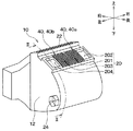
まず、図1、2に示す本実施形態の空調ユニット10の全体の概略構成について説明する。空調ユニット10は、車両用空調装置の一部を構成する車両用空調ユニットである。この空調ユニット10は、車室内のうち前席よりも車両前方側に搭載される。より具体的には、この空調ユニット10は、インストルメントパネルの内側に配置される。空調ユニット10は、熱交換器を通過した空気を車室内に向けて吹き出す。
(First Embodiment)
First, the overall schematic configuration of the
空調ユニット10は、空調ケース12と、図示しない送風機と、蒸発器14と、ヒータコア16と、PTCヒータ18とを備える。
The
空調ケース12は、空調ユニット10の外殻を構成する。図1に示すように、空調ケース12には、複数の吹出開口部20、22、24が形成されている。複数の吹出開口部20、22、24のそれぞれは、空調ケース12の内部から外部へ空気を吹き出すための開口部である。複数の吹出開口部20、22、24は、フェイス開口部20、デフロスタ開口部22およびフット開口部24を含む。フェイス開口部20は、図示しないダクトを介して、図示しないインストルメントパネルに設けられたフェイス吹出口に連なっている。デフロスタ開口部22は、図示しないダクトを介して、図示しないインストルメントパネルに設けられたデフロスタ吹出口に連なっている。
The
フェイス吹出口は、運転席センタ吹出口、運転席サイド吹出口、助手席センタ吹出口および助手席サイド吹出口を含む。運転席センタ吹出口および運転席サイド吹出口は、インストルメントパネルのうち運転席側に設けられている。助手席センタ吹出口および助手席サイド吹出口は、インストルメントパネルのうち助手席側に設けられている。運転席センタ吹出口および助手席センタ吹出口は、インストルメントパネルのうち車両左右方向の中央側に設けられている。運転席サイド吹出口および助手席サイド吹出口は、インストルメントパネルのうち車両左右方向の外側に設けられている。 The face outlet includes a driver's seat center outlet, a driver's seat side outlet, a passenger seat center outlet and a passenger seat side outlet. The driver's seat center outlet and the driver's seat side outlet are provided on the driver's side of the instrument panel. The passenger seat center outlet and the passenger seat side outlet are provided on the passenger seat side of the instrument panel. The driver's seat center outlet and the passenger seat center outlet are provided on the center side of the instrument panel in the left-right direction of the vehicle. The driver's seat side outlet and the passenger's seat side outlet are provided on the outside of the instrument panel in the left-right direction of the vehicle.
図1、3に示すように、フェイス開口部20は、運転席センタ開口部201、運転席サイド開口部202、助手席センタ開口部203および助手席サイド開口部204を含む。図3は、後述する調整部品40を設けていない状態の空調ユニット10を示している。
As shown in FIGS. 1 and 3, the
図示しないが、運転席センタ開口部201は、運転席センタ吹出口に連なっている。運転席サイド開口部202は、運転席サイド吹出口に連なっている。助手席センタ開口部203は、助手席センタ吹出口に連なっている。助手席サイド開口部204は、助手席サイド吹出口に連なっている。
Although not shown, the driver's seat center opening 201 is connected to the driver's seat center outlet. The driver's
送風機は、空調ケース12の内部に設けられる。送風機は、複数の吹出開口部20、22、24のいずれかに向かう空気流れを形成する。
The blower is provided inside the
蒸発器14は、空調ケース12の内部に設けられる。蒸発器14は、複数の吹出開口部20、22、24のいずれかに向かう空気を冷却する冷却器である。蒸発器14は、空気と冷凍サイクルの冷媒との熱交換によって、冷媒を蒸発させるとともに、空気を冷却する冷却用の熱交換器である。
The evaporator 14 is provided inside the
ヒータコア16およびPTCヒータ18は、空調ケース12の内部に設けられる。ヒータコア16およびPTCヒータ18は、複数の吹出開口部20、22、24のいずれかに向かう空気を加熱する加熱器である。ヒータコア16は、空気とエンジン冷却水との熱交換によって、空気を加熱する加熱用の熱交換器である。PTCヒータ18は、ヒータコア16を通過した空気を加熱する補助暖房装置である。
The
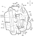
図2に示すように、空調ケース12の内部には、複数の吹出開口部20、22、24のいずれかに向かって空気が流れる空気通路26が形成されている。空気通路26は、空調ケース12の内部における上側に位置する上側通路28と、空調ケース12の内部における下側に位置する下側通路30とを含む。上側通路28と下側通路30とは、空調ケース12に設けられた上下仕切壁32によって仕切られている。
As shown in FIG. 2, an air passage 26 through which air flows toward any of the plurality of
上側通路28には、蒸発器14の上側部分と、ヒータコア16の上側部分とが配置されている。上側通路28は、蒸発器14の空気流れ下流側に形成された上側温風通路281、上側冷風通路282および上側混合通路283を含む。
An upper portion of the evaporator 14 and an upper portion of the
上側温風通路281は、空気がヒータコア16の上側部分を通過することによって生成された温風を上側混合通路283に導く。上側冷風通路282は、空気が蒸発器14の上側部分を通過することによって生成された冷風を、ヒータコア16の上側部分を迂回させて上側混合通路283に導く。上側混合通路283は、上側温風通路281からの温風と上側冷風通路282からの冷風との混合風をフェイス開口部20およびデフロスタ開口部22に導く。
The upper
下側通路30には、蒸発器14の下側部分と、ヒータコア16の下側部分と、PTCヒータ18とが配置されている。下側通路30は、蒸発器14の空気流れ下流側に形成された下側温風通路301、下側冷風通路302および下側混合通路303を含む。
In the lower passage 30, a lower portion of the evaporator 14, a lower portion of the
下側温風通路301は、空気がヒータコア16の下側部分を通過することによって生成された温風を下側混合通路303に導く。下側温風通路301には、PTCヒータ18が配置されている。ヒータコア16の下側部分を通過した空気は、PTCヒータ18によって加熱される。下側冷風通路302は、空気が蒸発器14の下側部分を通過することによって生成された冷風を、ヒータコア16の下側部分を迂回させて下側混合通路303に導く。下側混合通路303は、下側温風通路301からの温風と下側冷風通路302からの冷風との混合風を、連通路304を介して図1に示すフット開口部24に導く。また、下側混合通路303は、下側温風通路301からの温風と下側冷風通路302からの冷風との混合風を、連通口305を介して上側混合通路283に導く。連通口305は、上下仕切壁32に形成されている。連通口305は、上側混合通路283と下側混合通路303とを連通させる。
The lower
図2に示すように、空調ユニット10は、エアミックスドア34と、吹出モードドア36とを備える。
As shown in FIG. 2, the
エアミックスドア34は、冷風と温風との混合割合を調整して空調風の温度を調整する温調用ドアである。エアミックスドア34は、上側エアミックスドア341と、下側エアミックスドア342とを含む。上側エアミックスドア341は、上側通路28のうち蒸発器14とヒータコア16との間に配置されている。下側エアミックスドア342は、下側通路30のうち蒸発器14とヒータコア16との間に配置されている。
The air mix door 34 is a temperature control door that adjusts the temperature of the conditioned air by adjusting the mixing ratio of the cold air and the hot air. The air mix door 34 includes an upper air mix door 341 and a lower air mix door 342. The upper air mix door 341 is arranged between the evaporator 14 and the
吹出モードドア36は、複数の吹出開口部20、22、24を選択的に開閉する。吹出モードドア36が複数の吹出開口部20、22、24を選択的に開閉することで、フェイスモード、フットモードなどの各吹出モードが実現される。吹出モードドア36は、フェイスドア361、デフロスタドア362およびフットドア363を含む。本実施形態では、フットドア363は、連通口305を開閉するドア364と一体化されている。
The blowout mode door 36 selectively opens and closes the plurality of
フェイスモードでは、フェイスドア361がフェイス開口部20を開く。デフロスタドア362がデフロスタ開口部22を塞ぐ。フットドア363が、フット開口部24に連なる連通路304を塞ぐとともに、連通口305を開く。エアミックスドア34は、フェイス吹出口からの吹出風の温度が所望の温度となるように、ドア位置が設定される。
In face mode, the face door 361 opens the
これにより、上側温風通路281および下側温風通路301のそれぞれからの温風と、上側冷風通路282および下側冷風通路302のそれぞれからの冷風とが、図2中の矢印のように、上側混合通路283で混合されながらフェイス開口部20に向かって流れる。運転席センタ開口部201、運転席サイド開口部202、助手席センタ開口部203および助手席サイド開口部204のそれぞれを通過した風が、運転席センタ吹出口、運転席サイド吹出口、助手席センタ吹出口および助手席サイド吹出口のそれぞれから車室内に吹き出される。
As a result, the hot air from each of the upper
次に、本実施形態の空調ユニット10の特徴部分について説明する。図1に示すように、空調ユニット10は、2つの調整部品40を備える。2つの調整部品40は、運転席センタ開口部201に設けられた第1調整部品40aと、助手席センタ開口部203に設けられた第2調整部品40bとを含む。第1調整部品40aは、運転席センタ開口部201から流出する空気流れを調整する。第2調整部品40bは、助手席センタ開口部203から流出する空気流れを調整する。第1調整部品40aと第2調整部品40bとは一体化されている。第1調整部品40aは、運転席センタ開口部201に固定される。第2調整部品40bは、助手席センタ開口部203に固定される。なお、第1調整部品40aは、運転席センタ開口部201に接続されるダクトの運転席センタ開口部201側に固定されていてもよい。第2調整部品40bは、助手席センタ開口部203に接続されるダクトの助手席センタ開口部203側に固定されていてもよい。
Next, the characteristic portion of the
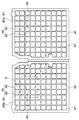
図4に示すように、2つの調整部品40のそれぞれは、枠42と格子44とを有する。枠42は、調整部品40が設けられる吹出開口部の開口縁部に沿う形状である。
As shown in FIG. 4, each of the two adjusting
格子44は、枠42で囲まれた領域内にある。格子44は、複数の隙間45を形成するように配列された複数の線状部材46である。複数の線状部材46は、複数の隙間45を形成する網状の部材である。格子44が配置された格子領域47では、複数の隙間45を空気が通過することができる。したがって、複数の隙間45は、空気が通過できる複数の空気通過部である。複数の線状部材46は、複数の空気通過部のそれぞれを仕切る仕切りである。本実施形態では、枠42で囲まれた領域の全部が格子領域47となっている。
The
具体的には、図5に示すように、複数の線状部材46は、複数の第1線状部材461と、複数の第2線状部材462とを有する。複数の第1線状部材461のそれぞれは、互いに間をあけて配置されている。複数の第2線状部材462のそれぞれは、互いに間をあけて配置されている。複数の第1線状部材461のそれぞれと、複数の第2線状部材462のそれぞれとが、交差している。このため、複数の隙間45のそれぞれの形状は四角である。
Specifically, as shown in FIG. 5, the plurality of
また、複数の第1線状部材461のそれぞれと複数の第2線状部材462のそれぞれとは、両者が交差している交差部463で結合して一体化している。なお、図6に示すように、複数の第1線状部材461のそれぞれと複数の第2線状部材462のそれぞれとは、交差部463で一体化していなくてもよい。すなわち、複数の第1線状部材461のそれぞれと複数の第2線状部材462のそれぞれとが編まれていてもよい。
Further, each of the plurality of first linear members 461 and each of the plurality of second linear members 462 are connected and integrated at an
枠42と格子44とは、樹脂製の一体成形品として構成されている。一体成形品とは、接合部を持たない連続した成形品である。枠42と格子44とは、樹脂製でなくてもよい。
The
このように、本実施形態の空調ユニット10は、2つの調整部品40を備える。このため、格子44によって運転席センタ開口部201と助手席センタ開口部203とのそれぞれを通過する空気流れを整流することができる。これにより、運転席センタ吹出口と助手席センタ吹出口とのそれぞれから吹き出される吹出風の風速分布を均一に近づけることができる。
As described above, the
さらに、格子44によって運転席センタ開口部201と助手席センタ開口部203とのそれぞれを通過する空気流れに対して抵抗をつけることができる。これにより、運転席センタ吹出口と助手席センタ吹出口とのそれぞれから吹き出される吹出風の風量を低減させ、風速を低下させることができる。
Further, the
これらの結果、本実施形態の空調ユニット10によれば、2つの調整部品40が設けられていない場合と比較して、吹出風の騒音を低減することができる。
As a result, according to the
また、本実施形態の空調ユニット10では、複数の線状部材46の太さを変更したり、隣り合う線状部材46の間隔を変更したりしてもよい。このように変更することで、所望の騒音低減効果が得られるように、運転席センタ開口部201と助手席センタ開口部203とのそれぞれを通過する空気流れの圧力損失を調整することができる。
Further, in the
(第2実施形態)
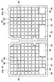
図7に示すように、本実施形態は、調整部品40がじゃま板48を有する点で、第1実施形態と異なる。空調ユニット10のその他の構成は、第1実施形態と同じである。
(Second Embodiment)
As shown in FIG. 7, the present embodiment differs from the first embodiment in that the adjusting
2つの調整部品40のそれぞれは、枠42と、格子44と、2つのじゃま板48とを有する。じゃま板48は、空気流れを阻害する板部材である。
Each of the two adjusting
格子44と2つのじゃま板48とは、枠42で囲まれた領域内に配置されている。2つのじゃま板48は、枠42で囲まれた領域のうち中央部の周辺部の一部に配置されている。したがって、じゃま板48は、枠42で囲まれた領域において偏って配置されている。格子44は、枠42で囲まれた領域のうち2つのじゃま板48を除く領域に配置されている。枠42と、格子44と、2つのじゃま板48は、樹脂製の一体成形品で構成されている。これらは、樹脂製でなくてもよい。
The
格子44が配置された格子領域47は、複数の隙間45が形成されている。じゃま板48が配置されたじゃま板領域49は、隙間が形成されていない。このため、格子領域47の開口率は、じゃま板領域49の開口率よりも高い。開口率は、部材が配置された領域全体に対するその部材によって形成されている隙間の割合である。その部材が隙間を形成していない場合、開口率は0%である。したがって、格子領域47は、じゃま板領域49よりも、空気流れに対する抵抗が低い領域である。じゃま板領域49は、格子領域47よりも、空気流れに対する抵抗が高い領域である。格子44は、じゃま板48と比較して、空気流れに対して小さな抵抗を付与する低抵抗部材である。じゃま板48は、格子44と比較して、空気流れに対して大きな抵抗を付与する高抵抗部材である。
A plurality of
本実施形態では、格子領域47が、空気が流れる第1領域に対応する。じゃま板領域49が、第1領域よりも空気流れに対する抵抗が大きな第2領域に対応する。じゃま板48が、第1領域における空気流れに対する抵抗よりも、空気流れに対して大きな抵抗を付与する高抵抗部材に対応する。格子44が、第2領域における空気流れに対する抵抗よりも、空気流れに対して小さな抵抗を付与する低抵抗部材に対応する。
In this embodiment, the
また、本実施形態では、格子44と複数の隙間45とを含む格子領域47の全面積は、調整部品40が設けられた吹出開口部201、203の全開口面積のうち半分以上の大きさである。格子領域47は、一続きの領域となっている。じゃま板48のうち空気流れを阻害する部位の面積は、複数の隙間45のそれぞれの面積の平均値よりも大きい。
Further, in the present embodiment, the total area of the
本実施形態においても、格子44によって、第1実施形態と同様の効果が得られる。さらに、本実施形態によれば、下記の効果も得られる。
Also in this embodiment, the same effect as that of the first embodiment can be obtained by the
近年、空調ユニット10の小型化により、冷風と暖風とを混合するスペースである上側混合通路283と下側混合通路303とが小さくなっている。このため、本実施形態と異なり、調整部品40が運転席センタ開口部201に設けられていない場合、フェイスモード時に、暖風と冷風とが、十分に混合されずに、運転席センタ開口部201を通過する。すなわち、運転席センタ開口部201は、暖風が通過する領域と冷風が通過する領域とが存在する。運転席センタ開口部201を通過した暖風と冷風とが、その状態のまま、ダクトを流れて運転席センタ吹出口から吹き出される。このため、運転席センタ吹出口から吹き出される吹出風の温度ばらつきが大きいという問題が生じる。すなわち、運転席センタ吹出口において、吹出口内の温度ばらつきが大きいという問題が生じる。温度ばらつきが大きいとは、最小温度と最大温度との差が大きいことを意味する。同様に、調整部品40が助手席センタ開口部203に設けられていない場合も、助手席センタ吹出口において、吹出口内の温度ばらつきが大きいという問題が生じる。
In recent years, due to the miniaturization of the
これに対して、本実施形態の空調ユニット10では、運転席センタ開口部201に、調整部品40が設けられている。本実施形態の調整部品40は、じゃま板48を有する。枠42で囲まれた領域のうちじゃま板領域49は、じゃま板48が配置されていない領域(すなわち、格子領域47)と比較して、空気流れに対する抵抗が大きい。このため、運転席センタ開口部201を通過する風流れを乱すことができる。
On the other hand, in the
本実施形態では、運転席センタ開口部201のうち調整部品40が設けられていない場合の暖風側の領域に、じゃま板48が配置されている。このため、じゃま板48によって、暖風と冷風とが運転席センタ開口部201を通過する際に、暖風を冷風側に向かわせることができる。これにより、暖風と冷風とを混合させることができる。よって、運転席センタ吹出口において、吹出口内の温度ばらつきを小さくすることができる。
In the present embodiment, the
本実施形態の空調ユニット10では、助手席センタ開口部203にも、調整部品40が設けられている。このため、助手席センタ吹出口においても、吹出口内の温度ばらつきを小さくすることができる。
In the
また、上側混合通路283と下側混合通路303とが小さく、かつ、運転席センタ開口部201と助手席センタ開口部203とに調整部品40が設けられていない場合を想定する。この場合、フェイスモード時に、運転席サイド開口部202および助手席サイド開口部204よりも、運転席センタ開口部201および助手席センタ開口部203の方に暖風が多く流れる。このため、運転席サイド吹出口および助手席サイド吹出口よりも運転席センタ吹出口および助手席センタ吹出口の方が、吹出口から吹き出される吹出風の温度が高くなる。このように、同じ目標温度の吹出風を複数の吹出口から吹き出したいときに、複数の吹出口のそれぞれからの吹出風の温度差が大きいという問題が生じる。すなわち、吹出口間の温度ばらつきが大きいという問題が生じる。
Further, it is assumed that the
これに対して、本実施形態の空調ユニット10では、フェイス開口部20のうち運転席センタ開口部201と助手席センタ開口部203とのそれぞれに、調整部品40を設けている。これにより、運転席センタ開口部201と助手席センタ開口部203とでは、調整部品40を設けていない場合と比較して、暖風に対する抵抗が高くなっている。このため、運転席センタ開口部201および助手席センタ開口部203を流れる暖風の風量を減らし、運転席サイド開口部202および助手席サイド開口部204を流れる暖風の風量を増やすことができる。これにより、運転席センタ開口部201、運転席サイド開口部202、助手席センタ開口部203および助手席サイド開口部204のそれぞれを通過する暖風と冷風との混合割合を近づけることができる。運転席センタ吹出口、運転席サイド吹出口、助手席センタ吹出口および助手席サイド吹出口のそれぞれから吹き出される吹出風の温度を均一に近づけることができる。
On the other hand, in the
このように、本実施形態では、じゃま板48によって、運転席センタ開口部201と助手席センタ開口部203とのそれぞれの空気流れに対する抵抗を調整している。これにより、各開口部201、202、203、204において、暖風の流れやすさを調整して、冷風と暖風との混合割合を調整している。この結果、運転席センタ吹出口、助手席センタ吹出口、運転席サイド吹出口および助手席サイド吹出口において、吹出口間の温度ばらつきを小さくすることができる。
As described above, in the present embodiment, the
ここで、図8に、本発明者が行った試験結果を示す。図8は、比較例の空調ユニットと本実施形態の空調ユニット10とのそれぞれにおける吹出口内の温度ばらつきと、吹出口間の温度ばらつきとの測定結果を示している。比較例の空調ユニットは、2つの調整部品40のそれぞれが、2つのじゃま板48を有していない点で、本実施形態の空調ユニット10と異なる。比較例の空調ユニットの他の構成は、本実施形態の空調ユニット10と同じである。吹出口内の温度ばらつきは、1つのフェイス吹出口、すなわち、運転席センタ吹出口における吹出口内の温度ばらつきである。吹出口間の温度ばらつきは、4つのフェイス吹出口、すなわち、運転席センタ吹出口、助手席センタ吹出口、運転席サイド吹出口および助手席サイド吹出口における吹出口間の温度ばらつきである。
Here, FIG. 8 shows the test results conducted by the present inventor. FIG. 8 shows the measurement results of the temperature variation in the air outlet and the temperature variation between the air outlets in each of the air conditioning unit of the comparative example and the
図8に示す試験結果より、本実施形態の空調ユニット10によれば、比較例の空調ユニットよりも、吹出口内の温度ばらつきを小さくでき、かつ、吹出口間の温度ばらつきを小さくできることが確認された。
From the test results shown in FIG. 8, it was confirmed that the
また、本実施形態の空調ユニット10では、2つの調整部品40は、空調ケース12とは別体の部品である。このため、調整部品40のじゃま板48の数および位置を変更することで、空調ケース12の形状の変更を伴わずに、空調ユニット10が搭載される車種ごとに、温度ばらつきの低減を図ることができる。
Further, in the
また、本実施形態の空調ユニット10では、2つのじゃま板48は、枠42で囲まれた領域のうち中央部の周辺部に配置されている。枠42で囲まれた領域は、吹出開口部の開口領域に対応している。調整部品40を設けていない場合において、吹出開口部の開口領域の中央部では、通過する風の風速は高い。吹出開口部の開口領域の周辺部では、通過する風の風速は低い。このため、本実施形態では、調整部品40を設けていない場合に吹出開口部を通過する風の風速分布において風速が低い領域に、じゃま板48が配置されている。これにより、風量の低下および騒音の悪化を抑制しながら、温度ばらつきを小さくすることができる。
Further, in the
なお、じゃま板48の配置場所および数は、本実施形態に限定されない。じゃま板48の配置場所および数は、任意に変更可能である。例えば、枠42で囲まれた領域のうち中央部に、じゃま板48を配置してもよい。じゃま板48の配置場所や、枠42に囲まれた領域に対して、じゃま板48が占める範囲を変更することで、吹出口から吹き出される空気の温度分布を調整することができる。
The location and number of the
また、本実施形態では、格子44と2つのじゃま板48とが、一体成形品として構成されていた。しかし、格子44と2つのじゃま板48とが、別体で構成され、両者が接合されていてもよい。
Further, in the present embodiment, the
(第3実施形態)
図9に示すように、本実施形態では、2つの調整部品40のそれぞれにおいて、2つのじゃま板48のそれぞれに複数の開口部48aが形成されている。空調ユニット10のその他の構成は、第1実施形態と同じである。
(Third Embodiment)
As shown in FIG. 9, in the present embodiment, in each of the two adjusting
このように、じゃま板48に複数の開口部48aが形成されていてもよい。開口部48aは1つであってもよい。じゃま板48に、1つまたは複数の開口部48aを形成することで、じゃま板領域49における空気流れに対する抵抗を減らすことができる。調整部品40が設けられる吹出開口部の空気流れに対する抵抗を調整することができる。
In this way, a plurality of
(第4実施形態)
図10に示すように、本実施形態では、2つの調整部品40の形状が第1実施形態と異なる。空調ユニット10のその他の構成は、第1実施形態と同じである。
(Fourth Embodiment)
As shown in FIG. 10, in the present embodiment, the shapes of the two adjusting
2つの調整部品40のそれぞれは、枠42と、格子44aとを有する。格子44aは、第1実施形態の格子44と同じものである。格子44aは、枠42で囲まれた領域のうち一部の領域のみに配置されている。枠42で囲まれた領域のうち格子領域47aを除く領域は、空洞部となっている。換言すると、2つの調整部品40のそれぞれでは、枠42で囲まれた領域のうち格子領域47aを除く領域に、空洞部50が形成されている。格子領域47aは、格子44aが配置された領域である。空洞部50は、部材が何も配置されていない領域である。
Each of the two adjusting
本実施形態においても、格子44によって、第1実施形態と同様の効果が得られる。さらに、本実施形態では、空洞部50の開口率は、格子領域47aの開口率よりも高い。このため、空洞部50は、格子領域47aよりも、空気流れに対する抵抗が低い領域である。格子領域47aは、空洞部50よりも、空気流れに対する抵抗が高い領域である。格子44aは、空洞部50と比較して、空気流れに対して大きな抵抗を付与する高抵抗部材である。よって、本実施形態においても、第2実施形態と同様の効果が得られる。
Also in this embodiment, the same effect as that of the first embodiment can be obtained by the
なお、本実施形態では、空洞部50が、空気が流れる第1領域に対応する。格子領域47aが、第1領域よりも空気流れに対する抵抗が大きな第2領域に対応する。格子44aが、第1領域における空気流れに対する抵抗よりも、空気流れに対して大きな抵抗を付与する高抵抗部材に対応する。
In the present embodiment, the
(第5実施形態)
図11に示すように、本実施形態では、2つの調整部品40の形状が第1実施形態と異なる。空調ユニット10のその他の構成は、第1実施形態と同じである。
(Fifth Embodiment)
As shown in FIG. 11, in the present embodiment, the shapes of the two adjusting
2つの調整部品40のそれぞれは、枠42と、2つのじゃま板48とを有する。2つのじゃま板48は、枠42で囲まれた領域のうち一部の領域のみに配置されている。枠42で囲まれた領域のうちじゃま板領域49を除く領域は、空洞部となっている。換言すると、2つの調整部品40のそれぞれでは、枠42で囲まれた領域のうちじゃま板領域49を除く領域に、空洞部50が形成されている。空洞部50は、部材が何も配置されていない領域である。
Each of the two adjusting
本実施形態では、空洞部50の開口率は、じゃま板領域49の開口率よりも高い。このため、空洞部50は、じゃま板領域49よりも、空気流れに対する抵抗が低い領域である。じゃま板領域49は、空洞部50よりも、空気流れに対する抵抗が高い領域である。じゃま板48は、空洞部50と比較して、空気流れに対して大きな抵抗を付与する高抵抗部材である。よって、本実施形態においても、第2実施形態と同様の効果が得られる。
In the present embodiment, the aperture ratio of the
なお、本実施形態では、空洞部50が、空気が流れる第1領域に対応する。じゃま板領域49が、第1領域よりも空気流れに対する抵抗が大きな第2領域に対応する。じゃま板48が、第1領域における空気流れに対する抵抗よりも、空気流れに対して大きな抵抗を付与する高抵抗部材に対応する。
In the present embodiment, the
(第6実施形態)
図12に示すように、本実施形態では、2つの調整部品40の形状が第1実施形態と異なる。空調ユニット10のその他の構成は、第1実施形態と同じである。
(Sixth Embodiment)
As shown in FIG. 12, in the present embodiment, the shapes of the two adjusting
2つの調整部品40のそれぞれは、枠42と、第1格子44と、第2格子52とを有する。第1格子44と第2格子52とは、枠42で囲まれた領域に配置されている。第1格子44は、第2実施形態の格子44と同じである。第1格子44が配置された第1格子領域47は、第2実施形態の格子領域47と同じである。
Each of the two adjusting
第2格子52は、第1格子44と同様に、複数の隙間45を形成するように配列された複数の線状部材46である。第2格子52では、第1格子44よりも、隣り合う線状部材46の間隔が狭い。隣り合う線状部材46が密に配置されている。このため、第2格子52では、第1格子44よりも、複数の隙間45のそれぞれが小さい。
The
本実施形態においても、第1格子44および第2格子52によって、第1実施形態と同様の効果が得られる。さらに、本実施形態では、第1格子領域47の開口率は、第2格子52が配置された第2格子領域53の開口率よりも高い。このため、第1格子領域47は、第2格子領域53よりも、空気流れに対する抵抗が低い領域である。第2格子領域53は、第1格子領域47よりも、空気流れに対する抵抗が高い領域である。第1格子44は、第2格子52と比較して、空気流れに対して小さな抵抗を付与する低抵抗部材である。第2格子52は、第1格子44と比較して、空気流れに対して大きな抵抗を付与する高抵抗部材である。よって、本実施形態においても、第2実施形態と同様の効果が得られる。
Also in the present embodiment, the same effect as that of the first embodiment can be obtained by the
なお、本実施形態では、第1格子領域47が、空気が流れる第1領域に対応する。第2格子領域53が、第1領域よりも空気流れに対する抵抗が大きな第2領域に対応する。第2格子52が、第1領域における空気流れに対する抵抗よりも、空気流れに対して大きな抵抗を付与する高抵抗部材に対応する。第1格子44が、第2領域における空気流れに対する抵抗よりも、空気流れに対して小さな抵抗を付与する低抵抗部材に対応する。
In the present embodiment, the
(他の実施形態)
(1)第1−第4、第6実施形態では、格子44、第1格子44、第2格子52によって形成される複数の隙間45のそれぞれの形状が四角形状であった。しかしながら、複数の隙間のそれぞれの形状は、四角形以外の他の形状でもよい。
(Other embodiments)
(1) In the 1st to 4th and 6th embodiments, the shape of each of the plurality of
例えば、格子44、第1格子44、第2格子52のそれぞれを、図13に示すように、円形状の複数の隙間55を形成している網状の部材54に変更してもよい。この場合、円形状の複数の隙間55が、空気が通過できる複数の空気通過部である。網状の部材54は、複数の空気通過部のそれぞれを仕切る仕切りである。
For example, as shown in FIG. 13, each of the
また、図14に示すように、格子44、第1格子44、第2格子52のそれぞれを、六角形の複数の隙間57を形成している網状の部材56に変更してもよい。この場合、六角形の複数の隙間57が、空気が通過できる複数の空気通過部である。網状の部材56は、複数の空気通過部のそれぞれを仕切る仕切りである。
Further, as shown in FIG. 14, each of the
(2)上記各実施形態では、フェイス開口部20の4つの開口部201、202、203、204のうち2つの開口部201、203のみに、調整部品40を設けた。しかしながら、この場合に限らず、4つの開口部201、202、203、204のいずれか1つ以上に設けてもよい。例えば、4つの開口部201、202、203、204の全部に調整部品40を設けてもよい。この場合、センタ開口部201、203とサイド開口部202、204とで、第2実施形態と同様に、空気流れに対する抵抗の大きさを異ならせることが好ましい。これにより、第2実施形態と同様に、吹出口間の温度ばらつきを小さくすることが可能となる。
(2) In each of the above embodiments, the adjusting
(3)上記各実施形態では、フェイス開口部20に調整部品40を設けた。しかしながら、他の吹出開口部に調整部品40を設けてもよい。これにより、上記各実施形態と同様の効果が得られる。
(3) In each of the above embodiments, the adjusting
(4)本発明は上記した実施形態に限定されるものではなく、特許請求の範囲に記載した範囲内において適宜変更が可能であり、様々な変形例や均等範囲内の変形をも包含する。また、上記各実施形態は、互いに無関係なものではなく、組み合わせが明らかに不可な場合を除き、適宜組み合わせが可能である。また、上記各実施形態において、実施形態を構成する要素は、特に必須であると明示した場合および原理的に明らかに必須であると考えられる場合等を除き、必ずしも必須のものではないことは言うまでもない。また、上記各実施形態において、実施形態の構成要素の個数、数値、量、範囲等の数値が言及されている場合、特に必須であると明示した場合および原理的に明らかに特定の数に限定される場合等を除き、その特定の数に限定されるものではない。また、上記各実施形態において、構成要素等の材質、形状、位置関係等に言及するときは、特に明示した場合および原理的に特定の材質、形状、位置関係等に限定される場合等を除き、その材質、形状、位置関係等に限定されるものではない。
(まとめ)
上記各実施形態の一部または全部で示された第1の観点によれば、空調ユニットは、空調ケースと、冷却器と、加熱器と、調整部品とを備える。調整部品には、空気が流れる第1領域と、第1領域よりも空気流れに対する抵抗が大きな第2領域とが形成されている。
(4) The present invention is not limited to the above-described embodiment, and can be appropriately modified within the scope of claims, and includes various modifications and modifications within an equal range. Further, the above-described embodiments are not unrelated to each other, and can be appropriately combined unless the combination is clearly impossible. Further, in each of the above embodiments, it goes without saying that the elements constituting the embodiment are not necessarily essential except when it is clearly stated that they are essential and when they are clearly considered to be essential in principle. stomach. Further, in each of the above embodiments, when numerical values such as the number, numerical values, amounts, and ranges of the constituent elements of the embodiment are mentioned, when it is clearly stated that they are particularly essential, and in principle, the number is clearly limited to a specific number. It is not limited to the specific number except when it is done. Further, in each of the above embodiments, when the material, shape, positional relationship, etc. of the component or the like is referred to, except for the case where it is clearly stated and the case where it is limited to a specific material, shape, positional relationship, etc. in principle. , The material, shape, positional relationship, etc. are not limited.
(summary)
According to the first aspect shown in part or all of the above embodiments, the air conditioning unit includes an air conditioning case, a cooler, a heater, and an adjusting component. The adjusting component is formed with a first region through which air flows and a second region in which resistance to air flow is greater than that in the first region.
また、第2の観点によれば、第2領域には、第1領域よりも空気流れに対して大きな抵抗を付与する高抵抗部材が設けられている。これにより、第2領域の空気流れに対する抵抗を、第1領域の空気流れに対する抵抗よりも大きくできる。 Further, according to the second viewpoint, the second region is provided with a high resistance member that imparts a greater resistance to the air flow than the first region. As a result, the resistance to the air flow in the second region can be made larger than the resistance to the air flow in the first region.
また、第3の観点によれば、第1領域には、第2領域よりも空気流れに対して小さな抵抗を付与する低抵抗部材が設けられている。このように、第1領域に、低抵抗部材を設けることができる。 Further, according to the third viewpoint, the first region is provided with a low resistance member that imparts a smaller resistance to the air flow than the second region. In this way, the low resistance member can be provided in the first region.
また、第4の観点によれば、低抵抗部材は、空気が通過できる複数の空気通過部のそれぞれを仕切る仕切りである。高抵抗部材は、空気流れを阻害する部位を有する板部材である。低抵抗部材および高抵抗部材として、具体的には第4の観点に記載の部材を用いることができる。 Further, according to the fourth aspect, the low resistance member is a partition that partitions each of a plurality of air passing portions through which air can pass. The high resistance member is a plate member having a portion that obstructs the air flow. Specifically, as the low resistance member and the high resistance member, the members described in the fourth aspect can be used.
これによれば、仕切りによって、吹出開口部を通過する空気流れを整流することができる。これにより、車室内に設けられた吹出口から吹き出される吹出風の風速分布を均一に近づけることができる。さらに、仕切によって、吹出開口部を通過する空気流れに対して抵抗をつけることができる。これにより、吹出口から車室内に吹き出される吹出風の風量を低減させ、風速を低下させることができる。 According to this, the air flow passing through the blowout opening can be rectified by the partition. As a result, the wind speed distribution of the blown wind blown out from the blowout port provided in the vehicle interior can be made uniform. Further, the partition can provide resistance to the air flow passing through the blowout opening. As a result, the amount of air blown out from the air outlet into the vehicle interior can be reduced, and the wind speed can be reduced.
これらの結果、調整部品が設けられていない場合と比較して、吹出風の騒音を低減することができる。 As a result, it is possible to reduce the noise of the blown wind as compared with the case where the adjusting parts are not provided.
また、第5の観点によれば、空調ユニットは、空調ケースと、調整部品とを備える。調整部品は、空気が通過できる複数の空気通過部のそれぞれを仕切る仕切りを有する。 Further, according to the fifth aspect, the air conditioning unit includes an air conditioning case and adjusting parts. The adjusting component has a partition that partitions each of a plurality of air passing portions through which air can pass.
10 空調ユニット
12 空調ケース
14 蒸発器
16 ヒータコア
40 調整部品
44 格子
48 じゃま板
10
Claims (1)
空気を吹き出す吹出開口部(201、203)が形成された空調ケース(12)と、
前記空調ケースの内部に設けられ、前記吹出開口部に向かう空気を冷却する冷却器(14)と、
前記空調ケースの内部に設けられ、前記吹出開口部に向かう空気を加熱する加熱器(16、18)と、
前記吹出開口部に設けられ、前記吹出開口部を通過する空気流れを調整する調整部品(40)とを備え、
前記調整部品は、前記空調ケースと別体の部品であって、前記吹出開口部に固定され、
前記調整部品には、空気が流れる第1領域(47)と、前記第1領域よりも空気流れに対する抵抗が大きな第2領域(49)とが形成されており、
前記第2領域には、前記第1領域よりも空気流れに対して大きな抵抗を付与する高抵抗部材(48)が設けられており、
前記第1領域には、前記第2領域よりも空気流れに対して小さな抵抗を付与する低抵抗部材(44、54、56)が設けられており、
前記低抵抗部材は、前記第1領域内で、空気が通過できる複数の空気通過部(45、55、57)のそれぞれを仕切る仕切り(44、54、56)であり、
前記高抵抗部材は、空気流れを阻害する部位を有する板部材(48)であり、
前記仕切りと前記板部材とは、一体成形品として構成されている、または、別体で構成され、接合されており、
前記仕切りは、前記吹出開口部の開口領域の一部に対向し、
前記板部材は、前記吹出開口部の開口領域の他の一部に対向している、空調ユニット。 It ’s an air conditioning unit,
An air-conditioning case (12) having blowout openings (201, 203) for blowing air, and an air-conditioning case (12).
A cooler (14) provided inside the air conditioning case and cooling the air toward the outlet opening, and
Heaters (16, 18) provided inside the air conditioning case to heat the air toward the outlet opening, and
It is provided with an adjusting component (40) provided in the blowing opening and adjusting the air flow passing through the blowing opening.
The adjustment component, I component der of the air conditioning case and another member, is fixed to the opening portion,
The adjusting component is formed with a first region (47) through which air flows and a second region (49) in which resistance to air flow is greater than that of the first region.
The second region is provided with a high resistance member (48) that imparts greater resistance to the air flow than the first region.
The first region is provided with low resistance members (44, 54, 56) that impart a smaller resistance to the air flow than the second region.
The low resistance member is a partition (44, 54, 56) that partitions each of a plurality of air passing portions (45, 55, 57) through which air can pass in the first region.
The high resistance member is a plate member (48) having a portion that obstructs the air flow.
The partition and the plate member are configured as an integrally molded product, or are configured as separate bodies and joined to each other.
The partition faces a part of the opening region of the blowout opening and
The plate member is an air conditioning unit that faces another part of the opening region of the blowout opening.
Priority Applications (5)
| Application Number | Priority Date | Filing Date | Title |
|---|---|---|---|
| JP2017165846A JP6915460B2 (en) | 2017-08-30 | 2017-08-30 | Air conditioning unit |
| DE112018004833.0T DE112018004833T5 (en) | 2017-08-30 | 2018-07-26 | Air conditioning unit |
| PCT/JP2018/028141 WO2019044302A1 (en) | 2017-08-30 | 2018-07-26 | Air conditioning unit |
| CN201880055721.9A CN111032385B (en) | 2017-08-30 | 2018-07-26 | Air conditioning unit |
| US16/788,776 US11613155B2 (en) | 2017-08-30 | 2020-02-12 | Air-conditioning unit |
Applications Claiming Priority (1)
| Application Number | Priority Date | Filing Date | Title |
|---|---|---|---|
| JP2017165846A JP6915460B2 (en) | 2017-08-30 | 2017-08-30 | Air conditioning unit |
Publications (3)
| Publication Number | Publication Date |
|---|---|
| JP2019043226A JP2019043226A (en) | 2019-03-22 |
| JP2019043226A5 JP2019043226A5 (en) | 2019-11-14 |
| JP6915460B2 true JP6915460B2 (en) | 2021-08-04 |
Family
ID=65526301
Family Applications (1)
| Application Number | Title | Priority Date | Filing Date |
|---|---|---|---|
| JP2017165846A Active JP6915460B2 (en) | 2017-08-30 | 2017-08-30 | Air conditioning unit |
Country Status (5)
| Country | Link |
|---|---|
| US (1) | US11613155B2 (en) |
| JP (1) | JP6915460B2 (en) |
| CN (1) | CN111032385B (en) |
| DE (1) | DE112018004833T5 (en) |
| WO (1) | WO2019044302A1 (en) |
Families Citing this family (2)
| Publication number | Priority date | Publication date | Assignee | Title |
|---|---|---|---|---|
| EP3756913B1 (en) * | 2019-06-28 | 2022-03-30 | MAHLE International GmbH | Hvac-modul |
| FR3109333B1 (en) * | 2020-04-15 | 2023-01-13 | Valeo Systemes Thermiques | Heating, ventilation and/or air conditioning device for a motor vehicle |
Family Cites Families (28)
| Publication number | Priority date | Publication date | Assignee | Title |
|---|---|---|---|---|
| JPS61145017U (en) * | 1985-03-01 | 1986-09-06 | ||
| JP3146567B2 (en) * | 1991-11-06 | 2001-03-19 | 株式会社デンソー | Automotive air conditioners |
| IT232350Y1 (en) * | 1994-03-15 | 1999-12-17 | Foggini Progetti | AIR CONDITIONING VENT FOR AIR CONDITIONING OF VEHICLES WITH DIFFUSER AND FLOW CONCENTRATOR SELECTABLE AND INDIVIDUALLY |
| JP3284058B2 (en) * | 1996-08-30 | 2002-05-20 | 株式会社ケーヒン | Vehicle heating system |
| JP3870530B2 (en) * | 1998-02-04 | 2007-01-17 | 株式会社デンソー | Air conditioner for vehicles |
| US7238102B2 (en) | 2003-02-18 | 2007-07-03 | Delphi Technologies, Inc. | Heating, ventilation, and air conditioning system having a film valve and film for controlling air flow |
| BR0107915A (en) | 2000-01-19 | 2002-11-05 | Chemfab Corp | Uncoiled composite membranes with different opposite faces, methods for producing them and their use in various applications |
| US7927684B2 (en) | 2000-01-19 | 2011-04-19 | Saint-Gobain Performance Plastics Corporation | Low coefficient of friction polymer film |
| DE10121286A1 (en) * | 2001-04-30 | 2002-10-31 | Valeo Klimasysteme Gmbh | Air duct, for a motor vehicle air conditioning system, is provided with at least one plate which has a definite pattern of holes and covers the cross section of at least one air flow channel |
| JP3879655B2 (en) * | 2002-11-06 | 2007-02-14 | 株式会社デンソー | Ceiling blower for vehicle air conditioning |
| DE10304548A1 (en) * | 2003-01-16 | 2004-07-29 | König & Hohmann und Otto Lübeck GmbH & Co. KG | Air distributor covering outlet of ventilation equipment, has perforations designed in size, number and distribution to give appearance of closed metal surface |
| KR20040065885A (en) * | 2003-01-16 | 2004-07-23 | 현대모비스 주식회사 | Air-Duct of Automobile Air-Condition |
| DE10331398A1 (en) * | 2003-07-11 | 2005-01-27 | Volkswagen Ag | Air vents for a motor vehicle windscreen for moisture removal and deicing have differing hole diameters and densities to optimize the flow onto the screen |
| DE102004003196A1 (en) | 2004-01-22 | 2005-08-18 | Daimlerchrysler Ag | Air duct for car heaters has outlet grille with pattern of apertures, apertures near edges being smaller than those in center, equalizing pressure differences in air flow produced by control valve |
| DE102004057316A1 (en) * | 2004-11-27 | 2006-06-01 | Fischer Automotive Systems Gmbh | Air inlet unit for vehicle, comprising arrangement of specifically shaped air guiding element and front cover |
| KR101129810B1 (en) * | 2004-12-23 | 2012-03-26 | 한라공조주식회사 | Air conditioning system for vehicles |
| JP4559238B2 (en) * | 2005-01-07 | 2010-10-06 | カルソニックカンセイ株式会社 | Air conditioner for vehicles |
| DE102006009577A1 (en) | 2006-02-28 | 2007-09-06 | Behr Gmbh & Co. Kg | Motor vehicle ventilation system |
| DE102007011953A1 (en) * | 2006-03-10 | 2007-11-15 | Behr Gmbh & Co. Kg | Heat exchanger, particularly exhaust-gas heat exchanger for motor vehicle, comprises two flow paths and deflection region, which is located down stream of flow paths, where flow paths are traversed by fluid to be cooled |
| DE102006026655A1 (en) * | 2006-06-08 | 2007-12-13 | Daimlerchrysler Ag | Motor vehicle component for operating as a vehicle's perforated metal ventilation panel, e.g. for air-conditioning and passenger comfort, has an arched honeycomb structure |
| FR2912085B1 (en) * | 2007-02-05 | 2009-04-17 | Bourbon Automobile Soc Par Act | VENTILATION NOZZLE FOR A MOTOR VEHICLE, IN PARTICULAR FOR A HEADREST FOR A MOTOR VEHICLE SEAT |
| DE102008021015A1 (en) | 2007-04-25 | 2008-10-30 | Behr Gmbh & Co. Kg | Arrangement for mixing gaseous media, e.g. air in vehicle air conditioning system, and blocking cross-section has first, second elements that interact to define different open cross-sections in channel; each is rotatable about fixed axis |
| JP2009040304A (en) * | 2007-08-10 | 2009-02-26 | Denso Corp | Air-conditioner for vehicle |
| KR101481697B1 (en) * | 2008-09-29 | 2015-01-12 | 한라비스테온공조 주식회사 | Air conditioner for vehicle |
| DE102011113446A1 (en) * | 2011-09-14 | 2013-03-14 | Valeo Klimasysteme Gmbh | Vehicle air conditioning |
| WO2013185012A1 (en) * | 2012-06-08 | 2013-12-12 | Johnson Controls Technology Company | Flexible material air vent assembly |
| KR101595244B1 (en) * | 2012-10-30 | 2016-02-18 | 한온시스템 주식회사 | Air conditioner for vehicle |
| JP2017165846A (en) | 2016-03-15 | 2017-09-21 | アーゼッド・エレクトロニック・マテリアルズ(ルクセンブルグ)ソシエテ・ア・レスポンサビリテ・リミテ | Fine pattern forming composition and fine pattern forming method using the same |
-
2017
- 2017-08-30 JP JP2017165846A patent/JP6915460B2/en active Active
-
2018
- 2018-07-26 DE DE112018004833.0T patent/DE112018004833T5/en active Pending
- 2018-07-26 CN CN201880055721.9A patent/CN111032385B/en active Active
- 2018-07-26 WO PCT/JP2018/028141 patent/WO2019044302A1/en active Application Filing
-
2020
- 2020-02-12 US US16/788,776 patent/US11613155B2/en active Active
Also Published As
| Publication number | Publication date |
|---|---|
| WO2019044302A1 (en) | 2019-03-07 |
| US11613155B2 (en) | 2023-03-28 |
| CN111032385A (en) | 2020-04-17 |
| CN111032385B (en) | 2023-02-28 |
| US20200180389A1 (en) | 2020-06-11 |
| JP2019043226A (en) | 2019-03-22 |
| DE112018004833T5 (en) | 2020-07-09 |
Similar Documents
| Publication | Publication Date | Title |
|---|---|---|
| JP4883080B2 (en) | Air conditioner for vehicles | |
| US11254187B2 (en) | Vehicular air conditioner | |
| JP2018047711A (en) | Air conditioner for vehicle | |
| US20200223282A1 (en) | Vehicular air conditioner | |
| JP2009286286A (en) | Vehicular air conditioner | |
| JP2005170376A (en) | Air distribution module of air-conditioning system for vehicle | |
| JP6915460B2 (en) | Air conditioning unit | |
| WO2016088361A1 (en) | Vehicular air-conditioning unit | |
| KR102056123B1 (en) | Air distribution assembly for an air-conditioning system of a motor vehicle | |
| JP2016182835A (en) | Vehicular air conditioning unit | |
| US9423147B2 (en) | Mixer for mixing air flows | |
| JP2011025810A (en) | Air conditioner for vehicle | |
| JP4859768B2 (en) | Air conditioner for vehicles | |
| JP6795896B2 (en) | Vehicle air conditioner | |
| JP5928866B2 (en) | Air conditioning duct | |
| JP6790978B2 (en) | Blower | |
| KR20100006970A (en) | Air conditioning system for automotive vehicles | |
| JP2011207278A (en) | Air conditioning case | |
| JP6934274B2 (en) | Vehicle air conditioner | |
| JP2009006896A (en) | Vehicle air-conditioner | |
| KR101758724B1 (en) | Air conditioner for vehicle | |
| JP2009149126A (en) | Air conditioner for vehicle | |
| JP2016088290A (en) | Vehicular air conditioner | |
| JP2005231406A (en) | Vehicular air-conditioner | |
| JP2016117472A (en) | Vehicle air conditioner |
Legal Events
| Date | Code | Title | Description |
|---|---|---|---|
| A521 | Request for written amendment filed |
Free format text: JAPANESE INTERMEDIATE CODE: A523 Effective date: 20191004 |
|
| A621 | Written request for application examination |
Free format text: JAPANESE INTERMEDIATE CODE: A621 Effective date: 20191004 |
|
| A131 | Notification of reasons for refusal |
Free format text: JAPANESE INTERMEDIATE CODE: A131 Effective date: 20201013 |
|
| A521 | Request for written amendment filed |
Free format text: JAPANESE INTERMEDIATE CODE: A523 Effective date: 20201208 |
|
| A131 | Notification of reasons for refusal |
Free format text: JAPANESE INTERMEDIATE CODE: A131 Effective date: 20210209 |
|
| A521 | Request for written amendment filed |
Free format text: JAPANESE INTERMEDIATE CODE: A523 Effective date: 20210331 |
|
| TRDD | Decision of grant or rejection written | ||
| A01 | Written decision to grant a patent or to grant a registration (utility model) |
Free format text: JAPANESE INTERMEDIATE CODE: A01 Effective date: 20210615 |
|
| A61 | First payment of annual fees (during grant procedure) |
Free format text: JAPANESE INTERMEDIATE CODE: A61 Effective date: 20210628 |
|
| R151 | Written notification of patent or utility model registration |
Ref document number: 6915460 Country of ref document: JP Free format text: JAPANESE INTERMEDIATE CODE: R151 |