JP6914853B2 - Elastic sliding friction joint - Google Patents
Elastic sliding friction joint Download PDFInfo
- Publication number
- JP6914853B2 JP6914853B2 JP2017560617A JP2017560617A JP6914853B2 JP 6914853 B2 JP6914853 B2 JP 6914853B2 JP 2017560617 A JP2017560617 A JP 2017560617A JP 2017560617 A JP2017560617 A JP 2017560617A JP 6914853 B2 JP6914853 B2 JP 6914853B2
- Authority
- JP
- Japan
- Prior art keywords
- component
- connector
- components
- elastic
- sliding
- Prior art date
- Legal status (The legal status is an assumption and is not a legal conclusion. Google has not performed a legal analysis and makes no representation as to the accuracy of the status listed.)
- Active
Links
- 230000033001 locomotion Effects 0.000 claims description 103
- 230000003068 static effect Effects 0.000 claims description 18
- 230000000295 complement effect Effects 0.000 claims description 10
- 230000014759 maintenance of location Effects 0.000 claims description 9
- 238000006073 displacement reaction Methods 0.000 description 73
- 230000009471 action Effects 0.000 description 32
- 238000013461 design Methods 0.000 description 17
- 230000000694 effects Effects 0.000 description 17
- 230000001154 acute effect Effects 0.000 description 14
- 238000013016 damping Methods 0.000 description 14
- 230000001965 increasing effect Effects 0.000 description 14
- 206010052904 Musculoskeletal stiffness Diseases 0.000 description 11
- 238000012986 modification Methods 0.000 description 8
- 230000004048 modification Effects 0.000 description 8
- 230000008878 coupling Effects 0.000 description 7
- 238000010168 coupling process Methods 0.000 description 7
- 238000005859 coupling reaction Methods 0.000 description 7
- 238000010586 diagram Methods 0.000 description 7
- 239000000463 material Substances 0.000 description 7
- 238000000034 method Methods 0.000 description 6
- 238000006243 chemical reaction Methods 0.000 description 5
- 238000013519 translation Methods 0.000 description 5
- 238000005452 bending Methods 0.000 description 4
- 239000000314 lubricant Substances 0.000 description 4
- 238000000926 separation method Methods 0.000 description 4
- 238000003491 array Methods 0.000 description 3
- 238000010276 construction Methods 0.000 description 3
- 230000007246 mechanism Effects 0.000 description 3
- 230000007935 neutral effect Effects 0.000 description 3
- 238000012360 testing method Methods 0.000 description 3
- 229910001209 Low-carbon steel Inorganic materials 0.000 description 2
- 229910000831 Steel Inorganic materials 0.000 description 2
- 230000000712 assembly Effects 0.000 description 2
- 238000000429 assembly Methods 0.000 description 2
- 230000008901 benefit Effects 0.000 description 2
- 230000008859 change Effects 0.000 description 2
- 238000004891 communication Methods 0.000 description 2
- 230000006835 compression Effects 0.000 description 2
- 238000007906 compression Methods 0.000 description 2
- 230000008602 contraction Effects 0.000 description 2
- 238000013480 data collection Methods 0.000 description 2
- 239000004519 grease Substances 0.000 description 2
- 230000021715 photosynthesis, light harvesting Effects 0.000 description 2
- 238000011084 recovery Methods 0.000 description 2
- 239000010959 steel Substances 0.000 description 2
- 230000001960 triggered effect Effects 0.000 description 2
- UNPLRYRWJLTVAE-UHFFFAOYSA-N Cloperastine hydrochloride Chemical compound Cl.C1=CC(Cl)=CC=C1C(C=1C=CC=CC=1)OCCN1CCCCC1 UNPLRYRWJLTVAE-UHFFFAOYSA-N 0.000 description 1
- 230000005540 biological transmission Effects 0.000 description 1
- 230000000052 comparative effect Effects 0.000 description 1
- 239000004567 concrete Substances 0.000 description 1
- 230000002950 deficient Effects 0.000 description 1
- 230000000763 evoking effect Effects 0.000 description 1
- 238000009434 installation Methods 0.000 description 1
- 230000009916 joint effect Effects 0.000 description 1
- 230000001050 lubricating effect Effects 0.000 description 1
- 238000012423 maintenance Methods 0.000 description 1
- 238000004519 manufacturing process Methods 0.000 description 1
- 230000013011 mating Effects 0.000 description 1
- 238000005259 measurement Methods 0.000 description 1
- 230000002787 reinforcement Effects 0.000 description 1
- 238000006748 scratching Methods 0.000 description 1
- 230000002393 scratching effect Effects 0.000 description 1
- 238000010008 shearing Methods 0.000 description 1
- 239000007787 solid Substances 0.000 description 1
- 238000003860 storage Methods 0.000 description 1
- 238000009827 uniform distribution Methods 0.000 description 1
- 238000003466 welding Methods 0.000 description 1
- 239000002023 wood Substances 0.000 description 1
Images


Classifications
-
- E—FIXED CONSTRUCTIONS
- E04—BUILDING
- E04B—GENERAL BUILDING CONSTRUCTIONS; WALLS, e.g. PARTITIONS; ROOFS; FLOORS; CEILINGS; INSULATION OR OTHER PROTECTION OF BUILDINGS
- E04B1/00—Constructions in general; Structures which are not restricted either to walls, e.g. partitions, or floors or ceilings or roofs
- E04B1/36—Bearings or like supports allowing movement
-
- E—FIXED CONSTRUCTIONS
- E04—BUILDING
- E04B—GENERAL BUILDING CONSTRUCTIONS; WALLS, e.g. PARTITIONS; ROOFS; FLOORS; CEILINGS; INSULATION OR OTHER PROTECTION OF BUILDINGS
- E04B1/00—Constructions in general; Structures which are not restricted either to walls, e.g. partitions, or floors or ceilings or roofs
- E04B1/38—Connections for building structures in general
- E04B1/388—Separate connecting elements
-
- E—FIXED CONSTRUCTIONS
- E04—BUILDING
- E04B—GENERAL BUILDING CONSTRUCTIONS; WALLS, e.g. PARTITIONS; ROOFS; FLOORS; CEILINGS; INSULATION OR OTHER PROTECTION OF BUILDINGS
- E04B1/00—Constructions in general; Structures which are not restricted either to walls, e.g. partitions, or floors or ceilings or roofs
- E04B1/62—Insulation or other protection; Elements or use of specified material therefor
- E04B1/92—Protection against other undesired influences or dangers
- E04B1/98—Protection against other undesired influences or dangers against vibrations or shocks; against mechanical destruction, e.g. by air-raids
-
- E—FIXED CONSTRUCTIONS
- E04—BUILDING
- E04H—BUILDINGS OR LIKE STRUCTURES FOR PARTICULAR PURPOSES; SWIMMING OR SPLASH BATHS OR POOLS; MASTS; FENCING; TENTS OR CANOPIES, IN GENERAL
- E04H9/00—Buildings, groups of buildings or shelters adapted to withstand or provide protection against abnormal external influences, e.g. war-like action, earthquake or extreme climate
- E04H9/02—Buildings, groups of buildings or shelters adapted to withstand or provide protection against abnormal external influences, e.g. war-like action, earthquake or extreme climate withstanding earthquake or sinking of ground
- E04H9/021—Bearing, supporting or connecting constructions specially adapted for such buildings
- E04H9/0237—Structural braces with damping devices
-
- F—MECHANICAL ENGINEERING; LIGHTING; HEATING; WEAPONS; BLASTING
- F16—ENGINEERING ELEMENTS AND UNITS; GENERAL MEASURES FOR PRODUCING AND MAINTAINING EFFECTIVE FUNCTIONING OF MACHINES OR INSTALLATIONS; THERMAL INSULATION IN GENERAL
- F16B—DEVICES FOR FASTENING OR SECURING CONSTRUCTIONAL ELEMENTS OR MACHINE PARTS TOGETHER, e.g. NAILS, BOLTS, CIRCLIPS, CLAMPS, CLIPS OR WEDGES; JOINTS OR JOINTING
- F16B5/00—Joining sheets or plates, e.g. panels, to one another or to strips or bars parallel to them
- F16B5/0004—Joining sheets, plates or panels in abutting relationship
- F16B5/0056—Joining sheets, plates or panels in abutting relationship by moving the sheets, plates or panels or the interlocking key perpendicular to the main plane
- F16B5/0068—Joining sheets, plates or panels in abutting relationship by moving the sheets, plates or panels or the interlocking key perpendicular to the main plane and using I-shaped clamps with flanges moving towards each other
- F16B5/0072—Joining sheets, plates or panels in abutting relationship by moving the sheets, plates or panels or the interlocking key perpendicular to the main plane and using I-shaped clamps with flanges moving towards each other and using screw-thread
-
- F—MECHANICAL ENGINEERING; LIGHTING; HEATING; WEAPONS; BLASTING
- F16—ENGINEERING ELEMENTS AND UNITS; GENERAL MEASURES FOR PRODUCING AND MAINTAINING EFFECTIVE FUNCTIONING OF MACHINES OR INSTALLATIONS; THERMAL INSULATION IN GENERAL
- F16B—DEVICES FOR FASTENING OR SECURING CONSTRUCTIONAL ELEMENTS OR MACHINE PARTS TOGETHER, e.g. NAILS, BOLTS, CIRCLIPS, CLAMPS, CLIPS OR WEDGES; JOINTS OR JOINTING
- F16B5/00—Joining sheets or plates, e.g. panels, to one another or to strips or bars parallel to them
- F16B5/02—Joining sheets or plates, e.g. panels, to one another or to strips or bars parallel to them by means of fastening members using screw-thread
- F16B5/0241—Joining sheets or plates, e.g. panels, to one another or to strips or bars parallel to them by means of fastening members using screw-thread with the possibility for the connection to absorb deformation, e.g. thermal or vibrational
-
- F—MECHANICAL ENGINEERING; LIGHTING; HEATING; WEAPONS; BLASTING
- F16—ENGINEERING ELEMENTS AND UNITS; GENERAL MEASURES FOR PRODUCING AND MAINTAINING EFFECTIVE FUNCTIONING OF MACHINES OR INSTALLATIONS; THERMAL INSULATION IN GENERAL
- F16B—DEVICES FOR FASTENING OR SECURING CONSTRUCTIONAL ELEMENTS OR MACHINE PARTS TOGETHER, e.g. NAILS, BOLTS, CIRCLIPS, CLAMPS, CLIPS OR WEDGES; JOINTS OR JOINTING
- F16B7/00—Connections of rods or tubes, e.g. of non-circular section, mutually, including resilient connections
- F16B7/04—Clamping or clipping connections
- F16B7/0406—Clamping or clipping connections for rods or tubes being coaxial
- F16B7/0426—Clamping or clipping connections for rods or tubes being coaxial for rods or for tubes without using the innerside thereof
-
- E—FIXED CONSTRUCTIONS
- E04—BUILDING
- E04B—GENERAL BUILDING CONSTRUCTIONS; WALLS, e.g. PARTITIONS; ROOFS; FLOORS; CEILINGS; INSULATION OR OTHER PROTECTION OF BUILDINGS
- E04B2103/00—Material constitution of slabs, sheets or the like
- E04B2103/06—Material constitution of slabs, sheets or the like of metal
Description
本発明は、弾性滑り摩擦ジョイントに関し、特に、限定されないが、構造物の構造的接続システムであるか、または弾性滑り摩擦ジョイントを組み込んだ構造物またはその一部を形成する弾性滑り摩擦ジョイントに関する。 The present invention relates to an elastic sliding friction joint, and the present invention relates to an elastic sliding friction joint which is a structural connection system of a structure or forms a structure or a part thereof incorporating the elastic sliding friction joint.
地震の発生しやすい地方の近代的な建築物の設計は、地震被害の可能性を考慮している。建築物の耐震設計には、地震時に建築物の構造物に何らかの撓み能力があることを確実にすることを含む。研究は、建築物が元のままであり、恒久的な損傷を避けながら、建築物の移動を可能にする構造に焦点を当てている。摩擦を利用してエネルギーを消散させる構成要素が知られている。建築業界では、地震力に抵抗し減衰させるための利用可能な構造的ジョイント解決策は、主に、必要な延性とエネルギー散逸を達成するためのジョイントシステムのいくつかの構成要素の撓み/損傷に基づいている。相互に摺動する単純な平鋼板を使用した滑り摩擦ジョイントは、効果的な構造的接続解決策であることが既に証明されている。摺動摩擦板のエネルギー散逸機構は、受動的装置の中で効率的な手段である。一例がJP2014098440の特許明細書に示されている。地震時に板の変位が発生した後、板は静止する。これは元の事象前の位置にはない可能性がある。板間の摩擦は、固有の建築弾性からの任意の残留力に抵抗し、建築物(またはその一部)の元の位置への移動を防止するのに十分な大きさであり得る。耐震事象の結果としての非弾性建築物の変形もまた、寄与し得る。結果として、事象の後、建築物の変位またはドリフトが望ましくないままになる場合がある。既存の滑り摩擦ジョイント解決策は、占有者の即時の安全性が満たされていても、極めて大きな地震後に構造が使用できなくなる。例としては、湾曲したエレベータシャフトや構成要素、ドアの引っかかり、窓が閉まらないなどの原因で起こる塞がれたエレベータが挙げられる。 The design of modern buildings in earthquake-prone regions takes into account the potential for earthquake damage. Seismic design of a building involves ensuring that the structure of the building has some flexibility in the event of an earthquake. The study focuses on structures that allow the building to move while the building remains intact and avoids permanent damage. There are known components that use friction to dissipate energy. In the construction industry, available structural joint solutions for resisting and dampening seismic forces are primarily for flexing / damaging some components of the joint system to achieve the required ductility and energy dissipation. Is based. Sliding friction joints using simple flat steel plates that slide against each other have already proven to be effective structural connection solutions. The energy dissipation mechanism of the sliding friction plate is an efficient means in the passive device. An example is shown in the patent specification of JP2014098440. After the plate is displaced during an earthquake, the plate comes to rest. This may not be in the pre-event position. The friction between the boards can be large enough to resist any residual force from the inherent building elasticity and prevent the building (or part of it) from moving back to its original position. Deformation of inelastic buildings as a result of seismic events can also contribute. As a result, the displacement or drift of the building may remain undesired after the event. Existing sliding friction joint solutions make the structure unusable after a very large earthquake, even if the occupant's immediate safety is met. Examples include curved elevator shafts and components, blocked elevators caused by door snags, windows not closing, and so on.
建築物内の既存の滑り摩擦ジョイントの自己センタリング化の欠如は、地震後に構造を初期位置に戻すための追加システムの使用を必要とし、非常にコストがかかる。例としては、滑り摩擦ジョイントと組み合わせたポストテンションケーブル(Wolski et al.,2009)またはリングスプリング(Khoo et al.,2013)の使用がある。 The lack of self-centering of existing sliding friction joints in buildings requires the use of additional systems to return the structure to its initial position after an earthquake, which is very costly. Examples include the use of post-tension cables (Wolski et al., 2009) or ring springs (Khoo et al., 2013) in combination with sliding friction joints.
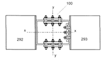
床板(または水平梁)とせん断壁との間で接続が行われる構造設計の他の状況では、接続は堅い。地震によって破壊動作が引き起こされた場合、接続は図28に示すように、接続されている構成要素に曲げモーメントとねじり荷重を与える。 In other situations of structural design where the connection is made between the floorboard (or horizontal beam) and the shear wall, the connection is tight. If an earthquake causes a rupture motion, the connection applies bending moments and torsional loads to the connected components, as shown in FIG.
橋は、様々な複雑な性質の柔軟な接続を利用して、下のポンツーンからの橋デッキを垂直に支えながら、並進と回転の相対的動作をある程度許容できるようにする。これは、地震荷重を減衰させ、関連する撓みを吸収するために必要である。また、交通量が多いために引き起こされる垂直方向の力をある程度減衰させる。 The bridge utilizes flexible connections of various complex properties to allow some relative movement of translation and rotation while vertically supporting the bridge deck from the lower Float. This is necessary to dampen the seismic load and absorb the associated deflection. It also damps the vertical force caused by heavy traffic to some extent.
したがって、本発明の目的は、外部荷重によって生じる構造要素間の力伝達を減衰し、外部荷重が加えられる前における構造要素の元の配置に、構造要素を付勢する構造に使用する弾性滑り摩擦ジョイントを提供することである。 Accordingly, an object of the present invention is to attenuate the transmission of force between the structural elements caused by the external load, to the original arrangement of the structural elements that definitive before the external load is applied, it uses a structure for biasing the structural elements elastic It is to provide a sliding friction joint.
第1の態様によれば、本発明は、相対的かつ抵抗性移動を許容し、かつ部材の間の任意の移動を少なくとも部分的に戻すために、第1の部材と第2の部材とを接続する滑りコネクタであると広く言うことができ、コネクタが、
前記第1の部材に接続可能な第1の構成要素と、
前記第2の部材に接続可能な第2の構成要素と、
第1の構成要素及び第2の構成要素の各々が、相互に摺動可能な傾斜表面を含み、
傾斜した表面の相対的移動が摩擦に抵抗できるように相互に摺動可能な傾斜表面を有する構成要素を共に保持する少なくとも1つの弾性固定具と、を含み、傾斜表面は作用の線、または複数の線に対して斜めであって第1及び第2の構成要素の傾斜表面の相対的な摺動運動の少なくとも部分的な戻りを引き起こす。
According to the first aspect, the present invention allows the first and second members to move relative and resistant to each other and to at least partially return any movement between the members. It can be broadly said that it is a slip connector to connect, and the connector is
A first component that can be connected to the first member,
A second component that can be connected to the second member,
Each of the first and second components comprises a slanted surface that is slidable with each other.
Comprising at least one elastic fastener relative movement of the inclined surface is held together a configuration element that have a slidable sloping surfaces mutually to allow resistance to friction, the inclined surface is a line of action , Or at least a partial return of the relative sliding motion of the slanted surfaces of the first and second components at an angle to the plurality of lines.
好ましくは、第1及び第2の構成要素の傾斜表面の相対的な摺動移動の完全な戻りを提供するために、傾斜表面の少なくとも1つの弾性固定具の作用の1つまたは複数の線に対する斜め角が、少なくとも1つの弾性固定具によって2つの構成要素の保持の下で、相互に摺動可能な傾斜表面間の摩擦抵抗に打ち勝つために十分なだけ設けられている。 Preferably, with respect to one or more lines of action of at least one elastic fixture on the sloping surface to provide a complete return of the relative sliding movement of the sloping surfaces of the first and second components. The oblique angle is provided sufficiently by at least one elastic fixture to overcome the frictional resistance between the slanted surfaces that are slidable with each other under the holding of the two components .
好ましくは、第1及び第2の構成要素の傾斜表面の摺動移動の少なくとも部分的な戻りは、少なくとも外力がない場合に生じる。 Preferably, at least a partial return of the sliding movement of the slanted surfaces of the first and second components occurs in the absence of at least an external force .
好ましくは、第1及び第2の構成要素の傾斜表面の摺動移動の戻りは、平衡位置に向かう戻りを含む。 Preferably, the return of sliding movement of the inclined surfaces of the first and second components includes a return towards the equilibrium position .
好ましくは、第1及び第2の構成要素の傾斜表面の摺動移動の戻りは、平衡位置への戻りを含む。 Preferably, the return of sliding movement of the slanted surfaces of the first and second components includes a return to equilibrium position .
好ましくは、第1及び第2の構成要素の傾斜表面の摺動移動の少なくとも部分的な戻りは、前記摺動移動の完全な戻りを含む。 Preferably, at least a partial return of the sliding movement of the slanted surfaces of the first and second components includes a complete return of the sliding movement .
好ましくは、第1及び第2の構成要素の摺動移動は、中心の状態から離れたコネクタの移動を含み、摺動移動の戻りは、中央の状態に向かう戻りを含む。 Preferably, the sliding movement of the first and second components includes the movement of the connector away from the central state, and the return of the sliding movement includes a return towards the central state .
好ましくは、少なくとも1つの弾性固定具による2つの構成要素の保持の下で、第1及び第2の構成要素の傾斜表面の相対的摺動移動の少なくとも部分的な戻りを提供するために、90度から傾斜表面と少なくとも1つの弾性固定具の1つまたは複数の作用の線との間の鋭角を引いたものである角度の正接は、第1の構成要素と第2の構成要素との摺動可能な傾斜表面の間の静止摩擦係数よりも大きい。
好ましくは、90度から傾斜表面と少なくとも1つの弾性固定具の1つまたは複数の作用の線との間の鋭角を引いた角度は、摺動可能な傾斜表面の間の静止摩擦係数が、0.36〜0.39であるとき、25〜30度の間の角度である。
好ましくは、少なくとも1つの弾性固定具による2つの構成要素の保持の下での第1及び第2の構成要素の傾斜表面の相対的摺動移動の少なくとも部分的な戻り提供するために、傾斜表面と、少なくとも1つの弾性固定具の1つまたは複数の作用の線との間の鋭角を90°から引いた角度の正弦が、これと傾斜表面の角度の余弦との和で割って、接触して傾斜表面間の静止摩擦係数よりも大きい。
好ましくは、90度から傾斜表面と少なくとも1つの弾性固定具の1つまたは複数の作用の線との間の鋭角を引いた角度は、摺動可能な傾斜表面の間の静止摩擦係数が、0.36〜0.39であるとき、25〜45度の間の角度である。
好ましくは、90度から傾斜表面と少なくとも1つの弾性固定具の1つまたは複数の作用の線との間の鋭角を引いた角度は、10〜90度の間の角度である。
好ましくは、第1の構成要素が、波形の複数の傾斜表面をアレイとして呈し、第2の構成要素が、第1の構成要素のアレイと係合する波形の複数の相補的な傾斜表面をアレイとして呈する。
好ましくは、第1の構成要素は、複数の上傾き傾斜表面及び下傾き傾斜表面をアレイとして呈し、第2の構成要素は、第1の構成要素のアレイと係合する複数の上傾き傾斜表面及び下傾き傾斜表面をアレイとして呈する。
好ましくは、第1及び第2の構成要素の傾斜表面は、傾斜表面の摺動移動の下で相互に乗り上げるようにされる。
第1の構成要素及び第2の構成要素の相対摺動移動の戻り速度は、少なくとも部分的に、少なくとも1つの弾性固定具による第1及び第2の構成要素の保持の大きさによって決定される。
好ましくは、少なくとも1つの弾性固定具による第1の構成要素と第2の構成要素の保持の大きさの増加は、摺動移動の戻り速度の増加に関連付けられる。
好ましくは、少なくとも2つの第2の構成要素があり、2つの第2の構成要素は第1の構成要素の少なくとも一部を挟む。
好ましくは、2つの第2の構成要素は、第1の構成要素の少なくとも一部を挟む。
好ましくは、弾性固定具は、第1の構成要素を通過する。
好ましくは、弾性固定具は、前記第2の構成要素から前記第1の構成要素を通過する。
好ましくは、弾性固定具は、第1の構成要素から第1の構成要素を通過する。
好ましくは、前記弾性固定具は、締結具と、締結具と第1及び第2の構成要素のアセンブリとの間に挿入され、付勢部材が、関連する弾性固定部の弾性的な保持を可能にする付勢力を加える少なくとも1つの付勢部材を備える。
好ましくは、付勢部材は、
・Belleville(ベルビル)ワッシャ、
・板ばね、
・コイルばね、の複数のうちの1つから選択される少なくとも1つのばねである。
Preferably, 90 to provide at least a partial return of the relative sliding movement of the inclined surfaces of the first and second components under the retention of the two components by at least one elastic fixture. The tangent of an angle, which is the degree minus the acute angle between the inclined surface and one or more lines of action of at least one elastic fixture, is the sliding of the first and second components. Greater than the coefficient of static friction between movable inclined surfaces.
Preferably, the angle obtained by subtracting the acute angle between the inclined surface and one or more lines of action of at least one elastic fixture from 90 degrees has a coefficient of static friction between the slidable inclined surfaces of 0. When it is .36 to 0.39, it is an angle between 25 and 30 degrees.
Preferably, an inclined surface is provided to provide at least a partial return of the relative sliding movement of the inclined surfaces of the first and second components under the retention of the two components by at least one elastic fixture. And a sine with an acute angle between one or more lines of action of at least one elastic fixture minus 90 °, divided by the sum of this and the cosine of the angle of the sloping surface to make contact. It is larger than the coefficient of static friction between inclined surfaces.
Preferably, the angle obtained by subtracting the acute angle between the inclined surface and one or more lines of action of at least one elastic fixture from 90 degrees has a coefficient of static friction between the slidable inclined surfaces of 0. When it is .36 to 0.39, it is an angle between 25 and 45 degrees.
Preferably, the angle obtained by subtracting the acute angle between the inclined surface and one or more lines of action of at least one elastic fixture from 90 degrees is an angle between 10 and 90 degrees.
Preferably, the first component presents a plurality of sloping surfaces of the waveform as an array, and the second component arrays a plurality of complementary sloping surfaces of the waveform that engage the array of first components. Presented as.
Preferably, the first component presents a plurality of up-sloping and down-sloping surfaces as an array, and the second component is a plurality of up-sloping surfaces that engage the array of first components. And the downwardly inclined inclined surface is presented as an array.
Preferably, the slanted surfaces of the first and second components are made to ride on each other under sliding movement of the slanted surface.
The return speed of the relative sliding movement of the first and second components is determined, at least in part, by the amount of retention of the first and second components by at least one elastic fixture. ..
Preferably, an increase in the amount of retention of the first and second components by at least one elastic fixture is associated with an increase in the return speed of sliding movement.
Preferably, there are at least two second components, the two second components sandwiching at least a portion of the first component.
Preferably, the two second components sandwich at least a portion of the first component.
Preferably, the elastic fixture passes through the first component.
Preferably, the elastic fixture passes from the second component through the first component.
Preferably, the elastic fixture passes from the first component to the first component.
Preferably, the elastic fixture is inserted between the fastener and the assembly of the fastener and the first and second components so that the urging member can elastically hold the associated elastic anchor. It is provided with at least one urging member that applies an urging force.
Preferably, the urging member
・ Belleville washer,
・ Leaf spring,
-A at least one spring selected from one of a plurality of coil springs.
好ましくは、移動中の第1及び第2の部材の最大変位が測定される。 Preferably, the maximum displacement of the first and second members in motion is measured.
好ましくは、変位測定装置は、前記第1の部材と第2の部材との間の最大変位、第2の構成要素に相対的な第1の構成要素の変位、固定具の作用の線に相対的な水平の方向の第2の構成要素に相対的な第1の構成要素の変位、固定具の作用の線に対して垂直な方向の第2の構成要素に相対的な第1の構成要素の変位のうちの少なくとも1つを測定するように提供される。 Preferably, the displacement measuring device is relative to the maximum displacement between the first member and the second member, the displacement of the first component relative to the second component, and the line of action of the fixture. Displacement of the first component relative to the second component in the horizontal direction, the first component relative to the second component in the direction perpendicular to the line of action of the fixture It is provided to measure at least one of the displacements of .
好ましくは、変位測定装置は、第2の構成要素に対する第1の構成要素の変位を測定する。 Preferably, the displacement measuring device measures the displacement of the first component with respect to the second component.
好ましくは、変位測定装置は、固定具の作用の線に平行な方向の第2の構成要素に対する第1の構成要素の変位を測定する。 Preferably, the displacement measuring device measures the displacement of the first component with respect to the second component in a direction parallel to the line of action of the fixture.
好ましくは、変位測定装置は、固定具の作用の線に垂直な方向の第2の構成要素に対する第1の構成要素の変位を測定する。 Preferably, the displacement measuring device measures the displacement of the first component with respect to the second component in the direction perpendicular to the line of action of the fixture.
好ましくは、複数の相互に傾斜した表面が、三角波形鋸歯波形、正弦波形截頭三角波形のような傾斜表面のアレイを画定するために設けられる。 Preferably, the inclined surface into a plurality of mutually are provided to define a triangular waveform sawtooth waveform, an array of inclined swash surface, such as a sine wave truncated triangular waveform.
好ましくは、第1の部材が、波形の複数の傾斜表面をアレイとして呈し、前記第2の部材が、前記第1の記述されたアレイと係合する波形の複数の相補的な傾斜表面をアレイとして呈する。 Preferably, the first member presents a plurality of sloping surfaces of the waveform as an array, and the second member arrays of a plurality of complementary sloping surfaces of the waveform that engage the first described array. Presented as.
したがって、別の態様では、本発明は、外力による相対的かつ抵抗性移動を許容し、かつ部材の間の任意の移動を少なくとも部分的に戻すように第1の部材と第2の部材とを接続する滑りコネクタであると広く言うことができ、コネクタが、
a)前記第1の部材に接続可能な第1の構成要素と、
b)第2の構成要素と、
c)第1の構成要素及び第2の構成要素のうちの少なくとも1つの少なくとも一部を上及び/または下に重なる少なくとも1つの第3の構成要素であって、第2の構成要素及び少なくとも1つの第3の構成要素のうちの少なくとも1つが、第2の部材に接続可能である、第3の構成要素と、
d)第1及び第3の構成要素を接触して保持するための少なくとも1つの弾性固定部と、
e)第2及び前記第3の構成要素を接触して保持するための少なくとも1つの弾性固定部と、を備えまたは含み、
第1及び第3の構成要素と第2及び第3の構成要素の各々の接触した相互関係は、相互に傾斜した表面であり、相互に傾斜した表面は、第1及び第3の構成要素の相対的に相互に及び第2もしくは第3の構成要素の相対的に相互に第1の方向への相対的な摺動を可能にし、相対的な摺動は、外力の停止時に、構成要素が第1の方向と対向する方向に戻るようにされるように関連する弾性固定具の弾性保持の方向に対して斜めに生じる。
Accordingly, in another aspect, the present invention includes a first member and a second member so as to permit relative and resistance moved by an external force, and returns any movement at least partially between the members It can be broadly said that it is a slip connector that connects the connector,
a) A first component that can be connected to the first member,
b) The second component and
c) At least one third component in which at least one of the first component and the second component overlaps above and / or below, the second component and at least one. With a third component, at least one of the third components is connectable to the second member.
d) At least one elastic fixation part for contacting and holding the first and third components,
e) wherein the second and the third component at least one elastic fixing portion for holding in contact with, the a was Bei Emma,
The contacting interrelationships of the first and third components with each of the second and third components are mutually inclined surfaces, and the mutually inclined surfaces are of the first and third components. It allows relative sliding of the second or third component relative to each other and relative to each other in the first direction, which allows the component to slide relative to each other when the external force is stopped. It occurs at an angle to the direction of elastic retention of the associated elastic fixture so that it returns in the direction opposite to the first direction .
好ましくは、第1の方向とは対向する方向への戻りが、少なくとも1つの弾性固定具による2つの構成要素の保持の下で、提供され、90度から傾斜表面と少なくとも1つの弾性固定具の1つまたは複数の作用の線との間の鋭角を引いたものである角度の正接は、第1の構成要素と第2の構成要素との相互に傾斜した表面の間の静止摩擦係数よりも大きい。Preferably, a return in the direction opposite to the first direction is provided under the retention of the two components by at least one elastic fixture, from 90 degrees to the inclined surface and at least one elastic fixture. The tangent of an angle, which is the subtraction of an acute angle between one or more lines of action, is greater than the coefficient of static friction between the mutually inclined surfaces of the first and second components. big.
好ましくは、90度から傾斜表面と少なくとも1つの弾性固定具の1つまたは複数の作用の線との間の鋭角を引いた角度は、摺動可能な傾斜表面の間の静止摩擦係数が、0.36〜0.39であるとき、25〜30度の間の角度である。Preferably, the angle obtained by subtracting the acute angle between the inclined surface and one or more lines of action of at least one elastic fixture from 90 degrees has a coefficient of static friction between the slidable inclined surfaces of 0. When it is .36 to 0.39, it is an angle between 25 and 30 degrees.
第1の構成要素及び第2の構成要素のうちの少なくとも1つの上に重なる部分の1つと、第1の構成要素及び第2の構成要素のうちの少なくとも1つの下に重なる対応する部分の1つとの、2つの第3の構成要素が設けられ、各々の上に重なるかまたは下に重なる部分が、相互に傾斜した表面の接触している相互関係を有する。One of the overlapping parts of at least one of the first component and the second component and one of the corresponding parts overlapping at least one of the first component and the second component. Two third components are provided, one on top of which or one on top of each other, with a contacting interrelationship of mutually inclined surfaces.
好ましくは、少なくとも1つの弾性固定具による2つの構成要素の保持の下で、第1の方向に対向する方向の戻りが設けられ、傾斜表面と、少なくとも1つの弾性固定具の1つまたは複数の作用の線との間の鋭角を90°から引いた角度の正弦が、これと傾斜表面の角度の余弦との和で割って、相互に傾斜した表面間の静止摩擦係数よりも大きい。Preferably, under the retention of the two components by at least one elastic fixture, a return in a direction opposite to the first direction is provided, with an inclined surface and one or more of the at least one elastic fixture. The sine at the angle of 90 ° minus the acute angle between the lines of action is greater than the coefficient of static friction between the mutually inclined surfaces, divided by the sum of this and the cosine of the angle of the inclined surface.
好ましくは、90度から傾斜表面と少なくとも1つの弾性固定具の1つまたは複数の作用の線との間の鋭角を引いた角度は、摺動可能な傾斜表面の間の静止摩擦係数が、0.36〜0.39であるとき、25〜45度の間の角度である。Preferably, the angle obtained by subtracting the acute angle between the inclined surface and one or more lines of action of at least one elastic fixture from 90 degrees has a coefficient of static friction between the slidable inclined surfaces of 0. When it is .36 to 0.39, it is an angle between 25 and 45 degrees.
好ましくは、第2の構成要素は、第2の部材に接続可能である。 Preferably, the second component is connectable to the second member.
好ましくは、第3の構成要素は、第2の部材に接続可能である。 Preferably, the third component is connectable to the second part material.
好ましくは、第1及び第2の部材は、第1及び第3の構成要素が相対的に摺動しているときに、コネクタによって弾性的に保持される方向に相対的に相互に変位させられない。Preferably, the first and second members are relatively displaced relative to each other in a direction elastically held by the connector when the first and third components are relatively sliding. do not have.
好ましくは、第1及び第2の部材は、第2及び第3の部材が相対的に摺動しているときに、コネクタによって弾性的に保持される方向に相対的に相互に変位させられない。 Preferably, the first and second members are not relatively displaced relative to each other in the direction elastically held by the connector when the second and third members are relatively sliding. ..
好ましくは、第1及び第2の部材は、第2及び第3の部材が相対的に摺動しているときに、コネクタによって弾性的に保持される方向に相対的に相互に変位させられない。Preferably, the first and second members are not relatively displaced relative to each other in the direction elastically held by the connector when the second and third members are relatively sliding. ..
好ましくは、第2の部材に接続可能な少なくとも1つの2つの第3の構成要素がある。 Preferably, there are at least one two third components that can be connected to the second member.
好ましくは、第2の構成要素と第3の構成要素との接触した相互関係があり、相互に傾斜した表面であり、このような相互に傾斜した表面が、第2及び第3の構成要素が、関連する弾性固定部の方向に斜めに摺動することを可能にする。
好ましくは、第2の構成要素がなく、第3の構成要素が、少なくとも1つの第2の部材、好ましくはいくつかの第2の部材に接続される。
好ましくは、少なくとも1つの前記第3の構成要素が、係合する第1の構成要素及び/または第2の構成要素に対して横方向に変位可能である。
好ましくは、弾性固定具は、第1の構成要素を少なくとも1つの第3の構成要素で取り込む。
好ましくは、弾性固定部の各々は、関連する弾性固定部の弾性保持をさせるための付勢力を加えるために、単一の、好ましくは2重ヘッド付き締結具と、締結具と、第1及び第3の、好ましくは第2の構成要素のアセンブリとの間、1つ、好ましくは2つのヘッドの間に、挿入された少なくとも1つの付勢部材とを備える。
好ましくは、単一の、好ましくは2重ヘッド付き締結具が螺刻される。
好ましくは、2重ヘッド付きの螺刻された締結具は、ボルト及びナットを含む。
好ましくは、付勢部材は、板ばね、コイルばね、ベルビルワッシャの複数のうちの1つから選択される少なくとも1つのバネである。
好ましくは、各々の各弾性固定部は、専用の付勢部材を有する。
好ましくは、各々の各弾性固定部は、1つの付勢部材に依存する。
好ましくは、各々の弾性固定部のために複数の付勢部材が設けられる。
好ましくは、各々の付勢部材は、螺刻された締結具のヘッドと隣接する第3の構成要素との間で作用する。
好ましくは、付勢部材は、各々のヘッドとその隣接する第3の構成要素との間に設けられる。
好ましくは、付勢部材は、複数の付勢部材のアセンブリであり得る。
好ましくは、前記第1の構成要素の少なくとも一部を挟むように前記弾性固定部を有する弾性的に拡張可能なクランプとして共に作用する前記第3の構成要素の2つがある。
好ましくは、前記第1の構成要素及び前記第2の構成要素の少なくとも一部を挟むように前記弾性固定部を有する弾性的に拡張可能なクランプとして共に作用する前記第3の構成要素の2つがある。
好ましくは、第1及び第3の構成要素が、相互に直線平行的な形態で移動するように適合されかつ構成される。
好ましくは、各々の第3の構成要素は、第3の構成要素と前記第1の構成要素との間の相対的な移動方向に延びる直線状の細長い部材である。
好ましくは、各々の第3の構成要素は、第3の構成要素と前記第1の構成要素と前記第2の構成要素との間の相対的な移動方向に延びる直線状の細長い部材である。
好ましくは、(a)前記第3の構成要素が設けられる少なくとも1つ及び好ましくは両方と、(b)前記第1の構成要素との少なくとも1つ、好ましくは両方が、前記摺動のために上に傾き、下に傾いた傾斜のアレイを提供して、前記クランプの拡張を引き起こす。
好ましくは、第1の構成要素が、波形の複数の傾斜表面をアレイとして呈し、第2の構成要素が、第1の構成要素のアレイと係合する波形の複数の相補的な傾斜表面をアレイとして呈する。
好ましくは、第1の構成要素は、複数の上傾き傾斜表面及び下傾き傾斜表面をアレイとして呈し、第2の構成要素は、第1の構成要素のアレイと係合する複数の上傾き傾斜表面及び下傾き傾斜表面をアレイとして呈する。
好ましくは、第1及び第2の構成要素の傾斜表面は、傾斜表面の摺動移動の下で相互に乗り上げるようにされる。
好ましくは、アレイは、少なくとも1つの第3の構成要素が第1の構成要素に相対的に移動する方向と平行な方向に延びる。
好ましくは、構造物は、建築構造物である。
好ましくは、第1の部材は、梁、柱、床板振れ止め及び基礎のうちの1つから選択される。
好ましくは、傾斜表面及び弾性固定部は、第3の構成要素を、第1の構成要素に対して移動させ、弾性固定部の付勢力に対向して移動させるが、摺動構成要素を平衡位置に向けて付勢させる力を加えると、隣接する構成要素が摺動する際に乗り上げることを可能にするように適合及び構成される。
Preferably, there is a contact interrelationship between the second component and the third component, which is a mutually sloping surface, such a mutually sloping surface where the second and third components Allows sliding diagonally in the direction of the associated elastic fixation.
Preferably, there is no second component, and the third component is connected to at least one second member, preferably some second member.
Preferably, at least one of the third components is laterally displaceable with respect to the first and / or second components that are engaged.
Preferably, the elastic fixture incorporates the first component with at least one third component.
Preferably, each of the elastic anchors has a single, preferably double-headed fastener, and a first and second It comprises at least one urging member inserted between a third, preferably second component assembly, and between one, preferably two heads.
Preferably, a single, preferably double-headed fastener is threaded.
Preferably, the threaded fastener with the double head includes bolts and nuts.
Preferably, the urging member is at least one spring selected from one of a plurality of leaf springs, coil springs, and bellville washers.
Preferably, each elastic fixation portion has a dedicated urging member.
Preferably, each elastic fixation depends on one urging member.
Preferably, a plurality of urging members are provided for each elastic fixation portion.
Preferably, each urging member acts between the head of the screwed fastener and an adjacent third component.
Preferably, the urging member is provided between each head and a third component adjacent thereto.
Preferably, the urging member can be an assembly of a plurality of urging members.
Preferably, there are two of the third components that act together as elastically expandable clamps having the elastic fixation so as to sandwich at least a portion of the first component.
Preferably, two of the first component and the third component acting together as an elastically expandable clamp having the elastic fixation portion so as to sandwich at least a part of the second component. be.
Preferably, the first and third components are adapted and configured to move in a form that is linearly parallel to each other.
Preferably, each third component is a linear elongated member that extends in the relative direction of movement between the third component and the first component.
Preferably, each third component is a linear elongated member that extends in a relative direction of movement between the third component, the first component, and the second component.
Preferably, (a) at least one and preferably both of which the third component is provided and (b) at least one, preferably both of the first component, are for said sliding. An array of tilted up and tilted down is provided to cause expansion of the clamp.
Preferably, the first component presents a plurality of sloping surfaces of the waveform as an array, and the second component arrays a plurality of complementary sloping surfaces of the waveform that engage the array of first components. Presented as.
Preferably, the first component presents a plurality of up-sloping and down-sloping surfaces as an array, and the second component is a plurality of up-sloping surfaces that engage the array of first components. And the downwardly inclined inclined surface is presented as an array.
Preferably, the slanted surfaces of the first and second components are made to ride on each other under sliding movement of the slanted surface.
Preferably, the array extends in a direction parallel to the direction in which at least one third component moves relative to the first component.
Preferably, the structure is a building structure.
Preferably, the first member is selected from one of a beam, a column, a floorboard steady rest and a foundation.
Preferably, the sloping surface and the elastic fixation portion move the third component relative to the first component and against the urging force of the elastic fixation portion, while the sliding component is in equilibrium position. When an urging force is applied towards, it is adapted and configured to allow adjacent components to ride as they slide.
好ましくは(a)前記第3の構成要素が設けられる少なくとも1つ及び好ましくは両方と、(b)前記第1の構成要素及び前記第2の構成要素の少なくとも1つ、好ましくは両方が、前記摺動のために上に傾き、下に傾いたアレイを提供して、前記クランプの拡張を引き起こす。 Preferably at least one and preferably with both, at least one of (b) said first component and said second configuration elements are provided with (a) the third component, preferably both, slope above for the slide, to provide array tilted down, causing the expansion of the clamp.
好ましくは、アレイは、第3の構成要素が第1及び第2の構成要素への相対的移動の方向と平行な方向に延びる。 Preferably, the array extends in a direction in which the third component is parallel to the direction of relative movement to the first and second components.
好ましくは、第1及び第2の部材は、構造物の構造部材である。 Preferably, the first and second members are structural members of the structure.
好ましくは、構造物は、建築構造物である。 Preferably, the structure is a building structure.
好ましくは、第1の部材は、梁、柱、床板振れ止め及び基礎のうちの1つから選択される。 Preferably, the first member is selected from one of a beam, a column, a floorboard steady rest and a foundation.
好ましくは、第2の部材は、梁、柱、床板振れ止め及び基礎のうちの1つから選択される。 Preferably, the second member is selected from one of beams, columns, floorboard steady rests and foundations.
好ましくは、傾斜表面及び弾性固定部は、第3の構成要素を、第1の構成要素及び第2の構成要素に対して移動させ、弾性固定部の付勢力に対向して移動させるが、摺動構成要素を平衡位置に向けて付勢させる力を加えると、隣接する構成要素が摺動する際に乗り上げることを可能にするように適合及び構成される。 Preferably, the sloping surface and the elastic fixation portion move the third component relative to the first and second components and oppose the urging force of the elastic fixation portion, while sliding. When a force that urges the dynamic component towards an equilibrium position is applied, it is adapted and configured to allow the adjacent component to ride as it slides.
好ましくは、第1の構成要素及び第3の構成要素は、回転軸の周りに相対的に相互に回転するように適合及び構成され、前記第1の構成要素及び第3の構成要素の各々が、それらの間に傾斜した摺動を生じさせる相互に係合可能な表面を含む。 Preferably, the first and third components are adapted and configured to rotate relative to each other around an axis of rotation, with each of the first and third components , including an engaging surface capable of mutually cause sliding inclined therebetween.
好ましくは、表面は、回転軸を中心に完全に回転するような形態で、相互に上下に傾斜するときに移動する。 Preferably, the surfaces move as they tilt up and down with each other in such a way that they rotate completely about the axis of rotation.
好ましくは、表面が傾斜形態で摺動するとき、第1及び第3の構成要素が、回転軸に平行な方向に相対的に相互に移動すると共に、その周りを回転する。 Preferably, when the surface slides in an inclined form, the first and third components move relative to each other in a direction parallel to the axis of rotation and rotate around it.
好ましくは、2つの第3の構成要素が設けられている場合、1つの第3の構成要素が、傾斜していないがむしろ平面である境界表面のために、相対回転の際に第1の構成要素の横方向に動くことができず、回転軸が、前記平面に直角である。 Preferably, if the two third components are provided, one third component, for inclined non but bounding surface is a plane rather, first configuration during relative rotation The element cannot move laterally and its axis of rotation is perpendicular to the plane.
好ましくは、回転形態で、傾斜表面が、(a)回転の軸と平行でなく(b)回転の軸に垂直でない1つまたは複数の法線を有する。 Preferably, in the form of rotation, the inclined surface has one or more normals that are (a) not parallel to the axis of rotation and (b) not perpendicular to the axis of rotation.
回転形態で、傾斜表面が、回転の軸に平行な方向から見たとき、その半径方向の距離における概念円に正接方向である回転軸から任意の所与の半径方向距離にある1つまたは複数の法線を有する。 A rotary form, the inclined surface, when viewed from the direction parallel to the axis of rotation, 1 knob others from the rotating shaft concept circle is tangential at the distance of its radial at any given radial distance It has multiple normals.
好ましくは、第1の構成要素及び第2の構成要素が、前記第1の構成要素及び第3の構成要素が、任意の2次元並進形態で変位させられたときに、前記第1の構成要素と第3の構成要素との間に、横方向移動を引き起こすことができる相互に傾斜した表面を含む。
好ましくは、第1及び第3の構成要素が、相互に直線平行的な形態で移動するように適合されかつ構成される。
好ましくは、第1及び第2の部材は、構造物の構造部材である。
好ましくは、構造物は、建築構造物である。
好ましくは、第1の部材は、梁、柱、床板振れ止め及び基礎のうちの1つから選択される。
好ましくは、第2の部材は、梁、柱、床板振れ止め及び基礎のうちの1つから選択される。
Preferably, the first component and the second component are the first component when the first component and the third component are displaced in any two-dimensional translational form. Includes a mutually sloping surface that can cause lateral movement between and the third component.
Preferably, the first and third components are adapted and configured to move in a form that is linearly parallel to each other.
Preferably, the first and second members are structural members of the structure.
Preferably, the structure is a building structure.
Preferably, the first member is selected from one of a beam, a column, a floorboard steady rest and a foundation .
Preferably, the second member is selected from one of beams, columns, floorboard steady rests and foundations .
したがって、さらなる態様では、本発明は、2つの構造部材の相対的移動を引き起こす外力を受ける可能性がある2つの構造部材間の減衰及び位置回復機能を提供する構造コネクタであると広く言え、コネクタが、
第2の摩擦板に並置され、付勢力下で共に保持される第1の摩擦板と、付勢力の前記方向に対する角度の方向に上に及び相対的に相互に摺動することができる第1の摩擦板と第2の摩擦板の接触摩擦面と、を備え、第1及び第2の摩擦板の接触表面間の静止摩擦係数が、前記動作に供されるとき、前記2つの構造部材によって前記第1の摩擦板と前記第2の摩擦板とに外力が加えられたとき、板の付勢力が、板の接触表面の間の静止摩擦力に打ち勝つために十分な大きさで第1及び第2の摩擦板の接触表面を第1の記述された方向と対向する方向に摺動させることを促すようである。
好ましくは、第1の摩擦板と第2の摩擦板との接触表面各々が、相互に摺動可能な傾斜表面を備え、板の上の及び相対的に互いの摺動の角度が、傾斜表面の傾斜角度によって決定される。
好ましくは、相互に摺動可能な傾斜表面各々は、複数の上傾き傾斜表面及び下傾き傾斜表面を備える。
好ましくは、傾斜表面は、鋸歯波形輪郭である。
好ましくは、傾斜表面は、付勢力の作用の線に対して斜めである。
好ましくは、第1の方向と対向する方向への摺動は、平衡位置に向かう戻りを含む。
好ましくは、第1の方向と対向する方向への摺動は、平衡位置への戻りを含む。
好ましくは、第1の方向と対向する方向への摺動は、第1の方向の前記摺動移動の完全な戻りを含む。
好ましくは、第1の構成要素は、第1の構造部材に関連付けられ、第2の構成要素は、第2の構造部材に関連付けられる。
好ましくは、第1の摩擦板及び第2の摩擦板のうちの少なくとも1つの少なくとも一部を上及び/または下に重なり、付勢力によって保持された少なくとも1つの第3の摩擦板をさらに備え、接触摩擦表面が、少なくとも1つの第3の摩擦板と第1の摩擦板及び第2の摩擦板のうちの少なくとも1つとの間にさらに設けられる。
好ましくは、第1の構成要素は、第1の構造部材に関連付けられ、第3の構成要素は、第2の構造部材に関連付けられる。
好ましくは、外力がない場合に、第1の方向とは対向する方向の摺動が、少なくとも1つの弾性固定具による2つの構成要素の保持の下で、提供され、90度から傾斜表面と少なくとも1つの弾性固定具の1つまたは複数の作用の線との間の鋭角を引いたものである角度の正接は、第1の構成要素と第2の構成要素との相互に傾斜した表面の間の静止摩擦係数よりも大きい。
好ましくは、90度から傾斜表面と少なくとも1つの弾性固定具の1つまたは複数の作用の線との間の鋭角を引いた角度は、摺動可能な傾斜表面の間の静止摩擦係数が、0.36〜0.39であるとき、25〜30度の間の角度である。
好ましくは、2つの第3の構成要素は、1つが、上に重なり、他の1つが下に重なって設けられる。
好ましくは、少なくとも1つの弾性固定具による2つの構成要素の保持の下で、第1の方向に対向する方向のコネクタ戻りが設けられ、傾斜表面と、少なくとも1つの弾性固定具の1つまたは複数の作用の線との間の鋭角を90°から引いた角度の正弦が、それと傾斜表面の角度の余弦との和で割って、相互に傾斜した表面間の静止摩擦係数よりも大きい。
好ましくは、90度から傾斜表面と少なくとも1つの弾性固定具の1つまたは複数の作用の線との間の鋭角を引いた角度は、摺動可能な傾斜表面の間の静止摩擦係数が、0.36〜0.39であるとき、25〜45度の間の角度である。
好ましくは、第1及び第2の摩擦板の接触表面の摺動を制限するための限界が設けられ、限界は、上に傾いたまたは下に傾いた傾斜表面の長さよりもさらに摺動を防止する。
好ましくは、付勢力は、少なくとも1つの弾性固定具によって提供され、少なくとも1つの弾性固定具各々が、締結具と、締結具と摩擦板のアセンブリとの間に挿入された少なくとも1つの付勢部材と、を備え、少なくとも1つの弾性固定具が前記限界を提供する。
Therefore, in a further aspect, the present invention can be broadly said to be a structural connector that provides damping and position recovery functions between two structural members that may be subject to external forces that cause the relative movement of the two structural members. but,
Juxtaposed to the second friction plates, a first friction plate is held together under the biasing force, to slide on and relative one another in the direction of the angle against the front Symbol Direction biasing force comprises a first friction plate and the contact friction surface of the second friction plates that can, the static friction coefficient between the contact surfaces of the first and second friction plates, when it is subjected to the operation, the two When an external force is applied to the first friction plate and the second friction plate by the structural member, the urging force of the plate is large enough to overcome the static friction force between the contact surfaces of the plate. It seems to encourage the contact surfaces of the first and second friction plates to slide in the direction opposite to the first described direction.
Preferably, each of the contact surfaces of the first friction plate and the second friction plate has an inclined surface that is slidable with each other, and the angle of sliding on the plate and relative to each other is the inclined surface. Determined by the tilt angle of.
Preferably, each of the slidable surfaces slidable with each other comprises a plurality of upslopes and downslopes.
Preferably, the sloping surface is a serrated corrugated contour.
Preferably, the sloping surface is beveled with respect to the line of action of the urging force .
Preferably, sliding in the direction opposite to the first direction includes a return towards the equilibrium position.
Preferably, sliding in the direction opposite to the first direction involves returning to the equilibrium position.
Preferably, sliding in a direction opposite to the first direction includes a complete return of said sliding movement in the first direction .
Preferably, the first component is associated with the first structural member and the second component is associated with the second structural member.
Preferably, at least a part of at least one of the first friction plate and the second friction plate is overlapped above and / or below, and at least one third friction plate held by the urging force is further provided. A contact friction surface is further provided between at least one third friction plate and at least one of the first friction plate and the second friction plate.
Preferably, the first component is associated with the first structural member and the third component is associated with the second structural member.
Preferably, in the absence of external force, sliding in the direction opposite to the first direction is provided under the holding of the two components by at least one elastic fixture, from 90 degrees to an inclined surface and at least. An acute angle tangent, which is the subtraction of an acute angle between one or more lines of action of an elastic fixture, is between the mutually inclined surfaces of the first and second components. Is greater than the coefficient of static friction of.
Preferably, the angle obtained by subtracting the acute angle between the inclined surface and one or more lines of action of at least one elastic fixture from 90 degrees has a coefficient of static friction between the slidable inclined surfaces of 0. When it is .36 to 0.39, it is an angle between 25 and 30 degrees.
Preferably, the two third components are provided, one on top and one on the bottom.
Preferably, under the retention of the two components by at least one elastic fixture, a connector return in the direction opposite to the first direction is provided, with an inclined surface and one or more of the at least one elastic fixture. The sine at the angle of 90 ° minus the acute angle between the lines of action of is greater than the coefficient of static friction between the mutually inclined surfaces, divided by the sum of it and the cosine of the angle of the inclined surface.
Preferably, the angle obtained by subtracting the acute angle between the inclined surface and one or more lines of action of at least one elastic fixture from 90 degrees has a coefficient of static friction between the slidable inclined surfaces of 0. When it is .36 to 0.39, it is an angle between 25 and 45 degrees.
Preferably, a limit is provided for limiting the sliding of the contact surfaces of the first and second friction plates, the limit preventing further sliding than the length of the inclined surface tilted up or down. do.
Preferably, the urging force is provided by at least one elastic fixture, each of which is an at least one urging member inserted between the fastener and the assembly of the fastener and the friction plate. And, at least one elastic fixture provides the limits.
好ましくは、付勢力は、少なくとも1つのばねによって提供される。 Preferably, the urging force is provided by at least one spring.
好ましくは、付勢力は、ばねまたはばねアセンブリによって提供される。 Preferably, the urging force is provided by a spring or spring assembly.
好ましくは、付勢力は、前記2つの構造部材によって加えられる外力がなくなったときに、第1及び第2の摩擦板の接触表面を前記第1の記述された方向と反対の方向に摺動させるのに十分である。 Preferably , the urging force slides the contact surfaces of the first and second friction plates in a direction opposite to the first described direction when the external force applied by the two structural members is eliminated. Enough for
好ましくは、摩擦板は、第1及び第2の摩擦板の前記接触表面が前記第1の記述された方向に相互に摺動するときに、前記付勢力に側方にまた対向して離れ、前記付勢力に垂直な方向に長手方向に変位する。 Preferably, the friction plates are separated from the urging force laterally as the contact surfaces of the first and second friction plates slide against each other in the first described direction. It is displaced in the longitudinal direction in the direction perpendicular to the urging force.
好ましくは、摩擦板は、第1及び第2の摩擦板の前記接触表面が前記第1の記述された方向と対向する前記方向に相対的に相互に摺動するときに、付勢力と側方にかつ共に固定し、前記付勢力に垂直な方向に長手方向に変位する。 Preferably, the friction plates are biased and lateral when the contact surfaces of the first and second friction plates slide relative to each other in the direction opposite to the first described direction. And both are fixed and displaced in the longitudinal direction in the direction perpendicular to the urging force.
好ましくは、摩擦板は、第1及び第2の摩擦板の前記接触表面が前記第2の記述された方向に相対的に相互に摺動するときに、付勢力に側方にかつ共に固定し、前記付勢力に垂直な方向に長手方向に変位する。 Preferably, the friction plates are laterally and together fixed to the urging force when the contact surfaces of the first and second friction plates slide relative to each other in the second described direction. , Displaces in the longitudinal direction in the direction perpendicular to the urging force.
好ましくは、摩擦板は、相互に相対的に直線平行的な形態で移動する。
好ましくは、摩擦板は、第1及び第2の摩擦板の前記接触表面が前記第1の記述された方向に相互に摺動するときに、1方向に回転軸を中心に回転変位し、付勢力の方向に平行な方向に離れる。
Preferably, the friction plates move in a form that is relatively linear and parallel to each other .
Preferably, the friction plate when the contact surfaces of the first and second friction plates to each other sliding phase to the first of the described direction, rotationally displaced around the rotation axis in one direction, Separate in a direction parallel to the direction of the urging force.
好ましくは、摩擦板は、第1及び第2の摩擦面の前記接触表面が前記第1の記述された方向と対向する前記方向に相互に摺動するときに、1方向に回転軸を中心に回転変位し、付勢力の方向に平行な方向に固定する。 Preferably, the friction plate when the contact surfaces of the first and second friction surfaces are mutually sliding phase into the direction opposite to the first of the described direction, around the rotation axis in one direction It is rotationally displaced and fixed in a direction parallel to the direction of the urging force.
好ましくは、摩擦板は、無指向性形態の平面方向に相対的に相互に滑り、第1及び第2の摩擦面の前記接触表面が相互に摺動するときに、付勢力の方向に対して、前記平面の平行な法線方向内に離れることができる。 Preferably, the friction plates slide relative to each other in the plane direction of the omnidirectional form, with respect to the direction of the urging force when the contact surfaces of the first and second friction surfaces slide against each other. , Can be separated within the parallel normal direction of the plane.
好ましくは、少なくとも2つの摩擦板の間の最大変位が、測定/記録される。 Preferably, the maximum displacement between at least two friction plates is measured / recorded.
好ましくは、2つの摩擦板の間の付勢力に平行な方向の変位が、測定/記録される。 Preferably, the displacement in the direction parallel to the urging force between the two friction plates is measured / recorded.
好ましくは、2つの摩擦板の間の付勢力に垂直な方向の変位が、測定/記録される。 Preferably, the displacement in the direction perpendicular to the urging force between the two friction plates is measured / recorded.
好ましくは、変位測定装置が、測定/記録の目的で前記構造コネクタに係合される。 Preferably, the displacement measuring device is engaged with the structural connector for measurement / recording purposes.
したがって、第1の態様では、本発明は、2つの構造部材の相対的移動を引き起こす動作を受ける可能性がある2つの構造部材間の減衰及び位置回復機能を提供する構造コネクタであると広く言うことができ、コネクタが、
第1のセットとして、第2の摩擦板に並置され、付勢力下で共に保持される第1の摩擦板と、前記動作に供されるとき、前記2つの構造部材によって前記第1の摩擦板と前記第2の摩擦板とに外力が加えられたとき、付勢力の方向に対して90度未満及び10度を超える角度の方向に上側に及び相対的に相互に摺動可能な第1の摩擦板と第2の摩擦板の接触摩擦面と、付勢力が、第1及び第2の摩擦板の接触表面を前記第1の記述された方向と対向する方向に摺動させることを促し、第2のセットとして、第4の摩擦板に並置され、第2の付勢力下で共に保持される第3の摩擦板と、前記動作に供されるとき、前記2つの構造部材によって前記第3の摩擦板と前記第4の摩擦板とに外力が加えられたとき、第2の付勢力の方向に対して90度未満及び10度を超える角度の方向に上側に及び相対的に相互に摺動可能な第3及び第4の摩擦板の接触摩擦面と、を備え、第2の付勢力が、第3及び第4の摩擦板の接触表面を前記第1の記述された方向と対向する方向に摺動させることを促し、
少なくとも、
(a)第1及び第2の板の摺動方向角度が、第3及び第4の板の側面方向角度と異なるか、
(b)記述された第1の付勢力が、第2の付勢力と同じではないか、
(c)前記第3及び第4の摩擦板が係合して上側に相互に摺動する前に、前記2つの構造部材の関連する移動の閾値に達する必要があるか、のうちの1つである。
Thus, in the first aspect, the invention is broadly referred to as a structural connector that provides damping and position recovery functions between two structural members that may be subjected to actions that cause relative movement of the two structural members. Can be a connector,
As a first set, a first friction plate juxtaposed with a second friction plate and held together under urging force, and the first friction plate by the two structural members when subjected to the operation. When an external force is applied to the second friction plate, the first friction plate is slid upward and relatively to each other in the direction of an angle of less than 90 degrees and more than 10 degrees with respect to the direction of the urging force. The contact friction surface of the friction plate and the second friction plate and the urging force promote the contact surface of the first and second friction plates to slide in the direction opposite to the first described direction. As a second set, a third friction plate juxtaposed to the fourth friction plate and held together under a second urging force, and when subjected to the operation, the third by the two structural members. When an external force is applied to the friction plate and the fourth friction plate, they slide upward and relative to each other in the direction of an angle of less than 90 degrees and more than 10 degrees with respect to the direction of the second urging force. With movable third and fourth friction plate contact friction surfaces, a second urging force opposes the contact surfaces of the third and fourth friction plates in the first described direction. Encourage them to slide in the direction,
at least,
(A) Is the sliding direction angle of the first and second plates different from the side surface angle of the third and fourth plates?
(B) Isn't the described first urging force the same as the second urging force?
(C) One of whether it is necessary to reach the associated movement threshold of the two structural members before the third and fourth friction plates engage and slide upwards from each other. Is.
したがって、別の態様では、本発明は、外部から誘発される振動事象中に前記第2の部材に対して第1の部材の弾性的な変位が発生することを可能にする形態で、第1の建築部材と少なくとも1つの他の建築部材とを接続することができるコネクタであると広く言うことができ、コネクタは、前記第1の構築部材と共に移動する第1の構成要素を含む第1のアセンブリと、前記第1の構成要素を少なくとも部分的に挟むクランプアセンブリと、を含むアセンブリを備え、前記クランプアセンブリが、前記少なくとも1つの他の建築部材に直接または間接的に接続され、前記第1の建築部材に対して移動し、
クランプアセンブリが、第1の構築部材と少なくとも1つの他の構築部材との間の相対的移動の方向に対して横方向に弾性的に拡張可能であるが、付勢手段によって接触して相互に摺動可能な面を有するクランプアセンブリ及び第1の構成要素を保持するように付勢され、作用の線が、接触して保持される摺動可能な表面に対して斜めである。
Therefore, in another aspect, the present invention is in a form that allows an elastic displacement of the first member with respect to the second member during an externally evoked vibration event. It can be broadly said that it is a connector capable of connecting a building member of the same to at least one other building member, and the connector is a first component including a first component that moves with the first building member. An assembly comprising an assembly and a clamp assembly that at least partially sandwiches the first component, wherein the clamp assembly is directly or indirectly connected to the at least one other building member, said first. Move to the building components of
The clamp assemblies are elastically expandable laterally with respect to the direction of relative movement between the first construction member and at least one other construction member, but are contacted by urging means to each other. The line of action, urged to hold the clamp assembly with the slidable surface and the first component, is slanted with respect to the slidable surface held in contact.
好ましくは、クランプアセンブリは、相互に摺動可能な接触する表面に2つの構成要素を保持するための少なくとも1つの弾性ボルト固定具を含む。 Preferably, the clamp assembly comprises at least one elastic bolt fixture for holding the two components on mutually slidable, contacting surfaces.
好ましくは、付勢手段は、ばねである。 Preferably, the urging means is a spring.
好ましくは、ばねは、圧縮ばねまたは引っ張りばねである。 Preferably, the spring is a compression spring or a tension spring.
好ましくは、ばねは、板ばね、コイルばね、ベルビルワッシャのうちの少なくとも1つを含むことができる。 Preferably, the spring can include at least one of a leaf spring, a coil spring and a bell bill washer.
好ましくは、クランプアセンブリは、第1の建築部材及び第2の建築部材との間の横方向及び相対的な変位の方向の両方において、前記第2の建築部材に対して相対的に移動する。 Preferably, the clamp assembly moves relative to the second building member in both the lateral and relative displacement directions between the first building member and the second building member.
好ましくは、変位は直線変位である。 Preferably, the displacement is a linear displacement.
好ましくは、変位は回転変位である。 Preferably, the displacement is a rotational displacement.
好ましくは、横方向の膨張を除いた変位は、平面内の変位である。 Preferably, the displacement excluding lateral expansion is the displacement in the plane.
したがって、別の態様では、本発明は、構造部材の間の滑り接続を提供するための滑りコネクタであると広く言うことができ、コネクタは、前記構造部材を係合する任意の適合を含むか、含まないか、または係合する任意の部材を含むか、含まないかを問わず、相互に対して摺動するよう適合され、作用の線(または複数の線)の弾性を有する少なくとも1つの固定具によってその接触関係に保持された表面と接触する少なくとも2つの構成要素を有し、作用の線は接触表面に斜めである。 Thus, in another aspect, the invention can be broadly referred to as a slip connector for providing a slip connection between structural members, and does the connector include any fit that engages said structural member? At least one that is adapted to slide relative to each other and has the elasticity of a line of action (or lines of action), including or not including any member that is included or engaged. It has at least two components that come into contact with the surface held in that contact by the fixture, and the line of action is oblique to the contact surface.
好ましくは、2つの構成要素のみがあり、各々が、それぞれの前記構造部材に直接的または間接的に接続するように適合される。 Preferably, there are only two components, each adapted to connect directly or indirectly to each said structural member.
別の態様によれば、
前記第1の部材に接続可能な第1の構成要素、
前記第2の部材に接続可能な第2の構成要素、
第1の構成要素の一部を上及び/または下に重なる少なくとも第3の構成要素、
第2の構成要素の一部、
第1及び少なくとも第3の構成要素を接触表面関係に保持するための少なくとも1つの弾性固定具、
第2及び少なくとも第3の構成要素を接触表面関係に保持するための少なくとも1つの弾性固定部、である少なくとも3つの構成要素がある。
According to another aspect
A first component that can be connected to the first member,
A second component that can be connected to the second member,
At least a third component, with a portion of the first component overlapping above and / or below.
Part of the second component,
At least one elastic fixture for holding the first and at least third components in a contact surface relationship,
There are at least three components that are at least one elastic anchor for holding the second and at least the third component in a contact surface relationship.
別の態様によれば、各々の表面対表面の相互関係は、相互に傾斜した表面であり、
このような相互に傾斜した表面が、関連する構成要素の関連する固定具の弾性保持の方向に対し斜めで相対的に摺動することを可能にする。
According to another aspect, each surface-to-surface interrelationship is a mutually sloping surface.
Such mutually inclined surfaces, to the direction of elastic holding Seki fixture for communication with associated components make it possible to slide relative obliquely.
好ましくは、各々の表面対表面の相互関係が、前記作用の線に対して各々が斜めの複数の表面領域である。 Preferably, the surface-to-surface interrelationship is a plurality of surface regions, each oblique to the line of action.
好ましくは、各々の表面対表面の相互関係は、三角波形輪郭の相互に傾斜した表面である。 Preferably, the surface-to-surface interrelationship of each is a mutually sloping surface of a triangular corrugated contour.
好ましくは、各々の表面対表面の相互関係は、鋸歯波形輪郭の相互に傾斜した表面である。 Preferably, the surface-to-surface interrelationship of each is a mutually sloping surface of the serrated corrugated contour.
好ましくは、各々の表面対表面の相互関係は、正弦波形輪郭の相互に傾斜した表面である。 Preferably, the surface-to-surface interrelationship is a mutually sloping surface with a sinusoidal contour.
好ましくは、各々の固定具は、ボルト及びナットを含む。 Preferably, each fixture comprises bolts and nuts.
好ましくは、各々のボルト及びナットは、少なくとも1つの弾性ワッシャまたはばねを含む。 Preferably, each bolt and nut comprises at least one elastic washer or spring.
したがって、別の態様では、本発明は、建築構造物、すなわちコネクタの滑りに見合った部材間の移動を可能にする構造物の部材間の滑りコネクタであると広く言うことができ、滑りコネクタは、少なくとも2つコネクタの構成要素の接触表面が、相互に対して(相互に)滑ることができるが、その関連する接触表面に対して斜めの作用の線を有する弾性固定具アセンブリによって共に保持される。 Thus, in another aspect, the invention can be broadly referred to as a sliding connector between members of a building structure, i.e. a structure that allows movement between members commensurate with the sliding of the connector. The contact surfaces of at least two connector components can slide against each other (mutually), but are held together by an elastic fixture assembly that has a line of action diagonal to its associated contact surfaces. NS.
好ましくは、移動は直線である。 Preferably, the movement is straight.
好ましくは、移動は平面である。 Preferably, the movement is planar.
好ましくは、滑るための前記コネクタの構成要素は、接触表面の第1のアレイと、接触表面の第2のアレイとを含み、表面の前記第1のアレイの表面または複数の表面の法線が、第1の平面に延び、表面の前記第2のアレイの表面または複数の表面の法線が、前記第1の平面に実質的に垂直な第2の平面内に延びる。 Preferably, the components of the connector for sliding include a first array of contact surfaces and a second array of contact surfaces, with the surface or surface normals of the first array of surfaces. , The normals of the surface or plurality of surfaces of the second array of surfaces extend into a second plane that is substantially perpendicular to the first plane.
別の態様によれば、移動は回転的である。 According to another aspect, the movement is rotational.
好ましくは、2つの接触表面は、滑る前記コネクタの前記構成要素が、相対的に相互に回転可能である回転の概念的な軸から実質的に半径方向に延びる。 Preferably, the two contact surfaces extend substantially radially from the conceptual axis of rotation in which the components of the sliding connector are relatively rotatable with respect to each other.
好ましくは、コネクタが動作する間の構造物の部材は、滑りの方向に相対的に相互に移動することができ、そのような滑り方向の移動が、構造物の部材間の任意のコネクタ誘起分離をもたらさない。 Preferably, the members of the structure can move relative to each other in the direction of sliding while the connectors operate, and such movement in the sliding direction is any connector-induced separation between the members of the structure. Does not bring.
好ましくは、弾性固定具アセンブリは、構造物の第1の前記部材に取り付けられ、構造物の前記第2の部材には、構成要素の前記2つの接触表面のうちの第1のものが取り付けられる。 Preferably, the elastic fixture assembly is attached to the first member of the structure and the second member of the structure is attached to the first of the two contact surfaces of the component. ..
したがって、別の態様では、本発明は、前記第1の構成要素の摺動表面を保持するように付勢された弾性的に拡張可能なクランプアセンブリと、接触する関係であるが、前記第1とクランプアセンブリの各々に対向する方向に力を加えることによって生じる第1の構成要素とクランプアセンブリの間の相対的移動の方向の横の方向内で拡張可能である、クランプアセンブリと、の間に挟まれた、第1の構成要素を備える滑りコネクタであると広く言うことができ、摺動表面は、付勢の作用の線に対して斜めになるように適合されかつ構成され、十分な前記力が加えられたときに横方向への膨張の発生を可能にするが、第1の構成要素及びクランプアセンブリを現状維持の状態に引き戻すことを可能にする。 Thus, in another aspect, the invention is in contact with an elastically expandable clamp assembly urged to hold the sliding surface of the first component, said first. And the clamp assembly, which is expandable within the lateral direction of the relative movement between the first component and the clamp assembly, which is created by applying a force in the opposite direction to each of the clamp assemblies. It can be broadly referred to as a sandwiched, sliding connector with a first component, the sliding surface being adapted and configured to be oblique to the line of urging action, sufficient said above. It allows lateral expansion to occur when a force is applied, but allows the first component and clamp assembly to be pulled back to the status quo.
したがって、別の態様では、本発明は、前記部材の抵抗性相対的移動を許容するために建築構造の部材間に取り付けられる滑りコネクタであると広く言うことができ、コネクタは、少なくとも第1と第2の構成要素であって、滑りと少なくとも1つの固定アセンブリが、第1と第2の構成要素を共に弾性的に保持して表面対表面接触表面が残るようにすることを可能にする表面対表面摩擦接触表面を有する、少なくとも第1と第2の構成要素を有し、構成が、
i.傾斜を上向きに摺動するように摺動を可能にする、及び/または
ii.傾斜を下向きに摺動するように、移動を有利にし、及び/または、現状を有利にするようにさせる回復性及び/または抵抗性構成要素を提供することのいずれかまたは両方をするように固定アセンブリの作用の線が、接触表面に対して十分に斜めであることを特徴とする。
Thus, in another aspect, the invention can be broadly referred to as a slip connector attached between members of a building structure to allow the relative movement of the members in resistance, the connector being at least first. A surface that is a second component that allows sliding and at least one fixed assembly to elastically hold both the first and second components so that a surface-to-surface contact surface remains. It has at least first and second components that have a frictional contact surface with the surface, and the configuration is
i. Allows sliding so that the slope slides upwards and / or ii. Fixed to provide recoverable and / or resistant components that favor movement and / or the status quo so that the slope slides downwards, or both. The line of action of the assembly is characterized by being sufficiently oblique with respect to the contact surface.
好ましくは、固定アセンブリは、接触表面に対して十分に斜めであり、その結果、
i.傾斜を上向きに摺動するように摺動表面の摺動を可能にし、作用の線に対する方向に第1及び第2の構成要素を分離させること、及び/または
ii.傾斜を下向きに摺動するように、摺動表面の移動を有利にし、第1及び第2の構成要素のうちの1つを作用の線の方向に共に近づけて移動させ、及び/または、現状を有利にするようにさせる回復性及び/または抵抗性構成要素を提供することのいずれかまたは両方をするように接触表面に対して十分斜めである。
Preferably, the fixed assembly is sufficiently slanted with respect to the contact surface, resulting in
i. Allowing the sliding surface to slide so that the slope slides upwards, separating the first and second components in the direction with respect to the line of action, and / or ii. The movement of the sliding surface is favored so that the slope slides downwards, one of the first and second components is moved together in the direction of the line of action, and / or the current state. Sufficiently oblique to the contact surface to provide either or both of a resilient and / or resistant component that favors.
好ましくは、第1及び第2の構成要素は、前記滑りによって許容される方向と対向する方向に建築構成要素の移動を防止するように相互に係合する滑り制限表面を含む。 Preferably, the first and second components include slip-restricting surfaces that engage with each other to prevent the building components from moving in a direction opposite to the direction allowed by the slip.
好ましくは、第1及び第2の構成要素は、傾斜を下向きに摺動するような方向に現状の状態からの滑りを防止するために相互に係合する滑り制限表面を含む。 Preferably, the first and second components include slip-restricting surfaces that engage with each other to prevent slipping from the current state in a direction that slides down the slope.
好ましくは、前記第1の構成要素は、前記建築部材の第1のものに取り付けられ、前記固定アセンブリが、前記建築部材の第2のものに取り付けられて、第2の構成要素は、作用の線に沿う方向に前記建築部材に対して移動可能である。
好ましくは、コネクタが動作する間の構造物の部材は、滑りの方向に相対的に相互に移動することができ、そのような滑り方向の移動が、構造物の部材間の任意のコネクタ誘起分離をもたらさない。
Preferably, the first component is attached to the first of the building members, the fixed assembly is attached to the second of the building members, and the second component is of action. It is movable with respect to the building member in the direction along the line.
Preferably, the members of the structure can move relative to each other in the direction of sliding while the connectors operate, and such movement in the sliding direction is any connector-induced separation between the members of the structure. Does not bring.
したがって、別の態様では、本発明は、上記のいずれか1つ以上の項に記載されたコネクタによって接続された少なくとも2つの構造要素を含む建築構造物であると広く言うことができる。
本発明は、本明細書で上述したような2つ以上の滑りコネクタを備える接続アセンブリであると広く言うことができ、滑りコネクタが、組み合わせて、2つの関連する構造部材間の線形の、無指向性の平面の、または回転動作のうちの少なくとも2つが吸収さる及びそれらの位置が回復されることを可能にする。
Thus, in another aspect, the invention can be broadly referred to as a building structure comprising at least two structural elements connected by the connectors described in any one or more of the above sections.
The present invention can be broadly referred to as a connection assembly comprising two or more sliding connectors as described herein, in which the sliding connectors are combined to form a linear, non-linear between two related structural members. Allows at least two of the directional plane or rotational movements to be absorbed and their position restored.
したがって、別の態様では、本発明は、上記のいずれか1つ以上に記載された1次元コネクタ、2次元コネクタ及び回転コネクタのうちの2つ以上を含む接続アセンブリであると広く言うことができ、構造部材間の直線的、平面的及び回転的相対変位のうちの2つ以上が吸収及び回復される。 Therefore, in another aspect, it can be broadly said that the present invention is a connection assembly comprising two or more of the one-dimensional connector, two-dimensional connector and rotary connector described in any one or more of the above. , Two or more of the linear, planar and rotational relative displacements between structural members are absorbed and restored.
また、本発明は、本明細書で個別または集合的に参照されるかまたは示される部品、要素及び特徴、ならびに前記部品、要素または特徴の任意の2つ以上の任意のまたはすべての組み合わせからなると広く言うことができる。本発明が関連する技術分野における既知の均等物を有する特定の整数が本明細書に記載されている場合、そのような既知の均等物は、個別に記載されているかのように本明細書に組み込まれるものとみなされる。 The present invention also comprises parts, elements and features that are individually or collectively referred to or indicated herein, as well as any two or more of the parts, elements or features. I can say it broadly. Where specific integers with known equivalents in the art to which the invention relates are described herein, such known equivalents are described herein as if they were described individually. It is considered to be incorporated.
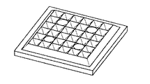
本発明では、以下に詳細及び変形例を説明するが、構成要素は、板間の摩擦によって建築物または構造物の位置回復能力ならびに減衰した移動を提供するように形成及び配置される。 In the present invention, details and modifications will be described below, but the components are formed and arranged to provide the ability to reposition a building or structure as well as dampened movement by friction between the plates.
本明細書に記載されたコネクタは、多くの構造用途に使用することができる。好ましい形態では、コネクタは建築構造物に利用されることが想定されており、これは本明細書でより詳細に説明する用途である。コネクタは、橋、塔、建築物のファサード、及び他の大型またはより小規模の構造物などの他の構造物においても使用され得ることも想定される。コネクタは、工業用棚吊りを含む多くの状況、または構造部材と自己センタリング化との間のコンプライアンスが望ましい任意の他の状況で使用することができる。さらに、コネクタは、スチール、コンクリート、木材、またはハイブリッド構造、及び柱から梁、柱から基礎、振れ止めまたはせん断壁接続に好適である。 The connectors described herein can be used for many structural applications. In a preferred embodiment, the connector is expected to be used in building structures, which is the application described in more detail herein. It is also envisioned that connectors can also be used in bridges, towers, building façade, and other structures such as other large or smaller structures. The connector can be used in many situations, including industrial shelving, or in any other situation where compliance between structural members and self-centering is desired. In addition, connectors are suitable for steel, concrete, wood, or hybrid structures and column-to-beam, column-to-foundation, steady rest or shear wall connections.
1次元コネクタ
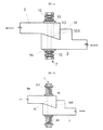
最初に、接続されている構成要素の1次元(以下、1Dとも称される)の相対的移動を可能にするいくつかの基本的なコネクタの形態について説明する。そのような1Dコネクタ1の一例は、例えば、図1a〜図1cに示すような状況で使用されてもよい。図1aにおいて、コネクタ1は、振れ止めフレームの状態で使用されて示されている。図1bには、フレーム1の状態に抵抗するときのコネクタ1が示されている。図1cでは、それらはせん断壁の押さえとして使用される。
One-dimensional connector First, some basic connector forms that allow one-dimensional (hereinafter, also referred to as 1D) relative movement of connected components will be described. An example of such a
図2a及び2bを参照すると、1Dコネクタの単純な形態が示されている。この構成では、第1の構成要素2は、弾性固定部7によって第2の構成要素3と共に保持される。第1の構成要素2及び第2の構成要素3の各々は、相補的な傾斜表面18を有する。傾斜表面18は、第1の構成要素2及び第2の構成要素3に対して斜めの角度であり、相補的な表面を相互に摺動させることによって、相互に対して(矢印によって示されるように)移動することができる。
With reference to FIGS. 2a and 2b, a simple form of the 1D connector is shown. In this configuration, the
構成要素2、3の1つは、弾性固定部7に対して垂直に移動することを可能にするスロット13を備える。第1の構成要素2は、相補的な表面が相互に中立位置を過ぎてさらに摺動するのを防止するための停止表面350をさらに備えてもよい。代替的に、第1の構成要素は、停止表面350を含まなくてもよいが、むしろスロット13の範囲は、コネクタが中立位置にあるときに弾性固定部7のシャフトに作用して、中立位置を過ぎて摺動することを防止するようであってもよい。
One of the
ワッシャ19は、第1の構成要素2及び第2の構成要素3の外表面に隣接して設けられてもよい。いずれかの構成要素がスロット13を備えている場合、ワッシャ19は、スロットのサイズよりも大きいサイズでなければならない。スロット付き構成要素が弾性固定部7に対して動くとき、ワッシャ19は、その構成要素の表面に対して摺動する。
The
ワッシャ19と弾性固定部手段7の端部との間には、2つの構成要素の傾斜表面を相互に係合させる何らかの形態の付勢手段を設けることができる。図2aにおいて、付勢手段は、ベルビルワッシャ10などのワッシャとして示されている。図2bにおいて、付勢手段351は、ばね部材として示されている。
Some form of urging means may be provided between the
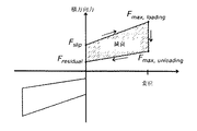
コネクタ1は、それ自体で(または2つの部材の間の接続を生成する同様のコネクタまたは他の方法に加えて)、2つの部材2及び3が十分に堅固でありながら弾性的に共に接続されることを確実にするのに役立つ。すなわち、コネクタは、好ましくは、接続部の高い初期剛性を提供し、2つの構成要素間の閾値力に達するまで、堅固な接続を効果的に提供する。この閾値力は、ここではFslipと称される。これは、コネクタを変位させ、2つの部材を相対的に相互に移動させるのに必要な力である。
The
これは、例えば、2つの部材2、3の地震荷重(またはそれらの間の他の振動によって引き起こされる移動)の間に起こり得る。
This can occur, for example, during seismic loads of two
重要なことに、本発明のコネクタは、エネルギーを消散させ(それにより地震荷重を大幅に低減して)、自己誘起回復力によって、接続を元の状態に向かって、好ましくは元の状態に戻すことができる。したがって、外部負荷(例えば、地震事象)が一旦停止すると、弾性ジョイントは、自己センタリング化される。 Importantly, the connectors of the present invention dissipate energy (thus significantly reducing seismic loads) and, by self-induced resilience, return the connection to its original state, preferably to its original state. be able to. Therefore, once the external load (eg, seismic event) is stopped, the elastic joint is self-centered.
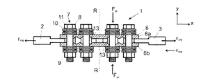
図3を参照すると、本発明のコネクタのいくつかの好ましい形態が示されている。 With reference to FIG. 3, some preferred embodiments of the connector of the present invention are shown.
この形態のコネクタは、第1の構成要素2と第2の構成要素3とから構成することができる。第1の構成要素2を、図1bに示すように(建築構造物の柱4aのような)第1の部材に固定することができ、第2の構成要素3は、第2の部材(建築構造物の梁4bのような)に接続することができる。クランプアセンブリまたは弾性固定部7は、アセンブリを共に保持する。本明細書に記載のいくつかの変形例では、第2の構成要素(図3cに示すように動作する)が存在しなくてもよい。
The connector of this form can be composed of the
コネクタ1は、それ自体でまたは2つの部材の間の接続を生成する同様のコネクタまたは他の方法に加えて、2つの部材2及び3が十分に堅固でありながら弾性的に共に接続されることを確実にするのに役立つ。
The
コネクタは、好ましくは、接続部の高い初期剛性を提供し、2つの構成要素間の閾値力に達するまで、堅固な接続を提供する。この閾値力は、ここではFslipと称される。これは、コネクタが2つの部材を相対的に相互に変位させるのに必要な力である。 The connector preferably provides a high initial stiffness of the connection and provides a robust connection until the threshold force between the two components is reached. This threshold force is referred to here as F slip. This is the force required for the connector to displace the two members relative to each other.
本発明のコネクタは、エネルギーを消散させ(それにより地震荷重を大幅に低減して)、自己誘起回復力(固定部7によって提供される)によって、接続を元の状態に向かって、好ましくは元の状態に戻すことができる。 The connectors of the present invention dissipate energy (thus significantly reducing seismic loads) and by self-induced resilience (provided by the fixation 7), the connection is returned to its original state, preferably original. Can be returned to the state of.
図3及び図5を参照すると、コネクタの第1の構成要素2及び第2の構成要素3は、好ましくは、第3の構成要素6によって少なくとも部分的に覆われているかまたは負重合されていることが分かる。好ましい形態では、第1及び第2の構成要素の各々の側に(対称状態)設けられた2つのそのような第3の構成要素6a及び6bが存在する。それらは、好ましくは、第1及び第2の構成要素2、3の対向する方向に作用する。
With reference to FIGS. 3 and 5, the
しかし、図8及び図9に示す変形では、第3の構成要素6のみを利用することができる(非対称状態)。1対の各々の構成要素が対向する方向に作用する第3の構成要素の複数の対が利用され得ることが想定される。
However, in the modifications shown in FIGS. 8 and 9, only the
好ましい形態の弾性固定部7は、第1及び第2の構成要素2、3をクランプし、取り込み及び/または挟む弾性的に拡張可能なクランプであると考えることができる。
The
好ましい形態では、第1及び第2の構成要素は、板状の形状である。それらは細長く、全体的に平坦であり、以下に説明する詳細については省略する。 In a preferred embodiment, the first and second components have a plate-like shape. They are elongated and generally flat, and the details described below are omitted.
それらは、図3a及び図3bを参照して分かるように、第3の構成要素6に対して方向xに移動することができる。この相対的移動は、好ましくは、このような第3の構成要素6の移動によって誘発される横方向運動以外の方向にのみ制限される。弾性的に拡張可能なクランプ7は、方向xに対して横方向、好ましくは方向zに拡張可能である。横方向の拡張は、好ましくは線形であるが、少なくともある程度の回転変位が生じる機構が使用されることが想定される。
They can move in the direction x with respect to the
アセンブリとして図3a、図3b及び図5に示す好ましい形態では、第1及び第2の構成要素2、3は、2つの第3の構成要素6a及び6bの間に取り込まれる。それらは接触する相互関係にあり、少なくとも1つの弾性的な固定部7によってその関係に保持されている。
In the preferred embodiment shown in FIGS. 3a, 3b and 5 as an assembly, the first and
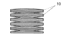
好ましい形態では、複数の弾性固定部7が設けられている。弾性固定部は、好ましくは、ボルト8及びナット9などの螺刻された締結具からなる。ボルト8は、図3aに見られるように、第1または第2の構成要素及び第3の構成要素のアセンブリを通って延びる。好ましくは少なくとも1つの付勢手段が、そのアセンブリの一部として取り込まれる。これは、例えばベルビルワッシャまたはばね10の形態であってもよい。このようなワッシャは、例えば、ボルトのヘッドと第1または第2の構成要素と第3の構成要素(複数の第3の構成要素)のアセンブリとの間のボルトのヘッド11によって取り込まれる。好ましい形態では、ワッシャは、ボルト11またはナット9のヘッド上及び隣接する第3の構成要素6に対して作用する。好ましくは、(図6に示すように)ボルトのヘッド11及び/またはナット9の各々に隣接して設けられた少なくとも1つのワッシャ10がある。
In a preferred embodiment, a plurality of
好ましい形態では、複数のワッシャ10が提供され、図3b及び図7に見られるように構成要素のアセンブリの各々の側に設けられてもよい。ワッシャは、弾性固定部7が構成要素のアセンブリに圧縮力を加えることを可能にするために設けられている。これは、アセンブリの移動に対する摩擦抵抗、及び付勢力に直接関係する。弾性固定部7の締め付け/緩めは、ジョイントの設計基準を満足させるために達成されるクランプ力の「チューニング」のための簡単な機構を提供する。
In a preferred embodiment, a plurality of
ワッシャを適切に選択することにより、適切な範囲の拡張を提供し、圧縮力を構成要素のアセンブリに及ぼすことができる。 Proper selection of washers can provide an appropriate range of extension and exert compressive forces on the component assembly.
別の形態では、例えば、外部ばね351は、2つの第3の構成要素6a、6bを相互に直接的に係合して付勢することができる。
In another embodiment, for example, the
図3bに示すように、アセンブリに作用する力Fprを見ることができる。弾性固定部7は、構成要素アセンブリの横方向の拡張を可能にする。この拡張は、弾性固定部によってもたらされる弾性力の方向と平行である。各々の弾性固定部の圧縮力は、ボルトの軸線と同軸であることが好ましい。圧縮力は、好ましくは、弾性的に拡張可能なクランプの第1/第2部材の間の相対的移動の方向に対して垂直である。圧縮力は、弾性的に拡張可能なクランプの拡張/伸縮方向と平行である。
As shown in FIG. 3b, the force Fpr acting on the assembly can be seen. The
好ましい形態では、第1及び第2の構成要素の各々に使用される少なくとも1つの弾性固定部がある。図3bには、第1の構成要素2と第2の構成要素3のそれぞれに2つの、合計4つの固定部7、が示されている。図3bに示すように、対称軸線RRを中心としたコネクタの対称的な設計は、負荷時にボルトにせん断力が誘導されるのを防止するのに役立つ。
In a preferred embodiment, there is at least one elastic fixation used for each of the first and second components. In FIG. 3b, two fixed
クランプの静止位置(図3bに見られる)からのクランプの拡張は、第1または第2の構成要素2、3の一方または両方とクランプとの間の相対的な移動の結果として誘発される(クランプ力Fprに対して好ましくは垂直な方向に)。拡張は、相互に対して相互に傾斜した関係を有する第3の構成要素6及びそれぞれの第1及び第2の構成要素2、3によってもたらされ、それにより、傾斜動作が2つの構成要素間に誘導される。第1または第2の構成要素とクランプの一方または両方の間の相対的移動は、第1及び第2の部材に十分大きな力Fslipが加えられて部材が引き離されるか、相互に向かって押圧される。
The extension of the clamp from the stationary position of the clamp (as seen in FIG. 3b) is triggered as a result of relative movement between one or both of the first or
構成要素アセンブリの横方向の拡張及び収縮は、図13a及び図13bに見ることができる。 Lateral expansion and contraction of the component assembly can be seen in FIGS. 13a and 13b.
図13aに見られるように2つの第3の構成要素6a、6bがある図示の例では、第2の構成要素3の移動に際して、2つの第3の構成要素6a、6bの間で相互に離れる変位が生じることが観察される。滑り力(Slip Force)によって誘起された第2の構成要素3の移動は、第3の構成要素6a、6bを、弾性固定部7によって加えられる弾性保持(例えば、クランプ力Fpr)の方向に平行な方向に相互に離れて変位させる。
In the illustrated example with two
好ましい形態では、少なくとも1つ、好ましくは複数の相補的な形状の傾斜表面が、第1及び第2の構成要素の各々と、第1及び第2の構成要素がそれぞれ係合する第3の構成要素の領域によって提供される。 In a preferred embodiment, at least one, preferably a plurality of complementary shaped inclined surfaces, have a third configuration in which each of the first and second components engages with the first and second components, respectively. Provided by the area of the element.
好ましくは、第1及び第2の構成要素の各々は、傾斜のアレイを呈し、アレイはX方向に延びる。傾斜は、接触して上下する傾斜である。それらはX−X方向の配列として延びる。それらは各々好ましくは同じ構成である。 Preferably, each of the first and second components exhibits a tilted array, which extends in the X direction. The slope is a slope that touches and moves up and down. They extend as an array in the XX direction. They each preferably have the same configuration.
好ましい形態では、傾斜表面18は、図5及び図16aに見られるように平面である。
In a preferred embodiment, the
代替の形態では、傾斜表面は、図17,15及び16b、及び18に示すように、丸みを帯びた、平坦な歯の形状、または波状に輪郭付けされている。図18を参照すると、波状の場合、接触点における正接5の角度は、静止位置からの変位に対して変化することが分かる。これは、移動に対する抵抗を変化させる効果を有する。 In an alternative form, the sloping surface is rounded, flat tooth shape, or wavy contoured, as shown in FIGS. 17, 15 and 16b, and 18. With reference to FIG. 18, it can be seen that in the case of a wavy shape, the angle of the tangent 5 at the contact point changes with respect to the displacement from the stationary position. This has the effect of changing resistance to movement.
したがって、所望の性能を確保するために、接触表面及び摺動限界停止装置の形状の適切な設計が必要となる。 Therefore, in order to ensure the desired performance, it is necessary to properly design the contact surface and the shape of the sliding limit stop device.
好ましい形態では、構成要素の接触表面の輪郭は、好ましくは、平行な罫線表面の形態であり、概念的な平行線は、点接触ではなく、第3の構成要素と第1及び相対的移動の範囲の第2の構成要素の各々との間の面対面表面領域接触を維持することを助けるような方向に向いている。好ましくは、任意の輪郭形態の平行罫線表面は、x−y平面に平行に走る罫線表面の概念線を有する。 In a preferred embodiment, the contour of the contact surface of the component is preferably in the form of a parallel ruled line surface, and the conceptual parallel line is not a point contact, but a third component and the first and relative movements. Oriented to help maintain face-to-face surface region contact with each of the second components of the range. Preferably, the parallel ruled line surface of any contour form has a conceptual line of ruled line surfaces running parallel to the xy plane.
図16bに示す例では、第3の構成要素6bの輪郭付けされた傾斜表面は、鋭い歯であるように見える断面である。これは、構成要素の縦方向の整列を維持するのに役立つ。代替的にまたは付加的に、Z方向のスロット13に固定部(例えばボルト)をぴったりと嵌め込むことは、第1及び第2及び第3の部材を縦方向に整列させるのを助ける。
In the example shown in FIG. 16b, the contoured sloping surface of the
別の形態では、図11gに示すように、スロット13は、第1の構成要素2及び第2の構成要素3ではなく、第3の構成要素6a及び6bの各々に設けられてもよい。この構成では、スロット13より大きい直径のワッシャ19が、弾性固定部7の各々に、第3の構成要素6a、6bに隣接して設けられてもよく、弾性固定部7と共に、隣接する第3の構成要素上に摺動してもよい。第1の構成要素2と第2の構成要素3との間の相対的動作の場合、弾性固定部7は、第1の構成要素及び第2の構成要素の各々と共に移動し、第3の構成要素6a及び6bのそれぞれのスロット13に沿って摺動する。
In another embodiment, as shown in FIG. 11g, the
弾性固定部がスロット13に関して移動すると、摺動ワッシャ19は、第3の構成要素6a及び6bの表面に押し込まれる。この形態では、ワッシャ10の付勢力の下で第3の構成要素6a、6bの面に対する摺動ワッシャ19の相対的動作は、第1の構成要素2と第2の構成要素3との間の相対的動作に付加的な抵抗力を提供する。スロット13が第3の構成要素6a及び6bに設けられている構成では、全抵抗力は、同一に構成された非対称コネクタの抵抗力の2倍になる。
When the elastic fixing portion moves with respect to the
しかしながら、この形態では、摺動ワッシャ19の第3の構成要素の面に対する相対的動作によってもたらされる抵抗力は、接続を元の状態に付勢する回復力を提供しない。このように、この形態では、傾斜表面18のより大きな角度θを用いて回復力を増加させることができる。
However, in this form, the resistance provided by the relative movement of the sliding
第1、第2、及び第3の構成要素の適切な材料選択は、構成要素間に適切な摩擦挙動が存在することを確実にする。移動すると、構成要素アセンブリの構成要素間の摩擦は、滑りコネクタが係合する第1の部材と第2の部材との間の動作の減衰をもたらす。減衰の程度は、摩擦係数、ジョイントの拡張を通って移動した横方向の距離、及び関連する弾性固定部が構成要素アセンブリに与える弾性保持の力を含む他の要因に依存する。 Appropriate material selection of the first, second, and third components ensures that proper friction behavior exists between the components. Upon movement, friction between the components of the component assembly results in damping of movement between the first and second members with which the sliding connector engages. The degree of damping depends on other factors, including the coefficient of friction, the lateral distance traveled through the extension of the joint, and the elastic holding force exerted by the associated elastic anchors on the component assembly.
摩損を制御するために、ジョイントの関連する摺動表面には、潤滑剤を塗布し、及び/または特殊コーティングを施すことができると予想される。十分な減衰を提供するために望ましい特性である摩擦係数を適度に高く保つことを可能にする様々な潤滑グリース製品が利用可能である。 It is expected that the associated sliding surfaces of the joint can be lubricated and / or specially coated to control wear. A variety of lubricating grease products are available that allow the coefficient of friction, which is a desirable property to provide sufficient damping, to be kept reasonably high.
見て分かるように、傾斜表面は向きを変え、これによりコネクタは2つの部材(例えば建築構造部材)の動作を2方向に吸収することができる。したがって、力Fslipは、(図4に示すように)正の力または負の力であってもよい。 As can be seen, the sloping surface turns, which allows the connector to absorb the movement of two members (eg, building structural members) in two directions. Therefore, the force F slip may be a positive force or a negative force (as shown in FIG. 4).
アセンブリとして残るように、好ましくは細長い形状のFslip方向に細長いコネクタが可能であるように、弾性固定部7は、好ましくは、第3の構成要素の開口12を通り、第1及び第2の構成要素のスロット13を通り、延びる。スロット13は、第1及び第2の構成要素の一方または両方に対する第3の構成要素の細長い方向の相対的移動を可能にするような大きさである。スロット及び固定部は、アセンブリの移動のラチェットを防止するようにその移動範囲を制限するように構成されてもよい。結果として、接触傾斜表面18の対は、事象の間に対として残り、隣接する傾斜表面に割り付けられない。スロット13は、そのようなラチェットを防止するための端部停止機能を提供することができる。代替的に、摺動動作の制限は、傾斜表面のラチェットを生じさせる程度に第1及び第2の構成要素の分離を防止することができる弾性固定部によって画定されてもよい。例えば、ボルトヘッド11とナット9との間の距離は、第3の構成要素6aと6bとの間の分離量を抑制して、x方向の第1の構成要素と第2の構成要素の動作範囲を制限するように設定することができる。以下に記載されるような鋸歯構成もこのような限界停止を提供し得る。
The
所望の摩擦係数を有する材料の適切な選択、傾斜表面の角度θの選択、及び弾性固定部の特性の適切な選択によって、図13aに示すような静止位置から、力Fslipの適用によって図13bに示すように変位した状態への変位時に、第3の構成要素に対して変位された第2の構成要素は、その静止位置に向かって戻されるように付勢される。 With the proper selection of the material with the desired coefficient of friction, the selection of the angle θ of the inclined surface, and the proper selection of the properties of the elastic fixation part, from the stationary position as shown in FIG. 13a, by applying the force F slip , FIG. 13b. At the time of displacement to the displaced state as shown in, the second component displaced with respect to the third component is urged to be returned toward its stationary position .
所与の摩擦係数及びクランプ力Fprに対して、角度θの増加は、第1または第2の構成要素に加えられる力の増加をもたらし、第3の構成要素によって、それを静止位置に向かって戻すように付勢することが理解されるであろう。第1及び第2の部材が受ける振動事象では、図4を参照すると、減衰が生じることが分かる。図4に示すように、ジョイントの荷重が滑り力の閾値に達するとジョイントの変形が開始する。ジョイントの拡張が継続するにつれて、ボルトの高いクランプ力の結果として滑り表面間の摩擦抵抗が増加する。このようなジョイントの強化は、ベルビルワッシャが完全にロックされた時点で停止する。ジョイントを無負荷にした後、ジョイントは元の位置に自己センタリング化する。 For a given coefficient of friction and clamping force F pr , an increase in angle θ results in an increase in the force applied to the first or second component, which is directed towards a stationary position by the third component. It will be understood to urge them to return. It can be seen that in the vibration event received by the first and second members, damping occurs with reference to FIG. As shown in FIG. 4, when the load of the joint reaches the threshold value of the sliding force, the deformation of the joint starts. As the joint expansion continues, the frictional resistance between the sliding surfaces increases as a result of the high clamping forces of the bolt. Such joint reinforcement stops when the Belleville washer is fully locked. After unloading the joint, the joint self-centers to its original position.
溶接及び/または機械的締結(またはその他)による第1及び第2の構成要素は、建築構造物に容易に組み込むことができる。それらの細長い方向は、適切な方法で印加力を解消し、エネルギーを散逸させる機能を提供し、それが関連する第1の構成要素と第2の構成要素との間の振動動作中に自己センタリング化能力を提供する。 The first and second components by welding and / or mechanical fastening (or others) can be easily incorporated into the building structure. Their elongated directions provide the ability to dissipate the applied force and dissipate energy in an appropriate manner and self-centering during the vibrational motion between the first and second components to which it is associated. Providing the ability to transform.
本ジョイント構成を簡単かつ容易に実現する1つの重要な特徴は、図3に示すようにコネクタが薄型であり、複数の傾斜サービス18が提供されることである。同様に、適切な量のクランプ力を比較的浅い形態で提供できることは、ベルビルワッシャのようなワッシャ型付勢手段10の利点である。
One important feature of realizing this joint configuration easily and easily is that the connector is thin as shown in FIG. 3 and a plurality of tilting
本発明のコネクタは、構造産業において特に有用にする細長い形状であることが好ましい。その狭い輪郭は、それが狭い空間に容易に位置決めされることを可能にする。その厚さ(y方向)は、弾性固定部のサイズ及び第1及び第2及び第3の構成要素の厚さによって決定される。角度θを増加させると、弾性固定部によって加えられる任意の所定の弾性保持力に対してより高い程度の減衰を与えるのに役立つが、このような角度の増加はまた、アセンブリの厚さを増加させる。したがって、角度θを最小にすることが望ましい。所与の用途では、設定された後の数学を参照して最小角度を決定することができる。 The connector of the present invention preferably has an elongated shape that makes it particularly useful in the structural industry. Its narrow contour allows it to be easily positioned in tight spaces. Its thickness (y direction) is determined by the size of the elastic fixation and the thickness of the first, second and third components. Increasing the angle θ helps to provide a higher degree of damping for any given elastic holding force applied by the elastic anchor, but such an increase in angle also increases the thickness of the assembly. Let me. Therefore, it is desirable to minimize the angle θ. For a given application, the minimum angle can be determined with reference to the mathematics after it has been set.
傾斜の角度は、振動動作中の無負荷時に、その時負荷されたベルビルワッシャによって引き起こされる、または増幅される力の反転が、接触滑り表面の間に作用する抵抗摩擦力よりも大きくなるように選択される。これは、エネルギーを消散させる弾性的な挙動を提供し、また、コネクタの自己センタリング化能力を提供して、コネクタを静止状態に戻すように付勢する。 The angle of inclination is selected so that the reversal of the force caused or amplified by the then loaded Belleville washer at no load during vibrating operation is greater than the resistance friction force acting between the contact sliding surfaces. Will be done. It provides an elastic behavior that dissipates energy and also provides the connector's self-centering ability to urge the connector to return to a quiescent state.
図8及び図9を参照すると、本発明の変形が提供され得ることが分かる。この変形例では、傾斜した第3の構成要素が1つだけ設けられている。第1及び第2の構成要素から第3の構成要素の対向する側の各々のボルト用の平坦なキャップ板30を設けることができる。平坦なキャップ板30自体は、自己センタリング化機能なしに摩擦抵抗及び減衰を提供するだけである。第2の傾斜した第3の構成要素の提供は、コネクタの自己センタリング化を増加させる。また、減衰効果も向上する。変形例が図10に示されており、板30の代わりに個々のワッシャ19が各々のボルトに設けられている。
With reference to FIGS. 8 and 9, it can be seen that modifications of the present invention can be provided. In this modification, only one inclined third component is provided. A
第1と第2の部材との間の接続に追加の減衰が必要な場合、複数のコネクタを並列に設けることができる。並列コネクタは、例えば図1b及び図1cに示されている。 If additional damping is required for the connection between the first and second members, a plurality of connectors may be provided in parallel. Parallel connectors are shown, for example, in FIGS. 1b and 1c.
第1の部材と第2の部材との間に変位を増加させる場合、複数のコネクタを直列に設けることができる。これにより、直列連結コネクタの伸び容量を増加させることができる。図3のコネクタは、各々の側が移動できる直列コネクタである。したがって、本明細書に記載された式に関して、図3bに示すコネクタの場合、njは2に等しい。 When increasing the displacement between the first member and the second member, a plurality of connectors can be provided in series. As a result, the elongation capacity of the series-connected connector can be increased. The connector of FIG. 3 is a series connector in which each side can be moved. Therefore, for the equations described herein, n j is equal to 2 for the connector shown in FIG. 3b.
図3c及び図3dは、コネクタを単数形で示している。ここで、構成要素6a及び6bは、部材3に対して縦方向及び横方向に移動することができるが、相対的な部材61を横方向にのみ移動させるために固定される。ベアリングピン60を使用して、部材6aと6bと61との間のそのような移動を可能にすることができる。
3c and 3d show the connectors in the singular. Here, the
図11a及び図11bを参照すると、本発明の代替的なコネクタは、印加力がコネクタの細長い方向と平行でない状況において利用され得ることが分かる。図11aに示す例では、コネクタ1の細長い方向LLは、振れ止め部材20から受け得る印加力Xに対してある角度をなしている。この構成では、第3のコネクタ6は、例えば構造物の梁31に固定され、第1の構成要素2は、第1の構成要素からコネクタの方向LLに対してある角度をなして延びる振れ止め部材20に固定される。ベアリングピン70を使用して、第1の構成要素2を横方向に移動を可能にすることができる。したがって、振れ止め部材20によって方向Xに加えられ得る力は、ある角度をなしている。しかし、本発明のコネクタは、この力を解消して、コネクタにおける方向LLの振れ止めの変位を可能にする。この構成の代替が、図12a及び図12bに示されており、細長いコネクタの両方の方向LLは、振れ止め部材20から受ける印加力Xに平行である。
With reference to FIGS. 11a and 11b, it can be seen that the alternative connector of the present invention can be utilized in situations where the applied force is not parallel to the elongated direction of the connector. In the example shown in FIG. 11a, the elongated direction LL of the
好ましい形態では、ボルトは、好ましくは高強度ボルトであり、少なくとも第1及び第2の構成の材料は、Bisplate(商標)である。好ましくは、第3の構成要素は、軟鋼である。軟鋼と共にBisplate(商標)が均一な摩擦挙動をもたらすことが判明した。 In a preferred embodiment, the bolt is preferably a high-strength bolt, and the material of at least the first and second configurations is Bisplate ™. Preferably, the third component is mild steel. Bisplatate ™, along with mild steel, has been found to provide uniform frictional behavior.
1Dコネクタの構造において、第1の構成要素2及び第2の構成要素3の終端の厚さは、傾斜表面の振幅よりも小さいか、等しいか、または大きくなるようにすることができる。
In the structure of the 1D connector, the thickness of the terminations of the
1Dコネクタの代替の実施形態を図15a及び図15bに示す。この実施形態によれば、第1及び第2の構成要素2、3及び第3の構成要素6a、6bの相補的な嵌合表面は、1方向に相互に表面を摺動させ得る傾斜表面18と、第1及び第2の構成要素が対向する方向に移動するように促され、それによってそのような対向する方向の移動が防止されるときに、そのような付加的な表面の相対的摺動を防止する付加表面5を有してもよい。
Alternative embodiments of the 1D connector are shown in FIGS. 15a and 15b. According to this embodiment, the complementary fitting surfaces of the first and
これにより、コネクタは、それが接続する第1及び第2部材の現状から1方向のみに変位できることを可能にする。これは拡張または収縮のためであり得る。 This allows the connector to be displaced in only one direction from the current state of the first and second members to which it connects. This can be due to expansion or contraction.
図15aにおいて、傾斜表面18は、第1及び第2の構成要素が相対的に相互に外側に移動することができるが、最初の静止位置よりも内側には移動しないように配置されている。図15bにおいて、傾斜表面18は、第1及び第2の構成要素が相互に向かって移動することができるが、最初の静止位置よりも外側には移動しないように配置されている。
In FIG. 15a, the
1方向1Dコネクタの用途は、壁と下側固定点との間の延長が望ましいが、相互に向かうこれらの2点の移動ができない、せん断壁内にあってもよい。 The use of the unidirectional 1D connector is preferably in an extension between the wall and the lower fixed point, but may be in a shear wall where these two points cannot move towards each other.
2次元コネクタ
図24〜図26bを参照すると、2Dの弾性並進滑り摩擦コネクタ構成要素が示されている。図24を参照すると、第1の構成要素202が平面図で示されており、図25では、第1のクランプ構成要素206aが示されている。これらの2つの構成要素は、方向XXのような第1の方向だけでなく、YY方向への傾斜表面を提供する相補的な嵌合表面を有する。結果として、これらの構成要素のアセンブリは、提供される構造物の2次元相対並進が可能となり得る。
Two-dimensional connector With reference to FIGS. 24-26b, 2D elastic translational sliding friction connector components are shown. With reference to FIG. 24, the
弾性固定部を形成するために、コネクタの1Dの実施形態を参照して上述したのと類似の形態で、ボルト及びワッシャ(またはばね)が利用される。好ましくは、ボルト8は、ジョイントの強度の約2倍以上の最終撓み能力を有する高張力である。この安全係数は、ボルトがほぼ完全に張力負荷をかけられ、故障の原因となる可能性はほとんどないので、設計基準からのボルトの破損を効果的に排除することを可能にする。
Bolts and washers (or springs) are utilized to form the elastic anchors in a manner similar to that described above with reference to the 1D embodiment of the connector. Preferably, the
2次元コネクタは、2つの直交方向にのみ移動するように制約されるのではなく、任意の並進方向に平面形態で変位することができるように設計されてもよい。その際、2つの構成要素の回転方向は変化しない。したがって、相対的移動は平面内で全方向であってもよい。 The two-dimensional connector may be designed so that it can be displaced in a planar form in any translational direction, rather than being constrained to move in only two orthogonal directions. At that time, the rotation directions of the two components do not change. Therefore, the relative movement may be omnidirectional in the plane.
変換コネクタ(1D/2D)の設計手順:
対称または非対称のコネクタの異なる条件に対する図13及び図14に示す自由体図に基づいて、設計手順は、第1及び第2の構成要素に作用する力の平衡を以下のように考慮して概説される。
滑り力Fslipは、

Fb,prは、初期歪み力を受けた結果としてのボルトクランプ力である
nbはボルト数である
θは溝の角度である
μsは、静摩擦係数であり
残留力、Fresidualは、
ここで
μsは、静摩擦係数であり
μkは、動摩擦係数(0.6μsと見なすことができる)であり
Fb、uは、次で与えられるボルトの最終的な力であり、
![]()
ksは、ワッシャまたはバネのスタックの剛性であり、
Δsは、初期応力後のワッシャまたはばねのスタックの最大の撓み量である。
Conversion connector (1D / 2D) design procedure:
Based on the free body diagrams shown in FIGS. 13 and 14 for different conditions of symmetric or asymmetric connectors, the design procedure is outlined considering the balance of forces acting on the first and second components as follows: Will be done.
Sliding force F slip is
Where μ s is the coefficient of static friction, μ k is the coefficient of dynamic friction (which can be considered as 0.6 μ s ), and F b and u are the final forces of the bolt given below.
![]()
Delta s is the maximum amount of deflection of the washer or spring stack after the initial stress.
注意すべきことは、
i.単動式のコネクタでは、ボルトクランプ力Fbに板と軸受ピン接触の摩擦抵抗を追加する必要があることである。
ii.非対称条件では、ボルトは、初期応力を受けた結果として生じる張力に加えて、せん断力を介してジョイント荷重を伝達する必要がある。
It should be noted
i. The connector of single-acting, is that the bolt clamping force F b is necessary to add a frictional resistance of the plate and the bearing pin contact.
ii. Under asymmetric conditions, the bolt must transmit the joint load through shear forces in addition to the tension resulting from the initial stress.
最大横方向の撓みは、
njは、直列配置されたジョイントの数である(例えば、njは、それぞれ単動及び複動コネクタの場合1と2に等しい)
自己センタリング化挙動を達成するためには、以下の考慮が必要である。
In order to achieve self-centering behavior, the following considerations are required.
設計手順で定義されているように、傾斜角度の最小要件があり、満たされていない場合、自己センタリング化能力はない。したがって、それは一定の限界から減少することはできない。また、最小要件を超えて角度を増加させることは、所与の移動範囲に対して板厚が上がるので効率的ではない。板の厚さを薄くしておくことで、材料コストを削減し、密閉空間での使用により適した製品になる。自己センタリング化は、傾斜の角度にのみ依存し、ボルトクランプ力を増加させることは影響を及ぼさないが、無負荷後に板を静止位置に反対方向に移動させるのを加速することに留意すべきである。したがって、純粋に摩擦係数の関数である最小角度θが存在する。ばね力の増加は、コネクタの減衰と静止位置への戻り速度に影響を及ぼす。工具を使用して、板に対する初期付勢力の適切な設定、すなわち初期応力が加えられた結果のボルトクランプ力を確保することができる。これにより、設計に必要な性能に応じてジョイントを「調整」することができる。 As defined in the design procedure, there is a minimum tilt angle requirement, and if not met, there is no self-centering capability. Therefore, it cannot be reduced from a certain limit. Also, increasing the angle beyond the minimum requirement is inefficient as it increases the plate thickness for a given range of movement. By reducing the thickness of the board, the material cost can be reduced and the product becomes more suitable for use in a closed space. It should be noted that self-centering depends only on the angle of inclination and increasing the bolt clamping force has no effect, but accelerates the movement of the plate in the opposite direction to the stationary position after no load. be. Therefore, there is a minimum angle θ that is purely a function of the coefficient of friction. The increase in spring force affects the damping of the connector and the rate of return to the rest position. A tool can be used to ensure the proper setting of the initial urging force on the plate, i.e. the bolt clamping force as a result of the initial stress being applied. This allows the joint to be "adjusted" according to the performance required for the design.
予測値とテストデータの比較
上記の式は、使用中に1Dコネクタが経験する力及び変位を理論的に予測する。図47は、テストデータが太字で示され、理論上計算された値がその上に重ね合わされている、1Dコネクタのこれらの予測された負荷及び無負荷力及び関連する変位の比較プロットを示す。この図は、テスト中のコネクタの負荷及び無負荷に関連するヒステリシスループが予測値に非常によく似ていることを示している。
Comparison of Predicted Values and Test Data The above equation theoretically predicts the forces and displacements experienced by a 1D connector during use. FIG. 47 shows a comparative plot of these predicted and unloaded forces and associated displacements of the 1D connector, with the test data shown in bold and the theoretically calculated values superimposed on it. This figure shows that the hysteresis loops associated with the load and no load of the connector under test are very similar to the predicted values.
テストされた値と予測された値との間の密接な相互関係に起因して、所望の放出力及び変位輪郭に適合するようにコネクタの物理的及び材料的特性を設計することが可能である。 Due to the close interrelationship between the tested and predicted values, it is possible to design the physical and material properties of the connector to fit the desired discharge and displacement contours. ..
例えば、図48〜図53は、接合部の力対変位特性に対する様々な設計パラメータの変化の予測される効果を示す。 For example, FIGS. 48-53 show the predicted effect of changes in various design parameters on the force vs. displacement characteristics of the joint.
図48は、傾斜表面の角度を変更する効果を示している。 FIG. 48 shows the effect of changing the angle of the inclined surface.
図49は、傾斜表面間の摩擦係数の違いを示している。 FIG. 49 shows the difference in the coefficient of friction between inclined surfaces.
図50は、付勢ワッシャの数を、直列で増やすことの効果を示している。 FIG. 50 shows the effect of increasing the number of urging washers in series.
図51は、ワッシャ数を、並列で増やすことの効果を示している。 FIG. 51 shows the effect of increasing the number of washers in parallel.
図52は、弾性固定ボルトの数を増やすことの効果を示している。 FIG. 52 shows the effect of increasing the number of elastic fixing bolts.
図53は、弾性固定部のボルト初期歪み力を増やすことの効果を示している。 FIG. 53 shows the effect of increasing the initial bolt strain force of the elastic fixing portion.
回転コネクタ
次に、上述したコネクタの変形例について説明する。この変形例は、並進滑りではなく回転弾性の滑り摩擦を提供する。回転弾性滑り摩擦コネクタは、図20に示すように、壁と床の接続の間で利用されてもよい。図20では、床14と支持壁15との間のこのような構造において、複数の回転コネクタ100を、利用することができる。
Rotating connector Next, a modification of the connector described above will be described. This variant provides rotationally elastic sliding friction rather than translational sliding. Rotational elastic sliding friction connectors may be utilized between wall and floor connections, as shown in FIG. In FIG. 20, a plurality of
図20に示されている構造物はまた、上述したような複数の1Dコネクタ1を含むことができる。図21及び図22を参照すると、回転コネクタ100の構成要素部品が示されている。図21a及び図21bには、第1のクランプ構成要素106a及び第1の構成要素102が示されている。これらは、好ましくは、図に見られるように、相互に係合可能な輪郭表面160を有する。表面は、実質的に半径方向に延びる山及び谷によって画定される。このような山及び谷は、第1の構成要素及び第1のクランプ構成要素102/106aの各々の相互に協働する傾斜表面160の上下を可能にする、斜めの側表面160を有する。実質的に半径方向に延びるセグメントの各々の側部は、隆起セグメントの縁部からその中心に向かって内側に斜めになる斜めの表面を含む。段付きセグメント及びトラフの表面は平行であり、斜めの表面は一定の高さで半径方向に延びている。
The structure shown in FIG. 20 can also include a plurality of
対応する隆起セグメント及び谷は、対向する斜めの表面が隆起セグメントまたは谷セグメントのいずれかで一致する位置で終了する。 The corresponding uplift segments and valleys end where the opposing diagonal surfaces coincide with either the uplift segment or the valley segment.
変位を引き起こす事象中に係合する斜めの表面間の荷重の均一な分散を確保するために、各々の斜めの表面は半径方向の長さに沿って一定の高さHである(図22cに示すように)。 Each diagonal surface has a constant height H along the radial length to ensure uniform distribution of the load between the diagonal surfaces engaged during the displacement-causing event (see FIG. 22c). As shown).
第1の構成要素102及び第1のクランプ構成要素106aは、好ましくは、軸線Xと一致する軸線の周りで同軸のままであるように保持される。これは、図示されている表面形状によってある程度達成されるが、構成要素102及び第1のクランプ構成要素106aは、先に説明したものと同様に、その関係を維持し、相対的移動をガイドするのを助けることができる。
The
締結具(ただしワッシャなし)は図22dと22eに示される。好ましい形態では、第1のクランプ構成要素106aは、ボルト軸610が貫通することができる複数の開口110を有する。第1の構成要素102は、好ましくは、各々を通ってボルトのシャフトの各々が貫通することができる複数のスロット111を有する。スロットは、孔110が設けられている軸に一致する軸Xからピッチ円直径上にある。好ましい形態では、複数の孔及びスロットが、軸Xの周りに等間隔で設けられる。スロットは、第1の構成要素と第1のクランプ構成要素との間の相対回転を可能にする。図22d及び図22eは、ボルト8のセットを有する回転コネクタに組み立てられた図21及び22の構成要素を示す。これらのボルトは、第1のクランプ構成要素106aの開口110と第1の構成要素102のスロット111の両方を通過する。クランプ構成要素106a、102が(図22dのように)相互に対して回転変位されると、ボルトは、開口110内に保持され、スロット111内の限界内で移動することができる。
Fasteners (but without washers) are shown in FIGS. 22d and 22e. In a preferred embodiment, the
図23の平面図に見られるように、例えば床120とせん断壁121との間で作用する使用において、回転コネクタ100は、ボルト122の使用によって床及びせん断壁120/121のうちの1つに固定されているのを見ることができる。ボルトは、第1の構成要素102及び第2の構成要素106aを通って延びる。それらは、第2のクランプ構成要素106bから、またはそれを貫通して突出し、第1の構成要素102の対向する側に設けられてもよい。前述した1Dコネクタと同様に、ボルト122の各々に螺刻されたナットと第1のクランプ構成要素106aとの間にワッシャ127のような付勢手段を設けることができる。
As seen in the plan view of FIG. 23, for example in use acting between the
図23に見られるような第2のクランプ構成要素106bは、平面の摺動表面を提供する。第1の構成要素102は、それらの間の相対的な横方向の移動なしに、第2の構成要素106b上で軸Xの周りを回転することができる。第1のクランプ構成要素106aの対応する輪郭表面と協働する第1の構成要素102の対向する側の輪郭表面と、第1のクランプ構成要素106Aを介して第1の構成要素を第2のクランプ構成要素106bに向けて付勢するワッシャ127を設けることにより、自己センタリング化能力を提供する回転コネクタ100によって弾性滑り摩擦接続を確立することができることが理解されよう。
The
そのような回転コネクタの対称バージョンが設けられてもよく、第2のクランプ構成要素は、第1の構成要素102と共に適切な輪郭表面を含み、自己センタリング化能力を有する弾性滑り摩擦を提供してもよい。
A symmetrical version of such a rotating connector may be provided and the second clamp component, along with the
さらに、図23に示す構成では、上部構造120と下部構造121との間の回転移動は、回転コネクタ構成要素の相対回転を引き起こし、2次的な結果的運動を引き起こさずに回転移動を減衰させる。特に、この用途におけるアセンブリは、回転コネクタの板106及び102の変位した位置にかかわらず、方向Xにおける構造物120及び121の間の距離にいかなる変化も生じさせない。
Further, in the configuration shown in FIG. 23, the rotational movement between the
図22h〜図22kは、第1の構成要素102及び第1のクランプ構成要素106aの代替の傾斜表面輪郭形状を示す。
22h-22k show alternative inclined surface contour shapes for the
回転コネクタの設計手順:
滑りモーメントMslipは、
![]()
最終的なモーメントMultは、次の式で与えられる。
![]()
The sliding moment M slip is
![]()
The final moment Multi is given by the following equation.
![]()
最大回転は次のように表わすことができる。
使用中のコネクタ
1D弾性滑り摩擦コネクタの1つの用途は、図27に示すような状況にあり、回転弾性滑り摩擦コネクタ100と1D弾性滑り摩擦コネクタ1と両方の組み合わせが、床構造物120A及びせん断壁121Aの中間に設けられている。そのような構成では、回転及び1D並進弾性滑り摩擦コネクタのアセンブリは、せん断壁121Aの回転及び上昇の両方の制御を可能にする。図28(せん断壁と構造床梁のような床構造物との間の堅固な接続を示す従来技術の図である)を参照すると、地震時の建築物の移動は、構造梁の上昇及び曲げモーメントの両方を誘発することができる。
Connector in use One use of the 1D elastic sliding friction connector is as shown in FIG. 27, and the combination of the rotary elastic sliding
図29では、回転コネクタと2D並進コネクタとの組み合わせのアセンブリ250が設けられているところを示しているが、構造物が純粋な破壊動作で変形することが分かる。上昇及び回転の両方が、アセンブリによって少なくとも部分的に吸収される。
FIG. 29 shows that the
図30を参照すると、2Dコネクタ200を介して接続された2つの構造構成要素280及び281の側面図が示されている。図31は、複動2Dコネクタ200が設けられている図30と同様の側面図を示す。構造構成要素280及び281の滑り方向の変位は、構造構成要素280及び281を離す2次的に変位引き起こすことはない。このような2次的な変位が副作用を引き起こす可能性があるため、これは有利である。
With reference to FIG. 30, side views of the two
2つの構造部材283及び284が2つの対称回転コネクタ100を組み込んだアセンブリによって接続され、2つの構造部材283及び284が相対的に相互に軸XXを中心に回転することを可能にする、回転コネクタのさらなる構成が図32に示されている。
A rotating connector in which two
図33を参照すると、少なくとも1つ、しかし好ましくは2つの(図示のような)回転コネクタ100が、構造部材286及び287を共に接続して軸Y−Yを中心に回転できることが分かる。本明細書で定義されるコネクタのアセンブリのさらなる変形例が図34に示されており、回転コネクタ100が示され、2つの1Dコネクタ1が、構造部材288及び289の中間に設けられている。
With reference to FIG. 33, it can be seen that at least one, but preferably two, rotating connectors (as shown) can connect the
図35は、上部及び下部2D並進コネクタ200及び側面回転コネクタ100のアセンブリが、X軸周りの構成要素290及び291の間の回転及びX軸、ならびに、X軸に垂直に伸びる軸線Zに沿った相互に対する変位を可能にするさらなる構成を示す。
In FIG. 35, the assembly of the upper and lower 2D
さらに別の構成が図36に示されており、2つの構造部品292及び293の垂直軸Y−Y及び水平軸X−Xの周りの回転を可能にする3つの回転コネクタ100が設けられている。
Yet another configuration is shown in FIG. 36, which is provided with three
図37を参照すると、構造構成要素294と295との間のさらなる構成が示されており、コネクタのアセンブリは、構造構成要素294と295の間のXX方向、ならびに軸線XXに垂直な軸線Z方向の相対的動作を可能にする、2つの2Dコネクタ200を含む。
With reference to FIG. 37, a further configuration between
1Dコネクタ1が回転コネクタ100と共に提供されて、方向XXにおける制限された並進運動及び2つの構造部品間の軸Y−Yの周りの回転運動を可能にする、構造部品296と297との間のさらなる構成が図38に示されている。
The
図39を参照すると、コネクタのアセンブリは、2Dコネクタ、回転コネクタ100、及び上部及び下部1Dコネクタ1からなるさらなる構成が示されている。
With reference to FIG. 39, the connector assembly is further shown to consist of a 2D connector, a
図40を参照すると、複数のコネクタが、回転コネクタ100と、2つの1Dコネクタの上部及び下部を含むアセンブリを生成するさらなる構成が示されている。
With reference to FIG. 40, a further configuration is shown in which the plurality of connectors generate an assembly that includes a
図41を参照すると、コネクタのアセンブリが、回転コネクタ100及び2Dコネクタ200の上部及び下部を含む、2つの構造要素302と304との間のさらなる構成が示されている。さらに、構造構成要素305及び306の軸X−Xの周りの回転を可能にする回転コネクタ100であるただ1つのコネクタが利用されている図42に示されているさらなる構成が示されている。
With reference to FIG. 41, the connector assembly shows a further configuration between the two
図44a〜図44cを参照すると、1つ以上の1Dコネクタが2つの構造部材の間に配置され、部材に平行な移動を制御する2つの構造部材21,22の間の別のセットの配置が示されている。この構成は、単動1Dコネクタまたは複数のコネクタの使用を含むことができる。コネクタは、構造部材のフランジまたは複数のフランジ23の間、構造部材のウェブ24の間、またはこれらの配置のいくつかの組み合わせの中に位置してもよい。
With reference to FIGS. 44a-44c, one or more 1D connectors are arranged between the two structural members, and another set of arrangements between the two
1Dコネクタのさらなる用途が図44dに示されており、単動コネクタ1またはコネクタ1のセットが振れ止め接続で使用されてもよい。
Further applications of the 1D connector are shown in FIG. 44d, where a
所望の構造特性を達成するために、1Dコネクタ、2次元コネクタ及び回転コネクタの異なる構成を実際に使用することができる。第1の1Dコネクタ310と第2の1Dコネクタ311が並列に接合されているそのような構成の1つが図45aに示されている。第1の構成要素312及び313、ならびに第2の構成要素314及び315の各々は、それらの終端で接続される。この結合の結果として、1Dコネクタ310及び311のいずれかの第1の構成要素と第2の構成要素との間の任意の相対的動作は、他のコネクタにおいて同じ相対的運動をもたらす。
Different configurations of 1D connectors, 2D connectors and rotating connectors can be used in practice to achieve the desired structural properties. One such configuration in which the
図45aに示す構成では、第1の1Dコネクタ310は、その傾斜表面に沿って距離L1だけ摺動することができる。距離L1を摺動させた後、第1のコネクタ310は、傾斜間の平坦な表面に沿って距離L2だけスライド摺動することができる。第2の1Dコネクタ311は、第1及び第2の構成要素の傾斜表面が第3の構成要素の対応する傾斜表面に接触する前に、最初にΔ1だけ摺動することができる。対応する傾斜表面が接触すると、第2の1Dコネクタ311は、その傾斜表面に沿ってΔ2の距離だけ摺動することができる。
In the configuration shown in FIG. 45a, a
図45aの例では、第1のコネクタ310の傾斜摺動距離L1は、第2のコネクタ311の第1のスライド距離Δ1に対応する。この構成では、第1及び第2の1Dコネクタによって提供される結合ジョイントの対向する側部は、第1の距離L1またはΔ1だけ変位することができ、主に、第1のコネクタ310の傾斜表面及び第2の距離L2によって支配され、または摺動抵抗が、主に第2のコネクタ311の傾斜表面によって支配される。
In the example of FIG. 45a, the inclined sliding distance L 1 of the
図45aに示すように、第1のコネクタ310及び第2のコネクタ311のそれぞれの傾斜表面は、異なる角度で傾いていてもよい。傾斜表面の各々のセットを異なる角度で提供することにより、結合されたジョイントは、様々な摺動抵抗特性を有することができる。図45aの例では、第1のコネクタ310の傾斜表面は、第2のコネクタ311の傾斜表面よりも急な角度で傾いている。この設計は、図45bに示すような力−変位特性を有する接合部を提供することができ、距離L1を超えて、ジョイントは、第1の剛性316を有し、第2の距離L2を超えて、ジョイントは、第2の剛性317を有し、第2の剛性は第1の剛性よりも小さい。
As shown in FIG. 45a, the inclined surfaces of the
上記の例は、より高い初期剛性及びより低い2次剛性を有するジョイントを提供するが、第1のコネクタ及び第2のコネクタの各々の傾斜表面の角度を変えることにより、第2の剛性が、または初期の剛性より小さいか、等しいかまたは大きい、異なるジョイント特性を提供することができる。 The above example provides a joint with higher initial stiffness and lower secondary stiffness, but by varying the angle of the inclined surface of each of the first and second connectors, the second stiffness can be increased. Alternatively, it can provide different joint properties that are less than, equal to, or greater than the initial stiffness.
さらに、上記の例では、距離L1及びΔ1は等しいが、第1のコネクタ310の傾斜表面が係合する前、間、または後で、第2のコネクタ311の傾斜表面が係合するように異なる大きさであってもよい。第1のコネクタの傾斜表面が係合している間に、第2のコネクタの傾斜表面が係合される場合、これは、両方のコネクタの傾斜表面が係合する変位の部分にわたって階段状の剛性特性を提供するのに役立つ。
Further, in the above example, the distances L 1 and Δ 1 are equal, but the inclined surface of the
前述の例では、2つの1Dコネクタが並列に接続されて示されているが、2つ以上の1Dコネクタが並行している他の構成も可能である。各々のコネクタ複合体の傾斜面の係合点及び角度を変化させることによって、力―変位特性を得ることができる。 In the above example, two 1D connectors are shown connected in parallel, but other configurations in which two or more 1D connectors are connected in parallel are possible. The force-displacement characteristic can be obtained by changing the engagement point and the angle of the inclined surface of each connector complex.
並行して1Dコネクタを使用することに加えて、2次元または回転コネクタを使用して結合ジョイントを形成することもできる。1Dコネクタのための図46aに示されているように、2次元コネクタが並列に使用される場合、傾斜表面のサイズ及び角度を、各々のコネクタについて変えることができる。回転コネクタが並列に使用されて結合ジョイントを生成する場合、各々の回転コネクタは、放射状セグメントの斜めの表面の異なる角度、異なる数のセグメント、または異なる高さのセグメントを有することができる。 In addition to using 1D connectors in parallel, two-dimensional or rotating connectors can also be used to form coupling joints. When two-dimensional connectors are used in parallel, the size and angle of the slanted surface can be varied for each connector, as shown in FIG. 46a for 1D connectors. When rotating connectors are used in parallel to produce coupling joints, each rotating connector can have different angles, different numbers of segments, or different height segments of the diagonal surface of the radial segments.
複数のコネクタ及び平行を使用する記述された結合ジョイントのいずれにおいても、各々のコネクタの摺動抵抗を変化させるために、異なるコネクタに異なるクランプ力を使用することもできる。 In any of the described coupling joints using multiple connectors and parallels, different clamping forces can be used for different connectors to vary the sliding resistance of each connector.
1Dコネクタ、2次元コネクタ、回転コネクタまたは変形、記述されているすべての組み合わせのいずれにおいても、摺動表面の間に特定の潤滑剤を加えて、表面の耐久性を高め、引っ掻き、かじりまたは錆のリスクを低減することができる。潤滑剤は、摺動表面における摩擦係数に予測可能な、好ましくは最小限の影響を与えるように選択することができる。摺動表面間の摩擦係数への影響が分かっているかまたは正確に予測できるグリース潤滑剤を使用することによって、力と変位との間の関係は、上述の式を用いて計算することができる。このような既知のグリースまたは潤滑剤は、経時的なメンテナンスを必要とせず、一定の摩擦係数を維持することができる。 In any of the 1D connectors, 2D connectors, rotating connectors or variants, all combinations described, a specific lubricant is added between the sliding surfaces to increase the durability of the surface, scratching, galling or rusting. Risk can be reduced. The lubricant can be selected to have a predictable, preferably minimal effect on the coefficient of friction on the sliding surface. By using a grease lubricant whose effect on the coefficient of friction between sliding surfaces is known or can be accurately predicted, the relationship between force and displacement can be calculated using the equations described above. Such known greases or lubricants do not require maintenance over time and can maintain a constant coefficient of friction.
センサ統合
コネクタは、変位センサまたは歪みセンサなどのセンサによって計測されてもよい。センサによって集められたデータを、コネクタの状態を判定するために、またはコネクタが受ける力を判定するために使用することができる。この感知されたデータを、その後、地震中及び地震後の両方で、建築物及び他の構造物の構造的健全性監視に使用することができる。
The sensor integrated connector may be measured by a sensor such as a displacement sensor or a strain sensor. The data collected by the sensor can be used to determine the state of the connector or to determine the force the connector receives. This sensed data can then be used to monitor the structural integrity of buildings and other structures, both during and after an earthquake.
既に説明したコネクタにおける力と変位との間の式と関係によれば、コネクタの構成要素の変位を検出することにより、関連する力を計算することができる。 According to the equation and relationship between force and displacement in the connector described above, the associated force can be calculated by detecting the displacement of the components of the connector.
第1の構成要素2と第2の構成要素3との間の相対変位を感知するために、ジョイント変位を検出するための変位センサ25を図46aに示すように位置させることができる。代替的に、図46bに示すように変位センサ25を配置し、第3の構成要素6a及び6bの板間の拡張を感知することができる。第3の構成要素の板間の変位が感知される場合、コネクタが経験した負荷力を計算するために、既知の傾斜角度を使用して、第1の構成要素と第2の構成要素との間の相対的変位を計算することができる。
In order to sense the relative displacement between the
1Dコネクタに関して図46に示されているが、センサ25はまた、2次元コネクタまたは回転コネクタに組み込むことができる。変位センサ25が2次元コネクタに使用される場合、2つの変位センサ25を直交させて配置し、コネクタの摺動軸と整列させることができる。その後、2つのセンサ値の二乗平均平方根を使用して、2次元コネクタが経験する全力を決定することができる。
Although shown in FIG. 46 with respect to the 1D connector, the
コネクタに使用される変位センサは、ポテンショメータ、線形可変差動トランス(LVDT)または差動可変リラクタンストランスデューサ(DVRT)センサ、ポータルゲージまたは他の一般的に使用される変位感知手段から選択することができる。 The displacement sensor used for the connector can be selected from potentiometers, linear variable differential transformers (LVDT) or differential variable reluctance transducer (DVRT) sensors, portal gauges or other commonly used displacement sensing means. ..
コネクタに組み込まれたセンサは、線によって給電されてもよいし、圧電発電機または弾性発電機を用いて自己給電されてもよい。センサで感知された情報を、センサに格納してもよく、有線または無線の手段によってデータ収集システムに送信してもよい。データ収集システムの例を図46cに示す。センサ25は、感知されたデータをノードに送信し、ノードはその後ゲートウェイまたは他のサーバと通信することができる。感知された情報を、ゲートウェイに格納し、及び/または処理することができる。単動コネクタからのデータを、他のコネクタからのデータと結合して、構造物の一部または全部に関する集約情報を提供することができる。その後、ゲートウェイまたは他のサーバからの情報にユーザがアクセスすることができる。
The sensor incorporated in the connector may be powered by a wire or may be self-powered using a piezoelectric generator or an elastic generator. The information sensed by the sensor may be stored in the sensor or transmitted to the data collection system by wired or wireless means. An example of a data collection system is shown in FIG. 46c. The
利点
構造物における本発明のコネクタの使用は、人命安全性を提供するのに役立つだけでなく、事故後のサービス性のために建築物がすぐに再使用できるように損傷を最小にすることを目的とする。コネクタを使用すると次のような効果がある。
・エネルギーを消散する(地震荷重を大幅に削減する)
・自己センタリング化能力(最小限の残留ドリフトまたはゼロの残留ドリフトで、地震後に構造物を初期位置に戻す)
・高い初期剛性を提供する(使用可能な地震荷重下での構造物のドリフトを制限する)
・被害回避(ジョイント不良など、地震後に建築物を再利用できるようにする)
・費用対効果の高いソリューションを提供する(自己センタリング化能力を備えた他の減衰システムと比較して)
・現場での簡単な設計、製作、設置。
Benefits The use of connectors of the present invention in structures not only helps provide life safety, but also minimizes damage so that the building can be reused immediately for post-accident serviceability. The purpose. Using a connector has the following effects.
・ Dissipate energy (significantly reduce seismic load)
Self-centering capability (minimum residual drift or zero residual drift to return the structure to its initial position after an earthquake)
-Provides high initial stiffness (limits structure drift under usable seismic loads)
・ Avoid damage (make it possible to reuse buildings after an earthquake, such as defective joints)
· Providing a cost-effective solution (compared to other damping systems with self-centering capabilities)
-Simple on-site design, manufacture and installation.
構造物における本発明のコネクタは、地震に起因するような様々な方向及び回転動作の範囲の減衰を可能にすることができる。重要なことに、コネクタは、2次的な結果的動作を引き起こすことなく、これらの方向及び回転動作を減衰させることができる。図27,30に例示されているように、コネクタの構成は、接続された構造物間に2次的な運動を生じさせることなく、入力動作の減衰を可能にする。 The connectors of the present invention in structures can allow damping in various directions and ranges of rotational motion as caused by earthquakes. Importantly, the connector can attenuate these directional and rotational movements without causing secondary consequential movements. As illustrated in FIGS. 27,30, the connector configuration allows damping of input motion without causing secondary motion between the connected structures.
コネクタの使用は自然に自己センタリング化させる解決策を提供する。これは、印可力を減衰させた後、コネクタが、元の構成に戻るように付勢されることを意味する。 The use of connectors provides a solution that naturally self-centers. This means that after the applied force is dampened, the connector is urged to return to its original configuration.
本発明のコネクタは、同じクランプ力に対して従来の摩擦ジョイントと比較して著しく大きな能力を提供する。これは、同じ能力を達成するために、より小さいボルトまたはより少ない数のボルトの使用を可能にし、材料を節約することができる。 The connectors of the present invention provide significantly greater capacity compared to conventional friction joints for the same clamping force. This allows the use of smaller or fewer bolts to achieve the same capacity and saves material.
Claims (16)
前記第1の部材(4a)に接続可能な第1の構成要素(2)と、
前記第2の部材(4b)に接続可能な第2の構成要素(3)と、
接触している相互に摺動可能な傾斜した表面(18)を有する前記2つの構成要素を保持するための少なくとも1つの弾性固定具(7)と、を備えるか、または含み、
前記第1の部材(4a)および前記第2の部材(4b)の相対的な移動を完全に戻すために、前記弾性固定部(7)の圧縮力の下で、前記相互に摺動可能な傾斜した表面(18)の傾斜角度が、前記相互に摺動可能な傾斜した表面(18)の間の摩擦抵抗に打ち勝つために十分な角度であることにより、
外力が加えられたとき、前記相互に摺動可能な傾斜した表面(18)が、第1の方向において相対的に摺動することを可能にし、前記相対的な摺動が、弾性固定部の圧縮力の方向に対して斜めであり、外力がなくなると、前記構成要素が、第1の方向とは反対の方向に初期位置に戻ることを特徴とする、滑りコネクタ(1)。 The first member (4a) and the first member (4a) are relative but resistant, allow movement from the initial position by an external load, and completely return such movement between the members to the initial position. A sliding connector (1) for connecting to the member (4b) of 2, wherein the connector is
A first component (2) that can be connected to the first member (4a),
A second component (3) that can be connected to the second member (4b),
And at least one elastic fastener for holding the two components having mutually slidable inclined surfaces in contact (18) (7), or provided with, or comprises,
Sliding with each other under the compressive force of the elastic fixation portion (7) in order to completely restore the relative movement of the first member (4a) and the second member (4b). By having the tilt angle of the tilted surface (18) sufficient to overcome the frictional resistance between the slanted surfaces (18) that are slidable with each other.
When an external force is applied, the mutually slidable inclined surface (18), make it possible to slide relative to the first direction, the relative sliding, the elastic fixing portion A slip connector (1) that is oblique to the direction of compressive force and returns to its initial position in a direction opposite to the first direction when the external force is removed.
a)前記第1の部材(4a)に接続可能な第1の構成要素(2)と、
b)第2の構成要素(3)と、
c)前記第1の構成要素(2)及び前記第2の構成要素(3)の各々の少なくとも一部を上または下に重なる少なくとも1つの第3の構成要素(6)であって、前記第2の構成要素(3)及び前記少なくとも1つの第3の構成要素(6)のうちの少なくとも1つが、前記第2の部材(4b)に接続可能である、第3の構成要素(6)と、
d)前記第1の構成要素(2)及び前記第3の構成要素(6)が接触している状態を保持するための少なくとも1つの弾性固定部(7)と、
e)前記第2の構成要素(3)及び前記第3の構成要素(6)が接触している状態を保持するための少なくとも1つの弾性固定部(7)と、を備えるかまたは含み、
前記第1の構成要素(2)及び前記第3の構成要素(6)並びに前記第2の構成要素(3)及び前記第3の構成要素(6)の各々が接触する相互関係は、相互に摺動可能な傾斜した表面(18)の接触する相互関係であり、
前記第1の部材(4a)および前記第2の部材(4b)の相対的な移動を完全に戻すために、前記弾性固定部(7)の圧縮力の下で、前記相互に摺動可能な傾斜した表面(18)の傾斜角度が、前記相互に摺動可能な傾斜した表面(18)の間の摩擦抵抗に打ち勝つために十分な角度であることにより、
外力が加えられたとき、前記相互に摺動可能な傾斜した表面(18)が、前記第1の構成要素(2)と前記第3の構成要素(6)および第2の構成要素(3)と前記第3の構成要素(6)が、相対的に相互に、第1の方向に相対的に摺動することを可能にし、前記相対的な摺動が、弾性固定部(7)の圧縮力の方向に対して斜めであり、外力がなくなると、構成要素が、第1の方向とは反対の方向に初期位置に戻ることを特徴とする、滑りコネクタ。 The first member (4a) and the first member (4a) are relative but resistant, allow movement from the initial position by an external load, and completely return such movement between the members to the initial position. A sliding connector (1) for connecting to the member (4b) of 2, wherein the connector is
a) A first component (2) that can be connected to the first member (4a), and
b) The second component (3) and
c) At least one third component (6) in which at least a part of each of the first component (2) and the second component (3) is overlapped above or below, and the first component (6). With the third component (6), at least one of the second component (3) and the at least one third component (6) can be connected to the second member (4b). ,
d) At least one elastic fixing portion (7) for holding the state in which the first component (2) and the third component (6) are in contact with each other.
e) Provided or includes at least one elastic fixing portion (7) for holding the second component (3) and the third component (6) in contact with each other.
The mutual relationships in which the first component (2), the third component (6), the second component (3), and the third component (6) are in contact with each other are mutual. It is a contacting interrelationship of slidable inclined surfaces (18).
Sliding with each other under the compressive force of the elastic fixation portion (7) in order to completely restore the relative movement of the first member (4a) and the second member (4b). By having the tilt angle of the tilted surface (18) sufficient to overcome the frictional resistance between the slanted surfaces (18) that are slidable with each other.
When an external force is applied, the slanted surfaces (18) that are slidable with each other are formed on the first component (2), the third component (6), and the second component (3). And the third component (6) allow relative sliding relative to each other in the first direction, and the relative sliding compresses the elastic fixation portion (7). A slip connector characterized in that it is slanted with respect to the direction of force and when the external force is removed, the component returns to its initial position in the direction opposite to the first direction.
Applications Claiming Priority (7)
| Application Number | Priority Date | Filing Date | Title |
|---|---|---|---|
| NZ708334 | 2015-05-20 | ||
| NZ70833415 | 2015-05-20 | ||
| NZ712496 | 2015-09-18 | ||
| NZ71249615 | 2015-09-18 | ||
| NZ71858516 | 2016-03-31 | ||
| NZ718585 | 2016-03-31 | ||
| PCT/IB2016/052962 WO2016185432A1 (en) | 2015-05-20 | 2016-05-20 | A resilient slip friction joint |
Publications (3)
| Publication Number | Publication Date |
|---|---|
| JP2018522169A JP2018522169A (en) | 2018-08-09 |
| JP2018522169A5 JP2018522169A5 (en) | 2019-06-20 |
| JP6914853B2 true JP6914853B2 (en) | 2021-08-04 |
Family
ID=57319554
Family Applications (1)
| Application Number | Title | Priority Date | Filing Date |
|---|---|---|---|
| JP2017560617A Active JP6914853B2 (en) | 2015-05-20 | 2016-05-20 | Elastic sliding friction joint |
Country Status (10)
| Country | Link |
|---|---|
| US (1) | US20180155949A1 (en) |
| EP (1) | EP3298219B1 (en) |
| JP (1) | JP6914853B2 (en) |
| KR (1) | KR20180019112A (en) |
| CN (2) | CN115217223A (en) |
| CA (1) | CA2986513A1 (en) |
| CL (1) | CL2017002932A1 (en) |
| NZ (1) | NZ737520A (en) |
| TW (1) | TWI708901B (en) |
| WO (1) | WO2016185432A1 (en) |
Families Citing this family (22)
| Publication number | Priority date | Publication date | Assignee | Title |
|---|---|---|---|---|
| CN115217223A (en) * | 2015-05-20 | 2022-10-21 | 奥克兰服务有限公司 | Sliding connection piece, connecting piece, structural connection piece and building structure |
| US10010758B2 (en) | 2015-07-20 | 2018-07-03 | Kinetic Furniture Of Vermont, Llc | Exercise chair |
| US10653919B2 (en) * | 2015-07-20 | 2020-05-19 | Kinetic Furniture Of Vermont Inc. | Fastener for an exercise chair |
| DE102017102561B4 (en) * | 2017-02-09 | 2023-06-01 | CG Rail - Chinesisch-Deutsches Forschungs- und Entwicklungszentrum für Bahn- und Verkehrstechnik Dresden GmbH | Crossbeam for pivot mounting with load distribution element |
| US10533338B2 (en) | 2017-05-11 | 2020-01-14 | Katerra, Inc. | Connector for use in inter-panel connection between shear wall elements |
| NL1042777B1 (en) * | 2018-03-06 | 2019-09-13 | Wavin Bv | A spacer for fixation to a construction element, for maintaining a relative distance to another construction element, and for restricting a movement about a position relative to another construction element |
| CN108589913B (en) * | 2018-05-08 | 2019-10-01 | 同济大学 | A kind of earthquake exempts from damage and is layered prefabricated assembled self-resetting swinging steel frame structural system |
| CN108590302B (en) * | 2018-05-08 | 2019-10-01 | 同济大学 | A kind of earthquake for waving core exempts to damage Self-resetting energy-consuming device |
| CN108590303B (en) * | 2018-05-08 | 2019-09-27 | 同济大学 | A kind of earthquake exempts to damage double-core self-resetting swinging module |
| US11145496B2 (en) * | 2018-05-29 | 2021-10-12 | Varian Semiconductor Equipment Associates, Inc. | System for using O-rings to apply holding forces |
| CN108750728A (en) * | 2018-06-13 | 2018-11-06 | 怀宁县明慧竹业有限公司 | A kind of device dedicated for unloading food steamer |
| CA3127904A1 (en) * | 2019-02-01 | 2020-08-06 | Thorlabs, Inc. | Piezoelectric braking device |
| TWI751408B (en) * | 2019-03-18 | 2022-01-01 | 方重懿 | Locator |
| CN109821410B (en) * | 2019-03-22 | 2024-02-06 | 国电环境保护研究院有限公司 | Supporting structure of desulfurization and denitrification tower |
| CN110219398A (en) * | 2019-04-12 | 2019-09-10 | 深圳全景空间工业有限公司 | A kind of lower margin fixing piece |
| CN112854472B (en) * | 2021-01-20 | 2022-07-01 | 重庆三峡学院 | Full-assembly type concrete node device with replaceable seismic isolation and reduction devices |
| US20220290458A1 (en) * | 2021-03-12 | 2022-09-15 | University Of Cincinnati | Nitinol belleville elastic nonlinear (ni-belle-e-n) structural assembly |
| CN113136945B (en) * | 2021-04-30 | 2022-07-29 | 福建九鼎建设集团有限公司 | Assembled self-resetting energy-dissipation beam column node based on compound steel pipe concrete column |
| CN113700755B (en) * | 2021-08-25 | 2022-07-12 | 浙江文信机电制造有限公司 | Transmission connecting pipe |
| CN114086662A (en) * | 2021-11-19 | 2022-02-25 | 中铁第四勘察设计院集团有限公司 | Friction energy dissipation damper, cantilever section friction energy dissipation beam column node and maintenance method thereof |
| CN114508039A (en) * | 2022-02-23 | 2022-05-17 | 浙江大学 | Friction type damping device with energy consumption and limiting functions |
| CN115110666B (en) * | 2022-07-05 | 2023-05-05 | 福建工程学院 | Energy dissipation and shock absorption connection structure of connecting beam |
Family Cites Families (28)
| Publication number | Priority date | Publication date | Assignee | Title |
|---|---|---|---|---|
| CH452286A (en) * | 1965-08-30 | 1968-05-31 | Wild Heerbrugg Ag | Pivot bearing |
| JPH0732653Y2 (en) * | 1989-03-10 | 1995-07-31 | 株式会社竹中工務店 | Resistance applying device |
| JP4019511B2 (en) * | 1998-05-13 | 2007-12-12 | 株式会社大林組 | Building vibration control structure |
| US20030148024A1 (en) * | 2001-10-05 | 2003-08-07 | Kodas Toivo T. | Low viscosity precursor compositons and methods for the depositon of conductive electronic features |
| JP2009109014A (en) * | 1999-04-06 | 2009-05-21 | Ohbayashi Corp | Damping structure of bolt joint |
| JP4423697B2 (en) * | 1999-04-06 | 2010-03-03 | 株式会社大林組 | Damping structure for bolted joints |
| US6840016B1 (en) * | 1999-08-03 | 2005-01-11 | Imad H. Mualla | Device for damping movements of structural elements and a bracing system |
| JP3797086B2 (en) * | 2000-10-06 | 2006-07-12 | 五洋建設株式会社 | Friction damper for seismic equipment |
| US7419145B2 (en) * | 2001-11-26 | 2008-09-02 | Lee George C | Friction damper |
| JP2005248989A (en) * | 2004-03-02 | 2005-09-15 | Showa Electric Wire & Cable Co Ltd | Vibration control damper |
| US8250818B2 (en) * | 2004-03-03 | 2012-08-28 | Robert Tremblay | Self-centering energy dissipative brace apparatus with tensioning elements |
| US7020026B2 (en) * | 2004-05-05 | 2006-03-28 | Sandisk Corporation | Bitline governed approach for program control of non-volatile memory |
| NZ540316A (en) * | 2005-05-24 | 2007-02-23 | Geoffrey John Thompson | Kinetic energy-absorbing and force-limiting connecting means |
| FR2889094B1 (en) * | 2005-07-28 | 2008-10-24 | Amada Europ Sa | SENSIBLY MONO-DIRECTIONAL DEFORMABILITY BONDING DEVICE |
| JP4975298B2 (en) * | 2005-10-27 | 2012-07-11 | 日立機材株式会社 | Friction joint structure |
| JP4678037B2 (en) * | 2008-04-22 | 2011-04-27 | 株式会社大林組 | Damping structure for bolted joints |
| CN101570982A (en) * | 2009-05-26 | 2009-11-04 | 上海大学 | Conical buckled shock-absorbing support |
| JP5509985B2 (en) * | 2010-03-26 | 2014-06-04 | 株式会社大林組 | Damping structure of joint |
| US8393119B2 (en) * | 2010-11-24 | 2013-03-12 | King Abdulaziz City Of Science And Technology | Smart isolation base for sensitive structures such as nuclear power plants against earthquake disturbances |
| WO2013149054A1 (en) * | 2012-03-28 | 2013-10-03 | Beard Scott Randall | Staggered truss system with controlled force slip joints |
| JP6031955B2 (en) * | 2012-11-14 | 2016-11-24 | 株式会社大林組 | Vibration control structure |
| US9316279B2 (en) * | 2013-01-04 | 2016-04-19 | Paul Meisel | Vibration isolator with low elevation seismic restraint |
| US9745741B2 (en) * | 2013-03-14 | 2017-08-29 | Timothy A. Hayes | Structural connection mechanisms for providing discontinuous elastic behavior in structural framing systems |
| US9080339B2 (en) * | 2013-03-14 | 2015-07-14 | Timothy A. Hayes | Structural connection mechanisms for providing discontinuous elastic behavior in structural framing systems |
| WO2015069120A1 (en) * | 2013-11-08 | 2015-05-14 | Iso Systems Limited | A resilient bearing |
| CN115217223A (en) * | 2015-05-20 | 2022-10-21 | 奥克兰服务有限公司 | Sliding connection piece, connecting piece, structural connection piece and building structure |
| JP6397457B2 (en) * | 2016-10-14 | 2018-09-26 | 三井ホーム株式会社 | Damping damper device and bearing wall structure |
| CN110173060B (en) * | 2019-06-24 | 2024-03-12 | 西安建筑科技大学 | Wooden sliding friction damper with variable damping force |
-
2016
- 2016-05-20 CN CN202210896567.6A patent/CN115217223A/en active Pending
- 2016-05-20 NZ NZ737520A patent/NZ737520A/en unknown
- 2016-05-20 EP EP16796000.4A patent/EP3298219B1/en active Active
- 2016-05-20 JP JP2017560617A patent/JP6914853B2/en active Active
- 2016-05-20 CA CA2986513A patent/CA2986513A1/en active Pending
- 2016-05-20 CN CN201680037527.9A patent/CN107849863B/en active Active
- 2016-05-20 WO PCT/IB2016/052962 patent/WO2016185432A1/en active Application Filing
- 2016-05-20 TW TW105115742A patent/TWI708901B/en active
- 2016-05-20 US US15/575,799 patent/US20180155949A1/en not_active Abandoned
- 2016-05-20 KR KR1020177036515A patent/KR20180019112A/en active IP Right Grant
-
2017
- 2017-11-20 CL CL2017002932A patent/CL2017002932A1/en unknown
Also Published As
| Publication number | Publication date |
|---|---|
| TWI708901B (en) | 2020-11-01 |
| CA2986513A1 (en) | 2016-11-24 |
| EP3298219A4 (en) | 2019-01-23 |
| CN115217223A (en) | 2022-10-21 |
| JP2018522169A (en) | 2018-08-09 |
| CL2017002932A1 (en) | 2018-05-18 |
| WO2016185432A1 (en) | 2016-11-24 |
| US20180155949A1 (en) | 2018-06-07 |
| TW201708734A (en) | 2017-03-01 |
| CN107849863B (en) | 2023-05-09 |
| CN107849863A (en) | 2018-03-27 |
| EP3298219A1 (en) | 2018-03-28 |
| NZ737520A (en) | 2022-05-27 |
| KR20180019112A (en) | 2018-02-23 |
| EP3298219B1 (en) | 2023-12-20 |
Similar Documents
| Publication | Publication Date | Title |
|---|---|---|
| JP6914853B2 (en) | Elastic sliding friction joint | |
| US9051733B2 (en) | Vibration damping device | |
| Dolce et al. | Shaking‐table tests on reinforced concrete frames with different isolation systems | |
| EP2821668A1 (en) | Vibration-insulating device and system | |
| Tsampras et al. | Experimental study of deformable connection consisting of friction device and rubber bearings to connect floor system to lateral force resisting system | |
| Lee et al. | Friction between a new low-steel composite material and milled steel for SAFE Dampers | |
| Soydan et al. | Retrofitting of pinned beam–column connections in RC precast frames using lead extrusion dampers | |
| Lu et al. | Investigation of the seismic response of high‐rise buildings supported on tension‐resistant elastomeric isolation bearings | |
| Fitzgerald et al. | Axial slip-friction connections for cross-laminated timber | |
| US5357723A (en) | Vibration damping device | |
| LIAO et al. | Shaking‐table test of a friction‐damped frame structure | |
| JP2019052674A (en) | Attenuation device, and, aseismic base isolation structure | |
| EP2265840B1 (en) | Bearing for structures | |
| JP6553446B2 (en) | Mass damper test equipment | |
| KR101670177B1 (en) | Apparatus of complex damper for construction | |
| CN115917181B (en) | Passive damper and damper system | |
| JP4902330B2 (en) | Seismic isolation devices and seismic isolation structures | |
| JP2013002192A (en) | Tension type base-isolation bearing device | |
| Konishi et al. | Evaluation of the fatigue life and behavior characteristics of U-shaped steel dampers after extreme earthquake loading | |
| WO2005111345A1 (en) | Base isolation structure | |
| Casarotti et al. | Evaluation of Response of an Isolated System Based on Double Curved Surface Sliders | |
| JP2002115418A (en) | Friction damper for aseismatic device | |
| JP5646845B2 (en) | Bridge girder support device | |
| Quaglini et al. | Effect of friction on the re-centring capability of sliding bearings with curved surfaces | |
| Khader et al. | Experimental evaluation and development of a self-centering friction damping brace |
Legal Events
| Date | Code | Title | Description |
|---|---|---|---|
| A521 | Request for written amendment filed |
Free format text: JAPANESE INTERMEDIATE CODE: A523 Effective date: 20180219 |
|
| A521 | Request for written amendment filed |
Free format text: JAPANESE INTERMEDIATE CODE: A523 Effective date: 20190516 |
|
| A621 | Written request for application examination |
Free format text: JAPANESE INTERMEDIATE CODE: A621 Effective date: 20190516 |
|
| A977 | Report on retrieval |
Free format text: JAPANESE INTERMEDIATE CODE: A971007 Effective date: 20200312 |
|
| A131 | Notification of reasons for refusal |
Free format text: JAPANESE INTERMEDIATE CODE: A131 Effective date: 20200317 |
|
| A601 | Written request for extension of time |
Free format text: JAPANESE INTERMEDIATE CODE: A601 Effective date: 20200611 |
|
| A521 | Request for written amendment filed |
Free format text: JAPANESE INTERMEDIATE CODE: A523 Effective date: 20200807 |
|
| A521 | Request for written amendment filed |
Free format text: JAPANESE INTERMEDIATE CODE: A821 Effective date: 20200807 |
|
| A131 | Notification of reasons for refusal |
Free format text: JAPANESE INTERMEDIATE CODE: A131 Effective date: 20210203 |
|
| A524 | Written submission of copy of amendment under article 19 pct |
Free format text: JAPANESE INTERMEDIATE CODE: A524 Effective date: 20210428 |
|
| TRDD | Decision of grant or rejection written | ||
| A01 | Written decision to grant a patent or to grant a registration (utility model) |
Free format text: JAPANESE INTERMEDIATE CODE: A01 Effective date: 20210706 |
|
| A61 | First payment of annual fees (during grant procedure) |
Free format text: JAPANESE INTERMEDIATE CODE: A61 Effective date: 20210714 |
|
| R150 | Certificate of patent or registration of utility model |
Ref document number: 6914853 Country of ref document: JP Free format text: JAPANESE INTERMEDIATE CODE: R150 |