JP6913099B2 - Digital filter with trusted input - Google Patents
Digital filter with trusted input Download PDFInfo
- Publication number
- JP6913099B2 JP6913099B2 JP2018540147A JP2018540147A JP6913099B2 JP 6913099 B2 JP6913099 B2 JP 6913099B2 JP 2018540147 A JP2018540147 A JP 2018540147A JP 2018540147 A JP2018540147 A JP 2018540147A JP 6913099 B2 JP6913099 B2 JP 6913099B2
- Authority
- JP
- Japan
- Prior art keywords
- input
- filter
- value
- coefficients
- confidence
- Prior art date
- Legal status (The legal status is an assumption and is not a legal conclusion. Google has not performed a legal analysis and makes no representation as to the accuracy of the status listed.)
- Active
Links
Images


Classifications
-
- H—ELECTRICITY
- H03—ELECTRONIC CIRCUITRY
- H03H—IMPEDANCE NETWORKS, e.g. RESONANT CIRCUITS; RESONATORS
- H03H17/00—Networks using digital techniques
- H03H17/02—Frequency selective networks
- H03H17/06—Non-recursive filters
-
- H—ELECTRICITY
- H03—ELECTRONIC CIRCUITRY
- H03H—IMPEDANCE NETWORKS, e.g. RESONANT CIRCUITS; RESONATORS
- H03H21/00—Adaptive networks
- H03H21/0012—Digital adaptive filters
- H03H21/0043—Adaptive algorithms
-
- H—ELECTRICITY
- H03—ELECTRONIC CIRCUITRY
- H03H—IMPEDANCE NETWORKS, e.g. RESONANT CIRCUITS; RESONATORS
- H03H21/00—Adaptive networks
- H03H21/0012—Digital adaptive filters
- H03H21/0067—Means or methods for compensation of undesirable effects
Description
本開示は、デジタルフィルタ、具体的には、雑音抑制のためのデジタルフィルタに関する。 The present disclosure relates to digital filters, specifically digital filters for noise suppression.
デジタルデバイスにおいて処理するためのアナログ信号を感知するために、その実際の情報コンテンツ変化より(有意に)速く信号をサンプリングすることは、情報の冗長性を活用してデジタル化された信号の増進を可能にする一般的な実践である。そのようなデバイスの例は、容量タッチ感知またはタッチレス位置およびジェスチャ感知システム、デジタル電圧計、温度計、または圧力センサを含む。 Sampling a signal (significantly) faster than its actual change in information content to sense an analog signal for processing in a digital device takes advantage of information redundancy to enhance the digitized signal. It is a general practice that makes it possible. Examples of such devices include capacitive touch or touchless position and gesture sensing systems, digital voltmeters, thermometers, or pressure sensors.
有意な雑音を受け得る例示的容量感知システムは、両方とも本願の出願人であるMicrochip Technology Inc.から入手可能であり、参照することによってそれらの全体として本明細書に組み込まれるアプリケーションノートAN1478「mTouchTM Sensing Solution Acquisition Methods CapacitiveVoltage Divider」およびAN1250「Microchip CTMU for Capacitive Touch Applications」で説明されるシステムを含む。 Exemplary volumetric sensing systems that are susceptible to significant noise are both Microchip Technology Inc., the applicant of the present application. The application notes AN1478 "mTouch TM Sensing Solution Accession Mechanism Method Divider" and AN1250 "Microchip Application System Included", which are available from and incorporated herein by reference in their entirety. ..
別の例示的用途は、本願の出願人によって製造されるGestIC(登録商標)技術としても公知であるタッチレス容量3Dジェスチャシステムである。 Another exemplary use is a touchless capacitive 3D gesture system, also known as the GestIC® technology manufactured by the applicant of the present application.
センサ信号は、典型的には、広帯域雑音、調和雑音、およびピーク雑音等の種々の雑音タイプによる妨害を受ける。後者の2つは、例えば、スイッチング電力供給部から生じ得、それは、電磁波耐性標準試験、例えば、IEC61000−4−4において対処される。 Sensor signals are typically disturbed by various noise types such as wideband noise, harmonic noise, and peak noise. The latter two can arise, for example, from a switching power supply, which is addressed in an electromagnetic tolerance standard test, eg, IEC61000-4-4.
信号収集は、例えば、時間的にいくつかのセンサを多重化するときにも、またはデータ伝送失敗等の不規則な事象によっても、計画的もしくは決定論的方式で中断され得る。そのような不連続性または欠落サンプルは、信号に望ましくない位相跳躍を引き起こし得る。規則的サンプリング間隔のために設計されているデジタルフィルタに関し、これは、フィルタタイミングを破損し、それらの雑音抑制性能に重大な影響を及ぼし得る。 Signal acquisition can be interrupted in a planned or deterministic manner, for example by multiplexing several sensors in time, or by an irregular event such as a data transmission failure. Such discontinuities or missing samples can cause unwanted phase jumps in the signal. For digital filters designed for regular sampling intervals, this can disrupt filter timing and have a significant impact on their noise suppression performance.
デジタル通信におけるチャネルコーディングとの関連で消去されたメッセージと同様に(Blahut,1983;Bossert,1999)、我々は、欠落サンプル、および、例えば、ピーク雑音に起因して、有用な情報を搬送しないサンプルをイレイジャーと呼ぶ。 Similar to messages erased in the context of channel coding in digital communications (Blahut, 1983; Bossert, 1999), we have missing samples and, for example, samples that do not carry useful information due to peak noise. Is called an erasure.
図1aは、雑音の多い実際の値のベースバンド信号を推定するための基本的プロシージャを行うシステム100を示す。アナログ/デジタル変換器(ADC)110は、その情報変化より(有意に)高いレートで信号をサンプリングする。次いで、デジタル信号は、低域通過フィルタ120に入力され、Rデシメータ130によってレートRで間引きされる。ダウンサンプリングされた結果は、さらに処理されるか、または単純に、例えば、図1aに示されるような数値ディスプレイ140上に表示される。その中で、低域通過フィルタ120は、広帯域雑音のより高い周波数成分を減衰させることができるが、雑音ピークを完全的には抑制しないであろう。
FIG. 1a shows a
ピーク雑音抑制の問題は、画像処理(T.Benazir,2013)、地震学、および医学(B.Boashash,2004)等の多くの用途で生じる。ピーク雑音に対抗するための標準アプローチは、メジアンフィルタまたは変異型を適用することである。 The problem of peak noise suppression arises in many applications such as image processing (T. Benazir, 2013), seismology, and medicine (B. Boashash, 2004). The standard approach to counter peak noise is to apply a median filter or variant.
ピーク雑音を抑制するが、依然として入力信号を平滑化するアプローチは、雑音ピークまたは異常値として識別されるサンプルを除外して、または、例えば、n個の最大およびn個の最小サンプルを除外して、時間窓内のサンプルの一部を平均するフィルタである(選択的算術平均(SAM)フィルタまたは「シグマフィルタ」(Lee,1983))。明確なこととして、SAMフィルタは、その入力信号の時間領域特性に適合する有限インパルス応答(FIR)を伴う時変フィルタである。 An approach that suppresses peak noise but still smoothes the input signal excludes samples identified as noise peaks or outliers, or, for example, excluding n maximum and n minimum samples. , A filter that averages a portion of a sample in a time window (selective arithmetic mean (SAM) filter or "sigma filter" (Lee, 1983)). To be clear, a SAM filter is a time-variable filter with a finite impulse response (FIR) that matches the time domain characteristics of its input signal.
しかしながら、雑音ピークの存在下では(すなわち、イレイジャーがあると)優れているが、ピークがないと、そのようなSAM平均化フィルタの雑音抑制特性は、32個のサンプルの窓長に対して図1bに示されるように、例えば、インパルス応答としてハミング窓を使用する他の最先端のフィルタ、または周波数応答が最小二乗方法を使用して設計されるフィルタより劣っている。フィルタの振幅応答に対して、最小二乗フィルタの実線曲線およびハミングフィルタの鎖線曲線は、長方形のインパルス応答を伴う平均化フィルタ(点線曲線)と比較して、向上したサイドローブ減衰を示す。 However, while excellent in the presence of noise peaks (ie, in the presence of erasure), in the absence of peaks, the noise suppression properties of such SAM averaging filters are shown for window lengths of 32 samples. As shown in 1b, it is inferior to, for example, other state-of-the-art filters that use a humming window as the impulse response, or filters that have a frequency response designed using the least squares method. For the amplitude response of the filter, the solid line curve of the least squared filter and the chain line curve of the humming filter show improved sidelobe attenuation compared to the averaging filter (dotted line curve) with a rectangular impulse response.
雑音を受ける処理信号の改良型方法およびシステムの必要性が存在する。本願は、上記のセンサシステムのうちのいずれかに制限されないが、雑音を受け、評価を必要とする任意のタイプの信号に適用され得る。 There is a need for improved methods and systems for noisy processing signals. The present application is not limited to any of the sensor systems described above, but may be applied to any type of signal that is noisy and requires evaluation.
ある実施形態によると、デジタルフィルタは、割り当てられたフィルタ関数を備え得、割り当てられたフィルタ係数、入力サンプルを受信する入力、信頼値を受信する別の入力、および出力を有し、各入力サンプル値は、入力信頼値に関連付けられており、各入力サンプルは、その関連付けられた信頼値で加重され、フィルタ出力は、入力サンプルおよび入力信頼値の両方に依存し、フィルタは、所定数の信頼加重入力サンプル、関連付けられた信頼値、割り当てられたフィルタ係数で加重される信頼値、および割り当てられたフィルタ係数でさらに加重された信頼加重入力サンプルを累積するように構成されるアキュムレータを備えている。 According to one embodiment, the digital filter may include an assigned filter function, having an assigned filter coefficient, an input that receives an input sample, another input that receives a confidence value, and an output, each input sample. The values are associated with an input confidence value, each input sample is weighted with that associated confidence value, the filter output depends on both the input sample and the input confidence value, and the filter has a given number of trusts. It has an accumulator configured to accumulate weighted input samples, associated confidence values, confidence values weighted by the assigned filter coefficients, and confidence weighted input samples further weighted by the assigned filter coefficients. ..
さらなる実施形態によると、フィルタは、係数組からの係数で加重される入力信頼値を受信し、係数組からの係数で加重される入力信頼値を受信し、第1の累積値を生成する第1のアキュムレータを有する第1のブランチと、入力信頼値を受信し、第2の累積値を生成する第2のアキュムレータを有する第2のブランチと、係数組からの係数と入力信頼値とで加重された入力サンプル値を受信し、第3の累積値を生成する第3のアキュムレータを有する第3のブランチと、信頼加重入力値を受信し、第4の累積値を生成する第4のアキュムレータを有する第4のブランチとを備え得る。さらなる実施形態によると、第1の累積値は、一定値から減算され、減算の結果は、第2の累積値で除算され、第4の累積値で乗算され、第3の累積値に加算され、第1、第2、第3、および第4のアキュムレータは、続いて、クリアされる。 According to a further embodiment, the filter receives a coefficient-weighted input confidence value from the coefficient set, receives a coefficient-weighted input confidence value from the coefficient set, and produces a first cumulative value. A first branch with an accumulator of 1 and a second branch with a second accumulator that receives input confidence values and produces a second cumulative value, and is weighted by the coefficients from the coefficient set and the input confidence values. A third branch with a third accumulator that receives the input sample values and produces a third cumulative value, and a fourth accumulator that receives a trust-weighted input value and produces a fourth cumulative value. It may have a fourth branch having. According to a further embodiment, the first cumulative value is subtracted from the constant value, and the result of the subtraction is divided by the second cumulative value, multiplied by the fourth cumulative value, and added to the third cumulative value. , 1st, 2nd, 3rd, and 4th accumulators are subsequently cleared.
別の実施形態によると、デジタルフィルタは、割り当てられたフィルタ関数を備え得、第1および第2のフィルタ係数組、入力サンプルを受信する入力、別の入力受信信頼情報値、および出力を有し、各入力サンプル値は、入力信頼値に関連付けられており、フィルタ出力は、入力サンプルおよび入力信頼値の両方に依存し、デジタルフィルタは、第1の係数組からの係数で加重される入力信頼値を受信し、第1の累積値を生成する第1のアキュムレータを有する第1のブランチと、第2の係数組からの係数で加重される入力信頼値を受信し、第2の累積値を生成する第2のアキュムレータを有する第2のブランチと、第1の係数組からの係数と入力信頼値とで加重された入力サンプル値を受信し、第3の累積値を生成する第3のアキュムレータを有する第3のブランチと、第2の係数組からの係数と入力信頼値とで加重された入力値を受信し、第4の累積値を生成する第4のアキュムレータを有する第4のブランチとを備えている。 According to another embodiment, the digital filter may comprise an assigned filter function, having a first and second set of filter coefficients, an input to receive an input sample, another input receive confidence information value, and an output. , Each input sample value is associated with an input confidence value, the filter output depends on both the input sample and the input confidence value, and the digital filter is an input confidence weighted by the coefficients from the first set of coefficients. Receives the first branch with the first accumulator that receives the values and produces the first cumulative value, and the input confidence values weighted by the coefficients from the second set of coefficients, and the second cumulative value. A third accumulator that receives a second branch with a second accumulator to generate and an input sample value weighted by the coefficients from the first set of coefficients and an input confidence value to generate a third cumulative value. And a third branch with a fourth accumulator that receives the coefficients and input confidence values weighted by the coefficients from the second set of coefficients and produces a fourth cumulative value. It has.
上記のデジタルフィルタのさらなる実施形態によると、第1の累積値は、一定値から減算され、減算の結果は、第2の累積値で除算され、第4の累積値で乗算され、第3の累積値に加算され、第1、第2、第3、および第4のアキュムレータは、続いて、クリアされる。 According to a further embodiment of the digital filter described above, the first cumulative value is subtracted from the constant value, the result of the subtraction is divided by the second cumulative value, multiplied by the fourth cumulative value, and the third. Added to the cumulative value, the first, second, third, and fourth accumulators are subsequently cleared.
上記のデジタルフィルタのうちのいずれかのさらなる実施形態によると、フィルタの複数のインスタンスが、並行して動作させられ、各インスタンスは、入力サンプルと関連付けられた信頼値とのサブセットに対して専用係数を用いで動作させられる。上記のデジタルフィルタのうちのいずれかのさらなる実施形態によると、信頼値は、デジタル論理値によって表される。上記のデジタルフィルタのうちのいずれかのさらなる実施形態によると、一定値は、全ての係数の合計である。上記のデジタルフィルタのうちのいずれかのさらなる実施形態によると、割り当てられたフィルタ関数は、低域通過フィルタ関数である。上記のデジタルフィルタのうちのいずれかのさらなる実施形態によると、低域通過は、高域通過または帯域通過を同等の低域通過領域に変換することから取得されている。上記のデジタルフィルタのうちのいずれかのさらなる実施形態によると、割り当てられたフィルタ関数は、正の値の係数のみまたは負の値の係数のみを有する。上記のデジタルフィルタのうちのいずれかのさらなる実施形態によると、割り当てられたフィルタ関数は、別のゼロではない係数と異なる大きさを有する少なくとも1つのゼロではない値の係数を有する。上記のデジタルフィルタのうちのいずれかのさらなる実施形態によると、デジタルフィルタのDC利得は、一定またはほぼ一定である。 According to a further embodiment of any of the above digital filters, multiple instances of the filter are run in parallel, with each instance having a dedicated factor for a subset of the input sample and associated confidence value. Can be operated using. According to a further embodiment of any of the above digital filters, the confidence value is represented by a digital logical value. According to a further embodiment of any of the above digital filters, the constant value is the sum of all the coefficients. According to a further embodiment of any of the above digital filters, the assigned filter function is a low pass filter function. According to a further embodiment of any of the above digital filters, the low pass is obtained from converting the high pass or band pass into an equivalent low pass region. According to a further embodiment of any of the above digital filters, the assigned filter function has only positive or negative coefficients. According to a further embodiment of any of the above digital filters, the assigned filter function has at least one non-zero value coefficient having a magnitude different from another non-zero coefficient. According to a further embodiment of any of the above digital filters, the DC gain of the digital filter is constant or nearly constant.
さらに別の実施形態によると、フィルタシステムは、第1および第2のデジタルフィルタであって、各々は、割り当てられたフィルタ関数を備え、割り当てられたフィルタ係数、入力サンプルを受信する入力、信頼値を受信する別の入力、および出力を有し、各入力サンプル値は、入力信頼値に関連付けられており、各入力サンプルは、その関連付けられた信頼値で加重され、フィルタ出力は、入力サンプルおよび入力信頼値の両方に依存し、フィルタは、信頼加重入力サンプル、関連付けられた信頼値、割り当てられたフィルタ係数で加重される信頼値、および割り当てられたフィルタ係数でさらに加重される信頼加重入力サンプルを累積するように構成される、アキュムレータを備えている、第1および第2のデジタルフィルタと、入力信号を受信し、該第1および第2のデジタルフィルタのための入力サンプルを生成するデマルチプレクサとを備え得る。 According to yet another embodiment, the filter system is a first and second digital filter, each comprising an assigned filter function, an assigned filter coefficient, an input receiving an input sample, a confidence value. Each input sample value is associated with an input confidence value, each input sample is weighted with that associated confidence value, and the filter output is the input sample and Relying on both input confidence values, the filter is a trust-weighted input sample, an associated confidence value, a confidence value weighted by the assigned filter coefficient, and a confidence-weighted input sample that is further weighted by the assigned filter coefficient. First and second digital filters with accumulators configured to accumulate, and a demultiplexer that receives the input signal and produces input samples for the first and second digital filters. Can be equipped with.
フィルタシステムのさらなる実施形態によると、システムは、該第1のデジタルフィルタのための該入力サンプルを受信し、関連付けられた信頼値を生成する第1の異常値検出器と、該第2のデジタルフィルタのための該入力サンプルを受信し、関連付けられた信頼値を生成する第2の異常値検出器とをさらに備え得る。フィルタシステムのさらなる実施形態によると、第1のデジタルフィルタのための入力サンプルは、高サンプルであり、第2のデジタルフィルタのための入力サンプルは、低サンプルである。 According to a further embodiment of the filter system, the system receives the input sample for the first digital filter and produces an associated confidence value with a first outlier detector and the second digital. It may further include a second outlier detector that receives the input sample for the filter and produces an associated confidence value. According to a further embodiment of the filter system, the input sample for the first digital filter is a high sample and the input sample for the second digital filter is a low sample.
さらに別の実施形態によると、フィルタシステムは、第1および第2のデジタルフィルタを備え、各々は、割り当てられたフィルタ関数を備え、第1および第2のフィルタ係数組、入力サンプルを受信する入力、信頼値を受信する別の入力、および出力を有し、各入力サンプル値は、入力信頼値に関連付けられており、フィルタ出力は、入力サンプルおよび入力信頼値の両方に依存し、デジタルフィルタの各々は、第1の係数組からの係数で加重される入力信頼値を受信し、第1の累積値を生成する第1のアキュムレータを有する第1のブランチと、第2の係数組からの係数で加重される入力信頼値を受信し、第2の累積値を生成する第2のアキュムレータを有する第2のブランチと、第1の係数組からの係数と入力信頼値とで加重された入力サンプル値を受信し、第3の累積値を生成する第3のアキュムレータを有する第3のブランチと、第2の係数組からの係数と入力信頼値とで加重された入力値を受信し、第4の累積値を生成する第4のアキュムレータを有する第4のブランチとをさらに備え、システムは、入力信号を受信し、第1および第2のデジタルフィルタのための入力サンプルを生成するデマルチプレクサをさらに備えている。 According to yet another embodiment, the filter system comprises first and second digital filters, each of which has an assigned filter function, a first and second set of filter coefficients, an input that receives an input sample. Each input sample value is associated with an input confidence value, the filter output depends on both the input sample and the input confidence value, and of the digital filter. Each receives an input confidence value weighted by a coefficient from the first set of coefficients, a first branch with a first accumulator that produces a first cumulative value, and a coefficient from the second set of coefficients. A second branch with a second accumulator that receives the input confidence values weighted by and produces a second cumulative value, and an input sample weighted by the coefficients from the first set of coefficients and the input confidence values. It receives a third branch with a third accumulator that receives the values and produces a third cumulative value, and receives the input values weighted by the coefficients from the second set of coefficients and the input confidence values, and the fourth. Further equipped with a fourth branch having a fourth accumulator that produces a cumulative value of, the system further comprises a demultiplexer that receives the input signal and produces input samples for the first and second digital filters. I have.
上記のフィルタシステムのさらなる実施形態によると、システムは、該第1のデジタルフィルタのための該入力サンプルを受信し、関連付けられた信頼値を生成する第1の異常値検出器と、該第2のデジタルフィルタのための該入力サンプルを受信し、関連付けられた信頼値を生成する第2の異常値検出器とをさらに備え得る。上記のフィルタシステムのさらなる実施形態によると、第1のデジタルフィルタのための入力サンプルは、高サンプルであり、第2のデジタルフィルタのための入力サンプルは、低サンプルである。 According to a further embodiment of the above filter system, the system receives the input sample for the first digital filter and produces an associated confidence value with a first outlier detector and the second. It may further include a second outlier detector that receives the input sample for the digital filter and produces an associated confidence value. According to a further embodiment of the filter system described above, the input sample for the first digital filter is a high sample and the input sample for the second digital filter is a low sample.
さらに別の実施形態によると、デジタルフィルタは、割り当てられたフィルタ関数を備え得、割り当てられたフィルタ係数、入力サンプルを受信する入力、別の入力受信信頼情報値、および出力を有し、各入力サンプル値は、入力信頼値に関連付けられており、フィルタ出力は、入力サンプル、入力信頼値、ならびにフィルタ係数に依存し、フィルタは、複数のアキュムレータを含み、出力サンプルは、事前決定された数のサンプル値の後に生成され、関連付けられた信頼値は、フィルタに入力されている。 According to yet another embodiment, the digital filter may comprise an assigned filter function, having an assigned filter coefficient, an input to receive an input sample, another input receive confidence information value, and an output, each input. The sample value is associated with the input confidence value, the filter output depends on the input sample, the input confidence value, and the filter coefficient, the filter contains multiple accumulators, and the output sample is of a predetermined number. The confidence value generated after the sample value and associated is entered in the filter.
さらに別の実施形態によると、デジタル入力サンプルをフィルタ処理する方法は、デジタル入力サンプル値および関連入力信頼値を受信するステップと、係数組からの係数で加重される入力信頼値を累積し、第1の累積値を生成するステップと、入力信頼値を累積し、第2の累積値を生成するステップと、係数組からの係数と入力信頼値とで加重された入力サンプル値を累積し、第3の累積値を生成するステップと、信頼加重入力値を累積し、第4の累積値を生成するステップとを含み得る。 According to yet another embodiment, the method of filtering a digital input sample is to accumulate the steps of receiving the digital input sample values and the associated input confidence values and the coefficient-weighted input confidence values from the coefficient set. The step of generating the cumulative value of 1, the step of accumulating the input confidence value, the step of generating the second cumulative value, and the step of accumulating the input sample value weighted by the coefficient from the coefficient set and the input confidence value, and the first It may include a step of generating a cumulative value of 3 and a step of accumulating trust-weighted input values and generating a fourth cumulative value.
方法のさらなる実施形態によると、方法は、一定値から第1の累積値を減算することであって、減算の結果は、第2の累積値で除算され、第4の累積値で乗算され、第3の累積値に加算される、ことと、続いて、第1、第2、第3、および第4のアキュムレータをクリアすることとをさらに含み得る。方法のさらなる実施形態によると、一定値は、全ての係数の合計である。方法のさらなる実施形態によると、入力信頼値は、2進である。 According to a further embodiment of the method, the method is to subtract the first cumulative value from a constant value, the result of the subtraction being divided by the second cumulative value and multiplied by the fourth cumulative value. It may further include adding to the third cumulative value, followed by clearing the first, second, third, and fourth accumulators. According to a further embodiment of the method, the constant value is the sum of all the coefficients. According to a further embodiment of the method, the input confidence value is binary.
さらに別の実施形態によると、デジタル入力サンプルをフィルタ処理する方法は、デジタル入力サンプル値および関連入力信頼値を受信するステップと、第1の係数組からの係数で加重される入力信頼値を累積し、第1の累積値を生成するステップと、第2の係数組からの係数で加重される入力信頼値を累積し、第2の累積値を生成するステップと、第1の係数組からの係数と入力信頼値とで加重された入力サンプル値を累積し、第3の累積値を生成するステップと、第2の係数組からの係数と入力信頼値とで加重される入力値を累積し、第4の累積値を生成するステップとを含み得る。 According to yet another embodiment, the method of filtering a digital input sample is to accumulate the steps of receiving the digital input sample values and associated input confidence values and the input confidence values weighted by the coefficients from the first set of coefficients. Then, from the step of generating the first cumulative value, the step of accumulating the input confidence values weighted by the coefficients from the second coefficient set, and generating the second cumulative value, and the step of generating the second cumulative value, and the first coefficient set. Accumulate the input sample values weighted by the coefficient and the input confidence value, and accumulate the step to generate the third cumulative value and the input value weighted by the coefficient from the second coefficient set and the input confidence value. , A step of generating a fourth cumulative value may be included.
方法のさらなる実施形態によると、方法は、一定値から第1の累積値を減算することであって、減算の結果は、第2の累積値で除算され、第4の累積値で乗算され、第3の累積値に加算される、ことと、続いて、第1、第2、第3、および第4のアキュムレータをクリアすることとをさらに含み得る。方法のさらなる実施形態によると、一定値は、全ての係数の合計である。方法のさらなる実施形態によると、入力信頼値は、2進である。
本発明は、例えば、以下を提供する。
(項目1)
割り当てられたフィルタ関数を備えているデジタルフィルタであって、前記デジタルフィルタは、割り当てられたフィルタ係数、入力サンプルを受信する入力、信頼値を受信する別の入力、および出力を有し、
各入力サンプル値は、入力信頼値に関連付けられており、各入力サンプルは、その関連付けられた信頼値で加重され、
前記フィルタ出力は、前記入力サンプルおよび前記入力信頼値の両方に依存し、
前記フィルタは、アキュムレータを備え、前記アキュムレータは、所定数の前記信頼加重入力サンプル、前記関連付けられた信頼値、割り当てられたフィルタ係数で加重された前記信頼値、および前記割り当てられたフィルタ係数でさらに加重された前記信頼加重入力サンプルを累積するように構成されている、フィルタ。
(項目2)
第1のアキュムレータを有する第1のブランチであって、前記第1のアキュムレータは、係数組からの係数で加重された前記入力信頼値を受信し、第1の累積値を生成する、第1のブランチと、
第2のアキュムレータを有する第2のブランチであって、前記第2のアキュムレータは、前記入力信頼値を受信し、第2の累積値を生成する、第2のブランチと、
第3のアキュムレータを有する第3のブランチであって、前記第3のアキュムレータは、前記係数組からの係数と前記入力信頼値とで加重された入力サンプル値を受信し、第3の累積値を生成する、第3のブランチと、
第4のアキュムレータを有する第4のブランチであって、前記第4のアキュムレータは、前記信頼加重入力値を受信し、第4の累積値を生成する、第4のブランチと
を備えている、項目1に記載のフィルタ。
(項目3)
前記第1の累積値は、一定値から減算され、前記減算の結果は、前記第2の累積値で除算され、前記第4の累積値で乗算され、前記第3の累積値に加算され、前記第1、第2、第3、および第4のアキュムレータは、続いて、クリアされる、項目2に記載のフィルタ。
(項目4)
前記フィルタの複数のインスタンスが、並行して動作させられ、各インスタンスは、入力サンプルと関連付けられた信頼値とのサブセットに対して専用係数を用いて動作させられる、項目1−3のうちの1項に記載のフィルタ。
(項目5)
入力サンプルは、前記フィルタの2つのインスタンスのうちの1つに交互に割り当てられる、項目4に記載のフィルタ。
(項目6)
信頼値は、デジタル論理値によって表される、項目1−5のうちの1項に記載のフィルタ。
(項目7)
前記一定値は、全ての係数の合計である、前記項目3−6のうちの1項に記載のフィルタ。
(項目8)
前記割り当てられたフィルタ関数は、低域通過フィルタ関数である、項目1−7のうちの1項に記載のフィルタ。
(項目9)
前記低域通過は、高域通過または帯域通過を同等の低域通過領域に変換することから取得されている、項目8に記載のフィルタ。
(項目10)
前記割り当てられたフィルタ関数は、正の値の係数のみまたは負の値の係数のみを有する、項目1−9のうちの1項に記載のフィルタ。
(項目11)
前記割り当てられたフィルタ関数は、別のゼロではない係数と異なる大きさを有する少なくとも1つのゼロではない値の係数を有する、項目1−10のうちの1項に記載のフィルタ。
(項目12)
デジタルフィルタのDC利得は、一定またはほぼ一定である、項目1−11のうちの1項に記載のフィルタ。
(項目13)
前記フィルタは、ソフトウェアによって形成されている、項目1−12のうちの1項に記載のフィルタ。
(項目14)
割り当てられたフィルタ関数を備えているデジタルフィルタであって、前記デジタルフィルタは、第1および第2のフィルタ係数組、入力サンプルを受信する入力、信頼値を受信する別の入力、および出力を有し、
各入力サンプル値は、入力信頼値に関連付けられており、
前記フィルタ出力は、前記入力サンプルおよび前記入力信頼値の両方に依存し、
前記デジタルフィルタは、
第1のアキュムレータを有する第1のブランチであって、前記第1のアキュムレータは、前記第1の係数組からの係数で加重された前記入力信頼値を受信し、第1の累積値を生成する、第1のブランチと、
第2のアキュムレータを有する第2のブランチであって、前記第2のアキュムレータは、前記第2の係数組からの係数で加重された前記入力信頼値を受信し、第2の累積値を生成する、第2のブランチと、
第3のアキュムレータを有する第3のブランチであって、前記第3のアキュムレータは、前記第1の係数組からの係数と前記入力信頼値とで加重された入力サンプル値を受信し、第3の累積値を生成する、第3のブランチと、
第4のアキュムレータを有する第4のブランチであって、前記第4のアキュムレータは、前記第2の係数組からの係数と前記入力信頼値とで加重された前記入力値を受信し、第4の累積値を生成する、第4のブランチと
を備えている、フィルタ。
(項目15)
前記第1の累積値は、一定値から減算され、前記減算の結果は、前記第2の累積値で除算され、前記第4の累積値で乗算され、前記第3の累積値に加算され、前記第1、第2、第3、および第4のアキュムレータは、続いて、クリアされる、項目14に記載のフィルタ。
(項目16)
前記フィルタの複数のインスタンスが、並行して動作させられ、各インスタンスは、入力サンプルと関連付けられた信頼値とのサブセットに対して専用係数を用いて動作させられる、項目15に記載のフィルタ。
(項目17)
信頼値は、デジタル論理値によって表される、前記項目14−16のうちの1項に記載のフィルタ。
(項目18)
前記一定値は、全ての係数の合計である、前記項目15−17のうちの1項に記載のフィルタ。
(項目19)
前記割り当てられたフィルタ関数は、低域通過フィルタ関数である、前記項目14−18のうちの1項に記載のフィルタ。
(項目20)
前記低域通過は、高域通過または帯域通過を同等の低域通過領域に変換することから取得されている、項目19に記載のフィルタ。
(項目21)
前記割り当てられたフィルタ関数は、正の値の係数のみまたは負の値の係数のみを有する、前記項目14−20のうちの1項に記載のフィルタ。
(項目22)
前記割り当てられたフィルタ関数は、別のゼロではない係数と異なる大きさを有する少なくとも1つのゼロではない値の係数を有する、前記項目14−21のうちの1項に記載のフィルタ。
(項目23)
デジタルフィルタのDC利得は、一定またはほぼ一定である、前記項目14−21のうちの1項に記載のフィルタ。
(項目24)
フィルタシステムであって、前記フィルタシステムは、
第1および第2のデジタルフィルタであって、各々は、割り当てられたフィルタ関数を備え、割り当てられたフィルタ係数、入力サンプルを受信する入力、信頼値を受信する別の入力、および出力を有し、各入力サンプル値は、入力信頼値に関連付けられており、各入力サンプルは、その関連付けられた信頼値で加重され、前記フィルタ出力は、前記入力サンプルおよび前記入力信頼値の両方に依存し、前記フィルタは、アキュムレータを備え、前記アキュムレータは、前記信頼加重入力サンプル、前記関連付けられた信頼値、割り当てられたフィルタ係数で加重された前記信頼値、および前記割り当てられたフィルタ係数でさらに加重された前記信頼加重入力サンプルを累積するように構成されている、第1および第2のデジタルフィルタと、
入力信号を受信し、前記第1および第2のデジタルフィルタのための入力サンプルを生成するデマルチプレクサと
を備えている、フィルタシステム。
(項目25)
前記第1のデジタルフィルタのための前記入力サンプルを受信し、関連付けられた信頼値を生成する第1の異常値検出器と、
前記第2のデジタルフィルタのための前記入力サンプルを受信し、関連付けられた信頼値を生成する第2の異常値検出器と
をさらに備えている、項目24に記載のフィルタシステム。
(項目26)
前記第1のデジタルフィルタのための入力サンプルは、高サンプルであり、前記第2のデジタルフィルタのための入力サンプルは、低サンプルである、項目24または25に記載のフィルタシステム。
(項目27)
フィルタシステムであって、前記フィルタシステムは、
第1および第2のデジタルフィルタであって、各々は、
割り当てられたフィルタ関数を備え、第1および第2のフィルタ係数組、入力サンプルを受信する入力、信頼値を受信する別の入力、および出力を有し、
各入力サンプル値は、入力信頼値に関連付けられており、
前記フィルタ出力は、前記入力サンプルおよび前記入力信頼値の両方に依存し、
各デジタルフィルタは、
第1のアキュムレータを有する第1のブランチであって、前記第1のアキュムレータは、前記第1の係数組からの係数で加重された前記入力信頼値を受信し、第1の累積値を生成する、第1のブランチと、
第2のアキュムレータを有する第2のブランチであって、前記第2のアキュムレータは、前記第2の係数組からの係数で加重された前記入力信頼値を受信し、第2の累積値を生成する、第2のブランチと、
第3のアキュムレータを有する第3のブランチであって、前記第3のアキュムレータは、前記第1の係数組からの係数と前記入力信頼値とで加重された入力サンプル値を受信し、第3の累積値を生成する、第3のブランチと、
第4のアキュムレータを有する第4のブランチであって、前記第4のアキュムレータは、前記第2の係数組からの係数と前記入力信頼値とで加重された前記入力値を受信し、第4の累積値を生成する、第4のブランチと
をさらに備えている、第1および第2のデジタルフィルタと、
入力信号を受信し、前記第1および第2のデジタルフィルタのための入力サンプルを生成するデマルチプレクサと
を備えている、フィルタシステム。
(項目28)
前記第1のデジタルフィルタのための前記入力サンプルを受信し、関連付けられた信頼値を生成する第1の異常値検出器と、
前記第2のデジタルフィルタのための前記入力サンプルを受信し、関連付けられた信頼値を生成する第2の異常値検出器と
をさらに備えている、項目27に記載のフィルタシステム。
(項目29)
前記第1のデジタルフィルタのための入力サンプルは、高サンプルであり、前記第2のデジタルフィルタのための入力サンプルは、低サンプルである、項目27または28に記載のフィルタシステム。
(項目30)
割り当てられたフィルタ関数を備えているデジタルフィルタであって、前記デジタルフィルタは、割り当てられたフィルタ係数、入力サンプルを受信する入力、信頼値を受信する別の入力、および出力を有し、
各入力サンプル値は、入力信頼値に関連付けられており、
前記フィルタ出力は、前記入力サンプル、前記入力信頼値、ならびに前記フィルタ係数に依存し、
前記フィルタは、複数のアキュムレータを含み、
出力サンプルは、事前決定された数のサンプル値および関連付けられた信頼値が前記フィルタに入力された後に生成される、デジタルフィルタ。
(項目31)
デジタル入力サンプルをフィルタ処理する方法であって、前記方法は、
デジタル入力サンプル値および関連入力信頼値を受信するステップと、
係数組からの係数で加重された前記入力信頼値を累積し、第1の累積値を生成するステップと、
前記入力信頼値を累積し、第2の累積値を生成するステップと、
前記係数組からの係数と前記入力信頼値とで加重された前記入力サンプル値を累積し、第3の累積値を生成するステップと、
前記信頼加重入力値を累積し、第4の累積値を生成するステップと
を含む、方法。
(項目32)
一定値から前記第1の累積値を減算することであって、前記減算の結果は、前記第2の累積値で除算され、前記第4の累積値で乗算され、前記第3の累積値に加算される、ことと、続いて、前記第1、第2、第3、および第4のアキュムレータをクリアすることとをさらに含む、項目31に記載の方法。
(項目33)
前記一定値は、全ての係数の合計である、項目32に記載の方法。
(項目34)
前記入力信頼値は、2進である、前記項目31−33のうちのいずれか1項に記載の方法。
(項目35)
デジタル入力サンプルをフィルタ処理する方法であって、前記方法は、
デジタル入力サンプル値および関連入力信頼値を受信するステップと、
第1の係数組からの係数で加重された前記入力信頼値を累積し、第1の累積値を生成するステップと、
第2の係数組からの係数で加重された前記入力信頼値を累積し、第2の累積値を生成するステップと、
前記第1の係数組からの係数と前記入力信頼値とで加重された入力サンプル値を累積し、第3の累積値を生成するステップと、
第2の係数組からの係数と前記入力信頼値とで加重された前記入力値を累積し、第4の累積値を生成するステップと
を含む、方法。
(項目36)
一定値から前記第1の累積値を減算することであって、前記減算の結果は、前記第2の累積値で除算され、前記第4の累積値で乗算され、前記第3の累積値に加算される、ことと、続いて、第1、第2、第3、および第4のアキュムレータをクリアすることとをさらに含む、項目35に記載の方法。
(項目37)
前記一定値は、全ての係数の合計である、項目36に記載の方法。
(項目38)
前記入力信頼値は、2進である、前記項目35−37のうちのいずれか1項に記載の方法。
According to a further embodiment of the method, the method is to subtract the first cumulative value from a constant value, the result of the subtraction being divided by the second cumulative value and multiplied by the fourth cumulative value. It may further include adding to the third cumulative value, followed by clearing the first, second, third, and fourth accumulators. According to a further embodiment of the method, the constant value is the sum of all the coefficients. According to a further embodiment of the method, the input confidence value is binary.
The present invention provides, for example,:
(Item 1)
A digital filter with an assigned filter function, said digital filter having an assigned filter coefficient, an input that receives an input sample, another input that receives a confidence value, and an output.
Each input sample value is associated with an input confidence value, and each input sample is weighted with that associated confidence value.
The filter output depends on both the input sample and the input confidence value.
The filter comprises an accumulator, which further comprises a predetermined number of the confidence-weighted input samples, the associated confidence value, the confidence value weighted by the assigned filter coefficient, and the assigned filter coefficient. A filter configured to accumulate the weighted confidence-weighted input samples.
(Item 2)
A first branch having a first accumulator, the first accumulator receiving the coefficient-weighted input confidence value from a set of coefficients and generating a first cumulative value. Brunch and
A second branch having a second accumulator, wherein the second accumulator receives the input confidence value and generates a second cumulative value.
A third branch having a third accumulator, the third accumulator receives an input sample value weighted by a coefficient from the coefficient set and the input confidence value, and obtains a third cumulative value. Generate a third branch and
A fourth branch having a fourth accumulator, wherein the fourth accumulator receives the trust-weighted input value and generates a fourth cumulative value with the fourth branch.
The filter according to
(Item 3)
The first cumulative value is subtracted from a constant value, the result of the subtraction is divided by the second cumulative value, multiplied by the fourth cumulative value, and added to the third cumulative value. The filter of
(Item 4)
Multiple instances of the filter are run in parallel, and each instance is run with a dedicated factor for a subset of the input sample and associated confidence value, one of items 1-3. The filters described in the section.
(Item 5)
The filter according to
(Item 6)
The filter according to
(Item 7)
The filter according to
(Item 8)
The filter according to
(Item 9)
8. The filter of
(Item 10)
The filter according to item 1-9, wherein the assigned filter function has only positive coefficients or only negative coefficients.
(Item 11)
The filter according to item 1-10, wherein the assigned filter function has at least one non-zero value coefficient having a magnitude different from another non-zero coefficient.
(Item 12)
The filter according to item 1-11, wherein the DC gain of the digital filter is constant or almost constant.
(Item 13)
The filter according to item 1-12, wherein the filter is formed by software.
(Item 14)
A digital filter with an assigned filter function, said digital filter having first and second set of filter coefficients, an input to receive an input sample, another input to receive a confidence value, and an output. death,
Each input sample value is associated with an input confidence value and
The filter output depends on both the input sample and the input confidence value.
The digital filter is
A first branch with a first accumulator, the first accumulator receiving the input confidence values weighted by the coefficients from the first set of coefficients and generating a first cumulative value. , The first branch,
A second branch with a second accumulator, the second accumulator receiving the input confidence value weighted by the coefficients from the second set of coefficients and generating a second cumulative value. , The second branch,
A third branch having a third accumulator, the third accumulator receives an input sample value weighted by a coefficient from the first set of coefficients and the input confidence value, and the third accumulator receives a third. A third branch that produces cumulative values, and
A fourth branch having a fourth accumulator, the fourth accumulator receives the input value weighted by the coefficients from the second set of coefficients and the input confidence value, and the fourth accumulator receives the fourth. With a fourth branch that produces cumulative values
Features a filter.
(Item 15)
The first cumulative value is subtracted from a constant value, the result of the subtraction is divided by the second cumulative value, multiplied by the fourth cumulative value, and added to the third cumulative value. The filter of item 14, wherein the first, second, third, and fourth accumulators are subsequently cleared.
(Item 16)
15. The filter of
(Item 17)
The filter according to
(Item 18)
The filter according to
(Item 19)
The filter according to
(Item 20)
The filter of item 19, wherein the low pass is obtained from converting high pass or band pass into an equivalent low pass region.
(Item 21)
The filter according to
(Item 22)
The filter according to
(Item 23)
The filter according to
(Item 24)
It is a filter system, and the filter system is
First and second digital filters, each with an assigned filter function, having an assigned filter coefficient, an input that receives an input sample, another input that receives a confidence value, and an output. , Each input sample value is associated with an input confidence value, each input sample is weighted with that associated confidence value, and the filter output depends on both the input sample and the input confidence value. The filter comprises an accumulator, which is further weighted with the confidence weighted input sample, the associated confidence value, the confidence value weighted with the assigned filter coefficient, and the assigned filter coefficient. A first and second digital filter configured to accumulate the confidence-weighted input samples.
With a demultiplexer that receives the input signal and produces input samples for the first and second digital filters.
It has a filter system.
(Item 25)
A first outlier detector that receives the input sample for the first digital filter and produces an associated confidence value.
With a second outlier detector that receives the input sample for the second digital filter and produces an associated confidence value.
24. The filter system according to item 24.
(Item 26)
The filter system according to item 24 or 25, wherein the input sample for the first digital filter is a high sample and the input sample for the second digital filter is a low sample.
(Item 27)
It is a filter system, and the filter system is
The first and second digital filters, each of which
It has an assigned filter function, a first and second set of filter coefficients, an input that receives an input sample, another input that receives a confidence value, and an output.
Each input sample value is associated with an input confidence value and
The filter output depends on both the input sample and the input confidence value.
Each digital filter
A first branch with a first accumulator, the first accumulator receiving the input confidence values weighted by the coefficients from the first set of coefficients and generating a first cumulative value. , The first branch,
A second branch with a second accumulator, the second accumulator receiving the input confidence value weighted by the coefficients from the second set of coefficients and generating a second cumulative value. , The second branch,
A third branch having a third accumulator, the third accumulator receives an input sample value weighted by a coefficient from the first set of coefficients and the input confidence value, and the third accumulator receives a third. A third branch that produces cumulative values, and
A fourth branch having a fourth accumulator, the fourth accumulator receives the input value weighted by the coefficients from the second set of coefficients and the input confidence value, and the fourth accumulator receives the fourth. With a fourth branch that produces cumulative values
With the first and second digital filters,
With a demultiplexer that receives the input signal and produces input samples for the first and second digital filters.
It has a filter system.
(Item 28)
A first outlier detector that receives the input sample for the first digital filter and produces an associated confidence value.
With a second outlier detector that receives the input sample for the second digital filter and produces an associated confidence value.
27. The filter system according to item 27.
(Item 29)
The filter system according to item 27 or 28, wherein the input sample for the first digital filter is a high sample and the input sample for the second digital filter is a low sample.
(Item 30)
A digital filter with an assigned filter function, said digital filter having an assigned filter coefficient, an input that receives an input sample, another input that receives a confidence value, and an output.
Each input sample value is associated with an input confidence value and
The filter output depends on the input sample, the input confidence value, and the filter coefficient.
The filter includes a plurality of accumulators.
The output sample is a digital filter that is generated after a predetermined number of sample values and associated confidence values have been entered into the filter.
(Item 31)
A method of filtering a digital input sample, wherein the method is
Steps to receive digital input sample values and associated input confidence values, and
A step of accumulating the input confidence values weighted by the coefficients from the coefficient set to generate a first cumulative value, and
A step of accumulating the input trust values and generating a second accumulated value,
A step of accumulating the input sample values weighted by the coefficients from the coefficient set and the input confidence value to generate a third cumulative value, and
With the step of accumulating the trust-weighted input values and generating a fourth cumulative value
Including methods.
(Item 32)
Subtracting the first cumulative value from a constant value, the result of the subtraction being divided by the second cumulative value, multiplied by the fourth cumulative value, and to the third cumulative value. 31. The method of item 31, further comprising adding, and subsequently clearing the first, second, third, and fourth accumulators.
(Item 33)
The method according to item 32, wherein the constant value is the sum of all the coefficients.
(Item 34)
The method according to any one of items 31-33, wherein the input confidence value is binary.
(Item 35)
A method of filtering a digital input sample, wherein the method is
Steps to receive digital input sample values and associated input confidence values, and
A step of accumulating the input confidence values weighted by the coefficients from the first coefficient set to generate the first cumulative value, and
A step of accumulating the input confidence values weighted by the coefficients from the second coefficient set to generate a second cumulative value, and
A step of accumulating the input sample values weighted by the coefficients from the first coefficient set and the input confidence value to generate a third cumulative value, and
A step of accumulating the input values weighted by the coefficients from the second coefficient set and the input confidence value to generate a fourth cumulative value.
Including methods.
(Item 36)
Subtracting the first cumulative value from a constant value, the result of the subtraction being divided by the second cumulative value, multiplied by the fourth cumulative value, and to the third cumulative value. 35. The method of item 35, further comprising being added and subsequently clearing the first, second, third, and fourth accumulators.
(Item 37)
36. The method of item 36, wherein the constant value is the sum of all coefficients.
(Item 38)
The method according to any one of items 35-37, wherein the input confidence value is binary.
種々の実施形態によると、入力信号が過剰にサンプリングされ、雑音が多い場合、実際の値のベースバンド信号、例えば、復調およびダウンサンプリングされたGestIC(登録商標)信号の確実な推定値が、取得されることができる。MGC3030またはMGC3130等のGestIC(登録商標)デバイス、もしくはより新しい設計が、本願の出願人から入手可能である。例えば、図11は、コントローラ740がGestIC(登録商標)デバイスを表す典型的実施形態を示す。2015年1月15日にオンライン公開された「GestIC(登録商標) Design Guide」等の一般説明および設計ガイドが、Microchip Technology Inc.から入手可能であり、参照することによって本明細書に組み込まれる。
According to various embodiments, if the input signal is oversampled and noisy, a reliable estimate of the actual value baseband signal, eg, demodulated and downsampled GestIC® signal, is obtained. Can be done. A GestIC® device, such as MGC3030 or MGC3130, or a newer design is available from the applicant of the present application. For example, FIG. 11 shows a typical embodiment in which the
図11に示される3Dジェスチャ検出システム700は、図11に示されるようなフレーム構造によって形成され得る伝送電極720、および複数の受信電極710a・・dを提供する。しかしながら、受信電極710a・・dの下の長方形のエリア全体が、伝送電極として使用され得る、またはそのような電極は、複数の伝送電極に分割されることもできる。伝送電極720は、交流電場を生成する。ジェスチャコントローラ740は、受信電極710a・・dからの信号を受信し、信号は、受信電極710a・・dと、システム接地および/または伝送電極720との間の静電容量を表し得る。ジェスチャコントローラ740は、信号を評価し、処理システム730にヒューマンデバイス入力情報を提供し得る。この情報は、コンピュータマウスによって生成される2D移動情報に類似する3D移動座標であり得、および/または検出されたジェスチャから生成されるコマンドを含み得る。
The 3D
そのような用途において直面された問題は、センサ信号に導入される雑音が、広帯域およびピーク雑音の両方であり、両方の問題を同時に対処する最先端のアプローチが既知ではなかったことである。GestIC(登録商標)用途ならびに他の用途においても、入力信号のいくつかのサンプルが、種々の理由で失われるか、または生成されることができない可能性がある。入力雑音の悪影響が明白であるが、入力サンプリング間隔の不規則性は、フィルタタイミングの破損につながり、雑音抑制性能に重大な影響を及ぼす。デジタルフィルタは、典型的には、規則的サンプリング間隔のために設計され、それ以外のものは、フィルタの観点から、入力信号の望ましくない位相跳躍につながる。信号内の雑音ピークおよび欠落サンプルの位置は、ある他の手段、例えば、ピーク雑音検出システムまたは決定論的雑音インジケータによって決定される。上記のように、広帯域雑音に対抗する、すなわち、周波数(低域通過)フィルタを適用するための標準アプローチがある。そして、ピーク雑音に対抗する、すなわち、信号サンプルの窓にわたってメジアンフィルタを適用するための別の標準アプローチがある。 The problem faced in such applications was that the noise introduced into the sensor signal was both wideband and peak noise, and no state-of-the-art approach to address both problems at the same time was known. Also in GestIC® applications and other applications, some samples of the input signal may be lost or unable to be produced for a variety of reasons. Although the adverse effects of input noise are obvious, irregularity in the input sampling interval leads to damage to the filter timing and has a significant effect on noise suppression performance. Digital filters are typically designed for regular sampling intervals, otherwise from the filter's point of view, it leads to unwanted phase jumps in the input signal. The location of noise peaks and missing samples in the signal is determined by some other means, such as a peak noise detection system or a deterministic noise indicator. As mentioned above, there is a standard approach to counter wideband noise, i.e. to apply a frequency (low pass) filter. And there is another standard approach to counter peak noise, i.e., to apply a median filter across the window of the signal sample.
そのような問題は、上記のように、GestIC(登録商標)システムで特に関連性があるが、これらのシナリオは、GestIC(登録商標)システムに適用され得るだけでなく、他のセンサシステムにも関連し得る。故に、提案される対策は、種々の信号源に適用され得る。 Such issues are particularly relevant in the GestIC® system, as described above, but these scenarios can be applied not only to the GestIC® system, but also to other sensor systems. Can be related. Therefore, the proposed measures can be applied to various signal sources.
提案されるフィルタリング方法のために、各入力サンプルは、信頼値に関連付けられる。この信頼値は、関連サンプルがイレイジャーであるかどうか、すなわち、それが実際に欠落しているサンプルであるか、または有用な情報を搬送しないことが既知であるサンプルであるかどうかを示している。信頼値は、ある他の手段によって把握されると仮定される。そのような手段は、例えば、決定論的入力、または、Grubbs検定(Grubbs,1950)、一般化極限スチューデント化偏差(GESD)検定、もしくはHampel識別子(Hampel,1974)等の異常値検出方法を含むことができる。画像処理との関連で、信頼値は、例えば、改良型アルファマッティングのための最小二乗回帰における重みとして使用される(J.Horentrup,2014)。 For the proposed filtering method, each input sample is associated with a confidence value. This confidence value indicates whether the associated sample is an erasure, that is, whether it is actually a missing sample or a sample that is known not to carry useful information. .. The confidence value is assumed to be grasped by some other means. Such means include, for example, deterministic input or outlier detection methods such as the Grubbs test (Grubbs, 1950), the generalized extreme student deviation (GESD) test, or the Hampel identifier (Hampl, 1974). be able to. In the context of image processing, confidence values are used, for example, as weights in least squares regression for improved alpha matting (J. Horentrup, 2014).
種々の実施形態によると、広帯域雑音を抑制することと望ましくない、例えば、雑音の多い、または欠落しているサンプルを無視することとのために、以下が観察されるべきである(両方の問題を同時に対処する最先端のアプローチが既知ではなかった):
1.イレイジャー(例えば、検出された雑音ピーク)が、フィルタ出力に影響してはならない。
2.一定のフィルタ利得が、DCにおいて提供されるべきである(一定の入力信号に対して、フィルタ出力信号レベルも一定でなければならない)。
3.イレイジャーがないときにはフォルトフィルタ特性を保ちながら、いくつかのイレイジャーへの段階的適合が提供されるべきである。
According to various embodiments, the following should be observed for suppressing wideband noise and ignoring unwanted, eg, noisy or missing samples (both problems): The state-of-the-art approach to coping with was unknown):
1. 1. Erasures (eg, detected noise peaks) must not affect the filter output.
2. A constant filter gain should be provided at the DC (for a constant input signal, the filter output signal level must also be constant).
3. 3. Gradual adaptation to some erasures should be provided while preserving fault filter characteristics in the absence of erasures.
図2は、典型的低域通過フィルタ関数(または「窓処理」関数)のフィルタ係数を示し、ここでは、長さ8の例示的正規化ハミング窓を示す。各フィルタ係数は、図2にも示されるタップ遅延線実装におけるその関連タップの重みを定義し、各タップは、棒プロットにおけるその関連付けられた係数の下に整列させられている。したがって、我々は、「フィルタ係数」および「タップ重み」という用語を同義的に使用する。この例では、タップ遅延線は、7つの連続した遅延段階z−1と、8つのタップ重みとを含む。例示的入力サンプルも、図2に示されている。他のサンプル構造が、より少ないまたは多い段階を伴って適用され得る。
FIG. 2 shows the filter coefficients of a typical lowpass filter function (or “window processing” function), showing an exemplary normalized humming window of
種々の実施形態によると、フィルタ関数および各サンプルのための信頼情報を伴う入力信号が与えられると、より少ない信頼を伴う入力サンプルに対応するフィルタタップの重みは、フィルタのDC利得を維持しながら低減させられる。図2は、低域通過フィルタの典型的重み/係数分布を示し、この例の低域通過フィルタ、例えば、7つの連続した遅延段階z−1によって形成される。他のサンプル構造が、より少ないまたは多い段階を伴って適用され得る。 According to various embodiments, given an input signal with a filter function and confidence information for each sample, the weight of the filter tap corresponding to the input sample with less confidence maintains the DC gain of the filter. It can be reduced. FIG. 2 shows a typical weight / coefficient distribution of a lowpass filter, formed by the lowpass filter of this example, eg, seven consecutive delay steps z-1. Other sample structures may be applied with fewer or more steps.
以下では、いかなる有用な情報も搬送しない入力サンプル、および同等に欠落サンプルは、イレイジャーと考えられることができ、対応するサンプルは、ゼロ信頼を有すると言われる。サンプルが消去されるかどうかという情報は、例えば、サンプルを閾値と比較することによって、任意の他のソースまたはアルゴリズムから把握されると仮定される。それぞれのデジタルフィルタのインパルス応答は、「フィルタ関数」と称されるであろう。 In the following, input samples that do not carry any useful information, and equally missing samples, can be considered erasures, and the corresponding samples are said to have zero confidence. Information on whether a sample is erased is assumed to be obtained from any other source or algorithm, for example by comparing the sample to a threshold. The impulse response of each digital filter will be referred to as the "filter function".
図3は、信頼入力を伴う例示的デジタルフィルタ300と、その入力信号源とのブロック図を示す。データ源320は、離散時間kにおけるサンプルxkを有する信号xを生成している。信号xは、ピーク雑音(または「異常値」)検出器330に入力され、検出器330は、信頼値ckをxkに関連付けることによって、各サンプルxkを「雑音が多くない」または「雑音が多い」に分類し、例えば、ck=1は、「雑音が多くない」または「xkにおける完全信頼」を意味し、ck=0は、「雑音が多い」または「xkにおける信頼がない」を意味する。すなわち、関連ck=0を伴うサンプルxkは、イレイジャーである。他の実施形態によると、信頼情報は、我々が外部インジケータ310と称するある外部手段からも生じ得る。この外部指示は、決定論的信頼入力と見なされることができる。
FIG. 3 shows a block diagram of an exemplary
図5は、いくつかのセンサ電極「2D電極パターン」520およびコントローラユニット「2Dタッチコントローラ」510から成る2D容量タッチ検出および指追跡システムを伴うシステム500を示し、それは、例えば、タッチパネルまたはタッチディスプレイで使用される。2D電極パターンの周囲に、4つのさらなる電極A、B、C、Dが配列され、それらは、3Dジェスチャコントローラ530とともに使用され、容量3Dジェスチャ検出システムを形成する。2Dタッチ検出システム510、520がアクティブであるとき、それは、3Dジェスチャ検出システムの受信された信号に干渉し、すなわち、3Dジェスチャ検出システムの受信されるデータは、雑音が多く、使用不可能である。機能的2D−3D容量センサシステム500を生じるために、2Dタッチコントローラ510は、いかなるタッチも検出されないとき、まれにしかアクティブではなく、それがアクティブである間、これは、3Dジェスチャコントローラ530(鎖線矢印)に信号伝達され、次いで、3Dジェスチャコントローラ530は、その現在の受信された値が雑音が多く、関連付けられたゼロ信頼であることを把握する。すなわち、2Dシステム510、520が受信された信号に干渉していた間にサンプルxkが生成されるとき、外部インジケータは、ck=0を設定することができ、そうでなければ、ck=1を設定することができる。xkおよびckは、3Dジェスチャコントローラ530内の信頼入力を伴うデジタルフィルタに入力される。
FIG. 5 shows a
単純なピーク雑音検出器または異常値検出器の例は、以下である:各時間kにおいて、最後のM個のサンプル An example of a simple peak noise detector or outlier detector is: At each time k, the last M samples
![]()
![]()
![]()
![]()
![]()
![]()
![]()
![]()
(1.主要アプローチ)
次数Nの標準デジタル有限入力応答(FIR)フィルタは、時不変フィルタ関数b=[b0;b1;…;bN]を用いて考慮され、bi,i=0,1,…,Nは、フィルタ係数である。サンプルxkを伴う所与の入力信号xに対して、フィルタ出力信号yは、以下であり、
(1. Main approach)
Standard digital finite input response of order N (FIR) filters, time-invariant filter function b = [b 0; b 1 ; ...; b N] be considered with, b i, i = 0,1, ..., N Is the filter coefficient. For a given input signal x with sample x k , the filter output signal y is:

![]()
![]()
これは、(1.1)における各フィルタ係数biを、その関連入力サンプルxk−iの信頼値ck−iで乗算することによって、達成される。しかしながら、修正されたフィルタ係数 This allows the respective filter coefficients b i in (1.1), by multiplying by the confidence value c k-i of the associated input sample x k-i, is achieved. However, the modified filter coefficient
![]()
![]()
![]()
その結果として、消去フィルタ重みは、他のフィルタ係数上に分配されなければならない。そうするための好ましいアプローチは、以下の消去重みを、
![]()
As a result, the elimination filter weights must be distributed over the other filter coefficients. The preferred approach to doing so is to use the following elimination weights,
![]()
![]()
![]()
![]()
![]()
![]()
これは、消去入力サンプルを、各時間インスタンスkにおいて非消去入力サンプルの平均によって置換し、全てのiにに対してck−i=1を設定することと同等である。アルゴリズムの実装のこの方法は、連続したサンプルの有限組のDC値を推定するために、窓処理およびDC値計算とともに行われるのと同様に、各入力サンプルの1回限りまたは「ブロック毎」の処理のために特に関心を引く。
証明:
This is equivalent to replacing the erased input sample with the average of the non-erased input sample at each time instance k and setting kk−i = 1 for all i. This method of implementing the algorithm is one-time or "block by block" for each input sample, as is done with windowing and DC value calculation to estimate a finite set of DC values for consecutive samples. Of particular interest for processing.
Proof:
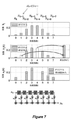
消去フィルタ係数重みの再分配が、図7で視覚化されている。一番上では、時間kにおける最新の8個の入力サンプルが示され、そのうち、xk−4およびxk−1は、イレイジャーである。第1のプロットは、下のシフトレジスタ実装と整列させられた、本来のフィルタ、すなわち、長さ8のハミング窓の係数biを示す。第2のプロットでは、時間kにおける、対応する入力サンプルxk−4およびxk−1がイレイジャーであるので、係数b1’(k)およびb4’(k)の値は、ゼロに設定される。第2のプロットの右端側に消去係数の合計も示されている。第3のプロットでは、第2のプロットの右に示されるような消去重みが、非消去入力サンプルに割り当てられる係数上に均一に再分配され、wi(k)を生じる。加算された重みは、第3のプロットにおいて異なる斜線で示される。係数重みは、本実施形態ではw0−w7として、下のシフトレジスタフィルタ図に示されている。
The redistribution of the elimination filter coefficient weights is visualized in FIG. At the top, the latest eight input samples at time k are shown, of which x k-4 and x k-1 are erasures. The first plot shows the original filter, the coefficient bi of the humming window of
時間k+1において次の入力サンプルがあると、サンプルおよびそれらの対応する信頼情報は、フィルタのシフトレジスタ内で右に移動し、該再分配は、再度、消去のシフトパターンのために行われ、異なるフィルタ係数wi(k+1)を生じる。
With the next input sample at
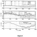
フィルタの雑音抑制性能の例が、図8に示されている。上のプロットは、追加のガウス雑音を伴う、ゆっくり変動する情報信号である、フィルタ入力信号を示し、いくつかの雑音ピークは、サンプル指数250から始まり、追加の60Hz正弦波雑音を伴う。第2のプロットは、長さ64のハミング関数を伴う従来の低域通過フィルタリングが、より高い周波数雑音を低減させるが、入力信号に存在する雑音ピークのみを不鮮明にすることを示す。しかしながら、雑音ピークを識別しているので、それらは、種々の実施形態によると、完全に抑制される。図8の下のプロットは、移動平均の代わりにハミング消去フィルタ関数を使用することの利益を実証する。非ピークサンプルに対する単純平均化、すなわち、選択的算術平均フィルタリングと比較して、ハミング消去フィルタリングは、入力信号に含まれる広帯域雑音のより良好な抑制を生じ、より平滑な出力を生じる。 An example of the noise suppression performance of the filter is shown in FIG. The plot above shows the filter input signal, which is a slowly fluctuating information signal with additional Gaussian noise, with some noise peaks starting at sample index 250 with additional 60 Hz sinusoidal noise. The second plot shows that conventional low frequency pass filtering with a humming function of length 64 reduces higher frequency noise, but blurs only the noise peaks present in the input signal. However, since they are identifying noise peaks, they are completely suppressed, according to various embodiments. The plot at the bottom of FIG. 8 demonstrates the benefits of using the Humming elimination filter function instead of the moving average. Compared to simple averaging for non-peak samples, i.e., selective arithmetic mean filtering, humming elimination filtering results in better suppression of the wideband noise contained in the input signal, resulting in a smoother output.
図9は、どのようにしてイレイジャーがフィルタの周波数応答に影響を及ぼすかを示す。ここでは、左側は、長方形の窓およびハミング窓を使用する典型的低域通過フィルタと、その関連規模スペクトルとを示す。右側に、2つの消去されたサンプルを使用する同一のフィルタリングが示されている。ハミング消去フィルタのスペクトルは、消去の位置に応じて、長方形の消去フィルタに類似することが観察されることができる。 FIG. 9 shows how the erasure affects the frequency response of the filter. Here, the left side shows a typical lowpass filter using a rectangular window and a humming window, and their related scale spectrum. On the right side, the same filtering using two erased samples is shown. It can be observed that the spectrum of the humming erasure filter resembles a rectangular erasure filter, depending on the position of the erasure.
(2.一般化)
(2a)非2進信頼入力)
この時点まで、信頼入力は、2進であった、すなわち、関連入力サンプルは、フィルタ出力値を計算するために使用されるか、または使用されないかのいずれかであった。しかしながら、上記注記を考慮すると、0〜1の実際の値をとるように信頼入力を一般化することが容易であり、すなわち、ck∈[0,1]であり、ckが大きいほど、関連サンプルxkを信頼している。ckの定義は別として、方程式(1.2)は、同一のままである。
(2. Generalization)
(2a) Non-binary reliability input)
Up to this point, the confidence input was binary, i.e. the associated input sample was either used or not used to calculate the filter output value. However, considering the above note, it is easy to generalize the trust input so that it takes an actual value of 0 to 1, that is, kk ∈ [0,1], and the larger ck , the more. I trust the related sample x k. Apart from the definition of kk , equation (1.2) remains the same.
(2b)一般的再分配関数)
2進信頼入力に対して、方程式(1.2)では、消去重みは、他の係数に均一に分配される。(1.2)内の2つの項は、それらの出力が合計される2つの平行フィルタブランチとして解釈されることができる。第1の項におけるフィルタ関数は、bおよび信頼入力から計算され、第2の項は、時変平均化フィルタである。後者は、係数giを伴う別のFIRフィルタ関数gを導入することによって一般化されることができ、以下を生じる。
(2b) General redistribution function)
For binary confidence inputs, in equation (1.2) the elimination weights are evenly distributed to the other coefficients. The two terms in (1.2) can be interpreted as two parallel filter branches where their outputs are summed. The filter function in the first term is calculated from b and the confidence input, and the second term is a time-varying averaging filter. The latter can be generalized by introducing another FIR filter function g with coefficients g i, resulting in the following.
![]()
![]()
![]()
![]()
故に、フィルタ出力は、以下のように与えられる。 Therefore, the filter output is given as follows.
![]()
![]()
![]()
![]()
![]()
![]()
図6のFIRフィルタのタップ遅延線実装の特徴的性質は、信頼値TDL−Cのタップ遅延線および信頼加重入力データTDL−XCのタップ遅延線が同一であること、すなわち、それらが同数の遅延段階であり、同一のタップ重みb0,b1,・・・およびg0,g1,・・・が、それぞれの遅延段階に接続されることである。当然ながら、一方または他方の遅延線は、入力変数タイプ、例えば、2進信頼入力に応じて、単純化され得る。g0=g1=g2・・・であるときも、遅延線または関連計算ブロックは、単純化されることができる。さらに、定数係数がタップ遅延線の外側で補償されることができるので、TDL−C内の重みb0,b1,・・・が、TDL−XC内の重みb0,b1,・・・と定数倍異なるかどうか、また、TDL−C内の重みg0,g1,・・・が、TDL−XC内の重みg0,g1,・・・と定数倍異なるかどうかも問題にならない。
The characteristic property of the tap delay line implementation of the FIR filter in FIG. 6 is that the tap delay line of the reliability value TDL-C and the tap delay line of the reliability weighted input data TDL-XC are the same, that is, they have the same number of delays. It is a stage, and the same tap weights b 0 , b 1 , ... And g 0 , g 1 , ... Are connected to each delay stage. Of course, one or the other delay line can be simplified depending on the input variable type, eg, binary confidence input. The delay line or related calculation block can also be simplified when g 0 = g 1 = g 2 ... Furthermore, since it is possible to constant coefficients is compensated outside the tapped delay line, weighted b 0, b 1 in the TDL-C, · · · is the
例えば、gi=1/8である場合、それぞれのタップ重みは、1に設定されることもでき、故に、乗算を保存し、(1/x)ブロックの前のタップ遅延線の端部における合計のみが、8で除算され、それは、ビットシフト演算を用いて行われることもできる。 For example, if gi = 1/8, each tap weight can also be set to 1, so save the multiplication and sum at the end of the tap delay line before the (1 / x) block. Only is divided by 8, which can also be done using the bit shift operation.
2進信頼入力または値の有限組からの信頼値に対して、図6の乗算によって実現される信頼加重入力データ値qkの計算は、条件文、例えば、IF/ELSEまたはSWITCH文によって実現されることもでき、例えば、qkは、ck=0であれば0に設定され、qkは、ck=1であれば1に設定される。遅延線の前の代わりに、条件文は、遅延線の各タップに割り付けられることもできる。タップ重み入力値bi・xk−1またはgi・xk−1は、次いで、関連ck−1が1である場合にのみ、それぞれの遅延線の出力合計値に加算される。この場合、サンプルxkは、TDL−XCに直接入力されることができ、事前にckで乗算される必要がない。同様のことが、TDL−Cに成り立つ。 The calculation of the confidence-weighted input data value q k realized by the multiplication of FIG. 6 with respect to the confidence value from the binary confidence input or a finite set of values is realized by a conditional statement, for example, an IF / ELSE or SWITCH statement. For example, q k is set to 0 if c k = 0, and q k is set to 1 if c k = 1. Instead of before the delay line, a conditional statement can also be assigned to each tap on the delay line. Tap weight input value b i · x k-1 or g i · x k-1 is then only if the associated c k-1 is 1, is added to the output sum of each delay line. In this case, the sample x k can be directly input to TDL-XC and does not need to be pre-multiplied by kk. The same applies to TDL-C.
インパルス応答bおよびgを伴うフィルタの次数は、必ずしも等しくなければならない必要はない。一般性を失うことなく、フィルタは、等しい次数Nを有するように定義され、Nは、少なくとも、bおよびgを伴うフィルタの次数の最大値と同じくらい大きく、未使用の係数は、ゼロ値であると仮定される。 The order of the filters with impulse responses b and g does not necessarily have to be equal. Without loss of generality, the filter is defined to have an equal order N, where N is at least as large as the maximum order of the filter with b and g, and the unused coefficient is zero. It is assumed that there is.
g=bを選択することは、消去係数重みを再分配するための別の好ましくないアプローチを生じることである。非消去フィルタ係数は、同一の倍数によって増減され、それは、各離散時間インスタンスkにおいて再計算され、すなわち、 Choosing g = b results in another unfavorable approach for redistributing elimination factor weights. The non-erasing filter factor is incremented or decremented by the same multiple, which is recalculated for each discrete-time instance k, i.e.
![]()
![]()
(3.例外処理)
(1.2)または(1.3)に分母があると、最新のN+1個の入力サンプル全てがゼロ信頼を伴う場合、出力値が計算されることができないことが明白である。そのような場合の可能な例外は、最新の有効出力サンプルを反復すること、または例外は、後続の処理段階に進められることであることができる。
(3. Exception handling)
With a denominator in (1.2) or (1.3), it is clear that the output value cannot be calculated if all of the latest N + 1 input samples have zero confidence. A possible exception in such a case could be to iterate over the latest valid output sample, or the exception could be advanced to a subsequent processing stage.
(4.特に、2つ以上の期待信号レベルを伴う信号に対する窓処理およびDC値計算)
対称フィルタまたは「窓処理」関数bに対して、関数bとの入力信号の畳み込み時にスナップショットを撮ることは、入力サンプルをbで加重し、点毎の積にわたって合計することと同等である。故に、窓信号のDC値に関心があるとき、上記の概念が、等しく適用されることができる。DC計算を伴う窓処理と連続フィルタリングとの間の主要な差異は、前者に対して、典型的には、各入力サンプルが、単一の出力値のみに影響すること、すなわち、それが入力サンプルの1回限りの処理またはブロック毎の処理であることである。
(4. In particular, window processing and DC value calculation for signals with two or more expected signal levels)
Taking a snapshot of the symmetric filter or "window processing" function b when convolving the input signal with the function b is equivalent to weighting the input sample with b and summing it over the point-by-point product. Therefore, when interested in the DC value of a window signal, the above concepts can be applied equally. The main difference between window processing with DC computation and continuous filtering is that, for the former, each input sample typically affects only a single output value, i.e. it is an input sample. It is a one-time process or a block-by-block process.
多くの用途では、測定信号は、典型的には、追加の雑音を伴って、2つの異なるレベルの間で交互する。我々は、これらのレベルを「高」および「低」信号レベルと称する。図12は、そのような高および低レベルを伴う例示的測定値を示す。例は、搬送周波数の2倍におけるアナログ受信信号の同期サンプリングを伴う振幅変調(AM)であり、情報は、「高」および「低」信号レベルの間の差に含まれる。方法は、例えば、容量タッチ検出システムまたはGestIC(登録商標)技術で適用される。そのようなAMセンサシステムの測定(または「受信された」)信号は、例えば、それを+1および−1で交互に乗算することによって復調されることができ、次いで、DC(ゼロ周波数)値、すなわち、実際の情報、「高」および「低」信号レベルの間の「平均」差を推定するために、低域通過フィルタ処理される。 In many applications, the measurement signals alternate between two different levels, typically with additional noise. We refer to these levels as "high" and "low" signal levels. FIG. 12 shows exemplary measurements with such high and low levels. An example is Amplitude Modulation (AM) with synchronous sampling of analog received signals at twice the carrier frequency, the information being included in the difference between the "high" and "low" signal levels. The method is applied, for example, in a capacitive touch detection system or GestIC® technology. The measured (or "received") signal of such an AM sensor system can be demodulated, for example, by alternately multiplying it by +1 and -1, followed by a DC (zero frequency) value, That is, it is lowpass filtered to estimate the "mean" difference between the actual information, the "high" and "low" signal levels.
ここで、2つのレベルを伴うそのような信号が考慮され、標準用途では、そのような信号は、低域通過フィルタに入力され、「高」および「低」サンプルという用語は、2つの異なる信号レベルのいずれか一方に対応するサンプルの組を表すことが保持される。それらのそれぞれの信号レベルからの偏差は、雑音によって引き起こされると仮定されるであろう。 Here, such signals with two levels are considered, and in standard applications such signals are input to a low pass filter, and the terms "high" and "low" samples are two different signals. Representing a set of samples corresponding to one of the levels is retained. Deviations from their respective signal levels would be assumed to be caused by noise.
「低」サンプルが、例えば、検出されたピーク雑音に起因して、無用であると検出されるとき、フィルタ内のその対応する係数の重みをゼロに設定し、他の係数上に消去重みを再分配したい。しかしながら、フィルタ出力の期待値を維持するために、再分配は、他の「低」サンプルに割り当てられた係数のみに対してでなければならない。そうでなければ、フィルタ出力は、「高」サンプルに割り当てられた係数が追加の重みを得るであろうため、そうなるべきであるよりも「高」レベルにより近くなるであろう。 When a "low" sample is detected as useless, for example due to detected peak noise, it sets the weight of its corresponding factor in the filter to zero and puts the elimination weight on top of the other factors. I want to redistribute. However, in order to maintain the expected value of the filter output, the redistribution must be for only the coefficients assigned to the other "low" samples. Otherwise, the filter output will be closer to the "high" level than it should be, as the coefficients assigned to the "high" sample will gain additional weight.
一般に、入力信号のサンプルは、同一の期待値を伴うサンプルの組に分類されなければならず、信頼入力を伴うデジタルフィルタリング、すなわち、係数重みの再分配は、各組に割り当てられた係数の全体的重みが一定のままであるように起こらなければならず、それは、同一の組内の1つの組の中で消去される重みを再分配するとき、最も容易に達成される。 In general, the samples of the input signal must be classified into a set of samples with the same expected value, and digital filtering with a trusted input, i.e., the redistribution of coefficient weights, is the total of the coefficients assigned to each set. It must happen so that the target weights remain constant, which is most easily achieved when redistributing the weights that are eliminated within one set within the same set.
図7Aは、2つのレベルを伴う信号の例示的窓処理およびDC計算を示す。消去された値のハンドリングは、図7Aに示されるように、「高」および「低」信号レベルにおけるサンプルに対して個々にそれぞれ行われる。1つおきのフィルタ係数が、「高」および「低」信号レベルからの測定値に割り当てられる。図7Aのグラフa)は、本来のフィルタ係数を示す。グラフb)は、「高」レベル係数を分離し、グラフc)は、「低」レベル係数を分離する。図7Aのグラフd)は、係数3が「低」信号レベルにおけるサンプルに対応し、消去されることを示す。その重みは、「低」信号レベルを伴うサンプルに割り当てられた他の係数に再分配される。グラフe)は、「低」信号レベル係数に対する再分配を示す。下のグラフf)は、再分配された「低」信号レベル係数および「高」信号レベル係数の組み合わせを示す。したがって、期待出力値は、保持される。方法は、1つが「高」信号レベルを伴うサンプルのため、1つが「低」信号レベルを伴うサンプルためである2つのデータブランチを伴って実装されることができ、最後にブランチの出力を合計する。再度、これは時変フィルタであるので、フィルタ係数の再分配は、各出力サンプルに対して更新される。
FIG. 7A shows exemplary window processing and DC computation of a signal with two levels. Handling of the erased values is done individually for the samples at the "high" and "low" signal levels, as shown in FIG. 7A. Every other filter factor is assigned to the measurements from the "high" and "low" signal levels. Graph a) of FIG. 7A shows the original filter coefficient. Graph b) separates the "high" level coefficients and graph c) separates the "low" level coefficients. Graph d) in FIG. 7A shows that the
(5.信頼出力)
即時に入力信頼値を処理する能力は、信頼値も各出力サンプルに対して提供されることができるかの問題を提起する。そのような出力信頼尺度は、入力サンプル値から独立するはずであるが、入力信頼値およびフィルタ係数のみの関数となるはずであり、すなわち、整数Mに対して、
(5. Reliable output)
The ability to process input confidence values immediately raises the question of whether confidence values can also be provided for each output sample. Such an output confidence measure should be independent of the input sample values, but should be a function of the input confidence values and the filter coefficients only, i.e. for the integer M.
![]()
![]()
(1.4)を満たし、容易に利用可能である尺度は、それらの対応する入力信頼値で加重されているフィルタ係数の合計、すなわち、 A measure that satisfies (1.4) and is readily available is the sum of the filter coefficients weighted by their corresponding input confidence values, ie.
![]()
全てのiに対してbi≧0であり、
![]()
Bi ≧ 0 for all i,
![]()
![]()
そのような信頼出力を利用して、多様な提案されるフィルタが、カスケード表示されることができる。この出力は、高レベル制御にも使用されることができ、例えば、「出力信頼が低すぎるならば、タッチ事象をトリガしない」。 Utilizing such confidence output, a variety of proposed filters can be cascaded. This output can also be used for high level control, for example, "If the output confidence is too low, it will not trigger a touch event."
(7.設計規則)
提案されるアプローチは、任意の低域通過FIRフィルタに適用可能である。しかしながら、全てのフィルタ係数は、同一の符号を有し、例えば、正の値であるべきである。主に、一定のDCフィルタ利得の要件は、タップ重み(のうちのいくつか)が負の値であるときに満たされることもできる。しかしながら、これは、いくつかの信頼入力配置に対して、望ましくないフィルタ特性、例えば、高域通過特性を生じる危険性を導入するであろう。
(7. Design rules)
The proposed approach is applicable to any low pass FIR filter. However, all filter coefficients should have the same sign and should be, for example, positive values. Primarily, the requirement for constant DC filter gain can also be met when the tap weights (some of them) are negative. However, this will introduce the risk of producing undesired filter characteristics, such as high pass characteristics, for some trusted input arrangements.
さらに、大きい値を伴う係数に割り当てられた入力サンプルが消去されるとき、フィルタ係数値が類似するほど、あまり問題ではなくなる。具体的には、方形窓、三角窓、ハミング、およびハン窓の係数は、これらの規則に従っている。 Moreover, when the input sample assigned to a coefficient with a large value is erased, the more similar the filter coefficient values are, the less problematic it is. Specifically, the coefficients of square windows, triangular windows, humming, and han windows follow these rules.
本来のフィルタ係数の選択および例外処理は別として、考慮すべきさらなるパラメータはない。 Apart from the original filter coefficient selection and exception handling, there are no additional parameters to consider.
このアプローチは、高域通過フィルタに拡張されることができる。図10は、上から1番目のプロットに示されるように、本来のフィルタ係数重みが正符号と負符号とを繰り返す高域通過フィルタの例を示す。したがって、実施形態によると、最初に、高域通過フィルタ係数は、上から2番目のプロットに示されるように、交互する符号を使用して復調される。次いで、図2に示される低域通過フィルタと同様の同方法は、上から3番目および4番目のプロットに示されるように適用される。次いで、上から4番目のプロットに示されるような修正された重みは、逆の交互する符号を使用して再変調される。これは、上から5番目のプロットに示されるような分配された重みをもたらす。フィルタ係数の再変調の代わりに、フィルタの入力信号が、復調されることもでき、再び信号を変調する前に、上から4番目のプロットによる係数を伴う同等の低域通過を用いてフィルタ処理されることができる。たとえ入力信号が高域通過フィルタを用いて直接フィルタ処理されるか、または復調され、同等の低域通過フィルタを用いてフィルタ処理されても、復調されるであろうならば、高域通過フィルタの入力信号のサンプルが、単一の期待値を有するであろうことが重要である。 This approach can be extended to high pass filters. FIG. 10 shows an example of a high frequency pass filter in which the original filter coefficient weight repeats a plus sign and a minus sign, as shown in the first plot from the top. Therefore, according to the embodiment, first, the high pass filter coefficients are demodulated using alternating signs, as shown in the second plot from the top. The same method, similar to the lowpass filter shown in FIG. 2, is then applied as shown in the third and fourth plots from the top. The modified weights, as shown in the fourth plot from the top, are then remodulated using the opposite alternating signs. This results in distributed weights as shown in the fifth plot from the top. Instead of remodulating the filter coefficients, the input signal of the filter can also be demodulated and filtered using equivalent low frequency passage with the coefficients from the fourth plot from the top before remodulating the signal. Can be done. A high pass filter, even if the input signal is directly filtered or demodulated with a high pass filter and will be demodulated with an equivalent low pass filter. It is important that the sample of the input signal of will have a single expected value.
(8.用途およびユースケース)
上記のように、提案される概念は、任意のフィルタリングシステムに適用可能であり、入力信号は、実際の情報変化より速くサンプリングされ、サンプリングレートが高いほど良好である。特に、そのようなシステムは、出願人のGestICシステムおよび1D/2D容量タッチソリューション等の3D容量センサシステムを含む。フィルタリング方法は、他のセンサ信号にさらに適用され得、容量センサシステムに制限されない。
(8. Applications and use cases)
As mentioned above, the proposed concept is applicable to any filtering system, the input signal is sampled faster than the actual information change, and the higher the sampling rate, the better. In particular, such systems include the applicant's GestIC system and 3D capacitive sensor systems such as 1D / 2D capacitive touch solutions. Filtering methods can be further applied to other sensor signals and are not limited to capacitive sensor systems.
(9.性質)
恣意的であるがゼロ信頼のデータでフィルタを初期化するとき、それは、ターンオン時間から入力信号の推定値を提供する。故に、フィルタは、ゼロではない平均を伴う信号をフィルタ処理すると、典型的ステップ応答を示さず、フィルタ条件は、ゼロで初期化されている。
(9. Properties)
When initializing the filter with arbitrary but zero-reliability data, it provides an estimate of the input signal from the turn-on time. Therefore, when the filter filters a signal with a non-zero average, it does not show a typical step response and the filter condition is initialized to zero.
(数値例)
以下では、信頼入力を伴うフィルタのための出力値のための計算の数値例を挙げる。以下の表は、時間kにおける入力サンプル値xkおよび関連付けられた信頼値ck、本来のフィルタ関数bの係数biを記述する。ここでは、gは、定数であり、すなわち、消去係数重みは、一様に再分配されるであろう。
(Numerical example)
The following is a numerical example of the calculation for the output value for a filter with a trusted input. The following table, the input sample value x k and associated confidence value c k at time k, which describes the coefficients b i of the original filter function b. Here, g is a constant, i.e. the elimination factor weights will be redistributed uniformly.
フィルタの初期化のために、フィルタのメモリ内の全ての信頼情報は、第1のサンプル・信頼ペア(x0,C0)を入力する前に、ゼロに設定される(例えば、ゼロ信頼を伴うN個のサンプルを入力することによって)。これは、k<0に対してck=0によって表に示されている。k=0であるとき、信頼ck=1を伴うサンプルx0=7が、フィルタに入力されている。上記の方程式によると、修正された係数bi’(k=0)および係数wi(k=0)は、以下のように計算される。 Due to the initialization of the filter, all trust information in the filter's memory is set to zero (eg, zero trust) before entering the first sample-trust pair (x 0 , C 0). By entering the accompanying N samples). This is shown in the table by kk = 0 for k <0. When k = 0, sample x 0 = 7 with confidence kk = 1 is input to the filter. According to the above equation, the modified coefficients b i '(k = 0) and the coefficients w i (k = 0) is calculated as follows.
k=9であるとき、2つの消去x5およびx8がフィルタのバッファ内にあるとき、bi’(k=9)およびwi(k=9)は、以下のように計算される。
When a k = 9, when the two erase x 5 and x 8 are in the buffer of the filter, b i '(k = 9 ) and wi (k = 9) is calculated as follows.
パケットデータ処理では、各入力サンプルは、単一の出力値のみに影響しており、故に、この実装は、図13−17による実施形態に示されるように、タップ遅延線(バッファ)の代わりにアキュムレータacc01・・acc04を使用して行われることができる。各新しいデータパケットに対して、いくつかの実施形態によると、これらのアキュムレータは、ゼロに設定され、次いで、それぞれの入力値が、それらに連続的に加算される。 In packet data processing, each input sample affects only a single output value, so this implementation replaces the tap delay line (buffer) as shown in the embodiment according to FIG. 13-17. It can be done using the accumulator acc01 ... acc04. For each new data packet, according to some embodiments, these accumulators are set to zero, and then their respective input values are continuously added to them.
さらに、出力データレートが、あるデシメーション係数だけ入力データレートよりも低いとき、アキュムレータを加えた他の実施形態よりも短い遅延線を伴う中間バージョンも可能である。 Further, when the output data rate is lower than the input data rate by a certain decimation factor, an intermediate version with a shorter delay line than in other embodiments with an accumulator is also possible.
以下では、データパケットの長さをLとして表し、低域通過フィルタの次数をNとして表し、N=L−1である。xk,k=0,1,…L−1が、長さLのデータパケットのL個のサンプルを表すとする。各そのようなサンプルは、2進信頼値ckε[0,1]に関連付けられ、すなわち、0≦ck≦1であり、ck=0は、xkが、例えば、ピーク雑音または異常値検出器によって、いかなる有用な情報も搬送しないと見なされ、フィルタ出力に影響しないものとすることを意味し、ck=1は、xkがフィルタ出力に完全に影響するものとすることを意味する。 In the following, the length of the data packet is represented by L, the order of the low-pass filter is represented by N, and N = L-1. It is assumed that x k , k = 0, 1, ... L-1 represents L samples of a data packet having a length L. Each such sample is associated with a binary confidence value c kε [0,1], i.e. 0 ≤ c k ≤ 1, where c k = 0 means that x k is, for example, peak noise or anomalous value. It is considered by the detector that it does not carry any useful information and does not affect the filter output, and kk = 1 means that x k has a complete effect on the filter output. do.
図13は、最小バッファ要件を伴う、換言すると、いかなる冗長なバッファも伴わず、4つのアキュムレータacc01、acc02、acc03、およびacc04のみを伴う、パケットデータ処理のための実装を示す。長さLの各データパケットが処理されるために、L個の入力サンプルxk,k=0,1,・・.,L−1が、それらの関連信頼ckと一緒にフィルタの中へフィードされる。対応するフィルタ係数bkは、フラッシュの中に記憶されることができる。いくつかの実施形態によると、各データパケット後に、アキュムレータacc0xは、ゼロにリセットされる必要がある。ボックス「L↓」によって表されるデシメーションブロックの右側の動作は、各データパケットのために1回のみ更新されるべきことに留意されたい。したがって、ボックス「L↓」は、アキュムレータが長さLを有するパケットの全ての入力値を累積すると、その入力におけるアキュムレータ値をその出力に転送するゲートを形成しているにすぎない。したがって、L値を累積した後、ボックス「L↓」は、累積値を出力するであろう。図13は、(.)−1によって表される乗法の逆転も含み、すなわち、ブロックの出力値は、入力値で除算された1である。 FIG. 13 shows an implementation for packet data processing with only four accumulators acc01, acc02, acc03, and acc04, with a minimum buffer requirement, in other words, without any redundant buffers. Since each data packet of length L is processed, L input samples x k , k = 0, 1, ... , L-1 are fed into the filter along with their associated confidence kk. The corresponding filter coefficient b k can be stored in the flash. According to some embodiments, the accumulator acc0x needs to be reset to zero after each data packet. Note that the behavior on the right side of the decimation block represented by the box "L ↓" should be updated only once for each data packet. Therefore, the box "L ↓" merely forms a gate that, when the accumulator accumulates all the input values of the packet having the length L, transfers the accumulator value at that input to its output. Therefore, after accumulating the L values, the box "L ↓" will output the accumulated values. FIG. 13 also includes the inversion of the multiplication represented by (.) -1 , that is, the output value of the block is 1 divided by the input value.
k=0,1,・・.,Nに対してbN−k=bkである対称フィルタインパルス応答に対して、図13のbN−kは、bkによって置換されることもできる。 k = 0,1, ... For symmetric filter impulse response is a b N-k = b k with respect to N, b N-k in FIG. 13 can also be replaced by b k.
ckε{0,1}を伴う2進信頼入力に対して、ckを用いた乗算、すなわち、信頼値を用いた加重は、スイッチ(図14参照)または変数の条件付きインクリメントを用いて実装されることもできる。 For binary confidence inputs with c kε {0,1}, multiplication with kk , i.e. weighting with confidence values, is implemented using a switch (see Figure 14) or conditional increments of variables. Can also be done.
他の実施形態によると、典型的ユースケースではないこともあるが、アキュムレータが各パケットL後にリセットされない場合、フィルタは、もはやFIRフィルタではないが、IIRフィルタであることができる。 According to other embodiments, the filter can be an IIR filter, although it is no longer an FIR filter, if the accumulator is not reset after each packet L, which may not be a typical use case.
具体的には、「信頼加重」データは、データを信頼値で乗算することを指し、スイッチを用いてデータパスを開放または閉鎖することも指す。同様に、「加重する」および「加重される」が、それぞれ、「乗算する」または「乗算される」を指す一方で、乗算は、データパスのスイッチをオンまたはオフにすることによっても起こり得る。 Specifically, "trust-weighted" data refers to multiplying data by a confidence value, and also refers to opening or closing a data path with a switch. Similarly, while "weighted" and "weighted" refer to "multiply" or "multiply," respectively, multiplication can also occur by switching the data path on or off. ..
対称フィルタインパルス応答および2進信頼値、サンプルx_kおよび関連付けられた信頼値c_k、フィルタ係数b_kを用いた1つのデータパケットを求める出力の計算のための疑似コードソフトウェア実装に関し、図14による実際の例が以下に示される。
float acc01=0;
uint16 acc02=0;
float acc03=0;
float acc04=0;
float aux = 0;for (k=0:N) aux+= b_k; // constant
for k=0:N
if (c_k==1) {
acc01 += b_k;
acc02++;
acc03 += b_k*x_k;
acc04 += x_k;
}
}
float out = (aux−acc01) * (1/acc02) * acc04 + acc03;
入力Lサンプルを有し、最終出力値を計算した後、ゼロにリセットされる必要がある、アキュムレータacc01、acc02、acc03、およびacc04を採用する代わりに、L個の入力値にわたる合計は、現在のパケットのためのデータを入力する前に、acc01、acc02、acc03、およびacc04の値を記憶し、現在のパケットのためのデータを入力した後、acc01、acc02、acc03、およびacc04のそれぞれの値から、これらの記憶された値を減算することによって、行われることもできる。これは、例えば、一次CICフィルタを採用することによって実現されることができ、一次CICフィルタは、例えば、IEEE Transactions on Acoustics,Speech,and Signal Processing,Vol.ASSP−29,No.2,April 1981,pages 155−162で出版された、Eugene B.Hogenauerによる「An Economical Class of Digital Filters for Decimation and Interpolation」(それは、デシメーションを用いた移動合計フィルタである)から公知である。これは、図15に示され、アキュムレータおよびデシメーション段後、現在の値から前の累積および間引き値を減算する追加の差動段がある。
A real-world example according to FIG. 14 relating to a pseudo-code software implementation for calculating the output to obtain a single data packet using a symmetric filter impulse response and binary confidence value, sample x_k and associated confidence value c_k, filter coefficient b_k. Is shown below.
float acc01 = 0;
wint16 acc02 = 0;
float acc03 = 0;
float acc04 = 0;
float aux = 0; for (k = 0: N) aux + = b_k; // constant
for k = 0: N
if (c_k == 1) {
acc01 + = b_k;
acc02 ++;
acc03 + = b_k * x_k;
acc04 + = x_k;
}
}
float out = (ax-acc01) * (1 / acc02) * acc04 + acc03;
Instead of adopting the accumulators acc01, acc02, acc03, and acc04, which have input L samples and need to be reset to zero after calculating the final output value, the sum over the L input values is the current Store the values of acc01, acc02, acc03, and acc04 before entering the data for the packet, and after entering the data for the current packet, from the respective values of acc01, acc02, acc03, and acc04. , It can also be done by subtracting these stored values. This can be achieved, for example, by adopting a primary CIC filter, which can be achieved, for example, by IEEE Transitions on Acoustics, Speech, and Signal Processing, Vol. ASSP-29, No. 2, April 1981, pages 155-162, published by Eugene B. et al. It is known from "An Electrical Class of Digital Filters for Decimation and Interpolation" by Hogenauer (it is a moving total filter using decimation). This is shown in FIG. 15, after the accumulator and decimation stages, there is an additional differential stage that subtracts the previous cumulative and decimate values from the current value.
(一般再分配関数)
連続データ処理に対するように、パケットデータ処理に対しても、一般再分配関数gが採用されることができる。そして、図13および14は、それぞれ、図16および図17に変化する。
(General redistribution function)
The general redistribution function g can be adopted for packet data processing as well as for continuous data processing. Then, FIGS. 13 and 14 change to FIGS. 16 and 17, respectively.
(複数の期待値を伴うサンプル値)
多くの用途、例えば、容量感知では、実際の情報は、振幅変調され、ADC出力データは、低域通過フィルタリングに先立って復調される必要があり、ADC出力値および復調されたADC出力値は両方とも、2つの期待値を有する。しかしながら、信頼入力を伴うデジタルフィルタは、単一の期待値を伴う入力サンプルに直接適用されることしかできない。故に、復調されたADC出力値は、各組内の全てのサンプルに対して単一の期待値を伴う2つの組に分割される必要がある。
(Sample value with multiple expected values)
In many applications, eg, capacitance sensing, the actual information is amplitude modulated and the ADC output data needs to be demodulated prior to low pass filtering, both the ADC output value and the demodulated ADC output value. Both have two expected values. However, digital filters with trusted inputs can only be applied directly to input samples with a single expected value. Therefore, the demodulated ADC output values need to be split into two sets with a single expected value for every sample in each set.
典型的には、ADCは、2つの異なる期待信号レベルにおけるサンプルを交互に出力し、それらは、それぞれ、低および高サンプルとして表され、偶数時間指数kに低サンプルが割り当てられ、奇数時間指数に高サンプルが割り当てられる。 Typically, the ADC alternately outputs samples at two different expected signal levels, which are represented as low and high samples, respectively, with the even time index k assigned the low sample and the odd time index to. High samples are assigned.
対称フィルタインパルス応答、すなわち、bi=bN−i、i=0,1,2,・・.Nを仮定する。xk (L)=x2kおよびxk (H)=x2k+1を導入し、フィルタ係数bi (e)=b2iおよびbi (o)=b2i+1に対しても同様である。 Symmetric filter impulse response, i.e., b i = b N-i , i = 0,1,2, ··. Assume N. x k (L) = x 2k and x k (H) = introduced x 2k + 1, is the same with respect to the filter coefficients b i (e) = b 2i and b i (o) = b 2i + 1.
本来の低域通過フィルタインパルス応答は、偶数のiを伴う係数biと奇数のiを伴う係数biとを分離することによって、2つに分割される。これは、長さL=16のハミング窓である、本来のフィルタインパルス応答の例に対して、図18に示されている。 Original low pass filter impulse response, by separating the factor b i with coefficients b i and odd i with an even number of i, is divided into two. This is shown in FIG. 18 as opposed to an example of the original filter impulse response, which is a humming window of length L = 16.
これらの例示的フィルタインパルス応答を使用して、図19は、復調されたサンプルxkがkの偶数値と奇数値とに対して区別され、2つのデータブランチに分割される方法を示し、qは、k/2の底値であり、図13による信頼入力を伴うが、異なるフィルタインパルス応答(図18および19参照)を伴うデジタルフィルタの2つのインスタンスが、それぞれ、偶数および奇数の指数kを伴うサンプルxkを処理するために採用される。この例における各データブランチは、信頼値cを生成するそれ自身のピーク雑音検出器を有する。各ブランチ上のサンプルレートは、入力サンプルレートの半分であり、各ブランチ上で考慮されるパケット長は、入力サンプルxkのパケット長の半分であり、例えば、ここでは、本来のパケット長は、L=16であり、信頼入力を伴う各デジタルフィルタのためのパケット長は、L’=L/2=8である。両方のフィルタの出力は、最終結果を生じるように加算される。 Using these exemplary filter impulse responses, FIG. 19 shows how the demodulated sample x k is distinguished for even and odd values of k and split into two data branches, q. Is the bottom value of k / 2, with the confidence input according to FIG. 13, but with two instances of the digital filter with different filter impulse responses (see FIGS. 18 and 19), with even and odd exponents k, respectively. It is employed to process the samples x k. Each data branch in this example has its own peak noise detector that produces a confidence value c. The sample rate on each branch is half the input sample rate, and the packet length considered on each branch is half the packet length of the input sample x k , for example, here the original packet length is L = 16, and the packet length for each digital filter with a trusted input is L'= L / 2 = 8. The outputs of both filters are added to produce the final result.
上記のデジタルフィルタは、ハードウェア(例えば、プログラマブル論理デバイス)、または、ソフトウェア(例えば、マイクロコントローラ、プロセッサ、もしくはデジタル信号プロセッサにおけるもの)によって形成されることができる。 The digital filters described above can be formed by hardware (eg, programmable logic devices) or software (eg, in microcontrollers, processors, or digital signal processors).
(文献目録)
B.Boashash,M.M.(2004).Signal Enhancement by Time−Frequency Peak Filtering.IEEE Transactions on Signals Processing,929−937.
Blahut,R.E.(1983).Theory and Practice of Error Control Codes.Reading,MA:Addison−Wesley.
Bossert,M.(1999).Channel Coding for Telecommunication.New York,NY,USA:John Wiley & Sons,Inc.
Commission,I.E.(n.d.).Electrical Fast Transient/Burst Immunity Test (IEC 61000−4−4).
Grubbs,F.E.(1950,Mar).Sample criteria for testing outlying observations.Ann.Math.Statist.,pp.27−58.
H.Hwang,R.H.(1995).Adaptive median filters:New algorithms and results.IEEE Transactions on Image Processing,499−502.
Hampel,F.R.(1974).The influence curve and its role in robust estiamteion.Journal of the American Statistical Association,69,383−393.
J.Horentrup,M.S.(2014).Confidence−aware guided image filter.IEEE International Conference on Image Processing,(pp.3243−3247).
K.Aiswarya,V.J.(2010).A new and efficient algorithm for the removal of high density salt and pepper noise in images and videos.Second International Conference on Computer Modeling and Simulation,(pp.409−413).
Kalman,R.E.(1960).A new approach to linear filtering and prediction problems.Transactions of the ASME−Journal of Basic Engineering,35−45.
Lee,J.−S.(1983).Digital image smoothing and the sigma filter.Computer Vision,Graphics,and Image Processing,255−269.
Microchip Touch and Input Sensing Solutions.(n.d.).Retrieved from http://www.microchip.com/touchandinputsensing
S.−J.Ko,Y.H.(1991).Center weighted median filters and their applications to image enhancement.IEEE Transactions on Circuits and Systems,984−993.
T.Benazir,B.I.(2013).Removal of high and low density impulse noise from digital images using non linear filter.International Conference on Signal Processing,Image Processing and Pattern Recognition,(pp.229−233).
(Bibliography)
B. Boashash, M. et al. M. (2004). Signal Enhancement by Time-Frequency Peak Filtering. IEEE Transitions on Signals Processing, 929-937.
Blahut, R. et al. E. (1983). Theory and Practice of Error Control Codes. Reading, MA: Addison-Wesley.
Bossert, M. et al. (1999). Channel Coding for Telecommunications. New York, NY, USA: John Wiley & Sons, Inc.
Communication, I. E. (Nd). Electrical Fast Transition / Burst Immunity Test (IEC 61000-4-4).
Grubbs, F. et al. E. (1950, Mar). Sample criteria for testing outlying observations. Ann. Math. Statist. , Pp. 27-58.
H. Hwang, R.M. H. (1995). Adaptive median filters: New algorithms and results. IEEE Transitions on Image Processing, 499-502.
Hampel, F. et al. R. (1974). The influence curve and it roll in robustation. Journal of the American Statistical Association, 69, 383-393.
J. Horentrup, M. et al. S. (2014). Confidence-aware guided image filter. IEEE International Convention on Image Processing, (pp. 3243-3247).
K. Aiswarya, V.I. J. (2010). A new and effective algorithm for the remote of high density salt and pepper noise in images and videos. Second International Convention on Computer Modeling and Simulation, (pp. 409-413).
Kalman, R.M. E. (1960). A new application to liner filtering and prophecy problems. Transitions of the ASME-Journal of Basic Engineering, 35-45.
Lee, J.M. -S. (1983). Digital image smoothing and the sigma filter. Computer Vision, Graphics, and Image Processing, 255-269.
Microchip Touch and Input Sensing Solutions. (Nd). Retrieved from http: // www. microchip. com / Touchandinputsensing
S. -J. Ko, Y. H. (1991). Center weighted median filters and their applications to image enhancement. IEEE Transitions on Circuits and Systems, 984-993.
T. Benazir, B. et al. I. (2013). Removal of high and low density impedance noise from digital images using non-linear filter. International Convention on Signal Processing, Image Processing and Pattern Recognition, (pp. 229-233).
Claims (25)
前記デジタルフィルタは、割り当てられたフィルタ係数を有する割り当てられたフィルタ関数と、複数の入力サンプル値を受信する入力と、複数の信頼値を受信する別の入力と、出力とを備え、
前記複数の入力サンプル値のそれぞれは、前記複数の信頼値のうちの信頼値に関連付けられており、前記複数の入力サンプル値のそれぞれは、その関連付けられた信頼値で加重されており、前記複数の信頼値のうちの一部は、前記割り当てられたフィルタ係数で加重されており、前記複数の入力サンプル値のうちの一部は、前記割り当てられたフィルタ係数でさらに加重されており、
前記デジタルフィルタの前記出力によって出力される値は、前記複数の入力サンプル値および前記複数の信頼値の両方に依存し、
前記デジタルフィルタは、複数のアキュムレータをさらに備え、前記複数のアキュムレータは、前記複数の入力サンプル値のうちの所定数の入力サンプル値と、前記複数の信頼値と、前記割り当てられたフィルタ係数で加重されている前記複数の信頼値のうちの前記一部と、前記割り当てられたフィルタ係数でさらに加重されている前記複数の入力サンプル値のうちの前記一部とを累積するように構成されている、デジタルフィルタ。 It ’s a digital filter,
The digital filter comprises an assigned filter function with an assigned filter coefficient, an input that receives a plurality of input sample values, another input that receives a plurality of confidence values, and an output.
Each of the plurality of input sample values is associated with a confidence value among the plurality of confidence values, and each of the plurality of input sample values is weighted by the associated confidence value. Some of the confidence values in are weighted by the assigned filter coefficients, and some of the plurality of input sample values are further weighted by the assigned filter coefficients.
The value output by the output of the digital filter depends on both the plurality of input sample values and the plurality of confidence values.
The digital filter further includes a plurality of accumulators, and the plurality of accumulators are weighted by a predetermined number of input sample values among the plurality of input sample values, the plurality of confidence values, and the assigned filter coefficient. It is configured to accumulate the part of the plurality of confidence values that have been set and the part of the plurality of input sample values that are further weighted by the assigned filter coefficient. , Digital filter.
前記デジタルフィルタは、
前記複数のアキュムレータのうちの第1のアキュムレータを有する第1のブランチであって、前記第1のアキュムレータは、前記割り当てられたフィルタ係数で加重されている前記複数の信頼値のうちの前記一部を受信し、第1の累積値を生成する、第1のブランチと、
前記複数のアキュムレータのうちの第2のアキュムレータを有する第2のブランチであって、前記第2のアキュムレータは、前記複数の信頼値を受信し、第2の累積値を生成する、第2のブランチと、
前記複数のアキュムレータのうちの第3のアキュムレータを有する第3のブランチであって、前記第3のアキュムレータは、前記割り当てられたフィルタ係数でさらに加重されている前記複数の入力サンプル値のうちの前記一部を受信し、第3の累積値を生成する、第3のブランチと、
前記複数のアキュムレータのうちの第4のアキュムレータを有する第4のブランチであって、前記第4のアキュムレータは、前記複数の入力サンプル値を受信し、第4の累積値を生成する、第4のブランチと
をさらに備えている、請求項1に記載のデジタルフィルタ。 The assigned filter coefficient is a coefficient from the coefficient set and
The digital filter is
A first branch having a first accumulator of the plurality of accumulators, wherein the first accumulator is the portion of the plurality of confidence values weighted by the assigned filter coefficient. And generate the first cumulative value, with the first branch,
A second branch having a second accumulator of the plurality of accumulators, wherein the second accumulator receives the plurality of confidence values and generates a second cumulative value. When,
A third branch of the plurality of accumulators having a third accumulator, wherein the third accumulator is the said of the plurality of input sample values further weighted by the assigned filter coefficient. A third branch that receives a portion and generates a third cumulative value,
A fourth branch having a fourth accumulator of the plurality of accumulators, wherein the fourth accumulator receives the plurality of input sample values and generates a fourth cumulative value. The digital filter according to claim 1, further comprising a branch.
前記デジタルフィルタは、
第1のアキュムレータを有する第1のブランチであって、前記第1のアキュムレータは、前記第1の係数組からの前記係数で加重されている前記複数の信頼値のうちの前記一部を受信し、第1の累積値を生成する、第1のブランチと、
第2のアキュムレータを有する第2のブランチであって、前記第2のアキュムレータは、前記第2の係数組からの前記係数で加重されている前記複数の信頼値のうちの前記別の一部を受信し、第2の累積値を生成する、第2のブランチと、
第3のアキュムレータを有する第3のブランチであって、前記第3のアキュムレータは、前記第1の係数組からの前記係数でさらに加重されている前記複数の入力サンプル値のうちの前記一部を受信し、第3の累積値を生成する、第3のブランチと、
第4のアキュムレータを有する第4のブランチであって、前記第4のアキュムレータは、前記第2の係数組からの前記係数でさらに加重されている前記複数の入力サンプル値のうちの前記別の一部を受信し、第4の累積値を生成する、第4のブランチと
をさらに備えている、請求項1に記載のデジタルフィルタ。 A part of the assigned filter coefficients is a coefficient from the first set of coefficients, and another part of the assigned filter coefficient is a coefficient from the second set of coefficients. A part of the plurality of confidence values is weighted by the coefficient from the first coefficient set , and another part of the plurality of confidence values is from the second coefficient set. It is weighted by the coefficients, and a part of the plurality of input sample values is further weighted by the coefficients from the first coefficient set, and is another one of the plurality of input sample values. The part is further weighted by the coefficients from the second set of coefficients.
The digital filter is
A first branch having a first accumulator, the first accumulator receiving the portion of the plurality of confidence values weighted by the coefficients from the first coefficient set. , The first branch, which produces the first cumulative value,
A second branch having a second accumulator, wherein the second accumulator is the other part of the plurality of confidence values weighted by the coefficients from the second set of coefficients. A second branch that receives and generates a second cumulative value,
A third branch having a third accumulator, wherein the third accumulator is a portion of the plurality of input sample values further weighted by the coefficients from the first coefficient set. With a third branch, which receives and generates a third cumulative value,
A fourth branch having a fourth accumulator, wherein the fourth accumulator is another of the plurality of input sample values further weighted by the coefficients from the second set of coefficients. The digital filter of claim 1, further comprising a fourth branch, which receives a portion and generates a fourth cumulative value.
請求項1〜13のうちの1項に記載の第1および第2のデジタルフィルタであって、前記第1および第2のデジタルフィルタのそれぞれは、割り当てられたフィルタ係数を有する割り当てられたフィルタ関数を備える、第1および第2のデジタルフィルタと、
入力信号を受信し、前記第1および第2のデジタルフィルタのための入力サンプルを生成するデマルチプレクサと
を備えている、フィルタシステム。 It is a filter system, and the filter system is
The first and second digital filters according to claim 1, wherein each of the first and second digital filters has an assigned filter function having an assigned filter coefficient. With the first and second digital filters,
A filter system comprising a demultiplexer that receives an input signal and produces an input sample for the first and second digital filters.
前記第1のデジタルフィルタのための前記入力サンプルを受信し、関連付けられた信頼値を生成する第1の異常値検出器と、
前記第2のデジタルフィルタのための前記入力サンプルを受信し、関連付けられた信頼値を生成する第2の異常値検出器と
をさらに備えている、請求項15に記載のフィルタシステム。 The filter system
A first outlier detector that receives the input sample for the first digital filter and produces an associated confidence value.
15. The filter system of claim 15, further comprising a second outlier detector that receives the input sample for the second digital filter and produces an associated confidence value.
複数の入力サンプル値および複数の入力信頼値を受信するステップであって、前記複数の入力サンプル値のそれぞれは、前記複数の入力信頼値のうちの入力信頼値に関連付けられており、前記複数の入力サンプル値のそれぞれは、その関連付けられた入力信頼値で加重されており、前記複数の入力サンプル値のうちの一部は、係数組からの係数でさらに加重されており、前記複数の入力信頼値のうちの一部は、前記係数組からの前記係数で加重されている、ステップと、
前記係数組からの前記係数で加重されている前記複数の入力信頼値のうちの前記一部を累積し、第1の累積値を生成するステップと、
前記複数の入力信頼値を累積し、第2の累積値を生成するステップと、
前記係数組からの前記係数でさらに加重されている前記複数の入力サンプル値のうちの前記一部を累積し、第3の累積値を生成するステップと、
前記複数の入力サンプル値を累積し、第4の累積値を生成するステップと
を含む、方法。 A method of filtering an input sample, wherein the method is
A step of receiving a plurality of input sample values and a plurality of input confidence values, each of the plurality of input sample values is associated with an input confidence value among the plurality of input confidence values, and the plurality of input confidence values are associated with the input confidence value. Each of the input sample values is weighted by its associated input confidence value, and some of the plurality of input sample values are further weighted by coefficients from the coefficient set, said that the plurality of input confidence values. Some of the values are weighted by the coefficients from the coefficient set, the steps and
A step of accumulating the part of the plurality of input confidence values weighted by the coefficient from the coefficient set to generate a first cumulative value.
A step of accumulating the plurality of input trust values and generating a second accumulated value, and
A step of accumulating the part of the plurality of input sample values further weighted by the coefficient from the coefficient set to generate a third cumulative value.
A method comprising accumulating the plurality of input sample values and generating a fourth cumulative value.
複数の入力サンプル値および複数の入力信頼値を受信するステップであって、前記複数の入力サンプル値のそれぞれは、前記複数の入力信頼値のうちの入力信頼値に関連付けられており、前記複数の入力サンプル値のそれぞれは、その関連付けられた入力信頼値で加重されており、前記複数の入力サンプル値のうちの一部は、第1の係数組からの係数でさらに加重されており、前記複数の入力サンプル値のうちの別の一部は、第2の係数組からの係数でさらに加重されており、前記複数の入力信頼値のうちの一部は、前記第1の係数組からの前記係数で加重されており、前記複数の入力信頼値のうちの別の一部は、前記第2の係数組からの前記係数で加重されている、ステップと、
前記第1の係数組からの前記係数で加重されている前記複数の入力信頼値のうちの前記一部を累積し、第1の累積値を生成するステップと、
前記第2の係数組からの前記係数で加重されている前記複数の入力信頼値のうちの前記別の一部を累積し、第2の累積値を生成するステップと、
前記第1の係数組からの前記係数でさらに加重されている前記複数の入力サンプル値のうちの前記一部を累積し、第3の累積値を生成するステップと、
前記第2の係数組からの前記係数でさらに加重されている前記複数の入力サンプル値のうちの前記別の一部を累積し、第4の累積値を生成するステップと
を含む、方法。 A method of filtering an input sample, wherein the method is
A step of receiving a plurality of input sample values and a plurality of input confidence values, each of the plurality of input sample values is associated with an input confidence value among the plurality of input confidence values, and the plurality of input confidence values are associated with the input confidence value. Each of the input sample values is weighted by its associated input confidence value, and some of the plurality of input sample values are further weighted by the coefficients from the first set of coefficients. Another part of the input sample values of is further weighted by the coefficients from the second coefficient set, and some of the plurality of input confidence values is said from the first coefficient set. The step and the step, which are coefficient-weighted and another portion of the plurality of input confidence values is coefficient-weighted from the second set of coefficients.
A step of accumulating a part of the plurality of input confidence values weighted by the coefficient from the first coefficient set to generate a first cumulative value.
A step of accumulating the other part of the plurality of input confidence values weighted by the coefficient from the second coefficient set to generate a second cumulative value.
A step of accumulating a part of the plurality of input sample values further weighted by the coefficient from the first coefficient set to generate a third cumulative value.
A method comprising accumulating the other portion of the plurality of input sample values further weighted by the coefficients from the second set of coefficients to generate a fourth cumulative value.
Applications Claiming Priority (3)
| Application Number | Priority Date | Filing Date | Title |
|---|---|---|---|
| US15/215,930 | 2016-07-21 | ||
| US15/215,930 US10277203B2 (en) | 2015-02-27 | 2016-07-21 | Digital filter with confidence input |
| PCT/EP2017/068172 WO2018015412A1 (en) | 2016-07-21 | 2017-07-18 | Digital filter with confidence input |
Publications (3)
| Publication Number | Publication Date |
|---|---|
| JP2019525502A JP2019525502A (en) | 2019-09-05 |
| JP2019525502A5 JP2019525502A5 (en) | 2020-08-06 |
| JP6913099B2 true JP6913099B2 (en) | 2021-08-04 |
Family
ID=59409322
Family Applications (1)
| Application Number | Title | Priority Date | Filing Date |
|---|---|---|---|
| JP2018540147A Active JP6913099B2 (en) | 2016-07-21 | 2017-07-18 | Digital filter with trusted input |
Country Status (6)
| Country | Link |
|---|---|
| EP (1) | EP3488524A1 (en) |
| JP (1) | JP6913099B2 (en) |
| KR (1) | KR102431556B1 (en) |
| CN (1) | CN108702143B (en) |
| TW (1) | TWI721194B (en) |
| WO (1) | WO2018015412A1 (en) |
Families Citing this family (3)
| Publication number | Priority date | Publication date | Assignee | Title |
|---|---|---|---|---|
| WO2022132212A1 (en) * | 2020-12-16 | 2022-06-23 | Microchip Technology Incorporated | Methods and systems for determining a noise-robust acquisition configuration for operating a sensor system |
| US11916582B2 (en) | 2020-12-16 | 2024-02-27 | Microchip Technology Incorporated | Methods and systems for determining a noise-robust acquisition configuration for operating a sensor system |
| CN114485723B (en) * | 2021-02-08 | 2024-02-27 | 北京理工大学 | High-rotation body air alignment method of self-adaptive robust matrix Kalman filtering |
Family Cites Families (15)
| Publication number | Priority date | Publication date | Assignee | Title |
|---|---|---|---|---|
| US4393456A (en) * | 1981-03-19 | 1983-07-12 | Bell Telephone Laboratories, Incorporated | Digital filter bank |
| TW247984B (en) * | 1990-12-21 | 1995-05-21 | Ampex | |
| US5231680A (en) * | 1990-12-21 | 1993-07-27 | Ampex Systems Corporation | Horizontal adaptive error concealment system for component digital television signals |
| US5249578A (en) * | 1992-09-15 | 1993-10-05 | Hewlett-Packard Company | Ultrasound imaging system using finite impulse response digital clutter filter with forward and reverse coefficients |
| JPH08137608A (en) * | 1994-11-07 | 1996-05-31 | Matsushita Electric Ind Co Ltd | Three-dimension coordinate input device |
| JP3181879B2 (en) * | 1998-07-22 | 2001-07-03 | シャープ株式会社 | Transmission device |
| US8671128B1 (en) * | 2006-06-21 | 2014-03-11 | Ikanos Communications, Inc. | Method and apparatus for a finite impulse response filter |
| US7865030B2 (en) * | 2006-09-13 | 2011-01-04 | Broadcom Corporation | Method and system for motion compensated temporal filtering using both FIR and IIR filtering |
| TW200906170A (en) * | 2007-07-18 | 2009-02-01 | Sunplus Technology Co Ltd | Image noise estimation system and method |
| US8660220B2 (en) * | 2008-09-05 | 2014-02-25 | Lsi Corporation | Reduced frequency data processing using a matched filter set front end |
| US8885890B2 (en) * | 2010-05-07 | 2014-11-11 | Microsoft Corporation | Depth map confidence filtering |
| EP2463856B1 (en) * | 2010-12-09 | 2014-06-11 | Oticon A/s | Method to reduce artifacts in algorithms with fast-varying gain |
| GB2487361A (en) * | 2011-01-17 | 2012-07-25 | Sony Corp | A digital interpolating FIR filter using fewer multipliers |
| CN104463819B (en) * | 2013-09-20 | 2019-03-08 | 汤姆逊许可公司 | Image filtering method and device |
| EP2887309A1 (en) * | 2013-12-20 | 2015-06-24 | Thomson Licensing | Method and apparatus for filtering an image |
-
2017
- 2017-07-18 EP EP17745153.1A patent/EP3488524A1/en active Pending
- 2017-07-18 KR KR1020187024996A patent/KR102431556B1/en active IP Right Grant
- 2017-07-18 JP JP2018540147A patent/JP6913099B2/en active Active
- 2017-07-18 CN CN201780013208.9A patent/CN108702143B/en active Active
- 2017-07-18 WO PCT/EP2017/068172 patent/WO2018015412A1/en active Application Filing
- 2017-07-20 TW TW106124396A patent/TWI721194B/en active
Also Published As
| Publication number | Publication date |
|---|---|
| EP3488524A1 (en) | 2019-05-29 |
| TW201806316A (en) | 2018-02-16 |
| KR102431556B1 (en) | 2022-08-11 |
| JP2019525502A (en) | 2019-09-05 |
| TWI721194B (en) | 2021-03-11 |
| CN108702143A (en) | 2018-10-23 |
| KR20190031429A (en) | 2019-03-26 |
| CN108702143B (en) | 2023-08-01 |
| WO2018015412A1 (en) | 2018-01-25 |
Similar Documents
| Publication | Publication Date | Title |
|---|---|---|
| Wen et al. | RobustSTL: A robust seasonal-trend decomposition algorithm for long time series | |
| US10135424B2 (en) | Digital filter with confidence input | |
| JP6913099B2 (en) | Digital filter with trusted input | |
| Vörös | Identification of nonlinear dynamic systems with input saturation and output backlash using three-block cascade models | |
| Fried et al. | Repeated median and hybrid filters | |
| Kopparapu et al. | Identifying optimal Gaussian filter for Gaussian noise removal | |
| US10277203B2 (en) | Digital filter with confidence input | |
| Khan et al. | Sparse reconstruction based on iterative TF domain filtering and Viterbi based IF estimation algorithm | |
| Tiels et al. | Initial estimates for Wiener–Hammerstein models using phase-coupled multisines | |
| Zhang et al. | A recursive frequency estimator using linear prediction and a Kalman-filter-based iterative algorithm | |
| Kim | A computationally efficient fixed-lag smoother using recent finite measurements | |
| Zhang et al. | Recursive parametric frequency/spectrum estimation for nonstationary signals with impulsive components using variable forgetting factor | |
| Zhou et al. | FIR-median hybrid filters with polynomial fitting | |
| Abbiati et al. | A new digital estimation technique for baseline restoration | |
| Aysal et al. | Second-order heavy-tailed distributions and tail analysis | |
| Akimov et al. | Weight and Time Recursions in Dynamic State Estimation Problem With Mixed-Norm Cost Function | |
| Thannoon et al. | Hardware Implementation of a High-Speed Adaptive Filter Using a Combination of Systolic and Convex Architectures | |
| Moir et al. | FIR Wiener Filters and Random Signals | |
| Giurghita et al. | Inference in nonlinear systems with unscented Kalman filters | |
| Heim et al. | Digital filter with confidence input | |
| Mate | Identification of time-varying system with wavelet based approach using multiple wavelet basis functions | |
| Al-Hawasy | THE DISCRETE CLASSICAL OPTIMAL CONTROL PROBLEM OF A NONLINEAR HYPERBOLIC PARTIAL DIFFERENTIAL EQUATION (DCOCP) | |
| Rzepka et al. | Estimation of varying bandwidth from multiple level crossings of stochastic signals | |
| Acar | Regressor Based Adaptive Infinite Impulse Response Filtering | |
| Wells et al. | Short-Time Wavelet Analysis of Analytic Residuals for Real-Time Spectral Modelling |
Legal Events
| Date | Code | Title | Description |
|---|---|---|---|
| A521 | Request for written amendment filed |
Free format text: JAPANESE INTERMEDIATE CODE: A523 Effective date: 20200624 |
|
| A621 | Written request for application examination |
Free format text: JAPANESE INTERMEDIATE CODE: A621 Effective date: 20200624 |
|
| A131 | Notification of reasons for refusal |
Free format text: JAPANESE INTERMEDIATE CODE: A131 Effective date: 20201111 |
|
| A521 | Request for written amendment filed |
Free format text: JAPANESE INTERMEDIATE CODE: A523 Effective date: 20210210 |
|
| A131 | Notification of reasons for refusal |
Free format text: JAPANESE INTERMEDIATE CODE: A131 Effective date: 20210329 |
|
| A521 | Request for written amendment filed |
Free format text: JAPANESE INTERMEDIATE CODE: A523 Effective date: 20210428 |
|
| TRDD | Decision of grant or rejection written | ||
| A01 | Written decision to grant a patent or to grant a registration (utility model) |
Free format text: JAPANESE INTERMEDIATE CODE: A01 Effective date: 20210611 |
|
| A61 | First payment of annual fees (during grant procedure) |
Free format text: JAPANESE INTERMEDIATE CODE: A61 Effective date: 20210709 |
|
| R150 | Certificate of patent or registration of utility model |
Ref document number: 6913099 Country of ref document: JP Free format text: JAPANESE INTERMEDIATE CODE: R150 |