JP6912485B2 - Ostomy pouch - Google Patents
Ostomy pouch Download PDFInfo
- Publication number
- JP6912485B2 JP6912485B2 JP2018540433A JP2018540433A JP6912485B2 JP 6912485 B2 JP6912485 B2 JP 6912485B2 JP 2018540433 A JP2018540433 A JP 2018540433A JP 2018540433 A JP2018540433 A JP 2018540433A JP 6912485 B2 JP6912485 B2 JP 6912485B2
- Authority
- JP
- Japan
- Prior art keywords
- outlet
- pouch
- closure
- retractable outlet
- retractable
- Prior art date
- Legal status (The legal status is an assumption and is not a legal conclusion. Google has not performed a legal analysis and makes no representation as to the accuracy of the status listed.)
- Active
Links
Images


Classifications
-
- A—HUMAN NECESSITIES
- A61—MEDICAL OR VETERINARY SCIENCE; HYGIENE
- A61F—FILTERS IMPLANTABLE INTO BLOOD VESSELS; PROSTHESES; DEVICES PROVIDING PATENCY TO, OR PREVENTING COLLAPSING OF, TUBULAR STRUCTURES OF THE BODY, e.g. STENTS; ORTHOPAEDIC, NURSING OR CONTRACEPTIVE DEVICES; FOMENTATION; TREATMENT OR PROTECTION OF EYES OR EARS; BANDAGES, DRESSINGS OR ABSORBENT PADS; FIRST-AID KITS
- A61F5/00—Orthopaedic methods or devices for non-surgical treatment of bones or joints; Nursing devices; Anti-rape devices
- A61F5/44—Devices worn by the patient for reception of urine, faeces, catamenial or other discharge; Portable urination aids; Colostomy devices
- A61F5/445—Colostomy, ileostomy or urethrostomy devices
-
- A—HUMAN NECESSITIES
- A61—MEDICAL OR VETERINARY SCIENCE; HYGIENE
- A61F—FILTERS IMPLANTABLE INTO BLOOD VESSELS; PROSTHESES; DEVICES PROVIDING PATENCY TO, OR PREVENTING COLLAPSING OF, TUBULAR STRUCTURES OF THE BODY, e.g. STENTS; ORTHOPAEDIC, NURSING OR CONTRACEPTIVE DEVICES; FOMENTATION; TREATMENT OR PROTECTION OF EYES OR EARS; BANDAGES, DRESSINGS OR ABSORBENT PADS; FIRST-AID KITS
- A61F5/00—Orthopaedic methods or devices for non-surgical treatment of bones or joints; Nursing devices; Anti-rape devices
- A61F5/44—Devices worn by the patient for reception of urine, faeces, catamenial or other discharge; Portable urination aids; Colostomy devices
- A61F5/4404—Details or parts
- A61F5/4407—Closure means other than valves
Description
以下の説明は、概して、オストミー器具、特に格納可能出口セクションを有する排水性オストミーパウチに関する。 The following description generally relates to ostomy appliances, especially drainage ostomy pouches with a retractable outlet section.
体の老廃物を取集するためのオストミーパウチは、外科手術、例えば結腸人工肛門造設術、回腸人工肛門造設術、又は人工膀胱造設術を受けた患者によって使用される。オストミーパウチは、典型的には平らな対向側壁であって、取集空洞を画定するためにそれらの縁に沿って共に固定された平らな対向側壁を含む。側壁の一方には、ストーマを受けるための開口と、パウチをユーザに固定するための手段、例えば粘着バリアとが設けられ、その結果、ストーマを通じて排出された体の老廃物が空洞内に受け入れられる。 An ostomy pouch for collecting body waste is used by patients who have undergone surgery, such as a colostomy, ileostomy, or urostomy. Ostomy pouches are typically flat facing side walls, including flat facing side walls that are fixed together along their edges to define the collection cavities. One of the sidewalls is provided with an opening for receiving the stoma and a means for fixing the pouch to the user, such as an adhesive barrier, so that the body waste discharged through the stoma is received in the cavity. ..
オストミーパウチは、下端に排出開口を有する排水性パウチであり得る。排出開口は、体の老廃物材料の取集中に閉鎖され得るが、パウチから老廃物材料を排水するために開放され得る。そのような排水性オストミーパウチは、例えば、No1anの(特許文献1)及びJensenらの(特許文献2)において開示されており、これらの文献は、その全体が参照により本明細書に組み込まれる。 The ostomy pouch can be a drainage pouch having a drainage opening at the lower end. The drainage opening can be closed to the body's concentration of waste material, but can be opened to drain the waste material from the pouch. Such drainage ostomy pouches are disclosed, for example, in No1an (Patent Document 1) and Jensen et al. (Patent Document 2), which are incorporated herein by reference in their entirety.
排水性オストミーパウチの排出開口は、典型的には、狭くなった首部分の端に画定される。この狭くなった首部分には、老廃物材料がパウチから排出されるまで排出開口を密封状態に維持するための閉鎖手段が設けられている。閉鎖手段は、前述のNo1an特許におけるようにクランプの形態を取り得、又は首部分を上方へ巻かれた状態で固定するための従来のワイヤタイヤ若しくはラップなどのデバイスであり得る。 The drainage opening of the drainage ostomy pouch is typically defined at the end of the narrowed neck. The narrowed neck is provided with closing means to keep the discharge opening sealed until the waste material is discharged from the pouch. The closing means may be in the form of a clamp as in the No1an patent described above, or may be a device such as a conventional wire tire or wrap for fixing the neck portion in an upwardly wound state.
ユーザ又は患者の生活の質のために、排水性パウチは、衣服又は環境を汚すリスクなしに排水するのが容易でなければならない。排水性パウチはまた、排出後に固定的に閉鎖するのが容易でなければならず、且つ不愉快な匂いのリスクが実質的に減少するように排水後及び再閉鎖前に清掃され易くなければならない。閉鎖手段はまた、老廃物がパウチから漏出するリスクを最小化するために、閉鎖されたときに固定的密封を提供しなければならない。 For the quality of life of the user or patient, the drainage pouch must be easy to drain without the risk of soiling clothing or the environment. The drainage pouch must also be easy to permanently close after drainage and be easy to clean after drainage and before reclosure so that the risk of unpleasant odors is substantially reduced. Closing means must also provide a fixed seal when closed to minimize the risk of waste products leaking out of the pouch.
閉鎖、洗浄及び排水操作に関して異なる解決策が提案されてきた。例えば、本出願と同一出願人によるものであり、全体が参照により本明細書に組み込まれるVi11efranceらの(特許文献3)、Friskeらの(特許文献4)及びFriskeらの(特許文献5)は、一体的な閉鎖具システムを有する排水性パウチを開示している。しかしながら、より容易な操作及び洗浄並びに漏出の低下したリスクのため、閉鎖具システムにおけるさらなる改良が望ましい。 Different solutions have been proposed for closure, cleaning and drainage operations. For example, Vi11efrance et al. (Patent Document 3), Frisk et al. (Patent Document 4) and Frisk et al. (Patent Document 5), which are by the same applicant as the present application and are incorporated herein by reference in their entirety, Discloses a drainage pouch with an integrated closure system. However, due to the easier operation and cleaning and the reduced risk of leakage, further improvements in the closure system are desirable.
したがって、第1格納位置と第2伸展位置との間で可動である格納可能出口を有する排水性オストミーパウチを提供することが望ましい。前記第2位置において、出口は、老廃物が結合領域から受け入れられてパウチから出ることができる第1状態、及び出口がパウチから密封されて洗浄を可能にする第2状態であり得る。 Therefore, it is desirable to provide a drainage ostomy pouch with a retractable outlet that is movable between the first retracted position and the second extended position. In the second position, the outlet can be a first state in which waste products can be received from the binding region and exit the pouch, and a second state in which the outlet is sealed from the pouch to allow cleaning.
一実施形態によれば、オストミーパウチであって、内部取集空洞を画定するために周辺部に沿って接合された第1側壁と第2側壁とを含む取集パウチと、実質的に内部取集空洞内に格納された第1位置と周辺部から外向きに伸展している第2位置との間で可動である格納可能出口と、格納可能出口の末端部に形成された排出開口と、取集空洞又は格納可能出口からの老廃物材料の排出を選択的に可能にするか又は防止するように構成された閉鎖部材とを有するオストミーパウチが提供される。 According to one embodiment, an ostomy pouch comprising a collection pouch including a first side wall and a second side wall joined along a periphery to define an internal collection cavity, and a substantially internal collection pouch. A storable outlet that is movable between the first position stored in the collection cavity and the second position that extends outward from the periphery, and a discharge opening formed at the end of the storable outlet. An ostomy pouch is provided with a closing member configured to selectively allow or prevent the discharge of waste material from a collection cavity or retractable outlet.
別の実施形態によると、排水性オストミーパウチであって、パウチ本体であって、その中に画定された老廃物取集空洞を有するパウチ本体と、パウチ本体の一端に配置された第1排出開口と、第1排出開口を介してパウチ本体に流体的に接続された格納可能出口であって、第2排出開口を有する格納可能出口と、第1排出開口を閉鎖するための第1閉鎖具と、第2排出開口を閉鎖するための第2閉鎖具とを有する排水性オストミーパウチが提供される。格納可能出口は、第1排出開口を通じて取集空洞内の位置に格納可能である。 According to another embodiment, a drainage ostomy pouch, a pouch body, a pouch body having a waste collection cavity defined therein, and a first discharge opening arranged at one end of the pouch body. And a retractable outlet fluidly connected to the pouch body via the first drainage opening, the retractable outlet having the second drainage opening, and the first closing tool for closing the first drainage opening. , A drainage ostomy pouch with a second closure for closing the second outlet opening is provided. The storable outlet can be stowed at a position within the collection cavity through the first discharge opening.
なお別の実施形態によると、排水性オストミーパウチであって、パウチ本体であって、その中に画定された老廃物取集空洞と第1閉鎖具とを有するパウチ本体と、老廃物取集空洞内の第1位置と老廃物取集空洞から伸展している第2位置との間で可動である格納可能出口とを有する排水性オストミーパウチが提供される。格納可能出口は、取集空洞から内容物を排水するための排出開口と、排出開口を選択的に閉鎖するための第2閉鎖具とを含む。 According to another embodiment, the drainage ostomy pouch, the pouch body, the pouch body having the waste collection cavity defined therein and the first closing tool, and the waste collection cavity. A drainage ostomy pouch is provided with a retractable outlet that is movable between a first position within and a second position extending from a waste collection cavity. The retractable outlet includes a discharge opening for draining the contents from the collection cavity and a second closure for selectively closing the discharge opening.
本開示の他の目的、特徴及び利点は、添付の図面と併せて以下の説明から明らかとなり、同様の符号は、同様の部品、要素、コンポーネント、ステップ及びプロセスを指す。 Other objects, features and advantages of the present disclosure will become apparent from the following description in conjunction with the accompanying drawings, with similar reference numerals referring to similar parts, elements, components, steps and processes.
本開示は、様々な形態の実施形態が可能であるが、本開示は説明目的でのみ検討され、本開示を説明又は図示されたいずれの特定の実施形態にも限定することを意図しないという理解の下に、1つ又は複数の実施形態が図面に示され且つ以下で説明される。 It is understood that the present disclosure may have various embodiments, but the present disclosure is for explanatory purposes only and is not intended to limit the disclosure to any particular embodiment described or illustrated. Below, one or more embodiments are shown in the drawings and described below.
図1〜4を参照すると、本明細書において説明される実施形態のオストミーパウチ10は、一般に、取集パウチ12と、第1の格納位置(図1)と第2の伸展位置(図2)との間で可動である格納可能出口14とを含む。取集パウチ12は、概して、周辺部で互いに接合されるか、又は単一のユニットとして互いに一体的に接続された第1側壁16と第2側壁18とによって形成され得る。取集パウチ12は、ストーマを受けるように構成された側壁16、18の1つにおける入口(図示せず)を含む。取集空洞20は、取集パウチ12内に、すなわち第1側壁16と第2側壁18との間に画定される。格納可能出口14は、取集空洞20内へ格納可能であり、且つ取集空洞20から外向きに伸展可能である。オストミーパウチ10は、取集パウチ12又は格納可能出口14からの老廃物材料又は他の内容物の排出を選択的に可能にするか又は防止するように構成された閉鎖具をさらに含む。一実施形態では、閉鎖具は、取集空洞20を選択的に閉鎖し、且つ取集空洞20からの内容物の漏出を実質的に防止するために取集パウチ12上に位置付けられた第1閉鎖具22である。閉鎖具は、代替的に、格納可能出口14を選択的に閉鎖し、且つ格納可能出口14からの内容物の漏出を実質的に防止するために格納可能出口14上に位置付けられた第2閉鎖具24として形成され得る。別の実施形態では、オストミーパウチ10は、第1閉鎖具22と第2閉鎖具24との両方を含む。
Referring to FIGS. 1 to 4, the
一実施形態では、格納可能出口14は、部分的に、壁26、例えば単一の連続的な壁、又は共に固定及び密封された2つ以上の壁によって形成される。格納可能出口14は、第1排出開口30を介して取集空洞20に接続された内部通路28を含む。一実施形態では、第1排出開口30は、取集パウチ12の周辺部における開口として形成される。格納可能出口壁26は、格納可能出口14が第1位置から第2位置へ移動されるときに裏返しにできる、すなわち反転可能であり、且つ逆も同様である。例えば、第1位置では、格納可能出口壁26の第1側32は、略外側に向き、且つ取集空洞20の任意の内容物を含む取集空洞20と直接連通している。第1位置では、格納可能出口14は、取集空洞20からの老廃物材料又は内容物の漏出を実質的に防止する逆止め弁を形成する。格納可能出口14が第2位置へ移動されると、出口壁26は、出口壁26の第1側32が略内側に向くように屈曲部34で折って重ねられる。格納可能出口14が第2位置にある状態で、格納可能出口壁26の第1側32は、略内側に向き、且つ格納可能出口14の内部通路28と直接連通している。したがって、第2位置では、格納可能出口14は、内部通路28において取集空洞20からの内容物を受けることができる。
In one embodiment, the
図5は、格納可能出口14が第1の格納位置にあるオストミーパウチ10の斜視図である。図5及び6に示されるとおり、一実施形態では、取集パウチ12は、一端において、取集パウチ12の本体38と比較して幅が小さくなるように形成された首部36を含み得る。格納可能出口14は、首部36に接続され得、且つ少なくとも第1の格納位置において首部36内に伸展し得る。一実施形態では、第1閉鎖具22は、取集パウチ12を選択的に閉鎖及び/又は密封するために、例えば首部36において取集パウチ12の周りに延在し、それにより、取集パウチ12からの内容物、例えば体の老廃物の意図しない流れを防ぐか又は限定する。
FIG. 5 is a perspective view of the
図5をなおも参照すると、格納可能出口14が第1位置にある状態で、第1閉鎖具22はまた、格納可能出口14を閉鎖又は密封できる。さらに、格納可能出口14が第1位置にある状態で、格納可能出口14の一部は、ユーザが格納可能出口14を第1位置から第2位置へ且つ逆に移動させるようための把持部40として機能するように、取集パウチ12から外向きに伸展し得る。第1位置では、格納可能出口14は、第1距離D1だけ取集パウチ12の取集空洞20内へ伸展する。
Still referring to FIG. 5, with the
図6は、取集パウチ12から伸展している第2位置にある格納可能出口14を示す。第2位置では、格納可能出口14は、第2距離D2だけ取集パウチ12内へ伸展することができる。第2距離D2は、第1距離D1未満である。しかしながら、いくつかの実施形態では、格納可能出口14は、取集パウチ12から完全に伸展し得、すなわち第2位置において取集パウチ12内へ伸展しない。第1閉鎖具22が開放状態にあるとき、格納可能出口14は、第2位置へ移動され得る。
FIG. 6 shows a
図7は、本明細書において説明される一実施形態による、開放状態にある格納可能出口14を示す。一実施形態では、第2閉鎖具24は、内部通路28の一端に形成された第2排出開口41を選択的に閉鎖及び/又は密封するために格納可能出口14におけるばね力によって形成され得る。例えば、第2閉鎖具24は、格納可能出口14の末端部42に位置付けられ得る。出口14は、それ自体で閉鎖するために付勢され得、且つ末端部42で内部通路28を閉鎖し得る。一構成では、出口壁26は、回復力に富むか又は弾性のある材料で作られ得、且つ対向壁セクション44を有し得る。壁セクション44は、材料の内部ばね力下で各壁セクション44が他の壁セクション44に向かって促されるように成形され得る。他の構成は、対向壁セクション44を互いに向かって促すために壁セクション44に対して外側又は内側に配置されたばね、例えば板ばねを含み得る。第2閉鎖具24は、例えば、対向壁セクション44をばね力に抗して互いから離れて移動させるために、例えば把持部40において、出口14の対向側方縁に内側に向けられる力をかけることによって開放され得る。他の実施形態では、第2閉鎖具24は、閉鎖状態で格納可能出口14の末端部42を閉鎖及び密封することができ、且つ開放状態で格納可能出口14の末端部42を開放する、当業者に理解される解放可能な閉鎖具であり得る。
FIG. 7 shows a
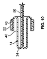
図8及び9は、本明細書において説明される一実施形態による、第1位置(図8)及び第2位置(図9)にある格納可能出口14を示す。図10は、図8及び9の格納可能出口14の断面を示す。図8〜10を参照すると、一実施形態では、格納可能出口14は、第1閉鎖具22の位置又はその近くに3層構成で形成され得る。この3層構成では、第1の外部層46は、取集パウチ12に固定され得る。第2層48は、第1位置で第1層46から取集パウチ12内へ伸展し得る。第3層50は、取集パウチ12から外向きに伸展する。第1、第2及び第3層46、48、50は、一体的及び連続的に形成され得るか、又は別個に形成されて、既知の締結技術、例えば熱密封若しくは溶接を使用して共に固定され得る。出口14は、屈曲部又は折り目34で折って重ねられ得る。
8 and 9 show
図11及び12は、本明細書において説明される一実施形態による、第1位置(図11)及び第2位置(図12)にある格納可能出口14を示す。図13は、図11及び12の格納可能出口14の断面を示す。図11〜13を参照すると、一実施形態では、格納可能出口14は、第1閉鎖具22の位置又はその近くに2層構成で形成され得る。この2層構成では、第1層146は、取集パウチ12に固定され得、且つ第1位置で取集パウチ12内へ伸展し得る。第1層146は、取集パウチ12から外向きに伸展する第2層148を形成するために屈曲部134で折り重なり得る。
11 and 12 show
図11〜13、特に図12をさらに参照すると、格納可能出口14は、第1位置と第2位置との間の移動中に望ましい屈曲及び/又は折り畳み特徴を達成するために、異なる強度又は可撓性のセクションを有して形成され得る。例えば、一実施形態では、格納可能出口14は、強化された剛性又は半剛性のセクション52と可撓性セクション54とを含み得る。半剛性のセクション52は、出口14の隣接する領域、例えば可撓性セクション54と比較して増加した材料若しくは壁厚さを有して形成され得、又は強度及び剛性を増加させるために別の材料が固定され得る。例えば、剛性又は半剛性のセクション52には、箔又は箔状材料、例えば金属箔が取り付けられている。半剛性のセクション52は、第1位置と第2位置との間で移動するための出口14の望ましい押し引きを可能にするために、格納可能出口14において十分な剛性を提供する。
Further referring to FIGS. 11-13, particularly FIG. 12, the
一実施形態では、半剛性のセクション52は、格納可能出口14の、反対側に向く略平らな表面に形成され得る。略又は実質的に平らな領域の上に半剛性のセクション52を形成することにより、半剛性のセクション52は、第1位置と第2位置との間での移動中、屈曲又は回転するために依然として曲がることができる。加えて、第1位置と第2位置との間での移動のため、ユーザは、1つ又は複数の半剛性のセクション52を弾性的に屈曲させるように、対向する横方向に内側へ向けられた力をかけることができ、この時間中に長手方向剛性を増加させる。
In one embodiment, the
1つ又は複数のやわらかい又は可撓性セクション54は、格納可能出口14の隣接する半剛性のセクション52と比較して材料若しくは壁厚さを減少させることによって形成され得、又は出口14の半剛性のセクション52と比較して剛性若しくは強度が低い材料から形成されることによって形成され得る。一実施形態では、可撓性セクション54は、例えば、対向側方縁56に沿って形成され得、縁56上の曲がった又は角度が付いたセクションとして延在し得る。したがって、側方縁56は、第1位置と第2位置との間での格納可能出口14の移動中に折り重なるように屈曲又は回転し得る。したがって、第1位置から第2位置へ移動するとき、格納可能出口14は、裏返しになり得るか又は「ひっくり返され」得る。
One or more soft or
図14〜20は、格納可能出口14の異なる図を示す。図14及び15は、第1位置及び第2位置にそれぞれ対応する位置にある格納可能出口14を示す。一実施形態では、格納可能出口14は、成形プロセスにおいて連続的な一部片構造として作られ得る。出口14は、例えば、シリコーン又は他の同様の好適なポリマーから作られ得る。
14-20 show different views of the
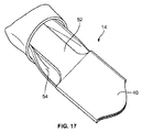
図16は、本明細書において説明される一実施形態による、型から取り出した後の格納可能パウチ14を示す。図16に示されるとおり、格納可能出口14は、半剛性のセクション52、可撓性セクション54及び把持部40を有するように型において形成され得る。図17は、出口14の望ましい形状を得るために、取集パウチへの取付けのために構成されている、一端で折り重ねられた格納可能出口14を示す。
FIG. 16 shows a
図18は、本明細書において説明される一実施形態による、出口14が閉鎖した状態の第1位置に対応する位置にある格納可能出口14を示す。高さ(又は内部開口若しくは流路にわたって測定された幅)は、取集パウチ12上の第1閉鎖具22の幾何学的形状によって画定され得ることが理解される(例えば、図1、2及び5を参照されたい)。図19は、格納可能出口14の対向側方縁56に対して対向する内側へ向けられた力をかけることに応じて開放状態にある格納可能出口14を示す。
FIG. 18 shows a
図20は、本明細書において説明される一実施形態による、取集パウチ12への挿入のために構成された格納可能出口14の端部を示す。図20における例を参照すると、半剛性のセクション52は、第1位置と第2位置との間での移動中、屈曲部34で折り重なるか又は巻くことができる。同様に、可撓性セクション54は、第1位置と第2位置との間での移動中、側方縁56の屈曲又は折り畳みを可能にするために伸びることができる。
FIG. 20 shows the end of a
図21A、21Bは、本明細書において説明される一実施形態による格納可能出口14の幾何学的形状を示す断面図及び斜視図である。図21A、21Bを参照すると、格納可能出口14は、第1の基端部58と第2の末端部42とを含み得る。基端部58は、概ね第1閉鎖具22の領域で取集パウチ12に固定され得る(例えば、図1、2、5及び6を参照されたい)。基端部58は、カラー60も有し得る。加えて、格納可能出口14の高さHは、第1端部58から第2端部42へ移動するにつれて減少し得る。すなわち、出口14は、第2端部42に向かって内側で先細になる。一実施形態では、高さHは、カラー60では実質的に一定であり得、且つ把持部40に向かって移動するにつれて減少することができる。高さHは、閉鎖状態では、把持部40に沿って実質的に一定であり得る。把持部40における高さHは、開放状態では、老廃物が格納可能出口14から流れ出ることを可能にするように増加し得る。
21A and 21B are cross-sectional views and perspective views showing the geometric shape of the
図21A、21Bを依然として参照すると、一実施形態では、カラー60は、約2.0mmの材料厚さを有し得る。可撓性セクション54は、約0.5mmの厚さを有し得る。半剛性のセクション52及び把持部40は、約2.0mmの材料厚さを有し得る。把持部40は、約0.8mmのSLSコアを備えて形成され得る。しかしながら、これらの寸法は例示のみを目的として提供され、本開示は、これらの寸法に限定されるものではない。格納可能出口が、本明細書において説明される機能性及び/又は特徴を維持する限り、格納可能出口が異なる寸法を有して形成され得ることは当業者にとって明らかである。
Still referring to FIGS. 21A, 21B, in one embodiment the
図22A、22Bは、本明細書において説明される別の実施形態による格納可能出口14の幾何学的形状を示す断面図及び斜視図である。図22A、22Bの格納可能出口14は、図21A、21Bのものと同様に形成され得る。しかしながら、図22A、22Bに示された実施形態では、把持部40の高さHは、把持部40の少なくとも一部に沿って第2の末端部42に向かう方向に減少し得る。例えば、一実施形態では、半剛性のセクション52が把持部40と接触するところでは、格納可能出口14は、およそ7.0mmの高さHを有し得る。高さHは、把持部40に沿って第2端部42に向かう方向に約5.0mmまで減少し得る。把持部40の残りの部分は、実質的に一定の高さHで形成され得る。加えて、把持部40は、圧延されたコアを有して形成され得、剛性を増加させるために箔がコアに追加され得る。これらの寸法は例示のみを目的として提供され、本開示は、寸法に限定されないことが理解される。格納可能出口14が、本明細書において説明される機能性及び/又は特徴を維持する限り、格納可能出口14が異なる寸法を有して形成され得ることは当業者にとって明らかである。
22A and 22B are cross-sectional views and perspective views showing the geometric shape of the
図23及び24は、本明細書において説明される別の実施形態による、取集パウチ212と格納可能出口214とを有するオストミーパウチ210を示す。図23及び24を参照すると、格納可能出口214は、内部通路228を含み、また、半剛性のセクション252と、可撓性セクション254と、把持部240とを含み得る。半剛性のセクション254及び把持部240は、実質的に同じ材料又は壁厚さを有して形成され得る。可撓性セクション254は、半剛性のセクション252及び把持部240と比較して材料又は壁厚さが減少し得る。
23 and 24 show an
オストミーパウチ210は、カラー260であって、取集パウチ212への格納可能出口214の取付け、及び/又は取集パウチ212若しくは格納可能出口214への第1閉鎖具222の取付けのための溶接されたゾーンとして機能し得るカラー260も含み得る。カラー260は、格納可能出口214と一部片として一体的及び連続的に形成され得る。代替的に、格納可能出口214は、既知の締結技術、例えば熱密封、溶接などを使用してカラー260に取り付けられ得る。第2閉鎖具224は、内部通路228を閉鎖するために、出口214の末端部242又はその近くに含まれ得る。
The
第1の格納位置では、格納可能出口214は、取集パウチ212内へ格納され、且つ取集パウチ開口230から第1距離D1だけ伸展し、把持部240は、取集パウチ212の外側に残る。一実施形態では、格納可能出口214は、格納可能出口214を第1位置と第2位置との間で移動させるときに取集パウチ212内を移動する屈曲部又は折り目234を含む。第1位置では、屈曲部234は、取集パウチ開口230から第1距離D1に位置付けられる。第2位置では、屈曲部234は、取集パウチ開口230から第1距離D1未満の第2距離D2に位置付けられる。しかしながら、出口214が第2位置にある状態で、屈曲部230は、取集パウチ212に残る。すなわち、第1位置から第2位置へ移動するとき、格納可能出口214は、完全に裏返されることも反転されることもない。
In the first storage position, the
図24を参照すると、格納可能出口214は、代替的に、互いに幅が均一である半剛性のセクション252と把持部240とを有して形成され得る。この実施形態では、可撓性セクション254は、格納可能出口214の末端部又は第2端部242まで完全に伸展し得、把持部240の対向側を分離し得る。
With reference to FIG. 24, the
図25及び26は、本明細書において説明される別の実施形態による、取集パウチ(図示せず)と格納可能出口314とを有するオストミーパウチ310を示す。この実施形態では、格納可能出口314の強化された又は半剛性のセクション352は、格納可能出口314の長さの少なくとも一部に沿って延在する1つ又は複数のリブ352として形成され得る。格納可能出口314はまた、可撓性セクション354を含み、1つ又は複数のリブ352によって少なくとも部分的に支持され得る。さらに、格納可能出口314は、1つ又は複数のリブ352の一端から延在することができる半剛性の把持部340と、ユーザによって把持される可撓性セクション354とを含む。内部通路328は、把持部340を含む格納可能出口314において画定される。一実施形態では、1つ又は複数のリブ352は、2つの離間されたリブ352を含む。リブ352は、取集パウチ(図示せず)内への格納中に角334の周りに巻くように構成される。
25 and 26 show an
図27は、本明細書において説明される別の実施形態による、取集パウチ412と格納可能出口414とを有するオストミーパウチ410を示す。一実施形態では、格納可能出口414は、末端部442に配置された半剛性の把持部440を有する可撓性セクション454として実質的に形成され得る。可撓性セクション454は、補強又は強化されたセクションなしに形成され得、比較的薄くやわらかい可撓性の材料から作られ得る。半剛性の把持部440は、実質的に上述のとおりに形成され得る。内部通路428は、格納可能出口414を通って延在し、第2閉鎖具424は、末端部442、例えば把持部440に位置付けられる。格納可能出口414は、比較的大きい排出開口430により、取集パウチ412の取集空洞420に接続され得る。第1閉鎖具422は、開口430を選択的に開放及び閉鎖することができる。一実施形態では、第1閉鎖具422は、排出開口430を密封可能に閉鎖するためのクランプ又は同様の閉鎖具であり得る。さらに、一実施形態では、格納可能出口414の幅Wは、開口430から把持部440の方向に減少し得る。
FIG. 27 shows an
図28〜31は、使用の異なるステージにある、本明細書において説明されるオストミーパウチ10、210、310、410の例を示す。格納可能出口14、214、314、414は、第1位置と第2位置との間で移動する。図28は、取集パウチ12、212、412内に格納された第1位置にある格納可能出口14、214、314、414の例を示し、明確にするために部分的に切り取られている。第1位置において、格納可能出口14、214、314、414は、取集パウチ12、212、412において第1距離D1だけ伸展する。図29は、取集パウチ12、212、412から伸展された第2位置にある格納可能出口14、214、314、414を示す。第2位置において、格納可能出口14、214、314、414は、取集パウチ12、212、412において第1距離D1未満の第2距離D2だけ伸展するか、又は取集パウチ12、212、412から完全に出るように伸展するかのいずれかである。
Figures 28-31 show examples of
図30は、明確にするために、取集パウチ12、212、412の切欠きセクション内から第2位置に向かって移動された格納可能出口14、214、314、414の例を示す。図31は、一実施形態による取集パウチ12、212、412の切欠きセクション内から第1の格納位置に向かって移動された格納可能出口14、214、314、414を示す。
FIG. 30 shows an example of
上記実施形態では、格納可能出口は、取集パウチ内に格納された第1位置と取集パウチ内から伸展している第2位置との間で移動され得る。格納可能出口は、格納可能出口が第2位置にある状態で老廃物が取集空洞から格納可能出口に受け入れられ得るように、第1排出開口によって取集パウチの取集空洞に接続される。第2排出開口は、オストミーパウチからの老廃物の排水を可能にするために格納可能出口の末端部に含まれる。 In the above embodiment, the retractable outlet can be moved between a first position stored in the collection pouch and a second position extending from the collection pouch. The retractable outlet is connected to the collection cavity of the collection pouch by a first discharge opening so that waste products can be received from the collection cavity into the retractable outlet with the retractable outlet in the second position. The second drainage opening is included at the end of the retractable outlet to allow drainage of waste products from the ostomy pouch.
上記実施形態におけるオストミーパウチは、閉鎖具を含む。閉鎖具は、オストミーパウチの正常な日常での使用において主閉鎖具として機能するように構成された第1閉鎖具であり得る。すなわち、第1閉鎖具は、体の老廃物が取集パウチの取集空洞において受け入れられ且つ保持され得るように、格納可能出口が第1位置にある状態で取集パウチを閉鎖及び密封し得る。換言すると、第1閉鎖具は、第1排出開口を閉鎖及び/又は密封し得る。格納可能出口が第1位置にある状態で、第1閉鎖具はまた、取集空洞を格納可能出口に接続する第1排出開口を閉鎖することにより、格納可能出口からの内容物の漏出を実質的に防止することが理解される。加えて、格納可能出口が第2の伸展位置にある状態で、追加的な体の老廃物が取集パウチに受け入れられ得ると同時に格納可能出口が清掃され得るように、第1閉鎖具は、格納可能出口の内部通路から取集空洞を分離するために閉鎖され得る。さらに、第1閉鎖具は、夜間排水システムに対する閉鎖具機構として機能し得る。例えば、格納可能出口が第2位置にある状態で、夜間排水システムを備えたオストミーパウチの長期にわたる夜間の使用のために、第1閉鎖具は、夜間排水システムに接続又は結合することができる。 The ostomy pouch in the above embodiment includes a closure. The closure can be a first closure configured to function as the primary closure in the normal daily use of the ostomy pouch. That is, the first closure may close and seal the collection pouch with the retractable outlet in the first position so that body waste can be received and held in the collection cavity of the collection pouch. .. In other words, the first closure may close and / or seal the first outlet. With the retractable outlet in the first position, the first closure also effectively leaks the contents from the retractable outlet by closing the first outlet that connects the collection cavity to the retractable outlet. It is understood that the prevention is achieved. In addition, the first closure allows the retractable outlet to be cleaned at the same time that additional body waste can be received by the collection pouch while the retractable outlet is in the second extended position. It can be closed to separate the collection cavity from the internal passage of the retractable outlet. In addition, the first closure can function as a closure mechanism for the nocturnal drainage system. For example, for long-term night use of an ostomy pouch with a night drainage system, with the retractable outlet in the second position, the first closure can be connected or coupled to the night drainage system.
代替的に、閉鎖具は、格納可能出口に位置付けられた第2閉鎖具であり得る。第2閉鎖具は、格納可能出口の内部通路を選択的に開放及び閉鎖し、且つ格納可能出口を介した取集空洞の排水を可能にするように構成される。第2閉鎖具は、格納可能出口の末端部に配置され得、いくつかの実施形態では、閉鎖状態において内部通路の末端部を密封し得る。すなわち、第2閉鎖具は、第2排出開口を閉鎖又は密封し得る。いくつかの実施形態では、夜間排水システムを備えたオストミーパウチの長期にわたる夜間の使用のために、第2閉鎖具は、夜間排水システムに接続又は結合され得る。別の実施形態では、オストミーパウチは、上述の第1閉鎖具と第2閉鎖具との両方を含む。 Alternatively, the closure can be a second closure located at the retractable outlet. The second closure is configured to selectively open and close the internal passages of the retractable outlet and allow drainage of the collection cavity through the retractable outlet. The second closure can be placed at the end of the retractable outlet and, in some embodiments, can seal the end of the internal passage in the closed state. That is, the second closure may close or seal the second discharge opening. In some embodiments, the second closure may be connected or coupled to the night drainage system for long-term night use of the ostomy pouch with the night drainage system. In another embodiment, the ostomy pouch comprises both the first closure and the second closure described above.
一実施形態によると、正常な日常での使用中、格納可能出口は、取集パウチ内へ格納され、及び第2閉鎖具は、第1閉鎖具内部に埋め込まれ得る。パウチを空にするとき、第1閉鎖具が開放され、及び格納可能出口が伸展される。第2閉鎖具は、パウチの排水を可能にするために分離又は開放され得る。格納可能出口が第2位置にある状態で、第1閉鎖具は、次いで閉鎖され得、及び格納可能出口の内部通路は、次いで連続的な老廃物又は流体出力の干渉なしに清掃され得る。一実施形態では、第1閉鎖具は、クランプであり得、及び第2閉鎖具は、1つ又は複数の閉鎖部材、例えば解放可能な締結具又はばね付勢閉鎖具であり得る。 According to one embodiment, during normal daily use, the retractable outlet may be retracted into the collection pouch and the second closure may be embedded within the first closure. When emptying the pouch, the first closure is opened and the retractable outlet is extended. The second closure can be separated or opened to allow drainage of the pouch. With the retractable outlet in the second position, the first closure can then be closed, and the internal passages of the retractable outlet can then be cleaned without the interference of continuous waste or fluid output. In one embodiment, the first closure can be a clamp, and the second closure can be one or more closure members, such as releasable fasteners or spring-loaded closures.
したがって、上述の実施形態では、第1及び第2独立閉鎖具を提供することにより、格納可能出口は、連続的な老廃物及び/又は流体出力からの干渉なしに清掃され得る。加えて、格納可能出口部材は、繰り返し折り畳むことなしに個別に保管され得る。他の実施形態では、単一の閉鎖具が取集空洞及び/又は格納可能出口からの内容物の漏出を実質的に防止又は限定し得る。 Thus, in the embodiments described above, by providing the first and second independent closures, the retractable outlet can be cleaned without interference from continuous waste and / or fluid output. In addition, the retractable outlet members can be stored individually without repeated folding. In other embodiments, a single closure may substantially prevent or limit the leakage of contents from the collection cavity and / or storable outlet.
上述の実施形態における個々の特徴は、上述の異なる実施形態の特定の特徴と組み合わされ得るか、又は上述の異なる実施形態の特定の特徴に取って代わり得ることが理解される。加えて、上述の特定の実施形態のいくつかの特徴のさらなる説明は、その特徴が別の実施形態で説明される場合に省略され得ることが理解される。さらになお、実施形態にわたる同様の特徴は、同様の用語法及び/又は参照符号と共に言及され得ることが理解される。 It is understood that the individual features in the above embodiments can be combined with or replace the particular features of the different embodiments described above. In addition, it is understood that further description of some features of the particular embodiment described above may be omitted if the features are described in another embodiment. Furthermore, it is understood that similar features across embodiments may be referred to with similar terminology and / or reference numerals.
本明細書において言及された全ての特許は、本開示の本文においてそのように具体的に指示されていようがいまいが、その全体が参照により本明細書に組み込まれる。 All patents referred to herein, whether or not as specifically indicated in the text of this disclosure, are incorporated herein by reference in their entirety.
本開示において、「1つの(a)」又は「1つの(an)」という語は、単数及び複数の両方を含むと解釈される。反対に、複数の品目へのいずれの言及も、適切な場合には単数を含む。 In the present disclosure, the terms "one (a)" or "one (an)" are to be construed as including both singular and plural. Conversely, any reference to multiple items includes the singular where appropriate.
前述したように、多くの修正形態及び変更形態が本発明の新規な概念の真の趣旨及び範囲から逸脱することなく達成され得ることが認められる。図示された特定の実施形態に対する限定は意図されず、又は推測されるべきでないことを理解されたい。本開示は、添付の特許請求の範囲により、特許請求の範囲内に含まれる全ての修正形態を包含することを意図される。 As mentioned above, it is acknowledged that many modifications and modifications can be achieved without departing from the true purpose and scope of the novel concept of the present invention. It should be understood that the limitations to the particular embodiments illustrated should not be intended or inferred. The present disclosure is intended to include all modifications contained within the scope of the claims, by the scope of the appended claims.
Claims (12)
内部取集空洞を画定するために周辺部に沿って接合された第1側壁と第2側壁とを有する取集パウチと、
実質的に前記内部取集空洞内に格納された第1位置と前記周辺部から外向きに伸展している第2位置との間で可動である格納可能出口と、
前記格納可能出口の末端部に形成された排出開口と、
前記取集空洞又は前記格納可能出口からの老廃物材料の排出を選択的に可能にするか又は防止するように構成された閉鎖具と
を含み、
前記閉鎖具は、前記取集パウチに位置付けられ、前記第1及び第2側壁の外部の周りに締結されるクランプであって、
前記クランプが前記第1及び第2側壁と前記格納可能出口とをクランプする、オストミーパウチ。 It ’s an ostomy pouch,
A collection pouch having a first side wall and a second side wall joined along the periphery to define an internal collection cavity.
A retractable outlet that is substantially movable between a first position housed in the internal collection cavity and a second position extending outward from the periphery.
With a discharge opening formed at the end of the retractable outlet,
Look including the said Toshu cavity or the storable configured closure to or to prevent the discharge of waste material from the outlet selectively possible to,
The closure is a clamp located on the collection pouch and fastened around the outside of the first and second sidewalls.
An ostomy pouch in which the clamp clamps the first and second sidewalls and the retractable outlet.
内部取集空洞を画定するために周辺部に沿って接合された第1側壁と第2側壁とを有する取集パウチと、
実質的に前記内部取集空洞内に格納された第1位置と前記周辺部から外向きに伸展している第2位置との間で可動である格納可能出口と、
前記格納可能出口の末端部に形成された排出開口と、
前記取集空洞又は前記格納可能出口からの老廃物材料の排出を選択的に可能にするか又は防止するように構成された閉鎖具と
を含み、
前記閉鎖具は、前記取集パウチに位置付けられ、夜間排水システムに接続するように構成される、オストミーパウチ。 It ’s an ostomy pouch,
A collection pouch having a first side wall and a second side wall joined along the periphery to define an internal collection cavity.
A retractable outlet that is substantially movable between a first position housed in the internal collection cavity and a second position extending outward from the periphery.
With the discharge opening formed at the end of the retractable outlet,
Look including the said Toshu cavity or the storable configured closure to or to prevent the discharge of waste material from the outlet selectively possible to,
The closure is an ostomy pouch that is located in the collection pouch and is configured to connect to a night drainage system.
内部取集空洞を画定するために周辺部に沿って接合された第1側壁と第2側壁とを有する取集パウチと、
実質的に前記内部取集空洞内に格納された第1位置と前記周辺部から外向きに伸展している第2位置との間で可動である格納可能出口と、
前記格納可能出口の末端部に形成された排出開口と、
前記取集空洞又は前記格納可能出口からの老廃物材料の排出を選択的に可能にするか又は防止するように構成された閉鎖具と
を含み、
前記閉鎖具は、前記格納可能出口に位置付けられ、夜間排水システムに接続するように構成される、オストミーパウチ。 It ’s an ostomy pouch,
A collection pouch having a first side wall and a second side wall joined along the periphery to define an internal collection cavity.
A retractable outlet that is substantially movable between a first position housed in the internal collection cavity and a second position extending outward from the periphery.
With a discharge opening formed at the end of the retractable outlet,
Look including the said Toshu cavity or the storable configured closure to or to prevent the discharge of waste material from the outlet selectively possible to,
The closure is an ostomy pouch located at the retractable outlet and configured to connect to a night drainage system.
内部取集空洞を画定するために周辺部に沿って接合された第1側壁と第2側壁とを有する取集パウチと、
実質的に前記内部取集空洞内に格納された第1位置と前記周辺部から外向きに伸展している第2位置との間で可動である格納可能出口と、
前記格納可能出口の末端部に形成された排出開口と、
前記取集空洞又は前記格納可能出口からの老廃物材料の排出を選択的に可能にするか又は防止するように構成された閉鎖具と
を含み、
前記格納可能出口が前記第2位置にある状態で、前記格納可能出口の内部通路は、前記内部取集空洞に接続される、オストミーパウチ。 It ’s an ostomy pouch,
A collection pouch having a first side wall and a second side wall joined along the periphery to define an internal collection cavity.
A retractable outlet that is substantially movable between a first position housed in the internal collection cavity and a second position extending outward from the periphery.
With the discharge opening formed at the end of the retractable outlet,
Look including the said Toshu cavity or the storable configured closure to or to prevent the discharge of waste material from the outlet selectively possible to,
An ostomy pouch in which the internal passage of the retractable outlet is connected to the internal collection cavity with the retractable outlet in the second position.
内部取集空洞を画定するために周辺部に沿って接合された第1側壁と第2側壁とを有する取集パウチと、
実質的に前記内部取集空洞内に格納された第1位置と前記周辺部から外向きに伸展している第2位置との間で可動である格納可能出口と、
前記格納可能出口の末端部に形成された排出開口と、
前記取集空洞又は前記格納可能出口からの老廃物材料の排出を選択的に可能にするか又は防止するように構成された閉鎖具と
を含み、
前記格納可能出口は、1つ又は複数の壁によって形成され、
前記1つ又は複数の壁は、前記第1位置から前記第2位置へ移動するときに裏返しにでき、且つ逆も同様である、オストミーパウチ。 It ’s an ostomy pouch,
A collection pouch having a first side wall and a second side wall joined along the periphery to define an internal collection cavity.
A retractable outlet that is substantially movable between a first position housed in the internal collection cavity and a second position extending outward from the periphery.
With a discharge opening formed at the end of the retractable outlet,
Look including the said Toshu cavity or the storable configured closure to or to prevent the discharge of waste material from the outlet selectively possible to,
The retractable outlet is formed by one or more walls
The ostomy pouch , wherein the one or more walls can be turned inside out when moving from the first position to the second position, and vice versa.
内部取集空洞を画定するために周辺部に沿って接合された第1側壁と第2側壁とを有する取集パウチと、
実質的に前記内部取集空洞内に格納された第1位置と前記周辺部から外向きに伸展している第2位置との間で可動である格納可能出口と、
前記格納可能出口の末端部に形成された排出開口と、
前記取集空洞又は前記格納可能出口からの老廃物材料の排出を選択的に可能にするか又は防止するように構成された閉鎖具と
を含み、
前記格納可能出口は、半剛性のセクションと可撓性セクションとを含む、オストミーパウチ。 It ’s an ostomy pouch,
A collection pouch having a first side wall and a second side wall joined along the periphery to define an internal collection cavity.
A retractable outlet that is substantially movable between a first position housed in the internal collection cavity and a second position extending outward from the periphery.
With a discharge opening formed at the end of the retractable outlet,
Look including the said Toshu cavity or the storable configured closure to or to prevent the discharge of waste material from the outlet selectively possible to,
The retractable outlet is an ostomy pouch that includes a semi-rigid section and a flexible section.
内部取集空洞を画定するために周辺部に沿って接合された第1側壁と第2側壁とを有する取集パウチと、
実質的に前記内部取集空洞内に格納された第1位置と前記周辺部から外向きに伸展している第2位置との間で可動である格納可能出口と、
前記格納可能出口の末端部に形成された排出開口と、
前記取集空洞又は前記格納可能出口からの老廃物材料の排出を選択的に可能にするか又は防止するように構成された閉鎖具と
を含み、
前記第1位置において、前記格納可能出口は、前記取集空洞からの老廃物材料の漏出を防ぐ逆止め弁を形成する、オストミーパウチ。 It ’s an ostomy pouch,
A collection pouch having a first side wall and a second side wall joined along the periphery to define an internal collection cavity.
A retractable outlet that is substantially movable between a first position housed in the internal collection cavity and a second position extending outward from the periphery.
With the discharge opening formed at the end of the retractable outlet,
Look including the said Toshu cavity or the storable configured closure to or to prevent the discharge of waste material from the outlet selectively possible to,
At said first position, the retractable outlet forms a check valve that prevents the leakage of waste material from the collection cavity, an ostomy pouch.
前記格納可能出口は、前記首部分に接続される、請求項1〜7のいずれか一項に記載のオストミーパウチ。 The collection pouch further includes the neck portion and includes.
The ostomy pouch according to any one of claims 1 to 7, wherein the retractable outlet is connected to the neck portion.
前記オストミーパウチは、排出開口からの前記老廃物材料の排出を選択的に可能にするか又は防止するように構成された第2閉鎖具をさらに含む、請求項1〜7のいずれか一項に記載のオストミーパウチ。 The closure is a first closure configured to selectively allow or prevent the discharge of waste material from the collection cavity.
The ostomy pouch further comprises a second closure configured to selectively allow or prevent the discharge of the waste material from the discharge opening, according to any one of claims 1-7. The listed ostomy pouch.
Applications Claiming Priority (3)
| Application Number | Priority Date | Filing Date | Title |
|---|---|---|---|
| US201662291912P | 2016-02-05 | 2016-02-05 | |
| US62/291,912 | 2016-02-05 | ||
| PCT/US2017/015727 WO2017136304A1 (en) | 2016-02-05 | 2017-01-31 | Retractable outlet for ostory pouch |
Publications (3)
| Publication Number | Publication Date |
|---|---|
| JP2019505313A JP2019505313A (en) | 2019-02-28 |
| JP2019505313A5 JP2019505313A5 (en) | 2020-01-30 |
| JP6912485B2 true JP6912485B2 (en) | 2021-08-04 |
Family
ID=58016857
Family Applications (1)
| Application Number | Title | Priority Date | Filing Date |
|---|---|---|---|
| JP2018540433A Active JP6912485B2 (en) | 2016-02-05 | 2017-01-31 | Ostomy pouch |
Country Status (9)
| Country | Link |
|---|---|
| US (1) | US11000400B2 (en) |
| EP (1) | EP3410992B1 (en) |
| JP (1) | JP6912485B2 (en) |
| AU (1) | AU2017213731B2 (en) |
| CA (1) | CA3013462C (en) |
| DK (1) | DK3410992T3 (en) |
| HU (1) | HUE050731T2 (en) |
| LT (1) | LT3410992T (en) |
| WO (1) | WO2017136304A1 (en) |
Families Citing this family (24)
| Publication number | Priority date | Publication date | Assignee | Title |
|---|---|---|---|---|
| AU2008266238A1 (en) | 2007-06-12 | 2008-12-24 | Convatec Technologies Inc. | Ostomy appliance |
| BRPI0919631A2 (en) | 2008-11-19 | 2015-12-01 | Convatec Technologies Inc | ostomy bag utensil |
| US8679581B2 (en) | 2009-07-07 | 2014-03-25 | Convatec Technologies, Inc. | Amphiphilic silicone copolymers for pressure sensitive adhesive applications |
| EP2475340B1 (en) | 2009-09-11 | 2019-11-13 | ConvaTec Technologies Inc. | Controlled discharge ostomy appliance and shield therefor |
| US10285847B2 (en) | 2011-09-29 | 2019-05-14 | Convatec Technologies Inc. | Ostomy pouch with filtering system |
| GB201115160D0 (en) | 2011-09-02 | 2011-10-19 | Trio Healthcare Ltd | Discharge solidifier and malodour control |
| CA3176048A1 (en) * | 2013-09-13 | 2015-03-19 | Fisher And Paykel Healthcare Limited | Humidification system |
| KR20160147898A (en) | 2014-04-24 | 2016-12-23 | 컨바텍 테크놀러지스 인크 | Ostomy pouch filter system |
| EP3362010B1 (en) * | 2015-10-14 | 2023-09-20 | ConvaTec Technologies Inc. | A medical device with an opening system |
| GB2566719B (en) * | 2017-09-22 | 2022-03-16 | Salts Healthcare Ltd | A drainable ostomy appliance |
| MX2020004744A (en) | 2017-11-09 | 2020-08-13 | 11 Health And Tech Limited | Ostomy monitoring system and method. |
| USD893514S1 (en) | 2018-11-08 | 2020-08-18 | 11 Health And Technologies Limited | Display screen or portion thereof with graphical user interface |
| EP3692956A1 (en) | 2019-02-07 | 2020-08-12 | ConvaTec Technologies Inc. | Adjustable convex ostomy device |
| CA3137964A1 (en) | 2019-04-25 | 2020-10-29 | Convatec Technologies Inc. | Ostomy wafers incorporating adhesives, ostomy devices including the same, and methods of applying |
| JP2022529521A (en) | 2019-04-25 | 2022-06-22 | コンバテック・テクノロジーズ・インコーポレイテッド | An ostomy wafer in a perforated chamber, an ostomy device including it, and a method for bonding the ostomy wafer and the ostomy device. |
| CA3137965A1 (en) | 2019-04-25 | 2020-10-29 | Convatec Technologies Inc. | Ostomy wafers incorporating adhesives and foam layers, ostomy devices including the same, and methods of applying ostomy wafers and ostomy devices |
| CA3156464A1 (en) | 2019-10-04 | 2021-04-08 | Convatec Limited | Ostomy appliance |
| EP4218690A1 (en) | 2019-10-04 | 2023-08-02 | ConvaTec Limited | Ostomy appliance |
| WO2021064408A1 (en) | 2019-10-04 | 2021-04-08 | Convatec Limited | Ostomy appliance |
| CN114502113A (en) | 2019-10-04 | 2022-05-13 | 康沃特克有限公司 | Ostomy appliance |
| US11701249B2 (en) | 2021-10-29 | 2023-07-18 | Gv Solutions Llc | Drain asembly for elimination of urine waste from an ostomy bag |
| US11951028B2 (en) | 2021-10-29 | 2024-04-09 | Gv Solutions Llc | Method for assembling a drain assembly and method for elimination of urine waste from an ostomy bag |
| AU2023203036B9 (en) * | 2022-01-31 | 2023-08-03 | Hollister Incorporated | Outlet closure and securement system for drainable pouch |
| USD978345S1 (en) | 2022-10-26 | 2023-02-14 | Gv Solutions Llc | Drain assembly for an ostomy bag |
Family Cites Families (19)
| Publication number | Priority date | Publication date | Assignee | Title |
|---|---|---|---|---|
| US3523534A (en) | 1967-04-05 | 1970-08-11 | Hollister Inc | Closure for drainage pouch |
| US4411659A (en) | 1982-03-16 | 1983-10-25 | Hollister Incorporated | Drainable collection pouch and filter assembly therefor |
| US6726667B2 (en) * | 2001-06-15 | 2004-04-27 | Hollister Incorporated | Drainable ostomy pouch and closure means therefor |
| DK174983B1 (en) | 2002-04-10 | 2004-04-05 | Hollister Inc | Empty ostomy bag with integrated closure |
| US6702794B2 (en) * | 2002-04-23 | 2004-03-09 | Bristol-Myers Squibb Company | Ostomy pouch clamp |
| IE20050438A1 (en) * | 2005-06-29 | 2007-01-24 | Gerard Ryder | Receptacle and method for disposing of bodily waste materials |
| JP3131250U (en) | 2007-02-14 | 2007-04-26 | アルケア株式会社 | Drainable excrement container |
| US20090209926A1 (en) * | 2008-02-14 | 2009-08-20 | Sandra Cochran | Urostomy pouch adapter |
| CA2720463C (en) * | 2008-04-04 | 2016-03-29 | Convatec Technologies Inc. | Drainable ostomy pouch |
| ES2609703T3 (en) * | 2008-04-04 | 2017-04-21 | Convatec Technologies Inc. | Drainable ostomy bag |
| US8672907B2 (en) * | 2010-07-26 | 2014-03-18 | Hollister Incorporated | Drainable ostomy pouch |
| US8882732B2 (en) * | 2010-11-22 | 2014-11-11 | Hollister Incorporated | Valve for ostomy pouch |
| US9993363B2 (en) * | 2011-08-09 | 2018-06-12 | Hollister Incorporated | Ostomy appliance |
| US20130253455A1 (en) * | 2012-03-22 | 2013-09-26 | Hollister Incorporated | Expandable ostomy appliance |
| US9011395B2 (en) * | 2012-03-23 | 2015-04-21 | Hollister Incorporated | Drainable ostomy pouch |
| US20140371699A1 (en) * | 2013-06-13 | 2014-12-18 | Julie Feingold | Closed ostomy bag system |
| EP3166549B1 (en) * | 2014-07-10 | 2019-09-11 | Coloplast A/S | Expandable collecting bag for an ostomy appliance |
| CN105147457B (en) * | 2015-08-25 | 2018-09-21 | 广州天沅硅胶机械科技有限公司 | A kind of collapsible menstrual cup |
| EP3362010B1 (en) * | 2015-10-14 | 2023-09-20 | ConvaTec Technologies Inc. | A medical device with an opening system |
-
2017
- 2017-01-31 EP EP17704634.9A patent/EP3410992B1/en active Active
- 2017-01-31 LT LTEP17704634.9T patent/LT3410992T/en unknown
- 2017-01-31 DK DK17704634.9T patent/DK3410992T3/en active
- 2017-01-31 CA CA3013462A patent/CA3013462C/en active Active
- 2017-01-31 WO PCT/US2017/015727 patent/WO2017136304A1/en active Application Filing
- 2017-01-31 HU HUE17704634A patent/HUE050731T2/en unknown
- 2017-01-31 AU AU2017213731A patent/AU2017213731B2/en active Active
- 2017-01-31 JP JP2018540433A patent/JP6912485B2/en active Active
- 2017-01-31 US US16/071,044 patent/US11000400B2/en active Active
Also Published As
| Publication number | Publication date |
|---|---|
| DK3410992T3 (en) | 2020-04-27 |
| EP3410992B1 (en) | 2020-03-11 |
| US11000400B2 (en) | 2021-05-11 |
| WO2017136304A1 (en) | 2017-08-10 |
| AU2017213731A8 (en) | 2018-08-23 |
| EP3410992A1 (en) | 2018-12-12 |
| JP2019505313A (en) | 2019-02-28 |
| HUE050731T2 (en) | 2020-12-28 |
| CA3013462C (en) | 2021-10-05 |
| AU2017213731B2 (en) | 2021-09-16 |
| CA3013462A1 (en) | 2017-08-10 |
| AU2017213731A1 (en) | 2018-08-16 |
| US20190029868A1 (en) | 2019-01-31 |
| WO2017136304A8 (en) | 2018-08-16 |
| LT3410992T (en) | 2020-04-10 |
Similar Documents
| Publication | Publication Date | Title |
|---|---|---|
| JP6912485B2 (en) | Ostomy pouch | |
| JP4601296B2 (en) | Drain ostomy pouch with complete closure | |
| US11065144B2 (en) | Ostomy pouch with night drainage adapter | |
| JP2005522271A5 (en) | ||
| US20210369493A1 (en) | Ostomy Pouch | |
| WO2021245394A1 (en) | An ostomy pouch | |
| JP5147590B2 (en) | Ostomy pouch that can be discharged | |
| EP2349136B1 (en) | Drainable pouch | |
| JP3131250U (en) | Drainable excrement container | |
| AU2022429676B2 (en) | Ostomy pouch closure system | |
| US11826276B2 (en) | Outlet closure and securement system for drainable pouch |
Legal Events
| Date | Code | Title | Description |
|---|---|---|---|
| A521 | Written amendment |
Free format text: JAPANESE INTERMEDIATE CODE: A523 Effective date: 20191210 |
|
| A621 | Written request for application examination |
Free format text: JAPANESE INTERMEDIATE CODE: A621 Effective date: 20191210 |
|
| A977 | Report on retrieval |
Free format text: JAPANESE INTERMEDIATE CODE: A971007 Effective date: 20200814 |
|
| A131 | Notification of reasons for refusal |
Free format text: JAPANESE INTERMEDIATE CODE: A131 Effective date: 20200825 |
|
| A521 | Written amendment |
Free format text: JAPANESE INTERMEDIATE CODE: A523 Effective date: 20201119 |
|
| A131 | Notification of reasons for refusal |
Free format text: JAPANESE INTERMEDIATE CODE: A131 Effective date: 20210112 |
|
| A601 | Written request for extension of time |
Free format text: JAPANESE INTERMEDIATE CODE: A601 Effective date: 20210412 |
|
| A521 | Written amendment |
Free format text: JAPANESE INTERMEDIATE CODE: A523 Effective date: 20210601 |
|
| TRDD | Decision of grant or rejection written | ||
| A01 | Written decision to grant a patent or to grant a registration (utility model) |
Free format text: JAPANESE INTERMEDIATE CODE: A01 Effective date: 20210629 |
|
| A61 | First payment of annual fees (during grant procedure) |
Free format text: JAPANESE INTERMEDIATE CODE: A61 Effective date: 20210708 |
|
| R150 | Certificate of patent or registration of utility model |
Ref document number: 6912485 Country of ref document: JP Free format text: JAPANESE INTERMEDIATE CODE: R150 |