EP2349136B1 - Drainable pouch - Google Patents
Drainable pouch Download PDFInfo
- Publication number
- EP2349136B1 EP2349136B1 EP09789847.2A EP09789847A EP2349136B1 EP 2349136 B1 EP2349136 B1 EP 2349136B1 EP 09789847 A EP09789847 A EP 09789847A EP 2349136 B1 EP2349136 B1 EP 2349136B1
- Authority
- EP
- European Patent Office
- Prior art keywords
- outlet valve
- opening
- central region
- pouch
- drainable
- Prior art date
- Legal status (The legal status is an assumption and is not a legal conclusion. Google has not performed a legal analysis and makes no representation as to the accuracy of the status listed.)
- Active
Links
Images


Classifications
-
- A—HUMAN NECESSITIES
- A61—MEDICAL OR VETERINARY SCIENCE; HYGIENE
- A61F—FILTERS IMPLANTABLE INTO BLOOD VESSELS; PROSTHESES; DEVICES PROVIDING PATENCY TO, OR PREVENTING COLLAPSING OF, TUBULAR STRUCTURES OF THE BODY, e.g. STENTS; ORTHOPAEDIC, NURSING OR CONTRACEPTIVE DEVICES; FOMENTATION; TREATMENT OR PROTECTION OF EYES OR EARS; BANDAGES, DRESSINGS OR ABSORBENT PADS; FIRST-AID KITS
- A61F5/00—Orthopaedic methods or devices for non-surgical treatment of bones or joints; Nursing devices; Anti-rape devices
- A61F5/44—Devices worn by the patient for reception of urine, faeces, catamenial or other discharge; Portable urination aids; Colostomy devices
- A61F5/4404—Details or parts
- A61F5/4405—Valves or valve arrangements specially adapted therefor ; Fluid inlets or outlets
Definitions
- the present disclosure is directed to a pouch for the collection of a liquid or semisolid body waste material and, more particularly, to a drainable pouch that can be closed during collection of liquid or semisolid body waste material and later opened and drained.
- Drainable pouches for the collection of liquid or semisolid body waste material are well known and typically include flat, opposing sidewalls secured together along their edges to define a collection cavity.
- One of the sidewalls is provided with an opening to receive a stoma, and means such as a connecting flange is provided for securing the pouch to an adhesive barrier placed to surround the stoma of a patient so that body waste material that is discharged from the stoma will be received within the cavity.
- the drainable pouch typically has a discharge opening which may be closed during collection of the liquid or semisolid body waste material that passes through the stoma but may be opened for draining the body waste material from the pouch.
- the drainable pouch will typically be provided with a closure for the discharge opening that may take a number of different forms so long as it serves to prevent leakage of the body waste material.
- WO-A-01/21115 discloses a drainable pouch comprising a pair of sidewalls of flexible sheet material having side edges joined together to define a cavity having a discharge end provided with an outlet valve for draining the cavity.
- a drainable pouch is typically reusable following periodic emptying of the body waste material, but it is important the pouch be provided with effective sealing in order to avoid odors or contents emanating or leaking from the resealed pouch. This requirement is coupled with a need for the pouch to be easily and conveniently drainable, either directly through the discharge opening, or by reason of connecting an ancillary drainage device in a secure manner to the discharge opening of the pouch. Users of drainable pouches often encounter difficulty and discomfort in unsealing, emptying, and resealing the pouches because of the nature of the drainage systems and manipulations which require greater dexterity than many patients possess.
- drainable pouches often show bulkiness after a period of time of accumulating body waste material. This is true with respect to both liquid and semisolid body waste material because the normally flat sidewalls of such pouches are formed of a thin film which easily expands outwardly as the body waste material accumulates. Further, these pouches often include a rigid outlet valve associated with the discharge opening of the drainable pouch.
- the present disclosure is directed to a drainable pouch comprised of a pair of sidewalls of flexible sheet material having side edges joined together to define a cavity having a discharge end provided with an outlet valve for draining the cavity.
- the sidewalls also are joined together throughout a central region thereof such that the cavity formed by the sidewalls completely surrounds the central region.
- the central region defines a peripheral edge and has at least one opening in a location which is spaced inwardly of the peripheral edge to receive the outlet valve when the discharge end is folded.
- the pair of sidewalls of flexible sheet material preferably defines a body portion forming the cavity.
- the discharge end of the cavity comprises a tubular neck portion integrally formed with and extending from the body portion, and the discharge end is foldable generally along or parallel to a longitudinal axis toward one of the sidewalls to thereby overlap the body portion. After folding the discharge end, the outlet valve will be generally adjacent the opening in the central region so the outlet valve can be received therein.
- the side edges and central region are welded and the at least one opening in the central region includes a slit extending through the sidewalls generally perpendicular to the longitudinal axis of the body portion.
- the side edges and central region are welded and the at least one opening in the central region includes a pair of holes forming a strip for receiving and securing the outlet valve after the discharge end is folded.
- the tubular neck portion comprising the discharge end of the cavity defines an opening for receiving the outlet valve.
- the outlet valve may be formed of a rigid material sealed within the opening for draining the cavity, and it also is preferably formed to include a first portion sealed within the opening and a second tubular portion or fitting which projects therefrom and can be connected to a collection device.
- the first portion of the outlet valve may have a generally elongated cross-section and the second tubular portion of the outlet valve may have a generally circular cross-section.
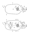
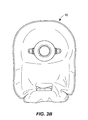
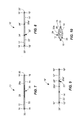
- a first embodiment of a drainable pouch according to the present disclosure is generally designated by the reference numeral 10.
- the drainable pouch 10 is formed of a pair of sidewalls 12 and 14 of flexible sheet material having side edges 16 and 18 joined together about the perimeter of the pouch as by welding at 20 to define a cavity 22 therebetween (see Figure 7 ). Further, the cavity 22 formed by the side walls 12 and 14 has a discharge end as at 24 provided with an outlet valve 26 for draining the cavity 22 of liquid or semisolid body waste materials collected therein.
- the sidewalls 12 and 14 are joined together as by welding at 28 throughout a central region 30 thereof such that the cavity 22 formed by the sidewalls 12 and 14 completely surrounds the central region 30 defined by the welding at 28.
- the central region 30 defined by the welding at 28 forms an internal peripheral edge 28a facing the cavity 22, and it also has at least one opening such as the slit or slot 32 in a location inwardly of the internal peripheral edge 28a to receive the outlet valve 26 when the discharge end 24 is folded (see Figures 1A and 2A ).
- the pair of sidewalls 12 and 14 of flexible sheet material preferably defines a body portion 34 forming the cavity 22.
- the discharge end 24 of the cavity 22 may then advantageously comprise a tubular neck portion 36 integrally formed with and extending from the body portion 34. When so formed, the discharge end 24 is foldable generally along or parallel to a longitudinal axis 38 toward one of the sidewalls 12 and 14 to overlap the body portion 34.
- the outlet valve 26 will be generally adjacent the opening or slit 32 in the central region 30 so the outlet valve 26 can be received and stored therein as shown in Figures 1A and 2A .
- the outlet valve 26 is located generally along or parallel to the longitudinal axis 38 of the body portion 34, and the slit 32 extends through the sidewalls 12 and 14 generally perpendicular to the longitudinal axis 38 of the body portion 34.
- the outlet valve 26 is formed of a rigid material in contrast to the soft, flexible material of the sidewalls 12 and 14, and is sealed in an opening 40 in the discharge end 24 (see Figure 10 ).
- the outlet valve 26 preferably includes a first portion 26a sealed within the opening 40 in the discharge end 24 and a second tubular portion 26b which may take the form of a barbed fitting.
- the outlet valve 26 may also include a rotatable flange 26c for opening and closing the valve.
- the first portion 26a of the outlet valve 26 may have a generally elongated cross-section.
- the generally elongated first portion 26a may then be positioned within the opening 40 and the flexible sheet material at the discharge end 24 of the cavity 22 may be sealed to the generally elongated first portion 26a.
- the second tubular portion 26b of the outlet valve 26 may have a generally circular cross-section.
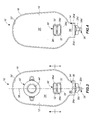
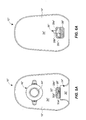
- a second embodiment of a drainable pouch which is similar in many respects to the embodiment of Figures 1 and 2 is generally designated by the reference numeral 10'.
- the drainable pouch 10' is formed of a pair of sidewalls 12' and 14' of flexible sheet material having side edges 16' and 18' joined together about the perimeter of the pouch as by welding at 20' to define a cavity 22' therebetween (see Figure 8 ). Further, the cavity 22' formed by the side walls 12' and 14' has a discharge end 24' provided with an outlet valve 26' for draining the cavity 22' of liquid or semisolid body waste materials.
- the sidewalls 12' and 14' are joined together as by welding at 28' throughout a central region 30' thereof such that the cavity 22' formed by the sidewalls 12' and 14' completely surrounds the central region 30' defined by the welding at 28'.
- the central region 30' defined by the welding at 28' forms an internal peripheral edge 28a' facing the cavity 22', but it has a pair of openings such as the holes 32' inwardly of the internal peripheral edge 28a' to receive the outlet valve 26' when the discharge end 24' is folded (see Figures 3A and 4A ).
- the welding at 28' results in a central welded strip 28b' between the holes 32' which cooperates with the outlet valve 26' in a manner described in more detail below.
- the pair of sidewalls 12' and 14' of flexible sheet material preferably defines a body portion 34' forming the cavity 22'.
- the discharge end 24' of the cavity 22 then advantageously comprises a tubular neck portion 36' integrally formed with and extending from the body portion 34'. When so formed, the discharge end 24' is foldable generally along or parallel to a longitudinal axis 38' toward one of the sidewalls 12' and 14' to overlap the body portion 34'.
- the outlet valve 26' will be generally adjacent the holes 32' in the central region 30' so the outlet valve 26' can be received and stored therein as shown in Figures 3A and 4A .
- the outlet valve 26' is located generally along or parallel to the longitudinal axis 38' of the body portion 34', and the holes 32' extend through the sidewalls 12' and 14' generally perpendicular to the longitudinal axis 38' of the body portion 34'.
- the outlet valve 26' is formed of a rigid material in contrast to the soft, flexible material of the sidewalls 12' and 14', and is sealed in an opening such as 40 ( Figure 10 ) in the discharge end 24'.
- the outlet valve 26' is preferably identical to the outlet valve 26 illustrated in Figures 1, 2 and 10 .
- it preferably includes a first portion 26a' similar or identical to first portion 26a ( Figure 10 ) and sealed within an opening such as 40 ( Figure 10 ) in the discharge end 24' and a second tubular portion 26b' which may take the form of a barbed fitting, and the outlet valve 26' may also advantageously include a rotatable flange 26c' provided for opening and closing the valve.
- the second tubular portion 26b' projects from the first portion 26a' such that a flexible tube can be inserted over the barbed fitting to drain the contents of the cavity 22' into a collection device.
- the first portion 26a' of the outlet valve 26' may have a generally elongated cross-section which may be positioned within the opening such as 40 ( Figure 10 ).
- the flexible sheet material at the discharge end 24' of the cavity 22' may be sealed to the generally elongated first portion 26a'.
- the second tubular portion 26b' of the outlet valve 26' may have a generally circular cross-section.
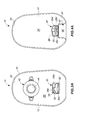
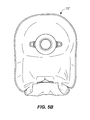
- a third embodiment of a drainable pouch which is similar in many respects to the embodiment of Figures 1 and 2 is generally designated by the reference numeral 10".
- the drainable pouch 10" is formed of a pair of sidewalls 12" and 14" of flexible sheet material having side edges 16" and 18" joined together about the perimeter of the pouch as by welding at 20" to define a cavity 22" therebetween (see Figure 9 ). Further, the cavity 22" formed by the side walls 12" and 14" has a discharge end as at 24" provided with an outlet valve 26" for draining the cavity 22" of liquid or semisolid body waste materials collected therein.
- the sidewalls 12" and 14" are joined together as by welding at 28" throughout a central region 30" thereof such that the cavity 22" formed by the sidewalls 12" and 14" completely surrounds the central region 30" defined by the welding at 28".
- the central region 30" defined by the welding at 28" forms an internal peripheral edge 28a" facing the cavity 22", but it also has at least one opening such as the slit 32" in a location inwardly of the internal peripheral edge 28a" to receive the outlet valve 26" when the discharge end 24" is folded (see Figures 5A and 6A ).
- the slit 32" has a first portion 32a" which corresponds to the entire slit 32 in Figure 1 and it also has a second portion 32b" which is transverse to the first portion, generally along or parallel to the longitudinal axis 38" of the body portion 34", and in alignment with the second tubular portion 26b" of the outlet valve 26" before the discharge end 24" has been folded.
- the pair of sidewalls 12" and 14" of flexible sheet material preferably defines a body portion 34" forming the cavity 22".
- the discharge end 24" of the cavity 22" then advantageously comprises a tubular neck portion 36" integrally formed with and extending from the body portion 34".
- the discharge end 24" is foldable generally along or parallel to the longitudinal axis 38" toward one of the sidewalls 12" and 14" to overlap the body portion 34".
- the outlet valve 26" will be generally adjacent the slit 32" in the central region 30" so the outlet valve 26" can be received and stored therein as shown in Figures 5A and 6A .
- the outlet valve 26" is located generally along or parallel to the longitudinal axis 38" of the body portion 34", and the slit 32" extends through the sidewalls 12" and 14"as previously described.
- the outlet valve 26" is formed of a rigid material in contrast to the soft, flexible material of the sidewalls 12" and 14", and is sealed in an opening such as 40 ( Figure 10 ) in the discharge end 24".
- the outlet valve 26" is preferably identical to the outlet valve 26 illustrated in Figures 1, 2 and 10 .
- it preferably includes a first portion 26a" similar or identical to the first portion 26a ( Figure 10 ) sealed within the opening such as 40 in the discharge end 24" and a second tubular portion 26b" which may take the form of a barbed fitting, and the outlet valve 26" may also advantageously include a rotatable flange 26c" provided for opening and closing the valve.
- the second tubular portion 26b" projects from the first portion 26a "such that a flexible tube can be inserted over the barbed fitting to drain the contents of the cavity 22" into a collection device.
- the first portion 26a" of the outlet valve 26" may have a generally elongated cross-section which may be positioned within the opening such as 40.
- the flexible sheet material at the discharge end 24" of the cavity 22" may be sealed to the generally elongated first portion 26a".
- the second tubular portion 26b" of the outlet valve 26" may have a generally circular cross-section.
- the drainable pouches 10, 10' and 10" will suitably be provided with a connecting flange such as 42, 42' and 42".
- These connecting flanges 42, 42' and 42" are provided for attaching the respective drainable pouches 10, 10' and 10" to the body so that holes 44, 44' and 44" through the respective connecting flanges 42, 42' and 42" are in line with a stoma for drainage of body waste material.
- the drainable pouches 10, 10' and 10" are well suited as urostomy pouches to receive liquid and semisolid body waste material.
- the outlet valves 26, 26'and 26" are typically formed of a rigid material for attachment to a collection device.
- the rigid material may comprise a suitable plastic, but it can cause considerable discomfort by rubbing against or digging into the skin of a person using one of the drainable pouches 10, 10' and 10".
- the drainable pouches 10, 10' and 10" overcome this problem by providing a way to isolate the outlet valves from the skin.
- the discharge end 24 is folded generally along or parallel to the longitudinal axis 38 so as to overlie the sidewall 12.
- the second tubular portion 26b and the rotatable flange 26c are then inserted through the slit 32 placing them on the side of the drainable pouch 10 opposite to the connecting flange 42.
- the portions of the outlet valve 26 externally of the drainable pouch 10 are located on the side of the drainable pouch 10 opposite the connecting flange 42 and opposite the sidewall 12 which is adjacent the skin during use (see Figures 1A and 2A ).
- the discharge end 24' is folded generally along or parallel to the longitudinal axis 38' so as to overlie the sidewall 14'.
- the second tubular portion 26b' and the rotatable flange 26c' are then inserted through the hole 32 located nearest to the discharge end 24', under the central welded strip 28b', and then through the hole 32 located furthest from the discharge end 24'.
- the portions of the outlet valve 26' externally of the drainable pouch 10' are generally located in recessed relation relative to the side of the drainable pouch 10' having the connecting flange 42' and are therefore recessed relative to the sidewall 12' which is adjacent the skin during use (see Figures 3A and 4A ).
- the discharge end 24" is folded generally along or parallel to the longitudinal axis 38" so as to overlie the sidewall 12".
- the second tubular portion 26b" and the rotatable flange 26c" are then inserted through the slit 32" placing them on the side of the drainable pouch 10" opposite to the connecting flange 42".
- the portions of the outlet valve 26" externally of the drainable pouch 10" are located on the side of the drainable pouch 10" opposite the connecting flange 42" and opposite the sidewall 12" which is adjacent the skin during use (see Figures 5A and 6A ).
- the central welded regions 30, 30' and 30" serve to prevent the appearance of bulkiness after a period of time of accumulating body waste material.
- the central welded regions 30, 30' and 30" serve to hold together the normally flat sidewalls 12, 14; 12', 14'; and 12", 14", respectively, which are formed of a thin odor barrier and liquid impervious film.
- the cavities 22, 22' and 22" fill with liquid or semisolid body waste material, the sidewalls 12, 14; 12', 14'; and 12", 14" are thereby prevented from expanding outwardly as they would otherwise do as body waste material accumulates.
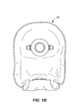
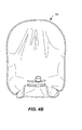
- FIGS 1B , 2B , 3B , 4B , 5B , and 6B are front and rear views illustrating filled drainable pouches 10, 10' and 10", respectively.
- the central welded regions 30, 30' and 30" serve to prevent the appearance of bulkiness and to receive and secure the rigid outlet valves 26, 26' and 26" while eliminating discomfort or pain to the user.
- the folding of the discharge ends 24, 24' and 24" makes it possible to make the drainable pouches 10, 10' and 10" larger because they can be folded as described.
- This makes it possible to initially fold the discharge ends 24, 24'and 24" such that the drainable pouches 10, 10' and 10" have a smaller overall area, and the cavities 22, 22' and 22" have a first, smaller capacity to receive body waste material and, later, to unfold the discharge ends 24, 24'and 24" such that the the drainable pouches 10, 10' and 10" have a larger overall area and the cavities 22, 22' and 22" have a second, larger capacity to receive body waste material should the user so desire. While the outlet valves 26, 26' and 26" would be adjacent the skin after unfolding, this may be acceptable to the user in order to lengthen the time before which the body waste material would need to be drained.
Description
- The present disclosure is directed to a pouch for the collection of a liquid or semisolid body waste material and, more particularly, to a drainable pouch that can be closed during collection of liquid or semisolid body waste material and later opened and drained.
- Drainable pouches for the collection of liquid or semisolid body waste material are well known and typically include flat, opposing sidewalls secured together along their edges to define a collection cavity. One of the sidewalls is provided with an opening to receive a stoma, and means such as a connecting flange is provided for securing the pouch to an adhesive barrier placed to surround the stoma of a patient so that body waste material that is discharged from the stoma will be received within the cavity. At its lower end, the drainable pouch typically has a discharge opening which may be closed during collection of the liquid or semisolid body waste material that passes through the stoma but may be opened for draining the body waste material from the pouch. As will be appreciated, the drainable pouch will typically be provided with a closure for the discharge opening that may take a number of different forms so long as it serves to prevent leakage of the body waste material.
-
WO-A-01/21115 - A drainable pouch is typically reusable following periodic emptying of the body waste material, but it is important the pouch be provided with effective sealing in order to avoid odors or contents emanating or leaking from the resealed pouch. This requirement is coupled with a need for the pouch to be easily and conveniently drainable, either directly through the discharge opening, or by reason of connecting an ancillary drainage device in a secure manner to the discharge opening of the pouch. Users of drainable pouches often encounter difficulty and discomfort in unsealing, emptying, and resealing the pouches because of the nature of the drainage systems and manipulations which require greater dexterity than many patients possess.
- In addition, drainable pouches often show bulkiness after a period of time of accumulating body waste material. This is true with respect to both liquid and semisolid body waste material because the normally flat sidewalls of such pouches are formed of a thin film which easily expands outwardly as the body waste material accumulates. Further, these pouches often include a rigid outlet valve associated with the discharge opening of the drainable pouch.
- These rigid outlet valves are typically sealed within the discharge opening and include a tubular fitting for connection to a collection device. However, such outlet valves can cause significant discomfort or pain when they come into contact with the skin of an individual using such a drainable pouch. Thus, there has been a need to address the apparently unrelated problems of bulking of the drainable pouch and protecting the user from the rigid outlet valve.
- The present disclosure is directed to a drainable pouch comprised of a pair of sidewalls of flexible sheet material having side edges joined together to define a cavity having a discharge end provided with an outlet valve for draining the cavity. The sidewalls also are joined together throughout a central region thereof such that the cavity formed by the sidewalls completely surrounds the central region. With this construction, the central region defines a peripheral edge and has at least one opening in a location which is spaced inwardly of the peripheral edge to receive the outlet valve when the discharge end is folded.
- In an exemplary embodiment, the pair of sidewalls of flexible sheet material preferably defines a body portion forming the cavity. Advantageously, the discharge end of the cavity comprises a tubular neck portion integrally formed with and extending from the body portion, and the discharge end is foldable generally along or parallel to a longitudinal axis toward one of the sidewalls to thereby overlap the body portion. After folding the discharge end, the outlet valve will be generally adjacent the opening in the central region so the outlet valve can be received therein.
- In one embodiment, the side edges and central region are welded and the at least one opening in the central region includes a slit extending through the sidewalls generally perpendicular to the longitudinal axis of the body portion. In another embodiment, the side edges and central region are welded and the at least one opening in the central region includes a pair of holes forming a strip for receiving and securing the outlet valve after the discharge end is folded.
- With the drainable pouch of the present disclosure, the tubular neck portion comprising the discharge end of the cavity defines an opening for receiving the outlet valve. Further, the outlet valve may be formed of a rigid material sealed within the opening for draining the cavity, and it also is preferably formed to include a first portion sealed within the opening and a second tubular portion or fitting which projects therefrom and can be connected to a collection device. In addition, the first portion of the outlet valve may have a generally elongated cross-section and the second tubular portion of the outlet valve may have a generally circular cross-section.
- Other advantages and features of the present disclosure will become apparent from the following specification taken in conjunction with the accompanying drawings.
-
-
Figure 1 is a front elevational view of a first embodiment of a drainable pouch according to the present disclosure; -
Figure 1A is a view similar toFigure 1 but with the outlet valve received within an opening in the drainable pouch; -
Figure 1B is a view similar toFigure 1A but showing the drainable pouch in a substantially filled condition; -
Figure 2 is a rear elevational view of the first embodiment of drainable pouch illustrated inFigure 1 ; -
Figure 2A is a view similar toFigure 2 but with the outlet valve received within an opening in the drainable pouch; -
Figure 2B is a view similar toFigure 2A but showing the drainable pouch in a substantially filled condition; -
Figure 3 is a front elevational view of a second embodiment of drainable pouch according to the present disclosure; -
Figure 3A is a view similar toFigure 3 but with the outlet valve received within an opening in the drainable pouch; -
Figure 3B is a view similar toFigure 3A but showing the drainable pouch in a substantially filled condition; -
Figure 4 is a rear elevational view of the second embodiment of drainable pouch illustrated inFigure 3 ; -
Figure 4A is a view similar toFigure 4 but with the outlet valve received within an opening in the drainable pouch; -
Figure 4B is a view similar toFigure 4A but showing the drainable pouch in a substantially filled condition; -
Figure 5 is a rear elevational view of the third embodiment of drainable pouch according to the present disclosure; -
Figure 5A is a view similar toFigure 5 but with the outlet valve received within an opening in the drainable pouch; -
Figure 6 is a rear elevational view of the third embodiment of drainable pouch illustrated inFigure 5 ; -
Figure 6A is a view similar toFigure 6 but with the outlet valve received within an opening in the trainable pouch; -
Figures 7 is a cross-sectional view taken generally along the line 7-7 ofFigure 1 illustrating the sidewall welds of the first embodiment; -
Figure 8 is a cross-sectional view taken generally along the line 8-8 ofFigure 3 illustrating the sidewall welds of the second embodiment; -
Figure 9 is a cross-sectional view taken generally along the line 9-9 ofFigure 5 illustrating the sidewall welds of the third embodiment; and -
Figure 10 is a cross-sectional view taken generally along the line 10-10 ofFigure 1 illustrating the outlet valve in the discharge end of the pouch. - In the various illustrations given, and with reference first to
Figures 1 and 2 , a first embodiment of a drainable pouch according to the present disclosure is generally designated by thereference numeral 10. Thedrainable pouch 10 is formed of a pair ofsidewalls side edges cavity 22 therebetween (seeFigure 7 ). Further, thecavity 22 formed by theside walls outlet valve 26 for draining thecavity 22 of liquid or semisolid body waste materials collected therein. - Referring to
Figures 1, 2 and7 , it will be seen that thesidewalls central region 30 thereof such that thecavity 22 formed by thesidewalls central region 30 defined by the welding at 28. With this construction, thecentral region 30 defined by the welding at 28 forms an internalperipheral edge 28a facing thecavity 22, and it also has at least one opening such as the slit orslot 32 in a location inwardly of the internalperipheral edge 28a to receive theoutlet valve 26 when thedischarge end 24 is folded (seeFigures 1A and 2A ). - As will be appreciated, the pair of
sidewalls body portion 34 forming thecavity 22. Thedischarge end 24 of thecavity 22 may then advantageously comprise atubular neck portion 36 integrally formed with and extending from thebody portion 34. When so formed, thedischarge end 24 is foldable generally along or parallel to alongitudinal axis 38 toward one of thesidewalls body portion 34. - After the
discharge end 24 has been folded, theoutlet valve 26 will be generally adjacent the opening orslit 32 in thecentral region 30 so theoutlet valve 26 can be received and stored therein as shown inFigures 1A and 2A . It will be appreciated from the drawings that theoutlet valve 26 is located generally along or parallel to thelongitudinal axis 38 of thebody portion 34, and theslit 32 extends through thesidewalls longitudinal axis 38 of thebody portion 34. Preferably, theoutlet valve 26 is formed of a rigid material in contrast to the soft, flexible material of thesidewalls Figure 10 ). - Referring to
Figures 1, 2 and10 , theoutlet valve 26 preferably includes afirst portion 26a sealed within the opening 40 in thedischarge end 24 and a secondtubular portion 26b which may take the form of a barbed fitting. Theoutlet valve 26 may also include arotatable flange 26c for opening and closing the valve. With this construction, it will be appreciated that the secondtubular portion 26b projects from thefirst portion 26a such that a flexible tube can be inserted over the barbed fitting to drain the contents of thecavity 22 into a collection device. - As shown in
Figure 10 , thefirst portion 26a of theoutlet valve 26 may have a generally elongated cross-section. The generally elongatedfirst portion 26a may then be positioned within theopening 40 and the flexible sheet material at the discharge end 24 of thecavity 22 may be sealed to the generally elongatedfirst portion 26a. Referring toFigures 1 and 2 , the secondtubular portion 26b of theoutlet valve 26 may have a generally circular cross-section. - Referring to
Figures 3 and 4 , a second embodiment of a drainable pouch which is similar in many respects to the embodiment ofFigures 1 and 2 is generally designated by the reference numeral 10'. The drainable pouch 10' is formed of a pair ofsidewalls 12' and 14' of flexible sheet material having side edges 16' and 18' joined together about the perimeter of the pouch as by welding at 20' to define a cavity 22' therebetween (seeFigure 8 ). Further, the cavity 22' formed by theside walls 12' and 14' has a discharge end 24' provided with an outlet valve 26' for draining the cavity 22' of liquid or semisolid body waste materials. - Referring to
Figures 3, 4 and8 , it will be seen that thesidewalls 12' and 14' are joined together as by welding at 28' throughout a central region 30' thereof such that the cavity 22' formed by thesidewalls 12' and 14' completely surrounds the central region 30' defined by the welding at 28'. With this construction, the central region 30' defined by the welding at 28' forms an internalperipheral edge 28a' facing the cavity 22', but it has a pair of openings such as theholes 32' inwardly of the internalperipheral edge 28a' to receive the outlet valve 26' when the discharge end 24' is folded (seeFigures 3A and 4A ). - By forming the pair of
holes 32', the welding at 28' results in a central weldedstrip 28b' between theholes 32' which cooperates with the outlet valve 26' in a manner described in more detail below. - As will be appreciated, the pair of
sidewalls 12' and 14' of flexible sheet material preferably defines a body portion 34' forming the cavity 22'. The discharge end 24' of thecavity 22 then advantageously comprises a tubular neck portion 36' integrally formed with and extending from the body portion 34'. When so formed, the discharge end 24' is foldable generally along or parallel to a longitudinal axis 38' toward one of the sidewalls 12' and 14' to overlap the body portion 34'. - After the discharge end 24' has been folded, the outlet valve 26' will be generally adjacent the
holes 32' in the central region 30' so the outlet valve 26' can be received and stored therein as shown inFigures 3A and 4A . It will be appreciated from the drawings that the outlet valve 26' is located generally along or parallel to the longitudinal axis 38' of the body portion 34', and theholes 32' extend through thesidewalls 12' and 14' generally perpendicular to the longitudinal axis 38' of the body portion 34'. Preferably, the outlet valve 26' is formed of a rigid material in contrast to the soft, flexible material of the sidewalls 12' and 14', and is sealed in an opening such as 40 (Figure 10 ) in the discharge end 24'. - As for the embodiment of
Figures 3 and 4 , the outlet valve 26' is preferably identical to theoutlet valve 26 illustrated inFigures 1, 2 and10 . In particular, it preferably includes afirst portion 26a' similar or identical tofirst portion 26a (Figure 10 ) and sealed within an opening such as 40 (Figure 10 ) in the discharge end 24' and a secondtubular portion 26b' which may take the form of a barbed fitting, and the outlet valve 26' may also advantageously include arotatable flange 26c' provided for opening and closing the valve. With this construction, it will be appreciated that the secondtubular portion 26b' projects from thefirst portion 26a' such that a flexible tube can be inserted over the barbed fitting to drain the contents of the cavity 22' into a collection device. - The
first portion 26a' of the outlet valve 26' may have a generally elongated cross-section which may be positioned within the opening such as 40 (Figure 10 ). The flexible sheet material at the discharge end 24' of the cavity 22' may be sealed to the generally elongatedfirst portion 26a'. Further, the secondtubular portion 26b' of the outlet valve 26' may have a generally circular cross-section. - Referring to
Figures 5 and 6 , a third embodiment of a drainable pouch which is similar in many respects to the embodiment ofFigures 1 and 2 is generally designated by thereference numeral 10". Thedrainable pouch 10" is formed of a pair ofsidewalls 12" and 14" of flexible sheet material having side edges 16" and 18" joined together about the perimeter of the pouch as by welding at 20" to define acavity 22" therebetween (seeFigure 9 ). Further, thecavity 22" formed by theside walls 12" and 14" has a discharge end as at 24" provided with anoutlet valve 26" for draining thecavity 22" of liquid or semisolid body waste materials collected therein. - Referring to
Figures 5, 6 and9 , it will be seen that thesidewalls 12" and 14" are joined together as by welding at 28" throughout acentral region 30" thereof such that thecavity 22" formed by thesidewalls 12" and 14" completely surrounds thecentral region 30" defined by the welding at 28". With this construction, thecentral region 30" defined by the welding at 28" forms an internalperipheral edge 28a" facing thecavity 22", but it also has at least one opening such as theslit 32" in a location inwardly of the internalperipheral edge 28a" to receive theoutlet valve 26" when thedischarge end 24" is folded (seeFigures 5A and 6A ). - As will be appreciated, the
slit 32" has afirst portion 32a" which corresponds to theentire slit 32 inFigure 1 and it also has asecond portion 32b" which is transverse to the first portion, generally along or parallel to thelongitudinal axis 38" of thebody portion 34", and in alignment with the secondtubular portion 26b" of theoutlet valve 26" before thedischarge end 24" has been folded. With this construction, it will be appreciated that it may be easier for theoutlet valve 26" to be received within theslit 32" once thedischarge end 24" has been folded than is the case with theslit 32 inFigure 1 because the secondtubular portion 26b"of theoutlet valve 26" which has a barbed fitting can more easily be passed through theslit 32" to rest in the positions shown inFigures 5A and 6A as a result of the alignedsecond portion 32b"of theslit 32". - As will be appreciated, the pair of
sidewalls 12" and 14" of flexible sheet material preferably defines abody portion 34" forming thecavity 22". Thedischarge end 24" of thecavity 22" then advantageously comprises atubular neck portion 36" integrally formed with and extending from thebody portion 34". When so formed, thedischarge end 24" is foldable generally along or parallel to thelongitudinal axis 38" toward one of thesidewalls 12" and 14" to overlap thebody portion 34". - After the
discharge end 24" has been folded, theoutlet valve 26" will be generally adjacent theslit 32" in thecentral region 30" so theoutlet valve 26" can be received and stored therein as shown inFigures 5A and 6A . It will be appreciated from the drawings that theoutlet valve 26" is located generally along or parallel to thelongitudinal axis 38" of thebody portion 34", and theslit 32" extends through thesidewalls 12" and 14"as previously described. Preferably, theoutlet valve 26" is formed of a rigid material in contrast to the soft, flexible material of thesidewalls 12" and 14", and is sealed in an opening such as 40 (Figure 10 ) in thedischarge end 24". - As for the embodiment of
Figures 5 and 6 , theoutlet valve 26" is preferably identical to theoutlet valve 26 illustrated inFigures 1, 2 and10 . In particular, it preferably includes afirst portion 26a" similar or identical to thefirst portion 26a (Figure 10 ) sealed within the opening such as 40 in thedischarge end 24" and a secondtubular portion 26b" which may take the form of a barbed fitting, and theoutlet valve 26" may also advantageously include arotatable flange 26c" provided for opening and closing the valve. With this construction, it will be appreciated that the secondtubular portion 26b" projects from thefirst portion 26a "such that a flexible tube can be inserted over the barbed fitting to drain the contents of thecavity 22" into a collection device. - The
first portion 26a" of theoutlet valve 26" may have a generally elongated cross-section which may be positioned within the opening such as 40. The flexible sheet material at thedischarge end 24" of thecavity 22" may be sealed to the generally elongatedfirst portion 26a". Further, the secondtubular portion 26b" of theoutlet valve 26" may have a generally circular cross-section. - While not important to understanding the features of the present disclosure, it will be appreciated from
Figures 1 ,3 and5 that thedrainable pouches flanges drainable pouches holes flanges drainable pouches - For this application, the
outlet valves 26,26'and 26" are typically formed of a rigid material for attachment to a collection device. The rigid material may comprise a suitable plastic, but it can cause considerable discomfort by rubbing against or digging into the skin of a person using one of thedrainable pouches drainable pouches - With the drainable pouch 10 (
Figures 1 and 2 ), thedischarge end 24 is folded generally along or parallel to thelongitudinal axis 38 so as to overlie thesidewall 12. The secondtubular portion 26b and therotatable flange 26c are then inserted through theslit 32 placing them on the side of thedrainable pouch 10 opposite to the connectingflange 42. Thus, the portions of theoutlet valve 26 externally of thedrainable pouch 10 are located on the side of thedrainable pouch 10 opposite the connectingflange 42 and opposite thesidewall 12 which is adjacent the skin during use (seeFigures 1A and 2A ). - With the drainable pouch 10' (
Figures 3 and 4 ), the discharge end 24' is folded generally along or parallel to the longitudinal axis 38' so as to overlie the sidewall 14'. The secondtubular portion 26b' and therotatable flange 26c' are then inserted through thehole 32 located nearest to the discharge end 24', under the central weldedstrip 28b', and then through thehole 32 located furthest from the discharge end 24'. Thus, the portions of the outlet valve 26' externally of the drainable pouch 10' are generally located in recessed relation relative to the side of the drainable pouch 10' having the connecting flange 42' and are therefore recessed relative to thesidewall 12' which is adjacent the skin during use (seeFigures 3A and 4A ). - With the
drainable pouch 10" (Figures 5 and 6 ), thedischarge end 24" is folded generally along or parallel to thelongitudinal axis 38" so as to overlie thesidewall 12". The secondtubular portion 26b" and therotatable flange 26c" are then inserted through theslit 32" placing them on the side of thedrainable pouch 10" opposite to the connectingflange 42". Thus, the portions of theoutlet valve 26" externally of thedrainable pouch 10" are located on the side of thedrainable pouch 10" opposite the connectingflange 42" and opposite thesidewall 12" which is adjacent the skin during use (seeFigures 5A and 6A ). - In addition to the foregoing, it will be appreciated that the central welded
regions regions flat sidewalls cavities sidewalls Figures 1B ,2B ,3B ,4B ,5B , and6B which are front and rear views illustrating filleddrainable pouches regions rigid outlet valves - As a still additional benefit of the present disclosure, the folding of the discharge ends 24, 24' and 24" makes it possible to make the
drainable pouches 24'and 24" such that thedrainable pouches cavities 24'and 24" such that the thedrainable pouches cavities outlet valves - While in the foregoing there have been set forth representative embodiments of the present disclosure, it will be appreciated that the details herein given may be varied by those skilled in the art without departing from the true scope of the appended claims.
Claims (15)
- A drainable pouch (10, 10', 10"), comprising: a pair of sidewalls (12, 12', 12", 14, 14', 14") of flexible sheet material having side edges (16, 16', 16", 18, 18', 18") joined together to define a cavity (22, 22', 22") having a discharge end (24, 24', 24") provided with an outlet valve (26, 26', 26") for draining the cavity, characterised in that the sidewalls are also joined together throughout a central region (30, 30', 30") thereof such that the cavity formed by the sidewalls completely surrounds the central region, the central region defining an internal peripheral edge (28a, 28a', 28a") and having at least one opening (32, 32', 32") inwardly of the peripheral edge to receive the outlet valve when the discharge end is folded.
- The drainable pouch of claim 1 wherein the pair of sidewalls (12, 12', 12", 14, 14', 14") of flexible sheet material defines a body portion (34, 34', 34") forming the cavity (22, 22', 22") and the discharge end (24, 24', 24") of the cavity comprises a tubular neck portion (36, 36', 36") integrally formed with and extending from the body portion.
- The drainable pouch of claim 1 wherein the discharge (24, 24', 24") end is foldable toward one of the sidewalls (12, 12', 12", 14, 14', 14") to overlap the body portion (34, 34', 34") to bring the outlet valve (26, 26', 26") generally adjacent the central region (30, 30', 30") so the opening in the central region can receive the outlet valve.
- The drainable pouch of claim 2 wherein the side edges (16, 16', 16", 18, 18', 18") and central region (30, 30', 30") are joined together by welding and the at least one opening in the central region includes a slit (32, 32', 32") extending through the sidewalls (12, 12', 12", 14, 14', 14") generally perpendicular to a longitudinal axis (38, 38', 38") of the body portion (34, 34', 34").
- The drainable pouch of claim 2 wherein the side edges (16', 18') and central region (30') are joined together by welding and the at least one opening (32') in the central region includes a pair of holes (32') forming a strip (28b') for receiving and securing the outlet valve (26') after the discharge end (24') is folded.
- The drainable pouch of claim 2 wherein the tubular neck portion (36, 36', 36") comprising the discharge end (24, 24', 24") of the cavity (22, 22', 22") defines an opening for receiving the outlet valve (26, 26', 26") which is formed of a rigid material and is sealed within the opening for draining the cavity.
- The drainable pouch of claim 2, wherein the side edges (16, 16', 16", 18, 18', 18") and central region (30, 30', 30") are joined together by welding and wherein the tubular neck portion (36, 36', 36") is being foldable toward one of the sidewalls (12, 12', 12", 14, 14', 14") to overlap the body portion (34, 34', 34"), wherein the peripheral edge (28a, 28a', 28a") is an internal peripheral edge and wherein the opening inwardly of the peripheral edge is extending through the welded sidewalls.
- The drainable pouch of claim 7 wherein the at least one opening in the central region includes a slit (32, 32', 32") extending through the sidewalls (12, 12', 12", 14, 14', 14") generally perpendicular to a longitudinal axis (38, 38', 38") of the body portion (34, 34', 34"), or
wherein the at least one opening in the central region (30') includes a pair of holes (32') forming a strip (28b') to receive and secure the outlet valve (26') after the discharge end is folded. - The drainable pouch of claim 7 wherein the tubular neck portion (36, 36', 36") defines an opening for receiving the outlet valve (26, 26', 26"), the outlet valve being formed of a rigid material and sealed within the opening.
- The drainable pouch of claim 7 wherein the pouch is an urostomy pouch and
wherein the tubular neck portion (36, 36', 36") defines an opening for receiving the outlet valve (26, 26', 26"), the outlet valve being formed of a rigid material and having a first portion (26a, 26a', 26a") sealed within the opening and a second tubular portion (26b, 26b', 26b") projecting therefrom, and wherein the opening in the central region (30, 30', 30") and the rigid outlet valve lying generally along or parallel to a longitudinal axis (38, 38', 38") of the body portion (34, 34', 34") so the opening can receive and secure the outlet valve when the discharge end (24, 24', 24") is folded to overlap the body portion. - The drainable urostomy pouch of claim 10 wherein the at least one opening in the central region (30, 30', 30") includes a slit (32, 32', 32") extending through the sidewalls (12, 12', 12", 14, 14', 14") generally perpendicular to a longitudinal axis (38, 38', 38") of the body portion (34, 34', 34").
- The drainable urostomy pouch (10') of claim 10 wherein the at least one opening in the central region (30') includes a pair of holes (32') forming a strip (28b') to receive and secure the outlet valve (26') after the discharge end (24') is folded.
- The drainable urostomy pouch of claim 10 wherein the first portion (26a, 26a', 26a") of the outlet valve (26, 26', 26") has a generally elongated cross-section and the second tubular portion (26b, 26b', 26b") of the outlet valve has a generally circular cross-section, or
wherein the central region (30, 30', 30") is generally rectangular in shape and has a width generally corresponding to the width of the opening defined by the tubular neck portion (36, 36', 36"). - The drainable urostomy pouch of claim 12 wherein the central region (30') and the holes (32') forming the strip (28b') are generally rectangular to define the central region as a welded perimeter region entirely surrounding the holes.
- The drainable urostomy pouch of claim 12 wherein the holes (32') have a greater width than the diameter of the tubular portion (26b') of the outlet valve (26') so the strip (28b') can secure the outlet valve after the discharge end (24') is folded.
Applications Claiming Priority (2)
| Application Number | Priority Date | Filing Date | Title |
|---|---|---|---|
| US8883308P | 2008-08-14 | 2008-08-14 | |
| PCT/US2009/047826 WO2010019313A1 (en) | 2008-08-14 | 2009-06-18 | Drainable pouch |
Publications (2)
| Publication Number | Publication Date |
|---|---|
| EP2349136A1 EP2349136A1 (en) | 2011-08-03 |
| EP2349136B1 true EP2349136B1 (en) | 2014-03-19 |
Family
ID=41077984
Family Applications (1)
| Application Number | Title | Priority Date | Filing Date |
|---|---|---|---|
| EP09789847.2A Active EP2349136B1 (en) | 2008-08-14 | 2009-06-18 | Drainable pouch |
Country Status (6)
| Country | Link |
|---|---|
| US (1) | US8562578B2 (en) |
| EP (1) | EP2349136B1 (en) |
| JP (1) | JP5416771B2 (en) |
| AU (1) | AU2009282410B2 (en) |
| CA (1) | CA2734117C (en) |
| WO (1) | WO2010019313A1 (en) |
Families Citing this family (3)
| Publication number | Priority date | Publication date | Assignee | Title |
|---|---|---|---|---|
| GB201115905D0 (en) * | 2011-09-14 | 2011-10-26 | Welland Medical Ltd | Urostomy pouch with integral closure tap system |
| GB201715394D0 (en) * | 2017-09-22 | 2017-11-08 | Salts Healthcare Ltd | An ostomy appliance |
| GB2615827A (en) * | 2022-02-22 | 2023-08-23 | Salts Healthcare Ltd | An ostomy appliance |
Family Cites Families (13)
| Publication number | Priority date | Publication date | Assignee | Title |
|---|---|---|---|---|
| US3734154A (en) * | 1971-04-23 | 1973-05-22 | Packaging Ass Inc | Disposable bag with self-closing valve |
| DE7211842U (en) * | 1972-03-28 | 1972-08-24 | Fresenius E Kg | UROMETER |
| US4084590A (en) * | 1975-08-18 | 1978-04-18 | Howmedica, Inc. | Stoma drainage appliance |
| US4188989A (en) * | 1976-08-20 | 1980-02-19 | G. D. Searle & Co. | Fluid collection receptacle |
| US4462510A (en) * | 1981-06-30 | 1984-07-31 | Kingsdown Medical Consultants Limited | Tap for drainage bag |
| US4449971A (en) * | 1982-05-24 | 1984-05-22 | Cawood Charles David | Urine collection method |
| US4723944A (en) * | 1986-06-05 | 1988-02-09 | Jensen Ole R | Fluid collection receptacle with improved non-return valve |
| USD337382S (en) * | 1989-10-23 | 1993-07-13 | H. G. Wallace Limited | Drainage bag |
| US6045542A (en) * | 1999-01-13 | 2000-04-04 | Cawood Family Limited Partnership | Urine collection device |
| US6736803B2 (en) * | 1999-01-13 | 2004-05-18 | Cawood Family Limited Partnership | Urine bag and self-retracting drain tube therefor |
| US6471680B1 (en) * | 1999-01-13 | 2002-10-29 | Cawood Family Limited Partnership | Urine bag and self-retracting drain tube therefor |
| DK173920B1 (en) * | 1999-09-17 | 2002-02-18 | Coloplast As | Collection bag with retaining means for a closing device |
| DK175390B1 (en) * | 2002-04-17 | 2004-09-20 | Coloplast As | Collection bag with improved recording means for a closure device |
-
2009
- 2009-06-18 CA CA2734117A patent/CA2734117C/en active Active
- 2009-06-18 EP EP09789847.2A patent/EP2349136B1/en active Active
- 2009-06-18 AU AU2009282410A patent/AU2009282410B2/en active Active
- 2009-06-18 JP JP2011523013A patent/JP5416771B2/en active Active
- 2009-06-18 US US13/057,870 patent/US8562578B2/en active Active
- 2009-06-18 WO PCT/US2009/047826 patent/WO2010019313A1/en active Application Filing
Also Published As
| Publication number | Publication date |
|---|---|
| JP2011530383A (en) | 2011-12-22 |
| JP5416771B2 (en) | 2014-02-12 |
| AU2009282410B2 (en) | 2013-10-10 |
| EP2349136A1 (en) | 2011-08-03 |
| US8562578B2 (en) | 2013-10-22 |
| CA2734117A1 (en) | 2010-02-18 |
| AU2009282410A1 (en) | 2010-02-18 |
| US20110172618A1 (en) | 2011-07-14 |
| CA2734117C (en) | 2014-04-22 |
| WO2010019313A1 (en) | 2010-02-18 |
Similar Documents
| Publication | Publication Date | Title |
|---|---|---|
| US7150728B2 (en) | Collecting bag having a vent aperture | |
| US11717434B2 (en) | Medical device with an opening system | |
| JP6912485B2 (en) | Ostomy pouch | |
| JP4245810B2 (en) | Human waste collection bag | |
| US6726667B2 (en) | Drainable ostomy pouch and closure means therefor | |
| US7261706B2 (en) | Package for an ostomy appliance | |
| US11065144B2 (en) | Ostomy pouch with night drainage adapter | |
| US20170209297A1 (en) | A drainable collection bag | |
| US6419664B1 (en) | Drainable collection bag for human body wastes | |
| CA2737221C (en) | Ostomy pouch | |
| US20210369493A1 (en) | Ostomy Pouch | |
| EP2349136B1 (en) | Drainable pouch | |
| JP2011530383A5 (en) | ||
| US11826276B2 (en) | Outlet closure and securement system for drainable pouch |
Legal Events
| Date | Code | Title | Description |
|---|---|---|---|
| PUAI | Public reference made under article 153(3) epc to a published international application that has entered the european phase |
Free format text: ORIGINAL CODE: 0009012 |
|
| 17P | Request for examination filed |
Effective date: 20110309 |
|
| AK | Designated contracting states |
Kind code of ref document: A1 Designated state(s): AT BE BG CH CY CZ DE DK EE ES FI FR GB GR HR HU IE IS IT LI LT LU LV MC MK MT NL NO PL PT RO SE SI SK TR |
|
| DAX | Request for extension of the european patent (deleted) | ||
| GRAP | Despatch of communication of intention to grant a patent |
Free format text: ORIGINAL CODE: EPIDOSNIGR1 |
|
| INTG | Intention to grant announced |
Effective date: 20131015 |
|
| GRAS | Grant fee paid |
Free format text: ORIGINAL CODE: EPIDOSNIGR3 |
|
| GRAA | (expected) grant |
Free format text: ORIGINAL CODE: 0009210 |
|
| AK | Designated contracting states |
Kind code of ref document: B1 Designated state(s): AT BE BG CH CY CZ DE DK EE ES FI FR GB GR HR HU IE IS IT LI LT LU LV MC MK MT NL NO PL PT RO SE SI SK TR |
|
| REG | Reference to a national code |
Ref country code: GB Ref legal event code: FG4D |
|
| REG | Reference to a national code |
Ref country code: CH Ref legal event code: EP |
|
| REG | Reference to a national code |
Ref country code: IE Ref legal event code: FG4D |
|
| REG | Reference to a national code |
Ref country code: AT Ref legal event code: REF Ref document number: 657167 Country of ref document: AT Kind code of ref document: T Effective date: 20140415 |
|
| REG | Reference to a national code |
Ref country code: DE Ref legal event code: R096 Ref document number: 602009022647 Country of ref document: DE Effective date: 20140424 |
|
| PG25 | Lapsed in a contracting state [announced via postgrant information from national office to epo] |
Ref country code: LT Free format text: LAPSE BECAUSE OF FAILURE TO SUBMIT A TRANSLATION OF THE DESCRIPTION OR TO PAY THE FEE WITHIN THE PRESCRIBED TIME-LIMIT Effective date: 20140319 Ref country code: NO Free format text: LAPSE BECAUSE OF FAILURE TO SUBMIT A TRANSLATION OF THE DESCRIPTION OR TO PAY THE FEE WITHIN THE PRESCRIBED TIME-LIMIT Effective date: 20140619 |
|
| REG | Reference to a national code |
Ref country code: NL Ref legal event code: VDEP Effective date: 20140319 |
|
| REG | Reference to a national code |
Ref country code: AT Ref legal event code: MK05 Ref document number: 657167 Country of ref document: AT Kind code of ref document: T Effective date: 20140319 |
|
| REG | Reference to a national code |
Ref country code: LT Ref legal event code: MG4D |
|
| PG25 | Lapsed in a contracting state [announced via postgrant information from national office to epo] |
Ref country code: CY Free format text: LAPSE BECAUSE OF FAILURE TO SUBMIT A TRANSLATION OF THE DESCRIPTION OR TO PAY THE FEE WITHIN THE PRESCRIBED TIME-LIMIT Effective date: 20140319 Ref country code: SE Free format text: LAPSE BECAUSE OF FAILURE TO SUBMIT A TRANSLATION OF THE DESCRIPTION OR TO PAY THE FEE WITHIN THE PRESCRIBED TIME-LIMIT Effective date: 20140319 Ref country code: FI Free format text: LAPSE BECAUSE OF FAILURE TO SUBMIT A TRANSLATION OF THE DESCRIPTION OR TO PAY THE FEE WITHIN THE PRESCRIBED TIME-LIMIT Effective date: 20140319 |
|
| PG25 | Lapsed in a contracting state [announced via postgrant information from national office to epo] |
Ref country code: HR Free format text: LAPSE BECAUSE OF FAILURE TO SUBMIT A TRANSLATION OF THE DESCRIPTION OR TO PAY THE FEE WITHIN THE PRESCRIBED TIME-LIMIT Effective date: 20140319 Ref country code: LV Free format text: LAPSE BECAUSE OF FAILURE TO SUBMIT A TRANSLATION OF THE DESCRIPTION OR TO PAY THE FEE WITHIN THE PRESCRIBED TIME-LIMIT Effective date: 20140319 |
|
| PG25 | Lapsed in a contracting state [announced via postgrant information from national office to epo] |
Ref country code: CZ Free format text: LAPSE BECAUSE OF FAILURE TO SUBMIT A TRANSLATION OF THE DESCRIPTION OR TO PAY THE FEE WITHIN THE PRESCRIBED TIME-LIMIT Effective date: 20140319 Ref country code: EE Free format text: LAPSE BECAUSE OF FAILURE TO SUBMIT A TRANSLATION OF THE DESCRIPTION OR TO PAY THE FEE WITHIN THE PRESCRIBED TIME-LIMIT Effective date: 20140319 Ref country code: IS Free format text: LAPSE BECAUSE OF FAILURE TO SUBMIT A TRANSLATION OF THE DESCRIPTION OR TO PAY THE FEE WITHIN THE PRESCRIBED TIME-LIMIT Effective date: 20140719 Ref country code: RO Free format text: LAPSE BECAUSE OF FAILURE TO SUBMIT A TRANSLATION OF THE DESCRIPTION OR TO PAY THE FEE WITHIN THE PRESCRIBED TIME-LIMIT Effective date: 20140319 Ref country code: BE Free format text: LAPSE BECAUSE OF FAILURE TO SUBMIT A TRANSLATION OF THE DESCRIPTION OR TO PAY THE FEE WITHIN THE PRESCRIBED TIME-LIMIT Effective date: 20140319 Ref country code: BG Free format text: LAPSE BECAUSE OF FAILURE TO SUBMIT A TRANSLATION OF THE DESCRIPTION OR TO PAY THE FEE WITHIN THE PRESCRIBED TIME-LIMIT Effective date: 20140619 Ref country code: NL Free format text: LAPSE BECAUSE OF FAILURE TO SUBMIT A TRANSLATION OF THE DESCRIPTION OR TO PAY THE FEE WITHIN THE PRESCRIBED TIME-LIMIT Effective date: 20140319 |
|
| PG25 | Lapsed in a contracting state [announced via postgrant information from national office to epo] |
Ref country code: AT Free format text: LAPSE BECAUSE OF FAILURE TO SUBMIT A TRANSLATION OF THE DESCRIPTION OR TO PAY THE FEE WITHIN THE PRESCRIBED TIME-LIMIT Effective date: 20140319 Ref country code: ES Free format text: LAPSE BECAUSE OF FAILURE TO SUBMIT A TRANSLATION OF THE DESCRIPTION OR TO PAY THE FEE WITHIN THE PRESCRIBED TIME-LIMIT Effective date: 20140319 Ref country code: PL Free format text: LAPSE BECAUSE OF FAILURE TO SUBMIT A TRANSLATION OF THE DESCRIPTION OR TO PAY THE FEE WITHIN THE PRESCRIBED TIME-LIMIT Effective date: 20140319 Ref country code: SK Free format text: LAPSE BECAUSE OF FAILURE TO SUBMIT A TRANSLATION OF THE DESCRIPTION OR TO PAY THE FEE WITHIN THE PRESCRIBED TIME-LIMIT Effective date: 20140319 |
|
| REG | Reference to a national code |
Ref country code: DE Ref legal event code: R097 Ref document number: 602009022647 Country of ref document: DE |
|
| PG25 | Lapsed in a contracting state [announced via postgrant information from national office to epo] |
Ref country code: PT Free format text: LAPSE BECAUSE OF FAILURE TO SUBMIT A TRANSLATION OF THE DESCRIPTION OR TO PAY THE FEE WITHIN THE PRESCRIBED TIME-LIMIT Effective date: 20140721 |
|
| PLBE | No opposition filed within time limit |
Free format text: ORIGINAL CODE: 0009261 |
|
| STAA | Information on the status of an ep patent application or granted ep patent |
Free format text: STATUS: NO OPPOSITION FILED WITHIN TIME LIMIT |
|
| PG25 | Lapsed in a contracting state [announced via postgrant information from national office to epo] |
Ref country code: LU Free format text: LAPSE BECAUSE OF FAILURE TO SUBMIT A TRANSLATION OF THE DESCRIPTION OR TO PAY THE FEE WITHIN THE PRESCRIBED TIME-LIMIT Effective date: 20140618 Ref country code: DK Free format text: LAPSE BECAUSE OF FAILURE TO SUBMIT A TRANSLATION OF THE DESCRIPTION OR TO PAY THE FEE WITHIN THE PRESCRIBED TIME-LIMIT Effective date: 20140319 Ref country code: MC Free format text: LAPSE BECAUSE OF FAILURE TO SUBMIT A TRANSLATION OF THE DESCRIPTION OR TO PAY THE FEE WITHIN THE PRESCRIBED TIME-LIMIT Effective date: 20140319 |
|
| REG | Reference to a national code |
Ref country code: CH Ref legal event code: PL |
|
| 26N | No opposition filed |
Effective date: 20141222 |
|
| REG | Reference to a national code |
Ref country code: IE Ref legal event code: MM4A |
|
| REG | Reference to a national code |
Ref country code: FR Ref legal event code: ST Effective date: 20150227 |
|
| PG25 | Lapsed in a contracting state [announced via postgrant information from national office to epo] |
Ref country code: IT Free format text: LAPSE BECAUSE OF FAILURE TO SUBMIT A TRANSLATION OF THE DESCRIPTION OR TO PAY THE FEE WITHIN THE PRESCRIBED TIME-LIMIT Effective date: 20140319 |
|
| REG | Reference to a national code |
Ref country code: DE Ref legal event code: R097 Ref document number: 602009022647 Country of ref document: DE Effective date: 20141222 |
|
| PG25 | Lapsed in a contracting state [announced via postgrant information from national office to epo] |
Ref country code: IE Free format text: LAPSE BECAUSE OF NON-PAYMENT OF DUE FEES Effective date: 20140618 Ref country code: LI Free format text: LAPSE BECAUSE OF NON-PAYMENT OF DUE FEES Effective date: 20140630 Ref country code: CH Free format text: LAPSE BECAUSE OF NON-PAYMENT OF DUE FEES Effective date: 20140630 |
|
| PG25 | Lapsed in a contracting state [announced via postgrant information from national office to epo] |
Ref country code: FR Free format text: LAPSE BECAUSE OF NON-PAYMENT OF DUE FEES Effective date: 20140630 |
|
| PG25 | Lapsed in a contracting state [announced via postgrant information from national office to epo] |
Ref country code: SI Free format text: LAPSE BECAUSE OF FAILURE TO SUBMIT A TRANSLATION OF THE DESCRIPTION OR TO PAY THE FEE WITHIN THE PRESCRIBED TIME-LIMIT Effective date: 20140319 |
|
| PG25 | Lapsed in a contracting state [announced via postgrant information from national office to epo] |
Ref country code: MT Free format text: LAPSE BECAUSE OF FAILURE TO SUBMIT A TRANSLATION OF THE DESCRIPTION OR TO PAY THE FEE WITHIN THE PRESCRIBED TIME-LIMIT Effective date: 20140319 |
|
| PG25 | Lapsed in a contracting state [announced via postgrant information from national office to epo] |
Ref country code: GR Free format text: LAPSE BECAUSE OF FAILURE TO SUBMIT A TRANSLATION OF THE DESCRIPTION OR TO PAY THE FEE WITHIN THE PRESCRIBED TIME-LIMIT Effective date: 20140620 |
|
| PG25 | Lapsed in a contracting state [announced via postgrant information from national office to epo] |
Ref country code: TR Free format text: LAPSE BECAUSE OF FAILURE TO SUBMIT A TRANSLATION OF THE DESCRIPTION OR TO PAY THE FEE WITHIN THE PRESCRIBED TIME-LIMIT Effective date: 20140319 Ref country code: HU Free format text: LAPSE BECAUSE OF FAILURE TO SUBMIT A TRANSLATION OF THE DESCRIPTION OR TO PAY THE FEE WITHIN THE PRESCRIBED TIME-LIMIT; INVALID AB INITIO Effective date: 20090618 |
|
| PG25 | Lapsed in a contracting state [announced via postgrant information from national office to epo] |
Ref country code: MK Free format text: LAPSE BECAUSE OF FAILURE TO SUBMIT A TRANSLATION OF THE DESCRIPTION OR TO PAY THE FEE WITHIN THE PRESCRIBED TIME-LIMIT Effective date: 20140319 |
|
| PGFP | Annual fee paid to national office [announced via postgrant information from national office to epo] |
Ref country code: DE Payment date: 20230626 Year of fee payment: 15 |
|
| PGFP | Annual fee paid to national office [announced via postgrant information from national office to epo] |
Ref country code: GB Payment date: 20230627 Year of fee payment: 15 |