JP6912380B2 - Systems and methods for wireless power transfer - Google Patents
Systems and methods for wireless power transfer Download PDFInfo
- Publication number
- JP6912380B2 JP6912380B2 JP2017534995A JP2017534995A JP6912380B2 JP 6912380 B2 JP6912380 B2 JP 6912380B2 JP 2017534995 A JP2017534995 A JP 2017534995A JP 2017534995 A JP2017534995 A JP 2017534995A JP 6912380 B2 JP6912380 B2 JP 6912380B2
- Authority
- JP
- Japan
- Prior art keywords
- transmitter
- power
- receiver
- electronic device
- antennas
- Prior art date
- Legal status (The legal status is an assumption and is not a legal conclusion. Google has not performed a legal analysis and makes no representation as to the accuracy of the status listed.)
- Active
Links
- 238000012546 transfer Methods 0.000 title claims description 334
- 238000000034 method Methods 0.000 title claims description 186
- 230000005540 biological transmission Effects 0.000 claims description 217
- 238000004891 communication Methods 0.000 claims description 192
- 238000005259 measurement Methods 0.000 claims description 19
- 230000001052 transient effect Effects 0.000 claims 1
- 230000015572 biosynthetic process Effects 0.000 description 136
- 238000005755 formation reaction Methods 0.000 description 136
- 238000007726 management method Methods 0.000 description 73
- 230000008569 process Effects 0.000 description 72
- 230000010287 polarization Effects 0.000 description 40
- 238000003860 storage Methods 0.000 description 35
- 238000010586 diagram Methods 0.000 description 32
- 239000002585 base Substances 0.000 description 25
- 230000006870 function Effects 0.000 description 24
- 238000012545 processing Methods 0.000 description 24
- 230000003044 adaptive effect Effects 0.000 description 19
- 230000008859 change Effects 0.000 description 18
- 239000000463 material Substances 0.000 description 18
- 230000004044 response Effects 0.000 description 18
- 239000003990 capacitor Substances 0.000 description 17
- 239000000700 radioactive tracer Substances 0.000 description 15
- 238000006243 chemical reaction Methods 0.000 description 14
- 238000004422 calculation algorithm Methods 0.000 description 12
- 238000009826 distribution Methods 0.000 description 11
- 238000012544 monitoring process Methods 0.000 description 11
- 230000033001 locomotion Effects 0.000 description 10
- 230000008901 benefit Effects 0.000 description 9
- 230000001965 increasing effect Effects 0.000 description 9
- 230000003313 weakening effect Effects 0.000 description 9
- 238000003491 array Methods 0.000 description 8
- 239000002245 particle Substances 0.000 description 8
- 230000002829 reductive effect Effects 0.000 description 8
- 230000006399 behavior Effects 0.000 description 7
- 230000036961 partial effect Effects 0.000 description 7
- 238000013461 design Methods 0.000 description 6
- 230000036541 health Effects 0.000 description 6
- 230000003993 interaction Effects 0.000 description 6
- 239000002086 nanomaterial Substances 0.000 description 6
- RYGMFSIKBFXOCR-UHFFFAOYSA-N Copper Chemical compound [Cu] RYGMFSIKBFXOCR-UHFFFAOYSA-N 0.000 description 5
- 239000008186 active pharmaceutical agent Substances 0.000 description 5
- 230000033228 biological regulation Effects 0.000 description 5
- 230000001276 controlling effect Effects 0.000 description 5
- 229910052802 copper Inorganic materials 0.000 description 5
- 239000010949 copper Substances 0.000 description 5
- 230000000694 effects Effects 0.000 description 5
- 238000005516 engineering process Methods 0.000 description 5
- 239000004033 plastic Substances 0.000 description 5
- 229920001875 Ebonite Polymers 0.000 description 4
- 230000009471 action Effects 0.000 description 4
- 230000004913 activation Effects 0.000 description 4
- 238000004364 calculation method Methods 0.000 description 4
- 230000010354 integration Effects 0.000 description 4
- 230000003287 optical effect Effects 0.000 description 4
- 238000005728 strengthening Methods 0.000 description 4
- 230000000712 assembly Effects 0.000 description 3
- 238000000429 assembly Methods 0.000 description 3
- 238000013475 authorization Methods 0.000 description 3
- 235000019504 cigarettes Nutrition 0.000 description 3
- 230000008878 coupling Effects 0.000 description 3
- 238000010168 coupling process Methods 0.000 description 3
- 238000005859 coupling reaction Methods 0.000 description 3
- 239000013078 crystal Substances 0.000 description 3
- 230000003111 delayed effect Effects 0.000 description 3
- 230000000670 limiting effect Effects 0.000 description 3
- 230000007246 mechanism Effects 0.000 description 3
- 238000012986 modification Methods 0.000 description 3
- 230000004048 modification Effects 0.000 description 3
- 230000002093 peripheral effect Effects 0.000 description 3
- 230000008054 signal transmission Effects 0.000 description 3
- 239000000758 substrate Substances 0.000 description 3
- 230000001360 synchronised effect Effects 0.000 description 3
- BQCADISMDOOEFD-UHFFFAOYSA-N Silver Chemical compound [Ag] BQCADISMDOOEFD-UHFFFAOYSA-N 0.000 description 2
- 238000004458 analytical method Methods 0.000 description 2
- 230000001010 compromised effect Effects 0.000 description 2
- 238000004590 computer program Methods 0.000 description 2
- 239000004020 conductor Substances 0.000 description 2
- 230000001186 cumulative effect Effects 0.000 description 2
- 230000005611 electricity Effects 0.000 description 2
- 230000007274 generation of a signal involved in cell-cell signaling Effects 0.000 description 2
- PCHJSUWPFVWCPO-UHFFFAOYSA-N gold Chemical compound [Au] PCHJSUWPFVWCPO-UHFFFAOYSA-N 0.000 description 2
- 229910052737 gold Inorganic materials 0.000 description 2
- 239000010931 gold Substances 0.000 description 2
- 230000017525 heat dissipation Effects 0.000 description 2
- -1 high temperatures Substances 0.000 description 2
- 230000001976 improved effect Effects 0.000 description 2
- 230000007257 malfunction Effects 0.000 description 2
- 230000010363 phase shift Effects 0.000 description 2
- 150000003071 polychlorinated biphenyls Chemical class 0.000 description 2
- 230000001105 regulatory effect Effects 0.000 description 2
- 238000012552 review Methods 0.000 description 2
- 238000005070 sampling Methods 0.000 description 2
- 230000011664 signaling Effects 0.000 description 2
- 229910052709 silver Inorganic materials 0.000 description 2
- 239000004332 silver Substances 0.000 description 2
- 239000007787 solid Substances 0.000 description 2
- 241000473391 Archosargus rhomboidalis Species 0.000 description 1
- HBBGRARXTFLTSG-UHFFFAOYSA-N Lithium ion Chemical compound [Li+] HBBGRARXTFLTSG-UHFFFAOYSA-N 0.000 description 1
- 230000002411 adverse Effects 0.000 description 1
- 239000003513 alkali Substances 0.000 description 1
- 238000013459 approach Methods 0.000 description 1
- 230000002238 attenuated effect Effects 0.000 description 1
- 230000009286 beneficial effect Effects 0.000 description 1
- OJIJEKBXJYRIBZ-UHFFFAOYSA-N cadmium nickel Chemical compound [Ni].[Cd] OJIJEKBXJYRIBZ-UHFFFAOYSA-N 0.000 description 1
- 239000002131 composite material Substances 0.000 description 1
- 239000012141 concentrate Substances 0.000 description 1
- 238000010924 continuous production Methods 0.000 description 1
- 238000005034 decoration Methods 0.000 description 1
- 230000001066 destructive effect Effects 0.000 description 1
- 238000001514 detection method Methods 0.000 description 1
- 235000019800 disodium phosphate Nutrition 0.000 description 1
- 230000005672 electromagnetic field Effects 0.000 description 1
- 230000005670 electromagnetic radiation Effects 0.000 description 1
- 239000000284 extract Substances 0.000 description 1
- 230000002349 favourable effect Effects 0.000 description 1
- 238000005286 illumination Methods 0.000 description 1
- 230000001939 inductive effect Effects 0.000 description 1
- 230000002452 interceptive effect Effects 0.000 description 1
- 230000001788 irregular Effects 0.000 description 1
- 229910001416 lithium ion Inorganic materials 0.000 description 1
- 239000002184 metal Substances 0.000 description 1
- 229910052751 metal Inorganic materials 0.000 description 1
- 229910052987 metal hydride Inorganic materials 0.000 description 1
- 230000006855 networking Effects 0.000 description 1
- 229910052759 nickel Inorganic materials 0.000 description 1
- PXHVJJICTQNCMI-UHFFFAOYSA-N nickel Substances [Ni] PXHVJJICTQNCMI-UHFFFAOYSA-N 0.000 description 1
- 238000013021 overheating Methods 0.000 description 1
- 229920001690 polydopamine Polymers 0.000 description 1
- 230000000644 propagated effect Effects 0.000 description 1
- 230000001902 propagating effect Effects 0.000 description 1
- 238000003908 quality control method Methods 0.000 description 1
- 230000005855 radiation Effects 0.000 description 1
- 230000010076 replication Effects 0.000 description 1
- 238000010079 rubber tapping Methods 0.000 description 1
- 239000004576 sand Substances 0.000 description 1
- 230000035939 shock Effects 0.000 description 1
- 230000026676 system process Effects 0.000 description 1
- 238000012360 testing method Methods 0.000 description 1
- 238000012549 training Methods 0.000 description 1
- 230000007704 transition Effects 0.000 description 1
- 230000001960 triggered effect Effects 0.000 description 1
- 238000002604 ultrasonography Methods 0.000 description 1
- 238000012795 verification Methods 0.000 description 1
- XLYOFNOQVPJJNP-UHFFFAOYSA-N water Substances O XLYOFNOQVPJJNP-UHFFFAOYSA-N 0.000 description 1
- 238000004804 winding Methods 0.000 description 1
Images


Classifications
-
- H—ELECTRICITY
- H02—GENERATION; CONVERSION OR DISTRIBUTION OF ELECTRIC POWER
- H02J—CIRCUIT ARRANGEMENTS OR SYSTEMS FOR SUPPLYING OR DISTRIBUTING ELECTRIC POWER; SYSTEMS FOR STORING ELECTRIC ENERGY
- H02J50/00—Circuit arrangements or systems for wireless supply or distribution of electric power
- H02J50/20—Circuit arrangements or systems for wireless supply or distribution of electric power using microwaves or radio frequency waves
-
- H—ELECTRICITY
- H02—GENERATION; CONVERSION OR DISTRIBUTION OF ELECTRIC POWER
- H02J—CIRCUIT ARRANGEMENTS OR SYSTEMS FOR SUPPLYING OR DISTRIBUTING ELECTRIC POWER; SYSTEMS FOR STORING ELECTRIC ENERGY
- H02J50/00—Circuit arrangements or systems for wireless supply or distribution of electric power
- H02J50/40—Circuit arrangements or systems for wireless supply or distribution of electric power using two or more transmitting or receiving devices
- H02J50/402—Circuit arrangements or systems for wireless supply or distribution of electric power using two or more transmitting or receiving devices the two or more transmitting or the two or more receiving devices being integrated in the same unit, e.g. power mats with several coils or antennas with several sub-antennas
-
- H04B5/26—
-
- H04B5/79—
Description
関連出願の相互参照
[0001] 本出願は、2013年5月10日に出願された、「Methodology For Pocket−Forming」と題する米国非仮特許出願第13/891,430号の一部継続出願であり、2012年10月31日に出願された「Scalable Antenna Assemblies For Power Transmission」と題する米国仮特許出願第61/720,798号、2012年7月6日に出願された、「Receivers For Power Transmission」と題する米国仮特許出願第61/668,799号、および2012年7月31日に出願された、「Transmitters For Wireless Power Transmission」と題する米国仮特許出願第61/677,706号の優先権を主張する。それらの全内容が、参照により全体として本明細書に援用される。
Cross-reference of related applications
[0001] This application is a partial continuation application of US non-provisional patent application No. 13 / 891,430, entitled "Methodology For Pocket-Forming", filed on May 10, 2013, and is a continuation application of the United States Non-Provisional Patent Application No. 13 / 891,430. U.S. Provisional Patent Application No. 61 / 720,798, entitled "Scalable Antonio Assemblies For Power Transfer," filed on 31st March, and "Receiving For Power Transfer, U.S.A.", filed on July 6, 2012. Claims the priority of patent application No. 61 / 668,799 and US provisional patent application No. 61 / 677,706 entitled "Transmitters For Wireless Power Transfer" filed on July 31, 2012. All of them are incorporated herein by reference in their entirety.
[0002] 本出願は、2013年6月24日に出願された、「Methodology for Multiple Pocket−Forming」と題する米国非仮特許出願第13/925,469号の一部継続出願であり、その全内容が、参照により全体として本明細書に援用される。 [0002] This application is a partial continuation application of US Non-Provisional Patent Application No. 13 / 925,469, entitled "Methodology for Multiple Pocket-Forming", filed on June 24, 2013, in its entirety. The contents are incorporated herein by reference in their entirety.
[0003] 本出願は、2013年7月19日に出願された、「Method for 3 Dimensional Pocket−Forming」と題する米国非仮特許出願第13/946,082号の一部継続出願であり、その全内容が、参照により全体として本明細書に援用される。 [0003] This application is a partial continuation of US Non-Provisional Patent Application No. 13 / 946,082, entitled "Method for 3 Dynamic Pocket-Forming," filed on July 19, 2013. The entire content is incorporated herein by reference in its entirety.
[0004] 本出願は、2013年5月10日に出願された、「Receivers for Wireless Power Transmission」と題する米国非仮特許出願第13/891,399号の一部継続出願であり、2012年10月31日に出願された、「Scalable Antenna Assemblies For Power Transmission」と題する米国仮特許出願第61/720,798号、2012年7月6日に出願された、「Receivers For Power Transmission」と題する米国仮特許出願第61/668,799号、および2012年7月31日に出願された、「Transmitters For Wireless Power Transmission」と題する米国仮特許出願第61/677,706号の優先権を主張する。それらの全内容が、参照により全体として本明細書に援用される。 [0004] This application is a partial continuation of US non-provisional patent application No. 13 / 891,399, entitled "Receiving for Wireless Power Transfer," filed on May 10, 2013, and is a continuation of the application in 2012. US Provisional Patent Application No. 61 / 720,798, entitled "Scalable Antonio Assemblies For Power Transfer," filed on March 31, 2012, entitled "Receiving For Power Transfer, US" filed on July 6, 2012. Claims the priority of provisional patent application No. 61 / 668,799 and US provisional patent application No. 61 / 677,706, entitled "Transmitters For Wireless Power Transfer", filed on July 31, 2012. All of them are incorporated herein by reference in their entirety.
[0005] 本出願は、2013年5月10日に出願された、「Transmitters for Wireless Power Transmission」と題する米国非仮特許出願第13/891,445号の一部継続出願であり、2012年10月31日に出願された、「Scalable Antenna Assemblies For Power Transmission」と題する米国仮特許出願第61/720,798号、2012年7月6日に出願された、「Receivers For Power Transmission」と題する米国仮特許出願第61/668,799号、および2012年7月31日に出願された、「Transmitters For Wireless Power Transmission」と題する米国仮特許出願第61/677,706号の優先権を主張する。それらの全内容が、参照により全体として本明細書に援用される。 [0005] This application is a partial continuation application of US non-provisional patent application No. 13 / 891,445 entitled "Transmitters for Wireless Power Transfer" filed on May 10, 2013, and is a continuation application of the US non-provisional patent application No. 13 / 891,445. US Provisional Patent Application No. 61 / 720,798, entitled "Scalable Antonio Assemblies For Power Transfer," filed on March 31, 2012, entitled "Receiving For Power Transfer, US" filed on July 6, 2012. Claims the priority of provisional patent application No. 61 / 668,799 and US provisional patent application No. 61 / 677,706, entitled "Transmitters For Wireless Power Transfer", filed on July 31, 2012. All of them are incorporated herein by reference in their entirety.
[0006] 本出願は、2013年6月25日に出願された、「Wireless Power Transmission with Selective Range」と題する米国非仮特許出願第13/926,020号の一部継続出願であり、その全内容が、参照により全体として本明細書に援用される。 [0006] This application is a partial continuation application of US non-provisional patent application No. 13 / 926,020 entitled "Wireless Power Transfer with Selective Range" filed on June 25, 2013, in its entirety. The contents are incorporated herein by reference in their entirety.
[0007] 本出願は、2014年5月23日に出願された、「Enhanced Transmitter for Wireless Power Transmission」と題する米国非仮特許出願第14/286,243号の一部継続出願であり、その出願は、参照により全体として本明細書に援用される。 [0007] This application is a partial continuation application of US Non-Provisional Patent Application No. 14 / 286,243 entitled "Enhanced Transmitter for Wireless Power Transfer" filed on May 23, 2014. Is incorporated herein by reference in its entirety.
[0008] 本出願は、2014年12月7日に出願された、「Receivers for Wireless Power Transmission」と題する米国非仮特許出願第14/583,625号、2014年12月7日に出願された「Methodology for Pocket−Forming」と題する米国非仮特許出願第14/583,630号、2014年12月7日に出願された「Transmitters for Wireless Power Transmission」と題する米国非仮特許出願第14/583,634号、2014年12月7日に出願された「Methodology for Multiple Pocket−Forming」と題する米国非仮特許出願第14/583,640号、2014年12月7日に出願された「Wireless Power Transmission with Selective Range」と題する米国非仮特許出願第14/583,641号、2014年12月27日に出願された「Method for 3 Dimensional Pocket−Forming」と題する米国非仮特許出願第14/583,643号に関し、これらの全てが参照により全体として本明細書に援用される。 [0008] This application was filed on December 7, 2014, and was filed on December 7, 2014, US Non-Provisional Patent Application No. 14 / 583,625, entitled "Receiving for Willless Power Transfer". US Non-Provisional Patent Application No. 14 / 583,630 entitled "Methology for Pocket-Forming", US Non-Provisional Patent Application No. 14/583 entitled "Transmitters for Willless Power Transition" filed on December 7, 2014. , 634, US Non-Provisional Patent Application No. 14 / 583,640, entitled "Methology for Multiple Pocket-Forming," filed December 7, 2014, "Willess Power," filed December 7, 2014. US Non-Provisional Patent Application No. 14 / 583,641 entitled "Transmission with Selective Range", US Non-Provisional Patent Application No. 14/583 entitled "Method for 3 Dimental Pocket-Forming" filed on December 27, 2014. , 643, all of which are incorporated herein by reference in their entirety.
[0009] 本開示は、包括的にはワイヤレス電力伝送に関する。 [0009] The present disclosure relates to wireless power transfer comprehensively.
[0010] スマートフォン、タブレット、ノートブックおよび他の電子デバイス等のポータブル電子デバイスは、他者と通信し、対話する上で日常的に必要なものとなっている。これらのデバイスを頻繁に用いることは、大量の電力を必要とする場合があり、これによって、これらのデバイスに取り付けられた電池が容易に消耗する場合がある。したがって、ユーザーは、デバイスを電源にプラグインし、そのようなデバイスを再充電することが頻繁に必要である。これは、電子機器を少なくとも1日に1回、または需要の高い電子デバイスでは、1日に1回よりも多く充電しなくてはならないことを必要とする場合がある。 [0010] Portable electronic devices, such as smartphones, tablets, notebooks and other electronic devices, have become routinely necessary for communicating and interacting with others. Frequent use of these devices can require large amounts of power, which can easily drain the batteries attached to these devices. Therefore, users often need to plug devices into power sources and recharge such devices. This may require the electronic device to be charged at least once a day, or, for demanding electronic devices, more than once a day.
[0011] そのような活動は長くかかる場合があり、ユーザーにとって負担となる場合がある。例えば、ユーザーは、自身の電子機器の電力が不足している場合、充電器を携帯することが必要とされる場合がある。更に、ユーザーは、接続するための利用可能な電源を見つけなくてはならない。最後に、ユーザーは、自身の電子デバイスを充電することを可能にするために、壁または他の電源にプラグインしなくてはならない。一方、そのような活動により、充電中に電子デバイスが動作不可能になる場合がある。 [0011] Such activities can be lengthy and burdensome to the user. For example, a user may be required to carry a charger if their electronic device is underpowered. In addition, the user must find an available power source to connect. Finally, the user must plug in a wall or other power source to be able to charge their electronic device. On the other hand, such activity may render the electronic device inoperable during charging.
[0012] この問題に対する現在の解決策は、再充電可能な電池を有するデバイスを含むことができる。一方、上述した手法は、ユーザーが追加の電池を携帯することを必要とし、電池の追加のセットが充電されることも確実にする。太陽電池式充電池も既知であるが、太陽電池は高価であり、任意の大きな容量の電池を充電するには太陽電池の大型アレイが必要とされる場合がある。他の手法は、電磁信号を用いることによって、デバイスのプラグを電気取出口に物理的に接続することなくデバイスの充電を可能にするマットまたはパッドを含む。この場合、デバイスは、依然として、充電されるために、ある期間にわたって一定の位置に配置されることを必要とする。電磁(EM)信号の単一ソースの電力伝送を仮定すると、EM信号電力は、距離rにわたって1/r2に比例する係数だけ低減し、換言すれば、距離の二乗に比例して減衰する。このため、EM送信機から遠い距離で受信される電力は、送信された電力の僅かな部分である。受信信号の電力を増大させるために、送信電力は増大されなくてはならない。送信信号がEM送信機から3センチメートルにおいて効果的に受信されると仮定して、3メートルの有効な距離にわたって同じ信号電力を受信することは、送信される電力を10,000倍増大させることを必要とする。そのような電力伝送は、エネルギーのほとんどが、送信されても意図されるデバイスに受信されないため無駄であり、生体組織にとって危険となる可能性があり、すぐ近くにあるほとんどの電子デバイスと干渉する可能性が非常に高く、また、熱として放散される場合がある。 Current solutions to this problem can include devices with rechargeable batteries. On the other hand, the technique described above requires the user to carry an additional battery and also ensures that an additional set of batteries is charged. Solar cell rechargeable batteries are also known, but solar cells are expensive and may require a large array of solar cells to charge any large capacity battery. Other techniques include mats or pads that allow the device to be charged by using electromagnetic signals without physically connecting the device's plug to an electrical outlet. In this case, the device still needs to be in place for a period of time in order to be charged. Assuming a single source power transmission of an electromagnetic (EM) signal, the EM signal power is reduced by a factor proportional to 1 / r 2 over the distance r, in other words, attenuated in proportion to the square of the distance. Therefore, the power received at a distance from the EM transmitter is a small portion of the transmitted power. In order to increase the power of the received signal, the transmitted power must be increased. Assuming that the transmitted signal is effectively received at 3 cm from the EM transmitter, receiving the same signal power over a valid distance of 3 meters increases the transmitted power by 10,000 times. Needs. Such power transfer is wasted because most of the energy is transmitted but not received by the intended device, which can be dangerous to living tissue and interferes with most electronic devices in the immediate vicinity. Very likely and may be dissipated as heat.
[0013] 指向性電力伝送等の更に別の手法では、通常、電力伝送効率を高めるために、信号を正しい方向に向けることを可能にするようにデバイスの位置を知ることが必要となる。しかし、デバイスが位置特定された場合であっても、受信デバイスの経路内または近傍における物体の反射および干渉に起因して、効果的な伝送は保証されない。加えて、多くの使用事例においてデバイスは静止しておらず、これにより困難さが増す。 Yet another approach, such as directional power transfer, usually requires knowing the location of the device to allow the signal to be directed in the correct direction in order to increase power transfer efficiency. However, even when the device is located, effective transmission is not guaranteed due to the reflection and interference of objects in or near the path of the receiving device. In addition, in many use cases the device is not stationary, which adds to the difficulty.
[0014] 本明細書に記載の実施形態は、電力伝送信号(例えば、無線周波数(RF)信号波)を送信して3次元エネルギーポケットを生じさせる送信機を備える。少なくとも1つの受信機は、電子デバイスに接続または一体化し、エネルギーポケットから電力を受信することができる。送信機は、通信媒体(例えば、Bluetooth(登録商標)技術)を用いて3次元空間において少なくとも1つの受信機を位置特定することができる。送信機は、少なくとも1つの受信機の各々の周りにエネルギーポケットが生じるように波形を生成する。送信機は、アルゴリズムを用いて3次元において波形を方向付け、波形の焦点を合わせ、波形を制御する。受信機は、送信信号(例えば、RF信号)を、電子デバイスに電力供給するための、および/または電池に充電するための電気に変換することができる。したがって、ワイヤレス電力伝送のための実施形態は、配線なしで複数の電力デバイスに電力供給し、これらの複数の電力デバイスに充電することを可能にすることができる。 [0014] The embodiments described herein include a transmitter that transmits a power transfer signal (eg, a radio frequency (RF) signal wave) to create a three-dimensional energy pocket. At least one receiver can be connected or integrated with an electronic device to receive power from the energy pocket. The transmitter can locate at least one receiver in three-dimensional space using a communication medium (eg, Bluetooth® technology). The transmitter produces a waveform such that an energy pocket is created around each of at least one receiver. The transmitter uses an algorithm to orient the waveform in three dimensions, focus the waveform, and control the waveform. The receiver can convert the transmitted signal (eg, RF signal) into electricity to power the electronic device and / or charge the battery. Therefore, embodiments for wireless power transfer can be able to power a plurality of power devices and charge these plurality of power devices without wiring.
[0015] 1つの実施形態では、ワイヤレス電力伝送のための方法が、送信機によって、第1の受信機に結合された第1の電子デバイスから第1の通信信号を受信することであって、第1の通信信号は、第1の電子デバイスに関連付けられた位置を含むことと、送信機によって、第1の電子デバイスに複数のアンテナを割り当てることと、送信機によって、第1の受信機に、複数のアンテナのうちの第1のアンテナから第1の電子デバイスの位置まで第1の位相で第1の電力伝送信号を送信することと、送信機によって、第1の受信機から、第1の電力伝送信号に基づく電圧レベルデータを受信することと、送信機によって、第1の受信機に、第1のアンテナから第1の電子デバイスの位置まで第2の位相で第2の電力伝送信号を送信することと、送信機によって、受信機から、第2の電力伝送信号に基づく電圧レベルデータを受信することと、送信機によって、第2の受信機に結合された第2の電子デバイスから第2の通信信号を受信することであって、第2の通信信号は、第2の電子デバイスに関連付けられた第2の位置を含むことと、送信機によって、複数のアンテナを第1のグループおよび第2のグループに分割することと、送信機によって、複数のアンテナの第1のグループを第1の電子デバイスに割り当て、複数のアンテナの第2のグループを第2の電子デバイスに割り当てることとを含むことができる。 [0015] In one embodiment, the method for wireless power transmission is to receive a first communication signal from a first electronic device coupled to a first receiver by a transmitter. The first communication signal includes a position associated with the first electronic device, assigns a plurality of antennas to the first electronic device by the transmitter, and causes the first receiver by the transmitter. The first power transmission signal is transmitted in the first phase from the first antenna among the plurality of antennas to the position of the first electronic device, and the first from the first receiver by the transmitter. The second power transmission signal in the second phase from the first antenna to the position of the first electronic device to the first receiver by receiving the voltage level data based on the power transmission signal of And receiving voltage level data based on the second power transmission signal from the receiver by the transmitter and from the second electronic device coupled to the second receiver by the transmitter. Receiving a second communication signal, wherein the second communication signal includes a second position associated with the second electronic device and, by transmitter, multiple antennas in a first group. And dividing into a second group, and assigning a first group of a plurality of antennas to a first electronic device and a second group of a plurality of antennas to a second electronic device by a transmitter. Can be included.
[0016] 別の実施形態では、送信機が、第1の受信機に結合された第1の電子デバイスから第1の通信信号を受信することであって、第1の通信信号は、第1の電子デバイスに関連付けられた位置を含むことと、第1の電子デバイスに複数のアンテナを割り当てることと、第1の受信機に、複数のアンテナのうちの第1のアンテナから第1の電子デバイスの位置まで第1の位相で第1の電力伝送信号を送信することと、第1の受信機から、第1の電力伝送信号に基づく電圧レベルデータを受信することと、第1の受信機に、第1のアンテナから第1の電子デバイスの位置まで第2の位相で第2の電力伝送信号を送信することと、受信機から、第2の電力伝送信号に基づく電圧レベルデータを受信することと、第2の受信機に結合された第2の電子デバイスから第2の通信信号を受信することであって、第2の通信信号は、第2の電子デバイスに関連付けられた第2の位置を含むことと、複数のアンテナを第1のグループおよび第2のグループに分割することと、複数のアンテナの第1のグループを第1の電子デバイスに割り当て、複数のアンテナの第2のグループを第2の電子デバイスに割り当てることとを含むことができる。 [0016] In another embodiment, the transmitter receives the first communication signal from the first electronic device coupled to the first receiver, the first communication signal being the first. To include the location associated with the electronic device, to assign a plurality of antennas to the first electronic device, and to assign the first receiver to the first antenna to the first electronic device among the plurality of antennas. To transmit the first power transmission signal in the first phase to the position of, to receive the voltage level data based on the first power transmission signal from the first receiver, and to the first receiver. To transmit a second power transmission signal in the second phase from the first antenna to the position of the first electronic device, and to receive voltage level data based on the second power transmission signal from the receiver. And to receive the second communication signal from the second electronic device coupled to the second receiver, the second communication signal being the second position associated with the second electronic device. To include, to divide the plurality of antennas into a first group and a second group, to assign the first group of the plurality of antennas to the first electronic device, and to divide the second group of the plurality of antennas. It can include assigning to a second electronic device.
[0017] 実施形態の更なる特徴および利点が、以下の説明に示され、部分的にこの説明から明らかとなる。書面による説明における例示的な実施形態およびその特許請求の範囲ならびに添付の図面において特に指摘された構造によって、本発明の目的および他の利点が実現され、達成されることとなる。 Further features and advantages of embodiments are set forth in the following description and are partially apparent from this description. The objects and other advantages of the present invention will be realized and achieved by the exemplary embodiments in the written description and their claims as well as the structures specifically pointed out in the accompanying drawings.
[0018] 上記の全体的な説明および以下の詳細な説明の双方が例示的かつ説明的なものであり、特許請求される本発明の更なる説明を与えることを意図していることを理解されたい。 It is understood that both the overall description above and the detailed description below are exemplary and descriptive and are intended to provide further description of the claimed invention. sea bream.
[0019] 本開示の非限定的な実施形態は、添付の図面を参照して例として説明される。添付の図面は、概略的であり、縮尺どおりに描かれることは意図されていない。背景技術を表すものとして示されない限り、図面は本開示の態様を表す。 [0019] Non-limiting embodiments of the present disclosure are illustrated by way of reference with reference to the accompanying drawings. The accompanying drawings are schematic and are not intended to be drawn to scale. Unless shown to represent background technology, the drawings represent aspects of the present disclosure.
[0098] ここで、本明細書の一部をなす図面に示される実施形態を参照して本開示が詳細に説明される。本開示の趣旨または範囲から逸脱することなく、他の実施形態を用いることができ、および/または他の変更を行うことができる。詳細な説明に記載される説明的な実施形態は、本明細書に提示される主題を限定することを意図するものではない。更に、本発明の趣旨または範囲から逸脱することなく、本明細書に記載の実施形態を組み合わせて、更なる実施形態を形成することができる。 [0098] Here, the present disclosure will be described in detail with reference to embodiments shown in the drawings that form part of this specification. Other embodiments may be used and / or other modifications may be made without departing from the spirit or scope of the present disclosure. The descriptive embodiments described in the detailed description are not intended to limit the subject matter presented herein. Further, further embodiments can be formed by combining the embodiments described in the present specification without departing from the spirit or scope of the present invention.
[0099] ここで、図面に示されている例示的な実施形態を参照し、本明細書において、これらの実施形態を説明するために特定の言い回しが用いられる。それにもかかわらず、それによって本発明の範囲を制限することは意図されていないことを理解されたい。関連技術分野における、本開示を保有する当業者が思いつくであろう、本明細書に示される発明的特徴の変形および更なる変更、ならびに本明細書に示される本発明の原理の更なる応用は、本発明の範囲内にあるとみなされる。 [0099] Here, with reference to exemplary embodiments shown in the drawings, certain language is used herein to describe these embodiments. Nevertheless, it should be understood that it is not intended to limit the scope of the invention. Modifications and further modifications of the invention features set forth herein, and further applications of the principles of the invention set forth herein, may be conceivable by those skilled in the art in the art. , Is considered to be within the scope of the present invention.
I.ワイヤレス電力伝送のためのシステムおよび方法
A.システム実施形態のコンポーネント
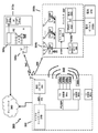
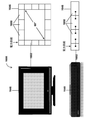
[0100] 図1は、エネルギーポケット104を形成することによるワイヤレス電力伝送のためのシステム100を示す。システム100は、送信機101と、受信機103と、クライアントデバイス105と、ポケット検出器107とを備えることができる。送信機101は、受信機103によって捕捉することができる電力伝送波を含む電力伝送信号を送信することができる。受信機103は、捕捉された波を、受信機103に関連付けられたクライアントデバイス105の代わりに電気エネルギーの使用可能なソースに変換することができるアンテナ、アンテナ素子および他の回路部(以下で詳述する)を含むことができる。いくつかの実施形態では、送信機101は、電力伝送波の位相、利得および/または他の波形特徴を操作することによって、および/または異なる送信アンテナを選択することによって、1つ以上の軌道において、電力伝送波から作成された電力伝送信号を送信することができる。そのような実施形態では、送信機101は、基礎をなす電力伝送波が空間内のある位置において収束するように電力伝送信号の軌道を操作することができ、結果として、ある特定の形の干渉が生じる。電力伝送波の収束時に生成される1つのタイプの干渉「強め合う干渉(constructive interference)」は、電力伝送波が共に合わさり、その位置に集中するエネルギーを強化させるような、電力伝送波の収束によって生じるエネルギー場とすることができる。これは、「弱め合う干渉(destructive interference)」と呼ばれる、電力伝送波が互いから減算されるように共に合わさり、その位置に集中するエネルギーを減衰させる干渉とは対照的である。強め合う干渉における十分なエネルギーの累積によって、エネルギー場または「エネルギーポケット(pocket of energy)」104を確立することができ、このエネルギーポケットは、受信機103のアンテナが電力伝送信号の周波数で動作するように構成されているとすると、これらのアンテナによって取り入れることができる。したがって、電力伝送波は、受信機103が電力伝送波を受信し、取り入れ、使用可能な電気エネルギーに変換することができる空間内の位置において、エネルギーポケット104を確立し、これによって、関連付けられた電気クライアントデバイス105に電源供給するかまたはこれらを充電することができる。検出器107は、電力伝送信号の受信に応答して通知またはアラートを生成することが可能な受信機103を備えるデバイスとすることができる。例として、ユーザーのクライアントデバイス105を充電するために受信機103の最適な配置を探索しているユーザーは、LEDライト108を備える検出器107を用いることができ、このLEDライト108は、検出器107が単一のビームまたはエネルギーポケット104からの電力伝送信号を捕捉するときに明るさを増すことができる。
I. Systems and methods for wireless power transfer A. Components of the system embodiment
[0100] FIG. 1 shows a
1.送信機
[0101] 送信機101は、デバイス105に関連付けられた受信機103に電力伝送信号を送信またはブロードキャストすることができる。後述する実施形態のうちのいくつかは、無線周波数(RF)波として電力伝送信号を記載しているが、電力伝送信号は、空間を通じて伝播されることが可能であり、かつ電気エネルギー源103に変換されることが可能な物理的媒体とすることができることが理解されるべきである。送信機101は、受信機103に向けられた単一のビームとして電力伝送信号を送信することができる。いくつかの場合、1つ以上の送信機101が、複数の方向において伝播される複数の電力伝送信号を送信することができ、物理的障害物(例えば、壁)を外れるように偏波することができる。複数の電力伝送信号が、3次元空間内の位置において収束し、エネルギーポケット104を形成することができる。エネルギーポケット104の境界内の受信機103は、電力伝送信号を捕捉し、使用可能なエネルギー源に変換することができる。送信機101は、電力伝送信号の位相および/または相対振幅調整に基づくポケット形成を制御して、強め合う干渉パターンを形成することができる。
1. 1. Transmitter
[0101] The
[0102] 例示的な実施形態は、RF波送信技法の使用を挙げているが、ワイヤレス充電技法は、RF波送信技法に限定されるべきではない。むしろ、可能なワイヤレス充電技法は、送信されたエネルギーを電力に変換する受信機にエネルギーを送信するための任意の数の代替的なまたは更なる技法を含むことができることが理解されるべきである。受信デバイスによって電力に変換することができるエネルギーのための非限定的な例示的な伝送技法は、超音波、マイクロ波、共鳴磁場および誘導磁場、レーザー光、赤外線、または他の形態の電磁エネルギーを含むことができる。超音波の場合、例えば、受信デバイスに向かって超音波を送信するトランスデューサーアレイを形成するように1つ以上のトランスデューサー素子を配置することができ、この受信デバイスは、超音波を受信し、超音波を電力に変換する。共鳴磁場および誘導磁場の場合、送信コイルにおいて磁場が生じ、受信機コイルによって電力に変換される。更に、例示的な送信機101が、潜在的に複数の送信機(送信アレイ)を含む単一のユニットとして示されているが、電力のRF送信、およびこの段落で述べられた他の電力伝送方法の双方の場合に、送信アレイは、小型の規則的構造ではなく、空間の周りに物理的に拡散した複数の送信機を含むことができる。
[0102] Although exemplary embodiments cite the use of RF wave transmission techniques, wireless charging techniques should not be limited to RF wave transmission techniques. Rather, it should be understood that possible wireless charging techniques can include any number of alternative or additional techniques for transmitting energy to a receiver that converts the transmitted energy into electric power. .. Non-limiting exemplary transmission techniques for energy that can be converted to power by the receiving device include ultrasonic, microwave, resonant and induced magnetic fields, laser light, infrared, or other forms of electromagnetic energy. Can include. In the case of ultrasonic waves, for example, one or more transducer elements can be arranged to form a transducer array that transmits the ultrasonic waves towards the receiving device, which receiving device receives the ultrasonic waves and receives the ultrasonic waves. Converts ultrasonic waves into power. In the case of a resonant magnetic field and an induced magnetic field, a magnetic field is generated in the transmitting coil and converted into power by the receiver coil. Further, the
[0103] 送信機は、アンテナが電力伝送信号を送信するために用いられるアンテナアレイを含む。各アンテナは電力伝送波を送信し、ここで、送信機は、異なるアンテナから送信された信号に異なる位相および振幅を適用する。エネルギーポケットの形成と同様に、送信機は、送信される信号の遅延したバージョンのフェーズドアレイを形成することができ、次に、信号の遅延したバージョンに異なる振幅を適用し、次に、適切なアンテナから信号を送信する。RF信号、超音波、マイクロ波等のような正弦波形の場合、信号を遅延させることは、信号に位相シフトを適用することと同様である。 [0103] The transmitter includes an antenna array in which the antenna is used to transmit a power transfer signal. Each antenna transmits a power transfer wave, where the transmitter applies different phases and amplitudes to signals transmitted from different antennas. Similar to the formation of energy pockets, the transmitter can form a phased array of delayed versions of the signal transmitted, then apply different amplitudes to the delayed version of the signal, and then the appropriate Send a signal from the antenna. For sinusoidal waveforms such as RF signals, ultrasonic waves, microwaves, etc., delaying the signal is similar to applying a phase shift to the signal.
2.エネルギーポケット
[0104] エネルギーポケット104は、送信機101によって送信された電力伝送信号の強め合う干渉パターンの位置において形成することができる。エネルギーポケット104は、エネルギーポケット104内に位置する受信機103によってエネルギーを取り入れることができる3次元場として現れることができる。ポケット形成中に送信機101によって生成されるエネルギーポケット104を、受信機103によって取り入れ、電荷に変換し、次に、受信機103(例えば、ラップトップコンピューター、スマートフォン、充電池)に関連付けられた電子クライアントデバイス105に提供することができる。いくつかの実施形態では、様々なクライアントデバイス105に電源供給する複数の送信機101および/または複数の受信機103が存在する場合がある。いくつかの実施形態では、アダプティブポケット形成は、電力レベルを調節し、および/またはデバイス105の動きを識別するために、電力伝送信号の送信を調整することができる。
2. Energy pocket
[0104] The
3.受信機
[0105] 受信機103は、関連付けられたクライアントデバイス105に電源供給するかまたはこれを充電するために用いることができる。クライアントデバイス105は、受信機103に結合または一体化された電気デバイスとすることができる。受信機103は、1つ以上の送信機101から生じた1つ以上の電力伝送信号からの電力伝送波を受信することができる。受信機103は、送信機101によって生成された単一のビームとして電力伝送信号を受信することができるか、または受信機103は、エネルギーポケット104から電力伝送波を取り入れることができる。これは、1つ以上の送信機101によって生成される複数の電力伝送波の収束の結果として生じる空間内の3次元場とすることができる。受信機103は、電力伝送信号から電力伝送波を受信し、単一のビームまたはエネルギーポケット104の電力伝送信号からエネルギーを取り入れるように構成されたアンテナ112のアレイを含むことができる。受信機103は回路部を含むことができ、この回路部は、次に、電力伝送信号(例えば、無線周波数電磁放射)のエネルギーを電気エネルギーに変換する。受信機103の整流器は、電気エネルギーをACからDCに変換することができる。他のタイプの調整も適用することができる。例えば、電圧調整回路は、クライアントデバイス105による要求に応じて、電気エネルギーの電圧を増減させることができる。次に、継電器は、受信機103からの電気エネルギーをクライアントデバイス105に伝達することができる。
3. 3. Receiving machine
[0105] The receiver 103 can be used to power or charge the associated client device 105. The client device 105 can be an electrical device coupled or integrated with the receiver 103. The receiver 103 can receive power transmission waves from one or more power transmission signals generated by one or
[0106] いくつかの実施形態では、受信機103は、データをリアルタイムでまたはほぼリアルタイムで交換するために、制御信号を送信機101に送信する通信コンポーネントを備えることができる。制御信号は、クライアントデバイス105、受信機103または電力伝送信号に関するステータス情報を含むことができる。ステータス情報は、数あるタイプの情報の中でも、例えば、デバイス105の現在の位置情報、受け取った電荷量、使用した電荷量、およびユーザーアカウント情報を含むことができる。更に、いくつかの用途では、受信機103は、受信機が収容する整流器を含めて、クライアントデバイス105に一体化することができる。実際的には、受信機103、配線111およびクライアントデバイス105は、単一のパッケージ内に含まれる単一のユニットとすることができる。
[0106] In some embodiments, the receiver 103 may include a communication component that transmits a control signal to the
4.制御信号
[0107] いくつかの実施形態では、制御信号は、電力伝送信号の生成および/またはポケット形成の制御を担う様々なアンテナ素子によって用いられるデータ入力としての役割を果たすことができる。制御信号は、外部電源(図示せず)および局部発振器チップ(図示せず)を用いて受信機103または送信機101によって生成することができ、これはいくつかの場合、圧電材料を用いることを含むことができる。制御信号は、Bluetooth(登録商標)、RFID、赤外線、近距離通信(NFC)等のプロセッサ間でデータを通信することが可能なRF波または任意の他の通信媒体もしくはプロトコルとすることができる。後に詳述するように、制御信号は、送信機101と受信機103との間で、電力伝送信号を調整するのに用いられる情報を伝達するのに用いることができ、また、ステータス、効率性、ユーザーデータ、電力消費、課金、ジオロケーションに関する情報、および他のタイプの情報を含むことができる。
4. Control signal
[0107] In some embodiments, the control signal can serve as a data input used by various antenna elements responsible for controlling the generation and / or pocket formation of the power transfer signal. The control signal can be generated by the receiver 103 or
5.検出器
[0108] 検出器107は、検出器107が1つ以上の送信機101から生じた電力伝送信号を受信することを可能にすることができる、受信機103に類似のハードウェアを含むことができる。ユーザーによって検出器107を用いてエネルギーポケット104の位置を特定することができ、それによって、ユーザーは、受信機103の好ましい配置を決定することができる。いくつかの実施形態では、検出器107は、検出器がエネルギーポケット104内に配置されたときを示すインジケーターライト108を備えることができる。例として、図1において、検出器107a、107bは、送信機101によって生成されたエネルギーポケット104内に位置し、これによって、検出器107a、107bがエネルギーポケット104の電力伝送信号を受信していることに起因して、それぞれのインジケーターライト108、108bをオンにするように検出器107a、107bをトリガーすることができるのに対し、エネルギーポケット104の外側に位置する第3の検出器107cのインジケーターライト108cは、第3の検出器107cが送信機101からの電力伝送信号を受信していないことに起因してオフにされる。代替的な実施形態において、インジケーターライト等の検出器の機能も、受信機またはクライアントデバイスに一体化されてもよいことが理解されるべきである。
5. Detector
[0108] The detector 107 can include hardware similar to the receiver 103, which can allow the detector 107 to receive power transfer signals generated from one or
6.クライアントデバイス
[0109] クライアントデバイス105は、連続電気エネルギーを必要とするかまたは電池からの電力を必要とする任意の電気デバイスとすることができる。クライアントデバイス105の非限定的な例は、数あるタイプの電気デバイスの中でも、ラップトップ、携帯電話、スマートフォン、タブレット、音楽プレーヤー、玩具、電池、フラッシュライト、ランプ、電子時計、カメラ、ゲームコンソール、機器、GPSデバイス、および装着可能なデバイスまたはいわゆる「ウェアラブル」(例えば、フィットネスブレスレット、歩数計、スマートウォッチ)を含むことができる。
6. Client device
[0109] The client device 105 can be any electrical device that requires continuous electrical energy or power from a battery. Non-limiting examples of client device 105 include laptops, mobile phones, smartphones, tablets, music players, toys, batteries, flash lights, lamps, electronic watches, cameras, game consoles, among other types of electrical devices. Devices, GPS devices, and wearable devices or so-called "wearables" (eg, fitness bracelets, pedometers, smartwatches) can be included.
[0110] いくつかの実施形態では、クライアントデバイス105aは、クライアントデバイス105aに関連付けられた受信機103aと別個の物理デバイスとすることができる。そのような実施形態では、クライアントデバイス105aは、変換された電気エネルギーを受信機103aからクライアントデバイス105aに伝達する配線111を介して受信機に接続することができる。いくつかの場合、電力消費ステータス、電力使用メトリック、デバイス識別子および他のタイプのデータ等の他のタイプのデータを、配線111を介してトランスポートすることができる。
[0110] In some embodiments, the
[0111] いくつかの実施形態では、クライアントデバイス105bは、受信機103bに恒久的に一体化するかまたは取り外し可能に結合し、それによって単一の一体化された製品またはユニットを形成することができる。例として、クライアントデバイス105bは、組込み受信機103aを有し、デバイス105bの電源入力に取り外し可能に結合することができるスリーブ内に配置することができる。この電源入力は、通常、デバイス105bの電池を充電するのに用いることができる。この例において、デバイス105bは、受信機から分離することができるが、デバイス105bが電荷を必要としているか否かまたはデバイス105bが用いられているか否かに関わらず、スリーブ内に留まることができる。別の例では、デバイス105bのための電荷を保持する電池を有する代わりに、デバイス105bは、明瞭に区別されない(indistinct)製品、デバイスまたはユニットを形成するようにデバイス105bに恒久的に一体化することができる、一体化された受信機105bを備えることができる。この例において、デバイス105bは、エネルギーポケット104を取り入れることによって電気エネルギーを生成するために、一体化された受信機103bにほぼ全面的に依拠することができる。当業者には、受信機103とクライアントデバイス105との間の接続を有線111とすることができるか、または回路基板もしくは集積回路上の電気接続とすることができるか、または更には、誘導もしくは磁気等のワイヤレス接続とすることができることが明らかであるべきである。
[0111] In some embodiments, the
B.ワイヤレス電力伝送の方法
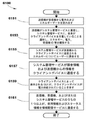
[0112] 図2は、例示的な方法200の実施形態によるワイヤレス電力伝送のステップを示す。
B. Wireless power transfer method
[0112] FIG. 2 shows the steps of wireless power transfer according to an
[0113] 第1のステップ201において、送信機(TX)は、接続を確立するかまたは他の形で受信機(RX)と連携する。すなわち、いくつかの実施形態では、送信機および受信機は、電気デバイスの2つのプロセッサ間で情報を送信することが可能なワイヤレス通信プロトコル(例えば、Bluetooth(登録商標)、Bluetooth(登録商標)低エネルギー(BLE)、Wi-Fi、NFC、ZigBee(登録商標))を用いることにより制御データを通信することができる。例えば、Bluetooth(登録商標)またはBluetooth(登録商標)の変形形態を実施する実施形態において、送信機は、受信機のブロードキャストするアドバタイズメント信号をスキャンすることができるか、または受信機はアドバタイズメント信号を送信機に送信することができる。アドバタイズメント信号は、受信機の存在を送信機に知らせることができ、送信機と受信機との間の関連付けをトリガーすることができる。本明細書に記載されるとき、いくつかの実施形態では、アドバタイズメント信号は、様々なデバイス(例えば、送信機、クライアントデバイス、サーバーコンピューター、他の受信機)によって、ポケット形成手順を実行および管理するのに用いることができる情報を通信することができる。アドバタイズメント信号内に含まれる情報は、デバイス識別子(例えば、MACアドレス、IPアドレス、UUID)、受信した電気エネルギーの電圧、クライアントデバイス電力消費、および電力伝送に関連する他のタイプのデータを含むことができる。送信機は、送信されたアドバタイズメント信号を使用して受信機を特定することができ、いくつかの場合、2次元空間内または3次元空間内で受信機を位置特定することができる。送信機が受信機を特定すると、送信機は、送信機において受信機と関連付けられた接続を確立し、送信機および受信機が第2のチャネルを介して信号を通信することを可能にすることができる。 [0113] In the first step 201, the transmitter (TX) establishes a connection or otherwise cooperates with the receiver (RX). That is, in some embodiments, the transmitter and receiver are capable of transmitting information between two processors of an electrical device, such as a wireless communication protocol (eg, Bluetooth®, Bluetooth® low). Control data can be communicated by using energy (BLE), Wi-Fi, NFC, ZigBee®). For example, in an embodiment that implements a Bluetooth® or a variant of Bluetooth®, the transmitter can scan the advertisement signal broadcast by the receiver, or the receiver can scan the advertisement signal. Can be sent to the transmitter. The advertisement signal can inform the transmitter of the presence of the receiver and can trigger the association between the transmitter and the receiver. As described herein, in some embodiments, the advertisement signal performs and manages the pocket formation procedure by various devices (eg, transmitters, client devices, server computers, other receivers). Information that can be used to do so can be communicated. The information contained within the advertisement signal should include device identifiers (eg, MAC address, IP address, UUID), voltage of received electrical energy, client device power consumption, and other types of data related to power transmission. Can be done. The transmitter can identify the receiver using the transmitted advertisement signal, and in some cases can locate the receiver in two-dimensional or three-dimensional space. When the transmitter identifies the receiver, the transmitter establishes a connection associated with the receiver at the transmitter, allowing the transmitter and receiver to communicate signals over a second channel. Can be done.
[0114] 次のステップ203において、送信機は、アドバタイズメント信号を用いて、電力伝送信号を送信するための1組の電力伝送信号特徴を決定し、次にエネルギーポケットを確立することができる。電力伝送信号の特徴の非限定的な例は、数ある中でも、位相、利得、振幅、大きさおよび方向を含むことができる。送信機は、受信機のアドバタイズメント信号または受信機から受信される後続の制御信号に含まれる情報を用いて、受信機が電力伝送信号を受信することができるように電力伝送信号をどのように生成および送信するかを決定することができる。いくつかの場合、送信機は、エネルギーポケットを確立するように電力伝送信号を送信することができ、このエネルギーポケットから受信機は電力エネルギーを取り入れることができる。いくつかの実施形態では、送信機は、電力伝送信号から受信機によって取り入れられる電気エネルギーの電圧等の、受信機から受信される情報に基づいて、エネルギーポケットを確立するのに必要とされる電力伝送信号特徴を自動的に特定することが可能なソフトウェアモジュールを実行するプロセッサを含むことができる。プロセッサおよびソフトウェアモジュールの機能は、特定用途向け集積回路(ASIC)においても実施することができることを理解するべきである。 [0114] In the next step 203, the transmitter can use the advertisement signal to determine a set of power transfer signal features for transmitting the power transfer signal and then establish an energy pocket. Non-limiting examples of features of power transfer signals can include, among others, phase, gain, amplitude, magnitude and direction. How the transmitter uses the information contained in the receiver's advertisement signal or subsequent control signals received from the receiver to allow the receiver to receive the power transmission signal. You can decide whether to generate and send. In some cases, the transmitter can transmit a power transmission signal to establish an energy pocket, from which the receiver can take in power energy. In some embodiments, the transmitter is the power required to establish an energy pocket based on information received from the receiver, such as the voltage of electrical energy taken up by the receiver from a power transmission signal. It can include processors running software modules that can automatically identify transmitted signal characteristics. It should be understood that the functionality of processor and software modules can also be implemented in application specific integrated circuits (ASICs).
[0115] 更にまたは代替的に、いくつかの実施形態では、第2の通信チャネルを介して受信機によって送信されるアドバタイズメント信号または後続の信号は、1つ以上の電力伝送信号特徴を示すことができ、次に、送信機がこれらの1つ以上の電力伝送信号特徴を用いて、電力伝送信号を生成および送信し、エネルギーポケットを確立することができる。例えば、いくつかの場合、送信機は、デバイスの位置およびデバイスまたは受信機のタイプに基づいて電力伝送信号を送信するのに必要な位相および利得を自動的に特定することができ、いくつかの場合、受信機は、送信機に、電力伝送信号を効果的に送信するための位相および利得を通知することができる。 [0115] Further or alternative, in some embodiments, the advertisement signal or subsequent signal transmitted by the receiver over the second communication channel exhibits one or more power transmission signal characteristics. The transmitter can then use one or more of these power transmission signal features to generate and transmit power transmission signals to establish an energy pocket. For example, in some cases, the transmitter can automatically determine the phase and gain required to transmit a power transmission signal based on the location of the device and the type of device or receiver, and in some cases. If so, the receiver can notify the transmitter of the phase and gain for effectively transmitting the power transmission signal.
[0116] 次のステップ205において、送信機は、電力伝送信号を送信するときに使用するのに適切な特徴を決定した後、制御信号と別個のチャネルを介して電力伝送信号の送信を開始することができる。電力伝送信号を送信して、エネルギーポケットを確立することができる。送信機のアンテナ素子は、電力伝送信号が受信機の周りの2次元空間または3次元空間において収束するように電力伝送信号を送信することができる。受信機の周りに結果として得られる場は、受信機が電気エネルギーを取り入れることができるエネルギーポケットを形成する。1つのアンテナ素子を用いて、電力伝送信号を送信し、2次元エネルギー伝送を確立することができ、いくつかの場合、第2のまたは追加のアンテナ素子を用いて、3次元エネルギーポケットを確立するために電力伝送信号を送信することができる。いくつかの場合、複数のアンテナ素子を用いて、エネルギーポケットを確立するために電力伝送信号を送信することができ、いくつかの場合、複数のアンテナは、送信機における全てのアンテナを含んでもよく、いくつかの場合、複数のアンテナは、送信機における1つ以上のアンテナだけを含んでもよく、全てのアンテナを含んでいなくてもよい。 [0116] In the next step 205, the transmitter initiates transmission of the power transfer signal via a channel separate from the control signal after determining suitable features to use when transmitting the power transfer signal. be able to. A power transfer signal can be transmitted to establish an energy pocket. The antenna element of the transmitter can transmit the power transfer signal so that the power transfer signal converges in the two-dimensional space or the three-dimensional space around the receiver. The resulting field around the receiver forms an energy pocket through which the receiver can take in electrical energy. One antenna element can be used to transmit power transmission signals to establish two-dimensional energy transmission, and in some cases a second or additional antenna element can be used to establish a three-dimensional energy pocket. Therefore, a power transmission signal can be transmitted. In some cases, multiple antenna elements can be used to transmit power transmission signals to establish an energy pocket, and in some cases, multiple antennas may include all antennas in the transmitter. In some cases, the plurality of antennas may include only one or more antennas in the transmitter and may not include all antennas.
[0117] 上述したように、送信機は、電力伝送信号特徴の決定された組に従って、電力伝送信号を生成および送信することができる。この組は、外部電源、および圧電材料を含む局部発振器チップを用いて生成および送信することができる。送信機は、受信機から受信した電力伝送およびポケット形成に関連する情報に基づいて電力伝送信号の生成および送信を制御するRFICを含むことができる。この制御データは、BLE、NFCまたはZigBee(登録商標)等のワイヤレス通信プロトコルを用いて、電力伝送信号と異なるチャネルを介して通信することができる。送信機のRFICは、必要に応じて、電力伝送信号の位相および/または相対的大きさを自動的に調整することができる。ポケット形成は、強め合う干渉パターンを形成するように電力伝送信号を送信する送信機によって達成される。 [0117] As described above, the transmitter can generate and transmit a power transfer signal according to a determined set of power transfer signal features. This set can be generated and transmitted using an external power source and a local oscillator chip containing piezoelectric material. The transmitter can include RFICs that control the generation and transmission of power transmission signals based on information related to power transfer and pocket formation received from the receiver. This control data can be communicated via a different channel than the power transfer signal using a wireless communication protocol such as BLE, NFC or ZigBee®. The RFIC of the transmitter can automatically adjust the phase and / or relative magnitude of the power transfer signal, if desired. Pocket formation is achieved by transmitters that transmit power transfer signals to form intensifying interference patterns.
[0118] 送信機のアンテナ素子は、ポケット形成中に電力伝送信号を送信するときに、波干渉の概念を用いて、ある特定の電力伝送信号特徴(例えば、送信方向、電力伝送信号波の位相)を決定することができる。アンテナ素子は、強め合う干渉の概念を用いてエネルギーポケットを生成することもできるが、弱め合う干渉の概念を利用して特定の物理的位置における送信ヌルを生成することもできる。 [0118] The antenna element of the transmitter uses the concept of wave interference when transmitting a power transfer signal during pocket formation to a particular power transfer signal feature (eg, transmission direction, phase of the power transfer signal wave). ) Can be determined. Antenna elements can use the concept of intensifying interference to generate energy pockets, but they can also use the concept of intensifying interference to generate transmit nulls at specific physical locations.
[0119] いくつかの実施形態では、ポケット形成を用いて複数の受信機に電力を提供することができ、これには送信機が複数のポケット形成のための手順を実行することが必要となる場合がある。複数のアンテナ素子を備える送信機は、それぞれの受信機に電力伝送信号を送信する任務を課せられた送信機のアンテナ素子ごとに、伝送信号波の位相および利得を自動的に形成することによって、複数ポケット形成を達成することができる。送信機のアンテナ素子によって、電力伝送信号を受信機のそれぞれのアンテナ素子に送信するための、電力伝送信号ごとの複数の波経路を生成することができるので、送信機は、位相および利得を独立して計算することができる。 [0119] In some embodiments, pocket formation can be used to power multiple receivers, which requires the transmitter to perform steps for multiple pocket formation. In some cases. A transmitter with a plurality of antenna elements automatically forms the phase and gain of the transmitted signal wave for each antenna element of the transmitter, which is tasked with transmitting a power transmission signal to each receiver. Multiple pocket formation can be achieved. The transmitter antenna element can generate multiple wave paths for each power transmission signal to transmit the power transmission signal to each antenna element of the receiver, so that the transmitter is phase and gain independent. Can be calculated.
[0120] 2つの信号を送信する送信機の2つのアンテナ素子について位相/利得調整を計算する例として、XおよびYを仮定する。ここで、YはXを180°位相シフトしたものである(Y=−X)。累積受信波形がX−Yである物理的位置において、受信機はX−Y=X+X=2Xを受信するのに対し、累積受信波形がX+Yである物理的位置において、受信機はX+Y=X−X=0を受信する。 [0120] As an example of calculating the phase / gain adjustment for two antenna elements of a transmitter transmitting two signals, X and Y are assumed. Here, Y is a phase shift of X by 180 ° (Y = −X). At the physical position where the cumulative reception waveform is XY, the receiver receives XY = X + X = 2X, whereas at the physical position where the cumulative reception waveform is XY, the receiver receives X + Y = X-. Receives X = 0.
[0121] 次のステップ207において、受信機は、単一のビームまたはエネルギーポケットの電力伝送信号から電気エネルギーを取り入れるかまたは他の形で受信することができる。受信機は、整流器およびAC/DC変換器を備えることができ、整流器およびAC/DC変換器は、電気エネルギーをAC電流からDC電流に変換することができ、次に、受信機の整流器は、電力エネルギーを整流し、結果として、ラップトップコンピューター、スマートフォン、電池、玩具または他の電気デバイス等の受信機に関連付けられたクライアントデバイスのための使用可能な電気エネルギーを得ることができる。受信機は、ポケット形成中に送信機によって生成されたエネルギーポケットを利用して、電子デバイスに充電するかまたは他の形で電力供給することができる。 [0121] In the next step 207, the receiver can take in or otherwise receive electrical energy from a power transfer signal in a single beam or energy pocket. The receiver can be equipped with a rectifier and an AC / DC converter, the rectifier and the AC / DC converter can convert electrical energy from AC current to DC current, and then the receiver rectifier Electric energy can be rectified, resulting in available electrical energy for client devices associated with receivers such as laptop computers, smartphones, batteries, toys or other electrical devices. The receiver can utilize the energy pockets generated by the transmitter during pocket formation to charge or otherwise power the electronic device.
[0122] 次のステップ209において、受信機は、受信機電力伝送信号を提供する単一のビームまたはエネルギーポケットの効率性を示す情報を含む制御データを生成することができる。次に、受信機は、制御データを含む制御信号を送信機に送信することができる。制御信号は、送信機および受信機が同期して通信している(すなわち、送信機が受信機からの制御データを受信することを予期している)か否かに依拠して、断続的に送信することができる。更に、送信機は、送信機および受信機が制御信号を通信しているか否かに関わらず、電力伝送信号を受信機に連続的に送信することができる。制御データは、電力伝送信号を送信し、および/または効果的なエネルギーポケットを確立することに関する情報を含むことができる。制御データにおける情報のうちのいくつかは、送信機に、電力伝送信号の特徴をどのように効果的に生成および送信し、いくつかの場合には調整するかを通知することができる。制御信号は、BLE、NFC、Wi−Fi等の電力伝送信号および/またはポケット形成に関連する制御データを送信することが可能なワイヤレスプロトコルを用いて、電力伝送信号と独立して、第2のチャネルを介して送信および受信することができる。 [0122] In the next step 209, the receiver can generate control data that includes information indicating the efficiency of a single beam or energy pocket that provides the receiver power transfer signal. The receiver can then transmit a control signal, including control data, to the transmitter. The control signal is intermittent, depending on whether the transmitter and receiver are communicating synchronously (ie, the transmitter expects to receive control data from the receiver). Can be sent. Further, the transmitter can continuously transmit the power transmission signal to the receiver regardless of whether the transmitter and the receiver are communicating the control signal. Control data can include information about transmitting power transfer signals and / or establishing effective energy pockets. Some of the information in the control data can inform the transmitter how to effectively generate and transmit the characteristics of the power transfer signal and, in some cases, adjust it. The control signal is a second, independent of the power transmission signal, using a wireless protocol capable of transmitting power transmission signals such as BLE, NFC, Wi-Fi and / or control data related to pocket formation. It can be transmitted and received over the channel.
[0123] 上述したように、制御データは、単一のビームの電力伝送信号の効果を示すかまたはエネルギーポケットを確立する情報を含むことができる。制御データは、受信機に関連付けられた受信機および/またはクライアントデバイスの様々な態様を監視する受信機のプロセッサによって生成することができる。制御データは、電力伝送信号および/またはポケット形成を調整するのに有用な数あるタイプの情報の中でも、電力伝送信号から受信した電気エネルギーの電圧、電力伝送信号受信の品質、充電の品質または電力受信の品質、および受信機の位置または動き等の様々なタイプの情報に基づくことができる。 [0123] As mentioned above, the control data can include information that indicates the effect of a single beam power transfer signal or establishes an energy pocket. Control data can be generated by the receiver's processor that monitors various aspects of the receiver and / or client device associated with the receiver. Control data is, among other types of information useful for coordinating power transmission signals and / or pocket formation, the voltage of electrical energy received from power transmission signals, the quality of power transmission signal reception, the quality of charging or power. It can be based on various types of information such as reception quality and receiver position or movement.
[0124] いくつかの実施形態では、受信機は、送信機から送信された電力伝送信号から受信した電力量を決定することができ、次に、送信機が電力伝送信号をより強力でない電力伝送信号に「分割」するかまたは分けるべきであることを示すことができる。より強力でない電力伝送信号は、デバイスの近傍の物体または壁から跳ね返ることができ、それによって、送信機から受信機に直接送信される電力量が低減する。 [0124] In some embodiments, the receiver can determine the amount of power received from the power transfer signal transmitted from the transmitter, and then the transmitter transmits the power transfer signal to less powerful power transfer. It can indicate that the signal is "split" or should be split. Less powerful power transfer signals can bounce off objects or walls near the device, thereby reducing the amount of power transmitted directly from the transmitter to the receiver.
[0125] 次のステップ211において、送信機は、電力伝送信号を送信するアンテナを較正することができ、それによって、アンテナは、より効果的な特徴組(例えば、方向、位相、利得、振幅)を有する電力伝送信号を送信する。いくつかの実施形態では、送信機のプロセッサは、受信機から受信した制御信号に基づいて、電力伝送信号を生成および送信するための、より効果的な特徴を自動的に決定することができる。制御信号は制御データを含むことができ、任意の数のワイヤレス通信プロトコル(例えば、BLE、Wi-Fi、ZigBee(登録商標))を用いて受信機によって送信することができる。制御データは、電力伝送波のためのより効果的な特徴を明示的に示す情報を含むことができるか、または送信機は、制御信号の波形特徴(例えば、形状、周波数、振幅)に基づいて、より効果的な特徴を自動的に決定することができる。次に、送信機は、新たに決定されたより効果的な特徴に従って、再較正された電力伝送信号を送信するようにアンテナを自動的に再構成することができる。例えば、送信機のプロセッサは、数ある電力伝送特徴のうちの特徴の中でも、電力伝送信号の利得および/または位相を調整し、ユーザーが、エネルギーポケットが確立された3次元空間の外側に受信機を動かした後に、受信機の位置の変化について調整することができる。 [0125] In the next step 211, the transmitter can calibrate the antenna that transmits the power transfer signal, whereby the antenna has a more effective feature set (eg, direction, phase, gain, amplitude). Transmits a power transfer signal with. In some embodiments, the transmitter processor can automatically determine more effective features for generating and transmitting a power transfer signal based on the control signal received from the receiver. The control signal can include control data and can be transmitted by the receiver using any number of wireless communication protocols (eg, BLE, Wi-Fi, ZigBee®). The control data can include information that explicitly indicates more effective features for the power transfer wave, or the transmitter is based on the waveform features of the control signal (eg, shape, frequency, amplitude). , More effective features can be determined automatically. The transmitter can then automatically reconfigure the antenna to transmit the recalibrated power transfer signal according to the newly determined more effective features. For example, the transmitter processor adjusts the gain and / or phase of the power transmission signal, among other features, to allow the user to move the receiver out of the three-dimensional space where the energy pocket is established. After moving, you can adjust for changes in the position of the receiver.
C.電力伝送システムのシステムアーキテクチャ
[0126] 例示的な実施形態によれば、図3は、ポケット形成を用いたワイヤレス電力伝送のためのアーキテクチャ300を示す。「ポケット形成」は、3次元空間内の位置において収束する2つ以上の電力伝送波342を生成し、結果としてその位置に強め合う干渉パターンを生成することを指すことができる。送信機302は、3次元空間において収束することができる制御された電力伝送波342(例えば、マイクロ波、電波、超音波)を送信および/またはブロードキャストすることができる。これらの電力伝送波342は、位相および/または相対的振幅調整を通じて、エネルギーポケットが意図される位置において強め合う干渉パターン(ポケット形成)を形成するように制御することができる。送信機は、同じ原理を用いて、ある位置における弱め合う干渉を生じさせ、それによって、送信ヌル、すなわち、送信された電力伝送波が互いに実質的に相殺し、大きなエネルギーを受信機によって収集することができない位置を生じさせることができることも理解されるべきである。通常の使用事例では、受信機の位置における電力伝送信号の照準合わせが目的であり、他の事例では、特定の位置への電力伝送を特に回避することが望ましい場合があり、他の事例では、電力伝送をある位置に照準合わせする一方で、同時に、第2の位置への送信を特に回避することが望ましい場合がある。電力伝送のためにアンテナを較正するとき、送信機は使用事例を考慮に入れる。
C. System architecture of power transmission system
[0126] According to an exemplary embodiment, FIG. 3 shows an
[0127] 送信機302のアンテナ素子306は、単一のアレイ、対のアレイ、4つ組のアレイ、または所望の用途に従って設計することができる任意の他の適切な構成で動作することができる。エネルギーポケットは、電力伝送波342が、3次元エネルギー場を形成するように蓄積する強め合う干渉パターンにおいて形成することができ、その周りに、弱め合う干渉パターンによって特定の物理的位置における1つ以上の対応する送信ヌルを生成することができる。特定の物理的位置における送信ヌルは、電力伝送波342の弱め合う干渉パターンに起因してエネルギーポケットが形成されない空間のエリアまたは領域を指すことができる。
The antenna element 306 of the
[0128] 次に、受信機320は、送信機302によって放射される電力伝送波342を利用して、電子デバイス313に充電または電力供給し、これによりワイヤレス電力伝送を効果的に提供するためのエネルギーポケットを確立することができる。エネルギーポケットは、エネルギーまたは電力が、電力伝送波342の強め合う干渉パターンの形態で蓄積することができる空間のエリアまたは領域を指すことができる。他の状況では、様々な電子機器、例えば、スマートフォン、タブレット、音楽プレーヤー、玩具等に同時に電力供給するための複数の送信機302および/または複数の受信機320が存在することができる。他の実施形態では、アダプティブポケット形成を用いて、電子デバイスに対する電力を調節することができる。アダプティブポケット形成は、1つ以上の標的とされる受信機に対する電力を調節するようにポケット形成を動的に調整することを指すことができる。
[0128] The receiver 320 then utilizes the
[0129] 受信機320は、送信機302に対する受信機320の位置を示すために、アンテナ素子324を通じて短い信号を生成することによって送信機302と通信することができる。いくつかの実施形態では、受信機320は、ネットワークインターフェースカード(図示せず)または同様のコンピューターネットワーキングコンポーネントを更に利用してネットワーク340を通じて、送信機302のいくつかの集合体を管理するクラウドコンピューティングサービス等の、システム300の他のデバイスまたはコンポーネントと通信することができる。受信機320は、アンテナ素子324によって捕捉された電力伝送信号342を、電気デバイス313および/またはデバイスの電池315に提供することができる電気エネルギーに変換するための回路部308を備えることができる。いくつかの実施形態では、回路部は、受信機の電池335に電気エネルギーを提供することができ、受信機の電池335は、電気デバイス313が受信機320に通信可能に結合されることなくエネルギーを蓄えることができる。
[0129] The receiver 320 can communicate with the
[0130] 通信コンポーネント324は、受信機320が、ワイヤレスプロトコルを介して制御信号345を送信することによって送信機302と通信することを可能にすることができる。ワイヤレスプロトコルは、専用プロトコルとすることもできるし、Bluetooth(登録商標)、BLE、Wi−Fi、NFC、ZigBee(登録商標)等の従来のワイヤレスプロトコルを用いることもできる。次に、通信コンポーネント324を用いて、電子デバイス313のための識別子等の情報、ならびに電池レベル情報、地理的位置データ、または電力をいつ受信機320に送信するか、および電力伝送波342を送達してエネルギーポケットを生じさせる位置を決定する際に送信機302に有用とすることができる他の情報を転送することができる。他の実施形態では、アダプティブポケット形成を用いて、電子デバイス313に提供される電力を調節することができる。そのような実施形態において、受信機の通信コンポーネント324は、受信機320において受信される電力量、および/または電子デバイス313bもしくは電池315に提供される電圧量を示す電圧データを送信することができる。
The communication component 324 can allow the receiver 320 to communicate with the
[0131] 送信機302が受信機320を識別し、位置特定すると、制御信号345のためのチャネルまたは経路を確立することができ、このチャネルまたは経路を通じて、送信機302は、受信機320から到来する制御信号345の利得および位相を知ることができる。送信機302のアンテナ素子306は、制御された電力伝送波342(例えば、無線周波数波、超音波)の送信またはブロードキャストを開始することができ、制御された電力伝送波342は、少なくとも2つのアンテナ素子306を用いて、それぞれのアンテナ素子306から放射された電力伝送波342を操作することによって、3次元空間において収束することができる。これらの電力伝送波342は、適切な圧電材料を用いて外部電源および局部発振器チップを用いることによって生成することができる。電力伝送波342は、送信機回路部301によって制御することができ、送信機回路部301は、電力伝送波342の位相および/または相対的な大きさを調整するための専用チップを含むことができる。電力伝送波342の位相、利得、振幅および他の波形は、アンテナ素子306が強め合う干渉パターンを形成する(ポケット形成)ための入力としての役割を果たすことができる。いくつかの実施態様では、送信機302のマイクロコントローラー310または他の回路は電力伝送信号を生成することができ、電力伝送信号は電力伝送波342を含み、送信機回路部301に接続されたアンテナ素子306の数に依拠して、送信機回路部301によって複数の出力に分割することができる。例えば、4つのアンテナ素子306a〜306dが1つの送信機回路301aに接続されている場合、電力伝送信号は、4つの異なる出力に分割され、各出力は、アンテナ素子306に向かい、それぞれのアンテナ素子306から生じる電力伝送波342として送信される。
[0131] Once the
[0132] ポケット形成は、干渉を利用して、アンテナ素子306の指向性を変更することができる。ここで、強め合う干渉はエネルギーポケットを生成し、弱め合う干渉は送信ヌルを生成する。次に、受信機320は、電子デバイスを充電し、電子デバイスに電源供給するためのポケット形成によって生成されるエネルギーポケットを利用し、それによってワイヤレス電力伝送を効果的に提供することができる。 [0132] Pocket formation can utilize interference to change the directivity of antenna element 306. Here, strengthening interference creates an energy pocket, and weakening interference creates a transmit null. The receiver 320 can then utilize the energy pockets generated by the pocket formation to charge the electronic device and power the electronic device, thereby effectively providing wireless power transfer.
[0133] 送信機302の各アンテナ306から各受信機320への位相および利得を計算することによって、複数のポケット形成を達成することができる。
Multiple pocket formations can be achieved by calculating the phase and gain from each antenna 306 of
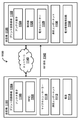
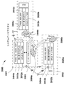
[0134] 図35は、例示的な実施形態による、ワイヤレス充電システムアーキテクチャ3500を示す。システムアーキテクチャ3500は、1つ以上のワイヤレス電力送信機3501と、1つ以上のワイヤレス電力受信機3520a、3530bとを備えることができる。いくつかの実施形態では、ワイヤレス充電システムアーキテクチャ3500は、1つ以上の電子デバイス3552を含むことができ、電子デバイス3552は、内蔵ワイヤレス電力受信機3520aを有していない場合がある。他の実施形態では、ワイヤレス充電システムアーキテクチャ3500は、内蔵電力受信機3520aを有する電子デバイス3552を備えることができる。ペアリングとは、ワイヤレス電力伝送システムの分散型システムデータベース内における、単一の電力受信機との単一の電子クライアントデバイスの関連付けを指すことができ、それによって、例えば、ユーザー、または自動システムプロセスが、クライアントデバイスが充電されるように命令する場合、システムは、この関連付けから、このクライアントデバイスを充電するためにいずれの電力受信機に電力を伝送するかを決定することができる。システムデータベースは、インストールされた製品のシステムデータベースの厳密なコピー、または任意のシステムコンピューター内に記憶され、任意のシステムコンピューターによってアクセス可能な、このデータベースのサブセットの厳密なコピーを指すことができる。
[0134] FIG. 35 shows a wireless
[0135] 電力送信機3501は、3D空間において収束することができる制御された無線周波数(RF)波を送信することができる。これらのRF波は、位相および/または相対的な振幅の調整を通じて、強め合う干渉パターンを形成する(ポケット形成)ように制御することができる。ポケット形成は、3D空間において収束し、制御された強め合う干渉パターンを形成する2つ以上のRF波を生成することを指すことができる。エネルギーポケットは、3次元形状をとることができる強め合う干渉パターンにおいて形成されることができるのに対し、特定の物理位置における送信ヌルは、弱め合う干渉パターンにおいて生成することができる。エネルギーポケットとは、RF波の強め合う干渉パターンの形態でエネルギーまたは電力が蓄積することができる空間のエリアまたは領域を指すことができる。特定の物理的位置における送信ヌルとは、RF波の弱め合う干渉パターンに起因してエネルギーポケットが形成されない空間のエリアまたは領域を指すことができる。アダプティブポケット形成とは、1つ以上の標的受信機に対する電力を調節するようにポケット形成を動的に調整することを指すことができる。電力とは、電気エネルギーを指すことができ、ここで、「ワイヤレス電力伝送」は、「ワイヤレスエネルギー送信」の同義語とすることができ、「ワイヤレス電力伝送」は、「ワイヤレスエネルギー送信」の同義語とすることができる。
[0135] The
[0136] 例示的な実施形態によれば、電力送信機3501は、数あるコンポーネントの中でも、電力送信機マネージャーアプリケーション3594aと、第三者BTLE API3512aと、BTLEチップ3512bと、アンテナマネージャーソフトウェア3593と、アンテナアレイ3586aとを備えることができる。電力送信機マネージャーアプリケーション3594aは、電力送信機3501内の不揮発性メモリにロードされた実行可能プログラムとすることができる。電力送信機マネージャーアプリケーション3594aは、数ある中でも、電力送信機3501の挙動を制御し、電子デバイス3552および電力受信機3520aの電荷の状態を監視することができ、電力受信機3520aの位置を追跡することができ、電力スケジュールを実行することができる。いくつかの実施形態では、電力送信機3501は、電力受信機3520a、電子デバイス3552、電力ステータス、電力スケジュール、ID、ペアリングに関係する情報、およびシステムを実行するのに必要な任意の情報を記憶するためのデータベース(図示せず)を含むことができる。BTLEまたはBLEとは、Bluetooth(登録商標)低エネルギー通信ハードウェアおよび/またはソフトウェアを指すことができる。データベースは、SQLファイル、または異なるフォーマットもしくは任意のフォーマットのファイル、またはコンピューターの揮発性もしくは不揮発性メモリ内のデータ構造のアレイとすることができるが、データベースのコンピューター内のデータを編成し、記憶し、取り出すために用いられるものを除く。第三者BTLE API3512aは、電力送信機マネージャーアプリケーション3594aとBTLEチップ3512bとの間の効果的な対話を可能にすることができる。アンテナマネージャーソフトウェア3593は、電力送信機マネージャーアプリケーション3594aからの命令を処理することができ、アンテナアレイ3586aを制御することができる。
[0136] According to an exemplary embodiment, the
[0137] 電力送信機3501に含めることができるアンテナアレイ3586aは、電力を伝送することが可能な複数のアンテナ素子を含むことができる。いくつかの実施形態では、アンテナアレイ3586aは、等間隔に配置されたグリッド内に分散させることができる64個〜256個のアンテナ素子を含むことができる。1つの実施形態では、アンテナアレイ3586aは、合計64個のアンテナ素子を有する8×8のグリッドを有することができる。別の実施形態では、アンテナアレイ3586aは、合計で256個のアンテナ素子を有する16×16のグリッドを有することができる。一方、アンテナ素子の数は、電力送信機3501の所望の範囲および電力伝送能力に関連して変動する場合がある。通常、より多くのアンテナ素子を用いると、より広い範囲およびより高い電力伝送能力を達成することができる。数ある中でも、円形パターンまたは多角形配置を含む代替的な構成も可能である。アンテナアレイ3586aのアンテナ素子は、900MHz、2.5GHz、5.250GHzまたは5.8Ghz等の周波数帯域において動作するためのアンテナタイプを含むことができ、アンテナ素子は、独立した周波数で動作することができ、ポケット形成のマルチチャネル動作を可能にする。
[0137] The
[0138] 電力送信機3501は、数ある中でも、Wi−Fi、ZigBee(登録商標)およびLAN等の他の通信方法を更に含むことができる。電力受信機3520aは、電力受信機アプリケーション3594bと、第三者BTLE API3512aと、BTLEチップ3512bと、アンテナアレイ3586bとを備えることができる。電力受信機3520aは、電子デバイス3552aおよび電子デバイス3520bを充電するかまたはこれらに電力供給するために、電力送信機3501によって生成されるエネルギーポケットを利用可能とすることができる。電力受信機アプリケーション3594bは、電力受信機3520a内の不揮発性メモリにロードされた実行可能命令とすることができる。第三者BTLE API3512aは、電力受信機アプリケーション3594bとBTLEチップ3512bとの間の効果的なインタラクションを可能にすることができる。アンテナアレイ3586bは、エネルギーポケットから電力を取り入れ可能とすることができる。
[0138] The
[0139] 電子デバイス3552および電子デバイス3520aは、ワイヤレス充電システムアーキテクチャ3500内のそれらのインタラクションを管理するためのGUIを含むことができる。GUIは、不揮発性メモリ内にロードされた実行可能プログラムに関連付けることができる。いくつかの実施形態では、電子デバイス3552および電子デバイス3520aは、電力受信機3520a、電力ステータス、電力スケジュール、ID、ペアリングに関係する情報、およびシステムを実行するのに必要な任意の情報を記憶するためのデータベース(図示せず)を含むことができる。システム管理GUIとは、ワイヤレス電力伝送システム内のコンピューター上で実行されるか、またはインターネットクラウド内にある場合がある遠隔サーバー上で実行されるソフトウェアアプリケーションプログラムを指すことができる。このシステム管理GUIは、システムユーザーまたはシステムオペレーターと、ワイヤレス電力伝送システム内のソフトウェアとの間のグラフィックユーザーインターフェースであり、構成、監視、命令、制御、報告、および任意の他のシステム管理機能のために用いられる。
[0139]
[0140] いくつかの実施形態では、ワイヤレス充電システムアーキテクチャ3500は、複数の電子デバイス3552を充電するための複数の電力送信機3501および/または複数の電力受信機3520aを含むことができる。複数の電力送信機3501を含むシステムにおいて、2つ以上の電力送信機が、数ある中でも、Bluetooth(登録商標)、BTLE、Wi−Fi、ZigBee(登録商標)、LAN、LTEおよびLTEダイレクトを含む、利用可能な任意の通信チャネルを用いて常時通信することができる。
[0140] In some embodiments, the wireless
[0141] 図36は、本開示の1つ以上の実施形態が動作することができるワイヤレス電力伝送システム3600(WPTS)の例示的な実施形態を示す。ワイヤレス電力伝送システム3600は、1つ以上のワイヤレス電力送信機3601と、1つ以上のワイヤレスで電力供給される受信機3620aとの間の通信、およびクライアントデバイス3620b内の通信を含むことができる。クライアントデバイス3652は、適応可能なペアリングされる受信機3620aとペアリングすることができ、これにより、クライアントデバイス3652へのワイヤレス電力伝送を可能にすることができる。別の実施形態では、クライアントデバイス3620bは、デバイスのハードウェアの一部分として内蔵されたワイヤレス電力受信機を含むことができる。クライアントデバイス3652は、ラップトップコンピューター、固定式コンピューター、モバイルフォン、タブレット、モバイルゲーム機、テレビ、ラジオ等の、エネルギー電源を用いる任意のデバイス、および/またはエネルギー電源を必要とするかもしくはエネルギー電源から利益を得ることができる任意の機器の組とすることができる。
[0141] FIG. 36 shows an exemplary embodiment of a wireless power transfer system 3600 (WPTS) in which one or more embodiments of the present disclosure can operate. The wireless
[0142] 1つの実施形態において、1つ以上のワイヤレス電力送信機3601は、組み込まれたソフトウェアとしての電力送信機マネージャーapp3694a(PWR TX MGR APP)と、Bluetooth(登録商標)低エネルギーチップ3612b(BTLE CHIP HW)のための第三者アプリケーションプログラミングインターフェース3612a(第三者API)とを一体化するマイクロプロセッサを含むことができる。Appとは、モバイル、ラップトップ、デスクトップまたはサーバーコンピューター上で実行されるソフトウェアアプリケーションを指すことができる。Bluetooth(登録商標)低エネルギーチップ3612aは、ワイヤレス電力送信機3601と、電力受信機3620a、クライアントデバイス3652および3620b等を含む他のデバイスとの間の通信を可能にすることができる。ワイヤレス電力送信機3601は、3D空間において収束し、ワイヤレスで電力供給される受信機上にエネルギーポケットを生じさせることができる制御されたRF波を形成するために用いることができるRFアンテナアレイを制御するアンテナマネージャーソフトウェア(アンテナMGRソフトウェア)も備えることができる。いくつかの実施形態では、1つ以上のBluetooth(登録商標)低エネルギーチップ3612bは、Wi−Fi、Bluetooth(登録商標)、LTEダイレクト等を含む他のワイヤレス通信プロトコルを利用してもよい。
[0142] In one embodiment, one or more
[0143] 電力送信機マネージャーapp3694aは、数ある中でも、接続の確立、接続の終了、およびデータの送信を含む複数の機能を実行するための第三者アプリケーションプログラミングインターフェース3612aを呼び出すことができる。第三者アプリケーションプログラミングインターフェース3612aは、電力送信機マネージャーapp3694aによって呼び出された機能に従って、Bluetooth(登録商標)低エネルギーチップ3612bにコマンドを発行することができる。
[0143] The power transmitter manager app3694a can call a third party
[0144] 電力送信機マネージャーapp3694aは、分散システムデータベースも含むことができる。分散システムデータベースは、クライアントデバイス3652のための識別子、電力受信機3620aのための電圧範囲、クライアントデバイス3652の位置、クライアントデバイス3652に関連付けられた信号強度および/または任意の他の関連情報等の、クライアントデバイス3652に関連付けられた関連情報を記憶することができる。データベースは、受信機ID、送信機ID、エンドユーザーハンドヘルドデバイス、システム管理サーバー、充電スケジュール、充電優先度、および/またはワイヤレス電力ネットワークに関連した任意の他のデータを含む、ワイヤレス電力ネットワークに関連する情報も記憶することができる。
[0144] The power transmitter manager ap3694a may also include a distributed system database. The distributed system database contains an identifier for the
[0145] 第三者アプリケーションプログラミングインターフェース3612aは、同時に、ブート時に電力送信機マネージャーapp3694aに登録することができるコールバック機能を通じて、電力送信機マネージャーapp3694aを呼び出すことができる。第三者アプリケーションプログラミングインターフェース3612aは、1秒間に10回行うことができるタイマーコールバックを有することができ、接続が開始する度、接続が終了する度、接続が試行される度、またはメッセージが受信される度、コールバックを送信することができる。
[0145] The third party
[0146] クライアントデバイス3620bは、電力受信機app3694b(PWR RX APP)と、Bluetooth(登録商標)低エネルギーチップ3630b(BTLE CHIP HW)のための第三者アプリケーションプログラミングインターフェース3650a(第三者API)と、ワイヤレス電力送信機3601から送信されたエネルギーポケットを受信し利用するのに用いることができるRFアンテナアレイ3686bと備えることができる。
[0146] The
[0147] 電力受信機app3694bは、数ある中でも、接続の確立、接続の終了およびデータの送信を含む複数の機能を実行するための第三者アプリケーションプログラミングインターフェース3650aを呼び出すことができる。第三者アプリケーションプログラミングインターフェース3650aは、1秒間に10回行うことができるタイマーコールバックを有することができ、接続が開始する度、接続が終了する度、接続が試行される度、またはメッセージが受信される度、コールバックを送信することができる。
[0147] The
[0148] クライアントデバイス3652は、BTLE接続3696を介して適応可能な電力受信機3620aにペアリングすることができる。グラフィカルユーザーインターフェース(GUI3698)を用いて、クライアントデバイス3652からのワイヤレス電力ネットワークを管理することができる。GUI3698は、任意のアプリケーションストアからダウンロードすることができ、数ある中でも、iOSおよびAndroidを含む任意のオペレーティングシステム上で実行することができるソフトウェアモジュールとすることができる。クライアントデバイス3652は、BTLE接続3696を介してワイヤレス電力送信機3601と通信して、デバイスのための識別子、電池レベル情報、地理的位置データ、またはワイヤレス電力送信機3601のために有用とすることができる任意の他の情報等の重要なデータを送信することもできる。
[0148] The
[0149] ワイヤレス電力伝送システム3600を管理するために、ワイヤレス電力マネージャーソフトウェアを用いることができる。ワイヤレス電力マネージャーは、メモリ内でホスティングされ、コンピューティングデバイス内でプロセッサによって実行されるソフトウェアモジュールとすることができる。ワイヤレス電力マネージャーは、ローカルアプリケーションGUIを含むかまたはウェブページGUIをホスティングすることができ、これらのGUIから、ユーザーは、オプションおよびステータスを見て、ワイヤレス電力伝送システム3600を管理するためのコマンドを実行することができる。クラウドベースとすることができるコンピューティングデバイスは、数ある中でも、Bluetooth(登録商標)、Bluetooth(登録商標)低エネルギー、Wi−FiまたはZigBee(登録商標)を含む標準的な通信プロトコルを通じてワイヤレス電力送信機3601に接続することができる。電力送信機マネージャーapp3694aは、クライアントデバイス3652によるアクセスおよびクライアントデバイス3652への電力伝送を制御するために、ワイヤレス電力マネージャーと情報を交換することができる。ワイヤレス電力マネージャーによって制御される機能は、個々のデバイスについて電力伝送をスケジューリングすること、異なるクライアントデバイス間で優先順位付けすること、クライアントごとに証明書にアクセスすること、電力送信機エリアに対する電力受信機の物理的位置を追跡すること、メッセージをブロードキャストすることと、および/またはワイヤレス電力伝送システム3600を管理するのに必要な任意の機能を含むことができる。
[0149] Wireless power manager software can be used to manage the wireless
[0150] コンピューティングデバイスは、ネットワーク接続を通じてワイヤレス電力送信機3601に接続することができる。ネットワーク接続は、数ある中でも、イントラネット、ローカルエリアネットワーク(LAN)、仮想プライベートネットワーク(VPN)、ワイヤレスエリアネットワーク(WAN)、Bluetooth(登録商標)、Bluetooth(登録商標)低エネルギー、Wi−FiおよびZigBee(登録商標)を含む、コンピューター間の任意の接続を指すことができる。電力送信機マネージャーapp3694aは、デバイスによる電力伝送へのアクセスを制御するために、ワイヤレス電力マネージャーと情報を交換することができる。ワイヤレス電力マネージャーによって制御される機能は、個々のデバイスのための電力伝送のスケジューリング、クライアントデバイスに割り当てられるアンテナ数、異なるクライアントデバイス間の優先順位、クライアントごとのアクセス証明書、物理的位置、メッセージのブロードキャスト、および/またはワイヤレス電力伝送システム3600内でコンポーネントを管理するのに必要とされる任意の機能を含むことができる。
[0150] The computing device can be connected to the
[0151] 1つ以上のワイヤレス電力送信機3601は、ワイヤレス電力送信機3601が通信を確立するのに十分近接した任意の単一ワイヤレス電力受信機に電力を自動的に送信することができる。次に、ワイヤレス電力受信機は、クライアントデバイス3652等の電気的に接続された電子デバイスに電力供給するかまたはこの電子デバイスを充電することができる。単一のワイヤレス電力送信機3601は、複数のワイヤレス電力受信機に同時に電力供給することができる。代替的に、ワイヤレス電力伝送システム3600内のコンポーネントは、ワイヤレス電力マネージャーグラフィカルユーザーインターフェースを通じて、数ある中でも、自動化された時間ベースでスケジューリングされた電力伝送の時刻、電力受信機の物理的位置、クライアントデバイスの所有者等の特定のシステム基準および/または条件に依拠して、特定のワイヤレス電力受信機にのみ電力を自動的に伝送するように構成されてもよい。
[0151] One or more
[0152] ワイヤレス電力受信機は、ワイヤレス電力送信機3601から送信されたエネルギーを、ワイヤレス電力受信機のアンテナ内に取得し、これを整流し、調整し、結果として得られた電気エネルギーを、電気的に接続されたデバイスに送信し、このデバイスに電力供給するかまたはこのデバイスを充電することができる。任意のワイヤレス電力受信機が異なる空間位置に動く場合、ワイヤレス電力送信機3601は、結果として得られるエネルギービームが受信機を標的に留めておくように、割り当てられるアンテナ数、送信されるRFの位相および振幅を変更することができる。
[0152] The wireless power receiver acquires the energy transmitted from the
[0153] 図37は、一実施形態による、ワイヤレス電力伝送システムネットワークを示す。いくつかの実施形態によれば、ワイヤレス電力伝送システムネットワーク3700は、インターネットクラウド3769を通じて遠隔情報サービス3777と通信することが可能な複数のワイヤレス電力伝送システムを含むことができる。
[0153] FIG. 37 shows a wireless power transfer system network according to one embodiment. According to some embodiments, the wireless power
[0154] いくつかの実施形態では、ワイヤレス電力伝送システムは、1つ以上のワイヤレス電力送信機3701と、1つ以上の電力受信機3720と、1つ以上のオプションのバックアップサーバー3767と、ローカルネットワーク3740とを備えることができる。いくつかの実施形態によれば、各電力送信機3701は、ワイヤレス電力送信機マネージャー3765のソフトウェアと、分散ワイヤレス電力伝送システムデータベース3763とを備えることができる。各電力送信機3701は、電力を管理し、1つ以上の電力受信機3720に電力を伝送することが可能とすることができ、ここで、各電力受信機3720は、1つ以上の電子デバイス3761を充電可能であるか、またはこれらの電子デバイスに電力を供給可能とすることができる。
[0154] In some embodiments, the wireless power transfer system comprises one or more
[0155] 電力送信機マネージャー3765は、数ある中でも、電力送信機3701の挙動を制御し、電子デバイス3761の充電状態を監視し、電力受信機3720を制御し、電力受信機3720の位置を追跡し、電力スケジュールを実行し、システムチェックアップを実行し、異なる電子デバイス3761の各々に提供されるエネルギーを追跡することができる。
[0155] The
[0156] いくつかの実施形態によれば、データベース3763は、電子デバイス3761の識別子、電力受信機3720からの測定値の電圧範囲、位置、信号強度、および/または電子デバイス3761からの任意の関連情報等の電子デバイス3761からの関連情報を記憶することができる。データベース3763は、受信機ID、送信機ID、エンドユーザーハンドヘルドデバイス名またはID、システム管理サーバーID、充電スケジュール、充電特性等のワイヤレス電力伝送システムに関連する情報、および/またはワイヤレス電力伝送システムネットワーク3700に関連する任意のデータも記憶することができる。更に、いくつかの実施形態では、データベース3763は、過去のおよび現在のシステムステータスのデータを記憶することができる。
[0156] According to some embodiments,
[0157] 過去のシステムステータスデータは、数ある中でも、電子デバイス3761に送達された電力量、ユーザーに関連付けられた電子デバイス3761のグループに転送されたエネルギー量、電子デバイス3761がワイヤレス電力送信機3701に関連付けられた時間量、ペアリング記録、システム内のアクティブティ、システム内の任意のワイヤレス電力デバイスの任意のアクションまたはイベント、エラー、障害および構成問題等の詳細を含むことができる。過去のシステムステータスデータは、電力スケジュール、名前、顧客サインイン名、権限付与および認証証明書、暗号化情報、システム動作の物理的エリア、システムを実行するための詳細、および任意の他のシステムもしくはユーザー関連情報も含むことができる。
[0157] Past system status data includes, among other things, the amount of power delivered to
[0158] データベース3763内に記憶された現在のシステムステータスデータは、数ある中でも、システム内の位置および/または動き、構成、ペアリング、エラー、障害、アラーム、問題、ワイヤレス電力デバイス間で送信されたメッセージおよび追跡情報を含むことができる。
[0158] Current system status data stored in
[0159] いくつかの例示的な実施形態によれば、電力送信機3701内のデータベース3763は、未来のシステムステータス情報を更に記憶することができ、システムの未来のステータスは、過去のシステムステータスデータからの履歴データおよび現在のシステムステータスデータに従って予測または評価することができる。
[0159] According to some exemplary embodiments, the
[0160] いくつかの実施形態では、ワイヤレス電力伝送システム内の全てのデバイスデータベース3763からの記録を、サーバー3767内に記憶し、周期的に更新することもできる。いくつかの実施形態では、ワイヤレス電力伝送システムネットワーク3700は、2つ以上のサーバー3767を含むことができる。他の実施形態では、ワイヤレス電力伝送システムネットワーク3700はサーバー3767を含まない場合がある。
[0160] In some embodiments, records from all
[0161] 別の例示的な実施形態では、ワイヤレス電力送信機3701は更に、ワイヤレス電力伝送システムにおける障害を検出可能とすることができる。電力伝送システム502における障害の例は、数ある中でも、任意のコンポーネントの過熱、機能不良、過負荷を含むことができる。システム内のワイヤレス電力送信機3701のうちのいずれかによって障害が検出される場合、障害は、システム内の任意のワイヤレス電力送信機マネージャー3765によって解析することができる。解析が完了した後、推奨またはアラートを生成し、電力伝送システムの所有者に報告するか、またはシステム所有者もしくは製造者もしくは供給者に配信するために遠隔のクラウドベースの情報サービスに報告することができる。
[0161] In another exemplary embodiment, the
[0162] いくつかの実施形態では、電力送信機3701は、情報を送受信するネットワーク3740を用いることができる。ネットワーク3740は、ローカルエリアネットワーク、またはワイヤレス電力伝送システムのコンポーネント間の任意の通信システムとすることができる。ネットワーク3740は、数ある中でも、電力送信機と、システム管理サーバー3767(存在する場合)と、他の電力伝送システム(存在する場合)との間の通信を可能にすることができる。いくつかの実施形態によれば、ネットワーク3740は、インターネットクラウド3779を通じた電力伝送システムと遠隔情報サービス3777との間のデータ通信を容易にすることができる。
[0162] In some embodiments, the
[0163] 遠隔情報サービス3777は、システムの所有者、システムの製造者もしくは供給者、またはサービスプロバイダーによって運用することができる。遠隔管理システムは、ビジネスクラウド3775と、遠隔マネージャー3773のソフトウェアと、バックエンドサーバー3769とを備えることができ、ここで、遠隔マネージャー3773は、汎用データベース3771を更に含むことができる。バックエンドサーバー3769および遠隔マネージャー3773の機能は、単一の物理的サーバーまたは仮想サーバーに組み合わせることができる。
[0163] The
[0164] 汎用データベース3771は、デバイスデータベース3763に記憶された情報の更なるバックアップを記憶することができる。更に、汎用データベース3771は、数ある中でも、マーケティング情報、顧客の課金、顧客の構成、顧客の認証、および顧客のサポート情報を記憶することができる。いくつかの実施形態では、汎用データベース3771は、数ある中でも、より人気のない特徴、システムにおけるエラー、問題報告、統計および品質制御等の情報も記憶することができる。各ワイヤレス電力送信機3701は、数ある中でも、認証、問題報告目的、またはステータスもしくは使用の詳細の報告のために遠隔マネージャー3773とのTCP通信接続を周期的に確立することができる。
[0164] The
[0165] 図38は、例示的な実施形態によるワイヤレス電力伝送システムアーキテクチャ3800を示す。ワイヤレス電力伝送システムアーキテクチャ3800は、ワイヤレス電力伝送システムと、インターネットクラウド3879と、遠隔情報サービス3883とを含むことができる。開示されるワイヤレス電力伝送システムは、1つ以上のワイヤレス電力送信機3877、任意のクライアントデバイス3861に結合または内蔵することができる1つ以上のワイヤレス電力受信機3820、1つ以上のローカルシステム管理サーバー3867またはクラウドベースの遠隔システム管理サーバー3873(例えば、バックエンドサーバー)、およびローカルネットワーク3840を含むことができる。ネットワーク3840接続は、数ある中でも、イントラネット、ローカルエリアネットワーク(LAN)、仮想プライベートネットワーク(VPN)、ワイヤレスエリアネットワーク(WAN)、およびインターネット等のコンピューター間の任意の接続を指すことができる。
[0165] FIG. 38 shows a wireless power
[0166] いくつかの実施形態によれば、各ワイヤレス電力送信機3877は、ワイヤレス電力送信機マネージャーソフトウェア3865と、分散システムデータベース3883と、TDM電力伝送3875のソフトウェアモジュールとを含むことができる。各ワイヤレス電力送信機3877は、1つ以上のワイヤレス電力受信機3820を管理可能であり、これらに電力を伝送可能とすることができ、各ワイヤレス電力受信機3820は、1つ以上のクライアントデバイス3861を充電可能であるかまたはこれらに電力を提供可能とすることができる。クライアントデバイス3861の例は、数ある中でも、スマートフォン、タブレット、音楽プレーヤーおよび玩具を含むことができる。ある種のクライアントデバイス3861は、システム管理GUIappを実行することができる。このappは、Apple iTunes、Android Play Storeおよび/またはamazon等のパブリックソフトウェアappストアまたはデジタルアプリケーション配信プラットフォームにおいて入手可能であり、ここからダウンロードおよびインストールすることができる。
[0166] According to some embodiments, each
[0167] 更なる実施形態によれば、ワイヤレス電力伝送システムは、システム管理GUIアプリケーションを、ローカルシステム管理サーバー3867またはクラウドベースの遠隔システム管理サーバー3873に含むか、またはこの管理サーバーにおいて実行するか、またはこの管理サーバーから実行することができる。このシステム管理GUIアプリケーションを用いて、数ある中でも、電力伝送スケジュール、およびクライアントデバイス3861の物理的位置等のシステム基準または動作条件に依拠して、特定のワイヤレス電力受信機3820へのワイヤレス電力の伝送を制御することができる、
[0167] According to a further embodiment, the wireless power transmission system includes the system management GUI application on the local
[0168] 各ワイヤレス電力送信機マネージャーソフトウェア3865は、ワイヤレス電力送信機3877の挙動を制御して、数ある中でも、電力伝送が開始した時点、ワイヤレス電力送信機3877およびワイヤレス電力受信機3820の双方の一意のシステム識別、接続されたデバイス数、用いられるアンテナの方向角、ワイヤレス電力受信機3820の電力受信機アンテナにおける電圧、ワイヤレス電力送信機508とワイヤレス電力受信機3820との間のリアルタイム通信接続等の異なる態様を監視可能とすることができ、これらの態様を用いて、ワイヤレス電力受信機3820がどこに位置していようとまたはどこに動かされようと、ワイヤレス電力受信機3820からの情報を追跡することができる。更に、電力送信機マネージャーソフトウェア3865は、TDM電力伝送3875の使用を制御することができ、これにより、ワイヤレス電力伝送システムをTDM電力伝送3875モードに入れることまたは入れないことが可能であり得る。特に、TDM電力伝送3875モードは、アンテナグループを再割当てすることによって、ワイヤレス電力送信機3877のアンテナアレイを制御することができ、ここで、各グループを用いて、オンラインモードにあるクライアントデバイス3861に対してのみ定期的な時間間隔で電力を伝送することができ、その間、オフラインモードにある残りのクライアントデバイス3861はワイヤレス電力送信機3877によって電源供給されるのを待機している。
[0168] Each wireless power
[0169] ワイヤレス電力送信機3877は、ワイヤレス電力送信機3877の十分近くにある全てのクライアントデバイス3861が十分な電力を受信するまで、TDM電力伝送3875モードを通じて、ワイヤレス電力受信機3820に結合されたクライアントデバイス3861のあるグループをオンラインにすることができ、クライアントデバイス3861の別のあるグループをオフラインにすることができ、逆もまた同様である。このTDM電力伝送サイクルは、同時に全てに電力供給するにはワイヤレス電力送信機3877のクライアントデバイス3861が多すぎる間、継続することができる。
[0169] The
[0170] いくつかの実施形態によれば、分散システムデータベース3883は、クライアントデバイス3861内のワイヤレス電力受信機3820、ワイヤレス電力送信機3877、およびローカルシステム管理サーバー3867からの関連情報を記録することができる。情報は、限定ではないが、クライアントデバイス3861のための識別子、ワイヤレス電力受信機3820内の電力回路の電圧測定値、位置、信号強度、ワイヤレス電力受信機3820のID、ワイヤレス電力送信機3877のID、エンドユーザーのハンドヘルドデバイス名のID、システム管理サーバーのID、充電スケジュール、充電特性、および/またはワイヤレス電力伝送システムに関連する任意のデータを含むことができる。更に、ワイヤレス電力送信機3877、クライアントデバイス3861に電力供給するワイヤレス電力受信機3820およびローカルシステム管理サーバー3867は、システム情報生成器として動作することができる。
[0170] According to some embodiments, the distributed
[0171] 分散システムデータベース3871は、例えば、MySQL、PostgreSQL、SQLite、Microsoft SQLサーバー、Microsoft Access、Oracle、SAP、dBASE、FoxPro、IBM DB2、LibreOffice Base、FileMaker Pro、および/またはデータの集合を編成することができる任意の他のタイプのデータベース等の従来技術のデータベース管理システム(DBMS)を通じて実施することができる。
[0171] The distributed
[0172] いくつかの実施形態では、ワイヤレス電力送信機3877は、ネットワーク3840を用いて情報を送受信することができる。ネットワーク3840は、ローカルエリアネットワーク、WIFI、またはワイヤレス電力伝送システムのコンポーネント間の任意の通信システムとすることができる。ネットワーク3840は、2つ以上のワイヤレス電力送信機3877間の通信、システム管理サーバー3867とのワイヤレス電力送信機3877の通信を可能にすることができ、数ある中でも、インターネットクラウド3879を通じたワイヤレス電力伝送システムと遠隔情報サービス3883との間の通信を容易にすることができる。
[0172] In some embodiments, the
[0173] 遠隔情報サービス3883は、システムの所有者、製造者、システムの供給者、またはサービスプロバイダーによって動作することができる。遠隔情報サービス3883は、バックエンドサーバー、遠隔情報サービスマネージャーおよび汎用遠隔情報サービスデータベース等の異なるコンポーネントを含むことができる。
[0173] The
[0174] 図39は、実施形態による、実装の1つ以上の実施形態が動作することができる例示的なコンピューティングデバイス3900である。1つの実施形態において、コンピューティングデバイス3900は、バス3995と、入力/出力(I/O)デバイス3985と、通信インターフェース3987と、メモリ3989と、ストレージデバイス3991と、中央処理装置3993とを備える。別の実施形態では、コンピューティングデバイス3900は、図39に示されるコンポーネントに対し、更なる、より少ない、異なる、または異なる配置のコンポーネントを備える。
[0174] FIG. 39 is an
[0175] 図39において、バス3995は、(I/O)デバイス3985、通信インターフェース3987、メモリ3989、ストレージデバイス3991および中央処理装置3993と物理的に通信する。バス3995は、コンピューティングデバイス3900内のコンポーネントが互いに通信することを可能にする経路を含む。(I/O)デバイス3985の例は、検査者または候補者が、キーボード、コンピューターマウス、ボタン、タッチスクリーン、タッチパッド、音声認識、生体メカニズム等を含む、コンピューティングデバイス3900に対する情報を入力することを可能にすることができる周辺装置および/または他のメカニズムを含む。(I/O)デバイス3985は、例えば、ディスプレイ、マイクロフォン、発光ダイオード(LED)、プリンター、スピーカー、向きセンサ等のコンピューティングデバイス3900のユーザーに情報を出力するメカニズムも含む。上記向きセンサは、1つ以上の加速度計、1つ以上のジャイロスコープ、1つ以上のコンパス等を含む。加速度計は、それぞれの軸を中心としたそれぞれの角度のそれぞれの変化を与える。ジャイロスコープは、それぞれの軸を中心としたそれぞれの角度のそれぞれの変化率を与え、コンパスはコンパス向首方向を与える。
[0175] In FIG. 39,
[0176] 通信インターフェース3987の例は、コンピューティングデバイス3900がネットワーク接続を通じて他のコンピューティングデバイスおよび/またはシステムと通信することを可能にするメカニズムを含む。メモリ3989の例は、ランダムアクセスメモリ(RAM)、リードオンリーメモリ(ROM)、フラッシュメモリ等を含む。ストレージデバイス3991の例は、磁気および/または光記録媒体、強誘電性RAM(F-RAM)ハードディスク、ソリッドステートドライブ、フロッピーディスク、光ディスク等を含む。1つの実施形態では、メモリ3989およびストレージデバイス3991は、中央処理装置3993によって実行するための情報および命令を記憶する。別の実施形態では、中央処理装置3993は、マイクロプロセッサ、特定用途向け集積回路(ASIC)、またはフィールドプログラマブルオブジェクトアレイ(FPOA)等を含むことができる。この実施形態では、中央処理装置3993は、メモリ3989およびストレージデバイス3991から取り出した命令を解釈し実行する。
An example of a
[0177] これらの実施態様の例は、サーバー、権限付与されたコンピューティングデバイス、スマートフォン、デスクトップコンピューター、ラップトップコンピューター、タブレットコンピューター、PDA、デジタルデータを受信、処理、送信することができる別のタイプのプロセッサ制御デバイス等を含む。更に、コンピューティングデバイス3900は、システムアーキテクチャの適切な動作に必要とされる、ある動作を実行することができる。適切なコンピューティングデバイス3900は、中央処理装置3993が、メモリ3989等のコンピューター可読媒体に含まれるソフトウェア命令を実行するのに応答してこれらの動作を実行することができる。
[0177] Examples of these embodiments are servers, authorized computing devices, smartphones, desktop computers, laptop computers, tablet computers, PDAs, and other types capable of receiving, processing, and transmitting digital data. Including processor control devices and the like. In addition, the
[0178] 1つの実施形態では、システムのソフトウェア命令は、ストレージデバイス3991等の別のメモリ位置から、または通信インターフェース3987を介して別のコンピューティングデバイス3900(例えば、第1のクライアントデバイス、第2のクライアントデバイス、コンピューティングデバイス等)からメモリ3989内に読み出される。この実施形態では、メモリ3989内に含まれるソフトウェア命令は、中央処理装置3993にプロセスを実行させる。
[0178] In one embodiment, the software instructions of the system are from another memory location, such as
[0179] 図40は、アダプティブ3Dポケット形成技法を用いてワイヤレスエネルギーを送信するためのワイヤレスエネルギー送信システム4000を示す機能ブロック図である。いくつかの実施形態では、ワイヤレスエネルギー送信システム4000は、クラウドサービスプロバイダーと、任意の数の適切なワイヤレス電力送信機4001〜4001nと、任意の数の適切なワイヤレス充電されるデバイスとを備える。他の実施形態では、ワイヤレスエネルギー送信システム4000は、図40に示されるコンポーネントに対し、更なる、より少ない、異なる、または異なる配置のコンポーネントを備える。
[0179] FIG. 40 is a functional block diagram showing a wireless
[0180] 図40において、クラウドサービスプロバイダーは、システム管理サービス4067および情報配信サービスを備える。ワイヤレス充電されるデバイスは、各々が関連付けられた受信機4020〜4020nと、クライアントデバイス4052〜4052nと、GUI4061〜4061nとを備える。いくつかの実施形態では、各々が受信機、クライアントデバイスおよびGUIを含む、更なるワイヤレス充電されるデバイス(例えば、最高でn個)が存在することができる。
[0180] In FIG. 40, the cloud service provider includes a
[0181] いくつかの実施態様では、クラウドサービスプロバイダー、ワイヤレス電力送信機4001、およびワイヤレス充電されるデバイスは、互いに1つ以上と有線/ワイヤレス通信する。これらの実施形態において、ワイヤレス電力送信機4001は、任意の適切なワイヤレスプロトコルを介して、ワイヤレス充電されるデバイスとワイヤレスで結合および通信する。適切なワイヤレスプロトコルの例は、Bluetooth(登録商標)、Bluetooth(登録商標)低エネルギー、Wi−Fi、ZigBee(登録商標)等を含む。
[0181] In some embodiments, the cloud service provider,
[0182] いくつかの実施形態では、クラウドサービスプロバイダーは、任意の数のプロセッサ、ランダムアクセスメモリモジュール、物理ストレージドライブ、有線通信ポート、ワイヤレス通信ポート等を含む、アプリケーションの所望の組を実行するのに必要とされる任意の数のコンポーネントを含むコンピューターハードウェアおよびソフトウェアとして実装される。例において、クラウドサービスプロバイダーは、コンピューティングデバイスの1つ以上のコンポーネントを用いて実装される。これらの実施形態において、クラウドサービスプロバイダーは、ユーザー証明書、デバイス識別、デバイス認証、1人以上のユーザーに関連付けられた使用および支払いを管理し、サービス要求、情報要求を処理し、1人以上のユーザーに関係するデータを記憶し読み出すことが可能なソフトウェアを含む、システム管理サービス4067をホスティングするのに必要な任意のソフトウェアを実行する。他の実施形態では、クラウドサービスプロバイダーは、ユーザーデータ、デバイスデータ、支払いデータ等を記憶するためのデータベースを更に備える。
[0182] In some embodiments, the cloud service provider executes the desired set of applications, including any number of processors, random access memory modules, physical storage drives, wired communication ports, wireless communication ports, and the like. Implemented as computer hardware and software that contains any number of components required for. In an example, a cloud service provider is implemented using one or more components of a computing device. In these embodiments, the cloud service provider manages user certificates, device identification, device authentication, usage and payments associated with one or more users, processes service requests, information requests, and one or more. It runs any software needed to host the
[0183] いくつかの実施形態では、システム管理サービス4067は、1つ以上のワイヤレス電力送信機から1つ以上の受信機への電力伝送、モバイルデバイスユーザーに関連付けられた証明書、ワイヤレス電力伝送に関連付けられた課金等を管理するように構成される。これらの実施形態において、システム管理サービス4067は、1つ以上のワイヤレス電力送信機4001に、1つ以上のワイヤレス電力受信機への電力伝送を開始、一時停止または停止するコマンド等を含むコマンドを発行するように構成されたハードウェアおよびソフトウェアである。例において、クラウドサービスプロバイダーは、コンピューティングデバイスと実質的に同様に機能する。別の例では、システム管理サービス4067は、ワイヤレス電力マネージャーと実質的に同様に機能する。
[0183] In some embodiments, the
[0184] いくつかの実施形態では、クラウドサービスプロバイダーは、情報配信サービスをホスティングするのに必要とされる任意のソフトウェアを実行する。そのようなソフトウェアの例は、1つ以上のユーザーに関連するデータの記憶および読み出し、データに対する解析の実行等が可能なソフトウェアを含む。他の実施形態では、情報配信サービスは、使用データ、課金データ、人口統計データ等をシステム管理サービス4067、ワイヤレス電力送信機4001、受信機4020および/またはクライアントデバイス4052から収集するように構成されたハードウェアおよびソフトウェアである。データの例は、充電に費やされた総時間、デバイスに送信された総エネルギー、デバイスに送達されたエネルギーの月平均量、エネルギーがモバイルデバイスに送信された位置、モバイルデバイスユーザーの人口統計記述子等を含む。
[0184] In some embodiments, the cloud service provider runs any software required to host an information delivery service. Examples of such software include software capable of storing and reading data related to one or more users, performing analysis on the data, and the like. In other embodiments, the information distribution service is configured to collect usage data, billing data, demographic data, etc. from
[0185] 他の実施形態において、ワイヤレス電力送信機4001は、任意の数のプロセッサ、ランダムアクセスメモリモジュール、物理ストレージドライブ、有線通信ポート、アンテナへの結合を可能にするワイヤレス通信インターフェース等を含む、アプリケーションの所望の組を実行するのに必要とされる任意の数のコンポーネントを含むコンピューターハードウェアおよびソフトウェアとして実装される。例において、ワイヤレス電力送信機4001は、コンピューティングデバイスの1つ以上のコンポーネントを用いて実装される。いくつかの実施形態では、ワイヤレス電力送信機4001は、アダプティブ3Dポケット形成技法を用いて、ワイヤレス充電されるデバイス(ワイヤレス電力受信機を含む)および(1つ以上の電気デバイスに結合された)ワイヤレス電力受信機に電力を伝送することが可能な送信機として実装される。これらの実施形態において、1つ以上のワイヤレス電力送信機4001が、(ワイヤレス充電されるデバイスの一部として、または1つ以上の電気デバイスに結合されて)1つ以上の受信機4020と通信し、3D空間における1つ以上の受信機4020を位置特定し、1つ以上の受信機4020においてエネルギーポケットを形成するように電力信号を送信する。
[0185] In another embodiment, the
[0186] いくつかの実施形態では、ワイヤレス充電されるデバイスは、任意の数のプロセッサ、ランダムアクセスメモリモジュール、物理ストレージドライブ、有線通信ポート、アンテナへの結合を可能にするワイヤレス通信インターフェース等を含む、アプリケーションの所望の組を実行するのに必要とされる任意の数のコンポーネントを含むコンピューターハードウェアおよびソフトウェアとして実装される。いくつかの実施形態では、ワイヤレス充電されるデバイスは、適切なワイヤレス電力受信機に結合され、これと通信するコンピューティングデバイスとして実装される。ワイヤレス充電されるデバイスの例は、モバイルフォン、ラップトップ、ポータブルビデオゲームシステム、ビデオゲームコントローラー等を含む。例において、ワイヤレス充電されるデバイスは、コンピューティングデバイスの1つ以上のコンポーネントを用いて実装される。いくつかの実施形態では、ワイヤレス充電されるデバイスは、アダプティブ3Dポケット形成技法を用いてワイヤレス電力送信機から電力を受信するように動作可能な受信機(例えば、受信機4020)を含んで実装される。これらの実施形態では、1つ以上のワイヤレス充電されるデバイスに含まれる受信機部分(例えば、受信機4020)は、1つ以上のワイヤレス電力送信機4001と通信し、1つ以上のワイヤレス充電されるデバイスに関連付けられた受信機の位置において形成されるエネルギーポケットからエネルギーを受信する。ワイヤレス充電されるデバイスは、固有の受信機(例えば、受信機4020)を含むことができるか、または別個のワイヤレス受信機に結合され、これと電気通信することができる。
[0186] In some embodiments, the wirelessly charged device includes any number of processors, random access memory modules, physical storage drives, wired communication ports, wireless communication interfaces that allow coupling to antennas, and the like. Implemented as computer hardware and software, including any number of components required to run the desired set of applications. In some embodiments, the wirelessly charged device is implemented as a computing device that is coupled to and communicates with a suitable wireless power receiver. Examples of wirelessly charged devices include mobile phones, laptops, portable video game systems, video game controllers and the like. In an example, a wirelessly charged device is implemented using one or more components of a computing device. In some embodiments, the wirelessly charged device is implemented including a receiver (eg, receiver 4020) capable of operating to receive power from a wireless power transmitter using adaptive 3D pocket forming techniques. NS. In these embodiments, a receiver portion (eg, receiver 4020) included in one or more wirelessly charged devices communicates with one or more
[0187] 動作時に、ワイヤレス電力送信機4001は、Bluetooth(登録商標)、Bluetooth(登録商標)低エネルギー、ZigBee(登録商標)等を含む適切なワイヤレス通信プロトコルを用いて個々の送信機に関連付けられた識別子をブロードキャストする。適切な識別子の例は、MACアドレス、IMEI、シリアル番号、ID文字列等を含む。他の実施形態では、適切な識別子は、ワイヤレス電力送信機4001において用いられるソフトウェアのバージョンに関する情報を更に含む。いくつかの実施形態では、ワイヤレス充電されるデバイス内のクライアントデバイス4052は、1つ以上のワイヤレス電力送信機4001によってブロードキャストされる1つ以上の識別子を検出し、ワイヤレス電力送信機4001の1つ以上のグラフィック表現を、GUI4061を通じてモバイルデバイスユーザーに表示するように構成される。他の実施形態では、クライアントデバイス4052は、ワイヤレス電力送信機4001上で実行しているソフトウェアのバージョンを判断し、このバージョン情報を用いて、ワイヤレス電力送信機4001によってブロードキャストされる情報内でワイヤレス電力送信機4001に関連付けられた識別子の位置およびフォーマットを決定する。
[0187] In operation, the
[0188] いくつかの実施形態では、クライアントデバイス4052は、充電、充電の一時停止、充電の終了、支払い取引の権限付与等を開始することの要求を含むユーザー要求をシステム管理サービス4067に通信することができる。他の実施形態では、クラウドサービスプロバイダーは、1つ以上のワイヤレス電力送信機4001と通信し、1つ以上のワイヤレス電力送信機4001からの電力信号の配信を管理する。ワイヤレス電力送信機4001は、受信機4020とワイヤレス通信し、アダプティブ3Dポケット形成技法を用いて、ワイヤレス電力送信機4001からの電力信号を受信機4020に送信するように構成される。
[0188] In some embodiments, the
[0189] 図41は、例示的な実施形態によるペアリングプロセス4100のフローチャートである。ペアリングプロセス4100は、電子デバイスが、システム内の利用可能な電力受信機を識別する(4121)ときに開始することができる。この際、信号強度を用いて、電子デバイスは、利用可能な電力受信機の各々の近接性を監視可能とすることができる(4123)。電子デバイスは、電力受信機のうちの1つがペアリングを実行するための近接性範囲内にあるか否かを絶えずチェックすることができる(4125)。電力受信機がいずれも範囲内にない場合、電子デバイスは、電力受信機の近接性の監視を継続することができる。電力受信機のうちの1つが範囲内にある場合、電子デバイスは、データベース4127のチェックに進み、電力受信機が既にペアリングされているか否かを判断することができる(4129)。電力受信機が別の電子デバイスに関連付けられている場合、電子デバイスは、電力受信機についてスキャンし続け、それらの近接性を追跡することができる。電力受信機が関連付けを有しない場合、電子デバイスは、ペアリングプロトコルを始めることができ、タイマーを開始し(4131)、電力受信機の近接性を継続的に監視することができる。時間が経過した後、電子デバイスは、電力受信機が依然として範囲内にあるか否かをチェックすることができる(4135)。電力受信機が近接性範囲内にない場合、電子デバイスは、電力受信機の近接性を追跡し続けることができる。電力受信機が依然として近接性範囲内にある場合、電子デバイスはデータベースを更新し(4137)、そのIDを電力受信機のIDと関連付けることができる。
[0189] FIG. 41 is a flowchart of the
[0190] いくつかの実施形態では、電子デバイスにおけるGUIは、データベースを更新する前に、所定の時間経過にわたっていくつかの信号強度測定値(RSSI)を解析することができる。いくつかの実施形態では、GUIは、信号強度測定値を計算し、その平均をとり、これを所定の基準値と比較することができる。内部データベースにおける情報を更新した後、電子デバイスは、更新されたデータベースのコピーを電力送信機に送信し(4139)、ペアリングプロセス4100が終了することができる。
[0190] In some embodiments, the GUI in an electronic device can analyze some signal strength measurements (RSSI) over a predetermined time period before updating the database. In some embodiments, the GUI can calculate signal strength measurements, average them, and compare them to a given reference value. After updating the information in the internal database, the electronic device can send a copy of the updated database to the power transmitter (4139) and the
[0191] 図42は、例示的な実施形態による、ペアリング解除プロセス4200のフローチャートである。ペアリング解除プロセス4200は、電力受信機にペアリングされている電子デバイスが、電力受信機の近接性を絶えず監視して(4241)、電力受信機がペアリング範囲外にあるか否かをチェックする(4243)ときに開始することができる。変化がない場合、電子デバイスは、ペアリングされた電力受信機の近接性を監視し続けることができる(4241)。変化がある場合、電子デバイスは、タイマーを開始することができる(4245)。時間が経過した後、電子デバイスは、電力受信機によってブロードキャストされたアドバタイズメント(ads)の信号強度をチェックして、電力受信機が依然として範囲内にあるか否かを判断することができる(4249)。これは、電子デバイスにおけるGUIによって行うことができる。GUIは、所定の時間経過にわたっていくつかの信号強度測定値(RSSI)を解析することができる。いくつかの実施形態では、GUIは、信号強度測定値を計算し、その平均をとり、これを所定の基準値と比較することができる。
[0191] FIG. 42 is a flowchart of the
[0192] 電子デバイスは、電力受信機が依然として近接性範囲内にあると判断する場合、電力受信機の近接性の通常監視を続けることができる。電子デバイスは、電力受信機がもはや近接性範囲内にないと判断する場合、内部データベースの更新(4251)に進むことができ、その後、データベースの更新バージョンを電力送信機に送信することができる(4253)。並列プロセスにおいて、電子デバイスは、利用可能な電力受信機をスキャンし識別することを開始し(4255)、利用可能な電力受信機の近接性を継続的に監視することができ、ペアリング解除プロセス4200は終了することができる。 [0192] The electronic device may continue to monitor the proximity of the power receiver normally if it determines that the power receiver is still within the proximity range. If the electronic device determines that the power receiver is no longer in proximity, it can proceed to update the internal database (4251) and then send an updated version of the database to the power transmitter ( 4253). In the parallel process, the electronic device begins to scan and identify the available power receivers (4255) and can continuously monitor the proximity of the available power receivers, the unpairing process. The 4200 can be terminated.
[0193] 例示的な実施形態において、ワイヤレス充電システムとインタラクトするためのGUIを含むスマートフォンは、携帯電話カバーに組み込まれた電力受信機とペアリングされる。第1の時点において、スマートフォンは電力送信機と通信し、認証され、電力受信機のデータベースを受信し、電力受信機デバイスについてスキャンを開始する。スキャン後、スマートフォンは、3つの利用可能な電力受信機を見つける。スマートフォンは、信号強度に基づいて電力デバイスの近接性を追跡する。第2の時点において、電力受信機のうちの1つがスマートフォンの近くに配置される。スマートフォンは、電力受信機が範囲内にあると判断し、ペアリングプロセスを開始する。数秒後、スマートフォンは、信号強度を再びチェックし、電力受信機が依然として、ペアリングのための受容可能な距離内にあると判断する。次に、スマートフォンは、自身の内部データベースを更新し、更新されたデータベースのコピーを電力送信機に送信する。第3の時点において、スマートフォンは、電力要求を電力送信機に送信する。電力送信機は、データベースを探索して、いずれの受信機がスマートフォンに関連付けられているかを判断し、次に、アンテナアレイを、スマートフォンに関連付けられた電力受信機に向け、電力伝送を開始する。 [0193] In an exemplary embodiment, a smartphone that includes a GUI for interacting with a wireless charging system is paired with a power receiver built into the cell phone cover. At the first point, the smartphone communicates with the power transmitter, is authenticated, receives the power receiver database, and initiates a scan for the power receiver device. After scanning, the smartphone finds three available power receivers. Smartphones track the proximity of power devices based on signal strength. At the second point, one of the power receivers is located near the smartphone. The smartphone determines that the power receiver is within range and initiates the pairing process. After a few seconds, the smartphone checks the signal strength again and determines that the power receiver is still within acceptable distance for pairing. The smartphone then updates its internal database and sends a copy of the updated database to the power transmitter. At a third point in time, the smartphone sends a power request to the power transmitter. The power transmitter searches the database to determine which receiver is associated with the smartphone, then points the antenna array at the power receiver associated with the smartphone and initiates power transmission.
D.エネルギーポケットを形成するシステムのコンポーネント
[0194] 図4は、ポケット形成手順を用いてワイヤレス電力伝送の例示的なシステム400のコンポーネントを示す。システム400は、1つ以上の送信機402と、1つ以上の受信機420と、1つ以上のクライアントデバイス446とを備えることができる。
D. System components that form energy pockets
[0194] FIG. 4 shows the components of an
1.送信機
[0195] 送信機402は、本明細書に記載されるように、ワイヤレス電力伝送のためのRF波442とすることができるワイヤレス電力伝送信号をブロードキャストすることが可能な任意のデバイスとすることができる。送信機402は、ポケット形成、アダプティブポケット形成および複数のポケット形成を含むことができる電力伝送信号を送信することに関係するタスクの実行を担うことができる。いくつかの実施態様では、送信機402は、RF波の形態でワイヤレス電力伝送を受信機420に送信することができ、このRF波は、任意の周波数または波長を有する任意の無線信号を含むことができる。送信機402は、1つ以上のアンテナ素子406と、1つ以上のRFIC408と、1つ以上のマイクロコントローラー410と、1つ以上の通信コンポーネント412と、電源414と、送信機402のための全ての要求されたコンポーネントを配置することができるハウジングとを備える。送信機402の様々なコンポーネントは、メタマテリアル、回路のマイクロプリント、ナノマテリアル等を含むことができ、および/またはこれらを用いて製造することができる。
1. 1. Transmitter
[0195]
[0196] 例示的なシステム400において、送信機402は、3次元空間内の位置において収束し、それによってエネルギーポケット444を形成する制御されたRF波442を送信するか、または他の形でブロードキャストすることができる。これらのRF波は、位相および/または相対振幅調節を通じて制御され、強め合う干渉パターンまたは弱め合うパターンを形成することができる(すなわち、ポケット形成)。エネルギーポケット444は、強め合う干渉パターンにおいて形成される場とすることができ、3次元の形状とすることができるのに対し、特定の物理的位置における送信ヌルは、弱め合う干渉パターンにおいて生成することができる。受信機420は、電子クライアントデバイス446(例えば、ラップトップコンピューター、携帯電話)を充電するかまたはこれに電源供給するためにポケット形成によって生成されるエネルギーポケット444から電気エネルギーを取り入れることができる。いくつかの実施形態では、システム400は、様々な電子機器に電力供給するための複数の送信機402および/または複数の受信機420を含むことができる。クライアントデバイス446の非限定的な例は、スマートフォン、タブレット、音楽プレーヤー、玩具等を同時に含むことができる。いくつかの実施形態では、アダプティブポケット形成を用いて、電子デバイスに対する電力を調節することができる。
[0196] In an
2.受信機
[0197] 受信機420は、少なくとも1つのアンテナ素子424、1つの整流器426、1つの電力変換器428および通信コンポーネント430を含めることができるハウジングを含むことができる。
受信機420のハウジングは、信号または波の送信および/または受信を容易にすることが可能な任意の材料、例えば、プラスチックまたは硬質ゴムから作製することができる。ハウジングは、例えば、ケースの形態で異なる電子機器に付加することができる外付けハードウェアとすることができるか、または電子機器内に組み込むこともできる。
2. Receiving machine
[0197] The
The housing of the
3.アンテナ素子
[0198] 受信機420のアンテナ素子424は、送信機402Aによって用いられる周波数帯域において信号を送信および/または受信することが可能な任意のタイプのアンテナを含むことができる。アンテナ素子424は、垂直偏波もしくは水平偏波、右偏波もしくは左偏波、楕円偏波、または他の偏波、および任意の数の偏波の組合せを含むことができる。複数の偏波を用いることは、使用中の好ましい向きがないか、または向きが経時的に連続して変化する場合があるデバイス、例えば、スマートフォンまたはポータブルゲーミングシステムにおいて有利であり得る。明確に定義された予期される向きを有するデバイス(例えば、両手を使うビデオゲームコントローラー)の場合、アンテナの好ましい偏波が存在する場合があり、これにより、複数のアンテナについて所与の偏波の比を指定することができる。受信機420のアンテナ素子424におけるアンテナのタイプは、約1/8インチ〜約6インチの高さと、約1/8インチ〜約6インチの幅とを有することができるパッチアンテナを含むことができる。パッチアンテナは、好ましくは、接続性に依拠した偏波を有することができ、すなわち、偏波は、いずれの側からパッチが供給されるかに依拠して変動することができる。いくつかの実施形態では、アンテナのタイプは、ワイヤレス電力伝送を最適化するようにアンテナ偏波を動的に変動させることが可能な、パッチアンテナ等の任意のタイプのアンテナとすることができる。
3. 3. Antenna element
[0198]
4.整流器
[0199] 受信機420の整流器426は、アンテナ素子424によって生成された交流(AC)電圧を直流(DC)電圧に整流するための、ダイオード、レジスタ、インダクタ、および/またはキャパシタを備えることができる。整流器426は、技術的に可能な限りアンテナ素子424Bの近くに配置し、電力伝送信号から収集された電力エネルギーにおける損失を最小にすることができる。AC電圧を整流した後、結果として得られるDC電圧を、電力変換器428を用いて調節することができる。電力変換器428は、入力に関わらず、電子デバイスに、またはこの例示的なシステム400におけるように電池に、一定の電圧出力を提供するのに役立つことができるDC/DC変換器とすることができる。通常の電圧出力は、約5ボルト〜約10ボルトとすることができる。いくつかの実施形態では、電力変換器は、高い効率性を提供することができる電子切り替えモードDC/DC変換器を含むことができる。そのような実施形態では、受信機420は、電力変換器428の前に電気エネルギーを受信するように位置を定められたキャパシタ(図示せず)を備えることができる。キャパシタは、十分な電流が電子切り替えデバイス(例えば、切り替えモードDC/DC変換器)に提供され、それによって電子切り替えデバイスが効果的に動作することができることを確実にすることができる。電子デバイス、例えば電話またはラップトップコンピューターを充電するとき、電子切り替えモードDC/DC変換器の動作を起動するのに必要とされる最小電圧を超えることができる初期高電流が必要とされる場合がある。そのような場合、キャパシタ(図示せず)を受信機420の出力に付加して、必要とされる追加のエネルギーを提供することができる。その後、低電力を提供することができる。例えば、電話またはラップトップにまだ電荷を蓄積させている間に、総初期電力の1/80を用いることができる。
4. rectifier
[0199] The
5.通信コンポーネント
[0200] 受信機420の通信コンポーネント430は、他の受信機420、クライアントデバイス、および/または送信機402等の、システム400の1つ以上の他のデバイスと通信することができる。以下の実施形態において説明されるように、受信機に関して、異なるアンテナ、整流器または電力変換器構成が可能である。
5. Communication component
[0200] The
E.複数のデバイスのためのポケット形成の方法
1.一次構成
[0201] 図5は、例示的な実施形態による、複数の受信機デバイスに電源供給するステップを示す。第1のステップ501において、送信機(TX)は、接続を確立するか、または他の形で受信機(RX)と連携する。すなわち、いくつかの実施形態では、送信機および受信機は、電気デバイスの2つのプロセッサ間で情報を送信することが可能なワイヤレス通信プロトコル(例えば、Bluetooth(登録商標)、BLE、Wi-Fi、NFC、ZigBee(登録商標))を用いることにより制御データを通信することができる。例えば、Bluetooth(登録商標)またはBluetooth(登録商標)の変形形態を実施する実施形態において、送信機は、受信機のブロードキャストするアドバタイズメント信号をスキャンすることができるか、または受信機はアドバタイズメント信号を送信機に送信することができる。アドバタイズメント信号は、受信機の存在を送信機に知らせることができ、送信機と受信機との間の関連付けをトリガーすることができる。後に記載されるように、いくつかの実施形態では、アドバタイズメント信号は、様々なデバイス(例えば、送信機、クライアントデバイス、サーバーコンピューター、他の受信機)によって、ポケット形成手順を実行および管理するのに用いることができる情報を通信することができる。アドバタイズメント信号内に含まれる情報は、デバイス識別子(例えば、MACアドレス、IPアドレス、UUID)、受信した電気エネルギーの電圧、クライアントデバイス電力消費、および電力伝送波に関連する他のタイプのデータを含むことができる。送信機は、送信されたアドバタイズメント信号を使用して受信機を特定することができ、いくつかの場合、2次元空間内または3次元空間内の受信機を位置特定することができる。送信機が受信機を特定すると、送信機は、送信機において受信機と関連付けられた接続を確立し、送信機および受信機が第2のチャネルを介して制御信号を通信することを可能にすることができる。
E. Method of pocket formation for
[0201] FIG. 5 shows a step of powering a plurality of receiver devices according to an exemplary embodiment. In the first step 501, the transmitter (TX) establishes a connection or otherwise works with the receiver (RX). That is, in some embodiments, the transmitter and receiver are capable of transmitting information between two processors of an electrical device, such as a wireless communication protocol (eg, Bluetooth®, BLE, Wi-Fi, etc. Control data can be communicated by using NFC, ZigBee (registered trademark). For example, in an embodiment that implements a Bluetooth® or a variant of Bluetooth®, the transmitter can scan the advertisement signal broadcast by the receiver, or the receiver can scan the advertisement signal. Can be sent to the transmitter. The advertisement signal can inform the transmitter of the presence of the receiver and can trigger the association between the transmitter and the receiver. As described below, in some embodiments, the advertisement signal is performed and managed by various devices (eg, transmitter, client device, server computer, other receiver) to perform and manage the pocket formation procedure. Information that can be used for can be communicated. The information contained within the advertisement signal includes device identifiers (eg, MAC address, IP address, UUID), voltage of received electrical energy, client device power consumption, and other types of data related to power transmission waves. be able to. The transmitter can identify the receiver using the transmitted advertisement signal, and in some cases can locate the receiver in two-dimensional or three-dimensional space. When the transmitter identifies the receiver, the transmitter establishes a connection associated with the receiver at the transmitter, allowing the transmitter and receiver to communicate control signals over a second channel. be able to.
[0202] 例として、Bluetooth(登録商標)プロセッサを備える受信機が通電されるか、または送信機の検出範囲内に入れられるとき、Bluetooth(登録商標)プロセッサは、Bluetooth(登録商標)規格に従って受信機のアドバタイズメントを開始することができる。送信機は、アドバタイズメントを認識し、制御信号および電力伝送信号を通信するための接続の確立を開始することができる。いくつかの実施形態では、アドバタイズメント信号は一意の識別子を含むことができ、それによって、送信機は、そのアドバタイズメントを区別し、最終的に、範囲内の近傍にある全ての他のBluetooth(登録商標)デバイスとその受信機を区別することができる。 [0202] As an example, when a receiver with a Bluetooth® processor is energized or placed within the detection range of a transmitter, the Bluetooth® processor receives according to the Bluetooth® standard. You can start advertising the aircraft. The transmitter can recognize the advertisement and initiate the establishment of a connection for communicating the control signal and the power transmission signal. In some embodiments, the advertisement signal can include a unique identifier, whereby the transmitter distinguishes the advertisement and, ultimately, all other Bluetooth in the vicinity of the range ( A registered trademark) device and its receiver can be distinguished.
[0203] 次のステップ503において、送信機がアドバタイズメント信号を検出すると、送信機は、その受信機との通信接続を自動的に形成することができ、これによって、送信機および受信機が、制御信号および電力伝送信号を通信することを可能にすることができる。次に、送信機は、受信機がリアルタイムサンプルデータの送信を開始するかまたはデータを制御することを命令することができる。送信機は、送信機のアンテナアレイのアンテナからの電力伝送信号の送信も開始することができる。 [0203] In the next step 503, when the transmitter detects an advertisement signal, the transmitter can automatically form a communication connection with its receiver, which allows the transmitter and receiver to form a communication connection. It is possible to make it possible to communicate control signals and power transmission signals. The transmitter can then instruct the receiver to start transmitting real-time sample data or control the data. The transmitter can also initiate transmission of power transfer signals from the antennas of the transmitter's antenna array.
[0204] 次のステップ505において、次に、受信機は、受信機のアンテナによって受信される電気エネルギーに基づいて、電力伝送信号の効率性に関係する数ある基準の中でも、電圧を測定することができる。受信機は、測定情報を含む制御データを生成することができ、次に、制御データを含む制御信号を送信機に送信することができる。例えば、受信機は、例えば、毎秒100回の速度で受信した電気エネルギーの電圧測定値をサンプリングすることができる。受信機は、制御信号の形態で、毎秒100回電圧サンプル測定値を送信機に返送することができる。
[0204] In the next step 505, the receiver then measures the voltage, among other criteria, related to the efficiency of the power transfer signal, based on the electrical energy received by the receiver's antenna. Can be done. The receiver can generate control data including measurement information and then can transmit a control signal containing the control data to the transmitter. For example, the receiver can sample voltage measurements of electrical energy received, for example, at a rate of 100 times per second. The receiver can send the voltage sample measurements back to the
[0205] 次のステップ507において、送信機は、受信機から受信した電圧測定値等の基準を監視する1つ以上のソフトウェアモジュールを実行することができる。アルゴリズムは、送信機のアンテナによって電力伝送信号の生成および送信を変動させ、受信機の周りのエネルギーポケットの効率性を最大にすることができる。例えば、送信機は、受信機によって受信される電力が、受信機の周りで効率的に確立されたポケットエネルギーを示すまで、送信機アンテナが電力伝送信号を送信する位相を調整することができる。アンテナのための最適な構成が特定されると、送信機のメモリは、その最も高いレベルで送信機ブロードキャストを保持するように構成を記憶することができる。 [0205] In the next step 507, the transmitter may execute one or more software modules that monitor a reference such as a voltage measurement received from the receiver. The algorithm can vary the generation and transmission of power transfer signals by the antenna of the transmitter, maximizing the efficiency of the energy pocket around the receiver. For example, the transmitter can adjust the phase in which the transmitter antenna transmits a power transmission signal until the power received by the receiver exhibits pocket energy efficiently established around the receiver. Once the optimal configuration for the antenna has been identified, the transmitter memory can store the configuration to hold the transmitter broadcast at its highest level.
[0206] 次のステップ509において、送信機のアルゴリズムは、電力伝送信号を調整することが必要であるときを判断し、そのような調整が必要であるという判断に応答して、送信アンテナの構成を変更することもできる。例えば、送信機は、受信機から受信されるデータに基づいて、受信機において受信される電力が最大未満であると判断することができる。次に、送信機は、電力伝送信号の位相を自動的に調整することができるが、同時に、受信機から折り返し報告される電圧の受信および監視も継続することができる。 [0206] In the next step 509, the transmitter algorithm determines when it is necessary to adjust the power transmission signal and, in response to the determination that such adjustment is necessary, configures the transmitting antenna. Can also be changed. For example, the transmitter can determine that the power received by the receiver is less than maximum, based on the data received from the receiver. The transmitter can then automatically adjust the phase of the power transfer signal, while at the same time continuing to receive and monitor the voltage reported back from the receiver.
[0207] 次のステップ511において、特定の受信機と通信するための定められた期間の後、送信機は、送信機の範囲内にあることができる他の受信機からのアドバタイズメントをスキャンし、および/または自動的に検出することができる。送信機は、第2の受信機からのBluetooth(登録商標)アドバタイズメントに応答して第2の受信機への接続を確立することができる。 [0207] In the next step 511, after a defined period of time to communicate with a particular receiver, the transmitter scans for advertisements from other receivers that can be within range of the transmitter. , And / or can be detected automatically. The transmitter can establish a connection to the second receiver in response to a Bluetooth® advertisement from the second receiver.
[0208] 次のステップ513において、第2の受信機との第2の通信接続を確立した後、送信機は、送信機のアンテナアレイにおける1つ以上のアンテナの調整に進むことができる。いくつかの実施形態では、送信機は、第2の受信機にサービス提供するためのアンテナのサブセットを特定し、それによって、アレイを、受信機に関連付けられたアレイのサブセットにパースすることができる。いくつかの実施形態では、アンテナアレイ全体が、所与の期間にわたって第1の受信機にサービス提供することができ、次に、アレイ全体が、その期間にわたって第2の受信機にサービス提供することができる。 [0208] In the next step 513, after establishing a second communication connection with the second receiver, the transmitter can proceed to tune one or more antennas in the transmitter's antenna array. In some embodiments, the transmitter identifies a subset of antennas for servicing a second receiver, whereby the array can be parsed into a subset of arrays associated with the receiver. .. In some embodiments, the entire antenna array can serve the first receiver over a given period of time, and then the entire array can serve the second receiver over that period. Can be done.
[0209] 送信機によって実行される手動または自動のプロセスは、第2の受信機にサービス提供するためのアレイのサブセットを選択することができる。この例において、送信機のアレイを半分に分割し、2つのサブセットを形成することができる。結果として、アンテナの半分を、電力伝送信号を第1の受信機に送信するように構成することができ、アンテナの半分を第2の受信機のために構成することができる。現在のステップ513において、送信機は、第2の受信機のためのアンテナのサブセットを構成または最適化するために上記で論考した同様の技法を適用することができる。電力伝送信号を送信するためのアレイのサブセットを選択する間、送信機および第2の受信機は制御データを通信することができる。結果として、送信機が第1の受信機と通信すること、および/または新たな受信機についてスキャンすることに交替して戻るまでに、送信機は、送信機のアンテナアレイの第2のサブセットによって送信される波の位相を調整し、電力伝送波を第2の受信機に効果的に送信するのに十分な量のサンプルデータを受信している。 [0209] The manual or automated process performed by the transmitter can select a subset of arrays to service the second receiver. In this example, the array of transmitters can be split in half to form two subsets. As a result, half of the antenna can be configured to transmit the power transfer signal to the first receiver and half of the antenna can be configured for the second receiver. In the current step 513, the transmitter can apply similar techniques discussed above to configure or optimize a subset of antennas for the second receiver. The transmitter and second receiver can communicate control data while selecting a subset of arrays to transmit power transfer signals. As a result, by the time the transmitter alternates back to communicating with the first receiver and / or scanning for a new receiver, the transmitter is by a second subset of the transmitter's antenna array. The phase of the transmitted wave is adjusted to receive a sufficient amount of sample data to effectively transmit the power transmission wave to the second receiver.
[0210] 次のステップ515において、電力伝送信号を第2の受信機に送信するように第2のサブセットを調整した後、送信機は、第1の受信機と制御データを通信すること、または更なる受信機についてスキャンすることに交替して戻ることができる。送信機は、第1のサブセットのアンテナを再構成し、次に、所定の間隔で第1の受信機と第2の受信機とを交互に切り替えることができる。 [0210] In the next step 515, after adjusting the second subset to transmit the power transfer signal to the second receiver, the transmitter communicates control data with the first receiver, or You can take turns back to scanning for more receivers. The transmitter can reconfigure the antennas of the first subset and then alternate between the first and second receivers at predetermined intervals.
[0211] 次のステップ517において、送信機は、受信機間で交互に切り替えることを継続し、所定の間隔で新たな受信機についてスキャンすることができる。各新たな受信機が検出されるとき、送信機は接続を確立し、それに応じて、電力伝送信号の送信を開始することができる。 [0211] In the next step 517, the transmitter can continue to alternate between receivers and scan for new receivers at predetermined intervals. When each new receiver is detected, the transmitter can establish a connection and start transmitting power transfer signals accordingly.
[0212] 1つの例示的な実施形態において、受信機は、スマートフォンのようなデバイスに電気的に接続することができる。送信機のプロセッサは、任意のBluetooth(登録商標)デバイスについてスキャンすることができる。受信機は、これがBluetooth(登録商標)デバイスであるというアドバタイズメントを、Bluetooth(登録商標)チップを通じて開始することができる。アドバタイズメント内で、一意の識別子が存在することができ、それによって、送信機は、そのアドバタイズメントをスキャンしたときに、そのアドバタイズメントを区別し、最終的に、範囲内の近傍にある全ての他のBluetooth(登録商標)デバイスとその受信機を区別することができる。送信機がそのアドバタイズメント信号を検出すると、これが受信機であることを認識し、次に送信機は、その受信機との通信接続をすぐに形成し、その受信機がリアルタイムサンプルデータの送信を開始することを命令することができる。 [0212] In one exemplary embodiment, the receiver can be electrically connected to a device such as a smartphone. The transmitter processor can scan for any Bluetooth® device. The receiver can initiate an advertisement that this is a Bluetooth® device through the Bluetooth® chip. Within the advertisement, a unique identifier can be present so that when the transmitter scans the advertisement, it distinguishes the advertisement and ultimately all nearby neighbors within range. It is possible to distinguish between other Bluetooth® devices and their receivers. When the transmitter detects the advertisement signal, it recognizes that it is a receiver, then the transmitter immediately forms a communication connection with the receiver, and the receiver sends real-time sample data. You can order to start.
[0213] 次に、受信機は、自身の受信アンテナにおいて電圧を測定し、その電圧サンプル測定値を送信機に返送する(例えば、毎秒100回)。送信機は、位相を調整することによって、送信アンテナの構成の変更を開始することができる。送信機が位相を調整するとき、送信機は、受信機から返送される電圧を監視する。いくつかの実施態様において、電圧が高いほど、より大きなエネルギーがポケット内に存在し得る。アンテナ位相は、電圧が最高レベルになり、受信機の周りに最大エネルギーポケットが存在するまで変えることができる。送信機は、電圧が最高レベルにあるように特定の位相にアンテナを保持することができる。 The receiver then measures the voltage at its receiving antenna and sends the voltage sample measurement back to the transmitter (eg, 100 times per second). The transmitter can start changing the configuration of the transmitting antenna by adjusting the phase. When the transmitter adjusts the phase, the transmitter monitors the voltage returned from the receiver. In some embodiments, the higher the voltage, the more energy may be present in the pocket. The antenna phase can be changed until the voltage is at its highest level and there is a maximum energy pocket around the receiver. The transmitter can hold the antenna in a particular phase so that the voltage is at the highest level.
[0214] 送信機は、一度に1つずつ、各個々のアンテナを変更することができる。例えば、送信機内に32個のアンテナが存在し、各アンテナが8つの位相を有する場合、送信機は、第1のアンテナから開始することができ、第1のアンテナが8つ全ての位相を経るようにする。次に、受信機は、第1のアンテナの8つの位相の各々について電力レベルを返送することができる。次に、送信機は、第1のアンテナの最高の位相を記憶することができる。送信機は、第2のアンテナについてこのプロセスを繰り返し、8つの位相を経るようにすることができる。受信機は、再び、各位相からの電力レベルを返送することができ、送信機は最も高いレベルを記憶することができる。次に、送信機は、第3のアンテナについてプロセスを繰り返し、32個全てのアンテナが8つの位相を経るまで、プロセスを繰り返し続けることができる。プロセスの終了時に、送信機は、最も効率的な方式で受信機に最大電圧を送信することができる。 [0214] The transmitter may change each individual antenna, one at a time. For example, if there are 32 antennas in the transmitter and each antenna has 8 phases, the transmitter can start from the 1st antenna and the 1st antenna goes through all 8 phases. To do so. The receiver can then send back the power level for each of the eight phases of the first antenna. The transmitter can then store the highest phase of the first antenna. The transmitter can repeat this process for the second antenna through eight phases. The receiver can again send back the power level from each phase, and the transmitter can memorize the highest level. The transmitter can then repeat the process for the third antenna and continue the process until all 32 antennas have gone through eight phases. At the end of the process, the transmitter can transmit the maximum voltage to the receiver in the most efficient way.
[0215] 別の例示的な実施形態では、送信機は、第2の受信機のアドバタイズメントを検出し、第2の受信機との通信接続を形成することができる。送信機が第2の受信機との通信を形成するとき、送信機は、第2の受信機に向けて元の32個のアンテナの照準合わせを行い、第2の受信機に照準合わせされた32個のアンテナの各々について位相プロセスを繰り返すことができる。プロセスが完了すると、第2の受信機は、送信機から可能な限り多くの電力を得ることができる。送信機は、1秒間第2の受信機と通信し、次に、所定の期間(例えば、1秒)にわたって第1の受信機に交替して戻り、送信機は、所定の間隔で第1の受信機と第2の受信機との間を交互に切り替えて往復し続けることができる。 [0215] In another exemplary embodiment, the transmitter can detect the advertisement of the second receiver and form a communication connection with the second receiver. When the transmitter forms communication with the second receiver, the transmitter aims the original 32 antennas towards the second receiver and is aimed at the second receiver. The phase process can be repeated for each of the 32 antennas. When the process is complete, the second receiver can get as much power as possible from the transmitter. The transmitter communicates with the second receiver for 1 second, then alternates back to the first receiver for a predetermined period of time (eg, 1 second), and the transmitter returns to the first receiver at predetermined intervals. It is possible to switch between the receiver and the second receiver alternately and continue reciprocating.
[0216] 更に別の実施態様では、送信機は、第2の受信機のアドバタイズメントを検出し、第2の受信機との通信接続を形成することができる。第1に、送信機は第1の受信機と通信し、第1の受信機に照準合わせされた例示的な32個のアンテナの半分を再割当てし、16個のみを第1の受信機に専用にすることができる。次に、送信機は、アンテナの第2の半分を第2の受信機に割り当て、16個のアンテナを第2の受信機に専用にすることができる。送信機は、アンテナの第2の半分のための位相を調整することができる。16個のアンテナが8つの位相の各々を経たとき、第2の受信機は、受信機にとって最も効率的な方式で最大電圧を得ていることができる。 [0216] In yet another embodiment, the transmitter can detect the advertisement of the second receiver and form a communication connection with the second receiver. First, the transmitter communicates with the first receiver, reallocates half of the thirty-two exemplary antennas aimed at the first receiver, and only 16 become the first receiver. Can be dedicated. The transmitter can then allocate the second half of the antennas to the second receiver and dedicate 16 antennas to the second receiver. The transmitter can adjust the phase for the second half of the antenna. When the 16 antennas go through each of the eight phases, the second receiver can get the maximum voltage in the most efficient way for the receiver.
2.ポケット形成のための最適な位置の決定
[0217] 図43は、追跡および位置決めのフローチャート4300を示す。このフローチャートは、数ある中でも、コントローラー、CPU、プロセッサ、コンピューターにおけるアルゴリズムによって、ワイヤレス電力伝送を通じて電力および/または電荷を受信することができる電子デバイスの最適な位置および向きを決定するのに利用することができる。最適な効率を達成するために、電子デバイスは、多岐にわたるセンサを用いて、ワイヤレス電力伝送が開始するとき(4359)に受信される電池における電圧レベルおよび/または電力レベルを判断することができる。そのようなセンサは、デバイスが最大利用可能効率で電力を受信しているか否かを示すことができる(4359)。電力効率を判断するセンサおよび/または回路の例は、加速度計、周囲光センサ、GPSセンサ、コンパス、近接性センサ、圧力センサ、ジャイロスコープ、赤外線センサ、モーション検出器、OPSセンサ回路および/または任意の他のタイプのセンサもしくは回路のうちの1つ以上を含むことができる。
2. Determining the optimal position for pocket formation
[0217] FIG. 43 shows a
[0218] 最大利用可能効率は、数ある中でも、送信機からの距離、障害物、温度に依拠することができる。デバイスが最大利用可能効率で電力を受信している場合、電子デバイス上および/または受信機内にインストールされたアプリケーション、ソフトウェアまたはプログラムは、これを認識し、および/または現在の位置を維持するようにユーザーに通知することができる(4363)。更に、デバイスが最大利用可能効率よりも低い効率で電力を受信している場合、ソフトウェアまたはプログラムは、多岐にわたるセンサを用いて、送信機の位置および向きに対する電子デバイスの最適な位置を追跡し決定することができる。センサは、数ある中でも、加速度計、赤外線、OPSを含むことができる。更に、通信モジュールによって、追跡および位置決めのために通信相互関係を用いることができる。通信モジュールは、数ある中でも、Bluetooth(登録商標)技術、赤外線通信、Wi−Fi、FM無線を含み、これらを組み合わせることができる。電子デバイスの各位置および/または向きにおいて受信した電圧レベルおよび/または電力を比較することによって、ソフトウェアおよび/またはプログラムは、最適な位置および/または向きに向けるためにデバイス位置を変更するようにユーザーに通知し、および/またはユーザーを誘導することができる(4365)。 [0218] Maximum available efficiency can depend on distance from the transmitter, obstacles, and temperature, among other things. If the device is receiving power at maximum available efficiency, the application, software or program installed on the electronic device and / or in the receiver will recognize this and / or maintain its current position. The user can be notified (4363). In addition, if the device is receiving power with an efficiency lower than the maximum available efficiency, the software or program uses a wide variety of sensors to track and determine the optimal position of the electronic device with respect to the position and orientation of the transmitter. can do. Sensors, among others, can include accelerometers, infrared rays, and OPS. In addition, the communication module allows communication interrelationships to be used for tracking and positioning. Communication modules include, among others, Bluetooth® technology, infrared communication, Wi-Fi, FM radio, and these can be combined. By comparing the received voltage level and / or power at each position and / or orientation of the electronic device, the software and / or program will reposition the device to orient it in the optimal position and / or orientation. Can be notified and / or the user can be guided (4365).
[0219] 図44Aは、送信機4401Aが複数の携帯電話4452Aにわたってポケット形成を生じさせることができるワイヤレス電力伝送4400Aを示す。図44Aに示すように、ワイヤレス電力伝送4400Aは、受信機におけるアンテナ4406BがRF波4442Bの同じ方向に面する場合があることに起因して、低い効率で携帯電話4452Aを充電しおよび/または携帯電話に電力を提供する場合があり、このため、エネルギーポケット4404Aは、より低い電荷および/または電力をアンテナ4406Bに提供する場合がある。
[0219] FIG. 44A shows a
[0220] 図44Bは、例示的な実施形態による、携帯電話が低い効率で電荷および/または電力を受信するワイヤレス電力伝送を示す。図44Bに示すように、携帯電話4452Bを180°回すことによって、アンテナ4406Bは、より高い効率で電力を受信することができ、そのような効率は、アンテナ4406Bの向きをRF波4442Bの反対方向に向けることができることに起因して達成することができる。 [0220] FIG. 44B illustrates wireless power transfer in which a mobile phone receives charge and / or power with low efficiency, according to an exemplary embodiment. As shown in FIG. 44B, by turning the mobile phone 4452B 180 °, the antenna 4406B can receive power with higher efficiency, such efficiency as directing the antenna 4406B in the opposite direction of the RF wave 4442B. Can be achieved due to being able to turn to.
3.充電を始動する受信機
[0221] 図45は、例示的な実施形態による、充電要求プロセス4500のフローチャートである。プロセス4500は、ワイヤレス充電システムと対話するためのGUIを含む電子デバイスが電力送信機と通信する(4569)ときに開始することができる。通信中、電子デバイスは、数ある中でも、デバイスIDおよび充電ステータスを含む情報を電力送信機に送信することができる。電力送信機は、自身のデータベースを更新することができ、システム内の利用可能な電力送信機のIDを含むコピーを電子デバイスに送信することができる。次に、電子デバイスは、自身のIDが電力受信機のIDと既に関連付けられているか否かをチェックすることができる(4571)。
3. 3. Receiver to start charging
[0221] FIG. 45 is a flowchart of the charging
[0222] 電子デバイスが既にペアリングされていない場合、電子デバイスは、電力受信機を求めてスキャンを開始することができる(4573)。システム内の全ての電力受信機が、任意の時点においてアドバタイズメントメッセージをブロードキャストすることができる。アドバタイズメントメッセージは、一意の32ビットデバイスIDおよびシステムIDまたはUUID(汎用一意識別子)を含むことができる。いくつかの実施形態では、アドバタイズメントメッセージは、追加の情報を含むことができる。電子デバイスは、異なる電力受信機によってブロードキャストされているアドバタイズメントの信号強度を監視可能であり、電子デバイスに対する電力受信機の近接性を追跡可能とすることができる。 [0222] If the electronic device is not already paired, the electronic device can initiate a scan in search of a power receiver (4573). All power receivers in the system can broadcast the advertisement message at any time. The advertisement message can include a unique 32-bit device ID and system ID or UUID (universally unique identifier). In some embodiments, the advertisement message may include additional information. The electronic device can monitor the signal strength of the advertisement being broadcast by different power receivers and can track the proximity of the power receiver to the electronic device.
[0223] 電子デバイスは、電力受信機がある時間量にわたって近接性範囲内にあることを検出するとき、データベースをチェックして、電力受信機が既に別の電子デバイスとペアリングされていないか否かを判断することに進むことができる。電力受信機が別のデバイスと既にペアリングされていない場合、電子デバイスは、ペアリング(4575)中に電子デバイスのIDとの電力受信機のIDの関連付けによりデータベースを更新することができる。次に、電子デバイスは、更新されたデータベースのコピーを電力送信機に送信することができる。 [0223] When an electronic device detects that a power receiver is within proximity for an amount of time, it checks the database to see if the power receiver is already paired with another electronic device. You can proceed to determine if. If the power receiver is not already paired with another device, the electronic device can update the database during pairing (4575) by associating the power receiver's ID with the electronic device's ID. The electronic device can then send a copy of the updated database to the power transmitter.
[0224] 電子デバイスがペアリングされると、ユーザーが電子デバイス内のGUIを通じて、または電子機器が、電力要求を電力送信機に送信することができる(4577)。電力送信機は、電子デバイスに電力を提供することが適切であるとみなす場合、電力受信機をオンにすることができる(4579)。 [0224] Once the electronic device has been paired, the user can send a power request to the power transmitter through the GUI within the electronic device or the electronic device (4577). The power transmitter can turn on the power receiver if it deems it appropriate to provide power to the electronic device (4579).
[0225] その後、電力送信機は、アンテナアレイを、電子デバイスに関連付けられた電力受信機に照準合わせし、電力受信機へのエネルギーの送信を開始することができる。次に、電力受信機は、電子デバイスへの充電を開始することができる(4581)。電子デバイスが充電されると、プロセスは終了することができる。 The power transmitter can then aim the antenna array at the power receiver associated with the electronic device and begin transmitting energy to the power receiver. The power receiver can then start charging the electronic device (4581). The process can be terminated when the electronic device is charged.
[0226] 図46は、マイクロコントローラーによって送信機4600からワイヤレス電力伝送を制御するのに利用することができる例示的なルーチン4600を示す。ルーチン4600は、送信機4600が受信機から電力送達要求4863を受信するときに開始することができる。電力送達要求(4863)時に、受信機は、遅延符号化、直交周波数分割多重(OFDM)、符号分割多重(CDM)、または受信機を含む所与の電子デバイスを識別するための他のバイナリコード化等の技法を用いてコード化することができる署名信号を送信することができる。この段階において、マイクロコントローラーは認証(4685)に進むことができ、認証において、マイクロコントローラーは受信機によって送信された署名信号を評価することができる。認証(4685)に基づいて、マイクロコントローラーは、判定(4687)に進むことができる。受信機が電力を受信する権限を付与されていない場合、マイクロコントローラーは、判定4687において、電力を送達しない(4689)ことを決定し、これにより終了(4691)時にルーチン4600を終了する。他方で、受信機が電力を受信する権限を付与されている場合、マイクロコントローラーは、デバイスタイプを決定すること(4693)に進むことができる。このステップにおいて、マイクロコントローラーは、受信機から、数あるそのような情報の中でも、デバイスのタイプ、製造者、シリアル番号、必要な総電力、電池レベル等の情報を得ることができる。その後、マイクロコントローラーは、デバイスモジュールの実行(4695)に進むことができ、ここで、デバイスモジュールは、認証されたデバイスに適したルーチンを実行することができる。更に、複数の受信機が電力を必要としている場合、マイクロコントローラーは、全ての受信機に等しく電力を送達することもできるし、受信機ごとに優先度ステータスを利用することもできる。そのような優先度ステータスは、ユーザー定義することができる。いくつかの実施形態では、ユーザーは、自身のゲームデバイスよりも自身のスマートフォンにより多くの電力を送達することを選択することができる。他の例では、ユーザーは、まず自身のスマートフォンに、次に自身のゲームデバイスに電力供給することを決めることができる。
[0226] FIG. 46 shows an exemplary routine 4600 that can be used to control wireless power transfer from the
[0227] 図47は、デバイスモジュールにおいてマイクロコントローラーによって利用することができるルーチン4700の例を示す。ルーチン4700は、電力送達プロファイルの決定(4741)を開始することができ、ここで、ルーチン4700は、デフォルト電力プロファイルで、またはユーザーカスタムプロファイルで実行することを決めることができる。前者の場合、マイクロコントローラーは電池レベルの検証(4743)に進むことができ、ここで、マイクロコントローラーは、受信機を含む電子デバイスの電力需要を判断することができる。その後、マイクロコントローラーは、判定4745に進むことができる。判定4745において、受信機を含む電子デバイスの電池が満充電されている場合、マイクロコントローラーは電力を送達しないこと(4747)に進むことができ、このため、終了(4751)時にルーチン4700を終了する。他方で、受信機を含む電子デバイスのバッテリが満充電されていない場合、マイクロコントローラーは、判定4749において、そのような電子デバイスが特定の電力供給基準を満たすか否かを検証することに進むことができる。上記の電力供給基準は、電力を必要とする電子デバイスに依拠することができる。例えば、スマートフォンは、数ある基準の中でも、使用されていない場合にのみ電力を受信することもできるし、ユーザーがそのスマートフォンで通話していない場合にのみ使用中に電力を受信することもできるし、またはWi−Fiを損なわない限り、使用中に電力を受信することもできる。ユーザーカスタムプロファイルの場合、数あるそのようなオプションの中でも、ユーザーは、電力を送達する前に自身の機器が有することができる最小電池レベルを指定することもできるし、またはユーザーは、自身のデバイスに電力供給するための基準を指定することもできる。
[0227] FIG. 47 shows an example of routine 4700 that can be utilized by a microcontroller in a device module.
[0228] 代替的に、マイクロコントローラーは、送信機上のプロセッサにデータを記録することもできる。そのようなデータは、デバイスがどの程度頻繁に電力を必要とするか、デバイスが何時に電力を要求するか、デバイスに電力供給するのにどの程度時間がかかるか、そのようなデバイスにどれだけの電力が送達されたか、デバイスの優先度ステータス、デバイスが主にどこで電力供給されるか(例えば、自宅または職場)に関する電力供給統計を含むことができる。更に、そのような統計をクラウドベースのサーバーにアップロードして、ユーザーが全てのそのような統計を見ることができるようにすることができる。いくつかの実施形態では、二次サービスとしてワイヤレス電力を提供する店、コーヒーショップ等は、受信した総電力に対して対応する金額をユーザーに課金するために上述した統計を用いることができる。いくつかの場合、ユーザーは、電力供給時間を購入することができ、例えば、ユーザーは、1時間の電力について支払うことができる。このため、上述した統計は、マイクロコントローラーがそのようなユーザーへの電力の送達をいつ停止するかを決めるのに役立つことができる。 [0228] Alternatively, the microcontroller can also record data to a processor on the transmitter. Such data is how often the device needs power, when the device requests power, how long it takes to power the device, and how much to such a device. It can include power supply statistics about whether the power was delivered, the priority status of the device, and where the device is primarily powered (eg, home or work). In addition, such statistics can be uploaded to a cloud-based server so that users can see all such statistics. In some embodiments, stores, coffee shops, etc. that provide wireless power as a secondary service can use the statistics described above to charge the user a corresponding amount for the total power received. In some cases, the user can purchase power supply time, for example, the user can pay for one hour of power. Thus, the statistics described above can help the microcontroller determine when to stop delivering power to such users.
4.充電を始動する送信機
[0229] 図48は、例示的な実施形態による、他の受信デバイスに電力を更にリダイレクトすることができるポータブルマット上に少なくとも1つのエネルギーポケットを生じさせる送信機を示す。図48は、ワイヤレス電力伝送4800の形態でのWPTに対する代替的な構成を示し、ここで、送信機4801は、ポータブルマット4894上に少なくとも1つのエネルギーポケット4804を生じさせることができる。マット4894は、送信機4801からワイヤレス電力を受信し、ポケット形成を通じてデバイス、例えば、受信機(図示せず)に作動的に結合されたスマートフォン3852にそのような電力を再送信するための少なくとも1つの受信機および少なくとも1つの送信機(図示せず)を含むことができる。いくつかの実施形態では、マット4894は、そのアンテナ素子を通じて送信された短RF信号により、または標準的な通信プロトコルを介して、送信機4801に通信することができる。上記は、送信機4801がマット4894を容易に位置特定することを可能にすることができる。開示された構成は、スマートフォン4852が送信機4801に直接通信することができない場合はいつでも有利であり得る。この構成は、マット4894は、任意の所望の到達するのが容易な位置において仮想的に配置することができるので、有利であり得る。最後に、送信機4801は、起動時にマット4894上にエネルギーポケット4804を発生させることができる、送信機4801のボタンに類似のボタン(図示せず)を含むことができる。マット4894上のエネルギーポケット4804の持続時間は、様々なユーザーの需要に合うように定義されたカスタムとすることができる。WPTのまた更なる利点は、他のデバイスをマット4894の近傍に配置することができ、同様にワイヤレスで電力を受信することもでき、すなわち、充電を必要とする電子デバイスがマット4894上に配置されることを必要としない場合さえあることであり得る。
4. Transmitter to start charging
[0229] FIG. 48 shows a transmitter according to an exemplary embodiment that creates at least one energy pocket on a portable mat that can further redirect power to other receiving devices. FIG. 48 shows an alternative configuration for WPT in the form of
[0230] 図49は、ワイヤレス電力伝送4900Aを描く図49Aおよび図49Bを含む。まず図49Aを参照すると、受信機(図示せず)に作動的に結合されたスマートフォン4952Aは、使用可能な電力がない場合があり、送信機4901Aと通信することができない場合がある。この実施形態において、トレーサーを用いて、電力が送達されるべき位置を送信機4901Aに通信することができる。トレーサーは、上記の位置を送信機4901Aに通信するために、送信機および受信機について上記で説明したように、内部に通信コンポーネント(図示せず)を含むことができる。そのような通信コンポーネントは、ユーザーの要求時にアクティブになることができる。例えば、トレーサーは、押下された後に上述した通信コンポーネントを起動することができる起動ボタン(図示せず)を含むことができる。
[0230] FIG. 49 includes FIGS. 49A and 49B depicting
[0231] 図49Bは、例示的な実施形態による、少なくとも1つの受信デバイスにわたってエネルギーポケットを生成するための所望の位置を確立する役割を果たすことができるトレーサーを含むワイヤレス電力伝送を示す。 [0231] FIG. 49B shows wireless power transfer, according to an exemplary embodiment, including a tracer that can serve to establish a desired position for creating energy pockets across at least one receiving device.
[0232] この起動後、通信コンポーネントは、トレーサーの位置においてエネルギーポケット4904Bを生じさせるための要求を送信機4901Aに送信することができる。スマートフォン4952Aを充電するために、ユーザーがスマートフォン4952Aの同じ位置または近接位置においてトレーサーを起動することができる(図49B)。必要な電荷を蓄積するとき、スマートフォン4952Aは、ワイヤレス電力送達を継続するために、任意選択で、自身の位置を(独自の手段によって)送信機4901Aに通信することができる。他の実施形態において、エネルギーポケット4904Bは、ユーザーが到達するのが有益または容易であり得るが、電子デバイスが存在しない場合がある空間のエリアまたは領域において生じさせることができる。この場合、スマートフォン4952A等の充電を必要とする電子デバイスを、エネルギーポケット4904Bを利用するために上記の位置に動かすことができる。充電を必要とする電子デバイスがないときのエネルギーポケット4904Bの持続時間は、ユーザーによってカスタム定義することができる。いくつかの他の実施形態では、エネルギーポケット4904Bの持続時間は、トレーサーの動作によって与えることができ、例えば、トレーサーの起動時に、少なくとも1つのエネルギーポケット4904Bを生成することができる。そのようなエネルギーポケット4904Bは、トレーサーの起動ボタンの第2の押下までアクティブなままとすることができる。
[0232] After this activation, the communication component can send a request to the
[0233] ワイヤレス電力伝送の上記の構成において、スマートフォン4952A等の電子デバイスは、より小さくかつより安価な受信機を利用することができる。上記は、受信機が送信機4901Aに位置を通信するために独自の通信コンポーネントを必要としない場合があることに起因して達成することができる。むしろ、トレーサーを用いてそのような機能を実行することができる。そのような他の実施形態において、トレーサーは、ユニバーサルシリアルバス(USB)等の接続を介して電子機器に接続することができるアクセサリの形態をとることができる。この場合、トレーサーは、デバイスに接続されるとアクティブになることができ、ワイヤレス電力送達の全体性を制御することができる。いくつかの実施形態では、ユーザーは、デバイスが充電を必要とするのと同じだけエネルギーポケット4904Bを生じさせることができる。
[0233] In the above configuration of wireless power transfer, electronic devices such as
[0234] 図50は、トレーサー5098を保有しているユーザーが、ポケット形成のための受信機を含むことができる様々な電子デバイスに電力供給するために異なる位置で様々なエネルギーポケット5004を生じさせることができるワイヤレス電力伝送5000を示す。エネルギーポケット5004は、要求時にユーザーが指定する位置で送信機5001によって形成することができる。更に、デバイスが電荷を蓄積すると、デバイスは、ワイヤレス電力送達を継続するために、任意選択で、自身の位置を(独自の手段によって)送信機5001に通信することができる。
[0234] FIG. 50 shows that the user holding the tracer 5098 creates
5.時分割多重を利用した複数のデバイスの電力供給
[0235] 図51は、例示的な実施形態による、2つ以上のクライアントデバイスに同時に電力供給するためのアンテナアレイのサブセットを自動的に割り当てる方法を示すフローチャートを示す。
5. Power supply for multiple devices using time division multiplexing
[0235] FIG. 51 shows a flow chart illustrating a method of automatically allocating a subset of antenna arrays for simultaneously powering two or more client devices, according to an exemplary embodiment.
[0236] 方法5100は、ユーザーまたはシステムオペレーターが、ウェブサイトを通じてまたはクライアントコンピューティングデバイス上でシステム管理GUIにアクセスし、適応可能なペアリングされる受信機とペアリングすることができるクライアントデバイスに、またはデバイスのハードウェアの一部として内蔵されたワイヤレス電力受信機を含むクライアントデバイスに充電するようにワイヤレス電力伝送システムに命令する(5153)ときに開始することができる。他の実施形態では、システム自動充電スケジュールが、ワイヤレス電力伝送システムに、クライアントデバイスを充電するように命令することもできる。その後、システム管理は、全てのシステム送信機に充電コマンドを送信することができる(5155)。各システム送信機は、自身が前記電力受信機の電力範囲内にあるか否かを判断することができ、電力範囲内にない場合、電力供給するようにクライアントデバイスのワイヤレス受信機を制御するのに最も良好な送信機を選択することができ(5157)、その後、選択された送信機は、ワイヤレス電力受信機とのリアルタイム通信を開始し、送信アンテナアレイに対するワイヤレス電力受信機の方向を追跡し(5159)、電力伝送アンテナアレイ全体をワイヤレス電力受信機に照準合わせし、電力伝送を開始する。次に、ワイヤレス電力受信機は、前記電力を受信し、その後、クライアントデバイスに電力供給することができる。
[0236]
[0237] 方法5100に続いて、ユーザーまたは自動スケジュールソフトウェアは、充電するように第2のクライアントデバイスに命令することができ(5161)、その後、選択された送信機は、第2のクライアントデバイス受信機とのリアルタイム通信を開始して、第2のワイヤレス電力受信機の方向を追跡し、送信機のアンテナアレイを半分に分割し(5163)、それによって、送信機が、電力アンテナアレイの半分またはサブセットを第1のクライアントデバイスに電力供給するために照準合わせおよび使用することができ、残りのアンテナを第2のクライアントデバイスに電力供給するために照準合わせおよび使用することができるようにし、双方のクライアントデバイスが継続的に電力を受信することができるようにする。次に、判定5165において、ユーザーまたは自動スケジュールソフトウェアが、充電するようにより多くのクライアントデバイスに命令する場合、選択された送信機は、第3のまたはそれ以降のクライアントデバイスとのリアルタイム通信を開始し、前記アンテナアレイをアンテナのサブセットに分割することによって自身のアンテナアレイを再割り当てし(5167)、各受信機に照準合わせおよび電力供給することができる。充電するクライアントデバイスがこれ以上ない場合、システムマネージャーは、判定5169において、充電または電力供給されているクライアントデバイスのうちのいずれかが電力供給を停止しているか否かをチェックすることができ、その後、1つ以上のクライアントデバイスが電力を停止している場合、前記クライアントデバイスの受信機に電力供給するように割り当てられたアンテナアレイのサブセットを、残りのクライアントデバイスの受信機間で再分配し(5171)、前記受信機に電力供給し続けることができる。送信機ソフトウェアは、アンテナアレイに対するそれらの厳密な方向を既に追跡し、迅速に用いているため、このプロセスは、電力供給されているデバイスについてほぼ瞬時に生じることができる。クライアントデバイスがいずれも電力を停止していない場合、システムマネージャーは、判定5165において、充電する更なるクライアントデバイスが存在するか否かをチェックし、上記で説明した同じステップを辿ることができる。この方法は、ワイヤレス電力供給システムが、1つ以上のクライアントデバイスの受信機を充電するかまたはこれに電力供給している限り、ループで継続することができる。
[0237] Following
[0238] 図52は、ワイヤレス電力管理ソフトウェアによって利用することができる例示的なルーチン5200のフローチャートを示す。このルーチンは、ステップ5273において、システム管理GUIによって1つ以上のクライアントデバイスに充電するようにシステムに命令するために始動することができる。システム管理は、ワイヤレス管理ソフトウェアによって管理される全てのシステム送信機にコマンドを配信することができる。次に、充電されるクライアントデバイスの数に基づいて、管理ソフトウェアは、判定5275において、利用可能な十分なアンテナおよび通信チャネルが存在するか否かを判断することができる。クライアントデバイスを充電するための十分なアンテナおよび通信チャネルが存在する場合、ステップ5277において、管理ソフトウェアは、クライアントデバイスを充電するために最も近い送信機を割り当てることができ、専用通信チャネルを割り当ててクライアントデバイスとの通信を開始することができる。専用通信チャネルは、電力伝送アンテナアレイからクライアントデバイス方向を連続して追跡するため、または電池レベルを監視するため、または受信機から測定値もしくは他の遠隔測定値もしくはメタデータを受信するため、またはワイヤレス電力伝送をサポートする任意の他の機能のためのものであり得る。専用通信チャネルは、クライアントデバイスとの通信のために利用可能なチャネルから選択することができる。
[0238] FIG. 52 shows a flowchart of an exemplary routine 5200 that can be utilized by wireless power management software. This routine can be initiated in
[0239] その後、ワイヤレス管理ソフトウェアは、判定5279において、より多くのデバイスが電力を要求するまで、クライアントデバイスの充電を継続することができる。電力を要求する更なるクライアントデバイスが存在しない場合、ルーチン5200は終了することができる。一方、更なるデバイスが電力を要求している場合、判定5279において、ワイヤレス電力マネージャーは、新たなクライアントデバイスに利用可能な十分なアンテナおよび通信チャネルが存在するか否かを判断することができる。十分なアンテナおよび通信チャネルが存在しない場合、ステップ5281において、ワイヤレス電力マネージャーは、時分割多重(TDM)を利用することによって、アンテナアレイおよび通信チャネルから全てのアンテナまたはアンテナのグループを割り当てることができる。
[0239] The wireless management software can then continue to charge the client device at
[0240] TDMは、経時的に利用可能なチャネルを共有することによって、チャネルを有するよりも多くの電力受信機との送信機通信に用いられる。TDMは各受信機に交代で通信し、有限の時間量にわたって各々と通信する。この時間量は、1秒以下等の短い時間量とすることができる。限られた数の送信機通信チャネルを共有することにより全ての受信機との高頻度の通信を可能にすることによって、送信機は全てのこれらの受信機を追跡し、および/またはこれらの受信機(およびその後、電力受信機が電力を伝送する先のクライアントデバイス)に電力供給することができる。 [0240] TDM is used for transmitter communication with more power receivers than having channels by sharing the channels available over time. The TDM takes turns communicating with each receiver and communicating with each for a finite amount of time. This amount of time can be a short amount of time such as 1 second or less. By allowing high frequency communication with all receivers by sharing a limited number of transmitter communication channels, the transmitter tracks and / or receives all these receivers. It can power the machine (and then the client device to which the power receiver transmits power).
[0241] TDMは、経時的に全てのデバイス間の送信機アンテナアレイ全体からの電力伝送の共有もサポートする。すなわち、送信機が電力を受信するようにスケジューリングされた受信機全体を通じて通信を自動的に切り替えるときに、送信機が、送信機アンテナアレイに対する受信機方向(角度)を追跡することができるように、送信機はまた、1つの受信機から別の受信機にアンテナアレイを迅速にリダイレクトし、各スケジューリングされた受信機が自身の「タイムスライス」中にアンテナ電力を周期的に得るようにする。送信機はまた、1つ以上の他のグループを1つ以上の他の受信機に同時に方向付けしながら、アンテナの個々のグループ(サブセット)を特定の受信機に向けることもできる。 [0241] TDM also supports sharing of power transmission from the entire transmitter antenna array between all devices over time. That is, the transmitter can track the receiver orientation (angle) with respect to the transmitter antenna array as it automatically switches communications throughout the receiver scheduled to receive power. The transmitter also rapidly redirects the antenna array from one receiver to another, allowing each scheduled receiver to periodically obtain antenna power during its "time slice". The transmitter can also direct individual groups (subsets) of antennas to a particular receiver while simultaneously directing one or more other groups to one or more other receivers.
[0242] TDMは、専用チャネルではなく、2つ以上のデバイスによって共有することができる既存の通信チャネルを用いることによって、送信機とクライアントデバイスの電力受信機との間の充電、およびより詳細には通信を可能にするために利用することができる。TDM技法を用いることによって、ワイヤレス電力送信機は、クライアントデバイスのあるグループに対し、自身の個々の送信アンテナおよび通信チャネルのうちの1つ以上を再割り当てすることを可能にすることができ、その結果、これらのクライアントデバイスは、オンラインモードにおいて同時に電力供給されることが可能である。オンラインクライントデバイスが電力供給され、限られた時間間隔において通信チャネルを保持している間、残りのクライアントデバイスをオフラインモードにすることができる。 [0242] The TDM charges between the transmitter and the power receiver of the client device, and in more detail, by using an existing communication channel that can be shared by two or more devices rather than a dedicated channel. Can be used to enable communication. By using TDM techniques, wireless power transmitters can allow a group of client devices to reassign one or more of their individual transmitting antennas and communication channels. As a result, these client devices can be powered simultaneously in online mode. The remaining client devices can be put into offline mode while the online client device is powered and holds the communication channel for a limited time interval.
[0243] その後、ワイヤレス電力マネージャーは、判定5279において、より多くのデバイスが電力を要求するまで、クライアントデバイスの充電を継続することができる。最終的に、判定5279において、電力を要求する更なるクライアントデバイスが存在しない場合、ルーチン5200は終了することができる。
[0243] The wireless power manager can then continue to charge the client device at
[0244] 図53は、実施形態による、ワイヤレス電力伝送システムにおいて時分割多重(TDM)方法を用いて複数のクライアントデバイスに電力供給するプロセス5300のフローチャートである。プロセス5300は、ステップ5383において、ワイヤレス電力送信機システム内のユーザーによって操作されるシステム管理GUIが、システム管理サーバーに、ワイヤレス電力受信機から1つ以上のクライアントデバイスに手動でまたは自動で電力供給するように命令するときに開始することができる。その後、ステップ5385において、システム管理サーバーは、ワイヤレス電力伝送システムにおいて1つ以上のワイヤレス電力送信機にコマンドを通信することができる。
[0244] FIG. 53 is a flow chart of a
[0245] 各ワイヤレス電力送信機は、ステップ5387において、送信機がクライアントデバイスの電力範囲内にあるか否かを判断するために、ローカルシステム分散データベース、またはシステムステータス、制御および形成の他のストレージ手段を検査し、電力を受信するように命令されたクライアントデバイスのワイヤレス電力受信機を制御することができる。クライアントデバイスのワイヤレス電力受信機がワイヤレス電力送信機の電力範囲内にない場合、プロセスは終了することができる。一方、クライアントデバイスのワイヤレス電力受信機が任意のワイヤレス電力送信機の電力範囲内にある場合、ステップ5389において、前記ワイヤレス電力送信機は、クライアントデバイスのワイヤレス電力受信機とのリアルタイム通信を開始することができる。ワイヤレス電力送信機に対して命令された、電力供給される1つ以上のクライアントデバイスが存在する度に、ワイヤレス電力送信機は、自身の電力伝送アンテナをグループに再分割することができ、ここで、各グループは、クライアントデバイスごとに割り当てられ、全てのクライアントデバイスに同時に電力供給することを可能にすることができる。
[0245] In
[0246] その後、ワイヤレス電力伝送システム内のシステム管理サーバーは、ステップ5391において、電力範囲内のクライアントデバイスの全てのワイヤレス電力受信機に電力供給するための十分な送信機アンテナが存在しない場合、ワイヤレス電力送信機に命令することができる。ワイヤレス電力送信機内の送信機アンテナが、全てのワイヤレス電力受信機の電力需要を満たすことができる場合、ステップ5393において、ワイヤレス電力送信機は、全てのクライアントデバイスへの電力供給を継続することができる。一方、ワイヤレス電力送信機の現在の電力リソースが全てのワイヤレス電力受信機の電力需要を満たさない場合、ステップ5395において、システム管理サーバーは、電力送信機マネージャーに、ワイヤレス電力送信機内のTDM電力伝送を実施するように命令することができる。ワイヤレス電力送信機内のワイヤレス電力マネージャーは、電力供給されるクライアントデバイスに関するコマンドを受信することができ、いずれのワイヤレス電力受信機がクライアントデバイスに関連付けられるかを決定することができる。
[0246] The system management server in the wireless power transfer system then wirelessly in
[0247] ワイヤレス電力送信機は、TDM電力伝送を用いることによって、自身の送信アンテナのうちの1つ以上をグループ化または再割当てすることができ、それによって、各グループは、異なるワイヤレス電力受信機に電力を伝送し、それによって、受信機のクライアントデバイスは電力を同時に受信する。ワイヤレス電力受信機を有する残りのクライアントデバイスは、オンラインクライアントデバイスが電力供給されている間、オフラインに設定することができる。TDM電力伝送システムは、ステップ5397において、オンラインクライアントデバイスに十分な電力が存在するか否かを判断することができる。オンラインクライアントデバイスに十分な電力が存在しない場合、すなわち、1つ以上のクライアントデバイスが十分な電力を受信しない場合がある場合、ワイヤレス電力送信機は、1つ以上のオンラインクライアントデバイスをオフラインに設定し、再び試行し、次に、全てのオンラインクライアントデバイスが十分な電力を受信するまでより多くのデバイスをオフラインにすることに進む。
[0247] Wireless power transmitters can group or reassign one or more of their transmitting antennas by using TDM power transfer, so that each group has a different wireless power receiver. The power is transmitted to the receiver so that the receiver's client device receives the power at the same time. The remaining client devices with wireless power receivers can be set offline while the online client device is powered. The TDM power transmission system can determine in
[0248] TDM電力伝送プロセスは、ステップ5399において、自動オンライン/オフラインプロセスを用いて、ワイヤレス電力送信機が、定期的な時間間隔(またはタイムスロット)において全てのクライアントデバイスに十分電力供給することを可能にすることができる。
[0248] In
[0249] 同様に、現在のオンラインクライアントデバイスのために十分な電力が存在しない場合、全てのオンラインクライアントデバイスが十分な電力を得るまで、最も長い間オンラインであったクライアントデバイスを1つずつオフラインにすることができる。一方、オンラインモードにあるクライアントデバイスが充分な電力を受信する場合、ステップ5393において、TDM電力伝送は、同じ量のクライアントデバイスをオンラインモードに維持し、それらに電力供給することを決めることができる。
[0249] Similarly, if there is not enough power for the current online client device, the client devices that have been online for the longest time are taken offline one by one until all the online client devices have enough power. can do. On the other hand, if the client devices in online mode receive sufficient power, in
[0250] 図54は、ワイヤレス電力送信機から受信機への電力伝送の平衡がよりとられるように、ワイヤレス電力受信機に割り当てられたアンテナ数を調整するためのプロセス5400のフローチャートである。プロセス5400は、ワイヤレス電力伝送のための全体プロセスの一部とすることができ、システムアーキテクチャの一部とすることができるマイクロプロセッサによって実行することができる。プロセス5400は、電力送信機マネージャーapp等の電力伝送管理アプリケーションにおけるソフトウェアコードを実行することによって、プロセッサによって実行することができる。いくつかの実施形態では、プロセッサは、ワイヤレス電力マネージャーアプリケーションにおいて計画された命令を実行することによってプロセス5400を実行することができ、更に他の実施形態では、プロセッサは、システムアーキテクチャの一部でない場合があるソフトウェアアプリケーションにおいて計画された命令を実行することによってプロセス5400を実行することができる。
[0250] FIG. 54 is a flow chart of
[0251] マイクロプロセッサによって実行されたコードは、システムアーキテクチャに含まれるいくつかのコンポーネントに、アクティビティを始動または終了させることができる。システムアーキテクチャに示されるものの代替として、有線接続された回路部を、ソフトウェア命令の代わりにまたはソフトウェア命令と組み合わせて用いて、本明細書に記載のプロセスを実施することができる。このため、本明細書に記載の実施態様は、ハードウェア回路部およびソフトウェアの任意の特定の組合せに限定されない。開示されるプロセス5400におけるブロックは特定の順序で示されているが、実際の順序は異なる場合がある。いくつかの実施形態では、いくつかのステップは並列に実行することができる。
[0251] Code executed by a microprocessor can initiate or terminate activity on some component of the system architecture. As an alternative to what is indicated in the system architecture, wired circuits can be used in place of or in combination with software instructions to carry out the processes described herein. For this reason, the embodiments described herein are not limited to any particular combination of hardware circuitry and software. The blocks in the disclosed
[0252] プロセスは、ステップ5451において、プロセッサが、ワイヤレス電力送信機(WPT)がこのWPTとの通信を確立するのに十分近いワイヤレス電力受信機(WPR)と通信することを命令するときに開始することができる。WPRは、数ある中でも、WPRの識別番号、WPRの概算空間位置、およびWPRの電力ステータスを含むことができるデータをWPTに通信することができる。ステップ5453において、プロセッサは、受信したデータ、およびデータベース等のデータベースに記憶することができる更なるデータから、WPTがWPRに電力を伝送するべきか否かを判断することができる。プロセッサは、WPTがWPRに電力供給するべきでないと判断する場合、ステップ5465において、範囲内にあり電力供給されるべき更なるワイヤレス電力受信機の検索を継続することができる。プロセッサが、WPTがWPRに電力供給するべきであると判断する場合、ステップ5455において、プロセッサは、WPRから受信した適切な概算空間位置データ、ならびに、数ある中でも、信号強度、WPTタイプ、WPRをアタッチすることができるデバイスタイプを含むことができる更なるメトリックを用いることによってWPRの位置のより良好な近似を計算することができる。
[0252] The process begins at
[0253] ステップ5457において、プロセッサは、RF波をWPRに送信するのに用いることができる、アンテナアレイからのアンテナの組を割り当てるようにWPTに命令することができる。ステップ5459において、プロセッサは、送信されるRF波の数あるパラメーターの中でも、振幅および位相を変更して、WPRに焦点を合わせることができるビームを成形するようにWPTに命令することができる。ステップ5461において、プロセッサは、WPRから到来することができるステータスデータを読み出すことができる。WPRから到来するステータスデータは、数ある動作パラメーターの中でも、WPRによって受信されるエネルギーの測定値、WPRの電力レベル、WPRの知覚される空間位置、WPRをアタッチすることができる電子デバイスに電力供給するのに十分な最小電力を含むことができる。いくつかの実施形態では、最小電力設定は、システム内の他の場所にあるルックアップテーブル等の他のソースから到来することができる。
[0253] At
[0254] ステップ5463において、プロセッサは、読み出された情報を用いて、WPRに送信された電力が、他のWPRと比較して平衡が取られていないか否か、または任意のWPRが得る電力が過度に多いかもしくは過度に少ないか否かを判断することができる。WPRによって受信される電力が最小電力未満である場合、プロセッサは、ステップ5457に戻って、WPTに、より多くのアンテナを、WPRに電力供給するのに用いることができるアンテナの組に割り当てるように命令することができる。いくつかの実施形態では、利用可能なアンテナの数が、WPRに電力供給するのに十分でない場合、WPTは、時分割多重等の技法を利用して、より多くのアンテナをWPRと共有して、1つ以上のワイヤレス電力送信機の電力範囲内に存在し得るWPRの電力需要を満たすことができる。時分割多重等の技法は、自動オンラインモードおよびオフラインモードシーケンス中の定期的な時間間隔またはスロット時間を通じて、複数のWPRに充電することを可能にすることができる。 [0254] In step 5436, the processor uses the read information to determine if the power transmitted to the WPR is unbalanced compared to other WPRs, or to obtain any WPR. It is possible to determine whether the power is excessively high or too low. If the power received by the WPR is less than the minimum power, the processor returns to step 5457 to assign the WPT more antennas to a set of antennas that can be used to power the WPR. You can order. In some embodiments, if the number of available antennas is not sufficient to power the WPR, the WPT will utilize techniques such as time division multiplexing to share more antennas with the WPR. It is possible to meet the power demand of WPR that may be within the power range of one or more wireless power transmitters. Techniques such as time division multiplexing can allow multiple WPRs to be charged through regular time intervals or slot times during automatic online and offline mode sequences.
[0255] WPRによって受信される電力が、WPRの必要とされる最小電力よりも実質的に多い場合、プロセッサは、ステップ5457に戻って、WPRに割り当てられるアンテナ数を低減するようにWPTに命令し、割当て解除されたアンテナを用いて他のWPRに電力供給し、第1のWPRが同時にワイヤレス電力供給され続けることを可能にする。ステップ5465において、プロセッサは、範囲内にあり電力供給されるべき別のワイヤレス電力供給された受信機を探すことができ、見つかった場合、プロセスは、ステップ5453に戻って、新たなWPRとの通信を始動することができ、ステップ5453からのプロセスが繰り返すことができる。プロセッサは、WPRとの通信から、WPTがWPRへの電力送信を終えたと判断するとき、ステップ5451に戻って、電力伝送が終了したことをWPRに通信し、ステップ5453において通信を切断することができる。次に、WPTは、ステップ5465において、データベースを検査して、いずれのWPRが、存在する場合、WPTが電力を伝送するべき範囲内にあるかを判断することができる。
[0255] If the power received by the WPR is substantially greater than the minimum power required by the WPR, the processor returns to step 5457 and instructs the WPT to reduce the number of antennas assigned to the WPR. The deassigned antenna is then used to power other WPRs, allowing the first WPR to continue to be wirelessly powered at the same time. At
[0256] 図55Aは、ワイヤレス電力伝送のために利用することができる送信機5500Aのブロック図を描く。そのような送信機5500Aは、1つ以上のアンテナ素子5506Aと、1つ以上の無線周波数集積回路(RFIC)5508Aと、1つ以上のマイクロコントローラー5510Aと、通信コンポーネント5512Aと、電源5514Aと、送信機5500Aのための全ての要求されたコンポーネントを配置することができるハウジング5501Aとを備えることができる。送信機5500A内のコンポーネントは、メタマテリアル、回路のマイクロプリント、ナノマテリアル等を用いて製造することができる。
[0256] FIG. 55A depicts a block diagram of a
[0257] 送信機5500Aは、上記の段落で言及したコンポーネントの使用を通じたポケット形成、アダプティブポケット形成および複数ポケット形成を担うことができる。送信機5500Aは、無線信号の形態でワイヤレス電力伝送を1つ以上の受信機に送信することができ、そのような信号は、任意の周波数または波長を有する任意の無線信号を含むことができる。
[0257]
[0258] 図55Bは、送信機5500Aにおいて用いることができるフラットパネルアンテナアレイ5500Bの例示的な図である。このとき、フラットパネルアンテナアレイ5500Bは、N個のアンテナ素子5506Aを含むことができ、ここで、電力伝送のための利得要件は、等間隔に配置されたグリッド内に分散させることができる64個〜256個のアンテナ素子5506Aとすることができる。1つの実施形態では、フラットパネルアンテナアレイ5500Bは、合計64個のアンテナ素子5506Aを有する8×8のグリッドを有することができる。別の実施形態では、フラットパネルアンテナレイ5500Bは、合計で256個のアンテナ素子5506Aを有する16×16のグリッドを有することができる。一方、アンテナ素子5506Aの数は、送信機5500Aの所望の範囲および電力伝送能力に関して変動する場合があり、アンテナ素子5506Aが多くなると、範囲が広くなり、電力伝送能力がより高くなる。円形パターンまたは多角形配置を含む代替的な構成も可能であり得る。フラットパネルアンテナアレイ5500Bを、多数の部分に分割し、複数の表面(多面)にわたって分散させることもできる。
[0258] FIG. 55B is an exemplary diagram of a flat
[0259] アンテナ素子5506Aは、平面アンテナ素子5506A、パッチアンテナ素子5506A、ダイポールアンテナ素子5506A、およびワイヤレス電力伝送に適した任意のアンテナを含むことができる。適切なアンテナタイプは、約1/2インチ〜約6インチの高さと、約1/2インチ〜約6インチの幅を有することができるパッチアンテナを含むことができる。アンテナ素子5506Aの形状および向きは、送信機5500Aの所望の特徴に依拠して変動してもよく、向きは、X軸、Y軸およびZ軸において平坦であってもよく、3次元配置における様々な向きのタイプおよび組合せであってもよい。アンテナ素子5506Aの材料は、高い効率、良好な熱放散等で無線信号送信を可能にすることができる任意の適切な材料を含むことができる。
[0259] The
[0260] アンテナ素子5506Aは、900MHz、2.5GHzまたは5.8GHz等の周波数帯域で動作するのに適したアンテナタイプを含むことができる。なぜなら、これらの周波数帯域は、連邦通信委員会(FCC)規則のパート18(工業、科学、および医療用機器)に準拠しているためである。アンテナ素子5506Aは独立した周波数で動作し、ポケット形成のマルチチャネル動作を可能にすることができる。
[0260] The
[0261] 更に、アンテナ素子5506Aは、少なくとも1つの偏波または偏波の選択を有することができる。そのような偏波は、垂直極、水平極、円偏波、左偏波、右偏波、または偏波の組合せを含むことができる。偏波の選択は、送信機5500Aの特性に依拠して変動することができる。更に、アンテナ素子5506Aは、送信機5500Aの様々な面に位置することができる。
[0261] Further, the
[0262] アンテナ素子5506Aは、単一のアレイ、ペアアレイ、クアッドアレイ、および所望の用途に従って設計することができる任意の他の適切な構成で動作することができる。
[0262]
[0263] 図56は、様々な実施形態によるアンテナアレイ5686Aを示す。アンテナアレイ5686Aは、900MHz、2.5GHzまたは5.8GHz等の周波数帯域で動作するのに適したアンテナタイプを含むことができる。なぜなら、これらの周波数帯域は、FCC規則のパート18に準拠しているためである。
[0263] FIG. 56 shows an
[0264] 図56Aは、全てのアンテナ素子5606Bが5.80hzで動作することができる単一のアレイ5686Aを示す。このため、単一のアレイ5686Aを用いて、単一のデバイスを充電するかまたはこれに電力供給することができる。
[0264] FIG. 56A shows a
[0265] 図56Bは、アンテナ素子5606Bの上半分5688Bが5.8GHzで動作することができ、下半分5690Bが2.4GHzで動作することができるペアアレイ5686Bを示す。次に、ペアアレイ5686Bを用いて、上記で説明した周波数帯域等の異なる周波数帯域で動作することができる2つの受信機を同時に充電し、これらに電力供給することができる。図56Bに示すように、アンテナ素子5606Bは、アンテナタイプに従ってサイズが変動することができる。
[0265] FIG. 56B shows a
[0266] 図56Cは、各アンテナ素子を、ワイヤレス電力伝送中に電力損失を回避するために仮想的に分割することができるクアッドアレイ5686Cを示す。この実施形態において、各アンテナ素子を、2つのアンテナ素子、すなわち、アンテナ素子5694Cおよびアンテナ素子5692Cに仮想的に分割することができる。アンテナ素子5694Cは、5.8GHzの周波数帯域で送信するために用いることができ、アンテナ素子5692Cは、2.4GHzの周波数帯域で送信するのに用いることができる。そして、クアッドアレイ5686Cは、異なる周波数帯域で動作している複数の受信機が充電されるかまたは電力供給される必要がある状況において用いることができる。
[0266] FIG. 56C shows a
[0267] 第1の例示的な実施形態では、2.4GHzで動作することができるポータブル電子デバイスに電力供給することができるかまたはこれを充電することができる。この例において、送信機を用いて、エネルギーポケットを1つの電子デバイス上に送達することができる。この送信機は、全てのアンテナ素子が2.4GHzの周波数待機で動作することができるフラットパネルアンテナの8×8の単一のアレイを有することができ、フラットアンテナは、他のアンテナよりも占有体積を少なくすることができ、これによって、送信機が、壁、ミラー、ドア、天井等の小さく薄い空間に配置されることが可能になる。更に、フラットパネルアンテナは、ワイヤレス電力伝送が狭い通路内へ長距離まで動作するように最適化することができ、そのような機能により、ポータブルデバイスが、電車の駅、バスの停留所、空港等の長いエリアにおいて動作することを可能にすることができる。更に、8×8のフラットパネルアンテナは、その小さな体積に起因して、他のアンテナよりも小さいエネルギーポケットを生成することができ、これによって損失を低減することができ、より正確なエネルギーポケットの生成を可能にすることができ、そのような精度は、エネルギーポケットを付近にまたは上方に必要としないエリアおよび/または物体付近の多岐にわたるポータブル電子デバイスを充電するかまたはこれらに電力供給するのに用いることができる。 [0267] In the first exemplary embodiment, a portable electronic device capable of operating at 2.4 GHz can be powered or charged. In this example, a transmitter can be used to deliver the energy pocket onto one electronic device. This transmitter can have a single 8x8 array of flat panel antennas in which all antenna elements can operate at a frequency standby of 2.4 GHz, with the flat antenna occupying more than any other antenna. The volume can be reduced, which allows the transmitter to be placed in a small, thin space such as a wall, mirror, door, ceiling, etc. In addition, flat panel antennas can be optimized for wireless power transfer to operate over long distances in narrow passages, such features allow portable devices to be used in train stations, bus stops, airports, etc. It can be made possible to operate in long areas. In addition, the 8x8 flat panel antenna can generate smaller energy pockets than other antennas due to its small volume, which can reduce the loss and more accurate energy pockets. Such precision can allow generation to charge or power a wide variety of portable electronic devices near and / or objects that do not require energy pockets near or above. Can be used.
[0268] 第2の例示的な実施形態では、2つの異なる周波数帯域で動作することができる2つの電子デバイスに同時に電力供給するかまたはこれらを同時に充電することができる。この例では、送信機を用いて、エネルギーポケットを2つの電子デバイスに送達することができる。この例において、送信機は、異なるタイプのアンテナ、すなわち、フラットパネルアンテナおよびダイポールアンテナを有するペアアレイを有することができる、ここで、アンテナの1/2は、フラットパネルアンテナによって形成することができ、他方の半分は、ダイポールアンテナによって形成することができる。第1の例示的な実施形態において説明されたように、フラットパネルアンテナは、かなりの距離にある狭い通路内に電力を放射するように最適化することができる。他方で、ダイポールアンテナは、より近い距離で電力を放射するが、それらの放射パターンに起因して更なるエリアをカバーするために利用することができる。更に、ダイポールアンテナは、手動で調整することができ、この特徴は、送信機が混雑した空間に配置され、送信が最適化される必要があるときに有利とすることができる。 [0268] In a second exemplary embodiment, two electronic devices capable of operating in two different frequency bands can be powered simultaneously or charged simultaneously. In this example, a transmitter can be used to deliver the energy pocket to two electronic devices. In this example, the transmitter can have a pair array with different types of antennas, i.e. flat panel antennas and dipole antennas, where half of the antennas can be formed by flat panel antennas. The other half can be formed by a dipole antenna. As described in the first exemplary embodiment, the flat panel antenna can be optimized to radiate power into a narrow passage at a considerable distance. On the other hand, dipole antennas radiate power at closer distances, but can be used to cover additional areas due to their radiation patterns. In addition, the dipole antenna can be adjusted manually, which feature can be advantageous when the transmitter is placed in a congested space and transmission needs to be optimized.
[0269] 図57は、ワイヤレス電力伝送においてTDMを利用した、経時的な通信チャネルの例示的な分布を描くチャート5700である。より詳細には、図57は、ワイヤレス電力送信機が4つの通信チャネルのみを可能にするのに対し、5つのクライアントデバイスへのチャネル割当てを有するテーブルを描く。
[0269] FIG. 57 is a
[0270] 図57のチャートは、送信機の限られた数の4つの通信チャネルをどのように用いて、5つの受信機、すなわち、送信機がチャネルを有する数よりも多くの受信機と通信することができるかを経時的に示す。時間は左から右に進み、10個のタイムスライスが表される。各タイムスライスは、有限量のクロック時間、例えば1秒を表す。各「Cn」は、送信機の通信チャネルのうちの1つを示す。各「Rn」は、ワイヤレス送信機から電力を受信し、そしてその後、電力をクライアントデバイスに伝送するワイヤレス電力受信機のうちの1つを示す。 [0270] The chart of FIG. 57 shows how to use a limited number of four communication channels of transmitters to communicate with five receivers, i.e., more receivers than the number of transmitters having channels. Show over time what can be done. Time progresses from left to right, representing 10 time slices. Each time slice represents a finite amount of clock time, eg 1 second. Each "Cn" indicates one of the communication channels of the transmitter. Each "Rn" refers to one of the wireless power receivers that receives power from the wireless transmitter and then transmits the power to the client device.
[0271] タイムスライスt0中、送信機は、チャネルC1を用いて受信機R1と通信し、チャネルC2を用いて受信機R2と通信し、C3を用いてR3と通信し、C4を用いてR4と通信し、受信機R5との通信は存在しない。 [0271] During time slice t0, the transmitter uses channel C1 to communicate with receiver R1, channel C2 to communicate with receiver R2, C3 to communicate with R3, and C4 to communicate with R4. There is no communication with the receiver R5.
[0272] タイムスライスt1中、送信機はここで、チャネルC1を用いて受信機R5と通信し、それによって、R5が電力受信の順番を得て、受信機R2はチャネルC2を通じた送信機との通信を継続し、受信機R3はチャネルC3を用いて継続し、受信機R4はチャネルC4を用いて継続する。受信機R1との通信は存在しない。 [0272] During time slice t1, the transmitter now communicates with receiver R5 using channel C1, thereby R5 getting the turn to receive power and receiver R2 with the transmitter through channel C2. The receiver R3 continues using the channel C3, and the receiver R4 continues using the channel C4. There is no communication with receiver R1.
[0273] タイムスライスt2中、送信機はここで、チャネルC2を用いて受信機R1と通信し、それによって、R1が電力受信の順番を得て、受信機R3はチャネルC3を通じた送信機との通信を継続し、受信機R4はチャネルC4を用いて継続し、受信機R5はチャネルC1を用いて継続する。受信機R2との通信は存在しない。 [0273] During time slice t2, the transmitter now communicates with receiver R1 using channel C2, whereby R1 gets the turn to receive power and receiver R3 with the transmitter through channel C3. The receiver R4 continues using the channel C4, and the receiver R5 continues using the channel C1. There is no communication with receiver R2.
[0274] 送信機が特定の受信機と通信しているタイムスライス中、送信機は、その通信を用いて受信機から受信機電力ステータスを得ることができ、その値を送信機が用いて、送信機アンテナをその受信機に照準合わせし、受信機のクライアントデバイスに電力供給する。システムは、受信機ビーコン信号送信および送信機ビーコン信号受信等の他の方法を用いて、受信機へのアンテナの照準合わせを制御することができる。送信機は、通信中の4つの受信機の各々にアンテナアレイのサブセットを照準合わせすることができる。 [0274] During a time slice in which the transmitter is communicating with a particular receiver, the transmitter can use that communication to obtain the receiver power status from the receiver, and that value is used by the transmitter. Aim the transmitter antenna at its receiver and power the receiver's client device. The system can control the aiming of the antenna to the receiver using other methods such as receiver beacon signal transmission and transmitter beacon signal reception. The transmitter can aim a subset of the antenna array to each of the four receivers in communication.
[0275] パターンは、受信機がユーザーによって電力を受信するようにスケジューリングされている間の時間を通じて継続する。より多くの受信機をスケジューリングされる受信機に加えることもできるし、またはいくつかを除去することもできる。利用可能な送信チャネル(この例では4つ)よりも多くが存在する場合、チャネルは経時的に共有され(TDM)、それによって、送信機は任意の数の受信機と通信することができる。利用可能な送信チャネルよりも多く存在しない場合、送信機は各チャネルを特定の受信機に専用にする。 [0275] The pattern continues throughout the time while the receiver is scheduled to receive power by the user. More receivers can be added to the scheduled receivers, or some can be removed. If there are more than four transmit channels available (four in this example), the channels are shared over time (TDM), which allows the transmitter to communicate with any number of receivers. If there are no more transmit channels available, the transmitter dedicates each channel to a particular receiver.
[0276] ワイヤレス電力伝送においてTDMを利用する通信チャネルの例示的な分布が、ワイヤレス電力送信機が4つの通信チャネルのみを可能にするのに対し、5つのクライアントデバイスへのチャネル割当てを有するテーブルに描かれている。ワイヤレス電力マネージャーは、5番目のクライアントデバイスR5が時間段階t1において充電を開始するように命令されるとき、TDM技法を利用することができる。その後、時間段階t1において、ワイヤレス電力マネージャーは、第1のクライアントデバイスR1との第1の通信チャネルC1を用いた通信を止めるようにワイヤレス電力送信機に命令することができ、第5のクライアントデバイスR5との第1の通信チャネルC1を用いたリアルタイム通信を開始する。その後、有限時間量後の時間段階t2において、ワイヤレス電力マネージャーは、ワイヤレス電力送信機に、第2のクライアントデバイスR2との第2の通信チャネルC2を用いた通信を止めるように命じることができ、次に、ワイヤレス電力送信機は、第2の通信チャネルC2を用いて、第1のクライアントデバイスR1との通信を再開することができ、アンテナグループを第1のクライアントデバイスRlに照準合わせする。その後、有限時間量後の時間段階t3において、ワイヤレス電力マネージャーは、ワイヤレス電力送信機に、第3の通信チャネルC3を用いていた第3のクライアントデバイスR3との通信を止めるように命じることができる。ワイヤレス電力送信機は、ここで、第3の通信チャネルC3を用いて、第2のクライアントデバイスR2との通信を再開することができ、アンテナグループを第2のクライアントデバイスR2に照準合わせする。このプロセスは、電力供給されるクライアントデバイスの量が変化するまで継続することができる。 [0276] An exemplary distribution of communication channels utilizing TDM in wireless power transfer in a table with channel allocations to 5 client devices, whereas wireless power transmitters allow only 4 communication channels. It is drawn. The wireless power manager can utilize the TDM technique when the fifth client device R5 is instructed to start charging at time step t1. Then, in the time step t1, the wireless power manager can instruct the wireless power transmitter to stop communication with the first client device R1 using the first communication channel C1 and the fifth client device. Real-time communication using the first communication channel C1 with R5 is started. Then, at the time stage t2 after a finite amount of time, the wireless power manager can order the wireless power transmitter to stop communicating with the second client device R2 using the second communication channel C2. The wireless power transmitter can then resume communication with the first client device R1 using the second communication channel C2, aiming the antenna group at the first client device Rl. Then, at the time step t3 after a finite amount of time, the wireless power manager can order the wireless power transmitter to stop communicating with the third client device R3, which was using the third communication channel C3. .. The wireless power transmitter can now resume communication with the second client device R2 using the third communication channel C3, aiming the antenna group at the second client device R2. This process can continue until the amount of powered client devices changes.
[0277] 図58は、いくつかの実施形態による、ワイヤレス電力受信機とワイヤレス電力送信機との間の例示的な潜在的インタラクションの図5800である。図5800は、TDM電力伝送(ソフトウェアモジュール)がワイヤレス電力送信機においてどのように動作することができるかに関するプロセスを説明することができる。特に、プロセスは時点t0において開始することができ、ここで、ワイヤレス電力デバイス(D1)は、ワイヤレス電力送信機の到達範囲内にあることができ、TDM電力伝送は、アンテナグループ(GA)をD1に電力供給するように割り当てるようにワイヤレス電力送信機に命令することができる。 [0277] FIG. 58 is FIG. 5800 of an exemplary potential interaction between a wireless power receiver and a wireless power transmitter, according to some embodiments. FIG. 5800 can describe a process relating to how TDM power transfer (software module) can operate in a wireless power transmitter. In particular, the process can start at point t 0 , where the wireless power device (D1) can be within reach of the wireless power transmitter, and TDM power transfer can be performed on the antenna group (GA). The wireless power transmitter can be instructed to assign power to D1.
[0278] D1が初期位置から移動する場合、時点t1において、TDM電力伝送は、ワイヤレス電力送信機に、元のグループからアンテナ数を変更し、アンテナグループ(GB1)をD1に電力供給するように割り当てるように命令することができる。同時に別のワイヤレス電力デバイス(D2)がワイヤレス電力送信機の到達範囲内に到来した場合、TDM電力伝送は、ワイヤレス電力送信機に、別のアンテナグループ(GB2)をD2に電力供給するように割り当てるように命令することができる。ここで、ワイヤレス電力送信機は、2つのワイヤレス電力受信機に電力供給することができる。 [0278] If D1 is moved from the initial position, at time t 1, TDM power transmission, the wireless power transmitter, to change the number of antennas from the original group, so that the antenna groups (GB1) to power the D1 Can be instructed to assign to. If another wireless power device (D2) arrives within the reach of the wireless power transmitter at the same time, TDM power transfer allocates the wireless power transmitter to power another antenna group (GB2) to D2. Can be ordered. Here, the wireless power transmitter can power the two wireless power receivers.
[0279] 時点t3において、D1およびD2の双方が自身の位置から移動する場合、TDM電力伝送は、ワイヤレス電力送信機に、元のグループからアンテナ数を変更し、アンテナグループ(GB1)をD1に電力供給するように割り当て、別のアンテナグループ(GC2)をD2に電力供給するように割り当てるように命令することができる。更なる2つのワイヤレス電力デバイス(D3およびD4)がワイヤレス電力送信機の到達範囲内に到来する場合、TDM電力伝送は、ワイヤレス電力送信機に、2つの更なるアンテナグループ(GC3およびGC4)をD3およびD4に電力供給するように割り当てるように命令することができる。ここで、ワイヤレス電力送信機は、4つのデバイスに電力供給することができ、更なるワイヤレス電力受信機に利用可能な送信アンテナをこれ以上有しない場合がある。 In [0279] the time t 3, if both the D1 and D2 are moved from its position, TDM power transmission, the wireless power transmitter, to change the number of antennas from the original group, an antenna group (GB1) D1 Can be assigned to power and another antenna group (GC2) can be instructed to power D2. If two more wireless power devices (D3 and D4) arrive within the reach of the wireless power transmitter, TDM power transfer will D3 the wireless power transmitter with two additional antenna groups (GC3 and GC4). And D4 can be instructed to be assigned to power. Here, the wireless power transmitter can power the four devices and may not have any more transmitting antennas available for additional wireless power receivers.
[0280] 時点t3において、更なるワイヤレス電力受信機(D5)がワイヤレス電力送信機の範囲内に到来し、D5に電力供給するための新たなグループに専用にするために利用可能な更なるアンテナが存在しない場合、TDM電力伝送は、アンテナ共有技法を利用して、全てのデバイスが電力を受信していることを確実にすることができる。例えば、TDM電力伝送は、定期的な時間間隔で、1つのデバイスから別のデバイスにアンテナグループを切り替えることができる。位置における他の変化が生じない場合、例えば、時点t4からt9まで、TDM電力伝送が継続し、最も多くの時間電力を伝送されているワイヤレス電力受信機から、最も少ない時間伝送されているワイヤレス電力受信機にグループを切り替え続けることができる。 In [0280] the time t 3, further wireless power receiver (D5) is coming within range of a wireless power transmitter, comprising further available for dedicated to a new group to power the D5 In the absence of an antenna, TDM power transfer can utilize antenna sharing techniques to ensure that all devices are receiving power. For example, TDM power transfer can switch antenna groups from one device to another at regular time intervals. If other changes in position does not occur, for example, from time t 4 to t 9, continued TDM power transmission from the wireless power receiver that is transmitted the most time power is transmitted smallest time You can keep switching groups to wireless power receivers.
[0281] 図59は、ワイヤレス電力伝送システムアーキテクチャの一部とすることができるワイヤレス電力受信機およびワイヤレス電力送信機の例示的な潜在的インタラクションのダイアグラム5900を示す。ダイアグラム5900は、ワイヤレス電力送信機によってサービングされるワイヤレス電力受信機の例を提供することができる。いくつかの実施形態によれば、更なるワイヤレス電力受信機を、それらがワイヤレス電力送信機の到達範囲内に到来するときにサービングすることができる。 [0281] FIG. 59 shows a diagram 5900 of exemplary potential interactions of wireless power receivers and wireless power transmitters that can be part of a wireless power transfer system architecture. Diagram 5900 can provide an example of a wireless power receiver served by a wireless power transmitter. According to some embodiments, additional wireless power receivers can be served when they are within reach of the wireless power transmitter.
[0282] 別の実施形態によれば、複数のワイヤレス電力送信機は、1つ以上の受信機に共に電力供給することができる。時点t0において、ワイヤレス電力デバイス(D1)がワイヤレス電力送信機の範囲内に到来する場合がある。プロセッサは、ワイヤレス電力送信機に、全ての送信機アンテナのアンテナグループ(GA)をクライアントデバイスD1に電力供給するように割り当てるように命令することができる。 [0282] According to another embodiment, the plurality of wireless power transmitters can power one or more receivers together. At time t 0, there is a case where the wireless power device (D1) comes within range of a wireless power transmitter. The processor can instruct the wireless power transmitter to assign an antenna group (GA) of all transmitter antennas to power client device D1.
[0283] 時点t1において、システムは、クライアントデバイスD2にも電力供給することを開始し、このため、送信機は、以前のアンテナグループGAを、電力供給され続ける、D1のためのアンテナグループGB1、および新たに電力供給されるデバイスD2のためのグループGB2である2つの新たなアンテナグループと交換する。2つのグループが存在するため、各々が、送信機アンテナアレイ全体の半分を得る。 In [0283] the time t 1, the system includes an antenna group for even begin to power the client device D2, Therefore, the transmitter of the previous antenna groups G A, continues to be powered, D1 G B1, and new and replaced with two new antenna groups is a group G B2 for the device D2 to be powered. Since there are two groups, each gets half of the entire transmitter antenna array.
[0284] 時点t2において、更なる2つのデバイスD3およびD4が電力を受信し始め、送信機は、以前の2つのアンテナグループGB1およびGB2を、現在電力供給されているクライアントデバイス(Dl D2 D3 D4)ごとに1つずつの、4つのアンテナグループ、すなわちGc1 Gc2 Gc3 Gc4と交換する。 [0284] At time t 2, it starts receiving power two devices D3 and D4 further, transmitter previous two antenna groups G B1 and G B2, client devices that are currently powered (Dl Replace with four antenna groups, one for each D2 D3 D4), ie G c1 G c2 G c3 G c4.
[0285] 時点t3において、第5のクライアントデバイスD5が電力を受信するように構成される。一方、最大許容同時アンテナグループは4である。このため、5つのデバイスに電力供給するには、時分割多重を用いて、4つのアンテナグループを用いて4つのデバイスに同時に電力供給しなくてはならず、5つのデバイスのうちの1つは、各後続の時間間隔tn中に電力供給されない。このため、時点t3において、最大で4つのアンテナグループGC1 GC2 GC3 GC4がそれぞれクライアントデバイスD5、D2、D3、D4に電力供給する。時点t4において、D2への電力が停止し、D1への電力が再開し、D3、D4、D5は電力を受信し続ける。サイクルパターンは、デバイスが充電されるまで無期限に継続する。 In [0285] the time t 3, configured as the fifth client device D5 receives power. On the other hand, the maximum permissible simultaneous antenna group is 4. Therefore, in order to power five devices, time division multiplexing must be used to simultaneously power four devices using four antenna groups, one of the five devices. , No power is supplied during each subsequent time interval t n. Thus, at time t 3, up to four antenna groups G C1 G C2 G C3 G C4 each client device D5, D2, D3, the power supplied to D4. At time t 4, the power to D2 is stopped, power to D1 is resumed, D3, D4, D5 continues to receive power. The cycle pattern continues indefinitely until the device is charged.
6.電力伝送管理
[0286] 図60は、ワイヤレス電力をデバイスに伝送するための例示的な方法を包括的に示す流れ図6000である。この例示的な方法のステップは、コンピューター可読コードを含むコンピューター可読媒体に組み込まれ、それによって、コンピューター可読コードがコンピューティングデバイスによって実行されるときに、ステップが実施される。いくつかの実施態様では、本方法の目的から逸脱することなく、方法のいくつかのステップを組み合わせることができるか、同時に実行することができるか、異なる順序で実行することができるか、または省くことができる。
6. Power transfer management
[0286] FIG. 60 is a flow diagram 6000 that comprehensively illustrates an exemplary method for transmitting wireless power to a device. The steps of this exemplary method are incorporated into a computer-readable medium containing computer-readable code, whereby the steps are performed when the computer-readable code is executed by a computing device. In some embodiments, several steps of the method can be combined, performed simultaneously, performed in a different order, or omitted without departing from the purpose of the method. be able to.
[0287] 図60において、クライアントデバイスがユーザーからの要求に応じてアプリケーションを開始するとき(6067)、プロセスが始まる。いくつかの実施形態では、クライアントデバイスは、自身が結合されている受信機を検出し、受信機から、受信機に関連付けられた識別子を読み出す。他の実施形態では、受信機はクライアントデバイスに内在し、したがって、クライアントデバイスは、受信機に関連付けられた識別子を既に含む。更に他の実施形態では、クライアントデバイスは、範囲内の他のデバイスに対し、受信機に関連付けられた識別子をブロードキャストするかまたは他の形でアドバタイズする。 [0287] In Figure 60, the process begins when the client device initiates an application in response to a request from the user (6067). In some embodiments, the client device detects the receiver to which it is attached and reads from the receiver the identifier associated with the receiver. In other embodiments, the receiver is inherent in the client device, and thus the client device already includes an identifier associated with the receiver. In yet another embodiment, the client device broadcasts or otherwise advertises the identifier associated with the receiver to other devices within range.
[0288] 次に、クライアントデバイスは、イントラネット、ローカルエリアネットワーク(LAN)、仮想プライベートネットワーク(VPN)、ワイヤレスエリアネットワーク(WAN)Bluetooth(登録商標)、Bluetooth(登録商標)低エネルギー、Wi−Fi、ZigBee(登録商標)等を含む適切なネットワーク接続を通じてシステム管理サービスと通信する(6069)。いくつかの実施形態では、クライアントデバイスは、クライアントデバイスのユーザーに関連付けられた証明書、クライアントデバイスに関連付けられた受信機の識別子等を通信する。次にシステム管理サービスは、クライアントデバイスに関連付けられた証明書を認証する(6071)。いくつかの実施形態では、証明書を認証することができない場合、ユーザーは登録するように指示される。他の実施形態では、認証が失敗する場合、システム管理サービスは、ユーザーに対しアクセスを拒否する。 Next, the client device is an intranet, local area network (LAN), virtual private network (VPN), wireless area network (WAN) Bluetooth®, Bluetooth® low energy, Wi-Fi, Communicate with system management services through appropriate network connections, including ZigBee® (6069). In some embodiments, the client device communicates a certificate associated with the user of the client device, a receiver identifier associated with the client device, and the like. The system management service then authenticates the certificate associated with the client device (6071). In some embodiments, the user is instructed to register if the certificate cannot be authenticated. In another embodiment, the system management service denies access to the user if authentication fails.
[0289] 次に、クライアントデバイスは、送信機からのブロードキャストを検出し、送信機に関連付けられた識別子を読み出す(6073)。いくつかの実施形態では、送信機は、自身の存在と、自身に関連付けられた識別子を、Bluetooth(登録商標)、Bluetooth(登録商標)低エネルギー(BTLE)、Wi−Fi等を用いてブロードキャストする。送信機に関連付けられた識別子は、送信機のMACアドレス、ネットワークアドレス、シリアル番号等を含むことができる。クライアントデバイスは、送信機の表現を、GUIを介してモバイルデバイスユーザーに表示する(6075)。いくつかの実施形態では、GUIは、モバイルデバイスユーザーが、送信機からクライアントデバイスへの電力伝送を要求することを可能にする送信機の表現を生成する。他の実施形態では、GUIは、例えば、送信機からクライアントデバイスへの距離、送信機から電力を受信することに関連付けられたコスト等の追加の情報を表示する。 The client device then detects the broadcast from the transmitter and reads the identifier associated with the transmitter (6073). In some embodiments, the transmitter broadcasts its presence and its associated identifier using Bluetooth®, Bluetooth Low Energy (BTLE), Wi-Fi, and the like. .. The identifier associated with the transmitter can include the MAC address, network address, serial number, etc. of the transmitter. The client device displays the transmitter representation to the mobile device user via the GUI (6075). In some embodiments, the GUI produces a transmitter representation that allows the mobile device user to request power transmission from the transmitter to the client device. In another embodiment, the GUI displays additional information such as, for example, the distance from the transmitter to the client device, the cost associated with receiving power from the transmitter, and the like.
[0290] 次に、クライアントデバイスは、モバイルデバイスユーザーから、クライアントデバイスに電力供給するためのコマンドを受信(6077)する。クライアントデバイスは、ワイヤレス電力送達のための要求をシステム管理サービスに送信する(6079)。いくつかの実施形態では、クライントデバイスによって送信される要求は、クライアントデバイスに関連付けられた証明書(例えば、ユーザーアカウント証明書)、1つ以上の付近の送信機に関連付けられた識別子、クライアントデバイスに関連付けられた識別子、クライアントデバイス(デバイスと一体でない場合)に結合された受信機に関連付けられた識別子、課金命令等を含む。 The client device then receives a command (6077) from the mobile device user to power the client device. The client device sends a request for wireless power delivery to the system management service (6079). In some embodiments, the request sent by the client device is a certificate associated with the client device (eg, a user account certificate), an identifier associated with one or more nearby transmitters, to the client device. Includes associated identifiers, identifiers associated with receivers associated with client devices (if not integrated with the device), billing instructions, etc.
[0291] 次に、システム管理サービスは、クライアントデバイスを認証し、課金構成を検証し、クライアントデバイスがワイヤレス電力を受信する権限を与えられているか否かを検証する(6081)。いくつかの実施形態では、システム管理サービスは、要求内に含まれる証明書(例えば、ユーザーアカウント証明書)およびクライアントデバイスに関連付けられた識別子を、クラウドサービスプロバイダー内のデータベースに記憶されているデータと比較することによってクライアントデバイスを認証する。他の実施形態では、システム管理サービスは、ユーザーの課金構成が有効であることを更に検証する。次に、システム管理サービスは、クライアントデバイスが電力を受信する権限を与えられているか否かを判断する(6083)。いくつかの実施形態では、クライアントデバイスが権限を与えられていない場合、プロセスは終了する。他の実施形態では、プロセスは、モバイルデバイスユーザーがアカウントに更なる資金提供をすることによってクライアントデバイスに権限を与えること、第三者からの認可を要求すること等を可能にする別のプロセスに続く。 The system management service then authenticates the client device, verifies the billing configuration, and verifies whether the client device is authorized to receive wireless power (6081). In some embodiments, the system management service combines the certificate contained within the request (eg, the user account certificate) and the identifier associated with the client device with the data stored in the database within the cloud service provider. Authenticate client devices by comparing. In another embodiment, the system management service further verifies that the user's billing configuration is valid. The system management service then determines whether the client device is authorized to receive power (6083). In some embodiments, the process terminates if the client device is not authorized. In other embodiments, the process is another process that allows the mobile device user to authorize the client device by further funding the account, request authorization from a third party, and so on. Continue.
[0292] システム管理サービスは、送信機と通信し、送信機に、クライアントデバイスに関連付けられた受信機に電力供給するように命令する(6085)。いくつかの実施形態では、システム管理サービスは、イントラネット、ローカルエリアネットワーク(LAN)、仮想プライベートネットワーク(VPN)、ワイヤレスエリアネットワーク(WAN)、Bluetooth(登録商標)、Bluetooth(登録商標)低エネルギー、Wi−Fi、ZigBee(登録商標)等を含む適切なネットワーク接続を用いて送信機と通信する。他の実施形態では、コマンドは、所望の電力出力、充電時間量、伝送電力量等を含む、所望の充電方法を実行するのに適切な任意の数のパラメーターを含む。いくつかの実施形態では、受信機はクライアントデバイスと一体である。他の実施形態では、受信機は、1つ以上のクライアントデバイスと結合され、電気通信するワイヤレス受信機である。 [0292] The system management service communicates with the transmitter and orders the transmitter to power the receiver associated with the client device (6085). In some embodiments, the system management service is an intranet, local area network (LAN), virtual private network (VPN), wireless area network (WAN), Bluetooth®, Bluetooth® low energy, Wi. -Communicate with the transmitter using an appropriate network connection, including Fi, ZigBee®, etc. In other embodiments, the command includes any number of parameters appropriate to perform the desired charging method, including the desired power output, charging time amount, transmission power amount, and the like. In some embodiments, the receiver is integrated with the client device. In another embodiment, the receiver is a wireless receiver that is coupled and telecommunications with one or more client devices.
[0293] 送信機は、受信機との通信を確立し、3D空間において受信機を位置特定する(6087)。次に送信機は、自身のアンテナを用いて、受信機におけるエネルギーポケットを形成する(6089)。次に、受信機は、送信機によって形成されたポケットからRFエネルギーを受信し、クライアントデバイスに電力供給する(6091)。 [0293] The transmitter establishes communication with the receiver and locates the receiver in 3D space (6087). The transmitter then uses its own antenna to form an energy pocket in the receiver (6089). The receiver then receives RF energy from the pocket formed by the transmitter and powers the client device (6091).
[0294] 図61は、デバイスに伝送されたワイヤレス電力を監視するための例示的な方法を包括的に示す流れ図6100である。この例示的な方法のステップは、コンピューター可読コードがコンピューティングデバイスによって実行されるときにステップが実施されるように、コンピューター可読コードを含むコンピューター可読媒体において具現化される。いくつかの実施態様では、本発明の目的から逸脱することなく、本方法のあるステップは組み合わせることができるか、同時に実行することができるか、異なる順序で実行することができるか、または省くことができる。 [0294] FIG. 61 is a flow diagram 6100 that comprehensively illustrates an exemplary method for monitoring wireless power transmitted to a device. The steps of this exemplary method are embodied in a computer-readable medium containing the computer-readable code so that the steps are performed when the computer-readable code is executed by the computing device. In some embodiments, certain steps of the method can be combined, performed simultaneously, performed in a different order, or omitted without departing from the object of the invention. Can be done.
[0295] 図61において、プロセスは、送信機が受信機から電力およびエネルギーデータを読み出す(6151)ことによって始まる。いくつかの実施形態では、受信機は、クライアントデバイスと一体である。他の実施形態では、受信機は、1つ以上のクライアントデバイスに結合され、電気通信するワイヤレス受信機である。いくつかの実施形態では、データは、ワイヤレス電力送信機から受信機に送達される電力の速度、ワイヤレス電力送信機から受信機に転送される総エネルギー、クライアントデバイスの現時点の電池電力レベル等を含む。 [0295] In FIG. 61, the process begins with the transmitter reading power and energy data from the receiver (6151). In some embodiments, the receiver is integrated with the client device. In another embodiment, the receiver is a wireless receiver that is coupled and telecommunications with one or more client devices. In some embodiments, the data includes the rate of power delivered from the wireless power transmitter to the receiver, the total energy transferred from the wireless power transmitter to the receiver, the current battery power level of the client device, and the like. ..
[0296] 次に、送信機は、システム管理サービスと通信し、システム管理サービスに、自身がクライアントデバイスを充電していることを通知する(6153)。いくつかの実施形態では、送信機は、クライアントデバイスのための充電要求を満たすために送信されるエネルギー/電力、受信機の識別子等を更に報告する。 [0296] The transmitter then communicates with the system management service and notifies the system management service that it is charging the client device (6153). In some embodiments, the transmitter further reports the energy / power transmitted to meet the charging requirements for the client device, the identifier of the receiver, and the like.
[0297] 次に、システム管理サービスは、要求される場合、送信機からクライアントデバイスに送信されるエネルギーについてモバイルデバイスユーザーに課金する(6155)。次に、システム管理サービスは、アカウント情報をクライアントデバイスに通信する(6157)。いくつかの実施形態では、アカウント情報は、現在の充電セッションに関連する課金情報および他の情報、以前の充電セッションからの情報、口座残高情報、現在の充電セッション中のワイヤレス電力の受信に関連付けられた料金(charges)、送信機からの電力伝送速度等を含む。 The system management service then charges the mobile device user for the energy transmitted from the transmitter to the client device, if requested (6155). The system management service then communicates the account information to the client device (6157). In some embodiments, the account information is associated with billing and other information related to the current charging session, information from a previous charging session, account balance information, and reception of wireless power during the current charging session. Includes charges, power transmission speed from transmitter, etc.
[0298] クライアントデバイスによって表示されるGUIは、クライアントデバイスが電力供給されていることを示す(6159)。いくつかの実施形態では、GUIは、上述した口座残高情報、口座情報等を表示する。 The GUI displayed by the client device indicates that the client device is powered (6159). In some embodiments, the GUI displays the account balance information, account information, etc. described above.
[0299] 次に、ワイヤレス電力送信機、受信機、および/またはシステム管理サービスのうちの1つ以上が、使用情報およびステータス情報を情報配信サービスに通信する(6161)。いくつかの実施形態では、使用情報およびステータス情報は、顧客挙動、人口統計、サービス品質等に対する解析を実行するために用いられる。いくつかの実施形態では、情報配信サービスは、遠隔クラウドにおいてホスティングされる。他の実施形態では、情報配信サービスは、ローカルネットワークにおいてホスティングされる。 [0299] The wireless power transmitter, receiver, and / or one or more of the system management services then communicate usage and status information to the information distribution service (6161). In some embodiments, usage and status information is used to perform analyzes on customer behavior, demographics, quality of service, and so on. In some embodiments, the information distribution service is hosted in a remote cloud. In other embodiments, the information distribution service is hosted on a local network.
[0300] 例えば、スマートフォンを有するユーザーは、歩いてコーヒーショップに入る。スマートフォンは、コーヒーショップによって運用されているワイヤレス電力送信機を検出し、送信機のIDを読み出す。次に、ユーザーは、スマートフォンの電力が低いことに気付き、モバイルappに、ローカルワイヤレス電力を要求するように命令することに進む。ユーザーは、ワイヤレス電力が利用可能であるときはいつでもおよび/またはどこでも自動的にこれを行うようにワイヤレス電力システム管理を構成しておくこともできる。次に、スマートフォンは自身のID、自身の受信機のID、および送信機のIDをシステム管理サービスに通信する。システム管理サービスは、自身のシステムデータベースをレビューし、スマートフォンまたは自身の受信機、および送信機を見つける。次に、システム管理サービスは送信機と通信し、ユーザーのスマートフォン受信機に電力供給するように送信機に命令する。次に、送信機は受信機と通信して受信機の位置を決定し、ポケット形成技法を用いてワイヤレスエネルギーを受信機に送信する。受信機は、このエネルギーを用いてスマートフォンに電力供給することに進む。 [0300] For example, a user with a smartphone walks into a coffee shop. The smartphone detects the wireless power transmitter operated by the coffee shop and reads out the transmitter ID. The user then notices that the smartphone is low power and proceeds to instruct the mobile app to request local wireless power. Users can also configure wireless power system management to do this automatically whenever and / or wherever wireless power is available. Next, the smartphone communicates its own ID, its own receiver ID, and the transmitter ID to the system management service. The system management service reviews its system database to find smartphones or its own receivers and transmitters. The system management service then communicates with the transmitter and commands the transmitter to power the user's smartphone receiver. The transmitter then communicates with the receiver to locate the receiver and uses pocket forming techniques to transmit wireless energy to the receiver. The receiver proceeds to use this energy to power the smartphone.
[0301] 別の例では、内蔵ワイヤレス電力受信機を有するウェアラブルデバイスを有するユーザーが、友人宅を訪問し、ここで、この家はワイヤレス電力送信機を備えている。ウェアラブルデバイスはこの家のワイヤレス電力送信機を検出し、送信機のIDを読出し、家の所有者の送信機は、任意のワイヤレス電力受信機に自動的に電力供給するようにシステム管理サービスを構成してある。ウェアラブルデバイスの受信機は、自身のIDおよび送信機のIDをシステム管理サービスに通信し、次に、システム管理サービスは、自身のシステムデータベースをレビューし、ウェアラブルデバイス、自身の受信機、および送信機を見つける。次に、システム管理サービスは送信機と通信し、ウェアラブルデバイス受信機に電力供給するように送信機に命令する。次に、送信機は、受信機と通信して受信機の位置を判断し、アダプティブ3Dポケット形成技法を用いて受信機にワイヤレスエネルギーを送信する。次に、受信機は、このエネルギーを用いてウェアラブルデバイスに電力供給する。 [0301] In another example, a user with a wearable device with a built-in wireless power receiver visits a friend's house, where the house is equipped with a wireless power transmitter. The wearable device detects this home wireless power transmitter, reads the transmitter ID, and the homeowner's transmitter configures the system management service to automatically power any wireless power receiver. It is done. The wearable device receiver communicates its ID and transmitter ID to the system management service, which then reviews its system database and wearable device, its receiver, and transmitter. Find out. The system management service then communicates with the transmitter and commands the transmitter to power the wearable device receiver. The transmitter then communicates with the receiver to determine the location of the receiver and uses adaptive 3D pocket forming techniques to transmit wireless energy to the receiver. The receiver then uses this energy to power the wearable device.
7.電力レベルの測定および報告
[0302] 図62は、実施形態による、ワイヤレス電力伝送システムにおける電池性能を監視するための方法6200のフローチャートである。いくつかの例示的な実施形態では、ワイヤレス電力伝送システムは、電子デバイスの電池が充電している現在の速度または実際の速度を求め、その値を予測基準速度と比較することが可能である。現在の速度が予測基準速度より著しく低い場合、電子デバイス内の電池または関連充電回路は機能不良である場合があり、著しく低い充電効率または性能を生じる場合がある。
7. Power level measurement and reporting
[0302] FIG. 62 is a flowchart of
[0303] ワイヤレス電力伝送システムがこのエラー条件を検出するとき、システムは、システムオペレーターもしくはクライアントデバイスのユーザー、または任意の他の適切な関係者に警告することができ、それによって問題を補正することができ、電子デバイス電池充電システムは、充電時に電力をもはや浪費しなくてよく、または必要より長い期間をかけて充電することを止める。 [0303] When a wireless power transmission system detects this error condition, the system may alert the system operator or the user of the client device, or any other appropriate party, thereby correcting the problem. The electronic device battery charging system no longer wastes power when charging, or stops charging for longer than necessary.
[0304] 代替的な実施形態では、ワイヤレス電力伝送システムは、デバイスが最初にシステムによるサービスを行ってからのクライアントデバイスの充電速度を監視し、これを基準として用いて、デバイスのための現在の充電速度と比較し、それによって、デバイスに対する現在の充電速度が、初期充電速度に基づく基準速度未満となる場合、システムによって、デバイスに何らかの不具合が生じており、充電に過度に長い時間がかかっているかまたは充電されているときに電力を浪費していることを示すアラートが生成される。 [0304] In an alternative embodiment, the wireless power transfer system monitors the charging rate of the client device since the device first serviced the system and uses this as a reference to the current current for the device. If compared to the charging speed, which causes the current charging speed for the device to be less than the reference speed based on the initial charging speed, then the system is causing some malfunction in the device and it takes an excessively long time to charge. An alert is generated indicating that you are wasting power when it is being charged or charged.
[0305] いくつかの例示的な実施形態において、電池性能を監視する(6281)方法は、ステップ6263から開始することができ、ここで、オペレーターまたはユーザーは、ワイヤレス電力伝送システムをインストールし動作させる。次に、ステップ6265において、クライアントデバイスをシステム内のワイヤレス電力受信機とペアリングすることができる。ペアリングは、クライアント電子デバイスが、電力受信機が適切な時間量にわたって適切な近接性範囲内にあることを検出するときに生じることができる。次に、電力受信機が既に別の電子デバイスとペアリングされていないか否かを判断するために内部データベースをチェックすることに進むことができる。電力受信機が既に別のデバイスとペアリングされていない場合、クライアント電子デバイスは、自身のIDを電力受信機のIDに関連付け、内部データベースを更新することができる。次に、電子デバイスは、更新されたデータベースレコードのコピーを電力送信機に送信することができる。このようにして、デバイスはワイヤレス充電を開始する準備を整えることができる。
[0305] In some exemplary embodiments, the method of monitoring battery performance (6281) can begin at
[0306] ステップ6267において、ワイヤレス電力送信機は、クライアントデバイスの電池レベルを連続的に監視し、ステップ6269において、電池が充電される必要があるか否かを判断することができる。他の実施形態では、ワイヤレス電力送信機は、所定のスケジュールに従ってクライアントデバイスを充電することができる。ワイヤレス電力伝送システムは、クライアントデバイスの電池を充電する時点である場合はいつでも、もしくは電池レベルが満充電未満であり、電池が充電される必要がある場合、自動的に充電することができ、または、システムは、システム内に組み込むことができるかもしくはオペレーターもしくはユーザー等によって構成することができる何らかの他の条件もしくは状況に応答して自動的に電池を充電することができる。
[0306] At
[0307] ワイヤレス電力送信機は、クライアントデバイスが充電される必要があると判断する場合、ステップ6271において、クライアントデバイスに接続されたワイヤレス電力受信機への電力の伝送を開始することができる。これを行うために、ワイヤレス電力送信機は、ワイヤレス電力受信機とリアルタイムで継続的に通信する。
[0307] If the wireless power transmitter determines that the client device needs to be charged, it can initiate the transmission of power to the wireless power receiver connected to the client device in
[0308] ステップ6273において、充電期間中、受信機は、充電電力値をワイヤレス電力送信機に常時送信する。更に、クライアントデバイスは、ステップ6275において、電池レベル値をワイヤレス電力送信機に常時送信することができる。
[0308] In
[0309] ステップ6273および6275において受信される値を用いて、ステップ6277において、ワイヤレス電力送信機は、クライアントデバイスの充電速度を計算することが可能である。いくつかの実施形態では、ワイヤレス電力送信機は、クライアントデバイス電池の充電速度を計算するために、自身の独自のリアルタイムクロック回路等を監視して、現在のリアルタイム時間またはクロック時間を測定する。
[0309] In
[0310] 次に、ステップ6279において、ワイヤレス電力送信機は、クライアントデバイスの充電速度が許容範囲内にあるか否かを判断することができる。いくつかの例示的な実施形態において、ワイヤレス電力送信機は、基準テーブルにおいて、特定のクライアントデバイスのための予測充電速度を調べることができ、デバイスの一意の識別情報またはカテゴリは、システムに対し前もって、オペレーターもしくはユーザーによって知らされるか、または前記カテゴリのクライアントデバイス通信によって自動的にクライアントデバイスからワイヤレス電力送信機もしくはワイヤレス電力伝送システムの他のシステムコンピューターに直接知らされる。前記基準テーブルは、送信機メモリ内、もしくはローカルデータベース内に位置するか、または遠隔サーバー上の遠隔管理もしくは情報サービスから送信機にダウンロードもしくは通信される。
[0310] Next, in
[0311] いくつかの実施形態では、特定のクライアントデバイスの予期される基準充電速度は、送信機のメモリに既に記憶されている。また、送信機が充電することを予期されるクライアントデバイスの各カテゴリまたはモデルの速度も全てメモリ内に記憶される。これらの速度は、送信機製造時に送信機のメモリに既に記憶されている場合があるか、またはワイヤレス電力伝送システムが充電することを予期される全てのタイプ、カテゴリまたはモデルのクライアントデバイスについて、更新された速度を含むシステム管理サーバー等の別のシステムコンピューターから送信機にアップロードまたは通信された場合がある。 [0311] In some embodiments, the expected reference charging rate for a particular client device is already stored in transmitter memory. Also, the speed of each category or model of client device that the transmitter is expected to charge is also stored in memory. These speeds may already be stored in the transmitter's memory when the transmitter is manufactured, or updated for all types, categories, or models of client devices that the wireless power transmission system is expected to charge. It may have been uploaded or communicated to the transmitter from another system computer, such as a system management server, that includes the speed.
[0312] ワイヤレス電力送信機が、デバイスの実際の充電性能が予測充電性能を下回ることを検出する場合、ステップ6281において、送信機は、システムオペレーターまたはクライアントデバイスのユーザーに、電池または充電回路またはクライアントデバイスのうちの他のものが機能不良であること、電力を失っている場合があること、充電に過度に長い時間がかかっていること、および調査または修理または交換される必要があることを警告することができる。いくつかの実施形態では、ワイヤレス電力送信機は、クライアントデバイスの電池が低充電速度または電力損失を引き起こしていないとき、システム機能不良の根本原因を判断することも可能である。
[0312] If the wireless power transmitter detects that the actual charging performance of the device is below the expected charging performance, in
[0313] いくつかの実施形態では、ワイヤレス電力送信機は、この情報を、自動データベース複製を通じて通信し、送信機と他のシステムコンピューターとの間のシステムネットワークにわたって、または他の適切な通信手段を通じてメッセージを送信する。更に、オペレーターまたはユーザーは、アラートを受信し、もはやクライアントデバイスをワイヤレス充電しないようにワイヤレスシステムを構成し、次に、クライアントデバイスをサービスから除去することによって応答し、それによって、このクライアントデバイスを調査、修理もしくは交換するかまたは他の適切な解決を行うことができる。 [0313] In some embodiments, the wireless power transmitter communicates this information through automatic database replication over the system network between the transmitter and other system computers, or through other suitable means of communication. Send a message. In addition, the operator or user receives an alert, configures the wireless system to no longer wirelessly charge the client device, and then responds by removing the client device from service, thereby investigating this client device. , Can be repaired or replaced or other appropriate solution can be taken.
[0314] ワイヤレス電力送信機が、解析されるデータ内にシステムまたはコンポーネントの障害の証拠が見つからないと判断する場合、ワイヤレス電力送信機は、クライアントデバイスの充電を続け、ステップ6283において、クライアントデバイスの電池レベルが満充電であるか否かを継続してチェックすることができる。クライアントデバイスの電池が満充電でない場合、ワイヤレス電力送信機は、ワイヤレス電力を、クライアントデバイスに接続されたワイヤレス電力受信機に伝送し続け、クライアントデバイスの充電を保持することができる。クライアントデバイスの電池が既に満充電であるか、またはデバイスの充電を停止する時点である場合、ステップ6285において、ワイヤレス電力送信機はデバイスの充電を停止し、プロセスは終了することができる。
[0314] If the wireless power transmitter determines that no evidence of system or component failure is found in the data being analyzed, the wireless power transmitter continues to charge the client device and in
[0315] 図63は、本開示の例示的な態様による、電池性能を監視するための方法のシーケンス図6300である。シーケンス図6300は、クライアントデバイス6352と、システム管理コンピューター6373と、ワイヤレス電力送信機6301と、ワイヤレス電力受信機6320と、ユーザーまたはオペレーター6375とを含む。
[0315] FIG. 63 is a sequence diagram 6300 of a method for monitoring battery performance according to an exemplary embodiment of the present disclosure. Sequence diagram 6300 includes a
[0316] システム管理コンピューターは、まず、クライアントデバイス6352の予測充電速度6355をワイヤレス電力送信機6301に送信する。次に、クライアントデバイス6352は、クライアントデバイス6373の電池レベルに関する情報6357を送信する。その後、ワイヤレス電力送信機6301は、クライアントデバイス6352に接続されたワイヤレス電力受信機6320へのワイヤレス電力の配信を開始する(6359)。次に、ワイヤレス電力受信機は、クライアントデバイス6352に送達された電力量の測定値6361を常時送信する。その後、クライアントデバイス6352は、最新の電池レベル6363をワイヤレス電力送信機6301に送信する。クライアントデバイス6352に送達された電力量の測定値6361および最新の電池レベル6363を用いて、ワイヤレス電力送信機6301は、クライアントデバイス6352の充電速度を計算する。クライアントデバイス6352の充電速度が閾値未満である場合、ワイヤレス電力送信機は、ユーザーまたはオペレーター6375にアラートを送信する(6365)。次に、ユーザーまたはオペレーター6375は、誤りを訂正するためのアクションを行う(6367)。
The system management computer first transmits the predicted
[0317] 例えば、家族は、自宅に設置されたワイヤレス電力伝送システムを有する。家族の一員が、スマートフォンにワイヤレスで電力供給し、これを充電するようにシステムを構成する。スマートフォンは、数年の使用年数である。システムは、スマートフォンがシステムの電力範囲内にあり、スマートフォンの電池レベルが充電を正当化するのに十分低いときはいつでも、スマートフォンに自動的に充電する。家族は、ワイヤレス電力伝送システムのためのシステム管理appである、パブリックappストアからダウンロードしたソフトウェアをスマートフォンにインストールしてある。このappは、スマートフォンの電池レベルの値をシステムに自動的に通信する。スマートフォンを充電した後、システムは、スマートフォンが、完全に充電されるのにかかるはずの時間の3倍時間がかかったことを観測する。次に、システムは、スマートフォン名、および問題の簡単な説明を有するテキストメッセージを所有者に送信することによって、家族のシステムの所有者にこの問題の警告を通信する。所有者は、その後、交換用のスマートフォンを購入する。 [0317] For example, a family has a wireless power transfer system installed at home. A family member configures the system to wirelessly power and charge smartphones. Smartphones have been in use for several years. The system automatically charges the smartphone whenever the smartphone is within the power range of the system and the battery level of the smartphone is low enough to justify charging. The family has installed software downloaded from the public app store, which is a systems management app for wireless power transfer systems, on their smartphones. This application automatically communicates the battery level value of the smartphone to the system. After charging the smartphone, the system observes that it took three times as long as it should have taken to fully charge the smartphone. The system then communicates a warning of this problem to the family system owner by sending a text message to the owner with the smartphone name and a brief description of the problem. The owner then purchases a replacement smartphone.
[0318] 別の例では、ユーザーは、ユーザーの腕で機能するウェアラブル製品を購入する。製品はワイヤレス電力受信機を含む。ワイヤレス電力送信機はユーザーの寝室内にあり、毎晩、ユーザーは、ユーザーの腕にウェアラブル製品を装着して就寝する。次に、ワイヤレス電力伝送システムは、電力受信機からある距離離れた寝室内の送信機から、ユーザーの腕のウェアラブル内の電力受信機まで電力を伝送することによって、ウェアラブル内の電池を自動的に充電する。毎晩、ウェアラブル電池はバックアップを充電する。 [0318] In another example, a user purchases a wearable product that works with the user's arm. The product includes a wireless power receiver. The wireless power transmitter is in the user's bedroom, and every night the user wears a wearable product on the user's arm and goes to bed. The wireless power transfer system then automatically removes the batteries in the wearable by transmitting power from a transmitter in the bedroom some distance from the power receiver to the power receiver in the wearable on the user's arm. Charge. Every night, the wearable battery charges the backup.
[0319] 送信機がウェアラブルクライアントデバイスを充電した最初の時点から始まり、送信機は、ウェアラブルの電池の充電速度を計算した。ワイヤレス電力伝送システムは、この特定のウェアラブル製品のための電池の充電速度に関する基準情報を有しない。 [0319] Starting from the very beginning when the transmitter charged the wearable client device, the transmitter calculated the charging speed of the wearable battery. Wireless power transfer systems do not have reference information on battery charging speeds for this particular wearable product.
[0320]1年以上後、ワイヤレス電力伝送システムは、ウェアラブル電池を充電する時間量が、今や、ユーザーがシステムを用いてウェアラブルデバイスのワイヤレス充電を始めたときよりも長くかかっていることを検出する。その後、システムは、ユーザーのウェアラブルは、今や充電により長い時間がかかっているというメッセージを含む電子メールを送信することによって、ユーザーにアラートを発行する。その後、ユーザーは、ウェアラブル製品を最新モデルと交換する。 [0320] More than a year later, wireless power transfer systems detect that the amount of time it takes to charge a wearable battery is now longer than when the user started wirelessly charging the wearable device with the system. .. The system then alerts the user by sending an email containing a message that the user's wearable is now taking longer to charge. The user then replaces the wearable product with the latest model.
8.安全な電力伝送
[0321] 図64は、健康安全性の禁止された状況に基づいて、クライアントデバイスがワイヤレス電力伝送システムから電力を受信することを禁止する方法6400のフローチャートを示す。開示される方法は、ワイヤレス電力伝送システムの1つ以上のコンポーネントにおいて動作することができる。ワイヤレス電力伝送システムは、数ある中でも、1つ以上のシステムコンピューターと、クライアントデバイス上で実行されるGUIシステム管理ソフトウェアと、1つ以上の遠隔情報サービスサーバーと、1つ以上のシステム管理サーバーとを含む。システムコンピューターは、ワイヤレス電力伝送システムのコンピューターのうちの1つを指すことができ、ワイヤレス電力伝送システムの全てのコンピューター間の通信ネットワークの一部である。システムコンピューターは、前記ネットワークを通じて任意の他のシステムコンピューターに通信することができ、ワイヤレス電力送信機、ワイヤレス電力受信機、クライアントデバイス、システム管理サービスサーバー、および/または任意の他のコンピューティングデバイスとすることができる。クライアントデバイスの例は、数ある中でも、スマートフォン、タブレットおよび音楽プレーヤーを含むことができる。
8. Safe power transfer
[0321] FIG. 64 shows a flow chart of
[0322] 遠隔情報サービスサーバーは、ワイヤレス電力伝送システムにおいて動作する全てのネットワークコンピューターにわたって複製または分散することができるシステムデータベースに結合することができる。前記分散システムデータベースは、全てのネットワークコンピューター内で動作するデータベース分散管理ソフトウェアと共に、ワイヤレス電力伝送システムにおけるインスタント通信を可能にすることができる。ネットワークコンピューターとは、任意のシステムコンピューター、またはオンラインであり、特定のワイヤレス電力伝送システムのネットワークへの接続を有するアクティブ遠隔情報サーバーを指すことができる。 [0322] The remote information service server can be combined with a system database that can be replicated or distributed across all network computers operating in a wireless power transfer system. The distributed system database, along with database distributed management software running within all network computers, can enable instant communication in wireless power transfer systems. A network computer can refer to any system computer, or an active remote information server that is online and has a connection to the network of a particular wireless power transfer system.
[0323] プロセスは、ステップ6469において、ワイヤレス電力伝送システム(WPTS)が起動し、システムチェックアップを実行して、全ての通信チャネルが適切に機能していることを確実にするときに開始することができる。その後、ステップ6471において、ユーザーは、WPTSのためのクライアントデバイスにシステム管理ソフトウェアapp(GUI App)をダウンロードしインストールするステップがまだ行われていない場合、このステップを行うことができる。このappは、Apple(登録商標)のiTunes(登録商標)、Google(登録商標)のPlay Store(登録商標)、Amazon(登録商標)のApp store(登録商標)等のパブリックソフトウェアappストアまたはデジタルアプリケーション配信プラットフォームにおいて入手可能であり、ここからダウンロードし、インストールすることができる。他の実施形態では、ユーザーは、ユーザーがWPTSに命令するか、WPTSを制御または構成することができるコンピューターまたはサーバーによってホスティングされるウェブページをブラウズすることができる。appまたはウェブページは、限定ではないが、業界標準チェックマーク制御、またはクライアントデバイスのビュースクリーン、もしくはワイヤレス電力伝送システムを管理するコンピューターによってサービングされるウェブページ上に表示および記載される健康安全性動作パラメーターを指定もしくは制御するための任意の他のユーザーインターフェース制御を含むユーザーインターフェースを有することができる。
[0323] The process begins at
[0324] プロセスに続いて、判定6473において、GUI appは、WPTSにおいて有効にされた電力伝送について任意の禁止事項が存在するか否かを検証する。電力伝送のための禁止事項が有効にされている場合、以下のステップ6485に続き、そうではなく、電力伝送のための禁止事項がまだ有効にされていない場合、判定6475において、GUIは、ユーザーがワイヤレス電力伝送のための健康安全性動作パラメーターを有効にすることを望むか否かを尋ねるメッセージをユーザーに対し表示することができる。ユーザーが禁止事項を有効にすることを受容しない場合、ステップ6491において、WPTSは禁止事項なしでの電力送達を可能にし、プロセスが終了する。判定508において、ユーザーが禁止事項を有効にすることを受容する場合、ステップ6477において、GUI appは、ユーザーによって使用される際に、ワイヤレス電力がデバイスに伝送されるべきでない状況をユーザーが指定することができるチェックリストをユーザーに対し表示することができる。次に、ステップ6479において、ユーザーは、限定ではないが、以下の基準を含むことができる禁止された状況を指定する。
[0324] Following the process, in
[0325] 1)クライアントデバイスが現在移動しており、ユーザーがデバイスを身に着けているか、またはデバイスを保持もしくは装着していることを示す場合。クライアントデバイスの動きまたは移動とは、デバイスに電力を伝送している送信機に対する、または送信機の空間的位置に対するクライアントデバイスの物理的な3D移動を指すことができ、それによって、動いている間、クライアントデバイスは、送信機からの自身の物理的距離を変更する場合があるか、または送信機のアンテナアレイからの自身の角度を変更する場合がある。 [0325] 1) When the client device is currently on the move, indicating that the user is wearing the device or holding or wearing the device. The movement or movement of the client device can refer to the physical 3D movement of the client device with respect to the transmitter transmitting power to the device or with respect to the spatial position of the transmitter, thereby moving while in motion. , The client device may change its physical distance from the transmitter or its angle from the transmitter's antenna array.
[0326] 2)クライアントデバイスが、現在、使用中であることを示す任意の姿勢に物理的に向けられている場合。例えば、デバイスが、現在垂直に向けられているモバイル携帯電話である場合。 [0326] 2) When the client device is physically oriented in any position that indicates it is currently in use. For example, if the device is a mobile phone that is currently oriented vertically.
[0327] 3)クライアントデバイスが、現在、デバイスがユーザーの顔に向けて保持されている場合等、自身がユーザーの近傍範囲内にあることを検出する場合。 [0327] 3) When the client device detects that it is in the vicinity of the user, such as when the device is currently held facing the user's face.
[0328] 4)クライアントデバイスが現在電話呼をかけている場合。 [0328] 4) When the client device is currently making a phone call.
[0329] 5)ユーザーが現在、クライアントデバイスを、タッチしているか、タッピングしているか、もしくはスワイプしているか、ピンチしているか、回している等の指ジェスチャーを行っている、または任意の方法でクライアントデバイスとインタラクトしている場合。 [0329] 5) The user is currently touching, tapping, swiping, pinching, turning, or otherwise performing finger gestures on the client device, or any method. When interacting with the client device in.
[0330] 6)クライアントデバイスが現在ヘッドセットまたは任意の他の外部デバイスに接続されている場合。 [0330] 6) If the client device is currently connected to a headset or any other external device.
[0331] その後、ステップ6487において、ユーザーが禁止された状況または基準を指定した後、全てのシステムコンピューターにわたって禁止状況ポリシーを適用する。次に、ステップ6483において、WPTSは、その分散データベース内のクライアントデバイスレコードを更新する。WPTSは、クライアントデバイスに関連付けられた禁止された状況を読み出し、検証する。その後、ステップ6485において、WPTSは、クライアントデバイスに関連付けられた禁止された状況を読み出し、検証する。次に、ステップ6487において、禁止された状況が存在する場合、ステップ6489において、電力送達が無効にされるか、または判定6487において、禁止された状況が存在しない場合、ステップ6489において、電力送達が有効にされる。プロセスが終了する。
[0331] Then, in
[0332] 前記クライアントデバイス上で実行されるGUI appは、クライアントデバイスを連続して監視して、前記クライアントデバイスの現在の動作が健康安全性の禁止された状況のうちのいずれかに合致するか否かを検出することができる。クライアントデバイスの監視は、限定ではないが、前記クライアントデバイスの内部の加速度計もしくはジャイロスコープ、またはデバイスが直面するのに役立つかどうかを(if devices is help to face)示すセンサを用いることによって、デバイスの現在の速さ、ヨー、ピッチもしくはロール、もしくは姿勢を求める前記デバイス内の測定ハードウェアを読み出すこと、または禁止された状況が存在するかどうかを示すデバイスの任意の他の態様を検知することを含むことができる。 [0332] The GUI application running on the client device continuously monitors the client device to see if the current operation of the client device matches any of the health-safety prohibited situations. Whether or not it can be detected. Monitoring of a client device is limited, but by using an accelerometer or gyroscope inside the client device, or a sensor that indicates if the device is help to face. Reading the measurement hardware within the device for the current speed, yaw, pitch or roll, or orientation of the device, or detecting any other aspect of the device indicating whether a prohibited situation exists. Can be included.
[0333] クライアントデバイスが、前記伝送システムから電力を受信することを禁止されている状況に現在あるか否かの健康安全性判断は、前記クライアントデバイスの制御および構成を記述するデータレコード内にGUI appによって記憶することができる。前記レコードは、WPTSの分散データベースの一部とすることができ、そのコピーは、前記クライアントデバイスのメモリ内に存在する。ワイヤレス電力伝送システム内のGUI appおよび他のコンピューターは、次に、上記システム全体にわたって前記更新されたレコードを自動的に分散して、WPTS全体にわたって前記データベースの全てのコピーを同一に保持する。 [0333] A health safety determination as to whether a client device is currently prohibited from receiving power from the transmission system is made in a GUI in a data record that describes the control and configuration of the client device. It can be memorized by app. The record can be part of a distributed database of WPTS, a copy of which resides in the memory of the client device. The GUI application and other computers in the wireless power transfer system then automatically distribute the updated records throughout the system to keep all copies of the database identical across the WPTS.
[0334] 例示的な実施形態は、クライアントデバイスに電力を伝送する判定をどのように行うかを説明する。システムデータベース内で、ペアリングされたクライアントデバイスのレコードは、前記クライアントデバイスに取り付けられるかまたは前記クライアントデバイス内に組み込まれたワイヤレス電力受信機のレコードに関連付けられる。 An exemplary embodiment describes how to make a determination to transmit power to a client device. Within the system database, the paired client device record is associated with a wireless power receiver record attached to or embedded within the client device.
[0335] ユーザーがWPTSの任意のユーザーインターフェース(GUIまたはウェブページ)を用いて(前記ワイヤレス電力受信機によって受信される電力から)前記クライアントデバイスが充電されるように手動で命令する場合、またはユーザーが前記ユーザーインターフェースを用いて、時点、名前、もしくは物理的位置等によって、もしくは他の方法で前記クライアントデバイスを自動的に充電するように前記ワイヤレス電力受信機のレコードを構成した場合、前記ワイヤレス電力受信機のレコードは、前記ワイヤレス電力受信機のデータベースレコードの現在の制御を有するワイヤレス電力送信機が前記ワイヤレス電力受信機に最も近いワイヤレス電力送信機であるため、このワイヤレス電力受信機によって更新され、前記ワイヤレス電力送信機が、前記クライアントデバイスに電力を出力することを可能にするように、現在その出力スイッチを閉じるべきであることを示す。前記ワイヤレス電力受信機の前記レコードも、他のワイヤレス電力送信機が読み出すために前記システム全体を通じて前記ワイヤレス電力送信機によって分散される。 [0335] When the user manually commands the client device to be charged (from the power received by the wireless power receiver) using any user interface (GUI or web page) of WPTS, or the user. If a record of the wireless power receiver is configured to automatically charge the client device by time, name, physical location, etc., or otherwise using the user interface, the wireless power. The receiver record is updated by this wireless power receiver because the wireless power transmitter with current control of the wireless power receiver database record is the wireless power transmitter closest to the wireless power receiver. Indicates that the wireless power transmitter should now close its output switch to allow it to output power to the client device. The record of the wireless power receiver is also distributed by the wireless power transmitter throughout the system for reading by other wireless power transmitters.
[0336] 前記ワイヤレス電力受信機を制御する前記ワイヤレス電力送信機は、前記ワイヤレス電力受信機に電力を伝送するべきであると判断すると、次に、前記ワイヤレス電力受信機に関連付けられるかまたはこれにペアリングされたクライアントデバイスのレコードを検査し、前記健康安全性判断が現在前記クライアントデバイスへの電力の伝送を禁止していない場合にのみ前記ワイヤレス電力受信機に電力を伝送する。電力伝送が禁止されていない場合、電力送信機は以下のアクションを行うことができる。 [0336] When the wireless power transmitter controlling the wireless power receiver determines that power should be transmitted to the wireless power receiver, it is then associated with or to the wireless power receiver. It inspects the records of the paired client device and transmits power to the wireless power receiver only if the health and safety determination does not currently prohibit the transmission of power to the client device. If power transfer is not prohibited, the power transmitter can take the following actions:
[0337] A)伝送アンテナを前記受信機に照準合わせされた状態に保持するために、受信した電力量の連続したフィードバックを得るように前記受信機とのリアルタイム通信を始める。 [0337] A) In order to keep the transmission antenna aimed at the receiver, real-time communication with the receiver is started so as to obtain continuous feedback of the received power amount.
[0338] B)前記受信機への電力伝送を始める。 [0338] B) Start power transmission to the receiver.
[0339] C)受信機に、クライアントデバイスと接続してこれに電気エネルギーを送信するための受信機の電気中継スイッチを閉じるように命令する。 [0339] C) Instruct the receiver to close the receiver's electrical relay switch for connecting to and transmitting electrical energy to the client device.
[0340] ユーザーが前記安全性禁止事項を変更する場合、前記ワイヤレス電力送信機は、前記ワイヤレス電力受信機が電力を受信するべきか否かを再度判断する。 [0340] If the user changes the safety prohibition, the wireless power transmitter redetermines whether the wireless power receiver should receive power.
F.選択的範囲を用いたワイヤレス電力伝送
1.強め合う干渉
[0341] 図6Aは、例示的なポケット形成プロセス中に実施することができるワイヤレス電力伝送原理を実施する例示的なシステムである。アンテナアレイに複数のアンテナを含む送信機601は、送信機601の各アンテナから送信された電力伝送波607の数ある属性の中でも、位相および振幅を調整することができる。位相または振幅調整がない場合、電力伝送波607は、アンテナの各々から送信することができる。この場合、送信される波は、送信機の各アンテナ素子から各位置に配置された受信機への異なる距離に起因して、異なる位相で異なる位置に到達することになる。
F. Wireless power transfer using
[0341] FIG. 6A is an exemplary system that implements the wireless power transfer principle that can be implemented during an exemplary pocket forming process. The transmitter 601 including a plurality of antennas in the antenna array can adjust the phase and amplitude among the many attributes of the power transmission wave 607 transmitted from each antenna of the transmitter 601. In the absence of phase or amplitude adjustment, the power transfer wave 607 can be transmitted from each of the antennas. In this case, the transmitted wave will reach different positions in different phases due to different distances from each antenna element of the transmitter to the receivers located at each position.
[0342] 受信機は、複数のアンテナ素子から複数の信号607aを受信することができ、これらの信号の複合物は、信号が弱め合うように合わさる場合、本質的にゼロにすることができる。送信機のアンテナ素子は、厳密に同じ電力伝送信号(すなわち、同じ特徴を有する電力伝送波を含む)を送信することができるが、電力伝送信号607aの各々は、互いに180°オフセットされた受信機に到達することができ、したがってこれらの電力伝送信号は互いに「相殺する」ことができる。このように互いにオフセットする信号は、「弱め合う干渉」と言うことができる。対照的に、いわゆる「強め合う干渉」の場合、図6Bに示すように、信号607bは、互いに厳密に「同相で」受信機に到達するので、信号の振幅が増大する。図6Aにおける説明的な例では、送信信号の位相は、伝送において同じであり、受信機において弱め合うように合わさる。一方で、図6Bにおいて、送信信号の位相は、送信において調整され、それによって、位相が位置合わせされた状態で受信機に到達し、強め合うように合わさる。この説明的な例では、図6Bにおける受信機の周りに位置するエネルギーポケットが存在し、図6Aにおける受信機の周りに位置する送信ヌルが存在することになる。
The receiver can receive a plurality of
[0343] 図7は、送信機702が電気デバイス701に関連付けられた複数の受信機のためのポケット形成を生成することができる選択的範囲700を用いたワイヤレス電力伝送を示す。送信機702は、選択的範囲700を用いたワイヤレス電力伝送を通じてポケット形成を生成することができ、この選択的範囲は、特定の物理的位置706に、1つ以上のワイヤレス充電半径704および1つ以上のヌル半径を含むことができる。ワイヤレス充電範囲704において、複数の電子デバイス701を充電するかまたはこれらに電力供給することができる。このため、いくつかのエネルギースポットを生じさせることができ、そのようなスポットは、電子デバイス701に電力供給し、電子デバイスを充電するための制約を可能にするために用いることができる。例として、制約は、ワイヤレス充電半径704内に含まれる特定のまたは限られたスポットにおいて特定の電子機器を動作させることを含むことができる。更に、選択的範囲700を有するワイヤレス電力伝送を用いることによって安全制約を実施することができ、そのような安全制約は、エネルギーが回避される必要があるエリアまたはゾーンにわたってエネルギーポケットを回避することができ、そのようなエリアは、エネルギーポケットに対し敏感な機器および/またはエネルギーポケットを自身の上および/または付近に望まない人々を含むエリアを含むことができる。図7に示す実施形態等の実施形態では、送信機702は、サービングされるエリアにおいて電気デバイス701に関連付けられた受信機と異なる平面に見られるアンテナ素子を含むことができる。例えば、電気デバイス701の受信機は、送信機702が天井に取り付けられる部屋内にあることができる。電力伝送波を用いてエネルギーポケットを確立するための選択的範囲は、送信機702のアンテナアレイを天井または他の高い位置に配置することによって、同心円として表すことができ、送信機702は、エネルギーポケットの「円錐」を生成する電力伝送波を放射することができる。いくつかの実施形態では、送信機701は、各充電半径704の半径を制御し、これによって、より低い平面にあるエリアまで下に向けられたエネルギーポケットを生じさせるようにサービスエリアの間隔を確立する。これにより、アンテナの位相および振幅の適切な選択を通じて円錐の幅を調整することができる。
[0343] FIG. 7 shows wireless power transfer using a
[0344] 図8は、送信機802が複数の受信機806のためのポケット形成を生成することができる選択的範囲800を用いたワイヤレス電力伝送を示す。送信機802は、選択的範囲800を用いたワイヤレス電力伝送を通じてポケット形成を生成することができ、この選択的範囲は、1つ以上のワイヤレス充電スポット804を含むことができる。ワイヤレス充電スポット804において、複数の電子デバイスを充電するかまたはこれらに電力供給することができる。複数の受信機806にわたって、それらを取り囲む障害物804に関わらず、エネルギーポケットを生成することができる。エネルギーポケットは、本明細書に記載の原理に従って、ワイヤレス充電スポット804内に強め合う干渉を生じさせることによって生成することができる。エネルギーポケットの位置特定は、受信機806を追跡することによって、および、数ある中でも、Bluetooth(登録商標)技術、赤外線通信、Wi−Fi、FM無線等の多岐にわたる通信システムにより複数の通信プロトコルを可能にすることによって、実行することができる。
[0344] FIG. 8 shows wireless power transfer using a
G.ヒートマップを用いた例示的なシステムの実施形態
[0345] 図9Aおよび図9Bは、例示的な実施形態による、クライアントコンピューティングプラットフォームをワイヤレス充電するためのアーキテクチャ900A、900Bの図を示す。いくつかの実施態様において、ユーザーは、部屋の中にいる場合があり、手に電子デバイス(例えば、スマートフォン、タブレット)を保持している場合がある。いくつかの実施態様では、電子デバイスは、部屋の中の家具の上にある場合がある。電子デバイスは、電子デバイスに組み込まれるか、または電子デバイスに接続された別個のアダプタとしての受信機920A、920Bを含むことができる。受信機920A、920Bは、図11に記載される全てのコンポーネントを含むことができる。送信機902A、902Bは、ユーザーのすぐ後ろの部屋の壁のうちの1つに掛かっている場合がある。送信機902A、902Bも、図11に記載される全てのコンポーネントを含むことができる。
G. An exemplary system embodiment using a heat map
[0345] FIGS. 9A and 9B show diagrams of
[0346] ユーザーが受信機920A、920Bと送信機902A、902Bとの間の経路を遮るように見える場合があるとき、RF波は、受信機920A、920Bに対し線形方向に容易に照準合わせされない場合がある。しかし、受信機920A、920Bから生成される短い信号は、用いられるアンテナ素子のタイプについて無指向性とすることができ、これらの信号は、送信機902A、902Bに到達するまで、壁944A、944Bにわたって跳ね返ることができる。ホットスポット944A、944Bは、RF信号波を反射する部屋内の任意のアイテムとすることができる。例えば、壁上の大きな金属の時計を用いて、RF波をユーザーの携帯電話に反射することができる。
[0346] RF waves are not easily aligned linearly with respect to
[0347] 送信機におけるマイクロコントローラーは、受信機から受信した信号に基づいて、各アンテナから送信される信号を調整する。調整は、受信機から受信した信号位相の共役を形成することと、アンテナ素子の組み込まれた位相を考慮に入れた、送信アンテナ位相の更なる調整を含むことができる。アンテナ素子は、所与の方向にエネルギーをステアリングするように同時に制御することができる。送信機902A、902Bは、部屋をスキャンし、ホットスポット944A、944Bを探すことができる。較正が行われると、送信機902A、902Bは、最も効果的な経路とすることができる経路を辿るチャネルにおけるRF波に焦点を当てることができる。その後、RF信号942A、942Bは、ユーザーおよび家具等の障害物を回避しながら、第1の電子デバイスにおけるエネルギーポケットおよび第2の電子デバイスにおける別のエネルギーポケットを形成することができる。サービスエリア、すなわち、図9Aおよび図9Bにおける部屋をスキャンするとき、送信機は、様々な方法を用いることができる。説明的な例として、ただし、用いることができる可能な方法を制限することなく、送信機は、受信機から到来する信号の位相および振幅を検出し、これらを用いて、例えば、これらの共役を計算し、送信時にこれらを適用することによって、送信位相および大きさの組を形成することができる。別の説明的な例として、送信機は、後続の送信において、送信アンテナの全ての取り得る位相を一度に1つずつ適用し、受信機からの信号を観測することによって各組合せにより形成されるエネルギーポケットの強度を検出することができる。次に、送信機は、この較正を随時繰り返す。送信機は、全ての可能な位相を探索する必要がなく、以前の較正値に基づいて強力なエネルギーポケットを生成する可能性がより高い位相の組内を探索することができることを留意されたい。更に別の説明的な例では、送信機は、アンテナのための送信位相のプリセット値を用いて、部屋内の異なる位置に向けられたエネルギーポケットを形成することができる。送信機は、例えば、後続の送信におけるアンテナのためのプリセット位相値を用いることによって、部屋内の物理的空間を上から下および左から右にスキャンすることができる。次に、送信機は、受信機からの信号を観測することによって、受信機の周りの最も強力なエネルギーポケットを結果として生成する位相値を検出する。本明細書において記載される実施形態の趣旨から逸脱することなく他の可能な方法が存在する。いずれの方法が用いられようと、スキャン結果は、部屋のヒートマップであり、そこから、送信機は、受信機の周りのエネルギーポケットを最大にするために送信アンテナのために用いる最良の位相および大きさの値を示すホットスポットを特定する。
[0347] The microcontroller in the transmitter adjusts the signal transmitted from each antenna based on the signal received from the receiver. The adjustment can include forming a conjugate of the signal phase received from the receiver and further adjusting the transmitting antenna phase, taking into account the incorporated phase of the antenna element. The antenna elements can be simultaneously controlled to steer the energy in a given direction.
[0348] 送信機902A、902Bは、Bluetooth(登録商標)接続を用いて受信機920A、920Bの位置を決定することができ、RF帯域の異なる重複しない部分を用いて、異なる受信機920A、920Bに対しRF波をチャネル設定することができる。いくつかの実施態様では、送信機902A、902Bは、部屋のスキャンを行って、受信機920A、920Bの位置を判断することができ、重複しないRF送信帯域によって、互いに直交するエネルギーポケットを形成する。複数のエネルギーポケットを用いてエネルギーを受信機に向けることは、いくつかの代替的な電力伝送方法よりも本質的に安全であり得る。なぜなら、いずれの単一の送信もあまり強力ではない一方、受信機において受信される合計の電力伝送信号は強力であるためである。
[0348]
H.例示的なシステム実施形態
[0349] 図10Aは、1つの送信機1002Aおよび少なくとも2つ以上の受信機1020Aを含むことができる複数ポケット形成1000Aを用いたワイヤレス電力伝送を示す。受信機1020Aは送信機1002Aと通信することができ、これについては図11において更に説明される。送信機1002Aが受信機1020Aを識別し、位置特定すると、受信機1020Aから到来する利得および位相を知ることによって、チャネルまたは経路を確立することができる。送信機1002Aは、2つのアンテナ素子の最小値を用いることによって、3次元空間において収束することができる制御されたRF波1042Aの送信を開始することができる。これらのRF波1042Aは、適切な圧電材料を用いて、外部電源および局部発振器チップを用いて生成することができる。RF波1042Aは、RFICによって制御することができ、RFICは、アンテナ素子が強め合う干渉パターンを形成する(ポケット形成)ための入力としての役割を果たすことができるRF信号の位相および/または相対的な大きさを調整するための専用チップを含むことができる。ポケット形成は、干渉を利用してアンテナ素子の指向性を変更することができ、ここで、強め合う干渉はエネルギーポケット1060Aを生成し、弱め合う干渉はヌルを生成する。次に、受信機1020Aは、電子デバイス、例えば、ラップトップコンピューター1062Aおよびスマートフォン1052Aを充電するかまたはこれに電源供給し、これによりワイヤレス電力伝送を効率的に提供するためにポケット形成によって生成されたエネルギーポケット1060Aを利用することができる。
H. An exemplary system embodiment
[0349] FIG. 10A shows wireless power transfer using
[0350] 送信機1002Aの各アンテナから各受信機1020Aへの位相および利得を計算することによって複数ポケット形成1000Aを達成することができる。送信機1002Aからのアンテナ素子によって受信機1020Aからのアンテナ素子まで複数の経路を生成することができるため、計算は独立して行うことができる。
I.例示的なシステム実施形態
[0351] 図10Bは、複数アダプティブポケット形成1000Bの例示的な説明である。この実施形態において、ユーザーは、部屋の中にいる場合があり、手に電子デバイスを保持している場合がある。この事例では、電子デバイスはタブレット1064Bとすることができる。更に、スマートフォン1052Bは、部屋の中の家具の上にあることができる。タブレット1064Bおよびスマートフォン1052Bは、各電子デバイスに組み込まれるか、またはタブレット1064Bおよびスマートフォン1052Bに接続された別個のアダプタとしての受信機を含むことができる。受信機は、図11に記載される全てのコンポーネントを含むことができる。送信機1002Bは、ユーザーのすぐ後ろの部屋の壁のうちの1つに掛かっている場合がある。送信機1002Bも、図11に記載される全てのコンポーネントを含むことができる。ユーザーが受信機と送信機1002Bとの間の経路を遮るように見える場合があるとき、RF波1042Bは、各受信機に対し視線内で容易に照準合わせされない場合がある。しかし、受信機から生成される短い信号は、用いられるアンテナ素子のタイプについて無指向性とすることができ、これらの信号は、送信機1002Bを見つけるまで、壁にわたって跳ね返ることができる。ほぼ即時に、送信機1002B内に存在するマイクロコントローラーは、各受信機によって送信される受信信号に基づいて、利得および位相を調整し、「弱め合う干渉」と呼ばれる、電力伝送波が互いから減算されるように共に合わさり、その位置に集中するエネルギーを減衰させる干渉とは対照的に、電力伝送波が共に合わさり、その位置に集中するエネルギーを強化させるように電力伝送波の収束を形成し、受信機から受信した信号位相の共役を形成し、アンテナ素子の組み込まれた位相を考慮に入れた、送信アンテナ位相の更なる調整を行うことによって、送信信号を再較正することができる。較正が行われると、送信機1002Bは、最も効率的な経路を辿るRF波に焦点を当てることができる。その後、ユーザーおよび家具等の障害物を考慮に入れながら、タブレット1064Bにおいてエネルギーポケット1060Bを形成し、スマートフォン1052Bにおいて別のエネルギーポケット1060Bを形成することができる。上記特性は、各エネルギーポケットに沿った送信があまり強力でないため、複数ポケット形成1000Bを用いたワイヤレス電力伝送が、本質的に安全とすることができるという点、およびRF送信が通常、生体組織から反射し、貫通しないという点で有利とすることができる。
I. An exemplary system embodiment
[0351] FIG. 10B is an exemplary description of the multiple
[0352] 送信機1002Bが受信機を識別し、位置特定すると、受信機から到来する利得および位相を知ることによって、チャネルまたは経路を確立することができる。送信機1002Bは、2つのアンテナ素子の最小値を用いることによって、3次元空間において収束することができる制御されたRF波1042Bの送信を開始することができる。これらのRF波1042Bは、適切な圧電材料を用いて、外部電源および局部発振器チップを用いて生成することができる。RF波1042Bは、RFICによって制御することができ、RFICは、アンテナ素子が強め合う干渉パターンおよび弱め合う干渉パターンを形成する(ポケット形成)ための入力としての役割を果たすことができるRF信号の位相および/または相対的な大きさを調整するための専用チップを含むことができる。ポケット形成は、干渉を利用してアンテナ素子の指向性を変更することができ、ここで、強め合う干渉はエネルギーポケットを生成し、弱め合う干渉は、特定の物理的位置においてヌルを生成する。次に、受信機は、電子デバイス、例えば、ラップトップコンピューターおよびスマートフォンを充電するかまたはこれに電源供給し、これによりワイヤレス電力伝送を効率的に提供するためにポケット形成によって生成されたエネルギーポケットを利用することができる。 [0352] Once the transmitter 1002B has identified and located the receiver, the channel or path can be established by knowing the gain and phase coming from the receiver. Transmitter 1002B can initiate transmission of a controlled RF wave 1042B that can converge in three-dimensional space by using the minimum values of the two antenna elements. These RF waves 1042B can be generated with an external power source and a local oscillator chip using suitable piezoelectric materials. The RF wave 1042B can be controlled by an RFIC, which can serve as an input to form (pocket formation) interference patterns in which the antenna elements strengthen and weaken each other. And / or a dedicated chip for adjusting the relative size can be included. Pocket formation can utilize interference to change the directivity of the antenna element, where strengthening interference produces energy pockets and weakening interference produces nulls at specific physical locations. The receiver then charges or powers electronic devices such as laptop computers and smartphones, thereby providing energy pockets generated by pocket formation to efficiently provide wireless power transfer. It can be used.
[0353] 送信機の各アンテナから各受信機への位相および利得を計算することによって複数ポケット形成1000Bを達成することができる。送信機からのアンテナ素子によって、受信機からのアンテナ素子まで複数の経路を生成することができるため、計算は独立して行うことができる。
[0354] 少なくとも2つのアンテナ素子の計算の例は、受信機からの信号の位相を決定し、受信パラメーターの共役を送信のためのアンテナ素子に適用することを含むことができる。 An example of the calculation of at least two antenna elements can include determining the phase of the signal from the receiver and applying the conjugate of the reception parameter to the antenna element for transmission.
[0355] いくつかの実施形態では、2つ以上の受信機が異なる周波数において動作し、ワイヤレス電力伝送中の電力損失を回避することができる。これは、複数の組み込まれたアンテナ素子のアレイを送信機1002Bに含めることによって達成することができる。1つの実施形態では、アレイ内の各アンテナによって単一の周波数を送信することができる。他の実施形態では、アレイ内のアンテナのうちのいくつかを用いて、異なる周波数で送信することができる。例えば、アレイ内のアンテナの1/2は2.4GHzで動作することができ、他方の1/2は5.8GHzで動作することができる。別の例では、アレイ内のアンテナの1/3は900MHzで動作することができ、別の1/3は2.4GHzで動作することができ、アレイ内の残りのアンテナは5.8GHzで動作することができる。 [0355] In some embodiments, two or more receivers can operate at different frequencies to avoid power loss during wireless power transfer. This can be achieved by including an array of multiple built-in antenna elements in transmitter 1002B. In one embodiment, each antenna in the array can transmit a single frequency. In other embodiments, some of the antennas in the array can be used to transmit at different frequencies. For example, 1/2 of the antennas in the array can operate at 2.4 GHz and the other 1/2 can operate at 5.8 GHz. In another example, one-third of the antennas in the array can operate at 900 MHz, another one-third can operate at 2.4 GHz, and the remaining antennas in the array can operate at 5.8 GHz. can do.
[0356] 別の実施形態では、アンテナ素子の各アレイは、ワイヤレス電力伝送中に1つ以上のアンテナ素子に仮想的に分割することができ、ここで、アレイ内のアンテナ素子の各組は、異なる周波数で送信することができる。例えば、送信機のアンテナ素子は、2.4GHzで電力伝送信号を送信することができるが、受信機の対応するアンテナ素子は、5.8GHzで電力伝送信号を受信するように構成することができる。この例において、送信機のプロセッサは、送信機のアンテナ素子を調整して、アレイ内のアンテナ素子を、独立して供給することができる複数のパッチに仮想的にまたは論理的に分割することができる。結果として、アンテナ素子のアレイの1/4は、受信機に必要な5.8GHzで送信可能とすることができる一方、アンテナ素子の別の組は、2.4GHzで送信することができる。したがって、アンテナ素子のアレイを仮想的に分割することによって、受信機に結合された電子デバイスは、ワイヤレス電力伝送を受信し続けることができる。上記は、例えば、アンテナ素子の1つの組が約2.4GHzで送信することができ、他のアンテナ素子が5.8GHzで送信することができ、このため、異なる周波数で動作する受信機と共に機能するときに所与のアレイにおける複数のアンテナ素子を調整することができることに起因して、有利とすることができる。この例において、アレイはアンテナ素子の等しい組(例えば、4つのアンテナ素子)に分割されるが、アレイは、異なる量のアンテナ素子の組に分割されてもよい。代替的な実施形態では、各アンテナ素子は、選択周波数間で交互に切り替えることができる。 [0356] In another embodiment, each array of antenna elements can be virtually divided into one or more antenna elements during wireless power transfer, where each set of antenna elements in the array is. It can be transmitted at different frequencies. For example, the antenna element of the transmitter can transmit the power transfer signal at 2.4 GHz, while the corresponding antenna element of the receiver can be configured to receive the power transfer signal at 5.8 GHz. .. In this example, the processor of the transmitter may adjust the antenna elements of the transmitter to virtually or logically divide the antenna elements in the array into multiple patches that can be supplied independently. can. As a result, a quarter of the array of antenna elements can transmit at 5.8 GHz required by the receiver, while another set of antenna elements can transmit at 2.4 GHz. Therefore, by virtually dividing the array of antenna elements, the electronic device coupled to the receiver can continue to receive wireless power transfer. The above, for example, allows one set of antenna elements to transmit at about 2.4 GHz and the other antenna elements to transmit at 5.8 GHz, thus working with receivers operating at different frequencies. It can be advantageous due to the ability to tune multiple antenna elements in a given array when doing so. In this example, the array is divided into equal sets of antenna elements (eg, four antenna elements), but the array may be divided into different amounts of sets of antenna elements. In an alternative embodiment, each antenna element can be switched alternately between selected frequencies.
[0357] ワイヤレス電力伝送の効率および(ポケット形成を用いて)送達することができる電力量は、所与の受信機および送信機システムにおいて用いられるアンテナ素子1006の総数の関数とすることができる。例えば、約15フィートで約1ワットを送達するために、受信機は、約80個のアンテナ素子を含むことができる一方、送信機は約256個のアンテナ素子を含むことができる。別の同一のワイヤレス電力伝送システム(約15フィートで約1ワット)は、約40個のアンテナ素子を有する受信機と、約512個のアンテナ素子を有する送信機とを備えることができる。受信機におけるアンテナ素子の数を半分に低減することは、送信機におけるアンテナ素子の数を2倍にすることを必要とする。いくつかの実施形態では、システム規模の展開において、送信機の数が受信機よりもはるかに少ないので、コストに起因して、受信機におけるよりも送信機におけるアンテナ素子の数を多くすることが有利である場合がある。一方、送信機1002Bに少なくとも2つのアンテナ素子がある限り、例えば、送信機よりも受信機により多くのアンテナ素子を配置することによって、反対のことが達成され得る。 The efficiency of wireless power transfer and the amount of power that can be delivered (using pocket formation) can be a function of the total number of antenna elements 1006 used in a given receiver and transmitter system. For example, to deliver about 1 watt at about 15 feet, the receiver can include about 80 antenna elements, while the transmitter can include about 256 antenna elements. Another identical wireless power transfer system (about 1 watt at about 15 feet) can include a receiver with about 40 antenna elements and a transmitter with about 512 antenna elements. Reducing the number of antenna elements in the receiver in half requires doubling the number of antenna elements in the transmitter. In some embodiments, in a system-scale deployment, the number of transmitters is much smaller than that of the receiver, so due to cost, it is possible to have more antenna elements in the transmitter than in the receiver. It may be advantageous. On the other hand, as long as the transmitter 1002B has at least two antenna elements, the opposite can be achieved, for example, by arranging more antenna elements in the receiver than in the transmitter.
II.送信機−ワイヤレス電力伝送のための送信機システムおよび方法
[0358] 送信機は、以下で説明するコンポーネントを用いたポケット形成、アダプティブポケット形成および複数ポケット形成を担うことができる。送信機は、空間を通じて伝播し、使用可能な電気エネルギーに変換されることが可能な任意の物理的媒体の形態でワイヤレス電力伝送信号を受信機に送信することができ、例は、RF波、赤外線、音響、電磁場および超音波を含むことができる。電力伝送信号は、任意の周波数または波長を有するほとんど任意の無線信号とすることができることを当業者は理解するべきである。送信機は、RF送信を参照して例としてのみ説明され、範囲をRF送信のみに限定するものではない。
II. Transmitter-Transmitter system and method for wireless power transfer
[0358] The transmitter may be responsible for pocket formation, adaptive pocket formation and multiple pocket formation using the components described below. The transmitter can transmit wireless power transmission signals to the receiver in the form of any physical medium that can propagate through space and be converted into usable electrical energy, eg RF waves, It can include infrared, acoustic, electromagnetic fields and ultrasonic waves. Those skilled in the art should understand that the power transfer signal can be almost any radio signal having any frequency or wavelength. The transmitter is described only as an example with reference to RF transmission and is not limited in scope to RF transmission only.
[0359] 送信機は、デスク、テーブル、床、壁等の複数の位置、表面、台、または埋込み構造に位置することができる。いくつかの場合、送信機は、本明細書に記載のプロセスおよびタスクを実行することが可能なプロセッサおよびソフトウェアモジュールを含む任意のコンピューティングデバイスとすることができるクライアントコンピューティングプラットフォーム内に位置することができる。クライアントコンピューティングプラットフォームの非限定的な例は、デスクトップコンピューター、ラップトップコンピューター、ハンドヘルドコンピューター、タブレットコンピューティングプラットフォーム、ノートブック、スマートフォン、ゲーミングコンソールおよび/または他のコンピューティングプラットフォームを含むことができる。他の実施形態では、クライアントコンピューティングプラットフォームは、多岐にわたる電子コンピューティングデバイスとすることができる。そのような実施形態において、クライアントコンピューティングプラットフォームの各々は、別個のオペレーティングシステムおよび/または物理的コンポーネントを有することができる。クライアントコンピューティングプラットフォームは同じオペレーティングシステムを実行してもよく、および/またはクライアントコンピューティングプラットフォームは異なるオペレーティングシステムを実行してもよい。クライアントコンピューティングプラットフォームおよびデバイスは、複数のオペレーティングシステムを実行可能とすることができる。更に、ボックス型送信機は、X軸、Y軸もしくはZ軸、またはそれらの任意の組合せに向けることができる、プリント回路基板(PCB)層のいくつかの構成を含むことができる。 [0359] The transmitter can be located in multiple locations such as desks, tables, floors, walls, surfaces, pedestals, or embedded structures. In some cases, the transmitter is located within a client computing platform that can be any computing device, including processors and software modules capable of performing the processes and tasks described herein. Can be done. Non-limiting examples of client computing platforms can include desktop computers, laptop computers, handheld computers, tablet computing platforms, notebooks, smartphones, gaming consoles and / or other computing platforms. In other embodiments, the client computing platform can be a wide variety of electronic computing devices. In such embodiments, each of the client computing platforms can have a separate operating system and / or physical components. The client computing platform may run the same operating system and / or the client computing platform may run different operating systems. Client computing platforms and devices can be made capable of running multiple operating systems. In addition, the box transmitter can include several configurations of printed circuit board (PCB) layers that can be directed to the X-axis, Y-axis or Z-axis, or any combination thereof.
[0360] ワイヤレス充電技法はRF波送信技法に限定されず、送信されたエネルギーを電力に変換する受信機にエネルギーを送信するための代替的なまたは追加の技法を含むことができることが理解されるべきである。受信デバイスによって電力に変換することができるエネルギーのための非限定的な例示的送信技法は、超音波、マイクロ波、共鳴磁場および誘導磁場、レーザー光、赤外線、または他の形態の電磁エネルギーを含むことができる。超音波の場合、例えば、トランスデューサーアレイを形成するように1つ以上のトランスデューサー素子を配置することができ、このトランスデューサーアレイは、超音波を受信デバイスに向けて送信し、受信デバイスは、超音波を受信し、超音波を電力に変換する。共鳴磁場および誘導磁場の場合、送信機コイルにおいて磁場が生じ、受信機コイルによって電力に変換される。 [0360] It is understood that wireless charging techniques are not limited to RF wave transmission techniques and can include alternative or additional techniques for transmitting energy to a receiver that converts the transmitted energy into electric power. Should be. Non-limiting exemplary transmission techniques for energy that can be converted to power by the receiving device include ultrasonic, microwave, resonant and induced magnetic fields, laser light, infrared, or other forms of electromagnetic energy. be able to. In the case of ultrasonic waves, for example, one or more transducer elements can be arranged to form a transducer array, which transmits the ultrasonic waves to the receiving device, which receives the receiving device. Receives ultrasonic waves and converts them into power. In the case of a resonant magnetic field and an induced magnetic field, a magnetic field is generated in the transmitter coil and converted into power by the receiver coil.
A.送信機デバイスのコンポーネント
[0361] 図11は、例示的な実施形態による、クライアントデバイスをワイヤレス充電するためのシステム1100アーキテクチャの図を示す。システム1100は、各々が特定用途向け集積回路(ASIC)を含むことができる送信機1101および受信機1120を含むことができる。送信機1101ASICは、1つ以上のプリント回路基板(PCB)1104と、1つ以上のアンテナ素子1106と、1つ以上の無線周波数集積回路(RFIC)1108と、1つ以上のマイクロコントローラー(MC)1110と、通信コンポーネント1112と、電源1114とを備えることができる。送信機1101はハウジングに入れることができ、ハウジングは、送信機1101のための全ての要求されたコンポーネントを配分することができる。送信機1101におけるコンポーネントは、メタマテリアル、回路のマイクロプリント、ナノマテリアルおよび/または任意の他のマテリアルを用いて製造することができる。送信機全体または受信機全体を単一の回路基板で実装することができること、および機能ブロックのうちの1つ以上を別個の回路基板で実装させることは当業者に明らかであるはずである。
A. Transmitter device components
[0361] FIG. 11 shows a diagram of the
1.プリント回路基板1104
[0362] いくつかの実施態様では、送信機1101は複数のPCB1104層を含むことができ、複数のPCB層は、ポケット形成に対し、より大きな制御を提供するためのアンテナ素子1106および/またはRFIC1108を含むことができ、標的受信機について応答を増大させることができる。PCB1104は、非導電基板上に積層された銅シートからエッチングされた導電トラック、パッドおよび/または他の特徴を用いて、本明細書に記載の電子コンポーネントを機械的に支持し、電気的に接続することができる。PCBは、一面(1つの銅層)、二面(2つの銅層)および/または多層とすることができる。複数のPCB1104層は、送信機1101によって転送することができる電力の範囲および量を増大させることができる。PCB1104層は、単一のMC1110および/または専用MC1110に接続することができる。同様に、RFIC1108は、上記の実施形態に示されているように、アンテナ素子1106に接続することができる。
1. 1. Printed circuit board 1104
[0362] In some embodiments, transmitter 1101 may include multiple PCB 1104 layers, the plurality of PCB layers
[0363] いくつかの実施態様において、内部に複数のPCB1104層を含むボックス型送信機は、ポケット形成に対し、より大きな制御を提供するアンテナ素子1108を含むことができ、標的受信機について応答を増大させることができる。更に、ボックス型送信機によってワイヤレス電力伝送の範囲を増大させることができる。複数のPCB1104層は、アンテナ素子1106の密度がより高いことに起因して、送信機1101によってワイヤレスで転送および/またはブロードキャストすることができる電力波(例えば、RF電力波、超音波)の範囲および量を増大させることができる。PCB1104層は、アンテナ素子1106ごとに単一のマイクロコントローラー1110および/または専用マイクロコントローラー1110に接続することができる。同様に、RFIC1108は、上記の実施形態に示されているように、アンテナ素子1101を制御することができる。更に、送信機1101のボックス形状は、ワイヤレス電力伝送の作用比を増大させることができる。
[0363] In some embodiments, a box transmitter containing multiple PCB1104 layers internally can include an
2.アンテナ素子
[0364] アンテナ素子1106は、指向性および/または無指向性とすることができ、平面アンテナ素子、パッチアンテナ素子、ダイポールアンテナ素子およびワイヤレス電力伝送に適した任意の他のアンテナを含むことができる。適切なアンテナタイプは、例えば、約1/8インチ〜約6インチの高さと、約1/8インチ〜約6インチの幅を有することができるパッチアンテナを含むことができる。アンテナ素子1106の形状および向きは、送信機1101の所望の特徴に依拠して変動してもよく、向きは、X軸、Y軸およびZ軸において平坦であってもよく、3次元構成における様々な向きのタイプおよび組合せであってもよい。アンテナ素子1106の材料は、高い効率、良好な熱放散等でRF信号送信を可能にすることができる任意の適切な材料を含むことができる。アンテナ素子1106の量は、送信機1101における所望の範囲および電力伝送能力に関連して変動することができ、アンテナ素子1106が多いと、範囲が広くなり、かつ電力伝送能力が高くなる。
2. Antenna element
[0364]
[0365] アンテナ素子1106は、900MHz、2.5GHzまたは5.8GHz等の周波数帯域で動作するのに適したアンテナタイプを含むことができる。なぜなら、これらの周波数帯域は、連邦通信委員会(FCC)規則のパート18(工業、科学、および医療用機器)に準拠しているためである。アンテナ素子1106は独立した周波数で動作し、ポケット形成のマルチチャネル動作を可能にすることができる。
[0365]
[0366] 更に、アンテナ素子1106は、少なくとも1つの偏波または偏波の選択を有することができる。そのような偏波は、垂直偏波、水平偏波、円偏波、左偏波、右偏波、または偏波の組合せを含むことができる。偏波の選択は、送信機1101の特性に依拠して変動することができる。更に、アンテナ素子1106は、送信機1101の様々な面に位置することができる。アンテナ素子1106は、単一のアレイ、対のアレイ、4つ組のアレイ、および所望の用途に従って設計することができる任意の他の適切な構成で動作することができる。
[0366] Further, the
[0367] いくつかの実施態様において、プリント回路基板PCB1104の側面全体にアンテナ素子1106を密に詰めることができる。RFIC1108は複数のアンテナ素子1106に接続することができる。複数のアンテナ素子1106が単一のRFICを取り囲むことができる。
[0367] In some embodiments, the
3.無線周波数集積回路
[0368] RFIC1108は、MC1110からのRF信号を受信し、RF信号を複数の出力に分割することができ、各出力はアンテナ素子1106にリンクされている。例えば、各RFIC1108は、4つのアンテナ素子1106に接続することができる。いくつかの実施態様では、各RFIC1108は、8つ、16個および/または複数のアンテナ素子1106に接続することができる。
3. 3. Radio frequency integrated circuit
[0368] The
[0369] RFIC1104は、増幅器、キャパシタ、発振器、圧電結晶等のデジタルおよび/またはアナログコンポーネントを含むことができる複数のRF回路を含むことができる。RFIC1104は、ポケット形成のための利得および/または位相等のアンテナ素子1106の特徴を制御し、方向、電力レベル等を通じてこれを管理することができる。各アンテナ素子1106におけるポケット形成の位相および振幅は、所望のポケット形成および送信ヌルステアリングを生成するために、対応するRFIC1108によって調節することができる。更に、RFIC1108はMC1110に接続することができ、MC1110は、デジタル信号処理(DSP)、ARM、PICクラスマイクロプロセッサ、中央処理装置、コンピューター等を利用することができる。送信機1101内に存在する、より少ない数のRFIC1108は、複数ポケット形成のより弱い制御、より低い粒度レベル、およびよりコストの低い実施形態等の所望の特徴に対応することができる。いくつかの実施態様では、RFIC1108は1つ以上のMC1110に結合することができ、MC1110は、独立した基地局にまたは送信機1101に含めることができる。
[0369] RFIC1104 can include multiple RF circuits that can include digital and / or analog components such as amplifiers, capacitors, oscillators, piezoelectric crystals. The RFIC 1104 can control features of the
[0370] 送信機1101のいくつかの実施態様では、各アンテナ素子1106における各ポケット形成の位相および振幅は、所望のポケット形成および送信ヌルステアリングを生成するために、対応するRFIC1108によって調節することができる。各アンテナ素子1106に結合された、選抜されたRFIC1108は、処理要件を低減させることができ、ポケット形成に対する制御を増大させることができ、MC1110に対する、より低い負荷で複数ポケット形成およびより高い粒度のポケット形成を可能にし、より多くの数の複数ポケット形成のより高度な応答を可能にすることができる。更に、複数ポケット形成はより多くの数の受信機に充電することができ、そのような受信機に対するより良好な軌道を可能にすることができる。
[0370] In some embodiments of transmitter 1101, the phase and amplitude of each pocket formation in each
[0371] RFIC1108およびアンテナ素子1106は、所望の用途に従って設計することができる任意の適切な構成で動作することができる。例えば、送信機1101は、平坦な構成においてアンテナ素子1106およびRFIC1108を含むことができる。4つ、8つ、16個、および/または任意の数のアンテナ素子1106のサブセットを、単一のRFIC1108に接続することができる。RFIC1108は、各アンテナ素子1106の後ろに直接組み込むことができ、そのような一体化により、コンポーネント間の距離が短くなることに起因した損失を低減することができる。いくつかの実施態様では、アンテナ素子1106の行または列を単一のMC1110に接続することができる。各行または列に接続されたRFIC1108は、行または列間の位相および利得を変更することによってポケット形成を生成することができる、よりコストの低い送信機1101を可能にする。いくつかの実施態様では、RFIC1108は、受信機1120が得るための2ボルト〜8ボルトの電力を出力することができる。
[0371] The
[0372] いくつかの実施態様において、RFIC1108のカスケード構成を実施することができる。RFIC1108のカスケード構成を用いた平坦な送信機1101は、ポケット形成に対するより良い制御を提供することができ、標的の受信機1106に対する応答を増大させることができ、RFIC1108の多重冗長性に起因して、より高い信頼性および正確度を達成することができる。
[0372] In some embodiments, a cascade configuration of RFIC1108 can be implemented. The flat transmitter 1101 using the cascade configuration of the
4.マイクロコントローラー
[0373] MC1110は、ARMおよび/またはDSPを実行するプロセッサを含むことができる。ARMは、縮小命令セットコンピューティング(RISC)に基づく汎用マイクロプロセッサのファミリーである。DSPは汎用信号処理チップであり、情報信号の数学的操作を提供し、これを何らかの形で変更または改善することができ、一連の番号またはシンボルおよびこれらの信号の処理による、別個の時間、別個の周波数、および/または他の別個の領域信号の表現によって特徴付けることができる。DSPは、連続した現実世界のアナログ信号を測定、フィルタリングおよび/または圧縮することができる。第1のステップは、信号をサンプリングし、次に、アナログ信号を別個のデジタル値のストリームに変換することができるアナログ/デジタル変換器(ADC)を用いて信号をデジタル化することによる、アナログ形式からデジタル形式への信号の変換とすることができる。MC1110は、Linuxおよび/または任意の他のオペレーティングシステムも実行することができる。MC1110は、ネットワーク1140を通じて情報を提供するために、Wi−Fiに接続することもできる。
4. Microcontroller
[0373] MC1110 may include a processor running ARM and / or DSP. ARM is a family of general purpose microprocessors based on reduced instruction set computing (RISC). A DSP is a general purpose signal processing chip that provides mathematical manipulation of information signals, which can be modified or improved in some way, at a separate time, by processing a series of numbers or symbols and these signals. Can be characterized by the frequency of, and / or the representation of other distinct region signals. DSPs can measure, filter, and / or compress continuous real-world analog signals. The first step is an analog format by sampling the signal and then digitizing the signal using an analog-to-digital converter (ADC) that can convert the analog signal into a stream of separate digital values. Can be a signal conversion from to digital format. The MC1110 can also run Linux and / or any other operating system. MC1110 can also connect to Wi-Fi to provide information through
[0374] MC1110は、ポケット形成の時間放出、ポケット形成の方向、跳ね返り角、電力強度等のRFIC1108の多岐にわたる特徴を制御することができる。更に、MC1110は、複数の受信機に対する、または単一の受信機に対する複数ポケット形成を制御することができる。送信機1101は、ワイヤレス電力伝送の距離の区別を可能にすることができる。更に、MC1110は、通信コンポーネント1112を制御することによって、通信プロトコルおよび信号を管理および制御することができる。MC1110は、通信コンポーネント1112によって受信される情報を処理することができ、通信コンポーネント1112は、受信機を追跡し、無線周波数信号1142(すなわち、エネルギーポケット)を受信機に対し集中させるために、受信機との間で信号を送受信することができる。受信機1120から、および受信機1120にネットワーク1140を通じて他の情報を送信することもでき、そのような情報は、数ある中でも認証プロトコルを含むことができる。
The MC1110 can control a wide range of features of the RFIC1108, such as time release of pocket formation, pocket formation direction, bounce angle, and power intensity. Further, the MC 1110 can control the formation of multiple pockets for multiple receivers or for a single receiver. The transmitter 1101 can make it possible to distinguish the distance of wireless power transmission. In addition, the MC 1110 can manage and control communication protocols and signals by controlling the
[0375] MC1110は、シリアル周辺インターフェース(SPI)および/または集積回路間(I2C)プロトコルを通じて通信コンポーネント1112と通信することができる。SPI通信は、例えば、組み込まれたシステム、センサおよびSDカードにおいて、短い距離の単一のマスター通信のために用いることができる。デバイスはマスター/スレーブモードで通信し、マスター/スレーブモードにおいて、マスターデバイスはデータフレームを始動する。個々のスレーブ選択線を用いて複数のスレーブデバイスが可能にされる。I2Cは、マルチマスター、マルチスレーブ、シングルエンド、低速周辺機器をコンピューターマザーボードに取り付けるのに用いられるシリアルコンピューターバス、および組込みシステムである。
[0375] MC1110 can communicate with the
5.通信コンポーネント
[0376] 通信コンポーネント1112は、数ある中でも、Bluetooth(登録商標)技術、赤外線通信、Wi−Fi、FM無線を含み、これらを組み合わせることができる。MC1110は、障害物に起因する損失を低減するために、ポケット形成を送信する最も効果的な軌道を含む、ポケット形成のための最適な時点および位置を決定することができる。そのような軌道は、直接ポケット形成、跳ね返り、およびポケット形成の距離区別を含むことができる。いくつかの実施態様では、通信コンポーネント1112は、複数のデバイスと通信することができ、これらの複数のデバイスは、受信機1120、クライアントデバイス、または他の送信機1101を含むことができる。
5. Communication component
[0376]
6.電源1101
[0377] 送信機1101は、AC電源またはDC電源を含むことができる電源1114によって供給することができる。電源1114によって提供される電圧、電力および電流強度は、送信される必要がある電力に依拠して変動することができる。無線信号への電力の変換は、MC1110によって管理することができ、RFIC1108によって実行することができる。RFIC1108は、複数の方法およびコンポーネントを利用して、多岐にわたる周波数、波長、強度および他の特徴で無線信号を生成することができる。無線信号生成のための多岐にわたる方法およびコンポーネントの例示的な使用として、発振器および圧電結晶を用いて、異なるアンテナ素子1106において無線周波数を生じさせ、変更することができる。更に、信号を平滑化するために多岐にわたるフィルターを用いることができ、送信される電力を増大させるために増幅器を用いることができる。
6. Power supply 1101
[0377] Transmitter 1101 can be supplied by power supply 1114, which can include AC power or DC power. The voltage, power and current strength provided by power supply 1114 can vary depending on the power that needs to be transmitted. The conversion of power to radio signals can be managed by the MC1110 and performed by the RFIC1108. The RFIC1108 can utilize multiple methods and components to generate radio signals at a wide variety of frequencies, wavelengths, intensities and other features. As an exemplary use of a wide variety of methods and components for radio signal generation, oscillators and piezoelectric crystals can be used to generate and modify radio frequencies in
[0378] 送信機1101は、数ワットから、特定の充電可能な電子デバイスによって必要とされる所定の数のワットまでの電力容量を用いてポケット形成しているRF電力波を放射することができる。各アンテナは、ある特定の電力容量を管理することができる。そのような電力容量は、用途に関連付けることができる。 Transmitter 1101 can radiate pocket-forming RF power waves with power capacities ranging from a few watts to a predetermined number of watts required by a particular rechargeable electronic device. .. Each antenna can manage a particular power capacity. Such power capacities can be associated with applications.
7.ハウジング
[0379] ハウジングに加えて、独立した基地局は、MC1110および電源1114を含むことができ、このため、いくつかの送信機1101を単一の基地局および単一のMC1110によって管理することができる。そのような能力により、送信機1101を、天井、装飾、壁等の多岐にわたる方策上の位置に配置することが可能になる。アンテナ素子1106、RFIC1108、MC1110、通信コンポーネント1112および電源1114は、複数の構成および組合せで接続することができ、これは、送信機1101の所望の特性に依拠することができる。
7. housing
[0379] In addition to the housing, an independent base station can include MC 1110 and power supply 1114, so that several transmitters 1101 can be managed by a single base station and a single MC 1110. .. Such capabilities allow the transmitter 1101 to be placed in a wide variety of tactical locations such as ceilings, decorations, walls, and the like. The
[0380] 図23は、例示的な実施形態による、ポータブルワイヤレス送信機を1つ以上のパワーアウトレットに接続することができる電源プラグを有するポータブル送信機2301を備えるワイヤレス電力伝送システム2300を示す。ポータブルワイヤレス送信機2301は、平坦な構成のアンテナ素子を含むことができる。ポータブルワイヤレス送信機2301は、1つ以上の電源プラグ2370を通じて電源に接続することができ、そのような電源プラグ2370は、各国および/または領域の標準に準拠することができる。電源プラグ2370は、ポータブルワイヤレス送信機2301を、壁、床、天井および/または電気アダプタにある1つ以上のパワーアウトレットに接続するように意図され得る。
[0380] FIG. 23 shows a wireless
[0381] ポータブルワイヤレス送信機2301の可搬性を増大させるために、電源プラグ2370は、折りたたみ可能、伸縮式、超小型等にすることができる。そのような特徴により、輸送およびポケット化(pocketing)のためにサイズを低減することができる。ポータブルワイヤレス送信機2301は、ハウジング2306に内蔵することができる。ハウジングは、水、高温、砂、虫、衝撃、振動、およびポータブルワイヤレス送信機2301の完全性に対する脅威となり得る他の悪条件に対し、更なる保護を提供することができる。このため、ハウジング2306は、上記の特性を提供することができる複数の材料を用いて作製することができる。
[0381] In order to increase the portability of the portable wireless transmitter 2301, the
[0382] 図24は、例示的な実施形態による、複数の電源プラグがポータブルワイヤレス送信機を多岐にわたる電源および/または電気アダプタに接続する送信機2401を備えるワイヤレス電力伝送システム2400を示す。図24は、様々な電源プラグを示すポータブルワイヤレス送信機2401を示し、そのような電源プラグは、USBアダプタ2470bおよびシガレットライタープラグ2470cを含むことができる。USBアダプタ2470bは、USBポートを有する任意のデバイスから電力を受信するのに用いることができる。これらのデバイスは、ラップトップ、スマートTV、タブレット等を含むことができる。シガレットライタープラグ2470cは、自動車において用いられるような、任意のシガレットライターソケットから電力を受信するために用いることができる。更に、ポータブルワイヤレス送信機2401は、多岐にわたる電源プラグ2470aを含むことができ、そのような電源プラグ2470aは、最終的な用途に依拠して変化することができる。
[0382] FIG. 24 shows a wireless
[0383] 図25は、送信機2501が、起動時に上面に少なくとも1つのエネルギーポケット2504を生じさせることができるボタン2572を含むことができるワイヤレス電力伝送システム2500を示す。受信機(図示せず)に作動的に結合されたスマートフォン2552は、そのような表面上に配置されると、上述したエネルギーポケット2504を利用することによって、電力をワイヤレスで受信することができる。ワイヤレス電力伝送2500のためのこの構成は、スマートフォン2552が自身の位置を送信機2501に通信することができないときはいつでも、例えば、スマートフォン2552の電力が完全に切れているときはいつでも有利であり得る。通信とは、データとして表される情報が、1つのコンピューターからワイヤレス電力伝送システムの1つ以上のコンピューターまたはプロセッサに送信されることを指すことができる。データは、一連のバイトの形態をとり、ここで、各バイトは8バイナリビットであり、各バイナリビットは、「0」または「1」の数値である。ビットは、別個のまたは異なる電圧または電流または位相または周波数値として「0」および「1」を表すことによって、1つのコンピューターから別のコンピューターに電気的にまたは電子的に通信される。ビットは、無線周波数(RF)エネルギーとして「0」および「1」を表すことによって、1つのコンピューターから別のコンピューターにワイヤレスに通信される。更に、スマートフォン2552は、送信機2501に近接していることに起因して、より高速に充電することができる。この構成のまた更なる利点は、ユーザーが送信機2501の表面から(スマートフォン2552が送信機2501との通信を確立するための最小電荷を蓄積した後に)スマートフォン2552を除去することを決める場合、スマートフォン2552が依然として、ポケット形成を通じてワイヤレスに電力を受信することができることである。このため、スマートフォン2552の移動性は妥協されなくてよい。
[0383] FIG. 25 shows a wireless
B.電力を送信する例示的な方法
[0384] 図12は、アンテナ素子を用いて受信機位置1200を決定するための方法である。受信機位置1200を決定するための方法は、MCによって管理されるプログラムされた規則またはロジックの組とすることができる。プロセスは、アンテナアレイからのアンテナの第1のサブセットを用いて第1の信号を捕捉することによってステップ1201を開始することができる。アンテナ素子の異なるサブセットに切り替え、次のステップ1203において、アンテナの第2のサブセットを用いて第2の信号を捕捉することによるプロセスが直後に続くことができる。例えば、第1の信号は、アンテナの行によって捕捉することができ、第2の捕捉は、アンテナの列により行うことができる。アンテナの行は、球座標系における方位等の水平度向きを提供することができる。アンテナの列は、仰角等の垂直度向きを提供することができる。第1の信号および第2の信号を捕捉するのに用いられるアンテナ素子は、直線上、垂直、水平、または対角線上の向きに位置合わせすることができる。アンテナの第1のサブセットおよび第2のサブセットは、送信機の周りの角度(degrees)をカバーするために、十字状の構造で位置合わせすることができる。
B. An exemplary way of transmitting power
[0384] FIG. 12 is a method for determining the
[0385] 垂直値および水平値の双方が測定されると、MCは、次のステップ1205において、信号を捕捉するのに用いられる垂直アンテナ素子および水平アンテナ素子のための位相および利得の適切な値を決定することができる。位相および利得のための適切な値は、アンテナに対する受信機の位置の関係によって決定することができる。値は、電子デバイスに充電するために受信機によって用いることができるエネルギーポケットを形成するようにアンテナ素子を調整するために、MCによって用いることができる。
[0385] Once both the vertical and horizontal values have been measured, the MC will in the
[0386] アンテナ素子の適切な値の計算に役立てるために、送信機における全てのアンテナ素子の初期値に関するデータを計算し、MCによって用いるために事前に記憶することができる。次のステップ1207において、信号を捕捉するために用いられる垂直アンテナおよび水平アンテナのための適切な値が決定された後、プロセスは、記憶されたデータを用いて、アレイ内の全てのアンテナについて適切な値を決定することによって継続することができる。記憶されたデータは、異なる周波数におけるアレイ内の全てのアンテナ素子について位相および利得の初期試験値を含むことができる。データの異なる組を異なる周波数について記憶することができ、MCは、それに応じて、適切なデータを選択することができる。次のステップ1209において、MCは次に、適切な位置においてエネルギーポケットを形成するために、RFICを通じて全てのアンテナを調整することができる。
[0386] Data on the initial values of all antenna elements in the transmitter can be calculated and pre-stored for use by the MC to aid in the calculation of appropriate values for the antenna elements. In the
C.アレイサブセット構成
[0387] 図13Aは、受信機位置を決定するための方法において用いることができるアレイサブセット構成1300Aの例示的な実施形態を示す。送信機は、アンテナ1306Aのアレイを含むことができる。アンテナの行1368Aは、まず、受信機によって送信される信号を捕捉するために用いることができる。次に、アンテナの行1368Aは、信号をRFICに転送することができ、RFICにおいて、信号は無線信号からデジタル信号に変換され、処理のためにMCに渡されることが可能である。次に、MCは、受信機位置に基づいて適切な位置においてエネルギーポケットを形成するために、アンテナの行1368Aにおける位相および利得のための適切な調整を決定することができる。第2の信号は、アンテナの列1370Aによって捕捉することができる。次に、アンテナの列1370Aは、信号をRFICに転送することができ、RFICにおいて、信号は、無線信号からデジタル信号に変換され、処理のためにMCに渡されることが可能である。次に、MCは、受信機位置に基づいて適切な位置においてエネルギーポケットを形成するために、アンテナの列1370Aにおける位相および利得のための適切な調整を決定することができる。アンテナの行1368Aおよびアンテナの列1370Aについて適切な調整が決定されると、MCは、アンテナに関する以前に記憶されたデータを用い、それに応じてアンテナの行1368Aおよびアンテナの列1370Aからの結果を用いて調整することによって、アンテナのアレイ1368Aにおける残りのアンテナ素子1306Aについて適切な値を決定することができる。
C. Array subset configuration
[0387] FIG. 13A shows an exemplary embodiment of an
D.送信機、送信機コンポーネント、アンテナタイル、および送信機に関連するシステムの構成
1.例示的なシステム
[0388] 図13Bは、アレイサブセット構成1300Bの別の例示的な実施形態を示す。アレイサブセット構成1300Bにおいて、双方の初期信号がアンテナの2つの対角線上のサブセットによって捕捉される。プロセスは同じ経路を辿り、それによって、各サブセットはそれに応じて調整される。行われた調整および以前に記憶したデータに基づいて、アンテナアレイの残りのアンテナ素子1306Bが調整される。
D. Transmitters, transmitter components, antenna tiles, and system configurations related to
[0388] FIG. 13B shows another exemplary embodiment of the array subset configuration 1300B. In array subset configuration 1300B, both initial signals are captured by two diagonal subsets of the antenna. The process follows the same path, thereby adjusting each subset accordingly. The remaining
2.平坦な送信機
[0389] 図14は、平坦な送信機1402の正面図、およびいくつかの実施形態の背面図を示す。送信機1402は、平坦な構成でアンテナ素子1406およびRFIC1408を備えることができる。RFIC1408は、各アンテナ素子1406の後ろに直接組み込むことができ、そのような一体化は、コンポーネント間の距離が短くなることに起因した損失を低減することができる。
2. Flat transmitter
[0389] FIG. 14 shows a front view of the
[0390] 送信機1402における1つの実施形態(すなわち、ビュー1)において、アンテナ素子1406ごとのポケット形成の位相および振幅は、所望のポケット形成および送信ヌルステアリングを生成するために、対応するRFIC1408によって調節することができる。各アンテナ素子1406に結合された、選抜されたRFIC1408は、処理要件を低減させることができ、ポケット形成に対する制御を増大させることができ、MC1410に対する、より低い負荷で複数ポケット形成およびより高い粒度のポケット形成を可能にし、このため、より多くの数の複数ポケット形成のより高度な応答を可能にすることができる。更に、複数ポケット形成はより多くの数の受信機に充電することができ、そのような受信機に対するより良好な軌道を可能にすることができる。図11の実施形態に記載されているように、RFIC1408は、1つ以上のMC1410に結合することができ、マイクロコントローラー1410は、独立した基地局または送信機1402に含めることができる。
[0390] In one embodiment of transmitter 1402 (ie, view 1), the phase and amplitude of pocket formation per antenna element 1406 is determined by the corresponding RFIC1408 to produce the desired pocket formation and transmit null steering. Can be adjusted. Selected RFIC1408 coupled to each antenna element 1406 can reduce processing requirements, increase control over pocket formation, and for MC1410 multiple pocket formation and higher particle size at lower load. It allows for pocket formation, which allows for a higher response to a larger number of multiple pocket formations. In addition, the multi-pocket formation can charge a larger number of receivers, allowing for a better trajectory for such receivers. As described in the embodiment of FIG. 11, the
[0391] 別の実施形態(すなわち、ビュー2)において、4つのアンテナ素子1406のサブセットを単一のRFIC1408に接続することができる。送信機142内に存在する、より少ない数のRFIC1408は、複数ポケット形成のより弱い制御、より低い粒度レベル、およびよりコストの低い実施形態等の所望の特徴に対応することができる。図11の実施形態に説明されるように、RFIC1408は、1つ以上のMC1410に結合することができ、マイクロコントローラー1410は、独立した基地局にまたは送信機1402に含めることができる。
[0391] In another embodiment (ie, view 2), a subset of the four antenna elements 1406 can be connected to a single RFIC1408. A smaller number of RFIC1408s present within the transmitter 142 can accommodate desired features such as weaker control of multiple pocket formation, lower particle size levels, and lower cost embodiments. As described in the embodiment of FIG. 11, the
[0392] 別の実施形態(すなわち、ビュー3)において、送信機1402は、平坦な構成においてアンテナ素子1406およびRFIC1408を含むことができる。アンテナ素子1406の行または列を単一のMC1410に接続することができる。送信機1402内に存在する、より少ない数のRFIC1408は、複数ポケット形成のより弱い制御、より低い粒度レベル、およびよりコストの低い実施形態等の所望の特徴に対応することができる。各行または列に接続されたRFIC1408は、行または列間の位相および利得を変更することによってポケット形成を生成することができる、よりコストの低い送信機1402を可能にすることができる。図11の実施形態に記載されているように、RFIC1408は1つ以上のMC1410に結合することができ、マイクロコントローラー1410は独立した基地局または送信機1402に含めることができる。
[0392] In another embodiment (ie, view 3),
[0393] いくつかの実施形態(すなわち、ビュー4)において、送信機1402は、平坦な構成においてアンテナ素子1406およびRFIC1408を含むことができる。この例示的な実施形態において、カスケード構成が示されている。2つのアンテナ素子1406を単一のRFIC1408に接続することができ、これを更に単一のRFIC1408に接続することができ、これを最終的なRFIC1408に接続することができ、これを更に1つ以上のMC1410に接続することができる。RFIC1408のカスケード構成を用いる平坦な送信機1402は、ポケット形成に対し、より大きな制御を提供することができ、標的受信機について応答を増大させることができる。更に、RFIC1408の多重冗長性に起因して、より高い信頼性および正確度を達成することができる。図11の実施形態に記載されているように、RFIC1408は1つ以上のMC1410に結合することができ、マイクロコントローラー1410は独立した基地局または送信機1402に含めることができる。
[0393] In some embodiments (ie, view 4),
3.複数のプリント回路基板層
[0394] 図15Aは、ポケット形成に対し、より大きな制御を提供するためのアンテナ素子1506Aを含むことができ、標的受信機について応答を増大させることができる、複数のPCB層1204Aを含むことができる送信機1502Aを示す。複数のPCB層1504Aは、送信機1502Aによって転送することができる電力の範囲および量を増大させることができる。PCB層1504Aは、単一のMCまたは専用MCに接続することができる。同様に、RFICは、上記の実施形態に示されているように、アンテナ素子1506Aに接続することができる。RFICは1つ以上のMCに結合することができる。更に、MCは独立した基地局または送信機1502Aに含めることができる。
3. 3. Multiple printed circuit board layers
[0394] FIG. 15A may include multiple PCB layers 1204A that can include
4.ボックス型送信機
[0395] 図15Bは、内部に複数のPCB層1504Bを含むことができるボックス型送信機1502Bを示す。ボックス型送信機1502Bは、ポケット形成に対し、より大きな制御を提供するアンテナ素子1506Bを含むことができ、標的受信機について応答を増大させることができる。更に、ボックス型送信機1502Bによってワイヤレス電力伝送の範囲を増大させることができる。複数のPCB層1504Bは、アンテナ素子1506Bの密度がより高いことに起因して、送信機1502Bによってワイヤレスで転送および/またはブロードキャストすることができるRF電力波の範囲および量を増大させることができる。PCB層1504Bは、アンテナ素子1506Bごとの単一のMCまたは専用MCに接続することができる。同様に、RFICは、上記の実施形態に示されるように、アンテナ素子1506Bを制御することができる。更に、送信機800のボックス形状は、ワイヤレス電力伝送の作用比を増大させることができる。このため、ボックス型送信機1502Bは、デスク、テーブル、床等の複数の表面に位置することができる。更に、ボックス型送信機1502Bは、X軸、Y軸もしくはZ軸、またはそれらの任意の組合せに向けることができる、PCB層1504Bのいくつかの構成を含むことができる。RFICは1つ以上のMCに結合することができる。更に、MCは、独立した基地局または送信機1502Bに含めることができる。
4. Box type transmitter
[0395] FIG. 15B shows a box-type transmitter 1502B that can include a plurality of PCB layers 1504B inside. The box transmitter 1502B can include an antenna element 1506B that provides greater control over pocket formation and can increase the response for the target receiver. Further, the box type transmitter 1502B can increase the range of wireless power transmission. The plurality of PCB layers 1504B can increase the range and amount of RF power waves that can be wirelessly transferred and / or broadcast by transmitter 1502B due to the higher density of antenna elements 1506B. The PCB layer 1504B can be connected to a single MC or a dedicated MC for each antenna element 1506B. Similarly, the RFIC can control the antenna element 1506B as shown in the above embodiment. Further, the box shape of the
5.様々なタイプの製品のための不規則アレイ
[0396] 図16は、送信機1602を異なるデバイスに組み入れるためのアーキテクチャ1600の図を示す。例えば、平坦な送信機1602は、テレビ1646のフレームに、またはサウンドバー1648のフレームにわたって適用することができる。送信機1602は、平坦な構成においてアンテナ素子およびRFICを有する複数のタイル1650を含むことができる。RFICは、各アンテナ素子の後ろに直接組み込むことができ、そのような一体化により、コンポーネント間の距離が短くなることに起因した損失を低減することができる。
5. Irregular array for various types of products
[0396] FIG. 16 shows a diagram of
[0397] 例えば、テレビ1646は、複数のタイル1650を含むテレビ1646の周りのベゼルを有することができ、各タイルは、ある特定の数のアンテナ素子から構成される。例えば、テレビ1646のベゼルの周りに20個のタイル1650が存在する場合、各タイル1650は、24個のアンテナ素子および/または任意の数のアンテナ素子を有することができる。
[0397] For example, a
[0398] タイル1650において、各アンテナ素子における各ポケット形成の位相および振幅は、所望のポケット形成および送信ヌルステアリングを生成するために、対応するRFICによって調節することができる。各アンテナ素子に結合された、選抜されたRFICは、処理要件を低減させることができ、ポケット形成に対する制御を増大させることができ、マイクロコントローラーに対する、より低い負荷で複数ポケット形成およびより高い粒度のポケット形成を可能にし、このため、より多くの数の複数ポケット形成のより高度な応答を可能にすることができる。更に、複数ポケット形成はより多くの数の受信機に充電することができ、そのような受信機に対するより良好な軌道を可能にすることができる。
[0398] At
[0399] RFICは、1つ以上のマイクロコントローラーに結合することができ、独立した基地局に、または送信機1602内のタイル1650に含めることができる。アンテナ素子の行または列を単一のマイクロコントローラーに接続することができる。いくつかの実施態様では、送信機1602内に存在する、より少ない数のRFICは、複数ポケット形成のより弱い制御、より低い粒度レベル、およびよりコストの低い実施形態等の所望の特徴に対応することができる。各行または列に接続されたRFICは、送信機1602の各々を制御するのに必要とされるRFICがより少ないため、より少ないコンポーネントを有することによってコストを低減することを可能にすることができる。RFICは、行または列間の位相および利得を変更することによってポケット形成電力伝送波を生成することができる。
[0399] The RFIC can be coupled to one or more microcontrollers and can be included in an independent base station or in
[0400] いくつかの実施態様では、送信機1602は、RFICを含むタイル1650のカスケード構成を用いることができ、RFICは、ポケット形成に対し、より大きな制御を提供することができ、標的受信機について応答を増大させることができる。更に、RFICの多重冗長性から、より高い信頼性および正確度を達成することができる。
[0400] In some embodiments, the
[0401] 1つの実施形態において、アンテナ素子を含む複数のPCB層が、ポケット形成に対し、より大きな制御を提供することができ、標的受信機について応答を増大させることができる。複数のPCB層は、送信機1602によって転送することができる電力の範囲および量を増大させることができる。PCB層は、単一のマイクロコントローラーまたは専用マイクロコントローラーに接続することができる。同様に、RFICはアンテナ素子に接続することができる。
[0401] In one embodiment, a plurality of PCB layers, including antenna elements, can provide greater control over pocket formation and can increase the response for the target receiver. The plurality of PCB layers can increase the range and amount of power that can be transferred by the
[0402]ボックス型送信機1602は内部に複数のPCB層を含むことができ、ポケット形成に対し、より大きな制御を提供するアンテナ素子を含むことができ、標的受信機について応答を増大させることができる。更に、ボックス型送信機1602によってワイヤレス電力伝送の範囲を増大させることができる。複数のPCB層は、アンテナ素子の密度がより高いことに起因して、送信機1602によってワイヤレスで転送および/またはブロードキャストすることができるRF電力波の範囲および量を増大させることができる。PCB層は、アンテナ素子ごとに単一のマイクロコントローラーまたは専用マイクロコントローラーに接続することができる。同様に、RFICはアンテナ素子を制御することができる。送信機1602のボックス形状は、ワイヤレス電力伝送の作用比を増大させることができる。このため、ボックス型送信機1602は、デスク、テーブル、床等の複数の表面に位置することができる。更に、ボックス型送信機は、X軸、Y軸およびもしくはZ軸、またはそれらの任意の組合せに向けることができる、PCB層のいくつかの構成を含むことができる。
[0402] The
6.複数のアンテナ素子
[0403] 図17は、複数のアンテナ素子1706を含む送信機構成1700の例である。アンテナ素子1706は、アンテナの行1768およびアンテナの列1770を配列することによってアレイを形成することができる。送信機構成は、ポケット形成のための利得および/または位相等のアンテナ素子1706の特徴を制御する少なくとも1つのRFIC1708を含むことができ、これを、方向、電力レベル等を通じて管理することができる。アンテナ素子1706のアレイはMC1710に接続することができ、MC1710は、障害物に起因する損失を低減するための、ポケット形成を送信する最も効果的な軌道を含む、ポケット形成のための最適な時点および位置を決定することができる。そのような軌道は、直接ポケット形成、跳ね返り、およびポケット形成の距離区別を含むことができる。
6. Multiple antenna elements
[0403] FIG. 17 is an example of a
[0404] 送信機デバイスは、アンテナ素子1706をどのように調整して適切な位置にエネルギーポケットを形成するかを決定するために、アンテナ素子1706を利用して受信機の位置を決定することができる。受信機は、情報を提供するために、トレーニング信号(train signal)を送信機に送信することができる。トレーニング信号は、アンテナ素子1706によって検出することができる任意の従来の既知の信号とすることができる。受信機によって送信される信号は、位相および利得等の情報を含むことができる。
[0404] The transmitter device may utilize the
7.強化型ワイヤレス電力送信機構成
[0405] 図26は、実施形態による、ワイヤレス電力伝送のために用いることができる強化型ワイヤレス電力送信機2601のブロック図を示す。送信機2601は、ハウジング2674、少なくとも2つ以上のアンテナ素子2606、少なくとも1つの受信(Rx)RF集積回路(RFIC)2626、複数の送信(Tx)RF集積回路(RFIC)2608、少なくとも1つのデジタル信号プロセッサ(DSP)および/またはマイクロコントローラー2610、および/または1つの通信コンポーネント2612を備えることができる。マイクロコントローラー2610を、独立した基地局または送信機2601に含めることができる。RF入力信号2642は、電源2614、および圧電材料を用いた局部発振器チップ(図示せず)を用いて生成することもできるし、または周波数チップ、Bluetooth(登録商標)およびWi−Fiから等、他のワイヤレスソース(図示せず)からのものとすることもできる。
7. Enhanced wireless power transmitter configuration
[0405] FIG. 26 shows a block diagram of an enhanced
[0406] ハウジング2674は、信号または波の送信および/または受信を可能にすることができる任意の材料、例えば、プラスチックまたは硬質ゴムから作製することができる。アンテナ素子2606は、900MHz、2.5GHzまたは5.8GHz等の周波数帯域で動作するためのアンテナタイプを含むことができる。なぜなら、これらの周波数帯域は、連邦通信委員会(FCC)規則のパート18、工業、科学、および医療用機器に準拠しているためである。アンテナ素子2606は、垂直偏波もしくは水平偏波、右偏波もしくは左偏波、楕円偏波、および/または他の偏波、および偏波の組合せを含むことができる。アンテナは、無指向性および/または指向性とすることができる。無指向性アンテナは、1つの平面における全ての方向に一様に電波電力を放射するアンテナのクラスである。指向性アンテナは、送信機の電力範囲内の3D物理空間においてワイヤレスエネルギーポケットが利用可能である場所を制御するように調整された方向または位相を有することができる、ワイヤレス電力送信機におけるアンテナまたはアンテナアレイとすることができる。アンテナタイプは、例えば、約1/8インチ〜約8インチの高さと、約1/8インチ〜約6インチの幅を有することができるパッチアンテナを含むことができる。用いることができる他のアンテナ素子2606のタイプは、数ある中でも、メタマテリアルベースのアンテナ、ダイポールアンテナおよび平板逆Fアンテナ(PIFA)を含む。
[0406] The
[0407] 送信機2601は、アンテナ素子2606をRX RFIC2626またはTX RFIC2608に接続することができる複数の配置を含むことができる。配置は、Rx RFIC2626に結合されたアンテナ素子2606の専用の行または列、およびTx RFIC2608に結合されたアンテナ素子2606の少なくとも2つ以上の行または列等の異なる構成を含むことができる。Rx RFIC2626は、RF入力信号2642の受信のための専用の組/構成のアンテナ素子2606から収集されたRF入力信号2642の位相および/または相対的な大きさを調整するための独自のチップを含むことができる。Rx RFICは、RF入力信号2642の受信および処理に特に専用のハードウェアおよび論理エレメントを含むように設計することができ、これらはTX RFIC2608のコンポーネントとしては含まれない。
[0407]
[0408] 強化型ワイヤレス送信機の本実施形態において、24個のRFICをアンテナ素子2606に接続することができ(2674)、RF入力信号2642の専用受信機が、送信機2601の構成および動作に依拠して、少なくとも2つ以上のアンテナ素子2606、例えば8つのアンテナ素子2606の専用列に作動的に結合されるとき、Rx RFICの動作を可能にするように構成することができる。残りの23個のTx RFIC2608は、Rx RFICによってRF入力信号2642を受信するのに用いられるアンテナ素子を除いて、アンテナ素子2606の組/構成に作動的に結合することができる。Tx RFICは、マイクロコントローラー2610からの制御信号に依拠して、送信アンテナ素子2606に結合することができる。
[0408] In this embodiment of the enhanced wireless transmitter, 24 RFICs can be connected to the antenna element 2606 (2674) and a dedicated receiver for the
[0409] マイクロコントローラー2610は、Rx RFIC2626の制御を実施し、Rx RFIC2626およびTx RFIC2608の動作における重複を伴うことなく送信と別個に受信を監視することを可能にする切り替え制御を用いてRx RFIC2626の動作を可能にする独自のアルゴリズムを含むことができる。RF入力信号2642は、マイクロコントローラー2610における制御を切り替えることによって、Rx RFIC2626が受信することを許可され得た後すぐにサンプリングすることができる。
[0409] The
[0410] Rx RFIC2626の動作の後、Tx RFIC2608は、受信機へのワイヤレス電力伝送を実施することができる。マイクロコントローラー2601は、ワイヤレス電力の伝送元の位置に応じて、アンテナ素子2606の列、アンテナ素子2606の行、またはTx RFIC2608に結合するためのアンテナ素子2606の配置の任意の補間を選択することができる。
[0410] After the operation of the
[0411] マイクロコントローラー2610は、ポケット形成のための最適な時点および位置を決定するために通信コンポーネント2612を通じて受信機によって送信された情報も処理することができる。通信コンポーネント2612は、Bluetooth(登録商標)、Wi−FiまたはZigBee(登録商標)を含むことができる標準的なワイヤレス通信プロトコルに基づくことができる。更に、通信コンポーネント2612を用いて、デバイスまたはユーザーの識別子、電池レベル、位置または他のそのような情報等の他の情報を転送することができる。レーダー、赤外線カメラ、または電子デバイスの場所の音響三角測量のためのサウンドデバイスを含む、他の通信コンポーネント2612も可能である。
[0411] The
[0412] 図27は、実施形態による、専用Rx RFIC2762に結合することができるアンテナ素子2706の送信機配置2701を示す。RF入力信号を受信することができる位置と、ワイヤレス電力伝送の効率を向上させることができる、ポケット形成のための最適な時点および位置の決定に関する、通信コンポーネントによって処理される受信機によって送信される情報とに依拠して、マイクロコントローラー2710は、送信機の送信動作を最大限にするように、Tx RFICと、アンテナ素子2706の配置とを選択することができる。マイクロコントローラー2710は、RF入力信号を受信するアンテナ素子2706を含めるようにアンテナ列2706bまたはアンテナ行2706aのいずれかに結合されたRx RFIC2726に切り替え制御信号を送信することができる。Rx RFIC2726による信号の受信および処理の後に、補間ステップの結果としてのアンテナ素子2706の複数の構成を用いて残りのアンテナ素子2706をTx RFICに結合することができる。補間ステップは、マイクロコントローラー2710によって、マイクロコントローラー2710内のARMマイクロプロセッサを用いてTx RFICの動作を制御し、送信機のワイヤレス電力伝送性能を向上させるように実行することができ、ワイヤレス電力の伝送を適切な位置に方向付ける。
[0412] FIG. 27 shows the
[0413] Rx RFIC2726に接続されたアンテナ素子2706は、処理要件を低減させることができ、ポケット形成に対する制御を増大させることができ、マイクロコントローラー2710に対するより少ない負荷で複数ポケット形成およびより高い粒度のポケット形成を可能にし、このため、伝送のためにより多くの数の複数ポケット形成のより高度な応答を可能にすることができる。更に、複数ポケット形成は、より多くの数の受信機に充電することができ、そのような受信機に対するより良好な軌道を可能にし、より安価な実施形態を提供することができる。
[0413] The
[0414] 図28は、実施形態による、強化型ワイヤレス電力送信機におけるRx RFIC2808のブロック図2800を示す。受信専用で、Rx RFIC2808に作動的に結合されたアンテナ素子2806によって受信されるRF入力信号は、それらがそこから送信機に放射され得る位置に依拠して、マイクロコントローラー2810を有効にする。次に、RF入力信号は、Rx RFIC2808に含まれるダウンコンバーターのアレイによる周波数サンプリングを受けることができ、ここで、約2.4GHzまたは約5.6GHzのRF入力信号の周波数範囲を、新たな周波数範囲のRF信号にシフトすることができる。
[0414] FIG. 28 shows a block diagram 2800 of the Rx RFIC 2808 in an enhanced wireless power transmitter according to an embodiment. RF input signals received by the antenna element 2806, which is receive-only and operatively coupled to the Rx RFIC 2808, activates the
[0415] ダウンコンバーター2876は、RF入力信号と混合して和ヘテロダインおよび差ヘテロダインを生じさせる所定の周波数の信号を提供する局部発振器(図示せず)を含むことができ、ここから、ヘテロダインの一方をフィルタリングして所望の出力周波数を提供することができる。本実施形態において、約5.8GHzの信号を約5.0GHzの出力信号にダウンコンバートすることができる。次に、ダウンコンバーター2876からの5.0GHzの出力信号を、マイクロコントローラー2810によって処理するために10MHzでアドレシングライン(A20)2878に供給することができる。強化型ワイヤレス電力送信機は、1つの周波数、例えば2.4GHzで受信し、より高い周波数、例えば5.7GHzで送信することができる。
[0415] The
[0416] マイクロコントローラー2810は、約1msecまたは約100μsecの制御信号をRx RFIC2808に送信することを可能にされ、RF入力信号をどの程度高速に受信することができるかに依拠して、1msecごとに、または毎秒約10回1msecにわたって制御を有効にすることができる。RF入力信号を常時、例えば10μsecごとに受信することができる場合、更新は、毎秒約1000回まで実施することができる。
マイクロコントローラー2810において、独自のアルゴリズムは、各A20 2878から到来する信号のサンプリングを可能にすることができ、ARMマイクロプロセッサ(図示せず)を用いて、ワイヤレス電力を受信機の適切な位置に伝送するためにアンテナ素子2806の決定された組/構成に結合された必要なTx RFICを駆動することができる。ワイヤレス電力伝送を用いて電力供給または充電される電子デバイスに望ましい場合があるように、ARMマイクロプロセッサを用いることによって、コスト、熱および電力使用を低減することができる。ARMマイクロプロセッサの命令セットアーキテクチャは、マイクロコントローラー2810のためのより高い処理電力およびエネルギー効率を可能にすることができる。
[0416] The
In
8.複数の送信機の構成
[0417] 図29は、単一の基地局2980に接続された複数のワイヤレス電力送信機2901を含むことができるワイヤレス電力システム2900のブロック図を示す。送信機2901は、1つ以上のアンテナ素子2906と、1つ以上の無線周波数集積回路(RFIC)2908と、通信コンポーネント2912と、上述した全てのコンポーネントを割り当てることができるハウジング2974とを備えることができる。基地局2980は、1つ以上のマイクロコントローラー2910と、電源2914と、上述した全てのコンポーネントを割り当てることができるハウジング2974とを備えることができる。ワイヤレス電力システム2900および基地局内のコンポーネントは、メタマテリアル、回路のマイクロプリント、ナノマテリアル等を用いて製造することができる。
8. Multiple transmitter configurations
[0417] FIG. 29 shows a block diagram of a
[0418] 基地局2980を多岐にわたる位置に配置することができ、ここで、送信機2910は、基地局2980に接続されたままにすることができる。そのような接続は、数ある中でも、同軸ケーブル、電話ケーブル、LANケーブル、ワイヤレス接続を含むことができる、多岐にわたる接続を含むことができる。基地局2980と送信機2910との間の接続は、RFIC2908とマイクロコントローラー2910との間のリンク、および電源2914の接続を確立することを目的とする。
[0418]
[0419] マイクロコントローラー2910は、ポケット形成の時間放出、ポケット形成の方法、跳ね返り角、電力強度等のRFIC2908の多岐にわたる特徴を制御することができる。更に、マイクロコントローラー2910は、複数の受信機に対する、または単一の受信機に対する複数ポケット形成を制御することができる。更に、マイクロコントローラー2910は、通信コンポーネント2912を制御することによって、通信プロトコルおよび信号を管理および制御することができる。プロトコルは、バイナリビットまたはバイト等の低レベル情報データと、数字桁、英数字、文字、句読点、数字、またはASCIIテーブル内の文字等の高レベル情報データとの間の変換方法を指すことができる。プロトコルは、時間にわたる情報データの予測フォーマットまたは予測パターンも有することができる。このため、マイクロコントローラー2910は、いくつかの送信機2901における上記の特徴を同時に駆動することができる。
[0419] The
[0420] 基地局2980には、電源2914を供給することができ、電源は次に、送信機2901に給電することができる。電源2914は、AC電源またはDC電源を含むことができる。電源2914によって提供される電圧、電力および電流強度は、伝送される必要がある電力に依拠して変動することができる。無線信号への電力の変換は、マイクロコントローラー2910によって管理することができ、RFIC2908によって実行することができる。RFIC2908は、複数の方法およびコンポーネントを利用して、広範にわたる周波数、波長、強度および他の特徴において無線信号を生成することができる。
[0420] The
[0421] 無線信号生成のための多岐にわたる方法およびコンポーネントの例示的な使用として、発振器および圧電性結晶を用いて、異なるアンテナ素子2906において無線周波数を生じさせ、変更することができる。更に、信号を平滑化するために多岐にわたるフィルターを用いることができ、伝送される電力を増大させるために増幅器を用いることができる。一方、いくつかの実施態様において、本発明の充電技法は、RF伝送技法に限定されず、受信デバイスにエネルギーを送信する更なる技法を含む。ここで、受信デバイスは、送信されたエネルギーを電力に変換する。受信デバイスによって電力に変換することができるエネルギーの例示的な形式は、超音波、マイクロ波、共鳴磁場および誘導磁場、レーザー光、赤外線、または他の形態の電磁エネルギーを含むことができる。超音波の場合、例えば、受信デバイスに向かって超音波を送信するトランスデューサーアレイを形成するように1つ以上のトランスデューサー素子を配置することができ、この受信デバイスは、超音波を受信し、超音波を電力に変換する。共鳴磁場および誘導磁場の場合、送信コイルにおいて磁場が生じ、受信機コイルによって電力に変換される。更にRFIC2908、マイクロコントローラー2910、通信コンポーネント2914および残りの電子コンポーネントは、ワイヤレス電力システム2900の信頼度を増大させるために、ソリッドステート回路に内蔵することができる。電子コンポーネントの信頼性を増大させる他の技法が用いられてもよい。
[0421] As an exemplary use of a wide variety of methods and components for radio signal generation, oscillators and piezoelectric crystals can be used to generate and modify radio frequencies in
[0422] 図30は、2つの送信機3001、基地局3080および接続3082を含むことができるワイヤレス電力システム3000を示す。基地局3080は、異なる部屋またはエリアカバレッジにおける異なる送信機3001の動作を可能にすることができる。各送信機3001は異なる周波数、電力強度および異なる範囲で動作することができる。更に、各送信機3001は、複数の受信機に電力を提供することができる。更に、基地局3080は、全ての送信機3001の単一の動作を可能にすることができ、このため、各送信機3001を単一の送信機として用いることによって、ワイヤレス充電に、より高い能力を提供することができる。
[0422] FIG. 30 shows a
[0423] 図31は、2つの送信機3101と、基地局3180と、接続3182とを含むことができるワイヤレス電力システム3100を示す。基地局3180は、異なる部屋またはエリアカバレッジにおいて異なる送信機3101の動作を可能にすることができる。各送信機3101は、異なる周波数、電力強度および異なる範囲で動作することができる。更に、各送信機3101は、複数の受信機に電力を提供することができる。更に、基地局3180は、全ての送信機3101の単一の動作を可能にすることができ、これにより、各送信機3101を単一の送信機として用いることによって、ワイヤレス充電に、より高い能力を提供することができる。更に、送信機3101は、照明用ソケット3184にプラグインすることができる。そのような照明用ソケット3184は、送信機3101を設置することができる場所を増大させることができる。
[0423] FIG. 31 shows a
III.受信機−ワイヤレス電力伝送を受信および利用するためのシステムおよび方法
A.受信機デバイスのコンポーネント
[0424] クライアントデバイスをワイヤレス充電するためのシステム1100のアーキテクチャを示す図11を参照すると、例示的な実施形態によれば、システム1100は、各々が特定用途向け集積回路(ASIC)を含むことができる送信機1101および受信機1120を備えることができる。受信機1120のASICは、プリント回路基板1122、アンテナ素子1124、整流器1126、電力変換器1129、通信コンポーネント1130および/または電力管理集積回路(PMIC)1132を備えることができる。受信機1120は、全ての要求されたコンポーネントを割り当てることができるハウジングも含むことができる。受信機1120の様々なコンポーネントは、メタマテリアル、回路のマイクロプリント、ナノマテリアル等を含むことができるか、またはこれらを用いて製造することができる。
III. Receiver-Systems and methods for receiving and utilizing wireless power transfer A. Receiver device components
[0424] With reference to FIG. 11, which shows the architecture of
1.アンテナ素子
アンテナ素子1124は、送信機1101のアンテナ素子1106について説明した帯域に類似した周波数帯域において動作するのに適したアンテナタイプを含むことができる。アンテナ素子1124は、垂直偏波もしくは水平偏波、右偏波もしくは左偏波、楕円偏波、または他の適切な偏波、および適切な偏波の組合せを含むことができる。複数の偏波を用いることは、使用中の好ましい向きがないか、または向きが経時的に連続して変化する場合があるデバイス、例えば、スマートフォンまたはポータブルゲーム機において有利であり得る。対照的に、明確に定義された予期される向きを有するデバイス、例えば、両手を使うビデオゲームコントローラーの場合、アンテナの好ましい偏波が存在する場合があり、これにより、複数のアンテナについて所与の偏波の比を指定することができる。適切なアンテナタイプは、約118インチ〜約6インチの高さと、約1/8インチ〜約6インチの幅とを有するパッチアンテナを含むことができる。パッチアンテナは、偏波が接続性に依拠することができ、すなわち、偏波は、いずれの側からパッチが供給されるかに依拠して変化することができるという利点を有することができる。これにより、受信機1120等の受信機が、自身のアンテナ偏波を動的に変更してワイヤレス電力伝送を最適化することができるという利点を更に立証することができる。本明細書における実施形態において説明されるように、受信機について、異なるアンテナ、整流器または電力変換器構成が可能である。
1. 1. Antenna element The
2.整流器
[0425] 整流器1126は、周期的に方向が反転する交流電流(AC)を、非負値をとる直流電流(DC)に変換することができる。入力AC正弦波の交互の特性に起因して、整流プロセス単体で、非負であるが電流パルスからなるDC電流を生成する。整流器の出力は、電子フィルターによって平滑化され、一定の電流を生成することができる。整流器1126は、アンテナ素子1124によって生成される交流(AC)電圧を直流(DC)電圧に整流する、ダイオードおよび/またはレジスタ、インダクタおよび/またはキャパシタを含むことができる。
2. rectifier
[0425] The
[0426] いくつかの実施態様では、整流器1126は、全波整流器とすることができる。全波整流器は、入力波形全体を、その出力において一定の極性(正または負)のうちの一方に変換することができる。全波整流は、入力波形の双方の極性を、脈動DC(直流)に変換し、より高い平均出力電圧をもたらすことができる。2つのダイオード、およびブリッジ構成におけるセンタータップ付き変換器および/または4つのダイオード、および任意のACソース(センタータップを有しない変換器を含む)を全波整流器に利用することができる。単一位相ACについて、変換器がセンタータップされている場合、バックツーバック型の2つのダイオード(必要な出力極性に依拠して、カソード/カソードまたはアノード/アノード)を利用して、全波整流器を形成することができる。ブリッジ整流器の場合と同じ出力電圧を得るために二次変換器において2倍の巻線が必要とされる場合があるが、電力定格は変化しない。整流器1126は、アンテナ素子1124が損失を最小にすることが技術的に可能である限り近くに配置することができる。AC電圧を整流した後、電力変換器1129を用いてDC電圧を整流することができる。
[0426] In some embodiments, the
3.電力変換器
[0427] 電力変換器1129は、一定の電圧出力を提供するのに役立ち、および/または受信機1120への電圧を昇圧させるのに役立つことができるDC/DC変換器とすることができる。いくつかの実施態様において、DC/DC変換器は、最大電力点追跡器(MPPT)とすることができる。MPPTは、より高いDC出力を、電池を充電するのに必要な、より低い電圧に変換する電子DC/DC変換器である。通常の電圧出力は、約5ボルト〜約10ボルトとすることができる。いくつかの実施形態では、電力変換器1129は、高い効率を提供することができる電子切り替えモードDC/DC変換器を含むことができる。そのような場合、キャパシタは、切り替えデバイスが動作するのに十分な電流が提供されることを確実にするように、電力変換器1129の前に含めることができる。電子デバイス、例えば、電話またはラップトップコンピューターを充電するとき、電子切り替えモードDC/DC変換器の動作を作動させるのに必要なレベルを超えることができる初期高電流が必要とされる場合がある。そのような場合、受信機1120の出力にキャパシタを加えて、必要とされる追加のエネルギーを提供することができる。その後、適切な量の電流を提供するために必要とされるのに応じて、より低い電力を提供することができ、例えば、電話またはラップトップにまだ電荷を蓄積させている間に、総初期電力の1/80を用いることができる。
3. 3. Power converter
[0427] The power converter 1129 can be a DC / DC converter that can help provide a constant voltage output and / or boost the voltage to receiver 1120. In some embodiments, the DC / DC converter can be a maximum power point tracker (MPPT). MPPT is an electronic DC / DC converter that converts higher DC output to the lower voltage needed to charge the battery. The normal voltage output can be from about 5 volts to about 10 volts. In some embodiments, the power converter 1129 can include an electronic switching mode DC / DC converter that can provide high efficiency. In such cases, the capacitor can be included in front of the power converter 1129 to ensure that sufficient current is provided for the switching device to operate. When charging an electronic device, such as a telephone or laptop computer, an initial high current that can exceed the level required to activate the operation of the electronic switching mode DC / DC converter may be required. In such cases, a capacitor can be added to the output of receiver 1120 to provide the additional energy required. It can then provide lower power, depending on what is needed to provide the appropriate amount of current, for example, total initial while still accumulating charge on the phone or laptop. 1/80 of electric power can be used.
[0428] 1つの実施形態では、複数の整流器1126をアンテナ素子1124に並列に接続することができる。例えば、4つの整流器1126は、アンテナ素子1124に並列に接続することができる。一方で、いくつかの更なる整流器1126を用いることができる。この構成は、各整流器1126が総電力の1/4を扱うことしか必要でないため、有利とすることができる。電子デバイスに1ワットが送達される場合、各整流器1126は、1/4ワットを扱うことしか必要でない場合がある。複数の低電力整流器1126を用いることは、同じ電力量を扱っている間、1つの高電力整流器1126を利用するよりもコストが低い可能性があるため、構成は、コストを大幅に削減することができる。いくつかの実施形態では、整流器1126が扱う総電力を結合して電力変換器1129に入れることができる。他の実施形態では、各整流器1126につき1つの電力変換器1129が存在してもよい。
[0428] In one embodiment, a plurality of
[0429] 他の実施形態では、複数のアンテナ素子1124を整流器1126に並列に接続することができ、その後、DC電圧を、電力変換器1129を通じて調節することができる。この例では、4つのアンテナ素子1124を単一の整流器1126に並列に接続することができる。この構成は、各アンテナ素子1124が総電力の1/4しか扱わない場合があるため、有利であることができる。更に、信号は互いに相殺しない場合があるので、構成は、単一の整流器1126と異なる偏波のアンテナ素子1124の使用を可能にすることができる。上記の特性に起因して、構成は、明確に定義されていないか、あるいは経時的に変動する向きを有する電子クライアントデバイスに適したものとすることができる。最後に、構成は、等しい偏波のアンテナ素子1124を用いるときに有利とすることができ、大きく異ならない位相のために構成することができる。一方、いくつかの実施形態では、アンテナ素子1124ごとに1つの整流器1126および/またはアンテナ素子1124ごとに複数の整流器1126が存在してもよい。
[0429] In another embodiment, a plurality of
[0430] 例示的な実施態様では、複数のアンテナ素子1124の出力を結合して並列な整流器1126に接続することができ、整流器1126の出力を更に結合して1つの電力変換器1129に入れることができる構成を実施することができる。出力を4つの並列な整流器1126において結合することができる16個のアンテナ素子1124が存在することができる。他の実施形態では、アンテナ素子1124は、(例えば4つの)グループに細分化することができ、独立した整流器1126に接続することができる。
[0430] In an exemplary embodiment, the outputs of a plurality of
[0431] 更に別の実施形態において、アンテナ素子1124のグループを異なる整流器1126に接続することができ、整流器1126を更に異なる電力変換器1129に接続することもできる構成を実施することができる。この実施形態では、アンテナ素子1124の4つのグループ(各々が並列な4つのアンテナ素子1124を含む)がそれぞれ、4つの整流器1126に独立して接続することができる。この実施形態では、各整流器1126の出力は、電力変換器1129(合計で4つ)に直接接続することができる。他の実施形態では、4つ全ての整流器1126の出力を各電力変換器1129の前で結合して、総電力を並列に扱うことができる。いくつかの実施形態では、各整流器1126の結合された出力は、単一の電力変換器1129に接続することができる。この構成は、整流器1126とアンテナ素子1124との間の大きな近接性を可能にするという点で有利とすることができる。この特性は、最小の損失を保つことができるため、望ましい場合がある。
[0431] In yet another embodiment, a configuration can be implemented in which a group of
4.通信コンポーネント
[0432] 通信コンポーネント1130は、送信機1101の場合と同様に、送信機とのまたは他の電子機器への通信のために受信機1120に含めることができる。いくつかの実施態様では、受信機1120は、電池レベル、ユーザーが予め定義した充電プロファイル等のプロセッサによって提供される要件に基づいて所与の送信機1120に通信するためのデバイスの内蔵通信コンポーネントを用いることができる。送信機1101は、1つ以上の1つ以上のプリント回路基板(PCB)1104、1つ以上のアンテナ素1106、1つ以上の無線周波数集積回路(RFIC)1108、1つ以上のマイクロコントローラー(MC)1110、通信コンポーネント1112、および電源1114を含むことができる。送信機1101は、送信機1101のための全ての要求されたコンポーネントを割り当てることができるハウジング内に収容することができる。送信機1101内のコンポーネントは、メタマテリアル、回路のマイクロプリント、ナノマテリアルおよび/または任意の他の材料を用いて製造することができる。受信機と送信機との間で通信コンポーネントによって通信される情報のタイプは、限定ではないが、数ある中でも電池における電力レベル、受信機において受信される信号強度および電力レベル、タイミング情報、位相および利得情報、ユーザー識別情報、クライアントデバイスの権利、セキュリティ関連シグナリング、緊急シグナリング、認証交換を含む。
4. Communication component
[0432] The
5.PMIC
[0433] 電力管理集積回路(PMIC)1132は、ホストシステムの電力要件を管理するためのシステムオンチップデバイスにおける集積回路および/またはシステムブロックである。PMIC1132は、電池管理、電圧調節および充電機能を含むことができる。PMIC1132は、動的電圧スケーリングを可能にするDC/DC変換器を含むことができる。いくつかの実施態様では、PMIC1132は、最大で95%の電力変換効率を提供することができる。いくつかの実施態様ではPMIC1132は、動的周波数スケーリングと組み合わせて一体化することができる。PMIC1132は、移動電話および/またはポータブルメディアプレーヤー等の電池式デバイスにおいて実施することができる。いくつかの実施態様では、電池は、入力キャパシタおよび出力キャパシタと交換することができる。PMIC1132は、電池および/またはキャパシタに直接接続することができる。電池が直接充電されるとき、キャパシタは実施されない場合がある。いくつかの実施態様では、PMIC1132は、電池の周りにコイルを巻かれることが可能である。PMIC1132は、充電器としての役割を果たす電力管理チップ(PMC)を含むことができ、電池に接続される。PMIC1132は、パルス周波数変調(PFM)およびパルス幅変調(PWM)を用いることができる。PMIC1132は、切り替え増幅器(クラスD電子増幅器)を用いることができる。いくつかの実施態様では、出力変換器、整流器および/またはBLEもPMIC1132に含めることができる。
5. PMIC
[0433] A power management integrated circuit (PMIC) 1132 is an integrated circuit and / or system block in a system-on-chip device for managing the power requirements of a host system. The
6.ハウジング
[0434] ハウジングは、信号または波送信および/または受信を可能にすることができる任意の適切な材料、例えば、プラスチックまたは硬質ゴムから作製することができる。ハウジングは、例えば、ケースの形態で異なる電子機器に追加することができる外付けハードウェアとすることができるか、または電子機器内に組み込むこともできる。
6. housing
[0434] The housing can be made from any suitable material that can enable signal or wave transmission and / or reception, such as plastic or hard rubber. The housing can be, for example, external hardware that can be added to different electronics in the form of a case, or it can be built into the electronics.
7.ネットワーク
[0435] ネットワーク1140は、送信機1101と受信機1120との間の通信を容易にする任意の共通通信アーキテクチャを含むことができる。当業者であれば、ネットワーク1140は、インターネット、プライベートイントラネット、または2つの何らかのハイブリッドとすることができることを理解するであろう。当業者には、ネットワークコンポーネントを、専用処理機器において実施することができるか、または代替的に、クラウド処理ネットワークにおいて実施することができることも明らかであるべきである。
7. network
[0435]
A.受信機、受信機コンポーネント、および受信機に関係するシステムのための構成
1.アンテナ素子に並列に接続された複数の整流器
[0436] 図18Aは、複数の整流器1826Aをアンテナ素子1824Aに並列に接続することができる構成1800Aを示す。この例において、4つの整流器1826Aをアンテナ素子1824Aに並列に接続することができる。一方、いくつかの更なる整流器1826Aが用いられてもよい。構成1800Aは、各整流器1826Aが総電力の1/4のみを扱えばよいため、有利とすることができる。電子デバイスに1ワットが送達される場合、各整流器1826Fは、4分の1ワットのみを扱えばよい場合がある。複数の低電力整流器1826Aを用いることは、同じ電力量を扱う際、1つの高電力整流器1826Aを利用するよりも安価にすることができるので、構成1800Aはコストを大幅に削減することができる。いくつかの実施形態では、整流器1826Aによって扱われる総電力は、1つのDC/DC変換器1828Aに組み合わせることができる。他の実施形態では、整流器1826Aあたり1つのDC/DC変換器1828Aが存在することができる。
A. Configuration for receivers, receiver components, and systems related to
[0436] FIG. 18A shows a
2.整流器に並列に接続された複数のアンテナ素子
[0437]図18は、複数のアンテナ素子1824Bを整流器1826Bに並列に接続し、その後、DC電圧をDC/DC変換器1828Bを通じて調節することができる構成1800Bを示す。この例では、4つのアンテナ素子1824Bを単一の整流器1826Bに並列に接続することができる。各アンテナ素子1824Bは総電力の1/4のみを扱えばよいので、構成1800Bは有利とすることができる。更に、信号が互いに相殺しない場合があるので、構成1800Bは、単一の整流器1826Bを用いて異なる偏波のアンテナ素子1824Bの使用を可能にすることができる。上記の特性に起因して、構成1800は、明確に定義されていないか、あるいは経時的に変動する向きを有する電子デバイスに適したものとすることができる。最後に、構成1800Bは、等しい偏波のアンテナ素子1824Bを用い、大きく異ならない位相のために構成されるときに有利とすることができる。一方、いくつかの実施形態では、アンテナ素子1824Bあたり1つの整流器1826Bまたはアンテナ素子1824Bあたり複数の整流器1826(図18Aに示すように)が存在し得る。
2. Multiple antenna elements connected in parallel to the rectifier
[0437] FIG. 18 shows a
3.複数の整流器に並列に接続された複数のアンテナ素子
[0438] 図19Aは、複数のアンテナ素子1924Aの出力を組み合わせて、並列な整流器1926Aに接続することができる構成1900Aを示し、整流器1926Aの出力は1つのDC変換器1928Aにおいて更に組み合わせることができる。構成1900Aは、例示として、16個のアンテナ素子1924Aを示し、16個のアンテナ素子1924Aの出力は、4つの並列の整流器1926Aにおいて結合することができる。他の実施形態において、アンテナ素子1924Aは、グループ(例えば、4つのグループ)に細分化することができ、以下の図19Bに示すように独立した整流器に接続することができる。
3. 3. Multiple antenna elements connected in parallel to multiple rectifiers
FIG. 19A shows a
4.グルーピングの置換
[0439] 図19Bは、アンテナ素子1624Bのグループを異なる整流器1926Bに接続することができる構成1900Bを示し、そしてこの整流器1926Bは、異なるDC変換器1928Bに接続することもできる。構成1900Bにおいて、アンテナ素子1924Bの4つのグループ(各々が、並列な4つのアンテナ素子1924Bを含む)は各々、4つの整流器1926Bに独立して接続することができる。この実施形態では、各整流器1926Bの出力はDC変換器1928B(合計4つ)に直接接続することができる。他の実施形態では、4つ全ての整流器1926Bの出力は、各DC変換器1928Bの前で組み合わせて、総電力を並列に扱うことができる。他の実施形態では、各整流器1926Bの組み合わされた出力は、単一のDC変換器1928Bに接続することができる。構成1900Bは、整流器1926Bとアンテナ素子1924Bとの間で大きな近接性を可能にするという点で有利とすることができる。この特性は、損失を最小限に保持することができるため、望ましい場合がある。
4. Grouping replacement
[0439] FIG. 19B shows
[0440] 受信機は、意図される機能を実行するために電力に頼ることができる電子デバイスまたは機器、例えば、電話、ラップトップコンピューター、遠隔テレビ、子供の玩具または任意の他のそのようなデバイスにおいて実施することができるか、これらに接続することができるか、またはこれらに組み込むことができる。ポケット形成を利用する受信機を用いて、「オン」もしくは「オフ」である間、または使用されているかもしくは使用されていない間、デバイスの電池を完全に充電することができる。更に、電池寿命を大幅に向上させることができる。例えば、1ワットを送達することができる受信機を利用して2ワットで動作するデバイスは、電池持続時間を約50%まで増大させることができる。最後に、電池上で現在実行しているいくつかのデバイスは、受信機を用いて完全に電力供給することができ、その後、電池はもはや必要とされない場合がある。この最後の特性は、壁時計等の、電池の交換を達成するのが厄介であるかまたは困難であり得るデバイスにとって有利である場合がある。以下の実施形態は、受信機の一体化を電子デバイスにおいてどのように実行することができるかのいくつかの例を提供する。 [0440] The receiver is an electronic device or device that can rely on power to perform its intended function, such as a telephone, laptop computer, remote television, children's toys or any other such device. Can be implemented in, can be connected to these, or can be incorporated into them. A receiver that utilizes pocket formation can be used to fully charge the device's battery while it is "on" or "off", or while it is being used or not being used. Further, the battery life can be significantly improved. For example, a device operating at 2 watts utilizing a receiver capable of delivering 1 watt can increase battery life by up to about 50%. Finally, some devices currently running on the battery can be fully powered using the receiver, after which the battery may no longer be needed. This last property may be advantageous for devices such as wall clocks where it can be awkward or difficult to achieve battery replacement. The following embodiments provide some examples of how receiver integration can be performed in electronic devices.
5.強化型ワイヤレス電力受信機構成
[0441] 図33は、1つ以上の電子デバイスにワイヤレスで電力供給するかまたはこれを充電するために用いることができる受信機3320のブロック図を示す。この実施形態のいくつかの態様によれば、受信機3320は、一定の安定した電力またはエネルギーを電子デバイスに送達するために送信されたRF技法波から生成される可変電源を用いて動作することができる。更に、受信機3320は、RF波から生成された可変電源を用いて、適切な動作のために受信機3320内の電子コンポーネントを起動することができる。
5. Enhanced wireless power receiver configuration
[0441] FIG. 33 shows a block diagram of a
[0442] 受信機3320は、電子デバイスに一体化することができ、信号または波の送信および/または受信を可能にする任意の適切な材料、例えば、プラスチックまたは硬質ゴムから作製することができるハウジングを含むことができる。このハウジングは、例えばケースの形態で異なる電子機器に追加することができるか、または電子機器に組み込むこともできる外部ハードウェアとすることができる。
[0442] The
[0443] 受信機3320は、RF波またはエネルギーポケットを電力に変換することができるアンテナアレイ3386を含むことができる。アンテナアレイ3386は、1つ以上の整流器3326に作動的に結合された1つ以上のアンテナ素子3324を含むことができる。RF波は、送信機および伝送環境の特性に依拠することができる電圧振幅および電力範囲内の正弦波形状を呈することができる。伝送環境は、物理的境界内の物体の変化もしくはこれらの物体の移動、または境界自体の移動による影響を受ける場合がある。環境は、伝送媒体の変化、例えば、気温または湿度の変化によって影響を受ける場合もある。結果として、受信機3320においてアンテナアレイ3386によって生成される電圧または電力は変動し得る。限定ではなく、例示的な実施形態として、送信されたRF波またはエネルギーポケットからアンテナ素子3324によって生成される交流(AC)電圧または電力は、約0ボルトまたは0ワットから、3ワットで約5ボルトまで変動し得る。
[0443] The
[0444] アンテナ素子3324は、送信機について記載された帯域に類似した周波数帯域において動作するのに適したアンテナタイプを含むことができる。アンテナ素子3324は、垂直偏波もしくは水平偏波、右偏波もしくは左偏波、楕円偏波、または他の偏波、および適切な偏波の組合せを含むことができる。複数の偏波を用いることは、使用中の好ましい向きがないか、または向きが経時的に連続して変化する場合があるデバイス、例えば、電子デバイスにおいて有利であり得る。逆に、明確に定義された向きを有するデバイス、例えば、両手を使うビデオゲームコントローラーの場合、アンテナの好ましい偏波が存在する場合があり、これにより、複数のアンテナについて所与の偏波の比を指定することができる。適切なアンテナタイプは、約1/8インチ〜約6インチの高さと、約1/8インチ〜約6インチの幅とを有することができるパッチアンテナを含むことができる。パッチアンテナは、偏波が接続性に依拠することができ、すなわち、偏波は、いずれの側からパッチが供給されるかに依拠して変化することができるという利点を有することができる。受信機3320は、ワイヤレス電力伝送を最適化するように自身のアンテナ偏波を動的に変更することができるので、これは更に有利であることがわかる。
[0444] The
[0445] 整流器3326は、アンテナ素子3324によって生成されたAC電圧を直流(DC)電圧に整流するための、ダイオードもしくはレジスタ、インダクタ、またはキャパシタを備えることができる。整流器3326は、技術的に可能な限りアンテナ素子3324の近くに配置し、損失を最小限にすることができる。1つの実施形態では、整流器3326は同期モードで動作することができ、この場合、整流器3326は、整流の効率を改善することができる切り替え要素を含むことができる。限定ではなく、例示的な実施形態として、整流器3326の出力は、約0ボルトから約5ボルトまで変動することができる。
[0445] The
[0446] 入力ブースト変換器は、整流器3326の可変DC出力電圧を、受信機3320および/または電子デバイスのコンポーネントによって用いることができる、より安定したDC電圧に変換する受信機3320に含めることができる。入力ブースト変換器3258は、整流器3326からの電圧を、受信機3320の適切な動作に適した電圧レベルまで増大させるステップアップDC/DC変換器として動作することができる。限定ではなく、例示的な実施形態として、入力ブースト変換器3258は、少なくとも0.4ボルトから約5ボルトの入力電圧を用いて動作して、約5ボルトの出力電圧を生成することができる。更に、入力ブースト変換器は、レール間の偏差を低減するかまたはなくすことができる。1つの実施形態では、入力ブースト変換器は、電力変換効率を増大させるために同期トポロジを呈することができる。
An input boost transducer can be included in the
[0447] RF波から生成された電圧または電力は、ワイヤレス電力伝送のいくつかの時点においてゼロになる場合があるので、受信機3320は、入力ブースト変換器から生じた出力電圧からのエネルギーまたは電荷を記憶するためのストレージ要素3352を含むことができる。このようにして、ストレージ要素3352は、出力ブースト変換器を通じて、連続的な電圧または電力を負荷に送達することができ、ここで、この負荷は、連続的な電力供給または充電を必要とする電子デバイスの電池または内部回路部を表すことができる。例えば、負荷は、2.5ワットで5ボルトの常時送達を必要とするモバイルフォンの電池とすることができる。
[0447] The voltage or power generated from the RF wave can be zero at some point in wireless power transfer, so the
[0448] ストレージ要素3352は、入力ブースト変換器3258から受信した電力または電力からの電荷を格納する電池3392を含むことができる。電池3392は、限定ではないが、数ある中でも、アルカリ、ニッケル−カドミウム(NiCd)、ニッケル水素(NiHM)、およびリチウムイオンを含む様々なタイプとすることができる。電池3392は、受信機3320を適合させるのに適した形状および寸法を呈することができる一方、電池3392の充電容量およびセル設計は、負荷要件に依拠することができる。例えば、モバイルフォンを充電するかまたはこれに電力供給するために、電池3392は約3ボルトから約4.2ボルトの電圧を送達することができる。
[0448] The
[0449] 別の実施形態では、ストレージ要素3352は、受信機によって必要とされる電荷を格納および送達するために、電池3392の代わりにキャパシタを備えることができる。例として、モバイルフォンを充電するかまたはこれに電力供給する場合、受信機3320は、負荷要件に合致するのに適した動作パラメーターを有するキャパシタを含むことができる。
[0449] In another embodiment, the
[0450] 受信機3320は、ストレージ要素3352および入力ブースト変換器に作動的に結合された出力ブースト変換器も備えることができ、ここで、この出力ブースト変換器は、負荷のインピーダンスおよび電力要件を適合させるために用いることができる。限定ではなく、例示的な実施形態として、出力ブースト変換器は、電池3392の出力電圧を、約3ボルトまたは4.2ボルトから、電子デバイスの電池または内部回路部によって必要とされる電圧とすることができる約5ボルトまで増大させることができる。入力ブースト変換器と同様に、出力ブースト変換器は、電力変換効率を向上させるための同期トポロジに基づくことができる。
[0450] The
[0451] ストレージ要素3352は、低損失レギュレーター(LDO)、マイクロコントローラー、および電気的に消去可能なプログラマブルリードオンリーメモリ(EEPROM)を含むことができる通信サブシステムに電力または電圧を提供することができる。LDOは、マイクロコントローラーにおけるように、低エネルギーアプリケーションに適した定常電圧を提供するDC線形電圧レギュレーターとして機能することができる。マイクロコントローラーは、受信機3320の動作および監視に関するデータを記憶するようにEEPROMに作動的に結合することができる。マイクロコントローラーは、クロック(CLK)入力および汎用入力/出力(GPIO)も含むことができる。
[0451]
[0452] 1つの実施形態において、マイクロコントローラーは、EEPROMと合わせて、負荷要件に従って入力ブースト変換器および出力ブースト変換器の動作を制御するためのアルゴリズムを実行することができる。マイクロコントローラーは、異なるノードにおいて1つ以上の電力測定値3388(ADC)を取得することによって、受信機3320の全体動作を能動的に監視することができる。例えば、マイクロコントローラーは、どれだけ多くの電圧または電力が整流器3326、入力ブースト変換器、電池3392、出力ブースト変換器、通信サブシステムおよび/または負荷に送達されているかを測定することができる。マイクロコントローラーは、これらの電力測定値3388を負荷に通信することができ、電子デバイスが、どれだけ多くの電力を受信機3320から引き出すことができるかを知ることができるようにする。別の実施形態では、マイクロコントローラーは、電力測定値3388に基づいて、出力ブースト変換器における負荷電流制限を調整することによって、負荷において送達される電力または電圧を制御することができる。更に別の実施形態において、マイクロコントローラーによって、最大電力点追跡(MPPT)アルゴリズムを実行して、入力ブースト変換器がアンテナアレイ3386から引き出すことができる電力量を制御し最適化することができる。
[0452] In one embodiment, the microcontroller, in conjunction with EEPROM, can execute algorithms to control the operation of the input and output boost transducers according to load requirements. The microcontroller can actively monitor the overall operation of the
[0453] 別の実施形態において、マイクロコントローラーは、電力測定値3388の監視に基づいて、ストレージ要素3352からドレインすることができる電力またはエネルギーを調節することができる。例えば、入力ブースト変換器における電力または電圧が低すぎる場合、マイクロコントローラーは、負荷に電力供給するために、電池3392をドレインするように出力ブースト変換器に指示することができる。
[0453] In another embodiment, the microcontroller can adjust the power or energy that can be drained from the
[0454] 受信機3320は、負荷において送達される電力を再開するかまたは中断するためのスイッチ3390を含むことができる。1つの実施形態では、マイクロコントローラーは、ワイヤレス電力伝送の1つ以上のユーザーによって契約されるサービスの条項に従って、または管理者ポリシーに従って、スイッチ3390の動作を制御することができる。
[0454] The
[0455] 図34は、ワイヤレス電力伝送中に受信機において実施することができる電力変換プロセス3400を示す。この実施形態のいくつかの態様によれば、電力変換プロセス3400は、受信機108および電子デバイスの内部コンポーネントに適切な電圧または電力を提供するために、RF波および/またはエネルギーポケットからの電力抽出を可能にすることができる。
[0455] FIG. 34 shows a
[0456] 電力変換プロセス3400は、アンテナ素子3324が、RF波および/またはエネルギーポケットをAC電圧またはAC電力に変換することができるときに開始することができる。ステップ3451において、整流器は、このAC電圧またはAC電力をDC電圧またはDC電力に整流することができる。この段階において、整流器において生成されたDC電圧またはDC電力は、RF波および/またはエネルギーポケットから電力を抽出するための条件に依拠して可変とすることができる。その後、ステップ3453において、入力ブースト変換器は、整流器から得られたDC電圧またはDC電力を、受信機のストレージ要素または他の内部コンポーネントによって用いることができる電圧または電力レベルに増大させることができる。1つの実施形態では、入力ブースト変換器は、アンテナアレイから引き出すことができる電力量の調整および最適化のためにマイクロコントローラーから(MPPTアルゴリズムに基づいて)入力を受信することができる。この段階において、入力ブースト変換器において安定化され増大された電圧を負荷によって直接利用することができるが、この電圧は、RF波の固有の特性を受けると、常に連続しているとは限らない場合がある。
[0456] The
[0457] 入力ブースト変換器によって生成される安定化されたDC電圧を用いて、ストレージ要素を充電することができ、ここで、ストレージ要素は、ステップ3455において、電池またはキャパシタの形態をとることができる。ストレージ要素は、連続した電力を負荷に送達するために常に適切な充電レベルを維持することができる。更に、ストレージ要素は、適切な電力または電圧を通信サブシステムに提供することができる。
The regulated DC voltage generated by the input boost transducer can be used to charge the storage element, where the storage element can take the form of a battery or capacitor in
[0458] ステップ3457において、ストレージ要素によって生成される電圧または電力は、出力ブースト変換器によって、負荷のインピーダンスおよび電力要件に合致するように増大させることができる。1つの実施形態では、マイクロコントローラーは、出力ブースト変換器において電流制限をセットアップし、用途に従って負荷に送達される電力量を調整することができる。
[0458] In
[0459] 第2のブースト変換後、ステップ3459において、出力ブースト変換器は、ここで、受信機に作動的に結合することができる電子デバイスを充電するかまたはこれに電力供給するための適切な電気規格範囲内で、安定し連続した電力または電圧を負荷に供給することができる。
[0459] After the second boost conversion, in
[0460] マイクロコントローラーは、ワイヤレス電力伝送のユーザーによって契約されたサービス条項に従って負荷における電力または電圧の送達を中断または再開させるためのスイッチを制御することができる。例えば、ワイヤレス電力伝送が、受信機のユーザーに提供されるサービスである場合、マイクロコントローラーは、スイッチの使用を通じて、ユーザーの契約のステータスに従って電子デバイスの電力供給または充電を中断または再開することができる。更に、マイクロコントローラーは、1つ以上の電子デバイスのために確立された充電または電力供給の優先度に基づいてスイッチの動作を調節することができる。例えば、マイクロコントローラーは、受信機に結合された電子デバイスが、充電を必要とする場合があり、充電のより高い優先度を有する場合がある適切な受信機に結合された電子デバイスと比較して、低い電力供給または充電優先度を有する場合、スイッチを開くことができる。この場合、送信機は、RF波を、より高い充電または電力供給優先度を有する電子デバイスに結合された受信機に向かって方向付けることができる。 [0460] The microcontroller may control a switch for suspending or resuming the delivery of power or voltage in a load in accordance with the terms of service contracted by the user of wireless power transfer. For example, if wireless power transfer is a service provided to the user of the receiver, the microcontroller may suspend or resume powering or charging the electronic device according to the status of the user's contract through the use of a switch. .. In addition, the microcontroller can adjust the operation of the switch based on the charging or power supply priorities established for one or more electronic devices. For example, a microcontroller compares an electronic device coupled to a receiver to an electronic device coupled to a suitable receiver that may require charging and may have a higher priority for charging. If you have a low power supply or charging priority, you can open the switch. In this case, the transmitter can direct the RF wave towards a receiver coupled to an electronic device with a higher charge or power supply priority.
6.組込み受信機
[0461] 図20Aは、通常の電話、コンピューターまたは他のデバイスを表すことができるデバイス2000Aが組込み受信機2020Aを含むことができる実施方式を示す。デバイス2000Aはまた、電源と、通信コンポーネント2030Aと、プロセッサとを含むことができる。受信機2020Aは、デバイス2000Aからの電源に電力を提供するためのポケット形成を利用することができる。更に、受信機2020Aは、電池レベル、ユーザーが予め定義した充電プロファイル等のプロセッサによって提供される要件に基づいて所与の送信機に通信するためのデバイス2000Aの内蔵通信コンポーネント2030A(例えば、Bluetooth(登録商標))を用いることができる。
6. Embedded receiver
[0461] FIG. 20A shows an embodiment in which
7.組込み受信機を有する電池
[0462] 図20Bは、デバイス2000Bが組込み受信機2020Bを有する電池を含むことができる別の実施方式を示す。電池は、ポケット形成を通じて電力をワイヤレスで受信することができ、自身の組込み受信機2020Bを通じて充電することができる。電池は、電源のための供給部として機能することもできるし、またはバックアップ供給部として機能することもできる。この構成は、電池が充電のために取り除かれる必要がないという点で有利とすることができる。これは、ゲームコントローラーにおいて、または電池、特にAAもしくはAAAを継続的に交換することができるゲーム機器において特に有用とすることができる。
7. Battery with built-in receiver
[0462] FIG. 20B shows another embodiment in which
8.外部通信コンポーネント
[0463] 図20Cは、受信機2020Cおよび通信コンポーネント2030Cを、デバイスに取り付けることができる外付けハードウェアに含めることができる代替的な実施方式2000Cを示す。ハードウェアは、電話、コンピューター、リモートコントローラー等に配置することができるケース等の適切な形態をとることができ、これらは、ユニバーサルシリアルバス(USB)等の適切なインターフェースを通じて接続することができる。他の実施形態では、ハードウェアは可撓性フィルム上にプリントすることができ、これは次に、電子機器に貼り付けるかまたは他の形で取り付けることができる。このオプションは、低いコストで生成することができ、様々なデバイスに容易に一体化することができるため、有利とすることができる。以前の実施形態におけるように、通信コンポーネント2030Cは、送信機または電子機器一般に通信を提供することができるハードウェアに含めることができる。
8. External communication component
[0463] FIG. 20C shows an
9.USBに接続する受信機のケーシングまたはハウジング
[0464] 図21Aは、フレックスケーブルまたはUSBを通じてスマートフォンおよび/または任意の他の電子デバイスに接続することができる受信機2102Aを含むケースの形態をとるハードウェアを示す。他の実施形態では、ハウジングまたはケースは、数あるそのようなオプションの中でも、コンピューターケース、電話ケースおよび/またはカメラケースとすることができる。
9. Receiver casing or housing that connects to USB
[0464] FIG. 21A shows hardware in the form of a case that includes a receiver 2102A that can be connected to a smartphone and / or any other electronic device via a flex cable or USB. In other embodiments, the housing or case can be a computer case, a telephone case and / or a camera case, among other such options.
10.プリントフィルム上のPCB
[0465] 図21Bは、複数のプリント受信機2102Bを含むことができるプリントフィルムまたはプリントフレキシブル回路基板(PCB)の形態でハードウェアを示す。プリントフィルムは、電子デバイスに貼り付けるかまたは他の形で取り付けることができ、USB等の適切なインターフェースを通じて接続することができる。プリントフィルムは、特定の電子デバイスサイズおよび/または要件を満たすようにセクションをそこから切り取ることができるという点で有利である場合がある。ワイヤレス電力伝送の効率および(ポケット形成を用いて)送達することができる電力量は、所与の受信機および送信機システムにおいて用いられるアンテナ素子の総数の関数とすることができる。例えば、約15フィートで約1ワットを送達するために、受信機は約80個のアンテナ素子を含むことができるのに対し、送信機は約256個のアンテナ素子を含むことができる。別の同一のワイヤレス電力伝送システム(約15フィートで約1ワット)は、約40個のアンテナ素子を有する受信機と、約512個のアンテナ素子を有する送信機とを含むことができる。受信機におけるアンテナ素子の数が半分に減ることは、送信機におけるアンテナ数が二倍になることを必要とする場合がある。いくつかの場合、受信機よりも送信機において多くの数のアンテナ素子を置くことが、コスト効率が良い場合がある。一方、送信機に少なくとも2つのアンテナ素子がある限り(送信機よりも受信機により多くのアンテナ素子を配置することによって)、反対のことが達成され得る。
10. PCB on print film
[0465] FIG. 21B shows the hardware in the form of a printed film or printed flexible circuit board (PCB) that may include
II.アンテナハードウェアおよび機能
A.間隔構成
[0466] 図22は、電子デバイス2252(例えば、スマートフォン)においてワイヤレス電力伝送を受信するために受信機2220を用いることができる内部ハードウェアを示す。いくつかの実施態様では、電子デバイス2252は、電子デバイス2252のケース2254(例えば、スマートフォンケース)の内部エッジの周りに組み込むことができる受信機2220を含むことができる。他の実施形態では、受信機2220は、ケース2254の背面を覆うように実装することができる。ケース2254は、数あるそのようなオプションの中でも、スマートフォンカバー、ラップトップカバー、カメラカバー、GPSカバー、ゲームコントローラーカバーおよび/またはタブレットカバーのうちの1つ以上とすることができる。ケース2254は、プラスチック、ゴムおよび/または任意の他の適切な材料から作製することができる。
II. Antenna hardware and features A. Interval configuration
[0466] FIG. 22 shows internal hardware in which a
[0467] 受信機2220は、図22に示されるグリッドエリア上に戦略的に分布されたアンテナ素子2224のアレイを含むことができる。ケース2254は、最適な受信のためにエッジの周り、および/またはケース2254の背面に沿って位置するアンテナ素子2224のアレイを含むことができる。アンテナ素子2224の数、間隔およびタイプは、電子デバイス2252の設計、サイズおよび/またはタイプに従って計算することができる。いくつかの実施形態では、アンテナ素子2224を含むケース2254と電子デバイス2252との間に間隔(例えば、1mm〜4mm)および/またはメタマテリアルが存在することができる。間隔および/またはメタマテリアルは、RF信号のための更なる利得を提供することができる。いくつかの実施態様では、ケース2254内に実装する多層PCBを作成する際にメタマテリアルを用いることができる。
The
B.メタマテリアル
[0468] 内部ハードウェアは、プリントフィルム2256の形態をとることができ、および/または可撓性PCBは、複数のプリントアンテナ素子2224(互いに直列に、並列に、または組み合わせて接続される)、整流器および電力変換器要素等の異なるコンポーネントを含むことができる。プリントフィルム2256は、電子デバイス2252および/またはタブレット等の任意の適切な電子デバイスに貼り付けるかまたは他の形で取り付けることができる。プリントフィルム2256は、可撓性ケーブル2258等の任意の適切なインターフェースを通じて接続することができる。プリントフィルム2256は、いくつかの利点を呈することができ、これらの利点のうちの1つは、特定のスマートモバイルデバイスサイズおよび/または要件を満たすようにプリントフィルム2256からセクションを切り取ることができることとすることができる。1つの実施形態によれば、受信機2220のためのアンテナ素子2224間の間隔は、約2nm〜約12nmの範囲を取ることができ、最も適切なのは約7nmである。更に、いくつかの実施態様では、スマートフォン等の電子デバイス2252のための受信機2220において用いることができるアンテナ素子2224の最適な量は、約20個〜約30個の範囲をとることができる。一方、受信機2220内のアンテナ素子2224の量は、電子デバイス2252の設計およびサイズに従って変動することができる。アンテナ素子2224は、数ある中でも、銅、金および銀等の異なる導電材料から作製することができる。更に、アンテナ素子2224は、数ある中でも、可撓性PCB等の任意の適切な非導電性可撓性基板上にプリント、エッチングまたは積層することができる。アンテナ素子2224の開示される構成および向きは、ワイヤレス充電のより良好な受信、効率および性能を呈することができる。
B. Metamaterial
[0468] Internal hardware can take the form of printed
C 内部ハードウェア
[0469] 図32は内部ハードウェア3200を示し、ここで、受信機3220は、スマートフォン3252におけるワイヤレス電力伝送のために用いることができる。図32は、スマートフォン3252がスマートフォン3252のケースの内部エッジの周りに組み込まれた受信機3220を含むことができる第1の実施形態を示す。受信機3220は、グリッドエリア上に戦略的に分布されたアンテナ素子3224のアレイを含むことができる。受信機とは、クライアントデバイスの電力供給または充電のためにエネルギーポケットを利用することができる、少なくとも1つのアンテナ素子、少なくとも1つの整流回路、および少なくとも1つの電力変換器を含むデバイスを指すことができる。
C internal hardware
[0469] FIG. 32 shows the
[0470] アンテナ素子3224の数およびタイプは、スマートフォン3252の設計に従って計算することができる。電子デバイス、例えば、電話(スマートフォン)またはラップトップコンピューターを充電するとき、電子切り替えモードDC/DC変換器の動作を起動するのに必要な最小電圧を超え得る初期高電流が必要とされる場合がある。そのような場合、キャパシタ(図示せず)を受信機3220の出力に付加して、必要とされる追加のエネルギーを提供することができる。その後、電話またはラップトップにまだ電荷を蓄積させている間に、低電力、例えば、総初期電力の1/80を提供することができる。充電とは、アンテナを用いて受信機によってRFエネルギーを電気エネルギーに変換することを指すことができる。ここで、電気エネルギーは、受信機からの電気回路接続を通じて電気的に接続されたクライアントデバイスに送信することができ、ここで、送信されるエネルギーは、デバイスによって、自身の電池を充電するか、自身の機能に電力供給するか、および/または任意の組合せを行うために用いることができる。クライアントデバイスとは、ワイヤレス電力伝送システムにおいて、ワイヤレス送信機から、ワイヤレス電力受信機との電気的接続を通じてワイヤレス電力を受信する任意のデバイスを指すことができる。クライアントデバイスは、コンピューター、ラップトップコンピューター、スマートフォン等のモバイル電子デバイス、電子玩具、テレビもしくは他の消費者デバイスのためのリモートコントロール、またはワイヤレスで電力供給される任意の電子デバイスもしくは電気デバイスとすることができる。
[0470] The number and type of
[0471] 最後に、通信コンポーネントは、送信機または他の電子機器と通信するために受信機3220に含めることができる。送信機とは、2つ以上のRF信号を生成することができるチップを含むデバイスを指すことができ、少なくとも1つのRF信号は、他のRF信号に対して位相シフトされ利得調整されており、それらのうちの実質的に全てが1つ以上のRFアンテナを通過し、それによって、焦点を合わせられたRF信号がターゲットに方向付けされる。
[0471] Finally, the communication component can be included in the
[0472] 以下の実施形態において説明されるように、受信機のための異なるアンテナ、整流器または電力変換器配置が可能である。特に、プリントフィルム3256または可撓性プリント回路基板(PCB)の形態の内部ハードウェア3200は、複数のプリントアンテナ素子3224(互いに、直列に、並列にまたは組み合わせて接続される)、整流器206および電力変換器3229要素等の異なるコンポーネントを含むことができる。プリントフィルム3256は、スマートフォン3252またはタブレット等の任意の電子デバイスに貼り付けるかまたは他の形で取り付けることができ、可撓性ケーブル等の任意のインターフェースを通じて接続することができる。プリントフィルム3256はいくつかの利点を呈することができ、これらの利点のうちの1つは、特定のスマートモバイルデバイスサイズおよび/または要件を満たすようにセクションをそこから切り取ることができることである。
[0472] Different antenna, rectifier or power converter arrangements for the receiver are possible as described in the following embodiments. In particular,
[0473] 1つの上記によれば、受信機3220のためのアンテナ素子3224間の間隔は、5nm〜12nmの範囲をとることができる。一方、受信機3220内のアンテナの量は、スマートフォン3252の設計およびサイズに応じて変動することができる。アンテナ素子3224は、数ある中でも、銅、金および銀等の異なる導電性材料から作製することができる。更に、アンテナ素子3224は、数ある中でも、可撓性プリント回路基板(PCB)等の任意の非導電性可撓性基板上にプリント、エッチングまたは積層することができる。アンテナ素子3224の開示される構成および向きは、ワイヤレス充電のより良好な受信、効率および性能を呈することができる。
[0473] According to one above, the spacing between the
[0474] 上記の方法記述およびプロセスフロー図は、単なる説明的な例として提供され、様々な実施形態のステップが提示される順序で実行されなくてはならないことを必要とするかまたは暗に意味するように意図されていない。当業者によって理解されるように、上記の実施形態におけるステップは任意の順序において実行することができる。「次に、」「次いで、」等の語は、ステップの順序を限定することを意図しておらず、これらの語は、単に、本方法の記述を通じて読み手を誘導するために用いられる。プロセスフロー図は、動作を連続したプロセスとして説明する場合があるが、動作の多くは、並列にまたは同時に実行することができる。更に、動作の順序は再配列することができる。プロセスは、方法、機能、手順、サブルーチン、サブプログラム等に対応することができる。プロセスが機能に対応するとき、その終了は、呼び出し機能またはメイン機能に機能が戻ることに対応することができる。 [0474] The method description and process flow diagram above are provided as mere explanatory examples and require or imply that the steps of the various embodiments must be performed in the order presented. Not intended to be. As will be appreciated by those skilled in the art, the steps in the above embodiments can be performed in any order. Words such as "next" and "next" are not intended to limit the order of the steps, and these words are used solely to guide the reader through the description of the method. Process flow diagrams may describe operations as a continuous process, but many of the operations can be performed in parallel or simultaneously. In addition, the order of operations can be rearranged. Processes can correspond to methods, functions, procedures, subroutines, subprograms, and the like. When a process corresponds to a function, its termination can correspond to returning the function to the calling function or the main function.
[0475] 本明細書に開示される実施形態に関連して説明される様々な説明的な論理ブロック、モジュール、回路およびアルゴリズムステップは、電子ハードウェア、コンピューターソフトウェア、または双方の組合せとして実施することができる。ハードウェアおよびソフトウェアのこの交換可能性を明確に示すために、様々な説明的なコンポーネント、ブロック、モジュール、回路およびステップが、通常、それらの機能の観点で説明された。そのような機能がハードウェアとして実施されるかまたはソフトウェアとして実施されるかは、システム全体に課される特定の用途および設計制約に依拠する。当業者は、説明された機能を、特定の用途ごとに様々な方法で実施することができるが、そのような実施の決定は、本発明の範囲からの逸脱を生じるものとして解釈されるべきではない。 [0475] The various descriptive logical blocks, modules, circuits and algorithm steps described in connection with the embodiments disclosed herein shall be performed as electronic hardware, computer software, or a combination thereof. Can be done. To articulate this interchangeability of hardware and software, various descriptive components, blocks, modules, circuits and steps have usually been described in terms of their functionality. Whether such functionality is implemented as hardware or software depends on the specific use and design constraints imposed on the entire system. One of ordinary skill in the art can perform the described functions in various ways for a particular application, but decisions of such practice should be construed as causing a deviation from the scope of the invention. do not have.
[0476] コンピューターソフトウェアにおいて実施される実施形態は、ソフトウェア、ファームウェア、ミドルウェア、マイクロコード、ハードウェア記述言語またはそれらの任意の組合せで実施することができる。コードセグメントまたは機械実行可能命令は、プロシージャ、関数、サブプログラム、プログラム、ルーチン、サブルーチン、モジュール、ソフトウェアパッケージ、クラス、または命令、データ構造もしくはプログラム文の任意の組合せを表すことができる。コードセグメントは、情報、データ、引数、パラメーターまたはメモリコンテンツを渡すおよび/または受信することによって別のコードセグメントまたはハードウェア回路に結合することができる。情報、引数、パラメーター、データ等は、メモリ共有、メッセージ共有、トークンパッシング、ネットワーク送信等を含む任意の適切な手段を介して渡すか、転送するか、または送信することができる。 [0476] The embodiments implemented in computer software can be implemented in software, firmware, middleware, microcode, hardware description languages or any combination thereof. A code segment or machine-executable instruction can represent any combination of procedure, function, subprogram, program, routine, subroutine, module, software package, class, or instruction, data structure or program statement. A code segment can be coupled to another code segment or hardware circuit by passing and / or receiving information, data, arguments, parameters or memory content. Information, arguments, parameters, data, etc. can be passed, transferred, or transmitted via any suitable means, including memory sharing, message sharing, token passing, network transmission, and the like.
[0477] これらのシステムおよび方法を実施するのに用いられる実際のソフトウェアコードまたは特殊化された制御ハードウェアは、本発明を限定するものではない。このため、システムおよび方法の動作および挙動は、特定のソフトウェアコードを参照することなく説明され、ソフトウェアおよび制御ハードウェアは、本明細書における説明に基づいてシステムおよび方法を実施するように設計することができると理解される。 [0477] The actual software code or specialized control hardware used to implement these systems and methods is not limiting the invention. As such, the behavior and behavior of the system and method shall be described without reference to specific software code, and the software and control hardware shall be designed to implement the system and method in accordance with the description herein. Is understood to be possible.
[0478] ソフトウェアで実施されるとき、機能は、非一時的コンピューター可読ストレージ媒体またはプロセッサ可読ストレージ媒体における1つ以上の命令またはコードとして記憶することができる。本明細書に開示される方法またはアルゴリズムのステップは、コンピューター可読ストレージ媒体またはプロセッサ可読ストレージ媒体上に存在することができるプロセッサ実行可能ソフトウェアモジュールに埋め込むことができる。非一時的コンピューター可読媒体またはプロセッサ可読媒体は、1つの場所から別の場所へのコンピュータープログラムの転送を容易にするコンピューターストレージ媒体および有形ストレージ媒体の双方を含む。非一時的プロセッサ可読ストレージ媒体は、コンピューターによってアクセス可能とすることができる任意の利用可能な媒体とすることができる。限定ではなく例として、そのような非一時的プロセッサ可読媒体は、RAM、ROM、EEPROM、CD−ROMもしくは他の光ディスクストレージ、磁気ディスクストレージもしくは他の磁気ストレージデバイス、または、命令もしくはデータ構造の形態で所望のプログラムコードを記憶することができ、コンピューターもしくはプロセッサによってアクセスすることができる、任意の他の有形ストレージ媒体を含むことができる。ディスク(disk)およびディスク(disc)は、本明細書において用いられるとき、コンパクトディスク(CD)、レーザーディスク、光ディスク、デジタル多用途ディスク(DVD)、フロッピーディスクおよびブルーレイディスクを含み、ここで、ディスク(disk)は通例、磁気的にデータを再生し、ディスク(disc)はレーザーを用いて光学的にデータを再生する。上記の組合せもコンピューター可読媒体の範囲内に含まれるべきである。更に、方法またはアルゴリズムの動作は、コンピュータープログラム製品に組み入れることができる、非一時的プロセッサ可読媒体および/またはコンピューター可読媒体上のコードおよび/または命令の1つまたは任意の組合せまたは組として存在することができる。 [0478] When implemented in software, a function may be stored as one or more instructions or codes on a non-temporary computer-readable storage medium or processor-readable storage medium. The steps of the method or algorithm disclosed herein can be embedded in a processor executable software module that can reside on a computer readable storage medium or a processor readable storage medium. Non-transient computer-readable or processor-readable media include both computer storage media and tangible storage media that facilitate the transfer of computer programs from one location to another. The non-temporary processor-readable storage medium can be any available medium that can be made accessible by the computer. By way of example, but not by limitation, such non-temporary processor readable media are RAM, ROM, EEPROM, CD-ROM or other optical disk storage, magnetic disk storage or other magnetic storage device, or in the form of instructions or data structures. Can include any other tangible storage medium that can store the desired program code in and can be accessed by a computer or processor. Discs, as used herein, include compact discs (CDs), laser discs, optical discs, digital versatile discs (DVDs), floppy discs and Blu-ray discs, where discs are used. A (disk) typically reproduces data magnetically, and a disc uses a laser to optically reproduce data. The above combinations should also be included within the scope of computer-readable media. In addition, the behavior of the method or algorithm exists as one or any combination or set of codes and / or instructions on a non-transitory processor-readable medium and / or computer-readable medium that can be incorporated into a computer program product. Can be done.
[0479] 開示された実施形態の上記の説明は、任意の当業者が本発明を作成または使用することを可能にするように提供される。これらの実施形態に対する様々な変更が当業者には容易に明らかとなり、本明細書に定義される一般的な原理は、本発明の趣旨または範囲から逸脱することなく、他の実施形態に適用することができる。このため、本発明は、本明細書に示される実施形態に限定されることを意図しておらず、添付の特許請求の範囲ならびに本明細書に開示される原理および新規の特徴に一致する最も広い範囲を与えられる。 [0479] The above description of the disclosed embodiments is provided to allow any person skilled in the art to create or use the present invention. Various changes to these embodiments will be readily apparent to those skilled in the art, and the general principles defined herein apply to other embodiments without departing from the spirit or scope of the invention. be able to. For this reason, the invention is not intended to be limited to the embodiments presented herein, and is most consistent with the appended claims and the principles and novel features disclosed herein. Given a wide range.
[0480] 様々な態様および実施形態が開示されたが、他の態様および実施形態が予期される。開示される様々な態様および実施形態は、説明を目的としており、限定を意図しておらず、真の範囲および趣旨は添付の特許請求の範囲によって示される。 [0480] Various aspects and embodiments have been disclosed, but other aspects and embodiments are expected. The various aspects and embodiments disclosed are for illustration purposes and are not intended to be limiting, and the true scope and intent is set forth in the appended claims.
Claims (23)
ハウジングに配置された、通信コンポーネント、複数のアンテナ、および制御装置を含む送信機によって受信することであって、
前記通信コンポーネントを介し、第1の受信機に結合された第1の電子デバイスから無線周波数範囲内の第1の周波数の第1の制御信号を、および、前記通信コンポーネントを介し、第2の受信機に結合された第2の電子デバイスから前記無線周波数範囲内の第2の周波数の第2の制御信号を、受信することであって、前記第1の制御信号は、前記第1の電子デバイスの位置を識別するのに使用される情報を含み、前記第2の制御信号は、前記第2の電子デバイスの位置を識別するのに使用される情報を含む、受信することと、
前記送信機の前記制御装置によって、前記第1の電子デバイスの位置、および前記第2の電子デバイスの位置に基づいて、(i)前記第1の電子デバイスに前記送信機の、複数のアンテナのうちの全てのアンテナより少ない数の第1のグループのアンテナを、および、(ii)前記第2の電子デバイスに前記送信機の、複数のアンテナのうちの全てのアンテナより少ない数の第2のグループのアンテナを、割り当てし、前記第1のグループのアンテナおよび前記第2のグループのアンテナは別個であることと、
前記送信機の前記制御装置によって、第1の制御信号に基づいて、方向、位相、利得、および振幅を含む第1の組の波形特徴であって、前記第1の電子デバイスに前記無線周波数範囲内の第3の周波数の電力伝送信号を送信するための第1の組の波形特徴と、第2の制御信号に基づいて、方向、位相、利得、および振幅を含む第2の組の波形特徴であって、前記第2の電子デバイスに前記無線周波数範囲内の第4の周波数の電力伝送信号を送信するための第2の組の波形特徴と、を決定し、前記第1の周波数は前記第3の周波数と異なっていることと、
複数のアンテナの前記第1のグループのアンテナを介し、前記第1の組の波形特徴を使用して、前記第1の電子デバイスの前記位置に第1の電力伝送信号を、複数のアンテナの前記第2のグループのアンテナを介し、前記第2の組の波形特徴を使用して、前記第2の電子デバイスの前記位置に第2の電力伝送信号を、送信することと
を含み、
前記第1の電力伝送信号のそれぞれは、前記第1の電力伝送信号の少なくとも1つの他の信号と、前記第1の電子デバイスの位置において強め合うように干渉し、
前記第2の電力伝送信号のそれぞれは、前記第2の電力伝送信号の少なくとも1つの他の信号と、前記第2の電子デバイスの位置において強め合うように干渉し、
前記無線周波数範囲は、900MHzおよび5.8GHzの間にわたる方法。 A method for wireless power transfer
Receiving by a transmitter, including communication components, multiple antennas, and controls, located in the housing.
The first control signal of the first frequency within the radio frequency range from the first electronic device coupled to the first receiver via the communication component, and the second reception via the communication component. The second control signal of the second frequency within the radio frequency range is received from the second electronic device coupled to the machine, and the first control signal is the first electronic device. The second control signal contains information used to identify the position of the second electronic device, and includes information used to identify the position of the second electronic device.
Based on the position of the first electronic device and the position of the second electronic device by the control device of the transmitter, (i) the first electronic device is attached to the plurality of antennas of the transmitter. A smaller number of antennas in the first group than all of our antennas, and (ii) a second group of antennas in said second electronic device with a smaller number of antennas than all of the antennas of the transmitter. The antennas of the group are assigned, and the antenna of the first group and the antenna of the second group are separate.
By the control device of the transmitter, based on the first control signal, direction, phase, gain, and a first set of waveform characteristics including the amplitude, the radio frequency to the first electronic device a first set of waveform characteristics for transmitting the third power transmission signal frequencies in the range, based on the second control signal, direction, phase, gain, and the second set comprising the amplitude a waveform feature, the fourth of the second set of waveform characteristics for transmitting power transmission signal frequency within the radio frequency range to said second electronic device, to determine, first The frequency of is different from the third frequency,
Via a plurality of antennas of the first group of antennas, by using the waveform feature of the first set, the first power transmission signal to the position of the first electronic device, the plurality of antennas through the antenna of the second group, using the waveform feature of the second set, the second power transmission signal to the position of the second electronic device, and a transmitting,
Each of the first power transfer signals interferes strongly with at least one other signal of the first power transfer signal at the position of the first electronic device.
Each of the second power transfer signals interferes strongly with at least one other signal of the second power transfer signal at the position of the second electronic device .
The radio frequency range is a method that spans between 900 MHz and 5.8 GHz.
前記第1のグループのアンテナおよび前記第2のグループのアンテナによりそれぞれ、前記第1の電力伝送信号および前記第2の電力伝送信号を実質的に同時に送信すること、または、
前記第1のグループの複数のアンテナおよび前記第2のグループの複数のアンテナにより、電力伝送信号を実質的に交互に送信すること
を含む、請求項1に記載の方法。 The transmission is
The first group of antennas and the second group of antennas transmit the first power transmission signal and the second power transmission signal substantially simultaneously, respectively, or
The method of claim 1, comprising transmitting power transmission signals substantially alternately by the plurality of antennas of the first group and the plurality of antennas of the second group.
前記第1のグループのアンテナが、前記第1の電子デバイスに割り当てられた後に、前記第2のグループのアンテナが、前記第2の電子デバイスに割り当てられる、請求項1に記載の方法。 The second control signal is received after the first control signal and is received.
The method of claim 1, wherein after the first group of antennas is assigned to the first electronic device, the second group of antennas is assigned to the second electronic device.
前記送信機によって、前記第1の受信機に、前記第1のグループの複数のアンテナのうちの第1のアンテナから前記第1の電子デバイスの前記位置まで第1の波形特徴を使用して第1の電力伝送信号を送信することと、
前記送信機によって、前記第1の受信機から、前記第1の電力伝送信号に基づく第1の電圧レベルデータを受信することと、
前記送信機によって、前記第1の受信機に、前記第1のグループの複数のアンテナのうちの前記第1のアンテナから前記第1の電子デバイスの前記位置まで第2の波形特徴を使用して第2の電力伝送信号を送信することと、
前記送信機によって、前記第1の受信機から、前記第2の電力伝送信号に基づく第2の電圧レベルデータを受信することと、
前記第1の電圧レベルデータおよび前記第2の電圧レベルデータの比較に基づいて、前記第1の電子デバイスの前記位置まで電力伝送信号を送信するための前記第1の組の波形特徴において、前記第1の波形特徴または前記第2の波形特徴のいずれを使用するかを決定することと、
を含む、請求項1に記載の方法。 By the transmitter, determining the first set of waveform characteristics,
The transmitter uses the first waveform feature to the first receiver from the first antenna of the plurality of antennas in the first group to the position of the first electronic device. Sending the power transmission signal of 1 and
Receiving the first voltage level data based on the first power transmission signal from the first receiver by the transmitter, and
The transmitter uses a second waveform feature to the first receiver from the first antenna of the plurality of antennas in the first group to the position of the first electronic device. Sending a second power transfer signal and
Receiving the second voltage level data based on the second power transmission signal from the first receiver by the transmitter, and
Based on the comparison of the first voltage level data and said second voltage level data, in the first set of waveform characteristics for transmitting power transmission signal to the position of the first electronic device, Determining whether to use the first waveform feature or the second waveform feature.
The method according to claim 1, wherein the method comprises.
前記送信機によって、前記第2の受信機に、前記第2のグループの複数のアンテナの第1のアンテナから前記第2の電子デバイスの前記位置まで第3の波形特徴を使用して第3の電力伝送信号を送信することと、
前記送信機によって、前記第2の受信機から、前記第3の電力伝送信号に基づく第3の電圧レベルデータを受信することと、
前記送信機によって、前記第1の受信機に、前記第2のグループの複数のアンテナの第1のアンテナから前記第2の電子デバイスの前記位置まで第4の波形特徴を使用して第4の電力伝送信号を送信することと、
前記送信機によって、前記第1の受信機から、前記第4の電力伝送信号に基づく第4の電圧レベルデータを受信することと、
前記第3の電圧レベルデータおよび前記第4の電圧レベルデータの比較に基づいて、前記第2の電子デバイスの前記位置まで電力伝送信号を送信するための前記第2の組の波形特徴において、前記第3の波形特徴または前記第4の波形特徴のいずれを使用するかを決定することと、を含む、請求項4に記載の方法。 By the transmitter, determining a second set of waveform characteristics,
A third using the third waveform feature from the first antenna of the plurality of antennas of the second group to the position of the second electronic device to the second receiver by the transmitter. Sending power transmission signals and
Receiving the third voltage level data based on the third power transmission signal from the second receiver by the transmitter, and
A fourth using the fourth waveform feature from the first antenna of the plurality of antennas of the second group to the position of the second electronic device to the first receiver by the transmitter. Sending power transmission signals and
Receiving the fourth voltage level data based on the fourth power transmission signal from the first receiver by the transmitter, and
Based on the comparison of the third voltage level data and said fourth voltage level data, in the second set of waveform characteristics for transmitting power transmission signal to said position of said second electronic device, The method of claim 4, comprising determining whether to use the third waveform feature or the fourth waveform feature.
前記第3の電圧レベルデータの、第4の電圧データに対する比較が、前記第3の電力伝送信号からの前記第2の電子デバイスに伝送された電力量が、前記第4の電力伝送信号からの前記第2の電子デバイスに伝送された電力レベルに比較して、より大きいことを示す場合、前記第3の波形特徴が前記第2の組の波形特徴において使用される、請求項5に記載の方法。 A comparison of the first voltage level data with respect to the second voltage data shows that the amount of power transmitted from the first power transmission signal to the first electronic device is from the second power transmission signal. compared to the power level transmitted to the first electronic device, indicating the greater, the first waveform features are used in the waveform characteristics of the first set,
A comparison of the third voltage level data with respect to the fourth voltage data shows that the amount of power transmitted to the second electronic device from the third power transmission signal is the amount of power transmitted from the fourth power transmission signal. compared to the power level transmitted to the second electronic device, indicating the greater, the third waveform feature is used in the waveform characteristics of the second set, according to claim 5 the method of.
電力伝送信号を送信するように構成された複数のアンテナと、
第1の受信機に結合された第1の電子デバイスから無線周波数範囲内の第1の周波数の第1の制御信号を、第2の受信機に結合された第2の電子デバイスから前記無線周波数範囲内の第2の周波数の第2の制御信号を、受信するように構成された通信コンポーネントであって、前記第1の制御信号は、前記第1の電子デバイスの位置を識別するのに使用される情報を含み、前記第2の制御信号は、前記第2の電子デバイスの位置を識別するのに使用される情報を含む、通信コンポーネントと、
前記通信コンポーネントに、および、前記複数のアンテナを制御するための回路に動作可能に結合された制御装置と
を備え、
前記制御装置は、
前記第1の電子デバイスの位置、および前記第2の電子デバイスの位置に基づいて、(i)前記第1の電子デバイスに前記送信機の、複数のアンテナのうちの全てのアンテナより少ない数の第1のグループのアンテナを、および、(ii)前記第2の電子デバイスに前記送信機の、複数のアンテナのうちの全てのアンテナより少ない数の第2のグループのアンテナを、割り当てし、前記第1のグループのアンテナおよび前記第2のグループのアンテナは別個であり、
第1の制御信号に基づいて、方向、位相、利得、および振幅を含む第1の組の波形特徴であって、前記第1の電子デバイスに前記無線周波数範囲内の第3の周波数の電力伝送信号を送信するための第1の組の波形特徴と、第2の制御信号に基づいて、方向、位相、利得、および振幅を含む第2の組の波形特徴であって、前記第2の電子デバイスに前記無線周波数範囲内の第4の周波数の電力伝送信号を送信するための第2の組の波形特徴とを決定し、前記第1の周波数は前記第3の周波数と異なっており、
複数のアンテナの前記第1のグループのアンテナを介し、前記第1の組の波形特徴を使用して、前記第1の電子デバイスの前記位置に第1の電力伝送信号を、および、複数のアンテナの前記第2のグループのアンテナを介し、前記第2の組の波形特徴を使用して、前記第2の電子デバイスの前記位置に第2の電力伝送信号を送信する
ように構成され、
前記第1の電力伝送信号のそれぞれは、前記第1の電力伝送信号の少なくとも1つの他の信号と、前記第1の電子デバイスの位置において強め合うように干渉し、
前記第2の電力伝送信号のそれぞれは、前記第2の電力伝送信号の少なくとも1つの他の信号と、前記第2の電子デバイスの位置において強め合うように干渉し、
前記無線周波数範囲は、900MHzおよび5.8GHzの間にわたる送信機。 Transmitter for wireless power transfer, located in the housing,
With multiple antennas configured to transmit power transfer signals,
The first control signal of the first frequency within the radio frequency range from the first electronic device coupled to the first receiver, and the radio frequency from the second electronic device coupled to the second receiver. A communication component configured to receive a second control signal of a second frequency within range, said first control signal used to identify the location of said first electronic device. The second control signal contains information that is used to identify the location of the second electronic device.
The communication component and a control device operably coupled to a circuit for controlling the plurality of antennas.
The control device is
Based on the position of the first electronic device and the position of the second electronic device, (i) the number of antennas of the transmitter to the first electronic device is smaller than that of all the antennas of the plurality of antennas. The first group of antennas and (ii) the second group of antennas, which is less than all of the antennas of the transmitter of the transmitter, are assigned to the second electronic device. The antennas of the first group and the antennas of the second group are separate and
Based on the first control signal, direction, phase, gain, and a first set of waveform features including amplitude, power of a third frequency within the radio frequency range to said first electronic device a first set of waveform characteristics for transmitting the transmission signal, based on the second control signal, direction, phase, gain, and a second set of waveform characteristics including the amplitude, the first determining a second set of waveform characteristics for transmitting a fourth power transmission signal frequency within the radio frequency range to a second electronic device, said first frequency is different from the third frequency And
Via a plurality of antennas of the first group of antennas, by using the waveform feature of the first set, the first power transmission signal to the position of the first electronic device, and a plurality of through the antenna of the second group of antennas, by using the waveform feature of the second set, the second power transmission signal is adapted to transmit to said position of said second electronic device,
Each of the first power transfer signals interferes strongly with at least one other signal of the first power transfer signal at the position of the first electronic device.
Each of the second power transfer signals interferes strongly with at least one other signal of the second power transfer signal at the position of the second electronic device .
The radio frequency range is a transmitter between 900 MHz and 5.8 GHz.
前記第1のグループのアンテナおよび前記第2のグループのアンテナによりそれぞれ、前記第1の電力伝送信号および前記第2の電力伝送信号を実質的に同時に送信すること、または、
前記第1のグループの複数のアンテナおよび前記第2のグループの複数のアンテナにより、電力伝送信号を実質的に交互に送信すること
を行うように更に構成される、請求項12に記載の送信機。 The transmitter
The first group of antennas and the second group of antennas transmit the first power transmission signal and the second power transmission signal substantially simultaneously, respectively, or
12. The transmitter according to claim 12 , further configured to transmit power transmission signals substantially alternately by the plurality of antennas of the first group and the plurality of antennas of the second group. ..
前記第2の制御信号を、前記第1の制御信号の後に受信することと、
前記第1のグループのアンテナが前記第1の電子デバイスに割り当てられた後に、前記第2のグループのアンテナを前記第2の電子デバイスに割り当てることと、
を行うように更に構成される、請求項13に記載の送信機。 The transmitter
Receiving the second control signal after the first control signal and
After the antenna of the first group is assigned to the first electronic device, the antenna of the second group is assigned to the second electronic device.
13. The transmitter according to claim 13, further configured to perform the above.
前記第1の受信機に、前記第1のグループの複数のアンテナのうちの第1のアンテナから前記第1の電子デバイスの前記位置まで第1の波形特徴を使用して第1の電力伝送信号を送信することと、
前記第1の受信機から、前記第1の電力伝送信号に基づく第1の電圧レベルデータを受信することと、
前記第1の受信機に、前記第1のグループの複数のアンテナのうちの前記第1のアンテナから前記第1の電子デバイスの前記位置まで第2の波形特徴を使用して第2の電力伝送信号を送信することと、
前記第1の受信機から、前記第2の電力伝送信号に基づく第2の電圧レベルデータを受信することと、
前記第1の電圧レベルデータおよび前記第2の電圧レベルデータの比較に基づいて、前記第1の電子デバイスの前記位置まで電力伝送信号を送信するための前記第1の組の波形特徴において、前記第1の波形特徴または前記第2の波形特徴のいずれを使用するかを決定することと、
を行うように更に構成される、請求項12に記載の送信機。 The transmitter
A first power transfer signal to the first receiver using the first waveform feature from the first antenna of the plurality of antennas in the first group to the position of the first electronic device. To send and
Receiving the first voltage level data based on the first power transmission signal from the first receiver, and
Second power transmission to the first receiver using the second waveform feature from the first antenna of the plurality of antennas in the first group to the position of the first electronic device. Sending a signal and
Receiving the second voltage level data based on the second power transmission signal from the first receiver, and
Based on the comparison of the first voltage level data and said second voltage level data, in the first set of waveform characteristics for transmitting power transmission signal to the position of the first electronic device, Determining whether to use the first waveform feature or the second waveform feature.
12. The transmitter according to claim 12, further configured to perform the above.
前記第2の受信機に、前記第2のグループの複数のアンテナの第1のアンテナから前記第2の電子デバイスの前記位置まで第3の波形特徴を使用して第3の電力伝送信号を送信することと、
前記第2の受信機から、前記第3の電力伝送信号に基づく第3の電圧レベルデータを受信することと、
前記第1の受信機に、前記第2のグループの複数のアンテナの第1のアンテナから前記第2の電子デバイスの前記位置まで第4の波形特徴を使用して第4の電力伝送信号を送信することと、
前記第1の受信機から、前記第4の電力伝送信号に基づく第4の電圧レベルデータを受信することと、
前記第3の電圧レベルデータおよび前記第4の電圧レベルデータの比較に基づいて、前記第2の電子デバイスの前記位置まで電力伝送信号を送信するための前記第2の組の波形特徴において、前記第3の波形特徴または前記第4の波形特徴のいずれを使用するかを決定することと、
を行うように更に構成される、請求項15に記載の送信機。 The transmitter
A third power transmission signal is transmitted to the second receiver using the third waveform feature from the first antenna of the plurality of antennas in the second group to the position of the second electronic device. To do and
Receiving the third voltage level data based on the third power transmission signal from the second receiver, and
A fourth power transmission signal is transmitted to the first receiver using the fourth waveform feature from the first antenna of the plurality of antennas in the second group to the position of the second electronic device. To do and
Receiving the fourth voltage level data based on the fourth power transmission signal from the first receiver, and
Based on the comparison of the third voltage level data and said fourth voltage level data, in the second set of waveform characteristics for transmitting power transmission signal to said position of said second electronic device, Determining whether to use the third waveform feature or the fourth waveform feature.
15. The transmitter according to claim 15, further configured to perform the above.
前記第1の電圧レベルデータの、第2の電圧データに対する比較が、前記第1の電力伝送信号からの前記第1の電子デバイスに伝送された電力量が、前記第2の電力伝送信号からの前記第1の電子デバイスに伝送された電力レベルに比較して、より大きいことを示す場合、前記第1の波形特徴を前記第1の組の波形特徴において使用することと、
前記第3の電圧レベルデータの、第4の電圧データに対する比較が、前記第3の電力伝送信号からの前記第2の電子デバイスに伝送された電力量が、前記第4の電力伝送信号からの前記第2の電子デバイスに伝送された電力レベルに比較して、より大きいことを示す場合、前記第3の波形特徴を前記第2の組の波形特徴において使用することと、
を行うように更に構成される、請求項16に記載の送信機。 The transmitter
A comparison of the first voltage level data with respect to the second voltage data shows that the amount of power transmitted from the first power transmission signal to the first electronic device is from the second power transmission signal. compared to the power level transmitted to the first electronic device, indicating the greater, and using said first waveform feature in said first set of waveform characteristics,
A comparison of the third voltage level data with respect to the fourth voltage data shows that the amount of power transmitted from the third power transmission signal to the second electronic device is from the fourth power transmission signal. and it was compared to the power level transmitted to the second electronic device, used in more cases indicate that large, the third of the waveform feature second set of waveform characteristics,
16. The transmitter according to claim 16, further configured to do so.
前記1または複数のプログラムは、1または複数のプロセッサによって実行された場合、前記送信機に、ステップを行わせる命令を有し、
前記ステップは、
前記通信コンポーネントを介し、第1の受信機に結合された第1の電子デバイスから無線周波数範囲内の第1の周波数の第1の制御信号を、および、前記通信コンポーネントを介し、第2の受信機に結合された第2の電子デバイスから前記無線周波数範囲内の第2の周波数の第2の制御信号を、受信することであって、前記第1の制御信号は、前記第1の電子デバイスの位置を識別するのに使用される情報を含み、前記第2の制御信号は、前記第2の電子デバイスの位置を識別するのに使用される情報を含む、受信することと、
前記送信機の前記制御装置によって、前記第1の電子デバイスの位置、および前記第2の電子デバイスの位置に基づいて、(i)前記第1の電子デバイスに前記送信機の、複数のアンテナのうちの全てのアンテナより少ない数の第1のグループのアンテナを、および、(ii)前記第2の電子デバイスに前記送信機の、複数のアンテナのうちの全てのアンテナより少ない数の第2のグループのアンテナを、割り当てし、前記第1のグループのアンテナおよび前記第2のグループのアンテナは別個であることと、
前記送信機の前記制御装置によって、第1の制御信号に基づいて、方向、位相、利得、および振幅を含む第1の組の波形特徴であって、前記第1の電子デバイスに前記無線周波数範囲内の第3の周波数の電力伝送信号を送信するための第1の組の波形特徴と、第2の制御信号に基づいて、方向、位相、利得、および振幅を含む第2の組の波形特徴であって、前記第2の電子デバイスに前記無線周波数範囲内の第4の周波数の電力伝送信号を送信するための第2の組の波形特徴と、を決定し、前記第1の周波数は前記第3の周波数と異なっていることと、
複数のアンテナの前記第1のグループのアンテナを介し、前記第1の組の波形特徴を使用して、前記第1の電子デバイスの前記位置に第1の電力伝送信号を、複数のアンテナの前記第2のグループのアンテナを介し、前記第2の組の波形特徴を使用して、前記第2の電子デバイスの前記位置に第2の電力伝送信号を、送信することと
を含み、
前記第1の電力伝送信号のそれぞれは、前記第1の電力伝送信号の少なくとも1つの他の信号と、前記第1の電子デバイスの位置において強め合うように干渉し、
前記第2の電力伝送信号のそれぞれは、前記第2の電力伝送信号の少なくとも1つの他の信号と、前記第2の電子デバイスの位置において強め合うように干渉し、
前記無線周波数範囲は、900MHzおよび5.8GHzの間にわたる一時的でないコンピュータ読取可能媒体。 A non-temporary computer-readable medium that stores one or more programs configured to be executed by one or more processors of a transmitter, including communication components, multiple antennas, and controls, located in a housing. There,
The one or more programs, when executed by one or more processors, have instructions that cause the transmitter to perform a step.
The step is
The first control signal of the first frequency within the radio frequency range from the first electronic device coupled to the first receiver via the communication component, and the second reception via the communication component. The second control signal of the second frequency within the radio frequency range is received from the second electronic device coupled to the machine, and the first control signal is the first electronic device. The second control signal contains information used to identify the position of the second electronic device, and includes information used to identify the position of the second electronic device.
Based on the position of the first electronic device and the position of the second electronic device by the control device of the transmitter, (i) the first electronic device is attached to the plurality of antennas of the transmitter. A smaller number of antennas in the first group than all of our antennas, and (ii) a second group of antennas in said second electronic device with a smaller number of antennas than all of the antennas of the transmitter. The antennas of the group are assigned, and the antenna of the first group and the antenna of the second group are separate.
By the control device of the transmitter, based on the first control signal, direction, phase, gain, and a first set of waveform characteristics including the amplitude, the radio frequency to the first electronic device a first set of waveform characteristics for transmitting the third power transmission signal frequencies in the range, based on the second control signal, direction, phase, gain, and the second set comprising the amplitude a waveform feature, the fourth of the second set of waveform characteristics for transmitting power transmission signal frequency within the radio frequency range to said second electronic device, to determine, first The frequency of is different from the third frequency,
Via a plurality of antennas of the first group of antennas, by using the waveform feature of the first set, the first power transmission signal to the position of the first electronic device, the plurality of antennas through the antenna of the second group, using the waveform feature of the second set, the second power transmission signal to the position of the second electronic device, and a transmitting,
Each of the first power transfer signals interferes strongly with at least one other signal of the first power transfer signal at the position of the first electronic device.
Each of the second power transfer signals interferes strongly with at least one other signal of the second power transfer signal at the position of the second electronic device .
The radio frequency range is a non-transient computer readable medium between 900 MHz and 5.8 GHz.
Priority Applications (1)
| Application Number | Priority Date | Filing Date | Title |
|---|---|---|---|
| JP2021113776A JP7274533B2 (en) | 2014-12-29 | 2021-07-08 | System and method for wireless power transfer |
Applications Claiming Priority (3)
| Application Number | Priority Date | Filing Date | Title |
|---|---|---|---|
| US14/584,061 | 2014-12-29 | ||
| US14/584,061 US9900057B2 (en) | 2012-07-06 | 2014-12-29 | Systems and methods for assigning groups of antenas of a wireless power transmitter to different wireless power receivers, and determining effective phases to use for wirelessly transmitting power using the assigned groups of antennas |
| PCT/US2015/067291 WO2016109316A1 (en) | 2014-12-29 | 2015-12-22 | Systems and methods for wireless power transmission |
Related Child Applications (1)
| Application Number | Title | Priority Date | Filing Date |
|---|---|---|---|
| JP2021113776A Division JP7274533B2 (en) | 2014-12-29 | 2021-07-08 | System and method for wireless power transfer |
Publications (3)
| Publication Number | Publication Date |
|---|---|
| JP2018506252A JP2018506252A (en) | 2018-03-01 |
| JP2018506252A5 JP2018506252A5 (en) | 2019-03-22 |
| JP6912380B2 true JP6912380B2 (en) | 2021-08-04 |
Family
ID=56284937
Family Applications (2)
| Application Number | Title | Priority Date | Filing Date |
|---|---|---|---|
| JP2017534995A Active JP6912380B2 (en) | 2014-12-29 | 2015-12-22 | Systems and methods for wireless power transfer |
| JP2021113776A Active JP7274533B2 (en) | 2014-12-29 | 2021-07-08 | System and method for wireless power transfer |
Family Applications After (1)
| Application Number | Title | Priority Date | Filing Date |
|---|---|---|---|
| JP2021113776A Active JP7274533B2 (en) | 2014-12-29 | 2021-07-08 | System and method for wireless power transfer |
Country Status (5)
| Country | Link |
|---|---|
| EP (1) | EP3241224A4 (en) |
| JP (2) | JP6912380B2 (en) |
| KR (1) | KR20170100649A (en) |
| CN (2) | CN107408448B (en) |
| WO (1) | WO2016109316A1 (en) |
Families Citing this family (45)
| Publication number | Priority date | Publication date | Assignee | Title |
|---|---|---|---|---|
| JP2018536372A (en) | 2015-10-15 | 2018-12-06 | オシア,インク. | Concentration method of pulsed transmission in multipath wireless power supply environment |
| RU2643177C1 (en) | 2016-12-14 | 2018-01-31 | Самсунг Электроникс Ко., Лтд. | Microwave wireless charger device with focusing of microwave field |
| KR102328712B1 (en) * | 2017-03-03 | 2021-11-22 | 삼성전자주식회사 | Transmitter for Transferring Wireless Power and Controlling Method Thereof |
| US11178625B2 (en) | 2017-06-06 | 2021-11-16 | Supply, Inc. | Method and system for wireless power delivery |
| EP3415137A1 (en) * | 2017-06-16 | 2018-12-19 | Koninklijke Philips N.V. | Harvesting energy during compression of a pill pack |
| CN110914783A (en) * | 2017-07-20 | 2020-03-24 | 惠普发展公司,有限责任合伙企业 | Application power distribution |
| KR101966636B1 (en) * | 2017-08-23 | 2019-04-08 | (주)성진아이엘 | Wireless power transmitter and operation method thereof |
| KR102029919B1 (en) * | 2017-09-11 | 2019-10-08 | 전자부품연구원 | Intelligent wireless power transmission device, charging system using intelligent wireless power and intelligent wireless power providing method |
| JP6602356B2 (en) * | 2017-09-27 | 2019-11-06 | 京セラ株式会社 | Power transmission device, power transmission control method, and wireless power transmission system |
| JP7005259B2 (en) * | 2017-10-04 | 2022-01-21 | キヤノン株式会社 | Power transmission equipment, control methods for power transmission equipment, and programs |
| CN117791902A (en) * | 2017-11-08 | 2024-03-29 | 欧希亚有限公司 | Wireless power transmission system and method of operating the same |
| KR102469310B1 (en) | 2017-11-23 | 2022-11-22 | 삼성전자주식회사 | Wireless power transmitting device, electronic device for wirelessly receiving power and method of operating thereof |
| CN108134416B (en) * | 2017-12-21 | 2021-11-09 | 同济大学 | Mobile optical charging system based on time division multiplexing and pulse width modulation and application |
| US10714983B2 (en) * | 2017-12-21 | 2020-07-14 | Apple Inc. | Near-field microwave wireless power system |
| EP3729602B1 (en) * | 2017-12-22 | 2023-03-29 | Ossia Inc. | Transmission path identification based on propagation channel diversity |
| CN108539876A (en) * | 2018-01-17 | 2018-09-14 | 北京网信云服信息科技有限公司 | A kind of wireless charging transmitter and wireless charging receiver |
| EP3763015A4 (en) * | 2018-03-08 | 2021-12-29 | Supply, Inc. | Method and system for wireless power delivery |
| US10923968B2 (en) * | 2018-03-12 | 2021-02-16 | Mediatek Inc. | Combined wireless charging and position tracking |
| JP2019170144A (en) * | 2018-03-23 | 2019-10-03 | 悠 小澤 | Radio power feeding system |
| US11404910B2 (en) * | 2018-03-23 | 2022-08-02 | Raytheon Company | Multi-cell inductive wireless power transfer system |
| WO2019191336A1 (en) | 2018-03-27 | 2019-10-03 | Auspion, Inc. | Situation aware wireless power transmission |
| KR102039921B1 (en) * | 2018-05-18 | 2019-11-05 | 한밭대학교 산학협력단 | Phase array antenna and wireless power transmission system and method using thereof |
| KR102602320B1 (en) | 2018-08-14 | 2023-11-16 | 삼성전자주식회사 | Wireless power receiving device, wireless power transmitting device, and method for controlling thereof |
| WO2020039500A1 (en) * | 2018-08-21 | 2020-02-27 | 三菱電機株式会社 | Non-contact power supply system, power reception apparatus for non-contact power supply, and activation signal transmission method by power reception apparatus for non-contact power supplying |
| JP6906488B2 (en) | 2018-09-05 | 2021-07-21 | 株式会社東芝 | Electronic devices and methods |
| CN109193968B (en) * | 2018-10-15 | 2019-10-29 | 清华大学 | Based on adaptive phase-adjusted ultrasonic wave charging system and method |
| KR102117330B1 (en) * | 2018-11-21 | 2020-06-01 | 성균관대학교 산학협력단 | Method and apparatus for microwave power transmitting and method and apparatus for microwave power receiving |
| CN112889183B (en) * | 2018-11-30 | 2022-04-22 | 华为技术有限公司 | Beam steering antenna structure and electronic device comprising said structure |
| KR102614867B1 (en) * | 2018-12-18 | 2023-12-15 | 한국전기연구원 | Two-dimension array type super high frequency transmission system |
| KR102630451B1 (en) | 2019-01-04 | 2024-01-31 | 삼성전자주식회사 | Wireless power transmitting device and method of operating thereof |
| CN111835097B (en) | 2019-04-22 | 2022-02-11 | 北京小米移动软件有限公司 | Wireless charging system, wireless charging device and wireless power receiving device |
| US11088449B2 (en) * | 2019-05-31 | 2021-08-10 | Sensata Technologies, Inc. | Radio frequency transceiver with an antenna having selectable polarization |
| CN110992088B (en) * | 2019-11-22 | 2022-06-03 | 北京交通大学 | Information age-based wireless energy supply network energy trading method |
| CN111121741A (en) * | 2019-12-17 | 2020-05-08 | 湖北麦格森斯科技有限公司 | Electronic compass without inclination angle compensation |
| NO345876B1 (en) * | 2020-01-27 | 2021-09-20 | Raadgivende Ingenioer Per Dypvik As | Electric charger for utilizing transmitted energy on a communication line |
| JP7386978B2 (en) | 2020-04-29 | 2023-11-27 | ファーウェイ デジタル パワー テクノロジーズ カンパニー リミテッド | Remote wireless charging transmitting end, receiving end, and system |
| CN111610391A (en) * | 2020-05-09 | 2020-09-01 | 广东雷霆技术有限公司 | Power supply efficiency detection method applied to NFC wireless power supply technology |
| KR102426981B1 (en) * | 2020-08-04 | 2022-07-28 | 연세대학교 산학협력단 | Transmitting and receiving apparatus and method of wireless power transmission system to improve wireless power transmission efficiency |
| KR102457507B1 (en) * | 2020-11-11 | 2022-10-20 | 연세대학교 산학협력단 | Apparatus and method for estimating channel of wireless power transmission system using an intelligent reflective surface |
| KR102580255B1 (en) * | 2020-11-30 | 2023-09-20 | 경희대학교 산학협력단 | Apparatus and method for transmitting wireless power to multi device |
| WO2022221435A1 (en) | 2021-04-14 | 2022-10-20 | Supply, Inc. | System and method for wireless power networking |
| CN113691966B (en) * | 2021-08-23 | 2023-09-05 | 上海联净电子科技有限公司 | Audio playing method, system, equipment and storage medium based on simultaneous transmission of information and energy |
| KR102609635B1 (en) * | 2021-10-22 | 2023-12-05 | 한국전자기술연구원 | mmWave wireless power transmission device using Rotman lens |
| WO2023240429A1 (en) * | 2022-06-14 | 2023-12-21 | Qualcomm Incorporated | Radio frequency energy harvesting configuration |
| CN117314397B (en) * | 2023-11-29 | 2024-02-02 | 贵州省公路建设养护集团有限公司 | Safety inspection method based on bridge construction, electronic equipment and storage medium |
Family Cites Families (32)
| Publication number | Priority date | Publication date | Assignee | Title |
|---|---|---|---|---|
| CN1260653A (en) * | 1998-07-24 | 2000-07-19 | 休斯电子公司 | Multi-mode, multi-modulation point-to-multi point communication |
| JP4152595B2 (en) * | 2001-01-11 | 2008-09-17 | 横浜ゴム株式会社 | Transponder and its system |
| US20040203989A1 (en) * | 2002-09-12 | 2004-10-14 | Broadcom Corporation | Using location information to control transmission signal levels of wireless devices |
| CN100574164C (en) * | 2003-02-05 | 2009-12-23 | 日本电信电话株式会社 | Radio communications system, transmitter, receiver and communication, method of sending and receiving |
| US7437166B2 (en) * | 2003-09-24 | 2008-10-14 | Telefonaktiebolaget Lm Ericsson (Publ) | Reducing shared downlink radio channel interference by transmitting to multiple mobiles using multiple antenna beams |
| US7742444B2 (en) * | 2005-03-15 | 2010-06-22 | Qualcomm Incorporated | Multiple other sector information combining for power control in a wireless communication system |
| JP2007135335A (en) * | 2005-11-11 | 2007-05-31 | Toyota Motor Corp | Energy supply apparatus, energy supply method |
| US8159090B2 (en) * | 2006-09-01 | 2012-04-17 | Powercast Corporation | Hybrid power harvesting and method |
| JP2008092704A (en) * | 2006-10-03 | 2008-04-17 | Toyota Motor Corp | Power feeding system between road vehicle |
| US8159364B2 (en) * | 2007-06-14 | 2012-04-17 | Omnilectric, Inc. | Wireless power transmission system |
| US8729734B2 (en) * | 2007-11-16 | 2014-05-20 | Qualcomm Incorporated | Wireless power bridge |
| US7800541B2 (en) * | 2008-03-31 | 2010-09-21 | Golba Llc | Methods and systems for determining the location of an electronic device |
| US8629650B2 (en) * | 2008-05-13 | 2014-01-14 | Qualcomm Incorporated | Wireless power transfer using multiple transmit antennas |
| US7893564B2 (en) * | 2008-08-05 | 2011-02-22 | Broadcom Corporation | Phased array wireless resonant power delivery system |
| US9473209B2 (en) * | 2008-08-20 | 2016-10-18 | Intel Corporation | Wireless power transfer apparatus and method thereof |
| US8497658B2 (en) * | 2009-01-22 | 2013-07-30 | Qualcomm Incorporated | Adaptive power control for wireless charging of devices |
| US8294766B2 (en) * | 2009-01-28 | 2012-10-23 | Apple Inc. | Generating a three-dimensional model using a portable electronic device recording |
| WO2010116441A1 (en) * | 2009-03-30 | 2010-10-14 | 富士通株式会社 | Wireless power supply system, wireless power transmission device, and wireless power receiving device |
| KR101087870B1 (en) * | 2009-09-02 | 2011-11-30 | 채광묵 | Transmitting Apparatus and Receiving Apparatus for Remote Position Indication |
| US8541974B2 (en) * | 2009-09-17 | 2013-09-24 | Qualcomm Incorporated | Movable magnetically resonant antenna for wireless charging |
| US8781420B2 (en) * | 2010-04-13 | 2014-07-15 | Apple Inc. | Adjustable wireless circuitry with antenna-based proximity detector |
| US8803370B2 (en) * | 2010-06-17 | 2014-08-12 | Semiconductor Energy Laboratory Co., Ltd. | Wireless power feeding system and wireless power feeding method |
| US20120274154A1 (en) | 2011-04-27 | 2012-11-01 | Research In Motion Limited | Methods and apparatuses for wireless power transfer |
| US9030161B2 (en) * | 2011-06-27 | 2015-05-12 | Board Of Regents, The University Of Texas System | Wireless power transmission |
| EP2579522B1 (en) * | 2011-10-05 | 2018-05-30 | BlackBerry Limited | Wireless power charging and communication with wireless communication devices in a communication system |
| EP2810356A1 (en) * | 2012-02-05 | 2014-12-10 | Humavox Ltd. | Remote charging system |
| JP5929563B2 (en) | 2012-07-03 | 2016-06-08 | 三菱電機株式会社 | Wireless power feeding system, power transmitting device and power receiving device |
| US9912199B2 (en) * | 2012-07-06 | 2018-03-06 | Energous Corporation | Receivers for wireless power transmission |
| US20140008993A1 (en) * | 2012-07-06 | 2014-01-09 | DvineWave Inc. | Methodology for pocket-forming |
| US20140354063A1 (en) * | 2013-05-10 | 2014-12-04 | DvineWave Inc. | Tracking surface for determining optimal charging position |
| US20140375253A1 (en) * | 2013-06-24 | 2014-12-25 | DvineWave Inc. | Methodology for multiple pocket-forming |
| KR101434060B1 (en) * | 2012-12-28 | 2014-08-25 | 삼성전기주식회사 | Electronics shelf label system |
-
2015
- 2015-12-22 EP EP15876036.3A patent/EP3241224A4/en active Pending
- 2015-12-22 JP JP2017534995A patent/JP6912380B2/en active Active
- 2015-12-22 CN CN201580077115.3A patent/CN107408448B/en active Active
- 2015-12-22 CN CN201910405209.9A patent/CN110289701B/en active Active
- 2015-12-22 WO PCT/US2015/067291 patent/WO2016109316A1/en active Application Filing
- 2015-12-22 KR KR1020177021228A patent/KR20170100649A/en not_active Application Discontinuation
-
2021
- 2021-07-08 JP JP2021113776A patent/JP7274533B2/en active Active
Also Published As
| Publication number | Publication date |
|---|---|
| EP3241224A1 (en) | 2017-11-08 |
| EP3241224A4 (en) | 2018-05-30 |
| WO2016109316A1 (en) | 2016-07-07 |
| KR20170100649A (en) | 2017-09-04 |
| CN110289701A (en) | 2019-09-27 |
| JP2018506252A (en) | 2018-03-01 |
| CN107408448A (en) | 2017-11-28 |
| JP2021182858A (en) | 2021-11-25 |
| CN107408448B (en) | 2019-06-14 |
| CN110289701B (en) | 2023-11-24 |
| JP7274533B2 (en) | 2023-05-16 |
Similar Documents
| Publication | Publication Date | Title |
|---|---|---|
| JP7274533B2 (en) | System and method for wireless power transfer | |
| US11722177B2 (en) | Wireless power receivers that are externally attachable to electronic devices | |
| US10396604B2 (en) | Systems and methods for operating a plurality of antennas of a wireless power transmitter | |
| US10498144B2 (en) | Systems and methods for wirelessly delivering power to electronic devices in response to commands received at a wireless power transmitter | |
| US9923386B1 (en) | Systems and methods for wireless power transmission by modifying a number of antenna elements used to transmit power waves to a receiver | |
| US9887739B2 (en) | Systems and methods for wireless power transmission by comparing voltage levels associated with power waves transmitted by antennas of a plurality of antennas of a transmitter to determine appropriate phase adjustments for the power waves | |
| US10291055B1 (en) | Systems and methods for controlling far-field wireless power transmission based on battery power levels of a receiving device | |
| US10148097B1 (en) | Systems and methods for using a predetermined number of communication channels of a wireless power transmitter to communicate with different wireless power receivers | |
| US9900057B2 (en) | Systems and methods for assigning groups of antenas of a wireless power transmitter to different wireless power receivers, and determining effective phases to use for wirelessly transmitting power using the assigned groups of antennas | |
| US9853692B1 (en) | Systems and methods for wireless power transmission | |
| US10122415B2 (en) | Systems and methods for assigning a set of antennas of a wireless power transmitter to a wireless power receiver based on a location of the wireless power receiver | |
| US10103552B1 (en) | Protocols for authenticated wireless power transmission | |
| US9876536B1 (en) | Systems and methods for assigning groups of antennas to transmit wireless power to different wireless power receivers | |
| US9893554B2 (en) | System and method for providing health safety in a wireless power transmission system | |
| US10141768B2 (en) | Systems and methods for maximizing wireless power transfer efficiency by instructing a user to change a receiver device's position | |
| US10075017B2 (en) | External or internal wireless power receiver with spaced-apart antenna elements for charging or powering mobile devices using wirelessly delivered power | |
| US9941707B1 (en) | Home base station for multiple room coverage with multiple transmitters | |
| US9899844B1 (en) | Systems and methods for configuring operational conditions for a plurality of wireless power transmitters at a system configuration interface | |
| US10063064B1 (en) | System and method for generating a power receiver identifier in a wireless power network | |
| US20160013656A1 (en) | System and Method for Providing Health Safety in a Wireless Power Transmission System | |
| WO2016109324A1 (en) | Tracking surface for determining optimal charging position | |
| WO2016109318A1 (en) | Systems and methods for wireless power transmission | |
| WO2016109312A1 (en) | System and method for providing health safety in a wireless power transmission system | |
| US20240097739A1 (en) | Enhanced transmitter for wireless power transmission | |
| WO2016109311A1 (en) | External or internal receiver for smart mobile devices |
Legal Events
| Date | Code | Title | Description |
|---|---|---|---|
| A521 | Request for written amendment filed |
Free format text: JAPANESE INTERMEDIATE CODE: A523 Effective date: 20181225 |
|
| A621 | Written request for application examination |
Free format text: JAPANESE INTERMEDIATE CODE: A621 Effective date: 20181225 |
|
| A871 | Explanation of circumstances concerning accelerated examination |
Free format text: JAPANESE INTERMEDIATE CODE: A871 Effective date: 20181225 |
|
| A975 | Report on accelerated examination |
Free format text: JAPANESE INTERMEDIATE CODE: A971005 Effective date: 20190115 |
|
| A521 | Request for written amendment filed |
Free format text: JAPANESE INTERMEDIATE CODE: A523 Effective date: 20190207 |
|
| A871 | Explanation of circumstances concerning accelerated examination |
Free format text: JAPANESE INTERMEDIATE CODE: A871 Effective date: 20190207 |
|
| A975 | Report on accelerated examination |
Free format text: JAPANESE INTERMEDIATE CODE: A971005 Effective date: 20190214 |
|
| A131 | Notification of reasons for refusal |
Free format text: JAPANESE INTERMEDIATE CODE: A131 Effective date: 20190510 |
|
| A601 | Written request for extension of time |
Free format text: JAPANESE INTERMEDIATE CODE: A601 Effective date: 20190802 |
|
| A521 | Request for written amendment filed |
Free format text: JAPANESE INTERMEDIATE CODE: A523 Effective date: 20191111 |
|
| A131 | Notification of reasons for refusal |
Free format text: JAPANESE INTERMEDIATE CODE: A131 Effective date: 20200206 |
|
| A601 | Written request for extension of time |
Free format text: JAPANESE INTERMEDIATE CODE: A601 Effective date: 20200501 |
|
| A521 | Request for written amendment filed |
Free format text: JAPANESE INTERMEDIATE CODE: A523 Effective date: 20200703 |
|
| A131 | Notification of reasons for refusal |
Free format text: JAPANESE INTERMEDIATE CODE: A131 Effective date: 20201007 |
|
| A601 | Written request for extension of time |
Free format text: JAPANESE INTERMEDIATE CODE: A601 Effective date: 20201215 |
|
| A601 | Written request for extension of time |
Free format text: JAPANESE INTERMEDIATE CODE: A601 Effective date: 20210303 |
|
| A521 | Request for written amendment filed |
Free format text: JAPANESE INTERMEDIATE CODE: A523 Effective date: 20210406 |
|
| TRDD | Decision of grant or rejection written | ||
| A01 | Written decision to grant a patent or to grant a registration (utility model) |
Free format text: JAPANESE INTERMEDIATE CODE: A01 Effective date: 20210510 |
|
| A601 | Written request for extension of time |
Free format text: JAPANESE INTERMEDIATE CODE: A601 Effective date: 20210604 |
|
| A61 | First payment of annual fees (during grant procedure) |
Free format text: JAPANESE INTERMEDIATE CODE: A61 Effective date: 20210708 |
|
| R150 | Certificate of patent or registration of utility model |
Ref document number: 6912380 Country of ref document: JP Free format text: JAPANESE INTERMEDIATE CODE: R150 |