JP6910766B2 - Display device - Google Patents
Display device Download PDFInfo
- Publication number
- JP6910766B2 JP6910766B2 JP2016165644A JP2016165644A JP6910766B2 JP 6910766 B2 JP6910766 B2 JP 6910766B2 JP 2016165644 A JP2016165644 A JP 2016165644A JP 2016165644 A JP2016165644 A JP 2016165644A JP 6910766 B2 JP6910766 B2 JP 6910766B2
- Authority
- JP
- Japan
- Prior art keywords
- value
- light source
- source unit
- brightness
- drive
- Prior art date
- Legal status (The legal status is an assumption and is not a legal conclusion. Google has not performed a legal analysis and makes no representation as to the accuracy of the status listed.)
- Active
Links
Images


Description
本発明は、表示装置に関する。 The present invention relates to a display device.
表示装置で表示された画像(表示画像)の輝度の上限の向上と、表示画像のコントラストの向上とが望まれている。液晶表示装置では、バックライトユニットのローカルデミング制御を行うことにより、白色の表示輝度(画面の輝度)を高め、黒色の表示輝度を低減することができる。それにより、表示画像の輝度の上限の向上と、表示画像のコントラストの向上との両方を実現することができる。ローカルデミング制御については、例えば、特許文献1に開示されている。
It is desired to improve the upper limit of the brightness of the image (display image) displayed on the display device and to improve the contrast of the displayed image. In the liquid crystal display device, the white display brightness (screen brightness) can be increased and the black display brightness can be reduced by performing local deming control of the backlight unit. As a result, both the upper limit of the brightness of the display image and the contrast of the display image can be improved. Local demming control is disclosed in, for example,
ローカルデミング制御では、バックライトユニットが有する複数の光源部のそれぞれの発光輝度が個別に制御される。そのため、液晶パネルの透過率が入力画像データに応じた透過率に制御される場合には、ローカルデミング制御によって表示画像の画質劣化が生じることがある。具体的には、ローカルデミング制御によってバックライトユニットの発光輝度が基準の発光輝度から変化すると、入力画像データに応じた表示輝度が実現されなくなる。さらに、ローカルデミング制御によって光源部の発光輝度が複数の光源部の間でばらつくと、表示画像に輝度ムラが生じる。 In the local demming control, the emission brightness of each of the plurality of light source units included in the backlight unit is individually controlled. Therefore, when the transmittance of the liquid crystal panel is controlled to the transmittance according to the input image data, the image quality of the displayed image may be deteriorated by the local deming control. Specifically, when the emission brightness of the backlight unit changes from the reference emission brightness by the local deming control, the display brightness corresponding to the input image data cannot be realized. Further, if the emission brightness of the light source unit varies among the plurality of light source units due to the local demming control, the brightness unevenness occurs in the displayed image.
このような画質劣化を抑制するための方法として、入射輝度(バックライトユニットから発せられ光の、液晶パネルへの入射時における輝度)を推定し、且つ、推定した入射輝度に基づいて入力画像データを補正する方法が提案されている。補正後の画像データに応じた透過率に液晶パネルの透過率が制御されることにより、画面内の各位置において、入力画像データに応じた表示輝度を実現することができる。 As a method for suppressing such deterioration of image quality, the incident brightness (the brightness of the light emitted from the backlight unit at the time of incident on the liquid crystal panel) is estimated, and the input image data is based on the estimated incident brightness. A method of correcting the above has been proposed. By controlling the transmittance of the liquid crystal panel to the transmittance according to the corrected image data, it is possible to realize the display brightness according to the input image data at each position on the screen.
しかしながら、推定した入射輝度に基づいて入力画像データを補正しても、ローカルデミング制御によって、表示画像の他の画質劣化が生じることがある。具体的には、ローカルデミング制御によってバックライトユニットの発光輝度が急激に変化すると、「フリッカ」と呼ばれるちらつきが画面に生じる。バックライトユニットの発光輝度の時間変化(時間的な変化)を抑制すれば、このようなフリッカを抑制することができる。 However, even if the input image data is corrected based on the estimated incident brightness, other image quality deterioration of the displayed image may occur due to the local deming control. Specifically, when the emission brightness of the backlight unit suddenly changes due to local deming control, flicker called "flicker" occurs on the screen. Such flicker can be suppressed by suppressing the time change (time change) of the emission brightness of the backlight unit.
また、バックライトユニットの発光輝度を高めると、表示輝度を高めることができるものの、バックライトユニットの消費電力が増す。そして、電力(電源が液晶表示装置に出力可能な電力、液晶表示装置に入力可能な電力、等)には上限があり、バックライトユニットの発光輝度を高めることで、液晶表示装置に必要な電力(必要電力)が上限を超えることがある。各光源部の駆動値を補正すれば、上限に対する必要電力の超過を抑制することができる。駆動値は、光源部の発光輝度を制御する値である。しかしながら、各光源部の駆動値の補正によってバックライトユニットの発光輝度が急激に変化することがあり、フリッカが画面に生じることがある。各光源部の駆動値の時間変化を抑制すれば、このようなフリッカを抑制することができる。 Further, if the emission brightness of the backlight unit is increased, the display brightness can be increased, but the power consumption of the backlight unit increases. There is an upper limit to the electric power (electric power that can be output to the liquid crystal display device, electric power that can be input to the liquid crystal display device, etc.), and by increasing the emission brightness of the backlight unit, the electric power required for the liquid crystal display device. (Required power) may exceed the upper limit. By correcting the drive value of each light source unit, it is possible to suppress the excess of the required power with respect to the upper limit. The drive value is a value that controls the emission brightness of the light source unit. However, the emission brightness of the backlight unit may change abruptly due to the correction of the drive value of each light source unit, and flicker may occur on the screen. Such flicker can be suppressed by suppressing the time change of the drive value of each light source unit.
ここで、入射輝度の推定方法として、各光源部の目標輝度に基づいて入射輝度を推定する第1の方法と、各光源部の駆動値に基づいて入射輝度を推定する第2の方法とが考えられる。しかしながら、駆動値の補正などによって、目標輝度と大きく異なる発光輝度に各光源部の発光輝度が制御されることがある。そのため、第1の方法では、表示画像の画質劣化を高精度に抑制することができない。また、光源部の発光効率が複数の光源部の間でばらつく場合には、或る発光輝度を実現するための駆動値は、複数の光源部の間でばらつ
く。そのため、第2の方法で入射輝度を高精度に推定するためには、各光源部の発光効率を考慮する必要があり、処理負荷が増大してしまう。
Here, as a method of estimating the incident brightness, there are a first method of estimating the incident brightness based on the target brightness of each light source unit and a second method of estimating the incident brightness based on the drive value of each light source unit. Conceivable. However, the emission brightness of each light source unit may be controlled to the emission brightness that is significantly different from the target brightness by correcting the drive value or the like. Therefore, in the first method, deterioration of the image quality of the displayed image cannot be suppressed with high accuracy. Further, when the luminous efficiency of the light source unit varies among the plurality of light source units, the drive value for achieving a certain emission brightness varies among the plurality of light source units. Therefore, in order to estimate the incident brightness with high accuracy by the second method, it is necessary to consider the luminous efficiency of each light source unit, which increases the processing load.
本発明は、簡易な構成で表示画像の画質劣化を高精度に抑制することができる技術を提供することを目的とする。 An object of the present invention is to provide a technique capable of suppressing deterioration of image quality of a displayed image with high accuracy with a simple configuration.
本発明の第1の態様は、
複数の光源部を有する発光手段と、
前記発光手段から発せられた光を画像データに基づいて変調することにより画像を表示する表示手段と、
各光源部について、前記光源部の目標輝度である第1目標輝度を、入力画像データに基づいて決定する第1決定手段と、
前記目標輝度のフレーム間の時間変化が抑制されるように前記第1目標輝度を補正する第1補正処理を各光源部について行うことにより、各光源部の第2目標輝度を取得する第1補正手段と、
各光源部について、前記光源部の発光輝度を制御する駆動値である第1駆動値を、前記第2目標輝度に基づいて決定する第2決定手段と、
前記駆動値の時間変化が抑制されるように前記第1駆動値を補正する第2補正処理を各光源部について行うことにより、各光源部の第2駆動値を取得する第2補正手段と、
前記発光手段から発せられた光の、前記表示手段への入射時における輝度である入射輝度を、各光源部の前記第2目標輝度に基づいて推定する推定手段と、
前記推定手段によって推定された入射輝度に基づいて、前記入力画像データを補正する第3補正手段と、
各光源部の第2目標輝度と、各光源部の実際の発光輝度との差が第1閾値以下となるように、前記第1補正処理で使用される第1パラメータと、前記第2補正処理で使用される第2パラメータとの両方を設定する設定手段と、
ユーザからの要求を受け付け可能な受付手段と、
を有し、
前記複数の光源部は、前記第2駆動値を用いて駆動され、
前記表示手段は、前記発光手段から発せられた光を前記第3補正手段で補正された入力画像データに基づいて変調し、
前記設定手段は、前記要求があった場合に、
前記第1パラメータとして、前記要求に応じた第1の値を設定し、
前記第2パラメータとして、前記要求に応じた第2の値を設定する
ことを特徴とする表示装置である。
The first aspect of the present invention is
A light emitting means having a plurality of light source units and
A display means for displaying an image by modulating the light emitted from the light emitting means based on the image data, and a display means.
For each light source unit, a first determination means for determining the first target brightness, which is the target brightness of the light source unit, based on the input image data, and
The first correction for acquiring the second target brightness of each light source unit by performing the first correction process for correcting the first target brightness for each light source unit so that the time change of the target brightness between frames is suppressed. Means and
For each light source unit, a second determination means for determining a first drive value, which is a drive value for controlling the emission brightness of the light source unit, based on the second target brightness.
A second correction means for acquiring the second drive value of each light source unit by performing a second correction process for correcting the first drive value for each light source unit so that the time change of the drive value is suppressed.
An estimation means that estimates the incident brightness, which is the brightness of the light emitted from the light emitting means when it is incident on the display means, based on the second target brightness of each light source unit.
A third correction means that corrects the input image data based on the incident brightness estimated by the estimation means, and
The first parameter used in the first correction process and the second correction process so that the difference between the second target brightness of each light source unit and the actual emission brightness of each light source unit is equal to or less than the first threshold value. A setting means for setting both the second parameter used in
A reception means that can accept requests from users,
Have a,
The plurality of light source units are driven using the second drive value, and the plurality of light source units are driven.
The display means modulates the light emitted from the light emitting means based on the input image data corrected by the third correction means.
The setting means, when the request is made,
As the first parameter, a first value according to the request is set, and the first value is set.
The display device is characterized in that a second value according to the request is set as the second parameter.
本発明の第2の態様は、
複数の光源部を有する発光手段と、
前記発光手段から発せられた光を画像データに基づいて変調することにより画像を表示する表示手段と、を有する表示装置の制御方法であって、
各光源部について、前記光源部の目標輝度である第1目標輝度を、入力画像データに基づいて決定する第1決定ステップと、
前記目標輝度のフレーム間の時間変化が抑制されるように前記第1目標輝度を補正する第1補正処理を各光源部について行うことにより、各光源部の第2目標輝度を取得する第1補正ステップと、
各光源部について、前記光源部の発光輝度を制御する駆動値である第1駆動値を、前記第2目標輝度に基づいて決定する第2決定ステップと、
前記駆動値の時間変化が抑制されるように前記第1駆動値を補正する第2補正処理を各光源部について行うことにより、各光源部の第2駆動値を取得する第2補正ステップと、
前記発光手段から発せられた光の、前記表示手段への入射時における輝度である入射輝度を、各光源部の前記第2目標輝度に基づいて推定する推定ステップと、
前記推定ステップにおいて推定された入射輝度に基づいて、前記入力画像データを補正する第3補正ステップと、
各光源部の第2目標輝度と、各光源部の実際の発光輝度との差が第1閾値以下となるように、前記第1補正処理で使用される第1パラメータと、前記第2補正処理で使用される第2パラメータとの両方を設定する設定ステップと、
ユーザからの要求を受け付る受付ステップと、
を有し、
前記複数の光源部は、前記第2駆動値を用いて駆動され、
前記表示手段は、前記発光手段から発せられた光を前記第3補正ステップで補正された入力画像データに基づいて変調し、
前記設定ステップでは、前記要求があった場合に、
前記第1パラメータとして、前記要求に応じた第1の値を設定し、
前記第2パラメータとして、前記要求に応じた第2の値を設定する
ことを特徴とする制御方法である。
A second aspect of the present invention is
A light emitting means having a plurality of light source units and
A control method for a display device including a display means for displaying an image by modulating the light emitted from the light emitting means based on image data.
For each light source unit, the first determination step of determining the first target brightness, which is the target brightness of the light source unit, based on the input image data, and
The first correction for acquiring the second target brightness of each light source unit by performing the first correction process for correcting the first target brightness for each light source unit so that the time change of the target brightness between frames is suppressed. Steps and
For each light source unit, a second determination step of determining a first drive value, which is a drive value for controlling the emission brightness of the light source unit, based on the second target brightness.
A second correction step of acquiring the second drive value of each light source unit by performing a second correction process of correcting the first drive value for each light source unit so that the time change of the drive value is suppressed.
An estimation step of estimating the incident brightness, which is the brightness of the light emitted from the light emitting means at the time of incidence on the display means, based on the second target brightness of each light source unit.
A third correction step that corrects the input image data based on the incident brightness estimated in the estimation step, and
The first parameter used in the first correction process and the second correction process so that the difference between the second target brightness of each light source unit and the actual emission brightness of each light source unit is equal to or less than the first threshold value. Setting steps to set both with the second parameter used in
The reception step to receive the request from the user and
Have,
The plurality of light source units are driven using the second drive value, and the plurality of light source units are driven.
The display means modulates the light emitted from the light emitting means based on the input image data corrected in the third correction step.
In the setting step, when the request is made,
As the first parameter, a first value according to the request is set, and the first value is set.
The control method is characterized in that a second value according to the request is set as the second parameter.
本発明の第3の態様は、本発明の第2の態様である制御方法の各ステップをコンピュータに実行させるためのプログラムである。 A third aspect of the present invention is a program for causing a computer to execute each step of the control method according to the second aspect of the present invention.
本発明によれば、簡易な構成で表示画像の画質劣化を高精度に抑制することができる。 According to the present invention, deterioration of the image quality of the displayed image can be suppressed with high accuracy with a simple configuration.
<実施例1>
以下、本発明の実施例1について説明する。なお、以下では、本実施例に係る表示装置が透過型の液晶表示装置である場合の例を説明するが、本実施例に係る表示装置は透過型の液晶表示装置に限らない。本実施例に係る表示装置は、発光部と、発光部からの光を画像データに基づいて変調することにより画像を表示する表示部と、を有する表示装置であればよい。例えば、本実施例に係る表示装置は、反射型の液晶表示装置であってもよい。また、本実施例に係る表示装置は、液晶素子の代わりにMEMS(Micro Electro Mechanical System)シャッターを用いたMEMSシャッター方式表示装置であってもよい。
<Example 1>
Hereinafter, Example 1 of the present invention will be described. In the following, an example in which the display device according to this embodiment is a transmissive liquid crystal display device will be described, but the display device according to this embodiment is not limited to the transmissive liquid crystal display device. The display device according to the present embodiment may be any display device having a light emitting unit and a display unit that displays an image by modulating the light from the light emitting unit based on the image data. For example, the display device according to this embodiment may be a reflective liquid crystal display device. Further, the display device according to the present embodiment may be a MEMS shutter type display device using a MEMS (Micro Electro Mechanical System) shutter instead of the liquid crystal element.
図1は、本実施例に係る表示装置1の構成例を示すブロック図である。表示装置1は、液晶パネル部2、バックライトユニット3、特徴量取得部4、BL基準輝度決定部5、BL輝度決定部6、第1時間LPF処理部7、BL輝度記憶部8、入射輝度推定部9、画像補正値決定部10、及び、画像補正部11を有する。また、表示装置1は、RGB−BL輝度決定部12、駆動時間決定部13、総駆動時間決定部14、時間補正値決定部15、時間補正値選択部16、駆動時間補正部17、第2時間LPF処理部18、及び、駆動時間記憶部19を有する。また、表示装置1は、BL輝度検出部20、第2補正値決定部21、第1補正値記憶部22、ユーザI/F部23、シーンチェンジ検出部24、及び、パラメータ設定部25を有する。
FIG. 1 is a block diagram showing a configuration example of the
液晶パネル部2は、バックライトユニット3からの光を画像データに基づいて変調することにより画像を表示する。本実施例では、液晶パネル部2は、液晶ドライバ、コントロ
ール基板、及び、液晶パネルを有する。液晶パネルは、複数の液晶素子を有する。コントロール基板は、液晶パネル部2に入力された画像データに基づいて、液晶ドライバの処理を制御する。液晶ドライバは、コントロール基板からの指示(画像データに基づく指示)に応じて、液晶パネルの各液晶素子を駆動する。それにより、各液晶素子の透過率(開口率;変調率)が、液晶パネル部2に入力された画像データに基づく値に制御される。バックライトユニット3からの光が各液晶素子を透過することにより、画面に画像が表示される。
The liquid
バックライトユニット3は、複数の光源部を有する。各光源部は、1つ以上の光源(発光素子)を有する。光源としては、発光ダイオード(LED)、有機EL素子、冷陰極管、等を使用することができる。本実施例では、バックライトユニット3は、複数の光源、各光源の発光を制御する制御回路、及び、各光源から発せられた光を拡散させる光学ユニットを有する。バックライトユニット3は、例えば、水平方向m個×垂直方向n個の光源部を有する。本実施例では、バックライトユニット3は、水平方向10個×垂直方向6個の光源部を有する。また、本実施例では、各光源部は、発光色が互いに異なる複数の色光源部を有する。具体的には、各光源部は、赤色光を発する色光源部であるR光源部、緑色光を発する色光源部であるG光源部、及び、青色光を発する色光源部であるB光源部を有する。各色光源部は、1つ以上の光源を有する。例えば、赤色光を発するLEDであるR−LEDがR光源部として使用され、緑色光を発するLEDであるG−LEDがG光源部として使用され、青色光を発するLEDであるB−LEDがB光源部として使用される。本実施例では、R光源部からの赤色光、G光源部からの緑色光、及び、B光源部からの青色光が、混色し、液晶パネルの背面で白色光になるように、複数の光源部、光学ユニット、及び、液晶パネルが配置されている。
The
なお、色光源部は、R光源部、G光源部、及び、B光源部に限られない。バックライトユニット3は、R光源部、G光源部、及び、B光源部の少なくともいずれかを有していなくてもよい。バックライトユニット3は、黄色光を発する色光源部であるY光源部などを有していてもよい。また、複数の光源部の配置はマトリクス状の配置に限られない。例えば、複数の光源部が千鳥格子状に配置されていてもよい。
The color light source unit is not limited to the R light source unit, the G light source unit, and the B light source unit. The
本実施例では、複数の光源部が、画面の領域を構成する複数の分割領域にそれぞれ対応付けられている。特徴量取得部4は、複数の光源部のそれぞれについて、その光源部の分割領域に対応する画像領域(分割領域に表示される画像領域)における特徴量を、入力画像データから取得する。そして、特徴量取得部4は、各光源部に対して取得した特徴量を、BL基準輝度決定部5とシーンチェンジ検出部24とへ通知(出力)する。本実施例では、特徴量取得部4は、分割領域に対応する画像領域における階調値の最大値を、当該分割領域の光源部に対する特徴量として取得する。
In this embodiment, a plurality of light source units are associated with a plurality of divided areas constituting a screen area. The feature
ここで、各画素値がRGB値(赤色の階調値であるR値、緑色の階調値であるG値、及び、青色の階調値であるB値の組み合わせ)であるRGB画像データが入力画像データとして取得される場合を考える。この場合には、最大R値(R値の最大値)が特徴量として取得されてもよいし、最大G値(G値の最大値)が特徴量として取得されてもよいし、最大B値(B値の最大値)が特徴量として取得されてもよい。最大R値、最大G値、及び、最大B値のうちの最大値が、特徴量として取得されてもよい。各画素についてRGB値からY値(輝度値)が算出されてもよい。そして、Y値の最大値が特徴量として取得されてもよい。 Here, the RGB image data in which each pixel value is an RGB value (a combination of an R value which is a red gradation value, a G value which is a green gradation value, and a B value which is a blue gradation value) is Consider the case where it is acquired as input image data. In this case, the maximum R value (maximum value of R value) may be acquired as a feature amount, the maximum G value (maximum value of G value) may be acquired as a feature amount, or the maximum B value. (Maximum value of B value) may be acquired as a feature amount. The maximum value among the maximum R value, the maximum G value, and the maximum B value may be acquired as a feature amount. The Y value (luminance value) may be calculated from the RGB value for each pixel. Then, the maximum value of the Y value may be acquired as a feature amount.
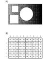
特徴量取得部4の処理の具体例を、図2(A),2(B)を用いて説明する。図2(A)は、入力画像データの一例を示す。図2(A)は、入力画像データの階調値が10ビットの値(0〜1023)である場合の例を示す。図2(A)では、階調値が大きいほど(
輝度が高いほど)白色に近く、且つ、階調値が小さいほど(輝度が低いほど)黒色に近い色で、階調値が示されている。図2(A)において、白色は階調値1023に対応し、黒色は階調値0に対応する。図2(A)の入力画像データには、階調値が1023である3つのオブジェクト(四角形の2つのオブジェクト、および、円形の1つのオブジェクト)が存在している。そして、図2(A)の入力画像データでは、左から右へ進む方向において、背景の階調値が512から0へ変化している。
A specific example of the processing of the feature
The gradation value is shown in a color closer to white (the higher the brightness) and closer to black as the gradation value is smaller (the lower the brightness). In FIG. 2A, white corresponds to the
図2(B)は、各分割領域(各光源部)に対して取得された特徴量の一例を示す。図2(B)は、図2(A)の入力画像データから取得された特徴量を示す。図2(B)において、水平方向に並んだ数値(1〜10)は、分割領域の水平位置(水平方向における位置)を示し、垂直方向に並んだ数値(1〜6)は、分割領域の垂直位置(垂直方向における位置)を示す。図2(B)に示すように、オブジェクトの少なくとも一部を含む分割領域では、特徴量(階調値の最大値;最大階調値)として1023が取得されている。そして、オブジェクトを含まない分割領域では、水平位置の増加に伴い、特徴量が512から0へ変化している。 FIG. 2B shows an example of the feature amount acquired for each divided region (each light source unit). FIG. 2B shows the feature amount acquired from the input image data of FIG. 2A. In FIG. 2B, the numerical values (1 to 10) arranged in the horizontal direction indicate the horizontal position (position in the horizontal direction) of the divided region, and the numerical values (1 to 6) arranged in the vertical direction indicate the horizontal position of the divided region. Indicates the vertical position (position in the vertical direction). As shown in FIG. 2B, 1023 is acquired as a feature amount (maximum value of gradation value; maximum gradation value) in the divided region including at least a part of the object. Then, in the divided region that does not include the object, the feature amount changes from 512 to 0 as the horizontal position increases.
なお、光源部に対応する領域(対応領域)は、上記分割領域に限られない。対応領域は他の対応領域から離れていてもよいし、対応領域の少なくとも一部が他の対応領域の少なくとも一部に重なっていてもよい。対応領域と光源の対応関係は、1対1の対応関係でなくてもよい。例えば、1つの対応領域に対して2つ以上の光源が対応付けられていてもよい。対応領域は、画面の領域の一部であってもよいし、画面の領域の全部であってもよい。 The area corresponding to the light source unit (corresponding area) is not limited to the above-mentioned divided area. The corresponding area may be separated from the other corresponding area, or at least a part of the corresponding area may overlap with at least a part of the other corresponding area. The correspondence between the corresponding region and the light source does not have to be a one-to-one correspondence. For example, two or more light sources may be associated with one corresponding region. The corresponding area may be a part of the screen area or the entire screen area.
なお、入力画像データはRGB画像データに限られない。例えば、各画素値がYCbCr値(輝度値であるY値、色差値であるCb値、及び、色差値であるCr値の組み合わせ)であるYCbCr画像データが、入力画像データとして取得されてもよい。また、特徴量も特に限定されない。例えば、特徴量として、階調値の他の代表値(最小値、平均値、中間値、最頻値、等)、階調値のヒストグラム、等が使用されてもよい。複数の光源部の間で共通の特徴量が取得されてもよい。例えば、複数の光源部の間で共通の特徴量として、入力画像データの画像領域全体に対応する特徴量が取得されてもよい。 The input image data is not limited to RGB image data. For example, YCbCr image data in which each pixel value is a YCbCr value (a combination of a Y value which is a luminance value, a Cb value which is a color difference value, and a Cr value which is a color difference value) may be acquired as input image data. .. Further, the feature amount is not particularly limited. For example, as the feature amount, other representative values of gradation values (minimum value, average value, median value, mode value, etc.), a histogram of gradation values, and the like may be used. A common feature amount may be acquired among a plurality of light source units. For example, as a feature amount common to a plurality of light source units, a feature amount corresponding to the entire image area of the input image data may be acquired.
BL基準輝度決定部5は、複数の光源部のそれぞれについて、その光源部の発光輝度(発光量)の基準である基準輝度を決定する。そして、BL基準輝度決定部5は、各光源部の基準輝度をBL輝度決定部6へ通知する。本実施例では、BL基準輝度決定部5は、複数の光源部のそれぞれについて、その光源部に対して取得された特徴量に応じて、当該光源部の基準輝度を決定する。
The BL reference
本実施例では、図3(A)の対応関係を示すルック・アップ・テーブル(LUT)が予め用意されている。図3(A)の対応関係は、特徴量と基準輝度との対応関係である。図3(A)の横軸は特徴量を示し、図3(A)の縦軸は基準輝度を示す。基準輝度(発光輝度)0[%]は、光源部が消灯している状態に対応し、基準輝度100[%]は、上限の発光輝度で光源部が発光している状態に対応する。BL基準輝度決定部5は、上記LUTを用いて、特徴量から基準輝度を決定する。図2(B)の特徴量が取得された場合には、図3(A)の対応関係から、図3(B)の基準輝度が決定される。
In this embodiment, a look-up table (LUT) showing the correspondence relationship shown in FIG. 3A is prepared in advance. The correspondence relationship in FIG. 3A is a correspondence relationship between the feature amount and the reference luminance. The horizontal axis of FIG. 3 (A) shows the feature amount, and the vertical axis of FIG. 3 (A) shows the reference luminance. The reference brightness (emission brightness) 0 [%] corresponds to the state in which the light source unit is turned off, and the reference brightness 100 [%] corresponds to the state in which the light source unit emits light at the upper limit emission brightness. The BL reference
なお、基準輝度の決定方法は上記方法に限られない。例えば、LUTの代わりに、特徴量と基準輝度との対応関係を示す関数が使用されてもよい。特徴量と基準輝度との対応関係は図3(A)の対応関係に限られない。特徴量と基準輝度との対応関係は特に限定されない。パラメータ設定部25からの指示に応じてBL基準輝度決定部5がLUTを書き替えて使用してもよい。パラメータ設定部25からBL基準輝度決定部5へLUTが通知さ
れ、通知されたLUTがBL基準輝度決定部5で使用されてもよい。パラメータ設定部25は、例えば、ユーザからの要求に応じて、LUTを書き替えるための指示、LUTの通知、等を行う。入力画像データの種類、表示装置1の使用環境、等に応じて、LUTを書き替えるための指示、LUTの通知、等が行われてもよい。
The method for determining the reference luminance is not limited to the above method. For example, instead of the LUT, a function indicating the correspondence between the feature amount and the reference luminance may be used. The correspondence between the feature amount and the reference luminance is not limited to the correspondence in FIG. 3 (A). The correspondence between the feature amount and the reference brightness is not particularly limited. The BL reference
BL輝度決定部6は、複数の光源部のそれぞれについて、その光源部の発光輝度の目標である目標輝度を、入力画像データに基づいて決定する。即ち、BL輝度決定部6は、各光源部の目標輝度を入力画像データに基づいて個別に決定する。以後、BL輝度決定部6によって決定された目標輝度を「第1目標輝度」と記載する。そして、BL輝度決定部6は、各光源部の第1目標輝度を、第1時間LPF処理部7へ通知する。本実施例では、BL輝度決定部6は、複数の光源部のそれぞれについて、その光源部に対して決定された基準輝度と、ユーザによって指定された輝度(ユーザ指定輝度)とに基づいて、当該光源部の第1目標輝度を決定する。本実施例では、表示輝度(画面の輝度)の上限がユーザによって指定される。「表示輝度の上限」は「階調値の上限に対応する表示輝度」とも言える。ユーザ指定輝度は、例えば、ユーザからの要求に応じて、パラメータ設定部25からBL輝度決定部6へ通知される。なお、ユーザ指定輝度は、表示輝度の上限に限られない。例えば、階調値の上限よりも小さい他の階調値に対応する表示輝度が、ユーザによって指定されてもよい。また、第1目標輝度の決定方法は特に限定されない。例えば、基準輝度が第1目標輝度として使用されてもよい。
The BL
第1目標輝度は、例えば、以下の式1を用いて算出される。式1において、「上限透過率」は、液晶パネルの透過率の上限である。
第1目標輝度=(ユーザ指定輝度÷上限透過率)×基準輝度 ・・・(式1)
The first target brightness is calculated using, for example, the following
1st target brightness = (user-specified brightness ÷ upper limit transmittance) × reference brightness ... (Equation 1)
上限透過率は特に限定されないが、上限透過率が10[%]である場合を考える。そして、ユーザ指定輝度が200[cd/m2]であり、且つ、基準輝度が100[%]である場合を考える。この場合には、式1を用いて、第1目標輝度2000[cd/m2]が得られる。上限透過率が10[%]であり、且つ、ユーザ指定輝度が1000[cd/m2]であり、且つ、基準輝度が100[%]である場合を考える。この場合には、式1を用いて、第1目標輝度10000[cd/m2]が得られる。上限透過率が10[%]であり、且つ、ユーザ指定輝度が1000[cd/m2]であり、且つ、基準輝度が80[%]である場合を考える。この場合には、式1を用いて、第1目標輝度8000[cd/m2]が得られる。
The upper limit transmittance is not particularly limited, but consider the case where the upper limit transmittance is 10 [%]. Then, consider the case where the user-specified luminance is 200 [cd / m 2 ] and the reference luminance is 100 [%]. In this case, the first target luminance 2000 [cd / m 2 ] can be obtained by using
ここで、光源部からの光が、当該光源部に対応する分割領域の周囲へ漏れる場合を考える。例えば、バックライトユニット3が直下型のバックライトユニットの場合において、上記漏れが生じる。この場合には、上記漏れを考慮して第1目標輝度を決定することが好ましい。上記漏れ(分割領域間における光(光源部からの光)の漏れ)を考慮して第1目標輝度を決定する方法としては、これまでに提案された種々の方法を用いることができる。例えば、上記漏れを考慮して第1目標輝度を決定する方法は、特開2014−44302号公報に開示されている。特開2014−44302号公報に開示の方法を用いた場合の具体例を、以下に説明する。
Here, consider a case where the light from the light source unit leaks to the periphery of the divided region corresponding to the light source unit. For example, when the
まず、基準輝度100[%]の光源部の第1目標輝度が100[cd/m2]となり、且つ、第1目標輝度が基準輝度に比例するように、各光源部の第1目標輝度が仮決定される。その後、複数の分割領域のそれぞれについて、バックライトユニット3(複数の光源部)から発せられた光の入射輝度(液晶パネルへの入射時における輝度)が、上記漏れを考慮して推定される。そして、推定された入射輝度が必要輝度(例えば、式1の左辺から
得られる輝度)よりも低い分割領域が存在する場合には、全ての分割領域において入射輝度が必要輝度以上となるように、各光源部の第1目標輝度が同じ増加率で高められる。
First, the first target brightness of each light source unit is set so that the first target brightness of the light source unit having a reference brightness of 100 [%] is 100 [cd / m 2] and the first target brightness is proportional to the reference brightness. It will be tentatively decided. After that, for each of the plurality of divided regions, the incident luminance (luminance at the time of incident on the liquid crystal panel) of the light emitted from the backlight unit 3 (plurality of light source units) is estimated in consideration of the above leakage. Then, when there is a divided region in which the estimated incident brightness is lower than the required brightness (for example, the brightness obtained from the left side of Equation 1), the incident brightness is equal to or higher than the required brightness in all the divided regions. The first target brightness of each light source unit is increased at the same rate of increase.
本実施例では、複数の分割領域のそれぞれについて、入射輝度の推定の対象である推定位置が予め定められている。推定位置は特に限定されないが、例えば、複数の分割領域のそれぞれについて、その分割領域の中心位置が推定位置として予め定められている。そのため、光源部と推定位置の組み合わせは、複数存在する。そして、複数の上記組み合わせのそれぞれについて、減衰係数が予め定められている。減衰係数は、その減衰係数に対応する光源部から発せられた光の、当該減衰係数に対応する推定位置に到達するまでの減衰の度合いである。 In this embodiment, the estimated positions for which the incident luminance is estimated are predetermined for each of the plurality of divided regions. The estimated position is not particularly limited, but for example, for each of the plurality of divided regions, the central position of the divided region is predetermined as the estimated position. Therefore, there are a plurality of combinations of the light source unit and the estimated position. Then, the attenuation coefficient is predetermined for each of the plurality of the above combinations. The attenuation coefficient is the degree of attenuation of the light emitted from the light source unit corresponding to the attenuation coefficient until it reaches the estimated position corresponding to the attenuation coefficient.
本実施例では、複数の推定位置のそれぞれについて、以下の処理が行われる。それにより、複数の分割領域にそれぞれ対応する複数の入射輝度が推定される。まず、処理対象の推定位置に対応する減衰係数を第1目標輝度に乗算する処理が、各光源部について行われる。次に、各光源部に対して得られた乗算結果の総和が、所定対象の推定位置における入射輝度として算出される。 In this embodiment, the following processing is performed for each of the plurality of estimated positions. As a result, a plurality of incident luminances corresponding to the plurality of divided regions are estimated. First, a process of multiplying the first target luminance by the attenuation coefficient corresponding to the estimated position of the processing target is performed for each light source unit. Next, the sum of the multiplication results obtained for each light source unit is calculated as the incident brightness at the estimated position of the predetermined target.
図3(C)は、上記方法によって決定された第1目標輝度の一例を示す。図3(C)は、上限透過率が100[%]であり、且つ、ユーザ指定輝度が1000[cd/m2]である場合を示す。図3(C)では、図3(B)で基準輝度が100[%]である分割領域に対して、ユーザ指定輝度1000[cd/m2]よりも低い第1目標輝度500[cd/m2]が対応付けられている。これは、上記分割領域の周囲から合計で500[cd/m2]以上の輝度の光が漏れくるからである。周囲からの光の漏れは、他の分割領域でも生じる。そのため、図3(B)では、他の分割領域に対しても、ユーザ指定輝度1000[cd/m2]に図3(B)の基準輝度を乗算することで得られる輝度(式1の左辺から得られる輝度)よりも低い第1目標輝度が対応付けられている。 FIG. 3C shows an example of the first target luminance determined by the above method. FIG. 3C shows a case where the upper limit transmittance is 100 [%] and the user-specified luminance is 1000 [cd / m 2 ]. In FIG. 3 (C), the first target luminance of 500 [cd / m], which is lower than the user-specified luminance of 1000 [cd / m 2 ], with respect to the divided region in which the reference luminance is 100 [%] in FIG. 3 (B). 2 ] is associated. This is because light having a total brightness of 500 [cd / m 2 ] or more leaks from the periphery of the divided region. Leakage of light from the surroundings also occurs in other compartments. Therefore, in FIG. 3B, the luminance obtained by multiplying the user-specified luminance 1000 [cd / m 2 ] by the reference luminance of FIG. 3B (the left side of Equation 1) also for the other divided regions. A first target brightness lower than (brightness obtained from) is associated.
第1時間LPF処理部7は、目標輝度の時間変化が抑制されるように第1目標輝度を補正する補正処理を各光源部について行うことにより、各光源部の第2目標輝度を取得する。第2目標輝度は、補正後の目標輝度である。目標輝度の時間変化の抑制度合いは特に限定されないが、例えば、ユーザに妨害として知覚されるフリッカの発生が抑制されるように、目標輝度の時間変化が抑制される。ここで考慮されるフリッカは、例えば、目標輝度の急激な時間変化に起因して生じるフリッカである。
The first time
本実施例では、第1時間LPF処理部7は、時間方向のLPF処理(時間LPF処理)を第1目標輝度に施すことにより、第1目標輝度を第2目標輝度に補正する。具体的には、表示装置1では、動画像データ(対象動画像データ)の各フレームの画像データが、入力画像データとして順に使用される。BL輝度記憶部8は、現在のフレーム(現フレーム)よりも前のフレームに対応する第2目標輝度を記憶する。本実施例では、BL輝度記憶部8は、現フレームの1つ前のフレーム(前フレーム)に対応する第2目標輝度を記憶する。そして、第1時間LPF処理部7は、BL輝度記憶部8が記憶する第2目標輝度(前フレームに対応する第2目標輝度)を用いて、BL輝度決定部6から通知された第1目標輝度(現フレームに対応する第1目標輝度)を補正する。
In this embodiment, the first time
本実施例では、第1時間LPF処理部7は、以下の式2を用いて、第2目標輝度BLC(x,y)を算出する。第2目標輝度BLC(x,y)は、現フレームに対応する第2目標輝度であり、位置(水平位置,垂直位置)=(x,y)の光源部に対応する第2目標輝度である。また、式2において、「BLL(x,y)」は、現フレームに対応する第1目標輝度であり、位置(x,y)の光源部に対応する第1目標輝度である。「PRBLC(x,y)」は、前フレームに対応する第2目標輝度であり、位置(x,y)の光源部に対
応する第2目標輝度である。そして、「α」は、第1目標輝度を補正する補正処理の時定数である。時定数αとしては、0よりも大きく且つ1よりも小さい値が使用される。時定数αは、パラメータ設定部25により設定される。
BLC(x,y)=(BLL(x,y)−PRBLC(x,y))
×(1−α)+PRBLC(x,y)
・・・(式2)
In this embodiment, the first time
BLC (x, y) = (BLL (x, y) -PRBLC (x, y))
× (1-α) + PRBLC (x, y)
... (Equation 2)
式2から、時定数αの低下により、第1目標輝度への目標輝度の時間変化の速度が増し、時定数αの増加により、第1目標輝度への目標輝度の時間変化の速度が低下することがわかる。具体的には、時定数αの低下により、1フレームあたりの第2目標輝度の変化量が増し、時定数αの増加により、1フレームあたりの第2目標輝度の変化量が減ることがわかる。時定数αは、「目標輝度の時間変化の抑制度合い」とも言える。
From
第1時間LPF処理部7は、各光源部の第2目標輝度を、入射輝度推定部9とRGB−BL輝度決定部12へ通知する。さらに、第1時間LPF処理部7は、各光源部の第2目標輝度をBL輝度記憶部8に記録する。
The first time
なお、第1目標輝度の補正方法は特に限定されない。例えば、現フレームよりも前のフレームとして、現フレームよりも2つ以上前のフレームが使用されてもよい。現フレームよりも前のフレームとして、2つ以上のフレームが使用されてもよい。 The method for correcting the first target luminance is not particularly limited. For example, as a frame before the current frame, two or more frames before the current frame may be used. Two or more frames may be used as frames prior to the current frame.
入射輝度推定部9は、各光源部の第2目標輝度に基づいて、複数の推定位置にそれぞれに対応する複数の入射輝度を推定する。そして、入射輝度推定部9は、各推定位置の入射輝度を画像補正値決定部10へ通知する。入射輝度の推定方法は上述したとおりである。分割領域の形状、推定位置、等は特に限定されない。本実施例では、各分割領域の形状が四角形である。そして、本実施例では、入射輝度推定部9は、各分割領域の四隅の位置、各分割領域の各辺の中心位置、及び、各分割領域の中心位置である複数の位置のそれぞれを、推定位置として使用する。
The incident
画像補正値決定部10は、入射輝度推定部9で使用された複数の推定位置のそれぞれについて、推定された入射輝度に基づいて、画像データを補正する補正値を決定する。そして、画像補正値決定部10は、各推定位置の補正値を画像補正部11へ出力する。表示装置には、「入力画像データに応じた輝度を正確に表示したい」というニーズがある。入射輝度が所定の輝度から変化すると、表示輝度も変化する。そのため、例えば、所定の輝度からの入射輝度の変化に対応する表示輝度の変化を低減する値が、補正値として決定される。本実施例では、以下の式3を用いて、画像データの階調値に乗算されるゲイン値である補正係数Gpnが、補正値として算出される。式3において、「Lt」は、上記所定の輝度であり、「Lpn」は、推定された入射輝度である。所定の輝度Ltは、例えば、ユーザ指定輝度に比例する輝度である。なお、補正値はゲイン値に限られない。例えば、補正値として、画像データの階調値に加算するオフセット値が決定されてもよい。
Gpn=Lt/Lpn ・・・(式3)
The image correction
Gpn = Lt / Lpn ... (Equation 3)
画像補正部11は、入射輝度推定部9によって推定された入射輝度に基づいて、入力画像データを補正する。本実施例では、画像補正部11は、画像補正値決定部10によって決定された補正値を用いて入力画像データの各階調値を補正することにより、処理画像データを生成する。そして、画像補正部11は、処理画像データを液晶パネル部2へ出力す
る。具体的には、入射輝度推定部9で使用された推定位置については、画像補正値決定部10によって決定された補正係数Gpnが入力画像データの階調値に乗算される。入射輝度推定部9で使用された推定位置とは異なる位置については、当該位置の周囲の複数の推定位置に対して決定された複数の補正係数Gpnを用いた補間処理により、補正係数が決定される。そして、決定された補間係数が入力画像データの階調値に乗算される。
The image correction unit 11 corrects the input image data based on the incident brightness estimated by the incident
RGB−BL輝度決定部12は、複数の光源部のそれぞれについて、その光源部の第2目標輝度から、当該光源部の有するR光源部の目標輝度、当該光源部の有するG光源部の目標輝度、及び、当該光源部の有するB光源部の目標輝度を個別に決定する。「光源部の第2目標輝度から複数の色光源部にそれぞれ対応する複数の目標輝度を決定する処理」は、「光源部の第2目標輝度を複数の色光源部にそれぞれ対応する複数の目標輝度へ分ける処理」とも言える。そして、RGB−BL輝度決定部12は、各色光源部の目標輝度を、駆動時間決定部13へ通知する。 For each of the plurality of light source units, the RGB-BL brightness determination unit 12 starts with the second target brightness of the light source unit, the target brightness of the R light source unit of the light source unit, and the target brightness of the G light source unit of the light source unit. , And the target brightness of the B light source unit of the light source unit is individually determined. The "process of determining a plurality of target luminances corresponding to a plurality of color light source portions from the second target luminance of the light source portion" is "a plurality of targets corresponding to the plurality of color light source portions of the second target brightness of the light source portion". It can also be said to be "processing to divide into brightness". Then, the RGB-BL luminance determination unit 12 notifies the drive time determination unit 13 of the target luminance of each color light source unit.
本実施例では、液晶パネルの背面に白色光を照射するための比率として、R光源部の発光輝度:G光源部の発光輝度:B光源部の発光輝度=3:6:1が予め定められている。そして、RGB−BL輝度決定部12は、複数の光源部のそれぞれについて、以下の式4−1〜4−3を用いて、R光源部の目標輝度、G光源部の目標輝度、及び、B光源部の目標輝度を算出する。光源部の目標輝度が500[cd/m2]である場合には、式4−1〜4−3を用いて、R光源部の目標輝度150[cd/m2]、G光源部の目標輝度300[cd/m2]、及び、B光源部の目標輝度50[cd/m2]が算出される。なお、比率は3:6:1に限られない。
R光源部の目標輝度=光源部の第2目標輝度×3÷(3+6+1)
・・・(式4−1)
G光源部の目標輝度=光源部の第2目標輝度×6÷(3+6+1)
・・・(式4−2)
B光源部の目標輝度=光源部の第2目標輝度×1÷(3+6+1)
・・・(式4−3)
In this embodiment, as the ratio for irradiating the back surface of the liquid crystal panel with white light, the emission brightness of the R light source unit: the emission brightness of the G light source unit: the emission brightness of the B light source unit = 3: 6: 1 is predetermined. ing. Then, the RGB-BL brightness determination unit 12 uses the following equations 4-1 to 4-3 for each of the plurality of light source units to obtain the target brightness of the R light source unit, the target brightness of the G light source unit, and B. Calculate the target brightness of the light source unit. When the target brightness of the light source unit is 500 [cd / m 2 ], the target brightness of the R light source unit is 150 [cd / m 2 ] and the target brightness of the G light source unit is set by using equations 4-1 to 4-3. A brightness of 300 [cd / m 2 ] and a target brightness of 50 [cd / m 2 ] of the B light source unit are calculated. The ratio is not limited to 3: 6: 1.
Target brightness of R light source unit = 2nd target brightness of light source unit x 3 ÷ (3 + 6 + 1)
... (Equation 4-1)
Target brightness of G light source unit = 2nd target brightness of light source unit x 6 ÷ (3 + 6 + 1)
... (Equation 4-2)
B Target brightness of the light source unit = Second target brightness of the light source unit x 1 ÷ (3 + 6 + 1)
... (Equation 4-3)
駆動時間決定部13は、各色光源部に対して駆動値決定処理を行う。色光源部に対する駆動値決定処理は、「色光源部の目標輝度に基づいて、色光源部の発光輝度を目標輝度へ制御する値である駆動値を決定する処理」である。そのため、光源部に対する駆動値決定処理(光源部に属す複数の色光源部にそれぞれ対応する複数の駆動値決定処理の組み合わせ)は、「光源部の第2目標輝度に基づいて、光源部の発光輝度を第2目標輝度へ制御する値である駆動値を決定する処理」と言える。駆動時間決定部13は、決定した駆動値(第1駆動値;未補正駆動値)を、総駆動時間決定部14と駆動時間補正部17へ通知する。
The drive time determination unit 13 performs a drive value determination process for each color light source unit. The drive value determination process for the color light source unit is "a process of determining a drive value which is a value for controlling the emission brightness of the color light source unit to the target brightness based on the target brightness of the color light source unit". Therefore, the drive value determination process for the light source unit (combination of a plurality of drive value determination processes corresponding to each of the plurality of color light source units belonging to the light source unit) is "light emission of the light source unit based on the second target brightness of the light source unit. It can be said to be "a process of determining a drive value which is a value for controlling the brightness to the second target brightness". The drive time determination unit 13 notifies the total drive
本実施例では、各色光源部がパルス幅変調方式で駆動される。そのため、色光源部の駆動時間に関する値が、駆動値として使用される。この場合には、駆動値決定処理は「駆動時間を決定する処理」とも言える。なお、色光源部の駆動方式は、パルス幅変調方式に限られない。例えば、パルス振幅変調方式、パルス幅変調方式とパルス振幅変調方式とを組み合わせた方式、等で色光源部が駆動されてもよい。パルス振幅変調方式で色光源部が駆動される場合には、駆動値として、色光源部に供給される電流値に関する値が使用される。パルス幅変調方式とパルス振幅変調方式とを組み合わせた方式で色光源部が駆動される場合には、駆動値として、駆動時間と、色光源部に供給される電流値とに関する値が使用される。 In this embodiment, each color light source unit is driven by a pulse width modulation method. Therefore, a value related to the drive time of the color light source unit is used as the drive value. In this case, the drive value determination process can be said to be "process for determining the drive time". The drive method of the color light source unit is not limited to the pulse width modulation method. For example, the color light source unit may be driven by a pulse amplitude modulation method, a method combining a pulse width modulation method and a pulse amplitude modulation method, or the like. When the color light source unit is driven by the pulse amplitude modulation method, a value related to the current value supplied to the color light source unit is used as the drive value. When the color light source unit is driven by a method that combines the pulse width modulation method and the pulse amplitude modulation method, a value related to the drive time and the current value supplied to the color light source unit is used as the drive value. ..
本実施例では、駆動時間決定部13は、各色光源部の発光効率を考慮して各色光源部の未補正駆動値を決定する。具体的には、駆動値決定処理として、「以下の3つの要素1〜3に基づいて色光源部の未補正駆動値を決定する処理」が行われる。
要素1:色光源部の目標輝度
要素2:色光源部の発光効率が基準の発光効率である場合における、色光源部の発光輝度と色光源部の未補正駆動値との対応関係
要素3:色光源部の発光効率と基準の発光効率との間の差
In this embodiment, the drive time determination unit 13 determines the uncorrected drive value of each color light source unit in consideration of the luminous efficiency of each color light source unit. Specifically, as the drive value determination process, "a process of determining the uncorrected drive value of the color light source unit based on the following three
Element 1: Target brightness of the color light source unit Element 2: Correspondence between the luminous brightness of the color light source unit and the uncorrected drive value of the color light source unit when the luminous efficiency of the color light source unit is the standard luminous efficiency Element 3: Difference between the luminous efficiency of the color light source and the standard luminous efficiency
「色光源部の発光効率が基準の発光効率である場合における、色光源部の発光輝度と色光源部の未補正駆動値との対応関係」は、「色光源部の発光効率が基準の発光効率である場合における、色光源部の発光輝度と色光源部の駆動時間との対応関係」とも言える。この対応関係は特に限定されないが、本実施例では、図4の対応関係が使用される。図4の横軸は、色光源部の発光輝度を示し、図4の縦軸は、色光源部の駆動時間を示す。図4の太実線は、色光源部の発光効率が基準の発光効率である場合の対応関係を示す。図4の駆動時間の値は、規格化された値である。駆動時間100[%]は、1フレームの期間において色光源部が点灯し続ける状態に対応する。実際には、光源ドライバ(各光源の発光を制御する制御回路)のリセット期間が必要である。そのため、1フレームの期間の長さが16.6[msec]である場合には、駆動時間100[%]は16.6[msec]以下の時間に対応する。 "The correspondence between the luminous brightness of the color light source unit and the uncorrected drive value of the color light source unit when the luminous efficiency of the color light source unit is the standard luminous efficiency" is "emission based on the luminous efficiency of the color light source unit". It can also be said that there is a correspondence between the luminous brightness of the color light source unit and the driving time of the color light source unit in the case of efficiency. This correspondence is not particularly limited, but in this embodiment, the correspondence of FIG. 4 is used. The horizontal axis of FIG. 4 indicates the emission brightness of the color light source unit, and the vertical axis of FIG. 4 indicates the driving time of the color light source unit. The thick solid line in FIG. 4 shows the correspondence when the luminous efficiency of the color light source unit is the reference luminous efficiency. The drive time value in FIG. 4 is a standardized value. The drive time of 100 [%] corresponds to a state in which the color light source unit continues to light for a period of one frame. Actually, a reset period of the light source driver (control circuit that controls the light emission of each light source) is required. Therefore, when the length of the period of one frame is 16.6 [msec], the drive time of 100 [%] corresponds to the time of 16.6 [msec] or less.
「色光源部の発光効率と基準の発光効率との間の差」として、以下の3つの差1〜3が存在し得る。本実施例では、差1〜3の全てが考慮される。なお、差1〜3の1つまたは2つが考慮されなくてもよい。例えば、差1のみが考慮されてもよいし、差2,3のみが考慮されてもよい。
差1:色光源部の製造時に生じた差
差2:色光源部の温度変化に起因して生じた差
差3:色光源部の経年劣化に起因して生じた差
As the "difference between the luminous efficiency of the color light source unit and the reference luminous efficiency", the following three
Difference 1: Difference caused during the manufacture of the color light source part Difference 2: Difference caused by the temperature change of the color light source part Difference 3: Difference caused by the aging deterioration of the color light source part
本実施例では、上記差1に起因した輝度変化(目標輝度からの発光輝度の変化)を低減する第1補正値Ch(c,x,y)が、第1補正値記憶部22に予め記録されている。第1補正値Ch(c,x,y)は、位置(x,y)の光源部に属し、且つ、発光色が色cである色光源部の補正値である。また、本実施例では、上記差2,3に起因した輝度変化(目標輝度からの発光輝度の変化)を低減する第2補正値Cd(c,x,y)が、第2補正値決定部21によって決定される。第2補正値Cd(c,x,y)は、位置(x,y)の光源部に属し、且つ、発光色が色cである色光源部の補正値である。
In this embodiment, the first correction value Ch (c, x, y) for reducing the brightness change (change in emission brightness from the target brightness) due to the
本実施例では、駆動時間決定部13は、図4の対応関係(図4の対応関係を示すLUT、図4の対応関係を示す関数、等)から、色光源部の目標輝度L(c,x,y)に対応する駆動時間Dr(c,x,y)=f(L(c,x,y))を取得する。また、駆動時間決定部13は、第1補正値Ch(c,x,y)を第1補正値記憶部22から取得し、第2補正値Cd(c,x,y)を第2補正値決定部21から取得する。そして、駆動時間決定部13は、以下の式5を用いて、駆動時間Dr(c,x,y)、第1補正値Ch(c,x,y)、及び、第2補正値Cd(c,x,y)から、色光源部の駆動時間RDr(c,x,y)を算出する。本実施例では、駆動時間決定部13は、駆動時間RDr(c,x,y)を未補正駆動値として通知する。
RDr(c,x,y)
=Dr(c,x,y)×Ch(c,x,y)×Cd(c,x,y)
・・・(式5)
In this embodiment, the drive time determination unit 13 determines the target luminance L (c, of the color light source unit) of the color light source unit from the correspondence relationship of FIG. The drive time Dr (c, x, y) = f (L (c, x, y)) corresponding to x, y) is acquired. Further, the drive time determination unit 13 acquires the first correction value Ch (c, x, y) from the first correction
RDr (c, x, y)
= Dr (c, x, y) x Ch (c, x, y) x Cd (c, x, y)
... (Equation 5)
このような処理が、各色光源部について個別に行われる。以後、位置(x,y)の光源部に属すR光源部の駆動時間RDr(c,x,y)を「駆動時間RDrr(x,y)」と記載する。位置(x,y)の光源部に属すG光源部の駆動時間RDr(c,x,y)を「駆動時間RDrg(x,y)」と記載する。そして、位置(x,y)の光源部に属すB光源部の駆動時間RDr(c,x,y)を「駆動時間RDrb(x,y)」と記載する。 Such processing is performed individually for each color light source unit. Hereinafter, the drive time RDr (c, x, y) of the R light source unit belonging to the light source unit at the position (x, y) will be referred to as “drive time RDrr (x, y)”. The drive time RDr (c, x, y) of the G light source unit belonging to the light source unit at the position (x, y) is described as "drive time RDrg (x, y)". Then, the drive time RDr (c, x, y) of the B light source unit belonging to the light source unit at the position (x, y) is described as "drive time RDrb (x, y)".
なお、駆動時間の値とは異なる値が駆動値として使用されてもよい。例えば、駆動値として、駆動時間に比例する他の値が使用されてもよい。具体的には、色光源部がパルス幅変調方式で駆動される場合などおいて、光源ドライバの処理を制御する制御値として、駆動時間に比例する値が使用される。そのような場合には、光源ドライバの制御値が駆動値として使用されてもよい。 A value different from the drive time value may be used as the drive value. For example, as the drive value, another value proportional to the drive time may be used. Specifically, when the color light source unit is driven by the pulse width modulation method, a value proportional to the drive time is used as a control value for controlling the processing of the light source driver. In such a case, the control value of the light source driver may be used as the drive value.
総駆動時間決定部14は、各色光源部の未補正駆動値に基づいて総駆動時間を決定し、決定した総駆動時間を時間補正値決定部15へ通知する。本実施例では、総駆動時間は、発光色が同じ複数の色光源部にそれぞれ対応する複数の駆動時間の総和である。また、本実施例では、総駆動時間決定部14は、複数の発光色のそれぞれについて総駆動時間を決定する。具体的には、総駆動時間決定部14は、各R光源部の未補正駆動値に基づいて、複数のR光源部にそれぞれ対応する複数の駆動時間の総和である総駆動時間を決定する。総駆動時間決定部14は、各G光源部の未補正駆動値に基づいて、複数のG光源部にそれぞれ対応する複数の駆動時間の総和である総駆動時間を決定する。そして、総駆動時間決定部14は、各B光源部の未補正駆動値に基づいて、複数のB光源部にそれぞれ対応する複数の駆動時間の総和である総駆動時間を決定する。
The total drive
時間補正値決定部15は、各色光源部の未補正駆動値を補正する時間補正値を決定し、決定した時間補正値を時間補正値選択部16へ通知する。時間補正値は、「駆動時間を補正する補正値」とも言える。具体的には、時間補正値決定部15は、総駆動時間決定部14によって決定された総駆動時間を閾値と比較し、比較結果に基づいて時間補正値を決定する処理を、複数の発光色のそれぞれについて行う。本実施例では、総駆動時間が閾値よりも長い発光色については、総駆動時間を閾値以下に制限する時間補正値が決定される。以下に、時間補正値決定部15の処理の具体例を説明する。
The time correction value determination unit 15 determines a time correction value for correcting the uncorrected drive value of each color light source unit, and notifies the time correction
R光源部に供給される電流量IR(x,y)、G光源部に供給される電流量IG(x,y)、及び、B光源部に供給される電流量IB(x,y)は、以下の式6−1〜6−3で表せる。式6−1〜6−3において、「Ir」は、R光源部に供給される電流量の時間平均であり、「Ig」は、G光源部に供給される電流量の時間平均であり、「Ib」は、B光源部に供給される電流量の時間平均である。「色光源部に供給される電流量の時間平均」は、例えば、「1フレームの期間において色光源部が点灯し続ける場合において当該期間に色光源部に供給される電流量の時間平均」である。
IR(x,y)=Ir×RDrr(x,y) ・・・(式6−1)
IG(x,y)=Ig×RDrg(x,y) ・・・(式6−2)
IB(x,y)=Ib×RDrb(x,y) ・・・(式6−3)
The amount of current IR (x, y) supplied to the R light source unit, the amount of current IG (x, y) supplied to the G light source unit, and the amount of current IB (x, y) supplied to the B light source unit are , Can be expressed by the following equations 6-1 to 6-3. In formulas 6-1 to 6-3, "Ir" is the time average of the amount of current supplied to the R light source unit, and "Ig" is the time average of the amount of current supplied to the G light source unit. “Ib” is the time average of the amount of current supplied to the B light source unit. The "time average of the amount of current supplied to the color light source unit" is, for example, "the time average of the amount of current supplied to the color light source unit during the period when the color light source unit continues to light". be.
IR (x, y) = Ir × RDrr (x, y) ... (Equation 6-1)
IG (x, y) = Ig x RDrg (x, y) ... (Equation 6-2)
IB (x, y) = Ib x RDrb (x, y) ... (Equation 6-3)
そして、各R光源部に供給される電流量IR(x,y)の総和SR、各G光源部に供給
される電流量IG(x,y)の総和SG、及び、各B光源部に供給される電流量IB(x,y)の総和SBは、以下の式7−1〜7−3で表せる。
SR=ΣIR(x,y)
=Σ(Ir×RDrr(x,y))
=Ir×ΣRDrr(x,y)
・・・(式7−1)
SG=ΣIG(x,y)
=Σ(Ig×RDrg(x,y))
=Ig×ΣRDrg(x,y)
・・・(式7−2)
SB=ΣIB(x,y)
=Σ(Ib×RDrb(x,y))
=Ib×ΣRDrb(x,y)
・・・(式7−3)
Then, the total SR of the current amount IR (x, y) supplied to each R light source unit, the total SG of the current amount IG (x, y) supplied to each G light source unit, and the total B light source unit are supplied. The total SB of the amount of current IB (x, y) to be generated can be expressed by the following equations 7-1 to 7-3.
SR = ΣIR (x, y)
= Σ (Ir × RDrr (x, y))
= Ir × ΣRDrr (x, y)
... (Equation 7-1)
SG = ΣIG (x, y)
= Σ (Ig × RDrg (x, y))
= Ig x ΣRDrg (x, y)
... (Equation 7-2)
SB = ΣIB (x, y)
= Σ (Ib x RDrb (x, y))
= Ib × ΣRDrb (x, y)
... (Equation 7-3)
式7−1のΣRDrr(x,y)は複数のR光源部の総駆動時間であり、式7−2のΣRDrg(x,y)は複数のG光源部の総駆動時間であり、式7−3のΣRDrb(x,y)は複数のB光源部の総駆動時間である。そのため、総駆動時間と比較される閾値ΣRDrr(x,y)max,ΣRDrg(x,y)max,ΣRDrb(x,y)maxは、以下の式8−1〜8−3によって得ることができる。式8−1〜8−3において、「SRmax」は、各R光源部に供給される電流量の総和の上限であり、「SGmax」は、各G光源部に供給される電流量の総和の上限であり、「SBmax」は、各B光源部に供給される電流量の総和の上限である。「ΣRDrr(x,y)max」は、複数のR光源部の総駆動時間と比較される閾値である。「ΣRDrg(x,y)max」は、複数のG光源部の総駆動時間と比較される閾値である。そして、「ΣRDrb(x,y)max」は、複数のR光源部の総駆動時間と比較される閾値である。
ΣRDrr(x,y)max=SRmax/Ir ・・・(式8−1)
ΣRDrg(x,y)max=SGmax/Ig ・・・(式8−2)
ΣRDrb(x,y)max=SBmax/Ib ・・・(式8−3)
ΣRDrr (x, y) in Equation 7-1 is the total drive time of the plurality of R light source units, and ΣRDrg (x, y) in Equation 7-2 is the total drive time of the plurality of G light source units. ΣRDrb (x, y) of -3 is the total drive time of the plurality of B light source units. Therefore, the threshold values ΣRDrr (x, y) max, ΣRDrg (x, y) max, and ΣRDrb (x, y) max to be compared with the total drive time can be obtained by the following equations 8-1 to 8-3. .. In equations 8-1 to 8-3, "SRmax" is the upper limit of the total amount of current supplied to each R light source unit, and "SGmax" is the total amount of current supplied to each G light source unit. It is an upper limit, and "SBmax" is an upper limit of the total amount of current supplied to each B light source unit. “ΣRDrr (x, y) max” is a threshold value to be compared with the total drive time of a plurality of R light source units. “ΣRDrg (x, y) max” is a threshold value to be compared with the total drive time of a plurality of G light source units. Then, "ΣRDrb (x, y) max" is a threshold value to be compared with the total drive time of the plurality of R light source units.
ΣRDrr (x, y) max = SRmax / Ir ... (Equation 8-1)
ΣRDrg (x, y) max = SGmax / Ig ... (Equation 8-2)
ΣRDrb (x, y) max = SBmax / Ib ... (Equation 8-3)
電流量SRmax,SGmax,SBmaxは、表示装置1に電力を供給する電源の性能、表示装置1(表示装置1の電源回路など)の性能、等に応じて決まる。そのため、「閾値ΣRDrr(x,y)max,ΣRDrg(x,y)max,ΣRDrb(x,y)maxは上記性能などによって決まる」とも言える。
The current amounts SRmax, SGmax, and SBmax are determined according to the performance of the power supply that supplies power to the
電源が出力可能な電流量の上限が複数の発光色の間で同じであっても、一般的に、色光源部に印加される電圧は、複数の発光色の間で異なる。また、一般的に、液晶パネルの背面に白色光を照射するために色光源部に必要な電力も、複数の発光色の間で異なる。そのため、一般的に、電流量SRmax、電流量SGmax、及び、電流量SGmaxは互いに異なり、閾値ΣRDrr(x,y)max、閾値ΣRDrg(x,y)max、閾値、ΣRDrb(x,y)maxは互いに異なる。 Even if the upper limit of the amount of current that can be output by the power supply is the same among the plurality of emission colors, the voltage applied to the color light source unit is generally different among the plurality of emission colors. Further, in general, the electric power required for the color light source unit for irradiating the back surface of the liquid crystal panel with white light also differs among the plurality of emitted colors. Therefore, in general, the current amount SRmax, the current amount SGmax, and the current amount SGmax are different from each other, and the threshold value ΣRDrr (x, y) max, the threshold value ΣRDrg (x, y) max, the threshold value, and the ΣRDrb (x, y) max. Are different from each other.
なお、式8−1〜8−3によれば、総駆動時間の上限が閾値として得られる。しかしながら、総駆動時間の上限とは異なる時間が閾値として使用されてもよい。例えば、総駆動時間の上限よりも短い時間が閾値として使用されてもよい。また、複数の発光色の間で共通の閾値が使用されてもよい。 According to Equations 8-1 to 8-3, the upper limit of the total driving time is obtained as a threshold value. However, a time different from the upper limit of the total drive time may be used as the threshold value. For example, a time shorter than the upper limit of the total drive time may be used as the threshold value. Further, a common threshold value may be used among a plurality of emission colors.
本実施例では、時間補正値決定部15は、以下の式9−1〜9−3を用いて、時間補正値GainR,GainG,GainBを算出する。式9−1〜9−3によれば、閾値を総駆動時間で除算することにより、時間補正値GainR,GainG,GainBが算出される。そのため、時間補正値GainR,GainG,GainBは、総駆動時間に対する閾値の割合である。
GainR=ΣRDrr(x,y)max/ΣRDrr(x,y)
・・・(式9−1)
GainG=ΣRDrg(x,y)max/ΣRDrg(x,y)
・・・(式9−2)
GainB=ΣRDrb(x,y)max/ΣRDrb(x,y)
・・・(式9−3)
In this embodiment, the time correction value determination unit 15 calculates the time correction values GainR, GainG, and GainB using the following equations 9-1 to 9-3. According to Equations 9-1 to 9-3, the time correction values GainR, GainG, and GainB are calculated by dividing the threshold value by the total drive time. Therefore, the time correction values GainR, GainG, and GainB are the ratios of the threshold values to the total drive time.
GainR = ΣRDrr (x, y) max / ΣRDrr (x, y)
... (Equation 9-1)
GainG = ΣRDrg (x, y) max / ΣRDrg (x, y)
... (Equation 9-2)
GainB = ΣRDrb (x, y) max / ΣRDrb (x, y)
... (Equation 9-3)
時間補正値GainRは、各R光源部の未補正駆動値(駆動時間)を補正する時間補正値である。時間補正値GainGは、各G光源部の未補正駆動値を補正する時間補正値である。そして、時間補正値GainBは、各B光源部の未補正駆動値を補正する時間補正値である。具体的には、時間補正値GainRは、各R光源部の未補正駆動値に乗算されるゲイン値である。時間補正値GainGは、各G光源部の未補正駆動値に乗算されるゲイン値である。そして、時間補正値GainBは、各B光源部の未補正駆動値に乗算されるゲイン値である。総駆動時間が閾値よりも長い発光色について、各未補正駆動値に時間補正値を乗算することにより、総駆動時間を閾値に制限することができる。 The time correction value GainR is a time correction value for correcting the uncorrected drive value (drive time) of each R light source unit. The time correction value GainG is a time correction value for correcting the uncorrected drive value of each G light source unit. The time correction value GainB is a time correction value for correcting the uncorrected drive value of each B light source unit. Specifically, the time correction value GainR is a gain value multiplied by the uncorrected drive value of each R light source unit. The time correction value GainG is a gain value that is multiplied by the uncorrected drive value of each G light source unit. The time correction value Gain B is a gain value that is multiplied by the uncorrected drive value of each B light source unit. The total drive time can be limited to the threshold value by multiplying each uncorrected drive value by the time correction value for the emission color whose total drive time is longer than the threshold value.
時間補正値決定部15は、式9−1〜9−3を用いて算出された時間補正値GainR,GainG,GainBを出力する。但し、ΣRDrr(x,y)≦ΣRDrr(x,y)maxの場合には、時間補正値決定部15は時間補正値GainR=1を出力する。ΣRDrg(x,y)≦ΣRDrg(x,y)maxの場合には、時間補正値決定部15は時間補正値GainG=1を出力する。そして、ΣRDrb(x,y)≦ΣRDrb(x,y)maxの場合には、時間補正値決定部15は時間補正値GainB=1を出力する。 The time correction value determination unit 15 outputs the time correction values GainR, GainG, and GainB calculated using the equations 9-1 to 9-3. However, when ΣRDrr (x, y) ≦ ΣRDrr (x, y) max, the time correction value determining unit 15 outputs the time correction value GainR = 1. When ΣRDrg (x, y) ≦ ΣRDrg (x, y) max, the time correction value determining unit 15 outputs the time correction value GainG = 1. Then, in the case of ΣRDrb (x, y) ≦ ΣRDrb (x, y) max, the time correction value determining unit 15 outputs the time correction value GainB = 1.
なお、時間補正値は上記値に限られない。総駆動時間に対する閾値の割合とは異なる値が時間補正値として決定されてもよい。総駆動時間を閾値よりも短い時間に制限する時間補正値が決定されてもよい。各未補正駆動値に加算されるオフセット値が時間補正値として決定されてもよい。 The time correction value is not limited to the above value. A value different from the ratio of the threshold value to the total drive time may be determined as the time correction value. A time correction value that limits the total drive time to a time shorter than the threshold value may be determined. The offset value added to each uncorrected drive value may be determined as the time correction value.
時間補正値選択部16は、時間補正値GainR、時間補正値GainG、及び、時間補正値GainBのいずれか1つを選択する。選択された時間補正値は、各未補正駆動値(各R光源部の未補正駆動値、各G光源部の未補正駆動値、及び、各B光源部の未補正駆動値)の補正に使用される。本実施例では、時間補正値選択部16は、時間補正値GainR、時間補正値GainG、及び、時間補正値GainBの最小値を選択する。そして、時間補正値選択部16は、選択した時間補正値を駆動時間補正部17へ通知する。
The time correction
複数の発光色の間で異なる時間補正値を用いた補正が行われる場合には、各未補正駆動値の補正によって、比率(R光源部の発光輝度:G光源部の発光輝度:B光源部の発光輝度)が、液晶パネルの背面に白色光を照射するための比率から変化することがある。時間補正値GainR、時間補正値GainG、及び、時間補正値GainBのいずれかを選択して補正に使用することにより、そのような比率の変化を抑制することができる。また、時間補正値GainR、時間補正値GainG、及び、時間補正値GainBの最小値
よりも大きい時間補正値を用いた補正が行われる場合には、各未補正駆動値を補正しても、総駆動時間が閾値よりも長い発光色が残ることがある。時間補正値GainR、時間補正値GainG、及び、時間補正値GainBの最小値を選択して補正に使用することにより、各発光色の総駆動時間を確実に閾値以下に制限することができる。
When correction using different time correction values is performed among a plurality of emission colors, the ratio (emission brightness of R light source unit: emission brightness of G light source unit: B light source unit) is obtained by correcting each uncorrected drive value. Luminance brightness) may change from the ratio for irradiating the back surface of the liquid crystal panel with white light. By selecting any one of the time correction value GainR, the time correction value GainG, and the time correction value GainB and using it for the correction, such a change in the ratio can be suppressed. Further, when correction is performed using a time correction value larger than the minimum values of the time correction value GainR, the time correction value GainG, and the time correction value GainB, even if each uncorrected drive value is corrected, the total is totaled. The emission color that has a driving time longer than the threshold value may remain. By selecting the minimum values of the time correction value GainR, the time correction value GainG, and the time correction value GainB and using them for the correction, the total drive time of each emission color can be surely limited to the threshold value or less.
なお、各未補正駆動値の補正に使用する時間補正値の選択方法(決定方法)は上記方法に限られない。例えば、時間補正値選択部16は、各未補正駆動値の補正に使用する時間補正値として、時間補正値GainR、時間補正値GainG、及び、時間補正値GainBの最大値を選択してもよい。時間補正値選択部16は、各未補正駆動値の補正に使用する時間補正値として、時間補正値GainR、時間補正値GainG、及び、時間補正値GainBのうちの2番目に大きい値を選択してもよい。時間補正値選択部16は、各未補正駆動値の補正に使用する時間補正値として、時間補正値GainR、時間補正値GainG、及び、時間補正値GainBの他の代表値(平均値、中間値、最頻値、等)を決定してもよい。時間補正値選択部16は、各R光源部の未補正駆動値の補正に使用する時間補正値として時間補正値GainRを選択してもよい。時間補正値選択部16は、各G光源部の未補正駆動値の補正に使用する時間補正値として時間補正値GainGを選択してもよい。時間補正値選択部16は、各B光源部の未補正駆動値の補正に使用する時間補正値として時間補正値GainBを選択してもよい。
The time correction value selection method (determination method) used for correction of each uncorrected drive value is not limited to the above method. For example, the time correction
駆動時間補正部17は、時間補正値選択部16から通知された時間補正値を用いて、駆動時間決定部13から通知された各未補正駆動値を補正する。本実施例では、駆動時間補正部17は、時間補正値選択部16から通知された時間補正値を、駆動時間決定部13から通知された各未補正駆動値に乗算する。それにより、駆動時間決定部13から通知された各未補正駆動値が補正され、各色光源部の第1補正駆動値(第3駆動値;駆動時間補正部17による補正後の駆動値)が得られる。そして、駆動時間補正部17は、各第1補正駆動値を第2時間LPF処理部18へ出力する。
The drive
なお、時間補正値決定部15は、総駆動時間決定部14によって決定された総駆動時間が閾値よりも長い発光色についてのみ時間補正値を決定してもよい。そして、駆動時間補正部17は、総駆動時間が閾値よりも長い発光色が存在しない場合に、各未補正駆動値の補正を省略してもよい。
The time correction value determination unit 15 may determine the time correction value only for the emission color whose total drive time determined by the total drive
第2時間LPF処理部18は、駆動値の時間変化が抑制されるように第1補正駆動値を補正する補正処理を各色光源部について行うことにより、各色光源部の第2補正駆動値(第2駆動値;補正処理後の駆動値)を取得する。駆動値の時間変化の抑制度合いは特に限定されないが、例えば、ユーザに妨害として知覚されるフリッカの発生が抑制されるように、駆動値の時間変化が抑制される。ここで考慮されるフリッカは、例えば、総駆動時間(表示装置1に必要な電力)を閾値以下に制限する補正に起因して生じるフリッカである。 The second time LPF processing unit 18 performs correction processing for each color light source unit to correct the first correction drive value so that the time change of the drive value is suppressed, so that the second correction drive value (second correction drive value) of each color light source unit is performed. 2 Drive value; drive value after correction processing) is acquired. The degree of suppression of the time change of the drive value is not particularly limited, but for example, the time change of the drive value is suppressed so as to suppress the occurrence of flicker perceived as an interference by the user. The flicker considered here is, for example, a flicker caused by a correction that limits the total drive time (power required for the display device 1) to a threshold value or less.
本実施例では、第2時間LPF処理部18は、時間LPF処理を第1補正駆動値に施すことにより、第1補正駆動値を第2補正駆動値に補正する。具体的には、駆動時間記憶部19は、現フレームよりも前のフレームに対応する第2補正駆動値を記憶する。本実施例では、駆動時間記憶部19は、前フレームに対応する第2補正駆動値を記憶する。そして、第2時間LPF処理部18は、駆動時間記憶部19が記憶する第2補正駆動値を用いて、駆動時間補正部17から通知された第1補正駆動値を補正する。過去の第2補正駆動値を用いることにより、総駆動時間が閾値を超えないように、第1補正駆動値を補正することができる。
In this embodiment, the second time LPF processing unit 18 corrects the first correction drive value to the second correction drive value by applying the time LPF process to the first correction drive value. Specifically, the drive
本実施例では、第2時間LPF処理部18は、以下の式10を用いて、第2補正駆動値
(駆動時間)PWM(x,y)を算出する。第2補正駆動値PWM(x,y)は、現フレームに対応する第2補正駆動値であり、位置(x,y)の光源部に対応する第2補正駆動値である。また、式10において、「cPWM(x,y)」は、現フレームに対応する第1補正駆動値(駆動時間)であり、位置(x,y)の光源部に対応する第1補正駆動値である。「PRPWM(x,y)」は、前フレームに対応する第2補正駆動値(駆動時間)であり、位置(x,y)の光源部に対応する第2補正駆動値である。そして、「β」は、第1補正駆動値を補正する補正処理の時定数である。時定数βとしては、0以上且つ1未満の値が使用される。時定数βは、パラメータ設定部25により設定される。
BLC(x,y)=(BLL(x,y)−PRBLC(x,y))
×(1−α)+PRBLC(x,y)
・・・(式10)
In this embodiment, the second time LPF processing unit 18 calculates the second correction drive value (drive time) PWM (x, y) using the following
BLC (x, y) = (BLL (x, y) -PRBLC (x, y))
× (1-α) + PRBLC (x, y)
... (Equation 10)
式10から、時定数βの低下により、第1補正駆動値への駆動値の時間変化の速度が増し、時定数βの増加により、第1補正駆動値への駆動値の時間変化の速度が低下することがわかる。具体的には、時定数βの低下により、1フレームあたりの第2補正駆動値の変化量が増し、時定数βの増加により、1フレームあたりの第2補正駆動値の変化量が減ることがわかる。時定数βは、「駆動値の時間変化の抑制度合い」とも言える。
From
第2時間LPF処理部18は、各色光源部の第2補正駆動値を、バックライトユニット3へ出力する。それにより、バックライトユニット3の各色光源部は、第2補正駆動値に応じた発光を行う。さらに、第2時間LPF処理部18は、各色光源部の第2補正駆動値を駆動時間記憶部19に記録する。
The second time LPF processing unit 18 outputs the second correction drive value of each color light source unit to the
なお、第1補正駆動値の補正方法は特に限定されない。例えば、現フレームよりも前のフレームとして、現フレームよりも2つ以上前のフレームが使用されてもよい。現フレームよりも前のフレームとして、2つ以上のフレームが使用されてもよい。また、駆動時間補正部17の処理が省略され、駆動値の時間変化が抑制されるように未補正駆動値が補正されてもよい。
The method of correcting the first correction drive value is not particularly limited. For example, as a frame before the current frame, two or more frames before the current frame may be used. Two or more frames may be used as frames prior to the current frame. Further, the processing of the drive
BL輝度検出部20は、バックライトユニット3から発せられた光の輝度(輝度分布;各光源部の発光輝度)を検出する輝度センサである。BL輝度検出部20は、バックライトユニット3からの光の輝度の検出結果を、第2補正値決定部21へ通知する。本実施例では、BL輝度検出部20は、複数の発光色のそれぞれについて輝度を検出する。即ち、BL輝度検出部20は、各色光源部の発光輝度を検出する。BL輝度検出部20の輝度検出は、各色光源部の発光効率の変化を検出するために行われる。そのため、BL輝度検出部20の輝度検出は、各色光源部の駆動条件(駆動時間)が同じ状態で行われる。なお、所定の駆動条件に対応する輝度を検出することができれば、輝度検出の方法は特に限定されない。例えば、輝度の検出値として時間積分された値が得られ、得られた検出値から単位時間に対応する輝度が得られてもよい。
The BL
第2補正値決定部21は、BL輝度検出部20からの検出結果に基づいて第2補正値を決定し、決定した第2補正値を駆動時間決定部13へ通知する。例えば、第2補正値決定部21は、基準の発光効率に対応する輝度(初期輝度)の値を予め記憶している。そして、第2補正値決定部21は、検出された輝度を初期輝度と比較し、比較結果に基づいて、検出された輝度が初期輝度へ近づけられるように駆動時間を補正する第2補正値を決定する処理を、各色光源部について行う。具体的には、検出された輝度が初期輝度に比べ5[%]だけ低い場合には、駆動時間を5[%]だけ伸ばす第2補正値が決定される。
The second correction value determination unit 21 determines the second correction value based on the detection result from the BL
ユーザI/F部23は、ユーザからの要求を受け付け可能なインターフェイス(受付部)である。ユーザが表示装置1に対する操作を行うと、ユーザI/F部23は、当該操作に対応する要求を、ユーザからの要求として判断する。そして、ユーザI/F部23は、当該要求に応じた情報をパラメータ設定部25へ出力する。例えば、表示装置1に設けられたボタンをユーザが押下すると、画面にメニュー画像が表示される。そして、メニュー画像に含まれる複数の項目のいずれかをユーザが選択すると、ユーザI/F部23は、選択された項目に対応する情報をパラメータ設定部25へ出力する。操作の種類、要求の種類、等は特に限定されない。本実施例では、ユーザ指定輝度に関する要求、BL基準輝度決定部5で使用されるLUTに関する要求、表示画像のコントラストに関する要求、等がユーザによって行われる。
The user I / F unit 23 is an interface (reception unit) capable of receiving a request from a user. When the user performs an operation on the
シーンチェンジ検出部24は、対象動画像データのシーンの切り替わりを検出する。具体的には、シーンチェンジ検出部24は、前フレームと現フレームとの間でシーンが切り替わったか否かを判断する。本実施例では、シーンチェンジ検出部24は、特徴量取得部4によって取得された特徴量に基づいて、シーンチェンジ(シーンの切り替わり)を検出する。例えば、シーンチェンジ検出部24は、前フレームと現フレームとの間における特徴量の変化の大きさが所定値以上である分割領域(変化領域)の数をカウントする。そして、変化領域の数が所定数以上である場合に、シーンチェンジ検出部24は、「前フレームと現フレームとの間でシーンが切り替わった」と判断する。変化領域の数が所定数未満である場合には、シーンチェンジ検出部24は、「前フレームと現フレームとの間でシーンが切り替わらなかった」と判断する。シーンチェンジ検出部24は、シーンチェンジの検出結果を、パラメータ設定部25へ通知する。
The scene
なお、シーンの切り替わりの検出方法は特に限定されない。例えば、対象動画像データに付加されたメタデータにシーンに関する情報(シーン情報)が含まれている場合には、シーン情報を用いてシーンの切り替わりが検出されてもよい。 The method of detecting the change of the scene is not particularly limited. For example, when the metadata added to the target moving image data includes information about the scene (scene information), the scene switching may be detected by using the scene information.
パラメータ設定部25は、表示装置1の各機能部への指示、各機能部へのパラメータの設定、等を行う。例えば、ユーザ指定輝度に関する要求があった場合には、パラメータ設定部25は、ユーザI/F部23からの情報に応じて、ユーザからの要求に対応するユーザ指定輝度を、BL輝度決定部6に対して設定する。BL基準輝度決定部5で使用されるLUTに関する要求があった場合には、パラメータ設定部25は、ユーザI/F部23からの情報に応じて、ユーザからの要求に対応するLUTを、BL基準輝度決定部5に対して設定する。若しくは、パラメータ設定部25は、ユーザI/F部23からの情報に応じて、ユーザからの要求に対応するLUTへのLUTの変更を、BL基準輝度決定部5に対して指示する。「BL基準輝度決定部5で使用されるLUTに関する要求」は、「表示画像のコントラストに関する要求」であってもよい。
The
また、パラメータ設定部25は、第1時間LPF処理部7の補正処理(時間LPF処理)で使用されるパラメータと、第2時間LPF処理部18の補正処理(時間LPF処理)で使用されるパラメータとを設定する。本実施例では、パラメータ設定部25は、時定数α,βを設定する。
Further, the
第2時間LPF処理部18の時間LPF処理で使用される時定数βが増加すると、駆動値(駆動時間)の時間変化は低減され、各光源部の第2目標輝度(時間LPF処理後の目標輝度)と、各光源部の実際の発光輝度との差が増す。これの具体例として、前フレームの入力画像データが図5(A)の画像データであり、且つ、現フレームの入力画像データが図5(B)の画像データである場合の例を説明する。 When the time constant β used in the time LPF processing of the second time LPF processing unit 18 increases, the time change of the driving value (driving time) is reduced, and the second target brightness of each light source unit (target after the time LPF processing). Brightness) and the actual emission brightness of each light source unit increase. As a specific example of this, an example will be described in which the input image data of the previous frame is the image data of FIG. 5 (A) and the input image data of the current frame is the image data of FIG. 5 (B).
図5(A),5(B)の例では、現フレームにおいて、前フレームでは存在していない
2つのオブジェクト(四角形のオブジェクト)が出現する。出現した2つのオブジェクトの輝度は高い。そのため、出現したオブジェクトの少なくとも一部を含む分割領域において、光源部の発光輝度の増加が生じ得る。そして、光源部の発光輝度が増加すると、バックライトユニット3の消費電力も増加する。
In the examples of FIGS. 5A and 5B, two objects (quadrilateral objects) that do not exist in the previous frame appear in the current frame. The brightness of the two objects that appear is high. Therefore, the emission brightness of the light source unit may increase in the divided region including at least a part of the appearing object. Then, as the emission brightness of the light source unit increases, the power consumption of the
図6(A)は、図5(A)の破線X上での第1目標輝度(前フレームの第1目標輝度;BL輝度決定部6によって決定された目標輝度)の分布を示す。図6(B)は、図5(B)の破線X上での第1目標輝度(現フレームの第1目標輝度)の分布を示す。図5(A)の破線Xの位置および向きは、図5(B)の破線Xのそれらと同じである。図6(A),6(B)の横軸は分割領域の水平位置を示し、図6(A),6(B)の縦軸は第1目標輝度を示す。図6(A),6(B)の例では、破線Xが通る10個の分割領域のうち、水平位置x=8,9,10の3つの分割領域の第1目標輝度が、高輝度なオブジェクトの出現により増加している。「分割領域の第1目標輝度」は「分割領域に対応する光源部に対して決定された第1目標輝度」である。 FIG. 6A shows the distribution of the first target luminance (first target luminance of the previous frame; the target luminance determined by the BL luminance determination unit 6) on the broken line X of FIG. 5 (A). FIG. 6B shows the distribution of the first target luminance (first target luminance of the current frame) on the broken line X of FIG. 5B. The position and orientation of the broken line X in FIG. 5 (A) are the same as those of the broken line X in FIG. 5 (B). The horizontal axis of FIGS. 6 (A) and 6 (B) indicates the horizontal position of the divided region, and the vertical axis of FIGS. 6 (A) and 6 (B) indicates the first target luminance. In the examples of FIGS. 6 (A) and 6 (B), among the 10 divided regions through which the broken line X passes, the first target luminance of the three divided regions at the horizontal positions x = 8, 9, and 10 is high brightness. It is increasing due to the appearance of objects. The "first target luminance of the divided region" is the "first target luminance determined for the light source unit corresponding to the divided region".
図6(C)は、第1時間LPF処理部7によって図6(B)の第1目標輝度から得られた第2目標輝度(現フレームの第2目標輝度;時間LPF処理後の目標輝度)の分布を示す。図6(C)の横軸は分割領域の水平位置を示し、図6(C)の縦軸は第2目標輝度を示す。図6(C)は、前フレームの第2目標輝度として、図6(A)の第1目標輝度と同じ輝度が得られた場合の例を示す。図6(C)の例では、時間LPF処理により、水平位置x=8,9,10の3つの分割領域の第2目標輝度として、図6(A)の第1目標輝度と図6(B)の第1目標輝度との間の輝度が得られている。第1時間LPF処理部7の時間LPF処理の時定数αが大きい場合には、目標輝度の時間変化の速度が遅く、図6(A)の第1目標輝度に近い第2目標輝度が得られる。第1時間LPF処理部7の時間LPF処理の時定数αが小さい場合には、目標輝度の時間変化の速度が速く、図6(B)の第1目標輝度に近い第2目標輝度が得られる。
FIG. 6C shows a second target luminance obtained from the first target luminance of FIG. 6B by the first time LPF processing unit 7 (second target luminance of the current frame; target luminance after the time LPF processing). The distribution of is shown. The horizontal axis of FIG. 6 (C) indicates the horizontal position of the divided region, and the vertical axis of FIG. 6 (C) indicates the second target luminance. FIG. 6C shows an example in which the same brightness as the first target brightness of FIG. 6A is obtained as the second target brightness of the front frame. In the example of FIG. 6 (C), the first target luminance of FIG. 6 (A) and the first target luminance of FIG. 6 (B) are set as the second target luminance of the three divided regions of the horizontal positions x = 8, 9 and 10 by the time LPF processing. ) Is obtained. When the time constant α of the time LPF processing of the first time
図7(A)は、図5(A)の破線X上での未補正駆動値(前フレームの未補正駆動値;駆動時間決定部13によって決定された駆動値)の分布を示す。図7(B)は、図5(B)の破線X上での未補正駆動値(現フレームの未補正駆動値)の分布を示す。図7(A),7(B)の横軸は分割領域の水平位置を示し、図7(A),7(B)の縦軸は未補正駆動値(駆動時間)を示す。図7(A)は、前フレームの第2目標輝度として、図6(A)の第1目標輝度と同じ輝度が得られた場合の例を示す。図7(B)の未補正駆動値は、図6(C)の第2目標輝度から得られた値である。複数の分割領域間で、光源部の発光効率は一様ではない。そのため、前フレームと現フレームとの間で第2目標輝度が同じであっても、前フレームと現フレームとの間で未補正駆動値は異なる。例えば、水平位置x=2〜7の分割領域では、前フレームと現フレームとの間で第2目標輝度が同じであるが、前フレームと現フレームとの間で未補正駆動値は異なる。 FIG. 7A shows the distribution of the uncorrected drive value (the uncorrected drive value of the previous frame; the drive value determined by the drive time determination unit 13) on the broken line X of FIG. 5 (A). FIG. 7 (B) shows the distribution of the uncorrected drive value (the uncorrected drive value of the current frame) on the broken line X of FIG. 5 (B). The horizontal axis of FIGS. 7 (A) and 7 (B) indicates the horizontal position of the divided region, and the vertical axis of FIGS. 7 (A) and 7 (B) indicates the uncorrected drive value (drive time). FIG. 7 (A) shows an example in which the same brightness as the first target brightness of FIG. 6 (A) is obtained as the second target brightness of the front frame. The uncorrected drive value in FIG. 7B is a value obtained from the second target luminance in FIG. 6C. The luminous efficiency of the light source unit is not uniform among the plurality of divided regions. Therefore, even if the second target brightness is the same between the previous frame and the current frame, the uncorrected drive value is different between the previous frame and the current frame. For example, in the divided region of the horizontal position x = 2 to 7, the second target luminance is the same between the previous frame and the current frame, but the uncorrected drive value is different between the previous frame and the current frame.
図8(A)は、駆動時間補正部17によって図7(B)の未補正駆動値から得られた第1補正駆動値(現フレームの第1補正駆動値)の分布を示す。図8(A)の横軸は分割領域の水平位置を示し、図8(A)の縦軸は第1補正駆動値を示す。図8(A)の例では、図7(B)の未補正駆動値よりも小さい値が第1補正駆動値として得られている。図8(B)は、第2時間LPF処理部18によって図8(A)の第1補正駆動値から得られた第2補正駆動値(現フレームの第2補正駆動値)の分布を示す。図8(B)の横軸は分割領域の水平位置を示し、図8(B)の縦軸は第2補正駆動値を示す。図8(B)は、前フレームの第2補正駆動値として、図7(A)の未補正駆動値と同じ駆動値が得られた場合の例を示す。水平位置x=1〜7の分割領域では、図7(A)の未補正駆動値が、図8(A)の第1補正駆動値よりも大きい。そのため、図8(B)の例では、水平位置x=1〜7の分割領域の第2補正駆動値として、図8(A)の第1補正駆動値よりも大きい駆動値が
得られている。一方、水平位置x=8〜10の分割領域では、図7(A)の未補正駆動値が、図8(A)の第1補正駆動値よりも小さい。そのため、図8(B)の例では、水平位置x=8〜10の分割領域の第2補正駆動値として、図8(A)の第1補正駆動値よりも小さい駆動値が得られている。
FIG. 8 (A) shows the distribution of the first corrected drive value (first corrected drive value of the current frame) obtained from the uncorrected drive value of FIG. 7 (B) by the drive
図9は、光源部の実際の発光輝度の分布を示す。図9は、図5(B)の破線X上での発光輝度(現フレームの発光輝度)を示す。図9の横軸は分割領域の水平位置を示し、図9の縦軸は実際の発光輝度を示す。図9の発光輝度は、図8(B)の第2補正駆動値から得られた輝度である。図9では、発光輝度として、図6(C)の第2目標輝度と異なる輝度が得られている。さらに、水平位置x=2〜7の分割領域の輝度と、水平位置8〜9の分割領域の輝度との比が、図9と図6(C)との間で異なっている。このように、第2時間LPF処理部18の時間LPF処理により、各光源部の第2目標輝度と各光源部の実際の発光輝度との差が生じる。
FIG. 9 shows the actual distribution of the emission brightness of the light source unit. FIG. 9 shows the emission brightness (emission brightness of the current frame) on the broken line X of FIG. 5 (B). The horizontal axis of FIG. 9 indicates the horizontal position of the divided region, and the vertical axis of FIG. 9 indicates the actual emission brightness. The emission brightness in FIG. 9 is the brightness obtained from the second correction drive value in FIG. 8 (B). In FIG. 9, as the emission brightness, a brightness different from the second target brightness of FIG. 6C is obtained. Further, the ratio of the brightness of the divided region at the horizontal position x = 2 to 7 and the brightness of the divided region at the
そして、光源部間の発光輝度の比が変化すると、入射輝度の分布の形状が変化する。そのため、光源部間の第2目標輝度の比が、光源部間の実際の発光輝度の比と異なると、推定された入射輝度の分布の形状が、実際の入射輝度の分布の形状と異なってしまう。推定された入射輝度の分布の形状が、実際の入射輝度の分布の形状と異なると、入射輝度の変化による表示輝度の変化を画像処理(画像補正部11の処理)で低減できず、入力画像データの輝度を忠実に表示できない。画像補正部11の処理を行わない場合の画質よりも低い画質に表示画像の画質が劣化することもある。 Then, when the ratio of the emission luminance between the light source portions changes, the shape of the incident luminance distribution changes. Therefore, when the ratio of the second target brightness between the light source units is different from the ratio of the actual emission brightness between the light source units, the shape of the estimated incident brightness distribution is different from the shape of the actual incident brightness distribution. It ends up. If the shape of the estimated incident luminance distribution is different from the shape of the actual incident luminance distribution, the change in display luminance due to the change in incident luminance cannot be reduced by image processing (processing of the image correction unit 11), and the input image. The brightness of the data cannot be displayed faithfully. The image quality of the displayed image may be deteriorated to a lower image quality than the image quality when the processing of the image correction unit 11 is not performed.
そこで、本実施例では、パラメータ設定部25は、各光源部の第2目標輝度(各光源部の第2目標輝度の形状)と、各光源部の実際の発光輝度(各光源部の実際の発光輝度の形状)との差が閾値以下となるように、時定数α,βを設定する。そのため、パラメータ設定部25は、時定数αと時定数βの一方を変更した場合に、各光源部の第2目標輝度と、各光源部の実際の発光輝度との差が閾値以下となるように、時定数αと時定数βの他方も変更する。
Therefore, in this embodiment, the
それにより、時定数αと時定数βとが互いに連動するように時定数αと時定数βとを設定する、という簡易な構成で、表示画像の画質劣化を高精度に抑制することができる。具体的には、入射輝度を高精度に推定でき、入力画像データを高精度に補正することができる。その結果、入射輝度の変化による画質劣化を高精度に抑制することができる。また、目立ったフリッカの発生を抑制できる値が時定数α,βとして設定されるため、フリッカの発生が抑制された高画質な表示画像を得ることができる。 As a result, deterioration of the image quality of the displayed image can be suppressed with high accuracy by a simple configuration in which the time constant α and the time constant β are set so that the time constant α and the time constant β are interlocked with each other. Specifically, the incident brightness can be estimated with high accuracy, and the input image data can be corrected with high accuracy. As a result, deterioration of image quality due to a change in incident brightness can be suppressed with high accuracy. Further, since the values capable of suppressing the occurrence of conspicuous flicker are set as the time constants α and β, it is possible to obtain a high-quality display image in which the occurrence of flicker is suppressed.
なお、第2目標輝度と実際の発光輝度との差と比較される閾値は、例えば、入射輝度の推定の精度を考慮して決定される。閾値は、メーカーによって予め定められた固定値であってもよいし、ユーザが変更可能な値であってもよい。表示装置1の使用環境、入力画像データの種類、等に応じて自動で閾値が決定されてもよい。
The threshold value to be compared with the difference between the second target brightness and the actual emission brightness is determined in consideration of, for example, the accuracy of estimating the incident brightness. The threshold value may be a fixed value predetermined by the manufacturer or a value that can be changed by the user. The threshold value may be automatically determined according to the usage environment of the
未処理駆動値への駆動値の時間変化の速度を高めることにより、各光源部の第2目標輝度と、各光源部の実際の発光輝度との差を低減することができる。しかしながら、未処理駆動値への駆動値の時間変化の速度を高めるだけでは、目立ったフリッカが発生してしまう。そこで、本実施例では、パラメータ設定部25は、未処理駆動値への駆動値の時間変化が第1目標輝度への目標輝度の時間変化よりも速い速度で行われるように、時定数α,βを設定する。具体的には、パラメータ設定部25は、時定数βとして、時定数αよりも小さい値を設定する。それにより、上記効果を得ることができる。
By increasing the rate of time change of the drive value to the unprocessed drive value, it is possible to reduce the difference between the second target brightness of each light source unit and the actual emission brightness of each light source unit. However, conspicuous flicker is generated only by increasing the speed of time change of the drive value to the unprocessed drive value. Therefore, in the present embodiment, the
なお、パラメータ設定部25は、時間LPF処理で使用されるパラメータとして、時定
数α,βとは異なるパラメータを設定してもよい。パラメータ設定部25は、時間LPF処理で使用されるパラメータとして、時定数α,βと他のパラメータとを設定してもよい。時間LPF処理で使用されるパラメータは特に限定されない。また、各光源部の第2目標輝度と、各光源部の実際の発光輝度との差が閾値以下となれば、時間LPF処理で使用されるパラメータの具体的な値は特に限定されない。また、時間LPF処理で使用されるパラメータの設定方法や変更方法は特に限定されない。
The
時定数α,βの設定方法の具体例を、図10を用いて説明する。なお、図10に示された時定数α,βは一例であり、図10の値とは異なる値が時定数α,βとして設定されてもよい。 A specific example of how to set the time constants α and β will be described with reference to FIG. The time constants α and β shown in FIG. 10 are examples, and values different from the values in FIG. 10 may be set as the time constants α and β.
(設定方法1)
設定方法1は、ユーザからの要求に応じ値を時定数α,βとして設定する方法である。ここで、「要求」は、例えば、「表示画像のコントラストに関する要求」である。表示画像のコントラストに関する要求は、例えば、図10の「高コントラストモード」を設定するための要求、図10の「低コントラストモード」を設定するための要求、等である。要求の有無は、ユーザI/F部23からの情報を用いて判断される。
(Setting method 1)
The
高コントラストモードは、低コントラストモードよりもコントラストが高い表示画像を実現する表示モードである。高コントラストモードに対応するコントラストは特に限定されないが、例えば、表示輝度の上限:表示輝度の下限=5000:1である。低コントラストモードは、高コントラストモードよりもコントラストが低い表示画像を実現する表示モードである。低コントラストモードに対応するコントラストは特に限定されないが、例えば、表示輝度の上限:表示輝度の下限=2500:1である。 The high contrast mode is a display mode that realizes a display image having a higher contrast than the low contrast mode. The contrast corresponding to the high contrast mode is not particularly limited, but for example, the upper limit of the display brightness: the lower limit of the display brightness = 5000: 1. The low contrast mode is a display mode that realizes a display image having a lower contrast than the high contrast mode. The contrast corresponding to the low contrast mode is not particularly limited, but for example, the upper limit of the display brightness: the lower limit of the display brightness = 2500: 1.
図10の例では、低コントラストモードを設定するための要求があった場合には、時定数αとして「0.80」が設定され、時定数βとして「0.80」よりも小さい「0.60」が設定される。高コントラストモードでは、光源部の発光輝度の上限と光源部の発光輝度の下限との差が、低コントラストモードよりも大きい。そのため、時定数α,βが一定である場合において、高コントラストモードでは、光源部の発光輝度の変動幅が低コントラストモードよりも大きく、低コントラストモードよりもフリッカが目立ちやすい。目立ったフリッカの発生を抑制するために、図10の例では、高コントラストモードを設定するための要求があった場合には、時定数αとして、低コントラストモードに対応する「0.80」よりも大きい「0.90」が設定される。同様に、時定数βとして、低コントラストモードに対応する「0.60」よりも大きい「0.70」が設定される。 In the example of FIG. 10, when there is a request to set the low contrast mode, “0.80” is set as the time constant α, and “0.” which is smaller than “0.80” as the time constant β. 60 "is set. In the high contrast mode, the difference between the upper limit of the emission brightness of the light source unit and the lower limit of the emission brightness of the light source unit is larger than that in the low contrast mode. Therefore, when the time constants α and β are constant, in the high contrast mode, the fluctuation range of the emission brightness of the light source unit is larger than in the low contrast mode, and flicker is more noticeable than in the low contrast mode. In order to suppress the occurrence of conspicuous flicker, in the example of FIG. 10, when there is a request to set the high contrast mode, the time constant α is set to "0.80" corresponding to the low contrast mode. Also large "0.90" is set. Similarly, as the time constant β, “0.70”, which is larger than “0.60” corresponding to the low contrast mode, is set.
なお、ユーザからの要求は特に限定されない。例えば、ユーザからの要求は、バックライトユニット3(各色光源部)に供給される電流値に関する要求であってもよい。具体的には、ユーザからの要求は、バックライトユニット3に供給される電流値が高い表示モードを設定するための要求、バックライトユニット3に供給される電流値が低い表示モードを設定するための要求、等であってもよい。バックライトユニット3に供給される電流値が変わると、総駆動時間の閾値も変わる。具体的には、バックライトユニット3に供給される電流値が高いほど、総駆動時間の閾値は小さい(短い)。そのため、総駆動時間が閾値を超えることを防ぐために、高い電流値に関する要求があった場合には、低い電流値に関する要求があった場合の時定数βよりも小さい時定数βが設定されることが好ましい。また、総駆動時間が閾値を超えることを確実に防ぐために、非常に大きい電流値に関する要求があった場合には、時定数β=0が設定されることが好ましい。
The request from the user is not particularly limited. For example, the request from the user may be a request regarding the current value supplied to the backlight unit 3 (each color light source unit). Specifically, the request from the user is to set a display mode in which the current value supplied to the
(設定方法2)
設定方法2は、表示装置1の表示モードの切り替わりを考慮した方法である。表示モー
ドの切り替わりは、例えば、高コントラストモードおよび低コントラストモードの一方から、高コントラストモードおよび低コントラストモードの他方への切り替わりである。なお、表示装置1が有する複数の表示モードは、高コントラストモードおよび低コントラストモードとは異なる表示モードを含んでいてもよい。そして、切り替え前の表示モードは、高コントラストモードおよび低コントラストモードと異なっていてもよい。同様に、切り替え後の表示モードは、高コントラストモードおよび低コントラストモードと異なっていてもよい。
(Setting method 2)
The
表示モードの切り替わりのタイミングでは、フリッカが目立たない可能性、ユーザがフリッカを許容する可能性、等が高い。そのため、パラメータ設定部25は、表示モードの切り替わりがあった場合に、小さい値(初期値)を時定数α,βとして設定し、時定数α,βを初期値から目標値へ段階的に高める。図10の例では、パラメータ設定部25は、表示モードの切り替わりがあった場合に、時定数αとして「0.20」を設定し、時定数βとして「0.20」よりも小さい「0.10」を設定する。時定数α,βの目標値は特に限定されないが、例えば、設定されている表示モードに応じた値が目標値として使用される。具体的には、高コントラストモードが設定されている場合には、時定数αの目標値として「0.90」が使用され、時定数βの目標値として「0.70」が使用される。低コントラストモードが設定されている場合には、時定数αの目標値として「0.80」が使用され、時定数βの目標値として「0.60」が使用される。
At the timing of switching the display mode, there is a high possibility that the flicker will not be noticeable, the user will tolerate the flicker, and the like. Therefore, the
(設定方法3)
設定方法3は、対象動画像データのシーンの切り替わりを考慮した方法である。対象動画像データのシーンの切り替わりの有無は、シーンチェンジ検出部24からの情報を用いて判断される。
(Setting method 3)
The
シーンの切り替わりのタイミングでは、フリッカが目立たない可能性が高い。そのため、パラメータ設定部25は、シーンの切り替わりがあった場合に、小さい値(初期値)を時定数α,βとして設定し、時定数α,βを初期値から目標値へ段階的に高める。図10の例では、パラメータ設定部25は、シーンの切り替わりがあった場合に、時定数αとして「0.10」を設定し、時定数βとして「0.10」よりも小さい「0.00」を設定する。
There is a high possibility that flicker will not be noticeable at the timing of scene switching. Therefore, the
なお、設定方法2,3において、初期値から目標値への変更の段階数は特に限定されない。例えば、時定数α,β=初期値の状態が所定時間だけ維持された後、時定数α,βが初期値から目標値へ瞬時に変更されてもよい(段階数=1)。時定数α,βが、初期値から目標値へ、2段階以上の段階数で徐々に変更されてもよい。
In the
以上述べたように、本実施例によれば、各光源部の第2目標輝度と、各光源部の実際の発光輝度との差が閾値以下となるように、パラメータ(時定数α,β)が設定される。そして、各光源部の第2目標輝度に基づいて入射輝度が推定され、推定された入射輝度に基づいて入力画像データが補正される。それにより、簡易な構成で表示画像の画質劣化を高精度に抑制することができる。 As described above, according to the present embodiment, the parameters (time constants α, β) are set so that the difference between the second target brightness of each light source unit and the actual emission brightness of each light source unit is equal to or less than the threshold value. Is set. Then, the incident brightness is estimated based on the second target brightness of each light source unit, and the input image data is corrected based on the estimated incident brightness. As a result, deterioration of the image quality of the displayed image can be suppressed with high accuracy with a simple configuration.
なお、本実施例では、各光源部が複数種類の色光源部を有する例を説明した。しかしながら、各光源部は複数種類の色光源部を有していなくてもよい。例えば、各光源部は1つ以上の白色光源(白色光を発する光源)のみを有していてもよい。その場合には、色光源部に対する上記処理が、光源部に対する処理として行われればよい。また、その場合には、RGB−BL輝度決定部12の処理と、時間補正値選択部16の処理とは省略される。
In this embodiment, an example in which each light source unit has a plurality of types of color light source units has been described. However, each light source unit does not have to have a plurality of types of color light source units. For example, each light source unit may have only one or more white light sources (light sources that emit white light). In that case, the above processing for the color light source unit may be performed as a processing for the light source unit. Further, in that case, the processing of the RGB-BL luminance determination unit 12 and the processing of the time correction
<実施例2>
以下、本発明の実施例2について説明する。なお、以下では、実施例1と異なる点(構成、処理、等)について詳しく説明し、実施例1と同じ点についての説明は省略する。本実施例では、駆動値に対する時間LPF処理による発光輝度(光源部の発光輝度)の変化を考慮して第2目標輝度が補正され、補正後の第2目標輝度に基づいて入射輝度が推定される。それにより、入射輝度をより高精度に推定することができ、表示画像の画質の劣化をより高精度に抑制することができる。
<Example 2>
Hereinafter, Example 2 of the present invention will be described. In the following, points different from Example 1 (configuration, processing, etc.) will be described in detail, and description of the same points as in Example 1 will be omitted. In this embodiment, the second target brightness is corrected in consideration of the change in the emission brightness (emission brightness of the light source unit) due to the time LPF processing with respect to the drive value, and the incident brightness is estimated based on the corrected second target brightness. NS. As a result, the incident luminance can be estimated with higher accuracy, and deterioration of the image quality of the displayed image can be suppressed with higher accuracy.
図11は、本実施例に係る表示装置101の構成例を示すブロック図である。図11では、実施例1(図1)と同じ機能部に対して、実施例1と同じ符号が付されている。図11に示すように、表示装置101は、実施例1の表示装置1の各機能部と、BL輝度補正部102とを有する。
FIG. 11 is a block diagram showing a configuration example of the
BL輝度補正部102は、目標輝度が光源部の実際の発光輝度に近づくように時定数β(駆動値の時間変化の抑制度合い)に基づいて第2目標輝度を補正する補正処理を各光源部について行うことにより、各光源部の第3目標輝度を取得する。具体的には、BL輝度補正部102は、駆動値に対する時間LPF処理による発光輝度(光源部の発光輝度)の変化を時定数βに基づいて考慮して、第2目標輝度を補正する。それにより、実際の発光輝度に近い第3目標輝度が得られる。そして、BL輝度補正部102は、各光源部の第3目標輝度を入射輝度推定部9へ通知する。本実施例では、入射輝度推定部9は、各光源部の第3目標輝度に基づいて入射輝度を推定する。
The BL brightness correction unit 102 performs correction processing for correcting the second target brightness based on the time constant β (the degree of suppression of the time change of the drive value) so that the target brightness approaches the actual emission brightness of the light source unit. The third target brightness of each light source unit is acquired by performing the above. Specifically, the BL brightness correction unit 102 corrects the second target brightness by considering the change in the emission brightness (emission brightness of the light source unit) due to the time LPF processing with respect to the drive value based on the time constant β. As a result, a third target brightness close to the actual emission brightness can be obtained. Then, the BL brightness correction unit 102 notifies the incident
BL輝度補正部102の処理の具体例を説明する。まず、BL輝度補正部102は、以下の式11を用いて、現フレームの第2目標輝度BLC(x,y)と、前フレームの第2目標輝度PRBLC(x,y)との差分値ΔBLC(x,y)を算出する。
ΔBLC(x,y)=BLC(x,y)−PRBLC(x,y)
・・・(式11)
A specific example of the processing of the BL luminance correction unit 102 will be described. First, the BL luminance correction unit 102 uses the following equation 11 to obtain a difference value ΔBLC between the second target luminance BLC (x, y) of the current frame and the second target luminance PRBLC (x, y) of the previous frame. (X, y) is calculated.
ΔBLC (x, y) = BLC (x, y) -PRBLC (x, y)
... (Equation 11)
次に、BL輝度補正部102は、以下の式12を用いて、時定数βと差分値ΔBLC(x,y)とから変化量hΔBLC(x,y)を算出する。前フレームから現フレームにかけて光源部の発光輝度が増加する場合には、駆動値に対する時間LPF処理により、フレーム間における発光輝度の増加量(増加率)が低減される。一方、前フレームから現フレームにかけて光源部の発光輝度が低下する場合には、駆動値に対する時間LPF処理により、フレーム間における発光輝度の低下量(低下率)が低減される。式12を用いることにより、駆動値に対する時間LPF処理による発光輝度の変化を考慮して、前フレームから現フレームにかけての光源部の発光輝度の変化量hΔBLC(x,y)を、高精度に推定することができる。
hΔ(x,y)=(1−β)×ΔBLC(x,y) ・・・(式12)
Next, the BL luminance correction unit 102 calculates the amount of change hΔBLC (x, y) from the time constant β and the difference value ΔBLC (x, y) using the following equation 12. When the emission brightness of the light source unit increases from the previous frame to the current frame, the amount of increase (increase rate) of the emission brightness between frames is reduced by the time LPF processing with respect to the drive value. On the other hand, when the emission brightness of the light source unit decreases from the previous frame to the current frame, the decrease amount (decrease rate) of the emission brightness between the frames is reduced by the time LPF processing with respect to the drive value. By using Equation 12, the amount of change in the emission brightness of the light source unit from the previous frame to the current frame hΔBLC (x, y) is estimated with high accuracy in consideration of the change in the emission brightness due to the time LPF processing with respect to the drive value. can do.
hΔ (x, y) = (1-β) × ΔBLC (x, y) ... (Equation 12)
そして、BL輝度補正部102は、以下の式13に示すように、前フレームの第2目標輝度PRBLC(x,y)に変化量hΔBLC(x,y)を加算する。それにより、現フレームの実際の発光輝度に非常に近い第3目標輝度hBLC(x,y)を算出することができる。換言すれば、現フレームの実際の発光輝度を高精度に推定することができる。
hBLC(x,y)=PRBLC(x,y)+hΔBLC(x,y)
・・・(式13)
Then, the BL luminance correction unit 102 adds the amount of change hΔBLC (x, y) to the second target luminance PRBLC (x, y) of the front frame, as shown in the following equation 13. Thereby, the third target brightness hBLC (x, y), which is very close to the actual emission brightness of the current frame, can be calculated. In other words, the actual emission brightness of the current frame can be estimated with high accuracy.
hBLC (x, y) = PRBLC (x, y) + hΔBLC (x, y)
... (Equation 13)
なお、第3目標輝度hBLC(x,y)の決定方法は上記方法に限られない。例えば、以下の方法で第3目標輝度hBLC(x,y)が決定されてもよい。以下の方法によれば、第3目標輝度hBLC(x,y)を、上記方法よりも容易に得ることができる。 The method for determining the third target brightness hBLC (x, y) is not limited to the above method. For example, the third target luminance hBLC (x, y) may be determined by the following method. According to the following method, the third target luminance hBLC (x, y) can be obtained more easily than the above method.
まず、BL輝度補正部102は、以下の式14を用いて、ゲイン値hGainを算出する。式14において、「Gain」は、時間補正値選択部16によって選択された時間補正値(ゲイン値)である。例えば、ゲイン値Gain=0.8且つ時定数β=0.75の場合には、ゲイン値hGain=1−{(1―0.8)×(1−0.75)}=1−0.05=0.95が得られる。このように、時定数βを用いて時間補正値を補正することにより、時間補正値が1へ近づけられる。ここでは、時間補正値が0.8から0.95へ増加する。「時間補正値を1へ近づける処理」は、「駆動時間補正部17の処理による発光輝度の低下量を低減する処理」とも言える。
hGain=1−{(1−Gain)×(1−β)} ・・・(式14)
First, the BL luminance correction unit 102 calculates the gain value hGain using the following
hGain = 1-{(1-Gain) × (1-β)} ・ ・ ・ (Equation 14)
次に、BL輝度補正部102は、ゲイン値hGainと第2目標輝度BLC(x,y)とから、現フレームの第3目標輝度hBLC(x,y)を算出する。BL輝度補正部102は、以下のように状況に応じて計算式(第3目標輝度hBLC(x,y)を算出するための計算式)を切り替える。それにより、現フレームの実際の発光輝度に近い第3目標輝度hBLC(x,y)を算出することができる。 Next, the BL luminance correction unit 102 calculates the third target luminance hBLC (x, y) of the current frame from the gain value hGain and the second target luminance BLC (x, y). The BL luminance correction unit 102 switches the calculation formula (calculation formula for calculating the third target luminance hBLC (x, y)) according to the situation as follows. Thereby, the third target brightness hBLC (x, y) close to the actual emission brightness of the current frame can be calculated.
(状況1)
状況1は、前フレームから現フレームにかけて光源部の発光輝度が低下する状況である。状況1は、「差分値ΔBLC(x,y)が負である状況」とも言える。上述したように、状況1に対応する光源部については、駆動値に対する時間LPF処理により、フレーム間における発光輝度の低下量(低下率)が低減される。そのため、状況1に対応する光源部については、以下の式15に示すように、第2目標輝度BLC(x,y)にゲイン値hGainを乗算すればよい。それにより、実際の発光輝度に近い第3目標輝度hBLC(x,y)を算出することができる。
hBLC(x,y)=BLC(x,y)×hGain ・・・(式15)
(Situation 1)
hBLC (x, y) = BLC (x, y) x hGain ... (Equation 15)
(状況2)
状況2は、前フレームから現フレームにかけて光源部の発光輝度が増加する状況である。状況2は、「差分値ΔBLC(x,y)が正である状況」とも言える。状況2に対応する光源部については、式15を用いると、第2目標輝度BLC(x,y)よりも低い第3目標輝度hBLC(x,y)が算出されてしまう。即ち、実際の発光輝度と目標輝度との差が増してしまう。上述したように、状況2に対応する光源部については、駆動値に対する時間LPF処理により、フレーム間における発光輝度の増加量(増加率)が低減される。そのため、状況2に対応する光源部については、以下の式16に示すように、第2目標輝度BLC(x,y)にゲイン値hGainの逆数を乗算すればよい。それにより、実際の発光輝度に近い第3目標輝度hBLC(x,y)を算出することができる。
hBLC(x,y)=BLC(x,y)×(1/hGain)
・・・(式16)
(Situation 2)
hBLC (x, y) = BLC (x, y) x (1 / hGain)
... (Equation 16)
(状況3)
状況3は、前フレームから現フレームにかけて光源部の発光輝度が変化しない状況である。状況3は、「差分値ΔBLC(x,y)が0である状況」とも言える。状況3に対応する光源部については、式15を用いて第3目標輝度hBLC(x,y)が算出されてもよいし、式16を用いて第3目標輝度hBLC(x,y)が算出されてもよい。
(Situation 3)
以上述べたように、本実施例によれば、駆動値に対する時間LPF処理による発光輝度の変化を考慮して第2目標輝度が補正され、補正後の第2目標輝度に基づいて入射輝度が推定される。それにより、入射輝度をより高精度に推定することができ、表示画像の画質の劣化をより高精度に抑制することができる。 As described above, according to the present embodiment, the second target brightness is corrected in consideration of the change in the emission brightness due to the time LPF processing with respect to the drive value, and the incident brightness is estimated based on the corrected second target brightness. Will be done. As a result, the incident luminance can be estimated with higher accuracy, and deterioration of the image quality of the displayed image can be suppressed with higher accuracy.
なお、実施例1,2の装置の各機能部は、個別のハードウェアであってもよいし、そうでなくてもよい。2つ以上の機能部の機能が、共通のハードウェアによって実現されてもよい。1つの機能部の複数の機能のそれぞれが、個別のハードウェアによって実現されてもよい。1つの機能部の2つ以上の機能が、共通のハードウェアによって実現されてもよい。また、各機能部は、ハードウェアによって実現されてもよいし、そうでなくてもよい。例えば、装置が、プロセッサと、制御プログラムが格納されたメモリとを有していてもよい。そして、装置が有する少なくとも一部の機能部の機能が、プロセッサがメモリから制御プログラムを読み出して実行することにより実現されてもよい。 It should be noted that each functional part of the devices of Examples 1 and 2 may or may not be individual hardware. The functions of two or more functional units may be realized by common hardware. Each of the plurality of functions of one functional unit may be realized by individual hardware. Two or more functions of one functional unit may be realized by common hardware. Further, each functional part may or may not be realized by hardware. For example, the device may have a processor and a memory in which the control program is stored. Then, the function of at least a part of the functional parts of the device may be realized by the processor reading the control program from the memory and executing it.
なお、実施例1,2はあくまで一例であり、本発明の要旨の範囲内で実施例1,2の構成を適宜変形したり変更したりすることにより得られる構成も、本発明に含まれる。実施例1,2の構成を適宜組み合わせて得られる構成も、本発明に含まれる。 It should be noted that Examples 1 and 2 are merely examples, and the present invention also includes configurations obtained by appropriately modifying or changing the configurations of Examples 1 and 2 within the scope of the gist of the present invention. A configuration obtained by appropriately combining the configurations of Examples 1 and 2 is also included in the present invention.
<その他の実施例>
本発明は、上述の実施例の1以上の機能を実現するプログラムを、ネットワーク又は記憶媒体を介してシステム又は装置に供給し、そのシステム又は装置のコンピュータにおける1つ以上のプロセッサがプログラムを読出し実行する処理でも実現可能である。また、1以上の機能を実現する回路(例えば、ASIC)によっても実現可能である。
<Other Examples>
The present invention supplies a program that realizes one or more functions of the above-described embodiment to a system or device via a network or storage medium, and one or more processors in the computer of the system or device reads and executes the program. It can also be realized by the processing to be performed. It can also be realized by a circuit (for example, ASIC) that realizes one or more functions.
1,101:表示装置 2:液晶パネル部 3:バックライトユニット
6:BL輝度決定部 7:第1時間LPF処理部 9:入射輝度推定部
11:画像補正部 13:駆動時間決定部 18:第2時間LPF処理部
25:パラメータ設定部
1,101: Display device 2: Liquid crystal panel unit 3: Backlight unit 6: BL brightness determination unit 7: 1st time LPF processing unit 9: Incident brightness estimation unit 11: Image correction unit 13: Drive time determination unit 18: No. 2-hour LPF processing unit 25: Parameter setting unit
Claims (12)
前記発光手段から発せられた光を画像データに基づいて変調することにより画像を表示する表示手段と、
各光源部について、前記光源部の目標輝度である第1目標輝度を、入力画像データに基づいて決定する第1決定手段と、
前記目標輝度のフレーム間の時間変化が抑制されるように前記第1目標輝度を補正する第1補正処理を各光源部について行うことにより、各光源部の第2目標輝度を取得する第1補正手段と、
各光源部について、前記光源部の発光輝度を制御する駆動値である第1駆動値を、前記第2目標輝度に基づいて決定する第2決定手段と、
前記駆動値の時間変化が抑制されるように前記第1駆動値を補正する第2補正処理を各光源部について行うことにより、各光源部の第2駆動値を取得する第2補正手段と、
前記発光手段から発せられた光の、前記表示手段への入射時における輝度である入射輝度を、各光源部の前記第2目標輝度に基づいて推定する推定手段と、
前記推定手段によって推定された入射輝度に基づいて、前記入力画像データを補正する第3補正手段と、
各光源部の第2目標輝度と、各光源部の実際の発光輝度との差が第1閾値以下となるように、前記第1補正処理で使用される第1パラメータと、前記第2補正処理で使用される第2パラメータとの両方を設定する設定手段と、
ユーザからの要求を受け付け可能な受付手段と、
を有し、
前記複数の光源部は、前記第2駆動値を用いて駆動され、
前記表示手段は、前記発光手段から発せられた光を前記第3補正手段で補正された入力画像データに基づいて変調し、
前記設定手段は、前記要求があった場合に、
前記第1パラメータとして、前記要求に応じた第1の値を設定し、
前記第2パラメータとして、前記要求に応じた第2の値を設定する
ことを特徴とする表示装置。 A light emitting means having a plurality of light source units and
A display means for displaying an image by modulating the light emitted from the light emitting means based on the image data, and a display means.
For each light source unit, a first determination means for determining the first target brightness, which is the target brightness of the light source unit, based on the input image data, and
The first correction for acquiring the second target brightness of each light source unit by performing the first correction process for correcting the first target brightness for each light source unit so that the time change of the target brightness between frames is suppressed. Means and
For each light source unit, a second determination means for determining a first drive value, which is a drive value for controlling the emission brightness of the light source unit, based on the second target brightness.
A second correction means for acquiring the second drive value of each light source unit by performing a second correction process for correcting the first drive value for each light source unit so that the time change of the drive value is suppressed.
An estimation means that estimates the incident brightness, which is the brightness of the light emitted from the light emitting means when it is incident on the display means, based on the second target brightness of each light source unit.
A third correction means that corrects the input image data based on the incident brightness estimated by the estimation means, and
The first parameter used in the first correction process and the second correction process so that the difference between the second target brightness of each light source unit and the actual emission brightness of each light source unit is equal to or less than the first threshold value. A setting means for setting both the second parameter used in
A reception means that can accept requests from users,
Have,
The plurality of light source units are driven using the second drive value, and the plurality of light source units are driven.
The display means modulates the light emitted from the light emitting means based on the input image data corrected by the third correction means.
The setting means, when the request is made,
As the first parameter, a first value according to the request is set, and the first value is set.
A display device characterized in that a second value according to the request is set as the second parameter.
ことを特徴とする請求項1に記載の表示装置。 The setting means has the first parameter and the second parameter so that the time change of the drive value to the first drive value is performed at a speed faster than the time change of the target brightness to the first target brightness. The display device according to claim 1, wherein parameters are set.
前記表示装置は、
各光源部の前記第1駆動値に基づいて、前記複数の光源部にそれぞれ対応する複数の駆動時間の総和である総駆動時間が第2閾値よりも長い場合に、前記総駆動時間が前記第2閾値以下となるように各光源部の前記第1駆動値を補正することにより、各光源部の第3駆動値を取得する第4補正手段、をさらに有し、
前記第2補正処理は、前記第3駆動値を補正する処理である
ことを特徴とする請求項1または2に記載の表示装置。 The drive value is a value related to the drive time of the light source unit.
The display device is
When the total drive time, which is the sum of the plurality of drive times corresponding to the plurality of light source units, is longer than the second threshold value based on the first drive value of each light source unit, the total drive time is said to be the first. Further, it has a fourth correction means for acquiring the third drive value of each light source unit by correcting the first drive value of each light source unit so as to be 2 threshold values or less.
The display device according to claim 1 or 2, wherein the second correction process is a process for correcting the third drive value.
ことを特徴とする請求項1〜3のいずれか1項に記載の表示装置。 The display device according to any one of claims 1 to 3, wherein the second determining means determines the first driving value of each light source unit in consideration of the luminous efficiency of each light source unit.
前記第2決定手段は、各光源部の前記第2目標輝度と、前記検出手段の検出結果とに基づいて、各光源部の前記第1駆動値を決定する
ことを特徴とする請求項4に記載の表示装置。 It further has a detecting means for detecting the brightness of the light emitted from the light emitting means.
4. The second determination means is characterized in that the first drive value of each light source unit is determined based on the second target brightness of each light source unit and the detection result of the detection means. The display device described.
ことを特徴とする請求項1〜5のいずれか1項に記載の表示装置。 The display device according to any one of claims 1 to 5, wherein the request is a request relating to the contrast of the image displayed by the display means.
前記設定手段は、高い電流値に関する要求があった場合に、低い電流値に関する要求があった場合の第2パラメータに比べ前記駆動値の時間変化の抑制度合いが小さい第2パラメータを設定する
ことを特徴とする請求項1〜5のいずれか1項に記載の表示装置。 The requirement is a requirement regarding the current value supplied to the light emitting means.
When there is a request for a high current value, the setting means sets a second parameter in which the degree of suppression of the time change of the drive value is smaller than that of the second parameter when there is a request for a low current value. The display device according to any one of claims 1 to 5, which is characterized.
前記表示装置は、前記動画像データのシーンの切り替わりを検出するシーンチェンジ検出手段、をさらに有し、
前記設定手段は、前記動画像データのシーンの切り替わりがあった場合に、
前記第1パラメータとして、第3の値を設定し、
前記第2パラメータとして、第4の値を設定し、
前記第1パラメータを、前記第3の値から、前記目標輝度の時間変化の抑制度合いが前記第3の値よりも大きい第5の値へ段階的に変更し、
前記第2パラメータを、前記第4の値から、前記駆動値の時間変化の抑制度合いが前記第4の値よりも大きい第6の値へ段階的に変更する
ことを特徴とする請求項1〜7のいずれか1項に記載の表示装置。 In the display device, the image data of each frame of the moving image data is sequentially used as the input image data.
The display device further includes a scene change detecting means for detecting a scene change of the moving image data.
The setting means is used when the scene of the moving image data is changed.
A third value is set as the first parameter,
A fourth value is set as the second parameter,
The first parameter is gradually changed from the third value to a fifth value in which the degree of suppression of the time change of the target brightness is larger than the third value.
Claims 1 to 1, characterized in that the second parameter is gradually changed from the fourth value to a sixth value in which the degree of suppression of the time change of the driving value is larger than the fourth value. 7. The display device according to any one of 7.
前記設定手段は、前記表示装置の表示モードの切り替わりがあった場合に、
前記第1パラメータとして、第7の値を設定し、
前記第2パラメータとして、第8の値を設定し、
前記第1パラメータを、前記第7の値から、前記目標輝度の時間変化の抑制度合いが前記第7の値よりも大きい第9の値へ段階的に変更し、
前記第2パラメータを、前記第8の値から、前記駆動値の時間変化の抑制度合いが前記第8の値よりも大きい第10の値へ段階的に変更する
ことを特徴とする請求項1〜8のいずれか1項に記載の表示装置。 The display device has a plurality of display modes.
The setting means is used when the display mode of the display device is switched.
A seventh value is set as the first parameter,
An eighth value is set as the second parameter,
The first parameter is gradually changed from the seventh value to a ninth value in which the degree of suppression of the time change of the target brightness is larger than the seventh value.
Claims 1 to 1, characterized in that the second parameter is gradually changed from the eighth value to a tenth value in which the degree of suppression of the time change of the driving value is larger than the eighth value. 8. The display device according to any one of 8.
前記推定手段は、前記入射輝度を、各光源部の前記第3目標輝度に基づいて推定する
ことを特徴とする請求項1〜9のいずれか1項に記載の表示装置。 By performing a third correction process for each light source unit to correct the second target brightness based on the degree of suppression of the time change of the drive value so that the target brightness approaches the actual emission brightness of the light source unit. Further, it has a fifth correction means for acquiring the third target brightness of the light source unit.
The display device according to any one of claims 1 to 9, wherein the estimation means estimates the incident brightness based on the third target brightness of each light source unit.
前記発光手段から発せられた光を画像データに基づいて変調することにより画像を表示する表示手段と、を有する表示装置の制御方法であって、
各光源部について、前記光源部の目標輝度である第1目標輝度を、入力画像データに基づいて決定する第1決定ステップと、
前記目標輝度のフレーム間の時間変化が抑制されるように前記第1目標輝度を補正する第1補正処理を各光源部について行うことにより、各光源部の第2目標輝度を取得する第1補正ステップと、
各光源部について、前記光源部の発光輝度を制御する駆動値である第1駆動値を、前記第2目標輝度に基づいて決定する第2決定ステップと、
前記駆動値の時間変化が抑制されるように前記第1駆動値を補正する第2補正処理を各光源部について行うことにより、各光源部の第2駆動値を取得する第2補正ステップと、
前記発光手段から発せられた光の、前記表示手段への入射時における輝度である入射輝度を、各光源部の前記第2目標輝度に基づいて推定する推定ステップと、
前記推定ステップにおいて推定された入射輝度に基づいて、前記入力画像データを補正する第3補正ステップと、
各光源部の第2目標輝度と、各光源部の実際の発光輝度との差が第1閾値以下となるように、前記第1補正処理で使用される第1パラメータと、前記第2補正処理で使用される第2パラメータとの両方を設定する設定ステップと、
ユーザからの要求を受け付る受付ステップと、
を有し、
前記複数の光源部は、前記第2駆動値を用いて駆動され、
前記表示手段は、前記発光手段から発せられた光を前記第3補正ステップで補正された入力画像データに基づいて変調し、
前記設定ステップでは、前記要求があった場合に、
前記第1パラメータとして、前記要求に応じた第1の値を設定し、
前記第2パラメータとして、前記要求に応じた第2の値を設定する
ことを特徴とする制御方法。 A light emitting means having a plurality of light source units and
A control method for a display device including a display means for displaying an image by modulating the light emitted from the light emitting means based on image data.
For each light source unit, the first determination step of determining the first target brightness, which is the target brightness of the light source unit, based on the input image data, and
The first correction for acquiring the second target brightness of each light source unit by performing the first correction process for correcting the first target brightness for each light source unit so that the time change of the target brightness between frames is suppressed. Steps and
For each light source unit, a second determination step of determining a first drive value, which is a drive value for controlling the emission brightness of the light source unit, based on the second target brightness.
A second correction step of acquiring the second drive value of each light source unit by performing a second correction process of correcting the first drive value for each light source unit so that the time change of the drive value is suppressed.
An estimation step of estimating the incident brightness, which is the brightness of the light emitted from the light emitting means at the time of incidence on the display means, based on the second target brightness of each light source unit.
A third correction step that corrects the input image data based on the incident brightness estimated in the estimation step, and
The first parameter used in the first correction process and the second correction process so that the difference between the second target brightness of each light source unit and the actual emission brightness of each light source unit is equal to or less than the first threshold value. Setting steps to set both with the second parameter used in
The reception step to receive the request from the user and
Have,
The plurality of light source units are driven using the second drive value, and the plurality of light source units are driven.
The display means modulates the light emitted from the light emitting means based on the input image data corrected in the third correction step.
In the setting step, when the request is made,
As the first parameter, a first value according to the request is set, and the first value is set.
A control method characterized in that a second value according to the request is set as the second parameter.
Priority Applications (1)
| Application Number | Priority Date | Filing Date | Title |
|---|---|---|---|
| JP2016165644A JP6910766B2 (en) | 2016-08-26 | 2016-08-26 | Display device |
Applications Claiming Priority (1)
| Application Number | Priority Date | Filing Date | Title |
|---|---|---|---|
| JP2016165644A JP6910766B2 (en) | 2016-08-26 | 2016-08-26 | Display device |
Publications (3)
| Publication Number | Publication Date |
|---|---|
| JP2018031955A JP2018031955A (en) | 2018-03-01 |
| JP2018031955A5 JP2018031955A5 (en) | 2019-09-05 |
| JP6910766B2 true JP6910766B2 (en) | 2021-07-28 |
Family
ID=61303007
Family Applications (1)
| Application Number | Title | Priority Date | Filing Date |
|---|---|---|---|
| JP2016165644A Active JP6910766B2 (en) | 2016-08-26 | 2016-08-26 | Display device |
Country Status (1)
| Country | Link |
|---|---|
| JP (1) | JP6910766B2 (en) |
Families Citing this family (2)
| Publication number | Priority date | Publication date | Assignee | Title |
|---|---|---|---|---|
| JP2019168603A (en) * | 2018-03-23 | 2019-10-03 | キヤノン株式会社 | Display device and method for controlling the same |
| CN117524094B (en) * | 2024-01-05 | 2024-03-29 | 深圳市伽彩光电有限公司 | LED screen display correction method and system |
Family Cites Families (12)
| Publication number | Priority date | Publication date | Assignee | Title |
|---|---|---|---|---|
| JP2006284982A (en) * | 2005-04-01 | 2006-10-19 | Seiko Epson Corp | Dimming information generation device, method thereof, program thereof, recording medium with program recorded therein, and image display device |
| JP2007272023A (en) * | 2006-03-31 | 2007-10-18 | Matsushita Electric Ind Co Ltd | Video display device |
| WO2009044828A1 (en) * | 2007-10-05 | 2009-04-09 | Sharp Kabushiki Kaisha | Image display |
| JP5183240B2 (en) * | 2008-02-19 | 2013-04-17 | シャープ株式会社 | Image display device and image display method |
| CN101281730A (en) * | 2008-03-20 | 2008-10-08 | 青岛海信电器股份有限公司 | Liquid crystal display method |
| US20090251400A1 (en) * | 2008-04-02 | 2009-10-08 | Hisense Beiging Electric Co., Ltd. | Lcd display method |
| KR101512047B1 (en) * | 2008-08-13 | 2015-04-16 | 삼성디스플레이 주식회사 | Local driving method of light source light-source apparatus performing for the method and display apparatus having the light-source apparatus |
| JP5199171B2 (en) * | 2009-04-17 | 2013-05-15 | 株式会社ジャパンディスプレイイースト | Display device |
| JP5467164B2 (en) * | 2012-05-16 | 2014-04-09 | シャープ株式会社 | Display device, television receiver, control program, and recording medium |
| JP6164922B2 (en) * | 2013-05-14 | 2017-07-19 | キヤノン株式会社 | Image display apparatus and control method thereof |
| JP2015018219A (en) * | 2013-06-14 | 2015-01-29 | キヤノン株式会社 | Image display device and method for controlling the same |
| JP6312406B2 (en) * | 2013-11-05 | 2018-04-18 | キヤノン株式会社 | LIGHT SOURCE DEVICE, LIGHT SOURCE DEVICE CONTROL METHOD, AND PROGRAM |
-
2016
- 2016-08-26 JP JP2016165644A patent/JP6910766B2/en active Active
Also Published As
| Publication number | Publication date |
|---|---|
| JP2018031955A (en) | 2018-03-01 |
Similar Documents
| Publication | Publication Date | Title |
|---|---|---|
| US10210821B2 (en) | Light source apparatus, image display apparatus and control method for light source apparatus | |
| JP5400949B2 (en) | Light emitting device for image display, image display device, and LED driver | |
| US20190088193A1 (en) | Display apparatus and control method therefor | |
| US9501979B2 (en) | Image display apparatus and control method thereof | |
| JP2011022481A (en) | Liquid crystal display apparatus | |
| JP2010139780A (en) | Display device, luminance adjusting device, luminance adjusting method, and program | |
| JP2009008916A (en) | Image display device | |
| JP2010139781A (en) | Display device, luminance adjusting device, backlight device, and luminance adjusting method, and program | |
| JP6727047B2 (en) | Display device | |
| RU2713387C9 (en) | Display device | |
| JP6910766B2 (en) | Display device | |
| CN109493809B (en) | Display device and backlight driving method | |
| US20180061331A1 (en) | Display apparatus, method, and medium for displaying an image | |
| JP6648932B2 (en) | Display device and control method thereof | |
| JP5267496B2 (en) | Liquid crystal display device and video display method used therefor | |
| JP6896507B2 (en) | Display device and its control method | |
| JP2019102184A (en) | Image display device and control method thereof | |
| WO2021100145A1 (en) | Led display device and brightness correction method for led display device | |
| JP2019124784A (en) | Control device, display device, control method, program, and storage media | |
| WO2010020949A1 (en) | Video processing with spatially-based backlight control | |
| JP2015081996A (en) | Display device, control method and program of display device | |
| JP6116635B2 (en) | Light source device, control method therefor, and liquid crystal display device | |
| JP5780614B2 (en) | Display device and display method | |
| JP2019144307A (en) | Display device and control method of the same | |
| JP2013068810A (en) | Liquid crystal display device and control method thereof |
Legal Events
| Date | Code | Title | Description |
|---|---|---|---|
| RD02 | Notification of acceptance of power of attorney |
Free format text: JAPANESE INTERMEDIATE CODE: A7422 Effective date: 20181116 |
|
| A521 | Written amendment |
Free format text: JAPANESE INTERMEDIATE CODE: A523 Effective date: 20190722 |
|
| A621 | Written request for application examination |
Free format text: JAPANESE INTERMEDIATE CODE: A621 Effective date: 20190722 |
|
| A977 | Report on retrieval |
Free format text: JAPANESE INTERMEDIATE CODE: A971007 Effective date: 20200825 |
|
| A131 | Notification of reasons for refusal |
Free format text: JAPANESE INTERMEDIATE CODE: A131 Effective date: 20201006 |
|
| A521 | Written amendment |
Free format text: JAPANESE INTERMEDIATE CODE: A523 Effective date: 20201117 |
|
| A131 | Notification of reasons for refusal |
Free format text: JAPANESE INTERMEDIATE CODE: A131 Effective date: 20210406 |
|
| A521 | Written amendment |
Free format text: JAPANESE INTERMEDIATE CODE: A523 Effective date: 20210428 |
|
| TRDD | Decision of grant or rejection written | ||
| A01 | Written decision to grant a patent or to grant a registration (utility model) |
Free format text: JAPANESE INTERMEDIATE CODE: A01 Effective date: 20210608 |
|
| A61 | First payment of annual fees (during grant procedure) |
Free format text: JAPANESE INTERMEDIATE CODE: A61 Effective date: 20210707 |
|
| R151 | Written notification of patent or utility model registration |
Ref document number: 6910766 Country of ref document: JP Free format text: JAPANESE INTERMEDIATE CODE: R151 |