JP6909244B2 - Pachinko machine - Google Patents
Pachinko machine Download PDFInfo
- Publication number
- JP6909244B2 JP6909244B2 JP2019008184A JP2019008184A JP6909244B2 JP 6909244 B2 JP6909244 B2 JP 6909244B2 JP 2019008184 A JP2019008184 A JP 2019008184A JP 2019008184 A JP2019008184 A JP 2019008184A JP 6909244 B2 JP6909244 B2 JP 6909244B2
- Authority
- JP
- Japan
- Prior art keywords
- value
- state
- variable display
- special
- numerical range
- Prior art date
- Legal status (The legal status is an assumption and is not a legal conclusion. Google has not performed a legal analysis and makes no representation as to the accuracy of the status listed.)
- Active
Links
Images


Description
本発明は、遊技を行うことが可能なパチンコ遊技機等の遊技機に関する。 The present invention relates to a gaming machine such as a pachinko gaming machine capable of playing a game.
遊技機として、遊技媒体である遊技球を発射装置によって遊技領域に発射し、遊技領域に設けられている入賞口などの入賞領域に遊技球が入賞すると、所定の入賞価値を遊技者に与えるように構成されたものがある。さらに、識別情報を可変表示(「変動」ともいう。)可能な可変表示手段が設けられ、可変表示手段において識別情報の可変表示の表示結果が特定表示結果となった場合に、所定の遊技価値を遊技者に与えるように構成されたものがある(いわゆるパチンコ機)。 As a gaming machine, a gaming ball, which is a gaming medium, is launched into a gaming area by a launching device, and when the gaming ball wins a prize in a winning area such as a winning opening provided in the gaming area, a predetermined winning value is given to the player. There is one configured in. Further, a variable display means capable of variable display (also referred to as “variation”) of the identification information is provided, and when the display result of the variable display of the identification information becomes the specific display result in the variable display means, a predetermined game value. There is something that is configured to give the player (so-called pachinko machine).
なお、入賞価値とは、入賞領域への遊技球の入賞に応じて賞球を払い出したり得点や景品を付与したりすることである。また、遊技価値とは、特定表示結果となった場合に遊技機の遊技領域に設けられた可変入賞球装置の状態が打球が入賞しやすい遊技者にとって有利な状態になることや、遊技者にとって有利な状態になるための権利を発生させたりすることや、賞球払出の条件が成立しやすくなる状態になることである。 The winning value is to pay out the winning ball or give a score or a prize according to the winning of the game ball in the winning area. Further, the game value means that the state of the variable winning ball device provided in the game area of the gaming machine becomes an advantageous state for the player who is likely to win a winning ball when a specific display result is obtained, or for the player. It is to generate the right to be in an advantageous state and to be in a state where the conditions for paying out prize balls are easily satisfied.
パチンコ遊技機では、始動入賞口に遊技球が入賞したことにもとづいて可変表示手段において開始される特別図柄(識別情報)の可変表示の表示結果として、あらかじめ定められた特定の表示態様が導出表示された場合に、「大当り(有利状態)」が発生する。なお、導出表示とは、図柄を停止表示させることである。大当りが発生すると、例えば、大入賞口が所定回数開放して打球が入賞しやすい大当り遊技状態に移行する。そして、各開放期間において、所定個(例えば10個)の大入賞口への入賞があると大入賞口は閉成する。そして、大入賞口の開放回数は、所定回数(例えば16ラウンド)に固定されている。なお、各開放について開放時間(例えば29秒)が決められ、入賞数が所定個に達しなくても開放時間が経過すると大入賞口は閉成する。以下、各々の大入賞口の開放期間をラウンドということがある。
そのようなパチンコ遊技機として、従来、複数の設定値のうちのいずれかに設定可能であり、設定された設定値にもとづいて遊技者にとって有利な有利状態の制御を実行可能なパチンコ遊技機があった。
In the pachinko gaming machine, as a display result of the variable display of the special symbol (identification information) started by the variable display means based on the winning of the game ball in the starting winning opening, a predetermined specific display mode is derived and displayed. If this is done, a "big hit (advantageous state)" will occur. The derivation display is to stop and display the symbol. When a big hit occurs, for example, the big winning opening is opened a predetermined number of times to shift to a big hit game state in which a hit ball is easy to win. Then, in each opening period, when a predetermined number (for example, 10) of prizes are awarded to the large prize openings, the large prize openings are closed. The number of times the large winning opening is opened is fixed to a predetermined number of times (for example, 16 rounds). An opening time (for example, 29 seconds) is determined for each opening, and even if the number of winnings does not reach a predetermined number, the large winning opening is closed when the opening time elapses. Hereinafter, the opening period of each large winning opening may be referred to as a round.
As such a pachinko gaming machine, conventionally, a pachinko gaming machine that can be set to one of a plurality of set values and can execute control of an advantageous state that is advantageous to the player based on the set set value. there were.
このようなパチンコ遊技機において、設定値を確認するための設定確認処理では、実行中のメイン処理が全て終了したときにしか次の処理へ移行できなかった(例えば、特許文献1参照)。In such a pachinko gaming machine, in the setting confirmation process for confirming the set value, the process can be shifted to the next process only when all the main processes being executed are completed (see, for example, Patent Document 1).
しかしながら、特許文献1にあっては、設定確認をすぐに行いたい状況のときに、実行中の全ての処理が終わるまで待たねばならず、好適に設定確認作業を実行することできないという問題がある。However, in
本発明は、このような問題点に着目してなされたもので、好適に設定確認作業を実行することができる遊技機を提供することを目的とする。The present invention has been made by paying attention to such a problem, and an object of the present invention is to provide a gaming machine capable of suitably performing a setting confirmation operation.
(A)本願発明に係る遊技機は、前記有利状態(例えば、大当り遊技状態)に制御される確率に関する設定値を設定可能な設定手段(例えば、CPU103が設定値変更処理を実行する部分)と、
設定値の設定を許可するための設定許可状態に制御可能な設定許可制御手段と、
前記設定許可状態に制御されたことを特定可能な特定情報を記憶する特定情報記憶手段と、
前記設定手段により設定された設定値を確認可能な設定確認状態に制御可能な設定確認制御手段(例えば、CPU103が設定値確認処理を実行する部分)と、
遊技に関する処理を実行可能な割込処理を実行する割込処理実行手段と、
遊技媒体が所定領域(例えば、通過ゲート41)を通過したことに基づいて、普通識別情報(例えば、普通図柄)の可変表示を行い表示結果を導出表示する普通可変表示手段(例えば、CPU103)と、
普通識別情報の可変表示を行う普通可変表示期間を計時する普通可変表示計時手段(例えば、普図変動時間タイマにより計時するCPU103)と、
特別識別情報(例えば、特別図柄)の可変表示を行い、可変表示結果を表示可能な特別可変表示手段(例えば、特図変動時間タイマにより計時するCPU103)と、
特別識別情報の可変表示を行う特別可変表示期間を計時する特別可変表示計時手段(例えば、CPU103)と、
特定信号を遊技機の外部に出力可能な外部出力手段(例えば、遊技場の管理コンピュータ等の管理装置に対してセキュリティ信号を出力する)と、を備え、
前記設定確認制御手段は、遊技機への電力供給が開始したときであって前記割込処理が許可される前に前記設定確認状態に制御可能であり、
前記設定確認状態が終了したときに前記割込処理が許可され、該割込処理が許可された後、遊技機への電力供給が停止されるまで前記設定確認状態に制御されず、
前記普通可変表示期間が計時されているときに遊技機への電力供給が停止され、その後に遊技機への電力供給が再開して前記設定確認状態に制御された場合に、該設定確認状態が終了するまで前記普通可変表示期間の計時が中断され、該設定確認状態が終了したときに前記普通可変表示期間の計時が再開され(例えば、CPU103は、普通図柄の可変表示が実行されているときに設定確認状態に制御されたことに基づいて普図変動時間タイマの計時を停止させ、設定確認状態が終了したことに基づいて普図変動時間タイマの計時を再開させる)、
前記特別可変表示期間が計時されているときに遊技機への電力供給が停止され、その後に遊技機への電力供給が再開して前記設定確認状態に制御された場合に、該設定確認状態が終了するまで前記特別可変表示期間の計時が中断され、該設定確認状態が終了したときに前記特別可変表示期間の計時が再開され(例えば、CPU103は、特別図柄の可変表示が実行されているときに設定確認状態に制御されたことに基づいて特図変動時間タイマの計時を停止させ、設定確認状態が終了したことに基づいて特図変動時間タイマの計時を再開させる)、
前記設定確認状態に制御されているときに前記特別可変表示手段の態様が可変表示結果とは異なる態様とされ(設定値確認処理において、第1特別図柄表示装置207SG004A及び第2特別図柄表示装置207SG004Bを構成する全セグメントの点灯を開始する)、
前記外部出力手段は、
前記設定確認状態に制御されているときに前記特定信号を出力可能であり(例えば、設定確認状態に制御されたときにセキュリティ信号が出力される)、
前記設定許可状態に制御されているときに前記特定信号を出力可能であり、
前記設定許可状態の制御が終了したことに基づいて前記特定情報が消去され、
前記特定情報記憶手段は、前記設定許可状態の制御が終了することなく遊技機への電力供給が停止された場合に前記特定情報を記憶可能であり、
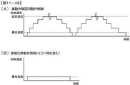
遊技機への電力供給が再開したときに、前記特定情報記憶手段に前記特定情報が記憶されていることに基づいてエラー報知を実行可能なエラー報知手段を備え、
前記エラー報知手段は、遊技機への電力供給が再開したときに、前記特定情報記憶手段に前記特定情報が記憶されている場合であって前記設定許可状態に制御されなかった場合に前記エラー報知を実行可能であり、
遊技機への電力供給が再開したときに、前記特定情報記憶手段に前記特定情報が記憶されている場合であって前記設定許可状態に制御された場合に前記エラー報知を実行せず、
前記外部出力手段は、前記エラー報知が実行されているときに前記特定信号を出力可能である、
ことを特徴とする。この特徴によれば、設定確認をすぐに行いたい状況のときに、好適に設定確認作業を実行することができる。
手段C1の遊技機は、
遊技者にとって有利な有利状態(大当り遊技状態)に制御可能な遊技機(パチンコ遊技機1)であって、
第1特定識別情報の可変表示(第1特別図柄の変動表示)と第2特定識別情報の可変表示(第2特別図柄の変動表示)とを並行して実行可能な特定識別情報可変表示手段(遊技制御用マイクロコンピュータ100)と、
遊技状態(非KT状態、KT状態)に応じて、第1特定識別情報の可変表示(第1特別図柄の変動表示)及び第2特定識別情報の可変表示(第2特別図柄の変動表示)のいずれか一方に対応して装飾識別情報の可変表示(飾り図柄の変動表示)を実行可能な装飾識別情報可変表示手段(演出制御用CPU120)と、
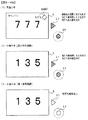
第1特定識別情報の可変表示(第1特別図柄の変動表示)及び第2特定識別情報の可変表示(第2特別図柄の変動表示)のうち、装飾識別情報の可変表示(飾り図柄の変動表示)に対応した特定識別情報の可変表示に基づいて前記有利状態(大当り遊技状態)に制御されるとき(図10−14(A1)〜(A4)に示すように、飾り図柄に対応する第1特別図柄の変動表示の表示結果が「大当り」となるとき)に、装飾識別情報の可変表示結果を報知する報知演出(図10−14(A4)に示すように、大当りとなる飾り図柄の組み合わせ(本例では、「222」)を停止表示させる演出)を実行可能な報知演出実行手段(演出制御用CPU120)と、を備え、
第1特定識別情報の可変表示(第1特別図柄の変動表示)及び第2特定識別情報の可変表示(第2特別図柄の変動表示)のうち、装飾識別情報の可変表示に対応しない特定識別情報の可変表示に基づいて前記有利状態に制御されるとき(図10−14(B1)〜(B4)に示すように、飾り図柄に対応しない第2特別図柄の変動表示の表示結果が「大当り」となるとき)には、前記報知演出を実行せず(図10−14(B1)に示すように、大当りとなる飾り図柄の組み合わせを停止表示させる演出を実行せずに、「FEVER」の文字を表示することで大当りの発生を報知している)、
さらに、
少なくとも前記有利状態に制御される確率が異なる有利設定値と不利設定値とを含む複数段階の設定値(例えば、最も遊技者にとって不利な設定値である1から最も遊技者にとって有利な設定値である6までの値)のうちのいずれかの設定値に設定可能な設定手段(例えば、CPU103が図11−32に示す設定値変更処理を実行する部分)と、
前記有利状態に制御するか否かを判定するための判定用乱数値を生成可能な判定用乱数値生成手段(例えば、乱数回路104や遊技制御カウンタ設定部207SG154)と、
前記判定用乱数値生成手段にて生成された判定用乱数値と、前記設定手段にて設定されている設定値に対応する有利状態判定値とにもとづいて、前記有利状態に制御するか否かを判定する有利状態判定手段(例えば、CPU103が図11−41に示す特別図柄通常処理を実行する部分)と、
前記有利状態判定手段によって前記有利状態に制御すると判定されたことにもとづいて前記有利状態に制御可能な遊技制御手段(例えば、CPU103が図5に示す特別図柄プロセス処理を実行する部分)と、
を備え、
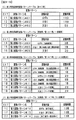
前記有利状態判定値の数が設定値に応じて異なることにより、前記有利状態に制御される確率が異なり(例えば、図11−11〜図11−20に示すように、設定されている設定値に応じて大当り判定値の数が異なることにより、大当り遊技状態に制御される確率が異なる部分)、
前記有利状態判定値は、所定の数値範囲において、前記設定手段にて設定可能な前記複数段階の設定値で共通の共通数値範囲(例えば、1020〜1237の範囲である大当り判定値の共通数値範囲)が少なくとも設定されており、
前記有利設定値の前記有利状態判定値は、所定の数値範囲において、前記共通数値範囲と、前記不利設定値の前記有利状態判定値では設定されていない非共通数値範囲(例えば、1238〜各設定値に応じた値までの範囲である大当り判定値の非共通数値範囲)とを含んで設定されており、
前記共通数値範囲と前記非共通数値範囲とは、所定基準値から連続した数値範囲となるように設定されている(例えば、図11−17及び図11−18に示すように、大当りの数値範囲は、通常状態であるか確変状態であるかにかかわらず1020を大当り基準値とした連続した数値範囲として設定されている部分)
ことを特徴としている。
このような構成によれば、装飾識別情報に対応しない特定識別情報の可変表示に基づいて有利状態に制御されるときには、報知演出を実行しないことによって、いずれの特定識別情報の可変表示に基づいて有利状態に制御されたかを遊技者が誤認してしまうことを防ぐことができる。さらに、有利状態に制御するか否かの判定を行う処理負荷を低減することができる。
(A) The gaming machine according to the present invention includes a setting means (for example, a portion where the
A setting permission control means that can control the setting permission state for permitting the setting of the setting value, and
Specific information storage means for storing specific information that can be identified as being controlled in the setting permission state, and
A setting confirmation control means (for example, a part where the
An interrupt process execution means that executes an interrupt process that can execute a game-related process,
With the ordinary variable display means (for example, CPU 103) that variably displays the ordinary identification information (for example, the ordinary symbol) based on the game medium passing through the predetermined area (for example, the passing gate 41) and derives and displays the display result. ,
A normal variable display time measuring means (for example, a
A special variable display means (for example, a
A special variable display timing means (for example, CPU 103) that measures a special variable display period for variable display of special identification information, and
It is equipped with an external output means capable of outputting a specific signal to the outside of the gaming machine (for example, outputting a security signal to a management device such as a management computer of a game hall).
The setting confirmation control means can control the setting confirmation state when the power supply to the gaming machine is started and before the interrupt processing is permitted.
When the setting confirmation state ends, the interrupt process is permitted, and after the interrupt process is permitted, the setting confirmation state is not controlled until the power supply to the gaming machine is stopped.
When the power supply to the game machine is stopped when the normal variable display period is timed, and then the power supply to the game machine is restarted and controlled to the setting confirmation state, the setting confirmation state is changed. The time measurement of the normal variable display period is interrupted until the end, and when the setting confirmation state ends, the time measurement of the normal variable display period is restarted (for example, when the
When the power supply to the game machine is stopped when the special variable display period is timed, and then the power supply to the game machine is restarted and controlled to the setting confirmation state, the setting confirmation state is changed. The time measurement of the special variable display period is interrupted until the end, and when the setting confirmation state ends, the time measurement of the special variable display period is restarted (for example, when the
When controlled to the setting confirmation state, the mode of the special variable display means is different from the variable display result (in the set value confirmation process, the first special symbol display device 207SG004A and the second special symbol display device 207SG004B). Start lighting all segments that make up),
The external output means
Wherein Ri can be output der the specific signal when it is controlled to set confirmation state (e.g., security signal is output when it is controlled to set confirmation state),
The specific signal can be output when controlled to the setting permission state, and the specific signal can be output.
The specific information is deleted based on the end of the control of the setting permission state.
The specific information storage means can store the specific information when the power supply to the gaming machine is stopped without ending the control of the setting permission state.
An error notification means capable of executing error notification based on the specific information stored in the specific information storage means when the power supply to the gaming machine is resumed is provided.
The error notification means notifies the error when the specific information is stored in the specific information storage means and is not controlled to the setting permission state when the power supply to the gaming machine is resumed. Is feasible and
When the power supply to the gaming machine is resumed, the error notification is not executed when the specific information is stored in the specific information storage means and is controlled to the setting permission state.
The external output means can output the specific signal when the error notification is being executed.
It is characterized by that. According to this feature, the setting confirmation work can be preferably executed when the setting confirmation is desired to be performed immediately.
The gaming machine of means C1
It is a gaming machine (pachinko gaming machine 1) that can be controlled to an advantageous state (big hit gaming state) that is advantageous for the player.
Specific identification information variable display means (variable display of specific identification information) that can execute variable display of the first specific identification information (variable display of the first special symbol) and variable display of the second specific identification information (variable display of the second special symbol) in parallel. Game control microcomputer 100) and
Variable display of the first specific identification information (variable display of the first special symbol) and variable display of the second specific identification information (variable display of the second special symbol) according to the game state (non-KT state, KT state). A decorative identification information variable display means (
Of the variable display of the first specific identification information (variable display of the first special symbol) and the variable display of the second specific identification information (variable display of the second special symbol), the variable display of the decorative identification information (variable display of the decorative symbol). ) Is controlled in the advantageous state (big hit game state) based on the variable display of the specific identification information (as shown in FIGS. 10-14 (A1) to (A4), the first corresponding the decorative symbol. When the display result of the variable display of the special symbol becomes a "big hit"), a notification effect for notifying the variable display result of the decoration identification information (as shown in FIG. 10-14 (A4)), a combination of decorative symbols that become a big hit. (In this example, the effect of stopping and displaying "222")) is provided with a notification effect execution means (effect control CPU 120) capable of executing the effect.
Of the variable display of the first specific identification information (variable display of the first special symbol) and the variable display of the second specific identification information (variable display of the second special symbol), the specific identification information that does not correspond to the variable display of the decorative identification information. When the advantageous state is controlled based on the variable display of (as shown in FIGS. 10-14 (B1) to (B4), the display result of the variable display of the second special symbol that does not correspond to the decorative symbol is "big hit". (When), the character "FEVER" is not executed (as shown in FIG. 10-14 (B1)), the effect of stopping and displaying the combination of decorative symbols that is a big hit is not executed. Is displayed to notify the occurrence of a big hit),
Moreover,
A multi-step setting value including at least an advantageous setting value and a disadvantage setting value having different probabilities of being controlled in the advantageous state (for example, from 1 which is the most disadvantageous setting value for the player to the most advantageous setting value for the player). A setting means that can be set to any of the set values (values up to 6) (for example, a portion where the
A random number value generation means for determination (for example, a
Whether or not to control the advantageous state based on the determination random value generated by the determination random value generation means and the advantageous state determination value corresponding to the set value set by the setting means. (For example, the portion where the
A game control means (for example, a portion where the
With
Since the number of the advantageous state determination values is different depending on the set value, the probability of being controlled to the advantageous state is different (for example, as shown in FIGS. 11-11 to 11-20, the set value is set. The probability of being controlled to the jackpot game state differs depending on the number of jackpot determination values),
The advantageous state determination value is a common numerical range common to the set values of the plurality of stages that can be set by the setting means in a predetermined numerical range (for example, a common numerical range of jackpot determination values in the range of 1020 to 1237). ) Is set at least
The advantageous state determination value of the advantageous setting value is a non-common numerical range (for example, 1238 to 1238 to each setting) that is not set in the common numerical range and the advantageous state determination value of the disadvantage setting value in a predetermined numerical range. It is set including the non-common numerical range of the jackpot judgment value, which is the range up to the value according to the value.
The common numerical range and the non-common numerical range are set to be continuous numerical ranges from a predetermined reference value (for example, as shown in FIGS. 11-17 and 11-18, a jackpot numerical range). Is the part set as a continuous numerical range with 1020 as the jackpot reference value regardless of whether it is in the normal state or the probabilistic state)
It is characterized by that.
According to such a configuration, when the control is performed in an advantageous state based on the variable display of the specific identification information that does not correspond to the decorative identification information, the notification effect is not executed, and the specific identification information is based on the variable display of any of the specific identification information. It is possible to prevent the player from misunderstanding whether the control is in an advantageous state. Further, it is possible to reduce the processing load for determining whether or not to control in an advantageous state.
手段C2の遊技機は、
手段C1の遊技機であって、
第1特定識別情報の可変表示(第1特別図柄の変動表示)及び第2特定識別情報の可変表示(第2特別図柄の変動表示)のうち、装飾識別情報の可変表示に対応した特定識別情報の可変表示に基づいて前記有利状態に制御されるとき(図10−14(A1)〜(A4)に示すように、飾り図柄に対応する第1特別図柄の変動表示の表示結果が「大当り」となるとき)に、可動体を用いた可動体演出(図10−14(A3)に示すように、可動体06TM100を傾倒位置から起立位置に動作させる可動体動作演出)を実行可能な可動体演出実行手段(演出制御用CPU120)を備え、
第1特定識別情報の可変表示(第1特別図柄の変動表示)及び第2特定識別情報の可変表示(第2特別図柄の変動表示)のうち、装飾識別情報の可変表示に対応しない特定識別情報の可変表示に基づいて前記有利状態に制御されるとき(図10−14(B1)〜(B4)に示すように、飾り図柄に対応しない第2特別図柄の変動表示の表示結果が「大当り」となるとき)には、前記可動体演出を実行しない(図10−14(B3)及び(B4)に示すように、可動体動作演出を実行しない)
ことを特徴とする遊技機。
このような構成によれば、装飾識別情報の可変表示に注目している遊技者が予期しない不規則なタイミングで可動体演出が実行されてしまうことにより、有利状態に制御される割合の高い可動体演出の興趣の低下を防ぐ。
The gaming machine of means C2 is
Means C1 gaming machine
Of the variable display of the first specific identification information (variable display of the first special symbol) and the variable display of the second specific identification information (variable display of the second special symbol), the specific identification information corresponding to the variable display of the decorative identification information. When the advantageous state is controlled based on the variable display of (as shown in FIGS. 10-14 (A1) to (A4), the display result of the variable display of the first special symbol corresponding to the decorative symbol is "big hit". (When), a movable body that can perform a movable body effect (a movable body motion effect that moves the movable body 06TM100 from an inclined position to an upright position as shown in FIG. 10-14 (A3)). Equipped with effect execution means (effect control CPU 120)
Of the variable display of the first specific identification information (variable display of the first special symbol) and the variable display of the second specific identification information (variable display of the second special symbol), the specific identification information that does not correspond to the variable display of the decorative identification information. When the advantageous state is controlled based on the variable display of (as shown in FIGS. 10-14 (B1) to (B4), the display result of the variable display of the second special symbol that does not correspond to the decorative symbol is "big hit". (When), the movable body effect effect is not executed (as shown in FIGS. 10-14 (B3) and (B4), the movable body motion effect is not executed).
A gaming machine characterized by that.
According to such a configuration, the player paying attention to the variable display of the decoration identification information executes the movable body effect at an unexpected irregular timing, so that the movable body is controlled at a high rate of advantageous state. Prevents the decline in the interest of body production.
手段C3の遊技機は、
手段C1又は手段C2の遊技機であって、
第1始動条件が成立(入賞球装置6Aへの始動入賞が発生)した後に第1開始条件が成立した(図10−3に示すように、第1特別図柄通常処理において、第2特別図柄の変動表示結果に基づく大当り遊技状態及び小当り遊技状態の何れにも制御されておらず且つ第1保留記憶数が0でない)ことに基づいて第1特定識別情報(第1特別図柄)の可変表示(変動表示)を実行し、
第2始動条件が成立(可変入賞球装置6Bへの始動入賞が発生)した後に第2開始条件が成立した(図10−4に示すように、第2特別図柄通常処理において、第2特別図柄の変動表示結果に基づく大当り遊技状態及び小当り遊技状態の何れにも制御されておらず且つ第2保留記憶数が0でない)ことに基づいて第2特定識別情報(第2特別図柄)の可変表示(変動表示)を実行し、
前記有利状態(大当り遊技状態)とは異なる特殊状態(小当り遊技状態)に制御可能であり、
前記有利状態(大当り遊技状態)に制御されているときに前記第1開始条件及び前記第2開始条件が成立不能であり(図10−3に示すように、第1特別図柄通常処理において、第2特別図柄の変動表示結果に基づく大当り遊技状態に制御されており(ステップS06TM1000AでYES)、図10−4に示すように、第2特別図柄通常処理において、第1特別図柄の変動表示結果に基づく大当り遊技状態に制御されており(ステップS06TM1000BでYES))、
前記特殊状態(小当り遊技状態)に制御されているときに前記第1開始条件及び前記第2開始条件が成立不能である(図10−3に示すように、第1特別図柄通常処理において、第2特別図柄の変動表示結果に基づく小当り遊技状態に制御されているときは(ステップS06TM1000AでYES)、第1特別図柄の変動表示が開始されず、図10−4に示すように、第2特別図柄通常処理において、第1特別図柄の変動表示結果に基づく小当り遊技状態に制御されているときは(ステップS06TM1000BでYES)、第2特別図柄の変動表示が開始されない)
ことを特徴とする遊技機。
このような構成によれば、有利状態に制御されているときに開始条件が成立不能であることにより、遊技者を有利状態における遊技に集中させることができる。また、特殊状態に制御されているときに開始条件が成立不能であることにより、遊技者を有利状態における遊技に集中させることができる。
The gaming machine of means C3 is
A gaming machine of means C1 or means C2.
After the first start condition is satisfied (starting prize for the winning ball device 6A occurs), the first start condition is satisfied (as shown in FIG. 10-3, in the first special symbol normal processing, the second special symbol Variable display of the first specific identification information (first special symbol) based on the fact that neither the big hit game state nor the small hit game state based on the variable display result is controlled and the first reserved storage number is not 0). Execute (variable display) and
After the second start condition is satisfied (starting prize for the variable winning ball device 6B occurs), the second starting condition is satisfied (as shown in FIG. 10-4, in the second special symbol normal processing, the second special symbol The second specific identification information (second special symbol) is variable based on the fact that neither the big hit game state nor the small hit game state is controlled based on the variable display result of the above and the second reserved memory number is not 0). Execute display (variable display) and
It is possible to control a special state (small hit game state) different from the advantageous state (big hit game state).
The first start condition and the second start condition cannot be satisfied when controlled to the advantageous state (big hit game state) (as shown in FIG. 10-3, in the first special symbol normal processing, the first 2 It is controlled to the jackpot game state based on the variation display result of the special symbol (YES in step S06TM1000A), and as shown in FIG. 10-4, in the second special symbol normal processing, the variation display result of the first special symbol is displayed. It is controlled to the jackpot game state based on (YES in step S06TM1000B),
The first start condition and the second start condition cannot be satisfied when the special state (small hit game state) is controlled (as shown in FIG. 10-3, in the first special symbol normal process). When the small hit game state is controlled based on the variation display result of the second special symbol (YES in step S06TM1000A), the variation display of the first special symbol is not started, and as shown in FIG. 10-4, the first 2 In the special symbol normal processing, when the small hit game state based on the variation display result of the first special symbol is controlled (YES in step S06TM1000B), the variation display of the second special symbol is not started).
A gaming machine characterized by that.
According to such a configuration, the player can concentrate on the game in the advantageous state because the start condition cannot be satisfied when the control is in the advantageous state. Further, since the start condition cannot be satisfied when the game is controlled to the special state, the player can concentrate on the game in the advantageous state.
手段C4の遊技機は、
手段C3の遊技機であって、
前記特殊状態(小当り遊技状態)に制御される頻度が高い特別状態(KT状態)に制御可能である
ことを特徴とする遊技機。
このような構成によれば、遊技者にとって有利な遊技状態として有利状態とは異なる遊技状態を実現できる。
The gaming machine of means C4 is
Means C3 gaming machine
A gaming machine characterized in that it can be controlled to a special state (KT state) that is frequently controlled to the special state (small hit gaming state).
According to such a configuration, it is possible to realize a gaming state different from the advantageous state as an advantageous gaming state for the player.
手段C5の遊技機は、
手段C1〜手段C4から選択される何れかの遊技機であって、
遊技状態によらず、第1特定識別情報の可変表示(第1特別図柄の変動表示)に対応して装飾識別情報(飾り図柄)よりも視認性が低い第1特殊識別情報の可変表示を実行可能(第1特別図柄の変動表示に対応して第1小図柄の変動表示を実行可能)であり、第2特定識別情報の可変表示(第2特別図柄の変動表示)に対応して装飾識別情報(飾り図柄)よりも視認性が低い第2特殊識別情報の可変表示を実行可能(第2特別図柄の変動表示に対応して第2小図柄の変動表示を実行可能)である
ことを特徴とする遊技機。
このような構成によれば、遊技者は、特殊識別情報の可変表示の状況を確認することによって、特定識別情報の可変表示の状況を把握することができる。
The gaming machine of means C5 is
Any gaming machine selected from means C1 to means C4.
Regardless of the game state, the variable display of the first special identification information, which is less visible than the decorative identification information (decorative symbol), is executed in response to the variable display of the first specific identification information (variable display of the first special symbol). Possible (variable display of the first small symbol can be executed corresponding to the variable display of the first special symbol), and decorative identification corresponding to the variable display of the second specific identification information (variable display of the second special symbol) It is characterized by being able to execute variable display of the second special identification information, which is less visible than information (decorative symbol) (variable display of the second small symbol can be executed in response to the variable display of the second special symbol). A game machine to be.
According to such a configuration, the player can grasp the status of the variable display of the specific identification information by checking the status of the variable display of the special identification information.
手段C6の遊技機は、
手段C1〜手段C5から選択される何れかの遊技機であって、
前記特定識別情報可変表示手段(遊技制御用マイクロコンピュータ100)を有する遊技制御部(主基板11)と、
前記装飾識別情報可変表示手段(演出制御用CPU120)と、装飾識別情報の可変表示(飾り図柄の変動表示)が実行されていないときに特別演出(第1デモ表示、第2デモ表示)を実行可能な特別演出実行手段(演出制御用CPU120)とを有する演出制御部(演出制御基板12)と、を含み、
前記特定識別情報可変表示手段(遊技制御用マイクロコンピュータ100)は、第1始動条件が成立(入賞球装置6Aへの始動入賞が発生)した後に第1開始条件が成立した(図10−3に示すように、第1特別図柄通常処理において、第2特別図柄の変動表示結果に基づく大当り遊技状態及び小当り遊技状態の何れにも制御されておらず且つ第1保留記憶数が0でない)ことに基づいて第1特定識別情報の可変表示(第1特別図柄の変動表示)を実行し、第2始動条件が成立(可変入賞球装置6Bへの始動入賞が発生)した後に第2開始条件が成立した(図10−4に示すように、第2特別図柄通常処理において、第1特別図柄の変動表示結果に基づく大当り遊技状態及び小当り遊技状態の何れにも制御されておらず且つ第2保留記憶数が0でない)ことに基づいて第2特定識別情報の可変表示(第2特別図柄の変動表示)を実行し、
前記遊技制御部(主基板11)は、前記第1始動条件が成立しておらず(入賞球装置6Aへの始動入賞が発生しておらず)且つ第1特定識別情報の可変表示が実行されていない(第1特別図柄の変動表示が実行されていない)ことに対応した第1特別コマンド(第1客待ちデモ表示指定コマンド)と、前記第2始動条件が成立しておらず(可変入賞球装置6Bへの始動入賞が発生しておらず)且つ第2特定識別情報の可変表示が実行されていない(第1特別図柄の変動表示が実行されていない)ことに対応した第2特別コマンドと(第2客待ちデモ表示指定コマンド)を送信可能であり、
前記演出制御部(演出制御基板12)は、前記第1特別コマンドを受信したときに第1遊技状態であることに応じて前記特別演出実行手段により第1特別演出を実行可能であり(図9−38に示すように、演出制御用CPU120は、第1客待ちデモ表示指定コマンドを受信したときに(ステップ026IWS4701でYES)、非KT状態であることに基づいて(ステップ026IWS4702でYES)、第1デモ表示を開始し(ステップ026IWS4711))、前記第2特別コマンドを受信したときに第2遊技状態であることに応じて前記特別演出実行手段により第2特別演出を実行可能である(図9−39に示すように、演出制御用CPU120は、第2客待ちデモ表示指定コマンドを受信したときに(ステップ026IWS4801でYES)、KT状態であることに基づいて(ステップ026IWS4802でYES)、第2デモ表示を開始する(ステップ026IWS4811))
ことを特徴とする遊技機。
このような構成によれば、現在の遊技状態に対応したコマンドを受信した場合にのみ、特別演出を開始させることが可能となり、遊技状態に応じて適切なタイミングで特別演出を開始させることができる。
The gaming machine of means C6 is
Any gaming machine selected from means C1 to means C5.
A game control unit (main board 11) having the specific identification information variable display means (game control microcomputer 100), and
When the decorative identification information variable display means (effect control CPU 120) and the decorative identification information variable display (decorative pattern variable display) are not executed, special effects (first demo display, second demo display) are executed. Including an effect control unit (effect control board 12) having a possible special effect execution means (effect control CPU 120),
In the specific identification information variable display means (
In the game control unit (main board 11), the first starting condition is not satisfied (starting winning to the winning ball device 6A has not occurred), and the variable display of the first specific identification information is executed. The first special command (first customer waiting demo display designation command) corresponding to the fact that the first special symbol is not displayed (variable display of the first special symbol is not executed) and the second start condition are not satisfied (variable prize). The second special command corresponding to the fact that the start winning prize for the ball device 6B has not occurred) and the variable display of the second specific identification information has not been executed (the variable display of the first special symbol has not been executed). And (second customer waiting demo display specification command) can be sent,
The effect control unit (effect control board 12) can execute the first special effect by the special effect executing means according to the first gaming state when the first special command is received (FIG. 9). As shown in −38, when the
A gaming machine characterized by that.
According to such a configuration, the special effect can be started only when the command corresponding to the current game state is received, and the special effect can be started at an appropriate timing according to the game state. ..
手段C7の遊技機は、
手段C6の遊技機であって、
前記第1特別演出(第1デモ表示)を実行しているときに、第1特定識別情報(第1特別図柄)に対応した開始条件が成立した(図10−3に示すように、第1特別図柄通常処理において、第2特別図柄の変動表示結果に基づく大当り遊技状態及び小当り遊技状態の何れにも制御されておらず且つ第1保留記憶数が0でない)ことに応じて前記第1特別演出を終了させ(図9−38に示すように、第1特別図柄の変動表示が開始されると(ステップ026IWS4714でYES)、第1デモ表示を終了させ(ステップ026IWS4716))、
前記第2特別演出(第2デモ表示)を実行しているときに、第2特定識別情報(第2特別図柄)に対応した開始条件が成立した(図10−4に示すように、第2特別図柄通常処理において、第1特別図柄の変動表示結果に基づく大当り遊技状態及び小当り遊技状態の何れにも制御されておらず且つ第2保留記憶数が0でない)ことに応じて前記第2特別演出を終了させる(図9−39に示すように、第2特別図柄の変動表示が開始されると(ステップ026IWS4814でYES)、第2デモ表示をさせる(ステップ026IWS4816))
ことを特徴とする遊技機。
このような構成によれば、特定識別情報の可変表示の実行状況に対応した適切な演出制御を実現可能となる。
The gaming machine of means C7 is
Means C6 gaming machine
While executing the first special effect (first demo display), the start condition corresponding to the first specific identification information (first special symbol) was satisfied (as shown in FIG. 10-3, the first In the special symbol normal processing, the first is not controlled by either the big hit game state or the small hit game state based on the variation display result of the second special symbol, and the first reserved storage number is not 0). When the special effect is finished (as shown in FIGS. 9-38, when the variable display of the first special symbol is started (YES in step 026IWS4714), the first demo display is finished (step 026IWS4716)).
While executing the second special effect (second demo display), the start condition corresponding to the second specific identification information (second special symbol) was satisfied (as shown in FIG. 10-4, the second In the special symbol normal processing, the second is not controlled by either the big hit game state or the small hit game state based on the variation display result of the first special symbol, and the second reserved storage number is not 0). When the special effect is terminated (as shown in FIGS. 9-39, when the variation display of the second special symbol is started (YES in step 026IWS4814), the second demo display is performed (step 026IWS4816)).
A gaming machine characterized by that.
According to such a configuration, it is possible to realize appropriate effect control corresponding to the execution status of the variable display of the specific identification information.
手段C8の遊技機は、
手段C1〜手段C7から選択される何れかの遊技機であって、
前記特定識別情報可変表示手段(遊技制御用マイクロコンピュータ100)は、第1始動条件が成立(入賞球装置6Aへの始動入賞が発生)した後に第1開始条件が成立した(図10−3に示すように、第1特別図柄通常処理において、第2特別図柄の変動表示結果に基づく大当り遊技状態及び小当り遊技状態の何れにも制御されておらず且つ第1保留記憶数が0でない)ことに基づいて第1特定識別情報の可変表示(第1特別図柄の変動表示)を実行し、第2始動条件が成立(可変入賞球装置6Bへの始動入賞が発生)した後に第2開始条件が成立した(図10−4に示すように、第2特別図柄通常処理において、第1特別図柄の変動表示結果に基づく大当り遊技状態及び小当り遊技状態の何れにも制御されておらず且つ第2保留記憶数が0でない)ことに基づいて第2特定識別情報の可変表示(第2特別図柄の変動表示)を実行し、
前記特別演出(第1デモ表示)の実行中において、前記第1開始条件が成立可能なときに、前記第1始動条件の成立(入賞球装置6Aへの始動入賞の発生)に応じて前記第1始動条件の成立に対応した保留記憶数を第1態様で表示可能であり(図10−1に示すように、第1保留記憶数が4であるときに、第1保留表示領域06TM011に4個の第1保留表示06TM010を表示可能であり)、
前記特別演出(第1デモ表示)の実行中において、前記第1開始条件が成立不能な(図10−3に示すように、第1特別図柄通常処理において、第2特別図柄の変動表示結果に基づく大当り遊技状態又は小当り遊技状態に制御されている)ときに、前記第1始動条件の成立(入賞球装置6Aへの始動入賞の発生)に応じて前記第1始動条件の成立に対応した保留記憶数を前記第1態様よりも視認性が低い第2態様で表示可能であり(図10−6に示すように、第1保留記憶数が1であるときに、第1保留記憶数特別表示領域06TM015に「1」を表示可能であり)、
前記特別演出(第2デモ表示)の実行中において、前記第2開始条件が成立可能なときに、前記第2始動条件の成立(可変入賞球装置6Bへの始動入賞の発生)に応じて前記第2始動条件の成立に対応した保留記憶数を第1態様で表示可能であり(図10−1に示すように、第2保留記憶数が4であるときに、第2保留表示領域06TM021に4個の第2保留表示06TM020を表示可能であり)、
前記特別演出(第2デモ表示)の実行中において、前記第2開始条件が成立不能な(図10−4に示すように、第2特別図柄通常処理において、第1特別図柄の変動表示結果に基づく大当り遊技状態又は小当り遊技状態に制御されている)ときに、前記第2始動条件の成立(可変入賞球装置6Bへの始動入賞の発生)に応じて前記第2始動条件の成立に対応した保留記憶数を前記第1態様よりも視認性が低い第2態様で表示可能である(図10−6に示すように、第2保留記憶数が0であるときに、第2保留記憶数特別表示領域06TM025に「0」を表示可能である)
ことを特徴とする遊技機。
このような構成によれば、第1態様よりも視認性の低い第2態様で保留記憶数を表示させることで、保留記憶数を適切に報知することができる。
The gaming machine of means C8 is
Any gaming machine selected from means C1 to means C7.
In the specific identification information variable display means (
During the execution of the special effect (first demo display), when the first start condition can be satisfied, the first start condition is satisfied (the start prize is generated in the winning ball device 6A). 1 The number of reserved storages corresponding to the establishment of the start condition can be displayed in the first aspect (as shown in FIG. 10-1, when the number of 1st reserved storages is 4, 4 in the 1st reserved display area 06TM011. The first hold display 06TM010 can be displayed),
During the execution of the special effect (first demo display), the first start condition cannot be satisfied (as shown in FIG. 10-3, in the first special symbol normal processing, the variation display result of the second special symbol is displayed. When the big hit game state or the small hit game state is controlled based on the above, the first start condition is satisfied according to the establishment of the first start condition (occurrence of a start prize to the winning ball device 6A). The reserved storage number can be displayed in the second aspect, which is less visible than the first aspect (as shown in FIG. 10-6, when the first reserved storage number is 1, the first reserved storage number is special. "1" can be displayed in the display area 06TM015),
When the second start condition can be satisfied during the execution of the special effect (second demo display), the second start condition is satisfied (the start prize is generated in the variable winning ball device 6B). The number of reserved storages corresponding to the establishment of the second start condition can be displayed in the first aspect (as shown in FIG. 10-1, when the number of second reserved storages is 4, the second reserved display area 06TM021 can be displayed. 4 second hold display 06TM020 can be displayed),
During the execution of the special effect (second demo display), the second start condition cannot be satisfied (as shown in FIG. 10-4, in the second special symbol normal processing, the variation display result of the first special symbol is displayed. When the big hit game state or the small hit game state is controlled based on the above, the second start condition is satisfied according to the establishment of the second start condition (occurrence of a start prize to the variable winning ball device 6B). The reserved storage number can be displayed in the second aspect, which is less visible than the first aspect (as shown in FIG. 10-6, when the second reserved storage number is 0, the second reserved storage number is displayed. "0" can be displayed in the special display area 06TM025)
A gaming machine characterized by that.
According to such a configuration, by displaying the reserved storage number in the second aspect, which is less visible than the first aspect, the reserved storage number can be appropriately notified.
手段C9の遊技機は、
手段C1〜手段C8から選択される何れかの遊技機であって、
第1特定識別情報の可変表示(第1特別図柄の変動表示)及び第2特定識別情報の可変表示(第2特別図柄の変動表示)のうちの一方の特定識別情報の可変表示中(第1特別図柄の変動表示中)に、他方の特定識別情報の可変表示結果(第2特別図柄の変動表示結果が「小当り」となること)に基づいて前記有利状態(大当り遊技状態)とは異なる特殊状態(小当り遊技状態)に制御されるときに、一方の特定識別情報の可変表示(第1特別図柄の変動表示)を中断させる可変表示中断手段(遊技制御用マイクロコンピュータ100)と、
前記特殊状態(小当り遊技状態)の終了に伴う終了演出(小当り終了指定コマンドの受信に応じて実行される演出であり、例えば、図10−12(A4)に示すように、開放していた特殊可変入賞球装置17を閉鎖後に、画像表示装置5にキャラクタ及び「30pt
GET!」の文字を表示させる演出等)を実行可能な終了演出実行手段(演出制御用CPU120)と、を備え、
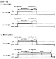
前記特殊状態(小当り遊技状態)に制御される頻度が高い特別状態(第2KT状態)よりも、非特別状態(第1KT状態)の方が前記終了演出(図10−12(B3)に示すように、開放していた特殊可変入賞球装置17を閉鎖後に、画像表示装置5のアクティブ表示領域06TM031に表示されていたアクティブ表示06TM030と、第2保留表示領域06TM021に表示されていた4個の第2保留表示06TM020とを消去する演出)の実行期間が短い(図10−11(A)に示すように、第2KT状態では、小当りエンディング期間が3秒である一方で、図10−11(B)に示すように、第1KT状態では、小当りエンディング期間が0.5秒である)
ことを特徴とする遊技機。
このような構成によれば、非特別状態において、一方の特定識別情報の可変表示を中断させる期間を短くすることができ、一方の特定演出情報の可変表示状況と一方の特定識別情報に対応した演出との不整合を抑制することができる。
The gaming machine of means C9 is
Any gaming machine selected from means C1 to means C8.
Variable display of one of the variable display of the first specific identification information (variable display of the first special symbol) and the variable display of the second specific identification information (variable display of the second special symbol) (first variable display of the specific identification information) It is different from the advantageous state (big hit game state) based on the variable display result of the other specific identification information (the variable display result of the second special symbol is "small hit") during the variable display of the special symbol). A variable display interrupting means (
An end effect (an effect executed in response to the reception of a small hit end designation command) accompanying the end of the special state (small hit game state), for example, as shown in FIG. 10-12 (A4), is open. After closing the special variable winning ball device 17, the character and "30pt" are displayed on the
GET! It is provided with an end effect execution means (effect control CPU 120) capable of executing an effect (such as an effect of displaying the characters).
The non-special state (first KT state) is shown in the end effect (FIG. 10-12 (B3)) than the special state (second KT state), which is frequently controlled by the special state (small hit game state). As described above, after closing the open special variable winning ball device 17, the active display 06TM030 displayed in the active display area 06TM031 of the
A gaming machine characterized by that.
According to such a configuration, it is possible to shorten the period for suspending the variable display of one specific identification information in the non-special state, and it corresponds to the variable display status of one specific effect information and the other specific identification information. Inconsistency with the production can be suppressed.
遊技機として、特開2017−086690号公報(図22)に示すように、可変表示の実行状況に応じてデモ表示(特別演出)を行う遊技機が提案されている。また、特開2015−156952号公報(段落0050)に示すように、第1特別図柄(第1特定識別情報)および第2特別図柄(第2特定識別情報)が同時に可変表示される遊技機が提案されている。特開2015−156952号公報(段落0050)に記載されたような2つの特定識別情報の可変表示を並行して実行可能な遊技機に対して、特開2017−086690号公報(図22)に記載された特別演出を実行する構成を適用した場合に、特別演出に関する演出制御を適切に行う必要がある。手段A1〜手段A9に係る発明は、上記の実状に鑑みてなされたものであり、2つの特定識別情報の可変表示を並行して実行可能な遊技機において、特別演出に関する演出制御を適切に行うことにある。 As a gaming machine, as shown in Japanese Patent Application Laid-Open No. 2017-086690 (FIG. 22), a gaming machine that performs demo display (special effect) according to the execution status of variable display has been proposed. Further, as shown in Japanese Patent Application Laid-Open No. 2015-156952 (paragraph 0050), there is a gaming machine in which the first special symbol (first specific identification information) and the second special symbol (second specific identification information) are variably displayed at the same time. Proposed. For a gaming machine capable of executing variable display of two specific identification information in parallel as described in JP-A-2015-156952 (paragraph 0050), JP-A-2017-086690 (Fig. 22) When the above-described configuration for executing the special effect is applied, it is necessary to appropriately control the effect related to the special effect. The inventions according to the means A1 to the means A9 have been made in view of the above-mentioned actual conditions, and appropriately control the effect related to the special effect in the gaming machine capable of executing the variable display of the two specific identification information in parallel. There is.
手段A1の遊技機は、
遊技者にとって有利な有利状態(大当り遊技状態)に制御可能な遊技機(パチンコ遊技機1)であって、
第1始動条件(入賞球装置6Aへの始動入賞が発生)が成立した後に第1開始条件が成立した(図10−3に示すように、第1特別図柄通常処理において、第2特別図柄の変動表示結果に基づく大当り遊技状態及び小当り遊技状態の何れにも制御されておらず且つ第1保留記憶数が0でない)ことに基づいて第1特定識別情報(第1特別図柄)の可変表示を実行するとともに、第2始動条件(可変入賞球装置6Bへの始動入賞が発生)が成立した後に第2開始条件が成立した(図10−4に示すように、第2特別図柄通常処理において、第1特別図柄の変動表示結果に基づく大当り遊技状態及び小当り遊技状態の何れにも制御されておらず且つ第2保留記憶数が0でない)ことに基づいて第2特定識別情報(第2特別図柄)の可変表示を実行し、第1特定識別情報の可変表示(第1特別図柄の変動表示)と第2特定識別情報の可変表示(第2特別図柄の変動表示)とを並行して実行可能な特定識別情報可変表示手段(遊技制御用マイクロコンピュータ100)と、
遊技状態(非KT状態、KT状態)に応じて、第1特定識別情報の可変表示(第1特別図柄の変動表示)及び第2特定識別情報の可変表示(第2特別図柄の変動表示)のいずれか一方に対応して装飾識別情報の可変表示(飾り図柄の変動表示)を実行可能な装飾識別情報可変表示手段(演出制御用CPU120)と、
装飾識別情報の可変表示(飾り図柄の変動表示)が実行されていないときに特別演出(第1デモ表示、第2デモ表示)を実行可能な特別演出実行手段(演出制御用CPU120)と、を備え、
前記特別演出(第1デモ表示、第2デモ表示)の実行中において、前記第1開始条件及び前記第2開始条件が成立可能なときに、前記第1始動条件及び前記第2始動条件のいずれか一方が成立したことに基づいて前記特別演出を終了させることが可能であり(図9−38に示すように、第1特別図柄の変動表示が開始されると(ステップ026IWS4714でYES)、第1デモ表示が終了し(ステップ026IWS4716)、図9−39に示すように、第2特別図柄の変動表示が開始されると(ステップ026IWS4814でYES)、第2デモ表示が終了し(ステップ026IWS4816))、
前記特別演出(第1デモ表示、第2デモ表示)の実行中において、前記第1開始条件及び前記第2開始条件が成立不能な(図10−3に示すように、第1特別図柄通常処理において、第2特別図柄の変動表示結果に基づいて小当り遊技状態に制御されている(ステップS06TM1000AでYES)、図10−4に示すように、第2特別図柄通常処理において、第1特別図柄の変動表示結果に基づいて小当り遊技状態に制御されている(ステップS06TM1000BでYES))ときに、前記第1始動条件及び前記第2始動条件のいずれか一方が成立したか否かにかかわらず前記特別演出を継続させることが可能である(図9−38に示すように、第1特別図柄の変動表示が開始されず(ステップ026IWS4714でNO)、小当り遊技状態に制御されているので(ステップ026IWS4715でNO)、第1デモ表示が終了せず、図9−39に示すように、第2特別図柄の変動表示が開始されず(ステップ026IWS4814でNO)、小当り遊技状態に制御されているので(ステップ026IWS4815でYES)、第2デモ表示が終了しない)
ことを特徴とする遊技機。
このような構成によれば、特定識別情報の変動表示の状況に対応した適切な演出制御を実現できる。
The gaming machine of means A1
It is a gaming machine (pachinko gaming machine 1) that can be controlled to an advantageous state (big hit gaming state) that is advantageous for the player.
After the first start condition (starting prize for the winning ball device 6A occurs) is satisfied, the first start condition is satisfied (as shown in FIG. 10-3, in the first special symbol normal processing, the second special symbol Variable display of the first specific identification information (first special symbol) based on the fact that neither the big hit game state nor the small hit game state based on the variable display result is controlled and the first reserved storage number is not 0). Is executed, and the second start condition is satisfied after the second start condition (starting prize for the variable winning ball device 6B is generated) is satisfied (as shown in FIG. 10-4, in the second special symbol normal processing). , The second specific identification information (second) based on the fact that neither the big hit game state nor the small hit game state based on the variation display result of the first special symbol is controlled and the second reserved storage number is not 0). The variable display of the special symbol) is executed, and the variable display of the first specific identification information (variable display of the first special symbol) and the variable display of the second specific identification information (variable display of the second special symbol) are performed in parallel. Executable specific identification information variable display means (
Variable display of the first specific identification information (variable display of the first special symbol) and variable display of the second specific identification information (variable display of the second special symbol) according to the game state (non-KT state, KT state). A decorative identification information variable display means (
A special effect execution means (
When the first start condition and the second start condition can be satisfied during the execution of the special effect (first demo display, second demo display), any of the first start condition and the second start condition. It is possible to end the special effect based on the establishment of either one (as shown in FIGS. 9-38, when the variable display of the first special symbol is started (YES in step 026IWS4714), the first 1 When the demo display ends (step 026IWS4716) and the variable display of the second special symbol starts (YES in step 026IWS4814) as shown in FIG. 9-39, the second demo display ends (step 026IWS4816). ),
While the special effect (first demo display, second demo display) is being executed, the first start condition and the second start condition cannot be satisfied (as shown in FIG. 10-3, the first special symbol normal process). In, the small hit game state is controlled based on the variation display result of the second special symbol (YES in step S06TM1000A), and as shown in FIG. 10-4, in the second special symbol normal processing, the first special symbol When the small hit game state is controlled based on the variation display result of (YES in step S06TM1000B), regardless of whether or not either the first start condition or the second start condition is satisfied. Since the special effect can be continued (as shown in FIGS. 9-38, the variation display of the first special symbol is not started (NO in step 026IWS4714), it is controlled to the small hit game state (NO). Step 026IWS4715 NO), the first demo display did not end, and as shown in FIG. 9-39, the variation display of the second special symbol did not start (NO in step 026IWS4814), and it was controlled to the small hit game state. (YES in step 026IWS4815), so the second demo display does not end)
A gaming machine characterized by that.
According to such a configuration, it is possible to realize appropriate effect control corresponding to the situation of variable display of the specific identification information.
手段A2の遊技機は、
手段A1の遊技機であって、
前記装飾識別情報可変表示手段(演出制御用CPU120)は、第1遊技状態(非KT状態)に制御されているときに第1特定識別情報の可変表示(第1特別図柄の変動表示)に対応して装飾識別情報の可変表示(飾り図柄の変動表示)を実行可能であり、第2遊技状態(KT状態)に制御されているときに第2特定識別情報の可変表示(第2特別図柄の変動表示)に対応して装飾識別情報の可変表示(飾り図柄の変動表示)を実行可能であり、
前記特別演出(第1デモ表示)の実行中に前記第1遊技状態(非KT状態)に制御されている場合には、前記第1開始条件が成立可能なときに、前記第1始動条件が成立(入賞球装置6Aへの始動入賞が発生)したことに応じて前記特別演出を終了させる(図9−38に示すように、入賞球装置6Aへの始動入賞が発生すると、第1特別図柄の変動表示が開始され(ステップ026IWS4714でYES)、第1デモ表示は終了する(ステップ026IWS4716))一方、前記第2始動条件が成立したときには前記特別演出を継続させ(図9−38に示すように、可変入賞球装置6Bへの始動入賞が発生すると、第2特別図柄の変動表示が開始されるが、第1特別図柄の変動表示が開始されず(ステップ026IWS4714でNO)、大当り遊技状態に制御されていないので(ステップ026IWS4715でNO)、第1デモ表示は終了せず(ステップ026IWS4716))、
前記特別演出(第2デモ表示)の実行中に前記第2遊技状態(KT状態)に制御されている場合には、前記第2開始条件が成立可能なときに、前記第2始動条件が成立したことに応じて前記特別演出を終了させる(図9−39に示すように、可変入賞球装置6Bへの始動入賞が発生すると、第2特別図柄の変動表示が開始され(ステップ026IWS4814でYES)、第2デモ表示は終了する(ステップ026IWS4816))一方、前記第1始動条件が成立したときには前記特別演出を継続させ(図9−39に示すように、入賞球装置6Aへの始動入賞が発生すると、第1特別図柄の変動表示が開始されるが、第2特別図柄の変動表示が開始されず(ステップ026IWS4814でNO)、KT状態に制御されているので(ステップ026IWS4815でYES)、第2デモ表示は終了せず(ステップ026IWS4816))、
前記特別演出(第1デモ表示、第2デモ表示)の実行中において、前記第1開始条件及び前記第2開始条件が成立不能な(図10−3に示すように、第1特別図柄通常処理において、第2特別図柄の変動表示結果に基づく小当り遊技状態に制御されている(ステップS06TM1000AでYES)、図10−4に示すように、第2特別図柄通常処理において、第1特別図柄の変動表示結果に基づく小当り遊技状態に制御されている(ステップS06TM1000BでYES))ときに、前記第1始動条件が成立したか否かにかかわらず当該特別演出を継続させ(図9−38に示すように、第1特別図柄の変動表示が開始されず(ステップ026IWS4714でNO)、小当り遊技状態に制御されているので(ステップ026IWS4715でNO)、第1デモ表示を終了させず、また、図9−39に示すように、第2特別図柄の変動表示が開始されず(ステップ026IWS4814でNO)、小当り遊技状態に制御されているので(ステップ026IWS4815でYES)、第2デモ表示を終了させない)、前記第2始動条件が成立したか否かにかかわらず当該特別演出を継続させる(図9−38に示すように、可変入賞球装置6Bへの始動入賞が発生すると、第1特別図柄の変動表示が開始されず(ステップ026IWS4714でNO)、小当り遊技状態に制御されているので(ステップ026IWS4715でNO)、第1デモ表示を終了させず、また、図9−39に示すように、第2特別図柄の変動表示が開始されず(ステップ026IWS4814でNO)、小当り遊技状態に制御されているので(ステップ026IWS4815でYES)、第2デモ表示を終了させない)
ことを特徴とする遊技機。
このような構成によれば、特定識別情報の変動表示の状況に対応した適切な演出制御を実現できる。
The gaming machine of means A2 is
It is a gaming machine of means A1 and
The decorative identification information variable display means (effect control CPU 120) corresponds to variable display of the first specific identification information (variable display of the first special symbol) when controlled to the first gaming state (non-KT state). It is possible to execute the variable display of the decorative identification information (variable display of the decorative symbol), and when the second game state (KT state) is controlled, the variable display of the second specific identification information (the second special symbol) is possible. Variable display of decorative identification information (variable display of decorative design) can be executed in response to variable display).
When the first game state (non-KT state) is controlled during the execution of the special effect (first demo display), the first start condition is set when the first start condition can be satisfied. The special effect is terminated in response to the establishment (starting prize for the winning ball device 6A occurs) (as shown in FIGS. 9-38, when the starting winning for the winning ball device 6A occurs), the first special symbol (YES in step 026IWS4714) and the first demo display ends (step 026IWS4716)), while the special effect is continued when the second start condition is satisfied (as shown in FIGS. 9-38). In Since it is not controlled (NO in step 026IWS4715), the first demo display does not end (step 026IWS4716).
When the second game state (KT state) is controlled during the execution of the special effect (second demo display), the second start condition is satisfied when the second start condition can be satisfied. The special effect is terminated in response to the above (as shown in FIGS. 9-39, when the start winning prize for the variable winning ball device 6B occurs, the variation display of the second special symbol is started (YES in step 026IWS4814). , The second demo display ends (step 026IWS4816). On the other hand, when the first start condition is satisfied, the special effect is continued (as shown in FIGS. 9-39, a start prize is generated in the prize ball device 6A. Then, the variation display of the first special symbol is started, but the variation display of the second special symbol is not started (NO in step 026IWS4814), and since it is controlled to the KT state (YES in step 026IWS4815), the second The demo display does not end (step 026IWS4816),
While the special effect (first demo display, second demo display) is being executed, the first start condition and the second start condition cannot be satisfied (as shown in FIG. 10-3, the first special symbol normal process). In, the small hit game state is controlled based on the variation display result of the second special symbol (YES in step S06TM1000A), and as shown in FIG. 10-4, in the second special symbol normal processing, the first special symbol When the small hit game state is controlled based on the variation display result (YES in step S06TM1000B), the special effect is continued regardless of whether or not the first starting condition is satisfied (Fig. 9-38). As shown, since the variation display of the first special symbol is not started (NO in step 026IWS4714) and is controlled to the small hit game state (NO in step 026IWS4715), the first demo display is not ended and the first demo display is not terminated. As shown in FIG. 9-39, the variation display of the second special symbol is not started (NO in step 026IWS4814) and is controlled to the small hit game state (YES in step 026IWS4815), so the second demo display is finished. The special effect is continued regardless of whether or not the second starting condition is satisfied (as shown in FIGS. 9-38, when the starting winning prize for the variable winning ball device 6B occurs, the first special symbol is displayed. Since the fluctuation display of the above is not started (NO in step 026IWS4714) and is controlled to the small hit game state (NO in step 026IWS4715), the first demo display is not ended, and as shown in FIG. 9-39. , The variation display of the second special symbol is not started (NO in step 026IWS4814), and it is controlled to the small hit game state (YES in step 026IWS4815), so the second demo display is not ended).
A gaming machine characterized by that.
According to such a configuration, it is possible to realize appropriate effect control corresponding to the situation of variable display of the specific identification information.
手段A3の遊技機は、
手段A1又は手段A2の遊技機であって、
前記有利状態(大当り遊技状態)とは異なる特殊状態(小当り遊技状態)に制御可能であり、
前記有利状態(大当り遊技状態)に制御されているときに前記第1開始条件及び前記第2開始条件が成立不能であり(図10−3に示すように、第1特別図柄通常処理において、第2特別図柄の変動表示結果に基づく大当り遊技状態に制御されており(ステップS06TM1000AでYES)、図10−4に示すように、第2特別図柄通常処理において、第1特別図柄の変動表示結果に基づく大当り遊技状態に制御されており(ステップS06TM1000BでYES))、
前記特殊状態(小当り遊技状態)に制御されているときに前記第1開始条件及び前記第2開始条件が成立不能である(図10−3に示すように、第1特別図柄通常処理において、第2特別図柄の変動表示結果に基づく小当り遊技状態に制御されているときは(ステップS06TM1000AでYES)、第1特別図柄の変動表示が開始されず、図10−4に示すように、第2特別図柄通常処理において、第1特別図柄の変動表示結果に基づく小当り遊技状態に制御されているときは(ステップS06TM1000BでYES)、第2特別図柄の変動表示が開始されない)
ことを特徴とする遊技機。
このような構成によれば、有利状態に制御されているときに開始条件が成立不能であることにより、遊技者を有利状態における遊技に集中させることができる。また、特殊状態に制御されているときに開始条件が成立不能であることにより、遊技者を有利状態における遊技に集中させることができる。
The gaming machine of means A3 is
A gaming machine of means A1 or means A2.
It is possible to control a special state (small hit game state) different from the advantageous state (big hit game state).
The first start condition and the second start condition cannot be satisfied when controlled to the advantageous state (big hit game state) (as shown in FIG. 10-3, in the first special symbol normal processing, the first 2 It is controlled to the jackpot game state based on the variation display result of the special symbol (YES in step S06TM1000A), and as shown in FIG. 10-4, in the second special symbol normal processing, the variation display result of the first special symbol is displayed. It is controlled to the jackpot game state based on (YES in step S06TM1000B),
The first start condition and the second start condition cannot be satisfied when the special state (small hit game state) is controlled (as shown in FIG. 10-3, in the first special symbol normal process). When the small hit game state is controlled based on the variation display result of the second special symbol (YES in step S06TM1000A), the variation display of the first special symbol is not started, and as shown in FIG. 10-4, the first 2 In the special symbol normal processing, when the small hit game state based on the variation display result of the first special symbol is controlled (YES in step S06TM1000B), the variation display of the second special symbol is not started).
A gaming machine characterized by that.
According to such a configuration, the player can concentrate on the game in the advantageous state because the start condition cannot be satisfied when the control is in the advantageous state. Further, since the start condition cannot be satisfied when the game is controlled to the special state, the player can concentrate on the game in the advantageous state.
手段A4の遊技機は、
手段A3の遊技機であって、
前記特殊状態(小当り遊技状態)に制御される頻度が高い特別状態(KT状態)に制御可能である
ことを特徴とする遊技機。
このような構成によれば、遊技者にとって有利な遊技状態として有利状態とは異なる遊技状態を実現できる。
The gaming machine of means A4 is
Means A3 gaming machine
A gaming machine characterized in that it can be controlled to a special state (KT state) that is frequently controlled to the special state (small hit gaming state).
According to such a configuration, it is possible to realize a gaming state different from the advantageous state as an advantageous gaming state for the player.
手段A5の遊技機は、
手段A1〜手段A4から選択される何れかの遊技機であって、
遊技状態によらず、第1特定識別情報の可変表示(第1特別図柄の変動表示)に対応して装飾識別情報(飾り図柄)よりも視認性が低い第1特殊識別情報の可変表示を実行可能(第1特別図柄の変動表示に対応して第1小図柄の変動表示を実行可能)であり、第2特定識別情報の可変表示(第2特別図柄の変動表示)に対応して装飾識別情報(飾り図柄)よりも視認性が低い第2特殊識別情報の可変表示を実行可能(第2特別図柄の変動表示に対応して第2小図柄の変動表示を実行可能)である
ことを特徴とする遊技機。
このような構成によれば、遊技者は、特殊識別情報の可変表示の状況を確認することによって、特定識別情報の可変表示の状況を把握することができる。
The gaming machine of means A5 is
Any gaming machine selected from means A1 to means A4.
Regardless of the game state, the variable display of the first special identification information, which is less visible than the decorative identification information (decorative symbol), is executed in response to the variable display of the first specific identification information (variable display of the first special symbol). Possible (variable display of the first small symbol can be executed corresponding to the variable display of the first special symbol), and decorative identification corresponding to the variable display of the second specific identification information (variable display of the second special symbol) It is characterized by being able to execute variable display of the second special identification information, which is less visible than information (decorative symbol) (variable display of the second small symbol can be executed in response to the variable display of the second special symbol). A game machine to be.
According to such a configuration, the player can grasp the status of the variable display of the specific identification information by checking the status of the variable display of the special identification information.
手段A6の遊技機は、
手段A1〜手段A5から選択される何れかの遊技機であって、
前記特定識別情報可変表示手段(遊技制御用マイクロコンピュータ100)を有する遊技制御部(主基板11)と、
前記装飾識別情報可変表示手段(演出制御用CPU120)と前記特別演出実行手段(演出制御用CPU120)とを有する演出制御部(演出制御基板12)と、を含み、
前記遊技制御部(主基板11)は、前記第1始動条件が成立しておらず(入賞球装置6Aへの始動入賞が発生しておらず)且つ第1特定識別情報の可変表示が実行されていない(第1特別図柄の変動表示が実行されていない)ことに対応した第1特別コマンド(第1客待ちデモ表示指定コマンド)と、前記第2始動条件が成立しておらず(可変入賞球装置6Bへの始動入賞が発生しておらず)且つ第2特定識別情報の可変表示が実行されていない(第1特別図柄の変動表示が実行されていない)ことに対応した第2特別コマンド(第2客待ちデモ表示指定コマンド)とを送信可能であり、
前記演出制御部(演出制御基板12)は、前記第1特別コマンドを受信したときに第1遊技状態であることに応じて前記特別演出実行手段により第1特別演出を実行可能であり(図9−38に示すように、演出制御用CPU120は、第1客待ちデモ表示指定コマンドを受信したときに(ステップ026IWS4701でYES)、非KT状態であることに基づいて(ステップ026IWS4702でYES)、第1デモ表示を開始し(ステップ026IWS4711))、前記第2特別コマンドを受信したときに第2遊技状態であることに応じて前記特別演出実行手段により第2特別演出を実行可能である(図9−39に示すように、演出制御用CPU120は、第2客待ちデモ表示指定コマンドを受信したときに(ステップ026IWS4801でYES)、KT状態であることに基づいて(ステップ026IWS4802でYES)、第2デモ表示を開始する(ステップ026IWS4811))
ことを特徴とする遊技機。
このような構成によれば、現在の遊技状態に対応したコマンドを受信した場合にのみ、特別演出を開始させることが可能となり、遊技状態に応じて適切なタイミングで特別演出を開始させることができる。
The gaming machine of means A6 is
Any gaming machine selected from means A1 to means A5.
A game control unit (main board 11) having the specific identification information variable display means (game control microcomputer 100), and
The effect control unit (effect control board 12) having the decorative identification information variable display means (effect control CPU 120) and the special effect execution means (effect control CPU 120) is included.
In the game control unit (main board 11), the first starting condition is not satisfied (starting winning to the winning ball device 6A has not occurred), and the variable display of the first specific identification information is executed. The first special command (first customer waiting demo display designation command) corresponding to the fact that the first special symbol is not displayed (variable display of the first special symbol is not executed) and the second start condition are not satisfied (variable prize). The second special command corresponding to the fact that the start winning prize for the ball device 6B has not occurred) and the variable display of the second specific identification information has not been executed (the variable display of the first special symbol has not been executed). (Second customer waiting demo display specification command) can be sent,
The effect control unit (effect control board 12) can execute the first special effect by the special effect executing means according to the first gaming state when the first special command is received (FIG. 9). As shown in −38, when the
A gaming machine characterized by that.
According to such a configuration, the special effect can be started only when the command corresponding to the current game state is received, and the special effect can be started at an appropriate timing according to the game state. ..
手段A7の遊技機は、
手段A6の遊技機であって、
前記第1特別演出(第1デモ表示)を実行しているときに、前記第1開始条件が成立した(図10−3に示すように、第1特別図柄通常処理において、第2特別図柄の変動表示結果に基づく大当り遊技状態及び小当り遊技状態の何れにも制御されておらず且つ第1保留記憶数が0でない)ことに応じて前記第1特別演出を終了させ(図9−38に示すように、第1特別図柄の変動表示が開始されると(ステップ026IWS4714でYES)、第1デモ表示を終了させ(ステップ026IWS4716))、
前記第2特別演出(第2デモ表示)を実行しているときに、前記第2開始条件が成立した(図10−4に示すように、第2特別図柄通常処理において、第1特別図柄の変動表示結果に基づく大当り遊技状態及び小当り遊技状態の何れにも制御されておらず且つ第2保留記憶数が0でない)ことに応じて前記第2特別演出を終了させる(図9−39に示すように、第2特別図柄の変動表示が開始されると(ステップ026IWS4814でYES)、第2デモ表示をさせる(ステップ026IWS4816))
ことを特徴とする遊技機。
このような構成によれば、特定識別情報の可変表示の実行状況に対応した適切な演出制御を実現可能となる。
The gaming machine of means A7 is
Means A6 gaming machine
While the first special effect (first demo display) is being executed, the first start condition is satisfied (as shown in FIG. 10-3, in the first special symbol normal processing, the second special symbol The first special effect is terminated according to the fact that neither the big hit game state nor the small hit game state based on the variable display result is controlled and the first reserved storage number is not 0) (Fig. 9-38). As shown, when the variable display of the first special symbol is started (YES in step 026IWS4714), the first demo display is ended (step 026IWS4716)).
While the second special effect (second demo display) is being executed, the second start condition is satisfied (as shown in FIG. 10-4, in the second special symbol normal processing, the first special symbol The second special effect is terminated according to the fact that neither the big hit game state nor the small hit game state based on the variable display result is controlled and the second reserved storage number is not 0) (FIG. 9-39). As shown, when the variable display of the second special symbol is started (YES in step 026IWS4814), the second demo display is made (step 026IWS4816)).
A gaming machine characterized by that.
According to such a configuration, it is possible to realize appropriate effect control corresponding to the execution status of the variable display of the specific identification information.
手段A8の遊技機は、
手段A1〜手段A7から選択される何れかの遊技機であって、
前記特別演出(第1デモ表示)の実行中において、前記第1開始条件が成立可能なときに、前記第1始動条件の成立(入賞球装置6Aへの始動入賞の発生)に応じて前記第1始動条件の成立に対応した保留記憶数を第1態様で表示可能であり(図10−1に示すように、第1保留記憶数が4であるときに、第1保留表示領域06TM011に4個の第1保留表示06TM010を表示可能であり)、
前記特別演出(第1デモ表示)の実行中において、前記第1開始条件が成立不能な(図10−3に示すように、第1特別図柄通常処理において、第2特別図柄の変動表示結果に基づく大当り遊技状態又は小当り遊技状態に制御されている)ときに、前記第1始動条件の成立(入賞球装置6Aへの始動入賞の発生)に応じて前記第1始動条件の成立に対応した保留記憶数を前記第1態様よりも視認性が低い第2態様で表示可能であり(図10−6に示すように、第1保留記憶数が1であるときに、第1保留記憶数特別表示領域06TM015に「1」を表示可能であり)、
前記特別演出(第2デモ表示)の実行中において、前記第2開始条件が成立可能なときに、前記第2始動条件の成立(可変入賞球装置6Bへの始動入賞の発生)に応じて前記第2始動条件の成立に対応した保留記憶数を第1態様で表示可能であり(図10−1に示すように、第2保留記憶数が4であるときに、第2保留表示領域06TM021に4個の第2保留表示06TM020を表示可能であり)、
前記特別演出(第2デモ表示)の実行中において、前記第2開始条件が成立不能な(図10−4に示すように、第2特別図柄通常処理において、第1特別図柄の変動表示結果に基づく大当り遊技状態又は小当り遊技状態に制御されている)ときに、前記第2始動条件の成立(可変入賞球装置6Bへの始動入賞の発生)に応じて前記第2始動条件の成立に対応した保留記憶数を前記第1態様よりも視認性が低い第2態様で表示可能である(図10−6に示すように、第2保留記憶数が0であるときに、第2保留記憶数特別表示領域06TM025に「0」を表示可能である)
ことを特徴とする遊技機。
このような構成によれば、第1態様よりも視認性の低い第2態様で保留記憶数を表示させることで、保留記憶数を適切に報知することができる。
The gaming machine of means A8 is
Any gaming machine selected from means A1 to means A7.
During the execution of the special effect (first demo display), when the first start condition can be satisfied, the first start condition is satisfied (the start prize is generated in the winning ball device 6A). 1 The number of reserved storages corresponding to the establishment of the start condition can be displayed in the first aspect (as shown in FIG. 10-1, when the number of 1st reserved storages is 4, 4 in the 1st reserved display area 06TM011. The first hold display 06TM010 can be displayed),
During the execution of the special effect (first demo display), the first start condition cannot be satisfied (as shown in FIG. 10-3, in the first special symbol normal processing, the variation display result of the second special symbol is displayed. When the big hit game state or the small hit game state is controlled based on the above, the first start condition is satisfied according to the establishment of the first start condition (occurrence of a start prize to the winning ball device 6A). The reserved storage number can be displayed in the second aspect, which is less visible than the first aspect (as shown in FIG. 10-6, when the first reserved storage number is 1, the first reserved storage number is special. "1" can be displayed in the display area 06TM015),
When the second start condition can be satisfied during the execution of the special effect (second demo display), the second start condition is satisfied (the start prize is generated in the variable winning ball device 6B). The number of reserved storages corresponding to the establishment of the second start condition can be displayed in the first aspect (as shown in FIG. 10-1, when the number of second reserved storages is 4, the second reserved display area 06TM021 can be displayed. 4 second hold display 06TM020 can be displayed),
During the execution of the special effect (second demo display), the second start condition cannot be satisfied (as shown in FIG. 10-4, in the second special symbol normal processing, the variation display result of the first special symbol is displayed. When the big hit game state or the small hit game state is controlled based on the above, the second start condition is satisfied according to the establishment of the second start condition (occurrence of a start prize to the variable winning ball device 6B). The reserved storage number can be displayed in the second aspect, which is less visible than the first aspect (as shown in FIG. 10-6, when the second reserved storage number is 0, the second reserved storage number is displayed. "0" can be displayed in the special display area 06TM025)
A gaming machine characterized by that.
According to such a configuration, by displaying the reserved storage number in the second aspect, which is less visible than the first aspect, the reserved storage number can be appropriately notified.
手段A9の遊技機は、
手段A1〜手段A8から選択される何れかの遊技機であって、
第1特定識別情報の可変表示(第1特別図柄の変動表示)及び第2特定識別情報の可変表示(第2特別図柄の変動表示)のうちの一方の特定識別情報の可変表示中(第1特別図柄の変動表示中)に、他方の特定識別情報の可変表示結果(第2特別図柄の変動表示結果が「小当り」となること)に基づいて前記有利状態(大当り遊技状態)とは異なる特殊状態(小当り遊技状態)に制御されるときに、一方の特定識別情報の可変表示(第1特別図柄の変動表示)を中断させる可変表示中断手段(遊技制御用マイクロコンピュータ100)と、
前記特殊状態(小当り遊技状態)の終了に伴う終了演出(小当り終了指定コマンドの受信に応じて実行される演出であり、例えば、図10−12(A4)に示すように、開放していた特殊可変入賞球装置17を閉鎖後に、画像表示装置5にキャラクタ及び「30pt
GET!」の文字を表示させる演出等)を実行可能な終了演出実行手段(演出制御用CPU120)と、を備え、
前記特殊状態(小当り遊技状態)に制御される頻度が高い特別状態(第2KT状態)よりも、非特別状態(第1KT状態)の方が前記終了演出(図10−12(B3)に示すように、開放していた特殊可変入賞球装置17を閉鎖後に、画像表示装置5のアクティブ表示領域06TM031に表示されていたアクティブ表示06TM030と、第2保留表示領域06TM021に表示されていた4個の第2保留表示06TM020とを消去する演出)の実行期間が短い(図10−11(A)に示すように、第2KT状態では、小当りエンディング期間が3秒である一方で、図10−11(B)に示すように、第1KT状態では、小当りエンディング期間が0.5秒である)
ことを特徴とする遊技機。
このような構成によれば、非特別状態において、一方の特定識別情報の可変表示を中断させる期間を短くすることができ、一方の特定演出情報の可変表示状況と一方の特定識別情報に対応した演出との不整合を抑制することができる。
The gaming machine of means A9 is
Any gaming machine selected from means A1 to means A8.
Variable display of one of the variable display of the first specific identification information (variable display of the first special symbol) and the variable display of the second specific identification information (variable display of the second special symbol) (first variable display of the specific identification information) It is different from the advantageous state (big hit game state) based on the variable display result of the other specific identification information (the variable display result of the second special symbol is "small hit") during the variable display of the special symbol). A variable display interrupting means (
An end effect (an effect executed in response to the reception of a small hit end designation command) accompanying the end of the special state (small hit game state), for example, as shown in FIG. 10-12 (A4), is open. After closing the special variable winning ball device 17, the character and "30pt" are displayed on the
GET! It is provided with an end effect execution means (effect control CPU 120) capable of executing an effect (such as an effect of displaying the characters).
The non-special state (first KT state) is shown in the end effect (FIG. 10-12 (B3)) than the special state (second KT state), which is frequently controlled by the special state (small hit game state). As described above, after closing the open special variable winning ball device 17, the active display 06TM030 displayed in the active display area 06TM031 of the
A gaming machine characterized by that.
According to such a configuration, it is possible to shorten the period for suspending the variable display of one specific identification information in the non-special state, and it corresponds to the variable display status of one specific effect information and the other specific identification information. Inconsistency with the production can be suppressed.
遊技機として、特開2017−086690号公報(図22)に示すように、可変表示の実行状況に応じてデモ表示(特別演出)を行う遊技機が提案されている。また、特開2015−156952号公報(段落0050)に示すように、第1特別図柄(第1特定識別情報)および第2特別図柄(第2特定識別情報)が同時に可変表示される遊技機が提案されている。特開2015−156952号公報(段落0050)に記載されたような2つの特定識別情報の可変表示を並行して実行可能な遊技機に対して、特開2017−086690号公報(図22)に記載された特別演出を実行する構成を適用した場合に、特別演出に関する演出制御を適切に行う必要がある。手段B1〜手段B9に係る発明は、上記の実状に鑑みてなされたものであり、2つの特定識別情報の可変表示を並行して実行可能な遊技機において、特別演出に関する演出制御を適切に行うことにある。 As a gaming machine, as shown in Japanese Patent Application Laid-Open No. 2017-086690 (FIG. 22), a gaming machine that performs demo display (special effect) according to the execution status of variable display has been proposed. Further, as shown in Japanese Patent Application Laid-Open No. 2015-156952 (paragraph 0050), there is a gaming machine in which the first special symbol (first specific identification information) and the second special symbol (second specific identification information) are variably displayed at the same time. Proposed. For a gaming machine capable of executing variable display of two specific identification information in parallel as described in JP-A-2015-156952 (paragraph 0050), JP-A-2017-086690 (Fig. 22) When the above-described configuration for executing the special effect is applied, it is necessary to appropriately control the effect related to the special effect. The inventions according to the means B1 to the means B9 have been made in view of the above-mentioned actual conditions, and appropriately control the effect related to the special effect in the gaming machine capable of executing the variable display of the two specific identification information in parallel. There is.
手段B1の遊技機は、
遊技者にとって有利な有利状態(大当り遊技状態)に制御可能な遊技機(パチンコ遊技機1)であって、
第1始動条件(入賞球装置6Aへの始動入賞が発生)が成立した後に第1開始条件が成立した(図10−3に示すように、第1特別図柄通常処理において、第2特別図柄の変動表示結果に基づく大当り遊技状態及び小当り遊技状態の何れにも制御されておらず且つ第1保留記憶数が0でない)ことに基づいて第1特定識別情報(第1特別図柄)の可変表示を実行するとともに、第2始動条件(可変入賞球装置6Bへの始動入賞が発生)が成立した後に第2開始条件が成立した(図10−4に示すように、第2特別図柄通常処理において、第1特別図柄の変動表示結果に基づく大当り遊技状態及び小当り遊技状態の何れにも制御されておらず且つ第2保留記憶数が0でない)ことに基づいて第2特定識別情報(第2特別図柄)の可変表示を実行し、第1特定識別情報の可変表示(第1特別図柄の変動表示)と第2特定識別情報の可変表示(第2特別図柄の変動表示)とを並行して実行可能な特定識別情報可変表示手段(遊技制御用マイクロコンピュータ100)と、
遊技状態(非KT状態、KT状態)に応じて、第1特定識別情報の可変表示(第1特別図柄の変動表示)及び第2特定識別情報の可変表示(第2特別図柄の変動表示)のいずれか一方に対応して装飾識別情報の可変表示(飾り図柄の変動表示)を実行可能な装飾識別情報可変表示手段(演出制御用CPU120)と、
装飾識別情報の可変表示(飾り図柄の変動表示)が実行されていないときに特別演出(第1デモ表示、第2デモ表示)を実行可能な特別演出実行手段(演出制御用CPU120)と、を備え、
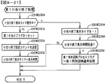
前記特別演出(第1デモ表示、第2デモ表示)の実行中において、前記第1開始条件及び前記第2開始条件が成立可能であるか否かにかかわらず、前記第1始動条件及び前記第2始動条件のいずれか一方が成立したことに基づいて前記特別演出を終了させる(図10−21に示すように、入賞球装置6Aへの始動入賞が発生し、第1保留記憶数が1となると(ステップS06TM1400でNO)、第1デモ表示を終了させ、図10−22に示すように、可変入賞球装置6Bへの始動入賞が発生し、第2保留記憶数が1となると(ステップS06TM1500でNO)、第2デモ表示を終了させる)
ことを特徴とする遊技機。
このような構成によれば、特定識別情報の始動条件の成立状況に応じた適切な演出制御を実現できる。
The gaming machine of means B1
It is a gaming machine (pachinko gaming machine 1) that can be controlled to an advantageous state (big hit gaming state) that is advantageous for the player.
After the first start condition (starting prize for the winning ball device 6A occurs) is satisfied, the first start condition is satisfied (as shown in FIG. 10-3, in the first special symbol normal processing, the second special symbol Variable display of the first specific identification information (first special symbol) based on the fact that neither the big hit game state nor the small hit game state based on the variable display result is controlled and the first reserved storage number is not 0). Is executed, and the second start condition is satisfied after the second start condition (starting prize for the variable winning ball device 6B is generated) is satisfied (as shown in FIG. 10-4, in the second special symbol normal processing). , The second specific identification information (second) based on the fact that neither the big hit game state nor the small hit game state based on the variation display result of the first special symbol is controlled and the second reserved storage number is not 0). The variable display of the special symbol) is executed, and the variable display of the first specific identification information (variable display of the first special symbol) and the variable display of the second specific identification information (variable display of the second special symbol) are performed in parallel. Executable specific identification information variable display means (
Variable display of the first specific identification information (variable display of the first special symbol) and variable display of the second specific identification information (variable display of the second special symbol) according to the game state (non-KT state, KT state). A decorative identification information variable display means (
A special effect execution means (
While the special effect (first demo display, second demo display) is being executed, the first start condition and the first start condition and the first start condition are irrespective of whether or not the first start condition and the second start condition can be satisfied. 2 The special effect is terminated based on the satisfaction of any one of the starting conditions (as shown in FIG. 10-21, a starting winning prize is generated in the winning ball device 6A, and the first reserved memory number is 1. When (NO in step S06TM1400), the first demo display is terminated, and as shown in FIG. 10-22, a start winning prize is generated in the variable winning ball device 6B, and when the second reserved storage number becomes 1 (step S06TM1500). NO), end the second demo display)
A gaming machine characterized by that.
According to such a configuration, it is possible to realize appropriate effect control according to the establishment status of the start condition of the specific identification information.
手段B2の遊技機は、
手段B1の遊技機であって、
前記装飾識別情報可変表示手段(演出制御用CPU120)は、第1遊技状態(非KT状態)に制御されているときに第1特定識別情報の可変表示(第1特別図柄の変動表示)に対応して装飾識別情報の可変表示(飾り図柄の変動表示)を実行可能であり、第2遊技状態(KT状態)に制御されているときに第2特定識別情報の可変表示(第2特別図柄の変動表示)に対応して装飾識別情報の可変表示(飾り図柄の変動表示)を実行可能であり、
前記特別演出(第1デモ表示、第2デモ表示)の実行中において、前記第1開始条件又は前記第2開始条件が成立可能な(図10−3に示すように、第1特別図柄通常処理で、第2特別図柄の変動表示結果に基づいて大当り遊技状態若しくは小当り遊技状態に制御されておらず、第1保留記憶数が0でない、又は、図10−4に示すように、第2特別図柄通常処理で、第1特別図柄の変動表示結果に基づいて大当り遊技状態若しくは小当り遊技状態に制御されておらず、第2保留記憶数が0でない)ときに、前記第1始動条件の成立(入賞球装置6Aへの始動入賞が発生)に応じて前記特別演出を終了させ(図10−21に示すように、入賞球装置6Aへの始動入賞が発生すると、第1特別図柄の変動表示が開始され(026IWS4714でYES)、第1デモ表示を終了させ)、前記第2始動条件の成立に応じて前記特別演出を終了させ(図10−22に示すように、可変入賞球装置6Bへの始動入賞が発生すると、第2特別図柄の変動表示が開始され(026IWS4814でYES)、第2デモ表示を終了させ)、
前記特別演出(第1デモ表示、第2デモ表示)の実行中において、前記第1開始条件又は前記第2開始条件が成立不能な(図10−3に示すように、第1特別図柄通常処理で、第2特別図柄が大当り遊技状態若しくは小当り遊技状態に制御されている、又は、図10−4に示すように、第2特別図柄通常処理で、第1特別図柄が大当り遊技状態若しくは小当り遊技状態に制御されている)ときに、前記第1始動条件の成立に応じて当該特別演出を終了させ(図10−21に示すように、入賞球装置6Aへの始動入賞が発生しても、第1特別図柄の変動表示は開始されない(ステップ026IWS4714でNO)が、第1保留記憶数が1となり(ステップS06TM1400でNO)、第1デモ表示を終了させ)、前記第2始動条件の成立に応じて当該特別演出を終了させる(図10−22に示すように、可変入賞球装置6Bへの始動入賞が発生しても、第2特別図柄の変動表示は開始されない(ステップ026IWS4814でNO)が、第2保留記憶数が1となり(ステップS06TM1500でNO)、第2デモ表示を終了させ)
ことを特徴とする遊技機。
このような構成によれば、特定識別情報の始動条件の成立状況に応じた適切な演出制御を実現できる。
The gaming machine of means B2 is
It is a gaming machine of means B1 and
The decorative identification information variable display means (effect control CPU 120) corresponds to variable display of the first specific identification information (variable display of the first special symbol) when controlled to the first gaming state (non-KT state). It is possible to execute the variable display of the decorative identification information (variable display of the decorative symbol), and when the second game state (KT state) is controlled, the variable display of the second specific identification information (the second special symbol) is possible. Variable display of decorative identification information (variable display of decorative design) can be executed in response to variable display).
While the special effect (first demo display, second demo display) is being executed, the first start condition or the second start condition can be satisfied (as shown in FIG. 10-3, the first special symbol normal process). Therefore, the big hit game state or the small hit game state is not controlled based on the variation display result of the second special symbol, and the first reserved memory number is not 0, or as shown in FIG. 10-4, the second When the special symbol normal processing is not controlled to the big hit game state or the small hit game state based on the variation display result of the first special symbol and the second reserved storage number is not 0), the first start condition is satisfied. The special effect is terminated according to the establishment (starting prize for the winning ball device 6A occurs) (as shown in FIG. 10-21, when the starting winning for the winning ball device 6A occurs, the first special symbol changes. The display is started (YES in 026IWS4714), the first demo display is ended), and the special effect is ended according to the establishment of the second starting condition (as shown in FIG. 10-22, the variable winning ball device 6B. When the start prize is generated, the variable display of the second special symbol is started (YES in 026IWS4814), and the second demo display is terminated).
While the special effect (first demo display, second demo display) is being executed, the first start condition or the second start condition cannot be satisfied (as shown in FIG. 10-3, the first special symbol normal process). Then, the second special symbol is controlled to the big hit game state or the small hit game state, or as shown in FIG. 10-4, in the second special symbol normal processing, the first special symbol is the big hit game state or the small hit game state. When the winning game state is controlled), the special effect is terminated according to the establishment of the first starting condition (as shown in FIG. 10-21, a starting prize is generated for the winning ball device 6A). However, the variable display of the first special symbol is not started (NO in step 026IWS4714), but the first reserved memory number becomes 1 (NO in step S06TM1400), the first demo display is terminated), and the second start condition is satisfied. The special effect is terminated according to the establishment (as shown in FIG. 10-22, even if a start winning prize is generated in the variable winning ball device 6B, the variation display of the second special symbol is not started (NO in step 026IWS4814). ), The number of second reserved storage becomes 1 (NO in step S06TM1500), and the second demo display is terminated).
A gaming machine characterized by that.
According to such a configuration, it is possible to realize appropriate effect control according to the establishment status of the start condition of the specific identification information.
手段B3の遊技機は、
手段B1又は手段B2の遊技機であって、
前記有利状態(大当り遊技状態)とは異なる特殊状態(小当り遊技状態)に制御可能であり、
前記有利状態(大当り遊技状態)に制御されているときに前記第1開始条件及び前記第2開始条件が成立不能であり(図10−3に示すように、第1特別図柄通常処理において、第2特別図柄の変動表示結果に基づく大当り遊技状態に制御されており(ステップS06TM1000AでYES)、図10−4に示すように、第2特別図柄通常処理において、第1特別図柄の変動表示結果に基づく大当り遊技状態に制御されており(ステップS06TM1000BでYES))、
前記特殊状態(小当り遊技状態)に制御されているときに前記第1開始条件及び前記第2開始条件が成立不能である(図10−3に示すように、第1特別図柄通常処理において、第2特別図柄の変動表示結果に基づく小当り遊技状態に制御されているときは(ステップS06TM1000AでYES)、第1特別図柄の変動表示が開始されず、図10−4に示すように、第2特別図柄通常処理において、第1特別図柄の変動表示結果に基づく小当り遊技状態に制御されているときは(ステップS06TM1000BでYES)、第2特別図柄の変動表示が開始されない)
ことを特徴とする遊技機。
このような構成によれば、有利状態に制御されているときに開始条件が成立不能であることにより、遊技者を有利状態における遊技に集中させることができる。また、特殊状態に制御されているときに開始条件が成立不能であることにより、遊技者を有利状態における遊技に集中させることができる。
The gaming machine of means B3 is
A gaming machine of means B1 or means B2.
It is possible to control a special state (small hit game state) different from the advantageous state (big hit game state).
The first start condition and the second start condition cannot be satisfied when controlled to the advantageous state (big hit game state) (as shown in FIG. 10-3, in the first special symbol normal processing, the first 2 It is controlled to the jackpot game state based on the variation display result of the special symbol (YES in step S06TM1000A), and as shown in FIG. 10-4, in the second special symbol normal processing, the variation display result of the first special symbol is displayed. It is controlled to the jackpot game state based on (YES in step S06TM1000B),
The first start condition and the second start condition cannot be satisfied when the special state (small hit game state) is controlled (as shown in FIG. 10-3, in the first special symbol normal process). When the small hit game state is controlled based on the variation display result of the second special symbol (YES in step S06TM1000A), the variation display of the first special symbol is not started, and as shown in FIG. 10-4, the first 2 In the special symbol normal processing, when the small hit game state based on the variation display result of the first special symbol is controlled (YES in step S06TM1000B), the variation display of the second special symbol is not started).
A gaming machine characterized by that.
According to such a configuration, the player can concentrate on the game in the advantageous state because the start condition cannot be satisfied when the control is in the advantageous state. Further, since the start condition cannot be satisfied when the game is controlled to the special state, the player can concentrate on the game in the advantageous state.
手段B4の遊技機は、
手段B3の遊技機であって、
前記特殊状態(小当り遊技状態)に制御される頻度が高い特別状態(KT状態)に制御可能である
ことを特徴とする遊技機。
このような構成によれば、遊技者にとって有利な遊技状態として有利状態とは異なる遊技状態を実現できる。
The gaming machine of means B4 is
It is a gaming machine of means B3,
A gaming machine characterized in that it can be controlled to a special state (KT state) that is frequently controlled to the special state (small hit gaming state).
According to such a configuration, it is possible to realize a gaming state different from the advantageous state as an advantageous gaming state for the player.
手段B5の遊技機は、
手段B1〜手段B4から選択される何れかの遊技機であって、
遊技状態によらず、第1特定識別情報の可変表示(第1特別図柄の変動表示)に対応して装飾識別情報(飾り図柄)よりも視認性が低い第1特殊識別情報の可変表示を実行可能(第1特別図柄の変動表示に対応して第1小図柄の変動表示を実行可能)であり、第2特定識別情報の可変表示(第2特別図柄の変動表示)に対応して装飾識別情報(飾り図柄)よりも視認性が低い第2特殊識別情報の可変表示を実行可能(第2特別図柄の変動表示に対応して第2小図柄の変動表示を実行可能)である
ことを特徴とする遊技機。
このような構成によれば、遊技者は、特殊識別情報の可変表示の状況を確認することによって、特定識別情報の可変表示の状況を把握することができる。
The gaming machine of means B5 is
Any gaming machine selected from means B1 to means B4.
Regardless of the game state, the variable display of the first special identification information, which is less visible than the decorative identification information (decorative symbol), is executed in response to the variable display of the first specific identification information (variable display of the first special symbol). Possible (variable display of the first small symbol can be executed corresponding to the variable display of the first special symbol), and decorative identification corresponding to the variable display of the second specific identification information (variable display of the second special symbol) It is characterized by being able to execute variable display of the second special identification information, which is less visible than information (decorative symbol) (variable display of the second small symbol can be executed in response to the variable display of the second special symbol). A game machine to be.
According to such a configuration, the player can grasp the status of the variable display of the specific identification information by checking the status of the variable display of the special identification information.
手段B6の遊技機は、
手段B1〜手段B5から選択される何れかの遊技機であって、
前記特定識別情報可変表示手段(遊技制御用マイクロコンピュータ100)を有する遊技制御部(主基板11)と、
前記装飾識別情報可変表示手段(演出制御用CPU120)と前記特別演出実行手段(演出制御用CPU120)とを有する演出制御部(演出制御基板12)と、を含み、
前記遊技制御部(主基板11)は、前記第1始動条件が成立しておらず(入賞球装置6Aへの始動入賞が発生しておらず)且つ第1特定識別情報の可変表示が実行されていない(第1特別図柄の変動表示が実行されていない)ことに対応した第1特別コマンド(第1客待ちデモ表示指定コマンド)と、前記第2始動条件が成立しておらず(可変入賞球装置6Bへの始動入賞が発生しておらず)且つ第2特定識別情報の可変表示が実行されていない(第1特別図柄の変動表示が実行されていない)ことに対応した第2特別コマンド(第2客待ちデモ表示指定コマンド)とを送信可能であり、
前記演出制御部(演出制御基板12)は、前記第1特別コマンドを受信したときに第1遊技状態であることに応じて前記特別演出実行手段により第1特別演出を実行可能であり(図9−38に示すように、演出制御用CPU120は、第1客待ちデモ表示指定コマンドを受信したときに(ステップ026IWS4701でYES)、非KT状態であることに基づいて(ステップ026IWS4702でYES)、第1デモ表示を開始し(ステップ026IWS4711))、前記第2特別コマンドを受信したときに第2遊技状態であることに応じて前記特別演出実行手段により第2特別演出を実行可能である(図9−39に示すように、演出制御用CPU120は、第2客待ちデモ表示指定コマンドを受信したときに(ステップ026IWS4801でYES)、KT状態であることに基づいて(ステップ026IWS4802でYES)、第2デモ表示を開始する(ステップ026IWS4811))
ことを特徴とする遊技機。
このような構成によれば、現在の遊技状態に対応したコマンドを受信した場合にのみ、特別演出を開始させることが可能となり、遊技状態に応じて適切なタイミングで特別演出を開始させることができる。
The gaming machine of means B6 is
Any gaming machine selected from means B1 to means B5.
A game control unit (main board 11) having the specific identification information variable display means (game control microcomputer 100), and
The effect control unit (effect control board 12) having the decorative identification information variable display means (effect control CPU 120) and the special effect execution means (effect control CPU 120) is included.
In the game control unit (main board 11), the first starting condition is not satisfied (starting winning to the winning ball device 6A has not occurred), and the variable display of the first specific identification information is executed. The first special command (first customer waiting demo display designation command) corresponding to the fact that the first special symbol is not displayed (variable display of the first special symbol is not executed) and the second start condition are not satisfied (variable prize). The second special command corresponding to the fact that the start winning prize for the ball device 6B has not occurred) and the variable display of the second specific identification information has not been executed (the variable display of the first special symbol has not been executed). (Second customer waiting demo display specification command) can be sent,
The effect control unit (effect control board 12) can execute the first special effect by the special effect executing means according to the first gaming state when the first special command is received (FIG. 9). As shown in −38, when the
A gaming machine characterized by that.
According to such a configuration, the special effect can be started only when the command corresponding to the current game state is received, and the special effect can be started at an appropriate timing according to the game state. ..
手段B7の遊技機は、
手段B6の遊技機であって、
前記第1特別演出(第1デモ表示)を実行しているときに、前記第1開始条件が成立した(図10−3に示すように、第1特別図柄通常処理において、第2特別図柄の変動表示結果に基づく大当り遊技状態及び小当り遊技状態の何れにも制御されておらず且つ第1保留記憶数が0でない)ことに応じて前記第1特別演出を終了させ(図9−38に示すように、第1特別図柄の変動表示が開始されると(ステップ026IWS4714でYES)、第1デモ表示を終了させ(ステップ026IWS4716))、
前記第2特別演出(第2デモ表示)を実行しているときに、前記第2開始条件が成立した(図10−4に示すように、第2特別図柄通常処理において、第1特別図柄の変動表示結果に基づく大当り遊技状態及び小当り遊技状態の何れにも制御されておらず且つ第2保留記憶数が0でない)ことに応じて前記第2特別演出を終了させる(図9−39に示すように、第2特別図柄の変動表示が開始されると(ステップ026IWS4814でYES)、第2デモ表示をさせる(ステップ026IWS4816))
ことを特徴とする遊技機。
このような構成によれば、特定識別情報の可変表示の実行状況に対応した適切な演出制御を実現可能となる。
The gaming machine of means B7 is
It is a gaming machine of means B6,
While the first special effect (first demo display) is being executed, the first start condition is satisfied (as shown in FIG. 10-3, in the first special symbol normal processing, the second special symbol The first special effect is terminated according to the fact that neither the big hit game state nor the small hit game state based on the variable display result is controlled and the first reserved storage number is not 0) (Fig. 9-38). As shown, when the variable display of the first special symbol is started (YES in step 026IWS4714), the first demo display is ended (step 026IWS4716)).
While the second special effect (second demo display) is being executed, the second start condition is satisfied (as shown in FIG. 10-4, in the second special symbol normal processing, the first special symbol The second special effect is terminated according to the fact that neither the big hit game state nor the small hit game state based on the variable display result is controlled and the second reserved storage number is not 0) (FIG. 9-39). As shown, when the variable display of the second special symbol is started (YES in step 026IWS4814), the second demo display is made (step 026IWS4816)).
A gaming machine characterized by that.
According to such a configuration, it is possible to realize appropriate effect control corresponding to the execution status of the variable display of the specific identification information.
手段B8の遊技機は、
手段B1〜手段B7から選択される何れかの遊技機であって、
前記特別演出(第1デモ表示)の実行中において、前記第1開始条件が成立可能なときに、前記第1始動条件の成立(入賞球装置6Aへの始動入賞の発生)に応じて前記第1始動条件の成立に対応した保留記憶数を第1態様で表示可能であり(図10−1に示すように、第1保留記憶数が4であるときに、第1保留表示領域06TM011に4個の第1保留表示06TM010を表示可能であり)、
前記特別演出(第1デモ表示)の実行中において、前記第1開始条件が成立不能な(図10−3に示すように、第1特別図柄通常処理において、第2特別図柄の変動表示結果に基づく大当り遊技状態又は小当り遊技状態に制御されている)ときに、前記第1始動条件の成立(入賞球装置6Aへの始動入賞の発生)に応じて前記第1始動条件の成立に対応した保留記憶数を前記第1態様よりも視認性が低い第2態様で表示可能であり(図10−6に示すように、第1保留記憶数が1であるときに、第1保留記憶数特別表示領域06TM015に「1」を表示可能であり)、
前記特別演出(第2デモ表示)の実行中において、前記第2開始条件が成立可能なときに、前記第2始動条件の成立(可変入賞球装置6Bへの始動入賞の発生)に応じて前記第2始動条件の成立に対応した保留記憶数を第1態様で表示可能であり(図10−1に示すように、第2保留記憶数が4であるときに、第2保留表示領域06TM021に4個の第2保留表示06TM020を表示可能であり)、
前記特別演出(第2デモ表示)の実行中において、前記第2開始条件が成立不能な(図10−4に示すように、第2特別図柄通常処理において、第1特別図柄の変動表示結果に基づく大当り遊技状態又は小当り遊技状態に制御されている)ときに、前記第2始動条件の成立(可変入賞球装置6Bへの始動入賞の発生)に応じて前記第2始動条件の成立に対応した保留記憶数を前記第1態様よりも視認性が低い第2態様で表示可能である(図10−6に示すように、第2保留記憶数が0であるときに、第2保留記憶数特別表示領域06TM025に「0」を表示可能である)
ことを特徴とする遊技機。
このような構成によれば、第1態様よりも視認性の低い第2態様で保留記憶数を表示させることで、保留記憶数を適切に報知することができる。
The gaming machine of means B8 is
Any gaming machine selected from means B1 to means B7.
During the execution of the special effect (first demo display), when the first start condition can be satisfied, the first start condition is satisfied (the start prize is generated in the winning ball device 6A). 1 The number of reserved storages corresponding to the establishment of the start condition can be displayed in the first aspect (as shown in FIG. 10-1, when the number of 1st reserved storages is 4, 4 in the 1st reserved display area 06TM011. The first hold display 06TM010 can be displayed),
During the execution of the special effect (first demo display), the first start condition cannot be satisfied (as shown in FIG. 10-3, in the first special symbol normal processing, the variation display result of the second special symbol is displayed. When the big hit game state or the small hit game state is controlled based on the above, the first start condition is satisfied according to the establishment of the first start condition (occurrence of a start prize to the winning ball device 6A). The reserved storage number can be displayed in the second aspect, which is less visible than the first aspect (as shown in FIG. 10-6, when the first reserved storage number is 1, the first reserved storage number is special. "1" can be displayed in the display area 06TM015),
When the second start condition can be satisfied during the execution of the special effect (second demo display), the second start condition is satisfied (the start prize is generated in the variable winning ball device 6B). The number of reserved storages corresponding to the establishment of the second start condition can be displayed in the first aspect (as shown in FIG. 10-1, when the number of second reserved storages is 4, the second reserved display area 06TM021 can be displayed. 4 second hold display 06TM020 can be displayed),
During the execution of the special effect (second demo display), the second start condition cannot be satisfied (as shown in FIG. 10-4, in the second special symbol normal processing, the variation display result of the first special symbol is displayed. When the big hit game state or the small hit game state is controlled based on the above, the second start condition is satisfied according to the establishment of the second start condition (occurrence of a start prize to the variable winning ball device 6B). The reserved storage number can be displayed in the second aspect, which is less visible than the first aspect (as shown in FIG. 10-6, when the second reserved storage number is 0, the second reserved storage number is displayed. "0" can be displayed in the special display area 06TM025)
A gaming machine characterized by that.
According to such a configuration, by displaying the reserved storage number in the second aspect, which is less visible than the first aspect, the reserved storage number can be appropriately notified.
手段B9の遊技機は、
手段B1〜手段B8から選択される何れかの遊技機であって、
第1特定識別情報の可変表示(第1特別図柄の変動表示)及び第2特定識別情報の可変表示(第2特別図柄の変動表示)のうちの一方の特定識別情報の可変表示中(第1特別図柄の変動表示中)に、他方の特定識別情報の可変表示結果(第2特別図柄の変動表示結果が「小当り」となること)に基づいて前記有利状態(大当り遊技状態)とは異なる特殊状態(小当り遊技状態)に制御されるときに、一方の特定識別情報の可変表示(第1特別図柄の変動表示)を中断させる可変表示中断手段(遊技制御用マイクロコンピュータ100)と、
前記特殊状態(小当り遊技状態)の終了に伴う終了演出(小当り終了指定コマンドの受信に応じて実行される演出であり、例えば、図10−12(A4)に示すように、開放していた特殊可変入賞球装置17を閉鎖後に、画像表示装置5にキャラクタ及び「30pt
GET!」の文字を表示させる演出等)を実行可能な終了演出実行手段(演出制御用CPU120)と、を備え、
前記特殊状態(小当り遊技状態)に制御される頻度が高い特別状態(第2KT状態)よりも、非特別状態(第1KT状態)の方が前記終了演出(図10−12(B3)に示すように、開放していた特殊可変入賞球装置17を閉鎖後に、画像表示装置5のアクティブ表示領域06TM031に表示されていたアクティブ表示06TM030と、第2保留表示領域06TM021に表示されていた4個の第2保留表示06TM020とを消去する演出)の実行期間が短い(図10−11(A)に示すように、第2KT状態では、小当りエンディング期間が3秒である一方で、図10−11(B)に示すように、第1KT状態では、小当りエンディング期間が0.5秒である)
ことを特徴とする遊技機。
このような構成によれば、非特別状態において、一方の特定識別情報の可変表示を中断させる期間を短くすることができ、一方の特定演出情報の可変表示状況と一方の特定識別情報に対応した演出との不整合を抑制することができる。
The gaming machine of means B9 is
Any gaming machine selected from means B1 to means B8.
Variable display of one of the variable display of the first specific identification information (variable display of the first special symbol) and the variable display of the second specific identification information (variable display of the second special symbol) (first variable display of the specific identification information) It is different from the advantageous state (big hit game state) based on the variable display result of the other specific identification information (the variable display result of the second special symbol is "small hit") during the variable display of the special symbol). A variable display interrupting means (
An end effect (an effect executed in response to the reception of a small hit end designation command) accompanying the end of the special state (small hit game state), for example, as shown in FIG. 10-12 (A4), is open. After closing the special variable winning ball device 17, the character and "30pt" are displayed on the
GET! It is provided with an end effect execution means (effect control CPU 120) capable of executing an effect (such as an effect of displaying the characters).
The non-special state (first KT state) is shown in the end effect (FIG. 10-12 (B3)) than the special state (second KT state), which is frequently controlled by the special state (small hit game state). As described above, after closing the open special variable winning ball device 17, the active display 06TM030 displayed in the active display area 06TM031 of the
A gaming machine characterized by that.
According to such a configuration, it is possible to shorten the period for suspending the variable display of one specific identification information in the non-special state, and it corresponds to the variable display status of one specific effect information and the other specific identification information. Inconsistency with the production can be suppressed.
遊技機として、特開2016−187523(図73)に示すように、電断が発生し、電断から復旧したときに、電源復旧指定コマンドを画像制御部が受信したことに基づいて電源復旧中であることを報知する電源復旧演出を行う遊技機が提案されている。特開2016−187523(図73)に示されている遊技機では、電断から復旧したときに、電断が発生したときの特定識別情報の可変表示状況に応じて適切な報知を行う必要がある。手段D1〜手段D10に係る発明は、上記の実状に鑑みてなされたものであり、電断が発生したときの特定識別情報の可変表示状況に応じて適切な報知を行う遊技機を提供することにある。 As a gaming machine, as shown in Japanese Patent Application Laid-Open No. 2016-187523 (FIG. 73), when a power failure occurs and the power is restored from the power failure, the power is being restored based on the image control unit receiving the power restoration designation command. A gaming machine that performs a power restoration effect to notify that the above is the case has been proposed. In the gaming machine shown in JP-A-2016-187523 (FIG. 73), when recovering from a power failure, it is necessary to provide appropriate notification according to the variable display status of the specific identification information when the power failure occurs. be. The inventions according to the means D1 to the means D10 have been made in view of the above-mentioned actual conditions, and provide a gaming machine that appropriately notifies according to the variable display status of the specific identification information when a power failure occurs. It is in.
手段D1の遊技機は、
遊技者にとって有利な有利状態(大当り遊技状態)に制御可能な遊技機(パチンコ遊技機1)であって、
第1特定識別情報の可変表示(第1特別図柄の変動表示)と第2特定識別情報の可変表示(第2特別図柄の変動表示)とを並行して実行可能な特定識別情報可変表示手段(遊技制御用マイクロコンピュータ100)を有する遊技制御手段(主基板11)と、
遊技状態(非KT状態、KT状態)に応じて、第1特定識別情報の可変表示(第1特別図柄の変動表示)及び第2特定識別情報の可変表示(第2特別図柄の変動表示)のいずれか一方に対応して装飾識別情報の可変表示(飾り図柄の変動表示)を実行可能な装飾識別情報可変表示手段(演出制御用CPU120)を有する演出制御手段(演出制御基板12)と、を備え、
前記遊技制御手段(主基板11)は、第1特定識別情報の可変表示(第1特別図柄の変動表示)に関する第1情報(第1客待ちデモ表示指定コマンド、第1特別図柄に対応した表示結果指定コマンド、第1特別図柄に対応した変動パターンコマンド)と、第2特定識別情報の可変表示(第2特別図柄の変動表示)に関する第2情報(第2客待ちデモ表示指定コマンド、第2特別図柄に対応した表示結果指定コマンド、第2特別図柄に対応した変動パターンコマンド)と、遊技状態に関する遊技状態情報(低確/非KT背景指定コマンド、低確/第1KT背景指定コマンド、高確/第1KT背景指定コマンド、高確/第2KT背景指定コマンド)と、を前記演出制御手段(演出制御基板12)に送信可能であり、
前記演出制御手段(演出制御基板12)は、電源断から復旧したときに、前記第1情報と、前記第2情報と、前記遊技状態情報と、に応じて異なる態様により復旧報知を実行可能である(図10−15の「状況2」に示すように、低確/非KT背景指定コマンド及び第2客待ちデモ表示指定コマンドを受信したことに基づいて、遊技状態が低確/非KT状態(通常状態)であり、メイン図柄である第1特別図柄の変動表示が実行されており、サブ図柄である第2特別図柄の変動表示が実行されていないことを特定可能であることから、画像表示装置5の画面全体に「電源断復旧中」という文字が表示され、図10−15の「状況4」に示すように、低確/非KT背景指定コマンド及び第1客待ちデモ表示指定コマンドを受信したことに基づいて、遊技状態が低確/非KT状態(通常状態)であり、メイン図柄である第1特別図柄の変動表示が実行されておらず、サブ図柄である第2特別図柄の変動表示が実行されていることを特定可能であることから、サブ図柄である第2小図柄の表示範囲(画面右上部)に「復旧中」という文字が表示され、その他の部分には各演出用図柄(飾り図柄及び第1小図柄)及び背景画像(晴れ画像)が表示される)
ことを特徴とする遊技機。
このような構成によれば、第1特定識別情報と第2特定識別情報が並行して可変表示を実行可能な遊技機において、電源断復旧に関する適切な報知を行うことができる。
The gaming machine of means D1
It is a gaming machine (pachinko gaming machine 1) that can be controlled to an advantageous state (big hit gaming state) that is advantageous for the player.
Specific identification information variable display means (variable display of specific identification information) that can execute variable display of the first specific identification information (variable display of the first special symbol) and variable display of the second specific identification information (variable display of the second special symbol) in parallel. A game control means (main board 11) having a game control microcomputer 100),
Variable display of the first specific identification information (variable display of the first special symbol) and variable display of the second specific identification information (variable display of the second special symbol) according to the game state (non-KT state, KT state). The effect control means (effect control board 12) having the decorative identification information variable display means (effect control CPU 120) capable of executing the variable display of the decoration identification information (variable display of the decorative pattern) corresponding to any one of them. Prepare,
The game control means (main board 11) has a first information (first customer waiting demo display designation command, display corresponding to the first special symbol) regarding variable display of the first specific identification information (variable display of the first special symbol). Result specification command, variation pattern command corresponding to the first special symbol) and second information (second customer waiting demo display specification command, second) regarding variable display of the second specific identification information (variation display of the second special symbol) Display result specification command corresponding to the special symbol, variation pattern command corresponding to the second special symbol) and game state information related to the game state (low accuracy / non-KT background specification command, low accuracy / first KT background specification command, high accuracy / 1st KT background designation command, high accuracy / 2nd KT background designation command) can be transmitted to the effect control means (effect control board 12).
When the effect control means (effect control board 12) recovers from a power failure, the effect control means (effect control board 12) can execute recovery notification in different modes depending on the first information, the second information, and the game state information. (As shown in "
A gaming machine characterized by that.
According to such a configuration, in a gaming machine capable of executing variable display of the first specific identification information and the second specific identification information in parallel, it is possible to appropriately notify the power failure recovery.
手段D2の遊技機は、
手段D1の遊技機であって、
第1特定識別情報の可変表示(第1特別図柄の変動表示)及び第2特定識別情報の可変表示(第2特別図柄の変動表示)のうち、装飾識別情報の可変表示(飾り図柄の変動表示)に対応しない特定識別情報の可変表示に対応して、装飾識別情報よりも視認性が低い特殊識別情報の可変表示(第1小図柄の変動表示、第2小図柄の変動表示)を実行可能である
ことを特徴とする遊技機。
このような構成によれば、遊技者は、特殊識別情報の可変表示の状況を確認することによって、特定識別情報の可変表示の状況を確認することができる。
The gaming machine of means D2 is
Means D1 gaming machine
Of the variable display of the first specific identification information (variable display of the first special symbol) and the variable display of the second specific identification information (variable display of the second special symbol), the variable display of the decorative identification information (variable display of the decorative symbol). ) Is supported, and variable display of special identification information (variable display of the first small symbol, variable display of the second small symbol), which is less visible than decorative identification information, can be executed. A gaming machine characterized by being.
According to such a configuration, the player can confirm the status of the variable display of the specific identification information by checking the status of the variable display of the special identification information.
手段D3の遊技機は、
手段D1又は手段D2の遊技機であって、
前記演出制御手段(演出制御用CPU120)は、電源断から復旧したときに、
前記第1情報(第1客待ちデモ表示指定コマンド、第1特別図柄に対応した表示結果指定コマンド、第1特別図柄に対応した変動パターンコマンド)及び前記第2情報(第2客待ちデモ表示指定コマンド、第2特別図柄に対応した表示結果指定コマンド、第2特別図柄に対応した変動パターンコマンド)のうち、装飾識別情報の可変表示(飾り図柄の変動表示)に対応した特定識別情報の可変表示(例えば、第1特別図柄の変動表示)に関する情報(第1客待ちデモ表示指定コマンド、第1特別図柄に対応した表示結果指定コマンド、第1特別図柄に対応した変動パターンコマンド)を受信していないときに、第1態様の復旧報知(図10−16(B)に示す、画面全体に「停電復旧中」の文字が表示された復旧画面)を実行し、
前記第1情報及び前記第2情報のうち、装飾識別情報の可変表示に対応しない特定識別情報の可変表示(例えば、第2特別図柄の変動表示)に関する情報(第2客待ちデモ表示指定コマンド、第2特別図柄に対応した表示結果指定コマンド、第2特別図柄に対応した変動パターンコマンド)を受信していないときに、第2態様の復旧報知(図10−16(A)に示す、サブ図柄に対応した第2小図柄の表示範囲(画面右上部)に「復旧中」の文字が表示され、その他の部分には各演出用図柄(飾り図柄及び第1小図柄)及び背景画像(晴れ画像)が表示された復旧画面)を実行し、その後、装飾識別情報の可変表示に対応しない特定識別情報の可変表示に関する情報(第2客待ちデモ表示指定コマンド、第2特別図柄に対応した表示結果指定コマンド、第2特別図柄に対応した変動パターンコマンド)を受信したときに、第2態様の復旧報知を終了する(各演出用図柄(飾り図柄、第1小図柄、第2小図柄)及び背景画像(晴れ画像)のみが表示される)
ことを特徴とする遊技機。
このような構成によれば、装飾識別情報に対応した特定識別情報の可変表示状況と装飾識別情報に対応しない特定識別情報の可変表示状況とに応じて、適切な態様で復旧過程を報知することが可能となる。
The gaming machine of means D3 is
A gaming machine of means D1 or means D2.
When the effect control means (effect control CPU 120) recovers from the power failure,
The first information (first customer waiting demo display designation command, display result designation command corresponding to the first special symbol, variation pattern command corresponding to the first special symbol) and the second information (second customer waiting demo display designation). Of the commands, the display result specification command corresponding to the second special symbol, and the variable pattern command corresponding to the second special symbol), the variable display of the specific identification information corresponding to the variable display of the decorative identification information (variable display of the decorative symbol). (For example, the information about (for example, the variation display of the first special symbol) (the first customer waiting demo display designation command, the display result specification command corresponding to the first special symbol, the variation pattern command corresponding to the first special symbol) is received. When not, the recovery notification of the first aspect (recovery screen shown in FIG. 10-16 (B) in which the characters "power failure is being recovered" is displayed on the entire screen) is executed.
Of the first information and the second information, information related to variable display of specific identification information (for example, variable display of a second special symbol) that does not correspond to variable display of decorative identification information (second customer waiting demo display designation command, When the display result specification command corresponding to the second special symbol and the variation pattern command corresponding to the second special symbol are not received, the recovery notification of the second mode (sub-symbols shown in FIG. 10-16 (A)) is received. The word "Recovering" is displayed in the display range (upper right part of the screen) of the 2nd small symbol corresponding to, and each production symbol (decorative symbol and 1st small symbol) and background image (sunny image) are displayed in other parts. ) Is displayed, and then the information related to the variable display of the specific identification information that does not correspond to the variable display of the decoration identification information (second customer waiting demo display specification command, display result corresponding to the second special symbol). When the designated command and the variable pattern command corresponding to the second special symbol are received, the recovery notification of the second mode is terminated (each effect symbol (decorative symbol, first small symbol, second small symbol) and background. Only the image (sunny image) is displayed)
A gaming machine characterized by that.
According to such a configuration, the recovery process is notified in an appropriate manner according to the variable display status of the specific identification information corresponding to the decoration identification information and the variable display status of the specific identification information not corresponding to the decoration identification information. Is possible.
手段D4の遊技機は、
手段D1〜手段D3から選択される何れかの遊技機であって、
第1始動条件が成立(入賞球装置6Aへの始動入賞が発生)した後に第1開始条件が成立した(図10−3に示すように、第1特別図柄通常処理において、第2特別図柄の変動表示結果に基づく大当り遊技状態及び小当り遊技状態の何れにも制御されておらず且つ第1保留記憶数が0でない)ことに基づいて第1特定識別情報(第1特別図柄)の可変表示(変動表示)を実行し、
第2始動条件が成立(可変入賞球装置6Bへの始動入賞が発生)した後に第2開始条件が成立した(図10−4に示すように、第2特別図柄通常処理において、第2特別図柄の変動表示結果に基づく大当り遊技状態及び小当り遊技状態の何れにも制御されておらず且つ第2保留記憶数が0でない)ことに基づいて第2特定識別情報(第2特別図柄)の可変表示(変動表示)を実行し、
前記有利状態(大当り遊技状態)とは異なる特殊状態(小当り遊技状態)に制御可能であり、
前記有利状態(大当り遊技状態)に制御されているときに前記第1開始条件及び前記第2開始条件が成立不能であり(図10−3に示すように、第1特別図柄通常処理において、第2特別図柄の変動表示結果に基づく大当り遊技状態に制御されており(ステップS06TM1000AでYES)、図10−4に示すように、第2特別図柄通常処理において、第1特別図柄の変動表示結果に基づく大当り遊技状態に制御されており(ステップS06TM1000BでYES))、
前記特殊状態(小当り遊技状態)に制御されているときに前記第1開始条件及び前記第2開始条件が成立不能である(図10−3に示すように、第1特別図柄通常処理において、第2特別図柄の変動表示結果に基づく小当り遊技状態に制御されているときは(ステップS06TM1000AでYES)、第1特別図柄の変動表示が開始されず、図10−4に示すように、第2特別図柄通常処理において、第1特別図柄の変動表示結果に基づく小当り遊技状態に制御されているときは(ステップS06TM1000BでYES)、第2特別図柄の変動表示が開始されない)
ことを特徴とする遊技機。
このような構成によれば、有利状態に制御されているときに開始条件が成立不能であることにより、遊技者を有利状態における遊技に集中させることができる。また、特殊状態に制御されているときに開始条件が成立不能であることにより、遊技者を有利状態における遊技に集中させることができる。
The gaming machine of means D4 is
Any gaming machine selected from means D1 to means D3.
After the first start condition is satisfied (starting prize for the winning ball device 6A occurs), the first start condition is satisfied (as shown in FIG. 10-3, in the first special symbol normal processing, the second special symbol Variable display of the first specific identification information (first special symbol) based on the fact that neither the big hit game state nor the small hit game state based on the variable display result is controlled and the first reserved storage number is not 0). Execute (variable display) and
After the second start condition is satisfied (starting prize for the variable winning ball device 6B occurs), the second starting condition is satisfied (as shown in FIG. 10-4, in the second special symbol normal processing, the second special symbol The second specific identification information (second special symbol) is variable based on the fact that neither the big hit game state nor the small hit game state is controlled based on the variable display result of the above and the second reserved memory number is not 0). Execute display (variable display) and
It is possible to control a special state (small hit game state) different from the advantageous state (big hit game state).
The first start condition and the second start condition cannot be satisfied when controlled to the advantageous state (big hit game state) (as shown in FIG. 10-3, in the first special symbol normal processing, the first 2 It is controlled to the jackpot game state based on the variation display result of the special symbol (YES in step S06TM1000A), and as shown in FIG. 10-4, in the second special symbol normal processing, the variation display result of the first special symbol is displayed. It is controlled to the jackpot game state based on (YES in step S06TM1000B),
The first start condition and the second start condition cannot be satisfied when the special state (small hit game state) is controlled (as shown in FIG. 10-3, in the first special symbol normal process). When the small hit game state is controlled based on the variation display result of the second special symbol (YES in step S06TM1000A), the variation display of the first special symbol is not started, and as shown in FIG. 10-4, the first 2 In the special symbol normal processing, when the small hit game state based on the variation display result of the first special symbol is controlled (YES in step S06TM1000B), the variation display of the second special symbol is not started).
A gaming machine characterized by that.
According to such a configuration, the player can concentrate on the game in the advantageous state because the start condition cannot be satisfied when the control is in the advantageous state. Further, since the start condition cannot be satisfied when the game is controlled to the special state, the player can concentrate on the game in the advantageous state.
手段D5の遊技機は、
手段D4の遊技機であって、
前記特殊状態(小当り遊技状態)に制御される頻度が高い特別状態(KT状態)に制御可能である
ことを特徴とする遊技機。
このような構成によれば、遊技者にとって有利な遊技状態として有利状態とは異なる遊技状態を実現できる。
The gaming machine of means D5 is
Means D4 gaming machine
A gaming machine characterized in that it can be controlled to a special state (KT state) that is frequently controlled to the special state (small hit gaming state).
According to such a configuration, it is possible to realize a gaming state different from the advantageous state as an advantageous gaming state for the player.
手段D6の遊技機は、
手段D1〜手段D5から選択される何れかの遊技機であって、
遊技状態によらず、第1特定識別情報の可変表示(第1特別図柄の変動表示)に対応して装飾識別情報(飾り図柄)よりも視認性が低い第1特殊識別情報の可変表示を実行可能(第1特別図柄の変動表示に対応して第1小図柄の変動表示を実行可能)であり、第2特定識別情報の可変表示(第2特別図柄の変動表示)に対応して装飾識別情報(飾り図柄)よりも視認性が低い第2特殊識別情報の可変表示を実行可能(第2特別図柄の変動表示に対応して第2小図柄の変動表示を実行可能)である
ことを特徴とする遊技機。
このような構成によれば、遊技者は、特殊識別情報の可変表示の状況を確認することによって、特定識別情報の可変表示の状況を把握することができる。
The gaming machine of means D6 is
Any gaming machine selected from means D1 to means D5.
Regardless of the game state, the variable display of the first special identification information, which is less visible than the decorative identification information (decorative symbol), is executed in response to the variable display of the first specific identification information (variable display of the first special symbol). Possible (variable display of the first small symbol can be executed corresponding to the variable display of the first special symbol), and decorative identification corresponding to the variable display of the second specific identification information (variable display of the second special symbol) It is characterized by being able to execute variable display of the second special identification information, which is less visible than information (decorative symbol) (variable display of the second small symbol can be executed in response to the variable display of the second special symbol). A game machine to be.
According to such a configuration, the player can grasp the status of the variable display of the specific identification information by checking the status of the variable display of the special identification information.
手段D7の遊技機は、
手段D1〜手段D6から選択される何れかの遊技機であって、
前記特定識別情報可変表示手段(遊技制御用マイクロコンピュータ100)を有する遊技制御部(主基板11)と、
前記装飾識別情報可変表示手段(演出制御用CPU120)と、装飾識別情報の可変表示(飾り図柄の変動表示)が実行されていないときに特別演出(第1デモ表示、第2デモ表示)を実行可能な特別演出実行手段(演出制御用CPU120)とを有する演出制御部(演出制御基板12)と、を含み、
前記特定識別情報可変表示手段(遊技制御用マイクロコンピュータ100)は、第1始動条件が成立(入賞球装置6Aへの始動入賞が発生)した後に第1開始条件が成立した(図10−3に示すように、第1特別図柄通常処理において、第2特別図柄の変動表示結果に基づく大当り遊技状態及び小当り遊技状態の何れにも制御されておらず且つ第1保留記憶数が0でない)ことに基づいて第1特定識別情報の可変表示(第1特別図柄の変動表示)を実行し、第2始動条件が成立(可変入賞球装置6Bへの始動入賞が発生)した後に第2開始条件が成立した(図10−4に示すように、第2特別図柄通常処理において、第1特別図柄の変動表示結果に基づく大当り遊技状態及び小当り遊技状態の何れにも制御されておらず且つ第2保留記憶数が0でない)ことに基づいて第2特定識別情報の可変表示(第2特別図柄の変動表示)を実行し、
前記遊技制御部(主基板11)は、前記第1始動条件が成立しておらず(入賞球装置6Aへの始動入賞が発生しておらず)且つ第1特定識別情報の可変表示が実行されていない(第1特別図柄の変動表示が実行されていない)ことに対応した第1特別コマンド(第1客待ちデモ表示指定コマンド)と、前記第2始動条件が成立しておらず(可変入賞球装置6Bへの始動入賞が発生しておらず)且つ第2特定識別情報の可変表示が実行されていない(第1特別図柄の変動表示が実行されていない)ことに対応した第2特別コマンド(第2客待ちデモ表示指定コマンド)とを送信可能であり、
前記演出制御部(演出制御基板12)は、前記第1特別コマンドを受信したときに第1遊技状態であることに応じて前記特別演出実行手段により第1特別演出を実行可能であり(図9−38に示すように、演出制御用CPU120は、第1客待ちデモ表示指定コマンドを受信したときに(ステップ026IWS4701でYES)、非KT状態であることに基づいて(ステップ026IWS4702でYES)、第1デモ表示を開始し(ステップ026IWS4711))、前記第2特別コマンドを受信したときに第2遊技状態であることに応じて前記特別演出実行手段により第2特別演出を実行可能である(図9−39に示すように、演出制御用CPU120は、第2客待ちデモ表示指定コマンドを受信したときに(ステップ026IWS4801でYES)、KT状態であることに基づいて(ステップ026IWS4802でYES)、第2デモ表示を開始する(ステップ026IWS4811))
ことを特徴とする遊技機。
このような構成によれば、現在の遊技状態に対応したコマンドを受信した場合にのみ、特別演出を開始させることが可能となり、遊技状態に応じて適切なタイミングで特別演出を開始させることができる。
The gaming machine of means D7 is
Any gaming machine selected from means D1 to means D6.
A game control unit (main board 11) having the specific identification information variable display means (game control microcomputer 100), and
When the decorative identification information variable display means (effect control CPU 120) and the decorative identification information variable display (decorative pattern variable display) are not executed, special effects (first demo display, second demo display) are executed. Including an effect control unit (effect control board 12) having a possible special effect execution means (effect control CPU 120),
In the specific identification information variable display means (
In the game control unit (main board 11), the first starting condition is not satisfied (starting winning to the winning ball device 6A has not occurred), and the variable display of the first specific identification information is executed. The first special command (first customer waiting demo display designation command) corresponding to the fact that the first special symbol is not displayed (variable display of the first special symbol is not executed) and the second start condition are not satisfied (variable prize). The second special command corresponding to the fact that the start winning prize for the ball device 6B has not occurred) and the variable display of the second specific identification information has not been executed (the variable display of the first special symbol has not been executed). (Second customer waiting demo display specification command) can be sent,
The effect control unit (effect control board 12) can execute the first special effect by the special effect executing means according to the first gaming state when the first special command is received (FIG. 9). As shown in −38, when the
A gaming machine characterized by that.
According to such a configuration, the special effect can be started only when the command corresponding to the current game state is received, and the special effect can be started at an appropriate timing according to the game state. ..
手段D8の遊技機は、
手段D7の遊技機であって、
前記第1特別演出(第1デモ表示)を実行しているときに、前記第1開始条件が成立した(図10−3に示すように、第1特別図柄通常処理において、第2特別図柄の変動表示結果に基づく大当り遊技状態及び小当り遊技状態の何れにも制御されておらず且つ第1保留記憶数が0でない)ことに応じて前記第1特別演出を終了させ(図9−38に示すように、第1特別図柄の変動表示が開始されると(ステップ026IWS4714でYES)、第1デモ表示を終了させ(ステップ026IWS4716))、
前記第2特別演出(第2デモ表示)を実行しているときに、前記第2開始条件が成立した(図10−4に示すように、第2特別図柄通常処理において、第1特別図柄の変動表示結果に基づく大当り遊技状態及び小当り遊技状態の何れにも制御されておらず且つ第2保留記憶数が0でない)ことに応じて前記第2特別演出を終了させる(図9−39に示すように、第2特別図柄の変動表示が開始されると(ステップ026IWS4814でYES)、第2デモ表示をさせる(ステップ026IWS4816))
ことを特徴とする遊技機。
このような構成によれば、特定識別情報の可変表示の実行状況に対応した適切な演出制御を実現可能となる。
The gaming machine of means D8
It is a gaming machine of means D7,
While the first special effect (first demo display) is being executed, the first start condition is satisfied (as shown in FIG. 10-3, in the first special symbol normal processing, the second special symbol The first special effect is terminated according to the fact that neither the big hit game state nor the small hit game state based on the variable display result is controlled and the first reserved storage number is not 0) (Fig. 9-38). As shown, when the variable display of the first special symbol is started (YES in step 026IWS4714), the first demo display is ended (step 026IWS4716)).
While the second special effect (second demo display) is being executed, the second start condition is satisfied (as shown in FIG. 10-4, in the second special symbol normal processing, the first special symbol The second special effect is terminated according to the fact that neither the big hit game state nor the small hit game state based on the variable display result is controlled and the second reserved storage number is not 0) (FIG. 9-39). As shown, when the variable display of the second special symbol is started (YES in step 026IWS4814), the second demo display is made (step 026IWS4816)).
A gaming machine characterized by that.
According to such a configuration, it is possible to realize appropriate effect control corresponding to the execution status of the variable display of the specific identification information.
手段D9の遊技機は、
手段D1〜手段D8から選択される何れかの遊技機であって、
前記特定識別情報可変表示手段(遊技制御用マイクロコンピュータ100)は、第1始動条件が成立(入賞球装置6Aへの始動入賞が発生)した後に第1開始条件が成立した(図10−3に示すように、第1特別図柄通常処理において、第2特別図柄の変動表示結果に基づく大当り遊技状態及び小当り遊技状態の何れにも制御されておらず且つ第1保留記憶数が0でない)ことに基づいて第1特定識別情報の可変表示(第1特別図柄の変動表示)を実行し、第2始動条件が成立(可変入賞球装置6Bへの始動入賞が発生)した後に第2開始条件が成立した(図10−4に示すように、第2特別図柄通常処理において、第1特別図柄の変動表示結果に基づく大当り遊技状態及び小当り遊技状態の何れにも制御されておらず且つ第2保留記憶数が0でない)ことに基づいて第2特定識別情報の可変表示(第2特別図柄の変動表示)を実行し、
前記特別演出(第1デモ表示)の実行中において、前記第1開始条件が成立可能なときに、前記第1始動条件の成立(入賞球装置6Aへの始動入賞の発生)に応じて前記第1始動条件の成立に対応した保留記憶数を第1態様で表示可能であり(図10−1に示すように、第1保留記憶数が4であるときに、第1保留表示領域06TM011に4個の第1保留表示06TM010を表示可能であり)、
前記特別演出(第1デモ表示)の実行中において、前記第1開始条件が成立不能な(図10−3に示すように、第1特別図柄通常処理において、第2特別図柄の変動表示結果に基づく大当り遊技状態又は小当り遊技状態に制御されている)ときに、前記第1始動条件の成立(入賞球装置6Aへの始動入賞の発生)に応じて前記第1始動条件の成立に対応した保留記憶数を前記第1態様よりも視認性が低い第2態様で表示可能であり(図10−6に示すように、第1保留記憶数が1であるときに、第1保留記憶数特別表示領域06TM015に「1」を表示可能であり)、
前記特別演出(第2デモ表示)の実行中において、前記第2開始条件が成立可能なときに、前記第2始動条件の成立(可変入賞球装置6Bへの始動入賞の発生)に応じて前記第2始動条件の成立に対応した保留記憶数を第1態様で表示可能であり(図10−1に示すように、第2保留記憶数が4であるときに、第2保留表示領域06TM021に4個の第2保留表示06TM020を表示可能であり)、
前記特別演出(第2デモ表示)の実行中において、前記第2開始条件が成立不能な(図10−4に示すように、第2特別図柄通常処理において、第1特別図柄の変動表示結果に基づく大当り遊技状態又は小当り遊技状態に制御されている)ときに、前記第2始動条件の成立(可変入賞球装置6Bへの始動入賞の発生)に応じて前記第2始動条件の成立に対応した保留記憶数を前記第1態様よりも視認性が低い第2態様で表示可能である(図10−6に示すように、第2保留記憶数が0であるときに、第2保留記憶数特別表示領域06TM025に「0」を表示可能である)
ことを特徴とする遊技機。
このような構成によれば、第1態様よりも視認性の低い第2態様で保留記憶数を表示させることで、保留記憶数を適切に報知することができる。
The gaming machine of means D9 is
Any gaming machine selected from means D1 to means D8.
In the specific identification information variable display means (
During the execution of the special effect (first demo display), when the first start condition can be satisfied, the first start condition is satisfied (the start prize is generated in the winning ball device 6A). 1 The number of reserved storages corresponding to the establishment of the start condition can be displayed in the first aspect (as shown in FIG. 10-1, when the number of 1st reserved storages is 4, 4 in the 1st reserved display area 06TM011. The first hold display 06TM010 can be displayed),
During the execution of the special effect (first demo display), the first start condition cannot be satisfied (as shown in FIG. 10-3, in the first special symbol normal processing, the variation display result of the second special symbol is displayed. When the big hit game state or the small hit game state is controlled based on the above, the first start condition is satisfied according to the establishment of the first start condition (occurrence of a start prize to the winning ball device 6A). The reserved storage number can be displayed in the second aspect, which is less visible than the first aspect (as shown in FIG. 10-6, when the first reserved storage number is 1, the first reserved storage number is special. "1" can be displayed in the display area 06TM015),
When the second start condition can be satisfied during the execution of the special effect (second demo display), the second start condition is satisfied (the start prize is generated in the variable winning ball device 6B). The number of reserved storages corresponding to the establishment of the second start condition can be displayed in the first aspect (as shown in FIG. 10-1, when the number of second reserved storages is 4, the second reserved display area 06TM021 can be displayed. 4 second hold display 06TM020 can be displayed),
During the execution of the special effect (second demo display), the second start condition cannot be satisfied (as shown in FIG. 10-4, in the second special symbol normal processing, the variation display result of the first special symbol is displayed. When the big hit game state or the small hit game state is controlled based on the above, the second start condition is satisfied according to the establishment of the second start condition (occurrence of a start prize to the variable winning ball device 6B). The reserved storage number can be displayed in the second aspect, which is less visible than the first aspect (as shown in FIG. 10-6, when the second reserved storage number is 0, the second reserved storage number is displayed. "0" can be displayed in the special display area 06TM025)
A gaming machine characterized by that.
According to such a configuration, by displaying the reserved storage number in the second aspect, which is less visible than the first aspect, the reserved storage number can be appropriately notified.
手段D10の遊技機は、
手段D1〜手段D9から選択される何れかの遊技機であって、
第1特定識別情報の可変表示(第1特別図柄の変動表示)及び第2特定識別情報の可変表示(第2特別図柄の変動表示)のうちの一方の特定識別情報の可変表示中(第1特別図柄の変動表示中)に、他方の特定識別情報の可変表示結果(第2特別図柄の変動表示結果が「小当り」となること)に基づいて前記有利状態(大当り遊技状態)とは異なる特殊状態(小当り遊技状態)に制御されるときに、一方の特定識別情報の可変表示(第1特別図柄の変動表示)を中断させる可変表示中断手段(遊技制御用マイクロコンピュータ100)と、
前記特殊状態(小当り遊技状態)の終了に伴う終了演出(小当り終了指定コマンドの受信に応じて実行される演出であり、例えば、図10−12(A4)に示すように、開放していた特殊可変入賞球装置17を閉鎖後に、画像表示装置5にキャラクタ及び「30pt
GET!」の文字を表示させる演出等)を実行可能な終了演出実行手段(演出制御用CPU120)と、を備え、
前記特殊状態(小当り遊技状態)に制御される頻度が高い特別状態(第2KT状態)よりも、非特別状態(第1KT状態)の方が前記終了演出(図10−12(B3)に示すように、開放していた特殊可変入賞球装置17を閉鎖後に、画像表示装置5のアクティブ表示領域06TM031に表示されていたアクティブ表示06TM030と、第2保留表示領域06TM021に表示されていた4個の第2保留表示06TM020とを消去する演出)の実行期間が短い(図10−11(A)に示すように、第2KT状態では、小当りエンディング期間が3秒である一方で、図10−11(B)に示すように、第1KT状態では、小当りエンディング期間が0.5秒である)
ことを特徴とする遊技機。
このような構成によれば、非特別状態において、一方の特定識別情報の可変表示を中断させる期間を短くすることができ、一方の特定演出情報の可変表示状況と一方の特定識別情報に対応した演出との不整合を抑制することができる。
The gaming machine of means D10 is
Any gaming machine selected from means D1 to means D9.
Variable display of one of the variable display of the first specific identification information (variable display of the first special symbol) and the variable display of the second specific identification information (variable display of the second special symbol) (first variable display of the specific identification information) It is different from the advantageous state (big hit game state) based on the variable display result of the other specific identification information (the variable display result of the second special symbol is "small hit") during the variable display of the special symbol). A variable display interrupting means (
An end effect (an effect executed in response to the reception of a small hit end designation command) accompanying the end of the special state (small hit game state), for example, as shown in FIG. 10-12 (A4), is open. After closing the special variable winning ball device 17, the character and "30pt" are displayed on the
GET! It is provided with an end effect execution means (effect control CPU 120) capable of executing an effect (such as an effect of displaying the characters).
The non-special state (first KT state) is shown in the end effect (FIG. 10-12 (B3)) than the special state (second KT state), which is frequently controlled by the special state (small hit game state). As described above, after closing the open special variable winning ball device 17, the active display 06TM030 displayed in the active display area 06TM031 of the
A gaming machine characterized by that.
According to such a configuration, it is possible to shorten the period for suspending the variable display of one specific identification information in the non-special state, and it corresponds to the variable display status of one specific effect information and the other specific identification information. Inconsistency with the production can be suppressed.
遊技機として、第1識別情報の可変表示および第2識別情報の可変表示を実行可能であり、可変手段が移動経路のうち特定経路を移動する遊技媒体が進入可能に設けられ特定経路への遊技媒体の発射を促進するための特定報知を実行可能に構成されたものがある。例えば、特開2017−148127号公報(段落0044)には、大当りまたは小当りが発生すると点灯して右打ち時であることを報知する第2遊技状態表示部が設けられていることが記載されている。しかしながら、特開2017−148127号公報(段落0044)に記載された遊技機では、第1識別情報の可変表示が実行される場合と第2識別情報の可変表示が実行される場合とで区別なく特定報知を実行している。そのため、必ずしも遊技媒体の発射の促進について適切な報知を行うことができない。そこで、手段E1〜手段E7に係る発明は、遊技媒体の発射の促進について適切な報知を行うことができる遊技機を提供することを目的とする。 As a gaming machine, it is possible to execute variable display of the first identification information and variable display of the second identification information, and a game medium in which the variable means moves on a specific route is provided so as to be able to enter the game. Some are configured to be feasible for specific notifications to facilitate the launch of the medium. For example, Japanese Patent Application Laid-Open No. 2017-148127 (paragraph 0044) describes that a second game state display unit is provided that lights up when a big hit or a small hit occurs to notify that it is a right-handed hit. ing. However, in the gaming machine described in Japanese Patent Application Laid-Open No. 2017-148127 (paragraph 0044), there is no distinction between the case where the variable display of the first identification information is executed and the case where the variable display of the second identification information is executed. Specific notification is being executed. Therefore, it is not always possible to give appropriate notification about the promotion of launching the game medium. Therefore, an object of the invention according to the means E1 to the means E7 is to provide a gaming machine capable of appropriately notifying the promotion of launching the gaming medium.
(手段E1)本発明による遊技機は、遊技を行うことが可能な遊技機であって、第1始動領域(例えば、第1始動入賞口)を遊技媒体(例えば、遊技球)が進入したことにもとづいて第1識別情報(例えば、第1特別図柄)の可変表示を実行可能であり、第2始動領域(例えば、第2始動入賞口)を遊技媒体が進入したことにもとづいて第2識別情報(例えば、第2特別図柄)の可変表示を実行可能な可変表示実行手段(例えば、遊技制御用マイクロコンピュータ100における第1特別図柄プロセス処理(ステップS25A)のステップS110A〜S113Aおよび第2特別図柄プロセス処理(ステップS25B)のステップS110A〜S113Aに相当する処理を実行する部分)と、遊技媒体が進入可能な第1状態(例えば、開状態)と遊技媒体が進入困難または進入不可能な第2状態(例えば、閉状態)とに変化可能な可変手段(例えば、特殊可変入賞球装置17)と、第1識別情報および第2識別情報のいずれかの可変表示が実行された後に、遊技者にとって有利な有利状態(例えば、大当り遊技状態)と該有利状態よりも有利度が低い特殊状態(例えば、小当り遊技状態)とのいずれかに制御可能な状態制御手段(例えば、遊技制御用マイクロコンピュータ100における第1特別図柄プロセス処理(ステップS25A)のステップS115A〜S121Aおよび第2特別図柄プロセス処理(ステップS25B)のステップS115A〜S121Aに相当する処理を実行する部分)と、特殊状態に制御されているときに可変手段を第1状態に制御する可変手段制御手段(例えば、遊技制御用マイクロコンピュータ100における第1特別図柄プロセス処理(ステップS25A)のステップS119A〜S121Aおよび第2特別図柄プロセス処理(ステップS25B)のステップS119A〜S121Aに相当する処理を実行する部分)とを備え、第1始動領域は、遊技媒体が移動可能な移動経路のうち所定経路(例えば、遊技領域の左方領域)を移動する遊技媒体が進入可能に設けられ、可変手段は、移動経路のうち特定経路(例えば、遊技領域の右方領域)を移動する遊技媒体が進入可能に設けられ、特定経路への遊技媒体の発射を促進するための特定報知(例えば、図9−48(1),(2)に示す右打ち報知)を実行可能な特定報知実行手段(例えば、遊技制御用マイクロコンピュータ100におけるステップ026IWS2012A,S2021B,S2027Bを実行する部分。例えば、演出制御用CPU120におけるステップ026IWS624,S634を実行する部分。)を備え、特定報知実行手段は、第1識別情報の可変表示が実行された後に特殊状態に制御されるときには、特定報知を実行しない(例えば、遊技制御用マイクロコンピュータ100は、ステップ026IWS2024AでYのときステップ026IWS2027Bと同様の処理を実行しない。例えば、演出制御用CPU120は、ステップ026IWS629でYのときステップ026IWS624と同様の処理を実行しない。図9−48(3)参照。)ことを特徴とする。そのような構成によれば、遊技媒体の発射の促進について適切な報知を行うことができる。
(Means E1) The gaming machine according to the present invention is a gaming machine capable of playing a game, and a gaming medium (for example, a gaming ball) has entered the first starting region (for example, the first starting winning opening). The variable display of the first identification information (for example, the first special symbol) can be executed based on the first identification information (for example, the first special symbol), and the second identification information (for example, the second start winning opening) is identified based on the entry of the game medium into the second start area (for example, the second start winning opening). Steps S110A to S113A and second special symbol of the first special symbol process process (step S25A) in the game control microcomputer 100 (for example, the variable display executing means capable of executing the variable display of the information (for example, the second special symbol)). A portion of the process process (step S25B) that executes the processes corresponding to steps S110A to S113A), a first state in which the game medium can enter (for example, an open state), and a second state in which the game medium is difficult or impossible to enter. For the player, after the variable means that can be changed to a state (for example, a closed state) (for example, a special variable winning ball device 17) and the variable display of either the first identification information or the second identification information are executed. A state control means (for example, a game control microcomputer) capable of controlling either an advantageous advantageous state (for example, a big hit gaming state) or a special state having a lower advantage than the advantageous state (for example, a small hit gaming state). In 100, the first special symbol process process (step S25A), steps S115A to S121A, and the second special symbol process process (step S25B), the portion corresponding to steps S115A to S121A) and the special state are controlled. Steps S119A to S121A of the variable means control means (for example, the first special symbol process process (step S25A) in the game control microcomputer 100) and the second special symbol process process (step) that control the variable means to the first state when the variable means is in the
(手段E2)手段E1において、第1識別情報の可変表示に関する情報を、保留記憶として記憶可能な第1保留記憶手段(例えば、第1保留記憶バッファ)と、第2識別情報の可変表示に関する情報を、保留記憶として記憶可能な第2保留記憶手段(例えば、第2保留記憶バッファ)とを備え、状態制御手段は、第1識別情報の可変表示の表示結果または第2識別情報の可変表示の表示結果として特定表示結果(例えば、大当り図柄)が導出表示されたときに有利状態(例えば、大当り遊技状態)に制御可能であるとともに、第1識別情報の可変表示の表示結果または第2識別情報の可変表示の表示結果として特殊表示結果(例えば、小当り図柄)が導出表示されたときに特殊状態(例えば、小当り遊技状態)に制御可能であり、第2識別情報の可変表示の表示結果が特殊表示結果となる頻度を高めた特別状態(例えば、KT状態)に制御可能であり(例えば、遊技制御用マイクロコンピュータ100は、ステップ026IWS2208A,S2213A,SS14A,S2219A,S2220A,S2208B,S2213B,SS14B,S2219B,S2220Bを実行する)、可変表示実行手段は、第1識別情報の可変表示と第2識別情報の可変表示とを並行して実行しているときに、一方の可変表示の表示結果として特殊表示結果を導出表示させたことにもとづいて、他方の可変表示の表示結果として特定表示結果および特殊表示結果とは異なる所定表示結果(例えば、はずれ図柄)を導出表示させる(例えば、演出制御用CPU120は、第1強制図柄確定指定コマンドや第2強制図柄確定指定コマンドを受信した場合には、ステップ026IWS9703においてはずれ図柄を確定表示させる制御を行う)ように構成されていてもよい。そのような構成によれば、可変表示を強制的に終了させることができ、保留記憶を円滑に消化することができる。
(Means E2) In means E1, information regarding a first reserved storage means (for example, a first reserved storage buffer) capable of storing information regarding variable display of first identification information as hold storage and information regarding variable display of second identification information. The state control means is provided with a second hold storage means (for example, a second hold storage buffer) that can store the first identification information as a hold storage, and the state control means is a display result of a variable display of the first identification information or a variable display of the second identification information. When a specific display result (for example, a jackpot symbol) is derived and displayed as a display result, it is possible to control the advantageous state (for example, a jackpot game state), and the display result of the variable display of the first identification information or the second identification information. When a special display result (for example, a small hit symbol) is derived and displayed as a display result of the variable display of, it is possible to control the special state (for example, a small hit game state), and the display result of the variable display of the second identification information. Can be controlled to a special state (for example, KT state) in which the frequency of the special display result is increased (for example, the
(手段E3)手段E1または手段E2において、特殊状態に制御されたときに所定価値を付与可能(例えば、特殊入賞口への遊技球の入賞にもとづき10個の賞球を払い出す)であるとともに、有利状態に制御されたときに所定価値よりも高い価値を付与可能(例えば、大入賞口への遊技球の入賞にもとづき15個の賞球を払い出す)な価値付与手段(例えば、払出制御用マイクロコンピュータ21TM370)を備え、特定報知実行手段は、特定報知として、第1特定報知(例えば、図9−48(1),(2)に示す右打ち表示器26および右打ち報知用LED37の点灯)と、該第1特定報知よりも視認性が高い第2特定報知(例えば、図9−48(1)に示す右打ち表示026IW007の表示)とを実行可能であり、有利状態に制御されるときには、第1特定報知および第2特定報知を実行し(例えば、遊技制御用マイクロコンピュータ100は、ステップ026IWS2021A,S2022A,S2021B,S2022Bを実行し、演出制御用CPU120は、ステップ026IWS624,S634を実行する。図9−48(1)参照。)、第2識別情報の可変表示が実行された後に特殊状態に制御されるときには、第1特定報知を実行し、第2特定報知を実行しない(例えば、遊技制御用マイクロコンピュータ100は、ステップ026IWS2027B,S2028Bを実行し、演出制御用CPU120は、ステップ026IWS634を実行する。図9−48(2)参照。)ように構成されていてもよい。そのような構成によれば、付与可能な価値に対応した報知を実現することができる。
(Means E3) In the means E1 or the means E2, a predetermined value can be given when the special state is controlled (for example, 10 prize balls are paid out based on the winning of the game ball to the special winning opening). , A value-imparting means (for example, payout control) that can give a value higher than a predetermined value when controlled to an advantageous state (for example, 15 prize balls are paid out based on the winning of a game ball to a large winning opening). The microcomputer 21TM370) is provided, and the specific notification executing means is the first specific notification (for example, the right-handed
(手段E4)手段E1から手段E3のうちのいずれかにおいて、状態制御手段は、複数種類の特殊状態(例えば、小当りA〜C)に制御可能であり、第1識別情報の可変表示が実行された後に特殊状態に制御されるときには、第2識別情報の可変表示が実行された後に特殊状態に制御されるときと比較して、高い割合により有利度が低い種類の特殊状態(例えば、小当りA)に制御し、特定報知実行手段は、第2識別情報の可変表示が実行された後に特殊状態に制御されるときに、特定報知を実行する(図9−48(2),(3)参照)ように構成されていてもよい。そのような構成によれば、遊技者の有利度を考慮した適切な報知を実現することができる。 (Means E4) In any one of the means E1 to the means E3, the state control means can control a plurality of types of special states (for example, small hits A to C), and variable display of the first identification information is executed. When controlled to a special state after being executed, a higher percentage of special states (eg, small) have a lower advantage than when controlled to a special state after the variable display of the second identification information is executed. Controlled to hit A), the specific notification executing means executes the specific notification when the variable display of the second identification information is executed and then controlled to a special state (FIGS. 9-48 (2), (3). ) May be configured as follows. According to such a configuration, it is possible to realize appropriate notification in consideration of the player's advantage.
(手段E5)手段E1から手段E4のうちのいずれかにおいて、少なくとも第1識別情報の可変表示に対応して可変表示演出(例えば、飾り図柄の変動表示)を実行可能な可変表示演出実行手段(例えば、演出制御用CPU120におけるステップS171〜S173を実行する部分)を備え、可変表示演出実行手段は、特殊状態に制御されるときと特殊状態に制御されないときとで共通態様の可変表示演出を実行可能である(例えば、演出制御用CPU120は、ステップ026IWS920〜S922を実行し、第1特別図柄の変動表示が実行されて小当りとなる場合には、強制的に非リーチはずれ図柄を停止表示する)ように構成されていてもよい。そのような構成によれば、第1識別情報の可変表示が実行された後に特殊状態に制御されることに対する遊技者への認識性を低下させることができる。
(Means E5) A variable display effect executing means (for example, a variable display effect executing means (for example, variable display of a decorative symbol) capable of executing a variable display effect (for example, a variable display of a decorative pattern) corresponding to at least the variable display of the first identification information in any one of the means E1 to the means E4. For example, a portion of the
(手段E6)手段E1から手段E5のうちのいずれかにおいて、特定経路における可変手段の上流側に、遊技媒体の移動を遅延させるための遅延手段(例えば、可変入賞球装置6Bに設けられた規制片)を備えるように構成されていてもよい。そのような構成によれば、通常時に第2識別情報の可変表示が実行された後の特殊状態への制御が実行されるタイミングに対して狙い打ちされることを防止することができる。 (Means E6) In any of the means E1 to the means E5, a delay means for delaying the movement of the game medium (for example, a regulation provided in the variable winning ball device 6B) on the upstream side of the variable means in the specific route. One piece) may be provided. According to such a configuration, it is possible to prevent the target from being targeted at the timing when the control to the special state is executed after the variable display of the second identification information is executed at the normal time.
(手段E7)手段E1から手段E6のうちのいずれかにおいて、遊技の進行を制御する遊技制御手段(例えば、遊技制御用マイクロコンピュータ100(具体的には、CPU103))と、遊技制御手段からの情報にもとづいて演出を制御する演出制御手段(例えば、演出制御用CPU120)とを備え、遊技制御手段は、所定の報知を行う報知手段(例えば、右打ち表示器26)による報知の実行を制御し(例えば、遊技制御用マイクロコンピュータ100は、ステップ026IWS2021A,S2021B,S2027Bを実行する)、演出制御手段は、特定報知実行手段を含み、特定報知実行手段は、報知手段による報知に対応して特定報知(例えば、右打ち報知用LED37の点灯)を実行する(例えば、演出制御用CPU120は、ステップ026IWS633でYのときステップ026IWS634を実行する)ように構成されていてもよい。そのような構成によれば、演出制御手段の処理負担を軽減しつつ、適切な報知を実現することができる。
(Means E7) In any one of the means E1 to the means E6, a game control means for controlling the progress of the game (for example, a game control microcomputer 100 (specifically, CPU 103)) and a game control means. The game control means is provided with an effect control means (for example, an effect control CPU 120) that controls the effect based on the information, and the game control means controls the execution of the notification by the notification means (for example, the right-handed display 26) that performs a predetermined notification. (For example, the
また、後述する発明を実施するための形態には、以下の手段(1)から(21)に係る発明が含まれる。従来より遊技機において特開2010−200902号公報に示されているような、有利状態に制御するか否かを判定するための判定用乱数値を所定の数値範囲内において生成可能な判定用乱数値生成手段を備え、該判定用乱数値生成手段にて生成された判定用乱数値と遊技機に設定されている設定値に対応する有利状態判定値とにもとづいて、有利状態に制御するか否かを判定し、遊技機に設定されている設定値毎に有利状態判定値数を異ならせることによって有利状態に制御する確率を異ならせることが考えられる。しかしながら、このように遊技機に設定されている設定値毎に有利状態判定値数を異ならせる場合は、複数の数値範囲にわたって有利状態判定値を設定すると、判定用乱数値有利状態判定値と一致するか否かの判定を複数回実行する必要があるため、有利状態に制御するか否かの判定を行う処理負荷が大きくなってしまうという問題がある。このような問題点に着目してなされたもので、有利状態に制御するか否かの判定を行う処理負荷を低減できる遊技機を提供することを目的とする。 Further, the embodiment for carrying out the invention described later includes the inventions according to the following means (1) to (21). Conventionally, as shown in Japanese Patent Application Laid-Open No. 2010-200902 in a gaming machine, a judgment random value for determining whether or not to control in an advantageous state can be generated within a predetermined numerical range. Whether to control the advantageous state based on the determination random value generated by the determination random value generation means and the advantageous state determination value corresponding to the set value set in the gaming machine. It is conceivable to determine whether or not the pachinko / pachislot machine has an advantageous state, and to make the number of advantageous state determination values different for each set value set in the gaming machine to make the probability of controlling the advantageous state different. However, when the number of advantageous state judgment values is different for each set value set in the gaming machine in this way, if the advantageous state judgment value is set over a plurality of numerical values, it matches the judgment random value advantageous state judgment value. Since it is necessary to execute the determination as to whether or not to perform the determination a plurality of times, there is a problem that the processing load for determining whether or not to control in an advantageous state becomes large. Focusing on such problems, it is an object of the present invention to provide a gaming machine capable of reducing a processing load for determining whether or not to control in an advantageous state.
手段1に記載の遊技機は、
遊技者にとって有利な有利状態(例えば、大当り遊技状態)に制御可能な遊技機(例えば、パチンコ遊技機1)であって、
少なくとも前記有利状態に制御される確率が異なる有利設定値と不利設定値とを含む複数段階の設定値(例えば、最も遊技者にとって不利な設定値である1から最も遊技者にとって有利な設定値である6までの値)のうちのいずれかの設定値に設定可能な設定手段(例えば、CPU103が図11−32に示す設定値変更処理を実行する部分)と、
前記有利状態に制御するか否かを判定するための判定用乱数値を生成可能な判定用乱数値生成手段(例えば、乱数回路104や遊技制御カウンタ設定部207SG154)と、
前記判定用乱数値生成手段にて生成された判定用乱数値と、前記設定手段にて設定されている設定値に対応する有利状態判定値とにもとづいて、前記有利状態に制御するか否かを判定する有利状態判定手段(例えば、CPU103が図11−41に示す特別図柄通常処理を実行する部分)と、
前記有利状態判定手段によって前記有利状態に制御すると判定されたことにもとづいて前記有利状態に制御可能な遊技制御手段(例えば、CPU103が図5に示す特別図柄プロセス処理を実行する部分)と、
を備え、
前記有利状態判定値の数が設定値に応じて異なることにより、前記有利状態に制御される確率が異なり(例えば、図11−11〜図11−20に示すように、設定されている設定値に応じて大当り判定値の数が異なることにより、大当り遊技状態に制御される確率が異なる部分)、
前記有利状態判定値は、所定の数値範囲において、前記設定手段にて設定可能な前記複数段階の設定値で共通の共通数値範囲(例えば、1020〜1237の範囲である大当り判定値の共通数値範囲)が少なくとも設定されており、
前記有利設定値の前記有利状態判定値は、所定の数値範囲において、前記共通数値範囲と、前記不利設定値の前記有利状態判定値では設定されていない非共通数値範囲(例えば、1238〜各設定値に応じた値までの範囲である大当り判定値の非共通数値範囲)とを含んで設定されており、
前記共通数値範囲と前記非共通数値範囲とは、所定基準値から連続した数値範囲となるように設定されている(例えば、図11−17及び図11−18に示すように、大当りの数値範囲は、通常状態であるか確変状態であるかにかかわらず1020を大当り基準値とした連続した数値範囲として設定されている部分)
ことを特徴としている。
この特徴によれば、有利状態に制御するか否かの判定を行う処理負荷を低減することができる。
The gaming machine described in
A gaming machine (for example, pachinko gaming machine 1) that can be controlled to an advantageous state (for example, a jackpot gaming state) that is advantageous to the player.
A multi-step setting value including at least an advantageous setting value and a disadvantage setting value having different probabilities of being controlled in the advantageous state (for example, from 1 which is the most disadvantageous setting value for the player to the most advantageous setting value for the player). A setting means that can be set to any of the set values (values up to 6) (for example, a portion where the
A random number value generation means for determination (for example, a
Whether or not to control the advantageous state based on the determination random value generated by the determination random value generation means and the advantageous state determination value corresponding to the set value set by the setting means. (For example, the portion where the
A game control means (for example, a portion where the
With
Since the number of the advantageous state determination values is different depending on the set value, the probability of being controlled to the advantageous state is different (for example, as shown in FIGS. 11-11 to 11-20, the set value is set. The probability of being controlled to the jackpot game state differs depending on the number of jackpot determination values),
The advantageous state determination value is a common numerical range common to the set values of the plurality of stages that can be set by the setting means in a predetermined numerical range (for example, a common numerical range of jackpot determination values in the range of 1020 to 1237). ) Is set at least
The advantageous state determination value of the advantageous setting value is a non-common numerical range (for example, 1238 to 1238 to each setting) that is not set in the common numerical range and the advantageous state determination value of the disadvantage setting value in a predetermined numerical range. It is set including the non-common numerical range of the jackpot judgment value, which is the range up to the value according to the value.
The common numerical range and the non-common numerical range are set to be continuous numerical ranges from a predetermined reference value (for example, as shown in FIGS. 11-17 and 11-18, a jackpot numerical range). Is the part set as a continuous numerical range with 1020 as the jackpot reference value regardless of whether it is in the normal state or the probabilistic state)
It is characterized by that.
According to this feature, it is possible to reduce the processing load for determining whether or not to control in an advantageous state.
手段2の遊技機は、手段1に記載の遊技機であって、
前記設定手段にて設定された設定値を特定可能な設定値情報を記憶可能な記憶手段(例えば、RAM102)を備え、
前記有利状態判定手段は、前記有利状態に制御するか否かを判定する毎に前記記憶手段に記憶されている設定値情報を読み出すとともに(例えば、CPU103が図11−41に示す特別図柄通常処理の207SGS550の処理を実行する部分)、該読み出した設定値情報から特定される設定値に対応した非共通数値範囲に含まれる有利状態判定値を、前記共通数値範囲に含まれる有利状態判定値とともに、前記判定用乱数値生成手段にて生成された判定用乱数値が一致するか否かを判定する有利状態判定値として設定する(例えば、CPU103が図11−41に示す特別図柄通常処理の207SG556の処理において、207SG550の処理にて読み出した設定値に応じた表示結果判定テーブルをセットする部部分)
ことを特徴としている。
この特徴によれば、設定値に対応した有利状態判定値が、有利状態判定手段によって有利状態に制御するか否かが判定される毎に繰り返し設定されるので、不適切な有利状態判定値によって不適切な判定が行われてしまうことを防ぐことができる。
The gaming machine of the
A storage means (for example, RAM 102) capable of storing set value information capable of specifying a set value set by the setting means is provided.
The advantageous state determining means reads out the set value information stored in the storage means each time it determines whether or not to control the advantageous state (for example, the
It is characterized by that.
According to this feature, the advantageous state determination value corresponding to the set value is repeatedly set every time it is determined whether or not the advantageous state is controlled by the advantageous state determination means. It is possible to prevent an inappropriate judgment from being made.
手段3の遊技機は、手段2に記載の遊技機であって、
前記記憶手段は、前記有利状態判定手段によって前記記憶手段から読み出された設定値情報を判定使用済設定値情報として記憶可能であって(例えば、CPU103が図11−41に示す特別図柄通常処理の207SGS566の処理にて、207SGS550の処理においてした設定値を判定使用済設定値として更新記憶する部分)、
前記記憶手段に記憶されている設定値情報が、前記有利状態判定手段による直前の判定において記憶された前記判定使用済設定値情報と同一であるか否かを、所定期間毎に照合可能な照合手段(例えば、CPU103が図11−41に示す207SGS552の処理において、207SGS550の処理において特定した設定値と判定使用済設定値を比較する部分)を更に備える
ことを特徴としている。
この特徴によれば、不適切な設定値情報によって不適切な有利状態判定値が設定されていることを特定できる。
The gaming machine of the
The storage means can store the set value information read from the storage means by the advantageous state determination means as the determination used set value information (for example, the special symbol normal processing shown by the
A collation that can collate every predetermined period whether or not the set value information stored in the storage means is the same as the determined used set value information stored in the immediately preceding determination by the advantageous state determination means. It is characterized in that the
According to this feature, it is possible to identify that an inappropriate advantageous state determination value is set by inappropriate setting value information.
手段4の遊技機は、手段3に記載の遊技機であって、
前記照合手段は、前記所定期間として、前記有利状態判定手段が前記有利状態に制御するか否かを判定する毎に照合を行う(例えば、図11−41に示すように、CPU103が可変表示を実行する毎に207SGS552の処理を実行する部分)
ことを特徴としている。
この特徴によれば、有利状態判定手段によって有利状態に制御するか否かが判定される毎に照合を行うので、不適切な有利状態判定値が設定されていることをより的確に特定できる。
The gaming machine of the
The collation means collates each time it determines whether or not the advantageous state determining means controls the advantageous state for the predetermined period (for example, as shown in FIGS. 11-41, the
It is characterized by that.
According to this feature, since the collation is performed every time it is determined whether or not the advantageous state is controlled by the advantageous state determination means, it is possible to more accurately identify that an inappropriate advantageous state determination value is set.
手段5の遊技機は、手段3または手段4に記載の遊技機であって、
前記照合手段の照合結果が同一ではないとの結果である場合に前記設定値情報が異常である旨のエラー報知を実行可能なエラー報知手段(例えば、演出制御用CPU120がエラー報知処理(207SGS439)を実行することで画像表示装置5にエラーに応じた報知画像207SG005M4を表示する部分)を備える
ことを特徴としている。
この特徴によれば、設定値情報が異常である旨を遊技機の周囲に認識させることができ、異常な設定値情報の対処を迅速に行うことができる。
The gaming machine of the
When the collation results of the collation means are not the same, the error notification means capable of executing the error notification that the set value information is abnormal (for example, the
According to this feature, it is possible to make the surroundings of the gaming machine recognize that the set value information is abnormal, and it is possible to quickly deal with the abnormal set value information.
手段6の遊技機は、手段5に記載の遊技機であって、
前記遊技制御手段は、前記照合手段の照合結果が同一ではないとの結果である場合に遊技を不能な遊技不能状態に制御するとともに、前記設定値情報が異常である旨を示すエラー報知情報を前記エラー報知手段に対して出力し(例えば、図11−41に示すように、CPU103が207SGS552の比較結果として設定値と判定使用済設定値とが一致しないと判定した場合に、ループ処理に移行する部分と207SGS554の処理を実行して演出制御基板12に対してエラー指定コマンドを送信する部分)、
前記エラー報知手段は、前記遊技制御手段により前記エラー報知情報が出力されたことにもとづいて前記エラー報知を実行可能である(例えば、演出制御用CPU120は、エラー報知処理(207SGS439)において、CPU103からエラー指定コマンドを受信したか否かを判定し、エラー指定コマンドを受信した場合に該受信したエラー指定コマンドに応じたエラー報知を実行する部分)
ことを特徴としている。
この特徴によれば、不適切な設定値情報にもとづく判定によって不適切な遊技が実行されることを防ぐことができる。
The gaming machine of the
The game control means controls the game to an incapable game state when the collation results of the collation means are not the same, and also provides error notification information indicating that the set value information is abnormal. Output to the error notification means (for example, as shown in FIGS. 11-41, when the
The error notification means can execute the error notification based on the output of the error notification information by the game control means (for example, the
It is characterized by that.
According to this feature, it is possible to prevent an inappropriate game from being executed due to a determination based on inappropriate set value information.
手段7の遊技機は、手段1〜手段6のいずれかに記載の遊技機であって、
可変表示を行うことが可能な遊技機(例えば、パチンコ遊技機1)であって、
前記有利状態判定手段は、前記有利状態に制御するか否かを可変表示毎に判定し(例えば、図11−41に示すように、CPU103が可変表示を実行する毎に可変表示結果判定モジュールを用いて可変表示結果を判定する部分)、
可変表示の実行条件が成立したときに前記判定用乱数値生成手段にて生成された判定用乱数値を保留記憶として記憶可能な保留記憶手段(例えば、CPU103が図11−39に始動入賞判定処理において207SGS510の処理を実行する部分)と、
前記有利状態判定手段による判定前に、前記有利状態に制御されることが判定されるか否かを保留記憶にもとづいて事前判定可能な事前判定手段(例えば、CPU103が図11−40に示す入賞時乱数値判定処理を実行する部分)と、
を更に備え、
前記事前判定手段は、前記有利状態判定手段が前記有利状態に制御するか否かを判定するための処理と共通の処理を実行することで前記事前判定を行う(例えば、CPU103が入賞時乱数値判定処理においても可変表示結果判定モジュールを用いて可変表示結果を判定する部分)
ことを特徴としている。
この特徴によれば、有利状態判定手段と事前判定手段の処理の一部を共通化することができるので、処理負荷を低減することができる。
The gaming machine of
A gaming machine capable of performing variable display (for example, pachinko gaming machine 1).
The advantageous state determining means determines whether or not to control the advantageous state for each variable display (for example, as shown in FIGS. 11-41, each time the
When the execution condition of the variable display is satisfied, the determination random value generated by the determination random value generation means can be stored as the pending storage means (for example, the
Prior to the determination by the advantageous state determining means, it is possible to predetermine whether or not it is determined that the advantageous state is controlled based on the hold memory (for example, the
Further prepare
The pre-determination means performs the pre-determination by executing a process common to a process for determining whether or not the advantageous state determination means controls the advantageous state (for example, when the
It is characterized by that.
According to this feature, a part of the processing of the advantageous state determination means and the pre-determination means can be shared, so that the processing load can be reduced.
手段8の遊技機は、手段1〜手段7のいずれかに記載の遊技機であって、
前記有利状態よりも遊技者にとって不利な特殊状態(例えば、小当り遊技状態)に制御可能な遊技機(例えば、パチンコ遊技機1)であって、
前記設定手段にて設定された設定値を特定可能な設定値情報を記憶可能な記憶手段(例えば、RAM102)と、
前記判定用乱数値生成手段にて生成された判定用乱数値と、前記設定手段にて設定されている設定値に対応する特殊状態判定値とにもとづいて、前記特殊状態に制御するか否かを判定する特殊状態判定手段(例えば、CPU103が図11−41に示す特別図柄通常処理を実行する部分)と、
を更に備え、
前記遊技制御手段は、前記特殊状態判定手段によって前記特殊状態に制御すると判定されたことにもとづいて前記特殊状態に制御可能であり(例えば、可変表示結果が小当りとなったことにもとづいて特図プロセスフラグの値を8”に更新し、小当り遊技状態に制御する部分)、
前記特殊状態判定値は、前記設定手段によって設定される設定値にかかわらず、前記共通数値範囲と前記非共通数値範囲とは異なる範囲において、前記所定基準値とは異なる特殊基準値から連続した共通数値範囲となるように同一の数が設定されており(例えば、図11−17に示すように、設定値にかかわらず、32767を小当り基準値として該32767から33094までの範囲が小当り判定値の共通数値範囲として設定されている部分)、
前記特殊状態判定手段は、前記設定手段にて設定されている設定値にかかわらず前記共通数値範囲に含まれる特殊状態判定値により前記特殊状態に制御するか否かを判定するが、該判定する毎に前記記憶手段に記憶されている設定値情報を読み出すとともに、該読み出した設定値情報から特定される設定値に対応した前記共通数値範囲に含まれる特殊状態判定値を設定する(例えば、図11−17〜図11−20に示すように、変動特図が第1特別図柄である場合は、小当り判定値の数値範囲は設定値にかかわらず32767〜33094の範囲であり、変動特図が第2特別図柄である場合は、小当り判定値の数値範囲は設定値にかかわらず32767〜33421の範囲であるが、CPU103は、可変表示を実行する際に必ずRAM102から設定値を読み出し、該読み出した設定値に応じた表示結果判定テーブルをセットして可変表示結果が小当たりとなるか否かを判定する部分)
ことを特徴としている。
この特徴部よれば、特殊状態に制御するか否かを判定するための処理負荷を低減できるとともに、有利状態判定手段が設定値情報から特定される設定値に対応した有利状態判定値を設定する場合にあっては、これら設定値情報から特定される設定値に対応する有利状態判定値や特殊状態判定値を設定する処理を共通化できるので、処理プログラムの容量も削減できる。
The gaming machine of the
A gaming machine (for example, pachinko gaming machine 1) that can be controlled to a special state (for example, a small hit gaming state) that is more disadvantageous to the player than the advantageous state.
A storage means (for example, RAM 102) capable of storing set value information capable of specifying a set value set by the setting means, and a storage means (for example, RAM 102).
Whether or not to control the special state based on the judgment random value generated by the determination random value generation means and the special state determination value corresponding to the set value set by the setting means. (For example, the portion where the
Further prepare
The game control means can be controlled to the special state based on the determination that the special state determination means controls the special state (for example, the special state is based on the fact that the variable display result is a small hit. Figure The part that updates the process flag value to 8 "and controls it to the small hit game state),
The special state determination value is continuously common from a special reference value different from the predetermined reference value in a range different from the common numerical range and the non-common numerical range regardless of the set value set by the setting means. The same number is set so as to be a numerical range (for example, as shown in FIG. 11-17, regardless of the set value, the range from 32767 to 33094 is the small hit determination with 32767 as the small hit reference value. The part that is set as the common numerical range of values),
The special state determination means determines whether or not to control the special state based on the special state determination value included in the common numerical range regardless of the set value set by the setting means. Each time, the set value information stored in the storage means is read, and a special state determination value included in the common numerical range corresponding to the set value specified from the read set value information is set (for example, FIG. As shown in 11-17 to 11-20, when the variable special figure is the first special symbol, the numerical range of the small hit determination value is in the range of 32767 to 33094 regardless of the set value, and the variable special figure. When is the second special symbol, the numerical range of the small hit determination value is in the range of 32767 to 33421 regardless of the set value, but the
It is characterized by that.
According to this feature unit, the processing load for determining whether or not to control the special state can be reduced, and the advantageous state determination means sets the advantageous state determination value corresponding to the set value specified from the set value information. In some cases, the process of setting the advantageous state determination value and the special state determination value corresponding to the set value specified from the set value information can be shared, so that the capacity of the processing program can be reduced.
手段9の遊技機は、手段1〜手段8のいずれかに記載の遊技機であって、
前記有利状態に制御される確率が最も低い設定値については、前記有利状態判定値の非共通数値範囲が設定されていない(例えば、図11−17〜図11−20に示すように、パチンコ遊技機1に設定されている設定値が1である場合は、大当り判定値の非共通数値範囲が設定されていない部分)
ことを特徴としている。
この特徴によれば、遊技者にとって最も不利な設定値については、共通数値範囲と非共通数値範囲のうち共通数値範囲のみを対象として有利状態に制御するか否かの判定を行えばよいので、有利状態に制御するか否かの判定を行う処理負荷を低減することができる。
The gaming machine of
For the set value having the lowest probability of being controlled to the advantageous state, a non-common numerical range of the advantageous state determination value is not set (for example, as shown in FIGS. 11-17 to 11-20, pachinko game If the set value set for
It is characterized by that.
According to this feature, for the setting value that is most disadvantageous to the player, it is sufficient to determine whether or not to control only the common numerical range out of the common numerical range and the non-common numerical range in an advantageous state. It is possible to reduce the processing load for determining whether or not to control in an advantageous state.
手段10の遊技機は、手段1〜手段9のいずれかに記載の遊技機であって、
遊技者にとって有利な有利状態(例えば、大当り遊技状態)に制御可能な遊技機(例えば、パチンコ遊技機1)であって、
少なくとも前記有利状態に制御される確率が異なる有利設定値と不利設定値とを含む複数段階の設定値(例えば、最も遊技者にとって不利な設定値である1から最も遊技者にとって有利な設定値である6までの値)のうちのいずれかの設定値に設定可能な設定手段(例えば、CPU103が図11−32に示す設定値変更処理を実行する部分)と、
前記有利状態に制御するか否かを判定するための判定用乱数値を生成可能な判定用乱数値生成手段(例えば、乱数回路104や遊技制御カウンタ設定部207SG154)と、
前記判定用乱数値生成手段にて生成された判定用乱数値と、前記設定手段にて設定されている設定値に対応する有利状態判定値とにもとづいて、前記有利状態に制御するか否かを判定する有利状態判定手段(例えば、CPU103が図11−41に示す特別図柄通常処理を実行する部分)と、
前記有利状態判定手段によって前記有利状態に制御すると判定されたことにもとづいて前記有利状態に制御可能な遊技制御手段(例えば、CPU103が図5に示す特別図柄プロセス処理を実行する部分)と、
を備え、
前記有利状態判定値の数が設定値に応じて異なることにより、前記有利状態に制御される確率が異なり(例えば、図11−11〜図11−20に示すように、設定されている設定値に応じて大当り判定値の数が異なることにより、大当り遊技状態に制御される確率が異なる部分)、
前記有利状態判定値は、所定の数値範囲において、前記設定手段にて設定可能な前記複数段階の設定値で共通の共通数値範囲(例えば、1020〜1237の範囲である大当り判定値の共通数値範囲)が少なくとも設定されており、
前記有利設定値の前記有利状態判定値は、所定の数値範囲において、前記共通数値範囲と、前記不利設定値の前記有利状態判定値では設定されていない非共通数値範囲(例えば、1238〜各設定値に応じた値までの範囲である大当り判定値の非共通数値範囲)とを含んで設定されており、
前記共通数値範囲と前記非共通数値範囲とは、所定基準値から連続した数値範囲となるように設定されている(例えば、図11−17及び図11−18に示すように、大当りの数値範囲は、通常状態であるか確変状態であるかにかかわらず1020を大当り基準値とした連続した数値範囲として設定されている部分)
ことを特徴としている。
この特徴によれば、有利状態に制御するか否かの判定を行う処理負荷を低減することができる。
また、例えば、有利状態判定値の共通数値範囲と非共通数値範囲とが複数の数値範囲にわたって設けられている場合は、判定用乱数値生成手段にて生成された判定用乱数値と有利状態判定値の各数値範囲にもとづいて有利状態に制御するか否かの判定を複数回実行する必要がある一方で、この発明では、有利状態判定値の共通数値範囲と非共通数値範囲とが所定基準値から連続した数値範囲となるように設定されているので、有利状態判定手段は、判定用乱数値生成手段にて生成された判定用乱数値と有利状態判定値の共通数値範囲と非共通数値範囲とを含む連続した数値範囲とにもとづいて有利状態に制御するか否かの判定を1度のみ実行すればよいため、有利状態に制御するか否かの判定を行う処理負荷を低減することができる。
The gaming machine of the
A gaming machine (for example, pachinko gaming machine 1) that can be controlled to an advantageous state (for example, a jackpot gaming state) that is advantageous to the player.
A multi-step setting value including at least an advantageous setting value and a disadvantage setting value having different probabilities of being controlled in the advantageous state (for example, from 1 which is the most disadvantageous setting value for the player to the most advantageous setting value for the player). A setting means that can be set to any of the set values (values up to 6) (for example, a portion where the
A random number value generation means for determination (for example, a
Whether or not to control the advantageous state based on the determination random value generated by the determination random value generation means and the advantageous state determination value corresponding to the set value set by the setting means. (For example, the portion where the
A game control means (for example, a portion where the
With
Since the number of the advantageous state determination values is different depending on the set value, the probability of being controlled to the advantageous state is different (for example, as shown in FIGS. 11-11 to 11-20, the set value is set. The probability of being controlled to the jackpot game state differs depending on the number of jackpot determination values),
The advantageous state determination value is a common numerical range common to the set values of the plurality of stages that can be set by the setting means in a predetermined numerical range (for example, a common numerical range of jackpot determination values in the range of 1020 to 1237). ) Is set at least
The advantageous state determination value of the advantageous setting value is a non-common numerical range (for example, 1238 to 1238 to each setting) that is not set in the common numerical range and the advantageous state determination value of the disadvantage setting value in a predetermined numerical range. It is set including the non-common numerical range of the jackpot judgment value, which is the range up to the value according to the value.
The common numerical range and the non-common numerical range are set to be continuous numerical ranges from a predetermined reference value (for example, as shown in FIGS. 11-17 and 11-18, a jackpot numerical range). Is the part set as a continuous numerical range with 1020 as the jackpot reference value regardless of whether it is in the normal state or the probabilistic state)
It is characterized by that.
According to this feature, it is possible to reduce the processing load for determining whether or not to control in an advantageous state.
Further, for example, when the common numerical range and the non-common numerical range of the advantageous state determination value are provided over a plurality of numerical ranges, the determination random value generated by the determination random value value generation means and the advantageous state determination are determined. While it is necessary to determine whether or not to control the advantageous state a plurality of times based on each numerical range of the value, in the present invention, the common numerical range and the non-common numerical range of the advantageous state determination value are predetermined criteria. Since the value is set to be a continuous numerical range, the advantageous state determination means has a common numerical range and a non-common numerical range of the judgment random value and the advantageous state judgment value generated by the judgment random value generation means. Since it is only necessary to execute the determination of whether or not to control in the advantageous state only once based on the continuous numerical range including the range, it is necessary to reduce the processing load for determining whether or not to control in the advantageous state. Can be done.
手段11の遊技機は、手段1〜手段10のいずれかに記載の遊技機であって、
遊技者にとって有利な有利状態(例えば、大当り遊技状態)に制御可能な遊技機(例えば、パチンコ遊技機1)であって、
少なくとも前記有利状態に制御される確率が異なる有利設定値と不利設定値とを含む複数段階の設定値(例えば、最も遊技者にとって不利な設定値である1から最も遊技者にとって有利な設定値である6までの値)のうちのいずれかの設定値に設定可能な設定手段(例えば、CPU103が図11−32に示す設定値変更処理を実行する部分)と、
前記有利状態に制御するか否か及び前記特殊状態に制御するか否かを判定するための判定用乱数値を生成可能な判定用乱数値生成手段(例えば、乱数回路104や遊技制御カウンタ設定部207SG154)と、
前記判定用乱数値生成手段にて生成された判定用乱数値と、前記設定手段にて設定されている設定値に対応する有利状態判定値とにもとづいて、前記有利状態に制御するか否かを判定する有利状態判定手段(例えば、CPU103が図11−41に示す特別図柄通常処理を実行する部分)と、
前記有利状態判定手段によって前記有利状態に制御すると判定されたことにもとづいて前記有利状態に制御可能であり、前記有利状態に制御すると判定される確率が、設定値に対応する有利状態判定値の数である通常数に対応した通常状態または前記有利状態となることにもとづいて前記通常数に対して増加された有利状態判定値の数である特別数に対応した特別状態に制御可能な遊技制御手段(例えば、CPU103が図5に示す特別図柄プロセス処理を実行する部分)と、
を備え、
前記有利状態判定値の数が設定値に応じて異なることにより、前記有利状態に制御される確率が異なり(例えば、図11−11〜図11−20に示すように、設定されている設定値に応じて大当り判定値の数が異なることにより、大当り遊技状態に制御される確率が異なる部分)、
前記有利状態判定値は、所定の数値範囲において、前記設定手段にて設定可能な前記複数段階の設定値で共通の共通数値範囲(例えば、1020〜1237の範囲である大当り判定値の共通数値範囲)が少なくとも設定されており、
前記有利設定値の前記有利状態判定値は、所定の数値範囲において、前記共通数値範囲と、前記不利設定値の前記有利状態判定値では設定されていない非共通数値範囲(例えば、1238〜各設定値に応じた値までの範囲である大当り判定値の非共通数値範囲)とを含んで設定されており、
前記共通数値範囲と前記非共通数値範囲とは、所定基準値から連続した数値範囲となるように設定されており(例えば、図11−17に示すように、設定値が2の場合は、1020を大当り基準値として該1020から大当り判定値の非共通数値範囲の最大値である1253までの範囲が連続した数値範囲として設定されている部分)、
前記有利状態判定値は、前記所定の数値範囲において、前記通常状態であるか前記特別状態であるかにかかわらず、前記所定基準値から連続した数値範囲となるように設定されている(例えば、図11−17及び図11−18に示すように、大当りの数値範囲は、通常状態であるか確変状態であるかにかかわらず1020を大当り基準値とした連続した数値範囲として設定されている部分)
ことを特徴としている。
この特徴によれば、有利状態に制御するか否かの判定を行う処理負荷を低減することができる。
また、例えば、有利状態判定値の共通数値範囲と非共通数値範囲とが複数の数値範囲にわたって設けられている場合は、判定用乱数値生成手段にて生成された判定用乱数値と有利状態判定値の各数値範囲にもとづいて有利状態に制御するか否かの判定を複数回実行する必要がある一方で、この発明では、有利状態判定値の共通数値範囲と非共通数値範囲とが所定基準値から連続した数値範囲となるように設定されているので、有利状態判定手段は、判定用乱数値生成手段にて生成された判定用乱数値と有利状態判定値の共通数値範囲と非共通数値範囲とを含む連続した数値範囲とにもとづいて有利状態に制御するか否かの判定を1度のみ実行すればよいため、有利状態に制御するか否かの判定を行う処理負荷を低減することができる。
また、例えば、判定用乱数値生成手段にて生成された判定用乱数値が有利状態判定値の最小値と最大値との間の値であるか否か(判定用乱数値が有利状態判定値の数値範囲内の値であるか否か)にもとづいて有利状態に制御することを判定する場合には、有利状態判定値の最小値と最大値との一方が所定基準値となるので、有利状態判定手段は、通常状態であるか特別状態であるかに応じて最小値と最大値のうち所定基準値ではない方の値を特定するのみで有利状態に制御するか否かの判定を行うことができるので、有利状態に制御するか否かの判定を行う処理負荷を低減することができる。
The gaming machine of the
A gaming machine (for example, pachinko gaming machine 1) that can be controlled to an advantageous state (for example, a jackpot gaming state) that is advantageous to the player.
A multi-step setting value including at least an advantageous setting value and a disadvantage setting value having different probabilities of being controlled in the advantageous state (for example, from 1 which is the most disadvantageous setting value for the player to the most advantageous setting value for the player). A setting means that can be set to any of the set values (values up to 6) (for example, a portion where the
Judgment random number value generation means (for example, a
Whether or not to control the advantageous state based on the determination random value generated by the determination random value generation means and the advantageous state determination value corresponding to the set value set by the setting means. (For example, the portion where the
Based on the determination that the advantageous state is controlled by the advantageous state determining means, the advantageous state can be controlled, and the probability that the advantageous state is determined to be controlled is the advantageous state determination value corresponding to the set value. Game control that can be controlled to a normal state corresponding to a normal number, which is a number, or a special state corresponding to a special number, which is the number of advantageous state determination values increased with respect to the normal number based on the advantageous state. Means (for example, a part where the
With
Since the number of the advantageous state determination values is different depending on the set value, the probability of being controlled to the advantageous state is different (for example, as shown in FIGS. 11-11 to 11-20, the set value is set. The probability of being controlled to the jackpot game state differs depending on the number of jackpot determination values),
The advantageous state determination value is a common numerical range common to the set values of the plurality of stages that can be set by the setting means in a predetermined numerical range (for example, a common numerical range of jackpot determination values in the range of 1020 to 1237). ) Is set at least
The advantageous state determination value of the advantageous setting value is a non-common numerical range (for example, 1238 to 1238 to each setting) that is not set in the common numerical range and the advantageous state determination value of the disadvantage setting value in a predetermined numerical range. It is set including the non-common numerical range of the jackpot judgment value, which is the range up to the value according to the value.
The common numerical range and the non-common numerical range are set so as to be continuous numerical ranges from a predetermined reference value (for example, as shown in FIG. 11-17, when the set value is 2, 1020 The range from 1020 to 1253, which is the maximum value of the non-common numerical range of the jackpot judgment value, is set as a continuous numerical range),
The advantageous state determination value is set to be a continuous numerical range from the predetermined reference value in the predetermined numerical range regardless of whether it is the normal state or the special state (for example,. As shown in FIGS. 11-17 and 11-18, the jackpot numerical range is a portion set as a continuous numerical range with 1020 as the jackpot reference value regardless of whether it is in the normal state or the probabilistic state. )
It is characterized by that.
According to this feature, it is possible to reduce the processing load for determining whether or not to control in an advantageous state.
Further, for example, when the common numerical range and the non-common numerical range of the advantageous state determination value are provided over a plurality of numerical ranges, the determination random value generated by the determination random value value generation means and the advantageous state determination are determined. While it is necessary to determine whether or not to control the advantageous state a plurality of times based on each numerical range of the value, in the present invention, the common numerical range and the non-common numerical range of the advantageous state determination value are predetermined criteria. Since the value is set to be a continuous numerical range, the advantageous state determination means has a common numerical range and a non-common numerical range of the judgment random value and the advantageous state judgment value generated by the judgment random value generation means. Since it is only necessary to execute the determination of whether or not to control in the advantageous state only once based on the continuous numerical range including the range, it is necessary to reduce the processing load for determining whether or not to control in the advantageous state. Can be done.
Further, for example, whether or not the determination random value generated by the determination random value generation means is a value between the minimum value and the maximum value of the advantageous state determination value (the determination random value is the advantageous state determination value). When determining to control to an advantageous state based on (whether or not the value is within the numerical range of), one of the minimum value and the maximum value of the advantageous state determination value becomes a predetermined reference value, which is advantageous. The state determining means determines whether or not to control the advantageous state only by specifying the value of the minimum value and the maximum value that is not the predetermined reference value, depending on whether the state is the normal state or the special state. Therefore, it is possible to reduce the processing load for determining whether or not to control in an advantageous state.
手段12の遊技機は、手段1〜手段11のいずれかに記載の遊技機であって、
第1識別情報(例えば、第1特別図柄)の可変表示と第2識別情報(例えば、第2特別図柄)の可変表示とを行うことが可能であり、遊技者にとって有利な有利状態(例えば、大当り遊技状態)と該有利状態よりも遊技者にとって不利な特殊状態(例えば、小当り遊技状態)とに制御可能な遊技機(例えば、パチンコ遊技機1)であって、
少なくとも前記有利状態に制御される確率が異なる有利設定値と不利設定値とを含む複数段階の設定値(例えば、最も遊技者にとって不利な設定値である1から最も遊技者にとって有利な設定値である6までの値)のうちのいずれかの設定値に設定可能な設定手段(例えば、CPU103が図11−32に示す設定値変更処理を実行する部分)と、
前記有利状態に制御するか否か及び前記特殊状態に制御するか否かを判定するための判定用乱数値を生成可能な判定用乱数値生成手段(例えば、乱数回路104や遊技制御カウンタ設定部207SG154)と、
前記判定用乱数値生成手段にて生成された判定用乱数値と、前記設定手段にて設定されている設定値に対応する有利状態判定値とにもとづいて、前記有利状態に制御するか否かを判定する有利状態判定手段(例えば、CPU103が図11−41に示す特別図柄通常処理を実行する部分)と、
前記判定用乱数値生成手段にて生成された判定用乱数値と、前記設定手段にて設定されている設定値に対応する特殊状態判定値とにもとづいて、前記特殊状態に制御するか否かを判定する特殊状態判定手段(例えば、CPU103が図11−41に示す特別図柄通常処理を実行する部分)と、
前記有利状態判定手段によって前記有利状態に制御すると判定された場合に前記有利状態に制御可能であり、前記特殊状態判定手段によって前記特殊状態に制御すると判定された場合に前記特殊状態に制御可能な遊技制御手段(例えば、CPU103が図5に示す特別図柄プロセス処理を実行する部分)と、
を備え、
前記有利状態判定値の数が設定値に応じて異なることにより、前記有利状態に制御される確率が異なり(例えば、図11−11〜図11−20に示すように、設定されている設定値に応じて大当り判定値の数が異なることにより、大当り遊技状態に制御される確率が異なる部分)、
前記有利状態判定値は、所定の数値範囲において、前記設定手段にて設定可能な前記複数段階の設定値で共通の第1共通数値範囲(例えば、1020〜1237の範囲である大当り判定値の共通数値範囲)が少なくとも設定されており、
前記有利設定値の前記有利状態判定値は、所定の数値範囲において、前記第1共通数値範囲と、前記不利設定値の前記有利状態判定値では設定されていない非共通数値範囲(例えば、1238〜各設定値に応じた値までの範囲である大当り判定値の非共通数値範囲)とを含んで設定されており、
前記第1共通数値範囲と前記非共通数値範囲とは、第1基準値から連続した数値範囲となるように設定されており(例えば、図11−17に示すように、設定値が2の場合は、1020を大当り基準値として該1020から大当り判定値の非共通数値範囲の最大値である1253までの範囲が連続した数値範囲として設定されている部分)、
前記特殊状態判定値として、前記設定手段によって設定される設定値にかかわらず、前記第1共通数値範囲と前記非共通数値範囲とは異なる範囲において前記第1基準値とは異なる第2基準値から連続した第2共通数値範囲となるように同一の数が設定されており、(例えば、図11−17に示すように、設定値にかかわらず、32767を小当り基準値として該32767から33094までの範囲が小当り判定値の共通数値範囲として設定されている部分)
前記特殊状態判定手段は、第1識別情報の可変表示を実行するときには第1識別情報の可変表示に対応する第1特殊状態判定値にて前記特殊状態に制御するか否かを判定し(例えば、図11−17及び図11−18に示すように、変動特図が第1特別図柄である場合は、小当り判定値の数値範囲に含まれる328個の判定値にて小当り遊技状態に制御するか否かを判定する部分)、第2識別情報の可変表示を実行するときには第2識別情報の可変表示に対応する第2特殊状態判定値にて前記特殊状態に制御するか否かを判定し(例えば、図11−19及び図11−20に示すように、変動特図が第1特別図柄である場合は、小当り判定値の数値範囲に含まれる655個の判定値にて小当り遊技状態に制御するか否かを判定する部分)、
前記第1特殊状態判定値と前記第2特殊状態判定値の数は異なるが、共通の前記第2基準値から連続した数値範囲となるように設定されている(例えば、図11−17〜図11−20に示すように、変動特図が第1特別図柄である場合は小当り判定値の数値範囲に含まれる判定値数は328個であり、変動特図が第2特別図柄である場合は小当り判定値の数値範囲に含まれる判定値数は655個であるが、変動特図にかからず小当り判定値の数値範囲は共通の値である32767を小当り基準値として設定されている部分)
ことを特徴としている。
この特徴によれば、有利状態に制御するか否かの判定を行う処理負荷並びに特殊状態に制御するか否かの判定を行う処理負荷を低減することができる。
また、例えば、有利状態判定値の第1共通数値範囲と非共通数値範囲とが複数の数値範囲にわたって設けられている場合は、判定用乱数値生成手段にて生成された判定用乱数値と有利状態判定値の各数値範囲にもとづいて有利状態に制御するか否かの判定を複数回実行する必要がある一方で、この発明では、有利状態判定値の第1共通数値範囲と非共通数値範囲とが第1基準値から連続した数値範囲となるように設定されているので、有利状態判定手段は、判定用乱数値生成手段にて生成された判定用乱数値と有利状態判定値の第1共通数値範囲と非共通数値範囲とを含む連続した数値範囲とにもとづいて有利状態に制御するか否かの判定を1度のみ実行すればよいため、有利状態に制御するか否かの判定を行う処理負荷を低減することができる。
また、例えば、判定用乱数値生成手段にて生成された判定用乱数値が特殊状態判定値の最小値と最大値との間の値であるか否か(判定用乱数値が特殊状態判定値の数値範囲内の値であるか否か)にもとづいて特殊状態に制御することを判定する場合には、特殊状態判定値の最小値と最大値との一方が第2基準値となるので、特殊状態判定手段は、変動特図に応じて最小値と最大値のうち第2基準値ではない方の値を特定するのみで特殊状態に制御するか否かの判定を行うことができるので、特殊状態に制御するか否かの判定を行う処理負荷を低減することができる。
The gaming machine of the
It is possible to perform variable display of the first identification information (for example, the first special symbol) and variable display of the second identification information (for example, the second special symbol), which is an advantageous state (for example, for example) that is advantageous to the player. A gaming machine (for example, pachinko gaming machine 1) that can be controlled into a special state (for example, a small hit gaming state) that is more disadvantageous to the player than the advantageous state (for example, a small hit gaming state).
A multi-step setting value including at least an advantageous setting value and a disadvantage setting value having different probabilities of being controlled in the advantageous state (for example, from 1 which is the most disadvantageous setting value for the player to the most advantageous setting value for the player). A setting means that can be set to any of the set values (values up to 6) (for example, a portion where the
Judgment random number value generation means (for example, a
Whether or not to control the advantageous state based on the determination random value generated by the determination random value generation means and the advantageous state determination value corresponding to the set value set by the setting means. (For example, the portion where the
Whether or not to control the special state based on the judgment random value generated by the determination random value generation means and the special state determination value corresponding to the set value set by the setting means. (For example, the portion where the
When the advantageous state determining means determines that the advantageous state is controlled, the advantageous state can be controlled, and when the special state determining means determines that the special state is controlled, the special state can be controlled. A game control means (for example, a portion where the
With
Since the number of the advantageous state determination values is different depending on the set value, the probability of being controlled to the advantageous state is different (for example, as shown in FIGS. 11-11 to 11-20, the set value is set. The probability of being controlled to the jackpot game state differs depending on the number of jackpot determination values),
The advantageous state determination value is a common first common numerical range (for example, a range of 1020-1237, which is a common jackpot determination value) that is common to the set values of the plurality of stages that can be set by the setting means in a predetermined numerical range. Numerical range) is set at least,
The advantageous state determination value of the advantageous setting value is a non-common numerical range (for example, 1238 to 1238 to) that is not set in the first common numerical range and the advantageous state determination value of the disadvantage setting value in a predetermined numerical range. It is set including the non-common numerical range of the jackpot judgment value, which is the range up to the value corresponding to each set value.
The first common numerical range and the non-common numerical range are set to be continuous numerical ranges from the first reference value (for example, when the set value is 2 as shown in FIG. 11-17). Is a portion in which the range from 1020 to 1253, which is the maximum value of the non-common numerical range of the jackpot determination value, is set as a continuous numerical range with 1020 as the jackpot reference value).
As the special state determination value, regardless of the set value set by the setting means, from the second reference value different from the first reference value in the range different from the first common numerical range and the non-common numerical range. The same number is set so as to be a continuous second common numerical range (for example, as shown in FIG. 11-17, regardless of the set value, 32767 is used as a small hit reference value from 32767 to 33094. The part where the range of is set as the common numerical range of the small hit judgment value)
When the variable display of the first identification information is executed, the special state determination means determines whether or not to control the special state with the first special state determination value corresponding to the variable display of the first identification information (for example). , As shown in FIGS. 11-17 and 11-18, when the variable special figure is the first special symbol, the small hit game state is entered with 328 judgment values included in the numerical range of the small hit judgment value. (Part for determining whether to control), when executing the variable display of the second identification information, whether or not to control the special state with the second special state determination value corresponding to the variable display of the second identification information is determined. Judgment (for example, as shown in FIGS. 11-19 and 11-20, when the variable special figure is the first special symbol, the small hit judgment value is small with 655 judgment values included in the numerical range of the small hit judgment value. The part that determines whether or not to control the winning game state),
Although the number of the first special state determination value and the second special state determination value are different, they are set to be in a continuous numerical range from the common second reference value (for example, FIGS. 11-17 to 11-17). As shown in 11-20, when the variable special figure is the first special symbol, the number of judgment values included in the numerical range of the small hit judgment value is 328, and when the variable special figure is the second special symbol. The number of judgment values included in the numerical range of the small hit judgment value is 655, but the numerical range of the small hit judgment value is set to 32767, which is a common value, as the small hit reference value regardless of the fluctuation special chart. Part)
It is characterized by that.
According to this feature, it is possible to reduce the processing load for determining whether or not to control in an advantageous state and the processing load for determining whether or not to control in a special state.
Further, for example, when the first common numerical range and the non-common numerical range of the advantageous state determination value are provided over a plurality of numerical ranges, it is advantageous to the determination random value generated by the determination random value generation means. While it is necessary to determine whether or not to control the advantageous state a plurality of times based on each numerical range of the advantageous state determination value, in the present invention, the first common numerical range and the non-common numerical range of the advantageous state determination value are used. Is set to be a continuous numerical range from the first reference value, so that the advantageous state determination means is the first of the determination random value and the advantageous state determination value generated by the determination random value generation means. Since it is only necessary to execute the determination of whether or not to control the advantageous state only once based on the continuous numerical range including the common numerical range and the non-common numerical range, it is determined whether or not to control the advantageous state. The processing load to be performed can be reduced.
Further, for example, whether or not the judgment random value generated by the judgment random value generation means is a value between the minimum value and the maximum value of the special state judgment value (the judgment random value is the special state judgment value). When determining to control to a special state based on (whether or not the value is within the numerical range of), one of the minimum value and the maximum value of the special state determination value is the second reference value. Since the special state determining means can determine whether or not to control the special state only by specifying the value of the minimum value and the maximum value that is not the second reference value according to the fluctuation special figure. It is possible to reduce the processing load for determining whether or not to control to a special state.
手段13の遊技機は、手段1〜手段12のいずれかに記載の遊技機であって、
遊技者にとって有利な有利状態(例えば、大当り遊技状態)と該有利状態よりも遊技者にとって不利な特殊状態(例えば、小当り遊技状態)とに制御可能な遊技機(例えば、パチンコ遊技機1)であって、
少なくとも前記有利状態に制御される確率が異なる有利設定値と不利設定値とを含む複数段階の設定値(例えば、最も遊技者にとって不利な設定値である1から最も遊技者にとって有利な設定値である6までの値)のうちのいずれかの設定値に設定可能な設定手段(例えば、CPU103が図11−32に示す設定値変更処理を実行する部分)と、
前記有利状態に制御するか否か及び前記特殊状態に制御するか否かを判定するための判定用乱数値を生成可能な判定用乱数値生成手段(例えば、乱数回路104や遊技制御カウンタ設定部207SG154)と、
前記判定用乱数値生成手段にて生成された判定用乱数値と、前記設定手段にて設定されている設定値に対応する有利状態判定値とにもとづいて、前記有利状態に制御するか否かを判定する有利状態判定手段(例えば、CPU103が図11−41に示す特別図柄通常処理を実行する部分)と、
前記判定用乱数値生成手段にて生成された判定用乱数値と、前記設定手段にて設定されている設定値に対応する特殊状態判定値とにもとづいて、前記特殊状態に制御するか否かを判定する特殊状態判定手段(例えば、CPU103が図11−41に示す特別図柄通常処理を実行する部分)と、
前記有利状態判定手段によって前記有利状態に制御すると判定されたことにもとづいて前記有利状態に制御可能であり、前記特殊状態判定手段によって前記特殊状態に制御すると判定されたことにもとづいて前記特殊状態に制御可能な遊技制御手段(例えば、CPU103が図5に示す特別図柄プロセス処理を実行する部分)と、
を備え、
前記有利状態判定値の数が設定値に応じて異なることにより、前記有利状態に制御される確率が異なり(例えば、図11−11〜図11−20に示すように、設定されている設定値に応じて大当り判定値の数が異なることにより、大当り遊技状態に制御される確率が異なる部分)、
前記有利状態判定値は、所定の数値範囲において、前記設定手段にて設定可能な前記複数段階の設定値で共通の第1共通数値範囲(例えば、1020〜1237の範囲である大当り判定値の共通数値範囲)が少なくとも設定されており、
前記有利設定値の前記有利状態判定値は、所定の数値範囲において、前記第1共通数値範囲と、前記不利設定値の前記有利状態判定値では設定されていない非共通数値範囲(例えば、1238〜各設定値に応じた値までの範囲である大当り判定値の非共通数値範囲)とを含んで設定されており、
前記第1共通数値範囲と前記非共通数値範囲とは、第1基準値から連続した数値範囲となるように設定されており(例えば、図11−17に示すように、設定値が2の場合は、1020を大当り基準値として該1020から大当り判定値の非共通数値範囲の最大値である1253までの範囲が連続した数値範囲として設定されている部分)、
前記特殊状態判定値は、最も前記有利状態に制御される確率が高い設定値に対応する前記有利状態判定値の範囲とは異なる範囲において前記第1基準値とは異なる第2基準値から連続した第2共通数値範囲となるように、前記設定手段によって設定される設定値にかかわらず同一の数が設定されている(例えば、図11−17及び図11−18に示すように、小当りの数値範囲は、パチンコ遊技機1に設定されている設定値が6である場合の大当り判定値の数値範囲とは異なる範囲において、変動特図が第1特別図柄であれば常に32767を小当り基準値として3267〜33094の連続した数値範囲として設定されており、変動特図が第2特別図柄であれば常に32767を小当り基準値として3267〜33421の連続した数値範囲として設定されている部分)
ことを特徴としている。
この特徴によれば、有利状態に制御するか否かの判定を行う処理負荷並びに特殊状態に制御するか否かの判定を行う処理負荷を低減することができる。
特に、設定される設定値に応じて変化する有利状態判定値の数値範囲に影響されて特殊状態判定値の数値範囲が変化することがないので、設定される設定値に応じて特殊状態判定値の数値範囲を常に同一の範囲で特定することができるので、特殊状態に制御するか否かの判定を行う処理負荷を低減することができる。
また、例えば、有利状態判定値の第1共通数値範囲と非共通数値範囲とが複数の数値範囲にわたって設けられている場合は、判定用乱数値生成手段にて生成された判定用乱数値と有利状態判定値の各数値範囲にもとづいて有利状態に制御するか否かの判定を複数回実行する必要がある一方で、この発明では、有利状態判定値の第1共通数値範囲と非共通数値範囲とが第1基準値から連続した数値範囲となるように設定されているので、有利状態判定手段は、判定用乱数値生成手段にて生成された判定用乱数値と有利状態判定値の第1共通数値範囲と非共通数値範囲とを含む連続した数値範囲とにもとづいて有利状態に制御するか否かの判定を1度のみ実行すればよいため、有利状態に制御するか否かの判定を行う処理負荷を低減することができる。
また、例えば、特殊状態判定値の共通数値範囲が複数の数値範囲にわたって設けられている場合は、判定用乱数値生成手段にて生成された判定用乱数値と特殊状態判定値の各数値範囲にもとづいて特殊状態に制御するか否かの判定を複数回実行する必要がある一方で、この発明では、特殊状態判定値の共通数値範囲が第2基準値から連続した数値範囲となるように設定されているので、特殊状態判定手段は、判定用乱数値生成手段にて生成された判定用乱数値と特殊状態判定値の共通数値範囲とにもとづいて有利状態に制御するか否かの判定を1度のみ実行すればよいため、特殊状態に制御するか否かの判定を行う処理負荷を低減することができる。
The gaming machine of the
A gaming machine (for example, pachinko gaming machine 1) that can be controlled into an advantageous state that is advantageous to the player (for example, a big hit gaming state) and a special state that is more disadvantageous to the player than the advantageous state (for example, a small hit gaming state). And
A multi-step setting value including at least an advantageous setting value and a disadvantage setting value having different probabilities of being controlled in the advantageous state (for example, from 1 which is the most disadvantageous setting value for the player to the most advantageous setting value for the player). A setting means that can be set to any of the set values (values up to 6) (for example, a portion where the
Judgment random number value generation means (for example, a
Whether or not to control the advantageous state based on the determination random value generated by the determination random value generation means and the advantageous state determination value corresponding to the set value set by the setting means. (For example, the portion where the
Whether or not to control the special state based on the judgment random value generated by the determination random value generation means and the special state determination value corresponding to the set value set by the setting means. (For example, the portion where the
The advantageous state can be controlled based on the determination that the advantageous state is controlled by the advantageous state determining means, and the special state is determined based on the determination that the special state determining means controls the special state. (For example, a part where the
With
Since the number of the advantageous state determination values is different depending on the set value, the probability of being controlled to the advantageous state is different (for example, as shown in FIGS. 11-11 to 11-20, the set value is set. The probability of being controlled to the jackpot game state differs depending on the number of jackpot determination values),
The advantageous state determination value is a common first common numerical range (for example, a range of 1020-1237, which is a common jackpot determination value) that is common to the set values of the plurality of stages that can be set by the setting means in a predetermined numerical range. Numerical range) is set at least,
The advantageous state determination value of the advantageous setting value is a non-common numerical range (for example, 1238 to 1238 to) that is not set in the first common numerical range and the advantageous state determination value of the disadvantage setting value in a predetermined numerical range. It is set including the non-common numerical range of the jackpot judgment value, which is the range up to the value corresponding to each set value.
The first common numerical range and the non-common numerical range are set to be continuous numerical ranges from the first reference value (for example, when the set value is 2 as shown in FIG. 11-17). Is a portion in which the range from 1020 to 1253, which is the maximum value of the non-common numerical range of the jackpot determination value, is set as a continuous numerical range with 1020 as the jackpot reference value).
The special state determination value is continuous from the second reference value different from the first reference value in a range different from the range of the advantageous state determination value corresponding to the set value having the highest probability of being controlled to the advantageous state. The same number is set regardless of the set value set by the setting means so as to be in the second common numerical range (for example, as shown in FIGS. 11-17 and 11-18, the small hit The numerical range is different from the numerical range of the jackpot judgment value when the set value set in the
It is characterized by that.
According to this feature, it is possible to reduce the processing load for determining whether or not to control in an advantageous state and the processing load for determining whether or not to control in a special state.
In particular, since the numerical range of the special state judgment value does not change due to the numerical range of the advantageous state judgment value that changes according to the set value, the special state judgment value is changed according to the set value. Since the numerical range of can always be specified in the same range, it is possible to reduce the processing load for determining whether or not to control to a special state.
Further, for example, when the first common numerical range and the non-common numerical range of the advantageous state determination value are provided over a plurality of numerical ranges, it is advantageous to the determination random value generated by the determination random value generation means. While it is necessary to determine whether or not to control the advantageous state a plurality of times based on each numerical range of the advantageous state determination value, in the present invention, the first common numerical range and the non-common numerical range of the advantageous state determination value are used. Is set to be a continuous numerical range from the first reference value, so that the advantageous state determination means is the first of the determination random value and the advantageous state determination value generated by the determination random value generation means. Since it is only necessary to execute the determination of whether or not to control the advantageous state only once based on the continuous numerical range including the common numerical range and the non-common numerical range, it is determined whether or not to control the advantageous state. The processing load to be performed can be reduced.
Further, for example, when a common numerical range of the special state determination value is provided over a plurality of numerical ranges, each numerical range of the determination random value and the special state determination value generated by the determination random value value generation means While it is necessary to execute the determination of whether or not to control to the special state a plurality of times, in the present invention, the common numerical range of the special state determination value is set to be a continuous numerical range from the second reference value. Therefore, the special state determination means determines whether or not to control the advantageous state based on the common numerical range of the determination random value and the special state determination value generated by the determination random value generation means. Since it only needs to be executed once, it is possible to reduce the processing load for determining whether or not to control the special state.
手段14の遊技機は、手段1〜手段13のいずれかに記載の遊技機であって、
遊技者にとって有利な有利状態(例えば、大当り遊技状態)と該有利状態よりも遊技者にとって不利な特殊状態(例えば、小当り遊技状態)とに制御可能な遊技機(例えば、パチンコ遊技機1)であって、
少なくとも前記有利状態に制御される確率が異なる有利判定値と不利判定値とを含む複数段階の設定値(例えば、最も遊技者にとって不利な設定値である1から最も遊技者にとって有利な設定値である6までの値)のうちのいずれかの設定値に設定可能な設定手段(例えば、CPU103が図11−32に示す設定値変更処理を実行する部分)と、
前記有利状態に制御するか否か及び前記特殊状態に制御するか否かを判定するための判定用乱数値を生成可能な判定用乱数値生成手段(例えば、乱数回路104や遊技制御カウンタ設定部207SG154)と、
前記判定用乱数値生成手段にて生成された判定用乱数値と、前記設定手段にて設定されている設定値に対応する有利状態判定値とにもとづいて、前記有利状態に制御するか否かを判定する有利状態判定手段(例えば、CPU103が図11−41に示す特別図柄通常処理を実行する部分)と、
前記判定用乱数値生成手段にて生成された判定用乱数値と、前記設定手段にて設定されている設定値に対応する特殊状態判定値とにもとづいて、前記特殊状態に制御するか否かを判定する特殊状態判定手段(例えば、CPU103が図11−41に示す特別図柄通常処理を実行する部分)と、
前記有利状態判定手段によって前記有利状態に制御すると判定されたことにもとづいて前記有利状態に制御可能であり、前記特殊状態判定手段によって前記特殊状態に制御すると判定されたことにもとづいて前記特殊状態に制御可能であり、前記有利状態に制御すると判定される確率が、設定値に対応する有利状態判定値の数である通常数に対応した通常状態(例えば、通常状態や時短状態)または前記有利状態となることにもとづいて前記通常数に対して増加された有利状態判定値の数である特別数に対応した特別状態(例えば、確変状態)に制御可能な遊技制御手段(例えば、CPU103が図5に示す特別図柄プロセス処理を実行する部分)と、
を備え、
前記有利状態判定値の数が設定値に応じて異なることにより、前記有利状態に制御される確率が異なり(例えば、図11−11〜図11−20に示すように、設定されている設定値に応じて大当り判定値の数が異なることにより、大当り遊技状態に制御される確率が異なる部分)、
前記有利状態判定値は、所定の数値範囲において、前記設定手段にて設定可能な前記複数段階の設定値で共通の第1共通数値範囲(例えば、1020〜1237の範囲である大当り判定値の共通数値範囲)が少なくとも設定されており、
前記有利設定値の前記有利状態判定値は、所定の数値範囲において、前記第1共通数値範囲と、前記不利設定値の前記有利状態判定値では設定されていない非共通数値範囲(例えば、1238〜各設定値に応じた値までの範囲である大当り判定値の非共通数値範囲)とを含んで設定されており、
前記第1共通数値範囲と前記非共通数値範囲とは、第1基準値から連続した数値範囲となるように設定されており(例えば、図11−17に示すように、設定値が2の場合は、1020を大当り基準値として該1020から大当り判定値の非共通数値範囲の最大値である1253までの範囲が連続した数値範囲として設定されている部分)、
前記有利状態判定値は、前記所定の数値範囲において、前記通常状態であるか前記特別状態であるかにかかわらず、前記第1基準値から連続した数値範囲となるように設定されており(例えば、図11−17及び図11−18に示すように、大当りの数値範囲は、通常状態であるか確変状態であるかにかかわらず1020を大当り基準値とした連続した数値範囲として設定されている部分)、
前記特殊状態判定値は、最も前記有利状態に制御される確率が高い設定値における前記特別状態に対応する前記有利状態判定値の範囲とは異なる範囲において前記第1基準値とは異なる第2基準値から連続した第2共通数値範囲となるように、前記設定手段によって設定される設定値及び前記通常状態であるか前記特別状態であるかにかかわらず同一の数が設定されている(例えば、図11−17〜図11−20に示すように、小当り判定値の数値範囲は、パチンコ遊技機1に設定値として6が設定されている場合の大当り判定値の数値範囲である1020〜1346や1020〜1674の数値範囲とは異なる範囲において、変動特図が第1特別図柄であれば設定値や遊技状態が通常状態、時短状態、確変状態のいずれであるかにかかわらず常に32767を小当り基準値として3267〜33094の連続した数値範囲として設定されており、変動特図が第2特別図柄であれば設定値や遊技状態が通常状態、時短状態、確変状態のいずれであるかにかかわらず常に32767を小当り基準値として3267〜33421の連続した数値範囲として設定されている部分)
ことを特徴としている。
この特徴によれば、有利状態に制御するか否かの判定を行う処理負荷並びに特殊状態に制御するか否かの判定を行う処理負荷を低減することができる。
特に、設定される設定値に応じて変化する有利状態判定値の数値範囲に影響されて特殊状態判定値の数値範囲が変化することがないので、特殊状態判定手段は、設定される設定値に応じて特殊状態判定値の数値範囲を常に同一の範囲で特定することができるので、特殊状態に制御するか否かの判定を行う処理負荷を低減することができる。
更に、設定される設定値に応じて特殊状態判定値の数値範囲が変化することがないので、特殊状態判定手段は、設定値されている設定値にかかわらず特殊状態判定値の数値範囲として常に同一の数値範囲を特定すればよいので、特殊状態に制御するか否かの判定を行う処理負荷を低減することができる。
また、例えば、有利状態判定値の第1共通数値範囲と非共通数値範囲とが複数の数値範囲にわたって設けられている場合は、判定用乱数値生成手段にて生成された判定用乱数値と有利状態判定値の各数値範囲にもとづいて有利状態に制御するか否かの判定を複数回実行する必要がある一方で、この発明では、有利状態判定値の第1共通数値範囲と非共通数値範囲とが第1基準値から連続した数値範囲となるように設定されているので、有利状態判定手段は、判定用乱数値生成手段にて生成された判定用乱数値と有利状態判定値の共通数値範囲と非共通数値範囲とを含む連続した数値範囲とにもとづいて有利状態に制御するか否かの判定を1度のみ実行すればよいため、有利状態に制御するか否かの判定を行う処理負荷を低減することができる。
また、例えば、特殊状態判定値の第2共通数値範囲が複数の数値範囲にわたって設けられている場合は、判定用乱数値生成手段にて生成された判定用乱数値と特殊状態判定値の各数値範囲にもとづいて特殊状態に制御するか否かの判定を複数回実行する必要がある一方で、この発明では、特殊状態判定値の第2共通数値範囲が第2基準値から連続した数値範囲となるように設定されているので、特殊状態判定手段は、判定用乱数値生成手段にて生成された判定用乱数値と特殊状態判定値の第2共通数値範囲とにもとづいて有利状態に制御するか否かの判定を1度のみ実行すればよいため、特殊状態に制御するか否かの判定を行う処理負荷を低減することができる。
The gaming machine of the
A gaming machine (for example, pachinko gaming machine 1) that can be controlled into an advantageous state that is advantageous to the player (for example, a big hit gaming state) and a special state that is more disadvantageous to the player than the advantageous state (for example, a small hit gaming state). And
A setting value in a plurality of stages including at least an advantageous determination value and an unfavorable determination value having different probabilities of being controlled in the advantageous state (for example, from 1 which is the most unfavorable setting value for the player to the most advantageous setting value for the player). A setting means that can be set to any of the set values (values up to 6) (for example, a portion where the
Judgment random number value generation means (for example, a
Whether or not to control the advantageous state based on the determination random value generated by the determination random value generation means and the advantageous state determination value corresponding to the set value set by the setting means. (For example, the portion where the
Whether or not to control the special state based on the judgment random value generated by the determination random value generation means and the special state determination value corresponding to the set value set by the setting means. (For example, the portion where the
The advantageous state can be controlled based on the determination that the advantageous state is controlled by the advantageous state determining means, and the special state is determined based on the determination that the special state is controlled by the special state determining means. The probability of being determined to control to the advantageous state is the number of advantageous state determination values corresponding to the set value, which is the normal state (for example, the normal state or the time saving state) corresponding to the normal number or the advantageous state. A game control means (for example, CPU 103) capable of controlling a special state (for example, a probabilistic state) corresponding to a special number which is the number of advantageous state determination values increased with respect to the normal number based on the state. The part that executes the special symbol process processing shown in 5) and
With
Since the number of the advantageous state determination values is different depending on the set value, the probability of being controlled to the advantageous state is different (for example, as shown in FIGS. 11-11 to 11-20, the set value is set. The probability of being controlled to the jackpot game state differs depending on the number of jackpot determination values),
The advantageous state determination value is a common first common numerical range (for example, a range of 1020-1237, which is a common jackpot determination value) that is common to the set values of the plurality of stages that can be set by the setting means in a predetermined numerical range. Numerical range) is set at least,
The advantageous state determination value of the advantageous setting value is a non-common numerical range (for example, 1238 to 1238 to) that is not set in the first common numerical range and the advantageous state determination value of the disadvantage setting value in a predetermined numerical range. It is set including the non-common numerical range of the jackpot judgment value, which is the range up to the value corresponding to each set value.
The first common numerical range and the non-common numerical range are set to be continuous numerical ranges from the first reference value (for example, when the set value is 2 as shown in FIG. 11-17). Is a portion in which the range from 1020 to 1253, which is the maximum value of the non-common numerical range of the jackpot determination value, is set as a continuous numerical range with 1020 as the jackpot reference value).
The advantageous state determination value is set to be a continuous numerical range from the first reference value in the predetermined numerical range regardless of whether it is the normal state or the special state (for example). As shown in FIGS. 11-17 and 11-18, the jackpot numerical range is set as a continuous numerical range with 1020 as the jackpot reference value regardless of whether it is in the normal state or the probabilistic state. part),
The special state determination value is a second reference different from the first reference value in a range different from the range of the advantageous state determination value corresponding to the special state in the set value having the highest probability of being controlled to the advantageous state. The set value set by the setting means and the same number are set regardless of whether the normal state or the special state is set so as to be a continuous second common numerical range from the value (for example,). As shown in FIGS. 11-17 to 11-20, the numerical range of the small hit determination value is the numerical range of the big hit determination value when 6 is set as the set value in the
It is characterized by that.
According to this feature, it is possible to reduce the processing load for determining whether or not to control in an advantageous state and the processing load for determining whether or not to control in a special state.
In particular, since the numerical range of the special state judgment value does not change due to the influence of the numerical range of the advantageous state judgment value that changes according to the set value to be set, the special state judgment means is set to the set value. Since the numerical range of the special state determination value can always be specified within the same range, the processing load for determining whether or not to control the special state can be reduced.
Further, since the numerical range of the special state determination value does not change according to the set value to be set, the special state determination means always uses the numerical range of the special state determination value as the numerical range of the special state determination value regardless of the set value. Since the same numerical range may be specified, it is possible to reduce the processing load for determining whether or not to control to a special state.
Further, for example, when the first common numerical range and the non-common numerical range of the advantageous state determination value are provided over a plurality of numerical ranges, it is advantageous to the determination random value generated by the determination random value generation means. While it is necessary to determine whether or not to control the advantageous state a plurality of times based on each numerical range of the advantageous state determination value, in the present invention, the first common numerical range and the non-common numerical range of the advantageous state determination value are used. Is set to be a continuous numerical range from the first reference value, so that the advantageous state determination means is a common numerical value of the determination random value and the advantageous state determination value generated by the determination random value generation means. Since it is only necessary to execute the determination of whether or not to control the advantageous state only once based on the continuous numerical range including the range and the non-common numerical range, the process of determining whether or not to control the advantageous state is performed. The load can be reduced.
Further, for example, when the second common numerical range of the special state determination value is provided over a plurality of numerical ranges, each numerical value of the determination random value and the special state determination value generated by the determination random value value generation means. While it is necessary to execute the determination of whether or not to control the special state a plurality of times based on the range, in the present invention, the second common numerical range of the special state determination value is a continuous numerical range from the second reference value. Therefore, the special state determination means controls the advantageous state based on the determination random value generated by the determination random value generation means and the second common numerical range of the special state determination value. Since it is only necessary to execute the determination of whether or not it is performed once, it is possible to reduce the processing load for determining whether or not to control the special state.
手段15の遊技機は、手段1〜手段14のいずれかに記載の遊技機であって、
遊技者にとって有利な有利状態(例えば、大当り遊技状態)に制御可能な遊技機(例えば、パチンコ遊技機1)であって、
少なくとも前記有利状態に制御される確率が異なる有利設定値と不利設定値とを含む複数段階の設定値(例えば、最も遊技者にとって不利な設定値である1から最も遊技者にとって有利な設定値である6までの値)のうちのいずれかの設定値に設定可能な設定手段(例えば、CPU103が図11−32に示す設定値変更処理を実行する部分)と、
前記有利状態に制御するか否かを判定するための判定用乱数値を生成可能な判定用乱数値生成手段(例えば、乱数回路104や遊技制御カウンタ設定部207SG154)と、
前記判定用乱数値生成手段にて生成された判定用乱数値と、前記設定手段にて設定されている設定値に対応する有利状態判定値とにもとづいて、前記有利状態に制御するか否かを判定する有利状態判定手段(例えば、CPU103が図11−41に示す特別図柄通常処理を実行する部分)と、
前記有利状態判定手段によって前記有利状態に制御すると判定されたことにもとづいて前記有利状態に制御可能な遊技制御手段(例えば、CPU103が図5に示す特別図柄プロセス処理を実行する部分)と、
を備え、
前記有利状態判定値の数が設定値に応じて異なることにより、前記有利状態に制御される確率が異なり(例えば、図11−11〜図11−20に示すように、設定されている設定値に応じて大当り判定値の数が異なることにより、大当り遊技状態に制御される確率が異なる部分)、
前記有利状態判定値は、所定の数値範囲において、前記設定手段にて設定可能な前記複数段階の設定値で共通の共通数値範囲(例えば、1020〜1237の範囲である大当り判定値の共通数値範囲)が少なくとも設定されており、
前記有利設定値の前記有利状態判定値は、所定の数値範囲において、前記共通数値範囲と、前記不利設定値の前記有利状態判定値では設定されない非共通数値範囲(例えば、1238〜各設定値(1を除く2〜6の値)に応じた値までの範囲である大当り判定値の非共通数値範囲)とを含んで設定されており、
前記共通数値範囲は、所定基準値から連続した数値範囲となるように設定されており(例えば、図11−55及び図11−56に示すように、1020を大当り基準値として、1020〜1237の範囲が大当り判定値の共通数値範囲に設定されている部分)、
前記非共通数値範囲は、前記共通数値範囲とは異なる範囲において、前記所定基準値とは異なる特定基準値から連続した数値範囲となるように設定されている(例えば、図11−55及び図11−56に示すように、設定値が2〜6の場合において、60000を基準値として、60000〜設定値に応じた値までの範囲が大当り判定値の非共通数値範囲に設定されている部分)
ことを特徴としている。
この特徴によれば、有利状態判定値の数値範囲として共通数値範囲と非共通数値範囲とが設定されており、このうち非共通数値範囲のみを変更するのみで各設定値毎に有利状態に制御される確率を異ならせることができるので、設定値に関する遊技機の開発負荷を軽減することができる。特にこの発明では、有利状態判定値の非共通数値範囲の基準値を、該非共通数値範囲の最小値とするとともに有利状態判定値の共通数値範囲の最大値よりも大きな値とする、或いは、有利状態判定値の非共通数値範囲の基準値を、該非共通数値範囲の最大値とするとともに有利状態判定値の共通数値範囲の最小値よりも小さな値とすることで、設定値に応じて該非共通数値範囲に含まれる有利状態判定値数が増加したとしても有利状態判定値の共通数値範囲と非共通数値範囲とが重複することがないので、設定値に関する遊技機の開発負荷を一層軽減することができる。
The gaming machine of the
A gaming machine (for example, pachinko gaming machine 1) that can be controlled to an advantageous state (for example, a jackpot gaming state) that is advantageous to the player.
A multi-step setting value including at least an advantageous setting value and a disadvantage setting value having different probabilities of being controlled in the advantageous state (for example, from 1 which is the most disadvantageous setting value for the player to the most advantageous setting value for the player). A setting means that can be set to any of the set values (values up to 6) (for example, a portion where the
A random number value generation means for determination (for example, a
Whether or not to control the advantageous state based on the determination random value generated by the determination random value generation means and the advantageous state determination value corresponding to the set value set by the setting means. (For example, the portion where the
A game control means (for example, a portion where the
With
Since the number of the advantageous state determination values is different depending on the set value, the probability of being controlled to the advantageous state is different (for example, as shown in FIGS. 11-11 to 11-20, the set value is set. The probability of being controlled to the jackpot game state differs depending on the number of jackpot determination values),
The advantageous state determination value is a common numerical range common to the set values of the plurality of stages that can be set by the setting means in a predetermined numerical range (for example, a common numerical range of jackpot determination values in the range of 1020 to 1237). ) Is set at least
The advantageous state determination value of the advantageous set value is a non-common numerical range (for example, 1238 to each set value (for example, 1238 to 1238 to each set value) that is not set by the common numerical range and the advantageous state determination value of the disadvantage setting value in a predetermined numerical range. It is set to include the non-common numerical range of the jackpot judgment value, which is the range up to the value corresponding to the value of 2 to 6 excluding 1.
The common numerical range is set to be a continuous numerical range from a predetermined reference value (for example, as shown in FIGS. 11-55 and 11-56, 1020 is used as a jackpot reference value, and 1020 to 1237. The part where the range is set to the common numerical range of the jackpot judgment value),
The non-common numerical range is set to be a continuous numerical range from a specific reference value different from the predetermined reference value in a range different from the common numerical range (for example, FIGS. 11-55 and 11). As shown in −56, when the set value is 2 to 6, the range from 60,000 to the value corresponding to the set value is set as the non-common numerical range of the jackpot judgment value with 60,000 as the reference value).
It is characterized by that.
According to this feature, a common numerical range and a non-common numerical range are set as the numerical range of the advantageous state judgment value, and only the non-common numerical range is changed to control the advantageous state for each set value. Since the probability of being played can be made different, it is possible to reduce the development load of the gaming machine regarding the set value. In particular, in the present invention, the reference value of the non-common numerical range of the advantageous state determination value is set to the minimum value of the non-common numerical range and is set to a value larger than the maximum value of the common numerical range of the advantageous state determination value, or is advantageous. By setting the reference value of the non-common numerical range of the state judgment value to the maximum value of the non-common numerical range and setting it to a value smaller than the minimum value of the common numerical range of the advantageous state judgment value, the non-common value is set according to the set value. Even if the number of advantageous state judgment values included in the numerical range increases, the common numerical range and non-common numerical range of the advantageous state judgment value do not overlap, so the development load of the gaming machine regarding the set value should be further reduced. Can be done.
手段16の遊技機は、手段1〜手段14のいずれかに記載の遊技機であって、
遊技者にとって有利な有利状態(例えば、大当り遊技状態)に制御可能な遊技機(例えば、パチンコ遊技機1)であって、
前記有利状態に制御される確率が異なる複数段階の設定値のうちのいずれかの設定値(例えば、最も遊技者にとって不利な設定値である1から最も遊技者にとって有利な設定値である6までの値)に設定可能な設定手段(例えば、CPU103が図11−32に示す設定値変更処理を実行する部分)と、
前記有利状態に制御するか否かを判定するための判定用乱数値を生成可能な判定用乱数値生成手段(例えば、乱数回路104や遊技制御カウンタ設定部207SG154)と、
前記判定用乱数値生成手段にて生成された判定用乱数値と、前記設定手段にて設定されている設定値に対応する有利状態判定値とにもとづいて、前記有利状態に制御するか否かを判定する有利状態判定手段(例えば、CPU103が図11−41に示す特別図柄通常処理を実行する部分)と、
前記有利状態判定手段によって前記有利状態に制御すると判定されたことにもとづいて前記有利状態に制御可能な遊技制御手段(例えば、CPU103が図5に示す特別図柄プロセス処理を実行する部分)と、
を備え、
前記有利状態判定値の数が設定値に応じて異なることにより、前記有利状態に制御される確率が異なり(例えば、図11−11〜図11−20に示すように、設定されている設定値に応じて大当り判定値の数が異なることにより、大当り遊技状態に制御される確率が異なる部分)、
前記有利状態判定値として、所定の数値範囲において、前記設定手段にて設定可能な各設定値で共通の共通数値範囲(例えば、1020〜1237の範囲である大当り判定値の共通数値範囲)と、前記設定手段にて設定可能な各設定値で異なる非共通数値範囲(例えば、1238〜各設定値(1〜6全ての値)に応じた値までの範囲である大当り判定値の非共通数値範囲)とが設定されており、
前記共通数値範囲は、所定基準値から連続した数値範囲となるように設定されており(例えば、図11−55及び図11−56に示すように、1020を大当り基準値として、1020〜1237の範囲が大当り判定値の共通数値範囲に設定されている部分)、
前記非共通数値範囲は、前記共通数値範囲とは異なる範囲において、前記所定基準値とは異なる特定基準値から連続した数値範囲となるように設定されている(例えば、図11−55及び図11−56に示すように、設定値が2〜6の場合において、60000を基準値として、60000〜設定値に応じた値までの範囲が大当り判定値の非共通数値範囲に設定されている部分)
ことを特徴としている。
この特徴によれば、有利状態判定値の数値範囲として共通数値範囲と非共通数値範囲とが設定されており、このうち非共通数値範囲のみを変更するのみで各設定値毎に有利状態に制御される確率を異ならせることができるので、設定値に関する遊技機の開発負荷を軽減することができる。特にこの発明では、有利状態判定値の非共通数値範囲の基準値を、該非共通数値範囲の最小値とするとともに有利状態判定値の共通数値範囲の最大値よりも大きな値とする、或いは、有利状態判定値の非共通数値範囲の基準値を、該非共通数値範囲の最大値とするとともに有利状態判定値の共通数値範囲の最小値よりも小さな値とすることで、設定値に応じて該非共通数値範囲に含まれる有利状態判定値数が増加したとしても有利状態判定値の共通数値範囲と非共通数値範囲とが重複することがないので、設定値に関する遊技機の開発負荷を一層軽減することができる。
The gaming machine of the
A gaming machine (for example, pachinko gaming machine 1) that can be controlled to an advantageous state (for example, a jackpot gaming state) that is advantageous to the player.
One of the setting values of the plurality of stages having different probabilities of being controlled in the advantageous state (for example, from 1 which is the most disadvantageous setting value for the player to 6 which is the most advantageous setting value for the player. Setting means (for example, the part where the
A random number value generation means for determination (for example, a
Whether or not to control the advantageous state based on the determination random value generated by the determination random value generation means and the advantageous state determination value corresponding to the set value set by the setting means. (For example, the portion where the
A game control means (for example, a portion where the
With
Since the number of the advantageous state determination values is different depending on the set value, the probability of being controlled to the advantageous state is different (for example, as shown in FIGS. 11-11 to 11-20, the set value is set. The probability of being controlled to the jackpot game state differs depending on the number of jackpot determination values),
As the advantageous state determination value, a common numerical range common to each set value that can be set by the setting means (for example, a common numerical range of jackpot determination values in the range of 1020 to 1237) in a predetermined numerical range. A non-common numerical range of jackpot determination values, which is a range from 1238 to a value corresponding to each set value (all
The common numerical range is set to be a continuous numerical range from a predetermined reference value (for example, as shown in FIGS. 11-55 and 11-56, 1020 is used as a jackpot reference value, and 1020 to 1237. The part where the range is set to the common numerical range of the jackpot judgment value),
The non-common numerical range is set to be a continuous numerical range from a specific reference value different from the predetermined reference value in a range different from the common numerical range (for example, FIGS. 11-55 and 11). As shown in −56, when the set value is 2 to 6, the range from 60,000 to the value corresponding to the set value is set as the non-common numerical range of the jackpot judgment value with 60,000 as the reference value).
It is characterized by that.
According to this feature, a common numerical range and a non-common numerical range are set as the numerical range of the advantageous state judgment value, and only the non-common numerical range is changed to control the advantageous state for each set value. Since the probability of being played can be made different, it is possible to reduce the development load of the gaming machine regarding the set value. In particular, in the present invention, the reference value of the non-common numerical range of the advantageous state determination value is set to the minimum value of the non-common numerical range and is set to a value larger than the maximum value of the common numerical range of the advantageous state determination value, or is advantageous. By setting the reference value of the non-common numerical range of the state judgment value to the maximum value of the non-common numerical range and setting it to a value smaller than the minimum value of the common numerical range of the advantageous state judgment value, the non-common value is set according to the set value. Even if the number of advantageous state judgment values included in the numerical range increases, the common numerical range and non-common numerical range of the advantageous state judgment value do not overlap, so the development load of the gaming machine regarding the set value should be further reduced. Can be done.
手段17の遊技機は、手段1〜手段16のいずれかに記載の遊技機であって、
遊技者にとって有利な有利状態(例えば、大当り遊技状態)と該有利状態よりも遊技者にとって不利な特殊状態(例えば、小当り遊技状態)とに制御可能な遊技機(例えば、パチンコ遊技機1)であって、
少なくとも前記有利状態に制御される確率が異なる有利設定値と不利設定値を含む複数段階の設定値(例えば、最も遊技者にとって不利な設定値である1から最も遊技者にとって有利な設定値である6までの値)のうちのいずれかの設定値に設定可能な設定手段(例えば、CPU103が図11−32に示す設定値変更処理を実行する部分)と、
前記有利状態に制御するか否か及び前記特殊状態に制御するか否かを判定するための判定用乱数値を生成可能な判定用乱数値生成手段(例えば、乱数回路104や遊技制御カウンタ設定部207SG154)と、
前記判定用乱数値生成手段にて生成された判定用乱数値と、前記設定手段にて設定されている設定値に対応する有利状態判定値とにもとづいて、前記有利状態に制御するか否かを判定する有利状態判定手段(例えば、CPU103が図11−41に示す特別図柄通常処理を実行する部分)と、
前記判定用乱数値生成手段にて生成された判定用乱数値と、前記設定手段にて設定されている設定値に対応する特殊状態判定値とにもとづいて、前記特殊状態に制御するか否かを判定する特殊状態判定手段(例えば、CPU103が図11−41に示す特別図柄通常処理を実行する部分)と、
前記有利状態判定手段によって前記有利状態に制御すると判定されたことにもとづいて前記有利状態に制御可能であり、前記特殊状態判定手段によって前記特殊状態に制御すると判定されたことにもとづいて前記特殊状態に制御可能な遊技制御手段(例えば、CPU103が図5に示す特別図柄プロセス処理を実行する部分)と、
を備え、
前記有利状態判定値の数が設定値に応じて異なることにより、前記有利状態に制御される確率が異なり(例えば、図11−11〜図11−20に示すように、設定されている設定値に応じて大当り判定値の数が異なることにより、大当り遊技状態に制御される確率が異なる部分)、
前記有利状態判定値は、所定の数値範囲において、前記設定手段にて設定可能な各設定値で共通の共通数値範囲(例えば、1020〜1237の範囲である大当り判定値の共通数値範囲)が少なくとも設定されており、
前記有利設定値の前記有利状態判定値は、所定の数値範囲において、前記共通数値範囲と、前記不利設定値の前記有利状態判定値では設定されていない非共通数値範囲(例えば、1238〜各設定値に応じた値までの範囲である大当り判定値の非共通数値範囲)とを含んで設定されており、
前記共通数値範囲と前記非共通数値範囲とは、所定基準値から連続した数値範囲となるように設定されており(例えば、図11−17に示すように、設定値が2の場合は、1020を大当り基準値として該1020から大当り判定値の非共通数値範囲の最大値である1253までの範囲が連続した数値範囲として設定されている部分)、
前記特殊状態判定値は、前記設定手段によって設定される設定値にかかわらず、前記有利状態判定値の範囲から連続した範囲において同一の数が設定されている(例えば、図11−53及び図11−54に示すように、小当り判定値の数値範囲は、設定されている設定値にかかわらず、大当り判定値の数値範囲に連続して328個の判定値を含む数値範囲に設定されている部分)
ことを特徴としている。
この特徴によれば、有利状態に制御するか否かの判定を行う処理負荷並びに特殊状態に制御するか否かの判定を行う処理負荷を低減することができる。
特にこの発明においては、有利状態判定値の数値範囲と特殊状態判定値の数値範囲とが連続して設定されるので、判定用乱数値生成手段にて生成された判定用乱数値が有利状態判定値や特殊状態判定値の最小値と最大値との間の値であるか否か(有利状態判定値の数値範囲内の値であるか否かや特殊状態判定値の数値範囲内の値であるか否か)にもとづいて有利状態や特殊状態に制御することを判定する場合には、判定用乱数値生成手段にて生成された判定用乱数値が有利状態判定値の数値範囲の最小値と特殊状態判定値の数値範囲の最大値との間の値であるか否か、または、判定用乱数値生成手段にて生成された判定用乱数値が有利状態判定値の数値範囲の最大値と特殊状態判定値の数値範囲の最大値との間の値であるか否かを判定することによって有利状態または特殊状態に制御するか否かを一度に判定することができるので、有利状態に制御するか否かの判定を行う処理負荷並びに特殊状態に制御するか否かの判定を行う処理負荷を低減することができる。
The gaming machine of the means 17 is the gaming machine according to any one of the
A gaming machine (for example, pachinko gaming machine 1) that can be controlled into an advantageous state that is advantageous to the player (for example, a big hit gaming state) and a special state that is more disadvantageous to the player than the advantageous state (for example, a small hit gaming state). And
A setting value in a plurality of stages including at least an advantageous setting value and a disadvantage setting value having different probabilities of being controlled in the advantageous state (for example, a setting value from 1 which is the most disadvantageous setting value for the player to the most advantageous setting value for the player). A setting means that can be set to any of the set values (values up to 6) (for example, a portion where the
Judgment random number value generation means (for example, a
Whether or not to control the advantageous state based on the determination random value generated by the determination random value generation means and the advantageous state determination value corresponding to the set value set by the setting means. (For example, the portion where the
Whether or not to control the special state based on the judgment random value generated by the determination random value generation means and the special state determination value corresponding to the set value set by the setting means. (For example, the portion where the
The advantageous state can be controlled based on the determination that the advantageous state is controlled by the advantageous state determining means, and the special state is determined based on the determination that the special state determining means controls the special state. (For example, a part where the
With
Since the number of the advantageous state determination values is different depending on the set value, the probability of being controlled to the advantageous state is different (for example, as shown in FIGS. 11-11 to 11-20, the set value is set. The probability of being controlled to the jackpot game state differs depending on the number of jackpot determination values),
The advantageous state determination value has at least a common numerical range (for example, a common numerical range of jackpot determination values in the range of 1020 to 1237) common to each set value that can be set by the setting means in a predetermined numerical range. Has been set and
The advantageous state determination value of the advantageous setting value is a non-common numerical range (for example, 1238 to 1238 to each setting) that is not set in the common numerical range and the advantageous state determination value of the disadvantage setting value in a predetermined numerical range. It is set including the non-common numerical range of the jackpot judgment value, which is the range up to the value according to the value.
The common numerical range and the non-common numerical range are set so as to be continuous numerical ranges from a predetermined reference value (for example, as shown in FIG. 11-17, when the set value is 2, 1020 The range from 1020 to 1253, which is the maximum value of the non-common numerical range of the jackpot judgment value, is set as a continuous numerical range),
Regardless of the set value set by the setting means, the same number of the special state determination values is set in a continuous range from the range of the advantageous state determination values (for example, FIGS. 11-53 and 11). As shown in −54, the numerical range of the small hit judgment value is set to a numerical range including 328 judgment values in succession to the numerical range of the big hit judgment value regardless of the set value. part)
It is characterized by that.
According to this feature, it is possible to reduce the processing load for determining whether or not to control in an advantageous state and the processing load for determining whether or not to control in a special state.
In particular, in the present invention, since the numerical range of the advantageous state determination value and the numerical range of the special state determination value are continuously set, the determination random value generated by the determination random value value generating means is used to determine the advantageous state. Whether or not the value or the value is between the minimum value and the maximum value of the special state judgment value (whether or not the value is within the numerical range of the advantageous state judgment value or the value within the numerical range of the special state judgment value When determining to control to an advantageous state or a special state based on (whether or not there is), the determination random value generated by the determination random value value generating means is the minimum value in the numerical range of the advantageous state determination value. Whether or not it is a value between and the maximum value of the numerical range of the special state judgment value, or the judgment random value generated by the judgment random value value generation means is the maximum value of the numerical range of the advantageous state judgment value. By determining whether or not the value is between the value and the maximum value in the numerical range of the special state determination value, it is possible to determine at once whether or not to control the advantageous state or the special state. It is possible to reduce the processing load for determining whether or not to control and the processing load for determining whether or not to control in a special state.
手段18の遊技機は、手段1〜手段17のいずれかに記載の遊技機であって、
第1識別情報(例えば、第1特別図柄)の可変表示と第2識別情報(例えば、第2特別図柄)の可変表示とを行うことが可能であり、遊技者にとって有利な有利状態(例えば、大当り遊技状態)と該有利状態よりも遊技者にとって不利な特殊状態(例えば、小当り遊技状態)とに制御可能な遊技機(例えば、パチンコ遊技機1)であって、
少なくとも前記有利状態に制御される確率が異なる有利設定値と不利設定値とを含む複数段階の設定値(例えば、最も遊技者にとって不利な設定値である1から最も遊技者にとって有利な設定値である6までの値)のうちのいずれかの設定値に設定可能な設定手段(例えば、CPU103が図11−32に示す設定値変更処理を実行する部分)と、
前記有利状態に制御するか否か及び前記特殊状態に制御するか否かを判定するための判定用乱数値を生成可能な判定用乱数値生成手段(例えば、乱数回路104や遊技制御カウンタ設定部207SG154)と、
前記判定用乱数値生成手段にて生成された判定用乱数値と、前記設定手段にて設定されている設定値に対応する有利状態判定値とにもとづいて、前記有利状態に制御するか否かを判定する有利状態判定手段(例えば、CPU103が図11−41に示す特別図柄通常処理を実行する部分)と、
前記判定用乱数値生成手段にて生成された判定用乱数値と、前記設定手段にて設定されている設定値に対応する特殊状態判定値とにもとづいて、前記特殊状態に制御するか否かを判定する特殊状態判定手段(例えば、CPU103が図11−41に示す特別図柄通常処理を実行する部分)と、
前記有利状態判定手段によって前記有利状態に制御すると判定されたことにもとづいて前記有利状態に制御可能であり、前記特殊状態判定手段によって前記特殊状態に制御すると判定されたことにもとづいて前記特殊状態に制御可能な遊技制御手段(例えば、CPU103が図5に示す特別図柄プロセス処理を実行する部分)と、
を備え、
前記有利状態判定値の数が設定値に応じて異なることにより、前記有利状態に制御される確率が異なり(例えば、図11−11〜図11−20に示すように、設定されている設定値に応じて大当り判定値の数が異なることにより、大当り遊技状態に制御される確率が異なる部分)、
前記有利状態判定値は、所定の数値範囲において、前記設定手段にて設定可能な前記複数段階の設定値で共通の第1共通数値範囲(例えば、1020〜1237の範囲である大当り判定値の共通数値範囲)が少なくとも設定されており、
前記有利設定値の前記有利状態判定値は、所定の数値範囲において、前記第1共通数値範囲と、前記不利設定値の前記有利状態判定値では設定されていない非共通数値範囲(例えば、1238〜各設定値に応じた値までの範囲である大当り判定値の非共通数値範囲)とを含んで設定されており、
前記第1共通数値範囲と前記非共通数値範囲とは、第1基準値から連続した数値範囲となるように設定されており(例えば、図11−17に示すように、設定値が2の場合は、1020を大当り基準値として該1020から大当り判定値の非共通数値範囲の最大値である1253までの範囲が連続した数値範囲として設定されている部分)、
前記特殊状態判定値として、前記設定手段によって設定される設定値にかかわらず、前記第1共通数値範囲と前記非共通数値範囲とは異なる範囲において前記第1基準値とは異なる第2基準値から連続した第2共通数値範囲となるように同一の数が設定されており、
前記有利状態判定値は、前記所定の数値範囲において、前記第1基準値から連続した数値範囲となるように設定されており(例えば、図11−17に示すように、設定値にかかわらず、32767を小当り基準値として該32767から33094までの範囲が小当り判定値の共通数値範囲として設定されている部分)、
前記特殊状態判定手段は、第1識別情報の可変表示を実行するときには第1識別情報の可変表示に対応する第1特殊状態判定値にて前記特殊状態に制御するか否かを判定し(例えば、図11−17及び図11−18に示すように、変動特図が第1特別図柄である場合は、小当り判定値の数値範囲に含まれる328個の判定値にて小当り遊技状態に制御するか否かを判定する部分)、第2識別情報の可変表示を実行するときには第2識別情報の可変表示に対応する第2特殊状態判定値にて前記特殊状態に制御するか否かを判定し(例えば、図11−19及び図11−20に示すように、変動特図が第1特別図柄である場合は、小当り判定値の数値範囲に含まれる655個の判定値にて小当り遊技状態に制御するか否かを判定する部分)、
前記第1特殊状態判定値と前記第2特殊状態判定値の数は異なるが、共通の前記第2基準値から連続した数値範囲となるように、最も前記有利状態に制御される確率が高い設定値における前記有利状態判定値の範囲とは異なる範囲に設定されている(例えば、図11−17〜図11−20に示すように、変動特図が第1特別図柄である場合は小当り判定値の数値範囲に含まれる判定値数は328個であり、変動特図が第2特別図柄である場合は小当り判定値の数値範囲に含まれる判定値数は655個であるが、小当り判定値の数値範囲は、パチンコ遊技機1に設定値として6が設定されている場合の確変状態での大当り判定値の数値範囲である1020〜1346の数値範囲とは異なる範囲において、32767を小当り基準値として、変動特図が第1特別図柄である場合は32767〜33094の数値範囲に設定されており、変動特図が第2特別図柄である場合は32767〜33421の数値範囲に設定されている部分)
ことを特徴としている。
この特徴によれば、有利状態に制御するか否かの判定を行う処理負荷並びに特殊状態に制御するか否かの判定を行う処理負荷を低減することができる。
特に、設定される設定値に応じて変化する有利状態判定値の数値範囲に影響されて特殊状態判定値の数値範囲が変化することがないので、特殊状態判定手段は、設定される設定値に応じて特殊状態判定値の数値範囲を常に同一の範囲で特定することができるので、特殊状態に制御するか否かの判定を行う処理負荷を低減することができる。
また、例えば、有利状態判定値の第1共通数値範囲と非共通数値範囲とが複数の数値範囲にわたって設けられている場合は、判定用乱数値生成手段にて生成された判定用乱数値と有利状態判定値の各数値範囲にもとづいて有利状態に制御するか否かの判定を複数回実行する必要がある一方で、この発明では、有利状態判定値の第1共通数値範囲と非共通数値範囲とが第1基準値から連続した数値範囲となるように設定されているので、有利状態判定手段は、判定用乱数値生成手段にて生成された判定用乱数値と有利状態判定値の第1共通数値範囲と非共通数値範囲とを含む連続した数値範囲とにもとづいて有利状態に制御するか否かの判定を1度のみ実行すればよいため、有利状態に制御するか否かの判定を行う処理負荷を低減することができる。
また、例えば、特殊状態判定値の共通数値範囲が複数の数値範囲にわたって設けられている場合は、判定用乱数値生成手段にて生成された判定用乱数値と特殊状態判定値の各数値範囲にもとづいて特殊状態に制御するか否かの判定を複数回実行する必要がある一方で、この発明では、特殊状態判定値の共通数値範囲が第2基準値から連続した数値範囲となるように設定されているので、特殊状態判定手段は、判定用乱数値生成手段にて生成された判定用乱数値と特殊状態判定値の共通数値範囲とにもとづいて有利状態に制御するか否かの判定を1度のみ実行すればよいため、特殊状態に制御するか否かの判定を行う処理負荷を低減することができる。
また、例えば、判定用乱数値生成手段にて生成された判定用乱数値が有利状態判定値の最小値と最大値との間の値であるか否か(判定用乱数値が有利状態判定値の数値範囲内の値であるか否か)にもとづいて有利状態に制御することを判定する場合には、有利状態判定値の最小値と最大値との一方が第1基準値となるので、有利状態判定手段は、通常状態であるか特別状態であるかに応じて最小値と最大値のうち第1基準値ではない方の値を特定するのみで有利状態に制御するか否かの判定を行うことができるので、有利状態に制御するか否かの判定を行う処理負荷を低減することができる。
また、例えば、判定用乱数値生成手段にて生成された判定用乱数値が特殊状態判定値の最小値と最大値との間の値であるか否か(判定用乱数値が特殊状態判定値の数値範囲内の値であるか否か)にもとづいて特殊状態に制御することを判定する場合には、特殊状態判定値の最小値と最大値との一方が第2基準値となるので、特殊状態判定手段は、変動特図に応じて最小値と最大値のうち第2基準値ではない方の値を特定するのみで特殊状態に制御するか否かの判定を行うことができるので、特殊状態に制御するか否かの判定を行う処理負荷を低減することができる。
The gaming machine of the
It is possible to perform variable display of the first identification information (for example, the first special symbol) and variable display of the second identification information (for example, the second special symbol), which is an advantageous state (for example, for example) that is advantageous to the player. A gaming machine (for example, pachinko gaming machine 1) that can be controlled into a special state (for example, a small hit gaming state) that is more disadvantageous to the player than the advantageous state (for example, a small hit gaming state).
A multi-step setting value including at least an advantageous setting value and a disadvantage setting value having different probabilities of being controlled in the advantageous state (for example, from 1 which is the most disadvantageous setting value for the player to the most advantageous setting value for the player). A setting means that can be set to any of the set values (values up to 6) (for example, a portion where the
Judgment random number value generation means (for example, a
Whether or not to control the advantageous state based on the determination random value generated by the determination random value generation means and the advantageous state determination value corresponding to the set value set by the setting means. (For example, the portion where the
Whether or not to control the special state based on the judgment random value generated by the determination random value generation means and the special state determination value corresponding to the set value set by the setting means. (For example, the portion where the
The advantageous state can be controlled based on the determination that the advantageous state is controlled by the advantageous state determining means, and the special state is determined based on the determination that the special state determining means controls the special state. (For example, a part where the
With
Since the number of the advantageous state determination values is different depending on the set value, the probability of being controlled to the advantageous state is different (for example, as shown in FIGS. 11-11 to 11-20, the set value is set. The probability of being controlled to the jackpot game state differs depending on the number of jackpot determination values),
The advantageous state determination value is a common first common numerical range (for example, a range of 1020-1237, which is a common jackpot determination value) that is common to the set values of the plurality of stages that can be set by the setting means in a predetermined numerical range. Numerical range) is set at least,
The advantageous state determination value of the advantageous setting value is a non-common numerical range (for example, 1238 to 1238 to) that is not set in the first common numerical range and the advantageous state determination value of the disadvantage setting value in a predetermined numerical range. It is set including the non-common numerical range of the jackpot judgment value, which is the range up to the value corresponding to each set value.
The first common numerical range and the non-common numerical range are set to be continuous numerical ranges from the first reference value (for example, when the set value is 2 as shown in FIG. 11-17). Is a portion in which the range from 1020 to 1253, which is the maximum value of the non-common numerical range of the jackpot determination value, is set as a continuous numerical range with 1020 as the jackpot reference value).
As the special state determination value, regardless of the set value set by the setting means, from the second reference value different from the first reference value in a range different from the first common numerical range and the non-common numerical range. The same number is set so that it is a continuous second common numerical range.
The advantageous state determination value is set to be a continuous numerical range from the first reference value in the predetermined numerical range (for example, as shown in FIGS. 11-17, regardless of the set value. 32767 is set as a small hit reference value, and the range from 32767 to 33094 is set as a common numerical range of small hit determination values).
When the variable display of the first identification information is executed, the special state determination means determines whether or not to control the special state with the first special state determination value corresponding to the variable display of the first identification information (for example). , As shown in FIGS. 11-17 and 11-18, when the variable special figure is the first special symbol, the small hit game state is entered with 328 judgment values included in the numerical range of the small hit judgment value. (Part for determining whether to control), when executing the variable display of the second identification information, whether or not to control the special state with the second special state determination value corresponding to the variable display of the second identification information is determined. Judgment (for example, as shown in FIGS. 11-19 and 11-20, when the variable special figure is the first special symbol, the small hit judgment value is small with 655 judgment values included in the numerical range of the small hit judgment value. The part that determines whether or not to control the winning game state),
Although the number of the first special state determination value and the second special state determination value are different, the setting having the highest probability of being controlled to the advantageous state so as to be a continuous numerical range from the common second reference value. The value is set in a range different from the range of the advantageous state determination value (for example, as shown in FIGS. 11-17 to 11-20, when the variation special figure is the first special symbol, the small hit determination is made. The number of judgment values included in the numerical range of the value is 328, and when the variable special figure is the second special symbol, the number of judgment values included in the numerical range of the small hit judgment value is 655, but the small hit. The numerical range of the judgment value is small 32767 in a range different from the numerical range of 1020-1346, which is the numerical range of the jackpot judgment value in the probability variation state when 6 is set as the set value in the
It is characterized by that.
According to this feature, it is possible to reduce the processing load for determining whether or not to control in an advantageous state and the processing load for determining whether or not to control in a special state.
In particular, since the numerical range of the special state judgment value does not change due to the influence of the numerical range of the advantageous state judgment value that changes according to the set value to be set, the special state judgment means is set to the set value. Since the numerical range of the special state determination value can always be specified within the same range, the processing load for determining whether or not to control the special state can be reduced.
Further, for example, when the first common numerical range and the non-common numerical range of the advantageous state determination value are provided over a plurality of numerical ranges, it is advantageous to the determination random value generated by the determination random value generation means. While it is necessary to determine whether or not to control the advantageous state a plurality of times based on each numerical range of the advantageous state determination value, in the present invention, the first common numerical range and the non-common numerical range of the advantageous state determination value are used. Is set to be a continuous numerical range from the first reference value, so that the advantageous state determination means is the first of the determination random value and the advantageous state determination value generated by the determination random value generation means. Since it is only necessary to execute the determination of whether or not to control the advantageous state only once based on the continuous numerical range including the common numerical range and the non-common numerical range, it is determined whether or not to control the advantageous state. The processing load to be performed can be reduced.
Further, for example, when a common numerical range of the special state determination value is provided over a plurality of numerical ranges, each numerical range of the determination random value and the special state determination value generated by the determination random value value generation means While it is necessary to execute the determination of whether or not to control to the special state a plurality of times, in the present invention, the common numerical range of the special state determination value is set to be a continuous numerical range from the second reference value. Therefore, the special state determination means determines whether or not to control the advantageous state based on the common numerical range of the determination random value and the special state determination value generated by the determination random value generation means. Since it only needs to be executed once, it is possible to reduce the processing load for determining whether or not to control the special state.
Further, for example, whether or not the determination random value generated by the determination random value generation means is a value between the minimum value and the maximum value of the advantageous state determination value (the determination random value is the advantageous state determination value). When determining to control to an advantageous state based on (whether or not the value is within the numerical range of), one of the minimum value and the maximum value of the advantageous state determination value is the first reference value. The advantageous state determining means determines whether or not to control the advantageous state only by specifying the value of the minimum value and the maximum value that is not the first reference value, depending on whether the state is the normal state or the special state. Therefore, it is possible to reduce the processing load for determining whether or not to control in an advantageous state.
Further, for example, whether or not the judgment random value generated by the judgment random value generation means is a value between the minimum value and the maximum value of the special state judgment value (the judgment random value is the special state judgment value). When determining to control to a special state based on (whether or not the value is within the numerical range of), one of the minimum value and the maximum value of the special state determination value is the second reference value. Since the special state determining means can determine whether or not to control the special state only by specifying the value of the minimum value and the maximum value that is not the second reference value according to the fluctuation special figure. It is possible to reduce the processing load for determining whether or not to control to a special state.
手段19の遊技機は、手段1〜手段18のいずれかに記載の遊技機であって、
第1識別情報(例えば、第1特別図柄)の可変表示と第2識別情報(例えば、第2特別図柄)の可変表示とを行うことが可能であり、遊技者にとって有利な有利状態(例えば、大当り遊技状態)と該有利状態よりも遊技者にとって不利な特殊状態(例えば、小当り遊技状態)とに制御可能な遊技機(例えば、パチンコ遊技機1)であって、
少なくとも前記有利状態に制御される確率が異なる有利設定値と不利設定値を含む複数段階の設定値(例えば、最も遊技者にとって不利な設定値である1から最も遊技者にとって有利な設定値である6までの値)のうちのいずれかの設定値に設定可能な設定手段(例えば、CPU103が図11−32に示す設定値変更処理を実行する部分)と、
前記有利状態に制御するか否か及び前記特殊状態に制御するか否かを判定するための判定用乱数値を生成可能な判定用乱数値生成手段(例えば、乱数回路104や遊技制御カウンタ設定部207SG154)と、
前記判定用乱数値生成手段にて生成された判定用乱数値と、前記設定手段にて設定されている設定値に対応する有利状態判定値とにもとづいて、前記有利状態に制御するか否かを判定する有利状態判定手段(例えば、CPU103が図11−41に示す特別図柄通常処理を実行する部分)と、
前記判定用乱数値生成手段にて生成された判定用乱数値と、前記設定手段にて設定されている設定値に対応する特殊状態判定値とにもとづいて、前記特殊状態に制御するか否かを判定する特殊状態判定手段(例えば、CPU103が図11−41に示す特別図柄通常処理を実行する部分)と、
前記有利状態判定手段によって前記有利状態に制御すると判定されたことにもとづいて前記有利状態に制御可能であり、前記特殊状態判定手段によって前記特殊状態に制御すると判定されたことにもとづいて前記特殊状態に制御可能であり、前記有利状態に制御すると判定される確率が、設定値に対応する有利状態判定値の数である通常数に対応した通常状態(例えば、通常状態や時短状態)または前記有利状態となることにもとづいて前記通常数に対して増加された有利状態判定値の数である特別数に対応した特別状態(例えば、確変状態)に制御可能な遊技制御手段(例えば、CPU103が図5に示す特別図柄プロセス処理を実行する部分)と、
を備え、
前記有利状態判定値の数が設定値に応じて異なることにより、前記有利状態に制御される確率が異なり(例えば、図11−11〜図11−20に示すように、設定されている設定値に応じて大当り判定値の数が異なることにより、大当り遊技状態に制御される確率が異なる部分)、
前記有利状態判定値は、所定の数値範囲において、前記設定手段にて設定可能な前記複数段階の設定値で共通の第1共通数値範囲(例えば、1020〜1237の範囲である大当り判定値の共通数値範囲)が少なくとも設定されており、
前記有利設定値の前記有利状態判定値は、所定の数値範囲において、前記共通数値範囲と、前記不利設定値の前記有利状態判定値では設定されていない非共通数値範囲(例えば、1238〜各設定値に応じた値までの範囲である大当り判定値の非共通数値範囲)とを含んで設定されており、
前記第1共通数値範囲と前記非共通数値範囲とは、第1基準値から連続した数値範囲となるように設定されており(例えば、図11−17に示すように、設定値が2の場合は、1020を大当り基準値として該1020から大当り判定値の非共通数値範囲の最大値である1253までの範囲が連続した数値範囲として設定されている部分)、
前記特殊状態判定値として、前記設定手段によって設定される設定値にかかわらず、前記第1共通数値範囲と前記非共通数値範囲とは異なる範囲において前記第1基準値とは異なる第2基準値から連続した第2共通数値範囲となるように同一の数が設定されており(例えば、図11−17に示すように、設定値にかかわらず、32767を小当り基準値として該32767から33094までの範囲が小当り判定値の共通数値範囲として設定されている部分)、
前記有利状態判定値は、前記所定の数値範囲において、前記通常状態であるか前記特別状態であるかにかかわらず、前記第1基準値から連続した数値範囲となるように設定されており(例えば、図11−17及び図11−18に示すように、大当りの数値範囲は、通常状態であるか確変状態であるかにかかわらず1020を大当り基準値とした連続した数値範囲として設定されている部分)、
前記特殊状態判定値の数は、前記設定手段によって設定される設定値及び前記通常状態であるか前記特別状態であるかにかかわらず同一の数であり(例えば、図11−17〜図11−20に示すように、小当り判定値の数値範囲は、パチンコ遊技機1に設定値として6が設定されている場合の大当り判定値の数値範囲である1020〜1346や1020〜1674の数値範囲とは異なる範囲において、変動特図が第1特別図柄であれば設定値や遊技状態が通常状態、時短状態、確変状態のいずれであるかにかかわらず常に32767を小当り基準値として3267〜33094の連続した数値範囲として設定されており、変動特図が第2特別図柄であれば設定値や遊技状態が通常状態、時短状態、確変状態のいずれであるかにかかわらず常に32767を小当り基準値として3267〜33421の連続した数値範囲として設定されている部分)、
前記特殊状態判定値の数は、前記設定手段によって設定される設定値にかかわらず、同一の数であり(例えば、図11−17〜図11−20に示すように、小当りの数値範囲は、変動特図が第1特別図柄であれば、設定される設定値にかかわらず、常に32767を小当り基準値として3267〜33094の連続した数値範囲として設定されており、変動特図が第2特別図柄であれば、設定される設定値にかかわらず、常に32767を小当り基準値として3267〜33421の連続した数値範囲として設定されている部分)、
前記特殊状態判定手段は、第1識別情報の可変表示を実行するときには第1識別情報の可変表示に対応する第1特殊状態判定値にて前記特殊状態に制御するか否かを判定し(例えば、図11−17及び図11−18に示すように、変動特図が第1特別図柄である場合は、小当り判定値の数値範囲に含まれる328個の判定値にて小当り遊技状態に制御するか否かを判定する部分)、第2識別情報の可変表示を実行するときには第2識別情報の可変表示に対応する第2特殊状態判定値にて前記特殊状態に制御するか否かを判定し(例えば、図11−19及び図11−20に示すように、変動特図が第1特別図柄である場合は、小当り判定値の数値範囲に含まれる655個の判定値にて小当り遊技状態に制御するか否かを判定する部分)、
前記第1特殊状態判定値と前記第2特殊状態判定値の数は異なるが、共通の前記第2基準値から連続した数値範囲となるように、最も前記有利状態に制御される確率が高い設定値における前記特別状態に対応する前記有利状態判定値の範囲とは異なる範囲に設定されている(例えば、図11−17〜図11−20に示すように、変動特図が第1特別図柄である場合は小当り判定値の数値範囲に含まれる判定値数は328個であり、変動特図が第2特別図柄である場合は小当り判定値の数値範囲に含まれる判定値数は655個であるが、小当り判定値の数値範囲は、パチンコ遊技機1に設定値として6が設定されている場合の確変状態での大当り判定値の数値範囲である1020〜1346の数値範囲とは異なる範囲において、32767を小当り基準値として、変動特図が第1特別図柄である場合は32767〜33094の数値範囲に設定されており、変動特図が第2特別図柄である場合は32767〜33421の数値範囲に設定されている部分)
ことを特徴としている。
この特徴によれば、有利状態に制御するか否かの判定を行う処理負荷並びに特殊状態に制御するか否かの判定を行う処理負荷を低減することができる。
特に、設定される設定値に応じて変化する有利状態判定値の数値範囲に影響されて特殊状態判定値の数値範囲が変化することがないので、特殊状態判定手段は、設定される設定値に応じて特殊状態判定値の数値範囲を常に同一の範囲で特定することができるので、特殊状態に制御するか否かの判定を行う処理負荷を低減することができる。
また、例えば、有利状態判定値の第1共通数値範囲と非共通数値範囲とが複数の数値範囲にわたって設けられている場合は、判定用乱数値生成手段にて生成された判定用乱数値と有利状態判定値の各数値範囲にもとづいて有利状態に制御するか否かの判定を複数回実行する必要がある一方で、この発明では、有利状態判定値の第1共通数値範囲と非共通数値範囲とが第1基準値から連続した数値範囲となるように設定されているので、有利状態判定手段は、判定用乱数値生成手段にて生成された判定用乱数値と有利状態判定値の第1共通数値範囲と非共通数値範囲とを含む連続した数値範囲とにもとづいて有利状態に制御するか否かの判定を1度のみ実行すればよいため、有利状態に制御するか否かの判定を行う処理負荷を低減することができる。
また、例えば、特殊状態判定値の共通数値範囲が複数の数値範囲にわたって設けられている場合は、判定用乱数値生成手段にて生成された判定用乱数値と特殊状態判定値の各数値範囲にもとづいて特殊状態に制御するか否かの判定を複数回実行する必要がある一方で、この発明では、特殊状態判定値の共通数値範囲が第2基準値から連続した数値範囲となるように設定されているので、特殊状態判定手段は、判定用乱数値生成手段にて生成された判定用乱数値と特殊状態判定値の共通数値範囲とにもとづいて有利状態に制御するか否かの判定を1度のみ実行すればよいため、特殊状態に制御するか否かの判定を行う処理負荷を低減することができる。
また、例えば、判定用乱数値生成手段にて生成された判定用乱数値が有利状態判定値の最小値と最大値との間の値であるか否か(判定用乱数値が有利状態判定値の数値範囲内の値であるか否か)にもとづいて有利状態に制御することを判定する場合には、有利状態判定値の最小値と最大値との一方が所定基準値となるので、有利状態判定手段は、通常状態であるか特別状態であるかに応じて最小値と最大値のうち所定基準値ではない方の値を特定するのみで有利状態に制御するか否かの判定を行うことができるので、有利状態に制御するか否かの判定を行う処理負荷を低減することができる。
また、例えば、判定用乱数値生成手段にて生成された判定用乱数値が特殊状態判定値の最小値と最大値との間の値であるか否か(判定用乱数値が特殊状態判定値の数値範囲内の値であるか否か)にもとづいて特殊状態に制御することを判定する場合には、特殊状態判定値の最小値と最大値との一方が第2基準値となるので、特殊状態判定手段は、変動特図に応じて最小値と最大値のうち第2基準値ではない方の値を特定するのみで特殊状態に制御するか否かの判定を行うことができるので、特殊状態に制御するか否かの判定を行う処理負荷を低減することができる。
The gaming machine of the
It is possible to perform variable display of the first identification information (for example, the first special symbol) and variable display of the second identification information (for example, the second special symbol), which is an advantageous state (for example, for example) that is advantageous to the player. A gaming machine (for example, pachinko gaming machine 1) that can be controlled into a special state (for example, a small hit gaming state) that is more disadvantageous to the player than the advantageous state (for example, a small hit gaming state).
A setting value in a plurality of stages including at least an advantageous setting value and a disadvantage setting value having different probabilities of being controlled in the advantageous state (for example, a setting value from 1 which is the most disadvantageous setting value for the player to the most advantageous setting value for the player). A setting means that can be set to any of the set values (values up to 6) (for example, a portion where the
Judgment random number value generation means (for example, a
Whether or not to control the advantageous state based on the determination random value generated by the determination random value generation means and the advantageous state determination value corresponding to the set value set by the setting means. (For example, the portion where the
Whether or not to control the special state based on the judgment random value generated by the determination random value generation means and the special state determination value corresponding to the set value set by the setting means. (For example, the portion where the
The advantageous state can be controlled based on the determination that the advantageous state is controlled by the advantageous state determining means, and the special state is determined based on the determination that the special state is controlled by the special state determining means. The probability of being determined to control to the advantageous state is the number of advantageous state determination values corresponding to the set value, which is the normal state (for example, the normal state or the time saving state) corresponding to the normal number or the advantageous state. A game control means (for example, CPU 103) capable of controlling a special state (for example, a probabilistic state) corresponding to a special number which is the number of advantageous state determination values increased with respect to the normal number based on the state. The part that executes the special symbol process processing shown in 5) and
With
Since the number of the advantageous state determination values is different depending on the set value, the probability of being controlled to the advantageous state is different (for example, as shown in FIGS. 11-11 to 11-20, the set value is set. The probability of being controlled to the jackpot game state differs depending on the number of jackpot determination values),
The advantageous state determination value is a common first common numerical range (for example, a range of 1020-1237, which is a common jackpot determination value) that is common to the set values of the plurality of stages that can be set by the setting means in a predetermined numerical range. Numerical range) is set at least,
The advantageous state determination value of the advantageous setting value is a non-common numerical range (for example, 1238 to 1238 to each setting) that is not set in the common numerical range and the advantageous state determination value of the disadvantage setting value in a predetermined numerical range. It is set including the non-common numerical range of the jackpot judgment value, which is the range up to the value according to the value.
The first common numerical range and the non-common numerical range are set to be continuous numerical ranges from the first reference value (for example, when the set value is 2 as shown in FIG. 11-17). Is a portion in which the range from 1020 to 1253, which is the maximum value of the non-common numerical range of the jackpot determination value, is set as a continuous numerical range with 1020 as the jackpot reference value).
As the special state determination value, regardless of the set value set by the setting means, from the second reference value different from the first reference value in the range different from the first common numerical range and the non-common numerical range. The same number is set so as to be a continuous second common numerical range (for example, as shown in FIG. 11-17, regardless of the set value, 32767 is used as a small hit reference value from 32767 to 33094. The part where the range is set as the common numerical range of the small hit judgment value),
The advantageous state determination value is set to be a continuous numerical range from the first reference value in the predetermined numerical range regardless of whether it is the normal state or the special state (for example). As shown in FIGS. 11-17 and 11-18, the jackpot numerical range is set as a continuous numerical range with 1020 as the jackpot reference value regardless of whether it is in the normal state or the probabilistic state. part),
The number of the special state determination values is the same as the set value set by the setting means regardless of whether it is the normal state or the special state (for example, FIGS. 11-17 to 11-). As shown in 20, the numerical range of the small hit determination value is the numerical range of 1020-1346 or 1020-1674, which is the numerical range of the big hit determination value when 6 is set as the set value in the
The number of the special state determination values is the same regardless of the set value set by the setting means (for example, as shown in FIGS. 11-17 to 11-20, the numerical range of the small hit is If the variable special figure is the first special symbol, it is always set as a continuous numerical range of 3267 to 33094 with 32767 as the small hit reference value regardless of the set value to be set, and the variable special figure is the second. If it is a special symbol, regardless of the set value, it is always set as a continuous numerical range of 3267 to 33421 with 32767 as the small hit reference value).
When the variable display of the first identification information is executed, the special state determination means determines whether or not to control the special state with the first special state determination value corresponding to the variable display of the first identification information (for example). , As shown in FIGS. 11-17 and 11-18, when the variable special figure is the first special symbol, the small hit game state is entered with 328 judgment values included in the numerical range of the small hit judgment value. (Part for determining whether to control), when executing the variable display of the second identification information, whether or not to control the special state with the second special state determination value corresponding to the variable display of the second identification information is determined. Judgment (for example, as shown in FIGS. 11-19 and 11-20, when the variable special figure is the first special symbol, the small hit judgment value is small with 655 judgment values included in the numerical range of the small hit judgment value. The part that determines whether or not to control the winning game state),
Although the number of the first special state determination value and the second special state determination value are different, the setting having the highest probability of being controlled to the advantageous state so as to be a continuous numerical range from the common second reference value. The value is set to a range different from the range of the advantageous state determination value corresponding to the special state (for example, as shown in FIGS. 11-17 to 11-20, the variable special figure is the first special symbol. In some cases, the number of judgment values included in the numerical range of the small hit judgment value is 328, and when the variable special figure is the second special symbol, the number of judgment values included in the numerical range of the small hit judgment value is 655. However, the numerical range of the small hit judgment value is different from the numerical range of 1020-1346, which is the numerical range of the big hit judgment value in the probabilistic state when 6 is set as the set value in the
It is characterized by that.
According to this feature, it is possible to reduce the processing load for determining whether or not to control in an advantageous state and the processing load for determining whether or not to control in a special state.
In particular, since the numerical range of the special state judgment value does not change due to the influence of the numerical range of the advantageous state judgment value that changes according to the set value to be set, the special state judgment means is set to the set value. Since the numerical range of the special state determination value can always be specified within the same range, the processing load for determining whether or not to control the special state can be reduced.
Further, for example, when the first common numerical range and the non-common numerical range of the advantageous state determination value are provided over a plurality of numerical ranges, it is advantageous to the determination random value generated by the determination random value generation means. While it is necessary to determine whether or not to control the advantageous state a plurality of times based on each numerical range of the advantageous state determination value, in the present invention, the first common numerical range and the non-common numerical range of the advantageous state determination value are used. Is set to be a continuous numerical range from the first reference value, so that the advantageous state determination means is the first of the determination random value and the advantageous state determination value generated by the determination random value generation means. Since it is only necessary to execute the determination of whether or not to control the advantageous state only once based on the continuous numerical range including the common numerical range and the non-common numerical range, it is determined whether or not to control the advantageous state. The processing load to be performed can be reduced.
Further, for example, when a common numerical range of the special state determination value is provided over a plurality of numerical ranges, each numerical range of the determination random value and the special state determination value generated by the determination random value value generation means While it is necessary to execute the determination of whether or not to control to the special state a plurality of times, in the present invention, the common numerical range of the special state determination value is set to be a continuous numerical range from the second reference value. Therefore, the special state determination means determines whether or not to control the advantageous state based on the common numerical range of the determination random value and the special state determination value generated by the determination random value generation means. Since it only needs to be executed once, it is possible to reduce the processing load for determining whether or not to control the special state.
Further, for example, whether or not the determination random value generated by the determination random value generation means is a value between the minimum value and the maximum value of the advantageous state determination value (the determination random value is the advantageous state determination value). When determining to control to an advantageous state based on (whether or not the value is within the numerical range of), one of the minimum value and the maximum value of the advantageous state determination value becomes a predetermined reference value, which is advantageous. The state determining means determines whether or not to control the advantageous state only by specifying the value of the minimum value and the maximum value that is not the predetermined reference value, depending on whether the state is the normal state or the special state. Therefore, it is possible to reduce the processing load for determining whether or not to control in an advantageous state.
Further, for example, whether or not the judgment random value generated by the judgment random value generation means is a value between the minimum value and the maximum value of the special state judgment value (the judgment random value is the special state judgment value). When determining to control to a special state based on (whether or not the value is within the numerical range of), one of the minimum value and the maximum value of the special state determination value is the second reference value. Since the special state determining means can determine whether or not to control the special state only by specifying the value of the minimum value and the maximum value that is not the second reference value according to the fluctuation special figure. It is possible to reduce the processing load for determining whether or not to control to a special state.
手段20の遊技機は、手段1〜手段19のいずれかに記載の遊技機であって、
遊技者にとって有利な有利状態(例えば、大当り遊技状態)と該有利状態よりも遊技者にとって不利な特殊状態(例えば、小当り遊技状態)とに制御可能な遊技機(例えば、パチンコ遊技機1)であって、
少なくとも前記有利状態に制御される確率が異なる有利設定値と不利設定値とを含む複数段階の設定値(例えば、最も遊技者にとって不利な設定値である1から最も遊技者にとって有利な設定値である6までの値)のうちのいずれかの設定値に設定可能な設定手段(例えば、CPU103が図11−32に示す設定値変更処理を実行する部分)と、
前記有利状態に制御するか否か及び前記特殊状態に制御するか否かを判定するための判定用乱数値を生成可能な判定用乱数値生成手段(例えば、乱数回路104や遊技制御カウンタ設定部207SG154)と、
前記判定用乱数値生成手段にて生成された判定用乱数値と、前記設定手段にて設定されている設定値に対応する有利状態判定値とにもとづいて、前記有利状態に制御するか否かを判定する有利状態判定手段(例えば、CPU103が図11−41に示す特別図柄通常処理を実行する部分)と、
前記判定用乱数値生成手段にて生成された判定用乱数値と、前記設定手段にて設定されている設定値に対応する特殊状態判定値とにもとづいて、前記特殊状態に制御するか否かを判定する特殊状態判定手段(例えば、CPU103が図11−41に示す特別図柄通常処理を実行する部分)と、
前記有利状態判定手段によって前記有利状態に制御すると判定されたことにもとづいて前記有利状態に制御可能であり、前記特殊状態判定手段によって前記特殊状態に制御すると判定されたことにもとづいて前記特殊状態に制御可能な遊技制御手段(例えば、CPU103が図5に示す特別図柄プロセス処理を実行する部分)と、
を備え、
前記有利状態判定値の数が設定値に応じて異なることにより、前記有利状態に制御される確率が異なり(例えば、図11−11〜図11−20に示すように、設定されている設定値に応じて大当り判定値の数が異なることにより、大当り遊技状態に制御される確率が異なる部分)、
前記有利状態判定値は、所定の数値範囲において、前記設定手段にて設定可能な前記複数段階の設定値で共通の第1共通数値範囲(例えば、1020〜1237の範囲である大当り判定値の共通数値範囲)が少なくとも設定されており、
前記有利設定値の前記有利状態判定値は、所定の数値範囲において、前記第1共通数値範囲と、前記不利設定値の前記有利状態判定値では設定されない非共通数値範囲(例えば、1238〜各設定値(1を除く2〜6の値)に応じた値までの範囲である大当り判定値の非共通数値範囲)とを含んで設定されており、
前記第1共通数値範囲は、第1基準値から連続した数値範囲となるように設定されており(例えば、図11−17に示すように、設定値が2の場合は、1020を大当り基準値として該1020から大当り判定値の非共通数値範囲の最大値である1253までの範囲が連続した数値範囲として設定されている部分)、
前記非共通数値範囲は、前記第1共通数値範囲とは異なる範囲において、前記第1基準値とは異なる特定基準値から連続した数値範囲となるように設定されており(例えば、図11−55及び図11−56に示すように、設定値が2〜6の場合において、60000を基準値として、60000〜設定値に応じた値までの範囲が大当り判定値の非共通数値範囲に設定されている部分)、
前記特殊状態判定値は、前記設定手段によって設定される設定値にかかわらず、前記有利状態判定値の共通数値範囲及び非共通数値範囲とは異なる範囲において、前記第1基準値及び前記特定基準値とは異なる第2基準値から連続した第2共通数値範囲となるように同一の数が設定されている(例えば、図11−55及び図11−56に示すように、小当り判定値の数値範囲が、大当り判定値の共通数値範囲や非共通数値範囲とは異なる範囲において、設定されている設定値にかかわらず、変動特図が第1特別図柄であれば常に32767〜33094の範囲に設定されており、変動特図が第2特別図柄であれば常に3267〜33421の範囲に設定されている部分)
ことを特徴としている。
この特徴によれば、有利状態に制御するか否かの判定を行う処理負荷並びに特殊状態に制御するか否かの判定を行う処理負荷を低減することができる。特にこの発明では、常に同一の小当り判定値の数値範囲にもとづいて特殊状態に制御するか否かを判定するので、特殊状態に制御するか否かの判定を行う処理負荷を低減することができる上、特殊状態に制御するか否かの判定を行う処理に関するデータ量を抑えることができる。
The gaming machine of the
A gaming machine (for example, pachinko gaming machine 1) that can be controlled into an advantageous state that is advantageous to the player (for example, a big hit gaming state) and a special state that is more disadvantageous to the player than the advantageous state (for example, a small hit gaming state). And
A multi-step setting value including at least an advantageous setting value and a disadvantage setting value having different probabilities of being controlled in the advantageous state (for example, from 1 which is the most disadvantageous setting value for the player to the most advantageous setting value for the player). A setting means that can be set to any of the set values (values up to 6) (for example, a portion where the
Judgment random number value generation means (for example, a
Whether or not to control the advantageous state based on the determination random value generated by the determination random value generation means and the advantageous state determination value corresponding to the set value set by the setting means. (For example, the portion where the
Whether or not to control the special state based on the judgment random value generated by the determination random value generation means and the special state determination value corresponding to the set value set by the setting means. (For example, the portion where the
The advantageous state can be controlled based on the determination that the advantageous state is controlled by the advantageous state determining means, and the special state is determined based on the determination that the special state determining means controls the special state. (For example, a part where the
With
Since the number of the advantageous state determination values is different depending on the set value, the probability of being controlled to the advantageous state is different (for example, as shown in FIGS. 11-11 to 11-20, the set value is set. The probability of being controlled to the jackpot game state differs depending on the number of jackpot determination values),
The advantageous state determination value is a common first common numerical range (for example, a range of 1020-1237, which is a common jackpot determination value) that is common to the set values of the plurality of stages that can be set by the setting means in a predetermined numerical range. Numerical range) is set at least,
The advantageous state determination value of the advantageous setting value is a non-common numerical range (for example, 1238 to 1238 to each setting) that is not set by the first common numerical range and the advantageous state determination value of the disadvantage setting value in a predetermined numerical range. It is set including the non-common numerical range of the jackpot judgment value, which is the range up to the value according to the value (value of 2 to 6 excluding 1).
The first common numerical range is set so as to be a continuous numerical range from the first reference value (for example, as shown in FIG. 11-17, when the set value is 2, 1020 is the jackpot reference value. The part from 1020 to 1253, which is the maximum value of the non-common numerical range of the jackpot judgment value, is set as a continuous numerical range).
The non-common numerical range is set to be a continuous numerical range from a specific reference value different from the first reference value in a range different from the first common numerical range (for example, FIGS. 11-55). And as shown in FIGS. 11-56, when the set value is 2 to 6, the range from 60,000 to the value corresponding to the set value is set as the non-common numerical range of the jackpot judgment value with 60,000 as the reference value. Part),
The special state determination value is the first reference value and the specific reference value in a range different from the common numerical range and the non-common numerical range of the advantageous state determination value, regardless of the setting value set by the setting means. The same number is set so as to be a continuous second common numerical value range from the second reference value different from the above (for example, as shown in FIGS. 11-55 and 11-56, the numerical value of the small hit determination value. In a range different from the common numerical range and non-common numerical range of the jackpot judgment value, regardless of the set value, if the variable special figure is the first special symbol, it is always set in the range of 32767 to 33094. If the variable special symbol is the second special symbol, it is always set in the range of 3267 to 33421)
It is characterized by that.
According to this feature, it is possible to reduce the processing load for determining whether or not to control in an advantageous state and the processing load for determining whether or not to control in a special state. In particular, in the present invention, since it is always determined whether or not to control the special state based on the numerical range of the same small hit determination value, it is possible to reduce the processing load for determining whether or not to control the special state. In addition, the amount of data related to the process of determining whether or not to control the special state can be suppressed.
手段21の遊技機は、手段1〜手段19のいずれかに記載の遊技機であって、
遊技者にとって有利な有利状態(例えば、大当り遊技状態)と該有利状態よりも遊技者にとって不利な特殊状態(例えば、小当り遊技状態)とに制御可能な遊技機(例えば、パチンコ遊技機1)であって、
前記有利状態に制御される確率が異なる複数段階の設定値(例えば、1〜6)のうちのいずれかの設定値に設定可能な設定手段(例えば、CPU103が図11−32に示す設定値変更処理を実行する部分)と、
前記有利状態に制御するか否か及び前記特殊状態に制御するか否かを判定するための判定用乱数値を生成可能な判定用乱数値生成手段(例えば、乱数回路104や遊技制御カウンタ設定部207SG154)と、
前記判定用乱数値生成手段にて生成された判定用乱数値と、前記設定手段にて設定されている設定値に対応する有利状態判定値とにもとづいて、前記有利状態に制御するか否かを判定する有利状態判定手段(例えば、CPU103が図11−41に示す特別図柄通常処理を実行する部分)と、
前記判定用乱数値生成手段にて生成された判定用乱数値と、前記設定手段にて設定されている設定値に対応する特殊状態判定値とにもとづいて、前記特殊状態に制御するか否かを判定する特殊状態判定手段(例えば、CPU103が図11−41に示す特別図柄通常処理を実行する部分)と、
前記有利状態判定手段によって前記有利状態に制御すると判定されたことにもとづいて前記有利状態に制御可能であり、前記特殊状態判定手段によって前記特殊状態に制御すると判定されたことにもとづいて前記特殊状態に制御可能な遊技制御手段(例えば、CPU103が図5に示す特別図柄プロセス処理を実行する部分)と、
を備え、
前記有利状態判定値の数が設定値に応じて異なることにより、前記有利状態に制御される確率が異なり(例えば、図11−11〜図11−20に示すように、設定されている設定値に応じて大当り判定値の数が異なることにより、大当り遊技状態に制御される確率が異なる部分)、
前記有利状態判定値として、所定の数値範囲において、前記設定手段にて設定可能な各設定値で共通の第1共通数値範囲(例えば、1020〜1237の範囲である大当り判定値の共通数値範囲)と、前記設定手段にて設定可能な各設定値で異なる非共通数値範囲(例えば、1238〜各設定値(1〜6全ての値)に応じた値までの範囲である大当り判定値の非共通数値範囲)とが設定されており、
前記共通数値範囲は、第1基準値から連続した数値範囲となるように設定されており(例えば、図11−17に示すように、設定値が2の場合は、1020を大当り基準値として該1020から大当り判定値の非共通数値範囲の最大値である1253までの範囲が連続した数値範囲として設定されている部分)、
前記非共通数値範囲は、前記共通数値範囲とは異なる範囲において、前記第1基準値とは異なる特定基準値から連続した数値範囲となるように設定されており(例えば、図11−55及び図11−56に示すように、設定値が2〜6の場合において、60000を基準値として、60000〜設定値に応じた値までの範囲が大当り判定値の非共通数値範囲に設定されている部分)、
前記特殊状態判定値は、前記設定手段によって設定される設定値にかかわらず、前記有利状態判定値の共通数値範囲及び非共通数値範囲とは異なる範囲において、前記第1基準値及び前記特定基準値とは異なる第2基準値から連続した共通数値範囲となるように同一の数が設定されている(例えば、図11−55及び図11−56に示すように、小当り判定値の数値範囲が、大当り判定値の共通数値範囲や非共通数値範囲とは異なる範囲において、設定されている設定値にかかわらず、変動特図が第1特別図柄であれば常に32767〜33094の範囲に設定されており、変動特図が第2特別図柄であれば常に3267〜33421の範囲に設定されている部分)
ことを特徴としている。
この特徴によれば、有利状態に制御するか否かの判定を行う処理負荷並びに特殊状態に制御するか否かの判定を行う処理負荷を低減することができる。特にこの発明では、常に同一の小当り判定値の数値範囲にもとづいて特殊状態に制御するか否かを判定するので、特殊状態に制御するか否かの判定を行う処理負荷を低減することができる上、特殊状態に制御するか否かの判定を行う処理に関するデータ量を抑えることができる。
The gaming machine of the
A gaming machine (for example, pachinko gaming machine 1) that can be controlled into an advantageous state that is advantageous to the player (for example, a big hit gaming state) and a special state that is more disadvantageous to the player than the advantageous state (for example, a small hit gaming state). And
Setting means that can be set to any of the setting values of a plurality of stages (for example, 1 to 6) having different probabilities of being controlled in the advantageous state (for example, changing the setting value shown by the
Judgment random number value generation means (for example, a
Whether or not to control the advantageous state based on the determination random value generated by the determination random value generation means and the advantageous state determination value corresponding to the set value set by the setting means. (For example, the portion where the
Whether or not to control the special state based on the judgment random value generated by the determination random value generation means and the special state determination value corresponding to the set value set by the setting means. (For example, the portion where the
The advantageous state can be controlled based on the determination that the advantageous state is controlled by the advantageous state determining means, and the special state is determined based on the determination that the special state determining means controls the special state. (For example, a part where the
With
Since the number of the advantageous state determination values is different depending on the set value, the probability of being controlled to the advantageous state is different (for example, as shown in FIGS. 11-11 to 11-20, the set value is set. The probability of being controlled to the jackpot game state differs depending on the number of jackpot determination values),
As the advantageous state determination value, a first common numerical range common to each set value that can be set by the setting means in a predetermined numerical range (for example, a common numerical range of jackpot determination values in the range of 1020 to 1237). And the non-common numerical value range that is different for each set value that can be set by the setting means (for example, 1238 to the value corresponding to each set value (all
The common numerical range is set so as to be a continuous numerical range from the first reference value (for example, as shown in FIG. 11-17, when the set value is 2, 1020 is set as the jackpot reference value. The part where the range from 1020 to 1253, which is the maximum value of the non-common numerical range of the jackpot judgment value, is set as a continuous numerical range),
The non-common numerical range is set to be a continuous numerical range from a specific reference value different from the first reference value in a range different from the common numerical range (for example, FIGS. 11-55 and FIG. As shown in 11-56, when the set value is 2 to 6, the range from 60,000 to the value corresponding to the set value is set as the non-common numerical range of the jackpot judgment value with 60,000 as the reference value. ),
The special state determination value is the first reference value and the specific reference value in a range different from the common numerical range and the non-common numerical range of the advantageous state determination value regardless of the set value set by the setting means. The same number is set so as to be a continuous common numerical range from the second reference value different from the above (for example, as shown in FIGS. 11-55 and 11-56, the numerical range of the small hit determination value is , In a range different from the common numerical range and non-common numerical range of the jackpot judgment value, regardless of the set value, if the variable special symbol is the first special symbol, it is always set in the range of 32767 to 33094. If the variable special symbol is the second special symbol, it is always set in the range of 3267 to 33421)
It is characterized by that.
According to this feature, it is possible to reduce the processing load for determining whether or not to control in an advantageous state and the processing load for determining whether or not to control in a special state. In particular, in the present invention, since it is always determined whether or not to control the special state based on the numerical range of the same small hit determination value, it is possible to reduce the processing load for determining whether or not to control the special state. In addition, the amount of data related to the process of determining whether or not to control the special state can be suppressed.
尚、この発明は、この発明の請求項に記載された発明特定事項のみを有するものであって良いし、この発明の請求項に記載された発明特定事項とともに該発明特定事項以外の構成を有するものであっても良い。 It should be noted that the present invention may have only the invention-specific matters described in the claims of the present invention, and has a configuration other than the invention-specific matters together with the invention-specific matters described in the claims of the present invention. It may be a thing.
(基本説明)
まず、パチンコ遊技機1の基本的な構成及び制御(一般的なパチンコ遊技機の構成及び制御でもある。)について説明する。
(Basic explanation)
First, the basic configuration and control of the pachinko gaming machine 1 (also the configuration and control of a general pachinko gaming machine) will be described.
(パチンコ遊技機1の構成等)
図1は、パチンコ遊技機1の正面図であり、主要部材の配置レイアウトを示す。パチンコ遊技機(遊技機)1は、大別して、遊技盤面を構成する遊技盤(ゲージ盤)2と、遊技盤2を支持固定する遊技機用枠(台枠)3とから構成されている。遊技盤2には、遊技領域が形成され、この遊技領域には、遊技媒体としての遊技球が、所定の打球発射装置から発射されて打ち込まれる。
(Configuration of
FIG. 1 is a front view of the
遊技盤2の所定位置(図1に示す例では、遊技領域の右側方)には、複数種類の特別識別情報としての特別図柄(特図ともいう)の可変表示(特図ゲームともいう)を行う第1特別図柄表示装置4A及び第2特別図柄表示装置4Bが設けられている。これらは、それぞれ、7セグメントのLEDなどからなる。特別図柄は、「0」〜「9」を示す数字や「−」などの点灯パターンなどにより表される。特別図柄には、LEDを全て消灯したパターンが含まれてもよい。 At a predetermined position of the game board 2 (in the example shown in FIG. 1, the right side of the game area), a variable display (also referred to as a special figure game) of a special symbol (also referred to as a special figure) as a plurality of types of special identification information is displayed. The first special symbol display device 4A and the second special symbol display device 4B to be performed are provided. Each of these consists of a 7-segment LED or the like. The special symbol is represented by a number indicating "0" to "9" or a lighting pattern such as "-". The special symbol may include a pattern in which all the LEDs are turned off.
なお、特別図柄の「可変表示」とは、例えば、複数種類の特別図柄を変動可能に表示することである(後述の他の図柄についても同じ)。変動としては、複数の図柄の更新表示、複数の図柄のスクロール表示、1以上の図柄の変形、1以上の図柄の拡大/縮小などがある。特別図柄や後述の普通図柄の変動では、複数種類の特別図柄又は普通図柄が更新表示される。後述の飾り図柄の変動では、複数種類の飾り図柄がスクロール表示又は更新表示されたり、1以上の飾り図柄が変形や拡大/縮小されたりする。なお、変動には、ある図柄を点滅表示する態様も含まれる。可変表示の最後には、表示結果として所定の特別図柄が停止表示(導出又は導出表示などともいう)される(後述の他の図柄の可変表示についても同じ)。なお、可変表示を変動表示、変動と表現する場合がある。 The "variable display" of the special symbol is, for example, to display a plurality of types of special symbols in a variable manner (the same applies to other symbols described later). Fluctuations include update display of a plurality of symbols, scroll display of a plurality of symbols, deformation of one or more symbols, enlargement / reduction of one or more symbols, and the like. When the special symbol or the ordinary symbol described later is changed, a plurality of types of special symbols or ordinary symbols are updated and displayed. In the variation of the decorative symbol described later, a plurality of types of decorative symbols are scrolled or updated, and one or more decorative symbols are deformed or enlarged / reduced. The variation also includes a mode in which a certain symbol is blinked and displayed. At the end of the variable display, a predetermined special symbol is stopped (also referred to as derivation or derivation display) as a display result (the same applies to the variable display of other symbols described later). The variable display may be expressed as a variable display or a variable display.
なお、第1特別図柄表示装置4Aにおいて可変表示される特別図柄を「第1特図」ともいい、第2特別図柄表示装置4Bにおいて可変表示される特別図柄を「第2特図」ともいう。また、第1特図を用いた特図ゲームを「第1特図ゲーム」といい、第2特図を用いた特図ゲームを「第2特図ゲーム」ともいう。なお、特別図柄の可変表示を行う特別図柄表示装置は1種類であってもよい。 The special symbol variably displayed on the first special symbol display device 4A is also referred to as a "first special symbol", and the special symbol variably displayed on the second special symbol display device 4B is also referred to as a "second special symbol". Further, the special figure game using the first special figure is also referred to as a "first special figure game", and the special figure game using the second special figure is also referred to as a "second special figure game". It should be noted that there may be one type of special symbol display device that performs variable display of the special symbol.
また、第1特別図柄表示装置4A及び第2特別図柄表示装置4Bの下方には、遊技領域の右方を狙って発射操作を行う右打ち操作を促すための右打ち表示器26が設けられている。なお、右打ち表示器26は、例えば、LEDによって構成され、主基板11に搭載された遊技制御用マイクロコンピュータ100(具体的には、CPU103)によって点灯制御される(図2参照)。
Further, below the first special symbol display device 4A and the second special symbol display device 4B, a right-handed
遊技盤2における遊技領域の中央付近には画像表示装置5が設けられている。画像表示装置5は、例えばLCD(液晶表示装置)や有機EL(Electro Luminescence)等から構成され、各種の演出画像を表示する。画像表示装置5は、プロジェクタ及びスクリーンから構成されていてもよい。画像表示装置5には、各種の演出画像が表示される。
An
例えば、画像表示装置5の画面上では、第1特図ゲームや第2特図ゲームと同期して、特別図柄とは異なる複数種類の装飾識別情報としての飾り図柄(数字などを示す図柄など)の可変表示が行われる。ここでは、第1特図ゲーム又は第2特図ゲームに同期して、「左」、「中」、「右」の各飾り図柄表示エリア5L、5C、5Rにおいて飾り図柄が可変表示(例えば上下方向のスクロール表示や更新表示)される。なお、同期して実行される特図ゲーム及び飾り図柄の可変表示を総称して単に可変表示ともいう。
For example, on the screen of the
また、例えば、画像表示装置5の画面上には、実行が保留されている可変表示に対応する保留表示を表示するための表示エリアが設けられている。本例では、第1特図の可変表示に対応する保留表示を表示するための第1保留表示領域5Aと、第2特図の可変表示に対応する保留表示を表示するための第2保留表示領域5Bとが設けられている。なお、画像表示装置5の画面上には、実行中の可変表示に対応するアクティブ表示を表示するための表示エリアが設けられていてもよい。保留表示及びアクティブ表示を総称して可変表示に対応する可変表示対応表示ともいう。
Further, for example, on the screen of the
また、画像表示装置5の右方には、右打ち操作を促すための右打ち報知用LED37が設けられている。なお、右打ち報知用LED37は、演出制御基板12に搭載された演出制御用CPU120によって点灯制御される(図2参照)。
Further, on the right side of the
保留されている可変表示の数は保留記憶数ともいう。第1特図ゲームに対応する保留記憶数を第1保留記憶数、第2特図ゲームに対応する保留記憶数を第2保留記憶数ともいう。また、第1保留記憶数と第2保留記憶数との合計を合計保留記憶数ともいう。 The number of variable displays on hold is also called the number of stored items on hold. The number of reserved storage corresponding to the first special figure game is also referred to as the first reserved storage number, and the number of reserved storage corresponding to the second special figure game is also referred to as the second reserved storage number. Further, the total of the first reserved storage number and the second reserved storage number is also referred to as a total reserved storage number.
また、遊技盤2の所定位置には、複数のLEDを含んで構成された第1保留表示器25Aと第2保留表示器25Bとが設けられ、第1保留表示器25Aは、LEDの点灯個数によって、第1保留記憶数を表示し、第2保留表示器25Bは、LEDの点灯個数によって、第2保留記憶数を表示する。
Further, at a predetermined position of the
画像表示装置5の下方には、第1始動入賞口を有する入賞球装置6Aが設けられている。第1始動入賞口に入賞した遊技球は、遊技盤2の背面に導かれ、第1始動口スイッチ22Aによって検出される。第1始動口スイッチ22Aによって遊技球が検出された場合には、この検出情報に基づき、所定個数(1個)の遊技球が賞球として払い出される。
Below the
また、第1始動入賞口の右方には、釘の列19が設けられており、遊技領域の右方から流下した遊技球が第1始動入賞口が設けられた領域に進入しないように構成されている。このように、遊技領域の右方から流下した遊技球が進入することを防止する釘の列19が設けられていることによって、遊技領域の左方を狙って遊技球を発射操作(いわゆる左打ち操作)した場合にのみ第1始動入賞口に遊技球が入賞可能に構成されている。
Further, a row of
なお、本例では、釘の列19が設けられていることにより左打ち操作した場合にのみ第1始動入賞口に遊技球が入賞可能に構成される場合を示しているが、そのような態様にかぎられない。例えば、第1始動入賞口が遊技領域の左方に設けられていることによって左打ち操作した場合にのみ第1始動入賞口に遊技球が入賞可能に構成してもよいし、第1始動入賞口が遊技領域の左方に設けられているとともに釘の列19も設けることによって左打ち操作した場合にのみ第1始動入賞口に遊技球が入賞可能に構成してもよい。
In this example, since the row of
画像表示装置5の右方には、通過ゲート41が設けられている。通過ゲート41を通過した遊技球は、ゲートスイッチ21によって検出される。
A passing
通過ゲート41の下方には、大入賞口を形成する特別可変入賞球装置7が設けられている。特別可変入賞球装置7は、やや傾斜した状態で左右方向に延在し、遊技球が流下する流路の底面として形成される板状の底面部材を、前後方向に進退移動させることにより、底面部材の下方に位置する大入賞口に遊技球が入賞可能な開状態(開放状態ともいう)と遊技球が入賞不能な閉状態(閉鎖状態ともいう)とに変化させる。特別可変入賞球装置7は、第1特別図柄表示装置4Aまたは第2特別図柄表示装置4Bに特定表示結果(大当り図柄)が導出表示されたときに生起する大当り遊技状態において、底面部材を前方に向けて前進移動させた閉状態から底面部材を後方に向けて後退移動させ、入賞領域となる大入賞口を開状態とする開放制御を実行する。
Below the
特別可変入賞球装置7の下方には、小当り用の特殊入賞口を形成する特殊可変入賞球装置17と、第2始動入賞口を有する可変入賞球装置6Bとが設けられており、図1に示すように、左側に特殊可変入賞球装置17が配置され、その右側に隣り合うように可変入賞球装置6Bが配置されている。これら特殊可変入賞球装置17および可変入賞球装置6Bは、やや傾斜した状態で左右方向に延在し、遊技球が流下する流路の底面として形成される板状の底面部材を、前後方向に進退移動させることにより、底面部材の下方に位置する特殊入賞口や第2始動入賞口に遊技球が入賞可能な開状態(開放状態ともいう)と遊技球が入賞不能な閉状態(閉鎖状態ともいう)とに変化させる。特殊可変入賞球装置17は、第1特別図柄表示装置4Aまたは第2特別図柄表示装置4Bに所定表示結果(小当り図柄)が導出表示されたときに生起する小当り遊技状態において、底面部材を前方に向けて前進移動させた閉状態から底面部材を後方に向けて後退移動させ、入賞領域となる特殊入賞口を開状態とする開放制御を実行する。また、可変入賞球装置6Bは、普通図柄表示器20に当り図柄が導出表示されたときに、底面部材を前方に向けて前進移動させた閉状態から底面部材を後方に向けて後退移動させ、入賞領域となる第2始動入賞口を開状態とする開放制御を実行する。
Below the special variable winning
なお、本例では、特別可変入賞球装置7と特殊可変入賞球装置17と可変入賞球装置6Bとは、同様の構造を有するように形成されている。また、図1に示すように、特別可変入賞球装置7は底面部材が左上から右下に向けてやや傾斜する態様で形成されているので、特別可変入賞球装置7上に落下した遊技球は、特別可変入賞球装置7が閉状態であれば特別可変入賞球装置7上を左上から右下に向けて移動して行き、その下の可変入賞球装置6B上に落下する。
In this example, the special variable winning
また、本例では、可変入賞球装置6Bと比較して特殊可変入賞球装置17の方が若干大きい。また、図1に示すように、特殊可変入賞球装置17および可変入賞球装置6Bは底面部材が右上から左下に向けてやや傾斜する態様で形成されているので、特殊可変入賞球装置17や可変入賞球装置6B上の遊技球は、特殊可変入賞球装置17や可変入賞球装置6Bが閉状態であれば特殊可変入賞球装置17や可変入賞球装置6B上を右上から左下に向けて移動して行く。また、図1に示すように、特殊可変入賞球装置17と可変入賞球装置6Bとは隣り合うように配置されているので、特別可変入賞球装置7に入賞することなく可変入賞球装置6B上に落下した遊技球は、可変入賞球装置6Bの底面部材が後退移動されて第2始動入賞口が開状態となっていれば、遊技球は第2始動入賞口に入賞し、特殊可変入賞球装置17の方には遊技球は流れて行かない。一方、第2始動入賞口が開状態となっていなければ、遊技球は可変入賞球装置6Bの底面部材の上を移動して特殊可変入賞球装置17の方に導かれる。この際に特殊可変入賞球装置17の底面部材が後退移動されて特殊入賞口が開状態となっていれば、遊技球は特殊入賞口に入賞する。さらに、特殊入賞口も開状態となっていなければ、遊技球は特殊可変入賞球装置17の底面部材の上を移動して、そのままアウト口の方へ落下することになる。
Further, in this example, the special variable winning ball device 17 is slightly larger than the variable winning ball device 6B. Further, as shown in FIG. 1, since the special variable winning ball device 17 and the variable winning ball device 6B are formed in such a manner that the bottom surface member is slightly inclined from the upper right to the lower left, the special variable winning ball device 17 and the variable winning ball device 17 are formed. The game ball on the winning ball device 6B moves from the upper right to the lower left on the special variable winning ball device 17 or the variable winning ball device 6B if the special variable winning ball device 17 or the variable winning ball device 6B is in the closed state. Go. Further, as shown in FIG. 1, since the special variable winning ball device 17 and the variable winning ball device 6B are arranged adjacent to each other, the special variable winning
また、本例では、特別可変入賞球装置7、特殊可変入賞球装置17および可変入賞球装置6Bには、底面部材上を流下する遊技球の流下速度を低下させる複数の規制片が形成されている。本例では、特別可変入賞球装置7、特殊可変入賞球装置17および可変入賞球装置6Bにおいて規制片が設けられていることによって、左上から右下方向または右上から左下方向に向けて流下する遊技球を前後方向成分の動きをもって蛇行するように、遊技球の流下方向を変更させて、その流下にかかる時間を、規制片がない場合よりも遅延させる。
Further, in this example, the special variable winning
なお、本例では、図1に示すように、特殊可変入賞球装置17が左側に配置され、可変入賞球装置6Bが右側に配置されているのであるが、特殊可変入賞球装置17および可変入賞球装置6Bの底面部材が右上方から左下方に緩やかに傾斜するように形成され、底面部材が後退しておらず閉状態である場合には可変入賞球装置6Bの方から特殊可変入賞球装置17の方に向かって遊技球が流れるように構成されているので、この意味で、可変入賞球装置6Bの方が上流側に設けられ、特殊可変入賞球装置17の方が下流側に設けられているといえる。 In this example, as shown in FIG. 1, the special variable winning ball device 17 is arranged on the left side and the variable winning ball device 6B is arranged on the right side. However, the special variable winning ball device 17 and the variable winning ball device 17 are arranged. The bottom member of the ball device 6B is formed so as to gently incline from the upper right to the lower left, and when the bottom member is not retracted and is in the closed state, the variable winning ball device 6B is used as the special variable winning ball device. Since the game ball is configured to flow toward 17, in this sense, the variable winning ball device 6B is provided on the upstream side, and the special variable winning ball device 17 is provided on the downstream side. It can be said that it is.
大入賞口内には、大入賞口内に入賞した遊技球を検出可能なスイッチ(第1カウントスイッチ23)が設けられている。第1カウントスイッチ23によって遊技球が検出された場合には、この検出情報に基づき、所定個数(例えば15個)の遊技球が賞球として払い出される。従って、特別可変入賞球装置7が開放制御されて大入賞口が開状態となれば、遊技者にとって有利な状態となる。その一方で、特別可変入賞球装置7が閉鎖制御されて大入賞口が閉状態となれば、大入賞口に遊技球を通過(進入)させて賞球を得ることができないため、遊技者にとって不利な状態となる。
A switch (first count switch 23) capable of detecting a winning game ball in the large winning opening is provided in the large winning opening. When a game ball is detected by the
特殊入賞口内には、特殊入賞口内に入賞した遊技球を検出可能なスイッチ(第2カウントスイッチ24)が設けられている。第2カウントスイッチ24によって遊技球が検出された場合には、この検出情報に基づき、所定個数(例えば10個)の遊技球が賞球として払い出される。ここで、特殊可変入賞球装置17において開状態となった特殊入賞口を遊技球が通過(進入)したときには、大入賞口に遊技球が入賞したときと比較すると賞球の数が少ないものの、例えば第1始動入賞口1や第2始動入賞口といった、他の入賞口を遊技球が通過(進入)したときよりも多くの賞球が払い出されるようになっている。従って、特殊可変入賞球装置17が開放制御されて特殊入賞口が開状態となれば、遊技者にとって有利な状態となる。その一方で、特殊可変入賞球装置17が閉鎖制御されて特殊入賞口が閉状態となれば、特殊入賞口に遊技球を通過(進入)させて賞球を得ることができないため、遊技者にとって不利な状態となる。
A switch (second count switch 24) capable of detecting a winning game ball in the special winning opening is provided in the special winning opening. When a game ball is detected by the
また、第2始動入賞口内には、第2始動入賞口内に入賞した遊技球を検出可能な第2始動口スイッチ22Bが設けられている。第2始動口スイッチ22Bによって遊技球が検出された場合には、この検出情報に基づき、所定個数(1個)の遊技球が賞球として払い出される。 Further, in the second start winning opening, a second starting opening switch 22B capable of detecting a winning game ball in the second starting winning opening is provided. When a game ball is detected by the second start port switch 22B, a predetermined number (1 piece) of game balls are paid out as prize balls based on this detection information.
以下、第1始動入賞口と第2始動入賞口とを総称して始動入賞口または始動口ということがある。 Hereinafter, the first start winning opening and the second starting winning opening may be collectively referred to as a starting winning opening or a starting opening.
なお、このパチンコ遊技機1では、通過ゲート41、特別可変入賞球装置7(大入賞口)、可変入賞球装置6B(第2始動入賞口)、および特殊可変入賞球装置17(特殊入賞口)が遊技領域の右方に設けられているので、大当り遊技中やKT状態(いわゆる小当りタイム)中である場合には、遊技者は遊技領域の右方を狙って発射操作(いわゆる右打ち操作)を行う。
In this
遊技盤2の所定位置(図1に示す例では、遊技領域の左右下方4箇所)には、所定の玉受部材によって常に一定の開放状態に保たれる一般入賞口10が設けられる。この場合には、一般入賞口10のいずれかに進入したときには、所定個数(例えば10個)の遊技球が賞球として払い出される。
A general winning
一般入賞口10を含む各入賞口に遊技球が進入することを「入賞」ともいう。特に、始動口(第1始動入賞口、第2始動入賞口始動口)への入賞を始動入賞ともいう。
The entry of a game ball into each winning opening including the general winning
遊技盤2の所定位置(図1に示す例では、遊技領域の左側方)には、普通図柄表示器20が設けられている。一例として、普通図柄表示器20は、7セグメントのLEDなどからなり、特別図柄とは異なる複数種類の普通識別情報としての普通図柄の可変表示を行う。普通図柄は、「0」〜「9」を示す数字や「−」などの点灯パターンなどにより表される。普通図柄には、LEDを全て消灯したパターンが含まれてもよい。このような普通図柄の可変表示は、普図ゲームともいう。
A
普通図柄表示器20の上方には、普図保留表示器25Cが設けられている。普図保留表示器25Cは、例えば4個のLEDを含んで構成され、実行が保留されている普図ゲームの数である普図保留記憶数をLEDの点灯個数により表示する。
A normal symbol display 25C is provided above the
なお、このパチンコ遊技機1では、通過ゲート41を遊技球が通過したことにもとづいて普通図柄の変動表示が実行されることから、通過ゲート41は普通始動領域としての役割を担っているのであるが、大当り図柄が導出表示された場合にも通過ゲート41を遊技球が通過したことにもとづいて大当り遊技状態に移行するので、通過ゲート41は作動領域としての役割も担っている。従って、通過ゲート41は、普通始動領域と作動領域との両方の役割を担う兼用ゲートとして構成されている。
In the
遊技盤2の表面には、上記の構成以外にも、遊技球の流下方向や速度を変化させる風車及び多数の障害釘が設けられている。遊技領域の最下方には、いずれの入賞口にも進入しなかった遊技球が取り込まれるアウト口が設けられている。
In addition to the above configuration, the surface of the
遊技機用枠3の左右上部位置には、効果音等を再生出力するためのスピーカ8L、8Rが設けられており、さらに遊技領域周辺部には、遊技効果用の枠LED9が設けられている。
Speakers 8L and 8R for reproducing and outputting sound effects and the like are provided at the upper left and right positions of the
遊技盤2の所定位置(図1では図示略)には、演出に応じて動作する可動体32が設けられている。
At a predetermined position of the game board 2 (not shown in FIG. 1), a
遊技機用枠3の右下部位置には、遊技球を打球発射装置により遊技領域に向けて発射するために遊技者等によって操作される打球操作ハンドル(操作ノブ)30が設けられている。
At the lower right position of the
遊技領域の下方における遊技機用枠3の所定位置には、賞球として払い出された遊技球や所定の球貸機により貸し出された遊技球を、打球発射装置へと供給可能に保持(貯留)する打球供給皿(上皿)が設けられている。上皿の下方には、上皿満タン時に賞球が払い出される打球供給皿(下皿)が設けられている。
At a predetermined position of the
遊技領域の下方における遊技機用枠3の所定位置には、遊技者が把持して傾倒操作が可能なスティックコントローラ31Aが取り付けられている。スティックコントローラ31Aには、遊技者が押下操作可能なトリガボタンが設けられている。スティックコントローラ31Aに対する操作は、コントローラセンサユニット35A(図2参照)により検出される。
A
遊技領域の下方における遊技機用枠3の所定位置には、遊技者が押下操作などにより所定の指示操作を可能なプッシュボタン31Bが設けられている。プッシュボタン31Bに対する操作は、プッシュセンサ35B(図2参照)により検出される。
A push button 31B is provided at a predetermined position of the
パチンコ遊技機1では、遊技者の動作(操作等)を検出する検出手段として、スティックコントローラ31Aやプッシュボタン31Bが設けられるが、これら以外の検出手段が設けられていてもよい。
The
(遊技の進行の概略)
このパチンコ遊技機1では、遊技状態が通常状態である場合には、遊技者は遊技領域の左方を狙って発射操作(いわゆる左打ち操作)を行うのが有利である。パチンコ遊技機1が備える打球操作ハンドル30への遊技者による回転操作により、左打ち操作を行い、入賞球装置6Aに形成された第1始動入賞口に遊技球が進入すると、第1特別図柄表示装置4Aによる第1特図ゲームが開始される。
(Outline of the progress of the game)
In the
なお、特図ゲームの実行中の期間や、後述する大当り遊技状態や小当り遊技状態に制御されている期間に、遊技球が始動入賞口へ進入(入賞)した場合(始動入賞が発生したが当該始動入賞に基づく特図ゲームを直ちに実行できない場合)には、当該進入に基づく特図ゲームは所定の上限数(例えば4)までその実行が保留される。 In addition, when the game ball enters (wins) the start winning opening during the period during which the special figure game is being executed or during the period controlled by the big hit game state or the small hit game state described later (the start prize has occurred). If the special figure game based on the start winning cannot be executed immediately), the execution of the special figure game based on the approach is suspended up to a predetermined upper limit (for example, 4).
第1特図ゲームにおいて、確定特別図柄として特定の特別図柄(大当り図柄、例えば「7」、後述の大当り種別に応じて実際の図柄は異なる。)が停止表示されれば、「大当り」となる。また、大当り図柄とは異なる特別図柄(ハズレ図柄、例えば「−」)が停止表示されれば「ハズレ」となる。なお、第1特図ゲームであっても、極低い割合で小当り図柄が停止表示され、「小当り」となる場合があるように構成してもよい。 In the first special symbol game, if a specific special symbol (big hit symbol, for example, "7", the actual symbol differs depending on the jackpot type described later) is stopped and displayed as a confirmed special symbol, it becomes "big hit". .. In addition, if a special symbol (missing symbol, for example, "-") different from the jackpot symbol is stopped and displayed, it becomes "missing". Even in the first special figure game, the small hit symbol may be stopped and displayed at an extremely low rate, resulting in a "small hit".
第1特図ゲームでの表示結果が「大当り」になった後には、遊技球が通過ゲート41を通過したことを条件として、遊技者にとって有利な有利状態として大当り遊技状態に制御される。
After the display result in the first special figure game becomes "big hit", the big hit game state is controlled as an advantageous state advantageous to the player on condition that the game ball has passed through the passing
大当り遊技状態では、特別可変入賞球装置7により形成される大入賞口が所定の態様で開放状態となる。当該開放状態は、所定期間(例えば29秒間や1.8秒間)の経過タイミングと、大入賞口に進入した遊技球の数が所定個数(例えば9個)に達するまでのタイミングと、のうちのいずれか早いタイミングまで継続される。前記所定期間は、1ラウンドにおいて大入賞口を開放することができる上限期間であり、以下、開放上限期間ともいう。このように大入賞口が開放状態となる1のサイクルをラウンド(ラウンド遊技)という。大当り遊技状態では、当該ラウンドが所定の上限回数(15回や2回)に達するまで繰り返し実行可能となっている。
In the big hit game state, the big winning opening formed by the special variable winning
大当り遊技状態においては、遊技者は、遊技球を大入賞口に進入させることで、賞球を得ることができる。従って、大当り遊技状態は、遊技者にとって有利な状態である。大当り遊技状態におけるラウンド数が多い程、また、開放上限期間が長い程遊技者にとって有利となる。 In the big hit game state, the player can obtain the prize ball by letting the game ball enter the big prize opening. Therefore, the jackpot gaming state is an advantageous state for the player. The larger the number of rounds in the jackpot game state and the longer the open upper limit period, the more advantageous it is for the player.
なお、「大当り」には、大当り種別が設定されている。例えば、大入賞口の開放態様(ラウンド数や開放上限期間)や、大当り遊技状態後の遊技状態(通常状態、確変状態(高確率状態)、KT状態、高ベース状態など)を複数種類用意し、これらに応じて大当り種別が設定されている。大当り種別として、多くの賞球を得ることができる大当り種別や、賞球の少ない又はほとんど賞球を得ることができない大当り種別が設けられていてもよい。 A jackpot type is set for "big hit". For example, prepare multiple types of opening modes (number of rounds and opening upper limit period) of the big winning opening, and gaming states (normal state, probability change state (high probability state), KT state, high base state, etc.) after the big hit game state. , The jackpot type is set according to these. As the jackpot type, a jackpot type in which a large number of prize balls can be obtained or a jackpot type in which a small number of prize balls or almost no prize balls can be obtained may be provided.
大当り遊技状態が終了した後は、上記大当り種別に応じて、確変状態やKT状態、高ベース状態に制御されることがある。 After the jackpot game state is completed, it may be controlled to a probability variation state, a KT state, or a high base state according to the jackpot type.
確変状態(確率変動状態)では、表示結果が「大当り」となる確率が通常状態よりも高くなる確変制御が実行される。確変状態は、特別図柄の変動効率が向上することに加えて「大当り」となりやすい状態であるので、遊技者にとってさらに有利な状態である。 In the probability variation state (probability fluctuation state), the probability variation control in which the probability that the display result becomes a "big hit" is higher than in the normal state is executed. The probabilistic state is a state that is more advantageous for the player because it is a state in which a “big hit” is likely to occur in addition to improving the fluctuation efficiency of the special symbol.
KT状態では、通常状態よりも小当りになりやすいKT制御が実行される。このパチンコ遊技機1では、小当り遊技状態でもある程度の賞球を得ることができるので、大当り遊技状態と比べると得られる賞球が少ないが遊技者にとって有利な状態である。
In the KT state, KT control is executed, which is more likely to be a small hit than in the normal state. In this
高ベース状態では、平均的な特図変動時間(特図を変動させる期間)を通常状態よりも短縮させる制御(時短制御)が実行され(時短状態)、普図ゲームで「普図当り」となる確率を通常状態よりも向上させる等により、第2始動入賞口に遊技球が進入しやすくなる制御(高開放制御、高ベース制御)も実行される。高ベース状態は、特別図柄(特に第2特別図柄)の変動効率が向上する状態であるので、遊技者にとって有利な状態である。 In the high base state, the control (time reduction control) that shortens the average special figure fluctuation time (period in which the special figure is changed) is shorter than the normal state is executed (time reduction state). Control (high opening control, high base control) that makes it easier for the game ball to enter the second starting winning opening is also executed by improving the probability of becoming the game ball from the normal state. The high base state is a state in which the fluctuation efficiency of the special symbol (particularly the second special symbol) is improved, which is advantageous for the player.
確変状態やKT状態、高ベース状態は、所定回数の特図ゲームが実行されたことと、次回の大当り遊技状態が開始されたこと等といった、いずれか1つの終了条件が先に成立するまで継続する。所定回数の特図ゲームが実行されたことが終了条件となるものを、回数切り(回数切り確変等)ともいう。 The probabilistic state, KT state, and high base state continue until any one of the end conditions such as the execution of the special figure game a predetermined number of times and the start of the next big hit game state are satisfied first. do. A game whose end condition is that the special figure game has been executed a predetermined number of times is also called a number cut (number cut probability change, etc.).
通常状態とは、遊技者にとって有利な大当り遊技状態等の有利状態、確変状態、KT状態、高ベース状態等の特別状態以外の遊技状態のことであり、特図ゲームにおける表示結果が「大当り」となる確率などのパチンコ遊技機1が、パチンコ遊技機1の初期設定状態(例えばシステムリセットが行われた場合のように、電源投入後に所定の復帰処理を実行しなかったとき)と同一に制御される状態である。
The normal state is a gaming state other than a special state such as an advantageous state such as a jackpot gaming state that is advantageous for the player, a probability variation state, a KT state, and a high base state, and the display result in the special figure game is "big hit". The
大当り遊技を終了し、遊技状態が確変状態やKT状態、高ベース状態に制御されると、遊技者は遊技領域の右方を狙って発射操作(右打ち操作)を行うのが有利である。パチンコ遊技機1が備える打球操作ハンドル30への遊技者による回転操作により、右打ち操作を行い、遊技球が通過ゲート41を通過すると、普通図柄表示器20による普図ゲームが開始される。なお、前回の普図ゲームの実行中の期間等に遊技球が通過ゲート41を通過した場合(遊技球が通過ゲート41を通過したが当該通過に基づく普図ゲームを直ちに実行できない場合)には、当該通過に基づく普図ゲームは所定の上限数(例えば4)まで保留される。
When the jackpot game is completed and the game state is controlled to the probability change state, the KT state, or the high base state, it is advantageous for the player to perform a firing operation (right-handed operation) aiming at the right side of the game area. When the player performs a right-handed strike operation on the ball striking operation handle 30 included in the
この普図ゲームでは、特定の普通図柄(普図当り図柄)が停止表示されれば、普通図柄の表示結果が「普図当り」となる。その一方、確定普通図柄として、普図当り図柄以外の普通図柄(普図ハズレ図柄)が停止表示されれば、普通図柄の表示結果が「普図ハズレ」となる。「普図当り」となると、可変入賞球装置6Bを所定期間開放状態とする開放制御が行われる(第2始動入賞口が開放状態になる)。 In this normal symbol game, if a specific normal symbol (design per normal symbol) is stopped and displayed, the display result of the normal symbol becomes "per normal symbol". On the other hand, if the normal symbol other than the normal symbol (the normal symbol lost symbol) is stopped and displayed as the confirmed normal symbol, the display result of the normal symbol becomes "normal symbol lost". When it becomes "per normal drawing", the opening control is performed so that the variable winning ball device 6B is opened for a predetermined period (the second starting winning opening is opened).
可変入賞球装置6Bに形成された第2始動入賞口に遊技球が進入すると、第2特別図柄表示装置4Bによる第2特図ゲームが開始される。 When the game ball enters the second starting winning opening formed in the variable winning ball device 6B, the second special symbol game by the second special symbol display device 4B is started.
第2特図ゲームにおいて、確定特別図柄として特定の特別図柄(大当り図柄、例えば「7」、後述の大当り種別に応じて実際の図柄は異なる。)が停止表示されれば、「大当り」となり、大当り図柄とは異なる所定の特別図柄(小当り図柄、例えば「2」)が停止表示されれば、「小当り」となる。また、大当り図柄や小当り図柄とは異なる特別図柄(ハズレ図柄、例えば「−」)が停止表示されれば「ハズレ」となる。 In the second special symbol game, if a specific special symbol (big hit symbol, for example, "7", the actual symbol differs depending on the jackpot type described later) is stopped and displayed as a confirmed special symbol, it becomes "big hit". If a predetermined special symbol (small hit symbol, for example, "2") different from the jackpot symbol is stopped and displayed, it becomes "small hit". Further, if a special symbol (missing symbol, for example, "-") different from the big hit symbol or the small hit symbol is stopped and displayed, it becomes "missing".
第2特図ゲームでの表示結果が「大当り」になった後には、遊技球が通過ゲート41を通過したことを条件として、遊技者にとって有利な有利状態として大当り遊技状態に制御される。第2特図ゲームでの表示結果が「小当り」になった後には、小当り遊技状態に制御される。
After the display result in the second special figure game becomes "big hit", the big hit game state is controlled as an advantageous state advantageous to the player on condition that the game ball has passed through the passing
小当り遊技状態では、特殊可変入賞球装置17により形成される特殊入賞口が所定の開放態様で開放状態となる。なお、大当り種別と同様に、「小当り」にも小当り種別を設けてもよい。 In the small hit game state, the special winning opening formed by the special variable winning ball device 17 is opened in a predetermined opening mode. As with the big hit type, the small hit type may be provided for the "small hit".
小当り遊技状態が終了した後は、遊技状態の変更が行われず、特図ゲームの表示結果が「小当り」となる以前の遊技状態に継続して制御される(但し、「小当り」発生時の特図ゲームが、上記回数切りにおける上記所定回数目の特図ゲームである場合には、当然遊技状態が変更される)。 After the small hit game state ends, the game state is not changed, and the game state is continuously controlled to the game state before the display result of the special figure game becomes "small hit" (however, "small hit" occurs. If the special figure game at the time is the special figure game of the predetermined number of times in the above number of times cut, the game state is naturally changed).
なお、遊技状態は、大当り遊技状態中に遊技球が特定領域(例えば、大入賞口内の特定領域)を通過したことに基づいて、変化してもよい。例えば、遊技球が特定領域を通過したとき、その大当り遊技状態後に確変状態に制御してもよい。 The game state may change based on the fact that the game ball has passed through a specific area (for example, a specific area in the big winning opening) during the big hit game state. For example, when the game ball passes through a specific area, it may be controlled to a probabilistic state after the big hit game state.
(演出の進行など)
パチンコ遊技機1では、遊技の進行に応じて種々の演出(遊技の進行状況を報知したり、遊技を盛り上げたりする演出)が実行される。当該演出について以下説明する。なお、当該演出は、画像表示装置5に各種の演出画像を表示することによって行われるが、当該表示に加えて又は代えて、スピーカ8L、8Rからの音声出力、及び/又は、枠LED9の点等/消灯、可動体32の動作等により行われてもよい。
(Progress of production, etc.)
In the
遊技の進行に応じて実行される演出として、画像表示装置5に設けられた「左」、「中」、「右」の飾り図柄表示エリア5L、5C、5Rでは、第1特図ゲーム又は第2特図ゲームが開始されることに対応して、飾り図柄の可変表示が開始される。第1特図ゲームや第2特図ゲームにおいて表示結果(確定特別図柄ともいう。)が停止表示されるタイミングでは、飾り図柄の可変表示の表示結果となる確定飾り図柄(3つの飾り図柄の組合せ)も停止表示(導出)される。
As an effect executed according to the progress of the game, in the decorative
飾り図柄の可変表示が開始されてから終了するまでの期間では、飾り図柄の可変表示の態様が所定のリーチ態様となる(リーチが成立する)ことがある。ここで、リーチ態様とは、画像表示装置5の画面上にて停止表示された飾り図柄が後述の大当り組合せの一部を構成しているときに未だ停止表示されていない飾り図柄については可変表示が継続している態様などのことである。
In the period from the start to the end of the variable display of the decorative symbol, the variable display mode of the decorative symbol may be a predetermined reach mode (reach is established). Here, the reach mode is a variable display of a decorative symbol that has not yet been stopped and displayed when the decorative symbol that has been stopped and displayed on the screen of the
また、飾り図柄の可変表示中に上記リーチ態様となったことに対応してリーチ演出が実行される。パチンコ遊技機1では、演出態様に応じて表示結果(特図ゲームの表示結果や飾り図柄の可変表示の表示結果)が「大当り」となる割合(大当り信頼度、大当り期待度とも呼ばれる。)が異なる複数種類のリーチ演出が実行される。リーチ演出には、例えば、ノーマルリーチと、ノーマルリーチよりも大当り信頼度の高いスーパーリーチと、がある。
In addition, the reach effect is executed in response to the above-mentioned reach mode during the variable display of the decorative symbol. In the
特図ゲームの表示結果が「大当り」となるときには、画像表示装置5の画面上において、飾り図柄の可変表示の表示結果として、予め定められた大当り組合せとなる確定飾り図柄が導出される(飾り図柄の可変表示の表示結果が「大当り」となる)。一例として、「左」、「中」、「右」の飾り図柄表示エリア5L、5C、5Rにおける所定の有効ライン上に同一の飾り図柄(例えば、「7」等)が揃って停止表示される。
When the display result of the special figure game is "big hit", a fixed decorative symbol that is a predetermined jackpot combination is derived as a display result of variable display of the decorative symbol on the screen of the image display device 5 (decoration). The display result of the variable display of the symbol is "big hit"). As an example, the same decorative symbols (for example, "7") are aligned and stopped and displayed on predetermined effective lines in the decorative
大当り遊技状態の終了後に確変状態に制御される「確変大当り」である場合には、奇数の飾り図柄(例えば、「7」等)が揃って停止表示され、大当り遊技状態の終了後に確変状態に制御されない「非確変大当り(通常大当り)」である場合には、偶数の飾り図柄(例えば、「6」等)が揃って停止表示されるようにしてもよい。この場合、奇数の飾り図柄を確変図柄、偶数の飾り図柄を非確変図柄(通常図柄)ともいう。非確変図柄でリーチ態様となった後に、最終的に「確変大当り」となる昇格演出を実行するようにしてもよい。 In the case of a "probability change jackpot" that is controlled to a probability change state after the end of the jackpot game state, an odd number of decorative symbols (for example, "7") are aligned and displayed as a stop, and the probability change state is entered after the end of the jackpot game state. In the case of an uncontrolled "non-probability variable jackpot (normal jackpot)", an even number of decorative symbols (for example, "6") may be aligned and displayed as a stop. In this case, the odd-numbered decorative symbol is also referred to as a probabilistic symbol, and the even-numbered decorative symbol is also referred to as a non-probable variable symbol (normal symbol). After the non-probability change symbol becomes the reach mode, the promotion effect that finally becomes the "probability change jackpot" may be executed.
特図ゲームの表示結果が「小当り」となるときには、画像表示装置5の画面上において、飾り図柄の可変表示の表示結果として、予め定められた小当り組合せとなる確定飾り図柄(例えば、「1 3 5」等)が導出される(飾り図柄の可変表示の表示結果が「小当り」となる)。一例として、「左」、「中」、「右」の飾り図柄表示エリア5L、5C、5Rにおける所定の有効ライン上にチャンス目を構成する飾り図柄が停止表示される。なお、特図ゲームの表示結果が、一部の大当り種別(小当り遊技状態と同様の態様の大当り遊技状態の大当り種別)の「大当り」となるときと、「小当り」となるときとで、共通の確定飾り図柄が導出表示されてもよい。
When the display result of the special figure game is "small hit", a fixed decorative symbol (for example, "for example," 1 3 5 ”etc.) Is derived (the display result of the variable display of the decorative pattern is a“ small hit ”). As an example, the decorative symbols constituting the chance eyes are stopped and displayed on the predetermined effective lines in the decorative
特図ゲームの表示結果が「ハズレ」となる場合には、飾り図柄の可変表示の態様がリーチ態様とならずに、飾り図柄の可変表示の表示結果として、非リーチ組合せの確定飾り図柄(「非リーチハズレ」ともいう。)が停止表示される(飾り図柄の可変表示の表示結果が「非リーチハズレ」となる)ことがある。また、表示結果が「ハズレ」となる場合には、飾り図柄の可変表示の態様がリーチ態様となった後に、飾り図柄の可変表示の表示結果として、大当り組合せでない所定のリーチ組合せ(「リーチハズレ」ともいう)の確定飾り図柄が停止表示される(飾り図柄の可変表示の表示結果が「リーチハズレ」となる)こともある。 When the display result of the special figure game is "missing", the variable display mode of the decorative symbol is not the reach mode, and the variable display result of the decorative symbol is a fixed decorative symbol of a non-reach combination ("" (Also referred to as "non-reach loss") may be stopped and displayed (the display result of the variable display of the decorative pattern may be "non-reach loss"). In addition, when the display result is "missing", after the variable display mode of the decorative symbol becomes the reach mode, the display result of the variable display of the decorative symbol is a predetermined reach combination ("reach loss") that is not a jackpot combination. The fixed decorative symbol (also referred to as) may be stopped and displayed (the display result of the variable display of the decorative symbol may be "reach loss").
パチンコ遊技機1が実行可能な演出には、上記の可変表示対応表示(保留表示やアクティブ表示)を表示することも含まれる。また、他の演出として、例えば、大当り信頼度を予告する予告演出等が飾り図柄の可変表示中に実行される。予告演出には、実行中の可変表示における大当り信頼度を予告する予告演出や、実行前の可変表示(実行が保留されている可変表示)における大当り信頼度を予告する先読み予告演出がある。先読み予告演出として、可変表示対応表示(保留表示やアクティブ表示)の表示態様を通常とは異なる態様に変化させる演出が実行されるようにしてもよい。
The effect that the
また、画像表示装置5において、飾り図柄の可変表示中に飾り図柄を一旦仮停止させた後に可変表示を再開させることで、1回の可変表示を擬似的に複数回の可変表示のように見せる擬似連演出を実行するようにしてもよい。
Further, in the
大当り遊技状態中にも、大当り遊技状態を報知する大当り中演出が実行される。大当り中演出としては、ラウンド数を報知する演出や、大当り遊技状態の価値が向上することを示す昇格演出が実行されてもよい。また、小当り遊技状態中にも、小当り遊技状態を報知する小当り中演出が実行される。なお、小当り遊技状態中と、一部の大当り種別(小当り遊技状態と同様の態様の大当り遊技状態の大当り種別で、例えばその後の遊技状態を高確状態とする大当り種別)での大当り遊技状態とで、共通の演出を実行することで、現在が小当り遊技状態中であるか、大当り遊技状態中であるかを遊技者に分からないようにしてもよい。そのような場合であれば、小当り遊技状態の終了後と大当り遊技状態の終了後とで共通の演出を実行することで、高確状態であるか低確状態であるかを識別できないようにしてもよい。 Even during the big hit game state, the big hit middle effect that notifies the big hit game state is executed. As the big hit middle effect, an effect of notifying the number of rounds and a promotion effect indicating that the value of the big hit gaming state is improved may be executed. Further, even during the small hit game state, the small hit medium effect for notifying the small hit game state is executed. It should be noted that the big hit game during the small hit game state and in some big hit types (the big hit type in the big hit game state in the same mode as the small hit game state, for example, the big hit type in which the subsequent game state is a highly accurate state). By executing a common effect depending on the state, the player may not know whether the player is currently in the small hit game state or the big hit game state. In such a case, by executing a common effect after the end of the small hit game state and after the end of the big hit game state, it is not possible to distinguish between the high accuracy state and the low accuracy state. You may.
また、例えば特図ゲーム等が実行されていないときには、画像表示装置5にデモ(デモンストレーション)画像が表示される(客待ちデモ演出が実行される)。 Further, for example, when a special figure game or the like is not executed, a demo (demonstration) image is displayed on the image display device 5 (a customer waiting demo effect is executed).
(基板構成)
パチンコ遊技機1には、例えば図2に示すような主基板11、演出制御基板12、音声制御基板13、LED制御基板14、中継基板15などが搭載されている。その他にも、パチンコ遊技機1の背面には、例えば払出制御基板、情報端子基板、発射制御基板、電源基板などといった、各種の基板が配置されている。
(Board configuration)
For example, the
主基板11は、メイン側の制御基板であり、パチンコ遊技機1における上記遊技の進行(特図ゲームの実行(保留の管理を含む)、普図ゲームの実行(保留の管理を含む)、大当り遊技状態、小当り遊技状態、遊技状態など)を制御する機能を有する。主基板11は、遊技制御用マイクロコンピュータ100、スイッチ回路110、ソレノイド回路111などを有する。
The
主基板11に搭載された遊技制御用マイクロコンピュータ100は、例えば1チップのマイクロコンピュータであり、ROM(Read Only Memory)101と、RAM(Random Access Memory)102と、CPU(Central Processing Unit)103と、乱数回路104と、I/O(Input/Output port)105とを備える。
The
CPU103は、ROM101に記憶されたプログラムを実行することにより、遊技の進行を制御する処理(主基板11の機能を実現する処理)を行う。このとき、ROM101が記憶する各種データ(後述の変動パターン、後述の演出制御コマンド、後述の各種決定を行う際に参照される各種テーブルなどのデータ)が用いられ、RAM102がメインメモリとして使用される。RAM102は、その一部または全部がパチンコ遊技機1に対する電力供給が停止しても、所定期間記憶内容が保存されるバックアップRAMとなっている。なお、ROM101に記憶されたプログラムの全部又は一部をRAM102に展開して、RAM102上で実行するようにしてもよい。
The
乱数回路104は、遊技の進行を制御するときに使用される各種の乱数値(遊技用乱数)を示す数値データを更新可能にカウントする。遊技用乱数は、CPU103が所定のコンピュータプログラムを実行することで更新されるもの(ソフトウェアで更新されるもの)であってもよい。
The
I/O105は、例えば各種信号(後述の検出信号)が入力される入力ポートと、各種信号(第1特別図柄表示装置4A、第2特別図柄表示装置4B、普通図柄表示器20、第1保留表示器25A、第2保留表示器25B、普図保留表示器25Cなどを制御(駆動)する信号、ソレノイド駆動信号)を伝送するための出力ポートとを含んで構成される。
The I / O 105 includes, for example, an input port into which various signals (detection signals described later) are input, various signals (first special symbol display device 4A, second special symbol display device 4B,
スイッチ回路110は、遊技球検出用の各種スイッチ(ゲートスイッチ21、始動口スイッチ(第1始動口スイッチ22Aおよび第2始動口スイッチ22B)、カウントスイッチ(第1カウントスイッチ23および第2カウントスイッチ24))からの検出信号(遊技球が通過又は進入してスイッチがオンになったことを示す検出信号など)を取り込んで遊技制御用マイクロコンピュータ100に伝送する。検出信号の伝送により、遊技球の通過又は進入が検出されたことになる。
The switch circuit 110 includes various switches for detecting game balls (
ソレノイド回路111は、遊技制御用マイクロコンピュータ100からのソレノイド駆動信号(例えば、ソレノイド81やソレノイド82、ソレノイド83をオンする信号など)を、普通電動役物用のソレノイド81や大入賞口扉用のソレノイド82、特殊入賞口用のソレノイド83に伝送する。
The
主基板11(遊技制御用マイクロコンピュータ100)は、遊技の進行の制御の一部として、遊技の進行に応じて演出制御コマンド(遊技の進行状況等を指定(通知)するコマンド)を演出制御基板12に供給する。主基板11から出力された演出制御コマンドは、中継基板15により中継され、演出制御基板12に供給される。当該演出制御コマンドには、例えば主基板11における各種の決定結果(例えば、特図ゲームの表示結果(大当り種別を含む。)、特図ゲームを実行する際に使用される変動パターン(詳しくは後述))、遊技の状況(例えば、可変表示の開始や終了、大入賞口の開放状況、入賞の発生、保留記憶数、遊技状態)、エラーの発生等を指定するコマンド等が含まれる。
The main board 11 (
演出制御基板12は、主基板11とは独立したサブ側の制御基板であり、演出制御コマンドを受信し、受信した演出制御コマンドに基づいて演出(遊技の進行に応じた種々の演出であり、可動体32の駆動、エラー報知、電断復旧の報知等の各種報知を含む)を実行する機能を有する。
The
演出制御基板12には、演出制御用CPU120と、ROM121と、RAM122と、表示制御部123と、乱数回路124と、I/O125とが搭載されている。
The
演出制御用CPU120は、ROM121に記憶されたプログラムを実行することにより、表示制御部123とともに演出を実行するための処理(演出制御基板12の上記機能を実現するための処理であり、実行する演出の決定等を含む)を行う。このとき、ROM121が記憶する各種データ(各種テーブルなどのデータ)が用いられ、RAM122がメインメモリとして使用される。
The
演出制御用CPU120は、コントローラセンサユニット35Aやプッシュセンサ35Bからの検出信号(遊技者による操作を検出したときに出力される信号であり、操作内容を適宜示す信号)に基づいて演出の実行を表示制御部123に指示することもある。
The
表示制御部123は、VDP(Video Display Processor)、CGROM(Character Generator ROM)、VRAM(Video RAM)などを備え、演出制御用CPU120からの演出の実行指示に基づき、演出を実行する。
The
表示制御部123は、演出制御用CPU120からの演出の実行指示に基づき、実行する演出に応じた映像信号を画像表示装置5に供給することで、演出画像を画像表示装置5に表示させる。表示制御部123は、さらに、演出画像の表示に同期した音声出力や、枠LED9および右打ち報知用LED37の点灯/消灯を行うため、音指定信号(出力する音声を指定する信号)を音声制御基板13に供給したり、LED信号(LEDの点灯/消灯態様を指定する信号)をLED制御基板14に供給したりする。また、表示制御部123は、可動体32を動作させる信号を当該可動体32又は当該可動体32を駆動する駆動回路に供給する。
The
音声制御基板13は、スピーカ8L、8Rを駆動する各種回路を搭載しており、当該音指定信号に基づきスピーカ8L、8Rを駆動し、当該音指定信号が指定する音声をスピーカ8L、8Rから出力させる。
The
LED制御基板14は、枠LED9や右打ち報知用LED37を駆動する各種回路を搭載しており、当該LED信号に基づき枠LED9や右打ち報知用LED37を駆動し、当該LED信号が指定する態様で枠LED9や右打ち報知用LED37を点灯/消灯する。このようにして、表示制御部123は、音声出力、LEDの点灯/消灯を制御する。
The
なお、音声出力、LEDの点灯/消灯の制御(音指定信号やLED信号の供給等)、可動体32の制御(可動体32を動作させる信号の供給等)は、演出制御用CPU120が実行するようにしてもよい。
The
乱数回路124は、各種演出を実行するために使用される各種の乱数値(演出用乱数)を示す数値データを更新可能にカウントする。演出用乱数は、演出制御用CPU120が所定のコンピュータプログラムを実行することで更新されるもの(ソフトウェアで更新されるもの)であってもよい。
The
演出制御基板12に搭載されたI/O125は、例えば主基板11などから伝送された演出制御コマンドを取り込むための入力ポートと、各種信号(映像信号、音指定信号、LED信号)を伝送するための出力ポートとを含んで構成される。
The I /
演出制御基板12、音声制御基板13、LED制御基板14といった、主基板11以外の基板をサブ基板ともいう。パチンコ遊技機1のようにサブ基板が機能別に複数設けられていてもよいし、1のサブ基板が複数の機能を有するように構成してもよい。
Boards other than the
(動作)
次に、パチンコ遊技機1の動作(作用)を説明する。
(motion)
Next, the operation (action) of the
(主基板11の主要な動作)
まず、主基板11における主要な動作を説明する。パチンコ遊技機1に対して電力供給が開始されると、遊技制御用マイクロコンピュータ100が起動し、CPU103によって遊技制御メイン処理が実行される。図3は、主基板11におけるCPU103が実行する遊技制御メイン処理を示すフローチャートである。
(Main operation of main board 11)
First, the main operations on the
図3に示す遊技制御メイン処理では、CPU103は、まず、割込禁止に設定する(ステップS1)。続いて、必要な初期設定を行う(ステップS2)。初期設定には、スタックポインタの設定、内蔵デバイス(CTC(カウンタ/タイマ回路)、パラレル入出力ポート等)のレジスタ設定、RAM102をアクセス可能状態にする設定等が含まれる。
In the game control main process shown in FIG. 3, the
次いで、クリアスイッチからの出力信号がオンであるか否かを判定する(ステップS3)。クリアスイッチは、例えば電源基板に搭載されている。クリアスイッチがオンの状態で電源が投入されると、出力信号(クリア信号)が入力ポートを介して遊技制御用マイクロコンピュータ100に入力される。クリアスイッチからの出力信号がオンである場合(ステップS3;Yes)、初期化処理(ステップS8)を実行する。初期化処理では、CPU103は、RAM102に記憶されるフラグ、カウンタ、バッファをクリアするRAMクリア処理を行い、作業領域に初期値を設定する。
Next, it is determined whether or not the output signal from the clear switch is ON (step S3). The clear switch is mounted on the power supply board, for example. When the power is turned on with the clear switch turned on, an output signal (clear signal) is input to the
また、CPU103は、初期化を指示する演出制御コマンドを演出制御基板12に送信する(ステップS9)。演出制御用CPU120は、当該演出制御コマンドを受信すると、例えば画像表示装置5において、遊技機の制御の初期化がなされたことを報知するための画面表示を行う。
Further, the
クリアスイッチからの出力信号がオンでない場合には(ステップS3;No)、RAM102(バックアップRAM)にバックアップデータが保存されているか否かを判定する(ステップS4)。不測の停電等(電断)によりパチンコ遊技機1への電力供給が停止したときには、CPU103は、当該電力供給の停止によって動作できなくなる直前に、電源供給停止時処理を実行する。この電源供給停止時処理では、RAM102にデータをバックアップすることを示すバックアップフラグをオンする処理、RAM102のデータ保護処理等が実行される。データ保護処理には、誤り検出符号(チェックサム、パリティビット等)の付加、各種データをバックアップする処理が含まれる。バックアップされるデータには、遊技を進行するための各種データ(各種フラグ、各種タイマの状態等を含む)の他、前記バックアップフラグの状態や誤り検出符号も含まれる。ステップS4では、バックアップフラグがオンであるか否かを判定する。バックアップフラグがオフでRAM102にバックアップデータが記憶されていない場合(ステップS4;No)、初期化処理(ステップS8)を実行する。
If the output signal from the clear switch is not on (step S3; No), it is determined whether or not the backup data is stored in the RAM 102 (backup RAM) (step S4). When the power supply to the
RAM102にバックアップデータが記憶されている場合(ステップS4;Yes)、CPU103は、バックアップしたデータのデータチェックを行い(誤り検出符号を用いて行われる)、データが正常か否かを判定する(ステップS5)。ステップS5では、例えば、パリティビットやチェックサムにより、RAM102のデータが、電力供給停止時のデータと一致するか否かを判定する。これらが一致すると判定された場合、RAM102のデータが正常であると判定する。
When the backup data is stored in the RAM 102 (step S4; Yes), the
RAM102のデータが正常でないと判定された場合(ステップS5;No)、内部状態を電力供給停止時の状態に戻すことができないので、初期化処理(ステップS8)を実行する。
If it is determined that the data in the
RAM102のデータが正常であると判定された場合(ステップS5;Yes)、CPU103は、主基板11の内部状態を電力供給停止時の状態に戻すための復旧処理(ステップS6)を行う。復旧処理では、CPU103は、RAM102の記憶内容(バックアップしたデータの内容)に基づいて作業領域の設定を行う。これにより、電力供給停止時の遊技状態に復旧し、特別図柄の変動中であった場合には、後述の遊技制御用タイマ割込み処理の実行によって、復旧前の状態から特別図柄の変動が再開されることになる。
When it is determined that the data in the
そして、CPU103は、電断からの復旧を指示する演出制御コマンドを演出制御基板12に送信する(ステップS7)。これに合わせて、バックアップされている電断前の遊技状態を指定する演出制御コマンドや、特図ゲームの実行中であった場合には当該実行中の特図ゲームの表示結果を指定する演出制御コマンドを送信するようにしてもよい。これらコマンドは、後述の特別図柄プロセス処理で送信設定されるコマンドと同じコマンドを使用できる。演出制御用CPU120は、電断からの復旧時を特定する演出制御コマンドを受信すると、例えば画像表示装置5において、電断からの復旧がなされたこと又は電断からの復旧中であることを報知するための画面表示を行う。演出制御用CPU120は、前記演出制御コマンドに基づいて、適宜の画面表示を行うようにしてもよい。
Then, the
復旧処理または初期化処理を終了して演出制御基板12に演出制御コマンドを送信した後には、CPU103は、乱数回路104を初期設定する乱数回路設定処理を実行する(ステップS10)。そして、所定時間(例えば2ms)毎に定期的にタイマ割込がかかるように遊技制御用マイクロコンピュータ100に内蔵されているCTCのレジスタの設定を行い(ステップS11)、割込みを許可する(ステップS12)。その後、ループ処理に入る。以後、所定時間(例えば2ms)ごとにCTCから割込み要求信号がCPU103へ送出され、CPU103は定期的にタイマ割込み処理を実行することができる。
After the restoration process or the initialization process is completed and the effect control command is transmitted to the
こうした遊技制御メイン処理を実行したCPU103は、CTCからの割込み要求信号を受信して割込み要求を受け付けると、図4のフローチャートに示す遊技制御用タイマ割込み処理を実行する。図4に示す遊技制御用タイマ割込み処理を開始すると、CPU103は、まず、所定のスイッチ処理を実行することにより、スイッチ回路110を介してゲートスイッチ21、第1始動口スイッチ22A、第2始動口スイッチ22B、第1カウントスイッチ23、第2カウントスイッチ24といった各種スイッチからの検出信号の受信の有無を判定する(ステップS21)。続いて、所定のメイン側エラー処理を実行することにより、パチンコ遊技機1の異常診断を行い、その診断結果に応じて必要ならば警告を発生可能とする(ステップS22)。この後、所定の情報出力処理を実行することにより、例えばパチンコ遊技機1の外部に設置されたホール管理用コンピュータに供給される大当り情報(大当りの発生回数等を示す情報)、始動情報(始動入賞の回数等を示す情報)、確率変動情報(確変状態となった回数等を示す情報)などのデータを出力する(ステップS23)。
When the
情報出力処理に続いて、主基板11の側で用いられる遊技用乱数の少なくとも一部をソフトウェアにより更新するための遊技用乱数更新処理を実行する(ステップS24)。この後、CPU103は、第1特別図柄プロセス処理を実行する(ステップS25A)。CPU103がタイマ割込み毎に第1特別図柄プロセス処理を実行することにより、第1特図ゲームの実行及び保留の管理や、大当り遊技状態や小当り遊技状態の制御、遊技状態の制御などが実現される(詳しくは後述)。また、CPU103は、第2特別図柄プロセス処理を実行する(ステップS25B)。CPU103がタイマ割込み毎に第2特別図柄プロセス処理を実行することにより、第2特図ゲームの実行及び保留の管理や、大当り遊技状態や小当り遊技状態の制御、遊技状態の制御などが実現される。なお、このパチンコ遊技機1では、第1特別図柄の変動表示と第2特別図柄の変動表示とを同時に並行して実行することが可能である。
Following the information output process, a game random number update process for updating at least a part of the game random numbers used on the
第1特別図柄プロセス処理および第2特別図柄プロセス処理に続いて、普通図柄プロセス処理が実行される(ステップS26)。CPU103がタイマ割込み毎に普通図柄プロセス処理を実行することにより、ゲートスイッチ21からの検出信号に基づく(通過ゲート41に遊技球が通過したことに基づく)普図ゲームの実行及び保留の管理や、「普図当り」に基づく可変入賞球装置6Bの開放制御などを可能にする。普図ゲームの実行は、普通図柄表示器20を駆動することにより行われ、普図保留表示器25Cを点灯させることにより普図保留数を表示する。
Following the first special symbol process process and the second special symbol process process, the normal symbol process process is executed (step S26). By executing the normal symbol process processing for each timer interrupt, the
普通図柄プロセス処理を実行した後、遊技制御用タイマ割込み処理の一部として、電断が発生したときの処理、賞球を払い出すための処理等などが行われてもよい。その後、CPU103は、コマンド制御処理を実行する(ステップS27)。CPU103は、上記各処理にて演出制御コマンドを送信設定することがある。ステップS27のコマンド制御処理では、送信設定された演出制御コマンドを演出制御基板12などのサブ側の制御基板に対して伝送させる処理が行われる。コマンド制御処理を実行した後には、割込みを許可してから、遊技制御用タイマ割込み処理を終了する。
After executing the normal symbol process process, as a part of the game control timer interrupt process, a process when a power failure occurs, a process for paying out a prize ball, and the like may be performed. After that, the
また、図4では記載を省略しているが、遊技制御用タイマ割込み処理では、遊技機の制御状態を遊技機外部で確認できるようにするための試験信号を出力するための処理である試験端子処理も実行される。試験端子処理では、CPU103は、右打ち操作を行う期間であることを特定可能な試験信号(右打ち試験信号)も出力する制御を行う。具体的には、試験端子処理において、CPU103は、大当り遊技中や、第2特別図柄の変動表示にもとづく小当り遊技中、KT状態中に右打ち試験信号を出力する制御を行う。一方、試験端子処理において、CPU103は、第1特別図柄の変動表示にもとづく小当り遊技中には右打ち試験信号を出力する制御を行わない。
Further, although the description is omitted in FIG. 4, in the game control timer interrupt process, a test terminal is a process for outputting a test signal so that the control state of the game machine can be confirmed outside the game machine. Processing is also executed. In the test terminal processing, the
図5は、第1特別図柄プロセス処理として、図4に示すステップS25Aにて実行される処理の一例を示すフローチャートである。この第1特別図柄プロセス処理において、CPU103は、まず、第1始動入賞判定処理を実行する(ステップS101A)。
FIG. 5 is a flowchart showing an example of the process executed in step S25A shown in FIG. 4 as the first special symbol process process. In this first special symbol process process, the
第1始動入賞判定処理では、第1始動入賞口への始動入賞の発生を検出し、RAM102の所定領域に保留情報を格納し第1保留記憶数を更新する処理が実行される。第1始動入賞口への始動入賞が発生すると、表示結果(大当り種別を含む)や変動パターンを決定するための乱数値が抽出され、保留情報としてRAM102に設けられた第1保留記憶バッファに記憶される。また、抽出した乱数値に基づいて、表示結果や変動パターンを先読み判定する処理が実行されてもよい。保留情報や第1保留記憶数を記憶した後には、演出制御基板12に始動入賞の発生、第1保留記憶数、先読み判定等の判定結果を指定するための演出制御コマンドを送信するための送信設定が行われる。こうして送信設定された始動入賞時の演出制御コマンドは、例えば第1特別図柄プロセス処理が終了した後、図4に示すステップS27のコマンド制御処理が実行されることなどにより、主基板11から演出制御基板12に対して伝送される。
In the first start winning determination process, a process of detecting the occurrence of a start winning in the first start winning opening, storing the hold information in a predetermined area of the
S101にて第1始動入賞判定処理を実行した後、CPU103は、RAM102に設けられた第1特図プロセスフラグの値に応じて、ステップS110A〜S121Aの処理のいずれかを選択して実行する。なお、第1特別図柄プロセス処理の各処理(ステップS110A〜S121A)では、各処理に対応した演出制御コマンドを演出制御基板12に送信するための送信設定が行われる。
After executing the first start winning determination process in S101, the
ステップS110Aの第1特別図柄通常処理は、第1特図プロセスフラグの値が“0”(初期値)のときに実行される。この第1特別図柄通常処理では、保留情報の有無などに基づいて、第1特図ゲームを開始するか否かの判定が行われる。また、第1特別図柄通常処理では、表示結果決定用の乱数値に基づき、第1特別図柄や飾り図柄の表示結果を「大当り」または「小当り」とするか否かや「大当り」とする場合の大当り種別を、その表示結果が導出表示される以前に決定(事前決定)する。さらに、第1特別図柄通常処理では、決定された表示結果に対応して、第1特図ゲームにおいて停止表示させる確定特別図柄(大当り図柄や小当り図柄、ハズレ図柄のいずれか)が設定される。その後、第1特図プロセスフラグの値が“1”に更新され、第1特別図柄通常処理は終了する。 The first special symbol normal process in step S110A is executed when the value of the first special symbol process flag is “0” (initial value). In this first special symbol normal processing, it is determined whether or not to start the first special symbol game based on the presence or absence of reserved information and the like. Further, in the first special symbol normal processing, whether or not the display result of the first special symbol or the decorative symbol is set as "big hit" or "small hit" or "big hit" is set based on the random value for determining the display result. The jackpot type of the case is determined (predetermined) before the display result is derived and displayed. Further, in the first special symbol normal processing, a definite special symbol (either a big hit symbol, a small hit symbol, or a lost symbol) to be stopped and displayed in the first special symbol game is set according to the determined display result. .. After that, the value of the first special symbol process flag is updated to "1", and the first special symbol normal processing ends.
乱数値に基づき各種の決定を行う場合には、ROM101に格納されている各種のテーブル(乱数値と比較される決定値が決定結果に割り当てられているテーブル)が参照される。主基板11における他の決定、演出制御基板12における各種の決定についても同じである。演出制御基板12においては、各種のテーブルがROM121に格納されている。
When making various determinations based on the random number value, various tables stored in the ROM 101 (a table in which the determination value to be compared with the random number value is assigned to the determination result) are referred to. The same applies to other decisions on the
ステップS111Aの第1変動パターン設定処理は、第1特図プロセスフラグの値が“1”のときに実行される。この第1変動パターン設定処理には、表示結果を「大当り」または「小当り」とするか否かの事前決定結果等に基づき、変動パターン決定用の乱数値を用いて変動パターンを複数種類のいずれかに決定する処理などが含まれている。第1変動パターン設定処理では、変動パターンを決定したときに、第1特図プロセスフラグの値が“2”に更新され、第1変動パターン設定処理は終了する。 The first variation pattern setting process in step S111A is executed when the value of the first special figure process flag is “1”. In this first fluctuation pattern setting process, a plurality of types of fluctuation patterns are set using random values for determining the fluctuation pattern based on a preliminary determination result of whether or not the display result is a "big hit" or a "small hit". It includes the process of deciding which one to use. In the first variation pattern setting process, when the variation pattern is determined, the value of the first special figure process flag is updated to "2", and the first variation pattern setting process ends.
変動パターンは、特図ゲームの実行時間(特図変動時間)(飾り図柄の可変表示の実行時間でもある)や、飾り図柄の可変表示の態様(リーチの有無等)、飾り図柄の可変表示中の演出内容(リーチ演出の種類等)を指定するものであり、可変表示パターンとも呼ばれる。 The fluctuation pattern includes the execution time of the special symbol game (special symbol fluctuation time) (which is also the execution time of the variable display of the decorative symbol), the mode of the variable display of the decorative symbol (presence or absence of reach, etc.), and the variable display of the decorative symbol. It specifies the content of the effect (type of reach effect, etc.), and is also called a variable display pattern.
ステップS112Aの第1特別図柄変動処理は、第1特図プロセスフラグの値が“2”のときに実行される。この第1特別図柄変動処理には、第1特別図柄表示装置4Aにおいて第1特別図柄を変動させるための設定を行う処理や、その第1特別図柄が変動を開始してからの経過時間を計測する処理などが含まれている。また、計測された経過時間が変動パターンに対応する特図変動時間に達したか否かの判定も行われる。そして、第1特別図柄の変動を開始してからの経過時間が特図変動時間に達したときには、第1特図プロセスフラグの値が“3”に更新され、第1特別図柄変動処理は終了する。 The first special symbol variation process in step S112A is executed when the value of the first special symbol process flag is “2”. In this first special symbol variation process, the process of setting the first special symbol to be varied in the first special symbol display device 4A and the elapsed time from the start of the variation of the first special symbol are measured. Processing to be done is included. In addition, it is also determined whether or not the measured elapsed time has reached the special figure fluctuation time corresponding to the fluctuation pattern. Then, when the elapsed time from the start of the fluctuation of the first special symbol reaches the special symbol fluctuation time, the value of the first special symbol process flag is updated to "3", and the first special symbol variation processing is completed. do.
なお、本例では、第1特別図柄の変動表示と第2特別図柄の変動表示とは並行して実行可能であるので、例えば、第1特別図柄変動処理(ステップS112A)に移行して第1特別図柄の変動表示中であるときに、第2特別図柄の変動表示において小当りとなり小当り遊技に制御される場合がある。この場合、遊技制御用マイクロコンピュータ100(具体的には、CPU103)は、小当り遊技中であるか否かを判定し(具体的には、第2特図プロセスフラグの値が第2小当り開放前処理〜第2小当り終了処理に相当する値であるか否かを判定し)、小当り遊技中であれば、第1特図プロセスフラグの値を第1特別図柄変動処理に相当する値から変更しないようにし、小当り遊技中でなければ、第1特図プロセスフラグの値を次の第1特別図柄停止処理に相当する値に更新可能としている。そのような制御を行うことにより、第2特別図柄の変動表示にもとづく小当り遊技中では第1特別図柄の変動表示を中断し、その小当り遊技の終了後に第1特別図柄の変動表示を再開するように制御している。なお、そのような制御にかぎらず、例えば、第2特別図柄の変動表示にもとづく小当り遊技中は、第1特別図柄が変動を開始してからの経過時間を計測する処理を中断(タイマの更新を中断)するように構成してもよい。 In this example, since the variation display of the first special symbol and the variation display of the second special symbol can be executed in parallel, for example, the first special symbol variation process (step S112A) is performed. When the variable display of the special symbol is being displayed, a small hit may occur in the variable display of the second special symbol and the game may be controlled by the small hit game. In this case, the game control microcomputer 100 (specifically, CPU 103) determines whether or not the small hit game is in progress (specifically, the value of the second special figure process flag is the second small hit). (Determining whether or not the value corresponds to the pre-opening process to the second small hit end process), and if the small hit game is in progress, the value of the first special figure process flag corresponds to the first special symbol variation process. The value is not changed, and the value of the first special symbol process flag can be updated to a value corresponding to the next first special symbol stop process if the small hit game is not in progress. By performing such control, the variation display of the first special symbol is interrupted during the small hit game based on the variation display of the second special symbol, and the variation display of the first special symbol is restarted after the end of the small hit game. It is controlled to do. Not limited to such control, for example, during the small hit game based on the fluctuation display of the second special symbol, the process of measuring the elapsed time from the start of the fluctuation of the first special symbol is interrupted (timer). It may be configured to suspend the update).
また、例えば、小当り終了処理期間としての小当りエンディング期間を遊技状態によって異ならせるように構成してもよい。例えば、通常状態において、第1特別図柄の変動表示を中断するように構成すると、第1特別図柄の変動表示の中断期間が長くなり、第1特別図柄の変動表示の実行期間と中断期間との差が大きくなると飾り図柄の揺れ停止などにより中断期間を吸収する必要があり、遊技者に違和感を与える演出になってしまう。そのため、通常状態では、小当りエンディング期間をKT状態(第1KT状態、第2KT状態)よりも短くすることが望ましい。この場合、例えば、通常状態では小当りエンディング期間が0.5秒であるのに対して、KT状態では小当りエンディング期間が3秒であるように構成してもよい。 Further, for example, the small hit ending period as the small hit end processing period may be configured to be different depending on the game state. For example, in the normal state, if the variation display of the first special symbol is interrupted, the interruption period of the variation display of the first special symbol becomes longer, and the execution period and the interruption period of the variation display of the first special symbol become longer. If the difference becomes large, it is necessary to absorb the interruption period by stopping the shaking of the decorative pattern, which gives the player a sense of discomfort. Therefore, in the normal state, it is desirable to make the small hit ending period shorter than the KT state (first KT state, second KT state). In this case, for example, the small hit ending period may be 0.5 seconds in the normal state, whereas the small hit ending period may be 3 seconds in the KT state.
また、上記のように構成する場合、例えば、第1KT状態では、小当り制御において実質的に遊技球が入賞困難であり特に演出を行わないので、第2KT状態に比べて小当りエンディング期間を短くするように構成してもよい。一方、第2KT状態では、小当り制御において遊技球が入賞容易であり小当り制御を強調する演出を実行するので、第1KT状態に比べて小当りエンディング期間を長くするように構成してもよい。この場合、例えば、第1KT状態では小当りエンディング期間が0.5秒であるのに対して、第2KT状態では小当りエンディング期間が3秒であるように構成してもよい。 Further, in the case of the above configuration, for example, in the first KT state, it is practically difficult for the game ball to win a prize in the small hit control, and no particular effect is performed. Therefore, the small hit ending period is shorter than in the second KT state. It may be configured to do so. On the other hand, in the second KT state, since the game ball is easy to win in the small hit control and the effect of emphasizing the small hit control is executed, the small hit ending period may be longer than in the first KT state. .. In this case, for example, the small hit ending period may be 0.5 seconds in the first KT state, whereas the small hit ending period may be 3 seconds in the second KT state.
さらに、小当り開放前処理期間としての小当りファンファーレ期間についても、上記の小当りエンディング期間と同様に、遊技状態によって期間の長さを異ならせてもよい。 Further, as for the small hit fanfare period as the small hit opening pretreatment period, the length of the period may be different depending on the game state, as in the above-mentioned small hit ending period.
ステップS113Aの第1特別図柄停止処理は、第1特図プロセスフラグの値が“3”のときに実行される。この第1特別図柄停止処理には、第1特別図柄表示装置4Aにて第1特別図柄の変動を停止させ、第1特別図柄の表示結果となる確定特別図柄を停止表示(導出)させるための設定を行う処理が含まれている。そして、表示結果が「大当り」である場合には第1特図プロセスフラグの値が“4”に更新される。その一方で、大当りフラグがオフであり、表示結果が「小当り」である場合には、第1特図プロセスフラグの値が“9”に更新される。また、表示結果が「ハズレ」である場合には、第1特図プロセスフラグの値が“0”に更新される。表示結果が「小当り」又は「ハズレ」である場合、確変状態やKT状態、高ベース状態に制御されているときであって、回数切りの終了成立する場合には、遊技状態も更新される。第1特図プロセスフラグの値が更新されると、第1特別図柄停止処理は終了する。 The first special symbol stop process in step S113A is executed when the value of the first special symbol process flag is “3”. In this first special symbol stop process, the first special symbol display device 4A stops the fluctuation of the first special symbol, and stops and displays (derives) the confirmed special symbol that is the display result of the first special symbol. The process of making settings is included. Then, when the display result is "big hit", the value of the first special figure process flag is updated to "4". On the other hand, when the big hit flag is off and the display result is "small hit", the value of the first special figure process flag is updated to "9". If the display result is "missing", the value of the first special figure process flag is updated to "0". When the display result is "small hit" or "miss", the game state is also updated when the probability change state, the KT state, or the high base state is controlled and the end of the number of cuts is established. .. When the value of the first special symbol process flag is updated, the first special symbol stop process ends.
ステップS114Aの第1ゲート通過待ち処理は、第4特図プロセスフラグの値が“4”のときに実行される。この第1ゲート通過待ち処理では、通過ゲート41への遊技球の通過を待機する制御を行う。通過ゲート41への遊技球の通過を検知したときには第1特図プロセスフラグの値が“5”に更新される。
The process of waiting for passage through the first gate in step S114A is executed when the value of the fourth special figure process flag is “4”. In this first gate passage waiting process, control is performed to wait for the passage of the game ball to the passing
ステップS115Aの第1大当り開放前処理は、第1特図プロセスフラグの値が“5”のときに実行される。この第1大当り開放前処理には、表示結果が「大当り」となったことなどに基づき、大当り遊技状態においてラウンドの実行を開始して大入賞口を開放状態とするための設定を行う処理などが含まれている。大入賞口を開放状態とするときには、大入賞口扉用のソレノイド82に対してソレノイド駆動信号を供給する処理が実行される。このときには、例えば大当り種別がいずれであるかに対応して、大入賞口を開放状態とする開放上限期間や、ラウンドの上限実行回数を設定する。これらの設定が終了すると、第1特図プロセスフラグの値が“6”に更新され、第1大当り開放前処理は終了する。
The first jackpot release preprocessing in step S115A is executed when the value of the first special figure process flag is “5”. In this first big hit pre-opening process, based on the fact that the display result is "big hit", etc., the process of starting the execution of the round in the big hit game state and setting the big winning opening to be in the open state, etc. It is included. When the large winning opening is opened, a process of supplying a solenoid drive signal to the
ステップS116Aの第1大当り開放中処理は、第1特図プロセスフラグの値が“6”のときに実行される。この第1大当り開放中処理には、大入賞口を開放状態としてからの経過時間を計測する処理や、その計測した経過時間や第1カウントスイッチ23によって検出された遊技球の個数などに基づいて、大入賞口を開放状態から閉鎖状態に戻すタイミングとなったか否かを判定する処理などが含まれている。そして、大入賞口を閉鎖状態に戻すときには、大入賞口扉用のソレノイド82に対するソレノイド駆動信号の供給を停止させる処理などを実行した後、第1特図プロセスフラグの値が“7”に更新し、第1大当り開放中処理を終了する。
The process during opening of the first jackpot in step S116A is executed when the value of the first special figure process flag is “6”. In this first big hit opening process, the process of measuring the elapsed time since the big winning opening is opened, the measured elapsed time, the number of game balls detected by the
ステップS117Aの第1大当り開放後処理は、第1特図プロセスフラグの値が“7”のときに実行される。この第1大当り開放後処理には、大入賞口を開放状態とするラウンドの実行回数が設定された上限実行回数に達したか否かを判定する処理や、上限実行回数に達した場合に大当り遊技状態を終了させるための設定を行う処理などが含まれている。そして、ラウンドの実行回数が上限実行回数に達していないときには、第1特図プロセスフラグの値が“6”に更新される一方、ラウンドの実行回数が上限実行回数に達したときには、第1特図プロセスフラグの値が“8”に更新される。第1特図プロセスフラグの値が更新されると、第1大当り開放後処理は終了する。 The first jackpot release post-processing in step S117A is executed when the value of the first special figure process flag is “7”. In this first big hit post-opening process, there is a process of determining whether or not the number of executions of the round that opens the big winning opening has reached the set maximum number of executions, and a big hit when the maximum number of executions is reached. It includes processing to make settings for ending the game state. Then, when the number of round executions has not reached the upper limit, the value of the first special figure process flag is updated to "6", while when the number of round executions reaches the upper limit, the first special figure Figure The value of the process flag is updated to "8". When the value of the first special figure process flag is updated, the post-processing after opening the first jackpot ends.
ステップS118Aの第1大当り終了処理は、第1特図プロセスフラグの値が“8”のときに実行される。この第1大当り終了処理には、大当り遊技状態の終了を報知する演出動作としてのエンディング演出が実行される期間に対応した待ち時間が経過するまで待機する処理や、大当り遊技状態の終了に対応して確変制御やKT制御、高ベース制御を開始するための各種の設定を行う処理などが含まれている。こうした設定が行われたときには、第1特図プロセスフラグの値が“0”に更新され、第1大当り終了処理は終了する。 The first jackpot end process of step S118A is executed when the value of the first special figure process flag is “8”. The first jackpot end process corresponds to a process of waiting until a waiting time corresponding to a period corresponding to a period in which the ending effect as an effect action for notifying the end of the jackpot game state is executed, and a process of waiting until the end of the jackpot game state is completed. It includes processing for performing various settings for starting probabilistic change control, KT control, and high-base control. When such a setting is made, the value of the first special figure process flag is updated to "0", and the first jackpot end process ends.
ステップS119Aの第1小当り開放前処理は、第1特図プロセスフラグの値が“9”のときに実行される。この第1小当り開放前処理には、表示結果が「小当り」となったことに基づき、小当り遊技状態において特殊入賞口を開放状態とするための設定を行う処理などが含まれている。このときには、第1特図プロセスフラグの値が“10”に更新され、第1小当り開放前処理は終了する。 The first small hit release preprocessing in step S119A is executed when the value of the first special figure process flag is “9”. This first small hit pre-opening process includes a process of setting the special winning opening to be open in the small hit game state based on the display result being "small hit". .. At this time, the value of the first special figure process flag is updated to "10", and the first small hit release preprocessing ends.
ステップS120Aの第1小当り開放中処理は、第1特図プロセスフラグの値が“10”のときに実行される。この第1小当り開放中処理には、特殊入賞口を開放状態としてからの経過時間を計測する処理や、その計測した経過時間などに基づいて、特殊入賞口を開放状態から閉鎖状態に戻すタイミングとなったか否かを判定する処理などが含まれている。特殊入賞口を閉鎖状態に戻して小当り遊技状態の終了タイミングとなったときには、第1特図プロセスフラグの値が“11”に更新され、第1小当り開放中処理は終了する。 The process of opening the first small hit in step S120A is executed when the value of the first special figure process flag is “10”. In this first small hit opening process, the process of measuring the elapsed time since the special winning opening is opened, and the timing of returning the special winning opening from the open state to the closed state based on the measured elapsed time, etc. It includes processing to determine whether or not it has become. When the special winning opening is returned to the closed state and the end timing of the small hit game state is reached, the value of the first special figure process flag is updated to "11", and the process during the opening of the first small hit is completed.
ステップS121Aの第1小当り終了処理は、第1特図プロセスフラグの値が“11”のときに実行される。この第1小当り終了処理には、小当り遊技状態の終了を報知する演出動作が実行される期間に対応した待ち時間が経過するまで待機する処理などが含まれている。ここで、小当り遊技状態が終了するときには、小当り遊技状態となる以前のパチンコ遊技機1における遊技状態を継続させる。小当り遊技状態の終了時における待ち時間が経過したときには、第1特図プロセスフラグの値が“0”に更新され、第1小当り終了処理は終了する。
The first small hit end process of step S121A is executed when the value of the first special figure process flag is “11”. The first small hit end process includes a process of waiting until a waiting time corresponding to a period in which the effect operation for notifying the end of the small hit game state is executed elapses. Here, when the small hit gaming state ends, the gaming state in the
なお、第2特別図柄プロセス処理(ステップS25B)において実行される処理は、第1特別図柄プロセス処理(ステップS25A)において実行される処理と同様である。すなわち、図5で説明した第1特別図柄プロセス処理において、「第1」を「第2」と読み替えれば、第2特別図柄プロセス処理が説明されることになる。また、第2特別図柄プロセス処理(ステップS25B)の第1始動入賞判定処理で抽出された各乱数値は、保留情報としてRAM102に設けられた第2保留記憶バッファに記憶される。
The process executed in the second special symbol process process (step S25B) is the same as the process executed in the first special symbol process process (step S25A). That is, in the first special symbol process process described with reference to FIG. 5, if "first" is read as "second", the second special symbol process process will be explained. Further, each random number value extracted in the first start winning determination process of the second special symbol process process (step S25B) is stored in the second hold storage buffer provided in the
なお、本例では、第1特別図柄の変動表示と第2特別図柄の変動表示とは並行して実行可能であるので、例えば、第2特別図柄変動処理に移行して第2特別図柄の変動表示中であるときに、第1特別図柄の変動表示において小当りとなり小当り遊技に制御される場合もある。この場合、遊技制御用マイクロコンピュータ100(具体的には、CPU103)は、小当り遊技中であるか否かを判定し(具体的には、第1特図プロセスフラグの値が第1小当り開放前処理〜第1小当り終了処理に相当する値であるか否かを判定し)、小当り遊技中であれば、第2特図プロセスフラグの値を第2特別図柄変動処理に相当する値から変更しないようにし、小当り遊技中でなければ、第2特図プロセスフラグの値を次の第2特別図柄停止処理に相当する値に更新可能としている。そのような制御を行うことにより、第1特別図柄の変動表示にもとづく小当り遊技中では第2特別図柄の変動表示を中断し、その小当り遊技の終了後に第2特別図柄の変動表示を再開するように制御している。なお、そのような制御にかぎらず、例えば、第1特別図柄の変動表示にもとづく小当り遊技中は、第2特別図柄が変動を開始してからの経過時間を計測する処理を中断(タイマの更新を中断)するように構成してもよい。 In this example, the variation display of the first special symbol and the variation display of the second special symbol can be executed in parallel. Therefore, for example, the transition to the second special symbol variation process is performed to change the second special symbol. When the display is in progress, a small hit may occur in the variable display of the first special symbol, and the game may be controlled by a small hit game. In this case, the game control microcomputer 100 (specifically, CPU 103) determines whether or not a small hit game is in progress (specifically, the value of the first special figure process flag is the first small hit). (Determining whether or not the value corresponds to the pre-opening process to the first small hit end process), and if the small hit game is in progress, the value of the second special figure process flag corresponds to the second special symbol variation process. The value is not changed, and the value of the second special symbol process flag can be updated to a value corresponding to the next second special symbol stop process if the small hit game is not in progress. By performing such control, the variation display of the second special symbol is interrupted during the small hit game based on the variation display of the first special symbol, and the variation display of the second special symbol is restarted after the end of the small hit game. It is controlled to do. Not limited to such control, for example, during the small hit game based on the fluctuation display of the first special symbol, the process of measuring the elapsed time from the start of the fluctuation of the second special symbol is interrupted (timer). It may be configured to suspend the update).
なお、第2特別図柄の変動表示にもとづく小当り制御に関しても、遊技状態によって小当りファンファーレ期間や小当りエンディング期間の長さを異ならせるように構成してもよい。 Regarding the small hit control based on the variation display of the second special symbol, the length of the small hit fanfare period and the small hit ending period may be different depending on the game state.
(演出制御基板12の主要な動作)
次に、演出制御基板12における主要な動作を説明する。演出制御基板12では、電源基板等から電源電圧の供給を受けると、演出制御用CPU120が起動して、図6のフローチャートに示すような演出制御メイン処理を実行する。図6に示す演出制御メイン処理を開始すると、演出制御用CPU120は、まず、所定の初期化処理を実行して(ステップS71)、RAM122のクリアや各種初期値の設定、また演出制御基板12に搭載されたCTC(カウンタ/タイマ回路)のレジスタ設定等を行う。また、初期動作制御処理を実行する(ステップS72)。初期動作制御処理では、可動体32を駆動して初期位置に戻す制御、所定の動作確認を行う制御といった可動体32の初期動作を行う制御が実行される。
(Main operation of the effect control board 12)
Next, the main operation of the
その後、タイマ割込みフラグがオンとなっているか否かの判定を行う(ステップS73)。タイマ割込みフラグは、例えばCTCのレジスタ設定に基づき、所定時間(例えば2ミリ秒)が経過するごとにオン状態にセットされる。このとき、タイマ割込みフラグがオフであれば(ステップS73;No)、ステップS73の処理を繰り返し実行して待機する。 After that, it is determined whether or not the timer interrupt flag is turned on (step S73). The timer interrupt flag is set to the ON state every time a predetermined time (for example, 2 milliseconds) elapses, based on the register setting of the CTC, for example. At this time, if the timer interrupt flag is off (step S73; No), the process of step S73 is repeatedly executed and waits.
また、演出制御基板12の側では、所定時間が経過するごとに発生するタイマ割込みとは別に、主基板11からの演出制御コマンドを受信するための割込みが発生する。この割込みは、例えば主基板11からの演出制御INT信号がオン状態となることにより発生する割込みである。演出制御INT信号がオン状態となることによる割込みが発生すると、演出制御用CPU120は、自動的に割込み禁止に設定するが、自動的に割込み禁止状態にならないCPUを用いている場合には、割込み禁止命令(DI命令)を発行することが望ましい。演出制御用CPU120は、演出制御INT信号がオン状態となることによる割込みに対応して、例えば所定のコマンド受信割込み処理を実行する。このコマンド受信割込み処理では、I/O125に含まれる入力ポートのうちで、中継基板15を介して主基板11から送信された制御信号を受信する所定の入力ポートより、演出制御コマンドを取り込む。このとき取り込まれた演出制御コマンドは、例えばRAM122に設けられた演出制御コマンド受信用バッファに格納する。その後、演出制御用CPU120は、割込み許可に設定してから、コマンド受信割込み処理を終了する。
Further, on the
ステップS73にてタイマ割込みフラグがオンである場合には(ステップS73;Yes)、タイマ割込みフラグをクリアしてオフ状態にするとともに(ステップS74)、コマンド解析処理を実行する(ステップS75)。コマンド解析処理では、例えば主基板11の遊技制御用マイクロコンピュータ100から送信されて演出制御コマンド受信用バッファに格納されている各種の演出制御コマンドを読み出した後に、その読み出された演出制御コマンドに対応した設定や制御などが行われる。例えば、どの演出制御コマンドを受信したかや演出制御コマンドが特定する内容等を演出制御プロセス処理等で確認できるように、読み出された演出制御コマンドをRAM122の所定領域に格納したり、RAM122に設けられた受信フラグをオンしたりする。また、演出制御コマンドが遊技状態を特定する場合、遊技状態に応じた背景の表示を表示制御部123に指示してもよい。
If the timer interrupt flag is on in step S73 (step S73; Yes), the timer interrupt flag is cleared and turned off (step S74), and the command analysis process is executed (step S75). In the command analysis process, for example, after reading various effect control commands transmitted from the
ステップS75にてコマンド解析処理を実行した後には、演出制御プロセス処理を実行する(ステップS76)。演出制御プロセス処理では、例えば画像表示装置5の表示領域における演出画像の表示動作、スピーカ8L、8Rからの音声出力動作、枠LED9及び装飾用LEDといった装飾発光体における点灯動作、可動体32の駆動動作といった、各種の演出装置を動作させる制御が行われる。また、各種の演出装置を用いた演出動作の制御内容について、主基板11から送信された演出制御コマンド等に応じた判定や決定、設定などが行われる。
After executing the command analysis process in step S75, the effect control process process is executed (step S76). In the effect control process processing, for example, the effect image display operation in the display area of the
ステップS76の演出制御プロセス処理に続いて、演出用乱数更新処理が実行され(ステップS77)、演出制御基板12の側で用いられる演出用乱数の少なくとも一部がソフトウェアにより更新される。その後、ステップS73の処理に戻る。ステップS73の処理に戻る前に、他の処理が実行されてもよい。
Following the effect control process process in step S76, the effect random number update process is executed (step S77), and at least a part of the effect random numbers used on the
図7は、演出制御プロセス処理として、図6のステップS76にて実行される処理の一例を示すフローチャートである。図7に示す演出制御プロセス処理において、演出制御用CPU120は、まず、先読予告設定処理を実行する(ステップS161)。先読予告設定処理では、例えば、主基板11から送信された始動入賞時の演出制御コマンドに基づいて、先読み予告演出を実行するための判定や決定、設定などが行われる。また、当該演出制御コマンドから特定される保留記憶数に基づき保留表示を表示するための処理が実行される。
FIG. 7 is a flowchart showing an example of the process executed in step S76 of FIG. 6 as the effect control process process. In the effect control process process shown in FIG. 7, the
ステップS161の処理を実行した後、演出制御用CPU120は、例えばRAM122に設けられた演出プロセスフラグの値に応じて、以下のようなステップS170〜S177の処理のいずれかを選択して実行する。
After executing the process of step S161, the
ステップS170の可変表示開始待ち処理は、演出プロセスフラグの値が“0”(初期値)のときに実行される処理である。この可変表示開始待ち処理は、主基板11から可変表示の開始を指定するコマンドなどを受信したか否かに基づき、画像表示装置5における飾り図柄の可変表示を開始するか否かを判定する処理などを含んでいる。画像表示装置5における飾り図柄の可変表示を開始すると判定された場合、演出プロセスフラグの値を“1”に更新し、可変表示開始待ち処理を終了する。
The variable display start waiting process in step S170 is a process executed when the value of the effect process flag is “0” (initial value). This variable display start waiting process is a process of determining whether or not to start the variable display of the decorative symbol on the
ステップS171の可変表示開始設定処理は、演出プロセスフラグの値が“1”のときに実行される処理である。この可変表示開始設定処理では、演出制御コマンドにより特定される表示結果や変動パターンに基づいて、飾り図柄の可変表示の表示結果(確定飾り図柄)、飾り図柄の可変表示の態様、リーチ演出や各種予告演出などの各種演出の実行の有無やその態様や実行開始タイミングなどを決定する。そして、その決定結果等を反映した演出制御パターン(表示制御部123に演出の実行を指示するための制御データの集まり)を設定する。その後、設定した演出制御パターンに基づいて、飾り図柄の可変表示の実行開始を表示制御部123に指示し、演出プロセスフラグの値を“2”に更新し、可変表示開始設定処理を終了する。表示制御部123は、飾り図柄の可変表示の実行開始の指示により、画像表示装置5において、飾り図柄の可変表示を開始させる。
The variable display start setting process in step S171 is a process executed when the value of the effect process flag is “1”. In this variable display start setting process, the display result of the variable display of the decorative symbol (fixed decorative symbol), the mode of the variable display of the decorative symbol, the reach effect, and various types are based on the display result and the variation pattern specified by the effect control command. It is determined whether or not various effects such as a notice effect are executed, their modes, and the execution start timing. Then, an effect control pattern (a collection of control data for instructing the
ステップS172の可変表示中演出処理は、演出プロセスフラグの値が“2”のときに実行される処理である。この可変表示中演出処理において、演出制御用CPU120は、表示制御部123を指示することで、ステップS171にて設定された演出制御パターンに基づく演出画像を画像表示装置5の表示画面に表示させることや、可動体32を駆動させること、音声制御基板13に対する指令(効果音信号)の出力によりスピーカ8L、8Rから音声や効果音を出力させること、LED制御基板14に対する指令(電飾信号)の出力により枠LED9や装飾用LEDを点灯/消灯/点滅させることといった、飾り図柄の可変表示中における各種の演出制御を実行する。こうした演出制御を行った後、例えば演出制御パターンから飾り図柄の可変表示終了を示す終了コードが読み出されたこと、あるいは、主基板11から確定飾り図柄を停止表示させることを指定するコマンドを受信したことなどに対応して、飾り図柄の表示結果となる確定飾り図柄を停止表示させる。確定飾り図柄を停止表示したときには、演出プロセスフラグの値が“3”に更新され、可変表示中演出処理は終了する。
The variable display effect process in step S172 is a process executed when the value of the effect process flag is “2”. In this variable display effect processing, the
ステップS173の特図当り待ち処理は、演出プロセスフラグの値が“3”のときに実行される処理である。この特図当り待ち処理において、演出制御用CPU120は、主基板11から大当り遊技状態又は小当り遊技状態を開始することを指定する演出制御コマンドの受信があったか否かを判定する。そして、大当り遊技状態又は小当り遊技状態を開始することを指定する演出制御コマンドを受信したきに、そのコマンドが大当り遊技状態の開始を指定するものであれば、演出プロセスフラグの値を“6”に更新する。これに対して、そのコマンドが小当り遊技状態の開始を指定するものであれば、演出プロセスフラグの値を小当り中演出処理に対応した値である“4”に更新する。また、大当り遊技状態又は小当り遊技状態を開始することを指定するコマンドを受信せずに、当該コマンドの受信待ち時間が経過したときには、特図ゲームにおける表示結果が「ハズレ」であったと判定して、演出プロセスフラグの値を初期値である“0”に更新する。演出プロセスフラグの値を更新すると、特図当り待ち処理を終了する。
The special figure hit waiting process in step S173 is a process executed when the value of the effect process flag is “3”. In this special figure hit waiting process, the
ステップS174の小当り中演出処理は、演出制御プロセスフラグの値が“4”のときに実行される処理である。この小当り中演出処理において、演出制御用CPU120は、例えば小当り遊技状態における演出内容に対応した演出制御パターン等を設定し、その設定内容に基づく小当り遊技状態における各種の演出制御を実行する。また、小当り中演出処理では、例えば主基板11から小当り遊技状態を終了することを指定するコマンドを受信したことに対応して、演出プロセスフラグの値を小当り終了演出に対応した値である“5”に更新し、小当り中演出処理を終了する。
The small hit medium effect process in step S174 is a process executed when the value of the effect control process flag is “4”. In this small hit medium effect process, the
ステップS175の小当り終了演出処理は、演出制御プロセスフラグの値が“5”のときに実行される処理である。この小当り終了演出処理において、演出制御用CPU120は、例えば小当り遊技状態の終了などに対応した演出制御パターン等を設定し、その設定内容に基づく小当り遊技状態の終了時における各種の演出制御を実行する。その後、演出プロセスフラグの値を初期値である“0”に更新し、小当り終了演出処理を終了する。
The small hit end effect process in step S175 is a process executed when the value of the effect control process flag is “5”. In this small hit end effect process, the
ステップS176の大当り中演出処理は、演出プロセスフラグの値が“6”のときに実行される処理である。この大当り中演出処理において、演出制御用CPU120は、例えば大当り遊技状態における演出内容に対応した演出制御パターン等を設定し、その設定内容に基づく大当り遊技状態における各種の演出制御を実行する。また、大当り中演出処理では、例えば主基板11から大当り遊技状態を終了することを指定するコマンドを受信したことに対応して、演出制御プロセスフラグの値をエンディング演出処理に対応した値である“7”に更新し、大当り中演出処理を終了する。
The jackpot effect process in step S176 is a process executed when the value of the effect process flag is “6”. In this big hit middle effect process, the
ステップS177のエンディング演出処理は、演出プロセスフラグの値が“7”のときに実行される処理である。このエンディング演出処理において、演出制御用CPU120は、例えば大当り遊技状態の終了などに対応した演出制御パターン等を設定し、その設定内容に基づく大当り遊技状態の終了時におけるエンディング演出の各種の演出制御を実行する。その後、演出プロセスフラグの値を初期値である“0”に更新し、エンディング演出処理を終了する。
The ending effect process of step S177 is a process executed when the value of the effect process flag is “7”. In this ending effect processing, the
(基本説明の変形例)
この発明は、上記基本説明で説明したパチンコ遊技機1に限定されず、本発明の趣旨を逸脱しない範囲で、様々な変形及び応用が可能である。
(Modified example of basic explanation)
The present invention is not limited to the
上記基本説明のパチンコ遊技機1は、入賞の発生に基づいて所定数の遊技媒体を景品として払い出す払出式遊技機であったが、遊技媒体を封入し入賞の発生に基づいて得点を付与する封入式遊技機であってもよい。
The
特別図柄の可変表示中に表示されるものは1種類の図柄(例えば、「−」を示す記号)だけで、当該図柄の表示と消灯とを繰り返すことによって可変表示を行うようにしてもよい。さらに可変表示中に当該図柄が表示されるものも、可変表示の停止時には、当該図柄が表示されなくてもよい(表示結果としては「−」を示す記号が表示されなくてもよい)。 Only one type of symbol (for example, a symbol indicating "-") is displayed during the variable display of the special symbol, and the variable display may be performed by repeating the display and extinguishing of the symbol. Further, even if the symbol is displayed during the variable display, the symbol may not be displayed when the variable display is stopped (the symbol indicating "-" may not be displayed as the display result).
上記基本説明では、遊技機としてパチンコ遊技機1を示したが、メダルが投入されて所定の賭け数が設定され、遊技者による操作レバーの操作に応じて複数種類の図柄を回転させ、遊技者によるストップボタンの操作に応じて図柄を停止させたときに停止図柄の組合せが特定の図柄の組み合わせになると、所定数のメダルが遊技者に払い出されるゲームを実行可能なスロット機(例えば、ビッグボーナス、レギュラーボーナス、RT、AT、ART、CZ(以下、ボーナス等)のうち1以上を搭載するスロット機)にも本発明を適用可能である。
In the above basic explanation, the
本発明を実現するためのプログラム及びデータは、パチンコ遊技機1に含まれるコンピュータ装置などに対して、着脱自在の記録媒体により配布・提供される形態に限定されるものではなく、予めコンピュータ装置などの有する記憶装置にインストールしておくことで配布される形態を採っても構わない。さらに、本発明を実現するためのプログラム及びデータは、通信処理部を設けておくことにより、通信回線等を介して接続されたネットワーク上の、他の機器からダウンロードすることによって配布する形態を採っても構わない。
The program and data for realizing the present invention are not limited to the form of being distributed and provided by the detachable recording medium to the computer device included in the
そして、ゲームの実行形態も、着脱自在の記録媒体を装着することにより実行するものだけではなく、通信回線等を介してダウンロードしたプログラム及びデータを、内部メモリ等に一旦格納することにより実行可能とする形態、通信回線等を介して接続されたネットワーク上における、他の機器側のハードウェア資源を用いて直接実行する形態としてもよい。さらには、他のコンピュータ装置等とネットワークを介してデータの交換を行うことによりゲームを実行するような形態とすることもできる。 The game can be executed not only by attaching a detachable recording medium, but also by temporarily storing the programs and data downloaded via the communication line or the like in the internal memory or the like. It may be executed directly using the hardware resources of other devices on the network connected via a communication line or the like. Further, the game can be executed by exchanging data with another computer device or the like via a network.
なお、本明細書において、演出の実行割合などの各種割合の比較の表現(「高い」、「低い」、「異ならせる」などの表現)は、一方が「0%」の割合であることを含んでもよい。例えば、一方が「0%」の割合で、他方が「100%」の割合又は「100%」未満の割合であることも含む。 In this specification, one of the expressions for comparison of various ratios such as the execution ratio of the production (expressions such as "high", "low", and "differentiate") is "0%". It may be included. For example, one may have a proportion of "0%" and the other may have a proportion of "100%" or less than "100%".
[特徴部21TMに関する説明]
次に、特徴部21TMに関して説明する。パチンコ遊技機1には、例えば図8−1に示すような主基板11、演出制御基板12、ターミナル基板(情報出力基板)21TM016といった、各種の制御基板が搭載されている。また、パチンコ遊技機1には、主基板11と演出制御基板12との間で伝送される各種の制御信号を中継するための中継基板15なども搭載されている。その他にも、パチンコ遊技機1における遊技盤2などの背面には、例えば払出制御基板、発射制御基板、インタフェース基板などといった、各種の基板が配置されている。
[Explanation of feature 21TM]
Next, the feature unit 21TM will be described. The
なお、前述した図2に示すように、主基板11には、第1始動口スイッチ22A及び第2始動口スイッチ22B、並びに、第1特別図柄表示装置4A及び第2特別図柄表示装置4B等の各種部品が接続されており、演出制御基板12には、スピーカ8L、8R、枠LED9等の各種演出装置が接続されているが、図8−1では、これらを省略している。
As shown in FIG. 2 described above, the
主基板11は、メイン側の制御基板であり、図8−3に示すように、基板ケース21TM201に収納された状態でパチンコ遊技機1の背面に搭載され、パチンコ遊技機1における遊技の進行を制御するための各種回路が搭載されている。主基板11は、主として、特図ゲームにおいて用いる乱数の設定機能、所定位置に配設されたスイッチ等からの信号の入力を行う機能、演出制御基板12などからなるサブ側の制御基板に宛てて、指令情報の一例となる制御コマンドを制御信号として出力して送信する機能、ホールの管理コンピュータに対して各種情報を出力する機能などを備えている。また、主基板11は、第1特別図柄表示装置4Aと第2特別図柄表示装置4Bを構成する各LED(例えばセグメントLED)などの点灯/消灯制御を行って第1特図や第2特図の変動表示を制御することや、普通図柄表示器20の点灯/消灯/発色制御などを行って普通図柄表示器20による普通図柄の変動表示を制御することといった、所定の表示図柄の変動表示を制御する機能も備えている。
The
また、主基板11には、図8−3に示すように、パチンコ遊技機1の背面側から視認可能な表示モニタ21TM029が設けられており、該表示モニタ21TM029に、入賞に関する各種の入賞情報を表示する機能も備えている。尚、表示モニタ21TM029の左側方には表示切替スイッチ21TM030が設けられており、該表示切替スイッチ21TM030の操作によって表示モニタ21TM029に表示されている情報を切り替えることが可能となっている。
Further, as shown in FIG. 8-3, the
主基板11には、例えば遊技制御用マイクロコンピュータ100や、遊技球検出用の各種スイッチからの検出信号の他、電源断信号、クリア信号、リセット信号等の各種信号を取り込んで遊技制御用マイクロコンピュータ100に伝送するスイッチ回路110、ターミナル基板21TM016からセキュリティ信号等の各種の信号の出力を行うための情報出力回路112が搭載されている。
In addition to the detection signals from the
また、図8−1に示す主基板11は、図8−3に示すように、透過性を有する合成樹脂材からなる基板ケース21TM201に封入されており、主基板11の中央には表示モニタ21TM029(例えば、7セグメント)が配置され、表示モニタ21TM029の右側には表示切替スイッチ21TM030が配置されている。表示モニタ21TM029及び表示切替スイッチ21TM030は、主基板11を視認する際の正面に配置されている。主基板11の背面中央下部には、後述する設定変更モードまたは設定確認モードに切り替えるための錠スイッチ21TM051(図8−1参照)が設けられている。主基板11は、遊技機用枠3を開放していない状態では視認できないので、主基板11を視認する際の正面とは、遊技機用枠3を開放した状態における遊技盤2の裏面側を視認する際の正面であり、パチンコ遊技機1の正面とは異なる。ただし、主基板11を視認する際の正面とパチンコ遊技機1の正面とが共通するようにしてもよい。
Further, as shown in FIG. 8-3, the
また、主基板11(遊技制御用マイクロコンピュータ100)は、各入賞口(大入賞口、第2始動入賞口、第1始動入賞口、第1〜第4一般入賞口、以下、「進入領域」ともいう)への遊技球の進入数の集計を行い、該集計による連比、役比などの各種の入賞情報が表示モニタ21TM029に表示されるようになっており、これら入賞情報が表示されることで、遊技場に設置後における連比、役比などの各種の入賞情報を確認できる。つまり、パチンコ遊技機1のメーカ側においては、予め定められた頻度で一般入賞口に遊技球が進入するように(試験を通過するように)遊技盤面を設計することが通常である。また、試験を行う際には、あらかじめ定められた頻度で一般入賞口に遊技球が進入しているかが確認される。さらに、パチンコ遊技機1を設置した後においても、どのような調整が行われているか、その調整の結果、設計どおりの頻度で一般入賞口に遊技球が進入しているかが確認される。そこで、本実施例のパチンコ遊技機1では、当該パチンコ遊技機1において、設置後にどのような調整を加えられたかを認識できるようになっている。
Further, the main board 11 (
また、電源基板は、透過性を有する合成樹脂材からなる基板ケースに封入されており、電源基板の背面右側下部には、後述する大当りの当選確率(出玉率)等の設定値を変更するための設定スイッチとして機能するクリアスイッチ(設定切替スイッチ)21TM052と、電源スイッチ21TM055が設けられている。遊技場の店員等が、パチンコ遊技機1に電源電圧が供給されていない状態で、電源スイッチ21TM055を操作することで、主基板11、演出制御基板12、払出制御基板21TM037等の各基板に所定の動作電圧が供給される。さらに、電源スイッチ21TM055が操作されるタイミングで、クリアスイッチ(設定切替スイッチ)21TM052が操作されていれば、遊技制御用マイクロコンピュータ100にクリア信号が入力され、後述する初期化処理(RAMクリア)が実行される。同じ電源基板上において、電源スイッチ21TM055とクリアスイッチ(設定切替スイッチ)21TM052を近くに配置することで、電源投入操作及び初期化操作を行い易いようにしている。
In addition, the power supply board is enclosed in a board case made of a permeable synthetic resin material, and set values such as a jackpot winning probability (ball output rate), which will be described later, are changed in the lower right side of the back surface of the power supply board. A clear switch (setting changeover switch) 21TM052 and a power supply switch 21TM055 that function as setting switches for the purpose are provided. By operating the power switch 21TM055 while the power supply voltage is not supplied to the
尚、錠スイッチ21TM051及びクリアスイッチ(設定切替スイッチ)21TM052は、パチンコ遊技機1の背面側に設けられており、所定のキー操作により開放可能な遊技機用枠3を開放しない限り操作不可能とされており、所定のキーを所持する店員のみが操作可能となる。また、錠スイッチ21TM051はキー操作を要することから、遊技店の店員のなかでも、錠スイッチ21TM051の操作を行うキーを所持する店員のみ操作が可能とされている。また、錠スイッチ21TM051は、所定のキーによってONとOFFの切替操作を実行可能なスイッチであるが、該切替操作を実行可能であると共に該切替操作とは異なる操作(例えば、押込み操作)を実行可能なスイッチであっても良い。
The lock switch 21TM051 and the clear switch (setting changeover switch) 21TM052 are provided on the back side of the
なお、錠スイッチ21TM051は、ON状態又はOFF状態を維持可能である。即ち、遊技場の店員等により力を加えられなくても、錠スイッチ21TM051は、ON状態又はOFF状態を維持可能である。また、錠スイッチ21TM051は、OFF状態でのみキーを挿抜可能な構成とする。このような構成によれば、遊技場の店員等は、キーを回収するために錠スイッチ21TM051をOFF状態としなければならないので、遊技場の店員等が錠スイッチ21TM051をON状態としたまま放置してしまうことを防ぐことができる。 The lock switch 21TM051 can maintain an ON state or an OFF state. That is, the lock switch 21TM051 can maintain the ON state or the OFF state even if no force is applied by the clerk of the amusement park or the like. Further, the lock switch 21TM051 has a configuration in which the key can be inserted and removed only in the OFF state. According to such a configuration, the clerk of the game hall must turn off the lock switch 21TM051 in order to collect the key, so that the clerk of the game hall or the like leaves the lock switch 21TM051 in the ON state. It can be prevented from being lost.
尚、図8−3に示すように、パチンコ遊技機1の背面側の下部には、各入賞口に入賞した遊技球やアウト口に進入した遊技球をパチンコ遊技機1外に排出するためのノズル(排出口)が設けられており、該ノズル内には、パチンコ遊技機1内から排出される遊技球を検出する(発射された遊技球を検出する)ための排出口スイッチ21TM070が設けられている。該排出口スイッチ21TM070は、スイッチ回路110に接続されている。
As shown in FIG. 8-3, in the lower part on the back side of the
主基板11から演出制御基板12に向けて伝送される制御信号は、中継基板15によって中継される。中継基板15を介して主基板11から演出制御基板12に対して伝送される制御コマンドは、例えば電気信号として送受信される演出制御コマンドである。演出制御コマンドには、例えば画像表示装置5における画像表示動作を制御するために用いられる表示制御コマンドや、スピーカ8L、8Rからの音声出力を制御するために用いられる音声制御コマンド、枠LED9や装飾用LEDの点灯動作などを制御するために用いられるLED制御コマンドが含まれている。
The control signal transmitted from the
図8−2は、払出制御基板21TM037および球払出装置21TM097などの払出に関連する構成要素を示すブロック図である。図8−2に示すように、払出制御基板21TM037には、払出制御用CPU21TM371を含む払出制御用マイクロコンピュータ21TM370が搭載されている。この実施の形態では、払出制御用マイクロコンピュータ21TM370は、1チップマイクロコンピュータであり、少なくともRAMが内蔵されている。払出制御用マイクロコンピュータ21TM370、RAM(図示せず)、払出制御用プログラムを格納したROM(図示せず)およびI/Oポート等は、払出制御基板21TM037を構成する。すなわち、払出制御基板21TM037は、払出制御用CPU21TM371、RAMおよびROMを有する払出制御用マイクロコンピュータ21TM370と、I/Oポートとで実現される。また、I/Oポートは、払出制御用マイクロコンピュータ21TM370に内蔵されていてもよい。 FIG. 8-2 is a block diagram showing components related to payout, such as the payout control board 21TM037 and the ball payout device 21TM097. As shown in FIG. 8-2, the payout control board 21TM037 is equipped with a payout control microcomputer 21TM370 including a payout control CPU 21TM371. In this embodiment, the payout control microcomputer 21TM370 is a one-chip microcomputer, and has at least a built-in RAM. The payout control microcomputer 21TM370, RAM (not shown), ROM (not shown) containing the payout control program, the I / O port, and the like constitute the payout control board 21TM037. That is, the payout control board 21TM037 is realized by the payout control CPU 21TM371, the payout control microcomputer 21TM370 having RAM and ROM, and the I / O port. Further, the I / O port may be built in the payout control microcomputer 21TM370.
球切れスイッチ21TM187、満タンスイッチ21TM048および払出個数カウントスイッチ21TM301からの検出信号は、中継基板21TM072を介して払出制御基板21TM037のI/Oポート21TM372fに入力される。なお、この実施の形態では、払出個数カウントスイッチ21TM301からの検出信号は、払出制御用マイクロコンピュータ21TM370に入力されたあと、I/Oポート21TM372aおよび出力回路21TM373Bを介して主基板11に出力される。
The detection signals from the ball-out switch 21TM187, the full tank switch 21TM048, and the payout number count switch 21TM301 are input to the I / O port 21TM372f of the payout control board 21TM037 via the relay board 21TM072. In this embodiment, the detection signal from the payout number count switch 21TM301 is input to the payout control microcomputer 21TM370 and then output to the
また、払出制御基板21TM037には、図8−2に示すように、遊技盤2を支持固定する遊技機用枠3の開放を検知する遊技機枠開放センサと、遊技盤2の前面を開閉可能に覆うガラス扉枠3aの開放を検知する扉枠開放センサと、を備える遊技機枠・扉枠開放センサ21TM300が接続されており、これらのセンサから出力される検知信号に基づいて、各種の異常(エラー)の発生を判定する機能も備えている。なお、遊技機用枠3の開放が検知されたときの検知信号と、ガラス扉枠3aの開放が検知されたときの検出信号とは、異なる端子に入力されることにより、払出制御用マイクロコンピュータ21TM370は、遊技機用枠3の開放状態と、ガラス扉枠3aの開放状態とを、区別して認識可能となっている。
Further, as shown in FIG. 8-2, the payout control board 21TM037 has a gaming machine frame opening sensor that detects the opening of the
また、払出モータ位置センサ21TM295からの検出信号は、中継基板21TM072を介して払出制御基板21TM037のI/Oポート21TM372eに入力される。払出モータ位置センサ21TM295は、払出モータ21TM289の回転位置を検出するための発光素子(LED)と受光素子とによるセンサであり、遊技球が詰まったこと、すなわちいわゆる球噛みを検出するために用いられる。払出制御基板21TM037に搭載されている払出制御用マイクロコンピュータ21TM370は、球切れスイッチ21TM187からの検出信号が球切れ状態を示していたり、満タンスイッチ21TM048からの検出信号が満タン状態を示していると、球払出処理を停止する。 Further, the detection signal from the payout motor position sensor 21TM295 is input to the I / O port 21TM372e of the payout control board 21TM037 via the relay board 21TM072. The payout motor position sensor 21TM295 is a sensor consisting of a light emitting element (LED) and a light receiving element for detecting the rotational position of the payout motor 21TM289, and is used to detect that the game ball is clogged, that is, so-called ball biting. .. In the payout control microcomputer 21TM370 mounted on the payout control board 21TM037, the detection signal from the ball out switch 21TM187 indicates the ball out state, or the detection signal from the full tank switch 21TM048 indicates the full tank state. Then, the ball payout process is stopped.
さらに、満タンスイッチ21TM048からの検出信号が満タン状態を示していると、払出制御用マイクロコンピュータ21TM370は、打球発射装置からの球発射を停止させるために、発射基板21TM090に対してローレベルの満タン信号を出力する。発射基板21TM090のAND回路21TM091が出力する発射モータ21TM094への発射モータ信号は、発射基板21TM090から発射モータ21TM094に伝えられる。払出制御用マイクロコンピュータ21TM370からの満タン信号は、発射基板21TM090に搭載されたAND回路21TM091の入力側の一方に入力され、駆動信号生成回路21TM092からの駆動信号(発射モータ21TM094を駆動するための信号であって、電源基板からの電源を供給する役割を果たす信号である。)は、AND回路21TM091の入力側の他方に入力される。そして、AND回路21TM091の発射モータ信号が発射モータ21TM094に入力される。すなわち、払出制御用マイクロコンピュータ21TM370が満タン信号を出力している間は、発射モータ21TM094への発射モータ信号の出力が停止される。 Further, when the detection signal from the full tank switch 21TM048 indicates a full tank state, the payout control microcomputer 21TM370 is at a low level with respect to the launch board 21TM090 in order to stop the ball launch from the ball launcher. Outputs a full tank signal. The launch motor signal to the launch motor 21TM094 output by the AND circuit 21TM091 of the launch board 21TM090 is transmitted from the launch board 21TM090 to the launch motor 21TM094. The full tank signal from the payout control microcomputer 21TM370 is input to one of the input sides of the AND circuit 21TM091 mounted on the launch board 21TM090, and the drive signal from the drive signal generation circuit 21TM092 (for driving the launch motor 21TM094). The signal, which serves to supply power from the power supply board), is input to the other side of the input side of the AND circuit 21TM091. Then, the launch motor signal of the AND circuit 21TM091 is input to the launch motor 21TM094. That is, while the payout control microcomputer 21TM370 outputs the full tank signal, the output of the launch motor signal to the launch motor 21TM094 is stopped.
払出制御用マイクロコンピュータ21TM370には、遊技制御用マイクロコンピュータ100とシリアル通信で信号を入出力(送受信)するためのシリアル通信回路21TM380が内蔵されている。この実施の形態では、遊技制御用マイクロコンピュータ100と 払出制御用マイクロコンピュータ21TM370とは、シリアル通信回路21TM505,21TM380を介して、遊技制御用マイクロコンピュータ100と 払出制御用マイクロコンピュータ21TM370との間の接続確認を行うために、一定の間隔(例えば1秒)で信号(賞球要求信号、受信ACK信号)をやり取り(送受信)している。すなわち、遊技制御用マイクロコンピュータ100は、シリアル通信回路21TM505を介して、一定の間隔で接続確認を行うための信号(この実施の形態における賞球要求信号)を送信し、 払出制御用マイクロコンピュータ21TM370は、遊技制御用マイクロコンピュータ100からの賞球要求信号を受信した場合、その旨を通知する信号(受信ACK信号)を遊技制御用マイクロコンピュータ100に送信する。この実施の形態では、賞球要求信号や受信ACK信号に特定のデータを乗せることにより、賞球要求信号や受信ACK信号を送受信するタイミングにおいて、遊技制御用マイクロコンピュータ100と払出制御用マイクロコンピュータ21TM370との間で特定のデータをやり取りするように構成している。例えば、入賞が発生した場合には、遊技制御用マイクロコンピュータ100は、払い出すべき賞球個数を示すデータを、賞球要求信号の所定ビットを異ならせることにより設定し、当該設定がなされた賞球要求信号を 払出制御用マイクロコンピュータ21TM370に送信する。そして、 払出制御用マイクロコンピュータ21TM370は、賞球払出動作が終了すると、賞球終了を示すデータを、受信ACK信号の所定ビットを異ならせることにより設定し、当該設定がなされた受信ACK信号を遊技制御用マイクロコンピュータ100に送信する。また、所定のエラー(球貸し、満タン、球切れなどのエラー)が発生した場合には、エラーの内容を示すデータを、受信ACK信号の所定ビットを異ならせることにより設定し、当該設定がなされた受信ACK信号を遊技制御用マイクロコンピュータ100に送信する。
The payout control microcomputer 21TM370 includes a serial communication circuit 21TM380 for inputting / outputting (transmitting / receiving) a signal by serial communication with the
払出制御用マイクロコンピュータ21TM370は、出力ポート21TM372bを介して、賞球払出数を示す賞球情報信号および貸し球数を示す球貸し個数信号をターミナル基板(枠用外部端子基板と盤用外部端子基板とを含む)21TM160に出力する。なお、出力ポート21TM372bの外側に、ドライバ回路が設置されているが、図8−2では記載省略されている。 The payout control microcomputer 21TM370 transmits a prize ball information signal indicating the number of prize balls paid out and a ball rental number signal indicating the number of balls to be rented to a terminal board (external terminal board for frame and external terminal board for board) via the output port 21TM372b. (Including and) Output to 21TM160. A driver circuit is installed outside the output port 21TM372b, but the description is omitted in FIG. 8-2.
また、 払出制御用マイクロコンピュータ21TM370は、出力ポート21TM372cを介して、7セグメントLEDによるエラー表示用LED21TM374にエラー信号を出力する。さらに、出力ポート21TM372bを介して、点灯/消灯を指示するための信号を賞球LED21TM053および球切れLED21TM054に出力する。なお、払出制御基板21TM037の入力ポート21TM372fには、エラー状態を解除するためのエラー解除スイッチ21TM375からの検出信号が入力される。エラー解除スイッチ21TM375は、ソフトウェアリセットによってエラー状態を解除するために用いられる。 Further, the payout control microcomputer 21TM370 outputs an error signal to the error display LED 21TM374 by the 7-segment LED via the output port 21TM372c. Further, a signal for instructing lighting / extinguishing is output to the prize ball LED21TM053 and the ball-out LED 21TM054 via the output port 21TM372b. A detection signal from the error release switch 21TM375 for canceling the error state is input to the input port 21TM372f of the payout control board 21TM037. The error release switch 21TM375 is used to release the error state by software reset.
さらに、 払出制御用マイクロコンピュータ21TM370からの払出モータ21TM289への駆動信号は、出力ポート21TM372aおよび中継基板21TM072を介して球払出装置21TM097の払出機構部分における払出モータ21TM289に伝えられる。なお、出力ポート21TM372aの外側に、ドライバ回路(モータ駆動回路)が設置されているが、図8−3では記載省略されている。 Further, the drive signal from the payout control microcomputer 21TM370 to the payout motor 21TM289 is transmitted to the payout motor 21TM289 in the payout mechanism portion of the ball payout device 21TM097 via the output port 21TM372a and the relay board 21TM072. A driver circuit (motor drive circuit) is installed outside the output port 21TM372a, but the description is omitted in FIG. 8-3.
遊技機に隣接して設置されているカードユニット21TM050には、カードユニット制御用マイクロコンピュータが搭載されている。また、カードユニット21TM050には、使用可表示ランプ、連結台方向表示器、カード投入表示ランプおよびカード挿入口が設けられている。インタフェース基板(中継基板)21TM066には、度数表示LED21TM060、球貸し可LED21TM061、球貸スイッチ21TM062および返却スイッチ21TM063が接続される。 A microcomputer for controlling the card unit is mounted on the card unit 21TM050 installed adjacent to the gaming machine. Further, the card unit 21TM050 is provided with a usable indicator lamp, a connecting stand direction indicator, a card insertion indicator lamp, and a card insertion slot. The frequency display LED 21TM060, the ball lending LED 21TM061, the ball lending switch 21TM062, and the return switch 21TM063 are connected to the interface board (relay board) 21TM066.
インタフェース基板21TM066からカードユニット21TM050には、遊技者の操作に応じて、球貸スイッチ21TM062が操作されたことを示す球貸スイッチ信号および返却スイッチ21TM063が操作されたことを示す返却スイッチ信号が与えられる。また、カードユニット21TM050からインタフェース基板21TM066には、プリペイドカードの残高を示すカード残高表示信号および球貸し可表示信号が与えられる。カードユニット21TM050と払出制御基板21TM037の間では、接続信号(VL信号)、ユニット操作信号(BRDY信号)、球貸し要求信号(BRQ信号)、球貸し完了信号(EXS信号)およびパチンコ機動作信号(PRDY信号)が入力ポート21TM372fおよび出力ポート21TM372dを介して送受信される。カードユニット21TM050と払出制御基板21TM037の間には、インタフェース基板21TM066が介在している。よって、接続信号(VL信号)等の信号は、図8−2に示すように、インタフェース基板21TM066を介してカードユニット21TM050と払出制御基板21TM037の間で送受信されることになる。 From the interface board 21TM066 to the card unit 21TM050, a ball lending switch signal indicating that the ball lending switch 21TM062 has been operated and a return switch signal indicating that the return switch 21TM063 has been operated are given to the card unit 21TM050. .. Further, the card unit 21TM050 gives the interface board 21TM066 a card balance display signal indicating the balance of the prepaid card and a ball lending availability display signal. Between the card unit 21TM050 and the payout control board 21TM037, a connection signal (VL signal), a unit operation signal (BRDY signal), a ball lending request signal (BRQ signal), a ball lending completion signal (EXS signal), and a pachinko machine operation signal ( The PRDY signal) is transmitted and received via the input port 21TM372f and the output port 21TM372d. An interface board 21TM066 is interposed between the card unit 21TM050 and the payout control board 21TM037. Therefore, as shown in FIG. 8-2, signals such as the connection signal (VL signal) are transmitted and received between the card unit 21TM050 and the payout control board 21TM037 via the interface board 21TM066.
パチンコ遊技機1の電源が投入されると、払出制御基板21TM037に搭載されている 払出制御用マイクロコンピュータ21TM370は、カードユニット21TM050にPRDY信号を出力する。また、カードユニット制御用マイクロコンピュータは、電源が投入されると、VL信号を出力する。 払出制御用マイクロコンピュータ21TM370は、VL信号の入力状態によってカードユニット21TM050の接続状態/未接続状態を判定する。カードユニット21TM050においてカードが受け付けられ、球貸スイッチが操作され球貸スイッチ信号が入力されると、カードユニット制御用マイクロコンピュータは、払出制御基板21TM037にBRDY信号を出力する。この時点から所定の遅延時間が経過すると、カードユニット制御用マイクロコンピュータは、払出制御基板21TM037にBRQ信号を出力する。
When the power of the
そして、 払出制御用マイクロコンピュータ21TM370は、カードユニット21TM050に対するEXS信号を立ち上げ、カードユニット21TM050からのBRQ信号の立ち下がりを検出すると、払出モータ21TM289を駆動し、所定個の貸し球を遊技者に払い出す。そして、払出が完了したら、 払出制御用マイクロコンピュータ21TM370は、カードユニット21TM050に対するEXS信号を立ち下げる。その後、カードユニット21TM050からのBRDY信号がオン状態でないことを条件に、遊技制御用マイクロコンピュータ100から払出指令信号を受けると賞球払出制御を実行する。
Then, the payout control microcomputer 21TM370 raises the XS signal for the card unit 21TM050, and when it detects the fall of the BRQ signal from the card unit 21TM050, it drives the payout motor 21TM289 and sends a predetermined number of rental balls to the player. Pay out. Then, when the payout is completed, the payout control microcomputer 21TM370 shuts down the EXS signal to the card unit 21TM050. After that, on condition that the BRDY signal from the card unit 21TM050 is not in the ON state, the prize ball payout control is executed when the payout command signal is received from the
カードユニット21TM050で用いられる電源電圧AC24Vは払出制御基板21TM037から供給される。すなわち、カードユニット21TM050に対する電源基板からの電力供給は、払出制御基板21TM037およびインタフェース基板21TM066を介して行われる。この例では、インタフェース基板21TM066内に配されているカードユニット21TM050に対するAC24Vの電源供給ラインに、カードユニット21TM050を保護するためのヒューズが設けられ、カードユニット21TM050に所定電圧以上の電圧が供給されることが防止される。 The power supply voltage AC24V used in the card unit 21TM050 is supplied from the payout control board 21TM037. That is, the power supply from the power supply board to the card unit 21TM050 is performed via the payout control board 21TM037 and the interface board 21TM066. In this example, a fuse for protecting the card unit 21TM050 is provided in the AC24V power supply line for the card unit 21TM050 arranged in the interface board 21TM066, and a voltage equal to or higher than a predetermined voltage is supplied to the card unit 21TM050. Is prevented.
本実施例のパチンコ遊技機1は、設定値に応じて大当りの当選確率(出玉率)が変わる構成とされている。詳しくは、後述する特別図柄プロセス処理の特別図柄通常処理において、設定値に応じた表示結果判定テーブル(当選確率)を用いることにより、大当りの当選確率(出玉率)が変わるようになっている。設定値は1〜6の6段階からなり、6が最も出玉率が高く、6,5,4,3,2,1の順に値が小さくなるほど出玉率が低くなる。すなわち、設定値として6が設定されている場合には遊技者にとって最も有利度が高く、5,4,3,2,1の順に値が小さくなるほど有利度が段階的に低くなる。
The
図8−4(A)〜(F)は、各設定値に対応する表示結果判定テーブルを示す説明図である。表示結果判定テーブルとは、ROM101に記憶されているデータの集まりであって、MR1と比較される当り判定値が設定されているテーブルである。各表示結果判定テーブルは、変動特図指定バッファが1(第1)である、つまり、第1特別図柄が変動表示の対象とされている場合と、変動特図指定バッファが2(第2)である、つまり、第2特別図柄が変動表示の対象とされている場合のそれぞれについて、大当りとする判定値が設定されている。 8-4 (A) to 8-4 (F) are explanatory views showing a display result determination table corresponding to each set value. The display result determination table is a collection of data stored in the ROM 101, and is a table in which a hit determination value to be compared with the MR1 is set. In each display result determination table, the variable special figure designation buffer is 1 (first), that is, the case where the first special symbol is the target of the variable display and the variable special figure designation buffer is 2 (second). That is, a determination value for a big hit is set for each of the cases where the second special symbol is the target of the variable display.
図8−4(A)に示すように、設定値1に対応する表示結果判定テーブルを用いるときに、変動特図指定バッファが第1である場合、つまり、第1特別図柄が変動表示の対象とされている場合には、設定値が「2」、「3」、「4」、「5」、「6」である場合よりも低い確率(1/300)で大当りに当選するようになっている。また、変動特図指定バッファが第2である場合には、大当りに対応する判定値として、変動特図指定バッファが第1である場合と同様の判定値が設定されており、第2特別図柄が変動表示の対象とされている場合にも、第1特別図柄が変動表示の対象とされている場合と同じ確率(1/300)で大当りに当選するようになっている。
As shown in FIG. 8-4 (A), when the display result determination table corresponding to the
また、図8−4(B)に示すように、設定値2に対応する表示結果判定テーブルを用いるときに、変動特図指定バッファが第1である場合には、設定値が「1」である場合よりも高い確率(1/280)で大当りに当選するようになっている。また、変動特図指定バッファが第2である場合には、大当りに対応する判定値として、変動特図指定バッファが第1である場合と同様の判定値が設定されており、第2特別図柄が変動表示の対象とされている場合にも、第1特別図柄が変動表示の対象とされている場合と同じ確率(1/280)で大当りに当選するようになっている。
Further, as shown in FIG. 8-4 (B), when the display result determination table corresponding to the
また、図8−4(C)に示すように、設定値3に対応する表示結果判定テーブルを用いるときに、変動特図指定バッファが第1である場合には、設定値が「1」、「2」である場合よりも高い確率(1/280)で大当りに当選するようになっている。また、変動特図指定バッファが第2である場合には、大当りに対応する判定値として、変動特図指定バッファが第1である場合と同様の判定値が設定されており、第2特別図柄が変動表示の対象とされている場合にも、第1特別図柄が変動表示の対象とされている場合と同じ確率(1/280)で大当りに当選するようになっている。
Further, as shown in FIG. 8-4 (C), when the display result determination table corresponding to the
また、図8−4(D)に示すように、設定値4に対応する表示結果判定テーブルを用いるときに、変動特図指定バッファが第1である場合には、設定値が「1」、「2」、「3」である場合よりも高い確率(1/250)で大当りに当選するようになっている。また、変動特図指定バッファが第2である場合には、大当りに対応する判定値として、変動特図指定バッファが第1である場合と同様の判定値が設定されており、第2特別図柄が変動表示の対象とされている場合にも、第1特別図柄が変動表示の対象とされている場合と同じ確率(1/250)で大当りに当選するようになっている。
Further, as shown in FIG. 8-4 (D), when the display result determination table corresponding to the
また、図8−4(E)に示すように、設定値5に対応する表示結果判定テーブルを用いるときに、変動特図指定バッファが第1である場合には、設定値が「1」、「2」、「3」、「4」である場合よりも高い確率(1/235)で大当りに当選するようになっている。また、変動特図指定バッファが第2である場合には、大当りに対応する判定値として、変動特図指定バッファが第1である場合と同様の判定値が設定されており、第2特別図柄が変動表示の対象とされている場合にも、第1特別図柄が変動表示の対象とされている場合と同じ確率(1/235)で大当りに当選するようになっている。
Further, as shown in FIG. 8-4 (E), when the display result determination table corresponding to the
また、図8−4(F)に示すように、設定値5に対応する表示結果判定テーブルを用いるときに、変動特図指定バッファが第1である場合には、設定値が「1」、「2」、「3」、「4」、「5」である場合よりも高い確率(1/220)で大当りに当選するようになっている。また、変動特図指定バッファが第2である場合には、大当りに対応する判定値として、変動特図指定バッファが第1である場合と同様の判定値が設定されており、第2特別図柄が変動表示の対象とされている場合にも、第1特別図柄が変動表示の対象とされている場合と同じ確率(1/220)で大当りに当選するようになっている。
Further, as shown in FIG. 8-4 (F), when the display result determination table corresponding to the
つまり、CPU103は、その時点で設定されている設定値に対応する表示結果判定テーブルを参照して、MR1の値が図8−4(A)〜(F)に示す大当りに対応するいずれかの当り判定値に一致すると、特別図柄に関して大当り(大当りA〜大当りF)とすることを決定する。すなわち、設定値に応じた確率で大当りの当選を決定する。尚、図8−4(A)〜(F)に示す「確率」は、大当りになる確率(割合)を示す。また、大当りにするか否か決定するということは、大当り遊技状態に制御するか否か決定するということであるが、第1特別図柄表示装置4Aまたは第2特別図柄表示装置4Bにおける停止図柄を大当り図柄にするか否か決定するということでもある。
That is, the
また、本実施例では、CPU103は、図8−4(A)〜(F)に示す表示結果判定テーブルを用いて大当りとするか否かを判定するようになっているが、大当り判定テーブルを別個に設け、大当りの判定は、変動特図指定バッファによらず第1特別図柄の変動表示である場合と第2特別図柄の変動表示である場合とで共通のテーブルを用いて行うようにしてもよい。
Further, in this embodiment, the
尚、本実施例では、パチンコ遊技機1に設定可能な設定値として1〜6の計6個の設定値を設けているが、本発明はこれに限定されるものではなく、パチンコ遊技機1に設定可能な設定値は、2個、3個、4個、5個、または7個以上であってもよい。
In the present embodiment, a total of 6 setting values, 1 to 6, are provided as setting values that can be set in the
(設定示唆演出)
設定コマンドを受信した演出制御用CPU120は、設定コマンドが指定する設定値に応じた演出を実行することにより、設定値を示唆することが可能である。例えば、大当り遊技状態が終了したときに実行されるエンディング演出の態様を、指定された設定値に応じて異ならせることで、遊技者に設定値を示唆することが可能である。図8−5(1)、(2)、及び(3)は、設定示唆演出の例を示している。図8−5(1)は、大当り終了画面において「晴れ」態様のエンディング画像が選択された例、図8−5(2)は、大当り終了画面において「曇り」態様のエンディング画面が選択された例、図8−5(3)は、大当り終了画面において「雨」態様のエンディング画像が選択された例を示している。また、図8−5(4)は、設定示唆演出の態様を、設定コマンドが指定した設定値に基づいて決定するためのテーブルの具体例を示す説明図である。
(Setting suggestion production)
The
CPU103は、設定値を指定する設定コマンドを演出制御用CPU120に送信している。また、CPU103は、大当り遊技状態が終了したときに、画像表示装置5においてエンディング演出を実行するための演出制御用コマンドを演出制御用CPU120に送信する。演出制御用CPU120は、受信した設定コマンドにより指定された設定値をRAM102に記憶することにより、記憶した設定値に基づいてエンディング演出の態様を決定可能である。例えば、大当り遊技状態が終了したときに送信される演出制御用コマンドに基づいて、画像表示装置5に、大当り遊技状態が終了したことを報知する文字(「BONUS終了」の文字)と共に、記憶している設定値に基づいて決定された態様(晴れの態様、曇りの態様、雨の態様)のエンディング画像を表示することが可能となる。
The
図8−5(4)に示すテーブルには、設定コマンドで指定された設定値が「1,2」である場合、「3,4」である場合、及び「5,6」である場合について、それぞれ、設定示唆演出の態様を、図8−5(1)に示す「晴れ」態様に決定する場合、図8−5(2)に示す「曇り」態様に決定する場合、及び図8−5(3)に示す「雨」態様に決定する場合、の判定値が割り振られている。 In the table shown in FIG. 8-5 (4), the setting values specified by the setting command are "1, 2", "3, 4", and "5, 6". When the mode of the setting suggestion effect is determined to be the "sunny" mode shown in FIG. 8-5 (1), the mode is determined to be the "cloudy" mode shown in FIG. 8-5 (2), and FIG. When determining the "rain" mode shown in 5 (3), the determination value of is assigned.
演出制御用CPU120は、受信した設定コマンドで指定された設定値が「1」又は「2」である場合には、低い割合(例えば20%)で(1)に示す「晴れ」態様の設定示唆演出(エンディング演出)を実行することに決定し、中程度の割合(例えば40%)で(2)に示す「曇り」態様の設定示唆演出(エンディング演出)を実行することに決定し、中程度の割合(例えば40%)で(3)に示す「雨」態様の設定示唆演出(エンディング演出)を実行することに決定する。また、演出制御用CPU120は、受信した設定コマンドで指定された設定値が「3」又は「4」である場合には、低い割合(例えば20%)で(1)に示す「晴れ」態様の設定示唆演出(エンディング演出)を実行することに決定し、高い割合(例えば50%)で(2)に示す「曇り」態様の設定示唆演出(エンディング演出)を実行することに決定し、中程度の割合(例えば30%)で(3)に示す「雨」態様の設定示唆演出(エンディング演出)を実行することに決定する。また、演出制御用CPU120は、受信した設定コマンドで指定された設定値が「5」又は「6」である場合には、高い割合(例えば50%)で(1)に示す「晴れ」態様の設定示唆演出(エンディング演出)を実行することに決定し、低い割合(例えば20%)で(2)に示す「曇り」態様の設定示唆演出(エンディング演出)を実行することに決定し、中程度の割合(例えば30%)で(3)に示す「雨」態様の設定示唆演出(エンディング演出)を実行することに決定する。
When the setting value specified by the received setting command is "1" or "2", the
このように、設定値に応じて設定示唆演出の各態様の決定割合を異ならせることにより、遊技者は設定示唆演出がどのような態様で実行されるかに関心を抱くことになり、設定示唆演出の興趣を向上させることができる。本例では、遊技者は、大当り遊技状態が終了したときに実行されるエンディング演出がどのような態様で実行されるかに関心を抱くことになり、特に、「晴れ」態様でエンディング演出が実行されることに期待することになる。 In this way, by making the determination ratio of each mode of the setting suggestion effect different according to the set value, the player becomes interested in how the setting suggestion effect is executed, and the setting suggestion is performed. It is possible to improve the interest of the production. In this example, the player becomes interested in how the ending effect executed when the jackpot game state ends is executed, and in particular, the ending effect is executed in the "sunny" mode. You will expect it to be done.
(電源投入時処理)
次に、電源投入時処理について説明する。
図8−6〜図8−8は、パチンコ遊技機1の電源投入時に遊技制御用マイクロコンピュータ100において実行される処理の一例を示す図である。
(Processing when power is turned on)
Next, the power-on processing will be described.
8-6 to 8-8 are diagrams showing an example of processing executed by the
図8−6に示すように、遊技制御用マイクロコンピュータ100のCPU103は、電源が投入された後に、バックアップRAM領域のデータチェックを行う(ステップS21TM4010)。この処理は、データチェックとしてパリティチェックを行う。
As shown in FIG. 8-6, the
チェック結果が正常であれば(ステップS21TM4010でYES)、CPU103は、RAM102の設定値格納領域に格納されている設定値が、正規の値、例えば、0〜5の何れかに合致するか否かを確認する(ステップS21TM4020)。本例では設定値格納領域に格納されている設定値として、0、1、2、3、4、及び5の6つの数字を正規の値としており、大当り確率が異なる6段階の設定値を設けている。本例における設定値0は前述した図8−4等で示す設定値1に相当し、本例における設定値1は前述した図8−4等で示す設定値2に相当し、本例における設定値2は前述した図8−4等で示す設定値3に相当し、本例における設定値3は前述した図8−4等で示す設定値4に相当し、本例における設定値4は前述した図8−4等で示す設定値5に相当し、本例における設定値5は前述した図8−4等で示す設定値6に相当する。
If the check result is normal (YES in step S21TM4010), the
ここで、本例では、パチンコ遊技機1が遊技機メーカから出荷される際(遊技場に設置される前)には、設定値格納領域に、上記正規の値のうち最も大当り確率が低い値(本例では0)が記憶されているものとする。なお、設定値格納領域のデータが壊れている場合には、正規の値となっていない場合がある。設定値が正規の値であれば(ステップS21TM4020でYES)、設定変更中フラグがセットされているか否かを確認する(ステップS21TM4030)。設定変更中フラグは、後述する設定変更モードに移行したときにセットされ(ステップS21TM4580)、錠スイッチ21TM051がOFF状態に切り替えられたときにクリアされる(ステップS21TM4720)。
Here, in this example, when the
設定変更中フラグがセットされていなければ(ステップS21TM4030でNO)、CPU103は、クリアスイッチ(設定切替スイッチ)21TM052がON状態であるか否かを確認する(ステップS21TM4040)。
If the setting changing flag is not set (NO in step S21TM4030), the
クリアスイッチ(設定切替スイッチ)21TM052がON状態であれば(ステップS21TM4040でYES)、CPU103は、RAMクリアフラグを1に設定する(ステップS21TM4050)。RAMクリアフラグの値は、RAMクリア(遊技状態の初期化)が実行されることに決定されたか否かを示す値であり、値が1である場合にはRAMクリアが実行されることに決定されたことを示している。本例では、RAMクリアフラグが1にセットされた時点では実際にRAMクリアは実行されておらず、設定変更モードに制御される場合には、設定変更モードに関する処理が終了した後にRAMクリアが実行されることになる。
If the clear switch (setting changeover switch) 21TM052 is in the ON state (YES in step S21TM4040), the
RAMクリアフラグの値が格納される領域は、バックアップRAM領域には含まれない。そのため電源断が発生した場合にはRAMクリアフラグの値は保持されず、電源復旧時のRAMクリアフラグの値は0(初期値が非セット状態)となっている。なお、遊技状態が初期化されることの報知は、設定変更モード又は設定確認モードに制御される前に行われるようにしても良く、後述するように、設定変更モード又は設定確認モードの終了後に行われるようにしても良い。 The area where the value of the RAM clear flag is stored is not included in the backup RAM area. Therefore, when the power is cut off, the value of the RAM clear flag is not retained, and the value of the RAM clear flag at the time of power restoration is 0 (the initial value is not set). Note that the notification that the game state is initialized may be performed before being controlled to the setting change mode or the setting confirmation mode, and as will be described later, after the setting change mode or the setting confirmation mode is completed. It may be done.
一方、クリアスイッチ(設定切替スイッチ)21TM052がOFF状態であれば(ステップS21TM4040でNO)、CPU103は、ステップS21TM4060に移行する。
On the other hand, if the clear switch (setting changeover switch) 21TM052 is in the OFF state (NO in step S21TM4040), the
次いで、CPU103は、遊技機用枠3又はガラス扉枠3aが開放状態となっているか否かを確認する(ステップS21TM4060)。ここで、前述したように、遊技機用枠3の開放状態、ガラス扉枠3aの開放状態は、遊技機枠・扉枠開放センサ21TM300により検出可能となっており、遊技機枠・扉枠開放センサ21TM300から払出制御用マイクロコンピュータ21TM370に、遊技機用枠3の開放状態が検出されたことを示す検出信号、ガラス扉枠3aの開放状態が検出されたことを示す検出信号が出力される。払出制御用マイクロコンピュータ21TM370が、遊技機用枠3の開放状態が検出されたことを認識すると、遊技制御用マイクロコンピュータ100に、遊技機用枠3の開放状態が検出された旨を通知し、ガラス扉枠3aの開放状態が検出されたことを認識すると、遊技制御用マイクロコンピュータ100に、ガラス扉枠3aの開放状態が検出された旨を通知することで、遊技制御用マイクロコンピュータ100側で、遊技機用枠3の開放状態と、ガラス扉枠3aの開放状態とを、個別に認識可能となっている。
Next, the
なお、遊技機枠・扉枠開放センサ21TM300から遊技制御用マイクロコンピュータ100に対して、遊技機用枠3の開放状態が検出されたことを示す検出信号、ガラス扉枠3aの開放状態が検出されたことを示す検出信号が出力される構成とした場合(即ち、遊技制御用マイクロコンピュータ100が遊技機枠・扉枠開放センサ21TM300を備える場合)には、遊技制御用マイクロコンピュータ100は、これらの検出信号の入力によって、遊技機用枠3の開放状態と、ガラス扉枠3aの開放状態とを、個別に認識可能となる。
The gaming machine frame / door frame opening sensor 21TM300 detects the opening state of the glass door frame 3a, which is a detection signal indicating that the opening state of the
CPU103が、遊技機用枠3の開放状態又はガラス扉枠3aの開放状態を認識した場合には(ステップS21TM4060でYES)、錠スイッチ21TM051がON状態であるか否かを確認する(ステップS21TM4070)。そして、錠スイッチ21TM051がON状態であれば(ステップS21TM4070でYES)、図8−7に示す、設定変更モード又は設定確認モードに関連したステップS21TM4510以降の処理、に移行する。設定変更モードに移行した場合には設定値の確認及び変更が可能となり、設定確認モードに移行した場合には設定値の確認が可能となる。
When the
即ち、バックアップRAM領域のデータチェック結果が正常であり(ステップS21TM4010でYES)、設定値が正規の値であり(ステップS21TM4020でYES)、設定変更中に電源断が発生していない場合には(ステップS21TM4030でNO)、遊技機用枠3が開放状態であり(ステップS21TM4060でYES)、且つ、錠スイッチ21TM051がON状態である(ステップS21TM4070でYES)ことを条件として、設定値の変更及び/又は確認が可能となる。一方、遊技機用枠3が閉鎖状態であるか(ステップS21TM4060でNO)、又は、錠スイッチ21TM051がOFF状態である(ステップS21TM4070でNO)場合には、設定変更モード及び設定確認モードの何れのモードにも制御されることなく、後述するステップS21TM4760(設定コマンドの送信)に移行する。
That is, when the data check result of the backup RAM area is normal (YES in step S21TM4010), the set value is a normal value (YES in step S21TM4020), and the power is not cut off during the setting change (YES). The set value is changed and / on the condition that the
本実施形態では、設定値の変更を許可しないものの設定値を確認することが可能な状態(設定確認モード)とするためには、(1)遊技機用枠3が開放状態であり、(2)錠スイッチ21TM051がON状態である、という2つの条件が必要となっている。CPU103は、ステップS21TM4060及びステップS21TM4070の判定処理によって、これら(1)及び(2)の条件が何れも成立していることを確認したときに、設定値を確認することが可能な状態(設定確認モード)に移行可能としている。また、これら(1)及び(2)の条件に加えて、さらに、(3)クリアスイッチ(設定切替スイッチ)21TM052がON状態である(YES)と判定されたことに基づいてRAMクリアフラグがセットされていることを条件として、後述するように、設定値を変更することが可能な状態(設定変更モード)に移行可能となっている。
In the present embodiment, in order to make it possible to confirm the set value (setting confirmation mode) although the change of the set value is not permitted, (1) the
前述したように、設定値を確認又は変更するために操作しなければならない錠スイッチ21TM051は、遊技盤2の裏面側に設けられており、遊技機用枠3を開放状態としなければ操作することができない。仮に、遊技機用枠3が開放状態となっていないにもかかわらず、錠スイッチ21TM051が操作されたということは、遊技機枠・扉枠開放センサ21TM300に異常があるか、又は、何らかの不正な手段で設定値の確認又は変更が行われようとしている可能性がある。このような状態で、設定値の確認又は変更を許可することは不適切であるため、本実施形態では、遊技機用枠3が開放状態となっていないときには、パチンコ遊技機1を設定確認モード及び設定変更モードの何れにも制御させないようにしている。
As described above, the lock switch 21TM051 that must be operated to confirm or change the set value is provided on the back side of the
なお、本実施形態では、(1)の条件として、遊技機用枠3又はガラス扉枠3aの何れか一方が開放状態となっているときには、パチンコ遊技機1を設定確認モード又は設定変更モードに制御可能としているが、このような形態に限らず、仮に、ガラス扉枠3aが開放状態となっていても、遊技機用枠3が開放状態となっていなければ、設定確認モード及び設定変更モードの何れにも制御させないようにしても良い。
In the present embodiment, as the condition (1), when either the
一方、ステップS21TM4060で、遊技機用枠3の開放状態又はガラス扉枠3aの開放状態を認識しなかった場合(ステップS21TM4060でNO)、即ち、遊技機用枠3及びガラス扉枠3aが何れも閉鎖状態となっている場合には、設定変更モード及び設定確認モードの何れのモードにも制御されることなく、後述するステップS21TM4760(設定コマンドの送信)に移行する。また、ステップS21TM4070で、錠スイッチ21TM051がOFF状態であることが確認されると(ステップS21TM4070でNO)、設定変更モード及び設定確認モードの何れのモードにも制御されることなく、後述するステップS21TM4760(設定コマンドの送信)に移行する。
On the other hand, when the open state of the
バックアップRAM領域のデータチェックにおいて(ステップS21TM4010)、チェック結果が異常であれば(ステップS21TM4010でNO)、CPU103は、ステップS21TM4120に移行する。また、設定値格納領域に格納されている値のチェックにおいて(ステップS21TM4020)、設定値格納領域に正規の値(0〜5)が格納されていない場合には(ステップS21TM4020でNO)、CPU103は、ステップS21TM4120に移行する。また、設定変更中フラグのチェックにおいて(ステップS21TM4030)、設定変更中フラグがセットされていることが確認された場合には(ステップS21TM4030でYES)、CPU103は、ステップS21TM4120に移行する。
In the data check of the backup RAM area (step S21TM4010), if the check result is abnormal (NO in step S21TM4010), the
ここで、仮に、設定値格納領域に正規の値(0〜5)が格納されている場合であっても、バックアップRAM領域の一部が壊れている場合には、ステップS21TM4010でNOと判定されて、ステップS21TM4120に移行する。即ち、設定値格納領域に格納されている値が不適切である可能性がある場合には、設定変更モード移行条件(後述するステップS21TM4120〜ステップS21TM4140)が成立していることに基づいて設定変更モードに制御されることになる。また、仮に、バックアップRAM領域のデータチェックにおいて(ステップS21TM4010)、チェック結果が正常であっても(ステップS21TM4010でYES)、設定値格納領域に正規の値(0〜5)が格納されていない場合には(ステップS21TM4020でNO)、設定変更モード移行条件(後述するステップS21TM4120〜ステップS21TM4140)が成立していることに基づいて設定変更モードに制御されることになる。また、前回の電源断発生時に設定変更モードに制御されていた場合には、設定変更モード移行条件(後述するステップS21TM4120〜ステップS21TM4140)が成立していることに基づいて設定変更モードに制御されることになる。 Here, even if a regular value (0 to 5) is stored in the set value storage area, if a part of the backup RAM area is damaged, it is determined as NO in step S21TM4010. Then, the process proceeds to step S21TM4120. That is, if there is a possibility that the value stored in the set value storage area is inappropriate, the setting is changed based on the setting change mode transition condition (step S21TM4120 to step S21TM4140 described later) being satisfied. It will be controlled by the mode. Further, even if the data check in the backup RAM area (step S21TM4010) is normal (YES in step S21TM4010), the normal value (0 to 5) is not stored in the set value storage area. (NO in step S21TM4020), the setting change mode is controlled based on the condition that the setting change mode transition condition (step S21TM4120 to step S21TM4140 described later) is satisfied. Further, when the setting change mode is controlled when the power is cut off last time, the setting change mode is controlled based on the condition of the setting change mode transition condition (step S21TM4120 to step S21TM4140 described later) is satisfied. It will be.
ステップS21TM4120において、CPU103は、遊技機用枠3又はガラス扉枠3aが開放状態となっているか否かを確認する(ステップS21TM4120)。CPU103が、遊技機用枠3の開放状態又はガラス扉枠3aの開放状態を認識した場合には(ステップS21TM4120でYES)、錠スイッチ21TM051がON状態であるか否かを確認する(ステップS21TM4130)。
In step S21TM4120, the
錠スイッチ21TM051がON状態であれば(ステップS21TM4130でYES)、CPU103は、クリアスイッチ(設定切替スイッチ)21TM052がON状態であるか否かを確認する(ステップS21TM4140)。
If the lock switch 21TM051 is in the ON state (YES in step S21TM4130), the
クリアスイッチ(設定切替スイッチ)21TM052がON状態であれば(ステップS21TM4140でYES)、CPU103は、RAMクリアフラグを1に設定する(ステップS21TM4150)。そして、図8−7に示す、設定変更モードに関連したステップS21TM4510以降の処理が実行される。
If the clear switch (setting changeover switch) 21TM052 is in the ON state (YES in step S21TM4140), the
一方、ステップS21TM4120で、遊技機用枠3の開放状態又はガラス扉枠3aの開放状態を認識しなかった場合(ステップS21TM4120でNO)、即ち、遊技機用枠3及びガラス扉枠3aが何れも閉鎖状態となっている場合、ステップS21TM4130で、錠スイッチ21TM051がON状態となっていない場合(ステップS21TM4130でNO)、ステップS21TM4140において、クリアスイッチ(設定切替スイッチ)21TM052がON状態となっていない場合(ステップS21TM4140でNO)には、CPU103は、設定変更モードに関連したステップS21TM4510以降の処理を実行することなく、設定値格納領域に格納されている設定値が異常である可能性があることを示す設定値異常エラーコマンドを演出制御用CPU120に送信する。
On the other hand, when the open state of the
演出制御用CPU120は、設定値異常エラーコマンドを受信すると、画像表示装置5において、設定値が異常である可能性があることを報知する。例えば「設定値が異常である可能性があります」というメッセージを表示する。さらに、演出制御用CPU120は、画像表示装置5において、一旦は電源断の状態(電源スイッチ21TM055をOFF)にした後、電源再投入時(電源スイッチ21TM055をON時)に設定変更モードに移行させて設定値を変更するための操作を行う(設定値を確定させる)ように促す報知を行う。例えば「電源断後に電源を再投入して設定変更モードに移行させて下さい」というメッセージを表示する。なお、スピーカ8L、8Rからの音声出力により、同様の報知を行うようにしても良い。
When the
次いで、演出制御用CPU120は、電源断となるまで所定のループ処理(ステップS21TM4200〜ステップS21TM4220の繰り返し)を実行する。
Next, the
このループ処理では、CPU103が、4msのウエイト(ステップS21TM4200)を行った後に、表示モニタ21TM029に「E」の文字を表示すること等により、「設定値が正規の値(0〜5)ではない可能性があるにもかかわらず設定変更モードに制御するための移行条件(ステップS21TM4120〜ステップS21TM4140で全てYESと判定されること)が成立しておらず設定変更モードに移行していないこと」を報知する(ステップS21TM4210)。そして、セキュリティ信号線の一端が接続されている出力端子(端子番号10)からセキュリティ信号を出力する(ステップS21TM4220)。セキュリティ信号はセキュリティ信号線の他端が接続されている外部装置(例えば、複数の遊技機の情報を管理するホールコンピュータ、当該遊技機に対応して設けられるカードユニット又は呼出ランプ装置等)に入力される。
In this loop processing, after the
ループ処理の期間は、表示モニタ21TM029が備える7セグメント表示器に、4ms毎に「E」の文字が表示されることになる。4msのウエイトを設けることで7セグメント表示器に過度の熱が滞留して表示器にダメージを及ぼすことを防止するようにしている。また、ループ処理の期間はセキュリティ信号が継続して出力されている。セキュリティ信号を外部出力することで、ホールコンピュータ等の外部装置において、セキュリティ信号が入力されたことに基づいて当該パチンコ遊技機1で所定事象(本例では、設定値が正規の値(0〜5)ではない可能性があるにもかかわらず設定変更モードに制御するための移行条件が成立しておらず設定変更モードに移行していないこと)が発生した可能性を特定可能となる。
During the loop processing period, the character "E" is displayed every 4 ms on the 7-segment display provided in the display monitor 21TM029. By providing a weight of 4 ms, it is possible to prevent excessive heat from staying in the 7-segment display and damaging the display. In addition, the security signal is continuously output during the loop processing period. By outputting the security signal to the outside, a predetermined event (in this example, the set value is a normal value (0 to 5)) in the
ステップS21TM4200〜ステップS21TM4220のループ処理は、電力供給が停止するまで(電源スイッチ21TM055がOFFとされるまで)継続されることになる。 The loop processing in steps S21TM420 to S21TM4220 is continued until the power supply is stopped (until the power switch 21TM055 is turned off).
即ち、バックアップRAM領域のデータチェック結果が異常である場合(ステップS21TM4010でNO)、設定値が正規の値ではない場合(ステップS21TM4020でNO)、及び、設定変更中に電源断が発生した場合(即ち、電源投入時に設定変更中フラグがセットされていた場合であり、ステップS21TM4030でYESと判定される場合)、のいずれかに該当する場合には、この状態で遊技を行わせるべきではなく、通常遊技処理(例えば、賞球処理や特別図柄プロセス処理等を含む遊技制御用タイマ割込処理)に移行する前に、設定値格納領域の設定値を正規の値に確定させる必要がある。そのため、RAMクリアフラグをセットして設定変更モードに移行させるようにしている。 That is, when the data check result of the backup RAM area is abnormal (NO in step S21TM4010), when the set value is not a normal value (NO in step S21TM4020), and when the power is cut off during the setting change (NO). That is, if the setting changing flag is set when the power is turned on and YES is determined in step S21TM4030), the game should not be played in this state. Before shifting to the normal game processing (for example, the game control timer interrupt processing including the prize ball processing, the special symbol process processing, etc.), it is necessary to fix the set value of the set value storage area to a regular value. Therefore, the RAM clear flag is set to shift to the setting change mode.
本実施形態では、設定値の変更が可能な状態(設定変更モード)とするためには、(1)遊技機用枠3が開放状態であり、(2)錠スイッチ21TM051がON状態であり、(3)クリアスイッチ(設定切替スイッチ)21TM052がON状態である、という3つの条件が必要となっている。CPU103は、ステップS21TM4120、ステップS21TM4130、及びステップS21TM4140の判定処理によって、これら(1)〜(3)の条件が何れも成立していることを確認したときに、設定値の変更が可能な状態(設定変更モード)に移行可能としている。
In the present embodiment, in order to make the set value changeable (setting change mode), (1) the
仮に、(1)〜(3)の条件のうち何れかの条件が成立していなければ、設定値の変更が許可されないため、設定値格納領域の設定値を正規の値に確定させることができず、通常遊技処理に移行させることができない。そのため、ステップS21TM4120、ステップS21TM4130、及びステップS21TM4140の判定処理のうち、何れかでNOと判定された場合には、前述したループ処理(ステップS21TM4200〜ステップS21TM4220)に移行する。 If any of the conditions (1) to (3) is not satisfied, the change of the set value is not permitted, so that the set value of the set value storage area can be fixed to a regular value. Therefore, it is not possible to shift to normal game processing. Therefore, if NO is determined in any of the determination processes of step S21TM4120, step S21TM4130, and step S21TM4140, the process proceeds to the loop process (step S21TM4200 to step S21TM4220) described above.
ループ処理(ステップS21TM4200〜ステップS21TM4220)に移行してしまうと通常遊技処理に移行することができなくなるため、遊技場の店員等は、一旦パチンコ遊技機1を電源断として再度電源を投入しなければならない。このように、設定変更モードに移行するための条件が成立していない場合には、一旦は電源断を行わせて、次の電源投入時に(1)〜(3)の条件を全て成立させるようにして、設定変更モードに移行させ、設定値格納領域の設定値を正規の値に確定させるようにしている。
If the process shifts to the loop process (step S21TM4200 to step S21TM4220), the normal game process cannot be performed. Therefore, the
なお、CPU103は、(1)〜(3)の条件のうち何れかの条件が成立していない場合には、第1特別図柄表示装置4Aや第2特別図柄表示装置4Bを、予め定められた電源断指示態様で発光させることにより、電源をOFF状態とするように促すようにしても良い。
When any of the conditions (1) to (3) is not satisfied, the
本実施形態では、設定変更中フラグがセットされていない場合(ステップS21TM4030でNO)、設定値の変更を許可しないものの、設定値を確認することが可能な状態(設定確認モード)とするために、(1)遊技機用枠3が開放状態であり(ステップS21TM4060でYES)、(2)錠スイッチ21TM051がON状態である(ステップS21TM4070でYES)、という2つの条件が必要となっている。
In the present embodiment, when the setting changing flag is not set (NO in step S21TM4030), the setting value is not allowed to be changed, but the setting value can be confirmed (setting confirmation mode). , (1) The
しかしながら、設定変更中フラグがセットされている場合には(ステップS21TM4030でYES)、(1)遊技機用枠3が開放状態であり(ステップS21TM4120でYES)、(2)錠スイッチ21TM051がON状態である(ステップS21TM4130でYES)、という2つの条件が成立している場合であっても、設定確認モードに制御されることはない。これら(1)及び(2)の条件が成立している場合であっても、(3)ステップS21TM4140でクリアスイッチ(設定切替スイッチ)21TM052がON状態でない(NO)と判定された場合には、設定変更モード及び設定確認モードの何れのモードにも制御されることなく遊技停止状態(ステップS21TM4200〜ステップS21TM4220のループ処理)に制御されることになる。
However, when the setting changing flag is set (YES in step S21TM4030), (1) the
次に、設定変更モード及び設定確認モードに関連する処理について、図8−7及び図8−8を用いて説明する。図8−7の処理において、CPU103は、RAM102の設定値格納領域に格納されている設定値が、正規の値(本例では0〜5の何れか)に合致するか否かを確認する(ステップS21TM4510)。設定値格納領域に正規の値(0〜5)が格納されている場合には(ステップS21TM4510でYES)、ステップS21TM4530に移行する。設定値格納領域に正規の値(0〜5)が格納されていない場合には(ステップS21TM4510でNO)、CPU103は、設定値格納領域に、正規の値として、最も大当り確率が低い「0」を格納する(ステップS21TM4520)。そして、ステップS21TM4530に移行する。
Next, the processes related to the setting change mode and the setting confirmation mode will be described with reference to FIGS. 8-7 and 8-8. In the process of FIG. 8-7, the
次いで、CPU103は、4msのウエイト(ステップS21TM4530)を行った後に、電源断用処理を実行する(ステップS21TM4540)。電源断用処理において、CPU103は、不測の停電等を含む電源断に基づく電源断信号が入力されているか否かを確認して、電源断信号が入力されている場合には、当該電力供給の停止によって動作できなくなる直前に、電源供給停止時処理を実行する。この電源供給停止時処理では、RAM102にデータをバックアップすることを示すバックアップフラグをオンする処理、RAM102のデータ保護処理等が実行される。データ保護処理には、誤り検出符号(チェックサム、パリティビット等)の付加、各種データをバックアップする処理が含まれる。バックアップされるデータには、遊技を進行するための各種データ(各種フラグ、各種タイマの状態等を含む)の他、前記バックアップフラグの状態や誤り検出符号も含まれる。即ち、電源断用処理では所定のバックアップ領域にチェックデータを格納する。
Next, the
これにより、設定変更モード又は設定確認モードに制御されているときに(ステップS21TM4530〜ステップS21TM4620の繰返し処理、又は、ステップS21TM4530〜ステップS21TM4570及びステップS21TM4650の繰返し処理が行われているときに)、電源断が発生した場合、電源復旧後のステップS21TM4010で適切にデータチェックが実行されることになる。 As a result, when controlled to the setting change mode or the setting confirmation mode (when the iterative processing of steps S21TM4530 to S21TM4620 or the iterative processing of steps S21TM4530 to S21TM4570 and step S21TM4650 is being performed), the power supply is supplied. If a disconnection occurs, the data check will be properly executed in step S21TM4010 after the power is restored.
次いで、CPU103は、設定値格納領域に格納されている設定値(本例では0〜5)に対応した値を、表示モニタ21TM029に表示させる(ステップS21TM4550)。ここで、表示モニタ21TM029に表示される値は、設定値格納領域に格納されている値(0〜5)に1を加算した値(1〜6)である。遊技場の店員は通常、設定値の範囲を1〜6と認識しているため、設定値格納領域に格納されている値をそのまま表示モニタ21TM029に表示させてしまうと、遊技場の店員が実際の設定値を誤って認識してしまうおそれがある。従って、本例では[設定値格納領域に格納されている値+1]を、設定値として表示モニタ21TM029に表示させるようにしている。次いで、CPU103は、セキュリティ信号を出力する(ステップS21TM4560)。
Next, the
次いで、CPU103は、RAMクリアフラグが0であるか否かを確認する(ステップS21TM4570)。RAMクリアフラグが0であれば(ステップS21TM4570でYES)、即ち、モード(ここでは設定確認モード)終了後にRAMクリアが実行されない場合には、CPU103は、設定確認モードに制御されたことを指定する設定確認モードコマンドを送信し(ステップS21TM4650)、ステップS21TM4680に移行する。演出制御用CPU120は、設定確認モードコマンドを受信したことに基づいて、遊技制御用マイクロコンピュータ100が設定確認モードに移行したことを特定可能である。従って、画像表示装置5やスピーカ8L、8Rにより、当該遊技機が設定確認モードに制御されていることを報知することが可能となる。
Next, the
一方、RAMクリアフラグが1であれば(ステップS21TM4570でNO)、即ち、モード(ここでは設定変更モード)終了後にRAMクリアが実行される場合には、CPU103は、設定値の変更が行われている可能性があることを示す設定変更中フラグをセットする(ステップS21TM4580)。設定変更中フラグの値が格納される領域は、バックアップRAM領域に含まれるため、電源断の状態となっても、設定変更中フラグの値は保持される。そのため設定変更モードに制御されているときに電源断が発生した場合には、次回の電源投入時に設定変更中フラグの値が1の状態(セット状態)となっている。
On the other hand, if the RAM clear flag is 1 (NO in step S21TM4570), that is, if the RAM clear is executed after the mode (here, the setting change mode) is completed, the
次いで、CPU103は、設定変更モードに制御されたことを指定する設定変更モードコマンドを送信する(ステップS21TM4590)。演出制御用CPU120は、設定変更モードコマンドを受信したことに基づいて、遊技制御用マイクロコンピュータ100が設定変更モードに移行したことを特定可能である。従って、画像表示装置5やスピーカ8L、8Rにより、当該遊技機が設定変更モードに制御されていることを報知することが可能となる。
Next, the
次いで、CPU103は、設定切替スイッチ(クリアスイッチ)21TM052が操作されたか否かを示す設定切替スイッチ情報を入力し(ステップS21TM4600)、設定切替スイッチ(クリアスイッチ)21TM052が操作されたか否かを確認する(ステップS21TM4610)。
Next, the
設定切替スイッチ(クリアスイッチ)21TM052が操作されていなければ(ステップS21TM4610でNO)、CPU103は、ステップS21TM4680に移行する。設定切替スイッチ(クリアスイッチ)21TM052が操作された場合には(ステップS21TM4610でYES)、CPU103は、RAM102の設定値格納領域に格納されている設定値を更新して(ステップS21TM4620)、ステップS21TM4680に移行する。更新された設定値は次回のステップS21TM4550で表示モニタ21TM029に表示される。
If the setting changeover switch (clear switch) 21TM052 is not operated (NO in step S21TM4610), the
遊技場の店員が、設定切替スイッチ(クリアスイッチ)21TM052を操作する(ステップS21TM4610でYES)毎に、設定値格納領域に格納されている設定値が更新される(ステップS21TM4620)。例えば、正規の設定値が0〜5の範囲であり、設定変更モードに制御されたとき(電源投入時、前回の電源断発生時)に設定値格納領域に格納されていた設定値が3であったとすると、設定変更操作毎に、設定値格納領域に格納される設定値が、3→4→5→0→1→2→3の順序で更新され、これに応じて、表示モニタ21TM029に表示される情報が、4→5→6→1→2→3→4の順序で更新されることになる。 Each time the clerk of the amusement park operates the setting changeover switch (clear switch) 21TM052 (YES in step S21TM4610), the set value stored in the set value storage area is updated (step S21TM4620). For example, the regular setting value is in the range of 0 to 5, and the setting value stored in the setting value storage area when the setting change mode is controlled (when the power is turned on or when the power is cut off last time) is 3. If there is, the setting value stored in the setting value storage area is updated in the order of 3 → 4 → 5 → 0 → 1 → 2 → 3 for each setting change operation, and the display monitor 21TM029 responds accordingly. The displayed information will be updated in the order of 4 → 5 → 6 → 1 → 2 → 3 → 4.
ここで、現在の設定値の表示(ステップS21TM4550)及びセキュリティ信号の出力(ステップS21TM4560)、並びに設定確認モードコマンドの送信(ステップS21TM4650)を実行可能であるが、設定変更モードコマンドの送信(ステップS21TM4590)及び設定値の更新(ステップS21TM4620)を実行できない状態は、設定値の確認は可能であるか設定値の変更はできない設定確認モードに相当する。設定確認モードに制御されている期間は、ステップS21TM4530〜ステップS21TM4570及びステップS21TM4650の処理が繰り返し実行されることになる。 Here, the display of the current setting value (step S21TM4550), the output of the security signal (step S21TM4560), and the transmission of the setting confirmation mode command (step S21TM4650) can be executed, but the setting change mode command is transmitted (step S21TM4590). ) And the state in which the update of the set value (step S21TM4620) cannot be executed corresponds to the setting confirmation mode in which the set value can be confirmed or the set value cannot be changed. During the period controlled by the setting confirmation mode, the processes of steps S21TM4530 to S21TM4570 and step S21TM4650 are repeatedly executed.
設定確認モードには、錠スイッチ21TM051がON状態であり(ステップS21TM4070でYESと判定され)、クリアスイッチ(設定切替スイッチ)21TM052がOFF状態であること(ステップS21TM4040でNOと判定されてRAMクリアフラグが0のままであること)に基づいて制御される。 In the setting confirmation mode, the lock switch 21TM051 is in the ON state (YES is determined in step S21TM4070), and the clear switch (setting changeover switch) 21TM052 is in the OFF state (NO is determined in step S21TM4040 and the RAM clear flag). Is still 0).
また、現在の設定値の表示(ステップS21TM4550)及びセキュリティ信号の出力(ステップS21TM4560)を実行可能であると共に、設定変更モードコマンドの送信(ステップS21TM4590)及び設定値の更新(ステップS21TM4620)を実行可能な状態は、設定値の確認及び変更が可能な設定変更モードに相当する。 In addition, the current set value can be displayed (step S21TM4550) and the security signal can be output (step S21TM4560), and the setting change mode command can be transmitted (step S21TM4590) and the set value can be updated (step S21TM4620). The state corresponds to a setting change mode in which the set value can be confirmed and changed.
設定変更モードには、錠スイッチ21TM051がON状態であり(ステップS21TM4070又はステップS21TM4130でYESと判定され)、クリアスイッチ(設定切替スイッチ)21TM052がON状態であること(ステップS21TM4040又はステップS21TM4140でYESと判定されて、ステップS21TM4050又はステップS21TM4150でRAMクリアフラグが1に設定されていること)に基づいて制御される。 In the setting change mode, the lock switch 21TM051 is in the ON state (determined as YES in step S21TM4070 or step S21TM4130), and the clear switch (setting changeover switch) 21TM052 is in the ON state (YES in step S21TM4040 or step S21TM4140). It is determined and controlled based on (the RAM clear flag is set to 1 in step S21TM4050 or step S21TM4150).
なお、設定確認モードコマンドに関しては、設定確認モード制御時に1回のみ送信されるコマンドである。そのため、CPU103は、設定確認モードコマンドを送信したときに、設定確認モードコマンドを送信したことを特定可能であり電源断時のバックアップ記憶が不要な設定確認モードコマンド送信フラグをセットするようにしておき、設定変更中フラグがクリアされたとき(ステップS21TM4720)に、設定確認モードコマンド送信フラグをクリアするようにしても良い。そして、設定確認モードコマンド送信フラグがセットされていない場合にのみ、設定確認モードコマンドを送信可能としても良い。同様に、設定変更モードコマンドに関しては、設定変更モード制御時に1回のみ送信されるコマンドである。そのため、CPU103は、設定変更モードコマンドを送信したときに、設定変更モードコマンドを送信したことを特定可能であり電源断時のバックアップ記憶が不要な設定変更モードコマンド送信フラグをセットするようにしておき、設定変更中フラグがクリアされたとき(ステップS21TM4720)に、設定変更モードコマンド送信フラグをクリアするようにしても良い。そして、設定変更モードコマンド送信フラグがセットされていない場合にのみ、設定変更モードコマンドを送信可能としても良い。
The setting confirmation mode command is a command that is transmitted only once when the setting confirmation mode is controlled. Therefore, the
CPU103は、ステップS21TM4680において、錠スイッチ21TM051がOFF状態であるか否かを確認する。そして、錠スイッチ21TM051がON状態であれば(ステップS21TM4680でNO)、再び4msのウエイト(ステップS21TM4530)を行った後にステップS21TM4540以降の処理を繰り返す。即ち、RAMクリアフラグの値が0であれば設定確認モードの制御を継続し、RAMクリアフラグの値が1であれば設定変更モードの制御を継続する。
In step S21TM4680, the
ステップS21TM4680において、錠スイッチ21TM051がOFF状態であれば(ステップS21TM4680でYES)、CPU103は、設定変更モード又は設定確認モードを終了させて、セキュリティ信号タイマの値として1000msを設定する(ステップS21TM4710)。セキュリティ信号タイマの値として所定時間が設定されることで、その後、通常遊技処理に移行した際の情報出力処理において、セキュリティ信号タイマの値が所定時間から0msになるまでセキュリティ信号が継続して出力されることになる。例えば、遊技制御用タイマ割込処理が2ms毎に実行される場合には、セキュリティ信号タイマの値が2msずつ減算され、0msになった時点でセキュリティ信号の出力が停止される。従って、ステップS21TM4710の時点では、設定変更モードが終了したのか、あるいは、設定確認モードが終了したのかにかかわらず、セキュリティ信号の残り出力期間が1000msに設定されていることになる。
In step S21TM4680, if the lock switch 21TM051 is in the OFF state (YES in step S21TM4680), the
即ち、図8−9(1)に示すように、設定変更モード及び設定確認モードの何れかの制御の開始に対応してセキュリティ信号の出力を開始し(ステップS21TM4560)、設定変更モード及び設定確認モードの何れかの制御の終了に対応して、設定変更モード及び設定確認モードの何れかの制御の終了から少なくとも1secが経過するまでセキュリティ信号を継続して出力するようにセキュリティ信号タイマの値をセットする(ステップS21TM4710)。 That is, as shown in FIG. 8-9 (1), the output of the security signal is started corresponding to the start of the control of either the setting change mode or the setting confirmation mode (step S21TM4560), and the setting change mode and the setting confirmation are performed. Corresponding to the end of the control of any of the modes, the value of the security signal timer is set so that the security signal is continuously output until at least 1 sec has elapsed from the end of the control of either the setting change mode or the setting confirmation mode. Set (step S21TM4710).
ここで、ステップS21TM4560でセキュリティ信号の出力を開始する処理は、設定変更モードに制御されるか、あるいは設定確認モードに制御されるかにかかわらず(何れのモードに制御されるかの判定を行うことなく)共通の処理として実行されている。また、ステップS21TM4710においてセキュリティ信号の残り出力期間をセットする処理も、設定変更モードに制御されたのか、あるいは設定確認モードに制御されたのかにかかわらず(何れのモードに制御されたかの判定を行うことなく)共通の処理として実行されている。このように、設定変更モードに制御される場合と、設定確認モードに制御される場合とで、セキュリティ信号の出力開始制御及び出力終了制御を共通化することにより、セキュリティ信号の出力制御を簡素化し、制御負担を軽減させることができる。 Here, the process of starting the output of the security signal in step S21TM4560 determines whether it is controlled in the setting change mode or the setting confirmation mode (which mode is controlled). It is being executed as a common process (without). Further, in step S21TM4710, the process of setting the remaining output period of the security signal is also determined regardless of whether it is controlled in the setting change mode or the setting confirmation mode (which mode is controlled). It is being executed as a common process. In this way, the output control of the security signal is simplified by sharing the output start control and output end control of the security signal between the case of being controlled in the setting change mode and the case of being controlled in the setting confirmation mode. , The control load can be reduced.
また、設定変更モード及び設定確認モードの何れかの制御の開始に対応してセキュリティ信号の出力を開始し、設定変更モード及び設定確認モードの何れかの制御の終了に対応してセキュリティ信号の出力を停止することにより、ホールコンピュータ等の外部装置に対して、当該遊技機が設定変更モード又は設定確認モードに制御された可能性があることを適切に通知することができる。 In addition, the output of the security signal is started in response to the start of control in either the setting change mode or the setting confirmation mode, and the security signal is output in response to the end of control in either the setting change mode or the setting confirmation mode. By stopping, it is possible to appropriately notify an external device such as a hall computer that the gaming machine may have been controlled to the setting change mode or the setting confirmation mode.
ここで、設定変更モード又は設定確認モードの制御が終了した直後のステップS21TM4710では、設定変更モードに制御された場合と、設定確認モードに制御された場合とで共通の値(1000ms)をセキュリティ信号タイマにセットしている。しかしながら、設定変更モードに制御された場合と、設定変更モードに制御された場合とで、セキュリティ信号の出力開始制御及び出力終了制御を両方とも共通化してしまうと、外部装置側で何れのモードに制御されたのかを把握することが困難となってしまう。 Here, in step S21TM4710 immediately after the control of the setting change mode or the setting confirmation mode is completed, a common value (1000 ms) is set as a security signal between the case where the setting change mode is controlled and the case where the setting confirmation mode is controlled. It is set in the timer. However, if both the output start control and the output end control of the security signal are shared between the case where the setting change mode is controlled and the case where the setting change mode is controlled, which mode is used on the external device side. It becomes difficult to grasp whether it is controlled.
そこで、本実施形態では、図8−9(2)に示すように、設定変更モードに制御された場合、即ちRAMクリアフラグが1にセットされている場合には、一旦はステップS21TM4710でセキュリティ信号タイマの値として1000msをセットした後に、後述するステップS21TM4770でNOと判定されたことに基づいて、RAMクリア後のステップS21TM1465でセキュリティ信号タイマの値として30000msを再セットする(上書きする)ようにしている。即ち、セキュリティ信号の残り出力期間を一旦は1secにセットした後に、セキュリティ信号の残り出力期間を30secに再セットする(上書きする)ようにしている。 Therefore, in the present embodiment, as shown in FIG. 8-9 (2), when the setting change mode is controlled, that is, when the RAM clear flag is set to 1, the security signal is once in step S21TM4710. After setting 1000 ms as the timer value, 30000 ms is reset (overwritten) as the security signal timer value in step S21TM1465 after clearing the RAM based on the determination of NO in step S21TM4770 described later. There is. That is, after the remaining output period of the security signal is once set to 1 sec, the remaining output period of the security signal is reset (overwritten) to 30 sec.
以上に示した信号出力制御を行った場合、セキュリティ信号の最終的な出力停止タイミングは、図8−9(2)に示すように、設定確認モードに制御されていた場合には設定確認モード終了から1secが経過したタイミングとなり、設定変更モードに制御されていた場合には設定変更モード終了から30secが経過したタイミングとなる。 When the signal output control shown above is performed, the final output stop timing of the security signal is as shown in FIG. 8-9 (2), and when the setting confirmation mode is controlled, the setting confirmation mode ends. It is the timing when 1 sec has elapsed from the above, and when the setting change mode is controlled, the timing is 30 sec after the end of the setting change mode.
具体的には、設定確認モードに制御されていた場合(RAMクリアが行われず、セキュリティ信号タイマの値が1秒から変更されなかった場合)には、割込許可後の遊技制御用タイマ割込処理(例えば、情報出力処理)において、セキュリティ信号タイマの値が1000msから0msになるまでセキュリティ信号の出力を継続し、設定変更モードに制御されていた場合(RAMクリアが行われた場合であり、セキュリティ信号タイマの値が1秒から30秒に変更された場合)には、割込許可後の遊技制御用タイマ割込処理(例えば、情報出力処理)において、セキュリティ信号タイマの値が30000msから0msになるまでセキュリティ信号の出力を継続することになる。なお、設定確認モードに制御されていた場合、設定変更モードに制御されていた場合に、遊技制御用タイマ割込処理に移行する前のタイミングで、セキュリティ信号タイマの値が所定時間(1000ms又は30000ms)から0msになるまでセキュリティ信号の出力を継続するようにして、セキュリティ信号の出力終了後に遊技制御用タイマ割込処理に移行するようにしても良い。 Specifically, when the setting confirmation mode is controlled (RAM is not cleared and the value of the security signal timer is not changed from 1 second), the game control timer interrupt after the interrupt is permitted is interrupted. In the process (for example, information output process), the output of the security signal is continued until the value of the security signal timer changes from 1000 ms to 0 ms, and the setting change mode is controlled (RAM clear is performed). When the value of the security signal timer is changed from 1 second to 30 seconds), the value of the security signal timer is changed from 30,000 ms to 0 ms in the game control timer interrupt process (for example, information output process) after the interrupt is permitted. The output of the security signal will be continued until becomes. In addition, when it is controlled to the setting confirmation mode, when it is controlled to the setting change mode, the value of the security signal timer is set for a predetermined time (1000 ms or 30000 ms) at the timing before shifting to the game control timer interrupt processing. ) To 0 ms, the output of the security signal may be continued, and after the output of the security signal is completed, the process may shift to the game control timer interrupt process.
このように、設定確認モードの制御が終了した場合と、設定変更モードの制御が終了した場合とで、少なくとも1secはセキュリティ信号が継続して出力されることになり、設定変更モードに制御された場合には、設定変更モードの制御が終了してから30secが経過するまでセキュリティ信号が継続して出力されることになる。このような構成により、セキュリティ信号の出力制御を共通化しつつ、設定確認モードに制御された場合と、設定変更モードに制御された場合とで、セキュリティ信号の出力期間を異ならせることができる。 In this way, the security signal is continuously output for at least 1 sec depending on whether the control of the setting confirmation mode is finished or the control of the setting change mode is finished, and the control is controlled to the setting change mode. In this case, the security signal is continuously output until 30 sec elapses after the control of the setting change mode is completed. With such a configuration, while standardizing the output control of the security signal, the output period of the security signal can be different depending on whether the mode is controlled in the setting confirmation mode or the setting change mode.
その結果、外部装置においては、初期化処理が実行されずに設定確認モードに制御されたのか、又は、初期化処理が実行されて設定変更モードに制御されたのかを把握することも可能となる。例えば、セキュリティ信号の出力期間が30秒未満であれば初期化処理が実行されることなく設定確認モードに制御されたことを特定可能であり、セキュリティ信号の出力期間が30秒以上であれば初期化処理が実行されて設定変更モードに制御された可能性があることを推定可能となる。 As a result, it is also possible to grasp whether the external device is controlled to the setting confirmation mode without executing the initialization process, or is controlled to the setting change mode by executing the initialization process. .. For example, if the output period of the security signal is less than 30 seconds, it can be specified that the setting confirmation mode is controlled without executing the initialization process, and if the output period of the security signal is 30 seconds or more, the initial setting is performed. It is possible to estimate that the conversion process may have been executed and controlled to the setting change mode.
なお、磁気異常等の遊技停止対象エラーが異常検出センサにより検出された場合にも、セキュリティ信号が出力されることになる。この場合のセキュリティ信号は、遊技機の電源がOFFとなるまで継続して出力される。また、CPU103は、異常検出センサにより異常が検出されたことに基づいてRAM102のバックアップ領域(ただし初期化処理によりクリアされる領域)に異常検出フラグをセットする。そして、電源復旧時に異常検出フラグがセットされていることに基づいて、セキュリティ信号を4分間出力するものとする。
A security signal is also output when an error for which the game is stopped, such as a magnetic abnormality, is detected by the abnormality detection sensor. The security signal in this case is continuously output until the power of the gaming machine is turned off. Further, the
ここで、電源復旧時に設定確認モードに制御された場合には、RAMクリアが実行されないため、信号出力処理において異常検出フラグの値が初期化されずにセットされたままの状態となっており、セキュリティ信号を電源ONから4分間継続して出力することが可能である。即ち、セキュリティ信号の出力期間を、設定確認モードの制御終了から1秒が経過するまでの期間に限定させないことが可能となる。一方で、電源復旧時に設定変更モードに制御された場合には、RAMクリアが実行されることになるため、その後の信号出力処理において異常検出フラグがクリアされた状態となっており(電源断発生時に異常が検出されていたか否かが不明な状態となっており)、結果として、セキュリティ信号の出力期間は、設定変更モードの終了から30秒が経過するまでの期間(RAMクリアの実行に応じた期間)となる。 Here, when the setting confirmation mode is controlled at the time of power restoration, the RAM clear is not executed, so that the value of the abnormality detection flag is not initialized in the signal output processing and remains set. It is possible to continuously output the security signal for 4 minutes after the power is turned on. That is, it is possible not to limit the output period of the security signal to the period from the end of the control of the setting confirmation mode to the elapse of one second. On the other hand, if the setting change mode is controlled when the power is restored, the RAM is cleared, so the abnormality detection flag is cleared in the subsequent signal output processing (power off occurs). Sometimes it is unknown whether an abnormality has been detected), and as a result, the output period of the security signal is the period from the end of the setting change mode until 30 seconds have passed (depending on the execution of RAM clear). Period).
なお、図8−7のステップS21TM4710に示す例では、セキュリティ信号タイマの値として1秒を設定するようにしているが、このような形態に限らず、設定変更モード又は設定確認モードの終了後に最初に設定するセキュリティ信号タイマの値は、少なくともセキュリティ信号が出力されたことを外部装置側で認識可能な期間であれば良く、例えば50ms以上であれば良い。即ち、設定変更モードが終了した場合と設定確認モードが終了した場合とで、共通の50msをセキュリティ信号タイマの値として設定しても良い。 In the example shown in step S21TM4710 of FIG. 8-7, 1 second is set as the value of the security signal timer. The value of the security signal timer set to is at least a period during which the external device can recognize that the security signal has been output, and may be, for example, 50 ms or more. That is, a common 50 ms may be set as the value of the security signal timer when the setting change mode ends and when the setting confirmation mode ends.
ステップS21TM4710の処理の後、CPU103は、設定変更中フラグをクリアする(ステップS21TM4720)。ここで、設定変更中フラグがクリアされたことにより、これ以降に電源断が発生した場合には、電源復旧時に設定変更中フラグがセットされていない(ステップS21TM4030でNO)と判定されることになる。
After the process of step S21TM4710, the
次いで、CPU103は、表示モニタ21TM029に表示している設定値を消去する(ステップS21TM4730)。そして、設定値格納領域に格納されている設定値(0〜5の何れか)を設定コマンドにセットして、その設定コマンドを送信する(ステップS21TM4760)。なお、電源投入時に設定変更モード及び設定確認モードの何れのモードにも制御されない場合であっても、ステップS21TM4760の処理は実行されることになり、設定コマンドが送信される。
Next, the
ここで、遊技者は通常、設定値の範囲を1〜6と認識しており、演出制御用CPU120側で、設定コマンドが指定する値(設定値格納領域に格納されている値)をそのまま画像表示装置5に表示してしまうと、遊技者が設定値を誤って理解してしまうおそれがある。そこで、本実施形態では、演出制御用CPU120側で、設定コマンドにより指定される値(0〜5)に1を加算した値を設定値(1〜6)として認識し、設定値1〜6の範囲で、設定値を示唆する演出を実行するようにしている。
Here, the player usually recognizes that the range of the set value is 1 to 6, and the value specified by the setting command (the value stored in the set value storage area) is directly imaged on the
なお、このような形態に限らず、CPU103が、設定値格納領域に格納されている設定値(0〜5)に1を加算した値(1〜6)を設定コマンドにセットして、演出制御用CPU120に送信するようにしても良い。これにより、設定コマンドが指定する設定値の範囲は1〜6となり、遊技者が通常認識している範囲と合致することになる。演出制御用CPU120側では、設定コマンドが指定する設定値(1〜6)をそのまま画像表示装置5に表示したり、あるいは、設定コマンドが指定する設定値(1〜6)を示唆する演出を実行することで、適切に設定値を報知又は示唆することができる。また、演出制御用CPU120側で、受信した設定コマンドが指定する設定値に対して加算処理を行うことも不要となり、演出制御用CPU120側の制御負担を軽減できる。
Not limited to such a form, the
前述したように、演出制御用CPU120は、設定コマンドの受信により、設定確認モード又は設定変更モードが終了したことを特定可能である。また、設定コマンドが指定する設定値に応じた演出を実行することにより、設定値を示唆することが可能である。例えば、大当り遊技状態が終了したときに実行されるエンディング演出の態様を、指定された設定値に応じて異ならせることで、遊技者に設定値を示唆することが可能である。
As described above, the
次いで、CPU103は、RAMクリアフラグの値が0であるか否かを確認する(ステップS21TM4770)。
Next, the
ここで、RAMクリアフラグの値が0である(ステップS21TM4770でYES)ということは、バックアップRAM領域のデータチェック結果が正常であり(ステップS21TM4010でYES)、設定値が正規の値である(ステップS21TM4020でYES)、と判定され、且つ、設定変更中に電源断が発生しておらず(ステップS21TM4030でNO)、さらに、クリアスイッチ(設定切替スイッチ)21TM052がOFF状態である(ステップS21TM4040でNO)ということであるから、RAMクリアを伴わない電源断復旧時の処理を実行すれば良い。 Here, when the value of the RAM clear flag is 0 (YES in step S21TM4770), the data check result of the backup RAM area is normal (YES in step S21TM4010), and the set value is a normal value (step). It is determined that S21TM4020 is YES), the power is not cut off during the setting change (NO in step S21TM4030), and the clear switch (setting changeover switch) 21TM052 is in the OFF state (NO in step S21TM4040). ) Therefore, it is sufficient to execute the process at the time of power failure recovery without clearing the RAM.
CPU103は、RAMクリアフラグの値が0である場合、電源投入時にバックアップRAM領域のデータチェック結果が正常であった場合の処理を実行して、割込許可後に遊技制御用タイマ割込処理(特別図柄プロセス処理等を含む)に移行すれば良い。即ち、設定変更モード及び設定確認モードの何れにも制御されなかった場合、又は、設定確認モードの制御が終了した場合には、CPU103は、RAMクリアフラグの値が0であることに基づいてRAMクリアを実行することなく、電源断復旧時のコマンドとしてバックアップコマンドを送信して、通常遊技処理に移行することになる。
When the value of the RAM clear flag is 0, the
演出制御用CPU120では、このバックアップコマンド(復旧時のコマンド)を受信したことに基づいて、電力供給停止時のデータに基づいて電源断からの復旧が行われたこと(RAMクリアは行われてないこと)を認識する。演出制御用CPU120は、バックアップコマンドを受信すると、例えば画像表示装置5、スピーカ8L、8R、枠LED9等の演出装置において、電力供給停止時のデータに基づいて電源断からの復旧が行われたこと(RAMクリアは行われてないこと)を報知することが可能である。
In the
一方、RAMクリアフラグの値が1である(ステップS21TM4770でNO)ということは、ステップS21TM4050又はステップS21TM4150で、RAMクリアが1に設定されており、RAMクリアを実行することに決定されているということであるから、RAMクリアを伴う電源投入時の処理を実行すれば良い。 On the other hand, the fact that the value of the RAM clear flag is 1 (NO in step S21TM4770) means that the RAM clear is set to 1 in step S21TM4050 or step S21TM4150, and it is determined to execute the RAM clear. Therefore, it is sufficient to execute the process at the time of turning on the power accompanied by clearing the RAM.
CPU103は、RAMクリアフラグの値が1である場合、セキュリティ信号タイマの値として30秒を設定する処理、及び電源投入時にバックアップRAM領域のデータチェック結果が異常であった場合の処理を実行して、割込許可後に遊技制御用タイマ割込処理(特別図柄プロセス処理等を含む)に移行すれば良い。
When the value of the RAM clear flag is 1, the
図8−8に示すように、CPU103は、RAMクリアフラグが1であることに基づいてRAMクリア処理を行う(ステップS21TM1410)。RAMクリア処理では、RAM102の遊技状態情報格納領域に格納されている電力供給停止前の遊技状態を示すデータ(特別図柄プロセスフラグ、確変フラグ、時短フラグ、保留記憶等)はクリアされて、初期値が設定されるが、RAM102の設定値格納領域に格納されている設定値はクリアされず、RAMクリア処理の前から変更されない。また、設定値毎に、連比、役比、及びベース等の各集計値(表示モニタ21TM029に表示可能な遊技情報)が記憶されている領域も、クリアされず、これら設定値毎の各集計値は、RAMクリア処理の前から変更されない。そして、表示モニタ21TM029に「C」の文字を表示すること等により、遊技状態が初期化されたことを報知する(ステップS21TM1420)。なお、RAMクリア処理によって、所定のデータ(例えば、普通図柄当り判定用乱数を生成するためのカウンタのカウント値のデータ)は0に初期化されるが、任意の値またはあらかじめ決められている値に初期化するようにしてもよい。また、RAM102の全領域を初期化せず、所定のデータ(例えば、普通図柄当り判定用乱数を生成するためのカウンタのカウント値のデータ)をそのままにしてもよい。
As shown in FIG. 8-8, the
このRAMクリア処理において設定値格納領域に格納されている設定値をクリアさせない理由は、(a)設定変更モードに制御されなかった場合には、電源投入時に設定値格納領域には正規の値が格納されていたことになり(ステップS21TM4020でYES)、(b)設定変更モードに制御された場合には、設定値格納領域の値が0に設定されたか(ステップS21TM4520)又は設定変更モード中の操作によって正規の値が格納されている(ステップS21TM4610及びステップS21TM4620)ためである。さらに、RAMクリア処理以降は、設定変更モードに制御することができず、設定値格納領域に格納されている値を変更する機会がないためである。 The reason why the set value stored in the set value storage area is not cleared in this RAM clear process is as follows: (a) If the setting change mode is not controlled, a regular value is set in the set value storage area when the power is turned on. It means that it has been stored (YES in step S21TM4020), and (b) if it is controlled to the setting change mode, is the value of the setting value storage area set to 0 (step S21TM4520) or is in the setting change mode? This is because the regular value is stored by the operation (step S21TM4610 and step S21TM4620). Further, after the RAM clear processing, the setting change mode cannot be controlled, and there is no opportunity to change the value stored in the setting value storage area.
次いで、CPU103は、ROM101に格納されている初期化時設定テーブルの先頭アドレスをポインタに設定し(ステップS21TM1430)、初期化時設定テーブルの内容を順次作業領域に設定する(ステップS21TM1440)。ステップS21TM1430およびステップS21TM1440の処理によって、例えば、普通図柄当り判定用乱数カウンタ、特別図柄バッファ、総賞球数格納バッファ、特別図柄プロセスフラグなど制御状態に応じて選択的に処理を行うためのフラグに初期値が設定される。
Next, the
ステップS21TM1430、ステップS21TM1440の実行後、CPU103は、RAM102の設定値格納領域に格納されている設定値を読み出す(ステップS21TM1450)。後述する遊技制御用タイマ割込処理では、ここで読み出された設定値に基づいて特別図柄プロセス処理における大当り判定が実行される。次いで、CPU103は、電源投入時(あるいは設定変更モードの終了時)に初期化処理が行われたことを指定する初期化コマンドを送信する(ステップS21TM1460)。演出制御用CPU120では、この初期化コマンドを受信したことに基づいて、初期化処理が行われたこと(電力供給停止時のデータに基づいて電源断からの復旧が行われずに、RAMクリアが行われたこと)を認識する。演出制御用CPU120は、初期化コマンドを受信すると、例えば画像表示装置5、スピーカ8L、8R、枠LED9等の演出装置において、遊技状態等の初期化が行われたこと(電力供給停止時のデータに基づいて電源断からの復旧が行われずに、RAMクリアが行われたこと)を報知することが可能である。
After executing step S21TM1430 and step S21TM1440, the
次いで、CPU103は、セキュリティ信号タイマの値として30秒を設定する(ステップS21TM1465)。これにより、設定変更モード終了後のステップS21TM4710で設定されていたセキュリティ信号タイマの値(1秒)が、RAMクリアが実行されたことに対応した値(30秒)に変更(上書き)されることになる。また、設定変更モード及び設定確認モードの何れのモードにも制御されることなくRAMクリアが実行された場合には、ステップS21TM4710が実行されることなく(セキュリティ信号タイマの値として1秒が設定されることなく)、セキュリティ信号タイマの値が、RAMクリアが実行されたことに対応した30秒に設定される。一方、RAMクリアが実行されなかった場合(設定確認モードに制御された場合を含む)には、このステップS21TM1465の処理は実行されないので、セキュリティ信号タイマの値はステップS21TM4710で設定された1秒のままである。
Next, the
このステップS21TM1465又は前述したステップS21TM4710で、セキュリティ信号タイマの値が設定されたことにより、割込許可後の遊技制御用タイマ割込処理においてセキュリティ信号が出力されることになり(情報出力処理)、その後、割込許可により遊技制御用タイマ割込処理が実行される毎に、セキュリティ信号タイマの値が2msずつ減算され、セキュリティ信号タイマの値が0となったタイミングでセキュリティ信号の出力が停止されることになる。 Since the value of the security signal timer is set in step S21TM1465 or step S21TM4710 described above, the security signal is output in the game control timer interrupt process after the interrupt is permitted (information output process). After that, every time the game control timer interrupt process is executed by the interrupt permission, the value of the security signal timer is subtracted by 2 ms, and the output of the security signal is stopped at the timing when the value of the security signal timer becomes 0. Will be.
そして、CPU103は、シリアル通信回路21TM505の設定処理を実行する(ステップS21TM1480)。この設定処理では、主基板11の出力回路21TM067から払出制御基板21TM037の入力回路21TM373Aに接続確認信号が出力される。また、遊技制御用マイクロコンピュータ100のシリアル通信回路21TM505と、払出制御用マイクロコンピュータ21TM370のシリアル通信回路21TM380との通信を実行可能な状態に設定する。
Then, the
次に、CPU103は、乱数回路104を初期設定する乱数回路設定処理を実行する(ステップS21TM1490)。CPU103は、例えば、乱数回路設定プログラムに従って処理を実行することによって、乱数回路104に特図表示結果判定用の乱数値MR1の値を更新させるための設定を行う。
Next, the
そして、ステップS21TM1500において、CPU103は、所定時間(例えば2ms)毎に定期的にタイマ割込がかかるように遊技制御用マイクロコンピュータ100に内蔵されているCTCのレジスタの設定を行う。すなわち、初期値として例えば2msに相当する値が所定のレジスタ(時間定数レジスタ)に設定される。この実施例では、2ms毎に定期的にタイマ割込がかかるとする。
Then, in step S21TM1500, the
次いで、CPU103は、表示用乱数更新処理(ステップS21TM1520)および初期値用乱数更新処理(ステップS21TM1530)を繰返し実行する。表示用乱数更新処理および初期値用乱数更新処理を実行するときには割込禁止状態に設定し(ステップS21TM1510)、表示用乱数更新処理および初期値用乱数更新処理の実行が終了すると割込許可状態に設定する(ステップS21TM1540)。これにより、遊技制御用タイマ割込み処理を実行可能な通常遊技処理に移行する。本実施例では、表示用乱数とは、大当りとしない場合の特別図柄の停止図柄を決定するための乱数や大当りとしない場合にリーチとするか否かを決定するための乱数であり、表示用乱数更新処理とは、表示用乱数を発生するためのカウンタのカウント値を更新する処理である。また、初期値用乱数更新処理とは、初期値用乱数を発生するためのカウンタのカウント値を更新する処理である。この実施例では、初期値用乱数とは、普通図柄に関して当りとするか否か決定するための乱数を発生するためのカウンタ(普通図柄当り判定用乱数発生カウンタ)のカウント値の初期値を決定するための乱数である。後述する遊技の進行を制御する遊技制御処理(遊技制御用マイクロコンピュータ100が、遊技機に設けられている演出表示装置、可変入賞球装置、球払出装置等の遊技用の装置を、自身で制御する処理、または他のマイクロコンピュータに制御させるために指令信号を送信する処理、遊技装置制御処理ともいう)において、普通図柄当り判定用乱数のカウント値が1周(普通図柄当り判定用乱数の取りうる値の最小値から最大値までの間の数値の個数分歩進したこと)すると、そのカウンタに初期値が設定される。
Next, the
なお、本例では、CPU103は、ステップS21TM4770でRAMクリアフラグが0である(YES)と判定された場合、遊技機用枠3及びガラス扉枠3aが何れも閉鎖状態となっているか否かを確認することなく(遊技機用枠3又はガラス扉枠3aの状態によらず)、電源断復旧時の処理に移行しているが、このような形態に限らず、ステップS21TM4770でRAMクリアフラグが0である(YES)と判定された場合、遊技機用枠3及びガラス扉枠3aが何れも閉鎖状態となっていることを条件として(遊技機用枠3又はガラス扉枠3aの状態に応じて)、電源断復旧時の処理に移行しても良い。
In this example, when the RAM clear flag is determined to be 0 (YES) in step S21TM4770, the
また、本例では、CPU103は、ステップS21TM4770でRAMクリアフラグが1である(NO)と判定された場合、遊技機用枠3及びガラス扉枠3aが何れも閉鎖状態となっているか否かを確認することなく(遊技機用枠3又はガラス扉枠3aの状態によらず)、電源投入時の処理(ステップS21TM1410(RAMクリア)以降の処理)に移行しているが、このような形態に限らず、ステップS21TM4770でRAMクリアフラグが1である(NO)と判定された場合、遊技機用枠3及びガラス扉枠3aが何れも閉鎖状態となっていることを条件として(遊技機用枠3又はガラス扉枠3aの状態に応じて)、電源投入時の処理(ステップS21TM1410(RAMクリア)以降の処理)に移行しても良い。
Further, in this example, when the
以上に示したように、遊技場の店員等は、電源投入時に錠スイッチ21TM051をON状態とし、クリアスイッチ(設定切替スイッチ)21TM052をON状態とすることで、パチンコ遊技機1を設定変更モードに制御させることが可能であると共に、遊技状態等を初期化させること(RAMクリアを実行させること)ことが可能となる。また、電源投入時に錠スイッチ21TM051をON状態とし、クリアスイッチ(設定切替スイッチ)21TM052をOFF状態とすることで、パチンコ遊技機1を設定確認モードに制御させることが可能であると共に、遊技状態等を初期化させない(ステップS21TM4040又はステップS21TM4140でNOと判定させてRAMクリアフラグを1に設定させないこと)ことが可能となる。このように、遊技場の店員は、パチンコ遊技機1を設定変更モード及び設定確認モードの何れに制御させるのかを選択可能であると共に、遊技状態等を初期化させるか否かも選択可能となっている。
As shown above, the clerk of the amusement park puts the
前述したように、電源投入時に設定変更中フラグがセットされている場合には、電源断発生時に設定変更モードに制御されていたことになるため、設定値が不安定な状態となっており、遊技場側で確定させようとしている設定値が設定値格納領域に格納されていない可能性がある。図8−6〜図8−8に示した例では、CPU103は、設定変更中フラグがセットされていること(ステップS21TM4030でYES)に基づいて、通常遊技処理に移行させず遊技停止状態(ステップS21TM4200〜ステップS21TM4220のループ処理)に制御可能なようにしており、遊技停止状態への制御に対応してセキュリティ信号を出力するようにしている(ステップS21TM4220)。
As described above, if the setting changing flag is set when the power is turned on, it means that the setting change mode was controlled when the power was turned off, so the setting value is in an unstable state. There is a possibility that the set value to be confirmed on the playground side is not stored in the set value storage area. In the examples shown in FIGS. 8-6 to 8-8, the
このような構成とすることにより、設定値が不安定な状態で遊技が開始される(遊技制御用タイマ割込処理が実行される)ことを防止するとともに、電源が投入されたときに、電源断発生時に設定変更モードに制御されていたことを外部装置に通知可能としている。 With such a configuration, it is possible to prevent the game from being started (the game control timer interrupt process is executed) in a state where the set value is unstable, and when the power is turned on, the power is supplied. It is possible to notify the external device that the setting change mode was controlled when the interruption occurred.
また、図8−6〜図8−8に示した例では、CPU103は、設定変更中フラグがセットされていること(ステップS21TM4030でYES)に基づいて、設定変更モードに移行するための条件(ステップS21TM4120〜ステップS21TM4140が全てYESであること)が成立していない場合に、設定値異常エラーコマンドを送信する(ステップS21TM4190)とともに、遊技停止状態(ステップS21TM4200〜ステップS21TM4220のループ処理)において表示モニタ21TM029に「E」の文字を表示するエラー表示を行う(ステップS21TM4210)。
Further, in the examples shown in FIGS. 8-6 to 8-8, the
図8−10に示す例では、表示モニタ21TM029を構成する各7セグメント表示器21TM029A〜21TM029Dに、それぞれ「E」の文字を表示することで、遊技場の店員に異常の発生(設定変更モードに制御されていた状態で電源断が発生した可能性があること)を明確に報知するようにしている。また、設定値異常エラーコマンドを受信した演出制御用CPU120は、画像表示装置5に「電源断後に電源を再投入して設定変更モードに移行させて下さい」というメッセージを表示することにより、遊技場の店員等に、一旦は電源断の状態(電源スイッチ21TM055をOFF)にした後、電源再投入時(電源スイッチ21TM055をON時)に設定変更モードに移行させて設定値を変更するための操作を行う(設定値を確定させる)ように促す報知を行う。
In the example shown in FIG. 8-10, by displaying the letter "E" on each of the 7-segment displays 21TM029A to 21TM029D constituting the display monitor 21TM029, an abnormality occurs in the clerk of the amusement park (in the setting change mode). (There is a possibility that the power supply was cut off while it was being controlled) is clearly notified. In addition, the
本例では、(a)電源投入時に設定変更中フラグがセットされていた場合において、設定変更モードに制御するための移行条件が成立している場合、即ち、(i)遊技機用枠3が開放状態であり(ステップS21TM4120でYES)、(ii)錠スイッチ21TM051がON状態であり(ステップS21TM4130でYES)、且つ、(iii)クリアスイッチ(設定切替スイッチ)21TM052がON状態である(ステップS21TM4140でYES)、と判定された場合には、設定変更モードに制御される。その結果、主基板11側でのエラー表示(ステップS21TM4210:表示モニタ21TM029における「E」の表示)は実行されず、演出制御基板12側でのメッセージ表示(「電源断後に電源を再投入して設定変更モードに移行させて下さい」)も行われないことになる。
In this example, (a) when the setting changing flag is set when the power is turned on, and the transition condition for controlling the setting change mode is satisfied, that is, (i) the
ここで、設定変更モードコマンド(ステップS21TM4590)を受信した演出制御用CPU120では、画像表示装置5に設定変更モードに制御されたこと、即ち、設定変更操作(設定切替スイッチ(クリアスイッチ)21TM052の操作)に応じて設定値の変更が可能であることを報知できる。例えば、「設定変更モード中です」というメッセージや、「設定変更操作を行って設定値を変更して下さい」というメッセージを画像表示装置5に表示させることができる。これにより、遊技場の店員等は、設定変更モードに制御されていることを把握可能であり、設定切替スイッチ(クリアスイッチ)21TM052を操作することで、設定値格納領域に格納されている設定値を、予定していた設定値に変更した後に、錠スイッチ21TM051をOFF状態に切り替えることで、設定値を確定させてパチンコ遊技機1を通常遊技処理に移行させることができる。
Here, in the
一方で、(b)電源投入時に設定変更中フラグがセットされていた場合において、設定変更モードに制御するための移行条件が成立していない場合、即ち、上記(i)〜(iii)のうちの何れかの条件が不成立の場合には、設定変更モードに制御されることなく、設定値異常エラーコマンド送信(ステップS21TM4190)後に遊技停止状態(ステップS21TM4200〜ステップS21TM4220のループ処理)に制御される。その結果、主基板11側でのエラー表示(ステップS21TM4210:表示モニタ21TM029における「E」の表示)が実行されるとともに、演出制御基板12側でのメッセージ表示(「電源断後に電源を再投入して設定変更モードに移行させて下さい」)も行われることになる。
On the other hand, (b) when the setting changing flag is set when the power is turned on, and the transition condition for controlling the setting change mode is not satisfied, that is, among the above (i) to (iii). If any of the above conditions is not satisfied, the game is stopped (step S21TM4200 to step S21TM4220 loop processing) after the setting value error error command is transmitted (step S21TM4190) without being controlled by the setting change mode. .. As a result, an error display on the
このように、主基板11側でのエラー表示(ステップS21TM4210:表示モニタ21TM029における「E」の表示)が実行されるとともに、演出制御基板12側でのメッセージ表示(「電源断後に電源を再投入して設定変更モードに移行させて下さい」)も行われる場合には、遊技機の状態として、設定変更モード中に電源断が発生したにもかかわらず電源復旧後に設定変更モードへの移行条件が成立していない状態であることが報知されることになる。この場合には、遊技場の店員等は、設定変更モードに制御されておらず、遊技停止状態となっていること(電源を再投入して設定変更モードに制御させる必要があること)を把握可能である。従って、一端電源をOFFにした後に、設定変更モードへの移行条件(i)〜(iii)が全て成立するように操作して電源を再投入する。そして、設定変更モードにおいて、設定切替スイッチ(クリアスイッチ)21TM052を操作することで、設定値格納領域に格納されている設定値を、予定していた設定値に変更した後に、錠スイッチ21TM051をOFF状態に切り替えることで、設定値を確定させてパチンコ遊技機1を通常遊技処理に移行させることができる。
In this way, the error display on the
このように、設定変更モードにおいて電源断が発生した場合には、電源復旧時に遊技機の状態を適切に報知することができる。 In this way, when the power is cut off in the setting change mode, the state of the gaming machine can be appropriately notified when the power is restored.
ここで、電源復旧時に設定変更モードへの移行条件が成立している(a)の場合には、主基板11側でのエラー表示(ステップS21TM4210:表示モニタ21TM029における「E」の表示)が行われることなく自動的に設定変更モードに移行されることになり、不要なエラー表示を回避して適切に設定値の変更を促すことができる。
Here, if the condition for shifting to the setting change mode is satisfied when the power is restored (a), an error display (step S21TM4210: display of "E" on the display monitor 21TM029) is displayed on the
一方で、電源復旧時に設定変更モードへの移行条件が成立していない(b)の場合には、設定変更モード中に電源断が発生したにもかかわらず、電源復旧時に設定変更モードに移行できない状態となっているため、強制的に遊技停止状態(ステップS21TM4200〜ステップS21TM4220のループ処理)に制御され、主基板11側でのエラー表示(ステップS21TM4210:表示モニタ21TM029における「E」の表示)が行われることになる。これにより、設定値が確定していない不安定な状態での遊技の進行を制限することができ、適切な遊技制御を実現できる。
On the other hand, if the condition for shifting to the setting change mode is not satisfied when the power is restored (b), the mode cannot be switched to the setting change mode when the power is restored even though the power is cut off during the setting change mode. Since it is in the state, it is forcibly controlled to the game stop state (loop processing of step S21TM420 to step S21TM4220), and an error display (step S21TM4210: display of "E" on the display monitor 21TM029) on the
なお、設定変更中フラグがセットされている場合に(ステップS21TM4030でYES)、設定変更モードに移行するための移行条件(i)〜(iii)が全て成立している場合と、移行条件(i)〜(iii)の何れかが成立していない場合とで、設定値が異常である可能性があることを示すコマンドとして異なるコマンドを送信するようにしても良い。 When the setting changing flag is set (YES in step S21TM4030), the transition conditions (i) to (iii) for shifting to the setting change mode are all satisfied, and the transition condition (i) is satisfied. )-(Iii) may not be satisfied, and different commands may be sent as commands indicating that the set value may be abnormal.
例えば、移行条件が成立している場合には、設定値が異常である可能性があることを示すコマンドであり且つ設定変更モードに移行されたこと(あるいは移行する条件が成立していること)を示すコマンドを送信し、このコマンドを受信した演出制御用CPU120では、「設定値が異常である可能性があります」というメッセージ及び「自動的に設定変更モードに制御されます」というメッセージを画像表示装置5に表示させるようにすると良い。一方、移行条件が成立していない場合には、前述したようにステップS21TM4190の設定値異常エラーコマンドを送信すると良い。
For example, if the transition condition is satisfied, it is a command indicating that the set value may be abnormal, and the mode has been changed to the setting change mode (or the condition for transition is satisfied). On the
設定変更モード又は設定確認モードが終了して通常遊技処理へ移行した後は、遊技機用枠3及びガラス扉枠3aが何れも閉鎖状態となっているときに、(1)錠スイッチ21TM051が操作されたこと(OFF状態からON状態となったこと)に応じて、遊技制御用マイクロコンピュータ100から演出制御用CPU120に対して、錠スイッチ操作コマンドが送信され、(2)設定切替スイッチ(クリアスイッチ)21TM052が操作されたこと(OFF状態からON状態となったこと)に応じて、遊技制御用マイクロコンピュータ100から演出制御用CPU120に対して、設定切替スイッチ操作コマンドが送信されることになる。
After the setting change mode or setting confirmation mode is completed and the normal game processing is started, (1) the lock switch 21TM051 is operated when both the
そして、演出制御基板12(演出制御用CPU120)は、錠スイッチ操作コマンド、及び/又は、設定切替スイッチ操作コマンドを受信したことに基づいて、設定変更モード及び設定確認モードの何れにも制御されていないにもかかわらず、設定値を変更させるための操作が行われたことを特定して、その旨を報知可能である。例えば、錠スイッチ操作コマンドを受信したことに基づいて、画像表示装置5において「錠スイッチの操作を検出しました。」の文字を表示する異常操作警告報知を実行する。また、設定切替スイッチ操作コマンドを受信したことに基づいて、「設定切替スイッチの操作を検出しました。」の文字を表示する異常操作警告報知を実行する。これにより、遊技場の店員等は、設定変更モード及び設定確認モードの何れにも制御されていないにもかかわらず設定値を変更させるための操作が行われたことを明確に把握して、不正が行われていないか等を確認することができる。
Then, the effect control board 12 (effect control CPU 120) is controlled in either the setting change mode or the setting confirmation mode based on the reception of the lock switch operation command and / or the setting changeover switch operation command. Despite the fact that there is no such operation, it is possible to identify that an operation for changing the set value has been performed and notify the fact. For example, based on the reception of the lock switch operation command, the
なお、このような形態に限らず、遊技制御用マイクロコンピュータ100は、設定変更モード又は設定確認モードが終了して通常遊技処理へ移行した後は、錠スイッチ21TM051が操作されたか否か、及び、設定切替スイッチ(クリアスイッチ)21TM052が操作されたか否か、を確認することなく、錠スイッチ操作コマンド及び設定切替スイッチ操作コマンドを送信しないようにしても良い。このように、通常遊技処理(遊技制御用タイマ割込処理)が実行されている期間は、設定値を変更するための操作及び設定値を確認するための操作の実行状況を確認しないようにすることで、遊技制御用マイクロコンピュータ100の制御負担を軽減することが可能になる。
Not limited to such a form, the
(電源投入時処理の変形例)
図8−6に示した例では、電源投入時に設定変更中フラグがセットされていた場合には(ステップS21TM4030でYES)、(i)遊技機用枠3が開放状態であり(ステップS21TM4120でYES)、(ii)錠スイッチ21TM051がON状態であり(ステップS21TM4130でYES)、且つ、(iii)クリアスイッチ(設定切替スイッチ)21TM052がON状態である(ステップS21TM4140でYES)、という3条件が成立していることを確認した場合にのみ、RAMクリアフラグを1に設定して(ステップS21TM4150)、設定変更モードに移行した(ステップS21TM4570でNO)。
(Modified example of processing at power-on)
In the example shown in FIG. 8-6, when the setting changing flag is set when the power is turned on (YES in step S21TM4030), (i) the
このような形態に限らず、図8−11に示すように、電源投入時に設定変更中フラグがセットされていた場合には(ステップS21TM4030でYES)、(i)〜(iii)の3条件が成立しているか否かを確認することなく、RAMクリアフラグを1に設定して(ステップS21TM4150)、設定変更モードに移行する(ステップS21TM4570でNO)ようにしても良い。 Not limited to such a form, as shown in FIG. 8-11, when the setting changing flag is set when the power is turned on (YES in step S21TM4030), the three conditions (i) to (iii) are satisfied. The RAM clear flag may be set to 1 (step S21TM4150) and the mode may be shifted to the setting change mode (NO in step S21TM4570) without confirming whether or not it is satisfied.
図8−11に示す処理では、バックアップRAM領域のデータチェック結果が異常である場合(ステップS21TM4010でNO)、設定値が正規の値ではない場合(ステップS21TM4020でNO)、設定変更中フラグがセットされている場合(ステップS21TM4030でYES)に、(i)〜(iii)の条件が成立しているか否かを判定することなく、RAMクリアフラグを1に設定して(ステップS21TM4150)、設定変更モードに制御され(ステップS21TM4570でNO)、遊技停止状態(ステップS21TM4200〜ステップS21TM4220のループ処理に相当する処理)には制御されない部分が、図8−6に示した処理と異なる。それ以外の部分は、図8−6〜図8−8に示した処理と同様である。 In the process shown in FIG. 8-11, when the data check result of the backup RAM area is abnormal (NO in step S21TM4010) and the set value is not a normal value (NO in step S21TM4020), the setting changing flag is set. If this is the case (YES in step S21TM4030), the RAM clear flag is set to 1 (step S21TM4150) without determining whether the conditions (i) to (iii) are satisfied, and the setting is changed. The portion controlled by the mode (NO in step S21TM4570) and not controlled in the game stopped state (process corresponding to the loop process of step S21TM4200 to step S21TM4220) is different from the process shown in FIG. 8-6. The other parts are the same as the processes shown in FIGS. 8-6 to 8-8.
このような形態とした場合であっても、電源投入時に設定変更中フラグがセットされていることに基づいて、RAMクリアフラグが1に設定されて設定変更モードに移行されることになり、設定変更中に電源断が発生した場合の遊技機の状態を適切に定めることができる。 Even in such a form, the RAM clear flag is set to 1 and the setting is changed to the setting change mode based on the setting changing flag being set when the power is turned on. It is possible to appropriately determine the state of the gaming machine when the power is cut off during the change.
図8−11に示す例では、設定変更中フラグがセットされていない場合には(ステップS21TM4030でNO)、(i)遊技機用枠3が開放状態であり、(ii)錠スイッチ21TM051がON状態であり、且つ、(iii)クリアスイッチ(設定切替スイッチ)21TM052がON状態である、という3条件が成立していることに基づいて、設定変更モードに制御される(ステップS21TM4570でNOと判定されて、設定値格納領域の設定値を変更可能な状態となる)のに対して、設定変更中フラグがセットされている場合(ステップS21TM4030でYES)には、(i)〜(iii)の3条件が成立しているか否かにかかわらず、強制的に設定変更モードに制御されることになる。
In the example shown in FIG. 8-11, when the setting changing flag is not set (NO in step S21TM4030), (i) the
このように、設定変更モードに制御されているときに電源断が発生した場合には、電源復旧時に設定変更中フラグが設定されていることに基づいて、(i)〜(iii)の3条件が成立しているか否かにかかわらず自動的に設定変更モードに制御されることにより、設定値を確定させるための作業性を向上させることができる。 In this way, if a power failure occurs while the setting change mode is being controlled, the three conditions (i) to (iii) are based on the fact that the setting changing flag is set when the power is restored. By automatically controlling the setting change mode regardless of whether or not is satisfied, the workability for fixing the set value can be improved.
ここで、設定変更中フラグがセットされている場合(ステップS21TM4030でYES)には、(ii)錠スイッチ21TM051がON状態である(ステップS21TM4130でYES)という条件が成立していない場合でも、設定変更モードに制御されることになる。その結果、設定変更モードにおいては、錠スイッチ21TM051がOFF状態のままで、設定切替スイッチ(クリアスイッチ)21TM052を操作することで、設定値格納領域に格納されている設定値が変更されることになる(図8−7のステップS21TM4610〜ステップS21TM4620)。 Here, when the setting changing flag is set (YES in step S21TM4030), the setting is made even if the condition (ii) that the lock switch 21TM051 is ON (YES in step S21TM4130) is not satisfied. It will be controlled to the change mode. As a result, in the setting change mode, the setting value stored in the setting value storage area is changed by operating the setting changeover switch (clear switch) 21TM052 while the lock switch 21TM051 remains OFF. (Step S21TM461-10 in FIG. 8-7).
前述したように、設定変更モードを終了させる条件は、錠スイッチ21TM051をON状態からOFF状態に切り替えることである(ステップS21TM4680でYESと判定させることである)。そのため、設定値の変更操作を行った遊技場の店員は、設定値を確定して設定変更モードを終了させるために、錠スイッチ21TM051がOFF状態であれば、一旦、錠スイッチ21TM051をOFF状態からON状態に切り替えた後に、錠スイッチ21TM051をON状態からOFF状態に切り替える(ステップS21TM4680でYESと判定させる)ことになる。 As described above, the condition for terminating the setting change mode is to switch the lock switch 21TM051 from the ON state to the OFF state (determine YES in step S21TM4680). Therefore, the clerk of the amusement park who has performed the operation of changing the set value temporarily turns the lock switch 21TM051 from the OFF state if the lock switch 21TM051 is in the OFF state in order to confirm the set value and end the setting change mode. After switching to the ON state, the lock switch 21TM051 is switched from the ON state to the OFF state (YES is determined in step S21TM4680).
このように、設定変更中フラグがセットされていない場合と(ステップS21TM4030でNO)、設定変更中フラグがセットされている場合とで(ステップS21TM4030でYES)、設定変更モードの制御を開始させる条件を異ならせる一方で、設定変更モードの制御を終了させる条件(錠スイッチ21TM051をON状態からOFF状態に切り替える操作)は共通化することで、設定変更モードの制御を終了させる条件を明確にして、適切に通常遊技処理に移行させるようにしている。 In this way, the condition for starting the control of the setting change mode depending on whether the setting changing flag is not set (NO in step S21TM4030) or the setting changing flag is set (YES in step S21TM4030). By making the conditions for ending the control of the setting change mode (the operation of switching the lock switch 21TM051 from the ON state to the OFF state) common, the conditions for ending the control of the setting change mode are clarified. We are trying to properly shift to normal game processing.
ここで、設定変更中フラグがセットされている(ステップS21TM4030でYES)ことに基づいて設定変更モードに制御された場合に、錠スイッチ21TM051をON状態にするように促す報知を行うようにしても良い。例えば、CPU103は、設定変更中フラグがセットされている場合に(ステップS21TM4030でYES)、ステップS21TM4150でRAMクリアフラグを1に設定するとともに、設定値異常エラーコマンドを送信する(前述したステップS21TM4190に相当する処理を実行する)ようにしておき、設定値異常エラーコマンド(ステップS21TM4110)を受信した演出制御用CPU120が、「錠スイッチを一旦ONにして、設定値変更後にOFFに切り替えて下さい」というメッセージを画像表示装置5に表示するようにしても良い。
Here, even if the lock switch 21TM051 is urged to be turned ON when the setting change mode is controlled based on the setting changing flag being set (YES in step S21TM4030). good. For example, when the setting changing flag is set (YES in step S21TM4030), the
なお、図8−6〜図8−8、並びに図8−11に示した処理においては、設定変更中フラグがセットされている状態では通常遊技処理に移行できないようになっている。そのため、遊技機メーカーが、パチンコ遊技機1を出荷する際(遊技場への設置前)に、予め設定変更中フラグをセットさせておくことで、その後、遊技場側では、設定変更モードを経て設定値を変更し、設定変更モードを終了させなければ、当該パチンコ遊技機1での遊技を行わせることができなくなる。これにより、遊技場でパチンコ遊技機1を設置する際に、確実に設定変更モードに制御させて設定変更操作を行わせ、設定値を確定させる措置をとるようにすることができる。
In the processes shown in FIGS. 8-6 to 8-8 and 8-11, it is not possible to shift to the normal game process when the setting changing flag is set. Therefore, when the pachinko machine maker ships the pachinko game machine 1 (before installation in the game hall), the setting changing flag is set in advance, and then the game hall side goes through the setting change mode. Unless the set value is changed and the setting change mode is terminated, the
(設定値変更中に電源断が発生した場合の設定値記憶制御)
次に、設定値変更中に電源断が発生した場合の設定値記憶制御に関して、図8−12を用いて説明する。図8−7に示した例では、設定変更モードにおいて、設定切替スイッチ(クリアスイッチ)21TM052が操作されることで、設定値格納領域に格納されている設定値自体が変更されることになる。
(Set value storage control when the power is cut off while changing the set value)
Next, the set value storage control when a power failure occurs while changing the set value will be described with reference to FIGS. 8-12. In the example shown in FIG. 8-7, the setting value itself stored in the setting value storage area is changed by operating the setting changeover switch (clear switch) 21TM052 in the setting change mode.
まず、設定変更モード中に設定値の変更操作が行われて、錠スイッチ21TM051がON状態からOFF状態に切り替えられる前(設定変更モード終了前)に電源断が発生した場合の制御に関して、図8−12(1)を用いて説明する。 First, regarding the control when the power is cut off before the lock switch 21TM051 is switched from the ON state to the OFF state (before the end of the setting change mode) by the operation of changing the set value during the setting change mode, FIG. This will be described using -12 (1).
順番1に示すように、電源投入時に錠スイッチ21TM051をON状態として(クリアスイッチ21TM052もON状態として)設定変更モードに制御させるものとする。本例では、この電源投入時において、RAM102の設定値格納領域に設定値として「0」が格納されている。次いで、順番2に示すように、設定変更モードが開始されたことに伴い、RAM102の設定値格納領域に格納されている設定値「0」が読み出されて、読み出された設定値に1を加算した「1」が表示モニタ21TM029に表示されることになる。この時点で錠スイッチ21TM051はON状態のままである。
As shown in
次いで、順番3に示すように、設定変更モードにおいて、1回目の設定切替スイッチ(クリアスイッチ)21TM052の操作が行われたことに基づいて、設定値格納領域に格納される設定値が「0」から「1」に変更され、変更後の設定値に1を加算した「2」が表示モニタ21TM029に表示されることになる。この時点で錠スイッチ21TM051はON状態のままである。さらに、順番4に示すように、設定変更モードにおいて、2回目の設定切替スイッチ(クリアスイッチ)21TM052の操作が行われたことに基づいて、設定値格納領域に格納される設定値が「1」から「2」に変更され、変更後の設定値に1を加算した「3」が表示モニタ21TM029に表示されることになる。この時点で錠スイッチ21TM051はON状態のままである。
Next, as shown in
次いで、順番5に示すように、設定変更モードにおいて、錠スイッチ21TM051がON状態のままで、即ち、設定変更モードを終了させる操作が行われる前に、電源断が発生したものとする。このとき、設定値格納領域には、2回目の設定切替スイッチ(クリアスイッチ)21TM052の操作が行われた後の設定値「2」が格納された状態である。電源断の状態では、RAM102のバックアップ領域に形成された設定値格納領域に格納されている設定値「2」がそのまま保持されることになる。
Next, as shown in
次いで、順番6に示すように、電源投入時に錠スイッチ21TM051をON状態として(クリアスイッチ21TM052もON状態として)設定変更モードに制御させるものとする。この電源投入時において、RAM102の設定値格納領域に設定値として「2」が格納されている。この設定値「2」は、前回の設定変更モード中の電源断発生時に設定値格納領域に格納されていた値である。
Next, as shown in
次いで、順番7に示すように、設定変更モードが開始されたことに伴い、RAM102の設定値格納領域に格納されている設定値「2」が読み出されて、読み出された設定値に1を加算した「3」が表示モニタ21TM029に表示されることになる。この時点で錠スイッチ21TM051はON状態のままである。
Next, as shown in
なお、順番6の電源投入時には、設定変更中フラグがセットされた状態であるため、前述した図8−11に示した制御を適用する場合、錠スイッチ21TM051がOFF状態であっても(又はクリアスイッチ21TM052がOFF状態であっても)、自動的に設定変更モードに制御されることになる。そのため、順番6及び順番7における錠スイッチ21TM051の状態は、OFF状態である場合がある。
Since the setting changing flag is set when the power is turned on in
このように、設定変更モードにおいて設定値の変更が行われて、錠スイッチ21TM051がOFF状態とされることなく(設定変更モードを終了させることなく)電源断が発生した場合には、電源復旧時に、前回の設定変更モードにおける変更後の設定値が設定値格納領域に保持された状態となっている。従って、電源復旧時には、既に予定していた設定値が設定されている場合もあり、この場合には、遊技場の店員は改めて設定値を変更する操作を行わずとも、設定変更モードを終了させて遊技機を通常遊技処理に移行させれば良いため、作業性を向上させることができる。 In this way, if the set value is changed in the setting change mode and the power is cut off without turning off the lock switch 21TM051 (without ending the setting change mode), the power is restored at the time of power restoration. , The set value after the change in the previous setting change mode is held in the set value storage area. Therefore, when the power is restored, the planned setting value may have already been set. In this case, the pachinko / pachislot clerk terminates the setting change mode without performing an operation to change the setting value again. Since the gaming machine may be shifted to the normal gaming process, workability can be improved.
次に、設定変更モード中に設定値の変更操作が行われて、錠スイッチ21TM051がON状態からOFF状態に切り替えられた後(設定変更モード終了後)に電源断が発生した場合の制御に関して、図8−12(2)を用いて説明する。 Next, regarding the control when the power is cut off after the lock switch 21TM051 is switched from the ON state to the OFF state (after the setting change mode ends) by the operation of changing the set value during the setting change mode. This will be described with reference to FIG. 8-12 (2).
順番1〜順番4に関しては、図8−12(1)に示した例と同様であり、説明を省略する。次いで、順番5に示すように、設定変更モードにおいて、錠スイッチ21TM051がON状態からOFF状態に切り替えられたことにより、設定変更モードが終了する。これにより、2回目の設定切替スイッチ(クリアスイッチ)21TM052の操作が行われた後の設定値「2」が、最終的な設定値として確定する。このとき設定値格納領域には設定値として「2」が格納されており、表示モニタ21TM029には、確定した設定値に1を加算した「3」が表示されている。
The
その後に、順番6に示すように、電源スイッチ21TM055をOFF状態とする操作が行われて、電力供給が停止された状態となったものとする。この電源断の状態では、RAM102のバックアップ領域に形成された設定値格納領域に格納されている設定値「2」がそのまま保持されることになる。
After that, as shown in
次いで、順番7に示すように、電源投入時に錠スイッチ21TM051をON状態として(クリアスイッチ21TM052もON状態として)設定変更モードに制御させるものとする。この電源投入時において、RAM102の設定値格納領域に設定値として「2」が格納されている。この設定値「2」は、前回の設定変更モード終了時に最終的に設定値格納領域に格納されていた値である。
Next, as shown in
次いで、順番8に示すように、設定変更モードが開始されたことに伴い、RAM102の設定値格納領域に格納されている設定値「2」が読み出されて、読み出された設定値に1を加算した「3」が表示モニタ21TM029に表示されることになる。この時点で錠スイッチ21TM051はON状態のままである。
Next, as shown in
図8−12(1)及び(2)に示すように、設定変更モードに制御されているときに電源断が発生した場合と、設定変更モードの制御が終了した後に電力供給が停止された場合とで、何れの場合にも、電源復旧時には、前回の設定変更モードにおける設定変更操作に応じて変更された後の設定値、即ち電源断直前に設定値格納領域に格納されていた設定値が、有効な設定値(電源復旧時に設定格納領域に格納されている設定値)となっている。 As shown in FIGS. 8-12 (1) and 8-12, when the power supply is cut off while the setting change mode is controlled, and when the power supply is stopped after the setting change mode control is completed. In either case, when the power is restored, the set value after being changed according to the setting change operation in the previous setting change mode, that is, the set value stored in the set value storage area immediately before the power is turned off, is displayed. , It is a valid setting value (setting value stored in the setting storage area when the power is restored).
なお、図8−12に示した設定値の記憶制御に限られない。即ち、設定変更モードに制御されたときに設定値格納領域に格納されている設定値を設定情報一時記憶領域にコピーして、設定変更モードに制御されているときに設定切替スイッチ(クリアスイッチ)21TM052が操作された場合には、設定値格納領域の設定値を変更せずに設定情報一時記憶領域に記憶されている設定値を変更し、設定変更モードを終了させる操作(錠スイッチ21TM051をON状態からOFF状態に切り替える操作)が行われたことに基づいて、設定情報一時記憶領域に記憶されている設定値を設定値格納領域に格納して(上書きして)設定値を確定させるようにしても良い。なお、この場合に表示モニタ21TM029に表示させる設定値は、設定情報一時記憶領域に記憶されている設定値(0〜5)に1を加算した値(1〜6)となり、設定情報一時記憶領域に記憶されている設定値が変更されることに応じて、表示モニタ21TM029に表示される設定値も変化することになる。 It should be noted that the present invention is not limited to the storage control of the set value shown in FIG. 8-12. That is, the setting value stored in the setting value storage area when controlled in the setting change mode is copied to the setting information temporary storage area, and the setting changeover switch (clear switch) is used when the setting change mode is controlled. When 21TM052 is operated, the setting value stored in the setting information temporary storage area is changed without changing the setting value in the setting value storage area, and the setting change mode is terminated (lock switch 21TM051 is turned on). Based on the operation of switching from the state to the OFF state), the setting value stored in the setting information temporary storage area is stored (overwritten) in the setting value storage area to confirm the setting value. You may. In this case, the set value to be displayed on the display monitor 21TM029 is a value (1 to 6) obtained by adding 1 to the set value (0 to 5) stored in the set information temporary storage area. As the set value stored in is changed, the set value displayed on the display monitor 21TM029 also changes.
このような構成とすることで、電源投入に伴い設定変更モードに制御され、設定変更操作が行われた場合(表示モニタ21TM029に表示される設定値が変更された場合)であっても、設定変更モードを終了させる操作が完了することなく(錠スイッチ21TM051がOFF状態に切り替えられることなく)、電源断が発生した場合には、RAM102の設定値格納領域に格納されている設定値は、電源投入時(設定変更モードにおいて設定変更操作が行われる前)から変更されていないことになる。即ち、電力供給停止状態では、前回の電源投入時に設定値格納領域に格納されていた設定値が引き続き保持されていることになる。従って、電源復旧後に設定変更モード又は設定確認モードに制御されたときに表示モニタ21TM029(第1表示部21TM029A)に表示される設定値は、前回の電源投入時にRAM102の設定値格納領域に格納されていた設定値に応じた値となる。
With such a configuration, the setting is controlled even when the setting change mode is performed when the power is turned on and the setting change operation is performed (when the setting value displayed on the display monitor 21TM029 is changed). If the power is cut off without completing the operation to end the change mode (without switching the lock switch 21TM051 to the OFF state), the set value stored in the set value storage area of the
このように、設定変更モードに制御されているときに電源断が発生した場合の設定値を適切に定めることができる。また、設定変更モードが終了していない不安定な状態において電力供給が停止された場合に、設定値の変更を制限することができる。 In this way, it is possible to appropriately set the setting value when the power is cut off while the setting change mode is controlled. Further, when the power supply is stopped in an unstable state in which the setting change mode is not ended, the change of the setting value can be restricted.
上記の実施形態に示した設定変更モード及び設定確認モードに関連した制御は、複数の設定値(例えば0〜5)が設けられており、設定値に応じて大当り確率が異なる遊技機に対して適用可能であるが、これに限らず、複数の設定値(例えば0〜5)が設けられているものの、設定値によらず大当り確率は共通である(例えば、設定値0〜5の全てに関して大当り確率が300分の1である)遊技機に対しても適用可能である。
The control related to the setting change mode and the setting confirmation mode shown in the above embodiment is provided for a plurality of setting values (for example, 0 to 5), and for a gaming machine having a different jackpot probability depending on the setting values. It is applicable, but not limited to this, although a plurality of set values (for example, 0 to 5) are provided, the jackpot probability is common regardless of the set values (for example, for all of the
また、本特徴部21TMでは、以下に示す発明が開示されている。 Further, the present feature section 21TM discloses the following inventions.
特開2010−200902号公報(段落0007)に示すように、複数段階の設定値を外部からの設定変更操作に基づいて変更する設定変更手段を備える遊技機が提案されている。また、特開2014−200506号公報(段落0102)に示すように、主制御基板の外部出力端子から、「大当たり信号」等が出力される遊技機が提案されている。特開2010−200902号公報(段落0007)に記載されたような遊技機に関しては、設定値の変更等の際に、設定に関連する制御状態を外部装置側で把握することが必要となる場合があるが、特開2014−200506号公報(段落0102)に記載されている従来の遊技機の信号出力技術を適用しても、外部装置側でこれを把握することが困難であるという課題がある。手段O1〜手段O4に係る発明は、上記の実状に鑑みてなされたものであり、設定に関連する制御状態を遊技機外部に適切に通知可能な遊技機を提供することにある。 As shown in Japanese Patent Application Laid-Open No. 2010-200902 (paragraph 0007), a gaming machine including a setting changing means for changing a setting value in a plurality of stages based on a setting changing operation from the outside has been proposed. Further, as shown in Japanese Patent Application Laid-Open No. 2014-200506 (paragraph 0102), a gaming machine in which a "big hit signal" or the like is output from an external output terminal of a main control board has been proposed. Regarding a gaming machine as described in Japanese Patent Application Laid-Open No. 2010-200902 (paragraph 0007), when it is necessary for an external device to grasp the control state related to the setting when changing the setting value or the like. However, even if the signal output technology of the conventional gaming machine described in Japanese Patent Application Laid-Open No. 2014-200506 (paragraph 0102) is applied, there is a problem that it is difficult for the external device to grasp this. be. The invention according to the means O1 to the means O4 is made in view of the above-mentioned actual conditions, and an object of the present invention is to provide a gaming machine capable of appropriately notifying the outside of the gaming machine of a control state related to the setting.
手段O1の遊技機は、
設定値(大当り判定用乱数の範囲が異なる設定値0〜5の6段階)に応じた制御(特別図柄プロセス処理における大当り判定処理等)を実行可能な遊技機(パチンコ遊技機1)であって、
設定値を変更可能な設定変更モードに制御可能な設定変更モード制御手段(ステップS21TM4530〜ステップS21TM4620を実行可能な遊技制御用マイクロコンピュータ100)と、
設定値を確認可能な設定確認モードに制御可能な設定確認モード制御手段(ステップS21TM4530〜ステップS21TM4570及びステップS21TM4650を実行可能な遊技制御用マイクロコンピュータ100)と、
前記設定変更モード及び前記設定確認モードの何れかの制御の開始に対応して特定信号(セキュリティ信号)を出力する特定信号出力手段(ステップS21TM4560でセキュリティ信号を出力する遊技制御用マイクロコンピュータ100)と、
特定信号が出力される期間に関する値(セキュリティ信号タイマの値)を設定する設定手段(セキュリティ信号タイマの値をセットする遊技制御用マイクロコンピュータ100)と、を備え、
前記設定手段は、前記設定変更モードに制御される場合と前記設定確認モードに制御される場合とで共通の所定値を設定可能であり(ステップS21TM4710でセキュリティ信号タイマの値として1秒を設定し)、
前記特定信号出力手段は、前記設定変更モード及び前記設定確認モードの何れかの制御の終了に対応して、少なくとも前記所定値に対応した期間が経過するまで特定信号を出力する(設定確認モードの終了に伴い設定確認モードの終了から1秒が経過するまでセキュリティ信号を継続して出力し、設定変更モードの終了に伴い設定変更モードの終了から30秒が経過するまでセキュリティ信号を継続して出力する)
ことを特徴とする。
これによれば、設定に関連する遊技機の状態を外部装置に適切に通知できる。
The gaming machine of means O1 is
A gaming machine (pachinko gaming machine 1) capable of executing control (big hit determination processing in special symbol process processing, etc.) according to a set value (six stages of
A setting change mode control means (a
Setting confirmation mode control means (step S21TM4530 to step S21TM4570 and step S21TM4650 capable of executing the game control microcomputer 100) that can control the setting confirmation mode in which the set value can be confirmed, and
With a specific signal output means (
A setting means (a
The setting means can set a predetermined value common to the case where the setting change mode is controlled and the case where the setting confirmation mode is controlled (1 second is set as the value of the security signal timer in step S21TM4710). ),
The specific signal output means outputs a specific signal in response to the end of control of either the setting change mode or the setting confirmation mode until at least a period corresponding to the predetermined value elapses (in the setting confirmation mode). With the end, the security signal is continuously output until 1 second elapses from the end of the setting confirmation mode, and with the end of the setting change mode, the security signal is continuously output until 30 seconds elapse from the end of the setting change mode. do)
It is characterized by that.
According to this, the state of the gaming machine related to the setting can be appropriately notified to the external device.
手段O2の遊技機は、
手段O1の遊技機であって、
遊技状態を初期化する初期化手段(ステップS21TM4050、ステップS21TM4150でRAMクリアフラグがセットされていることに基づいてRAMクリア(ステップS21TM1410)を実行する遊技制御用マイクロコンピュータ100)を備え、
前記初期化手段は前記設定変更モードの制御に伴い遊技状態を初期化し(設定変更モードに制御される場合には、設定変更モードに制御された後にRAMクリアが実行されており)、
前記設定手段は、前記所定値を設定した後(ステップS21TM4710でセキュリティ信号タイマの値として1秒を設定した後)に、前記所定値に対応した期間よりも長い期間に対応した特定値を設定可能であり(RAMクリアが実行される場合にはステップS21TM1465でセキュリティ信号タイマの値として30秒を設定可能であり)、
前記特定信号出力手段は、前記設定変更モードの制御の終了に対応して、前記特定値に対応した期間が経過するまで特定信号を出力する(設定変更モードの終了に伴い設定変更モードの終了から30秒が経過するまでセキュリティ信号を継続して出力する)
ことを特徴とする。
これによれば、設定変更モードの制御が終了した場合及び設定確認モードの制御が終了した場合の何れの場合にも少なくとも所定値に対応した期間は特定信号が出力されることになり、設定変更モードに制御された場合には所定値に対応した期間よりも長い期間、特定信号が出力されることになるため、設定手段による設定処理を共通化しつつ設定変更モードと設定確認モードとで異なる出力期間を設定することが可能となる。
The gaming machine of means O2 is
It is a gaming machine of means O1 and
It is provided with an initialization means (a
The initialization means initializes the game state according to the control of the setting change mode (when controlled to the setting change mode, RAM clear is executed after being controlled to the setting change mode).
After setting the predetermined value (after setting 1 second as the value of the security signal timer in step S21TM4710), the setting means can set a specific value corresponding to a period longer than the period corresponding to the predetermined value. (When RAM clear is executed, 30 seconds can be set as the value of the security signal timer in step S21TM1465).
The specific signal output means outputs a specific signal until a period corresponding to the specific value elapses in response to the end of the control of the setting change mode (from the end of the setting change mode with the end of the setting change mode). Continuously output security signals until 30 seconds have passed)
It is characterized by that.
According to this, a specific signal is output at least for a period corresponding to a predetermined value in both cases when the control of the setting change mode is finished and when the control of the setting confirmation mode is finished, and the setting is changed. When controlled to a mode, a specific signal is output for a period longer than the period corresponding to the predetermined value. Therefore, the setting process by the setting means is standardized and the output is different between the setting change mode and the setting confirmation mode. It is possible to set the period.
手段O3の遊技機は、
手段O1又は手段O2の遊技機であって、
前記設定変更モードにおいて、前記設定変更モードを終了させるための特定操作(ステップS21TM4680で錠スイッチ21TM051がOFFとされたことの検出)が行われることなく当該遊技機への電力供給が停止された場合に特定情報(設定変更中フラグ)を記憶する特定情報記憶手段(RAM102のバックアップ領域において、設定変更モードに移行したことに基づいてステップS21TM4580で設定変更中フラグをセットし、設定変更モードが終了したことに基づいてステップS21TM4720で設定変更中フラグをクリアする遊技制御用マイクロコンピュータ100)を備え、
当該遊技機への電力供給が開始された場合に前記特定情報記憶手段に前記特定情報が記憶されているときに(電源復旧時のステップS21TM4030で設定変更中フラグがセットされていると判定された場合に)、遊技停止状態とするとともに特定信号を出力する(設定変更モードに移行するための条件が成立していないことに基づいてステップS21TM4200〜ステップS21TM4220の処理を電源断まで繰り返し実行する)ことが可能である
ことを特徴とする。
これによれば、設定変更モードの制御中に電力供給が停止された場合に、電力供給再開時に遊技機の状態を外部装置に適切に通知することができる。
The gaming machine of means O3 is
A gaming machine of means O1 or means O2,
In the setting change mode, when the power supply to the gaming machine is stopped without performing a specific operation for ending the setting change mode (detection that the lock switch 21TM051 is turned off in step S21TM4680). The setting change mode is set in step S21TM4580 based on the shift to the setting change mode in the backup area of the specific information storage means (RAM 102) for storing the specific information (setting change flag), and the setting change mode is terminated. Based on this, the game control microcomputer 100) that clears the setting changing flag in step S21TM4720 is provided.
When the power supply to the gaming machine is started and the specific information is stored in the specific information storage means (it is determined in step S21TM4030 at the time of power restoration that the setting changing flag is set). (In some cases), the game is stopped and a specific signal is output (the processing of steps S21TM4200 to S21TM4220 is repeatedly executed until the power is turned off based on the fact that the conditions for shifting to the setting change mode are not satisfied). Is possible.
According to this, when the power supply is stopped during the control of the setting change mode, the state of the gaming machine can be appropriately notified to the external device when the power supply is restarted.
手段O4の遊技機は、
手段O1〜手段O3から選択される何れかの遊技機であって、
遊技の進行を制御する遊技制御手段(遊技制御用タイマ割込処理を実行する遊技制御用マイクロコンピュータ100)と、
演出の実行を制御する演出制御手段(演出制御用CPU120)と、を備え、
前記遊技制御手段は、
表示手段(表示モニタ21TM029)と、
前記設定変更モード制御手段(ステップS21TM4530〜ステップS21TM4620の処理を実行する遊技制御用マイクロコンピュータ100)と、
前記設定変更モードにおいて、前記設定変更モードを終了させるための特定操作が行われることなく(ステップS21TM4680で錠スイッチ21TM051がOFFとされる操作が検出されることなく)当該遊技機への電力供給が停止された場合に特定情報を記憶する特定情報記憶手段(RAM102のバックアップ領域において、設定変更モードに移行したことに基づいてステップS21TM4580で設定変更中フラグをセットし、設定変更モードが終了したことに基づいてステップS21TM4720で設定変更中フラグをクリアする遊技制御用マイクロコンピュータ100)と、を有し、
当該遊技機への電力供給が開始された場合に前記特定情報記憶手段に前記特定情報が記憶されているときに(電源復旧時のステップS21TM4030で設定変更中フラグがセットされていると判定された場合に)、前記表示手段においてエラー報知を実行するとともに前記演出制御手段にエラーコマンドを送信することが可能であり(ステップS21TM4190で設定値異常エラーコマンドを送信し、ステップS21TM4210のエラー表示において表示モニタ21TM029に「E」の文字を表示することが可能であり)、
前記演出制御手段は、前記エラーコマンドを受信したことに応じて、設定値を変更するための操作を促す報知を行う(画像表示装置5に「電源断後に電源を再投入して設定変更モードに移行させて下さい」というメッセージを表示する)
ことを特徴とする。
これによれば、遊技場の店員に対して遊技機の状態を適切に報知できるとともに、設定値を変更するための操作を促すことができる。
The gaming machine of means O4 is
Any gaming machine selected from means O1 to means O3.
A game control means for controlling the progress of the game (a
It is equipped with an effect control means (
The game control means
Display means (display monitor 21TM029) and
The setting change mode control means (
In the setting change mode, power is supplied to the gaming machine without performing a specific operation for ending the setting change mode (without detecting an operation in which the lock switch 21TM051 is turned off in step S21TM4680). Specific information storage means for storing specific information when stopped (in the backup area of the
When the power supply to the game machine is started and the specific information is stored in the specific information storage means (it is determined in step S21TM4030 at the time of power restoration that the setting changing flag is set). (In some cases), it is possible to execute an error notification in the display means and send an error command to the effect control means (a set value abnormality error command is sent in step S21TM4190, and a display monitor is displayed in the error display in step S21TM4210. It is possible to display the letter "E" on 21TM029),
In response to receiving the error command, the effect control means notifies the
It is characterized by that.
According to this, the state of the game machine can be appropriately notified to the clerk of the game hall, and the operation for changing the set value can be urged.
また、特開2010−200902号公報(段落0007)に示すように、複数段階の設定値を外部からの設定変更操作に基づいて変更する設定変更手段を備える遊技機が提案されている。特開2010−200902号公報(段落0007)に記載されたような遊技機では、設定値を変更する際に電力供給が停止された場合に、遊技機の状態を適切に報知する必要がある。手段P1〜手段P4に係る発明は、上記の実状に鑑みてなされたものであり、設定値を変更する際に電力供給が停止された場合に、遊技機の状態を適切に報知する遊技機を提供することにある。 Further, as shown in Japanese Patent Application Laid-Open No. 2010-200902 (paragraph 0007), a gaming machine including a setting changing means for changing a setting value in a plurality of stages based on a setting changing operation from the outside has been proposed. In a gaming machine as described in Japanese Patent Application Laid-Open No. 2010-200902 (paragraph 0007), it is necessary to appropriately notify the state of the gaming machine when the power supply is stopped when the set value is changed. The inventions relating to the means P1 to the means P4 have been made in view of the above-mentioned actual conditions, and provide a gaming machine that appropriately notifies the state of the gaming machine when the power supply is stopped when the set value is changed. To provide.
手段P1の遊技機は、
設定値(大当り判定用乱数の範囲が異なる設定値0〜5の6段階)に応じた制御(特別図柄プロセス処理における大当り判定処理等)を実行可能な遊技機(パチンコ遊技機1)であって、
設定値を変更可能な設定変更モードに制御可能な設定変更モード制御手段(ステップS21TM4530〜ステップS21TM4620を実行可能な遊技制御用マイクロコンピュータ100)と、
前記設定変更モードに制御されたことを特定可能な特定情報を記憶する特定情報記憶手段(設定変更モードに移行したことに基づいてステップS21TM4580で設定変更中フラグをセットし、設定変更モードが終了したことに基づいてステップS21TM4720で設定変更中フラグをクリアする遊技制御用マイクロコンピュータ100)と、を備え、
前記特定情報記憶手段は、当該遊技機への電力供給が停止された後も前記特定情報を記憶可能であり(設定変更中フラグの値はRAM102のバックアップ領域に格納されており)、
当該遊技機への電力供給が開始された場合に前記特定情報記憶手段に前記特定情報が記憶されているときに(電源復旧時のステップS21TM4030で設定変更中フラグがセットされていると判定された場合に)、エラー報知を実行可能なエラー報知手段(設定変更モードへの移行条件が成立していない場合にステップS21TM4210でエラー表示を行う遊技制御用マイクロコンピュータ100)をさらに備える
ことを特徴とする。
これによれば、設定変更モードにおいて電力供給が停止された場合に遊技機の状態を適切に報知することができる。
The gaming machine of means P1 is
A gaming machine (pachinko gaming machine 1) capable of executing control (big hit determination processing in special symbol process processing, etc.) according to a set value (six stages of
A setting change mode control means (a
Specific information storage means for storing specific information that can be identified as being controlled in the setting change mode (the setting change mode is set in step S21TM4580 based on the transition to the setting change mode, and the setting change mode is terminated. Based on this, the game control microcomputer 100) that clears the setting changing flag in step S21TM4720 is provided.
The specific information storage means can store the specific information even after the power supply to the gaming machine is stopped (the value of the setting changing flag is stored in the backup area of the RAM 102).
When the power supply to the game machine is started and the specific information is stored in the specific information storage means (it is determined in step S21TM4030 at the time of power restoration that the setting changing flag is set). In some cases), it is further provided with an error notification means capable of executing error notification (a
According to this, when the power supply is stopped in the setting change mode, the state of the gaming machine can be appropriately notified.
手段P2の遊技機は、
手段P1の遊技機であって、
前記設定変更モード制御手段は、設定変更条件が成立していること(電源投入時に、遊技機用枠3が開放状態となっており、錠スイッチ21TM051がON状態であり、且つ、クリアスイッチ(設定切替スイッチ)21TM052がON状態であること)に基づいて前記設定変更モードに制御可能であり、
当該遊技機への電力供給が開始された場合に前記特定情報記憶手段に前記特定情報が記憶されているときに(電源復旧時のステップS21TM4030で設定変更中フラグがセットされていると判定された場合に)、前記設定変更条件が成立していることに基づいて、前記エラー報知を実行することなく前記設定変更モードに制御可能である(電源投入時に、ステップS21TM4120、ステップS21TM4130、ステップS21TM4140ですべてYESと判定されたことに基づいて、ステップS21TM4200〜ステップS21TM4220のループ処理に移行することなく設定変更モードに移行する)
ことを特徴とする。
これによれば、設定変更モードに制御される条件が成立しているときにはエラー報知を実行することなく設定変更モードに制御されることになり、不要なエラー報知を回避して適切に設定値の変更を促すことができる。
The gaming machine of means P2 is
It is a gaming machine of means P1 and
The setting change mode control means satisfies the setting change condition (when the power is turned on, the
When the power supply to the gaming machine is started and the specific information is stored in the specific information storage means (it is determined in step S21TM4030 at the time of power restoration that the setting changing flag is set). (In some cases), based on the fact that the setting change condition is satisfied, it is possible to control the setting change mode without executing the error notification (at the time of turning on the power, all in steps S21TM4120, step S21TM4130, and step S21TM4140). Based on the determination of YES, the mode shifts to the setting change mode without shifting to the loop processing of steps S21TM420 to step S21TM4220).
It is characterized by that.
According to this, when the condition to be controlled in the setting change mode is satisfied, the setting change mode is controlled without executing the error notification, and unnecessary error notification is avoided and the set value is appropriately set. You can encourage changes.
手段P3の遊技機は、
手段P1又は手段P2の遊技機であって、
当該遊技機への電力供給が開始された場合に前記特定情報記憶手段に前記特定情報が記憶されているときに(電源復旧時のステップS21TM4030で設定変更中フラグがセットされていると判定された場合に)、前記エラー報知を実行するとともに遊技停止状態とすることが可能である(電源投入時に、設定変更モードへの移行条件が成立していない場合には(ステップS21TM4120〜ステップS21TM4140の何れかでNOと判定された場合には)、設定変更モードに移行することなくステップS21TM4200〜ステップS21TM4220のループ処理に移行する)
ことを特徴とする。
これによれば、設定値が不安定な状態での遊技の進行を制限することができ、適切な遊技制御を実現できる。
The gaming machine of means P3 is
A gaming machine of means P1 or means P2,
When the power supply to the gaming machine is started and the specific information is stored in the specific information storage means (it is determined in step S21TM4030 at the time of power restoration that the setting changing flag is set). (In some cases), it is possible to execute the error notification and put the game in the game stop state (when the power is turned on, if the condition for shifting to the setting change mode is not satisfied (step S21TM4120 to step S21TM4140). If NO is determined in (), the process proceeds to the loop processing of step S21TM4200 to step S21TM4220 without shifting to the setting change mode).
It is characterized by that.
According to this, it is possible to limit the progress of the game in a state where the set value is unstable, and it is possible to realize appropriate game control.
手段P4の遊技機は、
手段P1〜手段P3から選択される何れかの遊技機であって、
遊技の進行を制御する遊技制御手段(遊技制御用タイマ割込処理を実行する遊技制御用マイクロコンピュータ100)と、
演出の実行を制御する演出制御手段(演出制御用CPU120)と、を備え、
前記遊技制御手段は、
表示手段(表示モニタ21TM029)と、
前記設定変更モード制御手段(ステップS21TM4530〜ステップS21TM4620の処理を実行する遊技制御用マイクロコンピュータ100)と、
前記特定情報記憶手段と、を有し、
当該遊技機への電力供給が開始された場合に前記特定情報記憶手段に前記特定情報が記憶されているときに(電源復旧時のステップS21TM4030で設定変更中フラグがセットされていると判定された場合に)、前記表示手段において前記エラー報知を実行するとともに前記演出制御手段にエラーコマンドを送信することが可能であり(ステップS21TM4190で設定値異常エラーコマンドを送信し、ステップS21TM4210のエラー表示において表示モニタ21TM029に「E」の文字を表示することが可能であり)、
前記演出制御手段は、前記エラーコマンドを受信したことに応じて、設定値を変更するための操作を促す報知を行う(画像表示装置5に「電源断後に電源を再投入して設定変更モードに移行させて下さい」というメッセージを表示する)
ことを特徴とする。
これによれば、遊技場の店員に対して遊技機の状態を適切に報知できるとともに、設定値を変更するための操作を促すことができる。
The gaming machine of means P4 is
Any gaming machine selected from means P1 to means P3.
A game control means for controlling the progress of the game (a
It is equipped with an effect control means (
The game control means
Display means (display monitor 21TM029) and
The setting change mode control means (
With the specific information storage means,
When the power supply to the game machine is started and the specific information is stored in the specific information storage means (it is determined in step S21TM4030 at the time of power restoration that the setting changing flag is set). (In some cases), it is possible to execute the error notification in the display means and send an error command to the effect control means (a set value abnormality error command is sent in step S21TM4190 and displayed in the error display in step S21TM4210). It is possible to display the letter "E" on the monitor 21TM029),
In response to receiving the error command, the effect control means notifies the
It is characterized by that.
According to this, the state of the game machine can be appropriately notified to the clerk of the game hall, and the operation for changing the set value can be urged.
また、特開2010−200902号公報(段落0007)に示すように、複数段階の設定値を外部からの設定変更操作に基づいて変更する設定変更手段を備える遊技機が提案されている。特開2010−200902号公報(段落0007)に記載されたような遊技機では、設定値を変更する際に電力供給が停止された場合に、遊技機の状態を適切に定める必要がある。手段Q1〜手段Q5に係る発明は、上記の実状に鑑みてなされたものであり、設定値を変更する際に電力供給が停止された場合に、遊技機の状態を適切に定める遊技機を提供することにある。 Further, as shown in Japanese Patent Application Laid-Open No. 2010-200902 (paragraph 0007), a gaming machine including a setting changing means for changing a setting value in a plurality of stages based on a setting changing operation from the outside has been proposed. In a gaming machine as described in Japanese Patent Application Laid-Open No. 2010-200902 (paragraph 0007), it is necessary to appropriately determine the state of the gaming machine when the power supply is stopped when the set value is changed. The inventions according to the means Q1 to the means Q5 have been made in view of the above-mentioned actual conditions, and provide a gaming machine that appropriately determines the state of the gaming machine when the power supply is stopped when the set value is changed. To do.
手段Q1の遊技機は、
設定値(大当り判定用乱数の範囲が異なる設定値0〜5の6段階)に応じた制御(特別図柄プロセス処理における大当り判定処理等)を実行可能な遊技機(パチンコ遊技機1)であって、
設定値を変更可能な設定変更モードに制御可能な設定変更モード制御手段(ステップS21TM4530〜ステップS21TM4620を実行可能な遊技制御用マイクロコンピュータ100)と、
前記設定変更モードに制御されたことを特定可能な特定情報を記憶する特定情報記憶手段(設定変更モードに移行したことに基づいてステップS21TM4580で設定変更中フラグをセットし、設定変更モードが終了したことに基づいてステップS21TM4720で設定変更中フラグをクリアする遊技制御用マイクロコンピュータ100)と、を備え、
前記特定情報記憶手段は、当該遊技機への電力供給が停止された後も前記特定情報を記憶可能であり(設定変更中フラグの値はRAM102のバックアップ領域に格納されており)、
前記設定変更モード制御手段は、当該遊技機への電力供給が開始された場合に前記特定情報記憶手段に前記特定情報が記憶されているときに(電源復旧時のステップS21TM4030で設定変更中フラグがセットされていると判定された場合に)、前記設定変更モードに制御する(電源投入時に、遊技機用枠3が開放状態となっており、錠スイッチ21TM051がON状態であり、且つ、クリアスイッチ(設定切替スイッチ)21TM052がON状態である、という設定変更モードに移行するための条件が成立しているか否かにかかわらず、自動的に設定変更モードに制御する)
ことを特徴とする。
これによれば、遊技状態の初期化を伴う設定変更モードにおいて電力供給が停止された場合に遊技機の状態を適切に定めることができる。
なお、手段Q1の遊技機が、前記設定変更モードの制御に対応して遊技状態を初期化する初期化手段(例えば、ステップS21TM4050、ステップS21TM4150でRAMクリアフラグがセットされていることに基づいてRAMクリア(ステップS21TM1410)を実行する遊技制御用マイクロコンピュータ100)を更に備えていても良い。
The gaming machine of means Q1 is
A gaming machine (pachinko gaming machine 1) capable of executing control (big hit determination processing in special symbol process processing, etc.) according to a set value (six stages of
A setting change mode control means (a
Specific information storage means for storing specific information that can be identified as being controlled in the setting change mode (the setting change mode is set in step S21TM4580 based on the transition to the setting change mode, and the setting change mode is terminated. Based on this, the game control microcomputer 100) that clears the setting changing flag in step S21TM4720 is provided.
The specific information storage means can store the specific information even after the power supply to the gaming machine is stopped (the value of the setting changing flag is stored in the backup area of the RAM 102).
The setting change mode control means sets the setting changing flag in step S21TM4030 at the time of power restoration when the specific information is stored in the specific information storage means when the power supply to the gaming machine is started. When it is determined that it is set), it is controlled to the setting change mode (when the power is turned on, the
It is characterized by that.
According to this, the state of the gaming machine can be appropriately determined when the power supply is stopped in the setting change mode accompanied by the initialization of the gaming state.
The RAM is set based on the initialization means (for example, step S21TM4050 and step S21TM4150) in which the gaming machine of means Q1 initializes the gaming state in response to the control of the setting change mode. A game control microcomputer 100) that executes clearing (step S21TM1410) may be further provided.
手段Q2の遊技機は、
手段Q1の遊技機であって、
前記設定変更モード制御手段は、当該遊技機への電力供給が開始された場合に、前記特定情報記憶手段に前記特定情報が記憶されていないときには設定変更条件が成立していることに基づいて前記設定変更モードに制御し(電源投入時に、設定変更中フラグがセットされていない場合には(ステップS21TM4030でNO)、遊技機用枠3が開放状態となっており、錠スイッチ21TM051がON状態であり、且つ、RAMクリアフラグが1である(クリアスイッチ(設定切替スイッチ)21TM052がON状態であったことにより設定変更モード終了後にRAMクリアが実行される)、という設定変更モードに移行するための条件が成立していることに基づいて設定変更モードに移行し)、前記特定情報記憶手段に前記特定情報が記憶されている場合には前記設定変更条件が成立しているか否かにかかわらず前記設定変更モードに制御する(電源投入時に、設定変更中フラグがセットされている場合には(ステップS21TM4030でYES)、設定変更モードに移行するための条件が成立しているか否かにかかわらず、自動的に設定変更モードに制御する)
ことを特徴とする。
これによれば、設定変更モード制御中に電源断が発生した場合には、電源復旧時に特定情報が記憶されていることに基づいて、設定変更条件が成立していないときにも設定変更モードに制御されることになるため、作業性を向上させることができる。
The gaming machine of means Q2 is
It is a gaming machine of means Q1 and
The setting change mode control means is based on the fact that the setting change condition is satisfied when the specific information is not stored in the specific information storage means when the power supply to the game machine is started. Controlled to the setting change mode (when the power is turned on, if the setting changing flag is not set (NO in step S21TM4030), the
It is characterized by that.
According to this, when the power is cut off during the setting change mode control, the setting change mode is set even when the setting change condition is not satisfied based on the specific information stored at the time of power restoration. Since it will be controlled, workability can be improved.
手段Q3の遊技機は、
手段Q1又は手段Q2の遊技機であって、
前記設定変更モード制御手段は、当該遊技機への電力供給が開始された場合の移行操作(電源投入時に、設定変更中フラグがセットされていないときには(ステップS21TM4030でNO)、遊技機用枠3が開放状態となっており、錠スイッチ21TM051がON状態であり、且つ、RAMクリアフラグが1である(クリアスイッチ(設定切替スイッチ)21TM052がON状態であったことにより設定変更モード終了後にRAMクリアが実行される)、という設定変更モードに移行するための条件が成立していること)に基づいて前記設定変更モードに制御することが可能であり、前記設定変更モードに制御されているときの特定操作(ステップS21TM4680で錠スイッチ21TM051がOFFになったことが確認されたこと)に基づいて前記設定変更モードを終了させることが可能であり、
前記特定情報記憶手段は、前記設定変更モードに制御されるときに前記特定情報を記憶し(設定変更モードの制御が開始されたステップS21TM4580のタイミングで設定変更中フラグをセットし)、前記特定操作に基づいて前記設定変更モードが終了するときに前記特定情報を消去し(設定変更モードの制御が終了したステップS21TM4720のタイミングで設定変更中フラグをクリアし)、
前記設定変更モード制御手段は、当該遊技機への電力供給が開始された場合に、前記特定情報記憶手段に前記特定情報が記憶されているときには前記移行操作が行われたか否かにかかわらず前記設定変更モードに制御し(電源投入時に、設定変更中フラグがセットされている場合には(ステップS21TM4030でYES)、設定変更モードに移行するための条件が成立しているか否かにかかわらず、自動的に設定変更モードに制御し)、前記特定操作に基づいて前記設定変更モードを終了させる(ステップS21TM4680で錠スイッチ21TM051がOFFになったことが確認されたことに基づいて設定変更モードを終了させる)
ことを特徴とする。
これによれば設定変更モードの制御を終了させる条件を適切に定めることができる。
The gaming machine of means Q3 is
A gaming machine of means Q1 or means Q2.
The setting change mode control means is a transition operation when the power supply to the gaming machine is started (when the power is turned on, when the setting changing flag is not set (NO in step S21TM4030), the
The specific information storage means stores the specific information when it is controlled to the setting change mode (sets the setting changing flag at the timing of step S21TM4580 when the control of the setting change mode is started), and the specific operation. When the setting change mode ends, the specific information is deleted (the setting changing flag is cleared at the timing of step S21TM4720 when the control of the setting change mode ends).
The setting change mode control means said, when the power supply to the gaming machine is started, when the specific information is stored in the specific information storage means, regardless of whether or not the transition operation is performed. Control to the setting change mode (when the setting changing flag is set when the power is turned on (YES in step S21TM4030), regardless of whether or not the conditions for shifting to the setting change mode are satisfied. The setting change mode is automatically controlled), and the setting change mode is terminated based on the specific operation (the setting change mode is terminated based on the confirmation that the lock switch 21TM051 is turned off in step S21TM4680. Let)
It is characterized by that.
According to this, the conditions for terminating the control of the setting change mode can be appropriately determined.
手段Q4の遊技機は、
手段Q1〜手段Q3から選択される何れかの遊技機であって、
設定値(大当り判定用乱数の範囲が異なる設定値0〜5の6段階)を記憶する設定値記憶手段(設定値が格納されるRAM102の設定値格納領域)を備え、
前記設定値記憶手段に記憶されている設定値に応じた制御(特別図柄プロセス処理における大当り判定処理等)を実行可能であり、
前記設定変更モードに制御されているときの変更操作に基づいて前記設定値記憶手段に記憶されている設定値を変更し(ステップS21TM4610で設定切替スイッチ(クリアスイッチ)21TM052が操作された場合には設定値格納領域に格納されている設定値を変更し)、
前記設定変更モード制御手段は、前記設定変更モードに制御されているときの特定操作に基づいて前記設定変更モードを終了させ(ステップS21TM4680で錠スイッチ21TM051がOFFになったことが確認されたことに基づいて設定変更モードを終了させ)、
前記設定値記憶手段は、前記設定変更モードに制御されている場合に前記特定操作が行われることなく当該遊技機への電力供給が停止されたときに、前記設定変更モードにおいて前記変更操作により変更された後の設定値を継続して記憶する(設定値格納領域はRAM102のバックアップ領域に形成されており、設定変更モード中に設定切替スイッチ(クリアスイッチ)21TM052が操作されると設定値格納領域に格納されている設定値自体が変更されることになるため、設定変更モード中に電源断が発生した場合でも変更操作により変更された後の設定値が保持される)
ことを特徴とする。
これによれば、電力供給が再開されたときに、電源断発生前の設定変更モードにおいて変更操作により変更された後の設定値が設定値記憶手段に記憶されており、当該設定値に応じた制御が実行されることになるため作業性を向上できる。
The gaming machine of means Q4 is
Any gaming machine selected from means Q1 to means Q3.
It is equipped with a set value storage means (a set value storage area of the
It is possible to execute control according to the set value stored in the set value storage means (big hit determination process in the special symbol process process, etc.).
The set value stored in the set value storage means is changed based on the change operation when the setting change mode is controlled (when the setting changeover switch (clear switch) 21TM052 is operated in step S21TM4610). Change the setting value stored in the setting value storage area),
The setting change mode control means terminates the setting change mode based on a specific operation when the setting change mode is controlled (it was confirmed in step S21TM4680 that the lock switch 21TM051 was turned off. Exit the setting change mode based on),
The set value storage means is changed by the change operation in the setting change mode when the power supply to the gaming machine is stopped without performing the specific operation when controlled in the setting change mode. The set value is continuously stored (the set value storage area is formed in the backup area of the
It is characterized by that.
According to this, when the power supply is restarted, the set value after being changed by the change operation in the setting change mode before the power failure occurs is stored in the set value storage means, and the set value corresponds to the set value. Workability can be improved because control is executed.
手段Q5の遊技機は、
手段Q1〜手段Q3から選択される何れかの遊技機であって、
設定値(大当り判定用乱数の範囲が異なる設定値0〜5の6段階)を記憶する設定値記憶手段(設定値が格納されるRAM102の設定値格納領域)を備え、
前記設定値記憶手段に記憶されている設定値に応じた制御(特別図柄プロセス処理における大当り判定処理等)を実行可能であり、
前記設定変更モード制御手段は、前記設定変更モードに制御されているときの変更操作と(設定変更モードにおいて設定切替スイッチ(クリアスイッチ)21TM052が操作された場合には設定値格納領域に格納されている設定値ではなく設定情報一時記憶領域に記憶されている設定値のみを変更し)、該変更操作後の特定操作とに基づいて前記設定値記憶手段に記憶されている設定値を変更するとともに前記設定変更モードを終了させ(設定変更モードにおいて錠スイッチ21TM051がOFFになったことが確認されたことに基づいてそのとき設定情報一時記憶領域に記憶されている設定値を設定値格納領域に格納して有効な設定値として確定させるとともに設定変更モードを終了させ)、
前記設定値記憶手段は、前記設定変更モードに制御されている場合に前記特定操作が行われることなく当該遊技機への電力供給が停止されたときに、前記設定変更モードにおいて前記変更操作が行われる前の設定値を記憶する(設定変更モード中に設定切替スイッチ(クリアスイッチ)21TM052が操作された場合でも錠スイッチ21TM051がOFFに切り替えられなければ設定値格納領域に格納されている設定値自体は変更されないため、設定変更モード中に電源断が発生した場合には設定変更モードに制御される前の設定値が保持される)
ことを特徴とする。
これによれば、設定変更モードが終了していない不安定な状態において電力供給が停止された場合に、設定値の変更を制限することができる。
The gaming machine of means Q5 is
Any gaming machine selected from means Q1 to means Q3.
It is equipped with a set value storage means (a set value storage area of the
It is possible to execute control according to the set value stored in the set value storage means (big hit determination process in the special symbol process process, etc.).
The setting change mode control means is stored in the setting value storage area when the change operation when the setting change mode is controlled and (when the setting changeover switch (clear switch) 21TM052 is operated in the setting change mode). (Change only the setting value stored in the setting information temporary storage area, not the existing setting value), and change the setting value stored in the setting value storage means based on the specific operation after the change operation. The setting value stored in the setting information temporary storage area at that time is stored in the setting value storage area based on the confirmation that the lock switch 21TM051 is turned off in the setting change mode. To confirm it as a valid setting value and exit the setting change mode),
When the setting value storage means is controlled in the setting change mode and the power supply to the gaming machine is stopped without performing the specific operation, the change operation is performed in the setting change mode. Stores the set value before it is set (even if the setting changeover switch (clear switch) 21TM052 is operated during the setting change mode, if the lock switch 21TM051 is not switched off, the setting value itself stored in the setting value storage area Is not changed, so if a power failure occurs during the setting change mode, the setting value before being controlled to the setting change mode is retained.)
It is characterized by that.
According to this, when the power supply is stopped in an unstable state in which the setting change mode is not ended, the change of the setting value can be restricted.
(特徴部026IWに関する説明)
次に、特徴部026IWについて説明する。まず、本特徴部026IWにおける遊技状態について説明する。まず、本特徴部026IWにおける遊技状態には、通常状態(低確率/非KT状態)と、通常状態よりも小当りになりやすいKT状態(いわゆる小当りタイム)とがある。さらに、KT状態には第1KT状態と第2KT状態との2種類があり、この特徴部026IWでは、遊技状態には、低確率状態且つ非KT状態(低確率/非KT状態:通常状態)に制御されている場合と、低確率且つ第1KT状態(低確率/第1KT状態)に制御されている場合と、高確率且つ第1KT状態(高確率/第1KT状態)に制御されている場合と、高確率且つ第2KT状態(高確率/第2KT状態)に制御されている場合とがある。
(Explanation of feature section 026IW)
Next, the feature unit 026IW will be described. First, the gaming state in the feature unit 026IW will be described. First, the gaming state in the feature unit 026IW includes a normal state (low probability / non-KT state) and a KT state (so-called small hit time) in which a small hit is more likely to occur than in the normal state. Further, there are two types of KT states, a first KT state and a second KT state, and in this feature unit 026IW, the gaming state is set to a low probability state and a non-KT state (low probability / non-KT state: normal state). When it is controlled, when it is controlled to the first KT state (low probability / first KT state) with low probability, and when it is controlled to the first KT state (high probability / first KT state) with high probability. , High probability and may be controlled to the second KT state (high probability / second KT state).
KT状態のうち第1KT状態は、後述するように、小当りが発生しやすく特殊可変入賞球装置17が開状態となりやすいものの、上流側の可変入賞球装置6Bの開放時間が極めて長く、小当りが発生しても下流側の特殊可変入賞球装置17に遊技球が入賞するケースは極めて少ない(例えば、100変動するごとに1球程度)。具体的には、第1KT状態では、小当りが発生しやすい状態に制御されるとともに高ベース状態に制御されて可変入賞球装置6Bの開放時間が長くなるように制御される。また、KT状態のうち第2KT状態は、後述するように、上流側の可変入賞球装置6Bの開放時間が短く、小当りが発生した場合に下流側の特殊可変入賞球装置17に遊技球が入賞しやすい。具体的には、第2KT状態では、小当りが発生しやすい状態に制御されるとともに低ベース状態に制御されて可変入賞球装置6Bの開放時間が短くなるように制御される。 In the first KT state among the KT states, as will be described later, small hits are likely to occur and the special variable winning ball device 17 is likely to be in the open state, but the opening time of the variable winning ball device 6B on the upstream side is extremely long, and small hits are made. Even if this occurs, there are very few cases where a game ball wins a special variable winning ball device 17 on the downstream side (for example, about one ball for every 100 fluctuations). Specifically, in the first KT state, it is controlled so that a small hit is likely to occur and is controlled to a high base state so that the opening time of the variable winning ball device 6B becomes long. Further, in the second KT state of the KT state, as will be described later, the opening time of the variable winning ball device 6B on the upstream side is short, and when a small hit occurs, the game ball is moved to the special variable winning ball device 17 on the downstream side. Easy to win. Specifically, in the second KT state, it is controlled so that a small hit is likely to occur and is controlled to a low base state so that the opening time of the variable winning ball device 6B is shortened.
また、KT状態は、通常状態(低確率/非KT状態)よりも小当りになりやすい遊技状態である。具体的には、この特徴部026IWでは、普図当りとなって可変入賞球装置6Bが開状態となる確率はKT状態の方が通常状態より高くなっている。そして、第1特別図柄の変動時には小当りと決定される割合が低いのに対して、第2特別図柄の変動時には小当りと決定される割合が高くなるよう構成されている(ただし、後述する強制はずれの場合を除く)ため、KT状態を、通常状態よりも小当りになりやすい遊技状態としている。これにより、KT状態では、主に第2特別図柄の変動を行わせることにより小当りを頻繁に発生させ、遊技者に有利な遊技状態となっている。 In addition, the KT state is a gaming state in which a small hit is more likely to occur than in the normal state (low probability / non-KT state). Specifically, in this feature unit 026IW, the probability that the variable winning ball device 6B will be in the open state is higher in the KT state than in the normal state. When the first special symbol fluctuates, the proportion determined as a small hit is low, whereas when the second special symbol fluctuates, the proportion determined as a small hit is high (however, it will be described later). (Except in the case of forced loss), the KT state is set to a gaming state in which a small hit is more likely to occur than in the normal state. As a result, in the KT state, small hits are frequently generated by mainly changing the second special symbol, which is advantageous to the player.
なお、KT状態を、通常状態よりも小当りになりやすい遊技状態とするための構成としては、これに限るものではない。例えば、KT状態であっても普図当りとなって可変入賞球装置6Bが開状態となる確率は通常状態と同じ(例えば、10%または100%)であるが、第2特別図柄の変動時に選択する変動パターンの有する変動時間が、KT状態の方が通常状態よりも短く構成することにより、KT状態の方が通常状態よりも一定時間に対する変動回数の割合が高くなり、KT状態を通常状態よりも小当りになりやすい遊技状態とするものであってもよい。 The configuration for setting the KT state to a gaming state in which a small hit is more likely to occur than in the normal state is not limited to this. For example, even in the KT state, the probability that the variable winning ball device 6B will be in the open state is the same as in the normal state (for example, 10% or 100%), but when the second special symbol changes. By configuring the fluctuation time of the selected fluctuation pattern to be shorter in the KT state than in the normal state, the ratio of the number of fluctuations to a certain time is higher in the KT state than in the normal state, and the KT state is set to the normal state. It may be in a gaming state in which a small hit is more likely to occur.
また、本特徴部026IWでは、遊技球が通過ゲート41を通過してから可変入賞球装置6Bに到達するまでの所要時間が0.6秒以上になるよう構成されている。具体的には、通過ゲート41および可変入賞球装置6Bの設置位置や、遊技球の流下経路を形成する釘群により調整されている。詳しくは後述するが、本特徴部026IWでは遊技球が通過ゲート41を通過したことにもとづいて可変入賞球装置6Bが開放状態に制御され得る構成であり、後述する第1KT状態では遊技球が通過ゲート41を通過してから可変入賞球装置6Bが開放状態に制御されるまでの時間が0.5秒となっており、遊技球が通過ゲート41を通過してから可変入賞球装置6Bに到達するまでの所要時間である0.6秒よりも短いことから、第1KT状態において一の遊技球が通過ゲート41を通過した場合に可変入賞球装置6Bが開放状態に制御された場合、該一の遊技球がそのまま可変入賞球装置6Bに入賞可能となっている。
Further, the feature unit 026IW is configured so that the time required from the game ball passing through the passing
(大当り確率、小当り確率)
図9−1および図9−2は、設定値ごとの大当り確率および小当り確率を説明するための説明図である。このうち、図9−1は、第1特別図柄の変動表示が実行される場合の大当り確率および小当り確率を示している。また、図9−2は、第2特別図柄の変動表示が実行される場合の大当り確率および小当り確率を示している。また、図9−1および図9−2に示すように、本例では、設定値「1」〜「6」の6段階に設定変更可能に構成する場合が示されている。なお、6段階に設定変更可能である場合にかぎらず、例えば、2〜5段階に設定変更可能に構成したり、7段階以上に設定変更可能に構成したりしてもよい。
(Big hit probability, small hit probability)
9-1 and 9-2 are explanatory diagrams for explaining the jackpot probability and the small hit probability for each set value. Of these, FIG. 9-1 shows the jackpot probability and the small hit probability when the variation display of the first special symbol is executed. Further, FIG. 9-2 shows the jackpot probability and the small hit probability when the variation display of the second special symbol is executed. Further, as shown in FIGS. 9-1 and 9-2, in this example, a case is shown in which the setting can be changed in 6 stages of the setting values "1" to "6". Not only when the setting can be changed in 6 steps, for example, the setting may be changed in 2 to 5 steps, or the setting may be changed in 7 or more steps.
まず、図9−1を用いて、第1特別図柄の変動表示が実行される場合の大当り確率および小当り確率について説明する。図9−1(A)に示す例では、非確変状態(低確率状態)では、設定値「1」の場合が大当り確率「205/65536」と最も低く、遊技者にとって最も不利な設定となっている。そして、設定値「2」、設定値「3」、設定値「4」、設定値「5」の順に大当り確率が高くなり、設定値「6」の場合が大当り確率「247/65536」と最も高く、遊技者にとって最も有利な設定となっている。また、図9−1(B)に示す例では、確変状態(高確率状態)では、非確変状態(低確率状態)と比較して全体に大当りの当選確率が10倍となっており、設定値「1」の場合が大当り確率「2050/65536」と最も低く、遊技者にとって最も不利な設定となっている。そして、設定値「2」、設定値「3」、設定値「4」、設定値「5」の順に大当り確率が高くなり、設定値「6」の場合が大当り確率「2470/65536」と最も高く、遊技者にとって最も有利な設定となっている。 First, the jackpot probability and the small hit probability when the variation display of the first special symbol is executed will be described with reference to FIG. 9-1. In the example shown in FIG. 9-1 (A), in the non-probability state (low probability state), the setting value "1" has the lowest jackpot probability "205/65536", which is the most disadvantageous setting for the player. ing. Then, the jackpot probability increases in the order of the set value "2", the set value "3", the set value "4", and the set value "5", and the jackpot probability "247/65536" is the highest when the set value is "6". It is expensive and is the most advantageous setting for players. Further, in the example shown in FIG. 9-1 (B), in the probabilistic state (high probability state), the overall jackpot winning probability is 10 times higher than that in the non-probability state (low probability state). When the value is "1", the jackpot probability is "2050/65536", which is the lowest, which is the most disadvantageous setting for the player. Then, the jackpot probability increases in the order of the set value "2", the set value "3", the set value "4", and the set value "5", and the jackpot probability "2470/65536" is the highest when the set value is "6". It is expensive and is the most advantageous setting for players.
一方で、小当りに関しては、図9−1(A),(B)に示すように、設定値「1」〜「6」のいずれであるかに関係なく、また、非確変状態(低確率状態)と確変状態(高確率状態)とのいずれであるかに関係なく、小当り確率が「6298/65536」と一定である。すなわち、本例では、小当り判定用の判定値は、設定値によらず共通であり、かつ非確変状態と確変状態とで共通である。このように設定値に応じて大当り確率を異ならせる一方で小当り確率は一定となるように構成する場合であっても、図9−1(A),(B)に示すように、はずれ確率を設定値「1」〜「6」で異ならせることによって、設定値ごとの判定値数が整合するように構成すればよい。 On the other hand, regarding the small hit, as shown in FIGS. 9-1 (A) and 9-1 (B), regardless of which of the set values "1" to "6", the non-probability state (low probability). The small hit probability is constant as "6298/65536" regardless of whether it is a state) or a probability variation state (high probability state). That is, in this example, the determination value for the small hit determination is common regardless of the set value, and is common to the non-probability change state and the probability change state. As shown in FIGS. 9-1 (A) and 9-1 (B), even when the jackpot probability is configured to be constant while the jackpot probability is made different according to the set value in this way, the missed probability is lost. May be configured so that the number of determination values for each set value is matched by making the set values "1" to "6" different.
次に、図9−2を用いて、第2特別図柄の変動表示が実行される場合の大当り確率および小当り確率について説明する。図9−2(A)に示す例では、非確変状態(低確率状態)では、設定値「1」の場合が大当り確率「205/65536」と最も低く、遊技者にとって最も不利な設定となっている。そして、設定値「2」、設定値「3」、設定値「4」、設定値「5」の順に大当り確率が高くなり、設定値「6」の場合が大当り確率「247/65536」と最も高く、遊技者にとって最も有利な設定となっている。また、図9−2(B)に示す例では、確変状態(高確率状態)では、非確変状態(低確率状態)と比較して全体に大当りの当選確率が10倍となっており、設定値「1」の場合が大当り確率「2050/65536」と最も低く、遊技者にとって最も不利な設定となっている。そして、設定値「2」、設定値「3」、設定値「4」、設定値「5」の順に大当り確率が高くなり、設定値「6」の場合が大当り確率「2470/65536」と最も高く、遊技者にとって最も有利な設定となっている。 Next, the jackpot probability and the small hit probability when the variation display of the second special symbol is executed will be described with reference to FIG. 9-2. In the example shown in FIG. 9-2 (A), in the non-probability state (low probability state), the setting value "1" has the lowest jackpot probability "205/65536", which is the most disadvantageous setting for the player. ing. Then, the jackpot probability increases in the order of the set value "2", the set value "3", the set value "4", and the set value "5", and the jackpot probability "247/65536" is the highest when the set value is "6". It is expensive and is the most advantageous setting for players. Further, in the example shown in FIG. 9-2 (B), in the probabilistic state (high probability state), the overall jackpot winning probability is 10 times higher than that in the non-probability state (low probability state). When the value is "1", the jackpot probability is "2050/65536", which is the lowest, which is the most disadvantageous setting for the player. Then, the jackpot probability increases in the order of the set value "2", the set value "3", the set value "4", and the set value "5", and the jackpot probability "2470/65536" is the highest when the set value is "6". It is expensive and is the most advantageous setting for players.
一方で、小当りに関しては、図9−2(A),(B)に示すように、設定値「1」〜「6」のいずれであるかに関係なく、また、非確変状態(低確率状態)と確変状態(高確率状態)とのいずれであるかに関係なく、小当り確率が「62986/65536」と一定である。すなわち、本例では、小当り判定用の判定値は、設定値によらず共通であり、かつ非確変状態と確変状態とで共通である。ただし、本例では、第2特別図柄の変動表示の場合(図9−2参照)には、第1特別図柄の変動表示を実行する場合(図9−1参照)と比較すると、小当りの当選確率が約10倍になっている(すなわち、第2特別図柄の変動表示を実行する場合の小当り判定用の判定値の数は、第1特別図柄の変動表示を実行する場合の小当り判定用の判定値の数よりも多い)。このように設定値に応じて大当り確率を異ならせる一方で小当り確率は一定となるように構成する場合であっても、図9−2(A),(B)に示すように、はずれ確率を設定値「1」〜「6」で異ならせることによって、設定値ごとの判定値数が整合するように構成すればよい。 On the other hand, regarding the small hit, as shown in FIGS. 9-2 (A) and 9-2 (B), regardless of which of the set values "1" to "6", the non-probability state (low probability). The small hit probability is constant as "62986/65536" regardless of whether it is a probabilistic state (state) or a probability variation state (high probability state). That is, in this example, the determination value for the small hit determination is common regardless of the set value, and is common to the non-probability change state and the probability change state. However, in this example, in the case of the variable display of the second special symbol (see FIG. 9-2), the small hit is compared with the case of executing the variable display of the first special symbol (see FIG. 9-1). The winning probability is about 10 times (that is, the number of judgment values for small hit determination when executing the variable display of the second special symbol is the small hit when executing the variable display of the first special symbol. More than the number of judgment values for judgment). As shown in FIGS. 9-2 (A) and 9-2 (B), even when the jackpot probability is configured to be constant while the jackpot probability is made different according to the set value in this way, the missed probability is lost. May be configured so that the number of determination values for each set value is matched by making the set values "1" to "6" different.
なお、本例では、図9−1および図9−2に示すように、はずれに対応する判定値は、全ての設定値「1」〜「6」に対応する判定値に含まれる(図9−1および図9−2に示すように、はずれ確率が0となる設定値はない)。そして、はずれに対応する判定値は、設定値に応じて異なっている(図9−1および図9−2に示すように、設定値「1」〜「6」のいずれであるかに応じて、はずれ確率が異なっている)。 In this example, as shown in FIGS. 9-1 and 9-2, the determination values corresponding to the deviations are included in the determination values corresponding to all the set values "1" to "6" (FIG. 9). As shown in -1 and FIG. 9-2, there is no set value at which the probability of loss is 0). Then, the determination value corresponding to the deviation differs depending on the set value (as shown in FIGS. 9-1 and 9-2, depending on which of the set values "1" to "6". , The probability of loss is different).
なお、本例で示した態様にかぎらず、例えば、はずれ確率が0となる場合(すなわち、はずれに対応する判定値が含まれない設定値)があるように構成してもよい。例えば、有利度が最も高い(大当り確率が最も高い)設定値「6」では、はずれ確率が0となり、はずれに対応する判定値が含まれないように構成してもよい。 In addition, not limited to the embodiment shown in this example, for example, there may be a case where the probability of loss is 0 (that is, a set value that does not include a determination value corresponding to loss). For example, at the set value "6" having the highest advantage (highest jackpot probability), the loss probability may be 0, and the determination value corresponding to the loss may not be included.
また、本例で示した態様にかぎらず、例えば、小当り確率が0となる場合(すなわち、小当りに対応する判定値が含まれない判定値)があるように構成してもよい。例えば、第1特別図柄の変動表示を実行する場合(図9−1)には、一律に小当り確率が0となるようにして、小当りに対する判定値が含まれないように構成してもよい。 Further, not limited to the mode shown in this example, for example, there may be a case where the small hit probability is 0 (that is, a judgment value that does not include the judgment value corresponding to the small hit). For example, when executing the variable display of the first special symbol (FIG. 9-1), the small hit probability may be uniformly set to 0 so that the judgment value for the small hit is not included. good.
なお、図9−1(A),(B)および図9−2(A),(B)では、確変状態(高確率状態)と非確変状態(低確率状態)とで小当り確率を一致させはずれ確率を異ならせているが、確変状態(高確率状態)では非確変状態(低確率状態)に対して大当り確率が上昇した分、非確変状態(低確率状態)よりも小当り確率を低下させ、はずれ確率を一致させてもよい。さらに、設定値が例えば「1」及び「2」で異なる値であっても、大当り確率及び小当り確率のそれぞれを一致させてもよい。これにより、実質的な設定可能段階数が6段階未満の遊技機又は設定変更機能による有利度の差がない遊技機において、6段階の設定変更機能を有する種別の遊技機とハードウェア・ソフトウェア構成の共通化を図ることができ、製造コストを低減できる。 In addition, in FIGS. 9-1 (A) and (B) and 9-2 (A) and 9-2 (B), the small hit probability is the same between the probabilistic state (high probability state) and the non-probability state (low probability state). Although the off-probability is different, in the probabilistic state (high probability state), the jackpot probability is higher than that in the non-probability state (low probability state), so the small hit probability is higher than in the non-probability state (low probability state). It may be lowered to match the probability of loss. Further, even if the set values are different in, for example, "1" and "2", the big hit probability and the small hit probability may be matched respectively. As a result, in a gaming machine in which the number of stages that can be substantially set is less than 6 or a gaming machine in which there is no difference in advantage due to the setting changing function, a gaming machine of a type having a setting changing function of 6 stages and a hardware / software configuration. Can be standardized and the manufacturing cost can be reduced.
(大当り種別判定テーブル)
図9−3(A),(B)は、ROM101に記憶されている大当り種別判定テーブルを示す説明図である。大当り種別判定テーブルは、可変表示結果を大当り図柄にする旨の判定がなされたときに、当り種別判定用の乱数にもとづいて、大当りの種別を「2R通常大当り」、「2R確変大当り」、「6R通常大当り」、「6R確変大当り」、「9R確変大当り」、または「16R確変大当り」のいずれかに決定するために参照されるテーブルである。
(Big hit type judgment table)
9-3 (A) and 9-3 (B) are explanatory views showing a jackpot type determination table stored in the ROM 101. In the jackpot type determination table, when it is determined that the variable display result is a jackpot symbol, the jackpot type is set to "2R normal jackpot", "2R probability variation jackpot", "2R probability variation jackpot" based on the random number for hit type determination. It is a table referred to for determining one of "6R normal jackpot", "6R probability variation jackpot", "9R probability variation jackpot", or "16R probability variation jackpot".
図9−3(A)に示すように、この特徴部026IWでは、設定値「1」〜「6」のいずれであるかに関係なく、第1特別図柄の変動表示を実行する場合には、9%の確率で「16R確変大当り」と決定され、56%の確率で「6R確変大当り」と決定され、35%の確率で「6R通常大当り」と決定される。また、図9−3(B)に示すように、この特徴部026IWでは、設定値「1」〜「6」のいずれであるかに関係なく、第2特別図柄の変動表示を実行する場合には、10%の確率で「16R確変大当り」と決定され、50%の確率で「9R確変大当り」と決定され、5%の確率で「2R確変大当り」と決定され、35%の確率で「2R通常大当り」と決定される。 As shown in FIG. 9-3 (A), in this feature unit 026IW, when executing the variable display of the first special symbol regardless of any of the set values "1" to "6", There is a 9% chance that it will be a "16R probability variation jackpot", a 56% chance that it will be a "6R probability variation jackpot", and a 35% chance that it will be a "6R normal jackpot". Further, as shown in FIG. 9-3 (B), in this feature unit 026IW, when the variation display of the second special symbol is executed regardless of any of the set values "1" to "6". Is determined to be a "16R probability variation jackpot" with a 10% probability, a "9R probability variation jackpot" with a 50% probability, a "2R probability variation jackpot" with a 5% probability, and a "2R probability variation jackpot" with a 35% probability. 2R normal jackpot "is determined.
「16R確変大当り」とは、16ラウンドの大当り遊技状態に制御し、その大当り遊技状態の終了後に高確率状態に移行させる大当りである。また、「9R確変大当り」とは、9ラウンドの大当り遊技状態に制御し、その大当り遊技状態の終了後に高確率状態に移行させる大当りである。また、「6R確変大当り」とは、6ラウンドの大当り遊技状態に制御し、その大当り遊技状態の終了後に高確率状態に移行させる大当りである。また、「2R確変大当り」とは、2ラウンドの大当り遊技状態に制御し、その大当り遊技状態の終了後に高確率状態に移行させる大当りである。 The "16R probability variation jackpot" is a jackpot that is controlled to a jackpot gaming state of 16 rounds and shifts to a high probability state after the jackpot gaming state ends. Further, the "9R probability variation jackpot" is a jackpot that is controlled to a jackpot gaming state of 9 rounds and shifts to a high probability state after the jackpot gaming state ends. Further, the "6R probability variation jackpot" is a jackpot that is controlled to a jackpot gaming state of 6 rounds and shifts to a high probability state after the jackpot gaming state ends. Further, the "2R probability variation jackpot" is a jackpot that is controlled to a jackpot gaming state of two rounds and shifts to a high probability state after the end of the jackpot gaming state.
「6R通常大当り」とは、6ラウンドの大当り遊技状態に制御し、その大当り遊技状態の終了後に低確率状態に移行させる大当りである。また、「2R通常大当り」とは、2ラウンドの大当り遊技状態に制御し、その大当り遊技状態の終了後に低確率状態に制御される大当りである。 The "6R normal jackpot" is a jackpot that is controlled to a jackpot gaming state of 6 rounds and shifts to a low probability state after the jackpot gaming state ends. Further, the "2R normal jackpot" is a jackpot that is controlled to a jackpot gaming state of two rounds and is controlled to a low probability state after the end of the jackpot gaming state.
この特徴部026IWでは、「16R確変大当り」、「9R確変大当り」、「6R確変大当り」、および「6R通常大当り」となる場合には、その大当り遊技の各ラウンドにおいて所定期間(本例では、30秒間)が経過するか所定数(本例では、10個)の遊技球が入賞するまで大入賞口が開放状態に制御され、ラウンドごとに最大で10個の大入賞口への入賞が可能である。これに対して、「2R確変大当り」および「2R通常大当り」となる場合には、その大当り遊技の各ラウンドにおいて短い期間(本例では、1.8秒間)のみ大入賞口が開放状態に制御され、ラウンドごとに入賞可能な大入賞口への入賞数は2〜3個程度である。 In this feature unit 026IW, when "16R probability variation jackpot", "9R probability variation jackpot", "6R probability variation jackpot", and "6R normal jackpot" are obtained, a predetermined period (in this example, in this example) in each round of the jackpot game. The large winning openings are controlled to be open until 30 seconds have passed or a predetermined number (10 in this example) of game balls have been won, and up to 10 large winning openings can be won in each round. Is. On the other hand, in the case of "2R probability variation big hit" and "2R normal big hit", the big winning opening is controlled to be open only for a short period (1.8 seconds in this example) in each round of the big hit game. The number of winnings to the large winning openings that can be won in each round is about 2 to 3.
また、この特徴部026IWでは、大当り遊技を終了するときに、大当り遊技前の遊技状態および大当り種別に応じて第1KT状態、第2KT状態または非KT状態のいずれかに制御されるのであるが、大当り遊技後の遊技状態の遷移の仕方については後述する(図9−28参照)。 Further, in this feature unit 026IW, when the big hit game is finished, it is controlled to either the first KT state, the second KT state, or the non-KT state according to the game state before the big hit game and the big hit type. The method of transitioning the gaming state after the jackpot game will be described later (see FIGS. 9-28).
(小当り種別判定テーブル)
図9−4(A),(B)は、ROM101に記憶されている小当り種別判定テーブルを示す説明図である。小当り種別判定テーブルは、可変表示結果を小当り図柄にする旨の判定がなされたときに、当り種別判定用の乱数にもとづいて、小当りの種別を「小当りA」、「小当りB」、または「小当りC」のいずれかに決定するために参照されるテーブルである。
(Small hit type judgment table)
9-4 (A) and 9-4 (B) are explanatory views showing a small hit type determination table stored in the ROM 101. In the small hit type determination table, when it is determined that the variable display result is a small hit symbol, the small hit type is set to "small hit A" or "small hit B" based on the random number for determining the hit type. , Or a table referenced to determine either "small hit C".
図9−4(A)に示すように、この特徴部026IWでは、設定値「1」〜「6」のいずれであるかに関係なく、第1特別図柄の変動表示を実行する場合には、100%の確率で「小当りA」と決定される。また、図9−4(B)に示すように、この特徴部026IWでは、設定値「1」〜「6」のいずれであるかに関係なく、第2特別図柄の変動表示を実行する場合には、70%の確率で「小当りB」と決定され、30%の確率で「小当りC」と決定される。 As shown in FIG. 9-4 (A), in this feature unit 026IW, when executing the variable display of the first special symbol regardless of any of the set values "1" to "6", It is determined as "small hit A" with a 100% probability. Further, as shown in FIG. 9-4 (B), in this feature unit 026IW, when the variation display of the second special symbol is executed regardless of any of the set values "1" to "6". Is determined to be "small hit B" with a probability of 70%, and is determined to be "small hit C" with a probability of 30%.
本例では、後述するように、「小当りA」の場合には、その小当り遊技中に特殊入賞口が極めて短い0.2秒間しか開放されず(図9−9参照)、小当り遊技中に特殊入賞口への遊技球の入賞を殆ど期待できない。また、「小当りB」の場合には、その小当り遊技中に特殊入賞口が0.8秒間開放され(図9−10参照)、小当り遊技中に特殊入賞口への遊技球の入賞をある程度期待できる。また、「小当りC」の場合には、その小当り遊技中に特殊入賞口が1.8秒間開放され(図9−11参照)、小当り遊技中に特殊入賞口への遊技球の入賞を最も期待できる。 In this example, as will be described later, in the case of "small hit A", the special winning opening is opened only for 0.2 seconds, which is extremely short during the small hit game (see FIG. 9-9), and the small hit game. You can hardly expect a game ball to win a special prize inside. In the case of "small hit B", the special winning opening is opened for 0.8 seconds during the small hit game (see FIG. 9-10), and the game ball wins the special winning opening during the small hit game. Can be expected to some extent. In the case of "small hit C", the special winning opening is opened for 1.8 seconds during the small hit game (see Fig. 9-11), and the game ball wins the special winning opening during the small hit game. Can be expected most.
(変動パターンテーブル)
図9−5〜図9−7は、この特徴部026IWで用いられる特別図柄および飾り図柄の変動パターン(変動時間)を示す説明図である。図9−5〜図9−7に示すEXTとは、それぞれの変動パターンに対応した演出制御コマンド(2バイト構成)の2バイト目のデータである。
(Variation pattern table)
9-5 to 9-7 are explanatory views showing a variation pattern (variation time) of the special symbol and the decorative symbol used in the feature unit 026IW. The EXT shown in FIGS. 9-5 to 9-7 is the second byte data of the effect control command (2-byte configuration) corresponding to each fluctuation pattern.
図9−5〜図9−7に示す例では、第1特別図柄および飾り図柄についての第1変動パターン#01〜#09の9種類と、第2特別図柄および飾り図柄についての第2変動パターン#01〜#34の34種類とが用いられる。以下、例えば変動パターン#n(n=01〜09または01〜34)というときには、第1変動パターン#nと第2変動パターン#nの双方を意味する。 In the examples shown in FIGS. 9-5 to 9-7, nine types of first variation patterns # 01 to # 09 for the first special symbol and decorative symbol, and a second variation pattern for the second special symbol and decorative symbol. 34 types of # 01 to # 34 are used. Hereinafter, for example, when the fluctuation pattern #n (n = 01 to 09 or 01 to 34) is used, it means both the first fluctuation pattern #n and the second fluctuation pattern #n.
第1特別図柄の変動表示を実行する場合、非KT状態(低確率/非KT状態)である場合には、図9−5(A)に示す非KT時用の第1特別図柄用変動パターンテーブルが選択されて変動パターンが決定される。図9−5(A)に示すように、非KT状態において第1特別図柄の変動表示が実行される場合には、第1変動パターン#01〜#06のいずれかに決定される。 When executing the variation display of the first special symbol, in the non-KT state (low probability / non-KT state), the variation pattern for the first special symbol for non-KT shown in FIG. 9-5 (A). The table is selected and the variation pattern is determined. As shown in FIG. 9-5 (A), when the variation display of the first special symbol is executed in the non-KT state, it is determined to be one of the first variation patterns # 01 to # 06.
第1特別図柄の変動表示を実行する場合、KT状態(低確率/第1KT状態、高確率/第1KT状態、高確率/第2KT状態)である場合には、図9−5(B)に示すKT時用の第1特別図柄用変動パターンテーブルが選択されて変動パターンが決定される。図9−5(B)に示すように、KT状態において第1特別図柄の変動表示が実行される場合には、第1変動パターン#07〜#09のいずれかに決定される。 When the variation display of the first special symbol is executed, if it is in the KT state (low probability / first KT state, high probability / first KT state, high probability / second KT state), it is shown in FIG. 9-5 (B). The variation pattern table for the first special symbol shown for KT is selected and the variation pattern is determined. As shown in FIG. 9-5 (B), when the variation display of the first special symbol is executed in the KT state, it is determined to be one of the first variation patterns # 07 to # 09.
第2特別図柄の変動表示を実行する場合、非KT状態(低確率/非KT状態)である場合には、図9−6(C)に示す非KT時用の第2特別図柄用変動パターンテーブルが選択されて変動パターンが決定される。図9−6(C)に示すように、非KT状態において第2特別図柄の変動表示が実行される場合には、第2変動パターン#01〜#03のいずれかに決定される。具体的には、はずれと決定する場合には第2変動パターン#01が決定されて、15分間の長期間にわたって第2特別図柄の変動表示が実行される。また、小当りと決定する場合にも第2変動パターン#02が決定されて、15分間の長期間にわたって第2特別図柄の変動表示が実行される。また、大当りと決定する場合にも第2変動パターン#03が決定されて、5分間というある程度長期間にわたって第2特別図柄の変動表示が実行される。
When executing the variation display of the second special symbol, in the non-KT state (low probability / non-KT state), the variation pattern for the second special symbol for non-KT shown in FIG. 9-6 (C). The table is selected and the variation pattern is determined. As shown in FIG. 9-6 (C), when the variation display of the second special symbol is executed in the non-KT state, it is determined to be one of the second variation patterns # 01 to # 03. Specifically, when it is determined to be out of alignment, the second
この特徴部026IWでは、非KT状態中であっても第2特別図柄の変動表示が実行されて小当りとなると、特殊入賞口への遊技球の入賞によりある程度の賞球を期待できる状況が生じてしまう。そこで、この特徴部026IWでは、図9−6(C)に示すように、非KT状態中に第2特別図柄の変動表示が実行されても、変動時間を極端に長くし変動表示の実行頻度を低下させることによって却って小当りの発生頻度を低下させるようにし、非KT状態中であるにもかかわらず小当りによる賞球の獲得を狙われてしまう事態を防止している。なお、この特徴部026IWにおいて、「小当りの発生頻度」とは、例えば、単位時間(例えば、1分)あたりの小当りの発生割合であり、KT状態では、例えば、単位時間あたりの小当りの発生割合が通常状態よりも高い状態となっている。 In this feature unit 026IW, even in the non-KT state, when the variation display of the second special symbol is executed and a small hit is obtained, a situation occurs in which a certain amount of prize balls can be expected due to the winning of the game ball to the special winning opening. I will end up. Therefore, in this feature unit 026IW, as shown in FIG. 9-6 (C), even if the fluctuation display of the second special symbol is executed during the non-KT state, the fluctuation time is made extremely long and the execution frequency of the fluctuation display is executed. By reducing the number of small hits, the frequency of small hits is reduced, and it is possible to prevent a situation in which a small hit is aimed at winning a prize ball even in a non-KT state. In this feature unit 026IW, the "frequency of small hits" is, for example, the rate of occurrence of small hits per unit time (for example, 1 minute), and in the KT state, for example, small hits per unit time. The rate of occurrence of is higher than the normal state.
なお、この特徴部026IWでは、図9−6(C)に示すように、非KT状態中に第2特別図柄の変動表示が実行される場合には、大当りとなる場合であっても変動時間を5分と比較的長くすることによって、非KT状態中に不当に特殊入賞口への入賞による賞球を狙う行為を防止するようにしている。ただし、大当りとなる場合には、小当りとなる場合と比較して第1保留記憶の消化を長くしなくてもよいので、小当りとなる場合よりも短い変動時間となるように構成している。 In this feature unit 026IW, as shown in FIG. 9-6 (C), when the variation display of the second special symbol is executed during the non-KT state, the variation time even if it is a big hit. By making the time relatively long, 5 minutes, it is possible to prevent the act of aiming at the prize ball by unreasonably winning a prize in the special winning opening during the non-KT state. However, in the case of a big hit, it is not necessary to lengthen the digestion of the first reserved memory as compared with the case of a small hit, so the fluctuation time is configured to be shorter than in the case of a small hit. There is.
第2特別図柄の変動表示を実行する場合、低確率/第1KT状態である場合には、その低確率/第1KT状態の契機となった6R通常大当りや2R通常大当りにもとづく大当り遊技を終了してからの変動回数に応じて、変動パターンテーブルを選択する。この場合、1変動目の変動表示を実行する場合であれば、図9−6(D)に示す低確率/第1KT時且つ1変動目用の第2特別図柄変動パターンテーブルが選択されて変動パターンが決定される。図9−6(D)に示すように、低確率/第1KT状態の1変動目として第2特別図柄の変動表示が実行される場合には、第2変動パターン#04〜#06のいずれかに決定される。 When executing the variable display of the second special symbol, if it is in the low probability / first KT state, the jackpot game based on the 6R normal jackpot or the 2R normal jackpot that triggered the low probability / first KT state is terminated. The fluctuation pattern table is selected according to the number of fluctuations since then. In this case, if the fluctuation display of the first fluctuation is to be executed, the second special symbol fluctuation pattern table for the low probability / first KT and the first fluctuation shown in FIG. 9-6 (D) is selected and fluctuates. The pattern is determined. As shown in FIG. 9-6 (D), when the variation display of the second special symbol is executed as the first variation in the low probability / first KT state, any one of the second variation patterns # 04 to # 06. Will be decided.
なお、図9−6(D)に示すように、低確率/第1KT状態の1変動目としてはずれと決定する場合には、変動時間が5秒と短い短縮変動の第2変動パターン#04に決定される。また、低確率/第1KT状態の1変動目として小当りと決定する場合には、小当りとしては比較的長めの7秒の変動時間である第2変動パターン#05(第2始動入賞口開放準備用の変動パターン)に決定される。この特徴部026IWでは、既に説明したように、第1KT状態に制御される場合には、小当りの頻度が高くなるものの可変入賞球装置6Bの開放時間を長くすることによって実際には特殊可変入賞球装置17内の特殊入賞口には滅多に入賞しないように設定されている。しかしながら、低確率/第1KT状態に移行した直後の状態では可変入賞球装置6Bや特殊可変入賞球装置17の底面部材上にある程度の遊技球が溜まっている可能性があり、直ちに特殊可変入賞球装置17を開状態に制御してしまったのでは、相当数の遊技球が特殊入賞口に入賞してしまう可能性がある。そこで、この特徴部026IWでは、第1KT状態の1変動目では、少なくとも7秒の変動時間を確保することによって、第1KT状態に移行する前から可変入賞球装置6Bや特殊可変入賞球装置17の底面部材上に溜まっている遊技球が全て落下するまでに十分な時間が経過してから特殊可変入賞球装置17を開状態に制御して特殊入賞口への入賞を可能とすることにより、第1KT状態において想定以上の賞球が得られるような事態が生じることを防止している。また、低確率/第1KT状態の1変動目として大当りと決定する場合には第2変動パターン#06が決定されて、2分間にわたって第2特別図柄の変動表示が実行される。
As shown in FIG. 9-6 (D), when it is determined that the first fluctuation in the low probability / first KT state is out of order, the second
また、低確率/第1KT状態の契機となった6R通常大当りや2R通常大当りにもとづく大当り遊技を終了してから2〜49変動目の変動表示を実行する場合であれば、図9−6(E)に示す低確率/第1KT時且つ2〜49変動目用の第2特別図柄変動パターンテーブルが選択されて変動パターンが決定される。図9−6(E)に示すように、低確率/第1KT状態の2〜49変動目として第2特別図柄の変動表示が実行される場合には、第2変動パターン#07〜#13のいずれかに決定される。また、図9−6(E)に示すように、低確率/第1KT状態の2〜49変動目としてはずれと決定する場合には、変動時間が5秒と短い短縮変動の第2変動パターン#07や、変動時間が1秒とさらに短い短縮変動の第2変動パターン#08に決定される場合がある。一方で、低確率/第1KT状態の2〜49変動目としてはずれと決定する場合には、リーチを伴う第2変動パターン#09に決定される場合がある。また、低確率/第1KT状態の2〜49変動目として小当りと決定する場合には、変動時間が5秒と短い短縮変動の第2変動パターン#10や、変動時間が1秒とさらに短い短縮変動の第2変動パターン#11に決定される場合がある。一方で、低確率/第1KT状態の2〜49変動目として小当りと決定する場合には、リーチを伴う第2変動パターン#12に決定される場合がある。第2変動パターン#07,#10は第2保留記憶が記憶されていないときのみ選択され得る変動パターンであり、第2変動パターン#08,#11は第2保留記憶が1個以上記憶されているときのみ選択され得る変動パターンである。これにより、保留記憶の消化を早め稼働率を高める構成としている。また、低確率/第1KT状態の2〜49変動目として大当りと決定する場合には、リーチを伴う第2変動パターン#13に決定される。
Further, if the fluctuation display of the 2nd to 49th fluctuations is executed after the jackpot game based on the 6R normal jackpot or the 2R normal jackpot that triggered the low probability / 1st KT state is executed, FIG. 9-6 (Fig. 9-6). The second special symbol fluctuation pattern table for the low probability / first KT and the 2nd to 49th fluctuations shown in E) is selected to determine the fluctuation pattern. As shown in FIG. 9-6 (E), when the fluctuation display of the second special symbol is executed as the 2nd to 49th fluctuations in the low probability / first KT state, the second fluctuation patterns # 07 to # 13 It is decided to be either. Further, as shown in FIG. 9-6 (E), when it is determined that the fluctuation time is out of the range of the 2nd to 49th fluctuations in the low probability / 1st KT state, the fluctuation time is as short as 5 seconds, and the second fluctuation pattern # It may be determined by 07 or the second
また、低確率/第1KT状態の契機となった6R通常大当りや2R通常大当りにもとづく大当り遊技を終了してから50変動目の変動表示(すなわち、低確率/第1KT状態における最終変動)を実行する場合であれば、図9−6(F)に示す低確率/第1KT時且つ50変動目用の第2特別図柄変動パターンテーブルが選択されて変動パターンが決定される。図9−6(F)に示すように、低確率/第1KT状態の50変動目として第2特別図柄の変動表示が実行される場合には、第2変動パターン#14〜#16のいずれかに決定される。 In addition, the 50th variation display (that is, the final variation in the low probability / 1st KT state) is executed after the jackpot game based on the 6R normal jackpot or the 2R normal jackpot that triggered the low probability / 1st KT state is completed. If this is the case, the second special symbol variation pattern table for the low probability / first KT and 50th variation shown in FIG. 9-6 (F) is selected and the variation pattern is determined. As shown in FIG. 9-6 (F), when the variation display of the second special symbol is executed as the 50th variation in the low probability / first KT state, any one of the second variation patterns # 14 to # 16. Will be decided.
この特徴部026IWでは、低確率/第1KT状態に制御されている場合には、例えば、画像表示装置5において「チャンスタイム中」などの文字表示が表示される。図9−6(F)に示すように、低確率/第1KT状態の50変動目としてはずれや小当りと決定する場合には、画像表示装置5において「チャンスタイム終了!!」などの文字表示を行う終了表示を伴う第2変動パターン#14や第2変動パターン#15に決定される。また、図9−6(F)に示すように、低確率/第1KT状態の50変動目として大当りと決定する場合には、画像表示装置5において「チャンスタイム終了!!」などの文字表示を行う終了表示の後に所定の復活表示を伴う第2変動パターン#16に決定される。
In the feature unit 026IW, when the low probability / first KT state is controlled, for example, a character display such as "during chance time" is displayed on the
なお、この特徴部026IWでは、図9−5に示すように、KT状態中に第1特別図柄の変動表示で大当りとなった場合には、変動時間が10秒の第1変動パターン#07を決定するように構成されている。これは、第2KT状態に移行した直後に第1特別図柄の変動表示で直ちに大当りが発生してしまったようなケースで、第1特別図柄の大当り変動の変動時間を長い変動時間としてしまうと、該第1特別図柄の大当り変動中に実行される第2特別図柄の変動は強制はずれとされる構成であるため、第2KT状態であるにもかかわらず強制はずれが頻発して遊技者が小当りによる利益を一切受けられないこととなる。そのため、この特徴部026IWでは、第1特別図柄の大当り変動の変動時間を短い変動時間とすることにより、強制はずれが頻発する前に第1特別図柄の変動にもとづく大当り遊技状態に移行するように構成されている。
In addition, in this feature unit 026IW, as shown in FIG. 9-5, when a big hit is made in the fluctuation display of the first special symbol during the KT state, the first
なお、本特徴部026IWとは異なり、第1特別図柄の大当り変動中に第2特別図柄の変動を開始した場合にも、該第2特別図柄の変動を強制はずれとしない構成(例えば、第1特別図柄の大当り図柄停止時に第2特別図柄の変動中であるときは、第2特別図柄を強制はずれとする構成)の遊技機であれば、KT状態中の第1特別図柄の大当りの変動時間を長い変動時間(例えば、1分)としてもよい。これは、第2KT状態に移行した直後に第1特別図柄の変動表示で直ちに大当りが発生してしまったようなケースで、大当りの変動時間をはずれと同じ短い変動時間としてしまうと、遊技者が小当りによる利益を一切受けられなくなる。そのため、KT状態中の第1特別図柄の大当りの変動時間を長い変動時間(例えば、1分)とすれば、そのようなケースであっても、少なくとも複数回小当りが発生可能な十分な時間(例えば、1分)が確保されるように構成される。 In addition, unlike the present feature unit 026IW, even if the fluctuation of the second special symbol is started during the jackpot fluctuation of the first special symbol, the fluctuation of the second special symbol is not forcibly missed (for example, the first). If the gaming machine has a configuration in which the second special symbol is forcibly removed when the second special symbol is changing when the special symbol jackpot symbol is stopped), the fluctuation time of the jackpot of the first special symbol in the KT state May be a long fluctuation time (for example, 1 minute). This is a case where a jackpot occurs immediately on the fluctuation display of the first special symbol immediately after shifting to the second KT state, and if the fluctuation time of the jackpot is set to the same short fluctuation time as the outlier, the player You will not be able to receive any profit from small hits. Therefore, if the fluctuation time of the big hit of the first special symbol in the KT state is a long fluctuation time (for example, 1 minute), even in such a case, a sufficient time that a small hit can occur at least a plurality of times. (For example, 1 minute) is configured to be secured.
第2特別図柄の変動表示を実行する場合、高確率/第1KT状態である場合には、その高確率/第1KT状態の契機となった6R確変大当りや9R確変大当りにもとづく大当り遊技を終了してからの変動回数に応じて、変動パターンテーブルを選択する。この場合、1変動目の変動表示を実行する場合であれば、図9−7(G)に示す高確率/第1KT時且つ1変動目用の第2特別図柄変動パターンテーブルが選択されて変動パターンが決定される。図9−7(G)に示すように、高確率/第1KT状態の1変動目として第2特別図柄の変動表示が実行される場合には、第2変動パターン#17〜#21のいずれかに決定される。 When executing the variable display of the second special symbol, if it is in the high probability / first KT state, the jackpot game based on the 6R probability variation jackpot or the 9R probability variation jackpot that triggered the high probability / first KT state is terminated. The fluctuation pattern table is selected according to the number of fluctuations since then. In this case, if the fluctuation display of the first fluctuation is to be executed, the second special symbol fluctuation pattern table for the high probability / first KT and the first fluctuation shown in FIG. 9-7 (G) is selected and fluctuates. The pattern is determined. As shown in FIG. 9-7 (G), when the fluctuation display of the second special symbol is executed as the first fluctuation in the high probability / first KT state, any one of the second fluctuation patterns # 17 to # 21 Will be decided.
なお、低確率/第1KT状態の1変動目と同様に、図9−7(G)に示すように、高確率/第1KT状態の1変動目としてはずれと決定する場合にも、変動時間が5秒と短い短縮変動の第2変動パターン#17に決定される場合がある。一方で、高確率/第1KT状態の1変動目としてはずれと決定する場合にも、リーチを伴う第2変動パターン#18に決定される場合がある。また、高確率/第1KT状態の1変動目として小当りと決定する場合にも、第2始動入賞口開放準備用の変動パターン(第2変動パターン#19)に決定される場合がある。一方で、高確率/第1KT状態の1変動目として小当りと決定する場合にも、リーチを伴う第2変動パターン#20に決定される場合がある。また、図9−7(G)に示すように、高確率/第1KT状態の1変動目として大当りと決定する場合には、リーチを伴う第2変動パターン#21に決定される。
As in the case of the first fluctuation of the low probability / first KT state, as shown in FIG. 9-7 (G), the fluctuation time is also determined to be out of the first fluctuation of the high probability / first KT state. It may be determined by the second fluctuation pattern # 17 of the shortened fluctuation as short as 5 seconds. On the other hand, even when it is determined that the first variation in the high probability / first KT state is out of order, the second
また、高確率/第1KT状態の契機となった6R確変大当りや9R確変大当りにもとづく大当り遊技を終了してから2変動目以降の変動表示を実行する場合であれば、図9−7(H)に示す高確率/第1KT時且つ2変動目以降用の第2特別図柄変動パターンテーブルが選択されて変動パターンが決定される。図9−7(H)に示すように、高確率/第1KT状態の2変動目以降として第2特別図柄の変動表示が実行される場合には、第2変動パターン#22〜#28のいずれかに決定される。 Further, in the case of executing the fluctuation display after the second fluctuation after finishing the jackpot game based on the 6R probability variation jackpot or the 9R probability variation jackpot that triggered the high probability / first KT state, FIG. 9-7 (H). The second special symbol fluctuation pattern table for the high probability / first KT and the second and subsequent fluctuations shown in) is selected to determine the fluctuation pattern. As shown in FIG. 9-7 (H), when the fluctuation display of the second special symbol is executed as the second and subsequent fluctuations in the high probability / first KT state, any of the second fluctuation patterns # 22 to # 28 Is decided.
なお、低確率/第1KT状態の2〜49変動目と同様に、図9−7(H)に示すように、高確率/第1KT状態の2変動目以降としてはずれと決定する場合には、変動時間が5秒と短い短縮変動の第2変動パターン#22や、変動時間が1秒とさらに短い短縮変動の第2変動パターン#23に決定される場合がある。一方で、高確率/第1KT状態の2変動目以降としてはずれと決定する場合には、リーチを伴う第2変動パターン#24に決定される場合がある。また、高確率/第1KT状態の2変動目以降として小当りと決定する場合には、変動時間が5秒と短い短縮変動の第2変動パターン#25や、変動時間が1秒とさらに短い短縮変動の第2変動パターン#26に決定される場合がある。一方で、高確率/第1KT状態の2変動目以降として小当りと決定する場合には、リーチを伴う第2変動パターン#27に決定される場合がある。第2変動パターン#22,#25は第2保留記憶が記憶されていないときのみ選択され得る変動パターンであり、第2変動パターン#23,#26は第2保留記憶が1個以上記憶されているときのみ選択され得る変動パターンである。これにより、保留記憶の消化を早め稼働率を高める構成としている。また、高確率/第1KT状態の2変動目以降として大当りと決定する場合には、リーチを伴う第2変動パターン#28に決定される。
As in the case of the 2nd to 49th fluctuations in the low probability / 1st KT state, as shown in FIG. 9-7 (H), when it is determined that the second and subsequent fluctuations in the high probability / 1st KT state are out of order, as shown in FIG. 9-7 (H). The second
第2特別図柄の変動表示を実行する場合、高確率/第2KT状態である場合には、図9−7(I)に示す高確率/第2KT時用の第2特別図柄用変動パターンテーブルが選択されて変動パターンが決定される。図9−7(I)に示すように、高確率/第2KT状態において第2特別図柄の変動表示が実行される場合には、第2変動パターン#29〜#34のいずれかに決定される。 When executing the variation display of the second special symbol, in the case of the high probability / second KT state, the variation pattern table for the second special symbol for the high probability / second KT shown in FIG. 9-7 (I) is displayed. It is selected and the variation pattern is determined. As shown in FIG. 9-7 (I), when the variation display of the second special symbol is executed in the high probability / second KT state, it is determined to be one of the second variation patterns # 29 to # 34. ..
なお、図9−7(I)に示すように、高確率/第2KT状態においてはずれと決定する場合には、変動時間が1.5秒と短い短縮変動の第2変動パターン#29に決定される場合や、変動時間が5秒の通常変動の第2変動パターン#30に決定される場合がある。一方で、高確率/第2KT状態においてはずれと決定する場合には、リーチを伴う第2変動パターン#31に決定される場合がある。また、高確率/第2KT状態において小当りと決定する場合には、変動時間が1.5秒と短い短縮変動の第2変動パターン#32に決定される場合や、変動時間が5秒の通常変動の第2変動パターン#33に決定される場合がある。また、高確率/第2KT状態において大当りと決定する場合には、リーチを伴う第2変動パターン#34に決定される。
As shown in FIG. 9-7 (I), when the deviation is determined in the high probability / second KT state, the second
変動パターンを決定する場合には、より具体的には、第1特別図柄と第2特別図柄とのいずれの変動表示を実行する場合であるかや、現在の遊技状態、可変表示結果に応じた変動パターンテーブルを用いて、変動パターン判定用の乱数にもとづいて抽選処理を行い、いずれの変動パターンとするかが決定される。図9−8は、図9−7(I)に示す高確率/第2KT時用の第2特別図柄用変動パターンテーブルのうち、可変表示結果が小当りとなる場合の変動パターンを決定するための小当り用変動パターンテーブルの具体例を示す説明図である。 When determining the variation pattern, more specifically, it depends on which of the first special symbol and the second special symbol is to be executed, the current gaming state, and the variable display result. Using the variation pattern table, a lottery process is performed based on a random number for determining the variation pattern, and which variation pattern is used is determined. FIG. 9-8 is for determining the fluctuation pattern when the variable display result is a small hit in the fluctuation pattern table for the second special symbol for high probability / second KT shown in FIG. 9-7 (I). It is explanatory drawing which shows the specific example of the variation pattern table for small hits.
図9−8に示すように、この特徴部026IWでは、高確率/第2KT状態中に第2特別図柄の変動表示を実行する場合であって、小当りとなる変動表示を実行する場合には、設定値「1」〜「6」のいずれであるかに関係なく、70%の確率で第2変動パターン#32と決定され、30%の確率で第2変動パターン#33と決定される。従って、本例では、第2KT状態の場合には、1.5秒の短縮変動の変動パターンが選択される確率が高い。
As shown in FIG. 9-8, in this feature unit 026IW, when the variation display of the second special symbol is executed during the high probability / second KT state, and when the variation display which is a small hit is executed, the variation display is executed. , Regardless of which of the set values "1" to "6", the second
なお、図9−8では、一例として、高確率/第2KT状態中に第2特別図柄の小当り変動を実行する場合の変動パターンテーブルを示したが、図9−5〜図9−7に示した他の変動パターンテーブルも同様に構成され、設定値「1」〜「6」のいずれであるかに関係なく、同じ確率で各変動パターンが決定される。 In addition, in FIG. 9-8, as an example, a variation pattern table in the case of executing the small hit variation of the second special symbol during the high probability / second KT state is shown, but FIGS. 9-5 to 9-7 show. The other variation pattern tables shown are also configured in the same manner, and each variation pattern is determined with the same probability regardless of which of the set values "1" to "6".
なお、図9−6〜図9−8に示す例では、第1KT状態の場合に5秒または1秒の短縮変動を実行し、第2KT状態の場合に1.5秒の短縮変動を高い確率で実行するように構成する場合を示しているが、そのような態様にかぎられない。例えば、低確率状態の場合に5秒または1秒の短縮変動を実行し、高確率状態の場合に1.5秒の短縮変動を実行するように構成してもよい。 In the examples shown in FIGS. 9-6 to 9-8, a shortening variation of 5 seconds or 1 second is executed in the case of the first KT state, and a shortening variation of 1.5 seconds is performed with a high probability in the case of the second KT state. It shows the case where it is configured to be executed in, but it is not limited to such a mode. For example, the shortening variation of 5 seconds or 1 second may be executed in the low probability state, and the shortening variation of 1.5 seconds may be executed in the high probability state.
次に、KT状態における可変入賞球装置6Bおよび特殊可変入賞球装置17の開放パターンについて説明する。図9−9〜図9−11は、KT状態における可変入賞球装置6Bおよび特殊可変入賞球装置17の開放パターンを説明するための説明図である。このうち、図9−9は、小当りAとなる場合の可変入賞球装置6Bおよび特殊可変入賞球装置17の開放パターンを示している。また、図9−10は、小当りBとなる場合の可変入賞球装置6Bおよび特殊可変入賞球装置17の開放パターンを示している。また、図9−11は、小当りCとなる場合の可変入賞球装置6Bおよび特殊可変入賞球装置17の開放パターンを示している。また、図9−9(1)〜図9−11(1)は、それぞれ、第1KT状態における可変入賞球装置6Bおよび特殊可変入賞球装置17の開放パターンを示し、図9−9(2)〜図9−11(2)は、それぞれ、第2KT状態における可変入賞球装置6Bおよび特殊可変入賞球装置17の開放パターンを示している。 Next, the opening patterns of the variable winning ball device 6B and the special variable winning ball device 17 in the KT state will be described. 9-9 to 9-11 are explanatory views for explaining the opening patterns of the variable winning ball device 6B and the special variable winning ball device 17 in the KT state. Of these, FIG. 9-9 shows the opening patterns of the variable winning ball device 6B and the special variable winning ball device 17 in the case of a small hit A. Further, FIG. 9-10 shows an opening pattern of the variable winning ball device 6B and the special variable winning ball device 17 in the case of a small hit B. Further, FIG. 9-11 shows an opening pattern of the variable winning ball device 6B and the special variable winning ball device 17 in the case of a small hit C. 9-9 (1) to 9-11 (1) show the opening patterns of the variable winning ball device 6B and the special variable winning ball device 17 in the first KT state, respectively, and FIGS. 9-9 (2) show the opening patterns. 9-11 (2) show the opening patterns of the variable winning ball device 6B and the special variable winning ball device 17 in the second KT state, respectively.
まず、図9−9(1)〜図9−11(1)を用いて、第1KT状態における可変入賞球装置6Bおよび特殊可変入賞球装置17の開放パターンについて説明する。図9−9(1)〜図9−11(1)に示すように、通過ゲート41を遊技球が通過してゲートスイッチ21にて遊技球が検出されると、普通図柄表示器20において普通図柄の変動表示が実行され、普図当りと決定された場合には普通図柄表示器20に当り図柄が導出表示され、はずれと決定された場合には普通図柄表示器20にはずれ図柄が導出表示される。この特徴部026IWでは、図9−9(1)〜図9−11(1)に示すように、普通図柄の変動時間は0.2秒とされ、当り図柄やはずれ図柄を導出表示する図柄確定時間は0.2秒とされている。そして、当り図柄を導出表示した場合には、図9−9(1)〜図9−11(1)に示すように、図柄確定時間0.2秒を経過した後、第2始動入賞口開放処理前時間0.1秒を経過してから、可変入賞球装置6Bが5.5秒間にわたって開状態とされ、第2始動入賞口に遊技球が入賞可能となる。
First, the opening patterns of the variable winning ball device 6B and the special variable winning ball device 17 in the first KT state will be described with reference to FIGS. 9-9 (1) to 9-11 (1). As shown in FIGS. 9-9 (1) to 9-11 (1), when the game ball passes through the passing
可変入賞球装置6Bが開状態となっているときに第2始動入賞口に遊技球が入賞すると、第2特別図柄の変動表示が実行され、小当りとすることに決定された場合には、第2特別図柄表示装置4Bに小当り図柄が導出表示される。そして、小当り図柄を導出表示した場合には、小当りAである場合には、図9−9(1)に示すように、特殊可変入賞球装置17が0.2秒間にわたって開状態とされ、小当りBである場合には、図9−10(1)に示すように、特殊可変入賞球装置17が0.8秒間にわたって開状態とされ、小当りCである場合には、図9−11(1)に示すように、特殊可変入賞球装置17が1.8秒間にわたって開状態とされ、特殊入賞口に遊技球が入賞可能な状態となる(ただし、小当りAの場合には、特殊可変入賞球装置17が極めて短い0.2秒間しか開放しないので、殆ど入賞は期待できない)。しかしながら、第1KT状態では、図9−9(1)に示すように、下流側の特殊可変入賞球装置17の開放時間が0.2秒、0.8秒または1.8秒と短いのに対して、上流側の可変入賞球装置6Bの開放時間が5.5秒と長い。従って、第1KT状態では、小当りが発生しやすい状態ではあるものの、特殊入賞口に遊技球が入賞することは極めて稀である(例えば、100変動表示ごとに1球程度)。 If a game ball wins in the second starting winning opening while the variable winning ball device 6B is in the open state, the variation display of the second special symbol is executed, and if it is decided to make a small hit, The small hit symbol is derived and displayed on the second special symbol display device 4B. Then, when the small hit symbol is derived and displayed, in the case of the small hit A, as shown in FIG. 9-9 (1), the special variable winning ball device 17 is opened for 0.2 seconds. , In the case of a small hit B, as shown in FIG. 9-10 (1), the special variable winning ball device 17 is opened for 0.8 seconds, and in the case of a small hit C, FIG. As shown in -11 (1), the special variable winning ball device 17 is opened for 1.8 seconds, and the game ball can be won in the special winning opening (however, in the case of small hit A, it is in a state of being able to win. , Since the special variable winning ball device 17 opens only for an extremely short 0.2 seconds, almost no winning can be expected). However, in the first KT state, as shown in FIG. 9-9 (1), the opening time of the special variable winning ball device 17 on the downstream side is as short as 0.2 seconds, 0.8 seconds, or 1.8 seconds. On the other hand, the opening time of the variable winning ball device 6B on the upstream side is as long as 5.5 seconds. Therefore, in the first KT state, although a small hit is likely to occur, it is extremely rare for a game ball to win a prize in the special winning opening (for example, about one ball for every 100 fluctuation display).
なお、第1KT状態では、図9−9(1)〜図9−11(1)に示すように、可変入賞球装置6Bの開放を終了した後、次の可変入賞球装置6Bの開放を行えるのは、次の普通図柄の変動時間0.2秒と図柄確定時間0.2秒と第2始動入賞口開放前処理時間0.1秒とを合計した少なくとも0.5秒を経過した後である。従って、この特徴部026IWでは、第1KT状態では、可変入賞球装置6Bの開放した後のインターバル期間として少なくとも0.5秒の閉鎖期間が設けられていることになる。 In the first KT state, as shown in FIGS. 9-9 (1) to 9-11 (1), the next variable winning ball device 6B can be opened after the opening of the variable winning ball device 6B is completed. Is after at least 0.5 seconds, which is the sum of the fluctuation time of the next normal symbol of 0.2 seconds, the symbol confirmation time of 0.2 seconds, and the processing time before opening the second start winning opening of 0.1 seconds. be. Therefore, in the feature unit 026IW, in the first KT state, a closing period of at least 0.5 seconds is provided as an interval period after the variable winning ball device 6B is opened.
また、本特徴部026IWでは、第1KT状態では、普通図柄の変動が行われていない状態で遊技球が通過ゲート41を通過した後、可変入賞球装置6Bが開放状態に制御されるのは、普通図柄の変動時間0.2秒と図柄確定時間0.2秒と第2始動入賞口開放前処理時間0.1秒とを合計した0.5秒を経過した後であるとともに、遊技球が通過ゲート41を通過してから可変入賞球装置6Bに到達するまでの所要時間が約0.6秒であるよう構成されている。このように、第1KT状態では、普通図柄の変動が行われていない状態で遊技球が通過ゲート41を通過してから可変入賞球装置6Bが開放状態に制御されるまでの時間の方が、普通図柄の変動が行われていない状態で遊技球が通過ゲート41を通過してから該遊技球が可変入賞球装置6Bに到達するまでの時間よりも短いため、可変入賞球装置6Bが既に開放状態に制御されているときに遊技球が該可変入賞球装置6Bに到達することとなる。従って、第1KT状態では、普通図柄の変動が行われていない状態で通過ゲート41を通過した遊技球は、可変入賞球装置6Bに入賞しやすくなっている。
Further, in the feature unit 026IW, in the first KT state, the variable winning ball device 6B is controlled to the open state after the game ball passes through the passing
次に、図9−9(2)〜図9−11(2)を用いて、第2KT状態における可変入賞球装置6Bおよび特殊可変入賞球装置17の開放パターンについて説明する。図9−9(2)〜図9−11(2)に示すように、通過ゲート41を遊技球が通過してゲートスイッチ21にて遊技球が検出されると、普通図柄表示器20において普通図柄の変動表示が実行され、普図当りと決定された場合には普通図柄表示器20に当り図柄が導出表示され、はずれと決定された場合には普通図柄表示器20にはずれ図柄が導出表示される。この特徴部026IWでは、図9−9(2)〜図9−11(2)に示すように、普通図柄の変動時間は1.0秒とされ、当り図柄やはずれ図柄を導出表示する図柄確定時間は0.2秒とされている。そして、当り図柄を導出表示した場合には、図9−9(2)〜図9−11(2)に示すように、図柄確定時間0.2秒を経過した後、第2始動入賞口開放処理前時間2.6秒を経過してから、可変入賞球装置6Bが0.2秒間にわたって開状態とされ、第2始動入賞口に遊技球が入賞可能となる。
Next, the opening patterns of the variable winning ball device 6B and the special variable winning ball device 17 in the second KT state will be described with reference to FIGS. 9-9 (2) to 9-11 (2). As shown in FIGS. 9-9 (2) to 9-11 (2), when the game ball passes through the passing
可変入賞球装置6Bが開状態となっているときに第2始動入賞口に遊技球が入賞すると、第2特別図柄の変動表示が実行され、小当りとすることに決定された場合には、第2特別図柄表示装置4Bに小当り図柄が導出表示される。そして、小当り図柄を導出表示した場合には、小当りAである場合には、図9−9(2)に示すように、特殊可変入賞球装置17が0.2秒間にわたって開状態とされ、小当りBである場合には、図9−10(2)に示すように、特殊可変入賞球装置17が0.8秒間にわたって開状態とされ、小当りCである場合には、図9−11(2)に示すように、特殊可変入賞球装置17が1.8秒間にわたって開状態とされ、特殊入賞口に遊技球が入賞可能となる。 If a game ball wins in the second starting winning opening while the variable winning ball device 6B is in the open state, the variation display of the second special symbol is executed, and if it is decided to make a small hit, The small hit symbol is derived and displayed on the second special symbol display device 4B. Then, when the small hit symbol is derived and displayed, in the case of the small hit A, as shown in FIG. 9-9 (2), the special variable winning ball device 17 is opened for 0.2 seconds. , In the case of a small hit B, as shown in FIG. 9-10 (2), the special variable winning ball device 17 is opened for 0.8 seconds, and in the case of a small hit C, FIG. As shown in -11 (2), the special variable winning ball device 17 is opened for 1.8 seconds, and a game ball can be won in the special winning opening.
第2KT状態では、第1KT状態とは異なり可変入賞球装置6Bの開放時間が0.2秒と極めて短い。また、この特徴部026IWでは、第2KT状態では、可変入賞球装置6Bの開放した後のインターバル期間(閉鎖期間)として少なくとも3.8秒(普通図柄の変動時間1.0秒+図柄確定時間0.2秒+第2始動入賞口開放処理前時間2.6秒)という比較的長い期間が確保されている。従って、第2KT状態では、図9−9(2)〜図9−11(2)に示すように、上流側の可変入賞球装置6Bの開放時間が短いとともにインターバル期間(閉鎖期間)が長いので、第1KT状態と比較して下流側の特殊可変入賞球装置17に遊技球が進入しやすく特殊入賞口に遊技球が入賞しやすい。ただし、小当りAの場合には、特殊可変入賞球装置17が極めて短い0.2秒間しか開放しないので、第2KT状態であっても、特殊入賞口への遊技球の入賞は殆ど期待できない。 In the second KT state, unlike the first KT state, the opening time of the variable winning ball device 6B is as short as 0.2 seconds. Further, in the feature unit 026IW, in the second KT state, the interval period (closing period) after the variable winning ball device 6B is opened is at least 3.8 seconds (normal symbol variation time 1.0 second + symbol confirmation time 0). A relatively long period of .2 seconds + time before the opening process of the second start winning opening is 2.6 seconds) is secured. Therefore, in the second KT state, as shown in FIGS. 9-9 (2) to 9-11 (2), the opening time of the variable winning ball device 6B on the upstream side is short and the interval period (closing period) is long. Compared with the first KT state, the game ball is more likely to enter the special variable winning ball device 17 on the downstream side, and the game ball is more likely to win the special winning opening. However, in the case of the small hit A, since the special variable winning ball device 17 opens only for 0.2 seconds, which is extremely short, it can hardly be expected that the game ball will win the special winning opening even in the second KT state.
なお、第2KT状態では、特殊入賞口に遊技球が入賞しやすく賞球が得られやすいことから、本例では「小当りRUSH」ともいい、第2KT状態中である場合には「小当りRUSH」などの文字表示が表示される。 In the second KT state, a game ball is easily won in the special winning opening and a prize ball is easily obtained. Therefore, in this example, it is also called "small hit RUSH", and in the second KT state, "small hit RUSH". Character display such as "is displayed.
また、本例では、小当り種別が小当りA〜Cのいずれであるかに応じて特殊可変入賞球装置17(特殊入賞口)の開放時間を異ならせる場合を示したが、そのような態様にかぎられない。例えば、小当り種別が小当りA〜Cのいずれであるかに応じて特殊可変入賞球装置17の開放回数を異ならせるように構成してもよい。この場合、例えば、小当りAの場合には小当り遊技中に特殊可変入賞球装置17を1回のみ開放するのに対して、小当りBや小当りCの場合には小当り遊技中に特殊可変入賞球装置17を2回〜11回開放するように構成してもよい。また、例えば、特殊可変入賞球装置17の開放時間はある程度短くても、0.4秒間の特殊可変入賞球装置17の開放を4回実行することにより、特殊可変入賞球装置17(特殊入賞口)にある程度遊技球が入賞可能な小当り種別を設けるように構成してもよく、様々な態様が考えられる。また、本例では、小当り種別が小当りA〜Cの3種類である場合を示したが、そのような態様にかぎらず、例えば、4種類以上の小当り種別を設けるように構成してもよい。 Further, in this example, a case is shown in which the opening time of the special variable winning ball device 17 (special winning opening) is different depending on which of the small hits A to C is the small hit type. I can't be limited. For example, the number of times the special variable winning ball device 17 is opened may be different depending on which of the small hits A to C is the small hit type. In this case, for example, in the case of small hit A, the special variable winning ball device 17 is opened only once during the small hit game, whereas in the case of small hit B or small hit C, during the small hit game. The special variable winning ball device 17 may be configured to be opened 2 to 11 times. Further, for example, even if the opening time of the special variable winning ball device 17 is short to some extent, the special variable winning ball device 17 (special winning opening) can be opened by executing the opening of the special variable winning ball device 17 four times for 0.4 seconds. ) May be configured to provide a small hit type in which a game ball can win a prize to some extent, and various modes can be considered. Further, in this example, the case where the small hit types are three types of small hits A to C is shown, but the case is not limited to such a mode, and for example, four or more types of small hit types are configured to be provided. May be good.
また、本特徴部026IWでは、第2KT状態では、普通図柄の変動が行われていない状態で遊技球が通過ゲート41を通過した後、可変入賞球装置6Bが開放状態に制御されるのは、普通図柄の変動時間1.0秒と図柄確定時間0.2秒と第2始動入賞口開放前処理時間2.6秒とを合計した3.8秒を経過した後であるとともに、遊技球が通過ゲート41を通過してから可変入賞球装置6Bに到達するまでの所要時間が約0.6秒であるよう構成されている。このように、第2KT状態では、普通図柄の変動が行われていない状態で遊技球が通過ゲート41を通過してから可変入賞球装置6Bが開放状態に制御されるまでの時間の方が、普通図柄の変動が行われていない状態で遊技球が通過ゲート41を通過してから該遊技球が可変入賞球装置6Bに到達するまでの時間よりも長いため、可変入賞球装置6Bが開放状態に制御される前に遊技球が該可変入賞球装置6Bに到達することとなる。従って、第2KT状態では、普通図柄の変動が行われていない状態で通過ゲート41を通過した遊技球は、可変入賞球装置6Bに入賞しにくくなっている。
Further, in the feature unit 026IW, in the second KT state, the variable winning ball device 6B is controlled to the open state after the game ball passes through the passing
なお、この特徴部026IWでは、普通図柄の変動表示を実行したり可変入賞球装置6Bを開放制御したりする処理は、遊技制御用マイクロコンピュータ100(具体的には、CPU103)によって普通図柄プロセス処理(ステップS26参照)が実行されることによって行われる。また、遊技制御用マイクロコンピュータ100は、ステップS26の普通図柄プロセス処理において、遊技状態が確変状態(高確率状態)であるか否かや、非KT状態、第1KT状態または第2KT状態のいずれであるか、大当り遊技状態であるか否かに関係なく、同じ確率(例えば、10%または100%)により普図当りとするか否かを決定する。
In the feature unit 026IW, the process of executing the variable display of the normal symbol and controlling the opening of the variable winning ball device 6B is the normal symbol process process by the game control microcomputer 100 (specifically, CPU 103). This is done by executing (see step S26). Further, in the normal symbol process processing of step S26, the
なお、この特徴部026IWでは、第1KT状態と第2KT状態とで普通図柄の変動時間と図柄確定時間とはそれぞれ0.2秒ずつで同じであり、第2始動入賞口開放処理前時間が第1KT状態では0.1秒と短く第2KT状態では2.6秒と長くすることによって、可変入賞球装置6Bの閉鎖期間(インターバル期間)を異ならせる場合を示したが、そのような態様にかぎられない。例えば、第1KT状態と第2KT状態とで変動時間や図柄確定時間を異ならせることによって、可変入賞球装置6Bの閉鎖期間(インターバル期間)を異ならせるように構成してもよい。また、例えば、可変入賞球装置6Bを閉鎖した後の第2始動入賞口開放処理後時間を制御可能に構成し、第1KT状態と第2KT状態とで第2始動入賞口開放処理後時間を異ならせることによって、可変入賞球装置6Bの閉鎖期間(インターバル期間)を異ならせるように構成してもよい。特に、上記のいずれかの方法により第1KT状態における可変入賞球装置6Bの閉鎖期間(インターバル期間)が短くなるように構成すれば、第1KT状態における特殊入賞口への入賞を抑制することができる。 In this feature unit 026IW, the fluctuation time of the normal symbol and the symbol confirmation time are the same for each of 0.2 seconds in the first KT state and the second KT state, and the time before the opening processing of the second start winning opening is the second. The case where the closing period (interval period) of the variable winning ball device 6B is changed by shortening it to 0.1 seconds in the 1KT state and lengthening it to 2.6 seconds in the second KT state has been shown, but only in such a mode. I can't. For example, the closing period (interval period) of the variable winning ball device 6B may be different by making the fluctuation time and the symbol determination time different between the first KT state and the second KT state. Further, for example, the time after the second start winning opening opening process after closing the variable winning ball device 6B is configured to be controllable, and the time after the second starting winning opening opening process differs between the first KT state and the second KT state. The closing period (interval period) of the variable winning ball device 6B may be different depending on the setting. In particular, if the variable winning ball device 6B in the first KT state is configured to have a shorter closing period (interval period) by any of the above methods, it is possible to suppress winning of the special winning opening in the first KT state. ..
この特徴部026IWでは、後述するように、第1KT状態では、高ベース状態であることを示す高ベースフラグをセットすることによって高ベース状態に制御することによって、図9−9(1)〜図9−11(1)に示すように、可変入賞球装置6Bの開放時間が長くなるように制御している。また、第2KT状態では、高ベースフラグをセットせず低ベース状態に制御することによって、図9−9(2)〜図9−11(2)に示すように、可変入賞球装置6Bの開放時間が短くなるように制御している。 As will be described later, in the feature unit 026IW, in the first KT state, by setting a high base flag indicating that the high base state is set, the high base state is controlled, and FIGS. 9-9 (1) to 9 (1) to FIG. As shown in 9-11 (1), the opening time of the variable winning ball device 6B is controlled to be long. Further, in the second KT state, the variable winning ball device 6B is opened as shown in FIGS. 9-9 (2) to 9-11 (2) by controlling the low base state without setting the high base flag. It is controlled so that the time is shortened.
なお、例えば、可変入賞球装置6Bの開放時間を延長することを示す特殊フラグ(開放延長フラグ)を設けるようにし、その特殊フラグがセットされていれば図9−9(1)〜図9−11(1)に示すような可変入賞球装置6Bを長時間開放する第1開放パターン(ロング開放)で制御し、特殊フラグがセットされていなければ図9−9(2)〜図9−11(2)に示す可変入賞球装置6Bを短時間開放する第2開放パターン(ショート開放)で制御するように構成してもよい。つまり、第1KT状態でのみ特殊フラグをセットし、大当り遊技状態を含む他の状態では、特殊フラグをセットしないように制御するように構成してもよい。 For example, a special flag (opening extension flag) indicating that the opening time of the variable winning ball device 6B is extended is provided, and if the special flag is set, FIGS. 9-9 (1) to 9- The variable winning ball device 6B as shown in 11 (1) is controlled by the first opening pattern (long opening) that opens for a long time, and if the special flag is not set, FIGS. 9-9 (2) to 9-11. The variable winning ball device 6B shown in (2) may be controlled by a second opening pattern (short opening) that opens for a short time. That is, the special flag may be set only in the first KT state, and the special flag may not be set in other states including the big hit game state.
また、第1KT状態であっても、低確率/第1KT状態中の最後の変動表示を実行する場合には、可変入賞球装置6Bの開放時間を短くしてもよい。例えば、低確率/第1KT状態の50回の特別図柄の短縮変動期間のうち、49回目の特別図柄の変動停止に応じて、前述の特殊フラグを消去するように構成してもよい。そのように構成すれば、低確率/第1KT状態の終了後に、左打ち報知を行うときに、可変入賞球装置6Bがロング開放していることに対して遊技者に違和感を与えることを抑制することができる。 Further, even in the first KT state, the opening time of the variable winning ball device 6B may be shortened when the final variation display in the low probability / first KT state is executed. For example, in the 50 times shortened fluctuation period of the special symbol in the low probability / first KT state, the above-mentioned special flag may be deleted in response to the 49th stop of the fluctuation of the special symbol. With such a configuration, it is possible to prevent the player from feeling uncomfortable with the variable winning ball device 6B being long open when performing a left-handed notification after the end of the low probability / first KT state. be able to.
なお、上記のように、可変入賞球装置6Bの開放制御用のフラグ(特殊フラグ)を用いて可変入賞球装置6Bを構成する場合、さらに、特別図柄の変動表示の短縮変動用のフラグを用いて特別図柄の変動表示を制御するようにしてもよく、この場合、特殊フラグと短縮変動用のフラグとを別々に管理して制御を行うように構成してもよい。 As described above, when the variable winning ball device 6B is configured by using the flag (special flag) for opening control of the variable winning ball device 6B, the flag for shortening the variation display of the special symbol is further used. The variation display of the special symbol may be controlled. In this case, the special flag and the flag for shortening variation may be managed and controlled separately.
また、低確率/非KT状態中においては可変入賞球装置6Bをショート開放するように構成してもよい。そのように構成すれば、低確率/非KT状態(左打ち状態)である場合に可変入賞球装置6Bの開放確率が高くなるように構成する場合には、遊技球を数個発射操作しただけでは可変入賞球装置6Bに入賞しないようすることができ、低確率/非KT状態中に右打ち操作が行われてしまうことを防止することができる。 Further, the variable winning ball device 6B may be configured to be short-opened in the low probability / non-KT state. With such a configuration, when the variable winning ball device 6B is configured to have a high opening probability in a low probability / non-KT state (left-handed state), only a few game balls are fired. It is possible to prevent the variable winning ball device 6B from winning a prize, and it is possible to prevent a right-handed operation from being performed during a low probability / non-KT state.
なお、この特徴部026IWでは、図9−9〜図9−11に示すように、普通図柄の変動時間が0.2秒と短い時間に設定されている。これは、例えば、第1KT状態において比較的変動時間が長い第2特別図柄の変動表示が実行される場合に、普通図柄が変動停止中であり且つ普通図柄の保留記憶がない状態では可変入賞球装置6Bが閉鎖状態となっており、第2特別図柄の変動停止タイミングを狙った攻略が可能となってしまうためである(小当りとなった場合に、普通図柄の変動時間が長いと通過ゲート41を通過した遊技球が可変入賞球装置6Bや特殊可変入賞球装置17に到達するまでに可変入賞球装置6Bが開放せず、特殊入賞口の入賞が可能となってしまう)。これに対して、この特徴部026IWでは、普通図柄の変動時間を短くすることにより、遊技球が通過ゲート41を通過してから可変入賞球装置6Bに到達する前に可変入賞球装置6Bの開放が開始されるように設定されているので、第1KT状態において第2特別図柄の変動表示にもとづく小当り発生タイミングを狙った発射操作による攻略要素を排除することができる。
In this feature unit 026IW, as shown in FIGS. 9-9 to 9-11, the fluctuation time of the normal symbol is set to a short time of 0.2 seconds. This is, for example, when the fluctuation display of the second special symbol having a relatively long fluctuation time is executed in the first KT state, the fluctuation of the normal symbol is stopped and there is no hold memory of the normal symbol. This is because the device 6B is in the closed state, and it is possible to capture the second special symbol aiming at the fluctuation stop timing (in the case of a small hit, if the fluctuation time of the normal symbol is long, the passing gate By the time the game ball that has passed through 41 reaches the variable winning ball device 6B or the special variable winning ball device 17, the variable winning ball device 6B does not open, and the special winning opening can be won). On the other hand, in this feature unit 026IW, by shortening the fluctuation time of the normal symbol, the variable winning ball device 6B is opened after the game ball passes through the passing
図9−12および図9−13は、演出制御用CPU120に送出される演出制御コマンドの内容の一例を示す説明図である。図9−12に示す例において、コマンド8000(H)〜8009(H),8011(H)〜8032(H)は、特別図柄の可変表示に対応して画像表示装置5において可変表示される飾り図柄の変動パターンを指定する演出制御コマンド(変動パターンコマンド)である。なお、変動パターンを指定する演出制御コマンドは、変動開始を指定するためのコマンドでもある。従って、演出制御用CPU120は、コマンド8000(H)〜8009(H),8011(H)〜8032(H)のいずれかを受信すると、画像表示装置5において飾り図柄の可変表示を開始するように制御する。
9-12 and 9-13 are explanatory views showing an example of the contents of the effect control command sent to the
コマンド9001(H)は、変動パターンコマンドで指定する飾り図柄の可変表示の表示結果をはずれとすることを指定する演出制御コマンド(表示結果1指定コマンド)(はずれ指定コマンド))である。コマンド9002(H)は、変動パターンコマンドで指定する飾り図柄の可変表示の表示結果を16R確変大当りとすることを指定する演出制御コマンド(表示結果2指定コマンド(16R確変大当り指定コマンド))である。コマンド9003(H)は、変動パターンコマンドで指定する飾り図柄の可変表示の表示結果を9R確変大当りとすることを指定する演出制御コマンド(表示結果3指定コマンド(9R確変大当り指定コマンド))である。コマンド9004(H)は、変動パターンコマンドで指定する飾り図柄の可変表示の表示結果を6R確変大当りとすることを指定する演出制御コマンド(表示結果4指定コマンド(6R確変大当り指定コマンド))である。コマンド9005(H)は、変動パターンコマンドで指定する飾り図柄の可変表示の表示結果を6R通常大当りとすることを指定する演出制御コマンド(表示結果5指定コマンド(6R通常大当り指定コマンド))である。コマンド9006(H)は、変動パターンコマンドで指定する飾り図柄の可変表示の表示結果を2R確変大当りとすることを指定する演出制御コマンド(表示結果6指定コマンド(2R確変大当り指定コマンド))である。コマンド9007(H)は、変動パターンコマンドで指定する飾り図柄の可変表示の表示結果を2R通常大当りとすることを指定する演出制御コマンド(表示結果7指定コマンド(2R通常大当り指定コマンド))である。コマンド9008(H)は、変動パターンコマンドで指定する飾り図柄の可変表示の表示結果を小当りとすることを指定する演出制御コマンド(表示結果8指定コマンド(小当り指定コマンド))である。
The command 9001 (H) is an effect control command (
以下、表示結果1指定コマンド〜表示結果8指定コマンドを、表示結果指定コマンドということがある。なお、この特徴部026IWでは、遊技制御用マイクロコンピュータ100は変動パターンコマンドの直前に表示結果指定コマンドを送信するので、演出制御用CPU120が第1変動パターンコマンドの直前に受信した表示結果指定コマンドは第1特別図柄についての表示結果指定コマンドであると判定でき、第2変動パターンコマンドの直前に受信した表示結果指定コマンドは第2特別図柄についての表示結果指定コマンドであると判定できるので、表示結果指定コマンドを第1特別図柄と第2特別図柄とについて兼用できるが、第1特別図柄についての表示結果指定コマンドと第2特別図柄についての表示結果指定コマンドとを別にしてもよい。
Hereinafter, the
また、遊技制御用マイクロコンピュータ100が表示結果指定コマンドを送信するのではなく、15R確変大当り/9R確変大当り/6R確変大当り/6R通常大当り/2R確変大当り/2R通常大当り/小当り/はずれのそれぞれに対応させて変動パターンコマンドを定め、演出制御用CPU120は、受信した変動パターンコマンドにもとづいて飾り図柄の停止図柄を決定するようにしてもよい。
In addition, the
コマンド9C00(H)は、右打ち表示器26の点灯を終了したことを指定する演出制御コマンド(右打ち点灯終了指定コマンド)である。コマンド9C01(H)は、右打ち表示器26の点灯を開始したことを指定する演出制御コマンド(右打ち点灯開始指定コマンド)である。
The command 9C00 (H) is an effect control command (right-handed lighting end designation command) for designating that the lighting of the right-handed
コマンドA000(H)は、第1特別図柄の可変表示の停止を特定可能な演出制御コマンド(第1図柄確定指定コマンド)である。コマンドA001(H)は、第2特別図柄の可変表示の停止を特定可能な演出制御コマンド(第2図柄確定指定コマンド)である。 The command A000 (H) is an effect control command (first symbol confirmation designation command) capable of specifying the stop of the variable display of the first special symbol. The command A001 (H) is an effect control command (second symbol confirmation designation command) capable of specifying the stop of the variable display of the second special symbol.
コマンドA002(H)は、第1特別図柄の可変表示を強制停止することを特定可能な演出制御コマンド(第1強制図柄確定指定コマンド)である。コマンドA003(H)は、第2特別図柄の可変表示を強制停止することを特定可能な演出制御コマンド(第2強制図柄確定指定コマンド)である。 The command A002 (H) is an effect control command (first forced symbol confirmation designation command) that can specify that the variable display of the first special symbol is forcibly stopped. The command A003 (H) is an effect control command (second forced symbol confirmation designation command) that can specify that the variable display of the second special symbol is forcibly stopped.
コマンドBXXX(H)(X=任意の16進数)は、大当り遊技開始から大当り遊技終了までの間に送出される演出制御コマンドである。そのうち、B000(H)は、第1大当り遊技の開始を指定する演出制御コマンド(第1大当り開始指定コマンド:第1ファンファーレ指定コマンド)である。B001(H)は、第1大当り遊技の終了を指定する演出制御コマンド(第1大当り終了指定コマンド:第1エンディング指定コマンド)である。B002(H)は、第2大当り遊技の開始を指定する演出制御コマンド(第2大当り開始指定コマンド:第2ファンファーレ指定コマンド)である。B003(H)は、第2大当り遊技の終了を指定する演出制御コマンド(第2大当り終了指定コマンド:第2エンディング指定コマンド)である。B004(H)は、小当り遊技の開始を指定する演出制御コマンド(小当り開始指定コマンド)である。B005(H)は、小当り遊技の終了を指定する演出制御コマンド(小当り終了指定コマンド)である。 The command BXXX (H) (X = arbitrary hexadecimal number) is an effect control command sent from the start of the big hit game to the end of the big hit game. Among them, B000 (H) is an effect control command (first jackpot start designation command: first fanfare designation command) for designating the start of the first jackpot game. B001 (H) is an effect control command (first jackpot end designation command: first ending designation command) for designating the end of the first jackpot game. B002 (H) is an effect control command (second jackpot start designation command: second fanfare designation command) for designating the start of the second jackpot game. B003 (H) is an effect control command (second jackpot end designation command: second ending designation command) for designating the end of the second jackpot game. B004 (H) is an effect control command (small hit start designation command) for designating the start of the small hit game. B005 (H) is an effect control command (small hit end designation command) for designating the end of the small hit game.
コマンドB1XX(H)は、大当り遊技中のラウンド中の表示を指定する演出制御コマンド(大入賞口開放中表示コマンド)である。なお、「XX」に表示するラウンド数が設定される。コマンドB2XX(H)は、大当り遊技中のラウンド後の表示(ラウンド間のインターバルの表示)を指定する演出制御コマンド(大入賞口開放後表示コマンド)である。 The command B1XX (H) is an effect control command (display command during the opening of the big winning opening) that specifies the display during the round during the big hit game. The number of rounds to be displayed in "XX" is set. The command B2XX (H) is an effect control command (display command after opening the big winning opening) that specifies the display after the round (display of the interval between rounds) during the big hit game.
コマンドB400(H)は、大入賞口に遊技球が入賞したことを指定する演出制御コマンド(大入賞口入賞指定コマンド)である。コマンドB401(H)は、特殊入賞口に遊技球が入賞したことを指定する演出制御コマンド(特殊入賞口入賞指定コマンド)である。 The command B400 (H) is an effect control command (a command for designating a prize in the prize opening) for designating that the game ball has won a prize in the prize opening. The command B401 (H) is an effect control command (special winning opening winning designation command) for designating that the game ball has won a prize in the special winning opening.
コマンドC000(H)は、第1保留記憶数が4に達していない状態で第1始動入賞口に遊技球が入賞したことを示す演出制御コマンド(第1有効始動入賞指定コマンド)である。コマンドC001(H)は、第2保留記憶数が4に達していない状態で第2始動入賞口に遊技球が入賞したことを示す演出制御コマンド(第2有効始動入賞指定コマンド)である。なお、第1有効始動入賞指定コマンドとして第1保留記憶数を示すコマンドを送信し、第2有効始動入賞指定コマンドとして第2保留記憶数を示すコマンドを送信してもよいが、この特徴部026IWでは、第1有効始動入賞指定コマンドおよび第2有効始動入賞指定コマンドは、始動入賞があったことを示すコマンドである。 The command C000 (H) is an effect control command (first effective start prize designation command) indicating that the game ball has won a prize in the first start winning opening in a state where the first reserved memory number has not reached 4. The command C001 (H) is an effect control command (second effective start prize designation command) indicating that the game ball has won a prize in the second start winning opening in a state where the second reserved memory number has not reached 4. It should be noted that a command indicating the first reserved storage number may be transmitted as the first valid start winning prize designation command, and a command indicating the second reserved storage number may be transmitted as the second valid start winning prize designation command. Then, the first effective start prize designation command and the second valid start prize designation command are commands indicating that there is a start prize.
コマンドC801(H)は、通過ゲート41を遊技球が通過したことを指定する演出制御コマンド(ゲート通過指定コマンド)である。
The command C801 (H) is an effect control command (gate passage designation command) for designating that the game ball has passed through the
コマンドD000(H)は、第1客待ち状態(第1特別図柄の変動が行われておらず、第1保留記憶が記憶されていない状態)であることを指定する演出制御コマンド(第1客待ちデモ表示指定コマンド)である。コマンドD001(H)は、第2客待ち状態(第2特別図柄の変動が行われておらず、第2保留記憶が記憶されていない状態)であることを指定する演出制御コマンド(第2客待ちデモ表示指定コマンド)である。なお、第1客待ちデモ表示指定コマンドは通常状態においてのみ送信され得るコマンドとしてもよい。また、第2客待ちデモ表示指定コマンドはKT状態においてのみ送信され得るコマンドとしてもよい。 The command D000 (H) is an effect control command (first customer) that specifies that it is in the first customer waiting state (the state in which the first special symbol is not changed and the first hold memory is not stored). Wait demo display specification command). The command D001 (H) is an effect control command (second customer) that specifies that it is in the second customer waiting state (the state in which the second special symbol is not changed and the second hold memory is not stored). Wait demo display specification command). The first customer waiting demo display designation command may be a command that can be transmitted only in the normal state. Further, the second customer waiting demo display designation command may be a command that can be transmitted only in the KT state.
コマンドE000(H)は、遊技状態が低確率/非KT状態であるときの背景表示を指定する演出制御コマンド(低確/非KT背景指定コマンド)である。コマンドE001(H)は、遊技状態が低確率/第1KT状態であるときの背景表示を指定する演出制御コマンド(低確/第1KT背景指定コマンド)である。コマンドE002(H)は、遊技状態が高確率/第1KT状態であるときの背景表示を指定する演出制御コマンド(高確/第1KT背景指定コマンド)である。コマンドE003(H)は、遊技状態が高確率/第2KT状態であるときの背景表示を指定する演出制御コマンド(高確/第2KT背景指定コマンド)である。 The command E000 (H) is an effect control command (low probability / non-KT background designation command) for designating the background display when the game state is the low probability / non-KT state. The command E001 (H) is an effect control command (low probability / first KT background designation command) for designating the background display when the gaming state is the low probability / first KT state. The command E002 (H) is an effect control command (high accuracy / first KT background designation command) for designating the background display when the game state is the high probability / first KT state. The command E003 (H) is an effect control command (high accuracy / second KT background designation command) for designating the background display when the game state is the high probability / second KT state.
コマンドE1XX(H)は、現在設定されている設定値を指定する演出制御コマンド(設定値コマンド)である。なお、「XX」に設定値が設定される。例えば、設定値「1」に設定されている場合には、設定値コマンドとしてコマンドE101(H)が送信される。また、例えば、設定値「6」に設定されている場合には、設定値コマンドとしてコマンドE106(H)が送信される。 The command E1XX (H) is an effect control command (setting value command) for designating the currently set setting value. A set value is set in "XX". For example, when the set value is set to "1", the command E101 (H) is transmitted as the set value command. Further, for example, when the set value is set to "6", the command E106 (H) is transmitted as the set value command.
演出制御基板12に搭載されている演出制御用CPU120(具体的には、演出制御用CPU120)は、主基板11に搭載されている遊技制御用マイクロコンピュータ100から上述した演出制御コマンドを受信すると図9−12および図9−13に示された内容に応じて画像表示装置5の表示状態を変更するとともに、ランプの表示状態を変更し、音声制御基板13に対して音番号データを出力する。なお、図9−12および図9−13に示された演出制御コマンド以外の演出制御コマンドも主基板11から演出制御基板12に送信される。例えば、大当り遊技に関するより詳細な演出制御コマンドや遊技状態を示す演出制御コマンド(例えば、初期化コマンドを示す演出制御コマンド)も主基板11から演出制御基板12に送信される。
When the effect control CPU 120 (specifically, the effect control CPU 120) mounted on the
図9−14は、第1特別図柄プロセス処理における第1特別図柄通常処理(ステップS110A)を示すフローチャートである。第1特別図柄通常処理が実行される状態は、第1特図プロセスフラグの値がステップS110Aを示す値となっている場合である。なお、第1特図プロセスフラグの値がステップS110Aを示す値となっている場合とは、第1特別図柄表示装置4Aにおいて第1特別図柄の変動表示がなされていない状態であって、かつ、第1大当り遊技(特別可変入賞球装置7を所定回開放)中でも小当り遊技中(特殊可変入賞球装置17を開放)中でもない場合である。
FIG. 9-14 is a flowchart showing the first special symbol normal process (step S110A) in the first special symbol process process. The state in which the first special symbol normal processing is executed is when the value of the first special symbol process flag is a value indicating step S110A. When the value of the first special symbol process flag is a value indicating step S110A, it means that the first special symbol display device 4A is not displaying the variation of the first special symbol, and This is a case where neither the first big hit game (the special variable winning
第1特別図柄通常処理において、遊技制御用マイクロコンピュータ100(具体的には、CPU103)は、まず、第1保留記憶数の値を確認する(ステップ026IWS51A)。具体的には、第1保留記憶数カウンタのカウント値を確認する。 In the first special symbol normal processing, the game control microcomputer 100 (specifically, the CPU 103) first confirms the value of the first reserved storage number (step 026IWS51A). Specifically, the count value of the first hold storage counter is confirmed.
第1保留記憶数が0であれば、第1客待ちデモ表示指定コマンドを演出制御用CPU120に送信する(ステップ026IWS52A)。 If the first hold storage number is 0, the first customer waiting demo display designation command is transmitted to the effect control CPU 120 (step 026IWS52A).
第1保留記憶数が0でなければ、遊技制御用マイクロコンピュータ100は、RAM102の第1保留記憶数バッファにおける保留記憶数=1に対応する保存領域に格納されている各乱数値を読み出してRAM102の第1乱数バッファ領域に格納するとともに(ステップ026IWS53A)、第1保留記憶数の値を1減らし(第1保留記憶数カウンタのカウント値を1減算し)、かつ、各保存領域の内容をシフトする(ステップ026IWS54A)。すなわち、RAM102の第1保留記憶数バッファにおいて第1保留記憶数=n(n=2,3,4)に対応する保存領域に格納されている各乱数値を、第1保留記憶数=n−1に対応する保存領域に格納する。よって、各第1保留記憶数に対応するそれぞれの保存領域に格納されている各乱数値が抽出された順番は、常に、第1保留記憶数=1,2,3,4の順番と一致するようになっている。すなわち、この例では、可変表示の開始条件が成立する毎に、各保存領域の内容をシフトする構成としているので、各乱数値が抽出された順番を特定することができる。なお、本例では、第1保留記憶数に対応するそれぞれの保存領域に格納されている各乱数値と、第2保留記憶数に対応するそれぞれの保存領域に格納されている各乱数値とが抽出された順番についても特定可能に保存される。
If the first reserved storage number is not 0, the
次いで、遊技制御用マイクロコンピュータ100は、RAM102に設定されている設定値を示す設定値コマンドを演出制御基板12に送信する制御を行う(ステップ026IWS55A)。なお、本例では、ステップ026IWS55Aの処理が実行されることによって、変動表示が開始されるごとに設定値コマンドが送信されるのであるが、電源投入時に設定変更処理(設定値を変更する処理)を実行したときにも設定値コマンドが送信される。
Next, the
なお、設定値コマンドを送信するタイミングは、本例で示したものにかぎらず、例えば、変動表示の終了ごとに設定値コマンドを送信するように構成したり、変動表示中に設定値コマンドを送信するように構成したりしてもよい。 The timing of sending the setting value command is not limited to the one shown in this example. For example, the setting value command is configured to be transmitted at each end of the fluctuation display, or the setting value command is transmitted during the fluctuation display. It may be configured to do so.
その後、遊技制御用マイクロコンピュータ100は、現在の遊技状態に応じた背景指定コマンドを演出制御用CPU120に送信する(ステップ026IWS56A)。具体的に、確変フラグおよび高ベースフラグがオフである場合には低確率/非KT状態であると判定して低確/非KT背景指定コマンドを、確変フラグがオフで高ベースフラグがオンである場合には低確率/第1KT状態であると判定して低確/第1KT背景指定コマンドを、確変フラグがオンおよび高ベースフラグがオンである場合には高確率/第1KT状態であると判定して高確/第1KT背景指定コマンドを、確変フラグがオンで高ベースフラグがオフである場合には高確率/第2KT状態であると判定して高確/第2KT背景指定コマンドを、送信する。
After that, the
次いで、遊技制御用マイクロコンピュータ100は、第2特別図柄の大当り変動中であるか否かを判定する(ステップ026IWS57A)。具体的に、第2特別図柄の変動表示にもとづいて大当りとなることを示す第2大当りフラグがセットされている場合には第2特別図柄の大当り変動中であると判定する。第2特別図柄の大当り変動中であると判定した場合には、ステップ026IWS58A以降の処理を行うことなくステップ026IWS69Aへ移行する。これにより、第2特別図柄の大当り変動中に第1特別図柄の変動を開始する場合には、大当り判定値が記憶されているか否かにかかわらず強制的にはずれとする構成になっている。
Next, the
なお、強制的にはずれとする方法については、上述したものに限られない。例えば、ステップ026IWS57Aにて第2特別図柄の大当り変動中である場合に、当り判定用乱数としてはずれの乱数値(固定値)を設定する処理を行い、ステップ026IWS59Aへ移行することにより、始動入賞時にいずれの当り判定用乱数が取得されていたかにかかわらず強制的にはずれとするものであってもよい。 It should be noted that the method of forcibly disengaging is not limited to the above-mentioned method. For example, when the big hit of the second special symbol is changing in step 026IWS57A, a process of setting a random number value (fixed value) that is out of order as a random number for hit determination is performed, and by shifting to step 026IWS59A, at the time of starting winning. Regardless of which hit determination random number has been acquired, it may be forcibly removed.
また、例えば、ステップ026IWS57Aにて第2特別図柄の大当り変動中である場合に、ステップ026IWS58A〜S63Aの処理を行わずに、当り判定用乱数としてはずれの乱数値(固定値)を設定して小当り判定を行うことにより、始動入賞時にいずれの当り判定用乱数が取得されていたかにかかわらず強制的にはずれとするものであってもよい。 Further, for example, when the big hit of the second special symbol is changing in step 026IWS57A, a random number value (fixed value) that is out of alignment is set as a random number for hit determination without performing the processing of steps 026IWS58A to S63A. By performing the hit determination, it may be forcibly removed regardless of which random number for the hit determination was acquired at the time of the start winning.
第2特別図柄の大当り変動中でない場合には、遊技制御用マイクロコンピュータ100は、第1乱数格納バッファから当り判定用乱数を読み出し(ステップ026IWS58A)、大当り判定モジュールを実行する(ステップ026IWS59A)。大当り判定モジュールは、当り判定用乱数が、あらかじめ決められている大当り判定値と一致したら大当りとすることに決定するプログラムである。大当りとすることに決定した場合には(ステップ026IWS60A)、遊技制御用マイクロコンピュータ100は、第1特別図柄の変動表示にもとづいて大当りとなることを示す第1大当りフラグをセットする(ステップ026IWS61A)。そして、当り種別判定用乱数にもとづいて大当り種別が16R確変大当り、6R確変大当り、および6R通常大当りのいずれであるかを判定し(ステップ026IWS62A)、大当り種別を記憶し(ステップ026IWS63A)、ステップ026IWS69Aへ移行する。
When the jackpot fluctuation of the second special symbol is not in progress, the
また、ステップ026IWS60Aにおいて大当りとしない場合には、遊技制御用マイクロコンピュータ100は、小当り判定モジュールを実行する(ステップ026IWS64A)。小当り判定モジュールは、当り判定用乱数(小当り判定用の乱数でもよい)が、あらかじめ決められている小当り判定値と一致したら小当りとすることに決定するプログラムである。小当りとすることに決定した場合には(ステップ026IWS65A)、遊技制御用マイクロコンピュータ100は、第1特別図柄の変動表示にもとづいて小当りとなることを示す第1小当りフラグをセットする(ステップ026IWS66A)。また、遊技制御用マイクロコンピュータ100は、当り種別判定用乱数にもとづいて小当り種別を判定し(ステップ026IWS67A)、小当り種別を記憶する(ステップ026IWS68A)。なお、本例では、第1特別図柄の変動表示を実行する場合には、小当り種別として小当りAと決定される(図9−4(A)参照)。そして、ステップ026IWS69Aへ移行する。
If the big hit is not made in step 026IWS60A, the
次いで、遊技制御用マイクロコンピュータ100は、高ベース状態の残余回数を示す高ベース回数カウンタの値が「0」であるか否かを判定し(ステップ026IWS69A)、「0」である場合、ステップ026IWS75Aへ移行する。高ベース回数カウンタの値が「0」でない場合、すなわち、低確率/第1KT状態である場合、遊技制御用マイクロコンピュータ100は、高ベース回数カウンタの値を「1」減算し(ステップ026IWS70A)、「0」になったか否かを判定する(ステップ026IWS71A)。高ベース回数カウンタの値が「0」にならない場合、ステップ026IWS75Aへ移行する。高ベース回数カウンタの値が「0」になった場合、遊技制御用マイクロコンピュータ100は、高ベース状態であることを示す高ベースフラグをリセットする(ステップ026IWS72A)とともに、特別図柄の変動表示の短縮制御中であることを示す特図時短フラグをリセットする(ステップ026IWS73A)。また、遊技制御用マイクロコンピュータ100は、右打ち表示器26の点灯を変動終了まで延長することを示す点灯延長フラグ(状態延長フラグ)をセットする(ステップ026IWS74A)。そして、ステップ026IWS75Aに移行する。
Next, the
この特徴部026IWでは、後述するように、高ベースフラグがセットされて高ベース状態における変動表示の実行回数が管理されるのは、6R通常大当りや2R通常大当りにもとづく大当り遊技の終了時に低確率/高ベース状態(低確率/第1KT状態)に制御され50回の変動表示が実行される場合である。低確率/高ベース状態(低確率/第1KT状態)である場合には、50回目の変動表示を開始するときに、ステップ026IWS71A,S71BでYと判定されてステップ026IWS72A,S72Bで高ベースフラグがリセットされるとともに、ステップ026IWS73A,S73Bで特図時短フラグもリセットされ、低確率/低ベース状態(通常状態(非KT状態))に移行することになる。 In this feature unit 026IW, as will be described later, it is highly probable that the high base flag is set and the number of executions of the fluctuation display in the high base state is managed at the end of the big hit game based on the 6R normal big hit or the 2R normal big hit. / High base state (low probability / first KT state) is controlled and 50 times of fluctuation display is executed. In the case of the low probability / high base state (low probability / first KT state), when the 50th variation display is started, it is determined as Y in steps 026IWS71A and S71B, and the high base flag is set in steps 026IWS72A and S72B. At the same time as being reset, the special time saving flag is also reset in steps 026IWS73A and S73B, and the state shifts to the low probability / low base state (normal state (non-KT state)).
なお、点灯延長フラグ(状態延長フラグ)は、右打ち報知を継続して右打ち状態を継続するものであり、遊技状態としては高ベース状態が終了しているものの第1KT状態と共通の変動短縮状態としつつ、第1KT状態と共通の演出背景とするためのフラグである。 The lighting extension flag (state extension flag) is for continuing the right-handed notification and continuing the right-handed state, and although the high base state has ended as the game state, the fluctuation reduction common to the first KT state is shortened. It is a flag for making the production background common to the first KT state while keeping the state.
そして、ステップ026IWS75Aにおいて、第1特図プロセスフラグの値を第1変動パターン設定処理に対応した値に更新する(ステップ026IWS75A)。なお、図示は省略したが、ステップ026IWS75Aの直前において停止する図柄の確定をしている。 Then, in step 026IWS75A, the value of the first special figure process flag is updated to a value corresponding to the first fluctuation pattern setting process (step 026IWS75A). Although not shown, the symbol to be stopped immediately before step 026IWS75A is confirmed.
なお、ステップ026IWS59Aでは、遊技状態を加味して、非確変時大当り判定テーブルおよび確変時大当り判定テーブルのいずれかを用いて大当りとするか否かの判定を行う。 In step 026IWS59A, it is determined whether or not to make a big hit by using either the non-probable change big hit determination table or the probable change big hit determination table in consideration of the gaming state.
図9−15は、第1特別図柄プロセス処理における第1変動パターン設定処理(ステップS111A)を示すフローチャートである。第1変動パターン設定処理において、遊技制御用マイクロコンピュータ100(具体的には、CPU103)は、まず、特別図柄の変動表示の短縮制御中であることを示す特図時短フラグがセットされているか否かを確認する(ステップ026IWS1700A)。なお、本例では、特図時短フラグがセットされ特別図柄の変動表示の短縮制御が行われることによって、第2特別図柄の変動表示を実行させた方が有利な状態になり(図9−5〜図9−7参照)、小当りが発生しやすい状態となるので、KT状態に制御されている状態となる。特図時短フラグがセットされていなければ(すなわち、KT状態でなければ)、遊技制御用マイクロコンピュータ100は、変動パターンを決定するための変動パターンテーブルとして、図9−5(A)に示す非KT時用の第1特別図柄用変動パターンテーブルを選択する(ステップ026IWS1701A)。特図時短フラグがセットされていれば(すなわち、KT状態であれば)、遊技制御用マイクロコンピュータ100は、変動パターンを決定するための変動パターンテーブルとして、図9−5(B)に示すKT時用の第1特別図柄用変動パターンテーブルを選択する(ステップ026IWS1702A)。
FIG. 9-15 is a flowchart showing the first variation pattern setting process (step S111A) in the first special symbol process process. In the first variation pattern setting process, first, whether or not the game control microcomputer 100 (specifically, the CPU 103) is set with the special figure time reduction flag indicating that the variation display of the special symbol is being shortened. (Step 026IWS1700A). In this example, it is more advantageous to execute the variation display of the second special symbol by setting the special symbol time reduction flag and performing the shortening control of the variation display of the special symbol (Fig. 9-5). (Refer to FIG. 9-7), since a small hit is likely to occur, the state is controlled to the KT state. If the special figure time reduction flag is not set (that is, if it is not in the KT state), the
次に、遊技制御用マイクロコンピュータ100は、ステップ026IWS1701A,S1702Aにて使用することに決定した変動パターンテーブルと、第1特別図柄判定用バッファに格納されている変動パターン決定用乱数とにもとづいて、図9−5に示した変動パターンのいずれとするのかを決定する(ステップ026IWS1703A)。本例では、変動パターンを決定することによって、第1特別図柄の変動時間が決定される。また、変動時間を決定したあと、決定した変動時間が設定されている変動パターンを複数の変動パターンの中から選択するようにしてもよい。
Next, the
変動パターンを決定すると、遊技制御用マイクロコンピュータ100は、決定した変動パターンを示す変動パターンコマンドを演出制御用CPU120に送信する制御を行う(ステップ026IWS1704A)。
When the variation pattern is determined, the
また、ステップ026IWS1703Aにて第1特別図柄の変動時間(変動パターン)を決定すると、遊技制御用マイクロコンピュータ100は、決定した変動時間を示す変動時間データを第1変動時間タイマに設定して変動時間の計測を開始するとともに(ステップ026IWS1705A)、第1特別図柄表示装置4Aでの第1特別図柄の変動表示を開始する(ステップ026IWS1706A)。そして、遊技制御用マイクロコンピュータ100は、第1特図プロセスフラグの値を第1特別図柄変動処理に対応した値に更新する(ステップ026IWS1707A)。
Further, when the fluctuation time (fluctuation pattern) of the first special symbol is determined in step 026IWS1703A, the
図9−16は、第1特別図柄プロセス処理における第1特別図柄変動処理(ステップS112A)を示すフローチャートである。第1特別図柄変動処理において、CPU103は、まず、まだ送信していなければ、大当りとするか否かの決定結果、および大当り種別の決定結果にもとづいて、いずれかの表示結果指定コマンド(表示結果1指定コマンド、表示結果2指定コマンド、表示結果4指定コマンド、表示結果5指定コマンド)を演出制御用CPU120に対して送信する制御を行う(ステップ026IWS1120A)。
FIG. 9-16 is a flowchart showing the first special symbol variation process (step S112A) in the first special symbol process process. In the first special symbol variation process, the
次いで、CPU103は、第1変動時間タイマを1減算し(ステップ026IWS1121A)、第1変動時間タイマがタイムアウトしたら(ステップ026IWS1122A)、演出制御用CPU120に第1図柄確定指定コマンドを送信する制御を行う(ステップ026IWS1123A)。そして、CPU103は、第1特図プロセスフラグの値を第1特別図柄停止処理(ステップS113A)に対応した値に更新する(ステップ026IWS1127A)。
Next, the
第1変動時間タイマがタイムアウトしていない場合には、CPU103は、第2特別図柄表示装置4Bにて大当り図柄を導出表示しているか否かを確認する(ステップ026IWS1124A)。なお、第2特別図柄表示装置4Bにて大当り図柄を導出表示しているか否かは、例えば、第2特図プロセスフラグの値が第2特別図柄停止処理に対応した値となっているとともに、第2特別図柄の変動表示にもとづいて大当りとなることを示す第2大当りフラグがセットされているか否かを確認することにより判定できる。
When the first fluctuation time timer has not timed out, the
第2特別図柄表示装置4Bにて大当り図柄を導出表示していなければ、CPU103は、第2特別図柄表示装置4Bにて小当り図柄を導出表示しているか否かを確認する(ステップ026IWS1125A)。なお、第2特別図柄表示装置4Bにて小当り図柄を導出表示しているか否かは、例えば、第2特図プロセスフラグの値が第2特別図柄停止処理に対応した値となっているとともに、第2特別図柄の変動表示にもとづいて小当りとなることを示す第2小当りフラグがセットされているか否かを確認することにより判定できる。
If the big hit symbol is not derived and displayed on the second special symbol display device 4B, the
第2特別図柄表示装置4Bにて大当り図柄を導出表示していれば(ステップ026IWS1124AのY)、または小当り図柄を導出表示していれば(ステップ026IWS1125AのY)、CPU103は、演出制御用CPU120に第1強制図柄確定指定コマンドを送信する制御を行う(ステップ026IWS1126A)。そして、CPU103は、第1特図プロセスフラグの値を第1特別図柄停止処理(ステップS113A)に対応した値に更新する(ステップ026IWS1127A)。
If the big hit symbol is derived and displayed on the second special symbol display device 4B (Y in step 026IWS1124A), or if the small hit symbol is derived and displayed (Y in step 026IWS1125A), the
ステップ026IWS1124A,S1125Aの処理が実行されることによって、この特徴部026IWでは、第1特別図柄の変動表示の実行中に第2特別図柄の変動表示が大当りまたは小当りとなれば、第1特別図柄の変動表示は強制的に停止され、第1特別図柄と第2特別図柄とで同時に大当りや小当りが発生する事態が生じないようにしている。なお、この場合、演出制御用CPU120側では、第1特別図柄の変動表示が強制はずれとされた場合には、ステップ026IWS1124Aで送信された表示結果1指定コマンドにもとづいて、飾り図柄の変動表示結果として強制的にはずれ図柄を停止表示するように制御する。
By executing the processing of steps 026IWS1124A and S1125A, in this feature unit 026IW, if the variation display of the second special symbol becomes a big hit or a small hit during the execution of the variation display of the first special symbol, the first special symbol The fluctuation display of is forcibly stopped so that a situation in which a big hit or a small hit occurs at the same time in the first special symbol and the second special symbol does not occur. In this case, on the
第2特別図柄表示装置4Bにて大当り図柄および小当り図柄のいずれも導出表示していなければ(ステップ026IWS1124AのN、ステップ026IWS1125AのN)、そのまま処理を終了する。 If neither the big hit symbol nor the small hit symbol is derived and displayed on the second special symbol display device 4B (N in step 026IWS1124A, N in step 026IWS1125A), the process ends as it is.
図9−17は、第1特別図柄停止処理を示すフローチャートである。第1特別図柄停止処理において、まず、CPU103は、点灯延長フラグがセットされているか否かを確認する(ステップ026IWS2010A)。点灯延長フラグがセットされていれば、CPU103は、セットされていた点灯延長フラグをリセットする(ステップ026IWS2011A)。また、CPU103は、右打ち表示器26の点灯を終了する制御を行う(ステップ026IWS2012A)とともに、演出制御用CPU120に対して右打ち点灯終了指定コマンドを送信する制御を行う(ステップ026IWS2013A)。
FIG. 9-17 is a flowchart showing the first special symbol stop processing. In the first special symbol stop process, the
本例では、可変入賞球装置6B(第2始動入賞口)が遊技領域の右方に設けられているので、遊技状態がKT状態に制御されている場合には、右打ち操作を行った方が遊技者にとって有利であり、右打ち表示器26が点灯される。従って、本例では、低確率/第1KT状態中は右打ち表示器26が点灯されるのであるが、ステップ026IWS69A〜S74A,S69B〜S74Bの処理が実行されることによって、50回目の変動表示を開始するときに低確率/第1KT状態を終了して通常状態(非KT状態)に移行するとともに、ステップ026IWS2010A〜S2013A,S2010B〜S2013Bの処理が実行されることによって、50回目の変動表示を終了するときに右打ち表示器26が消灯される。
In this example, since the variable winning ball device 6B (second starting winning opening) is provided on the right side of the game area, when the game state is controlled to the KT state, the person who performs the right-handed operation. Is advantageous for the player, and the right-
次いで、CPU103は、第1特別図柄表示装置4Aにおいて第1特別図柄の停止図柄を導出表示させる(ステップ026IWS2014A)。次いで、CPU103は、第1大当りフラグがセットされているか否かを判定する(ステップ026IWS2015A)。第1大当りフラグがセットされている場合、CPU103は、大当り信号1(大当り遊技中であることを示す信号)および大当り信号2(連荘中であることを示す信号)を外部出力することを示す大当り信号出力フラグをセットする(ステップ026IWS2017A)。本特徴部026IWでは、ステップ026IWS2017Aで大当り信号出力フラグがセットされたことにもとづいて、情報出力処理(ステップS23)が実行されて、大当り信号1のホールコンピュータに対する外部出力が開始され、大当り信号2の外部出力中でなければ、大当り信号2のホールコンピュータに対する外部出力が開始される。
Next, the
次いで、CPU103は、大入賞口開放前タイマを設定し(ステップ026IWS2018A)、大当り種別に応じたラウンド1用開放パターンデータをセットし(ステップ026IWS2019A)、大当りのラウンド数を示すラウンド数カウンタに「1」をセットする(ステップ026IWS2020A)。
Next, the
次いで、CPU103は、右打ち表示器26の点灯を開始する制御を行う(ステップ026IWS2021A)とともに、演出制御用CPU120に対して右打ち点灯開始指定コマンドを送信する制御を行う(ステップ026IWS2022A)。
Next, the
そして、CPU103は、第1特図プロセスフラグの値を第1ゲート通過待ち処理に対応した値に設定する(ステップ026IWS2023A)。
Then, the
ステップ026IWS2021A,S2022Aの処理が実行されることによって、本例では、第1特別図柄の変動表示において大当りとなったときに右打ち表示器26の点灯が開始される。すなわち、本例では、本例では、特別可変入賞球装置7(大入賞口)が遊技領域の右方に設けられているので、大当り遊技中は右打ち操作を行った方が遊技者にとって有利であり、右打ち表示器26が点灯される。
By executing the processes of steps 026IWS2021A and S2022A, in this example, the right-handed
なお、本例では、大当り図柄が導出表示された後、さらに通過ゲート41を遊技球が通過したことにもとづいて大当り遊技が開始されるので、通過ゲート41を遊技球が通過したタイミングで右打ち表示器26の点灯を開始するように構成してもよい。
In this example, after the jackpot symbol is derived and displayed, the jackpot game is started based on the fact that the game ball has passed through the passing
第1大当りフラグがセットされていない場合には(ステップ026IWS2015AのN)、CPU103は、第1小当りフラグがセットされているか否かを判定する(ステップ026IWS2024A)。第1小当りフラグがセットされている場合、演出制御用CPU120に対して小当り開始指定コマンドを送信する制御を行う(ステップ026IWS2025A)。そして、CPU103は、第1特図プロセスフラグの値を第1小当り開放前処理に対応した値に設定する(ステップ026IWS2029A)。
If the first big hit flag is not set (N in step 026IWS2015A), the
なお、本例では、特殊可変入賞球装置17(特殊入賞口)が遊技領域の右方に設けられているので、小当り遊技中は右打ち操作を行った方が遊技者にとって本来有利であるが、既に説明したように、第1特別図柄の変動表示において小当りとなる場合には小当り種別が小当りAとなる場合しかなく、特殊入賞口への遊技球の入賞を殆ど期待できない。そのため、本例では、第1特別図柄の変動表示において小当りとなる場合には、右打ち表示器26を点灯せず、右打ち点灯開始指定コマンドの送信も行わない。
In this example, since the special variable winning ball device 17 (special winning opening) is provided on the right side of the game area, it is inherently advantageous for the player to perform the right-handed operation during the small hit game. However, as already explained, when a small hit is made in the variable display of the first special symbol, the small hit type is only small hit A, and it is almost impossible to expect the game ball to win the special winning opening. Therefore, in this example, when a small hit occurs in the variable display of the first special symbol, the right-handed
第1小当りフラグもセットされていなければ(ステップ026IWS2024AのN)、CPU103は、第1特図プロセスフラグの値を第1特別図柄通常処理に対応した値に設定する(ステップ026IWS2030A)。
If the first small hit flag is not set (N in step 026IWS2024A), the
なお、本例では、第1特別図柄で大当り図柄を停止表示したときに、遊技者に対して遊技領域の右方に遊技球を発射操作することを促す右打ち報知を実行可能に構成されている。また、第1特別図柄で大当り図柄を停止表示したときに、右打ち報知として、遊技者に対して通過ゲート41を狙って遊技球を発射操作することを促す発射促進報知を実行可能に構成されていてもよい。
In this example, when the jackpot symbol is stopped and displayed in the first special symbol, the right-handed notification that urges the player to launch the game ball to the right of the game area can be executed. There is. In addition, when the jackpot symbol is stopped and displayed on the first special symbol, a launch promotion notification that urges the player to launch the game ball aiming at the passing
また、第2特別図柄で大当り図柄を停止表示した状態では右打ち報知や発射促進報知を実行せず、その状態で第1始動入賞口に遊技球が入賞した場合に右打ち報知や発射促進報知を実行する(この場合、ゲート通過待ち状態であるので、第1始動入賞口に遊技球が入賞しても直ちには第1特別図柄の変動表示は開始されず、第1保留記憶となる)ように構成してもよい。 In addition, when the jackpot symbol is stopped and displayed in the second special symbol, the right-handed notification or the launch promotion notification is not executed, and when the game ball wins the first start winning opening in that state, the right-handed notification or the launch promotion notification is executed. (In this case, since the gate is waiting to pass through, even if the game ball wins in the first start winning opening, the variation display of the first special symbol is not started immediately, and the first holding memory is set). It may be configured as.
また、逆に、通常状態(低確率/非KT状態)で通過ゲート41での遊技球の通過を検出した場合には、認識度合いが低い態様(例えば、小音量の音出力や小画面表示)により、遊技者に対して遊技領域の左方に遊技球を発射操作することを促す左打ち報知を行うように構成してもよい。一方で、通常状態(低確率/非KT状態)で第2始動入賞口や特殊入賞口への遊技球の入賞を検出した場合には、認識度合いが高い態様(例えば、大音量の音出力や大画面表示)により左打ち報知を行うように構成してもよい。そのように構成すれば、的確に発射報知を行うことができる。特に、上記の構成により、偶発的に遊技領域の右方に遊技球を発射操作した遊技者に対しては、遊技機の周囲への認識度合いが低い態様により軽度な左打ち報知を行う一方で、右打ち操作を意図的に行う遊技者に対しては、遊技機の周囲への認識度合いが高い態様により左打ち報知を行うように構成してもよい。そのように構成すれば、意図的に右打ち操作を行う遊技者に対して、遊技店の店員から左打ち操作に戻すように促すことができる。
On the contrary, when the passage of the game ball at the passing
また、上記の場合に、通過ゲート41や第2始動入賞口、特殊入賞口での遊技球の検出数が一定数に達した場合に左打ち報知を行うように構成してもよい。また、通過ゲート41では所定期間内(例えば、1分間)に複数回(例えば、5回)遊技球を検知した場合に左打ち報知を行い、第2始動入賞口や特殊入賞口では所定数よりも少ない特定数(例えば、1個)以上遊技球を検出した場合に左打ち報知を行うように構成してもよい。
Further, in the above case, the left-handed notification may be performed when the number of detected game balls at the passing
また、例えば、通過ゲート41での遊技球の検出では外部信号の出力を行わない一方で、第2始動入賞口や特殊入賞口での遊技球の検出では外部信号の出力を行うように構成してもよい。
Further, for example, the detection of the game ball at the passing
なお、本特徴部026IWでは特定の条件が満たされたときにデモ表示を行うものであるが、通常状態においてデモ表示を行っているときに通過ゲート41、第2始動入賞口または特殊入賞口への遊技球の入賞を検出した場合には、実行していたデモ表示の実行を終了して左打ち報知を行うものであってもよい。
In this feature unit 026IW, the demo display is performed when a specific condition is satisfied, but when the demo display is performed in the normal state, the
図9−18は、第1特別図柄プロセス処理における第1ゲート通過待ち処理(ステップS114A)を示すフローチャートである。第1ゲート通過待ち処理において、CPU103は、ゲートスイッチ21からの検出信号を入力したか否かを確認する(ステップ026IWS2501A)。ゲートスイッチ21からの検出信号を入力していなければ、そのまま処理を終了する。ゲートスイッチ21からの検出信号を入力していれば、CPU103は、セットされていれば、確変状態であることを示す確変フラグや、高ベースフラグ、特図時短フラグをリセットし、高ベース回数カウンタの値を0クリアする(ステップ026IWS2504A)。次いで、CPU103は、第1大当り開始指定コマンドを送信し(ステップ026IWS2505A)、第1特図プロセスフラグの値を第1大当り開放前処理に対応した値に設定する(ステップ026IWS2506A)。
FIG. 9-18 is a flowchart showing a first gate passage waiting process (step S114A) in the first special symbol process process. In the first gate passage waiting process, the
この特徴部026IWでは、第1ゲート通過待ち処理が実行されることによって、第1特別図柄の変動表示結果として大当り図柄が導出表示されると直ちに大当り遊技が開始されるのではなく、通過ゲート41を遊技球が通過し、ゲートスイッチ21で検出されたことを条件として、大当り遊技に移行するように構成されている。
In this feature unit 026IW, the jackpot game is not started as soon as the jackpot symbol is derived and displayed as the variation display result of the first special symbol by executing the first gate passage waiting process, but the
図9−19および図9−20は、第1特別図柄プロセス処理における第1大当り終了処理(ステップS118A)を示すフローチャートである。第1大当り終了処理において、CPU103は、大当り終了表示タイマが設定されているか否か確認し(ステップ026IWS2200A)、大当り終了表示タイマが設定されている場合には、ステップ026IWS2204Aに移行する。大当り終了表示タイマが設定されていない場合には、第1大当りフラグをリセットし(ステップ026IWS2201A)、第1大当り終了指定コマンドを送信する制御を行う(ステップ026IWS2202A)。そして、大当り終了表示タイマに、画像表示装置5において大当り終了表示が行われている時間(大当り終了表示時間)に対応する表示時間に相当する値を設定し(ステップ026IWS2203A)、処理を終了する。
9-19 and 9-20 are flowcharts showing the first jackpot end process (step S118A) in the first special symbol process process. In the first jackpot end processing, the
ステップ026IWS2204Aでは、大当り終了表示タイマの値を1減算する(ステップ026IWS2204A)。そして、CPU103は、大当り終了表示タイマの値が0になっているか否か、すなわち大当り終了表示時間が経過したか否か確認する(ステップ026IWS2205A)。経過していなければ処理を終了する。
In step 026IWS2204A, the value of the jackpot end display timer is subtracted by 1 (step 026IWS2204A). Then, the
大当り終了表示時間を経過していれば(ステップ026IWS2205AのY)、CPU103は、今回終了した大当りの種別が16R確変大当りであるか否かを確認する(ステップ026IWS2206A)。なお、16R確変大当りであるか否かは、例えば、第1特別図柄通常処理のステップ026IWS63Aで記憶した大当り種別を確認することにより判定できる。16R確変大当りであれば、CPU103は、確変状態であることを示す確変フラグをセットして確変状態(高確率状態)に移行する(ステップ026IWS2207A)とともに、特別図柄の変動表示の短縮制御中であることを示す特図時短フラグをセットしてKT状態に移行する(ステップ026IWS2208A)。そして、ステップ026IWS2223Aに移行する。なお、16R確変大当りであった場合には、高ベースフラグのセットは行われないので、高確率/低ベース状態(高確率/第2KT状態)に制御されることになる。
If the jackpot end display time has elapsed (Y in step 026IWS2205A), the
16R確変大当りでなければ、CPU103は、今回終了した大当りの種別が6R確変大当りであるか否かを確認する(ステップ026IWS2209A)。なお、6R確変大当りであるか否かは、例えば、第1特別図柄通常処理のステップ026IWS63Aで記憶した大当り種別を確認することにより判定できる。6R確変大当りであれば、CPU103は、確変フラグをセットして確変状態(高確率状態)に移行する(ステップ026IWS2212A)とともに、高ベースフラグをセットして高ベース状態に移行し(ステップ026IWS2213A)、さらに特図時短フラグをセットしてKT状態に移行する(ステップ026IWS2214A)。そして、ステップ026IWS2223Aに移行する。従って、6R確変大当りであった場合には、高確率/高ベース状態(高確率/第1KT状態)に制御されることになる。
If it is not a 16R probability variation jackpot, the
なお、6R確変大当りである場合には、高ベースフラグをセットするだけで高ベース回数カウンタのセットは行わない。この場合、高ベース回数カウンタは大当り遊技を開始するときに0にリセットされているので(第1ゲート通過待ち処理のステップ026IWS2504A参照)、高ベース回数カウンタの値は0のままである。従って、6R確変大当りにもとづく大当り遊技の終了後は、高確率/高ベース状態(高確率/第1KT状態)に制御され、その後の変動表示において高ベース回数カウンタの値が0であることから、第1特別図柄停止処理のステップ026IWS2010AでYと判定されてステップ026IWS2011Aの高ベース回数カウンタの減算処理は行われない。そして、次回の大当りが発生するまで高確率/高ベース状態(高確率/第1KT状態)が維持されることになる。 In the case of a 6R probability variation jackpot, the high base number counter is not set only by setting the high base flag. In this case, since the high base number counter is reset to 0 when the jackpot game is started (see step 026IWS2504A of the first gate passage waiting process), the value of the high base number counter remains 0. Therefore, after the jackpot game based on the 6R probability variation jackpot is completed, the high probability / high base state (high probability / first KT state) is controlled, and the value of the high base count counter is 0 in the subsequent fluctuation display. It is determined as Y in step 026IWS2010A of the first special symbol stop processing, and the subtraction processing of the high base number counter of step 026IWS2011A is not performed. Then, the high probability / high base state (high probability / first KT state) is maintained until the next big hit occurs.
6R確変大当りでもなければ(すなわち、6R通常大当りであれば)、CPU103は、高ベースフラグをセットして高ベース状態に移行する(ステップ026IWS2219A)とともに、特図時短フラグをセットしてKT状態に移行する(ステップ026IWS2220A)。また、CPU103は、高ベース回数カウンタに「50」をセットする(ステップ026IWS2221A)。そして、ステップ026IWS2223Aに移行する。従って、6R通常大当りであった場合には、低確率/高ベース状態(低確率/第1KT状態)に制御されることになる。
If it is not a 6R probability variation jackpot (that is, if it is a 6R normal jackpot), the
そして、CPU103は、第1特図プロセスフラグの値を第1特別図柄通常処理(ステップS110A)に対応した値に更新する(ステップ026IWS2223A)。
Then, the
図9−21は、第1特別図柄プロセス処理における第1小当り終了処理(ステップS121A)を示すフローチャートである。第1小当り終了処理において、CPU103は、小当り終了表示タイマが設定されているか否か確認し(ステップ026IWS2300A)、小当り終了表示タイマが設定されている場合には、ステップ026IWS2304Aに移行する。小当り終了表示タイマが設定されていない場合には、第1小当りフラグをリセットし(ステップ026IWS2301A)、小当り終了指定コマンドを送信する制御を行う(ステップ026IWS2302A)。そして、小当り終了表示タイマに、画像表示装置5において小当り終了表示が行われている時間(小当り終了表示時間)に対応する表示時間に相当する値を設定し(ステップ026IWS2303A)、処理を終了する。
FIG. 9-21 is a flowchart showing the first small hit end process (step S121A) in the first special symbol process process. In the first small hit end process, the
ステップ026IWS2304Aでは、小当り終了表示タイマの値を1減算する(ステップ026IWS2304A)。そして、CPU103は、小当り終了表示タイマの値が0になっているか否か、すなわち小当り終了表示時間が経過したか否か確認する(ステップ026IWS2305A)。経過していなければ処理を終了する。
In step 026IWS2304A, the value of the small hit end display timer is subtracted by 1 (step 026IWS2304A). Then, the
小当り終了表示時間を経過していれば(ステップ026IWS2305AのY)、CPU103は、第1特図プロセスフラグの値を第1特別図柄通常処理(ステップS110A)に対応した値に更新する(ステップ026IWS2309A)。
If the small hit end display time has elapsed (Y in step 026IWS2305A), the
図9−22は、第2特別図柄プロセス処理における第2特別図柄通常処理を示すフローチャートである。第2特別図柄通常処理が実行される状態は、第2特図プロセスフラグの値が第2特別図柄通常処理を示す値となっている場合である。なお、第2特図プロセスフラグの値が第2特別図柄通常処理を示す値となっている場合とは、第2特別図柄表示装置4Bにおいて第2特別図柄の変動表示がなされていない状態であって、かつ、第2大当り遊技(特別可変入賞球装置7を所定回開放)中でも小当り遊技中(特殊可変入賞球装置17を開放)中でもない場合である。
FIG. 9-22 is a flowchart showing the second special symbol normal processing in the second special symbol process processing. The state in which the second special symbol normal processing is executed is when the value of the second special symbol process flag is a value indicating the second special symbol normal processing. When the value of the second special symbol process flag is a value indicating the second special symbol normal processing, it means that the second special symbol display device 4B does not display the variation of the second special symbol. In addition, the case is not during the second big hit game (the special variable winning
第2特別図柄通常処理において、遊技制御用マイクロコンピュータ100(具体的には、CPU103)は、まず、第2保留記憶数の値を確認する(ステップ026IWS51B)。具体的には、第2保留記憶数カウンタのカウント値を確認する。 In the second special symbol normal processing, the game control microcomputer 100 (specifically, CPU 103) first confirms the value of the second reserved storage number (step 026IWS51B). Specifically, the count value of the second reserved storage counter is confirmed.
第2保留記憶数が0であれば、第2客待ちデモ表示指定コマンドを演出制御用CPU120に送信する(ステップ026IWS52B)。 If the second hold storage number is 0, the second customer waiting demo display designation command is transmitted to the effect control CPU 120 (step 026IWS52B).
第2保留記憶数が0でなければ、遊技制御用マイクロコンピュータ100は、RAM102の第2保留記憶数バッファにおける保留記憶数=1に対応する保存領域に格納されている各乱数値を読み出してRAM102の第2乱数バッファ領域に格納するとともに(ステップ026IWS53B)、第2保留記憶数の値を1減らし(第2保留記憶数カウンタのカウント値を1減算し)、かつ、各保存領域の内容をシフトする(ステップ026IWS54B)。すなわち、RAM102の第2保留記憶数バッファにおいて第2保留記憶数=n(n=2,3,4)に対応する保存領域に格納されている各乱数値を、第2保留記憶数=n−1に対応する保存領域に格納する。よって、各第2保留記憶数に対応するそれぞれの保存領域に格納されている各乱数値が抽出された順番は、常に、第2保留記憶数=1,2,3,4の順番と一致するようになっている。すなわち、この例では、可変表示の開始条件が成立する毎に、各保存領域の内容をシフトする構成としているので、各乱数値が抽出された順番を特定することができる。
If the second reserved storage number is not 0, the
次いで、遊技制御用マイクロコンピュータ100は、RAM102に設定されている設定値を示す設定値コマンドを演出制御基板12に送信する制御を行う(ステップ026IWS55B)。なお、本例では、ステップ026IWS55Bの処理が実行されることによって、変動表示が開始されるごとに設定値コマンドが送信されるのであるが、電源投入時に設定変更処理(設定値を変更する処理)を実行したときにも設定値コマンドが送信される。
Next, the
その後、遊技制御用マイクロコンピュータ100は、現在の遊技状態に応じた背景指定コマンドを演出制御用CPU120に送信する(ステップ026IWS56B)。なお、具体的な背景指定コマンドの送信の仕方は、第1特別図柄通常処理のステップ026IWS56Aで示した処理と同様である。
After that, the
次いで、遊技制御用マイクロコンピュータ100は、第1特別図柄の大当り変動中であるか否かを判定する(ステップ026IWS57B)。具体的に、第1特別図柄の変動表示にもとづいて大当りとなることを示す第1大当りフラグがセットされている場合には第1特別図柄の大当り変動中であると判定する。第1特別図柄の大当り変動中であると判定した場合には、ステップ026IWS58B以降の処理を行うことなくステップ026IWS69Bへ移行する。これにより、第1特別図柄の大当り変動中に第2特別図柄の変動を開始する場合には、大当り判定値が記憶されているか否かにかかわらず強制的にはずれとする構成になっている。
Next, the
なお、強制的にはずれとする方法については、上述したものに限られない。例えばステップ026IWS57Bにて第1特別図柄の大当り変動中である場合に、当り判定用乱数としてはずれの乱数値(固定値)を設定する処理を行い、ステップ026IWS59Bへ移行することにより、始動入賞時にいずれの当り判定用乱数が取得されていたかにかかわらず強制的にはずれとするものであってもよい。 It should be noted that the method of forcibly disengaging is not limited to the above-mentioned method. For example, when the jackpot fluctuation of the first special symbol is in progress in step 026IWS57B, a process of setting a random number value (fixed value) that is out of order as a random number for hit determination is performed, and the process proceeds to step 026IWS59B. It may be forcibly removed regardless of whether or not a random number for hit determination has been acquired.
また、例えば、ステップ026IWS57Bにて第1特別図柄の大当り変動中である場合に、ステップ026IWS58B〜S63Bの処理を行わずに、当り判定用乱数としてはずれの乱数値(固定値)を設定して小当り判定を行うことにより、始動入賞時にいずれの当り判定用乱数が取得されていたかにかかわらず強制的にはずれとするものであってもよい。 Further, for example, when the big hit of the first special symbol is fluctuating in step 026IWS57B, a random number value (fixed value) that is out of alignment is set as a random number for hit determination without performing the processing of steps 026IWS58B to S63B. By performing the hit determination, it may be forcibly removed regardless of which random number for the hit determination was acquired at the time of the start winning.
第1特別図柄の大当り変動中でない場合には、遊技制御用マイクロコンピュータ100は、第2乱数格納バッファから当り判定用乱数を読み出し(ステップ026IWS58B)、大当り判定モジュールを実行する(ステップ026IWS59B)。大当り判定モジュールは、当り判定用乱数が、あらかじめ決められている大当り判定値と一致したら大当りとすることに決定するプログラムである。大当りとすることに決定した場合には(ステップ026IWS60B)、遊技制御用マイクロコンピュータ100は、第2特別図柄の変動表示にもとづいて大当りとなることを示す第2大当りフラグをセットする(ステップ026IWS61B)。そして、当り種別判定用乱数にもとづいて大当り種別が16R確変大当り、9R確変大当り、2R確変大当り、および2R通常大当りのいずれであるかを判定し(ステップ026IWS62B)、大当り種別を記憶し(ステップ026IWS63B)、ステップ026IWS69Bへ移行する。
When the jackpot fluctuation of the first special symbol is not in progress, the
また、ステップ026IWS60Bにおいて大当りとしない場合には、遊技制御用マイクロコンピュータ100は、小当り判定モジュールを実行する(ステップ026IWS64B)。小当り判定モジュールは、当り判定用乱数(小当り判定用の乱数でもよい)が、あらかじめ決められている小当り判定値と一致したら小当りとすることに決定するプログラムである。小当りとすることに決定した場合には(ステップ026IWS65B)、遊技制御用マイクロコンピュータ100は、第2特別図柄の変動表示にもとづいて小当りとなることを示す第2小当りフラグをセットする(ステップ026IWS66B)。また、遊技制御用マイクロコンピュータ100は、当り種別判定用乱数にもとづいて小当り種別を判定し(ステップ026IWS67B)、小当り種別を記憶する(ステップ026IWS68B)。なお、本例では、第2特別図柄の変動表示を実行する場合には、小当り種別として小当りBまたは小当りCと決定される(図9−4(B)参照)。そして、ステップ026IWS69Bへ移行する。
If the big hit is not made in step 026IWS60B, the
次いで、遊技制御用マイクロコンピュータ100は、高ベース回数カウンタの値が「0」であるか否かを判定し(ステップ026IWS69B)、「0」である場合、ステップ026IWS75Bへ移行する。高ベース回数カウンタの値が「0」でない場合、すなわち、低確率/第1KT状態である場合、遊技制御用マイクロコンピュータ100は、高ベース回数カウンタの値を「1」減算し(ステップ026IWS70B)、「0」になったか否かを判定する(ステップ026IWS71B)。高ベース回数カウンタの値が「0」にならない場合、ステップ026IWS75Bへ移行する。高ベース回数カウンタの値が「0」になった場合、遊技制御用マイクロコンピュータ100は、高ベース状態であることを示す高ベースフラグをリセットする(ステップ026IWS72B)とともに、特別図柄の変動表示の短縮制御中であることを示す特図時短フラグをリセットする(ステップ026IWS73B)。また、遊技制御用マイクロコンピュータ100は、点灯延長フラグ(状態延長フラグ)をセットする(ステップ026IWS74B)。そして、ステップ026IWS75Bに移行する。
Next, the
そして、ステップ026IWS75Bにおいて、第2特図プロセスフラグの値を第2変動パターン設定処理に対応した値に更新する(ステップ026IWS75B)。なお、図示は省略したが、ステップ026IWS75Bの直前において停止する図柄の確定をしている。 Then, in step 026IWS75B, the value of the second special figure process flag is updated to a value corresponding to the second fluctuation pattern setting process (step 026IWS75B). Although not shown, the symbol to be stopped immediately before step 026IWS75B is confirmed.
なお、ステップ026IWS59Bでは、遊技状態を加味して、非確変時大当り判定テーブルおよび確変時大当り判定テーブルのいずれかを用いて大当りとするか否かの判定を行う。 In step 026IWS59B, it is determined whether or not to make a big hit by using either the non-probable change big hit determination table or the probable change big hit determination table in consideration of the gaming state.
第2変動パターン設定処理は、図9−15に示した第1変動パターン設定処理(ステップS111A)と同様である。すなわち、図9−15に示す第1変動パターン設定処理において、「第1」を「第2」に読み替えれば、第2変動パターン処理が説明されたことになる。ただし、第2変動パターン設定処理では、CPU103は、まず、ステップ026IWS1700Aと同様の処理を行い、特図時短フラグがセットされているか否かを確認する。特図時短フラグがセットされていなければ(すなわち、KT状態でなければ)、遊技制御用マイクロコンピュータ100は、変動パターンを決定するための変動パターンテーブルとして、図9−6(C)に示す非KT時用の第2特別図柄用変動パターンテーブルを選択する。特図時短フラグがセットされていれば(すなわち、KT状態であれば)、遊技制御用マイクロコンピュータ100は、確変フラグおよび高ベースフラグがセットされているか否かや、変動回数に応じて、変動パターンを決定するための変動パターンテーブルとして、図9−6(D)〜図9−7(I)に示すいずれかのKT時用の第2特別図柄用変動パターンテーブルを選択する。例えば、確変フラグがオフで高ベースフラグがオンであれば(低確率/第1KT状態であれば)、1変動目であれば図9−6(D)に示す第2特別図柄用変動パターンテーブルを選択し、2〜49変動目であれば図9−6(E)に示す第2特別図柄用変動パターンテーブルを選択し、50変動目であれば図9−6(F)に示す第2特別図柄用変動パターンテーブルを選択する。また、例えば、確変フラグおよび高ベースフラグの両方がオンであれば(高確率/第1KT状態であれば)、1変動目であれば図9−7(G)に示す第2特別図柄用変動パターンテーブルを選択し、2変動目以降であれば図9−7(H)に示す第2特別図柄用変動パターンテーブルを選択する。また、例えば、確変フラグがオンで高ベースフラグがオフであれば(高確率/第2KT状態であれば)、図9−7(I)に示す第2特別図柄用変動パターンテーブルを選択する。
The second variation pattern setting process is the same as the first variation pattern setting process (step S111A) shown in FIGS. 9-15. That is, in the first variation pattern setting process shown in FIGS. 9-15, if "first" is read as "second", the second variation pattern process is explained. However, in the second variation pattern setting process, the
第2特別図柄変動処理は、図9−16に示した第1特別図柄変動処理(ステップS112A)と同様である。すなわち、図9−16に示す第1特別図柄変動処理において、「第1」を「第2」に読み替えれば、第2特別図柄変動処理が説明されたことになる。 The second special symbol variation process is the same as the first special symbol variation process (step S112A) shown in FIGS. 9-16. That is, in the first special symbol variation processing shown in FIGS. 9-16, if "first" is read as "second", the second special symbol variation processing is explained.
なお、第2特別図柄変動処理においても、第1特別図柄変動処理のステップ026IWS1124A〜S1126Aと同様の処理が実行されて、第1特別図柄表示装置4Aにて大当り図柄または小当り図柄を導出表示していれば、演出制御用CPU120に第2強制図柄確定指定コマンドを送信する制御を行い、第2特別図柄の変動表示が強制はずれとなるように制御される。そのように構成することによって、第1KT状態終了後(時短状態終了後)の通常状態において、残りの第2保留記憶を消化することができ、遊技者不在の意図しないタイミングでの大当りの発生を抑制することができる。
In the second special symbol variation processing, the same processing as in steps 026IWS1124A to S1126A of the first special symbol variation processing is executed, and the big hit symbol or the small hit symbol is derived and displayed on the first special symbol display device 4A. If so, the
また、入賞球装置6A(第1始動入賞口)の下方に第1特別図柄用の可変入賞球装置を設けるように構成するとともに、遊技領域の右方に第2特別図柄用の入賞球装置(可変入賞球装置ではない始動入賞口)を設けるように構成し、第2KT状態(小当りRUSH)終了後に第1特別図柄の時短状態を経由して通常状態に移行するように構成した遊技機において、上記のように第2特別図柄の変動表示を強制はずれとする構成を適用してもよい。この場合、第1特別図柄の変動効率が高くなることにより第1特別図柄の変動表示にもとづく小当り発生の頻度も高くなるのであるが、それに伴って第2特別図柄の変動表示を強制はずれとする頻度も高めて、通常状態での第2保留記憶にもとづく第2特別図柄の変動表示の発生を抑制することができ、遊技者不在の意図しないタイミングでの大当りの発生をより一層抑制することができる。 In addition, a variable winning ball device for the first special symbol is provided below the winning ball device 6A (first starting winning opening), and a winning ball device for the second special symbol (on the right side of the gaming area). In a gaming machine configured to provide a starting winning opening, which is not a variable winning ball device, and to shift to a normal state via a time-saving state of the first special symbol after the end of the second KT state (small hit RUSH). , As described above, the configuration in which the variation display of the second special symbol is forcibly removed may be applied. In this case, as the fluctuation efficiency of the first special symbol increases, the frequency of small hits based on the fluctuation display of the first special symbol also increases, but the fluctuation display of the second special symbol is forcibly missed accordingly. By increasing the frequency of this, it is possible to suppress the occurrence of the fluctuation display of the second special symbol based on the second hold memory in the normal state, and further suppress the occurrence of the jackpot at the unintended timing when the player is absent. Can be done.
図9−23は、第2特別図柄停止処理を示すフローチャートである。第2特別図柄停止処理において、まず、CPU103は、点灯延長フラグがセットされているか否かを確認する(ステップ026IWS2010B)。点灯延長フラグがセットされていれば、CPU103は、セットされていた点灯延長フラグをリセットする(ステップ026IWS2011B)。また、CPU103は、右打ち表示器26の点灯を終了する制御を行う(ステップ026IWS2012B)とともに、演出制御用CPU120に対して右打ち点灯終了指定コマンドを送信する制御を行う(ステップ026IWS2013B)。
FIG. 9-23 is a flowchart showing the second special symbol stop process. In the second special symbol stop process, the
次いで、CPU103は、第2特別図柄表示装置4Bにおいて第2特別図柄の停止図柄を導出表示させる(ステップ026IWS2014B)。次いで、CPU103は、第2大当りフラグがセットされているか否かを判定する(ステップ026IWS2015B)。第2大当りフラグがセットされている場合、CPU103は、特図時短フラグがセットされているか否かを確認する(ステップ026IWS2016B)。特図時短フラグがセットされていなければ(すなわち、KT状態でなければ)、そのままステップ026IWS2018Bに移行する。
Next, the
特図時短フラグがセットされていれば(すなわち、KT状態中であれば)、CPU103は、大当り信号出力フラグをセットする(ステップ026IWS2017B)。本特徴部026IWでは、ステップ026IWS2017Bで大当り信号出力フラグがセットされたことにもとづいて、情報出力処理(ステップS23)が実行されて、大当り信号1のホールコンピュータに対する外部出力が開始され、大当り信号2の外部出力中でなければ、大当り信号2のホールコンピュータに対する外部出力が開始される。
If the special figure time reduction flag is set (that is, in the KT state), the
次いで、CPU103は、大入賞口開放前タイマを設定し(ステップ026IWS2018B)、大当り種別に応じたラウンド1用開放パターンデータをセットし(ステップ026IWS2019B)、ラウンド数カウンタに「1」をセットする(ステップ026IWS2020B)。
Next, the
次いで、CPU103は、右打ち表示器26の点灯を開始する制御を行う(ステップ026IWS2021B)とともに、演出制御用CPU120に対して右打ち点灯開始指定コマンドを送信する制御を行う(ステップ026IWS2022B)。
Next, the
そして、CPU103は、第2特図プロセスフラグの値を第2ゲート通過待ち処理に対応した値に設定する(ステップ026IWS2023B)。
Then, the
ステップ026IWS2021B,S2022Bの処理が実行されることによって、本例では、第2特別図柄の変動表示において大当りとなったときに右打ち表示器26の点灯が開始される。すなわち、本例では、本例では、特別可変入賞球装置7(大入賞口)が遊技領域の右方に設けられているので、大当り遊技中は右打ち操作を行った方が遊技者にとって有利であり、右打ち表示器26が点灯される。
By executing the processes of steps 026IWS2021B and S2022B, in this example, the right-handed
第2大当りフラグがセットされていない場合には(ステップ026IWS2015BのN)、CPU103は、第2小当りフラグがセットされているか否かを判定する(ステップ026IWS2024B)。第2小当りフラグがセットされている場合、演出制御用CPU120に対して小当り開始指定コマンドを送信する制御を行う(ステップ026IWS2025B)。
If the second big hit flag is not set (N in step 026IWS2015B), the
次いで、CPU103は、特図時短フラグがセットされているか否かを確認する(ステップ026IWS2026B)。特図時短フラグがセットされていなければ(すなわち、KT状態でなければ)、CPU103は、右打ち表示器26の点灯を開始する制御を行う(ステップ026IWS2027B)とともに、演出制御用CPU120に対して右打ち点灯開始指定コマンドを送信する制御を行う(ステップ026IWS2028B)。
Next, the
そして、CPU103は、第2特図プロセスフラグの値を第2小当り開放前処理に対応した値に設定する(ステップ026IWS2029B)。
Then, the
ステップ026IWS2027B,S2028Bの処理が実行されることによって、本例では、第2特別図柄の変動表示において小当りとなったときに右打ち表示器26の点灯が開始される。すなわち、本例では、本例では、特殊可変入賞球装置17(特殊入賞口)が遊技領域の右方に設けられているので、小当り遊技中は右打ち操作を行った方が遊技者にとって有利であり、右打ち表示器26が点灯される。
By executing the processing of step 026IWS2027B and S2028B, in this example, the right-handed
ただし、本例では、第2特別図柄の変動表示において小当りとなる場合であっても、KT状態中である場合には既に右打ち表示器26の点灯中である筈である。従って、本例では、ステップ026IWS2026Bの判定処理を行うことによって、KT状態中に第2特別図柄の変動表示において小当りとなった場合には、重複して右打ち表示器26の点灯を開始したり右打ち点灯開始指定コマンドを送信したりする処理を行わないようにしている。
However, in this example, even if a small hit is made in the variation display of the second special symbol, the right-handed
第2小当りフラグもセットされていなければ(ステップ026IWS2024BのN)、CPU103は、第2特図プロセスフラグの値を第2特別図柄通常処理に対応した値に設定する(ステップ026IWS2030B)。
If the second small hit flag is not set (N in step 026IWS2024B), the
図9−24は、第2特別図柄プロセス処理における第2ゲート通過待ち処理を示すフローチャートである。第2ゲート通過待ち処理において、CPU103は、ゲートスイッチ21からの検出信号を入力したか否かを確認する(ステップ026IWS2501B)。ゲートスイッチ21からの検出信号を入力していなければ、そのまま処理を終了する。ゲートスイッチ21からの検出信号を入力していれば、CPU103は、特図時短フラグがセットされているか否かを確認する(ステップ026IWS2502B)。特図時短フラグがセットされていれば(すなわち、KT状態であれば)、そのままステップ026IWS2504Bに移行する。
FIG. 9-24 is a flowchart showing a second gate passage waiting process in the second special symbol process process. In the second gate passage waiting process, the
特図時短フラグがセットされていなければ(すなわち、KT状態中でなければ)、CPU103は、大当り信号出力フラグをセットする(ステップ026IWS2503B)。特徴部026IWでは、ステップ026IWS2503Bで大当り信号出力フラグがセットされたことにもとづいて、情報出力処理(ステップS23)が実行されて、大当り信号1のホールコンピュータに対する外部出力が開始され、大当り信号2の外部出力中でなければ、大当り信号2のホールコンピュータに対する外部出力が開始される。
If the special figure time reduction flag is not set (that is, unless it is in the KT state), the
次いで、CPU103は、セットされていれば、確変フラグや、高ベースフラグ、特図時短フラグをリセットし、高ベース回数カウンタの値を0クリアする(ステップ026IWS2504B)。次いで、CPU103は、第2大当り開始指定コマンドを送信し(ステップ026IWS2505B)、第2特図プロセスフラグの値を第2大当り開放前処理に対応した値に設定する(ステップ026IWS2506B)。
Next, if set, the
この特徴部026IWでは、第2ゲート通過待ち処理が実行されることによって、第2特別図柄の変動表示結果として大当り図柄が導出表示されると直ちに大当り遊技が開始されるのではなく、通過ゲート41を遊技球が通過し、ゲートスイッチ21で検出されたことを条件として、大当り遊技に移行するように構成されている。
In this feature unit 026IW, the jackpot game is not started as soon as the jackpot symbol is derived and displayed as the variation display result of the second special symbol by executing the second gate passage waiting process, but the
図9−25および図9−26は、第2特別図柄プロセス処理における第2大当り終了処理を示すフローチャートである。第2大当り終了処理において、CPU103は、大当り終了表示タイマが設定されているか否か確認し(ステップ026IWS2200B)、大当り終了表示タイマが設定されている場合には、ステップ026IWS2204Bに移行する。大当り終了表示タイマが設定されていない場合には、第2大当りフラグをリセットし(ステップ026IWS2201B)、第2大当り終了指定コマンドを送信する制御を行う(ステップ026IWS2202B)。そして、大当り終了表示タイマに、画像表示装置5において大当り終了表示が行われている時間(大当り終了表示時間)に対応する表示時間に相当する値を設定し(ステップ026IWS2203B)、処理を終了する。
9-25 and 9-26 are flowcharts showing the second big hit end process in the second special symbol process process. In the second big hit end processing, the
ステップ026IWS2204Bでは、大当り終了表示タイマの値を1減算する(ステップ026IWS2204B)。そして、CPU103は、大当り終了表示タイマの値が0になっているか否か、すなわち大当り終了表示時間が経過したか否か確認する(ステップ026IWS2205B)。経過していなければ処理を終了する。
In step 026IWS2204B, the value of the jackpot end display timer is subtracted by 1 (step 026IWS2204B). Then, the
大当り終了表示時間を経過していれば(ステップ026IWS2205BのY)、CPU103は、今回終了した大当りの種別が16R確変大当りまたは2R確変大当りであるか否かを確認する(ステップ026IWS2206B)。なお、16R確変大当りまたは2R確変大当りであるか否かは、例えば、第2特別図柄通常処理のステップ026IWS63Bで記憶した大当り種別を確認することにより判定できる。16R確変大当りまたは2R確変大当りであれば、CPU103は、確変フラグをセットして確変状態(高確率状態)に移行する(ステップ026IWS2207B)とともに、特図時短フラグをセットしてKT状態に移行する(ステップ026IWS2208B)。そして、ステップ026IWS2223Bに移行する。なお、16R確変大当りまたは2R確変大当りであった場合には、高ベースフラグのセットは行われないので、高確率/低ベース状態(高確率/第2KT状態)に制御されることになる。
If the jackpot end display time has elapsed (Y in step 026IWS2205B), the
16R確変大当りおよび2R確変大当りのいずれでもなければ、CPU103は、今回終了した大当りの種別が9R確変大当りであるか否かを確認する(ステップ026IWS2209B)。なお、9R確変大当りであるか否かは、例えば、第2特別図柄通常処理のステップ026IWS63Bで記憶した大当り種別を確認することにより判定できる。9R確変大当りであれば、CPU103は、確変フラグをセットして確変状態(高確率状態)に移行する(ステップ026IWS2212B)とともに、高ベースフラグをセットして高ベース状態に移行し(ステップ026IWS2213B)、さらに特図時短フラグをセットしてKT状態に移行する(ステップ026IWS2214B)。そして、ステップ026IWS2223Bに移行する。従って、9R確変大当りであった場合には、高確率/高ベース状態(高確率/第1KT状態)に制御されることになる。
If it is neither a 16R probability variation jackpot nor a 2R probability variation jackpot, the
なお、9R確変大当りである場合には、高ベースフラグをセットするだけで高ベース回数カウンタのセットは行わない。この場合、高ベース回数カウンタは大当り遊技を開始するときに0にリセットされているので(第2ゲート通過待ち処理のステップ026IWS2504B参照)、高ベース回数カウンタの値は0のままである。従って、9R確変大当りにもとづく大当り遊技の終了後は、高確率/高ベース状態(高確率/第1KT状態)に制御され、その後の変動表示において高ベース回数カウンタの値が0であることから、第2特別図柄停止処理でステップ026IWS2010BでYと判定されてステップ026IWS2011Bの高ベース回数カウンタの減算処理は行われない。そして、次回の大当りが発生するまで高確率/高ベース状態(高確率/第1KT状態)が維持されることになる。 In the case of a 9R probability variation jackpot, the high base number counter is not set only by setting the high base flag. In this case, since the high base number counter is reset to 0 when the jackpot game is started (see step 026IWS2504B of the second gate passage waiting process), the value of the high base number counter remains 0. Therefore, after the jackpot game based on the 9R probability variation jackpot is completed, the high probability / high base state (high probability / first KT state) is controlled, and the value of the high base count counter is 0 in the subsequent fluctuation display. In the second special symbol stop process, it is determined as Y in step 026IWS2010B, and the subtraction process of the high base number counter in step 026IWS2011B is not performed. Then, the high probability / high base state (high probability / first KT state) is maintained until the next big hit occurs.
9R確変大当りでもなければ(すなわち、2R通常大当りであれば)、CPU103は、高ベースフラグをセットして高ベース状態に移行する(ステップ026IWS2219B)とともに、特図時短フラグをセットしてKT状態に移行する(ステップ026IWS2220B)。また、CPU103は、高ベース回数カウンタに「50」をセットする(ステップ026IWS2221B)。そして、ステップ026IWS2223Bに移行する。従って、2R通常大当りであった場合には、低確率/高ベース状態(低確率/第1KT状態)に制御されることになる。
If it is not a 9R probability variation jackpot (that is, if it is a 2R normal jackpot), the
そして、CPU103は、第2特図プロセスフラグの値を第2特別図柄通常処理に対応した値に更新する(ステップ026IWS2223B)。
Then, the
図9−27は、第2特別図柄プロセス処理における第2小当り終了処理を示すフローチャートである。第2小当り終了処理において、CPU103は、小当り終了表示タイマが設定されているか否か確認し(ステップ026IWS2300B)、小当り終了表示タイマが設定されている場合には、ステップ026IWS2304Bに移行する。小当り終了表示タイマが設定されていない場合には、第2小当りフラグをリセットし(ステップ026IWS2301B)、小当り終了指定コマンドを送信する制御を行う(ステップ026IWS2302B)。そして、小当り終了表示タイマに、画像表示装置5において小当り終了表示が行われている時間(小当り終了表示時間)に対応する表示時間に相当する値を設定し(ステップ026IWS2303B)、処理を終了する。
FIG. 9-27 is a flowchart showing the second small hit end process in the second special symbol process process. In the second small hit end process, the
ステップ026IWS2304Bでは、小当り終了表示タイマの値を1減算する(ステップ026IWS2304B)。そして、CPU103は、小当り終了表示タイマの値が0になっているか否か、すなわち小当り終了表示時間が経過したか否か確認する(ステップ026IWS2305B)。経過していなければ処理を終了する。
In step 026IWS2304B, the value of the small hit end display timer is subtracted by 1 (step 026IWS2304B). Then, the
小当り終了表示時間を経過していれば(ステップ026IWS2305BのY)、CPU103は、特図時短フラグがセットされているか否かを確認する(ステップ026IWS2306B)。特図時短フラグがセットされていなければ(すなわち、KT状態でなければ)、CPU103は、右打ち表示器26の点灯を終了する制御を行う(ステップ026IWS2307B)とともに、演出制御用CPU120に対して右打ち点灯終了指定コマンドを送信する制御を行う(ステップ026IWS2308B)。
If the small hit end display time has elapsed (Y in step 026IWS2305B), the
そして、CPU103は、第2特図プロセスフラグの値を第2特別図柄通常処理に対応した値に更新する(ステップ026IWS2309B)。
Then, the
ここで、この特徴部026IWにおける遊技状態の遷移について説明する。図9−28は、この特徴部026IWにおける遊技状態の遷移の仕方を説明するための説明図である。まず、この特徴部026IWでは、低確率/低ベース状態(通常状態(非KT状態))では、遊技者は遊技領域の左方を狙って遊技球の発射操作(左打ち)を行う。そのため、通常状態では、主として第1始動入賞口への始動入賞が発生し、主として第1特別図柄の変動表示が実行される。また、主として第1特別図柄の変動表示が実行されることから、低確率/低ベース状態において大当りが発生した場合には、主として16R確変大当り、6R確変大当り、または6R通常大当りが発生する。 Here, the transition of the gaming state in the feature unit 026IW will be described. FIG. 9-28 is an explanatory diagram for explaining how to transition the gaming state in the feature unit 026IW. First, in this feature unit 026IW, in the low probability / low base state (normal state (non-KT state)), the player performs a game ball launch operation (left-handed) aiming at the left side of the game area. Therefore, in the normal state, the starting prize is mainly generated in the first starting winning opening, and the variable display of the first special symbol is mainly executed. Further, since the variation display of the first special symbol is mainly executed, when a big hit occurs in a low probability / low base state, a 16R probability variable big hit, a 6R probability variable big hit, or a 6R normal big hit mainly occurs.
図9−28に示すように、低確率/低ベース状態において16R確変大当りが発生した場合には、その大当り遊技の終了後に高確率/低ベース状態(高確率/第2KT状態)に移行し、次の大当りが発生するまで高確率/低ベース状態が維持される(ステップ026IWS2206A〜S2208A参照)。また、低確率/低ベース状態において6R確変大当りが発生した場合には、その大当り遊技の終了後に高確率/高ベース状態(高確率/第1KT状態)に移行し、次の大当りが発生するまで高確率/高ベース状態が維持される(ステップ026IWS2209A,S2212A〜S2214A参照)。また、低確率/低ベース状態において6R通常大当りが発生した場合には、その大当り遊技の終了後に低確率/高ベース状態(低確率/第1KT状態)に移行し、次の大当りが発生するか50回の変動表示を終了するまで低確率/高ベース状態が維持される(ステップ026IWS2219A〜S2221A参照)。 As shown in FIG. 9-28, when a 16R probability variation jackpot occurs in the low probability / low base state, it shifts to the high probability / low base state (high probability / second KT state) after the end of the jackpot game. The high probability / low base state is maintained until the next jackpot occurs (see steps 026IWS2206A-S2208A). In addition, when a 6R probability variation jackpot occurs in a low probability / low base state, it shifts to a high probability / high base state (high probability / first KT state) after the end of the jackpot game, and until the next jackpot occurs. A high probability / high base state is maintained (see steps 026IWS2209A, S2212A-S2214A). In addition, when a 6R normal jackpot occurs in a low probability / low base state, it shifts to a low probability / high base state (low probability / first KT state) after the end of the jackpot game, and whether the next jackpot occurs. The low probability / high base state is maintained until the 50th variation display is completed (see steps 026IWS2219A to S2221A).
KT状態(高確率/高ベース状態、低確率/高ベース状態、高確率/低ベース状態)に移行した後である場合には、この特徴部026IWでは、遊技者は遊技領域の右方を狙って遊技球の発射操作(右打ち)を行う。そのため、KT状態では、主として第2始動入賞口への始動入賞が発生し、主として第2特別図柄の変動表示が実行される。また、主として第2特別図柄の変動表示が実行されることから、KT状態において大当りが発生した場合には、主として16R確変大当り、9R確変大当り、2R確変大当り、または2R通常大当りが発生する。 After shifting to the KT state (high probability / high base state, low probability / high base state, high probability / low base state), in this feature unit 026IW, the player aims at the right side of the game area. And perform the firing operation (right-handed) of the game ball. Therefore, in the KT state, the start winning is mainly generated in the second starting winning opening, and the variable display of the second special symbol is mainly executed. Further, since the variation display of the second special symbol is mainly executed, when a big hit occurs in the KT state, a 16R probability variation jackpot, a 9R probability variation jackpot, a 2R probability variation jackpot, or a 2R normal jackpot occurs mainly.
図9−28に示すように、高確率/高ベース状態(高確率/第1KT状態)において16R確変大当りまたは2R確変大当りが発生した場合には、その大当り遊技の終了後に高確率/低ベース状態(高確率/第2KT状態)に移行し、次の大当りが発生するまで高確率/低ベース状態が維持される(ステップ026IWS2206B〜S2208B参照)。また、高確率/高ベース状態(高確率/第1KT状態)において9R確変大当りが発生した場合には、その大当り遊技の終了後に高確率/高ベース状態(高確率/第1KT状態)に移行し、次の大当りが発生するまで高確率/高ベース状態が維持される(ステップ026IWS2209B,S2212B〜S2214B参照)。なお、この特徴部026IWでは、第2特別図柄の変動表示が実行される場合には、9R確変大当りとなる確率が合計で50%であるので(図9−3参照)、一旦高確率/高ベース状態となると50%の割合で高確率/高ベース状態がループすることになる。また、高確率/高ベース状態(高確率/第1KT状態)において2R通常大当りが発生した場合には、その大当り遊技の終了後に低確率/高ベース状態(低確率/第1KT状態)に移行し、次の大当りが発生するか50回の変動表示を終了するまで低確率/高ベース状態が維持される(ステップ026IWS2219B〜S2221B参照)。 As shown in FIG. 9-28, when a 16R probability variation jackpot or a 2R probability variation jackpot occurs in a high probability / high base state (high probability / first KT state), a high probability / low base state occurs after the jackpot game ends. (High probability / second KT state), and the high probability / low base state is maintained until the next big hit occurs (see steps 026IWS2206B to S2208B). In addition, when a 9R probability variation jackpot occurs in a high probability / high base state (high probability / first KT state), it shifts to a high probability / high base state (high probability / first KT state) after the jackpot game ends. , The high probability / high base state is maintained until the next big hit occurs (see steps 026IWS2209B, S2212B to S2214B). In this feature unit 026IW, when the variation display of the second special symbol is executed, the probability of becoming a 9R probability variation jackpot is 50% in total (see FIG. 9-3), so that the probability is once high / high. In the base state, the high probability / high base state loops at a rate of 50%. In addition, when a 2R normal jackpot occurs in a high probability / high base state (high probability / first KT state), it shifts to a low probability / high base state (low probability / first KT state) after the jackpot game ends. , The low probability / high base state is maintained until the next big hit occurs or the 50 fluctuation display is completed (see steps 026IWS2219B to S2221B).
図9−28に示すように、低確率/高ベース状態(低確率/第1KT状態)において16R確変大当りまたは2R確変大当りが発生した場合には、その大当り遊技の終了後に高確率/低ベース状態(高確率/第2KT状態)に移行し、次の大当りが発生するまで高確率/低ベース状態が維持される(ステップ026IWS2206B〜S2208B参照)。また、低確率/高ベース状態(低確率/第1KT状態)において9R確変大当りが発生した場合には、その大当り遊技の終了後に高確率/高ベース状態(高確率/第1KT状態)に移行し、次の大当りが発生するまで高確率/高ベース状態が維持される(ステップ026IWS2209B,S2212B〜S2214B参照)。また、低確率/高ベース状態(低確率/第1KT状態)において2R通常大当りが発生した場合には、その大当り遊技の終了後に低確率/高ベース状態(低確率/第1KT状態)に移行し、次の大当りが発生するか50回の変動表示を終了するまで低確率/高ベース状態が維持される(ステップ026IWS2219B〜S2221B参照)。なお、この特徴部026IWでは、第2特別図柄の変動表示が実行される場合には、2R通常大当りとなる確率が35%であるので(図9−3(D),(E)参照)、一旦低確率/高ベース状態となると35%の割合で低確率/高ベース状態がループすることになる。なお、6R通常大当りや2R通常大当りが発生して低確率/高ベース状態となった後、次の大当りが発生することなく、50回の変動表示が終了した場合には、図9−28に示すように、低確率/低ベース状態(通常状態(非KT状態))に移行する(ステップ026IWS2010A〜S2014A参照)。 As shown in FIG. 9-28, when a 16R probability variation jackpot or a 2R probability variation jackpot occurs in a low probability / high base state (low probability / first KT state), a high probability / low base state occurs after the jackpot game ends. (High probability / second KT state), and the high probability / low base state is maintained until the next big hit occurs (see steps 026IWS2206B to S2208B). In addition, when a 9R probability variation jackpot occurs in a low probability / high base state (low probability / first KT state), it shifts to a high probability / high base state (high probability / first KT state) after the jackpot game ends. , The high probability / high base state is maintained until the next big hit occurs (see steps 026IWS2209B, S2212B to S2214B). In addition, when a 2R normal jackpot occurs in a low probability / high base state (low probability / first KT state), it shifts to a low probability / high base state (low probability / first KT state) after the jackpot game ends. , The low probability / high base state is maintained until the next big hit occurs or the 50 fluctuation display is completed (see steps 026IWS2219B to S2221B). In this feature unit 026IW, when the variation display of the second special symbol is executed, the probability of becoming a 2R normal jackpot is 35% (see FIGS. 9-3 (D) and (E)). Once the low probability / high base state is reached, the low probability / high base state loops at a rate of 35%. If a 6R normal jackpot or a 2R normal jackpot occurs and the probability / high base state is reached, and then 50 fluctuation displays are completed without the next jackpot occurring, FIG. 9-28 shows. As shown, it transitions to a low probability / low base state (normal state (non-KT state)) (see steps 026IWS2010A-S2014A).
図9−28に示すように、高確率/低ベース状態(高確率/第2KT状態)において16R確変大当りまたは2R確変大当りが発生した場合には、その大当り遊技の終了後に高確率/低ベース状態(高確率/第2KT状態)に移行し、次の大当りが発生するまで高確率/低ベース状態が維持される(ステップ026IWS2206B〜S2208B参照)。なお、この特徴部026IWでは、第2特別図柄の変動表示が実行される場合には、第2特別図柄の変動表示が実行される場合には、16R確変大当りまたは2R確変大当りとなる確率が15%であるので(図9−3(D),(E)参照)、一旦高確率/低ベース状態となると15%の割合で高確率/低ベース状態がループすることになる。また、高確率/低ベース状態(高確率/第2KT状態)において9R確変大当りが発生した場合には、その大当り遊技の終了後に高確率/高ベース状態(高確率/第1KT状態)に移行し、次の大当りが発生するまで高確率/高ベース状態が維持される(ステップ026IWS2209B,S2212B〜S2214B参照)。また、高確率/低ベース状態(高確率/第2KT状態)において2R通常大当りが発生した場合には、その大当り遊技の終了後に低確率/高ベース状態(低確率/第1KT状態)に移行し、次の大当りが発生するか50回の変動表示を終了するまで低確率/高ベース状態が維持される(ステップ026IWS2219B〜S2221B参照)。 As shown in FIG. 9-28, when a 16R probability variation jackpot or a 2R probability variation jackpot occurs in a high probability / low base state (high probability / second KT state), a high probability / low base state occurs after the jackpot game ends. (High probability / second KT state), and the high probability / low base state is maintained until the next big hit occurs (see steps 026IWS2206B to S2208B). In this feature unit 026IW, when the variation display of the second special symbol is executed, the probability of becoming a 16R probability variation jackpot or a 2R probability variation jackpot is 15 when the variation display of the second special symbol is executed. Since it is% (see FIGS. 9-3 (D) and 9-3 (E)), once the high probability / low base state is reached, the high probability / low base state loops at a rate of 15%. In addition, when a 9R probability variation jackpot occurs in a high probability / low base state (high probability / second KT state), it shifts to a high probability / high base state (high probability / first KT state) after the jackpot game ends. , The high probability / high base state is maintained until the next big hit occurs (see steps 026IWS2209B, S2212B to S2214B). In addition, when a 2R normal jackpot occurs in a high probability / low base state (high probability / second KT state), it shifts to a low probability / high base state (low probability / first KT state) after the jackpot game ends. , The low probability / high base state is maintained until the next big hit occurs or the 50 fluctuation display is completed (see steps 026IWS2219B to S2221B).
なお、図9−28では、低確率/低ベース状態(通常状態(非KT状態))では第1特別図柄の変動表示が実行される場合について説明したが、低い割合で第2特別図柄の変動表示が実行される可能性もありうる。この場合、16R確変大当りまたは2R確変大当りが発生した場合には、高確率/低ベース状態(高確率/第2KT状態)に移行することになる。また、9R確変大当りが発生した場合には、高確率/高ベース状態(高確率/第1KT状態)に移行することになる。また、2R通常大当りが発生した場合には、低確率/高ベース状態(低確率/第1KT状態)に移行し、次の大当りが発生するか50回の変動表示を終了するまで低確率/高ベース状態が維持されることになる。 In addition, in FIG. 9-28, the case where the variation display of the first special symbol is executed in the low probability / low base state (normal state (non-KT state)) is described, but the variation of the second special symbol is performed at a low rate. It is possible that the display will be performed. In this case, when a 16R probability variation jackpot or a 2R probability variation jackpot occurs, the state shifts to a high probability / low base state (high probability / second KT state). Further, when a 9R probability variation jackpot occurs, the state shifts to a high probability / high base state (high probability / first KT state). In addition, when a 2R normal jackpot occurs, it shifts to a low probability / high base state (low probability / first KT state), and the low probability / high until the next jackpot occurs or the 50-time fluctuation display is completed. The base state will be maintained.
また、図9−28では、高確率/高ベース状態(高確率/第1KT状態)では第2特別図柄の変動表示が実行される場合について説明したが、低い割合で第1特別図柄の変動表示が実行される可能性もありうる。この場合、16R確変大当りが発生した場合には、高確率/低ベース状態(高確率/第2KT状態)に移行することになる。また、6R確変大当りが発生した場合には、高確率/高ベース状態(高確率/第1KT状態)に移行することになる。また、6R通常大当りが発生した場合には、低確率/高ベース状態(低確率/第1KT状態)に移行し、次の大当りが発生するか50回の変動表示を終了するまで低確率/高ベース状態が維持されることになる。 Further, in FIG. 9-28, the case where the variation display of the second special symbol is executed in the high probability / high base state (high probability / first KT state) has been described, but the variation display of the first special symbol is performed at a low rate. May be executed. In this case, when a 16R probability variation jackpot occurs, it shifts to a high probability / low base state (high probability / second KT state). Further, when a 6R probability variation jackpot occurs, the state shifts to a high probability / high base state (high probability / first KT state). In addition, when a 6R normal jackpot occurs, it shifts to a low probability / high base state (low probability / first KT state), and the low probability / high until the next jackpot occurs or the fluctuation display of 50 times is completed. The base state will be maintained.
また、図9−28では、低確率/高ベース状態(低確率/第1KT状態)では第2特別図柄の変動表示が実行される場合について説明したが、低い割合で第1特別図柄の変動表示が実行される可能性もありうる。この場合、16R確変大当りが発生した場合には、高確率/低ベース状態(高確率/第2KT状態)に移行することになる。また、6R確変大当りが発生した場合には、高確率/高ベース状態(高確率/第1KT状態)に移行することになる。また、6R通常大当りが発生した場合には、低確率/高ベース状態(低確率/第1KT状態)に移行し、次の大当りが発生するか50回の変動表示を終了するまで低確率/高ベース状態が維持されることになる。 Further, in FIG. 9-28, the case where the variation display of the second special symbol is executed in the low probability / high base state (low probability / first KT state) has been described, but the variation display of the first special symbol is performed at a low rate. May be executed. In this case, when a 16R probability variation jackpot occurs, it shifts to a high probability / low base state (high probability / second KT state). Further, when a 6R probability variation jackpot occurs, the state shifts to a high probability / high base state (high probability / first KT state). In addition, when a 6R normal jackpot occurs, it shifts to a low probability / high base state (low probability / first KT state), and the low probability / high until the next jackpot occurs or the fluctuation display of 50 times is completed. The base state will be maintained.
また、図9−28では、高確率/低ベース状態(高確率/第2KT状態)では第2特別図柄の変動表示が実行される場合について説明したが、低い割合で第1特別図柄の変動表示が実行される可能性もありうる。この場合、16R確変大当りが発生した場合には、高確率/低ベース状態(高確率/第2KT状態)に移行することになる。また、6R確変大当りが発生した場合には、高確率/高ベース状態(高確率/第1KT状態)に移行することになる。また、6R通常大当りが発生した場合には、低確率/高ベース状態(低確率/第1KT状態)に移行し、次の大当りが発生するか50回の変動表示を終了するまで低確率/高ベース状態が維持されることになる。 Further, in FIG. 9-28, the case where the variation display of the second special symbol is executed in the high probability / low base state (high probability / second KT state) has been described, but the variation display of the first special symbol is performed at a low rate. May be executed. In this case, when a 16R probability variation jackpot occurs, it shifts to a high probability / low base state (high probability / second KT state). Further, when a 6R probability variation jackpot occurs, the state shifts to a high probability / high base state (high probability / first KT state). In addition, when a 6R normal jackpot occurs, it shifts to a low probability / high base state (low probability / first KT state), and the low probability / high until the next jackpot occurs or the fluctuation display of 50 times is completed. The base state will be maintained.
図9−29は、パチンコ遊技機1が出力する外部出力信号を説明するための説明図である。外部出力端子板の端子01には、賞球信号が割り当てられている。賞球信号とは、賞球を所定個数(本例では、10個)払い出すごとに外部出力される信号である。また、外部出力端子板の端子05には、大当り信号1が割り当てられている。大当り信号1は、全ての大当り遊技の期間中にわたって連続して外部出力される信号(すなわち、大当り遊技中であることを示す信号)である。また、外部出力端子板の端子06には、大当り信号2が割り当てられている。大当り信号2は、全ての大当り遊技の期間中およびKT状態中にわたって連続して外部出力される信号(すなわち、連荘中であることを示す信号)である。また、外部出力端子坂の端子07には、特殊入賞口信号が割り当てられている。特殊入賞口入賞信号は、特殊入賞口への遊技球の入賞を検出したことにもとづいて外部出力される信号である。また、外部出力端子板の端子09には、賞球予定数信号が割り当てられている。賞球予定数信号とは、賞球の払出予定数が所定個数(本例では、10個)になるごとに外部出力される信号である。
9-29 is an explanatory diagram for explaining an external output signal output by the
なお、図9−29に示す各外部信号は、例えば、賞球を10個払い出したタイミングや、大当り発生のタイミング、特殊入賞口への入賞発生のタイミング、賞球予定数が10個に達したタイミングで外部信号の出力に対応したフラグ(例えば、ステップ026IWS2017A,S2017B,S2503B参照)やタイマがセットされ、それらのフラグやタイマがセットされたことにもとづいて、情報出力処理(ステップS23)が実行されることによってホールコンピュータなどに外部出力される。 For each external signal shown in FIGS. 9-29, for example, the timing of paying out 10 prize balls, the timing of a big hit, the timing of the occurrence of a prize at a special winning opening, and the planned number of prize balls reached 10. Flags (see, for example, steps 026IWS2017A, S2017B, S2503B) and timers corresponding to the output of external signals are set at the timing, and information output processing (step S23) is executed based on the setting of those flags and timers. It is output to the outside to a hall computer or the like.
次に、外部出力信号のうち大当り信号1および大当り信号2の出力タイミングについて説明する。図9−30は、大当り信号1および大当り信号2の出力タイミングを説明するための説明図である。本例では、遊技状態が通常状態であるときにステップ026IWS2017A,S2503Bで大当り信号出力フラグがセットされたことにもとづいて、情報出力処理(ステップS23)が実行されて、大当り信号1および大当り信号2の外部出力が開始される。その後、情報出力処理(ステップS23)において、大当り遊技を終了したタイミングで大当り信号1の外部出力が停止される。また、情報出力処理(ステップS23)において、KT状態を終了したタイミングで大当り信号2の外部出力が停止される。一方、遊技状態がKT状態であるときにステップ026IWS2017A,S2017Bで大当り信号出力フラグがセットされたことにもとづいて、情報出力処理(ステップS23)が実行されて、大当り信号1の外部出力が開始される。なお、この場合、KT状態中であるので、大当り信号2は継続して外部出力されている。その後、情報出力処理(ステップS23)において、大当り遊技を終了したタイミングで大当り信号1の外部出力が停止される。
Next, the output timings of the
まず、図9−30(1)を用いて、遊技状態が通常状態(低確率/非KT状態)である場合の大当り信号1および大当り信号2の出力タイミングを説明する。図9−30(1)に示すように、遊技状態が通常状態である場合、第1特別図柄の変動表示が実行されて大当り図柄が導出表示された場合には、その大当り図柄が導出表示されたタイミングで大当り信号1の外部出力が開始されるとともに、大当り信号2の外部出力が開始される(ステップ026IWS2017A参照)。一方、遊技状態が通常状態である場合、第2特別図柄の変動表示が実行されて大当り図柄が導出表示された場合には、大当り図柄が導出表示されたタイミングでは大当り信号1および大当り信号2の外部出力は開始されず、通過ゲート41を遊技球が通過したいタイミングで大当り信号1の外部出力が開始されるとともに大当り信号2の外部出力が開始される(ステップ026IWS2503B参照)。
First, the output timings of the
次に、図9−30(2)を用いて、遊技状態がKT状態(低確率/第1KT状態、高確率/第1KT状態、高確率/第2KT状態)である場合の大当り信号1および大当り信号2の出力タイミングを説明する。図9−30(2)に示すように、遊技状態がKT状態である場合、第1特別図柄の変動表示が実行されて大当り図柄が導出表示された場合には、その大当り図柄が導出表示されたタイミングで大当り信号1の外部出力が開始される(ステップ026IWS2017A参照)。また、遊技状態がKT状態である場合、第2特別図柄の変動表示が実行されて大当り図柄が導出表示された場合にも、その大当り図柄が導出表示されたタイミングで大当り信号1の外部出力が開始される(ステップ026IWS2017B参照)。なお、図9−30(2)に示すように、KT状態中である場合には、大当り信号2は継続して外部出力されている。
Next, using FIG. 9-30 (2), the
次に、遊技制御用マイクロコンピュータ100が実行する普通図柄プロセス処理(ステップS29)について説明する。図9−31は、普通図柄プロセス処理の一例を示すフローチャートである。普通図柄プロセス処理では、遊技制御用マイクロコンピュータ100(具体的には、CPU103)は、通過ゲート41を遊技球が通過してゲートスイッチ21がオン状態となったことを検出すると(ステップ026IWS5111)、ゲート通過指定コマンドを演出制御用CPU120に対して送信する制御を行う(ステップ026IWS5112)。そして、CPU103は、ゲートスイッチ通過処理(ステップ026IWS5113)を実行する。
Next, a normal symbol process process (step S29) executed by the
この特徴部026IWでは、ステップ026IWS5111〜S5113の処理が実行されることによって、通過ゲート41への遊技球の通過を検出した場合には、ゲート通過指定コマンドが送信される。なお、この特徴部026IWでは、通過ゲート41は兼用ゲートとして構成され作動領域の役割も担っているのであるが、大当り図柄を停止表示した後大当り遊技を開始する前のゲート通過待ち状態であるか否かには関係なく、ゲート通過指定コマンドが送信される。
In this feature unit 026IW, when the process of steps 026IWS5111 to S5113 is executed and the passage of the game ball to the passing
そして、CPU103は、普通図柄プロセスフラグの値に応じてステップ026IWS5100〜S5104に示された処理のうちのいずれかの処理を実行する。
Then, the
なお、この特徴部026IWでは、ゲート通過待ち状態であるか否かに関係なく、ステップ026IWS5111で通過ゲート41への遊技球の通過を検出した場合にはステップ026IWS5113のゲートスイッチ通過処理が実行されて普通図柄の変動表示が実行されるのであるが、そのような態様にかぎられない。例えば、ゲート通過待ち状態でないときに通過ゲート41を遊技球が通過した場合にのみ普通図柄の変動表示を実行するようにし、ゲート通過待ち状態では通過ゲート41を遊技球が通過しても普通図柄の変動表示を実行しないように構成してもよい。
In addition, in this feature unit 026IW, when the passage of the game ball to the passing
また、この特徴部026IWでは、通過ゲート41は普通始動領域と作動領域との兼用ゲートとして用いられているのであるが、タイマ割込処理内において特別図柄プロセス処理(ステップS25A,S25B参照)は普通図柄プロセス処理(ステップS26参照)よりも先に実行されるので、作動領域としての通過ゲート41の遊技球の通過の検出処理を行った後に普通始動領域としての通過ゲート41の遊技球の通過の検出処理が行われる。そのため、大当り遊技の開始のための処理を早く実行することができる。
Further, in this feature unit 026IW, the passing
ゲートスイッチ通過処理(ステップ026IWS5113):CPU103は、ゲート通過記憶カウンタ(通過ゲート41を通過した遊技球数をカウントするためのカウンタ)のカウント値(ゲート通過記憶数)が最大値(この例では「4」)に達しているか否か確認する。最大値に達していなければ、ゲート通過記憶カウンタのカウント値を+1する。なお、ゲート通過記憶カウンタの値に応じて普図保留表示器25CのLEDが点灯される。そして、CPU103は、普通図柄当り判定用乱数の値を抽出し、ゲート通過記憶数の値に対応した保存領域(普通図柄判定用バッファ)に格納する処理を行う。
Gate switch passage processing (step 026IWS5113): In the
普通図柄通常処理(ステップ026IWS5100):CPU103は、普通図柄の変動を開始することができる状態(例えば普通図柄プロセスフラグの値がステップ026IWS5100を示す値となっている場合、具体的には、普通図柄表示器20において普通図柄の変動表示がなされておらず、かつ、普通図柄表示器20に当たり図柄が導出表示されたことにもとづく可変入賞球装置6Bの開閉動作中でもない場合)には、ゲート通過記憶数の値を確認する。具体的には、ゲート通過記憶数カウンタのカウント値を確認する。ゲート通過記憶数が0でなければ、当りとするか否か(普通図柄の停止図柄を当り図柄とするか否か)を決定する。そして、普通図柄プロセスタイマに普通図柄の変動時間をセットし、タイマをスタートさせる。そして、普通図柄プロセスフラグの値を普通図柄変動処理(ステップ026IWS5101)を示す値(具体的には「1」)に更新する。
Normal symbol normal processing (step 026IWS5100): When the
普通図柄変動処理(ステップ026IWS5101):CPU103は、普通図柄プロセスタイマがタイムアウトしたか否か確認し、タイムアウトしていたら、普通図柄プロセスタイマに普通図柄停止図柄表示時間をセットし、タイマをスタートさせる。そして、普通図柄プロセスフラグの値を普通図柄停止処理(ステップ026IWS5102)を示す値(具体的には「2」)に更新する。
Normal symbol variation processing (step 026IWS5101): The
普通図柄停止処理(ステップ026IWS5102):CPU103は、普通図柄プロセスタイマがタイムアウトしたか否かを確認し、タイムアウトしていたら、普通図柄の停止図柄が当り図柄であるかどうかを確認する。当り図柄でなければ(はずれ図柄であれば)、普通図柄プロセスフラグの値を普通図柄通常処理(ステップ026IWS5100)を示す値(具体的には「0」)に更新する。一方、普通図柄の停止図柄が当り図柄であれば、普通図柄プロセスタイマに普通電動役物開放前時間をセットし、タイマをスタートさせる。そして、普通図柄プロセスフラグの値を普通電動役物開放前処理(ステップ026IWS5103)を示す値(具体的には「3」)に更新する。
Normal symbol stop processing (step 026IWS5102): The
普通電動役物開放前処理(ステップ026IWS5103):CPU103は、普通図柄プロセスタイマがタイムアウトしたか否かを確認し、タイムアウトしていたら、普通図柄プロセスタイマに普通電動役物作動時間をセットし、タイマをスタートさせ、可変入賞球装置6Bの開放を開始する。そして、普通図柄プロセスフラグの値を普通電動役物作動処理(ステップ026IWS5104)を示す値(具体的には「4」)に更新する。
Pre-processing for opening the normal electric accessory (step 026IWS5103): The
普通電動役物作動処理(ステップ026IWS5104):CPU103は、普通図柄プロセスタイマを計測し、普通図柄プロセスタイマがタイムアウトすると、可変入賞球装置6Bを閉鎖する。そして、普通図柄プロセスフラグの値を普通図柄通常処理(ステップ026IWS5100)を示す値(具体的には「0」)に更新する。
Normal electric accessory operation process (step 026IWS5104): The
図9−32は、普通図柄通常処理(ステップ026IWS5100)を示すフローチャートである。普通図柄通常処理において、CPU103は、ゲート通過記憶数カウンタのカウント値を確認することにより、ゲート通過記憶数が0であるか否かを確認する(ステップ026IWS5121)。ゲート通過記憶数が0であれば(ステップ026IWS5121のY)、そのまま処理を終了する。ゲート通過記憶数が0でなければ(ステップ026IWS5121のN)、CPU103は、ゲート通過記憶数=1に対応する保存領域に格納されている普通図柄当り判定用乱数値を読み出す(ステップ026IWS5122)。そして、CPU103は、ゲート通過記憶数カウンタの値を1減らし、かつ、各保存領域の内容をシフトする(ステップ026IWS5123)。すなわち、ゲート通過記憶数=n(n=2,3,4)に対応する保存領域に格納されている普通図柄当り判定用乱数値を、ゲート通過記憶数=n−1に対応する保存領域に格納する。よって、各ゲート通過記憶数に対応するそれぞれの保存領域に格納されている普通図柄当り判定用乱数値が抽出された順番は、常に、ゲート通過記憶数=1,2,3,4の順番と一致するようになっている。
FIG. 9-32 is a flowchart showing the normal symbol normal processing (step 026IWS5100). In the normal symbol normal processing, the
次いで、CPU103は、普通図柄当りとするか否かを決定するための普通図柄判定テーブルを用いて、乱数(普通図柄当り判定用乱数値)にもとづく抽選処理を行い、普通図柄当りとするか否かを決定する(ステップ026IWS5127)。なお、この特徴部026IWでは、ステップ026IWS5127において、CPU103は、確変状態であるか否かや、KT状態であるか否か、高ベース状態であるか否かに関係なく、一律に99/100の確率で普通図柄当りとすることに決定する。
Next, the
ステップ026IWS5127において、読み出した普通図柄当り判定用乱数値が当りの範囲内である場合(当りである場合)、CPU103は、表示結果として当り図柄を設定し(ステップ026IWS5128)、ステップ026IWS5130へ移行する。また、ステップ026IWS5127において、読み出した普通図柄当り判定用乱数値が当りの範囲内でない場合(はずれである場合)、CPU103は表示結果としてはずれ図柄を設定し(ステップ026IWS5129)、ステップ026IWS5130へ移行する。
In step 026IWS5127, when the read normal symbol hit determination random value is within the hit range (when it is a hit), the
ステップ026IWS5130において、CPU103は、高ベースフラグがセットされていれば、普通図柄変動時間として0.2秒を普通図柄プロセスタイマにセットする(ステップ026IWS5130のY,S5131)。また、高ベースフラグがセットされていなければ、すなわち通常状態または第2KT状態であれば、普通図柄変動時間として1.0秒を普通図柄プロセスタイマにセットする(ステップ026IWS5130のN,S5132)。
In step 026IWS5130, if the high base flag is set, the
そして、遊技制御用マイクロコンピュータ100は、普通図柄プロセスフラグの値を普通図柄変動処理(ステップ026IWS5101)を示す値(具体的には「1」)に更新する(ステップ026IWS5133)。
Then, the
図9−33は、普通図柄停止処理(ステップ026IWS5102)を示すフローチャートである。普通図柄停止処理において、CPU103は、普通図柄プロセスタイマの値を−1する(ステップ026IWS3701)。そして、CPU103は、普通図柄プロセスタイマの値が0になったかどうか、すなわち、普通図柄プロセスタイマがタイムアウトしたかどうかを確認する(ステップ026IWS3702)。普通図柄プロセスタイマがタイムアウトしていなければ(ステップ026IWS3702のN)、そのまま処理を終了する。
FIG. 9-33 is a flowchart showing the normal symbol stop processing (step 026IWS5102). In the normal symbol stop processing, the
普通図柄プロセスタイマがタイムアウトしたとき、すなわち、普通図柄停止図柄表示時間が経過したときは(ステップ026IWS3702のY)、CPU103は、普通図柄の停止図柄が当り図柄であるかどうか(ステップ026IWS5127にて当りと判定されたかどうか)を確認する(ステップ026IWS3703)。なお、普通図柄の停止図柄が当り図柄かどうかは、例えば、ステップ026IWS5127にて当りと判定されたときに普通図柄当り判定フラグをセットすることとして、そのフラグがセットされているかどうかによって確認することができる。
When the normal symbol process timer times out, that is, when the normal symbol stop symbol display time has elapsed (Y in step 026IWS3702), the
普通図柄の停止図柄が当り図柄でなく、はずれ図柄であると判定されたときは(ステップ026IWS3703のN)、CPU103は、普通図柄プロセスフラグの値を普通図柄通常処理(ステップ026IWS5100)を示す値(具体的には「0」)に更新する(ステップ026IWS3708)。
When it is determined that the stop symbol of the normal symbol is not a hit symbol but a missed symbol (N in step 026IWS3703), the
ステップ026IWS3703において、普通図柄の停止図柄が当り図柄であるときは(ステップ026IWS3703のY)、CPU103は、高ベースフラグがセットされているか否かを判定し(ステップ026IWS3704)、セットされている場合、すなわち、第1KT状態である場合には、普通電動役物開放前時間として0.1秒を普通図柄プロセスタイマにセットする(ステップ026IWS3706)。また、高ベースフラグがセットされていない場合、すなわち、通常状態または第2KT状態である場合には、普通電動役物開放前時間として2.6秒を普通図柄プロセスタイマにセットする(ステップ026IWS3705)。
In step 026IWS3703, when the stop symbol of the normal symbol is a hit symbol (Y in step 026IWS3703), the
次いで、CPU103は、特図プロセスフラグの値を、普通電動役物開放前処理(ステップ026IWS5103)に対応した値(具体的には「3」)に更新する(ステップ026IWS3707)。
Next, the
図9−34は、普通電動役物開放前処理(ステップ026IWS5103)を示すフローチャートである。普通電動役物開放前処理において、CPU103は、普通図柄プロセスタイマの値を−1する(ステップ026IWS3801)。そして、CPU103は、普通図柄プロセスタイマの値が0になったかどうか、すなわち、普通図柄プロセスタイマがタイムアウトしたかどうかを確認する(ステップ026IWS3802)。普通図柄プロセスタイマがタイムアウトしていなければ(ステップ026IWS3802のN)、そのまま処理を終了する。
FIG. 9-34 is a flowchart showing the normal electric accessory opening pretreatment (step 026IWS5103). In the normal electric accessory release preprocessing, the
普通図柄プロセスタイマがタイムアウトしたとき、すなわち、普通電動役物開放前時間が経過したときは(ステップ026IWS3802のY)、CPU103は、高ベースフラグがセットされているか否かを判定し(ステップ026IWS3803)、セットされている場合、すなわち、第1KT状態である場合には、普通電動役物開放時間として5.5秒を普通図柄プロセスタイマにセットする(ステップ026IWS3805)。また、高ベースフラグがセットされていない場合、すなわち、通常状態または第2KT状態である場合には、普通電動役物開放時間として0.2秒を普通図柄プロセスタイマにセットする(ステップ026IWS3804)。
When the normal symbol process timer times out, that is, when the time before opening the normal electric accessory has elapsed (Y in step 026IWS3802), the
このように、本特徴部026IWでは、第1KT状態では普通電動役物開放時間として5.5秒をセットするとともに、通常状態または第2KT状態では普通電動役物開放時間として0.2秒をセットすることにより、第1KT状態は通常状態または第2KT状態よりも第2始動入賞口に始動入賞しやすい状態としている。したがって、第1KT状態は通常状態または第2KT状態よりも、可変入賞球装置6Bの下流に設けられている特殊可変入賞球装置17に遊技球が達しにくく構成されている。 In this way, in this feature unit 026IW, 5.5 seconds is set as the normal electric accessory opening time in the first KT state, and 0.2 seconds is set as the normal electric accessory opening time in the normal state or the second KT state. By doing so, the first KT state is in a state in which it is easier to win a start prize in the second start winning opening than in the normal state or the second KT state. Therefore, in the first KT state, the game ball is less likely to reach the special variable winning ball device 17 provided downstream of the variable winning ball device 6B than in the normal state or the second KT state.
なお、遊技状態が第1KT状態である場合に第2始動入賞口に始動入賞しやすくなるようにする制御の仕方は、この特徴部026IWで示したものにかぎられない。例えば、第1KT状態である場合には、通常状態または第2KT状態である場合と比較して、可変入賞球装置6Bを多くの回数開放する(例えば、通常状態または第2KT状態では可変入賞球装置6Bの開放回数として1回をセットするのに対して、第1KT状態では可変入賞球装置6Bの開放回数として2回をセットする)ように制御してもよい。そのようにすれば、第1KT状態である場合には、可変入賞球装置6Bの開放回数を多くすることによって、第2始動入賞口に始動入賞しやすくすることができる。 It should be noted that the control method for facilitating the start winning in the second starting winning opening when the gaming state is the first KT state is not limited to that shown in the feature unit 026IW. For example, in the case of the first KT state, the variable winning ball device 6B is opened many times as compared with the case of the normal state or the second KT state (for example, the variable winning ball device in the normal state or the second KT state). The number of times the 6B is opened may be set to 1 time, whereas the number of times the variable winning ball device 6B may be opened may be set to 2 times in the first KT state). By doing so, in the case of the first KT state, by increasing the number of times the variable winning ball device 6B is opened, it is possible to facilitate starting winning in the second starting winning opening.
また、例えば、第1KT状態である場合には、通常状態または第2KT状態である場合と比較して、上記に示した可変入賞球装置6Bの開放時間を長くする制御と、可変入賞球装置6Bの開放回数を多くする制御とを組み合わせて実行してもよい。 Further, for example, in the case of the first KT state, the control for lengthening the opening time of the variable winning ball device 6B shown above and the variable winning ball device 6B as compared with the case of the normal state or the second KT state. It may be executed in combination with the control for increasing the number of times of opening.
次いで、CPU103は、可変入賞球装置6Bを開放状態に制御する(ステップ026IWS3806)。具体的には、ソレノイド81を駆動して可変入賞球装置6Bを開状態にする。
Next, the
そして、CPU103は、特図プロセスフラグの値を、普通電動役物作動処理(ステップ026IWS5104)に対応した値(具体的には「4」)に更新する(ステップ026IWS3807)。
Then, the
次に、演出制御手段の動作について説明する。図9−35〜図9−37は、コマンド解析処理(ステップS75)の具体例を示すフローチャートである。主基板11から受信された演出制御コマンドは受信コマンドバッファに格納されるが、コマンド解析処理では、演出制御用CPU120は、コマンド受信バッファに格納されているコマンドの内容を確認する。
Next, the operation of the effect control means will be described. 9-35 to 9-37 are flowcharts showing a specific example of the command analysis process (step S75). The effect control command received from the
コマンド解析処理において、演出制御用CPU120は、まず、コマンド受信バッファに受信コマンドが格納されているか否か確認する(ステップ026IWS611)。格納されているか否かは、コマンド受信個数カウンタの値と読出ポインタとを比較することによって判定される。両者が一致している場合が、受信コマンドが格納されていない場合である。コマンド受信バッファに受信コマンドが格納されている場合には、演出制御用CPU120は、コマンド受信バッファから受信コマンドを読み出す(ステップ026IWS612)。なお、読み出したら読出ポインタの値を+2しておく(ステップ026IWS613)。+2するのは2バイト(1コマンド)ずつ読み出すからである。
In the command analysis process, the
受信した演出制御コマンドが設定値コマンドであれば(ステップ026IWS614)、演出制御用CPU0120は、受信した設定値コマンドで示される設定値を、RAM122に形成されている設定値格納領域に格納する(ステップ026IWS615)。 If the received effect control command is a set value command (step 026 IWS614), the effect control CPU 0120 stores the set value indicated by the received set value command in the set value storage area formed in the RAM 122 (step). 026IWS615).
受信した演出制御コマンドが変動パターンコマンドであれば(ステップ026IWS616)、演出制御用CPU120は、受信した変動パターンコマンドを、RAM122に形成されている変動パターンコマンド格納領域に格納する(ステップ026IWS617)。そして、変動パターンコマンド受信フラグをセットする(ステップ026IWS618)。
If the received effect control command is a variation pattern command (step 026IWS616), the
受信した演出制御コマンドが表示結果指定コマンドであれば(ステップ026IWS619)、演出制御用CPU120は、受信した表示結果指定コマンドを、RAM122に形成されている表示結果指定コマンド格納領域に格納する(ステップ026IWS620)。
If the received effect control command is a display result specification command (step 026IWS619), the
受信した演出制御コマンドがいずれかの図柄確定指定コマンド(第1図柄確定指定コマンド、第2図柄確定指定コマンド、第1強制図柄確定指定コマンド、第2強制図柄確定指定コマンド)であれば(ステップ026IWS621)、演出制御用CPU120は、受信した図柄確定指定コマンドに応じた確定コマンド受信フラグをセットする(ステップ026IWS622)。
If the received effect control command is one of the symbol confirmation command (1st symbol confirmation command, 2nd symbol confirmation command, 1st forced symbol confirmation command, 2nd forced symbol confirmation command) (step 026IWS621) ), The
受信した演出制御コマンドが第1大当り開始指定コマンドまたは第2大当り開始指定コマンドであれば(ステップ026IWS623)、演出制御用CPU120は、画像表示装置5の表示画面において右打ち表示の表示を開始する制御を行う(ステップ026IWS624)。また、演出制御用CPU120は、受信した大当り開始指定コマンドに応じて第1大当り開始指定コマンド受信フラグまたは第2大当り開始指定コマンド受信フラグをセットする(ステップ026IWS625)。
If the received effect control command is the first jackpot start designation command or the second jackpot start designation command (step 026IWS623), the
受信した演出制御コマンドが第1大当り終了指定コマンドまたは第2大当り終了指定コマンドであれば(ステップ026IWS626)、演出制御用CPU120は、画像表示装置5の表示画面において右打ち表示の表示を終了する制御を行う(ステップ026IWS627)。また、演出制御用CPU120は、受信した大当り終了指定コマンドに応じて第1大当り終了指定コマンド受信フラグまたは第2大当り終了指定コマンド受信フラグをセットする(ステップ026IWS628)。
If the received effect control command is the first jackpot end designation command or the second jackpot end designation command (step 026IWS626), the
なお、本例では、ステップ026IWS624,S627の処理が実行されることによって、大当り遊技中に画像表示装置5の表示画面において右打ち表示が表示される。
In this example, by executing the processes of steps 026IWS624 and S627, the right-handed display is displayed on the display screen of the
受信した演出制御コマンドが小当り開始指定コマンドであれば(ステップ026IWS629)、演出制御用CPU120は、小当り開始指定コマンド受信フラグをセットする(ステップ026IWS630)。
If the received effect control command is a small hit start designation command (step 026IWS629), the
受信した演出制御コマンドが小当り終了指定コマンドであれば(ステップ026IWS631)、演出制御用CPU120は、小当り終了指定コマンド受信フラグをセットする(ステップ026IWS632)。
If the received effect control command is a small hit end designation command (step 026IWS631), the
受信した演出制御コマンドが右打ち点灯開始指定コマンドであれば(ステップ026IWS633)、演出制御用CPU120は、右打ち報知用LED37の点灯を開始する制御を行う(ステップ026IWS634)。
If the received effect control command is a right-handed lighting start designation command (step 026IWS633), the
受信した演出制御コマンドが右打ち点灯終了指定コマンドであれば(ステップ026IWS635)、演出制御用CPU120は、右打ち報知用LED37の点灯を終了する制御を行う(ステップ026IWS636)。
If the received effect control command is a right-handed lighting end designation command (step 026IWS635), the
受信した演出制御コマンドが低確/非KT背景指定コマンドであれば(ステップ026IWS637)、演出制御用CPU120は、画像表示装置5における背景画像を低確率/非KT状態に応じた背景画像(例えば、青色の背景画像)で表示する制御を行う(ステップ026IWS638)。また、演出制御用CPU120は、セットされていれば、第1KT状態であることを示す第1KT状態フラグをリセットする(ステップ026IWS639)。
If the received effect control command is a low-accuracy / non-KT background designation command (step 026IWS637), the
受信した演出制御コマンドが低確/第1KT背景指定コマンドであれば(ステップ026IWS640)、演出制御用CPU120は、画像表示装置5における背景画像を低確率/第1KT状態に応じた背景画像(例えば、緑色の背景画像)で表示する制御を行う(ステップ026IWS641)。また、演出制御用CPU120は、第1KT状態フラグをセットする(ステップ026IWS642)とともに、セットされていれば、高確率状態であることを示す高確率状態フラグや、第2KT状態であることを示す第2KT状態フラグをリセットする(ステップ026IWS643)。
If the received effect control command is a low accuracy / first KT background designation command (step 026IWS640), the
受信した演出制御コマンドが高確/第1KT背景指定コマンドであれば(ステップ026IWS644)、演出制御用CPU120は、画像表示装置5における背景画像を高確率/第1KT状態に応じた背景画像(例えば、黄色の背景画像)で表示する制御を行う(ステップ026IWS645)。また、演出制御用CPU120は、高確率状態フラグおよび第1KT状態フラグをセットする(ステップ026IWS646)とともに、セットされていれば、第2KT状態フラグをリセットする(ステップ026IWS647)。
If the received effect control command is a high-accuracy / first KT background designation command (step 026IWS644), the
受信した演出制御コマンドが高確/第2KT背景指定コマンドであれば(ステップ026IWS648)、演出制御用CPU120は、画像表示装置5における背景画像を高確率/第2KT状態に応じた背景画像(例えば、赤色の背景画像)で表示する制御を行う(ステップ026IWS649)。また、演出制御用CPU120は、高確率状態フラグおよび第2KT状態フラグをセットする(ステップ026IWS650)とともに、セットされていれば、第1KT状態フラグをリセットする(ステップ026IWS651)。
If the received effect control command is a high-accuracy / second KT background designation command (step 026IWS648), the
受信した演出制御コマンドが大入賞口入賞指定コマンドであれば(ステップ026IWS652)、演出制御用CPU120は、第2KT状態中で小当りが連続して発生している期間に発生した賞球をカウントするための小当り連続中賞球数カウンタの値を15加算する(ステップ026IWS653)。次いで、演出制御用CPU120は、加算後の小当り連続中賞球数カウンタの値にもとづいて、画像表示装置5において、第2KT状態中で小当りが連続して発生している期間に発生した賞球数を示す小当り連続中賞球数表示1が表示されていれば、小当り連続中賞球数表示1を更新する制御を行う(ステップ026IWS654)。
If the received effect control command is a large prize opening prize designation command (step 026IWS652), the
なお、本例では、小当り連続中賞球数表示1は、通常状態や第1KT状態中に16R確変大当りや2R確変大当りが発生したときに表示が開始され、16R確変大当りや2R確変大当り以外の大当りが発生したとき(すなわち、第2KT状態を終了するとき)に表示が終了される。
In this example, the small hit continuous middle prize
次いで、演出制御用CPU120は、加算後の小当り連続中賞球数カウンタの値がいずれかの閾値以上となっているか否かを確認する(ステップ026IWS655)。加算後の小当り連続中賞球数カウンタの値がいずれかの閾値以上となっていれば、演出制御用CPU120は、画像表示装置5において、加算後の小当り連続中賞球数カウンタの値に応じた小当り連続中賞球数表示2を表示する制御を行う(ステップ026IWS656)。例えば、加算後の小当り連続中賞球数カウンタの値が1000や、1005、1010となっていれば、今回の大入賞口への入賞で賞球数が1000個に達したことを意味しているので、閾値「1000」に到達したと判定し、賞球数が1000個に達した旨の小当り連続中賞球数表示2を表示する。例えば、画像表示装置5において、小当り連続中賞球数表示2として「1000OVER」などの文字表示を表示する。
Next, the
受信した演出制御コマンドが特殊入賞口入賞指定コマンドであれば(ステップ026IWS657)、演出制御用CPU120は、小当り連続中賞球数カウンタの値を10加算する(ステップ026IWS658)。次いで、演出制御用CPU120は、加算後の小当り連続中賞球数カウンタの値にもとづいて、画像表示装置5において、小当り連続中賞球数表示1が表示されていれば、小当り連続中賞球数表示1を更新する制御を行う(ステップ026IWS659)。
If the received effect control command is a special winning opening winning designation command (step 026IWS657), the
次いで、演出制御用CPU120は、加算後の小当り連続中賞球数カウンタの値がいずれかの閾値以上となっているか否かを確認する(ステップ026IWS660)。加算後の小当り連続中賞球数カウンタの値がいずれかの閾値以上となっていれば、演出制御用CPU120は、画像表示装置5において、加算後の小当り連続中賞球数カウンタの値に応じた小当り連続中賞球数表示2を表示する制御を行う(ステップ026IWS661)。例えば、加算後の小当り連続中賞球数カウンタの値が1000や、1005となっていれば、今回の大入賞口への入賞で賞球数が1000個に達したことを意味しているので、閾値「1000」に到達したと判定し、賞球数が1000個に達した旨の小当り連続中賞球数表示2を表示する。例えば、画像表示装置5において、小当り連続中賞球数表示2として「1000OVER」などの文字表示を表示する。
Next, the
なお、本例では、大入賞口や特殊入賞口への入賞にもとづいて小当り連続中賞球数表示1を更新したり小当り連続中賞球数表示2を表示したりする場合を示したが、そのような態様にかぎられない。例えば、第2KT状態中の小当り連続中に一般入賞口10への入賞が発生した場合にも、その一般入賞口10への入賞に対する賞球数に相当する値を小当り連続中賞球数カウンタに加算し、小当り連続中賞球数表示1を更新したり小当り連続中賞球数表示2を表示したりしてもよい。
In this example, the case where the small hit continuous middle prize
受信した演出制御コマンドがその他のコマンドであれば、演出制御用CPU120は、受信した演出制御コマンドを記憶したり、受信した演出制御コマンドに応じたフラグをセットしたりする処理を実行する(ステップ026IWS662)。そして、ステップ026IWS611に移行する。
If the received effect control command is another command, the
また、本特徴部026IWでは、演出制御手段(具体的には、演出制御用CPU120)は、例えば、演出制御プロセス処理(ステップS76)において、デモ表示制御処理を実行する。図9−38および図9−39は、デモ表示制御処理を示すフローチャートである。デモ表示制御処理において、演出制御用CPU120は、第1客待ちデモ表示指定コマンドを受信しているか否かを判定し(ステップ026IWS4701)、受信していなければステップ026IWS4706へ移行する。受信している場合には、通常状態であるか否かを判定し(ステップ026IWS4702)、通常状態でなければステップ026IWS4705へ移行する。具体的に、第1KT状態であることを示す第1KT状態フラグおよび第2KT状態であることを示す第2KT状態フラグのいずれもセットされていなければ通常状態であると判定する。
Further, in the feature unit 026IW, the effect control means (specifically, the effect control CPU 120) executes the demo display control process in, for example, the effect control process process (step S76). 9-38 and 9-39 are flowcharts showing the demo display control process. In the demo display control process, the
なお、第1客待ちデモ表示指定コマンドを受信しているか否かは、例えば、コマンド解析処理(ステップS75)において、第1客待ちデモ表示指定コマンドを受信した場合に、第1客待ちデモ表示指定コマンドを受信したことを示すフラグをセットするようにし、ステップ026IWS4701では、そのフラグがセットされているか否かを確認するようにすればよい。 Whether or not the first customer waiting demo display designation command is received is determined by, for example, when the first customer waiting demo display designation command is received in the command analysis process (step S75), the first customer waiting demo display designation command is received. A flag indicating that the specified command has been received may be set, and in step 026IWS4701, it may be confirmed whether or not the flag is set.
また、第1KT状態フラグおよび第2KT状態フラグは、例えば、コマンド解析処理(ステップS75)において、低確/第1KT背景指定コマンドや、高確/第1KT背景指定コマンド、高確/第2KT背景指定コマンドを受信したことにもとづいてセットされる。 Further, the first KT state flag and the second KT state flag are, for example, in the command analysis process (step S75), the low accuracy / first KT background specification command, the high accuracy / first KT background specification command, and the high accuracy / second KT background specification. Set based on the receipt of the command.
通常状態であれば、演出制御用CPU120は、第1デモ表示を開始するまでの時間(例えば、30秒)に相当する値を計測するための第1デモ待機タイマをセットし(ステップ026IWS4703)、第1デモ表示の待機中であることを示す第1デモ待機中フラグをセットする(ステップ026IWS4704)。そして、第1デモ受信フラグをリセットする(ステップ026IWS4705)。
Under the normal state, the
その後、演出制御用CPU120は、第1デモ待機中フラグがセットされているか否かを判定し(ステップ026IWS4706)、セットされている場合には第1特別図柄変動が開始される場合(ステップ026IWS4707のY)、または第2特別図柄の変動にもとづいて大当り遊技状態に制御される場合(ステップ026IWS4708のY)、ステップ026IWS4712へ移行する。これにより、第1特別図柄変動が開始されるか第2特別図柄の変動にもとづいて大当り遊技状態に制御される場合には第1デモ表示を実行しないようになっている。具体的に、ステップ026IWS4707では第1特別図柄の変動を示す変動パターンコマンドを受信した場合には第1特別図柄変動が開始されたと判定する。また、ステップ026IWS4708では第2大当り開始指定コマンドを受信した場合に第2特別図柄の変動にもとづいて大当り遊技状態に制御されると判定する。
After that, the
第1デモ待機中フラグがセットされており、第1特別図柄変動が開始されず(ステップ026IWS4707のN)、第2特別図柄の変動にもとづいて大当り遊技状態に制御されない場合(ステップ026IWS4708のN)、第1デモ待機タイマの値を1減算し(ステップ026IWS4709)、第1デモ待機タイマがタイムアウトした場合には(ステップ026IWS4710のY)、第1デモ表示を開始し(ステップ026IWS4711)、第1デモ待機フラグをリセットする(ステップ026IWS4712)。 When the first demo waiting flag is set, the first special symbol change is not started (N in step 026IWS4707), and the jackpot game state is not controlled based on the change in the second special symbol (N in step 026IWS4708). , The value of the first demo standby timer is subtracted by 1 (step 026IWS4709), and when the first demo standby timer times out (Y in step 026IWS4710), the first demo display is started (step 026IWS4711), and the first demo Reset the wait flag (step 026IWS4712).
その後、演出制御用CPU120は、第1デモ表示中である場合(ステップ026IWS4713のY)、第1特別図柄の変動が開始されるか(ステップ026IWS4714のY)、または第2特別図柄の変動にもとづいて大当り遊技状態に制御される場合(ステップ026IWS4715のY)、第1デモ表示を終了する(ステップ026IWS4716)。
After that, when the first demo is being displayed (Y in step 026IWS4713), the
また、演出制御用CPU120は、第2客待ちデモ表示指定コマンドを受信しているか否かを判定し(ステップ026IWS4801)、受信していなければステップ026IWS4806へ移行する。受信している場合には、KT状態であるか否かを判定し(ステップ026IWS4802)、KT状態でなければステップ026IWS4805へ移行する。具体的に、第1KT状態フラグおよび第2KT状態フラグのいずれかがセットされていればKT状態であると判定する。
Further, the
なお、第2客待ちデモ表示指定コマンドを受信しているか否かは、例えば、コマンド解析処理(ステップS75)において、第2客待ちデモ表示指定コマンドを受信した場合に、第2客待ちデモ表示指定コマンドを受信したことを示すフラグをセットするようにし、ステップ026IWS4801では、そのフラグがセットされているか否かを確認するようにすればよい。 Whether or not the second customer waiting demo display designation command is received is determined by, for example, when the second customer waiting demo display designation command is received in the command analysis process (step S75), the second customer waiting demo display designation command is received. A flag indicating that the specified command has been received may be set, and in step 026IWS4801, it may be confirmed whether or not the flag is set.
KT状態であれば、演出制御用CPU120は、第2デモ表示を開始するまでの時間(例えば、30秒)に相当する値を計測するための第2デモ待機タイマをセットし(ステップ026IWS4803)、第2デモ表示の待機中であることを示す第2デモ待機中フラグをセットする(ステップ026IWS4804)。そして、第2デモ受信フラグをリセットする(ステップ026IWS4805)。
In the KT state, the
その後、演出制御用CPU120は、第2デモ待機中フラグがセットされているか否かを判定し(ステップ026IWS4806)、セットされている場合には第2特別図柄変動が開始される場合(ステップ026IWS4807のY)、またはKT状態でない場合(ステップ026IWS4808のN)、ステップ026IWS4812へ移行する。これにより、第2特別図柄変動が開始されるかKT状態が終了した場合には第2デモ表示を実行しないようになっている。具体的に、ステップ026IWS4807では第2特別図柄の変動を示す変動パターンコマンドを受信した場合には第2特別図柄変動が開始されたと判定する。また、ステップ026IWS4808では第1KT状態フラグおよび第2KT状態フラグのいずれかもセットされていなければKT状態が終了したと判定する。
After that, the
第2デモ待機中フラグがセットされており、第2特別図柄変動が開始されず(ステップ026IWS4807のN)、KT状態が終了していない場合(ステップ026IWS4808のY)、第2デモ待機タイマの値を1減算し(ステップ026IWS4809)、第2デモ待機タイマがタイムアウトした場合には(ステップ026IWS4810のY)、第2デモ表示を開始し(ステップ026IWS4811)、第2デモ待機フラグをリセットする(ステップ026IWS4812)。 If the second demo waiting flag is set, the second special symbol change is not started (N in step 026IWS4807), and the KT state is not completed (Y in step 026IWS4808), the value of the second demo waiting timer. Is subtracted by 1 (step 026IWS4809), and if the second demo standby timer times out (Y in step 026IWS4810), the second demo display is started (step 026IWS4811), and the second demo standby flag is reset (step 026IWS4812). ).
その後、演出制御用CPU120は、第2デモ表示中である場合(ステップ026IWS4813のY)、第2特別図柄の変動が開始されるか(ステップ026IWS4814のY)、またはKT状態が終了した場合(ステップ026IWS4815のN)、第2デモ表示を終了する(ステップ026IWS4816)。
After that, when the
図9−40は、可変表示開始待ち処理(ステップS170)を示すフローチャートである。可変表示開始待ち処理において、演出制御用CPU120は、変動パターンコマンドを受信しているか否か確認する(ステップ026IWS811)。なお、変動パターンコマンドを受信しているか否かは、例えば、コマンド解析処理(ステップS75)において、変動パターンコマンドを受信した場合に、変動パターンコマンドを受信したことを示す変動パターンコマンド受信フラグをセットするようにし、ステップ026IWS811では、その変動パターンコマンド受信フラグがセットされているか否かを確認するようにすればよい。
FIG. 9-40 is a flowchart showing the variable display start waiting process (step S170). In the variable display start waiting process, the
変動パターンコマンドを受信していれば、演出制御用CPU120は、第1KT状態フラグまたは第2KT状態フラグがセットされているか否かを確認する(ステップ026IWS812)。第1KT状態フラグおよび第2KT状態フラグのいずれもセットされていなければ(すなわち、非KT状態であれば)、演出制御用CPU120は、第1特別図柄の変動表示を実行する場合であるか否かを確認する(ステップ026IWS813)。なお、第1特別図柄の変動表示を実行する場合であるか否かは、例えば、受信した変動パターンコマンドで示される変動パターンが第1変動パターン#01〜#09を指定するものであるか否かを確認することにより判定できる。第1特別図柄の変動表示を実行する場合でなければ(すなわち、第2特別図柄の変動表示を実行する場合であれば)、そのまま処理を終了する。第1特別図柄の変動表示を実行する場合であれば、演出制御用CPU120は、演出制御プロセスフラグの値を可変表示開始設定処理(ステップS171)に対応した値に更新する(ステップ026IWS815)。
If the variation pattern command is received, the
第1KT状態フラグまたは第2KT状態フラグがセットされていなければ(すなわち、KT状態であれば)、演出制御用CPU120は、第2特別図柄の変動表示を実行する場合であるか否かを確認する(ステップ026IWS814)。なお、第2特別図柄の変動表示を実行する場合であるか否かは、例えば、受信した変動パターンコマンドで示される変動パターンが第2変動パターン#01〜#34を指定するものであるか否かを確認することにより判定できる。第2特別図柄の変動表示を実行する場合でなければ(すなわち、第1特別図柄の変動表示を実行する場合であれば)、そのまま処理を終了する。第2特別図柄の変動表示を実行する場合であれば、演出制御用CPU120は、演出制御プロセスフラグの値を可変表示開始設定処理(ステップS171)に対応した値に更新する(ステップ026IWS816)。
If the first KT state flag or the second KT state flag is not set (that is, if it is in the KT state), the
ステップ026IWS812〜S815の処理が実行されることによって、この特徴部026IWでは、非KT状態である場合には、第1特別図柄の変動表示に対応して画像表示装置5において飾り図柄の変動表示が実行され、KT状態である場合には、第2特別図柄の変動表示に対応して画像表示装置5において飾り図柄の変動表示が実行される。言い換えれば、第1特別図柄の変動表示が実行される場合であってもKT状態である場合や、第2特別図柄の変動表示が実行される場合であっても非KT状態である場合には、飾り図柄の変動表示は実行されない。
By executing the process of steps 026IWS812 to S815, in the feature unit 026IW, in the non-KT state, the variable display of the decorative symbol is displayed on the
図9−41は、可変表示開始設定処理(ステップS171)を示すフローチャートである。可変表示開始設定処理において、演出制御用CPU120は、第1特別図柄の変動表示を実行する場合であるか否かを確認する(ステップ026IWS920)。なお、第1特別図柄の変動表示を実行する場合であるか否かは、例えば、変動パターンコマンド格納領域に格納されている変動パターンコマンドが第1変動パターン#01〜#09を指定するものであるか否かを確認することにより判定できる。第1特別図柄の変動表示を実行する場合であれば、演出制御用CPU120は、今回の変動表示が小当りとなるものであるか否かを確認する(ステップ026IWS921)。なお、今回の変動表示が小当りとなるものであるか否かは、例えば、表示結果指定コマンド格納領域に格納されている表示結果指定コマンドが表示結果8指定コマンドであるか否かを確認することにより判定できる。小当り変動であれば、演出制御用CPU120は、飾り図柄の停止図柄として非リーチはずれ図柄を決定する(ステップ026IWS922)。
FIG. 9-41 is a flowchart showing the variable display start setting process (step S171). In the variable display start setting process, the
既に説明したように、本例では、第1特別図柄の変動表示が実行されて小当りとなる場合には、小当りAとなる場合しかなく、小当り遊技中に特殊入賞口への遊技球の入賞を殆ど期待できない。そのため、ステップ026IWS920〜S922の処理が実行されることによって、本例では、第1特別図柄の変動表示が実行されて小当りとなる場合には、強制的に非リーチはずれ図柄を停止表示することにより、遊技者に過度の期待を抱かせないようにしている。 As already explained, in this example, when the variable display of the first special symbol is executed and a small hit is obtained, there is only a case where the small hit is A, and the game ball to the special winning opening during the small hit game. You can hardly expect a prize. Therefore, by executing the process of steps 026IWS920 to S922, in this example, when the variable display of the first special symbol is executed and a small hit is obtained, the non-reach out-of-reach symbol is forcibly stopped and displayed. This prevents the player from having excessive expectations.
第2特別図柄の変動表示を実行する場合(ステップ026IWS920のN)や、小当り変動でない場合(ステップ026IWS921のN)には、演出制御用CPU120は、変動表示結果に応じた飾り図柄の停止図柄を決定する(ステップ026IWS923)。ステップ026IWS923では、演出制御用CPU120は、表示結果1指定コマンドを受信した場合(はずれと決定されている場合)には、左中右の飾り図柄が全く不一致のはずれ図柄または左右の飾り図柄のみが一致したリーチはずれ図柄の組み合わせを決定する。また、表示結果2指定コマンドを受信した場合(16R確変大当りと決定されている場合)には、左中右の飾り図柄が奇数図柄のうち図柄「7」で揃った図柄の組み合わせを決定する。また、表示結果3指定コマンドや表示結果4指定コマンドを受信した場合(9R確変大当りや6R確変大当りと決定されている場合)には、左中右の飾り図柄が「7」以外の奇数図柄で揃った図柄の組み合わせを決定する。また、表示結果6指定コマンドを受信した場合(2R確変大当りと決定されている場合)には、中の飾り図柄が特殊図柄(本例では、図柄「R」)を含む図柄の組み合わせを決定する。また、表示結果5指定コマンドや表示結果7指定コマンドを受信した場合(6R通常大当りや2R通常大当りと決定されている場合)には、左中右の飾り図柄が偶数図柄で揃った図柄の組み合わせを決定する。また、表示結果8指定コマンドを受信した場合(小当りと決定されている場合)には、小当り図柄(例えば、「135」)の飾り図柄の組み合わせを決定する。
When executing the variation display of the second special symbol (N in step 026IWS920) or when there is no small hit variation (N in step 026IWS921), the
次いで、演出制御用CPU120は、今回の変動表示がはずれとなるものであるか否かを確認する(ステップ026IWS924)。なお、今回の変動表示がはずれとなるものであるか否かは、例えば、表示結果指定コマンド格納領域に格納されている表示結果指定コマンドが表示結果1指定コマンドであるか否かを確認することにより判定できる。はずれ変動でなければ、そのままステップ026IWS928に移行する。はずれ変動であれば(ステップ026IWS924のY)、演出制御用CPU120は、現在設定されている設定値を示唆する設定値示唆演出の有無および種類を決定するための設定値示唆演出設定処理を実行する(ステップ026IWS925)。
Next, the
ステップ026IWS925では、演出制御用CPU120は、設定値格納領域(ステップ026IWS615参照)に格納されている設定値を特定する。そして、演出制御用CPU120は、設定値示唆演出の有無および種類を決定するための設定値示唆演出決定テーブルとして、特定した設定値に対応するテーブルを用いて、乱数にもとづく抽選処理を行い、設定値示唆演出の有無および種類を決定する。
In step 026IWS925, the
図9−42は、設定値示唆演出決定テーブルの具体例を説明するための説明図である。図9−42に示すように、設定値示唆演出決定テーブルには、設定値示唆演出なし、設定値示唆演出A、設定値示唆演出B、設定値示唆演出C、設定値示唆演出D、設定値示唆演出E、および設定値示唆演出Fに対して、それぞれ判定値が割り振られている。 FIG. 9-42 is an explanatory diagram for explaining a specific example of the set value suggestion effect determination table. As shown in FIG. 9-42, in the set value suggestion effect determination table, there is no set value suggestion effect, set value suggestion effect A, set value suggestion effect B, set value suggestion effect C, set value suggestion effect D, and set value. Judgment values are assigned to the suggestion effect E and the set value suggestion effect F, respectively.
設定値示唆演出Aは、例えば、画像表示装置5において青色の表示色で所定のキャラクタ画像を表示する態様により実行される演出であり、図9−42に示すように、設定値「1」である場合に最も実行割合が高い。また、設定値示唆演出Bは、例えば、画像表示装置5において緑色の表示色で所定のキャラクタ画像を表示する態様により実行される演出であり、図9−42に示すように、設定値「2」である場合に最も実行割合が高い。また、設定値示唆演出Cは、例えば、画像表示装置5において黄色の表示色で所定のキャラクタ画像を表示する態様により実行される演出であり、図9−42に示すように、設定値「3」である場合に最も実行割合が高い。また、設定値示唆演出Dは、例えば、画像表示装置5において橙色の表示色で所定のキャラクタ画像を表示する態様により実行される演出であり、図9−42に示すように、設定値「4」である場合に最も実行割合が高い。また、設定値示唆演出Eは、例えば、画像表示装置5において赤色の表示色で所定のキャラクタ画像を表示する態様により実行される演出であり、図9−42に示すように、設定値「5」である場合に最も実行割合が高い。また、設定値示唆演出Fは、例えば、画像表示装置5において虹色の表示色で所定のキャラクタ画像を表示する態様により実行される演出であり、図9−42に示すように、設定値「6」である場合に最も実行割合が高い。
The set value suggestion effect A is, for example, an effect executed by displaying a predetermined character image in a blue display color on the
次いで、演出制御用CPU120は、第2KT状態フラグがセットされているか否かを確認する(ステップ026IWS926)。第2KT状態フラグがセットされていなければ(すなわち、第2KT状態でなければ)、そのままステップ026IWS928に移行する。第2KT状態フラグがセットされていれば(ステップ026IWS926のY)、すなわち、第2KT状態であれば、演出制御用CPU120は、第2KT状態(小当りRUSH)が継続することを示唆する小当りRUSH継続示唆演出の有無および種類を決定するための小当りRUSH継続示唆演出設定処理を実行する(ステップ026IWS927)。
Next, the
図9−43は、小当りRUSH継続示唆演出決定テーブルの具体例を説明するための説明図である。図9−43に示すように、小当りRUSH継続示唆演出決定テーブルには、小当りRUSH継続示唆演出なし、小当りRUSH継続示唆演出A、および小当りRUSH継続示唆演出Bに対して、それぞれ判定値が割り振られている。小当りRUSH継続示唆演出Aは、例えば、画像表示装置5において青色の表示色で所定の演出画像を表示する態様により実行される演出である。また、小当りRUSH継続示唆演出Bは、例えば、画像表示装置5において赤色の表示色で所定の演出画像を表示する態様により実行される演出である。
FIG. 9-43 is an explanatory diagram for explaining a specific example of the small hit RUSH continuation suggestion effect determination table. As shown in FIGS. 9-43, in the small hit RUSH continuation suggestion effect determination table, the small hit RUSH continuation suggestion effect is not determined, the small hit RUSH continuation suggestion effect A, and the small hit RUSH continuation suggestion effect B are determined. A value has been assigned. The small hit RUSH continuation suggestion effect A is, for example, an effect executed by displaying a predetermined effect image in a blue display color on the
図9−43に示すように、本例では、設定値「1」である場合に小当りRUSH継続示唆演出の実行割合が最も高く、設定値「2」である場合に小当りRUSH継続示唆演出の実行割合が次に高く、設定値「3」である場合に小当りRUSH継続示唆演出の実行割合がさらに次に高く、設定値「4」である場合に小当りRUSH継続示唆演出の実行割合がさらに次に高く、設定値「5」である場合に小当りRUSH継続示唆演出の実行割合がさらに次に高く、設定値「6」である場合に小当りRUSH継続示唆演出の実行割合が最も低くなっている。 As shown in FIGS. 9-43, in this example, when the set value is "1", the execution rate of the small hit RUSH continuation suggestion effect is the highest, and when the set value is "2", the small hit RUSH continuation suggestion effect is produced. The execution rate of the small hit RUSH continuation suggestion effect is the next highest when the setting value is "3", and the execution rate of the small hit RUSH continuation suggestion effect is the next highest when the setting value is "4". Is the next highest, and when the set value is "5", the execution rate of the small hit RUSH continuation suggestion effect is the next highest, and when the setting value is "6", the execution rate of the small hit RUSH continuation suggestion effect is the highest. It's getting low.
また、図9−43に示すように、設定値「1」である場合に小当りRUSH継続示唆演出Aの実行割合が最も高く、設定値「6」である場合に小当りRUSH継続示唆演出Bの実行割合が最も高くなっている。 Further, as shown in FIGS. 9-43, the execution rate of the small hit RUSH continuation suggestion effect A is the highest when the set value is "1", and the small hit RUSH continuation suggestion effect B is when the set value is "6". Execution rate is the highest.
本例では、設定値「1」の場合に大当り確率が最も低く設定値「6」の場合に大当り確率が最も高くなっているのであるが、第2KT状態中である場合には大当りの発生を契機として第2KT状態が終了する場合があるのであるから、設定値「1」である場合が最も第2KT状態が継続しやすい(継続期待度が高い)設定状態であり、設定値「6」である場合が最も第2KT状態が継続しにくい(継続期待度が低い)設定状態であるといえる。従って、本例では、設定値「1」である場合に小当りRUSH継続示唆演出の実行割合が最も高く、設定値「6」である場合に小当りRUSH継続示唆演出の実行割合が最も低くなっているのであるから、小当りRUSH継続示唆演出が実行されることによって、第2KT状態(小当りRUSH)が継続することに対する期待感を高めることができる。 In this example, the jackpot probability is the lowest when the set value is "1", and the jackpot probability is the highest when the set value is "6". Since the second KT state may end as an opportunity, the setting value "1" is the setting state in which the second KT state is most likely to continue (the probability of continuation is high), and the setting value "6" is set. In some cases, it can be said that the second KT state is the setting state in which it is most difficult to continue (the degree of continuation expectation is low). Therefore, in this example, when the set value is "1", the execution rate of the small hit RUSH continuation suggestion effect is the highest, and when the set value is "6", the execution rate of the small hit RUSH continuation suggestion effect is the lowest. Therefore, by executing the small hit RUSH continuation suggestion effect, it is possible to increase the expectation that the second KT state (small hit RUSH) will continue.
なお、上記に説明したように、第2KT状態(小当りRUSH)の継続期待度とは、大当りが発生せずに第2KT状態への制御期間が長くなることに対する期待度である。 As described above, the continuation expectation of the second KT state (small hit RUSH) is the expectation that the control period to the second KT state will be longer without the occurrence of a big hit.
また、本例では、設定値「1」である場合に小当りRUSH継続示唆演出Aの実行割合が最も高くなっているのであるから、特に小当りRUSH継続示唆演出Aが実行されることによって、第2KT状態(小当りRUSH)が継続することに対する期待感をさらに高めることができる。 Further, in this example, when the set value is "1", the execution rate of the small hit RUSH continuation suggestion effect A is the highest. Therefore, especially when the small hit RUSH continuation suggestion effect A is executed, the small hit RUSH continuation suggestion effect A is executed. It is possible to further increase the expectation that the second KT state (small hit RUSH) will continue.
次いで、演出制御用CPU120は、受信した変動パターンコマンドで示される変動パターンにもとづいて、使用する飾り図柄の変動パターン、および設定値示唆演出や小当りRUSH継続示唆演出の実行を決定している場合には、設定値示唆演出や小当りRUSH継続示唆演出に応じたプロセステーブルを選択する(ステップ026IWS928)。
Next, when the
次いで、演出制御用CPU120は、ステップ026IWS928で選択したプロセステーブルにおけるプロセスデータ1のプロセスタイマ設定値をプロセスタイマに設定してプロセスタイマをスタートさせる(ステップ026IWS929)。次いで、演出制御用CPU120は、プロセスデータ1の内容(表示制御実行データ1、ランプ制御実行データ1、音番号データ1)に従って演出装置(画像表示装置5、各種ランプ、スピーカ8L,8R)の制御を実行する(ステップ026IWS930)。例えば、画像表示装置5において変動パターンに応じた画像を表示させるために、VDPに制御信号(表示制御実行データ)を出力する。また、各種ランプを点灯/消灯制御を行わせるために、LED制御基板14に対して制御信号(ランプ制御実行データ)を出力する。また、スピーカ8L,8Rからの音声出力を行わせるために、音声制御基板13に対して制御信号(音番号データ)を出力する。
Next, the
なお、設定値示唆演出の実行を決定した場合には、ステップ026IWS928で選択した設定値示唆演出を含むプロセステーブルに従ってステップ026IWS930おおよび可変表示中演出処理(ステップS172)が実行されることによって、飾り図柄の変動表示中(はずれ変動中)に設定値示唆演出が実行される。 When it is decided to execute the set value suggestion effect, step 026IWS930 and the variable display effect process (step S172) are executed according to the process table including the set value suggestion effect selected in step 026IWS928. The set value suggestion effect is executed during the fluctuation display of the symbol (during the deviation fluctuation).
また、小当りRUSH継続示唆演出の実行を決定した場合には、ステップ026IWS928で選択した小当りRUSH継続示唆演出を含むプロセステーブルに従ってステップ026IWS930おおよび可変表示中演出処理(ステップS172)が実行されることによって、飾り図柄の変動表示中(第2KT状態中のはずれ変動中)に小当りRUSH継続示唆演出が実行される。 Further, when it is decided to execute the small hit RUSH continuation suggestion effect, step 026IWS930 and the variable display during effect process (step S172) are executed according to the process table including the small hit RUSH continuation suggestion effect selected in step 026IWS928. As a result, the small hit RUSH continuation suggestion effect is executed during the variation display of the decorative symbol (during the deviation variation in the second KT state).
次いで、演出制御用CPU120は、変動時間に応じた値を飾り図柄変動時間タイマに設定して飾り図柄変動時間タイマをスタートさせる(ステップ026IWS931)。そして、演出制御プロセスフラグを、可変表示中演出処理(ステップS172)に応じた値に更新する(ステップ026IWS932)。
Next, the
図9−44および図9−45は、演出制御プロセス処理における特図当り待ち処理(ステップS173)を示すフローチャートである。特図当り待ち処理において、演出制御用CPU120は、まず、飾り図柄の停止図柄として大当り図柄を表示していることを示す停止図柄表示フラグ1がセットされているか否かを確認する(ステップ026IWS9701)。停止図柄表示フラグ1がセットされていれば、ステップ026IWS9706に移行する。この特徴部026IWでは、飾り図柄の停止図柄として大当り図柄を表示した場合には、ステップ026IWS9705で停止図柄表示フラグ1がセットされる。そして、大当り中演出を実行するときに停止図柄表示フラグ1がリセットされる。従って、停止図柄表示フラグ1がセットされているということは、大当り図柄を確定表示したが大当り中演出をまだ実行していない段階であるので、ステップ026IWS9703の飾り図柄の停止図柄を表示する処理を実行することなく、ステップ026IWS9706に移行する。
9-44 and 9-45 are flowcharts showing a special figure hit waiting process (step S173) in the effect control process process. In the special symbol hit waiting process, the
停止図柄表示フラグ1がセットされていなければ、演出制御用CPU120は、飾り図柄の停止図柄として小当り図柄を表示していることを示す停止図柄表示フラグ2がセットされているか否かを確認する(ステップ026IWS9702)。停止図柄表示フラグ2がセットされていれば、ステップ026IWS9716に移行する。この特徴部026IWでは、飾り図柄の停止図柄として小当り図柄を表示した場合には、ステップ026IWS9715で停止図柄表示フラグ2がセットされる。そして、小当り中演出を実行するときに停止図柄表示フラグ2がリセットされる。従って、停止図柄表示フラグ2がセットされているということは、小当り図柄を確定表示したが小当り中演出をまだ実行していない段階であるので、ステップ026IWS9703の飾り図柄の停止図柄を表示する処理を実行することなく、ステップ026IWS9716に移行する。
If the stop
停止図柄表示フラグ1および停止図柄表示フラグ2のいずれもセットされていなければ、演出制御用CPU120は、画像表示装置5において停止表示中の左中右の飾り図柄の停止図柄(はずれ図柄、大当り図柄、小当り図柄)を確定表示させる制御を行う(ステップ026IWS9703)。なお、第1強制図柄確定指定コマンドや第2強制図柄確定指定コマンドを受信した場合には、ステップ026IWS9703において、演出制御用CPU120は、はずれ図柄を確定表示させる制御を行う。
If neither the stop
ステップ026IWS9703の処理で大当り図柄を確定表示した場合には(ステップ026IWS9704のY)、演出制御用CPU120は、停止図柄表示フラグ1をセットする(ステップ026IWS9705)。
When the jackpot symbol is confirmed and displayed in the process of step 026IWS9703 (Y in step 026IWS9704), the
次いで、演出制御用CPU120は、いずれかの大当り開始指定コマンド(第1大当り開始指定コマンド、第2大当り開始指定コマンド)を受信したか否かを確認する(ステップ026IWS9706)。いずれかの大当り開始指定コマンドを受信している場合には、演出制御用CPU120は、停止図柄表示フラグ1をリセットする(ステップ026IWS9707)。
Next, the
次いで、演出制御用CPU120は、今回発生した大当りの大当り種別が16R確変大当りまたは2R確変大当りであるか否かを確認する(ステップ026IWS9708)。なお、大当り種別が16R確変大当りまたは2R確変大当りであるか否かは、例えば、受信した表示結果指定コマンドが表示結果2指定コマンドまたは表示結果6指定コマンドであるか否かを確認することにより判定できる。16R確変大当りまたは2R確変大当りであれば、そのままステップ026IWS9710に移行する。
Next, the
16R確変大当りおよび2R確変大当りのいずれでもなければ、第2KT状態中であった場合には今回の大当り遊技の終了後に第2KT状態が終了することを意味している。この場合、演出制御用CPU120は、第2KT状態中に小当りが連続して発生した回数をカウントするための小当り連続数カウンタ、および小当り連続中賞球数カウンタの値を0クリアする(ステップ026IWS9709)。
If it is neither a 16R probability variation jackpot nor a 2R probability variation jackpot, it means that the second KT state ends after the end of the current jackpot game if it is in the second KT state. In this case, the
次いで、演出制御用CPU120は、大当り中演出に応じたプロセステーブルを選択する(ステップ026IWS9710)。次いで、演出制御用CPU120は、プロセスタイマ設定値をプロセスタイマに設定することによってプロセスタイマをスタートさせ(ステップ026IWS9711)、プロセスデータ1の内容(表示制御実行データ1、ランプ制御実行データ1、音番号データ1)に従って演出装置(演出用部品としての画像表示装置5、演出用部品としての各種ランプ、および演出用部品としてのスピーカ8L,8R)の制御を実行する(ステップ026IWS9712)。
Next, the
その後、演出制御用CPU120は、演出制御プロセスフラグの値を大当り中演出処理(ステップS176)に応じた値に更新する(ステップ026IWS9713)。
After that, the
ステップ026IWS9703の処理で大当り図柄を確定表示していなければ(ステップ026IWS9704のN)、ステップ026IWS9703の処理で小当り図柄を確定表示した場合には(ステップ026IWS9714のY)、演出制御用CPU120は、停止図柄表示フラグ2をセットする(ステップ026IWS9715)。
If the big hit symbol is not confirmed and displayed in the process of step 026IWS9703 (N in step 026IWS9704), and if the small hit symbol is confirmed and displayed in the process of step 026IWS9703 (Y in step 026IWS9714), the
次いで、演出制御用CPU120は、小当り開始指定コマンドを受信したか否かを確認する(ステップ026IWS9716)。小当り開始指定コマンドを受信している場合には、演出制御用CPU120は、停止図柄表示フラグ2をリセットする(ステップ026IWS9717)。
Next, the
次いで、演出制御用CPU120は、小当り連続数カウンタの値を1加算する(ステップ026IWS9718)。また、演出制御用CPU120は、更新後の小当り連続数カウンタの値にもとづいて、画像表示装置5において、第2KT状態中における小当りの連続回数を示す小当り連続数表示1が表示されていれば、小当り連続数表示1を更新する制御を行う(ステップ026IWS9719)。
Next, the
なお、本例では、小当り連続数表示1は、通常状態や第1KT状態中に16R確変大当りや2R確変大当りが発生したときに表示が開始され、16R確変大当りや2R確変大当り以外の大当りが発生したとき(すなわち、第2KT状態を終了するとき)に表示が終了される。
In this example, the small hit
次いで、演出制御用CPU120は、加算後の小当り連続数カウンタの値がいずれかの閾値となっているか否かを確認する(ステップ026IWS9720)。加算後の小当り連続数カウンタの値がいずれかの閾値となっていれば、演出制御用CPU120は、画像表示装置5において、加算後の小当り連続数カウンタの値に応じた小当り連続数表示2を表示する制御を行う(ステップ026IWS9721)。例えば、加算後の小当り連続数カウンタの値が10となっていれば、今回の小当り発生で小当り連続数が10回に達したことを意味しているので、閾値「10」に到達したと判定し、小当り連続数が10回に達した旨の小当り連続数表示2を表示する。例えば、画像表示装置5において、小当り連続数表示2として「10COMBO」などの文字表示を表示する。
Next, the
次いで、演出制御用CPU120は、小当り中演出に応じたプロセステーブルを選択する(ステップ026IWS9722)。次いで、演出制御用CPU120は、プロセスタイマ設定値をプロセスタイマに設定することによってプロセスタイマをスタートさせ(ステップ026IWS9723)、プロセスデータ1の内容(表示制御実行データ1、ランプ制御実行データ1、音番号データ1)に従って演出装置(演出用部品としての画像表示装置5、演出用部品としての各種ランプ、および演出用部品としてのスピーカ8L,8R)の制御を実行する(ステップ026IWS9724)。
Next, the
そして、演出制御用CPU120は、演出制御プロセスフラグの値を小当り中演出処理(ステップS174)に応じた値に更新する(ステップ026IWS9725)。
Then, the
ステップ026IWS9703の処理で大当り図柄や小当り図柄を表示しなかった場合(すなわち、はずれ図柄を表示した場合)には(ステップ026IWS9704のN、且つステップ026IWS9714のN)、演出制御用CPU120は、演出制御プロセスフラグの値を可変表示開始待ち処理(ステップS170)に応じた値に更新する(ステップ026IWS9726)。
When the big hit symbol or the small hit symbol is not displayed in the process of step 026IWS9703 (that is, when the missed symbol is displayed) (N in step 026IWS9704 and N in step 026IWS9714), the
次に、本特徴部026IWにおいて実行される演出の演出態様について説明する。まず、設定値示唆演出の演出態様について説明する。図9−46は、設定値示唆演出の演出態様を説明するための説明図である。本例では、はずれとなる飾り図柄の変動表示において設定値示唆演出を実行可能である。図9−46(A)に示すように、画像表示装置5において左中右の飾り図柄の変動表示を実行しているときに、設定値示唆演出の実行タイミングとなると、図9−46(B1)〜(B3)に示すように、飾り図柄の変動表示中に設定値示唆演出が実行される。
Next, an effect mode of the effect executed in the feature unit 026IW will be described. First, an effect mode of the set value suggestion effect will be described. FIG. 9-46 is an explanatory diagram for explaining an effect mode of the set value suggestion effect. In this example, it is possible to execute the setting value suggestion effect in the variable display of the decorative pattern that is out of alignment. As shown in FIG. 9-46 (A), when the variable display of the decorative symbol on the left, middle, and right is being executed on the
本例では、図9−46(B1)〜(B3)に示すように、画像表示装置5において所定のキャラクタ画像026IW001,026IW002,026IW003を表示する態様により設定値示唆演出が実行される。この場合、例えば、設定値示唆演出Aを実行する場合には、図9−46(B1)に示すように、画像表示装置5において青色の表示色で所定のキャラクタ画像026IW001を表示する態様により設定値示唆演出が実行される。また、例えば、設定値示唆演出Cを実行する場合には、図9−46(B2)に示すように、画像表示装置5において黄色の表示色で所定のキャラクタ画像026IW002を表示する態様により設定値示唆演出が実行される。また、例えば、設定値示唆演出Eを実行する場合には、図9−46(B3)に示すように、画像表示装置5において赤色の表示色で所定のキャラクタ画像026IW003を表示する態様により設定値示唆演出が実行される。
In this example, as shown in FIGS. 9-46 (B1) to (B3), the set value suggestion effect is executed by displaying a predetermined character image 026IW001,026IW002,026IW003 on the
なお、図9−46に示す例では、設定値示唆演出Aや、設定値示唆演出C、設定値示唆演出Eを実行する場合を示したが、例えば、設定値示唆演出Bを実行する場合には緑色の表示色で所定のキャラクタ画像が表示され、設定値示唆演出Dを実行する場合には橙色の表示色で所定のキャラクタ画像が表示され、設定値示唆演出Fを実行する場合には虹色の表示色で所定のキャラクタ画像が表示される。 In the example shown in FIGS. 9-46, the case where the set value suggestion effect A, the set value suggestion effect C, and the set value suggestion effect E are executed is shown. Is displayed with a predetermined character image in a green display color, a predetermined character image is displayed with an orange display color when the set value suggestion effect D is executed, and a rainbow is displayed when the set value suggestion effect F is executed. A predetermined character image is displayed in the color display color.
本例では、はずれとなる飾り図柄の変動表示中に異なる表示色のキャラクタ画像が表示されて設定値示唆演出が実行されるかによって、遊技者に対して現在いずれの設定値に設定されているかに対して期待感をもたせることができる。 In this example, which setting value is currently set for the player depending on whether a character image having a different display color is displayed during the variable display of the decorative pattern that is out of alignment and the setting value suggestion effect is executed. You can have a sense of expectation for it.
次に、小当りRUSH継続示唆演出の演出態様について説明する。図9−47は、小当りRUSH継続示唆演出の演出態様を説明するための説明図である。本例では、第2KT状態中(小当りRUSH中)のはずれとなる飾り図柄の変動表示において小当りRUSH継続示唆演出を実行可能である。 Next, the production mode of the small hit RUSH continuation suggestion effect will be described. FIG. 9-47 is an explanatory diagram for explaining an effect mode of the small hit RUSH continuation suggestion effect. In this example, it is possible to execute the small hit RUSH continuation suggestion effect in the variable display of the decorative symbol that is out of the second KT state (during the small hit RUSH).
本例では、第2KT状態中である場合には、図9−47(A)に示すように、例えば、画像表示装置5において「小当りRUSH」などの文字表示026IW004が表示され、第2KT状態中であることが認識可能に表示される。そして、図9−47(A)に示すように、第2KT状態中に画像表示装置5において左中右の飾り図柄の変動表示を実行しているときに、小当りRUSH継続示唆演出の実行タイミングとなると、図9−47(B1)〜(B3)に示すように、飾り図柄の変動表示中に小当りRUSH継続示唆演出が実行される。
In this example, in the second KT state, as shown in FIG. 9-47 (A), for example, the
本例では、図9−47(B1),(B2)に示すように、画像表示装置5において所定の演出画像026IW005,026IW006を表示する態様により小当りRUSH継続示唆演出が実行される。なお、本例では、所定の演出画像026IW005,026IW006として、レーシングカーの画像が表示される場合が示されている。この場合、例えば、小当りRUSH継続示唆演出Aを実行する場合には、図9−47(B1)に示すように、画像表示装置5において青色の表示色で所定の演出画像026IW005を表示する態様により小当りRUSH継続示唆演出が実行される。また、例えば、小当りRUSH継続示唆演出Bを実行する場合には、図9−47(B2)に示すように、画像表示装置5において赤色の表示色で所定の演出画像026IW005を表示する態様により小当りRUSH継続示唆演出が実行される。
In this example, as shown in FIGS. 9-47 (B1) and 9-47 (B2), the small hit RUSH continuation suggestion effect is executed by displaying a predetermined effect image 026IW005, 026IW006 on the
本例では、第2KT状態中のはずれとなる飾り図柄の変動表示中に、小当りRUSH継続示唆演出が実行されることによって、あるいはいずれの表示色の演出画像が表示されて小当りRUSH継続示唆演出が実行されるかによって、遊技者に対して第2KT状態(小当りRUSH)が継続することに対して期待感をもたせることができる。 In this example, the small hit RUSH continuation suggestion effect is executed by executing the small hit RUSH continuation suggestion effect during the variable display of the decorative pattern that is out of the second KT state, or the effect image of any display color is displayed to suggest the small hit RUSH continuation. Depending on whether the effect is executed, the player can be expected to continue the second KT state (small hit RUSH).
次に、右打ち報知の表示態様について説明する。図9−48は、右打ち報知の表示態様を説明するための説明図である。本例では、第1特別図柄の変動表示で大当りとなった場合であるか第2特別図柄の変動表示が実行されて大当りとなった場合であるかに関係なく、大当り遊技中である場合には、図9−48(1)に示すように、遊技制御用マイクロコンピュータ100(具体的には、CPU103)によって、右打ち表示器26が点灯される(ステップ026IWS2021A,S2021B参照)。また、右打ち点灯開始指定コマンドを受信したことにもとづいて、図9−48(1)に示すように、演出制御用CPU120によって、右打ち報知用LED37が点灯される(ステップ026IWS2022A,S2022B,S634参照)。さらに、図9−48(1)に示すように、演出制御用CPU120によって、画像表示装置5の表示画面において右打ち表示026IW007が表示される(ステップ026IWS624参照)。
Next, the display mode of the right-handed notification will be described. FIG. 9-48 is an explanatory diagram for explaining a display mode of the right-handed notification. In this example, regardless of whether the variable display of the first special symbol is a big hit or the variable display of the second special symbol is executed and a big hit is performed, the jackpot game is in progress. As shown in FIG. 9-48 (1), the right-handed
また、本例では、第2特別図柄の変動表示で小当りとなった場合には、小当り遊技中に、図9−48(2)に示すように、遊技制御用マイクロコンピュータ100(具体的には、CPU103)によって、右打ち表示器26が点灯される(ステップ026IWS2027B参照)。また、右打ち点灯開始指定コマンドを受信したことにもとづいて、図9−48(2)に示すように、演出制御用CPU120によって、右打ち報知用LED37が点灯される(ステップ026IWS2028B,S634参照)。ただし、大当り遊技中とは異なり、図9−48(2)に示すように、画像表示装置5の表示画面における右打ち表示026IW007の表示は行われない。
Further, in this example, when a small hit is obtained in the variable display of the second special symbol, the game control microcomputer 100 (specifically, as shown in FIG. 9-48 (2)) during the small hit game. The right-handed
一方、本例では、第1特別図柄の変動表示で小当りとなった場合には、図9−48(3)に示すように、小当り遊技中に、右打ち表示器26の点灯および右打ち報知用LED37の点灯は行われず、画像表示装置5の表示画面における右打ち表示026IW007の表示も行われない。
On the other hand, in this example, when a small hit is obtained in the variable display of the first special symbol, as shown in FIG. 9-48 (3), the right-handed
以上に説明したように、本特徴部026IWによれば、第1始動領域(例えば、第1始動入賞口)を遊技媒体(例えば、遊技球)が進入したことにもとづいて第1識別情報(例えば、第1特別図柄)の可変表示を実行可能であり、第2始動領域(例えば、第2始動入賞口)を遊技媒体が進入したことにもとづいて第2識別情報(例えば、第2特別図柄)の可変表示を実行可能である。また、遊技媒体が進入可能な第1状態(例えば、開状態)と遊技媒体が進入困難または進入不可能な第2状態(例えば、閉状態)とに変化可能な可変手段(例えば、特殊可変入賞球装置17)を備える。また、第1識別情報および第2識別情報のいずれかの可変表示が実行された後に、遊技者にとって有利な有利状態(例えば、大当り遊技状態)と該有利状態よりも有利度が低い特殊状態(例えば、小当り遊技状態)とのいずれかに制御可能であり、特殊状態に制御されているときに可変手段を第1状態に制御する。また、第1始動領域は、遊技媒体が移動可能な移動経路のうち所定経路(例えば、遊技領域の左方領域)を移動する遊技媒体が進入可能に設けられ、可変手段は、移動経路のうち特定経路(例えば、遊技領域の右方領域)を移動する遊技媒体が進入可能に設けられている。また、特定経路への遊技媒体の発射を促進するための特定報知(例えば、図9−48(1),(2)に示す右打ち報知)を実行可能であり、第1識別情報の可変表示が実行された後に特殊状態に制御されるときには、特定報知を実行しない(例えば、図9−48(3)参照)。そのため、遊技媒体の発射の促進について適切な報知を行うことができる。 As described above, according to the feature unit 026IW, the first identification information (for example, the game ball) is based on the fact that the game medium (for example, the game ball) has entered the first start area (for example, the first start winning opening). , The first special symbol) can be variably displayed, and the second identification information (for example, the second special symbol) is based on the fact that the game medium has entered the second starting area (for example, the second starting winning opening). Variable display of is possible. Further, a variable means (for example, a special variable prize) that can be changed into a first state in which the game medium can enter (for example, an open state) and a second state in which the game medium cannot enter or cannot enter (for example, a closed state). A ball device 17) is provided. Further, after the variable display of either the first identification information or the second identification information is executed, an advantageous state advantageous to the player (for example, a big hit gaming state) and a special state having a lower advantage than the advantageous state (for example, a jackpot gaming state) For example, it can be controlled to either the small hit game state), and the variable means is controlled to the first state when it is controlled to the special state. Further, the first start area is provided so that the game medium moving on a predetermined path (for example, the left area of the game area) can enter the movement path in which the game medium can move, and the variable means is out of the movement path. A game medium that moves on a specific route (for example, the area to the right of the game area) is provided so as to be accessible. Further, it is possible to execute a specific notification (for example, a right-handed notification shown in FIGS. 9-48 (1) and (2)) for promoting the launch of the game medium to the specific route, and the first identification information is variably displayed. When the special state is controlled after the execution of, the specific notification is not executed (see, for example, FIG. 9-48 (3)). Therefore, it is possible to appropriately notify the promotion of the launch of the game medium.
具体的には、本特徴部026IWに示したように、第1特別図柄の変動表示と第2特別図柄の変動表示とが並行して実行可能であり、第1特別図柄側の小当り種別の方が第2特別図柄側の小当り種別よりも特殊入賞口への入賞割合(有利度)が低くなるように構成され、第1特別図柄の変動表示において小当りとなったときに第2特別図柄の変動表示を強制的にはずれ停止させるように構成した場合に、入賞割合(有利度)が低い第1特別図柄側の小当りに対して右打ち報知を実行してしまうと、実質的に殆ど特殊入賞口への入賞が期待できないのに遊技者が遊技球を無駄打ちすることになり、却って不利な発射促進報知を行うことになってしまい好ましくない。そこで、本例では、第2特別図柄側の小当りに対しては右打ち報知を実行する一方で、第1特別図柄側の小当りに対しては右打ち報知を実行しないようにすることにより、遊技者の無駄打ちによる不利益の発生を抑制することができ、適切な報知を実現することができる。 Specifically, as shown in the feature unit 026IW, the variation display of the first special symbol and the variation display of the second special symbol can be executed in parallel, and the small hit type on the first special symbol side can be executed. It is configured so that the winning ratio (advantage) to the special winning opening is lower than the small hit type on the 2nd special symbol side, and when the small hit is made in the variable display of the 1st special symbol, the 2nd special If the variable display of the symbol is forcibly removed and stopped, if the right-handed notification is executed for the small hit on the side of the first special symbol with a low winning rate (advantage), it is practically Although it is almost impossible to expect a prize in the special winning opening, the player wastes the game ball, and on the contrary, a disadvantageous launch promotion notification is given, which is not preferable. Therefore, in this example, the right-handed notification is executed for the small hit on the second special symbol side, while the right-handed notification is not executed for the small hit on the first special symbol side. , It is possible to suppress the occurrence of disadvantages due to the player's wasteful hitting, and it is possible to realize appropriate notification.
また、本特徴部026IWによれば、第1識別情報の可変表示に関する情報を、保留記憶として記憶可能な第1保留記憶手段(例えば、第1保留記憶バッファ)と、第2識別情報の可変表示に関する情報を、保留記憶として記憶可能な第2保留記憶手段(例えば、第2保留記憶バッファ)とを備える。また、第1識別情報の可変表示の表示結果または第2識別情報の可変表示の表示結果として特定表示結果(例えば、大当り図柄)が導出表示されたときに有利状態(例えば、大当り遊技状態)に制御可能であるとともに、第1識別情報の可変表示の表示結果または第2識別情報の可変表示の表示結果として特殊表示結果(例えば、小当り図柄)が導出表示されたときに特殊状態(例えば、小当り遊技状態)に制御可能である。また、第2識別情報の可変表示の表示結果が特殊表示結果となる頻度を高めた特別状態(例えば、KT状態)に制御可能である。また、第1識別情報の可変表示と第2識別情報の可変表示とを並行して実行しているときに、一方の可変表示の表示結果として特殊表示結果を導出表示させたことにもとづいて、他方の可変表示の表示結果として特定表示結果および特殊表示結果とは異なる所定表示結果(例えば、はずれ図柄)を導出表示させる。そのため、可変表示を強制的に終了させることができ、保留記憶を円滑に消化することができる。 Further, according to the feature unit 026IW, the first reserved storage means (for example, the first reserved storage buffer) that can store the information related to the variable display of the first identification information as the reserved storage and the variable display of the second identification information. The information is provided as a second hold storage means (for example, a second hold storage buffer) that can be stored as hold storage. Further, when the specific display result (for example, the jackpot symbol) is derived and displayed as the display result of the variable display of the first identification information or the display result of the variable display of the second identification information, the advantageous state (for example, the jackpot game state) is set. It is controllable, and when a special display result (for example, a small hit symbol) is derived and displayed as a display result of the variable display of the first identification information or a display result of the variable display of the second identification information, a special state (for example, a small hit symbol) is displayed. It is possible to control the small hit game state). Further, it is possible to control to a special state (for example, a KT state) in which the frequency at which the display result of the variable display of the second identification information becomes the special display result is increased. Further, based on the fact that the special display result is derived and displayed as the display result of one of the variable displays when the variable display of the first identification information and the variable display of the second identification information are executed in parallel. As the display result of the other variable display, a predetermined display result (for example, an outlier symbol) different from the specific display result and the special display result is derived and displayed. Therefore, the variable display can be forcibly terminated, and the reserved memory can be smoothly digested.
また、本特徴部026IWによれば、特殊状態に制御されたときに所定価値を付与可能(例えば、特殊入賞口への遊技球の入賞にもとづき10個の賞球を払い出す)であるとともに、有利状態に制御されたときに所定価値よりも高い価値を付与可能(例えば、大入賞口への遊技球の入賞にもとづき15個の賞球を払い出す)である。また、特定報知として、第1特定報知(例えば、図9−48(1),(2)に示す右打ち表示器26および右打ち報知用LED37の点灯)と、該第1特定報知よりも視認性が高い第2特定報知(例えば、図9−48(1)に示す右打ち表示026IW007の表示)とを実行可能である。また、有利状態に制御されるときには、第1特定報知および第2特定報知を実行し(図9−48(1)参照)、第2識別情報の可変表示が実行された後に特殊状態に制御されるときには、第1特定報知を実行し、第2特定報知を実行しない(図9−48(2)参照)。そのため、付与可能な価値に対応した報知を実現することができる。
Further, according to the feature unit 026IW, a predetermined value can be given when the special state is controlled (for example, 10 prize balls are paid out based on the winning of the game ball to the special winning opening). It is possible to give a value higher than a predetermined value when controlled to an advantageous state (for example, 15 prize balls are paid out based on the winning of a game ball to the large winning opening). Further, as the specific notification, the first specific notification (for example, the right-handed
また、本特徴部026IWによれば、複数種類の特殊状態(例えば、小当りA〜C)に制御可能である。また、第1識別情報の可変表示が実行された後に特殊状態に制御されるときには、第2識別情報の可変表示が実行された後に特殊状態に制御されるときと比較して、高い割合により有利度が低い種類の特殊状態(例えば、小当りA)に制御する。また、第2識別情報の可変表示が実行された後に特殊状態に制御されるときに、特定報知を実行する(図9−48(2),(3)参照)。そのため、遊技者の有利度を考慮した適切な報知を実現することができる。 Further, according to the feature unit 026IW, it is possible to control a plurality of types of special states (for example, small hits A to C). Further, when the variable display of the first identification information is executed and then controlled to the special state, a higher ratio is more advantageous than when the variable display of the second identification information is executed and then controlled to the special state. It is controlled to a special state of a low degree (for example, small hit A). Further, when the variable display of the second identification information is executed and then the special state is controlled, the specific notification is executed (see FIGS. 9-48 (2) and 9-48 (3)). Therefore, it is possible to realize appropriate notification in consideration of the player's advantage.
また、本特徴部026IWによれば、少なくとも第1識別情報の可変表示に対応して可変表示演出(例えば、飾り図柄の変動表示)を実行可能である。また、特殊状態に制御されるときと特殊状態に制御されないときとで共通態様の可変表示演出を実行可能である(例えば、第1特別図柄の変動表示が実行されて小当りとなる場合には、強制的に非リーチはずれ図柄を停止表示する)。そのため、第1識別情報の可変表示が実行された後に特殊状態に制御されることに対する遊技者への認識性を低下させることができる。また、その上で、第2保留記憶手段が記憶する保留記憶を円滑に消化することができる。 Further, according to the feature unit 026IW, it is possible to execute a variable display effect (for example, variable display of a decorative pattern) at least corresponding to the variable display of the first identification information. In addition, it is possible to execute a variable display effect of a common mode when it is controlled to a special state and when it is not controlled to a special state (for example, when the variable display of the first special symbol is executed and a small hit is obtained). , Forcibly stop and display the non-reach out-of-reach symbol). Therefore, it is possible to reduce the player's recognition of being controlled to a special state after the variable display of the first identification information is executed. On top of that, the reserved memory stored by the second reserved storage means can be smoothly digested.
また、本特徴部026IWによれば、特定経路における可変手段の上流側に、遊技媒体の移動を遅延させるための遅延手段(例えば、可変入賞球装置6Bに設けられた規制片)を備える。そのため、通常時に第2識別情報の可変表示が実行された後の特殊状態への制御が実行されるタイミングに対して狙い打ちされることを防止することができる。従って、遊技機に対する攻略対策を強化することができる。 Further, according to the feature unit 026IW, a delay means for delaying the movement of the game medium (for example, a regulation piece provided in the variable winning ball device 6B) is provided on the upstream side of the variable means in the specific route. Therefore, it is possible to prevent the second identification information from being targeted at the timing when the control to the special state is executed after the variable display of the second identification information is executed at the normal time. Therefore, it is possible to strengthen the strategy measures against the gaming machine.
なお、遅延手段は、本例で示した態様にかぎられない。例えば、遊技領域の右方に設けられた可変入賞球装置6Bや特殊可変入賞球装置17の上流側に、遅延手段として、遊技球が左右に蛇行するように移動させる通路部材を設けるように構成してもよい。 The delay means is not limited to the mode shown in this example. For example, a passage member for moving the game ball so as to meander left and right is provided as a delay means on the upstream side of the variable winning ball device 6B and the special variable winning ball device 17 provided on the right side of the game area. You may.
また、本特徴部026IWによれば、遊技の進行を制御する遊技制御手段(例えば、遊技制御用マイクロコンピュータ100(具体的には、CPU103))と、遊技制御手段からの情報にもとづいて演出を制御する演出制御手段(例えば、演出制御用CPU120)とを備える。また、遊技制御手段は、所定の報知を行う報知手段(例えば、右打ち表示器26)による報知の実行を制御する。また、演出制御手段は、報知手段による報知に対応して特定報知(例えば、右打ち報知用LED37の点灯)を実行する。そのため、演出制御手段の処理負担を軽減しつつ、適切な報知を実現することができる。 Further, according to the feature unit 026IW, the effect is produced based on the game control means for controlling the progress of the game (for example, the game control microcomputer 100 (specifically, the CPU 103)) and the information from the game control means. It is provided with an effect control means for controlling (for example, an effect control CPU 120). Further, the game control means controls the execution of the notification by the notification means (for example, the right-handed display 26) that performs a predetermined notification. Further, the effect control means executes a specific notification (for example, lighting of the right-handed notification LED 37) in response to the notification by the notification means. Therefore, it is possible to realize appropriate notification while reducing the processing load of the effect control means.
なお、本例では、第1特別図柄の変動表示が実行された場合であるか第2特別図柄の変動表示が実行された場合であるかに関係なく、大当り遊技中に右打ち報知を実行する場合を示しているが、そのような態様にかぎられない。例えば、遊技領域の左方に特別可変入賞球装置(左大入賞口)が設けられているとともに遊技領域の右方にも特別可変入賞球装置(右大入賞口)が設けられ、第1特別図柄の変動表示で大当りとなった場合には大当り遊技中に左大入賞口を開放し、第2特別図柄の変動表示で大当りとなった場合には大当り遊技中に右大入賞口を開放するように構成された遊技機に適用する場合には、第2特別図柄の変動表示で大当りとなった場合には大当り遊技中に右打ち報知を実行する一方で、第1特別図柄の変動表示で大当りとなった場合には大当り遊技中に右打ち報知を実行しないように構成してもよい。また、このように構成した場合には、第1特別図柄の変動表示で大当りとなった場合には大当り遊技中に左打ち報知を実行するように構成してもよい。すなわち、特定報知実行手段は、可変手段(この例では、右大入賞口)を制御対象とした種別の有利状態に制御されるときに、特定報知を実行するように構成してもよい。そのように構成すれば、第1特別図柄の変動表示で大当りとなった場合には大当り遊技中に左打ち報知を実行することにより、遊技者が誤って右打ち操作を行うことを抑制することができ、遊技者の不利益の発生を抑えることができる。 In this example, right-handed notification is executed during the jackpot game regardless of whether the variable display of the first special symbol is executed or the variable display of the second special symbol is executed. The case is shown, but it is not limited to such an aspect. For example, a special variable winning ball device (left large winning opening) is provided on the left side of the game area, and a special variable winning ball device (right large winning opening) is also provided on the right side of the game area. If a big hit is made on the variable display of the symbol, the left big winning opening is opened during the big hit game, and if a big hit is made on the variable display of the second special symbol, the right big winning opening is opened during the big hit game. When applied to a gaming machine configured as described above, if a jackpot is achieved in the variable display of the second special symbol, a right-handed notification is executed during the jackpot game, while the variable display of the first special symbol is used. If a big hit occurs, the right-handed notification may not be executed during the big hit game. Further, in the case of such a configuration, if a jackpot is obtained in the variable display of the first special symbol, the left-handed notification may be executed during the jackpot game. That is, the specific notification executing means may be configured to execute the specific notification when the variable means (in this example, the right-handed winning opening) is controlled to an advantageous state of the type to be controlled. With such a configuration, when a big hit is obtained in the variable display of the first special symbol, the left-handed notification is executed during the big-hit game to prevent the player from accidentally performing the right-handed operation. It is possible to suppress the occurrence of disadvantages for the player.
また、本例では、可変入賞球装置6B(第2始動入賞口)が遊技領域の右方に設けられていることから、KT状態中も右打ち報知を実行する場合を示したが、そのような態様にかぎられない。例えば、第2始動入賞口が遊技領域の左方に設けられた遊技機に適用する場合には、KT状態中や高ベース状態中、時短状態中に右打ち報知を実行しないように構成してもよい。 Further, in this example, since the variable winning ball device 6B (second starting winning opening) is provided on the right side of the game area, a case where right-handed notification is executed even in the KT state is shown. It is not limited to any aspect. For example, when the second start winning opening is applied to a gaming machine provided on the left side of the gaming area, the right-handed notification is not executed during the KT state, the high base state, or the time saving state. May be good.
また、本例では、大当り遊技中のみ右打ち表示器26および右打ち報知用LED37の点灯の点灯に加えて画像表示装置5の表示画面において右打ち表示026IW007を表示することにより右打ち報知を実行する場合を示したが、そのような態様にかぎられない。例えば、第2KT状態中(小当りRUSH中)であっても、大当り遊技終了後の最初の変動表示を実行する場合には、右打ち表示器26および右打ち報知用LED37の点灯の点灯に加えて画像表示装置5の表示画面において右打ち表示026IW007を表示することにより右打ち報知を実行するように構成してもよい。または、この場合、例えば、大当り遊技終了時のエンディング期間において、右打ち表示器26および右打ち報知用LED37の点灯の点灯に加えて画像表示装置5の表示画面において右打ち表示026IW007を表示することにより右打ち報知を実行するように構成してもよい。
Further, in this example, in addition to lighting the right-handed
また、本例では、画像表示装置5の表示画面において表示する右打ち表示は、本例で示した態様にかぎられない。例えば、図9−48(1)で示したような比較的大きなサイズの右打ち表示026IW007とは別に、画像表示装置5において右打ちを示す記号表示(例えば、右向きの三角形表示)を表示することにより、右打ち報知を実行可能に構成してもよい。
Further, in this example, the right-handed display displayed on the display screen of the
また、小当り制御の仕方は、本例で示した態様にかぎられない。例えば、複数の特殊可変入賞球装置を備え、小当り種別に応じて開放対象となる特殊可変入賞球装置(特殊入賞口)が異なるように構成し、第1特別図柄の変動表示で小当りとなる場合と第2特別図柄の変動表示で小当りとなる場合とで小当り種別の選択割合が異なるように構成してもよい。この場合、第1特別図柄の変動表示を実行する場合には、賞球数が少ない特殊可変入賞球装置が開放する小当り種別(または入賞率が低い開放態様の小当り種別)が選択されやすく、第2特別図柄の変動表示を実行する場合には、賞球数が多い特殊可変入賞球装置が開放する小当り種別(または入賞率が高い開放態様の小当り種別)が選択されやすくなるように構成してもよい。 Further, the method of small hit control is not limited to the mode shown in this example. For example, a plurality of special variable winning ball devices are provided, and the special variable winning ball device (special winning opening) to be opened is configured to be different depending on the small hit type. The selection ratio of the small hit type may be different depending on whether the case is a small hit or a small hit is obtained by the variable display of the second special symbol. In this case, when executing the variable display of the first special symbol, it is easy to select the small hit type (or the small hit type in the open mode with a low winning rate) opened by the special variable winning ball device having a small number of prize balls. , When executing the variable display of the second special symbol, the small hit type (or the small hit type in the open mode with a high winning rate) opened by the special variable winning ball device having a large number of prize balls can be easily selected. It may be configured as.
また、本例では、第2特別図柄の変動表示において小当りが発生した場合には小当り遊技中に右打ち報知を行い(図9−48(2)参照)、第1特別図柄の変動表示において小当りが発生した場合には小当り遊技中に右打ち報知を行わない(図9−48(3)参照)場合を示したが、第2特別図柄の変動表示において小当りが発生した場合にも右打ち報知を行わない場合があるように構成してもよい。例えば、通常状態中であり左打ち操作を行うべき状況において第2特別図柄の変動表示が実行されて小当りが発生した場合には、その小当り遊技中に右打ち報知を行わないように構成してもよい。 Further, in this example, when a small hit occurs in the variation display of the second special symbol, a right-handed notification is given during the small hit game (see FIG. 9-48 (2)), and the variation display of the first special symbol is performed. In the case where a small hit occurs, the right-handed notification is not performed during the small hit game (see FIG. 9-48 (3)), but when a small hit occurs in the variation display of the second special symbol. It may be configured so that the right-handed notification may not be performed. For example, if a small hit occurs when the second special symbol variation display is executed in a situation where a left-handed operation should be performed in a normal state, the right-handed notification is not performed during the small hit game. You may.
また、本特徴部026IWによれば、可変表示の表示結果として特定表示結果(例えば、大当り図柄)が導出表示されたときに、遊技者にとって有利な有利状態(例えば、大当り遊技状態)に制御可能である。また、可変表示の表示結果として特定表示結果とは異なる特殊表示結果(例えば、小当り図柄)が導出表示されたときに、有利状態とは異なる特殊状態(例えば、小当り遊技状態)に制御可能である。また、可変表示の表示結果を決定するための判定値(例えば、大当り判定用の判定値、小当り判定用の判定値)を用いて、可変表示の表示結果を決定する。また、非特定状態(例えば、非確変状態)と該非特定状態よりも有利状態に制御されやすい特定状態(例えば、確変状態)とに制御可能である。また、判定値には、可変表示の表示結果として特定表示結果を導出表示することを決定するための特定判定値(例えば、大当り判定用の判定値)と、可変表示の表示結果として特殊表示結果を導出表示することを決定するための特殊判定値(例えば、小当り判定用の判定値)とが含まれる。また、特定判定値の数が異なる複数の設定値(例えば、設定値「1」〜「6」)のうちのいずれかの設定値に設定可能である。また、特殊判定値の数は、設定値によらず共通であり、かつ非特定状態に制御されているときと特定状態に制御されているときとで共通である(図9−1および図9−2参照)。そのため、適切な遊技性を実現することができる。 Further, according to the present feature unit 026IW, when a specific display result (for example, a big hit symbol) is derived and displayed as a variable display display result, it is possible to control an advantageous state (for example, a big hit game state) that is advantageous to the player. Is. Further, when a special display result (for example, a small hit symbol) different from the specific display result is derived and displayed as the display result of the variable display, it is possible to control the special state (for example, the small hit game state) different from the advantageous state. Is. Further, the display result of the variable display is determined by using the determination value for determining the display result of the variable display (for example, the determination value for the big hit determination and the determination value for the small hit determination). Further, it is possible to control a non-specific state (for example, a non-probable change state) and a specific state (for example, a probable change state) that is more likely to be controlled in an advantageous state than the non-specific state. In addition, the judgment values include a specific judgment value (for example, a judgment value for jackpot judgment) for determining to derive and display a specific display result as a variable display display result, and a special display result as a variable display display result. Is included as a special determination value (for example, a determination value for small hit determination) for determining to derive and display. Further, it is possible to set to any one of a plurality of set values (for example, set values "1" to "6") in which the number of specific determination values is different. Further, the number of special determination values is common regardless of the set value, and is common when controlled to the non-specific state and when controlled to the specific state (FIGS. 9-1 and 9). See -2). Therefore, appropriate playability can be realized.
具体的には、設定値によって大当り当選確率以外の抽選確率や種別振り分けが変化すると、設定値によって有利度合いの差(出玉性能の差)が顕著になりすぎ、射幸性が過度に高くなるおそれがある。そこで、本特徴部026IWでは、特殊判定値の数を設定値によらず共通とする(小当り当選確率を共通とする)ことにより、設定値によって有利度合いの差が過度に大きくなることを防止し、射幸性が過度に高くなることを防止している。 Specifically, if the lottery probability other than the jackpot winning probability and the type distribution change depending on the set value, the difference in the degree of advantage (difference in ball ejection performance) becomes too remarkable depending on the set value, and the gambling may become excessively high. There is. Therefore, in this feature unit 026IW, by making the number of special judgment values common regardless of the set value (the small hit winning probability is common), it is possible to prevent the difference in the degree of advantage from becoming excessively large depending on the set value. However, it prevents the gambling from becoming excessively high.
また、本特徴部026IWによれば、第1識別情報の可変表示と第2識別情報の可変表示とを並行して実行可能(例えば、第1特別図柄の変動表示と第2特別図柄の変動表示とを並行して実行可能である)である。また、第2識別情報の可変表示の表示結果が特殊表示結果(例えば、小当り図柄)となる頻度を高めた特別状態(例えば、KT状態)に制御可能である。そのため、特別状態に制御可能な遊技機において、適切な遊技性を実現することができる。 Further, according to the feature unit 026IW, the variable display of the first identification information and the variable display of the second identification information can be executed in parallel (for example, the variable display of the first special symbol and the variable display of the second special symbol). Can be executed in parallel). Further, it is possible to control the display result of the variable display of the second identification information to a special state (for example, KT state) in which the frequency of becoming a special display result (for example, a small hit symbol) is increased. Therefore, it is possible to realize appropriate playability in a gaming machine that can be controlled to a special state.
また、本特徴部026IWによれば、特別状態として、第1特別状態(例えば、第1KT状態)と該第1特別状態よりも有利度が高い第2特別状態(例えば、第2KT状態)とに制御可能である。そのため、第2特別状態に制御可能な遊技機において、適切な遊技性を実現することができる。 Further, according to the present feature unit 026IW, as special states, there are a first special state (for example, a first KT state) and a second special state (for example, a second KT state) having a higher advantage than the first special state. It is controllable. Therefore, it is possible to realize appropriate playability in the gaming machine that can be controlled to the second special state.
また、本特徴部026IWによれば、特別状態の有利度に対応した特別示唆演出(例えば、図9−47に示す小当りRUSH継続示唆演出)を実行可能である。そのため、特別状態の有利度が示唆されることにより、遊技に対する興趣を向上させることができる。 Further, according to the feature unit 026IW, it is possible to execute a special suggestion effect (for example, a small hit RUSH continuation suggestion effect shown in FIGS. 9-47) corresponding to the advantage of the special state. Therefore, by suggesting the advantage of the special state, it is possible to improve the interest in the game.
また、本特徴部026IWによれば、可変表示の表示結果として特定表示結果(例えば、大当り図柄)および特殊表示結果(例えば、小当り図柄)とは異なる所定表示結果(例えば、はずれ図柄)が導出表示される可変表示が実行されるときに、設定値を示唆する設定値示唆演出(例えば、図9−46に示す設定値示唆演出)を実行可能である。そのため、設定値示唆演出を実行することにより、遊技に対する興趣を向上させることができる。 Further, according to the present feature unit 026IW, a predetermined display result (for example, a missed symbol) different from the specific display result (for example, a big hit symbol) and the special display result (for example, a small hit symbol) is derived as the display result of the variable display. When the variable display to be displayed is executed, the set value suggestion effect suggesting the set value (for example, the set value suggestion effect shown in FIGS. 9-46) can be executed. Therefore, it is possible to improve the interest in the game by executing the set value suggestion effect.
なお、本例では、はずれとなる変動表示において小当りRUSH継続示唆演出や設定値示唆演出を実行する場合を示したが、そのような態様にかぎられない。例えば、大当り遊技中や小当り遊技中に小当りRUSH継続示唆演出や設定値示唆演出を実行するように構成してもよく、様々な態様が考えられる。 In this example, the case where the small hit RUSH continuation suggestion effect and the set value suggestion effect are executed in the variable display that is out of the way is shown, but the present invention is not limited to such an aspect. For example, it may be configured to execute the small hit RUSH continuation suggestion effect or the set value suggestion effect during the big hit game or the small hit game, and various aspects are conceivable.
また、本特徴部026IWによれば、複数種類の特殊状態(例えば、小当りA〜C)に制御可能である。また、特殊状態の種類を決定するための特殊種類判定値(例えば、小当り種別判定値)を用いて、特殊状態の種類を決定する。また、特殊種類判定値の数は、設定値によらず共通である(図9−4参照)。そのため、より適切な遊技性を実現することができる。 Further, according to the feature unit 026IW, it is possible to control a plurality of types of special states (for example, small hits A to C). Further, the type of the special state is determined by using the special type determination value (for example, the small hit type determination value) for determining the type of the special state. The number of special type determination values is the same regardless of the set value (see FIG. 9-4). Therefore, more appropriate playability can be realized.
具体的には、本特徴部026IWでは、特殊種類判定値の数を設定値によらず共通とする(小当り種別の振り分けを共通とする)ことにより、設定値によって有利度合いの差が過度に大きくなることを防止し、射幸性が過度に高くなることを防止している。 Specifically, in this feature unit 026IW, the number of special type determination values is common regardless of the set value (the distribution of small hit types is common), so that the difference in the degree of advantage is excessive depending on the set value. It prevents it from growing and prevents it from becoming excessively gambling.
なお、本例では、図9−4に示すように、設定値「1」〜「6」のいずれであるかに関係なく、小当り種別の割り振りが同じである場合を示したが、そのような態様にかぎられない。例えば、設定値「1」〜「6」のいずれであるかに応じて小当り種別の決定割合を異ならせて、設定値によって有利度に差が出るように構成してもよい。 In this example, as shown in FIG. 9-4, the case where the small hit type allocation is the same regardless of which of the set values "1" to "6" is set is shown. It is not limited to any aspect. For example, the small hit type determination ratio may be different depending on which of the set values "1" to "6", and the advantage may be different depending on the set value.
また、本特徴部026IWによれば、複数種類の有利状態(例えば、16R確変大当り、9R確変大当り、6R確変大当り、6R通常大当り、2R確変大当り、2R通常大当り)に制御可能である。また、有利状態の種類を決定するための有利種類判定値(例えば、大当り種別判定値)を用いて、有利状態の種類を決定する。また、有利種類判定値の数は、設定値によらず共通である(図9−3参照)。そのため、より適切な遊技性を実現することができる。 Further, according to this feature unit 026IW, it is possible to control a plurality of types of advantageous states (for example, 16R probability variation jackpot, 9R probability variation jackpot, 6R probability variation jackpot, 6R normal jackpot, 2R probability variation jackpot, 2R normal jackpot). In addition, the type of advantageous state is determined by using the advantageous type determination value (for example, the jackpot type determination value) for determining the type of advantageous state. Further, the number of advantageous type determination values is the same regardless of the set value (see FIG. 9-3). Therefore, more appropriate playability can be realized.
具体的には、本特徴部026IWでは、有利種類判定値の数を設定値によらず共通とする(大当り種別の振り分けを共通とする)ことにより、設定値によって有利度合いの差が過度に大きくなることを防止し、射幸性が過度に高くなることを防止している。 Specifically, in this feature unit 026IW, the number of advantageous type determination values is common regardless of the set value (the distribution of the jackpot type is common), so that the difference in the degree of advantage is excessively large depending on the set value. It prevents it from becoming excessively high in gambling.
なお、本例では、図9−3に示すように、設定値「1」〜「6」のいずれであるかに関係なく、大当り種別の割り振りが同じである場合を示したが、そのような態様にかぎられない。例えば、設定値「1」〜「6」のいずれであるかに応じて大当り種別の決定割合を異ならせて、設定値によって有利度に差が出るように構成してもよい。 In this example, as shown in FIG. 9-3, the case where the jackpot type allocation is the same regardless of which of the set values "1" to "6" is set is shown. It is not limited to the aspect. For example, the determination ratio of the jackpot type may be different depending on which of the set values "1" to "6", and the advantage may be different depending on the set value.
また、本特徴部026IWによれば、可変表示態様を決定するための可変表示態様判定値(例えば、変動パターン判定値)を用いて、可変表示態様を決定する。また、可変表示態様判定値の数は、設定値によらず共通である(図9−8参照)。そのため、より適切な遊技性を実現することができる。 Further, according to the feature unit 026IW, the variable display mode is determined by using the variable display mode determination value (for example, the variable pattern determination value) for determining the variable display mode. Further, the number of variable display mode determination values is the same regardless of the set value (see FIG. 9-8). Therefore, more appropriate playability can be realized.
具体的には、本特徴部026IWでは、可変表示態様判定値の数を設定値によらず共通とする(変動パターンの振り分けを共通とする)ことにより、設定値によって有利度合いの差が過度に大きくなることを防止し、射幸性が過度に高くなることを防止している。 Specifically, in the feature unit 026IW, the number of variable display mode determination values is common regardless of the set value (the distribution of the fluctuation pattern is common), so that the difference in the degree of advantage is excessive depending on the set value. It prevents it from growing and prevents it from becoming excessively gambling.
特に、変動パターンの選択割合が設定値によって異なると、1の小当り制御から次の小当り制御までの期間が変化することになり、小当り当選確率を共通としても大当り抽選以外の要素で有利度合い(出玉性能の差)が大きく異なってしまい、好ましくないが、本特徴部026IWでは、設定値によらず変動パターンの選択割合を共通とすることにより、そのような問題が生じないようにしている。 In particular, if the selection ratio of the fluctuation pattern differs depending on the set value, the period from one small hit control to the next small hit control will change, and even if the small hit winning probability is common, it is advantageous in factors other than the big hit lottery. It is not preferable because the degree (difference in ball ejection performance) is greatly different, but in this feature unit 026IW, by making the selection ratio of the fluctuation pattern common regardless of the set value, such a problem does not occur. ing.
なお、本例では、図9−8に示すように、設定値「1」〜「6」のいずれであるかに関係なく、変動パターンの割り振りが同じである場合を示したが、そのような態様にかぎられない。例えば、設定値「1」〜「6」のいずれであるかに応じて変動パターンの決定割合を異ならせて、変動時間の差を設けることにより、設定値によって変動効率を異ならせるようにし、設定値によって有利度に差が出るように構成してもよい。 In this example, as shown in FIG. 9-8, the case where the fluctuation pattern allocation is the same regardless of which of the set values "1" to "6" is set is shown. It is not limited to the aspect. For example, the fluctuation efficiency is set to be different depending on the set value by making the determination ratio of the fluctuation pattern different depending on which of the set values "1" to "6" and providing a difference in the fluctuation time. It may be configured so that the advantage varies depending on the value.
また、本特徴部026IWによれば、可変表示の表示結果として特定表示結果(例えば、大当り図柄)が導出表示されたときに、遊技者にとって有利な有利状態(例えば、大当り遊技状態)に制御可能である。また、可変表示の表示結果として特定表示結果とは異なる特殊表示結果(例えば、小当り図柄)が導出表示されたときに、有利状態とは異なる特殊状態(例えば、小当り遊技状態)に制御可能である。また、可変表示の表示結果を決定するための判定値(例えば、大当り判定用の判定値、小当り判定用の判定値)を用いて、可変表示の表示結果を決定する。また、判定値には、可変表示の表示結果として特定表示結果を導出表示することを決定するための特定判定値(例えば、大当り判定用の判定値)と、可変表示の表示結果として特殊表示結果を導出表示することを決定するための特殊判定値(例えば、小当り判定用の判定値)と、可変表示の表示結果として特定表示結果および特殊表示結果とは異なる所定表示結果とすることを決定するための所定判定値(例えば、はずれ判定用の判定値)とが含まれる。また、特定判定値の数が異なる複数の設定値(例えば、設定値「1」〜「6」)のうちのいずれかの設定値に設定可能である。また、特殊判定値の数は、設定値によらず共通である(図9−1および図9−2参照)。また、所定判定値は、全ての設定値に対応する判定値に含まれ、所定判定値の数は、設定値に応じて異なる(図9−1および図9−2参照)。そのため、設定値の推測の困難性を高めて、遊技に対する興趣を向上させることができる。 Further, according to the present feature unit 026IW, when a specific display result (for example, a big hit symbol) is derived and displayed as a variable display display result, it is possible to control an advantageous state (for example, a big hit game state) that is advantageous to the player. Is. Further, when a special display result (for example, a small hit symbol) different from the specific display result is derived and displayed as the display result of the variable display, it is possible to control the special state (for example, the small hit game state) different from the advantageous state. Is. Further, the display result of the variable display is determined by using the determination value for determining the display result of the variable display (for example, the determination value for the big hit determination and the determination value for the small hit determination). In addition, the judgment values include a specific judgment value (for example, a judgment value for jackpot judgment) for deciding to derive and display a specific display result as a variable display display result, and a special display result as a variable display display result. It is decided that the special judgment value (for example, the judgment value for small hit judgment) for deciding to derive and display the variable display and the predetermined display result different from the specific display result and the special display result as the display result of the variable display. A predetermined determination value (for example, a determination value for determination of loss) is included. Further, it is possible to set to any one of a plurality of set values (for example, set values "1" to "6") in which the number of specific determination values is different. The number of special determination values is the same regardless of the set value (see FIGS. 9-1 and 9-2). Further, the predetermined determination value is included in the determination values corresponding to all the set values, and the number of the predetermined determination values differs depending on the set values (see FIGS. 9-1 and 9-2). Therefore, it is possible to increase the difficulty of guessing the set value and improve the interest in the game.
また、本特徴部026IWによれば、非特定状態(例えば、非確変状態)と該非特定状態よりも有利状態に制御されやすい特定状態(例えば、確変状態)とに制御可能である。また、所定判定値は、全ての設定値の特定状態に対応する判定値に含まれる(図9−1および図9−2参照)。そのため、特定状態中における設定値の推測の困難性を高めることができる。 Further, according to the present feature unit 026IW, it is possible to control a non-specific state (for example, a non-probable change state) and a specific state (for example, a probable change state) which is more likely to be controlled in an advantageous state than the non-specific state. Further, the predetermined determination value is included in the determination value corresponding to the specific state of all the set values (see FIGS. 9-1 and 9-2). Therefore, it is possible to increase the difficulty of estimating the set value in the specific state.
また、本特徴部026IWによれば、第1識別情報の可変表示と第2識別情報の可変表示とを並行して実行可能である(例えば、第1特別図柄の変動表示と第2特別図柄の変動表示とを並行して実行可能である)。また、第2識別情報の可変表示に対応する特殊判定値の数は、第1識別情報の可変表示に対応する特殊判定値の数よりも多く、特定状態中の第2識別情報の可変表示に対応する判定値には、所定判定値が含まれる(図9−1および図9−2参照)。そのため、特定状態中の第2識別情報の可変表示の表示結果を用いた設定値の推測の困難性を高めることができる。 Further, according to the feature unit 026IW, the variable display of the first identification information and the variable display of the second identification information can be executed in parallel (for example, the variable display of the first special symbol and the variable display of the second special symbol). It can be executed in parallel with the variable display). Further, the number of special determination values corresponding to the variable display of the second identification information is larger than the number of special determination values corresponding to the variable display of the first identification information, and the second identification information in the specific state can be displayed in a variable manner. The corresponding determination value includes a predetermined determination value (see FIGS. 9-1 and 9-2). Therefore, it is possible to increase the difficulty of estimating the set value using the display result of the variable display of the second identification information in the specific state.
また、本特徴部026IWによれば、第2識別情報の可変表示の表示結果が特殊表示結果となる頻度を高めた特別状態(例えば、KT状態)に制御可能である。また、特別状態に制御され、所定表示結果(例えば、はずれ図柄)が導出表示される可変表示が実行されるときに、設定値を示唆する設定値示唆演出(例えば、図9−46に示す設定値示唆演出)を実行可能である。そのため、設定値示唆演出を実行することにより、遊技に対する興趣を向上させることができる。 Further, according to the feature unit 026IW, it is possible to control the display result of the variable display of the second identification information to a special state (for example, a KT state) in which the frequency of the special display result is increased. Further, when a variable display that is controlled to a special state and a predetermined display result (for example, an outlier symbol) is derived and displayed is executed, a set value suggestion effect (for example, the setting shown in FIG. 9-46) that suggests a set value is executed. Value suggestion effect) can be executed. Therefore, it is possible to improve the interest in the game by executing the set value suggestion effect.
また、本特徴部026IWによれば、第1識別情報(例えば、第1特別図柄)の可変表示および第2識別情報(例えば、第2特別図柄)の可変表示を行うことが可能である。また、可変表示の表示結果として特定表示結果(例えば、大当り図柄)が導出表示されたときに、遊技者にとって有利な有利状態(例えば、大当り遊技状態)に制御可能である。また、可変表示の表示結果として特定表示結果とは異なる特殊表示結果(例えば、小当り図柄)が導出表示されたときに、有利状態とは異なる特殊状態(例えば、小当り遊技状態)に制御可能である。また、可変表示の表示結果を決定するための判定値(例えば、大当り判定用の判定値、小当り判定用の判定値)を用いて、可変表示の表示結果を決定する。また、判定値には、可変表示の表示結果として特定表示結果を導出表示することを決定するための特定判定値(例えば、大当り判定用の判定値)と、可変表示の表示結果として特殊表示結果を導出表示することを決定するための特殊判定値(例えば、小当り判定用の判定値)とが含まれる。また、特定判定値の数が異なる複数の設定値(例えば、設定値「1」〜「6」)のうちのいずれかの設定値に設定可能である。また、第2識別情報の可変表示に対応する判定値のうち特殊判定値の数は、設定値によらず共通であり(図9−2参照)、第1識別情報の可変表示に対応する判定値と第2識別情報の可変表示に対応する判定値とで、特殊判定値の数が異なる(図9−1および図9−2参照)。そのため、適切な遊技性を実現しつつ、遊技の単調さを解消することができる。 Further, according to the feature unit 026IW, it is possible to perform variable display of the first identification information (for example, the first special symbol) and variable display of the second identification information (for example, the second special symbol). Further, when a specific display result (for example, a big hit symbol) is derived and displayed as a display result of the variable display, it is possible to control the advantageous state (for example, the big hit game state) which is advantageous for the player. Further, when a special display result (for example, a small hit symbol) different from the specific display result is derived and displayed as the display result of the variable display, it is possible to control the special state (for example, the small hit game state) different from the advantageous state. Is. Further, the display result of the variable display is determined by using the determination value for determining the display result of the variable display (for example, the determination value for the big hit determination and the determination value for the small hit determination). In addition, the judgment values include a specific judgment value (for example, a judgment value for jackpot judgment) for determining to derive and display a specific display result as a variable display display result, and a special display result as a variable display display result. Is included as a special determination value (for example, a determination value for small hit determination) for determining to derive and display. Further, it is possible to set to any one of a plurality of set values (for example, set values "1" to "6") in which the number of specific determination values is different. Further, among the judgment values corresponding to the variable display of the second identification information, the number of special judgment values is the same regardless of the set value (see FIG. 9-2), and the judgment corresponding to the variable display of the first identification information. The number of special judgment values differs between the value and the judgment value corresponding to the variable display of the second identification information (see FIGS. 9-1 and 9-2). Therefore, it is possible to eliminate the monotony of the game while realizing appropriate game playability.
なお、本特徴部026IWには、以下に示すような課題を解決するための構成が開示されている。すなわち、遊技機において、特定信号を出力可能に構成されたものがある。例えば、特開2014−200506号公報には、全ての大当り状態中に大当り信号(特定信号)を外部出力端子から出力することが記載されている。 The feature unit 026IW discloses a configuration for solving the following problems. That is, some gaming machines are configured to be able to output a specific signal. For example, Japanese Patent Application Laid-Open No. 2014-200506 describes that a jackpot signal (specific signal) is output from an external output terminal during all jackpot states.
しかしながら、特開2014−200506号公報に記載された遊技機では、通常状態であるか特別状態であるかや、第1識別情報の可変表示により所定条件が成立する場合であるか第2識別情報の可変表示により所定条件が成立する場合であるかについては何ら考慮されていない。従って、通常状態において第2識別情報の可変表示により所定条件が成立する場合に適切に信号を出力できるようにする必要がある。 However, in the gaming machine described in Japanese Patent Application Laid-Open No. 2014-200506, whether it is in a normal state or a special state, and whether a predetermined condition is satisfied by the variable display of the first identification information, or the second identification information. No consideration is given to whether or not the predetermined condition is satisfied by the variable display of. Therefore, it is necessary to appropriately output a signal when a predetermined condition is satisfied by the variable display of the second identification information in the normal state.
そこで、本特徴部026IWでは、第2識別情報の可変表示により所定条件が成立する場合に適切に信号を出力できるようにするという課題を解決すべく、以下の手段(1)〜(5)の構成が開示されている。 Therefore, in order to solve the problem that the present feature unit 026IW can appropriately output a signal when a predetermined condition is satisfied by the variable display of the second identification information, the following means (1) to (5) The configuration is disclosed.
(手段1)本発明による遊技機は、第1識別情報(例えば、第1特別図柄)の可変表示および第2識別情報(例えば、第2特別図柄)の可変表示を行うことが可能であり、遊技者にとって有利な有利状態(例えば、大当り遊技状態)と該有利状態とは異なる特殊状態(例えば、小当り遊技状態)とに制御可能な遊技機であって、第1識別情報の可変表示と第2識別情報の可変表示とを並行して実行可能な可変表示実行手段(例えば、遊技制御用マイクロコンピュータ100における第1特別図柄プロセス処理(ステップS25A)のステップS110A〜S113Aを実行する部分、第2特別図柄プロセス処理(ステップS25B)でステップS110A〜S113Aと同様の処理を実行する部分)と、所定条件(例えば、大当り図柄を導出表示)が成立した後、特定領域(例えば、通過ゲート41)を遊技媒体(例えば、遊技球)が通過したことにもとづいて、有利状態に制御可能な有利状態制御手段(例えば、遊技制御用マイクロコンピュータ100における第1特別図柄プロセス処理(ステップS25A)のステップS115A〜S118Aを実行する部分、第2特別図柄プロセス処理(ステップS25B)でステップS115A〜S118Aと同様の処理を実行する部分)と、特殊状態に制御可能な特殊状態制御手段(例えば、遊技制御用マイクロコンピュータ100における第1特別図柄プロセス処理(ステップS25A)のステップS119A〜S121Aを実行する部分、第2特別図柄プロセス処理(ステップS25B)でステップS119A〜S121Aと同様の処理を実行する部分)と、通常状態よりも特殊状態による遊技価値が付与されやすい特別状態(例えば、KT状態)に制御可能な特別状態制御手段(例えば、遊技制御用マイクロコンピュータ100におけるステップ026IWS2208A,S2213A,S2214A,S2219A,S2220A,S2208B,S2213B,S2214B,S2219B,S2220Bを実行する部分)と、特定信号(例えば、大当り信号1)を出力可能な特定信号出力手段(例えば、遊技制御用マイクロコンピュータ100におけるステップS23およびステップ026IWS2017A,S2017B,S2503Bを実行する部分)とを備え、特定信号出力手段は、通常状態において第1識別情報の可変表示により所定条件が成立したことにもとづいて特定信号を出力可能であり(例えば、図9−30(1)に示すように、通常状態では、第1特別図柄で大当り図柄を導出表示したことにもとづいて大当り信号1の外部出力を開始する)、通常状態において第2識別情報の可変表示により所定条件が成立したことにもとづいて特定信号を出力しない(例えば、図9−30(1)に示すように、通常状態では、第2特別図柄で大当り図柄を導出表示しても大当り信号1の外部出力を開始しない)ことを特徴とする。そのような構成によれば、第2識別情報の可変表示により所定条件が成立する場合に適切に信号を出力することができる。
(Means 1) The gaming machine according to the present invention can perform variable display of the first identification information (for example, the first special symbol) and variable display of the second identification information (for example, the second special symbol). A gaming machine that can be controlled into an advantageous state (for example, a big hit game state) that is advantageous to the player and a special state (for example, a small hit game state) that is different from the advantageous state, and is a variable display of the first identification information. A portion for executing steps S110A to S113A of the first special symbol process process (step S25A) in the
(手段2)手段1において、特定信号は、有利状態への制御を特定可能な信号(例えば、大当り信号1)であり、特定信号出力手段は、通常状態において第2識別情報の可変表示により所定条件が成立した場合に、特定領域を遊技媒体が通過したことにもとづいて特定信号を出力可能である(例えば、図9−30(1)に示すように、通常状態では、第2特別図柄で大当り図柄を導出表示した場合、通過ゲート41の遊技球の通過にもとづいて大当り信号1の外部出力を開始する)ように構成されていてもよい。そのような構成によれば、遊技機の外部において有利状態に制御されていることを特定することができる。
(Means 2) In the
(手段3)手段1または手段2において、特別状態および有利状態に対応する特別信号(例えば、大当り信号2)を出力可能な特別信号出力手段(例えば、遊技制御用マイクロコンピュータ100におけるステップS23およびステップ026IWS2017A,S2503Bを実行する部分)を備え、特別信号出力手段は、特定信号とは異なる出力端子を用いて特別信号を出力可能であり(例えば、図9−29に示すように、大当り信号1は端子番号「05」の出力端子から外部出力し、大当り信号2は端子番号「06」の出力端子から外部出力する)、特定信号の出力開始のタイミングと共通のタイミングにおいて特別信号の出力を開始する(例えば、図9−30に示すように、通常状態において、大当り信号1と同様に、第1特別図柄で大当り図柄を導出表示したことにもとづいて大当り信号2の外部出力を開始し、第2特別図柄で大当り図柄を導出表示した場合には、通過ゲート41の遊技球の通過にもとづいて大当り信号2の外部出力を開始する)ように構成されていてもよい。そのような構成によれば、適切に特別信号を出力することができる。
(Means 3) In
(手段4)手段1から手段3のうちのいずれかにおいて、有利状態において遊技媒体が進入可能な第1領域(例えば、大入賞口)と、特殊状態において遊技媒体が進入可能な第2領域(例えば、特殊入賞口)と、第2領域に遊技媒体が進入したことに対応する特殊信号(例えば、特殊入賞口入賞信号)を出力可能な特殊信号出力手段(例えば、遊技制御用マイクロコンピュータ100におけるステップS23を実行する部分)とを備え、特殊信号出力手段は、特定信号とは異なる出力端子を用いて特殊信号を出力可能である(例えば、図9−29に示すように、大当り信号1は端子番号「05」の出力端子から外部出力し、特殊入賞口入賞信号は端子番号「07」の出力端子から外部出力する)ように構成されていてもよい。そのような構成によれば、第2領域への遊技媒体の進入状況を外部で監視することができる。
(Means 4) In any of
(手段5)手段1から手段4のうちのいずれかにおいて、特定信号出力手段は、第1識別情報の可変表示により所定条件が成立した場合、および特別状態において第2識別情報の可変表示により所定条件が成立した場合に、特定領域を遊技媒体が通過したか否かにかかわらず、特定信号を出力可能である(例えば、図9−30(1),(2)に示すように、第1特別図柄で大当り図柄が導出表示された場合には、その大当り図柄が導出表示されたタイミングで大当り信号1の外部出力を開始し、図9−30(2)に示すように、KT状態において第2特別図柄で大当り図柄が導出表示された場合には、その大当り図柄が導出表示されたタイミングで大当り信号1の外部出力を開始する)ように構成されていてもよい。そのような構成によれば、遊技中の状態に対応した信号出力を行うことができる。
(Means 5) In any of the
なお、この特徴部026IWで示した構成は、特徴部21TMで示した構成と適宜組み合わせて遊技機を構成することが可能である。例えば、特徴部21TMで示した設定値を変更可能とする構成を本特徴部026IWに適用し、設定値示唆演出を実行可能に構成したり、小当りRUSH継続示唆演出を実行可能に構成したり、右打ち報知を実行可能に構成したりしてもよい。 The configuration shown by the feature unit 026IW can be appropriately combined with the configuration shown by the feature unit 21TM to form a gaming machine. For example, a configuration in which the set value shown by the feature unit 21TM can be changed is applied to the feature unit 026IW to enable the set value suggestion effect, or the small hit RUSH continuation suggestion effect can be executed. , Right-handed notification may be configured to be executable.
[特徴部06TMに関する説明]
次に、特徴部06TMに関して説明する。本実施形態では、前述した[特徴部026IWに関する説明]において示したように、第1特別図柄の変動表示と第2特別図柄の変動表示とを同時に並行して実行することが可能である。
[Explanation of feature part 06TM]
Next, the feature unit 06TM will be described. In the present embodiment, as shown in the above-mentioned [Explanation of the feature unit 026IW], it is possible to simultaneously execute the variable display of the first special symbol and the variable display of the second special symbol in parallel.
(遊技状態と演出用図柄及び演出モードの関係)
まず、各遊技状態(低確/非KT状態、低確/第1KT状態、高確/第1KT状態、及び高確/第2KT状態)と、各演出用図柄(飾り図柄、第1小図柄、及び第2小図柄)及び各演出モード(通常モード、時短モード、確変モード、及び小当りRUSHモード)の関係に関して詳細に説明する。この実施の形態では、画像表示装置5の右上部及び左上部に表示される、飾り図柄よりも小さな図柄であって、特別図柄が変動表示されているか否か及び特別図柄の表示結果を示す図柄を小図柄と称する。小図柄の変動表示は、特別図柄の変動表示と並行して実行可能であり、小図柄の停止表示も、特別図柄の停止表示と並行して実行可能である。そして、第1特別図柄に対応した第1小図柄が変動表示及び停止表示される画像表示装置5の画面左上部のエリアを左から第1小図柄表示エリア5l1、第1小図柄表示エリア5c1、及び第1小図柄表示エリア5r1とし、第2特別図柄に対応した第2小図柄が変動表示及び停止表示される画像表示装置5の画面右上部のエリアを左から第2小図柄表示エリア5l2、第2小図柄表示エリア5c2、及び第2小図柄表示エリア5r2とする。
(Relationship between game state and production pattern and production mode)
First, each game state (low accuracy / non-KT state, low accuracy / first KT state, high accuracy / first KT state, and high accuracy / second KT state) and each production symbol (decorative symbol, first small symbol, And the second small symbol) and each effect mode (normal mode, time saving mode, probability variation mode, and small hit RUSH mode) will be described in detail. In this embodiment, the symbols displayed on the upper right and upper left portions of the
第1小図柄表示エリア5l1,5c1,5r1、及び、第2小図柄表示エリア5l2,5c2,5r2は、何れも、図柄表示エリア5L,5C,5Rよりも表示領域が小さい。従って、第1小図柄の視認性は飾り図柄の視認性より低く、第2小図柄の視認性は飾り図柄の視認性より低くなっている。
The first small symbol display area 5l1, 5c1, 5r1 and the second small symbol display area 5l2, 5c2, 5r2 all have smaller display areas than the
図10−1(1)〜(4)は、遊技状態に対応した飾り図柄及び小図柄の具体例を示す説明図である。本実施形態では、図柄表示エリア5L、図柄表示エリア5C、及び、図柄表示エリア5Rにおいて飾り図柄の変動表示が実行される。ここで、第1特別図柄の変動表示に対応して飾り図柄の変動表示が実行される場合と、第2特別図柄の変動表示に対応して飾り図柄の変動表示が実行される場合とがあり、第1特別図柄の変動表示及び第2特別図柄の変動表示のうち何れの特別図柄の変動表示に対応して飾り図柄の変動表示が実行されるのかは、遊技状態に応じて異なる。以下の説明においては、第1特別図柄及び第2特別図柄のうち、飾り図柄に対応した特別図柄をメイン図柄と称し、第1特別図柄及び第2特別図柄のうち、飾り図柄に対応していない特別図柄をサブ図柄と称している。
10-1 (1) to (4) are explanatory views showing specific examples of decorative symbols and small symbols corresponding to the gaming state. In the present embodiment, the variable display of the decorative symbol is executed in the symbol display area 5L, the
すなわち、メイン図柄が第1特別図柄であり、サブ図柄が第2特別図柄である状態とは、第1小図柄表示エリア5l1、第1小図柄表示エリア5c1、及び第1小図柄表示エリア5r1において、第1特別図柄の変動表示に対応して第1小図柄の変動表示が実行されるとともに、図柄表示エリア5L、図柄表示エリア5C、及び図柄表示エリア5Rにおいて、第1特別図柄の変動表示に対応して飾り図柄の変動表示が実行され、第2小図柄表示エリア5l2、第2小図柄表示エリア5c2、及び第2小図柄表示エリア5r2において、第2特別図柄の変動表示に対応して第2小図柄の変動表示が実行される状態である。
That is, the state in which the main symbol is the first special symbol and the sub symbol is the second special symbol is defined in the first small symbol display area 5l1, the first small symbol display area 5c1, and the first small symbol display area 5r1. , The variable display of the first small symbol is executed in response to the variable display of the first special symbol, and the variable display of the first special symbol is performed in the symbol display area 5L, the
一方、メイン図柄が第2特別図柄であり、サブ図柄が第1特別図柄である状態とは、第2小図柄表示エリア5l2、第2小図柄表示エリア5c2、及び第2小図柄表示エリア5r2において、第2特別図柄の変動表示に対応して第2小図柄の変動表示が実行されるとともに、図柄表示エリア5L、図柄表示エリア5C、及び図柄表示エリア5Rにおいて、第2特別図柄の変動表示に対応して飾り図柄の変動表示が実行され、第1小図柄表示エリア5l1、第1小図柄表示エリア5c1、及び第1小図柄表示エリア5r1において、第1特別図柄の変動表示に対応して第1小図柄の変動表示が実行される状態である。
On the other hand, the state in which the main symbol is the second special symbol and the sub symbol is the first special symbol is defined in the second small symbol display area 5l2, the second small symbol display area 5c2, and the second small symbol display area 5r2. , The variation display of the second small symbol is executed in response to the variation display of the second special symbol, and the variation display of the second special symbol is performed in the symbol display area 5L, the
本実施形態における遊技状態として、前述したように、低確低ベース状態に対応した「低確/非KT状態」(通常状態と称する場合がある)と、低確高ベース状態に対応した「低確/第1KT状態」と、高確高ベース状態に対応した「高確/第1KT状態」と、高確低ベース状態に対応した「高確/第2KT状態」と、がある。そして、遊技状態が、(i)低確/非KT状態(通常状態)に制御されている場合には、メイン図柄は第1特別図柄であり、サブ図柄は第2特別図柄である。一方、遊技状態が、(ii)低確/第1KT状態に制御されている場合、(iii)高確/第1KT状態に制御されている場合、(iv)高確/第2KT状態に制御されている場合は、何れの場合も、メイン図柄は第2特別図柄であり、サブ図柄は第1特別図柄である。 As the gaming state in the present embodiment, as described above, the "low accuracy / non-KT state" (sometimes referred to as the normal state) corresponding to the low accuracy low base state and the "low accuracy / high base state" corresponding to the low accuracy high base state are used. There are a "high accuracy / first KT state", a "high accuracy / first KT state" corresponding to a high accuracy high base state, and a "high accuracy / second KT state" corresponding to a high accuracy low base state. When the gaming state is controlled to (i) low accuracy / non-KT state (normal state), the main symbol is the first special symbol and the sub symbol is the second special symbol. On the other hand, when the gaming state is controlled to (ii) low accuracy / first KT state, when controlled to (iii) high accuracy / first KT state, it is controlled to (iv) high accuracy / second KT state. If so, in each case, the main symbol is the second special symbol and the sub symbol is the first special symbol.
即ち、(i)の場合には、飾り図柄及び第1小図柄が、第1特別図柄の変動表示に対応した情報であり、第2小図柄が、第2特別図柄の変動表示に対応した情報となるが、(ii)〜(iv)の場合には、飾り図柄及び第2小図柄が、第2特別図柄の変動表示に対応した情報であり、第1小図柄が、第1特別図柄の変動表示に対応した情報となる。なお、以下の説明において、図中の「特図1」とは第1特別図柄を示しており、図中の「特図2」とは第2特別図柄を示している。 That is, in the case of (i), the decorative symbol and the first small symbol are the information corresponding to the variable display of the first special symbol, and the second small symbol is the information corresponding to the variable display of the second special symbol. However, in the cases of (ii) to (iv), the decorative symbol and the second small symbol are information corresponding to the variable display of the second special symbol, and the first small symbol is the information corresponding to the variable display of the first special symbol. The information corresponds to the variable display. In the following description, "special figure 1" in the figure indicates the first special symbol, and "special figure 2" in the figure indicates the second special symbol.
図10−1(1)は、遊技状態が低確/非KT状態(通常状態)であり、メイン図柄が第1特別図柄であり、サブ図柄が第2特別図柄であるときに画像表示装置5に表示される画像の例を示す図である。また、図10−1(2)は、遊技状態が低確/第1KT状態であり、メイン図柄が第2特別図柄であり、サブ図柄が第1特別図柄であるときに画像表示装置5に表示される画像の例を示す図である。また、図10−1(3)は、遊技状態が高確/第1KT状態であり、メイン図柄が第2特別図柄であり、サブ図柄が第1特別図柄であるときに画像表示装置5に表示される画像の例を示す図である。また、図10−1(4)は、遊技状態が高確/第2KT状態であり、メイン図柄が第2特別図柄であり、サブ図柄が第1特別図柄であるときに画像表示装置5に表示される画像の例を示す図である。
FIG. 10-1 (1) shows the
図10−1(1)〜(4)に示すように、画像表示装置5の画面左下部には、第1保留記憶数(0〜4個の第1保留表示06TM010)を表示する第1保留表示領域06TM011が設けられており、画像表示装置5の画面右下部には、第2保留記憶数(0〜4個の第2保留表示06TM020)を表示する第2保留表示領域06TM021が設けられている。また、画像表示装置5の画面中央下部には、実行されている飾り図柄の変動表示に対応した情報であり、実行されているメイン図柄としての特別図柄の変動表示に対応した情報でもあるアクティブ表示06TM030を表示するアクティブ表示領域06TM031が設けられている。
As shown in FIGS. 10-1 (1) to (4), the first hold that displays the first hold storage number (0 to 4 first hold display 06TM010) is displayed at the lower left of the screen of the
さらに、画像表示装置5の画面左部(第1保留表示領域06TM011の上部)には第1保留記憶数を表示する第1保留記憶数特別表示領域06TM015が設けられており、画像表示装置5の画面右部(第2保留表示領域06TM021の上部)には第2保留記憶数を表示する第2保留記憶数特別表示領域06TM025が設けられている。そして、前述したように、画像表示装置5の画面左上部には、第1特別図柄に対応した第1小図柄を表示する第1小図柄表示エリア5l1、第1小図柄表示エリア5c1、及び、第1小図柄表示エリア5r1が設けられており、画像表示装置5の画面右上部には、第2特別図柄に対応した第2小図柄を表示する第2小図柄表示エリア5l2、第2小図柄表示エリア5c2、及び、第2小図柄表示エリア5r2が設けられている。
Further, a first reserved storage number special display area 06TM015 for displaying the first reserved storage number is provided on the left side of the screen of the image display device 5 (upper part of the first reserved display area 06TM011), and the
ここで、第1保留表示領域06TM011には、第1保留記憶数に対応した数のオブジェクト(丸形の画像)が表示され、第2保留表示領域06TM021には、第2保留記憶数に対応した数のオブジェクト(丸形の画像)が表示される。これに対して、第1保留記憶数特別表示領域06TM015には、第1保留記憶数が数値により表示され、第2保留記憶数特別表示領域06TM025には、第2保留記憶数が数値により表示される。第1保留表示領域06TM011におけるオブジェクトの表示範囲は、第1保留記憶数特別表示領域06TM015における数値の表示範囲よりも広く、第1保留表示領域06TM011には、第1保留記憶数が、第1保留記憶数特別表示領域06TM015よりも高い視認性で表示されることになる。また、第2保留表示領域06TM021におけるオブジェクトの表示範囲は、第2保留記憶数特別表示領域06TM025における数値の表示範囲よりも広く、第2保留表示領域06TM021には、第2保留記憶数が、第2保留記憶数特別表示領域06TM025よりも高い視認性で表示されることになる。 Here, the number of objects (round image) corresponding to the first reserved storage number is displayed in the first reserved display area 06TM011, and the second reserved display area 06TM021 corresponds to the second reserved storage number. A number of objects (round image) are displayed. On the other hand, the first reserved storage number is numerically displayed in the first reserved storage number special display area 06TM015, and the second reserved storage number is numerically displayed in the second reserved storage number special display area 06TM025. NS. The display range of the object in the first hold display area 06TM011 is wider than the display range of the numerical value in the first hold storage number special display area 06TM015, and the first hold storage number is the first hold in the first hold display area 06TM011. It will be displayed with higher visibility than the memory number special display area 06TM015. Further, the display range of the object in the second hold display area 06TM021 is wider than the display range of the numerical value in the second hold storage number special display area 06TM025, and the second hold display area 06TM021 has the second hold storage number. 2 The number of reserved memories is displayed with higher visibility than the special display area 06TM025.
また、第1保留表示領域06TM011には、メイン図柄が第1特別図柄でありサブ図柄が第2特別図柄となっているときには(即ち、遊技状態が(i)低確/非KT状態(通常状態)であるときには)、第1保留記憶数に対応した数のオブジェクトが表示されるが、メイン図柄が第2特別図柄でありサブ図柄が第1特別図柄となっているときには(即ち、遊技状態が(ii)低確/第1KT状態、(iii)高確/第1KT状態、及び(iv)高確/第2KT状態、の何れかの状態であるときには)、オブジェクト自体が表示されないようになっている。このように、第1保留表示領域06TM011には、遊技状態に応じて第1保留記憶数相当のオブジェクトが表示される。一方で、第1保留記憶数特別表示領域06TM015には、遊技状態にかかわらず(遊技状態が(ii)〜(iv)の何れかのときにも)第1保留記憶数が表示される。そのため遊技者は、第1保留表示領域06TM011にオブジェクトが表示されない遊技状態((ii)〜(iv)の何れか)のときにも、第1保留記憶数特別表示領域06TM015を確認することにより、第1保留記憶数を把握することができる。 Further, in the first hold display area 06TM011 when the main symbol is the first special symbol and the sub symbol is the second special symbol (that is, the gaming state is (i) low probability / non-KT state (normal state). ), The number of objects corresponding to the first reserved memory number is displayed, but when the main symbol is the second special symbol and the sub symbol is the first special symbol (that is, the game state is (Ii) Low accuracy / 1st KT state, (iii) High accuracy / 1st KT state, and (iv) High accuracy / 2nd KT state), the object itself is no longer displayed. There is. In this way, in the first hold display area 06TM011, an object corresponding to the first hold storage number is displayed according to the game state. On the other hand, in the first reserved storage number special display area 06TM015, the first reserved storage number is displayed regardless of the gaming state (even when the gaming state is any of (ii) to (iv)). Therefore, the player can check the first reserved storage number special display area 06TM015 even in the gaming state (any of (ii) to (iv)) in which the object is not displayed in the first reserved display area 06TM011. The number of first reserved memories can be grasped.
また、第2保留表示領域06TM021には、メイン図柄が第2特別図柄でありサブ図柄が第1特別図柄となっているときには(即ち、遊技状態が(ii)低確/第1KT状態、(iii)高確/第1KT状態、及び(iv)高確/第2KT状態、の何れかの状態であるときには)、第2保留記憶数に対応した数のオブジェクトが表示されるが、メイン図柄が第1特別図柄でありサブ図柄が第2特別図柄となっているときには(即ち、遊技状態が(i)低確/非KT状態(通常状態)であるときには)、オブジェクト自体が表示されないようになっている。このように、第2保留表示領域06TM021には、遊技状態に応じて第2保留記憶数相当のオブジェクトが表示される。一方で、第2保留記憶数特別表示領域06TM025には、遊技状態にかかわらず(遊技状態が(i)のときにも)第2保留記憶数が表示される。そのため遊技者は、第2保留表示領域06TM021にオブジェクトが表示されない遊技状態(i)のときにも、第2保留記憶数特別表示領域06TM025を確認することにより、第2保留記憶数を把握することができる。 Further, in the second hold display area 06TM021, when the main symbol is the second special symbol and the sub symbol is the first special symbol (that is, the game state is (ii) low probability / first KT state, (iii). ) High accuracy / 1st KT state and (iv) High accuracy / 2nd KT state), the number of objects corresponding to the 2nd reserved storage number is displayed, but the main symbol is the first. When 1 is a special symbol and the sub symbol is the 2nd special symbol (that is, when the game state is (i) low accuracy / non-KT state (normal state)), the object itself is not displayed. There is. In this way, in the second hold display area 06TM021, an object corresponding to the second hold storage number is displayed according to the game state. On the other hand, in the second reserved storage number special display area 06TM025, the second reserved storage number is displayed regardless of the gaming state (even when the gaming state is (i)). Therefore, the player can grasp the second reserved storage number by checking the second reserved storage number special display area 06TM025 even in the gaming state (i) in which the object is not displayed in the second reserved display area 06TM021. Can be done.
また、アクティブ表示領域06TM031には、遊技状態にかかわらず、第1特別図柄及び第2特別図柄のうち、メイン図柄となっている特別図柄の変動表示に対応したオブジェクトが表示され、サブ図柄となっている特別図柄の変動表示に対応したオブジェクトは表示されないようになっている。 Further, in the active display area 06TM031, an object corresponding to the variable display of the special symbol which is the main symbol among the first special symbol and the second special symbol is displayed regardless of the game state, and becomes a sub symbol. The object corresponding to the variable display of the special symbol is not displayed.
図10−1(1)に示す例は、遊技状態が低確/非KT状態に制御されているときの画像表示装置5の画面を示している。遊技状態が低確/非KT状態に制御されているときには、演出制御用CPU120により、演出モードが通常モードに制御される。演出モードが通常モードのときには、飾り図柄の背景画像として、太陽と山とを含む晴れの風景をあらわした「晴れ画像」が表示されることになる。
The example shown in FIG. 10-1 (1) shows the screen of the
本例では、第1保留記憶数が4であり、第2保留記憶数が2の状態であるときに、メイン図柄となっている第1特別図柄の変動表示とサブ図柄となっている第2特別図柄の変動表示とが同時に並行して実行されている。また、第1保留記憶数特別表示領域06TM015には「4」と表示され、第2保留記憶数特別表示領域06TM025には「2」と表示され、第1保留表示領域06TM011には4つの第1保留表示06TM010が表示されている。また、アクティブ表示領域06TM031には、飾り図柄の変動表示(メイン図柄である第1特別図柄の変動表示)に対応したアクティブ表示06TM030が表示されている。また、図柄表示エリア5L、図柄表示エリア5C、及び、図柄表示エリア5Rにおいて飾り図柄(メイン図柄である第1特別図柄に対応した情報)の変動表示が実行されており、第1小図柄表示エリア5l1、第1小図柄表示エリア5c1、及び、第1小図柄表示エリア5r1において第1小図柄(第1特別図柄に対応した情報)の変動表示が実行されており、第2小図柄表示エリア5l2、第2小図柄表示エリア5c2、及び、第2小図柄表示エリア5r2において第2小図柄(サブ図柄である第2特別図柄に対応した情報)の変動表示が実行されている。
In this example, when the first reserved memory number is 4 and the second reserved memory number is 2, the variation display of the first special symbol which is the main symbol and the second symbol which is the sub symbol The variable display of the special symbol is being executed in parallel at the same time. Further, "4" is displayed in the first reserved storage number special display area 06TM015, "2" is displayed in the second reserved storage number special display area 06TM025, and four firsts are displayed in the first reserved storage number special display area 06TM011. Hold display 06TM010 is displayed. Further, in the active display area 06TM031, the active display 06TM030 corresponding to the variable display of the decorative symbol (variable display of the first special symbol which is the main symbol) is displayed. Further, in the symbol display area 5L, the
図10−1(2)に示す例は、遊技状態が低確/第1KT状態に制御されているときの画像表示装置5の画面を示している。遊技状態が低確/第1KT状態に制御されているときには、演出制御用CPU120により、演出モードが時短モードに制御される。演出モードが時短モードのときには、飾り図柄の背景画像として、雲を含む曇りの風景をあらわした「曇り画像」が表示されることになる。
The example shown in FIG. 10-1 (2) shows the screen of the
本例では、第1保留記憶数が2であり、第2保留記憶数が4の状態であるときに、サブ図柄となっている第1特別図柄の変動表示とメイン図柄となっている第2特別図柄の変動表示とが同時に並行して実行されている。また、第1保留記憶数特別表示領域06TM015には「2」と表示され、第2保留記憶数特別表示領域06TM025には「4」と表示され、第2保留表示領域06TM021には4つの第2保留表示06TM020が表示されている。また、アクティブ表示領域06TM031には、飾り図柄の変動表示(メイン図柄である第2特別図柄の変動表示)に対応したアクティブ表示06TM030が表示されている。また、図柄表示エリア5L、図柄表示エリア5C、及び、図柄表示エリア5Rにおいて飾り図柄(メイン図柄である第2特別図柄に対応した情報)の変動表示が実行されており、第1小図柄表示エリア5l1、第1小図柄表示エリア5c1、及び、第1小図柄表示エリア5r1において第1小図柄(サブ図柄である第1特別図柄に対応した情報)の変動表示が実行されており、第2小図柄表示エリア5l2、第2小図柄表示エリア5c2、及び、第2小図柄表示エリア5r2において第2小図柄(第2特別図柄に対応した情報)の変動表示が実行されている。
In this example, when the first reserved memory number is 2 and the second reserved memory number is 4, the variable display of the first special symbol which is the sub symbol and the second symbol which is the main symbol. The variable display of the special symbol is being executed in parallel at the same time. Further, "2" is displayed in the first reserved storage number special display area 06TM015, "4" is displayed in the second reserved storage number special display area 06TM025, and four seconds are displayed in the second reserved storage number special display area 06TM021. Hold display 06TM020 is displayed. Further, in the active display area 06TM031, the active display 06TM030 corresponding to the variable display of the decorative symbol (variable display of the second special symbol which is the main symbol) is displayed. Further, in the symbol display area 5L, the
図10−1(3)に示す例では、遊技状態が高確/第1KT状態に制御されているときの画像表示装置5の画面を示している。遊技状態が高確/第1KT状態に制御されているときには、演出制御用CPU120により、演出モードが確変モードに制御される。演出モードが確変モードのときには、飾り図柄の背景画像として、雲と雨とを含む雨の風景をあらわした「雨画像」が表示されることになる。
In the example shown in FIG. 10-1 (3), the screen of the
本例では、第1保留記憶数が2であり、第2保留記憶数が4の状態であるときに、サブ図柄となっている第1特別図柄の変動表示とメイン図柄となっている第2特別図柄の変動表示とが同時に並行して実行されている。また、第1保留記憶数特別表示領域06TM015には「2」と表示され、第2保留記憶数特別表示領域06TM025には「4」と表示され、第2保留表示領域06TM021には4つの第2保留表示06TM020が表示されている。また、アクティブ表示領域06TM031には、飾り図柄の変動表示(メイン図柄である第2特別図柄の変動表示)に対応したアクティブ表示06TM030が表示されている。また、図柄表示エリア5L、図柄表示エリア5C、及び、図柄表示エリア5Rにおいて飾り図柄(メイン図柄である第2特別図柄に対応した情報)の変動表示が実行されており、第1小図柄表示エリア5l1、第1小図柄表示エリア5c1、及び、第1小図柄表示エリア5r1において第1小図柄(サブ図柄である第1特別図柄に対応した情報)の変動表示が実行されており、第2小図柄表示エリア5l2、第2小図柄表示エリア5c2、及び、第2小図柄表示エリア5r2において第2小図柄(第2特別図柄に対応した情報)の変動表示が実行されている。
In this example, when the first reserved memory number is 2 and the second reserved memory number is 4, the variable display of the first special symbol which is the sub symbol and the second symbol which is the main symbol. The variable display of the special symbol is being executed in parallel at the same time. Further, "2" is displayed in the first reserved storage number special display area 06TM015, "4" is displayed in the second reserved storage number special display area 06TM025, and four seconds are displayed in the second reserved storage number special display area 06TM021. Hold display 06TM020 is displayed. Further, in the active display area 06TM031, the active display 06TM030 corresponding to the variable display of the decorative symbol (variable display of the second special symbol which is the main symbol) is displayed. Further, in the symbol display area 5L, the
図10−1(4)に示す例では、遊技状態が高確/第2KT状態に制御されているときの画像表示装置5の画面を示している。遊技状態が高確/第2KT状態に制御されているときには、演出制御用CPU120により、演出モードが小当りRUSHモードに制御される。演出モードが小当りRUSHモードのときには、飾り図柄の背景画像として、雲と風と雨とを含む台風の風景をあらわした「台風画像」が表示されることになる。
In the example shown in FIG. 10-1 (4), the screen of the
本例では、第1保留記憶数が2であり、第2保留記憶数が4の状態であるときに、サブ図柄となっている第1特別図柄の変動表示とメイン図柄となっている第2特別図柄の変動表示とが同時に並行して実行されている。また、第1保留記憶数特別表示領域06TM015には「2」と表示され、第2保留記憶数特別表示領域06TM025には「4」と表示され、第2保留表示領域06TM021には4つの第2保留表示06TM020が表示されている。また、アクティブ表示領域06TM031には、飾り図柄の変動表示(メイン図柄である第2特別図柄の変動表示)に対応したアクティブ表示06TM030が表示されている。また、図柄表示エリア5L、図柄表示エリア5C、及び、図柄表示エリア5Rにおいて飾り図柄(メイン図柄である第2特別図柄に対応した情報)の変動表示が実行されており、第1小図柄表示エリア5l1、第1小図柄表示エリア5c1、及び、第1小図柄表示エリア5r1において第1小図柄(サブ図柄である第1特別図柄に対応した情報)の変動表示が実行されており、第2小図柄表示エリア5l2、第2小図柄表示エリア5c2、及び、第2小図柄表示エリア5r2において第2小図柄(第2特別図柄に対応した情報)の変動表示が実行されている。
In this example, when the first reserved memory number is 2 and the second reserved memory number is 4, the variable display of the first special symbol which is the sub symbol and the second symbol which is the main symbol. The variable display of the special symbol is being executed in parallel at the same time. Further, "2" is displayed in the first reserved storage number special display area 06TM015, "4" is displayed in the second reserved storage number special display area 06TM025, and four seconds are displayed in the second reserved storage number special display area 06TM021. Hold display 06TM020 is displayed. Further, in the active display area 06TM031, the active display 06TM030 corresponding to the variable display of the decorative symbol (variable display of the second special symbol which is the main symbol) is displayed. Further, in the symbol display area 5L, the
ここで、図10−1(1)に示すように、遊技状態が(i)低確/非KT状態(通常モード)のときには、第2特別図柄がサブ図柄であるが、第2小図柄表示エリア5l2,5c2,5r2において第2小図柄が変動表示又は停止表示(確定停止)されることにより、遊技者は、飾り図柄に対応していない第2特別図柄が変動表示していること又は停止表示(確定停止)していることを把握することができる。また、図10−1(2)〜(4)に示すように、遊技状態が(ii)低確/第1KT状態、(iii)高確/第1KT状態、及び(iv)高確/第2KT状態、の何れかの状態であるときには、第1特別図柄がサブ図柄であるが、第1小図柄表示エリア5l1,5c1,5r1において第1小図柄が変動表示又は停止表示(確定停止)されることにより、遊技者は、飾り図柄に対応していない第1特別図柄が変動表示していること又は停止表示(確定停止)していることを把握することができる。前述したように、小図柄の視認性は飾り図柄の視認性より低いものの、小図柄の変動状況によって、遊技者は、サブ図柄となっている特別図柄の変動状況を確認することができる。 Here, as shown in FIG. 10-1 (1), when the gaming state is (i) low accuracy / non-KT state (normal mode), the second special symbol is a sub symbol, but the second small symbol is displayed. When the second small symbol is changed or stopped (fixed stop) in the areas 5l2, 5c2, 5r2, the player can change or stop the second special symbol that does not correspond to the decorative symbol. It is possible to grasp that it is displayed (fixed stop). Further, as shown in FIGS. 10-1 (2) to (4), the gaming states are (ii) low accuracy / first KT state, (iii) high accuracy / first KT state, and (iv) high accuracy / second KT. In any of the states, the first special symbol is a sub symbol, but the first small symbol is variable display or stop display (fixed stop) in the first small symbol display area 5l1, 5c1, 5r1. As a result, the player can grasp that the first special symbol that does not correspond to the decorative symbol is displayed in a variable manner or is displayed as a stop (fixed stop). As described above, although the visibility of the small symbol is lower than the visibility of the decorative symbol, the player can confirm the fluctuation status of the special symbol which is the sub symbol depending on the fluctuation status of the small symbol.
また、本実施形態では、遊技状態に応じて、画像表示装置5に表示される背景画像を異ならせている。遊技状態が低確/非1KT状態(通常状態)に制御されているときには、図10−1(1)に示すように、演出制御用CPU120が、CPU103から送信された背景指定コマンド(通常状態に対応した背景画像を表示するよう指定するコマンド)に基づいて、画像表示装置5に表示される背景画像を晴れ画像に設定することにより、演出モードが通常モードに制御される。また、遊技状態が低確/第1KT状態に制御されているときには、図10−1(2)に示すように、演出制御用CPU120が、CPU103から送信された背景指定コマンド(低確/第1KT状態に対応した背景画像を表示するよう指定するコマンド)に基づいて、画像表示装置5に表示される背景画像を曇り画像に設定することにより、演出モードが時短モードに制御される。また、遊技状態が高確/第1KT状態に制御されているときには、図10−1(3)に示すように、演出制御用CPU120が、CPU103から送信された背景指定コマンド(高確/第1KT状態に対応した背景画像を表示するよう指定するコマンド)に基づいて、画像表示装置5に表示される背景画像を雨画像に設定することにより、演出モードが確変モードに制御される。また、遊技状態が高確/第2KT状態に制御されているときには、図10−1(4)に示すように、演出制御用CPU120が、CPU103から送信された背景指定コマンド(高確/第2KT状態に対応した背景画像を表示するよう指定するコマンド)に基づいて、画像表示装置5に表示される背景画像を台風画像に設定することにより、演出モードが小当りRUSHモードに制御される。
Further, in the present embodiment, the background image displayed on the
(遊技フロー)
図10−2は、本実施形態の遊技フローを示す説明図である。前述したように、本実施形態では、遊技状態に対応した複数の演出モードが設けられており、演出制御用CPU120は、複数の演出モードのうちの現在の遊技状態に対応した演出モードに制御可能である。
(Game flow)
FIG. 10-2 is an explanatory diagram showing a game flow of the present embodiment. As described above, in the present embodiment, a plurality of effect modes corresponding to the game state are provided, and the
遊技状態が低確/非KT状態に制御されており、演出モードが通常モードに制御されているときに変動表示が開始されて、変動表示の表示結果が「16R確変大当り」、「6R確変大当り」、及び「6R通常大当り」の何れかとなった場合には、大当り遊技状態に制御される。変動表示の結果が「16R確変大当り」であった場合には、大当り遊技状態終了後に、遊技状態が高確/第2KT状態に制御され、演出モードは小当りRUSHモードに制御されることになる。また、変動表示の結果が「6R確変大当り」であった場合には、大当り遊技状態終了後に、遊技状態が高確/第1KT状態に制御され、演出モードは確変モードに制御されることになる。また、変動表示の結果が「6R通常大当り」であった場合には、大当り遊技状態終了後に、遊技状態が低確/第1KT状態に制御され、演出モードは時短モードに制御されることになる。従って、通常状態において大当りが発生したときに、遊技者は何れの大当り種別となるかに特に注目することになる。 When the game state is controlled to the low probability / non-KT state and the effect mode is controlled to the normal mode, the variation display is started, and the display results of the variation display are "16R probability variation jackpot" and "6R probability variation jackpot". , And "6R normal jackpot", the jackpot game state is controlled. When the result of the variation display is "16R probability variation big hit", the game state is controlled to the high probability / second KT state after the big hit game state ends, and the effect mode is controlled to the small hit RUSH mode. .. Further, when the result of the variation display is "6R probability variation jackpot", the gaming state is controlled to the high accuracy / first KT state after the jackpot gaming state ends, and the effect mode is controlled to the probability variation mode. .. Further, when the result of the variable display is "6R normal jackpot", the gaming state is controlled to the low accuracy / first KT state after the jackpot gaming state ends, and the effect mode is controlled to the time saving mode. .. Therefore, when a jackpot occurs in a normal state, the player pays particular attention to which jackpot type is used.
遊技状態が高確/第2KT状態に制御されており、演出モードが小当りRUSHモードに制御されているときに変動表示が開始されて、変動表示の表示結果が「小当り」となった場合には、小当り遊技状態に制御される。そして、小当り遊技状態終了後に、遊技状態が高確/第2KT状態に制御され、演出モードは小当りRUSHモードに制御されることになる。即ち、小当りRUSHモードが継続する。また、遊技状態が高確/第2KT状態に制御されており、演出モードが小当りRUSHモードに制御されているときに変動表示が開始されて、変動表示の表示結果が「16R確変大当り」及び「2R確変大当り」の何れかとなった場合には、大当り遊技状態に制御される。そして、大当り遊技状態終了後に、遊技状態が高確/第2KT状態に制御され、演出モードは小当りRUSHモードに制御されることになる。即ち、小当りRUSHモードが継続する。 When the game state is controlled to the high accuracy / second KT state, the variation display is started when the effect mode is controlled to the small hit RUSH mode, and the display result of the variation display becomes "small hit". Is controlled to the small hit game state. Then, after the small hit game state ends, the game state is controlled to the high accuracy / second KT state, and the effect mode is controlled to the small hit RUSH mode. That is, the small hit RUSH mode continues. Further, when the game state is controlled to the high accuracy / second KT state and the effect mode is controlled to the small hit RUSH mode, the variation display is started, and the display result of the variation display is "16R probability variation big hit" and When any of the "2R probability variation jackpot" is obtained, the jackpot game state is controlled. Then, after the big hit game state ends, the game state is controlled to the high accuracy / second KT state, and the effect mode is controlled to the small hit RUSH mode. That is, the small hit RUSH mode continues.
遊技状態が高確/第2KT状態に制御されており、演出モードが小当りRUSHモードに制御されているときに変動表示が開始されて、変動表示の表示結果が「9R確変大当り」となった場合には、大当り遊技状態に制御される。そして、大当り遊技状態終了後に、遊技状態が高確/第1KT状態に制御され、演出モードは確変モードに制御されることになる。また、遊技状態が高確/第2KT状態に制御されており、演出モードが小当りRUSHモードに制御されているときに変動表示が開始されて、変動表示の表示結果が「2R通常大当り」となった場合には、大当り遊技状態に制御される。そして、大当り遊技状態終了後に、遊技状態が低確/第1KT状態に制御され、演出モードは時短モードに制御されることになる。 When the game state is controlled to the high accuracy / second KT state and the effect mode is controlled to the small hit RUSH mode, the variation display is started, and the display result of the variation display is "9R probability variation big hit". In that case, it is controlled to the jackpot game state. Then, after the jackpot gaming state ends, the gaming state is controlled to the high accuracy / first KT state, and the effect mode is controlled to the probability variation mode. Further, when the game state is controlled to the high accuracy / second KT state and the effect mode is controlled to the small hit RUSH mode, the variable display is started, and the display result of the variable display is "2R normal big hit". When it becomes, it is controlled to the big hit game state. Then, after the jackpot game state ends, the game state is controlled to the low accuracy / first KT state, and the effect mode is controlled to the time saving mode.
遊技状態が高確/第1KT状態に制御されており、演出モードが確変モードに制御されているときに変動表示が開始されて、変動表示の表示結果が「16R確変大当り」及び「2R確変大当り」の何れかとなった場合には、大当り遊技状態に制御される。そして、大当り遊技状態終了後に、遊技状態が高確/第2KT状態に制御され、演出モードは小当りRUSHモードに制御されることになる。また、遊技状態が高確/第1KT状態に制御されており、演出モードが確変モードに制御されているときに変動表示が開始されて、変動表示の表示結果が「9R確変大当り」となった場合には、大当り遊技状態に制御される。そして、大当り遊技状態終了後に、遊技状態が高確/第1KT状態に制御され、演出モードは確変モードに制御されることになる。即ち、確変モードが継続する。 When the game state is controlled to the high accuracy / first KT state and the effect mode is controlled to the probability variation mode, the variation display is started, and the display results of the variation display are "16R probability variation jackpot" and "2R probability variation jackpot". If it becomes any of the above, it is controlled to the big hit game state. Then, after the big hit game state ends, the game state is controlled to the high accuracy / second KT state, and the effect mode is controlled to the small hit RUSH mode. Further, when the game state is controlled to the high accuracy / first KT state and the effect mode is controlled to the probability variation mode, the variation display is started, and the display result of the variation display becomes "9R probability variation jackpot". In that case, it is controlled to the jackpot game state. Then, after the jackpot gaming state ends, the gaming state is controlled to the high accuracy / first KT state, and the effect mode is controlled to the probability variation mode. That is, the probabilistic mode continues.
遊技状態が高確/第1KT状態に制御されており、演出モードが確変モードに制御されているときに変動表示が開始されて、変動表示の表示結果が「2R通常大当り」となった場合には、大当り遊技状態に制御される。そして、大当り遊技状態終了後に、遊技状態が低確/第1KT状態に制御され、演出モードは時短モードに制御されることになる。 When the game state is controlled to the high accuracy / first KT state, the variation display is started when the effect mode is controlled to the probability variation mode, and the display result of the variation display becomes "2R normal jackpot". Is controlled to the jackpot game state. Then, after the jackpot game state ends, the game state is controlled to the low accuracy / first KT state, and the effect mode is controlled to the time saving mode.
遊技状態が低確/第1KT状態に制御されており、演出モードが時短モードに制御されているときに変動表示が開始されて、変動表示の表示結果が「16R確変大当り」及び「2R確変大当り」の何れかとなった場合には、大当り遊技状態に制御される。そして、大当り遊技状態終了後に、遊技状態が高確/第2KT状態に制御され、演出モードは小当りRUSHモードに制御されることになる。また、遊技状態が低確/第1KT状態に制御されており、演出モードが時短モードに制御されているときに変動表示が開始されて、変動表示の表示結果が「9R確変大当り」となった場合には、大当り遊技状態に制御される。そして、大当り遊技状態終了後に、遊技状態が高確/第1KT状態に制御され、演出モードは確変モードに制御されることになる。 When the game state is controlled to the low probability / first KT state and the effect mode is controlled to the time saving mode, the variation display is started, and the display results of the variation display are "16R probability variation jackpot" and "2R probability variation jackpot". If it becomes any of the above, it is controlled to the big hit game state. Then, after the big hit game state ends, the game state is controlled to the high accuracy / second KT state, and the effect mode is controlled to the small hit RUSH mode. Further, when the game state is controlled to the low probability / first KT state and the effect mode is controlled to the time saving mode, the variation display is started, and the display result of the variation display is "9R probability variation jackpot". In that case, it is controlled to the jackpot game state. Then, after the jackpot gaming state ends, the gaming state is controlled to the high accuracy / first KT state, and the effect mode is controlled to the probability variation mode.
遊技状態が低確/第1KT状態に制御されており、演出モードが時短モードに制御されているときに変動表示が開始されて、変動表示の表示結果が「2R通常大当り」となった場合には、大当り遊技状態に制御される。そして、大当り遊技状態終了後に、遊技状態が低確/第1KT状態に制御され、演出モードは時短モードに制御されることになる。 When the game state is controlled to the low accuracy / 1st KT state, the variation display is started when the effect mode is controlled to the time saving mode, and the display result of the variation display becomes "2R normal jackpot". Is controlled to the jackpot game state. Then, after the jackpot game state ends, the game state is controlled to the low accuracy / first KT state, and the effect mode is controlled to the time saving mode.
遊技状態が低確/第1KT状態に制御され、演出モードが時短モードに制御されてから所定回数(本例では50回)の変動表示が実行されるまでに大当りが発生しなかった場合には、遊技状態が低確/第1KT状態から低確/非KT状態(通常状態)に移行し、演出モードが時短モードから通常モードに移行する。即ち、遊技状態が低確/第1KT状態に制御されてから(演出モードが時短モードに制御されてから)所定回数(50回)の特別図柄の変動表示が終了するまでに、特別図柄の変動表示結果が「16R確変大当り」、「2R確変大当り」、「9R確変大当り」、及び「2R通常大当り」の何れの表示結果にもならなかった場合には、所定回数目(50回目)の変動表示終了後に、遊技状態が低確/第1KT状態から低確/非KT状態(通常状態)に転落し、演出モードは時短モードから通常モードに転落することになる。 When the game state is controlled to the low accuracy / first KT state, and no big hit occurs between the time when the effect mode is controlled to the time saving mode and the time when the fluctuation display of a predetermined number of times (50 times in this example) is executed. , The gaming state shifts from the low probability / first KT state to the low probability / non-KT state (normal state), and the effect mode shifts from the time saving mode to the normal mode. That is, the change of the special symbol changes from the time when the game state is controlled to the low accuracy / first KT state (after the effect mode is controlled to the time saving mode) to the end of the change display of the special symbol for a predetermined number of times (50 times). If the display result does not become any of the display results of "16R probability variation jackpot", "2R probability variation jackpot", "9R probability variation jackpot", and "2R normal jackpot", the fluctuation of the predetermined number of times (50th) After the display ends, the game state falls from the low probability / first KT state to the low probability / non-KT state (normal state), and the effect mode falls from the time saving mode to the normal mode.
ここで、前述した図9−4等に示しているように、遊技状態が、(iv)高確/第2KT状態(演出モード:小当りRUSHモード)に制御されている場合のみならず、(i)低確/非KT状態(演出モード:通常モード)に制御されている場合、(ii)低確/第1KT状態(演出モード:時短モード)に制御されている場合、(iii)高確/第1KT状態(演出モード:確変モード)に制御されている場合にも、小当りが発生して、小当り遊技状態に制御されうる。 Here, as shown in FIG. 9-4 and the like described above, not only when the game state is controlled to (iv) high accuracy / second KT state (effect mode: small hit RUSH mode), but also ( i) When controlled in the low accuracy / non-KT state (effect mode: normal mode), (ii) When controlled in the low accuracy / first KT state (effect mode: time saving mode), (iii) high accuracy / Even when controlled in the first KT state (effect mode: probability variation mode), a small hit can occur and be controlled in the small hit game state.
しかしながら本実施形態では、非KT状態では、表示結果が「はずれ」となる第2変動パターンの変動時間、及び、表示結果が「小当り」となる第2変動パターンの変動時間が15分と設定されているため(図9−6(C)を参照)、可変入賞球装置6Bに遊技球を入賞させることが実質的には困難となっている。また、前述したように、第1KT状態では、高ベース状態に制御されて可変入賞球装置6Bの開放時間が長くなるように制御されるため(図9−9〜図9−11を参照)、小当りが発生しても下流側の特殊可変入賞球装置17に遊技球が入賞するケースは極めて少なくなっている(例えば、100変動するごとに1球程度)。即ち、(i)低確/非KT状態(演出モード:通常モード)、(ii)低確/第1KT状態(演出モード:時短モード)、(iii)高確/第1KT状態(演出モード:確変モード)では、小当りが発生しても、特殊可変入賞球装置17に遊技球が入賞する頻度が低い。 However, in the present embodiment, in the non-KT state, the fluctuation time of the second fluctuation pattern in which the display result is "off" and the fluctuation time of the second fluctuation pattern in which the display result is "small hit" are set to 15 minutes. (See FIG. 9-6 (C)), it is practically difficult to make the variable winning ball device 6B win a game ball. Further, as described above, in the first KT state, the variable winning ball device 6B is controlled to be open for a long time by being controlled to the high base state (see FIGS. 9-9 to 9-11). Even if a small hit occurs, the number of cases where a game ball wins a special variable winning ball device 17 on the downstream side is extremely small (for example, about one ball for every 100 fluctuations). That is, (i) low accuracy / non-KT state (effect mode: normal mode), (ii) low accuracy / first KT state (effect mode: time saving mode), (iii) high accuracy / first KT state (effect mode: probability change). In the mode), even if a small hit occurs, the frequency at which the game ball wins the special variable winning ball device 17 is low.
従って、これら(i)〜(iii)の遊技状態では、メイン図柄となっている特別図柄((i)の場合は第1特別図柄、(ii)又は(iii)の場合は第2特別図柄)の表示結果が小当り図柄となった場合、これに対応して画像表示装置5に小当りが発生したことを示唆する飾り図柄の組合せ「135」を停止表示(確定停止)させるものの、遊技者に対して特殊可変入賞球装置17に遊技球を入賞させるように促す表示(画面上部における「小当り!!」の文字の表示)を行わず、遊技球が特殊可変入賞球装置17に入賞する期待感を過度に持たせないようにしている。
Therefore, in the gaming states of (i) to (iii), the special symbol that is the main symbol (the first special symbol in the case of (i), and the second special symbol in the case of (ii) or (iii)). When the display result of is a small hit symbol, the combination of decorative symbols "135" suggesting that a small hit has occurred is stopped and displayed (fixed stop) on the
一方で、(iv)高確/第2KT状態(演出モード:小当りRUSHモード)では、低ベース状態に制御されて可変入賞球装置6Bの開放時間が短くなるように制御されるため(図9−9〜図9−11を参照)、小当りが発生すると下流側の特殊可変入賞球装置17に遊技球が入賞する頻度が高い。従って、(iv)の遊技状態では、メイン図柄となっている第2特別図柄の表示結果が小当り図柄となった場合、これに対応して画像表示装置5に小当りが発生したことを示唆する飾り図柄の組合せ「135」を停止表示(確定停止)させるとともに、遊技者に対して特殊可変入賞球装置17に遊技球を入賞させるように促す表示(画面上部における「小当り!!」の文字の表示)を行い、遊技球が特殊可変入賞球装置17に入賞する期待感を持たせるようにしている。
On the other hand, in the (iv) high accuracy / second KT state (effect mode: small hit RUSH mode), the variable winning ball device 6B is controlled so as to shorten the opening time by being controlled to the low base state (FIG. 9). (Refer to -9 to 9-11), when a small hit occurs, the game ball frequently wins the special variable winning ball device 17 on the downstream side. Therefore, in the gaming state of (iv), when the display result of the second special symbol, which is the main symbol, is a small hit symbol, it is suggested that a small hit has occurred in the
このように、(i)低確/非KT状態(演出モード:通常モード)、(ii)低確/第1KT状態(演出モード:時短モード)、(iii)高確/第1KT状態(演出モード:確変モード)では、小当りが発生したこと(メイン図柄となっている特別図柄の表示結果が小当り図柄となったこと)を遊技者が認識し難い態様で飾り図柄を停止表示(確定停止)させるのに対して、(iv)高確/第2KT状態(演出モード:小当りRUSHモード)では、小当りが発生したこと(メイン図柄となっている特別図柄の表示結果が小当り図柄となったこと)を遊技者が認識し易い態様で飾り図柄が停止表示(確定停止)される。 In this way, (i) low accuracy / non-KT state (effect mode: normal mode), (ii) low accuracy / first KT state (effect mode: time saving mode), (iii) high accuracy / first KT state (effect mode). : In the probability variation mode), the decorative symbol is stopped and displayed (fixed stop) in a manner that makes it difficult for the player to recognize that a small hit has occurred (the display result of the special symbol that is the main symbol has become a small hit symbol). In contrast to (iv) high accuracy / second KT state (effect mode: small hit RUSH mode), a small hit has occurred (the display result of the special symbol that is the main symbol is the small hit symbol). The decorative symbol is stopped and displayed (fixed stop) in a manner that allows the player to easily recognize the fact that it has become.
前述したように、KT状態のうち第1KT状態は、小当りが発生しやすく特殊可変入賞球装置17が開状態となりやすいものの、上流側の可変入賞球装置6Bの開放時間が極めて長く、小当りが発生しても下流側の特殊可変入賞球装置17に遊技球が入賞するケースは極めて少ない(例えば、100変動するごとに1球程度)。即ち、第1KT状態では、小当りが発生しやすい状態に制御されるとともに高ベース状態に制御されて可変入賞球装置6Bの開放時間が長くなるように制御される。また、KT状態のうち第2KT状態は、後述するように、上流側の可変入賞球装置6Bの開放時間が短く、小当りが発生した場合に下流側の特殊可変入賞球装置17に遊技球が入賞しやすい。即ち、第2KT状態では、小当りが発生しやすい状態に制御されるとともに低ベース状態に制御されて可変入賞球装置6Bの開放時間が短くなるように制御される。 As described above, in the first KT state among the KT states, small hits are likely to occur and the special variable winning ball device 17 is likely to be in the open state, but the opening time of the variable winning ball device 6B on the upstream side is extremely long, and small hits are made. Even if this occurs, there are very few cases where a game ball wins a special variable winning ball device 17 on the downstream side (for example, about one ball for every 100 fluctuations). That is, in the first KT state, it is controlled so that a small hit is likely to occur and is controlled to a high base state so that the opening time of the variable winning ball device 6B becomes long. Further, in the second KT state of the KT state, as will be described later, the opening time of the variable winning ball device 6B on the upstream side is short, and when a small hit occurs, the game ball is moved to the special variable winning ball device 17 on the downstream side. Easy to win. That is, in the second KT state, it is controlled so that a small hit is likely to occur and is controlled to a low base state so that the opening time of the variable winning ball device 6B is shortened.
また、KT状態は、通常状態(低確率/非KT状態)よりも小当りになりやすい遊技状態である。具体的には、普図当りとなって可変入賞球装置6Bが開状態となる確率はKT状態の方が通常状態より高くなっている。そして、図9−1及び図9−2に示すように、第1特別図柄の変動時には小当りと決定される割合が低いのに対して、第2特別図柄の変動時には小当りと決定される割合が高くなるよう構成されている(ただし、前述した強制はずれの場合を除く)ため、KT状態を、通常状態よりも小当りになりやすい遊技状態としている。これにより、KT状態では、主に第2特別図柄の変動を行わせることにより小当りを頻繁に発生させ、遊技者に有利な遊技状態となっている。このような構成によれば、KT状態に制御可能な遊技機において、遊技者にとって有利な遊技状態として大当り遊技状態とは異なる遊技状態を実現できる。 In addition, the KT state is a gaming state in which a small hit is more likely to occur than in the normal state (low probability / non-KT state). Specifically, the probability that the variable winning ball device 6B will be in the open state is higher in the KT state than in the normal state. Then, as shown in FIGS. 9-1 and 9-2, the ratio of small hits determined when the first special symbol fluctuates is low, whereas small hits are determined when the second special symbol fluctuates. Since the ratio is configured to be high (however, except for the case of forced loss described above), the KT state is set to a gaming state in which a small hit is more likely to occur than in the normal state. As a result, in the KT state, small hits are frequently generated by mainly changing the second special symbol, which is advantageous to the player. According to such a configuration, in a gaming machine that can be controlled to a KT state, it is possible to realize a gaming state different from the jackpot gaming state as an advantageous gaming state for the player.
(特別図柄通常処理)
次に、図10−3を用いて、本実施形態における第1特別図柄通常処理を具体的に説明する。図10−3は、第1特別図柄プロセス処理における第1特別図柄通常処理(ステップS110A)を示すフローチャートである。第1特別図柄通常処理が実行される状態は、第1特図プロセスフラグの値がステップS110Aを示す値となっている場合である。なお、第1特図プロセスフラグの値がステップS110Aを示す値となっている場合とは、第1特別図柄表示装置4Aにおいて第1特別図柄の変動表示がなされていない状態であって、かつ、第1大当り遊技(特別可変入賞球装置7を所定回開放)中でも、第1小当り遊技(特殊可変入賞球装置17を開放)中でもない場合である。
(Special design normal processing)
Next, with reference to FIG. 10-3, the first special symbol normal processing in this embodiment will be specifically described. FIG. 10-3 is a flowchart showing the first special symbol normal process (step S110A) in the first special symbol process process. The state in which the first special symbol normal processing is executed is when the value of the first special symbol process flag is a value indicating step S110A. When the value of the first special symbol process flag is a value indicating step S110A, it means that the first special symbol display device 4A is not displaying the variation of the first special symbol, and This is a case where neither the first big hit game (the special variable winning
第1特別図柄通常処理において、遊技制御用マイクロコンピュータ100(具体的には、CPU103)は、まず、第2特別図柄プロセスフラグの値が、第2大当り開放前処理(5)、第2大当り開放中処理(6)、第2大当り開放後処理(7)、及び第2大当り終了処理(8)、並びに、第2小当り開放前処理(9)、第2小当り開放中処理(10)、及び第2小当り終了処理(11)、の何れかの処理に対応した値であるか否かを確認する(ステップS06TM1000A)。第2特別図柄プロセスフラグの値が、第2大当り開放前処理(5)、第2大当り開放中処理(6)、第2大当り開放後処理(7)、及び第2大当り終了処理(8)、並びに、第2小当り開放前処理(9)、第2小当り開放中処理(10)、及び第2小当り終了処理(11)、の何れかの処理に対応した値である場合には(ステップS06TM1000AでYES)、そのまま処理を終了する。 In the first special symbol normal processing, the game control microcomputer 100 (specifically, CPU 103) first sets the value of the second special symbol process flag to the second jackpot opening preprocessing (5) and the second jackpot opening. Medium processing (6), second jackpot opening post-processing (7), second jackpot ending processing (8), second small hit opening preprocessing (9), second small hit opening processing (10), It is confirmed whether or not the value corresponds to any of the processes of the second small hit end process (11) and the second small hit end process (11) (step S06TM1000A). The values of the second special symbol process flag are the second jackpot opening pre-processing (5), the second jackpot opening processing (6), the second jackpot opening post-processing (7), and the second jackpot end processing (8). In addition, when the value corresponds to any of the second small hit opening pre-processing (9), the second small hit opening processing (10), and the second small hit end processing (11) ( YES in step S06TM1000A), the process ends as it is.
一方、第2特別図柄プロセスフラグの値が、第2大当り開放前処理(5)、第2大当り開放中処理(6)、第2大当り開放後処理(7)、及び第2大当り終了処理(8)、並びに、第2小当り開放前処理(9)、第2小当り開放中処理(10)、及び第2小当り終了処理(11)、の何れの処理にも対応していない値である場合には(ステップS06TM1000AでNO)、図9−14に示したステップ026IWS51A以降の処理と同様の処理を実行する。 On the other hand, the values of the second special symbol process flag are the second jackpot opening pre-processing (5), the second jackpot opening processing (6), the second jackpot opening post-processing (7), and the second jackpot end processing (8). ), And the value does not correspond to any of the second small hit opening pre-processing (9), the second small hit opening processing (10), and the second small hit end processing (11). In this case (NO in step S06TM1000A), the same process as the process after step 026IWS51A shown in FIG. 9-14 is executed.
なお、前述したステップ026IWS52Aの処理において、CPU103は、演出制御用CPU120に第1客待ちデモ表示指定コマンドのみを送信しているが、これに限らず、ステップ026IWS52Aの処理において、CPU103は、演出制御用CPU120に、第1客待ちデモ表示指定コマンド、及び、現在の遊技状態に対応した背景表示を指定する演出制御コマンド(低確/非KT背景指定コマンド、高確/第2KT背景指定コマンド、高確/第1KT背景指定コマンド、及び低確/第1KT背景指定コマンドの何れか)を送信するようにしても良い。
In the process of step 026IWS52A described above, the
このように、CPU103は、ステップS06TM1000Aにおいて、第2特別図柄の変動表示結果に基づいて大当り遊技状態又は小当り遊技状態に制御されている期間であるか否かを確認しており、第2特別図柄の変動表示結果に基づいて大当り遊技状態又は小当り遊技状態に制御されている期間である場合には(YES)、第1特別図柄プロセスフラグの値を、第1特別図柄通常処理を示す値(0)から第1変動パターン設定処理を示す値(1)に更新させないことにより、第1特別図柄の変動表示を開始させない。
In this way, in step S06TM1000A, the
仮に、第2特別図柄の変動表示結果に基づいて大当り遊技状態又は小当り遊技状態に制御されている期間において第1特別図柄の変動表示を開始させてしまうと、当該開始された第1特別図柄の変動表示結果が「大当り」又は「小当り」となった場合の制御が問題となり、遊技制御が複雑化してしまう。本実施形態のように、第2特別図柄の変動表示結果に基づいて大当り遊技状態又は小当り遊技状態に制御されている期間は、第1特別図柄の変動表示を開始させないようにすることで、遊技状態の制御が適切に行われるようにしている。また、第2特別図柄の変動表示結果に基づいて遊技者にとって有利な状態(大当り遊技状態、小当り遊技状態)に制御されているときには、第1特別図柄の変動表示を開始させないことにより、遊技者を当該有利な状態における遊技に集中させるようにしている。 If the variation display of the first special symbol is started during the period controlled to the big hit game state or the small hit game state based on the variation display result of the second special symbol, the started first special symbol is started. The control when the fluctuation display result of is "big hit" or "small hit" becomes a problem, and the game control becomes complicated. As in the present embodiment, during the period in which the big hit game state or the small hit game state is controlled based on the variation display result of the second special symbol, the variation display of the first special symbol is not started. The game state is properly controlled. Further, when the player is controlled to be in an advantageous state (big hit game state, small hit game state) based on the variation display result of the second special symbol, the variation display of the first special symbol is not started, so that the game is played. The person is focused on the game in the advantageous state.
また、図10−4を用いて、本実施形態における第2特別図柄通常処理を具体的に説明する。図10−4は、第2特別図柄プロセス処理における第2特別図柄通常処理を示すフローチャートである。第2特別図柄通常処理が実行される状態は、第2特図プロセスフラグの値が第2特別図柄通常処理を示す値となっている場合である。なお、第2特図プロセスフラグの値が第2特別図柄通常処理を示す値となっている場合とは、第2特別図柄表示装置4Bにおいて第2特別図柄の変動表示がなされていない状態であって、かつ、第2大当り遊技(特別可変入賞球装置7を所定回開放)中でも、第2小当り遊技(特殊可変入賞球装置17を開放)中でもない場合である。
In addition, the second special symbol normal processing in the present embodiment will be specifically described with reference to FIGS. 10-4. FIG. 10-4 is a flowchart showing the second special symbol normal processing in the second special symbol process processing. The state in which the second special symbol normal processing is executed is when the value of the second special symbol process flag is a value indicating the second special symbol normal processing. When the value of the second special symbol process flag is a value indicating the second special symbol normal processing, it means that the second special symbol display device 4B does not display the variation of the second special symbol. In addition, it is neither the second big hit game (the special variable winning
第2特別図柄通常処理において、遊技制御用マイクロコンピュータ100(具体的には、CPU103)は、まず、第1特別図柄プロセスフラグの値が、第1大当り開放前処理(5)、第1大当り開放中処理(6)、第1大当り開放後処理(7)、及び第1大当り終了処理(8)、並びに、第1小当り開放前処理(9)、第1小当り開放中処理(10)、及び第1小当り終了処理(11)、の何れかの処理に対応した値であるか否かを確認する(ステップS06TM1000B)。第1特別図柄プロセスフラグの値が、第1大当り開放前処理(5)、第1大当り開放中処理(6)、第1大当り開放後処理(7)、及び第1大当り終了処理(8)、並びに、第1小当り開放前処理(9)、第1小当り開放中処理(10)、及び第1小当り終了処理(11)、の何れかの処理に対応した値である場合には(ステップS06TM1000BでYES)、そのまま処理を終了する。 In the second special symbol normal processing, the game control microcomputer 100 (specifically, CPU 103) first sets the value of the first special symbol process flag to the first jackpot opening preprocessing (5) and the first jackpot opening. Medium processing (6), first jackpot opening post-processing (7), first jackpot ending processing (8), first small hit opening preprocessing (9), first small hit opening processing (10), And, it is confirmed whether or not the value corresponds to any of the processes of the first small hit end process (11) (step S06TM1000B). The values of the first special symbol process flag are the first jackpot opening pre-processing (5), the first jackpot opening processing (6), the first jackpot opening post-processing (7), and the first jackpot end processing (8). In addition, when the value corresponds to any of the first small hit opening pre-processing (9), the first small hit opening processing (10), and the first small hit end processing (11) ( YES in step S06TM1000B), the process ends as it is.
一方、第1特別図柄プロセスフラグの値が、第1大当り開放前処理(5)、第1大当り開放中処理(6)、第1大当り開放後処理(7)、及び第1大当り終了処理(8)、並びに、第1小当り開放前処理(9)、第1小当り開放中処理(10)、及び第1小当り終了処理(11)、の何れの処理にも対応していない値である場合には(ステップS06TM1000BでNO)、図9−22に示したステップ026IWS51B以降の処理と同様の処理を実行する。 On the other hand, the values of the first special symbol process flag are the first jackpot opening pre-processing (5), the first jackpot opening processing (6), the first jackpot opening post-processing (7), and the first jackpot end processing (8). ), And the value does not correspond to any of the first small hit opening pre-processing (9), the first small hit opening processing (10), and the first small hit end processing (11). In this case (NO in step S06TM1000B), the same process as the process after step 026IWS51B shown in FIG. 9-22 is executed.
なお、前述したステップ026IWS52Bの処理において、CPU103は、演出制御用CPU120に第2客待ちデモ表示指定コマンドのみを送信しているが、これに限らず、ステップ026IWS52Bの処理において、CPU103は、演出制御用CPU120に、第2客待ちデモ表示指定コマンド、及び、現在の遊技状態に対応した背景表示を指定する演出制御コマンド(低確/非KT背景指定コマンド、高確/第2KT背景指定コマンド、高確/第1KT背景指定コマンド、及び低確/第1KT背景指定コマンドの何れか)を送信するようにしても良い。
In the process of step 026IWS52B described above, the
このように、CPU103は、ステップS06TM1000Bにおいて、第1特別図柄の変動表示結果に基づいて大当り遊技状態又は小当り遊技状態に制御されている期間であるか否かを確認しており、第1特別図柄の変動表示結果に基づいて大当り遊技状態又は小当り遊技状態に制御されている期間である場合には(YES)、第2特別図柄プロセスフラグの値を、第2特別図柄通常処理を示す値(0)から第2変動パターン設定処理を示す値(1)に更新させないことにより、第2特別図柄の変動表示を開始させない。
In this way, in step S06TM1000B, the
仮に、第1特別図柄の変動表示結果に基づいて大当り遊技状態又は小当り遊技状態に制御されている期間において第2特別図柄の変動表示を開始させてしまうと、当該開始された第2特別図柄の変動表示結果が「大当り」又は「小当り」となった場合の制御が問題となり、遊技制御が複雑化してしまう。本実施形態のように、第1特別図柄の変動表示結果に基づいて大当り遊技状態又は小当り遊技状態に制御されている期間は、第2特別図柄の変動表示を開始させないようにすることで、遊技状態の制御が適切に行われるようにしている。また、第1特別図柄の変動表示結果に基づいて遊技者にとって有利な状態(大当り遊技状態、小当り遊技状態)に制御されているときには、第2特別図柄の変動表示を開始させないことにより、遊技者を当該有利な状態における遊技に集中させるようにしている。 If the variation display of the second special symbol is started during the period controlled to the big hit game state or the small hit game state based on the variation display result of the first special symbol, the started second special symbol is started. The control when the fluctuation display result of is "big hit" or "small hit" becomes a problem, and the game control becomes complicated. As in the present embodiment, during the period in which the big hit game state or the small hit game state is controlled based on the variation display result of the first special symbol, the variation display of the second special symbol is not started. The game state is properly controlled. Further, when the player is controlled to be in an advantageous state (big hit game state, small hit game state) based on the variation display result of the first special symbol, the variation display of the second special symbol is not started, so that the game is played. The person is focused on the game in the advantageous state.
本実施形態では、図10−3に示すように、第1特別図柄通常処理において第1保留記憶数が0であれば(ステップ026IWS51AでYES)、第1客待ちデモ表示指定コマンドを演出制御用CPU120に送信する(ステップ026IWS52A)。また、図10−4に示すように、第2特別図柄通常処理において第2保留記憶数が0であれば(ステップ026IWS51BでYES)、第2客待ちデモ表示指定コマンドを演出制御用CPU120に送信する(ステップ026IWS52B)。
In the present embodiment, as shown in FIG. 10-3, if the first reserved storage number is 0 in the first special symbol normal processing (YES in step 026IWS51A), the first customer waiting demo display designation command is used for effect control. It is transmitted to the CPU 120 (step 026IWS52A). Further, as shown in FIG. 10-4, if the second reserved storage number is 0 in the second special symbol normal processing (YES in step 026IWS51B), the second customer waiting demo display designation command is transmitted to the
ここで、図9−38及び図9−39に示したように、演出制御用CPU120は、第1客待ちデモ表示指定コマンドを受信し、遊技状態が(i)低確/非KT状態(通常状態)に制御され、第1特別図柄の変動表示が開始されておらず(第1保留記憶数が0のままで)、第2特別図柄の変動表示結果に基づく大当り遊技状態が開始されていないときに、第1デモ待機タイマがタイムアウトすると、画像表示装置5において、後述する第1デモ表示を開始する。一方、遊技状態が(i)低確/非KT状態(通常状態)に制御されていないときに((ii)低確/第1KT状態、(iii)高確/第1KT状態、及び(iv)高確/第2KT状態の何れかに制御されているときに)、第1客待ちデモ表示指定コマンドを受信した場合には、第1デモ表示を開始させない。
Here, as shown in FIGS. 9-38 and 9-39, the
第1デモ表示では、現在の遊技状態((i)低確/非KT状態(通常状態))に対応した背景画像である晴れ画像を背景として、画像表示装置5の画面右下部にプッシュボタン31Bを操作するように促す操作促進表示06TM050及び「メニュー」という文字が表示される。操作促進表示06TM050が表示されている状態で、プッシュボタン31Bが操作されたことをプッシュセンサが検出すると、音量調節用バー及び光量調節用バーを含むメニュー画面が表示され、スティックコントローラ31A及びプッシュボタン31Bの操作により音量調節及び光量調節ができるようになる。
In the first demo display, the push button 31B is displayed at the lower right of the screen of the
また、図9−38及び図9−39に示したように、演出制御用CPU120は、第2客待ちデモ表示指定コマンドを受信し、遊技状態が(ii)低確/第1KT状態、(iii)高確/第1KT状態、及び(iv)高確/第2KT状態、の何れかの状態に制御され、第2特別図柄の変動表示が開始されておらず(第2保留記憶数が0のままで)、当該遊技状態が継続されているときに、第2デモ待機タイマがタイムアウトすると、画像表示装置5において、後述する第2デモ表示を開始する。なお、(ii)〜(iv)の何れの遊技状態も、第1特別図柄の変動表示結果に基づく大当り遊技状態が開始された場合には、一旦は低確/低ベース状態に移行するため終了することになる。一方、遊技状態が(ii)〜(iv)の何れの遊技状態にも制御されていないときに((i)低確/非KT状態(通常状態)に制御されているときに)、第2客待ちデモ表示指定コマンドを受信した場合には、第2デモ表示を開始させない。
Further, as shown in FIGS. 9-38 and 9-39, the
第2デモ表示では、現在の遊技状態((ii)低確/第1KT状態、(iii)高確/第1KT状態、及び(iv)高確/第2KT状態)の何れか)に対応した背景画像(曇り画像、雨画像、及び台風画像の何れか)を背景として、第1デモ表示と同様に画像表示装置5の画面右下部にプッシュボタン31Bを操作するように促す操作促進表示06TM050及び「メニュー」という文字が表示される。操作促進表示06TM050が表示されている状態で、プッシュボタン31Bが操作されたことをプッシュセンサが検出すると、音量調節用バー及び光量調節用バーを含むメニュー画面が表示され、スティックコントローラ31A及びプッシュボタン31Bの操作により音量調節及び光量調節ができるようになる。
In the second demo display, the background corresponding to the current gaming state (any of (ii) low accuracy / first KT state, (iii) high accuracy / first KT state, and (iv) high accuracy / second KT state)). With the image (either a cloudy image, a rain image, or a typhoon image) as a background, the operation promotion display 06TM050 and " The words "Menu" are displayed. When the push sensor detects that the push button 31B has been operated while the operation promotion display 06TM050 is displayed, a menu screen including a volume control bar and a light intensity control bar is displayed, and the
このように、CPU103は、第1特別図柄通常処理において第1保留記憶数が0であることに基づいて第1客待ちデモ表示指定コマンドを送信し、第2特別図柄通常処理において第2保留記憶数が0であることに基づいて第2客待ちデモ表示指定コマンドを送信している。即ち、CPU103は、特別図柄に応じて異なる客待ちコマンドを演出制御用CPU120に送信している。これにより、演出制御用CPU120側では、現在の遊技状態に対応した客待ちコマンド、即ち、(i)低確/非KT状態(通常状態)であれば第1客待ちデモ表示指定コマンド、(ii)低確/第1KT状態、(iii)高確/第1KT状態、及び(iv)高確/第2KT状態)の何れかであれば第2客待ちデモ表示指定コマンド、を受信した場合にのみ、デモ表示を開始させることが可能となり、遊技状態に応じて適切なタイミングでデモ表示を開始させることができる。
In this way, the
なお、本実施形態では、第1デモ表示及び第2デモ表示において、何れの場合にも操作促進表示06TM050及び「メニュー」という文字が画面右下部に表示されるようになっており、遊技状態に応じて異なる演出部分(背景画像)を除いては、第1デモ表示が行われる場合と、第2デモ表示が行われる場合とで、共通の演出態様が採用されている。このような形態に限らず、第1表示と第2デモ表示とで、遊技状態に応じて異なる演出部分(背景画像)以外の演出態様を異ならせるようにしても良い。 In this embodiment, in both the first demo display and the second demo display, the operation promotion display 06TM050 and the characters "menu" are displayed at the lower right of the screen, and the game is in the gaming state. Except for different effect portions (background images), a common effect mode is adopted depending on whether the first demo display is performed or the second demo display is performed. Not limited to such a form, the first display and the second demo display may have different production modes other than the different production portion (background image) depending on the game state.
例えば、第1客待ちデモ表示指定コマンドを受信した場合に実行する第1デモ表示では、画像表示装置5の画面左下部にデモ表示において表示させるオブジェクト(本例では操作促進表示06TM050及び「メニュー」という文字)を表示させる一方で、第2客待ちデモ表示指定コマンドを受信した場合に実行する第2デモ表示では、画像表示装置5の画面右下部にデモ表示において表示させるオブジェクト(本例では操作促進表示06TM050及び「メニュー」という文字)を表示させるようにしても良い。このような構成によれば、各遊技状態において、メイン図柄である特別図柄に対応した保留表示領域にオブジェクトが表示される(例えば、通常状態であるときには、メイン図柄である第1特別図柄に対応した第1保留表示領域06TM011にオブジェクトが表示され、高確/第2KT状態であるときには、メイン図柄である第2特別図柄に対応した第2保留表示領域06TM021にオブジェクトが表示される)ことにより、遊技者が現在の遊技状態とメイン図柄とを認識し易くなる。 For example, in the first demo display executed when the first customer waiting demo display designation command is received, the objects to be displayed in the demo display at the lower left of the screen of the image display device 5 (in this example, the operation promotion display 06TM050 and the "menu"". In the second demo display, which is executed when the second customer waiting demo display specification command is received, the object to be displayed in the demo display at the lower right of the screen of the image display device 5 (operation in this example) is displayed. The promotion display 06TM050 and the characters "menu") may be displayed. According to such a configuration, in each game state, the object is displayed in the hold display area corresponding to the special symbol which is the main symbol (for example, in the normal state, it corresponds to the first special symbol which is the main symbol. The object is displayed in the first reserved display area 06TM011 and the object is displayed in the second reserved display area 06TM021 corresponding to the second special symbol which is the main symbol in the high accuracy / second KT state). It becomes easier for the player to recognize the current game state and the main symbol.
なお、第1デモ表示と第2デモ表示とで、表示させるオブジェクトの表示色を異ならせるようにしても良く、例えば、第1デモ表示では操作促進表示06TM050及び「メニュー」という文字を青色で表示させ、第2デモ表示では操作促進表示06TM050及び「メニュー」という文字を赤色で表示させるようにしても良い。また、第1デモ表示と第2デモ表示とで、表示させるオブジェクト自体(オブジェクトの形状)を異ならせるようにしても良く、例えば、第1デモ表示ではプッシュボタン31Bを模した画像でありプッシュボタン31Bを操作するよう促す操作促進表示06TM050を表示させ、第2デモ表示ではスティックコントローラ31Aを模した画像でありスティックコントローラ31Aを操作するよう促す操作促進表示06TM050を表示させるようにしても良い。
The display color of the object to be displayed may be different between the first demo display and the second demo display. For example, in the first demo display, the operation promotion display 06TM050 and the characters "menu" are displayed in blue. In the second demo display, the operation promotion display 06TM050 and the characters "menu" may be displayed in red. Further, the object itself (object shape) to be displayed may be different between the first demo display and the second demo display. For example, in the first demo display, the image imitates the push button 31B and is a push button. The operation promotion display 06TM050 that prompts the user to operate the 31B may be displayed, and the operation promotion display 06TM050 that is an image imitating the
(デモ表示中の始動入賞)
次に、遊技状態が低確/非KT状態(通常モード)に制御されてから、第1デモ表示が実行されているときに、第2特別図柄の変動表示に基づいて小当りとなり、小当り遊技状態に制御されているときに、入賞球装置6Aに遊技媒体が始動入賞する場合の演出例に関して、図10−5及び図10−6を用いて説明する。図10−5は、第1デモ表示及び始動入賞に関連した各演出の実行タイミングを示すタイムチャートであり、図10−6は、第1デモ表示及び始動入賞に関連した演出画像の一例を示す説明図である。
(Starting prize during demo display)
Next, after the game state is controlled to the low accuracy / non-KT state (normal mode), when the first demo display is being executed, a small hit is made based on the variation display of the second special symbol, and the small hit is made. An example of the effect in which the game medium starts and wins the winning ball device 6A while being controlled to the gaming state will be described with reference to FIGS. 10-5 and 10-6. FIG. 10-5 is a time chart showing the execution timing of each effect related to the first demo display and the start winning, and FIG. 10-6 shows an example of the effect image related to the first demo display and the start winning. It is explanatory drawing.
図10−6(1)に示すように、遊技状態が低確/非KT状態(通常状態)に制御されているときには、演出制御用CPU120により、演出モードが通常モードに制御されている。演出モードが通常モードのときには、飾り図柄の背景画像として「晴れ画像」が表示されることになる。演出制御用CPU120は、画像表示装置5において第1デモ表示を実行しており、画像表示装置5の画面右下部に操作促進表示06TM050及び「メニュー」という文字を表示させている。また、第1保留記憶数が0であり、第2保留記憶数が0であることに基づいて、第1保留記憶数特別表示領域06TM015に「0」、及び第2保留記憶数特別表示領域06TM025に「0」を表示させている。
As shown in FIG. 10-6 (1), when the gaming state is controlled to the low accuracy / non-KT state (normal state), the
また、演出制御用CPU120は、前回実行された(直近に実行された)第1特別図柄の変動表示の表示結果が「はずれ」であったことに基づいて、その変動表示が確定停止したときの飾り図柄(2,4,7)を、第1デモ表示中も図柄表示エリア(5L、5C、5R)に継続して表示させるとともに、その変動表示が確定停止したときの小図柄(2,4,7)を第1小図柄表示エリア(5l1、5c1、5r1)に継続して表示させている。
Further, the
一方、演出制御用CPU120は、実行している第2特別図柄の変動表示(小当り変動)が終了したことに対応して、第2小図柄表示エリア5l2、5c2、5r2に(1,3,5)を確定停止させる。即ち、第2特別図柄の変動表示の表示結果が「小当り」となったことに対応して第2小図柄の組み合わせが確定停止され、小当り遊技状態に制御されることになる(図10−5に示すT1のタイミング)。ここで、遊技状態が、メイン図柄である第1特別図柄に対応した低確/非KT状態(通常状態)に制御されていることから、後述するように第2特別図柄の変動表示に基づいて小当り遊技状態に制御されたとしても、第1デモ表示を終了させることなく継続して実行する。
On the other hand, the
次いで、第2特別図柄の変動表示に基づいて小当り遊技状態に制御されている期間において、第1デモ表示を継続して実行しているときに新たに入賞球装置6Aへの始動入賞が発生し、第1保留記憶数が1となったものとする(図10−5に示すT2のタイミング)。このときCPU103は、第1保留記憶数が増加したことを示すコマンドを演出制御用CPU120に送信する。演出制御用CPU120は、第1保留記憶数が増加したことを示すコマンドを受信したことに基づいて、第1保留記憶数特別表示領域06TM015に「1」を表示させる。
Next, during the period in which the small hit game state is controlled based on the variable display of the second special symbol, a new start prize is generated to the winning ball device 6A while the first demo display is continuously executed. Then, it is assumed that the first reserved storage number is 1 (timing of T2 shown in FIG. 10-5). At this time, the
このとき、CPU103は、入賞球装置6Aへの始動入賞が発生すると、第1特別図柄プロセス処理において、第1始動入賞判定処理を実行し、ステップS110Aの第1特別図柄通常処理を実行する(図5を参照)。ここで、前述した図10−3に示したように、第2特別図柄の変動表示結果に基づいて小当り遊技状態に制御されているときには、第2特別図柄プロセスフラグの値が、第2小当り開放前処理(9)、第2小当り開放中処理(10)、及び第2小当り終了処理(11)、の何れかの処理に対応した値であるため(ステップS06TM1000AでYES)、第1特別図柄プロセスフラグの値が、第1特別図柄通常処理を示す値(0)から第1変動パターン設定処理を示す値(1)に更新されない。即ち、第1始動入賞口(入賞球装置6A)への始動入賞が発生しても第1特別図柄の変動表示が開始されない。その後に、第2特別図柄プロセスフラグの値が、第2小当り開放前処理(9)、第2小当り開放中処理(10)、及び第2小当り終了処理(11)、の何れの処理に対応した値でもなくなったときに(ステップS06TM1000AでNO)、第1特別図柄プロセスフラグの値が、第1特別図柄通常処理を示す値(0)から第1変動パターン設定処理を示す値(1)に更新されて、第1特別図柄の変動表示が開始される。
At this time, when the start winning to the winning ball device 6A occurs, the
そして、図9−38に示すように、演出制御用CPU120は、第1特別図柄の変動表示が開始されていないことに基づいて、ステップ026IWS4714でNOと判定し、小当り遊技状態(第2特別図柄の変動表示結果に基づく小当り遊技状態)に制御されていることに基づいて、ステップ026IWS4715でNOと判定するので、第1デモ表示を終了させず(ステップ026IWS4716が実行されず)、結果として第1デモ表示が継続して実行されることになる。即ち、第2特別図柄の変動表示結果に基づいて小当り遊技状態に制御されている期間は、入賞球装置6Aへの始動入賞が発生しても、第1デモ表示を終了させることなく継続して実行する。
Then, as shown in FIGS. 9-38, the
即ち、本実施形態では、第1デモ表示を実行している場合(メイン図柄が第1特別図柄である場合)に、第2特別図柄の変動表示に基づいて小当り遊技状態に制御されているとき(第2特別図柄プロセスフラグの値が9〜11の範囲であるとき)は、第1特別図柄の変動表示が開始されないようになっており、第1特別図柄の始動条件が成立したか否か(第1始動入賞口への入賞が発生したか否か)にかかわらず、第1デモ表示の実行を継続するようにしている。仮に、小当り遊技状態に制御されていることにより第1特別図柄の変動表示が開始されない状態であるにもかかわらず第1始動入賞口への入賞に応じて第1デモ表示を直ちに終了させてしまうと、遊技者が、デモ表示が終了したにもかかわらず飾り図柄の変動表示が開始されないことに違和感を感じてしまう。そのため、このような状態では、第1始動入賞口への入賞が発生しても第1デモ表示を終了させないようにして、遊技者に違和感を与えないようにしている。このように、第1特別図柄の変動表示の状況に対応した適切な演出制御を実現できる。 That is, in the present embodiment, when the first demo display is executed (when the main symbol is the first special symbol), the small hit game state is controlled based on the variable display of the second special symbol. When (when the value of the second special symbol process flag is in the range of 9 to 11), the variation display of the first special symbol is not started, and whether or not the start condition of the first special symbol is satisfied. Regardless of whether (whether or not a prize has been awarded to the first start winning opening), the execution of the first demo display is continued. Even though the variable display of the first special symbol is not started due to the control of the small hit game state, the first demo display is immediately terminated according to the winning of the first starting winning opening. In that case, the player feels uncomfortable that the variable display of the decorative pattern is not started even though the demo display is finished. Therefore, in such a state, the first demo display is not terminated even if a prize is won in the first start winning opening, so that the player does not feel uncomfortable. In this way, it is possible to realize appropriate effect control corresponding to the situation of the variable display of the first special symbol.
また、第1デモ表示が実行されている場合、遊技状態が小当り遊技状態(第2特別図柄の変動表示結果に基づく小当り遊技状態)に制御されているときに、第1始動入賞口への入賞が発生すると、演出制御用CPU120は、小当り開始指定コマンド等の小当り遊技状態に関するコマンドと、第1始動入賞口への入賞に対応した1セットのコマンド(例えば、図柄指定コマンド、変動カテゴリコマンド、及び第1保留記憶数加算指定コマンド)を短期間で続けて受信することになる。仮に、このような状況で各コマンドに対応した演出を短期間で実行させようとすると、演出制御が複雑化してしまい、演出制御用CPU120の処理負担が過度に増大してしまう。従って、本実施形態では、第1デモ表示が実行されている場合、遊技状態が小当り遊技状態(第2特別図柄の変動表示結果に基づく小当り遊技状態)に制御されているときに、第1始動入賞口への入賞が発生しても、既に実行しているデモ表示を継続し、新たな始動入賞に対応した予告演出等は実行しないようにすることで、演出制御の処理負担を軽減するようにしている。
Further, when the first demo display is executed, when the game state is controlled to the small hit game state (small hit game state based on the variation display result of the second special symbol), the first start winning opening is entered. When a prize is generated, the
本実施形態では、第1デモ表示が実行されているときに、第2特別図柄の変動表示結果に基づく小当り遊技状態に制御されている期間は、第1特別図柄プロセスフラグの値が第1特別図柄通常処理を示す値(0)から第1変動パターン設定処理を示す値(1)に更新されず、第1特別図柄プロセス処理における第1特別図柄通常処理以降の処理に進まない。これにより、演出制御用CPU120に送信されるコマンドの数が抑えられ演出制御用CPU120の処理負担を軽減することができる。
In the present embodiment, when the first demo display is being executed, the value of the first special symbol process flag is the first during the period in which the small hit game state based on the variation display result of the second special symbol is controlled. The value (0) indicating the special symbol normal processing is not updated to the value (1) indicating the first variation pattern setting processing, and the process after the first special symbol normal processing in the first special symbol process processing does not proceed. As a result, the number of commands transmitted to the
また、第2特別図柄の変動表示結果に基づいて小当り遊技状態に制御されている期間は、第1特別図柄の変動開始条件が成立不能であるものの、新たに入賞球装置6Aへの始動入賞が発生すると、CPU103は、ステップS101Aの第1始動入賞判定処理を実行する。第1始動入賞判定処理では、RAM102の所定領域に保留情報を格納して第1保留記憶数を更新する処理が実行され、表示結果(大当り種別を含む)や変動パターンを決定するための乱数値が抽出され、保留情報としてRAM102に設けられた第1保留記憶バッファに記憶される。保留情報や第1保留記憶数を記憶した後には、演出制御基板12に始動入賞の発生、第1保留記憶数、先読み判定等の判定結果を指定するための演出制御コマンドを送信するための送信設定が行われる。こうして送信設定された始動入賞時の演出制御コマンドは、例えば第1特別図柄プロセス処理が終了した後、図4に示すステップS27のコマンド制御処理が実行されることなどにより、主基板11から演出制御基板12に対して伝送される。
In addition, during the period in which the small hit game state is controlled based on the variation display result of the second special symbol, although the variation start condition of the first special symbol cannot be satisfied, a new start prize is given to the winning ball device 6A. When the above occurs, the
第1保留記憶数が増加したことを示すコマンドを受信した演出制御用CPU120は、画像表示装置5の第1保留記憶数特別表示領域06TM015の値を「0」から「1」に更新する。このように、第1特別図柄の変動開始条件が成立不能であるときに、入賞球装置6Aへの始動入賞が発生しても、第1特別図柄の変動表示は実行されない一方で、第1保留記憶数特別表示領域06TM015の値が更新されることにより、少なくとも第1始動入賞口への入賞が発生して第1保留記憶数が増加したことを遊技者は認識することができる。
Upon receiving the command indicating that the first reserved storage number has increased, the
ここで、図10−6(2)に示すように、第1保留記憶数が「0」から「1」になったにもかかわらず、第1保留表示領域06TM011にはオブジェクト(丸形の画像)が表示されていない状態となっている。即ち、第1保留記憶数を表示可能な表示領域のうち、視認性の高い第1保留表示領域06TM011には第1保留記憶数(第1保留記憶数に対応した数のオブジェクト)が表示されず、視認性の低い第1保留記憶数特別表示領域06TM015にのみ第1保留記憶数が表示されるようになっている。 Here, as shown in FIG. 10-6 (2), although the first reserved storage number has changed from "0" to "1", the first reserved display area 06TM011 has an object (round image). ) Is not displayed. That is, among the display areas capable of displaying the first reserved storage number, the first reserved storage number (the number of objects corresponding to the first reserved storage number) is not displayed in the highly visible first reserved display area 06TM011. The first reserved storage number is displayed only in the first reserved storage number special display area 06TM015, which has low visibility.
仮に、この状態において、第1始動入賞口への入賞が発生したことに応じて第1保留表示領域06TM011にオブジェクトを表示させると、遊技者は直ちに第1保留記憶に基づく飾り図柄の変動表示(メイン図柄である第1特別図柄に対応した変動表示)が実行されることを期待するが、第2特別図柄の変動表示結果に基づく小当り遊技状態に制御されている状態では、第1保留表示領域06TM011にオブジェクトが表示されているものの飾り図柄の変動表示は開始されない(オブジェクトがアクティブ表示領域06TM031にシフトされずアクティブ表示06TM030とならない)ことになり、遊技者を混乱させることになる。従って、視認性の高い第1保留表示領域06TM011には第1保留記憶数(第1保留記憶数に対応した数のオブジェクト)を表示させず、視認性の低い第1保留記憶数特別表示領域06TM015にのみ第1保留記憶数を表示させることで、遊技者を混乱させることなく更新後の第1保留記憶数を適切に報知するようにしている。 If, in this state, an object is displayed in the first hold display area 06TM011 in response to the winning of the first start winning opening, the player immediately displays the variation of the decorative symbol based on the first hold memory ( It is expected that the variable display corresponding to the first special symbol, which is the main symbol, will be executed, but in the state where the small hit game state is controlled based on the variable display result of the second special symbol, the first hold display is displayed. Although the object is displayed in the area 06TM011, the variable display of the decorative symbol is not started (the object is not shifted to the active display area 06TM031 and does not become the active display 06TM030), which confuses the player. Therefore, the first reserved display area 06TM011 with high visibility does not display the first reserved storage number (the number of objects corresponding to the first reserved storage number), and the first reserved storage number special display area 06TM015 with low visibility is not displayed. By displaying the first reserved memory number only in the player, the updated first reserved memory number is appropriately notified without confusing the player.
次いで、図10−6(3)に示すように、小当り遊技状態が終了し、遊技状態が低確/非KT状態に制御されると、第1特別図柄の変動開始条件が成立したことに基づいて、即ち、第2特別図柄プロセスフラグの値が、第2小当り開放前処理(9)、第2小当り開放中処理(10)、及び第2小当り終了処理(11)、の何れの処理に対応した値でもなくなったときに(ステップS06TM1000AでNO)、CPU103は、第1特別図柄の変動表示を開始する(図10−5に示すT3のタイミング)。
Next, as shown in FIG. 10-6 (3), when the small hit game state ends and the game state is controlled to the low probability / non-KT state, the fluctuation start condition of the first special symbol is satisfied. Based on that, that is, the value of the second special symbol process flag is any of the second small hit opening pre-processing (9), the second small hit opening processing (10), and the second small hit end processing (11). When the value corresponding to the process of is no longer available (NO in step S06TM1000A), the
このとき、第1特別図柄の変動表示が開始されたことに基づいて(図9−38に示すステップ026IWS4714でYES)、演出制御用CPU120は、第1デモ表示を終了させる(ステップ026IWS4716)。これにより、画像表示装置5の画面右下部における操作促進表示06TM050及び「メニュー」の文字が非表示となる。一方で、現在の遊技状態((i)低確/非KT状態(通常状態))に対応した背景画像である晴れ画像は継続して表示されることになる。このように、第1特別図柄の変動表示が開始されたことに伴い、背景画像よりも表示優先度の高い(背景画像よりも手前に表示されているように見える)操作促進表示06TM050及び「メニュー」の文字は非表示とされるが、第1デモ表示よりも表示優先度の低い(操作促進表示06TM050及び「メニュー」の文字よりも奥に表示されているように見える)背景画像自体は継続して表示されることになる。これにより、遊技者は、飾り図柄(メイン図柄である第1特別図柄に対応した情報)の変動表示が開始される前(第1デモ表示が表示されていたとき)と開始された後(第1デモ表示が非表示となった後)とで、遊技状態は変化していないことを容易に把握可能となっている。
At this time, based on the start of the variable display of the first special symbol (YES in step 026IWS4714 shown in FIG. 9-38), the
演出制御用CPU120は、画像表示装置5の図柄表示エリア5L、図柄表示エリア5C、及び図柄表示エリア5Rにおいて、飾り図柄(メイン図柄である第1特別図柄に対応した情報)の変動表示を開始させ、画像表示装置5の第1小図柄表示エリア5l1、第1小図柄表示エリア5c1、及び第1小図柄表示エリア5r1において、第1小図柄(第1特別図柄に対応した情報)の変動表示を開始させる。また、演出制御用CPU120は、第1保留記憶数が0となったことに伴い、第1保留記憶数特別表示領域06TM015に「0」を表示させ、アクティブ表示領域06TM031にアクティブ表示06TM030を表示させる。このとき表示されるアクティブ表示06TM030は、第1デモ表示が実行されているときに発生した第1始動入賞口への入賞に基づく保留記憶に対応した情報である。また、第1デモ表示の終了に伴い、第1保留表示領域06TM011には、第1保留記憶数に対応した数の第1保留表示06TM010(第1デモ表示が実行されているときに発生した第1始動入賞口への入賞に基づく保留記憶に対応した情報)が表示されることになる。
The
以上に示したように、第2特別図柄の変動表示結果に基づく小当り遊技状態が終了したことに応じて第1特別図柄の変動開始条件が成立し、第1特別図柄の変動表示が開始されたことに応じて、演出制御用CPU120が第1デモ表示を終了させる。このように、第1特別図柄の変動表示の実行状況に対応した適切な演出制御を実現可能となる。
As shown above, the fluctuation start condition of the first special symbol is satisfied according to the end of the small hit game state based on the variation display result of the second special symbol, and the variation display of the first special symbol is started. In response to this, the
なお、本実施形態では、第2デモ表示が実行されている場合に、第1特別図柄の変動表示結果に基づく小当り遊技状態に制御されたときにも、第2デモ表示が終了することなく継続されるようになっている。そして、第2デモ表示が実行されている場合に、第1特別図柄の変動表示結果に基づく小当り遊技状態に制御されている期間内に第2始動入賞口への始動入賞が発生したときには、第2特別図柄の変動表示は開始されず、第2保留記憶数特別表示領域06TM025に表示されている第2保留記憶数が0から1に更新される。このときにも第2デモ表示が終了することなく継続しており、第2保留表示領域06TM021にはオブジェクト(丸形の画像)が表示されない。 In the present embodiment, when the second demo display is executed, the second demo display does not end even when the small hit game state based on the variation display result of the first special symbol is controlled. It is supposed to be continued. Then, when the second demo display is executed and a start prize is generated in the second start prize opening within the period controlled by the small hit game state based on the variation display result of the first special symbol, the start prize is generated. The variable display of the second special symbol is not started, and the second reserved storage number displayed in the second reserved storage number special display area 06TM025 is updated from 0 to 1. Even at this time, the second demo display continues without ending, and the object (round image) is not displayed in the second hold display area 06TM021.
具体的には、第2デモ表示が実行されている場合(遊技状態が、(ii)低確/第1KT状態、(iii)高確/第1KT状態、及び(iv)高確/第2KT状態、の何れかの遊技状態に制御されている場合)に、第1特別図柄の変動表示結果に基づく小当り遊技状態に制御されると、第1特別図柄プロセスフラグの値が「9」〜「11」の範囲であることに基づいて、図10−4に示したステップS06TM1000BでYESと判定されて第2特別図柄プロセスフラグの値が第2変動パターン設定処理に対応した値とはならないため、第2特別図柄の変動表示が開始されない。そして、この状態(第2デモ表示が実行されており第1特別図柄の変動表示結果に基づく小当り遊技状態に制御されている期間)で第2始動入賞口への入賞が発生した場合、図9−39のステップ026IWS4814でNOと判定され、さらに、ステップ026IWS4815でYESと判定されて、ステップ026IWS4816が実行されず第2デモ表示が終了しない。 Specifically, when the second demo display is executed (the game state is (ii) low accuracy / first KT state, (iii) high accuracy / first KT state, and (iv) high accuracy / second KT state. When it is controlled to the small hit game state based on the variation display result of the first special symbol, the value of the first special symbol process flag is set to "9" to "9" to ". Based on the range of "11", it is determined as YES in step S06TM1000B shown in FIG. 10-4, and the value of the second special symbol process flag does not correspond to the value corresponding to the second variation pattern setting process. The variable display of the second special symbol is not started. Then, when a prize is generated in the second start winning opening in this state (the period during which the second demo display is executed and the small hit game state is controlled based on the variable display result of the first special symbol), the figure is shown. 9-39, step 026IWS4814 is determined to be NO, and step 026IWS4815 is determined to be YES, step 026IWS4816 is not executed, and the second demo display is not completed.
ここで、第2保留記憶数が増加したことを示すコマンドを受信した演出制御用CPU120は、画像表示装置5の第2保留記憶数特別表示領域06TM025の値を「0」から「1」に更新する。但し、第2保留記憶数が「0」から「1」になったにもかかわらず、第2保留表示領域06TM021にはオブジェクト(丸形の画像)が表示されていない状態となっている。即ち、第2保留記憶数を表示可能な表示領域のうち、視認性の高い第2保留表示領域06TM021には第2保留記憶数(第2保留記憶数に対応した数のオブジェクト)が表示されず、視認性の低い第2保留記憶数特別表示領域06TM025にのみ第2保留記憶数が表示されるようになっている。
Here, the
その後、第1特別図柄の変動表示結果に基づく小当り遊技状態が終了し、遊技状態が、(ii)低確/第1KT状態、(iii)高確/第1KT状態、及び(iv)高確/第2KT状態、の何れかの遊技状態に制御されると、第2特別図柄の変動開始条件が成立したことに基づいて、即ち、第1特別図柄プロセスフラグの値が、第1小当り開放前処理(9)、第1小当り開放中処理(10)、及び第1小当り終了処理(11)、の何れの処理に対応した値でもなくなったときに(ステップS06TM1000BでNO)、CPU103は、第2特別図柄の変動表示を開始する。このとき、第2特別図柄の変動表示が開始されたことに基づいて(図9−39に示すステップ026IWS4814でYES)、演出制御用CPU120は、第2デモ表示を終了させる(ステップ026IWS4816)。これにより、画像表示装置5の画面右下部における操作促進表示06TM050及び「メニュー」の文字が非表示となる。一方で、現在の遊技状態((ii)低確/第1KT状態、(iii)高確/第1KT状態、及び(iv)高確/第2KT状態、の何れか)に対応した背景画像(曇り画像、雨画像、及び台風画像、の何れか)は継続して表示されることになる。
After that, the small hit game state based on the variation display result of the first special symbol ends, and the game states are (ii) low accuracy / first KT state, (iii) high accuracy / first KT state, and (iv) high accuracy. When controlled to any of the game states of / 2nd KT state, the value of the 1st special symbol process flag is released based on the condition that the fluctuation start condition of the 2nd special symbol is satisfied, that is, the value of the 1st special symbol process flag is released. When the value corresponding to any of the pre-processing (9), the first small hit opening process (10), and the first small hit end process (11) is lost (NO in step S06TM1000B), the
このように、第2特別図柄の変動表示が開始されたことに伴い、背景画像よりも表示優先度の高い(背景画像よりも手前に表示されているように見える)操作促進表示06TM050及び「メニュー」の文字は非表示とされるが、第2デモ表示よりも表示優先度の低い(操作促進表示06TM050及び「メニュー」の文字よりも奥に表示されているように見える)背景画像自体は継続して表示されることになる。これにより、遊技者は、飾り図柄(メイン図柄である第2特別図柄に対応した情報)の変動表示が開始される前(第2デモ表示が表示されていたとき)と開始された後(第2デモ表示が非表示となった後)とで、遊技状態は変化していないことを容易に把握可能となっている。 In this way, with the start of the variable display of the second special symbol, the operation promotion display 06TM050 and the "menu" having a higher display priority than the background image (it seems to be displayed in front of the background image). The characters "" are hidden, but the background image itself, which has a lower display priority than the second demo display (it seems to be displayed behind the operation promotion display 06TM050 and the characters "menu"), continues. Will be displayed. As a result, the player can display the decorative symbol (information corresponding to the second special symbol, which is the main symbol) before and after the variable display (when the second demo display is displayed) and after the start (the second demo display). 2 After the demo display is hidden), it is possible to easily grasp that the game state has not changed.
演出制御用CPU120は、画像表示装置5の図柄表示エリア5L、図柄表示エリア5C、及び図柄表示エリア5Rにおいて、飾り図柄(メイン図柄である第2特別図柄に対応した情報)の変動表示を開始させ、画像表示装置5の第2小図柄表示エリア5l2、第2小図柄表示エリア5c2、及び第2小図柄表示エリア5r2において、第2小図柄(第2特別図柄に対応した情報)の変動表示を開始させる。また、演出制御用CPU120は、第2保留記憶数が0となったことに伴い、第2保留記憶数特別表示領域06TM025に「0」を表示させ、アクティブ表示領域06TM031にアクティブ表示06TM030を表示させる。このとき表示されるアクティブ表示06TM030は、第2デモ表示が実行されているときに発生した第2始動入賞口への入賞に基づく保留記憶に対応した情報である。また、第2デモ表示の終了に伴い、第2保留表示領域06TM021には、第2保留記憶数に対応した数の第2保留表示06TM020(第2デモ表示が実行されているときに発生した第2始動入賞口への入賞に基づく保留記憶に対応した情報)が表示されることになる。
The
(小当り遊技状態に伴う特別図柄変動中断処理)
本実施形態では、第1特別図柄及び第2特別図柄のうちの一方の特別図柄の変動表示中に、他方の特別図柄の変動表示結果に基づいて小当り遊技状態に制御されたときには、一方の特別図柄の変動表示を一旦は中断して、その後に他方の特別図柄の変動表示結果に基づく小当り遊技状態が終了したときに、一方の特別図柄の変動表示を再開させるようにしている。以下、小当りの発生に伴う特別図柄の変動中断処理及び変動再開処理に関して、具体的に説明する。
(Special symbol change interruption processing due to small hit game state)
In the present embodiment, during the variable display of one of the first special symbol and the second special symbol, when the small hit game state is controlled based on the variable display result of the other special symbol, one of the special symbols is displayed. The variation display of the special symbol is temporarily interrupted, and then when the small hit game state based on the variation display result of the other special symbol ends, the variation display of one special symbol is restarted. Hereinafter, the fluctuation suspension processing and the fluctuation restart processing of the special symbol due to the occurrence of the small hit will be specifically described.
図10−7は、第1特別図柄プロセス処理における第1特別図柄変動処理(ステップS112A)を示すフローチャートである。第1特別図柄変動処理において、CPU103は、まず、まだ送信していなければ、大当りとするか否かの決定結果、および大当り種別の決定結果にもとづいて、いずれかの表示結果指定コマンド(表示結果1指定コマンド、表示結果2指定コマンド、表示結果4指定コマンド、表示結果5指定コマンド)を演出制御用CPU120に対して送信する制御を行う(ステップ026IWS1120A)。
FIG. 10-7 is a flowchart showing the first special symbol variation process (step S112A) in the first special symbol process process. In the first special symbol variation process, the
次いで、CPU103は、第1変動中断フラグがセットされているかを確認する(ステップS06TM1200A)。第1変動中断フラグがセットされていなければ(ステップS06TM1200AでNO)、ステップ026IWS1121A以降の処理に進み、第1変動中断フラグがセットされていれば(ステップS06TM1200AでYES)、そのまま処理を終了する。第1変動中断フラグは、第2特別図柄の変動表示の表示結果が小当り図柄となったときにセットされる。
Next, the
次いで、CPU103は、第1変動時間タイマを1減算し(ステップ026IWS1121A)、第1変動時間タイマがタイムアウトしたら(ステップ026IWS1122A)、演出制御用CPU120に第1図柄確定指定コマンドを送信する制御を行う(ステップ026IWS1123A)。そして、CPU103は、第1特図プロセスフラグの値を第1特別図柄停止処理(ステップS113A)に対応した値に更新する(ステップ026IWS1127A)。
Next, the
第1変動時間タイマがタイムアウトしていない場合には、CPU103は、第2特別図柄表示装置4Bにて大当り図柄を導出表示しているか否かを確認する(ステップ026IWS1124A)。なお、第2特別図柄表示装置4Bにて大当り図柄を導出表示しているか否かは、例えば、第2特図プロセスフラグの値が第2特別図柄停止処理に対応した値となっているとともに、第2特別図柄の変動表示にもとづいて大当りとなることを示す第2大当りフラグがセットされているか否かを確認することにより判定できる。
When the first fluctuation time timer has not timed out, the
第2特別図柄表示装置4Bにて大当り図柄を導出表示していれば(ステップ026IWS1124AでYES)、CPU103は、演出制御用CPU120に第1強制図柄確定指定コマンドを送信する制御を行い(ステップS06TM1210A)、第2特別図柄表示装置4Bにて小当り図柄を導出表示しているか否かを確認する(ステップS06TM1220A)。
If the jackpot symbol is derived and displayed on the second special symbol display device 4B (YES in step 026IWS1124A), the
第2特別図柄表示装置4Bにて大当り図柄を導出表示していなければ、CPU103は、第2特別図柄表示装置4Bにて小当り図柄を導出表示しているか否かを確認する(ステップS06TM1220A)。なお、第2特別図柄表示装置4Bにて小当り図柄を導出表示しているか否かは、例えば、第2特図プロセスフラグの値が第2特別図柄停止処理に対応した値となっているとともに、第2特別図柄の変動表示にもとづいて小当りとなることを示す第2小当りフラグがセットされているか否かを確認することにより判定できる。
If the big hit symbol is not derived and displayed on the second special symbol display device 4B, the
第2特別図柄表示装置4Bにて小当り図柄を導出表示していれば(ステップS06TM1220AでYES)、CPU103は、第1変動中断フラグをセットし(ステップS06TM1230A)、そのまま処理を終了する。
If the small hit symbol is derived and displayed on the second special symbol display device 4B (YES in step S06TM1220A), the
第2特別図柄表示装置4Bにて小当り図柄を導出表示していなければ(ステップS06TM1220AでNO)、CPU103は、第1特図プロセスフラグの値を第1特別図柄停止処理(ステップS113A)に対応した値に更新し(ステップ026IWS1127A)、そのまま処理を終了する。
If the small hit symbol is not derived and displayed by the second special symbol display device 4B (NO in step S06TM1220A), the
ステップS06TM1200A、ステップS06TM1220A、及びステップS06TM1230Aの処理が実行されることによって、この特徴部06TMでは、第1特別図柄の変動表示の実行中に第2特別図柄の変動表示が小当りとなれば、第1変動中断フラグがセットされ、第1変動時間タイマの減算(ステップ026IWS1121A)が実行されず、第1特別図柄プロセスフラグの値が第1特別図柄変動処理の値から更新されないため、第1特別図柄の変動表示が中断されるようにしている。 By executing the processes of step S06TM1200A, step S06TM1220A, and step S06TM1230A, in this feature unit 06TM, if the variation display of the second special symbol becomes a small hit during the execution of the variation display of the first special symbol, the first Since the 1 fluctuation interruption flag is set, the subtraction of the 1st fluctuation time timer (step 026IWS1121A) is not executed, and the value of the 1st special symbol process flag is not updated from the value of the 1st special symbol variation processing, the 1st special symbol The fluctuation display of is interrupted.
また、ステップ026IWS1124Aの処理が実行されることによって、この特徴部06TMでは、第1特別図柄の変動表示の実行中に第2特別図柄の変動表示が大当りとなれば、第1特別図柄の変動表示は強制的に停止され、第1特別図柄と第2特別図柄とで同時に大当りが発生する事態が生じないようにしている。なお、この場合、演出制御用CPU120側では、第1特別図柄の変動表示が強制はずれとされた場合には、ステップ026IWS1120Aで送信された表示結果1指定コマンドにもとづいて、飾り図柄の変動表示結果として強制的にはずれ図柄を停止表示するように制御する。
Further, by executing the process of step 026IWS1124A, in this feature unit 06TM, if the variation display of the second special symbol becomes a big hit during the execution of the variation display of the first special symbol, the variation display of the first special symbol is performed. Is forcibly stopped so that a big hit does not occur at the same time in the first special symbol and the second special symbol. In this case, on the
図10−8は、第2特別図柄プロセス処理における第2特別図柄変動処理(ステップS112B)を示すフローチャートである。第2特別図柄変動処理において、CPU103は、まず、まだ送信していなければ、大当りとするか否かの決定結果、および大当り種別の決定結果にもとづいて、いずれかの表示結果指定コマンド(表示結果1指定コマンド、表示結果2指定コマンド、表示結果4指定コマンド、表示結果5指定コマンド)を演出制御用CPU120に対して送信する制御を行う(ステップ026IWS1120B)。
FIG. 10-8 is a flowchart showing the second special symbol variation process (step S112B) in the second special symbol process process. In the second special symbol variation process, the
次いで、CPU103は、第2変動中断フラグがセットされているかを確認する(ステップS06TM1200B)。第2変動中断フラグがセットされていなければ(ステップS06TM1200BでNO)、ステップ026IWS1121B以降の処理に進み、第2変動中断フラグがセットされていれば(ステップS06TM1200BでYES)、そのまま処理を終了する。第2変動中断フラグは、第1特別図柄の変動表示の表示結果が小当り図柄となったときにセットされる。
Next, the
次いで、CPU103は、第2変動時間タイマを1減算し(ステップ026IWS1121B)、第2変動時間タイマがタイムアウトしたら(ステップ026IWS1122B)、演出制御用CPU120に第2図柄確定指定コマンドを送信する制御を行う(ステップ026IWS1123B)。そして、CPU103は、第2特図プロセスフラグの値を第2特別図柄停止処理(ステップS113B)に対応した値に更新する(ステップ026IWS1127B)。
Next, the
第2変動時間タイマがタイムアウトしていない場合には、CPU103は、第1特別図柄表示装置4Aにて大当り図柄を導出表示しているか否かを確認する(ステップ026IWS1124B)。なお、第1特別図柄表示装置4Aにて大当り図柄を導出表示しているか否かは、例えば、第1特図プロセスフラグの値が第1特別図柄停止処理に対応した値となっているとともに、第1特別図柄の変動表示にもとづいて大当りとなることを示す第1大当りフラグがセットされているか否かを確認することにより判定できる。
When the second fluctuation time timer has not timed out, the
第1特別図柄表示装置4Aにて大当り図柄を導出表示していれば(ステップ026IWS1124BでYES)、CPU103は、演出制御用CPU120に第2強制図柄確定指定コマンドを送信する制御を行い(ステップS06TM1210B)、第1特別図柄表示装置4Aにて小当り図柄を導出表示しているか否かを確認する(ステップS06TM1220B)。
If the jackpot symbol is derived and displayed by the first special symbol display device 4A (YES in step 026IWS1124B), the
第1特別図柄表示装置4Aにて大当り図柄を導出表示していなければ、CPU103は、第1特別図柄表示装置4Aにて小当り図柄を導出表示しているか否かを確認する(ステップS06TM1220B)。なお、第1特別図柄表示装置4Aにて小当り図柄を導出表示しているか否かは、例えば、第1特図プロセスフラグの値が第1特別図柄停止処理に対応した値となっているとともに、第1特別図柄の変動表示にもとづいて小当りとなることを示す第1小当りフラグがセットされているか否かを確認することにより判定できる。
If the big hit symbol is not derived and displayed by the first special symbol display device 4A, the
第1特別図柄表示装置4Aにて小当り図柄を導出表示していれば(ステップS06TM1220BでYES)、CPU103は、第2変動中断フラグをセットし(ステップS06TM1230B)、そのまま処理を終了する。
If the small hit symbol is derived and displayed by the first special symbol display device 4A (YES in step S06TM1220B), the
第1特別図柄表示装置4Aにて小当り図柄を導出表示していなければ(ステップS06TM1220BでNO)、CPU103は、第2特図プロセスフラグの値を第2特別図柄停止処理(ステップS113B)に対応した値に更新し(ステップ026IWS1127B)、そのまま処理を終了する。
If the small hit symbol is not derived and displayed by the first special symbol display device 4A (NO in step S06TM1220B), the
ステップS06TM1200B、ステップS06TM1220B、及びステップS06TM1230Bの処理が実行されることによって、この特徴部06TMでは、第2特別図柄の変動表示の実行中に第1特別図柄の変動表示が小当りとなれば、第2変動中断フラグがセットされ、第2変動時間タイマの減算(ステップ026IWS1121B)が実行されず、第2特別図柄プロセスフラグの値が第2特別図柄変動処理の値から更新されないため、第2特別図柄の変動表示が中断されるようにしている。 By executing the processes of step S06TM1200B, step S06TM1220B, and step S06TM1230B, in this feature unit 06TM, if the variation display of the first special symbol becomes a small hit during the execution of the variation display of the second special symbol, the first 2 Since the fluctuation interruption flag is set, the subtraction of the second fluctuation time timer (step 026IWS1121B) is not executed, and the value of the second special symbol process flag is not updated from the value of the second special symbol variation processing, the second special symbol The fluctuation display of is interrupted.
また、ステップ026IWS1124Bの処理が実行されることによって、この特徴部06TMでは、第2特別図柄の変動表示の実行中に第1特別図柄の変動表示が大当りとなれば、第2特別図柄の変動表示は強制的に停止され、第1特別図柄と第2特別図柄とで同時に大当りが発生する事態が生じないようにしている。なお、この場合、演出制御用CPU120側では、第2特別図柄の変動表示が強制はずれとされた場合には、ステップ026IWS1120Bで送信された表示結果1指定コマンドにもとづいて、飾り図柄の変動表示結果として強制的にはずれ図柄を停止表示するように制御する。
Further, by executing the process of step 026IWS1124B, if the variation display of the first special symbol becomes a big hit during the execution of the variation display of the second special symbol in the feature unit 06TM, the variation display of the second special symbol is performed. Is forcibly stopped so that a big hit does not occur at the same time in the first special symbol and the second special symbol. In this case, on the
図10−9は、第1特別図柄プロセス処理における第1小当り終了処理(ステップS121A)を示すフローチャートである。第1小当り終了処理において、CPU103は、小当り終了表示タイマが設定されているか否か確認し(ステップ026IWS2300A)、小当り終了表示タイマが設定されている場合には、ステップ026IWS2304Aに移行する。小当り終了表示タイマが設定されていない場合には、第1小当りフラグをリセットし(ステップ026IWS2301A)、第2変動中断フラグがセットされていれば第2変動中断フラグをリセットし(ステップS06TM1300A)、小当り終了指定コマンドを送信する制御を行う(ステップ026IWS2302A)。そして、小当り終了表示タイマに、画像表示装置5において小当り終了表示が行われている時間(小当り終了表示時間)に対応する表示時間に相当する値を設定し(ステップ026IWS2303A)、処理を終了する。
FIG. 10-9 is a flowchart showing the first small hit end process (step S121A) in the first special symbol process process. In the first small hit end process, the
ステップ026IWS2304Aでは、小当り終了表示タイマの値を1減算する(ステップ026IWS2304A)。そして、CPU103は、小当り終了表示タイマの値が0になっているか否か、すなわち小当り終了表示時間が経過したか否か確認する(ステップ026IWS2305A)。経過していなければ処理を終了する。
In step 026IWS2304A, the value of the small hit end display timer is subtracted by 1 (step 026IWS2304A). Then, the
小当り終了表示時間を経過していれば(ステップ026IWS2305AでYES)、CPU103は、第1特図プロセスフラグの値を第1特別図柄通常処理(ステップS110A)に対応した値に更新する(ステップ026IWS2309A)。
If the small hit end display time has elapsed (YES in step 026IWS2305A), the
図10−10は、第2特別図柄プロセス処理における第2小当り終了処理を示すフローチャートである。第2小当り終了処理において、CPU103は、小当り終了表示タイマが設定されているか否か確認し(ステップ026IWS2300B)、小当り終了表示タイマが設定されている場合には、ステップ026IWS2304Bに移行する。小当り終了表示タイマが設定されていない場合には、第2小当りフラグをリセットし(ステップ026IWS2301B)、第1変動中断フラグがセットされていれば第1変動中断フラグをリセットし(ステップS06TM1300B)、小当り終了指定コマンドを送信する制御を行う(ステップ026IWS2302B)。そして、小当り終了表示タイマに、画像表示装置5において小当り終了表示が行われている時間(小当り終了表示時間)に対応する表示時間に相当する値を設定し(ステップ026IWS2303B)、処理を終了する。
FIG. 10-10 is a flowchart showing the second small hit end process in the second special symbol process process. In the second small hit end process, the
ステップ026IWS2304Bでは、小当り終了表示タイマの値を1減算する(ステップ026IWS2304B)。そして、CPU103は、小当り終了表示タイマの値が0になっているか否か、すなわち小当り終了表示時間が経過したか否か確認する(ステップ026IWS2305B)。経過していなければ処理を終了する。
In step 026IWS2304B, the value of the small hit end display timer is subtracted by 1 (step 026IWS2304B). Then, the
小当り終了表示時間を経過していれば(ステップ026IWS2305BでYES)、CPU103は、特図時短フラグがセットされているか否かを確認する(ステップ026IWS2306B)。特図時短フラグがセットされていなければ(すなわち、KT状態でなければ)、CPU103は、右打ち表示器26の点灯を終了する制御を行う(ステップ026IWS2307B)とともに、演出制御用CPU120に対して右打ち点灯終了指定コマンドを送信する制御を行う(ステップ026IWS2308B)。
If the small hit end display time has elapsed (YES in step 026IWS2305B), the
そして、CPU103は、第2特図プロセスフラグの値を第2特別図柄通常処理に対応した値に更新する(ステップ026IWS2309B)。
Then, the
ステップS06TM1300Aの処理が実行されることによって、この特徴部06TMでは、第1特別図柄の変動表示結果に基づく小当り遊技状態が終了すると、第2変動中断フラグがリセットされ、図10−8に示したように、ステップS06TM1200BでNOと判定されることにより、中断されていた第2特別図柄の変動表示が再開されるようにしている。同様に、第2特別図柄の変動表示結果に基づく小当り遊技状態が終了すると、第1変動中断フラグがリセットされ、図10−7に示したように、ステップS06TM1200AでNOと判定されることにより、中断されていた第1特別図柄の変動表示が再開されるようにしている。 By executing the process of step S06TM1300A, in this feature unit 06TM, when the small hit game state based on the variation display result of the first special symbol ends, the second variation interruption flag is reset and shown in FIG. 10-8. As described above, by determining NO in step S06TM1200B, the interrupted variation display of the second special symbol is restarted. Similarly, when the small hit game state based on the variation display result of the second special symbol ends, the first variation interruption flag is reset, and as shown in FIG. 10-7, NO is determined in step S06TM1200A. , The suspended display of the change of the first special symbol is resumed.
次に、遊技状態が高確/第2KT状態(小当りRUSHモード)、又は低確/第1KT状態(時短モード)に制御されてから、第2特別図柄の変動表示結果が「小当り」となり、小当り遊技状態に制御される場合の演出例に関して、図10−11及び図10−12を用いて説明する。 Next, after the game state is controlled to the high accuracy / second KT state (small hit RUSH mode) or the low accuracy / first KT state (time saving mode), the variation display result of the second special symbol becomes "small hit". An example of the effect when the game is controlled to the small hit game state will be described with reference to FIGS. 10-11 and 10-12.
図10−11(A)は、遊技状態が高確/第2KT状態(小当りRUSHモード)に制御されているときに発生した小当りに関連した各演出の実行タイミングを示すタイムチャートであり、図10−12(A1)〜(A5)は、遊技状態が高確/第2KT状態(小当りRUSHモード)に制御されているときに発生した小当りに関連した演出画像の一例を示す説明図である。また、図10−11(B)は、遊技状態が低確/第1KT状態(時短モード)に制御されているときに発生した小当りに関連した各演出の実行タイミングを示すタイムチャートであり、図10−12(B1)〜(B4)は、遊技状態が低確/第1KT状態(時短モード)に制御されているときに発生した小当りに関連した演出画像の一例を示す説明図である。 FIG. 10-11 (A) is a time chart showing the execution timing of each effect related to the small hit that occurred when the game state was controlled to the high accuracy / second KT state (small hit RUSH mode). 10-12 (A1) to (A5) are explanatory views showing an example of an effect image related to a small hit generated when the game state is controlled to the high accuracy / second KT state (small hit RUSH mode). Is. Further, FIG. 10-11 (B) is a time chart showing the execution timing of each effect related to the small hit generated when the game state is controlled to the low accuracy / first KT state (time saving mode). 10-12 (B1) to (B4) are explanatory views showing an example of an effect image related to a small hit generated when the gaming state is controlled to the low accuracy / first KT state (time saving mode). ..
[小当りRUSHモード中の小当り]
まず、図10−12(A1)に示すように、遊技状態が高確/第2KT状態に制御されているときには、演出制御用CPU120により、演出モードが小当りRUSHモードに制御されている。演出モードが小当りRUSHモードのときには、飾り図柄の背景画像として「台風画像」が表示されることになる。CUP103が、第1特別図柄及び第2特別図柄の変動表示を同時に実行しているとき、演出制御用CPU120は、画像表示装置5の図柄表示エリア5L、図柄表示エリア5C、及び図柄表示エリア5Rにおいて、飾り図柄(メイン図柄である第2特別図柄に対応した情報)の変動表示を実行しており、画像表示装置5の第2小図柄表示エリア5l2、第2小図柄表示エリア5c2、及び第2小図柄表示エリア5r2において、第2小図柄(第2特別図柄に対応した情報)の変動表示を実行しており、画像表示装置5の第1小図柄表示エリア5l1、第1小図柄表示エリア5c1、及び第1小図柄表示エリア5r1において、第1小図柄(サブ図柄である第1特別図柄に対応した情報)の変動表示を実行している(図10−11(A)に示すT1のタイミング)。
[Small hit in RUSH mode]
First, as shown in FIG. 10-12 (A1), when the gaming state is controlled to the high accuracy / second KT state, the effect mode is controlled to the small hit RUSH mode by the
演出制御用CPU120は、第1保留記憶数が0であるので、画像表示装置5の第1保留記憶数特別表示領域06TM015に「0」を表示させており、第2保留記憶数が4であるので、画像表示装置5の第2保留記憶数特別表示領域06TM025に「4」を表示させている。また、アクティブ表示領域06TM031には、現在実行中の変動表示に対応したアクティブ表示06TM030を表示させており、第2保留表示領域06TM021には、第2保留表示06TM020を4つ表示させている。
Since the first reserved storage number is 0 in the
第2KT状態中である場合には、図10−12(A1)に示すように、画像表示装置5において、第2KT状態中における小当りの連続回数を示す小当り連続数表示1が表示されるとともに、第2KT状態中で小当りが連続して発生している期間に発生した賞球数を示す小当り連続中賞球数表示1が表示される。本例では、16R確変大当りが発生して第2KT状態に移行された後、現時点までに小当りが9回発生しているものとし、図10−12(A1)に示すように、小当り連続数表示1として「9回目」などの文字が表示されている場合が示されている。また、最初の16R確変大当りにもとづく大当り遊技中に15個×10球×16ラウンド=2400個の賞球が得られ、その後の小当り毎に10個×3球=30個の賞球が得られ、9回の小当り発生により30個×9=270個の賞球が得られたことにより、合計で2670個の賞球が得られていることにもとづいて、図10−12(A1)に示すように、小当り連続中賞球数表示1として「2670pt」などの文字が表示されている場合が示されている。
When in the second KT state, as shown in FIG. 10-12 (A1), the
次いで、図10−12(A2)に示すように、演出制御用CPU120は、画像表示装置5の図柄表示エリア5Lに飾り図柄の「1」、図柄表示エリア5Cに飾り図柄の「3」、及び図柄表示エリア5Rに飾り図柄の「5」を確定停止させ、画像表示装置5の第2小図柄表示エリア5l2に第2小図柄の「1」、第2小図柄表示エリア5c2に第2小図柄の「3」、及び第2小図柄表示エリア5r2に第2小図柄の「5」を確定停止させる(図10−11に示すT2のタイミング)。即ち、第2特別図柄の変動表示結果が「小当り」となる飾り図柄及び第2小図柄の組み合わせを確定停止させ、小当り遊技状態に制御される。また、画像表示装置5の上部に「小当り!!」の文字を表示させることにより小当りの発生を報知している。そして、演出制御用CPU120は、遊技状態が小当り遊技状態に制御されることから、小当り連続数表示1を「10回目」に更新させている。
Next, as shown in FIG. 10-12 (A2), the
次いで、遊技状態が小当り遊技状態に制御され、特殊可変入賞球装置17が開放中である期間(図10−11(A)に示すT2〜T3の期間)には、図10−12(A3)に示すように、演出制御用CPU120は、アクティブ表示領域06TM031に表示されていたアクティブ表示06TM030と、第2保留表示領域06TM021に表示されていた4つの第2保留表示06TM020を消去し、画像表示装置5にキャラクタ、及び、「小当りアタッカー開放中!」の台詞を表示させる。
Next, during the period in which the gaming state is controlled to the small hit gaming state and the special variable winning ball device 17 is open (the period of T2 to T3 shown in FIG. 10-11 (A)), FIG. 10-12 (A3). ), The
次いで、特殊可変入賞球装置17が開放中である期間に特殊入賞口に遊技球が3個入賞し、賞球数がさらに10個×3球=30個増加して合計で2700個になったものとする。この場合、図10−12(A4)に示すように、演出制御用CPU120は、特殊可変入賞球装置17が閉鎖してから小当り遊技状態が終了するまでの期間(図10−11(A)に示すT3〜T4の小当りエンディング期間)に、画像表示装置5にキャラクタ、及び、「30pt GET!!」の台詞を表示させ、小当り連続中賞球数表示1を「2700pt」に更新させる。また、本例では、第2KT状態(小当りRUSHモード)での小当り終了処理期間としての小当りエンディング期間を3秒としている。
Next, while the special variable winning ball device 17 was open, three game balls were won in the special winning opening, and the number of winning balls was further increased by 10 × 3 balls = 30 to a total of 2700. It shall be. In this case, as shown in FIG. 10-12 (A4), the
次いで、図10−12(A5)に示すように、遊技状態が小当り遊技状態から高確/第2KT状態に制御され、第2特別図柄の変動表示が開始されると、演出制御用CPU120は、画像表示装置5の図柄表示エリア5L、図柄表示エリア5C、及び図柄表示エリア5Rにおいて、飾り図柄の変動表示を開始させるとともに、画像表示装置5の第2小図柄表示エリア5l2、第2小図柄表示エリア5c2、及び第2小図柄表示エリア5r2において、第2小図柄の変動表示を開始させる(図10−11に示すT4のタイミング)。
Next, as shown in FIG. 10-12 (A5), when the gaming state is controlled from the small hit gaming state to the high accuracy / second KT state and the variation display of the second special symbol is started, the
ここで、演出制御用CPU120は、第2保留記憶数が3となったことに伴い、アクティブ表示領域06TM031にアクティブ表示06TM030を表示するとともに、第2保留表示領域06TM021に第2保留表示06TM020をアクティブ表示領域06TM031側に1つシフトさせ、第2保留記憶数特別表示領域06TM025に「3」を表示させる。
Here, the
また、本実施形態では、第2特別図柄の変動表示結果が「小当り」となる第2小図柄の組み合わせを確定停止させると、CPU103は、第1特別図柄変動処理において、第2特別図柄で小当り図柄を停止表示している状態であることにより(ステップS06TM1220AでYES)、第1変動中断フラグをセットし(ステップS06TM1230A)、そのまま処理を終了する。そして、その後の第1特別図柄変動処理のステップS06TM1200Aでは、第1変動中断フラグがセットされていることに基づいて、ステップ026IWS1121A以降の処理を実行せず、そのまま処理を終了する(ステップS06TM1200AでYES)。即ち、第1変動中断フラグがセットされている期間は、第1変動タイマを減算しないことから、第1特別図柄の変動表示が中断される。
Further, in the present embodiment, when the combination of the second small symbols whose variation display result of the second special symbol is "small hit" is fixedly stopped, the
小当り遊技状態が終了すると、CPU103は、第2小当り終了処理において、小当り終了表示タイマが動作していないことに基づいて、ステップ026IWS2301A以降の処理を実行し、ステップS06TM1300Aで第1変動中断フラグがセットされていることにより第1変動中断フラグをリセットする。
When the small hit game state ends, the
CPU103は、第1変動中断フラグがセットされていたことにより、第1特別図柄変動処理において、ステップS06TM1200Aで第1変動中断フラグがセットされていないことに基づいて、026IWS1121A以降の処理を実行する(ステップS06TM1200AでNO)。即ち、第1変動中断フラグがリセットされると、第1変動タイマが減算されることから、第1特別図柄の変動表示が再開される。
Since the first fluctuation interruption flag is set, the
従って、第2KT状態中において、第1特別図柄の変動表示に関して、遊技状態が小当り遊技状態に制御されたタイミングから小当り遊技状態が終了するタイミングまでの期間(図10−11(A)に示すT2〜T4の期間)において、第1特別図柄の変動表示を一時的に中断しており、小当り遊技状態が終了したタイミングで(図10−11(A)に示すT4のタイミングで)、第1特別図柄の変動表示を再開している。本例では、図10−11(A)に示すT5のタイミングが、実行中の第1特別図柄の変動表示が終了する本来のタイミングであったが、小当り遊技状態に制御されている期間(図10−11(A)に示すT2〜T4の期間)において、第1特別図柄の変動表示を中断していたので、第1特別図柄の変動表示の実行期間は、第1特別図柄の変動表示を中断していた期間(図10−11(A)に示すT2〜T4の期間)の分だけ(図10−11(A)に示すT5のタイミングからT6のタイミングまで)延長されている。 Therefore, in the second KT state, regarding the variation display of the first special symbol, the period from the timing when the gaming state is controlled to the small hit gaming state to the timing when the small hit gaming state ends (in FIG. 10-11 (A)). In the period of T2 to T4 shown), the fluctuation display of the first special symbol is temporarily suspended, and at the timing when the small hit game state ends (at the timing of T4 shown in FIG. 10-11 (A)). The variable display of the first special symbol has been resumed. In this example, the timing of T5 shown in FIG. 10-11 (A) was the original timing at which the variable display of the first special symbol being executed ends, but the period during which the small hit game state is controlled ( Since the variation display of the first special symbol was interrupted in the period (T2 to T4 shown in FIG. 10-11 (A)), the execution period of the variation display of the first special symbol is the variation display of the first special symbol. Is extended (from the timing of T5 shown in FIG. 10-11 (A) to the timing of T6) by the amount of the period during which the above was interrupted (the period of T2 to T4 shown in FIG. 10-11 (A)).
[時短モード中の小当り]
まず、図10−12(B1)に示すように、遊技状態が低確/第1KT状態に制御されているときには、演出制御用CPU120により、演出モードが時短RUSHモードに制御されている。演出モードが時短モードのときには、飾り図柄の背景画像として「曇り画像」が表示されることになる。CUP103が、第1特別図柄及び第2特別図柄の変動表示を同時に実行しているとき、演出制御用CPU120は、画像表示装置5の図柄表示エリア5L、図柄表示エリア5C、及び図柄表示エリア5Rにおいて、飾り図柄(メイン図柄である第2特別図柄に対応した情報)の変動表示を実行しており、画像表示装置5の第2小図柄表示エリア5l2、第2小図柄表示エリア5c2、及び第2小図柄表示エリア5r2において、第2小図柄(第2特別図柄に対応した情報)の変動表示を実行しており、画像表示装置5の第1小図柄表示エリア5l1、第1小図柄表示エリア5c1、及び第1小図柄表示エリア5r1において、第1小図柄(サブ図柄である第1特別図柄に対応した情報)の変動表示を実行している(図10−6(B)に示すT1のタイミング)。
[Small hit in time saving mode]
First, as shown in FIG. 10-12 (B1), when the gaming state is controlled to the low accuracy / first KT state, the effect mode is controlled to the time saving RUSH mode by the
演出制御用CPU120は、第1保留記憶数が0であるので、画像表示装置5の第1保留記憶数特別表示領域06TM015に「0」を表示させており、第2保留記憶数が4であるので、画像表示装置5の第2保留記憶数特別表示領域06TM025に「4」を表示させている。また、アクティブ表示領域06TM031には、現在実行中の変動表示に対したアクティブ表示06TM030を表示させており、第2保留表示領域06TM021には、第2保留表示06TM020を4つ表示させている。
Since the first reserved storage number is 0 in the
第1KT状態中である場合には、図10−12(B1)に示すように、画像表示装置5において、図10−12(A1)に示した小当り連続数表示1及び小当り連続中賞球数表示1が表示されていない。本例では、図9−9(1)〜図9−11(1)に示すように、第1KT状態では、下流側の特殊可変入賞球装置17の開放時間が0.2秒、0.8秒または1.8秒と短いのに対して、上流側の可変入賞球装置6Bの開放時間が5.5秒と長い。従って、第1KT状態では、小当りが発生しやすい状態ではあるものの、特殊入賞口に遊技球が入賞することは極めて稀である(例えば、100変動表示ごとに1球程度)ので、小当り連続数表示1及び小当り連続中賞球数表示1が表示されていない。
In the first KT state, as shown in FIG. 10-12 (B1), in the
次いで、図10−12(B2)に示すように、演出制御用CPU120は、画像表示装置5の図柄表示エリア5Lに飾り図柄の「1」、図柄表示エリア5Cに飾り図柄の「3」、及び図柄表示エリア5Rに飾り図柄の「5」を確定停止させ、画像表示装置5の第2小図柄表示エリア5l2に第2小図柄の「1」、第2小図柄表示エリア5c2に第2小図柄の「3」、及び第2小図柄表示エリア5r2に第2小図柄の「5」を確定停止させる(図10−6(B)に示すT2のタイミング)。即ち、第2特別図柄の表示結果が「小当り」となる第2小図柄の組み合わせを確定停止させ、小当り遊技状態に制御される。
Next, as shown in FIG. 10-12 (B2), the
前述したように、本実施形態では、第1KT状態に制御されているときに、小当りが発生しても、特殊入賞口に遊技球が入賞することは極めて稀であるので、第2特別図柄の変動表示結果が「小当り」となっても、遊技者に小当りが発生していることを報知する必要性は低い。従って、第1KT状態中に、第2特別図柄の表示結果が「小当り」となる場合には、飾り図柄及び第2小図柄の変動表示結果が「小当り」となる第2小図柄の組み合わせ(本例では、「135」等)を確定停止させているものの、確定停止した飾り図柄の上部に「小当り!!」の文字を表示させていない。即ち、確定停止した飾り図柄の上部に「小当り!!」の文字を表示させることにより小当りの発生を遊技者が把握し易い態様で報知していた第2KT状態中とは異なり、第1KT状態中には「小当り!!」等の文字を表示しないことにより小当りの発生を遊技者が把握し難くなっている。このような構成によれば、第1KT状態中に、第2特別図柄の変動表示結果が「小当り」となっても、遊技者は小当りが発生していることを認識困難となり、第1KT状態中に小当りが発生しても遊技者に過度の期待を抱かせないようにしている。 As described above, in the present embodiment, even if a small hit occurs when the game is controlled to the first KT state, it is extremely rare for the game ball to win the special winning opening, so that the second special symbol is used. Even if the variable display result of is "small hit", it is less necessary to notify the player that a small hit has occurred. Therefore, in the first KT state, when the display result of the second special symbol is "small hit", the combination of the decorative symbol and the second small symbol whose variable display result of the second small symbol is "small hit". Although (in this example, "135", etc.) is fixedly stopped, the characters "small hit !!" are not displayed at the top of the decorative symbol that has been fixedly stopped. That is, unlike the second KT state in which the player easily grasps the occurrence of the small hit by displaying the characters "small hit !!" on the upper part of the decorative symbol that has been confirmed and stopped, the first KT By not displaying characters such as "small hit !!" during the state, it is difficult for the player to grasp the occurrence of the small hit. According to such a configuration, even if the variation display result of the second special symbol becomes "small hit" during the first KT state, it becomes difficult for the player to recognize that the small hit has occurred, and the first KT Even if a small hit occurs during the state, the player is prevented from having excessive expectations.
次いで、遊技状態が小当り遊技状態に制御され、特殊可変入賞球装置17が開放中である期間(図10−11(B)に示すT2〜T3の期間)では、図10−12(B3)に示すように、演出制御用CPU120は、画像表示装置5の図柄表示エリア5Lに飾り図柄の「1」、図柄表示エリア5Cに飾り図柄の「3」、及び図柄表示エリア5Rに飾り図柄の「5」を確定停止させた状態で、アクティブ表示領域06TM031に表示されていたアクティブ表示06TM030と、第2保留表示領域06TM021に表示されていた4つの第2保留表示06TM020を消去する。また、本例では、第1KT状態中の小当り終了処理期間としての小当りエンディング期間を0.5秒としている。
Next, in the period in which the gaming state is controlled to the small hit gaming state and the special variable winning ball device 17 is open (the period of T2 to T3 shown in FIG. 10-11 (B)), FIG. 10-12 (B3). As shown in the above, the
次いで、遊技状態が小当り遊技状態から低確/第1KT状態に制御されると、演出制御用CPU120は、図10−12(B4)に示すように、画像表示装置5の図柄表示エリア5L、図柄表示エリア5C、及び図柄表示エリア5Rにおいて、飾り図柄の変動表示を開始させるとともに、画像表示装置5の第2小図柄表示エリア5l2、第2小図柄表示エリア5c2、及び第2小図柄表示エリア5r2において、第2小図柄の変動表示を開始させる(図10−11(B)に示すT4のタイミング)。
Next, when the gaming state is controlled from the small hit gaming state to the low accuracy / first KT state, the
ここで、演出制御用CPU120は、第2保留記憶数が3となったことに伴い、アクティブ表示領域06TM031にアクティブ表示06TM030を表示するとともに、第2保留表示領域06TM021に第2保留表示06TM020をアクティブ表示領域06TM031側に1つシフトさせ、第2保留記憶数特別表示領域06TM025に「3」を表示させる。
Here, the
また、前述したように、第1KT状態中においても、第1特別図柄の変動表示に関して、遊技状態が小当り遊技状態に制御されたタイミングから小当り遊技状態が終了するタイミングまでの期間(図10−11(B)に示すT2〜T4の期間)において、第1特別図柄の変動表示を一時的に中断しており、小当り遊技状態が終了したタイミングで(図10−11(B)に示すT4のタイミングで)、第1特別図柄の変動表示を再開している。本例では、図10−11(B)に示すT5のタイミングが、実行中の第1特別図柄の変動表示が終了する本来のタイミングであったが、小当り遊技状態に制御されている期間(図10−11(B)に示すT2〜T4の期間)において、第1特別図柄の変動表示を中断していたので、第1特別図柄の変動表示の実行期間は、第1特別図柄の変動表示を中断していた期間(図10−11(B)に示すT2〜T4の期間)の分だけ(図10−11(B)に示すT5のタイミングからT6のタイミングまで)延長されている。 Further, as described above, even during the first KT state, regarding the variation display of the first special symbol, the period from the timing when the gaming state is controlled to the small hit gaming state to the timing when the small hit gaming state ends (FIG. 10). During the period of T2 to T4 shown in -11 (B)), the variation display of the first special symbol is temporarily suspended, and at the timing when the small hit game state ends (shown in FIG. 10-11 (B)). (At the timing of T4), the variable display of the first special symbol is restarted. In this example, the timing of T5 shown in FIG. 10-11 (B) was the original timing at which the variable display of the first special symbol being executed ends, but the period during which the small hit game state is controlled ( Since the variation display of the first special symbol was interrupted in the period (T2 to T4 shown in FIG. 10-11 (B)), the execution period of the variation display of the first special symbol is the variation display of the first special symbol. Is extended by the amount of the period during which the above was interrupted (the period of T2 to T4 shown in FIG. 10-11 (B)) (from the timing of T5 shown in FIG. 10-11 (B) to the timing of T6).
このように、第1KT状態では、小当り遊技状態において実質的に遊技球が特殊入賞口に入賞困難であるため、小当り制御を強調する演出(「小当り!!」の文字表示)を実行せず、第2KT状態に比べて小当りエンディング期間を短くするように構成している。一方で、第2KT状態では、小当り遊技状態において遊技球が特殊入賞口に入賞容易であるため、小当り制御を強調する演出(「小当り!!」の文字表示)を実行するとともに、第1KT状態に比べて小当りエンディング期間を長くするように構成している。本例では、第1KT状態では小当りエンディング期間が0.5秒であるのに対して、第2KT状態では小当りエンディング期間が3秒であるように構成している。 In this way, in the first KT state, since it is practically difficult for the game ball to win the special winning opening in the small hit game state, the effect of emphasizing the small hit control (character display of "small hit !!") is executed. Instead, it is configured to shorten the small hit ending period as compared with the second KT state. On the other hand, in the second KT state, since it is easy for the game ball to win the special winning opening in the small hit game state, the effect of emphasizing the small hit control (character display of "small hit !!") is executed and the second It is configured so that the small hit ending period is longer than that in the 1KT state. In this example, the small hit ending period is 0.5 seconds in the first KT state, whereas the small hit ending period is 3 seconds in the second KT state.
前述したように、第1特別図柄の変動表示中に第2特別図柄の変動表示の表示結果が「小当り」となり、小当り遊技状態に制御されるときに、第1特別図柄の変動表示が中断される。また、第1KT状態における小当りエンディング期間は0.5秒間であるのに対して、第2KT状態における小当りエンディング期間は3秒間である。ここで、第1KT状態と第2KT状態とで、同じ種別の小当りが発生した場合には特殊可変入賞球装置17の開放時間は共通である(例えば、小当りBの場合は0.8秒間である)ので、第2KT状態では、第1特別図柄の変動表示が[0.8秒間+3秒間=3.8秒間]にわたって中断する一方で、第1KT状態では、第1特別図柄の変動表示が[0.8秒間+0.5秒間=1.3秒間]にわたって中断する。 As described above, the display result of the variation display of the second special symbol becomes "small hit" during the variation display of the first special symbol, and when the small hit game state is controlled, the variation display of the first special symbol is displayed. It will be interrupted. Further, the small hit ending period in the first KT state is 0.5 seconds, whereas the small hit ending period in the second KT state is 3 seconds. Here, when the same type of small hit occurs in the first KT state and the second KT state, the opening time of the special variable winning ball device 17 is the same (for example, in the case of the small hit B, 0.8 seconds). Therefore, in the second KT state, the fluctuation display of the first special symbol is interrupted for [0.8 seconds + 3 seconds = 3.8 seconds], while in the first KT state, the fluctuation display of the first special symbol is displayed. It is interrupted for [0.8 seconds + 0.5 seconds = 1.3 seconds].
このように、特殊入賞口への入賞期待度が低い第1KT状態においては、特殊入賞口への入賞期待度が高い第2KT状態よりも、変動表示の中断時間を短くすることができる。仮に、第1KT状態において、第2KT状態と共通の小当りエンディング期間を設けると、小当り制御を強調する演出が実行されず、特殊入賞口への入賞期待度が低いにもかかわらず第1特別図柄の変動表示が中断する期間が長い(例えば、3.8秒である)ことにより、第1特別図柄の変動表示時間と、第1特別図柄の変動表示に対応した演出との不整合が大きくなってしまい、遊技者に違和感を与えることになる。本実施形態のように、第1KT状態における小当りエンディング期間を、第2KT状態における小当りエンディング期間よりも短い時間に設定することで、第1KT状態における第1特別図柄の変動表示時間と第1特別図柄の変動表示に対応した演出との不整合を抑制して、遊技者に違和感を与えないようにすることができる。 As described above, in the first KT state in which the expectation of winning the special winning opening is low, the interruption time of the variable display can be shortened as compared with the second KT state in which the expectation of winning the special winning opening is high. If the small hit ending period common to the second KT state is provided in the first KT state, the effect of emphasizing the small hit control is not executed, and the first special despite the low expectation of winning the special winning opening. Due to the long interruption period of the variation display of the symbol (for example, 3.8 seconds), there is a large inconsistency between the variation display time of the first special symbol and the effect corresponding to the variation display of the first special symbol. This will give the player a sense of discomfort. By setting the small hit ending period in the first KT state to a time shorter than the small hit ending period in the second KT state as in the present embodiment, the variation display time of the first special symbol in the first KT state and the first It is possible to suppress inconsistency with the effect corresponding to the variable display of the special symbol so as not to give the player a sense of discomfort.
(大当りが発生する場合の演出制御)
次に、第1特別図柄の変動表示と第2特別図柄の変動表示が同時に並行して実行されている場合に、何れかの特別図柄の変動表示結果が「大当り」となる場合の演出制御に関して、図10−13及び図10−14を用いて説明する。
(Direction control when a big hit occurs)
Next, regarding the effect control when the variation display result of any of the special symbols becomes a "big hit" when the variation display of the first special symbol and the variation display of the second special symbol are executed in parallel at the same time. , 10-13 and 10-14.
図10−13(A)は、遊技状態が低確/非KT状態(通常モード)に制御されており、第1特別図柄の表示結果が「大当り」となることに伴い、第2特別図柄の表示結果が強制的に「はずれ」となるときの各演出の実行タイミングを示すタイムチャートである。また、図10−14(A1)〜(A4)は、遊技状態が低確/非KT状態(通常モード)に制御されており、第1特別図柄の表示結果が「大当り」となることに伴い、第2特別図柄の表示結果が強制的に「はずれ」となるときの演出画像の一例を示す説明図である。 In FIG. 10-13 (A), the gaming state is controlled to the low accuracy / non-KT state (normal mode), and as the display result of the first special symbol becomes a "big hit", the second special symbol It is a time chart which shows the execution timing of each effect when the display result is forcibly "off". Further, in FIGS. 10-14 (A1) to (A4), the gaming state is controlled to the low accuracy / non-KT state (normal mode), and the display result of the first special symbol becomes "big hit". , Is an explanatory diagram showing an example of an effect image when the display result of the second special symbol is forcibly "off".
また、図10−13(B)は、遊技状態が低確/非KT状態(通常モード)に制御されており、第2特別図柄の表示結果が「大当り」となることに伴い、第1特別図柄の表示結果が強制的に「はずれ」となるときの各演出の実行タイミングを示すタイムチャートである。また、図10−14(B1)〜(B4)は、遊技状態が低確/非KT状態(通常モード)に制御されており、第2特別図柄の表示結果が「大当り」となることに伴い、第1特別図柄の表示結果が強制的に「はずれ」となるときの演出画像の一例を示す説明図である。 Further, in FIG. 10-13 (B), the gaming state is controlled to the low accuracy / non-KT state (normal mode), and the display result of the second special symbol becomes "big hit", so that the first special It is a time chart which shows the execution timing of each effect when the display result of a symbol is forcibly "off". Further, in FIGS. 10-14 (B1) to (B4), the gaming state is controlled to the low accuracy / non-KT state (normal mode), and the display result of the second special symbol becomes "big hit". , Is an explanatory diagram showing an example of an effect image when the display result of the first special symbol is forcibly "off".
(第2特別図柄が強制はずれとなる場合)
まず、図10−14(A1)に示すように、遊技状態が低確/非KT状態に制御されているときには、演出制御用CPU120により、演出モードが通常モードに制御されている。演出モードが通常モードのときには、飾り図柄の背景画像として「晴れ画像」が表示されることになる。ここで、CPU103が、第2特別図柄の変動表示を実行している状態で、第1特別図柄の変動表示を開始したものとする。これに対応して、演出制御用CPU120は、画像表示装置5の第2小図柄表示エリア5l2、第2小図柄表示エリア5c2、及び第2小図柄表示エリア5r2において、第2小図柄(サブ図柄である第2特別図柄に対応した情報)の変動表示を実行している状態で、画像表示装置5の図柄表示エリア5L、図柄表示エリア5C、及び図柄表示エリア5Rにおいて、飾り図柄(メイン図柄である第1特別図柄に対応した情報)の変動表示を開始するとともに、画像表示装置5の第1小図柄表示エリア5l1、第1小図柄表示エリア5c1、及び第1小図柄表示エリア5r1において、第1小図柄の変動表示を開始する(図10−13(A)に示すT1のタイミング)。
(When the second special symbol is forcibly removed)
First, as shown in FIG. 10-14 (A1), when the gaming state is controlled to the low accuracy / non-KT state, the effect mode is controlled to the normal mode by the
また、演出制御用CPU120は、第1保留記憶数が0であり、第2保留記憶数が0であることに基づいて、画像表示装置5の第1保留記憶数特別表示領域06TM015に「0」を表示させ、第2保留記憶数特別表示領域06TM025に「0」を表示させている。アクティブ表示領域06TM031には、アクティブ表示06TM030を表示させている。
Further, the
次いで、演出制御用CPU120は、図10−14(A2)に示すように、変動パターンにおけるリーチ状態を成立させるべきタイミングにおいて、画像表示装置5の図柄表示エリア5L及び図柄表示エリア5Rに「2」の飾り図柄を停止表示させることによりリーチ状態とし、画像表示装置5の上部に「リーチ!!」の文字を表示させる(図10−13(A)のT2のタイミング)。このとき、第1小図柄表示エリア5l1、第1小図柄表示エリア5c1、及び第1小図柄表示エリア5r1では、第1小図柄の変動表示を継続している。即ち、飾り図柄が停止表示された図柄表示エリア5Lに対応した第1小図柄表示エリア5l1、及び、飾り図柄が停止表示された図柄表示エリア5Rに対応した第1小図柄表示エリア5r1においても、第1小図柄を停止表示させることなく継続して変動表示させている。
Next, as shown in FIG. 10-14 (A2), the
次いで、演出制御用CPU120は、図10−14(A3)に示すように、リーチ状態を継続したまま、可動体06TM100を傾倒位置から起立位置に動作させる可動体動作演出を実行するとともに、可動体06TM100の周囲に炎エフェクト画像06TM150を重畳表示するエフェクト演出を実行する(図10−13(A)に示すT3のタイミング)。炎エフェクト画像06TM150は、背景画像及び飾り図柄よりも表示優先度の高い(表示レイヤが上位である)画像であるため、遊技者からは背景画像及び飾り図柄よりも手前に表示されているように見える。
Next, as shown in FIG. 10-14 (A3), the
次いで、演出制御用CPU120は、図10−14(A4)に示すように、起立位置にある可動体06TM100を傾倒位置に戻す動作を実行する(図10−13(A)に示すT4)。これにより可動体動作演出が終了して、図柄表示エリア5Lに飾り図柄の「2」、飾り図柄表示エリア5Cに飾り図柄の「2」、及び飾り図柄表示エリア5Rに飾り図柄の「2」を確定停止させ、第1小図柄表示エリア5l1に第1小図柄の「2」、第1小図柄表示エリア5c1に第1小図柄の「2」、及び第1小図柄表示エリア5r1に第1小図柄の「2」を確定停止させる。即ち、第1特別図柄の表示結果が「大当り」となる飾り図柄及び第1小図柄の組み合わせを確定停止させる。そして、画像表示装置5の上部に「大当り!!」の文字を表示させることにより大当りの発生を報知する。
Next, as shown in FIG. 10-14 (A4), the
このとき、前述した図10−8に示すように、第2特別図柄変動処理において、第1特別図柄表示装置4Aにて大当り図柄を導出表示していれば(ステップ026IWS1124BでYES)、演出制御用CPU120に第2強制図柄確定指定コマンドを送信する制御を行い(ステップS06TM1210B)、第2特別図柄の変動表示が強制はずれとなるように制御される。従って、図10−14(A4)に示すように、第2強制図柄確定指定コマンドを受信した演出制御用CPU120は、第2小図柄表示エリア5l2に第2小図柄の「7」、第2小図柄表示エリア5c2に第2小図柄の「8」、及び第2小図柄表示エリア5r2に第2小図柄の「2」を確定停止させる。即ち、第2特別図柄の表示結果が「はずれ」となる第2小図柄の組み合わせを確定停止させる。
At this time, as shown in FIG. 10-8 described above, if the jackpot symbol is derived and displayed by the first special symbol display device 4A in the second special symbol variation processing (YES in step 026IWS1124B), it is for effect control. Control is performed to send the second compulsory symbol confirmation designation command to the CPU 120 (step S06TM1210B), and the variation display of the second special symbol is controlled so as to be forcibly missed. Therefore, as shown in FIG. 10-14 (A4), the
(第1特別図柄が強制はずれとなる場合)
まず、図10−14(B1)に示すように、遊技状態が低確/非KT状態に制御されているときには、演出制御用CPU120により、演出モードが通常モードに制御されている。演出モードが通常モードのときには、飾り図柄の背景画像として「晴れ画像」が表示されることになる。ここで、CPU103が、第2特別図柄の変動表示を実行している状態で、第1特別図柄の変動表示を開始したものとする。これに対応して、演出制御用CPU120は、画像表示装置5の第2小図柄表示エリア5l2、第2小図柄表示エリア5c2、及び第2小図柄表示エリア5r2において、第2小図柄(サブ図柄である第2特別図柄に対応した情報)の変動表示を実行している状態で、画像表示装置5の図柄表示エリア5L、図柄表示エリア5C、及び図柄表示エリア5Rにおいて、飾り図柄(メイン図柄である第1特別図柄に対応した情報)の変動表示を開始するとともに、画像表示装置5の第1小図柄表示エリア5l1、第1小図柄表示エリア5c1、及び第1小図柄表示エリア5r1において、第1小図柄の変動表示を開始する(図10−13(B)に示すT1のタイミング)。
(When the first special symbol is forcibly removed)
First, as shown in FIG. 10-14 (B1), when the gaming state is controlled to the low accuracy / non-KT state, the effect mode is controlled to the normal mode by the
また、演出制御用CPU120は、第1保留記憶数が0であり、及び第2保留記憶数が0であることに基づいて、画像表示装置5の第1保留記憶数特別表示領域06TM015に「0」を表示させ、及び第2保留記憶数特別表示領域06TM025に「0」を表示させている。また、アクティブ表示領域06TM031には、アクティブ表示06TM030を表示させている。
Further, the
次いで、演出制御用CPU120は、図10−14(B2)に示すように、変動パターンにおけるリーチ状態を成立させるべきタイミングにおいて、画像表示装置5の図柄表示エリア5L及び図柄表示エリア5Rに「2」の飾り図柄を停止表示させることによりリーチ状態とし、画像表示装置5の上部に「リーチ!!」の文字を表示させる(図10−13(B)のT2のタイミング)。このとき、第1小図柄表示エリア5l1、第1小図柄表示エリア5c1、及び第1小図柄表示エリア5r1では、第1小図柄の変動表示を継続している。即ち、飾り図柄が停止表示された図柄表示エリア5Lに対応した第1小図柄表示エリア5l1、及び、飾り図柄が停止表示された図柄表示エリア5Rに対応した第1小図柄表示エリア5r1においても、第1小図柄を停止表示させることなく継続して変動表示させている。
Next, as shown in FIG. 10-14 (B2), the
次いで、演出制御用CPU120は、図10−14(B3)に示すように、第2特別図柄の変動パターンにおける後述するブラックアウト演出を実行させるべきタイミングにおいて(図10−13(B)に示すT3のタイミングにおいて)、画像表示装置5においてブラックアウト演出を実行する。本実施形態におけるブラックアウト演出とは、画像表示装置5の表示画面の全域を覆う被覆画像として暗転画像06TM200を表示することにより、背景画像、飾り図柄、及びリーチ演出画像の視認性を低下させて視認困難状態とする演出である。本実施形態では、ブラックアウト演出が実行されることにより、背景画像、及び飾り図柄が視認困難状態となる。
Next, as shown in FIG. 10-14 (B3), the
ここで、ブラックアウト演出により、飾り図柄は視認困難状態となるが、第1小図柄及び第2小図柄は視認可能な状態のままである。即ち、図柄表示エリア5L及び図柄表示エリア5Rにおいて停止表示していた「2」の飾り図柄、並びに、図柄表示エリア5Cにおいて変動表示されている飾り図柄の視認性は低下する一方で、第1小図柄表示エリア5l1、第1小図柄表示エリア5c1、及び第1小図柄表示エリア5r1において変動表示されている第1小図柄、並びに、第2小図柄表示エリア5l2、第2小図柄表示エリア5c2、及び第2小図柄表示エリア5r2において変動表示されている第2小図柄の視認性は低下していない。
Here, due to the blackout effect, the decorative symbol becomes difficult to see, but the first small symbol and the second small symbol remain visible. That is, while the visibility of the decorative symbol of "2" that was stopped and displayed in the symbol display area 5L and the
次いで、演出制御用CPU120は、図10−14(B4)に示すように、変動表示を実行していた第2特別図柄の表示結果が「大当り」となるタイミングで(図10−13(B)に示すT4のタイミングで)、画像表示装置5の中央部(図柄表示エリア5L、5C、5R)に「FEVER」の文字を表示させることにより大当りの発生を報知する。そして、第2小図柄表示エリア5l2に第2小図柄の「7」、第2小図柄表示エリア5c2に第2小図柄の「7」、及び第2小図柄表示エリア5r2に第2小図柄の「7」を確定停止させる。即ち、第2特別図柄の表示結果が「大当り」となる飾り図柄及び第2小図柄の組み合わせを確定停止させる。
Next, as shown in FIG. 10-14 (B4), the
このとき、前述した図10−7に示すように、第1特別図柄変動処理において、第2特別図柄表示装置4Bにて大当り図柄を導出表示していれば(ステップ026IWS1124AでYES)、演出制御用CPU120に第1強制図柄確定指定コマンドを送信する制御を行い(ステップS06TM1210A)、第1特別図柄の変動表示が強制はずれとなるように制御される。従って、図10−14(B4)に示すように、第1強制図柄確定指定コマンドを受信した演出制御用CPU120は、第1小図柄表示エリア5l1に第1小図柄の「2」、第1小図柄表示エリア5c1に第1小図柄の「4」、及び第1小図柄表示エリア5r1に第1小図柄の「7」を確定停止させる。即ち、第1特別図柄の表示結果が「はずれ」となる第1小図柄の組み合わせを確定停止させる。
At this time, as shown in FIG. 10-7 described above, if the jackpot symbol is derived and displayed by the second special symbol display device 4B in the first special symbol variation processing (YES in step 026IWS1124A), it is for effect control. Control is performed to send the first compulsory symbol confirmation designation command to the CPU 120 (step S06TM1210A), and the variation display of the first special symbol is controlled so as to be forcibly missed. Therefore, as shown in FIG. 10-14 (B4), the
図10−14(A4)に示すように、飾り図柄に対応する第1特別図柄の変動表示の表示結果が「大当り」となるときには、大当りとなる飾り図柄の組み合わせ(本例では、「222」)を停止表示させる演出を実行している一方で、図10−14(B4)に示すように、飾り図柄に対応しない第2特別図柄の変動表示の表示結果が「大当り」となるときには、大当りとなる飾り図柄の組み合わせを停止表示させる演出を実行せずに、「FEVER」の文字を表示することで大当りの発生を報知している。仮に、飾り図柄に対応した特別図柄(メイン図柄)が、変動表示の途中で一方の特別図柄から他方の特別図柄に切り替わる(例えば、第1特別図柄から第2特別図柄に切り替わる)ような演出を実行してしまうと、いずれの特別図柄の表示結果であるのか不明確となり、遊技者が誤認してしまうおそれがある。そのため、飾り図柄に対応しない特別図柄(サブ図柄)の変動表示の表示結果が大当りとなるときには、大当りとなる飾り図柄の組み合わせを表示する演出を実行しないことによって、いずれの特別図柄の表示結果で大当りとなったかを遊技者が誤認してしまうことを防ぐことができる。 As shown in FIG. 10-14 (A4), when the display result of the variation display of the first special symbol corresponding to the decorative symbol is "big hit", the combination of decorative symbols that becomes a big hit (in this example, "222"). ) Is stopped and displayed, but as shown in FIG. 10-14 (B4), when the display result of the variable display of the second special symbol that does not correspond to the decorative symbol is "big hit", it is a big hit. The occurrence of a big hit is notified by displaying the characters "FEVER" without executing the effect of stopping and displaying the combination of decorative symbols. Temporarily, the special symbol (main symbol) corresponding to the decorative symbol is switched from one special symbol to the other special symbol in the middle of the variable display (for example, the first special symbol is switched to the second special symbol). If it is executed, it becomes unclear which special symbol is displayed, and the player may misidentify it. Therefore, when the display result of the variable display of the special symbol (sub symbol) that does not correspond to the decorative symbol becomes a big hit, the effect of displaying the combination of the decorative symbols that becomes the big hit is not executed, so that the display result of any special symbol can be used. It is possible to prevent the player from misunderstanding that the jackpot has been achieved.
また、図10−14(A3)及び(A4)に示すように、飾り図柄に対応する第1特別図柄(メイン図柄)の変動表示の表示結果が「大当り」となるときには、可動体06TM100を傾倒位置から起立位置に動作させる可動体動作演出を実行している一方で、図10−14(B3)及び(B4)に示すように、飾り図柄に対応しない第2特別図柄(サブ図柄)の変動表示の表示結果が「大当り」となるときには、可動体動作演出を実行していない。このような構成によれば、飾り図柄の変動表示に注目している遊技者が予期しない不規則なタイミング(本例では、メイン図柄である第1特別図柄の変動表示中にサブ図柄である第2特別図柄の変動表示結果が「大当り」となるタイミング)で可動体動作演出が実行されてしまうことにより、期待度の高い可動体動作演出の興趣が低下してしまうことを防止することができる。 Further, as shown in FIGS. 10-14 (A3) and (A4), when the display result of the variation display of the first special symbol (main symbol) corresponding to the decorative symbol is "big hit", the movable body 06TM100 is tilted. As shown in FIGS. 10-14 (B3) and (B4), the variation of the second special symbol (sub symbol) that does not correspond to the decorative symbol is executed while the movable body motion effect of operating from the position to the standing position is executed. When the display result of the display is "big hit", the movable body motion effect is not executed. According to such a configuration, the player paying attention to the variable display of the decorative symbol has an unexpected irregular timing (in this example, the sub symbol during the variable display of the first special symbol which is the main symbol). 2 It is possible to prevent the interest in the highly expected movable body movement effect from being lowered by executing the movable body motion effect at the timing (when the variable display result of the special symbol becomes a "big hit"). ..
(電源断から復旧したときの処理)
次に、パチンコ遊技機1が電源断から復旧したときの処理について具体的に説明する。本実施形態では、電源断後にパチンコ遊技機1に対して電力供給が開始されると、遊技制御用マイクロコンピュータ100が起動し、CPU103によって遊技制御メイン処理が実行される。図3に示すように、CPU103は、遊技制御メイン処理における復旧時のコマンド送信(ステップS7)の処理で、電源断から復旧したことを指定する(復旧画面を表示するように指定する)停電復旧1指定コマンド、並びに、第1保留記憶数指定コマンド及び第2保留記憶数指定コマンドを演出制御用CPU120に送信する。また、電源断時に第1特別図柄及び第2特別図柄の少なくとも一方が変動表示されていた場合には、上記のコマンドに加えて、実行されていた特別図柄の変動表示の表示結果を指定する表示結果指定コマンド(表示結果1指定コマンド〜表示結果8指定コマンド)を演出制御用CPU120に送信する。
(Processing when recovering from power failure)
Next, the processing when the
次いで、CPU103は、遊技制御メイン処理において割込許可(ステップS12)の処理まで実行すると、ループ処理に入る。以後、所定時間(例えば2ms)ごとにCTCから割込み要求信号がCPU103へ送出され、CPU103は定期的にタイマ割込み処理を実行することができる。こうした遊技制御メイン処理を実行したCPU103は、CTCからの割込み要求信号を受信して割込み要求を受け付けると、図4のフローチャートに示す遊技制御用タイマ割込み処理を実行する。
Next, when the
そして、CPU103は、遊技制御用タイマ割込み処理におけるコマンド制御処理(ステップS27)において、RAM102にバックアップされている電源断時の遊技状況を示すデータ(遊技状態、並びに、第1特別図柄の変動状況及び第2特別図柄の変動状況等)に応じたコマンドのセットを、1回の割込み内で演出制御用CPU120に対して送信する。これらのコマンドには、第1客待ち状態又は第2客待ち状態であること指定する客待ちデモ指定コマンド(第1客待ちデモ表示指定コマンド、第2客待ちデモ表示指定コマンド)、遊技状態に応じた背景表示を指定する背景指定コマンド(低確/非KT背景指定コマンド、低確/第1KT背景指定コマンド、高確/第1KT背景指定コマンド、高確/第2KT背景指定コマンド)、及び図柄確定指定コマンド(第1図柄確定指定コマンド、第2図柄確定指定コマンド)等が含まれる。
Then, in the command control process (step S27) in the game control timer interrupt process, the
以下の説明では、画像表示装置5に表示される復旧画面に、(1)メイン図柄に対応した復旧画像、(2)サブ図柄に対応した復旧画像、並びに、(3)各演出用図柄(飾り図柄、第1小図柄、第2小図柄)及び背景画像、が重畳表示されることになる。これら(1)〜(3)の画像に関して、表示優先度が最も高い画像(最も手前に表示されているように見える画像)は、(1)メイン図柄に対応した復旧画像であり、表示優先度が2番目に高い画像((1)よりも奥に(3)よりも手前に表示されているように見える画像)は、(2)サブ図柄に対応した復旧画像であり、表示優先度が最も低い画像(最も奥に表示されているように見える画像)は、(3)各演出用図柄及び背景画像である。
In the following description, on the recovery screen displayed on the
演出制御用CPU120は、停電復旧1指定コマンドを受信したときに、(1)メイン図柄に対応した復旧画像と(2)サブ図柄に対応した復旧画像の両方の表示制御を実行するようにしている。本実施形態において、メイン図柄に対応した復旧画像は、画面全体に「停電復旧中」の文字が表示された画像であるため、(1)メイン図柄に対応した復旧画像が表示されると、これよりも表示優先度の低い(2)サブ図柄に対応した復旧画像を、遊技者が視認できない状態となる。結果として、復旧画面は、画面全体に「停電復旧中」の文字が表示されたもの(後述する図10−18に示す状況2及び状況6と同様)となる。
When the
図10−15には、電源断から復旧したときにCPU103から演出制御用CPU120に送信されるコマンドの例を示している。これらのコマンドは、前述したように、停電復旧1指定コマンド、第1保留記憶数指定コマンド及び第2保留記憶数指定コマンド、並びに、第1特別図柄に対応した表示結果指定コマンド及び第2特別図柄に対応した表示結果指定コマンド、を送信した後の割込み処理で送信される。なお、図10−15では、電源断時の第1特別図柄及び第2特別図柄の変動状況として代表的な状況を示しているが、電源断時の第1特別図柄及び第2特別図柄の変動状況として他の状況に対応したコマンドも送信可能となっている。
FIG. 10-15 shows an example of a command transmitted from the
図10−15の「状況1」は、電源断時の変動状況として、第2特別図柄が第2客待ち状態であり、第1特別図柄が第1客待ち状態であるときの状況を示している。「状況1」の場合には、CPU103は、電源復旧時に同じ割込処理内で、背景指定コマンド→第2客待ちデモ表示指定コマンド→背景指定コマンド→第1客待ちデモ表示指定コマンドの順で各コマンドを演出制御用CPU120に送信する。演出制御用CPU120は、背景指定コマンドに基づいて電源断時の遊技状態((i)低確/非KT状態(通常状態)、(ii)低確/第1KT状態、(iii)高確/第1KT状態、(iv)高確/第2KT状態)を特定可能である。なお、第1客待ちデモ表示指定コマンドは、電源断時の第1保留記憶数が0であることに基づいて送信され、第2客待ちデモ表示指定コマンドは、電源断時の第2保留記憶数が0であることに基づいて送信される。
“
図10−15の「状況2」は、電源断時の変動状況として、第2特別図柄が第2客待ち状態であり、第1特別図柄が変動表示中であり且つ変動表示の残り時間が8ms以上であるときの状況を示している。「状況2」の場合には、CPU103は、電源復旧時に同じ割込処理内で、背景指定コマンド→第2客待ちデモ表示指定コマンドの順で各コマンドを演出制御用CPU120に送信する。
In "
図10−15の「状況3」は、電源断時の変動状況として、第2特別図柄が第2客待ち状態であり、第1特別図柄が変動表示中であり且つ変動表示の残り時間が4msであるときの状況を示している。「状況3」の場合には、CPU103は、電源復旧時に同じ割込処理内で、背景指定コマンド→第2客待ちデモ表示指定コマンド→第1図柄確定指定コマンドの順で各コマンドを演出制御用CPU120に送信する。演出制御用CPU120は、背景指定コマンド及び第1特別図柄確定指定コマンドを受信したことに基づいて、第1特別図柄がメイン図柄となっている場合には飾り図柄及び第1小図柄を確定停止させ、第1特別図柄がサブ図柄となっている場合には第1小図柄を確定停止させる。
In "
図10−15の「状況4」は、電源断時の変動状況として、第2特別図柄が変動表示中であり且つ変動表示の残り時間が8ms以上であり、第1特別図柄が第1客待ち状態であるときの状況を示している。「状況4」の場合には、CPU103は、電源復旧時に同じ割込処理内で、背景指定コマンド→第1客待ちデモ表示指定コマンドの順で各コマンドを演出制御用CPU120に送信する。
In "
図10−15の「状況5」は、電源断時の変動状況として、第2特別図柄が変動表示中であり且つ変動表示の残り時間が4msであり、第1特別図柄が第1客待ち状態であるときの状況を示している。「状況5」の場合には、CPU103は、電源復旧時に同じ割込処理内で、第2図柄確定指定コマンド→背景指定コマンド→第1客待ちデモ表示指定コマンドの順で各コマンドを演出制御用CPU120に送信する。
In "
図10−15の「状況6」は、電源断時の変動状況として、第2特別図柄が変動表示中であり且つ変動表示の残り時間が8ms以上であり、第1特別図柄が変動表示中であり且つ変動表示の残り時間が8ms以上であるときの状況を示している。「状況6」の場合には、CPU103は、電源復旧時の割込み処理においてコマンドを演出制御用CPU120に送信しない。
In "
(復旧画面)
また、図10−15には、電源復旧時に画像表示装置5に表示される復旧画面の例を示している。演出制御用CPU120は、上述した「状況1」〜「状況6」の各遊技状況に応じて異なる態様の復旧画面を表示可能である。なお、図10−15に示す例では、電源断発生時の遊技状態が低確/非KT状態(通常状態)に制御されており、メイン図柄が第1特別図柄であり、サブ図柄が第2特別図柄となっていた場合の例である。
(Recovery screen)
Further, FIG. 10-15 shows an example of a recovery screen displayed on the
「状況1」の場合、演出制御用CPU120は、低確/非KT背景指定コマンド、第1客待ちデモ表示指定コマンド、及び第2客待ちデモ表示指定コマンドを受信したことに基づいて、電源断発生時の遊技状態が低確/非KT状態(通常状態)であり、メイン図柄が第1特別図柄であり、サブ図柄が第2特別図柄であることを特定可能である。また、メイン図柄の変動表示が実行されておらず、サブ図柄の変動表示も実行されていない状況であることから、(1)メイン図柄に対応した復旧画像の表示制御を実行せず、(2)サブ図柄に対応した復旧画像の表示制御を実行せず、(3)各演出用図柄(飾り図柄、第1小図柄、第2小図柄)及び背景画像の表示制御のみを実行する。
In the case of "
即ち、演出制御用CPU120は、飾り図柄の背景画像として「晴れ画像」を表示させるとともに、画像表示装置5の図柄表示エリア5L、5C、5Rに、復旧時の飾り図柄としてはずれ図柄(本例では「247」)を表示させ、画像表示装置5の第1小図柄表示エリア5l1、5c1、5r1に、復旧時の第1小図柄としてはずれ図柄(本例では「247」)を表示させ、画像表示装置5の第2小図柄表示エリア5l2、5c2、5r2に、復旧時の第2小図柄としてはずれ図柄(本例では「152」)を表示させる。また、第1保留記憶数が0であることに基づいて、第1保留記憶数特別表示領域06TM015に「0」を表示させ、第2保留記憶数が0であることに基づいて、第2保留記憶数特別表示領域06TM025に「0」を表示させる。
That is, the
「状況2」の場合、演出制御用CPU120は、低確/非KT背景指定コマンド及び第2客待ちデモ表示指定コマンドを受信したことに基づいて、電源断発生時の遊技状態が低確/非KT状態(通常状態)であり、メイン図柄が第1特別図柄であり、サブ図柄が第2特別図柄であることを特定可能である。また、メイン図柄の変動表示が実行されており、サブ図柄の変動表示は実行されていない状況であることから、(1)メイン図柄に対応した復旧画像の表示制御を実行し、(2)サブ図柄に対応した復旧画像の表示制御を実行せず、(3)各演出用図柄(飾り図柄、第1小図柄、第2小図柄)及び背景画像の表示制御を実行する。
In the case of "
演出制御用CPU120が、(1)メイン図柄に対応した復旧画像の表示制御、並びに、(3)各演出用図柄(飾り図柄、第1小図柄、第2小図柄)及び背景画像の表示制御を実行する結果、表示優先度が高く画面全体にわたって表示される(1)メイン図柄に対応した復旧画像のみが画面に表示されることになる。即ち、画像表示装置5の画面全体に「電源断復旧中」という文字が表示される。
The
「状況3」の場合、演出制御用CPU120は、低確/非KT背景指定コマンド、並びに、第2客待ちデモ表示指定コマンド及び第1図柄指定確定指定コマンドを受信したことに基づいて、電源断発生時の遊技状態が低確/非KT状態(通常状態)であり、メイン図柄が第1特別図柄であり、サブ図柄が第2特別図柄であることを特定可能である。また、メイン図柄を確定停止させるタイミング(即ち確定停止した状態の飾り図柄及び確定停止した状態の第1小図柄を表示させても良いタイミング)であり、サブ図柄の変動表示は実行されていない状況であることから、(1)メイン図柄に対応した復旧画像の表示制御を実行せず、(2)サブ図柄に対応した復旧画像の表示制御を実行せず、(3)各演出用図柄(飾り図柄、第1小図柄、第2小図柄)及び背景画像の表示制御のみを実行する。
In the case of "
即ち、演出制御用CPU120は、飾り図柄の背景画像として「晴れ画像」を表示させるとともに、画像表示装置5の図柄表示エリア5L、5C、5Rに、復旧時の飾り図柄として確定停止した状態のはずれ図柄(本例では「247」)を表示させ、画像表示装置5の第1小図柄表示エリア5l1、5c1、5r1に、復旧時の第1小図柄として確定停止した状態のはずれ図柄(本例では「247」)を表示させ、画像表示装置5の第2小図柄表示エリア5l2、5c2、5r2に、復旧時の第2小図柄としてはずれ図柄(本例では「152」)を表示させる。また、第1保留記憶数が0であることに基づいて、第1保留記憶数特別表示領域06TM015に「0」を表示させ、第2保留記憶数が0であることに基づいて、第2保留記憶数特別表示領域06TM025に「0」を表示させる。
That is, the
「状況4」の場合、演出制御用CPU120は、低確/非KT背景指定コマンド及び第1客待ちデモ表示指定コマンドを受信したことに基づいて、電源断発生時の遊技状態が低確/非KT状態(通常状態)であり、メイン図柄が第1特別図柄であり、サブ図柄が第2特別図柄であることを特定可能である。また、メイン図柄の変動表示が実行されておらず、サブ図柄の変動表示が実行されている状況であることから、(1)メイン図柄に対応した復旧画像の表示制御を実行せず、(2)サブ図柄に対応した復旧画像の表示制御を実行し、(3)各演出用図柄(飾り図柄、第1小図柄、第2小図柄)及び背景画像の表示制御を実行する。
In the case of "
演出制御用CPU120が、(2)サブ図柄に対応した復旧画像の表示制御、並びに、(3)各演出用図柄(飾り図柄、第1小図柄、第2小図柄)及び背景画像の表示制御を実行する結果、(2)サブ図柄に対応した復旧画像と、(3)各演出用図柄(飾り図柄、第1小図柄、第2小図柄)及び背景画像とが重畳表示されることになる。ここで、表示優先度が高い画像は(2)サブ図柄に対応した復旧画像であるが、(2)サブ図柄に対応した復旧画像の表示範囲はサブ図柄の表示範囲(第1小図柄の場合は画面左上部、第2小図柄の場合は画面右上部)に限られるため、(2)サブ図柄に対応した復旧画像の部分(本例では画面右上部)を除いて、(3)各演出用図柄(飾り図柄及び第1小図柄)及び背景画像を視認可能となる。その結果、サブ図柄に対応した復旧画像の表示範囲(本例では、第2小図柄の表示範囲である画面右上部)には「復旧中」と表示され、その他の部分には各演出用図柄(飾り図柄及び第1小図柄)及び背景画像が表示されることになる。
The
「状況5」の場合、演出制御用CPU120は、第2図柄確定指定コマンド、低確/非KT背景指定コマンド、及び第1客待ちデモ表示指定コマンドを受信したことに基づいて、電源断発生時の遊技状態が低確/非KT状態(通常状態)であり、メイン図柄が第1特別図柄であり、サブ図柄が第2特別図柄であることを特定可能である。また、メイン図柄の変動表示は実行されておらず、サブ図柄を確定停止させるタイミング(即ち確定停止した状態の第2小図柄を表示させても良いタイミング)であることから、(1)メイン図柄に対応した復旧画像の表示制御を実行せず、(2)サブ図柄に対応した復旧画像の表示制御を実行せず、(3)各演出用図柄(飾り図柄、第1小図柄、第2小図柄)及び背景画像の表示制御のみを実行する。
In the case of "
即ち、演出制御用CPU120は、飾り図柄の背景画像として「晴れ画像」を表示させるとともに、画像表示装置5の図柄表示エリア5L、5C、5Rに、復旧時の飾り図柄としてはずれ図柄(本例では「247」)を表示させ、画像表示装置5の第1小図柄表示エリア5l1、5c1、5r1に、復旧時の第1小図柄としてはずれ図柄(本例では「247」)を表示させ、画像表示装置5の第2小図柄表示エリア5l2、5c2、5r2に、復旧時の第2小図柄として確定停止した状態のはずれ図柄(本例では「152」)を表示させる。また、第1保留記憶数が0であることに基づいて、第1保留記憶数特別表示領域06TM015に「0」を表示させ、第2保留記憶数が0であることに基づいて、第2保留記憶数特別表示領域06TM025に「0」を表示させる。
That is, the
「状況6」の場合、演出制御用CPU120はコマンドを受信しないため、電源断発生時の遊技状態、並びに、メイン図柄及びサブ図柄を特定することができない。そのため、停電復旧1指定コマンドを受信したことに基づいて、(1)メイン図柄に対応した復旧画像と(2)サブ図柄に対応した復旧画像の両方の表示制御を実行している状態である。そして、前述したように、(1)メイン図柄に対応した復旧画像と、これよりも表示優先度の低い(2)サブ図柄に対応した復旧画像とが重畳表示される結果、復旧画面は、画面全体に「停電復旧中」の文字が表示されたものとなる。
In the case of "
なお、本例では、電源断が発生したときに、遊技状態が低確/非KT状態に制御されている場合の例を示したが、電源断が発生したときに、遊技状態が高確/第2KT状態、高確/第1KT状態、及び低確/第1KT状態の何れかのKT状態に制御されていれば、各KT状態に対応した背景指定コマンドが送信される。そして、背景指定コマンドを受信した演出制御用CPU120は、遊技状態(何れのKT状態であるか)とともに、メイン図柄が第2特別図柄であり、サブ図柄が第1特別図柄であることを特定可能である。
In this example, the game state is controlled to the low accuracy / non-KT state when the power is cut off, but the game state is highly accurate / when the power is cut off. If any of the KT states of the second KT state, the high accuracy / first KT state, and the low accuracy / first KT state is controlled, the background specification command corresponding to each KT state is transmitted. Then, the
例えば、遊技状態が高確/第2KT状態に制御されており、メイン図柄である第2特別図柄の変動表示が実行されておらず、サブ図柄である第1特別図柄の変動表示が実行されている状態で電源断が発生した場合には、図10−15の「状況2」に示すケースに該当する。この場合に演出制御用CPU120は、(1)メイン図柄である第2特別図柄に対応した復旧画像の表示制御を実行せず、(2)サブ図柄である第1特別図柄に対応した復旧画像の表示制御を実行し、(3)各演出用図柄(飾り図柄、第1小図柄、第2小図柄)及び背景画像(本例では台風画像)の表示制御を実行する。
For example, the game state is controlled to the high accuracy / second KT state, the variation display of the second special symbol which is the main symbol is not executed, and the variation display of the first special symbol which is the sub symbol is executed. If the power is cut off while the power is off, it corresponds to the case shown in "
演出制御用CPU120が、(2)サブ図柄に対応した復旧画像の表示制御、並びに、(3)各演出用図柄(飾り図柄、第1小図柄、第2小図柄)及び背景画像の表示制御を実行する結果、(2)サブ図柄に対応した復旧画像と、(3)各演出用図柄(飾り図柄、第1小図柄、第2小図柄)及び背景画像とが重畳表示されることになる。ここで、表示優先度が高い画像は(2)サブ図柄に対応した復旧画像であるが、(2)サブ図柄に対応した復旧画像の表示範囲はサブ図柄の表示範囲(第1小図柄の場合は画面左上部、第2小図柄の場合は画面右上部)に限られるため、(2)サブ図柄に対応した復旧画像の部分(本例では画面左上部)を除いて、(3)各演出用図柄(飾り図柄及び第2小図柄)及び背景画像(本例では台風画像)を視認可能となる。その結果、サブ図柄に対応した復旧画像の表示範囲(本例では、第1小図柄の表示範囲である画面左上部)には「復旧中」と表示され、その他の部分には各演出用図柄(飾り図柄及び第2小図柄)及び背景画像が表示されることになる。
The
このように、CPU103は、電源断から復旧したときに、電源断が発生したときの遊技状態、並びに、第1特別図柄の変動状況及び第2特別図柄の変動状況を特定可能するためのコマンドのセットを演出制御用CPU120に送信可能である。そして、上記コマンドのセットを受信した演出制御用CPU120は、上記コマンドのセットに基づいて特定される遊技状態、並びに、第1特別図柄の変動状況及び第2特別図柄の変動状況に応じて、異なる態様の復旧画面を表示可能である。このような構成によれば、第1特別図柄と第2特別図柄が並行して変動表示を実行可能な遊技機において、電源断復旧に関する適切な報知を行うことができる。
In this way, when the
(状況6における復旧画面の具体例)
次に、前述した「状況6」に示したように、第1特別図柄の変動表示と第2特別図柄の変動表示とを並行して実行しているときに電源断が発生したケースの具体例に関して説明する。本例では、電源断が発生したときに、遊技状態が低確/非KT状態(通常状態)に制御されており(即ちメイン図柄が第1特別図柄であり、サブ図柄が第2特別図柄であり)、第1保留記憶数は0であり、第2保留記憶数は0であったものとする。前述したように、「状況6」では、演出制御用CPU120が、停電復旧1指定コマンドを受信したことに基づいて、(1)メイン図柄に対応した復旧画像と(2)サブ図柄に対応した復旧画像の両方の表示制御を実行している状態である。そして、前述したように、(1)メイン図柄に対応した復旧画像と、これよりも表示優先度の低い(2)サブ図柄に対応した復旧画像とが重畳表示される結果、復旧画面は、画面全体に「停電復旧中」の文字が表示されたものとなっている。
(Specific example of recovery screen in situation 6)
Next, as shown in "
図10−16(A)に示すように、電源断から復旧後に、電源断発生時に実行中であった第1特別図柄の変動表示と、電源断発生時に実行中であった第2特別図柄の変動表示とを並行して実行しているときに、第1特別図柄の変動表示が第2特別図柄の変動表示よりも先に終了すると、第1保留記憶数が0であることから、CPU103は、第1客待ちデモ表示指定コマンド及び背景指定コマンドを演出制御用CPU120に送信する(図10−3のステップ026IWS52A)。
As shown in FIG. 10-16 (A), after the power is restored, the fluctuation display of the first special symbol that was being executed when the power was cut off and the second special symbol that was being executed when the power was cut off. If the variation display of the first special symbol ends before the variation display of the second special symbol while the variation display is being executed in parallel, the first reserved storage number is 0, so that the
演出制御用CPU120は、第1客待ちデモ表示指定コマンド及び背景指定コマンドを受信したことに基づいて、(1)メイン図柄に対応した復旧画像の表示制御を終了させるとともに、(3)各演出用図柄(飾り図柄、第1小図柄、第2小図柄)及び背景画像(本例では晴れ画像)を表示させる。但し、第2特別図柄に関しては、第2客待ちデモ表示指定コマンド及び背景指定コマンドを受信しておらず、変動パターンコマンド及び背景指定コマンドも受信していないため、(2)サブ図柄に対応した復旧画像の表示制御は継続している。従って、(2)サブ図柄に対応した復旧画像と(3)各演出用図柄(飾り図柄、第1小図柄、第2小図柄)及び背景画像(本例では晴れ画像)とが重畳表示されることになる。その結果、サブ図柄に対応した復旧画像の表示範囲(本例では、第2小図柄の表示範囲である画面右上部)には「復旧中」と表示され、その他の部分には各演出用図柄(飾り図柄及び第1小図柄)及び背景画像(本例では晴れ画像)が表示されることになる。
Based on the reception of the first customer waiting demo display designation command and the background designation command, the
ここで、電源断発生時に第1保留記憶数が1以上であった場合には、CPU103は、電源断から復旧後に、電源断発生時に実行中であった第1特別図柄の変動表示が終了した後、第1客待ちデモ表示指定コマンド及び背景指定コマンドを送信しないが、次の第1特別図柄の変動表示を開始させるときに、変動パターンコマンド及び背景指定コマンドを送信することになる(図10−3のステップ026IWS56A、図9−15のステップ026IWS1704A)。変動パターンコマンド及び背景指定コマンドを受信した演出制御用CPU120は、(1)メイン図柄に対応した復旧画像の表示制御を終了させるとともに、(3)各演出用図柄(飾り図柄、第1小図柄、第2小図柄)及び背景画像(本例では晴れ画像)を表示させる。その結果、サブ図柄に対応した復旧画像の表示範囲(本例では、第2小図柄の表示範囲である画面右上部)には「復旧中」と表示され、その他の部分には各演出用図柄(飾り図柄及び第1小図柄)及び背景画像(本例では晴れ画像)が表示されることになる。
Here, if the number of first reserved storage is 1 or more when the power is cut off, the
図10−16(B)に示すように、電源断から復旧後に、電源断発生時に実行中であった第1特別図柄の変動表示と、電源断発生時に実行中であった第2特別図柄の変動表示とを並行して実行しているときに、第2特別図柄の変動表示が第1特別図柄の変動表示よりも先に終了すると、第2保留記憶数が0であることから、CPU103は、第2客待ちデモ表示指定コマンド及び背景指定コマンドを演出制御用CPU120に送信する(図10−4のステップ026IWS52B)。
As shown in FIG. 10-16 (B), after the power is restored, the fluctuation display of the first special symbol that was being executed when the power was cut off and the second special symbol that was being executed when the power was cut off were displayed. If the variation display of the second special symbol ends before the variation display of the first special symbol while the variation display is being executed in parallel, the second reserved storage number is 0, so that the
演出制御用CPU120は、第2客待ちデモ表示指定コマンド及び背景指定コマンドを受信したことに基づいて、(2)サブ図柄に対応した復旧画像の表示制御を終了させるとともに、(3)各演出用図柄(飾り図柄、第1小図柄、第2小図柄)及び背景画像(本例では晴れ画像)を表示させる。但し、第1特別図柄に関しては、第1客待ちデモ表示指定コマンド及び背景指定コマンドを受信しておらず、変動パターンコマンド及び背景指定コマンドも受信していないため、(1)メイン図柄に対応した復旧画像の表示制御は継続している。従って、(1)メイン図柄に対応した復旧画像と(3)各演出用図柄(飾り図柄、第1小図柄、第2小図柄)及び背景画像(本例では晴れ画像)とが重畳表示されることになる。そして、(1)メイン図柄に対応した復旧画像と、これよりも表示優先度の低い(3)各演出用図柄(飾り図柄、第1小図柄、第2小図柄)及び背景画像(本例では晴れ画像)とが重畳表示される結果、復旧画面は、画面全体に「停電復旧中」の文字が表示されたものとなっている。
Based on the reception of the second customer waiting demo display designation command and the background designation command, the
ここで、電源断発生時に第2保留記憶数が1以上であった場合には、CPU103は、電源断から復旧後に、電源断発生時に実行中であった第2特別図柄の変動表示が終了した後、第2客待ちデモ表示指定コマンド及び背景指定コマンドを送信しないが、次の第2特別図柄の変動表示を開始させるときに、変動パターンコマンド及び背景指定コマンドを送信することになる(図10−4のステップ026IWS56B等)。変動パターンコマンド及び背景指定コマンドを受信した演出制御用CPU120は、(2)サブ図柄に対応した復旧画像の表示制御を終了させるとともに、(3)各演出用図柄(飾り図柄、第1小図柄、第2小図柄)及び背景画像(本例では晴れ画像)を表示させる。そして、(1)メイン図柄に対応した復旧画像と、これよりも表示優先度の低い(3)各演出用図柄(飾り図柄、第1小図柄、第2小図柄)及び背景画像(本例では晴れ画像)とが重畳表示される結果、復旧画面は、画面全体に「停電復旧中」の文字が表示されたものとなっている。
Here, if the number of second hold storages is 1 or more when the power is cut off, the
図10−16(C)に示すように、電源断から復旧後に、電源断発生時に実行中であった第1特別図柄の変動表示と、電源断発生時に実行中であった第2特別図柄の変動表示とを並行して実行している場合に、第1特別図柄の変動表示及び第2特別図柄の変動表示が終了すると、第1保留記憶数が0であり第2保留記憶数も0であることから、CPU103は、第1客待ちデモ表示指定コマンド及び背景指定コマンド、並びに、第2客待ちデモ表示指定コマンド及び背景指定コマンドを演出制御用CPU120に送信する(図10−3のステップ026IWS52A、図10−4のステップ026IWS52B)。
As shown in FIG. 10-16 (C), after the power is restored, the fluctuation display of the first special symbol that was being executed when the power was cut off and the second special symbol that was being executed when the power was cut off. When the variable display of the first special symbol and the variable display of the second special symbol are completed when the variable display is executed in parallel, the first reserved storage number is 0 and the second reserved stored number is also 0. Therefore, the
演出制御用CPU120は、第1客待ちデモ表示指定コマンド及び背景指定コマンド、並びに、第2客待ちデモ表示指定コマンド及び背景指定コマンドを受信したことに基づいて、(1)メイン図柄に対応した復旧画像の表示制御を終了させ、(2)サブ図柄に対応した復旧画像の表示制御を終了させるとともに、(3)各演出用図柄(飾り図柄、第1小図柄、第2小図柄)及び背景画像(本例では晴れ画像)を表示させる。その結果、(3)各演出用図柄(飾り図柄、第1小図柄、第2小図柄)及び背景画像(本例では晴れ画像)のみが表示されることになる。このように、(1)メイン図柄に対応した復旧画像の表示制御と、(2)サブ図柄に対応した復旧画像の表示制御とを同時に終了させて、(3)各演出用図柄(飾り図柄、第1小図柄、第2小図柄)及び背景画像(本例では晴れ画像)のみを表示させることが可能である。 Based on receiving the first customer waiting demo display designation command and background designation command, and the second customer waiting demo display designation command and background designation command, the effect control CPU 120 (1) restores corresponding to the main symbol. The image display control is terminated, (2) the display control of the restored image corresponding to the sub symbol is terminated, and (3) each effect symbol (decorative symbol, first small symbol, second small symbol) and background image. (Sunny image in this example) is displayed. As a result, (3) only the production symbols (decorative symbol, first small symbol, second small symbol) and background image (sunny image in this example) are displayed. In this way, (1) the display control of the restored image corresponding to the main symbol and (2) the display control of the restored image corresponding to the sub symbol are terminated at the same time, and (3) each effect symbol (decorative symbol, It is possible to display only the first small symbol, the second small symbol) and the background image (sunny image in this example).
ここで、電源断発生時に第1保留記憶数が1以上であり第2保留記憶数が1以上であった場合には、CPU103は、第1特別図柄の変動表示及び第2特別図柄の変動表示が終了したときに、第1客待ちデモ表示指定コマンド及び背景指定コマンド、並びに、第2客待ちデモ表示指定コマンド及び背景指定コマンドを送信しないが、次の第1特別図柄の変動表示及び次の第2特別図柄の変動表示を開始させるときに、第1特別図柄の変動表示に対応した変動パターンコマンド及び背景指定コマンド、並びに、第2特別図柄の変動表示に対応した変動パターンコマンド及び背景指定コマンドを送信することになる(図10−3のステップ026IWS56A、図9−15のステップ026IWS1704A、図10−4のステップ026IWS56B等)。
Here, when the first hold storage number is 1 or more and the second hold storage number is 1 or more when the power is cut off, the
演出制御用CPU120は、、第1特別図柄の変動表示に対応した変動パターンコマンド及び背景指定コマンド、並びに、第2特別図柄の変動表示に対応した変動パターンコマンド及び背景指定コマンドを受信したことに基づいて、(1)メイン図柄に対応した復旧画像の表示制御を終了させ、(2)サブ図柄に対応した復旧画像の表示制御を終了させるとともに、(3)各演出用図柄(飾り図柄、第1小図柄、第2小図柄)及び背景画像(本例では晴れ画像)を表示させる。その結果、(3)各演出用図柄(飾り図柄、第1小図柄、第2小図柄)及び背景画像(本例では晴れ画像)のみが表示されることになる。このように、(1)メイン図柄に対応した復旧画像の表示制御と、(2)サブ図柄に対応した復旧画像の表示制御とを同時に終了させて、(3)各演出用図柄(飾り図柄、第1小図柄、第2小図柄)及び背景画像(本例では晴れ画像)のみを表示させることが可能である。
The
なお、電源断発生時に第1保留記憶数が0であり第2保留記憶数が1以上であったことに基づいて、電源復旧後に、第1特別図柄の変動表示に対応した第1客待ちデモ表示指定コマンド及び背景指定コマンド、並びに、第2特別図柄の変動表示に対応した変動パターンコマンド及び背景指定コマンドが送信された場合、これらのコマンドを受信した演出制御用CPU120は、(1)メイン図柄に対応した復旧画像の表示制御を終了させ、(2)サブ図柄に対応した復旧画像の表示制御を終了させるとともに、(3)各演出用図柄(飾り図柄、第1小図柄、第2小図柄)及び背景画像(本例では晴れ画像)を表示させる。その結果、(3)各演出用図柄(飾り図柄、第1小図柄、第2小図柄)及び背景画像(本例では晴れ画像)のみが表示されることになる。このように、(1)メイン図柄に対応した復旧画像の表示制御と、(2)サブ図柄に対応した復旧画像の表示制御とを同時に終了させて、(3)各演出用図柄(飾り図柄、第1小図柄、第2小図柄)及び背景画像(本例では晴れ画像)のみを表示させることが可能である。
In addition, based on the fact that the first reserved storage number was 0 and the second reserved storage number was 1 or more when the power was cut off, the first customer waiting demo corresponding to the variable display of the first special symbol after the power was restored. When the display designation command and the background designation command, and the variation pattern command and the background designation command corresponding to the variation display of the second special symbol are transmitted, the
また、電源断発生時に第1保留記憶数が1以上であり第2保留記憶数が0であったことに基づいて、電源復旧後に、第1特別図柄の変動表示に対応した変動パターンコマンド及び背景指定コマンド、並びに、第2特別図柄の変動表示に対応した第2客待ちデモ表示指定コマンド及び背景指定コマンドが送信された場合、これらのコマンドを受信した演出制御用CPU120は、(1)メイン図柄に対応した復旧画像の表示制御を終了させ、(2)サブ図柄に対応した復旧画像の表示制御を終了させるとともに、(3)各演出用図柄(飾り図柄、第1小図柄、第2小図柄)及び背景画像(本例では晴れ画像)を表示させる。その結果、(3)各演出用図柄(飾り図柄、第1小図柄、第2小図柄)及び背景画像(本例では晴れ画像)のみが表示されることになる。このように、(1)メイン図柄に対応した復旧画像の表示制御と、(2)サブ図柄に対応した復旧画像の表示制御とを同時に終了させて、(3)各演出用図柄(飾り図柄、第1小図柄、第2小図柄)及び背景画像(本例では晴れ画像)のみを表示させることが可能である。
Further, based on the fact that the first reserved storage number was 1 or more and the second reserved storage number was 0 when the power was cut off, the variation pattern command and background corresponding to the variation display of the first special symbol after the power was restored. When the designated command and the second customer waiting demo display designated command and the background designated command corresponding to the variable display of the second special symbol are transmitted, the
図10−17は、低確/非KT状態において電源断が発生した場合の画面遷移の例を示す図である。図10−17に示すように、遊技状態が低確/非KT状態(メイン図柄:第1特別図柄、サブ図柄:第2特別図柄)に制御されており、第1特別図柄の変動表示と第2特別図柄の変動表示が並行して実行されているときに、電源断が発生したものとする(図10−17に示すT1のタイミング)。このとき、第1保留記憶数が0であり、第2保留記憶数が0である。 FIG. 10-17 is a diagram showing an example of screen transition when a power failure occurs in a low accuracy / non-KT state. As shown in FIGS. 10-17, the gaming state is controlled to the low accuracy / non-KT state (main symbol: 1st special symbol, sub symbol: 2nd special symbol), and the variable display of the 1st special symbol and the first 2 It is assumed that the power supply is cut off while the variable display of the special symbol is being executed in parallel (timing of T1 shown in FIG. 10-17). At this time, the first reserved storage number is 0, and the second reserved storage number is 0.
電源が投入されると(図10−17に示すT2のタイミング)、CPU103は、遊技制御メイン処理における復旧時のコマンド送信(ステップS7)の処理で、停電復旧1指定コマンド、第1保留記憶数指定コマンド及び第2保留記憶数指定コマンド、並びに、第1特別図柄に対応した表示結果指定コマンド及び第2特別図柄に対応した表示結果指定コマンドを、演出制御用CPU120に送信する。このとき、(1)メイン図柄に対応した復旧画像と、これよりも表示優先度の低い(2)サブ図柄に対応した復旧画像とが重畳表示される結果、復旧画面は、画面全体に「停電復旧中」の文字が表示されたものとなっている。
When the power is turned on (timing of T2 shown in FIG. 10-17), the
また、図10−15の「状況6」に示したように、遊技制御メイン処理において割込許可(ステップS12)が行われ、遊技制御用タイマ割込み処理が実行された後も、復旧時の送信コマンドセットが送信されないことにより、画面全体に「停電復旧中」の文字が表示されたまま変化しない。ここで、遊技制御用タイマ割込み処理が実行されたことにより、電源断により中断されていた第1特別図柄の変動表示が再開され、電源断により中断されていた第2特別図柄の変動表示が再開される(図10−17に示すT3のタイミング)。
Further, as shown in "
次いで、第1特別図柄の変動表示が終了すると(図10−17に示すT4のタイミング)、第1保留記憶数が0であることに基づいて、CPU103は、第1客待ちデモ表示指定コマンド及び背景指定コマンドを演出制御用CPU120に送信する。演出制御用CPU120は、第1客待ちデモ表示指定コマンド及び背景指定コマンドを受信したことに基づいて、(1)メイン図柄に対応した復旧画像の表示制御を終了させるとともに、(3)各演出用図柄(飾り図柄、第1小図柄、第2小図柄)及び背景画像(本例では晴れ画像)を表示させる。但し、第2特別図柄に関しては、第2客待ちデモ表示指定コマンド及び背景指定コマンドを受信しておらず、変動パターンコマンド及び背景指定コマンドも受信していないため、(2)サブ図柄に対応した復旧画像の表示制御は継続している。従って、(2)サブ図柄に対応した復旧画像と(3)各演出用図柄(飾り図柄、第1小図柄、第2小図柄)及び背景画像(本例では晴れ画像)とが重畳表示されることになる。その結果、サブ図柄に対応した復旧画像の表示範囲(本例では、第2小図柄の表示範囲である画面右上部)には「復旧中」と表示され、その他の部分には各演出用図柄(飾り図柄及び第1小図柄)及び背景画像(本例では晴れ画像)が表示されることになる。
Next, when the variation display of the first special symbol is completed (timing of T4 shown in FIG. 10-17), the
次いで、第2特別図柄の変動表示が終了すると(図10−17に示すT5のタイミング)、第2保留記憶数が0であることに基づいて、CPU103は、第2客待ちデモ表示指定コマンド及び背景指定コマンドを演出制御用CPU120に送信する。演出制御用CPU120は、第2客待ちデモ表示指定コマンド及び背景指定コマンドを受信したことに基づいて、(2)サブ図柄に対応した復旧画像の表示制御を終了させる。その結果、(3)各演出用図柄(飾り図柄、第1小図柄、第2小図柄)及び背景画像(本例では晴れ画像)のみが表示されることになる。
Next, when the variation display of the second special symbol is completed (timing of T5 shown in FIG. 10-17), the
図10−18は、低確/非KT状態において電源断が発生した場合の画面遷移の例を示す図である。図10−18に示すように、遊技状態が低確/非KT状態(メイン図柄:第1特別図柄、サブ図柄:第2特別図柄)に制御されており、第1特別図柄の変動表示と第2特別図柄の変動表示が並行して実行されているときに、電源断が発生したものとする(図10−18に示すT1のタイミング)。このとき、第1保留記憶数が0であり、第2保留記憶数が0である。 FIG. 10-18 is a diagram showing an example of screen transition when a power failure occurs in a low accuracy / non-KT state. As shown in FIG. 10-18, the gaming state is controlled to the low accuracy / non-KT state (main symbol: 1st special symbol, sub symbol: 2nd special symbol), and the variable display of the 1st special symbol and the first 2 It is assumed that the power supply is cut off while the variable display of the special symbol is being executed in parallel (timing of T1 shown in FIG. 10-18). At this time, the first reserved storage number is 0, and the second reserved storage number is 0.
電源が投入されると(図10−18に示すT2のタイミング)、CPU103は、遊技制御メイン処理における復旧時のコマンド送信(ステップS7)の処理で、停電復旧1指定コマンド、第1保留記憶数指定コマンド及び第2保留記憶数指定コマンド、並びに、第1特別図柄に対応した表示結果指定コマンド及び第2特別図柄に対応した表示結果指定コマンドを、演出制御用CPU120に送信する。このとき、(1)メイン図柄に対応した復旧画像と、これよりも表示優先度の低い(2)サブ図柄に対応した復旧画像とが重畳表示される結果、復旧画面は、画面全体に「停電復旧中」の文字が表示されたものとなっている。
When the power is turned on (timing of T2 shown in FIG. 10-18), the
また、図10−15の「状況6」に示したように、遊技制御メイン処理において割込許可(ステップS12)が行われ、遊技制御用タイマ割込み処理が実行された後も、復旧時の送信コマンドセットが送信されないことにより、画面全体に「停電復旧中」の文字が表示されたまま変化しない。ここで、遊技制御用タイマ割込み処理が実行されたことにより、電源断により中断されていた第1特別図柄の変動表示が再開され、電源断により中断されていた第2特別図柄の変動表示が再開される(図10−18に示すT3のタイミング)。
Further, as shown in "
次いで、第2特別図柄の変動表示が終了すると(図10−18に示すT4のタイミング)、第2保留記憶数が0であることに基づいて、CPU103は、第2客待ちデモ表示指定コマンド及び背景指定コマンドを演出制御用CPU120に送信する。演出制御用CPU120は、第2客待ちデモ表示指定コマンド及び背景指定コマンドを受信したことに基づいて、(2)サブ図柄に対応した復旧画像の表示制御を終了させるとともに、(3)各演出用図柄(飾り図柄、第1小図柄、第2小図柄)及び背景画像(本例では晴れ画像)を表示させる。但し、第1特別図柄に関しては、第1客待ちデモ表示指定コマンド及び背景指定コマンドを受信しておらず、変動パターンコマンド及び背景指定コマンドも受信していないため、(1)メイン図柄に対応した復旧画像の表示制御は継続している。従って、(1)メイン図柄に対応した復旧画像と(3)各演出用図柄(飾り図柄、第1小図柄、第2小図柄)及び背景画像(本例では晴れ画像)とが重畳表示されることになる。その結果、画面全体に「停電復旧中」の文字が表示されたまま変化しない。
Next, when the variation display of the second special symbol is completed (timing of T4 shown in FIG. 10-18), the
次いで、第1特別図柄の変動表示が終了すると(図10−18に示すT5のタイミング)、第1保留記憶数が0であることに基づいて、CPU103は、第1客待ちデモ表示指定コマンド及び背景指定コマンドを演出制御用CPU120に送信する。演出制御用CPU120は、第1客待ちデモ表示指定コマンド及び背景指定コマンドを受信したことに基づいて、(1)メイン図柄に対応した復旧画像の表示制御を終了させる。その結果、(3)各演出用図柄(飾り図柄、第1小図柄、第2小図柄)及び背景画像(本例では晴れ画像)のみが表示されることになる。
Next, when the variation display of the first special symbol is completed (timing of T5 shown in FIG. 10-18), the
図10−19は、高確/第2KT状態において電源断が発生した場合の画面遷移の例を示す図である。図10−19に示すように、遊技状態が高確/第2KT状態(メイン図柄:第2特別図柄、サブ図柄:第1特別図柄)に制御されており、第1特別図柄の変動表示と第2特別図柄の変動表示が並行して実行されているときに、電源断が発生したものとする(図10−19に示すT1のタイミング)。このとき、第1保留記憶数が0であり、第2保留記憶数が0である。 FIG. 10-19 is a diagram showing an example of screen transition when a power failure occurs in the high accuracy / second KT state. As shown in FIG. 10-19, the game state is controlled to the high accuracy / second KT state (main symbol: second special symbol, sub symbol: first special symbol), and the variable display of the first special symbol and the first 2 It is assumed that the power supply is cut off while the variable display of the special symbol is being executed in parallel (timing of T1 shown in FIG. 10-19). At this time, the first reserved storage number is 0, and the second reserved storage number is 0.
電源が投入されると(図10−19に示すT2のタイミング)、CPU103は、遊技制御メイン処理における復旧時のコマンド送信(ステップS7)の処理で、停電復旧1指定コマンド、第1保留記憶数指定コマンド及び第2保留記憶数指定コマンド、並びに、第1特別図柄に対応した表示結果指定コマンド及び第2特別図柄に対応した表示結果指定コマンドを、演出制御用CPU120に送信する。このとき、(1)メイン図柄に対応した復旧画像と、これよりも表示優先度の低い(2)サブ図柄に対応した復旧画像とが重畳表示される結果、復旧画面は、画面全体に「停電復旧中」の文字が表示されたものとなっている。
When the power is turned on (timing of T2 shown in FIG. 10-19), the
また、図10−15の「状況6」に示したように、遊技制御メイン処理において割込許可(ステップS12)が行われ、遊技制御用タイマ割込み処理が実行された後も、復旧時の送信コマンドセットが送信されないことにより、画面全体に「停電復旧中」の文字が表示されたまま変化しない。ここで、遊技制御用タイマ割込み処理が実行されたことにより、電源断により中断されていた第1特別図柄の変動表示が再開され、電源断により中断されていた第2特別図柄の変動表示が再開される(図10−19に示すT3のタイミング)。
Further, as shown in "
次いで、第2特別図柄の変動表示が終了すると(図10−19に示すT4のタイミング)、第2保留記憶数が0であることに基づいて、CPU103は、第2客待ちデモ表示指定コマンド及び背景指定コマンドを演出制御用CPU120に送信する。演出制御用CPU120は、第2客待ちデモ表示指定コマンド及び背景指定コマンドを受信したことに基づいて、(1)メイン図柄に対応した復旧画像の表示制御を終了させるとともに、(3)各演出用図柄(飾り図柄、第1小図柄、第2小図柄)及び背景画像(本例では台風画像)を表示させる。但し、第1特別図柄に関しては、第1客待ちデモ表示指定コマンド及び背景指定コマンドを受信しておらず、変動パターンコマンド及び背景指定コマンドも受信していないため、(2)サブ図柄に対応した復旧画像の表示制御は継続している。従って、(2)サブ図柄に対応した復旧画像と(3)各演出用図柄(飾り図柄、第1小図柄、第2小図柄)及び背景画像(本例では台風画像)とが重畳表示されることになる。その結果、サブ図柄に対応した復旧画像の表示範囲(本例では、第1小図柄の表示範囲である画面左上部)には「復旧中」と表示され、その他の部分には各演出用図柄(飾り図柄及び第2小図柄)及び背景画像(本例では台風画像)が表示されることになる。
Next, when the variation display of the second special symbol is completed (timing of T4 shown in FIG. 10-19), the
次いで、第1特別図柄の変動表示が終了すると(図10−19に示すT5のタイミング)、第1保留記憶数が0であることに基づいて、CPU103は、第1客待ちデモ表示指定コマンド及び背景指定コマンドを演出制御用CPU120に送信する。演出制御用CPU120は、第1客待ちデモ表示指定コマンド及び背景指定コマンドを受信したことに基づいて、(2)サブ図柄に対応した復旧画像の表示制御を終了させる。その結果、(3)各演出用図柄(飾り図柄、第1小図柄、第2小図柄)及び背景画像(本例では台風画像)のみが表示されることになる。
Next, when the variation display of the first special symbol is completed (timing of T5 shown in FIG. 10-19), the
図10−20は、高確/第2KT状態において電源断が発生した場合の画面遷移の例を示す図である。図10−20に示すように、遊技状態が高確/第2KT状態(メイン図柄:第2特別図柄、サブ図柄:第1特別図柄)に制御されており、第1特別図柄の変動表示と第2特別図柄の変動表示が並行して実行されているときに、電源断が発生したものとする(図10−20に示すT1のタイミング)。このとき、第1保留記憶数が0であり、第2保留記憶数が0である。 FIG. 10-20 is a diagram showing an example of screen transition when a power failure occurs in the high accuracy / second KT state. As shown in FIG. 10-20, the game state is controlled to the high accuracy / second KT state (main symbol: second special symbol, sub symbol: first special symbol), and the variable display of the first special symbol and the first 2 It is assumed that the power supply is cut off while the variable display of the special symbol is being executed in parallel (timing of T1 shown in FIG. 10-20). At this time, the first reserved storage number is 0, and the second reserved storage number is 0.
電源が投入されると(図10−20に示すT2のタイミング)、CPU103は、遊技制御メイン処理における復旧時のコマンド送信(ステップS7)の処理で、停電復旧1指定コマンド、第1保留記憶数指定コマンド及び第2保留記憶数指定コマンド、並びに、第1特別図柄に対応した表示結果指定コマンド及び第2特別図柄に対応した表示結果指定コマンドを、演出制御用CPU120に送信する。このとき、(1)メイン図柄に対応した復旧画像と、これよりも表示優先度の低い(2)サブ図柄に対応した復旧画像とが重畳表示される結果、復旧画面は、画面全体に「停電復旧中」の文字が表示されたものとなっている。
When the power is turned on (timing of T2 shown in FIG. 10-20), the
また、図10−15の「状況6」に示したように、遊技制御メイン処理において割込許可(ステップS12)が行われ、遊技制御用タイマ割込み処理が実行された後も、復旧時の送信コマンドセットが送信されないことにより、画面全体に「停電復旧中」の文字が表示されたまま変化しない。ここで、遊技制御用タイマ割込み処理が実行されたことにより、電源断により中断されていた第1特別図柄の変動表示が再開され、電源断により中断されていた第2特別図柄の変動表示が再開される(図10−20に示すT3のタイミング)。
Further, as shown in "
次いで、第1特別図柄の変動表示が終了すると(図10−20に示すT4のタイミング)、第1保留記憶数が0であることに基づいて、CPU103は、第1客待ちデモ表示指定コマンド及び背景指定コマンドを演出制御用CPU120に送信する。演出制御用CPU120は、第1客待ちデモ表示指定コマンド及び背景指定コマンドを受信したことに基づいて、(2)サブ図柄に対応した復旧画像の表示制御を終了させるとともに、(3)各演出用図柄(飾り図柄、第1小図柄、第2小図柄)及び背景画像(本例では台風画像)を表示させる。但し、第2特別図柄に関しては、第2客待ちデモ表示指定コマンド及び背景指定コマンドを受信しておらず、変動パターンコマンド及び背景指定コマンドも受信していないため、(1)メイン図柄に対応した復旧画像の表示制御は継続している。従って、(1)メイン図柄に対応した復旧画像と(3)各演出用図柄(飾り図柄、第1小図柄、第2小図柄)及び背景画像(本例では台風画像)とが重畳表示されることになる。その結果、画面全体に「停電復旧中」の文字が表示されたまま変化しない。
Next, when the variation display of the first special symbol is completed (timing of T4 shown in FIG. 10-20), the
次いで、第2特別図柄の変動表示が終了すると(図10−20に示すT5のタイミング)、第2保留記憶数が0であることに基づいて、CPU103は、第2客待ちデモ表示指定コマンド及び背景指定コマンドを演出制御用CPU120に送信する。演出制御用CPU120は、第2客待ちデモ表示指定コマンド及び背景指定コマンドを受信したことに基づいて、(1)メイン図柄に対応した復旧画像の表示制御を終了させる。その結果、(3)各演出用図柄(飾り図柄、第1小図柄、第2小図柄)及び背景画像(本例では台風画像)のみが表示されることになる。
Next, when the variation display of the second special symbol is completed (timing of T5 shown in FIG. 10-20), the
以上に示したように、第1特別図柄の変動表示と第2特別図柄の変動表示とが並行して実行されている状況で電源断が発生した場合には、電源断が発生したときの遊技状態、並びに、第1特別図柄の残り変動時間及び第2特別図柄の残り変動時間に応じて異なる態様で復旧画面を表示させることが可能である。これにより、メイン図柄の変動表示状況とサブ図柄の変動表示状況とに応じて、適切な態様で復旧過程を報知することが可能となる。 As shown above, if a power failure occurs in a situation where the variation display of the first special symbol and the variation display of the second special symbol are executed in parallel, the game when the power disconnection occurs. It is possible to display the recovery screen in different modes depending on the state, the remaining fluctuation time of the first special symbol, and the remaining fluctuation time of the second special symbol. As a result, it is possible to notify the restoration process in an appropriate manner according to the variable display status of the main symbol and the variable display status of the sub symbol.
(デモ表示中に始動入賞が発生した場合の変形例)
前述した例では、第1デモ表示を実行している場合に、第2特別図柄の変動表示結果に基づいて小当り遊技状態に制御されているとき(第2特別図柄プロセスフラグの値が9〜11の範囲であるとき)は、第1特別図柄の変動表示が開始されないようになっており、第1特別図柄の始動条件が成立したか否か(第1始動入賞口への入賞が発生したか否か)にかかわらず、第1デモ表示の実行を継続している。このような形態に限らず、第1デモ表示を実行している場合に、第2特別図柄の変動表示結果に基づいて小当り遊技状態に制御されているときに第1特別図柄の始動条件が成立すると、直ちに第1デモ表示を終了させるようにしても良い。図10−21及び図10−22は、デモ表示制御処理の変形例を示すフローチャートである。
(Modification example when a start prize occurs during the demo display)
In the above-described example, when the first demo display is being executed and the small hit game state is controlled based on the variation display result of the second special symbol (the value of the second special symbol process flag is 9 to 9 to In the range of 11), the variable display of the first special symbol is not started, and whether or not the start condition of the first special symbol is satisfied (a prize is generated in the first start winning opening). Regardless of (whether or not), the execution of the first demo display is continued. Not limited to such a form, when the first demo display is executed, the start condition of the first special symbol is set when the small hit game state is controlled based on the variation display result of the second special symbol. As soon as it is established, the first demo display may be terminated. 10-21 and 10-22 are flowcharts showing a modification of the demo display control process.
図10−21に示すステップ026IWS4701〜ステップ026IWS4714の処理は、図9−38に示した処理と同様であるため、説明を省略する。演出制御用CPU120は、ステップ026IWS4714で第1特別図柄の変動表示が開始されたか否かを確認する。第1特別図柄の変動表示が開始されていないとき(ステップ026IWS4714でNO)、演出制御用CPU120は、第1保留記憶数が0であるか否かを確認する(ステップ06TM1400)。第1保留記憶数が0であるときには(ステップ06TM1400でYES)、図9−38に示したステップ026IWS4715以降の処理を実行する。即ち、第2特別図柄の変動表示結果に基づいて大当り遊技状態が開始されたか否かを確認して(ステップ026IWS4715)、大当り遊技状態が開始されていれば(ステップ026IWS4715でYES)第1デモ表示を終了させ(ステップ026IWS4716)、大当り遊技状態が開始されていなければ(ステップ026IWS4715でNO)、第1デモ表示を継続させる。
Since the processing of step 026IWS4701 to step 026IWS4714 shown in FIG. 10-21 is the same as the processing shown in FIG. 9-38, the description thereof will be omitted. The
一方、演出制御用CPU120は、第1保留記憶数が0でないときには(ステップ06TM1400でNO)、第1デモ表示を終了させる(026IWS4716)。即ち、第1デモ表示を実行している場合に、第2特別図柄の変動表示結果に基づいて小当り遊技状態に制御されているか否かにかかわらず、第1特別図柄の始動条件が成立すると直ちに第1デモ表示を終了させる。
On the other hand, when the first reserved storage number is not 0 (NO in step 06TM1400), the
図10−22に示すステップ026IWS4801〜ステップ026IWS4814の処理は、図9−39に示した処理と同様であるため、説明を省略する。演出制御用CPU120は、ステップ026IWS4814で第2特別図柄の変動表示が開始されたか否かを確認する。第2特別図柄の変動表示が開始されていないとき(ステップ026IWS4814でNO)、演出制御用CPU120は、第2保留記憶数が0であるか否かを確認する(ステップ06TM1500)。第2保留記憶数が0であるときには(ステップ06TM1500でYES)、図9−39に示したステップ026IWS4815以降の処理を実行する。即ち、KT状態に制御されているか否かを確認して(ステップ026IWS4815)、KT状態に制御されていれば(ステップ026IWS4815でYES)、第2デモ表示を継続させ、KT状態に制御されていなければ(ステップ026IWS4815でNO)第2デモ表示を終了させる(ステップ026IWS4816)。即ち、第2デモ表示を実行している場合に、第1特別図柄の変動表示結果に基づいて小当り遊技状態に制御されているか否かにかかわらず、第2特別図柄の始動条件が成立すると直ちに第1デモ表示を終了させる。
Since the processing of step 026IWS4801 to step 026IWS4814 shown in FIG. 10-22 is the same as the processing shown in FIG. 9-39, the description thereof will be omitted. The
本実施形態では、遊技状態が小当り遊技状態に制御されているときは、第1特別図柄及び第2特別図柄の変動表示が開始されないようになっている。そして、前述した図9−38及び図9−39に示した処理では、デモ表示制御処理において、入賞球装置6Aへの始動入賞が発生しても、第1特別図柄の変動表示が開始されないため、第1デモ表示の実行を継続し、可変入賞球装置6Bへの始動入賞が発生しても第2特別図柄の変動表示が開始されないため、第2デモ表示の実行を継続している。これに対して本変形例では、遊技状態が小当り遊技状態に制御されているときは、第1特別図柄の変動表示は開始されないようになっているものの、図10−21に示すように、入賞球装置6Aへの始動入賞が発生し、第1保留記憶数が1となると(ステップ06TM1400でNO)、第1デモ表示を直ちに終了させるようにしている。また、本変形例では、遊技状態が小当り遊技状態に制御されているときは、第2特別図柄の変動表示は開始されないようになっているものの、図10−22に示すように、可変入賞球装置6Bへの始動入賞が発生し、第2保留記憶数が1となると(ステップ06TM1500でYES)、第2デモ表示を直ちに終了させるようにしている。 In the present embodiment, when the gaming state is controlled to the small hit gaming state, the variable display of the first special symbol and the second special symbol is not started. Then, in the processes shown in FIGS. 9-38 and 9-39 described above, in the demo display control process, even if a start winning prize is generated in the winning ball device 6A, the variable display of the first special symbol is not started. , The execution of the first demo display is continued, and the execution of the second demo display is continued because the variable display of the second special symbol is not started even if the start winning prize to the variable winning ball device 6B occurs. On the other hand, in this modified example, when the gaming state is controlled to the small hit gaming state, the variation display of the first special symbol is not started, but as shown in FIG. 10-21, When the start winning to the winning ball device 6A occurs and the first reserved storage number becomes 1 (NO in step 06TM1400), the first demo display is immediately terminated. Further, in this modified example, when the gaming state is controlled to the small hit gaming state, the variable display of the second special symbol is not started, but as shown in FIG. 10-22, the variable winning is won. When the start winning prize for the ball device 6B occurs and the second reserved storage number becomes 1 (YES in step 06TM1500), the second demo display is immediately terminated.
次に、遊技状態が低確/非KT状態(通常モード)に制御されてから、第1デモ表示が実行されているときに、第2特別図柄の変動表示に基づいて小当りとなり、小当り遊技状態に制御されているときに、入賞球装置6Aに遊技媒体が始動入賞する場合の演出例に関して、図10−23及び図10−24を用いて説明する。図10−23は、第1デモ表示及び始動入賞に関連した各演出の実行タイミングを示すタイムチャートの変形例であり、図10−24は、第1デモ表示及び始動入賞に関連した演出画像の変形例を示す説明図である。 Next, after the game state is controlled to the low accuracy / non-KT state (normal mode), when the first demo display is being executed, a small hit is made based on the variation display of the second special symbol, and the small hit is made. An example of the effect in which the game medium starts and wins the winning ball device 6A while being controlled to the gaming state will be described with reference to FIGS. 10-23 and 10-24. FIG. 10-23 is a modified example of the time chart showing the execution timing of each effect related to the first demo display and the start winning, and FIG. 10-24 shows the effect image related to the first demo display and the start winning. It is explanatory drawing which shows the modification.
図10−23(1)に示すように、遊技状態が低確/非KT状態(通常状態)に制御されているときには、演出制御用CPU120により、演出モードが通常モードに制御されている。演出モードが通常モードのときには、飾り図柄の背景画像として「晴れ画像」が表示されることになる。演出制御用CPU120は、画像表示装置5において第1デモ表示を実行しており、画像表示装置5の画面右下部に操作促進表示06TM050及び「メニュー」という文字を表示させている。また、第1保留記憶数が0であり、第2保留記憶数が0であることに基づいて、第1保留記憶数特別表示領域06TM015に「0」、及び第2保留記憶数特別表示領域06TM025に「0」を表示させている。
As shown in FIG. 10-23 (1), when the gaming state is controlled to the low accuracy / non-KT state (normal state), the
また、演出制御用CPU120は、前回実行された(直近に実行された)第1特別図柄の変動表示の表示結果が「はずれ」であったことに基づいて、その変動表示が確定停止したときの飾り図柄(2,4,7)を、第1デモ表示中も図柄表示エリア(5L、5C、5R)に継続して表示させるとともに、その変動表示が確定停止したときの小図柄(2,4,7)を第1小図柄表示エリア(5l1、5c1、5r1)に継続して表示させている。
Further, the
一方、演出制御用CPU120は、実行している第2特別図柄の変動表示(小当り変動)が終了したことに対応して、第2小図柄表示エリア5l2、5c2、5r2に(1,3,5)を確定停止させる。即ち、第2特別図柄の変動表示の表示結果が「小当り」となったことに対応して第2小図柄の組み合わせが確定停止され、小当り遊技状態に制御されることになる(図10−23に示すT1のタイミング)。ここで、遊技状態が、メイン図柄である第1特別図柄に対応した低確/非KT状態(通常状態)に制御されていることから、後述するように第2特別図柄の変動表示に基づいて小当り遊技状態に制御されたとしても、第1デモ表示を終了させることなく継続して実行する。
On the other hand, the
次いで、第2特別図柄の変動表示に基づいて小当り遊技状態に制御されている期間において、第1デモ表示を継続して実行しているときに新たに入賞球装置6Aへの始動入賞が発生し、第1保留記憶数が1となったものとする(図10−23に示すT2のタイミング)。このときCPU103は、第1保留記憶数が増加したことを示すコマンドを演出制御用CPU120に送信する。演出制御用CPU120は、第1保留記憶数が増加したことを示すコマンドを受信したことに基づいて、第1保留記憶数特別表示領域06TM015に「1」を表示させる。
Next, during the period in which the small hit game state is controlled based on the variable display of the second special symbol, a new start prize is generated to the winning ball device 6A while the first demo display is continuously executed. Then, it is assumed that the first reserved storage number is 1 (timing of T2 shown in FIG. 10-23). At this time, the
このとき、CPU103は、入賞球装置6Aへの始動入賞が発生すると、第1特別図柄プロセス処理において、第1始動入賞判定処理を実行し、ステップS110Aの第1特別図柄通常処理を実行する(図5を参照)。ここで、前述した図10−3に示したように、第2特別図柄の変動表示結果に基づいて小当り遊技状態に制御されているときには、第2特別図柄プロセスフラグの値が、第2小当り開放前処理(9)、第2小当り開放中処理(10)、及び第2小当り終了処理(11)、の何れかの処理に対応した値であるため(ステップS06TM1000AでYES)、第1特別図柄プロセスフラグの値が、第1特別図柄通常処理を示す値(0)から第1変動パターン設定処理を示す値(1)に更新されない。即ち、第1始動入賞口(入賞球装置6A)への始動入賞が発生しても第1特別図柄の変動表示が開始されない。その後に、第2特別図柄プロセスフラグの値が、第2小当り開放前処理(9)、第2小当り開放中処理(10)、及び第2小当り終了処理(11)、の何れの処理に対応した値でもなくなったときに(ステップS06TM1000AでNO)、第1特別図柄プロセスフラグの値が、第1特別図柄通常処理を示す値(0)から第1変動パターン設定処理を示す値(1)に更新されて、第1特別図柄の変動表示が開始される。
At this time, when the start winning to the winning ball device 6A occurs, the
そして、図10−21に示すように、演出制御用CPU120は、第1特別図柄の変動表示が開始されていないことに基づいて、ステップ026IWS4714でNOと判定し、第1保留記憶数が0ではない(第1保留記憶数が増加したことを示すコマンドを受信している)ことに基づいて、ステップ06TM1400でNOと判定することにより、第1デモ表示を終了させる(ステップ026IWS4716が実行される)。即ち、第2特別図柄の変動表示結果に基づいて小当り遊技状態に制御されている期間において、入賞球装置6Aへの始動入賞が発生すると、第1デモ表示を終了させる。
Then, as shown in FIG. 10-21, the
即ち、本実施形態では、第1デモ表示を実行している場合(メイン図柄が第1特別図柄である場合)に、第2特別図柄の変動表示に基づいて小当り遊技状態に制御されているとき(第2特別図柄プロセスフラグの値が9〜11の範囲であるとき)は、第1特別図柄の変動表示の開始条件が成立したか否かにかかわらず、第1特別図柄の始動条件が成立した(第1始動入賞口への入賞が発生した)ことに応じて、第1デモ表示を終了させるようにしている。仮に、小当り遊技状態に制御されていることにより第1特別図柄の変動表示が開始されない状態であるにもかかわらず第1始動入賞口への入賞に応じて第1デモ表示の実行を継続させてしまうと、遊技者に、第1始動入賞口への入賞が無効であったと誤認させてしまう。そのため、このような状態では、第1始動入賞口への入賞が発生すると第1デモ表示を終了させるようにして、遊技者の誤認の発生を抑えるようにしている。このように、第1特別図柄の変動表示の状況に対応した適切な演出制御を実現できる。 That is, in the present embodiment, when the first demo display is executed (when the main symbol is the first special symbol), the small hit game state is controlled based on the variable display of the second special symbol. When (when the value of the second special symbol process flag is in the range of 9 to 11), the start condition of the first special symbol is set regardless of whether or not the start condition of the variable display of the first special symbol is satisfied. The first demo display is terminated according to the establishment (a prize is generated in the first start winning opening). Even though the variable display of the first special symbol is not started due to the control of the small hit game state, the execution of the first demo display is continued according to the winning of the first starting winning opening. If this happens, the player will misunderstand that the winning of the first starting winning opening was invalid. Therefore, in such a state, when a prize is won in the first start winning opening, the first demo display is terminated to suppress the occurrence of misidentification by the player. In this way, it is possible to realize appropriate effect control corresponding to the situation of the variable display of the first special symbol.
図10−24(2)に示すように、第1保留記憶数が1となったことに基づいて(図10−21に示すステップS06TM1400でNO)、演出制御用CPU120は、第1デモ表示を終了させる(ステップ026IWS4716)。これにより、画像表示装置5の画面右下部における操作促進表示06TM050及び「メニュー」の文字が非表示となる。一方で、現在の遊技状態((i)低確/非KT状態(通常状態))に対応した背景画像である晴れ画像は継続して表示されることになる。このように、第1保留記憶数が0でなくなったことに伴い、背景画像よりも表示優先度の高い(背景画像よりも手前に表示されているように見える)操作促進表示06TM050及び「メニュー」の文字は非表示とされるが、第1デモ表示よりも表示優先度の低い(操作促進表示06TM050及び「メニュー」の文字よりも奥に表示されているように見える)背景画像自体は継続して表示されることになる。これにより、遊技者は、第1デモ表示が終了する前(第1デモ表示が表示されていたとき)と終了した後(第1デモ表示が非表示となった後)とで、遊技状態は変化していないことを容易に把握可能となっている。
As shown in FIG. 10-24 (2), based on the fact that the first reserved storage number is 1 (NO in step S06TM1400 shown in FIG. 10-21), the
また、第2特別図柄の変動表示結果に基づいて小当り遊技状態に制御されている期間は、第1特別図柄の変動開始条件が成立不能であるものの、新たに入賞球装置6Aへの始動入賞が発生すると、CPU103は、ステップS101Aの第1始動入賞判定処理を実行する。第1始動入賞判定処理では、RAM102の所定領域に保留情報を格納して第1保留記憶数を更新する処理が実行され、表示結果(大当り種別を含む)や変動パターンを決定するための乱数値が抽出され、保留情報としてRAM102に設けられた第1保留記憶バッファに記憶される。保留情報や第1保留記憶数を記憶した後には、演出制御基板12に始動入賞の発生、第1保留記憶数、先読み判定等の判定結果を指定するための演出制御コマンドを送信するための送信設定が行われる。こうして送信設定された始動入賞時の演出制御コマンドは、例えば第1特別図柄プロセス処理が終了した後、図4に示すステップS27のコマンド制御処理が実行されることなどにより、主基板11から演出制御基板12に対して伝送される。
In addition, during the period in which the small hit game state is controlled based on the variation display result of the second special symbol, although the variation start condition of the first special symbol cannot be satisfied, a new start prize is given to the winning ball device 6A. When the above occurs, the
第1保留記憶数が増加したことを示すコマンドを受信した演出制御用CPU120は、画像表示装置5の第1保留記憶数特別表示領域06TM015の値を「0」から「1」に更新する。このように、第1特別図柄の変動開始条件が成立不能であるときに、入賞球装置6Aへの始動入賞が発生しても、第1特別図柄の変動表示は実行されない一方で、第1保留記憶数特別表示領域06TM015の値が更新されることにより、少なくとも第1始動入賞口への入賞が発生して第1保留記憶数が増加したことを遊技者は認識することができる。
Upon receiving the command indicating that the first reserved storage number has increased, the
ここで、図10−24(2)に示すように、第1保留記憶数が「0」から「1」になったにもかかわらず、第1保留表示領域06TM011にはオブジェクト(丸形の画像)が表示されていない状態となっている。即ち、第1保留記憶数を表示可能な表示領域のうち、視認性の高い第1保留表示領域06TM011には第1保留記憶数(第1保留記憶数に対応した数のオブジェクト)が表示されず、視認性の低い第1保留記憶数特別表示領域06TM015にのみ第1保留記憶数が表示されるようになっている。 Here, as shown in FIG. 10-24 (2), although the first reserved storage number has changed from "0" to "1", the first reserved display area 06TM011 has an object (round image). ) Is not displayed. That is, among the display areas capable of displaying the first reserved storage number, the first reserved storage number (the number of objects corresponding to the first reserved storage number) is not displayed in the highly visible first reserved display area 06TM011. The first reserved storage number is displayed only in the first reserved storage number special display area 06TM015, which has low visibility.
仮に、この状態において、第1始動入賞口への入賞が発生したことに応じて第1保留表示領域06TM011にオブジェクトを表示させると、遊技者は直ちに第1保留記憶に基づく飾り図柄の変動表示(メイン図柄である第1特別図柄に対応した変動表示)が実行されることを期待するが、第2特別図柄の変動表示結果に基づく小当り遊技状態に制御されている状態では、第1保留表示領域06TM011にオブジェクトが表示されているものの飾り図柄の変動表示は開始されない(オブジェクトがアクティブ表示領域06TM031にシフトされずアクティブ表示06TM030とならない)ことになり、遊技者を混乱させることになる。従って、視認性の高い第1保留表示領域06TM011には第1保留記憶数(第1保留記憶数に対応した数のオブジェクト)を表示させず、視認性の低い第1保留記憶数特別表示領域06TM015にのみ第1保留記憶数を表示させることで、遊技者を混乱させることなく更新後の第1保留記憶数を適切に報知するようにしている。 If, in this state, an object is displayed in the first hold display area 06TM011 in response to the winning of the first start winning opening, the player immediately displays the variation of the decorative symbol based on the first hold memory ( It is expected that the variable display corresponding to the first special symbol, which is the main symbol, will be executed, but in the state where the small hit game state is controlled based on the variable display result of the second special symbol, the first hold display is displayed. Although the object is displayed in the area 06TM011, the variable display of the decorative symbol is not started (the object is not shifted to the active display area 06TM031 and does not become the active display 06TM030), which confuses the player. Therefore, the first reserved display area 06TM011 with high visibility does not display the first reserved storage number (the number of objects corresponding to the first reserved storage number), and the first reserved storage number special display area 06TM015 with low visibility is not displayed. By displaying the first reserved memory number only in the player, the updated first reserved memory number is appropriately notified without confusing the player.
次いで、図10−24(3)に示すように、小当り遊技状態が終了し、遊技状態が低確/非KT状態に制御されると、第1特別図柄の変動開始条件が成立したことに基づいて、即ち、第2特別図柄プロセスフラグの値が、第2小当り開放前処理(9)、第2小当り開放中処理(10)、及び第2小当り終了処理(11)、の何れの処理に対応した値でもなくなったときに(ステップS06TM1000AでNO)、CPU103は、第1特別図柄の変動表示を開始する(図10−23に示すT3のタイミング)。
Next, as shown in FIG. 10-24 (3), when the small hit game state ends and the game state is controlled to the low probability / non-KT state, the fluctuation start condition of the first special symbol is satisfied. Based on that, that is, the value of the second special symbol process flag is any of the second small hit opening pre-processing (9), the second small hit opening processing (10), and the second small hit end processing (11). When the value corresponding to the process of is no longer available (NO in step S06TM1000A), the
演出制御用CPU120は、画像表示装置5の図柄表示エリア5L、図柄表示エリア5C、及び図柄表示エリア5Rにおいて、飾り図柄(メイン図柄である第1特別図柄に対応した情報)の変動表示を開始させ、画像表示装置5の第1小図柄表示エリア5l1、第1小図柄表示エリア5c1、及び第1小図柄表示エリア5r1において、第1小図柄(第1特別図柄に対応した情報)の変動表示を開始させる。また、演出制御用CPU120は、第1保留記憶数が0となったことに伴い、第1保留記憶数特別表示領域06TM015に「0」を表示させ、アクティブ表示領域06TM031にアクティブ表示06TM030を表示させる。
The
なお、本実施形態では、第2デモ表示が実行されている場合に、第1特別図柄の変動表示結果に基づく小当り遊技状態に制御されたときにも、第2デモ表示が終了することなく継続されるようになっている。そして、第2デモ表示が実行されている場合に、第1特別図柄の変動表示結果に基づく小当り遊技状態に制御されている期間内に第2始動入賞口への始動入賞が発生したときには、第2特別図柄の変動表示は開始されず、第2保留記憶数特別表示領域06TM025に表示されている第2保留記憶数が0から1に更新される。このときにも第2デモ表示が終了し、第2保留表示領域06TM021にはオブジェクト(丸形の画像)が表示されない。 In the present embodiment, when the second demo display is executed, the second demo display does not end even when the small hit game state based on the variation display result of the first special symbol is controlled. It is supposed to be continued. Then, when the second demo display is executed and a start prize is generated in the second start prize opening within the period controlled by the small hit game state based on the variation display result of the first special symbol, the start prize is generated. The variable display of the second special symbol is not started, and the second reserved storage number displayed in the second reserved storage number special display area 06TM025 is updated from 0 to 1. At this time as well, the second demo display ends, and the object (round image) is not displayed in the second hold display area 06TM021.
具体的には、第2デモ表示が実行されている場合(遊技状態が、(ii)低確/第1KT状態、(iii)高確/第1KT状態、及び(iv)高確/第2KT状態、の何れかの遊技状態に制御されている場合)に、第1特別図柄の変動表示結果に基づく小当り遊技状態に制御されると、第1特別図柄プロセスフラグの値が「9」〜「11」の範囲であることに基づいて、図10−4に示したステップS06TM1000BでYESと判定されて第2特別図柄プロセスフラグの値が第2変動パターン設定処理に対応した値とはならないため、第2特別図柄の変動表示が開始されない。そして、この状態(第2デモ表示が実行されており第1特別図柄の変動表示結果に基づく小当り遊技状態に制御されている期間)で第2始動入賞口への入賞が発生した場合、図10−22のステップ026IWS4814でNOと判定され、さらに、ステップS06TM1500でNOと判定されて、ステップ026IWS4816が実行され第2デモ表示が終了する。 Specifically, when the second demo display is executed (the game state is (ii) low accuracy / first KT state, (iii) high accuracy / first KT state, and (iv) high accuracy / second KT state. When it is controlled to the small hit game state based on the variation display result of the first special symbol, the value of the first special symbol process flag is set to "9" to "9" to ". Based on the range of "11", it is determined as YES in step S06TM1000B shown in FIG. 10-4, and the value of the second special symbol process flag does not correspond to the value corresponding to the second variation pattern setting process. The variable display of the second special symbol is not started. Then, when a prize is generated in the second start winning opening in this state (the period during which the second demo display is executed and the small hit game state is controlled based on the variable display result of the first special symbol), the figure is shown. It is determined as NO in step 026IWS4814 of 10-22, and further determined as NO in step S06TM1500, step 026IWS4816 is executed, and the second demo display ends.
このとき、第2保留記憶数が1となったことに基づいて(図10−22に示すステップS06TM1500でNO)、演出制御用CPU120は、第2デモ表示を終了させる(ステップ026IWS4816)。これにより、画像表示装置5の画面右下部における操作促進表示06TM050及び「メニュー」の文字が非表示となる。一方で、現在の遊技状態((ii)低確/第1KT状態、(iii)高確/第1KT状態、及び(iv)高確/第2KT状態、の何れか)に対応した背景画像(曇り画像、雨画像、及び台風画像、の何れか)は継続して表示されることになる。
At this time, based on the fact that the second reserved storage number is 1 (NO in step S06TM1500 shown in FIG. 10-22), the
このように、第2保留記憶数が1となったことに伴い、背景画像よりも表示優先度の高い(背景画像よりも手前に表示されているように見える)操作促進表示06TM050及び「メニュー」の文字は非表示とされるが、第2デモ表示よりも表示優先度の低い(操作促進表示06TM050及び「メニュー」の文字よりも奥に表示されているように見える)背景画像自体は継続して表示されることになる。これにより、遊技者は、飾り図柄(メイン図柄である第2特別図柄に対応した情報)の変動表示が開始される前(第2デモ表示が表示されていたとき)と開始された後(第2デモ表示が非表示となった後)とで、遊技状態は変化していないことを容易に把握可能となっている。 In this way, as the second reserved storage number becomes 1, the operation promotion display 06TM050 and the "menu" having a higher display priority than the background image (it seems to be displayed in front of the background image). The characters of are hidden, but the background image itself, which has a lower display priority than the second demo display (it seems to be displayed behind the operation promotion display 06TM050 and the characters of "menu"), continues. Will be displayed. As a result, the player can display the decorative symbol (information corresponding to the second special symbol, which is the main symbol) before and after the variable display (when the second demo display is displayed) and after the start (the second demo display). 2 After the demo display is hidden), it is possible to easily grasp that the game state has not changed.
ここで、第2保留記憶数が増加したことを示すコマンドを受信した演出制御用CPU120は、画像表示装置5の第2保留記憶数特別表示領域06TM025の値を「0」から「1」に更新する。但し、第2保留記憶数が「0」から「1」になったにもかかわらず、第2保留表示領域06TM021にはオブジェクト(丸形の画像)が表示されていない状態となっている。即ち、第2保留記憶数を表示可能な表示領域のうち、視認性の高い第2保留表示領域06TM021には第2保留記憶数(第2保留記憶数に対応した数のオブジェクト)が表示されず、視認性の低い第2保留記憶数特別表示領域06TM025にのみ第2保留記憶数が表示されるようになっている。
Here, the
その後、第1特別図柄の変動表示結果に基づく小当り遊技状態が終了し、遊技状態が(ii)低確/第1KT状態、(iii)高確/第1KT状態、及び(iv)高確/第2KT状態、の何れかの遊技状態に制御されると、第2特別図柄の変動開始条件が成立したことに基づいて、即ち、第1特別図柄プロセスフラグの値が、第1小当り開放前処理(9)、第1小当り開放中処理(10)、及び第1小当り終了処理(11)、の何れの処理に対応した値でもなくなったときに(ステップS06TM1000BでNO)、CPU103は、第2特別図柄の変動表示を開始する。
After that, the small hit game state based on the variation display result of the first special symbol ends, and the game states are (ii) low accuracy / first KT state, (iii) high accuracy / first KT state, and (iv) high accuracy /. When controlled to any of the game states of the second KT state, the value of the first special symbol process flag is set before the first small hit is released, based on the fact that the fluctuation start condition of the second special symbol is satisfied. When the value corresponding to any of the processes (9), the first small hit opening process (10), and the first small hit end process (11) is lost (NO in step S06TM1000B), the
演出制御用CPU120は、画像表示装置5の図柄表示エリア5L、図柄表示エリア5C、及び図柄表示エリア5Rにおいて、飾り図柄(メイン図柄である第2特別図柄に対応した情報)の変動表示を開始させ、画像表示装置5の第2小図柄表示エリア5l2、第2小図柄表示エリア5c2、及び第2小図柄表示エリア5r2において、第2小図柄(第2特別図柄に対応した情報)の変動表示を開始させる。また、演出制御用CPU120は、第2保留記憶数が0となったことに伴い、第2保留記憶数特別表示領域06TM025に「0」を表示させ、アクティブ表示領域06TM031にアクティブ表示06TM030を表示させる。
The
(1)上記の実施形態では、図5に示したように、第1特別図柄プロセス処理における第1ゲート通過待ち処理(第1特別図柄プロセスフラグ:4)、第1大当り開放前処理(第1特別図柄プロセスフラグ:5)、第1大当り開放中処理(第1特別図柄プロセスフラグ:6)、第1大当り開放後処理(第1特別図柄プロセスフラグ:7)、第1大当り終了処理(第1特別図柄プロセスフラグ:8)、第1小当り開放前処理(第1特別図柄プロセスフラグ:9)、第1小当り開放中処理(第1特別図柄プロセスフラグ:10)、及び第1小当り終了処理(第1特別図柄プロセスフラグ:11)と、第2特別図柄プロセス処理における第2ゲート通過待ち処理(第2特別図柄プロセスフラグ:4)、第2大当り開放前処理(第2特別図柄プロセスフラグ:5)、第2大当り開放中処理(第2特別図柄プロセスフラグ:6)、第2大当り開放後処理(第2特別図柄プロセスフラグ:7)、第2大当り終了処理(第2特別図柄プロセスフラグ:8)、第2小当り開放前処理(第2特別図柄プロセスフラグ:9)、第2小当り開放中処理(第2特別図柄プロセスフラグ:10)、及び第2小当り終了処理(第2特別図柄プロセスフラグ:11)と、が個別に設けられている例について説明した。 (1) In the above embodiment, as shown in FIG. 5, the first gate passage waiting process (first special symbol process flag: 4) and the first jackpot opening pre-processing (first) in the first special symbol process process. Special symbol process flag: 5), 1st jackpot opening process (1st special symbol process flag: 6), 1st jackpot opening post-processing (1st special symbol process flag: 7), 1st jackpot end process (1st) Special symbol process flag: 8), 1st small hit release pre-processing (1st special symbol process flag: 9), 1st small hit opening process (1st special symbol process flag: 10), and 1st small hit end Processing (1st special symbol process flag: 11), 2nd gate passage waiting process in 2nd special symbol process processing (2nd special symbol process flag: 4), 2nd big hit pre-opening process (2nd special symbol process flag) : 5), 2nd jackpot opening process (2nd special symbol process flag: 6), 2nd jackpot opening post-processing (2nd special symbol process flag: 7), 2nd jackpot end process (2nd special symbol process flag) : 8), 2nd small hit opening pre-processing (2nd special symbol process flag: 9), 2nd small hit opening processing (2nd special symbol process flag: 10), and 2nd small hit end processing (2nd) An example in which special symbol process flags: 11) and are individually provided has been described.
即ち、第1特別図柄の変動表示結果に基づいて大当り遊技状態又は小当り遊技状態に制御される場合の処理(第1特別図柄プロセスフラグ:4〜11)と、第2特別図柄の変動表示結果に基づいて大当り遊技状態又は小当り遊技状態に制御される場合の処理(第2特別図柄プロセスフラグ:4〜11)とが、個別に設けられている例について説明した。このような形態に限らず、第1特別図柄の変動表示結果に基づいて大当り遊技状態又は小当り遊技状態に制御される場合の処理(第1特別図柄プロセスフラグ:4〜11)と、第2特別図柄の変動表示結果に基づいて大当り遊技状態又は小当り遊技状態に制御される場合の処理(第2特別図柄プロセスフラグ:4〜11)とを共通化する(即ちCPU103が共通のプログラムを実行する)ようにしても良い。
That is, the process when the big hit game state or the small hit game state is controlled based on the variation display result of the first special symbol (first special symbol process flag: 4 to 11) and the variation display result of the second special symbol. An example has been described in which the processes (second special symbol process flags: 4 to 11) when the process is controlled to the big hit game state or the small hit game state are individually provided based on the above. Not limited to such a form, processing when the game is controlled to the big hit game state or the small hit game state based on the variation display result of the first special symbol (first special symbol process flag: 4 to 11) and the second The process (second special symbol process flag: 4 to 11) when the special symbol is controlled to the big hit game state or the small hit game state based on the variation display result of the special symbol is shared (that is, the
具体的には、第1特別図柄プロセスフラグが4の場合と第2特別図柄プロセスフラグが4の場合とで共通のゲート通過待ち処理が実行され、第1特別図柄プロセスフラグが5の場合と第2特別図柄プロセスフラグが5の場合とで共通の大当り開放前処理が実行され、第1特別図柄プロセスフラグが6の場合と第2特別図柄プロセスフラグが6の場合とで共通の大当り開放中処理が実行され、第1特別図柄プロセスフラグが7の場合と第2特別図柄プロセスフラグが7の場合とで共通の大当り開放後処理が実行され、第1特別図柄プロセスフラグが8の場合と第2特別図柄プロセスフラグが8の場合とで共通の大当り終了処理が実行され、第1特別図柄プロセスフラグが9の場合と第2特別図柄プロセスフラグが9の場合とで共通の小当り開放前処理が実行され、第1特別図柄プロセスフラグが10の場合と第2特別図柄プロセスフラグが10の場合とで共通の小当り開放中処理が実行され、第1特別図柄プロセスフラグが11の場合と第2特別図柄プロセスフラグが11の場合とで共通の小当り終了処理が実行されるようにしても良い。このように、大当り遊技状態又は小当り遊技状態に関連した処理については、第1特別図柄の変動表示結果に基づく処理であるか又は第2特別図柄の変動表示結果に基づく処理であるかによらずプログラムを共通化するようにしても良い。 Specifically, the gate passage waiting process common to the case where the first special symbol process flag is 4 and the case where the second special symbol process flag is 4, is executed, and the case where the first special symbol process flag is 5 and the case where the first special symbol process flag is 5. 2 The common jackpot release pre-processing is executed when the special symbol process flag is 5, and the common jackpot opening process is executed when the first special symbol process flag is 6 and the second special symbol process flag is 6. Is executed, the common jackpot release post-processing is executed when the first special symbol process flag is 7 and when the second special symbol process flag is 7, and when the first special symbol process flag is 8 and the second The common jackpot end processing is executed when the special symbol process flag is 8, and the common small hit release preprocessing is executed when the first special symbol process flag is 9 and when the second special symbol process flag is 9. It is executed, and the common small hit opening process is executed when the first special symbol process flag is 10 and when the second special symbol process flag is 10, and when the first special symbol process flag is 11, the second special symbol process flag is 11. The small hit end process common to the case where the special symbol process flag is 11 may be executed. As described above, the processing related to the big hit gaming state or the small hit gaming state depends on whether the processing is based on the variation display result of the first special symbol or the variation display result of the second special symbol. You may make the program common.
(2)上記の実施形態において、大当り図柄が確定停止した後のゲート通過待ち状態(大当り開始前の状態であり、第1特別図柄プロセスフラグが「4」のとき又は第2特別図柄プロセスフラグが「4」のとき)においても、遊技状態に対応したデモ表示を実行するようにしても良い。即ち、大当り図柄が確定停止した後に所定期間(例えば30秒)が経過しても通過ゲート41を遊技球が通過しなかった場合(ゲートスイッチ21により遊技球が検出されなかった場合)に、遊技状態が(i)低確/非KT状態であるときには第1デモ表示を実行し、遊技状態が(ii)低確/第1KT状態、(iii)高確/第1KT状態、及び(iv)高確/第2KT状態のいずれかであるときには第2デモ表示を実行するようにしても良い。
(2) In the above embodiment, the gate passage waiting state after the jackpot symbol has been fixed and stopped (the state before the jackpot start, when the first special symbol process flag is "4", or the second special symbol process flag is set. Even in the case of "4"), the demo display corresponding to the gaming state may be executed. That is, when the game ball does not pass through the passing
前述したように、ゲート通過待ち状態では、第1始動入賞口への入賞が発生しても当該始動入賞に基づく第1特別図柄の変動表示は開始されず、第2始動入賞口への入賞が発生しても当該始動入賞に基づく第2特別図柄の変動表示は開始されない。演出制御用CPU120は、ゲート通過待ち状態においてデモ表示を実行しているときに、第1始動入賞口又は第2始動入賞口への入賞が発生したことに応じて、実行中のデモ表示(第1デモ表示又は第2デモ表示)を終了させるとともに、遊技球が通過ゲート41を通過するように発射を促す報知(例えば、「ゲートを通過させて大当りを開始させろ」又は「右打ちせよ」という文字を画像表示装置5に表示させる報知)を実行するようにしても良い。即ち、遊技状態によらず(第1デモ表示が実行されているか又は第2デモ表示が実行されているかによらず)、第1始動入賞口に遊技球が入賞したことに応じて、実行されているデモ表示を終了させ、第2始動入賞口に遊技球が入賞したことに応じて、実行されているデモ表示を終了させるようにしても良い。このように、ゲート通過待ち状態においても、始動条件の成立状況に応じてデモ表示に関する適切な制御を実現できる。
As described above, in the state of waiting for the gate to pass, even if a prize is generated in the first start winning opening, the variable display of the first special symbol based on the starting winning is not started, and the winning in the second starting winning opening is started. Even if it occurs, the variable display of the second special symbol based on the starting prize is not started. The
なお、ゲート通過待ち状態におけるデモ表示中に始動入賞が発生したときに、実行中のデモ表示を継続可能としても良い。例えば、ゲート通過待ち状態におけるデモ表示中に始動入賞(第1始動入賞口への入賞又は第2始動入賞口への入賞)が発生したときに、実行中のデモ表示を終了させず遊技球が通過ゲート41を通過するまで(大当り開始演出が開始されるまで)継続させるようにしても良い。また、ゲート通過待ち状態におけるデモ表示中に始動入賞が発生したときに、そのときの遊技状態に応じて、実行中のデモ表示を継続させるようにしても良く、例えば、遊技状態が(i)低確/非KT状態である場合(第1デモ表示中)は、第1始動入賞口への入賞が発生したときに第1デモ表示を終了させるが、第2始動入賞口への入賞が発生しても第1デモ表示を終了させず、遊技状態が(ii)低確/第1KT状態、(iii)高確/第1KT状態、及び(iv)高確/第2KT状態のいずれかである場合(第2デモ表示中)は、第2始動入賞口への入賞が発生したときに第2デモ表示を終了させるが、第1始動入賞口への入賞が発生しても第2デモ表示を終了させないようにしても良い。 It should be noted that when a start prize is generated during the demo display in the state of waiting for the gate to pass, the running demo display may be continued. For example, when a start prize (a prize in the first start prize opening or a prize in the second start prize opening) occurs during the demo display while waiting for the gate to pass, the game ball does not end the running demo display. It may be continued until it passes through the passing gate 41 (until the big hit start effect is started). Further, when a start prize is generated during the demo display in the gate passage waiting state, the running demo display may be continued according to the game state at that time. For example, the game state is (i). In the low accuracy / non-KT state (during the first demo display), the first demo display is terminated when a prize is entered in the first start winning opening, but a prize is generated in the second start winning opening. Even if the first demo display is not terminated, the game state is one of (ii) low accuracy / first KT state, (iii) high accuracy / first KT state, and (iv) high accuracy / second KT state. In the case (during the second demo display), the second demo display is terminated when a prize is entered in the second start winning opening, but the second demo display is displayed even if a prize is generated in the first start winning opening. You may not end it.
(3−1)また、デモ表示(第1デモ表示、第2デモ表示)の実行中に小当り遊技状態に制御された場合の当該小当り遊技状態において、普通図柄の変動表示に関する始動条件が成立したときに(遊技球が通過ゲート41を通過したときに)、実行中のデモ表示を終了させず継続させるようにしても良い。 (3-1) Further, in the small hit game state when the small hit game state is controlled during the execution of the demo display (first demo display, second demo display), the start condition regarding the variation display of the normal symbol is set. When it is established (when the game ball passes through the passing gate 41), the running demo display may be continued without being terminated.
(3−2)また、デモ表示(第1デモ表示、第2デモ表示)の実行中に小当り遊技状態に制御された場合の当該小当り遊技状態において、普通図柄の変動表示に関する始動条件が成立したこと(遊技球が通過ゲート41を通過したこと)に対応して、実行中のデモ表示を終了させるようにしても良い。この場合には、普通図柄の変動表示に関する始動条件が成立したとき(遊技球が通過ゲート41を通過したとき)の遊技状態が(i)低確/非KT状態(即ち左打ち操作を行うべき状態)であり、且つ、小当り遊技状態の終了後にも遊技球が通過ゲート41を通過したことが検出された場合(即ち、左打ち操作を行うべき遊技状態であるにもかかわらず継続して右打ち操作が行われている場合)には、左打ち報知を行うようにしても良い。
(3-2) Further, in the small hit game state when the small hit game state is controlled during the execution of the demo display (first demo display, second demo display), the start condition regarding the variation display of the normal symbol is set. In response to the establishment (the game ball has passed through the passing gate 41), the running demo display may be terminated. In this case, the game state when the start condition regarding the fluctuation display of the normal symbol is satisfied (when the game ball passes through the passing gate 41) is (i) a low probability / non-KT state (that is, a left-handed operation should be performed). When it is detected that the game ball has passed through the passing
本発明は、以上に説明したものに限られるものではない。また、その具体的な構成は上述の実施形態や後述の他の形態例に加えて、本発明の要旨を逸脱しない範囲における変更や追加があっても本発明に含まれる。 The present invention is not limited to those described above. Further, the specific configuration is included in the present invention even if there are changes or additions within a range that does not deviate from the gist of the present invention, in addition to the above-described embodiment and other embodiment examples described later.
また、上述した実施の形態及び各変形例に示した構成、後述の形態例及び各変形例に示した構成のうち、全部または一部の構成を任意に組み合わせることとしてもよい。 Further, all or a part of the configurations shown in the above-described embodiment and each modification, and the configurations shown in the following embodiment and each modification may be arbitrarily combined.
なお、今回開示された上述の実施形態及び後述の形態はすべての点で例示であって制限的なものではないと考えられるべきである。本発明の範囲は上述の説明及び後述の説明ではなく特許請求の範囲によって示され、特許請求の範囲と均等の意味および範囲内での全ての変更が含まれることが意図される。 It should be noted that the above-described embodiment and the following-described embodiment disclosed this time are exemplary in all respects and are not considered to be restrictive. The scope of the present invention is shown by the scope of claims rather than the above description and the description below, and is intended to include all modifications within the meaning and scope equivalent to the scope of claims.
本発明の遊技機としては、他にも、遊技者にとって有利な有利状態(大当り遊技状態)に制御可能な遊技機(パチンコ遊技機1)であって、
第1特定識別情報の可変表示(第1特別図柄の変動表示)と第2特定識別情報の可変表示(第2特別図柄の変動表示)とを並行して実行可能な特定識別情報可変表示手段(遊技制御用マイクロコンピュータ100)と、
遊技状態(非KT状態、KT状態)に応じて、第1特定識別情報の可変表示(第1特別図柄の変動表示)及び第2特定識別情報の可変表示(第2特別図柄の変動表示)のいずれか一方に対応して装飾識別情報の可変表示(飾り図柄の変動表示)を実行可能な装飾識別情報可変表示手段(演出制御用CPU120)と、
第1特定識別情報の可変表示(第1特別図柄の変動表示)及び第2特定識別情報の可変表示(第2特別図柄の変動表示)のうち、装飾識別情報の可変表示(飾り図柄の変動表示)に対応した特定識別情報の可変表示に基づいて前記有利状態(大当り遊技状態)に制御されるとき(図10−14(A1)〜(A4)に示すように、飾り図柄に対応する第1特別図柄の変動表示の表示結果が「大当り」となるとき)に、装飾識別情報の可変表示結果を報知する報知演出(図10−14(A4)に示すように、大当りとなる飾り図柄の組み合わせ(本例では、「222」)を停止表示させる演出)を実行可能な報知演出実行手段(演出制御用CPU120)と、を備え、
第1特定識別情報の可変表示(第1特別図柄の変動表示)及び第2特定識別情報の可変表示(第2特別図柄の変動表示)のうち、装飾識別情報の可変表示に対応しない特定識別情報の可変表示に基づいて前記有利状態に制御されるとき(図10−14(B1)〜(B4)に示すように、飾り図柄に対応しない第2特別図柄の変動表示の表示結果が「大当り」となるとき)には、前記報知演出を実行せず(図10−14(B1)に示すように、大当りとなる飾り図柄の組み合わせを停止表示させる演出を実行せずに、「FEVER」の文字を表示することで大当りの発生を報知している)、
さらに、
少なくとも前記有利状態に制御される確率が異なる有利設定値と不利設定値とを含む複数段階の設定値(例えば、最も遊技者にとって不利な設定値である1から最も遊技者にとって有利な設定値である6までの値)のうちのいずれかの設定値に設定可能な設定手段(例えば、CPU103が図11−32に示す設定値変更処理を実行する部分)と、
前記有利状態に制御するか否かを判定するための判定用乱数値を生成可能な判定用乱数値生成手段(例えば、乱数回路104や遊技制御カウンタ設定部207SG154)と、
前記判定用乱数値生成手段にて生成された判定用乱数値と、前記設定手段にて設定されている設定値に対応する有利状態判定値とにもとづいて、前記有利状態に制御するか否かを判定する有利状態判定手段(例えば、CPU103が図11−41に示す特別図柄通常処理を実行する部分)と、
前記有利状態判定手段によって前記有利状態に制御すると判定されたことにもとづいて前記有利状態に制御可能な遊技制御手段(例えば、CPU103が図5に示す特別図柄プロセス処理を実行する部分)と、
を備え、
前記有利状態判定値の数が設定値に応じて異なることにより、前記有利状態に制御される確率が異なり(例えば、図11−11〜図11−20に示すように、設定されている設定値に応じて大当り判定値の数が異なることにより、大当り遊技状態に制御される確率が異なる部分)、
前記有利状態判定値は、所定の数値範囲において、前記設定手段にて設定可能な前記複数段階の設定値で共通の共通数値範囲(例えば、1020〜1237の範囲である大当り判定値の共通数値範囲)が少なくとも設定されており、
前記有利設定値の前記有利状態判定値は、所定の数値範囲において、前記共通数値範囲と、前記不利設定値の前記有利状態判定値では設定されていない非共通数値範囲(例えば、1238〜各設定値に応じた値までの範囲である大当り判定値の非共通数値範囲)とを含んで設定されており、
前記共通数値範囲と前記非共通数値範囲とは、所定基準値から連続した数値範囲となるように設定されている(例えば、図11−17及び図11−18に示すように、大当りの数値範囲は、通常状態であるか確変状態であるかにかかわらず1020を大当り基準値とした連続した数値範囲として設定されている部分)遊技機が挙げられる。
このような構成によれば、装飾識別情報に対応しない特定識別情報の可変表示に基づいて有利状態に制御されるときには、報知演出を実行しないことによって、いずれの特定識別情報の可変表示に基づいて有利状態に制御されたかを遊技者が誤認してしまうことを防ぐことができる。さらに、有利状態に制御するか否かの判定を行う処理負荷を低減することができる。
The gaming machine of the present invention is also a gaming machine (pachinko gaming machine 1) that can be controlled to an advantageous state (big hit gaming state) that is advantageous to the player.
Specific identification information variable display means (variable display of specific identification information) that can execute variable display of the first specific identification information (variable display of the first special symbol) and variable display of the second specific identification information (variable display of the second special symbol) in parallel. Game control microcomputer 100) and
Variable display of the first specific identification information (variable display of the first special symbol) and variable display of the second specific identification information (variable display of the second special symbol) according to the game state (non-KT state, KT state). A decorative identification information variable display means (
Of the variable display of the first specific identification information (variable display of the first special symbol) and the variable display of the second specific identification information (variable display of the second special symbol), the variable display of the decorative identification information (variable display of the decorative symbol). ) Is controlled in the advantageous state (big hit game state) based on the variable display of the specific identification information (as shown in FIGS. 10-14 (A1) to (A4), the first corresponding the decorative symbol. When the display result of the variable display of the special symbol becomes a "big hit"), a notification effect for notifying the variable display result of the decoration identification information (as shown in FIG. 10-14 (A4)), a combination of decorative symbols that become a big hit. (In this example, the effect of stopping and displaying "222")) is provided with a notification effect execution means (effect control CPU 120) capable of executing the effect.
Of the variable display of the first specific identification information (variable display of the first special symbol) and the variable display of the second specific identification information (variable display of the second special symbol), the specific identification information that does not correspond to the variable display of the decorative identification information. When the advantageous state is controlled based on the variable display of (as shown in FIGS. 10-14 (B1) to (B4), the display result of the variable display of the second special symbol that does not correspond to the decorative symbol is "big hit". (When), the character "FEVER" is not executed (as shown in FIG. 10-14 (B1)), the effect of stopping and displaying the combination of decorative symbols that is a big hit is not executed. Is displayed to notify the occurrence of a big hit),
Moreover,
A multi-step setting value including at least an advantageous setting value and a disadvantage setting value having different probabilities of being controlled in the advantageous state (for example, from 1 which is the most disadvantageous setting value for the player to the most advantageous setting value for the player). A setting means that can be set to any of the set values (values up to 6) (for example, a portion where the
A random number value generation means for determination (for example, a
Whether or not to control the advantageous state based on the determination random value generated by the determination random value generation means and the advantageous state determination value corresponding to the set value set by the setting means. (For example, the portion where the
A game control means (for example, a portion where the
With
Since the number of the advantageous state determination values is different depending on the set value, the probability of being controlled to the advantageous state is different (for example, as shown in FIGS. 11-11 to 11-20, the set value is set. The probability of being controlled to the jackpot game state differs depending on the number of jackpot determination values),
The advantageous state determination value is a common numerical range common to the set values of the plurality of stages that can be set by the setting means in a predetermined numerical range (for example, a common numerical range of jackpot determination values in the range of 1020 to 1237). ) Is set at least
The advantageous state determination value of the advantageous setting value is a non-common numerical range (for example, 1238 to 1238 to each setting) that is not set in the common numerical range and the advantageous state determination value of the disadvantage setting value in a predetermined numerical range. It is set including the non-common numerical range of the jackpot judgment value, which is the range up to the value according to the value.
The common numerical range and the non-common numerical range are set to be continuous numerical ranges from a predetermined reference value (for example, as shown in FIGS. 11-17 and 11-18, a jackpot numerical range). Is a portion set as a continuous numerical range with 1020 as a jackpot reference value regardless of whether it is in a normal state or a probabilistic state).
According to such a configuration, when the control is performed in an advantageous state based on the variable display of the specific identification information that does not correspond to the decorative identification information, the notification effect is not executed, and the specific identification information is based on the variable display of any of the specific identification information. It is possible to prevent the player from misunderstanding whether the control is in an advantageous state. Further, it is possible to reduce the processing load for determining whether or not to control in an advantageous state.
また、設定値と報知演出とを関連付けてもよい。例えば、報知演出の報知態様を複数備え、設定値が1の場合は設定値が6の場合よりも特定の報知演出(レインボー等)の実行頻度を低くするようにしてもよい。そうすることで遊技者は報知演出から設定値を推測することができ興趣が向上する。 Further, the set value and the notification effect may be associated with each other. For example, a plurality of notification modes of the notification effect may be provided, and when the set value is 1, the execution frequency of a specific notification effect (rainbow, etc.) may be lower than when the set value is 6. By doing so, the player can infer the set value from the notification effect, and the interest is improved.
また、設定値に関する示唆演出を設け、第1特定識別情報の可変表示と第2特定識別情報の可変表示とで示唆演出の実行頻度を異ならせる様にしてもよい。そうすることで遊技者は設定値といずれの変動が実行されているかにより注目することができ興趣が向上する。 Further, a suggestion effect regarding the set value may be provided so that the execution frequency of the suggestion effect differs between the variable display of the first specific identification information and the variable display of the second specific identification information. By doing so, the player can pay attention to the set value and which fluctuation is executed, and the interest is improved.
また、装飾識別情報に対応しない特定識別情報の可変表示に基づいて有利状態に制御されるときに、設定値に関する示唆演出を実行するようにしてもよい。そのようにすれば、装飾識別情報の可変表示結果を報知する報知演出を実行することなく有利状態に制御される場合には、報知演出の実行に代えて設定値示唆演出が行われるようになるので、報知演出が実行されなくても設定値示唆演出に注目させることができ、遊技者の違和感を軽減できるとともに遊技興趣を向上させることができる。 Further, when the advantageous state is controlled based on the variable display of the specific identification information that does not correspond to the decorative identification information, the suggestion effect regarding the set value may be executed. By doing so, when the notification effect for notifying the variable display result of the decoration identification information is controlled in an advantageous state without executing the notification effect, the set value suggestion effect is performed instead of the execution of the notification effect. Therefore, even if the notification effect is not executed, the set value suggestion effect can be focused on, the player's discomfort can be reduced, and the game enjoyment can be improved.
また、遊技中において所定の実行条件が成立した場合に、画像表示装置(演出表示装置)の表示態様や可動体の動作態様によって設定値示唆演出を行うようにしてもよい。例えば、所定の実行条件が成立した場合(特定種類の大当り発生や、特定回数の確変大当り継続や、特定種類のリーチ演出や予告演出の発生等)に画像表示装置にキャラクタを表示させ、あるいは、可動体を動作させ、当該キャラクタの表示態様や当該可動体の動作態様を所定の実行条件が成立する毎に複数種類の中から抽選等により選択するとともに、設定されている設定値によって各キャラクタの選択割合や各動作態様の選択割合を異ならせることにより、設定されている設定値が遊技者にとって有利であるほど、所定の実行条件が成立した場合に特定種類のキャラクタが出現しやすくなる、あるいは、可動体が特定種類の動作態様で動作しやすくなるようにしてもよい。そのようにすれば、遊技中において所定の実行条件が成立した場合に設定値示唆演出が行われるようになるため、遊技興趣を向上させることができる。 Further, when a predetermined execution condition is satisfied during the game, the set value suggestion effect may be performed depending on the display mode of the image display device (effect display device) or the operation mode of the movable body. For example, when a predetermined execution condition is satisfied (a specific type of big hit occurs, a specific number of probabilistic big hits continue, a specific type of reach effect or advance notice effect occurs, etc.), the character is displayed on the image display device, or The movable body is operated, and the display mode of the character and the operation mode of the movable body are selected from a plurality of types by lottery or the like each time a predetermined execution condition is satisfied, and each character is selected according to the set value. By making the selection ratio and the selection ratio of each operation mode different, the more advantageous the set value is for the player, the easier it is for a specific type of character to appear when a predetermined execution condition is satisfied, or , The movable body may be facilitated to operate in a specific kind of operation mode. By doing so, when a predetermined execution condition is satisfied during the game, the set value suggestion effect is performed, so that the game interest can be improved.
さらに、興趣を向上させることができ有利状態に制御するか否かの判定を行う処理負荷を低減することができる遊技機の形態の一例として、遊技者にとって有利な有利状態(例えば、大当り遊技状態)に制御可能な遊技機(例えば、パチンコ遊技機1)であって、
少なくとも前記有利状態に制御される確率が異なる有利設定値と不利設定値とを含む複数段階の設定値(例えば、最も遊技者にとって不利な設定値である1から最も遊技者にとって有利な設定値である6までの値)のうちのいずれかの設定値に設定可能な設定手段(例えば、CPU103が図11−32に示す設定値変更処理を実行する部分)と、
前記有利状態に制御するか否かを判定するための判定用乱数値を生成可能な判定用乱数値生成手段(例えば、乱数回路104や遊技制御カウンタ設定部207SG154)と、
前記判定用乱数値生成手段にて生成された判定用乱数値と、前記設定手段にて設定されている設定値に対応する有利状態判定値とにもとづいて、前記有利状態に制御するか否かを判定する有利状態判定手段(例えば、CPU103が図11−41に示す特別図柄通常処理を実行する部分)と、
前記有利状態判定手段によって前記有利状態に制御すると判定されたことにもとづいて前記有利状態に制御可能な遊技制御手段(例えば、CPU103が図5に示す特別図柄プロセス処理を実行する部分)と、
を備え、
前記有利状態判定値の数が設定値に応じて異なることにより、前記有利状態に制御される確率が異なり(例えば、図11−11〜図11−20に示すように、設定されている設定値に応じて大当り判定値の数が異なることにより、大当り遊技状態に制御される確率が異なる部分)、
前記有利状態判定値は、所定の数値範囲において、前記設定手段にて設定可能な前記複数段階の設定値で共通の共通数値範囲(例えば、1020〜1237の範囲である大当り判定値の共通数値範囲)が少なくとも設定されており、
前記有利設定値の前記有利状態判定値は、所定の数値範囲において、前記共通数値範囲と、前記不利設定値の前記有利状態判定値では設定されていない非共通数値範囲(例えば、1238〜各設定値に応じた値までの範囲である大当り判定値の非共通数値範囲)とを含んで設定されており、
前記共通数値範囲と前記非共通数値範囲とは、所定基準値から連続した数値範囲となるように設定されている(例えば、図11−17及び図11−18に示すように、大当りの数値範囲は、通常状態であるか確変状態であるかにかかわらず1020を大当り基準値とした連続した数値範囲として設定されている部分)遊技機が挙げられる。以下に、この遊技機の形態例の一例を他の形態例として説明する。
Further, as an example of a form of a gaming machine capable of improving the interest and reducing the processing load for determining whether or not to control the advantageous state, an advantageous state advantageous for the player (for example, a jackpot gaming state). ) Is a controllable gaming machine (for example, pachinko gaming machine 1).
A multi-step setting value including at least an advantageous setting value and a disadvantage setting value having different probabilities of being controlled in the advantageous state (for example, from 1 which is the most disadvantageous setting value for the player to the most advantageous setting value for the player). A setting means that can be set to any of the set values (values up to 6) (for example, a portion where the
A random number value generation means for determination (for example, a
Whether or not to control the advantageous state based on the determination random value generated by the determination random value generation means and the advantageous state determination value corresponding to the set value set by the setting means. (For example, the portion where the
A game control means (for example, a portion where the
With
Since the number of the advantageous state determination values is different depending on the set value, the probability of being controlled to the advantageous state is different (for example, as shown in FIGS. 11-11 to 11-20, the set value is set. The probability of being controlled to the jackpot game state differs depending on the number of jackpot determination values),
The advantageous state determination value is a common numerical range common to the set values of the plurality of stages that can be set by the setting means in a predetermined numerical range (for example, a common numerical range of jackpot determination values in the range of 1020 to 1237). ) Is set at least
The advantageous state determination value of the advantageous setting value is a non-common numerical range (for example, 1238 to 1238 to each setting) that is not set in the common numerical range and the advantageous state determination value of the disadvantage setting value in a predetermined numerical range. It is set including the non-common numerical range of the jackpot judgment value, which is the range up to the value according to the value.
The common numerical range and the non-common numerical range are set to be continuous numerical ranges from a predetermined reference value (for example, as shown in FIGS. 11-17 and 11-18, a jackpot numerical range). Is a portion set as a continuous numerical range with 1020 as a jackpot reference value regardless of whether it is in a normal state or a probabilistic state). Hereinafter, an example of the form example of this gaming machine will be described as another form example.
(この実施形態の特徴部207SGに関する説明) (Explanation of Feature 207SG of This Embodiment)
次に、この実施の形態の特徴部207SGについて説明する。図11−1は、この実施の形態の特徴部207SGにおけるパチンコ遊技機1の正面図であり、主要部材の配置レイアウトを示す。図11−1及び図11−7に示すように、パチンコ遊技機(遊技機)1は、大別して、縦長の方形枠状に形成された外枠207SG001aと、遊技盤面を構成する遊技盤(ゲージ盤)2と、遊技盤2を支持固定する遊技機用枠(台枠)207SG003とから構成されている。遊技盤2には、遊技領域が形成され、この遊技領域には、遊技媒体としての遊技球が所定の打球発射装置から発射されて打ち込まれる。また、遊技機用枠207SG003には、ガラス窓を有するガラス扉枠207SG003aが左側辺を中心として遊技機用枠207SG003の前面を開放する扉開放位置と該前面を閉鎖する扉閉鎖位置との間で回動可能に設けられ、該ガラス扉枠207SG003aにより遊技領域を開閉できるようになっており、ガラス扉枠207SG003aを閉鎖したときにガラス窓を通して遊技領域を透視できるようになっている。
Next, the feature portion 207SG of this embodiment will be described. FIG. 11-1 is a front view of the
また、遊技機用枠207SG003は、遊技場の店員等が所有する扉キーを図示しない錠前に挿入して解錠することで開放可能となり、店員以外の遊技者等は遊技機用枠207SG003及びガラス扉枠207SG003aを開放することはできないようになっている。 Further, the gaming machine frame 207SG003 can be opened by inserting the door key owned by the clerk of the game hall into a lock (not shown) and unlocking it, and the player other than the clerk can open the gaming machine frame 207SG003 and the glass. The door frame 207SG003a cannot be opened.
また、図11−1に示すように、画像表示装置5の表示領域の下部の左右2箇所には、第1保留記憶表示エリア207SG005D、第2保留記憶表示エリア207SG005Uが設定されている。第1保留記憶表示エリア207SG005D、第2保留記憶表示エリア207SG005Uでは、特図ゲームに対応した可変表示の保留記憶数(特図保留記憶数)を特定可能に表示する保留記憶表示が行われる。パチンコ遊技機(遊技機)1の遊技盤2における画像表示装置5の左側は、遊技球が流下可能な左遊技領域207SG002Lに形成されており、遊技盤2における画像表示装置5の右側は、遊技球が流下可能な右遊技領域207SG002Rに形成されている。
Further, as shown in FIG. 11-1, a first reserved storage display area 207SG005D and a second reserved storage display area 207SG005U are set at two positions on the left and right below the display area of the
左遊技領域207SG002Lは、打球操作ハンドル30の操作によって比較的弱く打ち出された(左打ち)遊技球が流下する遊技領域であり、右遊技領域207SG002Rは、打球操作ハンドル30の操作によって左遊技領域207SG002Lを流下する遊技球よりも強く打ち出された(右打ち)遊技球が、画像表示装置5の上方経路207SG002Cを通過して流下する遊技領域である。
The left game area 207SG002L is a game area in which a (left-handed) game ball launched relatively weakly by the operation of the ball striking operation handle 30 flows down, and the right game area 207SG002R is a left game area 207SG002L by the operation of the ball striking
また、左遊技領域207SG002Lには、一般入賞口10が配置されており、右遊技領域207SG002Rには、該右遊技領域207SG002Rの上流方から下流側にかけて、通過ゲート41、可変入賞球装置6B、一般入賞口10、特別可変入賞球装置7が配置されている。つまり、左遊技領域207SG002Lを流下する遊技球は、一般入賞口10と入賞球装置6Aが形成する第1始動入賞口に入賞可能となっており、右遊技領域207SG002Rを流下する遊技球は、可変入賞球装置6Bが形成する第2始動入賞口、一般入賞口10及び特別可変入賞球装置7が形成する大入賞口に入賞可能となっているとともに、通過ゲート41を通過可能となっている。
Further, a general winning
図11−1に示すように、入賞球装置6Aと可変入賞球装置6B及び特別可変入賞球装置7の間には、複数の障害釘207SGK1が配設されている。このため、左遊技領域207SG002Lを流下する遊技球は、第2始動入賞口や大入賞口に入賞不能であるとともに、右遊技領域207SG002Rを流下する遊技球は、第1始動入賞口に入賞不能となっている。
As shown in FIG. 11-1, a plurality of obstacle nails 207SGK1 are arranged between the winning ball device 6A, the variable winning ball device 6B, and the special variable winning
図11−2及び図11−7に示すように、この実施の形態の特徴部207SGにおける主基板11は、第1部材と第2部材とにより開放可能に構成された基板ケース207SG201に収納された状態でパチンコ遊技機1の背面に搭載されている。また、主基板11には、パチンコ遊技機1の設定値を変更可能な設定値変更状態に切り替えるための錠スイッチ207SG051と、設定値変更状態において後述する大当りの当選確率(出玉率)等の設定値を変更するための設定スイッチとして機能する設定切替スイッチ207SG052と、遊技機用枠207SG003の開放を検知する開放センサ207SG090と、が設けられている。尚、詳細は後述するが、この実施の形態の特徴部207SGにおける設定値変更状態は、遊技場の店員等がパチンコ遊技機1に設定されている設定値を確認可能な状態(設定値確認状態)でもある。
As shown in FIGS. 11-2 and 11-7, the
これら錠スイッチ207SG051及び設定切替スイッチ207SG052といった遊技者が操作可能な操作部が設けられた設定切替本体部は、主基板11とともに基板ケース207SG201内に収容されており、錠スイッチ207SG051及び設定切替スイッチ207SG052は、基板ケース207SG201を開放しなくても操作可能となるように基板ケース207SG201の背面に形成された開口を介して背面側に露出している。
The setting switching main body unit provided with the operation unit that can be operated by the player such as the lock switch 207SG051 and the setting changeover switch 207SG052 is housed in the board case 207SG201 together with the
錠スイッチ207SG051及び設定切替スイッチ207SG052を有する基板ケース207SG201は、パチンコ遊技機1の背面に設けられているため、遊技機用枠207SG003を閉鎖した状態では操作が極めて困難であり、所定の扉キーを用いて遊技機用枠207SG003を開放することで操作が可能となる。また、錠スイッチ207SG051は、遊技場の店員等が所有する設定キーの操作を要することから、設定キーを所持する店員のみ操作が可能とされている。また、錠スイッチ207SG051は、設定キーによって、後述するONとOFFの切替操作を実行可能なスイッチでもある。尚、この実施の形態の特徴部207SGでは、扉キーと設定キーとが別個のキーである形態を例示しているが、これらは1のキーにて兼用されていてもよい。
Since the board case 207SG201 having the lock switch 207SG051 and the setting changeover switch 207SG052 is provided on the back surface of the
また、基板ケース207SG201には、設定値や後述するベース値を表示可能な表示モニタ207SG029が配置されている。該表示モニタ207SG029は、主基板11に接続されているとともに、基板ケース207SG201の上部に配置されている。つまり、表示モニタ207SG029は、基板ケース207SG201における主基板11を視認する際の正面に配置されている。主基板11は、遊技機用枠207SG003を開放していない状態では視認できないので、主基板11を視認する際の正面とは、遊技機用枠207SG003を開放した状態における遊技盤2の裏面側を視認する際の正面であり、パチンコ遊技機1の正面とは異なる。ただし、主基板11を視認する際の正面とパチンコ遊技機1の正面とが共通するようにしてもよい。
Further, in the board case 207SG201, a display monitor 207SG029 capable of displaying a set value and a base value described later is arranged. The display monitor 207SG029 is connected to the
また、図11−1及び図11−2に示すように、この実施の形態の特徴部207SGにおけるパチンコ遊技機1の遊技盤2の所定位置(例えば、遊技領域の左下方位置)には、第1特図の可変表示を実行可能な第1特別図柄表示装置207SG004A、第2特図の可変表示を実行可能な第2特別図柄表示装置207SG004B、第1保留記憶数を表示可能な第1保留表示器207SG025A、第2保留記憶数を表示可能な第2保留表示器207SG025B、普通図柄の可変表示を実行可能な普通図柄表示器207SG020、普図保留記憶数を表示可能な普図保留表示器207SG025C、大当り遊技中に当該大当り遊技のラウンド数(大当り種別)を表示可能なラウンド表示器207SG131、高ベース状態(時短状態)や大当り遊技状態等の遊技球を右遊技領域207SG002Rに向けて打ち出す遊技状態において点灯する右打ちランプ207SG132、確変状態であるとき点灯する確変ランプ207SG133、高ベース状態(時短状態)において点灯する時短ランプ207SG134が纏めて配置されている遊技情報表示部207SG200が設けられている。
Further, as shown in FIGS. 11-1 and 11-2, the
図11−3及び図11−4に示すように、第1特別図柄表示装置207SG004Aと第2特別図柄表示装置207SG004Bとは、それぞれ8セグメントのLEDから構成されている。また、第1特別図柄表示装置207SG004Aと第2特別図柄表示装置207SG004Bとでは、特別図柄の可変表示結果がはずれや小当りである場合は、共通の組合せで該可変表示結果を導出表示可能となっている。 As shown in FIGS. 11-3 and 11-4, the first special symbol display device 207SG004A and the second special symbol display device 207SG004B are each composed of 8-segment LEDs. Further, in the first special symbol display device 207SG004A and the second special symbol display device 207SG004B, when the variable display result of the special symbol is out of place or a small hit, the variable display result can be derived and displayed by a common combination. ing.
第1特別図柄の可変表示において該可変表示結果が大当りとなる場合について、第1特別図柄表示装置207SG004Aは、大当り種別毎に2種類の大当り図柄(点灯するLEDの組合せ)にて可変表示結果と導出表示可能となっている。また、第2特別図柄の可変表示において該可変表示結果が大当りとなる場合について、第2特別図柄表示装置207SG004Bは、大当り種別毎に2種類の大当り図柄(点灯するLEDの組合せ)にて可変表示結果と導出表示可能となっている。 In the case where the variable display result is a big hit in the variable display of the first special symbol, the first special symbol display device 207SG004A has a variable display result with two types of big hit symbols (combination of lit LEDs) for each big hit type. Derived display is possible. Further, in the case where the variable display result is a big hit in the variable display of the second special symbol, the second special symbol display device 207SG004B is variably displayed by two kinds of big hit symbols (combination of lit LEDs) for each big hit type. The result and derivation can be displayed.
尚、この実施の形態の特徴部207SGにおいては、第1特別図柄表示装置207SG004Aと第2特別図柄表示装置207SG004Bとで導出表示可能な大当り図柄は全て異なっているが、第1特別図柄表示装置207SG004Aで導出表示可能な大当り図柄と第2特別図柄表示装置207SG004Bで導出表示可能な大当り図柄は少なくとも一部が重複していてもよい。 In the feature unit 207SG of this embodiment, the jackpot symbols that can be derived and displayed by the first special symbol display device 207SG004A and the second special symbol display device 207SG004B are all different, but the first special symbol display device 207SG004A At least a part of the jackpot symbol that can be derived and displayed in the above and the jackpot symbol that can be derived and displayed by the second special symbol display device 207SG004B may overlap.
図11−5に示すように、第1保留表示器207SG025Aと第2保留表示器207SG025Bとは、それぞれ4セグメントのLEDが左右方向に並列して配置されている。これら第1保留表示器207SG025Aと第2保留表示器207SG025Bとでは、保留記憶数が1個であれば左端部のLEDのみが点灯し、保留記憶数が増加していく毎に左から2番目、左から3番目、左から4番目のLEDが順次点灯する。そして、可変表示が実行される毎に、保留記憶が減少する(消費される)ことに応じて、該可変表示に対応する保留表示器でのLEDが所定のシフト方向(この実施の形態の特徴部207SGでは左方向)に向けて消灯していく。 As shown in FIG. 11-5, the first hold indicator 207SG025A and the second hold indicator 207SG025B each have four segments of LEDs arranged side by side in the left-right direction. In these first hold indicator 207SG025A and second hold indicator 207SG025B, if the number of hold storage is one, only the LED at the left end is lit, and each time the number of hold storage increases, it is the second from the left. The third LED from the left and the fourth LED from the left light up in sequence. Then, each time the variable display is executed, the LED on the hold display corresponding to the variable display is set in a predetermined shift direction (characteristic of this embodiment) in response to the decrease (consumption) of the hold memory. In part 207SG, the lights are turned off toward the left).
尚、この実施の形態の特徴部207SGでは、第1特図保留記憶と第2特図保留記憶とが両方存在する場合は、第2特図保留記憶にもとづく可変表示が優先して実行される様になっている。このため、図11−6に示すように、例えば第1特図保留記憶が1個存在するとともに第2特図保留記憶が2個存在する場合(第1保留表示器207SG025Aの左端部のLEDのみが点灯しているとともに、第2保留表示器207SG25Bの左2個のLEDが点灯している場合)は、第2特図保留記憶にもとづく可変表示の実行によって第2特図保留記憶が0個となった後に、第1特図保留記憶にもとづく可変表示が実行される。 In the feature unit 207SG of this embodiment, when both the first special figure holding memory and the second special figure holding storage exist, the variable display based on the second special figure holding storage is preferentially executed. It has become like. Therefore, as shown in FIG. 11-6, for example, when one first special figure hold memory and two second special figure hold memories exist (only the LED at the left end of the first hold indicator 207SG025A). Is lit and the two LEDs on the left of the second hold indicator 207SG25B are lit), the second special figure hold memory is 0 by executing the variable display based on the second special figure hold memory. After that, the variable display based on the first special figure hold memory is executed.
また、図11−6に示すように、ラウンド表示器207SG131は5個のセグメント(LED)から構成されている。尚、この実施の形態の特徴部207SGにおける大当り種別としては、5ラウンド大当りである大当りA、10ラウンド大当りである大当りB、15ラウンド大当りである大当りCの計3個の大当り種別が設けられており、これら大当り種別に応じてラウンド表示器207SG131を構成するセグメントのうちいずれのセグメントが点灯するかが異なっている。 Further, as shown in FIG. 11-6, the round display 207SG131 is composed of five segments (LEDs). As the jackpot types in the feature unit 207SG of this embodiment, a total of three jackpot types are provided: a jackpot A which is a 5-round jackpot, a jackpot B which is a 10-round jackpot, and a jackpot C which is a 15-round jackpot. Therefore, which segment of the segments constituting the round display 207SG131 is lit differs depending on the jackpot type.
主基板11から演出制御基板12に向けて伝送される制御信号は、中継基板15によって中継される。中継基板15を介して主基板11から演出制御基板12に対して伝送される制御コマンドは、例えば電気信号として送受信される演出制御コマンドである。演出制御コマンドには、例えば画像表示装置5における画像表示動作を制御するために用いられる表示制御コマンドや、スピーカ8L、8Rからの音声出力を制御するために用いられる音声制御コマンド、遊技効果ランプ9や装飾用LEDの点灯動作などを制御するために用いられるLED制御コマンドが含まれている。
The control signal transmitted from the
尚、この実施の形態の特徴部207SGにおける演出制御基板12には、可変表示中等にそれぞれの原点位置と演出位置との間で動作可能な第1可動体207SG321及び第2可動体207SG322と、第1可動体207SG321が該第1可動体207SG321の原点位置に位置していることを検出可能な原点検出センサ207SG331と、第2可動体207SG322が該第2可動体207SG322の原点位置に位置していることを検出可能な原点検出センサ207SG332と、が接続されている。
The
図11−8(A)は、この実施の形態における特徴部207SGで用いられる演出制御コマンドの内容の一例を示す説明図である。演出制御コマンドは、例えば2バイト構成であり、1バイト目はMODE(コマンドの分類)を示し、2バイト目はEXT(コマンドの種類)を表す。MODEデータの先頭ビット(ビット7)は必ず「1」とされ、EXTデータの先頭ビットは「0」とされる。尚、図11−8(A)に示されたコマンド形態は一例であって、他のコマンド形態を用いてもよい。また、この例では、制御コマンドが2つの制御信号で構成されることになるが、制御コマンドを構成する制御信号数は、1であってもよいし、3以上の複数であってもよい。 FIG. 11-8 (A) is an explanatory diagram showing an example of the contents of the effect control command used in the feature unit 207SG in this embodiment. The effect control command has, for example, a 2-byte structure, the first byte represents MODE (command classification), and the second byte represents EXT (command type). The first bit (bit 7) of the MODE data is always set to "1", and the first bit of the EXT data is set to "0". The command form shown in FIG. 11-8 (A) is an example, and other command forms may be used. Further, in this example, the control command is composed of two control signals, but the number of control signals constituting the control command may be one or a plurality of three or more.
図11−8(A)に示す例において、コマンド8001Hは、第1特別図柄表示装置207SG004Aにおける第1特図を用いた特図ゲームにおける可変表示の開始を指定する第1可変表示開始コマンドである。コマンド8002Hは、第2特別図柄表示装置207SG004Bにおける第2特図を用いた特図ゲームにおける可変表示の開始を指定する第2可変表示開始コマンドである。コマンド81XXHは、特図ゲームにおける特別図柄の可変表示に対応して画像表示装置5における「左」、「中」、「右」の各飾り図柄表示エリア5L,5C,5Rで可変表示される飾り図柄などの変動パターン(変動時間)を指定する変動パターン指定コマンドである。ここで、XXHは不特定の16進数であることを示し、演出制御コマンドによる指示内容に応じて任意に設定される値であればよい。尚、変動パターン指定コマンドでは、指定する変動パターンなどに応じて、異なるEXTデータが設定される。
In the example shown in FIG. 11-8 (A), the command 8001H is a first variable display start command for designating the start of variable display in the special figure game using the first special figure in the first special symbol display device 207SG004A. .. The command 8002H is a second variable display start command for designating the start of the variable display in the special figure game using the second special figure in the second special symbol display device 207SG004B. The command 81XXH is a decoration that is variably displayed in each of the "left", "middle", and "right" decorative
コマンド8CXXHは、可変表示結果通知コマンドであり、特別図柄や飾り図柄などの可変表示結果を指定する演出制御コマンドである。可変表示結果通知コマンドでは、例えば図11−8(B)に示すように、可変表示結果が「はずれ」であるか「大当り」であるか「小当り」であるかの決定結果(事前決定結果)や、可変表示結果が「大当り」となる場合の大当り種別を複数種類のいずれとするかの決定結果(大当り種別決定結果)に応じて、異なるEXTデータが設定される。 The command 8CXXXH is a variable display result notification command, and is an effect control command for designating a variable display result such as a special symbol or a decorative symbol. In the variable display result notification command, for example, as shown in FIG. 11-8 (B), the determination result (predetermined result) of whether the variable display result is "missing", "big hit", or "small hit". ) Or, different EXT data are set according to the determination result (big hit type determination result) of which of the plurality of types the jackpot type is to be used when the variable display result is "big hit".
可変表示結果通知コマンドでは、例えば図11−8(B)に示すように、コマンド8C00Hは、可変表示結果が「はずれ」となる旨の事前決定結果を示す第1可変表示結果指定コマンドである。コマンド8C01Hは、可変表示結果が「大当り」で大当り種別が「大当りA」となる旨の事前決定結果及び大当り種別決定結果を通知する第2可変表示結果指定コマンドである。コマンド8C02Hは、可変表示結果が「大当り」で大当り種別が「大当りB」となる旨の事前決定結果及び大当り種別決定結果を通知する第3可変表示結果指定コマンドである。コマンド8C03Hは、可変表示結果が「大当り」で大当り種別が「大当りC」となる旨の事前決定結果及び大当り種別決定結果を通知する第4可変表示結果指定コマンドである。コマンド8C04Hは、可変表示結果が「小当り」となる旨の事前決定結果を通知する第5可変表示結果指定コマンドである。 In the variable display result notification command, for example, as shown in FIG. 11-8 (B), the command 8C00H is a first variable display result designation command indicating a predetermined result indicating that the variable display result is “missing”. The command 8C01H is a second variable display result designation command for notifying the pre-determined result that the variable display result is "big hit" and the big hit type is "big hit A" and the big hit type determination result. The command 8C02H is a third variable display result designation command for notifying the pre-determined result that the variable display result is "big hit" and the big hit type is "big hit B" and the big hit type determination result. The command 8C03H is a fourth variable display result designation command for notifying the pre-determined result that the variable display result is "big hit" and the big hit type is "big hit C" and the big hit type determination result. The command 8C04H is a fifth variable display result designation command for notifying a preliminary determination result that the variable display result is a "small hit".
コマンド8F00Hは、画像表示装置5における「左」、「中」、「右」の各飾り図柄表示エリア5L,5C,5Rで飾り図柄の変動停止(確定)を指定する図柄確定コマンドである。コマンド95XXHは、パチンコ遊技機1における現在の遊技状態を指定する遊技状態指定コマンドである。遊技状態指定コマンドでは、例えばパチンコ遊技機1における現在の遊技状態に応じて、異なるEXTデータが設定される。具体的な一例として、コマンド9500Hを時短制御が行われない遊技状態(低ベース状態、通常状態)に対応した第1遊技状態指定コマンドとし、コマンド9501Hを時短制御が行われる遊技状態(高ベース状態、時短状態)に対応した第2遊技状態指定コマンドとする。
The command 8F00H is a symbol confirmation command for designating the change stop (confirmation) of the decorative symbol in each of the “left”, “middle”, and “right” decorative
コマンド96XXHは、パチンコ遊技機1においてエラー(異常)の発生および発生したエラー(異常)の種別を指定するエラー(異常)指定コマンドである。エラー(異常)指定コマンドでは、例えば、各エラー(異常)に対応するEXTデータが設定されることにより、演出制御基板12側において、いずれのエラー(異常)の発生が判定されたのかを特定することができ、特定したエラー(異常)の発生が、後述するエラー報知処理によって報知される。
The command 96XXH is an error (abnormal) designation command that specifies the occurrence of an error (abnormality) and the type of the error (abnormality) that has occurred in the
コマンドA0XXHは、大当り遊技状態または小当り遊技状態の開始を示す演出画像の表示を指定する当り開始指定コマンド(「ファンファーレコマンド」ともいう)である。コマンドA1XXHは、大当り遊技状態または小当り遊技状態において、大入賞口が開放状態となっている期間であることを通知する大入賞口開放中通知コマンドである。コマンドA2XXHは、大当り遊技状態または小当り遊技状態において、大入賞口が開放状態から閉鎖状態に変化した期間であることを通知する大入賞口開放後通知コマンドである。コマンドA3XXHは、大当り遊技状態または小当り遊技状態の終了時における演出画像の表示を指定する当り終了指定コマンドである。 The command A0XXH is a hit start designation command (also referred to as a "fanfare command") for designating the display of an effect image indicating the start of the big hit game state or the small hit game state. The command A1XXH is a notification command during the opening of the big winning opening that notifies that the big winning opening is in the open state in the big hit gaming state or the small hit gaming state. The command A2XXH is a notification command after opening the big winning opening that notifies that the big winning opening has changed from the open state to the closed state in the big hit gaming state or the small hit gaming state. The command A3XXH is a hit end designation command for designating the display of the effect image at the end of the big hit game state or the small hit game state.
当り開始指定コマンドや当り終了指定コマンドでは、例えば可変表示結果通知コマンドと同様のEXTデータが設定されることなどにより、事前決定結果や大当り種別決定結果に応じて異なるEXTデータが設定されてもよい。あるいは、当り開始指定コマンドや当り終了指定コマンドでは、事前決定結果及び大当り種別決定結果と設定されるEXTデータとの対応関係を、可変表示結果通知コマンドにおける対応関係とは異ならせるようにしてもよい。大入賞口開放中通知コマンドや大入賞口開放後通知コマンドでは、大当り遊技状態または小当り遊技状態におけるラウンドの実行回数(例えば「1」〜「15」)に対応して、異なるEXTデータが設定される。 In the hit start designation command and the hit end designation command, different EXT data may be set according to the pre-determination result and the jackpot type determination result, for example, by setting the same EXT data as the variable display result notification command. .. Alternatively, in the hit start designation command or the hit end designation command, the correspondence between the pre-determined result and the jackpot type determination result and the set EXT data may be different from the correspondence in the variable display result notification command. .. In the notification command while the big winning opening is open and the notification command after opening the big winning opening, different EXT data is set according to the number of rounds executed (for example, "1" to "15") in the big hit game state or the small hit game state. Will be done.
コマンドB100Hは、入賞球装置6Aが形成する第1始動入賞口を通過(進入)した遊技球が第1始動口スイッチ22Aにより検出されて始動入賞(第1始動入賞)が発生したことに基づき、第1特別図柄表示装置207SG004Aにおける第1特図を用いた特図ゲームを実行するための第1始動条件が成立したことを通知する第1始動口入賞指定コマンドである。コマンドB200Hは、可変入賞球装置6Bが形成する第2始動入賞口を通過(進入)した遊技球が第2始動口スイッチ22Bにより検出されて始動入賞(第2始動入賞)が発生したことに基づき、第2特別図柄表示装置207SG004Bにおける第2特図を用いた特図ゲームを実行するための第2始動条件が成立したことを通知する第2始動口入賞指定コマンドである。 The command B100H is based on the fact that the game ball that has passed (entered) the first starting winning opening formed by the winning ball device 6A is detected by the first starting opening switch 22A and the starting winning (first starting winning) is generated. This is a first start opening winning designation command for notifying that the first start condition for executing the special figure game using the first special figure in the first special symbol display device 207SG004A is satisfied. The command B200H is based on the fact that the game ball that has passed (entered) the second start winning opening formed by the variable winning ball device 6B is detected by the second starting opening switch 22B and the starting winning (second starting winning) is generated. , The second start opening winning designation command for notifying that the second start condition for executing the special figure game using the second special figure in the second special symbol display device 207SG004B is satisfied.
コマンドC1XXHは、画像表示装置5などにて特図保留記憶数を特定可能に表示するために、第1特図保留記憶数を通知する第1保留記憶数通知コマンドである。コマンドC2XXHは、画像表示装置5などにて特図保留記憶数を特定可能に表示するために、第2特図保留記憶数を通知する第2保留記憶数通知コマンドである。第1保留記憶数通知コマンドは、例えば第1始動入賞口を遊技球が通過(進入)して第1始動条件が成立したことに基づいて、第1始動口入賞指定コマンドが送信されるときに、主基板11から演出制御基板12に対して送信される。第2保留記憶数通知コマンドは、例えば第2始動入賞口を遊技球が通過(進入)して第2始動条件が成立したことに基づいて、第2始動口入賞指定コマンドが送信されるときに、主基板11から演出制御基板12に対して送信される。また、第1保留記憶数通知コマンドや第2保留記憶数通知コマンドは、第1開始条件と第2開始条件のいずれかが成立したとき(保留記憶数が減少したとき)に、特図ゲームの実行が開始されることなどに対応して送信されるようにしてもよい。
The command C1XXH is a first hold storage number notification command for notifying the first special figure hold storage number in order to display the special figure hold storage number identifiable on the
第1保留記憶数通知コマンドや第2保留記憶数通知コマンドに代えて、合計保留記憶数を通知する合計保留記憶数通知コマンドを送信するようにしてもよい。すなわち、合計保留記憶数の増加(または減少)を通知するための合計保留記憶数通知コマンドが用いられてもよい。 Instead of the first hold storage number notification command and the second hold storage number notification command, the total hold storage number notification command for notifying the total hold storage number may be transmitted. That is, a total hold storage number notification command may be used to notify an increase (or decrease) of the total hold storage number.
コマンドC4XXH及びコマンドC6XXHは、入賞時判定結果の内容を示す演出制御コマンド(入賞時判定結果指定コマンド)である。このうち、コマンドC4XXHは、入賞時判定結果として、変動表示結果が「大当り」となるか否か及び大当り種別(確変や非確変や突確)の判定結果を示す図柄指定コマンドである。また、コマンドC6XXHは、入賞時判定結果として、変動パターン判定用の乱数値MR3が、「非リーチ」、「スーパーリーチ」、「その他」のいずれの変動パターンとなるかの判定結果を示す変動カテゴリコマンドである。 The command C4XXH and the command C6XXH are effect control commands (commands for designating a winning determination result) indicating the contents of the winning determination result. Of these, the command C4XXH is a symbol designation command that indicates whether or not the variable display result is a "big hit" and the judgment result of the big hit type (probability change, non-probability change, or sudden change) as the judgment result at the time of winning. Further, the command C6XXH is a variation category indicating a determination result of whether the random value MR3 for determining the variation pattern is the variation pattern of "non-reach", "super reach", or "other" as the determination result at the time of winning. It is a command.
コマンドD0XXHは、新たに設定された設定値を主基板11から演出制御基板12(演出制御用CPU120)に指定するための設定値指定コマンドである。コマンドE101Hは、パチンコ遊技機1がRAM102の内容をクリアせずに起動したこと(電断復旧したこと、ホットスタートとも言う)を通知するホットスタート通知コマンドである。コマンドE102Hは、パチンコ遊技機1がRAM102の内容をクリアして起動したこと(コールドスタート)を通知するコールドスタート通知コマンドである。コマンドE103Hは、パチンコ遊技機1において設定値の変更操作が開始されたこと(パチンコ遊技機1が設定値変更状態で起動したこと)を通知する設定値変更開始通知コマンドである。コマンドE104Hは、パチンコ遊技機1において設定値の変更操作が終了したことを通知する設定値変更終了通知コマンドである。コマンドE105Hは、パチンコ遊技機1において設定値の確認操作が開始されたこと(パチンコ遊技機1が設定値確認状態で起動したこと)を通知する設定値確認開始通知コマンドである。コマンドE106Hは、パチンコ遊技機1の設定値の確認操作が終了したことを通知する設定値変更終了通知コマンドである。
The command D0XXH is a setting value designation command for designating the newly set setting value from the
主基板11に搭載された遊技制御用マイクロコンピュータ100は、例えば1チップのマイクロコンピュータであり、遊技制御用のプログラムや固定データ等を記憶するROM(Read Only Memory)101と、遊技制御用のワークエリアを提供するRAM(Random Access Memory)102と、遊技制御用のプログラムを実行して制御動作を行うCPU(Central Processing Unit)103と、CPU103とは独立して乱数値を示す数値データの更新を行う乱数回路104と、I/O(Input/Output port)105と、時刻情報を出力可能なリアルタイムクロック(RTC)106とを備えて構成される。
The
一例として、遊技制御用マイクロコンピュータ100では、CPU103がROM101から読み出したプログラムを実行することにより、パチンコ遊技機1における遊技の進行を制御するための処理が実行される。このときには、CPU103がROM101から固定データを読み出す固定データ読出動作や、CPU103がRAM102に各種の変動データを書き込んで一時記憶させる変動データ書込動作、CPU103がRAM102に一時記憶されている各種の変動データを読み出す変動データ読出動作、CPU103がI/O105を介して遊技制御用マイクロコンピュータ100の外部から各種信号の入力を受付ける受信動作、CPU103がI/O105を介して遊技制御用マイクロコンピュータ100の外部へと各種信号を出力する送信動作なども行われる。
As an example, in the
図11−9は、主基板11の側においてカウントされる乱数値を例示する説明図である。図11−9に示すように、この実施の形態の特徴部207SGでは、主基板11の側において、特図表示結果判定用の乱数値MR1の他、大当り種別判定用の乱数値MR2、変動パターン判定用の乱数値MR3、普図表示結果判定用の乱数値MR4、MR4の初期値決定用の乱数値MR5のそれぞれを示す数値データが、カウント可能に制御される。尚、遊技効果を高めるために、これら以外の乱数値が用いられてもよい。これらの乱数値MR1〜MR5は、CPU103にて、異なるランダムカウンタを用いて、ソフトウェアによる更新によってカウントするようにしてもよいし、乱数回路104によって更新されてもよい。乱数回路104は、遊技制御用マイクロコンピュータ100に内蔵されるものであってもよいし、遊技制御用マイクロコンピュータ100とは異なる乱数回路チップとして構成されるものであってもよい。こうした遊技の進行を制御するために用いられる乱数は、遊技用乱数ともいう。
FIG. 11-9 is an explanatory diagram illustrating a random number value counted on the side of the
尚、この実施の形態では各乱数値MR1〜MR5をそれぞれ図11−9に示す範囲の値として用いる形態を例示しているが、この発明はこれに限定されるものではなく、これら各乱数値MR1〜MR5の範囲は、パチンコ遊技機1に設定されている設定値に応じて異ならせてもよい。
In this embodiment, each random value MR1 to MR5 is used as a value in the range shown in FIG. 11-9, but the present invention is not limited to this, and each random value is not limited to this. The range of MR1 to MR5 may be different depending on the set value set in the
図11−10は、この実施の形態における変動パターンを示している。この実施の形態では、可変表示結果が「はずれ」となる場合のうち、飾り図柄の可変表示態様が「非リーチ」である場合と「リーチ」である場合のそれぞれに対応して、また、可変表示結果が「大当り」となる場合などに対応して、複数の変動パターンが予め用意されている。また、可変表示結果が「小当り」となる場合などに対応して、1の変動パターンが予め用意されている。尚、可変表示結果が「はずれ」で飾り図柄の可変表示態様が「非リーチ」である場合に対応した変動パターンは、非リーチ変動パターン(「非リーチはずれ変動パターン」ともいう)と称され、可変表示結果が「はずれ」で飾り図柄の可変表示態様が「リーチ」である場合に対応した変動パターンは、リーチ変動パターン(「リーチはずれ変動パターン」ともいう)と称される。また、非リーチ変動パターンとリーチ変動パターンは、可変表示結果が「はずれ」となる場合に対応したはずれ変動パターンに含まれる。可変表示結果が「大当り」である場合に対応した変動パターンは、大当り変動パターンと称される。可変表示結果が「小当り」である場合に対応した変動パターンは、小当り変動パターンと称される。 FIG. 11-10 shows the variation pattern in this embodiment. In this embodiment, among the cases where the variable display result is "off", the variable display mode of the decorative symbol is "non-reach" and "reach", respectively, and is variable. A plurality of fluctuation patterns are prepared in advance in response to a case where the display result is a "big hit". In addition, one variation pattern is prepared in advance in response to a case where the variable display result is a "small hit". The variation pattern corresponding to the case where the variable display result is "off" and the variable display mode of the decorative symbol is "non-reach" is called a non-reach variation pattern (also referred to as "non-reach out-of-reach variation pattern"). The variation pattern corresponding to the case where the variable display result is "out of reach" and the variable display mode of the decorative symbol is "reach" is called a reach variation pattern (also referred to as "out of reach variation pattern"). Further, the non-reach fluctuation pattern and the reach fluctuation pattern are included in the missed fluctuation pattern corresponding to the case where the variable display result is “off”. The fluctuation pattern corresponding to the case where the variable display result is "big hit" is called a big hit fluctuation pattern. The fluctuation pattern corresponding to the case where the variable display result is "small hit" is called a small hit fluctuation pattern.
大当り変動パターンやリーチ変動パターンには、ノーマルリーチのリーチ演出が実行されるノーマルリーチ変動パターンと、スーパーリーチα、スーパーリーチβといったスーパーリーチのリーチ演出が実行されるスーパーリーチ変動パターンとがある。尚、この実施の形態では、ノーマルリーチ変動パターンを1種類のみしか設けていないが、この発明はこれに限定されるものではなく、スーパーリーチと同様に、ノーマルリーチα、ノーマルリーチβ、…のように、複数のノーマルリーチ変動パターンを設けてもよい。また、スーパーリーチ変動パターンでも、スーパーリーチαやスーパーリーチβに加えてスーパーリーチγ…といった3以上のスーパーリーチ変動パターンを設けてもよい。 The jackpot fluctuation pattern and the reach fluctuation pattern include a normal reach fluctuation pattern in which a normal reach reach effect is executed and a super reach fluctuation pattern in which a super reach reach effect such as super reach α and super reach β is executed. In this embodiment, only one type of normal reach variation pattern is provided, but the present invention is not limited to this, and like the super reach, the normal reach α, the normal reach β, ... A plurality of normal reach fluctuation patterns may be provided. Further, as for the super reach fluctuation pattern, three or more super reach fluctuation patterns such as super reach γ may be provided in addition to the super reach α and the super reach β.
図11−10に示すように、この実施の形態の特徴部207SGにおけるノーマルリーチのリーチ演出が実行されるノーマルリーチ変動パターンの特図変動時間については、スーパーリーチ変動パターンであるスーパーリーチα、スーパーリーチβよりも短く設定されている。また、この実施の形態におけるスーパーリーチα、スーパーリーチβといったスーパーリーチのリーチ演出が実行されるスーパーリーチ変動パターンの特図変動時間については、スーパーリーチβのスーパーリーチ演出が実行される変動パターンの方が、スーパーリーチαのスーパーリーチ演出が実行される変動パターンよりも特図変動時間が長く設定されている。 As shown in FIG. 11-10, regarding the special figure fluctuation time of the normal reach fluctuation pattern in which the reach effect of the normal reach is executed in the feature unit 207SG of this embodiment, the super reach fluctuation patterns Super Reach α and Super Reach β Is set shorter than. Further, regarding the special figure fluctuation time of the super reach fluctuation pattern in which the super reach effect of super reach α, super reach β, etc. is executed in this embodiment, the fluctuation pattern in which the super reach effect of super reach β is executed is In this case, the special figure fluctuation time is set longer than the fluctuation pattern in which the super reach effect of the super reach α is executed.
尚、この実施の形態では、前述したようにスーパーリーチβ、スーパーリーチα、ノーマルリーチの順に可変表示結果が「大当り」となる大当り期待度が高くなるように設定されているため、ノーマルリーチ変動パターン及びスーパーリーチ変動パターンにおいては変動時間が長いほど大当り期待度が高くなっている。 In this embodiment, as described above, the variable display result is set to be "big hit" in the order of super reach β, super reach α, and normal reach, so that the big hit expectation is set to be high. In the super reach fluctuation pattern, the longer the fluctuation time, the higher the expectation of a big hit.
尚、この実施の形態の特徴部207SGにおいては、後述するように、これら変動パターンを、例えば、非リーチの種別や、ノーマルリーチの種別や、スーパーリーチの種別等のように、変動パターンの種別を先に決定してから、該決定した種別に属する変動パターンに属する変動パターンから実行する変動パターンを決定するのではなく、これらの種別を決定することなしに変動パターン判定用の乱数値MR3のみを用いて決定するようにしているが、この発明はこれに限定されるものではなく、たとえば、変動パターン判定用の乱数値MR3に加えて、変動パターン種別判定用の乱数値を設けて、これら変動パターン種別判定用の乱数値から変動パターンの種別を先に決定してから、該決定した種別に属する変動パターンに属する変動パターンから実行する変動パターンを決定するようにしてもよい。 In the feature unit 207SG of this embodiment, as will be described later, these fluctuation patterns are classified into, for example, a non-reach type, a normal reach type, a super reach type, and the like. Rather than determining the variation pattern to be executed from the variation patterns belonging to the variation pattern belonging to the determined type after determining first, only the random number value MR3 for determining the variation pattern is determined without determining these types. However, the present invention is not limited to this. For example, in addition to the random value MR3 for determining the fluctuation pattern, a random value for determining the fluctuation pattern type is provided to determine these fluctuations. The type of the variation pattern may be determined first from the random value for determining the pattern type, and then the variation pattern to be executed may be determined from the variation patterns belonging to the variation pattern belonging to the determined type.
また、この実施の形態の特徴部207SGでは、図11−10に示すように、変動パターン毎に変動内容(演出内容)が予め決定されている形態を例示しているが、この発明はこれに限定されるものではなく、設定されている設定値に応じて同じ変動パターンであっても変動内容(演出内容)が異なるようにしてもよい。例えば、ノーマルリーチはずれの変動パターンPA2−1の場合は、設定されている設定値が1の場合は、ノーマルリーチはずれとなる変動パターンとし、設定されている設定値が2の場合は、擬似連演出を2回実行して非リーチはずれとなる変動パターンとして、設定されている設定値が3の場合は、擬似連演出を3回実行してスーパーリーチはずれとなる変動パターン…等とすればよい。 Further, as shown in FIG. 11-10, the feature unit 207SG of this embodiment exemplifies a mode in which the fluctuation content (effect content) is predetermined for each fluctuation pattern, and the present invention illustrates this. The variation content (effect content) may be different depending on the set value, even if the variation pattern is the same. For example, in the case of the fluctuation pattern PA2-1 that is out of normal reach, if the set value is 1, the fluctuation pattern is out of normal reach, and if the set value is 2, a pseudo-continuous effect is performed. As a fluctuation pattern that is executed twice and becomes non-reach out of reach, when the set value is 3, the pseudo-continuous effect may be executed three times to make a fluctuation pattern that is out of super reach.
遊技制御用マイクロコンピュータ100では、CPU103がROM101から読み出したプログラムを実行し、RAM102をワークエリアとして用いることで、パチンコ遊技機1における遊技の進行を制御するための各種の処理が実行される。また、CPU103は、乱数生成プログラムを実行することで、主基板11の側において用いられる各種の乱数の全てを生成可能とされている。
In the
遊技制御用マイクロコンピュータ100が備えるROM101には、ゲーム制御用のプログラムの他にも、遊技の進行を制御するために用いられる各種のテーブルデータなどが記憶されている。例えば、ROM101には、CPU103が各種の判定や決定を行うために用意された、図11−11〜図11−24などに示す複数の判定テーブルを構成するテーブルデータが記憶されている。また、ROM101には、CPU103が主基板11から各種の制御信号を出力させるために用いられる複数の制御パターンテーブルを構成するテーブルデータや、特別図柄や普通図柄などの可変表示における各図柄の変動態様となる変動パターンを複数種類格納する変動パターンテーブルなどが記憶されている。
The ROM 101 included in the
ROM101が記憶する判定テーブルには、例えば図11−11(A)に示す第1特図用表示結果判定テーブル(設定値1)、図11−11(B)に示す第2特図用表示結果判定テーブル(設定値2)、図11−12(A)に示す第1特図用表示結果判定テーブル(設定値2)、図11−12(B)に示す第2特図用表示結果判定テーブル(設定値2)、図11−13(A)に示す第1特図用表示結果判定テーブル(設定値3)、図11−13(B)に示す第2特図用表示結果判定テーブル(設定値3)、図11−14(A)に示す第1特図用表示結果判定テーブル(設定値4)、図11−14(B)に示す第2特図用表示結果判定テーブル(設定値4)、図11−15(A)に示す第1特図用表示結果判定テーブル(設定値5)、図11−15(B)に示す第2特図用表示結果判定テーブル(設定値5)、図11−16(A)に示す第1特図用表示結果判定テーブル(設定値6)、図11−16(B)に示す第2特図用表示結果判定テーブル(設定値6)、図11−21(A)に示す大当り種別判定テーブル(第1特別図柄用)、図11−21(B)に示す大当り種別判定テーブル(第2特別図柄用)の他、大当り変動パターン判定テーブル、小当り変動パターン判定テーブル、はずれ変動パターン判定テーブル、普図表示結果判定テーブル(図示略)、普図変動パターン決定テーブル(図示略)などが含まれている。 The determination table stored in the ROM 101 includes, for example, the first special figure display result determination table (set value 1) shown in FIG. 11-11 (A) and the second special figure display result shown in FIG. 11-11 (B). Judgment table (set value 2), first special figure display result judgment table (set value 2) shown in FIG. 11-12 (A), second special figure display result judgment table shown in FIG. 11-12 (B). (Setting value 2), the first special figure display result determination table (set value 3) shown in FIG. 11-13 (A), and the second special figure display result determination table (setting) shown in FIG. 11-13 (B). Value 3), the first special figure display result determination table (set value 4) shown in FIG. 11-14 (A), and the second special figure display result determination table (set value 4) shown in FIG. 11-14 (B). ), The first special figure display result determination table (set value 5) shown in FIG. 11-15 (A), the second special figure display result determination table (set value 5) shown in FIG. 11-15 (B), The first special figure display result determination table (set value 6) shown in FIG. 11-16 (A), the second special figure display result determination table (set value 6) shown in FIG. 11-16 (B), and FIG. 11 In addition to the jackpot type determination table (for the first special symbol) shown in -21 (A) and the jackpot type determination table (for the second special symbol) shown in FIG. 11-21 (B), the jackpot fluctuation pattern determination table and the small hit A fluctuation pattern determination table, an outlier variation pattern determination table, a general map display result determination table (not shown), a general map variation pattern determination table (not shown), and the like are included.
この実施の形態の特徴部207SGのパチンコ遊技機1は、設定値に応じて大当りの当選確率(出玉率)が変わる構成とされている。詳しくは、後述する特別図柄プロセス処理の特別図柄通常処理において、設定値に応じた表示結果判定テーブル(当選確率)を用いることにより、大当りの当選確率(出玉率)が変わるようになっている。設定値は1〜6の6段階からなり、6が最も出玉率が高く、6、5、4、3、2、1の順に値が小さくなるほど出玉率が低くなる。すなわち、設定値として6が設定されている場合には遊技者にとって最も有利度が高く、5、4、3、2、1の順に値が小さくなるほど有利度が段階的に低くなる。換言すれば、設定値とは、最も大きい値である6が最も遊技場側にとって不利な値であり、5、4、3、2、1の順に値が小さくなるほど遊技場側にとって有利な値となる。
The
図11−11(A)〜図11−16(B)は、各設定値に対応する表示結果判定テーブルを示す説明図である。表示結果判定テーブルとは、ROM101に記憶されているデータの集まりであって、MR1と比較される当り判定値が設定されているテーブルである。この実施の形態の特徴部207SGでは、表示結果判定テーブルとして、第1特図と第2特図とで個別の表示結果判定テーブルを用いているが、この発明はこれに限定されるものではなく、第1特図と第2特図とで共通の表示結果判定テーブルを用いるようにしても良い。 11-11 (A) to 11-16 (B) are explanatory views showing a display result determination table corresponding to each set value. The display result determination table is a collection of data stored in the ROM 101, and is a table in which a hit determination value to be compared with the MR1 is set. In the feature unit 207SG of this embodiment, as the display result determination table, individual display result determination tables are used for the first special figure and the second special figure, but the present invention is not limited thereto. , The display result determination table common to the first special figure and the second special figure may be used.
図11−11(A)に示すように、設定値が1であり変動特図が第1特図である場合に用いる第1特図用表示結果判定テーブル(設定値1)においては、遊技状態が通常状態または時短状態である場合は、0〜65535の範囲で値を取り得る数値であり、特図表示結果判定用の乱数値MR1と比較される当り判定値のうち、1020〜1237までが「大当り」に割り当てられており、32767〜33094までが「小当り」に割り当てられており、その他の数値範囲が「はずれ」に割り当てられている。また、遊技状態が確変状態である場合は、前述の当り判定値のうち、1020〜1346までが「大当り」に割り当てられており、32767〜33094までが「小当り」に割り当てられており、その他の数値範囲が「はずれ」に割り当てられている。 As shown in FIG. 11-11 (A), in the display result determination table for the first special figure (set value 1) used when the set value is 1 and the variable special figure is the first special figure, the gaming state Is a numerical value that can take a value in the range of 0 to 65535 when is in a normal state or a time saving state, and of the hit judgment values compared with the random number value MR1 for determining the special figure display result, up to 1020 to 1237 are It is assigned to "big hit", 32767 to 33094 are assigned to "small hit", and other numerical ranges are assigned to "missing". When the game state is a probabilistic state, of the above-mentioned hit determination values, 1020 to 1346 are assigned to "big hits", 32767 to 33094 are assigned to "small hits", and others. The numerical range of is assigned to "outside".
図11−11(B)に示すように、設定値が1であり変動特図が第2特図である場合に用いる第2特図用表示結果判定テーブル(設定値1)においては、遊技状態が通常状態または時短状態である場合は、0〜65535の範囲で値を取り得る数値であり、特図表示結果判定用の乱数値MR1と比較される当り判定値のうち、1020〜1237までが「大当り」に割り当てられており、32767〜33421までが「小当り」に割り当てられており、その他の数値範囲が「はずれ」に割り当てられている。また、遊技状態が確変状態である場合は、前述の当り判定値のうち、1020〜1346までが「大当り」に割り当てられており、32767〜33421までが「小当り」に割り当てられており、その他の数値範囲が「はずれ」に割り当てられている。 As shown in FIG. 11-11 (B), in the display result determination table for the second special figure (set value 1) used when the set value is 1 and the variable special figure is the second special figure, the gaming state Is a numerical value that can take a value in the range of 0 to 65535 when is in a normal state or a time saving state, and of the hit judgment values compared with the random number value MR1 for determining the special figure display result, up to 1020 to 1237 are It is assigned to "big hit", 32767 to 33421 are assigned to "small hit", and other numerical ranges are assigned to "out of place". When the game state is a probabilistic state, of the above-mentioned hit determination values, 1020 to 1346 are assigned to "big hits", 32767 to 33421 are assigned to "small hits", and others. The numerical range of is assigned to "outside".
図11−12(A)に示すように、設定値が2であり変動特図が第1特図である場合に用いる第1特図用表示結果判定テーブル(設定値2)においては、遊技状態が通常状態または時短状態である場合は、0〜65535の範囲で値を取り得る数値であり、特図表示結果判定用の乱数値MR1と比較される当り判定値のうち、1020〜1253までが「大当り」に割り当てられており、32767〜33094までが「小当り」に割り当てられており、その他の数値範囲が「はずれ」に割り当てられている。また、遊技状態が確変状態である場合は、前述の当り判定値のうち、1020〜1383までが「大当り」に割り当てられており、32767〜33094までが「小当り」に割り当てられており、その他の数値範囲が「はずれ」に割り当てられている。 As shown in FIG. 11-12 (A), in the display result determination table for the first special figure (set value 2) used when the set value is 2 and the variable special figure is the first special figure, the gaming state Is a numerical value that can take a value in the range of 0 to 65535 when is in a normal state or a time saving state, and of the hit judgment values compared with the random number value MR1 for determining the special figure display result, up to 1020 to 1253 It is assigned to "big hit", 32767 to 33094 are assigned to "small hit", and other numerical ranges are assigned to "missing". When the game state is a probable change state, of the above-mentioned hit determination values, 1020 to 1383 are assigned to "big hits", 32767 to 33094 are assigned to "small hits", and others. The numerical range of is assigned to "outside".
図11−12(B)に示すように、設定値が2であり変動特図が第2特図である場合に用いる第2特図用表示結果判定テーブル(設定値2)においては、遊技状態が通常状態または時短状態である場合は、0〜65535の範囲で値を取り得る数値であり、特図表示結果判定用の乱数値MR1と比較される当り判定値のうち、1020〜1253までが「大当り」に割り当てられており、32767〜33421までが「小当り」に割り当てられており、その他の数値範囲が「はずれ」に割り当てられている。また、遊技状態が確変状態である場合は、前述の当り判定値のうち、1020〜1383までが「大当り」に割り当てられており、32767〜33421までが「小当り」に割り当てられており、その他の数値範囲が「はずれ」に割り当てられている。 As shown in FIG. 11-12 (B), in the display result determination table for the second special figure (set value 2) used when the set value is 2 and the variable special figure is the second special figure, the gaming state Is a numerical value that can take a value in the range of 0 to 65535 when is in a normal state or a time saving state, and of the hit judgment values compared with the random number value MR1 for determining the special figure display result, up to 1020 to 1253 It is assigned to "big hit", 32767 to 33421 are assigned to "small hit", and other numerical ranges are assigned to "out of place". When the game state is a probable change state, of the above-mentioned hit determination values, 1020 to 1383 are assigned to "big hits", 32767 to 33421 are assigned to "small hits", and others. The numerical range of is assigned to "outside".
図11−13(A)に示すように、設定値が3であり変動特図が第1特図である場合に用いる第1特図用表示結果判定テーブル(設定値3)においては、遊技状態が通常状態または時短状態である場合は、0〜65535の範囲で値を取り得る数値であり、特図表示結果判定用の乱数値MR1と比較される当り判定値のうち、1020〜1272までが「大当り」に割り当てられており、32767〜33094までが「小当り」に割り当てられており、その他の数値範囲が「はずれ」に割り当てられている。また、遊技状態が確変状態である場合は、前述の当り判定値のうち、1020〜1429までが「大当り」に割り当てられており、32767〜33094までが「小当り」に割り当てられており、その他の数値範囲が「はずれ」に割り当てられている。 As shown in FIG. 11-13 (A), in the display result determination table for the first special figure (set value 3) used when the set value is 3 and the variable special figure is the first special figure, the gaming state Is a numerical value that can take a value in the range of 0 to 65535 when is in a normal state or a time saving state, and of the hit judgment values compared with the random number value MR1 for determining the special figure display result, up to 1020 to 1272 are It is assigned to "big hit", 32767 to 33094 are assigned to "small hit", and other numerical ranges are assigned to "missing". When the game state is a probabilistic state, of the above-mentioned hit determination values, 1020 to 1429 are assigned to "big hits", 32767 to 33094 are assigned to "small hits", and others. The numerical range of is assigned to "outside".
図11−13(B)に示すように、設定値が3であり変動特図が第2特図である場合に用いる第2特図用表示結果判定テーブル(設定値3)においては、遊技状態が通常状態または時短状態である場合は、0〜65535の範囲で値を取り得る数値であり、特図表示結果判定用の乱数値MR1と比較される当り判定値のうち、1020〜1272までが「大当り」に割り当てられており、32767〜33421までが「小当り」に割り当てられており、その他の数値範囲が「はずれ」に割り当てられている。また、遊技状態が確変状態である場合は、前述の当り判定値のうち、1020〜1429までが「大当り」に割り当てられており、32767〜33421までが「小当り」に割り当てられており、その他の数値範囲が「はずれ」に割り当てられている。 As shown in FIG. 11-13 (B), in the display result determination table for the second special figure (set value 3) used when the set value is 3 and the variable special figure is the second special figure, the gaming state Is a numerical value that can take a value in the range of 0 to 65535 when is in a normal state or a time saving state, and of the hit judgment values compared with the random number value MR1 for determining the special figure display result, up to 1020 to 1272 are It is assigned to "big hit", 32767 to 33421 is assigned to "small hit", and other numerical ranges are assigned to "out of place". When the game state is a probable change state, of the above-mentioned hit determination values, 1020 to 1429 are assigned to "big hits", 32767 to 33421 are assigned to "small hits", and others. The numerical range of is assigned to "outside".
図11−14(A)に示すように、設定値が4であり変動特図が第1特図である場合に用いる第1特図用表示結果判定テーブル(設定値4)においては、遊技状態が通常状態または時短状態である場合は、0〜65535の範囲で値を取り得る数値であり、特図表示結果判定用の乱数値MR1と比較される当り判定値のうち、1020〜1292までが「大当り」に割り当てられており、32767〜33094までが「小当り」に割り当てられており、その他の数値範囲が「はずれ」に割り当てられている。また、遊技状態が確変状態である場合は、前述の当り判定値のうち、1020〜1487までが「大当り」に割り当てられており、32767〜33094までが「小当り」に割り当てられており、その他の数値範囲が「はずれ」に割り当てられている。 As shown in FIG. 11-14 (A), in the display result determination table for the first special figure (set value 4) used when the set value is 4 and the variable special figure is the first special figure, the gaming state Is a numerical value that can take a value in the range of 0 to 65535 when is in a normal state or a time saving state, and of the hit judgment values compared with the random number value MR1 for determining the special figure display result, up to 1020 to 1292 are It is assigned to "big hit", 32767 to 33094 are assigned to "small hit", and other numerical ranges are assigned to "missing". When the game state is a probabilistic state, of the above-mentioned hit determination values, 1020 to 1487 are assigned to "big hits", 32767 to 33094 are assigned to "small hits", and others. The numerical range of is assigned to "outside".
図11−14(B)に示すように、設定値が4であり変動特図が第2特図である場合に用いる第2特図用表示結果判定テーブル(設定値4)においては、遊技状態が通常状態または時短状態である場合は、0〜65535の範囲で値を取り得る数値であり、特図表示結果判定用の乱数値MR1と比較される当り判定値のうち、1020〜1292までが「大当り」に割り当てられており、32767〜33421までが「小当り」に割り当てられており、その他の数値範囲が「はずれ」に割り当てられている。また、遊技状態が確変状態である場合は、前述の当り判定値のうち、1020〜1487までが「大当り」に割り当てられており、32767〜33421までが「小当り」に割り当てられており、その他の数値範囲が「はずれ」に割り当てられている。 As shown in FIG. 11-14 (B), in the display result determination table for the second special figure (set value 4) used when the set value is 4 and the variable special figure is the second special figure, the gaming state Is a numerical value that can take a value in the range of 0 to 65535 when is in a normal state or a time saving state, and of the hit judgment values compared with the random number value MR1 for determining the special figure display result, up to 1020 to 1292 are It is assigned to "big hit", 32767 to 33421 are assigned to "small hit", and other numerical ranges are assigned to "out of place". When the game state is a probabilistic state, of the above-mentioned hit determination values, 1020 to 1487 are assigned to "big hits", 32767 to 33421 are assigned to "small hits", and others. The numerical range of is assigned to "outside".
図11−15(A)に示すように、設定値が5であり変動特図が第1特図である場合に用いる第1特図用表示結果判定テーブル(設定値4)においては、遊技状態が通常状態または時短状態である場合は、0〜65535の範囲で値を取り得る数値であり、特図表示結果判定用の乱数値MR1と比較される当り判定値のうち、1020〜1317までが「大当り」に割り当てられており、32767〜33094までが「小当り」に割り当てられており、その他の数値範囲が「はずれ」に割り当てられている。また、遊技状態が確変状態である場合は、前述の当り判定値のうち、1020〜1556までが「大当り」に割り当てられており、32767〜33094までが「小当り」に割り当てられており、その他の数値範囲が「はずれ」に割り当てられている。 As shown in FIG. 11-15 (A), in the display result determination table for the first special figure (set value 4) used when the set value is 5 and the variable special figure is the first special figure, the gaming state Is a numerical value that can take a value in the range of 0 to 65535 when is in a normal state or a time saving state, and out of the hit judgment values compared with the random number value MR1 for determining the special figure display result, up to 1020 to 1317 are It is assigned to "big hit", 32767 to 33094 are assigned to "small hit", and other numerical ranges are assigned to "missing". When the game state is a probabilistic state, of the above-mentioned hit determination values, 1020 to 1556 are assigned to "big hits", 32767 to 33094 are assigned to "small hits", and others. The numerical range of is assigned to "outside".
図11−15(B)に示すように、設定値が5であり変動特図が第2特図である場合に用いる第2特図用表示結果判定テーブル(設定値5)においては、遊技状態が通常状態または時短状態である場合は、0〜65535の範囲で値を取り得る数値であり、特図表示結果判定用の乱数値MR1と比較される当り判定値のうち、1020〜1317までが「大当り」に割り当てられており、32767〜33421までが「小当り」に割り当てられており、その他の数値範囲が「はずれ」に割り当てられている。また、遊技状態が確変状態である場合は、前述の当り判定値のうち、1020〜1556までが「大当り」に割り当てられており、32767〜33421までが「小当り」に割り当てられており、その他の数値範囲が「はずれ」に割り当てられている。 As shown in FIG. 11-15 (B), in the display result determination table for the second special figure (set value 5) used when the set value is 5 and the variable special figure is the second special figure, the gaming state Is a numerical value that can take a value in the range of 0 to 65535 when is in a normal state or a time saving state, and out of the hit judgment values compared with the random number value MR1 for determining the special figure display result, up to 1020 to 1317 are It is assigned to "big hit", 32767 to 33421 are assigned to "small hit", and other numerical ranges are assigned to "missing". When the game state is a probabilistic state, of the above-mentioned hit determination values, 1020 to 1556 are assigned to "big hits", 32767 to 33421 are assigned to "small hits", and others. The numerical range of is assigned to "outside".
図11−16(A)に示すように、設定値が6であり変動特図が第1特図である場合に用いる第1特図用表示結果判定テーブル(設定値6)においては、遊技状態が通常状態または時短状態である場合は、0〜65535の範囲で値を取り得る数値であり、特図表示結果判定用の乱数値MR1と比較される当り判定値のうち、1020〜1346までが「大当り」に割り当てられており、32767〜33094までが「小当り」に割り当てられており、その他の数値範囲が「はずれ」に割り当てられている。また、遊技状態が確変状態である場合は、前述の当り判定値のうち、1020〜1674までが「大当り」に割り当てられており、32767〜33094までが「小当り」に割り当てられており、その他の数値範囲が「はずれ」に割り当てられている。 As shown in FIG. 11-16 (A), in the display result determination table for the first special figure (set value 6) used when the set value is 6 and the variable special figure is the first special figure, the gaming state Is a numerical value that can take a value in the range of 0 to 65535 when is in a normal state or a time saving state, and of the hit judgment values compared with the random number value MR1 for determining the special figure display result, up to 1020 to 1346 are It is assigned to "big hit", 32767 to 33094 are assigned to "small hit", and other numerical ranges are assigned to "missing". When the game state is a probabilistic state, of the above-mentioned hit determination values, 1020 to 1674 are assigned to "big hits", 32767 to 33094 are assigned to "small hits", and others. The numerical range of is assigned to "outside".
図11−16(B)に示すように、設定値が6であり変動特図が第2特図である場合に用いる第2特図用表示結果判定テーブル(設定値4)においては、遊技状態が通常状態または時短状態である場合は、0〜65535の範囲で値を取り得る数値であり、特図表示結果判定用の乱数値MR1と比較される当り判定値のうち、1020〜1346までが「大当り」に割り当てられており、32767〜33421までが「小当り」に割り当てられており、その他の数値範囲が「はずれ」に割り当てられている。また、遊技状態が確変状態である場合は、前述の当り判定値のうち、1020〜1674までが「大当り」に割り当てられており、32767〜33421までが「小当り」に割り当てられており、その他の数値範囲が「はずれ」に割り当てられている。 As shown in FIG. 11-16 (B), in the display result determination table for the second special figure (set value 4) used when the set value is 6 and the variable special figure is the second special figure, the gaming state Is a numerical value that can take a value in the range of 0 to 65535 when is in a normal state or a time saving state, and of the hit judgment values compared with the random number value MR1 for determining the special figure display result, up to 1020 to 1346 are It is assigned to "big hit", 32767 to 33421 are assigned to "small hit", and other numerical ranges are assigned to "missing". When the game state is a probabilistic state, of the above-mentioned hit determination values, 1020 to 1674 are assigned to "big hits", 32767 to 33421 are assigned to "small hits", and others. The numerical range of is assigned to "outside".
以上のように、各表示結果判定テーブルにおいては、遊技状態が確変状態(高確状態)であるときに、通常状態または時短状態(低確状態)であるときよりも多くの判定値が、「大当り」の特図表示結果に割り当てられている。これにより、パチンコ遊技機1において確変制御が行われる確変状態(高確状態)では、通常状態または時短状態(低確状態)であるときに特図表示結果を「大当り」として大当り遊技状態に制御すると決定される確率(この実施の形態の特徴部207SGでは、設定値が1の場合は1/300、設定値が2の場合は1/280、設定値が3の場合は1/260、設定値が4の場合は1/240、設定値が5の場合は1/220、設定値が6の場合は1/200)に比べて、特図表示結果を「大当り」として大当り遊技状態に制御すると決定される確率が高くなる(この実施の形態の特徴部207SGでは、設定値が1の場合は1/200、設定値が2の場合は1/180、設定値が3の場合は1/160、設定値が4の場合は1/140、設定値が5の場合は1/120、設定値が6の場合は1/100)。即ち、各表示結果判定テーブルでは、パチンコ遊技機1における遊技状態が確変状態(高確状態)であるときに、通常状態や時短状態であるときに比べて大当り遊技状態に制御すると決定される確率が高くなるように、判定値が大当り遊技状態に制御するか否かの決定結果に割り当てられている。
As described above, in each display result judgment table, when the game state is the probability change state (high probability state), more judgment values are set than when the game state is the normal state or the time saving state (low probability state). It is assigned to the special figure display result of "big hit". As a result, in the probability change state (high probability state) in which the probability change control is performed in the
尚、この実施の形態の特徴部207SGでは、図11−11〜図11-16に示すように、各設定値に応じて通常状態や時短状態における大当り確率に対する確変状態における大当り確率の倍率がそれぞれ異なる(例えば、設定値1であれば通常状態や時短状態における大当り確率に対する確変状態における大当り確率の倍率は1.5倍であり、設定値2であればば通常状態や時短状態における大当り確率に対する確変状態における大当り確率の倍率は約1.56倍であり、設定値3であれば通常状態や時短状態における大当り確率に対する確変状態における大当り確率の倍率は1.625倍である)ように設定されている形態を例示しているが、この発明はこれに限定されるものではなく、各設定値での通常状態や時短状態における大当り確率に対する確変状態における大当り確率の倍率は全て一定(例えば、5倍)に設定してもよい。 In the feature unit 207SG of this embodiment, as shown in FIGS. 11-11 to 11-16, the multiplication factor of the jackpot probability in the probability variation state with respect to the jackpot probability in the normal state and the time saving state is different according to each set value. Different (for example, if the set value is 1, the probability variation of the jackpot probability in the normal state or the time saving state is 1.5 times, and if the setting value is 2, the probability variation with respect to the jackpot probability in the normal state or the time saving state is 1.5 times. The jackpot probability multiplier in the state is about 1.56 times, and if the set value is 3, the jackpot probability multiplier in the probability variation state with respect to the jackpot probability in the normal state or the time saving state is 1.625 times). However, the present invention is not limited to this, and the multiplication factor of the jackpot probability in the probability variation state to the jackpot probability in the normal state and the time saving state at each set value is constant (for example, 5 times). ) May be set.
また、各第1特図用表示結果判定テーブルにおいては、遊技状態や設定値にかかわらず、特図表示結果を「小当り」として小当り遊技状態に制御すると決定される確率が同一値となるように判定値が割り当てられている。具体的には、図11−11(A)、図11−12(A)、図11−13(A)、図11−14(A)、図11−15(A)、図11−16(A)に示すように、第1特図用表示結果判定テーブルにおいては、遊技状態や設定値にかかわらず、特図表示結果を「小当り」として小当り遊技状態に制御すると決定される確率が1/200に設定されている。 Further, in each of the first special figure display result determination tables, the probability of being determined to control the special figure display result as a "small hit" to the small hit game state is the same regardless of the game state or the set value. Judgment values are assigned as follows. Specifically, FIGS. 11-11 (A), 11-12 (A), 11-13 (A), 11-14 (A), 11-15 (A), 11-16 (Fig. 11-16). As shown in A), in the display result determination table for the first special figure, there is a probability that the special figure display result is determined to be controlled to the small hit game state as a "small hit" regardless of the game state or the set value. It is set to 1/200.
一方で、各第2特図用表示結果判定テーブルにおいては、遊技状態や設定値にかかわらず、特図表示結果を「小当り」として小当り遊技状態に制御すると決定される確率が第1特図用表示結果判定テーブルとは異なる同一値となるように判定値が割り当てられている。具体的には、図11−11(B)、図11−12(B)、図11−13(B)、図11−14(B)、図11−15(B)、図11−16(B)に示すように、第2特図用表示結果判定テーブルにおいては、遊技状態や設定値にかかわらず、特図表示結果を「小当り」として小当り遊技状態に制御すると決定される確率が1/100に設定されている。 On the other hand, in each display result determination table for the second special figure, the probability of being determined to control the special figure display result as a "small hit" to the small hit game state is the first special regardless of the game state or the set value. Judgment values are assigned so that the values are the same as those in the display result judgment table for figures. Specifically, FIG. 11-11 (B), FIG. 11-12 (B), FIG. 11-13 (B), FIG. 11-14 (B), FIG. 11-15 (B), FIG. 11-16 ( As shown in B), in the display result determination table for the second special figure, there is a probability that the special figure display result is determined to be controlled to the small hit game state as a "small hit" regardless of the game state or the set value. It is set to 1/100.
尚、この実施の形態の特徴部207SGでは、設定値にかかわらず特図表示結果を「小当り」として小当り遊技状態に制御すると決定される確率が同一確率である形態を例示しているが、この発明はこれに限定されるものではなく、設定値に応じて特図表示結果を「小当り」として小当り遊技状態に制御すると決定される確率を異ならせてもよい。更に、この実施の形態の特徴部207SGでは、変動特図に応じて特図表示結果を「小当り」として小当り遊技状態に制御すると決定される確率が異なる形態を例示しているが、この発明はこれに限定されるものではなく、変動特図にかかわらず特図表示結果を「小当り」として小当り遊技状態に制御すると決定される確率を同一確率としてもよい。 It should be noted that the feature unit 207SG of this embodiment exemplifies a mode in which the probability of being determined to control the small hit game state with the special figure display result as "small hit" is the same regardless of the set value. The present invention is not limited to this, and the probability of being determined to control the small hit game state with the special figure display result as a "small hit" may be different depending on the set value. Further, the feature unit 207SG of this embodiment exemplifies a mode in which the probability of being determined to control the special figure display result as a "small hit" and the small hit gaming state is different according to the variable special map. The invention is not limited to this, and the probability of being determined to control the small hit gaming state with the special figure display result as a "small hit" may be the same probability regardless of the variable special figure.
ここで、各表示結果判定テーブルにおいて「大当り」や「小当り」に割り当てられている当り判定値の数値範囲に着目すると、図11−17に示すように、遊技状態が通常状態または時短状態の場合における第1特図用表示結果判定テーブルにおいては、当り判定値のうち1020〜1237までの範囲が、設定値にかかわらず大当りを判定するための大当り判定値の共通数値範囲に設定されている。 Here, focusing on the numerical range of the hit judgment values assigned to the "big hit" and the "small hit" in each display result judgment table, as shown in FIG. 11-17, the game state is the normal state or the time saving state. In the display result determination table for the first special figure in the case, the range from 102 to 1237 of the hit determination values is set to the common numerical range of the jackpot determination values for determining the jackpot regardless of the set value. ..
尚、設定値が1の場合は、大当りを判定するための大当り判定値の共通数値範囲のみが設定されている(1020〜1237までが「大当り」に割り当てられている)一方で、設定値2〜設定値6の場合は、該大当り判定値の共通数値範囲から連続するように、1238から各設定値に応じた数値範囲が大当り判定値の非共通数値範囲に設定されている。この大当り判定値の非共通数値範囲は、設定値2では1238〜1253の範囲、設定値3では1238〜1272の範囲、設定値4では1238〜1292の範囲、設定値5では1238〜1317の範囲、設定値6では1238〜1346の範囲にそれぞれ設定されている。
When the set value is 1, only the common numerical range of the big hit judgment value for judging the big hit is set (1020 to 1237 are assigned to "big hit"), while the
つまり、この実施の形態の特徴部207SGでは、遊技状態が通常状態または時短状態である場合における第1特図用表示結果判定テーブルにおいては、設定値が1の場合は0〜65535の範囲で値を取り得る当り判定値のうち、共通数値範囲(1020〜1237)内の数値のみが「大当り」に割り当てられている一方で、設定値が2以上である場合は、大当り判定値のうち、共通数値範囲に非共通数値範囲を加えた範囲内の数値が「大当り」に割り当てられている。更に、非共通数値範囲は、設定値の値が大きくなるに連れて1238を基準として増加していく。 That is, in the feature unit 207SG of this embodiment, in the display result determination table for the first special figure when the gaming state is the normal state or the time saving state, the value is in the range of 0 to 65535 when the set value is 1. Of the hit judgment values that can be taken, only the values within the common numerical range (1020 to 1237) are assigned to "big hit", while when the set value is 2 or more, the common numerical value among the big hit judgment values Numerical values within the range obtained by adding the non-common numerical range to the numerical range are assigned to "big hits". Further, the non-common numerical range increases with reference to 1238 as the value of the set value increases.
このため、大当り確率は、1020を大当り判定値の基準値(大当り基準値)として、設定値が大きくなるに連れて共通数値範囲に連続する非共通数値範囲が増加していくことによって高くなっていく。 Therefore, the jackpot probability increases as the non-common numerical range continuous with the common numerical range increases as the set value increases, with 1020 as the reference value for the jackpot determination value (big hit reference value). go.
尚、遊技状態が通常状態または時短状態である場合における第1特図用表示結果判定テーブルにおいては、当り判定値のうち32767〜33094までの範囲が、設定値にかかわらず小当りを判定するための小当り判定値の共通数値範囲に設定されている。ここで設定値が6の場合に注目すると、該設定値が6の場合は、前述したように当り判定値のうち1020〜1346までが大当り判定値の数値範囲に設定されている一方で、小当り判定値は、前記設定値6の場合の大当り判定値の範囲(1020〜1346)とは異なる数値範囲において、32767を小当り判定値の基準値(小当り基準値)として、32767〜33094の範囲に設定されているので、小当り判定値の数値範囲が各設定値に応じて変化する大当り判定値の範囲に重複することが防止されている。
In the display result determination table for the first special figure when the game state is the normal state or the time saving state, the range from 32767 to 33094 of the hit determination values is to determine the small hit regardless of the set value. It is set in the common numerical range of the small hit judgment value of. Focusing on the case where the set value is 6, when the set value is 6, the hit judgment values from 102 to 1346 are set in the numerical range of the big hit judgment value as described above, while they are small. The hit judgment value is 32767 to 33094 with 32767 as the reference value (small hit reference value) of the small hit judgment value in a numerical range different from the range of the big hit judgment value (1020 to 1346) in the case of the
次に、図11−18に示すように、遊技状態が確変状態の場合における第1特図用表示結果判定テーブルにおいては、当り判定値のうち1020〜1346までの範囲が、設定値にかかわらず大当りを判定するための大当り判定値の共通数値範囲に設定されている。 Next, as shown in FIG. 11-18, in the display result determination table for the first special figure when the gaming state is in the probabilistic state, the range from 102 to 1346 of the hit determination values is irrespective of the set value. It is set in the common numerical range of the jackpot judgment value for judging the jackpot.
尚、設定値が1の場合は、大当りを判定するための大当り判定値の共通数値範囲のみが設定されている(1020〜1346までが「大当り」に割り当てられている)一方で、設定値2〜設定値6の場合は、該大当り判定値の共通数値範囲から連続するように、1347から各設定値に応じた数値範囲が大当り判定値の非共通数値範囲に設定されている。この大当り判定値の非共通数値範囲は、設定値2では1347〜1383の範囲、設定値3では1347〜1429の範囲、設定値4では1347〜1487の範囲、設定値5では1347〜1556の範囲、設定値6では1347〜1674の範囲にそれぞれ設定されている。
When the set value is 1, only the common numerical range of the big hit judgment value for judging the big hit is set (1020 to 1346 are assigned to the "big hit"), while the
つまり、この実施の形態の特徴部207SGでは、遊技状態が確変状態である場合における第1特図用表示結果判定テーブルにおいては、設定値が1の場合は0〜65535の範囲で値を取り得る当り判定値のうち、共通数値範囲(1020〜1346)内の数値のみが「大当り」に割り当てられている一方で、設定値が2以上である場合は、大当り判定値のうち、共通数値範囲に非共通数値範囲を加えた範囲内の数値が「大当り」に割り当てられている。更に、非共通数値範囲は、設定値の値が大きくなるに連れて1347を基準として増加していく。 That is, in the feature unit 207SG of this embodiment, in the display result determination table for the first special figure when the gaming state is the probabilistic state, the value can be taken in the range of 0 to 65535 when the set value is 1. Of the hit judgment values, only the values within the common numerical range (1020 to 1346) are assigned to "big hit", while when the set value is 2 or more, the common numerical range of the big hit judgment values is set. Numerical values within the range including the non-common numerical range are assigned to "big hits". Further, the non-common numerical range increases with reference to 1347 as the value of the set value increases.
このため、大当り確率は、1020を大当り判定値の基準値(大当り基準値)として、設定値が大きくなるに連れて共通数値範囲に連続する非共通数値範囲が増加していくことによって高くなっていく。 Therefore, the jackpot probability increases as the non-common numerical range continuous with the common numerical range increases as the set value increases, with 1020 as the reference value for the jackpot determination value (big hit reference value). go.
尚、遊技状態が確変状態である場合における第1特図用表示結果判定テーブルにおいては、遊技状態が通常状態または時短状態である場合における第1特図用表示結果判定テーブルと同じく、当り判定値のうち32767〜33094までの範囲が、設定値にかかわらず小当りを判定するための小当り判定値の共通数値範囲に設定されている。ここで設定値が6の場合に注目すると、該設定値が6の場合は、前述したように当り判定値のうち1020〜1674までが大当り判定値の数値範囲に設定されている一方で、小当り判定値は、前記設定値6の場合の大当り判定値の範囲(1020〜1674)とは異なる数値範囲において、32767を小当り判定値の基準値(小当り基準値)として、32767〜33094の範囲に設定されているので、小当り判定値の数値範囲が各設定値に応じて変化する大当り判定値の範囲に重複することが防止されている。
In the display result determination table for the first special figure when the game state is the probabilistic state, the hit determination value is the same as the display result determination table for the first special figure when the game state is the normal state or the time saving state. Of these, the range from 32767 to 33094 is set to the common numerical range of the small hit determination value for determining the small hit regardless of the set value. Focusing on the case where the set value is 6, when the set value is 6, 1020 to 1674 of the hit judgment values are set in the numerical range of the big hit judgment value as described above, while they are small. The hit judgment value is 32767 to 33094 with 32767 as the reference value (small hit reference value) of the small hit judgment value in a numerical range different from the range of the big hit judgment value (1020 to 1674) in the case of the
図11−19に示すように、遊技状態が通常状態または時短状態の場合における第2特図用表示結果判定テーブルにおいては、当り判定値のうち1020〜1237までの範囲が、設定値にかかわらず大当りを判定するための大当り判定値の共通数値範囲に設定されている。 As shown in FIG. 11-19, in the display result determination table for the second special figure when the gaming state is the normal state or the time saving state, the range from 102 to 1237 of the hit determination values is irrespective of the set value. It is set in the common numerical range of the jackpot judgment value for judging the jackpot.
尚、設定値が1の場合は、大当りを判定するための大当り判定値の共通数値範囲のみが設定されている(1020〜1237までが「大当り」に割り当てられている)一方で、設定値2〜設定値6の場合は、該大当り判定値の共通数値範囲から連続するように、1238から各設定値に応じた数値範囲が大当り判定値の非共通数値範囲に設定されている。この大当り判定値の非共通数値範囲は、設定値2では1238〜1253の範囲、設定値3では1238〜1272の範囲、設定値4では1238〜1292の範囲、設定値5では1238〜1317の範囲、設定値6では1238〜1346の範囲にそれぞれ設定されている。
When the set value is 1, only the common numerical range of the big hit judgment value for judging the big hit is set (1020 to 1237 are assigned to "big hit"), while the
つまり、この実施の形態の特徴部207SGでは、遊技状態が通常状態または時短状態である場合における第2特図用表示結果判定テーブルにおいては、設定値が1の場合は0〜65535の範囲で値を取り得る当り判定値のうち、共通数値範囲(1020〜1237)内の数値のみが「大当り」に割り当てられている一方で、設定値が2以上である場合は、大当り判定値のうち、共通数値範囲に非共通数値範囲を加えた範囲内の数値が「大当り」に割り当てられている。更に、非共通数値範囲は、設定値の値が大きくなるに連れて1238を基準として増加していく。 That is, in the feature unit 207SG of this embodiment, in the display result determination table for the second special figure when the gaming state is the normal state or the time saving state, the value is in the range of 0 to 65535 when the set value is 1. Of the hit judgment values that can be taken, only the values within the common numerical range (1020 to 1237) are assigned to "big hit", while when the set value is 2 or more, the common numerical value among the big hit judgment values Numerical values within the range obtained by adding the non-common numerical range to the numerical range are assigned to "big hits". Further, the non-common numerical range increases with reference to 1238 as the value of the set value increases.
このため、大当り確率は、1020を大当り判定値の基準値(大当り基準値)として、設定値が大きくなるに連れて共通数値範囲に連続する非共通数値範囲が増加していくことによって高くなっていく。 Therefore, the jackpot probability increases as the non-common numerical range continuous with the common numerical range increases as the set value increases, with 1020 as the reference value for the jackpot determination value (big hit reference value). go.
尚、遊技状態が通常状態または時短状態である場合における第2特図用表示結果判定テーブルにおいては、当り判定値のうち32767〜33421までの範囲が、設定値にかかわらず小当りを判定するための小当り判定値の共通数値範囲に設定されている。ここで設定値が6の場合に注目すると、該設定値が6の場合は、前述したように当り判定値のうち1020〜1346までが大当り判定値の数値範囲に設定されている一方で、小当り判定値は、前記設定値6の場合の大当り判定値の範囲(1020〜1346)とは異なる数値範囲において、32767を小当り判定値の基準値(小当り基準値)として、32767〜33421の範囲に設定されているので、小当り判定値の数値範囲が各設定値に応じて変化する大当り判定値の範囲に重複することが防止されている。
In the display result determination table for the second special figure when the game state is the normal state or the time saving state, the range from 32767 to 33421 of the hit determination values is to determine the small hit regardless of the set value. It is set in the common numerical range of the small hit judgment value of. Focusing on the case where the set value is 6, when the set value is 6, the hit judgment values from 102 to 1346 are set in the numerical range of the big hit judgment value as described above, while they are small. The hit judgment value is 32767 to 33421 with 32767 as the reference value (small hit reference value) of the small hit judgment value in a numerical range different from the range of the big hit judgment value (1020 to 1346) in the case of the
次に、図11−20に示すように、遊技状態が確変状態の場合における第2特図用表示結果判定テーブルにおいては、当り判定値のうち1020〜1346までの範囲が、設定値にかかわらず大当りを判定するための大当り判定値の共通数値範囲に設定されている。 Next, as shown in FIG. 11-20, in the display result determination table for the second special figure when the gaming state is in the probabilistic state, the range from 102 to 1346 of the hit determination values is irrespective of the set value. It is set in the common numerical range of the jackpot judgment value for judging the jackpot.
尚、設定値が1の場合は、大当りを判定するための大当り判定値の共通数値範囲のみが設定されている(1020〜1346までが「大当り」に割り当てられている)一方で、設定値2〜設定値6の場合は、該大当り判定値の共通数値範囲から連続するように、1347から各設定値に応じた数値範囲が大当り判定値の非共通数値範囲に設定されている。この大当り判定値の非共通数値範囲は、設定値2では1347〜1383の範囲、設定値3では1347〜1429の範囲、設定値4では1347〜1487の範囲、設定値5では1347〜1556の範囲、設定値6では1347〜1674の範囲にそれぞれ設定されている。
When the set value is 1, only the common numerical range of the big hit judgment value for judging the big hit is set (1020 to 1346 are assigned to the "big hit"), while the
つまり、この実施の形態の特徴部207SGでは、遊技状態が確変状態である場合における第2図用表示結果判定テーブルにおいては、設定値が1の場合は0〜65535の範囲で値を取り得る当り判定値のうち、共通数値範囲(1020〜1346)内の数値のみが「大当り」に割り当てられている一方で、設定値が2以上である場合は、大当り判定値のうち、共通数値範囲に非共通数値範囲を加えた範囲内の数値が「大当り」に割り当てられている。更に、非共通数値範囲は、設定値の値が大きくなるに連れて1347を基準として増加していく。 That is, in the feature unit 207SG of this embodiment, in the display result determination table for FIG. 2 when the gaming state is the probabilistic state, when the set value is 1, the value can be taken in the range of 0 to 65535. Of the judgment values, only the values within the common numerical range (1020 to 1346) are assigned to the "big hit", while when the set value is 2 or more, the big hit judgment values are not included in the common numerical range. Numerical values within the range including the common numerical value range are assigned to "big hits". Further, the non-common numerical range increases with reference to 1347 as the value of the set value increases.
このため、大当り確率は、1020を大当り判定値の基準値(大当り基準値)として、設定値が大きくなるに連れて共通数値範囲に連続する非共通数値範囲が増加していくことによって高くなっていく。 Therefore, the jackpot probability increases as the non-common numerical range continuous with the common numerical range increases as the set value increases, with 1020 as the reference value for the jackpot determination value (big hit reference value). go.
尚、遊技状態が確変状態である場合における第2特図用表示結果判定テーブルにおいては、遊技状態が通常状態または時短状態である場合における第2特図用表示結果判定テーブルと同じく、当り判定値のうち32767〜33421までの範囲が、設定値にかかわらず小当りを判定するための小当り判定値の共通数値範囲に設定されている。ここで設定値が6の場合に注目すると、該設定値が6の場合は、前述したように当り判定値のうち1020〜1674までが大当り判定値の数値範囲に設定されている一方で、小当り判定値は、前記設定値6の場合の大当り判定値の範囲(1020〜1674)とは異なる数値範囲において、32767を小当り判定値の基準値(小当り基準値)として、32767〜33421の範囲に設定されているので、小当り判定値の数値範囲が各設定値に応じて変化する大当り判定値の範囲に重複することが防止されている。
In the display result determination table for the second special figure when the game state is the probabilistic state, the hit determination value is the same as the display result determination table for the second special figure when the game state is the normal state or the time saving state. Of these, the range from 32767 to 33421 is set to the common numerical range of the small hit determination value for determining the small hit regardless of the set value. Focusing on the case where the set value is 6, when the set value is 6, 1020 to 1674 of the hit judgment values are set in the numerical range of the big hit judgment value as described above, while they are small. The hit judgment value is 32767 to 33421 with 32767 as the reference value (small hit reference value) of the small hit judgment value in a numerical range different from the range of the big hit judgment value (1020 to 1674) in the case of the
以上、この実施の形態の特徴部207SGにおいては、図11−17〜図11−20に示すように、各表示結果判定テーブルにおいて、遊技状態及び設定値にかかわらず、当り判定値の1020を基準として共通数値範囲または共通数値範囲と非共通数値範囲とからなる連続した1の数値範囲内に含まれる判定値を大当り判定値の数値範囲とするとともに、遊技状態及び設定値にかかわらず、当り判定値の32767を基準として連続した1の数値範囲(共通数値範囲)内に含まれる判定値を小当り判定値の数値範囲として可変表示結果を判定するようになっている。
As described above, in the feature unit 207SG of this embodiment, as shown in FIGS. 11-17 to 11-20, in each display result determination table, the hit determination value of 1020 is used as a reference regardless of the game state and the set value. The judgment value included in the common numerical range or the continuous numerical range of 1 consisting of the common numerical range and the non-common numerical range is set as the numerical range of the jackpot judgment value, and the hit judgment is made regardless of the game state and the set value. The variable display result is determined by using the determination value included in a continuous numerical range of 1 (common numerical range) with the
更に、これら各表示結果判定テーブルにおいては、変動特図が同一である場合は、遊技状態にかかわらず小当り判定値の数値範囲は同一(小当り判定値の数値範囲に含まれる判定値数が同一)である。また、変動特図が第1特図であるか第2特図であるかに応じて小当り判定値の数値範囲に含まれる判定値数が異なる(第1特図用表示結果判定テーブルにおける小当り判定値の数値範囲に含まれる判定値数は328個であるのに対して、第2特図用表示結果判定テーブルにおける小当り判定値の数値範囲に含まれる判定値数は655個と約2倍である)一方で、小当り判定値の数値範囲自体は、32767を基準値(小当り基準値)として設定されている。 Further, in each of these display result judgment tables, when the fluctuation special figures are the same, the numerical range of the small hit judgment value is the same regardless of the game state (the number of judgment values included in the numerical range of the small hit judgment value is Same). Further, the number of judgment values included in the numerical range of the small hit judgment value differs depending on whether the fluctuation special figure is the first special figure or the second special figure (small in the display result judgment table for the first special figure). While the number of judgment values included in the numerical range of the hit judgment value is 328, the number of judgment values included in the numerical range of the small hit judgment value in the display result judgment table for the second special figure is about 655. On the other hand, the numerical range itself of the small hit determination value is set with 32767 as the reference value (small hit reference value).
更に、前述したように、各遊技状態においては、パチンコ遊技機1に設定されている設定値が1の場合が最も特図表示結果を「大当り」として大当り遊技状態に制御すると決定される確率が低く、設定値の値が大きくなるほど特図表示結果を「大当り」として大当り遊技状態に制御すると決定される確率が高くなるように判定値が割り当てられている(大当り確率:設定値6>設定値5>設定値4>設定値3>設定値2>設定値1)。
Further, as described above, in each gaming state, when the set value set in the
つまり、CPU103は、その時点で設定されている設定値に対応する表示結果判定テーブルを参照して、MR1の値が大当りに対応するいずれかの当り判定値に一致すると、特別図柄に関して大当り(大当りA〜大当りC)とすることを決定する。また、MR1が小当りに対応するいずれかの当り判定値に一致すると、特別図柄に関して小当りとすることを決定する。すなわち、設定値に応じた確率で大当り及び小当りの当選を決定する。尚、図11−11(A)図11−16(B)に示す「確率」は、大当りになる確率(割合)並びに小当りになる確率(割合)を示す。また、大当りにするか否か決定するということは、大当り遊技状態に制御するか否か決定するということであるが、第1特別図柄表示装置207SG004Aまたは第2特別図柄表示装置207SG004Bにおける停止図柄を大当り図柄にするか否か決定するということでもある。また、小当りにするか否か決定するということは、小当り遊技状態に制御するか否か決定するということであるが、第1特別図柄表示装置207SG004Aまたは第2特別図柄表示装置207SG004Bにおける停止図柄を小当り図柄にするか否か決定するということでもある。
That is, the
尚、この実施の形態では、パチンコ遊技機1に設定可能な設定値として1〜6の計6個の設定値を設けているが、この発明はこれに限定されるものではなく、パチンコ遊技機1に設定可能な設定値は、5個以下や7個以上であってもよい。
In this embodiment, a total of 6 setting values, 1 to 6, are provided as setting values that can be set in the
図11−21(A)及び図11−21(B)は、ROM101に記憶されている大当り種別判定テーブル(第1特別図柄用)、大当り種別判定テーブル(第2特別図柄用)を示す説明図である。このうち、図11−21(A)は、遊技球が第1始動入賞口に入賞したことに基づく保留記憶を用いて(すなわち、第1特別図柄の可変表示が行われるとき)大当り種別を決定する場合のテーブルである。また、図11−21(B)は、遊技球が第2始動入賞口に入賞したことに基づく保留記憶を用いて(すなわち、第2特別図柄の可変表示が行われるとき)大当り種別を決定する場合のテーブルである。 11-21 (A) and 11-21 (B) are explanatory views showing a jackpot type determination table (for the first special symbol) and a jackpot type determination table (for the second special symbol) stored in the ROM 101. Is. Of these, FIG. 11-21 (A) determines the jackpot type using the hold memory based on the game ball winning the first start winning opening (that is, when the variable display of the first special symbol is performed). It is a table when you do. Further, FIG. 11-21 (B) determines the jackpot type using the hold memory based on the game ball winning the second start winning opening (that is, when the second special symbol is variably displayed). It is a table of cases.
大当り種別判定テーブルは、可変表示結果を大当り図柄にする旨の判定がなされたときに、当り種別判定用の乱数(MR2)に基づいて、大当りの種別を大当りA〜大当りCのうちのいずれかに決定するために参照されるテーブルである。 In the jackpot type determination table, when it is determined that the variable display result is a jackpot symbol, the jackpot type is selected from jackpot A to jackpot C based on the random number (MR2) for determining the jackpot type. The table referenced to determine.
ここで、この実施の形態の特徴部207SGにおける大当り種別について、図11−22を用いて説明する。この実施の形態の特徴部207SGでは、大当り種別として、大当り遊技状態の終了後において時短制御のみが実行されて低確高ベース状態に移行する大当りA(非確変大当りともいう)と、大当り遊技の終了後において高確制御と時短制御とが実行されて高確高ベース状態に移行する大当りBや大当りC(確変大当りともいう)が設定されている。 Here, the jackpot type in the feature portion 207SG of this embodiment will be described with reference to FIGS. 11-22. In the feature unit 207SG of this embodiment, as the jackpot type, the jackpot A (also referred to as non-probability variable jackpot) in which only the time saving control is executed after the end of the jackpot game state and the state shifts to the low probability high base state, and the jackpot game After the end, the high-accuracy control and the time-saving control are executed, and the jackpot B and the jackpot C (also referred to as the probabilistic jackpot) that shift to the high-accuracy high-base state are set.
「大当りA」による大当り遊技状態は、特別可変入賞球装置7を遊技者にとって有利な第1状態に変化させるラウンドが5回(いわゆる5ラウンド)、繰返し実行される通常開放大当りであり、「大当りB」による大当り遊技状態は、特別可変入賞球装置7を遊技者にとって有利な第1状態に変化させるラウンドが10回(いわゆる10ラウンド)、繰返し実行される通常開放大当りである。更に、「大当りC」による大当り遊技状態は、特別可変入賞球装置7を遊技者にとって有利な第1状態に変化させるラウンドが15回(いわゆる15ラウンド)、繰返し実行される通常開放大当りである。
The jackpot game state by "big hit A" is a normally open jackpot that is repeatedly executed five times (so-called five rounds) that change the special variable winning
「大当りA」による大当り遊技状態の終了後において実行される時短制御は、所定回数(この実施の形態の特徴部207SGでは100回)の特図ゲームが実行されること、或いは該所定回数の特図ゲームが実行される前に大当り遊技状態となることにより終了する。 The time saving control executed after the end of the big hit game state by the "big hit A" is that the special figure game is executed a predetermined number of times (100 times in the feature unit 207SG of this embodiment), or the special figure game of the predetermined number of times is executed. Figure Ends when the game is in a jackpot game state before the game is executed.
一方、大当りBや大当りCの大当り遊技状態の終了後において実行される高確制御と時短制御は、該大当り遊技状態の終了後において再度大当りが発生するまで継続して実行される。よって、再度発生した大当りが大当りBや大当りCである場合には、大当り遊技状態の終了後に再度、高確制御と時短制御が実行されるので、大当り遊技状態が通常状態を介することなく連続的に発生する、いわゆる連荘状態となる。 On the other hand, the high-accuracy control and the time saving control executed after the end of the jackpot gaming state of the jackpot B or the jackpot C are continuously executed until the jackpot occurs again after the end of the jackpot gaming state. Therefore, when the big hit that occurs again is the big hit B or the big hit C, the high accuracy control and the time saving control are executed again after the end of the big hit game state, so that the big hit game state is continuous without going through the normal state. It becomes a so-called consecutive villa state that occurs in.
尚、この実施の形態の特徴部207SGにおいては、大当り種別として大当りA〜大当りCの3種類を設ける形態を例示しているが、この発明はこれに限定されるものではなく、大当り種別は2種類以下、または4種類以上設けてもよい。 In the feature unit 207SG of this embodiment, a mode in which three types of jackpot A to jackpot C are provided as jackpot types is illustrated, but the present invention is not limited to this, and the jackpot type is 2. There may be less than one type, or four or more types.
また、図11−21(A)に示すように、大当り種別判定テーブル(第1特別図柄用)においては、設定値が「1」である場合は、MR2の判定値の範囲0〜299のうち、0〜99までが大当りAに割り当てられており、100〜249までが大当りBに割り当てられており、250〜299までが大当りCに割り当てられている。また、設定値が「2」である場合は、MR2の判定値の範囲0〜299のうち、0〜99までが大当りAに割り当てられており、100〜229までが大当りBに割り当てられており、200〜299までが大当りCに割り当てられている。また、設定値が「3」である場合は、MR2の判定値の範囲0〜299のうち、0〜99までが大当りAに割り当てられており、100〜209までが大当りBに割り当てられており、150〜299までが大当りCに割り当てられている。また、設定値が「4」である場合は、MR2の判定値の範囲0〜299のうち、0〜99までが大当りAに割り当てられており、100〜189までが大当りBに割り当てられており、190〜299までが大当りCに割り当てられている。また、設定値が「5」である場合は、MR2の判定値の範囲0〜299のうち、0〜99までが大当りAに割り当てられており、100〜169までが大当りBに割り当てられており、170〜299までが大当りCに割り当てられている。また、設定値が「6」である場合は、MR2の判定値の範囲0〜299のうち、0〜99までが大当りAに割り当てられており、100〜149までが大当りBに割り当てられており、150〜299までが大当りCに割り当てられている。 Further, as shown in FIG. 11-21 (A), in the jackpot type determination table (for the first special symbol), when the set value is "1", the MR2 determination value ranges from 0 to 299. , 0 to 99 are assigned to jackpot A, 100 to 249 are assigned to jackpot B, and 250 to 299 are assigned to jackpot C. When the set value is "2", out of the range 0 to 299 of the judgment value of MR2, 0 to 99 are assigned to the jackpot A, and 100 to 229 are assigned to the jackpot B. , 200-299 are assigned to jackpot C. When the set value is "3", out of the range 0 to 299 of the judgment value of MR2, 0 to 99 are assigned to the jackpot A, and 100 to 209 are assigned to the jackpot B. , 150-299 are assigned to jackpot C. When the set value is "4", out of the range 0 to 299 of the judgment value of MR2, 0 to 99 are assigned to the jackpot A, and 100 to 189 are assigned to the jackpot B. , 190-299 are assigned to jackpot C. When the set value is "5", out of the range 0 to 299 of the judgment value of MR2, 0 to 99 are assigned to the jackpot A, and 100 to 169 are assigned to the jackpot B. , 170-299 are assigned to jackpot C. When the set value is "6", out of the range 0 to 299 of the judgment value of MR2, 0 to 99 are assigned to the jackpot A, and 100 to 149 are assigned to the jackpot B. , 150-299 are assigned to jackpot C.
このように、第1特別図柄の特図ゲームにおいて大当りが発生した場合は、大当り遊技終了後に時短制御のみが実行される大当りAを決定する割合が同一である一方で、大当り遊技終了後に時短制御と確変制御の両方が実行される大当りBと大当りCのうち、大当りCを決定する割合が設定値6、5、4、3、2、1の順に低くなる。つまり、変動特図が第1特別図柄である場合は、パチンコ遊技機1に設定されている設定値が6である場合が最も出玉率が高く、設定値が5、4,3、2、1の順に小さくなるほど出玉率が低くなっている。
In this way, when a big hit occurs in the special figure game of the first special symbol, the ratio of determining the big hit A in which only the time saving control is executed after the big hit game ends is the same, while the time saving control after the big hit game ends. Of the jackpot B and jackpot C for which both the probability variation control and the probability variation control are executed, the ratio of determining the jackpot C decreases in the order of the set values 6, 5, 4, 3, 2, and 1. That is, when the variable special symbol is the first special symbol, the ball output rate is highest when the set value set in the
一方で、図11−21(B)に示すように、大当り種別判定テーブル(第2特別図柄用)においては、設定値が「1」である場合は、MR2の判定値の範囲0〜299のうち、0〜99までが大当りAに割り当てられており、100〜199までが大当りBに割り当てられており、200〜299までが大当りCに割り当てられている。また、設定値が「2」である場合は、MR2の判定値の範囲0〜299のうち、0〜99までが大当りAに割り当てられており、100〜179までが大当りBに割り当てられており、180〜299までが大当りCに割り当てられている。また、設定値が「3」である場合は、MR2の判定値の範囲0〜299のうち、0〜99までが大当りAに割り当てられており、100〜159までが大当りBに割り当てられており、160〜299までが大当りCに割り当てられている。また、設定値が「4」である場合は、MR2の判定値の範囲0〜299のうち、0〜99までが大当りAに割り当てられており、100〜139までが大当りBに割り当てられており、140〜299までが大当りCに割り当てられている。また、設定値が「5」である場合は、MR2の判定値の範囲0〜299のうち、0〜99までが大当りAに割り当てられており、100〜119までが大当りBに割り当てられており、120〜299までが大当りCに割り当てられている。また、設定値が「6」である場合は、MR2の判定値の範囲0〜299のうち、0〜99までが大当りAに割り当てられており、100〜299までが大当りCに割り当てられている(大当りBには判定値が割り当てられていない)。 On the other hand, as shown in FIG. 11-21 (B), in the jackpot type determination table (for the second special symbol), when the set value is "1", the range of the determination value of MR2 is 0 to 299. Of these, 0 to 99 are assigned to jackpot A, 100 to 199 are assigned to jackpot B, and 200 to 299 are assigned to jackpot C. When the set value is "2", out of the range 0 to 299 of the judgment value of MR2, 0 to 99 are assigned to the jackpot A, and 100 to 179 are assigned to the jackpot B. , 180-299 are assigned to jackpot C. When the set value is "3", out of the range 0 to 299 of the judgment value of MR2, 0 to 99 are assigned to the jackpot A, and 100 to 159 are assigned to the jackpot B. , 160-299 are assigned to jackpot C. When the set value is "4", out of the range 0 to 299 of the judgment value of MR2, 0 to 99 are assigned to the jackpot A, and 100 to 139 are assigned to the jackpot B. , 140 to 299 are assigned to jackpot C. When the set value is "5", out of the range 0 to 299 of the judgment value of MR2, 0 to 99 are assigned to the jackpot A, and 100 to 119 are assigned to the jackpot B. , 120-299 are assigned to jackpot C. When the set value is "6", out of the range 0 to 299 of the judgment value of MR2, 0 to 99 are assigned to the jackpot A, and 100 to 299 are assigned to the jackpot C. (A judgment value is not assigned to the jackpot B).
このように、第2特別図柄の特図ゲームにおいて大当りが発生した場合は、大当り遊技終了後に時短制御のみが実行される大当りAを決定する割合が同一である一方で、大当り遊技終了後に時短制御と確変制御の両方が実行される大当りBと大当りCのうち、大当りCを決定する割合が設定値6、5、4、3、2、1の順に低くなる。つまり、変動特図が第2特別図柄である場合は、パチンコ遊技機1に設定されている設定値が6である場合が最も出玉率が高く、設定値が5、4,3、2、1の順に小さくなるほど出玉率が低くなっている。
In this way, when a big hit occurs in the special figure game of the second special symbol, the ratio of determining the big hit A in which only the time saving control is executed after the big hit game ends is the same, while the time saving control after the big hit game ends. Of the jackpot B and jackpot C for which both the probability variation control and the probability variation control are executed, the ratio of determining the jackpot C decreases in the order of the set values 6, 5, 4, 3, 2, and 1. That is, when the variable special symbol is the second special symbol, the ball output rate is highest when the set value set in the
尚、この実施の形態の特徴部207SGでは、変動特図が第2特図であり、且つパチンコ遊技機1に設定されている設定値が6である場合には、大当り種別を大当りBに決定しない形態を例示している、つまり、設定されている設定値に応じて大当り種別の決定割合が異なることには、いずれかの大当り種別を決定しないこと(決定割合が0%である)ことを含んでいるが、変動特図が第2特図であり、且つパチンコ遊技機1に設定されている設定値が6である場合においても、大当り種別を大当りBに決定する場合を設けてもよい。
In the feature unit 207SG of this embodiment, when the variable special figure is the second special figure and the set value set in the
このように、この実施の形態の特徴部207SGでは、設定されている設定値に応じて可変表示結果が大当りとなった場合の大当り種別の決定割合が異なっているので、遊技興趣を向上できるようになっている。 As described above, in the feature unit 207SG of this embodiment, the determination ratio of the jackpot type when the variable display result is a jackpot differs according to the set value, so that the game entertainment can be improved. It has become.
尚、この実施の形態の特徴部207SGでは、大当り種別を大当り種別判定用の乱数値であるMR2を用いて決定しているが、この発明はこれに限定されるものではなく、大当り種別は、特図表示結果判定用の乱数値であるMR1を用いて決定してもよい。 In the feature unit 207SG of this embodiment, the jackpot type is determined by using MR2 which is a random value for determining the jackpot type, but the present invention is not limited to this, and the jackpot type is not limited to this. It may be determined using MR1 which is a random value for determining the special figure display result.
また、この実施の形態の特徴部207SGでは、パチンコ遊技機1に設定される設定値が大きいほど遊技者にとって有利となる(大当り確率が高まることや、大当り種別としての大当りCが決定されやすくなること等)形態を例示しているが、この発明はこれに限定されるものではなく、パチンコ遊技機1に設定される設定値が小さいほど遊技者にとって有利となるようにしてもよい。
Further, in the feature unit 207SG of this embodiment, the larger the set value set in the
また、この実施の形態の特徴部207SGでは、パチンコ遊技機1に設定される設定値に応じて大当り確率が変化する一方で、遊技性自体は変化しない形態を例示しているが、この発明はこれに限定されるものではなく、パチンコ遊技機1に設定される設定値に応じて遊技性が変化するようにしてもよい。
Further, the feature unit 207SG of this embodiment illustrates a mode in which the jackpot probability changes according to the set value set in the
例えば、パチンコ遊技機1に設定される設定値が1である場合は、通常状態での大当り確率が1/320、確変状態が65%の割合でループする遊技性(所謂確変ループタイプ)とし、パチンコ遊技機1に設定されている設定値が2である場合は、通常状態での大当り確率が1/200、大当り遊技中に遊技球が、特別可変入賞球装置7内に設けられた所定スイッチを通過することに基づいて大当り遊技終了後の遊技状態を確変状態に制御する一方で、変動特図に応じて大当り遊技中に遊技球が該所定スイッチを通過する割合が異なる遊技性(所謂V確変タイプ)とし、パチンコ遊技機1に設定されている設定値が3である場合は、大当り確率が1/320且つ小当り確率が1/50であり、高ベース中(時短制御中)に遊技球が特別可変入賞球装置7内に設けられた所定スイッチを通過することに基づいて大当り遊技状態に制御する遊技性(所謂1種2種混合タイプ)としてもよい。更に、パチンコ遊技機1に設定されている設定値が1〜3のいずれかである場合は遊技性が同一であるが、これら設定値が1〜3のいずれかである場合よりも大当り確率や小当り確率が高い一方で大当り遊技中に獲得可能な賞球数が少ない設定(例えば、パチンコ遊技機1に設定されている設定値が4〜6のいずれかである場合)を設けてもよい。
For example, when the set value set in the
更に、このように、設定値に応じて遊技性を変化させる場合は、共通のスイッチを異なる用途に使用してもよい。具体的には、上述の例であれば、設定値が1〜3の場合は、特別可変入賞球装置7内に設けられた所定スイッチを演出用スイッチ(遊技球が所定領域を通過する毎に所定の演出を実行するためのスイッチ)として使用し、設定値が4〜6の場合は、該所定スイッチを遊技用スイッチ(遊技球が所定スイッチを通過したことに基づいて遊技状態を確変状態や大当り遊技状態に制御するためのスイッチ)として使用してもよい。
Further, when the game playability is changed according to the set value in this way, a common switch may be used for different purposes. Specifically, in the above example, when the set value is 1 to 3, the predetermined switch provided in the special variable winning
また、ROM101には、変動パターン判定用の乱数値MR3に基づいて変動パターンを決定するための変動パターン判定テーブルも記憶されており、変動パターンを、事前決定結果に応じて前述した複数種類のうちのいずれかの変動パターンに決定する。 Further, the ROM 101 also stores a variation pattern determination table for determining the variation pattern based on the random number value MR3 for determining the variation pattern, and the variation pattern can be selected from the plurality of types described above according to the predetermined determination result. Determine to one of the fluctuation patterns of.
具体的には、変動パターン判定テーブルとしては、可変表示結果を「大当り」にすることが事前決定されたときに使用される大当り用変動パターン判定テーブルと、可変表示結果を「小当り」にすることが事前決定されたときに使用される大当り用変動パターン判定テーブルと、可変表示結果を「はずれ」にすることが事前決定されたときに使用されるはずれ用変動パターン判定テーブルとが予め用意されている。 Specifically, as the fluctuation pattern judgment table, the fluctuation pattern judgment table for big hits used when it is predetermined to set the variable display result to "big hit" and the variable display result to be "small hit". A fluctuation pattern judgment table for big hits used when it is pre-determined, and a fluctuation pattern judgment table for loss used when it is pre-determined to make the variable display result "off" are prepared in advance. ing.
大当り用変動パターン判定テーブルにおいては、ノーマルリーチ大当りの変動パターン(PB1−1)、スーパーリーチα大当りの変動パターン(PB1−2)、スーパーリーチβ大当りの変動パターン(PB1−3)の各変動パターンに対して、変動パターン判定用の乱数値MR3がとりうる範囲のうち所定の乱数値が判定値として割り当てられている。 In the jackpot fluctuation pattern determination table, the fluctuation patterns of the normal reach jackpot (PB1-1), the fluctuation pattern of the super reach α jackpot (PB1-2), and the fluctuation pattern of the super reach β jackpot (PB1-3) are used. On the other hand, a predetermined random number value is assigned as the determination value in the range that the random number value MR3 for determining the fluctuation pattern can take.
図11−23(A)及び図11−23(B)に示すように、大当り用変動パターン判定テーブルとしては、大当り種別が大当りAである場合に使用される大当り用変動パターン判定テーブル(大当りA用)と、大当り種別が大当りB、大当りC用である場合に使用される大当り用変動パターン判定テーブル(大当りB、大当りC用)が予め用意されており、これら大当り用変動パターン判定テーブル(大当りA用)と大当り用変動パターン判定テーブル(大当りB、大当りC用)には、ノーマルリーチ大当りの変動パターン(PB1−1)、スーパーリーチα大当りの変動パターン(PB1−2)、スーパーリーチβ大当りの変動パターン(PB1−3)の各変動パターンに対して、変動パターン判定用の乱数値MR3がとりうる範囲のうち所定の乱数値が判定値として割り当てられている。 As shown in FIGS. 11-23 (A) and 11-23 (B), the jackpot variation pattern determination table is a jackpot variation pattern determination table (big hit A) used when the jackpot type is jackpot A. (For big hit) and the big hit fluctuation pattern judgment table (for big hit B and big hit C) used when the big hit type is for big hit B and big hit C are prepared in advance, and these big hit fluctuation pattern judgment tables (for big hit C) are prepared in advance. The fluctuation pattern judgment table for (for A) and jackpot (for jackpot B and jackpot C) shows the fluctuation pattern of normal reach jackpot (PB1-1), the fluctuation pattern of super reach α jackpot (PB1-2), and the fluctuation pattern of super reach β jackpot. For each fluctuation pattern of the fluctuation pattern (PB1-3), a predetermined random number value within the range that the random number value MR3 for determining the fluctuation pattern can take is assigned as a determination value.
図11−23(A)に示すように、大当り用変動パターン判定テーブル(大当りA用)においては、設定値が「1」である場合は、MR3の判定値の範囲1〜997のうち、1〜400までがノーマルリーチ大当りの変動パターン(PB1−1)に割り当てられており、401〜850までがスーパーリーチα大当りの変動パターン(PB1−2)に割り当てられており、851〜997までがスーパーリーチβ大当りの変動パターン(PB1−3)に割り当てられている。また、設定値が「2」である場合は、MR3の判定値の範囲1〜997のうち、1〜380までがノーマルリーチ大当りの変動パターン(PB1−1)に割り当てられており、381〜835までがスーパーリーチα大当りの変動パターン(PB1−2)に割り当てられており、836〜997までがスーパーリーチβ大当りの変動パターン(PB1−3)に割り当てられている。また、設定値が「3」である場合は、MR3の判定値の範囲1〜997のうち、1〜360までがノーマルリーチ大当りの変動パターン(PB1−1)に割り当てられており、361〜820までがスーパーリーチα大当りの変動パターン(PB1−2)に割り当てられており、821〜997までがスーパーリーチβ大当りの変動パターン(PB1−3)に割り当てられている。また、設定値が「4」である場合は、MR3の判定値の範囲1〜997のうち、1〜340までがノーマルリーチ大当りの変動パターン(PB1−1)に割り当てられており、341〜805までがスーパーリーチα大当りの変動パターン(PB1−2)に割り当てられており、806〜997までがスーパーリーチβ大当りの変動パターン(PB1−3)に割り当てられている。また、設定値が「5」である場合は、MR3の判定値の範囲1〜997のうち、1〜320までがノーマルリーチ大当りの変動パターン(PB1−1)に割り当てられており、321〜790までがスーパーリーチα大当りの変動パターン(PB1−2)に割り当てられており、791〜997までがスーパーリーチβ大当りの変動パターン(PB1−3)に割り当てられている。また、設定値が「6」である場合は、MR3の判定値の範囲1〜997のうち、1〜300までがノーマルリーチ大当りの変動パターン(PB1−1)に割り当てられており、301〜775までがスーパーリーチα大当りの変動パターン(PB1−2)に割り当てられており、776〜997までがスーパーリーチβ大当りの変動パターン(PB1−3)に割り当てられている。
As shown in FIG. 11-23 (A), in the jackpot fluctuation pattern determination table (for jackpot A), when the set value is "1", 1 of the
図11−23(B)に示すように、大当り用変動パターン判定テーブル(大当りB、大当りC用)においては、設定値が「1」である場合、MR3の判定値の範囲1〜997のうち、1〜200までがノーマルリーチ大当りの変動パターン(PB1−1)に割り当てられており、201〜550までがスーパーリーチα大当りの変動パターン(PB1−2)に割り当てられており、551〜997までがスーパーリーチβ大当りの変動パターン(PB1−3)に割り当てられている。また、設定値が「2」である場合、MR3の判定値の範囲1〜997のうち、1〜180までがノーマルリーチ大当りの変動パターン(PB1−1)に割り当てられており、181〜510までがスーパーリーチα大当りの変動パターン(PB1−2)に割り当てられており、511〜997までがスーパーリーチβ大当りの変動パターン(PB1−3)に割り当てられている。また、設定値が「3」である場合、MR3の判定値の範囲1〜997のうち、1〜160までがノーマルリーチ大当りの変動パターン(PB1−1)に割り当てられており、161〜470までがスーパーリーチα大当りの変動パターン(PB1−2)に割り当てられており、471〜997までがスーパーリーチβ大当りの変動パターン(PB1−3)に割り当てられている。また、設定値が「4」である場合、MR3の判定値の範囲1〜997のうち、1〜140までがノーマルリーチ大当りの変動パターン(PB1−1)に割り当てられており、141〜430までがスーパーリーチα大当りの変動パターン(PB1−2)に割り当てられており、431〜997までがスーパーリーチβ大当りの変動パターン(PB1−3)に割り当てられている。また、設定値が「5」である場合、MR3の判定値の範囲1〜997のうち、1〜120までがノーマルリーチ大当りの変動パターン(PB1−1)に割り当てられており、121〜390までがスーパーリーチα大当りの変動パターン(PB1−2)に割り当てられており、391〜997までがスーパーリーチβ大当りの変動パターン(PB1−3)に割り当てられている。また、設定値が「6」である場合、MR3の判定値の範囲1〜997のうち、1〜100までがノーマルリーチ大当りの変動パターン(PB1−1)に割り当てられており、101〜350までがスーパーリーチα大当りの変動パターン(PB1−2)に割り当てられており、351〜997までがスーパーリーチβ大当りの変動パターン(PB1−3)に割り当てられている。
As shown in FIG. 11-23 (B), in the jackpot fluctuation pattern determination table (for jackpot B and jackpot C), when the set value is "1", the range of the determination values of MR3 is 1 to 997. , 1 to 200 are assigned to the fluctuation pattern of the normal reach jackpot (PB1-1), and 2001 to 550 are assigned to the fluctuation pattern of the super reach α jackpot (PB1-2), and 551 to 997 are assigned to the fluctuation pattern (PB1-2). It is assigned to the fluctuation pattern (PB1-3) of the super reach β jackpot. When the set value is "2", out of the
このように、特図ゲームにおいて大当りAが当選した場合に、スーパーリーチα大当りの変動パターン(PB1−2)を決定する割合が、スーパーリーチβ大当りの変動パターン(PB1−3)を決定する割合よりも高く、かつ、設定値6、5、4、3、2、1の順に低くなるようになっている。また、特図ゲームにおいて大当りBまたは大当りCが当選した場合に、スーパーリーチβ大当りの変動パターン(PB1−3)を決定する割合が、スーパーリーチα大当りの変動パターン(PB1−2)を決定する割合よりも高く、かつ、設定値6、5、4、3、2、1の順に低くなるようになっている。 In this way, when the jackpot A is won in the special figure game, the ratio of determining the fluctuation pattern of the super reach α jackpot (PB1-2) determines the fluctuation pattern of the super reach β jackpot (PB1-3). It is higher than the set value, and is lower in the order of the set values 6, 5, 4, 3, 2, and 1. Further, when the jackpot B or the jackpot C is won in the special figure game, the ratio of determining the fluctuation pattern of the super reach β jackpot (PB1-3) determines the fluctuation pattern of the super reach α jackpot (PB1-2). It is higher than the ratio and lowers in the order of the set values 6, 5, 4, 3, 2, and 1.
つまり、この実施の形態では、これらの判定値が、大当りの種別が「大当りB」または「大当りC」である場合にはスーパーリーチβが決定され易く、大当りの種別が「大当りA」である場合には、スーパーリーチαが決定され易いように割り当てられていることで、スーパーリーチβの変動パターンが実行されたときには、「大当りB」または「大当りC」となるのではないかという遊技者の期待感を高めることできる。 That is, in this embodiment, when these determination values are that the type of jackpot is "big hit B" or "big hit C", the super reach β is easily determined, and the type of jackpot is "big hit A". In this case, the player is assigned so that the super reach α can be easily determined, so that when the fluctuation pattern of the super reach β is executed, the player may be “big hit B” or “big hit C”. Can raise the expectation of.
また、小当り用変動パターン判定テーブルにおいては、小当りの変動パターン(PC1−1)の変動パターンに対して、変動パターン判定用の乱数値MR3がとりうる範囲のうち所定の乱数値が判定値として割り当てられている。具体的には、図11−23(C)に示すように、小当り用変動パターン判定テーブルにおいては、設定値が1〜6のいずれである場合でも、MR3の判定値の範囲0〜997のうち、0〜997までが小当りの変動パターン(PC1−1)に割り当てられている。尚、この実施における小当りの変動パターンとしてはPC1−1のみが設けられているが、この発明はこれに限定されるものではなく、小当りの変動パターンとしては2以上の変動パターンを設け、設定値1〜6で小当りの変動パターンを複数の変動パターンから異なる割合で決定してもよい。 Further, in the variation pattern determination table for small hits, a predetermined random number value is a determination value within the range that the random number value MR3 for determining the variation pattern can take with respect to the variation pattern of the variation pattern (PC1-1) for small hits. Is assigned as. Specifically, as shown in FIG. 11-23 (C), in the small hit variation pattern determination table, the range of the determination value of MR3 is 0 to 997 regardless of the set value of 1 to 6. Of these, 0 to 997 are assigned to the small hit fluctuation pattern (PC1-1). Although only PC1-1 is provided as the variation pattern of the small hit in this embodiment, the present invention is not limited to this, and two or more variation patterns are provided as the variation pattern of the small hit. The fluctuation pattern of the small hit may be determined from a plurality of fluctuation patterns at different ratios with the set values 1 to 6.
また、はずれ用変動パターン判定テーブルには、遊技状態が時短制御の実施されていない低ベース状態において保留記憶数が1個以下である場合に使用されるはずれ用変動パターン判定テーブルAと、低ベース状態において合計保留記憶数が2〜4個である場合に使用されるはずれ用変動パターン判定テーブルBと、低ベース状態において合計保留記憶数が5〜8個である場合に使用されるはずれ用変動パターン判定テーブルCと、遊技状態が時短制御の実施されている高ベース状態である場合に使用されるはずれ用変動パターン判定テーブルDとが予め用意されている。 Further, the deviation pattern determination table includes the deviation pattern determination table A used when the number of reserved storages is 1 or less in the low base state in which the game state is not subjected to the time reduction control, and the low base. The deviation pattern determination table B used when the total number of reserved storages is 2 to 4 in the state, and the deviation variation used when the total number of reserved storages is 5 to 8 in the low base state. A pattern determination table C and a variation pattern determination table D for deviation used when the game state is a high base state in which time reduction control is performed are prepared in advance.
はずれ用変動パターン判定テーブルAにおいては、短縮なしの非リーチはずれの変動パターン(PA1−1)、ノーマルリーチはずれの変動パターン(PA2−1)、スーパーリーチαはずれの変動パターン(PA2−2)、スーパーリーチβはずれの変動パターン(PA2−3)に対して変動パターン判定用の乱数値MR3がとりうる範囲のうち所定の乱数値が判定値として割り当てられている。 In the deviation pattern determination table A, the non-reach deviation variation pattern without shortening (PA1-1), the normal reach deviation variation pattern (PA2-1), the super reach α deviation variation pattern (PA2-2), and the super A predetermined random number value is assigned as a determination value within the range that the random number value MR3 for determining the variation pattern can take with respect to the variation pattern (PA2-3) out of reach β.
図11−24(A)に示すように、はずれ用変動パターン判定テーブルA(低ベース中合算保留記憶数1個以下用)においては、設定値が「1」である場合、MR3の判定値の範囲1〜997のうち、1〜450までが非リーチはずれの変動パターン(PA1−1)に割り当てられており、451〜700までがノーマルリーチはずれの変動パターン(PA2−1)に割り当てられており、701〜900までがスーパーリーチαはずれの変動パターン(PA2−2)に割り当てられ、901〜997までがスーパーリーチβはずれの変動パターン(PA2−3)に割り当てられている。また、設定値が「2」である場合、MR3の判定値の範囲1〜997のうち、1〜430までが非リーチはずれの変動パターン(PA1−1)に割り当てられており、431〜700までがノーマルリーチはずれの変動パターン(PA2−1)に割り当てられており、701〜900までがスーパーリーチαはずれの変動パターン(PA2−2)に割り当てられ、901〜997までがスーパーリーチβはずれの変動パターン(PA2−3)に割り当てられている。また、設定値が「3」である場合、MR3の判定値の範囲1〜997のうち、1〜410までが非リーチはずれの変動パターン(PA1−1)に割り当てられており、411〜700までがノーマルリーチはずれの変動パターン(PA2−1)に割り当てられており、701〜900までがスーパーリーチαはずれの変動パターン(PA2−2)に割り当てられ、901〜997までがスーパーリーチβはずれの変動パターン(PA2−3)に割り当てられている。また、設定値が「4」である場合、MR3の判定値の範囲1〜997のうち、1〜390までが非リーチはずれの変動パターン(PA1−1)に割り当てられており、391〜700までがノーマルリーチはずれの変動パターン(PA2−1)に割り当てられており、701〜900までがスーパーリーチαはずれの変動パターン(PA2−2)に割り当てられ、901〜997までがスーパーリーチβはずれの変動パターン(PA2−3)に割り当てられている。また、設定値が「5」である場合、MR3の判定値の範囲1〜997のうち、1〜370までが非リーチはずれの変動パターン(PA1−1)に割り当てられており、371〜700までがノーマルリーチはずれの変動パターン(PA2−1)に割り当てられており、701〜900までがスーパーリーチαはずれの変動パターン(PA2−2)に割り当てられ、901〜997までがスーパーリーチβはずれの変動パターン(PA2−3)に割り当てられている。また、設定値が「6」である場合、MR3の判定値の範囲1〜997のうち、1〜350までが非リーチはずれの変動パターン(PA1−1)に割り当てられており、351〜700までがノーマルリーチはずれの変動パターン(PA2−1)に割り当てられており、701〜900までがスーパーリーチαはずれの変動パターン(PA2−2)に割り当てられ、901〜997までがスーパーリーチβはずれの変動パターン(PA2−3)に割り当てられている。
As shown in FIG. 11-24 (A), in the deviation pattern determination table A (for low-base medium total hold storage number of 1 or less), when the set value is "1", the determination value of MR3 is determined. Of the
また、はずれ用変動パターン判定テーブルBにおいては、合計保留記憶数が2〜4個に対応する短縮の非リーチはずれの変動パターン(PA1−2)、ノーマルリーチはずれの変動パターン(PA2−1)、スーパーリーチαはずれの変動パターン(PA2−2)、スーパーリーチβはずれの変動パターン(PA2−3)に対して変動パターン判定用の乱数値MR3がとりうる範囲のうち所定の乱数値が判定値として割り当てられている。 Further, in the deviation pattern determination table B, the shortened non-reach deviation variation pattern (PA1-2), the normal reach deviation variation pattern (PA2-1), and the super A predetermined random number value within the range that the random number value MR3 for determining the variation pattern can be assigned to the variation pattern (PA2-2) out of reach α and the variation pattern (PA2-3) out of reach β is assigned as the determination value. Has been done.
図11−24(B)に示すように、はずれ用変動パターン判定テーブルB(低ベース中合算保留記憶数2〜4個用)においては、設定値が「1」である場合、MR3の判定値の範囲1〜997のうち、1〜500までが非リーチはずれの変動パターン(PA1−2)に割り当てられており、501〜700までがノーマルリーチはずれの変動パターン(PA2−1)に割り当てられており、701〜900までがスーパーリーチαはずれの変動パターン(PA2−2)に割り当てられ、901〜997までがスーパーリーチβはずれの変動パターン(PA2−3)に割り当てられている。また、設定値が「2」である場合、MR3の判定値の範囲1〜997のうち、1〜480までが非リーチはずれの変動パターン(PA1−2)に割り当てられており、481〜700までがノーマルリーチはずれの変動パターン(PA2−1)に割り当てられており、701〜900までがスーパーリーチαはずれの変動パターン(PA2−2)に割り当てられ、901〜997までがスーパーリーチβはずれの変動パターン(PA2−3)に割り当てられている。また、設定値が「3」である場合、MR3の判定値の範囲0〜997のうち、1〜460までが非リーチはずれの変動パターン(PA1−2)に割り当てられており、461〜700までがノーマルリーチはずれの変動パターン(PA2−1)に割り当てられており、701〜900までがスーパーリーチαはずれの変動パターン(PA2−2)に割り当てられ、901〜997までがスーパーリーチβはずれの変動パターン(PA2−3)に割り当てられている。また、設定値が「4」である場合、MR3の判定値の範囲1〜997のうち、1〜440までが非リーチはずれの変動パターン(PA1−2)に割り当てられており、441〜700までがノーマルリーチはずれの変動パターン(PA2−1)に割り当てられており、701〜900までがスーパーリーチαはずれの変動パターン(PA2−2)に割り当てられ、901〜997までがスーパーリーチβはずれの変動パターン(PA2−3)に割り当てられている。また、設定値が「5」である場合、MR3の判定値の範囲1〜997のうち、1〜420までが非リーチはずれの変動パターン(PA1−2)に割り当てられており、421〜700までがノーマルリーチはずれの変動パターン(PA2−1)に割り当てられており、701〜900までがスーパーリーチαはずれの変動パターン(PA2−2)に割り当てられ、901〜997までがスーパーリーチβはずれの変動パターン(PA2−3)に割り当てられている。また、設定値が「6」である場合、MR3の判定値の範囲1〜997のうち、1〜400までが非リーチはずれの変動パターン(PA1−2)に割り当てられており、401〜700までがノーマルリーチはずれの変動パターン(PA2−1)に割り当てられており、701〜900までがスーパーリーチαはずれの変動パターン(PA2−2)に割り当てられ、901〜997までがスーパーリーチβはずれの変動パターン(PA2−3)に割り当てられている。
As shown in FIG. 11-24 (B), in the deviation pattern determination table B (for 2 to 4 total pending storage numbers in the low base), when the set value is "1", the determination value of MR3. Of the
また、はずれ用変動パターン判定テーブルCにおいては、合計保留記憶数が5〜8個に対応する短縮の非リーチはずれの変動パターン(PA1−3)、ノーマルリーチはずれの変動パターン(PA2−1)、スーパーリーチαはずれの変動パターン(PA2−2)、スーパーリーチβはずれの変動パターン(PA2−3)に対して変動パターン判定用の乱数値MR3がとりうる範囲のうち所定の乱数値が判定値として割り当てられている。 Further, in the deviation pattern determination table C, the shortened non-reach deviation variation pattern (PA1-3), the normal reach deviation variation pattern (PA2-1), and the super A predetermined random number value within the range that the random number value MR3 for determining the variation pattern can be assigned to the variation pattern (PA2-2) out of reach α and the variation pattern (PA2-3) out of reach β is assigned as the determination value. Has been done.
図11−24(C)に示すように、はずれ用変動パターン判定テーブルC(低ベース中合算保留記憶数5個以上用)においては、設定値が「1」である場合、MR3の判定値の範囲1〜997のうち、1〜550までが非リーチはずれの変動パターン(PA1−3)に割り当てられており、551〜700までがノーマルリーチはずれの変動パターン(PA2−1)に割り当てられており、701〜900までがスーパーリーチαはずれの変動パターン(PA2−2)に割り当てられ、901〜997までがスーパーリーチβはずれの変動パターン(PA2−3)に割り当てられている。また、設定値が「2」である場合、MR3の判定値の範囲1〜997のうち、1〜530までが非リーチはずれの変動パターン(PA1−3)に割り当てられており、531〜700までがノーマルリーチはずれの変動パターン(PA2−1)に割り当てられており、701〜900までがスーパーリーチαはずれの変動パターン(PA2−2)に割り当てられ、901〜997までがスーパーリーチβはずれの変動パターン(PA2−3)に割り当てられている。また、設定値が「3」である場合、MR3の判定値の範囲1〜997のうち、1〜510までが非リーチはずれの変動パターン(PA1−3)に割り当てられており、511〜700までがノーマルリーチはずれの変動パターン(PA2−1)に割り当てられており、701〜900までがスーパーリーチαはずれの変動パターン(PA2−2)に割り当てられ、901〜997までがスーパーリーチβはずれの変動パターン(PA2−3)に割り当てられている。また、設定値が「4」である場合、MR3の判定値の範囲1〜997のうち、1〜490までが非リーチはずれの変動パターン(PA1−3)に割り当てられており、491〜700までがノーマルリーチはずれの変動パターン(PA2−1)に割り当てられており、701〜900までがスーパーリーチαはずれの変動パターン(PA2−2)に割り当てられ、901〜997までがスーパーリーチβはずれの変動パターン(PA2−3)に割り当てられている。また、設定値が「5」である場合、MR3の判定値の範囲1〜997のうち、1〜470までが非リーチはずれの変動パターン(PA1−3)に割り当てられており、471〜700までがノーマルリーチはずれの変動パターン(PA2−1)に割り当てられており、701〜900までがスーパーリーチαはずれの変動パターン(PA2−2)に割り当てられ、901〜997までがスーパーリーチβはずれの変動パターン(PA2−3)に割り当てられている。また、設定値が「6」である場合、MR3の判定値の範囲1〜997のうち、1〜450までが非リーチはずれの変動パターン(PA1−3)に割り当てられており、451〜700までがノーマルリーチはずれの変動パターン(PA2−1)に割り当てられており、701〜900までがスーパーリーチαはずれの変動パターン(PA2−2)に割り当てられ、901〜997までがスーパーリーチβはずれの変動パターン(PA2−3)に割り当てられている。
As shown in FIG. 11-24 (C), in the deviation pattern determination table C (for low-base medium total hold storage number of 5 or more), when the set value is "1", the determination value of MR3 is determined. Of the
また、はずれ用変動パターン判定テーブルDにおいては、時短制御中に対応する短縮の非リーチはずれの変動パターン(PA1−4)、ノーマルリーチはずれの変動パターン(PA2−1)、スーパーリーチαはずれの変動パターン(PA2−2)、スーパーリーチβはずれの変動パターン(PA2−3)に対して変動パターン判定用の乱数値MR3がとりうる範囲のうち所定の乱数値が判定値として割り当てられている。 Further, in the deviation pattern determination table D, the shortening non-reach deviation variation pattern (PA1-4), the normal reach deviation variation pattern (PA2-1), and the super reach α deviation variation pattern corresponding to the time reduction control are performed. (PA2-2), a predetermined random number value within the range that the random number value MR3 for determining the fluctuation pattern can take is assigned as the determination value to the fluctuation pattern (PA2-3) out of the super reach β.
図11−24(D)に示すように、はずれ用変動パターン判定テーブルD(高ベース中用)においては、設定値が「1」である場合、MR3の判定値の範囲1〜997のうち、1〜550までが非リーチはずれの変動パターン(PA1−4)に割り当てられており、551〜700までがノーマルリーチはずれの変動パターン(PA2−1)に割り当てられており、701〜900までがスーパーリーチαはずれの変動パターン(PA2−2)に割り当てられ、901〜997までがスーパーリーチβはずれの変動パターン(PA2−3)に割り当てられている。また、設定値が「2」である場合、MR3の判定値の範囲1〜997のうち、1〜530までが非リーチはずれの変動パターン(PA1−4)に割り当てられており、531〜700までがノーマルリーチはずれの変動パターン(PA2−1)に割り当てられており、701〜900までがスーパーリーチαはずれの変動パターン(PA2−2)に割り当てられ、901〜997までがスーパーリーチβはずれの変動パターン(PA2−3)に割り当てられている。また、設定値が「3」である場合、MR3の判定値の範囲1〜997のうち、1〜510までが非リーチはずれの変動パターン(PA1−4)に割り当てられており、511〜700までがノーマルリーチはずれの変動パターン(PA2−1)に割り当てられており、701〜900までがスーパーリーチαはずれの変動パターン(PA2−2)に割り当てられ、901〜997までがスーパーリーチβはずれの変動パターン(PA2−3)に割り当てられている。
また、設定値が「4」である場合、MR3の判定値の範囲1〜997のうち、1〜490までが非リーチはずれの変動パターン(PA1−4)に割り当てられており、491〜700までがノーマルリーチはずれの変動パターン(PA2−1)に割り当てられており、701〜900までがスーパーリーチαはずれの変動パターン(PA2−2)に割り当てられ、901〜997までがスーパーリーチβはずれの変動パターン(PA2−3)に割り当てられている。また、設定値が「5」である場合、MR3の判定値の範囲1〜997のうち、1〜470までが非リーチはずれの変動パターン(PA1−4)に割り当てられており、471〜700までがノーマルリーチはずれの変動パターン(PA2−1)に割り当てられており、701〜900までがスーパーリーチαはずれの変動パターン(PA2−2)に割り当てられ、901〜997までがスーパーリーチβはずれの変動パターン(PA2−3)に割り当てられている。また、設定値が「6」である場合、MR3の判定値の範囲1〜997のうち、1〜450までが非リーチはずれの変動パターン(PA1−4)に割り当てられており、451〜700までがノーマルリーチはずれの変動パターン(PA2−1)に割り当てられており、701〜900までがスーパーリーチαはずれの変動パターン(PA2−2)に割り当てられ、901〜997までがスーパーリーチβはずれの変動パターン(PA2−3)に割り当てられている。
As shown in FIG. 11-24 (D), in the deviation pattern determination table D (for high base and medium), when the set value is "1", the range of the determination values of MR3 is 1 to 997. 1 to 550 are assigned to the non-reach out-of-reach fluctuation pattern (PA1-4), 551 to 700 are assigned to the normal reach out-of-reach fluctuation pattern (PA2-1), and 701 to 900 are assigned to the super reach. α is assigned to the deviation pattern (PA2-2), and 901 to 997 are assigned to the fluctuation pattern of super reach β deviation (PA2-3). When the set value is "2", out of the
When the set value is "4", out of the
このように、はずれ用変動パターン判定テーブルA〜Dを用いる場合、非リーチ変動パターンやノーマルリーチ変動パターンを決定する割合は、スーパーリーチ変動パターンを決定する割合よりも高く、ノーマルリーチ変動パターンを決定する割合は、設定値6、5、4、3、2、1の順に低くなるように設定されている。また、はずれ用変動パターン判定テーブルA〜Dを用いる場合は、変動パターン判定テーブルにかかわらず判定値のうち701〜900までがスーパーリーチαはずれの変動パターン、901〜997までがスーパーリーチβはずれの変動パターンにそれぞれ割り当てられている、つまり、可変表示結果がはずれである場合は、設定されている設定値にかかわらずスーパーリーチの変動パターンを共通の決定割合で決定するので、スーパーリーチの変動パターンによる可変表示が実行されないことにより演出効果が低下してしまうことを防ぐことができる。 As described above, when the deviation pattern determination tables A to D are used, the ratio of determining the non-reach fluctuation pattern and the normal reach fluctuation pattern is higher than the ratio of determining the super reach fluctuation pattern, and the ratio of determining the normal reach fluctuation pattern is determined. Is set to decrease in the order of the set values 6, 5, 4, 3, 2, and 1. When the deviation pattern determination tables A to D are used, 701 to 900 of the determination values are the fluctuation patterns of the super reach α deviation, and 901 to 997 are the deviation patterns of the super reach β, regardless of the fluctuation pattern determination table. If each variation pattern is assigned, that is, if the variable display result is out of alignment, the super reach variation pattern is determined at a common determination rate regardless of the set value, so the super reach variation pattern It is possible to prevent the effect from being lowered due to the fact that the variable display is not executed.
尚、この実施の形態の特徴部207SGにおいては、はずれ用変動パターンとしてスーパーリーチαはずれの変動パターンの決定割合とスーパーリーチβはずれの変動パターンの決定割合とが各設定値間にて完全に同一の形態を例示しているが、この発明はこれに限定されるものではなく、これらスーパーリーチαはずれの変動パターンの決定割合とスーパーリーチβはずれの変動パターンの決定割合とは、各設定値間において僅差(例えば、1%程度)で異なっていてもよい。 In the feature unit 207SG of this embodiment, the determination ratio of the fluctuation pattern of the super reach α deviation and the determination ratio of the fluctuation pattern of the deviation of the super reach β are completely the same between the set values as the deviation pattern. However, the present invention is not limited to this. May differ by a small margin (for example, about 1%).
尚、この実施の形態の特徴部207SGでは、可変表示結果がはずれである場合は、設定されている設定値にかかわらずスーパーリーチの変動パターンの決定割合が同一である形態を例示しているが、この発明はこれに限定されるものではなく、可変表示結果がはずれである場合は、設定されている設定値にかかわらず非リーチ、ノーマルリーチ、スーパーリーチの全ての変動パターンの決定割合が同一であってもよいし、また、非リーチとノーマルリーチとのいずれかの変動パターンの決定割合のみが同一であってもよい。 In addition, in the feature unit 207SG of this embodiment, when the variable display result is out of alignment, the embodiment in which the determination ratio of the fluctuation pattern of the super reach is the same regardless of the set value is illustrated. , The present invention is not limited to this, and when the variable display result is out of alignment, the determination ratio of all the fluctuation patterns of non-reach, normal reach, and super reach is the same regardless of the set value. It may be present, or only the determination rate of the fluctuation pattern of either the non-reach or the normal reach may be the same.
また、この実施の形態の特徴部207SGでは、可変表示結果がはずれである場合は、設定されている設定値にかかわらずスーパーリーチαはずれの変動パターンの決定割合とスーパーリーチβはずれの変動パターンの決定割合の両方が設定されている設定値にかかわらず同一である形態を例示しているが、この発明はこれに限定されるものではなく、可変表示結果がはずれである場合は、スーパーリーチαはずれの変動パターンの決定割合とスーパーリーチβはずれの変動パターンの決定割合のどちらか一方のみの決定割合が設定されている設定値にかかわらず同一であってもよい。 Further, in the feature unit 207SG of this embodiment, when the variable display result is out of alignment, the determination rate of the fluctuation pattern of the outlier of Super Reach α and the fluctuation pattern of the outlier of Super Reach β are determined regardless of the set value. Although the embodiment in which both of the determination ratios are the same regardless of the set value is illustrated, the present invention is not limited to this, and when the variable display result is out of order, the super reach α is illustrated. The determination rate of only one of the deviation pattern determination rate and the super reach β deviation variation pattern may be the same regardless of the set value.
また、この実施の形態の特徴部207SGでは、可変表示結果がはずれである場合は、設定されている設定値にかかわらずスーパーリーチαはずれの変動パターンの決定割合とスーパーリーチβはずれの変動パターンの決定割合の両方が設定されている設定値にかかわらず同一である形態を例示しているが、この発明はこれに限定されるものではなく、可変表示結果が大当りである場合においても、設定されている設定値にかかわらずスーパーリーチ大当りの変動パターンの決定割合が設定されている設定値にかかわらず同一であってもよい。 Further, in the feature unit 207SG of this embodiment, when the variable display result is out of alignment, the determination rate of the fluctuation pattern of the outlier of Super Reach α and the fluctuation pattern of the outlier of Super Reach β are determined regardless of the set value. Although the embodiment in which both of the determination ratios are the same regardless of the set value is illustrated, the present invention is not limited to this, and is set even when the variable display result is a big hit. Regardless of the set value, the determination rate of the fluctuation pattern of the super reach jackpot may be the same regardless of the set value.
尚、この実施の形態の特徴部207SGでは、可変表示結果がはずれである場合は、設定されている設定値に応じて非リーチやノーマルリーチの変動パターンの決定割合が異なる形態を例示しているが、設定されている設定値によっては、非リーチの変動パターンとノーマルリーチの変動パターンのうち、決定されない変動パターンが1つまたは複数あってもよい。つまり、設定されている設定値に応じて変動パターンの決定割合が異なることには、いずれかの変動パターンを決定しないこと(決定割合が0%であること)や、特定の変動パターンを100%の割合で決定することも含まれている。 In the feature unit 207SG of this embodiment, when the variable display result is out of alignment, a mode in which the determination ratio of the non-reach or normal reach fluctuation pattern differs depending on the set value is illustrated. , Depending on the set value, there may be one or a plurality of undetermined fluctuation patterns among the non-reach fluctuation pattern and the normal reach fluctuation pattern. In other words, if the determination rate of the fluctuation pattern differs depending on the set value, one of the variation patterns should not be determined (the determination rate is 0%), or the specific variation pattern is 100%. It is also included to decide by the ratio of.
尚、短縮なしの非リーチはずれの変動パターン(PA1−1)よりも非リーチはずれの変動パターン(PA1−2)の方が変動時間は短く、さらに、変動パターン(PA1−2)よりも非リーチはずれの変動パターン(PA1−3)の方が変動時間は短い(図11−10参照)。よって、保留記憶数が増加した場合には、変動時間が短い非リーチはずれの変動パターンが決定されることにより、保留記憶が消化されやすくなって、保留記憶数が上限数である4に達しているときに始動入賞することで、保留記憶がなされない無駄な始動入賞が発生し難くなるようになるとともに、保留記憶数が減少した場合には、変動時間が長い短縮なしの非リーチはずれの変動パターン(PA1−1)が決定されることによって、可変表示の時間が長くなることにより、可変表示が実行されないことによる遊技の興趣低下を防ぐことができるようになる。 The non-reach non-reach variation pattern (PA1-2) has a shorter variation time than the non-reach non-reach variation pattern (PA1-1) without shortening, and the non-reach variation pattern (PA1-2) is shorter than the non-reach variation pattern (PA1-2). The deviation pattern (PA1-3) has a shorter fluctuation time (see FIG. 11-10). Therefore, when the number of reserved memories increases, the non-reach out-of-reach fluctuation pattern with a short fluctuation time is determined, so that the reserved memories are easily digested, and the number of reserved memories reaches the upper limit of 4. By winning a start prize while the player is in the game, it becomes difficult for a useless start prize that is not stored on hold to occur. By determining the pattern (PA1-1), the variable display time becomes longer, so that it is possible to prevent the game from being less interesting due to the variable display not being executed.
また、この実施の形態の特徴部207SGでは、図11−24(A)〜図11−24(C)に示すように、合算保留記憶数に応じて異なるはずれ用変動パターン判定テーブルを用いて変動パターンを決定する形態を例示しているが、この発明はこれに限定されるものではなく、変動対象の特別図柄における保留記憶数(例えば、第1特別図柄の可変表示を実行する場合は第1特別図柄の保留記憶数、第2特別図柄の可変表示を実行する場合は第2特別図柄の保留記憶数)に応じて異なるはずれ用変動パターン判定テーブルを用いて変動パターンを決定してもよい。 Further, in the feature unit 207SG of this embodiment, as shown in FIGS. 11-24 (A) to 11-24 (C), variations are made using a variation pattern determination table for deviation, which differs depending on the total number of reserved storages. Although the form of determining the pattern is illustrated, the present invention is not limited to this, and the number of reserved memories in the special symbol to be changed (for example, when the variable display of the first special symbol is executed, the first is the first. The variation pattern may be determined using a variation pattern determination table for deviation, which differs depending on the number of reserved memory of the special symbol and the number of reserved memory of the second special symbol when the variable display of the second special symbol is executed.
また、この実施の形態の特徴部207SGの各はずれ用変動パターン判定テーブルにおいては、パチンコ遊技機1に設定されている設定値が1〜6のいずれの数値であっても、スーパーリーチはずれの変動パターン(PA2−2及びPA2−3)に割り当てられている乱数値の範囲が同一となっている。しかしながら、大当り確率及びはずれ確率は、パチンコ遊技機1に設定されている設定値に応じて異なっているので、実際に可変表示がスーパーリーチはずれの変動パターンにて実行される割合(スーパーリーチはずれの変動パターンの出現率)は、パチンコ遊技機1に設定されている設定値に応じて異なっている。尚、この実施の形態の特徴部207SGでは、パチンコ遊技機1に設定されている設定値に応じて可変表示がスーパーリーチはずれの変動パターンにて実行される割合が異なる形態を例示しているが、この発明はこれに限定されるものではなく、設定値毎の大当り確率及びはずれ確率を考慮し、パチンコ遊技機1に設定されている設定値にかかわらず同一の割合で可変表示がスーパーリーチはずれの変動パターンにて実行されるようにしてもよい。
Further, in each of the deviation pattern determination tables of the feature unit 207SG of this embodiment, even if the set value set in the
図11−1に示す遊技制御用マイクロコンピュータ100が備えるRAM102は、その一部または全部が所定の電源基板において作成されるバックアップ電源によってバックアップされているバックアップRAMであればよい。すなわち、パチンコ遊技機1に対する電力供給が停止しても、所定期間(バックアップ電源としてのコンデンサが放電してバックアップ電源が電力供給不能になるまで)は、RAM102の一部または全部の内容は保存される。特に、少なくとも、遊技状態すなわち遊技制御手段の制御状態に応じたデータ(特図プロセスフラグなど)と未払出賞球数を示すデータとは、バックアップRAMに保存されるようにすればよい。遊技制御手段の制御状態に応じたデータとは、停電等が生じた後に復旧した場合に、そのデータにもとづいて、制御状態を停電等の発生前に復旧させるために必要なデータである。また、制御状態に応じたデータと未払出賞球数を示すデータとを遊技の進行状態を示すデータと定義する。
The
このようなRAM102には、パチンコ遊技機1における遊技の進行などを制御するために用いられる各種のデータを保持する領域として、図11−25に示す遊技制御用データ保持エリア207SG150が設けられている。遊技制御用データ保持エリア207SG150は、第1特図保留記憶部207SG151Aと、第2特図保留記憶部207SG151Bと、普図保留記憶部207SG151Cと、遊技制御フラグ設定部207SG152と、遊技制御タイマ設定部207SG153と、遊技制御カウンタ設定部207SG154と、遊技制御バッファ設定部207SG155とを備えている。
The
第1特図保留記憶部207SG151Aは、入賞球装置6Aが形成する第1始動入賞口を遊技球が通過(進入)して始動入賞(第1始動入賞)が発生したものの未だ開始されていない特図ゲーム(第1特別図柄表示装置207SG004Aにおける第1特図を用いた特図ゲーム)の保留データを記憶する。一例として、第1特図保留記憶部207SG151Aは、第1始動入賞口への入賞順(遊技球の検出順)に保留番号と関連付けて、その遊技球の通過(進入)における第1始動条件の成立に基づいてCPU103により乱数回路104等から抽出された可変表示結果判定用の乱数値MR1や大当り種別判定用の乱数値MR2、変動パターン判定用の乱数値MR3を示す数値データなどを保留データとして、その記憶数が所定の上限値(例えば「4」)に達するまで記憶する。こうして第1特図保留記憶部207SG151Aに記憶された保留データは、第1特図を用いた特図ゲームの実行が保留されていることを示し、この特図ゲームにおける可変表示結果(特図表示結果)に基づき大当りとなるか否かなどを判定可能にする保留情報となる。
The first special figure reservation storage unit 207SG151A is a special feature in which the game ball passes (enters) the first starting winning opening formed by the winning ball device 6A and a starting winning (first starting winning) is generated, but it has not been started yet. The reserved data of the figure game (the special figure game using the first special figure in the first special symbol display device 207SG004A) is stored. As an example, the first special figure reservation storage unit 207SG151A associates the winning order (the order of detecting the game ball) with the first starting winning opening with the holding number, and sets the first starting condition in the passage (entry) of the game ball. Numerical data indicating the random number value MR1 for determining the variable display result, the random number value MR2 for determining the jackpot type, and the random number value MR3 for determining the fluctuation pattern extracted from the
第2特図保留記憶部207SG151Bは、可変入賞球装置6Bが形成する第2始動入賞口を遊技球が通過(進入)して始動入賞(第2始動入賞)が発生したものの未だ開始されていない特図ゲーム(第2特別図柄表示装置207SG004Bにおける第2特図を用いた特図ゲーム)の保留データを記憶する。一例として、第2特図保留記憶部207SG151Bは、第2始動入賞口への入賞順(遊技球の検出順)に保留番号と関連付けて、その遊技球の通過(進入)における第2始動条件の成立に基づいてCPU103により乱数回路104等から抽出された可変表示結果判定用の乱数値MR1や大当り種別判定用の乱数値MR2、変動パターン判定用の乱数値MR3を示す数値データなどを保留データとして、その数が所定の上限値(例えば「4」)に達するまで記憶する。こうして第2特図保留記憶部207SG151Bに記憶された保留データは、第2特図を用いた特図ゲームの実行が保留されていることを示し、この特図ゲームにおける可変表示結果(特図表示結果)に基づき大当りとなるか否かなどを判定可能にする保留情報となる。
The second special figure reservation storage unit 207SG151B has not been started yet, although the game ball has passed (entered) the second start winning opening formed by the variable winning ball device 6B and the starting winning (second starting winning) has occurred. The reserved data of the special figure game (the special figure game using the second special figure in the second special symbol display device 207SG004B) is stored. As an example, the second special figure reservation storage unit 207SG151B associates the winning order (the order of detecting the game ball) with the second starting winning opening with the holding number, and sets the second starting condition in the passage (entry) of the game ball. Numerical data indicating the random number value MR1 for determining the variable display result, the random number value MR2 for determining the jackpot type, and the random number value MR3 for determining the fluctuation pattern extracted from the
尚、第1始動入賞口を遊技球が通過(進入)したことによる第1始動条件の成立に基づく保留情報(第1保留情報)と、第2始動入賞口を遊技球が通過(進入)したことによる第2始動入賞の成立に基づく保留情報(第2保留情報)とを、共通の保留記憶部にて保留番号と対応付けて記憶するようにしてもよい。この場合には、第1始動入賞口と第2始動入賞口のいずれを遊技球が通過(進入)したかを示す始動口データを保留情報に含め、保留番号と対応付けて記憶させればよい。 It should be noted that the hold information (first hold information) based on the establishment of the first start condition due to the game ball passing (entering) through the first start winning opening and the game ball passing (entering) through the second start winning opening. The hold information (second hold information) based on the establishment of the second start winning prize may be stored in association with the hold number in the common hold storage unit. In this case, the start port data indicating which of the first start winning opening and the second starting winning opening the game ball has passed (entered) may be included in the hold information and stored in association with the hold number. ..
普図保留記憶部207SG151Cは、通過ゲートを通過した遊技球がゲートスイッチ21によって検出されたにもかかわらず、未だ普通図柄表示器20により開始されていない普図ゲームの保留情報を記憶する。例えば、普図保留記憶部207SG151Cは、遊技球が通過ゲートを通過した順に保留番号と対応付けて、その遊技球の通過に基づいてCPU103により乱数回路104等から抽出された普図表示結果判定用の乱数値MR4を示す数値データなどを保留データとして、その数が所定の上限値(例えば「4」)に達するまで記憶する。
The normal figure hold storage unit 207SG151C stores the hold information of the normal figure game that has not yet been started by the
遊技制御フラグ設定部207SG152には、パチンコ遊技機1における遊技の進行状況などに応じて状態を更新可能な複数種類のフラグが設けられている。例えば、遊技制御フラグ設定部207SG152には、複数種類のフラグそれぞれについて、フラグの値を示すデータや、オン状態あるいはオフ状態を示すデータが記憶される。
The game control flag setting unit 207SG152 is provided with a plurality of types of flags whose state can be updated according to the progress of the game in the
遊技制御タイマ設定部207SG153には、パチンコ遊技機1における遊技の進行を制御するために用いられる各種のタイマが設けられている。例えば、遊技制御タイマ設定部207SG153には、複数種類のタイマそれぞれにおけるタイマ値を示すデータが記憶される。
The game control timer setting unit 207SG153 is provided with various timers used to control the progress of the game in the
遊技制御カウンタ設定部207SG154には、パチンコ遊技機1における遊技の進行を制御するために用いられるカウント値を計数するための複数種類のカウンタが設けられている。例えば、遊技制御カウンタ設定部207SG154には、複数種類のカウンタそれぞれにおけるカウント値を示すデータが記憶される。ここで、遊技制御カウンタ設定部207SG154には、遊技用乱数の一部または全部をCPU103がソフトウェアにより更新可能にカウントするためのランダムカウンタが設けられてもよい。
The game control counter setting unit 207SG154 is provided with a plurality of types of counters for counting the count values used for controlling the progress of the game in the
遊技制御カウンタ設定部207SG154のランダムカウンタには、乱数回路104で生成されない乱数値、例えば、乱数値MR1〜MR4を示す数値データが、ランダムカウント値として記憶され、CPU103によるソフトウェアの実行に応じて、定期的あるいは不定期に、各乱数値を示す数値データが更新される。CPU103がランダムカウント値を更新するために実行するソフトウェアは、ランダムカウント値を乱数回路104における数値データの更新動作とは別個に更新するためのものであってもよいし、乱数回路104から抽出された数値データの全部又は一部にスクランブル処理や演算処理といった所定の処理を施すことによりランダムカウント値を更新するためのものであってもよい。
Random numbers not generated by the
遊技制御バッファ設定部207SG155には、パチンコ遊技機1における遊技の進行を制御するために用いられるデータを一時的に記憶する各種のバッファが設けられている。例えば、遊技制御バッファ設定部207SG155には、複数種類のバッファそれぞれにおけるバッファ値を示すデータが記憶される。
The game control buffer setting unit 207SG155 is provided with various buffers for temporarily storing data used for controlling the progress of the game in the
また、図2に示す演出制御基板12に搭載されたRAM122には、演出動作を制御するために用いられる各種データを保持する領域として、例えば図11−26(A)に示すような演出制御用データ保持エリア207SG190が設けられている。図11−26(A)に示す演出制御用データ保持エリア207SG190は、演出制御フラグ設定部207SG191と、演出制御タイマ設定部207SG192と、演出制御カウンタ設定部207SG193と、演出制御バッファ設定部207SG194とを備えている。
Further, the
演出制御フラグ設定部207SG191には、例えば画像表示装置5の画面上における演出画像の表示状態などといった演出動作状態や主基板11から送信された演出制御コマンド等に応じて状態を更新可能な複数種類のフラグが設けられている。例えば、演出制御フラグ設定部207SG191には、複数種類のフラグそれぞれについて、フラグの値を示すデータや、オン状態あるいはオフ状態を示すデータが記憶される。
The effect control flag setting unit 207SG191 has a plurality of types capable of updating the state according to the effect operation state such as the display state of the effect image on the screen of the
演出制御タイマ設定部207SG192には、例えば画像表示装置5の画面上における演出画像の表示動作などといった各種演出動作の進行を制御するために用いられる複数種類のタイマが設けられている。例えば、演出制御タイマ設定部207SG192には、複数種類のタイマそれぞれにおけるタイマ値を示すデータが記憶される。
The effect control timer setting unit 207SG192 is provided with a plurality of types of timers used to control the progress of various effect operations such as the display operation of the effect image on the screen of the
演出制御カウンタ設定部207SG193には、各種演出動作の進行を制御するために用いられる複数種類のカウンタが設けられている。例えば、演出制御カウンタ設定部207SG193には、複数種類のカウンタそれぞれにおけるカウント値を示すデータが記憶される。 The effect control counter setting unit 207SG193 is provided with a plurality of types of counters used to control the progress of various effect operations. For example, the effect control counter setting unit 207SG193 stores data indicating the count values of the plurality of types of counters.
演出制御バッファ設定部207SG194には、各種演出動作の進行を制御するために用いられるデータを一時的に記憶する各種のバッファが設けられている。例えば、演出制御バッファ設定部207SG194には、複数種類のバッファそれぞれにおけるバッファ値を示すデータが記憶される。 The effect control buffer setting unit 207SG194 is provided with various buffers for temporarily storing data used for controlling the progress of various effect operations. For example, the effect control buffer setting unit 207SG194 stores data indicating buffer values in each of a plurality of types of buffers.
この実施例では、図11−26(B)に示すような始動入賞時受信コマンドバッファ207SG194Aを構成するデータが、演出制御バッファ設定部207SG194の所定領域に記憶される。始動入賞時受信コマンドバッファ207SG194Aには、第1特図保留記憶の合計保留記憶数の最大値(例えば「4」)に対応した格納領域(バッファ番号「1−1」〜「1−4」に対応した領域)と、変動表示中の第1特図に対応した格納領域(バッファ番号「1−0」に対応した領域)とが設けられている。また、始動入賞時受信コマンドバッファ207SG194Aには、第2特図保留記憶の合計保留記憶数の最大値(例えば「4」)に対応した格納領域(バッファ番号「2−1」〜「2−4」に対応した領域)と、変動表示中の第2特図に対応した格納領域(バッファ番号「2−0」に対応した領域)とが設けられている。第1始動入賞口や第2始動入賞口への始動入賞があったときには、始動口入賞指定コマンド(第1始動口入賞指定コマンドまたは第2始動口入賞指定コマンド)、図柄指定コマンド、変動カテゴリ指定コマンド及び保留記憶数通知コマンド(第1保留記憶数通知コマンドまたは第2保留記憶数通知コマンド)という4つのコマンドが1セットとして、主基板11から演出制御基板12へと送信される。始動入賞時受信コマンドバッファ207SG194Aにおける第1特図保留記憶に対応した格納領域と第2特図保留記憶に対応した格納領域は、これらの始動口入賞指定コマンド、図柄指定コマンド、変動カテゴリ指定コマンド、保留記憶数通知コマンドを対応付けて、第1特図保留記憶と第2特図保留記憶とに分けて格納するための格納領域(エントリ)が確保されている。
In this embodiment, the data constituting the start winning command buffer 207SG194A as shown in FIG. 11-26 (B) is stored in a predetermined area of the effect control buffer setting unit 207SG194. The reception command buffer 207SG194A at the time of starting winning is stored in the storage area (buffer numbers "1-1" to "1-4" corresponding to the maximum value (for example, "4") of the total number of reserved storages in the first special figure reserved storage. A corresponding area) and a storage area (area corresponding to the buffer number “1-0”) corresponding to the first special figure during variable display are provided. Further, the start winning command buffer 207SG194A has a storage area (buffer numbers "2-1" to "2-4" corresponding to the maximum value (for example, "4") of the total number of reserved storages in the second special figure reserved storage. (Area corresponding to) and a storage area (area corresponding to the buffer number “2-0”) corresponding to the second special figure during variable display are provided. When there is a start prize to the 1st start winning opening or the 2nd starting winning opening, the starting opening winning designation command (1st starting opening winning designation command or the 2nd starting opening winning designation command), the symbol designation command, and the variable category designation A set of four commands, a command and a hold storage number notification command (first hold storage number notification command or second hold storage number notification command), is transmitted from the
これら格納領域(エントリ)の記憶内容は、開始条件が成立して最上位の保留記憶(バッファ番号「1−1」またはバッファ番号「2−1」)の変動表示が開始されるときに、後述するように1つずつ上位にシフトされていくとともに、該開始条件が成立した保留記憶の内容を格納するバッファ番号「1−0」またはバッファ番号「2−0」の記憶内容は、当該変動表示を終了するときに実行される演出図柄変動停止処理においてクリアされるようになっている。 The stored contents of these storage areas (entries) will be described later when the start condition is satisfied and the variable display of the highest held storage (buffer number "1-1" or buffer number "2-1") is started. The stored contents of the buffer number "1-0" or the buffer number "2-0" for storing the contents of the reserved storage for which the start condition is satisfied are displayed in such a variable manner. It is designed to be cleared in the effect symbol fluctuation stop processing executed when the process is finished.
更に、この実施形態の特徴部207SGにおける始動入賞時受信コマンドバッファ207SG194Aには、保留記憶表示の表示パターン(表示態様)に応じたフラグ値がセットされる保留表示フラグを第1特図保留記憶及び第2特図保留記憶に対応する各バッファ番号に対応付けて格納できるように記憶領域が、各格納領域(エントリ)毎に確保されている。 Further, in the start winning command buffer 207SG194A in the feature unit 207SG of this embodiment, the hold display flag in which the flag value corresponding to the display pattern (display mode) of the hold storage display is set is set in the first special figure hold storage and the hold display flag. A storage area is secured for each storage area (entry) so that the buffer numbers corresponding to the second special figure reserved storage can be stored in association with each buffer number.
尚、保留表示フラグには、先読予告設定処理において、保留表示予告演出の実行が決定されなかった場合には、通常の保留記憶表示の表示パターンに対応する「0」が格納されることで、通常の表示態様(例えば、白抜き○)の保留記憶表示が第1保留記憶表示エリア5D、第2保留記憶表示エリア5Uに表示され、保留表示予告演出の実行が決定された場合には、通常の表示態様とは異なる特別態様(例えば、四角形(◇)や星(☆))の保留記憶表示の表示パターンに対応する「1」(四角形(◇))または「2」(星(☆))がセットされることで、通常の表示態様とは異なる特別態様の保留記憶表示が第1保留記憶表示エリア207SG005D、第2保留記憶表示エリア207SG005Uに表示されて、該保留記憶表示に対応する変動表示において、大当りとなる可能性やスーパーリーチとなる可能性が高いことが予告されるようになっている。 In the hold display flag, when the execution of the hold display notice effect is not determined in the pre-reading notice setting process, "0" corresponding to the display pattern of the normal hold storage display is stored. , When the hold storage display in the normal display mode (for example, white circle) is displayed in the first hold storage display area 5D and the second hold storage display area 5U, and the execution of the hold display notice effect is decided, "1" (square (◇)) or "2" (star (☆)) corresponding to the display pattern of the hold memory display of a special mode (for example, square (◇) or star (☆)) different from the normal display mode. ) Is set, a hold storage display in a special mode different from the normal display mode is displayed in the first hold storage display area 207SG005D and the second hold storage display area 207SG005U, and the variation corresponding to the hold storage display. In the display, it is announced that there is a high possibility of a big hit or a super reach.
演出制御用CPU120は、第1始動入賞口への始動入賞時には、コマンドを始動入賞時受信コマンドバッファ207SG194Aの第1特図保留記憶に対応する空きエントリにおける先頭(バッファ番号の最も若いエントリ)から格納していき、第2始動入賞口への始動入賞時には、コマンドを始動入賞時受信コマンドバッファ207SG194Aの第2特図保留記憶に対応する空きエントリにおける先頭(バッファ番号の最も若いエントリ)から格納していく。始動入賞時には、始動口入賞指定コマンドから保留記憶数通知コマンドまでが順次送信される。従って、コマンド受信が行われれば、第1特図保留記憶または第2特図保留記憶に対応するバッファ番号の末尾「1」〜「4」のそれぞれに対応する格納領域に、始動口入賞指定コマンド、図柄指定コマンド、変動カテゴリ指定コマンド、保留記憶数通知コマンドの順に格納されていくことになる。
The
図11−26(B)に示す始動入賞時受信コマンドバッファ207SG194Aに格納されているコマンドは、演出図柄の変動表示を開始するごとに、直前に終了した変動表示の保留記憶に対応したエントリ(バッファ番号「1−0」または「2−0」のエントリ)に格納されているものが削除されるとともに、該開始する変動表示の保留記憶に対応したエントリ(バッファ番号「1−1」または「2−1」に対応したエントリ)に格納されているものと、該開始する変動表示の保留記憶以降のエントリの記憶内容がシフトされる。例えば図11−26(B)に示す格納状態において第1特図保留記憶の演出図柄の変動表示が終了した場合には、バッファ番号「0」に格納されている各コマンドが削除され、バッファ番号「1」に格納されている各コマンドがバッファ番号「0」にシフトされるとともに、バッファ番号「2」に対応した領域にて格納されている各コマンドがバッファ番号「1」に対応した領域にシフトされ、バッファ番号「3」、「4」のそれぞれに対応した領域にて格納されている各コマンドが、バッファ番号「2」、「3」に対応した領域にシフトされる。よって、バッファ番号「0」は、その時点において変動表示されている保留記憶に関する各コマンドを格納するための領域(エントリ)となる。 The command stored in the start winning command buffer 207SG194A shown in FIG. 11-26 (B) is an entry (buffer) corresponding to the hold storage of the variation display that ended immediately before each time the variation display of the effect symbol is started. The entry (entry with the number "1-0" or "2-0") is deleted, and the entry corresponding to the hold storage of the variable display to be started (buffer number "1-1" or "2") is deleted. The stored contents of the entries after the hold storage of the variable display to be started are shifted from those stored in the entry corresponding to -1 ”. For example, when the variation display of the effect symbol of the first special figure hold storage is completed in the stored state shown in FIGS. 11-26 (B), each command stored in the buffer number “0” is deleted and the buffer number is deleted. Each command stored in "1" is shifted to the buffer number "0", and each command stored in the area corresponding to the buffer number "2" is moved to the area corresponding to the buffer number "1". Each command that is shifted and stored in the area corresponding to the buffer numbers "3" and "4" is shifted to the area corresponding to the buffer numbers "2" and "3". Therefore, the buffer number "0" is an area (entry) for storing each command related to the hold storage that is variablely displayed at that time.
尚、この実施の形態の特徴部207SGにおける先読予告設定処理においては、例えば、演出制御用CPU120が保留表示フラグがセットされていないエントリがあるか否かを判定し、保留表示フラグがセットされていないエントリがある場合には、該エントリに対応して格納されている図柄指定コマンドや変動カテゴリコマンドにもとづいて保留表示予告演出の実行の有無と、該保留表示予告演出の実行の有無に応じた保留記憶表示の表示態様(表示パターン)を決定する。保留表示予告演出の実行を決定した場合は、保留記憶表示態様を四角(◇)と星(☆)とから決定し、保留表示予告演出の非実行を決定した場合は、保留記憶表示の表示態様を白抜き○に決定する。そして、該決定した保留記憶表示の表示態様に応じた値を保留表示フラグにセットする。
In the read-ahead notice setting process in the feature unit 207SG of this embodiment, for example, the
保留表示フラグがセットされた後は、演出制御用CPU120が保留表示更新処理(図11−52参照)を実行することによって、保留記憶表示が第1保留記憶表示エリア207SG005Dや第2保留記憶表示エリア207SG005Uに表示されるようになる。
After the hold display flag is set, the
尚、この実施の形態の特徴部207SGでは、先読予告設定処理において実行を決定可能な先読み予告演出として保留表示予告演出を実行可能な形態を例示しているが、この発明はこれに限定されるものではなく、先読み予告演出としては、例えば、画像表示装置5に表示される背景画像が変化する背景変化演出や、パチンコ遊技機1に設けられている可動体が動作する動作演出等の保留表示予告演出以外の演出を実行可能としてもよい。
The feature unit 207SG of this embodiment exemplifies a mode in which a hold display notice effect can be executed as a look-ahead notice effect that can be determined to be executed in the look-ahead notice setting process, but the present invention is limited to this. As the look-ahead notice effect, for example, a background change effect in which the background image displayed on the
次に、この実施の形態の特徴部207SGにおける表示モニタ207SG029の表示について説明する。 Next, the display of the display monitor 207SG029 in the feature unit 207SG of this embodiment will be described.
図11−27(A)に示すように、表示モニタ207SG029は、第1表示部207SG029A、第2表示部207SG029B、第3表示部207SG029C、第4表示部207SG029Dを備えている。第1表示部207SG029A〜第5表示部207SG29Eは、いずれも「8」の字を描く7つのセグメントによって構成される7セグメントと、7セグメントの右側方下部に配置されたドットによって構成されている。これらの第1表示部207SG029A〜第5表示部207SG29Eは、それぞれ種々の色、例えば赤色、青色、緑色、黄色、白色等で点灯、点滅可能とされている。また、これらの色を極短周期で変化させながら異なる色やいわゆるレインボーで表示させることも可能である。 As shown in FIG. 11-27 (A), the display monitor 207SG029 includes a first display unit 207SG029A, a second display unit 207SG029B, a third display unit 207SG029C, and a fourth display unit 207SG029D. The first display unit 207SG029A to the fifth display unit 207SG29E are each composed of seven segments composed of seven segments drawing the character "8" and dots arranged on the lower right side of the seven segments. The first display unit 207SG029A to the fifth display unit 207SG29E can be lit and blinked in various colors such as red, blue, green, yellow, and white, respectively. It is also possible to display these colors in different colors or so-called rainbows while changing them in a very short cycle.
尚、この実施の形態の特徴部207SGにおける表示モニタ207SG029の表示制御は、パチンコ遊技機1の試験時においてROM101やRAM102の全領域における試験対象外の領域を用いて実行されるようになっている。
The display control of the display monitor 207SG029 in the feature unit 207SG of this embodiment is executed by using the areas not subject to the test in the entire area of the ROM 101 and the
表示モニタ207SG029には、図11−27(B)及び図11−27(C)に示すように、全遊技状態のアウト6000球毎の通常状態(低確低ベース状態)で算出されたベース値(計測中のリアルタイム値)であるベースLと、全遊技状態における1回目のアウト6000球毎の通常状態(低確低ベース状態)で算出されたベース値であるベース1と、全遊技状態における2回目のアウト6000球毎の通常状態(低確低ベース状態)で算出されたベース値であるベース2と、全遊技状態における3回目のアウト6000球毎の通常状態(低確低ベース状態)で算出されたベース値であるベース3と、を表示可能となっている。ベースL、ベース1、ベース2、ベース3は、百分率にて表示モニタ207SG029に表示される。
As shown in FIGS. 11-27 (B) and 11-27 (C), the display monitor 207SG029 has a base value calculated in a normal state (low accuracy and low base state) for each out 6000 balls in all game states. Base L (real-time value during measurement),
実際に表示モニタ207SG029にてベースLを表示する場合は、該ベースLの略記である「bL.」を表示するために第1表示部207SG029Aに「b」、第2表示部207SG029Bに「L.」が表示されるとともに、算出した値の上位2桁(「00」〜「99」の値)が第3表示部207SG029Cと第4表示部207SG029Dとにおいて表示される。また、表示モニタ207SG029にてベース1を表示する場合は、該ベースの略記である「b1.」を表示するために第1表示部207SG029Aに「b」、第2表示部207SG029Bに「1.」が表示されるとともに、算出した値の上位2桁(「00」〜「99」の値)が第3表示部207SG029Cと第4表示部207SG029Dとにおいて表示される。また、表示モニタ207SG029にてベース2を表示する場合は、該ベースの略記である「b2.」を表示するために第1表示部207SG029Aに「b」、第2表示部207SG029Bに「2.」が表示されるとともに、算出した値の上位2桁(「00」〜「99」の値)が第3表示部207SG029Cと第4表示部207SG029Dとにおいて表示される。また、表示モニタ207SG029にてベース3を表示する場合は、該ベースの略記である「b3.」を表示するために第1表示部207SG029Aに「b」、第2表示部207SG029Bに「3.」が表示されるとともに、算出した値の上位2桁(「00」〜「99」の値)が第3表示部207SG029Cと第4表示部207SG029Dとにおいて表示される。
When the base L is actually displayed on the display monitor 207SG029, "b" is displayed on the first display unit 207SG029A and "L." is displayed on the second display unit 207SG029B in order to display the abbreviation "bL." Is displayed, and the upper two digits of the calculated value (values of "00" to "99") are displayed on the third display unit 207SG029C and the fourth display unit 207SG029D. When the
この実施の形態の表示モニタ207SG029では、主基板11(CPU103)の制御によってこれらベースL、ベース1、ベース2、ベース3を順次表示する制御を実行するようになっている。例えば、図11−29に示すように、主基板11は、ベースL→ベース1→ベース2→ベース3の順番で表示モニタ207SG029の表示を5秒間隔で切り替える制御を実行する。尚、これら表示モニタ207SG029における各ベース値の表示は、パチンコ遊技機1に設定されている設定値に応じて表示色が異なるようになっている。具体的には、図11−28に示すように、パチンコ遊技機1に設定されている設定値が「1」である場合は表示モニタ207SG029における各ベース値を白色にて表示し、パチンコ遊技機1に設定されている設定値が「2」である場合は表示モニタ207SG029における各ベース値を青色にて表示し、パチンコ遊技機1に設定されている設定値が「3」である場合は表示モニタ207SG029における各ベース値を黄色にて表示し、パチンコ遊技機1に設定されている設定値が「4」である場合は表示モニタ207SG029における各ベース値を緑色にて表示し、パチンコ遊技機1に設定されている設定値が「5」である場合は表示モニタ207SG029における各ベース値を赤色にて表示し、パチンコ遊技機1に設定されている設定値が「6」である場合は表示モニタ207SG029における各ベース値を紫色にて表示する。このため遊技場の店員等は、CPU103が後述する設定値変更処理を実行せずとも、表示モニタ207SG029の表示色を確認するのみでパチンコ遊技機1に設定されている設定値を特定可能となっている。
In the display monitor 207SG029 of this embodiment, the control of sequentially displaying the base L, the
次に、この実施の形態の特徴部207SGにおける遊技制御メイン処理について説明する。図11−30は、CPU103が実行する遊技制御メイン処理を示すフローチャートである。遊技制御メイン処理では、CPU103は、先ず、割込禁止に設定する(207SGSa001)。続いて、必要な初期設定を行う(207SGSa002)。初期設定には、スタックポインタの設定、内蔵デバイス(CTC(カウンタ/タイマ回路)、パラレル入出力ポート等)のレジスタ設定、RAM102をアクセス可能状態にする設定等が含まれる。
Next, the game control main processing in the feature unit 207SG of this embodiment will be described. FIG. 11-30 is a flowchart showing a game control main process executed by the
次いで、CPU103は、RAM102にバックアップデータが記憶されているか否か(107SGSa003)や、RAM102(バックアップRAM)が正常であるか否か(107SGSa004)を判定する。バックアップデータが記憶されていない場合(207SGSa003;N)やRAM102が正常でない場合(207SGSa004;N)は、207SGSa017に進み、バックアップデータが記憶されており、且つRAM102が正常である場合(207SGSa003;Y、207SGSa004;Y)は、更にRAM102に格納されている設定値が1〜6のいずれかであるか、つまり、RAM102に正常な値の設定値が格納されているか否かを判定する(207SGSa005)。
Next, the
RAM102に格納されている設定値が1〜6のいずれかではない場合(207SGSa005;N)は、207SGSa017に進み、RAM102に格納されている設定値が1〜6のいずれかである場合(207SGSa005;Y)は、電断前に後述する設定値変更処理の実行中であったこと(設定値変更処理の実行中に電断が発生したこと)を示す設定値変更中フラグがセットされているか否かを判定する(207SGSa006)。設定値変更中フラグがセットされている場合(207SGSa006;Y)は、207SGSa017に進み、設定値変更中フラグがセットされていない場合は、後述するRAMクリア処理を実行したことを示すRAMクリアフラグがセットされていれば該RAMクリアフラグをクリアし(207SGSa007)、クリアスイッチがONであるか否か、つまり、クリアスイッチが操作されている状態でパチンコ遊技機1が起動したか否かを判定する(207SGSa008)。
If the set value stored in the
クリアスイッチがONである場合(207SGSa008;Y)は、RAMクリアフラグをセットして207SGSa011に進み(207SGSa010)、クリアスイッチがOFFである場合(207SGSa008;N)は、207SGSa010を実行せずに207SGSa011に進む。 When the clear switch is ON (207SGSa008; Y), the RAM clear flag is set and the process proceeds to 207SGSa011 (207SGSa010). When the clear switch is OFF (207SGSa008; N), the RAM clear flag is set to 207SGSa010 without executing 207SGSa010. move on.
207SGSa011においてCPU103は、錠スイッチ207SG051がONであるか否かを判定する(207SGSa011)。錠スイッチ207SG051がONである場合(207SGSa011;Y)は、更に開放センサ207SG090がONであるか否かを判定する(207SGSa012)。開放センサ207SG090がONである場合、つまり、錠スイッチ207SG051がON且つ遊技機用枠207SG003が開放されている状態でパチンコ遊技機1が起動した場合(207SGSa012;Y)は、RAMクリアフラグがセットされているか否かを判定する(207SGSa013a)。
In the 207SGSa011, the
RAMクリアフラグがセットされている場合(207SGSa013a;Y)は、パチンコ遊技機1に設定されている設定値を変更するための設定値変更処理(207SGSa013b)を実行して207SGSa013dに進み、RAMクリアフラグがセットされていない場合(207SGSa013a;N)は、パチンコ遊技機1に設定されている設定値を確認するための設定値確認処理(207SGSa013c)を実行して207SGSa013dに進む。
When the RAM clear flag is set (207SGSa013a; Y), the set value change process (207SGSa013b) for changing the set value set in the
尚、錠スイッチ207SG051がOFFである場合(207SGSa011;N)や開放センサがOFFである場合(207SGSa012;N)は、207SGSa013a〜207SGSa013cの処理を実行せずに207SGSa013dに進む。 When the lock switch 207SG051 is OFF (207SGSa011; N) or the release sensor is OFF (207SGSa012; N), the process proceeds to 207SGSa013d without executing the processes of 207SGSa013a to 207SGSa013c.
207SGSa013dにおいてCPU103は、RAMクリアフラグがセットされているか否か、つまり、今回のパチンコ遊技機1の起動に際してRAM102をクリアするか(RAMクリア処理(207SGSa009)を実行するか)否かを判定する(207SGSa013d)。RAMクリアフラグがセットされている場合(207SGSa013d;Y)はRAMクリア処理(207SGSa013e)を実行した後に207SGSa014に進み、RAMクリアフラグがセットされていない場合(207SGSa013d;N)はRAMクリア処理(207SGSa013e)を実行せずに207SGSa014に進む。
In the 207SGSa013d, the
207SGSa014においてCPU103は、再度RAMクリアフラグがセットされているか否か判定する(207SGSa014)。RAMクリアフラグがセットされている場合(207SGSa014;Y)は207SGSa022に進み、RAMクリアフラグがセットされていない場合(207SGSa014;N)は、主基板11の内部状態を電力供給停止(電断)時の状態に戻すための復旧処理を行う(207SGSa015)。
In the 207SGSa014, the
復旧処理では、CPU103は、RAM102の記憶内容(バックアップしたデータの内容)に基づいて作業領域の設定を行う。これにより、電力供給停止時の遊技状態に復旧し、特別図柄の変動中であった場合には、後述の遊技制御用タイマ割込み処理の実行によって、復旧前の状態から特別図柄の変動が再開されることになる。そして、CPU103は、パチンコ遊技機1が電断前の状態で復旧(ホットスタートで起動)したとして、演出制御基板12に対してホットスタート通知コマンドを含む復旧時のコマンドを送信し、207SGSa028に進む(207SGSa016)。
In the recovery process, the
また、207SGSa017においてCPU103は、クリアスイッチがONであるか否か、つまり、クリアスイッチが操作されている状態でパチンコ遊技機1が起動したか否かを判定する(207SGSa017)。クリアスイッチがONである場合(207SGSa017;Y)は、更に錠スイッチ207SG051がONであるか否か(207SGSa018)や、開放センサ207SG090がONであるか否かを判定する(207SGSa019)。
Further, in the 207SGSa017, the
錠スイッチ207SG051がONであり(207SGSa018;Y)、且つ開放センサ207SG090がONである場合、つまり、RAM102にバックアップデータが存在しない、RAM102が正常ではない、または、正常な設定値が設定されていないが、遊技場の従業員等の操作により正式な手順によりパチンコ遊技機1を起動した場合(遊技機用枠207SG003を開放し、錠スイッチ207SG051をONとした状態でクリアスイッチを操作しつつパチンコ遊技機1を起動した場合)は、RAM102に記憶されている設定値をクリアするとともに(207SGSa020)、設定値変更中フラグがセットされていれば該設定値変更中フラグをクリアする(207SGSa021)。そして、前述した207SGSa009〜207SGSa016の処理を実行する。
When the lock switch 207SG051 is ON (207SGSa018; Y) and the release sensor 207SG090 is ON, that is, there is no backup data in the
尚、クリアスイッチがOFFである場合(207SGSa017;N)、錠スイッチ207SG051がOFFである場合(207SGSa018;N)、開放センサ207SG090がOFFである場合(207SGSa019;N)は、207SGSa031に進む。 If the clear switch is OFF (207SGSa017; N), the lock switch 207SG051 is OFF (207SGSa018; N), and the release sensor 207SG090 is OFF (207SGSa019; N), the process proceeds to 207SGSa031.
また、2078SGSa022においてCPU103は、パチンコ遊技機1がコールドスタートにて起動したとして、演出制御基板12に対してコールドスタート通知コマンドを含む復旧時のコマンドを送信する(207SGSa022)。そして、パチンコ遊技機1のコールドスタートを報知するための期間に応じたコールドスタート報知タイマをセットし(207SGSa023)、図11−36(A)に示すように、表示モニタ207SG029を構成する全セグメントの点滅を開始することによってコールドスタートの報知を開始する(207SGSa024)。
Further, in 2078SGSa022, the
207SGSa024の実行後、CPU103は、コールドスタート報知タイマの値を−1し(207SGSa025)、該コールドスタート報知タイマがタイマアウトしたか否かを判定する(207SGSa026)。コールドスタート報知タイマがタイマアウトしていない場合(207SGSa026;N)は、207SGSa025と207SGSa026の処理を繰り返し実行し、コールドスタート報知タイマがタイマアウトした場合(207SGSa026;Y)は、表示モニタ207SG029における全セグメントの点滅を終了し(207SGSa027)、207SGSa028に進む。
After executing 207SGSa024, the
尚、この実施の形態の特徴部207SGでは、パチンコ遊技機1のコールとスタート時にコールドスタート報知タイマの期間(例えば、5秒間)に亘って表示モニタ207SG029を構成する全セグメントを点滅させる形態を例示しているが、この発明はこれに限定されるものではなく、パチンコ遊技機1のコールとスタート時には、表示モニタ207SG029を構成する全セグメントのうち一部のセグメントのみを点滅させるようにしてもよいし、また、表示モニタ207SG029を構成する全セグメントのうち少なくとも一部のセグメントを点灯させるようにしてもよい。
In the feature unit 207SG of this embodiment, all the segments constituting the display monitor 207SG029 are blinked over the period of the cold start notification timer (for example, 5 seconds) at the time of calling and starting the
そして、207SGSa028においてCPU103は、乱数回路104を初期設定する乱数回路設定処理(207SGSa028)を実行し、所定時間(例えば2ms)毎に定期的にタイマ割込がかかるように遊技制御用マイクロコンピュータ100に内蔵されているCTCのレジスタの設定を行い(207SGSa029)、割込みを許可する(207SGSa030)。その後、ループ処理に入る。以後、所定時間(例えば2ms)ごとにCTCから割込み要求信号がCPU103へ送出され、CPU103は定期的にタイマ割込み処理を実行することができる。
Then, in the 207SGSa028, the
また、207SGSa031においてCPU103は、RAM102に異常な設定値が記憶されていること(設定値異常エラー)や、後述する設定変更中の電断から復帰したこと等にもとづいて、演出制御基板12に対して設定値の異常に応じたエラー指定コマンドを送信する(207SGSa031)。更に、エラー報知実行待ちタイマをセットする(207SGSa032)。そして、CPU103は、エラー報知実行待ちタイマの値を−1し(207SGSa033)、該エラー報知実行待ちタイマがタイマアウトしたか否かを判定する(207SGSa034)。エラー報知実行待ちタイマがタイマアウトしていない場合(207SGSa034;N)は、207SGSa033と207SGSa034の処理を繰り返し実行し、エラー報知実行待ちタイマがタイマアウトした場合(207SGSa034;Y)は、図11−36(B)に示すように、設定値異常エラーの発生や設定変更中の電断から復帰しことの報知(エラー報知)として、表示モニタ207SG029を構成する第1表示部207SG029A、第2表示部207SG029B、第3表示部207SG029C、第4表示部207SG029Dのそれぞれにおいて「E.」を表示する(207SGSa035)。
Further, in the 207SGSa031, the
また、CPU103は、図11−37(B)に示すように、第1特別図柄表示装置207SG004A及び第2特別図柄表示装置207SG004Bを構成する全てのLEDを点滅させるとともに(207SGSa036)、パチンコ遊技機1に設けられた図示しないターミナル基板を介して遊技場の管理コンピュータ等の管理装置に対してセキュリティ信号を出力し207SGSa032に進む(207SGSa037)。以降、CPU103は、パチンコ遊技機1の電断発生まで(遊技場の店員等の操作によってパチンコ遊技機1の電源がOFFになるまで)207SGSa032〜207SGSa037の処理を繰り返し実行することで、表示モニタ207SG029、第1特別図柄表示装置207SG004A、第2特別図柄表示装置207SG004Bによるエラーの発生報知を実行する。
Further, as shown in FIG. 11-37 (B), the
このように、この実施の形態の特徴部207SGにおけるパチンコ遊技機1は、異常な設定値が設定されていることや設定値の変更中の電断から復帰した場合に、表示モニタ207SG029、第1特別図柄表示装置207SG004A、第2特別図柄表示装置207SG004Bによるエラーの発生報知を実行するので、遊技場の店員等は、パチンコ遊技機1の正面側と背面側の両面からエラーの発生や設定値の変更中の電断から復帰したことを認識することが可能となっている。加えて、パチンコ遊技機1のエラーの発生や設定値の変更中の電断からの復帰は遊技場の管理装置においても認識することができるので、パチンコ遊技機1のセキュリティ性を向上できるようになっている。
As described above, when the
尚、この実施の形態の特徴部207SGの遊技制御メイン処理では、図11−30に示すように、207SGSa008においてクリアスイッチがONであると判定した場合(207SGSa008;Y)や207SGSa021において設定値変更中フラグをクリアした後にRAMクリア処理(207SGSa009)を実行する形態を例示しているが、この発明はこれに限定されるものではなく、この発明はこれに限定されるものではなく、該RAMクリア処理は、207SGSa008においてクリアスイッチがONであると判定した場合(207SGSa008;Y)や207SGSa021において設定値変更中フラグをクリアした後ではなく、207SGSa014においてRAMクリアフラグがセットされていると判定した場合(207SGSa014;Y)に実行してもよい。 In the game control main process of the feature unit 207SG of this embodiment, as shown in FIG. 11-30, when it is determined that the clear switch is ON in 207SGSa008 (207SGSa008; Y) or the set value is being changed in 207SGSa021. Although the embodiment in which the RAM clear process (207SGSa009) is executed after clearing the flag is illustrated, the present invention is not limited thereto, and the present invention is not limited thereto, and the RAM clear process is not limited thereto. Is not when it is determined that the clear switch is ON in 207SGSa008 (207SGSa008; Y) or after clearing the setting value changing flag in 207SGSa021, but when it is determined that the RAM clear flag is set in 207SGSa014 (207SGSa014). It may be executed in Y).
図11−31(A)は、CPU103が遊技制御面処理において実行するRAMクリア処理(207SGSa009)を示すフローチャートである。RAMクリア処理では、CPU103は、先ず、RAM102における先頭から2番目のアドレスを指定する(207SGSa041)。次いで、指定したアドレスに「00H」をセット(格納)する(207SGSa042)。そして、指定されたアドレスがRAM102の最後のアドレス(後述するFXXX)であるか否かを判定する(207SGSa043)。指定されたアドレスがRAM102の最後のアドレスでない場合(207SGSa043;N)は、RAM102における次のアドレスを指定し(207SGSa044)、該指定したアドレスがRAMクリアフラグを格納しているアドレス(F002)であるか否かを判定する(207SGSa45)。
FIG. 11-31 (A) is a flowchart showing a RAM clear process (207SGSa009) executed by the
指定したアドレスがRAMクリアフラグを格納しているアドレスでない場合(207SGSa045;N)は207SGSa042に進み、指定したアドレスがRAMクリアフラグを格納しているアドレスである場合(207SGSa045;N)は、更に次のアドレスを指定して207SGSa042に進む(207SGSa046)。尚、指定されたアドレスがRAM102の最後のアドレスである場合(207SGSa043;Y)は、RAMクリア処理を終了する。 If the specified address is not the address that stores the RAM clear flag (207SGSa045; N), the process proceeds to 207SGsa042, and if the specified address is the address that stores the RAM clear flag (207SGSa045; N), the next step is continued. Specify the address of 207SGSa042 and proceed to 207SGSa042 (207SGSa046). If the specified address is the last address of the RAM 102 (207SGSa043; Y), the RAM clear process ends.
尚、この実施の形態の特徴部207SGにおけるRAM102は、図11−31(B)に示すように、格納領域毎にアドレス(F000〜FXXX)が割り当てられている。これら格納領域のうち、RAM102の先頭のアドレス(F000)には、パチンコ遊技機1に設定されている設定値が格納されており、RAM102の先頭から2番目のアドレス(F001)には、後述する仮設定値が格納されている。更に、3番目のアドレス(F002)には、RAMクリアフラグが格納されている。その他のアドレス(F003以降)には、特図保留記憶や普図保留記憶、各種カウンタの値、各種タイマ、各種フラグ、パチンコ遊技機1にて発生したエラー情報を含む遊技情報、前回の特別図柄通常処理において可変表示結果を判定する際に表示結果判定テーブルをセットするために読み出した設定値(判定使用済設定値)と、が格納されている。尚、バックアップデータ(バックアップフラグを含む)は、その他の情報が記憶される領域のうち、特定のバックアップデータ記憶領域に記憶される。また、工場出荷時におけるRAM102の先頭のアドレス(F000)には、工場出荷状態を示す値(例えば、設定値「0」)がセットされている。尚、RAM102の先頭のアドレス(F000)に工場出荷状態を示す値がセットされている状態においてパチンコ遊技機1を起動した場合は、必ず設定変更処理が実行されるようにしてもよいし、画像表示装置5での表示等によって設定変更処理を実行するためのパチンコ遊技機1を再起動するように促してもよい。
As shown in FIG. 11-31 (B), addresses (F000 to FXXX) are assigned to the
つまり、この実施の形態の特徴部207SGにおけるRAMクリア処理とは、設定値を除くアドレスに「00H」を格納することによって設定値とRAMクリアフラグ以外のデータをクリアする処理である。 That is, the RAM clear processing in the feature unit 207SG of this embodiment is a process of clearing data other than the set value and the RAM clear flag by storing "00H" at an address other than the set value.
尚、この実施の形態における特徴部207SGでは、RAMクリア処理において設定値以外のデータをクリアする形態を例示しているが、この発明はこれに限定されるものではなく、パチンコ遊技機1がコールドスタートで起動した場合は、RAM102の所定のアドレス(この実施の形態の特徴部207SGではアドレスF003以降)に格納されている遊技情報のみをクリアするようにしてもよい。
The feature unit 207SG in this embodiment illustrates a mode in which data other than the set value is cleared in the RAM clearing process, but the present invention is not limited to this, and the
また、この実施の形態における特徴部207SGでは、RAM102にRAMクリアフラグを記憶する形態を例示しているが、この発明はこれに限定されるものではなく、RAMクリアフラグを、遊技制御用マイクロコンピュータ100のレジスタ(例えば、演算の中心となるアキュームレータ、アキュームレータの状態を記憶するフラグレジスタ、汎用レジスタのいずれか)に記憶することで、RAM102にRAMクリアフレアグを記憶したり読み出したりする処理を省略し、CPU103の処理負荷を軽減できるようにしてもよい。尚、RAM102にRAMクリアフラグを記憶する場合は、RAMクリアフラグを遊技制御用マイクロコンピュータ100のレジスタに記憶する場合よりも該レジスタの自由度を向上できるので、RAMクリアフラグがCPU103の処理によって他の情報(データ)に上書きされてしまうことを防ぐことができる。
Further, the feature unit 207SG in this embodiment illustrates a mode in which the RAM clear flag is stored in the
図11−32は、CPU103が遊技制御メイン処理で実行する設定値変更処理(207SGSa013b)を示すフローチャートである。設定値変更処理においてCPU103は、先ず、第1特別図柄表示装置207SG004A及び第2特別図柄表示装置207SG004Bを構成する全セグメントの点灯を開始するとともに(207SGSa051)、右打ちランプ207SG132及び第1保留表示器207SG025A、第2保留表示器207SG025Bの点滅を開始する(207SGSa052、図11−37(A)参照)。更にCPU103は、設定値変更処理に応じた態様(図11−6に示す大当りA、大当りB、大当りCのいずれでもない態様)として、ラウンド表示器207SG131を構成するセグメントのうち、1のセグメントのみの点灯を開始する(207SGSa052a)。
FIG. 11-32 is a flowchart showing a set value change process (207SGSa013b) executed by the
また、CPU103は、演出制御基板12に対して設定値変更開始通知コマンドを送信し(207SGSa053)、RAM102のアドレスF000に設定値として1〜6のいずれかの値が記憶されているか否かを判定する(207SGSa053a)。RAM102に設定値として1〜6以外の値が記憶されている場合や、RAM102に設定値が記憶されていない場合(207SGSa020において設定値がクリアされている場合)は、RAM102におけるアドレスF000に設定値として「1」をセット(設定値を「1」にリセット)して207SGSa054に進む(207SGSa053b)。尚、RAM102に設定値として1^&のいずれかの値が記憶されている場合(207SGSa053a;Y)は、207SGSa053bの処理を実行せずに207SGSa054に進む。
Further, the
207SGSa054においてCPU103は、電源断検出処理を実行するまで待機するための電源断検出処理実行開始待ちタイマをセットする。そして、該電源断検出処理実行開始待ちタイマの値を−1し(207SGSa055)、電源断検出処理実行開始待ちタイマがタイマアウトしたか否かを判定する(207SGSa056)。電源断検出処理実行開始待ちタイマがタイマアウトしていない場合(207SGSa056;N)は、207SGSa055と207SGSa056の処理を繰り返し実行し、電源断検出処理実行開始待ちタイマがタイマアウトした場合(207SGSa056;Y)は、電源断検出処理を実行する(207SGSa057)。
In the 207SGSa054, the
電源断検出処理の実行後、CPU103は、RAM102におけるアドレスF000に格納されている設定値の表示を表示モニタ207SG029において開始し(207SGSa058)、パチンコ遊技機1に設けられた図示しないターミナル基板を介して遊技場の管理コンピュータ等の管理装置に対してセキュリティ信号を出力する(207SGSa059)。
After executing the power failure detection process, the
そしてCPU103は、設定値変更中フラグをセットし(207SGSa061)、設定切替スイッチ207SG052の操作が有りか否かを判定する(207SGSa062)。設定切替スイッチ207SG052の操作が無い場合(207SGSa062;N)は207SGSa065に進み、設定切替スイッチ207SG052の操作が有る場合(207SGSa062;Y)は、該設定切替スイッチ207SG052の操作にもとづいてRAM102におけるアドレスF001の内容を更新する(207SGSa063)。
Then, the
具体的には、表示モニタ207SG029に表示されている設定値が「1」である場合は、該「1」よりも遊技者にとって1段階有利な設定値である「2」を仮の設定値としてRAM102のアドレスF001に格納し、表示モニタ207SG029に表示されている設定値が「2」である場合は、該「2」よりも遊技者にとって1段階有利な設定値である「3」を仮の設定値としてRAM102のアドレスF001に格納する等、表示モニタ207SG029に表示されている設定値よりも1大きい数値を借りの設定としてRAM102のアドレスF001に格納する。尚、表示モニタ207SG029に表示されている設定値が「6」である場合は、「1」を仮の設定値としてRAM102のアドレスF001に格納すればよい。
Specifically, when the setting value displayed on the display monitor 207SG029 is "1", "2", which is a setting value one step more advantageous to the player than the "1", is set as a temporary setting value. When the set value stored in the address F001 of the
そして、CPU103は、RAM102におけるアドレスF001格納されている設定値(仮の設定値)を表示モニタ207SG029に表示し(207SGSa064)、錠スイッチ207SG051がONであるか否かを判定する(207SGSa065)。
Then, the
錠スイッチ207SG051がONである場合(207SGSa065;Y)、CPU103は、207SGSa062〜207SGSa065の処理を繰り返し実行することによってRAM102のアドレスF001に新たな仮の設定値を格納する処理や、アドレスF001に格納されている設定値を表示モニタ207SG029に表示する処理を実行する。
When the lock switch 207SG051 is ON (207SGSa065; Y), the
また、207SGSa065において錠スイッチ207SG051がOFFである場合(207SGSa065;N)は、CPU103は、設定値変更中フラグをクリアする(207SGSa066)とともに、表示モニタ207SG029における設定値(または仮の設定値)の表示を終了し(207SGSa067)、第1特別図柄表示装置207SG004A及び第2特別図柄表示装置207SG004Bを構成する全セグメントを消灯する(207SGSa067a)。更に、CPU103は、右打ちランプ207SG132、第1保留表示器207SG025A及び第2保留表示器207SG025Bの点滅と、ラウンド表示器207SG131を構成するセグメントの点灯を終了する(207SGSa068、207SGSa068a)。
When the lock switch 207SG051 is OFF in 207SGSa065 (207SGSa065; N), the
そしてCPU103は、RAM102におけるアドレスF001に仮の設定値が格納されているか否かを判定する(207SGSa069)。RAM102におけるアドレスF001に仮の設定値が格納されていない場合(207SGSa069;N)は207SGSa072に進み、RAM102におけるアドレスF001に仮の設定値が格納されている場合(207SGSa069;Y)は、更にRAM102におけるアドレスF000に格納されている設定値の値とアドレスF001に格納されている仮の設定値の値とが異なっているか否かを判定する(207SGSa070)。
Then, the
RAM102におけるアドレスF000に格納されている設定値の値とアドレスF001に格納されている仮の設定値の値とが同一である場合(207SGSa070;N)は207SGSa072に進み、RAM102におけるアドレスF000に格納されている設定値の値とアドレスF001に格納されている仮の設定値の値とが異なっている場合(207SGSa070;Y)は、RAM102におけるアドレスF001に格納されている仮の設定値をアドレスF000に格納し(207SGSa071)、207SGSa072に進む。つまり、207SGSa071の処理では、仮の設定値を実際の設定値としてRAM102に更新記憶する。
When the value of the set value stored in the address F000 in the
また、CPU103は、演出制御基板12に対して設定値変更終了通知コマンドを送信し(207SGSa073)、設定値変更処理を終了する。
Further, the
図11−33は、CPU103が遊技制御メイン処理で実行する設定値確認処理(207SGSa013c)を示すフローチャートである。設定値確認処理においてCPU103は、先ず、第1特別図柄表示装置207SG004A及び第2特別図柄表示装置207SG004Bを構成する全セグメントの点灯を開始するとともに(207SGSa101)、右打ちランプ207SG132及び第1保留表示器207SG025A、第2保留表示器207SG025Bの点滅を開始する(207SGSa102、図11−37(A)参照)。更にCPU103は、設定値確認処理に応じた態様(図11−6に示す大当りA、大当りB、大当りCのいずれでもない態様)として、ラウンド表示器207SG131を構成するセグメントのうち、1のセグメントのみの点灯を開始する(207SGSa103)。
FIG. 11-33 is a flowchart showing a set value confirmation process (207SGSa013c) executed by the
また、CPU103は、演出制御基板12に対して設定値確認開始通知コマンドを送信し(207SGSa104)、電源断検出処理を実行するまで待機するための電源断検出処理実行開始待ちタイマをセットする(207SGSa105)。そして、該電源断検出処理実行開始待ちタイマの値を−1し(207SGSa106)、電源断検出処理実行開始待ちタイマがタイマアウトしたか否かを判定する(207SGSa107)。電源断検出処理実行開始待ちタイマがタイマアウトしていない場合(207SGSa107;N)は、207SGSa106と207SGSa107の処理を繰り返し実行し、電源断検出処理実行開始待ちタイマがタイマアウトした場合(207SGSa107;Y)は、電源断検出処理を実行する(207SGSa108)。尚、本電源断検出処理(207SGSa108)は、前述した設定値変更処理の電源断検出処理(207SGSa057)と同一の処理である。
Further, the
電源断検出処理の実行後、CPU103は、RAM102におけるアドレスF000に格納されている設定値の表示を表示モニタ207SG029において開始し(207SGSa109)、パチンコ遊技機1に設けられた図示しないターミナル基板を介して遊技場の管理コンピュータ等の管理装置に対してセキュリティ信号を出力する(207SGSa110)。
After executing the power failure detection process, the
そしてCPU103は、錠スイッチ207SG051がONであるか否かを判定する(207SGSa111)。錠スイッチ207SG051がONである場合(207SGSa111;Y)、CPU103は、207SGSa111の処理を繰り返し実行することによって錠スイッチ207SG051がOFFとなるまで待機する。また、207SGSa111において錠スイッチ207SG051がOFFである場合(207SGSa111;N)は、表示モニタ207SG029における設定値の表示を終了するとともに(207SGSa112)、第1特別図柄表示装置207SG004A及び第2特別図柄表示装置207SG004Bを構成する全セグメントを消灯する(207SGSa112a)。更に、CPU103は、右打ちランプ207SG132、第1保留表示器207SG025A及び第2保留表示器207SG025Bの点滅と、ラウンド表示器207SG131を構成するセグメントの点灯を終了する(207SGSa113、207SGSa114)。
Then, the
そしてCPU103は、演出制御基板12に対して設定値確認終了通知コマンドを送信し(207SGSa115)、設定値確認処理を終了する。
Then, the
このように、設定値変更処理や設定値確認処理の開始時から第1特別図柄表示装置207SG004A、第2特別図柄表示装置207Sg004B及びラウンド表示器207SG131の点灯と、第1保留表示器207SG025A、第2保留表示器207Sg025B及び右打ちランプ207SG232の点滅とを開始することによって、遊技者や遊技場の店員等は、パチンコ遊技機1の正面側から該パチンコ遊技機1が設定値の変更中または設定値の確認中であることを認識可能となっている。
In this way, from the start of the set value change process and the set value confirmation process, the first special symbol display device 207SG004A, the second special symbol display device 207Sg004B and the round display 207SG131 are lit, and the first hold indicator 207SG025A, the second By starting the holding display 207Sg025B and the right-handed lamp 207SG232 blinking, the player, the clerk of the game hall, etc., can see the
尚、この実施の形態の特徴部207SGでは、設定値変更処理や設定値確認処理の開始時に、設定値変更処理や設定値確認処理に応じた態様として、ラウンド表示器207SG131を構成するセグメントのうち1のLEDのみを点灯する形態を例示しているが、この発明はこれに限定されるものではなく、ラウンド表示器207SG131を構成するセグメントの点灯パターンは、図11−6に示す大当りA、大当りB、大当りCのいずれにも該当しない態様であれば特にその点灯態様は問わない。 In the feature unit 207SG of this embodiment, among the segments constituting the round display 207SG131, as a mode corresponding to the set value change process and the set value confirmation process at the start of the set value change process and the set value confirmation process. Although the embodiment of lighting only the LED of No. 1 is illustrated, the present invention is not limited to this, and the lighting patterns of the segments constituting the round display 207SG131 are the jackpot A and the jackpot shown in FIG. 11-6. As long as it does not correspond to either B or the jackpot C, the lighting mode is not particularly limited.
また、この実施の形態の特徴部207SGでは、図11−37(A)に示すように、設定値変更処理や設定値確認処理の開始時に、設定値変更処理や設定値確認処理に応じた態様として、ラウンド表示器207SG131を構成するセグメントが同一態様にて点灯する形態を例示しているが、この発明はこれに限定されるものではなく、ラウンド表示器207SG131を構成するセグメントは、設定値変更処理の開始時と設定値確認処理の開始時とで異なる態様にて点灯してもよい。 Further, in the feature unit 207SG of this embodiment, as shown in FIG. 11-37 (A), at the start of the set value change process and the set value confirmation process, the mode corresponding to the set value change process and the set value confirmation process. However, the present invention is not limited to this, and the segment constituting the round display 207SG131 is changed in set value. It may be lit in different modes at the start of the process and at the start of the set value confirmation process.
以上のようにこの実施の形態の特徴部207SGでは、パチンコ遊技機1の電源を一旦OFF(電断)した後に再起動する際に、遊技機用枠207SG003が開放されている状態で錠スイッチ207SG051とクリアスイッチとをONとすることで設定値変更処理を実行するようになっている。
As described above, in the feature unit 207SG of this embodiment, when the
このとき、表示モニタ207SG029では、図11−35(A)〜図11−35(E)に示すように、パチンコ遊技機1の電源をOFFとすることによって第1表示部207SG029A、第2表示部207SG029B、第3表示部207SG029C、第4表示部207SG029Dを用いた表示(図11−27に示すベース値の表示)が終了する。つまり、この実施の形態における表示モニタ207SG029は、起動時に設定値変更処理を実行する場合と、起動が終了した後にベース値を表示する場合とでは、使用する表示部数が異なっている。
At this time, in the display monitor 207SG029, as shown in FIGS. 11-35 (A) to 11-35 (E), by turning off the power of the
次に、パチンコ遊技機1の再起動によってCPU103が設定値変更処理を開始すると、第4表示部207SG029Dにおいてパチンコ遊技機1に設定されている設定値の表示が開始される。そして、このように第4表示部207SG029Dにおいて設定値が表示されている状態で設定切替スイッチ207SG052が操作されると、第4表示部207SG029Dでの表示が更新されていくようになっている。尚、この状態にて錠スイッチ207SG051がOFFとなった場合は、第4表示部207SG29Dに表示されている数値が新たな設定値として設定される。
Next, when the
また、この実施の形態の特徴部207SGでは、パチンコ遊技機1の電源を一旦OFF(電断)した後に再起動する際に、遊技機用枠207SG003が開放されている状態で錠スイッチ207SG051をON(クリアスイッチはOFF)とすることで設定値確認処理を実行するようになっている。
Further, in the feature unit 207SG of this embodiment, when the
このとき、表示モニタ207SG029では、図11−35(A)、図11−35(B)及び図11−35(E)に示すように、パチンコ遊技機1の電源をOFFとすることによって第1表示部207SG029A、第2表示部207SG029B、第3表示部207SG029C、第4表示部207SG029Dを用いた表示(図11−27に示すベース値の表示)が終了する。つまり、この実施の形態における表示モニタ207SG029は、起動時に設定値確認処理を実行する場合と、起動が終了した後にベース値を表示する場合とでは、使用する表示部数が異なっている。
At this time, in the display monitor 207SG029, as shown in FIGS. 11-35 (A), 11-35 (B), and 11-35 (E), the
次に、パチンコ遊技機1の再起動によってCPU103が設定値確認処理を開始すると、第4表示部207SG029Dにおいてパチンコ遊技機1に設定されている設定値の表示が開始される。尚、該第4表示部207SG029Dにける設定値の表示は、錠スイッチ207SG051がOFFとなることによって終了し、パチンコ遊技機1が遊技可能な状態となる。
Next, when the
図11−34は、CPU103が設定値変更処理や設定値確認処理で実行する電断検出処理(207SGSa013c)を示すフローチャートである。設定値確認処理においてCPU103は、先ず、先ず、電源基板(図示略)からの電源電圧が所定値以下に低下したことを示す電源断信号の入力が有るか否かを判定する(207SGS081)。電源断信号の入力が無い場合は(207SGS081;N)、処理を終了し、電源断信号の入力が有る場合は(207SGS081;Y)、RAM122に記憶されている設定値情報を含むバックアップデータを特定し(207SGS082)、該特定したバックアップデータをRAM122に設けられたバックアップデータ記憶領域に格納する(207SGS083)。そして、バックアップデータを復旧させるときに用いるチェックデータを作成し、バックアップデータ記憶領域に格納した後(207SGS084)、パチンコ遊技機1が電断するまでいずれの処理も実行しないループ処理に移行する。
FIG. 11-34 is a flowchart showing a power failure detection process (207SGSa013c) executed by the
尚、この実施の形態の特徴部207SGにおける遊技制御用タイマ割込処理では、図11−38に示すように、CPU103は、前述した207SGSa057及び207SGSa108と同一の電源断検出処理(207SGS200)を実行した後にS21〜S27(図4参照)を実行するようになっている。
In the game control timer interrupt process in the feature unit 207SG of this embodiment, as shown in FIGS. 11-38, the
次に、図5のステップS101において実行される本特徴部207SGの始動入賞判定処理について、図11−39にもとづいて説明する。始動入賞判定処理においてCPU103は、まず、入賞球装置6Aが形成する第1始動入賞口に対応して設けられた第1始動口スイッチ22Aからの検出信号に基づき、第1始動口スイッチ22Aがオンであるか否かを判定する(207SGS501a)。このとき、第1始動口スイッチ22Aがオンであれば(207SGS501a;Y)、第1特図を用いた特図ゲームの保留記憶数である第1特図保留記憶数が、所定の上限値(例えば上限記憶数としての「4」)となっているか否かを判定する(207SGS502)。CPU103は、例えば遊技制御カウンタ設定部207SG154に設けられた第1保留記憶数カウンタの格納値である第1保留記憶数カウント値を読み取ることにより、第1特図保留記憶数を特定できればよい。207SGS502にて第1特図保留記憶数が上限値ではないときには(207SGS502;N)、例えば遊技制御バッファ設定部155に設けられた始動口バッファの格納値を、「1」に設定する(207SGS503)。
Next, the start winning determination process of the feature unit 207SG executed in step S101 of FIG. 5 will be described with reference to FIGS. 11-39. In the start winning determination process, the
207SGS501aにて第1始動口スイッチ22Aがオフであるときや(207SGS501a;N)、207SGS502にて第1特図保留記憶数が上限値に達しているときには(207SGS502;Y)、可変入賞球装置6Bが形成する第2始動入賞口に対応して設けられた第2始動口スイッチ22Bからの検出信号に基づき、第2始動口スイッチ22Bがオンであるか否かを判定する(207SGS501b)。このとき、第2始動口スイッチ22Bがオンであれば(207SGS501b;Y)、第2特図を用いた特図ゲームの保留記憶数である第2特図保留記憶数が、所定の上限値(例えば上限記憶数としての「4」)となっているか否かを判定する(207SGS505)。CPU103は、例えば遊技制御カウンタ設定部207SG154に設けられた第2保留記憶数カウンタの格納値である第2保留記憶数カウント値を読み取ることにより、第2特図保留記憶数を特定できればよい。207SGS505にて第2特図保留記憶数が上限値ではないときには(207SGS505;N)、例えば遊技制御バッファ設定部155に設けられた始動口バッファの格納値を、「2」に設定する(207SGS506)。
When the first start port switch 22A is off in the 207SGS501a (207SGS501a; N), or when the first special figure hold storage number reaches the upper limit value in the 207SGS502 (207SGS502; Y), the variable winning ball device 6B Based on the detection signal from the second start port switch 22B provided corresponding to the second start winning opening formed by, it is determined whether or not the second start port switch 22B is on (207SGS501b). At this time, if the second start port switch 22B is on (207SGS501b; Y), the second special figure reserved storage number, which is the reserved storage number of the special figure game using the second special figure, is a predetermined upper limit value (207SGS501b; Y). For example, it is determined whether or not the upper limit storage number is "4") (207SGS505). The
207SGS503,207SGS506の処理のいずれかを実行した後には、始動口バッファの格納値である始動口バッファ値に応じた特図保留記憶数を1加算するように更新する(207SGS507)。例えば、始動口バッファ値が「1」であるときには第1保留記憶数カウント値を1加算する一方で、始動口バッファ値が「2」であるときには第2保留記憶数カウント値を1加算する。こうして、第1保留記憶数カウント値は、第1始動入賞口を遊技球が通過(進入)して第1特図を用いた特図ゲームに対応した第1始動条件が成立したときに、1増加するように更新される。また、第2保留記憶数カウント値は、第2始動入賞口を遊技球が通過(進入)して第2特図を用いた特図ゲームに対応した第2始動条件が成立したときに、1増加するように更新される。このときには、合計保留記憶数も1加算するように更新する(207SGS508)。例えば、遊技制御カウンタ設定部207SG154に設けられた合計保留記憶数カウンタの格納値である合計保留記憶数カウント値を、1加算するように更新すればよい。 After executing any of the processes of 207SGS503 and 207SGS506, the special figure hold storage number corresponding to the start port buffer value, which is the stored value of the start port buffer, is updated to be added by 1 (207SGS507). For example, when the start port buffer value is "1", the first hold storage count value is added by 1, while when the start port buffer value is "2", the second hold storage count value is added by 1. In this way, the first hold memory count value is set to 1 when the game ball passes (enters) the first start winning opening and the first start condition corresponding to the special figure game using the first special figure is satisfied. Updated to increase. Further, the second reserved memory count value is set to 1 when the game ball passes (enters) the second start winning opening and the second start condition corresponding to the special figure game using the second special figure is satisfied. Updated to increase. At this time, the total number of reserved storages is also updated to be added by 1 (207SGS508). For example, the total hold storage count value, which is the stored value of the total hold storage counter provided in the game control counter setting unit 207SG154, may be updated so as to be added by 1.
207SGS508の処理を実行した後に、CPU103は、乱数回路104や遊技制御カウンタ設定部207SG154のランダムカウンタによって更新されている数値データのうちから、特図表示結果判定用の乱数値MR1や大当り種別判定用の乱数値MR2、変動パターン判定用の乱数値MR3を示す数値データを抽出して特定する(207SGS509)。こうして抽出した各乱数値を示す数値データは、始動口バッファ値に応じた特図保留記憶部における空きエントリの先頭に、保留情報としてセットされることで記憶される(207SGS510)。例えば、始動口バッファ値が「1」であるときには、第1特図保留記憶部207SG151Aに乱数値MR1〜MR3を示す数値データが格納される一方、始動口バッファ値が「2」であるときには、第2特図保留記憶部207SG151Bに乱数値MR1〜MR3を示す数値データが格納される。
After executing the processing of the 207SGS508, the
特図表示結果判定用の乱数値MR1や大当り種別判定用の乱数値MR2を示す数値データは、特別図柄や飾り図柄の可変表示結果を「大当り」とするか否か、更には可変表示結果を「大当り」とする場合の大当り種別を判定するために用いられる。変動パターン判定用の乱数値MR3は、特別図柄や飾り図柄の可変表示時間を含む変動パターンを判定するために用いられる。CPU103は、207SGS509の処理を実行することにより、特別図柄や飾り図柄の可変表示結果や可変表示時間を含む可変表示態様の判定に用いられる乱数値のうち全部を示す数値データを抽出するとともに、後述する可変表示結果判定モジュール(207SGS525)において可変表示結果を判定するために特定する。
The numerical data indicating the random value MR1 for determining the special figure display result and the random value MR2 for determining the jackpot type determines whether or not the variable display result of the special symbol or decorative symbol is set as "big hit", and further, the variable display result. It is used to determine the type of big hit when it is called "big hit". The random value MR3 for determining the variation pattern is used to determine the variation pattern including the variable display time of the special symbol or the decorative symbol. By executing the processing of the 207SGS 509, the
207SGS510の処理に続いて、始動口バッファ値に応じた始動口入賞指定コマンドの送信設定が行われる(207SGS511)。例えば、始動口バッファ値が「1」であるときにはROM101における第1始動口入賞指定コマンドテーブルの記憶アドレスを送信コマンドバッファにおいて送信コマンドポインタにより指定されたバッファ領域に格納することなどにより、演出制御基板12に対して第1始動口入賞指定コマンドを送信するための設定を行う。これに対して、始動口バッファ値が「2」であるときにはROM101における第2始動口入賞指定コマンドテーブルの記憶アドレスを送信コマンドバッファのバッファ領域に格納することなどにより、演出制御基板12に対して第2始動口入賞指定コマンドを送信するための設定を行う。こうして設定された始動口入賞指定コマンドは、例えば特別図柄プロセス処理が終了した後、図4に示すステップS27のコマンド制御処理が実行されることなどにより、主基板11から演出制御基板12に対して伝送される。
Following the processing of the 207SGS510, the transmission setting of the start opening winning designation command according to the start opening buffer value is performed (207SGS511). For example, when the start port buffer value is "1", the storage address of the first start port winning designation command table in the ROM 101 is stored in the buffer area specified by the send command pointer in the send command buffer. The setting for transmitting the first start opening prize designation command to 12 is made. On the other hand, when the start port buffer value is "2", the storage address of the second start port winning designation command table in the ROM 101 is stored in the buffer area of the transmission command buffer, so that the
207SGS511の処理に続いて、入賞時乱数値判定処理を実行する(207SGS512)。その後、例えばROM101における保留記憶数通知コマンドテーブルの記憶アドレスを送信コマンドバッファにおいて送信コマンドポインタによって指定されたバッファ領域に格納することなどにより、演出制御基板12に対して保留記憶数通知コマンドを送信するための設定を行う(207SGS513)。こうして設定された保留記憶数通知コマンドは、例えば特別図柄プロセス処理が終了した後、図4に示すステップS27のコマンド制御処理が実行されることなどにより、主基板11から演出制御基板12に対して伝送される。
Following the process of 207SGS511, the random value determination process at the time of winning is executed (207SGS512). After that, for example, the hold storage number notification command is transmitted to the
207SGS513の処理を実行した後には、始動口バッファ値が「1」であるか否かを判定する(207SGS514)。このとき、始動口バッファ値が「1」であれば(207SGS514;Y)始動口バッファをクリアして、その格納値を「0」に初期化してから(207SGS515)、207SGS504の処理に進む。これに対して、始動口バッファ値が「2」であるときには(207SGS514;N)、始動口バッファをクリアして、その格納値を「0」に初期化してから(207SGS516)、始動入賞処理を終了する。これにより、第1始動口スイッチ22Aと第2始動口スイッチ22Bの双方が同時に有効な遊技球の始動入賞を検出した場合でも、確実に双方の有効な始動入賞の検出に基づく処理を完了できる。 After executing the process of 207SGS513, it is determined whether or not the start port buffer value is "1" (207SGS514). At this time, if the start port buffer value is "1" (207SGS514; Y), the start port buffer is cleared, the stored value is initialized to "0" (207SGS515), and then the process proceeds to 207SGS504. On the other hand, when the start port buffer value is "2" (207SGS514; N), the start port buffer is cleared, the stored value is initialized to "0" (207SGS516), and then the start winning process is performed. finish. As a result, even when both the first start port switch 22A and the second start port switch 22B simultaneously detect a valid start prize for the game ball, the process based on the detection of both valid start prizes can be reliably completed.
図11−40(A)は、入賞時乱数値判定処理として、図11−39の207SGS512にて実行される処理の一例を示すフローチャートである。本特徴部207SGにおいて、特別図柄や飾り図柄の可変表示が開始されるときには、後述する特別図柄通常処理(図5のステップS22、図11−41)により、特図表示結果(特別図柄の可変表示結果)を「大当り」として大当り遊技状態に制御するか否かの判定や特図表示結果を「小当り」として小当り遊技状態に制御するか否かの判定が行われる。他方、これらの判定とは別に、遊技球が始動入賞口(第1始動入賞口または第2始動入賞口)にて検出されたタイミングで、CPU103が207SGS512の入賞時乱数値判定処理を実行することにより、特図表示結果として大当り図柄や小当り図柄を停止表示すると判定されるか否かの判定や、飾り図柄の可変表示態様がスーパーリーチを伴う所定表示態様となるか否かの判定などを行う。これにより、始動入賞口に進入した遊技球の検出に基づく特別図柄や飾り図柄の可変表示が開始されるより前、つまり、該可変表示の開始時に大当りや小当りとするか否かが決定されるよりも前に、特図表示結果が「大当り」や「小当り」となることや、飾り図柄の可変表示態様がいずれのカテゴリの可変表示態様となるかを判定し、この判定結果に基づいて、演出制御用CPU120などにより、後述するように、保留表示予告演出等の先読予告演出が実行されるようになる。
FIG. 11-40 (A) is a flowchart showing an example of the process executed by the 207SGS 512 of FIG. 11-39 as the winning random number value determination process. When the variable display of the special symbol or the decorative symbol is started in the feature unit 207SG, the special symbol display result (variable display of the special symbol) is performed by the special symbol normal processing (step S22 in FIG. 5, FIG. 11-41) described later. The result) is set as "big hit" to determine whether or not to control the big hit gaming state, and the special figure display result is set to "small hit" to determine whether to control to the small hit gaming state. On the other hand, apart from these determinations, the
図11−40(A)に示す入賞時乱数値判定処理において、CPU103は、まず、例えば遊技制御フラグ設定部207SG152などに設けられた時短フラグや確変フラグの状態を確認することなどにより、パチンコ遊技機1における現在の遊技状態を特定する(207SGS521)。CPU103は、確変フラグがオンであるときには確変状態であることを特定し、確変フラグがオフで時短フラグがオンであるときには時短状態であることを特定し、確変フラグと時短フラグがともにオフであるときには通常状態であることを特定すればよい。
In the winning random number value determination process shown in FIG. 11-40 (A), the
207SGS521の処理に続いて、CPU103は、RAM102における先頭のアドレス(図11−31(B)参照)を参照し、パチンコ遊技機1に設定されている設定値を特定する(207SGS522)。次いで、現在の遊技状態、始動口バッファ値及び設定値に応じた特図表示結果判定テーブルを選択してセットする(207SGS524)。その後、図11−42に示す可変表示結果判定モジュール(207SGS525)において、特図表示結果が「大当り」、「小当り」、「はずれ」のいずれになるかを判定する処理を行う。
Following the processing of the 207SGS521, the
図11−42に示すように、可変表示結果判定モジュールにおいて、CPU103は、セットした特図表示結果判定テーブルにおける大当り判定値の数値範囲と特定した特図表示結果判定用の乱数値MR1を示す数値データとを比較し(207SGS571)、特図表示結果判定用の乱数値MR1を示す数値データが所定の大当り判定範囲内であるか否かを判定する(207SGS572)。このとき、乱数値MR1が大当り判定範囲の範囲内であると判定されることにより、その乱数値MR1を含む保留データに基づく可変表示結果が「大当り」に決定されると判定できる。
As shown in FIGS. 11-42, in the variable display result determination module, the
207SGS572にて大当り判定範囲内であると判定された場合(207SGS572;Y)、可変表示において大当りとなると判定する(207SGS576)。一方、207SGS572にて大当り判定範囲内ではないと判定された場合、つまり、可変表示において大当りとならないと判定された場合には(207SGS572;N)、セットした特図表示結果判定テーブルにおける小当り判定値の数値範囲と特定した特図表示結果判定用の乱数値MR1を示す数値データとを比較し(207SGS573)、図11−39の207SGS509にて抽出された特図表示結果判定用の乱数値MR1を示す数値データが所定の小当り判定範囲内であるか否かを判定する(207SGS574)。 When it is determined by the 207SGS572 that it is within the jackpot determination range (207SGS572; Y), it is determined that the jackpot is a jackpot in the variable display (207SGS576). On the other hand, when it is determined by the 207SGS572 that it is not within the jackpot determination range, that is, when it is determined that the jackpot is not a jackpot in the variable display (207SGS572; N), the small hit determination in the set special figure display result determination table The numerical range of the value is compared with the numerical data indicating the specified random number value MR1 for determining the special figure display result (207SGS573), and the random number value MR1 for determining the special figure display result extracted in 207SGS509 of FIGS. 11-39. It is determined whether or not the numerical data indicating the above is within the predetermined small hit determination range (207SGS574).
乱数値MR1を示す数値データが所定の小当り判定範囲内であると判定された場合(207SGS574;Y)、可変表示において小当りとなると判定する(207SGS577)。一方、207SGS574にて小当り判定範囲内ではないと判定された場合、つまり、可変表示において小当りとならないと判定された場合には(207SGS574;N)、可変表示においてはずれとなると判定する(207SGS575)。 When it is determined that the numerical data indicating the random value MR1 is within the predetermined small hit determination range (207SGS574; Y), it is determined that the numerical data is a small hit in the variable display (207SGS577). On the other hand, if it is determined by the 207SGS574 that it is not within the small hit determination range, that is, if it is determined that the small hit is not achieved in the variable display (207SGS574; N), it is determined that the variable display is out of range (207SGS575). ).
図11−40(A)に戻って、207SGS575にて可変表示において大当りとなると判定したか否かを確認し(207SGS526)、大当りとならないと判定した場合(207SGS526;N)、207SGS525において可変表示において小当りとなると判定したか否かを確認し(207SGS527)、小当りとならないと判定した場合、つまり、可変表示においてはずれとなると判定した場合には(207SGS526;N)、可変表示結果が「はずれ」となることに応じた図柄指定コマンドである第1図柄指定コマンドの送信設定を実行し(207SGS527a)、時短フラグがセットされているか否か、つまり、現在の遊技状態が時短状態であるか否かを判定する(207SGS528)。 Returning to FIG. 11-40 (A), it is confirmed by 207SGS575 whether or not it is determined that a big hit is obtained in the variable display (207SGS526), and when it is determined that the large hit is not obtained (207SGS526; N), in the variable display in 207SGS525. If it is confirmed whether or not it is determined to be a small hit (207SGS527), and if it is determined that it is not a small hit, that is, if it is determined that the variable display is out of order (207SGS526; N), the variable display result is "out of order". The transmission setting of the first symbol designation command, which is the symbol designation command corresponding to the above, is executed (207SGS527a), and whether or not the time saving flag is set, that is, whether or not the current gaming state is the time saving state. (207SGS528).
207SGS526にて可変表示において大当りとなると判定した場合には(207SGS526;Y)、大当り種別判定用の乱数値MR2と大当り種別判定テーブルとに基づいて、大当り種別を判定する(207SGS533)。このとき、CPU103は、始動口バッファ値に対応して特定される変動特図(「1」に対応する「第1特図」または「2」に対応する「第2特図」)に応じて、大当り種別判定テーブルを構成するテーブルデータから大当り種別判定用テーブルデータを選択する。そして、選択した大当り種別判定用テーブルデータを参照することにより、大当り種別が複数種別のいずれに判定されるかを判定する。
When it is determined by the 207SGS526 that a big hit is obtained in the variable display (207SGS526; Y), the big hit type is determined based on the random number value MR2 for determining the big hit type and the big hit type determination table (207SGS533). At this time, the
また、判定した大当り種別に応じた図柄指定コマンド、つまり、大当りAである場合には第2図柄指定コマンド、大当りBである場合には第3図柄指定コマンド、大当りCである場合には第4図柄指定コマンドの送信設定を実行し(207SGS534)、その後、大当り変動パターンを判定するためのテーブルとして、大当り種別に応じた大当り用変動パターン判定テーブルを選択してセットして(207SGS535)、207SGS536に進む。 Further, a symbol designation command according to the determined jackpot type, that is, a second symbol designation command in the case of jackpot A, a third symbol designation command in the case of jackpot B, and a fourth symbol designation command in the case of jackpot C. The transmission setting of the symbol specification command is executed (207SGS534), and then, as a table for determining the jackpot fluctuation pattern, a jackpot fluctuation pattern determination table according to the jackpot type is selected and set (207SGS535), and the 207SGS536 is set. move on.
また、207SGS527にて可変表示において小当りとなると判定した場合には(207SGS527;Y)、可変表示結果が「小当り」となることに応じた図柄指定コマンドである第6図柄指定コマンドの送信設定を実行し(207SGS531)、小当り用変動パターン判定テーブルを選択してセットして(207SGS532)、207SGS536に進む。 Further, when the 207SGS527 determines that a small hit is obtained in the variable display (207SGS527; Y), the transmission setting of the sixth symbol designation command, which is a symbol designation command corresponding to the variable display result being a "small hit". (207SGS531), select and set the variation pattern determination table for small hits (207SGS532), and proceed to 207SGS536.
また、207SGS528にて時短フラグがセットされていない場合は(207SGS528;N)、はずれ用変動パターン判定テーブルAを選択してセットし(207SGS529)、時短フラグがセットされている場合は(207SGS528;Y)、はずれ用変動パターン判定テーブルDを選択してセットする(207SGS530)。尚、はずれ用変動パターン判定テーブルAは、保留記憶数が2個以下である場合に使用されるはずれ用変動パターン判定テーブルである。また、はずれ用変動パターン判定テーブルDは、遊技状態が時短制御の実行されている高ベース状態である場合に使用されるはずれ用変動パターン判定テーブルである。 If the time reduction flag is not set in 207SGS528 (207SGS528; N), the deviation pattern determination table A is selected and set (207SGS529), and if the time reduction flag is set (207SGS528; Y). ), The deviation pattern determination table D is selected and set (207SGS530). The deviation pattern determination table A is an deviation variation pattern determination table used when the number of reserved storages is 2 or less. Further, the deviation pattern determination table D is an deviation variation pattern determination table used when the game state is a high base state in which the time saving control is executed.
尚、本特徴部207SGでは、これらのはずれ用変動パターン判定テーブルAやはずれ用変動パターン判定テーブルDに加えて、合算保留記憶数が2〜4個である場合に使用されるはずれ用変動パターン判定テーブルBと、合算保留記憶数が5個以上である場合に使用されるはずれ用変動パターン判定テーブルCが予め用意されているが、図11−24に示すように、はずれ用変動パターン判定テーブルAにおいては、非リーチの変動パターンに対しては変動パターン判定用の乱数値MR3がとりうる範囲のうち、設定値1が1の場合は1〜450、設定値が2の場合は1〜430、設定値が3の場合は1〜410、設定値が4の場合は1〜390、設定値が5の場合は1〜370、設定値が6の場合は1〜350がそれぞれ割り当てられている。
In this feature unit 207SG, in addition to these deviation pattern determination tables A and deviation pattern determination tables D, the deviation pattern determination used when the total number of pending storages is 2 to 4 is determined. Table B and the deviation pattern determination table C used when the total number of pending storages is 5 or more are prepared in advance. As shown in FIG. 11-24, the deviation pattern determination table A is used. In the range that the random number value MR3 for determining the fluctuation pattern can take for the non-reach fluctuation pattern, 1 to 450 when the
また、はずれ用変動パターン判定テーブルBにおいては、非リーチの変動パターンに対しては変動パターン判定用の乱数値MR3がとりうる範囲のうち、設定値が1の場合は1〜500、設定値が2の場合は1〜480、設定値が3の場合は1〜460、設定値が4の場合は1〜440、設定値が5の場合は1〜420、設定値が6の場合は1〜400がそれぞれ割り当てられている。 Further, in the deviation pattern determination table B, for the non-reach variation pattern, the set value is 1 to 500 when the set value is 1 in the range that the random number value MR3 for the variation pattern determination can take. 2 is 1 to 480, 3 is 1 to 460, 4 is 1 to 440, 5 is 1 to 420, and 6 is 1 to 1. 400 are assigned to each.
また、はずれ用変動パターン判定テーブルC及びはずれ用変動パターン判定テーブルDにおいては、非リーチの変動パターンに対しては変動パターン判定用の乱数値MR3がとりうる範囲のうち、設定値が1の場合は1〜550、設定値が2の場合は1〜530、設定値が3の場合は1〜510、設定値が4の場合は1〜490、設定値が5の場合は1〜470、設定値が6の場合は1〜450がそれぞれ割り当てられている。 Further, in the deviation pattern determination table C and the deviation pattern determination table D, when the set value is 1 in the range that the random number value MR3 for the variation pattern determination can take for the non-reach variation pattern. 1 to 550, 1 to 530 when the set value is 2, 1 to 510 when the set value is 3, 1 to 490 when the set value is 4, 1 to 470 when the set value is 5, set. When the value is 6, 1 to 450 are assigned respectively.
一方で、いずれのはずれ用変動パターン判定テーブルにおいても、スーパーリーチの変動パターンに対して動パターン判定用の乱数値MR3がとりうる範囲のうち、701〜997までが設定値にかかわらず割り当てられている。 On the other hand, in any of the deviation pattern determination tables, 701 to 997 of the range that the random value MR3 for dynamic pattern determination can take for the fluctuation pattern of super reach is assigned regardless of the set value. There is.
このため、207SGS529においてはずれ用変動パターン判定テーブルAまたははずれ用変動パターン判定テーブルDを用いて変動パターンを判定することで、非リーチとスーパーリーチの判定は、該判定後に保留記憶数が変化しても必ず非リーチまたはスーパーリーチの変動パターンとなるので、始動入賞時の判定においては、はずれ用変動パターン判定テーブルAまたははずれ用変動パターン判定テーブルDを用いて変動パターンを判定するようになっている。 Therefore, in the 207SGS529, by determining the variation pattern using the deviation pattern determination table A or the deviation pattern determination table D, the non-reach and super reach determinations are determined by changing the number of reserved memories after the determination. Is always a non-reach or super-reach fluctuation pattern. Therefore, in the determination at the time of starting winning, the fluctuation pattern is determined using the deviation pattern determination table A or the deviation pattern determination table D. ..
207SGS529,207SGS530,207SGS532,207SGS535の処理のいずれかを実行した後には、これらの各ステップにおいてセットされた各変動パターン判定テーブルと変動パターン判定用の乱数値MR3を示す数値データとを用いて、乱数値MR3が含まれる判定値の範囲に応じた変動カテゴリを判定する(207SGS536)。本特徴部207SGでは、図11−40(B)に示すように、少なくとも可変表示結果が「はずれ」となる場合に、合計保留記憶数にかかわらず共通して「非リーチ」の可変表示態様となる変動カテゴリと、「スーパーリーチ」の可変表示態様となる変動カテゴリと、「非リーチ」と「スーパーリーチ」以外の可変表示態様(例えばノーマルリーチや小当り)となる「その他」の変動カテゴリと、を設け、乱数値MR3に基づいて、このような変動カテゴリに決定されるか否かを判定できればよい。 After executing any of the processes of 207SGS529, 207SGS530, 207SGS532, and 207SGS535, the variation pattern determination table set in each of these steps and the numerical data indicating the random number value MR3 for the variation pattern determination are used to perform disturbance. The variation category according to the range of determination values including the numerical value MR3 is determined (207SGS536). In this feature unit 207SG, as shown in FIG. 11-40 (B), when at least the variable display result is "off", the variable display mode is "non-reach" in common regardless of the total number of reserved storages. Variable category, variable display mode of "super reach", variable display mode other than "non-reach" and "super reach" (for example, normal reach and small hit), and "other" variable category. It suffices if it is possible to determine whether or not the variable category is determined based on the random number value MR3.
その後、207SGS536の処理による判定結果に応じた変動カテゴリ指定コマンドを、演出制御基板12に対して送信するための設定を行ってから(207SGS537)、入賞時乱数値判定処理を終了する。 After that, after making a setting for transmitting the variable category designation command according to the determination result by the processing of 207SGS536 to the effect control board 12 (207SGS537), the random number value determination processing at the time of winning is completed.
尚、図柄指定コマンドや変動カテゴリ指定コマンドは、CPU103がコマンド制御処理を実行することで送信される。
The symbol designation command and the variable category designation command are transmitted when the
図11−41は、特別図柄通常処理として、図5のS110にて実行される処理の一例を示すフローチャートである。図11−41に示す特別図柄通常処理において、CPU103は、まず、第2特図保留記憶数が「0」であるか否かを判定する(207SGS541)。第2特図保留記憶数は、第2特別図柄表示装置4Bによる第2特図を用いた特図ゲームの保留記憶数である。例えば、207SGS541の処理では、遊技制御カウンタ設定部207SG154に記憶されている第2保留記憶数カウント値を読み出し、その読出値が「0」であるか否かを判定すればよい。
FIG. 11-41 is a flowchart showing an example of the process executed in S110 of FIG. 5 as the special symbol normal process. In the special symbol normal processing shown in FIGS. 11-41, the
207SGS541にて第2特図保留記憶数が「0」以外であるときには(207SGS541;N)、第2特図保留記憶部207SG151Bにて保留番号「1」に対応して記憶されている保留データとして、特図表示結果判定用の乱数値MR1、大当り種別判定用の乱数値MR2、変動パターン判定用の乱数値MR3を示す数値データをそれぞれ読み出して特定する(207SGS542)。このとき読み出された数値データは、例えば変動用乱数バッファなどに格納されて、一時記憶されればよい。 When the second special figure hold storage number is other than "0" in 207SGS541 (207SGS541; N), it is set as the hold data stored in the second special figure hold storage unit 207SG151B corresponding to the hold number "1". , The numerical data indicating the random number value MR1 for determining the special figure display result, the random number value MR2 for determining the jackpot type, and the random number value MR3 for determining the fluctuation pattern are read out and specified (207SGS542). The numerical data read at this time may be stored in, for example, a random number buffer for fluctuation and temporarily stored.
207SGS542の処理に続いて、第2特図保留記憶数カウント値や合計保留記憶数カウント値を1減算して更新することなどにより、第2特図保留記憶数と合計保留記憶数を1減算させるように更新するとともに、第2特図保留記憶部207SG151Bのデータを更新する。具体的には、第2特図保留記憶部207SG151Bにて保留番号「1」より下位のエントリ(例えば保留番号「2」〜「4」に対応するエントリ)に記憶された乱数値MR1〜MR3を示す保留データを、1エントリずつ上位にシフトする(207SGS543)。 Following the processing of the 207SGS542, the second special figure holding memory number and the total holding storage number are subtracted by 1 by subtracting 1 from the second special figure holding storage number count value and the total holding storage number count value and updating. The data in the second special figure reservation storage unit 207SG151B is updated. Specifically, the random number values MR1 to MR3 stored in the entries lower than the hold number "1" (for example, the entries corresponding to the hold numbers "2" to "4") in the second special figure hold storage unit 207SG151B are stored. The indicated pending data is shifted upward one entry at a time (207SGS543).
その後、変動特図指定バッファの格納値である変動特図指定バッファ値を「2」に更新した後(207SGS544)、207SGS549に移行する。 After that, after updating the variable special figure designated buffer value, which is the stored value of the variable special figure designated buffer, to "2" (207SGS544), the process shifts to 207SGS549.
一方、207SGS541にて第2特図保留記憶数が「0」であるときには(207SGS541;Y)、第1特図保留記憶数が「0」であるか否かを判定する(207SGS545)。第1特図保留記憶数は、第1特別図柄表示装置4Aによる第1特図を用いた特図ゲームの保留記憶数である。例えば、207SGS545の処理では、遊技制御カウンタ設定部207SG154にて第1保留記憶数カウンタが記憶する第1保留記憶数カウント値を読み出し、その読出値が「0」であるか否かを判定すればよい。このように、207SGS545の処理は、207SGS541にて第2特図保留記憶数が「0」であると判定されたときに実行されて、第1特図保留記憶数が「0」であるか否かを判定する。これにより、第2特図を用いた特図ゲームは、第1特図を用いた特図ゲームよりも優先して実行が開始されることになる。 On the other hand, when the second special figure reserved storage number is "0" in 207SGS541 (207SGS541; Y), it is determined whether or not the first special figure reserved storage number is "0" (207SGS545). The first special figure hold storage number is the hold storage number of the special figure game using the first special figure by the first special symbol display device 4A. For example, in the processing of the 207SGS545, the game control counter setting unit 207SG154 reads out the first hold storage number count value stored in the first hold storage number counter, and determines whether or not the read value is "0". good. As described above, the process of 207SGS545 is executed when it is determined by 207SGS541 that the number of reserved second special figure is "0", and whether or not the number of reserved first special figure is "0". Is determined. As a result, the special figure game using the second special figure is started to be executed with priority over the special figure game using the first special figure.
尚、第2特図を用いた特図ゲームが第1特図を用いた特図ゲームよりも優先して実行されるものに限定されず、例えば第1始動入賞口や第2始動入賞口を遊技球が進入(通過)して始動入賞が発生した順に、特図ゲームの実行が開始されるようにしてもよい。この場合には、始動入賞が発生した順番を特定可能なデータを記憶するテーブルを設けて、その記憶データから第1特図と第2特図のいずれを用いた特図ゲームの実行を開始するかを決定できればよい。 It should be noted that the special figure game using the second special figure is not limited to the one executed with priority over the special figure game using the first special figure, for example, the first start winning opening and the second starting winning opening. The execution of the special figure game may be started in the order in which the game balls enter (pass) and the start prize is generated. In this case, a table for storing data that can specify the order in which the start winnings are generated is provided, and execution of the special figure game using either the first special figure or the second special figure is started from the stored data. I just need to be able to decide.
207SGS545にて第1特図保留記憶数が「0」以外であるときには(207SGS545;N)、第1特図保留記憶部151Aにて保留番号「1」に対応して記憶されている保留データとして、特図表示結果判定用の乱数値MR1、大当り種別判定用の乱数値MR2、変動パターン判定用の乱数値MR3を示す数値データをそれぞれ読み出して特定する(207SGS546)。このとき読み出された数値データは、例えば変動用乱数バッファなどに格納されて、一時記憶されればよい。 When the number of the first special figure hold storage is other than "0" in the 207SGS545 (207SGS545; N), it is set as the hold data stored in the first special figure hold storage unit 151A corresponding to the hold number "1". , The numerical data indicating the random number value MR1 for determining the special figure display result, the random number value MR2 for determining the jackpot type, and the random number value MR3 for determining the fluctuation pattern are read out and specified (207SGS546). The numerical data read at this time may be stored in, for example, a random number buffer for fluctuation and temporarily stored.
207SGS546の処理に続いて、第1特図保留記憶数カウント値や合計保留記憶数カウント値を1減算して更新することなどにより、第1特図保留記憶数と合計保留記憶数を1減算させるように更新するとともに、第1特図保留記憶部207SG151Aのデータを更新する。具体的には、第1特図保留記憶部207SG151Aにて保留番号「1」より下位のエントリ(例えば保留番号「2」〜「4」に対応するエントリ)に記憶された乱数値MR1〜MR3を示す保留データを、1エントリずつ上位にシフトする(207SGS547)。 Following the processing of the 207SGS546, the first special figure holding memory number and the total holding storage number are subtracted by 1 by subtracting 1 from the first special figure holding storage number count value and the total holding storage number count value and updating. The data of the first special figure reservation storage unit 207SG151A is updated. Specifically, the random number values MR1 to MR3 stored in the entries lower than the hold number "1" (for example, the entries corresponding to the hold numbers "2" to "4") in the first special figure hold storage unit 207SG151A are stored. The indicated pending data is shifted upward one entry at a time (207SGS547).
その後、変動特図指定バッファの格納値である変動特図指定バッファ値を「1」に更新した後(207SGS548)、207SGS549に移行する。 After that, after updating the variable special figure designated buffer value, which is the stored value of the variable special figure designated buffer, to "1" (207SGS548), the process shifts to 207SGS549.
207SGS549においては、例えば、遊技制御フラグ設定部207SG152などに設けられた時短フラグや確変フラグの状態を確認することなどにより、パチンコ遊技機1における現在の遊技状態を特定する(207SGS549)。CPU103は、確変フラグがオンであるときには確変状態であることを特定し、確変フラグがオフで時短フラグがオンであるときには時短状態であることを特定し、確変フラグと時短フラグがともにオフであるときには通常状態であることを特定すればよい。
In the 207SGS549, for example, the current gaming state in the
207SGS549の処理に続いて、CPU103は、RAM102の先頭のアドレス(図11−31(B)参照)を参照し、パチンコ遊技機1に設定されている設定値を特定する(207SGS550)。
Following the processing of the 207SGS549, the
次いで、CPU103は、RAM102に記憶されている遊技情報(図11−31(B)参照)を参照し、判定使用済設定値の記憶があるか否かを判定する(207SGS551)。判定使用済設定値の記憶があると判定した場合には(207SGS551:Y)、207SGS550にて特定した設定値と記憶されている判定使用済設定値とを比較し(207SGS552)、特定した設定値と記憶されている判定使用済設定値とが同じであるか否かを判定する(207SGS553)。
Next, the
207SGS553において、特定した設定値と記憶されている判定使用済設定値とが同じでないと判定した場合は(207SGS553:N)、演出制御基板12に対して設定値の異常に応じたエラー指定コマンドを送信するための設定を行うとともに(207SGS554)、パチンコ遊技機1に設けられた図示しないターミナル基板を介して遊技場の管理コンピュータ等の管理装置に対してセキュリティ信号を出力して(207SGS555)、ループ処理に入る。以降、CPU103は、他の処理を実行することが無くなるので、該ループ処理によってパチンコ遊技機は遊技不能な状態(遊技不能状態)となる。尚、エラー指定コマンドは、CPU103がコマンド制御処理を実行することで送信される。
When it is determined in the 207SGS553 that the specified set value and the stored determination used set value are not the same (207SGS553: N), an error specification command corresponding to the abnormality of the set value is issued to the
このように、この実施の形態の特徴部207SGにおけるパチンコ遊技機1は、前回の可変表示を実行する際に参照した設定値(判定使用済設定値)と現在RAM102の先頭のアドレスに格納されている設定値が異なっている場合に、遊技場の管理装置において判定使用済設定値と現在RAM102の先頭のアドレスに格納されている設定値が異なっている旨を認識することができるので、パチンコ遊技機1のセキュリティ性を向上できるようになっている。
As described above, the
尚、この実施の形態の特徴部207SGでは、CPU103がループ処理を実行することにより他の処理を実行しないことでパチンコ遊技機1を遊技不能状態に制御する形態を例示したが、この発明はこれに限定されるものではなく、CPU103は、遊技球の発射を制限すること、各入賞口への遊技球が入賞したとしても賞球の払い出しや特別図柄の可変表示を行わないこと等の処理を実行することによりパチンコ遊技機1を遊技不能状態に制御してもよい。
In the feature unit 207SG of this embodiment, the
また、本特徴部207SGの特別図柄通常処理では、判定使用済設定値と現在RAM102の先頭のアドレスに格納されている設定値が異なっていることを異常として、該異常を遊技場の管理装置において認識可能な形態を例示しているが、この発明はこれに限定されるものではなく、例えば、表示モニタ207SG029、第1特別図柄表示装置207SG004A、第2特別図柄表示装置207SG004Bを図11−36(B)や図11−37(B)に示すような表示態様(点灯態様)とすることによって、該異常を遊技者や遊技場の店員等に報知してもよい。
Further, in the special symbol normal processing of the feature unit 207SG, it is regarded as an abnormality that the determined used set value and the set value currently stored in the start address of the
また、本特徴部207SGの特別図柄通常処理では、判定使用済設定値と現在RAM102の先頭のアドレスに格納されている設定値が異なっている場合、演出制御基板12に対するエラー指定コマンドの送信と遊技場の管理装置に向けてのセキュリティ信号の出力をそれぞれ1回のみ実行する形態を例示しているが、この発明はこれに限定されるものではなく、これらエラー指定コマンドの送信やセキュリティ信号の出力は、前述した遊技不能状態において所定期間毎に繰り返し実行してもよい。
Further, in the special symbol normal processing of the feature unit 207SG, when the determined used set value and the set value currently stored in the start address of the
また、本特徴部207SGの特別図柄通常処理では、判定使用済設定値と現在RAM102の先頭のアドレスに格納されている設定値が異なっている場合は、CPU103がパチンコ遊技機1を遊技不能状態に制御する形態を例示したが、この発明はこれに限定されるものではなく、判定使用済設定値と現在RAM102の先頭のアドレスに格納されている設定値が異なっている場合、CPU103は、パチンコ遊技機1を遊技不能状態に制御せずともよい。
Further, in the special symbol normal processing of the feature unit 207SG, if the determined used set value and the set value currently stored in the start address of the
更に、判定使用済設定値と現在RAM102の先頭のアドレスに格納されている設定値が異なっている場合にCPU103によるパチンコ遊技機1の遊技不能状態への制御を実行しない場合は、例えば、遊技場の管理装置に向けてのセキュリティ信号の出力のみを実行してもよいし、また、RAM102の先頭アドレスに格納されている設定値を再設定指定してもよい。尚、RAM102の先頭アドレスに格納されている設定値の再設定を行う場合は、例えば、判定使用済設定値をRAM102の先頭アドレスに格納してもよいし、最も遊技者にとって不利な値(この実施の形態の特徴部207SGでは1)を設定することによって、パチンコ遊技機1が遊技場の意図に反して過度に遊技者にとって有利となることを防止してもよい。
Further, when the determination used setting value and the setting value currently stored in the start address of the
207SGS551において判定使用済設定値の記憶がないと判定した場合、つまり、パチンコ遊技機1がコールドスタートで起動して1回目の可変表示を実行する場合(207SGS551:N)または207SGS553において特定した設定値と記憶されている判定使用済設定値とが同じであると判定した場合は(207SGS553:Y)、現在の遊技状態、始動口バッファ値及び設定値に応じた特図表示結果判定テーブルを選択してセットする(207SGS556)。その後、図11−40(A)に示す207SGS525における可変表示結果判定モジュールにおいて実行する処理と同じ処理、つまり、図11−42に示す207SGS571〜207SGS577の処理を行う(207SGS557)。
Judgment in 207SGS551 When it is determined that the used set value is not stored, that is, when the
続いて、207SGS557において可変表示において大当りとなると判定したか否かを確認し(207SGS558)、大当りとならないと判定した場合(207SGS558;N)、207SGS557において可変表示において小当りとなると判定したか否かを確認する(207SGS559)。 Subsequently, it is confirmed whether or not the 207SGS557 determines that the variable display is a big hit (207SGS558), and when it is determined that the variable display is not a big hit (207SGS558; N), whether or not the 207SGS557 determines that the variable display is a small hit. Is confirmed (207SGS559).
207SGS558にて可変表示において大当りとなると判定した場合には(207SGS558;Y)、遊技制御フラグ設定部207SG152に設けられた大当りフラグをオン状態にセットする(207SGS561)。このときには、大当り種別を複数種類のいずれかに決定するための使用テーブルとして、図11−21(A)(B)に示す大当り種別判定テーブルを選択してセットする(207SGS562)。こうしてセットされた大当り種別判定テーブルを参照することにより、変動用乱数バッファに格納された大当り種別判定用の乱数値MR2を示す数値データと、大当り種別判定テーブルにおいて「大当りA」、「大当りB」、「大当りC」の各大当り種別に割り当てられた判定値のいずれと合致するかに応じて、大当り種別を複数種別のいずれとするかを決定する(207SGS563)。 When the 207SGS558 determines that a big hit will occur in the variable display (207SGS558; Y), the big hit flag provided in the game control flag setting unit 207SG152 is set to the ON state (207SGS561). At this time, the jackpot type determination table shown in FIGS. 11-21 (A) and 11-21 (B) is selected and set as a table to be used for determining the jackpot type to one of a plurality of types (207SGS562). By referring to the jackpot type determination table set in this way, the numerical data indicating the random number value MR2 for jackpot type determination stored in the variable random number buffer, and "big hit A" and "big hit B" in the jackpot type determination table. , It is determined which of the plurality of types the jackpot type should be, depending on which of the determination values assigned to each jackpot type of "big hit C" is matched (207SGS563).
207SGS563の処理にて大当り種別を決定することにより、大当り遊技状態の終了後における遊技状態を、時短状態と、時短状態よりも遊技者にとって有利度が高い確変状態とのうち、いずれの遊技状態に制御するかが、可変表示結果としての確定特別図柄が導出される以前に決定されることになる。こうして決定された大当り種別に対応して、例えば遊技制御バッファ設定部207SG155に設けられた大当り種別バッファの格納値である大当り種別バッファ値を設定することなどにより(207SGS564)、決定された大当り種別を記憶する。一例として、大当り種別が「大当りA」であれば「1」とし、「大当りB」であれば「2」とし、「大当りC」であれば「3」とすればよい。 By determining the jackpot type in the processing of the 207SGS563, the gaming state after the end of the jackpot gaming state can be changed to either a time-saving state or a probabilistic state in which the player has a higher advantage than the time-saving state. Whether to control is decided before the definite special symbol as a variable display result is derived. Corresponding to the jackpot type determined in this way, for example, by setting the jackpot type buffer value which is the stored value of the jackpot type buffer provided in the game control buffer setting unit 207SG155 (207SGS564), the determined jackpot type can be set. Remember. As an example, if the jackpot type is "big hit A", it may be set to "1", if it is "big hit B", it may be set to "2", and if it is "big hit C", it may be set to "3".
一方、207SGS559にて可変表示において小当りとなると判定した場合には(207SGS559;Y)、207SGS560に進んで、遊技制御フラグ設定部207SG152に設けられた小当りフラグをオン状態にセットする(207SGS560)。 On the other hand, when the 207SGS559 determines that a small hit is obtained in the variable display (207SGS559; Y), the process proceeds to 207SGS560 and the small hit flag provided in the game control flag setting unit 207SG152 is set to the ON state (207SGS560). ..
一方、207SGS559にて可変表示において小当りとなると判定しなかった場合、つまり、可変表示においてはずれとなる場合には(207SGS559;N)、207SGS565に進む。 On the other hand, if the 207SGS559 does not determine that a small hit will occur in the variable display, that is, if the variable display does not result in a small hit (207SGS559; N), the process proceeds to 207SGS565.
207SGS565においては、大当り遊技状態に制御するか否か(大当りフラグがセットされているか否か)の事前決定結果、小当り遊技状態に制御するか否か(大当りフラグがセットされているか否か)の事前決定結果、更には、大当り遊技状態とする場合における大当り種別の決定結果に対応して、確定特別図柄を設定する。一例として、特図表示結果を「はずれ」とする旨の事前決定結果に対応して、はずれ図柄となる「−」の記号を示す特別図柄を、確定特別図柄に設定する。また、207SGS558にて特図表示結果が「大当り」であると判定された場合には、207SGS563における大当り種別が「大当りA」である場合には「1」の数字を示す特別図柄を確定特別図柄に設定する。また、大当り種別が「大当りB」である場合には、「3」の数字を示す特別図柄を、確定特別図柄に設定する。また、207SGS559にて特図表示結果が「小当り」であると判定された場合(207SGS560において小当りフラグがセットされた場合)には、特図表示結果を「小当り」とする旨の事前決定結果に対応して、小当り図柄となる「2」の記号を示す特別図柄を、確定特別図柄に設定する。尚、これら確定特別図柄は一例であり、これら以外の確定特別図柄を設定してもよいし、確定特別図柄として複数種類の図柄を設定するようにしてもよい。 In the 207SGS565, whether or not to control the big hit game state (whether or not the big hit flag is set) is determined in advance, and whether or not to control the small hit game state (whether or not the big hit flag is set). In addition, a definite special symbol is set according to the pre-determined result of the above, and further, the determined result of the jackpot type in the case of the jackpot gaming state. As an example, a special symbol indicating the "-" symbol, which is an outlier symbol, is set as the finalized special symbol in response to the pre-determined result that the special symbol display result is "out of place". Further, when the special figure display result is determined to be "big hit" by 207SGS558, when the big hit type in 207SGS563 is "big hit A", the special symbol indicating the number "1" is confirmed. Set to. When the jackpot type is "big hit B", the special symbol indicating the number "3" is set as the finalized special symbol. In addition, when the special figure display result is determined to be "small hit" by 207SGS559 (when the small hit flag is set in 207SGS560), the special figure display result is set to "small hit" in advance. Corresponding to the determination result, the special symbol indicating the symbol "2" which is the small hit symbol is set as the finalized special symbol. It should be noted that these confirmed special symbols are examples, and other confirmed special symbols may be set, or a plurality of types of symbols may be set as confirmed special symbols.
207SGS565にて確定特別図柄を設定した後には、207SGS553において特定した設定値を判定使用済設定値としてRAM102に更新記憶した後(207SGS566)、特図プロセスフラグの値を変動パターン設定処理に対応した値である“1”に更新してから(207SGS567)、特別図柄通常処理を終了する。
After the fixed special symbol is set in the 207SGS565, the set value specified in the 207SGS553 is updated and stored in the
尚、207SGS545にて第1特図を用いた特図ゲームの保留記憶数が「0」である場合には(207SGS545;Y)、所定のデモ表示設定を行ってから(207SGS568)、特別図柄通常処理を終了する。このデモ表示設定では、例えば画像表示装置5において所定の演出画像を表示することなどによるデモンストレーション表示(デモ画面表示)を指定する演出制御コマンド(客待ちデモ指定コマンド)が、主基板11から演出制御基板12に対して送信済みであるか否かを判定する。このとき、既に、客待ちデモ指定コマンドを送信済みであれば、そのままデモ表示設定を終了する。これに対して、未送信であれば、客待ちデモ指定コマンドを送信するための設定を行ってから、デモ表示設定を終了する。
If the number of reserved memory of the special figure game using the first special figure is "0" in 207SGS545 (207SGS545; Y), after performing the predetermined demo display setting (207SGS568), the special symbol is normal. End the process. In this demo display setting, for example, an effect control command (customer waiting demo specification command) for designating a demonstration display (demo screen display) by displaying a predetermined effect image on the
尚、この実施の形態の特徴部207SGでは、判定使用済み設定値をRAM102に遊技情報の1つとして記憶しているため(図11−31(B)参照)、パチンコ遊技機1をコールドスタートにて起動した場合には、最初の可変表示を実行する際に判定使用済設定値が存在しない形態を例示しているが、この発明はこれに限定されるものではなく、例えば、判定使用済み設定値をRAM102におけるRAMクリア処理にてクリアされてない領域に格納することによって、パチンコ遊技機1をコールドスタートにて起動した場合においても最初の可変表示を実行する際に判定使用済設定値とRAM102の先頭のアドレスに格納されている設定値(パチンコ遊技機1に設定されている設定値)を比較できるようにしてもよい。
Since the feature unit 207SG of this embodiment stores the determined used setting value as one of the game information in the RAM 102 (see FIG. 11-31 (B)), the
尚、この実施の形態の特徴部207SGでは、図11−40及び図11−41に示すように、共通の処理を実行する可変表示結果判定モジュールを用いて可変表示結果を判定する形態を例示したが、この発明はこれに限定されるものではなく、可変表示結果判定モジュールには、CPU103が特定した設定値(RAM102の先頭のアドレスに格納されている設定値)と判定使用済設定値とを比較する処理(図11−41に示す207SGS551〜207SGS553)や、該処理結果としてCPU103が特定した設定値と判定使用済設定値とが一致しなかった場合にパチンコ遊技機1を遊技停止状態に制御する処理(207SGS554〜207SGS555)等を含めてもよい。このようにすることで、入賞時乱数値判定処理を実行する場合においてもCPU103が特定した設定値と判定使用済設定値とを比較する処理や該処理結果としてCPU103が特定した設定値と判定使用済設定値とが一致しなかった場合にパチンコ遊技機1を遊技停止状態に制御する処理を実行することができるので、パチンコ遊技機1のセキュリティ性をより一層向上させることができる。
In addition, in the feature unit 207SG of this embodiment, as shown in FIGS. 11-40 and 11-41, a mode in which the variable display result is determined by using the variable display result determination module that executes common processing is illustrated. However, the present invention is not limited to this, and the variable display result determination module is provided with a set value specified by the CPU 103 (a set value stored at the start address of the RAM 102) and a determined used set value. The
次に、演出制御用CPU120が実行する処理について説明する。
Next, the process executed by the
図11−43は、演出制御用CPU120が実行する演出制御メイン処理を示すフローチャートである。演出制御メイン処理において演出制御用CPU120は、先ず、所定の初期化処理を実行して(207SGS401)、RAM122のクリアや各種初期値の設定、また演出制御基板12に搭載されたCTC(カウンタ/タイマ回路)のレジスタ設定等を行う。
FIG. 11-43 is a flowchart showing the effect control main process executed by the
また、演出制御用CPU120は、主基板11から送信されるコマンドの受信待ち期間に応じたコマンド受信待ちタイマをセットする(207SGS403)。そして、コマンド受信待ちタイマの値を−1し(207SGS404)、該コマンド受信待ちタイマがタイマアウトしたか否かを判定する(207SGS405)。コマンド受信待ちタイマがタイマアウトした場合(207SGS405;N)は、207SGS404及び207SGS405の処理を繰り返し実行し、コマンド受信待ちタイマがタイマアウトするまで待機する。
Further, the
そして、コマンド受信待ちタイマがタイマアウトした場合(207SGS405;Y)、演出制御用CPU120は、ホットスタート通知コマンドの受信が有るか否かを判定する(207SGS406)。ホットスタート通知コマンドの受信が有る場合(207SGS406;Y)、即ち、パチンコ遊技機1が電断復旧した場合は、RAM122に記憶されている遊技者情報(後述する遊技者情報入力処理において該遊技者情報の入力を受け付けてからRAM122に記憶される変動回数、大当り回数、スーパーリーチ回数等を含む情報)をクリアし(207SGS407)、207SGS427に進む。
Then, when the command reception waiting timer goes out (207SGS405; Y), the
ホットスタート通知コマンドの受信が無い場合(207SGS406;N)、演出制御用CPU120は、コールド通知コマンドの受信が有るか否かを判定する(207SGS408)。コールド通知コマンドの受信が有る場合(207SGS408;Y)は、RAM122に記憶されている遊技者情報と演出用情報(前回のパチンコ遊技機1の起動時からRAM122に記憶される変動回数、大当り回数、スーパーリーチ回数等を含む情報)をクリアするとともに(207SGS409)、RAM102に記憶されていた情報がクリアされたことや、RAM122に記憶されていた遊技者情報と演出用情報がクリアされたことを報知(RAMクリア報知を実行)するためのRAMクリア報知処理を実行する(207SGS410)。尚、RAMクリア報知処理では、画像表示装置5における画像(例えば、図11−36(A)に示すように、画像表示装置5においてRAM122に記憶されていた遊技者情報と演出用情報がクリアされたことを報知する報知画像207SG005M1)の表示、遊技効果ランプ9の発光、スピーカ8L,8Rからの音出力等を所定期間(例えば、10秒間)し、パチンコ遊技機1を起動した遊技場の店員等にRAM122に記憶されていた遊技者情報と演出用情報とがクリアされたことを報知できればよい。そして、RAMクリア報知処理の実行後は、207SGS427に進む。
When the hot start notification command is not received (207SGS406; N), the
また、コールドスタート通知コマンドの受信が無い場合(207SGS408;N)、演出制御用CPU120は、設定値変更開始通知コマンドまたは設定値確認開始通知コマンドの受信が有るか否かを判定する(207SGS411)。設定値変更開始通知コマンドまたは設定値確認開始通知コマンドの受信が有る場合(207SGS411;Y)、即ち、パチンコ遊技機1が設定値変更状態や設定値確認状態で起動した場合は、設定値の変更操作中であることの報知(設定値変更中報知)や設定値の確認中であることの報知(設定値確認中報知)を実行するための設定値関連報知処理を実行する(207SGS412)。
Further, when the cold start notification command is not received (207SGS408; N), the
尚、この実施の形態の特徴部207SGでは、設定値変更中報知や設定値確認中報知として、図11−50(B)及び図11−50(C)に示すように、画像表示装置5において、設定変値の更中であることを示す報知画像207SG005M2や設定値の確認中であることを示す報知画像207SG005M3を表示するが、パチンコ遊技機1が設定値変更状態や設定値確認状態で起動している状態とは、一般的に遊技機用枠207SG003が開放されており、且つ設定値の変更や確認を行う遊技場の店員等は、主基板11に搭載されている表示モニタ207SG029を視認している状態である。つまり、設定値変更状態や設定値確認状態とは、設定値の変更や確認を行う遊技場の店員等からは画像表示装置5において表示されている画像を視認することができない状態であるため、該遊技場の店員は画像表示装置5の表示からはパチンコ遊技機1が設定値変更状態や設定値確認状態であるか否かを判断することができないと考えられる。そこで、設定値変更中報知や設定値確認中報知としては、スピーカ8L,8Rからの音出力や、遊技効果ランプ9の発光によって、設定値の変更や確認を行う遊技場の店員にパチンコ遊技機1が設定値変更状態や設定値確認状態で起動していることを報知してもよい。
In the feature unit 207SG of this embodiment, as shown in FIGS. 11-50 (B) and 11-50 (C), the
また、演出制御用CPU120は、第1可動体207SG321の動作チェックを行うための第1可動体初期化処理(207SGS413)と、第2可動体207SG322の動作チェックを行うための第2可動体初期化処理(207SGS414)を実行する。尚、この実施の形態の特徴部207SGにおける第1可動体初期化処理と第2可動体初期化処理とでは、第1可動体207SG321の動作チェックが終了した後に第2可動体207SG322の動作チェックを実行するようになっている(図11−49参照)。
In addition, the
ここで、第1可動体初期化処理と第2可動体初期化処理について図11−47及び図11−48を用いて説明する。図11−47は、演出制御用CPU120が行う非検出時動作制御と実動作確認用動作制御の動作態様を示す概略説明図である。図11−48は、(A)は実動作確認用動作制御における制御速度を示す説明図、(B)は非検出時動作制御における制御速度を示す説明図である。
Here, the first movable body initialization process and the second movable body initialization process will be described with reference to FIGS. 11-47 and 11-48. FIG. 11-47 is a schematic explanatory view showing operation modes of non-detection operation control and actual operation confirmation operation control performed by the
第1可動体207SG321と第2可動体207SG322は、それぞれの原点位置(第1位置)と演出位置(第2位置)との間で往復動作可能に設けられており、原点位置から演出位置(第2位置)への往動作や演出位置から原点位置への復動作は、可変表示中等における第1可動体207SG321と第2可動体207SG322の実際の動作態様である。 The first movable body 207SG321 and the second movable body 207SG322 are provided so as to be able to reciprocate between their respective origin positions (first position) and effect position (second position), and are provided so as to be able to reciprocate from the origin position to the effect position (first position). The forward movement to the second position) and the return movement from the effect position to the origin position are actual operation modes of the first movable body 207SG321 and the second movable body 207SG322 during variable display and the like.
演出制御用CPU120は、第1可動体初期化処理や第2可動体初期化処理を実行したときに可動体207SG321,207SG322の被検出部が原点検出センサ207SG331,207SG332により検出されない場合、つまり、可動体207SG321,207SG322が何らかの理由(例えば、搬送や遊技島への設置時に原点位置から動いてしまっている場合、前回の動作時に原点復帰できなかった場合(例えば、演出の実行時において、モータの脱調、故障、引っ掛かりなどにより可動体207SG321,207SG322の原点復帰が確認できなかったり動作できなくなるといった可動体エラー(動作異常)が発生した場合など)、遊技機の振動により原点位置から動いてしまった場合など)により原点位置以外の位置(例えば、図11−32における非検出時動作制御に対応する黒丸で示す位置など、原点位置と合体位置との間の所定位置)にある場合、原点復帰させるための非検出時動作制御を実行する。この非検出時動作制御を実行する場合、可動体207SG321,207SG322は原点位置から離れた位置にあるため、動作としては可動体207SG321,207SG322を原点位置方向に移動させる動作のみとされている。
The
また、演出制御用CPU120は、第1可動体初期化処理や第2可動体初期化処理において非検出時動作制御を実行した場合、または、可動体207SG321,207SG322が原点検出センサ207SG331,207SG332により検出された場合、実動作確認動作制御を実行する。実動作確認用動作制御は、可動体207SG321,207SG322を用いた演出(例えば、可変表示中に実行な可動体演出等)において実際に行われる実動作と同一の動作とされている。
Further, the
次に、演出制御用CPU120が非検出時動作制御と実動作確認動作制御を実行する際に設定する制御速度について比較する。尚、図11−48(A)及び図11−48(B)にて示す速度は、演出制御用CPU120が各可動体207SG321,207SG322を動作させるために設定する制御速度であって、可動体207SG321,207SG322の実際の動作速度とは異なる。つまり、例えば、所定の可動体207SG321,207SG322を動作させる場合において、原点位置と演出位置との間における一の移動区間と他の移動区間に同一の制御速度を設定した場合でも、一の移動区間と他の移動区間とで態様が異なる場合(例えば、バネがある区間とない区間、直線区間と曲線区間)や、同一の移動区間でも上昇する場合と下降する場合においては、可動体207SG321,207SG322を実際に動作させた場合の動作速度は制御速度とは異なることがある。また、可動体207SG321,207SG322に対し同一の制御速度を設定しても、各可動体207SG321,207SG322の大きさ、重量、動作態様、動作距離、駆動機構等の違いがある場合、各可動体207SG321,207SG322の実際の動作速度は必ずしも同一にはならない。複数の可動体207SG321,207SG322を同一性能のステッピングモータにて動作させる場合において、各可動体207SG321,207SG322に対し同一の制御速度を設定しても、各可動体207SG321,207SG322の大きさ、重量、動作態様、動作距離、駆動機構等の違いがある場合、各可動体207SG321,207SG322の実際の動作速度は必ずしも同一にはならない。
Next, the control speed set when the
図11−48(A)に示すように、演出制御用CPU120は、実動作確認用動作制御を実行する場合、セットした実動作確認用プロセスデータにおいて実動作確認用プロセスタイマのタイマカウント値に対応して設定されている制御速度に基づいて可動体207SG321,207SG322を動作させる。具体的には、原点位置から加速した後に減速して演出位置に停止させるとともに、演出位置から加速した後に減速して原点位置に停止させる制御を行う。すなわち、各可動体207SG321,207SG322が正常に動作可能であることを確認するための実動作確認用動作制御では、原点位置と演出位置との間において、可動体207SG321,207SG322の制御速度を低速→高速→低速の順に変化させる。つまり、演出制御用CPU120は、各可動体207SG321,207SG322を用いた演出を実行する場合、第1速度である最低速度(低速)と該最低速度よりも速い第2速度としての最高速度(高速)との範囲内の速度で各可動体207SG321,207SG322が動作するように制御するため、実動作確認用動作制御を実行する場合においても、第1速度である最低速度(低速)と該最低速度よりも速い第2速度としての最高速度(高速)との範囲内の速度で各可動体207SG321,207SG322が動作するように制御する。
As shown in FIG. 11-48 (A), when the
すなわち、上記第1速度としての最低速度や第2速度としての最高速度は、可動体207SG321,207SG322の実際の動作速度であって、該動作速度としての最低速度や最高速度となるように制御速度が設定されることになる。尚、以下においては、最低制御速度に基づいて可動体207SG321,207SG322を動作させた場合は最低速度にて動作し、最高制御速度に基づいて可動体207SG321,207SG322を動作させた場合は最高速度にて動作するものとして説明する。 That is, the minimum speed as the first speed and the maximum speed as the second speed are the actual operating speeds of the movable bodies 207SG321 and 207SG322, and the control speeds are controlled so as to be the minimum speed and the maximum speed as the operating speeds. Will be set. In the following, when the movable bodies 207SG321 and 207SG322 are operated based on the minimum control speed, the movable bodies 207SG321 and 207SG322 are operated at the minimum speed, and when the movable bodies 207SG321 and 207SG322 are operated based on the maximum control speed, the maximum speed is reached. It will be described as operating.
ここで、可動体207SG321,207SG322の加速時及び減速時における動作速度が、実動作確認用動作制御における最低速度となるように制御速度が設定されている。また、演出位置に移動した後に原点位置に復帰させる際においては、演出位置に停止させるときよりも長い時間にわたり実動作確認用動作制御における最低速度となるように制御することで、可動体207SG321,207SG322を確実に減速させてから原点検出センサ207SG331,207SG332により被検出部が検出されるようにしている。 Here, the control speed is set so that the operating speeds of the movable bodies 207SG321 and 207SG322 during acceleration and deceleration are the minimum speeds in the actual operation confirmation operation control. Further, when returning to the origin position after moving to the effect position, the movable body 207SG3211 is controlled so as to be the minimum speed in the operation control for actual operation check for a longer time than when the device is stopped at the effect position. After the 207SG322 is surely decelerated, the detected portion is detected by the origin detection sensors 207SG331 and 207SG332.
また、図11−48(B)に示すように、演出制御用CPU120は、非検出時動作制御を実行する場合、原点位置と演出位置との間の任意の位置から原点位置まで移動させる期間において、常に実動作確認用動作制御における最低速度(第1速度)にて動作するように制御する。つまり、演出制御用CPU120は、第1動作制御としての非検出時動作制御における最高速度(最大動作速度)が、第2動作制御としての実動作確認用動作制御における最低速度以下の速度(この実施の形態の特徴部207SGでは、実動作確認用動作制御における最低速度と同じ速度)となるように、常に実動作確認用動作制御において設定されている制御速度のうち最も低い最低制御速度に基づいて可動体207SG321,207SG322を動作させる制御を行う。
Further, as shown in FIG. 11-48 (B), when the
この場合、可動体207SG321,207SG322は原点位置からどの程度離れた位置にあるかが不明であるため、可動体207SG321,207SG322が原点位置の近傍に位置していた場合、実動作確認用動作制御において加速したときの制御速度、つまり高速で動作させると、可動体207SG321,207SG322が原点位置に復帰したときに原点検出センサ207SG331,207SG332にて被検出部を確実に検出できなかったり、近距離から可動体207SG321,207SG322が原点位置に復帰して移動規制されたときの衝撃により可動体207SG321,207SG322等が破損したりする虞があるため、実動作確認用動作制御における最低速度にて動作するように制御する。 In this case, since it is unknown how far the movable bodies 207SG321 and 207SG322 are from the origin position, when the movable bodies 207SG321 and 207SG322 are located near the origin position, in the operation control for actual operation confirmation. When operated at the control speed when accelerating, that is, at high speed, when the movable bodies 207SG321 and 207SG322 return to the origin position, the origin detection sensors 207SG331 and 207SG332 cannot reliably detect the detected portion, or they can move from a short distance. Since there is a risk that the movable bodies 207SG321, 207SG322, etc. may be damaged by the impact when the bodies 207SG321 and 207SG322 return to the origin position and the movement is restricted, the movable body 207SG321, 207SG322, etc. may be damaged. Control.
図11−43に戻り、第1可動体初期化処理(207SGS413)と第2可動体初期化処理(207SGS413)の実行後、演出制御用CPU120は、第1可動体207SG321の動作チェック中に設定値の変更または設定値の確認が終了したことを示す設定値早期変更終了フラグがセットされているか否かを判定する(207SGS415)。設定値早期変更終了フラグがセットされていない場合(207SGS415;N)は、更に設定値変更終了通知コマンドまたは設定値確認終了通知コマンドの受信があるか否かを判定する(207SGS416)。設定値変更終了通知コマンドまたは設定値確認終了通知コマンドの受信がある場合(207SGS416;N)207SGS412に進み、設定値変更終了通知コマンド及び設定値確認終了通知コマンドの受信が無い場合(207SGS416;Y)は207SGS417に進む。尚、設定値早期変更終了フラグがセットされている場合(207SGS415;Y)は、207SGS416の処理を実行せずに207SGS417に進む。
Returning to FIG. 11-43, after executing the first movable body initialization process (207SGS413) and the second movable body initialization process (207SGS413), the
207SGS417において演出制御用CPU120は、第1可動体207SG321の初期化(動作チェック)が終了したか否かを判定する(207SGS417)。第1可動体207SG321の初期化が終了していない場合(207SGS417;N)は、設定値早期変更終了フラグをセットして207SG412に進み(207SGS418)、第1可動体207SG321の初期化が終了している場合(207SGS417;Y)は、第2可動体207SG322の初期化(動作チェック)が終了しているか否かを判定する(207SGS419)。第2可動体207SG322の初期化が終了していない場合(207SGS419;N)は207SGS412に進み、第2可動体207SG322の初期化が終了している場合(207SGS419;Y)は、設定値早期変更終了フラグがセットされているか否かを判定する(207SGS420)。
In the 207SGS417, the
207SGS420において、設定値早期変更終了フラグガセットされている場合(207SGS420;Y)は、設定値早期変更終了フラグをクリアし(207SGS421)、207SGS413と同一処理である第1可動体初期化処理(207SGS422)と、207SGS414と同一処理である第2可動体初期化処理(207SGS423)を実行し、これら第1可動体初期化処理(207SGS422)と207SGS414と第2可動体初期化処理(207SGS423)において第1可動体207SG321と第2可動体207SG322の初期化(動作チェック)が終了したか否かを判定する(207SGS424)。第1可動体207SG321と第2可動体207SG322の初期化が終了していない場合(207SGS424;N)は207SGS422に進み、第1可動体207SG321と第2可動体207SG322の初期化が終了している場合(207SGS424;Y)は、207SGS427に進む。 In the 207SGS420, when the set value early change end flag is set (207SGS420; Y), the set value early change end flag is cleared (207SGS421), and the first movable body initialization process (207SGS422) which is the same process as the 207SGS413 Then, the second movable body initialization process (207SGS423), which is the same process as the 207SGS414, is executed, and the first movable body initialization process (207SGS422), the 207SGS414, and the second movable body initialization process (207SGS423) are performed. It is determined whether or not the initialization (operation check) of the body 207SG321 and the second movable body 207SG322 is completed (207SGS424). When the initialization of the first movable body 207SG321 and the second movable body 207SG322 is not completed (207SGS424; N), the process proceeds to 207SGS422, and when the initialization of the first movable body 207SG321 and the second movable body 207SG322 is completed. (207SGS424; Y) proceeds to 207SGS427.
以上のようにこれら207SG412〜207SG424の処理については、図11−49(A)に示すように、演出制御用CPU120は、設定値変更開始通知コマンドや設定値確認開始通知コマンドを受信した時点(パチンコ遊技機1が設定値変更状態や設定値確認状態に制御された時点)から設定値変更報知や設定値確認中報知を開始するとともに、第1可動体初期化処理と第2可動体初期化処理を実行する。尚、前述したように、この実施の形態の特徴部207SGでは、第2可動体初期化処理は、第1可動体初期化処理が終了してから実行される、つまり、第1可動体207SG321の動作チェック終了後に第2可動体207SG322の動作チェックが実行されるようになっている。
As described above, regarding the processing of these 207SG412 to 207SG424, as shown in FIG. 11-49 (A), the
このとき、図11−49(A)に示すように、第1可動体初期化処理と第2可動体初期化処理に演出制御用CPU120が設定値変更終了通知コマンドや設定値確認終了通知コマンドを受信した場合、つまり、第1可動体207SG321と第2可動体207SG322の動作チェックが終了した後に設定値の変更や設定値の確認が終了した場合は、再度第1可動体初期化処理と第2可動体初期化処理が実行されるようになっている。
At this time, as shown in FIG. 11-49 (A), the
一方で、図11−49(B)に示すように、第1可動体初期化処理と第2可動体初期化処理のうち、第1可動体初期化処理のみが終了しているタイミングで演出制御用CPU120が設定値変更終了通知コマンドや設定値確認終了通知コマンドを受信した場合、つまり、第1可動体207SG321の動作チェックは終了しているが未だ第2可動体207SG322の動作チェックが終了していない状態で設定値の変更や設定値の確認が終了した場合は、第2可動体初期化処理が終了した後、再度第1可動体初期化処理と第2可動体初期化処理が実行されるようになっている。
On the other hand, as shown in FIG. 11-49 (B), of the first movable body initialization process and the second movable body initialization process, the effect control is performed at the timing when only the first movable body initialization process is completed. When the
更に、図11−49(C)に示すように、第1可動体初期化処理が未だ終了していないタイミングで演出制御用CPU120が設定値変更終了通知コマンドや設定値確認終了通知コマンドを受信した場合、つまり、第1可動体207SG321の動作チェックが終了していない状態で設定値の変更や設定値の確認が終了した場合は、実行中の第1可動体初期化処理と第2可動体初期化処理のみを実行し、再度第1可動体初期化処理と第2可動体初期化処理とが実行されないようになっている。
Further, as shown in FIG. 11-49 (C), the
尚、207SGS411において設定値変更開始通知コマンド及び設定値確認開始通知コマンドの受信が無い場合(207SGS411;N)、演出制御用CPU120は、エラー指定コマンドの受信が有るか否かを判定する(207SGS425)。エラー指定コマンドの受信が有る場合(207SGS425;Y)は、エラー指定コマンドが示すエラー報知を行うためのエラー報知処理(207SGS426)を実行し、エラー指定コマンドの受信が無い場合(207SGS425;N)は、207SGS403に進む。
If the 207SGS411 does not receive the set value change start notification command and the set value confirmation start notification command (207SGS411; N), the
尚、この実施の形態の特徴部207SGにおけるエラー報知としては、図11−50(D)に示すように、画像表示装置5においてエラー指定コマンドから特定したエラーに応じた報知画像207SG005M4を表示すればよい。このように画像表示装置5においてエラー指定コマンドから特定したエラーに応じた報知画像207SG005M4が表示されることによって、遊技者は、これら報知画像207SG005M4から不正な値が設定値として設定されていることや、設定値の変更中に電断が発生した状態でパチンコ遊技機1に電源が再投入されたこと、前回の可変表示において参照した設定値(判定使用済設定値)がRAM102の先頭アドレスに格納されている設定値と異なっていること等を認識することができる。尚、この実施の形態の特徴部207SGでは、パチンコ遊技機1の起動時に実行可能なエラー報知処理(207SGS426)と、パチンコ遊技機1の起動が完了した後に実行可能なエラー報知処理(207SGS439)との、2つのエラー報知処理が存在する。
As the error notification in the feature unit 207SG of this embodiment, as shown in FIG. 11-50 (D), if the
このうち、パチンコ遊技機1の起動時に実行可能なエラー報知処理(207SGS426)については、パチンコ遊技機1の起動時に発生したエラー(CPU103が図11−30に示す遊技制御メイン処理の207SGSa031の処理にて送信するエラー指定コマンドの受信)にもとづいて画像表示装置5において報知画像207SG005M4を表示し、パチンコ遊技機1の起動が完了した後に実行可能なエラー報知処理(207SGS439)については、パチンコ遊技機1の起動が完了した後に発生したエラー(CPU103が図11−41に示す特別図柄通常処理の207SGS554の処理にて送信するエラー指定コマンドの受信)にもとづいて画像表示装置5において報知画像207SG005M4を表示すればよい。
Of these, regarding the error notification process (207SGS426) that can be executed when the
このように、この実施の形態の特徴部207SGにおける演出制御メイン処理では、図11−44に示すように、パチンコ遊技機1をホットスタートで起動した場合には、遊技者情報(該遊技者情報の入力を受け付けてからの変動回数、大当り回数、スーパーリーチ回数等)をRAM122からクリアする一方で、演出用情報(パチンコ遊技機1の前回起動時からの変動回数、大当り回数、スーパーリーチ回数等)と設定値情報(パチンコ遊技機1に設定されている設定値に対応する「1」〜「6」のいずれかの数値)についてはRAM122からクリアしないようになっている。また、パチンコ遊技機1をコールドスタートで起動した場合には、遊技者情報と演出用情報をRAM122からクリアする一方で、設定値情報についてはRAM122からクリアしないようになっている。更に、パチンコ遊技機1を設定値変更状態や設定確認状態にて起動した場合には、遊技者情報と演出用情報とをRAM122からクリアしない一方で、設定値情報についてはRAM122に既に記憶されている設定値情報に上書き(更新記憶)するようになっている。
As described above, in the effect control main process in the feature unit 207SG of this embodiment, as shown in FIGS. 11-44, when the
つまり、この実施の形態の特徴部207SGにおいては、パチンコ遊技機1がホットスタート、コールドスタート、設定値確認状態、設定値変更状態のいずれで起動するかに応じてRAM122からクリアする情報が異なっている。
That is, in the feature unit 207SG of this embodiment, the information to be cleared from the
そして、207SGS427において演出制御用CPU120は、ホットスタート通知コマンド、コールドスタート通知コマンド、設定値変更終了通知コマンド、設定値確認終了通知コマンドのいずれを受信したかを特定し、画像表示装置5において該受信したコマンドに応じた初期図柄の表示を開始する。具体的には、図11−45に示すように、受信したコマンドがホットスタート通知コマンドや設定値確認終了通知コマンド、コールドスタート通知コマンドである場合、つまり、パチンコ遊技機1に新たな設定値が設定されていない場合には、画像表示装置5に初期図柄として左から「1」、「2」、「3」の組み合わせで飾り図柄の表示を開始する。また、受信したコマンドが設定値変更終了通知コマンドである場合、つまり、パチンコ遊技機1に新たな設定値が設定された可能性のある場合には、画像表示装置5に初期図柄として左から「4」、「5」、「6」の組み合わせで飾り図柄の表示を開始する。
Then, in the 207SGS427, the
尚、この実施の形態における特徴部207SGにおいては、パチンコ遊技機1に新たな設定値が設定された可能性のある場合には、画像表示装置5に初期図柄として左から「4」、「5」、「6」の組み合わせで飾り図柄の表示を開始する形態を例示しているが、この発明はこれに限定されるものではなく、遊技者にとって有利な設定値(例えば、「6」)が設定された場合は、遊技者にとって不利な設定値が(例えば「1」)が設定された場合よりも高い割合で初期図柄として飾り図柄を「4」、「5」、「6」の組み合わせで表示してもよい。このようにすることで、パチンコ遊技機1に遊技者にとって有利な設定値が設定されていることを示唆することでき、遊技興趣を向上できる。
In the feature unit 207SG in this embodiment, if there is a possibility that a new set value has been set in the
尚、この実施の形態における特徴部207SGにおいては、パチンコ遊技機1に新たな設定値が設定された可能性のある場合には、画像表示装置5に初期図柄として左から「4」、「5」、「6」の組み合わせで飾り図柄の表示を開始する形態を例示しているが、この発明はこれに限定されるものではなく、遊技者にとって有利な設定値(例えば、「6」)が設定された場合と、遊技者にとって不利な設定値が(例えば「1」)が設定された場合とで、画像表示装置5に表示する初期図柄を異ならせてもよい。また、遊技者にとって有利な設定値(例えば、「6」)が設定された場合と、遊技者にとって不利な設定値が(例えば「1」)が設定された場合とで、スピーカ8L,8Rから出力される音の音量や、遊技効果ランプ9の光量等を異ならせるようにしてもよい。
In the feature unit 207SG in this embodiment, if there is a possibility that a new set value has been set in the
そして、図11−43に戻り演出制御用CPU120は、最初の4変動において先読予告演出の実行を規制するために、先読規制カウンタに「4」をセットする(207SGS428)。その後、演出制御用CPU120は、タイマ割込フラグの監視(207SGS429)を行うループ処理に移行する。タイマ割込が発生すると、演出制御用CPU120は、タイマ割込処理においてタイマ割込フラグをセットする。タイマ割込フラグがセット(オン)されていたら、演出制御用CPU120は、そのフラグをクリアし(207SGS430)、以下の処理を実行する。
Then, returning to FIGS. 11-43, the
演出制御用CPU120は、まず、パチンコ遊技機1が起動したことを報知するための起動報知処理を実行する(207SGS431)。起動報知処理においては、例えば、該割込がパチンコ遊技機1の起動から最初の割込であるか否かを判定する。パチンコ遊技機1の起動から最初の割込である場合は、ホットスタート通知コマンド、コールドスタート通知コマンド、設定値変更終了通知コマンド、設定値確認終了通知コマンドのいずれを受信したかを特定し、該受信したコマンドに対応する起動報知用プロセステーブルを選択するとともに、該受信したコマンドに対応する起動報知用プロセスタイマをスタートさせる。そして、起動報知用プロセスタイマをスタートさせた後は、次回以降の割込において起動報知処理を実行することによって起動報知用プロセスタイマの値と起動報知用プロセステーブルにもとづいてパチンコ遊技機1の起動報知を実行すればよい。
First, the
尚、この実施の形態における特徴部207SGでは、パチンコ遊技機1の起動時に受信したコマンドがホットスタート通知コマンド、コールドスタート通知コマンド、設定値変更終了通知コマンド、設定値確認終了通知コマンドのいずれかであるかに応じて、パチンコ遊技機1の起動報知の態様が異なっている。
In the feature unit 207SG in this embodiment, the command received at the time of starting the
具体的には、図11−46に示すように、パチンコ遊技機1を起動する際にホットスタート通知コマンドや設定値確認終了通知コマンドを受信している場合、つまり、パチンコ遊技機1に新たな設定値が設定されていない場合には、遊技効果ランプ9の60秒間の発光とスピーカ8L,8Rから30秒間の出力音Aの出力を実行する。尚、これら遊技効果ランプ9の60秒間の発光開始タイミングとスピーカ8L,8Rから30秒間の出力音Aの出力開始タイミングとは同であるが、これら遊技効果ランプ9の60秒間の発光開始タイミングとスピーカ8L,8Rから30秒間の出力音Aの出力開始タイミングとは異なっていてもよい。
Specifically, as shown in FIGS. 11-46, when the hot start notification command or the set value confirmation end notification command is received when the
また、パチンコ遊技機1を起動する際にコールドスタート通知コマンドを受信している場合、つまり、パチンコ遊技機1に新たな設定値が設定されておらず、且つRAM102におけるデータがクリアされている場合には、遊技効果ランプ9の60秒間の発光とスピーカ8L,8Rから30秒間の出力音Bの出力を実行する。尚、これら遊技効果ランプ9の60秒間の発光開始タイミングとスピーカ8L,8Rから30秒間の出力音Bの出力開始タイミングとは同一であるが、これら遊技効果ランプ9の60秒間の発光開始タイミングとスピーカ8L,8Rから30秒間の出力音Bの出力開始タイミングは異なっていてもよい。
Further, when the cold start notification command is received when starting the
つまり、この発明における特定制御とは、パチンコ遊技機1がホットスタートや設定確認状態で起動した場合に、演出制御用CPU120が、遊技効果ランプ9の60秒間の発光とスピーカ8L,8Rから30秒間の出力音Aの出力を実行することと、パチンコ遊技機1がコールドスタートで起動した場合に、演出制御用CPU120が遊技効果ランプ9の60秒間の発光とスピーカ8L,8Rから30秒間の出力音Bの出力を実行することの両方を含んでいる。
That is, the specific control in the present invention means that when the
また、パチンコ遊技機1を起動する際に設定値変更終了通知コマンドまたは設定値変更終了通知コマンドを受信している場合には、遊技効果ランプ9の40秒間の発光とスピーカ8L,8Rから20秒間の出力音Cの出力、そして画像表示装置5において40秒間のメッセージ画像(例えば、設定値の変更が終了した旨のメッセージ画像)の表示を実行する。尚、これら遊技効果ランプ9の40秒間の発光開始タイミングとスピーカ8L,8Rからの20秒間の出力音Cの出力開始タイミング、画像表示装置5でのメッセージ画像の表示開始タイミングは同一であるが、これら遊技効果ランプ9の40秒間の発光開始タイミングとスピーカ8L,8Rからの20秒間の出力音Cの出力開始タイミング、画像表示装置5でのメッセージ画像の表示開始タイミングは異なっていてもよい。
When the
特に、パチンコ遊技機1を起動する際に設定値変更終了通知コマンドを受信している場合は、パチンコ遊技機1を起動する際にホットスタート通知コマンドやコールドスタート通知コマンドを受信している場合とは異なり、画像表示装置5においてメッセージ画像の表示を行うため、パチンコ遊技機1の設定値が変更されたことが認識され易いようになっている。
In particular, when the setting value change end notification command is received when the
尚、この実施の形態の特徴部207SGでは、パチンコ遊技機1が起動した際の起動報知を遊技効果ランプ9、スピーカ8L,8R、画像表示装置5を用いて実行する形態を例示しているが、この発明はこれに限定されるものではなく、パチンコ遊技機1に遊技場の管理コンピュータや各台計数機等の管理装置に信号を出力可能な外部出力端子を設け、パチンコ遊技機1が起動した際の起動報知として、該外部出力端子から管理装置にパチンコ遊技機1が起動したことを特定可能な信号を出力するようにしてもよい。
The feature unit 207SG of this embodiment illustrates a mode in which the activation notification when the
また、この実施例の特徴部207SGでは、パチンコ遊技機1がホットスタート、コールドスタート、設定変更状態、設定確認状態のいずれで起動した場合であっても起動報知を実行する装置が一部共通である(いずれにおいても遊技効果ランプ9の発光とスピーカ8L,8Rからの音出力を実行する)形態を例示しているが、この発明はこれに限定されるものではなく、パチンコ遊技機1がホットスタート、コールドスタート、設定変更状態、設定確認状態のいずれで起動したかに応じて起動報知を実行する装置が異なる(例えば、パチンコ遊技機1がコールドスタートで起動した場合には、画像表示装置5にてメッセージ画像を表示し、パチンコ遊技機1が設定変更状態で起動した場合には、前述した外部出力端子から管理装置に信号を出力する等)ようにしてもよい。
Further, in the feature unit 207SG of this embodiment, even if the
また、パチンコ遊技機1がホットスタート、コールドスタート、設定変更状態、設定確認状態のいずれで起動したかに応じて起動報知を実行する各装置での報知態様を異ならせてもよい。具体的には、パチンコ遊技機1がコールドスタートで起動した場合は、パチンコ遊技機1に設けられている全ての遊技効果ランプ9を発光させる一方で、パチンコ遊技機1が設定変更状態で起動した場合には、パチンコ遊技機1に設けられている遊技効果ランプ9のうち一部のみを発光させてもよい。
Further, the notification mode in each device that executes the start notification may be different depending on whether the
更に、パチンコ遊技機1が設定変更状態で起動した場合は、遊技機用枠207SG003が開放されている状態であるので、スピーカ8L,8Rのうち一方のみから音出力を行い(パチンコ遊技機1に3個以上のスピーカが設けられている場合は、一部のスピーカからのみ音出力を行う)、パチンコ遊技機1がコールドスタートで起動した場合は、遊技機用枠207SG003が閉鎖されている状態であることが多いので、全てのスピーカ8L,8Rからの音出力を行うようにしてもよい。更に、パチンコ遊技機1が設定変更状態で起動した場合は、画像表示装置5において「設定変更中」等の設定変更中である旨を示すメッセージ画像を表示する一方で、パチンコ遊技機1がコールドスタートで起動した場合は、画像表示装置5において「RAMがクリアされました」等のRAM102やRAM122がクリアされた旨を示すメッセージ画像を表示してもよい。
Further, when the
更に、パチンコ遊技機1に前述した外部出力端子を複数設ける場合は、各報知に応じて管理装置に信号を出力する端子を異ならせてもよい。例えば、パチンコ遊技機1が設定変更状態で起動した場合は、設定値変更中報知として、設定値の変更が終了するまでの期間(設定値変更終了通知コマンドや設定値指定コマンドを受信するまでの期間)にわたって設定変更に対応する端子から管理装置に信号を出力し、設定値の変更が終了した後は、RAMクリア報知として、エラーやRAMクリアに対応する端子から管理装置に信号を出力する。尚、パチンコ遊技機1がコールドスタートで起動した場合は、RAMクリア報知として、エラーやRAMクリアに対応する端子から管理装置に信号を出力するのみでよい。
Further, when the
尚、外部出力端子を各報知において共通して用いる場合には、各報知に応じて管理装置に対して信号を出力するタイミングを異ならせるようにしてもよい。 When the external output terminal is used in common for each notification, the timing of outputting the signal to the management device may be different according to each notification.
以上のように起動報知処理では、受信したコマンドに応じてパチンコ遊技機1の起動報知態様が異なる形態を例示しているが、この発明はこれに限定されるものではなく、これらパチンコ遊技機1の起動報知は、受信したコマンドにかかわらず1の報知態様にて実行してもよい。また、パチンコ遊技機1の起動報知は、ホットスタート通知コマンド、コールドスタート通知コマンド、設定値確認終了通知コマンド、設定値変更終了通知コマンドのいずれを受信した場合でも実行する形態を例示しているが、この発明はこれに限定されるものではなく、これらホットスタート通知コマンド、コールドスタート通知コマンド、設定値確認終了通知コマンド、設定値変更終了通知コマンドのうちで、受信してもパチンコ遊技機1の起動報知を実行しないコマンドを設けてもよい。
As described above, the activation notification process exemplifies a mode in which the activation notification mode of the
また、この実施の形態における特徴部207SGにおいては、この発明における初期化演出として、パチンコ遊技機1を起動した際に受信したコマンドに応じて異なる態様の起動報知を実行したり、パチンコ遊技機1を起動した際に受信したコマンドに応じて異なる組み合わせの飾り図柄を画像表示装置5に表示する形態を例示しているが、この発明はこれに限定されるものではなく、これら初期化演出としての起動報知の態様や飾り図柄の組み合わせは、パチンコ遊技機1を起動した際に受信したコマンドに応じて全て異なっていてもよいし、一部のみが同一であってもよい。
Further, in the feature unit 207SG in this embodiment, as an initialization effect in the present invention, a different mode of activation notification is executed according to a command received when the
また、この実施の形態における特徴部207SGにおいては、パチンコ遊技機1がホットスタートで起動した場合、コールドスタートで起動した場合、設定変更状態で起動した場合、設定確認状態で起動した場合のいずれにおいても起動報知を実行する形態を例示しているが、この発明はこれに限定されるものではなく、パチンコ遊技機1がホットスタートで起動した場合や設定確認状態で起動した場合は、これら起動報知を実行しないようにしてもよい。
Further, in the feature unit 207SG in this embodiment, the
図11−43に戻り、次に演出制御用CPU120は、電源断検出処理を実行する(207SGS432)。電源断検出処理では、図11−51に示すように、演出制御用CPU120は、先ず、電源基板(図示略)からの電源電圧が所定値以下に低下したことを示す電源断信号の入力が有るか否かを判定する(207SGS441)。電源断信号の入力が無い場合は(207SGS441;N)、処理を終了し、電源断信号の入力が有る場合は(207SGS441;Y)、RAM122に記憶されている設定値情報や遊技者情報等を含むバックアップデータを特定し(207SGS442)、該特定したバックアップデータをRAM122に設けられたバックアップデータ記憶領域に格納する(207SGS443)。そして、バックアップデータを復旧させるときに用いるチェックデータを作成し、バックアップデータ記憶領域に格納した後(207SGS444)、パチンコ遊技機1が電断するまでいずれの処理も実行しないループ処理に移行する。
Returning to FIGS. 11-43, the
図11−43に戻り、次に演出制御用CPU120は、受信した演出制御コマンドを解析し、受信した演出制御コマンドに応じたフラグをセットする処理等を行う(コマンド解析処理:207SGS433)。このコマンド解析処理において演出制御用CPU120は、受信コマンドバッファに格納されている主基板11から送信されてきたコマンドの内容を確認する。尚、遊技制御用マイクロコンピュータ100から送信された演出制御コマンドは、演出制御INT信号にもとづく割込処理で受信され、RAM122に形成されているバッファ領域に保存されている。コマンド解析処理では、バッファ領域に保存されている演出制御コマンドがどのコマンド(図11−8参照)であるのか解析する。
Returning to FIGS. 11-43, the
次いで、演出制御用CPU120は、演出制御プロセス処理を行う(207SGS434)。演出制御プロセス処理では、制御状態に応じた各プロセスのうち、現在の制御状態(演出制御プロセスフラグ)に対応した処理を選択して画像表示装置5の表示制御を実行する。
Next, the
次いで、大当り図柄判定用乱数などの演出用乱数を生成するためのカウンタのカウント値を更新する演出用乱数更新処理(207SGS435)、遊技者情報の入力を受け付ける遊技者情報入力処理(207SGS436)、遊技者情報を出力する遊技者情報出力処理(207SGS437)、演出用情報を集計する演出用情報集計処理(207SGS438)、エラー報知処理(207SGS439)を実行する。その後、S52に移行する。 Next, the effect random number update process (207SGS435) for updating the count value of the counter for generating the effect random number such as the jackpot symbol determination random number, the player information input process (207SGS436) for accepting the input of the player information, and the game. The player information output process (207SGS437) that outputs the person information, the effect information aggregation process (207SGS438) that aggregates the effect information, and the error notification process (207SGS439) are executed. After that, it shifts to S52.
尚、遊技者情報入力処理では、演出制御用CPU120は、遊技者のスティックコントローラ31Aやプッシュボタン31Bの操作によってパスワード(予め遊技者の遊技情報が記憶されている外部のサーバにて生成されたパスワード。遊技者は、スマートフォン等の通信端末を使用することで該サーバにアクセスし、生成されたパスワードを受信可能)の入力を受け付け、該パスワードから特定した遊技者情報をRAM122に記憶する。更に、演出制御用CPU120は、可変表示、大当り遊技、スーパーリーチが実行される毎に記憶している遊技者情報としての変動回数、大当り回数、スーパーリーチ回数等を更新記憶する。
In the player information input process, the
遊技者情報出力処理では、演出制御用CPU120は、遊技者のスティックコントローラ31Aやプッシュボタン31Bの操作によって、RAM122に記憶されている遊技者情報にもとづいて2次元コードを生成し、該2次元コードを画像表示装置5に表示する。そして、該2次元コードの表示終了後は、RAM122に記憶される遊技者情報をクリアする。尚、遊技者は、画像表示装置5に表示された2次元コードをスマートフォン等の携帯端末にて読み込むことによって今回の遊技にて集計した遊技者情報を外部サーバに送信することによって、パチンコ遊技機1における累計の遊技者情報を該サーバに記憶させておくことができる。
In the player information output process, the
演出用情報集計処理では、演出制御用CPU120は、可変表示、大当り遊技、スーパーリーチが実行される毎に演出用情報としてRAM122に記憶されている変動回数、大当り回数、スーパーリーチ回数等を更新記憶する。
In the effect information aggregation process, the
エラー報知処理では、演出制御用CPU120は、CPU103からエラー指定コマンドを受信したか否かを判定する。エラー指定コマンドを受信している場合は、該受信したエラー指定コマンドに応じたエラー報知を実行する。
In the error notification process, the
次に、この実施の形態の特徴部207SGにおける演出制御プロセス処理について説明する。図11−52に示すように、演出制御プロセス処理において演出制御用CPU120は、先ず、先読規制カウンタの値が「0」であるか否かを判定する(207SGS451)。先読規制カウンタの値が「0」である場合(207SGS451;Y)は、先読予告設定処理(S161)を実行した後、第1保留記憶表示エリア207SG005D及び第2保留記憶表示エリア207SG005Uに表示される保留記憶表示数や保留記憶表示の表示態様を始動入賞時受信コマンドバッファ207SG194Aに記憶されている保留記憶数や保留表示フラグの値に応じて更新する保留表示更新処理(207SGS454)を実行し、演出制御プロセスフラグに応じてS170〜S177(図7参照)のいずれかの処理を実行する。
Next, the effect control process processing in the feature unit 207SG of this embodiment will be described. As shown in FIGS. 11-52, in the effect control process process, the
また、先読規制カウンタの値が「1」〜「4」のいずれかである場合(207SGS451;N)は、更に演出制御プロセスフラグの値が「1」であるか否かを判定する(207SGS452)。演出制御プロセスフラグの値が「0」、「2」〜「7」のいずれかである場合(207SGS452;N)は、保留表示更新処理(207SGS454)を実行するとともに演出制御プロセスフラグに応じてS170〜S177(図7参照)のいずれかの処理を実行し、演出制御プロセスフラグの値が「1」のである場合(207SGS452;Y)は、先読規制カウンタの値を−1し(207SGS453)、保留表示更新処理(207SGS454)を実行するとともに演出制御プロセスフラグに応じてS170〜S177(図7参照)のいずれかの処理を実行する。以上のように207SGS451〜207SGS453の処理を実行することで、起動直後のパチンコ遊技機1においては、可変表示が4回実行されるまで先読予告演出の実行が規制されるようになっている。
Further, when the value of the read-ahead regulation counter is any one of "1" to "4" (207SGS451; N), it is further determined whether or not the value of the effect control process flag is "1" (207SGS452). ). When the value of the effect control process flag is any of "0", "2" to "7" (207SGS452; N), the hold display update process (207SGS454) is executed and S170 is executed according to the effect control process flag. When any of the processes of ~ S177 (see FIG. 7) is executed and the value of the effect control process flag is “1” (207SGS452; Y), the value of the read-ahead restriction counter is decremented by -1 (207SGS453). The hold display update process (207SGS454) is executed, and any of the processes S170 to S177 (see FIG. 7) is executed according to the effect control process flag. By executing the processes of 207SGS451 to 207SGS453 as described above, in the
尚、この実施の形態における特徴部207SGにおいては、パチンコ遊技機1が起動したことにもとづいて、演出制御用CPU120が演出制御メイン処理及び演出制御プロセス処理を実行することで、4回の可変表示にわたって先読予告演出の実行を規制する形態を例示しているが、この発明はこれに限定されるものではなく、パチンコ遊技機1が起動したことにもとづいて、CPU103が始動入賞判定処理(図5参照)を実行しないことで、4回の可変表示にわたって先読予告演出の実行を規制するようにしてもよい。
In the feature unit 207SG in this embodiment, the
以上のようにこの実施の形態の特徴部207SGでは、パチンコ遊技機1において遊技が可能な状態となったことにもとづいて、4回の可変表示に亘って先読予告演出の実行を規制する形態を例示しているが、この発明はこれに限定されるものではなく、遊技が可能となったことにもとづいて、遊技進行に関わる設定として、スピーカ8L,8Rから出力される音の音量、遊技効果ランプ9の光量、RTCに応じた演出の設定等を工場出荷時の状態としてもよい。
As described above, in the feature unit 207SG of this embodiment, the execution of the pre-reading notice effect is restricted over four variable displays based on the state in which the
また、この実施の形態の特徴部207SGでは、先読み予告演出として保留表示予告演出を実行可能な形態を例示しているが、この発明はこれに限定されるものではなく、先読み予告演出としては、例えば、画像表示装置5に特定の背景画像を表示する演出や、特定の可動体の動作、スピーカ8L、8Rからの音出力、遊技効果ランプ9の発光を行う演出等を実行してもよい。
Further, the feature unit 207SG of this embodiment illustrates a mode in which the hold display advance notice effect can be executed as the look-ahead advance notice effect, but the present invention is not limited to this, and the look-ahead advance notice effect is not limited to this. For example, an effect of displaying a specific background image on the
以上、この実施の形態の特徴部207SGにおけるパチンコ遊技機1においては、図11−17〜図11−20に示すように、表示結果判定テーブルにおいては、パチンコ遊技機1に設定されている設定値にかかわらず、当り判定値のうち1020〜1237までの範囲が大当り判定値の共通数値範囲として設定されている。そして、パチンコ遊技機1に設定されている設定値が2〜6のいずれかである場合(パチンコ遊技機1に設定されている設定値が1以外の場合)は、1238から各設定値に応じた値までの範囲が大当り判定値の非共通数値範囲として設定されている。つまり、パチンコ遊技機1に設定されている設定値が2〜6のいずれかである場合は、当たり判定値の1020を大当り基準値として、大当り判定値の共通数値範囲と非共通数値範囲とが連続した数値範囲となるように設定されているので、大当り遊技状態に制御されるか否かの判定を行う際は、乱数値MR1の値が1020から各設定値に応じた非共通数値範囲の最大値までの数値範囲内であるか否かを判定すればよいので、CPU103が有利状態に制御するか否かの判定を行う処理負荷を低減することができる。
As described above, in the
特にこの実施の形態の特徴部207SGにおいては、0〜65535の範囲内において大当り判定値の数値範囲が1020を基準値とした1箇所に設定されているので、有利状態判定値の数値範囲が複数設けられている場合と比較して乱数値MR1の値が大当り判定値の数値範囲内の値であるか否か(大当り遊技状態に制御するか否か)の判定を複数回実行する必要が無いため、CPU103が有利状態に制御するか否かの判定を行う処理負荷を低減することができる。
In particular, in the feature unit 207SG of this embodiment, since the numerical range of the jackpot determination value is set to one place with 1020 as the reference value within the range of 0 to 65535, there are a plurality of numerical ranges of the advantageous state determination value. It is not necessary to execute the determination of whether or not the value of the random number value MR1 is within the numerical range of the jackpot determination value (whether or not to control the jackpot gaming state) multiple times as compared with the case where the random value is provided. Therefore, it is possible to reduce the processing load for determining whether or not the
また、図11−17〜図11−20に示すように、表示結果判定テーブルにおいては、遊技状態が通常状態や時短状態、確変状態のいずれかであるかにかかわらず、前述した当り判定値の1020を大当り基準値として、大当り判定値の共通数値範囲と非共通数値範囲とが連続した数値範囲となるように設定されているので、大当り遊技状態に制御されるか否かの判定を行う際は、乱数値MR1の値が、1020から通常状態や時短状態に応じた非共通数値範囲の最大値までの数値範囲内であるか否か、及び1020から確変状態に応じた非共通数値範囲の最大値までの範囲内であるか否を判定すればよいので、CPU103が大当り遊技状態に制御するか否かの判定を行う処理負荷を低減することができる。
Further, as shown in FIGS. 11-17 to 11-20, in the display result determination table, the above-mentioned hit determination value is obtained regardless of whether the game state is the normal state, the time saving state, or the probability variation state. Since 1020 is set as the jackpot reference value and the common numerical range and the non-common numerical range of the jackpot determination value are set to be continuous numerical ranges, when determining whether or not the jackpot game state is controlled. Is whether or not the value of the random number value MR1 is within the numerical range from 1020 to the maximum value of the non-common numerical range according to the normal state or the time saving state, and from 1020 to the non-common numerical range according to the probability variation state. Since it is sufficient to determine whether or not it is within the range up to the maximum value, it is possible to reduce the processing load for determining whether or not the
更に、図11−17〜図11−20に示すように、表示結果判定テーブルにおいては、変動特図が第1特図であるか第2特図であるかに応じて小当り判定値の数値範囲に含まれる判定値数が異なる(第1特図用表示結果判定テーブルにおける小当り判定値の数値範囲に含まれる判定値数は328個であるのに対して、第2特図用表示結果判定テーブルにおける小当り判定値の数値範囲に含まれる判定値数は655個と約2倍である)一方で、小当り判定値の数値範囲自体は、32767を基準値(小当り基準値)として設定されている。このため、小当り遊技状態に制御されるか否かの判定を行う際は、乱数値MR1の値が、32767から変動特図に応じた小当り判定値の数値範囲の最大値までの数値範囲内であるか否かを判定すればよいので、CPU103が小当り遊技状態に制御するか否かの判定を行う処理負荷を低減することができる。
Further, as shown in FIGS. 11-17 to 11-20, in the display result determination table, the numerical value of the small hit determination value depending on whether the fluctuation special figure is the first special figure or the second special figure. The number of judgment values included in the range is different (the number of judgment values included in the numerical range of the small hit judgment value in the first special figure display result judgment table is 328, whereas the number of judgment values included in the second special figure display result is different. The number of judgment values included in the numerical range of the small hit judgment value in the judgment table is 655, which is about twice.) On the other hand, the numerical range of the small hit judgment value itself uses 32767 as the reference value (small hit reference value). It is set. Therefore, when determining whether or not the small hit game state is controlled, the value of the random number MR1 is a numerical range from 32767 to the maximum value of the numerical range of the small hit determination value according to the fluctuation special figure. Since it is only necessary to determine whether or not the number is within, the processing load for determining whether or not the
尚、図11−17〜図11−20に示すように、表示結果判定テーブルにおいて小当り判定値の数値範囲は、パチンコ遊技機1に設定されている設定値にかかわらず、パチンコ遊技機1に設定されている設定値が6である場合の大当りの判定値の数値範囲とは異なる数値範囲(32767〜33094または、32767〜33421)に設定されているので、大当り遊技状態に制御されるか否かの判定を行う際は、乱数値MR1が1020から各設定値に応じた非共通数値範囲の最大値までの数値範囲内であるか否かを判定すればよく、小当り遊技状態に制御されるか否かの判定を行う際は、乱数値MR1が32767から変動特図に応じた小当り判定値の数値範囲の最大値までの範囲内であるか否かを判定すればよいので、CPU103が大当り遊技状態に制御するか否かの判定を行う処理負荷並びに小当り遊技状態に制御するか否かの判定を行う処理負荷を低減することができる。
As shown in FIGS. 11-17 to 11-20, the numerical range of the small hit determination value in the display result determination table is set to the
また、この実施の形態の特徴部207SGにおけるRAM102は、パチンコ遊技機1に設定された設置値を記憶可能となっている。そして、図11−41に示すように、この実施の形態の特徴部207SGにおけるCPU103は、可変表示を開始する毎(開始する可変表示の可変表示結果を決定する毎)に該RAM102に記憶されている設定値を読み出すとともに、該読み出した設定値に対応する大当り判定値の共通数値範囲と非共通数値範囲とを設定し(設定値に応じた表示結果判定テーブルを設定し)、大当り遊技状態に制御するか否かの判定を行う。つまり、CPU103は、可変表示を実行する毎にRAM102から設定値を読み出し、該読み出した設定値に応じた表示結果判定テーブルを設定するので、不適切な設定値が読み出されることによって不適切な可変表示結果の判定が行われることを防ぐことができる。
Further, the
尚、この実施の形態の特徴部207SGでは、可変表示を実行する毎にRAM102から設定値を読み出すとともに、該読み出した設定値に応じた表示結果判定テーブルを設定する形態を例示しているが、この発明はこれに限定されるものではなく、例えば、パチンコ遊技機1が起動した時点でCPU103がRAM102から設定値を読み出し、該読み出した設定値に応じた表示結果判定テーブルを設定してもよい。尚、このようにパチンコ遊技機1が起動した時点でRAM102から読み出した設定値に応じた表示結果判定テーブルを設定する場合は、パチンコ遊技機1に電断が発生するまでの期間において該設定された表示結果判定テーブルを用いて全ての可変表示結果を判定すればよい。
In the feature unit 207SG of this embodiment, a set value is read from the
また、CPU103は、可変表示を開始する毎(開始する可変表示の可変表示結果を決定する毎)に該RAM102に記憶されている設定値を読み出すとともに、該読み出した設定値と前回可変表示結果を判定するためにRAM102から読み出した設定値(判定使用済設定値)とを比較し、該比較結果として今回RAM102から読み出した設定値と判定使用済設定値とが一致しなかった場合には、画像表示装置5に表示される画像によってエラー報知が実行される(図11−50参照)ので、不適切な設定値が読み出されることによって不適切な可変表示結果の判定が行われることを防ぐことができる。更に、RAM102に不適切な設定値が設定されていることをより的確に特定することができるばかりか、RAM102に設定されている設定値が異常である旨を遊技機の周囲に認識させることができるので、遊技場の店員等が異常な設定値への対処を迅速に行うことができる。
Further, the
尚、この実施の形態の特徴部207SGでは、可変表示を実行する毎にRAM102に記憶されている設定値と判定使用済設定値とを比較する形態を例示したが、この発明はこれに限定されるものではなく、RAM102に記憶されている設定値と判定使用済設定値とは、可変表示の所定回数の実行や、所定時間の経過にもとづいて実行してもよい。
In the feature unit 207SG of this embodiment, a mode of comparing the set value stored in the
また、CPU103は、RAM102から読み出した設定値と前回使用済設定値とを比較し、該比較結果として今回RAM102から読み出した設定値と判定使用済設定値とが一致しなかった場合には、演出制御基板12に対してエラー指定コマンドを送信し、演出制御用CPU120は、CPU103から該エラー指定コマンドを受信したことにもとづいて画像表示装置5に報知画像207SG005M4を表示するので、適切な設定値が読み出されることによって不適切な可変表示結果の判定が行われることをより確実に防ぐことができる。
Further, the
また、CPU103は、図11−40〜図11−42に示すように、入賞時乱数値判定を実行するときと特別図柄通常処理を実行するときとで共通の可変表示結果判定モジュールを用いて可変表示結果を判定するので、これら入賞時乱数値判定を実行するときと特別図柄通常処理を実行するときとで処理の一部を共通化することができ、CPU103の処理負荷を抑えることができる。
Further, as shown in FIGS. 11-40 to 11-42, the
また、この実施の形態の特徴部207SGでは、図11−17〜図11−20に示すように、変動特図が同一であればパチンコ遊技機1に設定されている設定値にかかわらず小当り判定値の数値範囲は同一となっているが、CPU103は、可変表示を実行する際にRAM102から読み出した設定値に応じた小当り判定値の数値範囲を設定する(RAM102から読み出した設定値に応じた表示結果判定テーブルを設定する)ので、CPU103が小当り遊技状態に制御するか否かを判定するための処理負荷を低減できる、更に、この実施の形態の特徴部207SGのように、RAM102から読み出した設定値に応じた大当り判定値の数値範囲と小当り判定値の数値範囲を設定する場合は、RAM102から読み出す設定値に対応する表示結果判定テーブルを設定するための処理を共通化することができるので、処理プログラムの容量も削減することができる。
Further, in the feature unit 207SG of this embodiment, as shown in FIGS. 11-17 to 11-20, if the fluctuation special figures are the same, a small hit is made regardless of the set value set in the
また、図11−17〜図11−20に示すように、パチンコ遊技機1に設定値として1(最も大当り確率が低い設定値)が設定されている場合は、大当り判定値の非共通数値範囲が設定されていないので、パチンコ遊技機1に設定値として1が設定されている場合は、大当り判定値の数値範囲として共通数値範囲のみを対象として大当り遊技状態に制御するか否かを判定すればよいので、CPU103が大当り遊技状態に制御するか否かの判定を行う処理負荷を低減することができる。
Further, as shown in FIGS. 11-17 to 11-20, when 1 (the set value having the lowest jackpot probability) is set as the set value in the
尚、この実施の形態の特徴部207SGにおいては、図11−17〜図11-20に示すように、大当り基準値を大当り判定値の共通数値範囲の最低値に設定する形態を例示しているが、この発明はこれに限定されるものではなく、大当り基準値を大当り判定値の共通数値範囲の最大値に設定してもよい。つまり、この実施の形態の特徴部207SGにおいては、大当り判定値の非共通数値範囲を大当り判定値の共通数値範囲の最大値から連続するように設定しているが、この発明はこれに限定されるものではなく、大当り判定値の非共通数値範囲を大当り判定値の共通数値範囲の最小値から連続するように設定してもよい。 In the feature unit 207SG of this embodiment, as shown in FIGS. 11-17 to 11-20, a mode in which the jackpot reference value is set to the lowest value in the common numerical range of the jackpot determination value is illustrated. However, the present invention is not limited to this, and the jackpot reference value may be set to the maximum value in the common numerical range of the jackpot determination value. That is, in the feature unit 207SG of this embodiment, the non-common numerical range of the jackpot determination value is set to be continuous from the maximum value of the common numerical range of the jackpot determination value, but the present invention is limited to this. Instead, the non-common numerical range of the jackpot determination value may be set to be continuous from the minimum value of the common numerical range of the jackpot determination value.
また、この実施の形態の特徴部207SGにおいては、図11−17〜図11-20に示すように、小当り基準値を小当り判定値の共通数値範囲の最低値に設定する形態を例示しているが、この発明はこれに限定されるものではなく、小当り基準値を小当り判定値の共通数値範囲の最大値に設定してもよい。 Further, in the feature unit 207SG of this embodiment, as shown in FIGS. 11-17 to 11-20, a mode in which the small hit reference value is set to the lowest value in the common numerical range of the small hit determination value is illustrated. However, the present invention is not limited to this, and the small hit reference value may be set to the maximum value in the common numerical range of the small hit determination value.
また、この実施の形態には、以下に示す発明207SGも含まれている。つまり、従来、設定値変更機能付きパチンコ遊技機として、例えば、特開2010−200902号公報に記載されているものがある。しかしながら、特開2010−200902号公報に記載されている遊技機にあっては、設定状態であることが液晶画面でのみ報知されるため、設定状態であることの報知を好適に行うことができないという問題があった。そのため、該問題点に着目した場合に、該問題を解決する発明207SGの手段1に記載の遊技機として、
可変表示を行い、遊技者にとって有利な有利状態(例えば、大当り遊技状態)に制御可能な遊技機(例えば、パチンコ遊技機1)であって、
複数の設定値(例えば、設定値としての1〜6)のうちのいずれかの設定値を設定可能な設定手段(例えば、CPU103が図11−32に示す設定値変更処理を実行する部分)と、
前記設定手段によって設定された設定値にもとづいて前記有利状態に関する制御を実行可能な遊技制御手段(例えば、CPU103が特別図柄プロセス処理を実行する部分)と、
を備え、
前記遊技制御手段により制御され、少なくとも可変表示を行うことが可能な可変表示部(例えば、第1特別図柄表示装置207SG004Aと第2特別図柄表示装置207SG004B)を含む情報表示部(例えば、遊技情報表示部207SG200)を有し、
特定条件が成立したとき(例えば、図11−30に示すように、パチンコ遊技機1の起動時にクリアスイッチ、錠スイッチ207SG051、開放センサ207SG090がそれぞれONであるとき)に前記設定手段による設定値の設定を行うことが可能な設定状態(例えば、CPU103が図11−32に示す設定値変更処理を実行中である状態)に移行し、
前記設定状態であるときに、該設定状態であることを認識可能な表示を前記情報表示部において行う(例えば、図11−37(A)に示すように、CPU103が設定値変更処理の実行中である場合は第1特別図柄表示装置207SG004Aと第2特別図柄表示装置207SG004Bとを構成する全セグメントを点灯させる部分)
ことを特徴とする遊技機が記載されており、この特徴によれば、遊技機において重要な表示となる可変表示が実行される情報表示部において設定状態であることが報知されるので、好適な報知を行うことができる。
The embodiment also includes the invention 207SG shown below. That is, conventionally, as a pachinko gaming machine with a setting value changing function, for example, there is one described in Japanese Patent Application Laid-Open No. 2010-200902. However, in the gaming machines described in Japanese Patent Application Laid-Open No. 2010-200902, since the setting state is notified only on the liquid crystal screen, it is not possible to suitably notify the setting state. There was a problem. Therefore, when focusing on the problem, as the gaming machine according to the
A gaming machine (for example, pachinko gaming machine 1) that can be variably displayed and controlled to an advantageous state (for example, a jackpot gaming state) that is advantageous to the player.
With a setting means capable of setting any one of a plurality of setting values (for example, 1 to 6 as setting values) (for example, a portion where the
A game control means (for example, a portion where the
With
An information display unit (for example, a game information display) including a variable display unit (for example, a first special symbol display device 207SG004A and a second special symbol display device 207SG004B) controlled by the game control means and capable of performing at least variable display. Part 207SG200)
When a specific condition is satisfied (for example, as shown in FIG. 11-30, when the clear switch, the lock switch 207SG051 and the release sensor 207SG090 are each ON when the
When it is in the set state, the information display unit displays a display that can recognize the set state (for example, as shown in FIG. 11-37 (A), the
A gaming machine characterized by this is described, and according to this feature, it is notified that the information display unit in which the variable display, which is an important display in the gaming machine, is executed is in the set state, which is preferable. Notification can be performed.
更には、発明207SGの手段2に記載の遊技機として、
可変表示を行い、遊技者にとって有利な有利状態(例えば、大当り遊技状態)に制御可能な遊技機(例えば、パチンコ遊技機1)であって、
複数の設定値(例えば、設定値としての1〜6)のうちのいずれかの設定値を設定可能な設定手段(例えば、CPU103が図11−32に示す設定値変更処理を実行する部分)と、
前記設定手段によって設定された設定値にもとづいて前記有利状態に関する制御を実行可能な遊技制御手段(例えば、CPU103が特別図柄プロセス処理を実行する部分)と、
を備え、
前記遊技制御手段により制御され、少なくとも可変表示を行うことが可能な可変表示部(例えば、第1特別図柄表示装置207SG004Aと第2特別図柄表示装置207SG004B)を含む情報表示部(例えば、遊技情報表示部207SG200)を有し、
確認条件が成立したとき(例えば、図11−30に示すように、パチンコ遊技機1の起動時にクリアスイッチがOFF、錠スイッチ207SG051と開放センサ207SG090とがONであるとき)に前記設定手段により設定されている設定値の確認を行うことが可能な確認状態(例えば、CPU103が図11−33に示す設定値確認処理を実行中である状態)に移行し、
前記確認状態であるときに、該確認状態であることを認識可能な表示を前記情報表示部において行う(例えば、図11−37(A)に示すように、CPU103が設定値確認処理の実行中である場合は第1特別図柄表示装置207SG004Aと第2特別図柄表示装置207SG004Bとを構成する全セグメントを点灯させる部分)
ことを特徴とする遊技機が記載されており、この特徴によれば、遊技機において重要な表示となる可変表示が実行される情報表示部において確認状態であることが報知されるので、好適な報知を行うことができる。
Further, as the gaming machine according to the
A gaming machine (for example, pachinko gaming machine 1) that can be variably displayed and controlled to an advantageous state (for example, a jackpot gaming state) that is advantageous to the player.
With a setting means capable of setting any one of a plurality of setting values (for example, 1 to 6 as setting values) (for example, a portion where the
A game control means (for example, a portion where the
With
An information display unit (for example, a game information display) including a variable display unit (for example, a first special symbol display device 207SG004A and a second special symbol display device 207SG004B) controlled by the game control means and capable of performing at least variable display. Part 207SG200)
When the confirmation condition is satisfied (for example, as shown in FIG. 11-30, when the clear switch is OFF and the lock switch 207SG051 and the release sensor 207SG090 are ON when the
When the confirmation state is reached, the information display unit displays a display recognizable as the confirmation state (for example, as shown in FIG. 11-37 (A), the
A gaming machine characterized by this is described, and according to this feature, it is notified in the information display unit where the variable display, which is an important display in the gaming machine, is executed, and thus it is preferable. Notification can be performed.
更には、発明207SGの手段3に記載の遊技機として、
前記設定状態または前記確認状態であることを認識可能な表示は、遊技中において前記情報表示部に表示される表示とは異なる表示である(例えば、図11−4及び図11−37に示すように、第1特別図柄表示装置207SG004Aと第2特別図柄表示装置207SG004Bとが可変表示結果を導出表示する場合の表示態様と、設定値変更状態や設定値確認状態である場合の表示態様と、が異なる部分)
ことを特徴とする遊技機が記載されており、この特徴によれば、設定状態または確認状態であることを的確に認識できる。
Further, as the gaming machine according to the
The display recognizable as the set state or the confirmed state is a display different from the display displayed on the information display unit during the game (for example, as shown in FIGS. 11-4 and 11-37). In addition, the display mode when the first special symbol display device 207SG004A and the second special symbol display device 207SG004B derive and display the variable display result, and the display mode when the set value is changed or the set value is confirmed. Different part)
A gaming machine characterized by this is described, and according to this feature, it is possible to accurately recognize that it is in a set state or a confirmed state.
更には、発明207SGの手段4に記載の遊技機として、
前記設定状態または前記確認状態であるときに、前記設定状態または前記確認状態であることを認識可能な表示を前記可変表示部において行う(例えば、第1特別図柄表示装置207SG004Aや第2特別図柄表示装置207SG004Bを構成する全セグメントを点灯させる部分)
ことを特徴とする遊技機が記載されており、この特徴によれば、可変表示部において好適な報知を行うことができる。
Further, as the gaming machine according to the
In the set state or the confirmed state, the variable display unit displays a display that can recognize the set state or the confirmed state (for example, the first special symbol display device 207SG004A or the second special symbol display). The part that lights all the segments that make up the device 207SG004B)
A gaming machine characterized by this is described, and according to this feature, suitable notification can be performed in the variable display unit.
更には、発明207SGの手段5に記載の遊技機として、
前記可変表示部は、独立して点灯可能な複数の小表示部にて構成され(例えば、第1特別図柄表示装置207SG004Aや第2特別図柄表示装置207SG004Bがそれぞれ8個のセグメントにて構成されている部分)、
前記設定状態または前記確認状態であることを認識可能な表示として、前記小表示部の全てを点灯状態とした表示を行う(例えば、第1特別図柄表示装置207SG004Aや第2特別図柄表示装置207SG004Bを構成する全セグメントを点灯させる部分)
ことを特徴とする遊技機が記載されており、この特徴によれば、前記設定状態または前記確認状態であることを認識し易くできる。
Further, as the gaming machine according to the
The variable display unit is composed of a plurality of small display units that can be lit independently (for example, the first special symbol display device 207SG004A and the second special symbol display device 207SG004B are each composed of eight segments. Part),
As a display recognizable as the set state or the confirmation state, a display is performed in which all of the small display units are lit (for example, the first special symbol display device 207SG004A and the second special symbol display device 207SG004B). The part that lights all the constituent segments)
A gaming machine characterized by the above is described, and according to this feature, it is possible to easily recognize the setting state or the confirmation state.
更には、発明207SGの手段6に記載の遊技機として、
遊技媒体を遊技領域(例えば、左遊技領域207SG002Lと右遊技領域207SG002R)に発射して遊技を行う遊技機(例えば、パチンコ遊技機1)であって、
前記情報表示部は、前記遊技領域において遊技媒体の発射方向を報知する発射方向報知部(例えば、右打ちランプ207SG132)を含み、
前記設定状態または前記確認状態であるときに、前記設定状態または前記確認状態であることを認識可能な表示を前記発射方向報知部において行う(例えば、図11−37(A)に示すように、設定値変更状態や設定値確認状態において右打ちランプ207SG132を点滅させる部分)
ことを特徴とする遊技機が記載されており、この特徴によれば、発射方向報知部において好適な報知を行うことができる。
Further, as the gaming machine according to the
A gaming machine (for example, pachinko gaming machine 1) that launches a gaming medium into a gaming area (for example, left gaming area 207SG002L and right gaming area 207SG002R) to play a game.
The information display unit includes a launch direction notification unit (for example, a right-handed lamp 207SG132) that notifies the launch direction of the game medium in the game area.
When the setting state or the confirmation state is in effect, the launch direction notification unit makes a display recognizable that the setting state or the confirmation state is in effect (for example, as shown in FIG. 11-37 (A)). The part that blinks the right-handed lamp 207SG132 in the set value change state or the set value confirmation state)
A gaming machine characterized by this is described, and according to this feature, suitable notification can be performed by the launch direction notification unit.
更には、発明207SGの手段7に記載の遊技機として、
可変表示に関する情報を保留情報として記憶可能な保留記憶手段(例えば、CPU103が図5に示す始動入賞判定処理を実行する部分)を備え、
前記情報表示部は、前記保留記憶手段に記憶されている保留記憶に対応した保留表示を表示可能な保留表示部(例えば、第1保留表示器207SG025Aと第2保留表示器207SG025B)を含み、
前記設定状態または前記確認状態であるときに、前記設定状態または前記確認状態であることを認識可能な表示を前記保留表示部において行う(例えば、図11−37(A)に示すように、設定値変更状態や設定値確認状態において第1保留表示器207SG025Aと第2保留表示器207SG025Bとを構成する全セグメントを点滅させる部分)
ことを特徴とする遊技機が記載されており、この特徴によれば、保留表示部において好適な報知を行うことができる。
Further, as the gaming machine according to the
It is provided with a hold storage means (for example, a portion where the
The information display unit includes a hold display unit (for example, a first hold display 207SG025A and a second hold display 207SG025B) capable of displaying a hold display corresponding to the hold storage stored in the hold storage means.
When the setting state or the confirmation state is reached, a display recognizable as the setting state or the confirmation state is performed on the hold display unit (for example, as shown in FIG. 11-37 (A)). A part that blinks all the segments constituting the first hold indicator 207SG025A and the second hold indicator 207SG025B in the value change state or the set value confirmation state)
A gaming machine characterized by this is described, and according to this feature, suitable notification can be performed in the hold display unit.
更には、発明207SGの手段8に記載の遊技機として、
前記有利状態において、遊技媒体が進入可能な第1状態と該第1状態よりも遊技媒体が進入し難い第2状態とに変化可能な特別可変装置(特別可変入賞球装置7)を備え、
前記情報表示部は、前記特別可変装置が前記有利状態において前記第1状態となる回数を報知する回数報知部(例えば、ラウンド表示器207SG131)を備え、
前記設定状態または前記確認状態であるときに、前記設定状態または前記確認状態であることを認識可能な表示を前記回数報知部において行う(例えば、図11−37(A)に示すように、設定値変更状態や設定値確認状態においてラウンド表示器207SG131を構成するセグメントのうち、1のセグメントのみを点灯する部分)
ことを特徴とする遊技機が記載されており、この特徴によれば、回数報知部において好適な報知を行うことができる。
Further, as the gaming machine according to the
In the advantageous state, a special variable device (special variable winning ball device 7) capable of changing into a first state in which the game medium can enter and a second state in which the game medium is less likely to enter than the first state is provided.
The information display unit includes a number notification unit (for example, a round display 207SG131) that notifies the number of times the special variable device is in the first state in the advantageous state.
When the setting state or the confirmation state is in effect, the number-of-times notification unit displays a display that can recognize the setting state or the confirmation state (for example, as shown in FIG. 11-37 (A)). Of the segments that make up the round display 207SG131 in the value change state or set value confirmation state, only one segment is lit)
A gaming machine characterized by this is described, and according to this feature, a suitable notification can be performed by the number-of-times notification unit.
更には、発明207SGの手段8に記載の遊技機として、
前記遊技制御手段が遊技の進行を制御するための遊技情報を少なくとも記憶可能な遊技情報記憶手段(例えば、RAM102)と、
電源投入時の遊技機の状態を検出可能な検出手段(例えば、クリアスイッチ)と、
前記検出手段により検出された電源投入時の遊技機の状態を特定可能な状態情報(例えば、RAMクリアフラグ)を記憶可能な状態情報記憶手段(例えば、RAM102のアドレスF002の領域)と、
を備え、
前記遊技制御手段は、
前記検出手段により検出される電源投入時の遊技機の状態が特殊状態(例えば、クリアスイッチがONである状態)であることを含む第1条件(例えば、クリアスイッチがONである状態)が成立しているときには、前記遊技情報の消去を伴う前記遊技情報記憶手段の初期化を行うための初期化処理(例えば、CPU103が図11−31(A)に示すRAMクリア処理を実行する部分)を実行可能であり、
前記検出手段により検出される電源投入時の遊技機の状態が特殊状態(例えば、クリアスイッチがONである状態)であることを含む第2条件(例えば、クリアスイッチがONであり、且つ錠スイッチ207SG051と開放センサ207SG090とがONである状態)が成立しているときには、前記設定値を変更するための設定変更処理を実行可能であるとともに、前記第1条件が成立した場合に実行する前記初期化処理と共通の初期化処理を、前記状態情報記憶手段に記憶されている状態情報にもとづいて実行可能であり(例えば、RAMクリア処理と設定値変更処理を実行可能な部分)、
前記第1条件と前記第2条件のいずれが成立した場合であっても、前記状態情報を消去しない(例えば、図11−31(A)に示すように、RAMクリア処理においてRAMクリアフラグをクリアしない部分)
ことを特徴とする遊技機が記載されており、この特徴によれば、第1条件の成立時と第2条件の成立時とで初期化処理の共通化することができるので、初期化処理の処理プログラムの記憶容量が増大してしまうことを防ぎつつ、状態情報にもとづいた初期化処理を的確に実行できる。
Further, as the gaming machine according to the
A game information storage means (for example, RAM 102) capable of storing at least game information for the game control means to control the progress of the game, and
A detection means (for example, a clear switch) that can detect the state of the gaming machine when the power is turned on,
A state information storage means (for example, the area of the address F002 of the RAM 102) that can store the state information (for example, the RAM clear flag) that can specify the state of the gaming machine at the time of turning on the power detected by the detection means, and
With
The game control means
The first condition (for example, the state in which the clear switch is ON) including that the state of the gaming machine at the time of turning on the power detected by the detection means is a special state (for example, the state in which the clear switch is ON) is satisfied. At this time, an initialization process for initializing the game information storage means accompanied by erasing the game information (for example, a portion where the
A second condition (for example, the clear switch is ON and the lock switch is ON) including that the state of the gaming machine at the time of turning on the power detected by the detection means is a special state (for example, a state in which the clear switch is ON). When the 207SG051 and the open sensor 207SG090 are ON) are satisfied, the setting change process for changing the set value can be executed, and the initial stage to be executed when the first condition is satisfied. The initialization process common to the conversion process can be executed based on the state information stored in the state information storage means (for example, the part where the RAM clear process and the set value change process can be executed).
Regardless of whether the first condition or the second condition is satisfied, the state information is not erased (for example, as shown in FIG. 11-31 (A), the RAM clear flag is cleared in the RAM clear process. Not part)
A gaming machine characterized by this is described, and according to this feature, the initialization process can be standardized when the first condition is satisfied and when the second condition is satisfied. It is possible to accurately execute the initialization process based on the state information while preventing the storage capacity of the processing program from increasing.
また、この実施の形態には、以下に示す発明208SGも含まれている。つまり、従来、設定値変更機能付きパチンコ遊技機として、例えば、特開2010−200902号公報に記載されているものがある。しかしながら、特開2010−200902号公報に記載されている遊技機にあっては、設定状態において所定のエラーが発生したことを好適に放置することができないという問題があった。そのため、該問題点に着目した場合に、該問題を解決する発明208SGの手段1に記載の遊技機として、
可変表示を行い、遊技者にとって有利な有利状態(例えば、大当り遊技状態)に制御可能な遊技機(例えば、パチンコ遊技機1)であって、
複数の設定値(例えば、設定値としての1〜6)のうちのいずれかの設定値を設定可能な設定手段(例えば、CPU103が図11−32に示す設定値変更処理を実行する部分)と、
前記設定手段によって設定された設定値にもとづいて前記有利状態に関する制御を実行可能な遊技制御手段(例えば、CPU103が特別図柄プロセス処理を実行する部分)と、
を備え、
前記遊技制御手段により制御され、少なくとも可変表示を行うことが可能な可変表示部(例えば、第1特別図柄表示装置207SG004Aと第2特別図柄表示装置207SG004B)を含む情報表示部(例えば、遊技情報表示部207SG200)を有し、
特定条件が成立したとき(例えば、図11−30に示すように、パチンコ遊技機1の起動時にクリアスイッチ、錠スイッチ207SG051、開放センサ207SG090がそれぞれONであるとき)に前記設定手段による設定値の設定を行うことが可能な設定状態(例えば、CPU103が図11−32に示す設定値変更処理を実行中である状態)に移行し、
前記特定条件が成立したが所定のエラーが発生した場合には、該所定のエラーが発生したことを特定可能な表示を前記可変表示領域において行う(例えば、図11−37(B)に示すように、設定値以上エラーが発生した場合は、第1特別図柄表示装置207SG004Aと第2特別図柄表示装置207SG004Bとを構成する全セグメントを点滅させる部分)
ことを特徴とする遊技機が記載されており、この特徴によれば、遊技機において重要な表示となる可変表示が実行される可変表示領域において、特定条件が成立しても所定のエラーが発生したことが表示により報知されるので、特定条件が成立したが所定のエラーが発生したことの報知を好適に行うことができる。
The embodiment also includes the invention 208SG shown below. That is, conventionally, as a pachinko gaming machine with a setting value changing function, for example, there is one described in Japanese Patent Application Laid-Open No. 2010-200902. However, in the gaming machines described in Japanese Patent Application Laid-Open No. 2010-200902, there is a problem that it is not possible to preferably leave the occurrence of a predetermined error in the set state. Therefore, when focusing on the problem, as the gaming machine according to the
A gaming machine (for example, pachinko gaming machine 1) that can be variably displayed and controlled to an advantageous state (for example, a jackpot gaming state) that is advantageous to the player.
With a setting means capable of setting any one of a plurality of setting values (for example, 1 to 6 as setting values) (for example, a portion where the
A game control means (for example, a portion where the
With
An information display unit (for example, a game information display) including a variable display unit (for example, a first special symbol display device 207SG004A and a second special symbol display device 207SG004B) controlled by the game control means and capable of performing at least variable display. Part 207SG200)
When a specific condition is satisfied (for example, as shown in FIG. 11-30, when the clear switch, the lock switch 207SG051 and the release sensor 207SG090 are each ON when the
When the specific condition is satisfied but a predetermined error occurs, a display capable of identifying that the predetermined error has occurred is performed in the variable display area (for example, as shown in FIGS. 11-37 (B)). If an error occurs in excess of the set value, all segments constituting the first special symbol display device 207SG004A and the second special symbol display device 207SG004B are blinked).
A gaming machine characterized by this is described, and according to this feature, a predetermined error occurs even if a specific condition is satisfied in a variable display area in which a variable display, which is an important display in the gaming machine, is executed. Since it is notified by the display that it has been done, it is possible to preferably notify that a predetermined error has occurred although the specific condition is satisfied.
更には、発明208SGの手段2に記載の遊技機として、
前記所定のエラーは、少なくとも前記設定値が記憶されている記憶領域に関するエラー(例えば、設定値以上エラー)である
ことを特徴とする遊技機が記載されており、この特徴によれば、設定値が記憶されている記憶領域に関するエラーが発生し、設定値の再設定が必要であることの報知を好適に行うことができる。
Further, as the gaming machine according to the
A gaming machine is described in which the predetermined error is at least an error related to a storage area in which the set value is stored (for example, an error equal to or greater than the set value). According to this feature, the set value is described. It is possible to preferably notify that an error regarding the storage area in which is stored occurs and that the set value needs to be reset.
更には、発明208SGの手段3に記載の遊技機として、
前記設定状態において変更された新たな設定値が確定する前に電断が発生した場合には、該電断からの復旧時において、前記設定値が記憶されている記憶領域に関するエラーが発生していなくても、エラーが発生したことを特定可能な表示を前記可変表示領域において行う(例えば、図11−37(B)に示すように設定変更中の電断から復帰した場合においても、第1特別図柄表示装置207SG004Aと第2特別図柄表示装置207SG004Bとを構成する全セグメントを点滅させる部分)
ことを特徴とする遊技機が記載されており、この特徴によれば、新たにエラーを設けることなしに、設定値が確定する前に電断が発生したことにより、設定値の再設定が必要であることの報知を好適に行うことができる。
Further, as the gaming machine according to the
If a power failure occurs before the new set value changed in the setting state is confirmed, an error regarding the storage area in which the set value is stored has occurred at the time of recovery from the power failure. Even if the error is not present, a display that can identify the occurrence of an error is performed in the variable display area (for example, even when the power failure during the setting change is restored as shown in FIG. 11-37 (B), the first display is performed. A part that blinks all the segments constituting the special symbol display device 207SG004A and the second special symbol display device 207SG004B)
A gaming machine characterized by this is described, and according to this feature, it is necessary to reset the set value because a power failure occurs before the set value is confirmed without setting a new error. It is possible to preferably notify that the above is true.
また、この実施の形態には、以下に示す発明209SGも含まれている。つまり、従来、設定値変更機能付きパチンコ遊技機として、例えば、特開2010−200902号公報に記載されているものがある。また、付与される遊技価値に関する所定情報を表示可能な情報表示手段を備えるパチンコ遊技機として、例えば、特許第6209653号公報に記載されているものがある。しかしながら、特開2010−200902号公報に記載されているパチンコ遊技機に特許第6209653号公報に記載されている情報表示手段を適用する場合、設定値を確認するための表示部と情報表示手段とを個別に設けると遊技機のコストを低減できないという問題があった。そのため、該問題点に着目した場合に、該問題を解決する発明209SGの手段1に記載の遊技機として、
遊技媒体を用いた遊技が可能であり、遊技者にとって有利な有利状態に制御可能な遊技機であって、
複数の設定値(例えば、設定値としての1〜6)のうちのいずれかの設定値を設定可能な設定手段(例えば、CPU103が図11−32に示す設定値変更処理を実行する部分)と、
前記設定手段によって設定された設定値にもとづいて前記有利状態に関する制御を実行可能な遊技制御手段(例えば、CPU103が特別図柄プロセス処理を実行する部分)と、
遊技媒体が所定領域に進入することにもとづいて遊技価値を付与する遊技価値付与手段(例えば、遊技球が第1始動入賞口、第2始動入賞口、一般入賞口10、大入賞口等に入賞することによって賞球が払い出される部分)と、
複数の表示部(例えば、第1表示部207SG029A〜第4表示部207SG029D)を有し、前記遊技価値付与手段によって付与される遊技価値に関する所定情報(例えば、図11−27(C)に示すベース値)を表示可能な情報表示手段(例えば、表示モニタ207SG029)と、
を備え、
前記情報表示手段は、所定条件が成立したときに前記設定手段により設定されている設定値を特定可能な設定値情報を表示可能であって(例えば、図11−35に示すように、パチンコ遊技機1を起動した際に錠スイッチ207SG051と開放センサ207SG090がON且つクリアスイッチがOFFである場合、設定値確認状態において設定値を表示可能な部分)、
前記所定情報が表示される場合と前記設定値情報が表示される場合とで、使用される前記表示部の数が異なる(例えば、図11−35に示すように、表示モニタ207SG029においてベース値が表示される場合は、第1表示部207SG029A、第2表示部207SG029B、第3表示部207SG029C、第4表示部207SG029Dが使用され、表示モニタ207SG029において設定値が表示される場合は、第4表示部207SG029Dのみが使用される部分)
ことを特徴とする遊技機が記載されており、この特徴によれば、遊技価値に関する所定情報を表示可能な情報表示手段に設定値情報も表示されるため、設定値情報を表示する表示手段を個別に設ける必要がなく、遊技機のコストを低減できる。
The embodiment also includes the invention 209SG shown below. That is, conventionally, as a pachinko gaming machine with a setting value changing function, for example, there is one described in Japanese Patent Application Laid-Open No. 2010-200902. Further, as a pachinko gaming machine provided with information display means capable of displaying predetermined information regarding the game value to be given, for example, there is one described in Japanese Patent No. 6209655. However, when the information display means described in Japanese Patent No. 6209655 is applied to the pachinko gaming machine described in Japanese Patent Application Laid-Open No. 2010-200902, a display unit and an information display means for confirming a set value are used. There is a problem that the cost of the gaming machine cannot be reduced if the above are provided individually. Therefore, when paying attention to the problem, as the gaming machine according to the
It is a gaming machine that can play a game using a gaming medium and can be controlled to an advantageous state that is advantageous to the player.
With a setting means capable of setting any one of a plurality of setting values (for example, 1 to 6 as setting values) (for example, a portion where the
A game control means (for example, a portion where the
A game value-giving means that gives game value based on the game medium entering a predetermined area (for example, a game ball wins a first start winning opening, a second starting winning opening, a general winning
A base having a plurality of display units (for example, the first display unit 207SG029A to the fourth display unit 207SG029D) and having predetermined information regarding the game value given by the game value adding means (for example, the base shown in FIGS. 11-27 (C)). An information display means (for example, display monitor 207SG029) capable of displaying a value) and
With
The information display means can display set value information capable of specifying a set value set by the setting means when a predetermined condition is satisfied (for example, as shown in FIGS. 11-35, a pachinko game. When the lock switch 207SG051 and the release sensor 207SG090 are ON and the clear switch is OFF when the
The number of the display units used differs depending on whether the predetermined information is displayed or the set value information is displayed (for example, as shown in FIGS. 11-35, the base value is different in the display monitor 207SG029. When displayed, the first display unit 207SG029A, the second display unit 207SG029B, the third display unit 207SG029C, and the fourth display unit 207SG029D are used, and when the set value is displayed on the display monitor 207SG029, the fourth display unit (Part where only 207SG029D is used)
A gaming machine characterized by this is described, and according to this feature, the set value information is also displayed in the information display means capable of displaying the predetermined information regarding the game value. Therefore, the display means for displaying the set value information is provided. It is not necessary to provide them individually, and the cost of the gaming machine can be reduced.
更には、発明209SGの手段2に記載の遊技機として、
前記情報表示手段は、少なくとも前記設定値が記憶されている記憶領域に関するエラーが発生したことを特定可能なエラー情報を表示可能であって(例えば、図11−36(B)に示すように、設定値異常エラーが発生した場合は、第1表示部207SG029A、第2表示部207SG029B、第3表示部207SG029C、第4表示部207SG029Dにおいて「E.」が表示される部分)、
前記所定情報が表示される場合と前記エラー情報が表示される場合とで、使用される前記表示部の数が同じである(例えば、図11−35(A)及び図11−36(B)に示すように、表示モニタ207SG029においてベース値を表示する場合と異常エラーの発生を表示する場合とで、どちらも第1表示部207SG029A、第2表示部207SG029B、第3表示部207SG029C、第4表示部207SG029Dを使用する部分)ことを特徴とする遊技機が記載されており、この特徴によれば、設定値が記憶されている記憶領域に関するエラーが発生したことを報知できるとともに、設定値情報とは異なるエラー情報であることを認識し易くできる。
Further, as the gaming machine according to the
The information display means can display error information that can identify that an error has occurred in a storage area in which at least the set value is stored (for example, as shown in FIG. 11-36 (B)). When a setting value abnormality error occurs, "E." is displayed in the first display unit 207SG029A, the second display unit 207SG029B, the third display unit 207SG029C, and the fourth display unit 207SG029D),
The number of the display units used is the same depending on whether the predetermined information is displayed or the error information is displayed (for example, FIGS. 11-35 (A) and 11-36 (B)). As shown in the above, in both the case of displaying the base value on the display monitor 207SG029 and the case of displaying the occurrence of an abnormal error, the first display unit 207SG029A, the second display unit 207SG029B, the third display unit 207SG029C, and the fourth display A game machine characterized by (a part using part 207SG029D) is described, and according to this feature, it is possible to notify that an error has occurred in a storage area in which a set value is stored, and also to notify the set value information. Can be easily recognized as different error information.
更には、発明209SGの手段3に記載の遊技機として、
前記表示部は、独立して点灯可能な複数の小表示部から構成されており(例えば、第1表示部207SG029A、第2表示部207SG029B、第3表示部207SG029C、第4表示部207SG029Dがそれぞれ8個のセグメントから構成されている部分)、
電源投入時の遊技機の状態を検出可能な検出手段(例えば、クリアスイッチ)を備え、
前記情報表示手段は、前記検出手段により検出された電源投入時の遊技機の状態が初期化条件(例えば、クリアスイッチがONであること)を満たす場合には、各表示部を構成する前記小表示部の全てを点灯した全点灯表示状態となる(例えば、図11−36(A)に示すように、第1表示部207SG029A、第2表示部207SG029B、第3表示部207SG029C、第4表示部207SG029Dを構成する全セグメントの全点灯と全消灯を繰り返す(点滅させる)部分)
ことを特徴とする遊技機が記載されており、この特徴によれば、小表示部の全てが正常であるか否かを確認できる。
Further, as the gaming machine according to the
The display unit is composed of a plurality of small display units that can be independently lit (for example, the first display unit 207SG029A, the second display unit 207SG029B, the third display unit 207SG029C, and the fourth display unit 207SG029D are each eight. Part composed of 10 segments),
Equipped with a detection means (for example, a clear switch) that can detect the state of the gaming machine when the power is turned on.
The information display means constitutes each display unit when the state of the gaming machine at power-on detected by the detection means satisfies an initialization condition (for example, the clear switch is ON). All the display units are lit in the fully lit display state (for example, as shown in FIG. 11-36 (A), the first display unit 207SG029A, the second display unit 207SG029B, the third display unit 207SG029C, and the fourth display unit are displayed. The part that repeats (blinks) all lighting and all extinguishing of all segments that make up the 207SG029D)
A gaming machine characterized by this is described, and according to this feature, it is possible to confirm whether or not all of the small display units are normal.
更には、発明209SGの手段4に記載の遊技機として、
電源投入時の遊技機の状態を検出可能な検出手段(例えば、クリアスイッチ)を備え、
前記情報表示手段は、前記検出手段により検出された電源投入時の遊技機の状態が前記所定条件を満たす場合には、前記全点灯表示状態とならずに前記設定値情報を表示する(例えば、図11−32に示すように、CPU103が設定値確認処理を実行する場合は、207SGSa015と207SGSa016との実行後、207SGSa28〜207SGSa030が実行されて表示モニタ207SG029にベース値が表示される部分)
ことを特徴とする遊技機が記載されており、この特徴によれば、設定値の確認を迅速に行うことができる。
Further, as the gaming machine according to the
Equipped with a detection means (for example, a clear switch) that can detect the state of the gaming machine when the power is turned on.
When the state of the gaming machine at the time of turning on the power detected by the detection means satisfies the predetermined condition, the information display means displays the set value information without being in the all-lit display state (for example,). As shown in FIG. 11-32, when the
A gaming machine characterized by this is described, and according to this feature, it is possible to quickly confirm the set value.
また、この実施の形態の形態には、以下に示す発明210SGも含まれている。つまり、従来、設定値の変更操作にもとづいて可動体の確認動作を実行するパチンコ遊技機として、例えば、特開2017−189349号公報に記載されているものがある。しかしながら、特開2017−189349号公報に記載されているパチンコ遊技機にあっては、設定値の変更中に可動体の確認動作を実行すると、作業者が該確認動作を見逃すことが考えられる。そこで、設定値の変更操作の終了後に再度確認動作を実行することが考えられるが、この場合は、1回目の可動体の確認動作中に設定値の変更操作が終了すると、該変更操が終了したタイミングから新たな可動体の確認動作が開始されることとなり、意図しない動作を可動体が行ってしまう虞があるという問題があった。そのため、該問題点に着目した場合に、該問題を解決する発明210SGの手段1に記載の遊技機として、
遊技者にとって有利な有利状態(例えば、大当り遊技状態)に制御可能な遊技機(例えば、パチンコ遊技機1)であって、
動作可能に設けられた可動体(例えば、第1可動体207SG321と第2可動体207SG322)と、
前記可動体の動作を制御する制御手段(例えば、演出制御用CPU120が第1可動体初期化処理や第2可動体初期化処理を実行する部分)と、
複数の設定値(例えば、設定値としての1〜6)のうちのいずれかの設定値を設定可能な設定手段(例えば、CPU103が図11−32に示す設定値変更処理を実行する部分)と、
前記設定手段によって設定された設定値にもとづいて前記有利状態に関する制御を実行可能な遊技制御手段(例えば、CPU103が特別図柄プロセス処理を実行する部分)と、
を備え、
特定条件が成立したときに前記設定手段による設定値の設定を行うことが可能な設定状態に移行し(例えば、図11−30に示すように、パチンコ遊技機1の起動時にクリアスイッチ、錠スイッチ207SG051、開放センサ207SG090がそれぞれONである場合に、CPU103が設定値変更処理を実行する部分)、
前記制御手段は、
前記可動体が正常に動作可能であることを確認するための確認動作を前記可動体に行わせるための確認動作制御(例えば、実動作確認動作制御)を、前記設定状態に移行したときと前記設定状態が終了したときとに実行可能であり(例えば、図11−49に示すように、演出制御用CPU120が、設定値変更開始通知コマンドや設定値確認開始通知コマンドを受信したタイミングから、実動作確認動作制御を含む第1可動体初期化処理と第2可動体初期化処理とを順番に実行する部分と、設定値変更終了通知コマンドや設定値確認終了通知コマンドを受信したタイミングから実動作確認動作制御を含む第1可動体初期化処理と第2可動体初期化処理とを順番に実行する部分)、
前記設定状態に移行したときの確認動作制御により前記可動体が確認動作を行っているときに前記設定状態が終了した場合には、該設定状態が終了したことによる確認動作制御は実行しない(例えば、図11−49(C)に示すように、演出制御用CPU120が設定値変更開始通知コマンドや設定値確認開始通知コマンドを受信したことにもとづいて実行中の第2可動体初期化処理中に演出制御用CPU120が設定値変更終了通知コマンドや設定値確認終了通知コマンドを受信した場合には、演出制御用CPU120が設定値変更終了通知コマンドや設定値確認終了通知コマンドを受信したことにもとづく第1可動体初期化処理と第2可動体初期化処理とを実行しない部分)
ことを特徴とする遊技機が記載されており、この特徴によれば、意図しない動作を可動体が行ってしまうことを防ぐことができる。
The embodiment of this embodiment also includes the invention 210SG shown below. That is, conventionally, as a pachinko gaming machine that executes a confirmation operation of a movable body based on an operation of changing a set value, for example, there is one described in Japanese Patent Application Laid-Open No. 2017-189349. However, in the pachinko gaming machine described in Japanese Patent Application Laid-Open No. 2017-189349, if the confirmation operation of the movable body is executed while the set value is changed, the operator may miss the confirmation operation. Therefore, it is conceivable to execute the confirmation operation again after the operation of changing the set value is completed. In this case, when the operation of changing the set value is completed during the first confirmation operation of the movable body, the change operation is completed. There is a problem that the confirmation operation of the new movable body is started from the timing of the movement, and the movable body may perform an unintended operation. Therefore, when focusing on the problem, as the gaming machine according to the
A gaming machine (for example, pachinko gaming machine 1) that can be controlled to an advantageous state (for example, a jackpot gaming state) that is advantageous to the player.
Movable bodies (for example, the first movable body 207SG321 and the second movable body 207SG322) provided so as to be movable, and
A control means for controlling the operation of the movable body (for example, a portion where the
With a setting means capable of setting any one of a plurality of setting values (for example, 1 to 6 as setting values) (for example, a portion where the
A game control means (for example, a portion where the
With
When a specific condition is satisfied, the setting state shifts to a setting state in which the set value can be set by the setting means (for example, as shown in FIG. 11-30, a clear switch and a lock switch are used when the
The control means
When the confirmation operation control for causing the movable body to perform the confirmation operation for confirming that the movable body can operate normally (for example, the actual operation confirmation operation control) is shifted to the set state and the above. It can be executed when the setting state is completed (for example, as shown in FIGS. 11-49, from the timing when the
If the setting state is terminated while the movable body is performing the confirmation operation by the confirmation operation control when the setting state is entered, the confirmation operation control due to the termination of the setting state is not executed (for example). , As shown in FIG. 11-49 (C), during the second movable body initialization process being executed based on the fact that the
A gaming machine characterized by this is described, and according to this feature, it is possible to prevent a movable body from performing an unintended operation.
更には、発明210SGの手段2に記載の遊技機として、
遊技者にとって有利な有利状態(例えば、大当り遊技状態)に制御可能な遊技機(例えば、パチンコ遊技機1)であって、
動作可能に設けられた可動体(例えば、第1可動体207SG321と第2可動体207SG322)と、
前記可動体の動作を制御する制御手段(例えば、演出制御用CPU120が第1可動体初期化処理や第2可動体初期化処理を実行する部分)と、
複数の設定値(例えば、設定値としての1〜6)のうちのいずれかの設定値を設定可能な設定手段(例えば、CPU103が図11−32に示す設定値変更処理を実行する部分)と、
前記設定手段によって設定された設定値にもとづいて前記有利状態に関する制御を実行可能な遊技制御手段(例えば、CPU103が特別図柄プロセス処理を実行する部分)と、
を備え、
確認条件が成立したときに前記設定手段により設定されている設定値の確認を行うことが可能な確認状態に移行し(例えば、図11−30に示すように、パチンコ遊技機1の起動時にクリアスイッチがOFF、錠スイッチ207SG051と開放センサ207SG090とがONの場合にCPU103が設定値確認処理を実行する部分)、
前記制御手段は、
前記可動体が正常に動作可能であることを確認するための確認動作を前記可動体に行わせるための確認動作制御(例えば、第1可動体初期化処理と第2可動体初期化処理)を、前記確認状態に移行したときと前記確認状態が終了したときとに実行可能であり(例えば、図11−49に示すように、演出制御用CPU120が、設定値変更開始通知コマンドや設定値確認開始通知コマンドを受信したタイミングから、実動作確認動作制御を含む第1可動体初期化処理と第2可動体初期化処理とを順番に実行する部分と、設定値変更終了通知コマンドや設定値確認終了通知コマンドを受信したタイミングから、実動作確認動作制御を含む第1可動体初期化処理と第2可動体初期化処理とを順番に実行する部分)、
前記確認状態に移行したときの確認動作制御により前記可動体が確認動作を行っているときに前記確認状態が終了した場合には、該確認状態が終了したことによる確認動作制御は実行しない(例えば、図11−49(C)に示すように、演出制御用CPU120が設定値変更開始通知コマンドや設定値確認開始通知コマンドを受信したことにもとづいて実行中の第2可動体初期化処理中に演出制御用CPU120が設定値変更終了通知コマンドや設定値確認終了通知コマンドを受信した場合には、演出制御用CPU120が設定値変更終了通知コマンドや設定値確認終了通知コマンドを受信したことにもとづく第1可動体初期化処理と第2可動体初期化処理とを実行しない部分)
ことを特徴とする遊技機が記載されており、この特徴によれば、意図しない動作を可動体が行ってしまうことを防ぐことができる。
Further, as the gaming machine according to the
A gaming machine (for example, pachinko gaming machine 1) that can be controlled to an advantageous state (for example, a jackpot gaming state) that is advantageous to the player.
Movable bodies (for example, the first movable body 207SG321 and the second movable body 207SG322) provided so as to be movable, and
A control means for controlling the operation of the movable body (for example, a portion where the
With a setting means capable of setting any one of a plurality of setting values (for example, 1 to 6 as setting values) (for example, a portion where the
A game control means (for example, a portion where the
With
When the confirmation condition is satisfied, the state shifts to a confirmation state in which the set value set by the setting means can be confirmed (for example, as shown in FIG. 11-30, it is cleared when the
The control means
Confirmation operation control (for example, first movable body initialization process and second movable body initialization process) for causing the movable body to perform a confirmation operation for confirming that the movable body can operate normally. It can be executed when the confirmation state is entered and when the confirmation state is completed (for example, as shown in FIGS. 11-49, the
If the confirmation state is terminated while the movable body is performing the confirmation operation by the confirmation operation control when the transition to the confirmation state is performed, the confirmation operation control due to the termination of the confirmation state is not executed (for example). , As shown in FIG. 11-49 (C), during the second movable body initialization process being executed based on the fact that the
A gaming machine characterized by this is described, and according to this feature, it is possible to prevent a movable body from performing an unintended operation.
更には、発明210SGの手段3に記載の遊技機として、
前記制御手段は、
前記可動体が所定の原点位置に位置していないときには、前記可動体を前記原点位置に位置させるための復帰動作をさせるための復帰動作制御(例えば、非検出時動作制御)を、前記確認動作制御を実行する前に実行可能であって、
前記復帰動作中において前記設定状態または前記確認状態が終了した場合には、該復帰動作の終了後に前記確認動作制御を実行する(例えば、第1可動体初期化処理や第2可動体初期化処理において、非検出自動作制御を終了した後に実動作確認動作制御を実行する部分)
ことを特徴とする遊技機が記載されており、この特徴によれば、意図しない動作を可動体が行ってしまうことを防ぐことができる。
Further, as the gaming machine according to the
The control means
When the movable body is not located at a predetermined origin position, the return operation control (for example, operation control at the time of non-detection) for causing the return operation for positioning the movable body at the origin position is performed by the confirmation operation. It is feasible and can be executed before the control is executed.
When the set state or the confirmation state ends during the return operation, the confirmation operation control is executed after the return operation ends (for example, a first movable body initialization process or a second movable body initialization process). In the part where the actual operation confirmation operation control is executed after the non-detection self-operation control is completed)
A gaming machine characterized by this is described, and according to this feature, it is possible to prevent a movable body from performing an unintended operation.
更には、発明210SGの手段4に記載の遊技機として、
前記制御手段は、
前記可動体が確認動作を行っているときに前記設定状態または前記確認状態が終了した場合には、該確認動作の動作状況が所定条件を満たす場合には該設定状態または該確認状態が終了したことによる確認動作制御は実行しない(例えば、図11−49(C)に示すように、演出制御用CPU120が設定値変更開始通知コマンドや設定値確認開始通知コマンドを受信したことにもとづく第1可動体初期化処理の実行中に設定値変更終了通知コマンドや設定値確認終了通知コマンドを受信した場合は、第2可動体初期化処理の実行後に新たに第1可動体初期化処理や第2可動体初期化処理を実行しない部分)一方、該確認動作の動作状況が所定条件を満たさない場合には該設定状態または該確認状態が終了したことによる確認動作制御を実行する(例えば、図11−49(B)に示すように、演出制御用CPU120が設定値変更開始通知コマンドや設定値確認開始通知コマンドを受信したことにもとづく第1可動体初期化処理が終了し、第2可動体初期化処理の実行中に設定値変更通知コマンドや設定値確認通知コマンドを受信した場合は、該第2可動体初期化処理の終了後に新たに第1可動体初期化処理と第2可動体初期化処理とを順番に実行する部分)
ことを特徴とする遊技機が記載されており、この特徴によれば、設定状態または確認状態が終了した場合に、確認動作の動作状況に応じて確認動作を再度実行させることができる。
Further, as the gaming machine according to the
The control means
When the set state or the confirmation state is terminated while the movable body is performing the confirmation operation, the set state or the confirmation state is terminated when the operation status of the confirmation operation satisfies a predetermined condition. The confirmation operation control is not executed (for example, as shown in FIG. 11-49 (C), the first movable unit is based on the fact that the
A gaming machine characterized by this is described, and according to this feature, when the setting state or the confirmation state is completed, the confirmation operation can be executed again according to the operation status of the confirmation operation.
更には、発明210SGの手段5に記載の遊技機として、
複数の前記可動体を備え、
前記制御手段は、
前記可動体の各々について前記確認動作制御を順次実行可能であって(例えば、演出制御用CPU120が第1顔伝い初期化処理と第2可動体初期化処理とを順番に実行する部分)、
前記可動体の全てについて前記確認動作が終了していないときに前記設定状態または前記確認状態が終了した場合には、前記確認動作が終了した前記可動体の数が所定条件を満たす場合には該設定状態または該確認状態が終了したことによる確認動作制御は実行しない(例えば、図11−49(C)に示すように、演出制御用CPU120が設定値変更開始通知コマンドや設定値確認開始通知コマンドを受信したことにもとづく第1可動体初期化処理の実行中に設定値変更終了通知コマンドや設定値確認終了通知コマンドを受信した場合は、第2可動体初期化処理の実行後に新たに第1可動体初期化処理や第2可動体初期化処理を実行しない部分)一方、前記確認動作が終了した前記可動体の数が所定条件を満たさない場合には該設定状態または該確認状態が終了したことによる確認動作制御を前記可動体の各々について実行する(例えば、図11−49(B)に示すように、演出制御用CPU120が設定値変更開始通知コマンドや設定値確認開始通知コマンドを受信したことにもとづく第1可動体初期化処理が終了し、第2可動体初期化処理の実行中に設定値変更通知コマンドや設定値確認通知コマンドを受信した場合は、該第2可動体初期化処理の終了後に新たに第1可動体初期化処理と第2可動体初期化処理とを順番に実行する部分)
ことを特徴とする遊技機が記載されており、この特徴によれば、設定状態または確認状態が終了した場合に、確認動作の動作状況に応じて確認動作を再度実行させることができる。
Further, as the gaming machine according to the
With the plurality of said movable bodies,
The control means
The confirmation operation control can be sequentially executed for each of the movable bodies (for example, a portion in which the
When the setting state or the confirmation state is completed when the confirmation operation is not completed for all of the movable bodies, and when the number of the movable bodies for which the confirmation operation is completed satisfies a predetermined condition, the setting state or the confirmation state is completed. The confirmation operation control due to the setting state or the end of the confirmation state is not executed (for example, as shown in FIG. 11-49 (C), the
A gaming machine characterized by this is described, and according to this feature, when the setting state or the confirmation state is completed, the confirmation operation can be executed again according to the operation status of the confirmation operation.
以上、この実施の形態における特徴部207SGを図面により説明してきたが、具体的な構成はこれら実施例に限られるものではなく、この発明の要旨を逸脱しない範囲における変更や追加があってもこの発明に含まれる。 Although the feature portion 207SG in this embodiment has been described above with reference to the drawings, the specific configuration is not limited to these examples, and even if there are changes or additions within a range that does not deviate from the gist of the present invention. Included in the invention.
例えば、前記実施の形態の特徴部207SGでは、遊技情報表示部207SG200を、第1特別図柄表示装置207SG004A、第2特別図柄表示装置207SG004B、第1保留表示器207SG025A、第2保留表示器207SG025B、普通図柄表示器207SG020、普図保留表示器207SG025C、ラウンド表示器207SG131、右打ちランプ207SG132、確変ランプ207SG133、時短ランプ207SG134から構成する形態を例示したが、この発明はこれに限定されるものではなく、遊技情報表示部207SG200は、第1特別図柄表示装置207SG004Aと第2特別図柄表示装置207SG004Bとを含まなくとも含んでいればよい。 For example, in the feature unit 207SG of the above-described embodiment, the game information display unit 207SG200 is used as the first special symbol display device 207SG004A, the second special symbol display device 207SG004B, the first hold display 207SG025A, the second hold display 207SG025B, and the like. Although the embodiment including the design display 207SG020, the general drawing hold display 207SG025C, the round display 207SG131, the right-handed lamp 207SG132, the probability variation lamp 207SG133, and the time saving lamp 207SG134 has been illustrated, the present invention is not limited thereto. The game information display unit 207SG200 may include the first special symbol display device 207SG004A and the second special symbol display device 207SG004B even if they are not included.
また、前記実施の形態の特徴部207SGでは、CPU103が設定値変更処理を実行中(設定値変更状態)である場合と設定値確認処理を実行中(設定値確認状態)である場合とで第1特別図柄表示装置207SG004Aと第2特別図柄表示装置207SG004Bとを同一態様にて点灯させる形態を例示したが、この発明はこれに限定されるものではなく、CPU103が設定値変更処理を実行中である場合と設定値確認処理を実行中である場合とで、第1特別図柄表示装置207SG004Aと第2特別図柄表示装置207SG004Bとを異なる態様で点灯または点滅させるようにしてもよい。このようにすることで、第1特別図柄表示装置207SG004Aと第2特別図柄表示装置207SG004Bとの点灯態様または点滅態様によりパチンコ遊技機1が設定値変更状態と設定値確認状態とのどちらの状態であるのかを分かり易く報知できる。
Further, in the feature unit 207SG of the above-described embodiment, there are cases where the
また、前記実施の形態の特徴部207SGでは、設定値変更状態や設定値確認状態では、第1特別図柄表示装置207SG004Aや第2特別図柄表示装置207SG004Bを構成する全セグメントを点灯させることによって、第1特別図柄表示装置207SG004Aや第2特別図柄表示装置207SG004Bの表示態様(点灯態様)を第1特別図柄表示装置207SG004Aや第2特別図柄表示装置207SG004Bが可変表示結果を導出表示する場合の表示態様と異ならせる形態を例示したが、この発明はこれに限定されるものではなく、設定値変更状態や設定値確認状態における第1特別図柄表示装置207SG004Aや第2特別図柄表示装置207SG004Bの表示態様(点灯態様)は、第1特別図柄表示装置207SG004Aや第2特別図柄表示装置207SG004Bが可変表示結果を導出表示する場合の表示態様と異なっていれば、これら第1特別図柄表示装置207SG004Aや第2特別図柄表示装置207SG004Bを構成する全セグメントのうち一部のセグメントを点灯させなくともよい。 Further, in the feature unit 207SG of the above-described embodiment, in the set value change state and the set value confirmation state, all the segments constituting the first special symbol display device 207SG004A and the second special symbol display device 207SG004B are turned on, thereby making the first special symbol display device 207SG004A and the second special symbol display device 207SG004B. 1 The display mode (lighting mode) of the special symbol display device 207SG004A and the second special symbol display device 207SG004B is the display mode when the first special symbol display device 207SG004A and the second special symbol display device 207SG004B derive and display the variable display result. Although different forms have been illustrated, the present invention is not limited to this, and the display mode (lighting) of the first special symbol display device 207SG004A and the second special symbol display device 207SG004B in the set value changing state and the set value confirmation state. If the display mode is different from the display mode when the first special symbol display device 207SG004A or the second special symbol display device 207SG004B derives and displays the variable display result, the first special symbol display device 207SG004A or the second special symbol It is not necessary to light some of the segments constituting the display device 207SG004B.
また、前記実施の形態の特徴部207SGにおいて、設定値変更状態や設定値確認状態では、第1特別図柄表示装置207SG004Aと第2特別図柄表示装置207SG004Bと構成する全セグメント及びラウンド表示器207SG131を構成する1のセグメントの点灯、右打ちランプ207SG132及び第1保留表示器207SG025Aと第2保留表示器207SG025Bとを構成する全セグメントの点滅を行う形態を例示したが、この発明はこれに限定されるものではなく、設定値変更状態や設定値確認状態では、ラウンド表示器207SG131を構成する1のセグメントの点灯、右打ちランプ207SG132の点滅、第1保留表示器207SG025Aと第2保留表示器207SG025Bとを構成する全セグメントの点滅については、実行しない、もしくは一部のみ実行してもよい。 Further, in the feature unit 207SG of the above-described embodiment, in the set value change state and the set value confirmation state, all segments and the round display 207SG131 constituting the first special symbol display device 207SG004A and the second special symbol display device 207SG004B are configured. An embodiment of lighting of one segment, blinking of all segments constituting the right-handed lamp 207SG132, the first hold indicator 207SG025A, and the second hold indicator 207SG025B has been illustrated, but the present invention is limited thereto. Instead, in the set value change state or the set value confirmation state, one segment constituting the round display 207SG131 is lit, the right-handed lamp 207SG132 is blinking, and the first hold display 207SG025A and the second hold display 207SG025B are configured. For blinking of all segments to be performed, it may not be executed or only a part of the blinking may be executed.
また、前記実施の形態の特徴部207SGにおいて、設定値変更状態や設定値確認状態では、ラウンド表示器207SG131を構成するセグメントのうち1のセグメントのみを点灯する形態を例示しているが、この発明はこれに限定されるものではなく、図11−6に示す大当り種別に該当する組合せでなければ、設定値変更状態や設定値確認状態におけるラウンド表示器207SG131を構成するセグメントの点灯数は複数であってもよい。 Further, in the feature unit 207SG of the above-described embodiment, a mode in which only one of the segments constituting the round display 207SG131 is lit in the set value change state or the set value confirmation state is illustrated. Is not limited to this, and unless it is a combination corresponding to the jackpot type shown in FIG. 11-6, the number of lights of the segments constituting the round display 207SG131 in the set value change state and the set value confirmation state is a plurality. There may be.
また、前記実施の形態の特徴部207SGでは、第1特別図柄表示装置207SG004Aと第2特別図柄表示装置207SG004Bを用いて設定値異常エラーの報知を実行する形態を例示したが、この発明はこれに限定されるものではなく、例えば、パチンコ遊技機1にエラー報知用のLEDを個別に設け、該LEDを点灯または点滅させることによって設定値異常エラーが発生したことを報知してもよい。
Further, in the feature unit 207SG of the above-described embodiment, a mode in which the notification of the set value abnormality error is executed by using the first special symbol display device 207SG004A and the second special symbol display device 207SG004B has been exemplified. The present invention is not limited, and for example, the
また、前記実施の形態の特徴部207SGにおいては、パチンコ遊技機1にベース値を表示するための表示モニタ207SG029を備える形態を例示したが、この発明はこれに限定されるものではなく、パチンコ遊技機1には表示モニタ207SG029を備えないようにしてもよい。尚、このようにパチンコ遊技機1に表示モニタ207SG029を備えない場合は、設定値変更状態や設定値確認状態において設定値(または仮の設定値)を表示する表示手段を新たに備えればよい。
Further, in the feature unit 207SG of the above-described embodiment, a mode in which the
また、前記実施の形態の特徴部207SGでは、第1可動体初期化処理や第2可動体初期化処理の実行中に設定値の変更や設定値の確認が終了した場合は、第1可動体初期化処理の実行中であるか否か、つまり、第1可動体207SG321の確認動作が既に終了したか否かに応じて新たな第1可動体初期化処理や第2可動体初期化処理を実行するか否かを決定する形態を例示したが、この発明はこれに限定されるものではなく、新たな第1可動体初期化処理や第2可動体初期化処理を実行するか否は、各可動体の動作距離や各可動体の確認動作に要する残り期間等に応じて決定してもよい。 Further, in the feature unit 207SG of the above-described embodiment, when the change of the set value and the confirmation of the set value are completed during the execution of the first movable body initialization process and the second movable body initialization process, the first movable body A new first movable body initialization process or second movable body initialization process is performed depending on whether or not the initialization process is being executed, that is, whether or not the confirmation operation of the first movable body 207SG321 has already been completed. Although the embodiment for determining whether or not to execute is exemplified, the present invention is not limited to this, and whether or not to execute a new first movable body initialization process or second movable body initialization process is determined. It may be determined according to the operating distance of each movable body, the remaining period required for the confirmation operation of each movable body, and the like.
また、前記実施の形態の特徴部207SGでは、遊技情報表示部207SG200を構成する第1特別図柄表示装置207SG004A、第2特別図柄表示装置207SG004B、第1保留表示器207SG025A、第2保留表示器207SG025B、ラウンド表示器207SG0131、右打ちランプ207SG132等を、遊技中とは異なる態様とすることによってパチンコ遊技機1が設定値変更状態や設定値確認状態であることを報知する形態を例示したが、この発明はこれに限定されるものではなく、遊技情報表示部207SG200を構成する第1特別図柄表示装置207SG004A、第2特別図柄表示装置207SG004B、第1保留表示器207SG025A、第2保留表示器207SG025B、ラウンド表示器207SG0131、右打ちランプ207SG132等は、パチンコ遊技機1が設定値変更状態や設定値確認状態であることを報知可能であれば遊技中において表示(点灯または点滅)される態様であってもよい。
Further, in the feature unit 207SG of the embodiment, the first special symbol display device 207SG004A, the second special symbol display device 207SG004B, the first hold display 207SG025A, the second hold display 207SG025B, which constitute the game information display unit 207SG200, An example of a mode in which the
また、前記実施の形態の特徴部207SGでは、遊技情報表示部207SG200を構成する第1特別図柄表示装置207SG004A、第2特別図柄表示装置207SG004B、第1保留表示器207SG025A、第2保留表示器207SG025B、ラウンド表示器207SG0131、右打ちランプ207SG132等を、遊技中とは異なる態様とすることによってパチンコ遊技機1が設定値変更状態や設定値確認状態であることを報知する形態を例示したが、この発明はこれに限定されるものではなく、『遊技中とは異なる態様』には、点滅周期が異なることや輝度、各セグメントの発光色が異なること等を含んでいてもよい。
Further, in the feature unit 207SG of the embodiment, the first special symbol display device 207SG004A, the second special symbol display device 207SG004B, the first hold display 207SG025A, the second hold display 207SG025B, which constitute the game information display unit 207SG200, An example of a mode in which the
また、前記実施の形態の特徴部207SGでは、演出制御用CPU120が設定値変更開始通知コマンドや設定値確認開始通知コマンドを受信した時点から、第1可動体初期化処理や第2可動体初期化処理として、各可動体の非検出時動作制御と実動作確認動作制御とを実行する形態を例示したが、この発明はこれに限定されるものではなく、演出制御用CPU120が設定値変更開始通知コマンドや設定値確認開始通知コマンドを受信した時点から、各可動体の非検出時動作制御を実行し、演出制御用CPU120が設定値変更終了通知コマンドや設定値確認終了通知コマンドを受信した時点から、各可動体の実動作確認動作制御を実行してもよい。
Further, in the feature unit 207SG of the above-described embodiment, the first movable body initialization process and the second movable body initialization process are performed from the time when the
また、前記実施の形態の特徴部207SGでは、遊技情報表示部207SG200を構成する第1特別図柄表示装置207SG004A、第2特別図柄表示装置207SG004B、第1保留表示器207SG025A、第2保留表示器207SG025B、ラウンド表示器207SG131、右打ちランプ207SG132を点灯または点滅させることによってパチンコ遊技機1が設定値変更状態または設定値確認状態であることを報知する形態を例示したが、この発明はこれに限定されるものではなく、パチンコ遊技機1が設定値変更状態や設定値確認状態であるときに第1特別図柄表示装置207SG004A、第2特別図柄表示装置207SG004B、第1保留表示器207SG025A、第2保留表示器207SG025B、ラウンド表示器207SG131、右打ちランプ207SG132の点灯や点滅が実行されることの説明書きをパチンコ遊技機1の所定箇所(例えば、遊技情報表示部207SG200の近傍位置)に設けてもよい。このようにすることで、当該パチンコ遊技機1について熟知していない遊技場の店員等が、第1特別図柄表示装置207SG004A、第2特別図柄表示装置207SG004B、第1保留表示器207SG025A、第2保留表示器207SG025B、ラウンド表示器207SG131、右打ちランプ207SG132の点灯や点滅をパチンコ遊技機1の故障等と誤認してしまうことを防ぐことができる。
Further, in the feature unit 207SG of the above-described embodiment, the first special symbol display device 207SG004A, the second special symbol display device 207SG004B, the first hold display 207SG025A, the second hold display 207SG025B, which constitute the game information display unit 207SG200, An embodiment has been exemplified in which the
尚、この実施の形態の特徴部207SGの遊技制御メイン処理では、図11−30に示すように、207SGSa008においてクリアスイッチがONであると判定した場合(207SGSa008;Y)や207SGSa021において設定値変更中フラグをクリアした後にRAMクリア処理(207SGSa009)を実行する形態を例示しているが、この発明はこれに限定されるものではなく、この発明はこれに限定されるものではなく、該RAMクリア処理は、207SGSa008においてクリアスイッチがONであると判定した場合(207SGSa008;Y)や207SGSa021において設定値変更中フラグをクリアした後ではなく、207SGSa014においてRAMクリアフラグがセットされていると判定した場合(207SGSa014;Y)に実行してもよい。 In the game control main process of the feature unit 207SG of this embodiment, as shown in FIG. 11-30, when it is determined that the clear switch is ON in 207SGSa008 (207SGSa008; Y) or the set value is being changed in 207SGSa021. Although the embodiment in which the RAM clear process (207SGSa009) is executed after clearing the flag is illustrated, the present invention is not limited thereto, and the present invention is not limited thereto, and the RAM clear process is not limited thereto. Is not when it is determined that the clear switch is ON in 207SGSa008 (207SGSa008; Y) or after clearing the setting value changing flag in 207SGSa021, but when it is determined that the RAM clear flag is set in 207SGSa014 (207SGSa014). It may be executed in Y).
また、前記実施の形態の特徴部207SGでは、図11−17〜図11−20に示すように、遊技状態や設定値にかかわらず、小当り判定値の数値範囲(小当り判定値の共通数値範囲)を大当り判定値の数値範囲とは連続しない異なる範囲に設けたが、この発明はこれに限定されるものではなく、変形例として図11−53(A)及び図11−53(B)に示すように、遊技状態や設定値にかかわらず大当り判定値の数値範囲と小当り判定値の数値範囲とを連続して設けてもよい。 Further, in the feature unit 207SG of the above-described embodiment, as shown in FIGS. 11-17 to 11-20, the numerical range of the small hit determination value (common numerical value of the small hit determination value) regardless of the gaming state and the set value. The range) is provided in a different range that is not continuous with the numerical range of the jackpot determination value, but the present invention is not limited to this, and FIGS. 11-53 (A) and 11-53 (B) are modified examples. As shown in the above, the numerical range of the big hit determination value and the numerical range of the small hit determination value may be continuously provided regardless of the gaming state and the set value.
尚、このように大当り判定値の数値範囲と小当り判定値との数値範囲(小当り判定値の共通数値範囲)とを連続して設ける場合は、大当り判定値の非共通数値範囲の増加に応じて小当り判定値の基準値をシフトすることによって、小当り判定値の数値範囲に含まれる判定値数を維持しつつ、小当り判定値の数値範囲を変更すればよい。 When the numerical range of the big hit judgment value and the numerical range of the small hit judgment value (common numerical range of the small hit judgment value) are continuously provided in this way, the non-common numerical range of the big hit judgment value is increased. By shifting the reference value of the small hit determination value accordingly, the numerical range of the small hit determination value may be changed while maintaining the number of determination values included in the numerical range of the small hit determination value.
具体的には、遊技状態が通常状態または時短状態である場合は、図11−53(A)に示すように、設定値が1である場合は、大当り判定値の共通数値範囲を1020〜1237に設定するとともに、小当り判定値の共通数値範囲を該大当り判定値の共通数値範囲に連続するように1238〜1565(1238が小当り判定値の基準値)に設定する。また、設定値が2である場合は、大当り判定値の共通数値範囲(1020〜1237)に連続するように大当り判定値の非共通数値範囲を1238〜1253に設定するとともに、小当り判定値の共通数値範囲を該大当り判定値の非共通数値範囲に連続するように1254〜1581(1254が小当り判定値の基準値)に設定する。また、設定値が3である場合は、大当り判定値の共通数値範囲(1020〜1237)に連続するように大当り判定値の非共通数値範囲を1238〜1272に設定するとともに、小当り判定値の共通数値範囲を該大当り判定値の非共通数値範囲に連続するように1273〜1600(1273が小当り判定値の基準値)に設定する。以降、設定値が4〜6である場合においても同様に小当り判定値の共通数値範囲を設定すればよい。 Specifically, when the gaming state is the normal state or the time saving state, as shown in FIG. 11-53 (A), when the set value is 1, the common numerical range of the jackpot determination value is 1024 to 1237. Is set to 1238 to 1565 (1238 is a reference value for the small hit determination value) so that the common numerical range of the small hit determination value is continuous with the common numerical range of the big hit determination value. When the set value is 2, the non-common numerical range of the big hit judgment value is set to 1238 to 1253 so as to be continuous with the common numerical range (1020 to 1237) of the big hit judgment value, and the small hit judgment value is set. The common numerical range is set to 1254 to 1581 (1254 is a reference value of the small hit determination value) so as to be continuous with the non-common numerical range of the jackpot determination value. When the set value is 3, the non-common numerical range of the big hit judgment value is set to 1238 to 1272 so as to be continuous with the common numerical range (1020 to 1237) of the big hit judgment value, and the small hit judgment value is set. The common numerical range is set to 1273 to 1600 (1273 is the reference value of the small hit determination value) so as to be continuous with the non-common numerical range of the jackpot determination value. After that, even when the set value is 4 to 6, the common numerical range of the small hit determination value may be set in the same manner.
遊技状態が確変状態である場合は、図11−53(B)に示すように、設定値が1である場合は、大当り判定値の共通数値範囲を1020〜1346に設定するとともに、小当り判定値の共通数値範囲を、大当り判定値の共通数値範囲が通常状態または時短状態から増加した分シフトし、該大当り判定値の共通数値範囲に連続するように1347〜1674(1347が小当り判定値の基準値)に設定する。また、設定値が2である場合は、大当り判定値の共通数値範囲(1020〜1346)に連続するように大当り判定値の非共通数値範囲を1347〜1383に設定するとともに、小当り判定値の共通数値範囲を該大当り判定値の非共通数値範囲に連続するように1384〜1711(1384が小当り判定値の基準値)に設定する。また、設定値が3である場合は、大当り判定値の共通数値範囲(1020〜1346)に連続するように大当り判定値の非共通数値範囲を1347〜1429に設定するとともに、小当り判定値の共通数値範囲を該大当り判定値の非共通数値範囲に連続するように1430〜1757(1430が小当り判定値の基準値)に設定する。以降、設定値が4〜6である場合においても同様に小当り判定値の共通数値範囲を設定すればよい。 When the game state is the probabilistic state, as shown in FIG. 11-53 (B), when the set value is 1, the common numerical range of the big hit judgment value is set to 1020 to 1346, and the small hit judgment is made. The common numerical range of values is shifted by the amount that the common numerical range of the jackpot judgment value increases from the normal state or the time saving state, and 1347 to 1674 (1347 is the small hit judgment value) so as to be continuous with the common numerical range of the jackpot judgment value. Set to (reference value). When the set value is 2, the non-common numerical range of the big hit judgment value is set to 1347 to 1383 so as to be continuous with the common numerical range (1020 to 1346) of the big hit judgment value, and the small hit judgment value is set. The common numerical range is set to 1384 to 1711 (1384 is the reference value of the small hit determination value) so as to be continuous with the non-common numerical range of the jackpot determination value. When the set value is 3, the non-common numerical range of the big hit judgment value is set to 1347 to 1429 so as to be continuous with the common numerical range (1020 to 1346) of the big hit judgment value, and the small hit judgment value is set. The common numerical range is set to 1430 to 1757 (1430 is a reference value of the small hit determination value) so as to be continuous with the non-common numerical range of the jackpot determination value. After that, even when the set value is 4 to 6, the common numerical range of the small hit determination value may be set in the same manner.
また、このように大当り判定値の数値範囲と小当り判定値の数値範囲(小当り判定値の共通数値範囲)とを連続するように設定する形態としては、図11−54に示すように、小当り判定値の数値範囲を65308〜65535の範囲(当り判定値が取り得る数値の後端部の範囲)に設定するとともに、該小当り判定値の数値範囲に連続するように大当り判定値の共通数値範囲(64990〜65207)を設定してもよい。更にこの場合は、大当り判定値の共通数値範囲に連続するように大当り判定値の非共通数値範囲を設定し、設定値に応じて該大当り判定値の非共通数値範囲の最小値を異ならせることにより大当り確率を設定値に応じて異ならせればよい。 Further, as a form in which the numerical range of the big hit judgment value and the numerical range of the small hit judgment value (common numerical range of the small hit judgment value) are set to be continuous in this way, as shown in FIGS. 11-54, The numerical range of the small hit judgment value is set to the range of 65308 to 65535 (the range of the rear end of the numerical value that the hit judgment value can take), and the big hit judgment value is continuous with the numerical range of the small hit judgment value. A common numerical range (64990 to 65207) may be set. Further, in this case, the non-common numerical range of the jackpot judgment value is set so as to be continuous with the common numerical range of the jackpot judgment value, and the minimum value of the non-common numerical range of the jackpot judgment value is changed according to the set value. The jackpot probability may be different depending on the set value.
尚、図11−54に示すように大当り判定値の数値範囲と小当り判定値の数値範囲とを設定する場合は、可変表示結果を判定する際に、先ず、CPU103は、乱数値MR1の値が大当り判定値の最小値の値(図11−54に示す例であれば、設定値1では64990、設定値2では64974、設定値3では64954)以上であるか否かを判定し、乱数値MR1の値が大当り判定値の最小値の値以上であると判定した場合には、更に乱数値MR1が小当り判定値の基準値である65208以上であるか否かを判定することによって可変表示結果が大当りであるか小当りであるかを判定すればよい。このように可変表示の判定を行うことによって、可変表示結果が大当りとなるか否かの判定とか変表示結果が小当りとなるか否かの判定の両方を実行することなく可変表示結果を判定することができるので、CPU103の可変表示結果の判定に関する処理負荷を低減することができる。
When setting the numerical range of the big hit determination value and the numerical range of the small hit determination value as shown in FIGS. 11-54, when determining the variable display result, the
以上、図11−53及び図11−54にあっては、大当り判定値の数値範囲と小当り判定値の数値範囲(パチンコ遊技機1に設定値として1が設定されている場合は大当り判定値の共通数値範囲と小当り判定値の共通数値範囲、パチンコ遊技機1に設定値として2〜6が設定されている場合は大当り判定値の共通数値範囲及び非共通数値範囲と小当り判定値の共通数値範囲)が大当り判定値の基準値である1020から連続する数値範囲として設定されているとともに、小当り判定値の数値範囲は、パチンコ遊技機1に設定される設定値にかかわらず大当り判定値の数値範囲から連続した範囲において同一数の判定値を含むように設定されている。このため、CPU103は、乱数値MR1が1020と設定値に応じた小当り判定値の数値範囲の最大値との範囲内であるか否かを判定することによって、大当り遊技状態または小当り遊技状態に制御するか否かを判定することができる。更に、大当り遊技状態または小当り遊技状態に制御すると判定した場合は、乱数値MR1が設定値に応じた小当り判定値の数値範囲の最小値以上であるか否かを判定することによって大当り遊技状態と小当り遊技状態のどちらに制御するかを判定することができるので、CPU103が大当り遊技状態に制御するか否かの判定を行う処理負荷並びに小当り遊技状態に制御するか否かの判定を行う処理負荷を低減することができる。
As described above, in FIGS. 11-53 and 11-54, the numerical range of the jackpot determination value and the numerical range of the small hit determination value (when 1 is set as the set value in the
また、図11−53に示すように、CPU103によって遊技状態が確変状態に制御された場合は、大当り判定値が大当り基準値である1020から連続する数値範囲として増加するとともに、増加した大当り判定値の数値範囲に応じて小当り判定値の数値範囲がシフトするので、CPU103は、該大当り判定値数が増加した数値範囲内で大当り遊技状態に制御するか否かの判定や小当り遊技状態に制御するか否かの判定を行えばよいので、CPU103による大当り遊技状態に制御するか否かの判定を行う処理負荷並びに小当り遊技状態に制御するか否かの判定を行う処理負荷を低減することができる。
Further, as shown in FIGS. 11-53, when the gaming state is controlled to the probabilistic state by the
また、図11−53及び図11−54に示す形態においても、パチンコ遊技機1に設定されている設定値が1である場合は、大当り判定値の非共通数値範囲が設定されていないので、CPU103は、大当り判定値の共通数値範囲のみを対象として大当り遊技状態に制御するか否かの判定を行えばよいので、CPU103が大当り遊技状態に制御するか否かの判定を行う処理負荷を低減することができる。
Further, also in the modes shown in FIGS. 11-53 and 11-54, when the set value set in the
尚、図11−53及び図11−54に示す形態では、大当り判定値の数値範囲の最大値に連続するように小当り判定値の数値範囲を設定する形態を例示したが、この発明はこれに限定されるものではなく、大当り判定値の数値範囲の最小値に連続するように小当り判定値の数値範囲を設定してもよい。 In addition, in the form shown in FIGS. 11-53 and 11-54, the form in which the numerical range of the small hit judgment value is set so as to be continuous with the maximum value of the numerical range of the big hit judgment value is illustrated. The numerical range of the small hit determination value may be set so as to be continuous with the minimum value of the numerical range of the large hit determination value.
また、前記実施の形態の特徴部207SGでは、大当り判定値の共通数値範囲と非共通数値範囲とを連続して設定する形態を例示したが、この発明はこれに限定されるものではなく、図11−55及び図11−56に示すように、大当り判定値の共通数値範囲と非共通数値範囲とを異なる数値範囲に設定してもよい。 Further, in the feature unit 207SG of the above-described embodiment, a mode in which a common numerical range and a non-common numerical range of the jackpot determination value are continuously set is illustrated, but the present invention is not limited to this, and the present invention is not limited to this. As shown in 11-55 and FIG. 11-56, the common numerical range and the non-common numerical range of the jackpot determination value may be set to different numerical ranges.
尚、このように大当り判定値の共通数値範囲と非共通数値範囲とを異なる数値範囲に設定する場合は、図11−55及び図11−56に示すように、小当り判定値の数値範囲(小当り判定値の共通数値範囲)を、大当り判定値の共通数値範囲とは異なる数値範囲であるとともに大当り判定値の設定値が6の場合の非共通数値範囲(非共通数値範囲に含まれる判定値数が最も多い数値範囲)とは異なる数値範囲において、小当り判定値の基準値から連続する数値範囲(図11−55では32767〜33094、図11−56では32767〜33421、いずれの場合も小当り判定値の基準値は32767)に設定すればよい。 When the common numerical range and the non-common numerical range of the big hit judgment value are set to different numerical ranges in this way, as shown in FIGS. 11-55 and 11-56, the numerical range of the small hit judgment value (the numerical range of the small hit judgment value ( The non-common numerical range (judgment included in the non-common numerical range) when the small hit judgment value common numerical range) is different from the big hit judgment value common numerical range and the big hit judgment value setting value is 6. In a numerical range different from the numerical range with the largest number of values), a continuous numerical range from the reference value of the small hit judgment value (32767 to 33094 in FIG. 11-55, 32767 to 33421 in FIG. 11-56, in any case. The reference value of the small hit determination value may be set to 32767).
尚、図11−55及び図11−56に示す形態においては、変動特図に応じて小当り判定値の基準値は共通である一方で小当り判定値の数値範囲に含まれている判定値数が異なる形態を例示しているが、この発明はこれに限定されるものではなく、変動特図にかかわらず小当り判定値の基準値と小当り判定値の数値範囲に含まれる判定値数とは同一であってもよい。 In addition, in the form shown in FIGS. 11-55 and 11-56, the reference value of the small hit judgment value is common according to the fluctuation special figure, but the judgment value included in the numerical range of the small hit judgment value. Although the forms in which the numbers are different are illustrated, the present invention is not limited to this, and the number of judgment values included in the reference value of the small hit judgment value and the numerical range of the small hit judgment value regardless of the fluctuation special chart. May be the same as.
以上のように図11−55及び図11−56に示す形態にあっては、大当り判定値の共通数値範囲は、設定値にかかわらず1020を基準値とした1020〜1237の範囲に設定されている。また、パチンコ遊技機1に設定されている設定値が2〜6の場合において、大当り判定値の共通数値範囲と小当り判定値の数値範囲(小当り判定値の共通数値範囲)とは異なる数値範囲において、60000を基準値とした設定値に応じた範囲(設定値2であれば60000〜60016、設定値3であれば60000〜60035・・・設定値6であれば60000〜60109)が大当り判定値の非共通数値範囲として設定されている。このため、パチンコ遊技機1の開発環境において、設定値の変更に応じて大当り判定値の非共通数値範囲を変更するのみで大当り確率を異ならせることができるので、設定値に関するパチンコ遊技機の開発負荷を軽減することができる。更に、CPU103による大当り遊技状態に制御するか否かの判定並びに小当り遊技状態に制御するか否かの判定を行う処理負荷を低減することができる。
As described above, in the modes shown in FIGS. 11-55 and 11-56, the common numerical range of the jackpot determination value is set to the range of 1020 to 1237 with 1020 as the reference value regardless of the set value. There is. Further, when the set value set in the
特に、CPU103は、大当り判定値の非共通数値範囲について、設定値にかかわらず同一値である60000を基準値として大当り遊技状態に制御するか否かの判定を行うことができるので、CPU103が大当り遊技状態に制御するか否かの判定を行う処理負荷を低減することができる。
In particular, since the
また、図11−55及び図11−56に示す形態にあっては、前述した特徴部207SGと同じく、パチンコ遊技機1に設定値として1が設定される場合は大当り判定値の非共通数値範囲が設定されないので、CPU103は、大当り判定値の共通数値範囲のみを対象として大当り遊技状態に制御するか否かの判定を行えばよいので、CPU103による大当り遊技状態に制御するか否かの判定を行う処理負荷を低減することができる。
Further, in the modes shown in FIGS. 11-55 and 11-56, as in the above-mentioned feature unit 207SG, when 1 is set as the set value in the
また、図11−55及び図11−56に示す形態にあっては、小当り判定値の数値範囲(小当り判定値の共通数値範囲)は、設定値にかかわらず大当り判定値の共通数値範囲や非共通数値範囲とは異なる数値範囲において、32767を基準値(小当り基準値)として連続した数値範囲(32767〜33094)となるように設定されている。つまり、小当り判定値の数値範囲には、設定値にかかわらず同一数の設定値が含まれているので、CPU103は、パチンコ遊技機1に設定されている設定値にかかわらず同一値である32767を小当り基準値として小当り遊技状態に制御するか否かを判定できるので、CPU103の小当り遊技状態に制御するか否かの判定を行う処理負荷を低減することができる。
Further, in the modes shown in FIGS. 11-55 and 11-56, the numerical range of the small hit determination value (common numerical range of the small hit determination value) is the common numerical range of the big hit determination value regardless of the set value. In a numerical range different from the non-common numerical range, 32767 is set as a reference value (small hit reference value) to be a continuous numerical range (32767 to 33094). That is, since the numerical range of the small hit determination value includes the same number of set values regardless of the set value, the
尚、図11−55及び図11−56に示す形態にあっては、パチンコ遊技機1に設定されている設定値にかかわらず大当り判定値の共通数値範囲が設定されている一方で、パチンコ遊技機1に設定値として1が設定される場合は大当り判定値の非共通数値範囲を設定せず、パチンコ遊技機1に設定値として2以上の値が設定される場合は各設定値に応じた大当り判定値の非共通数値範囲を設定する形態を例示したが、この発明はこれに限定されるものではなく、パチンコ遊技機1に設定値として1が設定される場合においても大当り判定値の非共通数値範囲を設定してもよい。尚、このようにパチンコ遊技機1に設定値として1が設定される場合においても大当り判定値の非共通数値範囲を設定する場合は、例えば、図11−55及び図11−56と同様に基準値である1238〜各設定値に応じた値までの範囲を大当り判定値の非共通数値範囲とすればよい。そして、パチンコ遊技機1に設定値として1が設定される場合の大当り判定値の非共通数値範囲を最も小さく設定するとともに、パチンコ遊技機1に設定される設定値が大きくなるにしたがって大当り判定値の非共通数値範囲を拡大していくことによって、パチンコ遊技機1に設定される設定値に応じて大当り遊技状態に制御される確率を異ならせればよい。
In the modes shown in FIGS. 11-55 and 11-56, while the common numerical range of the jackpot determination value is set regardless of the set value set in the
更に、図11−55及び図11−56に示す形態にあっては、変動特図が第1特図である場合は、32767〜33094の範囲が小当り判定値の共通数値範囲に設定されている一方で、変動特図が第2特図である場合は、32767〜33421の範囲が小当り判定値の共通数値範囲に設定されている。すなわち、小当り判定値の数値範囲は、変動特図に応じて含まれる判定値数は異なるが同一値を基準とした連続する数値範囲として設定されているので、CPU103は、変動特図が第1特図である場合と第2特図である場合とで同一値である32767を基準値として小当り遊技状態に制御するか否かを判定できるので、CPU103による小当り遊技状態に制御するか否かの判定を行う処理負荷を低減することができる。
Further, in the modes shown in FIGS. 11-55 and 11-56, when the fluctuation special figure is the first special figure, the range of 32767 to 33094 is set as the common numerical range of the small hit determination value. On the other hand, when the variable special figure is the second special figure, the range of 32767 to 33421 is set to the common numerical range of the small hit determination value. That is, since the numerical range of the small hit determination value is set as a continuous numerical range based on the same value although the number of determination values included differs depending on the variation special map, the
尚、図11−55及び図11−56に示す形態にあっては、大当り判定値の非共通数値範囲の基準値を該非共通数値範囲の最低値として設定する形態を例示したが、この発明はこれに限定されるものではなく、大当り判定値の非共通数値範囲の基準値を該非共通数値範囲の最大値として設定してもよい。 In addition, in the form shown in FIGS. 11-55 and 11-56, the form in which the reference value of the non-common numerical range of the jackpot determination value is set as the minimum value of the non-common numerical range is illustrated, but the present invention has been illustrated. The present invention is not limited to this, and the reference value of the non-common numerical range of the jackpot determination value may be set as the maximum value of the non-common numerical range.
また、前記実施の形態の特徴部207SGにおいては、CPU103は、0〜65535の範囲で値を取り得る特図表示結果判定用の乱数値MR1の値が大当り判定値の共通数値範囲内または非共通数値範囲内の値であるか否かにもとづいて大当り遊技状態に制御するか否かを判定するとともに、前記乱数値MR1の値が小当り判定値の共通数値範囲内の値であるか否かにもとづいて小当り遊技状態に制御するか否かを判定する形態を例示したが、この発明はこれに限定されるものではなく、CPU103は、特徴部207SGに示した以外の方法によって大当り遊技状態に制御するか否かや小当り遊技状態に制御するか否かを判定してもよい。例えば、乱数値MR1の値に対して演算を行い、該演算結果の値にもとづいて大当り遊技状態や小当り遊技状態に制御するか否かを判定してもよい。更に、乱数値MR1の値に対して演算を行い、該演算結果の値が所定値(例えば、当り判定値の最大値である65535)を超えたか否かにもとづいて大当り遊技状態や小当り遊技状態に制御するか否かを判定してもよい。
Further, in the feature unit 207SG of the above-described embodiment, the
(特徴部10Fに関する説明)
次に、特徴部10Fについて説明する。特徴部10Fは、前述した設定値変更処理と設定値確認処理とにおいて、遊技停止開始処理および遊技停止終了処理が追加されたことに特徴を有している。
(Explanation of
Next, the
図12−1は、特徴部10Fにおける設定値変更処理を示すフローチャートである。図12−1において、図11−32と同じ処理には、同じ符号を付して説明を省略する。設定値変更処理においてCPU103は、先ず、遊技停止開始処理を実行する(10FS001)。遊技停止開始処理の詳細は、図12−3を用いて説明する。遊技停止開始処理の後は、第1特別図柄表示装置207SG004A及び第2特別図柄表示装置207SG004Bを構成する全セグメントの点灯を開始する(207SGSa051)。その後、図11−32に示す処理と同様の処理が実行される。
FIG. 12-1 is a flowchart showing a set value changing process in the
また、CPU103は、設定値変更中フラグをクリアする(207SGSa066)処理を実行した後に、遊技停止終了処理を実行する(10FS002)。遊技停止終了処理の詳細は、図12−4を用いて説明する。遊技停止終了処理の後は、表示モニタ207SG029における設定値(または仮の設定値)の表示を終了する(207SGSa067)。その後、図11−32に示す処理と同様の処理が実行される。
Further, the
図12−2は、特徴部10Fにおける設定値確認処理を示すフローチャートである。図12−2において、図11−33と同じ処理には、同じ符号を付して説明を省略する。設定値確認処理においてCPU103は、先ず、遊技停止開始処理を実行する(10FS001)。遊技停止開始処理の詳細は、図12−3を用いて説明する。この遊技停止開始処理は、図12−1の遊技停止開始処理と共通の処理である。遊技停止開始処理の後は、第1特別図柄表示装置207SG004A及び第2特別図柄表示装置207SG004Bを構成する全セグメントの点灯を開始する(207SGSa101)。その後、図11−33に示す処理と同様の処理が実行される。
FIG. 12-2 is a flowchart showing a set value confirmation process in the
また、CPU103は、207SGSa111において錠スイッチ207SG051がOFFとなった場合(207SGSa111;N)に、遊技停止終了処理を実行する(10FS002)。遊技停止終了処理の詳細は、図12−4を用いて説明する。この遊技停止終了処理は、図12−1の遊技停止終了処理と共通の処理である。遊技停止終了処理の後は、表示モニタ207SG029における設定値の表示を終了する(207SGSa112)。その後、図11−33に示す処理と同様の処理が実行される。
Further, the
(各種タイマについて)
次に、遊技停止開始処理について説明する。遊技中には、複数のタイマにより遊技に関する時間や期間が計時されている。CPU103は、遊技停止状態となるとこれら複数のタイマの計時を停止する。これら複数のタイマについて順に説明する。アタッカー開放時間タイマは、大入賞口を有する特別可変入賞球装置7の大入賞口扉の開放時間を計時するためのタイマである。CPU103は、アタッカー開放時間タイマにより、大入賞口扉が開放状態となってから閉鎖状態となるまでの時間を計時する。ラウンド間インターバル期間タイマは、大当り遊技状態中のラウンド間のインターバル期間を計時するためのタイマである。CPU103は、ラウンド間インターバル期間タイマにより、ラウンドが終了してから次のラウンドが開始されるまでの時間を計時する。
(About various timers)
Next, the game stop start process will be described. During the game, a plurality of timers clock the time and period related to the game. The
V蓋開放時間タイマは、特別可変入賞球装置7内に設けられた所定スイッチを通過することに基づいて大当り遊技終了後の遊技状態を確変状態に制御するV確変の遊技機において、所定スイッチ(V確変を検知するセンサ)の手前に設けられた開放状態と閉鎖状態とに制御されるV蓋の開放時間を計時するためのタイマである。V確変の遊技機においては、複数のラウンドの内の所定のラウンドにおいてV蓋が開放状態となる。このようなV蓋が開放状態となる領域をV入賞領域という。CPU103は、V蓋開放時間タイマにより、V蓋が開放状態となってから閉鎖状態となるまでの時間を計時する。V通過待ち時間タイマは、特別可変入賞球装置7内に設けられた所定スイッチを通過する遊技球を有効と判定するV入賞の時間を計時するためのタイマである。CPU103は、特別可変入賞球装置7の大入賞口扉が開放状態から閉鎖状態となった後にも遅れて所定スイッチを通過した遊技球(大入賞口扉の閉鎖間際で大入賞口内に入賞し所定スイッチを通過した遊技球)についても有効期間内のV入賞と判定する。CPU103は、V通過待ち時間タイマにより、V入賞が有効に判定されるV入賞の有効期間を計時する。
The V-cover opening time timer is a predetermined switch (in a V-probability game machine that controls the game state after the end of the big hit game to a probabilistic state based on passing through a predetermined switch provided in the special variable winning
電チュー開放時間タイマは、可変入賞球装置6B(普通電動役物)である一対の可動翼片を有する電動チューリップ型役物が開放状態に制御されているときの開放時間を計時するタイマである。可変入賞球装置6Bは、閉鎖状態と開放状態とに変化するが、CPU103は、電チュー開放時間タイマにより、可変入賞球装置6Bが開放状態となってから閉鎖状態となるまでの時間を計時する。
The electric chew opening time timer is a timer that measures the opening time when the electric tulip type accessory having a pair of movable wing pieces, which is a variable winning ball device 6B (ordinary electric accessory), is controlled to the open state. .. The variable winning ball device 6B changes between a closed state and an open state, and the
特図変動時間タイマは、特別図柄の可変表示の実行時間を計時するためのタイマである。CPU103は、特図変動時間タイマにより、特別図柄の可変表示が開始されてから特別図柄の可変表示が終了するまでの時間を計時する。普図変動時間タイマは、普通図柄の可変表示の実行時間を計時するためのタイマである。CPU103は、普通変動時間タイマにより、普通図柄の可変表示が開始されてから普通図柄の可変表示が終了するまでの時間を計時する。
The special figure fluctuation time timer is a timer for measuring the execution time of the variable display of the special symbol. The
ファンファーレ時間タイマは、大当り開始時に大当りに制御されることを報知する期間であるファンファーレ演出が実行される期間を計時するタイマである。ファンファーレ期間とは、大当り図柄が停止表示された後に、大当り遊技状態の開始を報知する演出動作としてのファンファーレ演出が実行される期間である。CPU103は、ファンファーレ時間タイマにより、ファンファーレ演出が開始されてからファンファーレ演出が終了するまでの時間を計時する。
The fanfare time timer is a timer that measures the period during which the fanfare effect is executed, which is a period for notifying that the big hit is controlled at the start of the big hit. The fanfare period is a period in which the fanfare effect as an effect operation for notifying the start of the jackpot game state is executed after the jackpot symbol is stopped and displayed. The
エンディング時間タイマは、大当り終了時に大当りの終了を報知する期間であるエンディング演出が実行される期間を計時するタイマである。エンディング期間とは、大当り終了処理が実行される期間であり、大当り遊技状態の終了を報知する演出動作としてのエンディング演出が実行される期間である。CPU103は、エンディング時間タイマにより、エンディング演出が開始されてからエンディング演出が終了するまでの時間を計時する。
The ending time timer is a timer that measures the period during which the ending effect, which is the period for notifying the end of the big hit at the end of the big hit, is executed. The ending period is a period during which the jackpot end process is executed, and is a period during which the ending effect as an effect action for notifying the end of the jackpot game state is executed. The
CPU103は、上記したタイマ以外のその他のタイマとして、特図変動停止期間タイマ、普図変動停止期間タイマ等がある。特図変動停止期間タイマとは、特別図柄の可変表示が導出表示されてから次の特別図柄の可変表示が開始されるまでの時間(例えば、0.5秒)を計時するタイマである。CPU103は、特図変動停止期間タイマにより、特別図柄の可変表示が導出表示されてから次の特別図柄の可変表示が開始されるまでの時間を計時する。普図変動停止期間タイマとは、普通図柄の可変表示が導出表示されてから次の普通図柄の可変表示が開始されるまでの時間(例えば、0.4秒)を計時するタイマである。CPU103は、普図変動停止期間タイマにより、普通図柄の可変表示が導出表示されてから次の普通図柄の可変表示が開始されるまでの時間を計時する。
As other timers other than the above-mentioned timers, the
(遊技停止開始処理)
次に、特徴部10Fにおける遊技停止開始処理について説明する。図12−3は、特徴部10Fにおける遊技停止開始処理を示すフローチャートである。CPU103は、まず遊技停止開始処理において、アタッカー開放時間タイマが作動中であるか否かを判定する(10FS010)。10FS010において、アタッカー開放時間タイマが作動中であれば(10FS010;Y)、作動中のアタッカー開放時間タイマを停止し(10FS020)、処理を終了する。アタッカー開放時間タイマが作動中でなければ(10FS010;N)、ラウンド間インターバル期間タイマが作動中であるか否かを判定する(10FS011)。10FS011において、ラウンド間インターバル期間タイマが作動中であれば(10FS011;Y)、作動中のラウンド間インターバル期間タイマを停止し(10FS020)、処理を終了する。
(Game stop start processing)
Next, the game stop start processing in the
ラウンド間インターバル期間タイマが作動中でなければ(10FS011;N)、V蓋開放時間タイマが作動中であるか否かを判定する(10FS012)。10FS012において、V蓋開放時間タイマが作動中であれば(10FS012;Y)、作動中のV蓋開放時間タイマを停止し(10FS020)、処理を終了する。V蓋開放時間タイマが作動中でなければ(10FS012;N)、V通過待ち時間タイマが作動中であるか否かを判定する(10FS013)。10FS013において、V通過待ち時間タイマが作動中であれば(10FS013;Y)、作動中のV通過待ち時間タイマを停止し(10FS020)、処理を終了する。 If the inter-round interval period timer is not operating (10FS011; N), it is determined whether or not the V-cover opening time timer is operating (10FS012). In 10FS012, if the V-cover opening time timer is operating (10FS012; Y), the operating V-cover opening time timer is stopped (10FS020), and the process is terminated. If the V-cover opening time timer is not operating (10FS012; N), it is determined whether or not the V-pass waiting time timer is operating (10FS013). In 10FS013, if the V-passing waiting time timer is operating (10FS013; Y), the operating V-passing waiting time timer is stopped (10FS020), and the process is terminated.
V通過待ち時間タイマが作動中でなければ(10FS013;N)、電チュー開放時間タイマが作動中であるか否かを判定する(10FS014)。10FS014において、電チュー開放時間タイマが作動中であれば(10FS014;Y)、作動中の電チュー開放時間タイマを停止し(10FS020)、処理を終了する。電チュー開放時間タイマが作動中でなければ(10FS014;N)、特図変動時間タイマが作動中であるか否かを判定する(10FS015)。10FS015において、特図変動時間タイマが作動中であれば(10FS015;Y)、作動中の特図変動時間タイマを停止し(10FS020)、処理を終了する。 If the V-passing waiting time timer is not operating (10FS013; N), it is determined whether or not the electric chew opening time timer is operating (10FS014). In 10FS014, if the electric chew open time timer is operating (10FS014; Y), the operating electric chew open time timer is stopped (10FS020), and the process is terminated. If the electric chew open time timer is not operating (10FS014; N), it is determined whether or not the special figure fluctuation time timer is operating (10FS015). In 10FS015, if the special figure fluctuation time timer is operating (10FS015; Y), the operating special figure fluctuation time timer is stopped (10FS020), and the process is terminated.
特図変動時間タイマが作動中でなければ(10FS015;N)、普図変動時間タイマが作動中であるか否かを判定する(10FS016)。10FS016において、普図変動時間タイマが作動中であれば(10FS016;Y)、作動中の普図変動時間タイマを停止し(10FS020)、処理を終了する。普図変動時間タイマが作動中でなければ(10FS016;N)、ファンファーレ時間タイマが作動中であるか否かを判定する(10FS017)。10FS017において、ファンファーレ時間タイマが作動中であれば(10FS017;Y)、作動中のファンファーレ時間タイマを停止し(10FS020)、処理を終了する。 If the special figure fluctuation time timer is not operating (10FS015; N), it is determined whether or not the normal figure fluctuation time timer is operating (10FS016). In 10FS016, if the normal figure fluctuation time timer is operating (10FS016; Y), the operating normal figure fluctuation time timer is stopped (10FS020), and the process is terminated. If the normal figure fluctuation time timer is not operating (10FS016; N), it is determined whether or not the fanfare time timer is operating (10FS017). In 10FS017, if the fanfare time timer is operating (10FS017; Y), the operating fanfare time timer is stopped (10FS020), and the process is terminated.
ファンファーレ時間タイマが作動中でなければ(10FS017;N)、エンディング時間タイマが作動中であるか否かを判定する(10FS018)。10FS018において、エンディング時間タイマが作動中であれば(10FS018;Y)、作動中のエンディング時間タイマを停止し(10FS020)、処理を終了する。エンディング時間タイマが作動中でなければ(10FS018;N)、その他のタイマとして特図変動停止期間タイマ等のタイマが作動中であるか否かを判定する(10FS019)。10FS019において、その他のタイマが作動中であれば(10FS019;Y)、作動中のその他のタイマを停止し(10FS020)、処理を終了する。その他のタイマが作動中でなければ(10FS019;N)、その他処理(10FS021)を実行し、その後に処理を終了する。 If the fanfare time timer is not running (10FS017; N), it is determined whether the ending time timer is running (10FS018). In 10FS018, if the ending time timer is operating (10FS018; Y), the operating ending time timer is stopped (10FS020), and the process ends. If the ending time timer is not operating (10FS018; N), it is determined whether or not a timer such as the special figure fluctuation stop period timer is operating as another timer (10FS019). In 10FS019, if the other timer is operating (10FS019; Y), the other timer in operation is stopped (10FS020), and the process ends. If the other timer is not running (10FS019; N), the other process (10FS021) is executed, and then the process ends.
ここで、その他処理(10FS021)においては、以下のような処理が含まれる。例えば、打球操作ハンドル30の発射を無効にする処理、始動口、一般入賞口10、アウト口、通過ゲート41に設けられた各種センサを無効にする処理、各種エラーの検知を無効にする処理、賞球の払出しを無効にする処理等が含まれる。その他処理(10FS021)により、各種の処理が無効とされ遊技が正常に実行されない状態となる。
Here, the other processing (10FS021) includes the following processing. For example, a process of disabling the firing of the
(遊技停止終了処理)
次に、特徴部10Fにおける遊技停止終了処理について説明する。図12−4は、特徴部10Fにおける遊技停止終了処理を示すフローチャートである。CPU103は、まず遊技停止終了処理において、アタッカー開放時間タイマが停止中であるか否かを判定する(10FS030)。10FS030において、アタッカー開放時間タイマが停止中であれば(10FS030;Y)、停止中のアタッカー開放時間タイマを作動させ(10FS040)、処理を終了する。アタッカー開放時間タイマが停止中でなければ(10FS030;N)、ラウンド間インターバル期間タイマが停止中であるか否かを判定する(10FS031)。10FS031において、ラウンド間インターバル期間タイマが停止中であれば(10FS031;Y)、停止中のラウンド間インターバル期間タイマを作動させ(10FS040)、処理を終了する。
(Game stop end processing)
Next, the game stop end processing in the
ラウンド間インターバル期間タイマが停止中でなければ(10FS031;N)、V蓋開放時間タイマが停止中であるか否かを判定する(10FS032)。10FS032において、V蓋開放時間タイマが停止中であれば(10FS032;Y)、停止中のV蓋開放時間タイマを作動させ(10FS040)、処理を終了する。V蓋開放時間タイマが停止中でなければ(10FS032;N)、V通過待ち時間タイマが停止中であるか否かを判定する(10FS033)。10FS033において、V通過待ち時間タイマが停止中であれば(10FS033;Y)、停止中のV通過待ち時間タイマを作動させ(10FS040)、処理を終了する。 If the inter-round interval period timer is not stopped (10FS031; N), it is determined whether or not the V-cover opening time timer is stopped (10FS032). In 10FS032, if the V-cover opening time timer is stopped (10FS032; Y), the stopped V-cover opening time timer is activated (10FS040), and the process ends. If the V-cover opening time timer is not stopped (10FS032; N), it is determined whether or not the V-pass waiting time timer is stopped (10FS033). In 10FS033, if the V-passing waiting time timer is stopped (10FS033; Y), the stopped V-passing waiting time timer is activated (10FS040), and the process is terminated.
V通過待ち時間タイマが停止中でなければ(10FS033;N)、電チュー開放時間タイマが停止中であるか否かを判定する(10FS034)。10FS034において、電チュー開放時間タイマが停止中であれば(10FS034;Y)、作動中の電チュー開放時間タイマを作動させ(10FS040)、処理を終了する。電チュー開放時間タイマが停止中でなければ(10FS034;N)、特図変動時間タイマが停止中であるか否かを判定する(10FS035)。10FS035において、特図変動時間タイマが停止中であれば(10FS035;Y)、停止中の特図変動時間タイマを作動させ(10FS040)、処理を終了する。 If the V-passing waiting time timer is not stopped (10FS033; N), it is determined whether or not the electric chew opening time timer is stopped (10FS034). In 10FS034, if the electric chew open time timer is stopped (10FS034; Y), the operating electric chew open time timer is activated (10FS040), and the process ends. If the electric chew open time timer is not stopped (10FS034; N), it is determined whether or not the special figure fluctuation time timer is stopped (10FS035). In 10FS035, if the special figure fluctuation time timer is stopped (10FS035; Y), the stopped special figure fluctuation time timer is activated (10FS040), and the process is terminated.
特図変動時間タイマが停止中でなければ(10FS035;N)、普図変動時間タイマが停止中であるか否かを判定する(10FS036)。10FS036において、普図変動時間タイマが停止中であれば(10FS036;Y)、停止中の普図変動時間タイマを作動させ(10FS040)、処理を終了する。普図変動時間タイマが停止中でなければ(10FS036;N)、ファンファーレ時間タイマが停止中であるか否かを判定する(10FS037)。10FS037において、ファンファーレ時間タイマが停止中であれば(10FS037;Y)、停止中のファンファーレ時間タイマを作動させ(10FS040)、処理を終了する。 If the special figure fluctuation time timer is not stopped (10FS035; N), it is determined whether or not the normal figure fluctuation time timer is stopped (10FS036). In 10FS030, if the normal figure fluctuation time timer is stopped (10FS036; Y), the stopped normal figure fluctuation time timer is activated (10FS040), and the process is terminated. If the normal figure fluctuation time timer is not stopped (10FS036; N), it is determined whether or not the fanfare time timer is stopped (10FS037). In 10FS037, if the fanfare time timer is stopped (10FS037; Y), the stopped fanfare time timer is activated (10FS040), and the process ends.
ファンファーレ時間タイマが停止中でなければ(10FS037;N)、エンディング時間タイマが停止中であるか否かを判定する(10FS038)。10FS038において、エンディング時間タイマが停止中であれば(10FS038;Y)、停止中のエンディング時間タイマを作動させ(10FS040)、処理を終了する。エンディング時間タイマが停止中でなければ(10FS038;N)、その他のタイマとして特図変動停止期間タイマ等のタイマが停止中であるか否かを判定する(10FS039)。10FS039において、その他のタイマが停止中であれば(10FS039;Y)、停止中のその他のタイマを作動させ(10FS040)、処理を終了する。その他のタイマが停止中でなければ(10FS039;N)、その他処理(10FS041)を実行し、その後に処理を終了する。 If the fanfare time timer is not stopped (10FS037; N), it is determined whether or not the ending time timer is stopped (10FS038). In 10FS038, if the ending time timer is stopped (10FS038; Y), the stopped ending time timer is activated (10FS040), and the process is terminated. If the ending time timer is not stopped (10FS038; N), it is determined whether or not a timer such as the special figure fluctuation stop period timer is stopped as another timer (10FS039). In 10FS039, if the other timer is stopped (10FS039; Y), the other timer that is stopped is activated (10FS040), and the process is terminated. If the other timer is not stopped (10FS039; N), the other process (10FS041) is executed, and then the process ends.
ここで、その他処理(10FS041)においては、以下のような処理が含まれる。例えば、打球操作ハンドル30の発射を有効にする処理、始動口、一般入賞口10、アウト口、通過ゲート41に設けられた各種センサを有効にする処理、各種エラーの検知を有効にする処理、賞球の払出しを有効にする処理等が含まれる。その他処理(10FS041)により、各種の処理が有効とされ遊技が正常に実行される状態となる。
Here, the other processing (10FS041) includes the following processing. For example, a process for enabling the firing of the
(特徴部の効果について)
図12−1〜図12−4に示すように、CPU103は、特別可変入賞球装置7が開状態に変化しているときに設定確認状態に制御されたことに基づいてアタッカー開放時間タイマの期間の計時を停止させ、設定確認状態が終了したことに基づいてアタッカー開放時間タイマの期間の計時を再開させる。このようにすれば、設定確認をすぐに行うことができるとともに、設定確認状態において特別可変入賞球装置7が開状態に変化している期間が減算されて遊技が進行してしまうことにより遊技者が不利になってしまうことを防止することができる。
(About the effect of the feature part)
As shown in FIGS. 12-1 to 12-4, the
図12−1〜図12−4に示すように、CPU103は、ラウンド間インターバル期間に設定確認状態に制御されたことに基づいてラウンド間インターバル期間タイマの期間の計時を停止させ、設定確認状態が終了したことに基づいてラウンド間インターバル期間タイマの期間の計時を再開させる。このようにすれば、設定確認をすぐに行うことができるとともに、設定確認状態においてラウンド間インターバル期間が減算されて遊技が進行してしまうことにより遊技者が不利になってしまうことを防止することができる。
As shown in FIGS. 12-1 to 12-4, the
図12−1〜図12−4に示すように、CPU103は、V入賞の有効期間に設定確認状態に制御されたことに基づいてV通過待ち時間タイマの有効期間の計時を停止させ、設定確認状態が終了したことに基づいてV通過待ち時間タイマの有効期間の計時を再開させる。このようにすれば、設定確認をすぐに行うことができるとともに、設定確認状態においてV入賞の有効期間が減算されて遊技が進行してしまうことにより遊技者が不利になってしまうことを防止することができる。
As shown in FIGS. 12-1 to 12-4, the
図12−1〜図12−4に示すように、CPU103は、可変入賞球装置6Bが開状態となっているときに設定確認状態に制御されたことに基づいて電チュー開放時間タイマの有効期間の計時を停止させ、設定確認状態が終了したことに基づいて電チュー開放時間タイマの有効期間の計時を再開させる。このようにすれば、設定確認をすぐに行うことができるとともに、設定確認状態において可変入賞球装置6Bが進入可能な状態となっているとき遊技が進行してしまうことにより遊技者が不利になってしまうことを防止することができる。
As shown in FIGS. 12-1 to 12-4, the
図12−1〜図12−4に示すように、CPU103は、特別図柄の可変表示が実行されているときに設定確認状態に制御されたことに基づいて特図変動時間タイマの有効期間の計時を停止させ、設定確認状態が終了したことに基づいて特図変動時間タイマの有効期間の計時を再開させる。このようにすれば、設定確認をすぐに行うことができるとともに、設定確認状態において特別図柄の可変表示が実行されて遊技が進行してしまうことにより遊技者が不利になってしまうことを防止することができる。
As shown in FIGS. 12-1 to 12-4, the
図12−1〜図12−4に示すように、CPU103は、普通図柄の可変表示が実行されているときに設定確認状態に制御されたことに基づいて普図変動時間タイマの有効期間の計時を停止させ、設定確認状態が終了したことに基づいて普図変動時間タイマの有効期間の計時を再開させる。このようにすれば、設定確認をすぐに行うことができるとともに、設定確認状態において普通図柄の可変表示が実行されて遊技が進行してしまうことにより遊技者が不利になってしまうことを防止することができる。
As shown in FIGS. 12-1 to 12-4, the
図12−1〜図12−4に示すように、CPU103は、ファンファーレ演出が実行されているときに設定確認状態に制御されたことに基づいて、ファンファーレ時間タイマの有効期間の計時を停止させ、設定確認状態が終了したことに基づいて、ファンファーレ時間タイマの有効期間の計時を再開させる。このようにすれば、設定確認をすぐに行うことができるとともに、設定確認状態においてファンファーレ演出が実行されて遊技が進行してしまうことにより遊技者が不利になってしまうことを防止することができる。
As shown in FIGS. 12-1 to 12-4, the
図12−1〜図12−4に示すように、CPU103は、エンディング演出が実行されているときに設定確認状態に制御されたことに基づいて、エンディング時間タイマの有効期間の計時を停止させ、設定確認状態が終了したことに基づいて、エンディング時間タイマの有効期間の計時を再開させる。このようにすれば、設定確認をすぐに行うことができるとともに、設定確認状態においてエンディング演出が実行されて遊技が進行してしまうことにより遊技者が不利になってしまうことを防止することができる。
As shown in FIGS. 12-1 to 12-4, the
図12−1〜図12−4に示すように、CPU103は、特別図柄の可変表示が停止した後から次の可変表示が開始されるまでに設定確認状態に制御されたことに基づいて特図変動停止期間タイマの期間の計時を停止させ、設定確認状態が終了したことに基づいて特図変動停止期間タイマの期間の計時を再開させる。このようにすれば、設定確認をすぐに行うことができるとともに、設定確認状態において特別図柄の可変表示が停止した後から次の可変表示が開始される期間が減算されて遊技が進行してしまうことにより遊技者が不利になってしまうことを防止することができる。
As shown in FIGS. 12-1 to 12-4, the
(特徴部の変形例について)
以上、特徴部10Fを図面により説明してきたが、具体的な構成は本例で示したものに限られるものではなく、この発明の要旨を逸脱しない範囲における変更や追加があってもこの発明に含まれる。以下に、特徴部10Fの変形例について説明する。
(About the modified example of the feature part)
Although the
特別図柄や飾り図柄の可変表示結果にもとづいて大当り遊技状態に移行する遊技機(いわゆる第一種の遊技機)について説明したが、遊技領域に設けられた特殊可変入賞球装置(いわゆる役物)内の特殊入賞口(V入賞口)に遊技球が入賞(V入賞)したことにもとづいて大当り遊技状態に移行する遊技機(いわゆる第二種の遊技機)や、第一種と第二種とを組み合わせた遊技機(一種二種混合機)において適用してもよい。第2始動入賞口への始動入賞が検出されると、大当り判定が実行され、大当りとする判定結果となったときには、第2特図の変動表示が実行されて大当り表示結果となって大当り遊技状態に制御される等、第1始動入賞口への始動入賞に基づく大当りと同様の遊技制御が実行される。一方、大当りとしない判定結果となったときには、小当り判定が実行され、小当りとする判定結果となれば、第2特図の変動表示が実行されて小当り表示結果となって小当り遊技状態に制御され、小当り用の特殊可変入賞球装置が所定時間開放状態に制御される。小当り遊技状態で小当り用の特殊可変入賞球装置に遊技球が受け入れられ、かつ、その遊技球が特殊入賞口(V領域)に進入して所定スイッチにより検出されると、大当り用の可変入賞球装置が所定ラウンド回数に亘り開放される大当り遊技状態となる第二種大当り遊技制御が遊技制御用マイクロコンピュータ100のCPU103により実行される。
We have described a gaming machine (so-called first-class gaming machine) that shifts to a jackpot gaming state based on the variable display results of special symbols and decorative symbols, but a special variable winning ball device (so-called accessory) provided in the gaming area. A gaming machine (so-called second-class gaming machine) that shifts to a jackpot game state based on a game ball winning (V-winning) in the special winning slot (V winning slot), and first-class and second-class gaming machines. It may be applied to a gaming machine (a type / two type mixer) in which the above is combined. When the start winning prize to the second starting winning opening is detected, the big hit judgment is executed, and when the judgment result is a big hit, the variation display of the second special figure is executed and the big hit display result is obtained. Game control similar to the jackpot based on the start winning to the first starting winning opening is executed, such as being controlled to the state. On the other hand, when the judgment result is not a big hit, the small hit judgment is executed, and when the judgment result is a small hit, the variation display of the second special figure is executed and the small hit display result is obtained. It is controlled to the state, and the special variable winning ball device for small hits is controlled to be open for a predetermined time. When the game ball is accepted by the special variable winning ball device for small hits in the small hit game state, and the game ball enters the special winning opening (V area) and is detected by a predetermined switch, the variable for big hits is made. The second-class jackpot game control in which the winning ball device is opened for a predetermined number of rounds is executed by the
このような一種二種混合機において、特殊入賞口(V領域)に進入した遊技球を有効と判定する有効期間を計時する小当り時間タイマを設けてもよい。CPU103は、小当り時間タイマにより特殊可変入賞球装置が開放状態から閉鎖状態となった後にも遅れて所定スイッチを通過した遊技球についても有効期間内の入賞と判定する。CPU103は、小当り時間タイマにより、特殊入賞口への入賞が有効に判定される期間を計時する。そして、CPU103は、小当り遊技状態となっているときに設定確認状態に制御されたことに基づいて、小当り時間タイマの有効期間の計時を停止させ、設定確認状態が終了したことに基づいて、小当り時間タイマの有効期間の計時を再開させるようにしてもよい。このようにすれば、設定確認をすぐに行うことができるとともに、設定確認状態において小当り遊技状態での制御が実行されて遊技が進行してしまうことにより遊技者が不利になってしまうことを防止することができる。
In such a
前述した実施形態では、設定確認状態について各種の制御が実行されていたが、図12−1〜図12−4に示すように、設定変更状態においても同様の制御が実行されるようにしてもよい。例えば、CPU103は、遊技者に有利な状態になっているとき等に設定変更状態に制御されたことに基づいて各種タイマの計時を停止させ、設定変更状態が終了したことに基づいて、各種タイマの計時を再開させるようにしてもよい。
In the above-described embodiment, various controls are executed for the setting confirmation state, but as shown in FIGS. 12-1 to 12-4, even if the same control is executed even in the setting change state. good. For example, the
特別図柄の可変表示が大当り表示結果となる場合と、はずれ表示結果となる場合とでタイマの制御を変えてもよい。具体的には、特別図柄の可変表示が大当り表示結果となる場合、設定確認状態に制御されたことに基づいて特図変動時間タイマの計時を停止させ、設定確認状態が終了したことに基づいて特図変動時間タイマの計時を再開させ、特別図柄の可変表示がはずれ表示結果となる場合には、設定確認状態に制御されたとしても特図変動時間タイマの計時を停止させないようにしてもよい。このようにすれば、遊技者にとって有利な状態となる大当り表示結果に関しては、遊技者に不利益を与えるためタイマを停止するが、はずれ表示結果に関しては遊技者に不利益とならないため、タイマを停止させないようにすることができる。制御の方法としては、設定値確認処理に伴う遊技停止開始処理が実行される前に現在の遊技状態が大当り表示結果となるかはずれ表示結果となるかを判定するようにすればよい。そして、はずれ表示結果の可変表示の実行中に設定確認が実行された場合には、はずれの可変表示の実行中は、特図変動時間タイマの計時を停止させずに、図柄停止期間となったときに、特図変動停止期間タイマを停止させるようにしてもよい。 The timer control may be changed depending on whether the variable display of the special symbol results in a jackpot display result or a missed display result. Specifically, when the variable display of the special symbol results in a big hit display result, the timing of the special figure fluctuation time timer is stopped based on the control to the setting confirmation state, and the setting confirmation state is completed. If the time measurement of the special figure fluctuation time timer is restarted and the variable display of the special symbol results in an incorrect display result, the time measurement of the special figure fluctuation time timer may not be stopped even if it is controlled to the setting confirmation state. .. In this way, the timer is stopped in order to give a disadvantage to the player for the jackpot display result which is advantageous for the player, but the timer is not disadvantageous to the player for the off display result. It can be prevented from stopping. As a control method, it may be determined whether the current game state is a jackpot display result or a missed display result before the game stop start process accompanying the set value confirmation process is executed. Then, when the setting confirmation is executed during the execution of the variable display of the out-of-order display result, the symbol stop period is reached without stopping the timing of the special figure fluctuation time timer during the execution of the out-of-order variable display. Occasionally, the special figure fluctuation stop period timer may be stopped.
遊技者にとって有利な設定値となる場合と、遊技者にとって不利な設定値となる場合とでタイマの制御を変えてもよい。例えば、遊技者に有利な設定値のときに設定確認状態となった場合には各種タイマを停止するが、遊技者に不利な設定値のときに設定確認状態となった場合には各種タイマを停止しないようにしてもよい。 The control of the timer may be changed depending on whether the set value is advantageous to the player or unfavorable to the player. For example, when the setting value is favorable to the player, the various timers are stopped, but when the setting value is unfavorable to the player, the various timers are stopped. You may not stop.
(特徴部10Fに関する発明の説明)
以上に説明したように、この特徴部10Fには、上述した特徴部10Fに関する、以下に示す発明が含まれている。従来、設定変更操作にもとづいて複数段階の設定値のうちのいずれかに設定可能であり、設定された設定値にもとづいて遊技者にとって有利な有利状態の制御を実行可能なパチンコ遊技機があった。このようなパチンコ遊技機において、設定値を確認するための設定確認処理では、実行中のメイン処理が全て終了したときにしか次の処理へ移行できなかった(例えば、特開2010−200902号公報参照)。
(Explanation of
As described above, the
しかし、特開2010−200902号公報のような遊技機の場合、設定確認をすぐに行いたい状況のときに、実行中の全ての処理が終わるまで待たねばならず、好適に設定確認作業を実行することができなかった。このような課題を解決するために、特徴部10Fは以下のように構成される。
However, in the case of a gaming machine such as Japanese Patent Application Laid-Open No. 2010-200902, when it is desired to confirm the setting immediately, it is necessary to wait until all the processing being executed is completed, and the setting confirmation work is appropriately executed. Couldn't. In order to solve such a problem, the
(1) 遊技者にとって有利な有利状態(例えば、大当り遊技状態)に制御可能な遊技機(例えば、パチンコ遊技機1)であって、
設定変更操作に伴って遊技者にとって有利度が異なる複数段階の設定値(例えば、設定値1〜3)のうちいずれかの設定値に設定可能な設定手段(例えば、CPU103が設定値変更処理を実行する部分)と、
いずれの設定値に設定されているかを確認可能な設定確認状態に制御可能な状態制御手段(例えば、CPU103が設定変値確認処理を実行する部分)と、
遊技者にとって有利な第1状態(例えば、開状態)と、不利な第2状態(例えば、閉状態)とに変化する可変入賞装置(例えば、特別可変入賞球装置7)と、
前記有利状態中に前記可変入賞装置を前記第2状態から前記第1状態に変化させる所定遊技(例えば、ラウンド)を複数回実行可能な所定遊技実行手段(例えば、CPU103)と、
前記可変入賞装置を前記第1状態に変化させる期間を計時する可変入賞計時手段(例えば、アタッカー開放時間タイマにより計時するCPU103)とを備え、
前記可変入賞計時手段は、前記可変入賞装置が前記第1状態に変化しているときに前記設定確認状態に制御されたことに基づいて期間の計時を停止させ、前記設定確認状態が終了したことに基づいて期間の計時を再開させる(例えば、CPU103は、特別可変入賞球装置7が開状態に変化しているときに設定確認状態に制御されたことに基づいてアタッカー開放時間タイマの期間の計時を停止させ、設定確認状態が終了したことに基づいてアタッカー開放時間タイマの期間の計時を再開させる)。
(1) A gaming machine (for example, pachinko gaming machine 1) that can be controlled to an advantageous state (for example, a jackpot gaming state) that is advantageous to the player.
A setting means (for example, the
A state control means (for example, a part where the
A variable winning device (for example, a special variable winning ball device 7) that changes between a first state (for example, an open state) that is advantageous to the player and a second state (for example, a closed state) that is unfavorable for the player.
A predetermined game executing means (for example, CPU 103) capable of executing a predetermined game (for example, a round) for changing the variable winning device from the second state to the first state a plurality of times during the advantageous state.
It is provided with a variable winning time measuring means (for example, a
The variable winning time timing means stops the time counting of the period based on the fact that the variable winning device is controlled to the setting confirmation state when the variable winning device is changed to the first state, and the setting confirmation state is completed. (For example, the
このような構成によれば、設定確認をすぐに行うことができるとともに、設定確認状態において可変入賞装置が第1状態に変化している期間が減算されて遊技が進行してしまうことにより遊技者が不利になってしまうことを防止することができる。 According to such a configuration, the setting can be confirmed immediately, and the period during which the variable winning device is changed to the first state is subtracted in the setting confirmation state, so that the game progresses, so that the player can proceed. Can be prevented from becoming disadvantageous.
(2) 上記(1)の遊技機において、
前記所定遊技の終了から次の前記所定遊技の開始までの期間(例えば、ラウンド間インターバル期間)を計時する所定遊技計時手段(例えば、ラウンド間インターバル期間タイマにより計時するCPU103)をさらに備え、
前記所定遊技計時手段は、前記所定遊技の終了から次の前記所定遊技の開始までの期間に前記設定確認状態に制御されたことに基づいて期間の計時を停止させ、前記設定確認状態が終了したことに基づいて期間の計時を再開させる(例えば、CPU103は、ラウンド間インターバル期間に設定確認状態に制御されたことに基づいてラウンド間インターバル期間タイマの期間の計時を停止させ、設定確認状態が終了したことに基づいてラウンド間インターバル期間タイマの期間の計時を再開させる)。
(2) In the gaming machine of (1) above
A predetermined game timing means (for example,
The predetermined game timing means stops the time timing of the period based on the fact that the time timing is controlled to the setting confirmation state during the period from the end of the predetermined game to the start of the next predetermined game, and the setting confirmation state ends. Based on this, the time counting of the period is restarted (for example, the
このような構成によれば、設定確認をすぐに行うことができるとともに、設定確認状態において所定遊技の終了から次の所定遊技の開始までの期間が減算されて遊技が進行してしまうことにより遊技者が不利になってしまうことを防止することができる。 According to such a configuration, the setting confirmation can be performed immediately, and the game progresses by subtracting the period from the end of the predetermined game to the start of the next predetermined game in the setting confirmation state. It is possible to prevent a person from being disadvantaged.
(3) 上記(1)または(2)の遊技機において、
前記可変入賞装置内に設けられ、遊技媒体が進入可能な特定領域(例えば、V入賞領域)と、
前記特定領域に遊技媒体が進入したことに基づいて、前記有利状態に制御される確率が高くなる特別状態(例えば、確変状態)に制御する特別状態制御手段(例えば、CPU103)と、
所定条件が成立(例えば、V入賞の有効期間となること)してから前記特定領域に進入した遊技媒体を有効と判定する有効期間(例えば、V入賞の有効期間)を計時する特定計時手段(例えば、V通過待ち時間タイマにより計時するCPU103)とをさらに備え、
前記特定計時手段は、前記所定条件が成立しているときに前記設定確認状態に制御されたことに基づいて有効期間の計時を停止させ、前記設定確認状態が終了したことに基づいて有効期間の計時を再開させる(例えば、CPU103は、V入賞の有効期間に設定確認状態に制御されたことに基づいてV通過待ち時間タイマの有効期間の計時を停止させ、設定確認状態が終了したことに基づいてV通過待ち時間タイマの有効期間の計時を再開させる)。
(3) In the gaming machine of (1) or (2) above
A specific area (for example, a V winning area) provided in the variable winning device and into which the game medium can enter, and
A special state control means (for example, CPU 103) that controls a special state (for example, a probabilistic state) in which the probability of being controlled to the advantageous state increases based on the entry of the game medium into the specific area.
A specific timekeeping means (for example, a valid period for V prize) that measures a valid period (for example, a valid period for V prize) for determining that a game medium that has entered the specific area is valid after a predetermined condition is satisfied (for example, the valid period for V prize). For example, a CPU 103) that clocks with a V-passing waiting time timer is further provided.
The specific timekeeping means stops the timing of the valid period based on the fact that it is controlled to the setting confirmation state when the predetermined condition is satisfied, and the valid period is based on the end of the setting confirmation state. Resuming the timekeeping (for example, the
このような構成によれば、設定確認をすぐに行うことができるとともに、設定確認状態において所定条件が成立しているときの有効期間が減算されて遊技が進行してしまうことにより遊技者が不利になってしまうことを防止することができる。 According to such a configuration, the setting can be confirmed immediately, and the valid period when the predetermined condition is satisfied in the setting confirmation state is subtracted and the game progresses, which is disadvantageous to the player. It is possible to prevent it from becoming.
(4) 上記(1)〜(3)のいずれかの遊技機において、
所定領域(例えば、通過ゲート41)に遊技媒体が進入したことに基づいて、普通識別情報(例えば、普通図柄)の可変表示を行い表示結果を導出表示する普通可変表示手段(例えば、CPU103)と、
前記普通可変表示手段の表示結果が所定表示結果(例えば、普図当り)となったときに、所定期間に亘り遊技媒体が進入可能な状態(例えば、開状態)となる普通可変入賞手段(例えば、可変入賞球装置6B)と、
前記普通可変入賞手段が進入可能な状態となる期間を計時する普通可変入賞計時手段(例えば、電チュー開放時間タイマにより計時するCPU103)とをさらに備え、
前記普通可変入賞計時手段は、前記普通可変入賞手段が進入可能な状態となっているときに前記設定確認状態に制御されたことに基づいて期間の計時を停止させ、前記設定確認状態が終了したことに基づいて期間の計時を再開させる(例えば、CPU103は、可変入賞球装置6Bが開状態となっているときに設定確認状態に制御されたことに基づいて電チュー開放時間タイマの有効期間の計時を停止させ、設定確認状態が終了したことに基づいて電チュー開放時間タイマの有効期間の計時を再開させる)。
(4) In any of the game machines (1) to (3) above,
With the ordinary variable display means (for example, CPU 103) that variably displays the ordinary identification information (for example, the ordinary symbol) based on the entry of the game medium into the predetermined area (for example, the passing gate 41) and derives and displays the display result. ,
When the display result of the ordinary variable display means becomes a predetermined display result (for example, per drawing), the game medium is in a state (for example, an open state) in which the game medium can enter for a predetermined period (for example, an open state). , Variable winning ball device 6B),
It is further provided with a normal variable winning time measuring means (for example, a
The normal variable winning time timing means stops the time counting of the period based on the fact that the normal variable winning means is controlled to the setting confirmation state when the normal variable winning means is in the enterable state, and the setting confirmation state ends. Based on this, the timing of the period is restarted (for example, the
このような構成によれば、設定確認をすぐに行うことができるとともに、設定確認状態において普通可変入賞手段が進入可能な状態となっているとき遊技が進行してしまうことにより遊技者が不利になってしまうことを防止することができる。 According to such a configuration, the setting can be confirmed immediately, and the player is disadvantaged because the game progresses when the normally variable winning means can enter in the setting confirmation state. It is possible to prevent it from becoming.
(5) 上記(1)〜(4)のいずれかの遊技機において、
識別情報(例えば、特別図柄)の可変表示を行い、特定表示結果(例えば、大当り表示結果)が導出されたときに前記有利状態(例えば、大当り遊技状態)に制御され、
識別情報の可変表示の実行期間を計時する可変表示計時手段(例えば、特図変動時間タイマにより計時するCPU103)をさらに備え、
前記可変表示計時手段は、識別情報の可変表示が実行されているときに前記設定確認状態に制御されたことに基づいて期間の計時を停止させ、前記設定確認状態が終了したことに基づいて期間の計時を再開させる(例えば、CPU103は、特別図柄の可変表示が実行されているときに設定確認状態に制御されたことに基づいて特図変動時間タイマの有効期間の計時を停止させ、設定確認状態が終了したことに基づいて特図変動時間タイマの有効期間の計時を再開させる)。
(5) In any of the game machines (1) to (4) above,
The identification information (for example, a special symbol) is variably displayed, and when a specific display result (for example, a big hit display result) is derived, it is controlled to the advantageous state (for example, a big hit game state).
Further equipped with a variable display time measuring means (for example,
The variable display time measuring means stops the time counting of the period based on being controlled to the setting confirmation state when the variable display of the identification information is being executed, and the period based on the end of the setting confirmation state. (For example, the
このような構成によれば、設定確認をすぐに行うことができるとともに、設定確認状態において識別情報の可変表示が実行されて遊技が進行してしまうことにより遊技者が不利になってしまうことを防止することができる。 According to such a configuration, the setting can be confirmed immediately, and the player is disadvantaged because the variable display of the identification information is executed in the setting confirmation state and the game progresses. Can be prevented.
(6) 上記(1)〜(5)のいずれかの遊技機において、
遊技媒体が所定領域(例えば、通過ゲート41)を通過したことに基づいて、普通識別情報(例えば、普通図柄)の可変表示を行い表示結果を導出する普通可変表示手段(例えば、CPU103)と、
普通識別情報の可変表示の実行期間を計時する普通可変表示計時手段(例えば、普図変動時間タイマにより計時するCPU103)とをさらに備え、
前記普通可変表示計時手段は、普通識別情報の可変表示が実行されているときに前記設定確認状態に制御されたことに基づいて期間の計時を停止させ、前記設定確認状態が終了したことに基づいて期間の計時を再開させる(例えば、CPU103は、普通図柄の可変表示が実行されているときに設定確認状態に制御されたことに基づいて普図変動時間タイマの有効期間の計時を停止させ、設定確認状態が終了したことに基づいて普図変動時間タイマの有効期間の計時を再開させる)。
(6) In any of the game machines (1) to (5) above,
Based on the fact that the game medium has passed through a predetermined area (for example, the passing gate 41), the ordinary variable display means (for example, CPU 103) that variably displays the ordinary identification information (for example, the ordinary symbol) and derives the display result,
It is further equipped with a normal variable display measuring means (for example, a
The normal variable display time measuring means stops the time counting of the period based on the fact that the time is controlled to the setting confirmation state when the variable display of the normal identification information is executed, and is based on the end of the setting confirmation state. (For example, the
このような構成によれば、設定確認をすぐに行うことができるとともに、設定確認状態において普通識別情報の可変表示が実行されて遊技が進行してしまうことにより遊技者が不利になってしまうことを防止することができる。 According to such a configuration, the setting can be confirmed immediately, and the player is disadvantaged because the variable display of the normal identification information is executed in the setting confirmation state and the game progresses. Can be prevented.
(7) 上記(1)〜(6)のいずれかの遊技機において、
前記有利状態の開始を所定期間に亘り報知する開始報知演出(例えば、ファンファーレ演出)を実行する開始報知演出実行手段(例えば、演出制御用CPU120)と、
前記開始報知演出の実行期間を計時する開始報知演出計時手段(例えば、ファンファーレ時間タイマにより計時するCPU103)とをさらに備え、
前記開始報知演出計時手段は、前記開始報知演出が実行されているときに前記設定確認状態に制御されたことに基づいて期間の計時を停止させ、前記設定確認状態が終了したことに基づいて期間の計時を再開させる(例えば、CPU103は、ファンファーレ演出が実行されているときに設定確認状態に制御されたことに基づいて、ファンファーレ時間タイマの有効期間の計時を停止させ、設定確認状態が終了したことに基づいて、ファンファーレ時間タイマの有効期間の計時を再開させる)。
(7) In any of the game machines (1) to (6) above,
A start notification effect execution means (for example, an effect control CPU 120) that executes a start notification effect (for example, a fanfare effect) for notifying the start of the advantageous state over a predetermined period.
Further provided with a start notification effect timing means (for example,
The start notification effect timing means stops the time counting of the period based on the fact that the start notification effect is controlled to the setting confirmation state when the start notification effect is being executed, and the period is based on the end of the setting confirmation state. (For example, the
このような構成によれば、設定確認をすぐに行うことができるとともに、設定確認状態において開始報知演出が実行されて遊技が進行してしまうことにより遊技者が不利になってしまうことを防止することができる。 According to such a configuration, the setting can be confirmed immediately, and the start notification effect is executed in the setting confirmation state to prevent the player from being disadvantaged due to the progress of the game. be able to.
(8) 上記(1)〜(7)のいずれかの遊技機において、
前記有利状態の終了を所定期間に亘り報知する終了報知演出(例えば、エンディング演出)を実行する終了報知演出実行手段(例えば、演出制御用CPU120)と、
前記終了報知演出の実行期間を計時する終了報知演出計時手段(例えば、エンディング時間タイマにより計時するCPU103)とをさらに備え、
前記終了報知演出計時手段は、前記終了報知演出が実行されているときに前記設定確認状態に制御されたことに基づいて期間の計時を停止させ、前記設定確認状態が終了したことに基づいて期間の計時を再開させる(例えば、CPU103は、エンディング演出が実行されているときに設定確認状態に制御されたことに基づいて、エンディング時間タイマの有効期間の計時を停止させ、設定確認状態が終了したことに基づいて、エンディング時間タイマの有効期間の計時を再開させる)。
(8) In any of the game machines (1) to (7) above,
An end notification effect execution means (for example, an effect control CPU 120) that executes an end notification effect (for example, an ending effect) that notifies the end of the advantageous state over a predetermined period.
Further provided with an end notification effect time measuring means (for example,
The end notification effect timing means stops the time counting of the period based on the fact that the end notification effect is controlled to the setting confirmation state when the end notification effect is being executed, and the period is based on the end of the setting confirmation state. (For example, the
このような構成によれば、設定確認をすぐに行うことができるとともに、設定確認状態において終了報知演出が実行されて遊技が進行してしまうことにより遊技者が不利になってしまうことを防止することができる。 According to such a configuration, the setting can be confirmed immediately, and it is possible to prevent the player from being disadvantaged due to the execution of the end notification effect in the setting confirmation state and the progress of the game. be able to.
(9) 上記(1)〜(8)のいずれかの遊技機において、
可変表示結果が特殊表示結果(例えば、小当り表示結果)となったことに基づいて特殊状態(例えば、小当り遊技状態)に制御可能な特殊状態制御手段(例えば、CPU103)と、
前記特殊状態において遊技媒体が進入可能となる特殊入賞装置(例えば、特殊可変入賞球装置)と、
前記特殊入賞装置内に設けられ、遊技媒体が進入可能な特殊領域(例えば、特殊入賞口)とをさらに備え、
前記特殊領域に遊技媒体が進入したことに基づいて、前記有利状態(例えば、大当り遊技状態)に制御され、
前記特殊状態において前記特殊領域に進入した遊技媒体を有効と判定する有効期間を計時する特殊計時手段(例えば、小当り時間タイマにより計時するCPU103)とをさらに備え、
前記特殊計時手段は、前記特殊状態において前記設定確認状態に制御されたことに基づいて有効期間の計時を停止させ、前記設定確認状態が終了したことに基づいて有効期間の計時を再開させる(例えば、CPU103は、小当り遊技状態となっているときに設定確認状態に制御されたことに基づいて、小当り時間タイマの有効期間の計時を停止させ、設定確認状態が終了したことに基づいて、小当り時間タイマの有効期間の計時を再開させる)。
(9) In any of the game machines (1) to (8) above,
A special state control means (for example, CPU 103) that can control a special state (for example, a small hit game state) based on the variable display result becoming a special display result (for example, a small hit display result).
A special winning device (for example, a special variable winning ball device) that allows the game medium to enter in the special state, and
It is further provided with a special area (for example, a special winning opening) provided in the special winning device and into which a game medium can enter.
Based on the fact that the game medium has entered the special area, the advantageous state (for example, the jackpot game state) is controlled.
Further provided with a special time measuring means (for example,
The special timekeeping means stops the time counting of the valid period based on the control of the setting confirmation state in the special state, and restarts the time counting of the valid period based on the end of the setting confirmation state (for example). , The
このような構成によれば、設定確認をすぐに行うことができるとともに、設定確認状態において特殊状態での制御が実行されて遊技が進行してしまうことにより遊技者が不利になってしまうことを防止することができる。 According to such a configuration, the setting can be confirmed immediately, and the player is disadvantaged because the control in the special state is executed in the setting confirmation state and the game progresses. Can be prevented.
(特徴部11Fに関する発明の説明)
特徴部11Fとして、以下に示す発明が含まれるようにしてもよい。従来、設定変更操作にもとづいて複数段階の設定値のうちのいずれかに設定可能であり、設定された設定値にもとづいて遊技者にとって有利な有利状態の制御を実行可能なパチンコ遊技機があった。このようなパチンコ遊技機において、設定値を確認するための設定確認処理では、実行中のメイン処理が全て終了したときにしか次の処理へ移行できなかった(例えば、特開2010−200902号公報参照)。
(Explanation of Invention Regarding Feature 11F)
The following inventions may be included as the feature portion 11F. Conventionally, there is a pachinko gaming machine that can be set to one of a plurality of stages of setting values based on a setting change operation and can execute control of an advantageous state that is advantageous to the player based on the set setting value. rice field. In such a pachinko gaming machine, in the setting confirmation process for confirming the set value, the process can be shifted to the next process only when all the main processes being executed are completed (for example, Japanese Patent Application Laid-Open No. 2010-200902). reference).
しかし、特開2010−200902号公報のような遊技機の場合、設定確認をすぐに行いたい状況のときに、実行中の全ての処理が終わるまで待たねばならず、好適に設定確認作業を実行することができなかった。このような課題を解決するために、特徴部11Fは以下のように構成される。 However, in the case of a gaming machine such as Japanese Patent Application Laid-Open No. 2010-200902, when it is desired to confirm the setting immediately, it is necessary to wait until all the processing being executed is completed, and the setting confirmation work is appropriately executed. Couldn't. In order to solve such a problem, the feature unit 11F is configured as follows.
(1) 遊技者にとって有利な有利状態(例えば、大当り遊技状態)に制御可能な遊技機(例えば、パチンコ遊技機1)であって、
設定変更操作に伴って遊技者にとって有利度が異なる複数段階の設定値(例えば、設定値1〜3)のうちいずれかの設定値に設定可能な設定手段(例えば、CPU103が設定値変更処理を実行する部分)と、
いずれの設定値に設定されているかを確認可能な設定確認状態に制御可能な状態制御手段(例えば、CPU103が設定変値確認処理を実行する部分)と、
所定領域(例えば、通過ゲート41)に遊技媒体が進入したことに基づいて、普通識別情報(例えば、普通図柄)の可変表示を行い表示結果を導出表示する普通可変表示手段(例えば、CPU103)と、
前記普通可変表示手段の表示結果が所定表示結果(例えば、普図当り)となったときに、所定期間に亘り遊技媒体が進入可能な状態(例えば、開状態)となる普通可変入賞手段(例えば、可変入賞球装置6B)と、
前記普通可変入賞手段が進入可能な状態となる期間を計時する普通可変入賞計時手段(例えば、電チュー開放時間タイマにより計時するCPU103)とを備え、
p前記普通可変入賞計時手段は、前記普通可変入賞手段が進入可能な状態となっているときに前記設定確認状態に制御されたことに基づいて期間の計時を停止させ、前記設定確認状態が終了したことに基づいて期間の計時を再開させる(例えば、CPU103は、可変入賞球装置6Bが開状態となっているときに設定確認状態に制御されたことに基づいて電チュー開放時間タイマの有効期間の計時を停止させ、設定確認状態が終了したことに基づいて電チュー開放時間タイマの有効期間の計時を再開させる)。
(1) A gaming machine (for example, pachinko gaming machine 1) that can be controlled to an advantageous state (for example, a jackpot gaming state) that is advantageous to the player.
A setting means (for example, the
A state control means (for example, a part where the
With the ordinary variable display means (for example, CPU 103) that variably displays the ordinary identification information (for example, the ordinary symbol) based on the entry of the game medium into the predetermined area (for example, the passing gate 41) and derives and displays the display result. ,
When the display result of the ordinary variable display means becomes a predetermined display result (for example, per drawing), the game medium is in a state (for example, an open state) in which the game medium can enter for a predetermined period (for example, an open state). , Variable winning ball device 6B),
It is provided with a normal variable winning time measuring means (for example, a
p. The normal variable winning means is stopped for a period based on being controlled to the setting confirmation state when the normal variable winning means is in a state where it can enter, and the setting confirmation state is completed. The timekeeping of the period is restarted based on the above (for example, the
このような構成によれば、設定確認をすぐに行うことができるとともに、設定確認状態において普通可変入賞手段が進入可能な状態となっているとき遊技が進行してしまうことにより遊技者が不利になってしまうことを防止することができる。 According to such a configuration, the setting can be confirmed immediately, and the player is disadvantaged because the game progresses when the normally variable winning means can enter in the setting confirmation state. It is possible to prevent it from becoming.
(2) 上記(1)の遊技機において、
遊技者にとって有利な第1状態(例えば、開状態)と、不利な第2状態(例えば、閉状態)とに変化する可変入賞装置(例えば、特別可変入賞球装置7)と、
前記有利状態中に前記可変入賞装置を前記第2状態から前記第1状態に変化させる所定遊技(例えば、ラウンド)を複数回実行可能な所定遊技実行手段(例えば、CPU103)と、
前記可変入賞装置を前記第1状態に変化させる期間を計時する可変入賞計時手段(例えば、アタッカー開放時間タイマにより計時するCPU103)とをさらに備え、
前記可変入賞計時手段は、前記可変入賞装置が前記第1状態に変化しているときに前記設定確認状態に制御されたことに基づいて期間の計時を停止させ、前記設定確認状態が終了したことに基づいて期間の計時を再開させる(例えば、CPU103は、特別可変入賞球装置7が開状態に変化しているときに設定確認状態に制御されたことに基づいてアタッカー開放時間タイマの期間の計時を停止させ、設定確認状態が終了したことに基づいてアタッカー開放時間タイマの期間の計時を再開させる)。
(2) In the gaming machine of (1) above
A variable winning device (for example, a special variable winning ball device 7) that changes between a first state (for example, an open state) that is advantageous to the player and a second state (for example, a closed state) that is unfavorable for the player.
A predetermined game executing means (for example, CPU 103) capable of executing a predetermined game (for example, a round) for changing the variable winning device from the second state to the first state a plurality of times during the advantageous state.
Further provided with variable winning time timing means (for example,
The variable winning time timing means stops the time counting of the period based on the fact that the variable winning device is controlled to the setting confirmation state when the variable winning device is changed to the first state, and the setting confirmation state is completed. (For example, the
このような構成によれば、設定確認をすぐに行うことができるとともに、設定確認状態において可変入賞装置が第1状態に変化している期間が減算されて遊技が進行してしまうことにより遊技者が不利になってしまうことを防止することができる。 According to such a configuration, the setting can be confirmed immediately, and the period during which the variable winning device is changed to the first state is subtracted in the setting confirmation state, so that the game progresses, so that the player can proceed. Can be prevented from becoming disadvantageous.
(3) 上記(2)の遊技機において、
前記所定遊技の終了から次の前記所定遊技の開始までの期間(例えば、ラウンド間インターバル期間)を計時する所定遊技計時手段(例えば、ラウンド間インターバル期間タイマにより計時するCPU103)をさらに備え、
前記所定遊技計時手段は、前記所定遊技の終了から次の前記所定遊技の開始までの期間に前記設定確認状態に制御されたことに基づいて期間の計時を停止させ、前記設定確認状態が終了したことに基づいて期間の計時を再開させる(例えば、CPU103は、ラウンド間インターバル期間に設定確認状態に制御されたことに基づいてラウンド間インターバル期間タイマの期間の計時を停止させ、設定確認状態が終了したことに基づいてラウンド間インターバル期間タイマの期間の計時を再開させる)。
(3) In the gaming machine of (2) above
A predetermined game timing means (for example,
The predetermined game timing means stops the time timing of the period based on the fact that the time timing is controlled to the setting confirmation state during the period from the end of the predetermined game to the start of the next predetermined game, and the setting confirmation state ends. Based on this, the time counting of the period is restarted (for example, the
このような構成によれば、設定確認をすぐに行うことができるとともに、設定確認状態において所定遊技の終了から次の所定遊技の開始までの期間が減算されて遊技が進行してしまうことにより遊技者が不利になってしまうことを防止することができる。 According to such a configuration, the setting confirmation can be performed immediately, and the game progresses by subtracting the period from the end of the predetermined game to the start of the next predetermined game in the setting confirmation state. It is possible to prevent a person from being disadvantaged.
(4) 上記(2)または(3)の遊技機において、
前記可変入賞装置内に設けられ、遊技媒体が進入可能な特定領域(例えば、V入賞領域)と、
前記特定領域に遊技媒体が進入したことに基づいて、前記有利状態に制御される確率が高くなる特別状態(例えば、確変状態)に制御する特別状態制御手段(例えば、CPU103)と、
所定条件が成立(例えば、V入賞の有効期間となること)してから前記特定領域に進入した遊技媒体を有効と判定する有効期間(例えば、V入賞の有効期間)を計時する特定計時手段(例えば、V通過待ち時間タイマにより計時するCPU103)とをさらに備え、
前記特定計時手段は、前記所定条件が成立しているときに前記設定確認状態に制御されたことに基づいて有効期間の計時を停止させ、前記設定確認状態が終了したことに基づいて有効期間の計時を再開させる(例えば、CPU103は、V入賞の有効期間に設定確認状態に制御されたことに基づいてV通過待ち時間タイマの有効期間の計時を停止させ、設定確認状態が終了したことに基づいてV通過待ち時間タイマの有効期間の計時を再開させる)。
(4) In the gaming machine of (2) or (3) above
A specific area (for example, a V winning area) provided in the variable winning device and into which the game medium can enter, and
A special state control means (for example, CPU 103) that controls a special state (for example, a probabilistic state) in which the probability of being controlled to the advantageous state increases based on the entry of the game medium into the specific area.
A specific timekeeping means (for example, a valid period for V prize) that measures a valid period (for example, a valid period for V prize) for determining that a game medium that has entered the specific area is valid after a predetermined condition is satisfied (for example, the valid period for V prize). For example, a CPU 103) that clocks with a V-passing waiting time timer is further provided.
The specific timekeeping means stops the timing of the valid period based on the fact that it is controlled to the setting confirmation state when the predetermined condition is satisfied, and the valid period is based on the end of the setting confirmation state. Resuming the timekeeping (for example, the
このような構成によれば、設定確認をすぐに行うことができるとともに、設定確認状態において所定条件が成立しているときの有効期間が減算されて遊技が進行してしまうことにより遊技者が不利になってしまうことを防止することができる。 According to such a configuration, the setting can be confirmed immediately, and the valid period when the predetermined condition is satisfied in the setting confirmation state is subtracted and the game progresses, which is disadvantageous to the player. It is possible to prevent it from becoming.
(5) 上記(1)〜(4)のいずれかの遊技機において、
識別情報(例えば、特別図柄)の可変表示を行い、特定表示結果(例えば、大当り表示結果)が導出されたときに前記有利状態(例えば、大当り遊技状態)に制御され、
識別情報の可変表示の実行期間を計時する可変表示計時手段(例えば、特図変動時間タイマにより計時するCPU103)をさらに備え、
前記可変表示計時手段は、識別情報の可変表示が実行されているときに前記設定確認状態に制御されたことに基づいて期間の計時を停止させ、前記設定確認状態が終了したことに基づいて期間の計時を再開させる(例えば、CPU103は、特別図柄の可変表示が実行されているときに設定確認状態に制御されたことに基づいて特図変動時間タイマの有効期間の計時を停止させ、設定確認状態が終了したことに基づいて特図変動時間タイマの有効期間の計時を再開させる)。
(5) In any of the game machines (1) to (4) above,
The identification information (for example, a special symbol) is variably displayed, and when a specific display result (for example, a big hit display result) is derived, it is controlled to the advantageous state (for example, a big hit game state).
Further equipped with a variable display time measuring means (for example,
The variable display time measuring means stops the time counting of the period based on being controlled to the setting confirmation state when the variable display of the identification information is being executed, and the period based on the end of the setting confirmation state. (For example, the
このような構成によれば、設定確認をすぐに行うことができるとともに、設定確認状態において識別情報の可変表示が実行されて遊技が進行してしまうことにより遊技者が不利になってしまうことを防止することができる。 According to such a configuration, the setting can be confirmed immediately, and the player is disadvantaged because the variable display of the identification information is executed in the setting confirmation state and the game progresses. Can be prevented.
(6) 上記(1)〜(5)のいずれかの遊技機において、
遊技媒体が所定領域(例えば、通過ゲート41)を通過したことに基づいて、普通識別情報(例えば、普通図柄)の可変表示を行い表示結果を導出する普通可変表示手段(例えば、CPU103)と、
普通識別情報の可変表示の実行期間を計時する普通可変表示計時手段(例えば、普図変動時間タイマにより計時するCPU103)とをさらに備え、
前記普通可変表示計時手段は、普通識別情報の可変表示が実行されているときに前記設定確認状態に制御されたことに基づいて期間の計時を停止させ、前記設定確認状態が終了したことに基づいて期間の計時を再開させる(例えば、CPU103は、普通図柄の可変表示が実行されているときに設定確認状態に制御されたことに基づいて普図変動時間タイマの有効期間の計時を停止させ、設定確認状態が終了したことに基づいて普図変動時間タイマの有効期間の計時を再開させる)。
(6) In any of the game machines (1) to (5) above,
Based on the fact that the game medium has passed through a predetermined area (for example, the passing gate 41), the ordinary variable display means (for example, CPU 103) that variably displays the ordinary identification information (for example, the ordinary symbol) and derives the display result,
It is further equipped with a normal variable display measuring means (for example, a
The normal variable display time measuring means stops the time counting of the period based on the fact that the time is controlled to the setting confirmation state when the variable display of the normal identification information is executed, and is based on the end of the setting confirmation state. (For example, the
このような構成によれば、設定確認をすぐに行うことができるとともに、設定確認状態において普通識別情報の可変表示が実行されて遊技が進行してしまうことにより遊技者が不利になってしまうことを防止することができる。 According to such a configuration, the setting can be confirmed immediately, and the player is disadvantaged because the variable display of the normal identification information is executed in the setting confirmation state and the game progresses. Can be prevented.
(7) 上記(1)〜(6)のいずれかの遊技機において、
前記有利状態の開始を所定期間に亘り報知する開始報知演出(例えば、ファンファーレ演出)を実行する開始報知演出実行手段(例えば、演出制御用CPU120)と、
前記開始報知演出の実行期間を計時する開始報知演出計時手段(例えば、ファンファーレ時間タイマにより計時するCPU103)とをさらに備え、
前記開始報知演出計時手段は、前記開始報知演出が実行されているときに前記設定確認状態に制御されたことに基づいて期間の計時を停止させ、前記設定確認状態が終了したことに基づいて期間の計時を再開させる(例えば、CPU103は、ファンファーレ演出が実行されているときに設定確認状態に制御されたことに基づいて、ファンファーレ時間タイマの有効期間の計時を停止させ、設定確認状態が終了したことに基づいて、ファンファーレ時間タイマの有効期間の計時を再開させる)。
(7) In any of the game machines (1) to (6) above,
A start notification effect execution means (for example, an effect control CPU 120) that executes a start notification effect (for example, a fanfare effect) for notifying the start of the advantageous state over a predetermined period.
Further provided with a start notification effect timing means (for example,
The start notification effect timing means stops the time counting of the period based on the fact that the start notification effect is controlled to the setting confirmation state when the start notification effect is being executed, and the period is based on the end of the setting confirmation state. (For example, the
このような構成によれば、設定確認をすぐに行うことができるとともに、設定確認状態において開始報知演出が実行されて遊技が進行してしまうことにより遊技者が不利になってしまうことを防止することができる。 According to such a configuration, the setting can be confirmed immediately, and the start notification effect is executed in the setting confirmation state to prevent the player from being disadvantaged due to the progress of the game. be able to.
(8) 上記(1)〜(7)のいずれかの遊技機において、
前記有利状態の終了を所定期間に亘り報知する終了報知演出(例えば、エンディング演出)を実行する終了報知演出実行手段(例えば、演出制御用CPU120)と、
前記終了報知演出の実行期間を計時する終了報知演出計時手段(例えば、エンディング時間タイマにより計時するCPU103)とをさらに備え、
前記終了報知演出計時手段は、前記終了報知演出が実行されているときに前記設定確認状態に制御されたことに基づいて期間の計時を停止させ、前記設定確認状態が終了したことに基づいて期間の計時を再開させる(例えば、CPU103は、エンディング演出が実行されているときに設定確認状態に制御されたことに基づいて、エンディング時間タイマの有効期間の計時を停止させ、設定確認状態が終了したことに基づいて、エンディング時間タイマの有効期間の計時を再開させる)。
(8) In any of the game machines (1) to (7) above,
An end notification effect execution means (for example, an effect control CPU 120) that executes an end notification effect (for example, an ending effect) that notifies the end of the advantageous state over a predetermined period.
Further provided with an end notification effect time measuring means (for example,
The end notification effect timing means stops the time counting of the period based on the fact that the end notification effect is controlled to the setting confirmation state when the end notification effect is being executed, and the period is based on the end of the setting confirmation state. (For example, the
このような構成によれば、設定確認をすぐに行うことができるとともに、設定確認状態において終了報知演出が実行されて遊技が進行してしまうことにより遊技者が不利になってしまうことを防止することができる。 According to such a configuration, the setting can be confirmed immediately, and it is possible to prevent the player from being disadvantaged due to the execution of the end notification effect in the setting confirmation state and the progress of the game. be able to.
(9) 上記(1)〜(8)のいずれかの遊技機において、
可変表示結果が特殊表示結果(例えば、小当り表示結果)となったことに基づいて特殊状態(例えば、小当り遊技状態)に制御可能な特殊状態制御手段(例えば、CPU103)と、
前記特殊状態において遊技媒体が進入可能となる特殊入賞装置(例えば、特殊可変入賞球装置)と、
前記特殊入賞装置内に設けられ、遊技媒体が進入可能な特殊領域(例えば、特殊入賞口)とをさらに備え、
前記特殊領域に遊技媒体が進入したことに基づいて、前記有利状態(例えば、大当り遊技状態)に制御され、
前記特殊状態において前記特殊領域に進入した遊技媒体を有効と判定する有効期間を計時する特殊計時手段(例えば、小当り時間タイマにより計時するCPU103)とをさらに備え、
前記特殊計時手段は、前記特殊状態において前記設定確認状態に制御されたことに基づいて有効期間の計時を停止させ、前記設定確認状態が終了したことに基づいて有効期間の計時を再開させる(例えば、CPU103は、小当り遊技状態となっているときに設定確認状態に制御されたことに基づいて、小当り時間タイマの有効期間の計時を停止させ、設定確認状態が終了したことに基づいて、小当り時間タイマの有効期間の計時を再開させる)。
(9) In any of the game machines (1) to (8) above,
A special state control means (for example, CPU 103) that can control a special state (for example, a small hit game state) based on the variable display result becoming a special display result (for example, a small hit display result).
A special winning device (for example, a special variable winning ball device) that allows the game medium to enter in the special state, and
It is further provided with a special area (for example, a special winning opening) provided in the special winning device and into which a game medium can enter.
Based on the fact that the game medium has entered the special area, the advantageous state (for example, the jackpot game state) is controlled.
Further provided with a special time measuring means (for example,
The special timekeeping means stops the time counting of the valid period based on the control of the setting confirmation state in the special state, and restarts the time counting of the valid period based on the end of the setting confirmation state (for example). , The
このような構成によれば、設定確認をすぐに行うことができるとともに、設定確認状態において特殊状態での制御が実行されて遊技が進行してしまうことにより遊技者が不利になってしまうことを防止することができる。 According to such a configuration, the setting can be confirmed immediately, and the player is disadvantaged because the control in the special state is executed in the setting confirmation state and the game progresses. Can be prevented.
(特徴部12Fに関する発明の説明)
特徴部12Fとして、以下に示す発明が含まれるようにしてもよい。従来、設定変更操作にもとづいて複数段階の設定値のうちのいずれかに設定可能であり、設定された設定値にもとづいて遊技者にとって有利な有利状態の制御を実行可能なパチンコ遊技機があった。このようなパチンコ遊技機において、設定値を確認するための設定確認処理では、実行中のメイン処理が全て終了したときにしか次の処理へ移行できなかった(例えば、特開2010−200902号公報参照)。
(Explanation of Invention Regarding Feature 12F)
The following inventions may be included as the feature portion 12F. Conventionally, there is a pachinko gaming machine that can be set to one of a plurality of stages of setting values based on a setting change operation and can execute control of an advantageous state that is advantageous to the player based on the set setting value. rice field. In such a pachinko gaming machine, in the setting confirmation process for confirming the set value, the process can be shifted to the next process only when all the main processes being executed are completed (for example, Japanese Patent Application Laid-Open No. 2010-200902). reference).
しかし、特開2010−200902号公報のような遊技機の場合、設定確認をすぐに行いたい状況のときに、実行中の全ての処理が終わるまで待たねばならず、好適に設定確認作業を実行することができなかった。このような課題を解決するために、特徴部12Fは以下のように構成される。 However, in the case of a gaming machine such as Japanese Patent Application Laid-Open No. 2010-200902, when it is desired to confirm the setting immediately, it is necessary to wait until all the processing being executed is completed, and the setting confirmation work is appropriately executed. Couldn't. In order to solve such a problem, the feature unit 12F is configured as follows.
(1) 識別情報の可変表示を行い、特定表示が結果導出されたときに遊技者にとって有利な有利状態(例えば、大当り遊技状態)に制御可能な遊技機(例えば、パチンコ遊技機1)であって、
設定変更操作に伴って遊技者にとって有利度が異なる複数段階の設定値(例えば、設定値1〜3)のうちいずれかの設定値に設定可能な設定手段(例えば、CPU103が設定値変更処理を実行する部分)と、
いずれの設定値に設定されているかを確認可能な設定確認状態に制御可能な状態制御手段(例えば、CPU103が設定変値確認処理を実行する部分)と、
識別情報(例えば、特別図柄)の可変表示の実行期間を計時する可変表示計時手段(例えば、特図変動時間タイマにより計時するCPU103)とを備え、
前記可変表示計時手段は、識別情報の可変表示が実行されているときに前記設定確認状態に制御されたことに基づいて期間の計時を停止させ、前記設定確認状態が終了したことに基づいて期間の計時を再開させる(例えば、CPU103は、特別図柄の可変表示が実行されているときに設定確認状態に制御されたことに基づいて特図変動時間タイマの有効期間の計時を停止させ、設定確認状態が終了したことに基づいて特図変動時間タイマの有効期間の計時を再開させる)。
(1) A gaming machine (for example, pachinko gaming machine 1) that can be controlled to an advantageous state (for example, a jackpot gaming state) that is advantageous to the player when the identification information is variably displayed and the specific display is derived as a result. hand,
A setting means (for example, the
A state control means (for example, a part where the
It is provided with a variable display time measuring means (for example,
The variable display time measuring means stops the time counting of the period based on being controlled to the setting confirmation state when the variable display of the identification information is being executed, and the period based on the end of the setting confirmation state. (For example, the
このような構成によれば、設定確認をすぐに行うことができるとともに、設定確認状態において識別情報の可変表示が実行されて遊技が進行してしまうことにより遊技者が不利になってしまうことを防止することができる。 According to such a configuration, the setting can be confirmed immediately, and the player is disadvantaged because the variable display of the identification information is executed in the setting confirmation state and the game progresses. Can be prevented.
(2) 上記(1)の遊技機において、
遊技者にとって有利な第1状態(例えば、開状態)と、不利な第2状態(例えば、閉状態)とに変化する可変入賞装置(例えば、特別可変入賞球装置7)と、
前記有利状態中に前記可変入賞装置を前記第2状態から前記第1状態に変化させる所定遊技(例えば、ラウンド)を複数回実行可能な所定遊技実行手段(例えば、CPU103)と、
前記可変入賞装置を前記第1状態に変化させる期間を計時する可変入賞計時手段(例えば、アタッカー開放時間タイマにより計時するCPU103)とをさらに備え、
前記可変入賞計時手段は、前記可変入賞装置が前記第1状態に変化しているときに前記設定確認状態に制御されたことに基づいて期間の計時を停止させ、前記設定確認状態が終了したことに基づいて期間の計時を再開させる(例えば、CPU103は、特別可変入賞球装置7が開状態に変化しているときに設定確認状態に制御されたことに基づいてアタッカー開放時間タイマの期間の計時を停止させ、設定確認状態が終了したことに基づいてアタッカー開放時間タイマの期間の計時を再開させる)。
(2) In the gaming machine of (1) above
A variable winning device (for example, a special variable winning ball device 7) that changes between a first state (for example, an open state) that is advantageous to the player and a second state (for example, a closed state) that is unfavorable for the player.
A predetermined game executing means (for example, CPU 103) capable of executing a predetermined game (for example, a round) for changing the variable winning device from the second state to the first state a plurality of times during the advantageous state.
Further provided with variable winning time timing means (for example,
The variable winning time timing means stops the time counting of the period based on the fact that the variable winning device is controlled to the setting confirmation state when the variable winning device is changed to the first state, and the setting confirmation state is completed. (For example, the
このような構成によれば、設定確認をすぐに行うことができるとともに、設定確認状態において可変入賞装置が第1状態に変化している期間が減算されて遊技が進行してしまうことにより遊技者が不利になってしまうことを防止することができる。 According to such a configuration, the setting can be confirmed immediately, and the period during which the variable winning device is changed to the first state is subtracted in the setting confirmation state, so that the game progresses, so that the player can proceed. Can be prevented from becoming disadvantageous.
(3) 上記(1)または(2)の遊技機において、
識別情報の可変表示が停止した後から次の可変表示が開始されるまでの期間を計時する停止計時手段(例えば、特図変動停止期間タイマにより計時するCPU103)をさらに備え、
前記停止計時手段は、識別情報の可変表示が停止した後から次の可変表示が開始されるまでに前記設定確認状態に制御されたことに基づいて期間の計時を停止させ、前記設定確認状態が終了したことに基づいて期間の計時を再開させる(例えば、CPU103は、特別図柄の可変表示が停止した後から次の可変表示が開始されるまでに設定確認状態に制御されたことに基づいて特図変動停止期間タイマの期間の計時を停止させ、設定確認状態が終了したことに基づいて特図変動停止期間タイマの期間の計時を再開させる)。
(3) In the gaming machine of (1) or (2) above
It is further provided with a stop timing means (for example,
The stop timing means stops the time counting of the period based on the fact that it is controlled to the setting confirmation state from the time when the variable display of the identification information is stopped until the next variable display is started, and the setting confirmation state is changed. The timing of the period is restarted based on the end (for example, the
このような構成によれば、設定確認をすぐに行うことができるとともに、設定確認状態において識別情報の可変表示が停止した後から次の可変表示が開始される期間が減算されて遊技が進行してしまうことにより遊技者が不利になってしまうことを防止することができる。 According to such a configuration, the setting confirmation can be performed immediately, and the period in which the next variable display is started after the variable display of the identification information is stopped in the setting confirmation state is subtracted to proceed with the game. It is possible to prevent the player from being disadvantaged by the loss.
(4) 上記(2)の遊技機において、
前記所定遊技の終了から次の前記所定遊技の開始までの期間(例えば、ラウンド間インターバル期間)を計時する所定遊技計時手段(例えば、ラウンド間インターバル期間タイマにより計時するCPU103)をさらに備え、
前記所定遊技計時手段は、前記所定遊技の終了から次の前記所定遊技の開始までの期間に前記設定確認状態に制御されたことに基づいて期間の計時を停止させ、前記設定確認状態が終了したことに基づいて期間の計時を再開させる(例えば、CPU103は、ラウンド間インターバル期間に設定確認状態に制御されたことに基づいてラウンド間インターバル期間タイマの期間の計時を停止させ、設定確認状態が終了したことに基づいてラウンド間インターバル期間タイマの期間の計時を再開させる)。
(4) In the gaming machine of (2) above
A predetermined game timing means (for example,
The predetermined game timing means stops the time timing of the period based on the fact that the time timing is controlled to the setting confirmation state during the period from the end of the predetermined game to the start of the next predetermined game, and the setting confirmation state ends. Based on this, the time counting of the period is restarted (for example, the
このような構成によれば、設定確認をすぐに行うことができるとともに、設定確認状態において所定遊技の終了から次の所定遊技の開始までの期間が減算されて遊技が進行してしまうことにより遊技者が不利になってしまうことを防止することができる。 According to such a configuration, the setting confirmation can be performed immediately, and the game progresses by subtracting the period from the end of the predetermined game to the start of the next predetermined game in the setting confirmation state. It is possible to prevent a person from being disadvantaged.
(5) 上記(2)〜(4)のいずれかの遊技機において、
前記可変入賞装置内に設けられ、遊技媒体が進入可能な特定領域(例えば、V入賞領域)と、
前記特定領域に遊技媒体が進入したことに基づいて、前記有利状態に制御される確率が高くなる特別状態(例えば、確変状態)に制御する特別状態制御手段(例えば、CPU103)と、
所定条件が成立(例えば、V入賞の有効期間となること)してから前記特定領域に進入した遊技媒体を有効と判定する有効期間(例えば、V入賞の有効期間)を計時する特定計時手段(例えば、V通過待ち時間タイマにより計時するCPU103)とをさらに備え、
前記特定計時手段は、前記所定条件が成立しているときに前記設定確認状態に制御されたことに基づいて有効期間の計時を停止させ、前記設定確認状態が終了したことに基づいて有効期間の計時を再開させる(例えば、CPU103は、V入賞の有効期間に設定確認状態に制御されたことに基づいてV通過待ち時間タイマの有効期間の計時を停止させ、設定確認状態が終了したことに基づいてV通過待ち時間タイマの有効期間の計時を再開させる)。
(5) In any of the game machines (2) to (4) above,
A specific area (for example, a V winning area) provided in the variable winning device and into which the game medium can enter, and
A special state control means (for example, CPU 103) that controls a special state (for example, a probabilistic state) in which the probability of being controlled to the advantageous state increases based on the entry of the game medium into the specific area.
A specific timekeeping means (for example, a valid period for V prize) that measures a valid period (for example, a valid period for V prize) for determining that a game medium that has entered the specific area is valid after a predetermined condition is satisfied (for example, the valid period for V prize). For example, a CPU 103) that clocks with a V-passing waiting time timer is further provided.
The specific timekeeping means stops the timing of the valid period based on the fact that it is controlled to the setting confirmation state when the predetermined condition is satisfied, and the valid period is based on the end of the setting confirmation state. Resuming the timekeeping (for example, the
このような構成によれば、設定確認をすぐに行うことができるとともに、設定確認状態において所定条件が成立しているときの有効期間が減算されて遊技が進行してしまうことにより遊技者が不利になってしまうことを防止することができる。 According to such a configuration, the setting can be confirmed immediately, and the valid period when the predetermined condition is satisfied in the setting confirmation state is subtracted and the game progresses, which is disadvantageous to the player. It is possible to prevent it from becoming.
(6) 上記(1)〜(5)のいずれかの遊技機において、
所定領域(例えば、通過ゲート41)に遊技媒体が進入したことに基づいて、普通識別情報(例えば、普通図柄)の可変表示を行い表示結果を導出表示する普通可変表示手段(例えば、CPU103)と、
前記普通可変表示手段の表示結果が所定表示結果(例えば、普図当り)となったときに、所定期間に亘り遊技媒体が進入可能な状態(例えば、開状態)となる普通可変入賞手段(例えば、可変入賞球装置6B)と、
前記普通可変入賞手段が進入可能な状態となる期間を計時する普通可変入賞計時手段(例えば、電チュー開放時間タイマにより計時するCPU103)とをさらに備え、
前記普通可変入賞計時手段は、前記普通可変入賞手段が進入可能な状態となっているときに前記設定確認状態に制御されたことに基づいて期間の計時を停止させ、前記設定確認状態が終了したことに基づいて期間の計時を再開させる(例えば、CPU103は、可変入賞球装置6Bが開状態となっているときに設定確認状態に制御されたことに基づいて電チュー開放時間タイマの有効期間の計時を停止させ、設定確認状態が終了したことに基づいて電チュー開放時間タイマの有効期間の計時を再開させる)。
(6) In any of the game machines (1) to (5) above,
With the ordinary variable display means (for example, CPU 103) that variably displays the ordinary identification information (for example, the ordinary symbol) based on the entry of the game medium into the predetermined area (for example, the passing gate 41) and derives and displays the display result. ,
When the display result of the ordinary variable display means becomes a predetermined display result (for example, per drawing), the game medium is in a state (for example, an open state) in which the game medium can enter for a predetermined period (for example, an open state). , Variable winning ball device 6B),
It is further provided with a normal variable winning time measuring means (for example, a
The normal variable winning time timing means stops the time counting of the period based on the fact that the normal variable winning means is controlled to the setting confirmation state when the normal variable winning means is in the enterable state, and the setting confirmation state ends. Based on this, the timing of the period is restarted (for example, the
このような構成によれば、設定確認をすぐに行うことができるとともに、設定確認状態において普通可変入賞手段が進入可能な状態となっているとき遊技が進行してしまうことにより遊技者が不利になってしまうことを防止することができる。 According to such a configuration, the setting can be confirmed immediately, and the player is disadvantaged because the game progresses when the normally variable winning means can enter in the setting confirmation state. It is possible to prevent it from becoming.
(7) 上記(1)〜(6)のいずれかの遊技機において、
遊技媒体が所定領域(例えば、通過ゲート41)を通過したことに基づいて、普通識別情報(例えば、普通図柄)の可変表示を行い表示結果を導出する普通可変表示手段(例えば、CPU103)と、
普通識別情報の可変表示の実行期間を計時する普通可変表示計時手段(例えば、普図変動時間タイマにより計時するCPU103)とをさらに備え、
前記普通可変表示計時手段は、普通識別情報の可変表示が実行されているときに前記設定確認状態に制御されたことに基づいて期間の計時を停止させ、前記設定確認状態が終了したことに基づいて期間の計時を再開させる(例えば、CPU103は、普通図柄の可変表示が実行されているときに設定確認状態に制御されたことに基づいて普図変動時間タイマの有効期間の計時を停止させ、設定確認状態が終了したことに基づいて普図変動時間タイマの有効期間の計時を再開させる)。
(7) In any of the game machines (1) to (6) above,
Based on the fact that the game medium has passed through a predetermined area (for example, the passing gate 41), the ordinary variable display means (for example, CPU 103) that variably displays the ordinary identification information (for example, the ordinary symbol) and derives the display result,
It is further equipped with a normal variable display measuring means (for example, a
The normal variable display time measuring means stops the time counting of the period based on the fact that the time is controlled to the setting confirmation state when the variable display of the normal identification information is executed, and is based on the end of the setting confirmation state. (For example, the
このような構成によれば、設定確認をすぐに行うことができるとともに、設定確認状態において普通識別情報の可変表示が実行されて遊技が進行してしまうことにより遊技者が不利になってしまうことを防止することができる。 According to such a configuration, the setting can be confirmed immediately, and the player is disadvantaged because the variable display of the normal identification information is executed in the setting confirmation state and the game progresses. Can be prevented.
(8) 上記(1)〜(7)のいずれかの遊技機において、
前記有利状態の開始を所定期間に亘り報知する開始報知演出(例えば、ファンファーレ演出)を実行する開始報知演出実行手段(例えば、演出制御用CPU120)と、
前記開始報知演出の実行期間を計時する開始報知演出計時手段(例えば、ファンファーレ時間タイマにより計時するCPU103)とをさらに備え、
前記開始報知演出計時手段は、前記開始報知演出が実行されているときに前記設定確認状態に制御されたことに基づいて期間の計時を停止させ、前記設定確認状態が終了したことに基づいて期間の計時を再開させる(例えば、CPU103は、ファンファーレ演出が実行されているときに設定確認状態に制御されたことに基づいて、ファンファーレ時間タイマの有効期間の計時を停止させ、設定確認状態が終了したことに基づいて、ファンファーレ時間タイマの有効期間の計時を再開させる)。
(8) In any of the game machines (1) to (7) above,
A start notification effect execution means (for example, an effect control CPU 120) that executes a start notification effect (for example, a fanfare effect) for notifying the start of the advantageous state over a predetermined period.
Further provided with a start notification effect timing means (for example,
The start notification effect timing means stops the time counting of the period based on the fact that the start notification effect is controlled to the setting confirmation state when the start notification effect is being executed, and the period is based on the end of the setting confirmation state. (For example, the
このような構成によれば、設定確認をすぐに行うことができるとともに、設定確認状態において開始報知演出が実行されて遊技が進行してしまうことにより遊技者が不利になってしまうことを防止することができる。 According to such a configuration, the setting can be confirmed immediately, and the start notification effect is executed in the setting confirmation state to prevent the player from being disadvantaged due to the progress of the game. be able to.
(9) 上記(1)〜(8)のいずれかの遊技機において、
前記有利状態の終了を所定期間に亘り報知する終了報知演出(例えば、エンディング演出)を実行する終了報知演出実行手段(例えば、演出制御用CPU120)と、
前記終了報知演出の実行期間を計時する終了報知演出計時手段(例えば、エンディング時間タイマにより計時するCPU103)とをさらに備え、
前記終了報知演出計時手段は、前記終了報知演出が実行されているときに前記設定確認状態に制御されたことに基づいて期間の計時を停止させ、前記設定確認状態が終了したことに基づいて期間の計時を再開させる(例えば、CPU103は、エンディング演出が実行されているときに設定確認状態に制御されたことに基づいて、エンディング時間タイマの有効期間の計時を停止させ、設定確認状態が終了したことに基づいて、エンディング時間タイマの有効期間の計時を再開させる)。
(9) In any of the game machines (1) to (8) above,
An end notification effect execution means (for example, an effect control CPU 120) that executes an end notification effect (for example, an ending effect) that notifies the end of the advantageous state over a predetermined period.
Further provided with an end notification effect time measuring means (for example,
The end notification effect timing means stops the time counting of the period based on the fact that the end notification effect is controlled to the setting confirmation state when the end notification effect is being executed, and the period is based on the end of the setting confirmation state. (For example, the
このような構成によれば、設定確認をすぐに行うことができるとともに、設定確認状態において終了報知演出が実行されて遊技が進行してしまうことにより遊技者が不利になってしまうことを防止することができる。 According to such a configuration, the setting can be confirmed immediately, and it is possible to prevent the player from being disadvantaged due to the execution of the end notification effect in the setting confirmation state and the progress of the game. be able to.
(10) 上記(1)〜(9)のいずれかの遊技機において、
可変表示結果が特殊表示結果(例えば、小当り表示結果)となったことに基づいて特殊状態(例えば、小当り遊技状態)に制御可能な特殊状態制御手段(例えば、CPU103)と、
前記特殊状態において遊技媒体が進入可能となる特殊入賞装置(例えば、特殊可変入賞球装置)と、
前記特殊入賞装置内に設けられ、遊技媒体が進入可能な特殊領域(例えば、特殊入賞口)とをさらに備え、
前記特殊領域に遊技媒体が進入したことに基づいて、前記有利状態(例えば、大当り遊技状態)に制御され、
前記特殊状態において前記特殊領域に進入した遊技媒体を有効と判定する有効期間を計時する特殊計時手段(例えば、小当り時間タイマにより計時するCPU103)とをさらに備え、
前記特殊計時手段は、前記特殊状態において前記設定確認状態に制御されたことに基づいて有効期間の計時を停止させ、前記設定確認状態が終了したことに基づいて有効期間の計時を再開させる(例えば、CPU103は、小当り遊技状態となっているときに設定確認状態に制御されたことに基づいて、小当り時間タイマの有効期間の計時を停止させ、設定確認状態が終了したことに基づいて、小当り時間タイマの有効期間の計時を再開させる)。
(10) In any of the game machines (1) to (9) above,
A special state control means (for example, CPU 103) that can control a special state (for example, a small hit game state) based on the variable display result becoming a special display result (for example, a small hit display result).
A special winning device (for example, a special variable winning ball device) that allows the game medium to enter in the special state, and
It is further provided with a special area (for example, a special winning opening) provided in the special winning device and into which a game medium can enter.
Based on the fact that the game medium has entered the special area, the advantageous state (for example, the jackpot game state) is controlled.
Further provided with a special time measuring means (for example,
The special timekeeping means stops the time counting of the valid period based on the control of the setting confirmation state in the special state, and restarts the time counting of the valid period based on the end of the setting confirmation state (for example). , The
このような構成によれば、設定確認をすぐに行うことができるとともに、設定確認状態において特殊状態での制御が実行されて遊技が進行してしまうことにより遊技者が不利になってしまうことを防止することができる。 According to such a configuration, the setting can be confirmed immediately, and the player is disadvantaged because the control in the special state is executed in the setting confirmation state and the game progresses. Can be prevented.
(特徴部13Fに関する発明の説明)
特徴部13Fとして、以下に示す発明が含まれるようにしてもよい。従来、設定変更操作にもとづいて複数段階の設定値のうちのいずれかに設定可能であり、設定された設定値にもとづいて遊技者にとって有利な有利状態の制御を実行可能なパチンコ遊技機があった。このようなパチンコ遊技機において、設定値を確認するための設定確認処理では、実行中のメイン処理が全て終了したときにしか次の処理へ移行できなかった(例えば、特開2010−200902号公報参照)。
(Explanation of Invention Regarding Feature 13F)
The following invention may be included as the feature portion 13F. Conventionally, there is a pachinko gaming machine that can be set to one of a plurality of stages of setting values based on a setting change operation and can execute control of an advantageous state that is advantageous to the player based on the set setting value. rice field. In such a pachinko gaming machine, in the setting confirmation process for confirming the set value, the process can be shifted to the next process only when all the main processes being executed are completed (for example, Japanese Patent Application Laid-Open No. 2010-200902). reference).
しかし、特開2010−200902号公報のような遊技機の場合、設定確認をすぐに行いたい状況のときに、実行中の全ての処理が終わるまで待たねばならず、好適に設定確認作業を実行することができなかった。このような課題を解決するために、特徴部13Fは以下のように構成される。 However, in the case of a gaming machine such as Japanese Patent Application Laid-Open No. 2010-200902, when it is desired to confirm the setting immediately, it is necessary to wait until all the processing being executed is completed, and the setting confirmation work is appropriately executed. Couldn't. In order to solve such a problem, the feature unit 13F is configured as follows.
(1) 識別情報の可変表示を行い、特定表示結果導出されたときに遊技者にとって有利な有利状態(例えば、大当り遊技状態)に制御可能な遊技機(例えば、パチンコ遊技機1)であって、
設定変更操作に伴って遊技者にとって有利度が異なる複数段階の設定値(例えば、設定値1〜3)のうちいずれかの設定値に設定可能な設定手段(例えば、CPU103が設定値変更処理を実行する部分)と、
いずれの設定値に設定されているかを確認可能な設定確認状態に制御可能な状態制御手段(例えば、CPU103が設定変値確認処理を実行する部分)と、
遊技媒体が所定領域(例えば、通過ゲート41)を通過したことに基づいて、普通識別情報(例えば、普通図柄)の可変表示を行い表示結果を導出する普通可変表示手段(例えば、CPU103)と、
普通識別情報の可変表示の実行期間を計時する普通可変表示計時手段(例えば、普図変動時間タイマにより計時するCPU103)とを備え、
前記普通可変表示計時手段は、普通識別情報の可変表示が実行されているときに前記設定確認状態に制御されたことに基づいて期間の計時を停止させ、前記設定確認状態が終了したことに基づいて期間の計時を再開させる(例えば、CPU103は、普通図柄の可変表示が実行されているときに設定確認状態に制御されたことに基づいて普図変動時間タイマの有効期間の計時を停止させ、設定確認状態が終了したことに基づいて普図変動時間タイマの有効期間の計時を再開させる)。
(1) A gaming machine (for example, pachinko gaming machine 1) that can be controlled to an advantageous state (for example, a jackpot gaming state) that is advantageous to the player when the identification information is variably displayed and the specific display result is derived. ,
A setting means (for example, the
A state control means (for example, a part where the
Based on the fact that the game medium has passed through a predetermined area (for example, the passing gate 41), the ordinary variable display means (for example, CPU 103) that variably displays the ordinary identification information (for example, the ordinary symbol) and derives the display result,
It is equipped with a normal variable display time measuring means (for example, a
The normal variable display time measuring means stops the time counting of the period based on the fact that the time is controlled to the setting confirmation state when the variable display of the normal identification information is executed, and is based on the end of the setting confirmation state. (For example, the
このような構成によれば、設定確認をすぐに行うことができるとともに、設定確認状態において普通識別情報の可変表示が実行されて遊技が進行してしまうことにより遊技者が不利になってしまうことを防止することができる。 According to such a configuration, the setting can be confirmed immediately, and the player is disadvantaged because the variable display of the normal identification information is executed in the setting confirmation state and the game progresses. Can be prevented.
(2) 上記(1)の遊技機において、
遊技者にとって有利な第1状態(例えば、開状態)と、不利な第2状態(例えば、閉状態)とに変化する可変入賞装置(例えば、特別可変入賞球装置7)と、
前記有利状態中に前記可変入賞装置を前記第2状態から前記第1状態に変化させる所定遊技(例えば、ラウンド)を複数回実行可能な所定遊技実行手段(例えば、CPU103)と、
前記可変入賞装置を前記第1状態に変化させる期間を計時する可変入賞計時手段(例えば、アタッカー開放時間タイマにより計時するCPU103)とをさらに備え、
前記可変入賞計時手段は、前記可変入賞装置が前記第1状態に変化しているときに前記設定確認状態に制御されたことに基づいて期間の計時を停止させ、前記設定確認状態が終了したことに基づいて期間の計時を再開させる(例えば、CPU103は、特別可変入賞球装置7が開状態に変化しているときに設定確認状態に制御されたことに基づいてアタッカー開放時間タイマの期間の計時を停止させ、設定確認状態が終了したことに基づいてアタッカー開放時間タイマの期間の計時を再開させる)。
(2) In the gaming machine of (1) above
A variable winning device (for example, a special variable winning ball device 7) that changes between a first state (for example, an open state) that is advantageous to the player and a second state (for example, a closed state) that is unfavorable for the player.
A predetermined game executing means (for example, CPU 103) capable of executing a predetermined game (for example, a round) for changing the variable winning device from the second state to the first state a plurality of times during the advantageous state.
Further provided with variable winning time timing means (for example,
The variable winning time timing means stops the time counting of the period based on the fact that the variable winning device is controlled to the setting confirmation state when the variable winning device is changed to the first state, and the setting confirmation state is completed. (For example, the
このような構成によれば、設定確認をすぐに行うことができるとともに、設定確認状態において可変入賞装置が第1状態に変化している期間が減算されて遊技が進行してしまうことにより遊技者が不利になってしまうことを防止することができる。 According to such a configuration, the setting can be confirmed immediately, and the period during which the variable winning device is changed to the first state is subtracted in the setting confirmation state, so that the game progresses, so that the player can proceed. Can be prevented from becoming disadvantageous.
(3) 上記(1)または(2)の遊技機において、
識別情報の可変表示が停止した後から次の可変表示が開始されるまでの期間を計時する停止計時手段(例えば、特図変動停止期間タイマにより計時するCPU103)をさらに備え、
前記停止計時手段は、識別情報の可変表示が停止した後から次の可変表示が開始されるまでに前記設定確認状態に制御されたことに基づいて期間の計時を停止させ、前記設定確認状態が終了したことに基づいて期間の計時を再開させる(例えば、CPU103は、特別図柄の可変表示が停止した後から次の可変表示が開始されるまでに設定確認状態に制御されたことに基づいて特図変動停止期間タイマの期間の計時を停止させ、設定確認状態が終了したことに基づいて特図変動停止期間タイマの期間の計時を再開させる)。
(3) In the gaming machine of (1) or (2) above
It is further provided with a stop timing means (for example,
The stop timing means stops the time counting of the period based on the fact that it is controlled to the setting confirmation state from the time when the variable display of the identification information is stopped until the next variable display is started, and the setting confirmation state is changed. The timing of the period is restarted based on the end (for example, the
このような構成によれば、設定確認をすぐに行うことができるとともに、設定確認状態において識別情報の可変表示が停止した後から次の可変表示が開始される期間が減算されて遊技が進行してしまうことにより遊技者が不利になってしまうことを防止することができる。 According to such a configuration, the setting confirmation can be performed immediately, and the period in which the next variable display is started after the variable display of the identification information is stopped in the setting confirmation state is subtracted to proceed with the game. It is possible to prevent the player from being disadvantaged by the loss.
(4) 上記(2)の遊技機において、
前記所定遊技の終了から次の前記所定遊技の開始までの期間(例えば、ラウンド間インターバル期間)を計時する所定遊技計時手段(例えば、ラウンド間インターバル期間タイマにより計時するCPU103)をさらに備え、
前記所定遊技計時手段は、前記所定遊技の終了から次の前記所定遊技の開始までの期間に前記設定確認状態に制御されたことに基づいて期間の計時を停止させ、前記設定確認状態が終了したことに基づいて期間の計時を再開させる(例えば、CPU103は、ラウンド間インターバル期間に設定確認状態に制御されたことに基づいてラウンド間インターバル期間タイマの期間の計時を停止させ、設定確認状態が終了したことに基づいてラウンド間インターバル期間タイマの期間の計時を再開させる)。
(4) In the gaming machine of (2) above
A predetermined game timing means (for example,
The predetermined game timing means stops the time timing of the period based on the fact that the time timing is controlled to the setting confirmation state during the period from the end of the predetermined game to the start of the next predetermined game, and the setting confirmation state ends. Based on this, the time counting of the period is restarted (for example, the
このような構成によれば、設定確認をすぐに行うことができるとともに、設定確認状態において所定遊技の終了から次の所定遊技の開始までの期間が減算されて遊技が進行してしまうことにより遊技者が不利になってしまうことを防止することができる。 According to such a configuration, the setting confirmation can be performed immediately, and the game progresses by subtracting the period from the end of the predetermined game to the start of the next predetermined game in the setting confirmation state. It is possible to prevent a person from being disadvantaged.
(5) 上記(2)〜(4)のいずれかの遊技機において、
前記可変入賞装置内に設けられ、遊技媒体が進入可能な特定領域(例えば、V入賞領域)と、
前記特定領域に遊技媒体が進入したことに基づいて、前記有利状態に制御される確率が高くなる特別状態(例えば、確変状態)に制御する特別状態制御手段(例えば、CPU103)と、
所定条件が成立(例えば、V入賞の有効期間となること)してから前記特定領域に進入した遊技媒体を有効と判定する有効期間(例えば、V入賞の有効期間)を計時する特定計時手段(例えば、V通過待ち時間タイマにより計時するCPU103)とをさらに備え、
前記特定計時手段は、前記所定条件が成立しているときに前記設定確認状態に制御されたことに基づいて有効期間の計時を停止させ、前記設定確認状態が終了したことに基づいて有効期間の計時を再開させる(例えば、CPU103は、V入賞の有効期間に設定確認状態に制御されたことに基づいてV通過待ち時間タイマの有効期間の計時を停止させ、設定確認状態が終了したことに基づいてV通過待ち時間タイマの有効期間の計時を再開させる)。
(5) In any of the game machines (2) to (4) above,
A specific area (for example, a V winning area) provided in the variable winning device and into which the game medium can enter, and
A special state control means (for example, CPU 103) that controls a special state (for example, a probabilistic state) in which the probability of being controlled to the advantageous state increases based on the entry of the game medium into the specific area.
A specific timekeeping means (for example, a valid period for V prize) that measures a valid period (for example, a valid period for V prize) for determining that a game medium that has entered the specific area is valid after a predetermined condition is satisfied (for example, the valid period for V prize). For example, a CPU 103) that clocks with a V-passing waiting time timer is further provided.
The specific timekeeping means stops the timing of the valid period based on the fact that it is controlled to the setting confirmation state when the predetermined condition is satisfied, and the valid period is based on the end of the setting confirmation state. Resuming the timekeeping (for example, the
このような構成によれば、設定確認をすぐに行うことができるとともに、設定確認状態において所定条件が成立しているときの有効期間が減算されて遊技が進行してしまうことにより遊技者が不利になってしまうことを防止することができる。 According to such a configuration, the setting can be confirmed immediately, and the valid period when the predetermined condition is satisfied in the setting confirmation state is subtracted and the game progresses, which is disadvantageous to the player. It is possible to prevent it from becoming.
(6) 上記(1)〜(5)のいずれかの遊技機において、
所定領域(例えば、通過ゲート41)に遊技媒体が進入したことに基づいて、普通識別情報(例えば、普通図柄)の可変表示を行い表示結果を導出表示する普通可変表示手段(例えば、CPU103)と、
前記普通可変表示手段の表示結果が所定表示結果(例えば、普図当り)となったときに、所定期間に亘り遊技媒体が進入可能な状態(例えば、開状態)となる普通可変入賞手段(例えば、可変入賞球装置6B)と、
前記普通可変入賞手段が進入可能な状態となる期間を計時する普通可変入賞計時手段(例えば、電チュー開放時間タイマにより計時するCPU103)とをさらに備え、
前記普通可変入賞計時手段は、前記普通可変入賞手段が進入可能な状態となっているときに前記設定確認状態に制御されたことに基づいて期間の計時を停止させ、前記設定確認状態が終了したことに基づいて期間の計時を再開させる(例えば、CPU103は、可変入賞球装置6Bが開状態となっているときに設定確認状態に制御されたことに基づいて電チュー開放時間タイマの有効期間の計時を停止させ、設定確認状態が終了したことに基づいて電チュー開放時間タイマの有効期間の計時を再開させる)。
(6) In any of the game machines (1) to (5) above,
With the ordinary variable display means (for example, CPU 103) that variably displays the ordinary identification information (for example, the ordinary symbol) based on the entry of the game medium into the predetermined area (for example, the passing gate 41) and derives and displays the display result. ,
When the display result of the ordinary variable display means becomes a predetermined display result (for example, per drawing), the game medium is in a state (for example, an open state) in which the game medium can enter for a predetermined period (for example, an open state). , Variable winning ball device 6B),
It is further provided with a normal variable winning time measuring means (for example, a
The normal variable winning time timing means stops the time counting of the period based on the fact that the normal variable winning means is controlled to the setting confirmation state when the normal variable winning means is in the enterable state, and the setting confirmation state ends. Based on this, the timing of the period is restarted (for example, the
このような構成によれば、設定確認をすぐに行うことができるとともに、設定確認状態において普通可変入賞手段が進入可能な状態となっているとき遊技が進行してしまうことにより遊技者が不利になってしまうことを防止することができる。 According to such a configuration, the setting can be confirmed immediately, and the player is disadvantaged because the game progresses when the normally variable winning means can enter in the setting confirmation state. It is possible to prevent it from becoming.
(7) 上記(1)〜(6)のいずれかの遊技機において、
識別情報(例えば、特別図柄)の可変表示を行い、特定表示結果(例えば、大当り表示結果)が導出されたときに前記有利状態(例えば、大当り遊技状態)に制御され、
識別情報の可変表示の実行期間を計時する可変表示計時手段(例えば、特図変動時間タイマにより計時するCPU103)をさらに備え、
前記可変表示計時手段は、識別情報の可変表示が実行されているときに前記設定確認状態に制御されたことに基づいて期間の計時を停止させ、前記設定確認状態が終了したことに基づいて期間の計時を再開させる(例えば、CPU103は、特別図柄の可変表示が実行されているときに設定確認状態に制御されたことに基づいて特図変動時間タイマの有効期間の計時を停止させ、設定確認状態が終了したことに基づいて特図変動時間タイマの有効期間の計時を再開させる)。
(7) In any of the game machines (1) to (6) above,
The identification information (for example, a special symbol) is variably displayed, and when a specific display result (for example, a big hit display result) is derived, it is controlled to the advantageous state (for example, a big hit game state).
Further equipped with a variable display time measuring means (for example,
The variable display time measuring means stops the time counting of the period based on being controlled to the setting confirmation state when the variable display of the identification information is being executed, and the period based on the end of the setting confirmation state. (For example, the
このような構成によれば、設定確認をすぐに行うことができるとともに、設定確認状態において識別情報の可変表示が実行されて遊技が進行してしまうことにより遊技者が不利になってしまうことを防止することができる。 According to such a configuration, the setting can be confirmed immediately, and the player is disadvantaged because the variable display of the identification information is executed in the setting confirmation state and the game progresses. Can be prevented.
(8) 上記(1)〜(7)のいずれかの遊技機において、
前記有利状態の開始を所定期間に亘り報知する開始報知演出(例えば、ファンファーレ演出)を実行する開始報知演出実行手段(例えば、演出制御用CPU120)と、
前記開始報知演出の実行期間を計時する開始報知演出計時手段(例えば、ファンファーレ時間タイマにより計時するCPU103)とをさらに備え、
前記開始報知演出計時手段は、前記開始報知演出が実行されているときに前記設定確認状態に制御されたことに基づいて期間の計時を停止させ、前記設定確認状態が終了したことに基づいて期間の計時を再開させる(例えば、CPU103は、ファンファーレ演出が実行されているときに設定確認状態に制御されたことに基づいて、ファンファーレ時間タイマの有効期間の計時を停止させ、設定確認状態が終了したことに基づいて、ファンファーレ時間タイマの有効期間の計時を再開させる)。
(8) In any of the game machines (1) to (7) above,
A start notification effect execution means (for example, an effect control CPU 120) that executes a start notification effect (for example, a fanfare effect) for notifying the start of the advantageous state over a predetermined period.
Further provided with a start notification effect timing means (for example,
The start notification effect timing means stops the time counting of the period based on the fact that the start notification effect is controlled to the setting confirmation state when the start notification effect is being executed, and the period is based on the end of the setting confirmation state. (For example, the
このような構成によれば、設定確認をすぐに行うことができるとともに、設定確認状態において開始報知演出が実行されて遊技が進行してしまうことにより遊技者が不利になってしまうことを防止することができる。 According to such a configuration, the setting can be confirmed immediately, and the start notification effect is executed in the setting confirmation state to prevent the player from being disadvantaged due to the progress of the game. be able to.
(9) 上記(1)〜(8)のいずれかの遊技機において、
前記有利状態の終了を所定期間に亘り報知する終了報知演出(例えば、エンディング演出)を実行する終了報知演出実行手段(例えば、演出制御用CPU120)と、
前記終了報知演出の実行期間を計時する終了報知演出計時手段(例えば、エンディング時間タイマにより計時するCPU103)とをさらに備え、
前記終了報知演出計時手段は、前記終了報知演出が実行されているときに前記設定確認状態に制御されたことに基づいて期間の計時を停止させ、前記設定確認状態が終了したことに基づいて期間の計時を再開させる(例えば、CPU103は、エンディング演出が実行されているときに設定確認状態に制御されたことに基づいて、エンディング時間タイマの有効期間の計時を停止させ、設定確認状態が終了したことに基づいて、エンディング時間タイマの有効期間の計時を再開させる)。
(9) In any of the game machines (1) to (8) above,
An end notification effect execution means (for example, an effect control CPU 120) that executes an end notification effect (for example, an ending effect) that notifies the end of the advantageous state over a predetermined period.
Further provided with an end notification effect time measuring means (for example,
The end notification effect timing means stops the time counting of the period based on the fact that the end notification effect is controlled to the setting confirmation state when the end notification effect is being executed, and the period is based on the end of the setting confirmation state. (For example, the
このような構成によれば、設定確認をすぐに行うことができるとともに、設定確認状態において終了報知演出が実行されて遊技が進行してしまうことにより遊技者が不利になってしまうことを防止することができる。 According to such a configuration, the setting can be confirmed immediately, and it is possible to prevent the player from being disadvantaged due to the execution of the end notification effect in the setting confirmation state and the progress of the game. be able to.
(10) 上記(1)〜(9)のいずれかの遊技機において、
可変表示結果が特殊表示結果(例えば、小当り表示結果)となったことに基づいて特殊状態(例えば、小当り遊技状態)に制御可能な特殊状態制御手段(例えば、CPU103)と、
前記特殊状態において遊技媒体が進入可能となる特殊入賞装置(例えば、特殊可変入賞球装置)と、
前記特殊入賞装置内に設けられ、遊技媒体が進入可能な特殊領域(例えば、特殊入賞口)とをさらに備え、
前記特殊領域に遊技媒体が進入したことに基づいて、前記有利状態(例えば、大当り遊技状態)に制御され、
前記特殊状態において前記特殊領域に進入した遊技媒体を有効と判定する有効期間を計時する特殊計時手段(例えば、小当り時間タイマにより計時するCPU103)とをさらに備え、
前記特殊計時手段は、前記特殊状態において前記設定確認状態に制御されたことに基づいて有効期間の計時を停止させ、前記設定確認状態が終了したことに基づいて有効期間の計時を再開させる(例えば、CPU103は、小当り遊技状態となっているときに設定確認状態に制御されたことに基づいて、小当り時間タイマの有効期間の計時を停止させ、設定確認状態が終了したことに基づいて、小当り時間タイマの有効期間の計時を再開させる)。
(10) In any of the game machines (1) to (9) above,
A special state control means (for example, CPU 103) that can control a special state (for example, a small hit game state) based on the variable display result becoming a special display result (for example, a small hit display result).
A special winning device (for example, a special variable winning ball device) that allows the game medium to enter in the special state, and
It is further provided with a special area (for example, a special winning opening) provided in the special winning device and into which a game medium can enter.
Based on the fact that the game medium has entered the special area, the advantageous state (for example, the jackpot game state) is controlled.
Further provided with a special time measuring means (for example,
The special timekeeping means stops the time counting of the valid period based on the control of the setting confirmation state in the special state, and restarts the time counting of the valid period based on the end of the setting confirmation state (for example). , The
このような構成によれば、設定確認をすぐに行うことができるとともに、設定確認状態において特殊状態での制御が実行されて遊技が進行してしまうことにより遊技者が不利になってしまうことを防止することができる。 According to such a configuration, the setting can be confirmed immediately, and the player is disadvantaged because the control in the special state is executed in the setting confirmation state and the game progresses. Can be prevented.
(特徴部40Fに関する説明)
次に、特徴部40Fについて説明する。特徴部40Fは、設定変更状態中や設定確認状態中における演出制御コマンドの処理について特徴を有している。設定変更状態中や設定確認状態中において、静電気等に起因するノイズが発生する場合がある。このような場合に、意図せずに演出制御コマンドが主基板11から演出制御基板12に送信される可能性がある。このようなイレギュラーなコマンドを受信したときの処理について以下に説明する。
図13−1は、この実施の形態における特徴部40Fにおける演出制御コマンドを例示する図である。図13−1は、前述した図11−8(A)に示した演出制御コマンドの一覧に一部の演出制御コマンドが追加されている。追加されているコマンドは、コマンドF1XXHおよびコマンドF2XXHである。これらのコマンドは、第1始動入賞口、または、第2始動入賞口への始動入賞時における大当り種別判定、変動パターン種別判定等の入賞時判定結果の内容を示す演出制御コマンドである。このうち、コマンドF1XXHは、入賞時判定結果のうち、大当りとなるか否か、および、大当りの種別の判定結果を示す図柄指定コマンドである。また、コマンドF2XXHは、入賞時判定結果のうち、変動パターン種別判定用乱数の値がいずれの判定値の範囲となるかの判定結果(変動パターン種別の判定結果)を示す変動種別コマンドである。
(Explanation of feature 40F)
Next, the feature unit 40F will be described. The feature unit 40F has a feature regarding the processing of the effect control command in the setting change state or the setting confirmation state. Noise due to static electricity or the like may occur during the setting change state or setting confirmation state. In such a case, the effect control command may be unintentionally transmitted from the
FIG. 13-1 is a diagram illustrating an effect control command in the feature unit 40F in this embodiment. In FIG. 13-1, some effect control commands are added to the list of effect control commands shown in FIG. 11-8 (A) described above. The commands added are command F1XXH and command F2XXXH. These commands are effect control commands that indicate the contents of the winning determination results such as the jackpot type determination and the variation pattern type determination at the time of starting winning to the first starting winning opening or the second starting winning opening. Of these, the command F1XXH is a symbol designation command that indicates whether or not a jackpot will be achieved and the determination result of the type of jackpot among the winning determination results. Further, the command F2XXH is a variation type command indicating a determination result (determination result of the variation pattern type) in which the value of the random number for determination of the variation pattern type falls within the range of the determination value among the determination results at the time of winning.
図13−1に示す各種の演出制御コマンドは、CPU103により所定のタイミングで主基板11から演出制御基板12に対して送信される。各種の演出制御コマンドを受信したことにより演出制御用CPU120は、各種の処理を実行する。演出制御コマンドに基づいて演出制御用CPU120により実行される各種処理の中から一部の処理について説明する。
Various effect control commands shown in FIG. 13-1 are transmitted from the
(変動パターン指定コマンドに基づく処理について)
演出制御用CPU120は、変動パターン指定コマンドを受信したことに基づいて、画像表示装置5を動作させることにより、表示される飾り図柄の変動表示を行う。また、特別図柄の変動表示に対応して画像表示装置5に飾り図柄を縮小した態様の常時小図柄を設けてもよい。このような場合に、演出制御用CPU120は、変動パターン指定コマンドを受信したことに基づいて、画像表示装置5を動作させることにより、表示される常時小図柄の変動表示を行う。
(About processing based on the fluctuation pattern specification command)
The
(第1変動開始コマンド、第2変動開始コマンドに基づく処理について)
変動表示を行う図柄として、飾り図柄、特別図柄、および、普通図柄に次ぐ第4の図柄として第4図柄を設けてもよい。第4図柄は、特別図柄(第1,第2特別図柄)が変動していることを示す図柄として、例えば、画像表示装置5のような表示装置において常に視認可能な態様で一定の動作により変動表示される。第4図柄が変動表示されることにより、飾り図柄の変動表示を含む演出内容が画面上から一瞬消えるような演出が行われたり、可動体が画像表示装置5の画面上の全部または一部を遮蔽するような演出が行われたりする等、飾り図柄が認識しにくくても、現在変動表示中の状態であるのか否かを認識することが可能となる。演出制御用CPU120は、第1変動開始コマンドを受信したことに基づいて、画像表示装置5を動作させることにより、第1特別図柄に対応する第4図柄の変動表示を行う。また、演出制御用CPU120は、第2変動開始コマンドを受信したことに基づいて、画像表示装置5を動作させることにより、第2特別図柄に対応する第4図柄の変動表示を行う。
(About processing based on the first fluctuation start command and the second fluctuation start command)
As a symbol for variable display, a decorative symbol, a special symbol, and a fourth symbol may be provided as a fourth symbol following the normal symbol. The fourth symbol is a symbol indicating that the special symbol (first and second special symbols) is fluctuating, and is fluctuated by a constant operation in a manner that is always visible in a display device such as an
(大入賞口開放中指定コマンドに基づく処理について)
大当り遊技中は、特別可変入賞球装置7を遊技者にとって有利な開状態(第1状態)に変化させるラウンド遊技が例えば、15回実行される。ラウンド遊技間は特別可変入賞球装置7が閉状態(第2状態)に制御されることにより、遊技球が大入賞口に入賞し難くなっている。演出制御用CPU120は、大入賞口開放中指定コマンドを受信したことに基づいて、特別可変入賞球装置7を開状態に制御する。また、演出制御用CPU120は、大入賞口開放中指定コマンドを受信したことに基づいて、画像表示装置5を動作させることにより、大当り遊技状態中のラウンド数の表示を更新する。
(About processing based on the designated command while the big winning opening is open)
During the jackpot game, a round game that changes the special variable winning
(第1始動口入賞指定コマンド、第2始動口入賞指定コマンドに基づく処理について)
演出制御用CPU120は、第1始動口入賞指定コマンドを受信したことに基づいて、画像表示装置5を動作させることにより、RAM122に設けられた演出制御コマンド受信用バッファに記憶される第1保留情報に対応した保留表示を表示する。また、演出制御用CPU120は、第2始動口入賞指定コマンドを受信したことに基づいて、画像表示装置5を動作させることにより、RAM122に設けられた演出制御コマンド受信用バッファに記憶される第2保留情報に対応した保留表示を表示する。
(About the processing based on the 1st start opening prize designation command and the 2nd start opening prize designation command)
The
(図柄指定コマンド、変動種別指定コマンドに基づく処理について)
演出制御用CPU120は、図柄指定コマンドや変動種別指定コマンドの受信に基づき、入賞時フラッシュ演出や入賞時保留変化演出を行う。入賞時フラッシュ演出とは、始動入賞が発生した際に第1始動口の周辺に設けられたランプを発光させる演出である。演出制御用CPU120は、図柄指定コマンドや変動種別指定コマンドによる保留情報により大当り期待度に基づいて入賞時フラッシュ演出の抽選をする。そして、抽選に当選した場合には、期待度に応じて異なる態様でランプが発光する。具体的に、演出制御用CPU120は、大当り期待度の高いものについては赤色発光をし、期待度がそれほど高くないものについては白色発光をし、抽選にはずれた場合やリーチを伴わないはずれ変動等にはランプを発光しないような制御を実行する。また、演出制御用CPU120は、入賞時フラッシュ演出とともに期待度に応じた音を出力する。なお、発光のみで音を出力しないように制御してもよい。
(About processing based on the symbol specification command and variation type specification command)
The
入賞時保留変化演出とは、始動入賞が発生した際に表示される保留表示の表示態様を通常とは異なる態様に変化させる演出である。演出制御用CPU120は、図柄指定コマンドや変動種別指定コマンドによる保留情報により大当り期待度に基づいて入賞時保留変化演出の抽選をする。そして、抽選に当選した場合には、入賞時の保留表示を通常の態様とは異なる態様により表示する。具体的には、大当り期待度の高いものから順に赤色、緑色、青色で保留表示を表示し、抽選にはずれた場合やリーチを伴わないはずれ変動等には通常態様の白色で保留表示を表示する。また、演出制御用CPU120は、入賞時保留変化演出とともに期待度に応じた音を出力する。なお、保留変化のみで音を出力しないように制御してもよい。
The hold change effect at the time of winning is an effect of changing the display mode of the hold display displayed when the start winning is generated to a mode different from the usual one. The
演出制御用CPU120は、図柄指定コマンドや変動種別指定コマンドを受信したことに基づいて、ランプを発光させる制御することにより、入賞時フラッシュ演出を実行する。また、演出制御用CPU120は、図柄指定コマンドや変動種別指定コマンドを受信したことに基づいて、画像表示装置5を動作させることにより、入賞時保留変化演出を実行する。なお、入賞時フラッシュ演出、入賞時保留変化演出のうちいずれか一方のみが実行されるようにしてもよい。また、入賞時には、音の出力のみによって期待度を示す演出が実行されるようにしてもよい。
The
次に、特徴部40Fにおいて実行される演出制御メイン処理について説明する。図13−2は、特徴部40Fにおける演出制御メイン処理を示すフローチャートである。図13−2においては、図11−43と同じ処理については同じ符号を付して説明を一部省略する。図13−2においては、図11−43における207SGS413〜207SGS415、および、207SGS417〜207SGS424に関する処理が削除されて、207SGS412の後にサブ側遊技停止処理が追加されている。 Next, the effect control main process executed in the feature unit 40F will be described. FIG. 13-2 is a flowchart showing the effect control main process in the feature unit 40F. In FIG. 13-2, the same processing as in FIGS. 11-43 is designated by the same reference numerals and a part of description thereof will be omitted. In FIG. 13-2, the processes related to 207SGS413 to 207SGS415 and 207SGS417 to 207SGS424 in FIGS. 11-43 are deleted, and the sub-side game stop process is added after 207SGS412.
演出制御用CPU120は、設定値変更開始通知コマンドまたは設定値確認開始通知コマンドの受信が有るか否かを判定する(207SGS411)。設定値変更開始通知コマンドまたは設定値確認開始通知コマンドの受信が有る場合(207SGS411;Y)、即ち、パチンコ遊技機1が設定値変更状態や設定値確認状態で起動した場合は、設定値の変更操作中であることの報知(設定値変更中報知)や設定値の確認中であることの報知(設定値確認中報知)を実行するための設定値関連報知処理を実行する(207SGS412)。設定値関連報知処理においては、設定変値の更中であることを示す報知画像や設定値の確認中であることを示す報知画像が表示される。
The
207SGS412おいて設定値関連報知処理を実行した後は、サブ側遊技停止処理を実行する(40FS001)。サブ側遊技停止処理においては、設定変更状態中や設定確認状態中に主基板11から演出制御基板12に対して演出制御コマンドが送信された場合に演出制御用CPU120によって、遊技を停止するための処理が実行される。サブ側遊技停止処理の詳細は、図13−3において説明する。
After executing the set value-related notification process in the 207SGS412, the sub-side game stop process is executed (40FS001). In the sub-side game stop processing, when the effect control command is transmitted from the
40FS001においてサブ側遊技停止処理が実行された後は、設定値変更終了通知コマンドまたは設定値確認終了通知コマンドの受信があるか否かを判定する(207SGS416)。設定値変更終了通知コマンドまたは設定値確認終了通知コマンドの受信がない場合(207SGS416;N)207SGS412に進み、設定値変更終了通知コマンド及び設定値確認終了通知コマンドの受信がある場合(207SGS416;Y)は207SGS427に進む。 After the sub-side game stop process is executed in 40FS001, it is determined whether or not the set value change end notification command or the set value confirmation end notification command is received (207SGS416). When the setting value change end notification command or the setting value confirmation end notification command is not received (207SGS416; N) Proceed to 207SGS412 and when the setting value change end notification command and the setting value confirmation end notification command are received (207SGS416; Y). Proceed to 207SGS427.
図13−3は、40FS001において実行される特徴部40Fにおけるサブ側遊技停止処理を示すフローチャートである。演出制御用CPU120は、CPU103によって主基板11から演出制御基板12に対して送信された演出制御コマンドをRAM122に設けられた演出制御コマンド受信用バッファに格納する。そして、演出制御用CPU120は、演出制御コマンド受信用バッファに格納されたコマンドを解析する。
FIG. 13-3 is a flowchart showing a sub-side game stop process in the feature unit 40F executed in 40FS001. The
サブ側遊技停止処理において、演出制御用CPU120は、演出制御コマンド受信用バッファを確認し、第1変動開始コマンドを受信したか否かを判定する(40FS010)。第1変動開始コマンドを受信していないと判定された場合には、40FS011の処理へ移行する。第1変動開始コマンドを受信したと判定された場合には、受信したコマンドを破棄する(40FS021)。演出制御用CPU120は、設定変更状態中や設定確認状態中において第1変動開始コマンドを破棄することにより、画像表示装置5を動作させることによる第1特別図柄に対応する第4図柄の変動表示を行う制御を実行しないようにすることができる。その後、処理を終了する。
In the sub-side game stop process, the
40FS011において、演出制御用CPU120は、演出制御コマンド受信用バッファを確認し、第2変動開始コマンドを受信したか否かを判定する。第2変動開始コマンドを受信していないと判定された場合には、40FS012の処理へ移行する。第2変動開始コマンドを受信したと判定された場合には、受信したコマンドを破棄する(40FS021)。演出制御用CPU120は、設定変更状態中や設定確認状態中において第2変動開始コマンドを破棄することにより、画像表示装置5を動作させることによる第2特別図柄に対応する第4図柄の変動表示を行う制御を実行しないようにすることができる。その後、処理を終了する。
In 40FS011, the
40FS012において、演出制御用CPU120は、演出制御コマンド受信用バッファを確認し、変動パターン指定コマンドを受信したか否かを判定する。変動パターン指定コマンドを受信していないと判定された場合には、40FS013の処理へ移行する。変動パターン指定コマンドを受信したと判定された場合には、受信したコマンドを破棄する(40FS021)。演出制御用CPU120は、設定変更状態中や設定確認状態中において変動パターン指定コマンドを破棄することにより、画像表示装置5を動作させることによる飾り図柄の変動表示や常時小図柄の変動表示を行う制御を実行しないようにすることができる。その後、処理を終了する。
In 40FS012, the
40FS013において、演出制御用CPU120は、演出制御コマンド受信用バッファを確認し、大入賞口開放中指定コマンドを受信したか否かを判定する。大入賞口開放中指定コマンドを受信していないと判定された場合には、40FS014の処理へ移行する。大入賞口開放中指定コマンドを受信したと判定された場合には、受信したコマンドを破棄する(40FS021)。演出制御用CPU120は、設定変更状態中や設定確認状態中において大入賞口開放中指定コマンドを破棄することにより、画像表示装置5を動作させることによる大当り遊技状態中のラウンド数の表示の更新を実行しないようにすることができる。その後、処理を終了する。
In 40FS013, the
40FS014において、演出制御用CPU120は、演出制御コマンド受信用バッファを確認し、第1始動入賞口指定コマンドを受信したか否かを判定する。第1始動入賞口指定コマンドを受信していないと判定された場合には、40FS015の処理へ移行する。第1始動入賞口指定コマンドを受信したと判定された場合には、受信したコマンドを破棄する(40FS021)。演出制御用CPU120は、設定変更状態中や設定確認状態中において第1始動入賞口指定コマンドを破棄することにより、画像表示装置5を動作させることによる第1保留情報の保留表示を表示しないようにすることができる。その後、処理を終了する。
In 40FS014, the
40FS015において、演出制御用CPU120は、演出制御コマンド受信用バッファを確認し、第2始動入賞口指定コマンドを受信したか否かを判定する。第2始動入賞口指定コマンドを受信していないと判定された場合には、40FS016の処理へ移行する。第2始動入賞口指定コマンドを受信したと判定された場合には、受信したコマンドを破棄する(40FS021)。演出制御用CPU120は、設定変更状態中や設定確認状態中において第2始動入賞口指定コマンドを破棄することにより、画像表示装置5を動作させることによる第2保留情報の保留表示を表示しないようにすることができる。その後、処理を終了する。
In 40FS015, the
40FS016において、演出制御用CPU120は、演出制御コマンド受信用バッファを確認し、図柄指定コマンドを受信したか否かを判定する。図柄指定コマンドを受信していないと判定された場合には、40FS016の処理へ移行する。図柄指定コマンドを受信したと判定された場合には、受信したコマンドを破棄する(40FS021)。演出制御用CPU120は、設定変更状態中や設定確認状態中において図柄指定コマンドを破棄することにより、ランプを発光させる制御による入賞時フラッシュ演出を実行しないようにすることができる。また、演出制御用CPU120は、設定変更状態中や設定確認状態中において図柄指定コマンドを破棄することにより、画像表示装置5を動作させることによる入賞時保留変化演出を実行しないようにすることができる。その後、処理を終了する。
In 40FS016, the
40FS017において、演出制御用CPU120は、演出制御コマンド受信用バッファを確認し、変動種別指定コマンドを受信したか否かを判定する。変動種別指定コマンドを受信していないと判定された場合には、40FS018の処理へ移行する。変動種別指定コマンドを受信したと判定された場合には、受信したコマンドを破棄する(40FS021)。演出制御用CPU120は、設定変更状態中や設定確認状態中において変動種別指定コマンドを破棄することにより、ランプを発光させる制御による入賞時フラッシュ演出を実行しないようにすることができる。また、演出制御用CPU120は、設定変更状態中や設定確認状態中において変動種別指定コマンドを破棄することにより、画像表示装置5を動作させることによる入賞時保留変化演出を実行しないようにすることができる。その後、処理を終了する。
In 40FS017, the
40FS018において、演出制御用CPU120は、演出制御コマンド受信用バッファを確認し、テストコマンドを受信したか否かを判定する。ここで、テストコマンドとは、工場出荷時等に遊技機に設けられている画面の状態や役物の状態を確認するためのコマンドを送る装置から演出制御基板12に直接送信されるコマンドである。テストコマンドを送信する場合には、テストコマンド送信専用の送信装置を演出制御基板12につなげた状態で各種のテストコマンドが送信される。
In 40FS018, the
40FS018において、テストコマンドを受信していないと判定された場合には、40FS019の処理へ移行する。テストコマンドを受信したと判定された場合には、設定変更状態中や設定確認状態中であってもテストコマンドに応じた制御を実行する(40FS020)。例えば、演出制御用CPU120は、設定変更状態中や設定確認状態中において画像表示装置5の液晶をチェックするためのテストコマンドを受信したことに基づいて、画像表示装置5を動作させることにより所定のチェック画面を表示させる。このように、設定変更状態中や設定確認状態中であってもテストコマンドの受信に基づいた処理が実行されることとなる。その後、処理を終了する。
If it is determined in 40FS018 that the test command has not been received, the process proceeds to 40FS019. When it is determined that the test command has been received, the control according to the test command is executed even in the setting change state or the setting confirmation state (40FS020). For example, the
40FS019において、演出制御用CPU120は、演出制御コマンド受信用バッファを確認し、設定変更終了通知コマンドまたは設定確認終了通知コマンド以外のその他のコマンドを受信したか否かを判定する(40FS019)。これらのコマンドは、例えば、図13−1に示すようなコマンドである。これらのコマンドを受信していないと判定された場合には、処理を終了する。これらのコマンドを受信したと判定された場合には、受信したコマンドを破棄する(40FS021)。演出制御用CPU120は、設定変更状態中や設定確認状態中においてこれらのコマンドを破棄することにより、画像表示装置5等の所定の演出手段が演出を実行しないようにすることができる。その後、処理を終了する。
In 40FS019, the
(特徴部の効果について)
図13−3に示すように、演出制御用CPU120は、設定変更状態に制御されているときに、変動パターン指定コマンドを受信したとしても変動パターン指定コマンドを破棄するため、当該変動パターン指定コマンドの受信に基づく制御を実行しない。このようにすれば、設定変更状態中においてイレギュラーなコマンドの受信があったとしても画像表示装置5等の所定の演出手段が誤動作することを防止できる。
(About the effect of the feature part)
As shown in FIG. 13-3, when the
図13−3に示すように、演出制御用CPU120は、設定確認状態に制御されているときに、変動パターン指定コマンドを受信したとしても変動パターン指定コマンドを破棄するため、当該変動パターン指定コマンドの受信に基づく制御を実行しない。このようにすれば、設定確認状態中においてイレギュラーなコマンドの受信があったとしても画像表示装置5等の所定の演出手段が誤動作することを防止できる。
As shown in FIG. 13-3, the
図13−3に示すように、演出制御用CPU120は、設定変更状態に制御されているときに、第1変動開始コマンド、第2変動開始コマンドを受信したとしても第1変動開始コマンド、第2変動開始コマンドを破棄するため、当該第1変動開始コマンド、第2変動開始コマンドの受信に基づく制御を実行しない。このようにすれば、設定変更状態中においてイレギュラーなコマンドの受信があったとしても画像表示装置5等の所定の演出手段が誤動作することを防止できる。
As shown in FIG. 13-3, even if the
図13−3に示すように、演出制御用CPU120は、設定確認状態に制御されているときに、第1変動開始コマンド、第2変動開始コマンドを受信したとしても第1変動開始コマンド、第2変動開始コマンドを破棄するため、当該第1変動開始コマンド、第2変動開始コマンドの受信に基づく制御を実行しない。このようにすれば、設定確認状態中においてイレギュラーなコマンドの受信があったとしても画像表示装置5等の所定の演出手段が誤動作することを防止できる。
As shown in FIG. 13-3, even if the
図13−3に示すように、演出制御用CPU120は、設定変更状態に制御されているときに、大入賞口開放中指定コマンドを受信したとしても大入賞口開放中指定コマンドを破棄するため、当該大入賞口開放中指定コマンドの受信に基づく制御を実行しない。このようにすれば、設定変更状態中においてイレギュラーなコマンドの受信があったとしても画像表示装置5等の所定の演出手段が誤動作することを防止できる。
As shown in FIG. 13-3, when the
図13−3に示すように、演出制御用CPU120は、設定確認状態に制御されているときに、大入賞口開放中指定コマンドを受信したとしても大入賞口開放中指定コマンドを破棄するため、当該大入賞口開放中指定コマンドの受信に基づく制御を実行しない。このようにすれば、設定確認状態中においてイレギュラーなコマンドの受信があったとしても画像表示装置5等の所定の演出手段が誤動作することを防止できる。
As shown in FIG. 13-3, when the
図13−3に示すように、演出制御用CPU120は、設定変更状態に制御されているときに、第1始動入賞口指定コマンド、第2始動入賞口指定コマンドを受信したとしても第1始動入賞口指定コマンド、第2始動入賞口指定コマンドを破棄するため、当該第1始動入賞口指定コマンド、第2始動入賞口指定コマンドの受信に基づく制御を実行しない。このようにすれば、設定変更状態中においてイレギュラーなコマンドの受信があったとしても画像表示装置5等の所定の演出手段が誤動作することを防止できる。
As shown in FIG. 13-3, even if the
図13−3に示すように、演出制御用CPU120は、設定確認状態に制御されているときに、第1始動入賞口指定コマンド、第2始動入賞口指定コマンドを受信したとしても第1始動入賞口指定コマンド、第2始動入賞口指定コマンドを破棄するため、当該第1始動入賞口指定コマンド、第2始動入賞口指定コマンドの受信に基づく制御を実行しない。このようにすれば、設定確認状態中においてイレギュラーなコマンドの受信があったとしても画像表示装置5等の所定の演出手段が誤動作することを防止できる。
As shown in FIG. 13-3, even if the
図13−3に示すように、演出制御用CPU120は、設定変更状態に制御されているときに、図柄指定コマンド、変動種別コマンドを破棄するため、当該図柄指定コマンド、変動種別コマンドの受信に基づく制御を実行しない。このようにすれば、設定変更状態中においてイレギュラーなコマンドの受信があったとしても入賞時ランプや画像表示装置5等の所定の演出手段が誤動作することを防止できる。
As shown in FIG. 13-3, the
図13−3に示すように、演出制御用CPU120は、設定確認状態に制御されているときに、図柄指定コマンド、変動種別コマンドを破棄するため、当該図柄指定コマンド、変動種別コマンドの受信に基づく制御を実行しない。このようにすれば、設定確認状態中においてイレギュラーなコマンドの受信があったとしても入賞時ランプや画像表示装置5等の所定の演出手段が誤動作することを防止できる。
As shown in FIG. 13-3, the
図13−3に示すように、演出制御用CPU120は、CPU103からのコマンドの解析をするが、その後、40FS021のように受信したコマンドを破棄する。このようにすれば、設定変更状態や設定確認状態においてイレギュラーなコマンドの受信があったとしても画像表示装置5等の所定の演出手段が誤動作することを防止できる。また、受信したコマンドが破棄されることで情報が残らないため設定変更状態や設定確認状態が終了したとしても誤ったコマンドが残らず、誤動作が実行されることがない。
As shown in FIG. 13-3, the
図13−2に示すように、設定値変更開始通知コマンドを受信したことに基づいて、設定変更状態であることを報知する画像を表示する設定をし、設定値確認開始通知コマンドを受信したことに基づいて、設定確認状態であることを報知する画像を表示する設定をする。このようにすれば、設定変更状態や設定確認状態に制御されていることを示すことができるとともに、設定変更状態や設定確認状態においてイレギュラーなコマンドの受信があったとしても画像表示装置5等の所定の演出手段が誤動作することを防止できる。
As shown in Fig. 13-2, based on the reception of the setting value change start notification command, the setting to display the image notifying that the setting is in the setting change state is set, and the setting value confirmation start notification command is received. Based on, set to display an image notifying that the setting is in the confirmation state. In this way, it can be shown that the control is controlled to the setting change state or the setting confirmation state, and even if an irregular command is received in the setting change state or the setting confirmation state, the
図13−3の40FS020に示すように、設定変更状態や設定確認状態に制御されているときであっても、テストコマンドに応じた制御を実行する。このようにすれば、設定変更状態または設定確認状態に制御されているときであっても、テストコマンドに基づいた画像表示装置5等の所定の演出手段の動作を実行することができる。
As shown in 40FS020 of FIG. 13-3, the control according to the test command is executed even when the setting is controlled to the setting change state or the setting confirmation state. In this way, even when the setting is changed or the setting is confirmed, the operation of the predetermined effect means such as the
(特徴部の変形例について)
以上、特徴部40Fを図面により説明してきたが、具体的な構成は本例で示したものに限られるものではなく、この発明の要旨を逸脱しない範囲における変更や追加があってもこの発明に含まれる。以下に、特徴部40Fの変形例について説明する。
(About the modified example of the feature part)
Although the feature portion 40F has been described above with reference to the drawings, the specific configuration is not limited to that shown in this example, and even if there are changes or additions within the range that does not deviate from the gist of the present invention, the present invention will have. included. A modified example of the feature portion 40F will be described below.
前述した実施形態において、演出制御用CPU120は、設定変更状態または設定確認状態に制御されているときに、送信されるコマンド毎に演出制御コマンド受信用バッファの解析を実行していた。しかしながら、コマンドを順に解析し、1つ1つ破棄をしていくのではなく、所定条件の成立により演出制御コマンド受信用バッファに格納されている全てのコマンドを破棄するようにしてもよい。例えば、設定変更状態が終了したことに基づいて、CPU103により主基板11から演出制御基板12に対して初期化コマンドが送信されるようにすればよい。そして、初期化コマンドを受信したことに基づいて、演出制御コマンド受信用バッファに格納されているコマンドを全て破棄するようにしてもよい。また、設定確認状態においても所定のコマンドを受信したことに基づいて演出制御コマンド受信用バッファに格納されているコマンドを全て破棄するようにしてもよい。
In the above-described embodiment, the
前述した実施形態において、設定変更状態または設定確認状態に制御されているときに、設定変更や設定確認に関するコマンド以外の演出制御コマンドが受信されたとしても演出制御コマンドに基づく処理が実行されない場合について説明した。しかし、設定変更状態または設定確認状態に制御されているときに演出制御コマンドが受信されたことに基づく処理が内部的に実行されるようにしてもよい。このような場合であっても設定変更状態または設定確認状態に制御されているときに実行される制御の方が、それ以外の演出制御コマンドを受信したことに基づく制御よりも優先順位が高いため、画像表示装置5の画面では、見た目上、設定変更状態や設定確認状態による画像が表示される。なお、音に関しては、設定変更状態中や設定確認状態中では、設定変更状態中や設定確認状態中の報知音を出力するチャンネル以外のチャンネルを消音すればよい。
In the above-described embodiment, when the setting change state or the setting confirmation state is controlled, even if an effect control command other than the command related to the setting change or setting confirmation is received, the process based on the effect control command is not executed. explained. However, the process based on the reception of the effect control command while being controlled in the setting change state or the setting confirmation state may be executed internally. Even in such a case, the control executed while being controlled to the setting change state or the setting confirmation state has a higher priority than the control based on receiving other effect control commands. On the screen of the
前述した実施形態において、設定変更状態または設定確認状態に制御されているときに受信したコマンドを解析する処理を実行していた。しかし、設定変更状態または設定確認状態に制御されているときは、コマンドを受信したとしても解析しないようにしてもよい。 In the above-described embodiment, the process of analyzing the command received while being controlled to the setting change state or the setting confirmation state is executed. However, when the setting is changed or the setting is confirmed, even if a command is received, it may not be analyzed.
前述した実施形態において、演出制御コマンドを受信しときに演出制御用CPU120により動作する所定の演出手段として、画像表示装置5や入賞時のランプについて説明した。しかし、所定の演出手段は、演出制御手段120がコマンドの受信に基づいて実行されるものであればどのようなものであってもよい。例えば、遊技者が操作する操作手段や遊技機に設けられた可動部材を所定の演出手段としてもよい。このような場合には、所定のコマンドの受信により操作手段が振動したり可動部材が動作したりするときに、設定変更状態中や設定確認状態中にこれらの動作の実行のためのコマンドが受信されたとしても当該コマンドを破棄する制御を実行すればよい。
In the above-described embodiment, the
前述した実施形態において、設定変更状態中や設定確認状態中に設定値変更終了通知コマンドや設定値確認終了通知コマンドのような設定変更状態や設定確認状態を終了させるためのコマンド以外のコマンドを受信しないように制御してもよい。 In the above-described embodiment, a command other than a command for terminating the setting change state or the setting confirmation state, such as the setting value change end notification command or the setting value confirmation end notification command, is received during the setting change state or the setting confirmation state. It may be controlled not to.
前述した実施形態において、画像表示装置5を動作させる制御とともに遊技機に設けられるランプを発光させたり、スピーカから音を出力させてもよい。このような場合には、設定変更状態中や設定確認状態中にこれらの演出手段が動作しないようにランプやスピーカに関するコマンドを受信したときに当該コマンドを破棄するようにすればよい。
In the above-described embodiment, the lamp provided in the gaming machine may be made to emit light or sound may be output from the speaker together with the control for operating the
前述した実施形態においては、図柄指定コマンドや変動種別コマンドを受信したことに基づく予告演出が実行される場合について説明した。しかしながら、実行される予告演出はいずれか一方のコマンドの受信により実行されるものであってもよいし、始動入賞の発生により変動パターンコマンドに関するコマンドが送信される場合には、当該変動パターンに関するコマンドに基づいて予告演出が実行されるようにしてもよい。このような場合には、設定変更状態中や設定確認状態中に変動パターンに関するコマンドを受信したとしてもそのコマンドを破棄すればよい。 In the above-described embodiment, the case where the advance notice effect based on the reception of the symbol designation command or the variation type command is executed has been described. However, the advance notice effect to be executed may be executed by receiving one of the commands, and when a command related to the fluctuation pattern command is transmitted due to the occurrence of a start winning prize, the command related to the fluctuation pattern is transmitted. The advance notice effect may be executed based on the above. In such a case, even if a command related to the fluctuation pattern is received during the setting change state or the setting confirmation state, the command may be discarded.
前述した実施形態において、設定変更状態中や設定確認状態中に図柄指定コマンドや変動種別コマンドを受信したことに基づいて、実行する予告の抽選を実行してもよい。そして、実際に予告を実行可能か否かを判断するタイミングで実行不可能と判断することにより、各種の予告を実行しないようにしてもよい。また、入賞時以外の連続した変動表示における先読み予告演出を実行する場合には、設定変更状態中や設定確認状態中に図柄指定コマンドや変動種別コマンドを受信したことに基づいて予告の抽選を実行し、予告を実際に開始するタイミングで設定変更状態や設定確認状態が終了している場合には、受信したコマンドに基づいた予告を実行してもよい。 In the above-described embodiment, the lottery for the advance notice to be executed may be executed based on the reception of the symbol designation command or the variation type command during the setting change state or the setting confirmation state. Then, various notices may not be executed by determining that the notice cannot be executed at the timing of actually determining whether or not the notice can be executed. In addition, when executing the look-ahead notice effect in the continuous fluctuation display other than the time of winning, the lottery of the notice is executed based on the reception of the symbol designation command and the fluctuation type command during the setting change state or the setting confirmation state. However, if the setting change state or the setting confirmation state ends at the timing when the notice is actually started, the notice based on the received command may be executed.
前述した実施形態においては、40FS001内の40FS021の処理において受信したコマンドが破棄される場合について説明した。しかしながら、受信したコマンドを破棄するタイミングは、設定値変更終了通知コマンドまたは設定値確認終了通知コマンドの受信あり(207SGS416;Y)と判定された後のタイミングであってもよい。このようにすれば、複数のイレギュラーなコマンドを受信していた場合に一気にコマンドを破棄することができる。 In the above-described embodiment, the case where the command received in the processing of 40FS021 in 40FS001 is discarded has been described. However, the timing of discarding the received command may be the timing after it is determined that the set value change end notification command or the set value confirmation end notification command has been received (207SGS416; Y). In this way, when a plurality of irregular commands are received, the commands can be discarded at once.
前述した実施形態においては、設定変更状態中や設定確認状態中に一度イレギュラーなコマンドを受信した際には、それ以降に別のイレギュラーなコマンドを受信しないように制限をかけるようにしてもよい。 In the above-described embodiment, when an irregular command is received once during the setting change state or the setting confirmation state, it is possible to restrict the reception of another irregular command thereafter. good.
(特徴部の関連づけに係る説明)
特徴部に関する各構成は、他の特徴部に関する各構成の一部または全部と、適宜、組み合わせられてもよい。このように組み合わせられた特徴部、あるいは、組み合わせられていない個別の特徴部について、他の特徴部に関する各構成の一部または全部と、適宜、組み合わせられてもよい。
(Explanation related to the association of feature parts)
Each configuration relating to the feature portion may be appropriately combined with a part or all of each configuration relating to the other feature portion. The feature portions thus combined or the individual feature portions that are not combined may be appropriately combined with a part or all of each configuration related to the other feature portions.
今回開示された実施の形態はすべての点で例示であって制限的なものではないと考えられるべきである。この発明の範囲は上記した説明ではなくて特許請求の範囲によって示され、特許請求の範囲と均等の意味および範囲内でのすべての変更が含まれることが意図される。 It should be considered that the embodiments disclosed this time are exemplary in all respects and not restrictive. The scope of the present invention is shown by the scope of claims rather than the above description, and is intended to include all modifications within the meaning and scope equivalent to the scope of claims.
1 … パチンコ遊技機
2 … 遊技盤
3 … 遊技機用枠
4A、4B … 特別図柄表示装置
5 … 画像表示装置
6A … 入賞球装置
6B … 可変入賞球装置
7 … 特別可変入賞球装置
8L、8R … スピーカ
9 … 枠LED
10 … 一般入賞口
11 … 主基板
12 … 演出制御基板
13 … 音声制御基板
14 … LED制御基板
15 … 中継基板
17 … 特殊可変入賞球装置
20 … 普通図柄表示器
21 … ゲートスイッチ
22A、22B … 始動口スイッチ
23 … 第1カウントスイッチ
24 … 第2カウントスイッチ
30 … 打球操作ハンドル
31A … スティックコントローラ
31B … プッシュボタン
32 … 可動体
41 … 通過ゲート
100 … 遊技制御用マイクロコンピュータ
101、121 … ROM
102、122 … RAM
103 … CPU
104、124 … 乱数回路
105、125 … I/O
120 … 演出制御用CPU
123 … 表示制御部
1 ...
10… General winning
102, 122 ... RAM
103 ... CPU
104, 124 ...
120 ... CPU for production control
123… Display control unit
Claims (1)
前記有利状態に制御される確率に関する設定値を設定可能な設定手段と、
設定値の設定を許可するための設定許可状態に制御可能な設定許可制御手段と、
前記設定許可状態に制御されたことを特定可能な特定情報を記憶する特定情報記憶手段と、
前記設定手段により設定された設定値を確認可能な設定確認状態に制御可能な設定確認制御手段と、
遊技に関する処理を実行可能な割込処理を実行する割込処理実行手段と、
遊技媒体が所定領域を通過したことに基づいて、普通識別情報の可変表示を行い表示結果を導出表示する普通可変表示手段と、
普通識別情報の可変表示を行う普通可変表示期間を計時する普通可変表示計時手段と、
特別識別情報の可変表示を行い、可変表示結果を表示可能な特別可変表示手段と、
特別識別情報の可変表示を行う特別可変表示期間を計時する特別可変表示計時手段と、
特定信号を遊技機の外部に出力可能な外部出力手段と、を備え、
前記設定確認制御手段は、遊技機への電力供給が開始したときであって前記割込処理が許可される前に前記設定確認状態に制御可能であり、
前記設定確認状態が終了したときに前記割込処理が許可され、該割込処理が許可された後、遊技機への電力供給が停止されるまで前記設定確認状態に制御されず、
前記普通可変表示期間が計時されているときに遊技機への電力供給が停止され、その後に遊技機への電力供給が再開して前記設定確認状態に制御された場合に、該設定確認状態が終了するまで前記普通可変表示期間の計時が中断され、該設定確認状態が終了したときに前記普通可変表示期間の計時が再開され、
前記特別可変表示期間が計時されているときに遊技機への電力供給が停止され、その後に遊技機への電力供給が再開して前記設定確認状態に制御された場合に、該設定確認状態が終了するまで前記特別可変表示期間の計時が中断され、該設定確認状態が終了したときに前記特別可変表示期間の計時が再開され、
前記設定確認状態に制御されているときに前記特別可変表示手段の態様が可変表示結果とは異なる態様とされ、
前記外部出力手段は、
前記設定確認状態に制御されているときに前記特定信号を出力可能であり、
前記設定許可状態に制御されているときに前記特定信号を出力可能であり、
前記設定許可状態の制御が終了したことに基づいて前記特定情報が消去され、
前記特定情報記憶手段は、前記設定許可状態の制御が終了することなく遊技機への電力供給が停止された場合に前記特定情報を記憶可能であり、
遊技機への電力供給が再開したときに、前記特定情報記憶手段に前記特定情報が記憶されていることに基づいてエラー報知を実行可能なエラー報知手段を備え、
前記エラー報知手段は、遊技機への電力供給が再開したときに、前記特定情報記憶手段に前記特定情報が記憶されている場合であって前記設定許可状態に制御されなかった場合に前記エラー報知を実行可能であり、
遊技機への電力供給が再開したときに、前記特定情報記憶手段に前記特定情報が記憶されている場合であって前記設定許可状態に制御された場合に前記エラー報知を実行せず、
前記外部出力手段は、前記エラー報知が実行されているときに前記特定信号を出力可能である、
ことを特徴とする遊技機。 A gaming machine that can be controlled to an advantageous state that is advantageous to the player.
A setting means capable of setting a setting value regarding the probability of being controlled to the advantageous state, and
A setting permission control means that can control the setting permission state for permitting the setting of the setting value, and
Specific information storage means for storing specific information that can be identified as being controlled in the setting permission state, and
A setting confirmation control means capable of controlling a setting confirmation state in which the setting value set by the setting means can be confirmed, and a setting confirmation control means.
An interrupt process execution means that executes an interrupt process that can execute a game-related process,
An ordinary variable display means that variably displays the ordinary identification information based on the fact that the game medium has passed through a predetermined area and derives and displays the display result.
Ordinary variable display timekeeping means for measuring the ordinary variable display period, which performs variable display of ordinary identification information,
A special variable display means that can display the variable display result by variable display of the special identification information,
Special variable display timekeeping means for timing the special variable display period for variable display of special identification information,
It is equipped with an external output means that can output a specific signal to the outside of the gaming machine.
The setting confirmation control means can control the setting confirmation state when the power supply to the gaming machine is started and before the interrupt processing is permitted.
When the setting confirmation state ends, the interrupt process is permitted, and after the interrupt process is permitted, the setting confirmation state is not controlled until the power supply to the gaming machine is stopped.
When the power supply to the gaming machine is stopped when the normal variable display period is clocked, and then the power supply to the gaming machine is restarted and controlled to the setting confirmation state, the setting confirmation state is changed. The time measurement of the normal variable display period is interrupted until the end, and when the setting confirmation state ends, the time measurement of the normal variable display period is restarted.
When the power supply to the gaming machine is stopped when the special variable display period is timed, and then the power supply to the gaming machine is restarted and controlled to the setting confirmation state, the setting confirmation state is changed. The time measurement of the special variable display period is interrupted until the end, and when the setting confirmation state ends, the time measurement of the special variable display period is restarted.
When controlled to the setting confirmation state, the mode of the special variable display means is different from the variable display result.
The external output means
It is capable of outputting the specific signal when it is controlled to the setting confirmation state,
The specific signal can be output when controlled to the setting permission state, and the specific signal can be output.
The specific information is deleted based on the end of the control of the setting permission state.
The specific information storage means can store the specific information when the power supply to the gaming machine is stopped without ending the control of the setting permission state.
An error notification means capable of executing error notification based on the specific information stored in the specific information storage means when the power supply to the gaming machine is resumed is provided.
The error notification means notifies the error when the specific information is stored in the specific information storage means and is not controlled to the setting permission state when the power supply to the gaming machine is resumed. Is feasible and
When the power supply to the gaming machine is resumed, the error notification is not executed when the specific information is stored in the specific information storage means and is controlled to the setting permission state.
The external output means can output the specific signal when the error notification is being executed.
A gaming machine characterized by that.
Priority Applications (1)
| Application Number | Priority Date | Filing Date | Title |
|---|---|---|---|
| JP2019008184A JP6909244B2 (en) | 2019-01-22 | 2019-01-22 | Pachinko machine |
Applications Claiming Priority (1)
| Application Number | Priority Date | Filing Date | Title |
|---|---|---|---|
| JP2019008184A JP6909244B2 (en) | 2019-01-22 | 2019-01-22 | Pachinko machine |
Publications (3)
| Publication Number | Publication Date |
|---|---|
| JP2020116023A JP2020116023A (en) | 2020-08-06 |
| JP2020116023A5 JP2020116023A5 (en) | 2020-10-22 |
| JP6909244B2 true JP6909244B2 (en) | 2021-07-28 |
Family
ID=71889168
Family Applications (1)
| Application Number | Title | Priority Date | Filing Date |
|---|---|---|---|
| JP2019008184A Active JP6909244B2 (en) | 2019-01-22 | 2019-01-22 | Pachinko machine |
Country Status (1)
| Country | Link |
|---|---|
| JP (1) | JP6909244B2 (en) |
Cited By (1)
| Publication number | Priority date | Publication date | Assignee | Title |
|---|---|---|---|---|
| JP2020116219A (en) * | 2019-01-25 | 2020-08-06 | 株式会社三共 | Game machine |
Families Citing this family (3)
| Publication number | Priority date | Publication date | Assignee | Title |
|---|---|---|---|---|
| JP7289524B2 (en) * | 2020-02-18 | 2023-06-12 | 株式会社ソフイア | game machine |
| JP2021074509A (en) * | 2020-08-07 | 2021-05-20 | 株式会社ユニバーサルエンターテインメント | Game machine |
| JP7330657B2 (en) | 2021-06-03 | 2023-08-22 | 株式会社三共 | game machine |
Family Cites Families (3)
| Publication number | Priority date | Publication date | Assignee | Title |
|---|---|---|---|---|
| JP6730626B2 (en) * | 2017-06-23 | 2020-07-29 | サミー株式会社 | Pachinko machine |
| JP6748627B2 (en) * | 2017-11-30 | 2020-09-02 | 株式会社ソフイア | Amusement machine |
| JP6787964B2 (en) * | 2018-09-26 | 2020-11-18 | 株式会社三共 | Game machine |
-
2019
- 2019-01-22 JP JP2019008184A patent/JP6909244B2/en active Active
Cited By (2)
| Publication number | Priority date | Publication date | Assignee | Title |
|---|---|---|---|---|
| JP2020116219A (en) * | 2019-01-25 | 2020-08-06 | 株式会社三共 | Game machine |
| JP7094902B2 (en) | 2019-01-25 | 2022-07-04 | 株式会社三共 | Pachinko machine |
Also Published As
| Publication number | Publication date |
|---|---|
| JP2020116023A (en) | 2020-08-06 |
Similar Documents
| Publication | Publication Date | Title |
|---|---|---|
| JP6811744B2 (en) | Game machine | |
| JP6909244B2 (en) | Pachinko machine | |
| JP6829228B2 (en) | Game machine | |
| JP6974268B2 (en) | Pachinko machine | |
| JP2019208772A (en) | Game machine | |
| JP6962876B2 (en) | Pachinko machine | |
| JP6898895B2 (en) | Pachinko machine | |
| JP2020202952A (en) | Game machine | |
| JP2020202954A (en) | Game machine | |
| JP2020202953A (en) | Game machine | |
| JP6827441B2 (en) | Game machine | |
| JP6974269B2 (en) | Pachinko machine | |
| JP6898894B2 (en) | Pachinko machine | |
| JP6949808B2 (en) | Pachinko machine | |
| JP2020198917A (en) | Game machine | |
| JP6902498B2 (en) | Pachinko machine | |
| JP6841790B2 (en) | Game machine | |
| JP6902499B2 (en) | Pachinko machine | |
| JP6826557B2 (en) | Game machine | |
| JP6854264B2 (en) | Game machine | |
| JP6800913B2 (en) | Game machine | |
| JP6829227B2 (en) | Game machine | |
| JP2019187873A (en) | Game machine | |
| JP2019187871A (en) | Game machine | |
| JP7123515B2 (en) | game machine |
Legal Events
| Date | Code | Title | Description |
|---|---|---|---|
| A621 | Written request for application examination |
Free format text: JAPANESE INTERMEDIATE CODE: A621 Effective date: 20200205 |
|
| A521 | Written amendment |
Free format text: JAPANESE INTERMEDIATE CODE: A523 Effective date: 20200910 |
|
| A977 | Report on retrieval |
Free format text: JAPANESE INTERMEDIATE CODE: A971007 Effective date: 20201118 |
|
| A131 | Notification of reasons for refusal |
Free format text: JAPANESE INTERMEDIATE CODE: A131 Effective date: 20201201 |
|
| A521 | Written amendment |
Free format text: JAPANESE INTERMEDIATE CODE: A523 Effective date: 20210128 |
|
| TRDD | Decision of grant or rejection written | ||
| A01 | Written decision to grant a patent or to grant a registration (utility model) |
Free format text: JAPANESE INTERMEDIATE CODE: A01 Effective date: 20210629 |
|
| A61 | First payment of annual fees (during grant procedure) |
Free format text: JAPANESE INTERMEDIATE CODE: A61 Effective date: 20210702 |
|
| R150 | Certificate of patent or registration of utility model |
Ref document number: 6909244 Country of ref document: JP Free format text: JAPANESE INTERMEDIATE CODE: R150 |