JP6904219B2 - Valve timing adjuster - Google Patents
Valve timing adjuster Download PDFInfo
- Publication number
- JP6904219B2 JP6904219B2 JP2017214052A JP2017214052A JP6904219B2 JP 6904219 B2 JP6904219 B2 JP 6904219B2 JP 2017214052 A JP2017214052 A JP 2017214052A JP 2017214052 A JP2017214052 A JP 2017214052A JP 6904219 B2 JP6904219 B2 JP 6904219B2
- Authority
- JP
- Japan
- Prior art keywords
- housing
- cam plate
- peripheral surface
- external tooth
- valve timing
- Prior art date
- Legal status (The legal status is an assumption and is not a legal conclusion. Google has not performed a legal analysis and makes no representation as to the accuracy of the status listed.)
- Active
Links
Images


Classifications
-
- F—MECHANICAL ENGINEERING; LIGHTING; HEATING; WEAPONS; BLASTING
- F01—MACHINES OR ENGINES IN GENERAL; ENGINE PLANTS IN GENERAL; STEAM ENGINES
- F01L—CYCLICALLY OPERATING VALVES FOR MACHINES OR ENGINES
- F01L1/00—Valve-gear or valve arrangements, e.g. lift-valve gear
- F01L1/34—Valve-gear or valve arrangements, e.g. lift-valve gear characterised by the provision of means for changing the timing of the valves without changing the duration of opening and without affecting the magnitude of the valve lift
- F01L1/344—Valve-gear or valve arrangements, e.g. lift-valve gear characterised by the provision of means for changing the timing of the valves without changing the duration of opening and without affecting the magnitude of the valve lift changing the angular relationship between crankshaft and camshaft, e.g. using helicoidal gear
- F01L1/352—Valve-gear or valve arrangements, e.g. lift-valve gear characterised by the provision of means for changing the timing of the valves without changing the duration of opening and without affecting the magnitude of the valve lift changing the angular relationship between crankshaft and camshaft, e.g. using helicoidal gear using bevel or epicyclic gear
-
- F—MECHANICAL ENGINEERING; LIGHTING; HEATING; WEAPONS; BLASTING
- F01—MACHINES OR ENGINES IN GENERAL; ENGINE PLANTS IN GENERAL; STEAM ENGINES
- F01L—CYCLICALLY OPERATING VALVES FOR MACHINES OR ENGINES
- F01L1/00—Valve-gear or valve arrangements, e.g. lift-valve gear
- F01L1/34—Valve-gear or valve arrangements, e.g. lift-valve gear characterised by the provision of means for changing the timing of the valves without changing the duration of opening and without affecting the magnitude of the valve lift
- F01L1/344—Valve-gear or valve arrangements, e.g. lift-valve gear characterised by the provision of means for changing the timing of the valves without changing the duration of opening and without affecting the magnitude of the valve lift changing the angular relationship between crankshaft and camshaft, e.g. using helicoidal gear
- F01L1/356—Valve-gear or valve arrangements, e.g. lift-valve gear characterised by the provision of means for changing the timing of the valves without changing the duration of opening and without affecting the magnitude of the valve lift changing the angular relationship between crankshaft and camshaft, e.g. using helicoidal gear making the angular relationship oscillate, e.g. non-homokinetic drive
-
- F—MECHANICAL ENGINEERING; LIGHTING; HEATING; WEAPONS; BLASTING
- F01—MACHINES OR ENGINES IN GENERAL; ENGINE PLANTS IN GENERAL; STEAM ENGINES
- F01L—CYCLICALLY OPERATING VALVES FOR MACHINES OR ENGINES
- F01L1/00—Valve-gear or valve arrangements, e.g. lift-valve gear
- F01L1/02—Valve drive
- F01L1/022—Chain drive
-
- F—MECHANICAL ENGINEERING; LIGHTING; HEATING; WEAPONS; BLASTING
- F01—MACHINES OR ENGINES IN GENERAL; ENGINE PLANTS IN GENERAL; STEAM ENGINES
- F01L—CYCLICALLY OPERATING VALVES FOR MACHINES OR ENGINES
- F01L1/00—Valve-gear or valve arrangements, e.g. lift-valve gear
- F01L1/02—Valve drive
- F01L1/04—Valve drive by means of cams, camshafts, cam discs, eccentrics or the like
- F01L1/047—Camshafts
- F01L1/053—Camshafts overhead type
- F01L2001/0537—Double overhead camshafts [DOHC]
-
- F—MECHANICAL ENGINEERING; LIGHTING; HEATING; WEAPONS; BLASTING
- F01—MACHINES OR ENGINES IN GENERAL; ENGINE PLANTS IN GENERAL; STEAM ENGINES
- F01L—CYCLICALLY OPERATING VALVES FOR MACHINES OR ENGINES
- F01L2820/00—Details on specific features characterising valve gear arrangements
- F01L2820/03—Auxiliary actuators
- F01L2820/032—Electric motors
Description
本発明は、バルブタイミング調整装置に関する。 The present invention relates to a valve timing adjusting device.
従来、内燃機関の駆動軸と連動して回転するハウジングと、従動軸に接続されるカムプレートと、を相対回転させることで、内燃機関のバルブのバルブタイミングを調整するバルブタイミング調整装置が知られている。例えば特許文献1のバルブタイミング調整装置では、軸方向で2つに分割されたハウジングのうち従動軸側のハウジングには、駆動軸等に巻き掛けられる無端伝動部材に噛み合い可能な環状の外歯部が2つ形成されている。また、当該バルブタイミング調整装置は、ハウジングおよびカムプレートに噛み合い可能なようカムプレートに対し従動軸とは反対側に設けられ、モータにより回転駆動され、ハウジングとカムプレートとを相対回転させることが可能な歯車部を備えている。
Conventionally, a valve timing adjusting device that adjusts the valve timing of a valve of an internal combustion engine by relatively rotating a housing that rotates in conjunction with a drive shaft of an internal combustion engine and a cam plate connected to a driven shaft has been known. ing. For example, in the valve timing adjusting device of
特許文献1のバルブタイミング調整装置では、ハウジングは、カムプレートの従動軸側の壁面に当接可能な当接可能面を有している。また、2つの外歯部のうちの一方は、当接可能面に対し従動軸側に形成されている。さらに、カムプレートが従動軸に接続された状態では、ハウジングの内側に、カムプレートおよび従動軸の端部が位置する。内燃機関の運転時、ハウジングには無端伝動部材から外歯部を経由して径内方向の荷重が作用し、カムプレートの外周面および従動軸の外周面は、ハウジングの内周面から径内方向の荷重を受け得る。ここで、カムプレートの外周面とハウジングの内周面との間の隙間よりも、従動軸の外周面とハウジングの内周面との間の隙間の方が大きい場合、ハウジングに曲げ応力が印加され、当接可能面がカムプレートの従動軸側の壁面に押し付けられる。そのため、カムプレートが変形するおそれがある。カムプレートが変形すると、カムプレートと歯車部とが偏当りし、カムプレートおよび歯車部の噛み合い部の歯面が摩耗するおそれがある。また、当接可能面がカムプレートの従動軸側の壁面に押し付けられると、当接可能面およびカムプレートの壁面に過大な応力が発生し、ハウジングの当接可能面およびカムプレートの壁面が摩耗するおそれがある。
In the valve timing adjusting device of
本発明は、上述の点に鑑みてなされたものであり、その目的は、部材の摩耗を抑制可能なバルブタイミング調整装置を提供することにある。 The present invention has been made in view of the above points, and an object of the present invention is to provide a valve timing adjusting device capable of suppressing wear of members.
本発明の一態様によれば、内燃機関(10)のバルブ(11、12)のバルブタイミングを調整するバルブタイミング調整装置(1)は、ハウジング(20)と外歯部(31、32)とカムプレート(40)と歯車部(50)とを備えている。ハウジングは、内燃機関の駆動軸(2)および従動軸(4、5)の一方と連動して回転可能である。外歯部は、環状に形成され、駆動軸または回転する他部材(6)に巻き掛けられる無端伝動部材(7、8)に噛み合い可能なようハウジングと一体に形成されている。外歯部は、少なくとも1つ形成されている。 According to one aspect of the present invention, the valve timing adjusting device (1) for adjusting the valve timing of the valves (11, 12) of the internal combustion engine (10) includes a housing (20) and an external tooth portion (31, 32). It includes a cam plate (40) and a gear portion (50). The housing can rotate in conjunction with one of the drive shaft (2) and the driven shaft (4, 5) of the internal combustion engine. The outer tooth portion is formed in an annular shape, and is integrally formed with the housing so as to be able to mesh with the endless transmission member (7, 8) wound around the drive shaft or another rotating member (6). At least one external tooth portion is formed.
カムプレートは、駆動軸および従動軸の他方に接続され、ハウジングに対し相対回転可能である。歯車部は、ハウジングおよびカムプレートに噛み合い可能なようカムプレートに対し駆動軸および従動軸の他方とは反対側に設けられ、モータ(80)により回転駆動され、ハウジングとカムプレートとを相対回転させることが可能である。ハウジングは、カムプレートの軸方向の一方側の壁面(401)に当接可能な内壁である当接可能面(201)を有している。 The cam plate is connected to the other of the drive shaft and the driven shaft and is rotatable relative to the housing. The gear portion is provided on the side opposite to the other of the drive shaft and the driven shaft with respect to the cam plate so as to be able to mesh with the housing and the cam plate, and is rotationally driven by the motor (80) to rotate the housing and the cam plate relative to each other. It is possible. The housing has a contactable surface (201) which is an inner wall that can contact the wall surface (401) on one side in the axial direction of the cam plate.
少なくとも1つの外歯部は、ハウジングの軸方向において、当接可能面に対し歯車部とは反対側に形成されている。カムプレートは、当接可能面に対し歯車部とは反対側においてハウジングの内周面(210)から径内方向の荷重を外周面(420)で受ける軸受部(42)を有している。そのため、無端伝動部材から外歯部を経由してハウジングに径内方向の荷重が作用したとき、当該径内方向の荷重をカムプレートの軸受部で受けることができる。これにより、ハウジングに曲げ応力が印加されて当接可能面がカムプレートの壁面に押し付けられることを抑制できる。その結果、カムプレートの変形を抑制し、カムプレートと歯車部との偏当りを抑制できる。したがって、カムプレートおよび歯車部の噛み合い部の歯面の摩耗を抑制することができる。 At least one external tooth portion is formed on the side opposite to the gear portion with respect to the contactable surface in the axial direction of the housing. The cam plate has a bearing portion (42) that receives a load in the in-diameter direction from the inner peripheral surface (210) of the housing on the outer peripheral surface (420) on the side opposite to the gear portion with respect to the contactable surface. Therefore, when a load in the in-diameter direction is applied to the housing from the endless transmission member via the external tooth portion, the load in the in-diameter direction can be received by the bearing portion of the cam plate. As a result, it is possible to prevent bending stress from being applied to the housing and pressing the contactable surface against the wall surface of the cam plate. As a result, the deformation of the cam plate can be suppressed, and the uneven contact between the cam plate and the gear portion can be suppressed. Therefore, it is possible to suppress wear of the tooth surface of the meshing portion of the cam plate and the gear portion.
また、本態様では、当接可能面がカムプレートの壁面に押し付けられることを抑制できるため、当接可能面および壁面に過大な応力が発生するのを抑制できる。そのため、ハウジングの当接可能面およびカムプレートの壁面の摩耗を抑制することができる。
また、本態様では、カムプレートは、当接可能面に対し歯車部側において、ハウジングから径内方向の荷重が作用しないよう形成されている。
Further, in this embodiment, since it is possible to suppress the contactable surface from being pressed against the wall surface of the cam plate, it is possible to suppress the generation of excessive stress on the contactable surface and the wall surface. Therefore, it is possible to suppress wear on the contactable surface of the housing and the wall surface of the cam plate.
Further, in this aspect, the cam plate is formed so that a load in the in-diameter direction does not act from the housing on the gear portion side with respect to the contactable surface.
以下、複数の実施形態によるバルブタイミング調整装置を図面に基づき説明する。なお、複数の実施形態において実質的に同一の構成部位には同一の符号を付し、説明を省略する。また、複数の実施形態において実質的に同一の構成部位は、同一または同様の作用効果を奏する。
(第1実施形態)
第1実施形態によるバルブタイミング調整装置、および、これを適用した車両の動力伝達系を図1、2に示す。
Hereinafter, valve timing adjusting devices according to a plurality of embodiments will be described with reference to the drawings. In the plurality of embodiments, substantially the same constituent parts are designated by the same reference numerals, and the description thereof will be omitted. In addition, substantially the same constituent sites in a plurality of embodiments exhibit the same or similar effects.
(First Embodiment)
The valve timing adjusting device according to the first embodiment and the power transmission system of the vehicle to which the valve timing adjusting device is applied are shown in FIGS.
図1に示すように、本実施形態のバルブタイミング調整装置1が設置される動力伝達系では、内燃機関(以下、「エンジン」という)10の「駆動軸」としてのクランクシャフト2に同軸に固定されるスプロケット3と、「従動軸」としてのカムシャフト4と同軸に設けられる外歯部31と、に「無端伝動部材」としてのチェーン7が巻き掛けられ、クランクシャフト2からチェーン7、外歯部31を経由してカムシャフト4に動力が伝達される。また、外歯部31と同軸に設けられる外歯部32と、「従動軸」としてのカムシャフト5に同軸に固定されるスプロケット6と、に「無端伝動部材」としてのチェーン8が巻き掛けられ、クランクシャフト2からチェーン7、外歯部31、外歯部32、チェーン8を経由してカムシャフト5に動力が伝達される。
As shown in FIG. 1, in the power transmission system in which the valve timing adjusting
前述の外歯部31および後述のカムプレート40は、それぞれ、バルブタイミング調整装置1の一部を構成している。カムシャフト4は「バルブ」としての吸気弁11を開閉駆動し、カムシャフト5は「バルブ」としての排気弁12を開閉駆動する。本実施形態のバルブタイミング調整装置1は、駆動源としてモータ80(後述)を用いる電動式であり、外歯部31をチェーン7に、カムプレート40をカムシャフト4に接続し、吸気弁11の開閉タイミングを調整する。
The
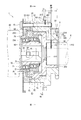
図2に示すように、バルブタイミング調整装置1は、ハウジング20、外歯部31、外歯部32、カムプレート40、歯車部50、ストッパ60、入力部材70等を備えている。
As shown in FIG. 2, the valve
ハウジング20は、外歯ハウジング21、ストッパハウジング22、カバーハウジング23を有している。外歯ハウジング21、ストッパハウジング22、カバーハウジング23は、それぞれ、例えば金属により形成されている。本実施形態では、外歯ハウジング21とストッパハウジング22とは一体に形成されている。カバーハウジング23は、外歯ハウジング21およびストッパハウジング22とは別体に形成されている。
The
外歯ハウジング21は、ハウジング板部211、ハウジング筒部212、ハウジング環状部213、ハウジング環状部214を有している。ハウジング板部211は、略円板状に形成されている。ハウジング板部211の中央には、ハウジング板部211を板厚方向に貫くハウジング穴部200が形成されている。ハウジング穴部200の内周面は、略円筒面状に形成されている。
The
ハウジング筒部212は、ハウジング板部211の一方の面のハウジング穴部200の外縁部から筒状に延びるようハウジング板部211と一体に形成されている。ハウジング筒部212の内周面は、略円筒面状に形成されている。ハウジング穴部200の内径とハウジング筒部212の内径とは同一である。これにより、ハウジング穴部200およびハウジング筒部212の内側には、略円筒面状の内周面210が形成されている。
The
ハウジング環状部213は、ハウジング板部211のハウジング筒部212とは反対側の端部の外周面から径外方向へ延びるよう環状にハウジング板部211と一体に形成されている。ハウジング環状部214は、ハウジング筒部212のハウジング板部211とは反対側の端部の外周面から径外方向へ延びるよう環状にハウジング筒部212と一体に形成されている。
The housing
ストッパハウジング22は、ハウジング板部211のハウジング筒部212とは反対側の面から略円筒状に延びるようハウジング板部211と一体に形成されている。ストッパハウジング22は、ハウジング筒部212と同軸に形成されている。
The
カバーハウジング23は、カバー筒部231、カバー底部232を有している。カバー筒部231は、略円筒状に形成されている。カバー底部232は、カバー筒部231の一方の端部を塞ぐようカバー筒部231と一体に形成されている。カバー底部232の中央には、カバー底部232を板厚方向に貫くカバー穴部230が形成されている。カバー穴部230の内周面は、略円筒状に形成されている。カバーハウジング23は、カバー筒部231のカバー底部232とは反対側の端部がストッパハウジング22の外歯ハウジング21とは反対側の端部に接合するよう設けられている。カバーハウジング23は、ストッパハウジング22と同軸に設けられている。カバーハウジング23とストッパハウジング22および外歯ハウジング21とは、ボルト15により一体に設けられている。
The
外歯部31は、例えば金属により形成されている。外歯部31は、ハウジング環状部213の径方向外側に位置するよう環状に外歯ハウジング21と一体に形成されている。外歯部31は、周方向に複数の外歯を有している(図3参照)。上述したように、外歯部31には、クランクシャフト2に巻き掛けられたチェーン7が巻き掛けられる。外歯部31は、チェーン7に噛み合い可能に形成されている。これにより、クランクシャフト2が回転すると、チェーン7を経由してハウジング20に動力が伝達し、ハウジング20は、クランクシャフト2に連動して回転する。
The
外歯部32は、例えば金属により形成されている。外歯部32は、ハウジング環状部214の径方向外側に位置するよう環状に外歯ハウジング21と一体に形成されている。外歯部32は、周方向に複数の外歯を有している。上述したように、外歯部32には、スプロケット6に巻き掛けられたチェーン8が巻き掛けられる。外歯部32は、チェーン8に噛み合い可能に形成されている。これにより、クランクシャフト2が回転すると、クランクシャフト2からチェーン7、外歯部31、外歯部32、チェーン8を経由してスプロケット6に動力が伝達し、スプロケット6およびカムシャフト5は、クランクシャフト2に連動して回転する。
The
外歯部31と外歯部32とは、同軸に設けられている。外歯部31の歯底径および歯先径は、外歯部32の歯底径および歯先径より大きく設定されている。外歯部31および外歯部32は、ハウジング20の軸方向に所定の間隔を空けて並ぶよう形成されている。すなわち、本実施形態では、外歯部は、ハウジング20の軸方向に2つ(31、32)形成されている。なお、外歯部31、外歯部32には焼き入れ処理が施されており、硬度が高められている。
The
カムシャフト5に固定されているスプロケット6の外縁部には外歯部が形成されている。スプロケット6の外歯部の外歯の数は、外歯部32の外歯の数と同じである。また、スプロケット6の外歯部の歯底径および歯先径は、外歯部32の歯底径および歯先径と同じである。
External teeth are formed on the outer edge of the
カムプレート40は、カムプレート本体41、軸受部42を有している。カムプレート本体41、軸受部42は、それぞれ、例えば金属により形成されている。本実施形態では、カムプレート本体41と軸受部42とは一体に形成されている。なお、カムプレート40には焼き入れ処理が施されており、硬度が高められている。
The
カムプレート本体41は、有底筒状に形成されている。カムプレート本体41の底部の中央には、底部を板厚方向に貫くプレート穴部410が形成されている。カムプレート本体41の筒部は、略円筒状に形成されている。軸受部42は、カムプレート本体41の底部の筒部とは反対側の面のプレート穴部410の外縁部から略円筒状に延びるよう形成されている。カムプレート本体41の筒部と軸受部42とは同軸に形成されている。軸受部42の内周面および外周面420は、略円筒面状に形成されている。
The cam plate
カムプレート40は、軸受部42がハウジング20の内周面210の内側に位置し、カムプレート本体41がストッパハウジング22の内側に位置するようハウジング20の内側に設けられている。ここで、軸受部42の外径は、内周面210の内径よりやや小さく設定されている。
The
ハウジング20は、当接可能面201を有している。当接可能面201は、ハウジング板部211のハウジング筒部212とは反対側の面に形成されている。当接可能面201は、カムプレート本体41の底部の軸受部42側の面である壁面401に当接可能である。すなわち、当接可能面201は、カムプレート40の軸方向の一方側の壁面401に当接可能な内壁である。
The
カムプレート40は、軸受部42の内側にカムシャフト4の端部が位置するようカムシャフト4に接続される。カムプレート40とカムシャフト4とは、ボルト16により互いに相対回転不能に固定される。これにより、カムプレート40は、カムシャフト4と一体に回転する。カムプレート40は、ハウジング20に対し相対回転可能である。
The
軸受部42は、ハウジング20の内周面210から径内方向の荷重を外周面420で受ける。すなわち、軸受部42は、外周面420でハウジング20を軸受けする。カムプレート40とハウジング20とが相対回転するとき、軸受部42の外周面420とハウジング20の内周面210とは摺動する。本実施形態では、軸受部42の外周面420の軸方向の長さは、ハウジング20の内周面210の軸方向の長さより短い。そのため、カムプレート40の壁面401とハウジング20の当接可能面201とが当接した状態では、軸受部42のカムプレート本体41とは反対側の端面は、ハウジング筒部212のハウジング板部211とは反対側の端面よりもカバーハウジング23側に位置している(図2参照)。
The bearing
カバー筒部231の内周壁には、環状の第1内歯部24が形成されている。第1内歯部24は、周方向に複数の内歯を有している。カムプレート本体41の筒部の内周壁には、環状の第2内歯部43が形成されている。第2内歯部43は、周方向に複数の内歯を有している。第1内歯部24と第2内歯部43とは、同軸に形成されている。第1内歯部24の歯底径および歯先径は、第2内歯部43の歯底径および歯先径より大きく設定されている。
An annular first
歯車部50は、例えば金属により略円筒状に形成されている。歯車部50は、第1外歯部51、第2外歯部52を有している。第1外歯部51、第2外歯部52は、歯車部50の外周壁に環状に形成されている。第1外歯部51と第2外歯部52とは、歯車部50の軸方向に隣接して並ぶよう同軸に形成されている。第1外歯部51の歯底径および歯先径は、第2外歯部52の歯底径および歯先径より大きく設定されている。
The
歯車部50は、第1外歯部51が第1内歯部24に噛み合い可能、かつ、第2外歯部52が第2内歯部43に噛み合い可能なようハウジング20の内側に設けられている。すなわち、歯車部50は、カムプレート本体41に対しカバーハウジング23側に設けられている。ここで、第1外歯部51の歯底径および歯先径は、第1内歯部24の歯底径および歯先径より小さく設定されている。また、第2外歯部52の歯底径および歯先径は、第2内歯部43の歯底径および歯先径より小さく設定されている。
The
ストッパ60は、例えば金属により形成されている。ストッパ60は、ストッパハウジング22の内周壁から径内方向へ突出するようストッパハウジング22と一体に形成されている。ストッパ60は、ストッパハウジング22の周方向に等間隔で4つ形成されている(図3参照)。カムプレート40は、ストッパ突出部45を有している。ストッパ突出部45は、カムプレート本体41の筒部の外周壁から径外方向へ突出するようカムプレート本体41と一体に形成されている。ストッパ突出部45は、カムプレート本体41の周方向に等間隔で4つ形成されている(図3参照)。
The
カムプレート40がハウジング20の内側に設けられた状態において、4つのストッパ突出部45は、それぞれ、各ストッパ60の間に位置している。ハウジング20に対しカムプレート40が相対回転すると、ストッパ突出部45の周方向の端部がストッパ60の周方向の端部に当接する。これにより、ハウジング20に対するカムプレート40の相対回転が規制される。すなわち、ストッパ60は、ハウジング20とカムプレート40との相対回転を所定の範囲に規制可能である。なお、ストッパ突出部45の先端部とストッパハウジング22の内周壁との間、および、ストッパ60の先端部とカムプレート本体41の筒部の外周壁との間には、所定の隙間が設定されている。よって、カムプレート40とハウジング20とが相対回転するとき、軸受部42の外周面420とハウジング20の内周面210とは摺動するものの、ストッパ突出部45とストッパハウジング22の内周壁、および、ストッパ60とカムプレート本体41の筒部の外周壁とは摺動しない。
In a state where the
入力部材70は、例えば金属により筒状に形成されている。入力部材70は、第1筒状面71、第2筒状面72を有している。第1筒状面71、第2筒状面72は、それぞれ、略円筒面状に形成され、入力部材70の軸方向に並ぶよう入力部材70の外周壁に形成されている。ここで、第1筒状面71は、入力部材70の内周面と同軸に形成されている。第2筒状面72は、入力部材70の内周面および第1筒状面71に対し所定量偏心するよう形成されている。
The
入力部材70は、第1筒状面71がカバーハウジング23のカバー穴部230の内側に位置し、第2筒状面72が歯車部50の内側に位置するようハウジング20の内側に設けられている。第1筒状面71とカバー穴部230との間には、第1ベアリング75が設けられている。第2筒状面72と歯車部50の内周壁との間には、第2ベアリング76が設けられている。この構成により、入力部材70がハウジング20に対し相対回転すると、歯車部50は、第1外歯部51が第1内歯部24に噛み合い、第2外歯部52が第2内歯部43に噛み合いながら、自転しつつハウジング20に対し公転する。歯車部50が自転しつつハウジング20に対し公転すると、ハウジング20とカムプレート40とは相対回転する。
The
モータ80は、モータシャフト81、ジョイント82を有している。モータシャフト81は、図示しないロータに固定されており、モータ80に通電されることによりロータとともに回転する。ジョイント82は、モータシャフト81の先端部に固定され、モータシャフト81とともに回転可能である。モータ80は、カムシャフト4に取り付けられたバルブタイミング調整装置1に対しカムシャフト4とは反対側に位置するようエンジン10に取り付けられる。モータ80は、図示しない電子制御ユニット(以下、「ECU」という)により通電が制御され、その回転が制御される。
The
入力部材70の内周壁には、軸方向へ延びるジョイント溝部73が形成されている。モータ80は、ジョイント82がジョイント溝部73に係合するようエンジン10に取り付けられる。そのため、通電によりモータ80が回転すると、入力部材70が回転する。入力部材70が回転すると、歯車部50が自転しつつハウジング20に対し公転する。これにより、ハウジング20とカムプレート40とは相対回転する。このように、歯車部50は、モータ80により回転駆動され、ハウジング20とカムプレート40とを相対回転させることが可能である。
A
図2に示すように、本実施形態では、2つの外歯部(31、32)のうち外歯部32は、ハウジング20の軸方向において、当接可能面201に対し歯車部50とは反対側に形成されている。また、カムプレート40は、当接可能面201に対し歯車部50とは反対側においてハウジング20の内周面210から径内方向の荷重を外周面420で受ける軸受部42を有している。そのため、チェーン7、チェーン8から外歯部31、外歯部32を経由してハウジング20に径内方向の荷重が作用したとき、当該径内方向の荷重をカムプレート40の軸受部42で受けることができる。これにより、ハウジング20に曲げ応力が印加されて当接可能面201がカムプレート40の壁面401に押し付けられることを抑制できる。
As shown in FIG. 2, in the present embodiment, the
また、本実施形態では、2つの外歯部(31、32)のうちハウジング20の軸方向の最も一方側の外歯部31と最も他方側の外歯部32との中間の位置である中間位置MPは、ハウジング20の軸方向において、当接可能面201に対し歯車部50とは反対側に設定されている。そのため、チェーン7から外歯部31に作用する力F1とチェーン8から外歯部32に作用する力F2との合力F3の位置である合力位置FPを、当接可能面201に対し歯車部50とは反対側に存在させることができる。
Further, in the present embodiment, of the two external tooth portions (31, 32), the intermediate position is an intermediate position between the
また、本実施形態では、中間位置MPは、ハウジング20の軸方向において、軸受部42の外周面420のうち内周面210に対向する部位の軸方向の範囲内に設定されている。そのため、合力位置FPを、軸受部42の外周面420のうち内周面210に対向する部位の軸方向の範囲内に存在させることができる。
Further, in the present embodiment, the intermediate position MP is set within the axial range of the portion of the outer
また、本実施形態では、中間位置MPは、ハウジング20の軸方向において、軸受部42の外周面420のうち内周面210に対向する部位の軸方向の範囲の中央に設定されている。そのため、合力位置FPを、軸受部42の外周面420のうち内周面210に対向する部位の軸方向の範囲の中央に存在させることができる。
Further, in the present embodiment, the intermediate position MP is set at the center of the axial range of the portion of the outer
なお、本実施形態では、チェーン7から外歯部31に作用する力F1、および、チェーン8から外歯部32に作用する力F2の大きさの違い、ならびに、エンジン10の運転状況等により、合力位置FPは、ハウジング20の軸方向において移動し得る。
In the present embodiment, the magnitude of the force F1 acting on the
しかしながら、本実施形態では、上述の構成により、合力位置FPは、ハウジング20の軸方向において、当接可能面201に対し歯車部50とは反対側に存在し得る。また、合力位置FPは、ハウジング20の軸方向において、軸受部42の外周面420のうち内周面210に対向する部位の軸方向の範囲内に存在し得る。さらに、合力位置FPは、ハウジング20の軸方向において、軸受部42の外周面420のうち内周面210に対向する部位の軸方向の範囲の中央に存在し得る。
However, in the present embodiment, according to the above configuration, the resultant force position FP may exist on the side opposite to the
次に、本実施形態によるバルブタイミング調整装置1の作動を説明する。なお、図1〜3は、エンジン始動前、すなわちエンジン10が停止している時のバルブタイミング調整装置1の状態を示している。以下では、エンジン10の停止中、カムプレート40がハウジング20に対し最遅角位置に設定される場合について説明する。
Next, the operation of the valve
<エンジン始動時>
エンジン10が停止している状態では、カムプレート40は、ハウジング20に対し最遅角位置にある。このとき、ハウジング20に形成されたストッパ60とカムプレート40のストッパ突出部45とは当接している。エンジン10が始動すると、ECUは、ストッパ60とストッパ突出部45との当接が維持される方向(遅角方向)に入力部材70が回転するようモータ80を回転駆動する。
<When starting the engine>
When the
<エンジン始動後>
エンジン10の始動直後は、ハウジング20とカムプレート40とは同位相で回転する。そのため、モータ80のモータシャフト81もハウジング20およびカムプレート40と同位相、同回転数で回転する。
<After starting the engine>
Immediately after the
<進角作動時>
バルブタイミング調整装置1を進角制御するとき、ECUは、ハウジング20の回転数より入力部材70の回転数が大きくなるようモータ80を回転制御する。これにより、歯車部50がハウジング20内で自転および公転し、カムプレート40が、ハウジング20に対し進角方向に相対回転する。その結果、カムシャフト4の回転位相が進角し、吸気弁11の開閉タイミングが進角側に変更される。
<At the time of advance operation>
When controlling the advance angle of the valve
<遅角作動時>
バルブタイミング調整装置1を遅角制御するとき、ECUは、ハウジング20の回転数より入力部材70の回転数が小さくなるようモータ80を回転制御する。これにより、歯車部50がハウジング20内で自転および公転し、カムプレート40が、ハウジング20に対し遅角方向に相対回転する。その結果、カムシャフト4の回転位相が遅角し、吸気弁11の開閉タイミングが遅角側に変更される。
<At the time of retard operation>
When controlling the retard angle of the valve
<中間位相保持作動時>
カムプレート40(カムシャフト4)が目標位相に到達すると、ECUは、ハウジング20の回転数と入力部材70の回転数とが同じになるようモータ80を回転制御する。これにより、歯車部50はハウジング20に対し相対回転せず、カムプレート40は、ハウジング20に対し所定の位相(目標位相)に保持される。その結果、カムシャフト4の回転位相が所定の位相(目標位相)に保持され、吸気弁11の開閉タイミングが所定のタイミングに保持される。
<At the time of intermediate phase holding operation>
When the cam plate 40 (camshaft 4) reaches the target phase, the ECU controls the rotation of the
<エンジン停止時作動>
バルブタイミング調整装置1の作動中にエンジン10の停止が指示されると、カムプレート40は、上記遅角作動時と同様の作動によりハウジング20に対して遅角方向に回転し、最遅角位置で回転が停止する。
<Operates when the engine is stopped>
When the
上述のように、本実施形態では、2つの外歯部(31、32)のうち外歯部32は、ハウジング20の軸方向において、当接可能面201に対し歯車部50とは反対側に形成されている。また、カムプレート40は、当接可能面201に対し歯車部50とは反対側においてハウジング20の内周面210から径内方向の荷重を外周面420で受ける軸受部42を有している。そのため、エンジン10の運転中、および、バルブタイミング調整装置1の作動中、チェーン7、チェーン8から外歯部31、外歯部32を経由してハウジング20に径内方向の荷重が作用したとき、当該径内方向の荷重をカムプレート40の軸受部42で受けることができる。これにより、ハウジング20に曲げ応力が印加されて当接可能面201がカムプレート40の壁面401に押し付けられることを抑制できる。
As described above, in the present embodiment, of the two external tooth portions (31, 32), the
以上説明したように、(1)本実施形態は、エンジン10の吸気弁11のバルブタイミングを調整するバルブタイミング調整装置1であって、ハウジング20と外歯部31、外歯部32とカムプレート40と歯車部50とを備えている。ハウジング20は、エンジン10のクランクシャフト2と連動して回転可能である。外歯部31、外歯部32は、環状に形成され、クランクシャフト2または回転する他部材であるスプロケット6に巻き掛けられるチェーン7またはチェーン8に噛み合い可能なようハウジング20と一体に形成されている。本実施形態では、外歯部は、2つ(31、32)形成されている。
As described above, (1) the present embodiment is a valve
カムプレート40は、エンジン10のカムシャフト4に接続され、ハウジング20に対し相対回転可能である。歯車部50は、ハウジング20およびカムプレート40に噛み合い可能なようカムプレート40に対しカムシャフト4とは反対側に設けられ、モータ80により回転駆動され、ハウジング20とカムプレート40とを相対回転させることが可能である。ハウジング20は、カムプレート40の軸方向の一方側の壁面401に当接可能な内壁である当接可能面201を有している。
The
2つの外歯部(31、32)のうち外歯部32は、ハウジング20の軸方向において、当接可能面201に対し歯車部50とは反対側に形成されている。カムプレート40は、当接可能面201に対し歯車部50とは反対側においてハウジング20の内周面210から径内方向の荷重を外周面420で受ける軸受部42を有している。そのため、チェーン7、チェーン8から外歯部31、外歯部32を経由してハウジング20に径内方向の荷重が作用したとき、当該径内方向の荷重をカムプレート40の軸受部42で受けることができる。これにより、ハウジング20に曲げ応力が印加されて当接可能面201がカムプレート40の壁面401に押し付けられることを抑制できる。その結果、カムプレート40の変形を抑制し、カムプレート40と歯車部50との偏当りを抑制できる。したがって、カムプレート40および歯車部50の噛み合い部(第2内歯部43、第2外歯部52)の歯面の摩耗を抑制することができる。
Of the two external tooth portions (31, 32), the
また、本実施形態では、当接可能面201がカムプレート40の壁面401に押し付けられることを抑制できるため、当接可能面201および壁面401に過大な応力が発生するのを抑制できる。そのため、ハウジング20の当接可能面201およびカムプレート40の壁面401の摩耗を抑制することができる。
Further, in the present embodiment, since the
ところで、上述の特許文献1(特開2009−185785号公報)のバルブタイミング調整装置では、ハウジングの内周面からの径内方向の荷重を、カムプレートの外周面、および、従動軸の外周面の2箇所で受ける構成である。そのため、例えばカムプレートと従動軸とが、互いの軸がずれた状態で接続された場合、カムプレートの外周面とハウジングの内周面との間の隙間の大きさと、従動軸の外周面とハウジングの内周面との間の隙間の大きさとが周方向で異なることとなり、ハウジングとカムプレートの円滑な相対回転が妨げられたり、相対回転が不能となったりするおそれがある。 By the way, in the valve timing adjusting device of Patent Document 1 (Japanese Unexamined Patent Publication No. 2009-185785) described above, a load in the in-diameter direction from the inner peripheral surface of the housing is applied to the outer peripheral surface of the cam plate and the outer peripheral surface of the driven shaft. It is a configuration that receives at two places. Therefore, for example, when the cam plate and the driven shaft are connected with their axes deviated from each other, the size of the gap between the outer peripheral surface of the cam plate and the inner peripheral surface of the housing and the outer peripheral surface of the driven shaft The size of the gap between the inner peripheral surface of the housing and the inner peripheral surface of the housing differs in the circumferential direction, which may hinder the smooth relative rotation of the housing and the cam plate, or may prevent the relative rotation.
一方、本実施形態では、カムプレート40のストッパ突出部45の先端部とストッパハウジング22の内周壁との間、および、ストッパ60の先端部とカムプレート本体41の筒部の外周壁との間には、所定の隙間が設定されている。よって、カムプレート40とハウジング20とが相対回転するとき、軸受部42の外周面420とハウジング20の内周面210とは摺動するものの、ストッパ突出部45とストッパハウジング22の内周壁、および、ストッパ60とカムプレート本体41の筒部の外周壁とは摺動しない。すなわち、本実施形態では、ハウジング20の内周面からの径内方向の荷重を、カムプレート40の1箇所で受ける構成である。そのため、例えばカムプレート40とカムシャフト4とが、互いの軸がずれた状態で接続された場合でも、ストッパ突出部45とストッパハウジング22の内周壁、および、ストッパ60とカムプレート本体41の筒部の外周壁との摺動を抑制でき、ハウジング20とカムプレート40とが相対回転不能となるのを抑制しつつ、ハウジング20とカムプレート40の円滑な相対回転を維持できる。
On the other hand, in the present embodiment, between the tip of the
また、(2)本実施形態では、2つの外歯部(31、32)のうちハウジング20の軸方向の最も一方側の外歯部31と最も他方側の外歯部32との中間の位置である中間位置MPは、ハウジング20の軸方向において、当接可能面201に対し歯車部50とは反対側に設定されている。そのため、チェーン7から外歯部31に作用する力F1とチェーン8から外歯部32に作用する力F2との合力F3の位置である合力位置FPを、当接可能面201に対し歯車部50とは反対側に存在させることができる。これにより、当接可能面201がカムプレート40の壁面401に押し付けられることを効果的に抑制できる。
(2) In the present embodiment, of the two external tooth portions (31, 32), the intermediate position between the
また、(3)本実施形態では、中間位置MPは、ハウジング20の軸方向において、軸受部42の外周面420のうち内周面210に対向する部位の軸方向の範囲内に設定されている。そのため、合力位置FPを、軸受部42の外周面420のうち内周面210に対向する部位の軸方向の範囲内に存在させることができる。これにより、当接可能面201がカムプレート40の壁面401に押し付けられることをより効果的に抑制できる。
(3) In the present embodiment, the intermediate position MP is set within the axial range of the portion of the outer
また、(4)本実施形態では、中間位置MPは、ハウジング20の軸方向において、軸受部42の外周面420のうち内周面210に対向する部位の軸方向の範囲の中央に設定されている。そのため、合力位置FPを、軸受部42の外周面420のうち内周面210に対向する部位の軸方向の範囲の中央に存在させることができる。これにより、当接可能面201がカムプレート40の壁面401に押し付けられることをより一層効果的に抑制できる。
(4) In the present embodiment, the intermediate position MP is set at the center of the axial range of the portion of the outer
上述の構成により、(5)本実施形態では、合力位置FPは、ハウジング20の軸方向において、当接可能面201に対し歯車部50とは反対側に存在し得る。また、(6)合力位置FPは、ハウジング20の軸方向において、軸受部42の外周面420のうち内周面210に対向する部位の軸方向の範囲内に存在し得る。さらに、(7)合力位置FPは、ハウジング20の軸方向において、軸受部42の外周面420のうち内周面210に対向する部位の軸方向の範囲の中央に存在し得る。そのため、当接可能面201がカムプレート40の壁面401に押し付けられることを効果的に抑制できる。
With the above configuration, (5) in the present embodiment, the resultant force position FP may exist on the side opposite to the
(第2実施形態)
第2実施形態によるバルブタイミング調整装置を図4に示す。第2実施形態は、ハウジング20の構成が第1実施形態と異なる。
(Second Embodiment)
The valve timing adjusting device according to the second embodiment is shown in FIG. In the second embodiment, the configuration of the
本実施形態では、ストッパハウジング22は、外歯ハウジング21とは別体に形成されている。ストッパハウジング22の硬度は、外歯ハウジング21の硬度より高く設定されている。ストッパハウジング22は、一方の端面の内縁部から略円筒状に突出するハウジング凸部225を有している。外歯ハウジング21は、ハウジング板部211のハウジング筒部212とは反対側の端面から略円形に凹むハウジング凹部215を有している。ストッパハウジング22は、ハウジング凸部225がハウジング凹部215に嵌合するよう外歯ハウジング21に接合している。外歯ハウジング21とストッパハウジング22とカバーハウジング23とは、ボルト15により一体に設けられている。
In the present embodiment, the
第2実施形態は、上述した点以外の構成は、第1実施形態と同様である。そのため、第1実施形態と同様の構成については、第1実施形態と同様の効果を奏することができる。なお、本実施形態では、ストッパハウジング22と外歯ハウジング21とが別体に形成されているため、ストッパハウジング22と外歯ハウジング21とが軸ずれするおそれがある。しかしながら、本実施形態では、カムプレート40のストッパ突出部45の先端部とストッパハウジング22の内周壁との間、および、ストッパ60の先端部とカムプレート本体41の筒部の外周壁との間に所定の隙間が設定されているため、ストッパハウジング22と外歯ハウジング21とが軸ずれしたとしても、ハウジング20とカムプレート40の円滑な相対回転を維持できる。
The second embodiment has the same configuration as the first embodiment except for the above-mentioned points. Therefore, with respect to the configuration similar to that of the first embodiment, the same effect as that of the first embodiment can be obtained. In this embodiment, since the
以上説明したように、本実施形態では、ストッパハウジング22と外歯ハウジング21とが別体に形成されているため、ストッパハウジング22と外歯ハウジング21とを一体に形成する場合と比べ、ストッパ60等を比較的容易に形成できる。また、ストッパ60が形成されるストッパハウジング22の硬度を外歯ハウジング21の硬度より高く設定することにより、ストッパ60の強度を高めつつ、外歯ハウジング21の形成を容易にすることができる。
As described above, in the present embodiment, since the
(第3実施形態)
第3実施形態によるバルブタイミング調整装置を図5に示す。第3実施形態は、カムプレート40の構成が第2実施形態と異なる。
(Third Embodiment)
The valve timing adjusting device according to the third embodiment is shown in FIG. In the third embodiment, the configuration of the
本実施形態では、軸受部42は、カムプレート本体41とは別体に形成されている。軸受部42は、有底円筒状に形成されている。カムプレート本体41には、底部の筒部とは反対側の端面から略円形に凹むカムプレート凹部415が形成されている。軸受部42は、底部側の端部がカムプレート凹部415に嵌合するようカムプレート本体41に接合している。軸受部42の底部には、軸受穴部425が形成されている。軸受穴部425は、プレート穴部410に連通している。カムプレート本体41と軸受部42とカムシャフト4とは、ボルト16により互いに固定される。
In the present embodiment, the bearing
第3実施形態は、上述した点以外の構成は、第2実施形態と同様である。そのため、第2実施形態と同様の構成については、第2実施形態と同様の効果を奏することができる。 The third embodiment has the same configuration as the second embodiment except for the above-mentioned points. Therefore, with respect to the configuration similar to that of the second embodiment, the same effect as that of the second embodiment can be obtained.
以上説明したように、本実施形態では、軸受部42とカムプレート本体41とが別体に形成されているため、外歯ハウジング21のカムシャフト4側へのオフセット量が大きい場合、カムプレート40を容易に製造でき、コストを低減することができる。
As described above, in the present embodiment, the bearing
(第4実施形態)
第4実施形態によるバルブタイミング調整装置を図6〜8に示す。第4実施形態は、ハウジング20の構成等が第1実施形態と異なる。
(Fourth Embodiment)
The valve timing adjusting device according to the fourth embodiment is shown in FIGS. 6 to 8. In the fourth embodiment, the configuration of the
図7に示すように、本実施形態では、外歯ハウジング21は、ハウジング板部211、ハウジング環状部213を有しているものの、第1実施形態で示したハウジング筒部212、ハウジング環状部214を有していない。また、本実施形態は、第1実施形態で示した外歯部32を備えていない。
As shown in FIG. 7, in the present embodiment, the
ハウジング環状部213は、ハウジング板部211のストッパハウジング22とは反対側の端部の外周面から径外方向へ延びるよう環状にハウジング板部211と一体に形成されている。外歯部31は、ハウジング環状部213の径方向外側に位置するよう環状に外歯ハウジング21と一体に形成されている。なお、カバー筒部231とカバー底部232とは別体に形成されている。
The housing
本実施形態では、カムプレート本体41には、延伸穴部411が形成されている。延伸穴部411は、プレート穴部410から径外方向へ延びるよう形成されている(図7、8参照)。カムプレート本体41の底部には、プレート穴部410の径方向外側において軸受部42側の端面から環状に凹む環状溝部412が形成されている。環状溝部412は、延伸穴部411に接続している。
In the present embodiment, the cam plate
本実施形態では、カムシャフト4の端部に、油路13が形成されている。バルブタイミング調整装置1がカムシャフト4に取り付けられたとき、油路13は、環状溝部412に接続する。油路13には、ポンプ14が接続される。ポンプ14は、図示しないオイルパンに貯留された潤滑油を汲み上げ、バルブタイミング調整装置1に供給する。ポンプ14からの潤滑油は、油路13、環状溝部412、延伸穴部411を経由してカムプレート本体41の内側に流れる。カムプレート本体41の内側に流れた潤滑油は、第2外歯部52と第2内歯部43との間、および、第1外歯部51と第1内歯部24との間に流れ、当該箇所を潤滑する。これにより、第2外歯部52と第2内歯部43との間、および、第1外歯部51と第1内歯部24との間の摩耗が抑制される。
In this embodiment, an
図8に示すように、第1実施形態と同様、ストッパ60は、ストッパハウジング22の周方向に等間隔で4つ形成されている。また、第1実施形態と同様、ストッパ突出部45は、カムプレート本体41の周方向に等間隔で4つ形成されている。
As shown in FIG. 8, four
図6に示すように、本実施形態のバルブタイミング調整装置1が適用されるエンジン10は、チェーン7を備えるものの、第1実施形態で示したチェーン8を備えていない。チェーン7は、スプロケット3と外歯部31とスプロケット6とに巻き掛けられる。ここで、スプロケット6の外歯部の外歯の数は、外歯部31の外歯の数と同じである。また、スプロケット6の外歯部の歯底径および歯先径は、外歯部31の歯底径および歯先径と同じである。
As shown in FIG. 6, the
図7に示すように、本実施形態では、軸受部42の外周面420の軸方向の長さは、ハウジング20の内周面210の軸方向の長さと略同じである。そのため、カムプレート40の壁面401とハウジング20の当接可能面201とが当接した状態では、軸受部42のカムプレート本体41とは反対側の端面は、ハウジング板部211のストッパハウジング22とは反対側の端面と略同一平面上に位置している。
As shown in FIG. 7, in the present embodiment, the axial length of the outer
本実施形態では、外歯部31は、ハウジング20の軸方向において、当接可能面201に対し歯車部50とは反対側に形成されている。また、カムプレート40は、当接可能面201に対し歯車部50とは反対側においてハウジング20の内周面210から径内方向の荷重を外周面420で受ける軸受部42を有している。そのため、チェーン7から外歯部31を経由してハウジング20に径内方向の荷重が作用したとき、当該径内方向の荷重をカムプレート40の軸受部42で受けることができる。これにより、ハウジング20に曲げ応力が印加されて当接可能面201がカムプレート40の壁面401に押し付けられることを抑制できる。
In the present embodiment, the
また、本実施形態では、外歯部31は、ハウジング20の軸方向において、軸受部42の外周面420のうち内周面210に対向する部位の軸方向の範囲内に位置している。そのため、チェーン7から外歯部31を経由してハウジング20に径内方向の荷重が作用したとき、当該径内方向の荷重をカムプレート40の軸受部42で適切に受けることができる。
Further, in the present embodiment, the
以上説明したように、(1)本実施形態は、外歯部を1つ(31)備えている。外歯部31は、ハウジング20の軸方向において、当接可能面201に対し歯車部50とは反対側に形成されている。また、カムプレート40は、当接可能面201に対し歯車部50とは反対側においてハウジング20の内周面210から径内方向の荷重を外周面420で受ける軸受部42を有している。そのため、チェーン7から外歯部31を経由してハウジング20に径内方向の荷重が作用したとき、当該径内方向の荷重をカムプレート40の軸受部42で受けることができる。これにより、ハウジング20に曲げ応力が印加されて当接可能面201がカムプレート40の壁面401に押し付けられることを抑制できる。その結果、カムプレート40の変形を抑制し、カムプレート40と歯車部50との偏当りを抑制できる。したがって、第1実施形態と同様、カムプレート40および歯車部50の噛み合い部(第2内歯部43、第2外歯部52)の歯面の摩耗を抑制することができる。
As described above, (1) the present embodiment includes one (31) external tooth portion. The
また、(8)本実施形態では、外歯部31は、ハウジング20の軸方向において、軸受部42の外周面420のうち内周面210に対向する部位の軸方向の範囲内に位置している。そのため、チェーン7から外歯部31を経由してハウジング20に径内方向の荷重が作用したとき、当該径内方向の荷重をカムプレート40の軸受部42で適切に受けることができる。これにより、当接可能面201がカムプレート40の壁面401に押し付けられることを効果的に抑制できる。
(8) In the present embodiment, the
(第5実施形態)
第5実施形態によるバルブタイミング調整装置を図9に示す。第5実施形態は、ハウジング20の構成等が第4実施形態と異なる。
(Fifth Embodiment)
The valve timing adjusting device according to the fifth embodiment is shown in FIG. In the fifth embodiment, the configuration of the
本実施形態では、ハウジング20は、プレート25を有している。プレート25は、例えば金属により略円環の板状に形成されている。プレート25の硬度は、ハウジング板部211の硬度より高く設定されている。ハウジング板部211には、ハウジング穴部200の径方向外側においてストッパハウジング22側の端面から環状に凹む環状凹部202が形成されている。環状凹部202の内径および外径は、プレート25の内径および外径と略同じである。また、環状凹部202の深さは、プレート25の板厚と略同じである。プレート25は、環状凹部202に嵌合するようハウジング板部211に設けられている。本実施形態では、カムプレート40の壁面401に当接可能な当接可能面201は、プレート25の歯車部50側の端面に形成されている。本実施形態では、当接可能面201がプレート25に形成されているため、カムプレート40との摺動によるハウジング板部211の摩耗を抑制することができる。
In this embodiment, the
(他の実施形態)
本発明の他の実施形態では、少なくとも1つの外歯部が、ハウジング20の軸方向において、当接可能面201に対し歯車部50とは反対側に形成されているのであれば、外歯部は、ハウジング20の軸方向に3つ以上形成されていてもよい。
(Other embodiments)
In another embodiment of the present invention, if at least one external tooth portion is formed on the side opposite to the
また、本発明の他の実施形態では、複数の外歯部のうちハウジング20の軸方向の最も一方側の外歯部と最も他方側の外歯部との中間の位置である中間位置は、ハウジング20の軸方向において、当接可能面201に対し歯車部50側に設定されていてもよい。
Further, in another embodiment of the present invention, the intermediate position, which is an intermediate position between the outermost tooth portion on the onemost side and the outermost tooth portion on the other side in the axial direction of the
また、本発明の他の実施形態では、前記中間位置は、ハウジング20の軸方向において、軸受部42の外周面420のうちハウジング20の内周面210に対向する部位の軸方向の範囲外に設定されていてもよい。
Further, in another embodiment of the present invention, the intermediate position is outside the axial range of the portion of the outer
また、本発明の他の実施形態では、前記中間位置は、ハウジング20の軸方向において、軸受部42の外周面420のうちハウジング20の内周面210に対向する部位の軸方向の範囲の中心に設定されていてもよい。また、前記中間位置は、ハウジング20の軸方向において、軸受部42の外周面420のうちハウジング20の内周面210に対向する部位の軸方向の範囲の中央以外の位置に設定されていてもよい。
Further, in another embodiment of the present invention, the intermediate position is the center of the axial range of the portion of the outer
また、本発明の他の実施形態では、少なくとも1つの外歯部は、ハウジング20の軸方向において、軸受部42の外周面420のうちハウジング20の内周面210に対向する部位の軸方向の範囲の中央に位置していてもよい。より詳細には、少なくとも1つの外歯部は、ハウジング20の軸方向において、軸受部42の外周面420のうちハウジング20の内周面210に対向する部位の軸方向の範囲の中心に位置していてもよい。この構成は、外歯部がハウジング20の軸方向に1つ形成される場合に好適である。
Further, in another embodiment of the present invention, at least one outer tooth portion is axially oriented at a portion of the outer
また、本発明の他の実施形態では、チェーンに代えて、例えばベルト等の伝達部材を用いてもよい。 Further, in another embodiment of the present invention, a transmission member such as a belt may be used instead of the chain.
また、上述の実施形態では、カムプレート40がカムシャフト4の端部に固定され、ハウジング20がクランクシャフト2に連動して回転する例を示した。これに対し、本発明の他の実施形態では、カムプレート40がクランクシャフト2の端部に固定され、ハウジング20がカムシャフト4に連動して回転することとしてもよい。
Further, in the above-described embodiment, an example is shown in which the
本発明のバルブタイミング調整装置1は、エンジン10の排気弁12のバルブタイミングを調整することとしてもよい。
The valve
このように、本開示は、上記実施形態に限定されるものではなく、その要旨を逸脱しない範囲で種々の形態で実施可能である。 As described above, the present disclosure is not limited to the above-described embodiment, and can be implemented in various forms without departing from the gist thereof.
1 バルブタイミング調整装置、2 クランクシャフト(駆動軸)、4、5 カムシャフト(従動軸)、7、8 チェーン(無端伝動部材)、10 エンジン(内燃機関)、11 吸気弁(バルブ)、12 排気弁(バルブ)、20 ハウジング、31、32 外歯部、40 カムプレート、42 軸受部、50 歯車部、80 モータ、201 当接可能面、210 内周面、401 壁面、420 外周面 1 Valve timing adjuster, 2 Crankshaft (drive shaft), 4, 5 Camshaft (driven shaft), 7, 8 Chain (endless transmission member), 10 Engine (internal combustion engine), 11 Intake valve (valve), 12 Exhaust Valve, 20 housing, 31, 32 outer tooth part, 40 cam plate, 42 bearing part, 50 gear part, 80 motor, 201 contactable surface, 210 inner peripheral surface, 401 wall surface, 420 outer peripheral surface
Claims (14)
前記内燃機関の駆動軸(2)および従動軸(4、5)の一方と連動して回転可能なハウジング(20)と、
前記駆動軸または回転する他部材(6)に巻き掛けられる無端伝動部材(7、8)に噛み合い可能なよう前記ハウジングと一体に形成された少なくとも1つの環状の外歯部(31、32)と、
前記駆動軸および前記従動軸の他方に接続され、前記ハウジングに対し相対回転可能なカムプレート(40)と、
前記ハウジングおよび前記カムプレートに噛み合い可能なよう前記カムプレートに対し前記駆動軸および前記従動軸の他方とは反対側に設けられ、モータ(80)により回転駆動され、前記ハウジングと前記カムプレートとを相対回転させることが可能な歯車部(50)と、を備え、
前記ハウジングは、前記カムプレートの軸方向の一方側の壁面(401)に当接可能な内壁である当接可能面(201)を有し、
少なくとも1つの前記外歯部は、前記ハウジングの軸方向において、前記当接可能面に対し前記歯車部とは反対側に形成されており、
前記カムプレートは、前記当接可能面に対し前記歯車部とは反対側において前記ハウジングの内周面(210)から径内方向の荷重を外周面(420)で受ける軸受部(42)を有し、
前記カムプレートは、前記当接可能面に対し前記歯車部側において、前記ハウジングから径内方向の荷重が作用しないよう形成されているバルブタイミング調整装置。 A valve timing adjusting device (1) for adjusting the valve timing of the valves (11, 12) of the internal combustion engine (10).
A housing (20) that can rotate in conjunction with one of the drive shaft (2) and the driven shaft (4, 5) of the internal combustion engine.
With at least one annular external tooth portion (31, 32) formed integrally with the housing so as to be able to mesh with the endless transmission member (7, 8) wound around the drive shaft or another rotating member (6). ,
A cam plate (40) connected to the other of the drive shaft and the driven shaft and rotatable relative to the housing.
A drive shaft and a driven shaft are provided on the opposite side of the cam plate so as to be able to mesh with the housing and the cam plate, and are rotationally driven by a motor (80) to bring the housing and the cam plate together. It is equipped with a gear unit (50) that can be rotated relative to each other.
The housing has a contactable surface (201) which is an inner wall capable of contacting a wall surface (401) on one side in the axial direction of the cam plate.
At least one of the external tooth portions is formed on the side opposite to the gear portion with respect to the contactable surface in the axial direction of the housing.
The cam plate has a bearing portion (42) that receives a load in the in-diameter direction from the inner peripheral surface (210) of the housing on the outer peripheral surface (420) on the side opposite to the gear portion with respect to the contactable surface. and,
The cam plate is a valve timing adjusting device formed so that a load in the in-diameter direction does not act from the housing on the gear portion side with respect to the contactable surface.
前記ハウジングの内周面(210)からの径内方向の荷重は、前記軸受部を経由して「前記駆動軸および前記従動軸の他方」の端部の外周面に作用する請求項1に記載のバルブタイミング調整装置。 The first aspect of claim 1, wherein the load in the in-diameter direction from the inner peripheral surface (210) of the housing acts on the outer peripheral surface of the end portion of "the drive shaft and the other of the driven shaft" via the bearing portion. Valve timing adjuster.
前記軸受部の軸方向の一部は、複数の前記外歯部のうち前記歯車部から最も離れた前記外歯部(32)の径方向内側に位置している請求項1〜3のいずれか一項に記載のバルブタイミング調整装置。 Any of claims 1 to 3, wherein a part of the bearing portion in the axial direction is located radially inside the external tooth portion (32) farthest from the gear portion among the plurality of external tooth portions. The valve timing adjusting device according to one item.
複数の前記外歯部のうち前記ハウジングの軸方向の最も一方側の前記外歯部(31)と最も他方側の前記外歯部(32)との中間の位置である中間位置(MP)は、前記ハウジングの軸方向において、前記当接可能面に対し前記歯車部とは反対側に設定されている請求項1〜4のいずれか一項に記載のバルブタイミング調整装置。 A plurality of the external tooth portions are formed in the axial direction of the housing.
Of the plurality of the external tooth portions, the intermediate position (MP), which is an intermediate position between the external tooth portion (31) on the most one side in the axial direction of the housing and the external tooth portion (32) on the farthest side, is The valve timing adjusting device according to any one of claims 1 to 4, which is set on the side opposite to the gear portion with respect to the contactable surface in the axial direction of the housing.
前記無端伝動部材から複数の前記外歯部それぞれに作用する力(F1、F2)の合力(F3)の位置である合力位置(FP)は、前記ハウジングの軸方向において、前記当接可能面に対し前記歯車部とは反対側に存在し得る請求項1〜7のいずれか一項に記載のバルブタイミング調整装置。 A plurality of the external tooth portions are formed in the axial direction of the housing.
The resultant force position (FP), which is the position of the resultant force (F3) of the forces (F1, F2) acting on each of the plurality of external tooth portions from the endless transmission member, is set on the abuttable surface in the axial direction of the housing. The valve timing adjusting device according to any one of claims 1 to 7 , which may exist on the side opposite to the gear portion.
前記ストッパハウジングと一体に形成され、前記カムプレートに当接することで前記ハウジングと前記カムプレートとの相対回転を所定の範囲に規制可能なストッパ(60)をさらに備える請求項1〜12のいずれか一項に記載のバルブタイミング調整装置。 The housing has an external tooth housing (21) on which the external tooth portion is formed, and a stopper housing (22) formed separately from the external tooth housing.
Any of claims 1 to 12 , further comprising a stopper (60) formed integrally with the stopper housing and capable of restricting the relative rotation between the housing and the cam plate within a predetermined range by abutting against the cam plate. The valve timing adjusting device according to one item.
Priority Applications (5)
| Application Number | Priority Date | Filing Date | Title |
|---|---|---|---|
| JP2017214052A JP6904219B2 (en) | 2017-11-06 | 2017-11-06 | Valve timing adjuster |
| DE112018005696.1T DE112018005696T5 (en) | 2017-11-06 | 2018-11-02 | Valve timing adjustment device |
| CN201880069340.6A CN111279055B (en) | 2017-11-06 | 2018-11-02 | Valve timing adjusting device |
| PCT/JP2018/040815 WO2019088250A1 (en) | 2017-11-06 | 2018-11-02 | Valve timing adjustment device |
| US16/865,805 US10975737B2 (en) | 2017-11-06 | 2020-05-04 | Valve timing adjustment device |
Applications Claiming Priority (1)
| Application Number | Priority Date | Filing Date | Title |
|---|---|---|---|
| JP2017214052A JP6904219B2 (en) | 2017-11-06 | 2017-11-06 | Valve timing adjuster |
Publications (3)
| Publication Number | Publication Date |
|---|---|
| JP2019085910A JP2019085910A (en) | 2019-06-06 |
| JP2019085910A5 JP2019085910A5 (en) | 2020-04-30 |
| JP6904219B2 true JP6904219B2 (en) | 2021-07-14 |
Family
ID=66333155
Family Applications (1)
| Application Number | Title | Priority Date | Filing Date |
|---|---|---|---|
| JP2017214052A Active JP6904219B2 (en) | 2017-11-06 | 2017-11-06 | Valve timing adjuster |
Country Status (5)
| Country | Link |
|---|---|
| US (1) | US10975737B2 (en) |
| JP (1) | JP6904219B2 (en) |
| CN (1) | CN111279055B (en) |
| DE (1) | DE112018005696T5 (en) |
| WO (1) | WO2019088250A1 (en) |
Families Citing this family (1)
| Publication number | Priority date | Publication date | Assignee | Title |
|---|---|---|---|---|
| JP7198099B2 (en) | 2019-02-01 | 2022-12-28 | 株式会社デンソー | valve timing adjuster |
Family Cites Families (9)
| Publication number | Priority date | Publication date | Assignee | Title |
|---|---|---|---|---|
| DE102004038681B4 (en) | 2004-08-10 | 2017-06-01 | Schaeffler Technologies AG & Co. KG | Electromotive camshaft adjuster |
| JP2007309430A (en) * | 2006-05-18 | 2007-11-29 | Denso Corp | Reduction gear and valve timing adjusting device |
| JP4552902B2 (en) | 2006-06-22 | 2010-09-29 | 株式会社デンソー | Valve timing adjustment device |
| JP2009185785A (en) * | 2008-02-08 | 2009-08-20 | Denso Corp | Valve timing adjusting device |
| JP5402571B2 (en) | 2009-11-26 | 2014-01-29 | 株式会社デンソー | Valve timing adjustment device |
| JP5907008B2 (en) * | 2012-09-05 | 2016-04-20 | 株式会社デンソー | Valve timing adjustment device |
| JP5987868B2 (en) * | 2014-07-22 | 2016-09-07 | 株式会社デンソー | Valve timing adjustment device |
| JP6863755B2 (en) | 2016-05-26 | 2021-04-21 | 豊和化成株式会社 | register |
| CN106837460B (en) * | 2017-04-12 | 2023-04-21 | 吉林大学 | Continuously variable valve timing device of internal combustion engine |
-
2017
- 2017-11-06 JP JP2017214052A patent/JP6904219B2/en active Active
-
2018
- 2018-11-02 CN CN201880069340.6A patent/CN111279055B/en active Active
- 2018-11-02 WO PCT/JP2018/040815 patent/WO2019088250A1/en active Application Filing
- 2018-11-02 DE DE112018005696.1T patent/DE112018005696T5/en active Pending
-
2020
- 2020-05-04 US US16/865,805 patent/US10975737B2/en active Active
Also Published As
| Publication number | Publication date |
|---|---|
| CN111279055A (en) | 2020-06-12 |
| US20200263574A1 (en) | 2020-08-20 |
| JP2019085910A (en) | 2019-06-06 |
| DE112018005696T5 (en) | 2020-07-09 |
| US10975737B2 (en) | 2021-04-13 |
| CN111279055B (en) | 2022-03-18 |
| WO2019088250A1 (en) | 2019-05-09 |
Similar Documents
| Publication | Publication Date | Title |
|---|---|---|
| KR101896672B1 (en) | Valve timing adjustment device | |
| JP5987868B2 (en) | Valve timing adjustment device | |
| US9534513B2 (en) | Camshaft phaser actuated by an electric motor | |
| US8322318B2 (en) | Harmonic drive camshaft phaser with phase authority stops | |
| JP5888283B2 (en) | Valve timing adjustment device | |
| JP2019007409A (en) | Valve opening/closing timing control device | |
| JP6904219B2 (en) | Valve timing adjuster | |
| JP5920632B2 (en) | Valve timing adjustment device | |
| CN106939806B (en) | Valve opening/closing timing control device | |
| JP7196493B2 (en) | valve timing adjuster | |
| JP2016089682A5 (en) | ||
| JP5402571B2 (en) | Valve timing adjustment device | |
| JP7294745B2 (en) | valve timing adjuster | |
| US10954828B2 (en) | Variable camshaft phaser with magnetic locking cover bushing | |
| JP7001023B2 (en) | Valve timing adjuster | |
| JP2006077662A (en) | Valve timing adjustment device | |
| JP2004300930A (en) | Valve timing adjusting device | |
| JP7226779B2 (en) | valve timing adjuster | |
| JP6907822B2 (en) | Valve timing adjustment device and rotation adjustment device | |
| JP4678537B2 (en) | Valve timing adjustment device | |
| JP5532338B2 (en) | Valve timing adjustment device | |
| JP6965636B2 (en) | Valve timing adjuster | |
| JP6927238B2 (en) | Valve timing adjuster | |
| US20190078473A1 (en) | Electric phaser with orbiting eccentric gears | |
| JP5040852B2 (en) | Valve timing adjustment device |
Legal Events
| Date | Code | Title | Description |
|---|---|---|---|
| A521 | Request for written amendment filed |
Free format text: JAPANESE INTERMEDIATE CODE: A523 Effective date: 20200319 |
|
| A621 | Written request for application examination |
Free format text: JAPANESE INTERMEDIATE CODE: A621 Effective date: 20200917 |
|
| TRDD | Decision of grant or rejection written | ||
| A01 | Written decision to grant a patent or to grant a registration (utility model) |
Free format text: JAPANESE INTERMEDIATE CODE: A01 Effective date: 20210525 |
|
| A61 | First payment of annual fees (during grant procedure) |
Free format text: JAPANESE INTERMEDIATE CODE: A61 Effective date: 20210607 |
|
| R151 | Written notification of patent or utility model registration |
Ref document number: 6904219 Country of ref document: JP Free format text: JAPANESE INTERMEDIATE CODE: R151 |