JP6902544B2 - Vents in the pressure vessel dome - Google Patents
Vents in the pressure vessel dome Download PDFInfo
- Publication number
- JP6902544B2 JP6902544B2 JP2018531464A JP2018531464A JP6902544B2 JP 6902544 B2 JP6902544 B2 JP 6902544B2 JP 2018531464 A JP2018531464 A JP 2018531464A JP 2018531464 A JP2018531464 A JP 2018531464A JP 6902544 B2 JP6902544 B2 JP 6902544B2
- Authority
- JP
- Japan
- Prior art keywords
- liner
- pressure vessel
- boss
- annular flange
- annular
- Prior art date
- Legal status (The legal status is an assumption and is not a legal conclusion. Google has not performed a legal analysis and makes no representation as to the accuracy of the status listed.)
- Active
Links
Images


Classifications
-
- F—MECHANICAL ENGINEERING; LIGHTING; HEATING; WEAPONS; BLASTING
- F17—STORING OR DISTRIBUTING GASES OR LIQUIDS
- F17C—VESSELS FOR CONTAINING OR STORING COMPRESSED, LIQUEFIED OR SOLIDIFIED GASES; FIXED-CAPACITY GAS-HOLDERS; FILLING VESSELS WITH, OR DISCHARGING FROM VESSELS, COMPRESSED, LIQUEFIED, OR SOLIDIFIED GASES
- F17C1/00—Pressure vessels, e.g. gas cylinder, gas tank, replaceable cartridge
- F17C1/02—Pressure vessels, e.g. gas cylinder, gas tank, replaceable cartridge involving reinforcing arrangements
- F17C1/04—Protecting sheathings
- F17C1/06—Protecting sheathings built-up from wound-on bands or filamentary material, e.g. wires
-
- F—MECHANICAL ENGINEERING; LIGHTING; HEATING; WEAPONS; BLASTING
- F17—STORING OR DISTRIBUTING GASES OR LIQUIDS
- F17C—VESSELS FOR CONTAINING OR STORING COMPRESSED, LIQUEFIED OR SOLIDIFIED GASES; FIXED-CAPACITY GAS-HOLDERS; FILLING VESSELS WITH, OR DISCHARGING FROM VESSELS, COMPRESSED, LIQUEFIED, OR SOLIDIFIED GASES
- F17C13/00—Details of vessels or of the filling or discharging of vessels
- F17C13/002—Details of vessels or of the filling or discharging of vessels for vessels under pressure
-
- F—MECHANICAL ENGINEERING; LIGHTING; HEATING; WEAPONS; BLASTING
- F17—STORING OR DISTRIBUTING GASES OR LIQUIDS
- F17C—VESSELS FOR CONTAINING OR STORING COMPRESSED, LIQUEFIED OR SOLIDIFIED GASES; FIXED-CAPACITY GAS-HOLDERS; FILLING VESSELS WITH, OR DISCHARGING FROM VESSELS, COMPRESSED, LIQUEFIED, OR SOLIDIFIED GASES
- F17C2201/00—Vessel construction, in particular geometry, arrangement or size
- F17C2201/01—Shape
- F17C2201/0104—Shape cylindrical
- F17C2201/0109—Shape cylindrical with exteriorly curved end-piece
-
- F—MECHANICAL ENGINEERING; LIGHTING; HEATING; WEAPONS; BLASTING
- F17—STORING OR DISTRIBUTING GASES OR LIQUIDS
- F17C—VESSELS FOR CONTAINING OR STORING COMPRESSED, LIQUEFIED OR SOLIDIFIED GASES; FIXED-CAPACITY GAS-HOLDERS; FILLING VESSELS WITH, OR DISCHARGING FROM VESSELS, COMPRESSED, LIQUEFIED, OR SOLIDIFIED GASES
- F17C2201/00—Vessel construction, in particular geometry, arrangement or size
- F17C2201/05—Size
- F17C2201/056—Small (<1 m3)
-
- F—MECHANICAL ENGINEERING; LIGHTING; HEATING; WEAPONS; BLASTING
- F17—STORING OR DISTRIBUTING GASES OR LIQUIDS
- F17C—VESSELS FOR CONTAINING OR STORING COMPRESSED, LIQUEFIED OR SOLIDIFIED GASES; FIXED-CAPACITY GAS-HOLDERS; FILLING VESSELS WITH, OR DISCHARGING FROM VESSELS, COMPRESSED, LIQUEFIED, OR SOLIDIFIED GASES
- F17C2203/00—Vessel construction, in particular walls or details thereof
- F17C2203/06—Materials for walls or layers thereof; Properties or structures of walls or their materials
- F17C2203/0602—Wall structures; Special features thereof
- F17C2203/0604—Liners
-
- F—MECHANICAL ENGINEERING; LIGHTING; HEATING; WEAPONS; BLASTING
- F17—STORING OR DISTRIBUTING GASES OR LIQUIDS
- F17C—VESSELS FOR CONTAINING OR STORING COMPRESSED, LIQUEFIED OR SOLIDIFIED GASES; FIXED-CAPACITY GAS-HOLDERS; FILLING VESSELS WITH, OR DISCHARGING FROM VESSELS, COMPRESSED, LIQUEFIED, OR SOLIDIFIED GASES
- F17C2203/00—Vessel construction, in particular walls or details thereof
- F17C2203/06—Materials for walls or layers thereof; Properties or structures of walls or their materials
- F17C2203/0602—Wall structures; Special features thereof
- F17C2203/0612—Wall structures
- F17C2203/0614—Single wall
- F17C2203/0619—Single wall with two layers
-
- F—MECHANICAL ENGINEERING; LIGHTING; HEATING; WEAPONS; BLASTING
- F17—STORING OR DISTRIBUTING GASES OR LIQUIDS
- F17C—VESSELS FOR CONTAINING OR STORING COMPRESSED, LIQUEFIED OR SOLIDIFIED GASES; FIXED-CAPACITY GAS-HOLDERS; FILLING VESSELS WITH, OR DISCHARGING FROM VESSELS, COMPRESSED, LIQUEFIED, OR SOLIDIFIED GASES
- F17C2203/00—Vessel construction, in particular walls or details thereof
- F17C2203/06—Materials for walls or layers thereof; Properties or structures of walls or their materials
- F17C2203/0602—Wall structures; Special features thereof
- F17C2203/0612—Wall structures
- F17C2203/0626—Multiple walls
- F17C2203/0629—Two walls
-
- F—MECHANICAL ENGINEERING; LIGHTING; HEATING; WEAPONS; BLASTING
- F17—STORING OR DISTRIBUTING GASES OR LIQUIDS
- F17C—VESSELS FOR CONTAINING OR STORING COMPRESSED, LIQUEFIED OR SOLIDIFIED GASES; FIXED-CAPACITY GAS-HOLDERS; FILLING VESSELS WITH, OR DISCHARGING FROM VESSELS, COMPRESSED, LIQUEFIED, OR SOLIDIFIED GASES
- F17C2203/00—Vessel construction, in particular walls or details thereof
- F17C2203/06—Materials for walls or layers thereof; Properties or structures of walls or their materials
- F17C2203/0634—Materials for walls or layers thereof
- F17C2203/0636—Metals
- F17C2203/0639—Steels
-
- F—MECHANICAL ENGINEERING; LIGHTING; HEATING; WEAPONS; BLASTING
- F17—STORING OR DISTRIBUTING GASES OR LIQUIDS
- F17C—VESSELS FOR CONTAINING OR STORING COMPRESSED, LIQUEFIED OR SOLIDIFIED GASES; FIXED-CAPACITY GAS-HOLDERS; FILLING VESSELS WITH, OR DISCHARGING FROM VESSELS, COMPRESSED, LIQUEFIED, OR SOLIDIFIED GASES
- F17C2203/00—Vessel construction, in particular walls or details thereof
- F17C2203/06—Materials for walls or layers thereof; Properties or structures of walls or their materials
- F17C2203/0634—Materials for walls or layers thereof
- F17C2203/0636—Metals
- F17C2203/0646—Aluminium
-
- F—MECHANICAL ENGINEERING; LIGHTING; HEATING; WEAPONS; BLASTING
- F17—STORING OR DISTRIBUTING GASES OR LIQUIDS
- F17C—VESSELS FOR CONTAINING OR STORING COMPRESSED, LIQUEFIED OR SOLIDIFIED GASES; FIXED-CAPACITY GAS-HOLDERS; FILLING VESSELS WITH, OR DISCHARGING FROM VESSELS, COMPRESSED, LIQUEFIED, OR SOLIDIFIED GASES
- F17C2203/00—Vessel construction, in particular walls or details thereof
- F17C2203/06—Materials for walls or layers thereof; Properties or structures of walls or their materials
- F17C2203/0634—Materials for walls or layers thereof
- F17C2203/0658—Synthetics
- F17C2203/066—Plastics
-
- F—MECHANICAL ENGINEERING; LIGHTING; HEATING; WEAPONS; BLASTING
- F17—STORING OR DISTRIBUTING GASES OR LIQUIDS
- F17C—VESSELS FOR CONTAINING OR STORING COMPRESSED, LIQUEFIED OR SOLIDIFIED GASES; FIXED-CAPACITY GAS-HOLDERS; FILLING VESSELS WITH, OR DISCHARGING FROM VESSELS, COMPRESSED, LIQUEFIED, OR SOLIDIFIED GASES
- F17C2203/00—Vessel construction, in particular walls or details thereof
- F17C2203/06—Materials for walls or layers thereof; Properties or structures of walls or their materials
- F17C2203/0634—Materials for walls or layers thereof
- F17C2203/0658—Synthetics
- F17C2203/0663—Synthetics in form of fibers or filaments
-
- F—MECHANICAL ENGINEERING; LIGHTING; HEATING; WEAPONS; BLASTING
- F17—STORING OR DISTRIBUTING GASES OR LIQUIDS
- F17C—VESSELS FOR CONTAINING OR STORING COMPRESSED, LIQUEFIED OR SOLIDIFIED GASES; FIXED-CAPACITY GAS-HOLDERS; FILLING VESSELS WITH, OR DISCHARGING FROM VESSELS, COMPRESSED, LIQUEFIED, OR SOLIDIFIED GASES
- F17C2205/00—Vessel construction, in particular mounting arrangements, attachments or identifications means
- F17C2205/03—Fluid connections, filters, valves, closure means or other attachments
- F17C2205/0302—Fittings, valves, filters, or components in connection with the gas storage device
- F17C2205/0305—Bosses, e.g. boss collars
-
- F—MECHANICAL ENGINEERING; LIGHTING; HEATING; WEAPONS; BLASTING
- F17—STORING OR DISTRIBUTING GASES OR LIQUIDS
- F17C—VESSELS FOR CONTAINING OR STORING COMPRESSED, LIQUEFIED OR SOLIDIFIED GASES; FIXED-CAPACITY GAS-HOLDERS; FILLING VESSELS WITH, OR DISCHARGING FROM VESSELS, COMPRESSED, LIQUEFIED, OR SOLIDIFIED GASES
- F17C2209/00—Vessel construction, in particular methods of manufacturing
- F17C2209/21—Shaping processes
- F17C2209/2109—Moulding
-
- F—MECHANICAL ENGINEERING; LIGHTING; HEATING; WEAPONS; BLASTING
- F17—STORING OR DISTRIBUTING GASES OR LIQUIDS
- F17C—VESSELS FOR CONTAINING OR STORING COMPRESSED, LIQUEFIED OR SOLIDIFIED GASES; FIXED-CAPACITY GAS-HOLDERS; FILLING VESSELS WITH, OR DISCHARGING FROM VESSELS, COMPRESSED, LIQUEFIED, OR SOLIDIFIED GASES
- F17C2209/00—Vessel construction, in particular methods of manufacturing
- F17C2209/21—Shaping processes
- F17C2209/2154—Winding
- F17C2209/2163—Winding with a mandrel
-
- F—MECHANICAL ENGINEERING; LIGHTING; HEATING; WEAPONS; BLASTING
- F17—STORING OR DISTRIBUTING GASES OR LIQUIDS
- F17C—VESSELS FOR CONTAINING OR STORING COMPRESSED, LIQUEFIED OR SOLIDIFIED GASES; FIXED-CAPACITY GAS-HOLDERS; FILLING VESSELS WITH, OR DISCHARGING FROM VESSELS, COMPRESSED, LIQUEFIED, OR SOLIDIFIED GASES
- F17C2209/00—Vessel construction, in particular methods of manufacturing
- F17C2209/22—Assembling processes
-
- F—MECHANICAL ENGINEERING; LIGHTING; HEATING; WEAPONS; BLASTING
- F17—STORING OR DISTRIBUTING GASES OR LIQUIDS
- F17C—VESSELS FOR CONTAINING OR STORING COMPRESSED, LIQUEFIED OR SOLIDIFIED GASES; FIXED-CAPACITY GAS-HOLDERS; FILLING VESSELS WITH, OR DISCHARGING FROM VESSELS, COMPRESSED, LIQUEFIED, OR SOLIDIFIED GASES
- F17C2221/00—Handled fluid, in particular type of fluid
- F17C2221/01—Pure fluids
- F17C2221/011—Oxygen
-
- F—MECHANICAL ENGINEERING; LIGHTING; HEATING; WEAPONS; BLASTING
- F17—STORING OR DISTRIBUTING GASES OR LIQUIDS
- F17C—VESSELS FOR CONTAINING OR STORING COMPRESSED, LIQUEFIED OR SOLIDIFIED GASES; FIXED-CAPACITY GAS-HOLDERS; FILLING VESSELS WITH, OR DISCHARGING FROM VESSELS, COMPRESSED, LIQUEFIED, OR SOLIDIFIED GASES
- F17C2221/00—Handled fluid, in particular type of fluid
- F17C2221/01—Pure fluids
- F17C2221/012—Hydrogen
-
- F—MECHANICAL ENGINEERING; LIGHTING; HEATING; WEAPONS; BLASTING
- F17—STORING OR DISTRIBUTING GASES OR LIQUIDS
- F17C—VESSELS FOR CONTAINING OR STORING COMPRESSED, LIQUEFIED OR SOLIDIFIED GASES; FIXED-CAPACITY GAS-HOLDERS; FILLING VESSELS WITH, OR DISCHARGING FROM VESSELS, COMPRESSED, LIQUEFIED, OR SOLIDIFIED GASES
- F17C2221/00—Handled fluid, in particular type of fluid
- F17C2221/01—Pure fluids
- F17C2221/014—Nitrogen
-
- F—MECHANICAL ENGINEERING; LIGHTING; HEATING; WEAPONS; BLASTING
- F17—STORING OR DISTRIBUTING GASES OR LIQUIDS
- F17C—VESSELS FOR CONTAINING OR STORING COMPRESSED, LIQUEFIED OR SOLIDIFIED GASES; FIXED-CAPACITY GAS-HOLDERS; FILLING VESSELS WITH, OR DISCHARGING FROM VESSELS, COMPRESSED, LIQUEFIED, OR SOLIDIFIED GASES
- F17C2221/00—Handled fluid, in particular type of fluid
- F17C2221/03—Mixtures
- F17C2221/032—Hydrocarbons
- F17C2221/033—Methane, e.g. natural gas, CNG, LNG, GNL, GNC, PLNG
-
- F—MECHANICAL ENGINEERING; LIGHTING; HEATING; WEAPONS; BLASTING
- F17—STORING OR DISTRIBUTING GASES OR LIQUIDS
- F17C—VESSELS FOR CONTAINING OR STORING COMPRESSED, LIQUEFIED OR SOLIDIFIED GASES; FIXED-CAPACITY GAS-HOLDERS; FILLING VESSELS WITH, OR DISCHARGING FROM VESSELS, COMPRESSED, LIQUEFIED, OR SOLIDIFIED GASES
- F17C2221/00—Handled fluid, in particular type of fluid
- F17C2221/03—Mixtures
- F17C2221/032—Hydrocarbons
- F17C2221/035—Propane butane, e.g. LPG, GPL
-
- F—MECHANICAL ENGINEERING; LIGHTING; HEATING; WEAPONS; BLASTING
- F17—STORING OR DISTRIBUTING GASES OR LIQUIDS
- F17C—VESSELS FOR CONTAINING OR STORING COMPRESSED, LIQUEFIED OR SOLIDIFIED GASES; FIXED-CAPACITY GAS-HOLDERS; FILLING VESSELS WITH, OR DISCHARGING FROM VESSELS, COMPRESSED, LIQUEFIED, OR SOLIDIFIED GASES
- F17C2223/00—Handled fluid before transfer, i.e. state of fluid when stored in the vessel or before transfer from the vessel
- F17C2223/01—Handled fluid before transfer, i.e. state of fluid when stored in the vessel or before transfer from the vessel characterised by the phase
- F17C2223/0107—Single phase
- F17C2223/0123—Single phase gaseous, e.g. CNG, GNC
-
- F—MECHANICAL ENGINEERING; LIGHTING; HEATING; WEAPONS; BLASTING
- F17—STORING OR DISTRIBUTING GASES OR LIQUIDS
- F17C—VESSELS FOR CONTAINING OR STORING COMPRESSED, LIQUEFIED OR SOLIDIFIED GASES; FIXED-CAPACITY GAS-HOLDERS; FILLING VESSELS WITH, OR DISCHARGING FROM VESSELS, COMPRESSED, LIQUEFIED, OR SOLIDIFIED GASES
- F17C2223/00—Handled fluid before transfer, i.e. state of fluid when stored in the vessel or before transfer from the vessel
- F17C2223/03—Handled fluid before transfer, i.e. state of fluid when stored in the vessel or before transfer from the vessel characterised by the pressure level
- F17C2223/036—Very high pressure (>80 bar)
-
- F—MECHANICAL ENGINEERING; LIGHTING; HEATING; WEAPONS; BLASTING
- F17—STORING OR DISTRIBUTING GASES OR LIQUIDS
- F17C—VESSELS FOR CONTAINING OR STORING COMPRESSED, LIQUEFIED OR SOLIDIFIED GASES; FIXED-CAPACITY GAS-HOLDERS; FILLING VESSELS WITH, OR DISCHARGING FROM VESSELS, COMPRESSED, LIQUEFIED, OR SOLIDIFIED GASES
- F17C2260/00—Purposes of gas storage and gas handling
- F17C2260/01—Improving mechanical properties or manufacturing
- F17C2260/011—Improving strength
-
- F—MECHANICAL ENGINEERING; LIGHTING; HEATING; WEAPONS; BLASTING
- F17—STORING OR DISTRIBUTING GASES OR LIQUIDS
- F17C—VESSELS FOR CONTAINING OR STORING COMPRESSED, LIQUEFIED OR SOLIDIFIED GASES; FIXED-CAPACITY GAS-HOLDERS; FILLING VESSELS WITH, OR DISCHARGING FROM VESSELS, COMPRESSED, LIQUEFIED, OR SOLIDIFIED GASES
- F17C2260/00—Purposes of gas storage and gas handling
- F17C2260/01—Improving mechanical properties or manufacturing
- F17C2260/012—Reducing weight
-
- Y—GENERAL TAGGING OF NEW TECHNOLOGICAL DEVELOPMENTS; GENERAL TAGGING OF CROSS-SECTIONAL TECHNOLOGIES SPANNING OVER SEVERAL SECTIONS OF THE IPC; TECHNICAL SUBJECTS COVERED BY FORMER USPC CROSS-REFERENCE ART COLLECTIONS [XRACs] AND DIGESTS
- Y02—TECHNOLOGIES OR APPLICATIONS FOR MITIGATION OR ADAPTATION AGAINST CLIMATE CHANGE
- Y02E—REDUCTION OF GREENHOUSE GAS [GHG] EMISSIONS, RELATED TO ENERGY GENERATION, TRANSMISSION OR DISTRIBUTION
- Y02E60/00—Enabling technologies; Technologies with a potential or indirect contribution to GHG emissions mitigation
- Y02E60/30—Hydrogen technology
- Y02E60/32—Hydrogen storage
Description
[背景]
圧力容器は、通常、例えば、水素、酸素、天然ガス、窒素、プロパン、メタン、及び、他の燃料の貯蔵などの様々な流体を加圧された状態で収容するために用いられる。適切な容器シェル材料は、熱硬化性または熱可塑性樹脂により互いに接着された、巻き付けられた、繊維ガラスフィラメントまたは他の合成フィラメント、の積層を含む。ポリマーまたは他の非金属の弾力性のあるライナまたはブラダが、多くの場合、複合材シェル内に配置されて容器を密閉し、且つ、内部流体が複合材料に接触することを防止する。容器の複合材構造は、重量の軽さ、並びに、腐食、疲労及び破局的な破損に対する耐性などの、多数の有利な点をもたらす。これらの特性は、少なくとも一部において、通常、圧力容器の製造において、主要な力の方向に配向される、強化繊維またはフィラメントの高比強度によるものである。
[background]
Pressure vessels are typically used to contain various fluids, such as hydrogen, oxygen, natural gas, nitrogen, propane, methane, and other fuel storage, in a pressurized state. Suitable container shell materials include laminates of wrapped, fibrous glass filaments or other synthetic filaments, bonded to each other by thermosetting or thermoplastics. Elastic liners or bladder of polymers or other non-metals are often placed within the composite shell to seal the vessel and prevent internal fluids from coming into contact with the composite. The composite structure of the vessel offers a number of advantages, including light weight and resistance to corrosion, fatigue and catastrophic breakage. These properties are due, at least in part, to the high specific strength of the reinforcing fibers or filaments, which are usually oriented in the direction of the major force in the manufacture of pressure vessels.
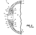
図1は、参照により本願明細書に援用される、“Pressure vessel with damage mitigating system”と題された米国特許第5,476,189号に開示された圧力容器などのような、長尺状の圧力容器10を図示する。容器10は、端部14を有する本体部12を備える。一般的にアルミニウムにて構成されたボス16は、容器10の一方、または、両方の端部に設けられて、容器10の内部と連通するためのポートを提供する。図2に示されるように、容器10には、外側複合材シェル18により覆われた内側ポリマーライナ20が形成されている。この場合において、「複合材」は、フィラメントが巻き付けられるか、または、積層される構造などの、繊維強化樹脂マトリクス材料を意味する。複合材シェル18は、容器10にかかる構造的荷重を解決する。
FIG. 1 is an elongated shape, such as the pressure vessel disclosed in US Pat. No. 5,476,189, entitled "Pressure vessel with damage monitoring system," which is incorporated herein by reference. The
図2は、参照により本願明細書に援用される、“Boss for a filament wound pressure vessel”と題された米国特許第5,429,845号に開示されたボスなどのような、ボス16を含む典型的な端部14が、図1の線分2−2に沿って切断された部分断面図を示す。ボス16は、通常、首部21及び環状フランジ22を備える。一般的に、シェル18は、インタフェース19にて首部21と接触し、且つ、フランジ22は、ライナ20とシェル18との間に挟まれている。この構造は、ボス16を容器10に固定すると共に、ボス16、シェル18及びライナ20の間のインタフェースにおける封止をもたらす。フランジ22の外側表面62における外側環状溝30は、ライナ20に形成された相補的な外側環状タブ32を受容する。同様に、フランジ22の内側表面60における内側環状溝34は、ライナ20に形成された内側環状タブ38を受容する。溝30,34及びタブ32,38はライナ20をボス16に固定する。
FIG. 2 includes a
この種の、ライナ及びボスが連結する構造は、例えば圧縮天然ガス(CNG)燃料コンテナ用などの、特定の用途において効果的であると証明されてきた。しかしながら、高圧(例えば、700バール)の設備において、ボスに隣接するプラスチックライナ材料のひずみが指摘されており、このひずみが、プラスチックライナ20がキー溝から引き抜かれる(つまり、タブ32,38が連結溝30,34から引き抜かれる)というある程度の傾向につながっている。高圧下の使用におけるこの領域のひずみは、ライナ20とボス16との間のキー溝内の高圧ガスの存在により生じる。高圧ガスは、ライナ材料に浸透し、その後、圧力が低下したときにガスを放出する。それゆえに、ライナ20とボス16との間のインタフェースに充満するガスは、例えば、ガスが容器10から放出される場合などは、容器10内のガスよりも高圧となりうる。その結果、ライナ20とボス16との間の過剰な圧力は、ライナ材料がキー溝の外へ押し出されることを引き起こしうる。さらに、フランジ22とライナ20との間の封止は、ライナ20がフランジ22を取り囲んでいるので、ライナ20の張力に少なくとも部分的に依存する。ライナ20が伸長したとき、ライナ20の伸長は、張力の減少を引き起こし、ひいては、ボス16とライナ20との間のインタフェースにおける漏れを引き起こしうる。
[概要]
1つの態様において、本開示は、内室を備え、且つ、外側シェルと、外側シェルに嵌合されたボスと、外側シェル内に配置された内側ライナと、を備える圧力容器を説明する。ボスは、内室と圧力容器の外部との間に延在するポートと、ポートから放射状に延在し、且つ、外側表面及び内側表面を備える環状フランジと、を備える。内側ライナは、フランジの外側表面に隣接する外側部と、フランジの内側表面に隣接する内側部と、内側部内の通気孔と、を備える。
This type of liner-boss connection structure has proven to be effective in certain applications, such as for compressed natural gas (CNG) fuel containers. However, in high pressure (eg 700 bar) equipment, strain on the plastic liner material adjacent to the boss has been pointed out, and this strain pulls the
[Overview]
In one aspect, the present disclosure describes a pressure vessel comprising an inner chamber and comprising an outer shell, a boss fitted to the outer shell, and an inner liner disposed within the outer shell. The boss comprises a port extending between the inner chamber and the outside of the pressure vessel, and an annular flange extending radially from the port and having an outer surface and an inner surface. The inner liner comprises an outer portion adjacent to the outer surface of the flange, an inner portion adjacent to the inner surface of the flange, and a vent in the inner portion.
他の態様において、本開示は、圧力容器を形成するための方法であって、ボスをマンドレルに取り付けることと、ボスのフランジの周囲に非金属ポリマーを流して、圧力容器の内側ライナを形成することと、ライナの内側部に通気孔を形成することと、ライナ、及び、ボスのフランジの少なくとも一部を包囲する外側シェルを形成することと、を備える、方法を説明する。ボスは、内室と圧力容器の外部との間で流体連通するように構成されたポートと、ポートから放射状に延在し、且つ、外側表面及び内側表面を備える環状フランジと、を備える。内側ライナは、フランジの外側表面に隣接する外側部と、フランジの内側表面に隣接する内側部と、を備える。 In another aspect, the present disclosure is a method for forming a pressure vessel, in which the boss is attached to a mandrel and a non-metallic polymer is run around the flange of the boss to form the inner liner of the pressure vessel. A method comprising forming a vent in the inner part of the liner and forming an outer shell surrounding at least a part of the liner and the flange of the boss will be described. The boss comprises a port configured to allow fluid communication between the inner chamber and the outside of the pressure vessel, and an annular flange extending radially from the port and having an outer surface and an inner surface. The inner liner comprises an outer portion adjacent to the outer surface of the flange and an inner portion adjacent to the inner surface of the flange.
本開示は、その様々な組合せにおいて、装置または方法の形態で、次の項目のリストにより特徴づけられてもよい。
項目1.内室を備える圧力容器であって、
上記圧力容器は、
外側シェルと、
上記外側シェルに嵌合されたボスであって、
上記内室と当該圧力容器の外部との間に延在するポートと、
上記ポートから放射状に延在し、且つ、外側表面及び内側表面を備える環状フランジと、
を備えるボスと、
上記外側シェル内に配置された内側ライナであって、
上記フランジの上記外側表面に隣接する外側部と、
上記フランジの上記内側表面に隣接する内側部と、
上記内側部内の通気孔と、
を備える内側ライナと、
を備える圧力容器。
The present disclosure, in various combinations thereof, in the form of a device or method, may be characterized by a list of the following items:
Item 1. A pressure vessel with an inner chamber
The above pressure vessel
With the outer shell,
A boss fitted to the outer shell
A port extending between the inner chamber and the outside of the pressure vessel,
An annular flange that extends radially from the port and has an outer and inner surface.
With a boss with
An inner liner placed in the outer shell,
The outer portion of the flange adjacent to the outer surface and
The inner part of the flange adjacent to the inner surface and
The ventilation holes in the inner part and
With an inner liner,
A pressure vessel equipped with.
項目2.上記フランジは、上記内側表面上に内側環状溝を備え、
上記ライナは、上記内側環状溝内に受容された内側環状タブを備え、
上記通気孔は、上記内側部において、上記内側環状タブよりも半径方向外側に配置されている、
項目1に記載の圧力容器。
The liner comprises an inner annular tab received within the inner annular groove.
The ventilation holes are arranged on the inner side in the radial direction with respect to the inner annular tab.
The pressure vessel according to item 1.
項目3.上記通気孔は、上記ライナの上記内側部を通って形成された開口を備え、上記環状フランジと上記ライナとの間のインタフェースを、上記内室と流体接続する、項目1〜2の何れかに記載の圧力容器。
Item 3. The ventilation hole comprises an opening formed through the inner portion of the liner, and the interface between the annular flange and the liner is fluidly connected to the inner chamber according to any one of
項目4.上記通気孔は、上記ポートの周囲に対称的に配置された複数の通気孔のうちの1つである、項目1〜3の何れかに記載の圧力容器。
項目5.上記通気孔は円形である、項目1〜4の何れかに記載の圧力容器。
Item 4. The pressure vessel according to any one of items 1 to 3, wherein the vent is one of a plurality of vents symmetrically arranged around the port.
項目6.上記通気孔は長尺状である、項目1〜4の何れかに記載の圧力容器。
項目7.圧力容器を形成するための方法であって、
ボスをマンドレルに取り付けることであって、
上記ボスは、
内室と上記圧力容器の外部との間の流体連通のために構成されたポートと、
上記ポートから放射状に延在し、且つ、外側表面及び内側表面を備える環状フランジと、
を備える、ボスをマンドレルに取り付けることと、
上記フランジの周囲に非金属ポリマーを流して、上記圧力容器の内側ライナを形成することであって、
上記内側ライナは、
上記フランジの上記外側表面に隣接する外側部と、
上記フランジの上記内側表面に隣接する内側部と、
を備える、上記フランジの周囲に非金属ポリマーを流して、上記圧力容器の内側ライナを形成することと、
上記ライナの上記内側部内に通気孔を形成することと、
上記ライナ、及び、上記ボスの上記フランジの少なくとも一部、を包囲する外側シェルを形成することと、
を備える方法。
Item 6. The pressure vessel according to any one of items 1 to 4 , wherein the ventilation holes are long.
Item 7. A method for forming a pressure vessel,
Attaching the boss to the mandrel,
The above boss
A port configured for fluid communication between the inner chamber and the outside of the pressure vessel,
An annular flange that extends radially from the port and has an outer and inner surface.
To attach the boss to the mandrel,
By flowing a non-metallic polymer around the flange to form the inner liner of the pressure vessel.
The above inner liner
The outer portion of the flange adjacent to the outer surface and
The inner part of the flange adjacent to the inner surface and
To form the inner liner of the pressure vessel by flowing a non-metallic polymer around the flange.
To form a vent in the inner part of the liner and
Forming an outer shell that surrounds the liner and at least a portion of the flange of the boss.
How to prepare.
項目8.上記フランジは、上記内側表面上に内側環状溝を備え、
上記内側ライナを形成することは、上記内側環状溝に上記ポリマーを流して、上記内側環状溝内に受容される内側環状タブを形成すること、を備える項目7に記載の方法。
Item 8. The flange has an inner annular groove on the inner surface.
7. The method of item 7, wherein forming the inner liner comprises flowing the polymer through the inner annular groove to form a receptive inner annular tab within the inner annular groove.
項目9.上記通気孔を形成することは、上記通気孔を、上記内側部において、上記内側環状タブよりも半径方向外側に配置すること、を備える項目8に記載の方法。
項目10.上記通気孔を形成することは、上記環状フランジと上記ライナとの間のインタフェースを上記内室と流体接続するために、上記ライナの上記内側部を通る開口を設けること、を備える項目7〜9の何れかに記載の方法。
Item 9. 8. The method of item 8, wherein forming the vents comprises arranging the vents radially outside the inner annular tab in the inner portion.
項目11.上記ポートの周囲に対称的に配置される複数の上記通気孔を形成すること、をさらに備える項目7〜10の何れかに記載の方法。
本概要は、詳細な説明において以下でさらに説明される概念を、単純化された形態で紹介するために提供される。本概要は、開示されるか、または、請求項に挙げられる主題の、重要な特徴、または、本質的な特徴を特定することを意図しておらず、さらに、開示されるか、または、請求項に挙げられる主題の、開示されたそれぞれの実施形態、または、全ての実施を説明することを意図していない。具体的には、1つの実施形態に関してここで開示された特徴は、他にも同様に適用され得る。さらに、本概要は、請求項に挙げられる主題の範囲を特定するための補助として用いられることを意図していない。多くの他の新たな有利な点、特徴、及び、関連性は、この説明が進むにつれて明らかになるであろう。以下に続く図及び説明は、具体的な実施形態をより詳細に例示する。
Item 11. The method according to any one of items 7 to 10, further comprising forming a plurality of the vents symmetrically arranged around the port.
This overview is provided to introduce in a simplified form the concepts further described below in the detailed description. This summary is not intended to identify the material or essential features of the subject matter disclosed or claimed, and is further disclosed or claimed. It is not intended to describe each disclosed embodiment or all implementation of the subject matter listed in the section. Specifically, the features disclosed herein with respect to one embodiment may apply to others as well. Moreover, this summary is not intended to be used as an aid in identifying the scope of the claims. Many other new advantages, features, and relevance will become apparent as this explanation progresses. The figures and description that follow exemplify specific embodiments in more detail.
開示される主題が、添付された図を参照してさらに説明され、これらの図において、同様の構造またはシステム要素は、いくつかの図を通して同様の参照番号により参照される。
上で特定された図は、開示された主題の1つまたはそれ以上の実施形態を示す一方で、本開示で述べたように他の実施形態もまた想定される。全ての場合において、本開示は、開示された主題を、限定ではなく代表として示す。本開示の原理の範囲及び精神に該当する多数の他の変形及び実施形態が、当業者により考案されうることが理解されるべきである。 While the figure identified above shows one or more embodiments of the disclosed subject matter, other embodiments are also envisioned as described in this disclosure. In all cases, the present disclosure presents the disclosed subject matter as a representative rather than a limitation. It should be understood that a number of other modifications and embodiments that fall under the scope and spirit of the principles of the present disclosure can be devised by those skilled in the art.
図は、一定の縮尺で描かれていない可能性がある。具体的には、いくつかの特徴は、明確にするために、他の特徴に対して拡大されうる。さらに、above、below、over、under、top、bottom、side、right、left、などのような用語が用いられる場合、それらの用語は、説明の理解を容易にするためにのみ用いられることが理解される。構造が、他の方向に配向されうることが想定される。
[詳細な説明]
高圧下におけるライナとボスとの分離を防止し、制御不能な漏れを防止し、さらに、ライナとボスとの間に閉じ込められたガスの放出を可能にする、ライナとボスとのインタフェース構造の必要性が残る。本開示は、圧力容器10’のライナ20’とボス16との間でガスが増大することを防止する特徴を備える圧力容器に関する。例えば、図3に示されるように、通気孔52は、通路を提供し、ガスが、この通路を通って、ボス16とライナ20’との間のインタフェースから容器10’の内室55に放出されうる。内室55は、ライナ20’内の内部空間として規定される。たとえ、ボス16とライナ20’とのインタフェース間にガスがあったとしても、ガスは通気孔52を通って逃げることができるので、このようなガスは増大せず、容器10’は、ボス16のフランジ22とライナ20’との間の確実な封止を発揮する。
The figure may not be drawn to a certain scale. Specifically, some features can be extended to other features for clarity. Furthermore, when terms such as above, below, over, under, top, bottom, side, light, left, etc. are used, it is understood that these terms are used only to facilitate the understanding of the description. Will be done. It is envisioned that the structure can be oriented in other directions.
[Detailed explanation]
The need for a liner-boss interface structure that prevents liner-boss separation under high pressure, prevents uncontrollable leaks, and allows the release of gas trapped between the liner and boss. Sex remains. The present disclosure relates to a pressure vessel having a feature of preventing gas from increasing between the liner 20'of the pressure vessel 10'and the
図3〜5は、外側シェル18及びライナ20’に嵌合されたボス16(つまり、配管ポート)を含む、ほぼ半球状、または、ドーム型の端部14’を備える、本開示の例示的な圧力容器10’の具体的な実施形態を示す。例示的な実施形態において、ボス16は、金属製であり、また、例えば、炭素鋼で形成されうる。ボス16のポート23は、圧力容器10’の内室55と、圧力容器10’の外部との間に延在する。例示的な実施形態において、ボス16は、ポート23から放射状に延在し、且つ、内側表面60及び外側表面62を備える、環状フランジ22を備える。例示的な実施形態において、環状フランジ22は、フランジ22の内側表面60上に配置された環状内側溝34、及び、フランジ22の外側表面62上に配置された環状外側溝30を備える。具体的な実施形態において、溝30,34は、ライナ20’のタブ32,38を受容且つ保持するために、それぞれの開口42,46におけるよりも、それぞれの底壁40,44における方が広くなるように形成されている。
3-5 are exemplary of the present disclosure, comprising a substantially hemispherical or dome-shaped end 14', including a boss 16 (ie, a piping port) fitted to an
具体的な実施形態において、圧力容器10’はシェル18内に配置されたライナ20’を備える。例示的な非金属ライナ20’は、フランジ22の内側表面60に隣接する内側部68、及び、フランジ22の外側表面62に隣接する外側部72を備える。タブ32,38は、ボス16の周囲に環状に延在すると共に、溝30,34の形状を補完する外形を備える。内側溝34は、内側タブ38を受容することにより、ライナ20’をボス16に固定する機械的な連結を形成する。外側タブ32は、外側溝30に受容され、ライナ20’をボス16にさらに固定するもう1つの機械的な連結を形成する。「蟻継ぎ」型の機械的な連結が示され、本開示で用いられるように、「蟻継ぎ」という用語は、縁、切り欠き、フレア、突起、または、類似または対応する構造、を含む、キー溝または連結鍵構造を表しており、ボス16の溝30,34と、ライナ20’の連結タブ32,38との間に形成された1つの接合部または(連続であるか、不連続である)複数の接合部の分離が構造的に抑制される。しかしながら、機械的な、摩擦による、または、(例えば、接着剤の使用による)化学的な、ライナ20’をボス16へ固定する他の手段または方法が用いられうることが考えられる。したがって、フランジ22が少なくとも部分的にライナ材料により包囲されることにより、ボス16とライナ20’とを機械的に共に封止する。しかしながら、例示的な実施形態において、ライナ20’の内側部68がフランジ22の内側表面60に接着されていないため、これらの部品間のインタフェースに充満するあらゆるガスが、通気孔52に流れることができ、圧力容器10’の内室55へ放出される。
In a specific embodiment, the pressure vessel 10'includes a liner 20'arranged within the
いくつかの実施形態において、ライナ20’は、プラスチック、エラストマー、または、他のポリマーにより作られてもよく、圧縮成形、ブロー成形、射出成形、または、あらゆる他の一般的に周知の技術により製造されてもよい。他の実施形態において、ライナ20’は、鋼、アルミニウム、ニッケル、チタン、プラチナ、金、銀、ステンレス鋼、及び、それらのあらゆる合金を含む他の材料から構成されてもよい。このような金属は、一般的に、高い弾性係数を有することを特徴としうる。1つの実施形態において、ライナ20’は、ブロー成形された高密度ポリエチレン(HDPE)にて形成される。 In some embodiments, the liner 20'may be made of plastic, elastomer, or other polymer and is manufactured by compression molding, blow molding, injection molding, or any other commonly known technique. May be done. In other embodiments, the liner 20'may be composed of steel, aluminum, nickel, titanium, platinum, gold, silver, stainless steel, and other materials including all alloys thereof. Such metals may generally be characterized by having a high elastic modulus. In one embodiment, the liner 20 'is formed by blow-molded high-density polyethylene (HDPE).
圧力容器10’の形成方法は、ボスをマンドレルに取り付けること、及び、ライナ20’のための流体ポリマー材料を、フランジ22の周囲及びボス16の溝30,34の中へ流し入れること、を含む。ライナ材料がその後凝固することにより、溝30内に受容された外側タブ32を含む、フランジ22の外側表面62に隣接する外側部72と、溝34内に受容された内側タブ38を含む、フランジ22の内側表面60に隣接する内側部68と、を形成する。それにより、ライナ20’は、ボス16に機械的に連結される。したがって、超高圧条件下であっても、ライナ20’のボス16からの分離が防止される。
The method of forming the pressure vessel 10'includes attaching the boss to the mandrel and pouring the fluid polymer material for the liner 20' around the
通気孔52は、ライナ20’の製造中または後に、あらゆる適切な方法にて、例えば、ドリル穿設、鋳造、または、穿刺により、形成されてもよく、さらに、ガスをボス16とライナ20’とのインタフェースから内室55へ流すのに有用なあらゆるサイズまたは形状を有してもよい。例えば、通気孔52は、円形、長尺状であってもよく、または、1つ以上の開口群領域を備えてもよい。通気孔52が長尺状である場合には、このような長尺状の通気孔は、ポート23に対して、半径方向、円周方向、または他の方向に延在してもよい。通気孔52は、個別の孔(例えば、互いに流体接続されない孔)として示されるが、ガスをボス16とライナ20’との間から圧力容器10’の内室55へ逃がすためのあらゆる適切なガス透過可能な構造または機構が用いられてもよい。
The
図5は、圧力容器10’の端部14’の内部の端部断面図である。例示的な実施形態において、複数の通気孔52が、ポート23の周囲に対称的に配置されている。図示された実施形態において、4つの円形の通気孔52が、ボス16の周囲に等間隔で、それぞれが、ボス16のポート23から等距離であることが示されている。しかしながら、通気孔52は、あらゆるサイズ、あらゆる数で設けられてもよく、また、フランジ22に隣接するライナ20’の内側部68上のあらゆる位置、具体的には、ライナ20’の内側タブ38とフランジ22の遠位端部78との間、に設けられてもよいと考えられる。ライナ20’を介するあらゆるガスの透過が比較的低速で生じることになるので、単一の通気孔52でさえ十分となりうると考えられる。
FIG. 5 is a cross-sectional view of the inside of the end portion 14'of the pressure vessel 10'. In an exemplary embodiment, a plurality of
外側シェル18は、ライナ20’及びボス16のフランジ22の少なくとも一部を包囲して形成される。シェル18のための適切な材料は、熱硬化性または熱可塑性樹脂により互いに接着される、巻き付けられた、繊維ガラスの繊維またはフィラメント、または、他の合成フィラメント、の積層の複合材料を含む。繊維は、繊維ガラス、アラミド、炭素、グラファイト、または、あらゆる他の一般的に周知の繊維強化材料であってもよい。使用される樹脂マトリクスは、エポキシ、ポリエステル、ビニル・エステル、熱可塑性材料、または、繊維と繊維との接着、繊維層と層との接着、及び、この容器が用いられる特定の用途に必要とされる破砕耐性、をもたらすことが可能なあらゆる他の適切な樹脂材料であってもよい。例示的な方法において、繊維のための分配ヘッドは、望ましいパターンで、ライナ20’上に繊維を巻き付けるように移動する。容器10’が、球状というよりもむしろ円筒状の場合には、繊維の巻き付けは、通常、ほぼ長手方向(ヘリカル)及び円周方向(フープ)巻きの両方が適用される。この巻付プロセスは、例えば樹脂含有量、繊維構造、巻付張力、及び、ライナ20’の軸に関連する巻付パターンなどの多数の要素により規定される。例示的な圧力容器の構成に関連する詳細は、参照により本願明細書に援用される、“Filament Winding Process and Apparatus”と題された米国特許第4,838,971号にて開示されている。
The
流体が圧力下で容器10’に収容されたとき、一部の流体は、ライナ20’を介して、ライナ20’とボス16のフランジ22との間のインタフェースに透過しうる。インタフェースにおけるガスの存在は、ボス16とライナ20’との封止された関係に支障をきたしうる。例示的な実施形態において、単一のまたは複数の通気孔52(例えば、あらゆる適切なサイズ及び形状の単一のまたは複数の開口)が、ライナ20’の内側部68を通して設けられ、容器10’の内室55と、(例えば、環状フランジ22とライナ20’との間のインタフェースにおける)フランジ22の内側表面60とを流体接続する。例示的な実施形態において、通気孔52は、ライナ20’のタブ38とフランジ22の遠位端部78との間に配置される。それゆえに、通気孔52は、内側部68において内側環状タブ38より半径方向外側に配置される。例示的な実施形態において、通気孔52は、ライナ20’の内側部68の全厚を通じて延在する。それゆえに、ボス16とライナ20’との間で増大するあらゆるガスは、ライナ20’とフランジ22との間から、通気孔52を通って、容器10’の内室55へ移動することができる。
When the fluid is contained in the container 10'under pressure, some fluid may permeate through the liner 20'to the interface between the liner 20'and the
約13インチの直径及び約35インチの長さを有する例示的なタイプ4(非金属)の圧力容器10’において、4つの通気孔52がライナ20’の内側部68にドリル穿設され、通気孔52のそれぞれは、圧力容器10’のボス16の、半径方向の中心から約3インチで、且つ、周囲に対称的に配置される。例示的な実施形態において、4つの通気孔52のそれぞれは、約0.125インチの直径を有する。圧力サイクル試験が、この例示的な圧力容器10’にて、水を用いて、下は360ポンド毎平方インチ(psi)から、上は4,500psiで15,000サイクル実行された。圧力サイクル試験に続き、圧力容器10’は、漏れの検査をされ、漏れの兆候を見せなかった。さらに、圧力容器10’は、ライナの膨れ、または、内側部68の近辺における他の損傷の視認可能な兆候を見せなかった。
In an exemplary type 4 (non-metal) pressure vessel 10'with a diameter of about 13 inches and a length of about 35 inches, four
より少ない、または、より多い通気孔52が圧力容器10’に用いられてもよいと考えられる。さらに、通気孔52は、例示的な実施形態におけるものとは異なるサイズとしてもよい。加えて、特定の圧力容器10’のための複数の通気孔52が、全て、同一のサイズ、形状で、対称的に配置されてもよい一方で、その代わりに、通気孔52は、単一の圧力容器において、異なるサイズ、形状、及び、配置の組み合わせを有してもよいということも考えられる。
It is believed that fewer or
本開示の主題がいくつかの実施形態を参照して説明されてきたが、当業者は、本開示の範囲から逸脱することなく、形態及び詳細において変更がなされうると認識するであろう。例えば、内側溝34が、外側溝30の配置と比べてフランジ22上の半径方向内側にあるように図示されている一方で、内側溝34は、外側溝30の配置と比べてフランジ22上の半径方向外側に配置されてもよいと考えられる。さらに、フランジ22は、図示されたものと異なる構造を備えてもよい。さらに、ライナ20’は、内側部68及び/または外側部72が、図示されたものよりも、広く、または、狭くフランジ22を覆うように形成されてもよい。加えて、1つの実施形態に関して開示されたあらゆる特徴は、他の実施形態に組み込まれてもよいし、その逆であってもよい。
Although the subject matter of the present disclosure has been described with reference to some embodiments, one of ordinary skill in the art will recognize that changes can be made in the form and details without departing from the scope of the present disclosure. For example, the
Claims (9)
前記圧力容器は、
外側シェルと、
前記外側シェルに嵌合されたボスであって、
前記内室と当該圧力容器の外部との間に延在するポートと、
前記ポートから放射状に延在し、且つ、外側表面及び内側表面を備える、環状フランジと、
を備えるボスと、
前記外側シェル内に配置された内側ライナであって、
前記環状フランジの前記外側表面に隣接する外側部と、
前記環状フランジの前記内側表面に隣接する内側部と、
前記環状フランジと前記内側ライナとの間のインタフェースを前記内室と流体接続する、前記内側ライナの前記内側部の厚さを通る通気開口部と、
を備える内側ライナと、
を備え、
前記通気開口部は、前記インタフェースと前記内室との間を流体接続するように前記内室に露出されている、
圧力容器。 A pressure vessel with an inner chamber
The pressure vessel
With the outer shell,
A boss fitted to the outer shell
A port extending between the inner chamber and the outside of the pressure vessel,
An annular flange that extends radially from the port and has an outer and inner surface.
With a boss with
An inner liner located within the outer shell.
An outer portion of the annular flange adjacent to the outer surface and
An inner portion of the annular flange adjacent to the inner surface and
A vent opening through the thickness of the inner portion of the inner liner, which fluidly connects the interface between the annular flange and the inner liner with the inner chamber.
With an inner liner,
With
The ventilation opening is exposed in the inner chamber so as to make a fluid connection between the interface and the inner chamber.
Pressure vessel.
前記内側ライナは、前記内側環状溝内に受容された内側環状タブを備え、
前記通気開口部は、前記内側部において、前記内側環状タブよりも半径方向外側に配置されている、
請求項1に記載の圧力容器。 The annular flange comprises an inner annular groove on the inner surface.
The inner liner comprises an inner annular tab received within the inner annular groove.
The ventilation opening is arranged on the inner side in the radial direction with respect to the inner annular tab.
The pressure vessel according to claim 1.
ボスをマンドレルに取り付けることであって、
前記ボスは、
内室と前記圧力容器の外部との間の流体連通のために構成されたポートと、
前記ポートから放射状に延在し、且つ、外側表面及び内側表面を備える、環状フランジと、
を備える、ボスをマンドレルに取り付けることと、
前記環状フランジの周囲に非金属ポリマーを流して、前記圧力容器の内側ライナを形成することであって、
前記内側ライナは、
前記環状フランジの前記外側表面に隣接する外側部と、
前記環状フランジの前記内側表面に隣接する内側部と、
を備える、前記環状フランジの周囲に非金属ポリマーを流して、前記圧力容器の内側ライナを形成することと、
前記環状フランジと前記内側ライナとの間のインタフェースを前記内室と流体接続する、前記内側ライナの前記内側部の厚さを通る通気開口部を形成することと、
前記内側ライナ、及び、前記ボスの前記環状フランジの少なくとも一部、を包囲する外側シェルを形成することと、
を備え、
前記通気開口部は、前記インタフェースと前記内室との間を流体接続するように前記内室に露出されている、
方法。 A method for forming a pressure vessel,
Attaching the boss to the mandrel,
The boss
A port configured for fluid communication between the inner chamber and the outside of the pressure vessel,
An annular flange that extends radially from the port and has an outer and inner surface.
To attach the boss to the mandrel,
By flowing a non-metallic polymer around the annular flange to form the inner liner of the pressure vessel.
The inner liner
An outer portion of the annular flange adjacent to the outer surface and
An inner portion of the annular flange adjacent to the inner surface and
To form the inner liner of the pressure vessel by flowing a non-metallic polymer around the annular flange.
Forming a ventilation opening through the thickness of the inner portion of the inner liner that fluidly connects the interface between the annular flange and the inner liner with the inner chamber.
Forming an outer shell that surrounds the inner liner and at least a portion of the annular flange of the boss.
With
The ventilation opening is exposed in the inner chamber so as to make a fluid connection between the interface and the inner chamber.
Method.
前記内側ライナを形成することは、前記内側環状溝に前記非金属ポリマーを流して、前記内側環状溝内に受容される内側環状タブを形成すること、を備える請求項6に記載の方法。 The annular flange comprises an inner annular groove on the inner surface.
The method of claim 6 , wherein forming the inner liner comprises flowing the non-metallic polymer through the inner annular groove to form a receptive inner annular tab within the inner annular groove.
Applications Claiming Priority (5)
| Application Number | Priority Date | Filing Date | Title |
|---|---|---|---|
| US201562268342P | 2015-12-16 | 2015-12-16 | |
| US62/268,342 | 2015-12-16 | ||
| US15/363,013 | 2016-11-29 | ||
| US15/363,013 US10627048B2 (en) | 2015-12-16 | 2016-11-29 | Pressure vessel dome vents |
| PCT/US2016/065307 WO2017105953A1 (en) | 2015-12-16 | 2016-12-07 | Pressure vessel dome vents |
Publications (3)
| Publication Number | Publication Date |
|---|---|
| JP2019500557A JP2019500557A (en) | 2019-01-10 |
| JP2019500557A5 JP2019500557A5 (en) | 2019-06-27 |
| JP6902544B2 true JP6902544B2 (en) | 2021-07-14 |
Family
ID=57714658
Family Applications (1)
| Application Number | Title | Priority Date | Filing Date |
|---|---|---|---|
| JP2018531464A Active JP6902544B2 (en) | 2015-12-16 | 2016-12-07 | Vents in the pressure vessel dome |
Country Status (12)
| Country | Link |
|---|---|
| US (2) | US10627048B2 (en) |
| EP (1) | EP3390888B1 (en) |
| JP (1) | JP6902544B2 (en) |
| KR (1) | KR102478330B1 (en) |
| CN (1) | CN108700255B (en) |
| AU (1) | AU2016370273A1 (en) |
| BR (1) | BR112018012424B1 (en) |
| CA (1) | CA3006580C (en) |
| ES (1) | ES2898305T3 (en) |
| PL (1) | PL3390888T3 (en) |
| RU (1) | RU2726956C2 (en) |
| WO (1) | WO2017105953A1 (en) |
Families Citing this family (8)
| Publication number | Priority date | Publication date | Assignee | Title |
|---|---|---|---|---|
| US10627048B2 (en) * | 2015-12-16 | 2020-04-21 | Hexagon Technology, As | Pressure vessel dome vents |
| JP6720898B2 (en) * | 2017-03-09 | 2020-07-08 | トヨタ自動車株式会社 | High pressure tank |
| FR3079930B1 (en) * | 2018-04-05 | 2022-03-04 | Ad Venta | Tank head leak test procedure |
| US11440399B2 (en) | 2019-03-22 | 2022-09-13 | Agility Fuel Systems Llc | Fuel system mountable to a vehicle frame |
| US20200347992A1 (en) | 2019-05-02 | 2020-11-05 | Agility Fuel Systems Llc | Polymeric liner based gas cylinder with reduced permeability |
| KR102442629B1 (en) * | 2020-09-28 | 2022-09-14 | 한화솔루션 주식회사 | High-pressure tank having sealing structure boss and making method thereof |
| KR102460148B1 (en) | 2021-01-04 | 2022-11-01 | 주식회사 성우하이텍 | pressure vessel |
| US11940102B2 (en) * | 2021-02-08 | 2024-03-26 | Carver Enterprises, Inc. | Cold storage system |
Family Cites Families (61)
| Publication number | Priority date | Publication date | Assignee | Title |
|---|---|---|---|---|
| BE332293A (en) | 1925-05-20 | |||
| US1835699A (en) | 1927-10-10 | 1931-12-08 | Commercial Solvents Corp | Apparatus and process for preserving liquid carbon dioxide |
| US2243240A (en) | 1938-03-18 | 1941-05-27 | Smith Corp A O | Pressure vessel for hydrogenating hydrocarbons |
| US2344856A (en) | 1942-07-02 | 1944-03-21 | Guyon L C Earle | Means for reinforcing hollow containers for gases under pressure |
| US2894387A (en) * | 1957-06-19 | 1959-07-14 | Yale & Towne Mfg Co | Changeable tumbler for a combination lock |
| US3231338A (en) | 1962-04-19 | 1966-01-25 | Chicago Bridge & Iron Co | Multi-layer pressure vessel for high temperature hydrogenation processes |
| US3224619A (en) | 1963-03-15 | 1965-12-21 | Chicago Bridge & Iron Co | Hydrogen processing multiple layer pressure vessels |
| US3348728A (en) | 1965-01-04 | 1967-10-24 | Grace W R & Co | Pressure vessels |
| US3368586A (en) | 1965-09-01 | 1968-02-13 | Bendix Corp | Accumulator |
| FR1485626A (en) | 1966-04-14 | 1967-06-23 | Chantiers De Latlantique | normally sealed enclosure or partition wall element resistant to deterioration by a diffusing agent and its various applications |
| US3472632A (en) | 1966-11-25 | 1969-10-14 | Universal Oil Prod Co | Internally lined reactor for high temperatures and pressures and leakage monitoring means therefor |
| US3841520A (en) | 1969-04-04 | 1974-10-15 | Airco Inc | Flame arresting vent valve |
| US3604587A (en) | 1969-04-07 | 1971-09-14 | Hahn & Clay | Multilayer pressure vessel |
| BE790519A (en) | 1971-10-26 | 1973-02-15 | Technigaz | IMPROVEMENTS TO PRESSURE CONTAINERS WITH THERMAL INSULATION |
| US4107372A (en) | 1974-08-22 | 1978-08-15 | H. B. Fuller Company | Composite |
| US4298416A (en) | 1976-12-08 | 1981-11-03 | Huron Chemicals Limited | Protection of substrates against corrosion |
| US4135621A (en) | 1978-02-24 | 1979-01-23 | The International Nickel Company, Inc. | Hydrogen storage module |
| US4241843A (en) | 1979-06-08 | 1980-12-30 | Amtrol Inc. | Lined metal tank with heat shield and method of making same |
| US4358377A (en) | 1980-09-02 | 1982-11-09 | The Dow Chemical Company | Shear-vectoring design for composite casing end and removable, pressure-locking closure therefor |
| DE3628608A1 (en) | 1986-08-22 | 1988-03-03 | Bosch Gmbh Robert | ELASTIC PARTITION |
| US5476189A (en) * | 1993-12-03 | 1995-12-19 | Duvall; Paul F. | Pressure vessel with damage mitigating system |
| US5518141A (en) * | 1994-01-24 | 1996-05-21 | Newhouse; Norman L. | Pressure vessel with system to prevent liner separation |
| US5697515A (en) | 1994-12-22 | 1997-12-16 | State Industries, Inc. | Tank and tank connector assembly |
| JPH09222198A (en) | 1996-02-19 | 1997-08-26 | Shinko Kiki Kogyo Kk | Mouth piece structure of frp high pressure container |
| RU2117853C1 (en) | 1997-02-18 | 1998-08-20 | Шевчук Константин Михайлович | Pressure vessel |
| US5918756A (en) * | 1997-04-29 | 1999-07-06 | Morgan; H. William | Vessel lock down system |
| JP3045835U (en) | 1997-07-31 | 1998-02-20 | ファイルド株式会社 | Health band |
| US6503584B1 (en) | 1997-08-29 | 2003-01-07 | Mcalister Roy E. | Compact fluid storage system |
| JPH11210988A (en) | 1998-01-23 | 1999-08-06 | Honda Motor Co Ltd | Mouthpiece structure of compressed natural gas container |
| US5979692A (en) * | 1998-03-13 | 1999-11-09 | Harsco Corporation | Boss for composite pressure vessel having polymeric liner |
| GB9817223D0 (en) | 1998-08-08 | 1998-10-07 | Borealis Consultants Limited | Venting of plastics lined pipelines |
| RU2162564C1 (en) | 2000-06-16 | 2001-01-27 | Колдыбаев Сергей Глебович | Pressure bottle made from composite materials and method of manufacture of such bottles |
| RU2187746C2 (en) | 2000-09-06 | 2002-08-20 | Общество с ограниченной ответственностью НПО "ПОИСК" | Metal liner, high-pressure bottle made form metal-filled plastic (versions) and method of manufacture of high-pressure bottle from metal- filled plastic |
| GB0029569D0 (en) | 2000-12-05 | 2001-01-17 | Dixon Roche Keith | Pipe construction |
| US6648167B1 (en) | 2001-02-14 | 2003-11-18 | Sermatech International, Inc. | Ducting passages for a polymeric lining |
| US20030146229A1 (en) * | 2002-02-06 | 2003-08-07 | Ingersoll-Rand Company | Pressure vessels for high pressure applications |
| US6787007B2 (en) | 2002-09-23 | 2004-09-07 | Bechtel Bwxt Idaho, Llc | Polymeric hydrogen diffusion barrier, high-pressure storage tank so equipped, method of fabricating a storage tank and method of preventing hydrogen diffusion |
| US7195839B2 (en) | 2003-02-11 | 2007-03-27 | Eveready Battery Company, Inc. | Battery cell with improved pressure relief vent |
| RU45503U1 (en) | 2004-11-24 | 2005-05-10 | Меркин Николай Александрович | HIGH PRESSURE CYLINDER |
| US7287663B2 (en) * | 2005-01-05 | 2007-10-30 | Amtrol Inc. | Lined pressure vessel and connector therefor |
| US7731051B2 (en) * | 2005-07-13 | 2010-06-08 | Gm Global Technology Operations, Inc. | Hydrogen pressure tank including an inner liner with an outer annular flange |
| US7870971B2 (en) * | 2007-08-29 | 2011-01-18 | GM Global Technology Operations LLC | Diffusion layer for pressure vessels |
| US8652589B2 (en) | 2008-01-25 | 2014-02-18 | Oerlikon Trading Ag, Truebbach | Permeation barrier layer |
| KR101498277B1 (en) * | 2009-01-09 | 2015-03-02 | 헥사곤 테크놀로지 에이에스 | Pressure vessel boss and liner interface |
| CA2751453C (en) | 2009-02-06 | 2017-09-19 | Hexagon Technology As | Pressure vessel longitudinal vents |
| US9347560B2 (en) | 2010-04-01 | 2016-05-24 | GM Global Technology Operations LLC | Temperature regulating device for a pressure vessel |
| DE102010017413B4 (en) * | 2010-06-17 | 2012-08-30 | Xperion Gmbh | Pressure vessel for storing a fluid |
| FR2962519B1 (en) | 2010-07-09 | 2012-07-20 | Air Liquide | FILLING FITTING, RECIPIENT AND FILLING METHOD THEREOF |
| DE102010033597A1 (en) * | 2010-08-06 | 2012-02-09 | Daimler Ag | Device for storing low molecular weight gases |
| WO2012074815A2 (en) | 2010-11-29 | 2012-06-07 | Mark Leavitt | Breather layer for exhausting permeate from pressure vessels |
| DE102011018207A1 (en) | 2011-04-20 | 2012-10-25 | Parker Hannifin Gmbh | Pressure vessel with defined leakage path |
| RU2510944C2 (en) * | 2012-07-03 | 2014-04-10 | Корпорация "САМСУНГ ЭЛЕКТРОНИКС Ко., Лтд." | Method of encoding/decoding multi-view video sequence based on adaptive local adjustment of brightness of key frames without transmitting additional parameters (versions) |
| US8733581B1 (en) * | 2012-07-16 | 2014-05-27 | Michael A. Olson | Boss seal for composite overwrapped pressure vessel |
| JP2014081014A (en) | 2012-10-15 | 2014-05-08 | Honda Motor Co Ltd | Pressure gas container and vehicle including the same |
| US9244033B2 (en) | 2013-01-24 | 2016-01-26 | GM Global Technology Operations LLC | Method for online detection of liner buckling in a storage system for pressurized gas |
| US9774047B2 (en) * | 2013-03-26 | 2017-09-26 | GM Global Technology Operations LLC | Method and apparatus for forming a matrix liner for a pressure vessel |
| FR3015629B1 (en) | 2013-12-20 | 2016-01-29 | Eads Composites Aquitaine | RESERVOIR FOR STORING LIQUID OR GASEOUS MEDIA UNDER PRESSURE |
| FR3015630B1 (en) | 2013-12-20 | 2016-01-29 | Eads Composites Aquitaine | RESERVOIR FOR STORING LIQUID OR GASEOUS MEDIA UNDER PRESSURE |
| US10627048B2 (en) * | 2015-12-16 | 2020-04-21 | Hexagon Technology, As | Pressure vessel dome vents |
| JP6971250B2 (en) * | 2016-03-16 | 2021-11-24 | ヘキサゴン テクノロジー アーエス | Instruments, pressure vessels, and methods for forming pressure vessels |
| US10088110B2 (en) * | 2016-05-17 | 2018-10-02 | Hexagon Technology As | Pressure vessel liner venting via nanotextured surface |
-
2016
- 2016-11-29 US US15/363,013 patent/US10627048B2/en active Active
- 2016-12-07 ES ES16822301T patent/ES2898305T3/en active Active
- 2016-12-07 BR BR112018012424-9A patent/BR112018012424B1/en active IP Right Grant
- 2016-12-07 AU AU2016370273A patent/AU2016370273A1/en not_active Abandoned
- 2016-12-07 JP JP2018531464A patent/JP6902544B2/en active Active
- 2016-12-07 RU RU2018125651A patent/RU2726956C2/en active
- 2016-12-07 CA CA3006580A patent/CA3006580C/en active Active
- 2016-12-07 KR KR1020187020132A patent/KR102478330B1/en active IP Right Grant
- 2016-12-07 PL PL16822301T patent/PL3390888T3/en unknown
- 2016-12-07 EP EP16822301.4A patent/EP3390888B1/en active Active
- 2016-12-07 WO PCT/US2016/065307 patent/WO2017105953A1/en active Application Filing
- 2016-12-07 CN CN201680074226.3A patent/CN108700255B/en active Active
-
2020
- 2020-01-29 US US16/775,400 patent/US11073240B2/en active Active
Also Published As
| Publication number | Publication date |
|---|---|
| US11073240B2 (en) | 2021-07-27 |
| EP3390888B1 (en) | 2021-09-08 |
| ES2898305T3 (en) | 2022-03-07 |
| RU2018125651A3 (en) | 2020-01-21 |
| CN108700255B (en) | 2020-08-28 |
| US20200166180A1 (en) | 2020-05-28 |
| US10627048B2 (en) | 2020-04-21 |
| KR102478330B1 (en) | 2022-12-15 |
| RU2018125651A (en) | 2020-01-16 |
| CA3006580A1 (en) | 2017-06-22 |
| WO2017105953A1 (en) | 2017-06-22 |
| BR112018012424B1 (en) | 2022-11-29 |
| JP2019500557A (en) | 2019-01-10 |
| EP3390888A1 (en) | 2018-10-24 |
| RU2726956C2 (en) | 2020-07-17 |
| CN108700255A (en) | 2018-10-23 |
| KR20180094996A (en) | 2018-08-24 |
| CA3006580C (en) | 2022-11-01 |
| BR112018012424A2 (en) | 2018-12-18 |
| US20170175951A1 (en) | 2017-06-22 |
| PL3390888T3 (en) | 2022-01-24 |
| AU2016370273A1 (en) | 2018-06-14 |
Similar Documents
| Publication | Publication Date | Title |
|---|---|---|
| JP6902544B2 (en) | Vents in the pressure vessel dome | |
| JP6971250B2 (en) | Instruments, pressure vessels, and methods for forming pressure vessels | |
| JP5587339B2 (en) | Interface between pressure vessel boss and liner | |
| JP5384742B2 (en) | Gas cylinder | |
| JP2012518146A (en) | Shear boss and shell interface element of pressure vessel | |
| US11371659B2 (en) | Boss with internal bearing |
Legal Events
| Date | Code | Title | Description |
|---|---|---|---|
| A521 | Request for written amendment filed |
Free format text: JAPANESE INTERMEDIATE CODE: A523 Effective date: 20190524 |
|
| A621 | Written request for application examination |
Free format text: JAPANESE INTERMEDIATE CODE: A621 Effective date: 20190524 |
|
| A977 | Report on retrieval |
Free format text: JAPANESE INTERMEDIATE CODE: A971007 Effective date: 20200515 |
|
| A131 | Notification of reasons for refusal |
Free format text: JAPANESE INTERMEDIATE CODE: A131 Effective date: 20200623 |
|
| A521 | Request for written amendment filed |
Free format text: JAPANESE INTERMEDIATE CODE: A523 Effective date: 20200918 |
|
| A131 | Notification of reasons for refusal |
Free format text: JAPANESE INTERMEDIATE CODE: A131 Effective date: 20210216 |
|
| A521 | Request for written amendment filed |
Free format text: JAPANESE INTERMEDIATE CODE: A523 Effective date: 20210510 |
|
| TRDD | Decision of grant or rejection written | ||
| A01 | Written decision to grant a patent or to grant a registration (utility model) |
Free format text: JAPANESE INTERMEDIATE CODE: A01 Effective date: 20210525 |
|
| A61 | First payment of annual fees (during grant procedure) |
Free format text: JAPANESE INTERMEDIATE CODE: A61 Effective date: 20210621 |
|
| R150 | Certificate of patent or registration of utility model |
Ref document number: 6902544 Country of ref document: JP Free format text: JAPANESE INTERMEDIATE CODE: R150 |