KR101498277B1 - Pressure vessel boss and liner interface - Google Patents
Pressure vessel boss and liner interface Download PDFInfo
- Publication number
- KR101498277B1 KR101498277B1 KR1020117017924A KR20117017924A KR101498277B1 KR 101498277 B1 KR101498277 B1 KR 101498277B1 KR 1020117017924 A KR1020117017924 A KR 1020117017924A KR 20117017924 A KR20117017924 A KR 20117017924A KR 101498277 B1 KR101498277 B1 KR 101498277B1
- Authority
- KR
- South Korea
- Prior art keywords
- boss
- pressure vessel
- keyway
- flange
- bore
- Prior art date
Links
Images


Classifications
-
- F—MECHANICAL ENGINEERING; LIGHTING; HEATING; WEAPONS; BLASTING
- F17—STORING OR DISTRIBUTING GASES OR LIQUIDS
- F17C—VESSELS FOR CONTAINING OR STORING COMPRESSED, LIQUEFIED OR SOLIDIFIED GASES; FIXED-CAPACITY GAS-HOLDERS; FILLING VESSELS WITH, OR DISCHARGING FROM VESSELS, COMPRESSED, LIQUEFIED, OR SOLIDIFIED GASES
- F17C1/00—Pressure vessels, e.g. gas cylinder, gas tank, replaceable cartridge
- F17C1/02—Pressure vessels, e.g. gas cylinder, gas tank, replaceable cartridge involving reinforcing arrangements
- F17C1/04—Protecting sheathings
- F17C1/06—Protecting sheathings built-up from wound-on bands or filamentary material, e.g. wires
-
- B—PERFORMING OPERATIONS; TRANSPORTING
- B05—SPRAYING OR ATOMISING IN GENERAL; APPLYING FLUENT MATERIALS TO SURFACES, IN GENERAL
- B05D—PROCESSES FOR APPLYING FLUENT MATERIALS TO SURFACES, IN GENERAL
- B05D7/00—Processes, other than flocking, specially adapted for applying liquids or other fluent materials to particular surfaces or for applying particular liquids or other fluent materials
- B05D7/22—Processes, other than flocking, specially adapted for applying liquids or other fluent materials to particular surfaces or for applying particular liquids or other fluent materials to internal surfaces, e.g. of tubes
- B05D7/227—Processes, other than flocking, specially adapted for applying liquids or other fluent materials to particular surfaces or for applying particular liquids or other fluent materials to internal surfaces, e.g. of tubes of containers, cans or the like
-
- B—PERFORMING OPERATIONS; TRANSPORTING
- B29—WORKING OF PLASTICS; WORKING OF SUBSTANCES IN A PLASTIC STATE IN GENERAL
- B29D—PRODUCING PARTICULAR ARTICLES FROM PLASTICS OR FROM SUBSTANCES IN A PLASTIC STATE
- B29D22/00—Producing hollow articles
- B29D22/003—Containers for packaging, storing or transporting, e.g. bottles, jars, cans, barrels, tanks
-
- F—MECHANICAL ENGINEERING; LIGHTING; HEATING; WEAPONS; BLASTING
- F17—STORING OR DISTRIBUTING GASES OR LIQUIDS
- F17C—VESSELS FOR CONTAINING OR STORING COMPRESSED, LIQUEFIED OR SOLIDIFIED GASES; FIXED-CAPACITY GAS-HOLDERS; FILLING VESSELS WITH, OR DISCHARGING FROM VESSELS, COMPRESSED, LIQUEFIED, OR SOLIDIFIED GASES
- F17C1/00—Pressure vessels, e.g. gas cylinder, gas tank, replaceable cartridge
- F17C1/02—Pressure vessels, e.g. gas cylinder, gas tank, replaceable cartridge involving reinforcing arrangements
- F17C1/08—Integral reinforcements, e.g. ribs
-
- F—MECHANICAL ENGINEERING; LIGHTING; HEATING; WEAPONS; BLASTING
- F17—STORING OR DISTRIBUTING GASES OR LIQUIDS
- F17C—VESSELS FOR CONTAINING OR STORING COMPRESSED, LIQUEFIED OR SOLIDIFIED GASES; FIXED-CAPACITY GAS-HOLDERS; FILLING VESSELS WITH, OR DISCHARGING FROM VESSELS, COMPRESSED, LIQUEFIED, OR SOLIDIFIED GASES
- F17C1/00—Pressure vessels, e.g. gas cylinder, gas tank, replaceable cartridge
- F17C1/16—Pressure vessels, e.g. gas cylinder, gas tank, replaceable cartridge constructed of plastics materials
-
- F—MECHANICAL ENGINEERING; LIGHTING; HEATING; WEAPONS; BLASTING
- F17—STORING OR DISTRIBUTING GASES OR LIQUIDS
- F17C—VESSELS FOR CONTAINING OR STORING COMPRESSED, LIQUEFIED OR SOLIDIFIED GASES; FIXED-CAPACITY GAS-HOLDERS; FILLING VESSELS WITH, OR DISCHARGING FROM VESSELS, COMPRESSED, LIQUEFIED, OR SOLIDIFIED GASES
- F17C2201/00—Vessel construction, in particular geometry, arrangement or size
- F17C2201/01—Shape
- F17C2201/0104—Shape cylindrical
- F17C2201/0109—Shape cylindrical with exteriorly curved end-piece
-
- F—MECHANICAL ENGINEERING; LIGHTING; HEATING; WEAPONS; BLASTING
- F17—STORING OR DISTRIBUTING GASES OR LIQUIDS
- F17C—VESSELS FOR CONTAINING OR STORING COMPRESSED, LIQUEFIED OR SOLIDIFIED GASES; FIXED-CAPACITY GAS-HOLDERS; FILLING VESSELS WITH, OR DISCHARGING FROM VESSELS, COMPRESSED, LIQUEFIED, OR SOLIDIFIED GASES
- F17C2201/00—Vessel construction, in particular geometry, arrangement or size
- F17C2201/05—Size
- F17C2201/056—Small (<1 m3)
-
- F—MECHANICAL ENGINEERING; LIGHTING; HEATING; WEAPONS; BLASTING
- F17—STORING OR DISTRIBUTING GASES OR LIQUIDS
- F17C—VESSELS FOR CONTAINING OR STORING COMPRESSED, LIQUEFIED OR SOLIDIFIED GASES; FIXED-CAPACITY GAS-HOLDERS; FILLING VESSELS WITH, OR DISCHARGING FROM VESSELS, COMPRESSED, LIQUEFIED, OR SOLIDIFIED GASES
- F17C2203/00—Vessel construction, in particular walls or details thereof
- F17C2203/06—Materials for walls or layers thereof; Properties or structures of walls or their materials
- F17C2203/0602—Wall structures; Special features thereof
- F17C2203/0604—Liners
-
- F—MECHANICAL ENGINEERING; LIGHTING; HEATING; WEAPONS; BLASTING
- F17—STORING OR DISTRIBUTING GASES OR LIQUIDS
- F17C—VESSELS FOR CONTAINING OR STORING COMPRESSED, LIQUEFIED OR SOLIDIFIED GASES; FIXED-CAPACITY GAS-HOLDERS; FILLING VESSELS WITH, OR DISCHARGING FROM VESSELS, COMPRESSED, LIQUEFIED, OR SOLIDIFIED GASES
- F17C2203/00—Vessel construction, in particular walls or details thereof
- F17C2203/06—Materials for walls or layers thereof; Properties or structures of walls or their materials
- F17C2203/0602—Wall structures; Special features thereof
- F17C2203/0612—Wall structures
- F17C2203/0614—Single wall
- F17C2203/0619—Single wall with two layers
-
- F—MECHANICAL ENGINEERING; LIGHTING; HEATING; WEAPONS; BLASTING
- F17—STORING OR DISTRIBUTING GASES OR LIQUIDS
- F17C—VESSELS FOR CONTAINING OR STORING COMPRESSED, LIQUEFIED OR SOLIDIFIED GASES; FIXED-CAPACITY GAS-HOLDERS; FILLING VESSELS WITH, OR DISCHARGING FROM VESSELS, COMPRESSED, LIQUEFIED, OR SOLIDIFIED GASES
- F17C2203/00—Vessel construction, in particular walls or details thereof
- F17C2203/06—Materials for walls or layers thereof; Properties or structures of walls or their materials
- F17C2203/0634—Materials for walls or layers thereof
- F17C2203/0658—Synthetics
- F17C2203/066—Plastics
-
- F—MECHANICAL ENGINEERING; LIGHTING; HEATING; WEAPONS; BLASTING
- F17—STORING OR DISTRIBUTING GASES OR LIQUIDS
- F17C—VESSELS FOR CONTAINING OR STORING COMPRESSED, LIQUEFIED OR SOLIDIFIED GASES; FIXED-CAPACITY GAS-HOLDERS; FILLING VESSELS WITH, OR DISCHARGING FROM VESSELS, COMPRESSED, LIQUEFIED, OR SOLIDIFIED GASES
- F17C2203/00—Vessel construction, in particular walls or details thereof
- F17C2203/06—Materials for walls or layers thereof; Properties or structures of walls or their materials
- F17C2203/0634—Materials for walls or layers thereof
- F17C2203/0658—Synthetics
- F17C2203/0663—Synthetics in form of fibers or filaments
- F17C2203/0673—Polymers
-
- F—MECHANICAL ENGINEERING; LIGHTING; HEATING; WEAPONS; BLASTING
- F17—STORING OR DISTRIBUTING GASES OR LIQUIDS
- F17C—VESSELS FOR CONTAINING OR STORING COMPRESSED, LIQUEFIED OR SOLIDIFIED GASES; FIXED-CAPACITY GAS-HOLDERS; FILLING VESSELS WITH, OR DISCHARGING FROM VESSELS, COMPRESSED, LIQUEFIED, OR SOLIDIFIED GASES
- F17C2205/00—Vessel construction, in particular mounting arrangements, attachments or identifications means
- F17C2205/03—Fluid connections, filters, valves, closure means or other attachments
- F17C2205/0302—Fittings, valves, filters, or components in connection with the gas storage device
- F17C2205/0305—Bosses, e.g. boss collars
-
- F—MECHANICAL ENGINEERING; LIGHTING; HEATING; WEAPONS; BLASTING
- F17—STORING OR DISTRIBUTING GASES OR LIQUIDS
- F17C—VESSELS FOR CONTAINING OR STORING COMPRESSED, LIQUEFIED OR SOLIDIFIED GASES; FIXED-CAPACITY GAS-HOLDERS; FILLING VESSELS WITH, OR DISCHARGING FROM VESSELS, COMPRESSED, LIQUEFIED, OR SOLIDIFIED GASES
- F17C2209/00—Vessel construction, in particular methods of manufacturing
- F17C2209/22—Assembling processes
-
- F—MECHANICAL ENGINEERING; LIGHTING; HEATING; WEAPONS; BLASTING
- F17—STORING OR DISTRIBUTING GASES OR LIQUIDS
- F17C—VESSELS FOR CONTAINING OR STORING COMPRESSED, LIQUEFIED OR SOLIDIFIED GASES; FIXED-CAPACITY GAS-HOLDERS; FILLING VESSELS WITH, OR DISCHARGING FROM VESSELS, COMPRESSED, LIQUEFIED, OR SOLIDIFIED GASES
- F17C2209/00—Vessel construction, in particular methods of manufacturing
- F17C2209/23—Manufacturing of particular parts or at special locations
- F17C2209/232—Manufacturing of particular parts or at special locations of walls
-
- F—MECHANICAL ENGINEERING; LIGHTING; HEATING; WEAPONS; BLASTING
- F17—STORING OR DISTRIBUTING GASES OR LIQUIDS
- F17C—VESSELS FOR CONTAINING OR STORING COMPRESSED, LIQUEFIED OR SOLIDIFIED GASES; FIXED-CAPACITY GAS-HOLDERS; FILLING VESSELS WITH, OR DISCHARGING FROM VESSELS, COMPRESSED, LIQUEFIED, OR SOLIDIFIED GASES
- F17C2221/00—Handled fluid, in particular type of fluid
- F17C2221/01—Pure fluids
- F17C2221/011—Oxygen
-
- F—MECHANICAL ENGINEERING; LIGHTING; HEATING; WEAPONS; BLASTING
- F17—STORING OR DISTRIBUTING GASES OR LIQUIDS
- F17C—VESSELS FOR CONTAINING OR STORING COMPRESSED, LIQUEFIED OR SOLIDIFIED GASES; FIXED-CAPACITY GAS-HOLDERS; FILLING VESSELS WITH, OR DISCHARGING FROM VESSELS, COMPRESSED, LIQUEFIED, OR SOLIDIFIED GASES
- F17C2221/00—Handled fluid, in particular type of fluid
- F17C2221/01—Pure fluids
- F17C2221/014—Nitrogen
-
- F—MECHANICAL ENGINEERING; LIGHTING; HEATING; WEAPONS; BLASTING
- F17—STORING OR DISTRIBUTING GASES OR LIQUIDS
- F17C—VESSELS FOR CONTAINING OR STORING COMPRESSED, LIQUEFIED OR SOLIDIFIED GASES; FIXED-CAPACITY GAS-HOLDERS; FILLING VESSELS WITH, OR DISCHARGING FROM VESSELS, COMPRESSED, LIQUEFIED, OR SOLIDIFIED GASES
- F17C2221/00—Handled fluid, in particular type of fluid
- F17C2221/03—Mixtures
- F17C2221/032—Hydrocarbons
- F17C2221/033—Methane, e.g. natural gas, CNG, LNG, GNL, GNC, PLNG
-
- F—MECHANICAL ENGINEERING; LIGHTING; HEATING; WEAPONS; BLASTING
- F17—STORING OR DISTRIBUTING GASES OR LIQUIDS
- F17C—VESSELS FOR CONTAINING OR STORING COMPRESSED, LIQUEFIED OR SOLIDIFIED GASES; FIXED-CAPACITY GAS-HOLDERS; FILLING VESSELS WITH, OR DISCHARGING FROM VESSELS, COMPRESSED, LIQUEFIED, OR SOLIDIFIED GASES
- F17C2221/00—Handled fluid, in particular type of fluid
- F17C2221/03—Mixtures
- F17C2221/032—Hydrocarbons
- F17C2221/035—Propane butane, e.g. LPG, GPL
-
- F—MECHANICAL ENGINEERING; LIGHTING; HEATING; WEAPONS; BLASTING
- F17—STORING OR DISTRIBUTING GASES OR LIQUIDS
- F17C—VESSELS FOR CONTAINING OR STORING COMPRESSED, LIQUEFIED OR SOLIDIFIED GASES; FIXED-CAPACITY GAS-HOLDERS; FILLING VESSELS WITH, OR DISCHARGING FROM VESSELS, COMPRESSED, LIQUEFIED, OR SOLIDIFIED GASES
- F17C2223/00—Handled fluid before transfer, i.e. state of fluid when stored in the vessel or before transfer from the vessel
- F17C2223/01—Handled fluid before transfer, i.e. state of fluid when stored in the vessel or before transfer from the vessel characterised by the phase
- F17C2223/0107—Single phase
- F17C2223/0123—Single phase gaseous, e.g. CNG, GNC
-
- F—MECHANICAL ENGINEERING; LIGHTING; HEATING; WEAPONS; BLASTING
- F17—STORING OR DISTRIBUTING GASES OR LIQUIDS
- F17C—VESSELS FOR CONTAINING OR STORING COMPRESSED, LIQUEFIED OR SOLIDIFIED GASES; FIXED-CAPACITY GAS-HOLDERS; FILLING VESSELS WITH, OR DISCHARGING FROM VESSELS, COMPRESSED, LIQUEFIED, OR SOLIDIFIED GASES
- F17C2223/00—Handled fluid before transfer, i.e. state of fluid when stored in the vessel or before transfer from the vessel
- F17C2223/03—Handled fluid before transfer, i.e. state of fluid when stored in the vessel or before transfer from the vessel characterised by the pressure level
- F17C2223/036—Very high pressure (>80 bar)
-
- F—MECHANICAL ENGINEERING; LIGHTING; HEATING; WEAPONS; BLASTING
- F17—STORING OR DISTRIBUTING GASES OR LIQUIDS
- F17C—VESSELS FOR CONTAINING OR STORING COMPRESSED, LIQUEFIED OR SOLIDIFIED GASES; FIXED-CAPACITY GAS-HOLDERS; FILLING VESSELS WITH, OR DISCHARGING FROM VESSELS, COMPRESSED, LIQUEFIED, OR SOLIDIFIED GASES
- F17C2260/00—Purposes of gas storage and gas handling
- F17C2260/01—Improving mechanical properties or manufacturing
- F17C2260/011—Improving strength
-
- F—MECHANICAL ENGINEERING; LIGHTING; HEATING; WEAPONS; BLASTING
- F17—STORING OR DISTRIBUTING GASES OR LIQUIDS
- F17C—VESSELS FOR CONTAINING OR STORING COMPRESSED, LIQUEFIED OR SOLIDIFIED GASES; FIXED-CAPACITY GAS-HOLDERS; FILLING VESSELS WITH, OR DISCHARGING FROM VESSELS, COMPRESSED, LIQUEFIED, OR SOLIDIFIED GASES
- F17C2260/00—Purposes of gas storage and gas handling
- F17C2260/03—Dealing with losses
- F17C2260/035—Dealing with losses of fluid
- F17C2260/036—Avoiding leaks
-
- Y—GENERAL TAGGING OF NEW TECHNOLOGICAL DEVELOPMENTS; GENERAL TAGGING OF CROSS-SECTIONAL TECHNOLOGIES SPANNING OVER SEVERAL SECTIONS OF THE IPC; TECHNICAL SUBJECTS COVERED BY FORMER USPC CROSS-REFERENCE ART COLLECTIONS [XRACs] AND DIGESTS
- Y02—TECHNOLOGIES OR APPLICATIONS FOR MITIGATION OR ADAPTATION AGAINST CLIMATE CHANGE
- Y02E—REDUCTION OF GREENHOUSE GAS [GHG] EMISSIONS, RELATED TO ENERGY GENERATION, TRANSMISSION OR DISTRIBUTION
- Y02E60/00—Enabling technologies; Technologies with a potential or indirect contribution to GHG emissions mitigation
- Y02E60/30—Hydrogen technology
- Y02E60/32—Hydrogen storage
-
- Y—GENERAL TAGGING OF NEW TECHNOLOGICAL DEVELOPMENTS; GENERAL TAGGING OF CROSS-SECTIONAL TECHNOLOGIES SPANNING OVER SEVERAL SECTIONS OF THE IPC; TECHNICAL SUBJECTS COVERED BY FORMER USPC CROSS-REFERENCE ART COLLECTIONS [XRACs] AND DIGESTS
- Y10—TECHNICAL SUBJECTS COVERED BY FORMER USPC
- Y10T—TECHNICAL SUBJECTS COVERED BY FORMER US CLASSIFICATION
- Y10T29/00—Metal working
- Y10T29/49—Method of mechanical manufacture
- Y10T29/49826—Assembling or joining
Abstract
압력 용기(10)용 보스(16A, 16B)는 플랜지(30A, 30B)를 구비한다. 이 플랜지(30A, 30B)는 내부 측벽(50)을 갖는 내부 키홈(44); 및 그 내부 측벽(50)에 배치된 복수의 보어(48)를 포함한다. 압력 용기(10)는 본체 섹션(12) 및 단부 섹션(14)을 포함한다. 단부 섹션(14)은 보스(16A, 16B)를 포함하고, 이 보스(16A, 16B)는 플랜지(30A, 30B)를 포함한다. 이 플랜지(30A, 30B)는 내부 측벽(50)을 갖는 내부 키홈(44); 및 그 내부 측벽(50)에 배치된 복수의 보어(48)를 포함한다. 다른 양태에서, 압력 용기(10)는 외부 쉘(18), 내부 라이너(20) 및 보스(16A)를 포함하고, 이 보스(16A)는 외측면(62) 및 내측면(60)을 갖는 플랜지(30A)를 포함한다. 라이너(20)는 복수의 앵커(49)를 통해 플랜지(30A)에 기계적으로 통합되되, 각각의 앵커(49)는 내측면(60)에서만 플랜지(30A)와 접촉한다. 압력 용기(10)를 형성하는 방법은 플랜지(30A, 30B)를 갖는 보스(16A, 16B)를 제공하는 것을 포함한다. 플랜지(30A, 30B)는 내부 측벽(50)을 갖는 내부 키홈(44), 및 그 내부 측벽(50)에 배치된 복수의 보어(48)를 포함한다. 그 방법은, 유체 폴리머 재료가 내부 키홈(44) 및 복수의 보어(48) 내로 흐르도록 하는 것을 포함한다.Bosses 16A, 16B for pressure vessel 10 are provided with flanges 30A, 30B. The flanges 30A, 30B have internal keyways 44 having internal side walls 50; And a plurality of bores 48 disposed in the inner sidewall 50 thereof. The pressure vessel (10) includes a body section (12) and an end section (14). The end section 14 includes bosses 16A and 16B and the bosses 16A and 16B include flanges 30A and 30B. The flanges 30A, 30B have internal keyways 44 having internal side walls 50; And a plurality of bores 48 disposed in the inner sidewall 50 thereof. In another aspect, the pressure vessel 10 includes an outer shell 18, an inner liner 20, and a boss 16A, which includes a flange 16 having an outer side 62 and an inner side 60, (30A). The liner 20 is mechanically integrated into the flange 30A through a plurality of anchors 49 wherein each anchor 49 contacts the flange 30A only on the inner side 60. [ The method of forming the pressure vessel 10 includes providing bosses 16A, 16B with flanges 30A, 30B. The flanges 30A and 30B include an inner keyway 44 having an inner side wall 50 and a plurality of bores 48 disposed in the inner side wall 50 thereof. The method includes causing the fluid polymer material to flow into the inner keyway (44) and the plurality of bores (48).
Description
본 발명은 압력 용기용 보스와 그 라이너를 연결하는 인터페이스 구조에 관한 것이다.The present invention relates to an interface structure for connecting a pressure vessel boss and a liner thereof.
예를 들면 산소, 천연 가스, 질소, 프로판 및 기타 연료를 저장하는 등과 같이 각종 유체를 가압하에 수용하는 데에 압력 용기가 통상 이용되고 있다. 적절한 컨테이너 재료로는 권취한 유리섬유 필라멘트 또는 기타 합성 필라멘트의 적층된 층들을 열경화성 또는 열가소성 수지로 함께 접합한 것을 포함한다. 엘라스토머 또는 기타 비금속 탄성 라이너 또는 블레더(bladder)가 종종 복합재 쉘 내에 배치되어, 용기를 밀봉하고 내부 유체가 복합재와 접촉하는 것을 방지한다. 용기의 복합재 구조는 경량이고 부식, 피로 및 파국적 고장(catastrophic failure)에 대한 저항성이 있는 등의 다수의 이점을 제공한다. 이러한 특성은 압력 용기의 구조에서 주된 힘의 방향으로 통상 배향되는 보강 섬유 또는 필라멘트의 높은 비강도(specific strength) 때문이다.BACKGROUND OF THE INVENTION Pressure vessels are commonly used to accommodate various fluids under pressure, such as, for example, storing oxygen, natural gas, nitrogen, propane, and other fuels. Suitable container materials include laminated layers of rolled glass fiber filaments or other synthetic filaments bonded together by thermosetting or thermoplastic resins. An elastomeric or other non-metallic elastic liner or bladder is often disposed within the composite shell to seal the container and prevent the inner fluid from contacting the composite. The composite structure of the vessel is lightweight and provides a number of advantages such as resistance to corrosion, fatigue and catastrophic failure. This property is due to the high specific strength of the reinforcing fibers or filaments normally oriented in the direction of the main force in the structure of the pressure vessel.
도 1 및 도 2에는 본 명세서에 참조로 인용되는 미국 특허 제5,476,189호에 개시된 것과 같은 길이가 긴 압력 용기(10)가 도시되어 있다. 이 압력 용기(10)는 본체 섹션(12) 및 단부 섹션(14)을 갖는다. 압력 용기(10)의 한쪽 또는 양쪽 단부에 보스(boss)(16)가 마련되어, 압력 용기(10)의 내부와 연통하는 포트를 제공한다. 압력 용기(10)는 외측 복합재 쉘(18)로 덮인 내측 폴리머 라이너(20)로 이루어진다. 여기서, "복합재"라 함은 필라멘트 권취 또는 적층 구조와 같이 섬유 보강 수지 매트릭스 재료를 의미한다.1 and 2 show a
라이너(20)는 외측 복합재 쉘(18)의 개구(26) 내에 개구(24)가 정렬된 대체로 반구형의 단부 섹션(22)을 구비한다. 보스(16)는 정렬된 개구들 내에 배치되는 것으로, 목부(28) 및 반경 방향 외측으로 돌출하는 플랜지부(30)를 포함한다. 보스(16)는 포트(32)를 형성하고, 이 포트를 통해 고압의 유체가 압력 용기(10)의 내부와 연통할 수 있다.The
라이너(20)는 이 라이너(20)에 개구(24)를 형성하는 이중층 립(lip)을 포함하는데, 그 외측 립 세그먼트(34)와 내측 립 세그먼트(36)는 그 사이에 보스(16)의 플랜지부(30)를 수용하는 환형 리세스(38)를 형성한다. 플랜지부(30)와 외측 및 내측 립 세그먼트(34, 46) 각각과의 사이에는 더브테일형 상호 맞물림 로킹 수단(40)이 마련되어 라이너(20)를 보스(16)에 고정시키게 된다.The
이러한 형태의 라이너와 보스의 상호 맞물림 구조는 압축 천연 가스(CNG) 연료 컨테이너와 같은 특정 용례에 효과적인 것으로 입증되었다. 그러나, 고압(예를 들면, 700 bar) 용례에서, 보스에 인접한 플라스틱 라이너 재료의 뒤틀림이 보고되었는데, 이는 플라스틱이 키홈(keyway)에서 빠지게 하는 약간의 경향[상호 맞물림 수단(40)에서 빠짐]을 초래하게 된다. 고압 용례에서 그 영역에서의 "뒤틀림"은 라이너(20)와 보스(16) 사이의 키홈에 고압 가스가 존재함으로 인해 초래된다. 고압 가스는 라이너 재료를 포화시킨 후에 압력이 떨어질 때에 탈기된다. 따라서, 라이너(20)와 보스(16) 사이의 영역에 침투한 가스는 예를 들면 가스가 압력 용기(10)로부터 배기되고 있을 때와 같이 압력 용기(10) 내의 가스보다 높은 압력을 가질 수 있다. 그 결과, 라이너(20)와 보스(16) 사이의 과도한 압력은 라이너 재료가 키홈에서 빠지게 압박할 수 있다.The intermeshing structure of this type of liner and boss has proven effective for certain applications such as compressed natural gas (CNG) fuel containers. However, in high pressure (e.g., 700 bar) applications, warpage of the plastic liner material adjacent to the boss has been reported, which may cause some tendency of the plastic to escape from the keyway (withdrawal from the interlocking means 40) . In high pressure applications, "twist" in that area is caused by the presence of high pressure gas in the keyway between the
따라서, 고압 하에서 라이너와 보스의 분리를 방지하는 한편, 라이너와 보스 사이의 키홈 내에 갇힌 임의의 그러한 가스를 배기시킬 수 있는 라이너와 보스의 인터페이스 구조에 대한 필요성이 여전히 존재한다.Thus, there is still a need for an interface structure of the liner and boss that can prevent separation of the liner and boss under high pressure, while exhausting any such gas trapped in the keyway between the liner and the boss.
하나의 양태에서, 본 발명은 압력 용기용 보스에 관한 것으로, 이 보스는 플랜지를 구비한다. 이 플랜지는 내부 측벽을 갖는 내부 키홈 및 그 내부 측벽에 배치된 복수의 보어를 포함한다.In one aspect, the present invention relates to a boss for a pressure vessel, the boss having a flange. The flange includes an inner keyway having an inner side wall and a plurality of bores disposed in the inner side wall thereof.
다른 양태에서, 본 발명은 본체 섹션 및 이 본체 섹션에 연결된 단부 섹션을 포함하는 압력 용기에 관한 것이다. 단부 섹션은 보스를 포함하고, 이 보스는 플랜지를 포함한다. 이 플랜지는 내부 측벽을 갖는 내부 키홈 및 그 내부 측벽에 배치된 복수의 보어를 포함한다.In another aspect, the present invention relates to a pressure vessel comprising a body section and an end section connected to the body section. The end section includes a boss, which includes a flange. The flange includes an inner keyway having an inner side wall and a plurality of bores disposed in the inner side wall thereof.
또 다른 양태에서, 본 발명은 복합재 쉘 및 보스를 포함하는 압력 용기에 관한 것이다. 복합재 쉘은 외측 쉘 및 이 외측 쉘 내에 배치된 내측 쉘을 포함한다. 보스는 복합재 쉘에 포트를 형성하는 것으로, 외측면 및 내측면을 갖는 플랜지를 포함한다. 라이너는 복수의 앵커를 통해 플랜지에 기계적으로 일체화되되, 각각의 앵커는 플랜지의 내측면에서만 플랜지와 접촉한다.In another aspect, the present invention is directed to a pressure vessel comprising a composite shell and a boss. The composite shell includes an outer shell and an inner shell disposed within the outer shell. The boss forms a port in the composite shell and includes a flange having an outer surface and an inner surface. The liner is mechanically integrated into the flange through a plurality of anchors, wherein each anchor contacts the flange only on the inner side of the flange.
또 다른 양태에서, 압력 용기를 형성하는 방법은 플랜지를 갖는 보스를 제공하는 것을 포함한다. 이 플랜지는 내부 측벽을 갖는 내부 키홈 및 그 내부 측벽에 배치된 복수의 보어를 포함한다. 그 방법은, 유체 폴리머 재료가 내부 키홈 및 복수의 보어 내로 흐르도록 하는 것을 포함한다.In another aspect, a method of forming a pressure vessel includes providing a boss having a flange. The flange includes an inner keyway having an inner side wall and a plurality of bores disposed in the inner side wall thereof. The method includes causing the fluid polymer material to flow into the inner keyway and the plurality of bores.
전술한 개요는 아래의 상세한 설명에서 보다 상세하게 설명할 개념을 간단한 형식으로 소개하고자 마련한 것이다. 이 개요는 개시하거나 청구하는 본 발명의 주요 특징 또는 필수 특징을 확인시키고자 한다거나, 개시하거나 청구하는 본 발명의 각각의 개시된 실시예 또는 모든 실시예를 설명하고자 한 것은 아니다. 구체적으로, 여기서 하나의 실시예에 대해 개시한 특징들은 다른 실시예에도 동일하게 적용될 수 있다. 또한, 전술한 개요는 청구된 본 발명의 범위를 결정하는 데에 보조 역활로서 이용하고자 하는 것은 아니다. 수많은 기타 신규한 이점, 특징 및 관계가 상세한 설명을 계속해서 읽음에 따라 명백해질 것이다. 후술하는 상세한 설명 및 도면은 특히 예시적인 실시예를 들고자 한 것이다.The foregoing summary is intended to provide a brief introduction to the concepts which will be described in more detail in the following detailed description. This Summary is not intended to identify or disclose each disclosed embodiment or every embodiment of the present invention which is intended to disclose or claim the essential features or essential features of the invention disclosed or claimed. Specifically, the features disclosed herein for one embodiment are equally applicable to other embodiments. Furthermore, the foregoing summary is not intended to be used as an aid in determining the scope of the claimed invention. Numerous other novel advantages, features, and relationships will become apparent as the description continues to be read. The following detailed description and drawings specifically illustrate exemplary embodiments.
본 발명에 따르면, 고압 하에서 라이너와 보스의 분리를 방지하는 한편, 라이너와 보스 사이의 키홈 내에 갇힌 임의의 그러한 가스를 배기시킬 수 있는 라이너와 보스의 인터페이스 구조를 제공한다.According to the present invention, there is provided an interface structure of a liner and a boss that can prevent separation of the liner and the boss under high pressure, while capable of exhausting any such gas confined in the keyway between the liner and the boss.
개시된 본 발명은 첨부 도면을 참조하여 보다 상세하게 설명할 것이며, 첨부 도면에서 동일한 구조 또는 시스템 요소들은 여러 도면에 걸쳐 동일한 도면 부호를 부여한다.
도 1은 통상의 길이가 긴 압력 용기의 측면도이다.
도 2는 도 1의 라인 2-2를 따라 취한 그 압력 용기의 부분 단면도이다.
도 3은 본 발명의 보스의 제1 실시예의 사시도이다.
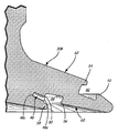
도 4a는 도 3의 라인 4-4를 따라 취한 보스의 부분 단면도이다.
도 4b는 도 4a와 유사하지만 보스가 용기 라이너에 연결된 상태로 나타내는 도면이다.
도 5는 본 발명의 보스의 제2 실시예의 사시도이다.
도 6a는 도 5의 라인 6-6을 따라 취한 보스의 부분 단면도이다.
도 6b는 도 6a와 유사하지만 보스가 용기 라이너에 연결된 상태로 나타내는 도면이다.
상기한 도면들에서는 본 발명의 하나 이상의 실시예에 대해 나타내고 있지만, 본 명세서에서 언급하는 바와 같이 다른 실시예들도 역시 모색될 수 있다. 모든 경우에 있어서, 본 명세서는 개시된 본 발명을 한정하고자 하는 것이 아니라 예시로서 제시하고 있다. 본 발명의 원리의 사상 및 범위 내에 포함되는 수많은 기타 수정예 및 실시예가 당업자들에 의해 안출될 수 있다는 점을 이해해야 할 것이다.
도면은 축적대로 도시되지 않을 수도 있다. 게다가, "위", "아래", "상", "하", "정상", "저부", "측부", "우측", "좌측" 등과 같은 용어가 사용되는 경우, 그 용어들은 상세한 설명의 이해를 용이하도록 하기 위해서만 사용한 것이라는 점을 이해해야 할 것이다. 구조체들을 다른 방식으로 배향할 수 있다는 점을 예상할 것이다.BRIEF DESCRIPTION OF THE DRAWINGS The present invention will now be described in more detail with reference to the accompanying drawings, in which like structure or system elements are given like reference numerals throughout the several views.
1 is a side view of a conventional long pressure vessel.
Figure 2 is a partial cross-sectional view of the pressure vessel taken along line 2-2 of Figure 1;
3 is a perspective view of a first embodiment of the boss of the present invention.
4A is a partial cross-sectional view of the boss taken along line 4-4 of FIG.
Figure 4b is similar to Figure 4a but with the boss connected to the container liner.
5 is a perspective view of a second embodiment of the boss of the present invention.
6A is a partial cross-sectional view of the boss taken along line 6-6 of FIG.
Figure 6b is a view similar to Figure 6a but with the boss connected to the container liner.
While the foregoing drawings illustrate one or more embodiments of the present invention, other embodiments as discussed herein may also be sought. In all instances, the specification sets forth the invention as illustrative rather than limiting. It should be understood that numerous other modifications and embodiments may be devised by those skilled in the art that fall within the spirit and scope of the principles of the invention.
The drawings may not be drawn to scale. In addition, when terms such as "up", "down", "up", "bottom", "normal", "bottom", "side", "right", "left", etc. are used, It should be understood that it is only used to facilitate understanding of You can expect to be able to orient structures in different ways.
하나의 실시예에서, 개선된 보스-라이너 인터페이스 구조가 도 3, 도 4a, 및 도 4b의 보스(16A)에 도시되어 있다. 환형의 외측 또는 외부 키홈(42) 및 환형의 내측 또는 내부 키홈(44)이 플랜지(30A)에 마련되어 라이너(20)의 상호 맞물림 키(42a, 44a)와 각각 맞물리도록 된다. 본 명세서에서 사용하는 바와 같은 "더브테일"이란 용어는, 보스의 키홈(42, 44)과 라이너(20)의 상호 맞물림 키(42a, 44a) 간에 형성된 결합의 분리가 구조적으로 방지되도록 립, 노치, 플레어(flare), 돌기 또는 이와 유사하거나 상응하는 구조를 포함하는 키홈 또는 상호 맞물림 키의 형상을 나타내는 것이다. 외부 키홈(42)은 반경 방향으로의 분리를 방지하도록 축방향으로 연장하는 환형 립(52)과, 축방향으로의 분리를 방지하도록 반경 방향으로 연장하는 환형 립(54)을 포함한다. 마찬가지로, 내부 키홈(44)은 반경 방향으로의 분리를 방지하도록 축방향으로 연장하는 환형 립(56)과, 축방향으로의 분리를 방지하도록 반경 방향으로 연장하는 환형 립(58)을 포함한다. In one embodiment, an improved boss-liner interface structure is shown in
보스(16A)의 플랜지(30A)의 내측면에서 내부 키홈(44)으로부터 반경 방향 내측으로 환형 홈(46)이 형성되어 있다. 이 홈(46)은 내부 키홈(44)의 내부 측벽(50)과 홈(46) 사이에 형성된 복수의 개별 보어(48)들에 의해 내부 키홈(44)에 연결되는데, 각각의 보어(48)는 제1 단부에서는 내부 키홈(44)에 제1 개구(48a)를 갖고 있고 제2 단부에서는 홈(46)에 제2 개구를 갖고 있다. 보어(48)는 단면이 예를 들면 원형이거나 길이가 길게 형성된 형상으로 될 수 있다. 예시적인 실시예에서, 홈(46)은 실질적으로 "V" 형상을 갖는다.An
압력 용기(10)를 형성하는 방법은, 라이너(20)를 위한 유체 폴리머 재료가 외부 키홈(42), 내부 키홈(44), 홈(46) 및 보어(48) 내로 유입되어 이들을 채우도록 하는 것을 포함한다. 그 후에, 라이너 재료를 응고시키면 키(42a), 키(44a) 및 앵커(49)가 형성된다. 라이너(20)는 보어(48) 내에 형성되어 홈(46) 내의 라이너 재료를 내부 키홈(44) 내의 라이너 재료[즉, 키(44a)]에 연결하는 앵커(49)에 의해 보스(16A)와 기계적으로 상호 맞물리게 된다. 따라서, 극단적인 압력 조건하에서도 보스(16A)로부터 라이너(20)의 분리가 방지된다. 사실상, 라이너(20)의 재료가 찢어진 후에나 라이너(20)와 보스(16A)가 분리될 수 있을 것이다.The method of forming the
플랜지(30A)는 내측면(60) 및 외측면(62)을 갖고 있다. 예시적인 실시예에서, 각각의 앵커(49)는 플랜지(30A)의 내측면과만 접촉하지, 플랜지(30A)의 외측면과는 접촉하지 않는다. 내부 키홈(44), 홈(46) 및 보어(48)가 모두 플랜지(30A)의 내측면(60)에 위치하기 때문에, 플랜지(30A)의 내측면에서부터 플랜지(30A)의 외측면에 이르는 가스 누설 통로가 존재하지 않는다. 게다가, 라이너(20)와 보스(16A) 사이에 축적된 어떠한 가스도 라이너(20)의 개구(24)(도 2 참조)에서 압력 용기(10) 내로 다시 빠져나올 수 있어, 라이너(20)와 보스(16A)의 인터페이스에서 파열 또는 분리를 방지할 수 있다.The
본 발명의 다른 예시적인 보스가 도 5, 도 6a 및 도 6b에 도시되어 있다. 이 예시적인 보스(16B)의 구조는 내부 키홈(44)으로부터 반경 방향 내측에 어떠한 홈도 마련되지 않는다는 점을 제외하면 전술한 보스(16A)와 유사하다. 내부 키홈(44) 내에는 복수의 개별 보어(48)들이 내부 키홈(44)의 측벽(50)의 개구(48a)를 통해 거의 반경 방향으로 보스(16B) 내로 마련되어 있다. 본 명세서에서 사용하는 바와 같은 "보어"란 용어는 소정 부재를 완전히 관통할 필요는 없다. 따라서, 보어(48)는 개구(48a)에서부터 도 6a 및 도 6b에 도면 부호 48c로 나타낸 바와 같은 폐쇄단까지 연장할 수 있다. 압력 용기(10)는 라이너(20)의 재료로 형성되고, 이 재료는 또한 환형 키홈(42, 44) 내로 유입되어 그와 상호 맞물리는 환형 키를 형성한다[각각 외부 키(42b) 및 내부 키(44b)]. 내부 키(44b)로부터 라이너 재료가 보어(48)를 채워 보스(16B)와 라이너(20)의 분리를 방지하는 앵커(49)를 형성한다.Other exemplary bosses of the present invention are shown in Figs. 5, 6A and 6B. The structure of this
전술한 각각의 보스 구조[도 3, 도 4a 및 도 4b에 도시한 보스(16A)와, 도 5, 도 6a, 및 도 6b에 도시한 보스(16B)]는 보스(16A, 16B)와 라이너(20) 사이에 고도로 안정되고 일체화된 인터페이스를 제공하여 보스(16A, 16B)와 라이너(20) 사이에서 파열 및/또는 가스 축적을 방지하도록 하고자 한 것이다.Each of the above-described boss structures (the
본 발명의 주제를 다수의 실시예를 참조하여 설명하였지만, 당업자라면 본 발명의 사상 및 범위로부터 벗어나지 않고 형태 및 세부 사항에 있어 변형이 이루어질 수 있다는 점을 이해할 수 있을 것이다. 게다가, 하나의 실시예에 대해 개시한 임의의 특징은 다른 실시예에 포함될 수 있고 그 반대로도 가능하다. 예를 들면, 몇몇 보어는 플랜지의 일부를 관통하지만(예를 들면, 도 3, 도 4a, 및 도 4b에 도시한 보어), 다른 보어는 그렇지 않을 수 있다(예를 들면, 도 5, 도 6a, 및 도 6b에 도시한 보어). 그러나 보어의 구성들은 플랜지 둘레에서 방사상으로 교대 배치되거나(관통 보어, 일단부 폐쇄 보어, 관통 보어 등), 플랜지 둘레에서 임의의 방식으로 혼재된 보어 구성의 배열로 배치될 수도 있다.Although the subject matter of the present invention has been described with reference to a number of embodiments, those skilled in the art will recognize that variations may be made in form and detail without departing from the spirit and scope of the invention. Moreover, any feature disclosed with respect to one embodiment may be included in another embodiment, and vice versa. For example, some bores penetrate a portion of the flange (e.g., the bores shown in Figures 3, 4A, and 4B), while the other bores may not (e.g., , And bore shown in Figure 6b). However, the configurations of the bores may be arranged radially alternately about the flange (through bores, one end closed bores, through bores, etc.), or an array of bore configurations mixed in any manner around the flange.
Claims (24)
상기 내측면에 배치되고 내부 측벽을 갖는 내부 키홈(keyway); 및
상기 내부 측벽에 배치된 복수의 보어
를 포함하며, 상기 보어는 상기 외측면과 연통하지 않는 것인 압력 용기용 보스.A boss for a pressure vessel having a flange having an outer surface and an inner surface, the boss comprising:
An inner keyway disposed on the inner side and having an inner side wall; And
A plurality of bores
Wherein the bore does not communicate with the outer surface.
본체 섹션; 및
상기 본체 섹션에 연결된 단부 섹션
을 포함하며, 상기 단부 섹션은 보스를 포함하고, 이 보스는 외측면과 내측면를 갖는 플랜지를 포함하며, 이 플랜지는,
상기 내측면에 배치되고 내부 측벽을 갖는 내부 키홈(keyway); 및
상기 내부 측벽에 배치된 복수의 보어
를 포함하며, 상기 보어는 상기 외측면과 연통하지 않는 것인 압력 용기.As a pressure vessel,
A body section; And
An end section connected to said body section
The end section including a boss, the boss comprising a flange having an outer surface and an inner surface,
An inner keyway disposed on the inner side and having an inner side wall; And
A plurality of bores
Wherein the bore does not communicate with the outer surface.
외부 쉘, 및 이 외부 쉘 내에 배치된 내부 라이너를 포함하는 복합재 쉘; 및
상기 복합재 쉘에 포트를 형성하는 보스
를 포함하며, 상기 보스는 외측면과 내측면을 갖는 플랜지를 포함하며, 이 플랜지는,
상기 내측면에 배치되고 내부 측벽을 갖는 내부 키홈(keyway); 및
상기 내부 측벽에 배치된 복수의 보어
를 포함하며, 상기 보어는 상기 외측면과 연통하지 않으며,
상기 라이너는 복수의 앵커를 통해 플랜지에 기계적으로 일체화되되, 각각의 앵커는 플랜지의 내측면에서만 플랜지와 접촉하는 것인 압력 용기.As pressure vessel:
A composite shell comprising an outer shell and an inner liner disposed within the outer shell; And
A boss forming a port in the composite shell;
Wherein the boss includes a flange having an outer surface and an inner surface,
An inner keyway disposed on the inner side and having an inner side wall; And
A plurality of bores
Wherein the bore does not communicate with the outer surface,
Wherein the liner is mechanically integrated into the flange through a plurality of anchors, wherein each anchor is in contact with the flange only on the inner side of the flange.
외측면과 내측면을 갖는 플랜지를 포함한 보스를 제공하되, 상기 플랜지는 상기 내측면에 배치되고 내부 측벽을 갖는 내부 키홈, 및 상기 내부 측벽에 배치된 복수의 보어를 포함하고, 상기 보어는 상기 외측면과 연통하지 않는 것인 보스를 제공하는 것; 및
유체 폴리머 재료가 상기 내부 키홈 및 복수의 보어 내로 흐르도록 하는 것
을 포함하는 압력 용기 형성 방법.A method of forming a pressure vessel, comprising:
Providing a boss comprising a flange having an outer surface and an inner surface, the flange including an inner keyway disposed on the inner surface and having an inner sidewall, and a plurality of bores disposed on the inner sidewall, Providing a boss that does not communicate with the side; And
Allowing the fluid polymer material to flow into the inner keyway and the plurality of bores
≪ / RTI >
Applications Claiming Priority (3)
| Application Number | Priority Date | Filing Date | Title |
|---|---|---|---|
| US14351609P | 2009-01-09 | 2009-01-09 | |
| US61/143,516 | 2009-01-09 | ||
| PCT/US2010/020425 WO2010080948A1 (en) | 2009-01-09 | 2010-01-08 | Pressure vessel boss and liner interface |
Publications (2)
| Publication Number | Publication Date |
|---|---|
| KR20110105851A KR20110105851A (en) | 2011-09-27 |
| KR101498277B1 true KR101498277B1 (en) | 2015-03-02 |
Family
ID=41664872
Family Applications (1)
| Application Number | Title | Priority Date | Filing Date |
|---|---|---|---|
| KR1020117017924A KR101498277B1 (en) | 2009-01-09 | 2010-01-08 | Pressure vessel boss and liner interface |
Country Status (10)
| Country | Link |
|---|---|
| US (3) | US9103500B2 (en) |
| EP (1) | EP2384408B1 (en) |
| JP (1) | JP5587339B2 (en) |
| KR (1) | KR101498277B1 (en) |
| CN (1) | CN102282409B (en) |
| AU (1) | AU2010203557B2 (en) |
| BR (1) | BRPI1006059B1 (en) |
| CA (1) | CA2749311C (en) |
| RU (1) | RU2511881C2 (en) |
| WO (1) | WO2010080948A1 (en) |
Cited By (2)
| Publication number | Priority date | Publication date | Assignee | Title |
|---|---|---|---|---|
| KR20190099315A (en) * | 2016-12-29 | 2019-08-26 | 압둘 아미아 샤바 | Improved antistatic pressure tank |
| KR20200010248A (en) * | 2017-05-24 | 2020-01-30 | 헥사곤 테크놀로지 에이에스 | Threaded Boss for Pressure Vessel |
Families Citing this family (36)
| Publication number | Priority date | Publication date | Assignee | Title |
|---|---|---|---|---|
| GB2485533B (en) * | 2010-11-15 | 2014-02-12 | Roger Carr | Vessel with associated collar |
| KR101221004B1 (en) * | 2011-01-19 | 2013-01-10 | 주식회사 일진유니스코 | Nozzle-boss for high pressure vessel |
| DE102011111406A1 (en) * | 2011-08-30 | 2013-02-28 | Amir R. Shubbar | Pressure tank with plug-in and welded connection for the connection piece |
| US8733581B1 (en) | 2012-07-16 | 2014-05-27 | Michael A. Olson | Boss seal for composite overwrapped pressure vessel |
| US20150330568A1 (en) * | 2012-12-05 | 2015-11-19 | Blue Wave Co S.A. | Pressure Vessel Having Composite Boss With Weldable Metal Fitting |
| WO2014106290A1 (en) | 2013-01-07 | 2014-07-10 | Fibrasynthetica Do Brasil Ltda. | Nozzle for a plastic container and plastic container for pressurized gases |
| JP5979446B2 (en) * | 2013-02-04 | 2016-08-24 | 豊田合成株式会社 | Pressure vessel |
| TR201302927A2 (en) * | 2013-03-11 | 2014-09-22 | Tofas Tuerk Otomobil Fabrikasi Anonim Sirketi | Boss structure |
| JP5936642B2 (en) * | 2013-04-17 | 2016-06-22 | 豊田合成株式会社 | Pressure vessel liner, mold thereof, and pressure vessel |
| JP6264244B2 (en) * | 2014-09-17 | 2018-01-24 | トヨタ自動車株式会社 | High pressure tank |
| DE102015105901A1 (en) | 2015-04-17 | 2016-10-20 | xperion Energy & Environment GmbH | Pressure vessel and method of manufacture |
| JP6582563B2 (en) * | 2015-06-02 | 2019-10-02 | 横浜ゴム株式会社 | Aircraft water tank |
| US10317009B2 (en) * | 2015-08-06 | 2019-06-11 | Toyota Jidosha Kabushiki Kaisha | High pressure tank, manufacturing method of high pressure tank, and inspection method of sealing characteristic |
| EP3368814A4 (en) * | 2015-10-30 | 2019-07-03 | Carleton Technologies, Inc. | Boss and seal for a high-pressure vessel |
| US10627048B2 (en) * | 2015-12-16 | 2020-04-21 | Hexagon Technology, As | Pressure vessel dome vents |
| AU2017229201A1 (en) * | 2016-03-07 | 2018-08-09 | Hexagon Technology As | Wound-in end protection component for pressure vessel |
| JP6575414B2 (en) | 2016-03-29 | 2019-09-18 | 豊田合成株式会社 | Pressure vessel |
| CA3018397C (en) * | 2016-04-06 | 2023-06-27 | Hexagon Technology As | Pressure vessel vented boss with sintered metal plug |
| KR102463415B1 (en) * | 2016-12-20 | 2022-11-03 | 현대자동차주식회사 | High pressure tank having reinforced boss-part |
| CN106838602B (en) * | 2017-01-19 | 2023-04-18 | 安徽绿动能源有限公司 | Metal bottle mouth structure and LPG gas cylinder |
| CN106870932A (en) * | 2017-02-17 | 2017-06-20 | 安徽绿动能源有限公司 | A kind of metal bottleneck structure and composite cylinder |
| JP7013857B2 (en) * | 2017-12-27 | 2022-02-01 | トヨタ自動車株式会社 | tank |
| JP7124450B2 (en) * | 2018-05-29 | 2022-08-24 | トヨタ自動車株式会社 | high pressure gas tank |
| CN109132246B (en) * | 2018-08-30 | 2023-07-04 | 浙江科赛新材料科技有限公司 | Oil tank joint |
| DE102018009829B4 (en) * | 2018-12-14 | 2020-09-17 | Emano Kunststofftechnik Gmbh | Pressure vessel and method of manufacturing the pressure vessel |
| US11440399B2 (en) | 2019-03-22 | 2022-09-13 | Agility Fuel Systems Llc | Fuel system mountable to a vehicle frame |
| US20200347992A1 (en) | 2019-05-02 | 2020-11-05 | Agility Fuel Systems Llc | Polymeric liner based gas cylinder with reduced permeability |
| JP6870027B2 (en) * | 2019-05-16 | 2021-05-12 | 本田技研工業株式会社 | High-pressure tank and its manufacturing method |
| JP2022538436A (en) | 2019-06-28 | 2022-09-02 | リナマー・コーポレーション | End bosses for type IV pressure vessels |
| DE102020001135B3 (en) * | 2020-02-20 | 2021-08-26 | Emano Kunststofftechnik Gmbh | Pressure vessel and method of making a pressure vessel |
| KR102442629B1 (en) * | 2020-09-28 | 2022-09-14 | 한화솔루션 주식회사 | High-pressure tank having sealing structure boss and making method thereof |
| CN112393112B (en) * | 2020-12-08 | 2022-08-09 | 亚普汽车部件股份有限公司 | Bottleneck seal structure and high-pressure composite container |
| KR102460148B1 (en) * | 2021-01-04 | 2022-11-01 | 주식회사 성우하이텍 | pressure vessel |
| FR3121968B1 (en) * | 2021-04-16 | 2023-12-08 | Faurecia Systemes Dechappement | Tank for pressurized gas |
| CN113548327A (en) * | 2021-07-09 | 2021-10-26 | 苏州方林科技股份有限公司 | Nested injection molding water nozzle structure and processing method thereof |
| DE102022002415B4 (en) * | 2022-07-04 | 2024-02-22 | Emano Kunststofftechnik Gmbh | pressure vessel |
Citations (4)
| Publication number | Priority date | Publication date | Assignee | Title |
|---|---|---|---|---|
| KR930016709A (en) * | 1992-01-10 | 1993-08-26 | 마이클 디. 슈미츠 | Opening for Pressure Vessel |
| US5476189A (en) * | 1993-12-03 | 1995-12-19 | Duvall; Paul F. | Pressure vessel with damage mitigating system |
| US5979692A (en) * | 1998-03-13 | 1999-11-09 | Harsco Corporation | Boss for composite pressure vessel having polymeric liner |
| US6227402B1 (en) * | 1999-04-07 | 2001-05-08 | Toyoda Gosei Co., Ltd | Pressure container |
Family Cites Families (20)
| Publication number | Priority date | Publication date | Assignee | Title |
|---|---|---|---|---|
| US4589563A (en) | 1983-03-07 | 1986-05-20 | Quality Products, Inc. | High-pressure container and method of making the same |
| US5429845A (en) | 1992-01-10 | 1995-07-04 | Brunswick Corporation | Boss for a filament wound pressure vessel |
| ATE130421T1 (en) | 1992-01-10 | 1995-12-15 | Technical Products Group Inc | POLE PIECE FOR A FIBER WOUND PRESSURE VESSEL. |
| US5494188A (en) | 1992-01-28 | 1996-02-27 | Edo Canada Ltd. | Fluid pressure vessel boss-liner attachment system with liner/exterior mechanism direct coupling |
| US5287988A (en) * | 1993-02-03 | 1994-02-22 | Brunswick Corporation | Metal-lined pressure vessel |
| US5518141A (en) | 1994-01-24 | 1996-05-21 | Newhouse; Norman L. | Pressure vessel with system to prevent liner separation |
| BR9600459A (en) * | 1996-01-17 | 1998-03-03 | Fibrasynthetica Do Brasil Comp | Plastic container for pressurized fluids |
| US5938209A (en) * | 1997-02-14 | 1999-08-17 | Alternative Fuel Systems, Inc. | Seal system for fluid pressure vessels |
| US5819978A (en) * | 1997-04-24 | 1998-10-13 | Essef Corporation | Two piece composite inlet |
| JPH1144399A (en) * | 1997-05-27 | 1999-02-16 | Mitsubishi Chem Corp | Pressure vessel |
| JPH10332083A (en) * | 1997-05-28 | 1998-12-15 | Mitsubishi Chem Corp | Pressure-resisting container |
| US6793095B1 (en) | 1998-02-04 | 2004-09-21 | Essef Corporation | Blow-molded pressure tank with spin-welded connector |
| US6135308A (en) | 1998-06-26 | 2000-10-24 | Industrial Technology Research Institute | Boss for a filament wound pressure vessel |
| US6386384B1 (en) * | 2000-02-09 | 2002-05-14 | Amtrol, Inc. | Full jacket gas cylinder |
| RU2188356C2 (en) * | 2000-11-10 | 2002-08-27 | Пермский государственный технический университет | High-pressure composite gas bottle |
| DE10360953B4 (en) * | 2002-12-27 | 2011-04-07 | Toyoda Gosei Co., Ltd., Nishikasugai-gun | pressure vessel |
| KR100469636B1 (en) * | 2004-03-11 | 2005-02-02 | 주식회사 케이시알 | The high gas-tighten metallic nozzle-boss for the high pressure composite vessel |
| JP4457359B2 (en) * | 2006-12-13 | 2010-04-28 | トヨタ自動車株式会社 | Pressure vessel |
| JP4392804B2 (en) | 2007-04-06 | 2010-01-06 | 豊田合成株式会社 | Pressure vessel |
| JP5711154B2 (en) * | 2009-02-18 | 2015-04-30 | ヘキサゴン テクノロジー アーエス | Shear boss and shell interface element of pressure vessel |
-
2010
- 2010-01-08 CN CN201080004144.4A patent/CN102282409B/en active Active
- 2010-01-08 AU AU2010203557A patent/AU2010203557B2/en not_active Ceased
- 2010-01-08 US US13/143,250 patent/US9103500B2/en active Active
- 2010-01-08 JP JP2011545439A patent/JP5587339B2/en active Active
- 2010-01-08 EP EP10700091.1A patent/EP2384408B1/en active Active
- 2010-01-08 KR KR1020117017924A patent/KR101498277B1/en active IP Right Grant
- 2010-01-08 CA CA2749311A patent/CA2749311C/en active Active
- 2010-01-08 WO PCT/US2010/020425 patent/WO2010080948A1/en active Application Filing
- 2010-01-08 RU RU2011133220/06A patent/RU2511881C2/en active
- 2010-01-08 BR BRPI1006059-6A patent/BRPI1006059B1/en active IP Right Grant
-
2015
- 2015-08-07 US US14/820,692 patent/US9644790B2/en active Active
-
2017
- 2017-04-04 US US15/478,610 patent/US10180210B2/en active Active
Patent Citations (4)
| Publication number | Priority date | Publication date | Assignee | Title |
|---|---|---|---|---|
| KR930016709A (en) * | 1992-01-10 | 1993-08-26 | 마이클 디. 슈미츠 | Opening for Pressure Vessel |
| US5476189A (en) * | 1993-12-03 | 1995-12-19 | Duvall; Paul F. | Pressure vessel with damage mitigating system |
| US5979692A (en) * | 1998-03-13 | 1999-11-09 | Harsco Corporation | Boss for composite pressure vessel having polymeric liner |
| US6227402B1 (en) * | 1999-04-07 | 2001-05-08 | Toyoda Gosei Co., Ltd | Pressure container |
Cited By (5)
| Publication number | Priority date | Publication date | Assignee | Title |
|---|---|---|---|---|
| KR20190099315A (en) * | 2016-12-29 | 2019-08-26 | 압둘 아미아 샤바 | Improved antistatic pressure tank |
| KR102439957B1 (en) | 2016-12-29 | 2022-09-06 | 압둘 아미아 샤바 | Improved antistatic pressure tank |
| KR20200010248A (en) * | 2017-05-24 | 2020-01-30 | 헥사곤 테크놀로지 에이에스 | Threaded Boss for Pressure Vessel |
| KR102325236B1 (en) * | 2017-05-24 | 2021-11-11 | 헥사곤 테크놀로지 에이에스 | Threaded bosses for pressure vessels |
| US11371653B2 (en) | 2017-05-24 | 2022-06-28 | Hexagon Technology As | Threaded boss for pressure vessel |
Also Published As
| Publication number | Publication date |
|---|---|
| US20170205029A1 (en) | 2017-07-20 |
| CA2749311A1 (en) | 2010-07-15 |
| KR20110105851A (en) | 2011-09-27 |
| AU2010203557B2 (en) | 2014-05-29 |
| US20150345702A1 (en) | 2015-12-03 |
| US9103500B2 (en) | 2015-08-11 |
| RU2011133220A (en) | 2013-02-20 |
| US9644790B2 (en) | 2017-05-09 |
| EP2384408A1 (en) | 2011-11-09 |
| JP5587339B2 (en) | 2014-09-10 |
| BRPI1006059A2 (en) | 2018-04-24 |
| RU2511881C2 (en) | 2014-04-10 |
| CN102282409B (en) | 2016-03-23 |
| WO2010080948A1 (en) | 2010-07-15 |
| EP2384408B1 (en) | 2019-03-13 |
| AU2010203557A1 (en) | 2011-07-14 |
| BRPI1006059B1 (en) | 2020-06-23 |
| US10180210B2 (en) | 2019-01-15 |
| CA2749311C (en) | 2015-03-24 |
| CN102282409A (en) | 2011-12-14 |
| US20110303681A1 (en) | 2011-12-15 |
| JP2012514727A (en) | 2012-06-28 |
Similar Documents
| Publication | Publication Date | Title |
|---|---|---|
| KR101498277B1 (en) | Pressure vessel boss and liner interface | |
| US11073240B2 (en) | Pressure vessel dome vents | |
| AU2020200292B2 (en) | Pressure vessel liner venting via nanotextured surface | |
| US8668108B2 (en) | Pressure vessel shear resistant boss and shell interface element |
Legal Events
| Date | Code | Title | Description |
|---|---|---|---|
| A201 | Request for examination | ||
| A302 | Request for accelerated examination | ||
| E902 | Notification of reason for refusal | ||
| E701 | Decision to grant or registration of patent right | ||
| GRNT | Written decision to grant | ||
| FPAY | Annual fee payment |
Payment date: 20180208 Year of fee payment: 4 |
|
| FPAY | Annual fee payment |
Payment date: 20190212 Year of fee payment: 5 |
|
| FPAY | Annual fee payment |
Payment date: 20200214 Year of fee payment: 6 |