JP6899541B2 - Electric tool - Google Patents
Electric tool Download PDFInfo
- Publication number
- JP6899541B2 JP6899541B2 JP2017107098A JP2017107098A JP6899541B2 JP 6899541 B2 JP6899541 B2 JP 6899541B2 JP 2017107098 A JP2017107098 A JP 2017107098A JP 2017107098 A JP2017107098 A JP 2017107098A JP 6899541 B2 JP6899541 B2 JP 6899541B2
- Authority
- JP
- Japan
- Prior art keywords
- rotating body
- motor
- motor shaft
- power tool
- rotation
- Prior art date
- Legal status (The legal status is an assumption and is not a legal conclusion. Google has not performed a legal analysis and makes no representation as to the accuracy of the status listed.)
- Active
Links
Images


Classifications
-
- H—ELECTRICITY
- H02—GENERATION; CONVERSION OR DISTRIBUTION OF ELECTRIC POWER
- H02K—DYNAMO-ELECTRIC MACHINES
- H02K7/00—Arrangements for handling mechanical energy structurally associated with dynamo-electric machines, e.g. structural association with mechanical driving motors or auxiliary dynamo-electric machines
- H02K7/14—Structural association with mechanical loads, e.g. with hand-held machine tools or fans
- H02K7/145—Hand-held machine tool
-
- B—PERFORMING OPERATIONS; TRANSPORTING
- B25—HAND TOOLS; PORTABLE POWER-DRIVEN TOOLS; MANIPULATORS
- B25F—COMBINATION OR MULTI-PURPOSE TOOLS NOT OTHERWISE PROVIDED FOR; DETAILS OR COMPONENTS OF PORTABLE POWER-DRIVEN TOOLS NOT PARTICULARLY RELATED TO THE OPERATIONS PERFORMED AND NOT OTHERWISE PROVIDED FOR
- B25F5/00—Details or components of portable power-driven tools not particularly related to the operations performed and not otherwise provided for
Description
本発明は、モータの回転角度を検出する回転検出部を備えた電動工具に関する。 The present invention relates to an electric tool provided with a rotation detection unit that detects a rotation angle of a motor.
穴あけ作業やねじ類の締付作業に用いられる手持ち式の電動工具は、小型化および軽量化のために、ビルトイン式モータを使用することが多い(たとえば特許文献1〜3)。ビルトイン式モータは、モータの構成要素をハウジングの内周面に突設されたリブ部材に直接組み付けることで構成される。
Hand-held power tools used for drilling work and screw tightening work often use a built-in motor for miniaturization and weight reduction (for example,
インパクト回転工具などの電動工具では、モータの回転角度から締付トルクを推定する制御が実施される。締付トルクの推定精度を高めるためには、モータの回転角度を高精度に検出する回転検出部を電動工具に設けることが必要となる。 For electric tools such as impact rotary tools, control is performed to estimate the tightening torque from the rotation angle of the motor. In order to improve the estimation accuracy of the tightening torque, it is necessary to provide the power tool with a rotation detection unit that detects the rotation angle of the motor with high accuracy.
本発明はこうした状況に鑑みなされたものであり、その目的は、回転検出部を効率的に電動工具に設ける技術を提供することにある。 The present invention has been made in view of such a situation, and an object of the present invention is to provide a technique for efficiently providing a rotation detection unit on a power tool.
上記課題を解決するために、本発明のある態様の電動工具は、モータと、モータの回転出力を先端工具に伝達する伝達機構と、モータの回転角度を検出する回転検出部と、を備えた電動工具であって、回転検出部は、モータのモータシャフトに取り付けられた回転体と、回転体の回転位置に応じた回転位置信号を出力する位置検出部とを有する。回転体は開口を有し、モータシャフトが回転体の開口に圧入固定される。 In order to solve the above problems, the power tool of one embodiment of the present invention includes a motor, a transmission mechanism for transmitting the rotation output of the motor to the tip tool, and a rotation detection unit for detecting the rotation angle of the motor. In the electric tool, the rotation detection unit includes a rotating body attached to the motor shaft of the motor and a position detecting unit that outputs a rotation position signal according to the rotation position of the rotating body. The rotating body has an opening, and the motor shaft is press-fitted and fixed to the opening of the rotating body.
本発明によれば、回転検出部を効率的に電動工具に設ける技術を提供できる。 According to the present invention, it is possible to provide a technique for efficiently providing a rotation detection unit on a power tool.
図1は、本発明の実施形態に係る電動工具の一部断面概要図を示す。電動工具1はハウジング2を備え、モータユニット4がハウジング2に内装される。モータユニット4は、ステータ、およびモータシャフト9と一体化したロータをハウジング2に組み付けることで機能するビルトイン式モータとして構成され、モータケースを有しないことで電動工具1の小型化および軽量化に貢献する。以下、モータユニット4の前方側のモータシャフト9を「モータシャフト9a」、後方側のモータシャフト9を「モータシャフト9b」と呼ぶ。モータシャフト9aには、遠心ファンである冷却ファン3が固定される。
FIG. 1 shows a partial cross-sectional schematic view of a power tool according to an embodiment of the present invention. The
駆動ブロック5は、モータの回転出力を先端工具に伝達する伝達機構を備える。具体的に駆動ブロック5は、モータシャフト9aの回転出力を出力軸6に伝達する動力伝達機構を備え、動力伝達機構は、モータシャフト9aに取り付けられたピニオンギヤに噛み合う遊星歯車減速機構を有してよい。電動工具1がインパクト回転工具である場合、動力伝達機構は、出力軸6に間欠的な回転衝撃力を発生させるインパクト機構を含む。出力軸6にはチャック機構7が連結し、ドリルやドライバなどの先端工具を着脱可能とする。ハウジング2のグリップ部には、作業者により操作される操作スイッチ8が設けられ、作業者が操作スイッチ8を引くとモータユニット4におけるロータが回転して、出力軸6が先端工具を駆動する。
The drive block 5 includes a transmission mechanism that transmits the rotational output of the motor to the tip tool. Specifically, the drive block 5 includes a power transmission mechanism that transmits the rotational output of the
モータユニット4はインナーロータ型のブラシレスモータであって、複数の永久磁石を有するロータがステータの内側で回転する。モータユニット4の構成要素であるロータおよびステータは、それぞれ別個独立にハウジング2に固定される。ハウジング2は、電動工具1の回転軸線中心を横切る垂直面で2分される一対の(左右の)半割れハウジング部材から構成される。モータユニット4のハウジング2への組付は、一方のハウジング部材に、ステータおよびモータシャフト9の第1軸受10a、第2軸受10bを組み込み、他方のハウジング部材をかさねて、一対のハウジング部材をねじ締め等で結合することで行われる。
The motor unit 4 is an inner rotor type brushless motor, and a rotor having a plurality of permanent magnets rotates inside the stator. The rotor and the stator, which are the components of the motor unit 4, are individually and independently fixed to the
モータユニット4の後方には、モータの回転角度を検出する回転検出部12が設けられる。回転検出部12は、モータシャフト9bに取り付けられた回転体20と、回転体20の回転位置に応じた回転位置信号を出力する位置検出部30とを有する。位置検出部30は、センサ基板上に設けられたセンサである。回転検出部12は、磁気式エンコーダであってよいが、光学式エンコーダであってもよい。
Behind the motor unit 4, a
回転検出部12が磁気式エンコーダである場合、回転体20は磁石を有し、位置検出部30は、磁力の変化を検出する磁気センサを有する。モータ回転角度の検出精度を高めるために、回転体20および位置検出部30の間隔は狭く設定され、たとえば両者の間隔は約2mmである。なお回転検出部12が光学式エンコーダである場合、回転体20は光を遮断/透過するスリットを形成された回転円板であり、位置検出部30は、フォトダイオードなどの受光素子を有する。回転検出部12はいずれの形式のエンコーダであってもよく、位置検出部30は、モータ回転を制御する制御部(図示せず)に、回転体20の回転位置に応じた回転位置信号を出力する。
When the
位置検出部30は支持部材14により、モータユニット4のステータ側に固定される。回転体20をモータシャフト9bに固定し、且つ位置検出部30をモータユニット4に固定することで、回転体20および位置検出部30の組付精度を高めることができ、回転体20および位置検出部30の間隔を所定値に高精度に設定できる。また位置検出部30をハウジング2に固定する場合と比べると、位置検出部30をモータユニット4に固定することで、ハウジング2の変形に対して回転体20および位置検出部30の相対位置が影響を受けにくく、信頼性の高い回転検出部12を実現できる。
The
図2は、回転体20およびモータシャフト9bの断面を示す。回転体20は開口21を有し、モータシャフト9bが回転体20の開口21に圧入固定される。モータシャフト9bと開口21とを圧入固定することで、たとえばモータシャフト9bと回転体20とをねじ締めにより固定する場合と比べると、組付工程を容易にできるだけでなく、部品点数を少なくして小型化を実現できる。
FIG. 2 shows a cross section of the rotating
なお図1を参照して、回転体20は、モータシャフト9bを支持する第2軸受10bに接触しない位置でモータシャフト9bに取り付けられる。回転体20を取り付ける前に、モータシャフト9bには、すでに第2軸受10bが圧入固定されている。回転体20は、開口21をモータシャフト9bと同軸に配置した状態で押し込まれて、モータシャフト9bに取り付けられるが、このとき回転体20は、第2軸受10bの圧入位置までは押し込まれないように設計されている。このため回転体20の押し込みによって、第2軸受10bの圧入位置がずれることはない。
With reference to FIG. 1, the rotating
なお回転体20の組付工程をさらに容易にするために、モータシャフト9bまたは開口21の少なくとも一方に、モータシャフト9bの圧入深さを制限する圧入制限部が設けられてよい。圧入制限部を利用することで、モータシャフト9bに対する回転体20の位置決めを容易に実現できるようになる。図3(a)〜(c)は、圧入制限部の例を示す。
In order to further facilitate the assembling process of the rotating
図3(a)は、回転体20の開口21の底部である圧入制限部22を示す。図3(a)に示す例では、開口21を有底に形成し、モータシャフト9bを圧入制限部22に当接するまで開口21に圧入することで、回転体20がモータシャフト9bに取り付けられる。
FIG. 3A shows a press-
図3(b)は、回転体20の開口21に形成された段部である圧入制限部23を示す。図3(b)に示す例では、開口21に小径部を形成し、モータシャフト9bを圧入制限部23に当接するまで開口21に圧入することで、回転体20がモータシャフト9bに取り付けられる。
FIG. 3B shows a press-fitting limiting
図3(c)は、モータシャフト9bに形成された段部である圧入制限部24を示す。図3(c)に示す例では、圧入制限部24が回転体20の開口21の端面に当接するまでモータシャフト9bを開口21に圧入することで、回転体20がモータシャフト9bに取り付けられる。
FIG. 3C shows a press-fitting limiting
回転検出部12がモータの回転角度を高精度に検出するためには、回転体20がモータシャフト9bに相対回転不能に取り付けられる必要がある。そこで回転体20は、モータシャフト9bに回転止め構造を介して固定される。図4(a)〜(b)は、回転止め機構の例を示す。
In order for the
図4(a)は、回転体20の開口21の断面をD形状とし、モータシャフト9bの端部断面をD形状とした回転止め構造を示す。断面D形状のモータシャフト9bを開口21に圧入することで、回転体20とモータシャフト9bとの相対回転が抑止される。
FIG. 4A shows a rotation stop structure in which the cross section of the
図4(b)は、開口21とモータシャフト9bにキー溝を形成し、両方のキー溝に、キーである回転抑止部材25を差し込んだ回転止め構造を示す。回転抑止部材25を開口21とモータシャフト9bのキー溝に配置することで、回転体20とモータシャフト9bとの相対回転が抑止される。
FIG. 4B shows a rotation stop structure in which a key groove is formed in the
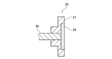
図5は、回転体20の一例を示す。この回転体20は、磁気式エンコーダにおける一部品を構成し、磁石26と、磁石26を固定する固定用ブッシュ27を有する。固定用ブッシュ27の固定面には磁石26を嵌合する凹部が形成され、磁石26は、凹部に嵌合されて固定される。なお磁石26は、ブッシュ固定面の凹部に接着固定されることが好ましい。これにより磁石26を固定用ブッシュ27に確実に固定できる。
FIG. 5 shows an example of the
磁石26は、固定用ブッシュ27の凹部に相対回転不能に嵌合する形状を有して、凹部に相対回転不能に嵌合することが好ましい。
図6(a)は、固定用ブッシュ27の固定面の凹部をD形状に形成した例を示す。磁石26は凹部に嵌合するD形状を有して、凹部に嵌合し、接着剤により固定される。
図6(b)は、固定用ブッシュ27の固定面の凹部を四角形状に形成した例を示す。磁石26は凹部に嵌合する四角形状を有して、凹部に嵌合し、接着剤により固定される。
It is preferable that the
FIG. 6A shows an example in which a recess on the fixing surface of the fixing
FIG. 6B shows an example in which the recesses on the fixing surface of the fixing
以上、本発明を実施形態をもとに説明した。この実施形態は例示であり、それらの各構成要素あるいは各処理プロセスの組合せにいろいろな変形例が可能なこと、またそうした変形例も本発明の範囲にあることは当業者に理解されるところである。 The present invention has been described above based on the embodiments. This embodiment is an example, and it will be understood by those skilled in the art that various modifications are possible for each of these components or combinations of each processing process, and that such modifications are also within the scope of the present invention. ..
本発明の態様の概要は、次の通りである。
本発明のある態様の電動工具(1)は、モータ(4)と、モータの回転出力を先端工具に伝達する伝達機構(5)と、モータの回転角度を検出する回転検出部(12)とを備える。回転検出部(12)は、モータのモータシャフト(9b)に取り付けられた回転体(20)と、回転体の回転位置に応じた回転位置信号を出力する位置検出部(30)とを有し、回転体(20)は開口(21)を有し、モータシャフト(9b)が回転体の開口に圧入固定される。
The outline of the aspect of the present invention is as follows.
The power tool (1) of an aspect of the present invention includes a motor (4), a transmission mechanism (5) that transmits the rotation output of the motor to the tip tool, and a rotation detection unit (12) that detects the rotation angle of the motor. To be equipped. The rotation detection unit (12) has a rotating body (20) attached to the motor shaft (9b) of the motor, and a position detecting unit (30) that outputs a rotation position signal according to the rotation position of the rotating body. The rotating body (20) has an opening (21), and the motor shaft (9b) is press-fitted and fixed to the opening of the rotating body.
モータシャフト(9b)または開口(21)の少なくとも一方に、モータシャフトの圧入深さを制限する圧入制限部(22,23,24)が設けられることが好ましい。回転体(20)は、モータシャフト(9b)に相対回転不能に取り付けられることが好ましい。 It is preferable that at least one of the motor shaft (9b) or the opening (21) is provided with a press-fit limiting portion (22, 23, 24) that limits the press-fit depth of the motor shaft. The rotating body (20) is preferably attached to the motor shaft (9b) so that it cannot rotate relative to each other.
回転検出部(12)は、磁気式エンコーダであってよく、回転体(20)は、磁石(26)と、磁石を固定する固定用ブッシュ(27)を有してよい。磁石(26)は、固定用ブッシュ(27)に接着固定されてよい。固定用ブッシュ(27)は、磁石の固定面に凹部を有し、磁石は、固定用ブッシュの凹部に相対回転不能に嵌合する形状を有してよい。なお回転体(20)は、モータシャフト(9b)を支持する軸受(10b)に接触しない位置でモータシャフトに取り付けられることが好ましい。 The rotation detection unit (12) may be a magnetic encoder, and the rotating body (20) may have a magnet (26) and a fixing bush (27) for fixing the magnet. The magnet (26) may be adhesively fixed to the fixing bush (27). The fixing bush (27) may have a recess on the fixing surface of the magnet, and the magnet may have a shape that fits into the recess of the fixing bush so as not to rotate relative to each other. The rotating body (20) is preferably attached to the motor shaft at a position where it does not come into contact with the bearing (10b) that supports the motor shaft (9b).
1・・・電動工具、2・・・ハウジング、4・・・モータユニット、5・・・駆動ブロック、6・・・出力軸、9a,9b・・・モータシャフト、10a・・・第1軸受、10b・・・第2軸受、12・・・回転検出部、20・・・回転体、21・・・開口、22,23,24・・・圧入制限部、25・・・回転抑止部材、26・・・磁石、27・・・固定用ブッシュ、30・・・位置検出部。 1 ... Electric tool, 2 ... Housing, 4 ... Motor unit, 5 ... Drive block, 6 ... Output shaft, 9a, 9b ... Motor shaft, 10a ... First bearing 10, b ... 2nd bearing, 12 ... rotation detection unit, 20 ... rotating body, 21 ... opening, 22, 23, 24 ... press-fitting limiting unit, 25 ... rotation restraining member, 26 ... Magnet, 27 ... Fixing bush, 30 ... Position detection unit.
Claims (7)
前記モータの回転出力を先端工具に伝達する伝達機構と、
前記モータの回転角度を検出する回転検出部と、を備えた電動工具であって、
前記回転検出部は、前記モータのモータシャフトに取り付けられた回転体と、前記回転体の回転位置に応じた回転位置信号を出力する位置検出部とを有し、
前記回転体は開口を有し、前記モータシャフトが前記回転体の前記開口に圧入固定され、
前記モータシャフトまたは前記開口の少なくとも一方に、前記モータシャフトの圧入深さを制限する圧入制限部が設けられる、
ことを特徴とする電動工具。 With the motor
A transmission mechanism that transmits the rotational output of the motor to the tip tool,
An electric tool including a rotation detection unit that detects the rotation angle of the motor.
The rotation detection unit includes a rotating body attached to the motor shaft of the motor and a position detecting unit that outputs a rotation position signal according to the rotation position of the rotating body.
The rotating body has an opening, and the motor shaft is press-fitted and fixed to the opening of the rotating body .
At least one of the motor shaft or the opening is provided with a press-fit limiting portion that limits the press-fit depth of the motor shaft.
A power tool characterized by that.
ことを特徴とする請求項1に記載の電動工具。 The position detection unit is fixed to the stator of the motor by a support member and faces the rotating body in the direction of the rotation axis.
The power tool according to claim 1.
ことを特徴とする請求項1または2に記載の電動工具。 The rotating body is attached to the motor shaft so as to be relatively non-rotatable.
The power tool according to claim 1 or 2.
前記回転体は、磁石と、磁石を固定する固定用ブッシュを有する、
ことを特徴とする請求項1から3のいずれかに記載の電動工具。 The rotation detection unit is a magnetic encoder and
The rotating body has a magnet and a fixing bush for fixing the magnet.
The power tool according to any one of claims 1 to 3, wherein the power tool is characterized in that.
ことを特徴とする請求項4に記載の電動工具。 The magnet is adhesively fixed to the fixing bush.
The power tool according to claim 4.
前記磁石は、前記固定用ブッシュの凹部に相対回転不能に嵌合する形状を有する、
ことを特徴とする請求項4または5に記載の電動工具。 The fixing bush has a recess on the fixing surface of the magnet.
The magnet has a shape that fits into the recess of the fixing bush so as not to rotate relative to each other.
The power tool according to claim 4 or 5.
ことを特徴とする請求項1から6のいずれかに記載の電動工具。 The rotating body is attached to the motor shaft at a position where it does not come into contact with the bearing supporting the motor shaft.
The power tool according to any one of claims 1 to 6, wherein the power tool.
Priority Applications (4)
| Application Number | Priority Date | Filing Date | Title |
|---|---|---|---|
| JP2017107098A JP6899541B2 (en) | 2017-05-30 | 2017-05-30 | Electric tool |
| PCT/JP2018/009893 WO2018220941A1 (en) | 2017-05-30 | 2018-03-14 | Power tool |
| EP18810556.3A EP3632625A4 (en) | 2017-05-30 | 2018-03-14 | Power tool |
| US16/617,494 US11478916B2 (en) | 2017-05-30 | 2018-03-14 | Electric power tool |
Applications Claiming Priority (1)
| Application Number | Priority Date | Filing Date | Title |
|---|---|---|---|
| JP2017107098A JP6899541B2 (en) | 2017-05-30 | 2017-05-30 | Electric tool |
Publications (2)
| Publication Number | Publication Date |
|---|---|
| JP2018202498A JP2018202498A (en) | 2018-12-27 |
| JP6899541B2 true JP6899541B2 (en) | 2021-07-07 |
Family
ID=64455360
Family Applications (1)
| Application Number | Title | Priority Date | Filing Date |
|---|---|---|---|
| JP2017107098A Active JP6899541B2 (en) | 2017-05-30 | 2017-05-30 | Electric tool |
Country Status (4)
| Country | Link |
|---|---|
| US (1) | US11478916B2 (en) |
| EP (1) | EP3632625A4 (en) |
| JP (1) | JP6899541B2 (en) |
| WO (1) | WO2018220941A1 (en) |
Family Cites Families (15)
| Publication number | Priority date | Publication date | Assignee | Title |
|---|---|---|---|---|
| US3938595A (en) * | 1974-09-19 | 1976-02-17 | Raymond International, Inc. | Apparatus and method for driving bulb piles |
| US4316512A (en) * | 1979-04-04 | 1982-02-23 | Sps Technologies, Inc. | Impact wrench |
| JPH02101946A (en) * | 1988-10-11 | 1990-04-13 | Matsushita Electric Ind Co Ltd | Electric motor with speed detecting device |
| SE511336C2 (en) * | 1997-10-27 | 1999-09-13 | Atlas Copco Tools Ab | Method for determining the installed torque in a screw joint during pulse tightening, method for controlling a tightening process, method for quality monitoring and a torque pulse tool for tightening screw joints |
| JP4407392B2 (en) * | 2004-06-17 | 2010-02-03 | パナソニック電工株式会社 | Impact tools |
| JP4631663B2 (en) | 2005-11-17 | 2011-02-16 | パナソニック電工株式会社 | Electric tool |
| JP4961808B2 (en) * | 2006-04-05 | 2012-06-27 | マックス株式会社 | Rebar binding machine |
| EP2141785B1 (en) * | 2008-07-04 | 2019-08-28 | Mabuchi Motor Co., Ltd. | Sensor magnet holder, motor having the holder incorporated therein, and method of manufacturing the motor |
| JP2012071360A (en) | 2010-09-27 | 2012-04-12 | Panasonic Eco Solutions Power Tools Co Ltd | Rotary tool |
| JP6354978B2 (en) * | 2014-03-27 | 2018-07-11 | 勝行 戸津 | Torque limiter in constant torque electric screwdriver |
| JP2016022555A (en) * | 2014-07-19 | 2016-02-08 | 日立工機株式会社 | Power tool |
| US10193422B2 (en) * | 2015-05-13 | 2019-01-29 | Makita Corporation | Power tool |
| JP2016221632A (en) | 2015-05-30 | 2016-12-28 | 日立工機株式会社 | Electric power tool |
| JP2017009312A (en) * | 2015-06-17 | 2017-01-12 | 株式会社ジェイテクト | Rotation angle sensor, motor device having the same, and manufacturing method of rotation angle sensor |
| US10226849B2 (en) * | 2015-10-14 | 2019-03-12 | Black & Decker Inc. | Handheld grinder with brushless electric motor |
-
2017
- 2017-05-30 JP JP2017107098A patent/JP6899541B2/en active Active
-
2018
- 2018-03-14 WO PCT/JP2018/009893 patent/WO2018220941A1/en active Application Filing
- 2018-03-14 EP EP18810556.3A patent/EP3632625A4/en active Pending
- 2018-03-14 US US16/617,494 patent/US11478916B2/en active Active
Also Published As
| Publication number | Publication date |
|---|---|
| EP3632625A4 (en) | 2020-06-03 |
| EP3632625A1 (en) | 2020-04-08 |
| US20200180131A1 (en) | 2020-06-11 |
| US11478916B2 (en) | 2022-10-25 |
| JP2018202498A (en) | 2018-12-27 |
| WO2018220941A1 (en) | 2018-12-06 |
Similar Documents
| Publication | Publication Date | Title |
|---|---|---|
| JP6906196B2 (en) | Electric tool | |
| JP5743085B2 (en) | Electric tool | |
| JP5025999B2 (en) | DC brushless motor for electric tools | |
| JP6952241B2 (en) | Electric tool | |
| JP5823165B2 (en) | Rotation detection device and motor | |
| US20140370791A1 (en) | Hand-Held Power Tool with an Electromotive Drive and at least a First Housing Part | |
| GB2460529A (en) | Stray flux conducting element for rotor position recognition | |
| WO2009034030A3 (en) | Direct drive two rotary axis spindle head | |
| KR101609300B1 (en) | Torque sensor | |
| JP6899541B2 (en) | Electric tool | |
| JP2007271566A (en) | Torque detector | |
| JP7194903B2 (en) | Electric tool | |
| JP6887118B2 (en) | Electric tool | |
| JP6228779B2 (en) | motor | |
| WO2017002465A1 (en) | Motor unit | |
| WO2016067811A1 (en) | Electrically powered device | |
| JP4716901B2 (en) | Geared motor | |
| JP7210478B2 (en) | Gear motor for automotive wiping system | |
| JP5652131B2 (en) | Electric tool | |
| CN110238800B (en) | Electric tool and torsion detecting device thereof | |
| JP5335341B2 (en) | motor | |
| JP2016011900A (en) | Attachment device of torque sensor | |
| JP6105294B2 (en) | motor | |
| JP2021036757A (en) | Geared motor | |
| JP2016011899A (en) | Attachment device of torque sensor |
Legal Events
| Date | Code | Title | Description |
|---|---|---|---|
| RD04 | Notification of resignation of power of attorney |
Free format text: JAPANESE INTERMEDIATE CODE: A7424 Effective date: 20180417 |
|
| A621 | Written request for application examination |
Free format text: JAPANESE INTERMEDIATE CODE: A621 Effective date: 20200110 |
|
| A131 | Notification of reasons for refusal |
Free format text: JAPANESE INTERMEDIATE CODE: A131 Effective date: 20210202 |
|
| A521 | Request for written amendment filed |
Free format text: JAPANESE INTERMEDIATE CODE: A523 Effective date: 20210326 |
|
| TRDD | Decision of grant or rejection written | ||
| A01 | Written decision to grant a patent or to grant a registration (utility model) |
Free format text: JAPANESE INTERMEDIATE CODE: A01 Effective date: 20210518 |
|
| A61 | First payment of annual fees (during grant procedure) |
Free format text: JAPANESE INTERMEDIATE CODE: A61 Effective date: 20210528 |
|
| R151 | Written notification of patent or utility model registration |
Ref document number: 6899541 Country of ref document: JP Free format text: JAPANESE INTERMEDIATE CODE: R151 |