JP6899392B2 - Equipment and methods for mechanically joining advanced high-strength steel - Google Patents
Equipment and methods for mechanically joining advanced high-strength steel Download PDFInfo
- Publication number
- JP6899392B2 JP6899392B2 JP2018538627A JP2018538627A JP6899392B2 JP 6899392 B2 JP6899392 B2 JP 6899392B2 JP 2018538627 A JP2018538627 A JP 2018538627A JP 2018538627 A JP2018538627 A JP 2018538627A JP 6899392 B2 JP6899392 B2 JP 6899392B2
- Authority
- JP
- Japan
- Prior art keywords
- joining
- indexing member
- joint
- opening
- advanced high
- Prior art date
- Legal status (The legal status is an assumption and is not a legal conclusion. Google has not performed a legal analysis and makes no representation as to the accuracy of the status listed.)
- Active
Links
- 238000005304 joining Methods 0.000 title claims description 107
- 229910000831 Steel Inorganic materials 0.000 title claims description 58
- 239000010959 steel Substances 0.000 title claims description 58
- 238000000034 method Methods 0.000 title claims description 30
- 238000010438 heat treatment Methods 0.000 claims description 48
- 229910052751 metal Inorganic materials 0.000 claims description 25
- 239000002184 metal Substances 0.000 claims description 25
- 230000005855 radiation Effects 0.000 claims description 6
- 238000001514 detection method Methods 0.000 claims description 3
- 230000001427 coherent effect Effects 0.000 claims 3
- 238000010304 firing Methods 0.000 claims 1
- 238000004093 laser heating Methods 0.000 description 19
- 238000002360 preparation method Methods 0.000 description 4
- 241000282412 Homo Species 0.000 description 2
- 230000008602 contraction Effects 0.000 description 2
- 238000010586 diagram Methods 0.000 description 2
- 150000002739 metals Chemical class 0.000 description 2
- 238000012545 processing Methods 0.000 description 2
- 238000012546 transfer Methods 0.000 description 2
- 230000002411 adverse Effects 0.000 description 1
- 229910052782 aluminium Inorganic materials 0.000 description 1
- XAGFODPZIPBFFR-UHFFFAOYSA-N aluminium Chemical compound [Al] XAGFODPZIPBFFR-UHFFFAOYSA-N 0.000 description 1
- 230000001174 ascending effect Effects 0.000 description 1
- 230000004071 biological effect Effects 0.000 description 1
- 239000000835 fiber Substances 0.000 description 1
- 239000000446 fuel Substances 0.000 description 1
- 238000012423 maintenance Methods 0.000 description 1
- 238000004519 manufacturing process Methods 0.000 description 1
- 238000012986 modification Methods 0.000 description 1
- 230000004048 modification Effects 0.000 description 1
- 238000011160 research Methods 0.000 description 1
- 238000007789 sealing Methods 0.000 description 1
Images


Classifications
-
- B—PERFORMING OPERATIONS; TRANSPORTING
- B23—MACHINE TOOLS; METAL-WORKING NOT OTHERWISE PROVIDED FOR
- B23K—SOLDERING OR UNSOLDERING; WELDING; CLADDING OR PLATING BY SOLDERING OR WELDING; CUTTING BY APPLYING HEAT LOCALLY, e.g. FLAME CUTTING; WORKING BY LASER BEAM
- B23K26/00—Working by laser beam, e.g. welding, cutting or boring
-
- B—PERFORMING OPERATIONS; TRANSPORTING
- B21—MECHANICAL METAL-WORKING WITHOUT ESSENTIALLY REMOVING MATERIAL; PUNCHING METAL
- B21D—WORKING OR PROCESSING OF SHEET METAL OR METAL TUBES, RODS OR PROFILES WITHOUT ESSENTIALLY REMOVING MATERIAL; PUNCHING METAL
- B21D39/00—Application of procedures in order to connect objects or parts, e.g. coating with sheet metal otherwise than by plating; Tube expanders
- B21D39/03—Application of procedures in order to connect objects or parts, e.g. coating with sheet metal otherwise than by plating; Tube expanders of sheet metal otherwise than by folding
- B21D39/031—Joining superposed plates by locally deforming without slitting or piercing
-
- B—PERFORMING OPERATIONS; TRANSPORTING
- B21—MECHANICAL METAL-WORKING WITHOUT ESSENTIALLY REMOVING MATERIAL; PUNCHING METAL
- B21J—FORGING; HAMMERING; PRESSING METAL; RIVETING; FORGE FURNACES
- B21J15/00—Riveting
- B21J15/02—Riveting procedures
- B21J15/025—Setting self-piercing rivets
-
- B—PERFORMING OPERATIONS; TRANSPORTING
- B21—MECHANICAL METAL-WORKING WITHOUT ESSENTIALLY REMOVING MATERIAL; PUNCHING METAL
- B21J—FORGING; HAMMERING; PRESSING METAL; RIVETING; FORGE FURNACES
- B21J15/00—Riveting
- B21J15/02—Riveting procedures
- B21J15/08—Riveting by applying heat, e.g. to the end parts of the rivets to enable heads to be formed
-
- B—PERFORMING OPERATIONS; TRANSPORTING
- B21—MECHANICAL METAL-WORKING WITHOUT ESSENTIALLY REMOVING MATERIAL; PUNCHING METAL
- B21J—FORGING; HAMMERING; PRESSING METAL; RIVETING; FORGE FURNACES
- B21J15/00—Riveting
- B21J15/10—Riveting machines
-
- B—PERFORMING OPERATIONS; TRANSPORTING
- B21—MECHANICAL METAL-WORKING WITHOUT ESSENTIALLY REMOVING MATERIAL; PUNCHING METAL
- B21J—FORGING; HAMMERING; PRESSING METAL; RIVETING; FORGE FURNACES
- B21J15/00—Riveting
- B21J15/10—Riveting machines
- B21J15/14—Riveting machines specially adapted for riveting specific articles, e.g. brake lining machines
- B21J15/142—Aerospace structures
-
- B—PERFORMING OPERATIONS; TRANSPORTING
- B23—MACHINE TOOLS; METAL-WORKING NOT OTHERWISE PROVIDED FOR
- B23K—SOLDERING OR UNSOLDERING; WELDING; CLADDING OR PLATING BY SOLDERING OR WELDING; CUTTING BY APPLYING HEAT LOCALLY, e.g. FLAME CUTTING; WORKING BY LASER BEAM
- B23K1/00—Soldering, e.g. brazing, or unsoldering
- B23K1/005—Soldering by means of radiant energy
- B23K1/0056—Soldering by means of radiant energy soldering by means of beams, e.g. lasers, E.B.
-
- B—PERFORMING OPERATIONS; TRANSPORTING
- B23—MACHINE TOOLS; METAL-WORKING NOT OTHERWISE PROVIDED FOR
- B23K—SOLDERING OR UNSOLDERING; WELDING; CLADDING OR PLATING BY SOLDERING OR WELDING; CUTTING BY APPLYING HEAT LOCALLY, e.g. FLAME CUTTING; WORKING BY LASER BEAM
- B23K26/00—Working by laser beam, e.g. welding, cutting or boring
- B23K26/20—Bonding
-
- B—PERFORMING OPERATIONS; TRANSPORTING
- B23—MACHINE TOOLS; METAL-WORKING NOT OTHERWISE PROVIDED FOR
- B23K—SOLDERING OR UNSOLDERING; WELDING; CLADDING OR PLATING BY SOLDERING OR WELDING; CUTTING BY APPLYING HEAT LOCALLY, e.g. FLAME CUTTING; WORKING BY LASER BEAM
- B23K26/00—Working by laser beam, e.g. welding, cutting or boring
- B23K26/60—Preliminary treatment
-
- B—PERFORMING OPERATIONS; TRANSPORTING
- B25—HAND TOOLS; PORTABLE POWER-DRIVEN TOOLS; MANIPULATORS
- B25J—MANIPULATORS; CHAMBERS PROVIDED WITH MANIPULATION DEVICES
- B25J9/00—Programme-controlled manipulators
-
- B—PERFORMING OPERATIONS; TRANSPORTING
- B32—LAYERED PRODUCTS
- B32B—LAYERED PRODUCTS, i.e. PRODUCTS BUILT-UP OF STRATA OF FLAT OR NON-FLAT, e.g. CELLULAR OR HONEYCOMB, FORM
- B32B15/00—Layered products comprising a layer of metal
- B32B15/01—Layered products comprising a layer of metal all layers being exclusively metallic
- B32B15/011—Layered products comprising a layer of metal all layers being exclusively metallic all layers being formed of iron alloys or steels
-
- B—PERFORMING OPERATIONS; TRANSPORTING
- B32—LAYERED PRODUCTS
- B32B—LAYERED PRODUCTS, i.e. PRODUCTS BUILT-UP OF STRATA OF FLAT OR NON-FLAT, e.g. CELLULAR OR HONEYCOMB, FORM
- B32B7/00—Layered products characterised by the relation between layers; Layered products characterised by the relative orientation of features between layers, or by the relative values of a measurable parameter between layers, i.e. products comprising layers having different physical, chemical or physicochemical properties; Layered products characterised by the interconnection of layers
- B32B7/04—Interconnection of layers
- B32B7/08—Interconnection of layers by mechanical means
-
- B—PERFORMING OPERATIONS; TRANSPORTING
- B62—LAND VEHICLES FOR TRAVELLING OTHERWISE THAN ON RAILS
- B62D—MOTOR VEHICLES; TRAILERS
- B62D65/00—Designing, manufacturing, e.g. assembling, facilitating disassembly, or structurally modifying motor vehicles or trailers, not otherwise provided for
- B62D65/02—Joining sub-units or components to, or positioning sub-units or components with respect to, body shell or other sub-units or components
- B62D65/06—Joining sub-units or components to, or positioning sub-units or components with respect to, body shell or other sub-units or components the sub-units or components being doors, windows, openable roofs, lids, bonnets, or weather strips or seals therefor
-
- B—PERFORMING OPERATIONS; TRANSPORTING
- B32—LAYERED PRODUCTS
- B32B—LAYERED PRODUCTS, i.e. PRODUCTS BUILT-UP OF STRATA OF FLAT OR NON-FLAT, e.g. CELLULAR OR HONEYCOMB, FORM
- B32B2250/00—Layers arrangement
- B32B2250/02—2 layers
Landscapes
- Engineering & Computer Science (AREA)
- Mechanical Engineering (AREA)
- Physics & Mathematics (AREA)
- Optics & Photonics (AREA)
- Plasma & Fusion (AREA)
- Transportation (AREA)
- Chemical & Material Sciences (AREA)
- Combustion & Propulsion (AREA)
- Manufacturing & Machinery (AREA)
- Robotics (AREA)
- Insertion Pins And Rivets (AREA)
- Connection Of Plates (AREA)
- Automatic Assembly (AREA)
- Laser Beam Processing (AREA)
- Mounting, Exchange, And Manufacturing Of Dies (AREA)
- Pressure Welding/Diffusion-Bonding (AREA)
Description
関連出願の相互参照
[0001] 本出願は、APPARATUS AND METHOD FOR MECHANICALLY JOINING ADVANCED HIGH STRENGTH STEELという表題でMark A. Savoy及びPhillip J. I. Morganによって2016年10月7日に出願された米国仮特許出願第62/405,288号;APPARATUS AND METHOD FOR MECHANICALLY JOINING ADVANCED HIGH STRENGTH STEELという表題でMark A. Savoy及びPhillip J. I. Morganによって2016年9月28日に出願された米国仮特許出願第62/400,809号;及びAPPARATUS AND METHOD FOR CLINCHING ADVANCE HIGH STRENGTH STEELという表題でMark A. Savoy及びPhillip J. I. Morganによって2016年2月3日に出願された米国仮特許出願第62/290,608号の優先権を主張する。前記仮特許出願のそれぞれの開示内容全体は、参照により本明細書に組み込まれる。
Cross-reference of related applications
[0001] This application is a US provisional patent application No. 62 / 405,288 filed on October 7, 2016 by Mark A. Savoy and Phillip JI Morgan under the title APPARATUS AND METHOD FOR MECHANICALLY JOINING ADVANCED HIGH STRENGTH STEEL. US Provisional Patent Application Nos. 62/400, 809 filed on September 28, 2016 by Mark A. Savoy and Phillip JI Morgan under the title APPARATUS AND METHOD FOR MECHANICALLY JOINING ADVANCED HIGH STRENGTH STEEL; and APPARATUS AND METHOD FOR Claims the priority of US Provisional Patent Application No. 62 / 290,608 filed on February 3, 2016 by Mark A. Savoy and Phillip JI Morgan under the title CLINCHING ADVANCE HIGH STRENGTH STEEL. The entire disclosure of each of the provisional patent applications is incorporated herein by reference.
[0002] 本発明は、レーザ加熱を用いて先進高強度鋼(advanced high strength steel)を機械的に接合するための装置及び方法に関する。 [0002] The present invention relates to an apparatus and method for mechanically joining advanced high strength steel using laser heating.
[0003] 米国特許第8,234,770号(Durandetら)によって開示されているように、予熱により自己穿孔リベットを用いて金属を接合するためにレーザが以前から使用されてきた。Durandetらはまた、機械的結合方法がクリンチ式プロセス又はプレス接合プロセスに好適であり得ることを開示している。 [0003] As disclosed in US Pat. No. 8,234,770 (Durandet et al.), Lasers have long been used to bond metals using self-perforated rivets by preheating. Durandet et al. Also disclose that mechanical bonding methods may be suitable for clinch or press bonding processes.
[0004] レーザが利用される場合、金属接合処理は、強いレーザビームからの散乱放射がオペレータに害を与えないように、光に対して安全な方法で実行されなければならない。これまで、このような処理は、オペレータがレーザビームに曝露しないように、使用中にオペレータが接近できない処理ステーションにおいて実行されてきた。 [0004] When a laser is utilized, the metal bonding process must be performed in a light-safe manner so that scattered radiation from a strong laser beam does not harm the operator. Historically, such processing has been performed in processing stations that are inaccessible to the operator during use so that the operator is not exposed to the laser beam.
[0005] 本発明の目的は、レーザ加熱を用いて先進高強度鋼の第1鋼板部分を第2金属シート部分に機械的に接合するための改良された装置を提供することである。 [0005] An object of the present invention is to provide an improved apparatus for mechanically joining a first steel plate portion of an advanced high-strength steel to a second metal sheet portion using laser heating.
[0006] 上記目的を遂行するために、本発明による装置は、シート部分の界面で金属の第2シート部分と接触する先進高強度鋼の第1シート部分に隣接して位置決めするための接合アセンブリを含む。接合アセンブリは、開口部を有する光に対して安全なチャンバを規定するハウジングを含み、また、加熱位置と接合位置との間でシート部分の界面に平行に移動するための光に対して安全な接触でハウジングに取り付けられる割り出し部材を含む。割り出し部材は、その加熱位置において、ハウジングの開口部に隣接して及び第1及び第2シート部分の接合箇所に位置付けられる開口部を含み、割り出し部材はまた、その接合位置においてシート部分の接合箇所に配置されるダイを含む。アクチュエータは、接合アセンブリの割り出し部材を、その加熱位置と接合位置との間で第1及び第2シート部分の界面に平行に移動する。接合アセンブリのレーザアセンブリは、レーザビームを、ハウジングチャンバ内からハウジングの開口部及びその加熱位置にある割り出し部材の開口部を介して投影するレーザコリメータを含み、接合箇所において先進高強度鋼板の第1シート部分の加熱を提供し、加熱後、アクチュエータは、第1及び第2シート部分の界面に平行に割り出し部材を接合位置へ移動させる。装置の検出器アセンブリは、第1シート部分が割り出し部材と光に対して安全に接触しているときだけレーザアセンブリの動作を許容し、アセンブリのクリンチパンチ又はリベットラムは、加熱された第1シート部分及び第2シート部分を接合箇所で互いに機械的に接合するために、割り出し部材の接合位置でダイと協働する。装置の制御器は、シート部分の接合作業のために接合アセンブリ、アクチュエータ、レーザアセンブリ、及びクリンチパンチ又はリベットラム、ならびに装置の他のいずれかの必要な構成要素を操作するように構成される。 [0006] In order to accomplish the above object, the apparatus according to the invention is a joining assembly for positioning adjacent to a first sheet portion of advanced high-strength steel that contacts a second sheet portion of metal at the interface of the sheet portion. including. The joint assembly includes a housing that defines a light-safe chamber with openings and is light-safe for moving parallel to the interface of the sheet portion between the heating position and the joint position. Includes indexing members that are attached to the housing by contact. The indexing member includes an opening located adjacent to the opening of the housing at its heating position and at the joint of the first and second sheet portions, and the indexing member also includes the joint of the seat portion at that joint position. Includes dies placed in. The actuator moves the indexing member of the joint assembly between its heating position and the joint position parallel to the interface of the first and second seat portions. The laser assembly of the joint assembly includes a laser collimator that projects a laser beam from within the housing chamber through the opening of the housing and the opening of the indexing member at its heating position, the first of which is an advanced high-strength steel plate at the joint. It provides heating of the seat portion, after which the actuator moves the indexing member to the joining position parallel to the interface of the first and second seat portions. The detector assembly of the device allows the operation of the laser assembly only when the first sheet portion is in safe contact with the indexing member and light, and the clinch punch or rivet ram of the assembly is the heated first sheet. Cooperate with the die at the joining position of the indexing member to mechanically join the portions and the second sheet portion to each other at the joining points. The control of the device is configured to operate the joining assembly, actuators, laser assembly, and clinch punch or rivet ram, as well as any other necessary component of the device for the joining operation of the seat portion.
[0007] 開示されているように、接合アセンブリは、加熱位置と接合位置との間の旋回移動のために割り出し部材をハウジングに取り付ける旋回接続部を含んでもよく、又は、加熱位置と接合位置との間の直線移動のために割り出し部材をハウジングに取り付ける滑り面を含んでもよい。 [0007] As disclosed, the joint assembly may include a swivel connection that attaches an indexing member to the housing for swivel movement between the heating position and the splicing position, or the heating position and the splicing position. It may include a sliding surface that attaches the indexing member to the housing for linear movement between.
[0008] 同じく開示されているように、ダイは、クリンチ接合部を提供するためのクリンチダイ、クリンチ−リベット接合部を提供するためのクリンチ−リベットダイ、フルパンチリベット接合部を提供するためのフルパンチリベットダイ、又は、自己穿孔リベット接合部を提供するための自己穿孔リベットダイである。 [0008] As also disclosed, the die is a clinch die for providing a clinch joint, a clinch-rivet die for providing a clinch-rivet joint, and a full punch for providing a rivet joint. A self-perforated rivet die or a self-perforated rivet die for providing a self-perforated rivet joint.
[0009] 開示される検出器アセンブリは、加圧ガスをハウジングのチャンバに供給するための加圧ガス源を含み、また、第1シート部分が割り出し部材に対して光に対して安全な接触下にあるかどうかを検出するために加圧ガス源からチャンバへのガス流を検出する検出器を含む。 [0009] The detector assembly disclosed includes a pressurized gas source for supplying pressurized gas to the chamber of the housing, and the first sheet portion is under light-safe contact with the indexing member. Includes a detector that detects the gas flow from the pressurized gas source to the chamber to detect if it is in.
[0010] 開示される接合アセンブリは、制御器の操作によってレーザ加熱を制御するために、割り出し部材の開口部を介して接合箇所における第1シート部分の温度を検知するための温度センサを含む。 [0010] The disclosed joint assembly includes a temperature sensor for detecting the temperature of the first sheet portion at the joint through the opening of the indexing member in order to control the laser heating by operating the controller.
[0011] 開示される一実施形態において、装置は、制御器によって操作される平行運動機械(PKM:parallel kinematic machine)であって、第1支持部と、第1支持部に取り付けられ、互いに向かって集束するように第1支持部から延びる3本の伸縮可能な支柱を有する三脚と、シート部分を互いに接続する接合を提供するために制御器の操作下にダイと協働するクリンチパンチ又はリベットラムを取り付けるために第1支持部から間隔を空けて3本の支柱によって取り付けられた第2支持部と、互いに直交する水平方向の移動のためにPKMを取り付けるレールと、を含む平行運動機械(PKM)を含む。 [0011] In one disclosed embodiment, the device is a parallel kinematic machine (PKM) operated by a controller, attached to a first support and a first support, facing each other. A tripod with three telescopic struts extending from the first support to focus and a clinch punch or rivet that works with the die under the operation of a controller to provide a joint that connects the seat portions to each other. A parallel motion machine that includes a second support mounted by three struts spaced apart from the first support to mount the ram, and a rail to mount the PKM for horizontal movement perpendicular to each other. PKM) is included.
[0012] 装置の別の開示される実施形態は、接合アセンブリを支持する1つの端部を有するC形フレームであって、第1及び第2シート部分を互いに接合するために制御器の操作下にダイと協働するクリンチパンチ又はリベットラムを支持する別の端部を有するC形フレームと、第1及び第2シート部分の異なる位置で接合を提供するために制御器の操作下にC形フレームを移動する装置のロボットと、を含む。 [0012] Another disclosed embodiment of the device is a C-shaped frame having one end supporting the joining assembly, under the operation of a controller to join the first and second seat portions to each other. A C-shaped frame with a separate end supporting a clinch punch or rivet ram that works with the die, and a C-shaped under the operation of a controller to provide joints at different positions on the first and second seat portions. Includes robots for devices that move frames.
[0013] 本発明の別の目的は、先進高強度鋼を機械的に接合するための改良された方法を提供することである。 [0013] Another object of the present invention is to provide an improved method for mechanically joining advanced high-strength steels.
[0014] 直ぐ前の目的を実施する際に、本発明の方法は、シート部分の界面で金属の第2シート部分と接触する先進高強度鋼の第1シート部分に隣接して接合アセンブリを位置付けることによって実行され、接合アセンブリは、開口部を有しかつ光に対して安全なチャンバを規定するハウジングを含み、接合アセンブリはまた、加熱位置と接合位置との間のシート部分の界面に平行な移動のために光に対して安全な接触でハウジングに取り付けられた割り出し部材を含み、割り出し部材は、加熱位置において、第1及び第2シート部分の接合箇所でハウジングの開口部に隣接して位置付けられる開口部を含み、割り出し部材は、接合位置において、接合位置においてシート部分の接合箇所に配置されるダイを含む。レーザビームは、ハウジングチャンバの内側から、ハウジングの開口部を介して、及びその加熱位置にある割り出し部材の開口部を介して投射され、先進高強度鋼の第1シート部分の加熱をその接合箇所においてもたらし、加熱後、割り出し部材が、第1及び第2シート部分の界面に平行に接合位置に移動される。第1シートと割り出し部材との光に対して安全な接触が検出された後に初めて、レーザビームの動作が許可される。クリンチパンチ又はリベットラムが、割り出し部材の接合位置でダイと協働して、加熱された第1シート部分と第2シート部分とを接合箇所で互いに機械的に接合するように操作される。使用される制御器は、接合アセンブリの位置決め、光に対して安全なレーザビームの投影、第1シート部分と割出し部材との光に対して安全な接触の検出、クリンチパンチ又はリベットラムの操作、及び第1及び第2シートを互いに接合する他のいずれかの処理を制御するように構成される。 [0014] In carrying out the immediate object, the methods of the invention position the joint assembly adjacent to the first sheet portion of advanced high-strength steel that contacts the second sheet portion of metal at the interface of the sheet portion. Performed by, the joining assembly includes a housing that has an opening and defines a light-safe chamber, and the joining assembly is also parallel to the interface of the sheet portion between the heating position and the joining position. Includes an indexing member attached to the housing in light-safe contact for movement, which is positioned adjacent to the opening in the housing at the joint of the first and second sheet portions in the heating position. The indexing member includes, at the joining position, a die that is placed at the joining point of the sheet portion at the joining position. The laser beam is projected from the inside of the housing chamber through the opening of the housing and through the opening of the indexing member at its heating position to heat the first sheet portion of the advanced high-strength steel at its junction. After heating, the indexing member is moved to the joining position parallel to the interface of the first and second sheet portions. The operation of the laser beam is permitted only after a safe contact with the light between the first sheet and the indexing member is detected. A clinch punch or rivet ram is operated in cooperation with the die at the joining position of the indexing member to mechanically join the heated first and second sheet portions to each other at the joining point. The controls used are the positioning of the joint assembly, the projection of a light-safe laser beam, the detection of light-safe contact between the first sheet portion and the indexing member, the operation of clinch punches or rivet rams. , And any other process of joining the first and second sheets to each other.
[0015] 開示されているように、割り出し部材は、加熱位置及び接合位置の間で旋回式に移動させられる、又は直線的に移動させられる。 [0015] As disclosed, the indexing member is swivelly or linearly moved between the heating and joining positions.
[0016] 同じく開示されているように、接合はクリンチ接合部、クリンチ−リベット接合部、フルパンチリベット接合部、又は、自己穿孔リベット接合部を提供する。 [0016] As also disclosed, the joint provides a clinch joint, a clinch-rivet joint, a full punch rivet joint, or a self-perforated rivet joint.
[0017] 光に対して安全なチャンバからの加圧ガスの流れは、レーザビームの動作を制御するために開示されているように感知される。 The flow of pressurized gas from the chamber, which is safe against light, is perceived as disclosed to control the operation of the laser beam.
[0018] さらに開示されるように、第1シート部分の温度は、その加熱を制御するために接合箇所で検知される。 [0018] As further disclosed, the temperature of the first sheet portion is detected at the joint to control its heating.
[0019] 方法の1つの実施において、制御器によって操作される平行運動機械(PKM)は、シート部分を互いに接続する接合を提供するためにダイと協働するクリンチパンチ又はリベットラムを取り付け、そして移動し、PKMは互いに直交するレール上で移動される。 [0019] In one implementation of the method, a parallel motion machine (PKM) operated by a controller is fitted with a clinch punch or rivet ram that works with the die to provide a joint that connects the seat portions to each other. As it moves, the PKMs are moved on rails that are orthogonal to each other.
[0020] 方法の別の実施において、C形フレームの両端部は、接合作業を提供する接合アセンブリ及びクリンチパンチ又はリベットラムを取り付け、C形フレームはロボットによって支持及び移動される。 [0020] In another embodiment of the method, both ends of the C-shaped frame are fitted with a joining assembly and a clinch punch or rivet ram that provide a joining operation, and the C-shaped frame is supported and moved by a robot.
[0021] 本発明の目的、特徴及び利点は、参照される図面と併せて読まれる場合、以下の好ましい実施形態の詳細な説明から容易に明らかになる。 [0021] The objects, features and advantages of the present invention, when read in conjunction with the referenced drawings, will be readily apparent from the detailed description of the preferred embodiments below.
[0040] 必要に応じて、本発明の詳細な実施形態が本明細書に開示されるが、開示された実施形態は、様々な代替形態で具体化され得る本発明の単なる例示であることが理解されるべきである。図は必ずしも一定の縮尺ではなく、いくつか特徴は、特定の構成要素の詳細を示すために誇張又は最小化されている場合がある。従って、本明細書で開示される特定の構造的及び機能的詳細は、限定としてではなく、単に本発明を多様に使用するために当業者に教示するための代表的な基本として解釈されるべきである。 [0040] If desired, detailed embodiments of the invention are disclosed herein, but the disclosed embodiments may be merely exemplary of the invention which can be embodied in various alternative embodiments. Should be understood. The figures are not necessarily to a constant scale and some features may be exaggerated or minimized to show the details of a particular component. Therefore, the particular structural and functional details disclosed herein should be construed not as limiting, but merely as a representative basis for teaching one of ordinary skill in the art to use the invention in a variety of ways. Is.
[0041] 図1を参照すると、本発明に従って構成された装置20及び22の2つの実施形態が、先進高強度鋼を機械的に接合するためのレーザ加熱のための本発明の方法を提供するために示されている。以下、本発明の装置及び方法の両方を、本発明の様々な態様の理解を促すために組み合わせて記載する。また、接合された先進高強度鋼は、700メガパスカルから1500メガパスカルまで又はそれ以上の引張強さを有する。従って、先進高強度鋼は、比較的薄いゲージで高い強度を提供することによって、従って車両燃費を向上させる一方でなおも構造強度を有する軽量構造を提供することによって、アンダーボディ構成要素などによる車体製造に使用するのに特に有用である。しかしながら、このような先進高強度鋼は硬く、そして機械的接合のために成形されることができる十分な延性がない。
[0041] With reference to FIG. 1, two embodiments of
[0042] 図1に示すレーザ加熱装置20及び22の2つの実施形態は、人間が接近することが防止されない限りレーザ加熱作業を実行することができないように制御することができる光に対して安全なワークステーション23内にある。しかしながら、後述するように、ワークステーションは、レーザ加熱中に人間が接近することが許容されるように構成されることもできる。レーザ加熱は、界面27(図4)を有し、図示されたようにそれぞれ下側及び上側アンダーボディ構成要素であるが他の金属構造体と同様に他の車体構成要素であってもよい先進高強度鋼の鋼片24と金属片26との機械的接合をもたらすために行われる。より詳細には、先進高強度鋼片24及び金属片26は、それぞれ、装置20によって接合される第1シート部分28及び第2シート部分30を有し、また装置22によって接合される第1シート部分32及び第2シート部分34を有する。先進高強度鋼のシート部分28及び32は、機械的接合を可能にするべくより延性であるようにレーザ加熱により直接的に加熱される。金属片26はまた、先進高強度鋼、又は、より硬度の劣る鋼、アルミニウム等などの他の金属から作製されてもよく、そのシート部分30及び34は、機械的接合のためにより延性であるように、レーザ加熱によって及び/又はシート片24のシート部分28及び32からの伝導熱によって加熱されてもよく、又は、されなくてもよい。
[0042] The two embodiments of the
[0043] 引き続き図1を参照すると、レーザ接合装置20は、工場の床などの水平支持体38に取り付けられた接合アセンブリ36を含む。装置20によって提供されるレーザ加熱は、以下により完全に記載するように、接合作業を容易にするために、先進高強度鋼の鋼板部分28を加熱する。装置20はまた、互いに直交する方向に延びる水平レール42及び44上に概略的に図示されたライザ41によって取り付けられた平行運動機械(PKMと呼ばれる)40を含む。PKM40は、接合をもたらすために接合アセンブリ36のダイ48(図2及び図3)と協働するクリンチパンチ又はリベットラム46を支持する。より具体的には、PKM40は、レール42及び44に沿って互いに直交する水平方向に異なる作業位置まで移動可能であり、この間、以下により完全に記載するように、PRMの支柱50の伸縮によって、クリンチパンチ又はリベットラム46を各作業ゾーン内の異なる位置及び向きに移動させる。
[0043] Continuing with reference to FIG. 1, the laser bonding apparatus 20 includes a
[0044] 引き続き図1を参照すると、レーザ接合装置22は、51で示され、異なる場所での接合を提供する移動用ロボット52によって支持される接合アセンブリを含む。図示されているように、装置22は、先進高強度鋼で作製された鋼片24のシート部分32の加熱を提供するためにレーザビームが供給される接合アセンブリ51を支持する一方の端部56を有するC形フレーム54を含み、C形フレーム54は、パンチ又はリベットラム46を支持する別の端部58を有する。C形フレーム54の端部58の接合アセンブリ51は、機械的接合を提供するためにクリンチパンチ又はリベットラム46と協働するダイ48(図13A、図13B、図13C及び図14〜図16)を含む。
[0044] Continuing with reference to FIG. 1, the
[0045] 図13A、図13B及び図13Cの進行図に示すように、装置20及び22の各実施形態のクリンチパンチ46p及びクリンチダイ48cは、鋼片24及び26の第1及び第2シート部分を互いに接合する図13Cに示すようなクリンチ接合部60を提供するために互いに協働する。
As shown in the progress charts of FIGS. 13A, 13B and 13C, the
[0046] 図14を参照すると、クリンチリベットダイ48cr及びリベット62はリベットラム46rの動作により金属片24及び26のクリンチリベット接合部64を互いに提供する。
[0046] Referring to FIG. 14, clinch rivet die 48 cr and rivet 62 provides together clinch rivet joint 64 of the
[0047] 図15を参照すると、フルパンチリベットダイ48fpr及びフル穿孔リベット66は、フルパンチリベット接合部68を提供するフルパンチリベット動作を提供する。この実施形態では、打ち抜かれた片は、リベットラム46rでリベット66を押し込むことにより、ダイ48fprの下に落ちる。
[0047] With reference to FIG. 15, the full punch rivet die 48 fpr and the full
[0048] 図16を参照すると、リベットラム46rによって押し込まれる自己穿孔リベットダイ48spr及び自己穿孔リベット70は、金属シート部分24及び26の間に自己穿孔リベット接合部71を提供する。
[0048] Referring to FIG. 16, the self-piercing rivet die 48 spr and self-piercing
[0049] レーザの光に対して安全な限界は、米国労働省労働安全衛生局のその技術マニュアル第III節:第6章のパラメータに従って変化し得る。具体的には、非ビーム危険性、生物学的影響及びレーザ危険性の分類は、特定の調査ガイドライン及び管理対策によって決定されるように特定の作業に応じて変化し得る。上記のような機械的接合のための先進高強度鋼のレーザ加熱は、人間へ暴露する恐れのない光でなければならないクラスIVレーザビームを必要とする。装置20及び22の両方は、以下に記載するように加熱を行う際に光に対して安全である。
[0049] The limits of laser light safety can vary according to the parameters of the US Department of Labor Occupational Safety and Health Administration, Section III: Chapter 6. Specifically, the classification of non-beam hazards, biological effects and laser hazards can vary depending on the particular task as determined by specific research guidelines and control measures. Laser heating of advanced high-strength steels for mechanical bonding as described above requires a Class IV laser beam that must be light that is not exposed to humans. Both
[0050] 図4を参照すると、装置20の接合アセンブリ36は、垂直壁76、床78及び天井80によって規定される光に対して安全なチャンバ74を有するハウジング72を含む。天井80の作業場所は、チャンバ74の上端に開口部82を有する。接合アセンブリ36のレーザアセンブリ83は、チャンバ74内に配置され、レーザ発生器88からケーブル86を介してレーザを受け入れるレーザコリメータ84を含み、レーザをビーム90として集中させ、レーザビームを、ハウジング開口部82を介して上方に投射する。
[0050] With reference to FIG. 4, the joining
[0051] 引き続き図4を参照すると、接合アセンブリ36はまた、図2に示す加熱位置と図3に示す接合位置との間の金属片24及び26のシート部分の界面27と平行な移動のために、この実施形態ではハウジング72の天井80において旋回接続部94(図2及び図3)によって取り付けられた割り出し部材92を含む。割り出し部材92は、割り出し部材がレーザビーム90による加熱のために加熱位置にあるときに、金属片24及び26の第1及び第2シート部分の接合箇所98においてその天井80のハウジング72の開口部82に隣接して配置される開口部96を有する。さらに、割り出し部材92は、割り出し部材の接合位置においてシート部分の接合箇所98に図5に示されているように配置される前述のダイ48を支持する。
[0051] Continuing with reference to FIG. 4, the joining
[0052] 図2〜図5に示すように、アクチュエータ100が、接合アセンブリ36の割り出し部材92を、図2、図4及び図3、図5にそれぞれ示されているその加熱位置と接合位置との間で、第1及び第2シート部分の界面27に平行に移動させる。
[0052] As shown in FIGS. 2 to 5, the
[0053] このようにして、図4に示すレーザアセンブリ83は、レーザビーム90を、割り出し部材の加熱位置においてハウジング開口部82及び割り出し部材92の開口部96を介して上方に投射し、接合箇所98において先進高強度鋼の金属片24のシート部分の加熱を提供し、それによりシート部分は前述の種類のいずれか1つの機械的接合作業を可能にするようにより延性になる。加熱後、アクチュエータ100は、割り出し部材92を、接合作業のため図5の接合位置へ、金属片24及び26のシート部分の界面に平行に移動させる。この加熱及び接合位置への割り出しは、迅速に実行することができるので、鋼に機械的接合のため十分な延性を提供するために加熱が実行されなければならない温度を低減する温度損失は最小である。
[0053] In this way, the
[0054] 図4に示すように、検出器アセンブリ106は、先進高強度鋼の金属片24のシート部分が割り出し部材92と光に対して安全に接触している場合に限り、レーザアセンブリ83の動作を許容する。結果として、レーザ加熱の間に人間のオペレータが作業及び/又はメンテナンスを行うことができるように、レーザビーム90は接合アセンブリ36の外側への露出を防止するように常に封じ込められる。
As shown in FIG. 4, the
[0055] 図1に示すPKM40は、接合のための金属の移動を許容するのに必要な延性を加熱がそこでもたらす割り出し部材の接合箇所で加熱された第1シート部分と第2シート部分を互いに機械的に接合するために関連するダイ48と協働するための図13A、13B、13C、14、15及び16に関連して先に記載したようなクリンチパンチ又はリベットラム46を支持する。
[0055] In the PKM 40 shown in FIG. 1, the first sheet portion and the second sheet portion heated at the joint portion of the indexing member where heating provides the ductility required to allow the movement of the metal for joining to each other. A clinch punch or rivet
[0056] 図1に示す制御器108は、図2〜図5に示すように、接合アセンブリ36、アクチュエータ100、レーザアセンブリ83、検出器アセンブリ106、及び図1に示すクリンチパンチ又はリベットラム46を操作し、同様に接合のための装置の他のいずれかの必要な構成要素を操作する。
[0056] The
[0057] 図2〜図5の実施形態に関連して前述したように、接合アセンブリ36のこの実施形態は、図2及び図4に示す加熱位置と、図3及び図5に示す接合位置との間の移動のために割り出し部材92をハウジング72に取り付ける旋回接続部94を含む。
[0057] As described above in connection with the embodiment of FIGS. 2-5, this embodiment of the joining
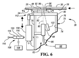
[0058] 図6〜図8に示す接合アセンブリ36の別の実施形態は、アクチュエータ100の制御による図7の加熱位置と図8の接合位置との間の直進移動のために割り出し部材92をハウジング72に取り付ける滑り面110を含む。各実施形態において、アクチュエータ100は、アクチュエータを割り出し部材に接続する連結部112を有する図6〜図8の実施形態による割り出し部材の移動を提供するために伸縮するシリンダである。
Another embodiment of the joining
[0059] 図4及び図6に示すように、接合アセンブリ36の各実施形態は、接合アセンブリハウジング72のチャンバ74に加圧ガスを供給するための加圧ガス源114と、センサ116及び118と、を含む検出アセンブリを有し、それらセンサ間に、金属片24のシート部分による割り出し部材開口部96の光に対して安全な密閉の欠如を表すセンサ間の十分なガス移動を検出するための検出器120が配置され、それによりレーザビーム90を十分に封じ込めることができない場合にレーザアセンブリ83がレーザビーム90を投射することを防止する信号を制御器108に供給するようにする。
As shown in FIGS. 4 and 6, each embodiment of the joining
[0060] 同じく図4及び図6に示されるように、接合アセンブリ36の各実施形態は、温度センサ122を含み、温度センサ122は、それが接続される制御器108の動作を介してレーザ加熱を制御するために、割り出し部材の開口部96を介して接合箇所98で金属片24のシート部分の温度を検知する。
[0060] As also shown in FIGS. 4 and 6, each embodiment of the
[0061] 図1を参照すると、前述のPKM40は、その第1支持部124をキャリッジ126に接続する上昇部41を含み、キャリッジ126は、制御器108の操作により選択された位置まで垂直レール42及び44によって直交する方向に移動するように支持されている。前述した伸縮可能な支柱50は、三脚130を提供するように第1支持部124から第2支持部128まで伸び、その第2支持部は、先に記載したように接合アセンブリ51と協働して任意の必要とされる向きでの動作を可能にする回転及び角度方向位置決めのためのパンチ又はリベットラム46を取り付けている。支柱50は、WORK STATION AND METHOD FOR JOINING METALLIC SHEETSという表題でMark A. Savoy及びPhillip J. I. Morganによって2016年9月15日に公開された米国特許出願公開第2016/0263641号に開示されているものなど任意の適切な方法で伸縮可能であってよく、前出の特許出願の開示内容全体は参照により本明細書に組み込まれる。より具体的には、支柱50は、それぞれ、PKMの第1支持部124に回動可能に接続された上端部及び第2支持部128に回動可能に接続された下端部と、細長いスクリュと、プラントキャリアを含むナットと、プラネットキャリア上で回転可能でありかつスクリュとナットとの間の相対回転により支柱の長さが変化するようにスクリュと噛合する複数のねじ付きローラと有するローラスクリュによって具体化されてもよい。
[0061] Referring to FIG. 1, the aforementioned PKM 40 includes an ascending section 41 that connects its first support portion 124 to the carriage 126, which is a vertical rail 42 up to a position selected by the operation of the
[0062] 図1及び図9〜図12を参照すると、装置22の他の実施形態は、PKMの代わりにロボット52による移動のために支持されているが、以下の記述を除いて、PKMの実施形態と同じ様に動作する多くの同じ構成要素を有し、従ってそれら同じ構成要素は、先の記載の大部分が同様に適用されることができるように及び繰り返されないように、同様の参照番号が適用される。
[0062] With reference to FIGS. 1 and 9-12, other embodiments of the
[0063] 図9に示すような装置22の実施形態において、C形フレーム54を提供するハウジング132は、レーザコリメータ84を支持し、及び図11に最もよく示されているように、そのレーザビーム90は、ハウジングによって規定される光に対して安全なチャンバ74内で第1ミラー134に向かって投影する。その第1ミラー134は、割り出し部材92に向かって上方に90度反射するように第2ミラー136に向かってレーザビームを90度反射し、割り出し部材92は、その加熱位置と接合位置との間で旋回することによって、先に記載した図2〜図5の実施形態と概ね同じように機能する。この実施形態におけるアクチュエータ100のピストン接続ロッドの伸縮は、割り出し部材92を加熱位置と接合位置との間で移動するように旋回接続部94の周りで旋回する。
[0063] In an embodiment of
[0064] 図9をさらに参照すると、装置22は、接合作業を提供するためにクリンチパンチ又はリベットラム46を垂直に移動させるローラスクリュ138を含む。図2〜図5及び図9〜図12の実施形態のそれぞれは、その割り出し部材に、ねじ留めなどによる任意の適切な方法で関連する割り出し部材92に固定されたダイインサート140が提供され、必要に応じてダイ48の異なる作業間での切り替え又は交換を行う。
[0064] Further referring to FIG. 9, the
[0065] 本発明が特に有用な車体組立中、接合される先進高強度鋼板のシート金属片は、通常、0.7〜2ミリメートルの厚さを有し、500〜700℃、通常は先進高強度鋼の微細構造に悪影響を及ぼすことを避けるために730°C以下の温度に加熱される。加熱時間は通常約1秒であり得、割り出し時間は約0.1〜0.3秒であり得、接合を行う時間は約0.3〜0.5秒であり得、前述のようにレーザは人間の安全が保護されるクラスIV又はそれと同等であり得る。従って、オペレータが図1に示される密閉されたワークステーション23内に置かれたとしても、作業は、上述のようにレーザビームからの散乱放射を閉じ込めることにより、レーザに対して安全であり得る。さらに、利用されるレーザは、波長1,064マイクロメートルのファイバレーザ又は波長980マイクロメートルのダイオードレーザであってもよい。また、レーザ加熱及び機械的接合の間に、シート部分28及び30ならびに32及び34を互いに及び関連する装置に対して位置決めするために、任意の適切な、しかし図示されていない締付け等が用いられてもよい。
[0065] During vehicle body assembly for which the present invention is particularly useful, the sheet metal pieces of the advanced high-strength steel sheets to be joined typically have a thickness of 0.7-2 mm and are at 500-700 ° C., usually at an advanced height. It is heated to a temperature of 730 ° C or lower to avoid adversely affecting the microstructure of high-strength steel. The heating time can usually be about 1 second, the indexing time can be about 0.1-0.3 seconds, the time for joining can be about 0.3-0.5 seconds, and the laser as described above. Can be Class IV or equivalent, which protects human safety. Therefore, even if the operator is placed in the
[0066] 例示的な実施形態を上に記載したが、これらの実施形態が本発明の全ての可能な形態を記載しているつもりはない。むしろ、本明細書で使用される用語は、限定ではなく説明のための用語であり、本発明の趣旨及び範囲から逸脱することなく様々な変更を行うことができることが理解される。加えて、様々な実施形態の特徴を組み合わせて、本発明のさらなる実施形態を形成することができる。 [0066] Although exemplary embodiments have been described above, these embodiments are not intended to describe all possible embodiments of the present invention. Rather, it is understood that the terms used herein are descriptive, not limiting, and that various modifications can be made without departing from the spirit and scope of the invention. In addition, the features of various embodiments can be combined to form further embodiments of the invention.
Claims (16)
シート部分の界面で金属の第2シート部分と接触する先進高強度鋼の第1シート部分に隣接して位置決めするための接合アセンブリであって、前記接合アセンブリは、開口部を有するチャンバであって、レーザに対して安全なチャンバを規定するハウジングを含み、かつ、加熱位置と接合位置との間で前記シート部分の界面に平行に移動するために前記ハウジングに取り付けられた割り出し部材を含み、前記割り出し部材は、開口部と、その開口部から間隔を空けてダイを取り付ける箇所と、を含み、前記割り出し部材の前記加熱位置において、その開口部が、前記ハウジングの前記開口部に整列し、かつ、前記第1及び第2シート部分の接合箇所に整列し、前記接合箇所において、前記割り出し部材のダイは、前記シート部分の前記接合箇所に整列して配置される、接合アセンブリと、
前記接合アセンブリの前記割り出し部材を、その加熱位置と接合位置との間で前記第1及び第2シート部分の界面に平行に移動させるアクチュエータと、
前記ハウジングのチャンバ内から、前記ハウジングの前記開口部及びその加熱位置にある前記割り出し部材の前記開口部を介してレーザビームを発射して、前記接合箇所において前記先進高強度鋼の前記第1シート部分の加熱をもたらすレーザコリメータを含み、加熱後、前記アクチュエータが、前記第1及び第2シート部分の界面に平行に前記接合位置へ前記割り出し部材を移動させる、レーザアセンブリと、
前記先進高強度鋼の前記第1シート部分が前記加熱位置の前記割り出し部材とのレーザビーム放射を封じ込める接触時だけ前記レーザアセンブリの発射を許容する検出器アセンブリと、
前記加熱された第1シート部分及び前記第2シート部分を前記接合箇所で互いに機械的に接合するために、前記割り出し部材の前記接合位置で前記ダイと協働するクリンチパンチ又はリベットラムと、
前記シート部分の接合作業のために前記接合アセンブリ、前記アクチュエータ、前記レーザアセンブリ、前記検出器アセンブリ及び前記クリンチパンチ又はリベットラムを操作するように構成された制御器と、を備える装置。 A device for mechanically joining advanced high-strength steel.
A joining assembly for positioning adjacent to a first sheet portion of advanced high-strength steel that contacts a second sheet portion of metal at the interface of the sheet portion, said joining assembly being a chamber having an opening. Includes a housing that defines a laser- safe chamber and includes indexing members attached to the housing to move parallel to the interface of the sheet portion between the heating position and the joining position. The indexing member includes an opening and a portion to which the die is attached at a distance from the opening, and at the heating position of the indexing member, the opening is aligned with the opening of the housing and , The joint assembly, which is aligned with the joints of the first and second sheet portions, where the die of the indexing member is aligned with the joints of the sheet portion.
An actuator that moves the indexing member of the joining assembly parallel to the interface of the first and second seat portions between the heating position and the joining position.
A laser beam is emitted from the inside of the chamber of the housing through the opening of the housing and the opening of the indexing member at the heating position thereof, and the first sheet of the advanced high-strength steel is emitted at the joint. A laser assembly comprising a laser collimator that results in heating of the portion, after which the actuator moves the indexing member to the joining position parallel to the interface of the first and second sheet portions.
A detector assembly that allows the laser assembly to be fired only when the first sheet portion of the advanced high-strength steel is in contact with the indexing member at the heating position to contain the laser beam radiation.
A clinch punch or rivet ram that cooperates with the die at the joining position of the indexing member to mechanically join the heated first sheet portion and the second sheet portion to each other at the joining portion.
A device comprising the joining assembly, the actuator, the laser assembly, the detector assembly and a controller configured to operate the clinch punch or rivet ram for joining the seat portion.
シート部分の界面で金属の第2シート部分と接触する先進高強度鋼の第1シート部分を接合アセンブリに隣接して位置付けることであって、前記接合アセンブリは、開口部を有するチャンバであって、レーザに対して安全なチャンバを規定するハウジングを含み、前記接合アセンブリはまた、加熱位置と接合位置との間の前記シート部分の界面に平行な移動のために前記ハウジングに取り付けられた割り出し部材を含み、前記割り出し部材は、前記加熱位置において、前記ハウジングの前記開口部に整列し、かつ、前記第1及び第2シート部分の接合箇所に整列して位置付けられる開口部を含み、前記割り出し部材は、前記割り出し部材が前記接合位置にある時に前記シート部分の接合箇所に整列して配置されるダイを含む、位置付けることと、
前記ハウジングのチャンバの内側から、前記ハウジングの前記開口部を介して、及びその加熱位置にある前記割り出し部材の前記開口部を介してレーザビームを発射して、前記先進高強度鋼の前記第1シート部分の加熱を前記接合箇所においてもたらし、加熱後、前記割り出し部材を、前記第1及び第2シート部分の界面に平行に前記接合位置に移動させることと、
前記加熱位置にある間に前記第1シート部分と前記割り出し部材とのレーザビーム放射を封じ込める接触を検出した後にのみ前記レーザビームの発射を許容することと、
前記加熱された前記先進高強度鋼の第1シート部分と金属の第2シート部分とを前記接合箇所で互いに機械的に接合するために、前記割り出し部材の前記接合位置で前記ダイと協働するようにクリンチパンチ又はリベットラムを操作することと、
前記接合アセンブリの位置決め、前記レーザに対して安全なレーザビームの発射、前記先進高強度鋼の第1シート部分と前記割り出し部材との前記レーザビーム放射を封じ込める接触の検出、及び、前記クリンチパンチ又は前記リベットラムの操作を制御するように構成された制御器を使用すること、を含む方法。 A method for mechanically joining advanced high-strength steel.
The method comprising positioning a first sheet portion of advanced high-strength steels in contact with the second sheet portion of the metal at the interface of the sheet portion adjacent to the joining assembly, the joint assembly, a chamber for chromatic openings The joining assembly also includes an indexing member attached to the housing for movement parallel to the interface of the seat portion between the heating position and the joining position, including a housing that defines a laser-safe chamber. The indexing member comprises an opening that is aligned with the opening of the housing and aligned with the joint of the first and second sheet portions at the heating position. Includes a die that is aligned and placed at the joint of the sheet portion when the indexing member is in the joint position.
A laser beam is emitted from the inside of the chamber of the housing through the opening of the housing and through the opening of the indexing member at the heating position thereof, and the first of the advanced high-strength steel. Heating of the sheet portion is brought about at the joint portion, and after heating, the indexing member is moved to the joint position parallel to the interface of the first and second sheet portions.
Allowing the laser beam to be emitted only after detecting the contact between the first sheet portion and the indexing member to contain the laser beam radiation while in the heating position.
In order to mechanically join the heated first sheet portion of the advanced high-strength steel and the second sheet portion of the metal to each other at the joining portion, the indexing member cooperates with the die at the joining position. To operate the clinch punch or rivet ram,
Positioning of the joint assembly, the detection of the contact to contain the laser beam radiation firing safe laser beam to the laser, the first sheet portion of advanced high strength steel and said indexing member, and the clinch punch or A method comprising using a controller configured to control the operation of the rivet ram.
開口部を有するエンクロージャであって、前記開口部は作業箇所として定義される、エンクロージャと、
コヒーレントレーザビームを生成して作動させ、前記ビームを前記作業箇所に向ける手段と、
前記エンクロージャに取り付けられた加圧ガス源であって、前記エンクロージャの前記開口部を介して空気流を送達する加圧ガス源と、
前記エンクロージャの前記開口部を通るガス流量を検知する手段と、
前記エンクロージャに移動可能に取り付けられた割り出し部材であって、前記割り出し部材は、前記割り出し部材が第1位置に移動する時に前記エンクロージャの前記開口部に整列する第1開口部を有し、前記第1位置は前記作業箇所でもあり、前記割り出し部材は、前記第1開口部から間隔を空けて第2開口部をさらに有する、割り出し部材と、
前記割り出し部材の前記第2開口部に確実に取り付けられたダイと、
前記作業箇所の前記第1位置から第2位置まで前記割り出し部材を往復させる手段であって、前記第2位置は、前記割り出し部材の前記第2開口部を前記作業箇所の前記エンクロージャの前記開口部に整列させる、往復させる手段と、
前記エンクロージャの前記開口部を通る既定の空気流を検知時に、前記生成して作動させる手段が、前記コヒーレントレーザビームを発射して前記作業箇所に向けるように、前記割り出し部材の前記第1開口部を覆う手段と、を備える、レーザに対して安全なハウジング。 A laser- safe housing
An enclosure having an opening, wherein the opening is defined as a work area.
A means of generating and operating a coherent laser beam to direct the beam to the work site,
A pressurized gas source attached to the enclosure that delivers airflow through the openings in the enclosure.
A means for detecting the gas flow rate through the opening of the enclosure, and
An indexing member movably attached to the enclosure, the indexing member having a first opening that aligns with the opening of the enclosure when the indexing member moves to a first position. One position is also the work location, and the indexing member has a second opening further spaced from the first opening, and the indexing member.
With a die securely attached to the second opening of the indexing member,
It is a means for reciprocating the indexing member from the first position to the second position of the working place, and the second position is the opening of the enclosure of the working place with the second opening of the indexing member. Means to align and reciprocate,
When a predetermined air flow through the opening of the enclosure is detected, the first opening of the indexing member so that the means of generating and operating the coherent laser beam emits the coherent laser beam and directs it toward the work site. A laser- safe housing, including means to cover.
Applications Claiming Priority (7)
| Application Number | Priority Date | Filing Date | Title |
|---|---|---|---|
| US201662290608P | 2016-02-03 | 2016-02-03 | |
| US62/290,608 | 2016-02-03 | ||
| US201662400809P | 2016-09-28 | 2016-09-28 | |
| US62/400,809 | 2016-09-28 | ||
| US201662405288P | 2016-10-07 | 2016-10-07 | |
| US62/405,288 | 2016-10-07 | ||
| PCT/US2017/014501 WO2017136169A1 (en) | 2016-02-03 | 2017-01-23 | Apparatus and method for mechanically joining advanced high strength steel |
Publications (3)
| Publication Number | Publication Date |
|---|---|
| JP2019505390A JP2019505390A (en) | 2019-02-28 |
| JP2019505390A5 JP2019505390A5 (en) | 2020-03-05 |
| JP6899392B2 true JP6899392B2 (en) | 2021-07-07 |
Family
ID=59385981
Family Applications (1)
| Application Number | Title | Priority Date | Filing Date |
|---|---|---|---|
| JP2018538627A Active JP6899392B2 (en) | 2016-02-03 | 2017-01-23 | Equipment and methods for mechanically joining advanced high-strength steel |
Country Status (9)
| Country | Link |
|---|---|
| US (2) | US9815109B2 (en) |
| EP (1) | EP3411178B1 (en) |
| JP (1) | JP6899392B2 (en) |
| KR (1) | KR20180109954A (en) |
| CN (2) | CN108698161B (en) |
| BR (1) | BR112018015738B1 (en) |
| CA (1) | CA3011906A1 (en) |
| MX (1) | MX2018009387A (en) |
| WO (1) | WO2017136169A1 (en) |
Families Citing this family (13)
| Publication number | Priority date | Publication date | Assignee | Title |
|---|---|---|---|---|
| KR20180077492A (en) * | 2016-12-29 | 2018-07-09 | 현대자동차주식회사 | Welding method for ultra high-tensile steel and non-steel material employing tailored softening heat-treatment using laser |
| KR102579210B1 (en) * | 2017-03-03 | 2023-09-15 | 유티카 엔터프라이지스 인코포레이티드 | Apparatus and method and resulting assembly for fastening clinch nuts to advanced high-strength steel plates |
| DE102018202140A1 (en) * | 2018-02-12 | 2019-08-14 | Arnold Umformtechnik Gmbh & Co. Kg | Method and device for introducing a joining element |
| CN108580786A (en) * | 2018-05-14 | 2018-09-28 | 柳州联泰汽车零部件有限公司 | A kind of automation riveting tool |
| CN109746377A (en) * | 2019-01-15 | 2019-05-14 | 同济大学 | Heat auxiliary hot melt self tapping blind riveting device and method |
| KR102248391B1 (en) | 2020-02-06 | 2021-05-04 | 박정헌 | Punching head in the form of a turret |
| CN111438327A (en) * | 2020-03-23 | 2020-07-24 | 首钢集团有限公司 | Mechanical connection method and device for automobile steel |
| CN113798324B (en) * | 2020-06-13 | 2024-06-04 | 上海梅山钢铁股份有限公司 | Strip steel riveting trolley |
| CN112620939B (en) * | 2020-12-03 | 2022-06-10 | 深圳市日昭自动化设备有限公司 | Etching snap ring equipment and integrative equipment of welding |
| US11813655B2 (en) | 2021-05-20 | 2023-11-14 | Kuka Systems North America Llc | Apparatus and methods for forming attachment pads |
| US20230041416A1 (en) * | 2021-08-03 | 2023-02-09 | Utica Enterprises, Inc. | Mechanically joining advanced high strength steel |
| DE102021121087A1 (en) * | 2021-08-13 | 2023-02-16 | Tox Pressotechnik Gmbh & Co. Kg | joining tool unit |
| DE102022109123A1 (en) * | 2022-04-13 | 2023-10-19 | Tox Pressotechnik Gmbh & Co. Kg | joining device |
Family Cites Families (52)
| Publication number | Priority date | Publication date | Assignee | Title |
|---|---|---|---|---|
| US4237363A (en) | 1977-02-04 | 1980-12-02 | Lemelson Jerome H | Beam welding apparatus and method |
| JPS62105736U (en) | 1985-12-23 | 1987-07-06 | ||
| JPS62179882A (en) | 1986-02-05 | 1987-08-07 | Aisan Ind Co Ltd | Heating method by laser beam |
| US5380978A (en) * | 1991-07-12 | 1995-01-10 | Pryor; Timothy R. | Method and apparatus for assembly of car bodies and other 3-dimensional objects |
| JP3123146B2 (en) * | 1991-09-11 | 2001-01-09 | トヨタ自動車株式会社 | Weld bead quality inspection equipment |
| GB9226517D0 (en) | 1992-12-19 | 1993-02-10 | Henrob Ltd | Improvements in or relating to sefl-piercing riveting |
| MY115011A (en) | 1995-04-18 | 2003-03-31 | Philip Morris Prod | Metal package and a method for making a metal package |
| JPH09300089A (en) * | 1996-05-13 | 1997-11-25 | Hitachi Ltd | Laser beam irradiation equipment, and lens barrel and nozzle used therefor |
| DE19630488C2 (en) | 1996-07-26 | 1999-07-08 | Boellhoff Gmbh | Method and device for joining by forming |
| DE19714129A1 (en) | 1997-04-05 | 1998-10-15 | Eckold Vorrichtung | Joining method and device |
| JP3315908B2 (en) | 1997-10-31 | 2002-08-19 | 株式会社東芝 | Semiconductor light emitting device and method of manufacturing the same |
| WO1999025510A2 (en) | 1997-11-17 | 1999-05-27 | Technische Universität Dresden | Method and device for thermally supporting mechanical joints |
| DE19800035A1 (en) | 1998-01-02 | 1999-07-08 | Volkswagen Ag | Joining of magnesium and plastic components especially of an automobile body |
| EP1159099B1 (en) | 1998-11-17 | 2004-09-15 | HENROB Limited | Improvements in or relating to fastening of sheet material |
| DE20013526U1 (en) | 2000-08-05 | 2000-12-07 | Avdel Verbindungselemente GmbH, 30851 Langenhagen | Device for connecting sheets by punch riveting or clinching |
| US6769595B2 (en) * | 2000-12-20 | 2004-08-03 | Alcoa Inc. | Friction plunge riveting |
| DE10119018A1 (en) * | 2001-04-18 | 2002-10-24 | Emhart Llc Newark | Positioning and/or mounting aid for devices used for machining components, has arrangement for producing light or laser beam for direction from reference position outside device, especially machining space, to reference point |
| US6684479B2 (en) * | 2001-08-22 | 2004-02-03 | General Motors Corporation | Method and apparatus for clinching metal sheets |
| US6694597B2 (en) * | 2002-03-08 | 2004-02-24 | General Motors Corporation | Method for riveting metal members |
| US6836948B2 (en) | 2003-02-05 | 2005-01-04 | General Motors Corporation | Method of joining a sheet metal part to a metal tube |
| US7267736B2 (en) | 2003-12-18 | 2007-09-11 | General Motors Corporation | Method of joining dissimilar materials |
| JP2005342739A (en) | 2004-06-01 | 2005-12-15 | Nissan Motor Co Ltd | Method for joining metallic plates, and joining structure |
| JP2006007266A (en) | 2004-06-25 | 2006-01-12 | Nissan Motor Co Ltd | Joining method using rivet |
| JP2006043769A (en) | 2004-07-05 | 2006-02-16 | Nissan Motor Co Ltd | Joining method with self-piercing rivet, and self-piercing rivet joining apparatus |
| DE102004062896B4 (en) | 2004-11-12 | 2006-09-07 | Fraunhofer-Gesellschaft zur Förderung der angewandten Forschung e.V. | Device and method for the positive connection of workpieces |
| KR100743857B1 (en) | 2005-07-14 | 2007-07-30 | 진인태 | Extruvet bonding apparatus and method of metal plates by plasticity flow |
| JP4871952B2 (en) * | 2006-04-14 | 2012-02-08 | 東芝三菱電機産業システム株式会社 | Laser ultrasonic characteristic measuring device |
| GB0609580D0 (en) | 2006-05-13 | 2006-06-21 | Henrob Ltd | Self-piercing riveting |
| JP2009538738A (en) | 2006-05-31 | 2009-11-12 | カースト シーアールシー リミテッド | Method and apparatus for joining metals using self-piercing rivets with preheating |
| US8671726B2 (en) * | 2008-03-10 | 2014-03-18 | Henrob Limited | Die condition detection |
| GB0813883D0 (en) * | 2008-07-30 | 2008-09-03 | Henrob Ltd | Joining apparatus and method |
| US20100083481A1 (en) * | 2008-10-08 | 2010-04-08 | Gm Global Technology Operations, Inc. | Method for attaching magnesium panels using self-piercing rivet |
| DE102008056278A1 (en) * | 2008-10-25 | 2010-04-29 | Kjellberg Finsterwalde Plasma Und Maschinen Gmbh | System for the thermal processing of workpieces |
| US8723078B2 (en) * | 2008-11-21 | 2014-05-13 | The Regents Of The University Of Michigan | Monitoring of a welding process |
| DE102010007573B4 (en) * | 2010-02-10 | 2012-06-21 | Thyssenkrupp Lasertechnik Gmbh | Apparatus and method for continuous welding of strips and / or sheets |
| DE102010029477A1 (en) * | 2010-05-28 | 2011-12-01 | Scansonic Mi Gmbh | Method and device for laser joining sheet metal parts |
| CN101879572A (en) * | 2010-06-21 | 2010-11-10 | 昆明理工大学 | Self-piercing riveting method by locally heating magnesium alloy plate with laser |
| US9259774B2 (en) | 2011-05-03 | 2016-02-16 | GM Global Technology Operations LLC | Clinching method and tool for performing the same |
| CN102672062B (en) * | 2012-05-25 | 2015-02-11 | 吉林大学 | Laser heating rivetless riveting device |
| CN103658416B (en) * | 2012-09-26 | 2016-06-08 | 山东科技大学 | A kind of laser auxiliary heating device for self-piercing riveting |
| US9162277B2 (en) * | 2013-02-18 | 2015-10-20 | Ford Motor Company | Indexing self-piercing die riveter |
| DE102013206547A1 (en) * | 2013-04-12 | 2014-10-16 | Airbus Operations Gmbh | Riveting device and riveting method |
| CN103600016B (en) * | 2013-11-25 | 2015-09-30 | 吉林大学 | Between ultrahigh-strength steel plates or with the clinching method of aluminium alloy plate |
| JP6687537B2 (en) | 2014-01-16 | 2020-04-22 | アトラス コプコ アイエイエス ユーケー リミテッド | Riveting method |
| CN104384422B (en) * | 2014-10-15 | 2016-10-19 | 上海交通大学 | Self-piercing riveting device and method towards unimach and light metal |
| DE102014116710A1 (en) * | 2014-11-14 | 2016-05-19 | Bwg Bergwerk- Und Walzwerk-Maschinenbau Gmbh | Method for joining metal strips |
| WO2016149034A1 (en) | 2015-03-13 | 2016-09-22 | Utica Enterprises, Inc. | Work station and method for joining metallic sheets |
| WO2016205541A1 (en) | 2015-06-16 | 2016-12-22 | The Regents Of The University Of Michigan | Fastener and method for joining dissimilar materials |
| US10603713B2 (en) | 2015-07-01 | 2020-03-31 | Nippon Steel Corporation | Mechanical joining apparatus and mechanical joining method |
| JP6460235B2 (en) | 2015-07-01 | 2019-01-30 | 新日鐵住金株式会社 | Mechanical joining apparatus and mechanical joining method |
| KR20180077492A (en) | 2016-12-29 | 2018-07-09 | 현대자동차주식회사 | Welding method for ultra high-tensile steel and non-steel material employing tailored softening heat-treatment using laser |
| CN112996929B (en) | 2018-11-05 | 2023-11-28 | 麦格纳国际公司 | Local resistance heating annealing process |
-
2017
- 2017-01-23 US US15/412,287 patent/US9815109B2/en active Active
- 2017-01-23 CA CA3011906A patent/CA3011906A1/en active Pending
- 2017-01-23 EP EP17747921.9A patent/EP3411178B1/en active Active
- 2017-01-23 MX MX2018009387A patent/MX2018009387A/en unknown
- 2017-01-23 WO PCT/US2017/014501 patent/WO2017136169A1/en active Application Filing
- 2017-01-23 JP JP2018538627A patent/JP6899392B2/en active Active
- 2017-01-23 KR KR1020187024242A patent/KR20180109954A/en active IP Right Grant
- 2017-01-23 CN CN201780009849.7A patent/CN108698161B/en active Active
- 2017-01-23 CN CN202110495860.7A patent/CN113510362A/en active Pending
- 2017-01-23 BR BR112018015738-4A patent/BR112018015738B1/en active IP Right Grant
-
2018
- 2018-06-22 US US16/015,698 patent/US11260447B2/en active Active
Also Published As
| Publication number | Publication date |
|---|---|
| BR112018015738B1 (en) | 2022-07-26 |
| CN108698161A (en) | 2018-10-23 |
| US11260447B2 (en) | 2022-03-01 |
| EP3411178A4 (en) | 2019-12-25 |
| KR20180109954A (en) | 2018-10-08 |
| EP3411178A1 (en) | 2018-12-12 |
| CN113510362A (en) | 2021-10-19 |
| BR112018015738A2 (en) | 2019-01-08 |
| CN108698161B (en) | 2021-04-20 |
| EP3411178B1 (en) | 2021-03-31 |
| MX2018009387A (en) | 2019-01-10 |
| US20180297106A1 (en) | 2018-10-18 |
| CA3011906A1 (en) | 2017-08-10 |
| JP2019505390A (en) | 2019-02-28 |
| WO2017136169A1 (en) | 2017-08-10 |
| US9815109B2 (en) | 2017-11-14 |
| US20170216907A1 (en) | 2017-08-03 |
Similar Documents
| Publication | Publication Date | Title |
|---|---|---|
| JP6899392B2 (en) | Equipment and methods for mechanically joining advanced high-strength steel | |
| JP2019505390A5 (en) | ||
| KR102579210B1 (en) | Apparatus and method and resulting assembly for fastening clinch nuts to advanced high-strength steel plates | |
| KR102305637B1 (en) | Systems and methods for separating tubular members | |
| KR101769270B1 (en) | Apparatus for welding robot | |
| US20210178457A1 (en) | Metallic sheet securement | |
| CN109940326B (en) | Laser welding fixture and laser welding workstation | |
| CN115958322A (en) | Steel structure bridge member general assembly line and assembly method thereof | |
| WO2021010061A1 (en) | Joining component manufacturing apparatus | |
| US7442899B2 (en) | Clamping device | |
| JP7368811B2 (en) | Fixing device for multi-axis robots | |
| JP3312896B2 (en) | Processing head for laser welding robot | |
| KR101768175B1 (en) | Spot welding equipment | |
| WO2021010060A1 (en) | Semi-finished product for joined product, and method for manufacturing joined product employing same | |
| RU187501U1 (en) | AUTOMATION FOR TWO-SIDED LASER-ARC WELDING OF T-BEAMS | |
| CN118342167A (en) | Digital flexible assembly system suitable for arc-shaped T-shaped part and welding method | |
| CN114192967A (en) | Welding device for producing large aluminum parts | |
| JP2911217B2 (en) | Box-shaped product coupling device | |
| JPH06235481A (en) | Piping assembling method and its device | |
| JPH11771A (en) | Joining device | |
| JP2007038253A (en) | Friction point welding equipment | |
| JP2016209923A (en) | Welded structure for vacuum valve, welding method for vacuum valve, and welding apparatus therefor |
Legal Events
| Date | Code | Title | Description |
|---|---|---|---|
| A521 | Request for written amendment filed |
Free format text: JAPANESE INTERMEDIATE CODE: A523 Effective date: 20200120 |
|
| A621 | Written request for application examination |
Free format text: JAPANESE INTERMEDIATE CODE: A621 Effective date: 20200120 |
|
| A131 | Notification of reasons for refusal |
Free format text: JAPANESE INTERMEDIATE CODE: A131 Effective date: 20210301 |
|
| A521 | Request for written amendment filed |
Free format text: JAPANESE INTERMEDIATE CODE: A523 Effective date: 20210510 |
|
| TRDD | Decision of grant or rejection written | ||
| A01 | Written decision to grant a patent or to grant a registration (utility model) |
Free format text: JAPANESE INTERMEDIATE CODE: A01 Effective date: 20210528 |
|
| A61 | First payment of annual fees (during grant procedure) |
Free format text: JAPANESE INTERMEDIATE CODE: A61 Effective date: 20210614 |
|
| R150 | Certificate of patent or registration of utility model |
Ref document number: 6899392 Country of ref document: JP Free format text: JAPANESE INTERMEDIATE CODE: R150 |
|
| R250 | Receipt of annual fees |
Free format text: JAPANESE INTERMEDIATE CODE: R250 |