JP6898859B2 - Methods and equipment for molding glass sheets - Google Patents
Methods and equipment for molding glass sheets Download PDFInfo
- Publication number
- JP6898859B2 JP6898859B2 JP2017561355A JP2017561355A JP6898859B2 JP 6898859 B2 JP6898859 B2 JP 6898859B2 JP 2017561355 A JP2017561355 A JP 2017561355A JP 2017561355 A JP2017561355 A JP 2017561355A JP 6898859 B2 JP6898859 B2 JP 6898859B2
- Authority
- JP
- Japan
- Prior art keywords
- glass sheet
- bending tool
- bending
- positioning device
- glass
- Prior art date
- Legal status (The legal status is an assumption and is not a legal conclusion. Google has not performed a legal analysis and makes no representation as to the accuracy of the status listed.)
- Active
Links
Images


Classifications
-
- C—CHEMISTRY; METALLURGY
- C03—GLASS; MINERAL OR SLAG WOOL
- C03B—MANUFACTURE, SHAPING, OR SUPPLEMENTARY PROCESSES
- C03B23/00—Re-forming shaped glass
- C03B23/02—Re-forming glass sheets
- C03B23/023—Re-forming glass sheets by bending
- C03B23/0235—Re-forming glass sheets by bending involving applying local or additional heating, cooling or insulating means
-
- C—CHEMISTRY; METALLURGY
- C03—GLASS; MINERAL OR SLAG WOOL
- C03B—MANUFACTURE, SHAPING, OR SUPPLEMENTARY PROCESSES
- C03B23/00—Re-forming shaped glass
- C03B23/02—Re-forming glass sheets
- C03B23/023—Re-forming glass sheets by bending
- C03B23/03—Re-forming glass sheets by bending by press-bending between shaping moulds
-
- C—CHEMISTRY; METALLURGY
- C03—GLASS; MINERAL OR SLAG WOOL
- C03B—MANUFACTURE, SHAPING, OR SUPPLEMENTARY PROCESSES
- C03B23/00—Re-forming shaped glass
- C03B23/02—Re-forming glass sheets
- C03B23/023—Re-forming glass sheets by bending
-
- C—CHEMISTRY; METALLURGY
- C03—GLASS; MINERAL OR SLAG WOOL
- C03B—MANUFACTURE, SHAPING, OR SUPPLEMENTARY PROCESSES
- C03B23/00—Re-forming shaped glass
- C03B23/02—Re-forming glass sheets
- C03B23/023—Re-forming glass sheets by bending
- C03B23/025—Re-forming glass sheets by bending by gravity
-
- C—CHEMISTRY; METALLURGY
- C03—GLASS; MINERAL OR SLAG WOOL
- C03B—MANUFACTURE, SHAPING, OR SUPPLEMENTARY PROCESSES
- C03B23/00—Re-forming shaped glass
- C03B23/02—Re-forming glass sheets
- C03B23/023—Re-forming glass sheets by bending
- C03B23/025—Re-forming glass sheets by bending by gravity
- C03B23/0258—Gravity bending involving applying local or additional heating, cooling or insulating means
-
- C—CHEMISTRY; METALLURGY
- C03—GLASS; MINERAL OR SLAG WOOL
- C03B—MANUFACTURE, SHAPING, OR SUPPLEMENTARY PROCESSES
- C03B23/00—Re-forming shaped glass
- C03B23/02—Re-forming glass sheets
- C03B23/023—Re-forming glass sheets by bending
- C03B23/03—Re-forming glass sheets by bending by press-bending between shaping moulds
- C03B23/0305—Press-bending accelerated by applying mechanical forces, e.g. inertia, weights or local forces
-
- C—CHEMISTRY; METALLURGY
- C03—GLASS; MINERAL OR SLAG WOOL
- C03B—MANUFACTURE, SHAPING, OR SUPPLEMENTARY PROCESSES
- C03B23/00—Re-forming shaped glass
- C03B23/02—Re-forming glass sheets
- C03B23/023—Re-forming glass sheets by bending
- C03B23/03—Re-forming glass sheets by bending by press-bending between shaping moulds
- C03B23/0307—Press-bending involving applying local or additional heating, cooling or insulating means
-
- C—CHEMISTRY; METALLURGY
- C03—GLASS; MINERAL OR SLAG WOOL
- C03B—MANUFACTURE, SHAPING, OR SUPPLEMENTARY PROCESSES
- C03B35/00—Transporting of glass products during their manufacture, e.g. hot glass lenses, prisms
- C03B35/14—Transporting hot glass sheets or ribbons, e.g. by heat-resistant conveyor belts or bands
-
- C—CHEMISTRY; METALLURGY
- C03—GLASS; MINERAL OR SLAG WOOL
- C03B—MANUFACTURE, SHAPING, OR SUPPLEMENTARY PROCESSES
- C03B2215/00—Press-moulding glass
-
- C—CHEMISTRY; METALLURGY
- C03—GLASS; MINERAL OR SLAG WOOL
- C03B—MANUFACTURE, SHAPING, OR SUPPLEMENTARY PROCESSES
- C03B2225/00—Transporting hot glass sheets during their manufacture
- C03B2225/02—Means for positioning, aligning or orientating the sheets during their travel, e.g. stops
-
- Y—GENERAL TAGGING OF NEW TECHNOLOGICAL DEVELOPMENTS; GENERAL TAGGING OF CROSS-SECTIONAL TECHNOLOGIES SPANNING OVER SEVERAL SECTIONS OF THE IPC; TECHNICAL SUBJECTS COVERED BY FORMER USPC CROSS-REFERENCE ART COLLECTIONS [XRACs] AND DIGESTS
- Y02—TECHNOLOGIES OR APPLICATIONS FOR MITIGATION OR ADAPTATION AGAINST CLIMATE CHANGE
- Y02P—CLIMATE CHANGE MITIGATION TECHNOLOGIES IN THE PRODUCTION OR PROCESSING OF GOODS
- Y02P40/00—Technologies relating to the processing of minerals
- Y02P40/50—Glass production, e.g. reusing waste heat during processing or shaping
- Y02P40/57—Improving the yield, e-g- reduction of reject rates
Description
本発明は、ガラスシートを成形することに関するものであり、特に、互いに接近離間して移動する対向曲げ工具を使用することに関する。本発明はまた、互いに接近して移動する2つの曲げ工具を有する、加熱されたガラスシートを曲げるためのプレス曲げステーションと共に使用される位置決めシステムにも関する。 The present invention relates to forming a glass sheet, and more particularly to using an opposed bending tool that moves close to and separated from each other. The present invention also relates to a positioning system used with a press bending station for bending a heated glass sheet, which has two bending tools that move in close proximity to each other.
ガラスのシートを成形または曲げるための様々なプロセスが知られている。典型的には、ガラスシートは、ガラスシートが変形可能である温度まで加熱され、そして曲げプロセスが実行される。ある特定の曲げプロセスでは、加熱されたガラスシートは、リング上に支持され、重力の影響下で、追加の押圧の助けを借りて、または借りずに、垂れさせる。そのリングは、例えばUS5,660,609に記載されているように、2つの曲げ段階においてガラスシートを曲げるように構成された2つのリングを含むことができる。 Various processes for forming or bending glass sheets are known. Typically, the glass sheet is heated to a temperature at which the glass sheet is deformable, and a bending process is performed. In certain bending processes, the heated glass sheet is supported on the ring and, under the influence of gravity, hangs with or without the help of additional pressing. The ring can include two rings configured to bend the glass sheet in two bending steps, for example as described in US 5,660,609.
別の知られているガラスシート曲げプロセスはプレス曲げプロセスであり、それによりガラスシート(または入れ子ペア)は、通常は離間した垂直関係にある、一対の相補的な成形部材の間で曲げられる。成形部材の様々な構成が一対の相補的な成形部材について知られており、例えばUS5,279,635及びUS5,755,845に提供されている例では、下部環状リング及び上部中実雄型(upper solid male)を有することが知られている。US5,735,922はまた、ガラスシートをプレス曲げするための方法及び装置も記載している。プレス曲げプロセスの他のバージョンでは、例えばUS5,122,177及びUS2015/0007612A1に記載されているように、分割された上部モールドを下部環状リングと一緒に使用することができる。 Another known glass sheet bending process is the press bending process, which allows the glass sheets (or nested pairs) to be bent between a pair of complementary molding members, which are usually in a vertically spaced relationship. Various configurations of molding members are known for a pair of complementary molding members, eg, in the examples provided in US 5,279,635 and US5,755,845, the lower annular ring and the upper solid male form (upper). It is known to have solid male). US 5,735,922 also describes methods and equipment for press bending glass sheets. In other versions of the press bending process, a split upper mold can be used with the lower annular ring, for example as described in US 5,122,177 and US2015 / 0007612A1.
プレス曲げプロセスの1つのタイプでは、第1の曲げ工具は、曲げられる加熱ガラス板の周囲に対応するリング状雌型モールドとして設計することができる一方で、全面成形型(full−faced mould)としても知られている実質的に中実の雄型モールドは、第2の曲げ工具を形成する。曲げプロセスを助けるために、複数の吸引孔が全面成形型部分に配置され、その位置は、環状モールドの形状及び/または曲げられるガラスシートのジオメトリーによって決定することができ、その時、環状モールドは、プレス曲げプロセス中に、加熱されたガラスシートと接触する。雄型モールドは、それを通して吸引を行うために、US7,866,187B2に記載されているような外周環状溝を有することができる。 In one type of press bending process, the first bending tool can be designed as a ring-shaped female mold corresponding to the perimeter of the heated glass plate to be bent, while as a full-faced mold. A substantially solid male mold, also known as, forms a second bending tool. To aid in the bending process, multiple suction holes are placed in the fully molded part, the position of which can be determined by the shape of the annular mold and / or the geometry of the glass sheet to be bent, at which time the annular mold During the press bending process, it comes into contact with the heated glass sheet. The male mold can have an outer annular groove as described in US7,866,187B2 for suction through it.
曲げられる加熱されたガラスシートは、関連する炉において曲げ温度まで加熱され、成形可能な状態の間に、全面成形型とリング状モールドとの間で移動される。その加熱されたガラスシートは、典型的には、加熱されたガラスシートをリング状モールド上に配置するためにその一部が垂直に移動することができる一連のローラを使用して、モールドの間で移送される。全面成形型との干渉を避けるために垂直方向に移動することができる少なくとも2つの止め具により、モールド間の移動方向における加熱されたガラスシートの位置決めが容易になる。加熱されたガラスシートをリング状モールド上に配置中にまたは配置直後に、全面成形型及びリング状モールドを互いに向かって移動させてプレスプロセスを行う。そのプレスプロセスの間に、全面成形型は、ガラスシートをリング状モールド上へプレスする。しかしながら、全面成形型またはリング状モールドのいずれかは、固定され、残りのモールドのみが動くことが理解される。結果として、加熱されたガラスシートの縁の成形が行われる。同時に、加熱されたガラスシートの中間領域は、更なる成形を行うために、真空を使用して成形面に対して保持される。これらの成形手順は、ガラスシートが急速に冷却され、短時間の後にガラスシートの縁が最適な曲げ温度を下回るため、比較的迅速に行う。 The heated glass sheet to be bent is heated to the bending temperature in the associated furnace and moved between the full-face mold and the ring mold while in a moldable state. The heated glass sheet is typically between molds using a series of rollers, some of which can be moved vertically to place the heated glass sheet on the ring mold. Will be transferred at. At least two fasteners that can be moved vertically to avoid interference with the full-face mold facilitate the positioning of the heated glass sheet in the direction of movement between the molds. During or immediately after the heated glass sheet is placed on the ring-shaped mold, the full-face molding mold and the ring-shaped mold are moved toward each other to perform a pressing process. During the pressing process, the full-face molding mold presses the glass sheet onto the ring-shaped mold. However, it is understood that either the full mold or the ring mold is fixed and only the remaining mold moves. As a result, the edges of the heated glass sheet are molded. At the same time, the intermediate region of the heated glass sheet is held against the molded surface using vacuum to perform further molding. These molding procedures are relatively quick as the glass sheet cools rapidly and the edges of the glass sheet fall below the optimum bending temperature after a short period of time.
曲げ工具を開き、曲げ工具から取り出した後、そのガラスシートは、所望の形状を有し、寸法的に安定していて、そして光学的に歪まないようにすべきである。そうでなければ、曲げプロセスは、廃棄物または品質の悪い製品をもたらす。廃棄物または品質の悪い製品が製造され得る1つの因子は、上記したタイプのプレス曲げプロセス中における、リング状モールド上での加熱されたガラスシートの位置決めである。 After opening the bending tool and removing it from the bending tool, the glass sheet should have the desired shape, be dimensionally stable, and not be optically distorted. Otherwise, the bending process results in waste or poor quality products. One factor that can produce waste or poor quality products is the positioning of the heated glass sheet on the ring mold during the press bending process of the type described above.
上記したように、垂直方向に移動可能な止め具により、モールド間の移動方向における加熱されたガラスシートの位置決めが容易になる。しかしながら、他の方向に、例えばモールド間の移動方向に実質的に直角に、加熱されたガラスシートを位置決めすることは、ガラスシートを炉に入れる前に、ローラ上でのみ行われる。結果として、第1の曲げ工具上における曲げプロセス中のガラスシートの位置合わせは、理想的ではない場合があり、その結果として、廃棄物または品質の悪い製品が生じる可能性がある。 As described above, the vertically movable fastener facilitates the positioning of the heated glass sheet in the direction of movement between the molds. However, positioning the heated glass sheet in other directions, eg, substantially at right angles to the direction of movement between the molds, is only done on the rollers before the glass sheets are placed in the furnace. As a result, the alignment of the glass sheet during the bending process on the first bending tool may not be ideal, resulting in waste or poor quality products.
ガラスの曲げ操作で使用されるガラス位置決めデバイスの例は、US4,666,492、US4,838,920、US5,017,210、及びUS5,743,931に記載されている。 Examples of glass positioning devices used in glass bending operations are described in US4,666,492, US4,838,920, US5,017,210, and US5,743,931.
一般的に、ガラスが、その上で曲げるための第1の曲げ工具上で支持されるとき、ガラスシートが正しく配置されていない場合、曲げた後にガラスシートが所望の特性を有していないことがある。これは、プレス曲げまたは重力たるみ曲げによってガラスシートを成形する場合に当てはまる。 Generally, when the glass is supported on a first bending tool for bending on it, if the glass sheet is not placed correctly, then the glass sheet does not have the desired properties after bending. There is. This is true when molding glass sheets by press bending or gravity sagging bending.
上記の問題を少なくとも部分的に克服するガラスシートを成形する方法及びガラス成形ラインを開発することは有益であろう。また、高温ガラスシートのための位置決めデバイス及び成形操作中のシートの正確な位置決めを容易にする高温ガラスシートを位置合わせする方法を開発することも有益であろう。 It would be beneficial to develop methods and glass forming lines for forming glass sheets that at least partially overcome the above problems. It would also be beneficial to develop a positioning device for the hot glass sheet and a method of aligning the hot glass sheet to facilitate accurate positioning of the sheet during the molding operation.
したがって、本発明は、第1の態様から、(i)ガラスシートを成形に適する温度まで加熱するステップと、(ii)ガラスシートを第1の曲げ工具上に置くステップであって、第1の曲げ工具がその上のガラスシートを支持し、ガラスシートが第1の曲げ工具に対して第1の位置にある、ステップと、(iii)ガラスシートが第1の曲げ工具に対して第2の位置に移動されるようにガラスシートの縁部分を接触させるステップと、(iv)第1の曲げ工具上でガラスシートを成形するステップとを含む、ガラスシートを成形するための方法を提供する。 Therefore, the present invention comprises, from the first aspect, (i) a step of heating the glass sheet to a temperature suitable for molding and (ii) a step of placing the glass sheet on the first bending tool. A step in which the bending tool supports the glass sheet on it and the glass sheet is in the first position with respect to the first bending tool, and (iii) the glass sheet is second with respect to the first bending tool. Provided is a method for forming a glass sheet, which comprises a step of bringing the edges of the glass sheet into contact so as to be moved to a position and (iv) a step of forming the glass sheet on a first bending tool.
従来技術の方法とは対照的に、ガラスシートの位置は、第1の曲げ工具上に置かれた後、かつ第1の曲げ工具上で成形される前に、調整される。これは、ガラスシートが第1の成形工具上の目標位置から逸脱するのに使用可能な時間が最少化されるように、成形される直前に、曲げプロセスの後期にガラスシートの位置が調整されるという利点を有する。 In contrast to prior art methods, the position of the glass sheet is adjusted after being placed on the first bending tool and before being molded on the first bending tool. This is because the position of the glass sheet is adjusted later in the bending process just before it is formed so that the time available for the glass sheet to deviate from the target position on the first forming tool is minimized. Has the advantage of
本発明の第1の態様による方法を行う際には、ステップ(ii)はステップ(iii)の前に行われる。 When performing the method according to the first aspect of the present invention, the step (ii) is performed before the step (iii).
好ましくは、第1の曲げ工具は、ガラスシートを上に支持するための上部成形面を有する少なくとも1つの成形レールを含む。 Preferably, the first bending tool includes at least one forming rail having an upper forming surface for supporting the glass sheet on top.
好ましくは、第1の曲げ工具は、ガラスシートをその外周領域において支持するように構成されたリングを含む。そのリングは連続的な上部成形面を有することができる。 Preferably, the first bending tool includes a ring configured to support the glass sheet in its outer peripheral region. The ring can have a continuous top molded surface.
好ましくは、ステップ(iv)の間に、第1の曲げ工具と第2の曲げ工具との間でガラスシートをプレス曲げすることによって第1の曲げ工具上でガラスシートが成形される。 Preferably, during the step (iv), the glass sheet is formed on the first bending tool by press bending the glass sheet between the first bending tool and the second bending tool.
当技術分野で知られているように、プレス曲げは、第1及び第2の曲げ工具などのプレス部材上に提供される相補的な対向成形面との間で、熱軟化ガラスシートがプレスされる成形プロセスである。 As is known in the art, in press bending, a heat softened glass sheet is pressed between a complementary molded surface provided on a pressed member such as a first and second bending tool. It is a molding process.
ステップ(iv)の間に、第1の曲げ工具と第2の曲げ工具との間でガラスシートをプレス曲げすることによって第1の曲げ工具上でガラスシートが成形される実施形態は、他の好ましい特徴を有する。 Other embodiments in which the glass sheet is formed on the first bending tool by press bending the glass sheet between the first bending tool and the second bending tool during the step (iv). It has favorable characteristics.
好ましくは、ステップ(iv)の間に、第1の曲げ工具は固定基準点に対して移動せず、第2の曲げ工具は固定基準点に対して第1の曲げ工具に向かって移動して、第1の曲げ工具と第2の曲げ工具との間でガラスシートをプレス曲げする。 Preferably, during step (iv), the first bending tool does not move relative to the fixed reference point and the second bending tool moves towards the first bending tool relative to the fixed reference point. , Press-bend the glass sheet between the first bending tool and the second bending tool.
好ましくは、ステップ(iv)の間に、第2の曲げ工具は固定基準点に対して移動せず、第1の曲げ工具は固定基準点に対して第2の曲げ工具に向かって移動して、第1の曲げ工具と第2の曲げ工具との間でガラスシートをプレス曲げする。 Preferably, during step (iv), the second bending tool does not move relative to the fixed reference point and the first bending tool moves towards the second bending tool relative to the fixed reference point. , Press-bend the glass sheet between the first bending tool and the second bending tool.
好ましくは、ステップ(iv)の間に、第1及び第2の曲げ工具の両方が互いの方向に向かって移動して、第1の曲げ工具と第2の曲げ工具との間でガラスシートをプレス曲げする。 Preferably, during the step (iv), both the first and second bending tools move in the direction of each other to move the glass sheet between the first bending tool and the second bending tool. Press bend.
好ましくは、ステップ(iv)の間に、第1の曲げ工具をその上のガラスシートと共に第2の曲げ工具に対して移動させて、第1の曲げ工具の少なくとも一部分と第2の曲げ工具の少なくとも一部分との間で、ガラスシートの少なくとも一部分をプレスすることによって、ガラスシートが第1の曲げ工具上で成形される。 Preferably, during step (iv), the first bending tool is moved with respect to the second bending tool along with the glass sheet on it so that at least a portion of the first bending tool and the second bending tool By pressing at least a portion of the glass sheet with at least a portion, the glass sheet is formed on the first bending tool.
好ましくは、第2の曲げ工具は、凸形成形面を有し、第1の曲げ工具は相補形の凹形成形面を有する。 Preferably, the second bending tool has a convex shaped surface and the first bending tool has a complementary concave shaped surface.
好ましくは、第2の曲げ工具は全面成形型である。 Preferably, the second bending tool is a full mold.
好ましくは、第2の曲げ工具は、少なくとも2つの部分(第1の部分及び第2の部分)を含み、更に好ましくは、第2の曲げ工具の第1の部分は、第2の曲げ工具の第2の部分に対して移動可能である。好ましくは、ガラスシートの一部分は、第1の曲げ工具と第2の曲げ工具の第1の部分との間で成形され、そしてガラスシートの別の部分は、第1の曲げ工具と第2の曲げ工具の第2の部分との間で成形される。 Preferably, the second bending tool comprises at least two parts (a first part and a second part), and more preferably, the first part of the second bending tool is of a second bending tool. It is movable with respect to the second part. Preferably, one portion of the glass sheet is formed between the first bending tool and the first portion of the second bending tool, and another portion of the glass sheet is formed between the first bending tool and the second. It is formed to and from the second part of the bending tool.
好ましくは、ステップ(iv)の間に、第2の曲げ工具の表面における1つ以上の開口部を通して真空が適用される。 Preferably, during the step (iv), a vacuum is applied through one or more openings in the surface of the second bending tool.
他の実施形態では、ステップ(iv)の間に、ガラスシートは、任意にガラスシートの選択的な領域を成形するために追加の押圧を提供することによって、第1の曲げ工具上で支持されながら重力の影響下で垂れ下がることによって成形される。 In another embodiment, during step (iv), the glass sheet is optionally supported on the first bending tool by providing additional pressure to form a selective area of the glass sheet. However, it is formed by hanging under the influence of gravity.
他の実施形態は、他の好ましい特徴を有する。 Other embodiments have other preferred characteristics.
好ましくは、ステップ(ii)の間に、第1の曲げ工具をガラスシートに対して移動させることによって、第1の曲げ工具上にガラスシートが置かれる。 Preferably, during step (ii), the glass sheet is placed on the first bending tool by moving the first bending tool relative to the glass sheet.
好ましくは、ステップ(ii)の間に、ガラスシートを第1の曲げ工具上へと落下させることによって、第1の曲げ工具上にガラスシートが置かれる。ガラスシートは、第1の曲げ工具上へと落下させる前に真空プラテンによって運ぶことができる。適切な真空プラテンは、U6,422,040B1に記載されている。ガラスシートは、例えばUS4,432,782、US5,078,776、及びUS6,505,483B1に記載されているように、第1の曲げ工具上へと落下させる前に、加熱されたガスクッション上で支持することができる。 Preferably, during step (ii), the glass sheet is placed on the first bending tool by dropping it onto the first bending tool. The glass sheet can be carried by a vacuum platen before being dropped onto the first bending tool. Suitable vacuum platens are described in U6,422,040B1. The glass sheet is placed on a heated gas cushion before being dropped onto the first bending tool, as described, for example, in US4,432,782, US5,078,776, and US6,505,483B1. Can be supported by.
好ましくは、ステップ(ii)の前に、最適な成形のための第1の曲げ工具に対するガラスシートの目標位置が存在し、そしてステップ(iii)の後に、第1の曲げ工具に対するガラスシートの第2の位置が、第1の曲げ工具に対するガラスシートの第1の位置に比べて、目標位置により近くなるように、第1の位置が目標位置から意図的にずらされている。 Preferably, before step (iii) there is a target position of the glass sheet relative to the first bending tool for optimal forming, and after step (iii) the first of the glass sheets relative to the first bending tool. The first position is intentionally displaced from the target position so that the position 2 is closer to the target position than the first position of the glass sheet with respect to the first bending tool.
好ましくは、最適な成形のための第1の曲げ工具に対するガラスシートの目標位置が存在し、そしてガラスシートの第2の位置がガラスシートの第1の位置に比べて目標位置により近い。 Preferably, there is a target position of the glass sheet with respect to the first bending tool for optimal forming, and the second position of the glass sheet is closer to the target position than the first position of the glass sheet.
好ましくは、ステップ(iii)の間に、第1の曲げ工具に隣接して位置決めされた可動部分と、可動部分に隣接して位置決めされた固定部分と、固定部分と可動部分との間に配置されたアクチュエータとを含む位置決めデバイスは、アクチュエータを係合させると、可動部分が固定部分に対して移動させられて、ガラスシートの縁部分に接触し、そしてガラスシートを第1の位置から第2の位置へと移動させる。 Preferably, during step (iii), a movable portion positioned adjacent to the first bending tool, a fixed portion positioned adjacent to the movable portion, and an arrangement between the fixed portion and the movable portion. When the actuator is engaged, the moving portion of the positioning device including the actuator is moved with respect to the fixed portion to contact the edge portion of the glass sheet, and the glass sheet is moved from the first position to the second position. Move to the position of.
ステップ(ii)において、ガラスシートが第1の曲げ工具上に置かれるとき、ガラスシートはその上でバウンドする場合があり、したがって、第1の曲げ工具に対するガラスシートの第1の位置は、ガラスシートが第1の曲げ工具上でのバウンドを停止するまで、一時的なものである。好ましくは、ステップ(iii)の間に、ガラスシートと第1の曲げ工具との間に相対的な垂直な移動はない。しかしながら、ガラスシートは、その上に置かれた後に第1の曲げ工具上でバウンドしながら、ステップ(iii)の間に、第2の位置に移動することができる。 In step (ii), when the glass sheet is placed on the first bending tool, the glass sheet may bounce on it, so the first position of the glass sheet with respect to the first bending tool is glass. It is temporary until the seat stops bouncing on the first bending tool. Preferably, there is no relative vertical movement between the glass sheet and the first bending tool during the step (iii). However, the glass sheet can be moved to a second position during the step (iii) while bouncing on the first bending tool after being placed on it.
好ましくは、ガラスシートは、単一のガラスシートであるか、または少なくとも2枚のガラスシートを含むガラスシートが積層している1枚のシートである。 Preferably, the glass sheet is a single glass sheet or a single sheet in which glass sheets including at least two glass sheets are laminated.
好ましくは、ガラスシートは、ガラスシートの入れ子ペア(nested pair)におけるガラスシートである。適切には、その入れ子ペアは、上部ガラスシートと下部ガラスシートからなり、好ましくは炭酸カルシウムのような適切な離型剤によって分離される。 Preferably, the glass sheet is a glass sheet in a nested pair of glass sheets. Suitably, the nested pair consists of an upper glass sheet and a lower glass sheet, preferably separated by a suitable mold release agent such as calcium carbonate.
したがって、第1の曲げ工具上のガラスシートの位置の、その上の目標位置からの逸脱が適宜修正可能であるため、本発明の第1の態様による方法は、第1の曲げ工具上のガラスシートの位置に関してより大きな再現性を提供する。ステップ(ii)の間に、ガラスシートが、位置の調整が要求されないように、第1の曲げ工具上に置かれる場合は、ガラスシートの縁は接触されないことは容易に明らかであろう。この状態では、第1の曲げ工具に対するガラスシートの第2の位置が、第1の曲げ工具に対するガラスシートの第1の位置と同じかまたは実質的に同じであれば、ガラスシートの縁と接触され得る。 Therefore, since the deviation of the position of the glass sheet on the first bending tool from the target position on it can be appropriately corrected, the method according to the first aspect of the present invention is the glass on the first bending tool. Provides greater reproducibility with respect to seat position. If during step (ii) the glass sheet is placed on the first bending tool so that no adjustment of position is required, it will be readily apparent that the edges of the glass sheet will not be touched. In this state, if the second position of the glass sheet with respect to the first bending tool is the same as or substantially the same as the first position of the glass sheet with respect to the first bending tool, it contacts the edge of the glass sheet. Can be done.
本発明の第2の態様により、本発明は、ガラスシート曲げ操作の曲げ工具に隣接して位置決めされた可動部分と、可動部分に隣接して位置決めされた固定部分と、固定部分と可動部分との間に配置されたアクチュエータとを含み、アクチュエータの係合に応答して、可動部分はガラスシートの縁に接触してその位置を調整する、高温ガラスシートのための位置決めデバイスを提供する。 According to the second aspect of the present invention, the present invention includes a movable portion positioned adjacent to a bending tool for a glass sheet bending operation, a fixed portion positioned adjacent to the movable portion, and a fixed portion and a movable portion. Provided is a positioning device for a hot glass sheet, including an actuator disposed between the moving parts, which contact the edge of the glass sheet to adjust its position in response to the engagement of the actuator.
好ましくは、可動部分はプッシャー部分を含む。 Preferably, the moving portion includes a pusher portion.
好ましくは、プッシャー部分はシート金属から形成される。 Preferably, the pusher portion is made of sheet metal.
好ましくは、プッシャー部分はバネ鋼から形成される。 Preferably, the pusher portion is formed of spring steel.
好ましくは、プッシャー部分はそれらに結合された接触材料を含む。好ましくは、接触材料はプッシャー部分の押し縁上に配置される。 Preferably, the pusher moiety comprises a contact material attached to them. Preferably, the contact material is placed on the push edge of the pusher portion.
好ましくは、プッシャー部分の断面形状は平坦である。 Preferably, the cross-sectional shape of the pusher portion is flat.
好ましくは、プッシャー部分の断面形状は起伏を含む。 Preferably, the cross-sectional shape of the pusher portion includes undulations.
好ましくは、プッシャー部分の断面形状は2つの起伏を含む。 Preferably, the cross-sectional shape of the pusher portion comprises two undulations.
好ましくは、断面形状の起伏は横方向に位置決めされる。 Preferably, the undulations of the cross-sectional shape are laterally positioned.
いくつかの実施形態では、可動部分は、固定部分に対して移動可能に結合される。 In some embodiments, the moving parts are movably coupled to the fixed parts.
いくつかの実施形態では、可動部分は、プッシャー取付け部分及びプッシャー部分を含み、そのプッシャー部分はプッシャー取付け部分に結合される。 In some embodiments, the movable portion includes a pusher mounting portion and a pusher portion, the pusher portion being coupled to the pusher mounting portion.
第3の態様により、本発明は、第1の曲げ工具を含むガラス曲げ操作を提供するステップと、その第1の曲げ工具に隣接して配置された可動部分を含む位置決めデバイス、その可動部分に隣接して位置決めされた固定部分、その固定部分とその可動部分との間に位置決めされたアクチュエータを含む位置決めデバイスを提供するステップと、高温ガラスシートを第1の曲げ工具上に置くステップと、可動部分を固定部分に対して移動させるアクチュエータを係合するステップと、及びガラスシートの縁を可動部分と接触させて、第1の曲げ工具に対する高温ガラスシートの位置を調整するステップとを含む、高温ガラスシートを位置合わせするための方法を提供する。 According to a third aspect, the present invention relates to a step of providing a glass bending operation including a first bending tool, a positioning device including a movable portion arranged adjacent to the first bending tool, and the movable portion thereof. Movable, a step of providing a positioning device comprising an adjacently positioned fixed portion, an actuator positioned between the fixed portion and the movable portion, and a step of placing a hot glass sheet on a first bending tool. High temperature, including engaging an actuator that moves the portion relative to a fixed portion, and bringing the edge of the glass sheet into contact with the moving portion to adjust the position of the hot glass sheet with respect to the first bending tool. A method for aligning glass sheets is provided.
好ましくは、可動部分はプッシャー部分を含む。 Preferably, the moving portion includes a pusher portion.
好ましくは、可動部分は、バネ鋼から形成されるプッシャー部分を含む。 Preferably, the moving portion includes a pusher portion formed of spring steel.
好ましくは、プッシャー部分及び/または可動部分はそれらに結合された接触材料を含む。好ましくは、接触材料は、プッシャー部分の押し縁上に配置される。 Preferably, the pusher portion and / or the moving portion comprises a contact material attached to them. Preferably, the contact material is placed on the push edge of the pusher portion.
好ましくは、プッシャー部分及び/または可動部分の断面形状は起伏を含む。 Preferably, the cross-sectional shape of the pusher portion and / or the movable portion includes undulations.
好ましくは、プッシャー部分及び/または可動部分の断面形状は2つの起伏を含む。 Preferably, the cross-sectional shape of the pusher portion and / or the movable portion comprises two undulations.
好ましくは、ガラス曲げ操作を提供するステップは、第1の曲げ工具及び第2の曲げ工具を提供することを含む。 Preferably, the step of providing the glass bending operation comprises providing a first bending tool and a second bending tool.
ガラス曲げ操作が第1の曲げ工具及び第2の曲げ工具を提供することを含む本発明の第3の態様の実施形態は、他の好ましい特徴を有する。 The embodiment of the third aspect of the present invention, wherein the glass bending operation provides a first bending tool and a second bending tool, has other preferred features.
好ましくは、可動部分はプッシャー部分を含み、そしてプッシャー部分の厚さは、第1の曲げ工具と第2の曲げ工具との間の最小距離未満である。 Preferably, the moving portion includes a pusher portion, and the thickness of the pusher portion is less than the minimum distance between the first bending tool and the second bending tool.
好ましくは、本発明の第3の態様の方法は、更に、高温ガラスシートを第1の曲げ工具上に配置するステップの後に、高温ガラスシートを第1の曲げ工具上に配置するステップの後に、第1の曲げ工具及び第2の曲げ工具の一方を第1の曲げ工具及び第2の曲げ工具の残りの一方に向けて移動させるステップを含む。 Preferably, the method of the third aspect of the present invention further follows the step of placing the hot glass sheet on the first bending tool, followed by the step of placing the hot glass sheet on the first bending tool. The step includes moving one of the first bending tool and the second bending tool toward the other one of the first bending tool and the second bending tool.
好ましくは、可動部分は、起伏を含む断面形状を有するプッシャー部分を含み、そして第1の曲げ工具及び第2の曲げ工具の一方を第1の曲げ工具及び第2の曲げ工具の残りの一方に向けて移動させるステップは、それらの間にあるプッシャー部分を圧縮する。 Preferably, the moving portion comprises a pusher portion having a cross-sectional shape including undulations, and one of the first bending tool and the second bending tool is attached to the other one of the first bending tool and the second bending tool. The moving step compresses the pusher portion between them.
好ましくは、本発明の第3の態様の方法は、更に、高温ガラスシートを第1の曲げ工具上に配置するステップの後に、第2の曲げ工具が第1の曲げ工具に向けて移動している間に第1の曲げ工具を第2の曲げ工具に向けて移動させるステップを含む。 Preferably, the method of the third aspect of the present invention further moves the second bending tool towards the first bending tool after the step of placing the hot glass sheet on the first bending tool. Includes the step of moving the first bending tool towards the second bending tool while in the meantime.
好ましくは、可動部分は起伏を含む断面形状を有するプッシャー部分を含み、そして第2の曲げ工具が第1の曲げ工具に向けて移動している間に第1の曲げ工具を第2の曲げ工具に向けて移動させるステップは、それらの間にあるプッシャー部分を圧縮する。 Preferably, the moving portion comprises a pusher portion having a cross-sectional shape including undulations, and the first bending tool is moved toward the first bending tool while the second bending tool is moving toward the first bending tool. The step of moving towards compresses the pusher portion between them.
また、本発明は、第4の態様により、ガラスシート曲げ操作の曲げ工具に隣接して位置決めされた可動部分と、傾動ポイントを有し、可動部分に隣接して位置決めされた傾動ポスト取付け台と、固定部分と可動部分との間に配置された第1のアクチュエータと、傾動ポスト取付け台の部分の間に配置された第2のアクチュエータであって、第1のアクチュエータの係合に応答して、可動部分はガラスシートの縁に接触して、その位置を調整し、また第2のアクチュエータの係合に応答して、可動部分及び傾動ポスト取付け台の一部分は傾動ポイントの周辺で移動される、アクチュエータとを含む、高温ガラスシートのための位置決めデバイスも提供する。 Further, according to the fourth aspect, the present invention includes a movable portion positioned adjacent to the bending tool for the glass sheet bending operation, and a tilt post mounting base having a tilt point and positioned adjacent to the movable portion. , A first actuator placed between the fixed and movable parts and a second actuator placed between the parts of the tilt post mount, in response to the engagement of the first actuator. , The movable part contacts the edge of the glass sheet to adjust its position, and in response to the engagement of the second actuator, the movable part and part of the tilt post mount are moved around the tilt point. Positioning devices for hot glass sheets, including actuators, are also provided.
また、本発明は、第5の態様により、ガラスシートを成形に適する温度まで加熱するための炉と、ガラスシートを、炉を通して搬送するためのコンベヤ手段と、ガラス曲げ操作中にガラスシートをその上に支持するための第1の曲げ工具と、第1の曲げ工具に対して配置された少なくとも1つの(第1の)位置決めデバイスとを含むガラスシート成形セクションとを含み、ガラスシートが第1の曲げ工具上に支持されるとき、第1の位置決めデバイスは第1の構成から第2の構成へと移動可能であって、第1の曲げ工具上でガラスシートの縁に接触して、第1の曲げ上でガラスシートの位置を調整することを特徴とする、ガラスシートを成形するためのガラス成形ラインも提供する。 Further, according to the fifth aspect, the present invention comprises a furnace for heating the glass sheet to a temperature suitable for molding, a conveyor means for transporting the glass sheet through the furnace, and the glass sheet during the glass bending operation. A glass sheet includes a first bending tool for supporting on and a glass sheet forming section including at least one (first) positioning device disposed with respect to the first bending tool, the glass sheet having a first. When supported on the bending tool of, the first positioning device is movable from the first configuration to the second configuration and comes into contact with the edge of the glass sheet on the first bending tool. Also provided is a glass forming line for forming a glass sheet, which comprises adjusting the position of the glass sheet on the bending of 1.
第1の曲げ工具上でのガラスシートの位置を調整するとき、第1の曲げ工具上のガラスシートの位置は、第1の曲げ工具に対する第1の位置から第1の曲げ工具に対する第2の位置へと移動される。 When adjusting the position of the glass sheet on the first bending tool, the position of the glass sheet on the first bending tool is changed from the first position with respect to the first bending tool to the second position with respect to the first bending tool. Moved to position.
好ましくは、ガラス成形ラインは、ガラスシートをコンベヤ手段から第1の曲げ工具上へと移送するための移送手段を更に含む。移送手段は、ガラスシートを第1の曲げ工具上に置くために使用される。 Preferably, the glass forming line further includes a transfer means for transferring the glass sheet from the conveyor means onto the first bending tool. The transfer means is used to place the glass sheet on the first bending tool.
好ましくは、その移送手段は、1つ以上のローラ及び/または真空プラテン及び/または加熱されたガスクッション上での浮遊を含む。 Preferably, the transfer means comprises floating on one or more rollers and / or vacuum platen and / or heated gas cushions.
好ましくは、第1の曲げ工具は、ガラスシートをその外周領域において支持するリングとして構成される。 Preferably, the first bending tool is configured as a ring that supports the glass sheet in its outer peripheral region.
好ましくは、ガラスシート成形セクションは、第1の曲げ工具と協働してガラスシートをその間に成形するように構成された第2の曲げ工具を含む。 Preferably, the glass sheet forming section includes a second bending tool configured to form a glass sheet in between in cooperation with the first bending tool.
適切には、ガラスシート成形セクションは、一対の相補的な成形部材を含むプレス曲げセクションである。 Suitable, the glass sheet forming section is a press bending section containing a pair of complementary forming members.
成形セクションが第2の曲げ工具を含む実施形態では、好ましくは、第2の曲げ工具は、少なくとも2つの部分(第1の部分及び第2の部分)を含む。好ましくは、第2の曲げ工具の第1の部分は、第2の曲げ工具の第2の部分に対して移動可能である。 In embodiments where the forming section comprises a second bending tool, the second bending tool preferably comprises at least two parts (a first part and a second part). Preferably, the first portion of the second bending tool is movable relative to the second portion of the second bending tool.
いくつかの実施形態では、第1の位置決めデバイスは、本発明の第2の態様または本発明の第4の態様による位置決めデバイスである。 In some embodiments, the first positioning device is a positioning device according to a second aspect of the invention or a fourth aspect of the invention.
いくつかの実施形態では、ガラス成形ラインは、複数の位置決めデバイスを含む。 In some embodiments, the glass forming line comprises a plurality of positioning devices.
本発明はまた、別の態様により、第1の曲げ工具を含むガラス曲げ操作を提供するステップと、高温ガラスシートを第1の曲げ工具上に配置するステップと、アクチュエータを係合して、第1の曲げ工具に対して位置決めデバイスを移動させるステップと、ガラスシートの縁を位置決めデバイスと接触させて、第1の曲げ工具上で高温ガラスシートの位置を調整するステップとを含む、高温ガラスシートを位置合わせするための方法も提供する。 The present invention also comprises engaging an actuator with a step of providing a glass bending operation including a first bending tool and a step of placing a hot glass sheet on the first bending tool, according to another aspect. A high temperature glass sheet including a step of moving the positioning device with respect to the bending tool 1 and a step of bringing the edge of the glass sheet into contact with the positioning device to adjust the position of the high temperature glass sheet on the first bending tool. It also provides a method for aligning.
本発明はまた、別の態様により、第1の曲げ工具と、第1の曲げ工具と協働するように成形された第2の曲げ工具と、第1の曲げ工具及び第2の曲げ工具の少なくとも1つに隣接して配置された位置決めデバイスとを含み、その位置決めデバイスの係合に応答して、その位置決めデバイスが、第1の曲げ工具及び第2の曲げ工具のうちの1つの上に配置された高温ガラスシートの縁に接触して高温ガラスシートの位置を調整する、高温ガラスシートをプレス曲げするための装置も提供する。 The present invention also comprises, according to another aspect, a first bending tool, a second bending tool formed to cooperate with the first bending tool, and a first bending tool and a second bending tool. Including a positioning device disposed adjacent to at least one, the positioning device responds to the engagement of the positioning device on one of a first bending tool and a second bending tool. Also provided is a device for press bending a hot glass sheet that contacts the edges of the placed hot glass sheet to adjust the position of the hot glass sheet.
本発明は、以下の図面(一定の縮尺ではない)を参照して説明される。 The present invention will be described with reference to the following drawings (not at a constant scale).
本発明は、明示的に反対に既定されている場合を除いて、様々な代替のオリエンテーション及びステップ順序が想定できることを理解すべきである。添付の図面に示され、以下の明細書に記載される特定のデバイス及びプロセスは、本発明の発明概念の単なる例示的な実施形態であることも理解すべきである。したがって、開示された実施形態に関連する特定の寸法、方向、オリエンテーションまたは他の物理的特性は、他に明示的に述べられていない限り、限定として考えるべきではない。 It should be understood that the present invention can assume various alternative orientations and step sequences, unless explicitly oppositely defined. It should also be understood that the particular devices and processes shown in the accompanying drawings and described in the following specification are merely exemplary embodiments of the invention concept of the present invention. Therefore, certain dimensions, orientations, orientations or other physical properties associated with the disclosed embodiments should not be considered as limitations unless explicitly stated otherwise.
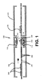
図1は、本発明の実施形態による位置決めデバイス102を含むプレス曲げ操作100を示す。プレス曲げ操作100は、ガラスシート106を予熱するのに役立つ予熱炉104を含む。加熱状態のガラスシート106は変形可能であり、したがってより大きな支持を必要とするため、ガラスシート106は、予熱炉104の出口領域において間隔が狭められているローラ108で炉104を通して移送される。
FIG. 1 shows a press bending operation 100 including a
予熱炉104の後には、第1の曲げ工具112及び第2の曲げ工具114が提供されている曲げステーション110が続く。図1及び図2に示したように、第1の曲げ工具112はリング状モールドであり、第2の曲げ工具114は全面成形型である。曲げステーション110は、複数の可動ローラ116を含む。ガラスシート106は、ガラスシート106が予熱炉104から出ると直ぐにローラ108から可動ローラ116上に移送される。第2の曲げ工具114との干渉を避けるために垂直に移動させることができる少なくとも2つの止め具118により、第1の曲げ工具112と第2の曲げ工具114との間の移動方向におけるガラスシート106の位置決めが容易になる。ガラスシートが第1の曲げ工具112と第2の曲げ工具114との間にあるとき、以下に記載される少なくとも2つの位置決めデバイス102、その構造及び操作を用いて、第1の曲げ工具112上にガラスシート106を位置決めするのを容易にすることができる。
The preheating
複数の可動ローラ116上へと移送された後、複数の可動ローラ116は下方に移動されて、ガラスシート106を第1の曲げ工具112上に位置決めすることを容易にする、すなわち、ガラスシート106は第1の曲げ工具112上に置かれる。複数の可動ローラ116の移動のタイミングは、止め具118に対してガラスシート106を注意深く位置決めするように行われる。あるいは、第1の曲げ工具112は、上方に移動させることができ、静止位置に留まるように構成されたローラのセットからガラスシート106を持ち上げ、それによってガラスシート106を第1の曲げ工具112上に置き得ることが理解される。
After being transferred onto the plurality of
ガラスシート106が第1の曲げ工具112上に位置決めされたら、第1の曲げ工具112及び第2の曲げ工具114は互いに向かって移動を開始して、ガラスシート106のプレス曲げを行う。第1の曲げ工具112及び第2の曲げ工具114が互いに向かって移動する間に、位置決めデバイス102を使用してガラスシート106を第1の曲げ工具112上に位置決めするが、位置決めデバイス102を使用して、ガラスシート102を、第1の曲げ工具112に対して任意の方向に位置決めすることができ、例えば垂直方向に移動可能な止め具(図示せず)に対してガラスシートを位置決めし得ることが理解される。位置決めデバイス102を用いてガラスシート106の位置を調整した後、ガラスシート106は、第1の曲げ工具112と第2の曲げ工具114との間でプレス曲げされる。
When the
位置決めデバイスを使用してガラスシート106を第1の曲げ工具112上に位置決めすることができる一方で、ガラスシートがプレス曲げされる前には、第1の曲げ工具112及び/または第2の曲げ工具114は移動しないことは直ちに明らかであろう。
The positioning device can be used to position the
また、不確かさを避けるために、第1の曲げ工具112は、第2の曲げ工具は移動させずに、第2の曲げ工具114に向かって移動することができる。あるいは、第2の曲げ工具114は、第1の曲げ工具112は移動させずに、第1の曲げ工具112に向かって移動することができる。あるいは、第1の曲げ工具112と第2の曲げ工具114の両方が互いに向かって移動する。これらの代替案のいずれにおいても、目的は、第1の曲げ工具112と第2の曲げ工具114との間で相対的な移動を引き起こして、第1の曲げ工具112と第2の曲げ工具114との間でガラスシート106をプレス曲げすることである。
Also, to avoid uncertainty, the
プレス中、第2の曲げ工具114で形成された通路120上に真空を引いて、ガラスシート106を所望の形状に成形するのを容易にすることができる。ガラスシート106の成形が完了したら、ガラスシート106は、第2の曲げ工具114の通路120を通して適用される陽圧によって、第2の曲げ工具114から解放することができる。
During pressing, a vacuum can be drawn over the
曲げステーション110は、曲げ工具112、114より多く含むことができ、図1及び図2に示した位置以外の他の位置に置くことができ、静止している曲げ工具を有することができ、そしてなお本発明の範囲及び趣旨内にあり得る、と理解することができる。曲げプロセスが完了すると、搬送装置(図示せず)は、成形されたガラスシート106を徐冷窯124中に移送するのに役立つ。徐冷窯124において、成形されたガラスシート106は、当該技術分野で知られているように焼き戻しまたは焼きなましすることができ、そして処理できる温度まで冷却することができる。成形ガラスシート106は、フロントグラス、サイドウィンドウ、サンルーフまたはリアウィンドウなどの車両用窓の構造において使用することができる。そのような窓はモノリシックまたはラミネートであってもよい。
The bending
位置決めデバイス102は、図2及び図3に最も明確に示されている。位置決めデバイス102の各々は、プラットフォーム126上に取り付けられたアセンブリである。プラットフォーム126は、剛体板であり、その上に第1の曲げ工具112が調整可能に取り付けられるが、そのような様式が位置決めデバイス102と第1の曲げ工具112との間に所定の空間的関係を確実にする限り、位置決めデバイス102は、別の方法で取り付け得ることが理解される。位置決めデバイス102のそれぞれは、固定部分128、可動部分130、及びアクチュエータ132を含む。図3に示すように、複数の位置決めデバイス102を第1の曲げ工具112の周縁部あたりに配置して、第1の曲げ工具112上に熱軟化ガラスシートを置いた後に、かつガラスシートがプレス曲げされる前に、第1の曲げ工具112に対してガラスシート106を位置決めするのを容易にすることができる。
The
固定部分128はプラットフォーム126に結合された硬質部材である。固定部分128は、互いに溶接された複数の金属部品から形成されるが、固定部分128は、複数の締結具を用いて互いに結合された部品を含み得ること、または固定部分128は形状的に単体であり得ることが理解される。固定部分128は第1の端部134及び第2の端部136を含む。第1の端部134は、複数の締結具を使用してプラットフォーム126に取り外し可能に結合されるフランジ部分138を含むが、第1の端部134は、他の形状を有することができ、また任意の従来の方法でプラットフォーム126に結合され得ることが理解される。第2の端部136はピボット部分140及び取付け部分141を含む。ピボット部分140は、取付け部分141が結合される一対の直交配置されたナックルジョイント142を含むが、ピボット部分140は、それに対して取付け部分141が枢動可能に結合されるのを容易にする他の構造を含み得ることが理解される。取付け部分141はピボット部分140に結合された硬質部材である。図2に示すように、取付け部分141は、ピボット部分140から離れて延在している硬質L字型部材であるが、取付け部分141は、アクチュエータ132が可動部分130上で移動できる様式でアクチュエータ132の取付けを可能にする他の形状を有し得ることが理解される。
The fixed
可動部分130は、取付け部分141に移動可能に結合されたアセンブリである。可動部分130は、複数の締結具を用いて一緒に結合された複数の部品から形成されるが、可動部分130は、互いに溶接された部品を含み得ることが理解される。可動部分130は、スライド部分143及びプッシャーアセンブリ144を含む。
The
スライド部分143は、ガイドレール145と、このガイドレール145と係合されたベアリングブロック146とを有するリニアスライドである。ガイドレール145は取付け部分140に結合され、そしてベアリングブロック146はプッシャーアセンブリ144に結合される。ベアリングブロック146は、ガイドレール145に沿ったプッシャーアセンブリ144の直線移動を容易にする。あるいは、可動部分130は、別の様式で、取付け部分141に移動可能に結合され得ることが理解される。
The
プッシャーアセンブリ144は、プッシャー部材147及びプッシャー部分148を含む。プッシャー部分148は、必要であれば、プッシャー部分148の交換を容易にするために、プッシャー部材147に取り外し可能に結合される。
The
プッシャー部材147は、取付け部分149、中間部分150、及びプッシャー取付け部分151を有する略S字状の部材である。プッシャー部材147は、互いに結合された一対の硬質金属部材を含むが、プッシャー部材は、一体的に形成することができ、そして他の材料から形成され得ることが理解される。取付け部分149は、ベアリングブロック146に結合されている。アクチュエータ132の一部分は、中間部分150に結合されて、プッシャー部材147、ひいてはプッシャーアセンブリ144の移動を引き起こす。プッシャー取付け部分151は、第1の曲げ工具112に隣接して位置決めされ、プッシャー部分148を取り付けるための場所を提供する。プッシャー取付け部分151は、プッシャー部分148をプッシャー取付け部分151に取り外し可能に結合する締結具を受容するためにその中に形成された少なくとも1つのアパーチャーを含むことができるが、プッシャー取付け部分151は、プッシャー取付け部分151に対してプッシャー部分148を取り外し可能に結合させる任意の様式で構成され得ることが理解される。
The pusher member 147 is a substantially S-shaped member having a mounting
プッシャー部分148は、バネ鋼のようなシート金属から形成された半硬質部材であるが、同様の特性を有する他の材料も使用され得ることが理解される。図4A及び図4Cの平面図を参照すると、プッシャー部分148は、略長方形の形状であり、取付けタブ156、押し縁158、及び接触材料160を含む。取付けタブ156は、プッシャー部分148の残りの部分から延在し、残りの部分に対してオフセットであってもよいが、取付けタブ156は、他の形状を有していてもよいか、またはプッシャー部分148は取付けタブ156を含んでいなくてもよいことが理解される。取付けタブ156は、プッシャー部分148と一体的に形成され、そしてプッシャー部分148をプッシャー取付け部分151に結合させるために、その中に形成された穿孔を含むことができる。押し縁158は、第1の曲げ工具112に隣接して位置決めされるプッシャー部分148の縁である。図4A及び図4Cに示すように、押し縁158は真っ直ぐであるが、押し縁158は、円弧形状またはガラスシート106の縁の形状に対応する他の形状を有し得ることが理解される。
It is understood that the
接触材料160は、プッシャー部分148の上方対向側面162の一部分と押し縁158とに結合されたワイヤ織クロス片である。接触材料160の配置が、位置決めデバイス102の使用中に、曲げ工具112、114のいずれかに干渉しない限りは、接触材料160はプッシャー部分148の任意の部分上に配置され得ることが理解される。好ましい実施形態では、接触材料160は、ステンレス鋼ワイヤクロスから形成され、そしてプッシャー部分148に溶接されるが、接触材料160は、他のクロス様材料から、例えば、ガラスに比べて柔らかく、高温での使用に適するフェルトから形成され得ることが理解される。更に、接触材料160は、任意の従来の方法で、例えば接着剤の使用または少なくとも1つの締結具の使用などによって、プッシャー部分148に結合され得ることが理解される。プッシャー部分148を形成する半硬質部材及び接触材料160の厚さは、ガラスシート106の厚さにほぼ等しいかまたはより薄い。更に、プッシャー部分148は接触材料160を含んでいなくてもよいか、または接触材料160は、押し縁158上にのみ配置されてもよいことが理解される。
The
また、第1の曲げ工具112及び第2の曲げ工具114がガラスシート106をプレス曲げしているとき、第2の曲げ工具114が、その中に、プッシャー部分の厚さを収容するのに適切な凹部を有するならば、その上に任意の接触材料を含むプッシャー部分は、ガラスシート106の厚さに比べてより厚いことも本発明の範囲内である。
Further, when the
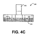
図4B及び図4Dは、本発明の別の実施形態によるプッシャー部分148の2つの断面形状を示す。
4B and 4D show two cross-sectional shapes of
図4A及び図4Bに示す実施形態は平坦な断面形状を有する。プレス曲げプロセス中に、第1の曲げ工具112と第2の曲げ工具114との間の最小距離は、ガラスシート106の厚さにほぼ等しいか、またはそれをわずかに超える。プッシャー部分148を形成する半硬質部材及び接触材料160の厚さはガラスシート106の厚さとほぼ同じかまたはそれより薄いことから、プレス曲げプロセス中にガラスシート106に隣接するプッシャー部分148の存在は、プレス曲げプロセスに影響を与えない。
The embodiments shown in FIGS. 4A and 4B have a flat cross-sectional shape. During the press bending process, the minimum distance between the
図4C及び図4Dに示した実施形態は、2つの横方向に位置決めされた起伏164を含む断面形状を有する。横方向に位置決めされた起伏164を有するプッシャー部分148を含む位置決めデバイス102の操作の間に、プレス曲げプロセスの動的条件が連続するガラスシート106の間に位置変動をもたらすとき、起伏164はガラスシート106の押し込みを容易にし得ることが理解される。更に、プレス曲げプロセスの動的条件が、第1の曲げ工具112に対してガラスシート106のバウンドをもたらすとき、起伏164によってガラスシート106の押し込みが容易になることが理解される。更に、連続ガラスシート106間の寸法変動も、横方向に位置決めされた起伏164を有するプッシャー部分148を使用することにより対応され得る。最後に、プレス曲げプロセスの間、第1の曲げ工具112と第2の曲げ工具114との間の最小距離は、起伏164の高さに比べてより小さくてもよく、その結果プッシャー部分148は一時的に圧縮される。
The embodiments shown in FIGS. 4C and 4D have a cross-sectional shape that includes two laterally positioned
アクチュエータ132は、アクチュエータ132の軸に対して略平行な経路でガイドレール145に沿って固定部分128に対してプッシャーアセンブリ144に移動を引き起こすリニアアクチュエータである。プッシャーアセンブリ144の移動に応答して、プッシャー部分148は、第1の曲げ工具112上でガラスシート106に接触し位置決めする。制御器または制御システム(図示せず)からの信号に応答して、アクチュエータ132の長さが長くなり、プッシャーアセンブリ144、ひいてはプッシャー部分148に対して力を適用する。アクチュエータ132は、空気圧アクチュエータ、電気アクチュエータ、または任意の他のタイプのリニアアクチュエータであり得る。アクチュエータ132は、プッシャーアセンブリ144を開始位置に戻すのを容易にするために、複動アクチュエータであるように構成することができる。あるいは、アクチュエータ132または位置決めデバイス102は、例えば、プッシャーアセンブリ144を開始位置に戻すコイルスプリングなどのような付勢部材(図示せず)を用いて構成され得ることが理解される。
The
使用時に、ガラスシート106が第1の曲げ工具112上にあるときに、かつプレス曲げプロセスの前または後に、位置決めデバイス102を用いて、第1の曲げ工具112と第2の曲げ工具114との間にガラスシート106を位置決めする。上記したように、プレス曲げ操作100は、ガラスシート106を第1の曲げ工具112上で、または第1の曲げ工具112を含むプラットフォーム126上で位置決めするのを容易にするように下方に移動される可動ローラ116を用いて構成することができ、そして位置決めデバイス102は、上方に移動して、一組のローラ(図示せず)からガラスシート106を持ち上げることができ、そこでその一組のローラは静止位置に留まるように構成される。
At the time of use, when the
プラットフォーム126は、ガラスシート106の形状及び位置合わせの必要性に基づいて、複数の位置決めデバイス102で構成することができる。位置決めデバイス102を使用してガラスシート106の位置を調整するために用いられるプロセスは、非常に短時間に行われる。非限定的な例として、位置決めデバイス102を使用してガラスシート106の位置を調整するために使用される時間は、0.3秒未満、すなわち約0.28秒であり得るが、時間は、プレス曲げプロセスの一部であるいくつもの変数に基づいて、より早くまたはより遅く調整され得ることが理解される。
The
第1の曲げ工具112及び第2の曲げ工具114が互いに向かって移動する間に、位置決めデバイス102を使用して、ガラスシート106を第1の曲げ工具112上に位置決めする。位置決めデバイス102を使用して、ガラスシート102を第1の曲げ工具112に対して任意の方向おいて位置決めし得ることが理解される。制御器または制御システム(図示せず)からの信号に応答して、アクチュエータ132の長さが長くなり、プッシャーアセンブリ144、ひいてはプッシャー部分148に対して力を適用し、押し縁158をガラスシート106の縁に接触させる。ガラスシート106の縁に加えられる力により、ガラスシート106は、第1の曲げ工具112上を、プレス曲げ操作100を使用して形成された連続するガラスシート106間の位置変動を最小にする位置まで移動する。位置決めデバイス102を用いてガラスシート106の位置を調整した後、位置決めデバイス102のプッシャーアセンブリ144が開始位置に戻り、ガラスシート106は、第1の曲げ工具112と第2の曲げ工具114との間でプレス曲げされる。あるいは、適切に配置された位置決めデバイス及び/または第2の曲げ工具に関して、プレス曲げ作業の間、プッシャーアセンブリは、第1の曲げ工具上でガラスシートを移動させた構成に留まることができる、すなわち、プッシャー部分148が、第1の曲げ工具112上でガラスシート106に接触し位置決めした後に、プッシャー部分148は、第1の曲げ工具112と第2の曲げ工具114との間に留まることができる。プレス曲げ操作中にプッシャー部分148が第1の曲げ工具112と第2の曲げ工具114との間に留まる場合、ガラスシートの湾曲が発生すると、プッシャー部分148は、プレス曲げ作業の全時間にわたってガラスシートと接触しない場合がある。
The
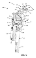
図5は、本発明の別の実施形態による位置決めデバイス168を示す。図5に示す実施形態は、図1〜3に示した位置決めデバイス102と同様の部品を含む。位置決めデバイス168の同様の構造的特徴は、以下で説明する特徴を除いて、同じ参照番号を含む。位置決めデバイス168は、傾動ポスト取付け台170、可動部分130、及びアクチュエータ132を含む。
FIG. 5 shows a
傾動ポスト取付け台170は、プラットフォーム126に結合された細長いアセンブリである。傾動ポスト取付け台170は一緒に結合された複数の部品から形成されるが、傾動ポスト取付け台170は任意の従来の方法で互いに結合された部品を含み得ることが理解される。傾動ポスト取付け台170は第1の端部172及び第2の端部174を含む。第1の端部172は、複数の締結具を使用してプラットフォーム126に取り外し可能に結合されるフランジ部分(図示せず)を含むことができるが、第1の端部172は、他の形状を有することができ、また任意の従来の方法でプラットフォーム126に結合され得ることが理解される。第2の端部174は、ピボット部分176、傾動取付け部分178、及び取付け部180を含む。傾動取付け部分178に結合されたアクチュエータ182は、傾動取付け部分178に対する取付け部分180の移動を容易にする。
The
ピボット部分176は、傾動取付け部分178が結合される一対の直交配置されたナックルジョイント184を含むが、ピボット部分176は、それに対して傾動取付け部分178が枢動可能に結合されるのを容易にする他の構造を含み得ることが理解される。
The
傾動取付け部分178は、ピボット部分176及び取付け部分180に枢動可能に結合された硬質アセンブリである。傾動取付け部分178は、複数の締結具を使用して互いに結合された一対の金属部材を含むが、その部材は、任意の従来の方法で互いに結合することができ、傾動取付け部分178は一体的に形成することができ、または傾動取付け部分178は他の材料から形成し得ることが理解される。図5に示すように、傾動取付け部分178は、傾動取付け部分178とピボット部分176とを調整可能に接合するピボット点186から離れるように延在している硬質S字形アセンブリであるが、傾動取付け部分178は、アクチュエータ182が取付け部分180上で移動できる様式で、アクチュエータ182及び取付け部分180の取付けを可能にする他の形状を有し得ることが理解される。傾動取付け部分178は、傾動取付け部分178及び取付け部分180を枢動可能に接合するその中に形成された第1の傾動ポイント188を含む。傾動取付け部分178はまた、その遠位端に下部アクチュエータ取付け189も含む。
Tilt mounting
取付け部分180は、第2の傾動ポイント190において傾動取付け部分178に枢動可能に結合された硬質部材である。第1の傾動ポイント188及び第2の傾動ポイント190の両方に配置されたピン192は、それらの間の枢動を可能にする。図5に示すように、取付け部分180は、傾動取付け部分178から離れて延在している硬質L字型部材であるが、取付け部分180は、アクチュエータ132が可動部分130上で移動できる様式でアクチュエータ132の取付けを可能にする他の形状を有し得ることが理解される。取付け部分180は、更に、傾動取付け部分178から離れて延在している部分上に上部アクチュエータ取付け194を含む。可動部分130は、図2に示した取付け部分141に対して可動部分130が構成されるのと同様な様式で、取付け部分180に対して構成される。
The mounting
アクチュエータ182は、傾動ポイント188、190周辺で、傾動取付け部分178に対してマウント部分180へと移動させて、プッシャー部分148を含むプッシャーアセンブリ144を第1の曲げ工具112から離れるように移動させるリニアアクチュエータである。アクチュエータ182は、下部アクチュエータ取付け189及び上部アクチュエータ取付け194に結合される。制御器または制御システム(図示せず)からの信号に応答して、アクチュエータ182の長さが短くなり、取付け部分180に力を適用して、傾動ポイント188、190周辺で取付け部分180を移動させる。アクチュエータ182は、空気圧アクチュエータ、電気アクチュエータ、または任意の他のタイプのリニアアクチュエータであり得る。アクチュエータ182は、取付け部分180及びプッシャーアセンブリ144を開始位置に戻すのを容易にするために、複動アクチュエータであるように構成することができる。あるいは、取付け部分180またはプッシャーアセンブリ144は、付勢部材(図示せず)、例えば、取付け部分180及びプッシャーアセンブリ144を開始位置に戻すねじりバネで構成され得ることが理解される。
A
あるいは、適切に構成された位置決めデバイス及び/または第2の曲げ工具に関して、プッシャーアセンブリは、上記したプレス曲げ操作の間、所定の位置に留まることができる。 Alternatively, with respect to a properly configured positioning device and / or second bending tool, the pusher assembly can remain in place during the press bending operation described above.
使用時には、プレス曲げプロセスの一部の間に、位置決めデバイス168を使用して、プッシャーアセンブリ144を含む取付け部分180を傾動ポイント188、190周辺で移動させて、プッシャー部分148を含むプッシャーアセンブリ144を第1の曲げ工具112から離れるように移動させる。上記したように、プレス曲げ操作100は、ガラスシート106を第1の曲げ工具112上で、または第1の曲げ工具112を含むプラットフォーム126上で位置決めするのを容易にするように下方に移動される可動ローラ116を用いて構成することができ、そして位置決めデバイス168は、上方に移動して、一組のローラ(図示せず)からガラスシート106を持ち上げることができ、そこでその一組のローラは静止位置に留まるように構成される。
In use, during part of the press bending process, a
第1の曲げ工具112及び第2の曲げ工具114が互いに向かって移動する間に、位置決めデバイス102に関して上記したように、位置決めデバイス168を使用してガラスシート106を第1の曲げ工具112上に位置決めする。位置決めデバイス168を使用してガラスシート106の位置を調整した後、アクチュエータ182は、制御システムからの信号に応答して長さを短くし、取付け部分180に力を適用して、傾動ポイント188、190周辺で取付け部分180を移動させる。したがって、プッシャー部分148を含むプッシャーアセンブリ144は、プレス曲げプロセスの一部の間に、第1の曲げ工具112から離れるように移動される。アクチュエータ182のタイミング及び係合を行って、位置決めデバイス168の使用がプレス曲げプロセスを妨げないように、プレス曲げ操作100の作業者が望むように取付け部分180を位置決めし得ることが理解される。
While the
図6〜11は、本発明によるガラスシートを成形する方法に含まれるステップを示す。 6-11 show the steps included in the method of molding a glass sheet according to the present invention.
図6は、ガラスシート206を支持する第1の曲げ工具212の概略平面図を示す。図7は、線M−M’に沿った断面による図6の概略側面図を示す。
FIG. 6 shows a schematic plan view of the
第1の曲げ工具212は、その上にガラスシート206を支持するための上部成形面を有するリングモールドである。そのリングモールドは、その上にガラスシートのスタック、特に、例えば炭酸カルシウムのような適切な離型剤によって分離される入れ子ペアを支持することもできる。
The
平面図における第1の曲げ工具212は、これまた矩形のアウトラインを有するガラスシート206を支持するように構成された矩形のアウトラインまたは周囲を有する。第1の曲げ工具は、第1の側面212’及び対向する第2の側面212’’を有する。その一端において側面212’及び212’’を接続すると第3の側面212’’であり、その他端では第4の側面212’’’’は側面212’及び212’’を接続し、それにより図6に示す矩形のアウトラインを形成する。第1の曲げ工具212は平面図アウトラインで他の形状を有することができる。例えば、第1の側面212’は第2の側面212’’に対して平行でなくてもよい。更に、またはその代わりに、第3の側面212’’’は第4の側面212’’’’に対して平行でなくてもよい。第1の曲げ工具のアウトラインは、台形であってもよく、または成形される特定のガラスシートを支持するように適切に構成された他の形状を有してもよい。側面212’、212’’、212’’’及び212’’’’のいずれかまたはすべては、例えば図3に示すように湾曲していてもよい。
The
第1の曲げ工具212の上部成形面は、図7において平坦として示されているが、典型的には、第2の曲げ工具の成形面に対する相補的形状を有するその少なくとも一部分を有するように構成され、そこで第1の曲げ工具と第2の曲げ工具との間でガラスシートがプレス曲げされる。そのような形状は当該技術分野でよく知られている。
The upper forming surface of the
第1の曲げ工具212は、等しい長さを有するように示してあるが、異なる長さを有していてもよく、適切に構成された支柱211及び213によってプラットフォーム226(硬質プレートである)上に取り付けられる。3本以上の支柱が存在し得る。典型的には、支柱211、213は、スチールのような硬質材料から作られ、高温環境に耐えることができる。
The
一端において、支柱211は(第1の側面212’の領域における)第1の成形工具212の下側に取り付けられ、そして他端においては、支柱211はプラットフォーム226に取り付けられる。同様に、一端において、支柱213は(第2の側面212’’の領域における)第1の成形工具212の下側に取り付けられ、そして他端においては、支柱213はプラットフォーム226に取り付けられる。
At one end, the
支柱211は、第1の曲げ工具212の上部成形面が水平に配向されているとみなし得るように等しい長さである。
The
また、プラットフォーム226には、第1の曲げ工具212と所定の空間関係において、位置決めデバイス202も取り付けられている。位置決めデバイス202は、第1の曲げ工具212の第1の側面212’に隣接して取り付けられる。
A
位置決めデバイス202は固定部分228及び可動部分230を含む。
The
固定部分228は、一端がプラットフォーム226に取り付けられ、他端が取付け部分241に取り付けられた硬質支柱234(すなわちスチール製)を含む。図2を参照すると、固定部分228は、固定部分128と同様に構成することができる。
The fixed
可動部分230は、取付け部分241に結合されたアセンブリである。アクチュエータ232、例えばリニアアクチュエータは、取付け部分241に固定された端部と、第1の側面212’に向かって(または離れて)取付け部分に対して直線的に移動可能な対向端部とを有する。
The
アクチュエータの可動部分は、そこに取り外し可能に結合されたプッシャー部分248を含む。例示的なプッシャー部分は、図4A、4B、4C及び4Dを参照して説明されたタイプのものである。図6〜図11には示されていないが、アクチュエータの可動部分は、図2に関連して説明したように、プッシャー部材を含むプッシャーアセンブリを含むことができる。
The moving part of the actuator includes a
この例におけるプッシャー部分248は、第1の主面と、プラットフォーム226に面している対向する第2の主面とを有するシート金属の矩形部材である。プッシャー部分248の第1の主面と第2の主面との間には、ガラスシート206の縁208に接触するための押し縁258がある。プッシャー部分の厚さ(すなわち、プッシャー部分248の第1の主面と第2の主面の分離)は、ガラスシート206が第1の曲げ工具212上を移動できるように、ガラスシートの縁208に適切に接触するように選択される。
The
プッシャー部分248の第2の主面(したがって対向するプッシャー部分248の第1の主面)は、以下でより詳細に説明するように、プッシャー部材が第1の曲げ工具212の上面を通過することができるように配置される。プッシャー部材が第1の曲げ工具212の上部成形面の上にあるとき、第1の曲げ工具212の上部成形面とプッシャー部材248の第2の主面との間に空間が存在することが好ましい
The second main surface of the pusher portion 248 (and thus the first main surface of the opposing pusher portion 248) is such that the pusher member passes over the upper surface of the
図6及び図7において、ガラスシート206は、成形に適する温度(例えば590℃〜670℃)まで加熱されており(例えば図1に示した予熱炉104において)、そして第1の曲げ工具212上に置かれた後の状態が示されている。したがって、第1の成形工具212上のガラスシート206は、第1の成形工具212上の加熱されたガラスシートとも呼ぶことができる。
In FIGS. 6 and 7, the
図7では、ガラスシートは平坦であるとして示されているが、ガラスシートが成形に適する温度まで加熱されていると仮定すると、その上に置かれた後に第1の曲げ工具212上で支持されるとき、ガラスシートは、重力の影響下で垂れ下がり、その結果して、ガラスシート206はラインM−M’に対して平行及び/または直角の方向にわずかな湾曲を有する。
In FIG. 7, the glass sheet is shown as flat, but assuming that the glass sheet has been heated to a temperature suitable for molding, it is placed on it and then supported on the
この例では、ガラスシート206はソーダ−ライム−シリケート組成物を有する。典型的なソーダ−ライム−シリケート組成物は、(重量を基準として)SiO2 69〜74%、Al2O3 0〜3%、Na2O 10〜16%、K2O 0〜5%、MgO 0〜6%、CaO 5〜14%、SO3 0〜2%及びFe2O3 0.005〜2%である。ガラス組成物は、他の添加剤も、例えば通常2%までの量で存在する精製助剤も含有することができる。
In this example, the
ガラスシート206は、0.5mm〜25mmの厚さ、典型的には0.5mm〜8mmの厚さを有することができる。
The
ガラスシート206は、平面視で矩形のアウトラインを有し、第1の主面及び対向する第2の主面を有する。ガラスシートの第2の主面はプラットフォーム226に面している。上記したように、ガラスシートは、適切な改良された第1の曲げ工具212を用いて、平面図において異なるアウトラインを有することができる。
The
ガラスシート206が第1の曲げ工具212上に支持されるように、ガラスシート206の第2主表面の部分は、第1の曲げ工具212の上部成形表面の少なくとも一部分と接触する。
The portion of the second main surface of the
図6及び図7は、第1の曲げ工具212に対する第1の位置におけるガラスシート206を示す。第1の成形工具212上に置かれた後、ガラスシートはその上でバウンドする。
6 and 7 show the
図6及び図7はまた、第1の構成における位置決めデバイスを示しており、そこではプッシャー部材248はガラスシート206と接触せず、第1の曲げ工具212の外周の外側にあり、すなわち、第1の側面212’と押し縁258との間に空間が存在する。
6 and 7 also show the positioning device in the first configuration, where the
図8及び図9において、プッシャー部分248が取付け部分分241から第1の側面212’に向かって、すなわち矢印233の方向に移動するように、アクチュエータ232は(適切な制御手段によって、図示されていない)係合された。位置決めデバイスの構成により、プッシャー部分248は第1の側面212’の上面を通過することができる。プッシャー部分248の第2の主面の一部はプラットフォーム226に面し、プッシャー部分248の第2の主面の別の部分は第1の側面212’の上面に面する。位置決めデバイス202は第2の構成で示される。位置決めデバイス202が第1の構成において存在するとき、プッシャー部分248の位置は要素248’として破線で示してある。
In FIGS. 8 and 9, the
図8及び図9において、ガラスシート206が依然として第1の曲げ工具に対して第1の位置にあるように、プッシャー部分248の押し縁258はガラスシートの縁208とちょうど接触している。
In FIGS. 8 and 9, the
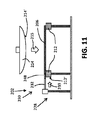
図10及び図11に示すように、アクチュエータの継続的な係合はプッシャー部分248を、取付け部分241から矢印233の方向に離れるように移動させ、ガラスシート206を第1の曲げ工具212上で移動させる。ガラスシート206は、第1の曲げ工具212に対して第2の位置に示されている。位置決めデバイス202は第3の構成で示されている。位置決めデバイスが第1の構成において存在するとき、プッシャー部分248の位置は要素248’として破線で示してある。ガラスの縁208の位置は第2の位置へ移動し、ガラスシートが第1の曲げ工具に対して第1の位置にあるときのガラスの縁208の位置は208’として破線で示してある。
As shown in FIGS. 10 and 11, continuous engagement of the actuator moves the
ガラスシート206が第1の曲げ工具に対して第2の位置へと移動されたとき、アクチュエータは適切な時間に係合解除される。
When the
第1の曲げ工具に対して第2の位置にあるガラスシート206は、次いで所望の形状に曲げられる。この例では、第1の曲げ工具212上に支持されたガラスシート206をプレス曲げするための凸形成形面214’を有する第2の曲げ工具214が提供される。この例では、第2の曲げ工具214は全面成形型である。
The
図10及び図11において、第1の曲げ工具212はプラットフォーム226上で静止し、第2の曲げ工具214は、矢印215の方向で第1の曲げ工具212に向かって移動して、第1の曲げ工具212と第2の曲げ工具214との間でガラスシート206をプレス曲げする。固定基準点に関して、例えばプラットフォーム226上の点に関して、第1の曲げ工具212はそれに対して移動しないが、第2の曲げ工具は固定基準点に対して第1の曲げ工具212に向かって移動してガラスシート206をプレス曲げする。
In FIGS. 10 and 11, the
しかしながら、示したものとは別の実施形態では、第2の曲げ工具214は静止し、そして、第1の曲げ工具212がその上に支持されたガラスシート206と共に、静的な第2の曲げ工具214に向かって矢印215と反対の方向に移動されて、第1の曲げ工具212と第2の曲げ工具214との間でガラスシート206をプレス曲げすることができるように、第1の曲げ工具212がプラットフォーム226上に適切に取り付けられて、それに対して移動させることができる。
However, in another embodiment shown, the
もう一つ別の実施形態では、第1の曲げ工具212及び第2の曲げ工具214の両方が、互いの方に移動可能であって、それらの間でガラスシート206をプレス曲げする。
In another embodiment, both the
ガラス板206が第1の曲げ工具212と第2の曲げ工具214との間で曲げられた後、搬送装置(図示せず)は、成形されたガラスシートを徐冷窯(例えば図1に示したような徐冷窯124)の中に移送するのに役立ち、当該技術分野で知られているように焼き戻しまたは焼きなましすることができ、そして処理できる温度まで冷却することができる。成形ガラスシート206は、フロントグラス、サイドウィンドウ、サンルーフまたはリアウィンドウなどの車両用窓の構造において使用することができる。そのような窓は、モノリシックまたはラミネートであってもよい。
After the
図6〜図11では、第1の曲げ工具212の第1の側面212’に隣接して1つの位置決めデバイス202のみが示されているが、第1の曲げ工具212の第1の側面212’に隣接する2つ以上の位置決めデバイスが存在していてもよい。
6 to 11 show only one
更に、第1の成形工具212上でガラスシートの位置を調整するために、他の側面212’’、212’’’及び212’’’’のいずれかまたはすべてに隣接する1つ以上の位置決めデバイスが存在していてもよい。
In addition, one or more positioning adjacent to any or all of the other sides 212'', 212'' and 212'''' to adjust the position of the glass sheet on the first forming
特許法の条項に従って、本発明は、その好ましい実施形態を表すと考えられるものとして記載されているが、本発明は、その範囲または趣旨から逸脱することなく、具体的に図示及び記載された以外の方法で実施できることに留意すべきである。
In accordance with the provisions of the Patent Act, the present invention is described as being considered to represent a preferred embodiment thereof, except that the present invention is specifically illustrated and described without departing from its scope or purpose. It should be noted that this can be done in the same way.
Claims (22)
i.前記ガラスシートを成形に適する温度まで加熱するステップと、
ii.前記ガラスシートを第1の曲げ工具上に置くステップであって、前記第1の曲げ工具がその上の前記ガラスシートを支持し、前記ガラスシートが前記第1の曲げ工具に対して第1の位置にある、ステップと、
iii.前記ガラスシートが前記第1の曲げ工具に対して第2の位置に移動されるように、前記ガラスシートの縁部分を、第1の曲げ工具に対して配置された少なくとも第1の位置決めデバイスに接触させるステップであって、前記第1の位置決めデバイスは、前記ガラスシートの縁部分に接触して、第1の曲げ工具上で前記ガラスシートの位置を調整するために、第1の構成から第2の構成へと移動可能である、接触させるステップと、
iv.前記第1の曲げ工具上で前記ガラスシートを成形するステップと、を含み、
前記ステップ(ii)は、前記ステップ(iii)の前に行う、前記方法。 It is a method of molding a glass sheet.
i. The step of heating the glass sheet to a temperature suitable for molding, and
ii. In the step of placing the glass sheet on the first bending tool, the first bending tool supports the glass sheet on the glass sheet, and the glass sheet is the first with respect to the first bending tool. In position, with steps,
iii. The edge portion of the glass sheet is placed on at least a first positioning device arranged with respect to the first bending tool so that the glass sheet is moved to a second position with respect to the first bending tool. In the step of contacting, the first positioning device comes into contact with the edge portion of the glass sheet to adjust the position of the glass sheet on the first bending tool. The step of contact, which can be moved to the configuration of 2 ,
iv. A step of forming the glass sheet on the first bending tool, only including,
The method, wherein the step (ii) is performed before the step (iii) .
ガラスシート曲げ操作の曲げ工具に隣接して位置決めされた可動部分と、
前記可動部分に隣接して位置決めされた固定部分と、
前記固定部分と前記可動部分との間に配置されたアクチュエータとを含み、前記アクチュエータの係合に応答して、前記可動部分が前記ガラスシートの縁に接触して、その位置を調整する、位置決めデバイス。 A positioning device for high temperature glass sheets
A moving part positioned adjacent to the bending tool for glass sheet bending operation,
A fixed portion positioned adjacent to the movable portion and
Positioning that includes an actuator disposed between the fixed portion and the movable portion, the movable portion contacting the edge of the glass sheet to adjust its position in response to the engagement of the actuator. device.
ガラスシート曲げ操作の曲げ工具に隣接して位置決めされた可動部分と、
傾動ポイントを有し、前記可動部分に隣接して位置決めされた傾動ポスト取付け台と、
前記傾動ポスト取付け台と前記可動部分との間に配置された第1のアクチュエータと、
前記傾動ポスト取付け台の部分の間に配置された第2のアクチュエータであって、前記第1のアクチュエータの係合に応答して、前記可動部分が前記ガラスシートの縁に接触してその位置を調整し、また前記第2のアクチュエータの係合に応答して、前記可動部分及び前記傾動ポスト取付け台の一部分が前記傾動ポイントの周辺で移動される、前記第2のアクチュエータと、を含む、前記位置決めデバイス。 A positioning device for high temperature glass sheets
A moving part positioned adjacent to the bending tool for glass sheet bending operation,
With a tilt post mount that has a tilt point and is positioned adjacent to the movable part,
A first actuator arranged between the tilting post mounting base and the movable portion,
A second actuator arranged between the portions of the tilt post mount, the movable portion of which comes into contact with the edge of the glass sheet to position it in response to the engagement of the first actuator. The second actuator, wherein the movable portion and a portion of the tilt post mount are moved around the tilt point in response to the engagement of the second actuator. Positioning device.
前記ガラスシートを成形に適する温度まで加熱するための炉と、
前記ガラスシートを、前記炉を通して搬送するためのコンベヤ手段と、
ガラス曲げ操作中に前記ガラスシートをその上に支持するための第1の曲げ工具と、前記第1の曲げ工具に対して配置された少なくとも1つの(第1の)位置決めデバイスとを含むガラスシート成形セクションを含み、
ガラスシートが前記第1の曲げ工具上に支持されるとき、前記第1の位置決めデバイスは第1の構成から第2の構成へと移動可能であり、前記第1の曲げ工具上で前記ガラスシートの縁に接触して、前記第1の曲げ工具上で前記ガラスシートの位置を調整することを特徴とする、ガラス成形ライン。 A glass molding line for molding glass sheets.
A furnace for heating the glass sheet to a temperature suitable for molding, and
Conveyor means for transporting the glass sheet through the furnace and
A glass sheet comprising a first bending tool for supporting the glass sheet on it during a glass bending operation and at least one (first) positioning device disposed with respect to the first bending tool. Including molding section
When the glass sheet is supported on the first bending tool, the first positioning device is movable from the first configuration to the second configuration, and the glass sheet is on the first bending tool. A glass forming line, characterized in that the position of the glass sheet is adjusted on the first bending tool in contact with the edge of the glass sheet.
第1の曲げ工具と、
前記第1の曲げ工具と協働するように成形された第2の曲げ工具と、
前記第1の曲げ工具及び前記第2の曲げ工具の少なくとも1つに隣接して配置された位置決めデバイスと、を含み、前記位置決めデバイスの係合に応答して、前記位置決めデバイスが、前記第1の曲げ工具及び前記第2の曲げ工具のうちの1つの上に配置された高温ガラスシートの縁に接触して、前記高温ガラスシートの位置を調整するために、第1の構成から第2の構成へと移動可能である、装置。
A device for press-bending high-temperature glass sheets.
The first bending tool and
A second bending tool molded to cooperate with the first bending tool,
In response to the engagement of the positioning device, the positioning device includes the first bending tool and a positioning device arranged adjacent to at least one of the second bending tools. To adjust the position of the hot glass sheet by contacting the edge of the bending tool and the hot glass sheet placed on one of the second bending tools, from the first configuration to the second. A device that can be moved into a configuration.
Applications Claiming Priority (3)
| Application Number | Priority Date | Filing Date | Title |
|---|---|---|---|
| US201562166752P | 2015-05-27 | 2015-05-27 | |
| US62/166,752 | 2015-05-27 | ||
| PCT/GB2016/051537 WO2016189319A1 (en) | 2015-05-27 | 2016-05-27 | Method and apparatus for shaping glass sheets |
Publications (3)
| Publication Number | Publication Date |
|---|---|
| JP2018519231A JP2018519231A (en) | 2018-07-19 |
| JP2018519231A5 JP2018519231A5 (en) | 2019-06-27 |
| JP6898859B2 true JP6898859B2 (en) | 2021-07-07 |
Family
ID=56096658
Family Applications (1)
| Application Number | Title | Priority Date | Filing Date |
|---|---|---|---|
| JP2017561355A Active JP6898859B2 (en) | 2015-05-27 | 2016-05-27 | Methods and equipment for molding glass sheets |
Country Status (12)
| Country | Link |
|---|---|
| US (1) | US10995029B2 (en) |
| EP (1) | EP3303233B1 (en) |
| JP (1) | JP6898859B2 (en) |
| KR (1) | KR102580463B1 (en) |
| CN (1) | CN107646023B (en) |
| BR (1) | BR112017025428B1 (en) |
| ES (1) | ES2733246T3 (en) |
| HU (1) | HUE043908T2 (en) |
| MX (1) | MX2017014975A (en) |
| PL (1) | PL3303233T3 (en) |
| TR (1) | TR201909289T4 (en) |
| WO (1) | WO2016189319A1 (en) |
Families Citing this family (7)
| Publication number | Priority date | Publication date | Assignee | Title |
|---|---|---|---|---|
| EP3538498B1 (en) | 2016-11-11 | 2023-01-25 | Pilkington Group Limited | Method of shaping a glass sheet and glass shaping line utilized therein |
| WO2018096339A1 (en) | 2016-11-23 | 2018-05-31 | Pilkington Group Limited | Method of shaping a glass sheet and bending tool utilized therein |
| EP3700870A1 (en) * | 2017-10-27 | 2020-09-02 | Saint-Gobain Glass France | Means for immobilizing a pulley |
| US20210253467A1 (en) | 2018-05-17 | 2021-08-19 | Pilkington Group Limited | Method of shaping glass sheets |
| PL236771B1 (en) * | 2018-08-08 | 2021-02-22 | Pilkington Automotive Poland Spolka Z Ograniczona Odpowiedzialnoscia | Glass bending press |
| GB201911334D0 (en) | 2019-08-08 | 2019-09-25 | Pilkington Group Ltd | Method for shaping coated glass sheets |
| WO2022189748A1 (en) * | 2021-03-09 | 2022-09-15 | Saint-Gobain Glass France | Method and device for positioning glass sheets for a glazing manufacturing facility |
Family Cites Families (35)
| Publication number | Priority date | Publication date | Assignee | Title |
|---|---|---|---|---|
| US3459526A (en) | 1966-01-24 | 1969-08-05 | Libbey Owens Ford Glass Co | Apparatus for bending glass sheets with aligning means |
| US4204853A (en) * | 1978-11-13 | 1980-05-27 | Ppg Industries, Inc. | Glass sheet alignment means and method of using |
| US4437872A (en) * | 1980-02-05 | 1984-03-20 | Mcmaster Harold | Apparatus for bending and tempering glass sheets |
| JPS595531B2 (en) * | 1980-06-02 | 1984-02-06 | セントラル硝子株式会社 | flat glass bending device |
| US4406685A (en) * | 1982-03-08 | 1983-09-27 | Ppg Industries, Inc. | Eccentrically mounted stop for outline molds for shaping glass sheets |
| US4432782A (en) | 1982-06-17 | 1984-02-21 | Ppg Industries, Inc. | Support for hot glass sheets of non-rectangular outline prior to bending |
| US4609391A (en) * | 1984-11-23 | 1986-09-02 | Glasstech, Inc. | Method for forming glass sheets |
| US4662925A (en) * | 1985-12-09 | 1987-05-05 | Ppg Industries, Inc. | Horizontal press bending of heat softened glass sheets |
| US4666492A (en) * | 1985-12-11 | 1987-05-19 | Ppg Industries, Inc. | Method and apparatus for shaping glass sheets |
| US4666493A (en) * | 1985-12-19 | 1987-05-19 | Ppg Industries, Inc. | Sheet positioning system |
| FR2606383B1 (en) * | 1986-11-06 | 1989-01-13 | Saint Gobain Vitrage | POSITIONING OF GLASS PLATES WITH A VIEW IN PARTICULAR OF THEIR BOMBING |
| US4767437A (en) * | 1987-03-25 | 1988-08-30 | Ppg Industries, Inc. | Horizontal press bending using a splitting vacuum/pressure pickup |
| US4775404A (en) | 1987-11-17 | 1988-10-04 | Glasstech, Inc. | Apparatus for registering glass sheet on glass sheet shaping tool |
| US4872898A (en) * | 1989-02-17 | 1989-10-10 | Libbey-Owens-Ford Co. | Centering and leveling of mobile press bending apparatus |
| FR2644776B1 (en) | 1989-03-24 | 1991-05-31 | Saint Gobain Vitrage | POSITIONING OF A GLASS SHEET RELATIVE TO BOMBING TOOLS AND / OR OTHER HEAT TREATMENTS |
| JPH0818678B2 (en) | 1989-09-05 | 1996-02-28 | 日本板硝子株式会社 | Air bed carrier |
| JPH0764575B2 (en) | 1990-01-11 | 1995-07-12 | 日本板硝子株式会社 | Method and apparatus for press bending of flat glass |
| US5066321A (en) | 1990-07-19 | 1991-11-19 | Glasstech, Inc. | Device for positioning hot glass sheets |
| JP3185934B2 (en) * | 1991-09-04 | 2001-07-11 | 日本板硝子株式会社 | Sheet glass bending method |
| FI89475C (en) * | 1991-09-27 | 1993-10-11 | Tamglass Eng Oy | Method and apparatus for bending and curing a sheet of glass |
| US5279635A (en) | 1992-01-08 | 1994-01-18 | Libbey-Owens-Ford Co. | Method and apparatus for controlling the temperature of glass sheets in press bending |
| GB9407610D0 (en) * | 1994-04-15 | 1994-06-08 | Pilkington Glass Ltd | Bending and tempering glass sheets |
| GB9407609D0 (en) | 1994-04-15 | 1994-06-08 | Pilkington Glass Ltd | Bending and tempering glass sheets |
| DE4412747A1 (en) | 1994-04-15 | 1995-10-19 | Flachglas Ag | Press bending station for bending glass panes |
| FR2725194B1 (en) | 1994-10-04 | 1996-10-31 | Saint Gobain Vitrage | METHOD AND DEVICE FOR THE BOMBING OF GLASS SHEETS |
| US5743931A (en) | 1995-08-14 | 1998-04-28 | Libbey-Owens-Ford Co. | Glass sheet conveying and bending apparatus |
| DE19725189C1 (en) | 1997-06-14 | 1998-11-26 | Sekurit Saint Gobain Deutsch | Device for bending glass sheets |
| US6505483B1 (en) | 2000-02-25 | 2003-01-14 | Surface Combustion, Inc. | Glass transportation system |
| US6422040B1 (en) | 2000-06-15 | 2002-07-23 | Glasstech, Inc. | Method for forming glass sheets |
| JP4688011B2 (en) * | 2001-05-09 | 2011-05-25 | 旭硝子株式会社 | Glass plate bending apparatus and method |
| DE10314266B3 (en) * | 2003-03-29 | 2004-06-09 | Saint-Gobain Sekurit Deutschland Gmbh & Co. Kg | Process for bending glass panes comprises placing the panes on a concave bending frame mold and pre-bending under gravitational force, transferring to a delivery mold, and further processing |
| US7866187B2 (en) | 2003-09-24 | 2011-01-11 | Pilkington North America, Inc. | Press bending station for the bending of glass sheets |
| US9346701B2 (en) | 2011-05-27 | 2016-05-24 | Pittsburgh Glass Works, Llc | Multi-stage glass pressing systems and methods |
| US9038421B2 (en) * | 2011-07-01 | 2015-05-26 | Sunpower Corporation | Glass-bending apparatus and method |
| US8881551B2 (en) * | 2011-10-17 | 2014-11-11 | Glasstech, Inc. | Method for positioning glass sheets for forming |
-
2016
- 2016-05-27 CN CN201680030516.8A patent/CN107646023B/en active Active
- 2016-05-27 MX MX2017014975A patent/MX2017014975A/en unknown
- 2016-05-27 KR KR1020177037222A patent/KR102580463B1/en active IP Right Grant
- 2016-05-27 JP JP2017561355A patent/JP6898859B2/en active Active
- 2016-05-27 HU HUE16726394A patent/HUE043908T2/en unknown
- 2016-05-27 US US15/576,959 patent/US10995029B2/en active Active
- 2016-05-27 TR TR2019/09289T patent/TR201909289T4/en unknown
- 2016-05-27 PL PL16726394T patent/PL3303233T3/en unknown
- 2016-05-27 WO PCT/GB2016/051537 patent/WO2016189319A1/en active Application Filing
- 2016-05-27 ES ES16726394T patent/ES2733246T3/en active Active
- 2016-05-27 EP EP16726394.6A patent/EP3303233B1/en active Active
- 2016-05-27 BR BR112017025428-0A patent/BR112017025428B1/en active IP Right Grant
Also Published As
| Publication number | Publication date |
|---|---|
| CN107646023A (en) | 2018-01-30 |
| US10995029B2 (en) | 2021-05-04 |
| KR20180011814A (en) | 2018-02-02 |
| EP3303233B1 (en) | 2019-05-15 |
| BR112017025428B1 (en) | 2022-11-16 |
| EP3303233A1 (en) | 2018-04-11 |
| US20180155232A1 (en) | 2018-06-07 |
| ES2733246T3 (en) | 2019-11-28 |
| HUE043908T2 (en) | 2019-09-30 |
| TR201909289T4 (en) | 2019-07-22 |
| CN107646023B (en) | 2020-12-01 |
| JP2018519231A (en) | 2018-07-19 |
| BR112017025428A2 (en) | 2018-08-07 |
| MX2017014975A (en) | 2018-03-23 |
| PL3303233T3 (en) | 2019-09-30 |
| WO2016189319A1 (en) | 2016-12-01 |
| KR102580463B1 (en) | 2023-09-21 |
Similar Documents
| Publication | Publication Date | Title |
|---|---|---|
| JP6898859B2 (en) | Methods and equipment for molding glass sheets | |
| US4265650A (en) | Method of bending glass sheets in unison to complicated shapes | |
| EP0183418B1 (en) | Method and apparatus for forming glass sheets | |
| US8869560B2 (en) | Process and system for precision glass sheet bending | |
| EP2128099B1 (en) | Method and apparatus for forming curved glass plate | |
| JP2018519231A5 (en) | ||
| EP0005306B1 (en) | Apparatus and method for bending glass | |
| KR102580465B1 (en) | Method for forming glass sheets and bending tools used therein | |
| JPH03122023A (en) | Contour forming mold and molding method for molding high temperature glass sheet | |
| JPH0647474B2 (en) | Method and apparatus for shaping heat-softened sheet material into a predetermined shape | |
| JP7227927B2 (en) | Method and apparatus for forming glass sheets | |
| US4290796A (en) | Mold alignment means for glass sheet shaping apparatus | |
| KR0160002B1 (en) | Flexible ring mould for bending glass sheet | |
| US4272275A (en) | Aligning glass sheets on an outline mold prior to transfer to shaping mold | |
| JPH07187692A (en) | Apparatus and method for molding heat- softened sheet material | |
| JPH09110449A (en) | Method and apparatus for molding heat-softening plate material | |
| US20020116950A1 (en) | Heated ceramic female mold | |
| US20210253467A1 (en) | Method of shaping glass sheets | |
| JP3027211B2 (en) | Method and apparatus for bending glass plate and bending mold used therefor | |
| WO2002024593A1 (en) | Glass sheet articulated quench ring assembly | |
| CA2058729A1 (en) | Bending glass sheets between a bottom outline mold and an upper vacuum press face |
Legal Events
| Date | Code | Title | Description |
|---|---|---|---|
| A521 | Request for written amendment filed |
Free format text: JAPANESE INTERMEDIATE CODE: A523 Effective date: 20190520 |
|
| A621 | Written request for application examination |
Free format text: JAPANESE INTERMEDIATE CODE: A621 Effective date: 20190520 |
|
| A977 | Report on retrieval |
Free format text: JAPANESE INTERMEDIATE CODE: A971007 Effective date: 20200529 |
|
| A131 | Notification of reasons for refusal |
Free format text: JAPANESE INTERMEDIATE CODE: A131 Effective date: 20200728 |
|
| A601 | Written request for extension of time |
Free format text: JAPANESE INTERMEDIATE CODE: A601 Effective date: 20201027 |
|
| A601 | Written request for extension of time |
Free format text: JAPANESE INTERMEDIATE CODE: A601 Effective date: 20201223 |
|
| A521 | Request for written amendment filed |
Free format text: JAPANESE INTERMEDIATE CODE: A523 Effective date: 20210115 |
|
| TRDD | Decision of grant or rejection written | ||
| A01 | Written decision to grant a patent or to grant a registration (utility model) |
Free format text: JAPANESE INTERMEDIATE CODE: A01 Effective date: 20210601 |
|
| A61 | First payment of annual fees (during grant procedure) |
Free format text: JAPANESE INTERMEDIATE CODE: A61 Effective date: 20210611 |
|
| R150 | Certificate of patent or registration of utility model |
Ref document number: 6898859 Country of ref document: JP Free format text: JAPANESE INTERMEDIATE CODE: R150 |