JP7227927B2 - Method and apparatus for forming glass sheets - Google Patents
Method and apparatus for forming glass sheets Download PDFInfo
- Publication number
- JP7227927B2 JP7227927B2 JP2019565562A JP2019565562A JP7227927B2 JP 7227927 B2 JP7227927 B2 JP 7227927B2 JP 2019565562 A JP2019565562 A JP 2019565562A JP 2019565562 A JP2019565562 A JP 2019565562A JP 7227927 B2 JP7227927 B2 JP 7227927B2
- Authority
- JP
- Japan
- Prior art keywords
- mold member
- glass sheet
- mold
- molding surface
- press bending
- Prior art date
- Legal status (The legal status is an assumption and is not a legal conclusion. Google has not performed a legal analysis and makes no representation as to the accuracy of the status listed.)
- Active
Links
Images


Classifications
-
- C—CHEMISTRY; METALLURGY
- C03—GLASS; MINERAL OR SLAG WOOL
- C03B—MANUFACTURE, SHAPING, OR SUPPLEMENTARY PROCESSES
- C03B23/00—Re-forming shaped glass
- C03B23/02—Re-forming glass sheets
- C03B23/023—Re-forming glass sheets by bending
- C03B23/03—Re-forming glass sheets by bending by press-bending between shaping moulds
- C03B23/0305—Press-bending accelerated by applying mechanical forces, e.g. inertia, weights or local forces
-
- C—CHEMISTRY; METALLURGY
- C03—GLASS; MINERAL OR SLAG WOOL
- C03B—MANUFACTURE, SHAPING, OR SUPPLEMENTARY PROCESSES
- C03B23/00—Re-forming shaped glass
- C03B23/02—Re-forming glass sheets
- C03B23/023—Re-forming glass sheets by bending
- C03B23/035—Re-forming glass sheets by bending using a gas cushion or by changing gas pressure, e.g. by applying vacuum or blowing for supporting the glass while bending
- C03B23/0352—Re-forming glass sheets by bending using a gas cushion or by changing gas pressure, e.g. by applying vacuum or blowing for supporting the glass while bending by suction or blowing out for providing the deformation force to bend the glass sheet
- C03B23/0355—Re-forming glass sheets by bending using a gas cushion or by changing gas pressure, e.g. by applying vacuum or blowing for supporting the glass while bending by suction or blowing out for providing the deformation force to bend the glass sheet by blowing without suction directly on the glass sheet
-
- C—CHEMISTRY; METALLURGY
- C03—GLASS; MINERAL OR SLAG WOOL
- C03B—MANUFACTURE, SHAPING, OR SUPPLEMENTARY PROCESSES
- C03B35/00—Transporting of glass products during their manufacture, e.g. hot glass lenses, prisms
- C03B35/14—Transporting hot glass sheets or ribbons, e.g. by heat-resistant conveyor belts or bands
- C03B35/16—Transporting hot glass sheets or ribbons, e.g. by heat-resistant conveyor belts or bands by roller conveyors
- C03B35/161—Transporting hot glass sheets or ribbons, e.g. by heat-resistant conveyor belts or bands by roller conveyors specially adapted for bent sheets or ribbons
Description
本発明は、ガラスシートを成形する方法およびガラスシートを成形するための装置に関する。 The present invention relates to a method of forming glass sheets and an apparatus for forming glass sheets.
相補的な成形表面を有する一対の成形部材の間で平らなガラスシートを曲げるか成形することは、当技術分野で周知されている。典型的には、熱軟化ガラスシートは、リング金型上で支持され、リング金型と上部の単一構造の全表面金型との間で曲げられる。 Bending or forming a flat glass sheet between a pair of forming members having complementary forming surfaces is well known in the art. Typically, a heat softened glass sheet is supported on a ring mold and bent between the ring mold and an upper unitary full surface mold.
US2015/0000340A1は、ガラスを成形するための装置に関し、この装置は、下部金型、固定金型、および上部金型を含む。ディスプレイガラス分野の同様の技術には、KR10-2015-0048450AおよびUS2015/0274570A1が含まれる。 US2015/0000340A1 relates to an apparatus for shaping glass, the apparatus comprising a lower mold, a stationary mold and an upper mold. Similar art in the display glass field includes KR10-2015-0048450A and US2015/0274570A1.
JPS638229Aは、成型可能に加熱されたガラスをガイドリングに固定し、プランジャーをガラスに対して押圧し、ガラスを開放部分に押し込むことにより、滑らかな表面および安定した寸法を有する超薄ガラスの中空品にプレートガラスを成型することに関する。 JPS638229A is a method of forming ultra-thin glass hollows with smooth surfaces and stable dimensions by fixing a moldable heated glass to a guide ring, pressing a plunger against the glass, and pushing the glass into the open part. It relates to forming plate glass into articles.
US5,401,286は、熱軟化ガラスシートを成形するための柔軟なリング金型に関し、ここで、支持されたガラスシートの最初の懸垂および成形の間にリング金型を支持し、金型を概して平面形状に維持するのに役立つ複数のポストを有する内部リングが提供される。 US 5,401,286 relates to a flexible ring mold for forming heat softened glass sheets, wherein the ring mold is supported during the initial suspension and forming of the supported glass sheet and the mold is An inner ring is provided having a plurality of posts that help maintain a generally planar shape.
環状金型および全面金型を含むプレス曲げステーションはWO2005/033026A1に記載されている。負圧源に選択的に接続された穴は、プレス曲げ加工の間に環状金型が加熱されたガラスシートと接触したときに、環状金型の構成により決定される全面金型の一部分に置かれる。加熱されたガラスシートは、負圧により穴を通して全面金型に引き寄せられて、その形状を得る。全面金型は、少なくとも1枚の細かいメッシュの布、すなわち、ステンレス織布により覆われ得る。 A press bending station including an annular die and a full face die is described in WO2005/033026A1. A hole selectively connected to a negative pressure source is positioned in a portion of the full face mold determined by the configuration of the annular mold when the annular mold contacts the heated glass sheet during press bending. be killed. The heated glass sheet is drawn by negative pressure through the holes into the full die to obtain its shape. The front mold can be covered with at least one fine-mesh cloth, ie, a woven stainless steel cloth.
車両の窓の窓ガラスとして特定の用途を有し得るある特定の複雑な曲げられたガラス形状を製造する場合、単一構造のプレス曲げ部材を使用してガラスを所望の形状に曲げることができない場合がある。単一構造のプレス曲げ部材を使用するある特定の形状については、プレス曲げ動作の間にガラス縁部の一部が座屈し、少なくとも光学歪みを生じるガラスの縁部のしわに繋がることがわかっている。 When manufacturing certain complex bent glass shapes that may have particular application as vehicle window glazings, it is not possible to bend the glass to the desired shape using a unitary press bending member. Sometimes. For certain geometries using unitary press bending members, it has been found that a portion of the glass edge buckles during the press bending operation, leading to edge wrinkling of the glass that produces at least optical distortion. there is
先行技術では、このタイプの問題は、US5,122,177に記載されているように、ガラスシートを下部のリング金型上で支持し、1つを超える可動部品から作製された上部のプレス曲げ部材を使用することにより克服され得る。US5,122,177には、曲げられるガラスシートの縁部がどのように成形フレーム上に支持されるかが記載されており、ガラスシートは、その周縁部で最初にクランプされ、続いて、ガラスシートの中央領域が所望の弯曲に押圧される。 In the prior art, this type of problem is caused by supporting a glass sheet on a lower ring mold and press-bending an upper made from more than one moving part, as described in US Pat. No. 5,122,177. It can be overcome by using members. US 5,122,177 describes how the edges of a glass sheet to be bent are supported on a forming frame, the glass sheet being first clamped at its periphery and then the glass The central area of the sheet is pressed into the desired curvature.
同様の二部金型がUS2015/0007612A1に記載されている。 A similar two-part mold is described in US2015/0007612A1.
しかしながら、先行技術に記載されているような二部プレス曲げ部材を使用するとき、ある特定の所望の曲げられたガラス形状について、プレス曲げ動作は、ガラスシートが成形中に破損する場合があるように、曲げ動作の間にガラスシートに非常に高い応力を導入し得ることがわかっている。 However, when using a two-part press bending member as described in the prior art, for certain desired bent glass shapes, the press bending action is such that the glass sheet may break during forming. In addition, it has been found that very high stresses can be introduced into the glass sheet during the bending operation.
本発明は、上記の問題を少なくとも部分的に克服することを目的とする。 The present invention aims at at least partially overcoming the above problems.
したがって、第1の態様から、本発明は、(i)ガラスシートを支持するための成形支持体を提供するステップと、(ii)少なくとも2つ(第1および第2)の金型部材を備えるプレス曲げ装置を提供することであって、第1および第2の金型部材の各々が成形支持体に対して可動である、提供するステップと、(iii)ガラスシートを加熱するステップと、(iv)ガラスシートを成形支持体上に位置付けするステップと、(v)成形支持体およびプレス曲げ装置のうちの少なくとも一方を他方に向かって移動させて、成形支持体と第1の金型部材との間でガラスシートをその第1の領域で押圧するステップと、(vi)第2の金型部材を第1の金型部材に対して移動させて、ガラスシートをその第2の領域で押圧するステップと、(vii)第1の金型部材を成形支持体に対して移動させて、第1の金型部材と成形支持体との間でガラスシートをその第1の領域でさらに押圧するステップと、を含む、ガラスシートを成形する方法を提供する。 Thus, from a first aspect, the invention comprises the steps of (i) providing a shaped support for supporting a glass sheet; and (ii) at least two (first and second) mold members. (iii) heating the glass sheet; iv) positioning the glass sheet on the shaping support; and (v) moving at least one of the shaping support and the press bending device toward the other to form the shaping support and the first mold member. (vi) moving a second mold member relative to the first mold member to press the glass sheet in its second region between (vii) moving the first mold member relative to the shaping support to further press the glass sheet in its first region between the first mold member and the shaping support; and a method of forming a glass sheet.
誤解を避けるために、第1の金型部材は成形支持体に対して可動であり、第2の金型部材は成形支持体に対して可動であり、第1の金型部材は第2の金型部材に対して可動である。 For the avoidance of doubt, the first mold member is movable relative to the shaping support, the second mold member is movable relative to the shaping support, and the first mold member is the second mold member. It is movable with respect to the mold member.
ステップ(v)の間、ガラスシートは、ステップ(vi)の間に第2の金型部材がガラスシートをプレス曲げするのに十分な力で成形支持体と第1の金型部材との間で押圧されるが、ステップ(v)の間では、第1の金型部材は、成形支持体に対してガラスシートにその第1の領域で最終的な所望の弯曲を与えるような最終的な位置にない。 During step (v) the glass sheet is clamped between the forming support and the first mold member with sufficient force for the second mold member to press bend the glass sheet during step (vi). but during step (v) the first mold member is pressed against the forming support in a final desired curvature in the first region thereof to give the glass sheet a final desired curvature. not in position.
ステップ(vii)の間、ガラスシートは、成形支持体と第1の金型部材との間で押圧されて、ガラスシートにその第1の領域で最終的な所望の弯曲を提供する。 During step (vii), the glass sheet is pressed between the shaping support and the first mold member to provide the glass sheet with the final desired curvature in its first region.
ステップ(v)の間、ガラスシートの第1の領域を部分的にクランプするだけで、第1の金型部材と成形支持体との間でガラスシートを第1の領域でさらに押圧するステップ(vii)を追加すると、成形プロセスの間にガラス破損の量が低減することがわかった。 During step (v) further pressing the glass sheet in the first region between the first mold member and the shaping support by only partially clamping the first region of the glass sheet ( vii) was found to reduce the amount of glass breakage during the molding process.
好ましくは、ステップ(v)の前、プレス曲げ装置は、ステップ(v)の前またはステップ(v)の間にプレス曲げ装置は、ガラスシートにその第2の領域で接触しないように構成されている。 Preferably, before step (v), the press bending device is configured such that before step (v) or during step (v) the press bending device does not contact the glass sheet at its second region. there is
好ましくは、ステップ(v)の前またはステップ(v)の間、プレス曲げ装置は、ガラスシートにその第2の領域で接触する。特に、好ましくは、ステップ(v)の前またはステップ(v)の間、第2の金型部材は、ガラスシートにその第2の領域で接触する。 Preferably, before step (v) or during step (v), the press bending device contacts the glass sheet at its second region. Particularly preferably, before or during step (v), the second mold member contacts the glass sheet at its second region.
好ましくは、ステップ(vii)の間、第2の金型部材も成形支持体に対して移動されて、ガラスシートをその第2の領域でさらに押圧する。ステップ(vii)の間、第2の金型部材が成形支持体に対して移動されるとき、第2の金型部材も第1の金型部材に対して移動し得る。 Preferably, during step (vii) a second mold member is also moved relative to the forming support to further press the glass sheet in its second region. During step (vii), when the second mold member is moved relative to the shaping support, the second mold member may also move relative to the first mold member.
好ましくは、ステップ(vii)の間、第2の金型部材が成形支持体に対して移動されるとき、成形支持体に対する第1および第2の金型部材の移動は同調される。 Preferably, during step (vii), when the second mold member is moved relative to the shaping support, the movements of the first and second mold members relative to the shaping support are synchronized.
好ましくは、ガラスシートの第1の領域は、ガラスシートの周辺領域である。好ましくは、周辺領域は、ガラスシートの全周囲の周りに延びる。 Preferably, the first area of the glass sheet is the peripheral area of the glass sheet. Preferably, the peripheral region extends around the entire perimeter of the glass sheet.
好ましくは、ガラスシートの第2の領域は、ガラスシートの中央領域である。 Preferably, the second region of the glass sheet is the central region of the glass sheet.
好ましくは、ガラスシートの第1の領域はガラスシートの周辺領域、特にガラスシートの全周囲の周りに延びる周辺領域であり、ガラスシートの第2の領域はガラスシートの中央領域であり、ガラスシートの中央領域は、ガラスシートの周辺領域の内側にある。 Preferably, the first region of the glass sheet is a peripheral region of the glass sheet, in particular a peripheral region extending around the entire perimeter of the glass sheet, and the second region of the glass sheet is a central region of the glass sheet, The central region of is inside the peripheral region of the glass sheet.
好ましくは、成形支持体は、ガラスシートをその周辺領域の周りで支持するための少なくとも1つのレールを備える。好ましくは、成形支持体は、ガラスシートを周辺領域で支持するためのリング型の雌金型である。 Preferably, the shaping support comprises at least one rail for supporting the glass sheet around its peripheral area. Preferably, the forming support is a ring-shaped female mold for supporting the glass sheet in the peripheral region.
好ましくは、ステップ(v)の間、ガラスシートは、周辺領域で第1の金型部材と成形支持体との間で押圧される。成形支持体がガラスシートをその周辺領域の周りで支持するための少なくとも1つのレールを備えるとき、ステップ(v)の間にガラスシートは、ガラスシートの周辺領域で第1の金型部材と成形支持体の少なくとも1つの成形レールとの間で押圧されることが好ましい。 Preferably, during step (v) the glass sheet is pressed between the first mold member and the shaping support in the peripheral region. When the forming support comprises at least one rail for supporting the glass sheet around its peripheral area, during step (v) the glass sheet is molded with the first mold member at the peripheral area of the glass sheet. It is preferably pressed against at least one shaped rail of the support.
好ましくは、ステップ(vi)の間、ガラスシートは、その中央領域で押圧されながら、ガラスシートは、第1の金型部材と成形支持体との間で押圧される。成形支持体がガラスシートをその周辺領域の周りで支持するための少なくとも1つのレールを備えるとき、ステップ(vi)の間にガラスシートはその中央領域で押圧されながら、ガラスシートは、第1の金型部材と成形支持体の少なくとも1つの成形レールとの間で押圧されることが好ましい。 Preferably, during step (vi) the glass sheet is pressed between the first mold member and the shaping support while the glass sheet is pressed in its central region. When the shaping support comprises at least one rail for supporting the glass sheet around its peripheral region, the glass sheet is pressed at its central region while the glass sheet is pressed at its central region during step (vi). It is preferably pressed between the mold member and at least one shaping rail of the shaping support.
好ましくは、第1の金型部材は、成形表面を有し、ガラスシートは、ステップ(v)の間に第1の金型部材の成形表面に面する。好ましくは、第1の金型部材は、その成形表面に少なくとも1つの開口部を有し、第1の金型部材の成形表面の少なくとも1つの開口部は、少なくとも1つの真空源と流体連通し、少なくとも1つの真空源は、ステップ(vii)の後に、ガラスシートの第1の領域の一部に少なくとも1つの負圧領域を提供するように動作可能である。第1の金型部材の成形表面の少なくとも1つの開口部と流体連通している少なくとも1つの真空源はまた、ステップ(v)、(vi)、および(vii)のうちの少なくとも1つの間にガラスシートの第1の領域の一部に少なくとも1つの負圧領域を提供するために使用され得る。第1の金型部材の成形表面の少なくとも1つの開口部はまた、例えば、圧縮空気などの流体源とも流体連通し得、ステップ(vii)の後のガラスシートの第1の領域の一部への少なくとも1つの負圧領域の提供に続いて、流体は、第1の金型部材の成形表面の少なくとも1つの開口部を通って流され得る。 Preferably, the first mold member has a molding surface and the glass sheet faces the molding surface of the first mold member during step (v). Preferably, the first mold member has at least one opening in its molding surface, and the at least one opening in the molding surface of the first mold member is in fluid communication with at least one vacuum source. , the at least one vacuum source is operable to provide at least one negative pressure region to a portion of the first region of the glass sheet after step (vii). At least one vacuum source in fluid communication with at least one opening in the molding surface of the first mold member is also provided during at least one of steps (v), (vi) and (vii) It can be used to provide at least one negative pressure region to a portion of the first region of the glass sheet. At least one opening in the molding surface of the first mold member may also be in fluid communication with a source of fluid, for example compressed air, to a portion of the first region of the glass sheet after step (vii). Following the provision of at least one negative pressure region of , fluid may be flowed through at least one opening in the molding surface of the first mold member.
好ましくは、第2の金型部材は、成形表面を有し、ガラスシートは、ステップ(vi)の間に第2の金型部材の成形表面に面する。好ましくは、第2の金型部材は、その成形表面に少なくとも1つの開口部を有し、第2の金型部材の成形表面の少なくとも1つの開口部は、少なくとも1つの真空源と流体連通し、少なくとも1つの真空源は、ステップ(vii)の後、ガラスシートの第2の領域の一部に少なくとも1つの負圧領域を提供するように動作可能である。第2の金型部材の成形表面の少なくとも1つの開口部と流体連通している少なくとも1つの真空源はまた、ステップ(v)、(vi)、および(vii)のうちの少なくとも1つの間にガラスシートの第2の領域の一部に少なくとも1つの負圧領域を提供するために使用され得る。第2の金型部材の成形表面の少なくとも1つの開口部はまた、例えば、圧縮空気などの流体源とも流体連通し得、ステップ(vii)の後のガラスシートの第2の領域の一部への少なくとも1つの負圧領域の提供に続いて、流体は、第2の金型部材の成形表面の少なくとも1つの開口部を通って流され得る。 Preferably, the second mold member has a shaping surface and the glass sheet faces the shaping surface of the second mold member during step (vi). Preferably, the second mold member has at least one opening in its molding surface, and the at least one opening in the molding surface of the second mold member is in fluid communication with at least one vacuum source. , the at least one vacuum source is operable to provide at least one negative pressure region to a portion of the second region of the glass sheet after step (vii). At least one vacuum source in fluid communication with at least one opening in the molding surface of the second mold member is also provided during at least one of steps (v), (vi) and (vii) It can be used to provide at least one negative pressure region to a portion of the second region of the glass sheet. At least one opening in the molding surface of the second mold member may also be in fluid communication with a source of fluid, for example compressed air, to a portion of the second region of the glass sheet after step (vii). Following the provision of at least one negative pressure region of , fluid may be flowed through at least one opening in the molding surface of the second mold member.
好ましくは、プレス曲げ装置は、第1および第2の金型部材の間に少なくとも1つ(第1)の隙間が存在するように構成されている。好ましくは、第1の隙間は、少なくとも1つの真空源と流体連通し、少なくとも1つの真空源は、第1の隙間に対向するガラスシートの一部に少なくとも1つの負圧領域を提供するように動作可能であり動作可能であり、第1の隙間に対向するガラスシートの一部は、ガラスシートの第1および第2の領域の間にある。第1の隙間はまた、例えば、圧縮空気などの流体源と流体連通し得、ステップ(vii)の後の第1の隙間に対向するガラスシートの一部への少なくとも1つの負圧領域の提供に続いて、流体は、第1の隙間を通って流され得る。 Preferably, the press bending device is configured such that there is at least one (first) gap between the first and second mold members. Preferably, the first gap is in fluid communication with at least one vacuum source, such that the at least one vacuum source provides at least one negative pressure region to a portion of the glass sheet opposite the first gap. A portion of the glass sheet that is operable and operable and that faces the first gap is between the first and second regions of the glass sheet. The first gap may also be in fluid communication with a source of fluid, such as compressed air, to provide at least one negative pressure region to the portion of the glass sheet opposite the first gap after step (vii). Subsequently, fluid may be channeled through the first gap.
ガラス曲げの間にガラスの1つ以上の選択された領域に負圧を使用することにより、例えば、WO2005000026A1およびWO2009002375A1に記載されているように、ガラス曲げプロセスが改善され得る。典型的には、ガラスの曲げの間のガラスの1つ以上の選択された領域への負圧の提供に続いて、負圧源が終了した後、空気、すなわち、圧縮空気は、ガラスシートと接触している成形表面の開口部を通って吹き付けられて、該成形表面からガラスシートを除去するのを支援する。 The use of negative pressure on one or more selected areas of the glass during glass bending can improve the glass bending process, for example as described in WO2005000026A1 and WO2009002375A1. Typically, following the application of negative pressure to one or more selected areas of the glass during bending of the glass, after the negative pressure source is terminated, air, i.e., compressed air, is applied to the glass sheet and It is blown through openings in the forming surfaces that it contacts to assist in removing the glass sheet from the forming surface.
好ましくは、第1の金型部材は、少なくとも1つの開口部を有する成形表面を有し、第2の金型部材は、少なくとも1つの開口部を有する成形表面を有し、第1の金型部材の成形表面の少なくとも1つの開口部および第2の金型部材の成形表面の少なくとも1つの開口部と流体連通している少なくとも1つの真空源が存在し、ここで、ステップ(vii)に続いて、少なくとも1つの真空源を使用して、ガラスシートの第1の領域の一部に少なくとも1つの負圧領域、およびガラスシートの第2の領域の一部に少なくとも1つの負圧領域を提供する。 Preferably, the first mold member has a molding surface with at least one opening, the second mold member has a molding surface with at least one opening, and the first mold member There is at least one vacuum source in fluid communication with at least one opening in the molding surface of the member and at least one opening in the molding surface of the second mold member, wherein following step (vii) providing at least one negative pressure region to a portion of the first region of the glass sheet and at least one negative pressure region to a portion of the second region of the glass sheet using at least one vacuum source. do.
好ましくは、第1の金型部材は、ステップ(v)の間に第1の金型部材の金型部材カバーが第1の金型部材とガラスシートとの間になるように金型部材カバーを有する。好ましくは、第1の金型部材の金型部材カバーは、布、より好ましくは通気性布を含む。好ましくは、布は、ステンレス鋼、ガラス繊維、ポリパラフェニレンテレフタルアミド繊維、またはそれらのブレンド、グラファイトを含有するポリベンゾオキサゾール(PBO)繊維、およびこれらの繊維の様々な織布のうちの少なくとも1つを含む。通常、第1の金型部材が金型部材カバーを有するとき、第1の金型部材の金型部材カバーは、ステップ(v)、(vi)、および(vii)の間に第1の金型部材とガラスシートとの間にある。 Preferably, the first mold member is placed against the mold member cover during step (v) such that the mold member cover of the first mold member is between the first mold member and the glass sheet. have Preferably, the mold member cover of the first mold member comprises fabric, more preferably breathable fabric. Preferably, the fabric is at least one of stainless steel, glass fiber, polyparaphenylene terephthalamide fiber, or blends thereof, graphite-containing polybenzoxazole (PBO) fiber, and various woven fabrics of these fibers. including one. Generally, when the first mold member has a mold member cover, the mold member cover of the first mold member is the first mold member during steps (v), (vi) and (vii). Between the mold member and the glass sheet.
好ましくは、第2の金型部材は、ステップ(v)の間に第2の金型部材の金型部材カバーが第2の金型部材とガラスシートとの間になるように金型部材カバーが提供される。好ましくは、第2の金型部材の金型部材カバーは、布、より好ましくは通気性布を含む。好ましくは、布は、ステンレス鋼、ガラス繊維、ポリパラフェニレンテレフタルアミド繊維、またはそれらのブレンド、グラファイトを含有するポリベンゾオキサゾール(PBO)繊維、およびこれらの繊維の様々な織布のうちの少なくとも1つを含む。通常、第2の金型部材が金型部材カバーを有するとき、第2の金型部材の金型部材カバーは、ステップ(v)、(vi)、および(vii)の間に第2の金型部材とガラスシートとの間にある。 Preferably, the second mold member is closed to the mold member cover during step (v) such that the mold member cover of the second mold member is between the second mold member and the glass sheet. is provided. Preferably, the mold member cover of the second mold member comprises fabric, more preferably breathable fabric. Preferably, the fabric is at least one of stainless steel, glass fiber, polyparaphenylene terephthalamide fiber, or blends thereof, graphite-containing polybenzoxazole (PBO) fiber, and various woven fabrics of these fibers. including one. Generally, when the second mold member has a mold member cover, the mold member cover of the second mold member will cover the second mold during steps (v), (vi) and (vii). Between the mold member and the glass sheet.
好ましくは、第1および第2の金型部材は各々、それぞれの金型部材カバーを有し、さらに、第1の金型部材の金型部材カバーおよび第2の金型部材の金型部材カバーは、単一の金型カバーの部分である。ステップ(v)の間、単一の金型カバーは、ガラスシートに面する。好ましくは、単一の金型カバーは、布、より好ましくは通気性布を含む。好ましくは、布は、ステンレス鋼、ガラス繊維、ポリパラフェニレンテレフタルアミド繊維、またはそれらのブレンド、グラファイトを含有するポリベンゾオキサゾール(PBO)繊維、およびこれらの繊維の様々な織布のうちの少なくとも1つを含む。通常、第1および第2の金型部材が各々、それぞれの金型部材カバーを有するとき、第1および第2の金型部材のそれぞれの金型部材カバーは、ステップ(v)、(vi)、および(vii)の間、それぞれ第1の金型部材とガラスシートおよび第2の金型部材とガラスシートとの間にある。 Preferably, the first and second mold members each have a respective mold member cover, and further a mold member cover for the first mold member and a mold member cover for the second mold member. is part of a single mold cover. During step (v) a single mold cover faces the glass sheet. Preferably, the single mold cover comprises fabric, more preferably breathable fabric. Preferably, the fabric is at least one of stainless steel, glass fiber, polyparaphenylene terephthalamide fiber, or blends thereof, graphite-containing polybenzoxazole (PBO) fiber, and various woven fabrics of these fibers. including one. Typically, when the first and second mold members each have respective mold member covers, the mold member covers for each of the first and second mold members are: steps (v), (vi) , and (vii) between the first mold member and the glass sheet and between the second mold member and the glass sheet, respectively.
好ましくは、ステップ(vi)の間、第2の金型部材は、第1の位置から第2の位置に移動され、第2の金型部材の第1の位置は、第2の金型部材の第2の位置に対して2mm超、好ましくは4mm~20mm、より好ましくは5mm~10mmだけ変位している。 Preferably, during step (vi) the second mold member is moved from the first position to the second position, the first position of the second mold member is displaced by more than 2 mm, preferably between 4 mm and 20 mm, more preferably between 5 mm and 10 mm relative to the second position of the.
好ましくは、ステップ(vi)の間、第2の金型部材は、第1の金型部材に対して2mm超、好ましくは第1の金型部材に対して4mm~20mm、より好ましくは第1の金型部材に対して5mm~10mmだけ移動される。 Preferably, during step (vi) the second mold member is more than 2 mm relative to the first mold member, preferably 4 mm to 20 mm relative to the first mold member, more preferably the first is moved by 5 mm to 10 mm with respect to the mold member.
好ましくは、第1の金型部材は、成形支持体に面する成形表面を有し、第2の金型部材は、成形支持体に面する成形表面を有し、ステップ(v)の前に、プレス曲げ装置は、第1および第2の金型部材の成形表面が、2mm超、好ましくは4mm~20mm、より好ましくは5mm~10mmだけ互いに変位するように構成されている。 Preferably, the first mold member has a molding surface facing the molding support and the second mold member has a molding surface facing the molding support, and prior to step (v) , the press bending device is arranged such that the forming surfaces of the first and second mold members are displaced from each other by more than 2 mm, preferably between 4 mm and 20 mm, more preferably between 5 mm and 10 mm.
ステップ(iii)の間、ガラスシートは、プレス曲げ、特に一対の相補的な成形部材間のプレス曲げにより成形され得るように、ガラスシートが好適に柔らかくなる(すなわち、好適に低い粘度を有する)温度まで加熱される。好ましくは、ステップ(iii)の間、ガラスシートは均一に加熱されるが、ガラスシートの選択された領域は、異なる温度に加熱され得る。 During step (iii), the glass sheet is suitably soft (i.e. has a suitably low viscosity) so that it can be formed by press bending, in particular by press bending between a pair of complementary forming members. heated to temperature. Preferably, the glass sheet is uniformly heated during step (iii), although selected areas of the glass sheet may be heated to different temperatures.
好ましくは、ステップ(iii)の間、ガラスシートは、580℃~700℃の温度に加熱される。 Preferably, during step (iii) the glass sheet is heated to a temperature between 580°C and 700°C.
好ましくは、ガラスシートは、成形支持体上にガラスシートを位置付けする前に加熱される。しかしながら、ガラスシートは、成形支持体上に位置付けされ、次いで、加熱され得る。ガラスシートは、成形支持体上に位置付けされる前に第1の温度まで加熱され、その後、成形支持体上にある間、第2の温度まで加熱され得る。 Preferably, the glass sheet is heated prior to positioning the glass sheet on the forming support. However, the glass sheet can be positioned on a forming support and then heated. The glass sheet can be heated to a first temperature before being positioned on the shaping support and then heated to a second temperature while on the shaping support.
好ましくは、ガラスシートは、ガラスシートの積層内、特に入れ子のペアの1枚のシートである。 Preferably, the glass sheet is a single sheet within a stack of glass sheets, particularly a nested pair.
好ましくは、ステップ(vii)に続いて、曲げられたガラスシートは、ガラスシートの主表面のうちの少なくとも1つに向けられた冷却流体のジェットでガラスシートを急冷することにより熱強化される。 Preferably, following step (vii), the bent glass sheet is thermally strengthened by quenching the glass sheet with a jet of cooling fluid directed at at least one of the major surfaces of the glass sheet.
好ましくは、ステップ(vii)に続いて、曲げられたガラスシートは、中間層材料の少なくとも1枚のシートを備える中間層構造を使用して別のガラスシートに積層される。好適な中間層材料には、ポリビニルブチラール、エチレンビニル酢酸コポリマー、ポリウレタン、ポリカーボネート、ポリ塩化ビニル、またはエチレンおよびメタクリル酸のコポリマーが含まれる。 Preferably, following step (vii), the bent glass sheet is laminated to another glass sheet using an interlayer construction comprising at least one sheet of interlayer material. Suitable interlayer materials include polyvinyl butyral, ethylene vinyl acetate copolymers, polyurethanes, polycarbonates, polyvinyl chloride, or copolymers of ethylene and methacrylic acid.
好ましくは、ガラスシートは、ガラスシートをその周辺の少なくとも一部の周りで支持するための上部成形表面を有するリング金型上に支持される。 Preferably, the glass sheet is supported on a ring mold having an upper molding surface for supporting the glass sheet around at least a portion of its periphery.
好ましくは、第1の金型部材は、環状リングである。 Preferably, the first mold member is an annular ring.
好ましくは、第2の金型部材は、第1の金型部材内に少なくとも部分的に配備される単一構造の金型である。 Preferably, the second mold member is a unitary mold that is at least partially disposed within the first mold member.
好ましくは、第2の金型部材は、第1の金型部材内に半径方向に配備される。 Preferably, the second mold member is radially disposed within the first mold member.
好ましくは、プレス曲げ装置は、3つ以上の金型部材を備える。 Preferably, the press bending device comprises three or more die members.
好ましくは、第1の金型部材、第2の金型部材、および成形支持体のうちの少なくとも1つに加熱手段が提供される。 Preferably, heating means are provided for at least one of the first mold member, the second mold member and the molding support.
好ましくは、第1の金型部材および第2の金型部材のうちの少なくとも1つは、セラミック、アルミニウム、ステンレス鋼、または鉄、特に鋳鉄のうちの少なくとも1つを含む。 Preferably, at least one of the first mold member and the second mold member comprises at least one of ceramic, aluminium, stainless steel or iron, especially cast iron.
好ましくは、成形支持体は、プレス曲げ装置と垂直に整列している。 Preferably, the shaped support is vertically aligned with the press bending device.
本発明の第1の態様による方法は、曲げられたガラスシートが1つ以上の方向に弯曲するように、平らなガラスシートを曲げるために使用され得る。好ましくは、1つ以上の方向のうちの少なくとも1つの弯曲の半径は、300mm~20000mm、より好ましくは1000mm~8000mmである。曲げられたガラスシートが2つ以上の方向に弯曲しているとき、好ましくは、2つ以上の弯曲方向のうちの2つは、互いに直交している。 A method according to the first aspect of the invention can be used to bend a flat glass sheet such that the bent glass sheet is curved in one or more directions. Preferably, the radius of curvature in at least one of the one or more directions is between 300mm and 20000mm, more preferably between 1000mm and 8000mm. When the bent glass sheet is curved in more than one direction, preferably two of the two or more curved directions are orthogonal to each other.
ガラスシートに好適なガラス組成物は、ソーダ石灰シリカガラス組成物である。 A preferred glass composition for the glass sheet is a soda lime silica glass composition.
典型的なソーダ石灰シリカガラス組成物は、(重量で)69~74%のSiO2、0~3%のAl2O3、10~16%のNa2O、0~5%のK2O、0~6%のMgO、5~14%のCaO、0~2%のSO3、0.005~2%のFe2O3である。ガラスはまた、通常2%までの量で存在するであろう他の添加剤、例えば、精製助剤を含有し得る。ソーダ石灰シリカガラス組成物は、透過光で見たときにガラスに所望の色を与えるために、Co3O4、NiO、およびSeなどの他の着色剤を含有し得る。透過したガラスの色は、BS EN410などの認識された標準に関して測定され得る。 A typical soda lime silica glass composition is (by weight) 69-74% SiO 2 , 0-3% Al 2 O 3 , 10-16% Na 2 O, 0-5% K 2 O , 0-6% MgO, 5-14% CaO, 0-2% SO3, 0.005-2% Fe 2 O 3 . The glass may also contain other additives, such as refining aids, which will normally be present in amounts up to 2%. The soda-lime-silica glass composition may contain other colorants such as Co3O4 , NiO, and Se to give the glass the desired color when viewed in transmitted light. The color of the transmitted glass can be measured with respect to a recognized standard such as BS EN410.
本発明はまた、第2の態様から、成形表面を各々有する少なくとも2つ(第1および第2)の金型部材を備えるプレス曲げ装置を備えるガラスシートを成形するための装置を提供し、プレス曲げ装置が、第1の金型部材の成形表面および第2の金型部材の成形表面が整列されて、成形支持体上に支持されるときにガラスシートを最終形状に押圧するための成形表面を有するプレス曲げ装置を提供するように第1および第2の金型部材が配置される、第1の構成と、第1の金型部材の成形表面が、第2の金型部材の成形表面に対して変位している、第2の構成と、を有し、第1および第2の金型部材は、互いに対して可動であり、プレス曲げ装置が、プレス曲げ動作の間に第1および第2の金型部材の位置を制御するための制御手段をさらに備え、制御手段が、第1および第2の金型部材の互いに対する位置を制御して、本発明の第1の態様に記載の方法のステップ(v)、(vi)、および(vii)のうちの少なくとも1つを実行するように構成されている。 The invention also provides, from a second aspect, an apparatus for shaping a glass sheet comprising a press bending apparatus comprising at least two (first and second) mold members each having a forming surface, the press A forming surface for bending the glass sheet into a final shape when the forming surface of the first mold member and the forming surface of the second mold member are aligned and supported on the forming support. a first arrangement wherein the first and second mold members are arranged to provide a press bending apparatus having a molding surface of the first mold member that is a molding surface of the second mold member; and a second configuration displaced relative to the first and second mold members, wherein the first and second mold members are movable relative to each other, and the press bending device is configured to displace the first and second mold members during the press bending operation. A method according to the first aspect of the invention, further comprising control means for controlling the position of the second mold member, the control means controlling the position of the first and second mold members relative to each other. is configured to perform at least one of steps (v), (vi) and (vii) of the method of
好ましくは、第1の金型部材の成形表面は、そこに少なくとも1つの開口部を有し、第1の金型部材の成形表面の少なくとも1つの開口部は、少なくとも1つの負圧源、特に少なくとも1つの真空源と流体連通している。好ましくは、制御手段はまた、少なくとも1つの負圧源も制御して、本発明の第1の態様による方法のステップ(vii)の後に、第1の金型部材の成形表面の少なくとも1つの開口部に負圧の少なくとも1つの領域を生成する。好ましくは、制御手段はまた、少なくとも1つの負圧源も制御して、本発明の第1の態様による方法のステップ(v)、(vi)、および(vii)のうちの少なくとも1つの間に第1の金型部材の成形表面の少なくとも1つの開口部に負圧の少なくとも1つの領域を生成する。 Preferably, the molding surface of the first mold member has at least one opening therein, and the at least one opening of the molding surface of the first mold member is connected to at least one source of underpressure, in particular In fluid communication with at least one vacuum source. Preferably, the control means also controls the at least one negative pressure source to open at least one opening in the molding surface of the first mold member after step (vii) of the method according to the first aspect of the invention. creating at least one area of negative pressure in the part. Preferably, the control means also controls at least one source of underpressure, during at least one of steps (v), (vi) and (vii) of the method according to the first aspect of the invention. At least one region of negative pressure is generated in at least one opening of the molding surface of the first mold member.
好ましくは、第2の金型部材の成形表面は、そこに少なくとも1つの開口部を有し、第2の金型部材の成形表面の少なくとも1つの開口部は、少なくとも1つの負圧源、特に少なくとも1つの真空源と流体連通している。好ましくは、制御手段はまた、少なくとも1つの負圧源も制御して、本発明の第1の態様による方法のステップ(vii)の後に、第2の金型部材の成形表面の少なくとも1つの開口部に負圧の少なくとも1つの領域を生成する。好ましくは、制御手段はまた、少なくとも1つの負圧源も制御して、本発明の第1の態様による方法のステップ(v)、(vi)、および(vii)のうちの少なくとも1つの間に第2の金型部材の成形表面の少なくとも1つの開口部に負圧の少なくとも1つの領域を生成する。 Preferably, the molding surface of the second mold member has at least one opening therein, the at least one opening of the molding surface of the second mold member being connected to at least one source of underpressure, in particular In fluid communication with at least one vacuum source. Preferably, the control means also controls the at least one negative pressure source to open at least one opening in the molding surface of the second mold member after step (vii) of the method according to the first aspect of the invention. creating at least one area of negative pressure in the part. Preferably, the control means also controls at least one source of underpressure, during at least one of steps (v), (vi) and (vii) of the method according to the first aspect of the invention. At least one area of negative pressure is generated in at least one opening of the molding surface of the second mold member.
好ましくは、プレス曲げ装置が第1の構成内にあるとき、プレス曲げ装置が、第1の金型部材の成形表面と第2の金型部材の成形表面との間に少なくとも1つ(第1)の隙間が存在するように配置され、より好ましくは、第1の隙間は、少なくとも1つの負圧源、特に真空源と流体連通している。好ましくは、制御手段はまた、少なくとも1つの負圧源も制御して、本発明の第1の態様による方法のステップ(vii)の後に、第1の隙間に負圧の少なくとも1つの領域を生成する。好ましくは、制御手段はまた、少なくとも1つの負圧源も制御して、本発明の第1の態様による方法のステップ(v)、(vi)、および(vii)のうちの少なくとも1つの間に第1の隙間に負圧の少なくとも1つの領域を生成する。 Preferably, when the press bending device is in the first configuration, at least one press bending device (first ), more preferably the first gap is in fluid communication with at least one source of negative pressure, in particular a vacuum source. Preferably, the control means also controls at least one source of underpressure to generate at least one region of underpressure in the first gap after step (vii) of the method according to the first aspect of the invention. do. Preferably, the control means also controls at least one source of underpressure, during at least one of steps (v), (vi) and (vii) of the method according to the first aspect of the invention. Creating at least one region of negative pressure in the first gap.
好ましくは、第1の金型部材および第2の金型部材のうちの少なくとも1つは、セラミック、アルミニウム、ステンレス鋼、または鉄、特に鋳鉄のうちの少なくとも1つを含む。 Preferably, at least one of the first mold member and the second mold member comprises at least one of ceramic, aluminium, stainless steel or iron, especially cast iron.
好ましくは、第1の金型部材は、環状リングである。 Preferably, the first mold member is an annular ring.
好ましくは、第2の金型部材は、第1の金型部材内に少なくとも部分的に配備される単一構造の金型である。 Preferably, the second mold member is a unitary mold that is at least partially disposed within the first mold member.
好ましくは、第2の金型部材は、第1の金型部材内に半径方向に配備される。 Preferably, the second mold member is radially disposed within the first mold member.
好ましくは、第1の金型部材は、環状リングであり、第2の金型部材は、第1の金型部材内に半径方向に配備される。 Preferably, the first mold member is an annular ring and the second mold member is radially disposed within the first mold member.
好ましくは、第1および/または第2の金型部材の成形表面は、布、好ましくは通気性布を含む。好ましくは、布は、ステンレス鋼、ガラス繊維、ポリパラフェニレンテレフタルアミド繊維、またはそれらのブレンド、グラファイトを含有するポリベンゾオキサゾール(PBO)繊維、およびこれらの繊維の様々な織布のうちの少なくとも1つを含む。 Preferably, the molding surfaces of the first and/or second mold members comprise fabric, preferably breathable fabric. Preferably, the fabric is at least one of stainless steel, glass fiber, polyparaphenylene terephthalamide fiber, or blends thereof, graphite-containing polybenzoxazole (PBO) fiber, and various woven fabrics of these fibers. including one.
好ましくは、第1の金型部材および第2の金型部材のうちの少なくとも1つに加熱手段が提供される。 Preferably, at least one of the first mold member and the second mold member is provided with heating means.
第3の態様から、本発明は、本発明の第2の態様によるプレス曲げ装置と、ガラスシートを上で支持するための成形支持体とを備えるアセンブリを提供する。 From a third aspect, the invention provides an assembly comprising a press bending device according to the second aspect of the invention and a shaped support for supporting a glass sheet thereon.
好ましくは、プレス曲げ装置は、成形支持体に対して垂直に配備される。 Preferably, the press bending device is arranged perpendicular to the forming support.
好ましくは、プレス曲げ装置は、成形支持体と整列される。 Preferably, the press bending device is aligned with the forming support.
好ましくは、成形支持体は、上部成形表面を有し、成形支持体の上部成形表面は、第1の構成のプレス曲げ装置の成形表面と相補的である。 Preferably, the shaping support has an upper shaping surface, the upper shaping surface of the shaping support being complementary to the shaping surface of the press bending device of the first configuration.
好ましくは、成形支持体は、凹状の上部成形表面を有する。 Preferably, the shaping support has a concave upper shaping surface.
好ましくは、成形支持体は、ガラスシートをその周辺の少なくとも一部の周りで支持するための上部成形表面を有するリング金型である。 Preferably, the shaping support is a ring mold having an upper shaping surface for supporting the glass sheet around at least a portion of its periphery.
好ましくは、アセンブリは、少なくとも3つの構成、以下、プレス曲げ装置が第1の配置内にあり、成形支持体に対して第1の距離だけ離間しているアセンブリのための第1の構成と、プレス曲げ装置が第2の配置内にあるアセンブリのための第2の構成と、プレス曲げ装置が第3の配置内にあるアセンブリのための第3の構成と、を有し、ここで、第1および第2の金型部材の成形表面は整列しているが、プレス曲げ部材が、成形支持体に対して第1の距離とは異なる第2の距離だけ離間している。好ましくは、第1の配置は、第2の配置と同じである。 Preferably, the assembly has at least three configurations, hereinafter a first configuration for the assembly in which the press bending device is in a first arrangement and is spaced a first distance with respect to the shaping support; a second configuration for assembly in which the press bending device is in the second configuration; and a third configuration for assembly in which the press bending device is in the third configuration, wherein The forming surfaces of the first and second mold members are aligned, but the press bending member is spaced apart from the forming support by a second distance different than the first distance. Preferably, the first arrangement is the same as the second arrangement.
使用時には、プレス曲げ装置が支持体に対して垂直に配備されるように、アセンブリを構成することが好ましい。 In use, the assembly is preferably configured so that the press bending device is arranged perpendicular to the support.
本発明の実施形態は、ここで、添付の図面を参照して、単なる例として説明される(縮尺通りではない)。 Embodiments of the invention will now be described, by way of example only, with reference to the accompanying drawings (not to scale).
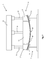
図1は、ガラスシートを曲げるためのプレス曲げステーション1の側面概略図を示す。プレス曲げプレスステーション1は、下部3および上部5を含む。
FIG. 1 shows a schematic side view of a
プレス曲げステーション1の下部3は、成形支持体を含み、ガラスシートをその上で支持する。この例では、成形支持体は、基部9を有するフレーム7であり、第1および第2の直立部11、13はそこから上方に延びる。環状リングの形態の下部支持体15は、第1および第2の直立部11、13に取り付けられている。従来技術のように、下部支持体15は、ガラスシートを上に支持するための上部成形表面15aを有し、すなわち、ガラスシート(図示なし)は、下部支持体15の上部成形表面15aの周辺領域の周りで支持される。
The
典型的には、当技術分野では、下部3は、曲げフレームまたは雌曲げフレームと呼ばれる。実質的に環状の支持リング15の代わりに、完全な接触支持体が、直立部11、13の端部に取り付けられ得る。
Typically, the
図1の例では、下部支持体15の上部成形表面は凹面である。下部支持体15はまた、「成形レール」または単に「レール」と呼ばれ得る。
In the example of FIG. 1, the upper molding surface of
図1には2つの直立部11、13のみが示されるが、実際には、下部支持体15が取り付けられる複数の直立部があり得る。
Although only two
プレス曲げステーション1の上部5は、第1の金型部材17と第2の金型部材19とを備える二部プレス曲げ部材6を備えるプレス曲げ装置を含む。このタイプの二部金型の例は、US5,122,177、WO2012166365A1、およびUS2015/0007612A1に記載されている。
The
図2、3、4、および5をさらに参照すると、第1の金型部材17は、下部成形表面21を有する環状リングである。第2の金型部材19は、第2の金型部材19が第1の金型部材17に対して垂直に移動し得るように、第1の金型部材17の中央開口部内に嵌合する単一構造の金型部材である。第2の金型部材19は、第1の金型部材17内に半径方向に配備される。
With further reference to FIGS. 2, 3, 4 and 5, the
第1の金型部材17は、外部周壁18aと対向する内部周壁18bとを有する。第2の金型部材19は、外部周壁20を有する。第2の金型部材19の外部周壁20は、第1の金型部材17の内部周壁18bに面し、そこから隙間40だけ離間している。図1の断面図では、隙間40は、2つの隙間39および41で表される。
The
第2の金型部材19は、下部成形表面23を有する。成形表面21、23は、ガラスシートがフレーム7、すなわち、支持体15の上部成形表面15a上に支持されるとき、かつ第1および第2の金型部材がある特定の所定の配置にあるとき、成形表面21、23が接触するガラスシートの領域にガラスシートの所望の弯曲を提供するように構成されている。
図4により明確に示されるように、下部支持体15の片側は、直立部11、11’、および11’’’に、反対側は直立部13、13’、および13’’に取り付けられる。直立部11、11’、11’’、13、13’、13’’は、基部9から上方に延び、一端が基部9に接続され、反対側が下部支持体15に接続される。追加の直立部が使用され得る。直立部間の補強クロスメンバーも使用され得る。
As shown more clearly in FIG. 4, the
さらに図5を参照すると、第2の金型部材19の外部周縁20aが第1の金型部材17の内部周縁18cと整列するとき、二部プレス曲げ部材6は、点線24で示されるように、所望の最終的な成形表面に対応する成形表面を有する。この例では、二部プレス曲げ部材6の成形表面は、下部支持体15の上部成形表面15aと相補的であるように構成された凸状成形表面である。所望の最終的な成形表面24は、下部支持体15の上部成形表面15a上に支持されたガラスシートを最終的な所望の形状に成形するための最終的な所望の位置における点線25として示される。
Still referring to FIG. 5, when the
図1および図5を参照すると、第1の金型部材17は、二部プレス曲げ部材の成形表面が二部プレス曲げ部材の所望の最終的な成形表面ではなくなるように、第2の金型部材19に対して変位している。第2の金型部材19の外部周縁20aは、第1の金型部材17の内部周縁18cから量43だけ変位している。
Referring to FIGS. 1 and 5, the
第1の金型部材17は、線形アクチュエータ31および33により垂直方向(矢印30で示される)に可動である。線形アクチュエータ31、33の移動は、第1の金型部材17の両側が同時に上下に移動するように同調される。
The
第2の金型部材19は、線形アクチュエータ35により垂直方向30に可動である。
第1の金型部材17および第2の金型部材19の両方は、互いに垂直方向に独立して可動である。
Both the
線形アクチュエータ31、33、および35は、好適なガントリ37に取り付けられ、ガントリはフレーム7に対して空間的に固定されている。
線形アクチュエータ31、33、および35の移動は、コンピュータに基づくシステムなどの好適な制御手段(図示なし)により制御され得る。
Movement of
図1(および図1の左側の一部の拡大図である図5)に示される構成では、第1の金型部材の成形表面21は、点線25で表される最終的な所望の位置から、一方の側においては垂直距離27、および他方の側においては垂直距離27’だけ変位している。距離27および27’は、同じであることが好ましい。
In the configuration shown in FIG. 1 (and FIG. 5, which is an enlarged view of the left portion of FIG. 1), the
第2の金型部材19の成形表面23は、点線25で表される最終的な所望の位置から垂直距離29だけ変位している。
上述されるような、成形表面21に対して成形表面23が量43だけ変位された第1の構成が図1に示される。変位43に起因して、二部金型6は、フレーム7上に支持されたガラスシートを最終的な所望の形状に曲げるように配置されていない。
A first configuration is shown in FIG. 1 in which forming
図1では、第1の金型部材17の内部周壁18bと第2の金型部材19の外部周壁20との間の2つの隙間39、41が示される。これらの2つの隙間39、41は、図2~4に例示されるように、第1および第2の金型部材17、19の間に延びる連続的な隙間40の部分である。隙間40は、好適な真空源と流体連通して、隙間に負圧領域を提供することによりガラスシートの成形を支援することができる。見てわかるように、隙間40は、二部プレス曲げ部材6の成形表面まで延びている。
In FIG. 1 two
図6は、図1に示される構成とは異なる構成のプレス曲げステーション1を示す。この第2の構成では、ガラスシート50は、フレーム7上に位置付けされており、本発明によるプレス曲げプロセスの途中である。ガラスシート50は、二部プレス曲げ部材6に面する主表面52と、基部9に面する(結果的に、フレーム7および下部支持体15に面する)対向する主表面54とを有する。ガラスシート50の主表面54は、下部支持体15の上部成形表面15a(この構成ではラベル付けされていないが、図1を参照されたい)と接触している。
FIG. 6 shows the
図1に示される構成から開始して、第1の金型部材17および第2の金型部材19の両方は、それぞれの線形アクチュエータ31、33、および35を励磁することによりフレーム7に向かって下方に移動している。第1および第2の金型部材17、19の両方の下方への移動は同調されて、第1および第2の金型部材17、19が、その間の相対的な移動なしに下方に移動する。
Starting from the configuration shown in FIG. 1, both the
フレーム7に向かう第1および第2の金型部材17、19の下方への移動は、各段階での第1および第2の金型部材の間の相対的な移動を伴うかまたは伴わない1つ以上の段階であり得る。一例では、下方への移動の第1の段階で、第1および第2の金型部材の下方への速度は、第1の速度u1であり、下方への移動の第1の段階に続く下方への移動の第2の段階では、第1および第2の金型部材の下方への速度は、第2の速度u2である。第1および第2の金型部材17、19が、下方への移動の第2の段階よりも下方への移動の第1の段階でより速く動くように、u1>u2を有することが好ましい。
The downward movement of the first and
図1および図6を参照すると、図6に示されるような第2の構成では、第1の金型部材17の成形表面21は、ガラスシート50の主表面52とその周辺領域で接触している。第1の金型部材17および第2の金型部材19の特定の配置に起因して、第2の金型部材19の成形表面23も、ガラスシート50の第2の主52表面とその中央領域で接触しており、その中央領域は、ガラスシートの周辺領域の内側にある。第1および第2の金型部材17、19の最終的な所望の位置にはまだ到達していない。
1 and 6, in a second configuration as shown in FIG. 6,
図7では、プレス曲げステーション1は、図1および6に示される構成とは異なる別の構成で示される。この構成の前は、プレス曲げステーション1は、図6に示される構成であった。
In FIG. 7 the
図7に示されるこの第3の構成では、第2の金型部材19は、第2の金型部材19の成形表面23がガラスシート50の主表面52にその中央領域でさらに接触して、ガラスシート50の中央領域をプレス曲げするように、線形アクチュエータ35を励磁することにより下方に移動している。この例では、成形表面23は、成形表面21と整列して示される(その結果、図5を参照すると、変位43はゼロである)。
In this third configuration, shown in FIG. 7, the
この第3の構成では、第1および第2の金型部材17、19は、二部プレス曲げ部材6に最終的な所望の成形表面を提供するように配置されるが、第1および第2の金型部材17、19の最終的な所望の位置にはまだ到達していない。図5を参照すると、変位43はゼロであるが、成形表面21および成形表面23が点線25で示される最終的な位置に到達していないため、垂直距離27および垂直距離29の両方は、ゼロより大きい。
In this third configuration, the first and
第1および第2の金型部材17、19の最終的な所望の位置は、第1および第2の金型部材17、19をフレーム7に向かってさらに下方に移動させて、ガラスシート50をその周辺および中央領域でさらにプレス曲げすることにより到達され得る。この例では、第1および第2の金型部材の最終的な所望の位置に移動する際、このさらなる移動ステップの間に成形表面23が成形表面21と整列したままであるような、第1および第2の金型部材の間に相対的な移動はない。これについては、図8を参照してさらに説明されるが、図の縮尺に起因して、異なる構成を表すことは困難である。
The final desired position of the first and
図8に示される第4の構成では、第1の金型部材17の成形表面21は、第2の金型部材19の成形表面23と整列される。図5を参照すると、変位43は、ゼロである。この配置の二部プレス曲げ部材6は、フレーム7上に支持されたガラスシート50を最終的な所望の形状に押圧するための押圧表面を有し、プレス曲げは、二部プレス曲げ部材6の所望の成形表面も所望の位置にあるように構成されている。図5を参照すると、この第4の構成では、成形表面21および成形表面23の両方は、点線25上にある。図7に示される構成から開始して、第1および第2の金型部材の両方は同時に、成形表面21、23が図7に示される構成から図8に示される構成に移動する際に整列したままになるように、所望の最終的な位置に移動された。
In a fourth configuration, shown in FIG. 8,
図8に示される構成では、隙間39、41は、隙間39、41に面するガラスシートの少なくとも近傍でガラスシート50の主表面52に負圧領域を提供するための真空源(図示なし)と流体連通している。
In the configuration shown in FIG. 8, the
真空源は、ガラスシート50の曲げを改善するために、任意の所望の時間の間、隙間39、41に真空を適用し得る。プレス曲げステーションが上述の第4の構成に到達した後に、隙間39、41に真空源を適用することが好ましい。真空は、段階的に適用され得、ある段階では別の段階と比較して異なるレベルの真空が適用される。真空段階の持続時間は、同じでも異なっていてもよい。1つ以上の真空段階での真空の持続時間は、0.05~5秒であり得る。
A vacuum source may apply a vacuum to
図9では、プレス曲げステーション1は、別(第5)の構成で示される。この第5の配置では、第1および第2の金型部材17、19の成形表面が整列しているため、二部プレス曲げ部材6は、図8に示されるのと本質的に同じように配置される(図5を参照すると、変位43はゼロである)。しかしながら、図8に示されるプレス曲げステーション1の構成とは対照的に、二部金型6が線形アクチュエータ31、33、35の好適な発動/励磁によりフレーム7に対して持ち上げられているため、図9に示されるプレス曲げステーション1の構成は異なる。第1および第2の金型部材17、19は、ガントリ37に向かって同じ速度で矢印30’の方向に上方に移動されており、すなわち、ガントリ37に向かう上方の第1および第2の金型部材17、19の移動は、第1および第2の金型部材の間の相対的な運動がない状態で同調される。
In FIG. 9 the
曲げられたガラスシート50は、隙間39、41(したがって、隙間40、図2~4を参照されたい)に真空が適用されることにより、二部プレス曲げ部材6の下側で支持されて、隙間(複数可)に対向するガラスシートの主表面52に負圧の領域を作るように示される。
The
隙間39、41に真空が適用されることに加えて、第1の金型部材17の成形表面21はそこに、真空源(隙間39、41に真空を提供するために使用されるのと同じ真空源であり得る)と流体連通している開口部を有してもよい。成形表面21の開口部と流体連通している真空源はまた、二部プレス曲げ部材6の下側でガラスシート50を支持するためにも使用され得る。
In addition to the vacuum being applied to the
さらに、隙間39、41、および/または第1の金型部材17の成形表面21の開口部に真空が適用されることに加えて、第2の金型部材19の成形表面23はそこに、真空源(隙間39、41に真空を提供するために使用されるのと同じ真空源であり得る)と流体連通している開口部を有してもよい。成形表面23の開口部と流体連通している真空源は、二部プレス曲げ部材6の下側でガラスシート50を支持するために使用され得る。
Further, in addition to applying a vacuum to
フレーム7(すなわち、下部支持体15の上部成形表面15aの上方)と二部プレス曲げ部材6との間に配備されたキャリアリング58が示される。曲げ動作の好適な時点で、隙間39、41(または、隙間40)に適用された真空は、曲げられたガラスシート50が二部プレス曲げ部材6の下側でもはや支持されず、代わりにそこから落下して、キャリアリング58により支持されるように終了する。隙間39、41(または、隙間40)はまた、隙間39、41での真空が終了した後、流体、すなわち圧縮空気が隙間39、41を通って、ガラスシート50に向かって流れて、第1および第2の金型部材17、19それぞれの成形表面21、23からの曲げられたガラスシート50の除去を支援するように、圧縮空気などの好適な流体源とも流体連通してもよい。
A
フレーム7と二部プレス曲げ部材6との間から離れるようにキャリアリング58を矢印60の方向に移動させるための好適なアクチュエータ(図示なし)が提供される。その後、曲げられたガラスシートは、その後の焼鈍または強化のために好適な搬送手段(図示なし)上に集積され得る。
A suitable actuator (not shown) is provided for moving
上述されるように、図には示されていないが、第1の金型部材17の成形表面21および/または第2の金型部材19の成形表面23は、そこに少なくとも1つの開口部を有し得、該開口部は、真空源などの少なくとも1つの負圧源と流体連通している。
As mentioned above, although not shown in the figures, the
隙間40で生成される負圧領域に加えて、第1の金型部材17の成形表面21の各開口部もしくは第1の金型部材17の成形表面21、および/または第2の金型部材19の成形表面23の各開口部もしくは第2の金型部材19の成形表面23に追加の負圧領域が存在し得、ガラスシートを曲げるときに改善された形状制御を可能にする。
In addition to the negative pressure area created in the
第1の金型部材17の成形表面21が、真空を提供するための1つ以上の開口部をそこに有する場合(例えば、隙間39、41に関して上述されるように)、成形表面21の任意の数の該開口部はまた、圧縮空気などの好適な流体源とも流体連通し得、真空が終了した後に、流体を、該開口部を通してガラスシートに向かって流すことにより、成形表面21からの曲げられたガラスシートの除去を支援する。
If
同様に、第2の金型部材19の成形表面23が(例えば、隙間39、41に関して上述されるように)真空を提供するための1つ以上の開口部をそこに有する場合、成形表面23の任意の数の該開口部はまた、圧縮空気などの好適な流体源とも流体連通し得、真空が終了した後に、流体を、該開口部を通してガラスシートに向かって流すことにより、成形表面23からの曲げられたガラスシートの除去を支援する。
Similarly, if molding
本発明による成形プロセスの間の第1および第2の金型部材17、19の一連の動きをさらに例示するために、図1(フレーム7上のガラスシート50を除く)、6、7、および8の左側部分が拡大され、追加の図として提供される。前述の図のこれらの拡大部は、それぞれ図10、12、13、および14に示される。追加の図11は、第1の金型部材17の成形表面21がガラスシート50にその周辺領域で接触する前に、第2の金型部材19の成形表面23がガラスシート50にその中央領域で接触するとき、成形動作の間の瞬間を示すために含まれる。
To further illustrate the sequence of motion of the first and
図1および図10を参照すると、ガラスシート50は、下部支持体15の成形表面15a上に支持されているように示される。ガラスシートは、当技術分野で既知の方法を使用して成形表面15a上に好適に位置付けされている。ガラスシート50は、第1の主表面52と、第2の対向する主表面54とを有する。第2の主表面54は、下部支持体15の上部成形表面15aに接触する。ガラスシートは熱軟化されており、その中央領域でわずかに垂れ下がり得る。
1 and 10,
ガラスシート50の上方に位置付けされた二部プレス曲げ部材6の一部が示される(6’で示される)。第1の金型部材17は、ガラスシート50の第1の主表面52に面する成形表面21を有し、第2の金型部材19は、ガラスシート50の第1の主表面52に面する成形表面23を有する。
A portion of the two-part
上述されるように、成形表面21、23は、縁部18cおよび20aが整列されていないため、変位43により互いにオフセットされる。
As noted above, molding surfaces 21, 23 are offset from each other by
この図に示されるように、成形表面21、23はどちらもガラスシート50に接触していない。
As shown in this figure, neither forming
図11では、第1および第2の金型部材17、19の両方は一緒に下方に移動して、それらの間に相対的な移動がなく、すなわち、図10に示される構成から始まって、第1および第2の金型部材17、19の両方が同じ速度で矢印30の方向に移動した。そのため、成形表面21、23は、まだ整列されておらず、上記の変位43が依然として存在する(この場合、変位43は、図10と同じである)。この構成では、成形表面23は、ガラスシート50の第1の主表面52にちょうど接触している。しかしながら、二部プレス曲げ部材6’の第1および第2の金型部材17、19の特定の配置のため、第2の金型部材19に対する第1の金型部材17の位置は、成形表面21がガラスシート50の第1の主表面52にまだ接触していない状態にある(しかし、成形表面23は、ガラスシート50の第1の主表面52に既に接触している)。
In FIG. 11 both the first and
二部プレス曲げ部材6’の第1および第2の金型部材17、19の異なる配置が使用され得、ここで、第2の金型部材19は、第1の金型部材17に対して配置されて、第1の金型部材17の成形表面21は、第2の金型部材19の成形表面23がガラスシートの第1の主表面52に接触する前に、ガラスシートの第1の主表面52に接触する。この代替実施形態における第2の金型部材の位置は、成形表面23aを有する19aとして仮想線で示される。第1および第2の金型部材は、第1および第2の金型部材の両方がフレームに向かって同じ速度で下方に移動するのと同時に、それらのそれぞれの成形表面がガラスシート50の第1の主表面52に接触するように、配置され得ることが容易に明らかであろう。
Different arrangements of the first and second die
図6の左側の一部の拡大図である図12は、ガラスシート50が、第1の成形部材17と下部支持体15との間で、その周辺領域で部分的に押圧されていることを示す。第1および第2の金型部材の両方が、同じ速度で(矢印30の方向に)下方に移動し続けているため(図10または11に示される配置で開始するとき)、ガラスシート50も第2の金型部材19によりその中央領域でわずかに押圧される。しかしながら、第1および第2の金型部材の成形表面は、上述されるように、ゼロではない変位43を依然として有する。
FIG. 12, which is an enlarged view of a portion of the left side of FIG. 6, shows that the
図7の左側の一部の拡大図である図13は、図12に示される配置後の二部プレス曲げ部材6’を示し、ここで、第1の金型部材17は、下部支持体15に対して静止したままであり、第2の金型部材19は、さらに下方(矢印30の方向)に移動して、ガラスシート50をその中央領域でプレス曲げする。ガラスシート50は、第1の金型部材17と下部支持体15との間で部分的に押圧されることにより、その周辺領域で十分に保持される。この構成では、第1および第2の金型部材17、19の成形表面21、23の間に変位はない(変位43は、ゼロである)。したがって、二部プレス曲げ部材6’は、所望の最終的な成形表面を有するが、二部プレス曲げ部材は、ガラスシート50を所望の形状に完全にプレス曲げするための最終的な位置にはない。これは、以下の図14に示される。
FIG. 13, which is an enlarged view of the left part of FIG. 7, shows the two-part press bending member 6' after the arrangement shown in FIG. , the
図8の左側の一部の拡大図である図14は、図13に示される構成後の二部プレス曲げ部材6’を示し、ここで、金型部材17および第2の金型部材19の両方は、同時に下方(矢印30の方向)に移動しており、すなわち、第1の金型部材17と第2の金型部材19との間に相対的な移動はない。また、第1および第2の金型部材の成形表面の間に変位はない(変位43は、ゼロである)。二部プレス曲げ部材6’は、所望の最終的な成形表面を有し(変位43がゼロであるため)、最終的な位置(図5の点線25を参照されたい)に移動して、ガラスシート50を所望の形状に完全にプレス曲げする。この最終的なプレス曲げステップの後、真空が隙間39(および、隙間41、図8を参照されたい)で生成されて、ガラスシート50を二部金型6’の下側に保持し、かつ上述されるように曲げられたガラスシートの形状制御を改善することができる。
FIG. 14, which is an enlarged view of a portion of the left side of FIG. 8, shows the two-part press bending member 6' after the configuration shown in FIG. Both are moving downward (in the direction of arrow 30) at the same time, ie there is no relative movement between the first and
図15は、図1に示されるタイプのプレス曲げステーション1を組み込んだガラス曲げライン70の部分の概略断面図を示し、その動作は図1~14を参照して説明される。
Figure 15 shows a schematic cross-sectional view of a portion of a
ガラス曲げライン70は、加熱炉72と、加熱されていてもいなくてもよいプレス曲げ部74と、焼鈍炉76と、を備える。
The
ローラー搬送ベッド78は、加熱炉72、プレス曲げ部74、および焼鈍炉76を通って延びて、ガラスシート50の搬送経路を画定する。ローラー搬送ベッドは、ガラスシート50を矢印82の方向に搬送するように構成された(すなわち、間隔を空けた平行関係にある)複数のローラー80を備える。この例では、ガラスシート50は、ローラー80と接触しているように示されるが、ガラスシート50は、好適なキャリッジ(図示なし)上に位置付けされ得、キャリッジは、ローラー80と接触している。ローラー80の代替として、またはローラー80に加えて、空気浮上装置を使用して、ガラスシートを矢印82の方向に搬送することができる。
加熱炉72では、ガラスシート50が曲げに好適な温度に加熱される。炉は、必要に応じて、電気加熱、ガス加熱、対流加熱、およびマイクロ波加熱、ならびにそれらの組み合わせなどの任意の好適な加熱手段を組み込み得る。
In
プレス曲げセクション74の内部にはプレス曲げステーション1がある。ガラスシート50がフレーム7と二部プレス曲げ部材6との間に搬送されるとき、ガラスシートは、図1~14を参照して説明されているように、その後のプレス曲げのためにフレーム7上に集積されることにより位置付けされる。ガラスシートを搬送ローラー80からフレーム7に移送するための方法は先行技術で知られており、例えば、搬送ローラーのいくつかは、ドロップローラーとして構成され得るか、または真空プラテンは、熱軟化ガラスシートを、好適に構成されたフレーム7上に集積するための搬送ローラーから懸垂するために使用され得る。
Inside the
図15および図1を参照すると、線形アクチュエータ31、33、35による二部プレス曲げ部材6の2つの第1および第2の金型部材17、19の相対的な移動を制御するためのコンピュータなどの制御手段84と電気通信している二部プレス曲げ部材6が示される。制御手段84は、ガラス曲げライン70の他の部分、例えば、搬送ローラーベッド78と電気通信して、ローラー80および/またはキャリアリング58の移動を制御するアクチュエータ(図示なし)の速度を制御し得る。
15 and 1, a computer or the like for controlling the relative movement of the two first and second die
キャリアリング58は、プレス曲げ部74と焼鈍炉76との間に示され、好適なアクチュエータ(図示なし)により、すなわち矢印60の方向に移動することにより、図9に示される位置と図15に示される位置との間で可動である。キャリアリング58により支持された曲げられたガラスシートは、二部プレス曲げ部材6とフレーム7との間(すなわち、プレス曲げ部74の内側)からプレス曲げ部74の外側に移動され、ここで、曲げられたガラスシートは、次いで、その後の焼鈍、すなわち、周囲温度への制御された冷却のために、焼鈍炉76に搬送される搬送ローラーベッド78の一部78’上に集積され得る。
The
図では、二部プレス曲げ部材6が前述されるように露出した成形表面21と23とを有するように示されるが、好ましい実施形態では、第1および第2の金型部材17、19の一方または両方には保護カバーが提供されて、金型部材(複数可)の成形表面を損傷および摩耗から保護し得る。下部支持体15にもこのような保護カバーが提供されて、上部成形表面15aを覆うことができる。カバーが使用されるとき、好ましくは、カバーは、例えば、ステンレス鋼、ガラス繊維、ポリフェニレンテレフタルアミド繊維(例えば、Kevlar(商標))、Kevlar(商標)がブレンドされた材料、グラファイトを含有するポリベンゾキサーレ(polybenzoxale)(PBO)繊維(例えば、Zylon(商標))、またはこれらの繊維の様々な織布からなる布を含む。
In the figures, the two-part
保護カバーを使用して、各成形表面21、23を覆う場合、成形表面21および成形表面23の両方を覆う単一のカバーを使用することが好ましい。
If protective covers are used to cover each
成形表面21および23の両方を覆う保護カバーが使用される場合、保護カバーは、前述されるように第1および第2の金型部材が可動するように十分に柔軟でなければならない。 If a protective cover is used that covers both molding surfaces 21 and 23, the protective cover must be sufficiently flexible to allow movement of the first and second mold members as previously described.
さらに、成形表面21および23の両方を覆う保護カバーが使用される場合、保護カバーは、例えば、前述されるように、第1および第2の金型部材の間の隙間40に、または第1および第2の金型部材のそれぞれの成形表面に存在し得る任意の開口部に、そこを通って真空の提供が可能になるように十分に多孔性または通気性があることが好ましい。
Additionally, if a protective cover is used that covers both molding surfaces 21 and 23, the protective cover may be applied, for example, to the
各成形表面21、23に個別の保護カバーを使用することができる。これには、第1および第2の金型部材の間の隙間が保護カバーの材料により妨げられ得ないという利点がある。
A separate protective cover can be used for each
図1、6、7、および8(または、図10~14)に示される構成の間を移動する際の、第1および第2の金型部材17、19の下方への移動が、図16および17(第1の例)ならびに図18および19(第2の例)で例示される。図16~19は、図1および図5の線25で表される該部分の成形表面の最終的な所望の位置に対する第1および第2の金型部材17、19の垂直位置を示す。
Downward movement of the first and
図16~19では、軸90は秒単位の時間であり、軸92はmm単位の距離である。
16-19,
図16および17では、点線は、該成形表面21の最終的な所望の位置に対する第1の金型部材17の成形表面21の垂直変位を表す。実線は、該成形表面23の最終的な所望の位置に対する第2の金型部材19の成形表面23の垂直変位を表す。成形表面21、23の最終的な所望の位置(それらが整列されるときについて、図5、7、および13、ならびにそれらの関連する説明を参照されたい)は、ゼロの基準データ点に対して-200mmの垂直変位にある。成形表面21は、時間=ゼロでゼロ基準データ点にあり、成形表面23は、時間=ゼロでゼロ基準データ点に対して+10mmにある。つまり、成形表面21の最終的な所望の位置では、200mmの下方への全体的な垂直移動がある一方、成形表面23では、210mmの下方への全体的な垂直移動がある。
16 and 17 the dashed lines represent the vertical displacement of the
図16および図17を参照すると、第1の実施形態における第1および第2の金型部材17、19の相対的な移動が記載される。
16 and 17, relative movement of the first and
時間t=0(すなわち、点AおよびA’)で、二部プレス曲げ金型6は、第1の金型部材17の成形表面21が第2の金型部材19の成形表面23に対して10mmだけ変位するように、配置される。図5を参照すると、距離27(したがって、距離27’、図1を参照されたい)は200mmであり、距離29は210mmであり、変位43は10mmである。
At time t=0 (ie, points A and A′), the two-part press bending die 6 is positioned so that the forming
0.5秒後(点B、B’で)、プレス曲げ動作が開始され、第1の金型部材17および第2の金型部材19の両方が、フレーム7上に支持されたガラスシート50に向かって下方に垂直移動する(例えば、図10を参照されたい)。第1および第2の金型部材17、19の両方は、同じ速度(=v1)で下方に移動するため、この下方への移動段階中、第1および第2の金型部材17、19の成形表面21、23の間に相対的な移動はなく、すなわち、点B-CおよびB’-C’では、第1および第2の金型部材17、19の移動が同調され、変位43は10mmに固定されたままである。
After 0.5 seconds (at points B, B') the press bending action is started and both the
1.2秒後(点C、C’で)、ガラスシート50の表面に近づくにつれて、第1および第2の金型部材17、19の下方への速度が(速度v2に)低減される。第1および第2の金型部材17、19の同調された下方への垂直移動は、点D、D’に到達するまで速度v2で継続される。
After 1.2 seconds (at points C, C'), the downward velocity of the first and
2.1秒後(点Dで)、第2の金型部材19は、速度v2で下方に垂直移動し続ける。しかしながら、点D’(点Dと時間的に一致する)で、第1の金型部材17の下方への垂直移動は停止される。プレス曲げステーションは、図6(または図12)に示される構成になっている。この時点で、ガラスシート50の主表面52は、ガラスシート50がフレーム7の下部支持体15と第1の金型部材17との間で部分的に押圧されるように、第1の金型部材17の成形表面21と接触している。
After 2.1 seconds (at point D), the
次の0.2秒間にわたって、第2の金型部材19は、速度v2で下方に移動し続けて、ガラスシート50が静的な第1の金型部材17により部分的に押圧されたまま、ガラスシート50をその中央領域でプレス曲げする。つまり、点D’と点E’との間で、第1の金型部材17は、フレーム7に対して静止したままであり、ガラスシートをその周辺領域で部分的に押圧する。
Over the next 0.2 seconds,
2.3秒後(点E’で)、第1の金型部材17の移動は、第1の金型部材17および第2の金型部材19の両方が同時に最終的な所望の位置(点F、F’)に到達するように、選択された下方への速度(=v3)で再開される。つまり、点Eと点Fとの間で、第2の金型部材19は、速度v2で下方に垂直移動し続ける一方、点E’と点F’との間では、第1の金型部材が、速度v3で下方に垂直移動する。
After 2.3 seconds (at point E'), movement of
点E’と点F’との間の第1の金型部材17の下方への移動は、下部支持体15の上部成形表面15aと第1の金型部材の成形表面21との間でガラスシートの周辺領域をさらに押圧する。つまり、周辺領域では、ガラスシートは、下部支持体15と第1の金型部材17との間でさらに押圧されながら、ガラスシートは、第2の金型部材19により中央領域でさらにプレス曲げされる。
Downward movement of
第1の金型部材17が点D’とE’(それぞれ点DとEに対応する)との間で静止しているため、第2の金型部材19は、点DとEとの間で下方に垂直移動し続けると、第1および第2の金型部材17、19の成形表面21、23の分離が減少することは明らかである。図5を参照すると、変位43は、点DとEとの間で減少する。
Since the
2.5秒後(点F、F’で)、第1および第2の金型部材17、19の両方は、最終的な所望の位置に到達し、ガラスシート50は、最終的な所望の形状にプレス曲げされる。プレス曲げステーションは、図8または図14に示される構成になっている。点F、F’で、二部曲げ部材6は、最終的な所望の弯曲を有する成形表面を有する。
After 2.5 seconds (at points F, F') both the first and
本発明の第1の態様による方法のこの特定の(図16および図17に例示されるような)例では、第1および第2のプレスの成形表面の初期分離(変位43)は、10mmである。第1の金型部材17は、成形表面21の位置が成形表面21の最終的な位置から2mm離れるような位置まで下方に垂直移動された。次いで、成形表面21、23は上述されるように移動されて、点F、Fにより示される最終的な位置に同時に到達したのは、第1および第2の金型部材17、19の両方の最初の下方への垂直移動が開始した2秒後、すなわち、点B、B’の2秒後である。
In this particular example (as illustrated in FIGS. 16 and 17) of the method according to the first aspect of the invention, the initial separation (displacement 43) of the forming surfaces of the first and second presses is 10 mm. be. The
点D’で第1の金型部材17を停止し、次いで、点E’で第1の金型部材の下方への移動を再開することにより、第2の金型部材19の成形表面23が最終的な位置、すなわち点F、F’に到達すると同時に、成形表面21を最終的な位置まで移動させるための第1の金型部材17のさらなる下方への移動、つまり、プレス曲げ動作の間にガラスシート50に生じる過渡応力が、第1の金型部材17が事前に停止することなく最終的な位置に移動するときと比較して低減されたことがわかった。つまり、第1の金型部材が点D’で停止することなく、代わりに第1の金型部材17の成形表面21が最終的な所望の位置(すなわち、ゼロデータから-200mm)になるまで速度v2で継続すると、プレス曲げ動作の間により多くのガラス破損があった。
By stopping the
第1および第2の金型部材17、19の修正された下方への移動を使用して、別の試験を実施した。
Another test was performed using a modified downward movement of the first and
この第2の例は、図18および19を参照して説明される。図18および19では、点線は、該成形表面21の最終的な所望の位置に対する第1の金型部材17の成形表面21の垂直変位を表す。実線は、該成形表面23の最終的な所望の位置に対する第2の金型部材19の成形表面23の垂直変位を表す。成形表面21、23の最終的な所望の位置(それらが整列されているときについては、図5、7、および13、ならびにそれらの関連する説明を参照されたい)は、ゼロの基準データ点に対して-200mmの垂直変位にある。成形表面21は、時間=ゼロでゼロ基準データ点にあり、成形表面23は、時間=ゼロでゼロ基準データ点に対して+10mmにある。つまり、成形表面21の最終的な所望の位置では、200mmの全体的な下方への移動があったが、成形表面23では、210mmの全体的な下方への移動であった。
This second example is described with reference to FIGS. 18 and 19 the dashed lines represent the vertical displacement of the
図18および19では、点D、D’まで(2.1秒で)、この第2の例での第1および第2の金型部材17、19の移動は、第1の例と同じである(図16および17に例示されるように)。つまり、点BとC(および、B’とC’)との間で、第1および第2の金型部材17、19の両方は、(変位43を10mmに固定して)速度v1で下方に垂直移動し、点CとD(ならびに、C’とD’)との間で、第1および第2の金型部材17、19の両方は、(再度、変位43を10mmに固定して)v2の速度で下方に垂直移動する。
18 and 19, up to points D, D' (in 2.1 seconds), the movement of the first and
この第2の例では、点Dで、第2の金型部材19は、点Fで最終的な位置に到達するまで、同じ速度v2で下方に垂直移動し続ける。この第2の例での第2の金型部材19は、図16および図17に関して記載される第1の例と同じ方法で下方に移動する。
In this second example, at point D, the
第1の例のように、第2の例では、第1の金型部材が点Dに到達するとき(2.1秒後)、その下方への移動が停止される。しかしながら、第1の例とは対照的に、第1の金型部材は、第1の金型部材17の成形表面21および第2の金型部材の成形表面23が(点G、G’で)整列するまで、静止したままである。図5を参照すると、点G、G’で、変位43はゼロであり、成形表面21、23は整列している。二部プレス曲げ部材6は、最終的な所望の成形表面(図5の点線24で表される)を有するが、最終的な所望の成形表面は、所望の最終的な位置(図5の点線25で表される)にない。
As in the first example, in the second example, when the first mold member reaches point D (after 2.1 seconds), its downward movement is stopped. However, in contrast to the first example, the first mold member is such that the
この時点で、変位43がゼロ(約2.43秒)であるとき、点G’で、第1の金型部材17の下方への移動が再開されて、第1の金型部材の成形表面21および第2の金型部材の成形表面23は、最終的な所望の位置に移動される。
At this point, when the
点G’と点F’との間で、第1および第2の金型部材17、19の移動は、2つの成形表面21、23の間に相対的な垂直移動がないように、再度同調される。第1および第2の金型部材17、19は、最終的な位置F、F’がゼロ基準データ点から垂直距離-200mmで到達されるまで、同じ速度(=v2)で下方に垂直移動する。成形表面21、23は整列され、変位43はゼロである。
Between points G' and F', the movement of the first and
次いで、プレス曲げステーションは図8(および図14)にも示されるような構成になるが、プレス曲げ動作の間の第1および第2の金型部材の間の相対的な移動は、本方法の第1の例と比較して異なる(図16および17を参照して上述されるように)。上述の第2の例は、図10~14に例示される。 The press bending station is then configured as also shown in FIG. 8 (and FIG. 14), but the relative movement between the first and second die members during the press bending operation is (as described above with reference to FIGS. 16 and 17). The second example described above is illustrated in FIGS. 10-14.
本発明によるこのような方法は、自動車用途の弯曲ガラスシート、例えば、フロントガラスのプライ、またはサイドライト、バックライト、もしくはルーフライト、すなわち、サンルーフのための窓ガラスとして使用するために、最初に平らなガラスシートを最終的な弯曲に曲げるのに部分的に有用である。2つのこのような弯曲したガラスシートは、ポリビニルブチラール(PVB)などの接着性中間層材料のうちの少なくとも1つのプライにより一緒に接合されて、車両のフロントガラスに使用され得る。 Such a method according to the present invention is primarily intended for use as curved glass sheets for automotive applications, such as plies of windshields, or glazings for sidelights, backlights, or rooflights, i.e. sunroofs. Partially useful for bending a flat glass sheet into a final curve. Two such curved glass sheets can be joined together by at least one ply of an adhesive interlayer material such as polyvinyl butyral (PVB) and used in a vehicle windshield.
図20は、二部プレス曲げ部材6の第1および第2の金型部材17、19を覆う単一の布16が存在することを除いて、図1~8を参照して説明されるようなプレス曲げステーション1と本質的に同じである別のプレス曲げステーション1’の概略側面図を示す。
FIG. 20 is as described with reference to FIGS. shows a schematic side view of another press-bending station 1' which is essentially the same as the other press-bending
プレス曲げステーション1’は、図8のプレス曲げステーション1と本質的に同じ構成で示される。しかしながら、第1および第2の金型部材は単一の布16で覆われているため、第1の金型部材17の成形表面は布16で覆われて、布16は、ガラスシート50の主表面52と直接接触している。そのため、第1の金型部材17の成形表面21および第2の金型部材19の成形表面23は、ガラスシート50の主表面52と間接的に接触している。
The press-bending station 1' is shown in essentially the same configuration as the press-bending
好ましくは、布16は、通気性布である。好ましくは、布16は、ステンレス鋼、ガラス繊維、ポリパラフェニレンテレフタルアミド繊維、またはそれらのブレンド、グラファイトを含有するポリベンゾオキサゾール(PBO)繊維、およびこれらの繊維の様々な織布のうちの少なくとも1つを含む。
Preferably,
図21は、第1の金型部材17を覆う第1の布16’および第2の金型部材19を覆う第2の布16’’があること、すなわち、布16’が第1の金型部材17の成形表面21を覆い、布16’’が第2の金型部材19の成形表面23を覆っていることを除いて、図1~8を参照して説明されるようなプレス曲げステーション1と本質的に同じである別のプレス曲げステーション1’’の概略側面図を示す。2つの布カバーを収容するために、第1の金型部材17の外部周壁18aおよび内部周壁18b、ならびに第2の金型部材19’の外部周壁20まで延びる布を収容するためのわずかにより小さい成形表面を有する第2の金型部材19’が提供される。そのため、隙間39’、41’は、図1の隙間39、41よりわずかに幅広い。また、2つの布16’、16’’が使用されるため、隙間39’および41’は、二部プレス曲げ部材106(第2の金型部材19’は、二部プレス曲げ部材6の第2の金型部材19とは異なるため106と示される)の成形表面の近くの布により妨げられない。2枚以上の布を使用すると、ガラスシートを曲げる際の継続的な使用に起因して布が摩耗するため、布の選択された領域を交換するだけでよいという利点も提供される。単一の布を使用すると、布が摩耗すると布全体を交換する必要がある一方、少なくとも第1および第2の布を使用するときは、必要に応じてこれらの布のうち1枚を交換するだけでよい。
FIG. 21 shows that there is a first cloth 16' covering the
プレス曲げステーション1’’は、図8のプレス曲げステーション1と本質的に同じ構成で示される。しかしながら、第1の金型部材17は布16’で覆われ、第2の金型部材19’は布16’’で覆われているため、布16’および16’’は、ガラスシート50の第1の主表面52と直接接触している。そのため、第1の金型部材17の成形表面21および第2の金型部材19の成形表面23はそれぞれ、布16’および16’’を介してガラスシート50の第1の主表面52と間接的に接触している。
The press-bending station 1'' is shown in essentially the same configuration as the press-bending
好ましくは、布16’、16’’のうちの少なくとも1つは、通気性布である。好ましくは、布16’および/または16’’は、ステンレス鋼、ガラス繊維、ポリパラフェニレンテレフタルアミド繊維、またはそれらのブレンド、グラファイトを含有するポリベンゾオキサゾール(PBO)繊維、およびこれらの繊維の様々な織布のうちの少なくとも1つを含む。 Preferably, at least one of fabrics 16', 16'' is a breathable fabric. Preferably, fabrics 16' and/or 16'' are made of stainless steel, glass fibers, polyparaphenylene terephthalamide fibers, or blends thereof, graphite-containing polybenzoxazole (PBO) fibers, and variations of these fibers. woven fabric.
本発明によるガラスシートを成形する方法を使用し、かつ曲げられたガラスシートの周辺領域のしわを改善するとき(単一の単一構造の上部プレス曲げ部材の使用と比較して)、成形動作、すなわち、プレス曲げ動作の間のガラス破損のリスクが低減した。 When using the method of forming a glass sheet according to the present invention and improving the wrinkling of the peripheral region of the bent glass sheet (compared to the use of a single monolithic upper press bending member), the forming operation ie the risk of glass breakage during the press bending operation is reduced.
本明細書で提供される例は、二部プレス曲げ部材のみに関するが、プレス曲げ装置は、3つ以上の独立して可動な金型部材を有するプレス曲げ部材を備えてもよく、例えば、ガラスシートの2つの対向する横方向周辺領域がステップ(v)の間に押圧され得、ステップ(vi)の間にガラスシートの2つの対向する横方向周辺領域の間のガラスシートの中央領域が押圧され得る。
Although the examples provided herein relate only to two-part press-bending members, the press-bending apparatus may comprise press-bending members having three or more independently movable die members, e.g. Two opposing lateral peripheral regions of the sheet may be pressed during step (v), and a central region of the glass sheet between the two opposing lateral peripheral regions of the glass sheet may be pressed during step (vi). can be
Claims (19)
(i)前記ガラスシートを支持するための成形支持体を提供するステップと、
(ii)少なくとも第1および第2の金型部材を備えるプレス曲げ装置を提供するステップであって、前記第1および第2の金型部材の各々が前記成形支持体に対して可動である、ステップと、
(iii)前記ガラスシートを加熱するステップと、
(iv)前記ガラスシートを前記成形支持体上に位置付けするステップと、
(v)前記成形支持体および前記プレス曲げ装置のうちの少なくとも一方を他方に向かって移動させて、前記成形支持体と前記第1の金型部材との間で前記ガラスシートをその第1の領域で押圧するステップと、
(vi)前記第2の金型部材を前記第1の金型部材に対して移動させて、前記ガラスシートをその第2の領域で押圧するステップと、
(vii)前記第1の金型部材を前記成形支持体に対して移動させて、前記第1の金型部材と前記成形支持体との間で前記ガラスシートをその前記第1の領域でさらに押圧するステップと、を含み、
前記ガラスシートの前記第1の領域が、前記ガラスシートの周辺領域であり、かつ前記ガラスシートの前記第2の領域が、前記ガラスシートの中央領域である、方法。 A method of forming a glass sheet, comprising:
(i) providing a shaped support for supporting said glass sheet;
(ii) providing a press bending apparatus comprising at least first and second die members, each of said first and second die members being movable with respect to said shaping support; a step;
(iii) heating the glass sheet;
(iv) positioning the glass sheet on the shaping support;
(v) moving at least one of said forming support and said press bending device toward the other to move said glass sheet between said forming support and said first mold member into its first position; pressing in the area;
(vi) moving the second mold member relative to the first mold member to press the glass sheet in its second region;
(vii) moving the first mold member relative to the shaping support to further move the glass sheet in the first region thereof between the first mold member and the shaping support; pressing;
The method, wherein the first region of the glass sheet is the peripheral region of the glass sheet and the second region of the glass sheet is the central region of the glass sheet.
成形表面を各々有する少なくとも第1および第2の金型部材を備えるプレス曲げ装置を備え、前記プレス曲げ装置が、
前記第1の金型部材の前記成形表面および前記第2の金型部材の前記成形表面が整列されて、成形支持体上に支持されるときに前記ガラスシートを最終形状に押圧するための成形表面を有する前記プレス曲げ装置を提供するように前記第1および第2の金型部材が配置される、第1の構成と、
前記第1の金型部材の前記成形表面が、前記第2の金型部材の前記成形表面に対して変位している、第2の構成と、を有し、
前記第1および第2の金型部材が、互いに対して可動であり、
前記プレス曲げ装置が、プレス曲げ動作の間に前記第1および第2の金型部材の位置を制御するための制御手段をさらに備え、
前記制御手段が、前記第1および第2の金型部材の互いに対する位置を制御して、請求項1~14のいずれかの方法におけるステップ(v)、(vi)、(vii)のそれぞれを全て実行するように構成されている、装置。 An apparatus for forming a glass sheet, comprising:
a press bending device comprising at least first and second mold members each having a forming surface, said press bending device comprising:
forming for pressing the glass sheet into a final shape when the forming surface of the first mold member and the forming surface of the second mold member are aligned and supported on a forming support; a first configuration, wherein the first and second mold members are arranged to provide the press bending device with a surface;
a second configuration, wherein the molding surface of the first mold member is displaced relative to the molding surface of the second mold member;
said first and second mold members being movable relative to each other;
said press bending apparatus further comprising control means for controlling the position of said first and second mold members during a press bending operation;
said control means controlling the positions of said first and second mold members relative to each other to perform each of steps (v), (vi) and (vii) in the method of any of claims 1-14; A device configured to do all .
An assembly comprising an apparatus according to any of claims 15-18 and a shaped support for supporting a glass sheet thereon.
Applications Claiming Priority (3)
| Application Number | Priority Date | Filing Date | Title |
|---|---|---|---|
| GB1708761.0 | 2017-06-01 | ||
| GBGB1708761.0A GB201708761D0 (en) | 2017-06-01 | 2017-06-01 | Method and apparatus for shaping a glass sheet |
| PCT/GB2018/051504 WO2018220394A1 (en) | 2017-06-01 | 2018-06-01 | Method and apparatus for shaping a glass sheet |
Publications (3)
| Publication Number | Publication Date |
|---|---|
| JP2020521711A JP2020521711A (en) | 2020-07-27 |
| JP2020521711A5 JP2020521711A5 (en) | 2021-07-26 |
| JP7227927B2 true JP7227927B2 (en) | 2023-02-22 |
Family
ID=59349784
Family Applications (1)
| Application Number | Title | Priority Date | Filing Date |
|---|---|---|---|
| JP2019565562A Active JP7227927B2 (en) | 2017-06-01 | 2018-06-01 | Method and apparatus for forming glass sheets |
Country Status (7)
| Country | Link |
|---|---|
| US (1) | US11661368B2 (en) |
| EP (1) | EP3630687A1 (en) |
| JP (1) | JP7227927B2 (en) |
| CN (1) | CN110691759B (en) |
| BR (1) | BR112019024731A2 (en) |
| GB (1) | GB201708761D0 (en) |
| WO (1) | WO2018220394A1 (en) |
Families Citing this family (5)
| Publication number | Priority date | Publication date | Assignee | Title |
|---|---|---|---|---|
| US11230487B2 (en) * | 2019-03-22 | 2022-01-25 | Glasstech, Inc. | Glass processing system with variable bending station |
| US11702356B2 (en) * | 2019-04-15 | 2023-07-18 | Corning Incorporated | Assemblies and methods for bending glass |
| CN114901474A (en) * | 2019-10-30 | 2022-08-12 | 康宁公司 | Method and system for press bending two or more glass layers |
| CN112060819B (en) * | 2020-09-14 | 2022-02-15 | 凯盛信息显示材料(池州)有限公司 | Mobile phone 3D glass layer cover plate texture processing device and processing method |
| CN113060929B (en) * | 2021-04-09 | 2022-12-20 | 福耀玻璃工业集团股份有限公司 | Automobile glass forming die and production method |
Citations (3)
| Publication number | Priority date | Publication date | Assignee | Title |
|---|---|---|---|---|
| JP2007506637A (en) | 2003-09-24 | 2007-03-22 | ピルキングトン・ノースアメリカ・インコーポレイテッド | Press bending station for sheet glass bending |
| WO2015064978A1 (en) | 2013-10-28 | 2015-05-07 | 코닝정밀소재 주식회사 | Glass substrate molding device |
| WO2015083734A1 (en) | 2013-12-03 | 2015-06-11 | 日本板硝子株式会社 | Glass plate and method for producing glass plate |
Family Cites Families (21)
| Publication number | Priority date | Publication date | Assignee | Title |
|---|---|---|---|---|
| JPS5925732B2 (en) * | 1979-01-26 | 1984-06-20 | 株式会社神奈川製作所 | CRT manufacturing equipment |
| JPS604976Y2 (en) | 1980-05-01 | 1985-02-15 | セントラル硝子株式会社 | Glass plate bending equipment |
| JPH0776102B2 (en) | 1986-06-25 | 1995-08-16 | 昭栄硝子株式会社 | Glass hollow body molding method |
| FR2600554B1 (en) | 1986-06-30 | 1988-09-02 | Elf Aquitaine | PROCESS AND DEVICE FOR DEACIDIFYING A GAS CONTAINING H2S OR / AND CO2 AS WELL AS MERCAPTANS |
| JPS6424034A (en) * | 1987-07-20 | 1989-01-26 | Nippon Sheet Glass Co Ltd | Method for bending sheet glass |
| US4877437A (en) * | 1988-04-29 | 1989-10-31 | Glasstech International L.P. | Vacuum platen for sharp bends |
| US4973344A (en) * | 1989-09-28 | 1990-11-27 | Libbey-Owens-Ford Co. | Method and apparatus for bending glass sheets |
| JPH0764575B2 (en) | 1990-01-11 | 1995-07-12 | 日本板硝子株式会社 | Method and apparatus for press bending of flat glass |
| DK0733396T3 (en) | 1991-10-09 | 2009-11-23 | Mitsubishi Heavy Ind Ltd | Extraction of carbon dioxide from exhaust gas from combustion |
| US5401286A (en) | 1993-11-12 | 1995-03-28 | Ppg Industries, Inc. | Method and apparatus for shaping sheets |
| US7240519B2 (en) | 2002-11-18 | 2007-07-10 | Ppg Industries Ohio, Inc. | Apparatus and method for bending glass sheets |
| CN1321081C (en) | 2002-11-18 | 2007-06-13 | Ppg工业俄亥俄公司 | Apparatus and method for bending glass sheets |
| FR2852951B1 (en) | 2003-03-26 | 2007-02-16 | Saint Gobain | METHOD FOR BOMBING GLASS SHEETS BY PRESSING AND SUCTION |
| RO119784B1 (en) | 2003-06-30 | 2005-03-30 | Valrom Industrie S.R.L. | Recipient for storing a liquid meant for alimentary consumption and process for making the same |
| FR2900842B1 (en) | 2006-05-10 | 2009-01-23 | Inst Francais Du Petrole | PROCESS FOR DEACIDIFYING A GASEOUS EFFLUENT WITH EXTRACTION OF PRODUCTS TO BE REGENERATED |
| US7975509B2 (en) | 2007-06-27 | 2011-07-12 | Pilkington North America, Inc. | Glass bending process |
| US20120297834A1 (en) | 2011-05-27 | 2012-11-29 | Pittsburgh Glass Works, Llc | Multi-stage glass pressing systems and methods |
| US9346701B2 (en) | 2011-05-27 | 2016-05-24 | Pittsburgh Glass Works, Llc | Multi-stage glass pressing systems and methods |
| JP2014139121A (en) | 2012-11-07 | 2014-07-31 | Nippon Electric Glass Co Ltd | Method and device for manufacturing cover glass for display |
| KR20150001964A (en) | 2013-06-28 | 2015-01-07 | 삼성디스플레이 주식회사 | Apparatus for forming a glass |
| CN104445888B (en) | 2014-12-16 | 2017-06-23 | 蓝思科技(长沙)有限公司 | A kind of forming method of bend glass |
-
2017
- 2017-06-01 GB GBGB1708761.0A patent/GB201708761D0/en not_active Ceased
-
2018
- 2018-06-01 JP JP2019565562A patent/JP7227927B2/en active Active
- 2018-06-01 CN CN201880035219.1A patent/CN110691759B/en active Active
- 2018-06-01 BR BR112019024731-9A patent/BR112019024731A2/en active Search and Examination
- 2018-06-01 EP EP18730078.5A patent/EP3630687A1/en active Pending
- 2018-06-01 WO PCT/GB2018/051504 patent/WO2018220394A1/en active Application Filing
- 2018-06-01 US US16/615,238 patent/US11661368B2/en active Active
Patent Citations (3)
| Publication number | Priority date | Publication date | Assignee | Title |
|---|---|---|---|---|
| JP2007506637A (en) | 2003-09-24 | 2007-03-22 | ピルキングトン・ノースアメリカ・インコーポレイテッド | Press bending station for sheet glass bending |
| WO2015064978A1 (en) | 2013-10-28 | 2015-05-07 | 코닝정밀소재 주식회사 | Glass substrate molding device |
| WO2015083734A1 (en) | 2013-12-03 | 2015-06-11 | 日本板硝子株式会社 | Glass plate and method for producing glass plate |
Also Published As
| Publication number | Publication date |
|---|---|
| US11661368B2 (en) | 2023-05-30 |
| JP2020521711A (en) | 2020-07-27 |
| WO2018220394A1 (en) | 2018-12-06 |
| CN110691759B (en) | 2023-06-16 |
| US20200156985A1 (en) | 2020-05-21 |
| CN110691759A (en) | 2020-01-14 |
| BR112019024731A2 (en) | 2020-06-16 |
| EP3630687A1 (en) | 2020-04-08 |
| GB201708761D0 (en) | 2017-07-19 |
Similar Documents
| Publication | Publication Date | Title |
|---|---|---|
| JP7227927B2 (en) | Method and apparatus for forming glass sheets | |
| FI79515C (en) | FOERFARANDE OCH ANORDNING FOER FORMNING AV GLASSKIVOR. | |
| US5858047A (en) | Method and apparatus of bending glass sheets | |
| US7240519B2 (en) | Apparatus and method for bending glass sheets | |
| EP0677489B1 (en) | Bending and tempering glass sheets | |
| JP2677451B2 (en) | Molding of glass sheet using the entire surface of the lower vacuum mold and the upper ring mold | |
| AU661536B2 (en) | Method and apparatus for bending glass sheets | |
| US20040129028A1 (en) | Method and device for bending glass panes in pairs | |
| WO2005108317A1 (en) | Sheet bending apparatus using vaccum device and method thereof | |
| HUT72393A (en) | Apparatus and method for bending and tempering glass sheets and thin glass sheets tempered and bent through the method in the apparatus | |
| JPH03131539A (en) | Press mold for bending molding, bending molding of plate glass and device therefor | |
| JP5148269B2 (en) | Apparatus and method for bending glass plates | |
| JP4806629B2 (en) | Method and apparatus for bending glass sheets | |
| JPH0747497B2 (en) | Apparatus and method for forming glass sheet | |
| JP2020508282A (en) | Glass pane with reduced tensile stress | |
| MXPA02012955A (en) | Method and device for bending a glass sheet. | |
| JP3720261B2 (en) | Method and apparatus for manufacturing bent glass sheet | |
| JP2625353B2 (en) | Vacuum pickup device | |
| JP7158419B2 (en) | Glass sheet forming method and apparatus | |
| KR970003514B1 (en) | Apparatus for bending glass sheet | |
| FI57394C (en) | FOERFARANDE FOER HAERDNING AV EN GLASSKIVA | |
| US4714489A (en) | Vacuum press construction | |
| CA2058729A1 (en) | Bending glass sheets between a bottom outline mold and an upper vacuum press face |
Legal Events
| Date | Code | Title | Description |
|---|---|---|---|
| A521 | Request for written amendment filed |
Free format text: JAPANESE INTERMEDIATE CODE: A523 Effective date: 20210513 |
|
| A621 | Written request for application examination |
Free format text: JAPANESE INTERMEDIATE CODE: A621 Effective date: 20210513 |
|
| A977 | Report on retrieval |
Free format text: JAPANESE INTERMEDIATE CODE: A971007 Effective date: 20220118 |
|
| A131 | Notification of reasons for refusal |
Free format text: JAPANESE INTERMEDIATE CODE: A131 Effective date: 20220201 |
|
| A601 | Written request for extension of time |
Free format text: JAPANESE INTERMEDIATE CODE: A601 Effective date: 20220412 |
|
| A601 | Written request for extension of time |
Free format text: JAPANESE INTERMEDIATE CODE: A601 Effective date: 20220630 |
|
| A521 | Request for written amendment filed |
Free format text: JAPANESE INTERMEDIATE CODE: A523 Effective date: 20220721 |
|
| A131 | Notification of reasons for refusal |
Free format text: JAPANESE INTERMEDIATE CODE: A131 Effective date: 20220906 |
|
| A521 | Request for written amendment filed |
Free format text: JAPANESE INTERMEDIATE CODE: A523 Effective date: 20221206 |
|
| TRDD | Decision of grant or rejection written | ||
| A01 | Written decision to grant a patent or to grant a registration (utility model) |
Free format text: JAPANESE INTERMEDIATE CODE: A01 Effective date: 20230124 |
|
| A61 | First payment of annual fees (during grant procedure) |
Free format text: JAPANESE INTERMEDIATE CODE: A61 Effective date: 20230210 |
|
| R150 | Certificate of patent or registration of utility model |
Ref document number: 7227927 Country of ref document: JP Free format text: JAPANESE INTERMEDIATE CODE: R150 |