CN110691759B - Method and apparatus for shaping glass sheets - Google Patents
Method and apparatus for shaping glass sheets Download PDFInfo
- Publication number
- CN110691759B CN110691759B CN201880035219.1A CN201880035219A CN110691759B CN 110691759 B CN110691759 B CN 110691759B CN 201880035219 A CN201880035219 A CN 201880035219A CN 110691759 B CN110691759 B CN 110691759B
- Authority
- CN
- China
- Prior art keywords
- mold part
- glass sheet
- mold
- forming
- forming surface
- Prior art date
- Legal status (The legal status is an assumption and is not a legal conclusion. Google has not performed a legal analysis and makes no representation as to the accuracy of the status listed.)
- Active
Links
Images


Classifications
-
- C—CHEMISTRY; METALLURGY
- C03—GLASS; MINERAL OR SLAG WOOL
- C03B—MANUFACTURE, SHAPING, OR SUPPLEMENTARY PROCESSES
- C03B23/00—Re-forming shaped glass
- C03B23/02—Re-forming glass sheets
- C03B23/023—Re-forming glass sheets by bending
- C03B23/03—Re-forming glass sheets by bending by press-bending between shaping moulds
- C03B23/0305—Press-bending accelerated by applying mechanical forces, e.g. inertia, weights or local forces
-
- C—CHEMISTRY; METALLURGY
- C03—GLASS; MINERAL OR SLAG WOOL
- C03B—MANUFACTURE, SHAPING, OR SUPPLEMENTARY PROCESSES
- C03B23/00—Re-forming shaped glass
- C03B23/02—Re-forming glass sheets
- C03B23/023—Re-forming glass sheets by bending
- C03B23/035—Re-forming glass sheets by bending using a gas cushion or by changing gas pressure, e.g. by applying vacuum or blowing for supporting the glass while bending
- C03B23/0352—Re-forming glass sheets by bending using a gas cushion or by changing gas pressure, e.g. by applying vacuum or blowing for supporting the glass while bending by suction or blowing out for providing the deformation force to bend the glass sheet
- C03B23/0355—Re-forming glass sheets by bending using a gas cushion or by changing gas pressure, e.g. by applying vacuum or blowing for supporting the glass while bending by suction or blowing out for providing the deformation force to bend the glass sheet by blowing without suction directly on the glass sheet
-
- C—CHEMISTRY; METALLURGY
- C03—GLASS; MINERAL OR SLAG WOOL
- C03B—MANUFACTURE, SHAPING, OR SUPPLEMENTARY PROCESSES
- C03B35/00—Transporting of glass products during their manufacture, e.g. hot glass lenses, prisms
- C03B35/14—Transporting hot glass sheets or ribbons, e.g. by heat-resistant conveyor belts or bands
- C03B35/16—Transporting hot glass sheets or ribbons, e.g. by heat-resistant conveyor belts or bands by roller conveyors
- C03B35/161—Transporting hot glass sheets or ribbons, e.g. by heat-resistant conveyor belts or bands by roller conveyors specially adapted for bent sheets or ribbons
Landscapes
- Chemical & Material Sciences (AREA)
- Engineering & Computer Science (AREA)
- Materials Engineering (AREA)
- Organic Chemistry (AREA)
- Re-Forming, After-Treatment, Cutting And Transporting Of Glass Products (AREA)
Abstract
描述了对玻璃板(50)进行成形的方法,该方法包含:提供用于对玻璃板进行支撑的成形支撑件(15);提供压弯装置,该压弯装置至少包含第一(17)模具部件和第二(19)模具部件,每个模具部件能够相对于成形支撑件移动;对玻璃板进行加热;在成形支撑件上对玻璃板进行定位;使成形支撑件和压弯装置中的至少一个朝向另一个移动以在成形支撑件与第一模具部件(17)之间,在玻璃板的第一区域中对玻璃板进行压制;使第二模具部件(19)相对于第一模具部件移动以在玻璃板的第二区域中对玻璃板进行压制,并且使第一模具部件相对于成形支撑件移动以在第一模具部件与第二模具部件之间,在玻璃板的第一区域中对玻璃板进行进一步压制。还描述了可用于进行该方法的装置。

A method of shaping a glass sheet (50) is described, the method comprising: providing a forming support (15) for supporting the glass sheet; providing a bending apparatus comprising at least a first (17) mold Parts and a second (19) mold part, each mold part is movable relative to the forming support; the glass sheet is heated; the glass sheet is positioned on the forming support; at least moving one towards the other to press the glass sheet in a first region of the glass sheet between the forming support and the first mold part (17); moving the second mold part (19) relative to the first mold part to press the glass sheet in the second region of the glass sheet, and move the first mold part relative to the forming support to between the first mold part and the second mold part, in the first region of the glass sheet The glass plates are further pressed. Apparatuses useful for carrying out the method are also described.
Description
本发明涉及对玻璃板进行成形的方法以及用于对玻璃板进行成形的装置。The invention relates to a method of shaping a glass sheet and an apparatus for shaping a glass sheet.
在具有互补成形表面的一对成形部件之间对平玻璃板进行弯曲或成形是本领域众所周知的。通常,将热软化的玻璃板支撑在环形模具上,并在环形模具与上整体完整表面模具之间进行弯曲。Bending or shaping flat glass sheets between a pair of shaping members having complementary shaping surfaces is well known in the art. Typically, the heat softened glass sheet is supported on a ring mold and bent between the ring mold and the upper integral full surface mold.
US2015/0000340A1涉及一种用于形成玻璃的装置,该装置包括下模具、固定模具和上模具。显示器玻璃领域中的类似技术包括KR10-2015-0048450A和US2015/0274570A1。US2015/0000340A1 relates to a device for forming glass, which includes a lower mold, a fixed mold and an upper mold. Similar technologies in the field of display glass include KR10-2015-0048450A and US2015/0274570A1.
JPS638229A涉及通过将可成形加热的玻璃固定到导向环上,将柱塞压在玻璃上并迫使玻璃进入开口部分,将平板玻璃成形为具有光滑表面和稳定尺寸的中空超薄玻璃制品。JPS638229A relates to forming flat glass into a hollow ultra-thin glass product with a smooth surface and stable dimensions by fixing formable heated glass to a guide ring, pressing a plunger against the glass and forcing the glass into an opening portion.
US5,401,286涉及一种用于对热软化的玻璃片进行成形的柔性环形模具,其中提供了具有多个柱的内环,所述多个柱在支撑的玻璃板的最初提升和成形期间帮助支撑环形模具并保持模具大体上为平面构造。US 5,401,286 relates to a flexible ring mold for shaping heat-softened glass sheets wherein an inner ring is provided with a plurality of posts which assist in supporting the supported glass sheet during initial lifting and shaping Ring the mold and hold the mold in a generally planar configuration.
在WO2005/033026A1中描述了一种压弯台,其包括环形模具和全表面模具。选择性地连接至负压源的孔被放在全表面模具的部分中,在压弯过程中,当环形模具与加热的玻璃板接触时,由环形模具的构造决定孔的位置。加热的玻璃板通过孔被负压吸向全表面模具,从而获得其形状。全表面模具可以用至少一种细网眼织物,即编织的不锈钢覆盖。In WO 2005/033026 A1 a press bending station is described comprising a ring die and a full surface die. Holes selectively connected to a source of negative pressure are placed in sections of the full-surface mould, the location of which is determined by the configuration of the ring mold when it comes into contact with the heated glass sheet during press bending. The heated glass sheet is sucked by negative pressure through the holes towards the full-surface mold, thereby acquiring its shape. Full surface molds can be covered with at least one fine mesh fabric, ie woven stainless steel.
为了制造可以具有如车辆窗户中的窗板的特别用途的某些复杂的弯曲玻璃形状,有时不可能使用整体压弯部件将玻璃弯曲成所期望的形状。已经发现,对于某些形状,使用整体压弯部件在压弯操作期间使玻璃边缘部分起皱,导致玻璃边缘中的皱纹,该皱纹至少产生光学畸变。In order to manufacture certain complex curved glass shapes that may have special uses such as glazing in vehicle windows, it is sometimes not possible to bend the glass into the desired shape using integral press bending components. It has been found that, for certain shapes, the use of integral press bending components partially corrugates the edge of the glass during the bending operation, resulting in wrinkles in the edge of the glass that produce at least optical distortion.
在现有技术中,可通过将玻璃板支撑在下环形模具上并使用由多于一个移动部件制成的上压弯部件来克服这种问题,如US5,122,177所述。在US5,122,177中描述了如何将待弯曲的玻璃板的边缘支撑在成形框架上,首先将玻璃板在其周边边缘夹紧,然后将玻璃板的中央区域压制成所期望的曲率。In the prior art, this problem can be overcome by supporting the glass sheet on a lower ring mold and using an upper press bending part made of more than one moving part, as described in US 5,122,177. In US Pat. No. 5,122,177 it is described how to support the edges of a glass sheet to be bent on a forming frame, first clamping the glass sheet at its peripheral edge and then pressing the central region of the glass sheet to the desired curvature.
在US2015/0007612A1中描述了类似的两部分模具。A similar two-part mold is described in US2015/0007612A1.
然而,已经发现,当使用如现有技术中所述的这种两部分压弯部件时,对于某些期望的弯曲玻璃形状,在弯曲操作期间压弯操作可能在玻璃板中引起非常高的应力,使得玻璃板在成形时可能会断裂。However, it has been found that when using such two-part press bending parts as described in the prior art, the press bending operation can induce very high stresses in the glass sheet during the bending operation for certain desired bent glass shapes , so that the glass sheet may break when it is formed.
本发明旨在至少部分地克服上述问题。The present invention aims at overcoming the above-mentioned problems at least in part.
因此,从第一方面来看,本发明提供了一种对玻璃板进行成形的方法,该方法包含以下步骤:(i)提供用于对玻璃板进行支撑的成形支撑件;(ii)提供压弯装置,所述压弯装置包含至少两个(第一和第二)模具部件,第一模具部件和第二模具部件中的每一个都能够相对于成形支撑件移动;(iii)对玻璃板进行加热;(iv)在成形支撑件上对玻璃板进行定位;(v)使成形支撑件和压弯装置中的至少一个朝向另一个移动,以在成形支撑件与第一模具部件之间,在玻璃板的第一区域中对玻璃板进行压制;(vi)使第二模具部件相对于第一模具部件移动,以在玻璃板的第二区域中对玻璃板进行压制,以及(vii)使第一模具部件相对于成形支撑件移动,以在第一模具部件与成形支撑件之间,在玻璃板的第一区域中对玻璃板进行进一步压制。Thus, viewed from a first aspect, the present invention provides a method of forming a glass sheet, the method comprising the steps of: (i) providing a forming support for supporting the glass sheet; (ii) providing a press A bending device comprising at least two (first and second) mold parts, each of the first mold part and the second mold part being movable relative to the forming support; (iii) for the glass sheet applying heat; (iv) positioning the glass sheet on the forming support; (v) moving at least one of the forming support and press bending device towards the other to be between the forming support and the first mold part, compressing the glass sheet in the first region of the glass sheet; (vi) moving the second mold part relative to the first mold part to compress the glass sheet in the second region of the glass sheet, and (vii) causing The first mold part is moved relative to the forming support to further compress the glass sheet in a first region of the glass sheet between the first mold part and the forming support.
为了避免疑问,第一模具部件能够相对于成形支撑件移动,第二模具部件能够相对于成形支撑件移动,并且第一模具部件能够相对于第二模具部件移动。For the avoidance of doubt, the first mold part is movable relative to the forming support, the second mold part is movable relative to the forming support and the first mold part is movable relative to the second mold part.
在步骤(v)期间,以足够的力在成形支撑件与第一模具部件之间对玻璃板进行压制,以允许在步骤(vi)期间,第二模具部件将玻璃板压弯,但是在步骤(v)中,第一模具部件相对于成形支撑件不处于在玻璃板的第一区域中为玻璃板提供最终期望的曲率的最终位置。During step (v), the glass sheet is pressed between the forming support and the first mold part with sufficient force to allow the second mold part to bend the glass sheet during step (vi), but during step In (v), the first mold part is not in a final position relative to the forming support to provide the glass sheet with the final desired curvature in the first region of the glass sheet.
在步骤(vii)期间,在成形支撑件与第一模具部件之间对玻璃板进行压制,以在玻璃板的第一区域中为玻璃板提供最终期望的曲率。During step (vii), the glass sheet is pressed between the forming support and the first mold part to provide the glass sheet with the final desired curvature in the first region of the glass sheet.
已经发现,通过在步骤(v)期间仅部分地夹持玻璃板的第一区域,增加步骤(vii)以在第一模具部件与成形支撑件之间,在第一区域中对玻璃板进行进一步压制,减少了成形过程中玻璃破裂的量。It has been found that by only partially clamping the first region of the glass sheet during step (v), step (vii) is added to further condition the glass sheet in the first region between the first mold part and the forming support. Pressing, which reduces the amount of glass breakage during the forming process.
优选地,在步骤(v)之前,将压弯装置构造成使得在步骤(v)之前或在步骤(v)期间,在玻璃板的第二区域中压弯装置不与玻璃板接触。Preferably, prior to step (v), the press bending device is configured such that the press bending device is not in contact with the glass sheet in the second region of the glass sheet before or during step (v).
优选地,在步骤(v)之前或在步骤(v)期间,在玻璃板的第二区域中压弯装置与玻璃板接触。尤其是,优选地,在步骤(v)之前或在步骤(v)期间,在玻璃板的第二区域中第二模具部件与玻璃板接触。Preferably, the press bending device is in contact with the glass sheet in the second region of the glass sheet before step (v) or during step (v). In particular, it is preferred that the second mold part is in contact with the glass sheet in the second region of the glass sheet before step (v) or during step (v).
优选地,在步骤(vii)期间,第二模具部件也相对于成形支撑件移动,以在玻璃板的第二区域中对玻璃板进行进一步压弯。当在步骤(vii)期间第二模具部件相对于成形支撑件移动时,第二模具部件也可以相对于第一模具部件移动。Preferably, also during step (vii) the second mold part is moved relative to the forming support for further bending of the glass sheet in the second region of the glass sheet. When the second mold part is moved relative to the forming support during step (vii), the second mold part may also be moved relative to the first mold part.
优选地,当在步骤(vii)期间,第二模具部件相对于成形支撑件移动时,第一模具部件和第二模具部件相对于成形支撑件的移动是同步的。Preferably, when the second mold part is moved relative to the forming support during step (vii), the movements of the first mold part and the second mold part relative to the forming support are synchronized.
优选地,玻璃板的第一区域是玻璃板的周缘区域。优选地,周缘区域围绕玻璃板的整个周边延伸。Preferably, the first region of the glass sheet is a peripheral region of the glass sheet. Preferably, the peripheral region extends around the entire periphery of the glass pane.
优选地,玻璃板的第二区域是玻璃板的中央区域。Preferably, the second region of the glass pane is a central region of the glass pane.
优选地,玻璃板的第一区域是玻璃板的周缘区域,尤其是围绕玻璃板的整个周边延伸的周缘区域,并且玻璃板的第二区域是玻璃板的中央区域,玻璃板的中央区域在玻璃板的周缘区域的内侧。Preferably, the first region of the glass pane is a peripheral region of the glass pane, in particular a peripheral region extending around the entire periphery of the glass pane, and the second region of the glass pane is a central region of the glass pane, the central region of the glass pane being at the edge of the glass pane. The inside of the perimeter area of the board.
优选地,成形支撑件包含用于围绕玻璃板的周缘区域对玻璃板进行支撑的至少一个轨道。优选地,成形支撑件是用于在周缘区域中对玻璃板进行支撑的环形凹模。Preferably, the forming support comprises at least one rail for supporting the glass sheet around its peripheral region. Preferably, the forming support is an annular die for supporting the glass sheet in the peripheral region.
优选地,在步骤(v)期间,在周缘区域中,在第一模具部件与成形支撑件之间对玻璃板进行压制。当成形支撑件包含用于围绕玻璃板的周缘区域对玻璃板进行支撑的至少一个轨道时,优选在步骤(v)期间,在玻璃板的周缘区域中,在第一模具部件与成形支撑件的至少一个成形轨道之间对玻璃板进行压制。Preferably, during step (v) the glass sheet is pressed between the first mold part and the forming support in the peripheral region. When the forming support comprises at least one rail for supporting the glass sheet around its peripheral region, preferably during step (v), in the peripheral region of the glass sheet, between the first mold part and the forming support The glass sheets are pressed between at least one forming track.
优选地,在步骤(vi)期间,在第一模具部件与成形支撑件之间对玻璃板进行压制的同时,在玻璃板的中央区域中对玻璃板进行压制。当成形支撑件包含用于围绕玻璃板的周缘区域对玻璃板进行支撑的至少一个轨道时,优选在步骤(vi)期间,在第一模具部件与成形支撑件的至少一个成形轨道之间对玻璃板进行压制的同时,在玻璃板的中央区域中对玻璃板进行压制。Preferably, during step (vi), the glass sheet is pressed in the central region of the glass sheet at the same time as the glass sheet is pressed between the first mold part and the forming support. When the forming support comprises at least one rail for supporting the glass sheet around the peripheral region of the glass sheet, preferably during step (vi) the glass is formed between the first mold part and the at least one forming rail of the forming support. Simultaneously with the sheet pressing, the glass sheet is pressed in the central region of the glass sheet.
优选地,第一模具部件具有成形表面,并且在步骤(v)期间,玻璃板面向第一模具部件的成形表面。优选地,第一模具部件在其成形表面中具有至少一个开口,第一模具部件的成形表面中的至少一个开口与至少一个真空源流体连通,至少一个真空源可操作为在步骤(vii)之后,在玻璃板的第一区域的一部分提供至少一个负压区域。与第一模具部件的成形表面中的至少一个开口流体连通的至少一个真空源也可以用于在步骤(v)、(vi)和(vii)中的至少一个期间在玻璃板的第一区域的一部分提供至少一个负压区域。第一模具部件的成形表面中的至少一个开口也可以与例如压缩空气的流体源流体连通,使得在步骤(vii)之后,在玻璃板的第一区域的一部分提供至少一个负压区域,然后可以使流体流过第一模具部件的成形表面中的至少一个开口。Preferably, the first mold part has a shaping surface and during step (v) the glass sheet faces the shaping surface of the first mold part. Preferably, the first mold part has at least one opening in its forming surface, the at least one opening in the forming surface of the first mold part being in fluid communication with at least one vacuum source, the at least one vacuum source being operable after step (vii) , providing at least one region of negative pressure in a portion of the first region of the glass sheet. At least one vacuum source in fluid communication with at least one opening in the forming surface of the first mold part may also be used to vacuum the first region of the glass sheet during at least one of steps (v), (vi) and (vii). One portion provides at least one negative pressure zone. The at least one opening in the forming surface of the first mold part may also be in fluid communication with a fluid source, such as compressed air, such that after step (vii) at least one negative pressure region is provided in a part of the first region of the glass sheet, which may then be A fluid is flowed through at least one opening in the forming surface of the first mold part.
优选地,第二模具部件具有成形表面,并且在步骤(vi)期间,玻璃板面向第二模具部件的成形表面。优选地,第二模具部件在其成形表面中具有至少一个开口,第二模具部件的成形表面中的至少一个开口与至少一个真空源流体连通,至少一个真空源可操作为在步骤(vii)之后,在玻璃板的第二区域的一部分提供至少一个负压区域。与第二模具部件的成形表面中的至少一个开口流体连通的至少一个真空源也可以用于在步骤(v)、(vi)和(vii)中的至少一个期间在玻璃板的第二区域的一部分提供至少一个负压区域。第二模具部件的成形表面中的至少一个开口也可以与例如压缩空气的流体源流体连通,使得在步骤(vii)之后,在玻璃板的第二区域的一部分提供至少一个负压区域,然后可以使流体流过第二模具部件的成形表面中的至少一个开口。Preferably, the second mold part has a shaping surface and during step (vi) the glass sheet faces the shaping surface of the second mold part. Preferably, the second mold part has at least one opening in its forming surface, the at least one opening in the forming surface of the second mold part being in fluid communication with at least one vacuum source, the at least one vacuum source being operable after step (vii) , providing at least one negative pressure zone in a portion of the second zone of the glass sheet. At least one vacuum source in fluid communication with at least one opening in the forming surface of the second mold part may also be used to vacuum the second region of the glass sheet during at least one of steps (v), (vi) and (vii). One portion provides at least one negative pressure zone. The at least one opening in the forming surface of the second mold part may also be in fluid communication with a fluid source, such as compressed air, such that after step (vii) at least one negative pressure region is provided in a part of the second region of the glass sheet, which may then be A fluid is flowed through at least one opening in the forming surface of the second mold part.
优选地,压弯装置被构造成使得在第一模具部件与第二模具部件之间存在至少一个(第一)间隙。优选地,第一间隙与至少一个真空源流体连通,至少一个真空源可操作为在与第一间隙相对的玻璃板的一部分提供至少一个负压区域,与第一间隙相对的玻璃板的一部分是在玻璃板的第一区域与第二区域之间。第一间隙也可以与例如压缩空气的流体源流体连通,使得在步骤(vii)之后,在与第一间隙相对的玻璃板的一部分提供至少一个负压区域,然后可以使流体流过第一间隙。Preferably, the press bending device is configured such that there is at least one (first) gap between the first mold part and the second mold part. Preferably, the first gap is in fluid communication with at least one vacuum source operable to provide at least one region of negative pressure in a portion of the glass sheet opposite the first gap, the portion of the glass sheet opposite the first gap being Between the first region and the second region of the glass sheet. The first gap may also be in fluid communication with a source of fluid, such as compressed air, such that after step (vii) at least one region of negative pressure is provided in a portion of the glass sheet opposite the first gap, fluid may then flow through the first gap .
通过在玻璃弯曲期间对玻璃的一个或多个选定区域使用负压,可以如例如在WO2005000026A1和WO2009002375A1中所述的那样改善玻璃弯曲过程。通常,在玻璃弯曲期间向玻璃的一个或多个选定区域提供负压之后,在使负压源停止之后,将空气(即压缩空气)吹过与玻璃板接触的成形表面中的开口,以协助从所述成形表面移除玻璃板。By applying negative pressure to one or more selected regions of the glass during glass bending, the glass bending process can be improved as eg described in WO2005000026A1 and WO2009002375A1. Typically, after the negative pressure is applied to one or more selected regions of the glass during glass bending, air (i.e., compressed air) is blown through openings in the forming surface in contact with the glass sheet after the source of the negative pressure is stopped to Assists in removing the glass sheet from the forming surface.
优选地,第一模具部件具有成形表面,该成形表面在其中具有至少一个开口,第二模具部件具有成形表面,该成形表面在其中具有至少一个开口,有至少一个真空源与第一模具部件的成形表面中的至少一个开口以及第二模具部件的成形表面中的至少一个开口流体连通,其中,在步骤(vii)之后,使用至少一个真空源以在玻璃板的第一区域的一部分提供至少一个负压区域,并且在玻璃板的第二区域的一部分提供至少一个负压区域。Preferably, the first mold part has a forming surface with at least one opening therein, the second mold part has a forming surface with at least one opening therein, at least one vacuum source and the first mold part The at least one opening in the forming surface is in fluid communication with the at least one opening in the forming surface of the second mold part, wherein after step (vii), at least one vacuum source is used to provide at least one regions of negative pressure, and at least one region of negative pressure is provided in a portion of the second region of the glass sheet.
优选地,第一模具部件具有模具部件罩,使得在步骤(v)期间,第一模具部件的模具部件罩在第一模具部件与玻璃板之间。优选地,第一模具部件的模具部件罩包含织物,更优选地,透气性织物。优选地,织物包含不锈钢、玻璃纤维、聚对亚苯基对苯二甲酰胺纤维或其混合物、含有石墨的聚苯并噁唑(PBO)纤维以及这些纤维的各种编织形式中的至少一种。通常,当第一模具部件具有模具部件罩时,在步骤(v)、(vi)和(vii)期间,第一模具部件的模具部件罩在第一模具部件与玻璃板之间。Preferably, the first mold part has a mold part enclosure such that during step (v) the mold part enclosure of the first mold part is between the first mold part and the glass sheet. Preferably, the mold part cover of the first mold part comprises a fabric, more preferably a breathable fabric. Preferably, the fabric comprises at least one of stainless steel, fiberglass, parylene terephthalamide fibers or mixtures thereof, polybenzoxazole (PBO) fibers containing graphite, and various weaves of these fibers . Typically, when the first mold part has a mold part shield, the mold part shield of the first mold part is between the first mold part and the glass sheet during steps (v), (vi) and (vii).
优选地,第二模具部件设置有模具部件罩,使得在步骤(v)期间,第二模具部件的模具部件罩在第二模具部件与玻璃板之间。优选地,第二模具部件的模具部件罩包含织物,更优选地,透气性织物。优选地,织物包含不锈钢、玻璃纤维、聚对亚苯基对苯二甲酰胺纤维或其混合物、含有石墨的聚苯并噁唑(PBO)纤维以及这些纤维的各种编织形式中的至少一种。通常,当第二模具部件具有模具部件罩时,在步骤(v)、(vi)和(vii)期间,第二模具部件的模具部件罩在第二模具部件与玻璃板之间。Preferably, the second mold part is provided with a mold part enclosure such that during step (v) the mold part enclosure of the second mold part is between the second mold part and the glass sheet. Preferably, the mold part cover of the second mold part comprises a fabric, more preferably a breathable fabric. Preferably, the fabric comprises at least one of stainless steel, fiberglass, parylene terephthalamide fibers or mixtures thereof, polybenzoxazole (PBO) fibers containing graphite, and various weaves of these fibers . Typically, when the second mold part has a mold part shield, the mold part shield of the second mold part is between the second mold part and the glass sheet during steps (v), (vi) and (vii).
优选地,第一模具部件和第二模具部件各具有各自的模具部件罩,并且其中第一模具部件的模具部件罩和第二模具部件的模具部件罩是单个模具罩的一部分。在步骤(v)期间,单个模具罩面向玻璃板。优选地,单个模具罩包含织物,更优选地,透气性织物。优选地,织物包含不锈钢、玻璃纤维、聚对亚苯基对苯二甲酰胺纤维或其混合物、含有石墨的聚苯并噁唑(PBO)纤维以及这些纤维的各种编织形式中的至少一种。通常,当第一模具部件和第二模具部件各具有各自的模具部件罩时,在步骤(v)、(vi)和(vii)期间,第一模具部件和第二模具部件的各自的模具部件罩分别在第一模具部件与玻璃板之间和第二模具部件与玻璃板之间。Preferably, the first mold part and the second mold part each have a respective mold part enclosure, and wherein the mold part enclosure of the first mold part and the mold part enclosure of the second mold part are part of a single mold enclosure. During step (v), a single mold cover faces the glass sheet. Preferably, the single mold cover comprises a fabric, more preferably a breathable fabric. Preferably, the fabric comprises at least one of stainless steel, fiberglass, parylene terephthalamide fibers or mixtures thereof, polybenzoxazole (PBO) fibers containing graphite, and various weaves of these fibers . Typically, when the first mold part and the second mold part each have a respective mold part housing, during steps (v), (vi) and (vii), the respective mold parts of the first mold part and the second mold part The hoods are respectively between the first mold part and the glass sheet and between the second mold part and the glass sheet.
优选地,在步骤(vi)期间,第二模具部件从第一位置移动到第二位置,第二模具部件的第一位置相对于第二模具部件的第二位置位移大于2mm,优选地在4mm与20mm之间,更优选地在5mm与10mm之间。Preferably, during step (vi), the second mold part is moved from the first position to the second position, the displacement of the first position of the second mold part relative to the second position of the second mold part is greater than 2 mm, preferably within 4 mm and 20mm, more preferably between 5mm and 10mm.
优选地,在步骤(vi)期间,第二模具相对于第一模具部件移动超过2mm,优选地,相对于第一模具部件移动4mm与20mm之间,更优选地,相对于第一模具移动5mm与10mm之间。Preferably, during step (vi), the second mold is moved by more than 2mm relative to the first mold part, preferably between 4mm and 20mm relative to the first mold part, more preferably by 5mm relative to the first mold and between 10mm.
优选地,第一模具部件具有面向成形支撑件的成形表面,第二模具部件具有面向成形支撑件的成形表面,并且在步骤(v)之前,将压弯装置构造成使得第一模具部件和第二模具部件的成形表面彼此位移大于2mm,优选地在4mm与20mm之间,更优选地在5mm与10mm之间。Preferably, the first mold part has a forming surface facing the forming support, the second mold part has a forming surface facing the forming support, and prior to step (v), the press bending device is configured such that the first mold part and the second The forming surfaces of the two mold parts are displaced from each other by more than 2mm, preferably between 4mm and 20mm, more preferably between 5mm and 10mm.
在步骤(iii)期间,将玻璃板加热至玻璃板适当地软化(即具有适当低的粘度)从而能够通过压弯,尤其是通过在一对互补的成形部件之间的压弯来成形的温度。尽管可以将玻璃板的选定区域加热到不同的温度,但是优选地在步骤(iii)期间将玻璃板均匀地加热。During step (iii), the glass sheet is heated to a temperature at which the glass sheet is suitably softened (i.e. has a suitably low viscosity) so that it can be formed by press bending, especially by press bending between a pair of complementary forming parts . While selected regions of the glass sheet may be heated to different temperatures, it is preferred that the glass sheet be heated uniformly during step (iii).
优选地,在步骤(iii)期间,将玻璃板加热到580℃和700℃之间的温度。Preferably, during step (iii) the glass sheet is heated to a temperature between 580°C and 700°C.
优选地,在成形支撑件上对玻璃板进行定位之前对玻璃板进行加热。然而,可以先在成形支撑件上对玻璃板进行定位,然后加热。在成形支撑件上对玻璃板进行定位之前,可以将玻璃板加热至第一温度,随后在成形支撑件上将玻璃板加热至第二温度。Preferably, the glass sheet is heated prior to positioning the glass sheet on the forming support. However, it is possible to first position the glass sheet on the forming support and then heat it. The glass sheet may be heated to a first temperature prior to positioning the glass sheet on the forming support and subsequently heated to a second temperature on the forming support.
优选地,玻璃板是玻璃板堆叠中的一块板,尤其是嵌套的(nested)一对。Preferably, the glass pane is a pane in a stack of glass panes, especially a nested pair.
优选地,在步骤(vii)之后,通过利用对着玻璃板的至少一个主表面的冷却流体的射流对该玻璃板进行淬火来对弯曲的玻璃板进行热钢化。Preferably, after step (vii), the bent glass sheet is thermally tempered by quenching the glass sheet with a jet of cooling fluid directed against at least one major surface of the glass sheet.
优选地,在步骤(vii)之后,使用包含至少一个中间层材料板的中间层结构将弯曲的玻璃板层压到另一玻璃板上。合适的中间层材料包括聚乙烯醇缩丁醛、乙烯乙酸乙烯酯共聚物、聚氨酯、聚碳酸酯、聚氯乙烯或乙烯与甲基丙烯酸的共聚物。Preferably, after step (vii), the curved glass sheet is laminated to another glass sheet using an interlayer structure comprising at least one sheet of interlayer material. Suitable interlayer materials include polyvinyl butyral, ethylene vinyl acetate copolymer, polyurethane, polycarbonate, polyvinyl chloride or copolymers of ethylene and methacrylic acid.
优选地,玻璃板被支撑在环形模具上,该环形模具具有用于围绕玻璃板的周缘的至少一部分对玻璃板进行支撑的上成形表面。Preferably, the glass sheet is supported on an annular mold having an upper forming surface for supporting the glass sheet around at least part of its periphery.
优选地,第一模具部件是环形圈。Preferably, the first mold part is an annular ring.
优选地,第二模具部件是整体模具,其至少部分地设置在第一模具部件内。Preferably, the second mold part is a monolithic mold which is at least partially arranged within the first mold part.
优选地,第二模具部件径向地设置在第一模具部件内。Preferably, the second mold part is arranged radially within the first mold part.
优选地,压弯装置包含多于两个的模具部件。Preferably, the press bending device comprises more than two die parts.
优选地,第一模具部件、第二模具部件和成形支撑件中的至少一个具备加热装置。Preferably, at least one of the first mold part, the second mold part and the forming support is provided with heating means.
优选地,第一模具部件和第二模具部件中的至少一个包含陶瓷、铝、不锈钢或铁,尤其是铸铁中的至少一种。Preferably, at least one of the first mold part and the second mold part contains at least one of ceramic, aluminium, stainless steel or iron, especially cast iron.
优选地,成形支撑件与压弯装置竖直对齐。Preferably, the forming support is vertically aligned with the press bending device.
根据本发明第一方面的方法可以用于对平玻璃板进行弯曲,使得弯曲的玻璃板在一个或多个方向上是曲面的。优选地,在一个或多个方向中的至少一个方向上的曲率半径在300mm与20000mm之间,更优选地在1000mm与8000mm之间。当弯曲的玻璃板在两个或更多个方向上是曲面的时,优选地,两个或更多个方向中的两个的曲率相互正交。The method according to the first aspect of the invention may be used to bend a flat glass sheet such that the curved glass sheet is curved in one or more directions. Preferably, the radius of curvature in at least one of the one or more directions is between 300mm and 20000mm, more preferably between 1000mm and 8000mm. When the curved glass sheet is curved in two or more directions, preferably the curvatures of two of the two or more directions are mutually orthogonal.
用于玻璃板的合适的玻璃组合物是钠钙硅玻璃组合物。A suitable glass composition for the glass pane is a soda lime silica glass composition.
典型的钠钙硅玻璃组合物为(按重量计)69至74%的SiO2、0至3%的Al2O3;、10至16%的Na2O、0至5%的K2O、0至6%的MgO、5至14%的CaO、0至2%的SO3、0.005至2%的Fe2O3。玻璃也可以含有其他添加剂,例如澄清助剂,其通常以至多2%的量存在。钠钙硅玻璃组合物可以含有诸如Co3O4、NiO和Se的其他着色剂,以在透射光下观察时赋予玻璃期望的颜色。可以根据诸如BS EN410的公认标准来测定透射的玻璃颜色。Typical soda lime silica glass compositions are (by weight) 69 to 74% SiO 2 , 0 to 3% Al 2 O 3 ; 10 to 16% Na 2 O, 0 to 5% K 2 O , 0 to 6% MgO, 5 to 14% CaO, 0 to 2% SO 3 , 0.005 to 2% Fe 2 O 3 . The glass may also contain other additives, such as fining aids, which are usually present in amounts of up to 2%. Soda lime silica glass compositions may contain other colorants such as Co3O4 , NiO , and Se to give the glass a desired color when viewed in transmitted light. The transmitted glass color can be determined according to recognized standards such as BS EN410.
从第二方面,本发明还提供一种用于对玻璃板进行成形的装置,所述装置包含:压弯装置,所述压弯装置包含至少两个(第一和第二)模具部件,每个模具部件均具有成形表面,所述压弯装置具有第一构造,其中,第一模具部件和第二模具部件被配置成使得第一模具部件的成形表面与第二模具部件的成形表面对齐,以向压弯装置提供用于在玻璃板被支撑在成形支撑件上时将玻璃板压制成最终形状的成形表面,以及第二构造,其中第一模具部件的成形表面相对于第二模具部件的成形表面位移,并且第一模具部件和第二模具部件相对于彼此能够移动;压弯装置还包含控制装置,以在压弯操作期间控制第一模具部件和第二模具部件的位置,该控制装置被构造成控制第一模具部件和第二模具部件相对于彼此的位置以进行本发明第一方面的方法的步骤(v)、(vi)和(vii)中的至少一个。From a second aspect, the present invention also provides an apparatus for shaping a glass sheet, said apparatus comprising: a press bending device comprising at least two (first and second) mold parts, each each of the mold parts has a forming surface, the press bending apparatus has a first configuration, wherein the first mold part and the second mold part are configured such that the forming surface of the first mold part is aligned with the forming surface of the second mold part, to provide the press bending apparatus with a forming surface for pressing the glass sheet into a final shape when the glass sheet is supported on a forming support, and a second configuration, wherein the forming surface of the first mold part is relative to the The forming surface is displaced and the first and second mold parts are movable relative to each other; the press bending apparatus further comprises control means to control the position of the first and second mold parts during the press bending operation, the control means is configured to control the position of the first mold part and the second mold part relative to each other to carry out at least one of steps (v), (vi) and (vii) of the method of the first aspect of the invention.
优选地,第一模具部件的成形表面在其中具有至少一个开口,并且第一模具部件的成形表面中的至少一个开口与至少一个负压源,尤其是至少一个真空源流体连通。优选地,在根据本发明第一方面的方法中的步骤(vii)之后,控制装置还控制至少一个负压源以在第一模具部件的成形表面中的至少一个开口产生至少一个负压区域。优选地,在根据本发明第一方面的方法中的步骤(v)、(vi)和(vii)中的至少一个步骤期间,控制装置还控制至少一个负压源以在第一模具部件的成形表面中的至少一个开口产生至少一个负压区域。Preferably, the forming surface of the first mold part has at least one opening therein, and the at least one opening in the forming surface of the first mold part is in fluid communication with at least one source of underpressure, in particular at least one source of vacuum. Preferably, after step (vii) in the method according to the first aspect of the invention, the control means also controls at least one source of underpressure to generate at least one underpressure region in at least one opening in the forming surface of the first mold part. Preferably, during at least one of steps (v), (vi) and (vii) of the method according to the first aspect of the invention, the control means also controls at least one source of negative pressure for forming the first mold part At least one opening in the surface creates at least one negative pressure region.
优选地,第二模具部件的成形表面在其中具有至少一个开口,并且第二模具部件的成形表面中的至少一个开口与至少一个负压源,尤其是至少一个真空源流体连通。优选地,在根据本发明第一方面的方法中的步骤(vii)之后,控制装置还控制至少一个负压源以在第二模具的成形表面中的至少一个开口产生至少一个负压区域。优选地,在根据本发明第一方面的方法中的步骤(v)、(vi)和(vii)中的至少一个步骤期间,控制装置还控制至少一个负压源以在第二模具的成形表面中的至少一个开口产生至少一个负压区域。Preferably, the forming surface of the second mold part has at least one opening therein, and the at least one opening in the forming surface of the second mold part is in fluid communication with at least one source of underpressure, in particular at least one source of vacuum. Preferably, after step (vii) in the method according to the first aspect of the invention, the control means further controls at least one source of underpressure to generate at least one area of underpressure in at least one opening in the forming surface of the second mould. Preferably, during at least one of steps (v), (vi) and (vii) of the method according to the first aspect of the present invention, the control means also controls at least one source of negative pressure to create pressure on the forming surface of the second mould. At least one opening in generates at least one negative pressure region.
优选地,将压弯装置配置成使得当压弯装置处于第一构造时,在第一模具部件的成形表面与第二模具部件的成形表面之间存在至少一个(第一)间隙,更优选地,其中,第一间隙与至少一个负压源,尤其是真空源流体连通。优选地,在根据本发明第一方面的方法中的步骤(vii)之后,控制装置还控制至少一个负压源以在第一间隙产生至少一个负压区域。优选地,在根据本发明第一方面的方法中的步骤(v)、(vi)和(vii)中的至少一个步骤期间,控制装置还控制至少一个负压源以在第一间隙产生至少一个负压区域。Preferably, the press bending device is configured such that there is at least one (first) gap between the forming surface of the first mold part and the forming surface of the second mold part when the press bending device is in the first configuration, more preferably , wherein the first gap is in fluid communication with at least one negative pressure source, especially a vacuum source. Preferably, after step (vii) in the method according to the first aspect of the present invention, the control means further controls at least one negative pressure source to generate at least one negative pressure region in the first gap. Preferably, during at least one of steps (v), (vi) and (vii) in the method according to the first aspect of the present invention, the control means also controls at least one source of negative pressure to generate at least one negative pressure in the first gap Negative pressure area.
优选地,第一模具部件和第二模具部件中的至少一个包含陶瓷、铝、不锈钢或铁,尤其是铸铁中的至少一种。Preferably, at least one of the first mold part and the second mold part contains at least one of ceramic, aluminium, stainless steel or iron, especially cast iron.
优选地,第一模具部件是环形圈。Preferably, the first mold part is an annular ring.
优选地,第二模具部件是整体模具,其至少部分地设置在第一模具部件内。Preferably, the second mold part is a monolithic mold which is at least partially arranged within the first mold part.
优选地,第二模具部件径向地设置在第一模具部件内。Preferably, the second mold part is arranged radially within the first mold part.
优选地,第一模具部件是环形圈,并且第二模具部件径向地设置在第一模具部件内。Preferably, the first mold part is an annular ring and the second mold part is arranged radially within the first mold part.
优选地,第一模具部件和/或第二模具部件的成形表面包含织物,优选地,透气性织物。优选地,织物包含不锈钢、玻璃纤维、聚对亚苯基对苯二甲酰胺纤维或其混合物、含有石墨的聚苯并噁唑(PBO)纤维以及这些纤维的各种编织形式中的至少一种。Preferably, the forming surface of the first mold part and/or the second mold part comprises a fabric, preferably a breathable fabric. Preferably, the fabric comprises at least one of stainless steel, fiberglass, parylene terephthalamide fibers or mixtures thereof, polybenzoxazole (PBO) fibers containing graphite, and various weaves of these fibers .
优选地,第一模具部件和第二模具部件中的至少一个具备加热装置。Preferably, at least one of the first mold part and the second mold part is provided with heating means.
从第三方面,本发明提供一种组件,其包含根据本发明第二方面的压弯装置和用于在其上对玻璃板进行支撑的成形支撑件。From a third aspect, the invention provides an assembly comprising a press bending device according to the second aspect of the invention and a forming support for supporting a glass sheet thereon.
优选地,压弯装置相对于成形支撑件竖直地设置。Preferably, the bending device is arranged vertically relative to the forming support.
优选地,压弯装置与成形支撑件对齐。Preferably, the press bending device is aligned with the forming support.
优选地,在第一构造中,成形支撑件具有上成形表面,并且成形支撑件的上成形表面与压弯装置的成形表面互补。Preferably, in the first configuration, the forming support has an upper forming surface, and the upper forming surface of the forming support is complementary to the forming surface of the press bending device.
优选地,成形支撑件具有凹形的上成形表面。Preferably, the forming support has a concave upper forming surface.
优选地,成形支撑件是具有上成形表面的环形模具,该上成形表面用于围绕玻璃板的至少一部分周缘对玻璃板进行支撑。Preferably, the forming support is an annular mold having an upper forming surface for supporting the glass sheet around at least part of its periphery.
优选地,组件具有至少三种构造:组件的第一构造,其中压弯装置处于第一配置,并且相对于成形支撑件间隔第一距离;组件的第二构造,其中压弯装置处于第二配置;以及组件的第三构造,其中压弯装置处于第三配置,其中第一模具部件与第二模具部件的成形表面对齐,但是压弯部件相对于成形支撑件间隔第二距离,该第二距离不同于第一距离。优选地,第一配置与第二配置相同。Preferably, the assembly has at least three configurations: a first configuration of the assembly in which the press bending device is in a first configuration and is spaced a first distance relative to the forming support; a second configuration of the assembly in which the press bending device is in a second configuration and a third configuration of the assembly, wherein the press bending device is in a third configuration, wherein the first mold part is aligned with the forming surface of the second mold part, but the press bending part is spaced a second distance apart from the forming support, the second distance different from the first distance. Preferably, the first configuration is the same as the second configuration.
在使用中,优选地将组件配置成使得压弯装置相对于支撑件竖直地设置。In use, the assembly is preferably configured such that the bending means is arranged vertically relative to the support.
现在将仅通过示例方式并参考附图(未按比例)描述本发明的实施方案,其中:Embodiments of the invention will now be described, by way of example only, with reference to the accompanying drawings (not to scale), in which:
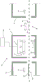
图1示出了用于对玻璃板进行弯曲的第一构造中的压弯台的示意性侧视图;Figure 1 shows a schematic side view of a press bending station in a first configuration for bending a glass sheet;
图2示出了第一配置中的两部分压弯部件的示意性等距图;Figure 2 shows a schematic isometric view of a two-part press-bent part in a first configuration;
图3示出了第二配置中的图2的两部分压弯部件的示意性等距图;Figure 3 shows a schematic isometric view of the two-part press-bending part of Figure 2 in a second configuration;
图4示出了与下支撑框架呈间隔开的关系的图3中所示的两部分压弯部件示意性等距图;Figure 4 shows a schematic isometric view of the two-part press-bending member shown in Figure 3 in spaced relationship to the lower support frame;
图5示出了图1中所示的压弯台的扩大部分的示意图;Figure 5 shows a schematic view of an enlarged portion of the press bending station shown in Figure 1;
图6示出了第二构造中的图1的压弯台的示意性侧视图;Figure 6 shows a schematic side view of the press bending station of Figure 1 in a second configuration;
图7示出第三构造中的图1的压弯台的示意性侧视图,其中两部分压弯部件的第一部分和第二部分没有移动到最终弯曲位置;Figure 7 shows a schematic side view of the press bending station of Figure 1 in a third configuration, with the first and second parts of the two-part press bending part not moved to the final bending position;
图8示出第四构造中的图1的压弯台的示意性侧视图,其中两部分压弯部件的第一和第二部分已经移动到最终弯曲位置;Figure 8 shows a schematic side view of the press bending station of Figure 1 in a fourth configuration, wherein the first and second parts of the two-part press bending part have been moved to a final bending position;
图9示出了第五构造中的图1的压弯台的示意性侧视图,其中两部分压弯部件的第一部分和第二部分处于与图7和图8相同的配置,但是两者已竖直地移动,并示出了被支撑在两部分压弯部件的成形表面上的弯曲的玻璃板;Figure 9 shows a schematic side view of the press bending station of Figure 1 in a fifth configuration, wherein the first and second parts of the two-part press bending part are in the same configuration as Figures 7 and 8, but both have been moves vertically and shows the curved glass sheet supported on the forming surface of the two-part press-bending part;
图10示出了图1中所示的压弯台的一部分的放大示意图,玻璃板在下支撑件上;Figure 10 shows an enlarged schematic view of a portion of the bending station shown in Figure 1 with the glass plate on the lower support;
图11示出在两部分压弯部件已经向下移动以在玻璃板的中央区域与玻璃板接触之后,图10中所示的压弯台的一部分的放大示意图;Figure 11 shows an enlarged schematic view of a portion of the press bending station shown in Figure 10 after the two-part press bending member has been moved downward to contact the glass sheet at its central region;
图12示出了图6中所示的压弯台的一部分的放大示意图;Figure 12 shows an enlarged schematic view of a part of the bending station shown in Figure 6;
图13示出了图7中所示的压弯台的一部分的放大示意图;Figure 13 shows an enlarged schematic view of a part of the bending station shown in Figure 7;
图14示出了图8中所示的压弯台的一部分的放大示意图;Figure 14 shows an enlarged schematic view of a part of the bending station shown in Figure 8;
图15示出了表示玻璃弯曲生产线的示意性侧视图,该玻璃弯曲生产线结合了图1中所示的压弯台;Figure 15 shows a schematic side view representing a glass bending line incorporating the bending station shown in Figure 1;
图16是示出(对于第一实施方案)两部分压弯部件的第一部分和第二部分的成形表面的竖直位置随时间而变化的曲线图;Figure 16 is a graph showing (for the first embodiment) the vertical position of the forming surfaces of the first and second parts of a two-part press-bent part as a function of time;
图17是示出如图16中所示的两部分压弯部件的第一部分和第二部分的成形表面的竖直位置随时间而变化的曲线图,但具有扩展轴;Figure 17 is a graph showing the vertical position of the forming surfaces of the first and second parts of the two-part press-bending part as a function of time as shown in Figure 16, but with an expanded axis;
图18是示出(对于第二实施方案)两部分压弯部件的第一部分和第二部分的成形表面的竖直位置随时间而变化的曲线图;Figure 18 is a graph showing (for a second embodiment) the vertical position of the forming surfaces of the first and second parts of a two-part press-bent part as a function of time;
图19是示出如图18中所示的两部分压弯部件的第一部分和第二部分的成形表面的竖直位置随时间而变化的曲线图,但具有扩展轴;Figure 19 is a graph showing the vertical position of the forming surfaces of the first and second parts of the two-part press-bent part as shown in Figure 18 as a function of time, but with an expanded axis;
图20示出了类似于图8中所示的压弯台的示意性侧视图,但是具有覆盖两部分压弯部件的第一模具部件和第二模具部件的单块织物;并且Figure 20 shows a schematic side view of a press bending station similar to that shown in Figure 8, but with a single piece of fabric covering the first and second mold parts of the two-part press bending part; and
图21示出了类似于图8中所示的压弯台的示意性侧视图,但是具有覆盖两部分压弯部件的第一模具部件的第一织物和覆盖两部分压弯部件的第二模具部件的不同的第二织物。Figure 21 shows a schematic side view of a press bending station similar to that shown in Figure 8, but with a first fabric covering the first mold part of the two-part press bending part and a second mold covering the two part press bending part A different second fabric for the part.
图1示出了表示用于对玻璃板进行弯曲的压弯台1的示意性侧视图。压弯台1包括下部3和上部5。Figure 1 shows a schematic side view representing a
压弯台1的下部3包括用于在其上支撑玻璃板的成形支撑件。在该示例中,成形支撑件是具有底座9的框架7,其具有从底座9向上延伸的第一立柱和第二立柱11、13。环形圈形式的下支撑件15安装在第一立柱和第二立柱11、13上。下支撑件15具有用于在其上支撑玻璃板的上成形表面15a,如本领域中的常规技术,即玻璃板(未示出)围绕其周缘区域被支撑在下支撑件15的上成形表面15a上。The
通常,在本领域中,下部3被称为弯曲框架或凹形弯曲框架。代替基本上环形的支撑环15,可以在立柱11、13的端部上安装完全接触支撑件。Generally, in the art, the
在图1的示例中,下支撑件15的上成形表面是凹形的。下支撑件15也可以被称为“成形轨道”,或简称为“轨道”。In the example of FIG. 1 , the upper forming surface of the
尽管在图1中仅示出了两个立柱11、13,但是在实践中可以存在多个立柱,下支撑件15安装在该多个立柱上。Although only two
压弯台1的上部5包括压弯装置,该压弯装置包含两部分压弯部件6,该两部分压弯部件6包含第一模具部件17和第二模具部件19。在US5,122,177、WO2012166365A1和US2015/0007612A1中描述了这种类型的两部分模具的示例。The
进一步参考图2、3、4和5,第一模具部件17是具有下成形表面21的环形圈。第二模具部件19是装配在第一模具部件17的中央开口内部的整体模具部件,使得第二模具部件19可相对于第一模具部件17竖直地移动。第二模具部件19径向地设置在第一模具部件17内。With further reference to FIGS. 2 , 3 , 4 and 5 , the
第一模具部件17具有外周壁18a和相对的内周壁18b。第二模具部件19具有外周壁20。第二模具部件19的外周壁20面向第一模具部件17的内周壁18b并且与第一模具部件17的内周壁18b间隔开间隙40。在图1的横截面视图中,间隙40由两个间隙39和41表示。The
第二模具部件19具有下成形表面23。成形表面21、23被构造成当玻璃板被支撑在框架7上,即支撑在支撑件15的上成形表面15a上且当第一模具部件和第二模具部件处于某预定的配置中时,在要被成形表面21、23接触的玻璃板的那些区域中提供玻璃板所期望的曲率。The
如图4中更清楚地示出的那样,下支撑件15的一侧安装在立柱11、11′和11″′上,而相对的一侧安装在立柱13、13′和13″上。立柱11、11′、11″、13、13′、13″从基座9向上延伸,在一端连接到基座9,而在相对的一端连接到下支撑件15。可以使用另外的立柱。也可以在立柱之间使用加强横梁。As shown more clearly in Fig. 4, the
进一步参考图5,当第二模具部件19的外周边缘20a与第一模具部件17的内周边缘18c对齐时,两部分压弯部件6具有与所期望的最终成形表面相对应的成形表面,如点线24所表示的那样。在该示例中,两部分压弯部件6的成形表面是凸形成形表面,其构造成与下支撑件15的上成形表面15a互补。所期望的最终成形表面24以虚线25示出在最终期望位置,用于将支撑在下支撑件15的上成形表面15a上的玻璃板成形为最终期望的形状。With further reference to FIG. 5, when the outer
参考图1和图5,第一模具部件17相对于第二模具部件19位移,使得两部分压弯部件的成形表面不是该两部分压弯部件的期望的最终成形表面。第二模具部件19的外周边缘20a与第一模具部件17的内周边缘18c位移了量43。Referring to Figures 1 and 5, the
第一模具部件17借助于线性致动器31和33能够在竖直方向(箭头30所示)上移动。线性致动器31、33的移动是同步的,使得第一模具部件17的两侧同时向上和向下移动。The
第二模具部件19借助于线性致动器35能够在竖直方向30上移动。The
第一模具部件17和第二模具部件19两者能够相对于彼此在竖直方向上独立地移动。Both the
线性致动器31、33和35安装到合适的机架37上,该机架相对于框架7在空间上固定。The
线性致动器31、33和35的移动可以通过合适的控制装置诸如基于计算机的系统(未示出)来控制。Movement of the
在图1(以及图5,其是图1的左手侧的一部分的放大视图)中所示的构造中,第一模具部件的成形表面21在一侧从由点线25表示的最终期望位置位移竖直距离27,在另一侧从由点线25表示的最终期望位置位移竖直距离27′。优选距离27与27′相同。In the configuration shown in FIG. 1 (and FIG. 5 , which is an enlarged view of a portion on the left-hand side of FIG. 1 ), the forming
第二模具部件19的成形表面23从由点线25表示的最终期望位置位移竖直距离29。The forming
如以上所讨论的那样,压弯台1在图1中以第一构造示出,其中成形表面23相对于成形表面21位移了量43。由于位移43,两部分模具6未配置成将支撑在框架7上的玻璃板弯曲成最终期望的形状。As discussed above, the
在图1中,示出了第一模具部件17的内周壁18b与第二模具部件19的外周壁20之间的两个间隙39、41。这两个间隙39、41是在第一模具部件17与第二模具部件19之间延伸的连续间隙40的一部分,如图2至4中所例示的那样。间隙40可以与合适的真空源流体连通,以通过在间隙提供负压区域来协助对玻璃板进行成形。如可看到的那样,间隙40延伸到两部分压弯部件6的成形表面。In FIG. 1 , two
图6示出了处于与图1中所示构造不同的构造的压弯台1。在该第二构造中,已经在框架7上对玻璃板50进行了定位并且在根据本发明的压弯过程的途中。玻璃板50具有面向两部分压弯部件6的主表面52和面向基座9(且因此面向框架7和下支撑件15)的相对的主表面54。玻璃板50的主表面54与下支撑件15的上成形表面15a(在该图中未标记,但参见图1)接触。FIG. 6 shows the
从图1中所示的构造开始,通过向相应的线性致动器31、33和35通电,第一模具部件17和第二模具部件19两者朝向框架7向下移动。第一模具部件17和第二模具部件19两者的向下移动是同步的,使得第一模具部件17和第二模具部件19在它们之间没有相对移动的情况下向下移动。Starting from the configuration shown in FIG. 1 , both the
第一模具部件17和第二模具部件19朝向框架7的向下移动可以是一个或多个阶段,在每个阶段中在第一模具部件与第二模具部件之间具有或没有相对移动。在一个示例中,在向下移动的第一阶段中,第一模具部件和第二模具部件的向下速度为第一速度u1,在向下移动的第一阶段之后的向下移动的第二阶段中,第一模具部件和第二模具部件的向下速度为第二速度u2。优选u1>u2,使得第一模具部件17和第二模具部件19在向下移动的第一阶段中比在向下移动的第二阶段中移动更快。The downward movement of the
参考图1和图6,在如图6中所示的第二构造中,第一模具部件17的成形表面21已经在玻璃板50的周缘区域中与玻璃板50的主表面52接触。由于第一模具部件17和第二模具部件19的特定配置,第二模具部件19的成形表面23也已经在玻璃板50的中央区域中与玻璃板50的第二主表面52接触。该中央区域在玻璃板的周缘区域的内侧。尚未达到第一模具部件17和第二模具部件19的最终期望位置。Referring to FIGS. 1 and 6 , in a second configuration as shown in FIG. 6 , the forming
在图7中,以与图1和图6中所示的构造不同的另一构造示出了压弯台1。在该构造之前,压弯台1处于图6中所示的构造。In FIG. 7 , the
在图7中所示的该第三构造中,通过向线性致动器35通电,第二模具部件19已向下移动,使得第二模具部件19的成形表面23在玻璃板的中央区域中进一步与玻璃板50的主表面52接触,以对玻璃板50的中央区域进行压弯。在该示例中,成形表面23被示为与成形表面21对齐(参照图5,使得位移43为零)。In this third configuration shown in FIG. 7 , the
在该第三构造中,尽管第一模具部件17和第二模具部件19配置成向两部分压弯部件6提供最终期望的成形表面,但是仍然没有到达第一模具部件17和第二模具部件19的最终期望位置。参考图5,位移43为零,但是竖直距离27和竖直距离29两者大于零,因为成形表面21和成形表面23尚未到达虚线25指示的最终位置。In this third configuration, the
通过使第一模具部件17和第二模具部件19朝向框架7进一步向下移动以在玻璃板的周缘和中央区域中对玻璃板50进一步进行压弯,可以到达第一模具部件17和第二模具部件19的最终期望位置。在该示例中,在向第一模具部件和第二模具部件的最终期望位置移动时,在第一模具部件与第二模具部件之间没有相对移动,使得在该进一步的移动步骤期间,成形表面23保持与成形表面21对齐。参照图8对此进行进一步描述,尽管由于附图的比例,难以表示出不同的构造。The
在图8中所示的第四构造中,第一模具部件17的成形表面21与第二模具部件19的成形表面23对齐。参考图5,位移43为零。在该配置中,两部分压弯部件6具有用于将支撑在框架7上的玻璃板50压制成最终期望的形状的压制表面,并且压弯被构造成使得两部分压弯部件6的期望的成形表面也处于期望的位置。参考图5,在该第四构造中,成形表面21和成形表面23两者位于虚线25上。从图7中所示的构造开始,第一模具部件和第二模具部件两者同时向期望的最终位置移动,使得成形表面21、23在从图7中所示的构造向图8中所示的构造移动中保持对齐。In a fourth configuration shown in FIG. 8 , the forming
在图8中所示的构造中,间隙39、41与真空源(未示出)流体连通,以至少在面向间隙39、41的玻璃板附近,在玻璃板50的主表面52处提供负压区域。In the configuration shown in FIG. 8, the
真空源可以向间隙39、41施加任何期望时间的真空,以改善玻璃板50的弯曲。优选在压弯台已达到上述第四构造之后向间隙39、41施加真空源。可以分阶段施加真空,在一个阶段中施加与另一阶段相比不同水平的真空。真空阶段的持续时间可以相同或不同。一个或多个真空阶段中的真空持续时间可以在0.05与5秒之间。The vacuum source may apply vacuum to
在图9中,压弯台1以另一(第五)构造示出。在该第五构造中,因为第一模具部件17和第二模具部件19的成形表面对齐(参照图5,位移43为零),所以两部分压弯部件6基本上以与图8中所示相同的方式配置。然而,与图8中所示的压弯台1的构造相比,图9中所示的压弯台1的构造不同,这是因为通过线性致动器31、33、35的合适的致动/通电,两部分模具6相对于框架7已经升高。第一模具部件17和第二模具部件19已经沿箭头30′的方向以相同的速率朝向机架37向上移动,即第一模具部件17和第二模具部件19朝向机架37向上的移动是同步的,在第一模具部件与第二模具部件之间没有相对移动。In FIG. 9 the
借助于在间隙39、41(因此间隙40,参见图2至4)施加真空以在与间隙相对的玻璃板的主表面52处产生负压区域,弯曲的玻璃板50被显示为支撑在两部分压弯部件6的下侧。A
除了在间隙39、41施加真空以外,第一模具部件17的成形表面21可以在其中具有与真空源(其可以是与用于在间隙39、41提供真空的真空源相同的真空源)流体连通的开口。与成形表面21中的开口流体连通的真空源也可以用于将玻璃板50支撑在两部分压弯部件6的下侧上。In addition to applying a vacuum at the
此外,除了在间隙39、41和/或第一模具部件17的成形表面21中的开口施加真空以外,第二模具部件19的成形表面23还可以在其中具有与真空源(其可以是与用于在间隙39、41提供真空的真空源相同的真空源)流体连通的开口。与成形表面23中的开口流体连通的真空源也可以用于将玻璃板50支撑在两部分压弯部件6的下侧上。Furthermore, in addition to applying a vacuum to the
承载环58被显示为设置在框架7(即,下支撑件15的上成形表面15a的上方)与两部分压弯部件6之间。在弯曲操作的合适时间,终止在间隙39、41(或间隙40)施加的真空,使得弯曲的玻璃板50不再被支撑在两部分压弯部件6的下侧上,而是从那里掉下来由承载环58支撑。间隙39、41(或间隙40)也可以与诸如压缩空气的合适的流体源流体连通,使得在间隙39、41处的真空终止之后,使流体即压缩空气向着玻璃板50流过间隙39、41,以协助将弯曲的玻璃板50从相应的第一模具部件17和第二模具部件19的成形表面21、23移除。The
提供合适的致动器(未示出)以沿箭头60的方向移动承载环58,使其远离框架7与两部分压弯部件6之间。此后,可以将弯曲的玻璃板放到合适的传送装置(未示出)上,以便随后进行退火或钢化。A suitable actuator (not shown) is provided to move the
如以上所讨论的那样,尽管未在图中示出,但是第一模具部件17的成形表面21和/或第二模具部件19的成形表面23可以在其中具有至少一个开口,所述开口与至少一个诸如真空源的负压源流体连通。As discussed above, although not shown in the figures, the forming
除了在间隙40产生的负压区域以外,在第一模具部件17的成形表面21中的该或每个开口和/或在第二模具部件19的成形表面23中的该或每个开口可以有另外的负压区域,以便当对玻璃板进行弯曲时能够改善形状控制。The or each opening in the forming
如果第一模具部件17的成形表面21在其中具有一个或多个用于提供真空的开口(例如,如以上关于间隙39、41所述),则在成形表面21中的任何数量的所述开口也可以与诸如压缩空气的合适的流体源流体连通,以在终止真空之后通过使流体朝向玻璃板流过所述开口来协助从成形表面21移除弯曲的玻璃板。If the forming
同样地,如果第二模具部件19的成形表面23在其中具有一个或多个用于提供真空的开口(例如,如以上关于间隙39、41所述),则在成形表面23中的任何数量的所述开口也可以与诸如压缩空气的合适的流体源流体连通,以在终止真空之后通过使流体朝向玻璃板流过所述开口来协助从成形表面23移除弯曲的玻璃板。Likewise, if the forming
为了进一步例示在根据本发明的成形过程期间第一模具部件17和第二模具部件19的移动顺序,图1(框架7上的玻璃板50除外)、6、7和8的左手部分已被放大并作为附加的图而提供。上述附图的这些放大部分分别示于图10、12、13和14中。包括另外的图11以示出在成形操作期间,在第一模具部件17的成形表面21在玻璃板50的周缘区域中与玻璃板50接触之前,当第二模具部件19的成形表面23在玻璃板50的中央区域中与玻璃板50接触时的瞬间。To further illustrate the sequence of movement of the
参考图1和10,玻璃板50被显示为支撑在下支撑件15的成形表面15a上。已经使用本领域已知的方法在成形表面15a上对玻璃板合适地进行了定位。玻璃板50具有第一主表面52和相对的第二主表面54。第二主表面54与下支撑件15的上成形表面15a接触。玻璃板已经被热软化并且可以在其中央区域中轻微下垂。Referring to FIGS. 1 and 10 , a
两部分压弯部件6的一部分(标记为6′)被显示为位于玻璃板50的上方。第一模具部件17具有面向玻璃板50的第一主表面52的成形表面21,第二模具部件19具有面向玻璃板50的第一主表面52的成形表面23。A portion of the two-part press bent
如上所述,因为边缘18c和20a未对齐,成形表面21、23彼此偏移了位移43。As mentioned above, because the
如该图中所示,成形面21、23均未与玻璃板50接触。As shown in the figure, neither the molding surfaces 21 , 23 are in contact with the
在图11中,第一模具部件17和第二模具部件19两者已经一起向下移动,使得它们之间没有相对移动,即,从图10中所示的构造开始,第一模具部件17和第二模具部件19两者以相同速度沿箭头30移动。这样,成形表面21、23仍未对齐,并且仍然存在上述位移43(在这种情况下,位移43与图10中的相同)。在这种构造中,成形表面23刚好与玻璃板50的第一主表面52接触。然而,因为两部分压弯部件6′的第一模具部件17和第二模具部件19的特定配置,第一模具部件17相对于第二模具部件19的位置使得成形表面21尚未与玻璃板50的第一主表面52接触(尽管成形表面23已经与玻璃板50的第一主表面52接触)。In FIG. 11, both the
可以使用两部分压弯部件6′的第一模具部件17和第二模具部件19的不同配置,其中将第二模具部件19相对于第一模具部件17配置使得在第二模具部件19的成形表面23与玻璃板的第一主表面52接触之前,第一模具部件17的成形表面21与玻璃板的第一主表面52接触。在该替代实施方案中,第二模具部件的位置以影像显示为具有成形表面23a的19a。显而易见的是,第一模具部件和第二模具部件可以被配置成使得当第一模具部件和第二模具部件以相同的速度朝向框架向下移动时,其各自的成形表面同时与玻璃板50的第一主表面52接触。Different configurations of the
图12是图6的左手侧的一部分的放大视图,示出了玻璃板50在第一成形部件17与下支撑件15之间,在其周缘区域中被部分压制。由于第一模具部件和第二模具部件两者已经以相同的速度继续向下移动(沿箭头30的方向)(当以图10或11中所示的配置开始时),玻璃板50也在其中央区域中被第二模具构件19轻微压制。然而,如上所述,第一模具部件和第二模具部件的成形表面仍然具有非零位移43。FIG. 12 is an enlarged view of a part of the left hand side of FIG. 6 showing that the
图13是图7的左手侧的一部分的放大图,示出了在图12中所示的配置之后的两部分压弯部件6′,其中第一模具部件17相对于下支撑件15保持静止,第二模具部件19已经进一步向下移动(沿箭头30的方向)以在玻璃板50的中央区域中对玻璃板50进行压弯。通过在第一模具部件17与下支撑件15之间部分地压制,玻璃板50在其周缘区域被充分地保持。在该构造中,第一模具部件17和第二模具部件19的成形表面21、23之间没有位移(位移43为零)。因此,两部分压弯部件6′具有期望的最终成形表面,但是两部分压弯部件不在将玻璃板50完全压弯成期望的形状的最终位置。这示于下面的图14中。Figure 13 is an enlarged view of a part of the left hand side of Figure 7 showing the two-part press bending part 6' after the configuration shown in Figure 12, wherein the
图14是图8的左手侧的一部分的放大图,示出了在图13中所示的构造之后的两部分压弯部件6′,其中第一模具部件17和第二模具部件两者已经同时向下移动(沿箭头30的方向),即在第一模具部件17与第二模具部件19之间没有相对移动。再次,在第一模具部件与第二模具部件的成形表面之间没有位移(位移43为零)。两部分压弯部件6′具有期望的最终成形表面(因为位移43为零)并且已经移动到将玻璃板50完全压弯成期望的形状的最终位置(参见图5中的虚线25)。在该最终压弯步骤之后,可以在间隙39(和间隙41,参见图8)产生真空,以将玻璃板50保持在两部分模具6′的下侧,并改善弯曲的玻璃板的形状控制,如上所述。Figure 14 is an enlarged view of a portion of the left hand side of Figure 8 showing the two-part press bending part 6' after the configuration shown in Figure 13, wherein both the
图15示出了表示玻璃弯曲生产线70的一部分的示意性横截面图,该玻璃弯曲生产线70并入了图1中所示类型的压弯台1,其操作参照图1至14进行描述。FIG. 15 shows a schematic cross-sectional view representing part of a
玻璃弯曲生产线70包含加热炉72,可以被加热或可以不被加热的压弯部74以及退火炉76。The
辊式传送床78延伸通过加热炉72、压弯部74和退火炉76,以限定玻璃板50的传送路径。辊式传送床包含多个构造成(以间隔开的平行关系)沿箭头82的方向传送玻璃板50的辊80。在此示例中,玻璃板50被显示为与辊80接触,但是可以在合适的托架(未示出)上对玻璃板50进行定位,托架与辊80接触。作为辊80的替代方案或除辊80以外,可以使用气浮装置沿箭头82的方向传送玻璃板。
在加热炉72中,玻璃板50被加热到适于弯曲的温度。加热炉可根据需要并入任何合适的加热装置,诸如电加热、气体加热、对流加热和微波加热及其组合。In the
压弯部74的内部是压弯台1。当玻璃板50被传送到框架7与两部分压弯部件6之间时,通过将玻璃板放在框架7上而在框架7上对其进行定位用于随后的压弯,如已经参考图1至14所述的。现有技术中已知用于将玻璃板从传送辊80传送到框架7的方法,例如,一些传送辊可以被构造成落下辊,或者可以使用真空台板来将热软化的玻璃板从传送辊上提起,以放在合适地构造的框架7上。Inside the
参照图15和图1,两部分压弯部件6被显示为与诸如计算机的控制装置84电连通,用于借助于线性致动器31、33、35来控制两部分压弯部件6的第一模具部件17和第二模具部件19的相对移动。控制装置84可以与玻璃弯曲生产线70的其他部分,例如传送辊床78电连通,以控制辊80和/或控制承载环58的移动的致动器(未示出)的速度。15 and FIG. 1, the two-part press-bending
承载环58被显示为在压弯部74与退火炉76之间,并且可以通过合适的致动器(未示出),即通过沿箭头60的方向移动而在图9中所示的位置与图15中所示的位置之间移动。由承载环58支撑的弯曲的玻璃板从在两部分压弯部件6与框架7之间(即,在压弯部74内部)移动到压弯部74的外部,然后在该处可以将弯曲的玻璃板放在辊式传送床78的部分78′上,以传送到退火炉76中,用于随后的退火,即受控冷却至环境温度。
尽管在图中两部分压弯部件6被显示为具有如本文之前所述的暴露的成形表面21和23,但是在优选实施方案中,第一模具部件17和第二模具部件19中的一个或两者可以具备保护罩,以保护模具部件的成形表面不受损伤和磨损。下支撑件15也可以具备这样的保护罩,以覆盖上成形表面15a。当使用罩时,优选地,罩包含由例如不锈钢、玻璃纤维、聚亚苯基对苯二甲酰胺纤维(例如,KevlarTM)、混合的KevlarTM材料、含有石墨的聚苯并噁唑(PBO)纤维(例如,ZylonTM)或这些纤维的各种编织形式制成的织物。Although in the figures the two-part
如果使用保护罩覆盖每个成形表面21、23,则优选使用覆盖成形表面21和成形表面23两者的单个罩。If a protective cover is used to cover each forming
如果使用覆盖成形表面21和23两者的保护罩,则该保护罩应具有足够的柔韧性以允许第一模具部件和第二模具部件如本文之前所述地移动。If a protective cover covering both forming
此外,如果使用覆盖成形表面21和23两者的保护罩,则优选该保护罩具有足够的多孔性或透气性,以允许通过其提供真空,例如通过第一模具部件与第二模具部件之间的间隙40,或者在如前所述的第一模具部件与第二模具部件各自的成形表面中的任何开口提供真空。Furthermore, if a protective cover is used covering both forming
可以为成形表面21、23的每一个使用单独的保护罩。其具有的优点是,第一模具部件与第二模具部件之间的间隙不会受到保护罩的材料的阻碍。A separate protective cover may be used for each of the forming
在图16、17(对于第一示例)以及在图18和19(对于第二个示例)中例示了图1、6、7和8(或图10至14)中所示构造之间移动中的第一模具部件17和第二模具部件19的向下移动。图16至19示出了相对于由图1和图5中的线25表示的所述部件的成形表面的最终期望位置的第一模具部件17和第二模具部件19的竖直位置。Moving between the configurations shown in Figures 1, 6, 7 and 8 (or Figures 10 to 14) is illustrated in Figures 16, 17 (for the first example) and in Figures 18 and 19 (for the second example) The downward movement of the
在图16至19中,轴90是以秒为单位的时间,而轴92是以mm为单位的距离。In Figures 16 to 19,
在图16和17中,虚线表示相对于所述成形表面21的最终期望位置的第一模具部件17的成形表面21的竖直位移。实线表示相对于所述成形表面23的最终期望位置的第二模具部件19的成形表面23的竖直位移。相对于零的参考基准点,成形表面21、23的最终期望位置(当它们对齐时,参见图5、7和13及其相关描述)在-200mm的竖直位移处。在时间=零处,成形表面21在零的参考基准点处,并且在时间=零处,相对于零的参考基准点,成形表面23在+10mm处。即,在成形表面21的最终期望位置,向下的总竖直移动为200mm,而对于成形表面23,向下的总竖直移动为210mm。In FIGS. 16 and 17 , dashed lines indicate the vertical displacement of the forming
参考图16和17,将描述在第一实施方案中第一模具部件17和第二模具部件19的相对移动。Referring to Figures 16 and 17, the relative movement of the
在时间t=0(即,点A和A′),两部分压弯模具6被配置成使得相对于第二模具部件19的成形表面23,第一模具部件17的成形表面21位移了10mm。参照图5,距离27(因此是距离27′,参见图1)为200mm,距离29为210mm,位移43为10mm。At time t=0 (ie points A and A'), the two-part press bending die 6 is configured such that the forming
0.5秒后(在点B、B′),压弯操作开始,第一模具部件17和第二模具部件19两者朝向支撑在框架7上的玻璃板50竖直向下移动,参见例如图10。第一模具部件17和第二模具部件19两者以相同的速度(=v1)向下移动,因此在该向下移动阶段期间,在第一模具部件17和第二模具部件19的成形表面21、23之间没有相对移动,即,在点B-C和B′-C′处,第一模具部件17和第二模具部件19的移动是同步的,并且位移43保持固定在10mm。After 0.5 seconds (at points B, B'), the press bending operation starts, both the
在1.2秒之后(在点C、C′处),当靠近玻璃板50的表面时,第一模具部件17和第二模具部件19的下降速度减小(至速度v2)。第一模具部件17和第二模具部件19的同步竖直向下移动以速度v2继续,直至到达点D,D′。After 1.2 seconds (at points C, C'), when approaching the surface of the
在2.1秒之后(在D点),第二模具部件19继续以速度v2竖直向下移动。然而,在点D′(其在时间上与点D重合),第一模具部件17的竖直向下移动停止。压弯台处于图6(或图12)中所示的构造。在该时间点,玻璃板50的主表面52已经被第一模具部件17的成形表面21所接触,使得玻璃板50在框架7的下支撑件15与第一模具部件17之间被部分地压制。After 2.1 seconds (at point D), the
在接下来的0.2秒内,第二模具部件19继续以速度v2向下移动,以在玻璃板50的中央区域中对玻璃板50进行压弯,同时玻璃板50保持被静止的第一模具部件17部分地压制。即,在点D′与E′之间,相对于框架7,第一模具部件17保持静止以在玻璃板的周缘区域中对玻璃板进行部分地压制。During the next 0.2 seconds, the
在2.3秒之后(在E′点),第一模具部件17的移动以选定的向下速度(=v3)重新开始,使得第一模具部件17和第二模具部件19两者同时到达最终期望位置(在点F、F′)。即,第二模具部件19在点E与F之间继续以速度v2竖直向下移动,而第一模具部件在点E′与F′之间以速度v3竖直向下移动。After 2.3 seconds (at point E'), the movement of the
第一模具部件17在点E′与F′之间的向下移动进一步在下支撑件15的上成形表面15a与第一模具部件的成形表面21之间对玻璃板的周缘区域进行压制。即,在周缘区域中,玻璃板在下支撑件15与第一模具部件17之间被进一步压制,同时玻璃板在中央区域中被第二模具部件19进一步压弯。The downward movement of the
显然,当第二模具部件19在点D与E之间继续竖直向下移动时,因为第一模具部件17在点D′与E′(其分别对应于点D和E)之间是静止的,所以第一模具部件17和第二模具部件19的成形表面21、23的间隔减小。参考图5,位移43在点D与E之间减小。Clearly, as the
在2.5秒之后(在点F、F′),第一模具部件17和第二模具部件19两者已经到达最终期望位置,并且将玻璃板50压弯成最终期望的形状。压弯台处于图8或图14中所示的构造。在点F、F′,两部分弯曲部件6的成形表面具有最终期望的曲率。After 2.5 seconds (at points F, F'), both the
在根据本发明第一方面的方法的该特定示例中(如图16和17中所例示的那样),第一压制和第二压制的成形表面的初始间隔(位移43)为10mm。第一模具部件17竖直向下移动至使得成形表面21的位置离成形表面21的最终位置2mm的位置。然后使成形表面21、23如上所述地移动以同时到达由点F、F指示的最终位置,这是第一模具部件17和第二模具部件19两者的初始竖直向下移动开始之后两秒,即在点B、B′之后两秒。In this particular example of the method according to the first aspect of the invention (as illustrated in Figures 16 and 17), the initial separation (displacement 43) of the forming surfaces of the first and second pressing is 10mm. The
通过在点D′使第一模具部件17停止,然后在点E′重新开始第一模具部件的向下移动,发现第一模具部件17的进一步向下移动使成形表面21移动至最终位置,同时,第二模具部件19的成形表面23到达最终位置,即在点F、F′,与在没有事先停止的情况下使第一模具部件17移动到最终位置时相比,压弯操作期间在玻璃板50中产生的瞬时应力减小了。即,在第一模具部件不在点D′停止,而是以速度v2继续直到第一模具部件17的成形表面21处于最终期望位置(即,距零基准的-200mm)的情况下,在压弯操作期间有较多的玻璃破裂。By stopping the
使用第一模具部件17和第二模具部件19的改变的向下移动进行另一测试。Another test was performed using a modified downward movement of the
参照图18和19描述该第二示例。在图18和19中,虚线表示第一模具部件17的成形表面21相对于所述成形表面21的最终期望位置的竖直位移。实线表示第二模具部件19的成形表面23相对于所述成形表面23的最终期望位置的竖直位移。成形表面21、23的最终期望位置(当它们对齐时,参见图5、7和13及其相关描述)相对于零的参考基准点的竖直位移为-200mm。成形表面21在时间=零时处于零的参考基准点,并且成形表面23在时间=零时相对于零的参考基准点处于+10mm处。即,在成形表面21的最终期望位置,总的向下移动为200mm,而对于成形表面23,总的向下移动为210mm。This second example is described with reference to FIGS. 18 and 19 . In FIGS. 18 and 19 , the dashed lines indicate the vertical displacement of the forming
在图18和图19中,直到点D、D′(在2.1秒),该第二示例中的第一模具部件17和第二模具部件19的移动与第一示例中的相同(如图16和17中所例示的那样)。即,在点B与C(以及B′与C′)之间,第一模具部件17和第二模具部件19两者以v1的速度竖直向下移动(位移43固定在10mm),并且在点C与D(以及C′与D′)之间,第一模具部件17和第二模具部件19两者以v2的速度竖直向下移动(再次,位移43固定在10mm)。In Figures 18 and 19, until point D, D' (at 2.1 seconds), the movement of the
在该第二示例中,在点D,第二模具部件19以相同的速度v2继续竖直向下移动,直到在点F到达最终位置。该第二示例中的第二模具部件19以与关于图16和图17所述的第一示例中相同的方式向下移动。In this second example, at point D, the
如在第一示例中那样,在第二示例中,当第一模具部件到达点D(2.1秒之后)时,其向下移动停止。然而,与第一示例相反,第一模具部件保持静止,直到第一模具部件17的成形表面21和第二模具部件的成形表面23对齐(在点G、G′)为止。参考图5,在点G、G′,位移43为零,并且成形表面21、23对齐。两部分压弯部件6具有最终期望的成形表面(在图5中由点线24表示),但是最终期望的成形表面不在期望的最终位置(在图5中由虚线25表示)。As in the first example, in the second example, when the first mold part reaches point D (after 2.1 seconds), its downward movement stops. However, contrary to the first example, the first mold part remains stationary until the forming
此时,当位移43为零(其约为2.43秒)时,在点G′,第一模具部件17的向下移动重新开始,以使第一模具部件的成形表面21和第二模具部件的成形表面23移动到最终期望位置。At this point, when the
在点G′与F′之间,第一模具部件17和第二模具部件19的移动再次同步,使得在两个成形表面21、23之间没有相对的竖直移动。第一模具部件17和第二模具部件19以相同的速度(=v2)竖直向下移动,直至到达最终位置F、F′,该最终位置距零的参考基准点的竖直距离为-200mm。成形表面21、23对齐并且位移43为零。Between points G' and F' the movements of the
然后,压弯装置也处于如图8中(和图14中)所示的构造,但是与该方法的第一示例(如以上参考图16和17所述的那样)相比,在压弯操作期间第一模具部件与第二模具部件之间的相对移动是不同的。在图10至14中例示了上述第二示例。The bending device is then also in the configuration as shown in Figure 8 (and in Figure 14), but in contrast to the first example of the method (as described above with reference to Figures 16 and 17), during the bending operation The relative movement between the first mold part and the second mold part is different during this time. The second example described above is illustrated in FIGS. 10 to 14 .
根据本发明的这种方法对于将最初平的玻璃板弯曲成最终曲率以用作汽车用的弯曲玻璃板,例如用作挡风玻璃中的层,或用作侧窗、后窗或顶窗即天窗的板特别有用。可以在车辆挡风玻璃中使用两块这样的弯曲玻璃板,通过至少一层诸如聚乙烯醇缩丁醛(PVB)的粘合剂中间层材料将其连接在一起。This method according to the invention is useful for bending an initially flat glass sheet to a final curvature for use as a curved glass sheet for automobiles, for example as a layer in a windshield, or as a side window, rear window or roof window i.e. Panels for sunroofs are especially useful. Two such curved glass panes may be used in vehicle windshields, joined together by at least one layer of adhesive interlayer material such as polyvinyl butyral (PVB).
图20示出了另一个压弯台1′的示意性侧视图,该压弯台1′与参照图1至8描述的压弯台1基本上相同,除了存在覆盖两部分压弯部件6的第一模具部件17和第二模具部件19的单块织物16以外。FIG. 20 shows a schematic side view of another bending
压弯台1′以与图8中的压弯台1基本上相同的构造示出。然而,因为第一模具部件和第二模具部件被单块织物16覆盖,所以第一模具部件17的成形表面被织物16覆盖,使得织物16与玻璃板50的主表面52直接接触。这样,第一模具部件17的成形表面21和第二模具部件19的成形表面23与玻璃板50的主表面52间接接触。The bending table 1 ′ is shown in substantially the same configuration as the bending table 1 in FIG. 8 . However, because the first and second mold parts are covered by a single piece of
优选地,织物16是透气性织物。优选地,织物16包含不锈钢、玻璃纤维、聚对亚苯基对苯二甲酰胺纤维或其混合物、含有石墨的聚苯并噁唑(PBO)纤维以及这些纤维的各种编织形式中的至少一种。Preferably,
图21示出了另一个压弯台1″的示意性侧视图,该压弯台1″与参照图1至8描述的压弯台1基本上相同,除了存在覆盖第一模具部件17的第一织物16′以及覆盖第二模具部件19的第二织物16″,即,织物16′覆盖第一模具部件17的成形表面21,织物16″覆盖第二模具部件19的成形表面23。为了容纳两个织物罩,提供具有稍小的成形表面的第二模具部件19′,以容纳延伸至第一模具部件17的外周壁18a和内周壁18b以及第二模具部件19′的外周壁20的织物。这样,间隙39′、41′比图1的间隙39、41稍宽。而且,因为使用了两块织物16′、16″,所以间隙39′和41′不会被两部分压弯部件106的成形表面附近的织物阻碍(因为第二模具部件19′不同于两部分压弯部件6的第二模具部件19,所以被标为106)。使用两块或更多块织物还提供了一个优点,当由于在对玻璃板进行弯曲中的连续使用而磨损织物时,可以只更换选定区域的织物。当使用一块织物时,如果织物磨损,需要更换整块织物,当使用至少第一织物和第二织物时,可以根据需要仅更换一块织物。FIG. 21 shows a schematic side view of another
压弯台1″以与图8中的压弯台1基本上相同的构造示出。然而,因为第一模具部件17被织物16′覆盖,第二模具部件19′被织物16″覆盖。织物16′和16″与玻璃板50的第一主表面52直接接触。这样,第一模具部件17的成形表面21和第二模具部件19的成形表面23分别通过织物16′和16″与玻璃板50的第一主表面52间接接触。The bending
优选地,织物16′、16″中的至少一个是透气性织物。优选地,织物16′和/或16″包含不锈钢、玻璃纤维、聚对亚苯基对苯二甲酰胺纤维或其混合物、含有石墨的聚苯并噁唑(PBO)纤维以及这些纤维的各种编织形式中的至少一种。Preferably, at least one of the
已经发现,当使用根据本发明的对玻璃板进行成形的方法时,以及改善弯曲的玻璃板的周缘区域中的皱纹时(与使用单个的整体式上压弯部件相比),减少了成形操作,即压弯操作期间的玻璃破裂的风险。It has been found that when using the method of shaping a glass sheet according to the invention, as well as improving the wrinkles in the peripheral region of the bent glass sheet (compared to using a single integral upper press bending part), the forming operations are reduced , the risk of glass breakage during the bending operation.
尽管本文提供的示例仅涉及两部分压弯部件,但是该压弯装置可以包含具有三个或更多个能够独立移动的模具部件的压弯部件,例如,在步骤(v)期间,可以对玻璃板的两个相对的横向周缘区域进行压制,在步骤(vi)期间,可以对玻璃板的两个相对的横向周缘区域之间的玻璃板的中央区域进行压制。Although the examples provided herein refer only to a two-part press bending unit, the press bending apparatus may comprise a press bending unit with three or more independently movable mold parts, for example, during step (v), glass may be Two opposing transverse peripheral regions of the sheet are pressed, during step (vi) the central region of the glass sheet may be pressed between the two opposing transverse peripheral regions of the glass sheet.
Claims (51)
Applications Claiming Priority (3)
| Application Number | Priority Date | Filing Date | Title |
|---|---|---|---|
| GB1708761.0 | 2017-06-01 | ||
| GBGB1708761.0A GB201708761D0 (en) | 2017-06-01 | 2017-06-01 | Method and apparatus for shaping a glass sheet |
| PCT/GB2018/051504 WO2018220394A1 (en) | 2017-06-01 | 2018-06-01 | Method and apparatus for shaping a glass sheet |
Publications (2)
| Publication Number | Publication Date |
|---|---|
| CN110691759A CN110691759A (en) | 2020-01-14 |
| CN110691759B true CN110691759B (en) | 2023-06-16 |
Family
ID=59349784
Family Applications (1)
| Application Number | Title | Priority Date | Filing Date |
|---|---|---|---|
| CN201880035219.1A Active CN110691759B (en) | 2017-06-01 | 2018-06-01 | Method and apparatus for shaping glass sheets |
Country Status (6)
| Country | Link |
|---|---|
| US (1) | US11661368B2 (en) |
| EP (1) | EP3630687B1 (en) |
| JP (1) | JP7227927B2 (en) |
| CN (1) | CN110691759B (en) |
| GB (1) | GB201708761D0 (en) |
| WO (1) | WO2018220394A1 (en) |
Families Citing this family (10)
| Publication number | Priority date | Publication date | Assignee | Title |
|---|---|---|---|---|
| US11230487B2 (en) * | 2019-03-22 | 2022-01-25 | Glasstech, Inc. | Glass processing system with variable bending station |
| CN111825342A (en) * | 2019-04-15 | 2020-10-27 | 康宁股份有限公司 | Assembly and method for bending glass |
| EP4051496A4 (en) * | 2019-10-30 | 2023-11-08 | Corning Incorporated | Methods and systems for press bending two or more plies of glass |
| CN111792619B (en) * | 2020-07-17 | 2024-05-17 | 中国科学技术大学 | A method for continuously batch-fabricating micro-nano structures on glass surfaces |
| CN112060819B (en) * | 2020-09-14 | 2022-02-15 | 凯盛信息显示材料(池州)有限公司 | Mobile phone 3D glass layer cover plate texture processing device and processing method |
| CN113060929B (en) * | 2021-04-09 | 2022-12-20 | 福耀玻璃工业集团股份有限公司 | Automobile glass forming die and production method |
| KR20240034969A (en) * | 2022-09-07 | 2024-03-15 | 삼성디스플레이 주식회사 | Molding method for cover window |
| WO2025012653A1 (en) | 2023-07-11 | 2025-01-16 | Pilkington Group Limited | Vehicular glazing |
| WO2025017270A1 (en) | 2023-07-20 | 2025-01-23 | Shanghai Yaohua Pilkington Glass Group Co.,Ltd., | Vehicular glazing |
| CN117756385A (en) * | 2023-12-21 | 2024-03-26 | 福耀玻璃工业集团股份有限公司 | Formed glass plate, glass plate forming method, glass plate forming device and vehicle |
Citations (5)
| Publication number | Priority date | Publication date | Assignee | Title |
|---|---|---|---|---|
| US5122177A (en) * | 1990-01-11 | 1992-06-16 | Nippon Sheet Glass Co., Ltd. | Method of and system for pressing sheet glass |
| CN1714054A (en) * | 2002-11-18 | 2005-12-28 | Ppg工业俄亥俄公司 | Apparatus and method for bending glass sheets |
| CN101720308A (en) * | 2007-06-27 | 2010-06-02 | 皮尔金顿北美公司 | Glass bending process |
| CN104445888A (en) * | 2014-12-16 | 2015-03-25 | 蓝思科技(长沙)有限公司 | Forming method for bent glass |
| EP3078642A1 (en) * | 2013-12-03 | 2016-10-12 | Nippon Sheet Glass Company, Limited | Glass plate and method for producing glass plate |
Family Cites Families (19)
| Publication number | Priority date | Publication date | Assignee | Title |
|---|---|---|---|---|
| JPS5925732B2 (en) * | 1979-01-26 | 1984-06-20 | 株式会社神奈川製作所 | CRT manufacturing equipment |
| JPS604976Y2 (en) | 1980-05-01 | 1985-02-15 | セントラル硝子株式会社 | Glass plate bending equipment |
| JPH0776102B2 (en) | 1986-06-25 | 1995-08-16 | 昭栄硝子株式会社 | Glass hollow body molding method |
| FR2600554B1 (en) | 1986-06-30 | 1988-09-02 | Elf Aquitaine | PROCESS AND DEVICE FOR DEACIDIFYING A GAS CONTAINING H2S OR / AND CO2 AS WELL AS MERCAPTANS |
| JPS6424034A (en) * | 1987-07-20 | 1989-01-26 | Nippon Sheet Glass Co Ltd | Method for bending sheet glass |
| US4877437A (en) * | 1988-04-29 | 1989-10-31 | Glasstech International L.P. | Vacuum platen for sharp bends |
| US4973344A (en) * | 1989-09-28 | 1990-11-27 | Libbey-Owens-Ford Co. | Method and apparatus for bending glass sheets |
| EP0537593B1 (en) | 1991-10-09 | 1999-04-14 | The Kansai Electric Power Co., Inc. | Recovery of carbon dioxide from combustion exhaust gas |
| US5401286A (en) | 1993-11-12 | 1995-03-28 | Ppg Industries, Inc. | Method and apparatus for shaping sheets |
| US7240519B2 (en) | 2002-11-18 | 2007-07-10 | Ppg Industries Ohio, Inc. | Apparatus and method for bending glass sheets |
| FR2852951B1 (en) * | 2003-03-26 | 2007-02-16 | Saint Gobain | METHOD FOR BOMBING GLASS SHEETS BY PRESSING AND SUCTION |
| RO119784B1 (en) | 2003-06-30 | 2005-03-30 | Valrom Industrie S.R.L. | Recipient for storing a liquid meant for alimentary consumption and process for making the same |
| US7866187B2 (en) | 2003-09-24 | 2011-01-11 | Pilkington North America, Inc. | Press bending station for the bending of glass sheets |
| FR2900842B1 (en) | 2006-05-10 | 2009-01-23 | Inst Francais Du Petrole | PROCESS FOR DEACIDIFYING A GASEOUS EFFLUENT WITH EXTRACTION OF PRODUCTS TO BE REGENERATED |
| US20120297834A1 (en) | 2011-05-27 | 2012-11-29 | Pittsburgh Glass Works, Llc | Multi-stage glass pressing systems and methods |
| US9346701B2 (en) | 2011-05-27 | 2016-05-24 | Pittsburgh Glass Works, Llc | Multi-stage glass pressing systems and methods |
| JP2014139121A (en) | 2012-11-07 | 2014-07-31 | Nippon Electric Glass Co Ltd | Method and device for manufacturing cover glass for display |
| KR20150001964A (en) | 2013-06-28 | 2015-01-07 | 삼성디스플레이 주식회사 | Apparatus for forming a glass |
| KR20150048450A (en) | 2013-10-28 | 2015-05-07 | 코닝정밀소재 주식회사 | Apparatus for forming glass substrate |
-
2017
- 2017-06-01 GB GBGB1708761.0A patent/GB201708761D0/en not_active Ceased
-
2018
- 2018-06-01 JP JP2019565562A patent/JP7227927B2/en active Active
- 2018-06-01 WO PCT/GB2018/051504 patent/WO2018220394A1/en active Application Filing
- 2018-06-01 US US16/615,238 patent/US11661368B2/en active Active
- 2018-06-01 EP EP18730078.5A patent/EP3630687B1/en active Active
- 2018-06-01 CN CN201880035219.1A patent/CN110691759B/en active Active
Patent Citations (5)
| Publication number | Priority date | Publication date | Assignee | Title |
|---|---|---|---|---|
| US5122177A (en) * | 1990-01-11 | 1992-06-16 | Nippon Sheet Glass Co., Ltd. | Method of and system for pressing sheet glass |
| CN1714054A (en) * | 2002-11-18 | 2005-12-28 | Ppg工业俄亥俄公司 | Apparatus and method for bending glass sheets |
| CN101720308A (en) * | 2007-06-27 | 2010-06-02 | 皮尔金顿北美公司 | Glass bending process |
| EP3078642A1 (en) * | 2013-12-03 | 2016-10-12 | Nippon Sheet Glass Company, Limited | Glass plate and method for producing glass plate |
| CN104445888A (en) * | 2014-12-16 | 2015-03-25 | 蓝思科技(长沙)有限公司 | Forming method for bent glass |
Also Published As
| Publication number | Publication date |
|---|---|
| GB201708761D0 (en) | 2017-07-19 |
| CN110691759A (en) | 2020-01-14 |
| WO2018220394A1 (en) | 2018-12-06 |
| JP2020521711A (en) | 2020-07-27 |
| US20200156985A1 (en) | 2020-05-21 |
| EP3630687A1 (en) | 2020-04-08 |
| US11661368B2 (en) | 2023-05-30 |
| EP3630687B1 (en) | 2025-03-19 |
| BR112019024731A2 (en) | 2020-06-16 |
| JP7227927B2 (en) | 2023-02-22 |
Similar Documents
| Publication | Publication Date | Title |
|---|---|---|
| CN110691759B (en) | Method and apparatus for shaping glass sheets | |
| EP0677489B1 (en) | Bending and tempering glass sheets | |
| CN102741190B (en) | Glass plate and method for manufacturing glass plate | |
| CA2141830C (en) | Method and apparatus of bending glass sheets | |
| FI79515B (en) | FOERFARANDE OCH ANORDNING FOER FORMNING AV GLASSKIVOR. | |
| KR100694359B1 (en) | Apparatus and method for bending glass sheets | |
| EP2233444A1 (en) | Glass pane bending and forming method, and glass pane bending and forming appratus | |
| KR101911654B1 (en) | Tool for a glass-bending process | |
| US20180194664A1 (en) | Glass-bending device and glass-bending method using a fan | |
| CN102741177A (en) | Method and device for gradually cooling glass plate | |
| MXPA02012955A (en) | Method and device for bending a glass sheet. | |
| JP4806629B2 (en) | Method and apparatus for bending glass sheets | |
| US20240182347A1 (en) | Method and apparatus for shaping a glass sheet | |
| JPH06115960A (en) | Device and method for forming glass sheet | |
| JPS6245177B2 (en) | ||
| JP3045674B2 (en) | Method and apparatus for forming heat softened sheet material | |
| AU2004226205A1 (en) | Method and device for bending glass sheets | |
| CN111278781A (en) | Method of controlling separation between glasses during co-sagging to reduce final shape mismatch between glasses | |
| FI57394C (en) | FOERFARANDE FOER HAERDNING AV EN GLASSKIVA | |
| JP5148269B2 (en) | Apparatus and method for bending glass plates | |
| JPH0729792B2 (en) | Method and apparatus for bending glass plate for laminated glass | |
| BR112019024731B1 (en) | METHOD OF SHAPING A SHEET OF GLASS, AND APPARATUS FOR SHAPING A SHEET OF GLASS | |
| JPH0729793B2 (en) | Bending forming method and apparatus for laminated glass for laminated glass |
Legal Events
| Date | Code | Title | Description |
|---|---|---|---|
| PB01 | Publication | ||
| PB01 | Publication | ||
| SE01 | Entry into force of request for substantive examination | ||
| SE01 | Entry into force of request for substantive examination | ||
| GR01 | Patent grant | ||
| GR01 | Patent grant |