JP6898855B2 - Optical system - Google Patents
Optical system Download PDFInfo
- Publication number
- JP6898855B2 JP6898855B2 JP2017555649A JP2017555649A JP6898855B2 JP 6898855 B2 JP6898855 B2 JP 6898855B2 JP 2017555649 A JP2017555649 A JP 2017555649A JP 2017555649 A JP2017555649 A JP 2017555649A JP 6898855 B2 JP6898855 B2 JP 6898855B2
- Authority
- JP
- Japan
- Prior art keywords
- pulse
- treatment
- probe
- optical path
- optical system
- Prior art date
- Legal status (The legal status is an assumption and is not a legal conclusion. Google has not performed a legal analysis and makes no representation as to the accuracy of the status listed.)
- Active
Links
Images

Classifications
-
- A—HUMAN NECESSITIES
- A61—MEDICAL OR VETERINARY SCIENCE; HYGIENE
- A61B—DIAGNOSIS; SURGERY; IDENTIFICATION
- A61B18/00—Surgical instruments, devices or methods for transferring non-mechanical forms of energy to or from the body
- A61B18/18—Surgical instruments, devices or methods for transferring non-mechanical forms of energy to or from the body by applying electromagnetic radiation, e.g. microwaves
- A61B18/20—Surgical instruments, devices or methods for transferring non-mechanical forms of energy to or from the body by applying electromagnetic radiation, e.g. microwaves using laser
- A61B18/203—Surgical instruments, devices or methods for transferring non-mechanical forms of energy to or from the body by applying electromagnetic radiation, e.g. microwaves using laser applying laser energy to the outside of the body
-
- A—HUMAN NECESSITIES
- A61—MEDICAL OR VETERINARY SCIENCE; HYGIENE
- A61B—DIAGNOSIS; SURGERY; IDENTIFICATION
- A61B18/00—Surgical instruments, devices or methods for transferring non-mechanical forms of energy to or from the body
- A61B2018/00315—Surgical instruments, devices or methods for transferring non-mechanical forms of energy to or from the body for treatment of particular body parts
- A61B2018/00452—Skin
- A61B2018/00476—Hair follicles
-
- A—HUMAN NECESSITIES
- A61—MEDICAL OR VETERINARY SCIENCE; HYGIENE
- A61B—DIAGNOSIS; SURGERY; IDENTIFICATION
- A61B18/00—Surgical instruments, devices or methods for transferring non-mechanical forms of energy to or from the body
- A61B2018/00636—Sensing and controlling the application of energy
- A61B2018/00696—Controlled or regulated parameters
- A61B2018/00702—Power or energy
- A61B2018/00708—Power or energy switching the power on or off
-
- A—HUMAN NECESSITIES
- A61—MEDICAL OR VETERINARY SCIENCE; HYGIENE
- A61B—DIAGNOSIS; SURGERY; IDENTIFICATION
- A61B18/00—Surgical instruments, devices or methods for transferring non-mechanical forms of energy to or from the body
- A61B2018/00636—Sensing and controlling the application of energy
- A61B2018/00773—Sensed parameters
- A61B2018/00779—Power or energy
- A61B2018/00785—Reflected power
Description
本発明は、光学系に関し、特に、光路の状態を決定するためのプローブパルスを持つ光学系に関する。本発明はまた、該光学系を有するレーザ処置装置に関する。本発明は更に、該レーザ処置装置を用いるための方法に関する。 The present invention relates to an optical system, and more particularly to an optical system having a probe pulse for determining the state of an optical path. The present invention also relates to a laser treatment apparatus having the optical system. The present invention further relates to a method for using the laser treatment apparatus.
毛及び皮膚の処置のための従来の技術は、それぞれ毛を切断する又は壊死した皮膚を除去するため皮膚の表面に置かれ皮膚表面上を引き動かされる、機械的な刃及び研磨剤の配置を含む。しかしながら、これら従来の技術は、皮膚表面に対しては過酷であり、損傷又は刺激を引き起こす。 Conventional techniques for the treatment of hair and skin are the placement of mechanical blades and abrasives that are placed on the surface of the skin and pulled over the surface of the skin to cut or remove necrotic skin, respectively. Including. However, these conventional techniques are harsh on the skin surface and cause damage or irritation.
機械的な刃及び研磨剤の代わりに、毛を切る又は皮膚を処置するためにレーザビームを用いることが知られている。レーザビーム処置は、切断部分を動かすことを必要としないこと、又は皮膚若しくは毛に対して研磨面が置かれることを必要としないことから、好適である。それ故、皮膚表面の損傷又は刺激の問題が軽減される。更に、切断要素の切れ味が鈍くなること、及び研磨剤が平滑となってしまうことといった問題がなくなる。 It is known to use a laser beam to cut hair or treat the skin instead of mechanical blades and abrasives. Laser beam treatment is preferred because it does not require the movement of the cut portion or the polishing surface being placed on the skin or hair. Therefore, the problem of skin surface damage or irritation is alleviated. Further, there are no problems that the sharpness of the cutting element becomes dull and the abrasive becomes smooth.
レーザビームはそれ自体が、高い強度の部分が皮膚表面に接触すると、損傷及び刺激を引き起こしてしまうことも知られている。従来の光学系は、皮膚表面がレーザビームの高強度部分に近過ぎる場合に、レーザビームの作動を止める。しかしながら、光学系は汚れてしまい得、レーザビームの軌道が意図された経路から逸れ得る。このことは、レーザビームが皮膚表面の不適切な領域に向けられること、及び/又は皮膚表面に対して損傷及び刺激を引き起こすことに帰着し得る。 The laser beam itself is also known to cause damage and irritation when high intensity portions come into contact with the skin surface. Conventional optics stop the operation of the laser beam when the skin surface is too close to the high intensity portion of the laser beam. However, the optics can become dirty and the trajectory of the laser beam can deviate from the intended path. This can result in the laser beam being directed at an inappropriate area of the skin surface and / or causing damage and irritation to the skin surface.
本発明の目的は、上述した問題を著しく軽減する又は克服する光学系を提供することにある。 An object of the present invention is to provide an optical system that significantly reduces or overcomes the above-mentioned problems.
本発明によれば、複数の光学的要素と、前記光学的要素を通る処置パルス光路に沿って処置パルスを生成するよう構成され、更に、前記光学的要素を通って延在するプローブパルス光路に沿ってプローブパルスを生成するよう構成された、パルス生成構成と、前記光学的要素を通る前記プローブパルス光路に沿って通過した前記プローブパルスの光学的特性を示す情報を生成するよう構成された、センサと、前記センサにより生成された前記情報に依存して、前記処置パルス光路に沿って前記処置パルスを選択的に発するよう、前記パルス生成構成を制御するよう構成された、コントローラと、を有する光学系が提供される。 According to the present invention, a plurality of optical elements and a probe pulse optical path extending through the optical element are configured to generate a treatment pulse along the treatment pulse optical path passing through the optical element. A pulse generation configuration configured to generate a probe pulse along and information indicating the optical properties of the probe pulse passing along the probe pulse optical path through the optical element. It comprises a sensor and a controller configured to control the pulse generation configuration to selectively emit the treatment pulse along the treatment pulse optical path depending on the information generated by the sensor. Optical systems are provided.
それ故、該光学系は、プローブパルスに関連するセンサにより生成された情報に依存してのみ、処置パルスを発する。 Therefore, the optics emit a treatment pulse only depending on the information generated by the sensor associated with the probe pulse.
前記少なくとも1つのセンサにより生成された情報は、前記処置パルス光路におけるいずれかの障害物を示すものであっても良い。 The information generated by the at least one sensor may indicate any obstacle in the treated pulsed optical path.
前記少なくとも1つのセンサは、前記プローブパルスの少なくとも1つの特性を示す情報を生成するよう構成されても良い。該少なくとも1つの特性は、限定するものではないが例えば、該光学系を通る変更されたプローブパルス光路の位置、強度、パワー、エネルギー、プローブパルスの空間的分布又は時間的分布であっても良い。幾つかの実施例においては、感知された特性の1つ以上が所定の値又は値の範囲に従わない場合、該コントローラが処置パルスを発しない。 The at least one sensor may be configured to generate information indicating at least one characteristic of the probe pulse. The at least one property may be, but is not limited to, for example, the position, intensity, power, energy, spatial or temporal distribution of the modified probe pulse optical path through the optical system. .. In some embodiments, the controller does not emit a treatment pulse if one or more of the sensed properties do not follow a predetermined value or range of values.
それ故、該少なくとも1つのセンサにより生成された、少なくとも1つのプローブパルスを示す情報が、処置パルス光路の状態が満足のいくものではないこと、即ち軌道が変化させられ、プローブパルスが皮膚表面に接触することを示唆する場合、処置パルス光路が発せられない。従って、皮膚表面に対する損傷又は刺激は、該光学系によって低減される。 Therefore, the information indicating at least one probe pulse generated by the at least one sensor is that the condition of the treatment pulse optical path is unsatisfactory, that is, the trajectory is changed and the probe pulse is applied to the skin surface. If it suggests contact, the treatment pulsed optical path is not emitted. Therefore, damage or irritation to the skin surface is reduced by the optical system.
前記処置パルスは、皮膚を処置する及び/又は毛を切断するよう構成されても良く、前記プローブパルスのパルスエネルギーよりも大きくても良いパルスエネルギーを持つ。 The treatment pulse may be configured to treat the skin and / or cut the hair and have a pulse energy that may be greater than the pulse energy of the probe pulse.
それ故、該光学系は、皮膚表面に接触し得るパルスが低強度のパルスのみとなることを確実にすることにより、皮膚表面に引き起こされる損傷又は刺激を低減させる。 Therefore, the optics reduce the damage or irritation caused to the skin surface by ensuring that the only pulses that can come into contact with the skin surface are low intensity pulses.
前記プローブパルスのパルスエネルギーは、皮膚表面に損害を与えるのに十分なものではなくても良い。 The pulse energy of the probe pulse may not be sufficient to damage the skin surface.
それ故、該光学系は、皮膚表面が損傷される又は刺激される可能性を、完全に除去するか又は少なくとも著しく低減させ得る。 Therefore, the optics can completely eliminate or at least significantly reduce the potential for damage or irritation of the skin surface.
前記プローブパルス光路は、前記処置パルス光路の少なくとも一部と一致するよう構成されても良い。代替としては、前記プローブパルス光路は、前記処置パルス光路とは異なる光路であっても良い。例えば、該プローブパルス光路は、該処置パルス光路と略平行に延在しても良い。 The probe pulsed optical path may be configured to coincide with at least a portion of the treated pulsed optical path. Alternatively, the probe pulsed optical path may be a different optical path than the treated pulsed optical path. For example, the probe pulsed optical path may extend substantially parallel to the treated pulsed optical path.
プローブパルスと処置パルスが一致する場合、プローブパルスは、処置パルスによりとられる正確な処置パルス光路の状態を確認することが可能となる。プローブパルスと処置パルスとで光路の差がないため、処置パルスの光路の状態の決定における誤差が消去されるか、又は少なくとも著しく低減され得る。 When the probe pulse and the treatment pulse match, the probe pulse can confirm the exact state of the treatment pulse optical path taken by the treatment pulse. Since there is no difference in the optical path between the probe pulse and the treatment pulse, the error in determining the state of the optical path of the treatment pulse can be eliminated, or at least significantly reduced.
前記プローブパルス光路は、前記光路の状態を決定するため、前記光路に略沿っているか又は前記光路に平行であっても良い。それ故、プローブパルス光路は、処置パルス光路よりも短くても良い。プローブパルス光路は、処置パルス光路の全体ではなく、処置パルス光路の特定の部分において合焦するよう構成されても良い。 The probe pulse optical path may be substantially along or parallel to the optical path in order to determine the state of the optical path. Therefore, the probe pulsed optical path may be shorter than the treated pulsed optical path. The probe pulsed optical path may be configured to focus at a specific portion of the treated pulsed optical path rather than the entire treated pulsed optical path.
前記パルス生成構成は、前記処置パルスを生成するよう構成された処置パルス生成器と、前記プローブパルスを生成するよう構成されたプローブパルス生成器と、を有しても良い。 The pulse generation configuration may include a treatment pulse generator configured to generate the treatment pulse and a probe pulse generator configured to generate the probe pulse.
それ故、該光学系は、少ない構成要素しか必要とせず、該光学系が用いられる装置のサイズを最小化することを支援し得る。また、プローブパルスが処置パルスと同じ光路に沿って進むことを確実することを容易化する。 Therefore, the optics require few components and can help minimize the size of the equipment in which the optics are used. It also facilitates ensuring that the probe pulse travels along the same optical path as the treatment pulse.
前記パルス生成器は、前記プローブパルスの10ms以内に、又はより好適には1ms以内に前記処置パルスを生成するよう構成されても良い。 The pulse generator may be configured to generate the treatment pulse within 10 ms of the probe pulse, or more preferably within 1 ms.
それ故、プローブパルスと処置パルスとの間の遅延が著しく小さくなり、これらパルス間の処置パルス光路における環境的な影響が無視できることを確実にする。 Therefore, the delay between the probe pulse and the treatment pulse is significantly reduced, ensuring that the environmental impact on the treatment pulse optical path between these pulses is negligible.
前記パルス生成器は、10msよりも短い時間間隔で連続するプローブパルスを生成するよう構成されても良い。 The pulse generator may be configured to generate continuous probe pulses at time intervals shorter than 10 ms.
それ故、該光学系は、プローブパルス光路に沿って毎秒少なくとも10個のプローブパルスを供給することが可能である。多数のプローブパルスは潜在的に、多数の処置パルスが発せられることに導き、処置を実行するために必要な時間を短縮することを支援し得る。更に、より多くの数のプローブパルスは、処置パルス光路における障害物のより迅速な識別に帰着する。 Therefore, the optical system is capable of supplying at least 10 probe pulses per second along the probe pulse optical path. A large number of probe pulses can potentially lead to a large number of treatment pulses being emitted, helping to reduce the time required to perform the treatment. In addition, a larger number of probe pulses result in faster identification of obstacles in the treatment pulse optical path.
前記コントローラは、前記センサにより測定された特性を所定の値と比較し、前記感知された特性が前記所定の値に合致する場合に前記処置パルスを発するよう構成されても良い。 The controller may be configured to compare the characteristics measured by the sensor with a predetermined value and emit the treatment pulse when the sensed characteristic matches the predetermined value.
それ故、プローブパルスの解析は迅速に実行されることができ、処置パルス光路の状態、又は任意に処置パルス光路を示すプローブパルス光路の状態が、完全に妨害されていない又は変更されていないことを、プローブパルスが確認した場合にのみ、処置パルスが生成されることを確実にする。 Therefore, the analysis of the probe pulse can be performed quickly and the state of the treated pulse path, or optionally the state of the probe pulse path indicating the treated pulse path, is not completely disturbed or altered. Ensure that a treatment pulse is generated only if the probe pulse is confirmed.
プローブパルスの少なくとも1つの決定された特性が、該少なくとも1つの特性の意図された値と合致する場合には、コントローラは、レーザパルス生成構成を作動させて、処置パルスを生成させる。該プローブパルスの少なくとも1つの特性は、障害物によって光路が妨害、遮断又は変更されていない場合に、意図された値に合致することとなる。 If at least one determined characteristic of the probe pulse matches the intended value of the at least one characteristic, the controller activates a laser pulse generation configuration to generate a treatment pulse. At least one property of the probe pulse will match the intended value if the optical path is not obstructed, blocked or altered by an obstacle.
前記コントローラは、前記センサにより測定された特性を所定の範囲と比較し、前記感知された特性が前記所定の範囲内である場合に、前記処置パルスを発するよう構成されても良い。 The controller may be configured to compare the characteristics measured by the sensor with a predetermined range and emit the treatment pulse when the sensed characteristics are within the predetermined range.
それ故、処置パルスは、処置パルス光路の状態、又は任意に処置パルス光路を示すプローブパルス光路の状態が、定義された範囲内であることを、プローブパルスが確認した場合にのみ生成される。このことは、処置パルス光路に対して、あまり大きくない変更又は妨害がある場合にも、処置パルスが発せられ得ることを意味する。それ故、皮膚表面又は光学系の他の構成要素が損傷又は刺激されない限り、処置パルス光路における小さな変化又は妨害は、処置パルスが生成されることを妨げない。 Therefore, a treatment pulse is generated only if the probe pulse confirms that the state of the treatment pulse path, or optionally the state of the probe pulse path indicating the treatment pulse path, is within a defined range. This means that the treatment pulse can be emitted even if there is a minor change or obstruction to the treatment pulse optical path. Therefore, small changes or obstructions in the treatment pulse optical path do not prevent the treatment pulse from being generated, unless the skin surface or other components of the optics are damaged or stimulated.
前記センサは、前記プローブパルス光路の端にあっても良い。 The sensor may be at the end of the probe pulsed optical path.
それ故、プローブパルスは、処置パルス光路、又は任意に処置パルス光路を示すプローブパルス光路の全体に沿って進むことが可能である。このことは、処置パルスの光路、又は任意に処置パルス光路を示すプローブパルスの光路の長さ全体の状態を、プローブパルスが確認することを確実にし、処置パルス光路の全体に亘って妨害又は変化がないことを確実にする。このことは、皮膚表面又は光学系の他の構成要素を処置パルスが損傷又は刺激する可能性を低減させることを支援する。 Therefore, the probe pulse can travel along the entire probe pulsed optical path indicating the treated pulsed optical path, or optionally the treated pulsed optical path. This ensures that the probe pulse confirms the state of the entire length of the treatment pulse optical path, or optionally the probe pulse optical path indicating the treatment pulse path, and interferes or changes throughout the treatment pulse path. Make sure there is no. This helps reduce the likelihood that the treatment pulse will damage or irritate the skin surface or other components of the optics.
本発明の他の態様によれば、本発明の光学系を有するレーザ処置装置が提供される。 According to another aspect of the present invention, there is provided a laser treatment apparatus having the optical system of the present invention.
それ故、該光学系は、毛を切断するため又は皮膚を処置するため用いられ得る。該光学系は、毛及び/又は皮膚と障害物との間の差を知るようプログラムされても良い。シェービングシステムにおいては、前記少なくとも1つのセンサは、皮膚表面又は水滴のような他の障害物から切断されるべき毛により引き起こされる障害物を識別することが可能な情報を生成することが可能であっても良い。例えば、多素子画像センサは、毛を識別することが可能であり、皮膚表面の平坦な面に対して、毛の円筒形の形状を比較することによって偽陽性を回避することが可能であり得る。 Therefore, the optics can be used to cut hair or treat the skin. The optics may be programmed to know the difference between hair and / or skin and obstacles. In a shaving system, the at least one sensor can generate information capable of identifying an obstacle caused by hair to be cut from the skin surface or other obstacles such as water droplets. You may. For example, a multi-element image sensor can identify hairs and avoid false positives by comparing the cylindrical shape of the hairs to the flat surface of the skin surface. ..
代替例においては、コントローラ及び強度センサが、毛により引き起こされた強度減少を感知しても良く、該強度減少が所定のレベルを下回る場合に、処置パルスの生成を防止する。他の代替の実施例においては、前記少なくとも1つのセンサが、特性の時間プロファイルを測定しても良い。毛の時間プロファイルは、毛が切断されると迅速に変化するが、皮膚又は水滴の障害物は、長い時間の間、プローブパルス光路に留まる。それ故、該光学系は、皮膚及び/又は障害物から毛を区別することが可能となり得る。 In an alternative example, the controller and intensity sensor may sense the intensity reduction caused by the hair and prevent the generation of treatment pulses when the intensity reduction is below a predetermined level. In other alternative embodiments, the at least one sensor may measure the time profile of the characteristic. The hair time profile changes rapidly as the hair is cut, but skin or water droplet obstacles remain in the probe pulsed optical path for extended periods of time. Therefore, the optics may be able to distinguish hair from skin and / or obstacles.
皮膚処置システムにおいては、少なくとも1つのセンサは皮膚位置センサであっても良い。皮膚位置センサは、皮膚表面の位置及び幾何を示す情報を生成することが可能であっても良い。皮膚表面の位置及び幾何の変化は、ミリ秒乃至秒のオーダーで生じる。空間的及び時間的な分布の変化は、毛及び/又は障害物から皮膚表面を区別するため用いられ得る。 In the skin treatment system, at least one sensor may be a skin position sensor. The skin position sensor may be capable of generating information indicating the position and geometry of the skin surface. Changes in the position and geometry of the skin surface occur on the order of milliseconds to seconds. Changes in spatial and temporal distribution can be used to distinguish the skin surface from hair and / or obstacles.
更に、毛及び/又は皮膚が位置する光路の部分より前で、プローブパルスの少なくとも1つの特性が決定されても良い。それ故、処置パルスは、毛を切断する及び/又は皮膚を処置するため発せられ得る。 In addition, at least one property of the probe pulse may be determined prior to the portion of the optical path where the hair and / or skin is located. Therefore, treatment pulses can be emitted to cut hair and / or treat the skin.
しかしながら、該光学系は、毛を切断する及び皮膚を処置するために用いられることに限定されるものではない。代替としては、該光学系は、光路に沿って有害な処置パルスが発せられる前に、光路上に障害物がないかチェックするためにプローブパルスが発せられるいずれの状況においても用いられることができる。 However, the optics are not limited to being used for cutting hair and treating the skin. Alternatively, the optics can be used in any situation where a probe pulse is emitted to check for obstacles on the optical path before a harmful treatment pulse is emitted along the optical path. ..
前記処置パルス光路の一部は、レーザ処置装置における凹部に亘っていても良いし、皮膚係合面が存する凹部に沿って延在する面に平行であっても良く、また任意に該面から離隔されても良い。 A part of the treatment pulse optical path may extend over a recess in the laser treatment apparatus, may be parallel to a plane extending along the recess in which the skin engaging surface resides, and optionally from that plane It may be separated.
それ故、プローブパルス及び/又は処置パルスは、該凹部を通過するときに皮膚表面から略同じ距離にある。このことは、これらパルスが、該凹部の一方の側における皮膚表面に近過ぎず、且つ他方の面から離れ過ぎないことを意味する。このことは、より均一な結果を与えることにより、不均一な性能を低減させることを支援する。 Therefore, the probe pulse and / or the treatment pulse are at approximately the same distance from the skin surface as they pass through the recess. This means that these pulses are not too close to and not too far from the skin surface on one side of the recess. This helps reduce non-uniform performance by giving more uniform results.
本発明の他の態様によれば、毛が延在する凹部を持つレーザ処置装置を用いて毛を切断するための方法であって、前記方法は、複数の光学的要素を通って延在するプローブパルス光路に沿ってプローブパルスを向けるよう光学系を動作させるステップと、前記プローブパルス光路に沿ったセンサを用いて前記プローブパルスの特性を測定することにより、前記光学的要素を通って延在する処置パルス光路の状態を示す情報を生成するステップと、前記プローブパルスの特性を示す情報を、所定の範囲と比較するステップと、前記プローブパルスの特性を示す情報が、前記所定の範囲内である場合に、前記凹部のなかに延在する毛を切断するため、前記光学的要素を通る前記処置パルス光路に沿って、処置パルスを発するステップと、を有する方法が提供される。 According to another aspect of the present invention, there is a method for cutting hair using a laser treatment device having recesses in which the hair extends, said method extending through a plurality of optical elements. Extend through the optical element by measuring the characteristics of the probe pulse using a step of operating the optical system to direct the probe pulse along the probe pulse optical path and a sensor along the probe pulse optical path. The step of generating information indicating the state of the pulsed optical path, the step of comparing the information indicating the characteristics of the probe pulse with a predetermined range, and the information indicating the characteristics of the probe pulse are within the predetermined range. In some cases, there is provided a method having a step of emitting a treatment pulse along the treatment pulse optical path through the optical element to cut hair extending in the recess.
それ故、処置パルス光路、又は任意に処置パルス光路を示すプローブパルス光路の状態が満足のいくものでない場合、即ち軌道が変化させられておりプローブパルスが皮膚表面に接触する場合には、処置パルスが発せられない。従って、皮膚表面に対する損傷又は刺激が、該光学系によって低減される。 Therefore, if the condition of the treatment pulse light path, or optionally the probe pulse light path indicating the treatment pulse light path, is unsatisfactory, that is, if the orbit is changed and the probe pulse comes into contact with the skin surface, the treatment pulse. Cannot be emitted. Therefore, damage or irritation to the skin surface is reduced by the optical system.
本発明の他の態様によれば、少なくとも1つのプロセッサにより実行されるときに、本発明による方法が実行されるようにする命令を有する、コンピュータプログラムが提供される。 According to another aspect of the invention, there is provided a computer program having instructions that allow the method according to the invention to be executed when executed by at least one processor.
本発明のこれらの及び他の態様は、以下に説明される実施例を参照しながら説明され明らかとなるであろう。 These and other aspects of the invention will be explained and clarified with reference to the examples described below.
本発明の実施例は、添付図面を参照しながら、単に例として、以下に説明される。 Examples of the present invention will be described below, by way of example only, with reference to the accompanying drawings.
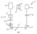
図1を参照すると、光学系1が示されている。光学系1は、意図された光路2に沿ってレーザパルスを導くよう構成される。意図された光路2は、レーザパルスが沿って進むことを意図された経路である。
With reference to FIG. 1, the
光学系1は、レーザパルス生成構成3を有する。レーザパルス生成構成3は、処置パルス及びプローブパルスを生成するよう構成される。それ故、レーザパルス生成構成3は、意図された光路2の最初にある。レーザパルス生成構成3は、光学系1の残りの部分に向けてレーザパルスを向けるよう構成される。レーザパルス生成構成3は、限定するものではないが例えばレーザダイオードであっても良い。
The
本実施例においては、レーザパルス生成構成3は、2つの異なるレーザパルスを生成するよう構成される。第1のレーザパルスは、プローブパルスである。第2のレーザパルスは、処置パルスである。レーザパルス生成構成3は、これらのパルスを連続して生成する。即ち、プローブパルスは、処置パルスの前に生成される。処置パルスは、処置パルス光路2に沿って進む。プローブパルスは、プローブパルス光路(図示されていない)に沿って進む。本実施例においては、プローブパルス光路は、処置パルス光路2と同一であり、処置パルス光路2に一致する。それ故、処置パルス光路2が妨害されて及び/又は乱されていなければ、プローブパルス及び処置パルスは共に該光路に沿って進む。しかしながら、処置パルス光路2が乱されている場合、プローブパルスは代替の光路4に沿って進む。
In this embodiment, the laser
代替の実施例においては、光学系1のレーザパルス生成構成3は、個々のレーザパルス生成器(図示されていない)を有しても良いことは、理解されるであろう。斯かる実施例においては、第1のレーザパルス生成器がプローブパルスを生成しても良く、第2のレーザパルス生成器が処置パルスを生成しても良い。これらレーザパルスが異なる光源からのものとなるため、プローブパルスは代替のプローブパルス光路(図示されていない)にのみ沿って進み得る。該代替のプローブパルス光路は、処置パルスの処置パルス光路2と略同じであっても良い。即ち、プローブパルスは、限定するものではないが例えば、処置パルス光路2に平行であり処置パルス光路2から離隔された、代替のプローブパルス光路に沿って進んでも良い。当該代替の経路は、処置パルス光路2に一致するプローブパルス光路に対する、プローブパルスのための所定の異なる経路(図示されていない)である。
It will be appreciated that in alternative embodiments, the laser
光学系1は更に、コントローラ5を有する。コントローラ5は、レーザパルス生成構成3の動作を制御するよう構成される。それ故、コントローラ5は、プローブパルス及び処置パルスの生成を制御する。コントローラ5は、プロセッサ6を有する。コントローラ5は更に、メモリ7を有する。コントローラ5は、光学系1を動作させることが可能である。
The
プロセッサ6は、いずれの適切な形態をとっても良い。例えば、プロセッサ6は、マイクロコントローラ、複数のマイクロコントローラ、回路、単一のプロセッサ、若しくは複数のプロセッサであっても良いし、又はこれらを含んでも良い。コントローラ5は、1つ又は複数のモジュールから形成されていても良い。 The processor 6 may take any suitable form. For example, the processor 6 may be a microcontroller, a plurality of microcontrollers, a circuit, a single processor, or a plurality of processors, or may include these. The controller 5 may be formed of one or more modules.
メモリ7は、いずれの適切な形態をとっても良い。メモリ7は、不揮発性メモリ及び/又はRAMを含んでも良い。該不揮発性メモリは、読み取り専用メモリ(ROM)、ハードディスクドライブ(HDD)又は固体ドライブ(SSD)を含んでも良い。メモリ7は、数ある中でも、オペレーティングシステムを保存する。メモリ7は、リモートに配置されていても良い。RAMは、データの一時的な保存のため、プロセッサ6により用いられる。
The
該オペレーティングシステムは、コントローラ5により実行されたときに、光学系1におけるハードウェア構成要素の動作を制御するコードを含んでも良い。
The operating system may include code that controls the operation of hardware components in
光学系1は更に、少なくとも1つのセンサ8を有する。本実施例においては、該光学系は、単一のレーザパルスセンサ8を有する。レーザパルスセンサ8は、電子センサであっても良い。代替としては、レーザパルスセンサ8は、フォトダイオードアレイであっても良い。本実施例においては、レーザパルスセンサ8は、処置パルス光路2に一致するプローブパルス光路に沿って進んだプローブパルスの少なくとも1つの光学的な特性を示す情報を生成するよう構成される。
The
本実施例においては、1つのレーザパルスセンサ8が、処置パルス光路2に一致するプローブパルス光路の端部に配置される。代替の実施例においては、レーザパルスセンサ8は、プローブパルス光路に沿った別の位置に配置されても良い。レーザパルスセンサ8は、プローブパルス光路と交差する。それ故、プローブパルスは、レーザパルスセンサ8により感知されるためには、処置パルス光路2の全体に沿って進む必要があるか、又は略沿って進む必要がある。しかしながら、1つよりも多いレーザパルスセンサ8が用いられても良いことは、理解されるであろう。
In this embodiment, one
プローブパルス光路に長く沿ってレーザパルスセンサ8が配置されるほど、処置パルス光路2、又は処置パルス光路を示すプローブパルス光路の大きな部分が、処置パルスのために安全であると宣言される。それ故、光学系1の安全性が増大され、損傷又は負傷の可能性が低減される。
The longer the
レーザパルスセンサ8は、プローブパルスの少なくとも1つの特性を示す情報を生成するよう構成される。該少なくとも1つの特性は、限定するものではないが例えば、光学系1を通る変化させられた光路4の位置、強度、パワー、エネルギー、プローブパルスの空間的分布又は時間的分布であっても良い。レーザパルスセンサ8は、該生成された情報をコントローラ5に通信するよう構成される。コントローラ5は、例えば変化させられた光路4及び/又はプローブパルスの強度のような少なくとも1つの特性を決定するために、レーザパルスセンサ8によって生成された情報を利用する。
The
コントローラ5は次いで、プローブパルスの少なくとも1つの決定された特性を、プローブパルスの該少なくとも1つの特性の意図された値と比較する。プローブパルスの少なくとも1つの決定された特性を、該少なくとも1つの特性の意図された値と比較することにより、コントローラ5は、処置パルス光路2の品質を決定することができる。プローブパルスの該少なくとも1つの決定された特性が、該少なくとも1つの特性の意図された値と合致する場合、コントローラ5は、処置パルスを生成するようレーザパルス生成構成3を作動させる。処置パルス光路2と一致するものであっても良いプローブパルス光路が、障害物9によって妨害され、遮断され又は変化させられていない場合には、プローブパルスの該少なくとも1つの決定された特性が、該意図された値と合致することとなる。障害物9は、限定するものではないが例えば、屑のような汚れであっても良いし、又は障害物9は、図3に示されるような皮膚表面22であっても良い。該汚れは、限定するものではないが例えば、屑及び水又は汗の滴であっても良い。該汚れは、光学系1のいずれの面にあっても良い。
The controller 5 then compares at least one determined property of the probe pulse with the intended value of the at least one property of the probe pulse. By comparing at least one determined property of the probe pulse with the intended value of the at least one property, the controller 5 can determine the quality of the treatment pulse
プローブパルスの該少なくとも1つの決定された特性が、意図された値と合致しない場合には、コントローラ5は、レーザパルス生成構成3を作動させない。それ故、処置パルスが生成されず、光学系1を通って進まない。処置パルス光路2、又は処置パルス光路2を示すプローブパルス光路が、プローブパルスを経路から逸らしてしまう屑若しくは汗(水)によって汚れている場合、又はプローブパルスを遮断する屑若しくは皮膚表面によって妨害されている場合、プローブパルスの該少なくとも1つの決定された特性が、該意図された値と合致しないこととなり得る。
If the at least one determined characteristic of the probe pulse does not match the intended value, the controller 5 will not activate the laser
代替の実施例においては、プローブパルスの該少なくとも1つの決定された特性が、意図された値の所定の範囲内にある場合、コントローラ5は、処置パルスを生成するようレーザパルス生成構成3を動作させても良い。該意図された値は、コントローラ5のメモリ7においてプログラムされた基準値であっても良い。代替としては、基準レベル又は意図される値は、処置パルス光路2と一致するものであっても良い、汚されていないプローブパルス光路に沿ってプローブパルスを送信することにより、製造の後に測定又は定義されても良い。他の実施例においては、基準レベル又は意図される値は、ユーザにより設定又は更新されても良い。
In an alternative embodiment, the controller 5 operates the laser
該所定の範囲は、±30%であっても良い。即ち、プローブパルスの該少なくとも1つの特性は、生成されるべき処置パルスについて、該プローブパルスの該少なくとも1つの特性の意図された値の±30%までの範囲内となる必要があり得る。より好適には、該所定の範囲は、±10%であっても良い。それ故、プローブパルスの該少なくとも1つの特性は、生成されるべき処置パルスについて、該プローブパルスの該少なくとも1つの特性の意図された値の±10%までの範囲内となる必要があり得る。光学系1の用途に依存して、プローブパルスの該少なくとも1つの特性が意図された範囲内となる必要がある所定の範囲は、±5%まで小さくされても良いし、又は±1%であっても良い。
The predetermined range may be ± 30%. That is, the at least one characteristic of the probe pulse may need to be within ± 30% of the intended value of the at least one characteristic of the probe pulse for the treatment pulse to be generated. More preferably, the predetermined range may be ± 10%. Therefore, the at least one characteristic of the probe pulse may need to be within ± 10% of the intended value of the at least one characteristic of the probe pulse for the treatment pulse to be generated. Depending on the application of
本実施例においては、光学系1を通って処置パルス光路2に沿って進むことを意図された処置パルスは、生体組織(図示されていない)、及び/又は、図2及び図3に例が示された、光学系1を有する装置の構成要素を損傷させるのに十分に大きなパルスエネルギーを持つ。それ故、生体組織に高強度の処置パルスを向け得る、変化させられた光路4に沿った処置パルスの生成及び発光を防止することにより、望ましくない損傷又は刺激が回避されることができる。処置パルスのパルスエネルギーは、0.1Jと1×103Jとの間であっても良い。処置パルスの強度は、1×104W/m2と1×1010W/m2との間であっても良い。
In this embodiment, the treatment pulse intended to travel through the
レーザパルス生成構成3により発せられるプローブパルスは、処置パルスのパルスエネルギーよりも小さなパルスエネルギーを持つ。プローブパルスのパルスエネルギーは、1×10⁻¹Jと1Jとの間であっても良い。それ故、処置パルス光路2と一致するものであり得るプローブパルス光路が汚されていて、プローブパルスが変化させられた光路4に沿って向きを変えられた場合であっても、プローブパルスは、生体組織又は光学系1を有する装置の構成要素に対して、あまり損傷又は刺激を引き起こさない。プローブパルスの強度は、プローブパルスが、生体組織又は光学系1を有する装置の構成要素に対して損傷又は刺激を引き起こすことができないほど、十分に低い。プローブパルスの強度は、1×10⁻⁵W/m2と1×107W/m2との間であっても良い。それ故、プローブパルスは弱く、処置パルスが生成されず発せられないため、プローブパルス光路及び/又は処置パルス光路2が汚されていても、光学系1によって損傷又は刺激は引き起こされない。
The probe pulse emitted by the laser
処置パルス光路2の状態が満足のいくものであるとコントローラ5が決定した場合、プローブパルスの発光と後続する処置パルスの発光との間の時間遅延は、10msよりも短い。より好適には、プローブパルスの発光と後続する処置パルスの発光との間の時間遅延は、1msよりも短い。それ故、処置パルス光路2の状態の解析と、処置パルスの発光との間の時間差は、処置パルス光路2における環境の変化、即ち汚れ9が位置すること又は新たな汚れが位置することが、最小となることを確実にするのに十分に小さい。それ故、処置パルスがレーザパルス生成構成3から発せられる場合、該パルスは、処置パルス光路2の長さに亘って好適に進む見込みが高い。
If the controller 5 determines that the condition of the treatment pulse
更に、後続するプローブパルス間の時間差は、10msより短い。それ故、処置パルス光路2に一致するプローブパルス光路、又は処置パルス光路2を示すプローブパルス光路の状態は、頻繁に評価され、処置パルス光路2に沿ったいずれの環境の変化もが測定されることを確実にする。このことは、処置パルスが損傷を引き起こし得る場合に、処置パルスが光学系1を通って進まないことを確実にすることを支援する。更にこのことは、より多くの処置パルスがレーザパルス生成構成3により発せられ得ることを意味し、光学系1を用いて実行されている手順又はタスクの速度を増大させ得る。
Furthermore, the time difference between subsequent probe pulses is less than 10 ms. Therefore, the state of the probe pulsed optical path that coincides with the treated pulsed
光学系1は更に、プローブパルス光路及び/又は処置パルス光路2に沿ってレーザパルスを向けるよう構成された付加的な構成要素を有しても良い。図1に示された本実施例においては、例えば、光学系1は更に、レンズ構成10を有する。レンズ構成10は、レーザパルス生成構成3から発せられたレーザパルスを合焦させるよう構成される。本実施例においては、レンズ構成10は、コリメータレンズ11を有する。コリメータレンズ11は、レーザパルス生成構成3から光学系1の残りの部分へと発せられたレーザパルスの発散を低減又は除去する。レンズ構成10は更に、少なくとも1つのフォーカスレンズ12を有する。本実施例は、平行にされたレーザパルスを収束させ方向付けするための2つのフォーカスレンズ12を有する。
The
光学系1は更に、第1の反射要素13及び第2の反射要素14を有する。第1及び第2の反射要素13、14は、入射したレーザパルスを、プローブパルス光路及び/又は処置パルス光路2に沿って反射させるよう構成される。しかしながら、代替の実施例においては、光学系1は、異なる数の反射要素を持っても良い。第1及び第2の反射要素13、14は、ミラー若しくはプリズム又はその他のいずれかの光学的に反射性の面を有しても良い。
The
光学系1は更に、エネルギー放散器(図示されていない)を有しても良い。該エネルギー放散器は、レーザパルスセンサ8に配置されても良い。それ故、処置パルス光路2に沿って進む処置パルスは、光学系1のいずれの構成要素に対しても損傷を引き起こさない。光学系1は更に、レーザパルスセンサ8の前において、プローブパルス光路及び/又は処置パルス光路2に配置された、検出器レンズ15を有する。検出器レンズ15は、レーザパルスの寸法をレーザパルスセンサ8に適するよう調節するよう構成される。検出器レンズ15は省略されても良いことは、理解されるであろう。
一実施例においては、光学系1は、プローブパルス光路及び/又は処置パルス光路2を調節するためのアクチュエータ(図示されていない)を有しても良い。それ故、ユーザは、処置パルス光路2を選択しても良く、このことがユーザ入力部(図示されていない)を用いて、第1及び第2の反射要素13、14間の処置の度合いを制御する。
In one embodiment, the
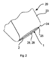
図2及び3に示されるように、レーザ処置装置20は、光学系1を有する。レーザ処置装置20は、限定するものではないが例えば、皮膚22から延在する毛21を切断するために用いられても良い。
As shown in FIGS. 2 and 3, the
レーザ処置装置20は、筐体23を有する。筐体23は、保護部24を有しても良い。保護部24は、毛及び皮膚操作モジュールであっても良い。筐体23は、皮膚係合面25を持つ。皮膚係合面25は、皮膚表面22に当てられるよう構成される。皮膚表面22は、限定するものではないが例えば、ユーザ又は処置されている人物の顔又は脚であっても良い。
The
皮膚係合面25は、凹部26を有する。凹部26の中心は、皮膚係合面25の中心と同心である。凹部26は、楕円形のスリットである。しかしながら、凹部26の断面の形状は、これに限定されるものではないことは、理解されるであろう。凹部26は、シェービングのストロークの方向において、0.3mm以上1.5mm以下の幅を持つ。該凹部の幅は、レーザ処置装置20への皮膚表面22のドーム形成を制御することを支援する。本実施例においては、凹部26の幅は0.8mmである。皮膚係合面25は、凹部26に亘って延在する面27に存する。
The
光学系1は、レーザ処置装置20の筐体23内に配置される。光学系1は、凹部26内に少なくとも部分的に配置される。凹部26は、切断領域28を有する。レーザ処置装置20の皮膚係合面25が、皮膚表面22に対して当てられ、皮膚表面22上を動かされるとき、皮膚表面22及び該皮膚表面上の毛21が、切断領域28へと延在し得る。
The
光学系1は、レーザパルスを凹部26に向け、処置パルス光路2の一部が、皮膚係合面25に亘って延在する面27に平行となり、該面から離隔されるようにする。処置パルス光路2は、凹部26に亘って延在する面27に近接する。それ故、レーザ処置装置20の皮膚係合面25が、皮膚表面22に対して当てられると、処置パルス光路2の少なくとも一部が、皮膚表面22に近接する。処置パルスは、発せられると、皮膚表面22から延在する毛21を切断し得る。
The
本実施例においては、プローブパルスは、レーザパルス生成構成3により発せられ、最初に皮膚表面22へと下に向けられる。レーザパルス生成構成3は、プローブパルスの発散を低減させるコリメータレンズ25にプローブパルスを向ける。平行にされたプローブパルスは次いで、フォーカスレンズ12を通過し、該フォーカスレンズ12が、プローブパルスを整合させて、処置パルス光路2と一致するものであっても良いプローブパルス光路へと続くようにする。
In this embodiment, the probe pulse is emitted by the laser
凹部26の一方の側に配置された第1の反射要素13は、凹部26の切断領域28に、入射したプローブパルスを反射させるよう構成される。即ち、第1の反射要素13は、レーザ処置装置20の凹部26に亘って延在する面27に略平行であり且つ該面から離隔されたプローブパルス光路における切断領域28に、入射したプローブパルスを反射させるよう構成される。それ故、プローブパルス光路は、処置パルス光路2と一致する。
The first
凹部26の他方の側に配置された第2の反射要素14は、プローブパルスを切断領域28から離れるように反射させるよう構成される。第2の反射要素14は、プローブパルスを、皮膚表面22から離れるように反射させるよう構成される。プローブパルスは、第2の反射要素14により、検出器レンズ15及びレーザパルスセンサ8の方へと向けられる。
A second
レーザパルスセンサ8は、光学系1を通る処置パルス光路2に一致するプローブパルス光路の状態を示す情報を生成し、該情報をコントローラ5に通信する。コントローラ5は、プローブパルスの光学的特性の少なくとも1つについての値を決定し、該値を予期される値と比較する。
The
処置パルス光路2が汚れている場合、即ち光学系1の構成要素が、プローブパルスを変化させられた光路4に沿って向けるような汚れを持つか、又はプローブパルスを妨害する皮膚表面22のような障害物9を持つ場合、決定される値は許容可能範囲内とはならない。それ故、コントローラ5は、処置パルスを発するようレーザパルス生成構成3を作動させず、損傷又は刺激を引き起こすことを回避する。
Treatment If the pulsed
処置パルス光路2が汚されていない場合又は妨害されていない場合、これら値は合致し、コントローラ5は、意図された光路2に沿って進み皮膚表面22から延在する毛21を切断する処置パルスを発するよう、レーザパルス生成構成3を作動させる。
If the treatment
光学系1は、毛及び/又は皮膚と障害物9との間の差を知っているようにプログラムされても良い。例えば、コントローラ5が、毛及び/又は皮膚のプロファイルを決定することが可能であっても良い。
The
シェービングシステムにおいては、少なくとも1つのセンサ8は、皮膚表面22又は水滴のような他の障害物9から、切断されるべき毛21により引き起こされる障害物を識別することが可能な情報を生成することが可能であっても良い。例えば、多素子センサが、毛21を識別し、毛21の円筒形の形状を皮膚表面22の平坦な面と比較することにより、偽陽性を回避することが可能であっても良い。
In a shaving system, at least one
代替の例においては、強度センサが毛21により引き起こされる強度低下を知っていても良く、強度低下が所定のレベルを下回ると、処置パルスの生成を防止する。他の代替実施例においては、少なくとも1つのセンサ8は、特性の時間的プロファイルを測定しても良い。毛21の時間プロファイルは、毛21が切断されると迅速に変化するが、皮膚又は水滴の障害物9は、長い時間の間、プローブパルス光路に留まる。それ故、光学系1は、皮膚表面22及び/又は障害物9から毛21を区別することが可能となり得る。
In an alternative example, the intensity sensor may be aware of the intensity reduction caused by the bristles 21, and when the intensity reduction falls below a predetermined level, it prevents the generation of treatment pulses. In other alternative embodiments, at least one
皮膚処置システムにおいては、少なくとも1つのセンサ8は皮膚位置センサであっても良い。皮膚位置センサは、皮膚表面の位置及び幾何を示す情報を生成することが可能であっても良い。皮膚表面の位置及び幾何の変化は、ミリ秒乃至秒のオーダーで生じる。空間的及び時間的な分布の変化は、毛21及び/又は障害物9から皮膚表面22を区別するため用いられ得る。
In the skin treatment system, at least one
代替の実施例においては、例えば、プローブパルスが凹部26に亘って延在する面27に平行に凹部26に亘って進む直前のような、毛21及び/又は皮膚表面22が位置する光路の部分より前で、プローブパルスの少なくとも1つの特性が決定されても良い。それ故、処置パルスは、毛21のみが光路2における「障害物」である場合に、毛を切断するために発せられ得る。
In an alternative embodiment, the portion of the optical path where the hair 21 and / or the
しかしながら、光学系1は、毛を切断するために用いられることに限定されるものではない。代替として、光学系1は、光路2に沿って有害な処置パルスが発せられる前に、光路上に障害物9がないかチェックするためにプローブパルスが発せられるいずれの状況においても用いられることができる。
However, the
「有する(comprising)」なる語は他の要素又はステップを除外するものではなく、「1つの(a又はan)」なる不定冠詞は複数を除外するものではないことは、理解されるであろう。単一のプロセッサ又はその他のユニットが、請求項に列記された幾つかのアイテムの機能を実行しても良い。特定の手段が相互に異なる従属請求項に列挙されているという単なる事実は、これら手段の組み合わせが有利に利用されることができないことを示すものではない。請求項におけるいずれの参照記号も、請求の範囲を限定するものとして解釈されるべきではない。 It will be understood that the word "comprising" does not exclude other elements or steps, and the indefinite article "one (a or an)" does not exclude more than one. .. A single processor or other unit may perform the functions of some of the items listed in the claims. The mere fact that certain means are listed in different dependent claims does not indicate that the combination of these means cannot be used to their advantage. None of the reference symbols in the claims should be construed as limiting the scope of the claims.
請求項は特徴の特定の組み合わせに向けたものであるが、本発明の開示の範囲は、いずれかの請求項において現在請求されているものと同一の発明に関するものであろうとなかろうと、また本発明が軽減するものと同一の技術的課題のいずれか又は全てを軽減するものであろうとなかろうと、明示的若しくは暗黙的にここで開示されたいずれの新規な特徴若しくは特徴の新規な組み合わせ、又はその一般化をも含むことは、理解されるべきである。本出願人はここで、本出願又は本出願から導かれるいずれかの更なる出願の手続きの間に、斯かる特徴及び/又は斯かる特徴の組み合わせに対して、新たな請求項が作成され得ることを注記しておく。 Although the claims are directed to a particular combination of features, the scope of the invention, whether or not it relates to the same invention currently claimed in any of the claims, and the present invention. A new feature or new combination of features, either explicitly or implicitly disclosed herein, whether or not it alleviates any or all of the same technical challenges as the invention alleviates. It should be understood that it also includes its generalization. Applicants may hereby make new claims for such features and / or combinations of such features during the procedure of this application or any further application derived from this application. Note that.
Claims (14)
前記光学的要素を通る処置パルス光路に沿って処置パルスを生成するよう構成され、更に、前記光学的要素を通って延在するプローブパルス光路に沿ってプローブパルスを生成するよう構成された、パルス生成構成と、
前記光学的要素を通る前記プローブパルス光路に沿って通過した前記プローブパルスの光学的特性を示す情報を生成するよう構成された、センサと、
前記センサにより生成された前記情報に依存して、前記処置パルス光路に沿って前記処置パルスを選択的に発するよう、前記パルス生成構成を制御するよう構成された、コントローラと、
を有し、前記センサにより生成される情報は、前記処置パルス光路における、前記処置パルスによる処置の対象ではない第1の障害物と前記処置パルスによる処置の対象である第2の障害物とを示し、
前記センサにより生成される情報が、前記処置パルス光路において前記第1の障害物がないことを示す場合にのみ、前記コントローラが、前記処置パルスを発するよう、前記パルス生成構成を制御する、光学系。 With multiple optics
A pulse configured to generate a treatment pulse along a treatment pulse optical path through the optical element and further to generate a probe pulse along a probe pulse optical path extending through the optical element. Generation configuration and
A sensor configured to generate information indicating the optical properties of the probe pulse that has passed along the probe pulse optical path through the optical element.
A controller configured to control the pulse generation configuration to selectively emit the treatment pulse along the treatment pulse optical path depending on the information generated by the sensor.
The information generated by the sensor includes a first obstacle in the treatment pulse optical path that is not the target of treatment by the treatment pulse and a second obstacle that is the target of treatment by the treatment pulse. shows and,
An optical system that controls the pulse generation configuration so that the controller emits the treatment pulse only if the information generated by the sensor indicates that the treatment pulse optical path is free of the first obstacle. ..
パルス生成機構により、複数の光学的要素を通って延在するプローブパルス光路に沿ってプローブパルスを生成するステップと、
前記プローブパルス光路に沿ったセンサにより、前記プローブパルスの特性を測定し、前記光学的要素を通って延在する処置パルス光路の状態を示す情報を生成するステップと、
コントローラにより、前記プローブパルスの特性を示す情報を、所定の範囲と比較するステップであって、前記プローブパルスの特性が前記所定の範囲内であることが、前記処置パルスによる処置の対象である前記毛が存在することに対応し、前記プローブパルスの特性が前記所定の範囲外であることは、前記処置パルスによる処置の対象ではない障害物が存在することに対応する、ステップと、
前記プローブパルスの特性を示す情報が、前記所定の範囲内である場合に、前記パルス生成機構により、前記凹部のなかに延在する毛を切断するため、前記光学的要素を通る前記処置パルス光路に沿って、処置パルスを発するステップと、
を有する方法。 A method of operating a laser treatment device having a recess in which the hair extends for cutting the hair.
A step of generating a probe pulse along a probe pulse optical path extending through multiple optical elements by a pulse generation mechanism.
A step of measuring the characteristics of the probe pulse by a sensor along the probe pulse optical path and generating information indicating the state of the treatment pulse optical path extending through the optical element.
The step of comparing the information indicating the characteristics of the probe pulse with the predetermined range by the controller, and the fact that the characteristics of the probe pulse are within the predetermined range is the target of the treatment by the treatment pulse. Corresponding to the presence of bristles and the fact that the properties of the probe pulse are outside the predetermined range corresponds to the presence of obstacles that are not subject to treatment by the treatment pulse .
When the information indicating the characteristics of the probe pulse is within the predetermined range, the treatment pulse optical path passing through the optical element is used to cut the hair extending in the recess by the pulse generation mechanism. Along with the step of emitting a treatment pulse,
Method to have.
Applications Claiming Priority (3)
| Application Number | Priority Date | Filing Date | Title |
|---|---|---|---|
| EP15166752 | 2015-05-07 | ||
| EP15166752.4 | 2015-05-07 | ||
| PCT/EP2016/059120 WO2016177589A1 (en) | 2015-05-07 | 2016-04-25 | An optical system |
Publications (3)
| Publication Number | Publication Date |
|---|---|
| JP2018521699A JP2018521699A (en) | 2018-08-09 |
| JP2018521699A5 JP2018521699A5 (en) | 2019-05-23 |
| JP6898855B2 true JP6898855B2 (en) | 2021-07-07 |
Family
ID=53274371
Family Applications (1)
| Application Number | Title | Priority Date | Filing Date |
|---|---|---|---|
| JP2017555649A Active JP6898855B2 (en) | 2015-05-07 | 2016-04-25 | Optical system |
Country Status (7)
| Country | Link |
|---|---|
| US (1) | US11311335B2 (en) |
| EP (1) | EP3291754B1 (en) |
| JP (1) | JP6898855B2 (en) |
| CN (1) | CN107635501B (en) |
| ES (1) | ES2714174T3 (en) |
| TR (1) | TR201902299T4 (en) |
| WO (1) | WO2016177589A1 (en) |
Families Citing this family (1)
| Publication number | Priority date | Publication date | Assignee | Title |
|---|---|---|---|---|
| CN109561930B (en) * | 2016-08-05 | 2022-06-10 | 皇家飞利浦有限公司 | Hair cutting device and method of operating a hair cutting device |
Family Cites Families (12)
| Publication number | Priority date | Publication date | Assignee | Title |
|---|---|---|---|---|
| IL97531A (en) * | 1991-03-12 | 1995-12-31 | Kelman Elliot | Hair cutting apparatus |
| IL109882A0 (en) | 1994-06-02 | 1994-10-07 | Kelman Elliot | Hair cutting apparatus |
| US5993440A (en) * | 1997-10-16 | 1999-11-30 | Ghassemi; Faramarz Frank | Non-invasive laser cutting device and method |
| AU3147200A (en) | 1999-03-08 | 2000-09-28 | Asah Medico A/S | An apparatus for tissue treatment and having a monitor for display of tissue features |
| DE19916653A1 (en) * | 1999-04-14 | 2000-10-19 | Holger Lubatschowski | Laser cyclo-photocoagulation for treatment of the cilary body in cases on intractable glaucoma uses opto-acoustic tissue differentiation so that tissue type is more accurately determined and an appropriate dose applied |
| US6704340B2 (en) * | 2001-01-29 | 2004-03-09 | Cymer, Inc. | Lithography laser system with in-place alignment tool |
| JP2002291764A (en) | 2001-03-29 | 2002-10-08 | Nidek Co Ltd | Laser therapeutic device |
| JP2004529705A (en) | 2001-04-20 | 2004-09-30 | コーニンクレッカ フィリップス エレクトロニクス エヌ ヴィ | Skin treatment device with protection against overdose of radiation pulses |
| JP4838716B2 (en) * | 2003-08-04 | 2011-12-14 | コーニンクレッカ フィリップス エレクトロニクス エヌ ヴィ | Device for shortening hairs by laser-induced photodestructive effect |
| US20060200114A1 (en) | 2005-03-04 | 2006-09-07 | Searete Llc, A Limited Liability Corporation Of State Of Delaware | Hair removal system with light source array |
| MY158884A (en) * | 2009-05-01 | 2016-11-30 | Xtralis Technologies Ltd | Particle detectors |
| RU2686188C2 (en) | 2013-10-08 | 2019-04-24 | Конинклейке Филипс Н.В. | Hair cutting device |
-
2016
- 2016-04-25 EP EP16722538.2A patent/EP3291754B1/en active Active
- 2016-04-25 TR TR2019/02299T patent/TR201902299T4/en unknown
- 2016-04-25 JP JP2017555649A patent/JP6898855B2/en active Active
- 2016-04-25 WO PCT/EP2016/059120 patent/WO2016177589A1/en active Application Filing
- 2016-04-25 US US15/570,515 patent/US11311335B2/en active Active
- 2016-04-25 ES ES16722538T patent/ES2714174T3/en active Active
- 2016-04-25 CN CN201680026279.8A patent/CN107635501B/en active Active
Also Published As
| Publication number | Publication date |
|---|---|
| JP2018521699A (en) | 2018-08-09 |
| WO2016177589A1 (en) | 2016-11-10 |
| US11311335B2 (en) | 2022-04-26 |
| CN107635501B (en) | 2021-03-26 |
| EP3291754A1 (en) | 2018-03-14 |
| CN107635501A (en) | 2018-01-26 |
| ES2714174T3 (en) | 2019-05-27 |
| US20180140357A1 (en) | 2018-05-24 |
| EP3291754B1 (en) | 2018-12-12 |
| TR201902299T4 (en) | 2019-03-21 |
Similar Documents
| Publication | Publication Date | Title |
|---|---|---|
| US9937004B2 (en) | Hair shortening device | |
| EP2456382B1 (en) | Epilation by applying light | |
| JP6684726B2 (en) | Equipment for cutting hair | |
| JP4838716B2 (en) | Device for shortening hairs by laser-induced photodestructive effect | |
| RU2656524C2 (en) | Cutting head for device for cutting hair | |
| JP2014509228A5 (en) | ||
| US9622818B2 (en) | LIOB based hair cutting device | |
| JP6898855B2 (en) | Optical system | |
| CN110121307B (en) | Light-based skin treatment device | |
| JP5829776B2 (en) | LIOB-based skin treatment system | |
| EP3171805A1 (en) | A device for cutting hair | |
| JP6383504B2 (en) | Laser shaving device | |
| US20220257806A1 (en) | Far-uvc germicidal system | |
| JP2018526041A (en) | Optical system | |
| CN107530128B (en) | Method for setting a cutting distance between a laser beam and a skin surface in a laser shaving device | |
| WO2019130465A1 (en) | Surgical treatment device |
Legal Events
| Date | Code | Title | Description |
|---|---|---|---|
| A521 | Request for written amendment filed |
Free format text: JAPANESE INTERMEDIATE CODE: A523 Effective date: 20190410 |
|
| A621 | Written request for application examination |
Free format text: JAPANESE INTERMEDIATE CODE: A621 Effective date: 20190410 |
|
| A131 | Notification of reasons for refusal |
Free format text: JAPANESE INTERMEDIATE CODE: A131 Effective date: 20200225 |
|
| A977 | Report on retrieval |
Free format text: JAPANESE INTERMEDIATE CODE: A971007 Effective date: 20200228 |
|
| A601 | Written request for extension of time |
Free format text: JAPANESE INTERMEDIATE CODE: A601 Effective date: 20200515 |
|
| A521 | Request for written amendment filed |
Free format text: JAPANESE INTERMEDIATE CODE: A523 Effective date: 20200807 |
|
| A02 | Decision of refusal |
Free format text: JAPANESE INTERMEDIATE CODE: A02 Effective date: 20210114 |
|
| A521 | Request for written amendment filed |
Free format text: JAPANESE INTERMEDIATE CODE: A523 Effective date: 20210420 |
|
| C60 | Trial request (containing other claim documents, opposition documents) |
Free format text: JAPANESE INTERMEDIATE CODE: C60 Effective date: 20210420 |
|
| A911 | Transfer to examiner for re-examination before appeal (zenchi) |
Free format text: JAPANESE INTERMEDIATE CODE: A911 Effective date: 20210428 |
|
| C21 | Notice of transfer of a case for reconsideration by examiners before appeal proceedings |
Free format text: JAPANESE INTERMEDIATE CODE: C21 Effective date: 20210430 |
|
| TRDD | Decision of grant or rejection written | ||
| A01 | Written decision to grant a patent or to grant a registration (utility model) |
Free format text: JAPANESE INTERMEDIATE CODE: A01 Effective date: 20210603 |
|
| A61 | First payment of annual fees (during grant procedure) |
Free format text: JAPANESE INTERMEDIATE CODE: A61 Effective date: 20210611 |
|
| R150 | Certificate of patent or registration of utility model |
Ref document number: 6898855 Country of ref document: JP Free format text: JAPANESE INTERMEDIATE CODE: R150 |