JP6684726B2 - Equipment for cutting hair - Google Patents
Equipment for cutting hair Download PDFInfo
- Publication number
- JP6684726B2 JP6684726B2 JP2016570780A JP2016570780A JP6684726B2 JP 6684726 B2 JP6684726 B2 JP 6684726B2 JP 2016570780 A JP2016570780 A JP 2016570780A JP 2016570780 A JP2016570780 A JP 2016570780A JP 6684726 B2 JP6684726 B2 JP 6684726B2
- Authority
- JP
- Japan
- Prior art keywords
- cutting
- laser beam
- skin
- controller
- hair
- Prior art date
- Legal status (The legal status is an assumption and is not a legal conclusion. Google has not performed a legal analysis and makes no representation as to the accuracy of the status listed.)
- Expired - Fee Related
Links
- 238000005520 cutting process Methods 0.000 title claims description 310
- 210000004209 hair Anatomy 0.000 title claims description 88
- 238000003384 imaging method Methods 0.000 claims description 66
- 230000003287 optical effect Effects 0.000 claims description 59
- 238000000034 method Methods 0.000 claims description 16
- 238000004590 computer program Methods 0.000 claims description 3
- 238000001514 detection method Methods 0.000 description 13
- 230000008859 change Effects 0.000 description 7
- 238000010586 diagram Methods 0.000 description 5
- 230000008569 process Effects 0.000 description 5
- 230000036556 skin irritation Effects 0.000 description 5
- 206010040880 Skin irritation Diseases 0.000 description 4
- 231100000475 skin irritation Toxicity 0.000 description 4
- 230000008901 benefit Effects 0.000 description 3
- 230000006378 damage Effects 0.000 description 3
- 230000006870 function Effects 0.000 description 3
- 238000012634 optical imaging Methods 0.000 description 3
- 230000001419 dependent effect Effects 0.000 description 2
- 238000005259 measurement Methods 0.000 description 2
- 230000004044 response Effects 0.000 description 2
- 230000000717 retained effect Effects 0.000 description 2
- 206010061218 Inflammation Diseases 0.000 description 1
- 230000009471 action Effects 0.000 description 1
- 230000015572 biosynthetic process Effects 0.000 description 1
- 238000005516 engineering process Methods 0.000 description 1
- 230000008020 evaporation Effects 0.000 description 1
- 238000001704 evaporation Methods 0.000 description 1
- 230000004054 inflammatory process Effects 0.000 description 1
- 230000003993 interaction Effects 0.000 description 1
- 238000000691 measurement method Methods 0.000 description 1
- 230000007935 neutral effect Effects 0.000 description 1
- 230000035939 shock Effects 0.000 description 1
- 230000037380 skin damage Effects 0.000 description 1
- 239000007787 solid Substances 0.000 description 1
Images


Classifications
-
- A—HUMAN NECESSITIES
- A61—MEDICAL OR VETERINARY SCIENCE; HYGIENE
- A61B—DIAGNOSIS; SURGERY; IDENTIFICATION
- A61B18/00—Surgical instruments, devices or methods for transferring non-mechanical forms of energy to or from the body
- A61B18/18—Surgical instruments, devices or methods for transferring non-mechanical forms of energy to or from the body by applying electromagnetic radiation, e.g. microwaves
- A61B18/20—Surgical instruments, devices or methods for transferring non-mechanical forms of energy to or from the body by applying electromagnetic radiation, e.g. microwaves using laser
- A61B18/203—Surgical instruments, devices or methods for transferring non-mechanical forms of energy to or from the body by applying electromagnetic radiation, e.g. microwaves using laser applying laser energy to the outside of the body
-
- A—HUMAN NECESSITIES
- A45—HAND OR TRAVELLING ARTICLES
- A45D—HAIRDRESSING OR SHAVING EQUIPMENT; EQUIPMENT FOR COSMETICS OR COSMETIC TREATMENTS, e.g. FOR MANICURING OR PEDICURING
- A45D7/00—Processes of waving, straightening or curling hair
-
- B—PERFORMING OPERATIONS; TRANSPORTING
- B26—HAND CUTTING TOOLS; CUTTING; SEVERING
- B26B—HAND-HELD CUTTING TOOLS NOT OTHERWISE PROVIDED FOR
- B26B19/00—Clippers or shavers operating with a plurality of cutting edges, e.g. hair clippers, dry shavers
- B26B19/38—Details of, or accessories for, hair clippers, or dry shavers, e.g. housings, casings, grips, guards
- B26B19/3873—Electric features; Charging; Computing devices
- B26B19/388—Sensors; Control
-
- A—HUMAN NECESSITIES
- A45—HAND OR TRAVELLING ARTICLES
- A45D—HAIRDRESSING OR SHAVING EQUIPMENT; EQUIPMENT FOR COSMETICS OR COSMETIC TREATMENTS, e.g. FOR MANICURING OR PEDICURING
- A45D7/00—Processes of waving, straightening or curling hair
- A45D2007/007—Processes of trimming or cutting hair for hairdressing purposes
-
- A—HUMAN NECESSITIES
- A61—MEDICAL OR VETERINARY SCIENCE; HYGIENE
- A61B—DIAGNOSIS; SURGERY; IDENTIFICATION
- A61B18/00—Surgical instruments, devices or methods for transferring non-mechanical forms of energy to or from the body
- A61B2018/00315—Surgical instruments, devices or methods for transferring non-mechanical forms of energy to or from the body for treatment of particular body parts
- A61B2018/00452—Skin
- A61B2018/00476—Hair follicles
-
- A—HUMAN NECESSITIES
- A61—MEDICAL OR VETERINARY SCIENCE; HYGIENE
- A61B—DIAGNOSIS; SURGERY; IDENTIFICATION
- A61B18/00—Surgical instruments, devices or methods for transferring non-mechanical forms of energy to or from the body
- A61B2018/00636—Sensing and controlling the application of energy
- A61B2018/00696—Controlled or regulated parameters
- A61B2018/00702—Power or energy
-
- A—HUMAN NECESSITIES
- A61—MEDICAL OR VETERINARY SCIENCE; HYGIENE
- A61B—DIAGNOSIS; SURGERY; IDENTIFICATION
- A61B18/00—Surgical instruments, devices or methods for transferring non-mechanical forms of energy to or from the body
- A61B2018/00636—Sensing and controlling the application of energy
- A61B2018/00773—Sensed parameters
- A61B2018/00779—Power or energy
- A61B2018/00785—Reflected power
Description
本発明は、レーザビームを用いて毛を切断するための装置に関する。また、本発明は、毛を切断するための方法、少なくとも1つのプロセッサによって実行される場合にかかる方法を実行させる命令を有するコンピュータプログラムに関する。 The present invention relates to a device for cutting hair with a laser beam. The invention also relates to a method for cutting hair, a computer program having instructions that, when executed by at least one processor, carry out such method.
毛を切断するために機械的な切断刃を配置する代わりとしてレーザビームを用いることが知られている。レーザビームに曝された毛はそのレーザビームからエネルギーを吸収し、この毛は蒸発又はレーザ誘起光学破壊及び生じる衝撃波のいずれかによって切断される。レーザビームには可動部品が必要無いため、切断要素が摩耗する又は鈍るという課題が排除される。さらに、毛を切断するためにレーザビームを使用すると、皮膚に接触する機械的な刃の鋭い刃先によりもたらされる皮膚炎症を防止する。レーザダイオードと、使用中、ビームが、ユーザの肌の表面に対して実質的に平行であり、且つ、かかる表面から間隔を空けるよう、切断領域を横切るようにレーザビームを方向付ける反射素子と、を含む装置を提供することが、国際公開第1992/16338号及び米国特許第5993440号から知られている。このようにして、装置は、肌を横切るように移動されるため、切断領域に入る毛が、レーザビームに晒され、レーザビームと毛との間の相互作用点において切断される。国際公開第2013/175355号は、シェーバが肌の上を移動される場合に、毛を切断するために肌に対して平行となるようにレーザビームを方向付ける光学系を有するレーザシェーバを開示している。 It is known to use laser beams as an alternative to placing mechanical cutting blades to cut hair. Hair exposed to the laser beam absorbs energy from the laser beam, and the hair is cut either by evaporation or laser-induced optical destruction and the resulting shock wave. Since the laser beam does not require moving parts, the problem of wear or blunting of the cutting element is eliminated. Moreover, the use of a laser beam to cut hair prevents skin irritation caused by the sharp cutting edges of mechanical blades that contact the skin. A laser diode and a reflective element that, in use, directs the laser beam across a cutting region so that the beam is substantially parallel to the surface of the user's skin and spaced from such surface; It is known from WO 1992/16338 and US Pat. No. 5,993,440 to provide a device comprising In this way, the device is moved across the skin so that the hair entering the cutting area is exposed to the laser beam and cut at the point of interaction between the laser beam and the hair. WO 2013/175355 discloses a laser shaver having optics that direct the laser beam so that it is parallel to the skin for cutting hair when the shaver is moved over the skin. ing.
シェービング性能は、通常、2つの基準−剃りの近さ及び皮膚の炎症によって測定される。切断高さは、皮膚の表面と毛髪が切断される箇所との間の距離である。良い性能のシェーバーでは、切断高さを最小にすべきであり、故に、毛を可能な限り皮膚の近傍で切断することによって残る毛の長さを最小にすべきである。しかしながら、皮膚の近傍にレーザビームを配置すると、レーザ−による熱及びエネルギーが皮膚に入射された場合に皮膚炎症を引き起こす場合がある。皮膚の損傷又は炎症を引き起こすことを避けるため、レーザビームから皮膚を保護する必要がある。 Shaving performance is usually measured by two criteria-shave proximity and skin irritation. The cutting height is the distance between the surface of the skin and the point where the hair is cut. For a good performing shaver, the cut height should be minimized and therefore the length of hair left by cutting the hair as close to the skin as possible should be minimized. However, placing the laser beam near the skin can cause skin irritation when the heat and energy from the laser is incident on the skin. There is a need to protect the skin from the laser beam to avoid causing skin damage or irritation.
本発明の目的は、上記の問題を実質的に軽減又は克服する、レーザビームを用いて毛を切断するための装置、及び/又は、毛を切断するための方法を提供することである。 It is an object of the present invention to provide a device for cutting hair with a laser beam and / or a method for cutting hair, which substantially reduces or overcomes the above problems.
本発明は、独立請求項によって規定されており、従属請求項は、好適な実施形態を規定している。 The invention is defined by the independent claims and the dependent claims define the preferred embodiments.
本発明の或る態様によれば、毛を切断するための装置であって、使用中、ユーザの肌の表面に対して配置されるように構成された肌接触面と、切断領域に延在している毛を切断するため、前記肌接触面に対して平行であり、且つ、前記肌接触面から離れた前記切断領域を横切るように切断レーザビームを方向付けるように構成された光学系と、前記切断領域における毛及び/又は肌を表す1又は複数のオブジェクトの存在を示す情報を生成するように構成される検出器と、前記切断領域における毛及び/又は肌を表す1又は複数のオブジェクトの存在を決定するとともに、前記検出器によって生成された前記情報に依存して前記光学系の1又は複数の特徴を調整するように構成されるコントローラと、を有し、前記コントローラは、前記検出器によって生成された前記情報に依存して前記切断領域における毛及び/又は肌を表す1又は複数のオブジェクトと前記切断レーザビームとの間の距離を示す情報を生成するとともに、前記コントローラによって生成された前記情報に依存して前記光学系の1又は複数の特徴を調整するように構成される、装置が提供される。 According to one aspect of the invention, a device for cutting hair, which in use, is adapted to be placed against a surface of a user's skin and which extends to the cutting area. An optical system configured to direct a cutting laser beam parallel to the skin-contacting surface and across the cutting region away from the skin-contacting surface to cut the hair being formed. A detector configured to generate information indicating the presence of one or more objects representing hair and / or skin in the cut region, and one or more objects representing hair and / or skin in the cut region And a controller configured to adjust one or more characteristics of the optical system depending on the information generated by the detector and determining the presence of the detector. Generated by the controller as well as generating information indicative of the distance between the cutting laser beam and one or more objects representing hair and / or skin in the cutting region depending on the information generated by An apparatus is provided that is configured to adjust one or more features of the optical system depending on the information.
上記構成により、切断領域における毛及び/又は肌の検出に依存して光学系の1又は複数の特徴を変更することが可能である。従って、切断レーザビームが、肌に対してダメージ又は炎症を与えることを防ぐことが可能である。さらに、装置の効率を最大化することが可能である。 With the above configuration, it is possible to change one or more characteristics of the optical system depending on the detection of hair and / or skin in the cut area. Therefore, it is possible to prevent the cutting laser beam from damaging or irritating the skin. Furthermore, it is possible to maximize the efficiency of the device.
検出器は、切断領域を横切るように方向付けられた光源の経路において受けられる毛及び/又は肌を表す1又は複数のオブジェクトの存在を示す情報を生成するように構成されるイメージングセンサを有していてもよい。 The detector comprises an imaging sensor configured to generate information indicative of the presence of one or more objects representing hair and / or skin received in the path of the light source directed across the cutting region. May be.
この構成により、切断領域におけるオブジェクトの存在を直接的に検出することが可能である。従って、検出器の精度を最大化することが可能である。 With this configuration, it is possible to directly detect the presence of the object in the cutting area. Therefore, it is possible to maximize the accuracy of the detector.
光源は、レーザビームであってもよい。 The light source may be a laser beam.
光源は、切断レーザビームであってもよい。光源は、切断レーザビームの付帯セクションであってもよい。 The light source may be a cutting laser beam. The light source may be an adjunct section of the cutting laser beam.
従って、イメージングセンサのための光源を供給するために切断レーザビームを用いることが可能である。これは、装置の複雑性が最小化され、結果、信頼性が最大化され得ることを意味する。 Therefore, it is possible to use a cutting laser beam to provide a light source for an imaging sensor. This means that the device complexity can be minimized and consequently the reliability can be maximized.
コントローラは、検出器によって生成された情報に依存して切断レーザビームと基準位置との間の距離を示す情報を生成するように構成されてもよい。 The controller may be configured to generate information indicative of the distance between the cutting laser beam and the reference position depending on the information generated by the detector.
この構成により、切断レーザビームの位置と切断領域におけるオブジェクトとの両方を決定することによって、切断レーザビームの経路における任意のずれを補償することが可能である。 With this configuration, it is possible to compensate for any deviations in the path of the cutting laser beam by determining both the position of the cutting laser beam and the object in the cutting region.
検出器は、切断領域において受けられる毛及び/又は肌を表す1又は複数のオブジェクトと基準位置との間の距離を示す情報を生成するように構成された距離センサを有していてもよい。 The detector may include a distance sensor configured to generate information indicative of a distance between the reference position and one or more objects representing hair and / or skin received in the cut region.
この構成により、肌の高さに基づいて、いつ肌が切断領域に突き出ているかを決定し、結果、肌に対するダメージ又は炎症を最小化することが可能である。 With this configuration, it is possible to determine when the skin protrudes into the cut region based on the height of the skin, and as a result, damage or inflammation to the skin can be minimized.
コントローラは、切断領域における毛及び/又は肌を表す1又は複数のオブジェクトの存在を検出するとともに、切断領域における毛を表す前記1又は複数のオブジェクトが検出された場合、切断領域における毛を表す1又は複数のオブジェクトの存在を無視するように構成されてもよい。 The controller detects the presence of one or more objects that represent hair and / or skin in the cut area, and, if the one or more objects that represent hair in the cut area is detected, represents the hair in the cut area. Alternatively, it may be configured to ignore the presence of multiple objects.
この構成により、肌から延びている毛によって生成される誤検出を無視することによって、切断領域における肌の存在を正確に検出することが可能である。 With this configuration, it is possible to accurately detect the presence of the skin in the cut region by ignoring the false detection generated by the hair extending from the skin.
コントローラによって調整される光学系の1又は複数の特徴が、切断レーザビームの強度であってもよい。 One or more characteristics of the optics adjusted by the controller may be the intensity of the cutting laser beam.
これは、任意の追加コンポーネントなしに、光学系の光学特性を変更することが可能であることを意味する。従って、光学系、ひいては装置の信頼性を最大化することが可能である。 This means that it is possible to change the optical properties of the optical system without any additional components. Therefore, it is possible to maximize the reliability of the optical system and thus the device.
コントローラは、切断領域における肌を表す1又は複数のオブジェクトの存在の検出に依存して切断レーザビームの強度を減少させるように構成されてもよい。 The controller may be configured to reduce the intensity of the cutting laser beam depending on detecting the presence of one or more objects representing skin in the cutting region.
従って、装置は、毛を切断するのに十分な強度で動作している切断レーザビームが肌に入射するのを防ぐように単純に動作され得る。 Thus, the device can simply be operated to prevent the cutting laser beam operating at sufficient intensity to cut hair from entering the skin.
コントローラは、切断領域における毛を表す1又は複数のオブジェクトの存在の検出に依存して切断レーザビームの強度を増加させるように構成されてもよい。 The controller may be configured to increase the intensity of the cutting laser beam depending on detecting the presence of one or more objects representing hair in the cutting region.
この構成により、毛が切断領域において検出されない場合に減少された強度レベルで切断レーザビームを動作させることによって、装置の効率を最大化することが可能である。 With this arrangement, it is possible to maximize the efficiency of the device by operating the cutting laser beam at a reduced intensity level if no hair is detected in the cutting area.
コントローラが調整する光学系の1又は複数の特徴は、切断レーザビームの経路であってもよい。 The one or more features of the optics that the controller coordinates may be the path of the cutting laser beam.
従って、切断レーザビームの経路における任意のずれを補償することが可能である。 Therefore, it is possible to compensate for any deviations in the path of the cutting laser beam.
コントローラは、切断レーザビームの経路と肌接触面との間の距離を修正するように工学系を調整するように構成されてもよい。 The controller may be configured to adjust the engineering system to modify the distance between the path of the cutting laser beam and the skin contact surface.
本発明の他の態様によれば、毛を切断する方法であって、光学系を用いて、切断領域に延在している毛を切断するため、肌接触面に対して平行であり、且つ、前記肌接触面から離れた前記切断領域を横切るように切断レーザビームを方向付けるステップと、検出器を用いて、前記切断領域における毛及び/又は肌を表す1又は複数のオブジェクトの存在を示す情報を生成するステップと、前記切断領域における毛及び/又は肌を表す1又は複数のオブジェクトの存在を決定するステップと、前記検出器によって生成された前記情報に依存して前記光学系の1又は複数の特徴を調整するステップと、前記検出器によって生成された情報に依存して切断領域における毛及び肌を表す1又は複数のオブジェクトと前記切断レーザビームとの間の距離を示す情報を生成するため、及び、前記生成された情報に依存して前記光学系の1又は複数の特徴を調整するため、コントローラを用いるステップと、を有する方法が提供される。 According to another aspect of the present invention, there is provided a method for cutting hair, which is parallel to a skin contact surface for cutting hair extending to a cutting area by using an optical system, and Directing a cutting laser beam across the cutting area away from the skin contact surface, and using a detector to indicate the presence of one or more objects representing hair and / or skin in the cutting area. Generating information, determining the presence of one or more objects representing hair and / or skin in the cut region, and depending on the information generated by the detector, one or more of the optical systems. Adjusting a plurality of features and the distance between the cutting laser beam and one or more objects representing hair and skin in a cutting region depending on the information generated by the detector. For generating information indicating, and, because depending on the generated information to adjust one or more characteristics of the optical system, the method comprising the steps of: using a controller is provided.
本発明の他の態様によれば、少なくとも1つのプロセッサによって実行された場合に、上記方法を実行させる命令を有するコンピュータプログラムが提供される。 According to another aspect of the invention, there is provided a computer program having instructions that, when executed by at least one processor, cause the method to be performed.
本発明の上記態様及び他の態様が、以下に説明される実施形態を参照して、明確且つ明らかとなる。 The above and other aspects of the invention will be clear and apparent with reference to the embodiments described below.
本発明の実施形態が、添付の図面を参照して、単なる一例として、説明される。
特に、図1乃至図3を参照すると、毛を切断するための装置10が示されている。装置10は、開口14を持つ肌接触面13を含む本体12を有する。図2に示されるように、使用中、本体12の肌接触面13は、ユーザの肌16と本体12の開口及びそこに規定される切断領域15に突き出ている肌16上の毛17とに対して配置される。本体12において、装置10は、切断レーザビーム18が肌接触面13に対して平行であり、且つ、肌接触面13から離れるように、切断領域15を横切るように切断レーザビーム18を方向付ける光学系20を有する。また、切断レーザビーム18は、本体12の開口14を横切るように延在する。このようにして、本体12の肌接触面13がユーザの肌16に対して配置された場合、切断レーザビーム18は、ユーザの肌16に対して平行且つ間隔を空けて存在し、切断領域15を横切る実質的に均一な切断高さを供給する。図2において距離H1として表されている、肌16の表面と切断領域15における切断レーザビーム18との間の距離が、切断高さである。
In particular, referring to FIGS. 1-3, a
光学系20は、開口14及び切断領域15の一方の側に配置された第1の反射素子21を有する。第1の反射素子21は、装置10の端部において開口14を横切るように切断レーザビーム18の入射セクション22を反射するように構成されている。即ち、第1の反射素子21は、切断領域15を横切るように切断レーザビーム18の入射セクション22を反射するように構成され、結果、切断レーザビーム18は、装置10の肌接触面13及び開口14に対して実質的に平行であり、且つ、装置10の肌接触面13及び開口14から間隔を開けた経路を追従する。
The
第1の反射素子21に対して切断領域15の反対側に、第2の反射素子23が、切断レーザビーム18の「使用された」セクション24が、消散され、ユーザの一部又は装置の他の部分と相互作用できないように、切断領域15から離れて、エメルギー消散器(図示省略)の方へ向かうように切断レーザビーム18を反射するために配置されている。図2に示される例では、第1の反射素子21に入射する切断レーザビーム18の入射セクション22は、本体12の肌接触面13に対して垂直であり、第1の反射素子21は、レーザビームが本体12の肌接触面13に対して平行となるように、90度反射させる。同様に、第2の反射素子23は、切断レーザビーム18を90度反射させ、切断領域15から垂直に離れるように構成されている。しかしながら、当然、第1及び第2の反射素子21,23は、レーザビーム生成器25及びエネルギー消散器(図示省略)などの光学系の他の部分の位置及び向きに依存して、異なる向きに配置されてもよいし、又は、異なる反射角を有してもよい。さらに、当然、第1及び第2の反射素子21,23は、切断領域15の片側に配置されない。それらは、光学系20の他のコンポーネントの位置、向き、及び、構成に依存して、代替的に、切断領域15内の任意の場所に配置されてもよい。第1の反射素子21及び/又は第2の反射素子23は、省略されてもよい。しかしながら、切断領域15内の切断レーザビーム18は、肌接触面13と切断レーザビーム18との間の距離が切断領域15を横切る際に一定であるように、本体12の肌接触面13及び開口14に対して平行なままでであるべきである。ここで説明される任意の反射素子は、ミラー又はプリズム又は任意の他の光学反射表面を有していてもよい。
On the opposite side of the cutting
装置10の光学系20は、ダイオードなどのレーザビーム生成器25を更に有する。図2に示されるように、光学系20は、レンズ構成32を含む。レンズ構成32は、1又は複数のレンズ素子を有する。本実施形態では、レンズ構成32は、コリメータレンズ33と焦点レンズ34とを含む。レーザビーム生成器25によって発せられたレーザビームは、コリメータレンズ33の方へ方向付けられる。コリメータレンズ33は、レーザビーム生成器25によって発せられたレーザビームの発散を減少又は除去する。レーザビームのコリメートされたセクション又は経路は、次いで、レーザビームを収束させるために、焦点レンズ34によって集中される。
The
また、装置10は、コントローラ27を有する。コントローラ27は、レーザビーム生成器25の動作を制御する、ひいては、切断レーザビーム18の動作を制御するように構成されている。図3を参照すると、コントローラ27は、プロセッサ28とメモリ29とを有する。コントローラ27は、光学系20を動作させるよう動作可能である。
The
プロセッサ28は、任意の適切な形式をとることができる。例えば、プロセッサ28は、マイクロコントローラ、複数のマイクロコントローラ、回路、単一のプロセッサ、又は、複数のプロセッサであってもよいし、それらを含んでいてもよい。コントローラ27は、1又は複数のモジュールの形式であってもよい。
メモリ29は、任意の適切な形式をとる。メモリ29は、非揮発性メモリ及び/又はRAMを含んでいてもよい。非揮発性メモリは、リードオンリーメモリ(ROM)、ハードディスクドライブ(HDD)、又は、ソリッドステートドライブ(SSD)を含んでいてもよい。メモリは、とりわけ、オペレーティングシステムを格納する。メモリは、リモートで処理されてもよい。RAMが、データの一時的なストレージのために、プロセッサ28によって使用される。オペレーティングシステムは、コントローラ27によって実行された場合に、装置10、又は、装置10を含むシステムのハードウェアコンポーネントの各々の動作を制御するコードを含んでいてもよい。コントローラ27は、1又は複数のプロファイルなどの1又は複数のオブジェクトをメモリ29によってリモート又はローカルに格納させることができる。コントローラ27は、非揮発性メモリによって格納される1又は複数のプロファイルなどの1又は複数のオブジェクトを参照し、RAMに対して1又は複数の格納されたオブジェクトをアップロードしてもよい。
コントローラ27は、例えば、ユーザ入力30などの入力に応じて装置10を動作させるように動作可能である。コントローラ27は、光学系20を動作させるように構成されている。
ユーザ入力30は、幾つかの形式のユーザインタフェースを有する。オプションで、装置10は、パワーなどの、装置の幾つかの動作特性を調整するための制御及び/又はディスプレイを含む。ユーザ入力30は、例えば、装置10をオン・オフするなど、ユーザが装置10を動作させることを可能にする。ユーザ入力30は、例えば、ボタン、タッチスクリーン、又は、スイッチであってもよい。
装置10が有していてもよいが図示されていない他のコンポーネントは、装置10における残骸の通過を制限するためのフィルタ又はウィンドウなどの他の光学コンポーネントを含む。バッテリ、又は、外部パワーケーブル(図示省略)への接続などの、装置の動作に必要な他のコンポーネントが、本体12内に配置されてもよい。さらに、装置10の本体12は、装置を動作させるために必要な、ユーザ入力30を形成し得る、ハンドル及び任意のスイッチ、ボタン、又は、他のコントロール及びディスプレイを有していてもよい。
Other components that
切断領域15は、本体12におけるチャンバ35に形成される。切断領域15に対する開口14は、チャンバ35に対する開口によって規定されている。
The cutting
装置10は、イメージングセンサ40を備える。イメージングセンサ40は、イメージングセンサ40に方向付けられる光源の1又は複数の光学特性を示す情報を生成するように構成された電子センサである。イメージングセンサ40は、イメージングセンサ40における光源強度プロファイルを示す情報を生成するように構成される。本実施形態では、光学系20が動作した場合、光源は、切断レーザビーム18である。上記情報は、コントローラ27に供給される。コントローラ27は、イメージングセンサ40によって供給された情報に依存して光学系20の1又は複数のコンポーネントの動作を制御してもよい。
The
イメージングセンサ40は、光学イメージングセンサである。本実施形態におけるイメージングセンサ40は、マルチ素子光学イメージング検出器である。光学イメージングセンサは、フォトダイオードアレイであってもよい。イメージングセンサ40は、切断レーザビーム18の光学経路の端部において配置される。本実施形態では、イメージングセンサ40は、エネルギー消散器(図示省略)にある。しかしながら、代替的なセンサ配置が用いられてもよいことが理解される。
The
イメージングセンサ40は、切断レーザビーム18の1又は複数の光学特性を検出するように構成される。検出器レンズ41が、イメージングセンサ40を適合させるため切断レーザビーム18の寸法を調整すべく、イメージングセンサ40の前の切断レーザビーム経路上に配置される。例えば、検出器レンズ41は、イメージングセンサ40における切断レーザビーム18の寸法がイメージングセンサ40の解像度に対応することを保証するように構成されてもよい。検出器レンズ41は、省略されてもよい。
イメージングセンサ40は、切断レーザビーム18の経路と交差する。イメージングセンサ40は、イメージングセンサ40における切断レーザビーム18の強度を検出するように構成される。本構成では、イメージングセンサ40は、切断レーザビーム18の経路の端部にある。
The
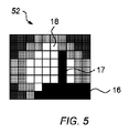
イメージングセンサ40は、切断レーザビーム18の強度を示す情報を生成するように構成される。イメージングセンサ40は、切断レーザビーム18の様々な領域の強度を示す情報を生成するように構成される。イメージングセンサ40は、本実施形態では、マルチ素子アレイを持ち、このため、各素子は、当該素子と交差している切断レーザビーム18の領域の強度を示す情報を供給することができる。イメージングセンサ40は、イメージングセンサ40と交差している光源の様々な領域の強度を示す情報を供給するプロファイルを生成することができる。かかるプロファイルは、図4に概略的に示されている。図4では、光源として機能する切断レーザビーム18の経路において受けられる毛17のみを示すプロファイル50が示されている。図5では、光源として機能する切断レーザビーム18の経路において受けられる毛17及び肌16を示すプロファイル52が示されている。
コントローラ27は、イメージングセンサ40における切断レーザビーム18の強度プロファイルを示す、イメージングセンサ40によって生成された情報を参照するように構成されている。コントローラ27に供給される情報に基づいて、コントローラ27は、切断レーザビーム18の経路において受けられる1又は複数のオブジェクトの存在を決定するように構成される。イメージングセンサ40に向けられた光源の経路において受けられる任意のオブジェクトは、イメージングセンサ40の少なくとも一部においてイメージングセンサ40に光が当たることを制限するように作用する。つまり、1又は複数のオブジェクトは、影を作る。オブジェクトのかかる影は、図4において強度プロファイル上に示されている。従って、コントローラ27は、オブジェクトが光源の経路において受けられているかどうかを決定するとともに、光源の経路において受けられるオブジェクトのタイプを識別することができる。
The
コントローラ27は、イメージングセンサ40によって生成された情報に基づいて、切断レーザビーム18の経路において受けられるオブジェクトのタイプを識別するように構成される。コントローラ27は、プロファイルを供給するイメージングセンサ40によって出力される1又は複数のフレームを参照するように構成される。イメージングセンサ40によって生成された情報に基づいて、コントローラ27は、オブジェクトのタイプを決定するため、オブジェクト認識を用いるように構成されている。これは、メモリ29に格納される基準プロファイルとの比較によって実行され得る。かかるオブジェクト認識は、既知であるため、ここでは、詳細な説明を省略する。
The
コントローラ27によって供給されるオブジェクト認識に基づいて、コントローラ27は、切断レーザビーム18の経路において受けられる1又は複数のオブジェクトのタイプを決定するように構成されている。コントローラ27は、オブジェクトが切断レーザビーム18の経路においていつ受けられるかを識別するように構成される。コントローラ27は、イメージングセンサ40によって生成された情報に基づいて切断レーザビーム18の経路におけるオブジェクトの決定された識別に依存して切断レーザビーム18の強度を調整するように構成される。
Based on the object recognition provided by
使用中、毛17は、切断レーザビーム18の経路において受けられる。切断レーザビーム18の強度は、その断面プロファイルに亘って変化するため、外側に向かうにつれてより低い強度を持つことが理解される。従って、オブジェクトは、切断レーザビーム18の切断動作を分けることなく、イメージングセンサ40によって識別されることが可能である。切断レーザビーム18の切断端は、所望の毛のタイプに対する切断動作を供給するのに十分なレーザ強度を持つ切断レーザビーム18の外縁として規定される。本実施形態では、切断レーザビーム18の切断端は、99%のレーザ強度を含む切断レーザビーム18の外縁として規定されているが、代替的な実施形態では、その割合が異なっていてもよいことが理解されよう。
During use, the
また、肌16も切断レーザビーム18の経路において受けられることがある(図5参照)。切断レーザビーム18と切断領域15における肌16との間の距離は、例えば、切断領域15における肌高さの変動及び肌ドーム形成などによる切断領域15内のユーザの肌16の高さにおける変化に応じて変わり得る。従って、肌16は、装置10の使用中、切断レーザビーム18に近づくように移動してもよいし、離れるように移動してもよい。コントローラ27は、イメージングセンサ40によって生成される情報を参照することによって、切断レーザビーム18の経路においてオブジェクトがいつ受けられるかを決定するように構成される。
The
コントローラ27は、イメージングセンサ40によって生成された情報に基づいて切断レーザビーム18の経路において受けられるオブジェクトのタイプを識別するように構成される。コントローラ27は、メモリ29によって格納される基準プロファイルを参照してもよい。コントローラ27が、オブジェクトが肌であると識別した場合、コントローラ27は、切断レーザビーム18の強度(例えば、レーザビームのパワー又はエネルギー)を減少させるように構成される。従って、肌に付与されるレーザエネルギーの量は、最小化又は防止される。このようにして、肌の輪郭などの肌高さにおける変動が、皮膚の炎症を最小にしつつ適応され得る。本実施形態では、コントローラ27が、切断領域15における毛17を示す情報を無視することによって、切断レーザビーム18の切断端と肌16との間の距離である切断高さを決定するように構成される。これは、切断高さの正確な決定が、肌のみを示す情報に基づいて決定され得るということを意味する。
The
本実施形態では、コントローラ27は、2つの異なるレーザビーム強度レベルで切断レーザビーム18を生成するようにレーザビーム生成器25を動作させる。第1のレーザビーム強度レベルに関して、切断レーザビーム18の所望の強度は、肌に損傷を与えるのに必要な強度よりも小さい。つまり、肌に安全な、検出レベルの強度である。第2のレーザビーム強度レベルに関して、切断レーザビーム18の所望の強度は、毛を切断するのに必要な強度以上である。レーザビーム強度レベルは、メモリ28に格納され、コントローラ27によって参照され得る。
In this embodiment, the
図6は、切断レーザビームを動作するためにコントローラ27によって実行されるプロセスを示している。ステップ600において、切断レーザビーム18は、第1のビーム強度レベルで動作される。
FIG. 6 shows the process performed by the
ステップ601において、光源として作用する切断レーザビーム18の経路における1又は複数のオブジェクトの存在を示すイメージングセンサ40によって生成された情報が、コントローラ27によって参照される。1又は複数のオブジェクトの存在は、ステップ602において試験される。コントローラ27が、光源として作用する切断レーザビーム18の経路においてオブジェクトが存在しないと決定した場合、ルーチンは繰り返される。
In
コントローラ27が、光源として作用する切断レーザビーム18の経路においてオブジェクトが存在すると決定した場合、コントローラ27は、ステップ603におけるオブジェクト認識プロセスに基づいて、オブジェクトのタイプを決定する。オブジェクトのタイプの決定は、ステップ604において試験される。生成された情報に基づいてコントローラ27によって肌の存在が識別された場合、プロセスは、繰り返され、切断レーザビーム18の動作は、第1のレーザビーム強度レベルで維持される。コントローラ27によって肌の存在が識別されない場合、プロセスは、肌の存在が決定されないまで繰り返される。肌が識別されないイベント、つまり、毛の存在がコントローラによって識別される場合、切断レーザビームは、ステップ605において、第2のレーザビーム強度レベルで動作される。プロセスは、オブジェクトが検出されなくなるまで、又は、肌の存在が決定されるまで、繰り返され、この場合、切断レーザビームは、第1のレーザビーム強度レベルで動作される。
If the
所与の切断高さのための所望の強度を示す情報は、基準プロファイルにおいて、メモリ29に格納されている。コントローラ27は、切断レーザビーム18の下端と切断領域15における肌16との間の距離を示す情報に応じて、所望の強度の基準プロファイルを参照するように構成されている。基準プロファイルは、ルックアップテーブルにおいて格納されてもよい。基準プロファイルは、メモリ29によって格納されてもよい。かかる構成では、コントローラ27は、基準プロファイルにアクセスするために、メモリ29を参照するように構成される。或る実施形態では、基準プロファイルは、RAMに格納される。基準プロファイルは、所望の強度を示す情報を供給する。
Information indicating the desired strength for a given cutting height is stored in
コントローラ27は、2以上の基準プロファイルから基準プロファイルを選択するように構成されることが理解されよう。つまり、各基準プロファイルは、決定された切断高さに基づき所望の動作強度を供給し得る。2以上の基準プロファイルは、メモリ29に格納されてもよい。あるいは、基準プロファイルは、コントローラ27が決定された切断高さに基づいて選択可能な2以上の所望の強度レベルを含んでいてもよい。ユーザは、所望のシェービング近さを選択することができる。例えば、コントローラ27が決定された切断高さに基づいて選択可能な2以上の所望の強度レベルを基準プロファイルが含む実施形態では、ユーザは、各々が所与の切断高さのための異なる強度レベルを持つ2以上の基準プロファイルから選択することができる。
It will be appreciated that the
装置10が動作された場合、コントローラ27は、イメージングセンサ40によって生成された情報を参照することによってコントローラ27により決定された切断高さに依存して、切断レーザビーム18の強度を調整するようレーザビーム生成器25を動作させるように構成される。
When the
或る実施形態では、コントローラ27は、イメージングセンサ40によって生成された情報によって決定されるような、切断高さの最小閾値に依存して、切断レーザビーム18の強度を調整するように動作可能である。かかる実施形態では、コントローラ27は、切断高さが最小閾値以下であると決定された場合に切断レーザビーム18が第1の強度レベルで動作するようにレーザビーム生成器25を動作させるとともに、コントローラ27は、切断高さが最小閾値よりも大きい場合に切断レーザビーム18が第2の強度レベルで動作するようにレーザビーム生成器25を動作させるように動作可能である。最小閾値は、1又は複数の基準プロファイルによって格納される。かかる構成により、コントローラ27は、切断レーザビーム18の強度レベルにおいて段階的な変化を実現するように構成される。
In some embodiments, the
代替的な実施形態では、基準プロファイルは、イメージングセンサ40によって供給された情報に基づいてコントローラ27により決定されるような切断高さのための1又は複数の閾値を含んでいてもよい。かかる実施形態では、各閾値は、対応する強度レベルを持つ。2以上の閾値及び対応する強度レベルが、基準プロファイルに格納されてもよい。他の代替案では、コントローラ27は、イメージングセンサ40によって供給された情報に基づいて強度レベルを何度も変更するようにレーザビーム生成器25を動作させることによって切断レーザビーム18に関する所望の強度レベルを決定するように構成される。
In alternative embodiments, the reference profile may include one or more thresholds for the cutting height as determined by
上記実施形態では、オブジェクトの存在が切断レーザビーム18の経路において検出されない場合、コントローラ27は、最初に、肌に安全な検出レベルの第1の強度レベルで切断レーザビーム18を動作させるが、代替的な実施形態では、切断レーザビーム18は、最初に、毛17の切断動作に必要な強度以上のレベルである第2のレーザビーム強度レベルで動作されるように構成されることが理解されよう。
In the above embodiment, if the presence of an object is not detected in the path of the cutting
かかる実施形態では、使用中、切断レーザビーム18は、最初に、第2のレーザビーム強度レベルで動作される。コントローラ27が、イメージングセンサ40によって供給された情報を参照して、切断レーザビーム18の経路において毛のみが存在することを決定した場合、コントローラ27は、切断レーザビーム18の強度レベルを毛17の切断動作に必要な強度以上で維持するように構成される。コントローラ27が、イメージングセンサ40によって供給された情報を参照して、切断レーザビーム18の経路において肌16が存在すると決定した場合、コントローラ27は、第1のレーザビーム強度レベルで動作させるため、切断レーザビーム18の強度レベルを減少させるように構成される。
In such an embodiment, during use, the cutting
上記の実施形態では、切断レーザビーム18は、イメージングセンサ40に入射し、強度プロファイル50,52が、切断レーザビーム18の経路において1又は複数のオブジェクトの存在を決定するために使用される。しかしながら、他の実施形態では、切断レーザビーム18の相対位置も決定され得ることが理解されよう。かかる実施形態では、切断レーザビーム18は、イメージングセンサ40に入射し、コントローラ27は、イメージングセンサ40によって生成された情報に基づいて切断レーザビーム18の経路を決定するように構成される。つまり、コントローラ27は、イメージングセンサ40上の切断レーザビーム18の切断端の位置も決定するように構成される。イメージングセンサ40上の切断レーザビーム18の切断端の位置が決定されるため、1又は複数のオブジェクトの位置と同様、当然、コントローラ27は、当該位置における任意の動き又はずれ、ひいては、切断領域15における切断レーザビーム18の経路における任意の動き又はずれを補償することができる。
In the above embodiment, the cutting
コントローラ27が、切断領域15における切断レーザビーム18の位置と切断領域15における肌16とを両方決定することができるため、コントローラ27は、切断レーザビーム18の切断端と肌16との間の距離を正確に決定することができる。このことは、使用中、又は、使用間における任意の変更を考慮に入れることを可能にする。かかる実施形態により、光学素子の位置決め変動が、考慮に入れられ得る。かかる光学素子の位置決め変動は、例えば、装置10のユーザによる落下などにより発生し得る。
Since the
上述の実施形態では、切断レーザビーム18は、イメージングセンサ40上に作用する光源として機能する。しかしながら、代替的な実施形態が想定されることが理解されよう。例えば、或る実施形態では、切断レーザビームは、主切断ビーム18と副検出ビーム(図示省略)とに分けられる。あるいは、副検出ビームは、独立したレーザビームなどの別個の光源である。かかる実施形態では、主切断ビーム及び副検出ビームは、切断領域15を横切るパスを通る。副検出ビームは、主切断ビーム18に対して平行に延在する。副検出ビームは、イメージングセンサ40に入射する。この構成により、副検出ビームの強度は、装置10の動作を通じて、肌に安全な強度レベルで持続的に維持され得る。
In the embodiment described above, the cutting
上述の実施形態では、イメージングセンサ40は、肌存在検出器として機能するように構成されるが、代替的な実施形態では、様々なタイプの肌存在検出器が使用されてもよいことが理解されよう。ここで、図7及び図8を参照すると、毛を切断するための装置10の代替的な構成が示されている。図7及び図9に示される装置10は、一般的に、上述の装置と同じであるため、詳細な説明は省略される。参照番号は、維持され、上記の詳細に説明された特徴及びコンポーネントを表している。しかしながら、この実施形態では、肌存在検出器は、距離センサ42である。
In the embodiments described above, the
距離センサ42は、切断領域15における肌16と装置10が肌16に対して配置された場合の基準位置との間の距離を示す情報を生成するように構成された電子センサである。当該距離は、肌高さである。かかる情報は、レーザ生成器25の動作を制御するコントローラ27に供給される。距離センサ42は、光学測定技術を用い、肌16の表面と装置10上の基準位置との間の距離を測定するために肌16との接触を必要としない共焦点レンズなどの光学センサである。距離センサ42は、例えば、三角測量、散乱光測定、及び/又は、影測定などによって、肌16の位置を示す情報を生成するように構成されていてもよい。本実施形態では、基準位置は、肌接触面13に基づいている。従って、切断領域15における肌16と基準位置との間の距離を示す供給される情報は、距離センサ42によって決定されるような切断領域15における肌と肌接触面13の平面との間の垂直距離である。しかしながら、代替的な基準位置が用いられてもよいことが理解される。例えば、基準位置は、切断レーザビーム18のニュートラル校正位置であってもよい。肌16の表面と切断領域15における切断レーザビーム18との間の距離である切断高さは、基準位置から計算されてもよい。
The
距離センサ42は、切断領域15において配置される。つまり、距離センサ42は、本体12におけるチャンバ35に配置される。距離センサ42は、非接触肌距離センサである。つまり、距離センサ42は、切断領域15における肌16と装置10が肌16に対して配置された場合の基準位置との間の距離を測定するように構成される。距離センサ42は、反射性又は透過性光センサであってもよい。距離センサ42は、可視光領域及び/又は近赤外線領域における光の1又は複数の波長を用いてもよい。しかしながら、代替的なセンサ構成が用いられてもよいことが理解される。距離センサ42は、切断領域15における肌16と切断レーザビーム18の伝搬方向に沿った基準位置との間の距離を決定するように構成される。つまり、切断領域15の長さに沿った基準位置である。
The
距離センサ42は、切断レーザビーム18の入射セクション22の伝搬方向において切断領域15の長さ方向を横切って切断領域15における毛及び/又は肌などのオブジェクトの存在及び距離を示す情報を決定するように構成される。図9によれば、伝搬方向は、軸901によって表されている。オブジェクトの高さは、軸900によって表されている。距離センサ42は、図9の線902によって示されるように、切断レーザビーム18の入射セクション22の伝搬方向に沿ったオブジェクトの高さを示す情報を供給するように構成されている。ピーク903は、切断領域15における毛17を表しており、線902の残りは、肌16を表していることが理解されよう。また、切断装置10は、切断レーザビーム18の入射セクション22の伝搬方向に対して垂直な方向において、肌16に沿って移動されるように構成されていることが理解されよう。
The
コントローラ27は、距離センサ42によって生成された、切断領域15における毛17及び肌16などの1又は複数のオブジェクトの高さを示す情報を参照するように構成されている。また、コントローラ27は、当該情報を切断レーザビーム18の入射セクション22の伝搬方向に沿った切断領域15のセクションを表す個別の瓶904に分割するように構成されている。つまり、切断領域15は、名目上、個別の瓶904のアレイに分割される。各瓶904は、毛の肌よりも大きい距離を表すように構成されている。
The
各瓶904に関して距離センサ42によって生成された情報に基づいて、1又は複数のオブジェクトの切断領域15への突出の最小距離である最小高さが、各瓶904のために供給される。この最小高さは、図9において、各瓶904のための点線905で表されている。コントローラ27は、最小高さに基づいて各瓶904のための肌の位置を決定するように構成される。従って、毛を表すピーク903は無視される。各瓶904のために決定された最小高さに基づいて、コントローラ27は、切断高さを決定するように構成される。切断高さは、瓶904のアレイを横切る肌の最大の最小高さとして決定される。
Based on the information generated by the
所与の切断高さに関する所望の強度を示す情報が、基準プロファイルにおいて、メモリ29に格納される。コントローラ27は、各瓶904のための最小高さを参照することにより決定されるような、切断レーザビーム18の下端と切断領域15における肌16との間の距離を示す情報に応じて、所望の強度の基準プロファイルを参照するように構成されている。従って、毛17に基づく誤検出が無視され得る。基準プロファイルは、ルックアップテーブルにおいて格納されてもよい。基準プロファイルは、メモリ29によって格納されてもよい。かかる構成では、コントローラ27は、基準プロファイルにアクセスするために、メモリ29を参照するように構成される。或る実施形態では、基準プロファイルは、RAMによって格納される。基準プロファイルは、所望の強度を示す情報を供給する。
Information indicating the desired strength for a given cutting height is stored in
コントローラ27は、2以上の基準プロファイルから基準プロファイルを選択するように構成されてもよいことが理解される。つまり、各基準プロファイルは、決定された切断高さに基づいて、所望の動作強度を供給し得る。2以上の基準プロファイルは、メモリ29に格納されてもよい。あるいは、基準プロファイルは、コントローラ27が決定された切断高さに基づいて選択可能な2以上の所望の強度レベルを含んでいてもよい。ユーザは、シェービングの所望の近さを選択できてもよい。例えば、基準プロファイルが、コントローラ27が決定された切断高さに基づいて選択可能な2以上の所望の強度レベルを含む実施形態では、ユーザは、それぞれ、所与の切断高さに関する異なる強度レベルを持つ2以上の基準プロファイルを選択できてもよい。
It is understood that the
装置10が動作される場合、コントローラ27は、各瓶904のために距離センサ42によって生成された情報を参照し、コントローラ27によって決定された切断高さに依存して、切断レーザビーム18の強度を調整するようにレーザビーム生成器25を動作させるように構成される。
When the
或る実施形態では、コントローラ27は、距離センサ42によって生成された情報によって決定されるような切断高さの最小閾値に依存して切断レーザビーム18の強度を調整するように動作可能である。かかる実施形態では、コントローラ27は、切断高さが最小閾値よりも大きい場合に切断レーザビーム18が第2の強度レベルで動作するようにレーザビーム生成器25を動作させるように動作可能である。また、コントローラ27は、切断高さが最小閾値以下であると決定された場合に切断レーザビーム18が第1の強度レベルで動作するようにレーザビーム生成器25を動作させるように動作可能である。最小閾値は、1又は複数の基準プロファイルによって格納されている。かかる構成により、コントローラ27は、切断レーザビーム18の強度レベルにおける段階的な変化を可能にするように構成される。
In some embodiments, the
代替的な実施形態では、基準プロファイルは、距離センサ42によって供給される情報基づいてコントローラ27によって決定されるような切断高さのための1又は複数の閾値を含んでいてもよい。かかる実施形態では、各閾値は、対応する強度レベルを持つ。2以上の閾値と対応する強度レベルとが、基準プロファイルによって格納され得る。他の代替例では、コントローラ27は、距離センサ42により供給される情報に基づいて強度レベルを常に変更するようにレーザビーム生成器25を動作させることによって、切断レーザビーム18に関する所望の強度レベルを決定するように構成される。
In alternative embodiments, the reference profile may include one or more thresholds for the cutting height as determined by
本構成では、距離センサ42は、切断領域15において配置され、切断領域15に対する開口14において配置される肌16を検出するように構成されているが、代替的な実施形態では、距離センサ42は、切断領域15の外側に配置されてもよいことが理解される。例えば、距離センサ42は、切断領域15に対する開口14に隣接するセンサ開口(図示省略)において肌を検出するために配置されてもよい。距離センサ42が切断領域15に配置されることの利点は、切断領域15における肌高さをより正確に決定することができることである。
In this configuration, the
上述の実施形態では、イメージングセンサ40又は距離センサ42のいずれかが使用されたが、代替的な実施形態では、装置10は、イメージングセンサ40と距離センサ42との両方を備えていてもよいことが理解されよう。かかる実施形態が、図9及び図10に示されている。イメージングセンサ40及び距離センサ42の構成は、一般的に、上述したものと同じであるため、詳細な説明は省略される。この実施形態では、コントローラ27は、切断領域における毛及び/又は肌を表す1又は複数のオブジェクトの存在を決定するとともに、イメージングセンサ40及び距離センサ42によって生成された情報に依存して切断レーザビーム18の動作を調整するように構成される。かかる実施形態により、切断高さの決定精度が、毛によって供給される誤検出の数を最小化することで最大化され得る。それは、肌16上の毛17により、コントローラ27によって決定された不正確な切断高さである。
In the embodiments described above, either the
用いられる検出器がイメージングセンサ40である実施形態に関して、切断レーザビーム18の入射セクション22の伝搬方向に対して平行な肌16の表面に沿って延在している毛17は、誤検出である不正確な切断高さを供給し得ることが分かっている。かかる実施形態では、伝搬方向に沿って肌に対して略平行に延在している毛は、イメージングセンサ40の幅を横切る影を生成することが分かっている。従って、コントローラ27は、切断高さが不正確に決定されるように、影が肌16を表していることを不正確に決定し得る。しかしながら、かかる実施形態では、切断レーザビーム18の入射セクション22の伝搬方向に対して垂直な肌16の表面に沿って延在している毛17は、この問題を起こさない。
For the embodiment where the detector used is an
同様に、用いられる検出器が距離センサ42である実施形態に関し、切断レーザビーム18の入射セクション22の伝搬方向に対して垂直な方向において肌16の表面に沿って延在している毛17は、誤検出である不正確な切断高さを供給し得ることが分かっている。かかる実施形態では、肌に対しては略平行であるが伝搬方向に対しては垂直に延在している毛は、少なくとも1つの瓶904の完全幅を横切るように延在する影を生成することが分かっている。従って、コントローラ27は、切断高さが不正確に決定されるように、毛が瓶904の最小高さを表していることを不正確に決定し得る。しかしながら、かかる実施形態では、切断レーザビーム18の入射セクション22の伝搬方向に対して平行な肌16の表面に沿って延在している毛17は、この問題を起こさない。これは、毛17が、瓶904の完全な幅を横切るように延在しないためである。従って、イメージングセンサ40と距離センサ42との両方を有する検出器を持つ実施形態では、コントローラは、イメージングセンサ40及び距離センサ42の両方によって生成された情報に基づいて切断高さを決定することができる。これは、不正確な切断高さの数を最小化できることを意味する。
Similarly, for the embodiment in which the detector used is a
上記の実施形態では、コントローラ27が調整する光学系の1又は複数の特徴が、切断レーザビーム18の強度であるが、代替的な実施形態では、光学系の1又は複数の他の特徴が調整されてもよいことが理解される。光学系の1又は複数の他の特徴は、切断レーザビーム18の強度の調整とともに、又は、切断レーザビーム18の強度の調整の代わりとして、調整されてもよい。
In the above embodiment, one or more characteristics of the optics that the
ここで、図11及び図12を参照すると、装置10の他の実施形態が示されている。図11及び図12に示されるような装置10のこの実施形態の構成は、一般的に、上述の実施形態と同じであり、このため、詳細な説明は、ここでは省略される。しかしながら、装置10の当該実施形態は、光学系20の1又は複数の光学コンポーネントに作用するように構成されたアクチュエータ45を更に有する。参照番号は、維持され、上記の詳細に説明された特徴及びコンポーネントを表している。
11 and 12, another embodiment of the
図11及び図12に示された装置10の実施形態では、アクチュエータ45は、第1の反射素子21に作用するように構成されている。アクチュエータ45は、第1の反射素子21を移動させるように構成されている。また、アクチュエータ45は、第1の反射素子21の回転を生じさせるように構成されている。第1の反射素子21は、切断レーザビーム18の入射セクション22の伝搬方向に対して垂直な回転軸周りに回転するように構成されている。第1の反射素子21は、前述のように、切断領域15を横切るように、切断レーザビーム18の入射セクション22を反射するように配置されている。
In the embodiment of the
アクチュエータ45は、例えば、ボイスコイル型アクチュエータ、ギア又はピエゾ電気変換器を具備するスピンドルモータなどの電子アクチュエータである。アクチュエータ45は、コントローラ27からのコマンドに応じて第1の反射素子21に作用する。コントローラ27は、切断領域15を横切るように切断レーザビーム18の伝播角度を制御するよう、アクチュエータ45を動作させるように構成されている。つまり、第1の反射素子21の動きは、切断レーザビーム18の経路が切断領域15を横切るように調整されることを可能にし、ひいては、切断高さの調整を可能にする。
The
コントローラ27は、第1の反射素子21を移動させるようにアクチュエータ45を動作するように構成される。従って、切断レーザビーム18の経路は、切断領域15における切断レーザビーム18の伝播方向に対して垂直な方向において変化する。コントローラ27は、イメージングセンサ40及び/又は距離センサ42によって生成される切断領域15における毛17及び/又は肌16を表す1又は複数のオブジェクトの存在を示す情報の1又は複数を参照するように構成される。従って、コントローラ27は、切断レーザビーム18が肌16に入射することを防止するため、切断レーザビーム18の経路を調整することができる。
The
アクチュエータ45が、光学系20の光学コンポーネントの1又は複数に作用するように構成される上述の実施形態では、アクチュエータ45が発生させる動きは、回転である。特に、図5及び図6を参照してここで説明された実施形態では、アクチュエータ45は、第1の反射素子21の回転を生じさせるため、第1の反射素子21に作用するように構成されている。しかしながら、代替的な構成も想定されることが理解される。
In the embodiments described above, where the
実施形態では、アクチュエータ45は、光学系20の1又は複数の光学コンポーネントの並進を生じさせるため、光学系20の光学コンポーネントの1又は複数に作用するように構成されてもよいことが理解される。例えば、或る実施形態では、アクチュエータ45は、第1の反射素子21の並進運動を生じさせるため、第1の反射素子21に作用するように構成される。並進運動は、切断領域15を横切る切断レーザビーム18の伝搬方向に対して垂直な、レーザビーム生成器25に向かう方向及び/又はレーザビーム生成器25から離れる方向にあってもよい。第2の反射素子23は、第1の反射素子21とともに移動してもよい、又は、第1の反射素子21の動きを許容するような大きさであってもよいことが理解される。
It is understood that in embodiments, the
代替的な実施形態では、第1の反射素子21の並進運動は、切断領域15を横切る切断レーザビーム18の経路に対して平行な、第2の反射素子23に向かう方向及び/又は第2の反射素子23から離れる方向にあってもよい。
In an alternative embodiment, the translational movement of the first
アクチュエータ45は、代替的に、又は、並列的に、レーザビーム生成器25自体の並進運動を生じさせるように、レーザビーム生成器25に作用してもよい。かかる実施形態では、アクチュエータ45は、切断領域15を横切るように切断レーザビーム18の伝搬方向に対して平行な並進運動を生じさせるため、レーザビーム生成器25に作用するように構成される。
The
アクチュエータ45は、代替的に、又は、並列的に、レンズ構成32に作用してもよい。例えば、アクチュエータ45は、焦点レンズ34に作用してもよい。アクチュエータは、レンズ構成32を通って切断レーザビーム18の光学軸に対して垂直な方向において焦点レンズ34の並進運動を生じさせてもよい。例えば、レーザに関するコリメータレンズ33の偏心がΔとして規定される場合、補償のためにシリンドリカル焦点レンズの必要な並進dは、以下の式で与えられる。

上記実施形態の各々において、イメージングセンサ40によって検出された切断レーザビーム18の光学特性の1又は複数に依存して調整される光学系20の1又は複数の特性は、切断領域15における毛17及び/又は肌16を表す1又は複数のオブジェクトの存在を示す特定の生成された情報に依存して、装置10がユーザの肌16の上を移動されるにつれて動的に調整されてもよい。当該構成の利点は、装置が、ユーザの肌の各部に対する切断レーザビーム18の動作を動的に調整できることである。
In each of the above embodiments, one or more characteristics of the
1又は複数の光学コンポーネントの調整を含む上述の実施形態では、光学コンポーネントの調整、又は、各光学コンポーネントの調整が、光学コンポーネントの向きの調整、又は、各光学コンポーネントの向きの調整を通じて達成されるが、代替的な実施形態では、光学コンポーネントの調整、又は、各光学コンポーネントの調整が、交換可能な光学コンポーネントを持つことによって達成されることが理解される。或る実施形態では、アクチュエータ又は各アクチュエータは、2以上の光学コンポーネントを置き換えるように動作可能である。 In the above-described embodiments that include adjusting one or more optical components, adjusting the optical components or adjusting each optical component is accomplished through adjusting the orientation of the optical components or adjusting the orientation of each optical component. However, it is understood that, in alternative embodiments, adjustment of the optical components, or adjustment of each optical component, is accomplished by having replaceable optical components. In some embodiments, the actuator or each actuator is operable to replace more than one optical component.
当然ながら、「有する」なる用語は、他の要素又はステップを除外せず、単数形は、複数存在することを除外しない。特定の特徴が相互に異なる従属請求項において言及されているという単なる事実は、これらの特徴の組み合わせが好適に用いられないということを示すものではない。請求項中の任意の参照符号は、請求項の範囲を限定するものとして解釈されるべきではない。 Of course, the term “comprising” does not exclude the presence of other elements or steps and the singular does not exclude the presence of a plurality. The mere fact that certain features are recited in mutually different dependent claims does not indicate that a combination of these features is not used to advantage. Any reference signs in the claims shall not be construed as limiting the scope of the claims.
本出願では、請求項は、特徴の特定の組合せに関して策定されているが、本発明の開示の範囲は、明示的に若しくは暗示的に本明細書に開示される任意の新規の特徴若しくは特徴の任意の新規の組合せ、又はそれらの任意の一般化も含み、それが、本出願において任意の請求項で特許請求されるものと同じ発明に関するかどうかには関わらず、また、親発明と同じ技術的問題の任意のもの又は全てを軽減するか否かには関わらないことが理解されるべきである。ここで、本出願人は、本出願又はそこから導出される任意のさらなる出願の手続き中に、新しい請求項が、そのような特徴及び/又は特徴の組合せに関して策定され得ることを通知する。 In this application, the claims are formulated with respect to particular combinations of features, but the scope of the disclosure of the present invention includes any novel feature or feature disclosed herein, either explicitly or implicitly. It also includes any novel combination, or any generalization thereof, whether or not it relates to the same invention as claimed in any claim of this application, and to the same technology as the parent invention. It should be understood that it does not matter whether or not to mitigate any or all of the physical problems. Applicant hereby advises that new claims may be drawn regarding such features and / or combinations of features during the prosecution of this application or any further applications derived therefrom.
Claims (15)
使用中、ユーザの肌の表面に対して配置されるように構成された肌接触面と、
切断領域に延在している毛を切断するため、前記肌接触面に対して平行であり、且つ、前記肌接触面から離れた前記切断領域を横切るように切断レーザビームを方向付けるように構成された光学系と、
前記切断領域における毛及び/又は肌を表す1又は複数のオブジェクトの存在を示す情報を生成するように構成される検出器と、
前記切断領域における毛及び/又は肌を表す1又は複数のオブジェクトの存在を決定するとともに、前記検出器によって生成された前記情報に依存して前記光学系の1又は複数の特徴を調整するように構成されるコントローラと、
を有し、
前記コントローラは、前記検出器によって生成された前記情報に依存して前記切断領域における毛及び/又は肌を表す1又は複数のオブジェクトと前記切断レーザビームとの間の距離を示す情報を生成するとともに、前記コントローラによって生成された前記情報に依存して前記切断レーザビームの強度を調整するように構成される、装置。 A device for cutting hair,
A skin contact surface configured to be placed against the surface of the user's skin during use;
Configured to direct a cutting laser beam parallel to the skin-contacting surface and across the cutting area remote from the skin-contacting surface to cut hairs extending to the cutting-area. Optical system,
A detector configured to generate information indicating the presence of one or more objects representing hair and / or skin in the cut area;
Determining the presence of one or more objects representing hair and / or skin in the cut region and adjusting one or more features of the optical system depending on the information generated by the detector. A configured controller,
Have
The controller generates information indicative of the distance between the cutting laser beam and one or more objects representing hair and / or skin in the cutting region, depending on the information generated by the detector; An apparatus configured to adjust the intensity of the cutting laser beam depending on the information generated by the controller.
使用中、ユーザの肌の表面に対して配置されるように構成された肌接触面と、 A skin contact surface configured to be placed against the surface of the user's skin during use;
切断領域に延在している毛を切断するため、前記肌接触面に対して平行であり、且つ、前記肌接触面から離れた前記切断領域を横切るように切断レーザビームを方向付けるように構成された光学系と、 Configured to direct a cutting laser beam parallel to the skin-contacting surface and across the cutting area remote from the skin-contacting surface to cut hairs extending to the cutting-area. Optical system,
前記切断領域における毛及び/又は肌を表す1又は複数のオブジェクトの存在を示す情報を生成するように構成される検出器と、 A detector configured to generate information indicating the presence of one or more objects representing hair and / or skin in the cut area;
前記切断領域における毛及び/又は肌を表す1又は複数のオブジェクトの存在を決定するとともに、前記検出器によって生成された前記情報に依存して前記光学系の1又は複数の特徴を調整するように構成されるコントローラと、 Determining the presence of one or more objects representing hair and / or skin in the cut region and adjusting one or more features of the optical system depending on the information generated by the detector. A configured controller,
を有し、Have
前記コントローラは、前記検出器によって生成された前記情報に依存して前記切断領域における毛及び/又は肌を表す1又は複数のオブジェクトと前記切断レーザビームとの間の距離を示す情報を生成するとともに、前記コントローラによって生成された前記情報に依存して前記切断レーザビームの経路を調整するように構成される、装置。 The controller generates information indicative of the distance between the cutting laser beam and one or more objects representing hair and / or skin in the cutting region, depending on the information generated by the detector; An apparatus configured to adjust a path of the cutting laser beam depending on the information generated by the controller.
光学系を用いて、切断領域に延在している毛を切断するため、肌接触面に対して平行であり、且つ、前記肌接触面から離れた前記切断領域を横切るように切断レーザビームを方向付けるステップと、
検出器を用いて、前記切断領域における毛及び/又は肌を表す1又は複数のオブジェクトの存在を示す情報を生成するステップと、
前記切断領域における毛及び/又は肌を表す1又は複数のオブジェクトの存在を決定するステップと、
前記検出器によって生成された前記情報に依存して前記光学系の1又は複数の特徴を調整するステップと、
前記検出器によって生成された情報に依存して切断領域における毛及び肌を表す1又は複数のオブジェクトと前記切断レーザビームとの間の距離を示す情報を生成するため、及び、前記生成された情報に依存して前記切断レーザビームの強度を調整するため、コントローラを用いるステップと、
を有する、方法。 A method of cutting hair,
An optical system is used to cut the hair extending to the cutting area, so that the cutting laser beam is parallel to the skin contact surface and crosses the cutting area away from the skin contact surface. The steps to direct,
Using a detector to generate information indicating the presence of one or more objects representing hair and / or skin in the cut region;
Determining the presence of one or more objects representing hair and / or skin in the cut area;
Adjusting one or more features of the optical system depending on the information generated by the detector;
Generating information indicative of the distance between the cutting laser beam and one or more objects representing hair and skin in the cutting region depending on the information generated by the detector; and the generated information. Using a controller to adjust the intensity of the cutting laser beam depending on
Having a method.
光学系を用いて、切断領域に延在している毛を切断するため、肌接触面に対して平行であり、且つ、前記肌接触面から離れた前記切断領域を横切るように切断レーザビームを方向付けるステップと、 An optical system is used to cut the hair extending to the cutting area, so that the cutting laser beam is parallel to the skin contact surface and crosses the cutting area away from the skin contact surface. The steps to direct,
検出器を用いて、前記切断領域における毛及び/又は肌を表す1又は複数のオブジェクトの存在を示す情報を生成するステップと、 Using a detector to generate information indicating the presence of one or more objects representing hair and / or skin in the cut region;
前記切断領域における毛及び/又は肌を表す1又は複数のオブジェクトの存在を決定するステップと、 Determining the presence of one or more objects representing hair and / or skin in the cut area;
前記検出器によって生成された前記情報に依存して前記光学系の1又は複数の特徴を調整するステップと、 Adjusting one or more features of the optical system depending on the information generated by the detector;
前記検出器によって生成された情報に依存して切断領域における毛及び肌を表す1又は複数のオブジェクトと前記切断レーザビームとの間の距離を示す情報を生成するため、及び、前記生成された情報に依存して前記切断レーザビームの経路を調整するため、コントローラを用いるステップと、 Generating information indicative of the distance between the cutting laser beam and one or more objects representing hair and skin in the cutting region depending on the information generated by the detector; and the generated information. Using a controller to adjust the path of the cutting laser beam depending on
を有する、方法。Having a method.
Applications Claiming Priority (3)
| Application Number | Priority Date | Filing Date | Title |
|---|---|---|---|
| EP14178615.2 | 2014-07-25 | ||
| EP14178615 | 2014-07-25 | ||
| PCT/EP2015/066982 WO2016012584A1 (en) | 2014-07-25 | 2015-07-24 | A device for cutting hair |
Publications (3)
| Publication Number | Publication Date |
|---|---|
| JP2017522071A JP2017522071A (en) | 2017-08-10 |
| JP2017522071A5 JP2017522071A5 (en) | 2018-06-21 |
| JP6684726B2 true JP6684726B2 (en) | 2020-04-22 |
Family
ID=51228328
Family Applications (1)
| Application Number | Title | Priority Date | Filing Date |
|---|---|---|---|
| JP2016570780A Expired - Fee Related JP6684726B2 (en) | 2014-07-25 | 2015-07-24 | Equipment for cutting hair |
Country Status (5)
| Country | Link |
|---|---|
| US (1) | US20170156796A1 (en) |
| EP (1) | EP3171806B1 (en) |
| JP (1) | JP6684726B2 (en) |
| CN (1) | CN106572886B (en) |
| WO (1) | WO2016012584A1 (en) |
Families Citing this family (10)
| Publication number | Priority date | Publication date | Assignee | Title |
|---|---|---|---|---|
| BR112017005895B1 (en) * | 2014-09-26 | 2021-02-09 | Koninklijke Philips N.V | device for shaving or hair removal from the skin |
| JP6622421B2 (en) * | 2016-03-01 | 2019-12-18 | コーニンクレッカ フィリップス エヌ ヴェKoninklijke Philips N.V. | System and method for automated hairstyle processing and hair cutting device |
| KR102597022B1 (en) * | 2016-11-22 | 2023-11-01 | 도미니언 에스테틱 테크놀로지스, 인크. | Systems and methods for cosmetic treatments |
| WO2018099932A1 (en) * | 2016-12-01 | 2018-06-07 | Koninklijke Philips N.V. | Hair cutting apparatus comprising a current detector |
| BR112019011037A2 (en) * | 2016-12-01 | 2019-10-15 | Koninklijke Philips Nv | hair or hair clippers, and method for indicating a haircutting process |
| EP3388011A1 (en) | 2017-04-12 | 2018-10-17 | Koninklijke Philips N.V. | A light-based skin treatment device |
| CN108287411A (en) * | 2018-01-29 | 2018-07-17 | 李明 | Laser razors |
| EP3552570A1 (en) * | 2018-04-13 | 2019-10-16 | Braun GmbH | Skin or hair treatment device for emitting high intense treatment light |
| CN108714916A (en) * | 2018-06-29 | 2018-10-30 | 蔡华杰 | A kind of electric shaver |
| EP3613376A1 (en) * | 2018-08-21 | 2020-02-26 | Koninklijke Philips N.V. | A handheld device for performing a treatment operation on skin |
Family Cites Families (15)
| Publication number | Priority date | Publication date | Assignee | Title |
|---|---|---|---|---|
| IL97531A (en) * | 1991-03-12 | 1995-12-31 | Kelman Elliot | Hair cutting apparatus |
| IL109882A0 (en) * | 1994-06-02 | 1994-10-07 | Kelman Elliot | Hair cutting apparatus |
| US6050990A (en) * | 1996-12-05 | 2000-04-18 | Thermolase Corporation | Methods and devices for inhibiting hair growth and related skin treatments |
| US5993440A (en) * | 1997-10-16 | 1999-11-30 | Ghassemi; Faramarz Frank | Non-invasive laser cutting device and method |
| WO2003101243A1 (en) * | 2002-05-31 | 2003-12-11 | Ya-Man Ltd. | Laser depilator |
| EP1653875B1 (en) * | 2003-08-04 | 2011-10-19 | Koninklijke Philips Electronics N.V. | A device for shortening hairs by means of laser induced optical breakdown effects |
| GB2465425B (en) * | 2008-11-21 | 2013-03-27 | Dezac Group Ltd | Light treatment apparatus |
| EP2409134B1 (en) * | 2009-03-19 | 2019-05-08 | Koninklijke Philips N.V. | Detector for birefringent objects |
| CN102204845B (en) * | 2010-03-31 | 2013-07-24 | 太阳系美容事业有限公司 | Skin calleidic laser device |
| US8834365B2 (en) * | 2010-12-23 | 2014-09-16 | Nlight Photonics Corporation | Skin color and capacitive sensor systems |
| WO2013175355A1 (en) * | 2012-05-22 | 2013-11-28 | Koninklijke Philips N.V. | Device for cutting hair. |
| BR112014030491A2 (en) * | 2012-07-31 | 2017-06-27 | Koninklijke Philips Nv | hair clipper using a laser beam and method of using a laser beam to cut field hair |
| JP2016504931A (en) * | 2013-01-10 | 2016-02-18 | コーニンクレッカ フィリップス エヌ ヴェKoninklijke Philips N.V. | Cutter head for hair cutting equipment |
| GB2495248A (en) * | 2013-01-10 | 2013-04-03 | Dezac Group Ltd | Light treatment apparatus for hair removal |
| JP6396344B2 (en) * | 2013-03-11 | 2018-09-26 | コーニンクレッカ フィリップス エヌ ヴェKoninklijke Philips N.V. | Hair cutting device |
-
2015
- 2015-07-24 US US15/325,226 patent/US20170156796A1/en not_active Abandoned
- 2015-07-24 WO PCT/EP2015/066982 patent/WO2016012584A1/en active Application Filing
- 2015-07-24 CN CN201580041104.XA patent/CN106572886B/en not_active Expired - Fee Related
- 2015-07-24 EP EP15741219.8A patent/EP3171806B1/en not_active Not-in-force
- 2015-07-24 JP JP2016570780A patent/JP6684726B2/en not_active Expired - Fee Related
Also Published As
| Publication number | Publication date |
|---|---|
| CN106572886B (en) | 2020-06-09 |
| US20170156796A1 (en) | 2017-06-08 |
| EP3171806A1 (en) | 2017-05-31 |
| JP2017522071A (en) | 2017-08-10 |
| CN106572886A (en) | 2017-04-19 |
| EP3171806B1 (en) | 2019-05-01 |
| WO2016012584A1 (en) | 2016-01-28 |
Similar Documents
| Publication | Publication Date | Title |
|---|---|---|
| JP6684726B2 (en) | Equipment for cutting hair | |
| EP2605882A1 (en) | Method of and material processing apparatus for optimising the focus of a fibre laser; method of measuring changes in the focus of a fibre laser | |
| EP3171805B1 (en) | A device for cutting hair | |
| EP3054883A1 (en) | A device for cutting hair | |
| JP6383504B2 (en) | Laser shaving device | |
| JP2023145783A (en) | Projection device, projection/projection reception device, and ranging device | |
| CN107635501B (en) | Optical system | |
| EP3302329A1 (en) | An optical system | |
| CN107530128B (en) | Method for setting a cutting distance between a laser beam and a skin surface in a laser shaving device | |
| JP2018526041A5 (en) | ||
| JP2022117057A (en) | Device and method for detecting cracks | |
| JP2007315782A (en) | Distance measuring apparatus, distance measuring method, and projector |
Legal Events
| Date | Code | Title | Description |
|---|---|---|---|
| RD04 | Notification of resignation of power of attorney |
Free format text: JAPANESE INTERMEDIATE CODE: A7424 Effective date: 20170214 |
|
| A521 | Request for written amendment filed |
Free format text: JAPANESE INTERMEDIATE CODE: A523 Effective date: 20180509 |
|
| A621 | Written request for application examination |
Free format text: JAPANESE INTERMEDIATE CODE: A621 Effective date: 20180509 |
|
| RD02 | Notification of acceptance of power of attorney |
Free format text: JAPANESE INTERMEDIATE CODE: A7422 Effective date: 20190308 |
|
| A977 | Report on retrieval |
Free format text: JAPANESE INTERMEDIATE CODE: A971007 Effective date: 20190614 |
|
| A131 | Notification of reasons for refusal |
Free format text: JAPANESE INTERMEDIATE CODE: A131 Effective date: 20190802 |
|
| TRDD | Decision of grant or rejection written | ||
| A01 | Written decision to grant a patent or to grant a registration (utility model) |
Free format text: JAPANESE INTERMEDIATE CODE: A01 Effective date: 20200303 |
|
| A61 | First payment of annual fees (during grant procedure) |
Free format text: JAPANESE INTERMEDIATE CODE: A61 Effective date: 20200330 |
|
| R150 | Certificate of patent or registration of utility model |
Ref document number: 6684726 Country of ref document: JP Free format text: JAPANESE INTERMEDIATE CODE: R150 |
|
| LAPS | Cancellation because of no payment of annual fees |