JP6898724B2 - Image processing methods, image processing devices and programs - Google Patents
Image processing methods, image processing devices and programs Download PDFInfo
- Publication number
- JP6898724B2 JP6898724B2 JP2016219647A JP2016219647A JP6898724B2 JP 6898724 B2 JP6898724 B2 JP 6898724B2 JP 2016219647 A JP2016219647 A JP 2016219647A JP 2016219647 A JP2016219647 A JP 2016219647A JP 6898724 B2 JP6898724 B2 JP 6898724B2
- Authority
- JP
- Japan
- Prior art keywords
- image
- subject
- dimensional
- fundus
- processing method
- Prior art date
- Legal status (The legal status is an assumption and is not a legal conclusion. Google has not performed a legal analysis and makes no representation as to the accuracy of the status listed.)
- Active
Links
Images


Classifications
-
- A—HUMAN NECESSITIES
- A61—MEDICAL OR VETERINARY SCIENCE; HYGIENE
- A61B—DIAGNOSIS; SURGERY; IDENTIFICATION
- A61B3/00—Apparatus for testing the eyes; Instruments for examining the eyes
- A61B3/10—Objective types, i.e. instruments for examining the eyes independent of the patients' perceptions or reactions
- A61B3/102—Objective types, i.e. instruments for examining the eyes independent of the patients' perceptions or reactions for optical coherence tomography [OCT]
Description
本発明は、画像処理方法、画像処理装置およびプログラムに関する。 The present invention relates to image processing methods, image processing devices and programs.
低コヒーレント光による干渉を利用した光干渉断層法(OCT:Optical Coherence Tomography)を用いて被検体の断層像(以下OCT断層像)を取得する断層画像撮影装置が知られている。このような断層画像撮影装置により眼底を撮影することによって、網膜層内部の状態を三次元的に観察することができる。断層画像撮影装置により得た画像は疾病の診断をより的確に行なう上で有用であるため、近年注目を集めている。また、OCT断層像において、網膜の形態変化を計測できれば、緑内障や病的近視などの疾病の進行度や治療後の回復具合を定量的に診断することができる。 There is known a tomographic imaging apparatus that acquires a tomographic image of a subject (hereinafter referred to as an OCT tomographic image) by using an optical coherence tomography (OCT) that utilizes interference by low coherent light. By photographing the fundus with such a tomographic imaging device, the state inside the retinal layer can be observed three-dimensionally. Images obtained by a tomographic imaging device have been attracting attention in recent years because they are useful for more accurate diagnosis of diseases. In addition, if the morphological change of the retina can be measured in the OCT tomographic image, the degree of progression of diseases such as glaucoma and pathological myopia and the degree of recovery after treatment can be quantitatively diagnosed.
一方、被検眼の眼底の診断には眼底正面像も有用であり、該正面像取得のためには眼底カメラや走査型レーザー検眼鏡(SLO:Scanning Lazer Ophtalmoscope)等が用いられる。また、眼底の正面像を用いた検査では、カラー眼底撮影のほか、フルオレセイン蛍光眼底撮影(FA)やインドシアニングリーン蛍光眼底撮影(ICG)、眼底自発蛍光撮影(FAF)等によっても行われる。これら撮影法は、網膜における特定の層の病変検査や機能検査が可能であるため、眼底検査では必要不可欠な検査となっている。 On the other hand, a frontal image of the fundus is also useful for diagnosing the fundus of the eye to be inspected, and a fundus camera, a scanning laser ophthalmoscope (SLO), or the like is used to acquire the frontal image. In addition to color fundus photography, examinations using a frontal image of the fundus are also performed by fluorescein fluorescence fundus photography (FA), indocyanine green fluorescence fundus photography (ICG), and fundus spontaneous fluorescence photography (FAF). These imaging methods are indispensable for fundus examination because they can examine lesions and functions of specific layers in the retina.
ここで、これら眼底正面像とOCT断層像において、各々の画像から得られる網膜各層に関する情報や疾患部位の情報を対応づけられると、両画像間での疾患の比較作業が容易になる。その結果、画像からの被検眼の状態の適切な読影が容易に実行できる。このような技術に関して、特許文献1では、眼底正面像とOCT断層像の両者を並べて表示する技術が開示されている。当該技術では、OCT断層像より得た異常部位の配置を眼底正面像に投影し、OCT断層像で得られる疾患部位や血管走行などについての情報との対応位置関係を眼底正面像上に表示している。
Here, if the information on each layer of the retina and the information on the diseased part obtained from each image can be associated with the frontal image of the fundus and the OCT tomographic image, it becomes easy to compare the diseases between the two images. As a result, an appropriate interpretation of the state of the eye to be inspected from the image can be easily performed. Regarding such a technique,
ここで、後部ぶどう腫等の立体的に把握すべき疾患を有する被検眼を読影する場合には、一般的には立体像を用いた方が読影し易い。ところで、三次元のOCT断層像には後部ぶどう腫の境界が分かり難く、一方、正面像にはその境界が明瞭である場合があることに、本願の発明者が初めて気がついた。このため、後部ぶどう腫等の立体的に把握すべき疾患を有する被検眼の正面像を、三次元のOCT断層像のように立体的に観察することが望まれる。しかし、特許文献1に開示される表示形態の場合、単に二次元のOCT断層像と二次元の眼底の正面像とが並べて表示されるだけであり、眼底の正面像だけで疾患を正確に読影することは容易ではない。
Here, when interpreting an eye to be examined having a disease to be grasped three-dimensionally such as posterior grape tumor, it is generally easier to interpret the image using a stereoscopic image. By the way, the inventor of the present application has noticed for the first time that the boundary of the posterior grape tumor is difficult to see in the three-dimensional OCT tomographic image, while the boundary may be clear in the front image. Therefore, it is desired to observe the frontal image of the eye to be inspected having a disease to be grasped three-dimensionally, such as posterior grape tumor, three-dimensionally like a three-dimensional OCT tomographic image. However, in the case of the display form disclosed in
本発明の目的の一つは、被検体の三次元OCT断層像に対して被検体の正面像を対応付けることを容易にし、読影が容易な画像を生成することである。 One of the objects of the present invention is to facilitate associating a frontal image of a subject with a three-dimensional OCT tomographic image of the subject and to generate an image that is easy to interpret.
本発明の一態様に係る画像処理方法は、
測定光を照射した被検体からの戻り光と前記測定光に対応する参照光とを干渉して得た干渉信号セットを用いて生成される前記被検体の三次元断層像を取得する断層像取得工程と、
前記被検体の正面像を取得する正面像取得工程と、
前記三次元断層像における前記被検体の境界面の形状情報を用いて前記正面像を立体像に変形することにより、前記正面像に関する立体像を生成する生成工程と、を含むことを特徴とする。
The image processing method according to one aspect of the present invention is
Acquisition of a tomographic image to acquire a three-dimensional tomographic image of the subject generated by using an interference signal set obtained by interfering the return light from the subject irradiated with the measurement light with the reference light corresponding to the measurement light. Process and
The front image acquisition step of acquiring the front image of the subject, and
By deforming the three-dimensional image of the front image using the shape information of the interface you Keru the subject in the three-dimensional tomographic image, to include a generation step of generating a three-dimensional picture of the front image It is a feature.
本発明の一つによれば、被検体の三次元OCT断層像に対して被検体の正面像を対応付けることを容易にし、読影が容易な画像を生成できる。 According to one of the present inventions, it is possible to easily associate a front image of a subject with a three-dimensional OCT tomographic image of the subject, and to generate an image that is easy to interpret.
以下、本発明を実施するための例示的な実施例を、図面を参照して詳細に説明する。ただし、以下の実施例で説明する形状、或いは構成要素の相対的な位置等は任意であり、本発明が適用される装置の構成又は様々な条件に応じて変更できる。また、図面において、同一であるか又は機能的に類似している要素を示すために図面間で同じ参照符号を用いる。 Hereinafter, exemplary examples for carrying out the present invention will be described in detail with reference to the drawings. However, the shape described in the following examples, the relative positions of the components, and the like are arbitrary and can be changed according to the configuration of the device to which the present invention is applied or various conditions. Also, in the drawings, the same reference numerals are used between the drawings to indicate elements that are the same or functionally similar.
[OCT装置の構成]
本実施例において、OCT断層像を生成する際に用いる三次元断層像を生成可能な三次元断層情報は、図1に示す画像形成装置を用いて取得する。図1は、本発明の一実施例における光干渉断層撮像法を用いた画像形成装置(OCT装置)の構成例を示す図である。図1に示すOCT装置は、OCT光学系200およびOCT情報処理部300より構成される。
[Configuration of OCT device]
In this embodiment, the three-dimensional tomographic information that can generate the three-dimensional tomographic image used when generating the OCT tomographic image is acquired by using the image forming apparatus shown in FIG. FIG. 1 is a diagram showing a configuration example of an image forming apparatus (OCT apparatus) using the optical coherence tomography imaging method according to an embodiment of the present invention. The OCT apparatus shown in FIG. 1 is composed of an OCT
<OCT光学系200の説明>
OCT光学系200は、光源部10、OCT干渉部20、測定アーム50、および参照アーム60を有する。なお、測定アーム50および参照アーム60内では測定光および参照光等は空間光として伝播されるが、その他の領域では測定光は光ファイバによって伝播される。
<Explanation of OCT
The OCT
光源部10には、射出される光の周波数が掃引される波長掃引光源が用いられる。OCT干渉部20は、カプラ21、22を有する。カプラ21は、光源部10から射出された光を測定光と参照光とに分割する。測定光は、測定アーム50を経由して被検眼100の眼底に照射される。被検眼100を経た測定光の戻り光は、測定アーム50を逆に辿りカプラ21に戻る。カプラ21に至った戻り光は、さらにカプラ22に導かれる。参照光は、参照アーム60を経由してカプラ22に至る。カプラ22では戻り光と参照光とが合波され、干渉光が生成される。該干渉光は、後述するOCT情報処理部300に導かれる。
A wavelength sweep light source in which the frequency of the emitted light is swept is used for the
測定アーム50は、偏光コントローラ51、コリメータレンズ52、X軸スキャナー53、Y軸スキャナー54およびフォーカスレンズ55を有する。測定アーム50に入射した測定光は、偏光コントローラ51で偏光状態を整えられた後、コリメータレンズ52から空間光として射出される。射出された測定光は、X軸スキャナー53、Y軸スキャナー54、およびフォーカスレンズ55を介して被検眼100の眼底に照射される。なお、X軸スキャナー53およびY軸スキャナー54は眼底を測定光で走査する機能を有する走査部を構成する。該走査部によって、測定光の眼底への照射位置が変えられる。測定光の眼底からの後方散乱光(反射光)は、戻り光として再びフォーカスレンズ55に至る。該フォーカスレンズ55に至った戻り光は、Y軸スキャナー54およびX軸スキャナー53を経てコリメータレンズ52に入射する。該戻り光は、さらに偏光コントローラ51を経由して測定アーム50から射出され、カプラ21を経由してカプラ22に入射する。
The
参照アーム60は、偏光コントローラ61、コリメータレンズ62、分散補償ガラス63、光路長調整光学系64、分散調整プリズムペア65およびコリメータレンズ66を有する。参照アーム60に入射した参照光は、偏光コントローラ61で偏光状態を整えられた後、コリメータレンズ62から空間光として射出される。射出された参照光は分散補償ガラス63、光路長調整光学系64、分散調整プリズムペア65を通り、コリメータレンズ66に入射する。ここで、分散補償ガラス63および分散調整プリズムペア65は、測定光が経る被検眼100等の分散に対して参照光の光路中での分散を合わせるために用いられる。
The
光路長調整光学系64は不図示の駆動系によって図中矢印方向に移動し、参照光の光路長を調整するために用いられる。該光路長調整光学系64によって参照光の光路長と測定光の光路長とが一致させられると、これら光を合波した際に干渉が得られる。コリメータレンズ66に入射した参照光は、参照アーム60から射出されてカプラ22に入射する。カプラ22では、測定アーム50を経由した被検眼100からの戻り光と参照アーム60を経由した参照光とが合波され、干渉光が生成される。生成された干渉光は情報処理部300に入力される。
The optical path length adjusting
なお、X軸スキャナー53、Y軸スキャナー54、フォーカスレンズ55、光路長調整光学系64、および光源部10は、不図示のOCT装置用制御部に接続される。該OCT装置用制御部は、上述したように、被検眼100の眼底上の所定位置に測定光を照射して干渉光を得るために、適宜これら構成を制御する。なお、これら構成はOCT情報処理部300によって制御されてもよい。
The
<OCT情報処理部300>
OCT情報処理部300は、信号取得部31、信号処理部32、表示制御部33、および表示部34を有する。信号取得部31にはカプラ22より干渉光が入力されており、該干渉光より、等波数間隔でデジタル信号としての干渉信号を取得する機能を有する。信号処理部32では、信号取得部31が取得したデジタル信号に対してフーリエ変換などの周波数分析を行う。これにより、被検眼100の眼底における深さ方向の各位置における断層情報が得られる。信号処理部32では、さらに、得られた断層情報から画像の生成、生成された画像の解析、解析結果の可視情報の生成、および画像の変形等が行われる。
<OCT
The OCT
信号処理部32で生成される画像や解析結果は表示制御部33に送られ、表示制御部33によって表示部34の表示画面に表示される。また、これら干渉信号、画像、および解析結果は、被検眼100に付随する患者情報、および検査条件等と共に、信号処理部32に付随する記憶部に記憶される。ここで、表示部34は、例えば液晶等のディスプレイにより構成される。なお、信号処理部32で生成された画像データは表示制御部33に送られた後、表示部34に有線で送信されてもよいし、無線で送信されてもよい。
The image and analysis result generated by the
また、本実施例において表示部34等はOCT情報処理部300に含まれているが、表示部34等の態様はこれに限られない。表示部34はOCT情報処理部300とは別に設けられてもよく、例えばユーザが持ち運び可能な装置の一例であるタブレットでもよい。この場合、表示部にタッチパネル機能を搭載させ、タッチパネル上で画像の表示位置の移動、拡大縮小、および表示される画像の変更等を操作可能に構成することが好ましい。また、OCT情報処理部300は、OCT光学系200と一体化した構成としてもよく、専用のコンピュータとして構成してもよい。また、該OCT情報処理部300は、上述したOCT装置用制御部と接続されていることが好ましい。
Further, in the present embodiment, the
なお、本実施例ではOCT装置として、測定光の波長を変化させるSS−OCT(Swept−Source OCT)装置を用いた場合を例示した。しかし、用いるOCT装置はこれに限られず、広帯域波長の光を用いるSD−OCT(Spectral−Domain OCT)装置等、他の公知の構成からなるOCT装置を用いることが可能である。 In this example, an example is shown in which an SS-OCT (Swept-Source OCT) device that changes the wavelength of the measurement light is used as the OCT device. However, the OCT device to be used is not limited to this, and it is possible to use an OCT device having another known configuration such as an SD-OCT (Spectral-Domain OCT) device that uses light having a wide band wavelength.
以上に述べたOCT装置を用い、被検眼100の眼底の任意の位置に測定光を照射して、当該位置での奥行き方向の断層に関する情報を取得する操作をA−scanと称する。また、この奥行き方向をA−scan方向と称する。A−scan方向と直交する方向に測定光を走査して複数回のA−scanを実行し、被検眼100における該方向に並ぶ複数の断層に関する情報を取得する操作をB−scanと称し、該方向をB−scan方向と称する。この奥行き方向と当該方向とから得られる情報から、被検眼100の眼底における深さ方向の二次元断層像が取得できる。さらにA−scan方向およびB−scan方向の何れとも直交する方向に測定光を走査することをC−scanと称し、当該方向をC−scan方向と称する。三次元断層像を取得する際に眼底面内において測定光を二次元ラスター走査する場合、高速な走査方向がB−scan方向に対応する。また、B−scanをその直交方向に並べるように測定光を低速で走査する走査方向がC−scan方向に対応する。A−scanおよびB−scanを行うことで二次元の断層像が得られ、A−scan、B−scanおよびC−scanを行うことで、三次元の断層像を得ることができる。
Using the OCT device described above, an operation of irradiating an arbitrary position of the fundus of the
測定光のB−scanおよびC−scanは、上述したX軸スキャナー53およびY軸スキャナー54により眼底上での測定光の照射位置を変化させることで行われる。X軸スキャナー53およびY軸スキャナー54は、それぞれ回転軸が互いに直交するよう配置された偏向ミラーで構成されている。X軸スキャナー53は測定光のX軸方向の走査を行い、Y軸スキャナー54は測定光のY軸方向の走査を行う。X軸方向およびY軸方向の各方向は、眼球の眼軸方向に対して垂直な方向で、互いに垂直な方向である。また、B−scan方向およびC−scan方向はX軸方向およびY軸方向と一致していることが多いが、一致していなくてもよい。このため、B−scan方向およびC−scan方向は、撮像したい二次元の断層像あるいは三次元の断層像に応じて、適宜決めることができる。
The B-scan and C-scan of the measurement light are performed by changing the irradiation position of the measurement light on the fundus by the
[眼底正面像撮影装置の構成]
本実施例において、眼底正面像を生成する際には、眼底正面像撮影装置として照明光走査型の眼底正面像撮影装置(SLO装置)を用いている。図2は、本発明の一実施例における眼底正面像を取得するSLO装置の構成例を示す図である。なお、眼底正面像を取得する装置はここで例示する様式のSLO装置に限ったものではなく、AO(Adaptive Optics)−SLO装置、および眼底カメラなど、眼底正面像を生成できる装置ならば用いることができる。また、眼底正面像を撮影する装置或いは構成は、前述したOCT装置内に実装されていてもよく、OCT装置とは独立していてもよい。
[Configuration of fundus front view imaging device]
In this embodiment, when the fundus front image is generated, an illumination light scanning type fundus front image photographing device (SLO device) is used as the fundus front image photographing device. FIG. 2 is a diagram showing a configuration example of an SLO device that acquires a frontal image of the fundus in one embodiment of the present invention. The device for acquiring the frontal image of the fundus is not limited to the SLO device of the style illustrated here, and any device capable of generating the frontal image of the fundus, such as an AO (Adaptive Optics) -SLO device and a fundus camera, should be used. Can be done. Further, the device or configuration for capturing the front view of the fundus may be mounted in the OCT device described above, or may be independent of the OCT device.
以下、図2を参照して、本実施例において用いたSLO装置について説明する。該SLO装置は、SLO光学系500とSLO情報処理部530とを有する。SLO光学系500は、前眼部観察用の光路LP1に配置される構成と、眼底撮影用の光路LP2に配置される構成とを有する。ダイクロイックミラー502は、被検眼100からの光路を、前眼部観察用光路LP1と固視灯およびSLO光学系の眼底撮影用光路LP2とに波長帯域ごとに分岐する。被検眼100の光軸上正面には対物レンズ501−1が配置され、被検眼100に対する対物レンズ501−1の後ろにダイクロイックミラー502が配置される。前眼部観察用光路LP1は該ダイクロイックミラー502の透過方向に配置され、眼底撮影用光路LP2は該ダイクロイックミラー502の反射方向に配置される。
Hereinafter, the SLO apparatus used in this embodiment will be described with reference to FIG. The SLO apparatus includes an SLO
以下、被検眼に照射する照明光を発するSLO光源510からダイクロイックミラー502の間に配置される、眼底撮影用光路LP2上の構成について述べる。SLO光源510は780nm付近に中心値を持つ眼底撮像用の光源であり、APD(Avalanche Photodiode)512は780nm付近に感度を持つ眼底撮像用のセンサである。なお、本明細書における波長の具体的な数値は例示であり、他の数値としてもよい。SLO光源510より射出された照明光は、第二のダイクロイックミラー508により眼底撮影用光路LP2方向に反射される。
Hereinafter, the configuration on the fundus photography optical path LP2 arranged between the
眼底撮影用光路LP2における第二のダイクロイックミラー508の透過方向には、固視灯509が配置される。該固視灯509は可視光を発生し、被検者にこの可視光の発光位置を注視させることによって被検眼の固視を促すものである。第二のダイクロイックミラー508の次には、孔あきミラー506が配置される。照明光および固視光は、該孔あきミラー506の孔部を通過し、眼底撮影用光路LP2に配置される後述する各光学要素を経て被検眼100に至る。孔あきミラー506の反射方向には、上述したAPD512が配置される。
A
孔あきミラー506から被検眼100方向には、レンズ505、SLOフォーカスレンズ507、ガルバノスキャナー504、共振スキャナー503、レンズ501−2、およびミラー511が配置される。SLO光源510および固視灯509から射出された光束は何れも共振スキャナー503、ガルバノスキャナー504の付近で一度結像し、被検眼100の眼底付近で再度結像する。不図示のモータによって、SLOフォーカスレンズ507が眼底撮影用光路LP2に沿った図中の矢印方向に移動することにより、照明光の二度目の結像位置を被検眼540の眼底面と一致させる。共振スキャナー503は、照明光を眼底上でX方向に主走査する。該共振スキャナー503に連動させて、ガルバノスキャナー504により照明光を眼底上でY方向に副走査することで、照明光による眼底面上の2次元走査を実行する。
A
前眼部観察用光路LP1上には、ダイクロイックミラー502から順に、レンズ522、523、および前眼部観察用のCCD524が配置される。CCD524は不図示の前眼部観察用照明光の波長、具体的には970nm付近に感度を有する。前眼観察用照明光により照明された被検眼100からの反射光は、CCD524により前眼部像として撮影される。
補正PD(PhotoDiode)525は、共振スキャナー503の走査状態を検知するためのセンサである。共振スキャナー503は、照明光を高速で往復走査できる半面、照明光の走査位置は走査タイミングより推定することを要する。補正PD525により走査タイミングに関する情報を取得することにより、照明光の走査位置を推定できる。
The correction PD (Photodiode) 525 is a sensor for detecting the scanning state of the
SLO情報処理部530は、制御部531、記憶部532、および画像生成部533を有し、例えばPC(Personal Computer)より構成される。制御部531は、SLO光学系500の全体、具体的には、SLOフォーカスレンズ507、固視灯509、SLO光源510、共振スキャナー503、ガルバノスキャナー504の駆動あるいは点灯等を制御する。制御部531は、例えばCPU等の処理装置を備える。記憶部532は、制御部531を実行するためのプログラムやデータなどを記憶している。画像生成部533は、APD512により受光された眼底反射光の強度、および補正PD525より得られる共振スキャナー503の走査位置情報等を用いて、眼底正面像を生成する。記憶部532は、この生成された眼底正面像、撮影条件、および被検眼に関する情報等を関連付けて記憶する。
The SLO
なお、以上に述べた実施例では、OCT装置およびSLO装置を個別に配置されるように図示している。しかし、例えばダイクロイックミラー等を介して、測定アーム50の光路と、眼底撮影用光路LP2とが共用する部分を設けて、これら装置を単一の複合装置としてもよい。また、この場合、OCT情報処理部300は、SLO情報処理部530を兼ねてもよい。或いは記憶部等、任意の構成を部分的に共用する態様としてもよい。また、各装置における光学部材の配置も、例えばSLO装置におけるSLO光源510と固視灯509の配置等、交換可能な構成を交換してもよい。
In the above-described embodiment, the OCT device and the SLO device are illustrated so as to be arranged separately. However, for example, a portion shared by the optical path of the measuring
[画像形成方法の説明]
次に図3を使い、本発明の一実施例である画像処理方法について説明する。本発明の画像処理方法は、第一の信号取得工程S100、第二の信号取得工程S101、形状解析工程S102、サーフェスレンダリング工程S103、および表示工程S104を有する。なお、第一の信号取得工程S100および形状解析工程S102はOCT装置における信号処理部32により、第二の信号取得工程S101はSLO装置における画像生成部533により実行される。サーフェスレンダリング工程S103は上述した信号処理部32により実行され、表示工程S104は表示制御部33および表示部34により実行される。各工程について、以下に説明する。
[Explanation of image formation method]
Next, an image processing method according to an embodiment of the present invention will be described with reference to FIG. The image processing method of the present invention includes a first signal acquisition step S100, a second signal acquisition step S101, a shape analysis step S102, a surface rendering step S103, and a display step S104. The first signal acquisition step S100 and the shape analysis step S102 are executed by the
第一の信号取得工程S100では、第一の信号取得手段としてのOCT装置により、眼底の三次元断層像を形成する干渉信号セットを取得する。OCT装置により、測定光で眼底上の所定の範囲を二次元ラスタスキャンすることで、信号取得部31は三次元断層像を形成するのに必要な干渉信号セットを取得する。なお、本実施例において、眼底の所定領域を測定光により二次元ラスタスキャンすることで取得した三次元断層像を生成するための複数の干渉信号群を干渉信号セットと称する。
In the first signal acquisition step S100, an interference signal set that forms a three-dimensional tomographic image of the fundus is acquired by the OCT device as the first signal acquisition means. The
ここで、第一の信号取得工程S100において、眼底からの干渉信号セットの取得とあわせて、信号処理部32がノイズ除去用のバックグラウンド信号を取得してもよい。バックグラウンド信号は、例えば、測定光の戻り光を遮断して参照光のみの光信号を取得すればよい。あるいは、B−scanにより取得した干渉信号セットを平均する等によりバックグラウンド信号を生成してもよい。
Here, in the first signal acquisition step S100, the
第二の信号取得工程S101では、第二の信号取得手段としてのSLO装置により、被検眼100の眼底正面像を形成する第二の信号を取得する。第二の信号は、被検眼100の眼底正面像を生成するためのものであり、本実施例ではSLO装置における画像生成部533により取得される。また、画像生成部533は、第二の信号の取得と共に当該信号を用いて眼底正面像も生成する(正面像生成工程)。なお、第二の信号取得に用いられる撮影装置は、前述したようにSLO装置(走査型レーザー検眼鏡)に限定されず、眼底カメラ等の眼底正面像を取得可能な種々の装置を用いることが可能である。従って、第二の信号も眼底正面像を生成可能な信号であれば、その種類、および態様等は限定されない。
In the second signal acquisition step S101, the second signal forming the fundus frontal image of the
本実施例では、第一の信号取得工程S100と第二の信号取得工程S101とは順次実行されることとしている。しかし、OCT装置内にSLO装置を実装する構成の場合、第一の信号取得工程S100と、第二の信号取得工程S101とを同時に行なってもよい。別々の工程であれば、例えば、OCT装置で眼底を広範囲に撮影し、SLO装置では必要な箇所に撮影領域を絞るような撮影もできる。 In this embodiment, the first signal acquisition step S100 and the second signal acquisition step S101 are sequentially executed. However, in the case of a configuration in which the SLO device is mounted in the OCT device, the first signal acquisition step S100 and the second signal acquisition step S101 may be performed at the same time. If it is a separate process, for example, the OCT device can take a wide range of images of the fundus, and the SLO device can take an image in which the imaging area is narrowed down to a necessary place.
形状解析工程S102において、信号処理部32は第一の信号取得工程S100で得た干渉信号セットに対してFFT(高速フーリエ変換)処理等を行い、三次元断層像を生成する。信号処理部32は、生成された三次元断層像に対し、さらにセグメンテーションおよび層形状解析の処理を行い、眼底における網膜の各層境界(各層間の境界面)の形状情報を取得する。ここで、取得した干渉信号セットを用いて形状情報を生成するまでの流れについて説明する。なお、形状解析工程S102は、以下の三次元断層像生成工程S102a、セグメンテーション工程S102b、および層形状解析工程S102cを含む。
In the shape analysis step S102, the
三次元断層像生成工程S102aにおいて、信号処理部32は、三次元断層像生成手段として、干渉信号セットを用いて三次元断層像を生成する。具体的には、信号処理部32は、まず、干渉信号から固定パターンノイズの除去を行う。固定パターンノイズの除去は、上述したバックグラウンド信号を干渉信号から減算することで行われる。次に、深さ分解能とダイナミックレンジを最適化するために、所望の窓関数処理を行う。その後、FFT処理を行うことによって一A−scanに基づく深さ方向の輝度画像を生成する。B−scanにより得た干渉信号セットに含まれる干渉信号の各々に対して、以上の処理を行うことで深さ方向の二次元断層像としての輝度画像を生成する。さらに、当該処理は、C−scan方向に並ぶ連続した複数のB−scanにより得た複数の干渉信号セットに対しても行われる。これにより、被検眼眼底の三次元断層像が生成できる。
In the three-dimensional tomographic image generation step S102a, the
なお、信号処理部32は、画像生成にあたって、既知の画質向上処理をおこなってもよい。例えば、同一箇所を複数回撮影したデータを重ね合わせして平均化することで、ランダムノイズを低減してもよい。またこの場合、さらに、重ね合わせの前に位置ずれ補正を行ってもよい。
The
次に、セグメンテーション工程S102bで、三次元断層像生成工程S102aで生成した三次元断層像に対し、セグメンテーションを行う。ここで、網膜のセグメンテーションについて説明する。まず、信号処理部32は、処理対象とする断層像に対して、メディアンフィルタとSobelフィルタとをそれぞれ適用して画像を作成する(以下、それぞれメディアン画像、Sobel画像と称する)。次に、信号処理部32は、作成したメディアン画像とSobel画像から、Aスキャン毎にプロファイルを作成する。メディアン画像では輝度値のプロファイル、Sobel画像では勾配のプロファイルとなる。そして、Sobel画像から作成したプロファイル内のピークを検出する。検出したピークの前後やピーク間に対応するメディアン画像のプロファイルを参照することで、網膜層の各領域の境界を抽出する。
Next, in the segmentation step S102b, the three-dimensional tomographic image generated in the three-dimensional tomographic image generation step S102a is segmented. Here, the segmentation of the retina will be described. First, the
以上の処理により信号処理部32が抽出する境界は、例えば次の6層の境界が挙げられる。即ち、
1) 神経線維層(NFL)、
2) 神経節細胞層(GCL)+内網状層(IPL)を合わせた層、
3) 内顆粒層(INL)+外網状層(OPL)を合わせた層、
4) 外顆粒層(ONL)+外境界膜(ELM)を合わせた層、
5) Ellipsoid Zone(EZ)+Interdigitation Zone(IZ)+網膜色素上皮(RPE)を合わせた層、および
6) 脈絡膜(Choroid)、の境界が抽出される。
ここで、網膜の層構造は既知である。境界の抽出後、どの境界の間の層がどの網膜層に対応するかのレジストレーションが行なわれ、信号処理部32により解剖学上の層境界の特定がなされる。層境界の特定がされたことにより、正面画像の変形を行うために形状情報の算出の対象となる層境界も容易に判別できる。
As the boundary extracted by the
1) Retinal nerve fiber layer (NFL),
2) A layer that combines the ganglion cell layer (GCL) + inner plexiform layer (IPL),
3) A layer that combines the inner nuclear layer (INL) + outer plexiform layer (OPL),
4) A layer that combines the outer nuclear layer (ONL) + external limiting membrane (ELM),
The boundary between 5) Ellipoid Zone (EZ) + Interdigtion Zone (IZ) + Retinal pigment epithelium (RPE) combined layer, and 6) Choroid is extracted.
Here, the layered structure of the retina is known. After the boundary is extracted, registration is performed to determine which layer between the boundaries corresponds to which retinal layer, and the
次に、層形状解析工程S102cにおいて、信号処理部32は、セグメンテーション工程S102bで抽出した境界面を使って求めた層境界の形状解析を行う。形状解析で用いるパラメータは、網膜層の特異的な形状を特徴量として抽出できればよく、特に限定されない。例えば、境界面の曲率や曲率半径、境界面の傾きや傾きの変化率、境界面の局所的な凹凸、あるいは層の厚さや厚さの変化率、およびそれら何れかの組合せがパラメータとして使用可能である。なお、層の厚さは境界面間のz軸(深さ方向の)距離として得られる。また、実際の形状解析において、これら全てのパラメータについて計算してもよいし、パラメータの種類や計算する領域を選択してもよい。パラメータや領域の選択は、検者が指定してもよいし、検査目的に応じて自動的に選択することとしてもよい。計算したパラメータは形状情報として、信号処理部32によって三次元断層像上での各層境界の位置と対応させて記憶される。なお、形状解析の詳細に関しては、具体的な疾患との関係を含めて後で詳述する。
Next, in the layer shape analysis step S102c, the
次に、サーフェスレンダリング工程S103について説明する。サーフェスレンダリング工程S103において、信号処理部32は、眼底正面像から特徴個所を抽出し、三次元断層像から生成した二次元正面像における対応する特徴箇所との位置合わせを行う。位置合わせ後、信号処理部32は、さらに形状情報を元に眼底正面像を三次元化すなわち立体像に変化させ、該立体像となった眼底正面像を三次元断層像(OCT像)上に重畳し、貼り合わせ画像を生成する。以下、サーフェスレンダリング工程S103の詳細について説明する。
Next, the surface rendering step S103 will be described. In the surface rendering step S103, the
まず、信号処理部32は、位置合わせ工程S103aを実行する。位置合わせ工程S103aにおいて、信号処理部32は、三次元断層像のデータを用いて図4(b)に示す眼底の二次元正面像を生成する。三次元断層像は、深さ方向に並ぶ画素の強度を比較するといくつかのピークを示す。該二次元正面像としては、この深さ方向における浅い位置から順に数えて同じ順番のピークを示す画素をつなぎ合わせて生成される所謂Enface(アンファス)画像を用いる。なお、本実施例では、予め取得されている干渉信号よりEnface画像を生成することとしており、該画像の生成方法の詳細を以下に述べる。
First, the
A−scanにより得られた情報を光軸方向手前側(網膜における浅い側)から配列し、全く信号のない位置から、最初に強い信号を得ることができる位置が眼底表層(網膜表面)の情報となる。即ち、測定光を走査した際の眼底上の各測定位置(撮影位置)でのAスキャン信号についてそれぞれ最初にピークをしめす信号の反射強度をつなぎ合わせていく。これにより、眼底表層を二次元的に表現する眼底表層についてのEnface画像を取得することができる。また、当該信号から特定の順位に位置するピークを示す信号の反射強度をつなぎ合わせることで、網膜における特定の層或いは深さでのEnface画像が得られる。なお、二次元正面像の生成方法はここで述べたEnface画像の生成方法に限られず、プロジェクション法等、三次元の断層情報を用いて二次元正面像を生成する二次元正面像生成工程として公知の種々の方法を用いることが可能である。 The information obtained by A-scan is arranged from the front side in the optical axis direction (shallow side in the retina), and the position where a strong signal can be obtained first from the position where there is no signal is the information on the fundus surface layer (retinal surface). It becomes. That is, the reflection intensities of the signals that first show the peaks of the A scan signals at each measurement position (imaging position) on the fundus when the measurement light is scanned are connected. As a result, it is possible to acquire an Enface image of the fundus surface layer that two-dimensionally represents the fundus surface layer. Further, by stitching the reflection intensities of the signal indicating the peak located at a specific rank from the signal, an Enface image at a specific layer or depth in the retina can be obtained. The method for generating a two-dimensional front image is not limited to the method for generating an Enface image described here, and is known as a two-dimensional front image generation step for generating a two-dimensional front image using three-dimensional tomographic information such as a projection method. It is possible to use various methods of.
正面像生成手段として、信号処理部32は、二次元正面像生成後に二次元正面像402(図4(b))中より図中の矢印402aにより示すような画像中の血管分岐等の特徴箇所を抽出する。続いて、信号処理部32は、図4(a)に示す眼底正面像401から、画像中の血管分岐等の二次元正面像402より抽出した特徴箇所に対応する特徴個所を抽出する。図4(a)において対応する特徴箇所についても、図4(b)と同様に矢印401aにて示している。信号処理部32は、さらに取得した両画像中の特徴箇所から、各々がどの程度位置ずれしているかを位置ずれ量(δX、δY)として算出する。位置ずれ量の算出方法は、例えば、片方の全画像領域を参照して、他方の特徴箇所を有する部分画像の位置、画像平面上で回転角度、および倍率を変えながら画像間の相関を算出し、相関が最大となる時の画素座標の差を位置ずれ量とすればよい。
As a frontal image generating means, the
なお、眼底正面像における特徴箇所の抽出、二次元平面像における特徴箇所の抽出、および相互相関による特徴箇所の対応付け等の信号処理部32で行なわれる操作は、一般的な画像処理法により自動で行なわれる。しかし、両画像を並べて表示部34に表示させ、特徴箇所を検者が指定する態様としてもよい。この場合、表示部34に表示された画像にポインタを重畳表示させ、検者は該ポインタを用いて特徴箇所を指定することとなる。
The operations performed by the
なお、SLO装置がOCT装置に実装され、照明光の照射位置と測定光の照射位置との関係が光学的に把握されている場合、撮影箇所の位置関係も予め把握しておくことが可能である。また、OCT装置の測定光の光軸とSLO装置と照明光の光軸とが同一となるように調整されている場合、眼底平面像の情報の取得位置と三次元断層像の情報の取得位置は同一とみなせる。当該構成の場合、光学系で走査位置の対応付けができているため、画像間でも対応付けができている。従って、この様な特徴箇所の抽出による位置合わせ工程は省略することが可能である。しかし、眼底平面像を眼底カメラ等により取得する場合、二次元平面像と眼底平面像とは眼底に対して異なるゆがみ方をした画像となる。この場合、特徴点から相互相関をとり、画像の回転、および倍率変更等の変形を行なった後に位置ずれを求めることを要する。 When the SLO device is mounted on the OCT device and the relationship between the irradiation position of the illumination light and the irradiation position of the measurement light is optically grasped, the positional relationship of the imaging location can also be grasped in advance. is there. Further, when the optical axis of the measurement light of the OCT device and the optical axis of the SLO device and the illumination light are adjusted to be the same, the acquisition position of the information of the fundus plane image and the acquisition position of the information of the three-dimensional tomographic image. Can be regarded as the same. In the case of this configuration, since the scanning positions can be associated with each other in the optical system, the images can also be associated with each other. Therefore, it is possible to omit the alignment step by extracting such a featured portion. However, when the fundus plane image is acquired by a fundus camera or the like, the two-dimensional plane image and the fundus plane image are images in which the fundus is distorted differently. In this case, it is necessary to obtain cross-correlation from the feature points and obtain the positional deviation after performing deformation such as rotation of the image and change of magnification.
位置ずれを求めた後、信号処理部32は、変形手段として、正面像変形工程S103bにおいて、予め取得した形状情報を用いて眼底正面像の変形を行なう。具体的には、信号処理部32は、位置合わせ工程S103aにて取得した位置ずれを用いて、眼底正面像を二次元平面像に合わせるように、配置、および向き等を修正する。修正後、信号処理部32は、図4(c)に示すように、層形状解析工程S102cで取得した形状情報を元に、眼底正面像にポリゴン化の処理を施し、平面的な眼底正面像を三次元的な画像に変形する(立体像403)。なお、ここでは眼底正面像を三次元的な立体像とするために、該眼底正面像をポリゴン化することとしているが、立体像とするための手法は形状情報を用いたその他の公知の方法を用いてもよい。例えば、眼底正面像の画素ごとに割り当てられる形状情報に応じて、正面像の表示時に平面的に配置される各々の画素を、被検眼の深さ方向にずらすことにより行なってもよい。
After obtaining the positional deviation, the
ここで、三次元断層像において、図4(b)の二次元正面像402を生成した元のデータによれば、図4(d)に示す三次元断層像404が予め生成されている。重ね合わせ工程S103cにおいて、信号処理部32は、位置合わせ工程S103aで得た位置情報により図4(c)に示す立体像403と図4(d)に示す三次元断層像404の表面とを対応付ける。対応付け終了後、信号処理部32は、三次元断層像404の表面上に、生成された三次元的な画像(立体像403)を重ね、貼り合わせることで生成立体像405を生成する。
Here, in the three-dimensional tomographic image, according to the original data that generated the two-dimensional front image 402 of FIG. 4 (b), the three-dimensional tomographic image 404 shown in FIG. 4 (d) is generated in advance. In the overlay step S103c, the
以上の工程を経た画像を参照することにより、眼底正面像を立体的に把握することが可能となり、OCT断層像と眼底正面像との対応付けができ、読影が容易な画像が生成できる。また、ここでは立体像とした三次元的な眼底平面像を三次元断層像に重ね合わせることとしているが、例えば図4(c)に示す立体像403を生成し、これを表示するのみとしてもよい。また、検者の指示等に応じて、立体像403等を必要により適宜表示させることとしてもよい。 By referring to the image that has undergone the above steps, the frontal fundus image can be grasped three-dimensionally, the OCT tomographic image and the frontal fundus image can be associated with each other, and an image that can be easily interpreted can be generated. Further, although the three-dimensional fundus plane image as a three-dimensional image is superimposed on the three-dimensional tomographic image here, for example, the three-dimensional image 403 shown in FIG. 4C may be generated and displayed only. Good. Further, the stereoscopic image 403 or the like may be displayed as appropriate according to the instruction of the examiner or the like.
なお、以上の例では、眼底正面像は、立体像とされた後に三次元断層像の表面形状に合わせて変形することとしているが、合わせる対象は眼底表面に限定されない。例えばICGの場合、脈絡網上の血管が蛍光してこれら血管が強調された眼底正面像が撮影される。従って、この場合に得られた眼底正面像は、三次元断層像からセグメンテーションによって同定された脈絡網の境界に対して位置合わせと変形とが行われることが好ましい。即ち、立体像とする際に合わせる対象となる層境界は、カラー眼底撮影やFA、ICG、FAF等、画像の取得方法に応じて変更されることが好ましい。 In the above example, the frontal image of the fundus is made into a three-dimensional image and then deformed according to the surface shape of the three-dimensional tomographic image, but the object to be matched is not limited to the surface of the fundus. For example, in the case of ICG, blood vessels on the choroidal network are fluorescent and a frontal image of the fundus in which these blood vessels are emphasized is taken. Therefore, it is preferable that the frontal image of the fundus obtained in this case is aligned and deformed with respect to the boundary of the choroidal network identified by segmentation from the three-dimensional tomographic image. That is, it is preferable that the layer boundary to be matched when forming a stereoscopic image is changed according to the image acquisition method such as color fundus photography, FA, ICG, FAF, and the like.
従って、セグメンテーション工程S102bは、三次元断層像において複数の境界面を特定する工程であって、形状情報を算出する境界面は、眼底正面像の生成に用いる第二の信号の取得方法に応じて指定されるとよい。具体的には、眼底正面像の取得方法および眼底正面層を取得した眼底における取得深さの少なくとも何れかに応じて形状情報を算出する境界が指定されるとよい。後述するように眼底正面像の取得方法に応じて平面画像として得られる境界が特定でき、取得方法とセグメンテーションの結果とのすりあわせから、眼底正面像の取得深さを推定することもできる。また、例えば、特定された複数の境界面を表示部34に表示させ、表示画面を介して形状情報を算出する境界面を指定することもできる。
Therefore, the segmentation step S102b is a step of specifying a plurality of boundary surfaces in the three-dimensional tomographic image, and the boundary surface for calculating the shape information depends on the method of acquiring the second signal used for generating the frontal image of the fundus. It should be specified. Specifically, it is preferable to specify the boundary for calculating the shape information according to at least one of the acquisition method of the frontal image of the fundus and the acquisition depth in the fundus where the frontal layer of the fundus is acquired. As will be described later, the boundary obtained as a plane image can be specified according to the acquisition method of the frontal fundus image, and the acquisition depth of the frontal fundus image can be estimated from the comparison between the acquisition method and the segmentation result. Further, for example, it is also possible to display a plurality of specified boundary surfaces on the
また、眼底正面像は眼底の表面のみの情報を示しているのではなく、実際には網膜層内の情報もある程度透けて見えるような状態にて提示している。従って、眼底正面像の撮影方法に依存せず、例えば疾患等の状態に鑑みて、任意の眼底正面像を用いることを可能とし、且つ変形させる対象となる境界面も任意に変更してもよい。また、眼底正面像は全面を重ね合わせなくてもよい。例えば、疾患部位の周辺領域のみや、眼底正面像から得られる特異的な分布点のみの眼底正面像を三次元断層像上に重ね合わせてもよい。これにより形状情報の算出に要する時間を短縮し、より短時間で生成立体像405を得ることができる。
In addition, the frontal image of the fundus does not show only the information on the surface of the fundus, but actually presents the information in the retinal layer in a state where it can be seen through to some extent. Therefore, it is possible to use an arbitrary frontal image of the fundus without depending on the method of photographing the frontal image of the fundus, for example, in view of a state such as a disease, and the boundary surface to be deformed may be arbitrarily changed. .. Further, the front view of the fundus does not have to be overlapped on the entire surface. For example, the frontal image of the fundus of only the peripheral region of the diseased part or only the specific distribution points obtained from the frontal image of the fundus may be superimposed on the three-dimensional tomographic image. As a result, the time required for calculating the shape information can be shortened, and the generated
続いて、表示工程S104について説明する。表示工程S104において、表示制御部33は、表示条件を用いて表示情報を作成し、表示部34に作成された表示情報を表示させる。具体的に、表示情報作成工程S104aでは、予め指定された表示条件を用いて、表示制御部33が表示情報を作成する。本実施例において、どの形状情報を用いて立体像とした眼底正面像を表示するかを表示条件として指定する。また、表示条件には、重ね合わせにより得た三次元の画像を表示する向きや倍率等も含まれる。
Subsequently, the display step S104 will be described. In the display step S104, the
表示処理工程S104bにおいて、表示制御部33は、表示条件に応じて生成された生成立体像405を表示部34に表示させる。表示画面の例を図5に示す。図5に示す表示画面には、三次元断層像上に眼底正面像を重ね合わせて得た生成立体像405、眼底画像選択ボタン202a〜202d、および視点移動ボタン203a〜203cを表示している。
In the display processing step S104b, the
眼底画像選択ボタン202a〜202dの何れかのボタンを介することにより、用いる眼底正面像の撮影方法を選択することができる。選択結果は、表示制御部33を介して信号処理部32に送られる。信号処理部32は、記憶部において、眼底正面像の撮影方法に対応して網膜中の何れの層境界に合わせて眼底正面像を立体像とするかを予め記憶している。立体像とする際に、信号処理部32は、この記憶された層境界に対応するようにセグメンテーションにより同定された層境界を用い、表示条件として指定された形状情報の取得を行なう。なお、通常はこのような層境界の指定を行なうこととし、検者の指示に応じて、適宜用いる層境界を変更することとしてもよい。また、眼底画像の撮影方法はこれら4つに限定されず、さらに他の撮影方法を含めることしてボタンを増加させてもよい。
By using any of the fundus
また、視点移動ボタン203a〜203cを用いて、表示されている生成立体像405をさらに変形させることもできる。例えば、拡大縮小ボタン203aを操作することで、生成立体像405の拡大縮小を行なうことができる。また、平行移動ボタン203bを操作することで、生成立体像405の表示位置、あるいは該生成立体像405を見る際の視点を移動させることができる。さらに、回転移動ボタン203cを操作することにより、生成立体像405を回転させることもできる。
Further, the displayed generated
表示処理工程S104bにより、診断に供せられる画像が表示部34に表示される。検者は、表示された画像を観察し、表示されている画像が被検眼の診断に適したものであるかどうかを判定する。より適切な画像の表示が必要となった場合、例えば図5に示される各ボタンを選択することにより、変更判定工程S104cにおいて表示条件の変更の指示があったか否かの判定が行なわれる。変更がないと判定される、信号処理部32によりフローが進められ、当該画像処理工程は終了する。表示条件変更の指示を受けた場合、信号処理部32によってフローは表示情報作成工程S104aに戻り、適切な画像の表示がされていると認められるまで、表示条件の変更が繰り返される。
In the display processing step S104b, an image to be used for diagnosis is displayed on the
以上に述べたように、図3を参照して説明した本実施例に係る画像処理方法は、第一の信号取得工程、断層像生成工程、第二の信号取得工程、正面像生成工程、算出工程および正面像変形工程を有する。第一の信号取得工程S100において、信号処理部32は被検眼100の眼底の干渉信号セットを取得する。三次元断層像生成工程S102aにおいて、信号処理部32は取得された干渉信号セットを用いて被検眼100の三次元断層像を生成する。なお、これら工程は、合わせて、測定光を照射した被検眼100からの戻り光と該測定光と対応する参照光とを干渉して得た干渉信号セットを用いて生成される被検眼100の三次元断層像を取得する断層像取得手段により実行される断層像取得工程と把握してもよい。第二の信号取得工程S101および正面像生成工程において、画像生成部533は、第二の信号の取得と、取得された第二の信号を用いて被検眼100の眼底正面像401の生成を行なう。これら眼底正面像401の生成および取得に至る工程は、合わせて被検眼100の眼底正面像401を取得する正面像取得手段により実行される正面像取得工程として把握してもよい。また、層形状解析工程S102cに対応する算出工程或いは情報取得工程において、信号処理部32は、算出手段或いは情報取得手段として、三次元断層像において眼底正面像401と対応する境界面の形状情報を算出又は取得する。また、正面像変形工程S103bにおいて、信号処理部32は、算出された形状情報を用いて眼底正面像401を変形する。
As described above, the image processing method according to the present embodiment described with reference to FIG. 3 includes a first signal acquisition step, a tomographic image generation step, a second signal acquisition step, a front image generation step, and a calculation. It has a process and a front image deformation process. In the first signal acquisition step S100, the
また、眼底正面像401の変形に際しては、位置合わせ工程S103aにおいて、信号処理部32により、三次元断層像からの被検眼100の二次元正面像402の生成、および眼底正面像401と生成された二次元正面像402との位置合わせが行われる。この場合、正面像変形工程S103bは、位置合わせ工程S103aを行なった後に実行される。また、信号処理部32は、三次元断層像の深さ方向において、同じ順番となる強度のピークを示す画素をつなぎ合わせて二次元正面像402を生成する。そして、以上の工程の終了後、重ね合わせ工程S103cにおいて、信号処理部32により、三次元断層像における対応する境界面に変形された正面像(立体像403)が貼り合わされる。なお、その際の眼底正面像401の変形により、該正面像は立体像に変形される。
Further, when the front view of the fundus 401 was deformed, the
なお、以上に述べた実施例では、眼底正面像401は撮影されたものをそのまま用いて立体像に変形することとしている。しかし、生成立体像405の読影を効率化するために、眼底正面像401を識別しやすいように該眼底正面像の色を変更したり、半透明にしたりしてもよい。さらにこの場合、不図示のポインタ等を表示画面に重畳表示させ、該ポインタを用いて特定の疾患部位、血管等を指定できることとし、当該指定された部位に着色することとしてもよい。また、形状情報を算出する対象として指定された境界面および算出された形状情報の少なくとも何れかに応じて立体像403に着色することとしてもよい。
In the above-described embodiment, the fundus front image 401 is transformed into a three-dimensional image by using the photographed image as it is. However, in order to improve the efficiency of interpretation of the generated
また、本実施例では、図5に示すように生成立体像405のみを表示部34に表示させることとしている。しかし、例えば眼底正面像401、二次元正面像402、および立体像403等、複数の画像が生成立体像405と同時、或いは独立して表示部34に表示される態様としてもよい。この場合、例えば、眼底正面像401において疾患部位等の特定の位置をポインタ等により指定したときに、他の画像において対応する位置を把握できるように他の画像中にもポインタ等が重畳表示されることが好ましい。本実施例の場合、これら処理は信号処理部32により実行される。
Further, in this embodiment, as shown in FIG. 5, only the generated
複数の画像を並べて表示する例として、画像処理方法における表示処理工程S104bにおいて、表示制御部33が眼底正面像401と変形された眼底正面像(立体像403)とを並べて表示部34に表示させる場合が考えられる。その際に、上述したように、表示制御部33は、表示部34に対して、眼底正面像と変形された眼底正面像とにおいて対応する点を示す表示の例であるポインタを各々の像に重畳させる。なお、ここで述べた該ポインタは特定の部位を指定する表示の一例であってその態様はこれに限られない。この場合、さらに眼底正面像401と変形された眼底正面像の一方において任意の部位を指定した場合、眼底正面像401と変形された眼底正面像の他方において該任意の部位に対応する部位を示すポインタを重畳表示することが好ましい。これにより、例えば眼底正面像401で見出した疾患部が、立体像とすることによって眼底上で実際にどのような形状となっているか、より具体的に把握可能となる。また、この場合、一方に表示されたポインタを移動等させた場合、他方に表示されたポインタも対応して移動されるとよい。
As an example of displaying a plurality of images side by side, in the display processing step S104b in the image processing method, the
なお、以上に例示した画像処理方法は、その要旨の範囲内において、種々の変形・変更が可能である。例えば、形状解析工程S102やサーフェスレンダリング工程S103は、第一と第二の信号を取得した直後ではなく、時間をおいてポスト処理で行ってもよい。また、表示する形状情報を変更する毎に形状解析を実行してもよい。この場合、これら工程で用いる眼底正面像および三次元断層像に関する情報は、不図示の記憶部に記憶されているものを読み出すことによって取得される。 The image processing method illustrated above can be variously modified and changed within the scope of its gist. For example, the shape analysis step S102 and the surface rendering step S103 may be performed by post processing after a while, not immediately after the first and second signals are acquired. Further, the shape analysis may be executed every time the displayed shape information is changed. In this case, information on the fundus front image and the three-dimensional tomographic image used in these steps is acquired by reading out what is stored in a storage unit (not shown).
さらに、本実施例では、図3に示す画像処理はOCT装置に付随する信号処理部32で行なうこととしている。しかし、画像処理を行う主体のみを画像処理装置として独立させ、OCT装置、およびSLO装置として例示した平面像撮影装置と通信可能な態様としてもよい。或いは、OCT装置或いは平面像撮影装置の何れかを制御する構成に当該画像処理装置を包含させてもよい。また、当該画像処理装置を、各々の装置から取得した信号を記憶した記憶装置と通信可能としてもよい。
Further, in this embodiment, the image processing shown in FIG. 3 is performed by the
また、上述した実施例では、取得した眼底正面像のほぼ全域を立体像とすることとしている。しかし立体像とする眼底上の領域はこれに限定されず、例えば、形状解析をする対象を眼底正面像中の疾患部位およびその近傍(例えば疾患部位の位置する網膜層)に領域を絞ってもよい。このようにすることで、計算する範囲やデータ量を減らすことができる。 Further, in the above-described embodiment, almost the entire area of the acquired frontal image of the fundus is regarded as a stereoscopic image. However, the region on the fundus to be a stereoscopic image is not limited to this, and for example, even if the target for shape analysis is narrowed down to the diseased part in the frontal image of the fundus and its vicinity (for example, the retinal layer where the diseased part is located). Good. By doing so, the calculation range and the amount of data can be reduced.
また、上述した実施例では、立体像へ変形する眼底正面像401が一つの場合について述べているが、変形する眼底正面像401は複数であってもよい。例えば、カラー眼底撮影により得た眼底正面像401を三次元断層像における網膜表面の形状に合わせて立体像に変形し、同時にICG撮影により得た眼底正面像をセグメンテーションにより特定した脈絡網における層境界の形状に合わせて立体像に変形することも可能である。この場合、生成される生成立体像405は、変形された網膜表面と同じく変形された脈絡網の層境界との2つの境界により挟まれた像となる。また、当該生成立体像405においては、2つの境界の間には特に画像を挟まなくてもよく、三次元断層像から対応する領域の画像を抽出して当該画像もあわせて示すこととしてもよい。この場合、疾病の状態に応じて、検者が2つの境界間の画像の表示、非表示を選択できるようにするとよい。
Further, in the above-described embodiment, the case where one fundus front image 401 is transformed into a stereoscopic image is described, but there may be a plurality of fundus front images 401 to be deformed. For example, the fundus front image 401 obtained by color fundus photography is transformed into a stereoscopic image according to the shape of the retinal surface in the three-dimensional tomographic image, and at the same time, the layer boundary in the choroid network identified by segmentation of the fundus front image obtained by ICG photography. It is also possible to transform it into a three-dimensional image according to the shape of. In this case, the generated
このような場合、画像処理方法としては、第二の信号取得工程S101が繰り返され、眼底正面像401を得るSLO装置からの信号の取得と、この眼底正面像401とは異なる第二の眼底正面像を得る例えばICG撮影により信号の取得とを行なう。また、セグメンテーション工程S102bは、両信号に対応する層境界(第一の境界面および第二の境界面)を取得するために繰り返される。従って、形状情報を取得する層形状解析工程S102cも三次元断層像において第二の眼底正面像に対応する第二の境界面に対しても行なわれ、第二の形状情報が算出される。第二の眼底正面像(第二の正面像)は、正面像変形工程S103bにおいてこの第二の形状情報を用いて変形される。重ね合わせ工程S103cでは、変形させた眼底正面像を、各々第一の境界面と第二の境界面の位置関係に対応させて、これらを三次元断層像に各々貼り付けることとなる。上述したように、これら二つの境界面の間に存在する三次元断層像の一部分は、該境界面自体に着目したい場合にはこれを表示せず、境界面間に着目したい場合にはこれを表示するとよい。 In such a case, as an image processing method, the second signal acquisition step S101 is repeated to acquire a signal from the SLO device that obtains the fundus front image 401, and a second fundus front surface different from the fundus front image 401. Obtaining an image For example, a signal is acquired by ICG imaging. Further, the segmentation step S102b is repeated in order to acquire the layer boundaries (first boundary surface and second boundary surface) corresponding to both signals. Therefore, the layer shape analysis step S102c for acquiring the shape information is also performed on the second boundary surface corresponding to the second frontal image of the fundus in the three-dimensional tomographic image, and the second shape information is calculated. The second fundus front image (second front image) is deformed by using the second shape information in the front image deformation step S103b. In the superimposition step S103c, the deformed frontal images of the fundus are attached to the three-dimensional tomographic images, respectively, corresponding to the positional relationship between the first boundary surface and the second boundary surface. As described above, a part of the three-dimensional tomographic image existing between these two boundary surfaces is not displayed when the boundary surface itself is desired to be focused on, and is displayed when the boundary surface is to be focused on. It should be displayed.
なお、OCT断層像は、通常表示時等において表示画面上の深さ方向と水平方向とが実寸法に対して異なる比率で表示されている。従って、形状解析を行うにあたり、OCTの三次元断層像において疾患部位等の大きさを評価するためには、表示画面上の画素数での評価ではなく、深さ方向と水平方向の実寸法で補正して評価することが好ましい。なお、画素数と実寸法との対応が既知で後から補正可能な場合や相対比較でもよい場合、画素数で評価してもよい。また、三次元断層像においては、網膜における中心部と周辺部とで断層上にゆがみが生じること、あるいは被検者の眼軸長等により深さ方向で得られる情報に差が出ることが知られている。従って、これらによる三次元断層画像に関する情報の違いを補正してもよい。 In the OCT tomographic image, the depth direction and the horizontal direction on the display screen are displayed at different ratios with respect to the actual dimensions at the time of normal display or the like. Therefore, in performing shape analysis, in order to evaluate the size of the diseased part, etc. in the OCT three-dimensional tomographic image, the actual dimensions in the depth direction and the horizontal direction are used instead of the evaluation based on the number of pixels on the display screen. It is preferable to correct and evaluate. If the correspondence between the number of pixels and the actual size is known and can be corrected later, or if relative comparison is possible, the number of pixels may be used for evaluation. In addition, in the three-dimensional tomographic image, it is known that the central part and the peripheral part of the retina are distorted on the tomography, or the information obtained in the depth direction differs depending on the axial length of the subject. Has been done. Therefore, the difference in the information regarding the three-dimensional tomographic image due to these may be corrected.
次に、上述した形状解析のパラメータについて説明する。形状解析のパラメータは、網膜層の特異的な形状を抽出する特徴量であればよい。上述したように、該特徴量は、境界面の曲率や曲率半径、境界面の傾きや傾きの変化率、境界面の局所的な凹凸、あるいは層の厚さ(層厚)や厚さの変化率の何れかの形状パラメータ、又はその組合せから表せる。なお、以下において、説明を簡略化するために二次元の断層像を使って形状解析の方法を説明し、その際、境界面=境界線として説明する。 Next, the parameters of the shape analysis described above will be described. The parameter of the shape analysis may be a feature amount that extracts a specific shape of the retinal layer. As described above, the feature amount includes the curvature and radius of curvature of the boundary surface, the inclination and inclination of the boundary surface, the local unevenness of the boundary surface, or the thickness (layer thickness) and the change of the thickness of the layer. It can be expressed from any shape parameter of the rate or a combination thereof. In the following, in order to simplify the explanation, a method of shape analysis will be described using a two-dimensional tomographic image, and at that time, a boundary surface = a boundary line will be described.
初めに形状情報におけるパラメータとして、境界線の曲率や曲率半径を算出してこれを用いる方法について説明する。ここで、曲率や曲率半径の算出には、既知の方法を用いることができる。算出方法の一例を、図6を使って説明する。図6は、セグメンテーションにより求めた三次元断層像中の境界線Lの一部と部分的な凹凸を特徴量として求める様式を説明する図である。なお、実際には境界面より特徴量を算出するが、ここでは説明を容易にするために、境界線から特徴量を算出する場合について述べる。 First, a method of calculating the curvature and radius of curvature of the boundary line as parameters in the shape information and using them will be described. Here, a known method can be used for calculating the curvature and the radius of curvature. An example of the calculation method will be described with reference to FIG. FIG. 6 is a diagram for explaining a mode in which a part of the boundary line L and a partial unevenness in the three-dimensional tomographic image obtained by segmentation are obtained as features. Actually, the feature amount is calculated from the boundary surface, but here, in order to facilitate the explanation, the case where the feature amount is calculated from the boundary line will be described.
該境界線Lは画素毎に座標値(x,z)をもち、近似曲線z(x)で表される。該近似曲線z(x)は、様々な曲線近似手法を用いて求めることができる。例えば、境界線の座標値から2次以上の多項式近似でカーブフィッティングすることが考えられる。この場合、境界線の曲率半径rや曲率(=1/r)は、境界線の近似曲線z(x)から(式1)によって算出できる。

次に、形状情報として、境界線の傾きや傾きの変化率を算出してこれを用いる方法について、図7を使って説明する。図7は、図6と同様に、三次元断層像中の境界線Lの一部とその形状変化を特徴量として求める他の様式を説明するための、眼底の断層像の境界線Lの模式図である。図7に示す例では、境界線Lは多項式z(x)で近似する。図7に示される直線L11〜L19は境界線Lにおける接線の例を表し、それぞれ傾き(dz(x)/dx)をもつ。眼球は球状であるので、断層像の境界線は、網膜浅層を除くと全体的には下向きに凸となり、最深部を挟んで傾き(dz(x)/dx)は、負および正の符号をもつ。例えば、L11が負の傾き、L15が傾き零、L19が正の傾きにそれぞれ相当する。眼底の形状に特徴(凹凸)がある場合、傾きの符号が局所的に反転したり、傾きの変化率(d2z(x)/dx2)が局所的に大きな値をとったりする。 Next, a method of calculating the inclination of the boundary line and the rate of change of the inclination as the shape information and using the inclination will be described with reference to FIG. 7. Similar to FIG. 6, FIG. 7 is a schematic diagram of the boundary line L of the tomographic image of the fundus to explain a part of the boundary line L in the three-dimensional tomographic image and another mode in which the shape change is obtained as a feature quantity. It is a figure. In the example shown in FIG. 7, the boundary line L is approximated by the polynomial z (x). The straight lines L11 to L19 shown in FIG. 7 represent examples of tangent lines at the boundary line L, and each has a slope (dz (x) / dx). Since the eyeball is spherical, the boundary line of the tomographic image is convex downward as a whole except for the superficial layer of the retina, and the inclination (dz (x) / dx) across the deepest part is a negative and positive sign. Have. For example, L11 corresponds to a negative slope, L15 corresponds to a zero slope, and L19 corresponds to a positive slope. When the shape of the fundus has a characteristic (unevenness), the sign of the inclination is locally inverted, and the rate of change of the inclination (d 2 z (x) / dx 2 ) takes a large value locally.
図7の例では、L12〜L14が凹部C30、L16〜L18が凸部C31に相当する。図7に示すように、傾きや変化率を用いることで、曲率と同様に境界線Lの凹凸を抽出することができる。なお、曲率の替わりに傾きを使う場合、計算量が少なくなる利点がある。パラメータとして境界線Lの傾きを使う方法は、接線の数等が少なくてすむRPE(網膜色素上皮)といった比較的なだらかな形状をもつ部位を対象に適用することが好ましいと考えられる。 In the example of FIG. 7, L12 to L14 correspond to the concave portion C30, and L16 to L18 correspond to the convex portion C31. As shown in FIG. 7, by using the inclination and the rate of change, the unevenness of the boundary line L can be extracted in the same manner as the curvature. If the slope is used instead of the curvature, there is an advantage that the amount of calculation is reduced. It is considered that the method of using the slope of the boundary line L as a parameter is preferably applied to a site having a relatively gentle shape such as RPE (retinal pigment epithelium) in which the number of tangents and the like can be small.
当該パラメータを用いることにより、境界線Lの傾きや傾きの変化率から局所的な凸部あるいは凹部の領域が抽出できる。例えば、局所的な凸部の領域を+1、局所的な凹部の領域を−1、それ以外の領域を0として、形状情報とすればよい。以上の手法を用いることによって、形状情報として、傾きや傾きの変化率、あるいは局所的な凹凸の情報を得ることができる。 By using this parameter, a local convex or concave region can be extracted from the slope of the boundary line L and the rate of change of the slope. For example, the shape information may be obtained by setting the local convex region as +1 and the local concave region as -1, and the other regions as 0. By using the above method, it is possible to obtain information on the inclination, the rate of change of the inclination, or local unevenness as the shape information.
次に、図7に示した接線を用いる方法によって境界線の局所的な凹凸を取得する他の方法について説明する。当該方法において、境界線Lは近似曲線z(x)で近似する。近似曲線z(x)における凹凸の向きは(式1)の符号から判定できる。局所的に符号が異なる領域がある場合、当該領域を局所的な凹凸として抽出できる。あるいは、境界線Lに対し下向きに凸の基準曲線L20を設けて、基準曲線L20に対する近似曲線z(x)のz方向での上下関係で判定してもよい。基準曲線L20は例えば、近似曲線z(x)よりも次数の低い2次の放物線等による曲線近似を行って導出すればよい。境界線の局所的な凹凸を求めることで、局所的な凸部あるいは凹部の領域が抽出でき、形状情報として局所的な凹凸の情報が得られる。 Next, another method of acquiring the local unevenness of the boundary line by the method using the tangent line shown in FIG. 7 will be described. In this method, the boundary line L is approximated by the approximate curve z (x). The direction of the unevenness on the approximate curve z (x) can be determined from the sign of (Equation 1). When there is a region having a locally different sign, the region can be extracted as a local unevenness. Alternatively, a reference curve L20 that is convex downward with respect to the boundary line L may be provided, and the determination may be made based on the vertical relationship of the approximate curve z (x) with respect to the reference curve L20 in the z direction. The reference curve L20 may be derived by performing curve approximation using, for example, a quadratic parabola having a lower order than the approximate curve z (x). By obtaining the local unevenness of the boundary line, the region of the local convex portion or the concave portion can be extracted, and the information of the local unevenness can be obtained as the shape information.
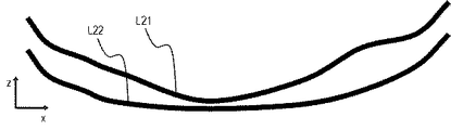
次に、形状情報として、層の厚さや厚さの変化率を算出してこれを用いる方法について、図8を使って説明する。なお、層の厚さは、2つの境界線間の間隔から算出できる。例えば、図8の境界線L21と境界線L22それぞれの同一x座標上のz座標の差から、これら境界の間の層の厚さを算出することができる。層の厚さを利用することで、例えば特定の層において菲薄化している領域を抽出できる。また、厚さの変化率を利用すると、特定の層において急峻に厚さが変化する部分を抽出できる。 Next, a method of calculating the thickness of the layer and the rate of change of the thickness as the shape information and using the same will be described with reference to FIG. The layer thickness can be calculated from the distance between the two boundary lines. For example, the thickness of the layer between the boundary lines L21 and the boundary line L22 in FIG. 8 can be calculated from the difference in the z-coordinates on the same x-coordinate. By using the thickness of the layer, for example, a thinned region in a specific layer can be extracted. Further, by using the rate of change in thickness, it is possible to extract a portion where the thickness changes sharply in a specific layer.
以上、異なるパラメータを用いた種々の形状情報の算出方法の例について説明したが、この方法以外で形状情報を算出してもよい。例えば、二次元断層像を元に算出する方法で説明したが、三次元的な解析手法から算出してもよい。その場合、曲線近似の替わりに曲面近似を行えばよい。 Although examples of various methods for calculating shape information using different parameters have been described above, shape information may be calculated by other methods. For example, although the method of calculating based on a two-dimensional tomographic image has been described, it may be calculated from a three-dimensional analysis method. In that case, the curved surface approximation may be performed instead of the curve approximation.
また、算出した形状情報に対し、平滑化や異常値の補正等の処理をしてもよい。形状解析のパラメータは、網膜層の特異的な形状を抽出する特徴量であればよく、他の形状パラメータを用いてもよい。また、複数のパラメータを組み合わせることで、抽出する領域をさらに絞ってもよい。あるいは被検眼の状態によっては、形状パラメータが算出できない領域が発生する場合もある。この場合、形状パラメータを算出できない領域についてはこれを異常値領域として、異常値領域の存在を形状情報としてもよい。例えば、緑内障でNFL(神経線維層)が菲薄化し一部が消失している場合がこのような場合の例として挙げられる。 Further, the calculated shape information may be subjected to processing such as smoothing and correction of abnormal values. The parameter of the shape analysis may be a feature amount that extracts a specific shape of the retinal layer, and other shape parameters may be used. Further, the area to be extracted may be further narrowed down by combining a plurality of parameters. Alternatively, depending on the condition of the eye to be inspected, there may be a region where the shape parameter cannot be calculated. In this case, for the region where the shape parameter cannot be calculated, this may be used as the outlier region, and the existence of the outlier region may be used as the shape information. For example, in glaucoma, the NFL (nerve fiber layer) is thinned and partly disappeared, which is an example of such a case.
また、形状情報を求めるに際して、例えば特定層の菲薄化等によってセグメンテーションがうまくできない、或いは明確な境界線が得られない等となる状況も考えられる。このような場合、例えば三次元断層像より抽出した深さ方向の二次元断層像を表示部34に表示させ、該二次元断層像に重畳表示したポインタ等を用いて層境界、即ち境界面の形状を修正できるようにするとよい。この場合、該境界面を修正する修正工程は、形状情報を算出する算出工程の前に行われ、形状情報の算出は境界面の修正の終了に応じて開始される。
In addition, when obtaining shape information, it is conceivable that segmentation cannot be performed well or a clear boundary line cannot be obtained due to, for example, thinning of a specific layer. In such a case, for example, a two-dimensional tomographic image in the depth direction extracted from the three-dimensional tomographic image is displayed on the
さらに、形状情報を取得する際に、例えば記憶部に記憶されている特定の層境界の形状との比較や、形状の急激な変化の検出等により、形状情報から特定の層境界の異常の有無が判別できる場合も考えられる。従って、層境界における異常領域、特異点等が想定された場合、当該領域等を検者に対して報知することが好ましい。この場合、例えば眼底正面像の立体像への変形に際して、これら領域に対して異常等を報知する特定の表示色を重畳することもできる。なお、ここでは形状情報として、部分的な凹凸部の曲率、境界の接線、境界間の変化率等の数値を例示した。しかし形状情報はこれらに限られず、例えば三次元の座標系に直接各境界をプロットしたもの等、境界の形状を再現可能な情報として取得できればその態様は上述した数値の様式に限定されない。 Further, when acquiring the shape information, for example, by comparing with the shape of a specific layer boundary stored in the storage unit or detecting a sudden change in the shape, the presence or absence of an abnormality in the specific layer boundary is present from the shape information. Can be determined in some cases. Therefore, when an abnormal region, a singular point, or the like at the layer boundary is assumed, it is preferable to notify the examiner of the region or the like. In this case, for example, when the frontal fundus image is transformed into a stereoscopic image, a specific display color for notifying an abnormality or the like can be superimposed on these areas. Here, as the shape information, numerical values such as the curvature of the partially uneven portion, the tangent line of the boundary, and the rate of change between the boundaries are illustrated. However, the shape information is not limited to these, and the mode is not limited to the above-mentioned numerical format as long as the shape of the boundary can be acquired as reproducible information such as a plot of each boundary directly on a three-dimensional coordinate system.
次に、特定の疾患を有する網膜に関して、眼底正面像を三次元化して三次元断層像上に表示する際に留意すべき網膜層の特異的な形状の例と形状パラメータについて説明する。図9は強度近視眼(所謂病的近視)と診断された被検眼の眼底正面像(図9(a))と想定される被検眼の形状変化(図9(b))を模式的に示している。 Next, for the retina having a specific disease, an example of a specific shape of the retinal layer and shape parameters to be noted when the frontal image of the fundus is three-dimensionalized and displayed on the three-dimensional tomographic image will be described. FIG. 9 schematically shows a change in the shape of the eye to be inspected (FIG. 9 (b)), which is assumed to be a frontal image of the fundus of the eye to be inspected (FIG. 9 (a)) diagnosed as severe myopia (so-called pathological myopia). There is.
強度近視において、通常被検眼100(眼球)は眼軸長方向に伸張する。しかし、この場合、図9(b)に示すように、強度近視の被検眼100の伸長は全体的に伸張する(黒矢印)だけでなく、病的近視と称されるように局所的に伸張する(白矢印)ことがある。このような強膜の部分的な後方伸張に伴い、網膜形状に変化が発生する。このような強膜が部分的に伸張した領域は後部ぶどう腫902cと総称される。後部ぶどう腫902cでは、FAFで撮影したとき、図9(a)に示す眼底正面像901において、白矢印方向に極度に湾曲が開始する境界902bに対応して図9(a)中に点線901aで示すリング状の輝線を生じることが知られている。三次元断層像ではこのような輝度変化点は見られないため、FAF画像と三次元断層像を重ね合わせて表示することで三次元断層像の読影が容易になる。その結果、後部ぶどう腫の領域や進行度合いなどを定量的に形状解析することが可能になる。
In severe myopia, the eye 100 (eyeball) to be inspected usually extends in the axial length direction. However, in this case, as shown in FIG. 9B, the extension of the
なお、ここで述べた後部ぶどう腫902aの境界902bは、眼底正面像において輝点として把握可能である。しかし、当該境界902bを、上述した生成立体像405等でさらに容易に認識できるように、強調することもできる。例えば、図9(a)に示す矢印901bのようなポインタを用いてリング状の輝線を指定することにより、該輝線に特定の色のリングを重畳させる等するとよい。この強調表示はポインタをドラッグすることで画像に書き加えてもよく、同程度の輝度を結ぶことにより信号処理部32等において自動で認識し且つ強調する操作を行うこととしてもよい。
The
また、上述した実施例では、形状情報を用いて眼底正面像を立体像に変形することとしている。しかし、眼底正面像から後部ぶどう腫等の眼底の深さ方向の疾患を立体的に把握可能であり、且つ三次元断層像への重ね合わせ等を考慮しなければ、眼底正面像を立体像に変形しなくともよい。具体的には、得られている形状情報を用いて被検体の深さ方向の位置情報を得ておき、該位置情報を色、濃淡、ハッチング、等高線等により表現してもよい。例えば、該位置情報を色で表現する場合、深さ方向の位置が深くなるに応じて色を変える表示を該正面像に重畳表示する、即ち該正面像に着色することで立体的な情報を読影可能としてもよい。この場合、表示制御手段として、表示制御部33がこれら深さ方向の位置情報を生成し、該位置情報を上述した表現方法により眼底正面像に与えることとすればよい。
Further, in the above-described embodiment, the frontal image of the fundus is transformed into a three-dimensional image by using the shape information. However, if it is possible to three-dimensionally grasp diseases in the depth direction of the fundus such as posterior cyst from the frontal image of the fundus, and if superimposition on a three-dimensional tomographic image is not taken into consideration, the frontal image of the fundus becomes a three-dimensional image. It does not have to be deformed. Specifically, the obtained shape information may be used to obtain position information in the depth direction of the subject, and the position information may be expressed by color, shading, hatching, contour lines, or the like. For example, when the position information is expressed by color, a display that changes the color according to the deepening of the position in the depth direction is superimposed on the front image, that is, three-dimensional information is displayed by coloring the front image. It may be readable. In this case, as the display control means, the
次に、被検眼が加齢黄斑変性に罹っている場合の例について説明する。加齢黄斑変性では、図10に示すように網膜色素上皮(RPE)(図10の境界線L4a)の形状に変化が発生する場合がある。加齢に伴いRPEの働きが低下すると、未消化の老廃物D1(ドルーゼン)がブルッフ膜(図10の境界線L5)とRPEとの間にたまる。その結果ドルーゼンによってRPEの境界線L4aは部分的に押し上げられ、変形境界線L4となる。OCT装置により得た二次元断層像では、RPEが網膜内側へ突出する形態が観察できる。 Next, an example of a case where the eye to be inspected suffers from age-related macular degeneration will be described. In age-related macular degeneration, changes may occur in the shape of retinal pigment epithelium (RPE) (boundary line L4a in FIG. 10) as shown in FIG. When the activity of RPE decreases with aging, undigested waste product D1 (drusen) accumulates between Bruch's membrane (boundary line L5 in FIG. 10) and RPE. As a result, the boundary line L4a of the RPE is partially pushed up by drusen to become the deformation boundary line L4. In the two-dimensional tomographic image obtained by the OCT device, the morphology of the RPE protruding inward of the retina can be observed.
老廃物が蓄積すると、炎症反応が起き脈絡膜から新生血管(CNV)が生えてくる。CNVがブルッフ膜を突き破ってRPEの下や上まで侵入して増殖すると、CNVに由来する漏出が激しくなって黄斑の機能低下につながる。ここでRPEの境界層の形状解析を行うことで、老廃物D1によりRPEが網膜内側へ突出する形態(変形境界線L4)が抽出される。例えば、RPEの変形境界線L4に対応する境界線L4aと局所的な凹凸を表す変形境界線L4とを比較することで老廃物の存在する可能性がある領域を抽出することができる。眼底正面像を例えばブルッフ膜或いはRPEからの情報が反映される撮影方法により生成することで、このような疾患に関しても立体像に変形することが可能となる。RPEに相当する部位の形状情報を近傍の眼底正面像に付与することにより、老廃物D1周囲の形状を描出することができ、CNVを見つけやすくなる。また、この場合、通常のRPEの形状に対して大きく変化している領域を上述した後部ぶどう腫の場合と同様に色を変える、或いは特定の表示色を用いて強調表示することにより、疾患部位の認識がより容易に行える。 Accumulation of waste products causes an inflammatory reaction and new blood vessels (CNV) grow from the choroid. When CNV penetrates the Bruch's membrane and invades below or above the RPE and proliferates, the leakage from the CNV becomes severe, leading to a decrease in the function of the macula. Here, by analyzing the shape of the boundary layer of the RPE, the form in which the RPE protrudes inside the retina (deformed boundary line L4) is extracted by the waste product D1. For example, by comparing the boundary line L4a corresponding to the deformation boundary line L4 of the RPE with the deformation boundary line L4 representing the local unevenness, a region where waste products may exist can be extracted. By generating a frontal image of the fundus by an imaging method that reflects information from, for example, the Bruch's membrane or RPE, it is possible to transform such a disease into a stereoscopic image. By adding the shape information of the portion corresponding to the RPE to the front view of the fundus in the vicinity, the shape around the waste product D1 can be visualized, and the CNV can be easily found. Further, in this case, the diseased part is formed by changing the color of the region that is significantly changed with respect to the shape of the normal RPE as in the case of the posterior grape tumor described above, or by highlighting the region using a specific display color. Can be recognized more easily.
上述した実施例によれば、OCT装置で得られる三次元断層像と、SLO装置等で得られる眼底正面像との対応を容易にできる。その結果、疾患部位や血管走行などの網膜形状を簡単に把握できるようになる。より詳細には、本実施例では、眼底正面像を網膜の形状情報に合わせて変形し、立体像としてOCT装置より得た三次元画像上に重ね合わせて表示する。その結果、特異的な網膜の形状に対応する眼底の疾患部位や血管走行が把握しやすい画像を提供することができる。 According to the above-described embodiment, it is possible to easily correspond the three-dimensional tomographic image obtained by the OCT device and the frontal image of the fundus obtained by the SLO device or the like. As a result, the shape of the retina such as the diseased part and the running of blood vessels can be easily grasped. More specifically, in this embodiment, the frontal image of the fundus is deformed according to the shape information of the retina and displayed as a stereoscopic image by superimposing it on the three-dimensional image obtained from the OCT apparatus. As a result, it is possible to provide an image in which the diseased part of the fundus and the blood vessel running corresponding to the specific shape of the retina can be easily grasped.
例えば、実際の診断時の読影において疾患部位や血管走行の形状を把握するために、検者が二次元のOCT断層像と二次元の眼底正面像とを交互に見比べる必要がある状態は、検者に煩雑さを感じさせる。また、例えば後部ぶどう腫等の立体的に把握すべき疾患を有する被検眼の読影の場合には、通常検者はこれら2つの二次元画像から立体的な被検眼を想定する。そして、診断に際しては、この想定された立体的な被検眼から疾患の状態等を推認することが必要となる。即ち、このような表示方法の場合、交互に見比べたとしても、立体的な被検眼の想定を行なえる充分な経験を有する検者でなければ被検眼に対する正確な読影を行なうことは容易ではない。上述した実施例によれば、眼底正面像から立体的な情報も合わせて得られるようになることから、不慣れな検者であっても疾患に関する情報を容易に読影することができる。 For example, in order to grasp the diseased part and the shape of blood vessel running in the interpretation at the time of actual diagnosis, the condition in which the examiner needs to alternately compare the two-dimensional OCT tomographic image and the two-dimensional frontal image of the fundus is examined. Make people feel complicated. Further, in the case of interpretation of an eye to be inspected having a disease to be grasped three-dimensionally, such as posterior grape tumor, the examiner usually assumes a three-dimensional eye to be inspected from these two two-dimensional images. Then, at the time of diagnosis, it is necessary to infer the state of the disease or the like from this assumed three-dimensional eye to be inspected. That is, in the case of such a display method, it is not easy to accurately interpret the eye to be inspected unless the examiner has sufficient experience to make a three-dimensional assumption of the eye to be inspected, even if they are compared alternately. .. According to the above-described embodiment, since three-dimensional information can also be obtained from the frontal image of the fundus, even an inexperienced examiner can easily interpret the information on the disease.
(第二の実施例)
上述した実施例では、眼底正面像を得た層境界の形状情報を三次元断層像より取得し、該形状情報を用いて眼底正面像を立体像に変形した。しかし、疾患等を診断する場合、被検眼或いは疾患部位の経過観察が不可欠である。本実施例では、このような要請に鑑み、経過観察を容易にする画像を提供する。
(Second Example)
In the above-described embodiment, the shape information of the layer boundary obtained from the frontal image of the fundus was acquired from the three-dimensional tomographic image, and the frontal image of the fundus was transformed into a three-dimensional image using the shape information. However, when diagnosing a disease or the like, follow-up of the eye to be inspected or the diseased part is indispensable. In view of such a request, the present embodiment provides an image that facilitates follow-up observation.
第二の実施例では、第一の信号および第二の信号の取得を複数回、それぞれ異なる日に行い、第一の実施例で述べた位置合わせ工程および形状解析工程を行う。さらに個々の形状解析結果に対し、形状情報の経時的な変化量あるいは変化率を算出する。変化量や変化率は初回の撮影を基準とすればよい。得られた経時的な変化量等は、取得された信号に対応して生成された立体像と共に表示される。このような解析結果を表示することで、経時的に形状が変化している部位を、網膜層の特異的な部位として抽出することができる。また得られた変化量等を眼底正面像の分類および疾患表示に反映することで、網膜形状に変化が生じた部位の疾患に着目しやすくなる。 In the second embodiment, the first signal and the second signal are acquired a plurality of times on different days, and the alignment step and the shape analysis step described in the first embodiment are performed. Furthermore, the amount or rate of change of the shape information over time is calculated for each shape analysis result. The amount of change and the rate of change may be based on the first shooting. The obtained amount of change over time is displayed together with the stereoscopic image generated corresponding to the acquired signal. By displaying such analysis results, it is possible to extract a site whose shape has changed over time as a specific site of the retinal layer. Further, by reflecting the obtained amount of change and the like in the classification of the frontal image of the fundus and the disease display, it becomes easy to pay attention to the disease at the site where the retinal shape has changed.
また、形状情報の経時的な変化量や変化率を算出する代わりに、生成順に複数の立体像或いは生成立体像を順番に表示したり、複数枚を並べて表示したりしてもよい。異なる日に得られた立体像等および形状情報を表示することで、病気の進行度合いや回復度合いといった経時的な変化の仕方が、視覚的に把握しやすくなる。本実施例によれば、OCT装置で得られるも眼底の構造情報と眼底正面像との対応を容易にして疾患部位の形状を簡単に把握できるようになると同時に、疾患部位の経時変化も把握することが容易となる。 Further, instead of calculating the amount of change and the rate of change of the shape information over time, a plurality of three-dimensional images or generated three-dimensional images may be displayed in order in the order of generation, or a plurality of three-dimensional images may be displayed side by side. By displaying stereoscopic images and shape information obtained on different days, it becomes easier to visually grasp how the disease progresses and recovers over time. According to this embodiment, the shape of the diseased part can be easily grasped by facilitating the correspondence between the structural information of the fundus and the frontal image of the fundus, which can be obtained by the OCT device, and at the same time, the change with time of the diseased part can be grasped. It becomes easy.
以上、本発明の好ましい実施例について詳述したが、本発明は係る特定の実施例に限定されるものではなく、本発明の趣旨に反しない範囲内において、種々の変形・変更された発明、および本発明と均等な発明も本発明に含まれる。例えば、画像の表示の位置関係やGUIの形状は変更可能である。また、3Dディスプレイによる立体視による表示でもよい。眼底正面像と形状解析を計算するプログラムであってもよい。 Although the preferred embodiments of the present invention have been described in detail above, the present invention is not limited to the specific embodiments, and various modified / modified inventions are provided within a range not contrary to the gist of the present invention. And the invention equivalent to the present invention is also included in the present invention. For example, the positional relationship of image display and the shape of GUI can be changed. Further, the display may be stereoscopically displayed by a 3D display. It may be a program that calculates the frontal image of the fundus and the shape analysis.
例えば、上述した実施例では、被検体が眼の場合について述べているが、例えば眼以外の皮膚や臓器等の被検体に本発明を適用することも可能である。この場合、本発明は眼科装置以外の、例えば内視鏡等の医療機器に対応した画像処理方法等としての態様を有する。従って、本発明は眼科装置に例示される検査装置に用いられる画像処理方法として把握され、被検眼は被検体の一態様として把握されることが好ましい。 For example, in the above-described embodiment, the case where the subject is an eye is described, but it is also possible to apply the present invention to a subject such as skin or an organ other than the eye, for example. In this case, the present invention has an aspect as an image processing method or the like corresponding to a medical device such as an endoscope other than an ophthalmic apparatus. Therefore, it is preferable that the present invention is grasped as an image processing method used in the inspection apparatus exemplified by the ophthalmic apparatus, and the eye to be inspected is grasped as one aspect of the subject.
(その他の実施例)
本発明は、上述の実施例の1以上の機能を実現するプログラムを、ネットワーク又は記憶媒体を介してシステム又は装置に供給し、そのシステム又は装置のコンピュータにおける1つ以上のプロセッサーがプログラムを読出し実行する処理でも実現可能である。また、1以上の機能を実現する回路(例えば、ASIC)によっても実現可能である。
(Other Examples)
The present invention supplies a program that realizes one or more functions of the above-described embodiment to a system or device via a network or storage medium, and one or more processors in the computer of the system or device reads and executes the program. It can also be realized by the processing to be performed. It can also be realized by a circuit (for example, ASIC) that realizes one or more functions.
100 被検体
200 OCT光学系
10 光源部
20 OCT干渉部
53 X軸スキャナー
54 Y軸スキャナー
300 情報処理部
31 信号取得部
32 信号処理部
33 表示制御部
34 表示部
100
Claims (22)
前記被検体の正面像を取得する正面像取得工程と、
前記三次元断層像における前記被検体の境界面の形状情報を用いて前記正面像を立体像に変形することにより、前記正面像に関する立体像を生成する生成工程と、
を含むことを特徴とする画像処理方法。 Acquisition of a tomographic image to acquire a three-dimensional tomographic image of the subject generated by using an interference signal set obtained by interfering the return light from the subject irradiated with the measurement light with the reference light corresponding to the measurement light. Process and
The front image acquisition step of acquiring the front image of the subject, and
A generation step of generating a three-dimensional image related to the front image by transforming the front image into a three-dimensional image using the shape information of the boundary surface of the subject in the three-dimensional tomographic image.
An image processing method comprising.
前記正面像と前記生成された二次元正面像との位置あわせを行う位置合わせ工程と、をさらに含み、
前記生成工程は、前記位置合わせ工程を行った後に実行されることを特徴とする請求項1に記載の画像処理方法。 A two-dimensional front image generation step of generating a two-dimensional front image of the subject using the three-dimensional tomographic image, and
Further including an alignment step of aligning the front image and the generated two-dimensional front image.
The image processing method according to claim 1, wherein the generation step is executed after performing the alignment step.
前記被検体の正面像を取得する正面像取得工程と、
前記三次元断層像における前記被検体の境界面の形状情報と前記正面像とを用いて、前記正面像に関する立体像を生成する生成工程と、
を含むことを特徴とする画像処理方法。 Acquisition of a tomographic image to acquire a three-dimensional tomographic image of the subject generated by using an interference signal set obtained by interfering the return light from the subject irradiated with the measurement light with the reference light corresponding to the measurement light. Process and
The front image acquisition step of acquiring the front image of the subject, and
Using said said front image and the shape information of the boundary surface of the object in the three-dimensional tomographic image, a generation step of generating a three-dimensional picture of the front image,
An image processing method comprising.
前記表示制御工程において、前記正面像と前記立体像とにおいて対応する点を示す表示を各々に重畳することを特徴とする請求項1乃至6の何れか一項に記載の画像処理方法。 A display control step of displaying the front image and the stereoscopic image side by side on the display means is further included.
The image processing method according to any one of claims 1 to 6, wherein in the display control step, displays indicating corresponding points in the front image and the stereoscopic image are superimposed on each other.
前記表示制御工程において、前記正面像と前記立体像の一方において任意の部位を指定した場合、前記正面像と前記立体像の他方において前記任意の部位に対応する部位を示す表示を重畳することを特徴とする請求項1乃至6の何れか一項に記載の画像処理方法。 A display control step of displaying the front image and the stereoscopic image side by side on the display means is further included.
In the display control step, when an arbitrary portion is specified in one of the front image and the stereoscopic image, a display indicating a portion corresponding to the arbitrary portion is superimposed on the other of the front image and the stereoscopic image. The image processing method according to any one of claims 1 to 6, wherein the image processing method is characterized.
前記境界面と前記第二の境界面との位置関係を用いて、前記立体像と前記第二の立体像とを互いに対応付けられた状態で表示手段に表示させる表示制御工程と、
をさらに含むことを特徴とする請求項1乃至6の何れか一項に記載の画像処理方法。 A step of transforming a second front image of the subject different from the front image into a second stereoscopic image using the shape information of the second boundary surface of the subject in the three-dimensional tomographic image.
A display control step of displaying the stereoscopic image and the second stereoscopic image on the display means in a state of being associated with each other by using the positional relationship between the boundary surface and the second boundary surface.
The image processing method according to any one of claims 1 to 6, further comprising.
前記被検体の正面像を取得する正面像取得工程と、
前記三次元断層像における前記被検体の境界面の形状情報を用いて得た前記被検体の深さ方向の位置情報を、前記正面像に重畳させた状態で表示手段に表示させる表示制御工程と、
を含むことを特徴とする画像処理方法。 Acquisition of a tomographic image to acquire a three-dimensional tomographic image of the subject generated by using an interference signal set obtained by interfering the return light from the subject irradiated with the measurement light with the reference light corresponding to the measurement light. Process and
The front image acquisition step of acquiring the front image of the subject, and
A display control step of displaying the position information in the depth direction of the subject obtained by using the shape information of the boundary surface of the subject in the three-dimensional tomographic image on the display means in a state of being superimposed on the front image. ,
An image processing method comprising.
前記形状情報を取得する境界面は、前記正面像の取得方法および前記被検体における前記正面像の取得深さの少なくとも何れかに応じて指定されることを特徴とする請求項1乃至11の何れか一項に記載の画像処理方法。 Further including a specific step of identifying a plurality of the boundary surfaces in the three-dimensional tomographic image.
Any of claims 1 to 11, wherein the boundary surface for acquiring the shape information is designated according to at least one of the acquisition method of the front image and the acquisition depth of the front image in the subject. The image processing method described in item 1.
前記特定された複数の境界面から前記形状情報を取得する境界面を指定する工程と、
をさらに含むことを特徴とする請求項1乃至11の何れか一項に記載の画像処理方法。 A specific step of identifying a plurality of the boundary surfaces in the three-dimensional tomographic image, and
A step of designating a boundary surface for acquiring the shape information from the specified plurality of boundary surfaces, and
The image processing method according to any one of claims 1 to 11, further comprising.
前記正面像は、眼底カメラおよび走査型レーザー検眼鏡の少なくとも何れかにより取得されたことを特徴とする請求項1乃至16の何れか一項に記載の画像処理方法。 The subject is an eye to be inspected and
The image processing method according to any one of claims 1 to 16, wherein the front image is acquired by at least one of a fundus camera and a scanning laser ophthalmoscope.
前記被検体の正面像を取得する正面像取得手段と、
前記三次元断層像における前記被検体の境界面の形状情報を用いて前記正面像を立体像に変形することにより、前記正面像に関する立体像を生成する生成手段と、
を備えることを特徴とする画像処理装置。 A tomographic image acquisition means for acquiring a three-dimensional tomographic image of the subject generated by using an interference signal set obtained by interfering the return light from the subject irradiated with the measurement light with the reference light corresponding to the measurement light. When,
A frontal image acquisition means for acquiring the frontal image of the subject, and
A generation means for generating a three-dimensional image related to the front image by transforming the front image into a three-dimensional image using the shape information of the boundary surface of the subject in the three-dimensional tomographic image.
An image processing device comprising.
前記被検体の正面像を取得する正面像取得手段と、
前記三次元断層像における前記被検体の境界面の形状情報と前記正面像とを用いて、前記正面像に関する立体像を生成する生成手段と、
を備えることを特徴とする画像処理装置。 Acquisition of a tomographic image to acquire a three-dimensional tomographic image of the subject generated by using an interference signal set obtained by interfering the return light from the subject irradiated with the measurement light with the reference light corresponding to the measurement light. Means and
A frontal image acquisition means for acquiring the frontal image of the subject, and
Above using shape information of the boundary surface of the object and the said front image in the three-dimensional tomographic image, a generation unit for generating stereoscopic image related to the frontal view,
An image processing device comprising.
前記被検体の正面像を取得する正面像取得手段と、
前記三次元断層像における前記被検体の境界面の形状情報を用いて得た前記被検体の深さ方向の位置情報を、前記正面像に重畳させた状態で表示手段に表示させる表示制御手段と、
を備えることを特徴とする画像処理装置。 Acquisition of a tomographic image to acquire a three-dimensional tomographic image of the subject generated by using an interference signal set obtained by interfering the return light from the subject irradiated with the measurement light with the reference light corresponding to the measurement light. Means and
A frontal image acquisition means for acquiring the frontal image of the subject, and
A display control means for displaying the position information in the depth direction of the subject obtained by using the shape information of the boundary surface of the subject in the three-dimensional tomographic image on the display means in a state of being superimposed on the front image. ,
An image processing device comprising.
Priority Applications (1)
| Application Number | Priority Date | Filing Date | Title |
|---|---|---|---|
| JP2016219647A JP6898724B2 (en) | 2016-11-10 | 2016-11-10 | Image processing methods, image processing devices and programs |
Applications Claiming Priority (1)
| Application Number | Priority Date | Filing Date | Title |
|---|---|---|---|
| JP2016219647A JP6898724B2 (en) | 2016-11-10 | 2016-11-10 | Image processing methods, image processing devices and programs |
Publications (3)
| Publication Number | Publication Date |
|---|---|
| JP2018075229A JP2018075229A (en) | 2018-05-17 |
| JP2018075229A5 JP2018075229A5 (en) | 2019-12-19 |
| JP6898724B2 true JP6898724B2 (en) | 2021-07-07 |
Family
ID=62148711
Family Applications (1)
| Application Number | Title | Priority Date | Filing Date |
|---|---|---|---|
| JP2016219647A Active JP6898724B2 (en) | 2016-11-10 | 2016-11-10 | Image processing methods, image processing devices and programs |
Country Status (1)
| Country | Link |
|---|---|
| JP (1) | JP6898724B2 (en) |
Families Citing this family (5)
| Publication number | Priority date | Publication date | Assignee | Title |
|---|---|---|---|---|
| JP7286283B2 (en) * | 2018-08-30 | 2023-06-05 | 株式会社トプコン | ophthalmic equipment |
| US11134836B2 (en) | 2019-01-16 | 2021-10-05 | Topcon Corporation | Ophthalmologic information processing apparatus, ophthalmologic apparatus and ophthalmologic information processing method |
| US11141060B2 (en) * | 2019-01-16 | 2021-10-12 | Topcon Corporation | Ophthalmologic apparatus and method of controlling the same |
| JP7379704B2 (en) * | 2019-12-05 | 2023-11-14 | アルコン インコーポレイティド | System and method for integrating visualization camera and optical coherence tomography |
| WO2023053727A1 (en) * | 2021-09-30 | 2023-04-06 | 富士フイルム株式会社 | Image processing device, processing system, image display method, and program |
Family Cites Families (4)
| Publication number | Priority date | Publication date | Assignee | Title |
|---|---|---|---|---|
| JP2008237840A (en) * | 2007-03-29 | 2008-10-09 | Gifu Univ | Image analysis system and image analysis program |
| JP6115007B2 (en) * | 2012-01-31 | 2017-04-19 | 株式会社ニデック | Ophthalmic image processing apparatus and program |
| JP6108827B2 (en) * | 2012-12-28 | 2017-04-05 | キヤノン株式会社 | Ophthalmic apparatus and alignment method |
| EP3069318B1 (en) * | 2013-11-14 | 2018-08-01 | Koninklijke Philips N.V. | Registration of medical images |
-
2016
- 2016-11-10 JP JP2016219647A patent/JP6898724B2/en active Active
Also Published As
| Publication number | Publication date |
|---|---|
| JP2018075229A (en) | 2018-05-17 |
Similar Documents
| Publication | Publication Date | Title |
|---|---|---|
| JP6898724B2 (en) | Image processing methods, image processing devices and programs | |
| JP6367563B2 (en) | Ophthalmic equipment | |
| CN112822972A (en) | Image processing apparatus, image processing method, and program | |
| JP6987495B2 (en) | Image processing device, its operation method, and program | |
| JP2017127506A (en) | Image forming method and apparatus | |
| US10561311B2 (en) | Ophthalmic imaging apparatus and ophthalmic information processing apparatus | |
| WO2021106987A1 (en) | Medical image processing device, optical coherence tomography device, medical image processing method, and program | |
| JP2022040372A (en) | Ophthalmologic apparatus | |
| JP7134324B2 (en) | OPHTHALMIC PHOTOGRAPHIC APPARATUS, CONTROL METHOD, PROGRAM, AND RECORDING MEDIUM THEREOF | |
| JP2019177032A (en) | Ophthalmologic image processing device and ophthalmologic image processing program | |
| JP2018051391A (en) | Ophthalmologic apparatus | |
| JP7096116B2 (en) | Blood flow measuring device | |
| JP7090438B2 (en) | Ophthalmologic imaging equipment, its control method, programs, and recording media | |
| JP7009265B2 (en) | Image processing equipment, image processing methods and programs | |
| JP6736734B2 (en) | Ophthalmic photographing device and ophthalmic information processing device | |
| JP2022189963A (en) | Ophthalmologic apparatus | |
| JP2022173339A (en) | Ophthalmologic imaging device, control method thereof, program, and recording medium | |
| JP7262929B2 (en) | Image processing device, image processing method and program | |
| JP7286283B2 (en) | ophthalmic equipment | |
| JP7204345B2 (en) | Image processing device, image processing method and program | |
| JP7050488B2 (en) | Ophthalmologic imaging equipment, its control method, programs, and recording media | |
| WO2019150862A1 (en) | Blood flow measurement device | |
| JP7387812B2 (en) | Image processing device, image processing method and program | |
| JP2019154993A (en) | Ophthalmologic apparatus, control method therefor, program, and storage medium | |
| JP6942626B2 (en) | Ophthalmologic imaging equipment, its control method, programs, and recording media |
Legal Events
| Date | Code | Title | Description |
|---|---|---|---|
| RD05 | Notification of revocation of power of attorney |
Free format text: JAPANESE INTERMEDIATE CODE: A7425 Effective date: 20171214 |
|
| RD04 | Notification of resignation of power of attorney |
Free format text: JAPANESE INTERMEDIATE CODE: A7424 Effective date: 20180126 |
|
| A521 | Written amendment |
Free format text: JAPANESE INTERMEDIATE CODE: A523 Effective date: 20191107 |
|
| A621 | Written request for application examination |
Free format text: JAPANESE INTERMEDIATE CODE: A621 Effective date: 20191107 |
|
| A977 | Report on retrieval |
Free format text: JAPANESE INTERMEDIATE CODE: A971007 Effective date: 20200916 |
|
| A131 | Notification of reasons for refusal |
Free format text: JAPANESE INTERMEDIATE CODE: A131 Effective date: 20201006 |
|
| A521 | Written amendment |
Free format text: JAPANESE INTERMEDIATE CODE: A523 Effective date: 20201202 |
|
| TRDD | Decision of grant or rejection written | ||
| A01 | Written decision to grant a patent or to grant a registration (utility model) |
Free format text: JAPANESE INTERMEDIATE CODE: A01 Effective date: 20210513 |
|
| A61 | First payment of annual fees (during grant procedure) |
Free format text: JAPANESE INTERMEDIATE CODE: A61 Effective date: 20210611 |
|
| R151 | Written notification of patent or utility model registration |
Ref document number: 6898724 Country of ref document: JP Free format text: JAPANESE INTERMEDIATE CODE: R151 |