JP6898285B2 - Surgical system and display method - Google Patents
Surgical system and display method Download PDFInfo
- Publication number
- JP6898285B2 JP6898285B2 JP2018179277A JP2018179277A JP6898285B2 JP 6898285 B2 JP6898285 B2 JP 6898285B2 JP 2018179277 A JP2018179277 A JP 2018179277A JP 2018179277 A JP2018179277 A JP 2018179277A JP 6898285 B2 JP6898285 B2 JP 6898285B2
- Authority
- JP
- Japan
- Prior art keywords
- pedal
- area
- foot
- surgical instrument
- operator
- Prior art date
- Legal status (The legal status is an assumption and is not a legal conclusion. Google has not performed a legal analysis and makes no representation as to the accuracy of the status listed.)
- Active
Links
Images


Classifications
-
- G—PHYSICS
- G16—INFORMATION AND COMMUNICATION TECHNOLOGY [ICT] SPECIALLY ADAPTED FOR SPECIFIC APPLICATION FIELDS
- G16H—HEALTHCARE INFORMATICS, i.e. INFORMATION AND COMMUNICATION TECHNOLOGY [ICT] SPECIALLY ADAPTED FOR THE HANDLING OR PROCESSING OF MEDICAL OR HEALTHCARE DATA
- G16H40/00—ICT specially adapted for the management or administration of healthcare resources or facilities; ICT specially adapted for the management or operation of medical equipment or devices
- G16H40/60—ICT specially adapted for the management or administration of healthcare resources or facilities; ICT specially adapted for the management or operation of medical equipment or devices for the operation of medical equipment or devices
- G16H40/63—ICT specially adapted for the management or administration of healthcare resources or facilities; ICT specially adapted for the management or operation of medical equipment or devices for the operation of medical equipment or devices for local operation
-
- A—HUMAN NECESSITIES
- A61—MEDICAL OR VETERINARY SCIENCE; HYGIENE
- A61B—DIAGNOSIS; SURGERY; IDENTIFICATION
- A61B1/00—Instruments for performing medical examinations of the interior of cavities or tubes of the body by visual or photographical inspection, e.g. endoscopes; Illuminating arrangements therefor
- A61B1/00002—Operational features of endoscopes
- A61B1/00039—Operational features of endoscopes provided with input arrangements for the user
- A61B1/00042—Operational features of endoscopes provided with input arrangements for the user for mechanical operation
-
- A—HUMAN NECESSITIES
- A61—MEDICAL OR VETERINARY SCIENCE; HYGIENE
- A61B—DIAGNOSIS; SURGERY; IDENTIFICATION
- A61B1/00—Instruments for performing medical examinations of the interior of cavities or tubes of the body by visual or photographical inspection, e.g. endoscopes; Illuminating arrangements therefor
- A61B1/00147—Holding or positioning arrangements
- A61B1/00149—Holding or positioning arrangements using articulated arms
-
- A—HUMAN NECESSITIES
- A61—MEDICAL OR VETERINARY SCIENCE; HYGIENE
- A61B—DIAGNOSIS; SURGERY; IDENTIFICATION
- A61B1/00—Instruments for performing medical examinations of the interior of cavities or tubes of the body by visual or photographical inspection, e.g. endoscopes; Illuminating arrangements therefor
- A61B1/00147—Holding or positioning arrangements
- A61B1/0016—Holding or positioning arrangements using motor drive units
-
- A—HUMAN NECESSITIES
- A61—MEDICAL OR VETERINARY SCIENCE; HYGIENE
- A61B—DIAGNOSIS; SURGERY; IDENTIFICATION
- A61B1/00—Instruments for performing medical examinations of the interior of cavities or tubes of the body by visual or photographical inspection, e.g. endoscopes; Illuminating arrangements therefor
- A61B1/04—Instruments for performing medical examinations of the interior of cavities or tubes of the body by visual or photographical inspection, e.g. endoscopes; Illuminating arrangements therefor combined with photographic or television appliances
- A61B1/05—Instruments for performing medical examinations of the interior of cavities or tubes of the body by visual or photographical inspection, e.g. endoscopes; Illuminating arrangements therefor combined with photographic or television appliances characterised by the image sensor, e.g. camera, being in the distal end portion
-
- A—HUMAN NECESSITIES
- A61—MEDICAL OR VETERINARY SCIENCE; HYGIENE
- A61B—DIAGNOSIS; SURGERY; IDENTIFICATION
- A61B18/00—Surgical instruments, devices or methods for transferring non-mechanical forms of energy to or from the body
- A61B18/04—Surgical instruments, devices or methods for transferring non-mechanical forms of energy to or from the body by heating
- A61B18/12—Surgical instruments, devices or methods for transferring non-mechanical forms of energy to or from the body by heating by passing a current through the tissue to be heated, e.g. high-frequency current
- A61B18/1206—Generators therefor
-
- A—HUMAN NECESSITIES
- A61—MEDICAL OR VETERINARY SCIENCE; HYGIENE
- A61B—DIAGNOSIS; SURGERY; IDENTIFICATION
- A61B34/00—Computer-aided surgery; Manipulators or robots specially adapted for use in surgery
- A61B34/25—User interfaces for surgical systems
-
- A—HUMAN NECESSITIES
- A61—MEDICAL OR VETERINARY SCIENCE; HYGIENE
- A61B—DIAGNOSIS; SURGERY; IDENTIFICATION
- A61B34/00—Computer-aided surgery; Manipulators or robots specially adapted for use in surgery
- A61B34/30—Surgical robots
-
- A—HUMAN NECESSITIES
- A61—MEDICAL OR VETERINARY SCIENCE; HYGIENE
- A61B—DIAGNOSIS; SURGERY; IDENTIFICATION
- A61B34/00—Computer-aided surgery; Manipulators or robots specially adapted for use in surgery
- A61B34/30—Surgical robots
- A61B34/35—Surgical robots for telesurgery
-
- A—HUMAN NECESSITIES
- A61—MEDICAL OR VETERINARY SCIENCE; HYGIENE
- A61B—DIAGNOSIS; SURGERY; IDENTIFICATION
- A61B34/00—Computer-aided surgery; Manipulators or robots specially adapted for use in surgery
- A61B34/30—Surgical robots
- A61B34/37—Master-slave robots
-
- A—HUMAN NECESSITIES
- A61—MEDICAL OR VETERINARY SCIENCE; HYGIENE
- A61B—DIAGNOSIS; SURGERY; IDENTIFICATION
- A61B90/00—Instruments, implements or accessories specially adapted for surgery or diagnosis and not covered by any of the groups A61B1/00 - A61B50/00, e.g. for luxation treatment or for protecting wound edges
- A61B90/36—Image-producing devices or illumination devices not otherwise provided for
- A61B90/361—Image-producing devices, e.g. surgical cameras
-
- A—HUMAN NECESSITIES
- A61—MEDICAL OR VETERINARY SCIENCE; HYGIENE
- A61B—DIAGNOSIS; SURGERY; IDENTIFICATION
- A61B90/00—Instruments, implements or accessories specially adapted for surgery or diagnosis and not covered by any of the groups A61B1/00 - A61B50/00, e.g. for luxation treatment or for protecting wound edges
- A61B90/36—Image-producing devices or illumination devices not otherwise provided for
- A61B90/37—Surgical systems with images on a monitor during operation
-
- G—PHYSICS
- G16—INFORMATION AND COMMUNICATION TECHNOLOGY [ICT] SPECIALLY ADAPTED FOR SPECIFIC APPLICATION FIELDS
- G16H—HEALTHCARE INFORMATICS, i.e. INFORMATION AND COMMUNICATION TECHNOLOGY [ICT] SPECIALLY ADAPTED FOR THE HANDLING OR PROCESSING OF MEDICAL OR HEALTHCARE DATA
- G16H20/00—ICT specially adapted for therapies or health-improving plans, e.g. for handling prescriptions, for steering therapy or for monitoring patient compliance
- G16H20/40—ICT specially adapted for therapies or health-improving plans, e.g. for handling prescriptions, for steering therapy or for monitoring patient compliance relating to mechanical, radiation or invasive therapies, e.g. surgery, laser therapy, dialysis or acupuncture
-
- A—HUMAN NECESSITIES
- A61—MEDICAL OR VETERINARY SCIENCE; HYGIENE
- A61B—DIAGNOSIS; SURGERY; IDENTIFICATION
- A61B18/00—Surgical instruments, devices or methods for transferring non-mechanical forms of energy to or from the body
- A61B18/04—Surgical instruments, devices or methods for transferring non-mechanical forms of energy to or from the body by heating
- A61B18/12—Surgical instruments, devices or methods for transferring non-mechanical forms of energy to or from the body by heating by passing a current through the tissue to be heated, e.g. high-frequency current
- A61B18/14—Probes or electrodes therefor
- A61B18/1482—Probes or electrodes therefor having a long rigid shaft for accessing the inner body transcutaneously in minimal invasive surgery, e.g. laparoscopy
-
- A—HUMAN NECESSITIES
- A61—MEDICAL OR VETERINARY SCIENCE; HYGIENE
- A61B—DIAGNOSIS; SURGERY; IDENTIFICATION
- A61B17/00—Surgical instruments, devices or methods, e.g. tourniquets
- A61B2017/00477—Coupling
-
- A—HUMAN NECESSITIES
- A61—MEDICAL OR VETERINARY SCIENCE; HYGIENE
- A61B—DIAGNOSIS; SURGERY; IDENTIFICATION
- A61B17/00—Surgical instruments, devices or methods, e.g. tourniquets
- A61B2017/00973—Surgical instruments, devices or methods, e.g. tourniquets pedal-operated
-
- A—HUMAN NECESSITIES
- A61—MEDICAL OR VETERINARY SCIENCE; HYGIENE
- A61B—DIAGNOSIS; SURGERY; IDENTIFICATION
- A61B18/00—Surgical instruments, devices or methods for transferring non-mechanical forms of energy to or from the body
- A61B2018/00571—Surgical instruments, devices or methods for transferring non-mechanical forms of energy to or from the body for achieving a particular surgical effect
- A61B2018/00589—Coagulation
-
- A—HUMAN NECESSITIES
- A61—MEDICAL OR VETERINARY SCIENCE; HYGIENE
- A61B—DIAGNOSIS; SURGERY; IDENTIFICATION
- A61B18/00—Surgical instruments, devices or methods for transferring non-mechanical forms of energy to or from the body
- A61B2018/00571—Surgical instruments, devices or methods for transferring non-mechanical forms of energy to or from the body for achieving a particular surgical effect
- A61B2018/00601—Cutting
-
- A—HUMAN NECESSITIES
- A61—MEDICAL OR VETERINARY SCIENCE; HYGIENE
- A61B—DIAGNOSIS; SURGERY; IDENTIFICATION
- A61B18/00—Surgical instruments, devices or methods for transferring non-mechanical forms of energy to or from the body
- A61B2018/00571—Surgical instruments, devices or methods for transferring non-mechanical forms of energy to or from the body for achieving a particular surgical effect
- A61B2018/0063—Sealing
-
- A—HUMAN NECESSITIES
- A61—MEDICAL OR VETERINARY SCIENCE; HYGIENE
- A61B—DIAGNOSIS; SURGERY; IDENTIFICATION
- A61B18/00—Surgical instruments, devices or methods for transferring non-mechanical forms of energy to or from the body
- A61B18/04—Surgical instruments, devices or methods for transferring non-mechanical forms of energy to or from the body by heating
- A61B18/12—Surgical instruments, devices or methods for transferring non-mechanical forms of energy to or from the body by heating by passing a current through the tissue to be heated, e.g. high-frequency current
- A61B18/1206—Generators therefor
- A61B2018/1246—Generators therefor characterised by the output polarity
- A61B2018/1253—Generators therefor characterised by the output polarity monopolar
-
- A—HUMAN NECESSITIES
- A61—MEDICAL OR VETERINARY SCIENCE; HYGIENE
- A61B—DIAGNOSIS; SURGERY; IDENTIFICATION
- A61B18/00—Surgical instruments, devices or methods for transferring non-mechanical forms of energy to or from the body
- A61B18/04—Surgical instruments, devices or methods for transferring non-mechanical forms of energy to or from the body by heating
- A61B18/12—Surgical instruments, devices or methods for transferring non-mechanical forms of energy to or from the body by heating by passing a current through the tissue to be heated, e.g. high-frequency current
- A61B18/1206—Generators therefor
- A61B2018/1246—Generators therefor characterised by the output polarity
- A61B2018/126—Generators therefor characterised by the output polarity bipolar
-
- A—HUMAN NECESSITIES
- A61—MEDICAL OR VETERINARY SCIENCE; HYGIENE
- A61B—DIAGNOSIS; SURGERY; IDENTIFICATION
- A61B34/00—Computer-aided surgery; Manipulators or robots specially adapted for use in surgery
- A61B34/30—Surgical robots
- A61B2034/301—Surgical robots for introducing or steering flexible instruments inserted into the body, e.g. catheters or endoscopes
-
- A—HUMAN NECESSITIES
- A61—MEDICAL OR VETERINARY SCIENCE; HYGIENE
- A61B—DIAGNOSIS; SURGERY; IDENTIFICATION
- A61B34/00—Computer-aided surgery; Manipulators or robots specially adapted for use in surgery
- A61B34/30—Surgical robots
- A61B2034/302—Surgical robots specifically adapted for manipulations within body cavities, e.g. within abdominal or thoracic cavities
Description
この発明は、手術システムおよび表示方法に関し、特に、手術器具を操作するための遠隔操作装置を備えた手術システムおよび手術システムにおける表示方法に関する。 This invention relates to a surgical system and a display method, and more particularly, to a display method in the surgical system and surgical system including a remote control device for operating a surgical instrument.
従来、手術器具を操作するための遠隔操作装置を備えた手術システムが知られている(たとえば、特許文献1参照)。 Conventionally, a surgical system including a remote control device for operating a surgical instrument is known (see, for example, Patent Document 1).
上記特許文献1には、手術部位の画像を撮像する内視鏡および複数の手術器具を各々支持するための複数のマニピュレータと、内視鏡によって撮像された画像を表示するための表示装置と、手術器具を遠隔で操作するための操作ハンドルおよび手術器具に関する機能を実行させるための複数のフットペダルを含む遠隔操作装置と、を備える手術システムが開示されている。この特許文献1の手術システムは、表示装置の右の領域に右手用の操作ハンドルにより操作する手術器具の情報が表示され、表示装置の左の領域に左手用の操作ハンドルにより操作する手術器具の情報が表示され、表示装置の中央に複数のフットペダルの配置が表示されるように構成されている。
The above-mentioned
しかしながら、特許文献1の手術システムでは、表示装置のフットペダルの配置の表示により操作者がフットペダルの配置を確認することができるものの、操作者が実際にどのフットペダルに足を位置させているのかを確認することができないという問題点がある。
However, in the surgical system of
この発明は、表示装置から目を離すことなく操作するフットペダルを確認することが可能な手術システムを提供するものである。 The present invention provides a surgical system capable of confirming a foot pedal to be operated without taking one's eyes off the display device.
この発明の第1の局面による手術システムは、手術部位の画像を撮像する内視鏡、第1手術器具および第2手術器具を各々支持するための複数のマニピュレータと、内視鏡によって撮像された画像を表示するための表示装置と、第1手術器具を操作するための第1操作ハンドルと、第2手術器具を操作するための第2操作ハンドルと、複数のフットペダルを有する操作ペダル部と、を含む遠隔操作装置と、少なくとも表示装置を制御するように構成された制御装置と、を備え、操作ペダル部は、それぞれのフットペダル上の操作準備位置に操作者の足が配置されたことを検出するための複数のセンサを含み、複数のフットペダルは、第1手術器具に関する機能を実行させるための第1フットペダルと、第2手術器具に関する機能を実行させるための第2フットペダルと、内視鏡に関する機能を実行させるための第3フットペダルと、を有しており、制御装置は、第1手術器具に関する情報を示す第1エリアと、第2手術器具に関する情報を示す第2エリアと、内視鏡に関する情報を示す第3エリアと、を配置したグラフィカルユーザインタフェースを内視鏡によって撮像された画像上に重ねて表示装置に表示するように構成されており、制御装置は、第1フットペダル、第2フットペダルおよび第3フットペダルのうちの少なくとも1つのフットペダルの操作準備位置に操作者の足が配置されたことを、複数のセンサのうちの少なくとも1つのセンサにより検出したことに基づいて、第1エリア、第2エリアおよび第3エリアのうちの対応するエリアの一部の範囲を強調表示するとともに、第1エリア、第2エリアおよび第3エリアとは異なる位置に、操作準備位置に操作者の足が配置されたフットペダルに関するペダル情報をポップアップ表示し、第1フットペダル、第2フットペダルまたは第3フットペダルが操作された場合に、第1エリア、第2エリアおよび第3エリアのうちの対応するエリアに、フットペダルの操作準備位置に操作者の足が配置された場合よりも大きい範囲を強調表示するように構成されている。 The surgical system according to the first aspect of the present invention is imaged by an endoscope that captures an image of the surgical site, a plurality of manipulators for supporting the first surgical instrument and the second surgical instrument, respectively, and an endoscope. A display device for displaying an image, a first operation handle for operating the first surgical instrument, a second operation handle for operating the second surgical instrument, and an operation pedal unit having a plurality of foot pedals. The remote control device including, and at least a control device configured to control the display device are provided, and the operation pedal unit has the operator's foot arranged at the operation preparation position on each foot pedal. The plurality of foot pedals include a plurality of sensors for detecting, a first foot pedal for performing a function related to the first surgical instrument, and a second foot pedal for performing a function related to the second surgical instrument. It has a third foot pedal for performing functions related to the endoscope, and the control device has a first area showing information about the first surgical instrument and a second area showing information about the second surgical instrument. A graphical user interface in which an area and a third area indicating information about the endoscope are arranged is superposed on the image captured by the endoscope and displayed on the display device, and the control device is configured. At least one of a plurality of sensors detects that the operator's foot is placed at the operation preparation position of at least one foot pedal of the first foot pedal, the second foot pedal, and the third foot pedal. Based on the above, the range of a part of the corresponding area of the first area, the second area, and the third area is highlighted, and the position is different from that of the first area, the second area, and the third area. , The pedal information about the foot pedal in which the operator's foot is placed in the operation preparation position is displayed in a pop-up, and when the first foot pedal, the second foot pedal or the third foot pedal is operated, the first area and the second The corresponding area of the area and the third area is configured to highlight a larger area than when the operator's foot is placed at the foot pedal operation ready position.
この発明の第1の局面による手術システムでは、上記のように構成することによって、フットペダルの操作準備位置に操作者の足が配置された場合に、フットペダルに対応するグラフィカルユーザインタフェースのエリアの表示形態が変更されて表示装置に表示されるので、操作者が実際にどのフットペダルに足を位置させているのかを目視で確認する必要がない。その結果、操作者が表示装置から目を離すことなく操作するフットペダルを確認することができる。
この発明の第2の局面による表示方法は、手術システムにおける情報の表示方法であって、手術システムは、内視鏡、第1手術器具および第2手術器具を各々支持するための複数のマニピュレータと、内視鏡によって撮像された画像を表示するための表示装置、第1手術器具を操作するための第1操作ハンドル、第2手術器具を操作するための第2操作ハンドルおよび複数のフットペダルを有する操作ペダル部を含む遠隔操作装置と、少なくとも表示装置を制御するように構成された制御装置と、を備え、操作ペダル部は、それぞれのフットペダル上の操作準備位置に操作者の足が配置されたことを検出するための複数のセンサを含み、複数のフットペダルは、第1手術器具に関する機能を実行させるための第1フットペダルと、第2手術器具に関する機能を実行させるための第2フットペダルと、内視鏡に関する機能を実行させるための第3フットペダルと、を有しており、第1手術器具に関する情報を示す第1エリアと、第2手術器具に関する情報を示す第2エリアと、内視鏡に関する情報を示す第3エリアと、を配置したグラフィカルユーザインタフェースを内視鏡によって撮像された画像上に重ねて表示装置に表示する工程と、第1フットペダル、第2フットペダルおよび第3フットペダルのうちの少なくとも1つのフットペダルの操作準備位置に操作者の足が配置されたことを、複数のセンサのうちの少なくとも1つのセンサにより検出したことに基づいて、第1エリア、第2エリアおよび第3エリアのうちの対応するエリアの一部の範囲を強調表示するとともに、第1エリア、第2エリアおよび第3エリアとは異なる位置に、操作準備位置に操作者の足が配置されたフットペダルに関するペダル情報をポップアップ表示する操作準備表示工程と、第1フットペダル、第2フットペダルまたは第3フットペダルが操作された場合に、第1エリア、第2エリアおよび第3エリアのうちの対応するエリアに、フットペダルの操作準備位置に操作者の足が配置された場合よりも大きい範囲を強調表示するペダル操作表示工程と、を備える。
In the surgical system according to the first aspect of the present invention, by configuring as described above, when the operator's foot is placed at the operation preparation position of the foot pedal, the area of the graphical user interface corresponding to the foot pedal Since the display form is changed and displayed on the display device, it is not necessary to visually confirm which foot pedal the operator actually positions his / her foot on. As a result, it is possible to confirm the foot pedal that the operator operates without taking his eyes off the display device.
The display method according to the second aspect of the present invention is a display method of information in a surgical system, in which the surgical system includes a plurality of manipulators for supporting an endoscope, a first surgical instrument, and a second surgical instrument, respectively. , A display device for displaying the image captured by the endoscope, a first operation handle for operating the first surgical instrument, a second operation handle for operating the second surgical instrument, and a plurality of foot pedals. A remote operation device including an operation pedal unit and a control device configured to control at least a display device are provided, and the operation pedal unit has an operator's foot arranged at an operation preparation position on each foot pedal. The plurality of foot pedals include a plurality of sensors for detecting that the foot pedal has been used, and the plurality of foot pedals are a first foot pedal for performing a function related to the first surgical instrument and a second foot pedal for performing a function related to the second surgical instrument. It has a foot pedal and a third foot pedal for performing functions related to the endoscope, and has a first area showing information about the first surgical instrument and a second area showing information about the second surgical instrument. The process of superimposing the graphical user interface on which the third area showing information about the endoscope is arranged on the image captured by the endoscope and displaying it on the display device, and the first foot pedal and the second foot pedal. And the first area based on the detection by at least one of the plurality of sensors that the operator's foot is placed at the operation ready position of at least one of the third foot pedals. , The operator's foot in the operation preparation position, in a position different from the first area, the second area and the third area , while highlighting a part of the corresponding area of the second area and the third area. The operation preparation display process that pops up the pedal information related to the foot pedal in which is placed , and the first area, the second area, and the third area when the first foot pedal, the second foot pedal, or the third foot pedal is operated. The corresponding area of the area includes a pedal operation display step that highlights a larger area than when the operator's foot is placed at the foot pedal operation preparation position.
本発明によれば、表示装置から目を離すことなく操作するフットペダルを確認することが可能な手術システムを提供することができる。 According to the present invention, it is possible to provide a surgical system capable of confirming a foot pedal to be operated without taking an eye on the display device.
以下、実施形態を図面に基づいて説明する。 Hereinafter, embodiments will be described with reference to the drawings.
(手術システムの構成)
図1〜図21を参照して、一実施形態による手術システム400の構成について説明する。
(Structure of surgical system)
The configuration of the
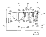
図1に示すように、手術システム400は、遠隔操作装置100と、患者側装置200とを備えている。遠隔操作装置100は、患者側装置200に設けられた医療器具(medical equipment)を遠隔操作するために設けられている。患者側装置200によって実行されるべき動作態様指令が術者(surgeon)である操作者Oにより遠隔操作装置100に入力されると、遠隔操作装置100は、動作態様指令をコントローラ206を介して患者側装置200に送信する。そして、患者側装置200は、遠隔操作装置100から送信された動作態様指令に応答して、マニピュレータ201に取り付けられた手術器具(surgical instrument)201a〜201c、内視鏡201d等の医療器具を操作する。これにより、低侵襲手術が行われる。
As shown in FIG. 1, the
患者側装置200は、患者Pに対して手術を行うインターフェースを構成する。患者側装置200は、患者Pが横たわる手術台300の傍らに配置される。患者側装置200は、複数のマニピュレータ201を有し、このうち1つのマニピュレータ201が内視鏡201dを支持し、その他のマニピュレータ201が手術器具201a〜201cを把持する。各マニピュレータ201は、プラットホーム203に共通に支持されている。複数のマニピュレータ201は複数の関節を有し、それぞれの関節には、サーボモータを含む駆動部と、エンコーダ等の位置検出器とが設けられている。マニピュレータ201は、コントローラ206を介して与えられた駆動信号によりマニピュレータ201に取り付けられた医療器具が所望の動作を行うように制御されるように構成されている。
The patient-
プラットホーム203は、手術室の床の上に載置されたポジショナ202に支持されている。ポジショナ202は、鉛直方向に調整可能な昇降軸を有する柱部204が、車輪を備え床面を移動可能なベース205に連結されている。
The
4つのマニピュレータ201のうち3つのマニピュレータ201の各々には、先端部に医療器具としての手術器具201a〜201cが着脱可能に取り付けられる。手術器具201a〜201cは、それぞれ、マニピュレータ201に取り付けられるハウジングと、細長形状のシャフトと、シャフトの先端部に設けられたエンドエフェクタとを備えている。エンドエフェクタとして、例えば、把持鉗子、シザーズ、フック、高周波ナイフ、スネアワイヤ、クランプ、ステイプラーが挙げられるがこれに限られるものではなく、各種の処置具を適用することができる。患者側装置200を用いた手術において、マニピュレータ201は、患者Pの体表に留置したカニューラ(トロカー)を介して患者Pの体内に手術器具201a〜201cを導入する。そして、手術器具201a〜201cのエンドエフェクタが手術部位の近傍に配置される。なお、手術器具201a、手術器具201bおよび手術器具201cは、それぞれ、特許請求の範囲の「第1手術器具」、「第2手術器具」および「交換用手術器具」の一例である。
4つのマニピュレータ201のうち1つのマニピュレータ201には、先端部に医療器具としての内視鏡201dが着脱可能に取り付けられる。内視鏡201dは、患者Pの体腔内を撮影するものであり、撮影した画像は、遠隔操作装置100に対して出力される。内視鏡201dとして、3次元画像を撮影することができる3D内視鏡若しくは2D内視鏡が用いられる。患者側装置200を用いた手術において、マニピュレータ201は、患者Pに体表に留置したトロカーを介して患者Pの体内に内視鏡201dを導入する。そして、内視鏡201dが手術部位の近傍に配置される。
An
遠隔操作装置100は、操作者Oとのインターフェースを構成する。遠隔操作装置100は、マニピュレータ201が把持する医療器具を操作者Oが操作するための装置である。すなわち、遠隔操作装置100は、操作者Oによって入力された手術器具201a〜201cおよび内視鏡201dによって実行されるべき動作態様指令をコントローラ206を介して患者側装置200へ送信可能に構成されている。遠隔操作装置100は、たとえば、マスタの操作をしながらも患者Pの様子がよく見えるように手術台300の傍らに設置される。なお、遠隔操作装置100は、例えば動作態様指令を無線で送信するようにし、手術台300が設置された手術室とは別室に設置することも可能である。
The
手術器具201a〜201cによって実行されるべき動作態様とは、手術器具201a〜201cの動作(一連の位置および姿勢)および手術器具201a〜201c個別の機能によって実現される動作の態様である。たとえば、手術器具201a〜201cが把持鉗子である場合には、手術器具201a〜201cによって実行されるべき動作態様とは、エンドエフェクタの手首のロール回転位置及びピッチ回転位置と、ジョーの開閉を行う動作である。また、手術器具201a〜201cが高周波ナイフである場合には、手術器具201a〜201cによって実行されるべき動作態様とは、高周波ナイフの振動動作、具体的には高周波ナイフに対する電流の供給であり得る。また、手術器具201a〜201cがスネアワイヤである場合には、手術器具201a〜201cによって実行されるべき動作態様とは、束縛動作および束縛状態の解放動作であり得る。また、バイポーラやモノポーラに電流を供給することによって手術対象部位を焼き切る動作であり得る。
The motion mode to be performed by the
内視鏡201dによって実行されるべき動作態様とは、たとえば、内視鏡201d先端の位置および姿勢の設定、ズーム倍率の設定である。
The operation mode to be executed by the
遠隔操作装置100は、図1および図2に示すように、操作ハンドル1と、操作ペダル部2と、表示装置3と、表示装置3を支持する表示部支持アーム4と、操作者Oの腕を支えるアームレスト5と、制御装置6と、を備えている。
As shown in FIGS. 1 and 2, the
操作ハンドル1は、マニピュレータ201が把持する医療器具を遠隔で操作するために設けられている。具体的には、操作ハンドル1は、医療器具(手術器具201a〜201c、内視鏡201d)を操作するための操作者Oによる操作を受け付ける。操作ハンドル1は、X方向に沿って一対設けられている。操作ハンドル1は、右側(X2方向側)に配置され、操作者Oの右手により操作される操作ハンドル1aと、左側(X1方向側)に配置され、操作者Oの左手により操作される操作ハンドル1bと、を含んでいる。なお、操作ハンドル1aおよび操作ハンドル1bは、それぞれ、特許請求の範囲の「第1操作ハンドル」および「第2操作ハンドル」の一例である。
The operation handle 1 is provided for remotely operating the medical device held by the
また、操作ハンドル1は、遠隔操作装置100の後方(Y2方向)側から、前方(Y1方向)側に向かって延びるように配置されている。操作ハンドル1は、所定の3次元の操作領域内で動かすことができるように構成されている。すなわち、操作ハンドル1は、上下方向(Z方向)、左右方向(X方向)、および前後方向(Y方向)に動かすことができるように構成されている。
Further, the operation handle 1 is arranged so as to extend from the rear (Y2 direction) side of the
右手用の操作ハンドル1aは、対応付られた手術器具201aを遠隔で操作するために設けられている。左手用の操作ハンドル1bは、対応付られた手術器具201bを遠隔で操作するために設けられている。操作ハンドル1aおよび1bには、図2に示すように、それぞれ、クラッチスイッチ11が設けられている。クラッチスイッチ11は、マニピュレータ201と、操作ハンドル1aおよび1bとの操作接続を一時切断する場合に操作される。操作ハンドル1aのクラッチスイッチ11が操作されると、操作ハンドル1aと、手術器具201aが設けられたマニピュレータ201との操作接続が一時切断される。また、操作ハンドル1bのクラッチスイッチ11が操作されると、操作ハンドル1bと、手術器具201bが設けられたマニピュレータ201との操作接続が一時切断される。
The operation handle 1a for the right hand is provided for remotely operating the corresponding
遠隔操作装置100と患者側装置200とは、複数のマニピュレータ201の動作の制御においては、マスタスレーブ型のシステムを構成する。すなわち、操作ハンドル1は、マスタスレーブ型のシステムにおけるマスタ側の操作部を構成し、医療器具を支持するマニピュレータ201はスレーブ側の動作部を構成する。そして、操作ハンドル1を操作者Oが操作すると、操作ハンドル1の動きをマニピュレータ201の先端部(手術器具201a〜201cのエンドエフェクタまたは内視鏡201d)がトレースして移動するようにマニピュレータ201の動作が制御される。
The
また、患者側装置200は、設定された動作倍率に応じてマニピュレータ201の動作を制御するよう構成されている。たとえば、動作倍率が1/2倍に設定されている場合、手術器具201a〜201cのエンドエフェクタは、操作ハンドル1の移動距離の1/2の移動距離を移動するよう制御される。これによって、精細な手術を精確に行うことができる。
Further, the patient-
操作ペダル部2は、図3〜図5に示すように、医療器具に関する機能を実行するための複数のフットペダル20を含んでいる。また、複数のフットペダル20は、基台部2aに配置されている。フットペダル20は、凝固ペダル21と、切断ペダル22と、クラッチペダル23と、カメラペダル24と、を含んでいる。また、操作ペダル部2には、切替ペダル25が設けられている。凝固ペダル21と、切断ペダル22と、クラッチペダル23と、カメラペダル24とは、下方向に押すことにより操作される。切替ペダル25は、水平方向に押すことにより操作される。フットペダル20は、操作者Oの足により操作される。
As shown in FIGS. 3 to 5, the
また、操作ペダル部2は、フットペダル20を操作する足の存在を検知するための複数のセンサ26を含んでいる。センサ26は、センサ26a、26b、26c、26d、26e、26f、26gを含んでいる。また、複数のセンサ26の各々は、発光部261と、受光部262とを備えている。センサ26は、発光部261からの光が足により遮断されて、受光部262による受光が中断することにより、足の存在を検知する。つまり、センサ26は、遮断型のセンサである。センサ26は、フットペダル20上に操作者Oの足が配置されたことを検出するために設けられている。つまり、センサ26は、フットペダル20の操作準備位置に操作者Oの足が配置されたことを検出する。
Further, the
センサ26によって検知された検知情報は、制御部61に送信され、当該検知情報を受領した制御部61は、対応するフットペダル20を操作する足の存在の有無を判定する。
The detection information detected by the
凝固ペダル21は、手術器具を用いて手術部位を凝固させる操作を行うことができる。具体的には、凝固ペダル21は、操作されることにより、対応する手術器具201a、201bまたは201cに凝固用の電圧が印加されて、手術部位の凝固が行われる。凝固ペダル21は、凝固ペダル21aと凝固ペダル21bとを含んでいる。凝固ペダル21aは、凝固ペダル21bよりも左側(X1方向側)に配置されている。凝固ペダル21aは、左手用の操作ハンドル1bにより操作される手術器具201bに関連付けて用いられる。また、凝固ペダル21bは、右手用の操作ハンドル1aにより操作される手術器具201aに関連付けて用いられる。凝固ペダル21aおよび21bは、第1の色を有している。たとえば、凝固ペダル21aおよび21bは、第1の色として青色を有している。
The
切断ペダル22は、手術器具を用いて手術部位を切断させる操作を行うことができる。具体的には、切断ペダル22は、操作されることにより、対応する手術器具201a、201bまたは201cに切断用の電圧が印加されて、手術部位の切断が行われる。切断ペダル22は、切断ペダル22aと切断ペダル22bとを含んでいる。切断ペダル22aは、切断ペダル22bよりも左側(X1方向側)に配置されている。切断ペダル22aは、左手用の操作ハンドル1bにより操作される手術器具201bに関連付けて用いられる。また、切断ペダル22bは、右手用の操作ハンドル1aにより操作される手術器具201aに関連付けて用いられる。切断ペダル22aおよび22bは、第1の色とは異なる第2の色を有している。たとえば、切断ペダル22aおよび22bは、第2の色として黄色を有している。
The cutting
つまり、右側用フットペダル(凝固ペダル21bおよび切断ペダル22b)は、右手用の操作ハンドル1aにより操作される手術器具201aに関する機能を実行させる。左側用フットペダル(凝固ペダル21aおよび切断ペダル22a)は、左手用の操作ハンドル1bにより操作される手術器具201bに関する機能を実行させる。なお、凝固ペダル21bは、特許請求の範囲の「第1フットペダル」および「第1凝固ペダル」の一例であり、切断ペダル22bは、特許請求の範囲の「第1フットペダル」および「第1切断ペダル」の一例である。また、凝固ペダル21aは、特許請求の範囲の「第2フットペダル」および「第2凝固ペダル」の一例であり、切断ペダル22aは、特許請求の範囲の「第2フットペダル」および「第2切断ペダル」の一例である。
That is, the right foot pedal (
クラッチペダル23は、クラッチ機能を実行させるために操作される。具体的には、クラッチペダル23は、マニピュレータ201と、操作ハンドル1aおよび1bとの操作接続を一時切断して手術器具の動作を停止させる場合に用いられる。クラッチペダル23が操作されている間は、操作ハンドル1aおよび1bを操作しても、患者側装置200のマニピュレータ201が動作しない。たとえば、操作により操作ハンドル1が移動可能な範囲の端部近傍に来た場合に、クラッチペダル23が操作されることにより、操作接続を一時切断して、操作ハンドル1を中央位置付近に戻すことができる。そして、クラッチペダル23の操作を中止するとマニピュレータ201と操作ハンドル1とが再び接続され、中央付近で操作ハンドル1の操作を再開することができる。ここで、クラッチペダル23は、両方の操作ハンドル1aおよび1bとマニピュレータ201との操作接続を一括して一時切断するために操作される。一方、操作ハンドル1aおよび1bに設けられたクラッチスイッチ11は、各操作ハンドル1aまたは1bと対応するマニピュレータ201との操作接続を個別に一時切断するために操作される。なお、クラッチペダル23は、特許請求の範囲の「第5フットペダル」の一例である。
The
カメラペダル24は、体腔内を撮像する内視鏡201dの位置および姿勢を操作するために用いられる。つまり、カメラペダル24は、内視鏡201dに関する機能を実行させる。具体的には、カメラペダル24は、内視鏡201dの操作ハンドル1による操作を有効にする。つまり、カメラペダル24が押されている間は、操作ハンドル1により内視鏡201dの位置および姿勢を操作することが可能である。たとえば、内視鏡201dは、左右の操作ハンドル1の両方を用いることにより操作される。具体的には、左右の操作ハンドル1の中間点を中心に左右の操作ハンドル1を回動させることにより、内視鏡201dが回動される。また、左右の操作ハンドル1を共に押し込むことにより、内視鏡201dが奥に進む。また、左右の操作ハンドル1を共に引っ張ることにより、内視鏡201dが手前に戻る。また、左右の操作ハンドル1を共に上下左右に移動させることにより、内視鏡201dが上下左右に移動する。なお、カメラペダル24は、特許請求の範囲の「第3フットペダル」の一例である。
The
切替ペダル25は、操作ハンドル1により操作されるマニピュレータ201を切り替えるために用いられる。たとえば、マニピュレータ201は、4つ設けられており、手術器具201a〜201cを保持する3つのマニピュレータ201を、切替ペダル25の操作により、左右の操作ハンドル1により操作されるマニピュレータ201が切り替えられる。つまり、切替ペダル25は、右手用の操作ハンドル1aにより操作されている手術器具201aまたは左手用の操作ハンドル1bにより操作されている手術器具201bを交換用の手術器具201cに変更するために操作される。切替ペダル25は、左方向(X1方向)に押されることにより操作される。たとえば、切替ペダル25を操作することにより、右手用の操作ハンドル1aにより操作されるマニピュレータ201が切り替えられる。この場合、左手用の操作ハンドル1bにより操作されるマニピュレータ201は変更せず、右手用の操作ハンドル1aにより操作されるマニピュレータ201が切り替えられる。また、たとえば、切替ペダル25を操作することにより、左手用の操作ハンドル1bにより操作されるマニピュレータ201が切り替えられる。この場合、右手用の操作ハンドル1aにより操作されるマニピュレータ201は変更せず、左手用の操作ハンドル1bにより操作されるマニピュレータ201が切り替えられる。なお、切替ペダル25は、特許請求の範囲の「第4フットペダル」の一例である。
The
図3〜図5に示すように、フットペダル20は、左側(X1側)から右側(X2側)に向かって、切替ペダル25、クラッチペダル23、カメラペダル24、切断ペダル22a、凝固ペダル21a、切断ペダル22b、凝固ペダル21aの順に配置されている。
As shown in FIGS. 3 to 5, the
図3〜図5に示したフットペダル20の配置は、左右の操作ハンドル1それぞれに割り当てられた凝固ペダル21と切断ペダル22の組を右足だけで操作するのに適しているが、凝固ペダル21aと切断ペダル22aの組はクラッチペダル23およびカメラペダル24よりも左側(X1側)に配置し、クラッチペダル23およびカメラペダル24を中央(凝固ペダル21aと切断ペダル22aの組および凝固ペダル21bと切断ペダル22bの組との間)に配置するようにすれば、左手用の操作ハンドル1bに割り当てられた凝固ペダル21aと切断ペダル22aは左足で操作し、右手用の操作ハンドル1aに割り当てられた凝固ペダル21bと切断ペダル22bは右足で操作するのに適した配置となる。
The arrangement of the
複数のフットペダル20が配置された基台部2aは、水平方向に移動可能である。具体的には、基台部2aは幅方向(X方向)の両側でスライド軸受により遠隔操作装置100の基台に連結されており、操作ペダル部2が奥行方向(前後方向、Y方向)にスライドして移動可能である。そして、操作ペダル部2の奥行方向の移動は、遠隔操作装置100の基台内に設けられたモーター等の駆動装置により電動で行うことができる。これにより、操作者Oの操作姿勢、体格、または好みに合わせてフットペダル20の位置を調整することができる。
The
足の存在を検知するセンサ26の数は、下方操作されるフットペダル20の数よりも多い。具体的には、センサ26は、7つ設けられている。また、下方向に押すことにより操作されるフットペダル20(凝固ペダル21a、21b、切断ペダル22a、22b、クラッチペダル23およびカメラペダル24)は、6つ設けられている。
The number of
複数のフットペダル20のうちのある1つのフットペダル20の近傍に、操作する足を検知するために用いるセンサ26が複数設けられ、これらの複数のセンサ26を用いて当該ある1つのフットペダル20を操作している又はしようとする足が存在するか否かを判定する。具体的には、制御部61は、複数のフットペダル20のうちある1つのフットペダル20の近傍に配置された複数のセンサ26より検知情報を受領した場合に、ある1つのフットペダル20の操作準備位置に操作者Oの足が配置されたと判定する。
A plurality of
なお、説明を簡潔にするために、本明細書においては、あるフットペダル20の先端側(Y1側)中央部とこれに隣接するフットペダル20の先端側(Y1側)中央部との間にセンサ26(発光−受光型センサの場合は発光部から照射される直線光)が配置されるという構成を、単に「あるペダルとこれに隣接するペダルの間にセンサが配置される」と表現する。そして、本明細書において、あるフットペダル20の先端側(Y1側)中央部に配置されるセンサ26(発光−受光型センサの場合は発光部から照射される直線光が当該中央部を通るセンサ)、および、あるペダルとこれに隣接するペダルとの間に存在するセンサを「あるペダルの近傍に配置されるセンサ」と定義する。
For the sake of brevity, in the present specification, between the central portion of the tip side (Y1 side) of a
センサ26aおよび26bにより、凝固ペダル21bに近づく足の存在を検知する。つまり、センサ26aおよび26bの両方により足を検知した場合、制御部61により、操作対象のフットペダル20は凝固ペダル21bであると判定される。また、センサ26bおよび26cにより、切断ペダル22bに近づく足の存在を検知する。つまり、センサ26bおよび26cの両方により足を検知した場合、制御部61により、操作対象のフットペダル20は切断ペダル22bであると判定される。
The
また、センサ26cおよび26dにより、凝固ペダル21aに近づく足の存在を検知する。つまり、センサ26cおよび26dの両方により足を検知した場合、制御部61により、操作対象のフットペダル20は凝固ペダル21aであると判定される。また、センサ26cおよび26dにより、切断ペダル22aに近づく足の存在を検知する。つまり、センサ26cおよび26dの両方により足を検知した場合、制御部61により、操作対象のフットペダル20は切断ペダル22aであると判定される。
In addition, the
また、センサ26fにより、カメラペダル24に近づく足の存在を検知する。つまり、センサ26fにより足を検知した場合、制御部61により、操作対象のフットペダル20はカメラペダル24であると判定される。また、センサ26gにより、クラッチペダル23に近づく足の存在を検知する。つまり、センサ26gにより足を検知した場合、制御部61により、操作対象のフットペダル20はクラッチペダル23であると判定される。
In addition, the
発光部261は、LEDなどの発光素子を含んでいる。発光部261は、可視光または赤外線などの非可視光を照射するように構成されている。受光部262は、受光素子を含んでいる。対応する発光部261と受光部262とは、平面視において、Y方向に沿って配置されている。つまり、図3〜図5の破線で示すように、発光部261からの光は、平面視において、主にY方向に沿って照射される。また、対応する発光部261および受光部262の配列方向は、平面視において、各々平行になるように配置されている。また、発光部261は、斜め下方向に向けて光を照射するように構成されている。
The
図6を用いて、操作ペダル部2の凝固ペダル21(21aおよび21b)と、切断ペダル22(22aおよび22b)との割り当ての例について説明する。凝固ペダル21aと切断ペダル22aとは、1組で用いられ、凝固ペダル21bと切断ペダル22bとは、1組で用いられる。ここで、1つの鉗子(たとえば、グラスパ)により、手術部位を切断することも凝固させることも可能である。1つの鉗子で切断及び凝固を行う場合、切断には高い電圧が印加され、凝固には切断の場合よりも低い電圧がかけられる。つまり、凝固ペダル21a(21b)と切断ペダル22a(22b)とを選択して使用することにより、手術部位の凝固および切断を行うことができる。また、グラスパなどで切断・凝固を行うことができるとしても、凝固用のシーリングデバイスを専用または併用で使用することがある。シーリングデバイスでは凝固が完了すると自動で電力提供が終了するなどの追加機能を有していることが多いためである。
An example of assignment between the solidification pedal 21 (21a and 21b) of the
図6に示す例では、4つのマニピュレータ201に対して、医療器具として、バイポーラの鉗子F1と、モノポーラの鉗子F2と、シーリングデバイスF3と、内視鏡201dが取付けられる。4つのマニピュレータ201の位置関係は、各マニピュレータに設けられた位置検出器により認識される。各マニピュレータの左右の位置関係は、プラットホーム203から見た位置で認識する。図6(A)では、内視鏡201dが取り付けられたマニピュレータ201から見て、左側にモノポーラの鉗子F2、内視鏡201dが取り付けられたマニピュレータ201から見て、左側から右側に向けて順に、バイポーラの鉗子F1、シーリングデバイスF3が配置されている。凝固ペダル21(21aおよび21b)と、切断ペダル22(22aおよび22b)との割り当てとして、まず、手術器具201bが取り付けられているマニピュレータ201が左側用フットペダル(凝固ペダル21aおよび切断ペダル22a)に割り当てられ、ひとつ右にある手術器具201aが取り付けられているマニピュレータ201が右側用フットペダル(凝固ペダル21bおよび切断ペダル22b)に割り当てられる。つまり、図6(A)では、左側用フットペダル(凝固ペダル21aおよび切断ペダル22a)に、モノポーラの鉗子F2が割り当てられる。また、右側用フットペダル(凝固ペダル21bおよび切断ペダル22b)に、バイポーラの鉗子F1が割り当てられる。なお、手術器具が2つだけ取り付けられている場合は、内視鏡201dが取り付けられたマニピュレータ201から見て、一番左側のマニピュレータ201から順に、それぞれ、左側用フットペダルおよび右側用フットペダルに割り当てられる。手術器具が1つだけ取り付けられている場合は、左側用フットペダルに割り当てられる。
In the example shown in FIG. 6, a bipolar forceps F1, a monopolar forceps F2, a sealing device F3, and an
図6(B)では、助手(たとえば、看護師)により、バイポーラの鉗子F1と、モノポーラの鉗子F2とが入れ替えられる。この場合、手術器具201aおよび201bのマニピュレータ201への取り付けにより手術器具201aおよび201bの種類が特定される。たとえば、インターフェースのICに器具の型番などの情報が記憶されていてもよい。そして、左側用フットペダル(凝固ペダル21aおよび切断ペダル22a)に、バイポーラの鉗子F1が割り当てられる。また、右側用フットペダル(凝固ペダル21bおよび切断ペダル22b)に、モノポーラの鉗子F2が割り当てられる。
In FIG. 6B, the assistant (for example, a nurse) replaces the bipolar forceps F1 with the monopolar forceps F2. In this case, the types of
図6(C)では、助手(たとえば、看護師)により、モノポーラの鉗子F2と、シーリングデバイスF3とが入れ替えられる。手術器具201aおよび201bのマニピュレータ201への取り付けにより手術器具201aおよび201bの種類が特定される。そして、左側用フットペダル(凝固ペダル21aおよび切断ペダル22a)に、引き続き、バイポーラの鉗子F1が割り当てられる。また、右側用フットペダル(凝固ペダル21bおよび切断ペダル22b)に、シーリングデバイスF3が割り当てられる。
In FIG. 6C, the monopolar forceps F2 and the sealing device F3 are replaced by an assistant (for example, a nurse). Attachment of the
図6(D)では、切替ペダル25により、右側にある2本のマニピュレータ201のうちアクティベートするマニピュレータ201が切り替えられる。つまり、操作ハンドル1により操作されるマニピュレータ201が切り替えられる。これにより、左手用の操作ハンドル1bにより、バイポーラの鉗子F1が取り付けられたマニピュレータ201が操作され、右手用の操作ハンドル1aにより、モノポーラの鉗子F2が取り付けられたマニピュレータ201が操作される。左側用フットペダル(凝固ペダル21aおよび切断ペダル22a)に、引き続き、バイポーラの鉗子F1が割り当てられる。また、右側用フットペダル(凝固ペダル21bおよび切断ペダル22b)に、モノポーラの鉗子F2が割り当てられる。
In FIG. 6D, the switching
図6(E)では、切替ペダル25により、右側にある2本のマニピュレータ201のうちアクティベートするマニピュレータ201が切り替えられる。つまり、操作ハンドル1により操作されるマニピュレータ201が切り替えられる。これにより、左手用の操作ハンドル1bにより、バイポーラの鉗子F1が取り付けられたマニピュレータ201が操作され、右手用の操作ハンドル1aにより、シーリングデバイスF3が取り付けられたマニピュレータ201が操作される。左側用フットペダル(凝固ペダル21aおよび切断ペダル22a)に、引き続き、バイポーラの鉗子F1が割り当てられる。また、右側用フットペダル(凝固ペダル21bおよび切断ペダル22b)に、シーリングデバイスF3が割り当てられる。
In FIG. 6E, the switching
なお、主に強い把持力が必要なときに使用される、電気をかけない単純なグラスパを使用することもあるが、電気がかけられない手術器具に対しては、凝固ペダル21(21aおよび21b)と、切断ペダル22(22aおよび22b)とによる操作は行われないので、凝固ペダル21および切断ペダル22は割り当てられない。すなわち、凝固ペダル21(21aおよび21b)と、切断ペダル22(22aおよび22b)の割当ての際には、電気がかけられない手術器具を把持するマニピュレータ201は除外するように設定しておけばよい。
It should be noted that a simple glass pad that does not apply electricity, which is mainly used when a strong gripping force is required, may be used, but for surgical instruments that do not apply electricity, the coagulation pedal 21 (21a and 21b) ) And the disconnection pedals 22 (22a and 22b) are not operated, so that the
また、左側用フットペダル(凝固ペダル21aおよび切断ペダル22a)と、右側用フットペダル(凝固ペダル21bおよび切断ペダル22b)とは、他の方法(ルール)により割り当ててもよい。たとえば、内視鏡201dが取り付けられたマニピュレータ201の左右のマニピュレータ201それぞれに必ずフットペダルが割り当てるようにしてもよい。たとえば、内視鏡201dが取り付けられたマニピュレータ201より左側にある1つのマニピュレータ201を左側用フットペダル(凝固ペダル21aおよび切断ペダル22a)に割り当て、内視鏡201dが取り付けられたマニピュレータ201より右側にある2つのマニピュレータ201のうち左側にあるマニピュレータ201を右側用フットペダル(凝固ペダル21bおよび切断ペダル22b)に割り当てるようにしてもよい。
Further, the left foot pedal (
図1に示すように、表示装置3は、内視鏡201dによって撮像された画像を表示することができるものである。表示装置3は、スコープ型表示装置または非スコープ型表示装置からなる。図1に示す例では、表示装置3は、スコープ型表示装置である。スコープ型表示装置とは、たとえば、覗き込むタイプの表示部である。また、非スコープ型表示装置とは、通常のパーソナルコンピュータのディスプレイのような覗き込むタイプではない平坦な画面を有する開放型の表示部を含む概念である。
As shown in FIG. 1, the display device 3 can display an image captured by the
図2に示すように、制御装置6は、例えば、CPU等の演算器を有する制御部61と、ROMおよびRAM等のメモリを有する記憶部62と、画像制御部63とを含んでいる。制御装置6は、少なくともマニピュレータ201および表示装置3を制御するように構成されている。制御装置6は、集中制御する単独の制御装置により構成されていてもよく、互いに協働して分散制御する複数の制御装置により構成されてもよい。制御部61は、操作ハンドル1により入力された動作態様指令を、操作ペダル部2の切替状態に応じて、手術器具201a〜201cによって実行されるべき動作態様指令であるか、または、内視鏡201dによって実行されるべき動作態様指令であるかを判定する。制御部61は、判定結果と操作ハンドル1による操作とに基づいて、対応するマニピュレータ201を動作させる信号を送信する。
As shown in FIG. 2, the control device 6 includes, for example, a
また、制御部61は、センサ26より操作者Oの足の存在の検知情報を受領して操作者Oの足の存在の有無を判定する。また、制御部61は、操作者Oの足が存在すると判定した場合に、対応する表示を表示装置3に表示させるように制御する。
Further, the
記憶部62には例えば手術器具201a〜201cの種類に応じた制御プログラムが記憶されていて、取り付けられた手術器具201a〜201cの種類に応じて制御部61がこれらの制御プログラムを読み出すことにより、遠隔操作装置100の操作ハンドル1及び/又は操作ペダル部2の動作指令が個別の手術器具201a〜201cに適合した動作をさせることができる。
For example, control programs corresponding to the types of
画像制御部63は、内視鏡201dが取得した画像を表示装置3に伝送する。画像制御部63は、必要に応じて画像の加工修正処理を行う。
The
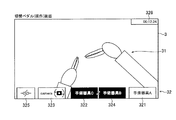
図7に示すように、制御装置6は、右手用の操作ハンドル1aによって操作される手術器具201aに関する情報を示す第1エリア321と、左手用の操作ハンドル1bによって操作される手術器具201bに関する情報を示す第2エリア322と、内視鏡201dに関する情報を示す第3エリア323と、を右から左に順に並べて配置したグラフィカルユーザインタフェース32を内視鏡201dによって撮像された画像31上に重ねて表示装置3に表示するように構成されている。
As shown in FIG. 7, the control device 6 has information on the
また、制御装置6は、右手用の操作ハンドル1aによって操作される手術器具201aに関する情報を示す第1エリア321と、左手用の操作ハンドル1bによって操作される手術器具201bに関する情報を示す第2エリア322と、内視鏡201dに関する情報を示す第3エリア323とを、操作ペダル部2の右側用フットペダル(凝固ペダル21bおよび切断ペダル22b)、左側用フットペダル(凝固ペダル21aおよび切断ペダル22a)およびカメラペダル24の並び順と同じ順に並べて配置したグラフィカルユーザインタフェース32を内視鏡201dによって撮像された画像31上に重ねて表示装置3に表示するように構成されている。
Further, the control device 6 has a
表示装置3に表示されるグラフィカルユーザインタフェース32は、図7に示すように、第1エリア321と、第2エリア322と、第3エリア323と、第4エリア324と、第5エリア325とを含む。また、グラフィカルユーザインタフェース32は、ステータスエリア326を含む。また、グラフィカルユーザインタフェース32は、ポップアップエリア327a(図9参照)と、ポップアップエリア327b(図13参照)と、ポップアップエリア327c(図15参照)と、ポップアップエリア327d(図17参照)とを含む。また、グラフィカルユーザインタフェース32は、内視鏡201dの水準器328(図14参照)が表示されるセンターエリアを含む。また、グラフィカルユーザインタフェース32は、エラー通知エリア329a(図20参照)と、エラー通知エリア329b(図21参照)とを含む。
As shown in FIG. 7, the
グラフィカルユーザインタフェース32の第1エリア321と、第2エリア322と、第3エリア323と、第4エリア324と、第5エリア325とは、表示装置3の下方の端部近傍領域に並んで配置される。なお、第1エリア321と、第2エリア322と、第3エリア323と、第4エリア324と、第5エリア325とが、表示装置3の上方の端部近傍領域に並んで配置されていてもよい。これにより、表示装置3の上方または下方に、手術器具201a、手術器具201bおよび内視鏡201dに関する情報が表示されるので、表示装置3の中央に表示する場合と異なり、第1エリア321、第2エリア322、第3エリア323、第4エリア324および第5エリア325によって、内視鏡201dにより撮像した画像31が見えにくくなるのを抑制することができる。
The
グラフィカルユーザインタフェース32のポップアップエリア327aおよび327bは、表示装置3の左右方向における左側で、上下方向における中央付近に配置される。グラフィカルユーザインタフェース32のポップアップエリア327cおよび327dは、表示装置3の左右方向における右側で、上下方向における中央付近に配置される。グラフィカルユーザインタフェース32のステータスエリア326と、エラー通知エリア329aは、表示装置3の上方の端部近傍領域に配置される。エラー通知エリア329bは、グラフィカルユーザインタフェース32の第2エリア322の上方に配置される。
The pop-up
第1エリア321には、右手用の操作ハンドル1aにより操作されている手術器具201aの種類が表示される。第2エリア322には、左手用の操作ハンドル1bにより操作されている手術器具201bの種類が表示される。第3エリア323には、内視鏡201dを示す情報が表示される。これにより、操作ハンドル1aにより操作されている手術器具201a、および、操作ハンドル1bにより操作されている手術器具201bの種類を操作者Oが容易に把握することができる。また、内視鏡201dを示す情報に基づいて内視鏡201dの状態を操作者Oが容易に把握することができる。
In the
第4エリア324は、第1エリア321と第2エリア322との間に配置されている。第4エリア324には、交換用の手術器具201cに関する情報が表示される。具体的には、第4エリア324には、交換用の手術器具201cの種類が表示される。これにより、手術器具201aまたは手術器具201bと交換された操作ハンドル1aまたは操作ハンドル1bにより操作される交換用の手術器具201cの情報を表示装置3の画面上で操作者Oが容易に把握することができる。また、第4エリア324は、第1エリア321および第2エリア322よりも薄目の色合いで情報が表示される。つまり、第4エリア324の情報は、第1エリア321および第2エリア322の情報よりも目立たないように表示される。
The
第5エリア325は、第2エリア322よりも左側に配置されている。第5エリア325には、クラッチ機能に関する情報が表示される。具体的には、第5エリア325には、クラッチペダル23の操作状態が表示される。これにより、マニピュレータ201と、操作ハンドル1との操作接続を一時切断して手術器具201aおよび201bの動作を停止させる場合に用いられるクラッチペダル23のクラッチ機能の状態を表示装置3の画面上で操作者Oが容易に把握することができる。
The
ステータスエリア326には、手術システム400のステータスが表示される。たとえば、ステータスエリア326には、手術時間が表示される。また、ステータスエリア326には、表示装置3の輝度調整情報やコントラスト調整情報が表示される。
The status of the
ポップアップエリア327a〜327dは、第1エリア321、第2エリア322および第3エリア323とは異なる位置に配置される。また、ポップアップエリア327a〜327dには、対応するフットペダル20の操作準備位置に操作者Oの足が配置されたことを、複数のセンサ26のうちの少なくとも1つのセンサ26により検出したことに基づいて、情報が表示される。これにより、操作者Oがフットペダル20の操作準備位置に足を配置した段階で、対応するエリアに加えて、別の位置にもフットペダル20に関する情報が表示されるので、操作するフットペダル20が操作準備位置に配置されていることを操作者Oが容易に認識することができる。
The pop-up
図9に示すように、ポップアップエリア327aには、クラッチペダル23の操作準備位置に操作者Oの足が配置された場合に、クラッチペダル23に関する情報が表示される。ポップアップエリア327aには、所定の時間(たとえば、3秒間)情報が表示される。つまり、ポップアップエリア327aの情報の表示は、クラッチペダル23の操作準備位置から操作者Oの足が移動するか、クラッチペダル23が操作されるか、または、所定の時間が経過すると消える。
As shown in FIG. 9, in the pop-up
図13に示すように、ポップアップエリア327bには、カメラペダル24の操作準備位置に操作者Oの足が配置された場合に、カメラペダル24に関する情報が表示される。ポップアップエリア327bには、所定の時間(たとえば、3秒間)情報が表示される。つまり、ポップアップエリア327bの情報の表示は、カメラペダル24の操作準備位置から操作者Oの足が移動するか、カメラペダル24が操作されるか、または、所定の時間が経過すると消える。
As shown in FIG. 13, in the pop-up
図15に示すように、ポップアップエリア327cには、切断ペダル22aまたは22bの操作準備位置に操作者Oの足が配置された場合に、切断ペダル22に関する情報が表示される。ポップアップエリア327cには、所定の時間(たとえば、3秒間)情報が表示される。つまり、ポップアップエリア327cの情報の表示は、切断ペダル22aまたは22bの操作準備位置から操作者Oの足が移動するか、切断ペダル22aまたは22bが操作されるか、または、所定の時間が経過すると消える。
As shown in FIG. 15, in the pop-up
図17に示すように、ポップアップエリア327dには、凝固ペダル21aまたは21bの操作準備位置に操作者Oの足が配置された場合に、凝固ペダル21に関する情報が表示される。ポップアップエリア327dには、所定の時間(たとえば、3秒間)情報が表示される。つまり、ポップアップエリア327dの情報の表示は、凝固ペダル21aまたは21bの操作準備位置から操作者Oの足が移動するか、凝固ペダル21aまたは21bが操作されるか、または、所定の時間が経過すると消える。
As shown in FIG. 17, in the pop-up
図14に示すように、内視鏡201dの水準器328は、カメラペダル24が操作された場合に、表示装置3に表示される。これにより、表示された水準器328を見ながら操作することにより操作者Oは内視鏡201dの姿勢を容易に変更させることができる。
As shown in FIG. 14, the
ここで、本実施形態では、制御装置6は、右側用フットペダル(凝固ペダル21bおよび切断ペダル22b)、左側用フットペダル(凝固ペダル21aおよび切断ペダル22a)およびカメラペダル24のうちの少なくとも1つのフットペダル20の操作準備位置に操作者Oの足が配置されたことを、複数のセンサ26のうちの少なくとも1つのセンサ26により検出したことに基づいて、第1エリア321、第2エリア322および第3エリア323のうちの対応するエリアの表示形態を変更するように構成されている。これにより、フットペダル20の操作準備位置に操作者Oの足が配置された場合に、フットペダル20に対応するグラフィカルユーザインタフェース32のエリアの表示形態が変更されて表示装置3に表示されるので、操作者Oが実際にどのフットペダル20に足を位置させているのかを目視で確認する必要がない。その結果、操作者Oが表示装置3から目を離すことなく操作するフットペダル20を確認することができる。
Here, in the present embodiment, the control device 6 is at least one of a right foot pedal (
エリアの表示形態の変更は、表示色の変更、反転表示、エリアの枠線の表示変更、表示エリアの拡大/縮小のうち少なくとも1つを含む。これにより、操作者Oがフットペダル20の操作準備位置に足を配置した場合に、対応するエリアにおいて、表示色の変更、反転表示、または、エリアの枠線の表示変更が行われるので、操作者Oが表示形態の変更を容易に認識して、操作するフットペダル20を容易に確認することができる。
The change of the display form of the area includes at least one of the change of the display color, the reverse display, the change of the display of the border of the area, and the enlargement / reduction of the display area. As a result, when the operator O places his / her foot in the operation preparation position of the
また、制御装置6は、凝固ペダル21aまたは21bの操作準備位置に操作者Oの足が配置されたことを、複数のセンサ26のうちの少なくとも1つのセンサ26により検出したことに基づいて、第1エリア321および第2エリア322のうちの対応するエリアに第1の色により情報を表示するように構成されている。また、制御装置6は、切断ペダル22aまたは22bの操作準備位置に操作者Oの足が配置されたことを、複数のセンサ26のうちの少なくとも1つのセンサ26により検出したことに基づいて、第1エリア321および第2エリア322のうちの対応するエリアに第2の色により情報を表示するように構成されている。これにより、凝固ペダル21aまたは21bを操作する場合と、切断ペダル22aまたは22bを操作する場合とで、対応するエリアに互いに異なる色で情報を表示することができるので、表示装置3から目を離すことなく操作するフットペダル20が凝固ペダル21aまたは21bか切断ペダル22aまたは22bかを操作者Oが容易に確認することができる。
Further, the control device 6 detects that the foot of the operator O is arranged at the operation preparation position of the
制御装置6は、フットペダル20が操作された場合に、対応するエリアに、フットペダル20の操作準備位置に操作者Oの足が配置された表示態様と異なる表示態様により情報を表示するように構成されている。これにより、フットペダル20の操作準備位置に操作者Oの足が配置された場合と、フットペダル20が操作された場合とで、互いに異なる表示がされるので、フットペダル20が操作準備状態であるかまたは操作状態であるかを操作者Oが容易に把握することができる。
When the
グラフィカルユーザインタフェース32の各エリアには、各フットペダル20の操作の状況が表示されるように構成されている。これにより、各フットペダル20の操作状況を操作者Oが容易に把握することができる。
Each area of the
具体的には、第1エリア321には、手術器具201aに関する情報に加えて右側用フットペダル(凝固ペダル21bおよび切断ペダル22b)に関する情報が表示される。たとえば、凝固ペダル21bまたは切断ペダル22bの操作準備位置に操作者Oの足が配置された場合に、対応するフットペダル20(凝固ペダル21bまたは切断ペダル22b)の色を用いて、第1エリア321の枠線を表示する。これにより、第1エリア321の表示により右側用フットペダル(凝固ペダル21bおよび切断ペダル22b)の操作による手術器具201aの機能の実行状態を操作者Oが容易に把握することができる。また、凝固ペダル21bまたは切断ペダル22bが操作された場合に、第1エリア321に凝固ペダル21bまたは切断ペダル22bに関する情報が操作準備位置に操作者Oの足が配置された場合と区別して表示される。たとえば、凝固ペダル21bまたは切断ペダル22bが操作された場合に、対応するフットペダル20(凝固ペダル21bまたは切断ペダル22b)の色を、第1エリア321の全体に表示する。これにより、第1エリア321の表示により凝固ペダル21bまたは切断ペダル22bの操作状態を操作者Oが容易に把握することができる。
Specifically, in the
つまり、凝固ペダル21bが操作された場合に、第1エリア321に凝固ペダル21bに関する情報が表示される。また、切断ペダル22bが操作された場合に、第1エリア321に切断ペダル22bに関する情報が表示される。これにより、第1エリア321の表示により右手用の操作ハンドル1aにより操作される手術器具201aによる凝固機能および切断機能の実行状態を操作者Oが容易に把握することができる。
That is, when the
また、第2エリア322には、手術器具201bに関する情報に加えて左側用フットペダル(凝固ペダル21aおよび切断ペダル22a)に関する情報が表示される。たとえば、凝固ペダル21aまたは切断ペダル22aの操作準備位置に操作者Oの足が配置された場合に、対応するフットペダル20(凝固ペダル21aまたは切断ペダル22a)の色を用いて、第2エリア322の枠線を表示する。これにより、第2エリア322の表示により左側用フットペダル(凝固ペダル21aおよび切断ペダル22a)の操作による手術器具201bの機能の実行状態を操作者Oが容易に把握することができる。また、凝固ペダル21aまたは切断ペダル22aが操作された場合に、第2エリア322に凝固ペダル21aまたは切断ペダル22aに関する情報が操作準備位置に操作者Oの足が配置された場合と区別して表示される。たとえば、凝固ペダル21aまたは切断ペダル22aが操作された場合に、対応するフットペダル20(凝固ペダル21aまたは切断ペダル22a)の色を、第2エリア322の全体に表示する。これにより、第2エリア322の表示により凝固ペダル21aまたは切断ペダル22aの操作状態を操作者Oが容易に把握することができる。
Further, in the
つまり、凝固ペダル21aが操作された場合に、第2エリア322に凝固ペダル21aに関する情報が表示される。また、切断ペダル22aが操作された場合に、第2エリア322に切断ペダル22aに関する情報が表示される。これにより、第2エリア322の表示により左手用の操作ハンドル1bにより操作される手術器具201bによる凝固機能および切断機能の実行状態を操作者Oが容易に把握することができる。
That is, when the
また、第3エリア323には、内視鏡201dに関する情報に加えてカメラペダル24に関する情報が表示される。たとえば、カメラペダル24の操作準備位置に操作者Oの足が配置された場合に、第3エリア323の枠線を強調表示する。これにより、第3エリア323の表示によりカメラペダル24の操作による内視鏡201dの機能の実行状態を操作者Oが容易に把握することができる。また、カメラペダル24が操作された場合に、第3エリア323にカメラペダル24に関する情報が操作準備位置に操作者Oの足が配置された場合と区別して表示される。たとえば、カメラペダル24が操作された場合に、第3エリア323の背景色と文字色とを反転表示させる。これにより、第3エリア323の表示によりカメラペダル24の操作状態を操作者Oが容易に把握することができる。
Further, in the
次に、図8〜図21を参照して、フットペダル20に対する操作者Oの操作に基づいて表示されるグラフィカルユーザインタフェース32の例について説明する。
Next, an example of the
図8に示すように、切替ペダル25が操作されると、左手用の操作ハンドル1bにより操作される手術器具が手術器具201bから手術器具201cに切り替えられる。この場合、第2エリア322および第4エリア324の背景色と文字色とが反転表示される。これにより、操作者Oは、手術器具が切り替えられたことを容易に認識することが可能である。
As shown in FIG. 8, when the switching
図9に示すように、クラッチペダル23の操作準備位置に操作者Oの足が配置された場合に、第5エリア325の枠線が強調して表示される。また、ポップアップエリア327aにクラッチペダル23に関する情報がポップアップ表示される。なお、クラッチペダル23の操作準備位置に操作者Oの足が配置されていることが継続している場合でも、ポップアップエリア327aの表示は、所定時間経過後、消える。その場合、第5エリア325の枠線の強調表示は、継続される。
As shown in FIG. 9, when the foot of the operator O is arranged at the operation preparation position of the
図10に示すように、クラッチペダル23が操作されると、操作ハンドル1と、マニピュレータ201との操作接続が一時切断される。この場合、クラッチペダル23の情報を表示する第5エリア325の背景色と文字色とが反転表示される。また、操作接続が一時切断された手術器具201aの情報を表示する第1エリア321の背景色と文字色とが反転表示される。また、操作接続が一時切断された手術器具201bの情報を表示する第2エリア322の背景色と文字色とが反転表示される。操作後、操作者Oの足が操作準備位置に戻ると、図9に示すように、第5エリア325の枠線が強調して表示される。
As shown in FIG. 10, when the
図11に示すように、右手用の操作ハンドル1aのクラッチスイッチ11が操作されると、操作ハンドル1aと、手術器具201aが設けられたマニピュレータ201との操作接続が一時切断される。この場合、操作接続が一時切断された手術器具201aの情報を表示する第1エリア321の背景色と文字色とが反転表示される。
As shown in FIG. 11, when the
図12に示すように、左手用の操作ハンドル1bのクラッチスイッチ11が操作されると、操作ハンドル1bと、手術器具201bが設けられたマニピュレータ201との操作接続が一時切断される。この場合、操作接続が一時切断された手術器具201bの情報を表示する第2エリア322の背景色と文字色とが反転表示される。
As shown in FIG. 12, when the
図13に示すように、カメラペダル24の操作準備位置に操作者Oの足が配置された場合に、第3エリア323の枠線が強調して表示される。また、ポップアップエリア327bにカメラペダル24に関する情報がポップアップ表示される。なお、カメラペダル24の操作準備位置に操作者Oの足が配置されていることが継続している場合でも、ポップアップエリア327bの表示は、所定時間経過後、消える。その場合、第3エリア323の枠線の強調表示は、継続される。
As shown in FIG. 13, when the foot of the operator O is arranged at the operation preparation position of the
図14に示すように、カメラペダル24が操作されると、操作ハンドル1aおよび1bにより、内視鏡201dの位置および姿勢を操作することが可能になる。この場合、カメラペダル24の情報を表示する第3エリア323の背景色と文字色とが反転表示される。また、センターエリアに内視鏡201dの水準器328が表示される。
As shown in FIG. 14, when the
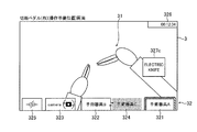
図15に示すように、右手により操作されている手術器具201aに対応する切断ペダル22bの操作準備位置に操作者Oの足が配置された場合に、第1エリア321の枠線が強調して表示される。具体的には、切断ペダル22bが有する第2の色により、枠線の左から半分以上が強調して表示される。残りの枠線は、凝固ペダル21bが有する第1の色により強調表示される。これにより、枠線を第2の色のみで強調して表示する場合と比べて、操作者Oが切断ペダル22bと凝固ペダル21bとのうち、切断ペダル22bの操作準備位置に足を配置していることを効果的に認識させることができる。また、ポップアップエリア327cに切断ペダル22bに関する情報がポップアップ表示される。なお、切断ペダル22bの操作準備位置に操作者Oの足が配置されていることが継続している場合でも、ポップアップエリア327cの表示は、所定時間経過後、消える。その場合、第1エリア321の枠線の強調表示は、継続される。
As shown in FIG. 15, when the foot of the operator O is placed at the operation preparation position of the cutting
なお、左手により操作されている手術器具201bに対応する切断ペダル22aの操作準備位置に操作者Oの足が配置された場合も、同様にして、第2エリア322の枠線が強調して表示される。
When the foot of the operator O is placed at the operation preparation position of the cutting pedal 22a corresponding to the
図16に示すように、切断ペダル22bが操作されると、手術器具201aに所定の電圧が印加されて、手術部位を切断することが可能になる。この場合、切断ペダル22bの情報を表示する第1エリア321の背景が、切断ペダル22bが有する第2の色で表示される。
As shown in FIG. 16, when the cutting
なお、切断ペダル22aが操作された場合も、同様にして、切断ペダル22aの情報を表示する第2エリア322の背景が、切断ペダル22aが有する第2の色で表示される。
When the
図17に示すように、右手により操作されている手術器具201aに対応する凝固ペダル21bの操作準備位置に操作者Oの足が配置された場合に、第1エリア321の枠線が強調して表示される。具体的には、凝固ペダル21bが有する第1の色により、枠線の右から半分以上が強調して表示される。残りの枠線は、切断ペダル22bが有する第2の色により強調表示される。これにより、枠線を第1の色のみで強調して表示する場合と比べて、操作者Oが切断ペダル22bと凝固ペダル21bとのうち、凝固ペダル21bの操作準備位置に足を配置していることを効果的に認識させることができる。また、ポップアップエリア327dに凝固ペダル21bに関する情報がポップアップ表示される。なお、凝固ペダル21bの操作準備位置に操作者Oの足が配置されていることが継続している場合でも、ポップアップエリア327dの表示は、所定時間経過後、消える。その場合、第1エリア321の枠線の強調表示は、継続される。
As shown in FIG. 17, when the foot of the operator O is placed at the operation preparation position of the
なお、左手により操作されている手術器具201bに対応する凝固ペダル21aの操作準備位置に操作者Oの足が配置された場合も、同様にして、第2エリア322の枠線が強調して表示される。
When the foot of the operator O is placed at the operation preparation position of the
図18に示すように、凝固ペダル21bが操作されると、手術器具201aに所定の電圧が印加されて、手術部位を凝固することが可能になる。この場合、凝固ペダル21bの情報を表示する第1エリア321の背景が、凝固ペダル21bが有する第1の色で表示される。
As shown in FIG. 18, when the
なお、凝固ペダル21aが操作された場合も、同様にして、凝固ペダル21aの情報を表示する第2エリア322の背景が、凝固ペダル21aが有する第1の色で表示される。
When the
図19に示すように、左手により操作されている手術器具201bに対応する切断ペダル22aの操作準備位置に操作者Oの足が配置され、かつ、クラッチペダル23の操作準備位置に操作者Oの足が配置された場合に、第2エリア322の枠線が強調して表示される。具体的には、切断ペダル22aが有する第2の色により、枠線の左から半分以上が強調して表示される。残りの枠線は、凝固ペダル21aが有する第1の色により強調表示される。また、ポップアップエリア327cに切断ペダル22aに関する情報がポップアップ表示される。また、第5エリア325の枠線が強調して表示される。また、ポップアップエリア327aにクラッチペダル23に関する情報がポップアップ表示される。
As shown in FIG. 19, the foot of the operator O is arranged at the operation preparation position of the cutting pedal 22a corresponding to the
図20に示すように、機能が制限される場合、エラー通知エリア329aに機能が制限される通知が表示される。また、切断や凝固の機能が設定されていない手術器具を用いている場合に、切断ペダル22や凝固ペダル21が操作された場合に、手術器具に対応するエリアの上側に機能しない操作が行われたことがポップアップ表示される。この場合、切断ペダル22や凝固ペダル21を操作したとしても、手術器具に電圧は印加されない。
As shown in FIG. 20, when the function is restricted, a notification whose function is restricted is displayed in the
図21に示すように、エラーが通知される場合、エラー通知エリア329bにエラーが通知される。
As shown in FIG. 21, when an error is notified, the error is notified to the
(変形例)
なお、今回開示された実施形態は、すべての点で例示であって制限的なものではないと考えられるべきである。本発明の範囲は、上記した実施形態の説明ではなく特許請求の範囲によって示され、さらに特許請求の範囲と均等の意味および範囲内でのすべての変更(変形例)が含まれる。
(Modification example)
It should be noted that the embodiments disclosed this time are exemplary in all respects and are not considered to be restrictive. The scope of the present invention is shown by the scope of claims rather than the description of the above-described embodiment, and further includes all modifications (modifications) within the meaning and scope equivalent to the scope of claims.
たとえば、上記実施形態では、操作ペダル部のフットペダルが、凝固ペダルと、切断ペダルとを含む構成の例を示したが、本発明はこれに限られない。本発明では、操作ペダル部のフットペダルが、凝固ペダルおよび切断ペダル以外の医療器具に関する機能を実行するためのフットペダルを含んでいてもよい。 For example, in the above embodiment, the foot pedal of the operation pedal portion has shown an example of a configuration including a coagulation pedal and a disconnection pedal, but the present invention is not limited to this. In the present invention, the foot pedal of the operation pedal section may include a foot pedal for performing functions related to medical devices other than the coagulation pedal and the disconnection pedal.
また、上記実施形態では、センサが遮断型のセンサの例を示したが、本発明はこれに限られない。本発明では、センサは、透過型であってもよいし、反射型であってもよい。また、光を用いずに、足の存在を検知してもよい。たとえば、音波を用いて検知してもよいし、コイルを用いて検知してもよい。また、センサは、非接触式に限らず、接触により足の存在を検知してもよい。たとえば、センサは、機械式のスイッチでもよい。 Further, in the above embodiment, an example of a sensor in which the sensor is a cutoff type is shown, but the present invention is not limited to this. In the present invention, the sensor may be a transmissive type or a reflective type. In addition, the presence of the foot may be detected without using light. For example, it may be detected by using a sound wave or by using a coil. Further, the sensor is not limited to the non-contact type, and the presence of the foot may be detected by contact. For example, the sensor may be a mechanical switch.
1a:操作ハンドル(第1操作ハンドル)、1b:操作ハンドル(第2操作ハンドル)、2:操作ペダル部、3:表示装置、6:制御装置、20:フットペダル、21a:凝固ペダル(第2フットペダル、第2凝固ペダル)、21b:凝固ペダル(第1フットペダル、第1凝固ペダル)、22a:切断ペダル(第2フットペダル、第2切断ペダル)、22b:切断ペダル(第1フットペダル、第1切断ペダル)、23:クラッチペダル(第5フットペダル)、24:カメラペダル(第3フットペダル)、25:切替ペダル(第4フットペダル)、26:センサ、32:グラフィカルユーザインタフェース、100:遠隔操作装置、201:マニピュレータ、201a:手術器具(第1手術器具)、201b:手術器具(第2手術器具)、201c:手術器具(交換用手術器具)、201d:内視鏡、321:第1エリア、322:第2エリア、323:第3エリア、324:第4エリア、325:第5エリア、328:水準器、400:手術システム 1a: Operation handle (first operation handle), 1b: Operation handle (second operation handle), 2: Operation pedal unit, 3: Display device, 6: Control device, 20: Foot pedal, 21a: Coagulation pedal (second operation pedal) Foot pedal, 2nd coagulation pedal), 21b: Coagulation pedal (1st foot pedal, 1st coagulation pedal), 22a: Cutting pedal (2nd foot pedal, 2nd cutting pedal), 22b: Cutting pedal (1st foot pedal) , 1st disconnect pedal), 23: Clutch pedal (5th foot pedal), 24: Camera pedal (3rd foot pedal), 25: Switching pedal (4th foot pedal), 26: Sensor, 32: Graphical user interface, 100: Remote control device, 201: Manipulator, 201a: Surgical instrument (first surgical instrument), 201b: Surgical instrument (second surgical instrument), 201c: Surgical instrument (replacement surgical instrument), 201d: Endoscope, 321 : 1st area, 322: 2nd area, 323: 3rd area, 324: 4th area, 325: 5th area, 328: leveling device, 400: surgical system
Claims (12)
前記内視鏡によって撮像された画像を表示するための表示装置と、前記第1手術器具を操作するための第1操作ハンドルと、前記第2手術器具を操作するための第2操作ハンドルと、複数のフットペダルを有する操作ペダル部と、を含む遠隔操作装置と、
少なくとも前記表示装置を制御するように構成された制御装置と、を備え、
前記操作ペダル部は、それぞれの前記フットペダル上の操作準備位置に操作者の足が配置されたことを検出するための複数のセンサを含み、
複数の前記フットペダルは、前記第1手術器具に関する機能を実行させるための第1フットペダルと、前記第2手術器具に関する機能を実行させるための第2フットペダルと、前記内視鏡に関する機能を実行させるための第3フットペダルと、を有しており、
前記制御装置は、前記第1手術器具に関する情報を示す第1エリアと、前記第2手術器具に関する情報を示す第2エリアと、前記内視鏡に関する情報を示す第3エリアと、を配置したグラフィカルユーザインタフェースを前記内視鏡によって撮像された画像上に重ねて前記表示装置に表示するように構成されており、
前記制御装置は、前記第1フットペダル、前記第2フットペダルおよび前記第3フットペダルのうちの少なくとも1つの前記フットペダルの操作準備位置に操作者の足が配置されたことを、前記複数のセンサのうちの少なくとも1つのセンサにより検出したことに基づいて、前記第1エリア、前記第2エリアおよび前記第3エリアのうちの対応するエリアの一部の範囲を強調表示するとともに、前記第1エリア、前記第2エリアおよび前記第3エリアとは異なる位置に、操作準備位置に操作者の足が配置された前記フットペダルに関するペダル情報をポップアップ表示し、前記第1フットペダル、前記第2フットペダルまたは前記第3フットペダルが操作された場合に、前記第1エリア、前記第2エリアおよび前記第3エリアのうちの対応するエリアに、前記フットペダルの操作準備位置に操作者の足が配置された場合よりも大きい範囲を強調表示するように構成されている、手術システム。 An endoscope that captures images of the surgical site, multiple manipulators to support each of the first and second surgical instruments, and
A display device for displaying an image captured by the endoscope, a first operation handle for operating the first surgical instrument, and a second operation handle for operating the second surgical instrument. A remote control device including an operation pedal unit having a plurality of foot pedals, and
A control device configured to control at least the display device.
The operation pedal unit includes a plurality of sensors for detecting that the operator's foot is arranged at the operation preparation position on each of the foot pedals.
The plurality of foot pedals include a first foot pedal for executing a function related to the first surgical instrument, a second foot pedal for executing a function related to the second surgical instrument, and a function related to the endoscope. It has a third foot pedal to run,
The control device graphically arranges a first area showing information about the first surgical instrument, a second area showing information about the second surgical instrument, and a third area showing information about the endoscope. The user interface is configured to be superimposed on the image captured by the endoscope and displayed on the display device.
The control device has the plurality of said that the operator's foot is arranged at the operation preparation position of at least one of the first foot pedal, the second foot pedal, and the third foot pedal. Based on the detection by at least one of the sensors, the first area, the second area, and a part of the corresponding area of the third area are highlighted and the first area is highlighted. The pedal information regarding the foot pedal in which the operator's foot is arranged at the operation preparation position is displayed in a pop-up at a position different from the area, the second area, and the third area, and the first foot pedal and the second foot are displayed. When the pedal or the third foot pedal is operated, the operator's foot is arranged at the operation preparation position of the foot pedal in the corresponding areas of the first area, the second area, and the third area. A surgical system that is configured to highlight a larger area than if it had been.
前記第2エリアには、前記第2手術器具の種類が表示され、
前記第3エリアには、前記内視鏡を示す文字又は図柄の情報が表示される、請求項1〜3のいずれか1項に記載の手術システム。 In the first area, the type of the first surgical instrument is displayed.
In the second area, the type of the second surgical instrument is displayed.
The surgical system according to any one of claims 1 to 3 , wherein information on characters or symbols indicating the endoscope is displayed in the third area.
前記第2フットペダルは、手術部位を凝固させる操作を行う第2凝固ペダルと、手術部位を切断する操作を行う第2切断ペダルと、を有し、
前記第1凝固ペダルおよび前記第2凝固ペダルは、第1の色を有し、
前記第1切断ペダルおよび前記第2切断ペダルは、前記第1の色とは異なる第2の色を有し、
前記制御装置は、前記第1凝固ペダルまたは前記第2凝固ペダルの操作準備位置に操作者の足が配置されたことを、前記複数のセンサのうちの少なくとも1つのセンサにより検出したことに基づいて、前記第1エリアおよび前記第2エリアのうちの対応するエリアの一部の領域を前記第1の色により強調表示し、前記第1切断ペダルまたは前記第2切断ペダルの操作準備位置に操作者の足が配置されたことを、前記複数のセンサのうちの少なくとも1つのセンサにより検出したことに基づいて、前記第1エリアおよび前記第2エリアのうちの対応するエリアの一部の領域を前記第2の色により強調表示するように構成されている、請求項1〜4のいずれか1項に記載の手術システム。 The first foot pedal includes a first coagulation pedal that performs an operation of coagulating the surgical site and a first cutting pedal that performs an operation of cutting the surgical site.
The second foot pedal has a second coagulation pedal that performs an operation of coagulating the surgical site and a second cutting pedal that performs an operation of cutting the surgical site.
The first coagulation pedal and the second coagulation pedal have a first color and have a first color.
The first disconnect pedal and the second disconnect pedal have a second color different from the first color.
The control device is based on the fact that at least one of the plurality of sensors detects that the operator's foot is arranged at the operation preparation position of the first coagulation pedal or the second coagulation pedal. , The first area and a part of the corresponding area of the second area are highlighted by the first color, and the operator is at the operation preparation position of the first disconnection pedal or the second disconnection pedal. Based on the detection by at least one of the plurality of sensors that the foot is arranged, a part of the corresponding area of the first area and the second area is covered with the above-mentioned area. The surgical system according to any one of claims 1 to 4 , which is configured to be highlighted by a second color.
前記第1切断ペダルが操作された場合に、操作準備位置に操作者の足が配置された場合よりも前記第1エリアの大きい範囲が前記第2の色により強調表示され、
前記第2凝固ペダルが操作された場合に、操作準備位置に操作者の足が配置された場合よりも前記第2エリアの大きい範囲が前記第1の色により強調表示され、
前記第2切断ペダルが操作された場合に、操作準備位置に操作者の足が配置された場合よりも前記第2エリアの大きい範囲が前記第2の色により強調表示される、請求項5に記載の手術システム。 When the first coagulation pedal is operated, a larger area of the first area is highlighted by the first color than when the operator's foot is placed at the operation preparation position.
When the first disconnect pedal is operated, a larger area of the first area is highlighted by the second color than when the operator's foot is placed at the operation preparation position.
When the second coagulation pedal is operated, a larger area of the second area is highlighted by the first color than when the operator's foot is placed at the operation preparation position.
When the second cut pedal is operated, than when the operator's foot is placed on the operation preparation position large range of the second area is highlighted by the second color, to claim 5 Described surgical system.
前記操作ペダル部は、前記第1操作ハンドルにより操作されている前記第1手術器具または前記第2操作ハンドルにより操作されている前記第2手術器具を前記交換用手術器具に変更するための第4フットペダルをさらに含み、
前記グラフィカルユーザインタフェースは、前記第1エリアと前記第2エリアとの間に配置された前記交換用手術器具に関する情報を示す第4エリアを含む、請求項1〜7のいずれか1項に記載の手術システム。 One of the plurality of manipulators supports a replacement surgical instrument.
The operation pedal unit is a fourth for changing the first surgical instrument operated by the first operation handle or the second surgical instrument operated by the second operation handle to the replacement surgical instrument. Including more foot pedals,
The graphic user interface according to any one of claims 1 to 7 , wherein the graphical user interface includes a fourth area showing information about the replacement surgical instrument disposed between the first area and the second area. Surgical system.
前記グラフィカルユーザインタフェースは、前記クラッチ機能に関する情報を示す第5エリアを含む、請求項1〜8のいずれか1項に記載の手術システム。 The operation pedal unit further includes a fifth foot pedal for executing the clutch function.
The surgical system according to any one of claims 1 to 8 , wherein the graphical user interface includes a fifth area showing information about the clutch function.
前記手術システムは、内視鏡、第1手術器具および第2手術器具を各々支持するための複数のマニピュレータと、前記内視鏡によって撮像された画像を表示するための表示装置、前記第1手術器具を操作するための第1操作ハンドル、前記第2手術器具を操作するための第2操作ハンドルおよび複数のフットペダルを有する操作ペダル部を含む遠隔操作装置と、少なくとも前記表示装置を制御するように構成された制御装置と、を備え、
前記操作ペダル部は、それぞれの前記フットペダル上の操作準備位置に操作者の足が配置されたことを検出するための複数のセンサを含み、
複数の前記フットペダルは、前記第1手術器具に関する機能を実行させるための第1フットペダルと、前記第2手術器具に関する機能を実行させるための第2フットペダルと、前記内視鏡に関する機能を実行させるための第3フットペダルと、を有しており、
前記第1手術器具に関する情報を示す第1エリアと、前記第2手術器具に関する情報を示す第2エリアと、前記内視鏡に関する情報を示す第3エリアと、を配置したグラフィカルユーザインタフェースを前記内視鏡によって撮像された画像上に重ねて前記表示装置に表示する工程と、
前記第1フットペダル、前記第2フットペダルおよび前記第3フットペダルのうちの少なくとも1つの前記フットペダルの操作準備位置に操作者の足が配置されたことを、前記複数のセンサのうちの少なくとも1つのセンサにより検出したことに基づいて、前記第1エリア、前記第2エリアおよび前記第3エリアのうちの対応するエリアの一部の範囲を強調表示するとともに、前記第1エリア、前記第2エリアおよび前記第3エリアとは異なる位置に、操作準備位置に操作者の足が配置された前記フットペダルに関するペダル情報をポップアップ表示する操作準備表示工程と、
前記第1フットペダル、前記第2フットペダルまたは前記第3フットペダルが操作された場合に、前記第1エリア、前記第2エリアおよび前記第3エリアのうちの対応するエリアに、前記フットペダルの操作準備位置に操作者の足が配置された場合よりも大きい範囲を強調表示するペダル操作表示工程と、を備える、表示方法。 A method of displaying information in a surgical system
The surgical system includes a plurality of manipulators for supporting an endoscope, a first surgical instrument and a second surgical instrument, a display device for displaying an image captured by the endoscope, and the first surgery. To control at least the display device and a remote control device including a first operation handle for operating the instrument, a second operation handle for operating the second surgical instrument, and an operation pedal unit having a plurality of foot pedals. With a control device configured in,
The operation pedal unit includes a plurality of sensors for detecting that the operator's foot is arranged at the operation preparation position on each of the foot pedals.
The plurality of foot pedals include a first foot pedal for executing a function related to the first surgical instrument, a second foot pedal for executing a function related to the second surgical instrument, and a function related to the endoscope. It has a third foot pedal to run,
A graphical user interface in which a first area showing information about the first surgical instrument, a second area showing information about the second surgical instrument, and a third area showing information about the endoscope are arranged is included in the above. The process of superimposing on the image captured by the endoscope and displaying it on the display device, and
At least one of the plurality of sensors indicates that the operator's foot is arranged at the operation preparation position of at least one of the first foot pedal, the second foot pedal, and the third foot pedal. Based on the detection by one sensor, the range of a part of the corresponding area among the first area, the second area, and the third area is highlighted, and the first area and the second area are highlighted. An operation preparation display step for popping up pedal information regarding the foot pedal in which the operator's foot is arranged at an operation preparation position at a position different from the area and the third area.
When the first foot pedal, the second foot pedal, or the third foot pedal is operated, the foot pedal is placed in the corresponding area of the first area, the second area, and the third area. A display method comprising a pedal operation display step that highlights a larger range than when the operator's foot is placed at the operation preparation position.
Priority Applications (4)
| Application Number | Priority Date | Filing Date | Title |
|---|---|---|---|
| JP2018179277A JP6898285B2 (en) | 2018-09-25 | 2018-09-25 | Surgical system and display method |
| US16/579,763 US20200093552A1 (en) | 2018-09-25 | 2019-09-23 | Surgical system and method of displaying information in the same |
| EP19199588.5A EP3628207B1 (en) | 2018-09-25 | 2019-09-25 | Surgical system and method of displaying information in the same |
| JP2021097237A JP7155344B2 (en) | 2018-09-25 | 2021-06-10 | Surgical system and display method |
Applications Claiming Priority (1)
| Application Number | Priority Date | Filing Date | Title |
|---|---|---|---|
| JP2018179277A JP6898285B2 (en) | 2018-09-25 | 2018-09-25 | Surgical system and display method |
Related Child Applications (1)
| Application Number | Title | Priority Date | Filing Date |
|---|---|---|---|
| JP2021097237A Division JP7155344B2 (en) | 2018-09-25 | 2021-06-10 | Surgical system and display method |
Publications (2)
| Publication Number | Publication Date |
|---|---|
| JP2020048708A JP2020048708A (en) | 2020-04-02 |
| JP6898285B2 true JP6898285B2 (en) | 2021-07-07 |
Family
ID=68069564
Family Applications (2)
| Application Number | Title | Priority Date | Filing Date |
|---|---|---|---|
| JP2018179277A Active JP6898285B2 (en) | 2018-09-25 | 2018-09-25 | Surgical system and display method |
| JP2021097237A Active JP7155344B2 (en) | 2018-09-25 | 2021-06-10 | Surgical system and display method |
Family Applications After (1)
| Application Number | Title | Priority Date | Filing Date |
|---|---|---|---|
| JP2021097237A Active JP7155344B2 (en) | 2018-09-25 | 2021-06-10 | Surgical system and display method |
Country Status (3)
| Country | Link |
|---|---|
| US (1) | US20200093552A1 (en) |
| EP (1) | EP3628207B1 (en) |
| JP (2) | JP6898285B2 (en) |
Families Citing this family (14)
| Publication number | Priority date | Publication date | Assignee | Title |
|---|---|---|---|---|
| CN112702966B (en) * | 2018-09-17 | 2024-03-15 | 柯惠Lp公司 | Foot pedal assignment for robotic surgical system |
| US11748924B2 (en) | 2020-10-02 | 2023-09-05 | Cilag Gmbh International | Tiered system display control based on capacity and user operation |
| US11883022B2 (en) | 2020-10-02 | 2024-01-30 | Cilag Gmbh International | Shared situational awareness of the device actuator activity to prioritize certain aspects of displayed information |
| US11877897B2 (en) | 2020-10-02 | 2024-01-23 | Cilag Gmbh International | Situational awareness of instruments location and individualization of users to control displays |
| US11877792B2 (en) | 2020-10-02 | 2024-01-23 | Cilag Gmbh International | Smart energy combo control options |
| US11911030B2 (en) | 2020-10-02 | 2024-02-27 | Cilag Gmbh International | Communication capability of a surgical device with component |
| US11883052B2 (en) | 2020-10-02 | 2024-01-30 | Cilag Gmbh International | End effector updates |
| US11672534B2 (en) | 2020-10-02 | 2023-06-13 | Cilag Gmbh International | Communication capability of a smart stapler |
| US11830602B2 (en) | 2020-10-02 | 2023-11-28 | Cilag Gmbh International | Surgical hub having variable interconnectivity capabilities |
| KR20230113360A (en) * | 2020-11-30 | 2023-07-28 | 인튜어티브 서지컬 오퍼레이션즈 인코포레이티드 | A system for providing composite indicators in a user interface for a robot-assisted system |
| CN112890954B (en) * | 2020-12-30 | 2022-08-09 | 北京和华瑞博医疗科技有限公司 | Mechanical arm motion control method and system and surgical operation system |
| JP2022115264A (en) * | 2021-01-28 | 2022-08-09 | 株式会社メディカロイド | Surgery system and display method |
| JP7350910B2 (en) * | 2022-01-31 | 2023-09-26 | 株式会社メディカロイド | Operation pedal device and remote control device |
| JP2024036816A (en) * | 2022-09-06 | 2024-03-18 | 川崎重工業株式会社 | Control method for surgical support system and operating device |
Family Cites Families (19)
| Publication number | Priority date | Publication date | Assignee | Title |
|---|---|---|---|---|
| DE4207901C3 (en) * | 1992-03-12 | 1999-10-07 | Aesculap Ag & Co Kg | Method and device for displaying a work area in a three-dimensional structure |
| US6120433A (en) * | 1994-09-01 | 2000-09-19 | Olympus Optical Co., Ltd. | Surgical manipulator system |
| JP4129313B2 (en) * | 1998-05-19 | 2008-08-06 | オリンパス株式会社 | Medical system control device |
| JP2002238919A (en) * | 2001-02-20 | 2002-08-27 | Olympus Optical Co Ltd | Control apparatus for medical care system and medical care system |
| US7846150B2 (en) * | 2004-11-01 | 2010-12-07 | Stryker Corporation | Apparatus and method for synchronizing a wireless remote control to a central control unit so as to allow remote control of a medical device over a secure wireless connection |
| JP4916011B2 (en) * | 2007-03-20 | 2012-04-11 | 株式会社日立製作所 | Master / slave manipulator system |
| US8423182B2 (en) * | 2009-03-09 | 2013-04-16 | Intuitive Surgical Operations, Inc. | Adaptable integrated energy control system for electrosurgical tools in robotic surgical systems |
| US8120301B2 (en) * | 2009-03-09 | 2012-02-21 | Intuitive Surgical Operations, Inc. | Ergonomic surgeon control console in robotic surgical systems |
| US8418073B2 (en) | 2009-03-09 | 2013-04-09 | Intuitive Surgical Operations, Inc. | User interfaces for electrosurgical tools in robotic surgical systems |
| IT1401669B1 (en) * | 2010-04-07 | 2013-08-02 | Sofar Spa | ROBOTIC SURGERY SYSTEM WITH PERFECT CONTROL. |
| US8600432B2 (en) * | 2010-07-16 | 2013-12-03 | Ari Krupnik | Methods and apparatus for leveraging a mobile phone or mobile computing device for use in controlling model vehicles |
| JP6021353B2 (en) * | 2011-08-04 | 2016-11-09 | オリンパス株式会社 | Surgery support device |
| KR102188033B1 (en) * | 2012-09-17 | 2020-12-07 | 인튜어티브 서지컬 오퍼레이션즈 인코포레이티드 | Methods and systems for assigning input devices to teleoperated surgical instrument functions |
| US9681982B2 (en) * | 2012-12-17 | 2017-06-20 | Alcon Research, Ltd. | Wearable user interface for use with ocular surgical console |
| WO2014104088A1 (en) * | 2012-12-25 | 2014-07-03 | 川崎重工業株式会社 | Surgical robot |
| WO2016201325A1 (en) * | 2015-06-12 | 2016-12-15 | Intuitive Surgical Operations, Inc. | User interfaces and displays for flux supply units |
| JP6950707B2 (en) * | 2016-11-28 | 2021-10-13 | ソニーグループ株式会社 | Information processing equipment and methods, and programs |
| US20200038125A1 (en) * | 2017-03-15 | 2020-02-06 | Covidien Lp | Robotic surgical systems, instruments, and controls |
| US10992857B2 (en) * | 2017-05-15 | 2021-04-27 | Sony Corporation | Input control device, input control method, and operation system |
-
2018
- 2018-09-25 JP JP2018179277A patent/JP6898285B2/en active Active
-
2019
- 2019-09-23 US US16/579,763 patent/US20200093552A1/en active Pending
- 2019-09-25 EP EP19199588.5A patent/EP3628207B1/en active Active
-
2021
- 2021-06-10 JP JP2021097237A patent/JP7155344B2/en active Active
Also Published As
| Publication number | Publication date |
|---|---|
| EP3628207A1 (en) | 2020-04-01 |
| JP2020048708A (en) | 2020-04-02 |
| US20200093552A1 (en) | 2020-03-26 |
| JP2021151519A (en) | 2021-09-30 |
| EP3628207B1 (en) | 2022-05-18 |
| JP7155344B2 (en) | 2022-10-18 |
Similar Documents
| Publication | Publication Date | Title |
|---|---|---|
| JP6898285B2 (en) | Surgical system and display method | |
| JP6856594B2 (en) | Surgical system and display method | |
| JP7080861B2 (en) | Surgical system | |
| KR102085678B1 (en) | Adaptable integrated energy control system for electrosurgical tools in robotic surgical systems | |
| CN107028662B (en) | Remote operation device and remote operation system | |
| JP6599402B2 (en) | Remote control device | |
| CN110226967A (en) | For remotely operating the structural adjustment system and method for medical system | |
| US20190314005A1 (en) | Remote control apparatus, surgical system, and method of identifying target pedal | |
| JP6902639B2 (en) | Surgical system | |
| JP2020044354A (en) | Remote operation device and remote operation system | |
| JP6778326B2 (en) | Master operation input device and master-slave manipulator | |
| JP7016400B2 (en) | Surgical system and display method | |
| KR20120045734A (en) | Master iput device of surgical robitc system and method of controlling surgical robitc system using the same | |
| JP6745392B2 (en) | Remote control device | |
| JP7128326B2 (en) | surgery system | |
| JP6665263B2 (en) | Remote control device, surgical system and method for specifying pedal to be operated |
Legal Events
| Date | Code | Title | Description |
|---|---|---|---|
| A521 | Request for written amendment filed |
Free format text: JAPANESE INTERMEDIATE CODE: A523 Effective date: 20200205 |
|
| A621 | Written request for application examination |
Free format text: JAPANESE INTERMEDIATE CODE: A621 Effective date: 20200205 |
|
| A977 | Report on retrieval |
Free format text: JAPANESE INTERMEDIATE CODE: A971007 Effective date: 20201209 |
|
| A131 | Notification of reasons for refusal |
Free format text: JAPANESE INTERMEDIATE CODE: A131 Effective date: 20201215 |
|
| A521 | Request for written amendment filed |
Free format text: JAPANESE INTERMEDIATE CODE: A523 Effective date: 20210203 |
|
| A131 | Notification of reasons for refusal |
Free format text: JAPANESE INTERMEDIATE CODE: A131 Effective date: 20210316 |
|
| A521 | Request for written amendment filed |
Free format text: JAPANESE INTERMEDIATE CODE: A523 Effective date: 20210414 |
|
| TRDD | Decision of grant or rejection written | ||
| A01 | Written decision to grant a patent or to grant a registration (utility model) |
Free format text: JAPANESE INTERMEDIATE CODE: A01 Effective date: 20210511 |
|
| A61 | First payment of annual fees (during grant procedure) |
Free format text: JAPANESE INTERMEDIATE CODE: A61 Effective date: 20210610 |
|
| R150 | Certificate of patent or registration of utility model |
Ref document number: 6898285 Country of ref document: JP Free format text: JAPANESE INTERMEDIATE CODE: R150 |