JP7128326B2 - surgery system - Google Patents

surgery system Download PDF

Info

Publication number
JP7128326B2
JP7128326B2 JP2021102387A JP2021102387A JP7128326B2 JP 7128326 B2 JP7128326 B2 JP 7128326B2 JP 2021102387 A JP2021102387 A JP 2021102387A JP 2021102387 A JP2021102387 A JP 2021102387A JP 7128326 B2 JP7128326 B2 JP 7128326B2
Authority
JP
Japan
Prior art keywords
pedal
area
surgical instrument
operated
surgical
Prior art date
Legal status (The legal status is an assumption and is not a legal conclusion. Google has not performed a legal analysis and makes no representation as to the accuracy of the status listed.)
Active
Application number
JP2021102387A
Other languages
Japanese (ja)
Other versions
JP2021137667A (en
Inventor
一樹 石原
顕一郎 鶴本
雄貴 鈴木
将哉 國本
佑樹 金原
勇一 影山
Current Assignee (The listed assignees may be inaccurate. Google has not performed a legal analysis and makes no representation or warranty as to the accuracy of the list.)
Medicaroid Corp
Original Assignee
Medicaroid Corp
Priority date (The priority date is an assumption and is not a legal conclusion. Google has not performed a legal analysis and makes no representation as to the accuracy of the date listed.)
Filing date
Publication date
Priority claimed from JP2020028096A external-priority patent/JP6902639B2/en
Application filed by Medicaroid Corp filed Critical Medicaroid Corp
Priority to JP2021102387A priority Critical patent/JP7128326B2/en
Publication of JP2021137667A publication Critical patent/JP2021137667A/en
Application granted granted Critical
Publication of JP7128326B2 publication Critical patent/JP7128326B2/en
Active legal-status Critical Current
Anticipated expiration legal-status Critical

Links

Images

Description

この発明は、手術システムに関し、特に、手術器具を操作するための遠隔操作装置を備えた手術システムに関する。 TECHNICAL FIELD The present invention relates to a surgical system, and more particularly to a surgical system with a remote control device for operating surgical instruments.

従来、手術器具を操作するための遠隔操作装置を備えた手術システムが知られている(たとえば、特許文献1参照)。 2. Description of the Related Art Conventionally, a surgical system equipped with a remote control device for operating surgical instruments is known (see Patent Document 1, for example).

上記特許文献1には、手術部位の画像を撮像する内視鏡および複数の手術器具を各々支持するための複数のマニピュレータと、内視鏡によって撮像された画像を表示するための表示装置と、手術器具を遠隔で操作するための右手用の操作ハンドルおよび左手用の操作ハンドルを含む遠隔操作装置と、を備える手術システムが開示されている。この特許文献1の手術システムは、表示装置の右側下端部の領域に右手用の操作ハンドルにより操作する手術器具の情報が表示され、表示装置の左側下端部の領域に左手用の操作ハンドルにより操作する手術器具の情報が表示され、中央上端部の領域に内視鏡の情報が表示されるように構成されている。 The above Patent Document 1 discloses an endoscope for capturing an image of a surgical site, a plurality of manipulators for respectively supporting a plurality of surgical instruments, a display device for displaying the image captured by the endoscope, A surgical system is disclosed that includes a remote control device including a right-handed operating handle and a left-handed operating handle for remotely manipulating surgical instruments. In the surgical system of Patent Document 1, the information of the surgical instrument to be operated by the operation handle for the right hand is displayed in the lower right area of the display device, and the operation handle for the left hand is displayed in the lower left area of the display device. The information of the surgical instrument to be used is displayed, and the information of the endoscope is displayed in the upper center area.

米国特許第8418073号明細書U.S. Pat. No. 8,418,073

しかしながら、特許文献1の手術システムでは、上記のように、右手用の操作ハンドルにより操作する手術器具の情報が表示装置の右側下端部の領域に表示され、左手用の操作ハンドルにより操作する手術器具の情報が表示装置の左側下端部の領域に表示され、内視鏡の情報が表示装置の中央上端部の領域に常時表示される。内視鏡の情報は常時表示されているため術野の視認の邪魔にならない中央上端部の領域に表示されている。このため、操作者が内視鏡を操作するために内視鏡の情報を確認する際に、視線を大きく動かす必要がある。その結果、内視鏡の情報の視認性が低下するという問題点がある。 However, in the surgical system of Patent Document 1, as described above, the information of the surgical instrument operated by the right-hand operation handle is displayed in the lower right area of the display device, and the surgical instrument operated by the left-hand operation handle is displayed. is displayed in the lower left area of the display device, and the endoscope information is always displayed in the upper center area of the display device. Since the endoscope information is always displayed, it is displayed in the central upper end region where it does not interfere with visual recognition of the operative field. Therefore, when the operator confirms the information of the endoscope in order to operate the endoscope, it is necessary to greatly move the line of sight. As a result, there is a problem that the visibility of information of the endoscope is lowered.

この発明は、内視鏡の情報の視認性が低下するのを抑制することが可能で、操作者が内視鏡の姿勢を容易に変更することが可能な手術システムを提供するものである。 SUMMARY OF THE INVENTION The present invention provides a surgical operation system capable of suppressing deterioration of visibility of information of an endoscope and allowing an operator to easily change the posture of the endoscope.

この発明の第1の局面による手術システムは、第1手術器具を支持するための第1マニピュレータと、第2手術器具を支持するための第2マニピュレータと、手術部位を撮像する内視鏡を支持するための第3マニピュレータと、内視鏡によって撮像された画像を表示するための表示装置、操作者の右手で操作される第1操作ハンドルおよび操作者の左手で操作される第2操作ハンドルを含む遠隔操作装置と、内視鏡によって撮像された画像上にグラフィカルユーザインタフェースを重ねて表示装置に表示するように構成された制御装置と、を備え、制御装置は、内視鏡を移動させる場合にのみ、内視鏡の水準器を示す表示をグラフィカルユーザインタフェースのセンターエリアに表示するように構成されている。 A surgical system according to a first aspect of the present invention supports a first manipulator for supporting a first surgical instrument, a second manipulator for supporting a second surgical instrument, and an endoscope for imaging a surgical site. a display device for displaying an image captured by the endoscope; a first operating handle operated by the operator's right hand; and a second operating handle operated by the operator's left hand. and a control device configured to display a graphical user interface overlaid on the image captured by the endoscope on the display device, the control device moving the endoscope only in the central area of the graphical user interface, a display showing the spirit level of the endoscope is displayed.

この発明の第2の局面による手術システムは、第1手術器具を支持するための第1マニピュレータと、第2手術器具を支持するための第2マニピュレータと、手術部位を撮像する内視鏡を支持するための第3マニピュレータと、内視鏡によって撮像された画像を表示するための表示装置、第1手術器具を操作するための第1操作ハンドル、第2手術器具を操作するための第2操作ハンドルおよび内視鏡に関する機能を第1および第2操作ハンドルに実行させるためのカメラペダルを含む操作ペダル部を備えた遠隔操作装置と、内視鏡によって撮像された画像上にグラフィカルユーザインタフェースを重ねて表示装置に表示するように構成された制御装置と、を備え、制御装置は、カメラペダルが操作された場合にのみ、内視鏡の水準器を示す表示をグラフィカルユーザインタフェースのセンターエリアに表示するように構成されている。 A surgical system according to a second aspect of the present invention supports a first manipulator for supporting a first surgical instrument, a second manipulator for supporting a second surgical instrument, and an endoscope for imaging a surgical site. a display device for displaying an image captured by the endoscope; a first operation handle for operating the first surgical instrument; and a second operation for operating the second surgical instrument. A remote control device having an operating pedal section including a camera pedal for causing the first and second operating handles to perform functions related to the handle and the endoscope, and a graphical user interface superimposed on the image captured by the endoscope. and a control device configured to display on the display device an indication of the endoscope spirit level in the center area of the graphical user interface only when the camera pedal is operated. is configured to

本発明によれば、内視鏡の情報の視認性が低下するのを抑制すること、および、操作者が内視鏡の姿勢を容易に変更することができる。 ADVANTAGE OF THE INVENTION According to this invention, it can suppress that the visibility of the information of an endoscope falls, and an operator can change the attitude|position of an endoscope easily.

一実施形態による手術システムの概略を示した図である。1 is a schematic diagram of a surgical system according to one embodiment; FIG. 一実施形態による手術システムの制御的な構成を示したブロック図である。FIG. 2 is a block diagram showing the control configuration of the surgical system according to one embodiment; 一実施形態による遠隔操作装置の操作ペダル部を示した斜視図である。It is a perspective view showing the operation pedal section of the remote control device according to one embodiment. 一実施形態による遠隔操作装置の操作ペダル部を示した平面図である。It is the top view which showed the operation pedal part of the remote control by one Embodiment. 一実施形態による遠隔操作装置の操作ペダル部を示した正面図である。It is the front view which showed the operation pedal part of the remote control by one Embodiment. 一実施形態による遠隔操作装置の操作ペダル部の割り当ての例を説明するための図である。FIG. 4 is a diagram for explaining an example of allocation of operation pedal units of a remote control device according to one embodiment; 一実施形態による表示装置に表示された通常画面の例を示した図である。It is a figure showing an example of a normal screen displayed on a display device by one embodiment. 一実施形態による切替ペダルが操作された場合の表示装置の画面の例を示した図である。FIG. 5 is a diagram showing an example of a screen of a display device when a switching pedal is operated according to one embodiment; 一実施形態によるクラッチペダルの操作準備位置に足がある場合の表示装置の画面の例を示した図である。FIG. 10 is a diagram showing an example of a screen of the display device when the foot is in the operation preparation position of the clutch pedal according to one embodiment; 一実施形態によるクラッチペダルが操作された場合の表示装置の画面の例を示した図である。It is a figure showing an example of a screen of a display when a clutch pedal is operated by one embodiment. 一実施形態によるクラッチスイッチ(右)が操作された場合の表示装置の画面の例を示した図である。It is a figure showing an example of a screen of a display when a clutch switch (right) is operated by one embodiment. 一実施形態によるクラッチスイッチ(左)が操作された場合の表示装置の画面の例を示した図である。It is a figure showing an example of a screen of a display when a clutch switch (left) is operated by one embodiment. 一実施形態によるカメラペダルの操作準備位置に足がある場合の表示装置の画面の例を示した図である。FIG. 11 is a diagram showing an example of a screen of a display device when the camera pedal is in an operation ready position according to one embodiment; 一実施形態によるカメラペダルが操作された場合の表示装置の画面の例を示した図である。FIG. 10 is a diagram showing an example of a screen of a display device when a camera pedal is operated according to one embodiment; 一実施形態による切断ペダル(右)の操作準備位置に足がある場合の表示装置の画面の例を示した図である。FIG. 11 is a diagram showing an example of a screen of a display device when a cutting pedal (right) is in a ready position for operation according to one embodiment; 一実施形態による切断ペダル(右)が操作された場合の表示装置の画面の例を示した図である。It is the figure which showed the example of the screen of a display apparatus when the cutting|disconnection pedal (right) by one Embodiment is operated. 一実施形態による凝固ペダル(右)の操作準備位置に足がある場合の表示装置の画面の例を示した図である。FIG. 10 is a diagram showing an example of the screen of the display device when the coagulation pedal (right) is in the ready position for operation according to one embodiment. 一実施形態による凝固ペダル(右)が操作された場合の表示装置の画面の例を示した図である。FIG. 10 is a diagram showing an example of a screen of a display device when a coagulation pedal (right) is operated according to one embodiment; 一実施形態による切断ペダル(左)およびクラッチペダルの操作準備位置に足がある場合の表示装置の画面の例を示した図である。FIG. 10 is a diagram showing an example of a screen of the display device when the disconnect pedal (left) and the clutch pedal are in the operation ready position according to one embodiment. 一実施形態による機能制限通知が表示された表示装置の画面の例を示した図である。FIG. 10 is a diagram illustrating an example of a screen of a display device displaying a function restriction notification according to one embodiment; 一実施形態によるエラー通知が表示された表示装置の画面の例を示した図である。FIG. 5 is a diagram illustrating an example of a screen of a display device displaying an error notification according to one embodiment;

以下、実施形態を図面に基づいて説明する。 Hereinafter, embodiments will be described based on the drawings.

(手術システムの構成)
図1~図21を参照して、一実施形態による手術システム400の構成について説明する。
(Configuration of surgical system)
The configuration of a surgical system 400 according to one embodiment will be described with reference to FIGS. 1-21.

図1に示すように、手術システム400は、遠隔操作装置100と、患者側装置200とを備えている。遠隔操作装置100は、患者側装置200に設けられた医療器具(medical equipment)を遠隔操作するために設けられている。患者側装置200によって実行されるべき動作態様指令が術者(surgeon)である操作者Oにより遠隔操作装置100に入力されると、遠隔操作装置100は、動作態様指令をコントローラ206を介して患者側装置200に送信する。そして、患者側装置200は、遠隔操作装置100から送信された動作態様指令に応答して、マニピュレータ201に取り付けられた手術器具(surgical instrument)201a~201c、内視鏡201d等の医療器具を操作する。これにより、低侵襲手術が行われる。 As shown in FIG. 1, the surgical system 400 includes a remote control device 100 and a patient-side device 200. As shown in FIG. A remote control device 100 is provided to remotely control medical equipment provided in a patient-side device 200 . When an operation mode command to be executed by the patient-side device 200 is input to the remote control device 100 by an operator O who is a surgeon (surgeon), the remote control device 100 transmits the motion mode command to the patient via the controller 206 . Send to the side device 200 . Then, the patient-side device 200 operates medical instruments such as surgical instruments 201a to 201c and an endoscope 201d attached to the manipulator 201 in response to the operation mode command transmitted from the remote control device 100. do. This allows minimally invasive surgery.

患者側装置200は、患者Pに対して手術を行うインターフェースを構成する。患者側装置200は、患者Pが横たわる手術台300の傍らに配置される。患者側装置200は、複数のマニピュレータ201を有し、このうち1つのマニピュレータ201が内視鏡201dを支持し、その他のマニピュレータ201が手術器具201a~201cを把持する。各マニピュレータ201は、プラットホーム203に共通に支持されている。複数のマニピュレータ201は複数の関節を有し、それぞれの関節には、サーボモータを含む駆動部と、エンコーダ等の位置検出器とが設けられている。マニピュレータ201は、コントローラ206を介して与えられた駆動信号によりマニピュレータ201に取り付けられた医療器具が所望の動作を行うように制御されるように構成されている。 The patient-side device 200 configures an interface for performing surgery on the patient P. FIG. The patient-side device 200 is arranged beside an operating table 300 on which the patient P lies. The patient-side device 200 has a plurality of manipulators 201, of which one manipulator 201 supports an endoscope 201d and the other manipulators 201 grip surgical instruments 201a-201c. Each manipulator 201 is commonly supported by a platform 203 . A plurality of manipulators 201 has a plurality of joints, and each joint is provided with a driving unit including a servomotor and a position detector such as an encoder. The manipulator 201 is configured such that the medical instrument attached to the manipulator 201 is controlled to perform a desired operation by a drive signal given via the controller 206 .

プラットホーム203は、手術室の床の上に載置されたポジショナ202に支持されている。ポジショナ202は、鉛直方向に調整可能な昇降軸を有する柱部204が、車輪を備え床面を移動可能なベース205に連結されている。 Platform 203 is supported by positioner 202 which rests on the floor of the operating room. In the positioner 202, a column 204 having a vertically adjustable lifting shaft is connected to a base 205 having wheels and capable of moving on the floor.

4つのマニピュレータ201のうち3つのマニピュレータ201の各々には、先端部に医療器具としての手術器具201a~201cが着脱可能に取り付けられる。手術器具201a~201cは、それぞれ、マニピュレータ201に取り付けられるハウジングと、細長形状のシャフトと、シャフトの先端部に設けられたエンドエフェクタとを備えている。エンドエフェクタとして、例えば、把持鉗子、シザーズ、フック、高周波ナイフ、スネアワイヤ、クランプ、ステイプラーが挙げられるがこれに限られるものではなく、各種の処置具を適用することができる。患者側装置200を用いた手術において、マニピュレータ201は、患者Pの体表に留置したカニューラ(トロカー)を介して患者Pの体内に手術器具201a~201cを導入する。そして、手術器具201a~201cのエンドエフェクタが手術部位の近傍に配置される。なお、手術器具201a、手術器具201bおよび手術器具201cは、それぞれ、特許請求の範囲の「第1手術器具」、「第2手術器具」および「交換用手術器具」の一例である。 Surgical instruments 201a to 201c as medical instruments are detachably attached to the distal ends of three manipulators 201 out of the four manipulators 201, respectively. The surgical instruments 201a to 201c each include a housing attached to the manipulator 201, an elongated shaft, and an end effector provided at the tip of the shaft. End effectors include, for example, grasping forceps, scissors, hooks, high-frequency knives, snare wires, clamps, and staplers, but are not limited to these, and various treatment tools can be applied. In surgery using the patient-side device 200, the manipulator 201 introduces surgical instruments 201a to 201c into the body of the patient P via a cannula (trocar) indwelled on the patient's body surface. Then, the end effectors of the surgical instruments 201a-201c are placed near the surgical site. The surgical instrument 201a, the surgical instrument 201b, and the surgical instrument 201c are examples of the "first surgical instrument," "second surgical instrument," and "replacement surgical instrument," respectively.

4つのマニピュレータ201のうち1つのマニピュレータ201には、先端部に医療器具としての内視鏡201dが着脱可能に取り付けられる。内視鏡201dは、患者Pの体腔内を撮影するものであり、撮影した画像は、遠隔操作装置100に対して出力される。内視鏡201dとして、3次元画像を撮影することができる3D内視鏡若しくは2D内視鏡が用いられる。患者側装置200を用いた手術において、マニピュレータ201は、患者Pに体表に留置したトロカーを介して患者Pの体内に内視鏡201dを導入する。そして、内視鏡201dが手術部位の近傍に配置される。 An endoscope 201d as a medical instrument is detachably attached to the distal end of one manipulator 201 out of the four manipulators 201 . The endoscope 201 d captures an image of the inside of the body cavity of the patient P, and the captured image is output to the remote control device 100 . As the endoscope 201d, a 3D endoscope or a 2D endoscope capable of taking three-dimensional images is used. In surgery using the patient-side device 200, the manipulator 201 introduces the endoscope 201d into the body of the patient P via a trocar indwelled on the patient's body surface. Then, the endoscope 201d is placed near the surgical site.

遠隔操作装置100は、操作者Oとのインターフェースを構成する。遠隔操作装置100は、マニピュレータ201が把持する医療器具を操作者Oが操作するための装置である。すなわち、遠隔操作装置100は、操作者Oによって入力された手術器具201a~201cおよび内視鏡201dによって実行されるべき動作態様指令をコントローラ206を介して患者側装置200へ送信可能に構成されている。遠隔操作装置100は、たとえば、マスタの操作をしながらも患者Pの様子がよく見えるように手術台300の傍らに設置される。なお、遠隔操作装置100は、例えば動作態様指令を無線で送信するようにし、手術台300が設置された手術室とは別室に設置することも可能である。 The remote control device 100 constitutes an interface with the operator O. FIG. A remote control device 100 is a device for an operator O to operate a medical instrument gripped by a manipulator 201 . In other words, the remote control device 100 is configured to be able to transmit operation mode instructions to be executed by the surgical instruments 201a to 201c and the endoscope 201d input by the operator O to the patient-side device 200 via the controller 206. there is The remote control device 100 is installed, for example, beside the operating table 300 so that the state of the patient P can be clearly seen while operating the master. Note that the remote control device 100 can be configured to transmit, for example, an operation mode command by radio, and can be installed in a separate room from the operating room where the operating table 300 is installed.

手術器具201a~201cによって実行されるべき動作態様とは、手術器具201a~201cの動作(一連の位置および姿勢)および手術器具201a~201c個別の機能によって実現される動作の態様である。たとえば、手術器具201a~201cが把持鉗子である場合には、手術器具201a~201cによって実行されるべき動作態様とは、エンドエフェクタの手首のロール回転位置及びピッチ回転位置と、ジョーの開閉を行う動作である。また、手術器具201a~201cが高周波ナイフである場合には、手術器具201a~201cによって実行されるべき動作態様とは、高周波ナイフの振動動作、具体的には高周波ナイフに対する電流の供給であり得る。また、手術器具201a~201cがスネアワイヤである場合には、手術器具201a~201cによって実行されるべき動作態様とは、束縛動作および束縛状態の解放動作であり得る。また、バイポーラやモノポーラに電流を供給することによって手術対象部位を焼き切る動作であり得る。 The operational aspects to be performed by the surgical instruments 201a-201c are the operations (series of positions and orientations) of the surgical instruments 201a-201c and the operational aspects achieved by the individual functions of the surgical instruments 201a-201c. For example, if the surgical instruments 201a-201c are grasping forceps, the motions to be performed by the surgical instruments 201a-201c are the roll and pitch rotation positions of the wrist of the end effector, and opening and closing of the jaws. It is action. Further, when the surgical instruments 201a to 201c are high-frequency knives, the operation mode to be performed by the surgical instruments 201a to 201c can be vibration operation of the high-frequency knives, specifically, supply of electric current to the high-frequency knives. . Further, when the surgical instruments 201a-201c are snare wires, the action mode to be performed by the surgical instruments 201a-201c can be a binding action and a binding release action. Also, it may be an operation of burning off a surgical target site by supplying a bipolar or monopolar current.

内視鏡201dによって実行されるべき動作態様とは、たとえば、内視鏡201d先端の位置および姿勢の設定、ズーム倍率の設定である。 The operation mode to be executed by the endoscope 201d is, for example, the setting of the position and posture of the tip of the endoscope 201d and the setting of the zoom magnification.

遠隔操作装置100は、図1および図2に示すように、操作ハンドル1と、操作ペダル部2と、表示装置3と、表示装置3を支持する表示部支持アーム4と、操作者Oの腕を支えるアームレスト5と、制御装置6と、を備えている。 1 and 2, the remote control device 100 includes an operation handle 1, an operation pedal portion 2, a display device 3, a display portion support arm 4 for supporting the display device 3, and an operator O's arm. and an armrest 5 for supporting and a control device 6.

操作ハンドル1は、マニピュレータ201が把持する医療器具を遠隔で操作するために設けられている。具体的には、操作ハンドル1は、医療器具(手術器具201a~201c、内視鏡201d)を操作するための操作者Oによる操作を受け付ける。操作ハンドル1は、X方向に沿って一対設けられている。操作ハンドル1は、右側(X2方向側)に配置され、操作者Oの右手により操作される操作ハンドル1aと、左側(X1方向側)に配置され、操作者Oの左手により操作される操作ハンドル1bと、を含んでいる。なお、操作ハンドル1aおよび操作ハンドル1bは、それぞれ、特許請求の範囲の「第1操作ハンドル」および「第2操作ハンドル」の一例である。 The operating handle 1 is provided for remotely operating a medical instrument gripped by the manipulator 201 . Specifically, the operation handle 1 receives an operation by an operator O for operating medical instruments (surgical instruments 201a to 201c, endoscope 201d). A pair of operation handles 1 are provided along the X direction. The operation handle 1 is arranged on the right side (X2 direction side) and operated by the operator O's right hand, and an operation handle 1a is arranged on the left side (X1 direction side) and operated by the operator O's left hand. 1b and . The operating handle 1a and the operating handle 1b are examples of the "first operating handle" and the "second operating handle" in the claims, respectively.

また、操作ハンドル1は、遠隔操作装置100の後方(Y2方向)側から、前方(Y1方向)側に向かって延びるように配置されている。操作ハンドル1は、所定の3次元の操作領域内で動かすことができるように構成されている。すなわち、操作ハンドル1は、上下方向(Z方向)、左右方向(X方向)、および前後方向(Y方向)に動かすことができるように構成されている。 Further, the operating handle 1 is arranged to extend from the rear (Y2 direction) side of the remote control device 100 toward the front (Y1 direction) side. The operating handle 1 is configured to be movable within a predetermined three-dimensional operating area. That is, the operating handle 1 is configured to be movable in the vertical direction (Z direction), the horizontal direction (X direction), and the front-back direction (Y direction).

右手用の操作ハンドル1aは、対応付られた手術器具201aを遠隔で操作するために設けられている。左手用の操作ハンドル1bは、対応付られた手術器具201bを遠隔で操作するために設けられている。操作ハンドル1aおよび1bには、図2に示すように、それぞれ、クラッチスイッチ11が設けられている。クラッチスイッチ11は、マニピュレータ201と、操作ハンドル1aおよび1bとの操作接続を一時切断する場合に操作される。操作ハンドル1aのクラッチスイッチ11が操作されると、操作ハンドル1aと、手術器具201aが設けられたマニピュレータ201との操作接続が一時切断される。また、操作ハンドル1bのクラッチスイッチ11が操作されると、操作ハンドル1bと、手術器具201bが設けられたマニピュレータ201との操作接続が一時切断される。 A right-hand operating handle 1a is provided for remotely operating the associated surgical instrument 201a. The operating handle 1b for the left hand is provided for remotely operating the associated surgical instrument 201b. As shown in FIG. 2, the operating handles 1a and 1b are provided with clutch switches 11, respectively. Clutch switch 11 is operated to temporarily cut off the operational connection between manipulator 201 and operating handles 1a and 1b. When the clutch switch 11 of the operating handle 1a is operated, the operating connection between the operating handle 1a and the manipulator 201 provided with the surgical instrument 201a is temporarily disconnected. Further, when the clutch switch 11 of the operating handle 1b is operated, the operating connection between the operating handle 1b and the manipulator 201 provided with the surgical instrument 201b is temporarily disconnected.

遠隔操作装置100と患者側装置200とは、複数のマニピュレータ201の動作の制御においては、マスタスレーブ型のシステムを構成する。すなわち、操作ハンドル1は、マスタスレーブ型のシステムにおけるマスタ側の操作部を構成し、医療器具を支持するマニピュレータ201はスレーブ側の動作部を構成する。そして、操作ハンドル1を操作者Oが操作すると、操作ハンドル1の動きをマニピュレータ201の先端部(手術器具201a~201cのエンドエフェクタまたは内視鏡201d)がトレースして移動するようにマニピュレータ201の動作が制御される。 The remote control device 100 and the patient-side device 200 constitute a master-slave system in controlling the operations of the plurality of manipulators 201 . That is, the operating handle 1 constitutes a master-side operation section in a master-slave type system, and the manipulator 201 that supports the medical instrument constitutes a slave-side operation section. When the operating handle 1 is operated by the operator O, the manipulator 201 is moved so that the tip of the manipulator 201 (the end effector of the surgical instruments 201a to 201c or the endoscope 201d) traces the movement of the operating handle 1. movement is controlled.

また、患者側装置200は、設定された動作倍率に応じてマニピュレータ201の動作を制御するよう構成されている。たとえば、動作倍率が1/2倍に設定されている場合、手術器具201a~201cのエンドエフェクタは、操作ハンドル1の移動距離の1/2の移動距離を移動するよう制御される。これによって、精細な手術を精確に行うことができる。 Further, the patient-side device 200 is configured to control the operation of the manipulator 201 according to the set operation magnification. For example, when the operating magnification is set to 1/2, the end effectors of the surgical instruments 201a to 201c are controlled so as to move a moving distance that is 1/2 of the moving distance of the operating handle 1. FIG. This allows precise surgery to be performed.

操作ペダル部2は、図3~図5に示すように、医療器具に関する機能を実行するための複数のフットペダル20を含んでいる。また、複数のフットペダル20は、基台部2aに配置されている。フットペダル20は、凝固ペダル21と、切断ペダル22と、クラッチペダル23と、カメラペダル24と、を含んでいる。また、操作ペダル部2には、切替ペダル25が設けられている。凝固ペダル21と、切断ペダル22と、クラッチペダル23と、カメラペダル24とは、下方向に押すことにより操作される。切替ペダル25は、水平方向に押すことにより操作される。フットペダル20は、操作者Oの足により操作される。 The operation pedal unit 2 includes a plurality of foot pedals 20 for performing functions related to medical instruments, as shown in FIGS. 3-5. A plurality of foot pedals 20 are arranged on the base portion 2a. Foot pedals 20 include a coagulation pedal 21 , a cutting pedal 22 , a clutch pedal 23 and a camera pedal 24 . A switching pedal 25 is provided in the operation pedal section 2 . The coagulation pedal 21, cutting pedal 22, clutch pedal 23, and camera pedal 24 are operated by pushing downward. The switching pedal 25 is operated by pushing it in the horizontal direction. The foot pedal 20 is operated by the operator O's foot.

また、操作ペダル部2は、フットペダル20を操作する足の存在を検知するための複数のセンサ26を含んでいる。センサ26は、センサ26a、26b、26c、26d、26e、26f、26gを含んでいる。また、複数のセンサ26の各々は、発光部261と、受光部262とを備えている。センサ26は、発光部261からの光が足により遮断されて、受光部262による受光が中断することにより、足の存在を検知する。つまり、センサ26は、遮断型のセンサである。センサ26は、フットペダル20上に操作者Oの足が配置されたことを検出するために設けられている。つまり、センサ26は、フットペダル20の操作準備位置に操作者Oの足が配置されたことを検出する。 The operation pedal section 2 also includes a plurality of sensors 26 for detecting the presence of the foot operating the foot pedal 20 . The sensors 26 include sensors 26a, 26b, 26c, 26d, 26e, 26f, 26g. Also, each of the plurality of sensors 26 includes a light emitting section 261 and a light receiving section 262 . The sensor 26 detects the existence of the foot when the light from the light emitting section 261 is blocked by the foot and the light receiving by the light receiving section 262 is interrupted. That is, the sensor 26 is a blocking type sensor. A sensor 26 is provided to detect that the foot of the operator O is placed on the foot pedal 20 . That is, the sensor 26 detects that the foot of the operator O is placed at the operation preparation position of the foot pedal 20 .

センサ26によって検知された検知情報は、制御部61に送信され、当該検知情報を受領した制御部61は、対応するフットペダル20を操作する足の存在の有無を判定する。 Detection information detected by the sensor 26 is transmitted to the control unit 61 , and the control unit 61 that receives the detection information determines whether or not there is a foot operating the corresponding foot pedal 20 .

凝固ペダル21は、手術器具を用いて手術部位を凝固させる操作を行うことができる。具体的には、凝固ペダル21は、操作されることにより、対応する手術器具201a、201bまたは201cに凝固用の電圧が印加されて、手術部位の凝固が行われる。凝固ペダル21は、凝固ペダル21aと凝固ペダル21bとを含んでいる。凝固ペダル21aは、凝固ペダル21bよりも左側(X1方向側)に配置されている。凝固ペダル21aは、左手用の操作ハンドル1bにより操作される手術器具201bに関連付けて用いられる。また、凝固ペダル21bは、右手用の操作ハンドル1aにより操作される手術器具201aに関連付けて用いられる。凝固ペダル21aおよび21bは、第1の色を有している。たとえば、凝固ペダル21aおよび21bは、第1の色として青色を有している。 The coagulation pedal 21 can be operated to coagulate a surgical site using a surgical instrument. Specifically, when the coagulation pedal 21 is operated, a voltage for coagulation is applied to the corresponding surgical instrument 201a, 201b, or 201c to coagulate the surgical site. Coagulation pedal 21 includes coagulation pedal 21a and coagulation pedal 21b. The coagulation pedal 21a is arranged on the left side (X1 direction side) of the coagulation pedal 21b. The coagulation pedal 21a is used in association with a surgical instrument 201b operated by the left hand operating handle 1b. Further, the coagulation pedal 21b is used in association with a surgical instrument 201a operated by the right hand operation handle 1a. Coagulation pedals 21a and 21b have a first color. For example, coagulation pedals 21a and 21b have blue as their first color.

切断ペダル22は、手術器具を用いて手術部位を切断させる操作を行うことができる。具体的には、切断ペダル22は、操作されることにより、対応する手術器具201a、201bまたは201cに切断用の電圧が印加されて、手術部位の切断が行われる。切断ペダル22は、切断ペダル22aと切断ペダル22bとを含んでいる。切断ペダル22aは、切断ペダル22bよりも左側(X1方向側)に配置されている。切断ペダル22aは、左手用の操作ハンドル1bにより操作される手術器具201bに関連付けて用いられる。また、切断ペダル22bは、右手用の操作ハンドル1aにより操作される手術器具201aに関連付けて用いられる。切断ペダル22aおよび22bは、第1の色とは異なる第2の色を有している。たとえば、切断ペダル22aおよび22bは、第2の色として黄色を有している。 The cutting pedal 22 can be operated to cut a surgical site using a surgical instrument. Specifically, when the cutting pedal 22 is operated, a cutting voltage is applied to the corresponding surgical instrument 201a, 201b or 201c to cut the surgical site. The cutting pedals 22 include a cutting pedal 22a and a cutting pedal 22b. The cutting pedal 22a is arranged on the left side (X1 direction side) of the cutting pedal 22b. The cutting pedal 22a is used in association with a surgical instrument 201b operated by a left hand operating handle 1b. Moreover, the cutting pedal 22b is used in association with the surgical instrument 201a operated by the right-hand operating handle 1a. Disconnect pedals 22a and 22b have a second color different from the first color. For example, disconnect pedals 22a and 22b have yellow as the second color.

つまり、右側用フットペダル(凝固ペダル21bおよび切断ペダル22b)は、右手用の操作ハンドル1aにより操作される手術器具201aに関する機能を実行させる。左側用フットペダル(凝固ペダル21aおよび切断ペダル22a)は、左手用の操作ハンドル1bにより操作される手術器具201bに関する機能を実行させる。なお、凝固ペダル21bは、特許請求の範囲の「第1ペダル」および「第1凝固ペダル」の一例であり、切断ペダル22bは、特許請求の範囲の「第1ペダル」および「第1切断ペダル」の一例である。また、凝固ペダル21aは、特許請求の範囲の「第2ペダル」および「第2凝固ペダル」の一例であり、切断ペダル22aは、特許請求の範囲の「第2ペダル」および「第2切断ペダル」の一例である。 That is, the right foot pedals (coagulation pedal 21b and cutting pedal 22b) perform functions related to the surgical instrument 201a operated by the right hand operating handle 1a. The left foot pedals (coagulation pedal 21a and cutting pedal 22a) perform functions related to the surgical instrument 201b operated by the left hand operating handle 1b. The coagulation pedal 21b is an example of the "first pedal" and "first coagulation pedal" in the claims, and the cutting pedal 22b is an example of the "first pedal" and "first cutting pedal" in the claims. is an example of The coagulation pedal 21a is an example of the "second pedal" and "second coagulation pedal" in the claims, and the cutting pedal 22a is an example of the "second pedal" and "second cutting pedal" in the claims. is an example of

クラッチペダル23は、クラッチ機能を実行させるために操作される。具体的には、クラッチペダル23は、マニピュレータ201と、操作ハンドル1aおよび1bとの操作接続を一時切断して手術器具の動作を停止させる場合に用いられる。クラッチペダル23が操作されている間は、操作ハンドル1aおよび1bを操作しても、患者側装置200のマニピュレータ201が動作しない。たとえば、操作により操作ハンドル1が移動可能な範囲の端部近傍に来た場合に、クラッチペダル23が操作されることにより、操作接続を一時切断して、操作ハンドル1を中央位置付近に戻すことができる。そして、クラッチペダル23の操作を中止するとマニピュレータ201と操作ハンドル1とが再び接続され、中央付近で操作ハンドル1の操作を再開することができる。ここで、クラッチペダル23は、両方の操作ハンドル1aおよび1bとマニピュレータ201との操作接続を一括して一時切断するために操作される。一方、操作ハンドル1aおよび1bに設けられたクラッチスイッチ11は、各操作ハンドル1aまたは1bと対応するマニピュレータ201との操作接続を個別に一時切断するために操作される。 A clutch pedal 23 is operated to perform a clutch function. Specifically, the clutch pedal 23 is used to temporarily disconnect the operating connection between the manipulator 201 and the operating handles 1a and 1b to stop the operation of the surgical instrument. While the clutch pedal 23 is operated, the manipulator 201 of the patient-side device 200 does not operate even if the operating handles 1a and 1b are operated. For example, when the operating handle 1 comes near the end of the movable range by operation, the operating connection is temporarily cut off by operating the clutch pedal 23 to return the operating handle 1 to the vicinity of the central position. can be done. When the operation of the clutch pedal 23 is stopped, the manipulator 201 and the operation handle 1 are connected again, and the operation of the operation handle 1 can be resumed near the center. Here, the clutch pedal 23 is operated to temporarily cut off the operational connection between both the operating handles 1a and 1b and the manipulator 201 collectively. On the other hand, the clutch switches 11 provided on the operating handles 1a and 1b are operated to temporarily cut off the operational connection between each operating handle 1a or 1b and the corresponding manipulator 201 individually.

カメラペダル24は、体腔内を撮像する内視鏡201dの位置および姿勢を操作するために用いられる。つまり、カメラペダル24は、内視鏡201dに関する機能を実行させる。具体的には、カメラペダル24は、内視鏡201dの操作ハンドル1による操作を有効にする。つまり、カメラペダル24が押されている間は、操作ハンドル1により内視鏡201dの位置および姿勢を操作することが可能である。たとえば、内視鏡201dは、左右の操作ハンドル1の両方を用いることにより操作される。具体的には、左右の操作ハンドル1の中間点を中心に左右の操作ハンドル1を回動させることにより、内視鏡201dが回動される。また、左右の操作ハンドル1を共に押し込むことにより、内視鏡201dが奥に進む。また、左右の操作ハンドル1を共に引っ張ることにより、内視鏡201dが手前に戻る。また、左右の操作ハンドル1を共に上下左右に移動させることにより、内視鏡201dが上下左右に移動する。 The camera pedal 24 is used for manipulating the position and orientation of the endoscope 201d that images the inside of the body cavity. In other words, the camera pedal 24 executes functions related to the endoscope 201d. Specifically, the camera pedal 24 enables operation by the operation handle 1 of the endoscope 201d. In other words, while the camera pedal 24 is being pushed, it is possible to operate the position and orientation of the endoscope 201d with the operating handle 1. FIG. For example, the endoscope 201d is operated by using both the left and right operation handles 1. FIG. Specifically, the endoscope 201d is rotated by rotating the left and right operation handles 1 around the middle point of the left and right operation handles 1. As shown in FIG. Also, by pushing both the left and right operation handles 1, the endoscope 201d advances to the back. Also, by pulling the left and right operation handles 1 together, the endoscope 201d returns to the front. Further, by moving both the left and right operation handles 1 vertically and horizontally, the endoscope 201d is moved vertically and horizontally.

切替ペダル25は、操作ハンドル1により操作されるマニピュレータ201を切り替えるために用いられる。たとえば、マニピュレータ201は、4つ設けられており、手術器具201a~201cを保持する3つのマニピュレータ201を、切替ペダル25の操作により、左右の操作ハンドル1により操作されるマニピュレータ201が切り替えられる。つまり、切替ペダル25は、右手用の操作ハンドル1aにより操作されている手術器具201aまたは左手用の操作ハンドル1bにより操作されている手術器具201bを交換用の手術器具201cに変更するために操作される。切替ペダル25は、左方向(X1方向)に押されることにより操作される。たとえば、切替ペダル25を操作することにより、右手用の操作ハンドル1aにより操作されるマニピュレータ201が切り替えられる。この場合、左手用の操作ハンドル1bにより操作されるマニピュレータ201は変更せず、右手用の操作ハンドル1aにより操作されるマニピュレータ201が切り替えられる。また、たとえば、切替ペダル25を操作することにより、左手用の操作ハンドル1bにより操作されるマニピュレータ201が切り替えられる。この場合、右手用の操作ハンドル1aにより操作されるマニピュレータ201は変更せず、左手用の操作ハンドル1bにより操作されるマニピュレータ201が切り替えられる。 A switching pedal 25 is used to switch the manipulator 201 operated by the operating handle 1 . For example, four manipulators 201 are provided, and the three manipulators 201 holding the surgical instruments 201a to 201c are switched between the manipulators 201 operated by the left and right operation handles 1 by operating the switching pedal 25. FIG. That is, the switching pedal 25 is operated to change the surgical instrument 201a operated by the right-hand operating handle 1a or the surgical instrument 201b operated by the left-hand operating handle 1b to the replacement surgical instrument 201c. be. The switching pedal 25 is operated by being pushed in the left direction (X1 direction). For example, by operating the switching pedal 25, the manipulator 201 operated by the right-hand operating handle 1a is switched. In this case, the manipulator 201 operated by the left-hand operation handle 1b is not changed, and the manipulator 201 operated by the right-hand operation handle 1a is switched. Further, for example, by operating the switching pedal 25, the manipulator 201 operated by the left hand operating handle 1b is switched. In this case, the manipulator 201 operated by the right-hand operation handle 1a is not changed, and the manipulator 201 operated by the left-hand operation handle 1b is switched.

図3~図5に示すように、フットペダル20は、左側(X1側)から右側(X2側)に向かって、切替ペダル25、クラッチペダル23、カメラペダル24、切断ペダル22a、凝固ペダル21a、切断ペダル22b、凝固ペダル21aの順に配置されている。 As shown in FIGS. 3 to 5, the foot pedal 20 includes a switching pedal 25, a clutch pedal 23, a camera pedal 24, a cutting pedal 22a, a coagulation pedal 21a, a The cutting pedal 22b and the coagulation pedal 21a are arranged in this order.

図3~図5に示したフットペダル20の配置は、左右の操作ハンドル1それぞれに割り当てられた凝固ペダル21と切断ペダル22の組を右足だけで操作するのに適しているが、凝固ペダル21aと切断ペダル22aの組はクラッチペダル23およびカメラペダル24よりも左側(X1側)に配置し、クラッチペダル23およびカメラペダル24を中央(凝固ペダル21aと切断ペダル22aの組および凝固ペダル21bと切断ペダル22bの組との間)に配置するようにすれば、左手用の操作ハンドル1bに割り当てられた凝固ペダル21aと切断ペダル22aは左足で操作し、右手用の操作ハンドル1aに割り当てられた凝固ペダル21bと切断ペダル22bは右足で操作するのに適した配置となる。 The arrangement of the foot pedals 20 shown in FIGS. 3 to 5 is suitable for operating the sets of the coagulation pedal 21 and the cutting pedal 22 assigned to the left and right operation handles 1, respectively, with only the right foot. The combination of the coagulation pedal 21a and the cutting pedal 22a is arranged on the left side (X1 side) of the clutch pedal 23 and the camera pedal 24, and the clutch pedal 23 and the camera pedal 24 are arranged in the center pedal 22b), the coagulation pedal 21a and the cutting pedal 22a assigned to the left-hand operation handle 1b are operated with the left foot, and the coagulation pedal 21a assigned to the right-hand operation handle 1a is operated. Pedal 21b and cutting pedal 22b are arranged to be suitable for operation with the right foot.

複数のフットペダル20が配置された基台部2aは、水平方向に移動可能である。具体的には、基台部2aは幅方向(X方向)の両側でスライド軸受により遠隔操作装置100の基台に連結されており、操作ペダル部2が奥行方向(前後方向、Y方向)にスライドして移動可能である。そして、操作ペダル部2の奥行方向の移動は、遠隔操作装置100の基台内に設けられたモーター等の駆動装置により電動で行うことができる。これにより、操作者Oの操作姿勢、体格、または好みに合わせてフットペダル20の位置を調整することができる。 A base portion 2a on which a plurality of foot pedals 20 are arranged is horizontally movable. Specifically, the base portion 2a is connected to the base of the remote control device 100 by slide bearings on both sides in the width direction (X direction), and the operation pedal portion 2 extends in the depth direction (front-rear direction, Y direction). It can be moved by sliding. Further, the movement of the operation pedal section 2 in the depth direction can be electrically performed by a driving device such as a motor provided in the base of the remote control device 100 . Accordingly, the position of the foot pedal 20 can be adjusted according to the operating posture, physique, or preference of the operator O.

足の存在を検知するセンサ26の数は、下方操作されるフットペダル20の数よりも多い。具体的には、センサ26は、7つ設けられている。また、下方向に押すことにより操作されるフットペダル20(凝固ペダル21a、21b、切断ペダル22a、22b、クラッチペダル23およびカメラペダル24)は、6つ設けられている。 The number of sensors 26 detecting the presence of feet is greater than the number of foot pedals 20 operated downward. Specifically, seven sensors 26 are provided. Six foot pedals 20 (coagulation pedals 21a and 21b, cutting pedals 22a and 22b, clutch pedal 23 and camera pedal 24) are provided to be operated by pushing downward.

複数のフットペダル20のうちのある1つのフットペダル20の近傍に、操作する足を検知するために用いるセンサ26が複数設けられ、これらの複数のセンサ26を用いて当該ある1つのフットペダル20を操作している又はしようとする足が存在するか否かを判定する。具体的には、制御部61は、複数のフットペダル20のうちある1つのフットペダル20の近傍に配置された複数のセンサ26より検知情報を受領した場合に、ある1つのフットペダル20の操作準備位置に操作者Oの足が配置されたと判定する。 A plurality of sensors 26 used for detecting an operating foot are provided in the vicinity of one of the plurality of foot pedals 20, and the one foot pedal 20 is detected using these sensors 26. It is determined whether or not there is a foot that is operating or is about to operate. Specifically, when the controller 61 receives detection information from a plurality of sensors 26 arranged in the vicinity of one foot pedal 20 among the plurality of foot pedals 20, the operation of one foot pedal 20 is detected. It is determined that the foot of the operator O has been placed in the preparation position.

なお、説明を簡潔にするために、本明細書においては、あるフットペダル20の先端側(Y1側)中央部とこれに隣接するフットペダル20の先端側(Y1側)中央部との間にセンサ26(発光-受光型センサの場合は発光部から照射される直線光)が配置されるという構成を、単に「あるペダルとこれに隣接するペダルの間にセンサが配置される」と表現する。そして、本明細書において、あるフットペダル20の先端側(Y1側)中央部に配置されるセンサ26(発光-受光型センサの場合は発光部から照射される直線光が当該中央部を通るセンサ)、および、あるペダルとこれに隣接するペダルとの間に存在するセンサを「あるペダルの近傍に配置されるセンサ」と定義する。 In order to simplify the explanation, in this specification, the distance between the tip side (Y1 side) central portion of a certain foot pedal 20 and the tip side (Y1 side) central portion of the foot pedal 20 adjacent thereto will be described. The configuration in which the sensor 26 (in the case of a light-emitting/light-receiving type sensor, a straight line of light emitted from the light-emitting portion) is arranged is simply expressed as "a sensor is arranged between a pedal and its adjacent pedal." . In this specification, a sensor 26 (in the case of a light-emitting/light-receiving type sensor, a sensor through which straight light emitted from the light-emitting part passes ), and a sensor existing between a certain pedal and a pedal adjacent thereto are defined as "sensors arranged in the vicinity of a certain pedal".

センサ26aおよび26bにより、凝固ペダル21bに近づく足の存在を検知する。つまり、センサ26aおよび26bの両方により足を検知した場合、制御部61により、操作対象のフットペダル20は凝固ペダル21bであると判定される。また、センサ26bおよび26cにより、切断ペダル22bに近づく足の存在を検知する。つまり、センサ26bおよび26cの両方により足を検知した場合、制御部61により、操作対象のフットペダル20は切断ペダル22bであると判定される。 Sensors 26a and 26b detect the presence of a foot approaching coagulation pedal 21b. That is, when both the sensors 26a and 26b detect the foot, the controller 61 determines that the coagulation pedal 21b is the foot pedal 20 to be operated. Sensors 26b and 26c also detect the presence of a foot approaching cutting pedal 22b. That is, when both the sensors 26b and 26c detect the foot, the controller 61 determines that the foot pedal 20 to be operated is the cutting pedal 22b.

また、センサ26cおよび26dにより、凝固ペダル21aに近づく足の存在を検知する。つまり、センサ26cおよび26dの両方により足を検知した場合、制御部61により、操作対象のフットペダル20は凝固ペダル21aであると判定される。また、センサ26cおよび26dにより、切断ペダル22aに近づく足の存在を検知する。つまり、センサ26cおよび26dの両方により足を検知した場合、制御部61により、操作対象のフットペダル20は切断ペダル22aであると判定される。 Sensors 26c and 26d also detect the presence of a foot approaching coagulation pedal 21a. That is, when both the sensors 26c and 26d detect the foot, the controller 61 determines that the coagulation pedal 21a is the foot pedal 20 to be operated. Sensors 26c and 26d also detect the presence of a foot approaching cutting pedal 22a. That is, when both the sensors 26c and 26d detect the foot, the controller 61 determines that the foot pedal 20 to be operated is the cutting pedal 22a.

また、センサ26fにより、カメラペダル24に近づく足の存在を検知する。つまり、センサ26fにより足を検知した場合、制御部61により、操作対象のフットペダル20はカメラペダル24であると判定される。また、センサ26gにより、クラッチペダル23に近づく足の存在を検知する。つまり、センサ26gにより足を検知した場合、制御部61により、操作対象のフットペダル20はクラッチペダル23であると判定される。 Further, presence of a foot approaching the camera pedal 24 is detected by the sensor 26f. That is, when the foot is detected by the sensor 26f, the controller 61 determines that the foot pedal 20 to be operated is the camera pedal 24. FIG. Further, presence of a foot approaching the clutch pedal 23 is detected by the sensor 26g. That is, when the foot is detected by the sensor 26g, the controller 61 determines that the foot pedal 20 to be operated is the clutch pedal 23. FIG.

発光部261は、LEDなどの発光素子を含んでいる。発光部261は、可視光または赤外線などの非可視光を照射するように構成されている。受光部262は、受光素子を含んでいる。対応する発光部261と受光部262とは、平面視において、Y方向に沿って配置されている。つまり、図3~図5の破線で示すように、発光部261からの光は、平面視において、主にY方向に沿って照射される。また、対応する発光部261および受光部262の配列方向は、平面視において、各々平行になるように配置されている。また、発光部261は、斜め下方向に向けて光を照射するように構成されている。 The light emitting section 261 includes a light emitting element such as an LED. The light emitting unit 261 is configured to emit invisible light such as visible light or infrared rays. The light receiving section 262 includes a light receiving element. The corresponding light-emitting portion 261 and light-receiving portion 262 are arranged along the Y direction in plan view. That is, as indicated by broken lines in FIGS. 3 to 5, the light from the light emitting section 261 is emitted mainly along the Y direction in plan view. Also, the corresponding light-emitting units 261 and light-receiving units 262 are arranged so that their alignment directions are parallel to each other in a plan view. Further, the light emitting section 261 is configured to emit light obliquely downward.

図6を用いて、操作ペダル部2の凝固ペダル21(21aおよび21b)と、切断ペダル22(22aおよび22b)との割り当ての例について説明する。凝固ペダル21aと切断ペダル22aとは、1組で用いられ、凝固ペダル21bと切断ペダル22bとは、1組で用いられる。ここで、1つの鉗子(たとえば、グラスパ)により、手術部位を切断することも凝固させることも可能である。1つの鉗子で切断及び凝固を行う場合、切断には高い電圧が印加され、凝固には切断の場合よりも低い電圧がかけられる。つまり、凝固ペダル21a(21b)と切断ペダル22a(22b)とを選択して使用することにより、手術部位の凝固および切断を行うことができる。また、グラスパなどで切断・凝固を行うことができるとしても、凝固用のシーリングデバイスを専用または併用で使用することがある。シーリングデバイスでは凝固が完了すると自動で電力提供が終了するなどの追加機能を有していることが多いためである。 An example of allocation between the coagulation pedals 21 (21a and 21b) and the cutting pedals 22 (22a and 22b) of the operation pedal section 2 will be described with reference to FIG. The coagulation pedal 21a and cutting pedal 22a are used as a set, and the coagulation pedal 21b and cutting pedal 22b are used as a set. Here, a single forceps (eg, grasper) can both cut and coagulate the surgical site. When cutting and coagulating with one forceps, a higher voltage is applied to cutting and a lower voltage is applied to coagulating than cutting. That is, by selectively using the coagulation pedal 21a (21b) and the cutting pedal 22a (22b), the surgical site can be coagulated and cut. Moreover, even if cutting and coagulation can be performed with a grasper or the like, a sealing device for coagulation may be used exclusively or in combination. This is because sealing devices often have additional functions such as automatic termination of power supply when coagulation is complete.

図6に示す例では、4つのマニピュレータ201に対して、医療器具として、バイポーラの鉗子F1と、モノポーラの鉗子F2と、シーリングデバイスF3と、内視鏡201dが取付けられる。4つのマニピュレータ201の位置関係は、各マニピュレータに設けられた位置検出器により認識される。各マニピュレータの左右の位置関係は、プラットホーム203から見た位置で認識する。図6(A)では、内視鏡201dが取り付けられたマニピュレータ201から見て、左側にモノポーラの鉗子F2、内視鏡201dが取り付けられたマニピュレータ201から見て、左側から右側に向けて順に、バイポーラの鉗子F1、シーリングデバイスF3が配置されている。凝固ペダル21(21aおよび21b)と、切断ペダル22(22aおよび22b)との割り当てとして、まず、手術器具201bが取り付けられているマニピュレータ201が左側用フットペダル(凝固ペダル21aおよび切断ペダル22a)に割り当てられ、ひとつ右にある手術器具201aが取り付けられているマニピュレータ201が右側用フットペダル(凝固ペダル21bおよび切断ペダル22b)に割り当てられる。つまり、図6(A)では、左側用フットペダル(凝固ペダル21aおよび切断ペダル22a)に、モノポーラの鉗子F2が割り当てられる。また、右側用フットペダル(凝固ペダル21bおよび切断ペダル22b)に、バイポーラの鉗子F1が割り当てられる。なお、手術器具が2つだけ取り付けられている場合は、内視鏡201dが取り付けられたマニピュレータ201から見て、一番左側のマニピュレータ201から順に、それぞれ、左側用フットペダルおよび右側用フットペダルに割り当てられる。手術器具が1つだけ取り付けられている場合は、左側用フットペダルに割り当てられる。 In the example shown in FIG. 6, a bipolar forceps F1, a monopolar forceps F2, a sealing device F3, and an endoscope 201d are attached to four manipulators 201 as medical instruments. The positional relationship of the four manipulators 201 is recognized by a position detector provided for each manipulator. The left and right positional relationship of each manipulator is recognized from the position viewed from the platform 203 . In FIG. 6A, monopolar forceps F2 are on the left side when viewed from the manipulator 201 to which the endoscope 201d is attached, and from the left side to the right side when viewed from the manipulator 201 to which the endoscope 201d is attached, Bipolar forceps F1 and sealing device F3 are arranged. As for the allocation of the coagulation pedals 21 (21a and 21b) and the cutting pedals 22 (22a and 22b), first, the manipulator 201 to which the surgical instrument 201b is attached is assigned to the left foot pedal (coagulation pedal 21a and cutting pedal 22a). The manipulator 201 assigned and to which the surgical instrument 201a one step to the right is attached is assigned to the right foot pedals (coagulation pedal 21b and cutting pedal 22b). That is, in FIG. 6A, the monopolar forceps F2 are assigned to the left foot pedals (coagulation pedal 21a and cutting pedal 22a). Moreover, the bipolar forceps F1 are assigned to the right foot pedals (coagulation pedal 21b and cutting pedal 22b). When only two surgical instruments are attached, the left foot pedal and the right foot pedal are sequentially attached to the leftmost manipulator 201 when viewed from the manipulator 201 to which the endoscope 201d is attached. assigned. If only one surgical instrument is attached, it is assigned to the left foot pedal.

図6(B)では、助手(たとえば、看護師)により、バイポーラの鉗子F1と、モノポーラの鉗子F2とが入れ替えられる。この場合、手術器具201aおよび201bのマニピュレータ201への取り付けにより手術器具201aおよび201bの種類が特定される。たとえば、インターフェースのICに器具の型番などの情報が記憶されていてもよい。そして、左側用フットペダル(凝固ペダル21aおよび切断ペダル22a)に、バイポーラの鉗子F1が割り当てられる。また、右側用フットペダル(凝固ペダル21bおよび切断ペダル22b)に、モノポーラの鉗子F2が割り当てられる。 In FIG. 6B, an assistant (for example, a nurse) replaces the bipolar forceps F1 with the monopolar forceps F2. In this case, the attachment of surgical instruments 201a and 201b to manipulator 201 identifies the type of surgical instruments 201a and 201b. For example, information such as the model number of the instrument may be stored in the IC of the interface. A bipolar forceps F1 is assigned to the left foot pedal (coagulation pedal 21a and cutting pedal 22a). The monopolar forceps F2 are assigned to the right foot pedals (coagulation pedal 21b and cutting pedal 22b).

図6(C)では、助手(たとえば、看護師)により、モノポーラの鉗子F2と、シーリングデバイスF3とが入れ替えられる。手術器具201aおよび201bのマニピュレータ201への取り付けにより手術器具201aおよび201bの種類が特定される。そして、左側用フットペダル(凝固ペダル21aおよび切断ペダル22a)に、引き続き、バイポーラの鉗子F1が割り当てられる。また、右側用フットペダル(凝固ペダル21bおよび切断ペダル22b)に、シーリングデバイスF3が割り当てられる。 In FIG. 6C, the monopolar forceps F2 and the sealing device F3 are exchanged by an assistant (for example, a nurse). The attachment of surgical instruments 201a and 201b to manipulator 201 identifies the type of surgical instruments 201a and 201b. Then, the left foot pedals (coagulation pedal 21a and cutting pedal 22a) are subsequently assigned to the bipolar forceps F1. Also, the right foot pedal (coagulation pedal 21b and cutting pedal 22b) is assigned a sealing device F3.

図6(D)では、切替ペダル25により、右側にある2本のマニピュレータ201のうちアクティベートするマニピュレータ201が切り替えられる。つまり、操作ハンドル1により操作されるマニピュレータ201が切り替えられる。これにより、左手用の操作ハンドル1bにより、バイポーラの鉗子F1が取り付けられたマニピュレータ201が操作され、右手用の操作ハンドル1aにより、モノポーラの鉗子F2が取り付けられたマニピュレータ201が操作される。左側用フットペダル(凝固ペダル21aおよび切断ペダル22a)に、引き続き、バイポーラの鉗子F1が割り当てられる。また、右側用フットペダル(凝固ペダル21bおよび切断ペダル22b)に、モノポーラの鉗子F2が割り当てられる。 In FIG. 6D, the switching pedal 25 switches the activated manipulator 201 out of the two manipulators 201 on the right side. That is, the manipulator 201 operated by the operating handle 1 is switched. As a result, the manipulator 201 to which the bipolar forceps F1 is attached is operated by the left-hand operation handle 1b, and the manipulator 201 to which the monopolar forceps F2 is attached is operated by the right-hand operation handle 1a. The left foot pedals (coagulation pedal 21a and cutting pedal 22a) are subsequently assigned bipolar forceps F1. The monopolar forceps F2 are assigned to the right foot pedals (coagulation pedal 21b and cutting pedal 22b).

図6(E)では、切替ペダル25により、右側にある2本のマニピュレータ201のうちアクティベートするマニピュレータ201が切り替えられる。つまり、操作ハンドル1により操作されるマニピュレータ201が切り替えられる。これにより、左手用の操作ハンドル1bにより、バイポーラの鉗子F1が取り付けられたマニピュレータ201が操作され、右手用の操作ハンドル1aにより、シーリングデバイスF3が取り付けられたマニピュレータ201が操作される。左側用フットペダル(凝固ペダル21aおよび切断ペダル22a)に、引き続き、バイポーラの鉗子F1が割り当てられる。また、右側用フットペダル(凝固ペダル21bおよび切断ペダル22b)に、シーリングデバイスF3が割り当てられる。 In FIG. 6E, the switching pedal 25 switches the activated manipulator 201 out of the two manipulators 201 on the right side. That is, the manipulator 201 operated by the operating handle 1 is switched. As a result, the manipulator 201 to which the bipolar forceps F1 is attached is operated by the left hand operating handle 1b, and the manipulator 201 to which the sealing device F3 is attached is operated by the right hand operating handle 1a. The left foot pedals (coagulation pedal 21a and cutting pedal 22a) are subsequently assigned bipolar forceps F1. Also, the right foot pedal (coagulation pedal 21b and cutting pedal 22b) is assigned a sealing device F3.

なお、主に強い把持力が必要なときに使用される、電気をかけない単純なグラスパを使用することもあるが、電気がかけられない手術器具に対しては、凝固ペダル21(21aおよび21b)と、切断ペダル22(22aおよび22b)とによる操作は行われないので、凝固ペダル21および切断ペダル22は割り当てられない。すなわち、凝固ペダル21(21aおよび21b)と、切断ペダル22(22aおよび22b)の割当ての際には、電気がかけられない手術器具を把持するマニピュレータ201は除外するように設定しておけばよい。 A simple grasper without electricity, which is mainly used when a strong gripping force is required, is sometimes used. ) and cutting pedals 22 (22a and 22b) are not assigned, coagulation pedals 21 and cutting pedals 22 are not assigned. That is, when assigning the coagulation pedals 21 (21a and 21b) and the cutting pedals 22 (22a and 22b), the manipulator 201 for gripping surgical instruments to which electricity is not applied should be excluded. .

また、左側用フットペダル(凝固ペダル21aおよび切断ペダル22a)と、右側用フットペダル(凝固ペダル21bおよび切断ペダル22b)とは、他の方法(ルール)により割り当ててもよい。たとえば、内視鏡201dが取り付けられたマニピュレータ201の左右のマニピュレータ201それぞれに必ずフットペダルが割り当てるようにしてもよい。たとえば、内視鏡201dが取り付けられたマニピュレータ201より左側にある1つのマニピュレータ201を左側用フットペダル(凝固ペダル21aおよび切断ペダル22a)に割り当て、内視鏡201dが取り付けられたマニピュレータ201より右側にある2つのマニピュレータ201のうち左側にあるマニピュレータ201を右側用フットペダル(凝固ペダル21bおよび切断ペダル22b)に割り当てるようにしてもよい。 Also, the left foot pedal (coagulation pedal 21a and cutting pedal 22a) and the right foot pedal (coagulation pedal 21b and cutting pedal 22b) may be assigned by another method (rule). For example, foot pedals may always be assigned to the left and right manipulators 201 of the manipulator 201 to which the endoscope 201d is attached. For example, one manipulator 201 on the left side of the manipulator 201 to which the endoscope 201d is attached is assigned to the left foot pedal (coagulation pedal 21a and cutting pedal 22a), and one manipulator 201 on the right side of the manipulator 201 to which the endoscope 201d is attached. Of two manipulators 201, the left manipulator 201 may be assigned to the right foot pedal (coagulation pedal 21b and cutting pedal 22b).

図1に示すように、表示装置3は、内視鏡201dによって撮像された画像を表示することができるものである。表示装置3は、スコープ型表示装置または非スコープ型表示装置からなる。図1に示す例では、表示装置3は、スコープ型表示装置である。スコープ型表示装置とは、たとえば、覗き込むタイプの表示部である。また、非スコープ型表示装置とは、通常のパーソナルコンピュータのディスプレイのような覗き込むタイプではない平坦な画面を有する開放型の表示部を含む概念である。 As shown in FIG. 1, the display device 3 can display an image captured by the endoscope 201d. The display device 3 may be a scope type display device or a non-scope type display device. In the example shown in FIG. 1, the display device 3 is a scope type display device. A scope type display device is, for example, a peek type display unit. Also, the non-scope type display device is a concept that includes an open type display unit having a flat screen, which is not a peek type like a normal personal computer display.

図2に示すように、制御装置6は、例えば、CPU等の演算器を有する制御部61と、ROMおよびRAM等のメモリを有する記憶部62と、画像制御部63とを含んでいる。制御装置6は、少なくとも内視鏡201dおよび表示装置3を制御するように構成されている。制御装置6は、集中制御する単独の制御装置により構成されていてもよく、互いに協働して分散制御する複数の制御装置により構成されてもよい。制御部61は、操作ハンドル1により入力された動作態様指令を、操作ペダル部2の切替状態に応じて、手術器具201a~201cによって実行されるべき動作態様指令であるか、または、内視鏡201dによって実行されるべき動作態様指令であるかを判定する。制御部61は、判定結果と操作ハンドル1による操作とに基づいて、対応するマニピュレータ201を動作させる信号を送信する。 As shown in FIG. 2, the control device 6 includes, for example, a control section 61 having a computing unit such as a CPU, a storage section 62 having memories such as ROM and RAM, and an image control section 63 . The control device 6 is configured to control at least the endoscope 201d and the display device 3 . The control device 6 may be composed of a single control device that performs centralized control, or may be composed of a plurality of control devices that cooperate with each other and perform distributed control. The control unit 61 converts the operation mode command input by the operation handle 1 into an operation mode command to be executed by the surgical instruments 201a to 201c according to the switching state of the operation pedal unit 2, or the operation mode command to be executed by the surgical instruments 201a to 201c. 201d is a motion mode command to be executed. The control unit 61 transmits a signal for operating the corresponding manipulator 201 based on the determination result and the operation of the operating handle 1 .

また、制御部61は、センサ26より操作者Oの足の存在の検知情報を受領して操作者Oの足の存在の有無を判定する。また、制御部61は、操作者Oの足が存在すると判定した場合に、対応する表示を表示装置3に表示させるように制御する。 Further, the control unit 61 receives detection information indicating the presence of the operator's O feet from the sensor 26 and determines whether or not the operator's O feet are present. Further, when the control unit 61 determines that the foot of the operator O is present, the control unit 61 controls the display device 3 to display the corresponding display.

記憶部62には例えば手術器具201a~201cの種類に応じた制御プログラムが記憶されていて、取り付けられた手術器具201a~201cの種類に応じて制御部61がこれらの制御プログラムを読み出すことにより、遠隔操作装置100の操作ハンドル1及び/又は操作ペダル部2の動作指令が個別の手術器具201a~201cに適合した動作をさせることができる。 The storage unit 62 stores, for example, control programs corresponding to the types of the surgical instruments 201a to 201c. Operation commands of the operating handle 1 and/or the operating pedal section 2 of the remote control device 100 can cause the individual surgical instruments 201a to 201c to operate appropriately.

画像制御部63は、内視鏡201dが取得した画像を表示装置3に伝送する。画像制御部63は、必要に応じて画像の加工修正処理を行う。 The image control unit 63 transmits the image acquired by the endoscope 201d to the display device 3 . The image control unit 63 performs image modification processing as necessary.

ここで、本実施形態では、図7に示すように、制御装置6は、右手用の操作ハンドル1aによって操作される手術器具201aに関する情報を示す第1エリア321と、左手用の操作ハンドル1bによって操作される手術器具201bに関する情報を示す第2エリア322と、内視鏡201dに関する情報を示す第3エリア323と、を右から左に順に並べて配置したグラフィカルユーザインタフェース32を内視鏡201dによって撮像された画像31上に重ねて表示装置3に表示するように構成されている。これにより、複数のマニピュレータ201に各々支持された手術器具201a、手術器具201bおよび内視鏡201dの情報がそれぞれ表示される第1エリア321、第2エリア322および第3エリア323を同じ高さ位置に並べて表示することができるので、複数のマニピュレータ201に各々支持された手術器具201a、手術器具201bおよび内視鏡201dの情報を確認する際に、視線を大きく動かす必要がない。その結果、複数のマニピュレータ201に各々支持された手術器具201a、201bおよび内視鏡201dの情報の視認性が低下するのを抑制することができる。 Here, in this embodiment, as shown in FIG. 7, the control device 6 includes a first area 321 indicating information about the surgical instrument 201a operated by the right-hand operating handle 1a and a left-hand operating handle 1b. The endoscope 201d captures an image of the graphical user interface 32 in which a second area 322 indicating information about the surgical instrument 201b to be operated and a third area 323 indicating information about the endoscope 201d are arranged in order from right to left. It is configured to be displayed on the display device 3 by being superimposed on the generated image 31 . As a result, the first area 321, the second area 322 and the third area 323, in which information on the surgical instruments 201a, 201b and endoscopes 201d respectively supported by the plurality of manipulators 201 are displayed, are positioned at the same height. Therefore, when confirming the information of the surgical instruments 201a, 201b and endoscope 201d respectively supported by the manipulators 201, there is no need to move the line of sight significantly. As a result, it is possible to suppress deterioration in the visibility of information of the surgical instruments 201a and 201b and the endoscope 201d respectively supported by the plurality of manipulators 201. FIG.

また、本実施形態では、制御装置6は、右手用の操作ハンドル1aによって操作される手術器具201aに関する情報を示す第1エリア321と、左手用の操作ハンドル1bによって操作される手術器具201bに関する情報を示す第2エリア322と、内視鏡201dに関する情報を示す第3エリア323とを、操作ペダル部2の右側用フットペダル(凝固ペダル21bおよび切断ペダル22b)、左側用フットペダル(凝固ペダル21aおよび切断ペダル22a)およびカメラペダル24の並び順と同じ順に並べて配置したグラフィカルユーザインタフェース32を内視鏡201dによって撮像された画像31上に重ねて表示装置3に表示するように構成されている。これにより、手術器具201aに関する情報、手術器具201bに関する情報、および、内視鏡201dに関する情報の表示の並び順と、対応するフットペダル20の並び順とを一致させることができるので、手術器具201a、手術器具201bおよび内視鏡201dに関する情報が表示される位置に基づいて、各フットペダル20の位置を操作者Oが直感的に把握することができる。 In addition, in this embodiment, the control device 6 includes a first area 321 indicating information on the surgical instrument 201a operated by the right-hand operation handle 1a and information on the surgical instrument 201b operated by the left-hand operation handle 1b. and a third area 323 indicating information about the endoscope 201d are divided into right foot pedals (coagulation pedal 21b and cutting pedal 22b) and left foot pedals (coagulation pedal 21a , and the cutting pedal 22a) and the camera pedal 24 are arranged in the same order as that of the endoscope 201d. As a result, the display order of the information on the surgical instrument 201a, the information on the surgical instrument 201b, and the information on the endoscope 201d can be matched with the order of the display of the corresponding foot pedals 20. The operator O can intuitively grasp the position of each foot pedal 20 based on the positions where the information about the surgical instrument 201b and the endoscope 201d are displayed.

表示装置3に表示されるグラフィカルユーザインタフェース32は、図7に示すように、第1エリア321と、第2エリア322と、第3エリア323と、第4エリア324と、第5エリア325とを含む。また、グラフィカルユーザインタフェース32は、ステータスエリア326を含む。また、グラフィカルユーザインタフェース32は、ポップアップエリア327a(図9参照)と、ポップアップエリア327b(図13参照)と、ポップアップエリア327c(図15参照)と、ポップアップエリア327d(図17参照)とを含む。また、グラフィカルユーザインタフェース32は、内視鏡201dの水準器328(図14参照)が表示されるセンターエリアを含む。また、グラフィカルユーザインタフェース32は、エラー通知エリア329a(図20参照)と、エラー通知エリア329b(図21参照)とを含む。 The graphical user interface 32 displayed on the display device 3 has a first area 321, a second area 322, a third area 323, a fourth area 324, and a fifth area 325, as shown in FIG. include. Graphical user interface 32 also includes status area 326 . The graphical user interface 32 also includes a pop-up area 327a (see FIG. 9), a pop-up area 327b (see FIG. 13), a pop-up area 327c (see FIG. 15), and a pop-up area 327d (see FIG. 17). Graphical user interface 32 also includes a center area in which spirit level 328 (see FIG. 14) of endoscope 201d is displayed. The graphical user interface 32 also includes an error notification area 329a (see FIG. 20) and an error notification area 329b (see FIG. 21).

グラフィカルユーザインタフェース32の第1エリア321と、第2エリア322と、第3エリア323と、第4エリア324と、第5エリア325とは、表示装置3の下方の端部近傍領域に並んで配置される。なお、第1エリア321と、第2エリア322と、第3エリア323と、第4エリア324と、第5エリア325とが、表示装置3の上方の端部近傍領域に並んで配置されていてもよい。これにより、表示装置3の上方または下方に、手術器具201a、手術器具201bおよび内視鏡201dに関する情報が表示されるので、表示装置3の中央に表示する場合と異なり、第1エリア321、第2エリア322、第3エリア323、第4エリア324および第5エリア325によって、内視鏡201dにより撮像した画像31が見えにくくなるのを抑制することができる。 The first area 321 , the second area 322 , the third area 323 , the fourth area 324 , and the fifth area 325 of the graphical user interface 32 are arranged side by side in the region near the lower edge of the display device 3 . be done. Note that the first area 321, the second area 322, the third area 323, the fourth area 324, and the fifth area 325 are arranged side by side in a region near the upper edge of the display device 3. good too. As a result, the information about the surgical instrument 201a, the surgical instrument 201b, and the endoscope 201d is displayed above or below the display device 3. Therefore, unlike the case where the information is displayed in the center of the display device 3, the first area 321 and the second area 321 are displayed. The second area 322, the third area 323, the fourth area 324, and the fifth area 325 can prevent the image 31 captured by the endoscope 201d from becoming difficult to see.

グラフィカルユーザインタフェース32のポップアップエリア327aおよび327bは、表示装置3の左右方向における左側で、上下方向における中央付近に配置される。グラフィカルユーザインタフェース32のポップアップエリア327cおよび327dは、表示装置3の左右方向における右側で、上下方向における中央付近に配置される。グラフィカルユーザインタフェース32のステータスエリア326と、エラー通知エリア329aは、表示装置3の上方の端部近傍領域に配置される。エラー通知エリア329bは、グラフィカルユーザインタフェース32の第2エリア322の上方に配置される。 The pop-up areas 327a and 327b of the graphical user interface 32 are arranged on the left side of the display device 3 in the horizontal direction and near the center in the vertical direction. The pop-up areas 327c and 327d of the graphical user interface 32 are arranged on the right side of the display device 3 in the horizontal direction and near the center in the vertical direction. A status area 326 and an error notification area 329 a of the graphical user interface 32 are arranged in the upper edge vicinity region of the display device 3 . An error notification area 329 b is arranged above the second area 322 of the graphical user interface 32 .

第1エリア321には、右手用の操作ハンドル1aにより操作されている手術器具201aの種類が表示される。第2エリア322には、左手用の操作ハンドル1bにより操作されている手術器具201bの種類が表示される。第3エリア323には、内視鏡201dを示す情報が表示される。これにより、操作ハンドル1aにより操作されている手術器具201a、および、操作ハンドル1bにより操作されている手術器具201bの種類を操作者Oが容易に把握することができる。また、内視鏡201dを示す情報に基づいて内視鏡201dの状態を操作者Oが容易に把握することができる。 The first area 321 displays the type of surgical instrument 201a being operated by the right-hand operating handle 1a. The second area 322 displays the type of surgical instrument 201b operated by the left hand operating handle 1b. Information indicating the endoscope 201d is displayed in the third area 323 . This allows the operator O to easily grasp the types of the surgical instrument 201a being operated by the operating handle 1a and the surgical instrument 201b being operated by the operating handle 1b. Further, the operator O can easily grasp the state of the endoscope 201d based on the information indicating the endoscope 201d.

第4エリア324は、第1エリア321と第2エリア322との間に配置されている。第4エリア324には、交換用の手術器具201cに関する情報が表示される。具体的には、第4エリア324には、交換用の手術器具201cの種類が表示される。これにより、手術器具201aまたは手術器具201bと交換して操作ハンドル1aまたは操作ハンドル1bにより操作される交換用の手術器具201cの情報を操作者Oが容易に把握することができる。また、第4エリア324は、第1エリア321および第2エリア322よりも薄目の色合いで情報が表示される。つまり、第4エリア324の情報は、第1エリア321および第2エリア322の情報よりも目立たないように表示される。 The fourth area 324 is arranged between the first area 321 and the second area 322 . A fourth area 324 displays information about the replacement surgical instrument 201c. Specifically, in the fourth area 324, the type of replacement surgical instrument 201c is displayed. Thus, the operator O can easily grasp the information of the replacement surgical instrument 201c to be operated by the operating handle 1a or 1b in exchange for the surgical instrument 201a or 201b. In addition, information is displayed in the fourth area 324 in a lighter shade than in the first area 321 and the second area 322 . That is, the information in the fourth area 324 is displayed less conspicuously than the information in the first area 321 and the second area 322 .

第5エリア325は、第2エリア322よりも左側に配置されている。第5エリア325には、クラッチ機能に関する情報が表示される。具体的には、第5エリア325には、クラッチペダル23の操作状態が表示される。これにより、マニピュレータ201と、操作ハンドル1との操作接続を一時切断して手術器具201aおよび201bの動作を停止させる場合に用いられるクラッチペダル23の状態を第5エリア325に表示させることができる。 The fifth area 325 is arranged on the left side of the second area 322 . A fifth area 325 displays information about the clutch function. Specifically, the operating state of the clutch pedal 23 is displayed in the fifth area 325 . As a result, the fifth area 325 can display the state of the clutch pedal 23 used when the operation connection between the manipulator 201 and the operating handle 1 is temporarily cut off to stop the operation of the surgical instruments 201a and 201b.

ステータスエリア326には、手術システム400のステータスが表示される。たとえば、ステータスエリア326には、手術時間が表示される。また、ステータスエリア326には、表示装置3の輝度調整情報やコントラスト調整情報が表示される。 Status area 326 displays the status of surgical system 400 . For example, status area 326 displays surgery time. Also, in the status area 326, luminance adjustment information and contrast adjustment information of the display device 3 are displayed.

ポップアップエリア327a~327dは、第1エリア321、第2エリア322および第3エリア323とは異なる位置に配置される。また、ポップアップエリア327a~327dには、対応するフットペダル20の操作準備位置に操作者Oの足が配置されたことを、複数のセンサ26のうちの少なくとも1つのセンサ26により検出したことに基づいて、情報が表示される。 The popup areas 327a to 327d are arranged at different positions from the first area 321, the second area 322 and the third area 323. FIG. In addition, the pop-up areas 327a to 327d are populated based on detection by at least one sensor 26 out of the plurality of sensors 26 that the foot of the operator O is placed at the operation preparation position of the corresponding foot pedal 20. information is displayed.

図9に示すように、ポップアップエリア327aには、クラッチペダル23の操作準備位置に操作者Oの足が配置された場合に、クラッチペダル23に関する情報が表示される。ポップアップエリア327aには、所定の時間(たとえば、3秒間)情報が表示される。つまり、ポップアップエリア327aの情報の表示は、クラッチペダル23の操作準備位置から操作者Oの足が移動するか、クラッチペダル23が操作されるか、または、所定の時間が経過すると消える。 As shown in FIG. 9, in the pop-up area 327a, information regarding the clutch pedal 23 is displayed when the foot of the operator O is placed at the operation ready position of the clutch pedal 23. As shown in FIG. Information is displayed in the pop-up area 327a for a predetermined time (for example, 3 seconds). That is, the display of the information in the pop-up area 327a disappears when the foot of the operator O moves from the operation ready position of the clutch pedal 23, when the clutch pedal 23 is operated, or when a predetermined period of time elapses.

図13に示すように、ポップアップエリア327bには、カメラペダル24の操作準備位置に操作者Oの足が配置された場合に、カメラペダル24に関する情報が表示される。ポップアップエリア327bには、所定の時間(たとえば、3秒間)情報が表示される。つまり、ポップアップエリア327bの情報の表示は、カメラペダル24の操作準備位置から操作者Oの足が移動するか、カメラペダル24が操作されるか、または、所定の時間が経過すると消える。 As shown in FIG. 13, in the pop-up area 327b, information about the camera pedal 24 is displayed when the foot of the operator O is placed at the operation preparation position of the camera pedal 24. As shown in FIG. Information is displayed in the pop-up area 327b for a predetermined time (for example, 3 seconds). That is, the display of the information in the pop-up area 327b disappears when the operator O's foot moves from the operation ready position of the camera pedal 24, when the camera pedal 24 is operated, or when a predetermined period of time elapses.

図15に示すように、ポップアップエリア327cには、切断ペダル22aまたは22bの操作準備位置に操作者Oの足が配置された場合に、切断ペダル22に関する情報が表示される。ポップアップエリア327cには、所定の時間(たとえば、3秒間)情報が表示される。つまり、ポップアップエリア327cの情報の表示は、切断ペダル22aまたは22bの操作準備位置から操作者Oの足が移動するか、切断ペダル22aまたは22bが操作されるか、または、所定の時間が経過すると消える。 As shown in FIG. 15, the pop-up area 327c displays information about the cutting pedal 22 when the foot of the operator O is placed at the operation ready position of the cutting pedal 22a or 22b. Information is displayed in the pop-up area 327c for a predetermined time (for example, 3 seconds). That is, the information in the pop-up area 327c is displayed when the foot of the operator O moves from the operation ready position of the cutting pedal 22a or 22b, when the cutting pedal 22a or 22b is operated, or when a predetermined time elapses. disappear.

図17に示すように、ポップアップエリア327dには、凝固ペダル21aまたは21bの操作準備位置に操作者Oの足が配置された場合に、凝固ペダル21に関する情報が表示される。ポップアップエリア327dには、所定の時間(たとえば、3秒間)情報が表示される。つまり、ポップアップエリア327dの情報の表示は、凝固ペダル21aまたは21bの操作準備位置から操作者Oの足が移動するか、凝固ペダル21aまたは21bが操作されるか、または、所定の時間が経過すると消える。 As shown in FIG. 17, the popup area 327d displays information about the coagulation pedal 21 when the operator O's foot is placed at the operation ready position of the coagulation pedal 21a or 21b. Information is displayed in the pop-up area 327d for a predetermined time (for example, 3 seconds). That is, the information in the pop-up area 327d is displayed when the foot of the operator O moves from the operation ready position of the coagulation pedal 21a or 21b, when the coagulation pedal 21a or 21b is operated, or when a predetermined time has passed. disappear.

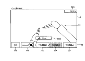
図14に示すように、内視鏡201dの水準器328は、カメラペダル24が操作された場合に、表示装置3に表示される。これにより、水準器328に基づいて操作することにより内視鏡201dの姿勢を容易に変更させることができる。 As shown in FIG. 14, the level 328 of the endoscope 201d is displayed on the display device 3 when the camera pedal 24 is operated. Accordingly, the posture of the endoscope 201d can be easily changed by operating based on the spirit level 328. FIG.

制御装置6は、右側用フットペダル(凝固ペダル21bおよび切断ペダル22b)、左側用フットペダル(凝固ペダル21aおよび切断ペダル22a)およびカメラペダル24のうちの少なくとも1つのフットペダル20の操作準備位置に操作者Oの足が配置されたことを、複数のセンサ26のうちの少なくとも1つのセンサ26により検出したことに基づいて、第1エリア321、第2エリア322および第3エリア323のうちの対応するエリアの表示形態を変更するように構成されている。 The controller 6 puts at least one foot pedal 20 of the right foot pedal (coagulation pedal 21b and cutting pedal 22b), the left foot pedal (coagulation pedal 21a and cutting pedal 22a) and the camera pedal 24 in the operation ready position. Based on detection by at least one sensor 26 of the plurality of sensors 26 that the feet of the operator O have been placed, correspondence among the first area 321, the second area 322, and the third area 323 It is configured to change the display form of the area to be displayed.

エリアの表示形態の変更は、表示色の変更、反転表示、エリアの枠線の表示変更、表示エリアの拡大/縮小のうち少なくとも1つを含む。 Changing the display mode of the area includes at least one of changing the display color, reversing display, changing the display of the frame line of the area, and enlarging/reducing the display area.

グラフィカルユーザインタフェース32の各エリアには、各フットペダル20の操作の状況が表示されるように構成されている。これにより、各フットペダル20の操作状況を操作者Oが容易に把握することができる。 Each area of the graphical user interface 32 is configured to display the operation status of each foot pedal 20 . This allows the operator O to easily grasp the operation status of each foot pedal 20 .

具体的には、第1エリア321には、手術器具201aに関する情報に加えて右側用フットペダル(凝固ペダル21bおよび切断ペダル22b)に関する情報が表示される。たとえば、凝固ペダル21bまたは切断ペダル22bの操作準備位置に操作者Oの足が配置された場合に、対応するフットペダル20(凝固ペダル21bまたは切断ペダル22b)の色を用いて、第1エリア321の枠線を表示する。これにより、第1エリア321の表示により右側用フットペダル(凝固ペダル21bおよび切断ペダル22b)の操作による手術器具201aの機能の実行状態を操作者Oが容易に把握することができる。また、凝固ペダル21bまたは切断ペダル22bが操作された場合に、第1エリア321に凝固ペダル21bまたは切断ペダル22bに関する情報が操作準備位置に操作者Oの足が配置された場合と区別して表示される。たとえば、凝固ペダル21bまたは切断ペダル22bが操作された場合に、対応するフットペダル20(凝固ペダル21bまたは切断ペダル22b)の色を、第1エリア321の全体に表示する。これにより、第1エリア321の表示により凝固ペダル21bまたは切断ペダル22bの操作状態を操作者Oが容易に把握することができる。 Specifically, in the first area 321, information on the right foot pedal (coagulation pedal 21b and cutting pedal 22b) is displayed in addition to information on the surgical instrument 201a. For example, when the foot of the operator O is placed at the operation ready position of the coagulation pedal 21b or cutting pedal 22b, the color of the corresponding foot pedal 20 (coagulation pedal 21b or cutting pedal 22b) is used to display the first area 321. display borders. Thus, the display in the first area 321 allows the operator O to easily grasp the execution state of the function of the surgical instrument 201a by operating the right foot pedal (coagulation pedal 21b and cutting pedal 22b). Further, when the coagulation pedal 21b or the cutting pedal 22b is operated, the information regarding the coagulation pedal 21b or the cutting pedal 22b is displayed in the first area 321, distinguishing from the case where the foot of the operator O is placed at the operation preparation position. be. For example, when the coagulation pedal 21b or the cutting pedal 22b is operated, the color of the corresponding foot pedal 20 (the coagulation pedal 21b or the cutting pedal 22b) is displayed in the entire first area 321. This allows the operator O to easily grasp the operation state of the coagulation pedal 21b or the cutting pedal 22b from the display of the first area 321. FIG.

つまり、凝固ペダル21bが操作された場合に、第1エリア321に凝固ペダル21bに関する情報が表示される。また、切断ペダル22bが操作された場合に、第1エリア321に切断ペダル22bに関する情報が表示される。これにより、第1エリア321の表示により右手用の操作ハンドル1aにより操作される手術器具201aによる凝固機能および切断機能の実行状態を操作者Oが容易に把握することができる。 That is, information about the coagulation pedal 21b is displayed in the first area 321 when the coagulation pedal 21b is operated. Further, when the disconnect pedal 22b is operated, information regarding the disconnect pedal 22b is displayed in the first area 321. FIG. Thus, the display in the first area 321 allows the operator O to easily grasp the execution state of the coagulation function and the cutting function by the surgical instrument 201a operated by the right-hand operation handle 1a.

また、第2エリア322には、手術器具201bに関する情報に加えて左側用フットペダル(凝固ペダル21aおよび切断ペダル22a)に関する情報が表示される。たとえば、凝固ペダル21aまたは切断ペダル22aの操作準備位置に操作者Oの足が配置された場合に、対応するフットペダル20(凝固ペダル21aまたは切断ペダル22a)の色を用いて、第2エリア322の枠線を表示する。これにより、第2エリア322の表示により左側用フットペダル(凝固ペダル21aおよび切断ペダル22a)の操作による手術器具201bの機能の実行状態を操作者Oが容易に把握することができる。また、凝固ペダル21aまたは切断ペダル22aが操作された場合に、第2エリア322に凝固ペダル21aまたは切断ペダル22aに関する情報が操作準備位置に操作者Oの足が配置された場合と区別して表示される。たとえば、凝固ペダル21aまたは切断ペダル22aが操作された場合に、対応するフットペダル20(凝固ペダル21aまたは切断ペダル22a)の色を、第2エリア322の全体に表示する。これにより、第2エリア322の表示により凝固ペダル21aまたは切断ペダル22aの操作状態を操作者Oが容易に把握することができる。 In addition, in the second area 322, information on the left foot pedal (coagulation pedal 21a and cutting pedal 22a) is displayed in addition to information on the surgical instrument 201b. For example, when the foot of the operator O is placed at the operation ready position of the coagulation pedal 21a or the cutting pedal 22a, the color of the corresponding foot pedal 20 (the coagulation pedal 21a or the cutting pedal 22a) is used to display the second area 322. display borders. Thus, the display in the second area 322 allows the operator O to easily grasp the execution state of the function of the surgical instrument 201b by operating the left foot pedal (coagulation pedal 21a and cutting pedal 22a). Further, when the coagulation pedal 21a or the cutting pedal 22a is operated, the information regarding the coagulation pedal 21a or the cutting pedal 22a is displayed in the second area 322, distinguishing from the case where the foot of the operator O is placed at the operation preparation position. be. For example, when the coagulation pedal 21a or the cutting pedal 22a is operated, the color of the corresponding foot pedal 20 (the coagulation pedal 21a or the cutting pedal 22a) is displayed in the entire second area 322. Accordingly, the display in the second area 322 allows the operator O to easily grasp the operation state of the coagulation pedal 21a or the cutting pedal 22a.

つまり、凝固ペダル21aが操作された場合に、第2エリア322に凝固ペダル21aに関する情報が表示される。また、切断ペダル22aが操作された場合に、第2エリア322に切断ペダル22aに関する情報が表示される。これにより、第2エリア322の表示により左手用の操作ハンドル1bにより操作される手術器具201bによる凝固機能および切断機能の実行状態を操作者Oが容易に把握することができる。 That is, information about the coagulation pedal 21a is displayed in the second area 322 when the coagulation pedal 21a is operated. Further, when the cutting pedal 22a is operated, information regarding the cutting pedal 22a is displayed in the second area 322. FIG. Thus, the display in the second area 322 allows the operator O to easily grasp the execution state of the coagulation function and the cutting function by the surgical instrument 201b operated by the left hand operation handle 1b.

また、第3エリア323には、内視鏡201dに関する情報に加えてカメラペダル24に関する情報が表示される。たとえば、カメラペダル24の操作準備位置に操作者Oの足が配置された場合に、第3エリア323の枠線を強調表示する。これにより、第3エリア323の表示によりカメラペダル24の操作による内視鏡201dの機能の実行状態を操作者Oが容易に把握することができる。また、カメラペダル24が操作された場合に、第3エリア323にカメラペダル24に関する情報が操作準備位置に操作者Oの足が配置された場合と区別して表示される。たとえば、カメラペダル24が操作された場合に、第3エリア323の背景色と文字色とを反転表示させる。これにより、第3エリア323の表示によりカメラペダル24の操作状態を操作者Oが容易に把握することができる。 Further, in the third area 323, information regarding the camera pedal 24 is displayed in addition to information regarding the endoscope 201d. For example, when the foot of the operator O is placed at the operation ready position of the camera pedal 24, the frame line of the third area 323 is highlighted. As a result, the display of the third area 323 allows the operator O to easily grasp the execution state of the function of the endoscope 201d by operating the camera pedal 24. FIG. Further, when the camera pedal 24 is operated, information regarding the camera pedal 24 is displayed in the third area 323, distinguishing from the case where the foot of the operator O is placed at the operation preparation position. For example, when the camera pedal 24 is operated, the background color and character color of the third area 323 are displayed in reverse. Accordingly, the operator O can easily grasp the operating state of the camera pedal 24 from the display of the third area 323 .

次に、図8~図21を参照して、フットペダル20に対する操作者Oの操作に基づいて表示されるグラフィカルユーザインタフェース32の例について説明する。 Next, examples of the graphical user interface 32 displayed based on the operation of the operator O on the foot pedal 20 will be described with reference to FIGS. 8 to 21. FIG.

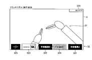
図8に示すように、切替ペダル25が操作されると、左手用の操作ハンドル1bにより操作される手術器具が手術器具201bから手術器具201cに切り替えられる。この場合、第2エリア322および第4エリア324の背景色と文字色とが反転表示される。これにより、操作者Oは、手術器具が切り替えられたことを容易に認識することが可能である。 As shown in FIG. 8, when the switching pedal 25 is operated, the surgical instrument operated by the left hand operation handle 1b is switched from the surgical instrument 201b to the surgical instrument 201c. In this case, the background color and character color of the second area 322 and the fourth area 324 are displayed in reverse. This allows the operator O to easily recognize that the surgical instrument has been switched.

図9に示すように、クラッチペダル23の操作準備位置に操作者Oの足が配置された場合に、第5エリア325の枠線が強調して表示される。また、ポップアップエリア327aにクラッチペダル23に関する情報がポップアップ表示される。なお、クラッチペダル23の操作準備位置に操作者Oの足が配置されていることが継続している場合でも、ポップアップエリア327aの表示は、所定時間経過後、消える。その場合、第5エリア325の枠線の強調表示は、継続される。 As shown in FIG. 9, when the foot of the operator O is placed at the operation ready position of the clutch pedal 23, the frame line of the fifth area 325 is highlighted. Information about the clutch pedal 23 is popped up in the popup area 327a. Note that even if the foot of the operator O continues to be placed at the operation ready position of the clutch pedal 23, the display of the pop-up area 327a disappears after a predetermined period of time has elapsed. In that case, the highlighting of the frame of the fifth area 325 continues.

図10に示すように、クラッチペダル23が操作されると、操作ハンドル1と、マニピュレータ201との操作接続が一時切断される。この場合、クラッチペダル23の情報を表示する第5エリア325の背景色と文字色とが反転表示される。また、操作接続が一時切断された手術器具201aの情報を表示する第1エリア321の背景色と文字色とが反転表示される。また、操作接続が一時切断された手術器具201bの情報を表示する第2エリア322の背景色と文字色とが反転表示される。操作後、操作者Oの足が操作準備位置に戻ると、図9に示すように、第5エリア325の枠線が強調して表示される。 As shown in FIG. 10, when the clutch pedal 23 is operated, the operating connection between the operating handle 1 and the manipulator 201 is temporarily disconnected. In this case, the background color and the character color of the fifth area 325 displaying the information of the clutch pedal 23 are displayed in reverse. In addition, the background color and the character color of the first area 321 displaying the information of the surgical instrument 201a whose operational connection has been temporarily disconnected are highlighted. In addition, the background color and the character color of the second area 322 displaying the information of the surgical instrument 201b whose operational connection has been temporarily disconnected are highlighted. After the operation, when the foot of the operator O returns to the operation preparation position, as shown in FIG. 9, the frame line of the fifth area 325 is highlighted.

図11に示すように、右手用の操作ハンドル1aのクラッチスイッチ11が操作されると、操作ハンドル1aと、手術器具201aが設けられたマニピュレータ201との操作接続が一時切断される。この場合、操作接続が一時切断された手術器具201aの情報を表示する第1エリア321の背景色と文字色とが反転表示される。 As shown in FIG. 11, when the clutch switch 11 of the operating handle 1a for the right hand is operated, the operating connection between the operating handle 1a and the manipulator 201 provided with the surgical instrument 201a is temporarily disconnected. In this case, the background color and the character color of the first area 321 displaying the information of the surgical instrument 201a whose operational connection has been temporarily disconnected are displayed in reverse.

図12に示すように、左手用の操作ハンドル1bのクラッチスイッチ11が操作されると、操作ハンドル1bと、手術器具201bが設けられたマニピュレータ201との操作接続が一時切断される。この場合、操作接続が一時切断された手術器具201bの情報を表示する第2エリア322の背景色と文字色とが反転表示される。 As shown in FIG. 12, when the clutch switch 11 of the operating handle 1b for the left hand is operated, the operating connection between the operating handle 1b and the manipulator 201 provided with the surgical instrument 201b is temporarily disconnected. In this case, the background color and the character color of the second area 322 displaying the information of the surgical instrument 201b whose operational connection has been temporarily disconnected are highlighted.

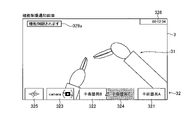
図13に示すように、カメラペダル24の操作準備位置に操作者Oの足が配置された場合に、第3エリア323の枠線が強調して表示される。また、ポップアップエリア327bにカメラペダル24に関する情報がポップアップ表示される。なお、カメラペダル24の操作準備位置に操作者Oの足が配置されていることが継続している場合でも、ポップアップエリア327bの表示は、所定時間経過後、消える。その場合、第3エリア323の枠線の強調表示は、継続される。 As shown in FIG. 13, when the foot of the operator O is placed at the operation ready position of the camera pedal 24, the frame line of the third area 323 is highlighted. Information about the camera pedal 24 is popped up in the popup area 327b. Note that even if the foot of the operator O continues to be placed at the operation preparation position of the camera pedal 24, the display of the pop-up area 327b disappears after a predetermined period of time has elapsed. In that case, the highlighting of the frame of the third area 323 continues.

図14に示すように、カメラペダル24が操作されると、操作ハンドル1aおよび1bにより、内視鏡201dの位置および姿勢を操作することが可能になる。この場合、カメラペダル24の情報を表示する第3エリア323の背景色と文字色とが反転表示される。また、センターエリアに内視鏡201dの水準器328が表示される。 As shown in FIG. 14, when the camera pedal 24 is operated, the position and orientation of the endoscope 201d can be operated with the operation handles 1a and 1b. In this case, the background color and character color of the third area 323 displaying the information of the camera pedal 24 are displayed in reverse. Also, the level 328 of the endoscope 201d is displayed in the center area.

図15に示すように、右手により操作されている手術器具201aに対応する切断ペダル22bの操作準備位置に操作者Oの足が配置された場合に、第1エリア321の枠線が強調して表示される。具体的には、切断ペダル22bが有する第2の色により、枠線の左から半分以上が強調して表示される。残りの枠線は、凝固ペダル21bが有する第1の色により強調表示される。これにより、枠線を第2の色のみで強調して表示する場合と比べて、操作者Oが切断ペダル22bと凝固ペダル21bとのうち、切断ペダル22bの操作準備位置に足を配置していることを効果的に認識させることができる。また、ポップアップエリア327cに切断ペダル22bに関する情報がポップアップ表示される。なお、切断ペダル22bの操作準備位置に操作者Oの足が配置されていることが継続している場合でも、ポップアップエリア327cの表示は、所定時間経過後、消える。その場合、第1エリア321の枠線の強調表示は、継続される。 As shown in FIG. 15, when the foot of the operator O is placed at the operation preparation position of the cutting pedal 22b corresponding to the surgical instrument 201a being operated with the right hand, the frame line of the first area 321 is emphasized. Is displayed. Specifically, the second color of the cutting pedal 22b highlights more than half of the frame line from the left. The remaining borders are highlighted by the first color that the coagulation pedal 21b has. As a result, compared to the case where the frame line is emphasized only with the second color, the operator O places his/her foot at the operation ready position of the cutting pedal 22b between the cutting pedal 22b and the coagulation pedal 21b. can be effectively recognized. Information about the cutting pedal 22b is popped up in the popup area 327c. Note that even if the foot of the operator O continues to be placed at the operation ready position of the cutting pedal 22b, the display of the pop-up area 327c disappears after a predetermined period of time has elapsed. In that case, the highlighting of the frame line of the first area 321 continues.

なお、左手により操作されている手術器具201bに対応する切断ペダル22aの操作準備位置に操作者Oの足が配置された場合も、同様にして、第2エリア322の枠線が強調して表示される。 Similarly, when the operator O's foot is placed at the operation preparation position of the cutting pedal 22a corresponding to the surgical instrument 201b being operated with the left hand, the frame line of the second area 322 is displayed with emphasis. be done.

図16に示すように、切断ペダル22bが操作されると、手術器具201aに所定の電圧が印加されて、手術部位を切断することが可能になる。この場合、切断ペダル22bの情報を表示する第1エリア321の背景が、切断ペダル22bが有する第2の色で表示される。 As shown in FIG. 16, when the cutting pedal 22b is operated, a predetermined voltage is applied to the surgical instrument 201a, making it possible to cut the surgical site. In this case, the background of the first area 321 displaying the information of the cutting pedal 22b is displayed in the second color of the cutting pedal 22b.

なお、切断ペダル22aが操作された場合も、同様にして、切断ペダル22aの情報を表示する第2エリア322の背景が、切断ペダル22aが有する第2の色で表示される。 Similarly, when the cutting pedal 22a is operated, the background of the second area 322 displaying the information of the cutting pedal 22a is displayed in the second color of the cutting pedal 22a.

図17に示すように、右手により操作されている手術器具201aに対応する凝固ペダル21bの操作準備位置に操作者Oの足が配置された場合に、第1エリア321の枠線が強調して表示される。具体的には、凝固ペダル21bが有する第1の色により、枠線の右から半分以上が強調して表示される。残りの枠線は、切断ペダル22bが有する第2の色により強調表示される。これにより、枠線を第1の色のみで強調して表示する場合と比べて、操作者Oが切断ペダル22bと凝固ペダル21bとのうち、凝固ペダル21bの操作準備位置に足を配置していることを効果的に認識させることができる。また、ポップアップエリア327dに凝固ペダル21bに関する情報がポップアップ表示される。なお、凝固ペダル21bの操作準備位置に操作者Oの足が配置されていることが継続している場合でも、ポップアップエリア327dの表示は、所定時間経過後、消える。その場合、第1エリア321の枠線の強調表示は、継続される。 As shown in FIG. 17, when the foot of the operator O is placed at the operation preparation position of the coagulation pedal 21b corresponding to the surgical instrument 201a being operated with the right hand, the frame line of the first area 321 is emphasized. Is displayed. Specifically, the first color of the coagulation pedal 21b is used to highlight more than half of the frame line from the right. The remaining border is highlighted by the second color that cutting pedal 22b has. As a result, compared to the case where the frame line is highlighted only in the first color, the operator O places his/her foot at the operation ready position of the coagulation pedal 21b between the cutting pedal 22b and the coagulation pedal 21b. can be effectively recognized. Information about the coagulation pedal 21b is popped up in the popup area 327d. Note that even if the foot of the operator O continues to be placed at the operation ready position of the coagulation pedal 21b, the display of the pop-up area 327d disappears after the lapse of a predetermined time. In that case, the highlighting of the frame line of the first area 321 continues.

なお、左手により操作されている手術器具201bに対応する凝固ペダル21aの操作準備位置に操作者Oの足が配置された場合も、同様にして、第2エリア322の枠線が強調して表示される。 Similarly, when the operator O's foot is placed at the operation preparation position of the coagulation pedal 21a corresponding to the surgical instrument 201b being operated with the left hand, the frame line of the second area 322 is displayed with emphasis. be done.

図18に示すように、凝固ペダル21bが操作されると、手術器具201aに所定の電圧が印加されて、手術部位を凝固することが可能になる。この場合、凝固ペダル21bの情報を表示する第1エリア321の背景が、凝固ペダル21bが有する第1の色で表示される。 As shown in FIG. 18, when the coagulation pedal 21b is operated, a predetermined voltage is applied to the surgical instrument 201a, making it possible to coagulate the surgical site. In this case, the background of the first area 321 displaying the information of the coagulation pedal 21b is displayed in the first color of the coagulation pedal 21b.

なお、凝固ペダル21aが操作された場合も、同様にして、凝固ペダル21aの情報を表示する第2エリア322の背景が、凝固ペダル21aが有する第1の色で表示される。 Similarly, when the coagulation pedal 21a is operated, the background of the second area 322 displaying the information of the coagulation pedal 21a is displayed in the first color of the coagulation pedal 21a.

図19に示すように、左手により操作されている手術器具201bに対応する切断ペダル22aの操作準備位置に操作者Oの足が配置され、かつ、クラッチペダル23の操作準備位置に操作者Oの足が配置された場合に、第2エリア322の枠線が強調して表示される。具体的には、切断ペダル22aが有する第2の色により、枠線の左から半分以上が強調して表示される。残りの枠線は、凝固ペダル21aが有する第1の色により強調表示される。また、ポップアップエリア327cに切断ペダル22aに関する情報がポップアップ表示される。また、第5エリア325の枠線が強調して表示される。また、ポップアップエリア327aにクラッチペダル23に関する情報がポップアップ表示される。 As shown in FIG. 19, the operator O's foot is placed at the operation ready position of the cutting pedal 22a corresponding to the surgical instrument 201b being operated with the left hand, and the operator O's foot is at the operation ready position of the clutch pedal 23. When the foot is placed, the frame line of the second area 322 is highlighted. Specifically, the second color of the cutting pedal 22a is used to highlight more than half of the frame line from the left. The remaining borders are highlighted by the first color that the coagulation pedal 21a has. Information about the cutting pedal 22a is popped up in the popup area 327c. Also, the frame line of the fifth area 325 is highlighted. Information about the clutch pedal 23 is popped up in the popup area 327a.

図20に示すように、機能が制限される場合、エラー通知エリア329aに機能が制限される通知が表示される。また、切断や凝固の機能が設定されていない手術器具を用いている場合に、切断ペダル22や凝固ペダル21が操作された場合に、手術器具に対応するエリアの上側に機能しない操作が行われたことがポップアップ表示される。この場合、切断ペダル22や凝固ペダル21を操作したとしても、手術器具に電圧は印加されない。 As shown in FIG. 20, when the function is restricted, a notification that the function is restricted is displayed in the error notification area 329a. Further, when a surgical instrument for which no cutting or coagulation function is set is used, when the cutting pedal 22 or the coagulation pedal 21 is operated, an operation that does not function is performed above the area corresponding to the surgical instrument. A pop-up will appear. In this case, even if the cutting pedal 22 or the coagulation pedal 21 is operated, no voltage is applied to the surgical instrument.

図21に示すように、エラーが通知される場合、エラー通知エリア329bにエラーが通知される。 As shown in FIG. 21, when an error is notified, the error is notified in the error notification area 329b.

(変形例)
なお、今回開示された実施形態は、すべての点で例示であって制限的なものではないと考えられるべきである。本発明の範囲は、上記した実施形態の説明ではなく特許請求の範囲によって示され、さらに特許請求の範囲と均等の意味および範囲内でのすべての変更(変形例)が含まれる。
(Modification)
It should be noted that the embodiments disclosed this time should be considered as examples and not restrictive in all respects. The scope of the present invention is indicated by the scope of the claims rather than the description of the above-described embodiments, and includes all modifications (modifications) within the meaning and scope equivalent to the scope of the claims.

たとえば、上記実施形態では、操作ペダル部のフットペダルが、凝固ペダルと、切断ペダルとを含む構成の例を示したが、本発明はこれに限られない。本発明では、操作ペダル部のフットペダルが、凝固ペダルおよび切断ペダル以外の医療器具に関する機能を実行するためのフットペダルを含んでいてもよい。 For example, in the above-described embodiment, the foot pedals of the operation pedal section exemplify the configuration including the coagulation pedal and the cutting pedal, but the present invention is not limited to this. In the present invention, the foot pedals of the operating pedal section may include foot pedals for performing functions related to medical instruments other than coagulation pedals and cutting pedals.

また、上記実施形態では、センサが遮断型のセンサの例を示したが、本発明はこれに限られない。本発明では、センサは、透過型であってもよいし、反射型であってもよい。また、光を用いずに、足の存在を検知してもよい。たとえば、音波を用いて検知してもよいし、コイルを用いて検知してもよい。また、センサは、非接触式に限らず、接触により足の存在を検知してもよい。たとえば、センサは、機械式のスイッチでもよい。 Further, in the above-described embodiment, an example of a blocking type sensor is shown, but the present invention is not limited to this. In the present invention, the sensor may be transmissive or reflective. Alternatively, the presence of the foot may be detected without using light. For example, it may be detected using sound waves, or may be detected using a coil. Moreover, the sensor is not limited to the non-contact type, and may detect the presence of the foot by contact. For example, the sensor may be a mechanical switch.

1a:操作ハンドル(第1操作ハンドル)、1b:操作ハンドル(第2操作ハンドル)、2:操作ペダル部、3:表示装置、6:制御装置、21a:凝固ペダル(第2フットペダル、第2凝固ペダル)、21b:凝固ペダル(第1フットペダル、第1凝固ペダル)、22a:切断ペダル(第2フットペダル、第2切断ペダル)、22b:切断ペダル(第1フットペダル、第1切断ペダル)、23:クラッチペダル(第5フットペダル)、24:カメラペダル(第3フットペダル)、25:切替ペダル(第4フットペダル)、32:グラフィカルユーザインタフェース、100:遠隔操作装置、201:マニピュレータ、201a:手術器具(第1手術器具)、201b:手術器具(第2手術器具)、201c:手術器具(交換用手術器具)、201d:内視鏡、321:第1エリア、322:第2エリア、323:第3エリア、324:第4エリア、325:第5エリア、328:水準器、400:手術システム 1a: operating handle (first operating handle), 1b: operating handle (second operating handle), 2: operating pedal section, 3: display device, 6: control device, 21a: coagulation pedal (second foot pedal, second coagulation pedal), 21b: coagulation pedal (first foot pedal, first coagulation pedal), 22a: cutting pedal (second foot pedal, second cutting pedal), 22b: cutting pedal (first foot pedal, first cutting pedal ), 23: clutch pedal (fifth foot pedal), 24: camera pedal (third foot pedal), 25: switching pedal (fourth foot pedal), 32: graphical user interface, 100: remote control device, 201: manipulator , 201a: surgical instrument (first surgical instrument), 201b: surgical instrument (second surgical instrument), 201c: surgical instrument (replacement surgical instrument), 201d: endoscope, 321: first area, 322: second Area, 323: Third area, 324: Fourth area, 325: Fifth area, 328: Spirit level, 400: Operation system

Claims (16)

第1手術器具を支持するための第1マニピュレータと、
第2手術器具を支持するための第2マニピュレータと、
手術部位を撮像する内視鏡を支持するための第3マニピュレータと、
前記内視鏡によって撮像された画像を表示するための表示装置、操作者の右手で操作される第1操作ハンドルおよび前記操作者の左手で操作される第2操作ハンドルを含む遠隔操作装置と、
前記内視鏡によって撮像された画像上にグラフィカルユーザインタフェースを重ねて前記表示装置に表示するように構成された制御装置と、を備え、
前記制御装置は、前記内視鏡を移動させる場合にのみ、前記内視鏡の水準器を示す表示を前記グラフィカルユーザインタフェースのセンターエリアに表示するように構成されている、手術システム。
a first manipulator for supporting a first surgical instrument;
a second manipulator for supporting a second surgical instrument;
a third manipulator for supporting an endoscope for imaging the surgical site;
a remote control device including a display device for displaying an image captured by the endoscope, a first operating handle operated by an operator's right hand, and a second operating handle operated by the operator's left hand;
a control device configured to display a graphical user interface overlaid on the image captured by the endoscope on the display device;
The surgical system of claim 1, wherein the controller is configured to display a display showing a spirit level of the endoscope in a center area of the graphical user interface only when moving the endoscope.
前記第1手術器具は、前記第1操作ハンドルで操作され、前記第2手術器具は、前記第2操作ハンドルで操作され、前記内視鏡は、前記第1および第2操作ハンドルの両方を操作することによって移動するように構成されている、請求項1に記載の手術システム。 The first surgical instrument is operated by the first operating handle, the second surgical instrument is operated by the second operating handle, and the endoscope operates both the first and second operating handles. 2. The surgical system of claim 1, configured to move by moving. 前記グラフィカルユーザインタフェースは、前記第1手術器具に関する情報を示す第1エリアと、前記第2手術器具に関する情報を示す第2エリアと、前記内視鏡に関する情報を示す第3エリアと、を前記表示装置の下方または上方の端部近傍領域に配置して表示する、請求項1または2に記載の手術システム。 The graphical user interface displays a first area indicating information about the first surgical instrument, a second area indicating information about the second surgical instrument, and a third area indicating information about the endoscope. 3. The surgical system according to claim 1 or 2, arranged and displayed in a region near the lower or upper edge of the device. 前記第1エリアには、前記第1手術器具の種類が表示され、
前記第2エリアには、前記第2手術器具の種類が表示される、請求項3に記載の手術システム。
The first area displays the type of the first surgical instrument,
The surgical system according to claim 3, wherein the second area displays the type of the second surgical instrument.
前記グラフィカルユーザインタフェースは、前記第1エリア、前記第2エリアおよび前記第3エリアを右から左に順に並べて配置して表示する、請求項3または4に記載の手術システム。 5. The surgical system according to claim 3, wherein said graphical user interface displays said first area, said second area and said third area arranged in order from right to left. 交換用手術器具を支持するための第4マニピュレータをさらに備え、
前記グラフィカルユーザインタフェースは、前記交換用手術器具に関する情報を示す第4エリアを前記第1エリアと前記第2エリアとの間に配置して表示する、請求項3~5のいずれか1項に記載の手術システム。
further comprising a fourth manipulator for supporting the replacement surgical instrument;
6. The graphical user interface according to any one of claims 3 to 5, wherein the graphical user interface displays a fourth area showing information about the replacement surgical instrument by arranging it between the first area and the second area. surgical system.
前記各マニピュレータを支持するプラットホームを備えた患者側装置を備える、請求項1~6のいずれか1項に記載の手術システム。 The surgical system according to any one of claims 1 to 6, comprising a patient-side device with a platform supporting each manipulator. 第1手術器具を支持するための第1マニピュレータと、
第2手術器具を支持するための第2マニピュレータと、
手術部位の撮像する内視鏡を支持するための第3マニピュレータと、
前記内視鏡によって撮像された画像を表示するための表示装置、前記第1手術器具を操作するための第1操作ハンドル、前記第2手術器具を操作するための第2操作ハンドルおよび前記内視鏡に関する機能を前記第1および第2操作ハンドルに実行させるためのカメラペダルを含む操作ペダル部を備えた遠隔操作装置と、
前記内視鏡によって撮像された画像上にグラフィカルユーザインタフェースを重ねて前記表示装置に表示するように構成された制御装置と、を備え、
前記制御装置は、前記カメラペダルが操作された場合にのみ、前記内視鏡の水準器を示す表示を前記グラフィカルユーザインタフェースのセンターエリアに表示するように構成されている、手術システム。
a first manipulator for supporting a first surgical instrument;
a second manipulator for supporting a second surgical instrument;
a third manipulator for supporting an endoscope for imaging a surgical site;
A display device for displaying an image captured by the endoscope, a first operating handle for operating the first surgical instrument, a second operating handle for operating the second surgical instrument, and the endoscope. a remote control device comprising an operation pedal section including a camera pedal for causing the first and second operation handles to perform a function related to a mirror;
a control device configured to display a graphical user interface overlaid on the image captured by the endoscope on the display device;
The surgical system of claim 1, wherein the controller is configured to display a display showing a spirit level of the endoscope in a center area of the graphical user interface only when the camera pedal is operated.
前記グラフィカルユーザインタフェースは、前記第1手術器具に関する情報を示す第1エリアと、前記第2手術器具に関する情報を示す第2エリアと、前記内視鏡に関する情報を示す第3エリアと、を前記表示装置の下方または上方の端部近傍領域に配置して表示する、請求項8に記載の手術システム。 The graphical user interface displays a first area indicating information about the first surgical instrument, a second area indicating information about the second surgical instrument, and a third area indicating information about the endoscope. 9. The surgical system according to claim 8, arranged and displayed in a region near the lower or upper edge of the device. 前記第1エリアには、前記第1手術器具の種類が表示され、
前記第2エリアには、前記第2手術器具の種類が表示される、請求項9に記載の手術システム。
The first area displays the type of the first surgical instrument,
The surgical system according to claim 9, wherein the second area displays the type of the second surgical instrument.
前記操作ペダル部は、前記第1手術器具に関する機能を実行させるための第1ペダルおよび前記第2手術器具に関する機能を実行させるための第2ペダルをさらに備え、
前記第1ペダルが操作された場合に、前記第1エリアに前記第1ペダルに関する情報が表示され、
前記第2ペダルが操作された場合に、前記第2エリアに前記第2ペダルに関する情報が表示され、
前記カメラペダルが操作された場合に、前記第3エリアに前記カメラペダルに関する情報が表示される、請求項9または10に記載の手術システム。
The operation pedal unit further includes a first pedal for executing a function related to the first surgical instrument and a second pedal for executing a function related to the second surgical instrument,
when the first pedal is operated, information about the first pedal is displayed in the first area;
when the second pedal is operated, information about the second pedal is displayed in the second area;
The surgical operation system according to claim 9 or 10, wherein information about said camera pedal is displayed in said third area when said camera pedal is operated.
前記第1ペダルとして、手術部位を凝固させる操作を行う第1凝固ペダルと、手術部位を切断する操作を行う第1切断ペダルと、を有し、
前記第2ペダルとして、手術部位を凝固させる操作を行う第2凝固ペダルと、手術部位を切断する操作を行う第2切断ペダルと、を有し、
前記第1凝固ペダルが操作された場合に、前記第1エリアに前記第1凝固ペダルに関する情報が表示され、
前記第1切断ペダルが操作された場合に、前記第1エリアに前記第1切断ペダルに関する情報が表示され、
前記第2凝固ペダルが操作された場合に、前記第2エリアに前記第2凝固ペダルに関する情報が表示され、
前記第2切断ペダルが操作された場合に、前記第2エリアに前記第2切断ペダルに関する情報が表示される、請求項11に記載の手術システム。
The first pedal includes a first coagulation pedal for performing an operation to coagulate the surgical site and a first cutting pedal for performing an operation to cut the surgical site,
As the second pedal, a second coagulation pedal for performing an operation to coagulate the surgical site and a second cutting pedal for performing an operation to cut the surgical site,
when the first coagulation pedal is operated, information about the first coagulation pedal is displayed in the first area;
when the first disconnect pedal is operated, information about the first disconnect pedal is displayed in the first area;
when the second coagulation pedal is operated, information about the second coagulation pedal is displayed in the second area;
12. The surgical system of claim 11, wherein information about the second cutting pedal is displayed in the second area when the second cutting pedal is operated.
前記グラフィカルユーザインタフェースは、前記第1エリア、前記第2エリアおよび前記第3エリアを、前記操作ペダル部の前記第1ペダル、前記第2ペダルおよび前記カメラペダルの並び順と同じ順に並べて表示するように構成されている、請求項11に記載の手術システム。 The graphical user interface arranges and displays the first area, the second area, and the third area in the same order as the order in which the first pedal, the second pedal, and the camera pedal of the operation pedal section are arranged. 12. The surgical system of claim 11, wherein the surgical system is configured to: 前記第1操作ハンドルは操作者の右手で操作され、前記第2操作ハンドルは前記操作者の左手で操作されるように構成されており、
前記グラフィカルユーザインタフェースは、前記第1エリア、前記第2エリアおよび前記第3エリアを右から左に順に並べて配置して表示する、請求項9~12のいずれか1項に記載の手術システム。
The first operating handle is configured to be operated by the operator's right hand, and the second operating handle is configured to be operated by the operator's left hand,
The surgical system according to any one of claims 9 to 12, wherein said graphical user interface displays said first area, said second area and said third area arranged in order from right to left.
交換用手術器具を支持するための第4マニピュレータをさらに備え、
前記操作ペダル部は、前記第1操作ハンドルにより操作されている前記第1手術器具または前記第2操作ハンドルにより操作されている前記第2手術器具を前記交換用手術器具に変更するための切替ペダルをさらに含み、
前記グラフィカルユーザインタフェースは、前記交換用手術器具に関する情報を示す第4エリアを前記第1エリアと前記第2エリアとの間に配置して表示する、請求項9~14のいずれか1項に記載の手術システム。
further comprising a fourth manipulator for supporting the replacement surgical instrument;
The operating pedal section has a switching pedal for changing the first surgical instrument operated by the first operating handle or the second surgical instrument operated by the second operating handle to the replacement surgical instrument. further comprising
15. The graphical user interface according to any one of claims 9 to 14, wherein the graphical user interface displays a fourth area showing information about the replacement surgical instrument by arranging it between the first area and the second area. surgical system.
前記各マニピュレータを支持するプラットホームを備えた患者側装置を備える、請求項8~15のいずれか1項に記載の手術システム。 The surgical system according to any one of claims 8 to 15, comprising a patient-side device with a platform supporting each manipulator.
JP2021102387A 2020-02-21 2021-06-21 surgery system Active JP7128326B2 (en)

Priority Applications (1)

Application Number Priority Date Filing Date Title
JP2021102387A JP7128326B2 (en) 2020-02-21 2021-06-21 surgery system

Applications Claiming Priority (2)

Application Number Priority Date Filing Date Title
JP2020028096A JP6902639B2 (en) 2018-09-25 2020-02-21 Surgical system
JP2021102387A JP7128326B2 (en) 2020-02-21 2021-06-21 surgery system

Related Parent Applications (1)

Application Number Title Priority Date Filing Date
JP2020028096A Division JP6902639B2 (en) 2018-09-25 2020-02-21 Surgical system

Publications (2)

Publication Number Publication Date
JP2021137667A JP2021137667A (en) 2021-09-16
JP7128326B2 true JP7128326B2 (en) 2022-08-30

Family

ID=77667296

Family Applications (1)

Application Number Title Priority Date Filing Date
JP2021102387A Active JP7128326B2 (en) 2020-02-21 2021-06-21 surgery system

Country Status (1)

Country Link
JP (1) JP7128326B2 (en)

Citations (8)

* Cited by examiner, † Cited by third party
Publication number Priority date Publication date Assignee Title
US20100228264A1 (en) 2009-03-09 2010-09-09 David Robinson Adaptable integrated energy control system for electrosurgical tools in robotic surgical systems
WO2017083768A1 (en) 2015-11-12 2017-05-18 Jarc Anthony Michael Surgical system with training or assist functions
JP2017512551A (en) 2014-03-17 2017-05-25 インテュイティブ サージカル オペレーションズ, インコーポレイテッド Method and apparatus for table posture tracking using reference markers
JP2017104455A (en) 2015-12-11 2017-06-15 株式会社メディカロイド Remote handling equipment and remote surgery system
WO2018170031A1 (en) 2017-03-15 2018-09-20 Covidien Lp Robotic surgical systems, instruments, and controls
JP6856594B2 (en) 2018-09-25 2021-04-07 株式会社メディカロイド Surgical system and display method
JP6902639B2 (en) 2018-09-25 2021-07-14 株式会社メディカロイド Surgical system
JP7016400B2 (en) 2020-12-14 2022-02-04 株式会社メディカロイド Surgical system and display method

Patent Citations (8)

* Cited by examiner, † Cited by third party
Publication number Priority date Publication date Assignee Title
US20100228264A1 (en) 2009-03-09 2010-09-09 David Robinson Adaptable integrated energy control system for electrosurgical tools in robotic surgical systems
JP2017512551A (en) 2014-03-17 2017-05-25 インテュイティブ サージカル オペレーションズ, インコーポレイテッド Method and apparatus for table posture tracking using reference markers
WO2017083768A1 (en) 2015-11-12 2017-05-18 Jarc Anthony Michael Surgical system with training or assist functions
JP2017104455A (en) 2015-12-11 2017-06-15 株式会社メディカロイド Remote handling equipment and remote surgery system
WO2018170031A1 (en) 2017-03-15 2018-09-20 Covidien Lp Robotic surgical systems, instruments, and controls
JP6856594B2 (en) 2018-09-25 2021-04-07 株式会社メディカロイド Surgical system and display method
JP6902639B2 (en) 2018-09-25 2021-07-14 株式会社メディカロイド Surgical system
JP7016400B2 (en) 2020-12-14 2022-02-04 株式会社メディカロイド Surgical system and display method

Also Published As

Publication number Publication date
JP2021137667A (en) 2021-09-16

Similar Documents

Publication Publication Date Title
JP7155344B2 (en) Surgical system and display method
US11432893B2 (en) Structural adjustment systems and methods for a teleoperational medical system
JP6856594B2 (en) Surgical system and display method
JP7080861B2 (en) Surgical system
CN111134849A (en) Surgical robot system
JP6599402B2 (en) Remote control device
JP2016516534A (en) Surgical instrument control input visualization field
US20190314005A1 (en) Remote control apparatus, surgical system, and method of identifying target pedal
CN115334992A (en) Virtual console for controlling surgical robot
JP6902639B2 (en) Surgical system
JP6778326B2 (en) Master operation input device and master-slave manipulator
JP7016400B2 (en) Surgical system and display method
KR20120045734A (en) Master iput device of surgical robitc system and method of controlling surgical robitc system using the same
JP7128326B2 (en) surgery system
JP6745392B2 (en) Remote control device
JP6665263B2 (en) Remote control device, surgical system and method for specifying pedal to be operated
JP2023111635A (en) Operation pedal device and remote operation device
JP2023010762A (en) Camera control
JP2021065396A (en) Surgical instrument

Legal Events

Date Code Title Description
A621 Written request for application examination

Free format text: JAPANESE INTERMEDIATE CODE: A621

Effective date: 20210621

A131 Notification of reasons for refusal

Free format text: JAPANESE INTERMEDIATE CODE: A131

Effective date: 20220531

A977 Report on retrieval

Free format text: JAPANESE INTERMEDIATE CODE: A971007

Effective date: 20220531

A521 Request for written amendment filed

Free format text: JAPANESE INTERMEDIATE CODE: A523

Effective date: 20220624

TRDD Decision of grant or rejection written
A01 Written decision to grant a patent or to grant a registration (utility model)

Free format text: JAPANESE INTERMEDIATE CODE: A01

Effective date: 20220802

A61 First payment of annual fees (during grant procedure)

Free format text: JAPANESE INTERMEDIATE CODE: A61

Effective date: 20220818

R150 Certificate of patent or registration of utility model

Ref document number: 7128326

Country of ref document: JP

Free format text: JAPANESE INTERMEDIATE CODE: R150