JP6895965B2 - Remote controller for controlling the device by bypassing the feedback signal from the native controller to the remote controller and its control method - Google Patents
Remote controller for controlling the device by bypassing the feedback signal from the native controller to the remote controller and its control method Download PDFInfo
- Publication number
- JP6895965B2 JP6895965B2 JP2018530533A JP2018530533A JP6895965B2 JP 6895965 B2 JP6895965 B2 JP 6895965B2 JP 2018530533 A JP2018530533 A JP 2018530533A JP 2018530533 A JP2018530533 A JP 2018530533A JP 6895965 B2 JP6895965 B2 JP 6895965B2
- Authority
- JP
- Japan
- Prior art keywords
- control
- feedback signal
- melting pressure
- signal
- controller
- Prior art date
- Legal status (The legal status is an assumption and is not a legal conclusion. Google has not performed a legal analysis and makes no representation as to the accuracy of the status listed.)
- Active
Links
Images

Classifications
-
- B—PERFORMING OPERATIONS; TRANSPORTING
- B29—WORKING OF PLASTICS; WORKING OF SUBSTANCES IN A PLASTIC STATE IN GENERAL
- B29C—SHAPING OR JOINING OF PLASTICS; SHAPING OF MATERIAL IN A PLASTIC STATE, NOT OTHERWISE PROVIDED FOR; AFTER-TREATMENT OF THE SHAPED PRODUCTS, e.g. REPAIRING
- B29C45/00—Injection moulding, i.e. forcing the required volume of moulding material through a nozzle into a closed mould; Apparatus therefor
- B29C45/17—Component parts, details or accessories; Auxiliary operations
- B29C45/76—Measuring, controlling or regulating
-
- B—PERFORMING OPERATIONS; TRANSPORTING
- B29—WORKING OF PLASTICS; WORKING OF SUBSTANCES IN A PLASTIC STATE IN GENERAL
- B29C—SHAPING OR JOINING OF PLASTICS; SHAPING OF MATERIAL IN A PLASTIC STATE, NOT OTHERWISE PROVIDED FOR; AFTER-TREATMENT OF THE SHAPED PRODUCTS, e.g. REPAIRING
- B29C45/00—Injection moulding, i.e. forcing the required volume of moulding material through a nozzle into a closed mould; Apparatus therefor
- B29C45/17—Component parts, details or accessories; Auxiliary operations
- B29C45/1775—Connecting parts, e.g. injection screws, ejectors, to drive means
-
- B—PERFORMING OPERATIONS; TRANSPORTING
- B29—WORKING OF PLASTICS; WORKING OF SUBSTANCES IN A PLASTIC STATE IN GENERAL
- B29C—SHAPING OR JOINING OF PLASTICS; SHAPING OF MATERIAL IN A PLASTIC STATE, NOT OTHERWISE PROVIDED FOR; AFTER-TREATMENT OF THE SHAPED PRODUCTS, e.g. REPAIRING
- B29C45/00—Injection moulding, i.e. forcing the required volume of moulding material through a nozzle into a closed mould; Apparatus therefor
- B29C45/17—Component parts, details or accessories; Auxiliary operations
- B29C45/72—Heating or cooling
-
- B—PERFORMING OPERATIONS; TRANSPORTING
- B29—WORKING OF PLASTICS; WORKING OF SUBSTANCES IN A PLASTIC STATE IN GENERAL
- B29C—SHAPING OR JOINING OF PLASTICS; SHAPING OF MATERIAL IN A PLASTIC STATE, NOT OTHERWISE PROVIDED FOR; AFTER-TREATMENT OF THE SHAPED PRODUCTS, e.g. REPAIRING
- B29C45/00—Injection moulding, i.e. forcing the required volume of moulding material through a nozzle into a closed mould; Apparatus therefor
- B29C45/17—Component parts, details or accessories; Auxiliary operations
- B29C45/76—Measuring, controlling or regulating
- B29C45/77—Measuring, controlling or regulating of velocity or pressure of moulding material
-
- B—PERFORMING OPERATIONS; TRANSPORTING
- B29—WORKING OF PLASTICS; WORKING OF SUBSTANCES IN A PLASTIC STATE IN GENERAL
- B29C—SHAPING OR JOINING OF PLASTICS; SHAPING OF MATERIAL IN A PLASTIC STATE, NOT OTHERWISE PROVIDED FOR; AFTER-TREATMENT OF THE SHAPED PRODUCTS, e.g. REPAIRING
- B29C2945/00—Indexing scheme relating to injection moulding, i.e. forcing the required volume of moulding material through a nozzle into a closed mould
- B29C2945/76—Measuring, controlling or regulating
- B29C2945/76003—Measured parameter
- B29C2945/76006—Pressure
-
- B—PERFORMING OPERATIONS; TRANSPORTING
- B29—WORKING OF PLASTICS; WORKING OF SUBSTANCES IN A PLASTIC STATE IN GENERAL
- B29C—SHAPING OR JOINING OF PLASTICS; SHAPING OF MATERIAL IN A PLASTIC STATE, NOT OTHERWISE PROVIDED FOR; AFTER-TREATMENT OF THE SHAPED PRODUCTS, e.g. REPAIRING
- B29C2945/00—Indexing scheme relating to injection moulding, i.e. forcing the required volume of moulding material through a nozzle into a closed mould
- B29C2945/76—Measuring, controlling or regulating
- B29C2945/76177—Location of measurement
- B29C2945/7618—Injection unit
- B29C2945/7619—Injection unit barrel
-
- B—PERFORMING OPERATIONS; TRANSPORTING
- B29—WORKING OF PLASTICS; WORKING OF SUBSTANCES IN A PLASTIC STATE IN GENERAL
- B29C—SHAPING OR JOINING OF PLASTICS; SHAPING OF MATERIAL IN A PLASTIC STATE, NOT OTHERWISE PROVIDED FOR; AFTER-TREATMENT OF THE SHAPED PRODUCTS, e.g. REPAIRING
- B29C2945/00—Indexing scheme relating to injection moulding, i.e. forcing the required volume of moulding material through a nozzle into a closed mould
- B29C2945/76—Measuring, controlling or regulating
- B29C2945/76177—Location of measurement
- B29C2945/7618—Injection unit
- B29C2945/7621—Injection unit nozzle
-
- B—PERFORMING OPERATIONS; TRANSPORTING
- B29—WORKING OF PLASTICS; WORKING OF SUBSTANCES IN A PLASTIC STATE IN GENERAL
- B29C—SHAPING OR JOINING OF PLASTICS; SHAPING OF MATERIAL IN A PLASTIC STATE, NOT OTHERWISE PROVIDED FOR; AFTER-TREATMENT OF THE SHAPED PRODUCTS, e.g. REPAIRING
- B29C2945/00—Indexing scheme relating to injection moulding, i.e. forcing the required volume of moulding material through a nozzle into a closed mould
- B29C2945/76—Measuring, controlling or regulating
- B29C2945/76177—Location of measurement
- B29C2945/76254—Mould
- B29C2945/76257—Mould cavity
-
- B—PERFORMING OPERATIONS; TRANSPORTING
- B29—WORKING OF PLASTICS; WORKING OF SUBSTANCES IN A PLASTIC STATE IN GENERAL
- B29C—SHAPING OR JOINING OF PLASTICS; SHAPING OF MATERIAL IN A PLASTIC STATE, NOT OTHERWISE PROVIDED FOR; AFTER-TREATMENT OF THE SHAPED PRODUCTS, e.g. REPAIRING
- B29C2945/00—Indexing scheme relating to injection moulding, i.e. forcing the required volume of moulding material through a nozzle into a closed mould
- B29C2945/76—Measuring, controlling or regulating
- B29C2945/76344—Phase or stage of measurement
- B29C2945/76367—Metering
-
- B—PERFORMING OPERATIONS; TRANSPORTING
- B29—WORKING OF PLASTICS; WORKING OF SUBSTANCES IN A PLASTIC STATE IN GENERAL
- B29C—SHAPING OR JOINING OF PLASTICS; SHAPING OF MATERIAL IN A PLASTIC STATE, NOT OTHERWISE PROVIDED FOR; AFTER-TREATMENT OF THE SHAPED PRODUCTS, e.g. REPAIRING
- B29C2945/00—Indexing scheme relating to injection moulding, i.e. forcing the required volume of moulding material through a nozzle into a closed mould
- B29C2945/76—Measuring, controlling or regulating
- B29C2945/76344—Phase or stage of measurement
- B29C2945/76381—Injection
-
- B—PERFORMING OPERATIONS; TRANSPORTING
- B29—WORKING OF PLASTICS; WORKING OF SUBSTANCES IN A PLASTIC STATE IN GENERAL
- B29C—SHAPING OR JOINING OF PLASTICS; SHAPING OF MATERIAL IN A PLASTIC STATE, NOT OTHERWISE PROVIDED FOR; AFTER-TREATMENT OF THE SHAPED PRODUCTS, e.g. REPAIRING
- B29C2945/00—Indexing scheme relating to injection moulding, i.e. forcing the required volume of moulding material through a nozzle into a closed mould
- B29C2945/76—Measuring, controlling or regulating
- B29C2945/76344—Phase or stage of measurement
- B29C2945/76397—Switch-over
-
- B—PERFORMING OPERATIONS; TRANSPORTING
- B29—WORKING OF PLASTICS; WORKING OF SUBSTANCES IN A PLASTIC STATE IN GENERAL
- B29C—SHAPING OR JOINING OF PLASTICS; SHAPING OF MATERIAL IN A PLASTIC STATE, NOT OTHERWISE PROVIDED FOR; AFTER-TREATMENT OF THE SHAPED PRODUCTS, e.g. REPAIRING
- B29C2945/00—Indexing scheme relating to injection moulding, i.e. forcing the required volume of moulding material through a nozzle into a closed mould
- B29C2945/76—Measuring, controlling or regulating
- B29C2945/76494—Controlled parameter
- B29C2945/76595—Velocity
-
- B—PERFORMING OPERATIONS; TRANSPORTING
- B29—WORKING OF PLASTICS; WORKING OF SUBSTANCES IN A PLASTIC STATE IN GENERAL
- B29C—SHAPING OR JOINING OF PLASTICS; SHAPING OF MATERIAL IN A PLASTIC STATE, NOT OTHERWISE PROVIDED FOR; AFTER-TREATMENT OF THE SHAPED PRODUCTS, e.g. REPAIRING
- B29C2945/00—Indexing scheme relating to injection moulding, i.e. forcing the required volume of moulding material through a nozzle into a closed mould
- B29C2945/76—Measuring, controlling or regulating
- B29C2945/76655—Location of control
- B29C2945/76658—Injection unit
- B29C2945/76665—Injection unit screw
-
- B—PERFORMING OPERATIONS; TRANSPORTING
- B29—WORKING OF PLASTICS; WORKING OF SUBSTANCES IN A PLASTIC STATE IN GENERAL
- B29C—SHAPING OR JOINING OF PLASTICS; SHAPING OF MATERIAL IN A PLASTIC STATE, NOT OTHERWISE PROVIDED FOR; AFTER-TREATMENT OF THE SHAPED PRODUCTS, e.g. REPAIRING
- B29C2945/00—Indexing scheme relating to injection moulding, i.e. forcing the required volume of moulding material through a nozzle into a closed mould
- B29C2945/76—Measuring, controlling or regulating
- B29C2945/76929—Controlling method
- B29C2945/76956—Proportional
- B29C2945/76966—Proportional and integral, i.e. Pl regulation
- B29C2945/76969—Proportional and integral, i.e. Pl regulation derivative and integral, i.e. PID regulation
-
- B—PERFORMING OPERATIONS; TRANSPORTING
- B29—WORKING OF PLASTICS; WORKING OF SUBSTANCES IN A PLASTIC STATE IN GENERAL
- B29C—SHAPING OR JOINING OF PLASTICS; SHAPING OF MATERIAL IN A PLASTIC STATE, NOT OTHERWISE PROVIDED FOR; AFTER-TREATMENT OF THE SHAPED PRODUCTS, e.g. REPAIRING
- B29C2945/00—Indexing scheme relating to injection moulding, i.e. forcing the required volume of moulding material through a nozzle into a closed mould
- B29C2945/76—Measuring, controlling or regulating
- B29C2945/76929—Controlling method
- B29C2945/76993—Remote, e.g. LAN, wireless LAN
Description
以下に説明されるシステム及び方法は、一般に装置のネイティブフィードバックコントローラを制御するためのリモートコントローラの分野に関する。 The systems and methods described below generally relate to the field of remote controllers for controlling the native feedback controller of the device.
射出成形は、溶解可能な材料、例えば熱可塑性材料ポリマーで作られたパーツの製造に一般的に用いられる。これらのパーツの射出成形を容易にするために、往復スクリューを収納している被加熱バレルに、固形プラスチック樹脂が導入される。その被加熱バレルと往復スクリューとが協働して、プラスチックを溶融すること、及び溶融されたプラスチックを所望の形状に形成するための金型キャビティ内に射出することを容易にする。従来、射出成形機は、成形プロセス中に種々の構成要素を制御するコントローラを含む。 Injection molding is commonly used in the manufacture of parts made of soluble materials, such as thermoplastic material polymers. In order to facilitate injection molding of these parts, a solid plastic resin is introduced into the barrel to be heated that houses the reciprocating screw. The barrel to be heated and the reciprocating screw work together to facilitate melting of the plastic and injection of the melted plastic into a mold cavity for forming the desired shape. Traditionally, injection molding machines include controllers that control various components during the molding process.
一実施形態によれば、装置のネイティブフィードバックコントローラに対してフィードバック信号を操作する方法が提供されている。この装置は、そのネイティブクコントローラに後付けするリモートコントローラをさらに備える。この方法は、その装置の成形プロセスの制御量をセンサにおいて検出すること、及びその制御量に基づいてそのセンサによりフィードバック信号を発生させることを含む。そのリモートコントローラにおいて、この方法は、フィードバック信号を受信すること、そのフィードバック信号に基づいて制御信号を発生させること、その制御信号及びフィードバック信号を、変更されたフィードバック信号に結合して、及びそのフィードバック信号の代わりに、変更されたフィードバック信号をそのネイティブコントローラに送信することをさらに含む。この方法は、そのネイティブコントローラにおいて、その変更されたフィードバック信号の少なくとも部分に基づいて、その装置の作動ユニットの動作を制御することをさらに含む。 According to one embodiment, a method of manipulating the feedback signal to the native feedback controller of the device is provided. The device further comprises a remote controller retrofitted to the native controller. This method includes detecting a controlled amount of the molding process of the device with a sensor, and generating a feedback signal by the sensor based on the controlled amount. In the remote controller, this method receives a feedback signal, generates a control signal based on the feedback signal, combines the control signal and the feedback signal with the modified feedback signal, and the feedback. It further includes sending the modified feedback signal to its native controller instead of the signal. The method further comprises controlling the operation of the operating unit of the device in the native controller based on at least a portion of the modified feedback signal.
別の実施形態によれば、射出成形装置の制御量を制御する方法が提供されている。この射出成形装置は、被加熱バレル、射出軸、作動ユニット、及びネイティブコントローラを備える。その作動ユニットは、射出軸と動作可能に結合され、被加熱バレルに対してその射出軸の動作を容易にするように構成されている。この方法は、成形プロセスの制御量をセンサにおいて検知すること、及びその制御量に基づいてそのセンサによりフィードバック信号を発生させることを含む。そのリモートコントローラにおいては、この方法は、フィードバック信号を受信すること、成形プロセスの制御量を所望の制御量設定点と比較すること、その制御量及びその所望の制御量設定点に基づいて制御信号を発生させること、制御信号及びフィードバック信号を、変更されたフィードバック信号に結合して、及びフィードバック信号の代わりに、その変更されたフィードバック信号をネイティブコントローラに送信することを含む。そのネイティブコントローラにおいては、この方法は、その変更されたフィードバック信号の少なくとも部分に基づいて作動ユニットの動作を制御することをさらに含む。 According to another embodiment, a method of controlling a controlled amount of an injection molding apparatus is provided. This injection molding device includes a barrel to be heated, an injection shaft, an operating unit, and a native controller. The actuating unit is operably coupled to the injection shaft and is configured to facilitate the movement of the injection shaft with respect to the barrel to be heated. This method includes detecting a controlled amount of a molding process with a sensor and generating a feedback signal by the sensor based on the controlled amount. In the remote controller, the method receives a feedback signal, compares the control amount of the molding process with the desired control amount setting point, and controls the control signal based on the control amount and the desired control amount setting point. Includes generating, combining the control and feedback signals with the modified feedback signal, and transmitting the modified feedback signal to the native controller in place of the feedback signal. In its native controller, this method further comprises controlling the operation of the actuating unit based on at least a portion of the modified feedback signal.
別の実施形態によれば、射出成形装置は、被加熱バレル、射出軸、作動ユニット、クランピングユニット、ノズル、ネイティブコントローラ、リモートコントローラ、及びセンサを備える射出成形装置を含む。その射出軸は、被加熱バレル中に配設され、その被加熱バレルに対して回転するように構成されている。その作動ユニットは、射出軸と動作可能に結合され、被加熱バレルに対して射出軸の動作を容易にするように構成されている。クランピングユニットは、金型用である。クランピングユニットは、被加熱バレルと関連付けられる。ノズルは、被加熱バレルの一端に配設され、被加熱バレルの内容物を、クランピングユニットに分配するように構成される。そのネイティブコントローラは、作動ユニットと通信し、射出軸の動作を容易にするように構成されている。そのリモートコントローラは、ネイティブコントローラと通信する。そのセンサは、リモートコントローラと通信し、成形プロセスの制御量を検知するように構成されている。リモートコントローラは、センサから制御量を検出し、その制御量を所望の制御量設定点と比較するように構成されている。リモートコントローラは、制御量及び所望の制御量設定点に基づいて制御信号を発生させ、制御信号及びフィードバック信号を結合して変更されたフィードバック信号にし、そして第1のフィードバック信号の代わりに、変更されたフィードバック信号をネイティブコントローラに送信するように、さらに構成されている。ネイティブコントローラは、変更されたフィードバック信号に基づいて作動ユニットの動作を制御するように構成されている。 According to another embodiment, the injection molding apparatus includes an injection molding apparatus including a barrel to be heated, an injection shaft, an operating unit, a clamping unit, a nozzle, a native controller, a remote controller, and a sensor. The injection shaft is arranged in a barrel to be heated and is configured to rotate with respect to the barrel to be heated. The actuating unit is operably coupled to the injection shaft and is configured to facilitate the movement of the injection shaft with respect to the barrel to be heated. The clamping unit is for a mold. The clamping unit is associated with the barrel to be heated. The nozzle is disposed at one end of the barrel to be heated and is configured to distribute the contents of the barrel to be heated to the clamping unit. The native controller is configured to communicate with the actuating unit to facilitate the operation of the injection shaft. The remote controller communicates with the native controller. The sensor is configured to communicate with the remote controller to detect the control amount of the molding process. The remote controller is configured to detect a controlled variable from a sensor and compare the controlled variable with a desired controlled variable set point. The remote controller generates a control signal based on the control amount and the desired control amount setting point, combines the control signal and the feedback signal into a modified feedback signal, and is modified instead of the first feedback signal. It is further configured to send the feedback signal to the native controller. The native controller is configured to control the operation of the actuating unit based on the modified feedback signal.
添付の図面と併用することによって、以下の説明から、一定の実施形態がより良く理解されると考えられる。 It is believed that certain embodiments will be better understood from the following description when used in combination with the accompanying drawings.
本明細書に開示された実施形態は、一般に射出成形によって製品を生産するシステム、機械、製品、及び方法に関し、より具体的には、低い、実質的に一定の圧力射出成形によって製品を生産するシステム、機械、製品、及び方法に関する。 The embodiments disclosed herein relate to systems, machines, products, and methods that generally produce products by injection molding, and more specifically, produce products by low, substantially constant pressure injection molding. Regarding systems, machines, products, and methods.
「実質的に一定の圧力(substantially constant pressure)」という用語は、本明細書において熱可塑性材料の溶融圧力に関して用いられる場合、基準溶融圧力からの偏差が、熱可塑性材料の物性における著しい変化を引き起こさないことを意味する。例えば、「実質的に一定の圧力」は、溶解した熱可塑性材料の粘性が著しく変化しない圧力ばらつきを含むが、これに限定されない。「実質的に一定(substantially constant)」という用語は、この点において、基準溶融圧力からおよそ30%の偏差を含む。例えば、「およそ4600psiの実質的に一定の圧力(a substantially constant pressure of approximately 4600 psi)」という用語は、約6000psi(4600psiを30%上回る)〜約3200psi(4600psiを30%下回る)範囲内の圧力変動を含む。溶融圧力は、溶融圧力が列記された圧力から30%未満で変動する限り、実質的に一定であるとみなされる。 When used herein with respect to the melting pressure of a thermoplastic material, the deviation from the reference melting pressure causes a significant change in the physical properties of the thermoplastic material. Means not. For example, "substantially constant pressure" includes, but is not limited to, pressure variations in which the viscosity of the melted thermoplastic material does not change significantly. The term "substantially constant" includes a deviation of approximately 30% from the reference melting pressure in this regard. For example, the term "a substantially constant pressure of approximately 4600 psi" is in the range of approximately 6000 psi (30% above 4600 psi) to approximately 3200 psi (30% below 4600 psi). Including fluctuations. The melting pressure is considered to be substantially constant as long as the melting pressure varies by less than 30% from the listed pressures.
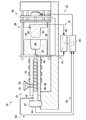
図1〜2の図及び例に関連して、図面全体を通して、同様の番号は、同じまたは対応する要素を示し、図1は、成形プラスチックパーツを製造するための射出成形装置10を例示している。射出成形装置10は、ホッパ14と、被加熱バレル16と、往復スクリュー18、と、ノズル20とを含む射出成形ユニット12を含むことができる。往復スクリュー18は、被加熱バレル16内に配設され、被加熱バレル16に対して往復運動するように構成されることができる。作動ユニット22は、往復スクリュー18に動作可能に結合され、電力による往復スクリュー18の往復運動を容易にすることができる。いくつかの実施形態では、作動ユニット22は、油圧モータを備えることができる。いくつかの実施形態では、作動ユニット22は、電気モータを備えることができる。他の実施形態では、作動ユニットは、付加的にまたは代替的に、バルブ、フローコントローラ、増幅器、または射出成形装置もしくは非射出成形装置に好適な任意の種々な他の制御装置を備えることができる。熱可塑性材料ペレット24は、ホッパ14内に置かれ、被加熱バレル16内に供給されることができる。いったん被加熱バレル16の内部に入ると、熱可塑性材料ペレット24は、加熱されて(例えば、約130℃〜約410℃の間)溶融され、溶融熱可塑性材料26を形成することができる。往復スクリュー18は、被加熱バレル16の内部で往復運動して、溶融熱可塑性材料26をノズル20の中に向かわせることができる。
In connection with the figures and examples of FIGS. 1-2, similar numbers indicate the same or corresponding elements throughout the drawing, and FIG. 1 illustrates an
ノズル20は、関連して金型キャビティ34を形成する第1及び第2の金型部30、32を有する金型28と関連付けることができる。クランピングユニット36は、金型28を支持することができ、第1及び第2の金型部30、32をクランプ位置(図示せず)と非クランプ位置(図1)との間で動かすように構成されることができる。第1及び第2の金型部30、32がクランプ位置にあるとき、ノズル20からの溶融熱可塑性材料26は、第1の金型部30によって定義されたゲート38に、かつ金型キャビティ34の中に、提供することができる。金型キャビティ34が充填されるに従って、溶融熱可塑性材料26は、金型キャビティ34の形状を取ることができる。いったん金型キャビティ34が十分に充填されると、往復スクリュー18は、停止することができ、溶融熱可塑性材料26は、金型28の内部で冷却されることが可能になる。いったん溶融熱可塑性材料26が冷却されて凝固するか、または少なくとも部分的に凝固すると、第1及び第2の金型部30、32は、それらの非クランプ位置に動かされて、溶融部分が金型28から取り除かれることを可能にすることができる。いくつかの実施形態では、金型28は、生産率全体を向上させるように、複数の金型キャビティ(例えば、34)を含むことができる。
The
クランピングユニット36は、成形プロセス中におよそ1000P.S.I.〜およそ6000P.S.I.の範囲内のクランプ力を付与して、第1及び第2の金型部30、32をともにクランプ位置に保持することができる。これらのクランプ力を支持するために、いくつかの実施形態では、金型28は、約165BHNを超え、260BHNを下回る表面硬度を有する材料から形成することができるが、以下にさらに論述されるように、材料が容易に機械加工可能である限り、260より大きい表面硬度BHN値を有する材料を用いてもよい。いくつかの実施形態では、金型28は、クラス101または102の射出金型(例えば、「超高生産性金型(ultra−high productivity mold)」)とすることができる。
The
射出成形装置10は、射出成形装置10の様々な構成要素と信号通信するネイティブコントローラ40を含むことができる。例えば、このネイティブコントローラ40は、信号線45を介してスクリュー制御44と信号通信することができる。そのネイティブコントローラ40は、スクリュー制御44に命令し、所望の成形プロセスを維持する速度で往復スクリュー18を前進させることができ、その結果、材料粘性、金型温度、溶融温度におけるばらつき、及び充填率に影響する他のばらつきが、ネイティブコントローラ40によって考慮される。成形サイクル中直ちにネイティブコントローラ40によって調整がなされてもよく、または後続のサイクルで補正をすることができる。さらに、数多くのサイクルからの数個の信号を、ネイティブコントローラ40によって、成形プロセスに対する調整を行うための基準として用いることができる。
The
ネイティブコントローラ40は、成形プロセスを制御するための好適な任意の種々のコントローラとすることができる。いくつかの実施形態では、ネイティブコントローラ40は、PIDコントローラとすることができる。ネイティブコントローラ40は、例えば、信号線37を介してクランピングユニット36の移動などの、射出成形装置10における種々の異なった機能を制御する役目を担うことができる。ネイティブコントローラ40は、射出成形ユニット12に対して独自に対応でき、かつ射出成形ユニット12と一緒に組み込まれるオンボードコントローラとすることができる。このようなことから、ネイティブコントローラ40の制御アーキテクチャに対する修正は、時間を食い、費用がかかり、ときには不可能であることがある。
The
一実施形態では、作動ユニット22が油圧モータである場合、スクリュー制御44は、往復スクリュー18と関連付けられる油圧バルブを備えることができる。別の実施形態では、作動ユニット22が電気モータである場合、スクリュー制御44は、往復スクリュー18と関連付けられる電気コントローラを備えることができる。図1の実施形態では、ネイティブコントローラ40は、ネイティブコントローラ40の出力部からスクリュー制御44に送信される信号を発生させることができる。
In one embodiment, if the
なおも図1を参照すると、リモートコントローラ46は、ネイティブコントローラ40、射出圧力センサ42、ノズル20内に、ノズルに、またはノズル付近に設置された溶融圧力センサ48、及び金型キャビティ34の一端の直近に設置されたキャビティ圧力センサ50と信号通信することができる。射出成形装置10、ネイティブコントローラ40は、作動ユニット22に設置された射出圧力センサ42と信号通信をすることができる(破線で示されている)。射出圧力センサ42は、フィードバック信号を、信号線43を介して、ネイティブコントローラ40に提供することによって、被加熱バレル16内部の射出圧力(すなわち、往復スクリュー18の先頭における被加熱バレル16の圧力)の検出(直接または間接)を容易にすることができる。ネイティブコントローラ40は、フィードバック信号から射出圧力を検出することができ、スクリュー制御44を制御することによって、射出成形装置10内の圧力を制御する(例えば、フィードバック制御する)ことができ、このスクリュー制御は、射出成形ユニット12によって噴射率を制御する。
Still referring to FIG. 1, the
溶融圧力センサ48は、ノズル20における、またはノズル付近の溶融熱可塑性材料26の実際の溶融圧力(例えば、測定された溶融圧力)の検出(直接または間接)を容易にすることができる。溶融圧力センサ48は、溶融熱可塑性材料26と直接接触してもよく、またはしなくてもよい。いくつかの実施形態では、溶融圧力センサ48は、ノズル20における溶融圧力に応じてネイティブコントローラ40の入力に信号回線49を介して電気信号を送信する圧力トランスデューサとすることができる。いくつかの実施形態では、溶融圧力センサ48は、ノズル20における溶融熱可塑性材料26の多様な追加的または代替的な特性、例えば温度、粘性、及び/または流量等のいずれかの監視を容易にすることができる。溶融圧力センサ48がノズル20内部に設置されていない場合、ネイティブコントローラ40は、論理、コマンド、及び/または実行可能プログラム命令によって設定され、構成され、及び/またはプログラムされ、ノズル20内の、ノズルにおける、またはノズル付近の測定された特性に対する値を推定し、または算出するために適切な補正係数を提供することができる。温度、粘性、流量、圧力、ひずみ、速度、その他等の、当技術分野で知られている溶融熱可塑性材料26、ネジ18、バレル等の任意の他の特性、またはこれらのいずれかを表す任意の他の特性ののうちの1つ以上を測定するために、溶融圧力センサ以外のセンサを使用することができることは、評価されるべきである。
The
キャビティ圧力センサ50は、ノズル20内の、ノズルにおける、またはノズル付近の溶融熱可塑性材料26の溶融圧力の検出(直接または間接)を容易にすることができる。キャビティ圧力センサ50は、溶融熱可塑性材料26と直接接触してもよく、またはしなくてもよい。いくつかの実施形態では、キャビティ圧力センサ50は、金型キャビティ34内のキャビティ圧力に応じてネイティブコントローラ40の入力部に信号線51を介して電気信号を送信する圧力トランスデューサとすることができる。他の実施形態では、キャビティ圧力センサ50は、溶融熱可塑性材料26または金型28の多様な付加的または代替的な特性、例えば溶融熱可塑性材料26のひずみ及び/または流量等のいずれかの監視を容易にすることができる。キャビティ圧力センサ50が金型キャビティ34内部に設置されていない場合、ネイティブコントローラ40は、論理、コマンド、及び/または実行可能プログラム命令によって設定され、構成され、及び/またはプログラムされ、金型28の測定された特性に対する値を推定し、または算出するために適切な補正係数を提供することができる。
The
以下に、より詳細に説明されるように、リモートコントローラ46は、射出成形装置10の溶融圧力及び/またはキャビティ圧力を検知することができ、そして信号(例えば、変更されたフィードバック信号)をネイティブコントローラ40に送信することができ、その信号は、ネイティブコントローラ40が往復スクリュー18を制御する方法に影響を及ぼす。リモートコントローラ46は、その成形プロセスの別の制御を容易にするように、変更されたフィードバック信号をネイティブコントローラ40に提供するための好適な任意の種々のコントローラとすることができる。いくつかの実施形態では、リモートコントローラ46は、PIDコントローラとすることができる。いくつかの実施形態では、リモートコントローラ46は、射出成形ユニット12に後付けされ、ネイティブコントローラ40が提供することができない付加的な機能性を提供することができる。
As described in more detail below, the
リモートコントローラ46を射出成形装置10に後付けする(例えば、関連付ける)ため、溶融圧力センサ48及び/またはキャビティ圧力センサ50からの出力部は、ネイティブコントローラ40から取り外され、そしてリモートコントローラ46に接続され、それによってリモートコントローラ46にそれぞれのフィードバック信号を迂回させることができる。リモートコントローラ46からの出力部は、溶融圧力センサ48及び/またはキャビティ圧力センサ50が以前に取り付けられたネイティブコントローラ40の入力部に接続されることができる。いったん後付けが完了すると、ネイティブコントローラ40は、もはや溶融圧力センサ48またはキャビティ圧力センサ50からフィードバック信号を直接受信しない。代わって、以下に説明されているように、リモートコントローラ46は、これらのフィードバック信号を受信し、そしてネイティブコントローラ40の動作を強化する変更されたフィードバック信号をネイティブコントローラ40に送信する。よって、ネイティブコントローラ40及びリモートコントローラ46は、リモートコントローラ46を付加する以前に実在した閉ループ型配列で動作する。
To retrofit (eg, associate) the
いくつかの実施形態では、溶融圧力センサ48及びキャビティ圧力センサ50は、従前より射出成形ユニット12上に実在することができ、ネイティブコントローラ40と信号通信することができる。そのような実施形態では、溶融圧力センサ48及びキャビティ圧力センサ50からの出力部は、ネイティブコントローラ40から取り外され、リモートコントローラ46と再接続されることができる。いくつかの実施形態では、溶融圧力センサ48及びキャビティ圧力センサ50は、従前より射出成形ユニット12上に実在しなくてもよい。そのような実施形態では、溶融圧力センサ48及びキャビティ圧力センサ50は、リモートコントローラ46の後付けの間に設置され、次いでそのリモートコントローラ46と接続されることができる。本開示の目的のため、溶融圧力及びキャビティ圧力のそれぞれは、射出圧力が「制御量」であるとみなされることができる場所で、「制御される量」とみなされることができる。制御される量は、金型キャビティ34の効果的な充填を容易にするように制御されることができる、熱可塑性材料26または金型キャビティ34の任意の特性であると理解されることができる。制御量は、往復スクリュー18または他の射出軸の効果的な制御を容易にするように制御されることができる、射出成形ユニット12の任意の特性であると理解されることができる。
In some embodiments, the
ネイティブコントローラ40とリモートコントローラ46との間のフィードバック関係の例のブロック図が、図2に例示され、ここで論述される。リモートコントローラ46において、射出成形装置10の所望の溶融圧力を表す設定点P2を提供することができる。射出成形装置10の実際の溶融圧力を示す信号S4が、リモートコントローラ46に提供されることができる。実際の溶融圧力は、設定点P2に対して比較されることができ、誤差信号E2を発生させ、制御信号C2を発生させるPID制御アルゴリズムG2に提供されることができる。制御信号C2及び信号S4は、結合された変更されたフィードバック信号S6にされ得る。いくつかの実施態様では、変更されたフィードバック信号S6はまた、フィードフォワードコンポーネントFF1を含むこともできる。変更されたフィードバック信号S6は、効果的な変更されたフィードバック信号の発生を容易にする好適な任意の他の種々の制御コンポーネントを付加的または代替的に含むことができる。
A block diagram of an example of a feedback relationship between the
変更されたフィードバック信号S6は、溶融圧力センサ48及び/またはキャビティ圧力センサ50からのフィードバック信号に代わって、ネイティブコントローラ40に送信されることができる。一実施形態では、変更されたフィードバック信号S6は、ネイティブコントローラ40とリモートコントローラ46との間の単一方向伝送リンクを通して送信されることができる。そのような実施形態では、ネイティブコントローラ40は、リモートコントローラ46にいかなる信号も送信しない。
The modified feedback signal S6 can be transmitted to the
ネイティブコントローラ40において、作動ユニット22の動作は、変更されたフィードバック信号S6に応じて制御されることができる。例えば、作動ユニット22の所望の射出圧力を表す設定点P1が、提供されることができる。この設定点P1は、変更されたフィードバック信号S6に対して比較されることができ、誤差信号E1が発生させることができる。誤差信号E1は、スクリュー制御44に命令する制御信号C1を発生させるPID制御アルゴリズムG1にもたらされ、射出圧力が設定点P1により示された所望の射出圧力に向かって収束することができる速度で、往復スクリュー18を前進させることができる。
In the
ネイティブコントローラ40は、設定点P1という所望の射出圧力に向かって制御しているが、リモートコントローラ46からの変更されたフィードバック信号S6は、(作動ユニット22の射出圧力を設定点P1に向かって制御するのではなく)実際に射出成形装置10の溶融圧力を設定点P2によって定義された所望の圧力に向かって制御する方法で、ネイティブコントローラ40からの制御信号C1に影響を及ぼすことができる。このため、リモートコントローラ46は、ネイティブコントローラ40の制御アーキテクチャの再プログラミング/再構成を必要とすることなく、射出成形ユニット12の溶融圧力を制御する能力をもたらすことができる。このようなことから、リモートコントローラ46は、ネイティブコントローラ40がそのような機能性を独立に提供することができない射出成形装置10に機能性を付加するコスト効果があり、かつ直接的な解決策とすることができる。
The
成形サイクル中、射出成形ユニット12の溶融圧力は、設定点P2を変更することによって変化させることができる。一実施形態では、異なった設定点が、成形サイクルの異なった状態に対応させることができる。例えば、最初の射出状態を開始するため、熱可塑性ペレット24を溶融し始め、かつノズル20にその溶融物を分配するのに十分上昇した溶融圧力を引き起こす設定点を提供することができる。いったんその溶融圧力が、金型キャビティ34を充填し始めるのに十分上昇すると、金型キャビティ34を適正に充填する適切な圧力で充填状態を開始する設置点を提供することができる。いったん金型キャビティ34が、ほぼ充填されると(例えば、充填の終了)、パッキング状態を開始し、保持状態の間実質的に一定の溶融圧力で保持するのに十分下降するような設定点を提供することができる。
During the molding cycle, the melting pressure of the
ネイティブコントローラ40及び/またはリモートコントローラ46は、ハードウエア、ソフトウエア、またはそれら両方の任意の組み合わせで実現されることができ、制御を達成するための1つ以上のコントローラを有する任意の制御機構を有することができる。ネイティブコントローラ40は、作動ユニット22の射出圧力を検知し、かつ制御するように説明されているが、ネイティブコントローラ40は、例えば被加熱バレル16の温度、ホッパ14の容積、または往復スクリュー18の速度などの好適な任意の種々の代替制御量を検知し、かつ制御するように構成されることができることは、評価されるべきである。また、リモートコントローラ46は、射出成形ユニット12の溶融圧力を制御する能力を提供するように説明されているが、作動ユニット22の射出圧力を使ったリモートコントローラは、例えばキャビティ圧力などの好適な任意の種々の代替制御量を検知し、かつ制御するように構成されることができることも、評価されるべきである。
The
前述の実施形態及び例は、例示及び説明を目的として提示されてきた。包括的であるか、または説明された形式に限定することは意図されていない。例えば、リモートコントローラ46は、射出成形装置上に提供されるように説明されているが、リモートコントローラは、ネイティブコントローラからのフィードバック制御を用いて、ネイティブコントローラがそのような機能性を独立して提供することができない装置に機能性を付加する任意の装置上に提供されることができる。上記の教示に鑑みて、数多くの改変が可能である。それらの改変のうちのいくつかが述べられ、他は当業者によって理解されるであろう。実施形態は、種々の実施形態の例示のために選択され説明された。当然ながら、その範囲は、本明細書で述べられた例または実施形態に限定されず、当業者によって、任意の数の用途及び同等の装置で使用することができる。むしろ、本明細書では、当該範囲は添付の特許請求の範囲によって定義されることが意図される。また、特許請求された、及び/または説明された任意の方法について、当該方法がフロー図とともに説明されているかに関わらず、特にことわらない限り、または文脈上必要とされない限り、方法の実行において行われるあらゆる明示的または暗示的なステップの順序付けは、それらのステップが、提示された順序で行われなければならず、また異なる順序で、または並行して行われ得ることを暗示しないことが理解されるべきである。
The aforementioned embodiments and examples have been presented for purposes of illustration and description. It is not intended to be inclusive or limited to the described form. For example, the
本明細書に開示された寸法及び値は、列記されたまさにその数値に厳密に限定されるとして理解されるべきではない。代わりに、特にことわらない限り、そのような寸法は各々、列記された値と、その値付近の機能的に同等な範囲との両方を意味することが意図される。例えば、「40mm」として開示された寸法は、「約40mm」を意味することが意図される。 The dimensions and values disclosed herein should not be understood as being strictly limited to the very numbers listed. Alternatively, unless otherwise stated, each such dimension is intended to mean both the listed values and a functionally equivalent range in the vicinity of those values. For example, the dimensions disclosed as "40 mm" are intended to mean "about 40 mm".
あらゆる相互参照または関連特許もしくは出願、及び本出願がその優先権または利益を主張するあらゆる特許出願または特許を含む、本明細書で引用されたすべての文書は、明らかに除外しないかそうでなければ限定されない限り、その全体が参照により本明細書に組み入れられる。あらゆる文書の引用は、それが、本明細書に開示または特許請求されたあらゆる発明に関する先行技術であること、またはそれ単独もしくは任意の他の参照文献との任意の組み合わせが、あらゆるそのような発明を教示、暗示、または開示することを認めるものではない。さらに、本書における用語のあらゆる意味または定義が、参照により組み入れられた文書における同じ用語のあらゆる意味または定義と矛盾する限りでは、本書においてその用語に割り当てられた意味または定義が勝るものとする。 All documents cited herein, including any cross-reference or related patents or applications, and any patent application or patent for which this application claims its priority or interest, are not expressly excluded or otherwise excluded. Unless limited, the whole is incorporated herein by reference. A citation of any document is that it is prior art for any invention disclosed or claimed herein, or any such invention alone or in any combination with any other reference. Is not permitted to teach, imply, or disclose. Moreover, as long as any meaning or definition of a term in this document contradicts any meaning or definition of the same term in the document incorporated by reference, the meaning or definition assigned to that term in this document shall prevail.
本発明の特定の実施形態を例示し説明してきたが、当業者においては、本発明の本質及び範囲から逸脱することなく、種々の他の変更及び改変を成すことができることが自明であろう。したがって、添付の特許請求の範囲において、本発明の範囲内であるすべてのそのような変更及び改変が網羅されることが意図される。 Having illustrated and described specific embodiments of the invention, it will be apparent to those skilled in the art that various other modifications and modifications can be made without departing from the essence and scope of the invention. Therefore, it is intended that the appended claims cover all such modifications and modifications that are within the scope of the present invention.
Claims (6)
前記射出成形装置は被加熱バレル、射出軸、及び作動ユニットを含み、
前記作動ユニットは、前記射出軸と動作可能に結合され、前記被加熱バレルに対して前記射出軸の動作を容易にするように構成されており、
前記後付けに先立ち、前記ネイティブコントローラは、フィードバック信号に基づき第1の制御アルゴリズムを用いて前記作動ユニットの前記動作を制御するように構成されていて、
前記方法は、
成形プロセスの前記制御量をセンサにおいて検知することと、
前記制御量に基づいて前記センサにより前記フィードバック信号を発生させることと、
前記リモートコントローラにおいて、
前記フィードバック信号を受信することと、
前記成形プロセスの前記制御量を所望の制御量設定点と比較することと、
前記制御量および前記所望の制御量設定点に基づき第2の制御アルゴリズムを用いて制御信号を発生させることと、
前記制御信号及び前記フィードバック信号を結合して、変更されたフィードバック信号にすることと、
前記変更されたフィードバック信号を前記フィードバック信号の代わりに前記ネイティブコントローラに送信することと、
前記ネイティブコントローラにおいて、前記ネイティブコントローラで実行される前記作動ユニットの前記動作の制御を変更するように、前記変更されたフィードバック信号の少なくとも部分的に基づき前記第1の制御アルゴリズムを用いて前記作動ユニットの前記動作を制御することと、
を含む、方法。 It is a method of controlling the control amount of the injection molding apparatus via a retrofit type remote controller with respect to the native controller of the injection molding apparatus.
The injection molding apparatus includes a barrel to be heated, an injection shaft, and an operating unit.
The actuating unit is operably coupled to the injection shaft and is configured to facilitate the operation of the injection shaft with respect to the heated barrel.
Prior to the retrofitting, the native controller is configured to control the operation of the actuating unit using a first control algorithm based on the feedback signal.
The method is
Detecting the controlled amount of the molding process with a sensor and
To generate the feedback signal by the sensor based on the control amount,
In the remote controller
Receiving the feedback signal and
Comparing the control amount of the molding process with the desired control amount setting point and
To generate a control signal using the second control algorithm based on the control amount and the desired control amount setting point,
Combining the control signal and the feedback signal into a modified feedback signal
Sending the modified feedback signal to the native controller in place of the feedback signal
The actuating unit using the first control algorithm based on at least a portion of the modified feedback signal such that the native controller modifies the control of the operation of the actuating unit performed by the native controller. To control the above-mentioned operation of
Including methods.
前記成形プロセスの前記制御量を前記所望の制御量設定点と比較することは、前記射出成形装置の前記溶融圧力を所望の溶融圧力設定点と比較することを含み、
前記制御信号を発生させることは、前記溶融圧力および前記所望の溶融圧力設定点に基づき前記制御信号を発生させることを含む、
請求項1に記載の方法。 Detecting the controlled amount of the molding process includes detecting the melting pressure of the injection molding apparatus.
Comparing the controlled amount of the molding process with the desired controlled amount setting point includes comparing the melting pressure of the injection molding apparatus with the desired melting pressure setting point.
Generating the control signal includes generating the control signal based on the melting pressure and the desired melting pressure setting point.
The method according to claim 1.
前記溶融圧力を検知することは、
前記センサから溶融圧力信号を受信することと、
前記溶融圧力信号に基づき前記溶融圧力に対する値を決定することと、を含み、
前記溶融圧力および前記所望の溶融圧力設定点に基づき制御信号を発生させることは、
前記溶融圧力に対する前記所望の溶融圧力設定点を定義することと、
前記所望の溶融圧力設定点を前記溶融圧力の前記値と比較することと、を含む、
請求項2に記載の方法。 Detecting the control amount of the molding process includes receiving a signal from the sensor.
Detecting the melting pressure
Receiving a melting pressure signal from the sensor
Including determining a value for the melting pressure based on the melting pressure signal.
Generating a control signal based on the melting pressure and the desired melting pressure setting point
Defining the desired melting pressure setting point for the melting pressure and
Comparing the desired melting pressure setting point with the value of the melting pressure includes.
The method according to claim 2.
Applications Claiming Priority (3)
| Application Number | Priority Date | Filing Date | Title |
|---|---|---|---|
| US201562267011P | 2015-12-14 | 2015-12-14 | |
| US62/267,011 | 2015-12-14 | ||
| PCT/US2016/065496 WO2017105979A1 (en) | 2015-12-14 | 2016-12-08 | Remote controller for controlling apparatus by diverting feedback signal from native controller to the remote controller and methods for same |
Publications (3)
| Publication Number | Publication Date |
|---|---|
| JP2018538175A JP2018538175A (en) | 2018-12-27 |
| JP2018538175A5 JP2018538175A5 (en) | 2020-01-23 |
| JP6895965B2 true JP6895965B2 (en) | 2021-06-30 |
Family
ID=57708758
Family Applications (1)
| Application Number | Title | Priority Date | Filing Date |
|---|---|---|---|
| JP2018530533A Active JP6895965B2 (en) | 2015-12-14 | 2016-12-08 | Remote controller for controlling the device by bypassing the feedback signal from the native controller to the remote controller and its control method |
Country Status (7)
| Country | Link |
|---|---|
| US (2) | US10399262B2 (en) |
| EP (1) | EP3389979B1 (en) |
| JP (1) | JP6895965B2 (en) |
| CN (1) | CN108290333B (en) |
| CA (1) | CA3006806C (en) |
| MX (1) | MX2018007122A (en) |
| WO (1) | WO2017105979A1 (en) |
Families Citing this family (4)
| Publication number | Priority date | Publication date | Assignee | Title |
|---|---|---|---|---|
| MX2018007122A (en) | 2015-12-14 | 2019-02-07 | Imflux Inc | Remote controller for controlling apparatus by diverting feedback signal from native controller to the remote controller and methods for same. |
| JP7245854B2 (en) * | 2018-06-22 | 2023-03-24 | アイエムフラックス インコーポレイテッド | Systems and approaches for controlling injection molding machines |
| JP7241781B2 (en) * | 2018-06-22 | 2023-03-17 | アイエムフラックス インコーポレイテッド | Systems and approaches for controlling injection molding machines |
| DE102020117665A1 (en) | 2020-07-03 | 2022-01-05 | Rheinisch-Westfälische Technische Hochschule (Rwth) Aachen | Phase-combining, model-based, predictive control of an injection molding machine and an injection molding machine with such a control |
Family Cites Families (32)
| Publication number | Priority date | Publication date | Assignee | Title |
|---|---|---|---|---|
| US1007686A (en) | 1907-09-21 | 1911-11-07 | Dwight Gerber | Car-truck. |
| US4311446A (en) * | 1974-01-21 | 1982-01-19 | Usm Corporation | Injection molding machine controls |
| DE2514009C3 (en) * | 1975-03-29 | 1981-03-12 | Robert Bosch Gmbh, 7000 Stuttgart | Plastic injection molding machine with a control device for regulating the hydraulic pressure acting on a plasticizing and injection screw |
| US4988273A (en) * | 1989-06-23 | 1991-01-29 | Cincinnati Milacron Inc. | Injection molding machines having a brushless DC drive system |
| JP2913233B2 (en) * | 1992-08-10 | 1999-06-28 | 住友重機械工業株式会社 | Pressure control device for electric injection molding machine |
| DE4321604A1 (en) * | 1993-06-29 | 1995-01-19 | Siemens Ag | Control device, in particular for a non-linear, time-variant process |
| JP3292552B2 (en) | 1993-07-29 | 2002-06-17 | 東洋機械金属株式会社 | Molding machine control system with remote control device |
| JP2756077B2 (en) * | 1993-12-27 | 1998-05-25 | 東芝機械株式会社 | Automatic setting method of injection molding speed condition of injection molding machine |
| JP3486456B2 (en) | 1994-04-27 | 2004-01-13 | 株式会社日本製鋼所 | Remote control method, local controller and remote control device for injection molding machine |
| US6681145B1 (en) * | 1996-06-06 | 2004-01-20 | The Boeing Company | Method for improving the accuracy of machines |
| JP3282092B2 (en) * | 1997-06-03 | 2002-05-13 | 日精樹脂工業株式会社 | Injection molding method of injection molding machine |
| US5869108A (en) * | 1997-06-06 | 1999-02-09 | Sumitomo Heavy Industries, Ltd. | Control system for controlling a motor-driven injection molding machine |
| IT1308787B1 (en) * | 1999-07-05 | 2002-01-10 | Fiat Ricerche | PROPULSION CONTROL SYSTEM FOR A VEHICLE. |
| JP3256902B2 (en) * | 2000-03-13 | 2002-02-18 | 住友重機械工業株式会社 | Control device for injection molding machine |
| US6663804B2 (en) * | 2000-03-13 | 2003-12-16 | Sumitomo Heavy Industries, Ltd. | Method and apparatus for controlling injection molding machine capable of reducing variations in weight of molded products |
| DE10115253A1 (en) * | 2001-03-28 | 2002-10-31 | Siemens Ag | production machine |
| JP4677682B2 (en) * | 2001-05-11 | 2011-04-27 | 株式会社安川電機 | Pressure control method and apparatus for injection shaft of electric injection molding machine |
| US7653460B2 (en) * | 2006-08-14 | 2010-01-26 | Husky Injection Molding Systems Ltd. | Thermal management of extruder of molding system, amongst other things |
| US8983680B2 (en) * | 2006-08-24 | 2015-03-17 | Kairos Autonmi, Inc. | Unmanned vehicle retrofitting system |
| US8610305B2 (en) * | 2006-09-18 | 2013-12-17 | Hinbit Development Ltd. | Retrofitting power distribution device and uses thereof |
| JP5604615B2 (en) * | 2009-03-23 | 2014-10-08 | 佐藤 寛 | Energy saving control device and equipment or injection molding machine equipped with this energy saving control device |
| US8786245B2 (en) * | 2010-05-18 | 2014-07-22 | Mitsubishi Electric Corporation | Motor control device |
| US9205587B2 (en) * | 2012-08-08 | 2015-12-08 | Synventive Molding Solutions, Inc. | Flow control apparatus and method |
| WO2012162245A1 (en) * | 2011-05-20 | 2012-11-29 | The Procter & Gamble Company | Method and apparatus for substantially constant pressure injection molding of thinwall parts |
| WO2012162218A1 (en) * | 2011-05-20 | 2012-11-29 | The Procter & Gamble Company | Apparatus and method for injection molding at low constant pressure |
| JP5998009B2 (en) * | 2011-12-12 | 2016-09-28 | 東芝機械株式会社 | Molding machine control device and molding machine control method |
| US9387616B2 (en) * | 2012-08-03 | 2016-07-12 | Otto Männer Innovation GmbH | Hot runner injection molding apparatus with additional controller |
| US8980146B2 (en) * | 2013-08-01 | 2015-03-17 | Imflux, Inc. | Injection molding machines and methods for accounting for changes in material properties during injection molding runs |
| CN105829056A (en) * | 2013-12-19 | 2016-08-03 | 艾姆弗勒克斯有限公司 | Methods of forming overmolded articles |
| JP6032232B2 (en) * | 2014-03-14 | 2016-11-24 | 横河電機株式会社 | measuring device |
| WO2016048934A1 (en) * | 2014-09-22 | 2016-03-31 | iMFLUX Inc. | Methods of using retrofitted injection molding machines with faster cycle times |
| MX2018007122A (en) | 2015-12-14 | 2019-02-07 | Imflux Inc | Remote controller for controlling apparatus by diverting feedback signal from native controller to the remote controller and methods for same. |
-
2016
- 2016-12-08 MX MX2018007122A patent/MX2018007122A/en unknown
- 2016-12-08 CN CN201680068399.4A patent/CN108290333B/en active Active
- 2016-12-08 WO PCT/US2016/065496 patent/WO2017105979A1/en active Application Filing
- 2016-12-08 JP JP2018530533A patent/JP6895965B2/en active Active
- 2016-12-08 EP EP16820422.0A patent/EP3389979B1/en active Active
- 2016-12-08 CA CA3006806A patent/CA3006806C/en active Active
- 2016-12-14 US US15/378,793 patent/US10399262B2/en active Active
-
2019
- 2019-07-16 US US16/513,511 patent/US10994461B2/en active Active
Also Published As
| Publication number | Publication date |
|---|---|
| MX2018007122A (en) | 2019-02-07 |
| US10399262B2 (en) | 2019-09-03 |
| US20170165887A1 (en) | 2017-06-15 |
| CN108290333A (en) | 2018-07-17 |
| WO2017105979A1 (en) | 2017-06-22 |
| CA3006806C (en) | 2021-03-30 |
| CN108290333B (en) | 2021-01-12 |
| EP3389979B1 (en) | 2021-04-21 |
| CA3006806A1 (en) | 2017-06-22 |
| US10994461B2 (en) | 2021-05-04 |
| US20190337208A1 (en) | 2019-11-07 |
| EP3389979A1 (en) | 2018-10-24 |
| JP2018538175A (en) | 2018-12-27 |
Similar Documents
| Publication | Publication Date | Title |
|---|---|---|
| JP6964587B2 (en) | Remote controller for controlling the device by bypassing the feedback signal from the native controller to the remote controller and its control method | |
| US10994461B2 (en) | Remote controller for controlling apparatus by diverting feedback signal from native controller to the remote controller and methods for same | |
| CA2994011C (en) | Injection molding apparatus and method of controlling same | |
| US11135754B2 (en) | Remote controller for controlling apparatus by diverting feedback signal from native controller to the remote controller and methods for same | |
| US20230031650A1 (en) | Systems and Approaches for Controlling an Injection Molding Machine | |
| TWI708673B (en) | Injection molding apparatus and method of controlling same | |
| WO2023043471A1 (en) | Remote controller for feedback control and methods for same |
Legal Events
| Date | Code | Title | Description |
|---|---|---|---|
| A521 | Written amendment |
Free format text: JAPANESE INTERMEDIATE CODE: A523 Effective date: 20191205 |
|
| A621 | Written request for application examination |
Free format text: JAPANESE INTERMEDIATE CODE: A621 Effective date: 20191205 |
|
| A977 | Report on retrieval |
Free format text: JAPANESE INTERMEDIATE CODE: A971007 Effective date: 20201221 |
|
| A131 | Notification of reasons for refusal |
Free format text: JAPANESE INTERMEDIATE CODE: A131 Effective date: 20210119 |
|
| TRDD | Decision of grant or rejection written | ||
| A01 | Written decision to grant a patent or to grant a registration (utility model) |
Free format text: JAPANESE INTERMEDIATE CODE: A01 Effective date: 20210511 |
|
| A61 | First payment of annual fees (during grant procedure) |
Free format text: JAPANESE INTERMEDIATE CODE: A61 Effective date: 20210608 |
|
| R150 | Certificate of patent or registration of utility model |
Ref document number: 6895965 Country of ref document: JP Free format text: JAPANESE INTERMEDIATE CODE: R150 |