JP6894251B2 - sewing machine - Google Patents
sewing machine Download PDFInfo
- Publication number
- JP6894251B2 JP6894251B2 JP2017026081A JP2017026081A JP6894251B2 JP 6894251 B2 JP6894251 B2 JP 6894251B2 JP 2017026081 A JP2017026081 A JP 2017026081A JP 2017026081 A JP2017026081 A JP 2017026081A JP 6894251 B2 JP6894251 B2 JP 6894251B2
- Authority
- JP
- Japan
- Prior art keywords
- feed
- tape
- sewing machine
- belt
- motor
- Prior art date
- Legal status (The legal status is an assumption and is not a legal conclusion. Google has not performed a legal analysis and makes no representation as to the accuracy of the status listed.)
- Active
Links
Images


Classifications
-
- D—TEXTILES; PAPER
- D05—SEWING; EMBROIDERING; TUFTING
- D05B—SEWING
- D05B27/00—Work-feeding means
Landscapes
- Engineering & Computer Science (AREA)
- Textile Engineering (AREA)
- Sewing Machines And Sewing (AREA)
Description
本発明は、テープ状の被縫製物の縫着に適したミシンに関する。 The present invention relates to a sewing machine suitable for sewing a tape-shaped object to be sewn.
従来のミシンは、テープ状の被縫製物をシート状の被縫製物に縫着する場合に、シート状の被縫製物の上に供給装置がテープ状の被縫製物を供給し、テープ状の被縫製物とシート状の被縫製物とを一緒に布押さえと送り歯に挟持してこれらの送りを行っていた(例えば、特許文献1参照)。 In a conventional sewing machine, when a tape-shaped sewn object is sewn on a sheet-shaped sewn object, a supply device supplies the tape-shaped sewn object onto the sheet-shaped sewn object, and the tape-shaped sewn object is supplied. The sewn object and the sheet-shaped sewn object are sandwiched between the cloth retainer and the feed dog to feed them (see, for example, Patent Document 1).
しかしながら、特許文献1のミシンは、テープ状の被縫製物とシート状の被縫製物とを、布押さえと送り歯で挟持して送り動作を行っているので、下側のシート状の被縫製物のみが送り歯に接した状態となり、テープ状の被縫製物とシート状の被縫製物とで送り量のズレが生じるという問題があった。 However, in the sewing machine of Patent Document 1, since the tape-shaped sewn object and the sheet-shaped sewn object are sandwiched between the cloth retainer and the feed dog to perform the feed operation, the lower sheet-shaped sewn object is sewn. There is a problem that only the object is in contact with the feed dog, and the feed amount is deviated between the tape-shaped sewn object and the sheet-shaped sewn object.
本発明は、テープ状の被縫製物とシート状の被縫製物とを良好に送るミシンを提供することをその目的とする。 An object of the present invention is to provide a sewing machine that can satisfactorily feed a tape-shaped sewn object and a sheet-shaped sewn object.
請求項1記載の発明は、
シート状被縫製物にテープ状被縫製物の縫着を行うミシンにおいて、
一定の送り方向に被縫製物を送る複数の送りベルトとその送り動作の駆動源となる送りモーターとを備えた上ベルト機構を備え、
前記上ベルト機構の複数の送りベルトは、前記テープ状被縫製物に上から接する中央ベルトと、当該中央ベルトの両隣で前記シート状被縫製物に上から接する側方ベルトとを有し、
前記送りモーターは、前記中央ベルトの搬送を行う第一の送りモーターと前記側方ベルトの搬送を行う第二の送りモーターとを個別に有することを特徴とする。
The invention according to claim 1
In a sewing machine that sews a tape-shaped sewn object onto a sheet-shaped sewn object.
It is equipped with an upper belt mechanism equipped with a plurality of feed belts that feed the sewing material in a fixed feed direction and a feed motor that is a drive source for the feed operation.
The plurality of feed belts of the upper belt mechanism have a central belt that contacts the tape-shaped sewing object from above and side belts that contact the sheet-shaped sewing object from above on both sides of the central belt.
The feed motor is characterized by individually having a first feed motor that conveys the central belt and a second feed motor that conveys the side belts.
請求項2記載の発明は、請求項1記載のミシンにおいて、
前記中央ベルトは、前記テープ状被縫製物に接する位置と針落ち位置とが前記送り方向に沿って並ぶように配置され、且つ、前記針落ち位置に対して前記送り方向下流側で前記テープ状被縫製物に接するように配置されていることを特徴とする。
The invention according to claim 2 is the sewing machine according to claim 1.
The central belt is arranged so that the position in contact with the tape-shaped sewing object and the needle drop position are lined up along the feed direction, and the tape shape is downstream of the needle drop position in the feed direction. It is characterized in that it is arranged so as to be in contact with the sewn object.
請求項3記載の発明は、請求項1又は2記載のミシンにおいて、
前記送りモーターの送り速度を制御する制御装置を備え、
前記制御装置は、前記第一の送りモーターの送り速度と前記第二の送りモーターの送り速度とを個別に設定入力する設定部を備えることを特徴とする。
The invention according to claim 3 is the sewing machine according to claim 1 or 2.
A control device for controlling the feed rate of the feed motor is provided.
The control device is characterized by including a setting unit for individually setting and inputting the feed rate of the first feed motor and the feed rate of the second feed motor.
請求項4記載の発明は、請求項1から3のいずれか一項に記載のミシンにおいて、
前記テープ状被縫製物の供給装置を備え、
当該供給装置は、前記中央ベルトの送り方向に直交する方向について、当該中央ベルトに一致する配置で前記テープ状被縫製物の供給を行うように配置されていることを特徴とする。
The invention according to claim 4 is the sewing machine according to any one of claims 1 to 3.
The tape-shaped sewn material supply device is provided.
The supply device is characterized in that it is arranged so as to supply the tape-shaped sewn product in an arrangement corresponding to the central belt in a direction orthogonal to the feed direction of the central belt.
請求項5記載の発明は、請求項3記載のミシンにおいて、
前記テープ状被縫製物の供給装置を備え、
当該供給装置は、前記中央ベルトの送り方向に直交する方向について、当該中央ベルトに一致する配置で前記テープ状被縫製物の供給を行うように配置されおり、
前記テープ状被縫製物の供給装置は、一定の送り方向に前記テープ状被縫製物を送るローラーと、その送り動作の駆動源となるテープ送りモーターとを備え、
前記制御装置は、前記テープ送りモーターの送り速度を制御し、前記テープ送りモーターの送り速度と前記第一の送りモーターおよび前記第二の送りモーターの送り速度とを個別に設定入力する設定部を備えることを特徴とする。
The invention according to claim 5 is the sewing machine according to claim 3.
The tape-shaped sewn material supply device is provided.
The supply device is arranged so as to supply the tape-shaped sewn product in an arrangement corresponding to the central belt in a direction orthogonal to the feed direction of the central belt.
The tape-shaped sewn supply device includes a roller that feeds the tape-shaped sewn product in a fixed feeding direction, and a tape feeding motor that is a drive source for the feeding operation.
The control device controls the feed rate of the tape feed motor, and sets and inputs the feed rate of the tape feed motor and the feed rates of the first feed motor and the second feed motor individually. It is characterized by being prepared.
本発明は、テープ状被縫製物に接する中央ベルトと、当該中央ベルトの両隣でシート状被縫製物に接する側方ベルトとを有するので、これらにより任意の長さでテープ状被縫製物を送ることができ、テープ状の被縫製物を長さにかかわらず良好に縫着することが可能となる。
さらに、中央ベルトと両側の側方ベルトとを第一の送りモーターと第二の送りモーターとで個別に搬送するので、テープ状被縫製物とシート状被縫製物の送り速度の差を調整することが可能となり、これらの速度差の影響を低減し或いは制御することができ、テープ状被縫製物の縫着縫製による縫い品質の向上を図ることが可能となる。
Since the present invention has a central belt in contact with the tape-shaped sewn object and side belts in contact with the sheet-shaped sewn object on both sides of the central belt, the tape-shaped sewn object is fed by these. This makes it possible to sew a tape-shaped object to be sewn satisfactorily regardless of the length.
Further, since the central belt and the side belts on both sides are individually conveyed by the first feed motor and the second feed motor, the difference in feed rate between the tape-shaped sewn product and the sheet-shaped sewn product is adjusted. It is possible to reduce or control the influence of these speed differences, and it is possible to improve the sewing quality by sewing the tape-shaped sewing object.
[実施形態の概略構成]
本発明の実施形態であるミシン10について図1〜図11に基づいて説明する。
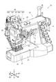
図1はミシン10の斜視図、図2はミシン10の針落ち位置周辺の斜視図である。
なお、以下の説明において、水平な一方向をX軸方向、水平且つX軸方向に直交する方向をY軸方向、鉛直上下方向をZ軸方向と定義する。また、図1に示すように、X軸方向の一方を「前」、他方を「後」とし、Y軸方向の一方の「左」、他方を「右」として以下の説明を行う。
ミシン10は、一本のテープ状被縫製物につき二本針による二重環縫いを行う二重環縫いミシンであり、シート状被縫製物である生地Cに対してテープ状被縫製物であるテープTの縫着を行う。なお、生地C及びテープTを総称して被縫製物という場合がある。
なお、本実施形態では、三本のテープTの縫着を行うミシンを例示しているが、テープTの本数は三本に限らず、単数又は三本以外の複数本の縫着を対象とするものでも良い。
[Outline configuration of the embodiment]
The
FIG. 1 is a perspective view of the
In the following description, one horizontal direction is defined as the X-axis direction, the horizontal and orthogonal directions to the X-axis direction are defined as the Y-axis direction, and the vertical vertical direction is defined as the Z-axis direction. Further, as shown in FIG. 1, one of the X-axis directions is "front", the other is "rear", one of the Y-axis directions is "left", and the other is "right".
The
In this embodiment, a sewing machine for sewing three tapes T is illustrated, but the number of tapes T is not limited to three, and a single piece or a plurality of tapes other than three are sewn. It may be something to do.
ミシン10は、ミシンフレーム20と、ミシンモーター16(図11参照)を駆動源として六本の縫い針11を上下動させる図示しない針上下動機構と、針板12の下側においてミシンモーター16を駆動源として六つのルーパーを往復移動させて六本の縫い針の上糸のループの各々にルーパー糸を挿通させる図示しないルーパー機構と、針板12の下側から送り歯を出没させて被縫製物をX軸方向に沿った送り方向下流側に送る図示しない下送り機構と、布押さえ31により被縫製物を上から押さえる布押さえ機構30と、針板12の上にある被縫製物に上から送りベルトを接触させて送り方向下流側(前方)に送る上ベルト機構50と、テープTを針落ち位置に供給するテープ供給装置70(図8参照)と、糸調子機構13と、天秤機構14と、上記各構成の制御を行う制御装置90とを備えている。
The
[ミシンフレーム]
ミシンフレーム20は、ミシン10の下部においてY軸方向に沿って延在するミシンベッド部21と、ミシンベッド部21の一端部から立設された立胴部22と、立胴部22の上端部からミシンベッド部21と同方向に延出されたミシンアーム部23とを備えている。
ミシンベッド部21の立胴部22とは逆側の端部上面には針板12が設けられ、当該針板12に形成された針穴に六本の縫い針11による針落ちが行われる。
[Sewing machine frame]
The
A
[針上下動機構]
針上下動機構は、ミシンアーム部23の先端部においてZ軸方向に沿って上下動可能に支持された針棒15(図3参照)と、当該針棒15の下端部に保持された六本の縫い針11と、ミシンモーター16から針棒15に上下動動作を付与するクランク機構とを備えている。
針棒15はその下端部において、六本の縫い針11をY軸方向に沿って並んだ状態で保持している。
ミシン10は、X軸方向前方に向かって被縫製物を搬送し、テープTの幅方向(短手方向)の両端部にテープTの長手方向(X軸方向)に沿って二本の縫い目を形成し、生地Cに縫着を行う。
なお、テープTは三本供給され、一本のテープTにつき二本の縫い針11により二本の上糸及び二本のルーパー糸を用いて縫製が行われる。
[Needle vertical movement mechanism]
The needle vertical movement mechanism consists of a needle rod 15 (see FIG. 3) supported so as to be vertically movable along the Z-axis direction at the tip of the sewing
At the lower end of the
The
Three tapes T are supplied, and one tape T is sewn with two
[糸調子機構及び天秤機構]
ミシン10は、上糸とルーパー糸とによる縫製を行い、糸調子機構13は、これら各糸に糸張力を付与する複数の糸調子器から構成されている。
[Thread tension mechanism and balance mechanism]
The
天秤機構14は、糸調子機構13において糸張力が付与された六本の上糸を挿通させる揺動式の天秤を備えている。この天秤は、ミシンモーター16から揺動の動力を得ており、縫い針11の上下動に同期して揺動することにより、適正なタイミングで各上糸の引き上げを行う。
The
[ルーパー機構]
ルーパー機構は、ミシンベッド部21の内部に配置され、Y軸方向に沿って往復の進退動作を行う六つのルーパーと、ミシンモーター16からルーパーに進退動作を付与する伝達機構とを備えている。
各ルーパーは、Y軸方向左側に向かって延出された尖鋭の部材であり、その先端部には、ルーパー糸を挿通する糸通し穴が形成され、針板12の下側に配置されている。そして、左方に向かって前進したときに、各ルーパーは下降した六本の縫い針11に通された上糸のループに個別に突入し、ルーパー糸を上糸のループに挿通することを可能としている。
また、各ルーパーが右方に後退する際に形成されるルーパー糸のループに下降してきた各縫い針11が個別に突入し、上糸が挿通される。これらを交互に繰り返すことにより、X軸方向に沿った二重環縫いの縫い目が形成されるようになっている。
[Looper mechanism]
The looper mechanism is arranged inside the sewing
Each looper is a sharp member extending toward the left side in the Y-axis direction, and a threading hole through which a looper thread is inserted is formed at the tip thereof and is arranged under the
Further, each
[下送り機構]
下送り機構は、針板12の開口部から歯先を出没させる送り歯と、送り歯をX−Z平面に沿った長円軌跡で周回させる周回機構とを備えている。
周回機構は、ミシンモーター16を駆動源として往復回動を行う水平送り軸と上下送り軸とを備え、送り歯を支持する送り台に上下の往復動作とX軸方向に平行な往復動作を付与して両動作の組み合わせにより送り歯にX−Z平面に沿った長円の周回動作を付与している。
送り歯は、長円軌跡の上部を通過する際に針板の開口部から歯先が上方に突出し、その際、送り歯は前方に向かって移動を行う。これにより、針板上の被縫製物に対して下側から歯先が接して、間欠的に一定の送りピッチで被縫製物を前方に送ることができる。
また、送り歯は、テープ供給装置70によりY軸方向に沿って並んで供給される三本のテープTの全範囲に対応して送りを行うことができるように、Y軸方向について通常の三倍の幅を有している。
[Downward feed mechanism]
The lower feed mechanism includes a feed dog that allows the tip of the tooth to appear and disappear from the opening of the
The orbiting mechanism includes a horizontal feed shaft and a vertical feed shaft that reciprocate with the
When the feed dog passes through the upper part of the oval locus, the tip of the tooth protrudes upward from the opening of the needle plate, and at that time, the feed dog moves forward. As a result, the tooth tips come into contact with the sewn object on the needle plate from below, and the sewn object can be intermittently fed forward at a constant feed pitch.
Further, the feed dogs are normally fed in the Y-axis direction so that the feed teeth can be fed over the entire range of the three tapes T supplied side by side along the Y-axis direction by the
[布押さえ機構]
図3は布押さえ機構30及び上ベルト機構50の側面図、図4は布押さえ機構30及び上ベルト機構50の下端部の斜視図、図5は布押さえ31の斜視図である。
図2〜図5に示すように、布押さえ機構30と上ベルト機構50は、三本のテープTに対応して三基ずつミシン10に搭載されている。また、図3では、一基の布押さえ機構30と一基の上ベルト機構50を図示している。
[Cloth holding mechanism]
FIG. 3 is a side view of the
As shown in FIGS. 2 to 5, three
各布押さえ機構30は、布押さえ31と、布押さえ31を下端部で支持する押さえ棒32と、布押さえ31に押さえ圧を付与する押さえ用エアシリンダー33と、手動の押さえ圧解除機構34とを備えている。
Each
押さえ棒32は、ミシンアーム部23の先端部において、上下動可能に支持されており、その上端部は押さえ用エアシリンダー33のプランジャー(ピストンロッド)に連結されている。そして、押さえ用エアシリンダー33の作動により、布押さえ31による被縫製物に対する押さえ圧の付与と布押さえ31の上昇による押さえ圧の解除とを切り替えることができる。
The
また、押さえ用エアシリンダー33には、外部の空圧源から空圧エアーが供給される二つのバルブ331,332が併設されており、一方のバルブ331には外部の空圧源から図示しない減圧弁を介して低圧(例えば、2kgf/cm2)のエアーが供給され、他方のバルブ332には外部の空圧源から減圧弁を介さずに高圧(例えば、4kgf/cm2)のエアーが供給される。
そして、各バルブ331,332は、それぞれエアーの供給と停止とを切り替える手動の押しボタン333,334を有しており、これらの押しボタン333,334の切り替え操作により、布押さえ31の押さえ圧の強弱を切り替えることができるようになっている。
なお、バルブ331,332は、三基の押さえ機構30において共用されており、一つの押しボタン333又は334を操作することにより、三基の押さえ機構30について押さえ圧の強弱の切り替えが同時に行われる。
Further, the
Each of the
The
押さえ圧解除機構34は、図3に示すように、押さえ棒32に固定装備された棒抱き341と、図示しない手動の押さえ上げレバーに連結された入力軸342と、入力軸342に固定装備された回動アーム343と、回動アーム343の回動端部と棒抱き341を連結するリンク部材344とを備えている。
この構成により、押さえ上げレバーを手動で図3の紙面に垂直な軸回りに入力軸342を反時計方向に回動させると、入力軸342を介して回動アーム343の回動端部が上方に回動し、リンク部材344を介して押さえ棒32及び布押さえ31を引き上げることができる。
なお、手動の押さえ上げレバー及び入力軸342も、三基の押さえ機構30において共用されており、一つの押さえ上げレバーを操作することにより、三つの布押さえ31を同時に引き上げることができる。
As shown in FIG. 3, the pressing
With this configuration, when the press-up lever is manually rotated counterclockwise around the axis perpendicular to the paper surface of FIG. 3, the rotating end of the
The manual pressing lever and the
布押さえ31は、図3〜図7に示すように、押さえ板311と、押さえ板311の前側中央に設けられた立設部312とを備えている。なお、図5では立設部312の図示を省略している。
立設部312の上端部には、押さえ棒32の下端部を挿入可能な連結穴が設けられており、頭無しネジにより押さえ棒32を保持することができる。
As shown in FIGS. 3 to 7, the
The upper end of the
押さえ板311は、前述した押さえ用エアシリンダー33からの押さえ圧を被縫製物に付与する機能を有しており、当該押さえ板311の中央部には、上下に貫通した二つの針挿通部313,314が形成されている。かかる針挿通部313,314を通って、押さえ板311の下側のテープTに対して二本の縫い針11,11による針落ちが行われる。
The
また、押さえ板311は、その上面から後端部を介して底面を通過するように、後述する上ベルト機構50の三本の送りベルトである中央ベルト511,左ベルト512,右ベルト513を送り方向に搬送可能にガイドする機能をも有している。
このため、押さえ板311の左後端部と左前端上部には、左ベルト512を搬送するための第一左ローラー351と第二左ローラー352とが回転可能に配置されている。
また、押さえ板311の右後端部と右前端上部には、右ベルト513を搬送するための第一右ローラー353と第二右ローラー354とが回転可能に配置されている。
Further, the holding
Therefore, a first
Further, a first
また、押さえ板311の後端部から中央部にかけては広く切り欠かれており、その内側には前後に並んで、中央ベルト511を搬送するための第一中央ローラー355及び第二中央ローラー356が回転可能に配置されている。そして、押さえ板311の中央前端上部には、第三中央ローラー357が回転可能に配置されている。
なお、第二左ローラー352、第二右ローラー354及び第三中央ローラー357は、押さえ板311ではなく、立設部312によって支持されている。
Further, a wide notch is formed from the rear end portion to the central portion of the holding
The second
これらのローラー351〜357により、中央ベルト511,左ベルト512,右ベルト513を、Y軸方向に並んだ状態で、且つ、押さえ板311の底面を前方に向かって円滑に搬送させることができる。
そして、左ベルト512及び右ベルト513は、押さえ板311の押さえ圧で生地Cの上面に接触しつつ、生地Cを前方に送り出すことができるようになっている。
また、中央ベルト511は、押さえ板311の押さえ圧でテープTの上面に接触しつつ、テープTを前方に送り出すことができるようになっている。
With these
The
Further, the
また、第一中央ローラー355は、X軸方向(送り方向)に沿って針落ち位置となる針挿通部313,314と並んだ配置であり、且つ、当該針挿通部313,314よりも前方(送り方向下流側)に配置されている。
これに対して、第一左ローラー351及び第一右ローラー353は、針挿通部313,314の左側と右側とにそれぞれ配置され、針挿通部313,314よりも後方(送り方向上流側)に配置されている。
Further, the first
On the other hand, the first
また、第一及び第二左ローラー351,352と第一及び第二右ローラー353,354とは、テープTの幅(短手方向幅)よりも広い間隔で配置されており、第一及び第二左ローラー351,352にガイドされる左ベルト512と第一及び第二右ローラー353,354にガイドされる右ベルト513は、いずれもテープTに接触しない配置となっている。
これにより、中央ベルト511は、針落ち位置よりも送り方向下流側でテープTに接して送りを行い、左ベルト512と右ベルト513は、針落ち位置よりも送り方向上流側で生地Cに接して送りを行う。
また、中央ベルト511の幅はテープTの幅と同一か若干広く又は若干狭く設定されており、中央ベルト511が生地Cに接触しないようになっている。
Further, the first and second
As a result, the
Further, the width of the
また、図6に示すように、中央ベルト511,左ベルト512,右ベルト513は、押さえ板311の底面を通過する際の高さが異なるように支持されている。即ち、中央ベルト511の押さえ板311の底面通過高さが最も高位置となり、左ベルト512及び右ベルト513の押さえ板311の底面通過高さは中央ベルト511より低位置となるように支持されている。
なお、中央ベルト511の押さえ板311の底面通過の高さは、第一中央ローラー355及び第二中央ローラー356の設置高さによって調節されており、左ベルト512と右ベルト513の押さえ板311の底面通過の高さは、押さえ板311の底面側に形成されたそれぞれのベルトをガイドする溝311a,311bの深さによって調節されている。
Further, as shown in FIG. 6, the
The height of the
このため、針落ちにより送りに対して抵抗が生じ易いテープTに対して中央ベルト511が適切にテープTに圧接した状態となるので、生地Cに対する遅れを抑制して、安定して被縫製物全体を送ることが可能となる。
For this reason, the
また、図7に示すように、押さえ板311の前端部(送り方向下流側端部)は、段ネジ315により立設部312に対してY軸回りに揺動可能に軸支されており、これにより、押さえ板311の後端部(送り方向上流側端部)は昇降可能となっている。
さらに、押さえ板311の左側面には、段ネジ315によって弾性部材としてのねじりコイルバネ316が装備されており、当該ねじりコイルバネ316の一端部は立設部312側に係止され、他端部は押さえ板311の後端部上面に圧接している。これにより、押さえ板311は、その後端部に下方側への弾性力が付与された状態となっている。
なお、上記図7では、各ベルト511〜513及び各ローラー351〜357の図示を省略している。
Further, as shown in FIG. 7, the front end portion (downstream end portion in the feed direction) of the holding
Further, the left side surface of the holding
In FIG. 7, the
押さえ板311は、押さえ棒32を介して押さえ用エアシリンダー33により下方に押圧されているので、通常の縫製時には、押さえ板311の底面は水平状態を維持して被縫製物の押さえを行っている。
しかしながら、押さえ板311は、前述したように立設部312に対して揺動可能であることから、被縫製物に段部があり、当該段部が後方から前方に向かって送られてくると、ねじりコイルバネ316に抗して押さえ板311の後端部が上方に揺動して段部を容易に乗り越え、段部がある被縫製物に対しても円滑且つ良好な送りを行うことができるようになっている。
Since the
However, since the holding
[上ベルト機構]
上ベルト機構50は、複数の送りベルトとしての無端環状の中央ベルト511,左ベルト512,右ベルト513と、中央ベルト511のベルト送りの駆動源となる第一の送りモーター52と、左ベルト512及び右ベルト513のベルト送りの駆動源となる第二の送りモーター55と、第一又は第二の送りモーター52,55から布押さえ31まで各ベルト511〜513をガイドするガイド機構53とを備えている。
[Upper belt mechanism]
The
第一及び第二の送りモーター52,55は、回転数が制御可能なモーター、例えば、直流モーター、交流モーター、ステッピングモーター等が使用される。
そして、第一の送りモーター52は、出力軸を左方に向けた状態で、モーターブラケット521を介してミシンアーム部23の先端部の前面側に固定装備されている。
また、第二の送りモーター55は、出力軸を左方に向けた状態で、モーターブラケット521を介してミシンアーム部23の先端部の前面側において、第一の送りモーター52の上方に固定装備されている。
As the first and
The
Further, the
そして、第一の送りモーター52の出力軸には中央ベルト511の一端部が巻回されるモータープーリ522が装備されている。
また、第二の送りモーター55の出力軸には左ベルト512,右ベルト513の一端部が巻回されるモータープーリ552が装備されている。
なお、第一の送りモーター52のモータープーリ522は、左ベルト512,右ベルト513の通過線上に配置されているが、当該モータープーリ522が左ベルト512,右ベルト513に接触、干渉しないように、これらを回避するための溝523がその外周に形成されている。
The output shaft of the
Further, the output shaft of the
The
また、前述したように、上ベルト機構50はミシン10に三基搭載されているが、第一及び第二の送りモーター52,55とそれらのモータープーリ522,552とモーターブラケット521は、一つのものを三基の上ベルト機構50で共用している。
従って、モータープーリ522,552は、いずれもY軸方向に長い円柱状であって、一方のモータープーリ522には、三本の中央ベルト511が掛け渡されており、他方のモータープーリ552には、三本の左ベルト512と三本の右ベルト513とが掛け渡されている。
Further, as described above, three
Therefore, each of the motor pulleys 522 and 552 has a columnar shape long in the Y-axis direction, and three
ガイド機構53は、主に、第一と第二のリンク部材531,532からなるガイドアーム533と、モータープーリ522又は552から布押さえ31に到るベルト経路の各部に回転可能に設けられた複数のガイドローラー534とから構成されている。
A plurality of
ガイドアーム533の第一のリンク部材531は、その一端部がモーターブラケット521の下部においてY軸回りに回動可能に連結され、その他端部は第二のリンク部材532の一端部にY軸回りに回動可能に連結されている。
第二のリンク部材532の他端部は、布押さえ31のすぐ上側で押さえ棒32の下端部に抱き締めされた締結部材535に対してY軸回りに回動可能に連結されている。
One end of the
The other end of the
第一のリンク部材531と第二のリンク部材532は、いずれも、左右一対であってX−Z平面に沿った平板状の側壁部を備えており、互いの側壁部は対向している。そして、各リンク部材531,532の互いに対向する側壁部の対向面上の各位置にガイドローラー534が配置されており、これによって、各ベルト511〜513のベルト経路がガイドアーム533の各リンク部材531,532に沿うように形成されている。
Both the
ガイドローラー534は、各リンク部材531,532の他に、モーターブラケット521の各位置にも配置されている。
それぞれのガイドローラー534は、所定のベルト経路を形成するために経路の角部等に配置されたものに加えて、各ベルト511〜513に弛みが生じないように圧接状態で配置されたテンションローラーとして機能するものも含まれている。
The
Each
各ベルト511〜513は、モータープーリ522又は552に一端部が巻回され、各ガイドローラー534を経て、布押さえ31に設けられた各ローラー351〜357に他端部が巻回されている。
これにより、中央ベルト511は、第一の送りモーター52が駆動すると、そのトルクによって、布押さえ31の底面側において前方に向かって搬送される。
また、左ベルト512及び右ベルト513は、第二の送りモーター55が駆動すると、そのトルクによって、布押さえ31の底面側において前方に向かって搬送される。
One end of each
As a result, when the
Further, when the
なお、第一及び第二の送りモーター52,55の回転数は、原則的には、布押さえ31の底面における各ベルト511〜513の搬送速度が、下送り機構による間欠的な送り速度を平均化して連続的な送り速度に換算した仮想的な送り速度と一致するように制御される。
但し、生地CとテープTとで送り速度に差が生じるような場合には、第一の送りモーター52と第二の送りモーター55の回転数を個別に増減させて調整が行われる。
In principle, the rotation speeds of the first and
However, if there is a difference in feed rate between the fabric C and the tape T, the rotation speeds of the
また、布押さえ31は、押さえ圧を解除する際には、押さえ棒32を介して上方の退避位置まで上昇移動を行うので、ガイドアーム533の第二のリンク部材532の他端部は、押さえ棒32と共に上方に移動を生じるが、ガイドアーム533の両端部がY軸回りに回動可能に連結され、第一のリンク部材531と第二のリンク部材532もY軸回りに回動可能に連結されているので、第一のリンク部材531と第二のリンク部材532との間で屈曲角度が変化することで、布押さえ31の上昇に対応することが可能である。
Further, when the pressing pressure is released, the cloth pressing 31 moves up to the upper retracted position via the
[テープ供給装置]
図8はテープ供給装置70の斜視図、図9は側面図である。テープ供給装置70は、三本のテープTをY軸方向に並列した状態で三つの布押さえ31に対して、その後側(送り方向上流側)から供給するように配置されている。
[Tape supply device]
FIG. 8 is a perspective view of the
テープ供給装置70は、テープTを供給する駆動源となるテープ搬送モーター71と、テープ搬送モーター71の出力軸に設けられた図示しない主動スプロケットと、主動スプロケットからタイミングベルト74を介して回転力が付与される従動スプロケット73と、従動スプロケット73と同軸で連動回転を行うテープ送りローラー75と、ミシンアーム部23の上方から垂下した状態で供給される各テープTの両側縁部を内側に折り込む三つの折り込みガイド76と、折り込まれた各テープTを布押さえ31の後端部に案内する送りガイド77とを備えている。
In the
テープ搬送モーター71は、その出力軸をY軸方向に向けた状態で、モーターブラケット72を介してミシンアーム部23の先端下部に支持されている。このテープ搬送モーター71は、回転数が制御可能なモーター、例えば、直流モーター、交流モーター、ステッピングモーター等が使用される。
従動スプロケット73及びテープ送りローラー75の回転軸もY軸方向に平行であり、これらは、三つの布押さえ31の後端部近傍であって、その後上方となる位置において回転可能に配置されている。
The
The rotation axes of the driven
三本のテープTはそれぞれリールRに巻かれており、各リールRは回転可能な状態でミシンアームを通って垂下状態で供給される。
三つの折り込みガイド76は、各リールRの下方に配置されており、垂下されたテープTを送りガイド77に案内するために、前斜め下に向かって傾斜して配置されている。
Each of the three tapes T is wound around a reel R, and each reel R is supplied in a drooping state through a sewing machine arm in a rotatable state.
The three folding guides 76 are arranged below each reel R, and are arranged so as to be inclined toward the front diagonally downward in order to guide the hanging tape T to the
図10は折り込みガイド76の斜視図である。この折り込みガイド76は、テープTを沿わせる長尺の平板の一端部側でその両側縁部を幅方向内側に折り畳むように曲成されている。この折り込みガイド76の両側縁部の曲成部は、他端部から一端部に向かうにつれて、折り込み量が漸増する形状である。
従って、折り込みガイド76の他端部から一端部に向かってテープTが進行すると、一端部側の曲成部に倣ってテープTの両側縁部が内側に徐々に折り畳まれ、折り込みガイド76の他端部から一端部を通過すると、テープTの両側縁部がその長手方向に平行に一定の幅で折り畳まれた状態となる。
FIG. 10 is a perspective view of the
Therefore, when the tape T advances from the other end of the
各折り込みガイド76は、その長手方向が前斜め下方向に沿うように、かつ、その一端部側がテープ送りローラー75及び送りガイド77側に向けられた状態で支持されている。また、各折り込みガイド76は、その曲成部が下面側となるように支持されている。
これらにより、リールRから垂下状態で供給されたテープTを折り込みガイド76の他端部側からその下面に沿わせてガイドし、一端部から折り畳んだ状態のテープTをテープ送りローラー75及び送りガイド77に供給することができる。
なお、テープTの両側縁部が内側に折り畳まれた部分は、二本の縫い針が個別に運針を行う縫い代となる。
Each
As a result, the tape T supplied from the reel R in a hanging state is guided from the other end side of the
The portion where both side edges of the tape T are folded inward serves as a seam allowance for the two sewing needles to individually move the needles.
送りガイド77は、三本のテープTを案内する案内溝がその上面に形成されており、各溝が前斜め下側に傾斜した状態で支持されている。送りガイド77のそれぞれの案内溝は、Y軸方向について、各布押さえ30に支持された三本の中央ベルト511に対して個別に配置が一致するようになっている。
この送りガイド77は、各折り畳みガイド76よりも緩やかに傾斜しており、その上面前端部は、送りローラー75の外周面下部に対して摺接或いはテープTを挟み込むことができる程度に近接している。
従って、この送りガイド77は、案内溝によって各折り込みガイド76を通過した各テープTを各布押さえ31に向かって案内すると共に、送りローラー75との間で挟み込むように各布押さえ31に向かって送り出すことができる。
The
The
Therefore, the
また、テープ供給装置70は、テープTを切断する図示しないメス機構を備えている。
このメス機構は、折り込みガイド76と送りローラー75との間で各テープTを切断するメスと、メスに切断動作を付与する切断用エアシリンダー732(図11参照)とを備えている。
そして、制御装置90は、テープ搬送モーター71の回転数を制御して、所定の目標長さ分だけ駆動を行うと、切断用エアシリンダー732を作動させて、テープTを目標とする長さで布押さえ31側に供給することができる。
なお、テープ搬送モーター71には、エンコーダー等の回転数検出手段を設けてもよい。
Further, the
This female mechanism includes a female that cuts each tape T between the
Then, when the
The
[生地搬送装置:制御系]
図11に示すように、ミシン10の制御装置90には、ミシンモーター16、上ベルト機構50の第一の送りモーター52、第二の送りモーター55、テープ供給装置70のテープ搬送モーター71が、ぞれぞれの駆動回路16a,52a,55a,71aを介して接続されている。
また、制御装置90には、布押さえ機構30の押さえ用エアシリンダー33を作動させる電磁弁33a、メス機構73の切断用エアシリンダー732を作動させる電磁弁732aが、ぞれぞれの駆動回路33b,732bを介して接続されている。
[Dough transfer device: control system]
As shown in FIG. 11, the
Further, in the
なお、布押さえ機構30は三基備えているが、図11では、押さえ用エアシリンダー33に関しては一つのみを図示して残りは省略している。
なお、前述したように、三基の押さえ用エアシリンダー33を作動させる電磁弁33aとその駆動回路33bは、一つのみであり、共用で三つのエアシリンダーを同時に作動させる。
Although three
As described above, there is only one
制御装置90は、CPU91、メモリ92等を備える制御回路であり、上記各モーター16,52,55,71や各エアシリンダー33,732の電磁弁33a,732aを制御して、テープTの供給からテープT及び生地Cの搬送、縫着縫製を実行することができる。
The
また、制御装置90には、設定部としての操作パネル93と調節ダイヤル94とがインターフェイス93a,94aを介して接続されている。
操作パネル93は、縫製に関する各種の設定を入力するボタンやキー等の入力部と、設定作業を補助する表示を行う表示部とを備えている。
この操作パネル93からは、例えば、ミシンモーター16の回転数、上ベルト機構50による被縫製物の送り速度、縫製の開始操作等が入力される。
Further, an
The
From the
上ベルト機構50による被縫製物の送り速度については、テープTの送り速度と生地Cの送り速度(第一の送りモーター52の送り速度と第二の送りモーター55の送り速度)について個別に設定することができる。また、これらは直接的な速度に限らず、例えば、テープT又は生地Cの基準となる送り速度とテープTと生地Cの送り速度の速度差や速度比の入力であっても良い。
また、同様に、操作パネル93は、テープ搬送モーター71の送り速度について個別に設定することができる。これにより、第一の送りモーター52及び第二の送りモーター55の送り速度に対して、テープ搬送モーター71の送り速度を適正に設定することで、
テープ供給装置70と布押さえ31との間で、テープTが弛んだりすることなく、良好に供給することができる。
上記各種の数値設定の際には、例えば、増減キーを用いて、表示部で表示される設定値の増減を入力し、決定キーにより設定値を決定する。
Regarding the feed rate of the sewn object by the
Similarly, the
The tape T can be satisfactorily supplied between the
When setting the various numerical values described above, for example, the increase / decrease key is used to input the increase / decrease of the set value displayed on the display unit, and the enter key is used to determine the set value.
調節ダイヤル94は、回転入力操作が可能であり、内蔵されたエンコーダー等の回転量検出センサーにより入力量が検出され、制御装置90に入力される。
この調節ダイヤル94は、上ベルト機構50の送り速度の調節を専用に入力する入力手段であり、正回転で生地Cの送り速度に対するテープTの送り速度の増加を入力し、逆回転で生地Cの送り速度に対するテープTの送り速度の低減を入力する。
また、調節ダイヤル94から入力される送り速度の設定値の増加又は低減は、回転操作時にリアルタイムで第一と第二の送りモーター52,55の速度制御に反映するようにしても良いし、調節ダイヤル94で回転操作して設定値を入力後に決定キー等で決定の入力操作をしてから第一と第二の送りモーター52,55の速度制御に反映するようにしても良い。また、決定キー等で決定の入力操作を行う場合には、操作パネル93の決定キーを利用しても良いし、調節ダイヤル94のダイヤルを押し込み操作、クリック操作可能とし、これら押し込み又はクリック操作で決定可能としても良い。
The
The
Further, the increase or decrease of the feed speed set value input from the
[発明の実施形態の技術的効果]
上記ミシン10は、上ベルト機構50が、テープTに接する中央ベルト511と、当該中央ベルト511の両隣で生地Cに接する側方ベルトとしての左ベルト512及び右ベルト513と、中央ベルト511の搬送を行う第一の送りモーター52と側方ベルトの搬送を行う第二の送りモーター55とを個別に有している。
このため、第一及び第二の送りモーター52,55の速度をミシンモーター16とは別に制御することで、被縫製物の上側部分と下側部分とで送り量の差を低減することが可能となる。
さらに、中央ベルト511と左ベルト512及び右ベルト513とを第一の送りモーター52と第二の送りモーター55とで個別に搬送するので、テープTと生地Cの送り速度の差を調整することが可能となり、これらの速度差の影響を低減し或いは制御することができ、テープTの縫着縫製による縫い品質の向上を図ることが可能となる。
[Technical Effects of Embodiments of the Invention]
In the
Therefore, by controlling the speeds of the first and
Further, since the
特に、制御装置90には、第一の送りモーター52の送り速度と第二の送りモーターの送り速度とテープ搬送モーター71の送り速度とを個別に設定入力する設定部としての操作パネル93及び調節ダイヤル94が併設されているので、第一の送りモーター52の送り速度と第二の送りモーターの送り速度の設定を容易に行うことができ、設定作業負担の低減を図ることが可能となる。
In particular, the
また、中央ベルト511は、テープTに接する位置と針落ち位置とがX軸方向に沿って並ぶように配置され、且つ、針落ち位置に対して送り方向下流側(前側)でテープTに接するように配置されている。
このため、縫い針11がテープTに刺さっている状態では抵抗が生じて左右の生地Cよりも送りに遅れが生じ易くなるが、中央ベルト511が針落ち位置の送り方向下流側で接するように配置することで、テープTを引っ張るようにして送ることができるので、中央部の遅れを低減して、全体的に良好に縫着縫製を行うことが可能となる。
Further, the
Therefore, when the
[その他]
なお、上記ミシン10では、三本のテープTに対応して、布押さえ機構30、上ベルト機構50及びテープ供給装置70を三基設けている場合を例示したが、これらは縫着するテープTの本数に合わせて増減可能である。
[Other]
In the
また、上記ミシン10では、上ベルト機構50は、中央ベルト511の両隣で生地Cに接する側方ベルトとして一本のテープTに対してそれぞれ個別に左ベルト512及び右ベルト513を備えている場合を例示したが、テープTが複数の場合には隣り合う左ベルト512と右ベルト513は共用として一本のベルトとしても良い。
Further, in the
なお、上記ミシン10では、テープ供給装置70にテープTを切断するメス機構を備えている場合を例示したが、布押さえ31の前方(送り方向下流側)にメス機構を設けて、1枚の生地CにテープTを縫着後に縫い終わり箇所でテープTを切断しても良い。また、メス機構を設けずに、複数枚の生地Cに連続してテープTを縫着して、縫着後に生地Cの縫い始め箇所と縫い終わり箇所に繋がるテープTを手挟みで切断しても良い。
In the
10 ミシン
11 縫い針
12 針板
15 針棒
16 ミシンモーター
20 ミシンフレーム
30 布押さえ機構
50 上ベルト機構
52 第一の送りモーター
53 ガイド機構
55 第二の送りモーター
70 テープ供給装置
90 制御装置
93 操作パネル(設定部)
94 調節ダイヤル(設定部)
313,314 針挿通部
511 中央ベルト
512 左ベルト(側方ベルト)
513 右ベルト(側方ベルト)
C 生地(シート状被縫製物)
T テープ(テープ状被縫製物)
10
94 Adjustment dial (setting part)
313,314
513 Right belt (side belt)
C fabric (sheet-shaped sewn product)
T tape (tape-shaped sewn product)
Claims (5)
一定の送り方向に被縫製物を送る複数の送りベルトとその送り動作の駆動源となる送りモーターとを備えた上ベルト機構を備え、
前記上ベルト機構の複数の送りベルトは、前記テープ状被縫製物に上から接する中央ベルトと、当該中央ベルトの両隣で前記シート状被縫製物に上から接する側方ベルトとを有し、
前記送りモーターは、前記中央ベルトの搬送を行う第一の送りモーターと前記側方ベルトの搬送を行う第二の送りモーターとを個別に有することを特徴とするミシン。 In a sewing machine that sews a tape-shaped sewn object onto a sheet-shaped sewn object.
It is equipped with an upper belt mechanism equipped with a plurality of feed belts that feed the sewing material in a fixed feed direction and a feed motor that is a drive source for the feed operation.
The plurality of feed belts of the upper belt mechanism have a central belt that contacts the tape-shaped sewing object from above and side belts that contact the sheet-shaped sewing object from above on both sides of the central belt.
The sewing machine is characterized in that the feed motor individually has a first feed motor that conveys the central belt and a second feed motor that conveys the side belts.
前記制御装置は、前記第一の送りモーターの送り速度と前記第二の送りモーターの送り速度とを個別に設定入力する設定部を備えることを特徴とする請求項1又は2記載のミシン。 A control device for controlling the feed rate of the feed motor is provided.
The sewing machine according to claim 1 or 2, wherein the control device includes a setting unit for individually setting and inputting the feed rate of the first feed motor and the feed rate of the second feed motor.
当該供給装置は、前記中央ベルトの送り方向に直交する方向について、当該中央ベルトに一致する配置で前記テープ状被縫製物の供給を行うように配置されていることを特徴とする請求項1から3のいずれか一項に記載のミシン。 The tape-shaped sewn material supply device is provided.
From claim 1, the supply device is arranged so as to supply the tape-shaped sewn product in an arrangement corresponding to the central belt in a direction orthogonal to the feed direction of the central belt. The sewing machine according to any one of 3.
当該供給装置は、前記中央ベルトの送り方向に直交する方向について、当該中央ベルトに一致する配置で前記テープ状被縫製物の供給を行うように配置されおり、
前記テープ状被縫製物の供給装置は、一定の送り方向に前記テープ状被縫製物を送るローラーと、その送り動作の駆動源となるテープ送りモーターとを備え、
前記制御装置は、前記テープ送りモーターの送り速度を制御し、前記テープ送りモーターの送り速度と前記第一の送りモーターおよび前記第二の送りモーターの送り速度とを個別に設定入力する設定部を備えることを特徴とする請求項3に記載のミシン。 The tape-shaped sewn material supply device is provided.
The supply device is arranged so as to supply the tape-shaped sewn product in an arrangement corresponding to the central belt in a direction orthogonal to the feed direction of the central belt.
The tape-shaped sewn supply device includes a roller that feeds the tape-shaped sewn product in a fixed feeding direction, and a tape feeding motor that is a drive source for the feeding operation.
The control device controls the feed rate of the tape feed motor, and sets and inputs the feed rate of the tape feed motor and the feed rates of the first feed motor and the second feed motor individually. The sewing machine according to claim 3, wherein the sewing machine is provided.
Priority Applications (2)
| Application Number | Priority Date | Filing Date | Title |
|---|---|---|---|
| JP2017026081A JP6894251B2 (en) | 2017-02-15 | 2017-02-15 | sewing machine |
| CN201810153872.XA CN108425187B (en) | 2017-02-15 | 2018-02-22 | Sewing machine |
Applications Claiming Priority (1)
| Application Number | Priority Date | Filing Date | Title |
|---|---|---|---|
| JP2017026081A JP6894251B2 (en) | 2017-02-15 | 2017-02-15 | sewing machine |
Publications (2)
| Publication Number | Publication Date |
|---|---|
| JP2018130318A JP2018130318A (en) | 2018-08-23 |
| JP6894251B2 true JP6894251B2 (en) | 2021-06-30 |
Family
ID=63157057
Family Applications (1)
| Application Number | Title | Priority Date | Filing Date |
|---|---|---|---|
| JP2017026081A Active JP6894251B2 (en) | 2017-02-15 | 2017-02-15 | sewing machine |
Country Status (2)
| Country | Link |
|---|---|
| JP (1) | JP6894251B2 (en) |
| CN (1) | CN108425187B (en) |
Families Citing this family (1)
| Publication number | Priority date | Publication date | Assignee | Title |
|---|---|---|---|---|
| CN109825960A (en) * | 2019-02-14 | 2019-05-31 | 吴江阳光科技缝纫机有限公司 | A kind of mop device and sewing machine |
Family Cites Families (11)
| Publication number | Priority date | Publication date | Assignee | Title |
|---|---|---|---|---|
| US5410975A (en) * | 1993-12-15 | 1995-05-02 | Ykk Corporation | Apparatus for sewing fabric pieces to slide fastener chain |
| US5694876A (en) * | 1995-06-20 | 1997-12-09 | One Union Special Corporation | Front roller feeder |
| JPH11300071A (en) * | 1998-04-16 | 1999-11-02 | Yamato Sewing Mach Co Ltd | Beltlike article cutter for sewing machine |
| JP3735768B2 (en) * | 2000-12-06 | 2006-01-18 | ヤマトミシン製造株式会社 | sewing machine |
| JP4623447B2 (en) * | 2001-01-31 | 2011-02-02 | ヤマトミシン製造株式会社 | sewing machine |
| JP4038112B2 (en) * | 2002-10-22 | 2008-01-23 | Juki株式会社 | Differential feed sewing machine |
| JP4121848B2 (en) * | 2002-12-24 | 2008-07-23 | Juki株式会社 | Differential feed sewing machine |
| JP4509491B2 (en) * | 2003-04-21 | 2010-07-21 | Juki株式会社 | Differential feed sewing machine |
| AT413289B (en) * | 2003-11-25 | 2006-01-15 | Sahl Johannes | SEWING MACHINE |
| JP2005192620A (en) * | 2003-12-26 | 2005-07-21 | Juki Corp | Cloth feeding mechanism of sewing machine |
| JP2005318930A (en) * | 2004-05-06 | 2005-11-17 | Juki Corp | Differential feed sewing machine |
-
2017
- 2017-02-15 JP JP2017026081A patent/JP6894251B2/en active Active
-
2018
- 2018-02-22 CN CN201810153872.XA patent/CN108425187B/en active Active
Also Published As
| Publication number | Publication date |
|---|---|
| CN108425187B (en) | 2021-10-26 |
| JP2018130318A (en) | 2018-08-23 |
| CN108425187A (en) | 2018-08-21 |
Similar Documents
| Publication | Publication Date | Title |
|---|---|---|
| US9365964B2 (en) | Apparatus for whipping button sewing thread | |
| JP6108742B2 (en) | Buttonhole sewing machine | |
| JP2017074269A (en) | sewing machine | |
| JP5925603B2 (en) | sewing machine | |
| JP7118539B2 (en) | sewing machine | |
| TW201713818A (en) | Sewing machine which can adjust a circumferential rotation locus of a feed dog arbitrarily, while coordinating with a high-speed sewing at the same time | |
| JP6918530B2 (en) | Flat stitch sewing machine | |
| JP6894251B2 (en) | sewing machine | |
| JP7388809B2 (en) | Feed-out arm type double chainstitch sewing machine | |
| WO2019073922A1 (en) | Sewing machine | |
| JP5142454B2 (en) | sewing machine | |
| JPH0780174A (en) | Sewing device for mask | |
| JP7088950B2 (en) | How to sew slide fasteners and slide fastener products | |
| CN107488942B (en) | Flat-seam sewing machine | |
| JPH0219194A (en) | Automatic manufacturing device for hair of wig | |
| JP4975311B2 (en) | Needle thread feeding device for sewing machine | |
| US3635178A (en) | Machine for making shirred curtains | |
| JP5854478B2 (en) | Lower thread feeding device for sewing device | |
| JP3673601B2 (en) | Seam and forming device thereof | |
| JP2024074332A (en) | sewing machine | |
| JP2018130517A (en) | Fabric transfer device for sewing machine | |
| JPH0229288A (en) | Sewing machine | |
| WO2019073918A1 (en) | Slide fastener sewing method and slide fastener product | |
| JP2005342158A (en) | Sewing machine | |
| JP5468235B2 (en) | Automatic bead sewing machine |
Legal Events
| Date | Code | Title | Description |
|---|---|---|---|
| A621 | Written request for application examination |
Free format text: JAPANESE INTERMEDIATE CODE: A621 Effective date: 20200120 |
|
| A977 | Report on retrieval |
Free format text: JAPANESE INTERMEDIATE CODE: A971007 Effective date: 20201005 |
|
| A131 | Notification of reasons for refusal |
Free format text: JAPANESE INTERMEDIATE CODE: A131 Effective date: 20201027 |
|
| A521 | Written amendment |
Free format text: JAPANESE INTERMEDIATE CODE: A523 Effective date: 20201218 |
|
| TRDD | Decision of grant or rejection written | ||
| A01 | Written decision to grant a patent or to grant a registration (utility model) |
Free format text: JAPANESE INTERMEDIATE CODE: A01 Effective date: 20210511 |
|
| A61 | First payment of annual fees (during grant procedure) |
Free format text: JAPANESE INTERMEDIATE CODE: A61 Effective date: 20210603 |
|
| R150 | Certificate of patent or registration of utility model |
Ref document number: 6894251 Country of ref document: JP Free format text: JAPANESE INTERMEDIATE CODE: R150 |