JP6891646B2 - Mechanical parts, watches - Google Patents
Mechanical parts, watches Download PDFInfo
- Publication number
- JP6891646B2 JP6891646B2 JP2017112337A JP2017112337A JP6891646B2 JP 6891646 B2 JP6891646 B2 JP 6891646B2 JP 2017112337 A JP2017112337 A JP 2017112337A JP 2017112337 A JP2017112337 A JP 2017112337A JP 6891646 B2 JP6891646 B2 JP 6891646B2
- Authority
- JP
- Japan
- Prior art keywords
- shaft member
- recess
- holding
- holding portion
- escape
- Prior art date
- Legal status (The legal status is an assumption and is not a legal conclusion. Google has not performed a legal analysis and makes no representation as to the accuracy of the status listed.)
- Active
Links
Images


Classifications
-
- G—PHYSICS
- G04—HOROLOGY
- G04B—MECHANICALLY-DRIVEN CLOCKS OR WATCHES; MECHANICAL PARTS OF CLOCKS OR WATCHES IN GENERAL; TIME PIECES USING THE POSITION OF THE SUN, MOON OR STARS
- G04B1/00—Driving mechanisms
- G04B1/10—Driving mechanisms with mainspring
- G04B1/16—Barrels; Arbors; Barrel axles
-
- G—PHYSICS
- G04—HOROLOGY
- G04B—MECHANICALLY-DRIVEN CLOCKS OR WATCHES; MECHANICAL PARTS OF CLOCKS OR WATCHES IN GENERAL; TIME PIECES USING THE POSITION OF THE SUN, MOON OR STARS
- G04B13/00—Gearwork
- G04B13/02—Wheels; Pinions; Spindles; Pivots
- G04B13/021—Wheels; Pinions; Spindles; Pivots elastic fitting with a spindle, axis or shaft
- G04B13/022—Wheels; Pinions; Spindles; Pivots elastic fitting with a spindle, axis or shaft with parts made of hard material, e.g. silicon, diamond, sapphire, quartz and the like
-
- F—MECHANICAL ENGINEERING; LIGHTING; HEATING; WEAPONS; BLASTING
- F16—ENGINEERING ELEMENTS AND UNITS; GENERAL MEASURES FOR PRODUCING AND MAINTAINING EFFECTIVE FUNCTIONING OF MACHINES OR INSTALLATIONS; THERMAL INSULATION IN GENERAL
- F16D—COUPLINGS FOR TRANSMITTING ROTATION; CLUTCHES; BRAKES
- F16D1/00—Couplings for rigidly connecting two coaxial shafts or other movable machine elements
- F16D1/10—Quick-acting couplings in which the parts are connected by simply bringing them together axially
- F16D1/108—Quick-acting couplings in which the parts are connected by simply bringing them together axially having retaining means rotating with the coupling and acting by interengaging parts, i.e. positive coupling
- F16D1/116—Quick-acting couplings in which the parts are connected by simply bringing them together axially having retaining means rotating with the coupling and acting by interengaging parts, i.e. positive coupling the interengaging parts including a continuous or interrupted circumferential groove in the surface of one of the coupling parts
-
- G—PHYSICS
- G04—HOROLOGY
- G04B—MECHANICALLY-DRIVEN CLOCKS OR WATCHES; MECHANICAL PARTS OF CLOCKS OR WATCHES IN GENERAL; TIME PIECES USING THE POSITION OF THE SUN, MOON OR STARS
- G04B13/00—Gearwork
- G04B13/02—Wheels; Pinions; Spindles; Pivots
- G04B13/025—Wheels; Pinions; Spindles; Pivots with elastic means between the toothing and the hub of a toothed wheel
-
- G—PHYSICS
- G04—HOROLOGY
- G04B—MECHANICALLY-DRIVEN CLOCKS OR WATCHES; MECHANICAL PARTS OF CLOCKS OR WATCHES IN GENERAL; TIME PIECES USING THE POSITION OF THE SUN, MOON OR STARS
- G04B15/00—Escapements
- G04B15/14—Component parts or constructional details, e.g. construction of the lever or the escape wheel
-
- F—MECHANICAL ENGINEERING; LIGHTING; HEATING; WEAPONS; BLASTING
- F16—ENGINEERING ELEMENTS AND UNITS; GENERAL MEASURES FOR PRODUCING AND MAINTAINING EFFECTIVE FUNCTIONING OF MACHINES OR INSTALLATIONS; THERMAL INSULATION IN GENERAL
- F16D—COUPLINGS FOR TRANSMITTING ROTATION; CLUTCHES; BRAKES
- F16D1/00—Couplings for rigidly connecting two coaxial shafts or other movable machine elements
- F16D1/10—Quick-acting couplings in which the parts are connected by simply bringing them together axially
- F16D2001/103—Quick-acting couplings in which the parts are connected by simply bringing them together axially the torque is transmitted via splined connections
-
- F—MECHANICAL ENGINEERING; LIGHTING; HEATING; WEAPONS; BLASTING
- F16—ENGINEERING ELEMENTS AND UNITS; GENERAL MEASURES FOR PRODUCING AND MAINTAINING EFFECTIVE FUNCTIONING OF MACHINES OR INSTALLATIONS; THERMAL INSULATION IN GENERAL
- F16D—COUPLINGS FOR TRANSMITTING ROTATION; CLUTCHES; BRAKES
- F16D2250/00—Manufacturing; Assembly
- F16D2250/0084—Assembly or disassembly
Description
本発明は、機械式部品、時計に関する。
The present invention relates to mechanical parts and watches.
機械式時計には、歯車等に代表される数多くの機械部品が搭載されている。歯車等の機械部品は、外周に複数の歯部が形成された回転部材の中心に設けられた貫通孔(保持部)に、軸部材が挿入され固定(保持)されてなる。従来、機械部品は金属材料を機械加工することにより形成されているが、近年では、時計用の機械部品の材料としてシリコンを含む基材が用いられるようになっている。シリコンを基材とする機械部品は、金属を基材とする機械部品と比べて軽いことから、機械部品の慣性力を小さくすることができるので、エネルギーの伝達効率の向上が見込まれる。また、シリコンはフォトリソグラフィーやエッチング技術を用いて形成する形状の自由度が高いため、シリコンを基材とすることで機械部品の加工精度を向上できるという利点もある。 Mechanical watches are equipped with many mechanical parts such as gears. A mechanical component such as a gear is formed by inserting a shaft member into a through hole (holding portion) provided at the center of a rotating member having a plurality of tooth portions formed on the outer circumference and fixing (holding) the shaft member. Conventionally, mechanical parts are formed by machining a metal material, but in recent years, a base material containing silicon has come to be used as a material for mechanical parts for watches. Since the silicon-based mechanical parts are lighter than the metal-based mechanical parts, the inertial force of the mechanical parts can be reduced, so that the energy transfer efficiency is expected to be improved. Further, since silicon has a high degree of freedom in shape formed by using photolithography or etching technology, there is an advantage that the processing accuracy of mechanical parts can be improved by using silicon as a base material.
特許文献1に、シリコンを基材とする回転部材(三番歯車)を有する機械部品(三番車)が開示されている。シリコンは金属と比べて脆性破壊し易いため、回転部材の貫通孔に軸部材(三番かな)を嵌合させる際に回転部材に加わる応力が大きいと、回転部材が破損する場合がある。そこで、特許文献1に記載の機械部品では、回転部材と軸部材とが嵌合することで生じる応力を緩和するため、回転部材の貫通孔の内周面に金属からなる応力緩和層を設け、軸部材の外周面と接触させる構造としている。 Patent Document 1 discloses a mechanical part (third wheel) having a rotating member (third gear) based on silicon. Since silicon is more brittle and fractured than metal, if the stress applied to the rotating member when fitting the shaft member (third kana) into the through hole of the rotating member is large, the rotating member may be damaged. Therefore, in the mechanical parts described in Patent Document 1, in order to relax the stress generated by the fitting of the rotating member and the shaft member, a stress relaxation layer made of metal is provided on the inner peripheral surface of the through hole of the rotating member. The structure is such that it is in contact with the outer peripheral surface of the shaft member.
しかしながら、特許文献1に記載の機械部品では、シリコンを基材として形成した回転部材の表面全体に金属膜を成膜した後、回転部材の貫通孔の内周面以外の部分の金属膜をフォトリソグラフィーやエッチング技術を用いて除去することにより、応力緩和層が形成される。そのため、回転部材を形成する工程に加えて、金属膜を成膜する工程と金属膜の一部を除去する工程とを必要とするので、機械部品の製造工数が増大して生産コストの上昇を招くおそれがある。 However, in the mechanical parts described in Patent Document 1, after forming a metal film on the entire surface of the rotating member formed of silicon as a base material, a photo of the metal film other than the inner peripheral surface of the through hole of the rotating member is photographed. A stress relaxation layer is formed by removal using lithography or etching techniques. Therefore, in addition to the step of forming the rotating member, the step of forming a metal film and the step of removing a part of the metal film are required, so that the manufacturing man-hours for mechanical parts are increased and the production cost is increased. There is a risk of inviting.
また、軸部材は切削加工や研削加工などの機械加工で形成されるため、回転部材の貫通孔と嵌合する部分、すなわち応力緩和層と接する部分の外径の大きさや軸方向における長さがばらつく場合がある。これに対して、応力緩和層は金属膜であるため、軸部材を機械加工する際のばらつきが大きいと、そのばらつきを吸収することが困難となる。例えば、軸部材の外径が小さいと、回転部材と軸部材とが嵌合する際の応力が不足して、回転部材から軸部材が抜けてしまう。一方、軸部材の外径が大きいと、回転部材と軸部材とが嵌合する際の応力を応力緩和層で緩和し切れず回転部材が破損してしまう。したがって、軸部材を機械加工する際のばらつきが生じると、機械部品の製造歩留まりの低下を招くおそれがある。 Further, since the shaft member is formed by machining such as cutting or grinding, the size of the outer diameter and the length in the axial direction of the portion that fits with the through hole of the rotating member, that is, the portion that contacts the stress relaxation layer It may vary. On the other hand, since the stress relaxation layer is a metal film, if there are large variations in machining the shaft member, it becomes difficult to absorb the variations. For example, if the outer diameter of the shaft member is small, the stress when the rotating member and the shaft member are fitted is insufficient, and the shaft member is pulled out from the rotating member. On the other hand, if the outer diameter of the shaft member is large, the stress when the rotating member and the shaft member are fitted cannot be completely relaxed by the stress relaxation layer, and the rotating member is damaged. Therefore, if there is a variation in machining the shaft member, the manufacturing yield of the machine parts may decrease.
本発明は、上述の課題の少なくとも一部を解決するためになされたものであり、以下の形態または適用例として実現することが可能である。 The present invention has been made to solve at least a part of the above-mentioned problems, and can be realized as the following forms or application examples.
[適用例1]本適用例に係る機械部品は、軸部材と、前記軸部材を保持する保持部を有する回転部材と、を備え、前記軸部材は、前記保持部と嵌合する凹部を有し、前記凹部の前記保持部と接する部分に、前記軸部材の軸方向に対して傾斜した第1テーパー部が設けられていることを特徴とする。 [Application Example 1] The mechanical component according to the present application example includes a shaft member and a rotating member having a holding portion for holding the shaft member, and the shaft member has a recess for fitting with the holding portion. A first tapered portion that is inclined with respect to the axial direction of the shaft member is provided at a portion of the recess that is in contact with the holding portion.
本適用例の機械部品の構成によれば、軸部材は回転部材の保持部と嵌合する凹部を有し、凹部の保持部と接する部分に第1テーパー部が設けられている。凹部に第1テーパー部が設けられていない場合、凹部の軸方向における長さが保持部の厚さに対して小さいと保持部が凹部に入らなくなり、凹部の軸方向における長さが保持部の厚さに対して大きいと保持部と凹部との嵌合にがたつきが生じてしまう。本適用例では、凹部に軸方向に対して傾斜した第1テーパー部が設けられているので、凹部の軸方向における長さがばらついた場合でも、保持部が第1テーパー部のいずれかの位置に接して凹部に嵌合する。そのため、回転部材に応力緩和層等を設けることなく、保持部を凹部に確実に嵌合させて、回転部材と軸部材とを固定することができる。これにより、機械部品の製造工数の増大と、機械部品の製造歩留まりの低下とが抑えられる。 According to the configuration of the mechanical parts of this application example, the shaft member has a recess for fitting with the holding portion of the rotating member, and the first tapered portion is provided at the portion in contact with the holding portion of the recess. When the concave portion is not provided with the first tapered portion, if the axial length of the concave portion is smaller than the thickness of the holding portion, the holding portion cannot enter the concave portion, and the axial length of the concave portion is the holding portion. If it is large with respect to the thickness, the fitting between the holding portion and the recess will rattle. In this application example, since the concave portion is provided with the first tapered portion inclined with respect to the axial direction, the holding portion is located at any position of the first tapered portion even if the length of the concave portion in the axial direction varies. Fits in the recess in contact with. Therefore, the rotating member and the shaft member can be fixed by securely fitting the holding portion into the recess without providing a stress relaxation layer or the like on the rotating member. As a result, it is possible to suppress an increase in man-hours for manufacturing machine parts and a decrease in manufacturing yield of machine parts.
[適用例2]上記適用例に係る機械部品であって、前記第1テーパー部は、前記凹部における一端側から他端側に近付くにしたがって径が小さくなるように形成されていることが好ましい。 [Application Example 2] It is preferable that the mechanical component according to the above application example is formed so that the diameter of the first tapered portion becomes smaller as it approaches from one end side to the other end side of the recess.
本適用例の機械部品の構成によれば、第1テーパー部が凹部における一端側から他端側に近付くにしたがって径が小さくなるように形成されているので、第1テーパー部の断面形状は、軸方向に対して他端側を向く傾斜面となっている。これにより、凹部に嵌合する保持部に対して、第1テーパー部から他端側に向かう応力が加えられるので、回転部材からの軸部材の抜けが抑えられる。 According to the configuration of the mechanical parts of this application example, the diameter of the first tapered portion becomes smaller as it approaches from one end side to the other end side of the recess, so that the cross-sectional shape of the first tapered portion is determined. It is an inclined surface facing the other end side with respect to the axial direction. As a result, stress is applied to the holding portion fitted in the recess from the first tapered portion toward the other end side, so that the shaft member can be suppressed from coming off from the rotating member.
[適用例3]上記適用例に係る機械部品であって、前記軸部材は、前記凹部に対して前記他端とは反対側に、前記凹部から遠ざかるにしたがって径が小さくなるように形成された第2テーパー部を有し、前記第1テーパー部の前記軸方向に対する傾斜角度は、前記第2テーパー部の前記軸方向に対する傾斜角度よりも大きいことが好ましい。 [Application Example 3] A mechanical component according to the above application example, the shaft member is formed on the opposite side of the recess from the other end so that the diameter decreases as the distance from the recess increases. It has a second tapered portion, and the inclination angle of the first tapered portion with respect to the axial direction is preferably larger than the inclination angle of the second tapered portion with respect to the axial direction.
本適用例の機械部品の構成によれば、軸部材は、凹部に対して他端とは反対側に、凹部から遠ざかるにしたがって径が小さくなるように、すなわち、凹部に近付くにしたがって径が大きくなるように形成された第2テーパー部を有する。そのため、回転部材に軸部材を第2テーパー部の側から挿入すると、回転部材の保持部は、第2テーパー部において凹部に近付くにしたがって外側へ押し広げられる。このとき、軸方向に対する第2テーパー部の傾斜角度が第1テーパー部の傾斜角度よりも小さいため、回転部材に軸部材を挿通する方向において保持部に加えられる応力が徐々に増加するので、回転部材に軸部材を容易に挿入することができる。一方、一旦保持部が凹部に嵌合すると、軸方向に対する第1テーパー部の傾斜角度が第2テーパー部の傾斜角度よりも大きいため、回転部材から軸部材が抜ける方向において保持部に加えられる応力が急激に増加するので、回転部材からの軸部材の抜けが抑えられる。 According to the configuration of the mechanical parts of this application example, the diameter of the shaft member decreases as the distance from the recess increases, that is, the diameter increases as the shaft member approaches the recess on the side opposite to the other end. It has a second tapered portion formed so as to become. Therefore, when the shaft member is inserted into the rotating member from the side of the second tapered portion, the holding portion of the rotating member is pushed outward as it approaches the recess in the second tapered portion. At this time, since the inclination angle of the second tapered portion with respect to the axial direction is smaller than the inclination angle of the first tapered portion, the stress applied to the holding portion gradually increases in the direction in which the shaft member is inserted into the rotating member. The shaft member can be easily inserted into the member. On the other hand, once the holding portion is fitted into the recess, the inclination angle of the first tapered portion with respect to the axial direction is larger than the inclination angle of the second tapered portion, so that the stress applied to the holding portion in the direction in which the shaft member is removed from the rotating member. Is rapidly increased, so that the shaft member can be prevented from coming off from the rotating member.
[適用例4]上記適用例に係る機械部品であって、前記凹部と前記第2テーパー部との境界部における前記軸部材の外径は、前記保持部が前記第1テーパー部に接する部分における前記軸部材の外径よりも大きいことが好ましい。 [Application Example 4] In the mechanical component according to the above application example, the outer diameter of the shaft member at the boundary portion between the concave portion and the second tapered portion is a portion where the holding portion is in contact with the first tapered portion. It is preferably larger than the outer diameter of the shaft member.
本適用例の機械部品の構成によれば、第1テーパー部を有する凹部と第2テーパー部との境界部における軸部材の外径が、保持部が第1テーパー部に接する部分における外径よりも大きい。そのため、凹部に嵌合した保持部が第2テーパー部側へ戻りにくくなるので、回転部材からの軸部材の抜けが抑えられる。 According to the configuration of the mechanical parts of this application example, the outer diameter of the shaft member at the boundary between the concave portion having the first tapered portion and the second tapered portion is larger than the outer diameter at the portion where the holding portion is in contact with the first tapered portion. Is also big. Therefore, it becomes difficult for the holding portion fitted in the concave portion to return to the second tapered portion side, so that the shaft member can be suppressed from coming off from the rotating member.
[適用例5]上記適用例に係る機械部品であって、前記軸部材は、前記凹部の前記他端側に前記保持部と接する突出部を有することが好ましい。 [Application Example 5] In the mechanical component according to the above application example, it is preferable that the shaft member has a protruding portion in contact with the holding portion on the other end side of the recess.
本適用例の機械部品の構成によれば、回転部材の保持部は、凹部に設けられた第1テーパー部に接するとともに、凹部の他端側に設けられた突出部にも接する。したがって、保持部に対して、第1テーパー部から突出部に向かう応力が加えられるので、回転部材からの軸部材の抜けを効果的に抑止できる。 According to the configuration of the mechanical parts of this application example, the holding portion of the rotating member is in contact with the first tapered portion provided in the recess and also in contact with the protruding portion provided on the other end side of the recess. Therefore, since stress is applied to the holding portion from the first tapered portion toward the protruding portion, it is possible to effectively prevent the shaft member from coming off from the rotating member.
[適用例6]上記適用例に係る機械部品であって、前記回転部材は、複数の歯部を有するリム部を有し、前記保持部は、前記リム部から前記軸部材に向かう方向に延在する第1保持部と、前記第1保持部と交差する方向に延在する第1部分と前記第1部分から前記軸部材に向かう方向に延在する第2部分とを有する第2保持部と、を有し、前記第2部分が前記第1テーパー部と接することが好ましい。 [Application Example 6] A mechanical component according to the above application example, the rotating member has a rim portion having a plurality of tooth portions, and the holding portion extends in a direction from the rim portion toward the shaft member. A second holding portion having a first holding portion existing, a first portion extending in a direction intersecting the first holding portion, and a second portion extending in a direction extending from the first portion toward the shaft member. It is preferable that the second portion comes into contact with the first tapered portion.
本適用例の機械部品の構成によれば、リム部から軸部材に向かう方向に延在する第1保持部に対して、第1保持部と交差する方向に延在する第1部分が撓むことで、第2部分がその延在方向である軸部材に向かう方向、及び軸部材から外側に向かう方向に変形することが可能となる。これにより、軸部材の凹部における外径がばらついた場合でも、回転部材の保持部に加えられる応力を緩和できるので、回転部材の破損を抑えることができる。また、第1部分が撓んで第2部分が変形することによって生じる応力により、回転部材の中心に軸部材を配置して保持することができる。 According to the configuration of the mechanical parts of this application example, the first portion extending in the direction intersecting the first holding portion bends with respect to the first holding portion extending in the direction from the rim portion toward the shaft member. As a result, the second portion can be deformed in the extending direction toward the shaft member and in the outward direction from the shaft member. As a result, even when the outer diameter of the concave portion of the shaft member varies, the stress applied to the holding portion of the rotating member can be relaxed, so that damage to the rotating member can be suppressed. Further, the shaft member can be arranged and held at the center of the rotating member due to the stress generated by the bending of the first portion and the deformation of the second portion.
[適用例7]上記適用例に係る機械部品であって、前記第2保持部は、複数の前記第1部分を有することが好ましい。 [Application Example 7] It is preferable that the second holding portion of the mechanical component according to the application example has a plurality of the first portions.
本適用例の機械部品の構成によれば、第1保持部と第2部分とを接続する複数の第1部分は、第1保持部及び第2保持部(第1部分及び第2部分)で構成される平面内においてリム部から軸部材に向かう方向に撓みやすい。このような第1部分を複数有することにより、軸部材の凹部における外径がばらついた場合でも、回転部材の中心に軸部材を保持するための十分な応力を得ることが可能となる。一方、複数の第1部分は、第1保持部及び第2保持部(第1部分及び第2部分)で構成される平面と交差する軸方向(軸部材の長手方向)には撓みにくい。したがって、第2部分は、軸部材に向かう方向、及び軸部材から外側に向かう方向には変形し易いが、軸方向には変形しにくいので、回転部材と軸部材とを確実に固定でき、軸部材に対する回転部材の傾きや抜けを抑止することができる。 According to the configuration of the mechanical parts of this application example, the plurality of first parts connecting the first holding part and the second part are the first holding part and the second holding part (the first part and the second part). It tends to bend in the direction from the rim portion to the shaft member in the formed plane. By having a plurality of such first portions, it is possible to obtain sufficient stress for holding the shaft member at the center of the rotating member even when the outer diameter of the concave portion of the shaft member varies. On the other hand, the plurality of first portions are less likely to bend in the axial direction (longitudinal direction of the shaft member) intersecting the plane formed by the first holding portion and the second holding portion (first portion and second portion). Therefore, the second portion is easily deformed in the direction toward the shaft member and the direction outward from the shaft member, but is not easily deformed in the axial direction, so that the rotating member and the shaft member can be securely fixed, and the shaft can be securely fixed. It is possible to prevent the rotating member from tilting or coming off with respect to the member.
[適用例8]本適用例に係る時計は、上記に記載の機械部品を備えたことを特徴とする。 [Application Example 8] The timepiece according to this application example is characterized by being provided with the mechanical parts described above.
本適用例の時計の構成によれば、上記適用例のいずれかに記載の機械部品を備えているので、品質とコスト競争力とに優れた精度の高い時計を提供することができる。 According to the configuration of the timepiece of the present application example, since the mechanical parts described in any of the above application examples are provided, it is possible to provide a highly accurate timepiece with excellent quality and cost competitiveness.
[適用例9]本適用例に係る機械部品の製造方法は、回転部材に軸部材を保持する保持部を形成する第1工程と、前記軸部材に、前記保持部と嵌合する凹部を形成する第2工程と、前記回転部材に前記軸部材を挿通して、前記保持部を前記凹部と嵌合させる第3工程と、を備え、前記第2工程では、前記凹部における一端側から他端側に近付くにしたがって径が小さくなるように第1テーパー部を形成し、前記第1工程で形成した前記保持部の内径は、前記第3工程で前記凹部に嵌合した前記保持部が前記第1テーパー部に接する部分における前記軸部材の外径よりも小さいことを特徴とする。 [Application Example 9] In the method for manufacturing a mechanical part according to this application example, a first step of forming a holding portion for holding a shaft member on a rotating member and a recess formed in the shaft member to be fitted with the holding portion are formed. A second step of inserting the shaft member into the rotating member and fitting the holding portion with the recess is provided. In the second step, one end side to the other end of the recess is provided. The first tapered portion is formed so that the diameter becomes smaller as it approaches the side, and the inner diameter of the holding portion formed in the first step is such that the holding portion fitted in the recess in the third step is the first. 1 It is characterized in that it is smaller than the outer diameter of the shaft member at the portion in contact with the tapered portion.
本適用例の機械部品の製造方法によれば、第2工程で軸部材の凹部に第1テーパー部を形成するので、凹部の軸方向における長さがばらついた場合でも、第3工程で回転部材に軸部材を挿通すると、保持部が第1テーパー部のいずれかの位置に接して凹部に嵌合する。そのため、回転部材に応力緩和層等を設けることなく、保持部を凹部に確実に嵌合させて、回転部材と軸部材とを固定することができる。これにより、機械部品の製造工数の増大と、機械部品の製造歩留まりの低下とが抑えられる。 According to the method for manufacturing mechanical parts of this application example, since the first tapered portion is formed in the recess of the shaft member in the second step, even if the length of the recess in the axial direction varies, the rotating member is formed in the third step. When the shaft member is inserted into the shaft member, the holding portion comes into contact with any position of the first tapered portion and fits into the recess. Therefore, the rotating member and the shaft member can be fixed by securely fitting the holding portion into the recess without providing a stress relaxation layer or the like on the rotating member. As a result, it is possible to suppress an increase in man-hours for manufacturing machine parts and a decrease in manufacturing yield of machine parts.
また、第1工程で形成した保持部の内径は、第3工程で凹部に嵌合した保持部が第1テーパー部に接する部分における軸部材の外径よりも小さいので、保持部が凹部に嵌合すると、第1テーパー部から保持部に対して径方向の外側に広げる応力が加えられる。そして、第1テーパー部の断面形状が、軸方向に対して他端側を向く傾斜面となっているので、凹部に嵌合する保持部に対して、第1テーパー部から他端側に向かう応力が加えられる。これにより、回転部材からの軸部材の抜けが抑えられる。 Further, since the inner diameter of the holding portion formed in the first step is smaller than the outer diameter of the shaft member in the portion where the holding portion fitted in the recess in the third step is in contact with the first tapered portion, the holding portion fits in the recess. Then, a stress is applied from the first tapered portion to the holding portion to spread outward in the radial direction. Since the cross-sectional shape of the first tapered portion is an inclined surface facing the other end side with respect to the axial direction, the first tapered portion is directed toward the other end side with respect to the holding portion fitted in the recess. Stress is applied. As a result, the shaft member can be prevented from coming off from the rotating member.
[適用例10]上記適用例に係る機械部品の製造方法であって、前記第2工程で、前記凹部に対して前記他端とは反対側に、前記凹部から遠ざかるにしたがって径が小さくなるように第2テーパー部を形成し、前記凹部と前記第2テーパー部との境界部における前記軸部材の外径は、前記第3工程で前記凹部と嵌合した前記保持部が前記第1テーパー部に接する部分における前記軸部材の外径よりも大きいことが好ましい。 [Application Example 10] In the method for manufacturing a mechanical part according to the above application example, in the second step, the diameter is reduced as the distance from the recess is increased from the other end to the opposite side of the recess. The outer diameter of the shaft member at the boundary between the concave portion and the second tapered portion is such that the holding portion fitted with the concave portion in the third step is the first tapered portion. It is preferable that the diameter is larger than the outer diameter of the shaft member at the portion in contact with the shaft member.
本適用例の機械部品の製造方法によれば、軸部材は、第1テーパー部を有する凹部に対して他端とは反対側に、凹部に近付くにしたがって径が大きくなるように形成された第2テーパー部を有する。そのため、回転部材に軸部材を第2テーパー部の側から挿入すると、保持部が第2テーパー部において凹部に近付くにしたがって外側へ押し広げられるので、回転部材に軸部材を容易に挿入することができる。また、凹部と第2テーパー部との境界部における軸部材の外径は、凹部と嵌合した保持部が第1テーパー部に接する部分における軸部材の外径よりも大きい。そのため、第2テーパー部から境界部を乗り越えて第1テーパー部を有する凹部に嵌合した保持部は、第2テーパー部側へ戻りにくくなる。これにより、回転部材からの軸部材の抜けが抑えられる。 According to the method for manufacturing mechanical parts of this application example, the shaft member is formed on the side opposite to the other end with respect to the concave portion having the first tapered portion so that the diameter increases as it approaches the concave portion. It has two tapered portions. Therefore, when the shaft member is inserted into the rotating member from the side of the second tapered portion, the holding portion is pushed outward as it approaches the recess in the second tapered portion, so that the shaft member can be easily inserted into the rotating member. it can. Further, the outer diameter of the shaft member at the boundary between the recess and the second tapered portion is larger than the outer diameter of the shaft member at the portion where the holding portion fitted with the recess is in contact with the first tapered portion. Therefore, the holding portion fitted in the recess having the first tapered portion over the boundary portion from the second tapered portion is less likely to return to the second tapered portion side. As a result, the shaft member can be prevented from coming off from the rotating member.
以下、本発明の実施形態について、図面を参照して説明する。なお、本実施形態では、本発明の時計の一例として、機械式時計を取り上げる。そして、本発明の機械部品の一例として、機械式時計のムーブメントにおける時計部品を構成する歯車の1つであるがんぎ車を例にあげて説明する。以下の各図においては、各層や各部材を認識可能な程度の大きさにするため、各層や各部材について実際とは異なる尺度で示している場合がある。 Hereinafter, embodiments of the present invention will be described with reference to the drawings. In the present embodiment, a mechanical timepiece will be taken up as an example of the timepiece of the present invention. Then, as an example of the mechanical parts of the present invention, an escape wheel, which is one of the gears constituting the clock parts in the movement of the mechanical timepiece, will be described as an example. In each of the following figures, in order to make each layer and each member recognizable in size, each layer and each member may be shown on a scale different from the actual one.
[機械式時計]
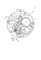
はじめに、本実施形態に係る時計としての機械式時計1について説明する。図1は、本実施形態に係る機械式時計のムーブメントの表側の平面図である。図1に示すように、本実施形態に係る機械式時計1は、ムーブメント10と、ムーブメント10を収納する図示しないケーシングと、により構成されている。
[Mechanical watch]
First, a mechanical timepiece 1 as a timepiece according to the present embodiment will be described. FIG. 1 is a plan view of the front side of the movement of the mechanical timepiece according to the present embodiment. As shown in FIG. 1, the mechanical timepiece 1 according to the present embodiment includes a
図1における紙面の手前側を表側といい、奥側を裏側という。ムーブメント10は、基板を構成する地板11を有している。地板11の裏側には、図示しない文字板が配されている。なお、ムーブメント10の表側に組み込まれる輪列を表輪列と称し、ムーブメント10の裏側に組み込まれる輪列を裏輪列と称する。
The front side of the paper in FIG. 1 is referred to as the front side, and the back side is referred to as the back side. The
地板11には、巻真案内穴11aが形成されており、巻真案内穴11aに巻真12が回転自在に組み込まれている。巻真12は、おしどり13、かんぬき14、かんぬきばね15、及び裏押さえ16を有する切換装置により、その軸方向の位置が決められている。また、巻真12の案内軸部には、きち車17が回転自在に設けられている。
A winding
このような構成のもと、巻真12が、回転軸方向に沿ってムーブメント10の内側に一番近い方の第1の巻真位置(0段目)にある状態で巻真12を回転させると、図示しないつづみ車の回転を介してきち車17が回転する。そして、きち車17が回転することにより、きち車17と噛合う丸穴車20が回転する。そして、丸穴車20が回転することにより、丸穴車20と噛合う角穴車21が回転する。さらに、角穴車21が回転することにより、香箱車22に収容された図示しないぜんまい(動力源)を巻き上げる。
Under such a configuration, the winding
ムーブメント10の表輪列は、上述した香箱車(機械部品)22の他に、所謂番車と呼ばれる二番車(機械部品)25、三番車(機械部品)26、及び四番車(機械部品)27により構成されており、香箱車22の回転力を伝達する機能を果している。また、ムーブメント10の表側には、表輪列の回転を制御するための脱進機構30及び調速機構31が配置されている。
In addition to the barrel wheel (mechanical parts) 22 described above, the front wheel train of the
二番車25は、香箱車22に噛合う歯車である。三番車26は、二番車25に噛合う歯車である。四番車27は、三番車26に噛合う歯車である。脱進機構30は、上述した表輪列の回転を制御する機構であって、四番車27と噛み合うがんぎ車(機械部品)35と、がんぎ車35を脱進させて規則正しく回転させるアンクル(機械部品)36と、を備えている。調速機構31は、上述した脱進機構30を調速する機構であって、てんぷ(機械部品)40を具備している。
The
[がんぎ車]
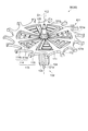
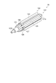
次に、本実施形態に係る脱進機構30が備えるがんぎ車35について、より詳細に説明する。図2は、本実施形態に係る脱進機構の平面図である。図3は、本実施形態に係る機械部品としてのがんぎ車を表面側から見た斜視図である。図4は、図2のA−A’線に沿うがんぎ車の断面図である。図5は、図4のC部を拡大した部分断面図である。図6は、本実施形態に係る回転部材としてのがんぎ歯車部の平面図である。図7は、本実施形態に係る軸部材の斜視図である。図8は、図2のB−B’線に沿う軸部材の断面図である。図9は、がんぎ歯車部と軸部材との嵌合を説明する部分断面図である。
[Escape car]
Next, the
図2及び図3に示すように、脱進機構30が備えるがんぎ車35は、回転部材としてのがんぎ歯車部101と、がんぎ歯車部101に同軸(軸線O1)上に固定された軸部材(回転軸)102と、を備えている。
As shown in FIGS. 2 and 3, the
以下の説明では、がんぎ歯車部101及び軸部材102の軸線O1に沿う長手方向を単に軸方向という。がんぎ歯車部101の表面101a及び裏面101bは、軸線O1(軸部材102の中心を軸方向に沿って通る線)と直交している。がんぎ歯車部101の表面101a及び裏面101bに平行な面内で軸線O1を通る方向を径方向という。がんぎ歯車部101及び軸部材102の軸線O1回りに周回する方向を周方向という。
In the following description, the longitudinal direction of the
がんぎ歯車部101は、表面101a、及び、裏面101b(図3参照)が平坦面とされるとともに、全面に亘って均一な厚みとされた板状のものである。がんぎ歯車部101は、単結晶シリコン等、結晶方位を有する材料、または金属等の材料からなる。
The
がんぎ歯車部101は、複数の歯部112を有するリム部111と、軸部材102を保持する保持部115と、を有する。リム部111は、がんぎ歯車部101の外縁の環状部分である。歯部112は、リム部111の外周から外側に向けて突設されており、特殊な鉤型状に形成されている。複数の歯部112の先端に、後述するアンクル36の爪石144a,144bが接触するようになっている。
The
保持部115は、リム部111に対して軸部材102側に配置されている。本実施形態では、がんぎ歯車部101は7つの保持部115を有している。保持部115は、環状のリム部111の周方向における7箇所に、360°/7の等ピッチで配置されている。なお、保持部115の数は、3つから7つの範囲でもよいし7つ以上でもよく、特に限定されない。
The holding
保持部115は、リム部111から延在する第1保持部113と、第1保持部113から分岐して設けられた第2保持部114と、を有する。第1保持部113、第2保持部114(第1部分114a、第2部分114b)、及びリム部111は、同一の材料で一体に形成されている。
The holding
がんぎ歯車部101の中央部の保持部115(第1保持部113及び第2保持部114)で囲まれた領域に、軸部材102が挿通されている。換言すれば、保持部115(第1保持部113及び第2保持部114)により、がんぎ歯車部101の中央部に軸部材102を挿通させる貫通孔が構成されている。
The
第1保持部113は、リム部111から軸部材102に向かう方向に延在する。第1保持部113は、軸部材102の溝125に嵌合することで、軸部材102に対するがんぎ歯車部101の回転を抑止する機能を有する。第1保持部113の先端は、第2保持部114の第2部分114bの先端よりも軸部材102の中心側に位置している(図6参照)。
The
第2保持部114は、第1部分114aと第2部分114bとを有している。第2保持部114は、軸部材102をがんぎ歯車部101の中心に固定するとともに、軸部材102に対するがんぎ歯車部101の傾きや抜けを抑止する機能を有する。
The
第1部分114aは、第1保持部113に接続され、第1保持部113から分岐して形成されており、第1保持部113の延在方向と交差する方向に延在する。第2保持部114は、複数の第1部分114aを有する。複数の第1部分114aは、互いに略平行に配置されている。第2部分114bは、複数の第1部分114aに接続され、軸部材102に向かう方向に延在する。複数の第1部分114aは、第2部分114bに対して、第2部分114bの延在方向に加えられる応力を緩和する機能を有する。
The
第2部分114bは、軸部材102の凹部127に嵌合している(図4及び図5参照)。第2部分114bの先端と接する内接円を、内接円114cとする(図6参照)。第2部分114bが凹部127に嵌合していない状態(がんぎ歯車部101に軸部材102が挿通されていない状態)、すなわち、第2保持部114に応力が加えられていない状態における内接円114cの径をD1とする。内接円114cの径D1を、第2保持部114の内径ともいう。第1保持部113は、内接円114cよりも内側まで延在している。
The
がんぎ歯車部101を軸部材102から見ると、第1保持部113と第2部分114bとはそれぞれ放射状に径方向の外側に向かって延在する。がんぎ歯車部101の表面101aに平行な面内において、第1保持部113の延在方向と第2部分114bの延在方向とは、それぞれ径方向に沿った方向であるが、互いに平行ではない。第1部分114aの延在方向は、がんぎ歯車部101の表面101aに平行な面内において、第1保持部113の延在方向及び第2部分114bの延在方向と交差する方向である。
When the
第1保持部113と第2部分114bとの間に梁状に形成された複数の第1部分114aは、複数の第1部分114aで構成される面(がんぎ歯車部101の表面101a及び裏面101b)内において、その延在方向には撓みにくいが、その延在方向と交差する方向には撓みやすい。また、複数の第1部分114aで構成される面と交差する軸方向には撓みにくい。
The plurality of
複数の第1部分114aが撓んで第2部分114bの延在方向の外側に変形すると、第2保持部114の内径、すなわち、第2部分114bの先端と接する内接円114c(図6参照)の径が径D1よりも大きくなる。そのため、軸部材102をがんぎ歯車部101に挿通する際には、軸部材102の外径に対応して複数の第1部分114aが撓み、軸部材102に対して第2部分114bの延在方向に変形することにより、容易に第2部分114bを凹部127に嵌合させることができる。複数の第1部分114aが撓んで変形できる内接円114cの最大径をD1maxとする。
When the plurality of
また、がんぎ車35に外力が加えられた際には、第2部分114bの延在方向に変形し易いので、がんぎ歯車部101の中心に軸部材102を保持することができる。また、複数の第1部分114aが撓むことで、がんぎ車35に加えられた外力を緩和できるので、がんぎ歯車部101の破損を抑えることができる。一方、軸方向、すなわち軸部材102ががんぎ歯車部101から抜ける方向には変形しにくいので、がんぎ歯車部101と軸部材102とを確実に固定でき、軸部材102に対するがんぎ歯車部101の傾きや抜けを抑止することができる。
Further, when an external force is applied to the
がんぎ車35(がんぎ歯車部101)の複数の歯部112は、アンクル36に噛合するようになっている。アンクル36は、3つのアンクルビーム143によってT字状に形成されたアンクル体142dと、軸であるアンクル真142fと、を備えている。アンクル体142dは、アンクル真142fによって回動可能に構成されている。なお、アンクル真142fは、その両端が地板11(図1参照)及び図示しないアンクル受に対してそれぞれ回動可能に支持されている。
The plurality of
3つのアンクルビーム143のうち、2つのアンクルビーム143の先端には爪石144a,144bが設けられ、残り1つのアンクルビーム143の先端にはアンクルハコ145が取り付けられている。爪石144a,144bは、四角柱状に形成されたルビーであり、接着材等によりアンクルビーム143に接着固定されている。
Of the three
このように構成されたアンクル36がアンクル真142fを中心に回動した際に、爪石144a或いは爪石144bが、がんぎ車35の歯部112の先端に接触するようになっている。また、この際、アンクルハコ145が取り付けられたアンクルビーム143が、図示しないドテピンに接触するようになっており、これによってアンクル36は、同方向にそれ以上回動しないようになっている。その結果、がんぎ車35の回転も一時的に停止するようになっている。
When the
図2に示すように、軸部材102の軸方向から見た平面視において、軸部材102は、がんぎ歯車部101の中央部に配置されている。図3及び図4に示すように、軸部材102は、がんぎ歯車部101の保持部115で囲まれた貫通孔内に、裏面101b側から挿通されている。軸部材102は、保持部115と嵌合する凹部127(図4参照)を有する。軸部材102の凹部127にがんぎ歯車部101の保持部115(第2保持部114の第2部分114b)が嵌合しており、これにより、軸部材102ががんぎ歯車部101に固定されている。
As shown in FIG. 2, the
軸部材102は、剛性や耐熱性に優れ切削加工や研削加工などの加工性も高い炭素鋼からなる。軸部材102の材料は、タンタル(Ta)またはタングステン(W)であってもよい。軸部材102は、ほぞ部121a,121bと、突出部としてのがんぎかな部122と、凹部127と、第1テーパー部としてのテーパー部126と、第2テーパー部としてのガイド部123とを有している。
The
ほぞ部121a,121bは、軸部材102における軸方向の両端部に位置している。ほぞ部121a,121bのうち、がんぎ歯車部101の裏面101b側に位置するほぞ部121aは、図示しない輪列受に回転可能に支持され、がんぎ歯車部101の表面101a側に位置するほぞ部121bは、地板11に回転可能に支持されている。
The
がんぎかな部122は、がんぎ歯車部101の裏面101b側に配置されている。がんぎかな部122は、凹部127に対してほぞ部121a側に軸部材102の軸方向に沿って形成されている。がんぎかな部122のうち、がんぎ歯車部101側の部分が突出部としての機能を有し、ほぞ部121a側の部分が歯車部としての機能を有する。がんぎかな部122のほぞ部121a側の部分が四番車27(図1参照)の歯車部に噛合されることで、四番車27の回転力が軸部材102に伝達され、がんぎ車35が回転するようになっている。
The
がんぎかな部122は、複数の歯124を有している。複数の歯124は、軸部材102の軸方向に沿って延在し、径方向の外側に突出するように形成されている。複数の歯124のほぞ部121b側の端部は、がんぎ歯車部101の保持部115(第2部分114b)の裏面101bに接している。周方向における複数の歯124同士の間には、軸方向に沿って溝125が形成されている。溝125は、がんぎかな部122から凹部127を経てガイド部123まで軸方向に沿って延在している(図7参照)。
The
本実施形態では、がんぎかな部122は7つの歯124を有している。歯124は、がんぎかな部122の周方向における7箇所に、360°/7の等ピッチで配置されている。したがって、溝125も、がんぎかな部122の周方向における7箇所に360°/7の等ピッチで配置されている。なお、歯124及び溝125の数は、本実施形態では7つであるが、3つから7つの範囲でもよいし7つ以上でもよく、特に限定されない。
In this embodiment, the
第2テーパー部としてのガイド部123は、がんぎ歯車部101の表面101a側に配置されている。ガイド部123は、凹部127に対して、がんぎかな部122とは反対側のほぞ部121b側に形成されている。ガイド部123は、ほぞ部121a,121bよりも大径に形成されている。ガイド部123は、がんぎ歯車部101に軸部材102を挿通する際に、保持部115の第2部分114bを案内する機能を有する。
The
ガイド部123は、凹部127からほぞ部121b側へ遠ざかるにしたがって径が小さくなるように形成されている。換言すれば、ガイド部123は、がんぎ歯車部101に挿入されるほぞ部121b側から、がんぎ歯車部101の保持部115と嵌合する凹部127に近付くにしたがって径が大きくなるように形成されている。ガイド部123は、周方向において溝125により分断されている。したがって、ガイド部123は、軸部材102のほぞ部121b側の周方向における7箇所に、360°/7の等ピッチで配置されている。また、ガイド部123と歯124とは、軸部材102の周方向における同じ位置に設けられている。
The
図4及び図5に示すがんぎ車35の断面は、図2のA−A’線に沿う断面である。すなわち、図4及び図5の左側が軸部材102のガイド部123とがんぎかな部122の歯124とを通る断面であり、右側が軸部材102の溝125を通る断面である。
The cross section of the
図4及び図5に示すように、溝125は、がんぎかな部122からガイド部123に亘って、軸方向に沿って直線状に設けられている。溝125は、径方向においてがんぎかな部122の歯124、凹部127、及びガイド部123よりも内側に窪むように形成されている(図7参照)。溝125は、第1保持部113と嵌合することで、軸部材102に対するがんぎ歯車部101の回転を抑止する機能を有する。
As shown in FIGS. 4 and 5, the
図5に示すように、第1保持部113は、軸方向(図5の上下方向)において、凹部127が配置された位置で溝125に嵌合する。溝125に第1保持部113が嵌合した状態では、第1保持部113と溝125との間に間隙Gが存在するよう設計されている。この状態においては、軸部材102と第1保持部113との間に応力は発生しない。ただし、がんぎ車35を組み込んだ機械式時計1(ムーブメント10)が動作している状態等で、がんぎ車35に外力が加えられたときには、第1保持部113は軸部材102と接触してもよい。
As shown in FIG. 5, the
図7に示すように、溝125は凹部127から窪むように設けられているので、周方向における溝125と凹部127との間には段差が形成されている。そして、溝125において、第1保持部113の先端は凹部127よりも軸部材102の中心側に位置している(図4参照)。そのため、がんぎ車35の回転方向である周方向に外力が加えられても、溝125に第1保持部113が嵌合した状態が保持される。これにより、軸部材102に対するがんぎ歯車部101の回転を抑止することができる。
As shown in FIG. 7, since the
また、溝125がガイド部123からがんぎかな部122に亘って設けられているので、軸部材102をがんぎ歯車部101にほぞ部121b側から挿通させる際に、周方向における第1保持部113の位置と溝125の位置とを合わせれば、第1保持部113が溝125に嵌合した状態で、軸部材102を挿通させることができる(図4参照)。
Further, since the
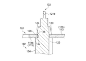
凹部127は、軸方向におけるガイド部123とがんぎかな部122との間に設けられている。換言すれば、軸部材102は、凹部127の一端側(ほぞ部121b側)にガイド部123を有し、凹部127の他端側(ほぞ部121a側)にがんぎかな部122(歯124)を有している。凹部127は、軸部材102の軸線O1(図4参照)回りに周回するように設けられている。
The
図8に示すがんぎ車35の断面は、図2のB−B’線に沿う断面であり、左右対称となっている。すなわち、図8の左側及び右側がともに軸部材102のガイド部123とがんぎかな部122の歯124とを通る断面である。
The cross section of the
図8に示すように、凹部127は、径方向においてがんぎかな部122の歯124及びガイド部123よりも内側(軸部材102の中心側)に窪むように形成されている。凹部127は、保持部115の第2部分114bと嵌合することで、がんぎ歯車部101に対する軸部材102の抜けを抑止する機能を有する。
As shown in FIG. 8, the
凹部127には、第1テーパー部としてのテーパー部126が設けられている。テーパー部126は、凹部127における一端側(ほぞ部121b側)に配置されている。テーパー部126は、第2部分114bと接している。換言すれば、テーパー部126は、凹部127の保持部115(第2部分114b)と接する部分に設けられている。なお、第2部分114bは、テーパー部126と接して凹部127と嵌合しているため、凹部127の底部には接していない。
The
テーパー部126は、軸方向におけるガイド部123側からがんぎかな部122に近付くにしたがって径が小さくなるように形成されている。したがって、ほぞ部121bから凹部127の他端側(ほぞ部121a側)に至るまでの軸部材102の外径は、ガイド部123においてほぞ部121b側からテーパー部126との境界部128に向かうにしたがって大きくなり、境界部128に到達した後、テーパー部126においてがんぎかな部122に近付くにしたがって小さくなる。
The tapered
なお、境界部128は、軸部材102においてテーパー部126とガイド部123との間に位置する部分である。例えば、軸部材102におけるテーパー部126からガイド部123に亘る部分の断面形状がテーパー部126とガイド部123とを斜辺とする三角形状である場合はその三角形の頂点を境界部128とし、断面形状がテーパー部126とガイド部123とを斜辺とする台形状である場合はその台形の上底を境界部128とする。
The
凹部127に軸方向に対して傾斜したテーパー部126が設けられているので、凹部127の軸方向における長さがばらついた場合でも、保持部115(第2部分114b)がテーパー部126のいずれかの位置に接して凹部127に嵌合する。すなわち、テーパー部126により凹部127の軸方向における長さのばらつきを吸収できる。そのため、がんぎ歯車部101に応力緩和層等を設けることなく、保持部115を凹部127に確実に嵌合させて、がんぎ歯車部101と軸部材102とを固定することができる。
Since the
ここで、ガイド部123のほぞ部121b側の端部における軸部材102の外径D2は、がんぎ歯車部101に軸部材102が挿通されていない状態における第2保持部114の内径、すなわち、第2部分114bの内接円114cの径D1(図6参照)以下であることが好ましい。軸部材102の外径D2が第2部分114bの内接円114cの径D1以下であると、軸部材102をがんぎ歯車部101にほぞ部121b側から挿通させる際に、軸部材102を容易に第2部分114bの内接円114cに挿入できる。
Here, the outer diameter D2 of the
保持部115が凹部127に嵌合した状態において第2部分114bがテーパー部126に接する部分における軸部材102の外径D4は、軸部材102が挿通されていない状態における第2部分114bの内接円114cの径D1よりも大きい。また、境界部128における軸部材102の外径D3は、第2部分114bの内接円114cの径D1よりも大きい。そして、境界部128における軸部材102の外径D3は、保持部115が凹部127に嵌合した状態において第2部分114bがテーパー部126に接する部分における軸部材102の外径D4よりも大きい。
The outer diameter D4 of the
そのため、保持部115が凹部127に嵌合した状態から、第2部分114bが軸部材102に対して相対的にガイド部123側へずれる方向、すなわち、がんぎ歯車部101から軸部材102が抜ける方向に移動しようとすると、境界部128に向かうにしたがって第2部分114bに加えられる応力が増大する。これにより、がんぎ歯車部101からの軸部材102の抜けが抑えられる。
Therefore, from the state where the holding
ただし、境界部128における軸部材102の外径D3は、複数の第1部分114a(図6参照)が撓んで第2部分114bの延在方向の外側に変形できる内接円114cの最大径D1max以下であることとする。境界部128における軸部材102の外径D3が内接円114cの最大径D1maxを超えると、第2部分114bがガイド部123から境界部128を乗り越えて凹部127に嵌合できなくなる。
However, the outer diameter D3 of the
さらに、がんぎかな部122の歯124の外接円の径D5は、境界部128における軸部材102の外径D3よりも大きく、内接円114cの最大径D1maxよりも大きい。これにより、複数の第1部分114aが撓んで第2部分114bが最大限に径方向の外側に移動しても、第2部分114bががんぎかな部122の歯124を乗り越えることはない。すなわち、がんぎかな部122の歯124により、軸方向における保持部115のほぞ部121a(図4参照)側の位置が規制される。
Further, the diameter D5 of the circumscribed circle of the
図9は、図8の左側の部分を拡大した部分断面図である。図9に、軸部材102が挿通されていない状態における第2部分114bの先端の位置を2点鎖線で示す。換言すれば、第2部分114bの内接円114cの径がD1のときの第2部分114bの先端の位置を2点鎖線で示す。また、保持部115が凹部127に嵌合した状態における第2部分114bの先端の位置を実線で示す。保持部115が凹部127に嵌合した状態では、第2部分114bの内接円114cの径は軸部材102の外径D4と同じとなる。なお、第2部分114bの角部を丸めたり、或いはテーパー形状としたりした場合は、第2部分114bの内接円114cの径は軸部材102の外径D4よりも小さくなる。
FIG. 9 is an enlarged partial cross-sectional view of the left side portion of FIG. FIG. 9 shows the position of the tip of the
図9に示すように、軸部材102が挿通されて保持部115が凹部127に嵌合した状態では、軸部材102が挿通されていない状態と比べて、第2部分114bが径方向の外側に押し広げられている。これにより、第2部分114bに径方向の外側に向かう応力が加えられるので、保持部115が凹部127に嵌合した状態を保持できる。
As shown in FIG. 9, when the
保持部115が凹部127に嵌合した状態における第2部分114bの先端の位置と境界部128との径方向における距離をD6とする。距離D6は、境界部128における軸部材102の外径D3と第2部分114bがテーパー部126と接する部分における軸部材102の外径D4との差の半分、すなわち、D6=(D3−D4)/2である。距離D6は、10μm程度であることが好ましい。距離D6が小さいと、第2部分114bを径方向の外側へ広げるような外力が加えられた場合に、第2部分114bが境界部128を越えてガイド部123側へずれてしまうおそれがある。
Let D6 be the radial distance between the position of the tip of the
テーパー部126の断面形状は、軸部材102の径方向の外側、かつ、軸方向のがんぎかな部122側を向く傾斜面となっている。一方、ガイド部123の断面形状は、軸部材102の径方向の外側、かつ、軸方向のほぞ部121b側を向く傾斜面となっている。テーパー部126の軸方向に対する傾斜角度をθ1とし、ガイド部123の軸方向に対する傾斜角度をθ2とする。テーパー部126の軸方向に対する傾斜角度θ1は、ガイド部123の軸方向に対する傾斜角度θ2よりも大きい。
The cross-sectional shape of the tapered
テーパー部126の軸方向に対する傾斜角度θ1がガイド部123の軸方向に対する傾斜角度θ2よりも大きいので、保持部115がテーパー部126からガイド部123に向かう方向、すなわち、がんぎ歯車部101から軸部材102が抜ける方向において第2部分114bに加えられる応力が急激に増加する。これにより、がんぎ歯車部101からの軸部材102の抜けが抑えられる。
Since the inclination angle θ1 of the
一方、ガイド部123の軸方向に対する傾斜角度θ2がテーパー部126の軸方向に対する傾斜角度θ1よりも小さいので、軸部材102をがんぎ歯車部101にほぞ部121b側から挿通させる際に、ガイド部123において第2部分114bに加えられる応力が徐々に増加する。これにより、第2部分114bが徐々に径方向の外側へ押し広げられるので、容易に軸部材102をがんぎ歯車部101に挿通させることができる。
On the other hand, since the inclination angle θ2 of the
また、テーパー部126の軸方向に対する傾斜角度θ1は、45°程度であることが好ましい。テーパー部126の傾斜角度θ1が45°程度であると、テーパー部126から保持部115(第2部分114b)に対して、径方向の外側に向かう応力と、軸方向のがんぎかな部122(歯124)側に向かう応力とがバランスよく加えられる。
Further, the inclination angle θ1 of the tapered
上述したように、第2部分114bに径方向の外側に向かう応力が加えられることにより、保持部115が凹部127に嵌合した状態を保持できる。そして、第2部分114bに軸方向のがんぎかな部122側に向かう応力が加えられることにより、第2部分114bががんぎかな部122の歯124に押し付けられる。これにより、がんぎ歯車部101からの軸部材102の抜けを効果的に抑止できる。そして、第2部分114bががんぎかな部122の歯124に押し付けられることにより、軸部材102に対してがんぎ歯車部101を、表面101a及び裏面101bが軸線O1と直交するように保持できる。
As described above, by applying a stress outward in the radial direction to the
テーパー部126の傾斜角度θ1が小さいと、テーパー部126から第2部分114bに対して加えられるがんぎかな部122側に向かう応力が小さくなるため、がんぎ歯車部101からの軸部材102の抜けを抑止する効果が低減する。テーパー部126の傾斜角度θ1が大きいと、テーパー部126の軸方向における長さが小さくなるため、テーパー部126により吸収可能なばらつきの幅が小さくなる。
When the inclination angle θ1 of the
[がんぎ車の製造方法]
次に、本実施形態に係る機械部品としてのがんぎ車35の製造方法について説明する。図10は、本実施形態に係るがんぎ車の製造方法を示すフローチャートである。図10に示すように、本実施形態に係る機械部品としてのがんぎ車35の製造方法は、回転部材としての歯車部(がんぎ歯車部101)を形成する工程(第1工程)と、軸部材102を形成する工程(第2工程)と、がんぎ歯車部101に軸部材102を挿通してがんぎ車35を形成する工程(第3工程)と、を含む。
[Manufacturing method of escape wheel]
Next, a method of manufacturing the
第1工程としてのがんぎ歯車部101を形成する工程は、がんぎ歯車部101に保持部115を形成する工程であり、ステップS01〜ステップS06を含む。まず、シリコンを含むウェハー状の基材を準備する(ステップS01)。次いで、例えばスピンコート法やスプレーコート法等により、基材の表面にフォトレジストを塗布する(ステップS02)。ステップS02で塗布するフォトレジストは、ネガ型、及びポジ型のいずれの材料も採用することができる。
The step of forming the
次いで、基材の表面に塗布したフォトレジストに対してフォトリソグラフィー技術により、露光をした後(ステップS03)、現像を行う(ステップS04)。これにより、図6に示すがんぎ歯車部101の平面視外形に対応するマスク(エッチングマスク)となるフォトレジストパターンが形成される。
Next, the photoresist applied to the surface of the base material is exposed by a photolithography technique (step S03) and then developed (step S04). As a result, a photoresist pattern serving as a mask (etching mask) corresponding to the plan view outer shape of the
次いで、ステップS03及びステップS04で形成したフォトレジストパターンをマスクとして、基材に、例えばディープ・リアクティブ・イオンエッチング(Deep Reactive Ion Etching:DRIE)等の異方性エッチングを施す(ステップS05)。これにより、フォトレジストパターンを介して、基材が表面側から略垂直方向に深掘りされ、図6に示すような、複数の歯部112を有するリム部111と、第1保持部113及び第2保持部114を有する保持部115とを有するがんぎ歯車部101の外形形状が得られる。
Next, using the photoresist patterns formed in steps S03 and S04 as a mask, the substrate is subjected to anisotropic etching such as Deep Reactive Ion Etching (DRIE) (step S05). As a result, the base material is deeply dug from the surface side in a substantially vertical direction via the photoresist pattern, and as shown in FIG. 6, the
次いで、フォトレジスト(フォトレジストパターン)を除去する(図10のステップS06)。ステップS06では、例えば、フォトレジストを溶解・剥離可能な発煙硝酸や有機溶剤等でのウェットエッチング、あるいは、酸素プラズマアッシング等により、フォトレジストを除去できる。これにより、がんぎ歯車部101を形成する工程は終了する。
Next, the photoresist (photoresist pattern) is removed (step S06 in FIG. 10). In step S06, the photoresist can be removed by, for example, wet etching with fuming nitric acid or an organic solvent capable of dissolving and peeling the photoresist, oxygen plasma ashing, or the like. This completes the step of forming the
なお、ステップS05で基材に異方性エッチングを施すときに、基材の裏面をエッチングから保護するマスクを形成するようにしてもよい。基材の裏面にマスクを形成することにより、ステップS05において基材が裏面側からエッチングされないので、歯部112や保持部115の側面(軸方向に沿った面)の形状が変化しないようにして、図4に示すようながんぎ歯車部101の断面形状を得ることができる。
When anisotropic etching is performed on the base material in step S05, a mask that protects the back surface of the base material from etching may be formed. By forming the mask on the back surface of the base material, the base material is not etched from the back surface side in step S05, so that the shapes of the side surfaces (surfaces along the axial direction) of the
このように、がんぎ歯車部101の基材をシリコンとすることで、がんぎ歯車部101の第1保持部113、第2保持部114、及びリム部111等の各部を、同一の基材から同じエッチング工程により形成することができ、1枚の基材からがんぎ歯車部101を複数取りできるので、がんぎ歯車部101の生産性を向上させるとともに生産コストを低減することができる。また、フォトリソグラフィーやエッチング技術を用いて形成するので、各部の形状を所望の形状に形成でき、かつ、その加工精度を向上できる。
In this way, by using silicon as the base material of the
第2工程としての軸部材102を形成する工程は、軸部材102に凹部127とがんぎかな部122とを形成する工程であり、図10に示すステップS11とステップS12とを含む。軸部材102を形成する工程は、ステップS01〜ステップS06のがんぎ歯車部101を形成する工程とは別に行われる。
The step of forming the
まず、軸部材102となる部材を準備する(ステップS11)。軸部材102は、軸体として十分な剛性を有しているとともに、耐熱性を有していることが望ましい。炭素鋼は、上述した剛性や耐熱性に優れた材料であることに加えて、切削加工や研削加工などの加工性も高い材料であるため、軸部材102の材料として特に好適である。なお、軸部材102の材料としてタンタル(Ta)またはタングステン(W)を用いてもよい。
First, a member to be the
次いで、軸部材102となる部材に対して、切削加工や研削加工などの機械加工を行う(ステップS12)。例えば、テーパー部126を有する凹部127は、軸方向におけるガイド部123とがんぎかな部122との間を周方向に1周、軸部材102の表面から内側(軸部材102の中心側)に切削加工することにより形成される。テーパー部126は、凹部127のガイド部123側からがんぎかな部122に近付くにしたがって径が小さくなるように形成される。同様に、ガイド部123は、凹部127からほぞ部121b側へ遠ざかるにしたがって径が小さくなるように形成される。これにより、図7に示すような、ほぞ部121a,121bと、がんぎかな部122と、ガイド部123と、凹部127と、テーパー部126と、溝125とを有する軸部材102が得られる。
Next, the member to be the
第3工程(ステップS21)は、がんぎ歯車部101に軸部材102を挿通して、保持部115を凹部127と嵌合させる工程である。ステップS21では、ステップS01〜ステップS06で形成されたがんぎ歯車部101に、ステップS11及びステップS12で形成された軸部材102を挿通することにより、がんぎ車35が形成される。
The third step (step S21) is a step of inserting the
ステップS21においてがんぎ歯車部101に軸部材102を挿通する手順を、図11〜図16を参照して説明する。図11〜図16は、がんぎ歯車部に軸部材を挿通する工程を説明する概略断面図である。図11〜図16は、図4の要部を拡大した部分断面図に相当する。なお、図11〜図16では、軸部材102に対してがんぎ歯車部101を押し込む場合の例を示しているが、がんぎ歯車部101に対して軸部材102を挿入して押し込むこととしてもよい。
The procedure for inserting the
まず、図11に示すように、軸部材102のほぞ部121b側にがんぎ歯車部101を配置する。より具体的には、軸部材102に対してがんぎ歯車部101を、ほぞ部121bが保持部115(第1保持部113及び第2保持部114の第2部分114b)により構成される貫通孔内を通ってがんぎ歯車部101から突出するように配置する。このとき、軸部材102の周方向において、第1保持部113と溝125とが同じ位置となり、第2部分114bとガイド部123とが同じ位置となるように、軸部材102とがんぎ歯車部101とを配置する(図2参照)。
First, as shown in FIG. 11, the
次いで、図12に示すように、軸部材102に対してがんぎ歯車部101を、第2保持部114の第2部分114bがガイド部123と接触するまで軸方向に沿って押し込む。その際、ガイド部123のほぞ部121b側の端部における軸部材102の外径D2(図8参照)が、がんぎ歯車部101に軸部材102が挿通されていない状態における第2部分114bの内接円114cの径D1(図6参照)以下であると、第2部分114bの内接円114c内にガイド部123のほぞ部121b側の端部が容易に挿入される。
Next, as shown in FIG. 12, the
一方、第1保持部113と溝125との間には間隙Gが存在する(図5参照)ため、軸部材102に対してがんぎ歯車部101を押し込むと、第1保持部113は溝125に容易に嵌合する。
On the other hand, since there is a gap G between the
次いで、図13に示すように、軸部材102に対してがんぎ歯車部101をさらに押し込む。そうすると、ガイド部123がほぞ部121b側から凹部127(テーパー部126)に近付くにしたがって軸部材102の径が大きくなるように形成されているので、第2部分114bは径方向の外側へ徐々に押し広げられる。
Next, as shown in FIG. 13, the
そして、図14に示すように、第2部分114bがガイド部123と凹部127(テーパー部126)との境界部128に差し掛かると、第2部分114bが径方向の外側へ最も押し広げられた状態となる。このとき、軸部材102から第2部分114bに加えられる径方向の外側への応力は最大となる。なお、境界部128における軸部材102の外径D3(図8参照)は、第2部分114bの内接円114cの最大径D1max以下であるので、第2部分114bは境界部128を乗り越えることができる。
Then, as shown in FIG. 14, when the
次いで、図15に示すように、第2部分114bが境界部128を乗り越えると、第2部分114bは、凹部127におけるガイド部123側に配置されたテーパー部126と接触する。第2部分114bは、境界部128を通過する際の径方向の外側へ最も押し広げられた状態から径方向の内側に戻ろうとする。その際、テーパー部126がガイド部123からがんぎかな部122の歯124(以下では、単に歯124と表記する)に近付くにしたがって軸部材102の径が小さくなるように形成されているので、第2部分114bが径方向の内側へ戻るに伴って、第2部分114bが歯124側へ移動する。
Then, as shown in FIG. 15, when the
この結果、図16に示すように、第2部分114bが、歯124に接した状態で凹部127に嵌合する。ステップS01〜ステップS06で形成したがんぎ歯車部101の第2部分114bの内接円114cの径D1(図6参照)が、ステップS21で凹部127に嵌合した状態において第2部分114bがテーパー部126に接する部分における軸部材102の外径D4(図8参照)よりも小さいので、凹部127に嵌合した状態においても、第2部分114bに径方向の外側に向かう応力が加えられる。
As a result, as shown in FIG. 16, the
また、テーパー部126から、周方向に複数配置された各第2部分114bに対して軸方向の歯124側に向かう応力が加えられることにより、保持部115が歯124に押し付けられる。これにより、軸部材102に対してがんぎ歯車部101を、表面101a及び裏面101bが軸線O1と直交するように保持できる(図4参照)。
Further, the holding
歯124の外接円の径D5(図8参照)は、境界部128における軸部材102の外径D3よりも大きく、内接円114cの最大径D1maxよりも大きい。したがって、歯124により、軸方向における第2部分114bのほぞ部121a(図4参照)側の位置が規制される。
The diameter D5 of the circumscribed circle of the tooth 124 (see FIG. 8) is larger than the outer diameter D3 of the
また、境界部128における軸部材102の外径D3が、保持部115が凹部127に嵌合した状態において第2部分114bがテーパー部126に接する部分における軸部材102の外径D4よりも大きい。そして、テーパー部126から、第2部分114bに対して軸方向の歯124側に向かう応力が加えられる。そのため、保持部115のほぞ部121b側への移動が抑制される。これにより、軸部材102に対するがんぎ歯車部101の抜け、換言すれば、がんぎ歯車部101からの軸部材102の抜けを抑止することができる。
Further, the outer diameter D3 of the
一方、第1保持部113は、図12〜図16に示す軸部材102に対してがんぎ歯車部101を押し込む過程において、溝125との間に間隙Gを有して溝125に嵌合した状態が維持される。そして、周方向における溝125と凹部127との間に段差が形成されているので、軸部材102に対するがんぎ歯車部101の回転を抑止することができる。
On the other hand, the
ところで、凹部127にテーパー部126が設けられていない場合、凹部127の軸方向における長さが第2部分114bの厚さに対して小さいと第2部分114bが凹部127に入らなくなり、凹部127の軸方向における長さが第2部分114bの厚さに対して大きいと第2部分114bと凹部127との嵌合にがたつきが生じてしまう。また、凹部127にテーパー部126が設けられていない場合、凹部127における軸部材102の外径がばらつくと、第2部分114bが凹部127に嵌合する応力が不足したり過剰となったりするおそれがある。
By the way, when the
本実施形態では、凹部127にテーパー部126が設けられているので、凹部127の軸方向における長さがばらついた場合でも、第2部分114bがテーパー部126のいずれかの位置に接して凹部127に嵌合する。そのため、がんぎ歯車部101に応力緩和層等を設けることなく、保持部115を凹部127に確実に嵌合させて、がんぎ歯車部101と軸部材102とを固定することができる。これにより、がんぎ車35の製造工数の増大と、がんぎ車35の製造歩留まりの低下とが抑えられる。
In the present embodiment, since the
以上述べた工程を経ることによって、機械部品としてのがんぎ車35の一連の製造工程が終了する。
By going through the steps described above, a series of manufacturing steps of the
上記実施形態は、あくまでも本発明の一態様を示すものであり、本発明の範囲内で任意に変形および応用が可能である。変形例としては、例えば、以下のようなものが考えられる。 The above-described embodiment shows only one aspect of the present invention, and can be arbitrarily modified and applied within the scope of the present invention. As a modification, for example, the following can be considered.
(変形例1)
上記実施形態では、テーパー部126が凹部127におけるガイド部123側に設けられた構成であったが、本発明はこれに限定されない。凹部127の底部全体がテーパー部126で構成されていてもよい。このような構成であっても、上記実施形態と同様の効果が得られる。
(Modification example 1)
In the above embodiment, the tapered
(変形例2)
上記実施形態では、がんぎ歯車部101が有する保持部115(第1保持部113、第2保持部114)の数が、がんぎかな部122の歯124の数と同じ(上記実施形態では7つ)構成であったが、本発明はこれに限定されない。保持部115の数ががんぎかな部122の歯124の数(すなわち、溝125の数)よりも少ない構成であっても、上記実施形態と同様の効果が得られる。ただし、この場合は、軸部材102の周方向において、第2部分114bがガイド部123に対向し、第1保持部113が溝125に嵌合できる位置に配置されているものとする。
(Modification 2)
In the above embodiment, the number of holding portions 115 (first holding
(変形例3)
本発明に係るがんぎ車の製造方法において、ステップS21でがんぎ歯車部101に軸部材102を挿通した後で、がんぎ歯車部101の表面に、二酸化ケイ素(SiO2)からなるシリコン酸化膜を形成する酸化処理を行うこととしてもよい。がんぎ歯車部101に酸化処理を行うと、シリコンを含む材料からなるがんぎ歯車部101の表面に形成されるシリコン酸化膜により、がんぎ歯車部101の機械的強度が向上する。酸化処理を行う場合は、例えば1000℃以上の高温で行う熱酸化処理を行うことが好ましい。
(Modification example 3)
In the method for manufacturing an escape wheel according to the present invention, after the
(変形例4)
上記実施形態では、機械部品の一例としてがんぎ車35を例にあげて説明したが、本発明はこれに限定されない。本発明の機械部品の構成及びその製造方法は、香箱車22、二番車25、三番車26、四番車27、アンクル36、てんぷ40等の他の機械部品にも適用することができる。また、本発明の機械部品の構成及びその製造方法は、軸部材が突出部(上記実施形態のがんぎ車35ではがんぎかな部122)を有してない機械部品にも適用することができる。
(Modification example 4)
In the above embodiment, the
1…機械式時計(時計)、35…がんぎ車(機械部品)、101…がんぎ歯車部(回転部材)、102…軸部材、111…リム部、113…第1保持部、114…第2保持部、114a…第1部分、114b…第2部分、115…保持部、122…がんぎかな部(突出部)、123…ガイド部(第2テーパー部)、124…歯(突出部)、126…テーパー部(第1テーパー部)、127…凹部。 1 ... Mechanical clock (clock), 35 ... Gang wheel (mechanical parts), 101 ... Gang gear part (rotating member), 102 ... Shaft member, 111 ... Rim part, 113 ... First holding part, 114 ... second holding part, 114a ... first part, 114b ... second part, 115 ... holding part, 122 ... stubborn part (protruding part), 123 ... guide part (second taper part), 124 ... teeth ( Protruding portion), 126 ... Tapered portion (first tapered portion), 127 ... Recessed portion.
Claims (6)
前記軸部材を保持する保持部を有するシリコンを含む材料を用いた回転部材と、を備え、
前記軸部材は、前記保持部と嵌合する凹部を有し、
前記軸部材は、
前記凹部の前記保持部と接する部分に、前記軸部材の軸方向に対して前記凹部における一端側から他端側に近付くにしたがって径が小さくなるように傾斜した第1テーパー部と、
前記凹部に対して前記他端とは反対側に、前記凹部から遠ざかるにしたがって径が小さくなるように形成された第2テーパー部と、を有し、
前記第1テーパー部の前記軸方向に対する傾斜角度は、前記第2テーパー部の前記軸方向に対する傾斜角度よりも大きいことを特徴とする時計に用いられる機械部品。 Shaft member and
A rotating member made of a material containing silicon, which has a holding portion for holding the shaft member, is provided.
The shaft member has a recess that fits with the holding portion.
The shaft member is
A first tapered portion that is inclined so that the diameter of the recess is reduced as it approaches the other end side of the recess from one end side to the other end side in the axial direction of the shaft member.
It has a second tapered portion formed so that the diameter becomes smaller as the distance from the recess increases, on the side opposite to the other end with respect to the recess.
A mechanical component used in a timepiece , wherein the inclination angle of the first taper portion with respect to the axial direction is larger than the inclination angle of the second taper portion with respect to the axial direction.
前記保持部は、前記リム部から前記軸部材に向かう方向に延在する第1保持部と、前記第1保持部と交差する方向に延在する第1部分と前記第1部分から前記軸部材に向かう方向に延在する第2部分とを有する第2保持部と、を有し、
前記第2部分が前記第1テーパー部と接することを特徴とする請求項1から3のいずれか一項に記載の時計に用いられる機械部品。 The rotating member has a rim portion having a plurality of tooth portions, and the rotating member has a rim portion.
The holding portion includes a first holding portion extending in a direction extending from the rim portion toward the shaft member, a first portion extending in a direction intersecting the first holding portion, and the shaft member extending from the first portion. With a second holding portion having a second portion extending in the direction toward
The mechanical component used in a timepiece according to any one of claims 1 to 3 , wherein the second portion is in contact with the first tapered portion.
Priority Applications (3)
| Application Number | Priority Date | Filing Date | Title |
|---|---|---|---|
| JP2017112337A JP6891646B2 (en) | 2017-06-07 | 2017-06-07 | Mechanical parts, watches |
| US16/001,231 US10747177B2 (en) | 2017-06-07 | 2018-06-06 | Mechanical component, timepiece, and manufacturing method of mechanical component |
| EP18176269.1A EP3413143A3 (en) | 2017-06-07 | 2018-06-06 | Mechanical component, timepiece, and manufacturing method of mechanical component |
Applications Claiming Priority (1)
| Application Number | Priority Date | Filing Date | Title |
|---|---|---|---|
| JP2017112337A JP6891646B2 (en) | 2017-06-07 | 2017-06-07 | Mechanical parts, watches |
Publications (3)
| Publication Number | Publication Date |
|---|---|
| JP2018205196A JP2018205196A (en) | 2018-12-27 |
| JP2018205196A5 JP2018205196A5 (en) | 2020-04-30 |
| JP6891646B2 true JP6891646B2 (en) | 2021-06-18 |
Family
ID=62562976
Family Applications (1)
| Application Number | Title | Priority Date | Filing Date |
|---|---|---|---|
| JP2017112337A Active JP6891646B2 (en) | 2017-06-07 | 2017-06-07 | Mechanical parts, watches |
Country Status (3)
| Country | Link |
|---|---|
| US (1) | US10747177B2 (en) |
| EP (1) | EP3413143A3 (en) |
| JP (1) | JP6891646B2 (en) |
Families Citing this family (5)
| Publication number | Priority date | Publication date | Assignee | Title |
|---|---|---|---|---|
| JP7143675B2 (en) * | 2018-08-14 | 2022-09-29 | セイコーエプソン株式会社 | Watch parts, movements and watches |
| JP6915602B2 (en) | 2018-10-24 | 2021-08-04 | セイコーエプソン株式会社 | Watch parts and watches |
| EP3779608A1 (en) * | 2019-08-16 | 2021-02-17 | Nivarox-FAR S.A. | Elastic holding member for a timepiece component on a support element |
| JP2021081299A (en) | 2019-11-19 | 2021-05-27 | セイコーエプソン株式会社 | Part for timepiece and timepiece |
| EP4180879A1 (en) * | 2021-11-10 | 2023-05-17 | GFD Gesellschaft für Diamantprodukte mbH | Micromechanical assembly, method for their preparation and their use |
Family Cites Families (12)
| Publication number | Priority date | Publication date | Assignee | Title |
|---|---|---|---|---|
| JPH0618303Y2 (en) | 1986-04-04 | 1994-05-11 | 株式会社精工舎 | Gear device with slip mechanism |
| JPH0618304Y2 (en) * | 1986-08-20 | 1994-05-11 | 株式会社精工舎 | Slip mechanism |
| JP2579563Y2 (en) * | 1992-03-12 | 1998-08-27 | セイコープレシジョン株式会社 | Gear with slip mechanism |
| EP1826635B1 (en) * | 2006-02-24 | 2009-10-14 | Patek, Philippe SA | Resilient fastening device for horology |
| EP2362276B1 (en) * | 2010-02-25 | 2012-10-31 | Montres Breguet SA | Programmable and reprogrammable mechanical memory wheel for a timepiece |
| EP2442189A1 (en) * | 2010-10-15 | 2012-04-18 | ETA SA Manufacture Horlogère Suisse | Assembly of a part not comprising a plastic range |
| CH704256A2 (en) * | 2010-12-22 | 2012-06-29 | Eta Sa Mft Horlogere Suisse | Assembly for assembling e.g. pivoting staff in opening of mobile of timepiece, has intermediate part that is deformed to radially clamp component and to stress deformation units to join together assembly for piece |
| JP5872181B2 (en) | 2011-01-27 | 2016-03-01 | セイコーインスツル株式会社 | Machine parts, machine assemblies and watches |
| CH709792A2 (en) | 2014-06-18 | 2015-12-31 | Eta Sa Manufacture Horlogère Suisse | Mobile clock. |
| CH709920A2 (en) * | 2014-07-24 | 2016-01-29 | Eta Sa Manufacture Horlogère Suisse | Set of mobile watch braking. |
| US9753433B2 (en) * | 2014-09-12 | 2017-09-05 | Seiko Instruments Inc. | Mechanical component, movement, and timepiece |
| JP6556826B2 (en) | 2015-03-11 | 2019-08-07 | シチズン時計株式会社 | Timepiece power transmission body and method of manufacturing timepiece power transmission body |
-
2017
- 2017-06-07 JP JP2017112337A patent/JP6891646B2/en active Active
-
2018
- 2018-06-06 EP EP18176269.1A patent/EP3413143A3/en not_active Withdrawn
- 2018-06-06 US US16/001,231 patent/US10747177B2/en active Active
Also Published As
| Publication number | Publication date |
|---|---|
| US20180356768A1 (en) | 2018-12-13 |
| EP3413143A3 (en) | 2019-01-23 |
| EP3413143A2 (en) | 2018-12-12 |
| US10747177B2 (en) | 2020-08-18 |
| JP2018205196A (en) | 2018-12-27 |
Similar Documents
| Publication | Publication Date | Title |
|---|---|---|
| JP6891646B2 (en) | Mechanical parts, watches | |
| JP7107405B2 (en) | mechanical parts and clocks | |
| JP6772790B2 (en) | How to make watch parts and how to make watches | |
| JP5395174B2 (en) | Clock gear system | |
| US11829108B2 (en) | Timepiece part and timepiece | |
| US10761483B2 (en) | Mechanical part, timepiece, and method of manufacturing a mechanical part | |
| JP5872181B2 (en) | Machine parts, machine assemblies and watches | |
| JP7444213B2 (en) | Ankle, movement and watch | |
| JP2012215183A (en) | Mechanical part assembly, method of manufacturing the same, and timepiece | |
| JP6736365B2 (en) | Manufacturing method of watch parts | |
| JP6743619B2 (en) | Method of manufacturing mechanical part and method of manufacturing timepiece | |
| JP6919166B2 (en) | Machine parts manufacturing method and watch manufacturing method | |
| JP2018044835A (en) | Method for manufacturing machine part, and method for manufacturing watch | |
| JP2018179788A (en) | Mechanical component, timepiece, and manufacturing method for mechanical component |
Legal Events
| Date | Code | Title | Description |
|---|---|---|---|
| RD05 | Notification of revocation of power of attorney |
Free format text: JAPANESE INTERMEDIATE CODE: A7425 Effective date: 20180910 |
|
| RD03 | Notification of appointment of power of attorney |
Free format text: JAPANESE INTERMEDIATE CODE: A7423 Effective date: 20190402 |
|
| A521 | Request for written amendment filed |
Free format text: JAPANESE INTERMEDIATE CODE: A523 Effective date: 20200323 |
|
| A621 | Written request for application examination |
Free format text: JAPANESE INTERMEDIATE CODE: A621 Effective date: 20200323 |
|
| RD07 | Notification of extinguishment of power of attorney |
Free format text: JAPANESE INTERMEDIATE CODE: A7427 Effective date: 20200806 |
|
| A977 | Report on retrieval |
Free format text: JAPANESE INTERMEDIATE CODE: A971007 Effective date: 20210217 |
|
| A131 | Notification of reasons for refusal |
Free format text: JAPANESE INTERMEDIATE CODE: A131 Effective date: 20210224 |
|
| A521 | Request for written amendment filed |
Free format text: JAPANESE INTERMEDIATE CODE: A523 Effective date: 20210329 |
|
| TRDD | Decision of grant or rejection written | ||
| A01 | Written decision to grant a patent or to grant a registration (utility model) |
Free format text: JAPANESE INTERMEDIATE CODE: A01 Effective date: 20210427 |
|
| A61 | First payment of annual fees (during grant procedure) |
Free format text: JAPANESE INTERMEDIATE CODE: A61 Effective date: 20210510 |
|
| R150 | Certificate of patent or registration of utility model |
Ref document number: 6891646 Country of ref document: JP Free format text: JAPANESE INTERMEDIATE CODE: R150 |