JP6891163B2 - Web liner with partially embedded filament - Google Patents
Web liner with partially embedded filament Download PDFInfo
- Publication number
- JP6891163B2 JP6891163B2 JP2018504690A JP2018504690A JP6891163B2 JP 6891163 B2 JP6891163 B2 JP 6891163B2 JP 2018504690 A JP2018504690 A JP 2018504690A JP 2018504690 A JP2018504690 A JP 2018504690A JP 6891163 B2 JP6891163 B2 JP 6891163B2
- Authority
- JP
- Japan
- Prior art keywords
- filament
- film
- liner
- adhesive
- filaments
- Prior art date
- Legal status (The legal status is an assumption and is not a legal conclusion. Google has not performed a legal analysis and makes no representation as to the accuracy of the status listed.)
- Active
Links
Images


Classifications
-
- C—CHEMISTRY; METALLURGY
- C09—DYES; PAINTS; POLISHES; NATURAL RESINS; ADHESIVES; COMPOSITIONS NOT OTHERWISE PROVIDED FOR; APPLICATIONS OF MATERIALS NOT OTHERWISE PROVIDED FOR
- C09J—ADHESIVES; NON-MECHANICAL ASPECTS OF ADHESIVE PROCESSES IN GENERAL; ADHESIVE PROCESSES NOT PROVIDED FOR ELSEWHERE; USE OF MATERIALS AS ADHESIVES
- C09J7/00—Adhesives in the form of films or foils
- C09J7/40—Adhesives in the form of films or foils characterised by release liners
- C09J7/403—Adhesives in the form of films or foils characterised by release liners characterised by the structure of the release feature
-
- B—PERFORMING OPERATIONS; TRANSPORTING
- B29—WORKING OF PLASTICS; WORKING OF SUBSTANCES IN A PLASTIC STATE IN GENERAL
- B29C—SHAPING OR JOINING OF PLASTICS; SHAPING OF MATERIAL IN A PLASTIC STATE, NOT OTHERWISE PROVIDED FOR; AFTER-TREATMENT OF THE SHAPED PRODUCTS, e.g. REPAIRING
- B29C70/00—Shaping composites, i.e. plastics material comprising reinforcements, fillers or preformed parts, e.g. inserts
- B29C70/04—Shaping composites, i.e. plastics material comprising reinforcements, fillers or preformed parts, e.g. inserts comprising reinforcements only, e.g. self-reinforcing plastics
- B29C70/06—Fibrous reinforcements only
- B29C70/10—Fibrous reinforcements only characterised by the structure of fibrous reinforcements, e.g. hollow fibres
- B29C70/16—Fibrous reinforcements only characterised by the structure of fibrous reinforcements, e.g. hollow fibres using fibres of substantial or continuous length
-
- C—CHEMISTRY; METALLURGY
- C09—DYES; PAINTS; POLISHES; NATURAL RESINS; ADHESIVES; COMPOSITIONS NOT OTHERWISE PROVIDED FOR; APPLICATIONS OF MATERIALS NOT OTHERWISE PROVIDED FOR
- C09J—ADHESIVES; NON-MECHANICAL ASPECTS OF ADHESIVE PROCESSES IN GENERAL; ADHESIVE PROCESSES NOT PROVIDED FOR ELSEWHERE; USE OF MATERIALS AS ADHESIVES
- C09J7/00—Adhesives in the form of films or foils
- C09J7/20—Adhesives in the form of films or foils characterised by their carriers
-
- C—CHEMISTRY; METALLURGY
- C09—DYES; PAINTS; POLISHES; NATURAL RESINS; ADHESIVES; COMPOSITIONS NOT OTHERWISE PROVIDED FOR; APPLICATIONS OF MATERIALS NOT OTHERWISE PROVIDED FOR
- C09J—ADHESIVES; NON-MECHANICAL ASPECTS OF ADHESIVE PROCESSES IN GENERAL; ADHESIVE PROCESSES NOT PROVIDED FOR ELSEWHERE; USE OF MATERIALS AS ADHESIVES
- C09J7/00—Adhesives in the form of films or foils
- C09J7/30—Adhesives in the form of films or foils characterised by the adhesive composition
- C09J7/35—Heat-activated
-
- C—CHEMISTRY; METALLURGY
- C09—DYES; PAINTS; POLISHES; NATURAL RESINS; ADHESIVES; COMPOSITIONS NOT OTHERWISE PROVIDED FOR; APPLICATIONS OF MATERIALS NOT OTHERWISE PROVIDED FOR
- C09J—ADHESIVES; NON-MECHANICAL ASPECTS OF ADHESIVE PROCESSES IN GENERAL; ADHESIVE PROCESSES NOT PROVIDED FOR ELSEWHERE; USE OF MATERIALS AS ADHESIVES
- C09J7/00—Adhesives in the form of films or foils
- C09J7/30—Adhesives in the form of films or foils characterised by the adhesive composition
- C09J7/38—Pressure-sensitive adhesives [PSA]
-
- C—CHEMISTRY; METALLURGY
- C09—DYES; PAINTS; POLISHES; NATURAL RESINS; ADHESIVES; COMPOSITIONS NOT OTHERWISE PROVIDED FOR; APPLICATIONS OF MATERIALS NOT OTHERWISE PROVIDED FOR
- C09J—ADHESIVES; NON-MECHANICAL ASPECTS OF ADHESIVE PROCESSES IN GENERAL; ADHESIVE PROCESSES NOT PROVIDED FOR ELSEWHERE; USE OF MATERIALS AS ADHESIVES
- C09J7/00—Adhesives in the form of films or foils
- C09J7/40—Adhesives in the form of films or foils characterised by release liners
- C09J7/401—Adhesives in the form of films or foils characterised by release liners characterised by the release coating composition
-
- C—CHEMISTRY; METALLURGY
- C09—DYES; PAINTS; POLISHES; NATURAL RESINS; ADHESIVES; COMPOSITIONS NOT OTHERWISE PROVIDED FOR; APPLICATIONS OF MATERIALS NOT OTHERWISE PROVIDED FOR
- C09J—ADHESIVES; NON-MECHANICAL ASPECTS OF ADHESIVE PROCESSES IN GENERAL; ADHESIVE PROCESSES NOT PROVIDED FOR ELSEWHERE; USE OF MATERIALS AS ADHESIVES
- C09J7/00—Adhesives in the form of films or foils
- C09J7/40—Adhesives in the form of films or foils characterised by release liners
- C09J7/405—Adhesives in the form of films or foils characterised by release liners characterised by the substrate of the release liner
-
- C—CHEMISTRY; METALLURGY
- C09—DYES; PAINTS; POLISHES; NATURAL RESINS; ADHESIVES; COMPOSITIONS NOT OTHERWISE PROVIDED FOR; APPLICATIONS OF MATERIALS NOT OTHERWISE PROVIDED FOR
- C09J—ADHESIVES; NON-MECHANICAL ASPECTS OF ADHESIVE PROCESSES IN GENERAL; ADHESIVE PROCESSES NOT PROVIDED FOR ELSEWHERE; USE OF MATERIALS AS ADHESIVES
- C09J2301/00—Additional features of adhesives in the form of films or foils
- C09J2301/20—Additional features of adhesives in the form of films or foils characterized by the structural features of the adhesive itself
- C09J2301/202—Additional features of adhesives in the form of films or foils characterized by the structural features of the adhesive itself the adhesive being in the form of fibres
-
- C—CHEMISTRY; METALLURGY
- C09—DYES; PAINTS; POLISHES; NATURAL RESINS; ADHESIVES; COMPOSITIONS NOT OTHERWISE PROVIDED FOR; APPLICATIONS OF MATERIALS NOT OTHERWISE PROVIDED FOR
- C09J—ADHESIVES; NON-MECHANICAL ASPECTS OF ADHESIVE PROCESSES IN GENERAL; ADHESIVE PROCESSES NOT PROVIDED FOR ELSEWHERE; USE OF MATERIALS AS ADHESIVES
- C09J2301/00—Additional features of adhesives in the form of films or foils
- C09J2301/20—Additional features of adhesives in the form of films or foils characterized by the structural features of the adhesive itself
- C09J2301/204—Additional features of adhesives in the form of films or foils characterized by the structural features of the adhesive itself the adhesive coating being discontinuous
-
- C—CHEMISTRY; METALLURGY
- C09—DYES; PAINTS; POLISHES; NATURAL RESINS; ADHESIVES; COMPOSITIONS NOT OTHERWISE PROVIDED FOR; APPLICATIONS OF MATERIALS NOT OTHERWISE PROVIDED FOR
- C09J—ADHESIVES; NON-MECHANICAL ASPECTS OF ADHESIVE PROCESSES IN GENERAL; ADHESIVE PROCESSES NOT PROVIDED FOR ELSEWHERE; USE OF MATERIALS AS ADHESIVES
- C09J2301/00—Additional features of adhesives in the form of films or foils
- C09J2301/30—Additional features of adhesives in the form of films or foils characterized by the chemical, physicochemical or physical properties of the adhesive or the carrier
- C09J2301/302—Additional features of adhesives in the form of films or foils characterized by the chemical, physicochemical or physical properties of the adhesive or the carrier the adhesive being pressure-sensitive, i.e. tacky at temperatures inferior to 30°C
-
- C—CHEMISTRY; METALLURGY
- C09—DYES; PAINTS; POLISHES; NATURAL RESINS; ADHESIVES; COMPOSITIONS NOT OTHERWISE PROVIDED FOR; APPLICATIONS OF MATERIALS NOT OTHERWISE PROVIDED FOR
- C09J—ADHESIVES; NON-MECHANICAL ASPECTS OF ADHESIVE PROCESSES IN GENERAL; ADHESIVE PROCESSES NOT PROVIDED FOR ELSEWHERE; USE OF MATERIALS AS ADHESIVES
- C09J2301/00—Additional features of adhesives in the form of films or foils
- C09J2301/30—Additional features of adhesives in the form of films or foils characterized by the chemical, physicochemical or physical properties of the adhesive or the carrier
- C09J2301/304—Additional features of adhesives in the form of films or foils characterized by the chemical, physicochemical or physical properties of the adhesive or the carrier the adhesive being heat-activatable, i.e. not tacky at temperatures inferior to 30°C
-
- Y—GENERAL TAGGING OF NEW TECHNOLOGICAL DEVELOPMENTS; GENERAL TAGGING OF CROSS-SECTIONAL TECHNOLOGIES SPANNING OVER SEVERAL SECTIONS OF THE IPC; TECHNICAL SUBJECTS COVERED BY FORMER USPC CROSS-REFERENCE ART COLLECTIONS [XRACs] AND DIGESTS
- Y10—TECHNICAL SUBJECTS COVERED BY FORMER USPC
- Y10T—TECHNICAL SUBJECTS COVERED BY FORMER US CLASSIFICATION
- Y10T428/00—Stock material or miscellaneous articles
- Y10T428/14—Layer or component removable to expose adhesive
- Y10T428/1476—Release layer
Description
感圧性接着剤は、2つの材料を接合するのに有用である。接着剤と材料との間の境界面は、接合された材料の性能にとって極めて重要である。いずれの境界面における接着性が失われると、材料の不良を招く可能性がある。 Pressure sensitive adhesives are useful for joining two materials. The interface between the adhesive and the material is crucial to the performance of the bonded material. Loss of adhesion at any interface can lead to material failure.
ピーク性能を必要とする接着境界面の1つの例としては、基材に接着されたイメージグラフィックを表示する耐久性フィルムがあり、このフィルムは、基材と接着するために接着剤層が付与されるバッキング材料である。基材に大きなイメージグラフィックフィルムを接着する際、フィルムと基材との間に空気が閉じ込められる問題が生じる。壁紙を貼ろうとしたことのある人であれば誰でも、接着剤付きフィルムの下に閉じ込められた空気を簡単に取り除くことができないときのいらいらには覚えがあるであろう。この問題に対する最も一般的な解決策は、フィルムを剥がしてから再び貼ること、又は、閉じ込められた空気を解放するためにフィルムに穿孔することである。このようなフィルムを何度も基材に接着しようとすると、感圧性接着剤が弱まるか、又は基材上のフィルムが不均一となるか若しくはずれてしまう確率が高くなる。フィルムに穿孔することはその外観を損なう。気泡の除去には労力も必要とされる。 One example of an adhesive interface that requires peak performance is a durable film that displays an image graphic attached to a substrate, which is provided with an adhesive layer to adhere to the substrate. It is a backing material. When a large image graphic film is adhered to a base material, there is a problem that air is trapped between the film and the base material. Anyone who has ever tried to apply wallpaper will remember the annoyance when the air trapped under the adhesive film cannot be easily removed. The most common solution to this problem is to peel off the film and then reapply it, or to pierce the film to release the trapped air. If such a film is repeatedly adhered to the substrate, the pressure-sensitive adhesive is weakened, or the film on the substrate is likely to be non-uniform or misaligned. Perforating the film spoils its appearance. Effort is also required to remove air bubbles.
従来のアプローチは、感圧性接着剤の特殊なトポグラフィ構成に注目することでイメージグラフィックフィルムの基材への容易な接着に対処しており、その多くは接着剤を構造化剥離ライナー上にコーティングし、それによって剥離ライナーの構造を接着剤層に刻印することによって行われてきた。この目的で、このような剥離ライナーを製造するために種々の技術が開発されてきた。例えば、米国特許第5,897,930号「Multiple Embossed Webs」(Calhoun,et.al)、及び米国特許出願「Adhesive Having a Microreplicated Topography and Methods of Making and Using the Same」(Sher et.al.)を参照。 Traditional approaches address the easy adhesion of image graphic films to substrates by focusing on the special topographical construction of pressure sensitive adhesives, many of which are coated on a structured release liner. It has been done by thereby imprinting the structure of the release liner on the adhesive layer. For this purpose, various techniques have been developed to manufacture such release liners. For example, U.S. Pat. No. 5,897,930 "Multiple Embossed Webs" (Calhoun, et. Al), and U.S. Patent Application "Addhesive Having a Microreplicated Topography and Method Used Mother" See.
トポグラフィ的接着剤への別のアプローチは、剥離又は転写ライナーに嶺又は窪みを形成して、接着剤に一時的なトポグラフィを作ることである。例えば、英国特許第1,511,060号は、熱及び圧力並びに特定のトポグラフィを有する剥離ライナーの適用によって形成される、又は接着剤を剥離ライナー上にコーティングし、その後すぐに剥離ライナーを除去することによって形成される、不浸透性バッキング上の感熱性及び感圧性接着剤を開示している。次に、所望の基材への接着剤の接合は、接着剤層を基材に接着する熱及び圧力の工程も必要とする。この工程は、最終製品の外観を向上するためにも必要である。バッキングへの層の接着を生じさせ、次いで最終的な基材への接着を生じさせるというこの複雑な手順により、大判グラフィックス及び他の産業用途におけるこの構成物の実用性は極めて小さくなっている。更に、非粘着性接着剤表面上に有効な一時的トポグラフィを作るために使用される窪みの深さは少なくとも45μmであり、窪みの幅が少なくとも130μmである場合に限られる。 Another approach to topographic adhesives is to create ridges or depressions in the peeling or transfer liner to create temporary topography in the adhesive. For example, UK Pat. No. 1,511,060 is formed by applying a release liner with heat and pressure as well as specific topography, or coats an adhesive onto the release liner and then immediately removes the release liner. Disclosed are heat-sensitive and pressure-sensitive adhesives on an impermeable backing that are formed thereby. Secondly, bonding the adhesive to the desired substrate also requires a heat and pressure step of adhering the adhesive layer to the substrate. This step is also necessary to improve the appearance of the final product. This complex procedure of causing the layer to adhere to the backing and then to the final substrate makes the construct extremely impractical in large format graphics and other industrial applications. .. Further, the depth of the recess used to create an effective temporary topography on the surface of the non-adhesive adhesive is at least 45 μm and only if the width of the recess is at least 130 μm.
接着剤表面に形成された一時的なトポグラフィの別の例は、米国特許第5,344,681号及び第5,449,540号(いずれもCalhoun et al.)に開示されている。セグメント化された感圧性接着剤転写テープは、転写前に接着剤が横方向に流動するのを防ぐが、転写後には流動して、連続的な接着接合を形成することができるように設計されている。小さな接着剤セグメントは厚さが制御可能である。接着剤転写テープは、1つは一連の窪みを有し、もう1つは比較的滑らかである反対側を向いた2つの面を有する担体と、テープをその両面が接触するようにテープ自体に巻き取った後、繰り出したときに、接着剤が一方の面から他方に転写するように、接着剤を含まない領域によって周囲を囲まれた窪みに存在する感圧性接着剤と、を含む。好ましくは、窪みはエンボス加工によって形成され、間隔があいている関係にある。好ましくは、窪みは断面が卵形、円形、多角形又は矩形である。好ましくは、接着剤はアクリル樹脂又はゴム樹脂で、感圧性である。 Another example of transient topography formed on the adhesive surface is disclosed in US Pat. Nos. 5,344,681 and 5,449,540 (both Calhon et al.). The segmented pressure sensitive adhesive transfer tape is designed to prevent the adhesive from flowing laterally before transfer, but to flow after transfer to form a continuous adhesive bond. ing. The thickness of the small adhesive segment is controllable. The adhesive transfer tape has a carrier with one having a series of recesses and the other having two opposite sides that are relatively smooth, and the tape on the tape itself so that both sides are in contact. Includes a pressure sensitive adhesive that is present in a recess surrounded by an adhesive-free region so that the adhesive transfers from one side to the other when unwound and then unwound. Preferably, the recesses are formed by embossing and are spaced apart. Preferably, the depression has an oval, circular, polygonal or rectangular cross section. Preferably, the adhesive is an acrylic resin or a rubber resin and is pressure sensitive.
接着剤表面に形成される一時的なトポグラフィの別の例は、米国特許第5,268,228号(Orr)に開示されている。両面接着剤被覆テープは、テープの一面又は両面に細かい溝を有し、空気排出を容易にして非接触領域を最小にする。テープの溝は、2つの被接着面が正常位置に存在すると、溝が大部分又は完全に消失するほど十分に細かい。実施例1は、下の接着剤表面に深さ70〜150μmの溝を配置した保護シートの刻み線を示す。 Another example of transient topography formed on the adhesive surface is disclosed in US Pat. No. 5,268,228 (Orr). The double-sided adhesive-coated tape has fine grooves on one or both sides of the tape to facilitate air drainage and minimize non-contact areas. The grooves in the tape are fine enough that the grooves disappear most or completely when the two surfaces to be adhered are in place. Example 1 shows a notched line of a protective sheet in which a groove having a depth of 70 to 150 μm is arranged on the surface of the lower adhesive.
イメージグラフィックス用の優れた感圧性接着剤は、3M(St.Paul,Minn.,USA)のイメージグラフィックフィルムとして入手可能である。このような利用性を有する感圧性接着剤は種々の特許に開示されている。このような材料について記載している特許の代表的な例には、米国特許第5,296,277号及び同第5,362,516号(いずれもWilson et al.)並びに同第5,141,790号(Calhoun et al.)が挙げられる。これらの特許は、接着剤と剥離ライナーとの間の境界面から、どのように接着剤のトポグラフィが構築されるかを開示している。接着剤表面の主要なトポグラフィ特徴部は、特定の接触面積を有する接着剤表面から突き出た別個の突起である。 Excellent pressure sensitive adhesives for image graphics are available as 3M (St. Paul, Minn., USA) image graphics films. Pressure-sensitive adhesives having such utility are disclosed in various patents. Representative examples of patents describing such materials include US Pat. Nos. 5,296,277 and 5,362,516 (both Wilson et al.) And 5,141. , 790 (Calhon et al.). These patents disclose how adhesive topography is constructed from the interface between the adhesive and the release liner. The main topographic feature of the adhesive surface is a separate protrusion protruding from the adhesive surface with a particular contact area.
当該技術分野では、空気排出、粘着性制御、又はその両方を有し、製造技法が複雑でないフィルムを必要とする。本明細書に記載のいくつかの実施形態において、粘着性制御及び空気排出は、1つの機械的特徴であるフィラメントによってもたらされ、当該フィラメントはその複数部分が主接着剤表面から隆起し、接着剤層を外側に保持して、設置表面からいくらか離れるように接着剤付きフィルムの接着剤層内に配設され、それにより粘着性をもたらす(スキージ又はその他の適用デバイスなどから、意図的な印加圧力があるまで)。フィラメントは、空気又は流体が接着剤層内に流出するためのチャネルも導入する。 The art requires a film that has air discharge, stickiness control, or both, and the manufacturing technique is not complicated. In some embodiments described herein, tackiness control and air effluence are provided by a filament, which is a mechanical feature, the filament having multiple portions raised from the surface of the main adhesive and adhered. The agent layer is held outward and placed within the adhesive layer of the adhesive film at some distance from the installation surface, thereby providing stickiness (intentional application, such as from a squeegee or other applicable device). Until there is pressure). The filament also introduces a channel for air or fluid to flow out into the adhesive layer.
本明細書に記載のグラフィックフィルムを壁に設置する施工者は、グラフィックフィルムを配置及び正しい位置まで再配置することによって粘着性制御を利用してもよく、次いで、スキージ、手、又はその他の圧力デバイスを使用してフィルムを適用面に更に押し付けて、フィラメントによって提供される排出路を通じて気泡又は流体泡をフィルムの縁から出してもよい。いくつかの実施形態において、フィラメントはホットメルト接着剤であり、熱を伴う設置技法は、グラフィックフィルムの基材への接合を改善する場合がある。 The installer who installs the graphic film described herein on the wall may take advantage of stickiness control by placing and rearranging the graphic film in place, followed by squeegee, hand, or other pressure. A device may be used to further press the film against the application surface to expel air bubbles or fluid bubbles from the edges of the film through the drainage channels provided by the filament. In some embodiments, the filament is a hot melt adhesive and thermal installation techniques may improve the bonding of the graphic film to the substrate.
いくつかの実施形態において、このようなフィルムは、空気排出及び粘着性制御特徴に関連する別個の製造技術の必要がなくなる可能性があることから、製造が簡素化される。いくつかの実施形態において、例えばフィラメントがホットメルト接着剤を含む場合、グラフィックフィルムと設置表面との間に得られる接合は、熱の存在下での設置の後、改善される。 In some embodiments, such films are simplified in manufacture because they may eliminate the need for separate manufacturing techniques related to air exhaust and stickiness control features. In some embodiments, for example, when the filament contains a hot melt adhesive, the bond obtained between the graphic film and the installation surface is improved after installation in the presence of heat.
空気排出及び再配置性は、いくつかの接着剤付きグラフィックフィルムに望ましい特徴であり、施工者はグラフィックの位置が許容できるまで表面上で複数回グラフィックを再配置することができ、その後施工者は適用デバイスを使用して空気又は流体のポケットを除去することができる。 Air exhaust and repositionability are desirable features for some adhesive graphic films, allowing the installer to rearrange the graphic multiple times on the surface until the position of the graphic is acceptable, after which the installer Air or fluid pockets can be removed using the applicable device.
一実施形態において、熱可塑性フィラメントは剥離ライナー内に押し込まれ、その結果フィラメントの一部が剥離ライナーの主表面を超えて延びる。接着剤付きフィルムの接着剤側は、フィラメント含有剥離ライナーと接触し、接着剤層が剥離ライナーの主表面を超えて延びるフィラメントの複数部分に接合し、これを包囲する。剥離ライナーを除去したときに得られる構造は、接着剤層がその中に埋め込まれているフィラメントの複数部分を含む、接着剤付きフィルムである。これらのフィラメントは、種々の実施形態において、接着剤層を保持し、設置面から離す働きをし(粘着性制御を助け、この補佐は再配置性につながり得る)、更にフィラメントの両側にチャネル(空気又は流体の排出を促進する)を形成する。これらの特徴のどちらかに合わせた特定の実施形態が作成されてもよい。 In one embodiment, the thermoplastic filament is pushed into the release liner so that a portion of the filament extends beyond the main surface of the release liner. The adhesive side of the adhesive film contacts the filament-containing release liner, and the adhesive layer joins and surrounds a plurality of parts of the filament extending beyond the main surface of the release liner. The structure obtained when the release liner is removed is an adhesive film containing multiple portions of filaments in which an adhesive layer is embedded. In various embodiments, these filaments serve to hold the adhesive layer and separate it from the installation surface (helping control stickiness, this assistance can lead to repositionability), as well as channels on either side of the filament ( (Promotes the discharge of air or fluid). Specific embodiments may be created for either of these features.
グラフィックフィルムは、商業的広告内容を含むものがよく見られるように、設置基材(壁、車両、ボート、トレーラートラックなど)上に設置されたとき、一般的に次のように設置される:主側面の片側に接着剤コーティングを有するフィルム(設置まで接着剤層を保護するための薄い犠牲ライナーフィルムと共に)に、選択した内容物を最初に印刷することで、グラフィックフィルムを製造できる。当該技術分野において、このフィルムはバッキングと呼ばれることもある。次に、オーバーラミネート保護層、又は保護クリアコートを、印刷面上に適用してもよい。これらの工程は、典型的には、看板工場で実施される。グラフィックフィルムが設置できる状態のとき、グラフィックフィルムを設置場所(これは壁、床、又は任意の好適な表面であってもよい)に運び、そこで施工者がライナーの複数部分を除去する。設置の詳細及びグラフィックフィルムのサイズに応じて、施工者はライナー全体を除去してもよく、又はライナーの特定部分のみを剥がして接着剤層を露出してもよい。次いで、施工者は、基材上にグラフィックフィルムを大まかに配置し、多くの場合は、グラフィックフィルムを基材に対して持ち上げ、位置調節し、再設置することで、反復的にちょうど適切な位置に合わせる。施工者が配置に満足すると、グラフィックフィルムがまだ比較的緩く壁に付着している間に、スキージ又はその他の圧力発生デバイスを使用して、接着剤付きグラフィックフィルムの緩く付着した領域を設置表面に押し付けることができる。次いで、ライナーの更なる部分を除去し、グラフィックフィルムを設置表面上に更に押し付ける。その間常に、施工者は、気泡又は流体泡を最小にするように注意する(設置するフィルムの特性に応じ、表面又は接着剤に洗剤及び水が噴霧され、これは設置プロセスを補佐し得る)。泡が発生した場合、施工者はそれをスキージで縁へと動かし、又はニードル若しくは鋭利なナイフで突いてもよい。 Graphic films are generally installed as follows when installed on installation substrates (walls, vehicles, boats, trailer trucks, etc.), as is often the case with commercial advertising content: Graphic films can be produced by first printing the selected contents on a film with an adhesive coating on one side of the main side surface (along with a thin sacrificial liner film to protect the adhesive layer until installation). In the art, this film is sometimes referred to as backing. Next, an overlaminated protective layer or a protective clear coat may be applied on the printed surface. These steps are typically performed in a sign factory. When the graphic film is ready for installation, the graphic film is taken to the installation site, which may be a wall, floor, or any suitable surface, where the installer removes multiple parts of the liner. Depending on the details of the installation and the size of the graphic film, the installer may remove the entire liner or peel off only certain parts of the liner to expose the adhesive layer. The installer then roughly places the graphic film on the substrate and, in many cases, lifts the graphic film relative to the substrate, adjusts its position, and repositions it to iteratively just in the right position. To match. When the installer is satisfied with the placement, a squeegee or other pressure generating device is used to apply the loosely adhered area of the glued graphic film to the installation surface while the graphic film is still relatively loosely attached to the wall. Can be pressed. The additional portion of the liner is then removed and the graphic film is further pressed onto the installation surface. In the meantime, the installer is always careful to minimize air bubbles or fluid bubbles (depending on the properties of the film to be installed, the surface or adhesive is sprayed with detergent and water, which can assist the installation process). If foam is generated, the installer may move it to the edge with a squeegee or poke it with a needle or sharp knife.
当該技術分野において既知であり、このような設置に好適なグラフィックフィルムは、強化された流体排出及び粘着性制御をもたらす特徴を含むように設計されている。流体排出に関して、このような特徴は、多くの場合、当該技術分野において既知の方法により、接着剤層自体の中に形成されたチャネルを介して存在するが、多くは隆起したパターンをライナー内にエンボス加工することを必要とし、これが接着剤層を構造化する役割を果たし、流体が排出し得るチャネルのネットワークを導入する。粘着性制御に関しては、当該技術分野において使用されたアプローチが多数あり、その大部分は、材料又は機械的特徴(例えば、隆起)の存在を必要とし、場合によってはセラミック材料で出来ており、施工者などからの圧力のような意図的な圧力が存在するとき以外は、接着剤層が設置基材に強く接着しないように設計されている。例えば、接着剤層上に配置され、小さく隆起した非接着性ペグの列は、良好な粘着性制御をもたらす可能性がある。 Graphic films known in the art and suitable for such installations are designed to include features that provide enhanced fluid drainage and stickiness control. With respect to fluid discharge, such features are often present through channels formed within the adhesive layer itself, by methods known in the art, but often with raised patterns within the liner. It requires embossing, which serves to structure the adhesive layer and introduces a network of channels through which the fluid can drain. When it comes to stickiness control, there are many approaches used in the art, most of which require the presence of materials or mechanical features (eg ridges) and in some cases are made of ceramic materials and are constructed. It is designed so that the adhesive layer does not adhere strongly to the installation substrate except when there is intentional pressure such as pressure from a person or the like. For example, a row of small, raised non-adhesive pegs placed on the adhesive layer can provide good adhesion control.
気泡形成の問題及び流体排出問題は、大判グラフィックスに関しては理解されているが、これらの問題は、小型グラフィックス、ステッカー、及びその他の接着剤付き物品でも存在し、この場合、経済又は製造上の理由から適用速度が重要である。 The problem of bubble formation and fluid drainage is understood for large format graphics, but these problems also exist for small graphics, stickers, and other glued articles, in this case economically or manufacturing. The application speed is important for the reason.
流体排出及び粘着性制御をもたらす新たな方法が発見された。新たな方法及び物品は、流体及び空気排出、並びに粘着性制御を、接着剤付きフィルムの接着剤層に埋め込まれている長く薄いフィラメント片の使用を通じて提供することを伴う。この新たに発見されたアプローチは、良好な現場パフォーマンスを提供しながら、製造コストの点で利益をもたらす可能性がある。一実施形態において、この新しい構造は、従来技術で使用されたアプローチであるエンボス加工ライナーを用いた接着剤層の構造化に伴う製造上の複雑さを防止又は最少化する可能性がある。種々の実施形態において、新たに発見されたプロセス及び物品はまた、流体排出と粘着性制御の両方を提供するのに、1つの機械的構造(部分的に埋め込まれているフィラメント)しか必要としない。 New methods have been discovered that result in fluid drainage and stickiness control. New methods and articles involve providing fluid and air discharge, as well as stickiness control, through the use of long, thin filament pieces embedded in the adhesive layer of the adhesive film. This newly discovered approach has the potential to benefit in terms of manufacturing costs while providing good field performance. In one embodiment, this new structure may prevent or minimize the manufacturing complexity associated with structuring the adhesive layer using the embossed liner, which is the approach used in the prior art. In various embodiments, the newly discovered processes and articles also require only one mechanical structure (partially embedded filament) to provide both fluid drainage and stickiness control. ..
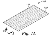
図1Aは、表面に押し込まれたフィラメント15を有する剥離ライナー12Aを含むフィラメント含有剥離ライナー10Aを示す図である。表示した実施形態では、接着剤層はまだ存在せず、後で層として適用されて、剥離ライナー12Aの主表面から隆起する程度まで、フィラメントを包囲又は部分的に包囲する。
FIG. 1A is a diagram showing a filament-containing
剥離ライナー12Aは、接着剤付きフィルムの接着剤部分を保護するとともに、ライナー原料(liner stock)として利用することを意図したフィルムである。剥離ライナー12Aは、任意の好適な種類のライナー材料であってもよく、いくつかの実施形態では、紙又はプラスチックベースのフィルムを含んでもよく、これは、用途に応じて、接着剤付きフィルムなどからの接着剤が過度に強力に表面に接着するのを防ぐ材料(シリコーンベースの材料など)でコーティングされてもよい。剥離ライナーは、接着剤付きフィルムの製造を促進し、上記接着剤バッキングを製造時から設置まで保護するように設計される。設置時に、剥離ライナーは、典型的には接着剤付きフィルムから除去され、廃棄又はリサイクルされる。剥離ライナーは、例えば、紙、ポリエステル、又はHDPEフィルム基材などの当該技術分野で既知の多種の材料を含んでもよい。
The
フィラメント15は、長く薄い(高アスペクト比の)繊維ストランドで、平均断面寸法が50μm以下である。いくつかの実施形態では、フィラメントは、特にダウンウェブ方向に、非常に長く延びる場合がある。他の実施形態では、フィラメントはフィラメント片であり、例えば、10〜50mmであるが、他のサイズのフィラメント片も可能である。フィラメントは、本開示で更に後述するように、表面ライナー12Aに挟まれる又は他の方法で押し込まれている。さらに大きい断面が可能であり、本開示の範囲内で想到されるが、接着剤層及びその他の基材の特徴によっては、フィラメントが大きくなるにつれて、完成したグラフィック物品にフィラメントが見えないようにすることが難しくなる場合がある。一実施形態において、フィラメント15は、熱可塑性押出物を含み、更なる実施形態では、約115℃〜171℃(又は200℃以上の高温、又は100℃以下の低温でも)溶融し得る熱可塑性樹脂を含む。フィラメントは、押出時に硬化する熱可塑性−熱硬化性材料から作製することができ、UV硬化性材料から作製することもできる。
The
ライナー12Aは、総面積「T」、平面透視(plan perspective)から見たときの「ランド」又はフィラメント15Aの面積である第1面積「A」を有する。いくつかの実施形態において、ライナー上には数百、又は数千、数十万さえものフィラメントが存在し得る。非熱硬化性接着剤フィラメントのA対Tの比は5〜99%、より好ましくは5〜50%であってもよく、本発明者らの実験では、グラフィックフィルム用途において、接着を大きく損なうことなく排出及び粘着性制御の優れた性能特性をもたらす比は約5%〜15%である。しかし、フィラメントが、熱活性化された熱硬化性接着剤ストランドの場合、A対Tの比は、はるかに高くなり、それでもなお十分な接着を提供し、熱活性化されていないフィラメントと比べて改善された接着さえも提供し得る。例えば、熱活性化された接着剤フィラメントでは、A対Tの比は10〜50%となることがあり、良好な空気排出及び十分な粘着性制御をもたらし、適用後に接着が向上することさえある(非熱活性化接着剤フィラメントと比べて)。当然、熱活性化された接着剤フィラメントの実施形態は、必要に応じてはるかに高いA対Tの比を用いることができ、おそらくは最大90%までの比率で、場合によりそれ以上が使用できる。A対Tの比が高くなると、粘着性が低くなり(これはある程度、再配置性の向上に対応する)、空気排出が改善されるが、初期接着が悪くなると考えられる。
The
これらの値は全て平均値であり、例示にすぎない。本明細書に記載の方法の特定の実施形態は変動が大きく、例えば、実際にはフィラメントが重なり合う場所もあれば、フィラメント自体が破断し、又はライナー12の表面に押し込まれていない場所もがある(したがって、図1に示すライナー12Aの一部の端面図(図1で「2」として指定されている)である図2を参照すると、フィラメント15がライナー12の表面17の中へ様々な程度で延びていることが示されており、表面17の中にほぼ完全に入っているものもあれば、全く入っていないものもある)。300μmの間隔、及び50μmの直径において、A対Tは約15%である。いくつかの実施形態において、上述のとおり、A対Tは、15%以上であり得るが、本開示の更なる評価で認識されるように、異なる用途では他のパーセンテージが好適である。
All of these values are average values and are merely examples. Certain embodiments of the methods described herein are highly variable, for example, in some places the filaments actually overlap, in other places the filaments themselves are broken or not pushed into the surface of the
記載のように、フィラメント15は、ロールツーロール製造操作によって剥離ライナー12に押し込まれてもよい。最も一般的には、これはニップによって実施される。概ね、フィラメントは、ダウンウェブ方向に適用され、その結果ダウンウェブ方向を向くが、いくつかの実施形態では、当該技術分野で既知の様々な技法(例えば、フィラメントが剥離ライナーの表面に導入されるときに剥離ライナーウェブ又はダイを左右に動かすこと、又は部分的に方向付けされた繊維片を異なる角度でライナー上に吹き付けること)によって、かなりのクロスウェブ作用が導入されてもよい。フィラメント15は、一般的に、押出によって製造され、その後所望の平均断面まで引き伸ばされた後、本開示で更に論じるように、剥離ライナー12の表面に押し込まれる。
As described, the
フィラメント15は、非常に長く、ウェブの延伸部分に沿って連続して(未破断)もよく、又はいくつかの実施形態と共に後述するように、意図的に若しくは製造プロセスの変動の結果としてのいずれかで、破断されてもよい。一実施形態において、フィラメント15は、ウェブ全体に均一に分配され、一実施形態では、前述のように、ウェブの表面積の約15%を覆う。フィラメント15は概ね線状であり、概ねダウンウェブの寸法性(dimensionality)を有してもよく(図1Aに関連する実施形態に示すように)、又は正弦曲線状若しくはジグザグ状のパターン(図1E参照)を表してもよく、又はこのようなパターンが組み合わされてもよい。正弦曲線状又はジグザグ状のパターンは、ウェブ又は設置ダイのクロスウェブ振動によってウェブに導入されてもよい。このようなパターンは、ダウンウェブ方向に、25〜50mm以上(以下)のいずれかの周期を有してもよい。図1Eは、かかるウェブがどのように見えるかを示す図である。部分的に埋め込まれているフィラメント10Eを有する剥離ライナーが、剥離ライナー12E及びその主側面に接触した多数のフィラメントを含むものとして示されている。図1E’はライナーの一部の拡大図であり、フィラメント3A及び3Bが粗い正弦曲線状のパターンを有し、その結果様々な点でフィラメントの重なり合いが生じることを示す。かかる重なり合いは、後でわかるように、クロスウェブの空気及び流体の排出に有効である。
The
下記の実施例の1つで更に述べるように、クロスウェブフィラメントは、ダウンウェブフィラメントに対して直交して方向付けされており(90度より大きい又は小さい異なる領域の他の方向も起こり得る)、ダウンウェブに方向付けされたフィラメントの上部(又は下部)に位置してもよい。図1Dは、かかる実施形態がどのように見えるかを示す図である。部分的に埋め込まれているフィラメント10Dを有する剥離ライナーは、概ね互いに直交して方向付けされた2組のフィラメントを含む多数のフィラメントと接触した剥離ライナー12Dを含む。例えば、図1D’において、フィラメント4B(ダウンウェブ方向に関連する)は、上又は下に重なり合い、クロスウェブ方向に関連するフィラメント4Aを超えて直交して延びていることが示されている。一実施形態において、フィラメント15は熱可塑性押出物を含む。一実施形態において、熱可塑性押出物は、ASTM D1238に従って測定したメルトインデックス値が1〜500である。
As further described in one of the examples below, the cross-web filament is oriented orthogonally to the down-web filament (other directions in different regions greater than or less than 90 degrees can occur). It may be located above (or below) the filament oriented to the downweb. FIG. 1D is a diagram showing what such an embodiment looks like. A release liner with a partially embedded
フィラメントは、フィラメント片又は断片であってもよく、真っ直ぐでも捲縮していてもよく、第三者の製造業者から入手可能なもの、例えば、Trevira GmbH(Hattersheim,Germany)から入手可能なT262 1.3 Dtex X 12MM非クリンピングコア−シースPES/PBT二成分であってもよい。 The filament may be a filament piece or fragment, straight or crimped, and may be available from a third party manufacturer, such as T262 1 available from Trevira GmbH (Hattersheim, Germany). .3 Dtex X 12MM Non-crimping core-sheath PES / PBT two components may be used.
フィラメントは、熱可塑性押出物の他に、液体押出プロセスによって製造できる。液体は、100%固体となり得る(例えば、UV硬化性樹脂)。液体はまた、溶媒又は溶媒の混合物(例えば、水、アルコール、ケトン、又は当該技術分野でポリマーを溶解することが既知の任意の溶媒)中の熱可塑性若しくは熱硬化性又はこれらの組み合わせを含むポリマー又はポリマーの混合物であってもよい。液体は、ラテックスエマルションのようなエマルションでもよい。液体は、ダイから出て、所望の直径で出る又は押出されたフィラメントに近い、より小さい直径に引き伸ばされるかのいずれかである。その後、溶媒を蒸発させてもよく、又は材料を硬化して本発明に有用なフィラメントを生成してもよい。 Filaments can be produced by a liquid extrusion process in addition to thermoplastic extrusions. The liquid can be 100% solid (eg, UV curable resin). The liquid is also a polymer comprising a solvent or a mixture of solvents (eg, water, alcohol, ketones, or any solvent known in the art to dissolve the polymer), thermoplastic or thermocurable, or a combination thereof. Alternatively, it may be a mixture of polymers. The liquid may be an emulsion such as a latex emulsion. The liquid either exits the die and exits at the desired diameter or is stretched to a smaller diameter, close to the extruded filament. The solvent may then be evaporated or the material may be cured to produce filaments useful in the present invention.
フィラメント15の断面形状は、図2でわかるように、基本的に円形であってもよく、又は任意の好適な形状であってもよい。押圧操作は、断面形状を変え、基本的に円形のフィラメントを有効に平坦化し得る。
As can be seen in FIG. 2, the cross-sectional shape of the
フィラメントは、好ましくはロールツーロール製造操作の一部として、剥離ライナーに押し込まれる。ライナー12は、剥離ライナーであってよい。ライナー12は、接着剤と共に使用することが当業者に知られており、かつその上に押圧されたフィラメントを有することができる任意の好適な剥離又は転写ライナーであることができる。ライナーの非限定例としては、3M(St.Paul,Minnesota)、及びその他の市販ライナー製品製造業者、例えば、Rexam Release Corporation(Oakbrook,Illinois)、Daubert Coated Products(Westchester,Ill)、又はLoparex(Cary,NC)からの種々の市販材料が挙げられる。ライナーは、典型的には市販のシリコーン剥離コーティングを有するポリエチレンコート紙、市販のシリコーン剥離コーティングを有するポリエチレンコートポリ(エチレンテレフタレート)フィルム、又はフィルムの製造中にパターンをエンボス加工し、その後市販のシリコーン剥離コーティングでコーティングできるキャストポリプロピレンフィルムである。その他の有用なライナーは、上で参照したCalhoun et al.及びWilson et al.の特許で特定されている。
The filament is pushed into the release liner, preferably as part of a roll-to-roll manufacturing operation. The
一般的に、フィラメントは、押圧中に剥離ライナーよりも硬く、そのためフィラメントは少なくとも部分的に剥離ライナーの表面上に押し込まれることになる(例えば、ライナー材料は押し込まれたフィラメントを収容するために多少変形することになる)。この適切な硬度の変動をもたらすため、剥離ライナーを軟化点まで加熱してもよい。いくつかの実施形態において、フィラメントは、典型的な加工温度において、すでに剥離ライナーよりも硬く、そのため必ずしも剥離ライナーの更なる軟化を必要としない場合がある。 Generally, the filament is harder than the release liner during pressing, so that the filament is at least partially pushed onto the surface of the release liner (eg, the liner material is somewhat to accommodate the pushed filament. Will be transformed). The release liner may be heated to the softening point to bring about this appropriate hardness variation. In some embodiments, the filament is already harder than the release liner at typical processing temperatures and may therefore not necessarily require further softening of the release liner.
図2は、図1Aの「2」から見た剥離ライナー10の端面図(又は図1B〜図1Eに示す実施形態に関連する類似の図)である。フィラメント15は、ライナー12の表面17全体に分配されていることがわかる。左から右へ、別個のフィラメントが剥離ライナー12に部分的に埋め込まれており、フィラメントの一部のみが表面17の主平面から外に延びていることがわかる。いくつかのフィラメントは、任意の断面において、0%、10%、20%、30%、40%、50%、60%、70%、80%、又は更には90%以上がライナー12内に包囲されてもよい。同じフィラメントが、異なる断面(アップウェブ又はダウンウェブ)で異なるパーセンテージで包囲されてもよい。それ故、フィラメントは、ライナー12内にどれだけ埋め込まれるか、又は逆に、ライナー12の主表面17からどれだけ突出するかに関して、変動を示す。いくつかの好ましい実施形態では、断面において、フィラメントの80〜100%はライナー12の表面17よりも下に延び、したがってフィラメントの残りの0〜20%は表面17の上に突出(例えば、隆起)している。一般的に、平均断面幅が15μmのフィラメントの場合、フィラメントは、ライナー内に平均で>3μm、好ましくは>5μm、更により好ましくは>10μm埋め込まれている。
FIG. 2 is an end view of the release liner 10 as viewed from “2” of FIG. 1A (or a similar view related to the embodiment shown in FIGS. 1B to 1E). It can be seen that the
図3は、更なる接着剤層20を追加的に含む、図2に示す剥離ライナーの断面図を示す。フィラメント15がライナー12に押し込まれた後、接着剤が、ライナー12のフィラメント含有側に配設される。接着剤は、液体コーティング(及びその後のUV硬化)などの当該技術分野において既知の技法によって、又は積層(両方の材料がニップを通るときに、接着剤又は接着剤付きライナーを、ライナー12のフィラメント含有側に押し込む)によって、配設されてもよい。接着剤層をライナー12のフィラメント含有側に配設するその他の方法は、当業者に明らかであろう。接着剤は任意の好適な感圧性接着剤であってもよい。感圧性接着剤の非限定例としては、米国特許第4,994,322号(Delgado et al.)、米国特許第4,968,562号(Delgado)、欧州特許出願公開第0 570 515号、欧州特許出願公開第0 617 798号に開示されているもの、米国特許第5,296,277号及び同第5,362,516号(いずれもWilson et al.)並びに同第5,141,790号(Calhoun et al.)、及び国際出願PCT/US96/1687号(Keller at al.)に開示されている感圧性接着剤、及びSatas,et al.,Handbook of Pressure Sensitive Adhesives,2nd Ed.(Von Nostrand Reinhold)N.Y.,1989)に開示されている任意の他の種類の感圧性接着剤が挙げられる。
FIG. 3 shows a cross-sectional view of the release liner shown in FIG. 2, further comprising an additional
好適な選択としては、粘着付与されたゴム、アクリレート、メタクリレートなどが挙げられる。製造プロセスの変動性により、接着剤が適用される前にフィラメント及びライナーが多少押されることがあり、その結果、所与のフィラメントのいくつかの部分が、断面で見たときに、ライナー12の表面から完全に隆起し、接着剤層20内に完全に包囲される。当然、その他のフィラメントはライナー12内に部分的に埋め込まれている状態であり、それによって接着剤層20に曝露しない部分を有する。図2を参照して述べたように、フィラメントは、好ましくは部分的にライナーに埋め込まれ、その結果接着剤コーティングはライナー内に埋め込まれていないフィラメントの部分のみを包囲し得る。実際には、フィラメントが平均で15μmの直径(又は高さ)を有する場合、当該フィラメントは、平均で約80〜100%、又は12〜15μmがライナー12の表面内に延び、フィラメントの残りの部分(0〜20%、又は約0〜3μm)は表面17から突出し、それによって接着剤層20に包囲され得る。前述のように、大量のフィラメント及びプロセス変動性を考慮すると、フィラメントが埋め込まれ得る実際の深さは様々であり、まったく埋め込まれていないフィラメントもあれば、ほぼ完全に埋め込まれているフィラメントもある。
Suitable choices include sticky rubber, acrylates, methacrylates and the like. Due to the variability of the manufacturing process, the filament and liner may be slightly pressed before the adhesive is applied, resulting in some parts of the given filament when viewed in cross section of the
一実施形態において、フィラメントは接着剤層20の厚さよりも小さい断面又は直径を有し、そのため表面17から完全に隆起したフィラメントでも、接着剤層20に完全に包囲され得る。図1及びA対Tのパーセンテージに少し戻ると、ここで、ライナー12を接着剤層20から除去すると、フィラメント15は接着剤層20に固着することになり、それにより接着剤層20の表面に一連のフィラメントが生じることが理解され得る。フィラメントの大部分は、一実施形態において、断面で、接着剤層20の表面上の80%以上に広がる直径を有するであろう。接着剤層20のフィラメント非含有側がグラフィック層(例えば、表面に設置しようとする印刷グラフィック)と接合しているとき、このように記載された構造の想到される適用の一例のように、これらのフィラメントは上記グラフィック層を表面に設置する間に、少なくとも次の2つの目的に有用である:(1)接着剤層をいくらか表面から離し、適用面上のグラフィック層の再配置性を向上する、及び(2)流体排出(例えば、気泡又は液泡を、手又はスキージで、かかるグラフィック層の端に動かし、グラフィック層の下から出るように)する。熱可塑性押出物がホットメルト接着剤を含む場合、グラフィックが、泡が除去された状態で正しく配置された後、グラフィックホットメルト接着剤を、例えばヒートガン若しくはトーチ又はその他の加熱デバイスを使用して活性化し、接着の向上を促進するとともに、フィラメントの平坦化も行う。図1を参照して述べたように、平均直径15μmのフィラメント(80〜100%、例えば12〜15μmがライナー12の表面内に延びる)を使用したとき、約15%という1つのA対Tの比は、空気排出及び再配置性に十分に有効であると思われる。しかし、より高いA対Tの比で、感圧性接着剤からの接着を犠牲にして、より優れた再配置性及び排出が得られると考えられる。フィラメントがホットメルト接着剤を含む場合、すなわち、最終的な接着剤品質が、最終的な加熱工程によっていずれにせよ強化される場合には、感圧性接着剤の性能はそれほど重要でない可能性がある。しかし、フィラメントがホットメルト接着剤を含まない場合、及び感圧性接着剤が当初の接着剤のメカニズムとして頼られることになる場合には、より低いA対Tが望ましいことがある。A対Tの比が15%よりも高く、なお良好な再配置性及び空気排出をもたらす(接着を向上しながら)ことができ、20%、25%、30%、35%、40%、45%、50%、55%、60%、65%、70%、75%、80%、さらにはそれよりも高い比が、いくつかの用途で好適となる場合があり、設置プロセスの間にヒートガンなどの熱の導入によって活性化されるホットメルト接着剤をフィラメントが含む実施形態では、高レベルの方が特に好適である。逆に、10%又は更には5%などの15%未満の比が、いくつかの用途で望ましい可能性がある。
In one embodiment, the filament has a cross section or diameter smaller than the thickness of the
種々の従来の接着剤配合物から接着剤を選択することができる。接着剤の非限定的な例としては、感圧性接着剤、適用時に感圧性であるホットメルト又は熱活性化接着剤、例えば米国特許第4,994,322号(Delgado et al.)、米国特許第4,968,562号(Delgado)、欧州特許出願公開第0570515号、欧州特許出願公開第0617708号に開示されている感圧性接着剤;米国特許第5,296,277号及び同第5,362,516号(いずれもWilson et al.)並びに同第5,141,790号(Calhoun et al.)及び米国特許出願公開第08/559,037号(Keller et al.)に開示されている感圧性接着剤(全て参照により援用される)及びSqatas,et al.,Handbook of Pressure Sensitive Adhesives,2nd Ed.(Von Nostrand Reinhold,N.Y.,1989)に開示されている任意の他の種類の感圧接着剤が挙げられ、上記開示を参照により援用する。 Adhesives can be selected from a variety of conventional adhesive formulations. Non-limiting examples of adhesives include pressure sensitive adhesives, hot melt or heat activated adhesives that are pressure sensitive when applied, such as US Pat. No. 4,994,322 (Delgado et al.), US Pat. Pressure-sensitive adhesives disclosed in Nos. 4,968,562 (Delgado), European Patent Application Publication No. 0570515, European Patent Application Publication No. 0617708; US Pat. Nos. 5,296,277 and 5, It is disclosed in 362,516 (both Wilson et al.), 5,141,790 (Calhoun et al.) And US Patent Application Publication No. 08 / 559,037 (Keller et al.). Pressure sensitive adhesives (all incorporated by reference) and Sqatas, et al. , Handbook of Pressure Sensitive Adhesives, 2nd Ed. Any other type of pressure sensitive adhesive disclosed in (Von Nostrand Reinhold, NY, 1989) is cited and incorporated by reference above.
図4は、図3に示す剥離ライナーの断面図であるが、紙バッキング25を更に含む。このような構造において、紙バッキング25はポリエチレンフィルム(ライナー12)を支持し、その上面側(すなわち、接着剤層20と接する側)は何らかの(多くの場合、シリコーンベース)剥離剤でコーティングされていると考えられる。ライナー12及び紙バッキング25は図4で別々に示されているが、実際には、「剥離ライナー」への言及は、紙バッキング(存在する場合)、ポリエチレンライナー層12、及び剥離剤(存在する場合)を含み得る。
FIG. 4 is a cross-sectional view of the release liner shown in FIG. 3, which further includes a
図5は、上述の図に示した接着剤層及びフィラメントの断面図であるが、ライナー12が除去されたものである。ライナー12の表面内に延びるフィラメント15は、接着剤層20から保護されていた。ここでは、フィラメントがライナー12に包囲された範囲で、主接着剤表面の平面19から隆起している。このようなフィラメントのこのような部分は、接着剤を含有しない。
FIG. 5 is a cross-sectional view of the adhesive layer and filament shown in the above figure, with the
図6は、ライナーが除去された(図5のように)状態の接着剤層及びフィラメントの断面図であるが、グラフィックの現場用途で典型的にみられるような多数の追加層を更に含む。接着剤層20は、フィルム30に連結されている。フィルム30は任意の好適なフィルムであってもよく、米国特許出願公開第2014/0141214号「Graphic Article」(Steelman and Lyon)及び同第2014/014009号「Graphic Article」(同じくSteelman and Lyon)に記載のような、PVCベースのフィルム、又はポリオレフィンフィルム、又は熱可塑性ポリウレタン及びセルロースエステルフィルムなどであってもよい。フィルム30は、接着剤表面との接触に有用なフィルム、例えば3Mから市販されているControltac(商標)ブランドのフィルム、米国特許第5,721,086号に開示のフィルム、箔、金属プレート、セラミックプレート、ポリマーシート、振動減衰材料、反射シート、再帰反射シート、上面被覆材料、産業用テープバッキング、低アレルギー性テープバッキング及びこれらの組み合わせも含んでもよい。
FIG. 6 is a cross-sectional view of the adhesive layer and filament with the liner removed (as in FIG. 5), but further includes a number of additional layers typically found in graphic field applications. The
フィルム30の上面には、文字、画像、グラフィック、広告などが印刷されてもよい。いくつかの実施形態において、ライナー(例えば、上記の実施形態のライナー12)は、フィラメント及び接着剤層並びにフィルム層30と共に、印刷又はその他の用途向けのシート又はロールとして販売されており、追加の接着剤層40、オーバーラミネート50、及びクリアコート層60のような更なる層が、(任意に)追加された層である。
Characters, images, graphics, advertisements, and the like may be printed on the upper surface of the
任意の好適なフィルムが、フィルム30を含むことができ、これはその表面から延びるフィラメントを有する接着剤の主表面(単数又は複数)の反対側の接着剤の主表面と接触する。接着剤がフィラメント含有ライナーに適用された後でフィルムが接着剤に積層されることから、フィルム30の露出した主表面の外観は、一般的に、フィラメントのトポグラフィによる悪影響を受けない。この利点により、フィルム30は、電子記録、インクジェット、スクリーン印刷、フレキソ印刷、電子切削又は他の画像形成若しくはグラフィック技法を含む任意の商業的技法を使用して画像形成することができる。
Any suitable film can include
図7は、適用されたフィルム物品51の断面図で、基材200に適用されたフィルム30を含む。基材200は、例えば、商業施設の壁であってもよく、フィルム30の上部主表面にグラフィックが印刷されていてもよい。適用技術者は、ライナー12(図2、3、4のような)を除去して、フィラメント含有接着剤層20を露出してもよい。技術者は、次に、接着剤とフィラメントとが露出されたフィルム(例えば、フィラメント15、接着剤層、及びフィルム30(及び図6に示す実施形態で例示するような、任意の更なるフィルム又は層)を含むスタック)を、壁の適用面にそっと接触させてもよい。フィラメントは接着剤層を基材200の適用面から離して保持して、再配置性(すなわち、技術者がグラフィックフィルムを取り付けた後、外して位置を変えることができること)を促進する。グラフィックが正しく配置されたら、技術者は、フィラメント含有接着剤層20を基材に更にしっかりと押しこみ、接着剤層20と基材200の表面との間をより密接に接触を促進させてもよい。空気又は流体排出チャネル又は導管14は、フィラメント15に隣接した領域に形成される。技術者は、次いで、スキージ又は類似デバイスを用いて、発生したエアポケット(又は適用プロセスに水若しくは流体混合物が使用される場合には流体ポケット)を押して、フィルム物品の辺縁に排出してもよい。かかる流体排出は、フィラメント15のいずれかの側に存在し得るフィラメントチャネルによって促進される。
FIG. 7 is a cross-sectional view of the applied film article 51, including the
適用後、フィラメントがホットメルト接着剤又は熱活性化された材料を含む場合、技術者はヒートガン又はその他の熱源を使用してフィラメントを加熱し、その後ローラー又はその他の適用デバイスを用いてフィルムを基材200の表面に更に押圧してもよい。このプロセスにおいて、更なる接着が促進されるように、フィラメントが平坦化される及び/又は接着が活性化される。
After application, if the filament contains a hot melt adhesive or heat activated material, the technician heats the filament using a heat gun or other heat source and then bases the film using a roller or other applicable device. It may be further pressed against the surface of the
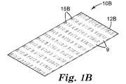
印刷したグラフィックを伴う多数のフィルム物品用途において、直線的な、概ねダウンウェブの空気排出は許容できる。しかし、場合によっては、クロスウェブの空気排出も有することが好ましくなり得る。クロスウェブの排出は、多数の方法で達成できる。一実施例において、ジグザグ状又は正弦曲線状のパターンがダウンウェブフィラメントに導入されて、クロスウェブの経路を与えてもよい(図1Eに示すように)。別の実施形態において、フィラメントのクロスウェブのセクション(section)を、レーザー切断及び/又は溶融することができる。例えば、ウェブ全体にわたる0.25〜5mmのフィラメントのセクションを、12mm以上のピッチで切断することができる。一実施形態において、切断は、5mmの間隙を12mmのピッチで除去する。図1Bは、かかる実施形態がどのように見えるかを示す図である。部分的に埋め込まれているフィラメントを有する剥離ライナー10Bは、部分的に埋め込まれているフィラメント15Bに接触した剥離ライナー12Bを含む。フィラメントは、ウェブのダウンウェブ方向と関連する方向性を有する。フィラメント間の領域は、一定のピッチで切断されており、フィラメント含有材料のセクションとフィラメント含有材料を欠くセクションとが交互になった、クロスウェブ方向の縞の様相を形成する。これらのクロスウェブセクションは、完成物品においてクロスウェブの空気排出を促進する。
Straight, generally down-web air vents are acceptable for many film article applications with printed graphics. However, in some cases it may also be preferable to have a cross-web air vent. Cross-web emissions can be achieved in a number of ways. In one embodiment, a zigzag or sinusoidal pattern may be introduced into the downweb filament to provide a crossweb path (as shown in FIG. 1E). In another embodiment, the cross-web section of the filament can be laser cut and / or melted. For example, sections of 0.25-5 mm filaments throughout the web can be cut at pitches of 12 mm and above. In one embodiment, cutting removes 5 mm gaps at a pitch of 12 mm. FIG. 1B is a diagram showing what such an embodiment looks like. The
別の実施形態では、フィラメントを周期的にエンボス加工することができる。エンボス加工は、好ましくはフィラメントの高さを50〜90%低くし、流体がクロスウェブに排出できるようにする。このエンボス加工は、クロスウェブの空気排出ももたらし、エンボスの長さ及び頻度は上述のレーザー切断法に近い。一実施形態において、フィラメントは、ライナーに押し込まれる前に、エンボス加工される。別の実施形態では、全フィラメントがライナー内に押し込まれた後、フィラメント及びライナーがエンボス加工される。いずれの場合も、フィラメントにクロスウェブのパターンが得られ、そのフィラメントの高さはフィラメント部分を押すことで効果的に低減されている。 In another embodiment, the filament can be embossed periodically. Embossing preferably reduces the height of the filament by 50-90%, allowing the fluid to drain into the crossweb. This embossing also results in cross-web air exhaust, and the length and frequency of embossing is close to the laser cutting method described above. In one embodiment, the filament is embossed before being pushed into the liner. In another embodiment, the filament and liner are embossed after the entire filament has been pushed into the liner. In each case, a cross-web pattern is obtained on the filament, and the height of the filament is effectively reduced by pressing the filament portion.
図8Aは、フィラメントが内部に押し込まれたライナーの製造プロセスの概略図であり、上記のように、当該ライナーは次に、接着剤層及び印刷されたフィルムに接触(例えば、被覆)されてもよい。図8に示すプロセスは、ロールツーロールプロセスで、フィルムは左から右へ運ばれる。本開示を読んだ当業者に明白であるように、他の製造プロセスも可能である。複数のフィラメント170が押出機150からチルロール120の上に押出される。押出されたフィラメントが最適な直径ではない場合、中間工程として、図9に示すように、ライナー上に配設される前にフィラメントをロール上で適切な直径まで引き伸ばしてもよく、この図は、溶融延伸プロセスの一部として、フィラメント170を、押出し速度よりも速く作動するチルロール125上に押出し、それによってフィラメントを引き伸ばす押出機150を示す。ロール110及びロール120(これは任意にチルロールであってもよい)は、ライナー140及びフィラメント170をニップ115で1つにし、それによってフィラメントをライナー140の表面内に押し込み、フィラメント含有ライナー140aを作製する。次いで、ロール130は、フィラメント含有ライナー140aを、必要に応じて更なる加工用に方向付ける。例えば、かかる更なる加工としては、フィラメント含有ライナー140を接着剤層及びフィルム、例えば、接着剤層20及びフィルム30(例えば、図6に示す)で被覆することが挙げられる。かかる実施形態において、接着剤と接していないフィルム30の主表面は、グラフィック印刷用原料として印刷工場に送ることができる状態である場合がある。しかし、図8に示すように、フィラメント含有ライナー140aは、ローラー180上に巻き取られる。巻き取られた後、フィラメント含有ライナー140aは、後で更に加工するために保管されてもよい。
FIG. 8A is a schematic diagram of the process of manufacturing a liner with filaments pushed into it, even if the liner is then contacted (eg, coated) with an adhesive layer and a printed film, as described above. Good. The process shown in FIG. 8 is a roll-to-roll process in which the film is transported from left to right. Other manufacturing processes are possible, as will be apparent to those skilled in the art who have read this disclosure. A plurality of
図8aに示す実施形態は、レーザー160も含み、これを使用して、フィラメント170がライナー140に押し込まれる前に、フィラメントの複数部分を切断できる(図1B参照)。かかる切断は、クロスウェブで、クロスウェブの流体排出を促進できる。レーザーは、赤外線レーザー、近赤外線レーザー、又は紫外線レーザーであってもよい。レーザーは、パルス状でも連続的でもよい。レーザーは、通常、フィラメントが配設されつつあるロールにレーザーを送る鏡を有するスキャナに送られる。スキャナの鏡は、レーザーをウェブの一端から他端へ向ける。ウェブの幅が広すぎる場合、このタスクを達成するために、複数のスキャナを1つのレーザー又は複数のレーザーと共に使用してもよい。
The embodiment shown in FIG. 8a also includes a
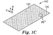
別の製造実施形態において、適切な平均サイズ(例えば、5〜50mm)のフィラメントセクションを、加熱したライナー上に吹き付けた後でその中に押し込んでもよい。図8Bは、吹付フィラメント装置201を示す。ホッパー210には、適切な寸法の繊維が装填されている。フィードロール203は、繊維をホッパーから引き、リッカーインロール200の歯に入れる。強制空気205は、好ましくは加熱され、リッカーインロール200から繊維を追い出し、フィラメント片をライナー207の主表面上に配設し、当該ライナーはわずかに粘着性になる点まで加熱されてもよい。ホッパーの底には、刻み目又はその他の方法でテクスチャー化されたロール(図8Bに表示されていない)があってもよく、これは回転し、必要であれば更にフィラメントを開き、好ましくはそれを個別化する。その後、フィラメントは、ニップ(図8Bに示されていない)でライナーの主表面内に押し込まれてもよい。吹付けられたフィラメントがウェブに達するまでに移動する距離の増大、又は空気流の増大は、配設されたフィラメント片に関連する寸法性を低下し得る(ライナー上に配設されたときのフィラメントの「不規則性」を効果的に増大する)。かかるフィラメント吹付けシステムの更なる別の実施形態では、1つはダウンウェブ方向に対して45°、1つはクロスウェブ方向に対して45°の、2つの繊維吹付けシステムを使用してもよく、その結果得られるフィラメントの組はライナー表面上で直交方向を向く傾向がある(したがって、完成物品で2方向の空気又は流体排出をもたらす)。図1Cは、得られた剥離ライナーを示し、この部分的に埋め込まれているフィラメントを有する剥離ライナー10Cは、剥離ライナー12Cをその上に配設されたフィラメント片と共に含む。フィラメント片は、その向きを基準として2種類の異なる組を含む。第1の組は、フィラメント片が概ね方向Aを向くように配設され、第2の組は、概ね方向Bを向くように配設されている。方向AとBとは90°異なる(他の差異も可能であり、本開示の範囲内で想到される)。図1C’は、図1Cに示すライナーの一部分を拡大しており、個別のフィラメント片4Aは、フィラメント片4Bにほぼ直交して配設されているのがわかる。
In another manufacturing embodiment, a filament section of suitable average size (eg, 5-50 mm) may be sprayed onto a heated liner and then tucked into it. FIG. 8B shows a
更に別の製造実施形態において、フィラメントは、接着剤付きフィルムの接着剤層に直接導入されてもよい。かかる製造プロセスは、図8Bに関連して示したプロセスと似ているが、ライナー207が接着剤被覆フィルムで、接着剤側を上に向けている点が異なる。既知の方法を用いてフィルムに接着剤層をコーティングした後、フィラメント片を接着剤コーティング上に直接配設し、必要に応じて強制空気205で冷却して接着剤層に適切なレオロジーを発生させ、それによりフィラメントが接着剤層内に深く沈みすぎるのを防ぐ。これにより、フィラメントは、接着剤表面にわずかに付着する。フィラメントは、空気流の方向と一致する全体的配列で接着剤層上に定着してもよく、上記の製造実施形態に関して述べたように、ウェブに対して2つ(又はそれ以上)の角度に方向付けされた複数のフィラメント配設ステーションがフィラメントの重なり合いをもたらし、最終的にはクロスウェブ及びダウンウェブの空気及び流体排出をもたらす。例えば、第1ステーションは、ダウンウェブから45°の角度でフィラメントを配置するよう方向付けされ、第2ステーションは、ダウンウェブから−45°の角度でフィラメントを配置するよう方向付けされてもよい。
In yet another manufacturing embodiment, the filament may be introduced directly into the adhesive layer of the adhesive film. Such a manufacturing process is similar to the process shown in connection with FIG. 8B, except that the
フィラメントが接着剤層の上に乗ると、次の工程は、本開示で上述されているように、フィラメントが、接着剤層の表面から外側に伸びた状態を概ね保つように、剥離ライナーを接着剤層(このときにはフィラメント片を含有する)に適用することである。したがって、ある装置構成では、接着剤被覆フィルム及びフィラメントが冷却され、剥離ライナーが軟化点まで加熱され、その後両方がニップに供給される。ライナーは、ニップロールに巻き付いたときに更に加熱される可能性がある。この加熱は、ライナー剥離層を軟化し、ニップ内で、フィラメントを有する低温の接着剤表面が高温の軟化ライナー表面に接触することで、フィラメントが少なくとも部分的にライナー剥離層に埋め込まれ、残りは接着剤層に部分的に埋め込まれる。現場で剥離ライナーを除去すると、剥離ライナー内に延びるフィラメントの複数部分が接着剤層から立ち上がった状態になり、上述の実施形態のメリット及び機能性をもたらす。 Once the filament is on top of the adhesive layer, the next step is to bond the release liner so that the filament generally remains stretched outward from the surface of the adhesive layer, as described above in the present disclosure. It is applied to the agent layer (which contains filament pieces at this time). Thus, in some device configurations, the adhesive coating film and filament are cooled, the release liner is heated to the softening point, and then both are fed to the nip. The liner can be further heated when wrapped around the nip roll. This heating softens the liner stripping layer, and in the nip, the cold adhesive surface with the filaments comes into contact with the hot softening liner surface, allowing the filament to be at least partially embedded in the liner stripping layer and the rest Partially embedded in the adhesive layer. When the release liner is removed in the field, a plurality of portions of the filament extending into the release liner are raised from the adhesive layer, which brings about the advantages and functionality of the above-described embodiment.
発明の有用性
イメージグラフィックフィルムが、本発明のフィラメント含有接着剤表面によって予想外に改善される。本発明のフィラメント含有接着剤表面を有するイメージグラフィックフィルムを使用して、接着剤のレオロジー(クリープコンプライアンス、弾性率など)に従って、所定の時間で流体排出をもたらすことができる。更に、良好な粘着性制御特性も実現し得る。
Usefulness of the Invention The image graphic film is unexpectedly improved by the filament-containing adhesive surface of the present invention. The image graphic film having the filament-containing adhesive surface of the present invention can be used to provide fluid discharge in a predetermined time according to the rheology of the adhesive (creep compliance, modulus, etc.). Further, good adhesiveness control characteristics can be realized.
当業者は、流体排出を制御できるが、(a)好適な接着剤を選択すること、及び(b)フィラメントの直径及び硬度、並びにライナー内にフィラメントがどれだけ押し込まれるかを制御することによって適切なトポグラフィを形成すること、及び(c)接着剤を支持基材に適切に適用すること、によって、接着剤境界面における流体進入を最小限に抑えることができる。これは、設置中に空気排出をもたらすが、その後接着剤と支持基材との間の境界面を封止する。 One of ordinary skill in the art can control fluid discharge, but is appropriate by (a) selecting a suitable adhesive and (b) controlling the diameter and hardness of the filament and how much the filament is pushed into the liner. By forming a good topography and (c) properly applying the adhesive to the supporting substrate, fluid ingress at the adhesive interface can be minimized. This results in air exhaust during installation, but then seals the interface between the adhesive and the supporting substrate.
あるいは、当業者は、最初の設置後に、より長い時間接着剤表面のトポグラフィを維持するように、異なるレオロジー特性の接着剤を選択して、同じ若しくは異なる支持基材上に複数回の再設置ができるようにすること、又は流体排出に利用できる経路を最大にすることもできる。 Alternatively, one of ordinary skill in the art may choose adhesives with different rheological properties to maintain topography of the adhesive surface for a longer period of time after initial installation and multiple reinstallations on the same or different supporting substrates. It can also be made possible, or the routes available for fluid discharge can be maximized.
本発明の接着剤表面は、ライナーをエンボス加工することによって、チャネル等を有する接着剤の構造化に関連する製造コストを削減することで、経済的価値を向上させる。 The adhesive surface of the present invention is improved in economic value by embossing the liner to reduce the manufacturing cost associated with the structuring of the adhesive having channels and the like.
更なる機能、利点、及び実施形態を実施例に記載する。 Further features, advantages, and embodiments are described in the Examples.
部分的に埋め込まれているフィラメントを有するウェブを調製した。得られた物品は、以下の実施例に示すように、良好な粘着性制御(再配置性を促進する)及び空気放出をもたらした。これらの実施例は例示を目的とするにすぎず、本開示の範囲を限定することを意味するものではない。 Webs with partially embedded filaments were prepared. The resulting article provided good stickiness control (promoting rearrangement) and air release, as shown in the examples below. These examples are for illustrative purposes only and are not meant to limit the scope of the present disclosure.
材料:
略称:説明
R1:Total Petrochemicals & Refining USA,Inc.(Houston,TX)から3860として入手可能なポリプロピレン樹脂ペレット。
L1:Loparex LLC(Cary,NC)からC2S4212A/4000D L/H PC SKC CL PETとして入手可能な剥離ライナー。
F1:3M Company(St.Paul,MN)から3M SCOTCHLITE反射グラフィックフィルムIJ5100として入手可能な反射グラフィックフィルム。
ADH1:FPC(Wauconda,IL)からSUREBONDER 725R4−1−GPグルースティックとして入手可能なホットメルト接着剤。
T1:3M Company(St.Paul,MN)からスコッチ両面テープ665 1/2インチとして入手可能な両面テープ。
F2:3M Company(St.Paul,MN)から9415強/弱粘着両面粘着テープとして入手可能な転写接着剤。
material:
Abbreviation: Description R1: Total Petrochemicals & Refining USA, Inc. Polypropylene resin pellets available as 3860 from (Houston, TX).
L1: A release liner available from Loparex LLC (Cary, NC) as C2S4212A / 4000D L / H PC SKC CL PET.
Reflective graphic film available as 3M SCOTCHLITE reflective graphic film IJ5100 from F1: 3M Company (St. Paul, MN).
ADH1: A hot melt adhesive available from FPC (Wauconda, IL) as a SUREBONDER 725R4-1-GP glue stick.
Double-sided tape available as Scotch double-sided tape 665 1/2 inch from T1: 3M Company (St. Paul, MN).
A transfer adhesive available from F2: 3M Company (St. Paul, MN) as a 9415 strong / weak adhesive double-sided adhesive tape.
実施例1:部分的に埋め込まれているフィラメントを有するライナー
ライナーL1を、剥離面を上にして、上のゴムロール(ロール1)と下のスチールロール(ロール2)とからなる加熱したニップを通るように、60フィート/分で供給した。ニップ圧は40ポンド/インチであった。両方のロール用のニップ熱交換器は、240°F(116℃)に設定し、出てくるライナーは、赤外線放射温度計で206°Fと推定された。樹脂R1を加熱し、480°F(249℃)にて、スクリュー直径50mm、L/Dが約32:1の押出機内で、1インチ当たり60のオリフィスを有する2インチのダイを通して、室温のスチールロール(ロール3)上に押出し成形した。穿孔されたダイのオリフィスは、0.008インチ(0.20mm)の開口部を有した。押出速度は、平均で0.14ポンド/時と測定されたが、低速押出機を運転したために、変動があった。
Example 1: A liner liner L1 with a partially embedded filament passes through a heated nip consisting of an upper rubber roll (roll 1) and a lower steel roll (roll 2) with the peel surface facing up. As such, it was supplied at 60 ft / min. The nip pressure was 40 lbs / inch. The nip heat exchangers for both rolls were set to 240 ° F. (116 ° C.) and the emerging liner was estimated to be 206 ° F. by an infrared thermometer. Resin R1 is heated and at 480 ° F (249 ° C), in an extruder with a screw diameter of 50 mm and an L / D of about 32: 1, through a 2-inch die with 60 orifices per inch, room temperature steel. It was extruded onto a roll (roll 3). The perforated die orifice had an opening of 0.008 inch (0.20 mm). Extrusion rates were measured on average at 0.14 lbs / h, but fluctuated due to the operation of the slow extruder.
得られた押出成形フィラメントを5インチ引き伸ばし、滑らかなスチールロール(ロール3)の側に触れた後、加熱ロール(ロール2)上の加熱されたライナーと共にはさみ、それによって押出されたフィラメントをライナーの上を向いた側に押し込んだ。かなりの数のフィラメントがダイチップ付近で一緒に「二重化」又は一体化し、上記の可変速度及びいくつかのダイチップ上での変動する蓄積物により、時として、不均一なフィラメント押出速度が存在した。 The resulting extruded filament is stretched 5 inches, touched on the side of a smooth steel roll (roll 3) and then sandwiched with a heated liner on a heating roll (roll 2), whereby the extruded filament is placed on the liner. I pushed it to the side facing up. A significant number of filaments were "duplicated" or integrated together near the die chips, and due to the variable speeds described above and the fluctuating buildups on some die chips, there were sometimes non-uniform filament extrusion rates.
次いで、フィラメントを、ロール2とロール3との間の加熱されたライナーで、間隙を2milに設定してはさみ、それによりフィラメントをライナー表面に埋め込んだ。フィラメントの大部分は高さ28〜30μmであったが、フィラメントの組み合わせ又は「二重化」及び上記の可変速度により、フィラメント幅は17〜155μmの範囲で変動した。これにより、埋め込まれているフィラメントを有するライナーを製造した。 The filament was then pinched with a heated liner between rolls 2 and 3 with a gap set to 2 mil, thereby embedding the filament in the liner surface. Most of the filaments were 28-30 μm high, but the filament width varied in the range 17-155 μm due to the combination or "duplication" of the filaments and the variable speeds described above. This produced a liner with an embedded filament.
実施例2:埋め込まれているフィラメントを有するライナーに積層されたフィルム
実施例1で得られた、埋め込まれているフィラメントを有するライナーのセクションを、硬く平坦な台の表面上に、埋め込まれているフィラメントが上を向くように置いた。次いで、反射グラフィックフィルムF1のわずかに大きなセクションをライナーに積層した。最初に、フィルムF1の小さいセクションをフィラメント含有ライナーに合わせ、手で台に付着させた。次いで、ゴムローラー(Marshalltown Company(Marshalltown,IA)から入手可能な部品番号EDI:19560の類似品)をフィルムF1の粘着部分上に置き、前進させて、埋め込まれているフィラメントを有するライナーにフィルムF1を積層した。
Example 2: Film laminated on a liner with embedded filaments The section of the liner with embedded filaments obtained in Example 1 is embedded on the surface of a hard, flat platform. The filament was placed with the filament facing up. A slightly larger section of the reflective graphic film F1 was then laminated on the liner. First, a small section of film F1 was aligned with the filament-containing liner and manually attached to the table. A rubber roller (similar to part number EDI: 19560 available from Marshalltown Company (IA)) is then placed on the adhesive portion of film F1 and advanced to advance the film F1 onto a liner with an embedded filament. Was laminated.
実施例3:フィラメントを有する再配置可能な接着フィルム
実施例2の積層体を、実施例1に使用したライナーL1をフィルムF1から除去することで、手で分離した。2枚のフィルムが分離されると、フィラメントは、フィルムF1の接着剤側に残った。これにより、部分的に埋め込まれているフィラメントを有する接着剤付きフィルムが形成された。
Example 3: Repositionable Adhesive Film with Filament The laminate of Example 2 was manually separated by removing the liner L1 used in Example 1 from the film F1. When the two films were separated, the filament remained on the adhesive side of the film F1. This formed an adhesive film with partially embedded filaments.
部分的に埋め込まれているフィラメントを有する接着剤付きフィルムを、追加の圧力を加えず、つまり、積極的に押すことなく、接着剤層が表面と密着するのをフィラメントが防ぐように、接着剤側を下にして表面上に置いた。次いで、部分的に埋め込まれているフィラメントを有する接着剤付きフィルムを、フィルムの角を引くことで除去し、再配置した。フィルムをそっと押すと、フィルムが表面に接着した。よりしっかりと押すと、より多くの接着剤が表面に接合し、接合が増大した。 Adhesive so that the filament prevents the adhesive layer from adhering to the surface without applying additional pressure, i.e., aggressively pressing the adhesive film with partially embedded filaments. Placed side down on the surface. The adhesive film with partially embedded filaments was then removed and rearranged by pulling the corners of the film. When the film was gently pressed, the film adhered to the surface. When pressed harder, more adhesive was bonded to the surface, increasing the bond.
部分的に埋め込まれているフィラメントを有する接着剤付きフィルムの別の試料(1.5インチ幅の細片)を、ハンドヘルド式ローラー(Marshalltown Company(Marshalltown,IA)から入手可能な部品番号EDI:19560の類似品)を、約100Nの下向きの力を加えながら、表面全体に押し、前進させることによって、ガラス表面に接着した。この動作は、トップ面を平滑にし、接着剤をガラス表面に接着し(約97%の接着剤の接触が、ガラスの裏面から観察された)、残留空気の大部分を除去し、それにより良好な接合を生成した。 Another sample of adhesive film with partially embedded filaments (1.5 inch wide strips), part number EDI: 19560, available from the Marshalltown Company (Marshalltown, IA). (Similar to) was adhered to the glass surface by pushing and advancing over the entire surface while applying a downward force of about 100 N. This operation smoothes the top surface, adheres the adhesive to the glass surface (about 97% adhesive contact was observed from the back surface of the glass) and removes most of the residual air, which is good. Produced a good bond.
実施例4:部分的に埋め込まれているホットメルト接着剤フィラメントを有する接着剤付きフィルム
フィラメントをライナーに押し込むためのフィラメントアライメントツールを構築した。ツールは、反対側の2つの側面に沿ったペグの列(0.039インチ(1mm)のペグで、中心間ピッチは0.079インチ(2mm))を有する平坦な矩形のプレートで構成された。
Example 4: A filament alignment tool for pushing an adhesive film filament with a partially embedded hot melt adhesive filament into a liner was constructed. The tool consisted of a flat rectangular plate with a row of pegs along two opposite sides (0.039 inch (1 mm) pegs with a center pitch of 0.079 inches (2 mm)). ..
約4インチ×4インチの接着剤付き反射グラフィックフィルムF1試料を、ライナーを除去し、接着剤側を上にして、アライメントツールの中心に置いた。黒い厚紙の表面を台の上にセットした。スティックのりADH1を、3M POLYGUN AE II(3M Company(St.Paul,MN))に置き、指示に従って加熱した。ホットメルト接着剤フィラメントを、次の手順を用いて手作業で作製した:1)概ね0.01g未満の接着剤を厚紙の上に押出した、2)ガンを厚紙から約0.13インチ(3mm)持ち上げて、フィラメントを作製した、3)ガンを、厚紙表面に並行に素早く加速し、10フィート/秒(3.0m/秒)よりも大きい速度で動かして、フィラメントを引き伸ばした、4)ホットメルト接着剤を厚紙に付着させた。 A approximately 4 inch x 4 inch adhesive reflective graphic film F1 sample was placed in the center of the alignment tool with the liner removed and the adhesive side up. The surface of black cardboard was set on the table. Glue stick ADH1 was placed in 3M POLYGUN AE II (3M Company (St. Paul, MN)) and heated according to the instructions. Hot melt adhesive filaments were manually prepared using the following procedure: 1) less than approximately 0.01 g of adhesive was extruded onto cardboard, and 2) the gun was approximately 0.13 inches (3 mm) from cardboard. ) Lifted to make filament 3) Rapidly accelerate the gun parallel to the cardboard surface and move it at speeds greater than 10 feet / sec (3.0 m / sec) to stretch the filament 4) Hot The melt adhesive was attached to the cardboard.
平均断面が100μm未満のホットメルト接着剤フィラメントを選択し、手でアライメントツールに移し、各ペグストリップの対応するペグの側に合わせ、グラフィックフィルムの接着剤表面上に約1mmの間隔で押圧した。フィラメントの貼り出した部分をカミソリで切断した。 Hot melt adhesive filaments with an average cross section of less than 100 μm were selected by hand and transferred to an alignment tool, aligned with the corresponding peg sides of each peg strip and pressed onto the adhesive surface of the graphic film at intervals of about 1 mm. The overhanging portion of the filament was cut with a razor.
この試料の約1.5インチ幅の細片を、ハンドヘルド式ローラー(Marshalltown Company(Marshalltown,IA)から入手可能な部品番号EDI:19560の類似品)を、約10Nの下向きの力を加えながら、表面全体に押し、前進させて、軽い付着をもたらすことによって、ガラス表面に適用した。ヒートガン(Master Appliance Corporation(RacineWI)から入手可能なMaster Heat Gun、型番HG−301A)を使用して、フィルム(及びフィラメント)温度を150°Fよりも高温に上げた。ハンドヘルド式ローラーを、約100Nの下向きの力を加えながら、表面全体に前進させた。この動作は、トップ面を平滑にし、ホットメルト接着剤フィラメントの形をガラス表面に合わせ、捕捉された空気の大部分を除去した。顕微分析により、フィラメント間には空気がほとんど又は全くないこと、及びフィラメントが変形し、ガラス表面に接着していることが明らかとなった。ガラス表面の裏側を観察した結果、ガラス表面の100%近くが接着剤層と接触しているように見えた(加熱及び適用前は、約66%であった)。 A strip of about 1.5 inches wide of this sample was applied to a handheld roller (similar to part number EDI: 19560 available from Marshalltown Company (IA)) with a downward force of about 10 N. It was applied to the glass surface by pushing it over the entire surface and advancing it to provide a light adhesion. A heat gun (Master Heat Gun, model number HG-301A) available from the Master Application Corporation (RacineWI) was used to raise the film (and filament) temperature above 150 ° F. The handheld roller was advanced over the entire surface while applying a downward force of about 100 N. This action smoothed the top surface, matched the shape of the hot melt adhesive filament to the glass surface, and removed most of the trapped air. Microspectroscopy revealed that there was little or no air between the filaments and that the filaments were deformed and adhered to the glass surface. As a result of observing the back side of the glass surface, it appeared that nearly 100% of the glass surface was in contact with the adhesive layer (about 66% before heating and application).
実施例5:クロスウェブの変動を有する部分的に埋め込まれているフィラメントを有する接着剤付きフィルム
反射グラフィックフィルムF1の約4インチ×2インチの試料を、接着剤側を上にして、上記のフィラメントアライメントツールの上に置いた。実施例1のフィラメントに類似したフィラメントを、反射グラフィックフィルムF1の接着剤表面上に置いた。フィラメント経路を鋭利なピンセットの先で誘導し、フィラメント経路に円弧を作ることによって、直線の平行経路からフィラメントを逸らした。
Example 5: Adhesive film with partially embedded filaments with cross-web variability A sample of approximately 4 inches x 2 inches of reflective graphic film F1 with the adhesive side up, the filaments above. Placed on top of the alignment tool. A filament similar to the filament of Example 1 was placed on the adhesive surface of the reflective graphic film F1. The filament path was guided with the tip of sharp tweezers to create an arc in the filament path, thereby deflecting the filament from a straight parallel path.
実施例6:ダウンウェブ変動性を有する部分的に埋め込まれているフィラメント及びダウンウェブフィラメントに垂直に配列された追加フィラメントを有する、粘着性制御された接着剤付きフィルム
実施例1のフィラメントと同様に調製したフィラメントを、実施例5に類似した接着剤付きフィルムの頂上に置いた。追加のフィラメントを、最初のフィラメントの列に概ね垂直に、この列に追加した。実施例5の方法を用いて、追加フィラメントに曲線を作ることで、フィラメントに、直線から約0.13インチ(3.3mm)ずれた曲線を形成した。最初のフィラメントの列に垂直なフィラメントは、約0.4インチ(10mm)の間隔であった。最終的な列は、約4インチ×4インチであった。これにより、変動するダウンウェブ方向を有するフィラメント及びダウンウェブフィラメントに垂直に配列された追加フィラメントを有する、接着剤付きフィルムを作製した。
Example 6: Adhesive-controlled adhesive film with partially embedded filaments with downweb variability and additional filaments arranged perpendicular to the downweb filaments, similar to the filaments of Example 1. The prepared filament was placed on top of an adhesive film similar to Example 5. Additional filaments were added to this row approximately perpendicular to the first row of filaments. By creating a curve on the additional filament using the method of Example 5, a curve deviated from the straight line by about 0.13 inch (3.3 mm) was formed on the filament. Filaments perpendicular to the first row of filaments were spaced about 0.4 inches (10 mm) apart. The final row was about 4 inches x 4 inches. This produced an adhesive film with filaments with varying downweb orientations and additional filaments arranged perpendicular to the downweb filaments.
約1インチ×3インチの細片を実施例6のこのフィルムから切断した。フィルムを、接着剤側を下にして、スライドガラス表面の上に置いた。左側の約0.25インチ(13mm)のセクションを、ガラスに押し付け、強力な接合を形成した。ハンドヘルド式ローラー(Marshalltown Company(Marshalltown,IA)から入手可能な部品番号EDI:19560の類似品)を、約100Nの下向きの力を加えながら、右側からその表面全体に押し、前進させることによって、細片をスライドガラスに接着した。捕捉された空気は、クロスウェブとダウンウェブの両方向で容易に排出された。 Approximately 1 inch x 3 inch strips were cut from this film of Example 6. The film was placed on a glass slide surface with the adhesive side down. A section of about 0.25 inches (13 mm) on the left side was pressed against the glass to form a strong bond. A handheld roller (similar to part number EDI: 19560 available from Marshalltown Company (IA)) is pushed from the right side onto the entire surface and advanced by applying a downward force of about 100N. The piece was glued to a glass slide. The captured air was easily expelled in both the cross-web and down-web directions.
実施例7:部分的に埋め込まれ、かつエンボス加工されたフィラメントを有する接着剤付きフィルム
約4インチ×4インチの転写接着剤F2のシートを、実施例4に記載のフィラメントアライメントツールのペグストリップの間に接着した。実施例1で作製したフィラメントに類似したフィラメントを、実施例4のフィラメントアライメントツール内のワイヤの上に置いた。転写接着剤F2のほんの外側で、フィラメントを、ペグストリップに並行な線で、カミソリで切断した。
Example 7: Adhesive film with partially embedded and embossed filaments A sheet of transfer adhesive F2 of approximately 4 inches x 4 inches is applied to the peg strips of the filament alignment tool according to Example 4. Glued in between. A filament similar to the filament made in Example 1 was placed on a wire in the filament alignment tool of Example 4. Just outside the transfer adhesive F2, the filament was cut with a razor along a line parallel to the peg strip.
31番(直径0.009インチ又は0.23mm)の銅ワイヤを、フィラメントの方向に直交して、0.4インチ(10mm)間隔で、転写接着剤F2のシートの接着剤側に置いた。実施例2で作製したフィラメントと類似したフィラメントを、銅ワイヤの上に置いた。8インチ×5インチの平坦な金属プレートを、上記構造物の上に置き、約2トンの力で、室温にて1分間、フィラメント及び転写テープ内に押し込んだ。こうして、銅ワイヤがフィラメントをエンボス加工した。プレートを除去し、反射グラフィックフィルムF1のシートを、上記エンボス加工されたフィラメントの上に、接着剤側をフィラメントに接着させて置いた。シートをハンドローラーでそっと圧延し、フィルムF1の接着剤付き側がエンボス加工されたフィラメントをつかむようにした。エンボス加工したフィラメントを含むグラフィックフィルムを、転写接着剤F2及びワイヤから除去した。これにより、部分的に埋め込まれかつエンボス加工されたフィラメントを有する接着剤付きフィルムを形成した。 No. 31 (0.009 inch or 0.23 mm diameter) copper wire was placed on the adhesive side of the sheet of transfer adhesive F2 at intervals of 0.4 inches (10 mm) orthogonal to the direction of the filament. A filament similar to the filament made in Example 2 was placed on the copper wire. An 8 inch x 5 inch flat metal plate was placed on the structure and pushed into the filament and transfer tape at room temperature for 1 minute with a force of about 2 tonnes. Thus, the copper wire embossed the filament. The plate was removed and a sheet of reflective graphic film F1 was placed on the embossed filament with the adhesive side adhered to the filament. The sheet was gently rolled with a hand roller so that the adhesive side of the film F1 grabbed the embossed filament. The graphic film containing the embossed filament was removed from the transfer adhesive F2 and the wire. This formed an adhesive film with partially embedded and embossed filaments.
約2インチ×3インチの細片をこのフィルムから切断した。この材料をガラス表面上に置いた。左側の約0.25インチ(13mm)のセクションを、ガラスに押し付け、強力な接合を形成した。ハンドヘルド式ローラー(Marshalltown Company(Marshalltown,IA)から入手可能な部品番号EDI:19560の類似品)を、約100Nの下向きの力を加えながら、右側からその表面全体に押し、前進させることによって、細片をスライドガラスに接着した。空気は、ダウンウェブとクロスウェブの両方向で容易に除去された。 Approximately 2 "x 3" strips were cut from this film. This material was placed on a glass surface. A section of about 0.25 inches (13 mm) on the left side was pressed against the glass to form a strong bond. A handheld roller (similar to part number EDI: 19560 available from Marshalltown Company (IA)) is pushed from the right side onto the entire surface and advanced by applying a downward force of about 100N. The piece was glued to a glass slide. Air was easily removed in both the down web and cross web directions.
実施例8:クロスウェブ切断を有する部分的に埋め込まれているフィラメントを有する接着剤付きフィルム
実施例1のフィラメントと同様に作製されたフィラメントを、実施例4と同様にフィラメントアライメントツールに配列し、1インチ(繊維26本)の列を作製した。フィラメントを、両面接着テープT1及び配置プレートを使用して配置した。次いで、400Wダイヤモンドレーザー(Coherent(Santa Clara,CA)から入手可能なDiamond E−400)を、10khz、出力8%に設定し、フィラメントに集中させながら、フィラメント方向に垂直に0.5m/秒でスキャンした。この動作はフィラメントの一部分を切断し、レーザーがスキャンした場所のフィラメントに約0.4mmの間隙を形成した。一部の材料はまた、溶融し、間隙の端近くのフィラメントに溜まった。その後、グラフィックフィルムの接着剤側をフィラメントに押し込んで付着させ、それによってクロスウェブとダウンウェブの両方向での空気排出並びに粘着性制御を促進した。
Example 8: Adhesive film with partially embedded filaments with cross-web cutting Filaments made similar to the filaments of Example 1 are arranged in a filament alignment tool as in Example 4. A 1 inch (26 fibers) row was made. Filaments were placed using double-sided adhesive tape T1 and a placement plate. Next, a 400 W diamond laser (Diamond E-400 available from Coherent (Santa Clara, CA)) was set at 10 kHz and an output of 8% at 0.5 m / sec perpendicular to the filament direction while concentrating on the filament. Scanned. This action cut a portion of the filament and created a gap of about 0.4 mm in the filament where the laser scanned. Some materials also melted and accumulated in filaments near the edges of the gap. The adhesive side of the graphic film was then pushed into the filament to allow it to adhere, thereby facilitating air exhaust and adhesion control in both the cross-web and down-web directions.
本発明は上記の実施形態に限定されず、少なくとも以下の実施形態が記載される。 The present invention is not limited to the above embodiments, and at least the following embodiments are described.
実施形態1.第1及び第2の主側面を有する剥離ライナーと、ライナーの第1主側面上に配設された複数のフィラメントと、を含む、フィルムベースの物品。 Embodiment 1. A film-based article comprising a release liner having first and second main sides and a plurality of filaments disposed on the first main side of the liner.
実施形態2.フィラメントが、高アスペクト比を有する熱可塑性押出物を含む、実施形態1に記載のフィルムベースの物品。 Embodiment 2. The film-based article of embodiment 1, wherein the filament comprises a thermoplastic extrusion having a high aspect ratio.
実施形態3.フィラメントが、ホットメルト接着材料を含む、実施形態1に記載のフィルムベースの物品。 Embodiment 3. The film-based article of embodiment 1, wherein the filament comprises a hot melt adhesive material.
実施形態4.フィラメントが、50μm未満であるが5μmよりも大きい平均断面を有する、実施形態1〜3のいずれかに記載のフィルムベースの物品。 Embodiment 4. The film-based article according to any of embodiments 1 to 3, wherein the filament has an average cross section of less than 50 μm but greater than 5 μm.
実施形態5.剥離ライナーが、ポリエステル系フィルムを含む、実施形態1〜4のいずれかに記載のフィルムベースの物品。 Embodiment 5. The film-based article according to any one of embodiments 1 to 4, wherein the release liner comprises a polyester-based film.
実施形態6.ライナーの第1主側面が、剥離コーティングを含む、実施形態1〜5のいずれかに記載のフィルムベースの物品。 Embodiment 6. The film-based article according to any of embodiments 1-5, wherein the first main side surface of the liner comprises a release coating.
実施形態7.剥離コーティングが、シリコーンベースの(silicon-based)コーティングを含む、実施形態6に記載のフィルムベースの物品。 Embodiment 7. The film-based article of embodiment 6, wherein the release coating comprises a silicone-based coating.
実施形態8.ライナーの第1主側面上に配設されたことが、その中に部分的に押し込まれていることを含む、実施形態1〜7のいずれかに記載のフィルムベースの物品。 Embodiment 8. The film-based article according to any of embodiments 1-7, comprising being partially tucked into the first main side surface of the liner.
実施形態9.フィラメントの複数部分が、ライナー内に少なくとも部分的に埋め込まれている、実施形態1〜8のいずれかに記載のフィルムベースの物品。 Embodiment 9. The film-based article according to any of embodiments 1-8, wherein the filament is at least partially embedded in the liner.
実施形態10.フィラメントのいくつかの部分が、ライナー内に少なくとも部分的に埋め込まれており、フィラメントのいくつかの部分が、ライナーの第1主表面から隆起している、実施形態1〜9のいずれかに記載のフィルムベースの物品。 Embodiment 10. 13. The embodiment 1-9, wherein some parts of the filament are at least partially embedded in the liner and some parts of the filament are raised from the first main surface of the liner. Film-based articles.
実施形態11.剥離ライナーが剥離ライナーのロールを含み、剥離ライナーのロールがダウンウェブ寸法及びクロスウェブ寸法を有する、実施形態1〜10のいずれかに記載のフィルムベースの物品。 Embodiment 11. The film-based article according to any of embodiments 1-10, wherein the release liner comprises a roll of release liner, the roll of release liner having downweb and crossweb dimensions.
実施形態12.フィラメントがダウンウェブ寸法に実質的に対応する長さを有する、実施形態1〜11のいずれかに記載のフィルムベースの物品。
実施形態13.フィラメントが、ライナーの第1主側面上に均一に分配されている、実施形態1〜12のいずれかに記載のフィルムベースの物品。 Embodiment 13. The film-based article according to any of embodiments 1-12, wherein the filaments are evenly distributed on the first main side surface of the liner.
実施形態14.フィラメントがダウンウェブに方向付けされている、実施形態1〜13のいずれかに記載のフィルムベースの物品。
実施形態15.フィラメントが長さ約75mm未満のフィラメントを含む、実施形態1〜14のいずれかに記載のフィルムベースの物品。
実施形態16.フィラメントが長さ約50mm未満のフィラメントを含む、実施形態1〜15のいずれかに記載のフィルムベースの物品。 Embodiment 16. The film-based article according to any of embodiments 1-15, wherein the filament comprises a filament less than about 50 mm in length.
実施形態17.フィラメントが長さ約25mm未満のフィラメントを含む、実施形態1〜16のいずれかに記載のフィルムベースの物品。
実施形態18.フィラメントが長さ約12mm未満のフィラメントを含む、実施形態1〜17のいずれかに記載のフィルムベースの物品。 Embodiment 18. The film-based article according to any of embodiments 1-17, wherein the filament comprises a filament less than about 12 mm in length.
実施形態19.フィラメントが、第1の方向に方向付けされた第1組のフィラメントと、第1の方向にほぼ直交して方向付けされた第2組のフィラメントと、を含む、実施形態1〜13又は15〜18に記載のフィルムベースの物品。
実施形態20.フィラメントが、フィルムの第1の寸法に従って配設された、複数回繰り返す規則的な間隔があいているフィラメントを含む、実施形態1〜18に記載のフィルムベースの物品。 20. The film-based article of embodiments 1-18, wherein the filament comprises filaments that are arranged according to the first dimension of the film and that are regularly spaced to repeat multiple times.
実施形態21.規則的な間隔があいているフィラメントが、平均してフィルムの第1寸法にほぼ平行に配設されており、規則的な間隔が、フィラメントを欠くフィルムの第1寸法に概ね直交して延びる縞を含む、実施形態20に記載のフィルムベースの物品。
21. Regularly spaced filaments are arranged on average approximately parallel to the first dimension of the film, with regular spacing stripes extending approximately perpendicular to the first dimension of the film lacking filaments. 20. The film-based article according to
実施形態22.フィラメントが、約5〜50μmの平均断面寸法、及び5〜50mmの長さを有する個別のフィラメント片を含み、かかる個別のフィラメント片が、第1の全体的方向に方向付けされた第1組と、第1の全体的方向とは異なる第2の全体的方向に方向付けされた第2組とを含む、実施形態1〜13又は15〜19に記載のフィルムベースの物品。 Embodiment 22. Filaments include individual filament pieces having an average cross-sectional dimension of about 5-50 μm and a length of 5-50 mm, such individual filament pieces with a first set oriented in the first overall direction. The film-based article of embodiments 1-13 or 15-19, comprising a second set oriented in a second overall direction that is different from the first overall direction.
実施形態23.第2の全体的方向が、第1の全体的方向から少なくとも45°異なる、実施形態22に記載のフィルムベースの物品。 23. 22. The film-based article of embodiment 22, wherein the second overall orientation differs by at least 45 ° from the first overall orientation.
実施形態24.第2の全体的方向が、第1の全体的方向から15°を超え約75°未満異なる、実施形態23に記載のフィルムベースの物品。 Embodiment 24. 23. The film-based article of embodiment 23, wherein the second overall orientation differs from the first overall orientation by more than 15 ° and less than about 75 °.
実施形態25.フィラメントが互いに重なり合う、実施形態1〜24のいずれかに記載のフィルムベースの物品。
実施形態26.フィラメントが、液体押出物を含む、実施形態1〜25のいずれかに記載のフィルムベースの物品。 Embodiment 26. The film-based article according to any of embodiments 1-25, wherein the filament comprises a liquid extrusion.
実施形態27.液体押出物が、放射線で硬化されている、実施形態1〜26のいずれかに記載のフィルムベースの物品。 Embodiment 27. The film-based article according to any of embodiments 1-26, wherein the liquid extrusion is radiation cured.
実施形態28.ライナーの第1主側面が総表面積「T」を有し、フィラメントの総面積が「A」を含み、A対Tの比が10〜90%である、実施形態1〜27のいずれかに記載のフィルムベースの物品。 Embodiment 28. The first main side surface of the liner has a total surface area "T", the total area of the filament contains "A", and the ratio of A to T is 10 to 90%, according to any one of embodiments 1 to 27. Film-based article.
実施形態29.上記の比が、5〜15%である、実施形態1〜28のいずれかに記載のフィルムベースの物品。 Embodiment 29. The film-based article according to any of embodiments 1-28, wherein the ratio is 5-15%.
Claims (14)
前記ライナーの前記第1主側面上に配設された複数のフィラメントと、を含み、
前記複数のフィラメントが、ダウンウェブに方向付けされている、フィルムベースの物品。 A peeling liner with first and second main surfaces,
A plurality of filaments disposed on the first main side of the liner, only including,
A film-based article in which the plurality of filaments are oriented down the web.
Applications Claiming Priority (3)
| Application Number | Priority Date | Filing Date | Title |
|---|---|---|---|
| US201562198974P | 2015-07-30 | 2015-07-30 | |
| US62/198,974 | 2015-07-30 | ||
| PCT/IB2016/054463 WO2017017613A1 (en) | 2015-07-30 | 2016-07-26 | Web liner with partially embedded filaments |
Publications (3)
| Publication Number | Publication Date |
|---|---|
| JP2018529798A JP2018529798A (en) | 2018-10-11 |
| JP2018529798A5 JP2018529798A5 (en) | 2019-09-05 |
| JP6891163B2 true JP6891163B2 (en) | 2021-06-18 |
Family
ID=56618205
Family Applications (1)
| Application Number | Title | Priority Date | Filing Date |
|---|---|---|---|
| JP2018504690A Active JP6891163B2 (en) | 2015-07-30 | 2016-07-26 | Web liner with partially embedded filament |
Country Status (7)
| Country | Link |
|---|---|
| US (1) | US20220177744A1 (en) |
| EP (1) | EP3328616A1 (en) |
| JP (1) | JP6891163B2 (en) |
| KR (1) | KR20180036737A (en) |
| CN (1) | CN107848192B (en) |
| BR (1) | BR112018001491A2 (en) |
| WO (1) | WO2017017613A1 (en) |
Families Citing this family (3)
| Publication number | Priority date | Publication date | Assignee | Title |
|---|---|---|---|---|
| US11512228B2 (en) | 2015-07-30 | 2022-11-29 | 3M Innovative Properties Company | Web with adhesive layer having partially embedded filaments |
| WO2017019234A1 (en) | 2015-07-30 | 2017-02-02 | 3M Innovative Properties Company | Method of making web with partially embedded fibers |
| WO2019140376A1 (en) * | 2018-01-12 | 2019-07-18 | Avery Dennison Corporation | Flexible packaging reclosure tape |
Family Cites Families (17)
| Publication number | Priority date | Publication date | Assignee | Title |
|---|---|---|---|---|
| JPS5145137A (en) | 1974-10-16 | 1976-04-17 | Unitika Ltd | |
| US4994322A (en) | 1989-09-18 | 1991-02-19 | Minnesota Mining And Manufacturing | Pressure-sensitive adhesive comprising hollow tacky microspheres and macromonomer-containing binder copolymer |
| US5141790A (en) | 1989-11-20 | 1992-08-25 | Minnesota Mining And Manufacturing Company | Repositionable pressure-sensitive adhesive tape |
| US4968562A (en) | 1990-02-27 | 1990-11-06 | Minnesota Mining And Manufacturing Company | Hollow acid-free acrylate polymeric microspheres having multiple small voids |
| CZ282458B6 (en) | 1991-02-06 | 1997-07-16 | Minnesota Mining And Manufacturing Company | Aqueous adhesive composition and use thereof |
| EP0603208B1 (en) | 1991-09-12 | 1998-09-23 | Minnesota Mining And Manufacturing Company | Patterned pressure sensitive adhesive transfer tape |
| AU670054B2 (en) | 1991-12-17 | 1996-07-04 | Minnesota Mining And Manufacturing Company | Tack-free elastomeric acrylate microspheres |
| US5175551A (en) | 1991-12-18 | 1992-12-29 | Unisys Corporation | Downdraft velocity estimator for a microburst precursor detection system |
| US5296277A (en) | 1992-06-26 | 1994-03-22 | Minnesota Mining And Manufacturing Company | Positionable and repositionable adhesive articles |
| US5268228A (en) | 1992-09-21 | 1993-12-07 | Norwood Industries, Inc. | Grooved pressure-sensitive adhesive tape |
| US5721086A (en) | 1996-07-25 | 1998-02-24 | Minnesota Mining And Manufacturing Company | Image receptor medium |
| US5897930A (en) | 1996-12-31 | 1999-04-27 | Minnesota Mining And Manufacturing Company | Multiple embossed webs |
| JP4726421B2 (en) * | 2003-04-30 | 2011-07-20 | 日東電工株式会社 | Fiber convex structure transfer sheet |
| DE102006018492A1 (en) * | 2006-04-19 | 2007-10-25 | Tesa Ag | Bubble-free adhesive layers |
| CN103732416B (en) | 2011-08-02 | 2018-01-26 | 3M创新有限公司 | graphic article |
| US20140014009A1 (en) | 2012-07-16 | 2014-01-16 | Mesheiah Crockwell | Hanging Jewelry Safe Disguised as a Garment Bag |
| DE102012223714A1 (en) | 2012-12-19 | 2014-06-26 | Robert Bosch Gmbh | Method for checking a separating valve and monitoring device for a separating valve |
-
2016
- 2016-07-26 CN CN201680042585.0A patent/CN107848192B/en active Active
- 2016-07-26 BR BR112018001491A patent/BR112018001491A2/en not_active Application Discontinuation
- 2016-07-26 EP EP16750265.7A patent/EP3328616A1/en active Pending
- 2016-07-26 US US15/748,697 patent/US20220177744A1/en not_active Abandoned
- 2016-07-26 JP JP2018504690A patent/JP6891163B2/en active Active
- 2016-07-26 WO PCT/IB2016/054463 patent/WO2017017613A1/en active Application Filing
- 2016-07-26 KR KR1020187005538A patent/KR20180036737A/en unknown
Also Published As
| Publication number | Publication date |
|---|---|
| CN107848192B (en) | 2021-11-05 |
| KR20180036737A (en) | 2018-04-09 |
| US20220177744A1 (en) | 2022-06-09 |
| CN107848192A (en) | 2018-03-27 |
| JP2018529798A (en) | 2018-10-11 |
| BR112018001491A2 (en) | 2018-09-11 |
| EP3328616A1 (en) | 2018-06-06 |
| WO2017017613A1 (en) | 2017-02-02 |
Similar Documents
| Publication | Publication Date | Title |
|---|---|---|
| JP6891164B2 (en) | Web with adhesive layer with partially embedded filaments | |
| KR100970405B1 (en) | Film structures and methods of making film structures | |
| US6524649B1 (en) | Method of enhancing coating speed | |
| JP4664290B2 (en) | Adhesive layer having a pyramid structure and release liner | |
| JP6891163B2 (en) | Web liner with partially embedded filament | |
| JP2018531633A5 (en) | ||
| US20120094064A1 (en) | Adhesive label, method of producing the same, and apparatus for producing the same | |
| JP2008150431A (en) | Adhesive sheet and method for producing adhesive sheet | |
| US7901759B2 (en) | Flat structure that is at least partially provided with a self-adhesive substance | |
| US8716179B2 (en) | Adhesive label and label issuing device | |
| KR102595995B1 (en) | Method for Making Webs with Partially Embedded Fibers | |
| EP2634764A2 (en) | Pressure-sensitive adhesive label and label issuing device | |
| JP3548931B2 (en) | Method of manufacturing adhesive sheet | |
| JP2016151587A (en) | Thermosensitive adhesive label | |
| JP2004277530A (en) | Pressure-sensitive adhesive sheet and method for manufacturing pressure-sensitive adhesive sheet | |
| JP2000017583A (en) | Wall paper | |
| JP2007314628A (en) | Method for transferring transfer coating film and sheet for transfer used therefor | |
| JP2010266526A (en) | Label set and method of manufacturing the same | |
| JPH11323743A (en) | Wallpaper, roll-like wallpaper and their production | |
| JP2005169679A (en) | Release paper, pressure-sensitive adhesive sheet, method for forming pressure-sensitive adhesive layer using release paper and lamination method of pressure-sensitive adhesive layer |
Legal Events
| Date | Code | Title | Description |
|---|---|---|---|
| A521 | Request for written amendment filed |
Free format text: JAPANESE INTERMEDIATE CODE: A523 Effective date: 20190724 |
|
| A621 | Written request for application examination |
Free format text: JAPANESE INTERMEDIATE CODE: A621 Effective date: 20190724 |
|
| A977 | Report on retrieval |
Free format text: JAPANESE INTERMEDIATE CODE: A971007 Effective date: 20200514 |
|
| A131 | Notification of reasons for refusal |
Free format text: JAPANESE INTERMEDIATE CODE: A131 Effective date: 20200901 |
|
| A521 | Request for written amendment filed |
Free format text: JAPANESE INTERMEDIATE CODE: A523 Effective date: 20201130 |
|
| TRDD | Decision of grant or rejection written | ||
| A01 | Written decision to grant a patent or to grant a registration (utility model) |
Free format text: JAPANESE INTERMEDIATE CODE: A01 Effective date: 20210427 |
|
| A61 | First payment of annual fees (during grant procedure) |
Free format text: JAPANESE INTERMEDIATE CODE: A61 Effective date: 20210526 |
|
| R150 | Certificate of patent or registration of utility model |
Ref document number: 6891163 Country of ref document: JP Free format text: JAPANESE INTERMEDIATE CODE: R150 |