JP6889869B2 - combine - Google Patents
combine Download PDFInfo
- Publication number
- JP6889869B2 JP6889869B2 JP2019033954A JP2019033954A JP6889869B2 JP 6889869 B2 JP6889869 B2 JP 6889869B2 JP 2019033954 A JP2019033954 A JP 2019033954A JP 2019033954 A JP2019033954 A JP 2019033954A JP 6889869 B2 JP6889869 B2 JP 6889869B2
- Authority
- JP
- Japan
- Prior art keywords
- vertical
- discharge cylinder
- frame
- horizontal frame
- extending
- Prior art date
- Legal status (The legal status is an assumption and is not a legal conclusion. Google has not performed a legal analysis and makes no representation as to the accuracy of the status listed.)
- Active
Links
- 230000003014 reinforcing effect Effects 0.000 claims description 44
- 239000002184 metal Substances 0.000 claims description 28
- 238000007599 discharging Methods 0.000 claims description 4
- 230000000694 effects Effects 0.000 description 5
- 239000002828 fuel tank Substances 0.000 description 5
- 239000000446 fuel Substances 0.000 description 2
- 238000000034 method Methods 0.000 description 2
- 230000001105 regulatory effect Effects 0.000 description 2
- 238000003860 storage Methods 0.000 description 2
- 230000032258 transport Effects 0.000 description 2
- 238000005452 bending Methods 0.000 description 1
- 239000000945 filler Substances 0.000 description 1
- 238000003306 harvesting Methods 0.000 description 1
- 238000007790 scraping Methods 0.000 description 1
- 239000002689 soil Substances 0.000 description 1
- 238000003466 welding Methods 0.000 description 1
Images


Landscapes
- Harvester Elements (AREA)
- Threshing Machine Elements (AREA)
Description
本発明は、コンバインに関するものである。 The present invention relates to a combine.
従来、グレンタンクの後側に、グレンタンクに貯留された穀粒を外部に排出する排出筒の上下方向に延在する縦排出筒を設け、脱穀装置と縦排出筒の間に形成された空間に、エンジンに供給する燃料を貯留する燃料タンク等を配置する技術が知られている。 Conventionally, a vertical discharge cylinder extending in the vertical direction of a discharge cylinder for discharging grains stored in the Glen tank to the outside is provided on the rear side of the Glen tank, and a space formed between the threshing device and the vertical discharge cylinder. In addition, a technique of arranging a fuel tank or the like for storing fuel to be supplied to an engine is known.
しかし、特許文献1に開示された技術では、縦排出筒を連結する左右方向に延在する横フレームを、縦排出筒よりも機体内側に設けられた上下方向に延在する縦フレームで支持しているので、脱穀装置と縦排出筒の間に形成される空間が狭くなり、大容量の燃料タンク等の装置を配置することができない恐れがあった。
However, in the technique disclosed in
そこで、本発明の課題は、脱穀装置と縦排出筒の間に大きな空間を形成できるコンバインを提供することにある。 Therefore, an object of the present invention is to provide a combine capable of forming a large space between the threshing device and the vertical discharge cylinder.
上記課題を解決した本発明は次記のとおりである。
請求項1に係る発明は、機体フレーム(1)の左右方向の左側に収穫された穀稈の脱穀を行う脱穀装置(4)を載設し、該機体フレーム(1)の左右方向の右側に脱穀処理された穀粒を貯留するグレンタンク(7)を載設したコンバインにおいて、
前記グレンタンク(7)に貯留された穀粒を外部に排出する排出筒(8)を設け、前記排出筒(8)を、前記グレンタンク(7)の後部にオーガメタル(9)を介して連通された上下方向に延在する縦排出筒(8A)と、該縦排出筒(8A)の上部に連通された前後方向に延在する横排出筒(8B)で形成し、前記縦排出筒(8A)をグレンタンク(7)の後壁(7A)の後側に設け、前記後壁(7A)と縦排出筒(8A)の間に左右方向に延在する横フレーム(20)を設け、前記縦排出筒(8A)の前方外側に上下方向に延在する縦フレーム(10)を設け、前記横フレーム(20)の左右方向の左部を、前記脱穀装置(4)の右壁(4A)に固定し、前記横フレーム(20)の左右方向の右部を、前記縦フレーム(10)の上部に固定し、前記縦排出筒(8A)と横フレーム(20)を前後方向に分割可能に形成された第1連結部材(25)で連結したことを特徴とするコンバインである。
The present invention that solves the above problems is as follows.
In the invention according to
A discharge cylinder (8) for discharging the grains stored in the grain tank (7) to the outside is provided, and the discharge cylinder (8) is placed at the rear of the grain tank (7) via an auger metal (9). The vertical discharge cylinder (8A) extending in the vertical direction and the horizontal discharge cylinder (8B) extending in the front-rear direction connected to the upper part of the vertical discharge cylinder (8A) are formed. (8A) is provided on the rear side of the rear wall (7A) of the Glen tank (7), and a horizontal frame (20) extending in the left-right direction is provided between the rear wall (7A) and the vertical discharge cylinder (8A). A vertical frame (10) extending in the vertical direction is provided on the front outer side of the vertical discharge cylinder (8A), and the left portion of the horizontal frame (20) in the left-right direction is formed on the right wall (4) of the grain removal device (4). 4A), the right part of the horizontal frame (20) in the left-right direction is fixed to the upper part of the vertical frame (10), and the vertical discharge cylinder (8A) and the horizontal frame (20) are divided in the front-rear direction. It is a combine characterized by being connected by a first connecting member (25) formed so as to be possible.
請求項2に係る発明は、背面視において、前記横フレーム(20)における縦排出筒(8A)と縦フレーム(10)の間の部位に、上下方向に延在するピン(22)を設け、前記後壁(7A)に設けられた後方に向かって延在する第2連結部材(21)を、前記ピン(22)に回転自在に支持した請求項1記載のコンバインである。
According to the second aspect of the present invention, in the rear view, a pin (22) extending in the vertical direction is provided at a portion between the vertical discharge cylinder (8A) and the vertical frame (10) in the horizontal frame (20). The combine according to
請求項3に係る発明は、前記縦フレーム(10)の上部とオーガメタル(9)の後部を第1補強部材(30)で連結した請求項1又は2記載のコンバインである。
The invention according to
請求項4に係る発明は、背面視において、前記横フレーム(20)における縦排出筒(8A)の左側近傍の部位とオーガメタル(9)の後部を第2補強部材(35)で連結した請求項1〜3のいずれか1項に記載のコンバインである。
The invention according to
請求項5に係る発明は、背面視において、前記第2補強部材(35)を、前記オーガメタル(9)の後部から縦排出筒(8A)に重ねて上下方向に延在させ、左側上方に湾曲させた後に左側上方に向かって延在させて、前記横フレーム(20)に連結した請求項4記載のコンバインである。
In the invention according to
請求項6に係る発明は、平面視において、前記横フレーム(20)の左右方向の中間部と右壁(4A)を、該右壁(4A)から右側前方に延在する支持部材(46)で連結した請求項1〜5のいずれか1項に記載のコンバインである。
The invention according to
請求項1記載の発明によれば、縦排出筒(8A)の前方外側に縦フレーム(10)が設けられているので、脱穀装置(4)の右壁(4A)と縦排出筒(8A)の間に大きな空間を形成することができ、燃料タンク等の装置を容易に行うことができる。また、横フレーム(20)の左右方向の両側部を脱穀装置(4)の右壁(4A)と縦フレーム(10)で支持しているので横フレーム(20)の剛性が高まり、横フレーム(20)のたわみ量を軽減して、グレンタンク(7)の前後・上下方向の振動を抑制することもできる。
According to the invention of
請求項2記載の発明によれば、請求項1記載の発明の効果に加えて、横フレーム(20)における縦排出筒(8A)と縦フレーム(10)の間の部位にピン(22)が設けられているので、ピン(22)を中心としてグレンタンク(7)を収納位置と開放位置に容易に回動することができる。
According to the invention of
請求項3記載の発明によれば、請求項1又は2記載の発明の効果に加えて、縦フレーム(10)の剛性が高まり、縦フレーム(10)のたわみ量を軽減して、グレンタンク(7)の前後・上下方向の振動をより抑制することもできる。
According to the invention of
請求項4記載の発明によれば、請求項1〜3のいずれか1項に記載の発明の効果に加えて、横フレーム(20)の剛性がより高まり、横フレーム(20)のたわみ量をより軽減して、グレンタンク(7)の前後・上下方向の振動をより抑制することもできる。
According to the invention of
請求項5記載の発明によれば、請求項4記載の発明の効果に加えて、第2補強部材(35)が縦排出筒(8A)に重さなって上下方向に延在しているので、脱穀装置(4)の右壁(4A)と縦排出筒(8A)の間に形成される空間の障害になることを防止することができる。
According to the invention of
請求項6記載の発明によれば、請求項1〜5のいずれか1項に記載の発明の効果に加えて、横フレーム(20)の剛性がさらに高まり、横フレーム(20)のたわみ量をさらに軽減して、グレンタンク(7)の前後・上下方向の振動をさらに抑制することもできる。
According to the invention of
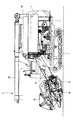
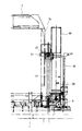
図1〜3に示すように、汎用コンバインは、機体フレーム1の下側に土壌面を走行する左右一対のクローラからなる走行装置2が設けられ、機体フレーム1の前側に圃場の穀稈を収穫する刈取前処理装置3が設けられ、刈取前処理装置3の後方左側に収穫された穀稈を脱穀・選別処理する脱穀装置4が設けられ、刈取前処理装置3の後方右側に操縦者が搭乗する操縦部5が設けられている。
As shown in FIGS. 1 to 3, the general-purpose combine is provided with a
操縦部5の下部には、エンジンを内装するエンジンルーム6が設けられ、操縦部5の後側には、脱穀・選別処理された穀粒を貯留するグレンタンク7が設けられ、グレンタンク7の後側には、穀粒を外部に排出する排出筒8が設けられている。排出筒8は、グレンタンク7の下部に連通され上下方向に延在する縦排出筒8Aと、縦排出筒8Aの上部に連通され前後方向に延在する横排出筒8Bから形成されている。
An
刈取前処理装置3は、圃場の穀稈を起立させながら掻込んで後方に搬送する掻込装置3Aと、後方に搬送された穀稈の株元を切断する刈刃装置3Bと、後方に搬送された穀稈を左側に寄せ集めるオーガ装置3Cと、寄せ集められた穀稈を脱穀装置4に搬送するフィーダハウス3Dから構成されている。
The
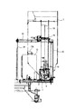
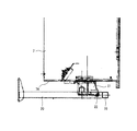
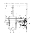
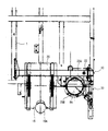
図4〜6に示すように、グレンタンク7の下部に設けられた搬出螺旋の搬出口と縦排出筒8Aの下部は、側面視においてエルボー形状に形成されたオーガメタル9を介して連通されている。また、オーガメタル9は、前後に分割して形成されている。
As shown in FIGS. 4 to 6, the carry-out spiral outlet provided in the lower part of the
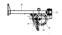
背面視において、縦排出筒8Aの右側には、上下方向に延在する縦フレーム10が設けられ、縦フレーム10の下部は、機体フレーム1に固定されている。また、縦排出筒8Aの上下方向の中間部における上側に偏移した部位には、左右方向に延在する横フレーム20が設けられ、横フレーム20の左部は、脱穀装置4の右壁に固定され、横フレーム20の右部は、縦フレーム10に固定されている。これにより、縦排出筒8Aの左側に大きな空間を形成することができ、エンジンに供給される軽油を貯留する大きな燃料タンク15を配置することができる。なお、縦フレーム10と横フレーム20の固定は、溶接、ボルト等の締結手段によって行うことができる。
In rear view, a
側面視において、縦フレーム10は、グレンタンク7の後壁と縦排出筒8Aの間に立設され、平面視において、横フレーム20は、グレンタンク7の後壁と縦排出筒8Aの間に横設されている。
In the side view, the
図7で示すように、グレンタンク7の後壁7Aと横フレーム20は、平面視で略山形形状に形成された連結部材(請求項における「第2連結部材」)21を介して連結されている。連結部材21の前部は、グレンタンク7の後壁7Aにおける右側に偏移した部位に固定され、連結部材21の後部は、横フレーム20の上面に立設されたピン22に回転自在に外嵌されている。これにより、ピン22を中心として、グレンタンク7の前部を機体フレーム1上の収納位置から機体フレーム1の外側の開放位置に回動して、脱穀装置4の右壁4Bに設けられたベルト等の張力調整を容易に行うことができる。また、横フレーム20は、脱穀装置4と縦フレーム10の間に架設されているので、グレンタンク7の回動によって横フレーム20が変形するのを防止することができる。
As shown in FIG. 7, the
図8に示すように、縦排出筒8Aと横フレーム20は、平面視で略矩形形状に形成された連結部材(請求項における「第1連結部材」)25を介して連結されている。連結部材25は、前後方向に分割可能に形成されている。
As shown in FIG. 8, the
前側に位置する前連結部材25Aの前部は、横フレーム20に固定され、前連結部材25Aの後部には、縦排出筒8Aの前部を挿入可能な半円形形状の切欠き部が形成されている。後側の後連結部材25Bの前部は、前連結部材25Aに着脱自在に固定され、後連結部材25Bの前部には、縦排出筒8Aの後部に外嵌可能な半円形形状の切欠き部が形成されている。これにより、縦排出筒8Aの上部を確実に横フレーム20の支持することができ、機体の後方から縦排出筒8Aの着脱作業を容易に行うことができる。
The front portion of the front connecting
本実施形態では、後連結部材25Bは、板状体を半円形形状に湾曲させて形成している。これにより、機体の後側から縦排出筒8Aの着脱作業をより容易に行うことができる。なお、連結部材25を、左右方向に分割可能に形成することもできる。これにより、機体の右側から縦排出筒8Aの着脱作業をより容易に行うことができる。
In the present embodiment, the
図9に示すように、横フレーム20の右部には、ブラケットを介して縦排出筒8Aの時計方向の回転角度を規制するリミットセンサ27が設けられ、第1補強部材30の上部には、ブラケットを介して縦排出筒8Aの反時計方向の回転角度を規制するリミットセンサ28が設けられている。これにより、縦排出筒8Aが過度に回転するのを規制して、横排出筒8Bと他の車両等の接触を防止することができる。
As shown in FIG. 9, a
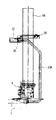
図10〜12に示すように、縦フレーム10の上部とオーガメタル9の後部は、第1補強部材30で連結されている。これにより、縦フレーム10の剛性が高まり、グレンタンク7の前後・上下方向への揺動を抑制することができる。また、オーガメタル9の後部には、縦排出筒8Aを回動させるモータ29が設けられている。
As shown in FIGS. 10 to 12, the upper part of the
背面視において、第1補強部材30は、オーガメタル9の後部から右側に向かって延在して縦フレーム10の下部に至り、上側に向かって湾曲した後に上側に向かって延在して縦フレーム10の上部に連結されている。
In the rear view, the first reinforcing
側面視において、第1補強部材30は、オーガメタル9の後部から上側に向かって延在して縦フレーム10の上部に至り、前側に向かって湾曲した後に前側に向かって延在して縦フレーム10の上部に連結されている。
In the side view, the first reinforcing
平面視において、第1補強部材30は、オーガメタル9における右側後部から右側に向かって延在して縦フレーム10に至り、前側に向かって湾曲した後に前側に向かって延在して縦フレーム10の後部に連結されている。
In a plan view, the first reinforcing
これにより、第1補強部材30の長さを短く形成することができ、第1補強部材30の重量を軽減して第1補強部材30の取付作業を容易に行うことができる。
As a result, the length of the first reinforcing
図13に示すように、縦フレーム10の上部とオーガメタル9の後部を連結する第1補強部材30に替えて、縦フレーム10の上部とオーガメタル9の下部に位置する機体フレーム1の後部を第1補強部材30Aで連結することもできる。なお、第1補強部材30Aは、側面視において、機体フレーム1の後部から後側に向かって延在し、上側に向かって湾曲した後に上側に向かって延在し、前方上側に湾曲して縦フレーム10の上部に連結されている。これにより、コンバインの後進時に、縦排出筒8Aと他の車両等の接触を防止することができる。
As shown in FIG. 13, instead of the first reinforcing
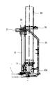
図14〜16に示すように、横フレーム20における縦排出筒8Aの左部に近接する部位とオーガメタル9の後部は、第2補強部材35で連結されている。これにより、横フレーム20の剛性が高まり、グレンタンク7の前後・上下方向への揺動を抑制することができる。
As shown in FIGS. 14 to 16, a portion of the
背面視において、第2補強部材35は、縦排出筒8Aの左部と重なってオーガメタル9の後部から上側に向かって延在して横フレーム20の下側に至り、左方上側に向かって湾曲した後に左方上側に向かって延在して横フレーム20の後部に連結されている。
In the rear view, the second reinforcing
側面視において、第2補強部材35は、オーガメタル9の後部から後側に向かって延在し、上側に向かって湾曲した後に上側に向かって延在し、前方上側に向かって湾曲した後に前方上側に向かって延在して横フレーム20の後部に連結されている。
In a side view, the second reinforcing
平面視において、第2補強部材35は、オーガメタル9の後部から後側に向かって延在し、左方前側に向かって湾曲した後に左方前側に向かって延在して横フレーム20の後部に連結されている。
In a plan view, the second reinforcing
これにより、第2補強部材35の長さを短く形成することができ、第2補強部材35の重量を軽減して第2補強部材35の取付作業を容易に行うことができる。また、第2補強部材35の上下方向に延在する部位は、縦排出筒8Aの左部の後側に設けられているので、コンバインの後進時に、縦排出筒8Aと他の車両等の接触を防止することができる。
As a result, the length of the second reinforcing
図15示すように、横フレーム20における縦排出筒8Aの左部に近接する部位とオーガメタル9の後部を連結する第2補強部材35替えて、横フレーム20における縦排出筒8Aの左部に近接する部位とオーガメタル9の下部に位置する機体フレーム1の後部を第2補強部材35A連結することもできる。なお、第2補強部材35Aは側面視において、機体フレーム1の後部から後側に向かって延在し、上側に向かって湾曲した後に上側に向かって延在し、上方前側に向かって湾曲した後に上方前側に向かって延在して横フレーム20の後部に至っている。これにより、コンバインの後進時に、縦排出筒8Aと他の車両等の接触をより防止することができる。
As shown in FIG. 15, the second reinforcing
縦フレーム10の上部とオーガメタル9の後部等を連結する第1補強部材30,31や横フレーム20における縦排出筒8Aの左部に近接する部位とオーガメタル9の後部等を連結する第2補強部材35,36を単体として設けるだけでなく、縦フレーム10の上部とオーガメタル9の後部等を連結する第1補強部材30,31と横フレーム20における縦排出筒8Aの左部に近接する部位とオーガメタル9の後部等を連結する第2補強部材35,36を同時に設けることが好ましい。これにより、グレンタンク7の前後・上下方向への揺動をより抑制することができる。
The first reinforcing
次に、脱穀装置4の右壁4Aと縦フレーム10の間に架設される他の形態の横フレーム20Aについて説明する。なお、同一部材には同一符号を付して説明を省略する。
Next, another form of the
図17に示すように、横フレーム20Aは、上下方向に所定の間隔を隔てた2本の上横フレーム40と下横フレーム41から形成されている。
As shown in FIG. 17, the
上横フレーム40の左部は、脱穀装置4の右壁4Aに固定され、上横フレーム40の右部は、縦フレーム10の上部に固定されている。
The left portion of the upper
下横フレーム41の左部は、脱穀装置4の右壁4Aに固定され、上横フレーム40の右部は、縦フレーム10における上下方向の中間部の左面に固定されている。平面視において、下横フレーム41は、燃料タンク15の給油口15Aと同一高さに設けられている。
The left portion of the lower horizontal frame 41 is fixed to the
これにより、脱穀装置4と縦フレーム10が強固に固定されて、縦フレーム10の剛性が高まり、グレンタンク7の前後・上下方向への揺動を抑制することができる。なお、第1補強部材30を設けて縦フレーム10の剛性をより高めるのが好ましい。
As a result, the threshing
次に、脱穀装置4の右壁4Aと縦フレーム10の間に架設されるさらに他の形態の横フレーム20Bについて説明する。なお、同一部材には同一符号を付して説明を省略する。
Next, another form of the
図18に示すように、横フレーム20Bは、左右方向に延在する横フレーム45と、横フレーム45の左右方向の中間部を支持する支持フレーム46から形成されている。
As shown in FIG. 18, the
横フレーム45の左部は、脱穀装置4の右壁4Aに固定され、横フレーム45の右部は、縦フレーム10の上部に固定されている。
The left portion of the
支持フレーム46の左部は、脱穀装置4の右壁4Aにおける横フレーム45の左部が固定された部位の後側に固定され、支持フレーム46の右部は、横フレーム45の左右方向の中間部の後面に固定されている。
The left part of the
これにより、横フレーム45の剛性が高まり、グレンタンク7の回動によって横フレーム20が変形するのをより防止することができる。なお、第2補強部材35を設けて横フレーム45の剛性をより高めるのが好ましい。
As a result, the rigidity of the
1 機体フレーム
4 脱穀装置
4A 右壁
7 グレンタンク
7A 後壁
8 排出筒
8A 縦排出筒
8B 横排出筒
9 オーガメタル
10 縦フレーム
20 横フレーム
21 連結部材(第2連結部材)
22 ピン
25 連結部材(第1連結部材)
30 第1補強部材
35 第2補強部材
1
22 pins
25 Connecting member (first connecting member)
30
Claims (6)
前記グレンタンク(7)に貯留された穀粒を外部に排出する排出筒(8)を設け、前記排出筒(8)を、前記グレンタンク(7)の後部にオーガメタル(9)を介して連通された上下方向に延在する縦排出筒(8A)と、該縦排出筒(8A)の上部に連通された前後方向に延在する横排出筒(8B)で形成し、前記縦排出筒(8A)をグレンタンク(7)の後壁(7A)の後側に設け、前記後壁(7A)と縦排出筒(8A)の間に左右方向に延在する横フレーム(20)を設け、前記縦排出筒(8A)の前方外側に上下方向に延在する縦フレーム(10)を設け、前記横フレーム(20)の左右方向の左部を、前記脱穀装置(4)の右壁(4A)に固定し、前記横フレーム(20)の左右方向の右部を、前記縦フレーム(10)の上部に固定し、前記縦排出筒(8A)と横フレーム(20)を前後方向に分割可能に形成された第1連結部材(25)で連結したことを特徴とするコンバイン。 A threshing device (4) for threshing harvested grains is mounted on the left side of the machine frame (1) in the left-right direction, and the threshed grains are stored on the right side of the machine frame (1) in the left-right direction. In the combine where the Glen tank (7) is installed
A discharge cylinder (8) for discharging the grains stored in the grain tank (7) to the outside is provided, and the discharge cylinder (8) is placed at the rear of the grain tank (7) via an auger metal (9). The vertical discharge cylinder (8A) extending in the vertical direction and the horizontal discharge cylinder (8B) extending in the front-rear direction connected to the upper part of the vertical discharge cylinder (8A) are formed. (8A) is provided on the rear side of the rear wall (7A) of the Glen tank (7), and a horizontal frame (20) extending in the left-right direction is provided between the rear wall (7A) and the vertical discharge cylinder (8A). A vertical frame (10) extending in the vertical direction is provided on the front outer side of the vertical discharge cylinder (8A), and the left portion of the horizontal frame (20) in the left-right direction is formed on the right wall (4) of the grain removal device (4). 4A), the right part of the horizontal frame (20) in the left-right direction is fixed to the upper part of the vertical frame (10), and the vertical discharge cylinder (8A) and the horizontal frame (20) are divided in the front-rear direction. A combine characterized by being connected by a possibly formed first connecting member (25).
Priority Applications (1)
| Application Number | Priority Date | Filing Date | Title |
|---|---|---|---|
| JP2019033954A JP6889869B2 (en) | 2019-02-27 | 2019-02-27 | combine |
Applications Claiming Priority (1)
| Application Number | Priority Date | Filing Date | Title |
|---|---|---|---|
| JP2019033954A JP6889869B2 (en) | 2019-02-27 | 2019-02-27 | combine |
Publications (2)
| Publication Number | Publication Date |
|---|---|
| JP2020137432A JP2020137432A (en) | 2020-09-03 |
| JP6889869B2 true JP6889869B2 (en) | 2021-06-18 |
Family
ID=72263921
Family Applications (1)
| Application Number | Title | Priority Date | Filing Date |
|---|---|---|---|
| JP2019033954A Active JP6889869B2 (en) | 2019-02-27 | 2019-02-27 | combine |
Country Status (1)
| Country | Link |
|---|---|
| JP (1) | JP6889869B2 (en) |
Family Cites Families (4)
| Publication number | Priority date | Publication date | Assignee | Title |
|---|---|---|---|---|
| JPH0530606Y2 (en) * | 1986-06-21 | 1993-08-05 | ||
| JP5421820B2 (en) * | 2010-02-26 | 2014-02-19 | 株式会社クボタ | Kernel transport device |
| JP2015128413A (en) * | 2013-12-03 | 2015-07-16 | 株式会社クボタ | Combine |
| JP6257480B2 (en) * | 2014-09-02 | 2018-01-10 | 株式会社クボタ | Harvesting machine |
-
2019
- 2019-02-27 JP JP2019033954A patent/JP6889869B2/en active Active
Also Published As
| Publication number | Publication date |
|---|---|
| JP2020137432A (en) | 2020-09-03 |
Similar Documents
| Publication | Publication Date | Title |
|---|---|---|
| JP7065809B2 (en) | Work vehicle | |
| JP2016067221A (en) | combine | |
| JP6765348B2 (en) | combine | |
| JP2009005623A (en) | Combine | |
| CN102461389B (en) | Combine harvester | |
| JP6889869B2 (en) | combine | |
| CN203206740U (en) | Harvester | |
| JP2018029555A (en) | Combine | |
| JP7433207B2 (en) | combine | |
| JP5682890B2 (en) | Combine | |
| JP6976087B2 (en) | combine | |
| JP7117995B2 (en) | harvester | |
| JP7121934B1 (en) | combine | |
| JP2013158263A (en) | Wheel-traveling combine harvester | |
| CN110617138B (en) | Combine harvester, semi-feeding combine harvester and harvester | |
| JP6838481B2 (en) | combine | |
| JP2025080406A (en) | combine | |
| JP7825159B2 (en) | combine | |
| JP2016140302A (en) | Combine | |
| JP2016021964A (en) | combine | |
| JP2008271872A (en) | Combine | |
| JP6844671B2 (en) | combine | |
| JP2019216648A (en) | Combine | |
| JP2010004844A (en) | Narrow guide of combined harvester | |
| JP4500553B2 (en) | Fuel tank mounting structure for combine |
Legal Events
| Date | Code | Title | Description |
|---|---|---|---|
| A621 | Written request for application examination |
Free format text: JAPANESE INTERMEDIATE CODE: A621 Effective date: 20191031 |
|
| A131 | Notification of reasons for refusal |
Free format text: JAPANESE INTERMEDIATE CODE: A131 Effective date: 20201016 |
|
| A521 | Written amendment |
Free format text: JAPANESE INTERMEDIATE CODE: A523 Effective date: 20201207 |
|
| TRDD | Decision of grant or rejection written | ||
| A01 | Written decision to grant a patent or to grant a registration (utility model) |
Free format text: JAPANESE INTERMEDIATE CODE: A01 Effective date: 20210423 |
|
| A61 | First payment of annual fees (during grant procedure) |
Free format text: JAPANESE INTERMEDIATE CODE: A61 Effective date: 20210506 |
|
| R150 | Certificate of patent or registration of utility model |
Ref document number: 6889869 Country of ref document: JP Free format text: JAPANESE INTERMEDIATE CODE: R150 |