JP6889863B2 - Heating and hot water supply system - Google Patents
Heating and hot water supply system Download PDFInfo
- Publication number
- JP6889863B2 JP6889863B2 JP2017142603A JP2017142603A JP6889863B2 JP 6889863 B2 JP6889863 B2 JP 6889863B2 JP 2017142603 A JP2017142603 A JP 2017142603A JP 2017142603 A JP2017142603 A JP 2017142603A JP 6889863 B2 JP6889863 B2 JP 6889863B2
- Authority
- JP
- Japan
- Prior art keywords
- heating
- hot water
- water supply
- heat exchanger
- passage
- Prior art date
- Legal status (The legal status is an assumption and is not a legal conclusion. Google has not performed a legal analysis and makes no representation as to the accuracy of the status listed.)
- Active
Links
- 238000010438 heat treatment Methods 0.000 title claims description 251
- XLYOFNOQVPJJNP-UHFFFAOYSA-N water Substances O XLYOFNOQVPJJNP-UHFFFAOYSA-N 0.000 title claims description 199
- 238000002485 combustion reaction Methods 0.000 claims description 16
- 238000007664 blowing Methods 0.000 claims description 15
- 238000009423 ventilation Methods 0.000 description 10
- 238000001514 detection method Methods 0.000 description 4
- 239000000567 combustion gas Substances 0.000 description 3
- 238000011144 upstream manufacturing Methods 0.000 description 3
- 238000010276 construction Methods 0.000 description 1
- 230000007423 decrease Effects 0.000 description 1
- 230000000694 effects Effects 0.000 description 1
- 239000002737 fuel gas Substances 0.000 description 1
- 239000007789 gas Substances 0.000 description 1
- 238000012986 modification Methods 0.000 description 1
- 230000004048 modification Effects 0.000 description 1
- 238000002360 preparation method Methods 0.000 description 1
- 239000008399 tap water Substances 0.000 description 1
- 235000020679 tap water Nutrition 0.000 description 1
Images
Classifications
-
- F—MECHANICAL ENGINEERING; LIGHTING; HEATING; WEAPONS; BLASTING
- F24—HEATING; RANGES; VENTILATING
- F24D—DOMESTIC- OR SPACE-HEATING SYSTEMS, e.g. CENTRAL HEATING SYSTEMS; DOMESTIC HOT-WATER SUPPLY SYSTEMS; ELEMENTS OR COMPONENTS THEREFOR
- F24D3/00—Hot-water central heating systems
- F24D3/08—Hot-water central heating systems in combination with systems for domestic hot-water supply
-
- F—MECHANICAL ENGINEERING; LIGHTING; HEATING; WEAPONS; BLASTING
- F24—HEATING; RANGES; VENTILATING
- F24D—DOMESTIC- OR SPACE-HEATING SYSTEMS, e.g. CENTRAL HEATING SYSTEMS; DOMESTIC HOT-WATER SUPPLY SYSTEMS; ELEMENTS OR COMPONENTS THEREFOR
- F24D3/00—Hot-water central heating systems
-
- F—MECHANICAL ENGINEERING; LIGHTING; HEATING; WEAPONS; BLASTING
- F24—HEATING; RANGES; VENTILATING
- F24H—FLUID HEATERS, e.g. WATER OR AIR HEATERS, HAVING HEAT-GENERATING MEANS, e.g. HEAT PUMPS, IN GENERAL
- F24H1/00—Water heaters, e.g. boilers, continuous-flow heaters or water-storage heaters
- F24H1/48—Water heaters for central heating incorporating heaters for domestic water
- F24H1/52—Water heaters for central heating incorporating heaters for domestic water incorporating heat exchangers for domestic water
Landscapes
- Engineering & Computer Science (AREA)
- Physics & Mathematics (AREA)
- Thermal Sciences (AREA)
- Chemical & Material Sciences (AREA)
- Combustion & Propulsion (AREA)
- Mechanical Engineering (AREA)
- General Engineering & Computer Science (AREA)
- Water Supply & Treatment (AREA)
- Steam Or Hot-Water Central Heating Systems (AREA)
Description
本発明は、燃焼熱により加熱した暖房熱媒を暖房端末に供給して暖房を行う暖房運転と、この暖房熱媒との熱交換により上水を加熱して給湯を行う給湯運転を実行可能な暖房給湯システムに関し、特に暖房運転と給湯運転を同時に実行可能な暖房給湯システムに関する。 INDUSTRIAL APPLICABILITY The present invention can execute a heating operation in which a heating heat medium heated by combustion heat is supplied to a heating terminal to perform heating, and a hot water supply operation in which tap water is heated and hot water is supplied by heat exchange with the heating heat medium. Regarding the heating / hot water supply system, particularly regarding the heating / hot water supply system capable of simultaneously performing the heating operation and the hot water supply operation.
従来から暖房熱媒である湯水を加熱手段で加熱して暖房端末に供給することにより暖房を行う温水暖房システムが広く使用されている。温水暖房システムは、例えば暖房運転開始直後には、暖房端末に供給される暖房熱媒の温度が予め設定された暖房用温度より低温であるため、暖房端末で送風機を作動させると低温の送風になるので、使用者に不快感を与える虞がある。このような低温の送風を防ぐために、例えば特許文献1のように、暖房熱媒の温度が低い場合には送風機の作動を禁止している。
Conventionally, a hot water heating system for heating by heating hot water, which is a heating heat medium, by a heating means and supplying it to a heating terminal has been widely used. In a hot water heating system, for example, immediately after the start of heating operation, the temperature of the heating heat medium supplied to the heating terminal is lower than the preset heating temperature. Therefore, there is a risk of causing discomfort to the user. In order to prevent such a low temperature blow, the operation of the blower is prohibited when the temperature of the heating heat medium is low, for example, as in
一方、暖房運転と給湯運転と暖房給湯同時運転の各運転を実行可能な暖房給湯装置に暖房端末を接続した暖房給湯システムが知られている。このような暖房給湯システムは、予め設定された暖房端末用設定温度に加熱した暖房熱媒を暖房用と給湯用に分配する分配手段を備え、分配手段の分配比を調整して暖房給湯同時運転を可能にしている。 On the other hand, there is known a heating / hot water supply system in which a heating terminal is connected to a heating / hot water supply device capable of performing each operation of heating operation, hot water supply operation, and simultaneous heating / hot water supply operation. Such a heating / hot water supply system includes a distribution means for distributing a heating heat medium heated to a preset temperature for a heating terminal for heating and hot water supply, and adjusts the distribution ratio of the distribution means to simultaneously operate the heating / hot water supply. Is possible.
暖房給湯同時運転を行う暖房給湯システムは、暖房給湯同時運転時に給湯を優先して分配手段の分配比を調整するように構成されている。そのため、暖房給湯同時運転の開始直後や給湯負荷が大きい場合に暖房用の暖房熱媒の分配比が小さくなり、暖房端末に供給される暖房熱媒が少なくなる。暖房熱媒の供給量が少量になると、暖房熱媒の温度が暖房端末用設定温度であっても暖房端末に十分な熱量を供給することができないので、暖房端末の送風機が作動すると低温の送風になり、暖房使用者に不快感を与える虞がある。 The heating and hot water supply system that simultaneously operates the heating and hot water supply is configured to give priority to the hot water supply and adjust the distribution ratio of the distribution means during the simultaneous operation of the heating and hot water supply. Therefore, the distribution ratio of the heating heat medium for heating becomes small immediately after the start of the simultaneous heating / hot water supply operation or when the hot water supply load is large, and the heating heat medium supplied to the heating terminal decreases. When the supply amount of the heating heat medium becomes small, even if the temperature of the heating heat medium is the set temperature for the heating terminal, it is not possible to supply a sufficient amount of heat to the heating terminal. This may cause discomfort to the heating user.
本発明の目的は、暖房端末の送風が低温になる虞がある場合には、暖房端末の送風運転を禁止することが可能な暖房給湯システムを提供することである。 An object of the present invention is to provide a heating / hot water supply system capable of prohibiting the blowing operation of the heating terminal when there is a possibility that the blowing air of the heating terminal becomes low.
請求項1の発明は、燃焼手段と、前記燃焼手段で発生する熱により暖房熱媒を加熱するための熱交換器と、送風機を有する暖房端末と、前記熱交換器と前記暖房端末とを接続する循環通路と、前記暖房熱媒を循環させるために前記循環通路に設けられた循環手段と、前記循環通路から分岐されて前記暖房端末をバイパスするバイパス通路と、前記循環通路と前記バイパス通路に前記暖房熱媒を分配するための分配手段と、前記バイパス通路に設けられた給湯用熱交換器と、前記給湯用熱交換器に上水を供給するための給水通路と、前記給湯用熱交換器で加熱された湯水を所定の給湯設定温度で給湯するための給湯通路とを備えた暖房給湯システムにおいて、前記分配手段は暖房運転と給湯運転と暖房給湯同時運転に対応可能なように分配比を調整可能であり、前記暖房給湯同時運転の開始時に前記分配手段の前記循環通路側の分配比率を一旦0%にした後に次第に上昇させ、前記循環通路側の分配比率が所定値未満である場合には、前記暖房端末の前記送風機の送風運転を禁止し、前記循環通路側の分配比率が所定値以上になると、前記送風運転の禁止を解除することを特徴としている。
The invention of
上記構成によれば、暖房給湯システムは、暖房給湯同時運転時に暖房熱媒を循環通路とバイパス通路に分配する分配手段の分配比を調整する。このとき、循環通路側の暖房端末への分配比率が所定値未満の場合には、暖房端末の送風機の送風運転を禁止するので、暖房端末における熱量の不足により空気が十分に加熱されずに低温の送風になることを防ぐことができる。 According to the above configuration, the heating / hot water supply system adjusts the distribution ratio of the distribution means for distributing the heating heat medium to the circulation passage and the bypass passage during the simultaneous operation of the heating / hot water supply. At this time, if the distribution ratio to the heating terminal on the circulation passage side is less than a predetermined value, the blower operation of the blower of the heating terminal is prohibited, so that the air is not sufficiently heated due to insufficient heat in the heating terminal and the temperature is low. It is possible to prevent the air from being blown.
請求項2の発明は、請求項1において、前記暖房給湯同時運転時には、前記暖房熱媒を暖房端末用設定温度に加熱して循環させることを特徴としている。 The invention of claim 2 is characterized in that, at the time of simultaneous operation of the heating and hot water supply, the heating heat medium is heated to a set temperature for a heating terminal and circulated.
上記構成により、暖房熱媒の温度が暖房運転用に設定された暖房端末用設定温度であっても、循環通路側の分配比率が所定値未満のため暖房給湯同時運転時に暖房端末に供給される熱量が不足する場合には、暖房端末の送風機の送風運転を禁止して低温の送風を防ぐことができる。 With the above configuration, even if the temperature of the heating heat medium is the set temperature for the heating terminal set for the heating operation, it is supplied to the heating terminal during the simultaneous operation of heating and hot water supply because the distribution ratio on the circulation passage side is less than a predetermined value. When the amount of heat is insufficient, it is possible to prohibit the blowing operation of the blower of the heating terminal to prevent low-temperature blowing.
本発明によれば、暖房給湯同時運転時の低温の送風を防ぐことができる。 According to the present invention, it is possible to prevent low-temperature air blowing during simultaneous operation of heating and hot water supply.
以下、本発明を実施するための形態について実施例に基づいて説明する。 Hereinafter, embodiments for carrying out the present invention will be described based on examples.
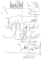
最初に、本発明の暖房給湯システムAの全体構成について、図1に基づいて説明する。
暖房給湯システムAは、暖房給湯装置1と暖房端末31を備え、暖房給湯装置1で加熱した暖房熱媒を暖房端末31との間で循環させて暖房運転を行い、暖房熱媒の熱を利用して加熱した上水を給湯設定温度に調整して給湯する給湯運転を行うことができるように構成されている。
First, the overall configuration of the heating / hot water supply system A of the present invention will be described with reference to FIG.
The heating / hot water supply system A includes a heating / hot
次に、暖房給湯装置1について説明する。
暖房給湯装置1は、燃焼手段である燃焼部2と、熱交換器10と、この熱交換器10と暖房端末31を接続する循環通路4と、循環通路4の熱交換器10より上流側に設けられた循環手段である循環ポンプ11等を備えている。燃焼部2は燃焼用送風機3を備え、この燃焼用送風機3により矢印ASで示す給気と矢印Fで示す燃料ガスを混合して供給される混合ガスを燃焼させる。発生する燃焼ガス量及び燃焼熱量は、燃焼用送風機3の回転数の制御により調整される。熱交換器10は、燃焼部2で発生した燃焼ガスと暖房熱媒との間で熱交換させて、暖房熱媒を予め設定されている暖房端末用設定温度に加熱する。熱交換により温度が下がった燃焼ガスは、矢印Eで示すように外部に排気される。
Next, the heating / hot
The heating / hot
また、暖房給湯装置1は、第1バイパス通路12(バイパス通路)と、この第1バイパス通路12に設けられた給湯用熱交換器20と、給水通路19と、給湯通路21等を備えている。第1バイパス通路12は、熱交換器10の下流側で循環通路4から分岐されて暖房端末31をバイパスし、循環ポンプ11の上流側で循環通路4に合流する。給水通路19は、矢印CWで示すように給湯用熱交換器20に上水を供給する。給湯通路21は、給湯用熱交換器20で加熱された湯水を矢印HWで示すように給湯栓等に給湯する。
Further, the heating / hot
さらに、暖房給湯装置1は、暖房運転等を制御する制御部5を備えている。暖房給湯装置1の設定操作等を行うための操作端末6は、制御部5に通信可能に接続され、例えば暖房端末31が暖房を行う室内に配設されている。また、屋外に配設された外気温度センサ30が制御部5と通信可能に接続されている。
Further, the heating / hot
次に、循環通路4について説明する。
循環通路4は、循環ポンプ11と熱交換器10の間に第1温度センサ13を備え、熱交換器10の下流側に第2温度センサ14を備えている。第1温度センサ13は、熱交換器10に流入する暖房熱媒の温度を検知する。第2温度センサ14は、熱交換器10で加熱された暖房熱媒の温度を検知する。
Next, the circulation passage 4 will be described.
The circulation passage 4 includes a
循環通路4と第1バイパス通路12の分岐部には、分配手段である第1分配弁15が設けられている。第1分配弁15は、暖房運転と給湯運転と暖房給湯同時運転に対応可能なように、熱交換器10で加熱された暖房熱媒を循環通路4と第1バイパス通路12に分配し、その分配比は調整可能である。第1分配弁15により循環通路4に分配された暖房熱媒は暖房端末31に供給され、第1バイパス通路12に分配された暖房熱媒は給湯用熱交換器20に供給される。
A
熱交換器10と第1分配弁15の間には、循環通路4内の圧力を開放する圧力開放弁16が設けられている。循環ポンプ11の上流側には、暖房端末31から戻ってくる暖房熱媒の温度を検知する暖房戻り温度センサ17が設けられている。循環ポンプ11と暖房戻り温度センサ17の間には、矢印Rで示すように暖房熱媒を補充するための補充通路18が接続されている。
A
次に、給湯用熱交換器20について説明する。
給湯用熱交換器20はプレート式熱交換器であり、積層された複数枚の熱交換プレート間に通路が形成されている。給湯用熱交換器20内では、暖房熱媒と給水通路19から供給される上水が互いに混ざり合うことなく対向するように熱交換プレート間の通路を一つ置きに流れる。これらの熱交換プレートには、表面積を拡大して熱交換効率を向上させるために凹凸が形成されている。
Next, the
The hot water
次に、給水通路19と給湯通路21について説明する。
給水通路19は、第2分配弁23と、流量調整弁24と、給湯流量センサ25と、入水温度センサ26を備えている。給湯栓等の開栓により矢印CWで示すように給水通路19に上水が供給される。給水通路19から第2バイパス通路22(給湯バイパス通路)が分岐され、この分岐部に配設された第2分配弁23が給水通路19と第2バイパス通路22に上水を分配し、その分配比は調整可能である。従って、第2分配弁23は、第2バイパス通路22を流れる上水の流量を調整する流量調整手段である。流量調整弁24は、第2分配弁23に入水する上水の流量を調整する。給湯流量センサ25は、第2分配弁23に供給される上水の流量を検知する。入水温度センサ26は、第2分配弁23に入水する上水の温度を検知する。
Next, the
The
給湯通路21には、合流部Cにおいて第2バイパス通路22が合流する。合流部Cと、給湯用熱交換器20との間には、出湯温度センサ27が設けられている。この出湯温度センサ27は、給湯用熱交換器20から出湯される湯水の温度を検知する。給湯通路21の下流側端部には、給湯温度センサ28が設けられている。この給湯温度センサ28は、給湯用熱交換器20で加熱された湯水と第2バイパス通路22を流れる上水とが混合されて給湯される湯水の給湯温度を検知する。給湯運転において、この給湯温度が給湯設定温度になるように第2分配弁23が制御される。
The
次に、制御部5について説明する。
制御部5は、暖房給湯装置1内に設けられた第1温度センサ13等の検知信号や燃焼用送風機3等の回転数等を検知信号として受信可能に、且つ燃焼用送風機3の回転数や第1分配弁15の分配比等の設定値を設定可能に接続されている。そして、それらの検知信号及び設定値に基づいて燃焼用送風機3や循環ポンプ11、第1分配弁15等を制御することにより、暖房運転、給湯運転、暖房給湯同時運転の各運転を制御する。
Next, the
The
制御部5は、例えば暖房運転中に給湯運転の要求があるときには、検知信号及び設定値、暖房給湯装置1の加熱能力等に基づいて暖房給湯同時運転の可否判定を行う。暖房給湯同時運転可能と判定した場合は暖房給湯同時運転を行い、暖房給湯同時運転不可と判定した場合は暖房運転を休止して給湯運転を行う。
For example, when there is a request for hot water supply operation during heating operation, the
次に、操作端末6について説明する。
操作端末6は、例えば温度や運転状況等を表示可能な表示部7と、暖房温度や給湯温度の設定操作や暖房運転の開始操作等を行うためのスイッチ部8と、図示を省略するが警報音等を出力する音声出力部を備えている。
Next, the operation terminal 6 will be described.
The operation terminal 6 includes, for example, a display unit 7 capable of displaying a temperature, an operating status, and the like, and a
次に、暖房端末31について説明する。
暖房端末31は、暖房用送風機32(送風機)と、暖房熱媒と空気の間で熱交換を行うための暖房用熱交換器33と、暖房端末31の運転を制御する暖房端末制御部34を備え、導入した空気を暖房用熱交換器33で加熱して温風を送り出すことにより暖房を行う。例えば暖房端末31がエアハンドラーの場合は、暖房用送風機32の送風運転により、暖房端末31内に取り入れた室内の空気と外気を暖房用熱交換器33で加熱して、温風を室内へ送風する。暖房端末31は、室内の空気を加熱して送風する暖房装置であってもよい。
Next, the
The
暖房給湯装置1に暖房端末31を接続する施工時等に、暖房端末31が要求する暖房熱媒の温度を暖房端末用設定温度に設定する。暖房端末用設定温度は、通常は60℃〜80℃程度に設定される。暖房端末制御部34は、暖房給湯装置1の制御部5に通信可能に接続され、暖房端末31から暖房運転の要求があった場合や、暖房給湯装置1の操作端末6の操作により暖房運転が開始された場合等に、制御部5と協働して暖房運転を制御する。
At the time of construction in which the
次に、暖房運転について説明する。
暖房運転では、暖房端末用設定温度に加熱された暖房熱媒を暖房端末31に供給するために、暖房熱媒が循環通路4を流れるように第1分配弁15の分配比を調整する。このとき、第1分配弁15に供給される暖房熱媒の流量に対して循環通路4側に分配される暖房熱媒の流量が略同じになるように第1分配弁15が調整され、暖房熱媒の循環通路4側の分配比率は略100%である。暖房熱媒は、循環通路4を流れて暖房用熱交換器33において空気を加熱した後、熱交換器10に戻る。暖房用熱交換器33で加熱された空気は、暖房用送風機32の送風運転により室内に送風される。
Next, the heating operation will be described.
In the heating operation, in order to supply the heating heat medium heated to the set temperature for the heating terminal to the
次に、給湯運転について説明する。
給湯運転は、給湯設定温度の給湯が可能なように熱交換器10で給湯設定温度より高温に加熱された暖房熱媒を給湯用熱交換器20に供給するために、暖房熱媒が第1バイパス通路12を流れるように第1分配弁15の分配比を調整する。このとき暖房熱媒の第1バイパス通路12側の分配比率は略100%である。例えば、通常は給湯設定温度が42℃程度に設定され、暖房端末用設定温度がそれより高い60℃に設定されている場合、給湯運転時にも暖房熱媒を暖房端末用設定温度に加熱する。
Next, the hot water supply operation will be described.
In the hot water supply operation, the heating heat medium is first in order to supply the heating heat medium heated to a temperature higher than the hot water supply set temperature by the
一方、高温給湯時には、暖房端末用設定温度より高い温度に暖房熱媒を加熱して給湯用熱交換器20に供給可能に構成されている。例えば、暖房端末用設定温度と給湯設定温度が共に60℃に設定され、暖房端末用設定温度の暖房熱媒では給湯設定温度の給湯が困難な場合には、その高温の給湯設定温度の給湯が可能な温度(例えば70℃)に暖房熱媒を加熱する。
On the other hand, at the time of high-temperature hot water supply, the heating heat medium is heated to a temperature higher than the set temperature for the heating terminal and can be supplied to the hot water
加熱された暖房熱媒は、給湯用熱交換器20で給水通路19から供給される上水と熱交換した後、熱交換器10に戻る。給湯用熱交換器20で給湯設定温度より高温に加熱された湯水は、給湯通路21で第2バイパス通路22の上水との混合により給湯設定温度に調整されて給湯栓等に供給される。
The heated heating heat medium exchanges heat with the clean water supplied from the
次に、暖房給湯同時運転について説明する。
暖房給湯システムAは、制御部5により暖房給湯同時運転可能と判定された場合には、給湯運転を優先して給湯設定温度の給湯が可能なように第1分配弁15の分配比を調整する。そして、熱交換器10で暖房端末用設定温度に加熱された暖房熱媒を循環通路4及び第1バイパス通路12に分配し、暖房端末31と給湯用熱交換器20に暖房熱媒を供給する。給湯用熱交換器20で加熱された上水は、給湯通路21で給湯設定温度に調整されて給湯栓等に供給される。暖房端末31は、暖房用熱交換器33で加熱された空気を暖房用送風機32の送風運転により送風して暖房を行う。
Next, the simultaneous operation of heating and hot water supply will be described.
When the
暖房熱媒の循環通路4側の分配比率は、給湯運転優先のため暖房給湯同時運転の開始直後に一旦略0%にされた後、給湯設定温度の給湯が安定すると次第に上昇する。制御部5は、この暖房給湯同時運転の開始直後に暖房端末31に送風運転の禁止信号を送信し、暖房端末制御部34はその禁止信号を受信して送風運転を停止する。循環通路4側の分配比率が所定値以上になると、制御部5は送風運転の禁止解除信号を送信し、暖房端末制御部34はその禁止解除信号を受信して送風運転を再開する。尚、循環通路4側の分配比率の所定値は、例えば30%に設定されるが、暖房端末31の暖房能力や暖房給湯装置1の加熱能力等に応じて適宜設定可能であり、上記に限定されるものではない。
Since the hot water supply operation is prioritized, the distribution ratio of the heating heat medium on the circulation passage 4 side is once set to about 0% immediately after the start of the simultaneous heating and hot water supply operation, and then gradually increases when the hot water supply at the hot water supply set temperature stabilizes. Immediately after the start of the simultaneous heating and hot water supply operation, the
次に、本発明の暖房給湯システムAの作用、効果について説明する。
暖房給湯装置1は、第1分配弁15の分配比を調整して暖房熱媒を循環通路4と第1バイパス通路12に分配可能である。循環通路4側の分配比率が小さいときは暖房端末31に供給される熱量が小さいため、暖房用熱交換器33で空気を十分に加熱することができない。このとき暖房端末31が送風運転を行うと低温の空気が送られることになり暖房使用者に不快感を与える虞がある。この低温の送風を防ぐため、暖房給湯システムAは、循環通路4側の分配比率が所定値未満の場合に暖房端末31の送風運転を禁止する。従って、送風運転の禁止により低温の送風を防ぐことができ、暖房使用者に不快感を与えない。
Next, the operation and effect of the heating / hot water supply system A of the present invention will be described.
The heating hot
また、暖房給湯システムAは、暖房給湯同時運転時には、熱交換器10で暖房端末用設定温度に加熱した暖房熱媒を、第1分配弁15で暖房端末31と給湯用熱交換器20に分配するように分配比を調整する。従って、たとえ暖房熱媒の温度が暖房端末用設定温度であっても、暖房端末31に供給される熱量が小さい場合には、暖房端末31の送風運転を禁止して低温の送風を防ぐことができる。また、送風運転を禁止しても、暖房給湯同時運転の継続により暖房熱媒の暖房端末31への供給が続くので、暖房端末31の降温を防ぐことができ、送風運転が再開したときに低温の送風を防ぐことができる。
Further, in the heating / hot water supply system A, during the simultaneous operation of heating / hot water supply, the heating heat medium heated to the set temperature for the heating terminal by the
暖房端末31が、外気を導入するため暖房給湯同時運転時に暖房用の熱量が不足して低温の送風になり易いエアハンドラーである場合には、送風運転を禁止することにより一層効果的に低温の送風を防ぐことができる。
When the
上記実施例は、暖房給湯同時運転の可否判定を行う構成であるが、その可否判定を省略し、第1分配弁15の分配比を調整して暖房給湯同時運転を行うように構成することもできる。このような構成でも、暖房給湯同時運転時に循環通路4側の分配比率が所定値より小さくなる場合に、暖房端末31の送風運転を禁止するように構成して低温の送風を防ぐことができる。その他、当業者であれば、本発明の趣旨を逸脱することなく、上記実施形態に種々の変更を付加した形態で実施可能であり、本発明はそのような変更形態を包含するものである。
In the above embodiment, it is configured to determine whether or not the heating and hot water supply can be operated simultaneously, but it is also possible to omit the determination and adjust the distribution ratio of the
1 暖房給湯装置
4 循環通路
5 制御部
10 熱交換器
12 第1バイパス通路(バイパス通路)
15 第1分配弁(分配手段)
19 給水通路
20 給湯用熱交換器
21 給湯通路
22 第2バイパス通路(給湯バイパス通路)
23 第2分配弁
31 暖房端末
32 暖房用送風機(送風機)
A 暖房給湯システム
1 Heating and hot water supply device 4
15 First distribution valve (distribution means)
19
23
A heating and hot water supply system
Claims (2)
前記分配手段は暖房運転と給湯運転と暖房給湯同時運転に対応可能なように分配比を調整可能であり、
前記暖房給湯同時運転の開始時に前記分配手段の前記循環通路側の分配比率を一旦0%にした後に次第に上昇させ、前記循環通路側の分配比率が所定値未満である場合には、前記暖房端末の前記送風機の送風運転を禁止し、前記循環通路側の分配比率が所定値以上になると、前記送風運転の禁止を解除することを特徴とする暖房給湯システム。 A combustion means, a heat exchanger for heating a heating heat medium by the heat generated by the combustion means, a heating terminal having a blower, a circulation passage connecting the heat exchanger and the heating terminal, and the heating. A circulation means provided in the circulation passage for circulating the heat medium, a bypass passage branched from the circulation passage and bypassing the heating terminal, and the heating heat medium are distributed to the circulation passage and the bypass passage. A hot water supply heat exchanger provided in the bypass passage, a water supply passage for supplying clean water to the hot water supply heat exchanger, and hot water heated by the hot water supply heat exchanger. In a heating hot water supply system equipped with a hot water supply passage for supplying hot water at a predetermined hot water supply set temperature,
The distribution ratio can be adjusted so that the distribution means can support heating operation, hot water supply operation, and simultaneous heating and hot water supply operation.
At the start of the simultaneous operation of heating and hot water supply, the distribution ratio on the circulation passage side of the distribution means is once set to 0% and then gradually increased. If the distribution ratio on the circulation passage side is less than a predetermined value, the heating terminal A heating / hot water supply system characterized in that the blowing operation of the blower is prohibited, and the prohibition of the blowing operation is lifted when the distribution ratio on the circulation passage side becomes a predetermined value or more.
Priority Applications (4)
| Application Number | Priority Date | Filing Date | Title |
|---|---|---|---|
| JP2017142603A JP6889863B2 (en) | 2017-07-24 | 2017-07-24 | Heating and hot water supply system |
| US16/629,962 US11549692B2 (en) | 2017-07-24 | 2018-07-13 | Heating and hot water supply system |
| PCT/JP2018/026558 WO2019021871A1 (en) | 2017-07-24 | 2018-07-13 | Heating and hot water supply system |
| CN201880046243.5A CN110869676B (en) | 2017-07-24 | 2018-07-13 | Heating hot water supply system |
Applications Claiming Priority (1)
| Application Number | Priority Date | Filing Date | Title |
|---|---|---|---|
| JP2017142603A JP6889863B2 (en) | 2017-07-24 | 2017-07-24 | Heating and hot water supply system |
Publications (2)
| Publication Number | Publication Date |
|---|---|
| JP2019023525A JP2019023525A (en) | 2019-02-14 |
| JP6889863B2 true JP6889863B2 (en) | 2021-06-18 |
Family
ID=65041356
Family Applications (1)
| Application Number | Title | Priority Date | Filing Date |
|---|---|---|---|
| JP2017142603A Active JP6889863B2 (en) | 2017-07-24 | 2017-07-24 | Heating and hot water supply system |
Country Status (4)
| Country | Link |
|---|---|
| US (1) | US11549692B2 (en) |
| JP (1) | JP6889863B2 (en) |
| CN (1) | CN110869676B (en) |
| WO (1) | WO2019021871A1 (en) |
Family Cites Families (13)
| Publication number | Priority date | Publication date | Assignee | Title |
|---|---|---|---|---|
| US3388860A (en) * | 1966-08-29 | 1968-06-18 | Westinghouse Electric Corp | Automatic temperature controls |
| JPS481556Y1 (en) * | 1970-11-27 | 1973-01-16 | ||
| NL181951C (en) * | 1977-01-28 | 1987-12-01 | Honeywell Bv | GAS REGULATOR AND ITS USE IN A HEATER WITH A GAS-FIRED HEATER. |
| JPH06347048A (en) | 1993-06-10 | 1994-12-20 | Fujitsu General Ltd | Fan con vector |
| JP4088790B2 (en) * | 2003-12-17 | 2008-05-21 | 日立アプライアンス株式会社 | Heat pump type water heater and its operating method |
| JP2005337632A (en) | 2004-05-28 | 2005-12-08 | Noritz Corp | Heat source device |
| JP4252989B2 (en) * | 2005-12-01 | 2009-04-08 | リンナイ株式会社 | Combined heat source machine |
| KR20090102940A (en) * | 2008-03-27 | 2009-10-01 | 주식회사 경동나비엔 | Boiler suppliable heating-water and hot-water simultaneously |
| JP5247621B2 (en) * | 2009-07-31 | 2013-07-24 | リンナイ株式会社 | Hot water heating system |
| JP6015925B2 (en) * | 2012-10-31 | 2016-10-26 | 株式会社ノーリツ | Water heater control device |
| JP2014163590A (en) * | 2013-02-25 | 2014-09-08 | Rinnai Corp | Hot-water supply/heating system |
| CN205825411U (en) * | 2016-06-29 | 2016-12-21 | 广东万家乐燃气具有限公司 | A kind of gas heater of band heating function |
| US10612795B2 (en) * | 2016-09-14 | 2020-04-07 | Lochinvar, Llc | Methods and system for demand-based control of a combination boiler |
-
2017
- 2017-07-24 JP JP2017142603A patent/JP6889863B2/en active Active
-
2018
- 2018-07-13 US US16/629,962 patent/US11549692B2/en active Active
- 2018-07-13 WO PCT/JP2018/026558 patent/WO2019021871A1/en not_active Ceased
- 2018-07-13 CN CN201880046243.5A patent/CN110869676B/en active Active
Also Published As
| Publication number | Publication date |
|---|---|
| US11549692B2 (en) | 2023-01-10 |
| WO2019021871A1 (en) | 2019-01-31 |
| CN110869676B (en) | 2021-05-28 |
| JP2019023525A (en) | 2019-02-14 |
| US20210088224A1 (en) | 2021-03-25 |
| CN110869676A (en) | 2020-03-06 |
Similar Documents
| Publication | Publication Date | Title |
|---|---|---|
| US11326785B2 (en) | Heating and hot-water-supply apparatus | |
| US11029039B2 (en) | Heating and hot water supplying device | |
| JP6830339B2 (en) | Heat source device | |
| JP2013224821A (en) | Hot water supply system | |
| US11946655B2 (en) | Heating and hot-water supply apparatus | |
| JP2005337632A (en) | Heat source device | |
| US10989442B2 (en) | Heating and hot water supply device | |
| WO2018020805A1 (en) | Heating and hot water supplying device | |
| JP6889863B2 (en) | Heating and hot water supply system | |
| JP6900812B2 (en) | Heating and hot water supply device | |
| US11788735B2 (en) | Heating and hot-water supply device | |
| JP2019078513A (en) | Hot water supply system, hot water supply control program, hot water supply control method and water heater | |
| JP7178125B2 (en) | Hot water supply system, hot water supply control method, hot water supply device and program | |
| JP2005241167A (en) | Heat pump type hot water supplying/heating system | |
| JP2016118338A (en) | Heating system | |
| JP2015222137A (en) | Heating heat source apparatus | |
| WO2019207725A1 (en) | Hot water storage-type hot water supply system | |
| JP2020118414A (en) | Heating and hot-water supply apparatus | |
| WO2020110335A1 (en) | Heating and hot-water supply apparatus | |
| JP2020067233A (en) | Heating water heater |
Legal Events
| Date | Code | Title | Description |
|---|---|---|---|
| A621 | Written request for application examination |
Free format text: JAPANESE INTERMEDIATE CODE: A621 Effective date: 20200623 |
|
| A131 | Notification of reasons for refusal |
Free format text: JAPANESE INTERMEDIATE CODE: A131 Effective date: 20210216 |
|
| A521 | Request for written amendment filed |
Free format text: JAPANESE INTERMEDIATE CODE: A523 Effective date: 20210408 |
|
| TRDD | Decision of grant or rejection written | ||
| A01 | Written decision to grant a patent or to grant a registration (utility model) |
Free format text: JAPANESE INTERMEDIATE CODE: A01 Effective date: 20210423 |
|
| A61 | First payment of annual fees (during grant procedure) |
Free format text: JAPANESE INTERMEDIATE CODE: A61 Effective date: 20210506 |
|
| R150 | Certificate of patent or registration of utility model |
Ref document number: 6889863 Country of ref document: JP Free format text: JAPANESE INTERMEDIATE CODE: R150 |