JP6889838B2 - Terminal bracket - Google Patents
Terminal bracket Download PDFInfo
- Publication number
- JP6889838B2 JP6889838B2 JP2017204963A JP2017204963A JP6889838B2 JP 6889838 B2 JP6889838 B2 JP 6889838B2 JP 2017204963 A JP2017204963 A JP 2017204963A JP 2017204963 A JP2017204963 A JP 2017204963A JP 6889838 B2 JP6889838 B2 JP 6889838B2
- Authority
- JP
- Japan
- Prior art keywords
- wall portion
- side wall
- coil spring
- wound coil
- terminal fitting
- Prior art date
- Legal status (The legal status is an assumption and is not a legal conclusion. Google has not performed a legal analysis and makes no representation as to the accuracy of the status listed.)
- Active
Links
Images


Classifications
-
- H—ELECTRICITY
- H01—ELECTRIC ELEMENTS
- H01R—ELECTRICALLY-CONDUCTIVE CONNECTIONS; STRUCTURAL ASSOCIATIONS OF A PLURALITY OF MUTUALLY-INSULATED ELECTRICAL CONNECTING ELEMENTS; COUPLING DEVICES; CURRENT COLLECTORS
- H01R13/00—Details of coupling devices of the kinds covered by groups H01R12/70 or H01R24/00 - H01R33/00
- H01R13/02—Contact members
- H01R13/15—Pins, blades or sockets having separate spring member for producing or increasing contact pressure
- H01R13/187—Pins, blades or sockets having separate spring member for producing or increasing contact pressure with spring member in the socket
-
- H—ELECTRICITY
- H01—ELECTRIC ELEMENTS
- H01H—ELECTRIC SWITCHES; RELAYS; SELECTORS; EMERGENCY PROTECTIVE DEVICES
- H01H1/00—Contacts
- H01H1/06—Contacts characterised by the shape or structure of the contact-making surface, e.g. grooved
-
- H—ELECTRICITY
- H01—ELECTRIC ELEMENTS
- H01R—ELECTRICALLY-CONDUCTIVE CONNECTIONS; STRUCTURAL ASSOCIATIONS OF A PLURALITY OF MUTUALLY-INSULATED ELECTRICAL CONNECTING ELEMENTS; COUPLING DEVICES; CURRENT COLLECTORS
- H01R13/00—Details of coupling devices of the kinds covered by groups H01R12/70 or H01R24/00 - H01R33/00
- H01R13/02—Contact members
- H01R13/33—Contact members made of resilient wire
-
- H—ELECTRICITY
- H01—ELECTRIC ELEMENTS
- H01R—ELECTRICALLY-CONDUCTIVE CONNECTIONS; STRUCTURAL ASSOCIATIONS OF A PLURALITY OF MUTUALLY-INSULATED ELECTRICAL CONNECTING ELEMENTS; COUPLING DEVICES; CURRENT COLLECTORS
- H01R12/00—Structural associations of a plurality of mutually-insulated electrical connecting elements, specially adapted for printed circuits, e.g. printed circuit boards [PCB], flat or ribbon cables, or like generally planar structures, e.g. terminal strips, terminal blocks; Coupling devices specially adapted for printed circuits, flat or ribbon cables, or like generally planar structures; Terminals specially adapted for contact with, or insertion into, printed circuits, flat or ribbon cables, or like generally planar structures
- H01R12/70—Coupling devices
- H01R12/71—Coupling devices for rigid printing circuits or like structures
- H01R12/72—Coupling devices for rigid printing circuits or like structures coupling with the edge of the rigid printed circuits or like structures
Landscapes
- Details Of Connecting Devices For Male And Female Coupling (AREA)
- Contacts (AREA)
Description
本明細書によって開示される技術は、端子金具に関する。 The techniques disclosed herein relate to terminal fittings.
電気自動車やハイブリッド車両に搭載される電源装置は、複数の単電池を組み合わせた組電池と、この組電池を収容する筐体とを備えている。筐体には、組電池に電気的に接続された雄端子が内部に配置されたコネクタ嵌合室が設けられており、このコネクタ嵌合室の内部に、相手側であるコネクタハウジングが嵌合することによって、電源装置が外部機器と接続される(特許文献1参照)。 A power supply device mounted on an electric vehicle or a hybrid vehicle includes an assembled battery in which a plurality of cells are combined and a housing for accommodating the assembled battery. The housing is provided with a connector fitting chamber in which a male terminal electrically connected to the assembled battery is arranged inside, and the connector housing on the other side is fitted inside the connector fitting chamber. By doing so, the power supply device is connected to an external device (see Patent Document 1).
メンテナンスや交換の際には、電源装置を車体から取り外す必要がある。例えば電源装置が車体の下部に搭載されている場合には、作業者が車体の下に潜り込み、コネクタハウジングを電源装置から取り外す作業を行う必要があるため、作業の負担が大きい。 It is necessary to remove the power supply from the vehicle body for maintenance and replacement. For example, when the power supply device is mounted on the lower part of the vehicle body, the work load is heavy because the operator needs to sneak under the vehicle body and remove the connector housing from the power supply device.
本明細書によって開示される端子金具は、平板状の相手端子と接続される端子金具であって、互いに向かい合って配置される一対の側壁部と、前記一対の側壁部を連結する連結壁部とを備え、内部に前記相手端子を収容可能な本体部と、前記本体部の内部に前記連結壁部に沿って配置され、前記本体部と電気的に接続されているとともに、前記本体部の内部に収容された前記相手端子に対して弾性的に接触する接触部とを備え、前記一対の側壁部のうち一方の側壁部が、前記相手端子を前記本体部の内部に挿入するための挿入口を有しており、他方の側壁部が、前記相手端子を前記本体部から抜出するための抜出口を有している。 The terminal fitting disclosed by the present specification is a terminal fitting connected to a flat plate-shaped mating terminal, and includes a pair of side wall portions arranged facing each other and a connecting wall portion connecting the pair of side wall portions. A main body portion capable of accommodating the mating terminal inside, and a main body portion arranged inside the main body portion along the connecting wall portion, electrically connected to the main body portion, and inside the main body portion. It is provided with a contact portion that elastically contacts the mating terminal accommodated in the above, and one of the side wall portions of the pair of side wall portions is an insertion port for inserting the mating terminal into the inside of the main body portion. The other side wall portion has an outlet for extracting the mating terminal from the main body portion.
上記の構成によれば、端子金具に対して相手端子を接続する際には、相手端子を、連結壁部と平行にスライドさせるようにして挿入口から本体部の内部に挿入すればよい。また、端子金具から相手端子を離脱させる際には、同様に、相手端子を、連結壁部と平行にスライドさせるようにして抜出口から本体部の外部に抜き出せばよい。このように、相手端子をスライドさせるように動かすことで、端子金具に対して相手端子を容易に挿抜することができるので、例えば車体の下に潜り込んで作業を行う場合のように、作業者が少々無理な姿勢で作業を行わなくてはならない場合も、作業負担を低減できる。 According to the above configuration, when connecting the mating terminal to the terminal fitting, the mating terminal may be inserted into the main body through the insertion port by sliding the mating terminal in parallel with the connecting wall portion. Further, when the mating terminal is detached from the terminal fitting, similarly, the mating terminal may be pulled out from the outlet to the outside of the main body portion by sliding the mating terminal in parallel with the connecting wall portion. By sliding the mating terminal in this way, the mating terminal can be easily inserted and removed from the terminal fitting, so that the operator can work by sneaking under the vehicle body, for example. Even if you have to work in a slightly unreasonable posture, you can reduce the work load.
上記の構成において、前記接触部が、導電性の線材が軸線に対して一方向に傾くように複数回巻回されたコイル状をなす斜め巻きコイルスプリングであって、前記斜め巻きコイルスプリングが、前記軸線が前記連結壁部と平行となる向きで、前記連結壁部と接触して配置されていても構わない。 In the above configuration, the contact portion is a coil-shaped diagonally wound coil spring in which the conductive wire rod is wound a plurality of times so as to be tilted in one direction with respect to the axis, and the diagonally wound coil spring is formed by the diagonally wound coil spring. The axis may be arranged in contact with the connecting wall portion in a direction parallel to the connecting wall portion.
また、前記斜め巻きコイルスプリングが、前記軸線が前記一対の側壁部に対して垂直な向きとなり、前記線材の傾きが前記連結壁部から離れるにしたがって前記一方の側壁部から前記他方の側壁部に近づく向きとなるように配置されていても構わない。 Further, the diagonally wound coil spring moves from one side wall portion to the other side wall portion as the axis is oriented perpendicular to the pair of side wall portions and the inclination of the wire rod is separated from the connecting wall portion. It may be arranged so as to approach each other.
このような構成によれば、相手端子を挿入口から本体部の内部に挿入する際には、斜め巻きコイルスプリングが倒れ込んで、ばねの高さ寸法(軸線に垂直な方向の寸法)が小さくなるように変形する。これにより、相手端子を低い挿入力でもって挿入することができる。また、相手端子を抜出口から本体部の外部に抜出する際にも、相手端子から斜め巻きコイルスプリングに対して、ばねの高さ寸法(コイル軸Aに垂直な方向の寸法)が小さくなろうとする方向に力が働くので、相手端子を低い抜出力でもって抜出することができる。 According to such a configuration, when the mating terminal is inserted into the inside of the main body from the insertion port, the diagonally wound coil spring collapses and the height dimension of the spring (dimension in the direction perpendicular to the axis) becomes small. It transforms like this. As a result, the mating terminal can be inserted with a low insertion force. Also, when the mating terminal is pulled out from the outlet to the outside of the main body, the height dimension of the spring (dimension in the direction perpendicular to the coil shaft A) is smaller than that of the diagonally wound coil spring from the mating terminal. Since the force acts in the direction of trying, the mating terminal can be pulled out with a low pull-out output.
上記の構成において、前記接触部が、前記連結壁部から連なり、前記連結壁部に沿って延びる板バネ状の弾性接触片であっても構わない。 In the above configuration, the contact portion may be a leaf spring-shaped elastic contact piece that is continuous from the connecting wall portion and extends along the connecting wall portion.
上記の構成において、前記本体部が、互いに向かい合って配置される一対の前記連結壁部および前記接触部を備えていても構わない。 In the above configuration, the main body portion may include a pair of the connecting wall portions and the contact portions arranged so as to face each other.
このような構成によれば、相手端子を端子金具の内部に挿入すると、一対の接触部によって相手端子が挟み付けられる。これにより、接触部を一定の接圧でもって相手端子に接触させることができ、端子金具と相手端子との電気的接続の信頼性を高めることができる。 According to such a configuration, when the mating terminal is inserted into the terminal fitting, the mating terminal is sandwiched by the pair of contact portions. As a result, the contact portion can be brought into contact with the mating terminal with a constant contact pressure, and the reliability of the electrical connection between the terminal fitting and the mating terminal can be improved.
本明細書によって開示される端子金具によれば、作業負担を低減できる。 According to the terminal fittings disclosed by the present specification, the work load can be reduced.
<実施形態1>
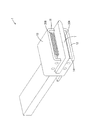
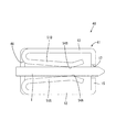
実施形態1を、図1〜図7を参照しつつ説明する。本実施形態の端子金具は、車両に搭載された機器から延びる電線に接続された雌端子金具1である。この雌端子金具1は、車両に搭載された蓄電装置が備える雄端子金具に接続される。雄端子金具は、平板状のタブ部Tを備えている。図1〜図4では、雄端子金具について、タブ部Tのみを模式的に示し、他の部分を省略している。
<Embodiment 1>
The first embodiment will be described with reference to FIGS. 1 to 7. The terminal fitting of the present embodiment is a female terminal fitting 1 connected to an electric wire extending from a device mounted on a vehicle. The female terminal fitting 1 is connected to a male terminal fitting provided in a power storage device mounted on the vehicle. The male terminal fitting includes a flat tab portion T. In FIGS. 1 to 4, only the tab portion T of the male terminal fitting is schematically shown, and other portions are omitted.
雌端子金具1は、図1に示すように、金属製の端子本体10と、この端子本体10に4つの保持軸30によって保持された4つの斜め巻きコイルスプリング20(接触部に該当)とを備えている。
As shown in FIG. 1, the female terminal fitting 1 includes a metal
端子本体10は、図1に示すように、内部に雄端子金具のタブ部Tを受け入れる角筒部11(本体部に該当)と、この角筒部11から連なる電線接続部18とを備えている。
As shown in FIG. 1, the
角筒部11は、図1に示すように、両端が開口した角筒状の部分であって、底壁部12と、天壁部13と、一対の側壁部(第1側壁部14および第2側壁部15)とを備えている。一対の側壁部14、15は、互いに向かい合って配置された、長方形の板状の部分である。底壁部12は、一対の側壁部14、15を連結する、長方形の板状の部分である。天壁部13は、底壁部12と向かい合って配置され、一対の側壁部14、15を連結する、長方形の板状の部分である。
As shown in FIG. 1, the
第1側壁部14は、タブ部Tの入口となる挿入スリット16(挿入口に該当)を有しており、第2側壁部15は、タブ部Tの出口となる抜出スリット17(抜出口に該当)を有している。挿入スリット16は、底壁部12と天壁部13との中央位置に配置されており、角筒部11の一方の開口縁(図1の手前側の開口縁)から他方の開口縁(図1の奥側の開口縁)の近傍まで、底壁部12および天壁部13と平行に延びている。抜出スリット17も同様である。挿入スリット16および抜出スリット17のスリット幅は、タブ部Tの厚さよりもやや大きくなっており、挿入スリット16および抜出スリット17を通過させてタブ部Tを角筒部11に対して挿抜することが可能となっている。
The first
電線接続部18は、図1に示すように、底壁部12から連なる平板状の部分であって、例えば電線の芯線Cが、抵抗溶接によって接続されている。
As shown in FIG. 1, the electric
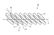
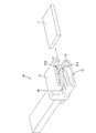
斜め巻きコイルスプリング20は、導電性の線材21を複数回巻回させたコイル状をなしている。この斜め巻きコイルスプリング20は、一般的なコイルスプリング100とは異なり、線材21がコイル軸A(軸線に該当)に対して一方向に傾くように巻かれている。図7に示す一般的なコイルスプリング100では、線材101の任意の点P101とそこから半周分離れた点P102とを結ぶ直線L101と、点P102とそこからさらに半周分離れた点P103とを結ぶ直線L102とが、コイル軸A100に対して反対方向に傾いている。これに対し、図6に示す斜め巻きコイルスプリング20においては、線材21の任意の点P1とそこから半周分離れた点P2とを結ぶ直線L1と、点P2とそこからさらに半周分離れた点P3とを結ぶ直線L2とが、コイル軸Aに対して同じ方向に傾いている。
The diagonally
このような構成の斜め巻きコイルスプリング20は、コイル軸Aに対して垂直な方向に荷重をかけられると、巻線が倒れ込んで、ばねの高さ寸法(コイル軸Aに垂直な方向の寸法)が小さくなるように変形する。
When a load is applied to the diagonally
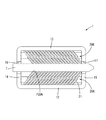
4つの斜め巻きコイルスプリング20のそれぞれは、図1及び図5に示すように、コイル軸Aが底壁部12および天壁部13に対して平行となり、一対の側壁部14、15に対して垂直となる向きで配置されている。4つの斜め巻きコイルスプリング20のうち2つは底壁部12に沿って配置され、他の2つは、天壁部13に沿って配置されている。なお、本明細書の説明において、底壁部12に沿って配置されている斜め巻きコイルスプリング20と天壁部13に沿って配置されている斜め巻きコイルスプリング20とを互いに区別して記載する場合には、底壁部12に沿って配置されている斜め巻きコイルスプリング20を「第1斜め巻きコイルスプリング20A」、天壁部13に沿って配置されている斜め巻きコイルスプリング20を「第2斜め巻きコイルスプリング20B」と記載し、区別せず総称する場合には、斜め巻きコイルスプリングの符号に添え字A、Bを付さないものとする。
In each of the four diagonally wound coil springs 20, as shown in FIGS. 1 and 5, the coil shaft A is parallel to the
4つの保持軸30のそれぞれは、金属製の丸棒であって、図1および図5に示すように、4つの斜め巻きコイルスプリング20のそれぞれの内部を貫通しており、一端が第1側壁部14に固定され、他端が第2側壁部15に固定されている。図5に示すように、2つの第1斜め巻きコイルスプリング20Aを保持する2つの保持軸30は、それぞれ、底壁部12との隙間が、第1斜め巻きコイルスプリング20Aを構成する線材21の外径と同程度となるように配置されており、第1斜め巻きコイルスプリング20Aが、底壁部12に接触した状態で保持されるようになっている。これにより、第1斜め巻きコイルスプリング20Aは、端子本体10に対して電気的に接続されている。同様に、2つの第2斜め巻きコイルスプリング20Bを保持する2つの保持軸30は、それぞれ天壁部13との隙間が、第2斜め巻きコイルスプリング20Bを構成する線材21の外径と同程度となるように配置されており、第2斜め巻きコイルスプリング20Bが、天壁部13に接触した状態で保持されるようになっている。これにより、第2斜め巻きコイルスプリング20Bは、端子本体10に対して電気的に接続されている。
Each of the four holding
図5に示すように、第1斜め巻きコイルスプリング20Aは、線材21が、底壁部12から離れるにしたがって、第1側壁部14から第2側壁部15に近づくように(図5の左下から右上に向かって)傾斜している。また、第2斜め巻きコイルスプリング20Bは、線材21が、天壁部13から離れるにしたがって、第1側壁部14から第2側壁部15に近づくように(図5の左上から右下に向かって)傾斜している。
As shown in FIG. 5, in the first diagonally wound
底壁部12と天壁部13との距離は、第1斜め巻きコイルスプリング20Aおよび第2斜め巻きコイルスプリング20Bの、負荷が加えられていない自由状態での高さ寸法(コイル軸Aに対して垂直な方向の寸法)と、タブ部Tの厚さとの合計よりも小さくなっている。タブ部Tが角筒部11の内部に挿入されておらず、斜め巻きコイルスプリング20A、20Bに負荷が加えられていない状態において、向かい合う斜め巻きコイルスプリング20A、20B間の距離は、タブ部Tの厚さよりも小さくなっている。
The distance between the
雄端子金具と雌端子金具1とを接続する際には、タブ部Tを、底壁部12および天壁部13と平行にスライドさせるようにして、挿入スリット16から角筒部11の内部に(図1に矢印で示す方向に)進入させる。タブ部Tは、第1斜め巻きコイルスプリング20Aと第2斜め巻きコイルスプリング20Bとの隙間に挿入され、第1斜め巻きコイルスプリング20Aと第2斜め巻きコイルスプリング20Bとを押圧しつつ、第2側壁部15に向かって進んでいく。
When connecting the male terminal fitting and the female terminal fitting 1, the tab portion T is slid parallel to the
タブ部Tが第2側壁部15に向かって進んでいくと、第1斜め巻きコイルスプリング20Aにおけるタブ部Tとの任意の接触点P20A(図3参照)に対して、第1側壁部14から第2側壁部15に向かう方向に押される力が働く。ここで、上記したように、第1斜め巻きコイルスプリング20Aは、線材21が、底壁部12から離れるにしたがって、第1側壁部14から第2側壁部15に近づくように傾斜している。したがって、第1斜め巻きコイルスプリング20Aは、タブ部Tからの押圧力によって倒れ込んで、ばねの高さ寸法(コイル軸Aに垂直な方向の寸法)が小さくなるように変形する。第2斜め巻きコイルスプリング20Bについても同様である。これにより、タブ部Tを低い挿入力でもって挿入することができる。
When the tab portion T advances toward the second
タブ部Tが雌端子金具1に対して正規位置(図2および図3に示す位置)まで挿入された状態では、第1斜め巻きコイルスプリング20Aが、タブ部Tと底壁部12とに挟まれ、第2斜め巻きコイルスプリング20Bが、タブ部Tと天壁部13とに挟まれた状態となる。タブ部Tが挿入されたことによって、第1斜め巻きコイルスプリング20Aは、ばねの高さ寸法(コイル軸Aに垂直な方向の寸法)が小さくなるように変形する。そして、第1斜め巻きコイルスプリング20Aの弾性復元力によって、第1斜め巻きコイルスプリング20Aがタブ部Tと底壁部12とに一定の接圧でもって接触する。同様に、第2斜め巻きコイルスプリング20Bも、タブ部Tと天壁部13とに一定の接圧でもって接触する。これにより、雌端子金具1と雄端子金具とが電気的に接続される。
When the tab portion T is inserted to the normal position (positions shown in FIGS. 2 and 3) with respect to the female terminal fitting 1, the first diagonally wound
雄端子金具を雌端子金具1から離脱させる際には、タブ部Tを、底壁部12および天壁部13と平行にスライドさせるようにして、抜出スリット17から角筒部11の外部に(図4に矢印で示す方向に)抜出させる。このとき、タブ部Tを角筒部11の内部に進入させる時と同様に、第1斜め巻きコイルスプリング20Aにおけるタブ部Tとの接触点P20Aに対して、第1側壁部14から第2側壁部15に向かう方向に押される力が働く。すなわち、タブ部Tから、第1斜め巻きコイルスプリング20Aが倒れ込み、ばねの高さ寸法(コイル軸Aに垂直な方向の寸法)が小さくなろうとする方向に力が働く。第2斜め巻きコイルスプリング20Bについても同様である。これにより、タブ部Tを低い抜出力でもって抜出することができる。
When the male terminal fitting is separated from the female terminal fitting 1, the tab portion T is slid parallel to the
なお、タブ部Tが第1側壁部14に向かって(すなわち、挿入スリット16から外部に離脱しようとする方向に)移動しようとすると、第1斜め巻きコイルスプリング20Aにおけるタブ部Tとの接触点P20Aに対して、第1側壁部14に向かって押される力が働く。ここで、上記したように、第1斜め巻きコイルスプリング20Aは、線材21が、底壁部12から離れるにしたがって、第1側壁部14から第2側壁部15に近づくように傾斜している。したがって、タブ部Tからの押圧力によって、第1斜め巻きコイルスプリング20Aは、コイル軸Aに対して立ち上がるように変形しようとして踏ん張る。第2斜め巻きコイルスプリング20Bについても同様である。このため、タブ部Tに対する離脱抵抗が大きくなり、タブ部Tが挿入スリット16から外部に離脱しにくいようになっている。このように、雌端子金具1に対するタブ部Tの挿抜方向が、一方向(挿入スリット16から入り、抜出スリット17から出る方向)となるように規制されている。
When the tab portion T tries to move toward the first side wall portion 14 (that is, in the direction in which the tab portion T tends to separate from the insertion slit 16 to the outside), the contact point with the tab portion T in the first diagonally wound
以上のように本実施形態によれば、雌端子金具1は、雄端子金具の平板状のタブ部Tと接続される端子金具であって、互いに向かい合って配置される一対の側壁部(第1側壁部14および第2側壁部15)と、一対の側壁部14、15を連結する底壁部12および天壁部13とを備え、内部にタブ部Tを収容可能な角筒部11と、角筒部11の内部に配置される第1斜め巻きコイルスプリング20Aおよび第2斜め巻きコイルスプリング20Bとを備えている。第1斜め巻きコイルスプリング20Aは、底壁部12に沿って配置され、角筒部11と電気的に接続されているとともに、角筒部11の内部に収容されたタブ部Tに対して弾性的に接触可能となっている。第2斜め巻きコイルスプリング20Bは、天壁部13に沿って配置され、天壁部13と電気的に接続されているとともに、角筒部11の内部に収容されたタブ部Tに対して弾性的に接触可能となっている。第1側壁部14が、タブ部Tを角筒部11の内部に挿入するための挿入スリット16を有しており、第2側壁部15が、タブ部Tを角筒部11から抜出するための抜出スリット17を有している。
As described above, according to the present embodiment, the female terminal fitting 1 is a terminal fitting connected to the flat tab portion T of the male terminal fitting, and is a pair of side wall portions (first) arranged facing each other. A
上記の構成によれば、雌端子金具1に対して雄端子金具を接続する際には、タブ部Tを、底壁部12および天壁部13と平行にスライドさせるようにして、挿入スリット16から角筒部11の内部に挿入すればよい。また、雌端子金具1から雄端子金具を離脱させる際には、同様に、タブ部Tを、底壁部12および天壁部13と平行にスライドさせるようにして、抜出スリット17から角筒部11の外部に抜き出せばよい。このように、タブ部Tをスライドさせるように動かすことで、雌端子金具1に対してタブ部Tを容易に挿抜することができるので、例えば車体の下に潜り込んで作業を行う場合のように、作業者が少々無理な姿勢で作業を行わなくてはならない場合も、作業負担を低減できる。
According to the above configuration, when connecting the male terminal fitting 1 to the female terminal fitting 1, the tab portion T is slid parallel to the
また、第1斜め巻きコイルスプリング20Aが、コイル軸Aが一対の側壁部14、15に対して垂直な向きとなり、線材21の傾きが底壁部12から離れるにしたがって第1側壁部14から第2側壁部15に近づく向きとなるように配置されている。同様に、第2斜め巻きコイルスプリング20Bが、コイル軸Aが一対の側壁部14、15に対して垂直な向きとなり、線材21の傾きが天壁部13から離れるにしたがって第1側壁部14から第2側壁部15に近づく向きとなるように配置されている。
Further, the first diagonally wound
このような構成によれば、タブ部Tを挿入スリット16から角筒部11の内部に挿入する際には、斜め巻きコイルスプリング20A、20Bが倒れ込んで、ばねの高さ寸法(コイル軸Aに垂直な方向の寸法)が小さくなるように変形する。これにより、タブ部Tを低い挿入力でもって挿入することができる。タブ部Tを抜出スリット17から角筒部11の外部に抜出する際にも、タブ部Tから、斜め巻きコイルスプリング20A、20Bに対して、ばねの高さ寸法(コイル軸Aに垂直な方向の寸法)が小さくなるように変形する方向に力が働くので、タブ部Tを低い抜出力でもって抜出することができる。
According to such a configuration, when the tab portion T is inserted into the inside of the
さらに、角筒部11が、互いに向かい合って配置される底壁部12と天壁部13、および第1斜め巻きコイルスプリング20Aと第2斜め巻きコイルスプリング20Bを備える。
Further, the
このような構成によれば、タブ部Tを雌端子金具1の内部に挿入すると、第1斜め巻きコイルスプリング20Aと第2斜め巻きコイルスプリング20Bによってタブ部Tが挟み付けられる。これにより、斜め巻きコイルスプリング20A、20Bを一定の接圧でもってタブ部Tに接触させることができ、雌端子金具1と雄端子金具との電気的接続の信頼性を高めることができる。
According to such a configuration, when the tab portion T is inserted into the female terminal fitting 1, the tab portion T is sandwiched between the first diagonally wound
<実施形態2>
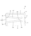
次に、実施形態2を図8〜図12を参照しつつ説明する。本実施形態の雌端子金具40は、斜め巻きコイルスプリング20に代えて板バネ状の弾性接触片51A、51Bを備えている点で、実施形態1と異なる。
<Embodiment 2>
Next, the second embodiment will be described with reference to FIGS. 8 to 12. The female terminal fitting 40 of the present embodiment is different from the first embodiment in that it includes leaf spring-shaped
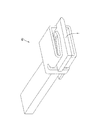
雌端子金具40は、金属製であって、図8に示すように、内部に雄端子金具のタブ部Tを受け入れる角筒部41と、この角筒部41から連なる電線接続部18と、角筒部41の内部に配置される一対の弾性接触片(第1弾性接触片51Aおよび第2弾性接触片51B)とを備えている。以下の説明において、実施形態1と同様の構成には、同一の符号を付して説明を省略する。実施形態1と同様に、図8〜図11では、雄端子金具について、タブ部Tのみを模式的に示し、他の部分を省略している。
The female terminal fitting 40 is made of metal, and as shown in FIG. 8, has a
角筒部41は、図8に示すように、両端が開口した角筒状の部分であって、底壁部12と、天壁部13と、一対の側壁部(第1側壁部42、第2側壁部15)とを備えている。底壁部12、天壁部13および第2側壁部15は、実施形態1と同様の構成を有している。第2側壁部15は、抜出スリット17を有している。抜出スリット17は、実施形態1と同様に、底壁部12と天壁部13との中央位置に配置されており、角筒部41の一方の開口縁(図8の手前側の開口縁)から他方の開口縁(図8の奥側の開口縁)の近傍まで延びている。
As shown in FIG. 8, the square
第1側壁部42は、図8に示すように、第2側壁部15と向かい合って配置され、直壁部43と、一対の湾曲部(第1湾曲部44、第2湾曲部45)とで構成されている。直壁部43は、底壁部12と天壁部13とを部分的に繋ぐ帯状の壁部であって、角筒部41の他方の開口縁(図8の奥側の開口縁)に隣接して配置されている。第1湾曲部44は、底壁部12から延び、角筒部41の内側に向かって折り返されるように湾曲する壁部であって、角筒部41の一方の開口縁(図8の手前側の開口縁)と直壁部43との間に配置されている。第2湾曲部45は、天壁部13から延び、角筒部41の内側に向かって折り返されるように湾曲する壁部であって、角筒部41の一方の開口縁と直壁部43との間に配置されている。2つの湾曲部44、45間の隙間は、タブ部Tの入口となる挿入口46となっている。
As shown in FIG. 8, the first
第1弾性接触片51Aは、図8に示すように、第1湾曲部44から連なり、第2側壁部15に向かって延びる板バネ状の部分である。この第1弾性接触片51Aは、第1湾曲部44から連なる一端が基端部52Aとなっており、他端が自由端部53Aとなっている。第1弾性接触片51Aは、基端部52Aに近い側の大部分が、基端部52Aから離れるに従って緩やかに底壁部12から離れ、自由端部53Aに近い残りの部分が自由端部53Aに近づくにつれて底壁部12に近づく山状をなしている。山の頂点部分は、タブ部Tに接触する接点部54Aとなっている。第1弾性接触片51Aは、自由端部53Aから基端部52Aに向かって延びる2本の分断スリット55A、55Aを有しており、これらの分断スリット55A、55Aによって、3本のばね片56A、56A、56Aに分断されている。
As shown in FIG. 8, the first
第2弾性接触片51Bは、第2湾曲部45から連なり、第2側壁部15に向かって延びる板バネ状の部分である。第2弾性接触片51Bは、第1弾性接触片51Aと同様の形状を有しているため、同一の構成には、同一の符号に、第1弾性接触片51Aの添え字Aに代えて添え字Bを付し、説明を省略する。第1弾性接触片51Aと第2弾性接触片51Bとは、互いに相手に対して凸となる向きで配置されており(図12を併せて参照)、接点部54A、54Bによってタブ部Tを挟み込んで保持することができるようになっている。タブ部Tが角筒部41の内部に挿入されておらず、2つの弾性接触片51A、51Bに負荷が加えられていない自由状態において、1対の接点部54A、54B間の距離は、タブ部Tの厚さよりも小さくなっている。
The second
雄端子金具と雌端子金具40とを接続する際には、タブ部Tを、底壁部12および天壁部13と平行にスライドさせるようにして、挿入口46から角筒部41の内部に(図8に矢印で示す方向に)進入させる。タブ部Tは、2つの弾性接触片51A、51Bの間に挿入され、第2側壁部15に向かって進んでいく。
When connecting the male terminal fitting and the female terminal fitting 40, slide the tab portion T in parallel with the
雄端子金具が雌端子金具40に対して正規位置(図9および図10に示す位置)まで挿入された状態では、図10に示すように、タブ部Tが接点部54A、54Bと当接する。第1弾性接触片51Aは底壁部12に近づくように、第2弾性接触片51Bは天壁部13に近づくように、それぞれ撓む。そして、弾性接触片51A、51Bからの弾性復元力によって、タブ部Tは、接点部54A、54B間に挟み付けられ、弾性接触片51A、51Bに対して一定の接圧でもって接触する。これにより、雌端子金具40と雄端子金具とが電気的に接続される。
When the male terminal fitting is inserted to the normal position (position shown in FIGS. 9 and 10) with respect to the female terminal fitting 40, the tab portion T comes into contact with the
雄端子金具を雌端子金具40から離脱させる際には、タブ部Tを、底壁部12および天壁部13と平行にスライドさせるようにして、抜出スリット17から角筒部41の外部に(図11に矢印で示す方向に)抜出させる。
When the male terminal fitting is separated from the female terminal fitting 40, the tab portion T is slid parallel to the
以上のように本実施形態によれば、雌端子金具40は、雄端子金具の平板状のタブ部Tと接続される端子金具であって、互いに向かい合って配置される一対の側壁部(第1側壁部42および第2側壁部15)と、一対の側壁部42、15を連結する底壁部12および天壁部13とを備え、内部にタブ部Tを収容可能な角筒部41と、角筒部41の内部に配置される第1弾性接触片51Aおよび第2弾性接触片51Bとを備えている。第1弾性接触片51Aは、底壁部12に沿って配置され、底壁部12と電気的に接続されているとともに、角筒部41の内部に収容されたタブ部Tに対して弾性的に接触可能となっている。第2弾性接触片51Bは、天壁部13に沿って配置され、天壁部13と電気的に接続されているとともに、角筒部41の内部に収容されたタブ部Tに対して弾性的に接触可能となっている。第1側壁部42が、タブ部Tを角筒部41の内部に挿入するための挿入スリット16を有しており、第2側壁部15が、タブ部Tを角筒部41から抜出するための抜出スリット17を有している。
As described above, according to the present embodiment, the female terminal fitting 40 is a terminal fitting connected to the flat tab portion T of the male terminal fitting, and is a pair of side wall portions (first) arranged facing each other. A
上記の構成によれば、実施形態1と同様に、雌端子金具40に対して雄端子金具を接続する際には、タブ部Tを、底壁部12および天壁部13に平行にスライドさせるようにして、挿入口46から角筒部11の内部に挿入すればよい。また、雌端子金具40から雄端子金具を離脱させる際には、同様に、タブ部Tを、底壁部12および天壁部13に平行にスライドさせるようにして、抜出スリット17から角筒部11の外部に抜き出せばよい。このように、タブ部Tをスライドさせるように動かすことで、雌端子金具40に対してタブ部Tを容易に挿抜することができるので、例えば車体の下に潜り込んで作業を行う場合のように、作業者が少々無理な姿勢で作業を行わなくてはならない場合も、作業負担を低減できる。
According to the above configuration, when connecting the male terminal fitting to the female terminal fitting 40, the tab portion T is slid parallel to the
また、角筒部41が、互いに向かい合って配置される底壁部12と天壁部13、および第1弾性接触片51Aと第2弾性接触片51Bを備える。
Further, the
このような構成によれば、タブ部Tを雌端子金具40の内部に挿入すると、第1弾性接触片51Aと第2弾性接触片51Bによってタブ部Tが挟み付けられる。これにより、弾性接触片51A、51Bを一定の接圧でもってタブ部Tに接触させることができ、雌端子金具40と雄端子金具との電気的接続の信頼性を高めることができる。
According to such a configuration, when the tab portion T is inserted into the female terminal fitting 40, the tab portion T is sandwiched between the first
<他の実施形態>
本明細書によって開示される技術は上記記述及び図面によって説明した実施形態に限定されるものではなく、例えば次のような種々の態様も含まれる。
(1)上記実施形態1では、雌端子金具1が、底壁部12および天壁部13と、第1斜め巻きコイルスプリング20A及び第2斜め巻きコイルスプリング20Bとを備えており、上記実施形態2では、雌端子金具40が、底壁部12および天壁部13と、第1弾性接触片51A及び第2弾性接触片51Bとを備えていたが、本体部が1つの連結壁部を備えており、この連結壁部に沿って配置された接触部が相手端子の片面のみに接触する構成となっていても構わない。
<Other Embodiments>
The techniques disclosed herein are not limited to the embodiments described above and in the drawings, and include, for example, various aspects such as:
(1) In the first embodiment, the female terminal fitting 1 includes a
(2)上記実施形態1では、雌端子金具1が、底壁部12に沿って配置される2つの第1斜め巻きコイルスプリング20Aを備えていたが、第1斜め巻きコイルスプリングが、1つまたは3つ以上であっても構わない。第2斜め巻きコイルスプリングについても同様である。
(2) In the first embodiment , the female terminal fitting 1 includes two first diagonally wound
(3)本体部が、斜め巻きコイルスプリングのコイル軸回りの回転を規制する回転規制部を備えていても構わない。 (3) The main body may be provided with a rotation regulating portion that regulates the rotation of the diagonally wound coil spring around the coil axis.
1、40…雌端子金具(端子金具)
11…角筒部(本体部)
12…底壁部(連結壁部)
13…天壁部(連結壁部)
14、42…第1側壁部(一方の側壁部)
15…第2側壁部(他方の側壁部)
16…挿入スリット(挿入口)
17…抜出スリット(抜出口)
20…斜め巻きコイルスプリング(接触部)
20A…第1斜め巻きコイルスプリング(接触部、斜め巻きコイルスプリング)
20B…第2斜め巻きコイルスプリング(接触部、斜め巻きコイルスプリング)
21…線材
46…挿入口
51A…第1弾性接触片(接触部、弾性接触片)
51B…第2弾性接触片(接触部、弾性接触片)
A…コイル軸(軸線)
T…タブ部(相手端子)
1, 40 ... Female terminal fittings (terminal fittings)
11 ... Square tube (main body)
12 ... Bottom wall (connecting wall)
13 ... Top wall (connecting wall)
14, 42 ... First side wall (one side wall)
15 ... Second side wall (the other side wall)
16 ... Insertion slit (insertion port)
17 ... Extraction slit (extraction outlet)
20 ... Diagonally wound coil spring (contact part)
20A ... 1st diagonally wound coil spring (contact part, diagonally wound coil spring)
20B ... 2nd diagonally wound coil spring (contact part, diagonally wound coil spring)
21 ...
51B ... Second elastic contact piece (contact part, elastic contact piece)
A ... Coil shaft (axis)
T ... Tab part (other terminal)
Claims (3)
互いに向かい合って配置される一対の側壁部と、前記一対の側壁部を連結する連結壁部とを備え、内部に前記相手端子を収容可能な本体部と、
前記本体部の内部に前記連結壁部に沿って配置され、前記本体部と電気的に接続されているとともに、前記本体部の内部に収容された前記相手端子に対して弾性的に接触する斜め巻きコイルスプリングとを備え、
前記一対の側壁部のうち一方の側壁部が、前記相手端子を前記本体部の内部に挿入するための挿入口を有しており、他方の側壁部が、前記相手端子を前記本体部から抜出するための抜出口を有しており、
前記斜め巻きコイルスプリングは、導電性の線材がコイル軸の回りに複数回巻回されたコイル状をなし、前記線材の任意の点P1とそこから半周分離れた点P2とを結ぶ直線と、前記点P2とそこからさらに半周分離れた点P3とを結ぶ直線とが、前記コイル軸に対して同じ方向に傾いており、
前記斜め巻きコイルスプリングが、前記軸線が前記一対の側壁部に対して垂直な向きとなり、前記線材の傾きが前記連結壁部から離れるにしたがって前記一方の側壁部から前記他方の側壁部に近づく向きとなるように配置されている端子金具。 It is a terminal fitting that is connected to a flat plate-shaped mating terminal.
A main body portion having a pair of side wall portions arranged facing each other and a connecting wall portion connecting the pair of side wall portions and capable of accommodating the mating terminal inside.
Diagonally arranged inside the main body along the connecting wall, electrically connected to the main body, and elastically in contact with the mating terminal housed inside the main body. Equipped with a winding coil spring
One side wall portion of the pair of side wall portions has an insertion port for inserting the mating terminal into the main body portion, and the other side wall portion pulls out the mating terminal from the main body portion. It has an outlet to put it out ,
The diagonally wound coil spring has a coil shape in which a conductive wire is wound a plurality of times around a coil shaft, and connects a straight line connecting an arbitrary point P1 of the wire and a point P2 half-circumfered from the point P1. The straight line connecting the point P2 and the point P3 further separated from the point P2 is inclined in the same direction with respect to the coil axis.
The direction in which the diagonally wound coil spring is oriented so that the axis is perpendicular to the pair of side wall portions and the inclination of the wire rod approaches the other side wall portion from the one side wall portion as the inclination increases from the connecting wall portion. Terminal fittings arranged so as to be.
Priority Applications (4)
| Application Number | Priority Date | Filing Date | Title |
|---|---|---|---|
| JP2017204963A JP6889838B2 (en) | 2017-10-24 | 2017-10-24 | Terminal bracket |
| CN201880065627.1A CN111316503B (en) | 2017-10-24 | 2018-10-19 | Terminal parts |
| US16/756,691 US20210126390A1 (en) | 2017-10-24 | 2018-10-19 | Terminal fitting |
| PCT/JP2018/039017 WO2019082809A1 (en) | 2017-10-24 | 2018-10-19 | Terminal fitting |
Applications Claiming Priority (1)
| Application Number | Priority Date | Filing Date | Title |
|---|---|---|---|
| JP2017204963A JP6889838B2 (en) | 2017-10-24 | 2017-10-24 | Terminal bracket |
Publications (3)
| Publication Number | Publication Date |
|---|---|
| JP2019079664A JP2019079664A (en) | 2019-05-23 |
| JP2019079664A5 JP2019079664A5 (en) | 2020-04-09 |
| JP6889838B2 true JP6889838B2 (en) | 2021-06-18 |
Family
ID=66247523
Family Applications (1)
| Application Number | Title | Priority Date | Filing Date |
|---|---|---|---|
| JP2017204963A Active JP6889838B2 (en) | 2017-10-24 | 2017-10-24 | Terminal bracket |
Country Status (4)
| Country | Link |
|---|---|
| US (1) | US20210126390A1 (en) |
| JP (1) | JP6889838B2 (en) |
| CN (1) | CN111316503B (en) |
| WO (1) | WO2019082809A1 (en) |
Families Citing this family (3)
| Publication number | Priority date | Publication date | Assignee | Title |
|---|---|---|---|---|
| JP7001961B2 (en) * | 2018-03-02 | 2022-01-20 | 株式会社オートネットワーク技術研究所 | Female terminal |
| JP7200660B2 (en) * | 2018-12-25 | 2023-01-10 | 三菱電機株式会社 | Connection terminal structure, light source unit and lighting equipment using this connection terminal structure |
| CN118156839A (en) * | 2024-04-19 | 2024-06-07 | 惠州尼索科连接技术有限公司 | Floating connector |
Family Cites Families (14)
| Publication number | Priority date | Publication date | Assignee | Title |
|---|---|---|---|---|
| DE1137783B (en) * | 1960-04-11 | 1962-10-11 | Krone Kg | Plug connection for electrical lines |
| US4810213A (en) * | 1975-01-30 | 1989-03-07 | Square D Company | Low resistance electrical connecting assembly |
| JPS56174480U (en) * | 1980-05-27 | 1981-12-23 | ||
| US5035628A (en) * | 1990-05-29 | 1991-07-30 | Amp Incorporated | Electrical connector for electrically interconnecting two parallel surfaces |
| DE19528127C2 (en) * | 1995-08-01 | 2000-05-04 | Abb Patent Gmbh | Contacting device for cable connections |
| JP2008053190A (en) * | 2006-08-28 | 2008-03-06 | Matsushita Electric Works Ltd | Connector |
| US8057270B2 (en) * | 2007-12-05 | 2011-11-15 | Mitsubishi Electric Corporation | Contact device |
| JP4212645B1 (en) * | 2008-04-14 | 2009-01-21 | 三菱電機株式会社 | Contact |
| WO2011001821A1 (en) * | 2009-07-03 | 2011-01-06 | 矢崎総業株式会社 | Female terminal |
| DE202010010827U1 (en) * | 2010-07-29 | 2010-10-21 | Rosenberger Hochfrequenztechnik Gmbh & Co. Kg | High Power Connectors |
| JP5782298B2 (en) * | 2011-05-31 | 2015-09-24 | 住友電気工業株式会社 | Oblique winding spring and wire for oblique winding spring |
| CN202772305U (en) * | 2012-08-22 | 2013-03-06 | 深圳市簧中簧电子有限公司 | Conductive terminal, circuit board equipped with conductive terminal, and board-to-board connector |
| JP6340666B2 (en) * | 2014-08-25 | 2018-06-13 | 北川工業株式会社 | Conductive member |
| JP6508035B2 (en) * | 2015-12-24 | 2019-05-08 | 株式会社オートネットワーク技術研究所 | Terminal bracket and connector |
-
2017
- 2017-10-24 JP JP2017204963A patent/JP6889838B2/en active Active
-
2018
- 2018-10-19 CN CN201880065627.1A patent/CN111316503B/en active Active
- 2018-10-19 WO PCT/JP2018/039017 patent/WO2019082809A1/en not_active Ceased
- 2018-10-19 US US16/756,691 patent/US20210126390A1/en not_active Abandoned
Also Published As
| Publication number | Publication date |
|---|---|
| CN111316503B (en) | 2021-08-24 |
| WO2019082809A1 (en) | 2019-05-02 |
| JP2019079664A (en) | 2019-05-23 |
| CN111316503A (en) | 2020-06-19 |
| US20210126390A1 (en) | 2021-04-29 |
Similar Documents
| Publication | Publication Date | Title |
|---|---|---|
| CN108461966B (en) | Movable cover plate | |
| EP2777095B1 (en) | Electrical disconnect with push-in connectors having a busbar | |
| US9748685B2 (en) | Multi-contact terminal | |
| TW510069B (en) | Female terminal | |
| US7255592B1 (en) | Electrical wire connector | |
| CN104241919B (en) | Electric connector | |
| CN106063045B (en) | Connector assembly | |
| JP6889838B2 (en) | Terminal bracket | |
| CN108963504B (en) | Connecting terminal | |
| EP2899813B1 (en) | Connector | |
| EP1635425A1 (en) | Connection terminal | |
| JP2011181330A (en) | Terminal fitting | |
| KR20140009492A (en) | Terminal fitting | |
| CN108604740A (en) | Terminal fittings | |
| CN109524818A (en) | Connector | |
| CN108258447A (en) | Terminal board | |
| CN201773987U (en) | Connector | |
| CN107851920B (en) | terminal | |
| US9502838B2 (en) | Electrical connector having an improved insulative base | |
| JP6898220B2 (en) | Connector housing | |
| US20200099158A1 (en) | Large current terminal and connector | |
| JP2009517822A (en) | Electrical terminal with guide means | |
| US11888301B2 (en) | Active cover plates | |
| KR102866341B1 (en) | electrical terminals | |
| JP6746357B2 (en) | Connector terminals and connectors |
Legal Events
| Date | Code | Title | Description |
|---|---|---|---|
| A621 | Written request for application examination |
Free format text: JAPANESE INTERMEDIATE CODE: A621 Effective date: 20200128 |
|
| A521 | Request for written amendment filed |
Free format text: JAPANESE INTERMEDIATE CODE: A523 Effective date: 20200228 |
|
| A131 | Notification of reasons for refusal |
Free format text: JAPANESE INTERMEDIATE CODE: A131 Effective date: 20210126 |
|
| A521 | Request for written amendment filed |
Free format text: JAPANESE INTERMEDIATE CODE: A523 Effective date: 20210312 |
|
| TRDD | Decision of grant or rejection written | ||
| A01 | Written decision to grant a patent or to grant a registration (utility model) |
Free format text: JAPANESE INTERMEDIATE CODE: A01 Effective date: 20210422 |
|
| A61 | First payment of annual fees (during grant procedure) |
Free format text: JAPANESE INTERMEDIATE CODE: A61 Effective date: 20210505 |
|
| R150 | Certificate of patent or registration of utility model |
Ref document number: 6889838 Country of ref document: JP Free format text: JAPANESE INTERMEDIATE CODE: R150 |
|
| R250 | Receipt of annual fees |
Free format text: JAPANESE INTERMEDIATE CODE: R250 |
|
| R250 | Receipt of annual fees |
Free format text: JAPANESE INTERMEDIATE CODE: R250 |
|
| R250 | Receipt of annual fees |
Free format text: JAPANESE INTERMEDIATE CODE: R250 |