JP6889832B2 - Charging roller and its manufacturing method - Google Patents
Charging roller and its manufacturing method Download PDFInfo
- Publication number
- JP6889832B2 JP6889832B2 JP2017076825A JP2017076825A JP6889832B2 JP 6889832 B2 JP6889832 B2 JP 6889832B2 JP 2017076825 A JP2017076825 A JP 2017076825A JP 2017076825 A JP2017076825 A JP 2017076825A JP 6889832 B2 JP6889832 B2 JP 6889832B2
- Authority
- JP
- Japan
- Prior art keywords
- outer peripheral
- peripheral surface
- rubber
- void volume
- roller
- Prior art date
- Legal status (The legal status is an assumption and is not a legal conclusion. Google has not performed a legal analysis and makes no representation as to the accuracy of the status listed.)
- Active
Links
Images


Landscapes
- Rolls And Other Rotary Bodies (AREA)
- Electrostatic Charge, Transfer And Separation In Electrography (AREA)
Description
本発明は、電子写真法を利用した画像形成装置に組み込んで使用される帯電ローラと、その製造方法に関するものである。 The present invention relates to a charging roller used by being incorporated in an image forming apparatus using an electrophotographic method, and a method for manufacturing the same.
レーザープリンタ、静電式複写機、普通紙ファクシミリ装置、またはこれらの複合機等の、電子写真法を利用した画像形成装置においては、感光体の表面を一様に帯電させるために、帯電ローラが用いられる。
帯電ローラとしては、例えば半導電性を付与したゴム組成物を筒状に成形したのちゴムを架橋させた単層の、あるいは上記層を含む複層構造のローラ本体を備えるものが一般的に用いられる。
In an image forming apparatus using an electrophotographic method such as a laser printer, an electrostatic copier, a plain paper facsimile machine, or a combination machine thereof, a charging roller is used to uniformly charge the surface of the photoconductor. Used.
As the charging roller, for example, a roller having a single-layer structure obtained by forming a semi-conductive rubber composition into a tubular shape and then cross-linking the rubber, or a roller body having a multi-layer structure including the above layer is generally used. Be done.
ローラ本体の外周面は、トナーに外添された外添剤や、あるいは画像形成を繰り返した際にトナーの粒子が微粉砕されて生じる破片などの微粉が付着し、蓄積されて形成画像に画像不良が生じるのを抑制するべく、その表面を整えるために、例えば研磨したり、研磨後にコーティング膜で被覆したりするのが一般的である。
しかしコーティング膜は、そのもとになる液状のコーティング剤をスプレー法、ディッピング法等の塗布方法によってローラ本体の外周面に塗布したのち、乾燥させて形成されるため、上記形成過程において埃等の異物の混入、厚みムラの発生等の様々な不良を生じやすい。
On the outer peripheral surface of the roller body, an external additive externally added to the toner or fine powder such as debris generated by finely crushing the toner particles when the image formation is repeated adheres and accumulates on the formed image. In order to prepare the surface in order to suppress the occurrence of defects, for example, it is generally polished or coated with a coating film after polishing.
However, the coating film is formed by applying a liquid coating agent, which is the basis of the coating film, to the outer peripheral surface of the roller body by a coating method such as a spray method or a dipping method, and then drying the coating film. Various defects such as foreign matter mixed in and uneven thickness are likely to occur.
また、コーティング剤を調製するには有機溶剤が必要であるが、有機溶剤の使用は環境に対する負荷が大きく、近年の低VOC(揮発性有機化合物)化の流れに逆行することにもなる。
そこでコーティング膜に代えて、例えば研磨の条件を調整したり、レーザー加工、ブラスト加工等の種々の加工を施したりすることによって、ローラ本体の外周面を、微粉の付着および蓄積を生じにくいと考えられる様々な凹凸形状に形成することが検討されている(特許文献1〜4等参照)。
In addition, an organic solvent is required to prepare a coating agent, but the use of an organic solvent has a large burden on the environment and goes against the recent trend toward low VOC (volatile organic compounds).
Therefore, instead of the coating film, it is considered that fine powder is less likely to adhere and accumulate on the outer peripheral surface of the roller body by, for example, adjusting the polishing conditions or performing various processing such as laser processing and blasting. It has been studied to form various uneven shapes (see
ところが発明者の検討によると、上記従来の帯電ローラでは、微粉の付着や蓄積を未だ十分に抑制できないのが現状である。また表面形状によっては感光体の表面を均一に帯電させることができず、帯電のムラを生じて、形成画像の画質が低下する場合もある。
本発明の目的は、コーティング膜を省略した簡単な構造を維持しながら、なおかつ感光体の表面をできるだけ均一に帯電できる上、微粉の付着や蓄積を現状よりもさらに良好に抑制できる帯電ローラと、その製造方法を提供することにある。
However, according to the study of the inventor, the current situation is that the conventional charging roller cannot sufficiently suppress the adhesion and accumulation of fine powder. Further, depending on the surface shape, the surface of the photoconductor cannot be uniformly charged, and uneven charging may occur, resulting in deterioration of the image quality of the formed image.
An object of the present invention is to provide a charging roller that can charge the surface of the photoconductor as uniformly as possible while maintaining a simple structure without a coating film, and can further suppress adhesion and accumulation of fine powder than the present state. The purpose is to provide the manufacturing method.
本発明は、ローラ本体を備え、前記ローラ本体は、ゴムを含むゴム組成物の架橋物によって単層に形成されているとともに、前記ローラ本体の外周面は、国際標準化機構規格ISO25178−2:2012において規定された、コア部の空隙容積Vvcと谷部の空隙容積Vvvとの和Vvc+Vvvで表される空隙容積Vvが、多数の凹凸からなる表面粗さ成分において0.3ml/m2未満で、かつ前記表面粗さ成分より低周波数の多数の凹凸からなる表面うねり成分において0.05ml/m2以上、6ml/m2以下である帯電ローラである。 The present invention includes a roller body, the roller body is formed in a single layer by a crosslinked product of a rubber composition containing rubber , and the outer peripheral surface of the roller body is the International Organization for Standardization Standard ISO25178-2: 2012. The void volume Vv represented by the sum Vvc + Vvv of the void volume Vvc in the core portion and the void volume Vvv in the valley portion specified in the above is less than 0.3 ml / m 2 in the surface roughness component composed of a large number of irregularities. Moreover, it is a charging roller having a surface waviness component having a large number of irregularities having a frequency lower than that of the surface roughness component, which is 0.05 ml / m 2 or more and 6 ml / m 2 or less.
また本発明は、かかる本発明の帯電ローラの製造方法であって、前記ローラ本体の前記外周面を研磨する工程、および研磨した前記外周面にレーザー加工、湿式ブラスト加工および乾式ブラスト加工からなる群より選ばれた少なくとも1種の加工をすることで、前記外周面を、前記表面粗さ成分の空隙容積Vvが0.3ml/m2未満、前記表面うねり成分の空隙容積Vvが0.05ml/m2以上、6ml/m2以下となるように仕上げる工程を含む、帯電ローラの製造方法である。
The present invention is the method for manufacturing a charged roller of the present invention, which comprises a step of polishing the outer peripheral surface of the roller body, and laser processing, wet blasting, and dry blasting on the polished outer peripheral surface. By performing at least one process selected from the above, the outer peripheral surface has a void volume Vv of the surface roughness component of less than 0.3 ml / m 2 and a void volume Vv of the surface waviness component of 0.05 ml /
本発明によれば、コーティング膜を省略した簡単な構造を維持しながら、なおかつ感光体の表面をできるだけ均一に帯電できる上、微粉の付着や蓄積を現状よりもさらに良好に抑制できる帯電ローラと、その製造方法を提供できる。 According to the present invention, a charging roller capable of maintaining a simple structure without a coating film, charging the surface of the photoconductor as uniformly as possible, and suppressing adhesion and accumulation of fine powder even better than the current state. The manufacturing method can be provided.
前述した各種の加工を経て形成されるローラ本体の外周面は、一般に、多数の微細な凹凸からなる表面粗さ成分と、当該表面粗さ成分より低周波数の、すなわち深さも開口面積も大きい多数の凹凸からなる表面うねり成分とが重畳した表面形状を有していることが知られている。
発明者の検討によると、上記のうち表面粗さ成分を構成する凹凸はできるだけ小さく、かつ少ないのが、外周面に微粉が付着、蓄積されるのを抑制する上で有効である。
The outer peripheral surface of the roller body formed through the various processes described above generally has a surface roughness component composed of a large number of fine irregularities and a large number having a lower frequency than the surface roughness component, that is, a large depth and opening area. It is known that the surface has a surface shape in which the surface waviness component composed of the unevenness of the surface is superimposed.
According to the study of the inventor, among the above, the irregularities constituting the surface roughness component are as small and small as possible, which is effective in suppressing the adhesion and accumulation of fine powder on the outer peripheral surface.
また表面うねり成分については、
(i) 当該表面うねり成分を構成する凹凸の凹部の深さが小さいほど、外周面に微粉が付着、蓄積されやすくなる傾向があり、逆に凹部の深さが大きいほど、外周面の平滑性が低下して、感光体の表面を均一に帯電できなくなる傾向があるため、当該凹部の深さを適度な範囲に調整するのが肝要であり、また
(ii) 上記表面うねり成分を構成する凹凸の凹部の開口面積が小さすぎても、逆に大きすぎても、外周面に微粉が付着、蓄積されやすくなる傾向があるため、当該開口面積についても、適度な範囲に調整するのが肝要である。
Regarding the surface swell component,
(i) The smaller the depth of the concave and convex recesses that make up the surface waviness component, the easier it is for fine powder to adhere and accumulate on the outer peripheral surface. Conversely, the larger the depth of the recesses, the smoother the outer peripheral surface. It is important to adjust the depth of the recess to an appropriate range, because the depth of the recess tends to decrease and the surface of the photoconductor tends to be unable to be charged uniformly.
(ii) If the opening area of the concave-convex concave portion constituting the surface waviness component is too small or, conversely, too large, fine powder tends to adhere to and accumulate on the outer peripheral surface. , It is important to adjust to an appropriate range.
そこで発明者は、前述したように感光体の表面をできるだけ均一に帯電できる上、微粉の付着や蓄積を現状よりもさらに良好に抑制できる帯電ローラを得るために、上記表面粗さ成分を構成する凹凸の大きさや数、あるいは表面うねり成分を構成する凹凸の凹部の深さや開口面積を、表面形状の新たな指標でもって把握することを検討した。
その結果、国際標準化機構規格ISO25178−2:2012「製品の幾何特性仕様(GPS)−表面性状−第2部:用語,定義及び表面性状パラメータ」において規定された、コア部の空隙容積Vvcと谷部の空隙容積Vvvとの和Vvc+Vvvで表される空隙容積Vvを、表面粗さ成分において0.3ml/m2未満に規定するとともに、表面うねり成分において0.05ml/m2以上、6ml/m2以下に規定すればよいことを見出した。
Therefore, as described above, the inventor constitutes the surface roughness component in order to obtain a charging roller capable of charging the surface of the photoconductor as uniformly as possible and suppressing the adhesion and accumulation of fine powder even better than the current state. It was examined to grasp the size and number of unevenness, or the depth and opening area of the concave and convex portions constituting the surface waviness component by using a new index of the surface shape.
As a result, the void volume Vvc and valley of the core part specified in the International Organization for Standardization Standard ISO25178-2: 2012 "Geometrical Characteristic Specifications (GPS) of Product-Surface Texture-Part 2: Terms, Definitions and Surface Texture Parameters". The void volume Vv represented by the sum Vvc + Vvv with the void volume Vvv of the portion is defined as less than 0.3 ml / m 2 in the surface roughness component, and 0.05 ml / m 2 or more and 6 ml / m in the surface waviness component. It was found that it should be specified in 2 or less.
すなわち、表面粗さ成分の空隙容積Vvが0.3ml/m2以上では、当該表面粗さ成分を構成する凹凸が大きく、かつ多くなって、ローラ本体の外周面に微粉が付着、蓄積されやすくなる。
これに対し、表面粗さ成分の空隙容積Vvを0.3ml/m2未満とすれば、当該表面粗さ成分を構成する凹凸を小さく、かつ少なくして、ローラ本体の外周面に微粉が付着、蓄積されるのを良好に抑制できる。
That is, when the void volume Vv of the surface roughness component is 0.3 ml / m 2 or more, the unevenness constituting the surface roughness component becomes large and large, and fine powder easily adheres to and accumulates on the outer peripheral surface of the roller body. Become.
On the other hand, if the void volume Vv of the surface roughness component is less than 0.3 ml / m 2, the unevenness constituting the surface roughness component is made small and small, and fine powder adheres to the outer peripheral surface of the roller body. , Accumulation can be suppressed satisfactorily.
また、表面うねり成分の空隙容積Vvが0.05ml/m2未満では、当該表面うねり成分を構成する凹凸の凹部の深さおよび/または開口面積が小さくなって、ローラ本体の外周面に微粉が付着、蓄積されやすくなる。
一方、表面うねり成分の空隙容積Vvが6ml/m2を超える場合には、上記凹部の深さが大きくなるため、感光体の表面を均一に帯電できなくなる。また上記凹部の開口面積が大きくなって、ローラ本体の外周面に微粉が付着、蓄積されやすくなる。
Further, when the void volume Vv of the surface waviness component is less than 0.05 ml / m 2 , the depth and / or opening area of the uneven recesses constituting the surface waviness component becomes small, and fine powder is generated on the outer peripheral surface of the roller body. It becomes easy to adhere and accumulate.
On the other hand, when the void volume Vv of the surface waviness component exceeds 6 ml / m 2 , the depth of the recesses becomes large, so that the surface of the photoconductor cannot be uniformly charged. Further, the opening area of the recess becomes large, and fine powder easily adheres to and accumulates on the outer peripheral surface of the roller body.
これに対し、表面うねり成分の空隙容積Vvを0.05ml/m2以上、6ml/m2以下とすれば、当該表面うねり成分を構成する凹凸の凹部の深さ、および開口面積をいずれも適度の範囲に調整して、感光体の表面をできるだけ均一に帯電できる上、ローラ本体の外周面に微粉が付着、蓄積されるのを良好に抑制できる。
なお、上述した効果をより一層向上することを考慮すると、表面粗さ成分の空隙容積Vvは、上記の範囲でも0.1ml/m2以上であるのが好ましく、0.28ml/m2以下であるのが好ましい。また、表面うねり成分の空隙容積Vvは、上記の範囲でも0.1ml/m2以上であるのが好ましく、4ml/m2以下であるのが好ましい。
On the other hand, if the void volume Vv of the surface swell component is 0.05 ml / m 2 or more and 6 ml / m 2 or less, the depth of the concave and convex recesses constituting the surface swell component and the opening area are both appropriate. The surface of the photoconductor can be charged as uniformly as possible, and fine powder can be satisfactorily suppressed from adhering to and accumulating on the outer peripheral surface of the roller body.
Incidentally, considering that further improve the effect described above, the void volume Vv of the surface roughness component is preferably at 0.1 ml / m 2 or more at the above-mentioned range, 0.28 ml / m 2 or less It is preferable to have it. Further, the void volume Vv of the surface waviness component is preferably 0.1 ml / m 2 or more, and preferably 4 ml / m 2 or less even in the above range.
上記表面粗さ成分および表面うねり成分の空隙容積Vvを、本発明では、例えば形状解析レーザー顕微鏡を用いて、ローラ本体の外周面の表面形状を測定した結果から、上記ISO規格に則って、下記の方法で求めた値でもって表すこととする。
すなわち表面粗さ成分の空隙容積Vvを求めるには、測定結果(原表面)を、メディアンフィルタを用いて平滑化し、平面傾きを補正し、さらに面状補正−うねり除去の補正によって表面うねり成分を除去して計測表面を求める。
In the present invention, the void volume Vv of the surface roughness component and the surface waviness component is measured based on the results of measuring the surface shape of the outer peripheral surface of the roller body using, for example, a shape analysis laser microscope. It is expressed by the value obtained by the method of.
That is, in order to obtain the void volume Vv of the surface roughness component, the measurement result (original surface) is smoothed by using a median filter, the plane inclination is corrected, and the surface waviness component is corrected by surface correction-waviness removal correction. Remove and obtain the measurement surface.
次いで、この計測表面に対して所定の評価領域を指定し、計測表面に対応する基準表面を求めて、負荷面積率p%における空隙容積と、負荷面積率q%における空隙容積との差分で表されるコア部の空隙容積Vvcと、負荷面積率p%における谷部の空隙容積Vvvとを演算する。
そして両容積の和Vvc+Vvvを求めて、表面粗さ成分の空隙容積Vvとする。
Next, a predetermined evaluation region is designated for this measurement surface, a reference surface corresponding to the measurement surface is obtained, and the difference between the void volume at the load area ratio p% and the void volume at the load area ratio q% is shown. The void volume Vvc of the core portion to be formed and the void volume Vvv of the valley portion at the load area ratio p% are calculated.
Then, the sum Vvc + Vvv of both volumes is obtained and used as the void volume Vv of the surface roughness component.
また表面うねり成分の空隙容積Vvを求めるには、測定結果(原表面)を、ローパスフィルタを用いて処理して高周波成分(表面粗さ成分)を除去し、メディアンフィルタを用いて平滑化し、さらに平面傾きを補正して計測表面を求める。
次いで、この計測表面に対して所定の評価領域を指定し、計測表面に対応する基準表面を求めて、負荷面積率p%における空隙容積と、負荷面積率q%における空隙容積との差分で表されるコア部の空隙容積Vvcと、負荷面積率p%における谷部の空隙容積Vvvとを演算する。
To obtain the void volume Vv of the surface waviness component, the measurement result (original surface) is processed with a low-pass filter to remove the high-frequency component (surface roughness component), smoothed with a median filter, and further. The plane inclination is corrected to obtain the measurement surface.
Next, a predetermined evaluation region is designated for this measurement surface, a reference surface corresponding to the measurement surface is obtained, and the difference between the void volume at the load area ratio p% and the void volume at the load area ratio q% is shown. The void volume Vvc of the core portion to be formed and the void volume Vvv of the valley portion at the load area ratio p% are calculated.
そして両容積の和Vvc+Vvvを求めて、表面うねり成分の空隙容積Vvとする。
なお、表面粗さ成分および表面うねり成分のいずれを求める場合も、負荷面積率pは80%、qは10%に設定するのが一般的である。
上記空隙容積Vvを満足する、表面うねり成分を構成する凹凸の、凹部の具体的なサイズは特に限定されないものの、当該凹部の深さは、1μm以上であるのが好ましく、50μm以下であるのが好ましい。また凹部の開口面積は、1μm2以上であるのが好ましく、1mm2以下であるのが好ましい。
Then, the sum Vvc + Vvv of both volumes is obtained and used as the void volume Vv of the surface waviness component.
When determining either the surface roughness component or the surface waviness component, the load area ratio p is generally set to 80% and q is generally set to 10%.
Although the specific size of the concave portion of the unevenness constituting the surface waviness component that satisfies the void volume Vv is not particularly limited, the depth of the concave portion is preferably 1 μm or more, preferably 50 μm or less. preferable. The opening area of the recess is preferably 1 μm 2 or more, and preferably 1 mm 2 or less.
またローラ本体の外周面の、前述したISO規格において規定された算術平均高さSa(線の算術平均高さRaを面に拡張したもの)は、0.8μm以上であるのが好ましく、3μm以下であるのが好ましい。
《帯電ローラとその製造方法》
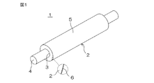
図1は、本発明の帯電ローラの、実施の形態の一例を示す斜視図である。
Further, the arithmetic mean height Sa (the arithmetic average height Ra of the line extended to the surface) specified in the ISO standard described above on the outer peripheral surface of the roller body is preferably 0.8 μm or more, preferably 3 μm or less. Is preferable.
<< Charging roller and its manufacturing method >>
FIG. 1 is a perspective view showing an example of an embodiment of the charging roller of the present invention.
図1を参照して、この例の帯電ローラ1は、半導電性を付与したゴム組成物によって、非多孔質でかつ単層の筒状に形成されたローラ本体2を備えている。ローラ本体2の中心の通孔3には、シャフト4が挿通されて固定されている。
シャフト4は、例えばアルミニウム、アルミニウム合金、ステンレス鋼等の金属によって一体に形成されている。
With reference to FIG. 1, the charging
The
シャフト4は、例えば導電性を有する接着剤を介して、ローラ本体2と電気的に接合されるとともに機械的に固定されるか、あるいは通孔3の内径よりも外径の大きいものを通孔3に圧入することで、ローラ本体2と電気的に接合されるとともに機械的に固定される。
ローラ本体2の外周面5には、図中に拡大して示すように酸化膜6が形成されている。
The
An
酸化膜6を形成することにより、当該酸化膜6が誘電層として機能して、帯電ローラ1の誘電正接を低減できる。また酸化膜6が低摩擦層として機能して、微粉の付着をさらに良好に抑制できる。
しかも酸化膜6は、例えば酸化性雰囲気中で外周面5に紫外線を照射する等して、当該外周面5の近傍のゴムを酸化させるだけで簡単に形成できるため、帯電ローラ1の生産性が低下したり、製造コストが高くついたりするのを抑制できる。
By forming the
Moreover, the
なお、ローラ本体2の「単層」とは、ゴム等からなる層の数が単層であることを指し、紫外線の照射等によって形成される酸化膜6は層数に含まないこととする。
帯電ローラ1を製造するには、まず調製したゴム組成物を、押出機を用いて筒状に押出成形し、次いで所定の長さにカットして加硫缶内で加圧、加熱してゴムを架橋させる。
次いで、架橋させた筒状体を、オーブン等を用いて加熱して二次架橋させ、冷却したのち、所定の外径となるように外周面5を研磨する。
The "single layer" of the
In order to manufacture the charged
Next, the crosslinked tubular body is heated by using an oven or the like for secondary cross-linking, cooled, and then the outer
研磨方法としては、例えば乾式トラバース研磨等の種々の研磨方法が採用可能である。
次いで研磨した外周面5を、レーザー加工、湿式ブラスト加工および乾式ブラスト加工からなる群より選ばれた少なくとも1種の加工によって、前述した表面粗さ成分および表面うねり成分の空隙容積Vvをともに満足する特定の表面形状に仕上げ加工してローラ本体2を形成する。
As the polishing method, various polishing methods such as dry traverse polishing can be adopted.
Next, the polished outer
すなわち、研磨しただけの外周面5は、表面粗さ成分を構成する凹凸が大きく、かつ多い状態である。
この状態の外周面5に、さらにレーザー加工や湿式もしくは乾式のブラスト加工によって、表面うねり成分を構成する、より低周波数の凹凸を形成することにより、それより微細な、表面粗さ成分を構成する凹凸を小さく、かつ少なくして、上記特定の表面形状を満足する外周面5を備えたローラ本体2を形成できる。
That is, the outer
On the outer
なお、外周面5の表面うねり成分の空隙容積Vvを、前述した範囲でも、例えば1ml/m2未満、特に0.5ml/m2以下とする場合には、外周面5を乾式トラバース研磨等した後に、鏡面研磨等の仕上げ研磨をした上で、レーザー加工、または湿式、乾式のブラスト加工をするのが好ましい。
レーザー加工は、例えば研磨後の外周面5に、所定の照射サイズに絞ったレーザーを、所定のピッチで照射位置を移動させながら照射することで実施される。
In addition, when the void volume Vv of the surface waviness component of the outer
Laser processing is performed, for example, by irradiating the outer
レーザー加工では、レーザーの照射によって発生する熱によって、外周面5を形成するゴム組成物の架橋物が選択的に溶融され、かつ少なくとも一部が蒸散されて、表面うねり成分を構成する多数の凹凸が形成される。
レーザー加工によって、ローラ本体の外周面を前述した特定の表面形状とするには、例えばレーザーの出力、外周面に照射するレーザーの照射サイズや照射位置の移動のピッチ、あるいは隣り合う照射位置の重なり度合い等を調整すればよい。
In laser processing, the crosslinked product of the rubber composition forming the outer
In order to obtain the above-mentioned specific surface shape of the outer peripheral surface of the roller body by laser processing, for example, the output of the laser, the irradiation size of the laser to irradiate the outer peripheral surface, the movement pitch of the irradiation position, or the overlap of adjacent irradiation positions. The degree and the like may be adjusted.
レーザー加工では、例えば照射位置の移動のピッチを小さくするほど、表面うねり成分の空隙容積Vvを小さくできる。
ピッチは、特定の表面形状を形成し得る任意の範囲に設定できるものの、特に30μm以上、中でも35μm以上、特に40μm以上であるのが好ましく、60μm以下であるのが好ましい。
In laser processing, for example, the smaller the pitch of movement of the irradiation position, the smaller the void volume Vv of the surface waviness component.
Although the pitch can be set to an arbitrary range in which a specific surface shape can be formed, the pitch is particularly preferably 30 μm or more, particularly 35 μm or more, particularly 40 μm or more, and preferably 60 μm or less.
レーザー加工は、特に外周面5の表面うねり成分の空隙容積Vvを、前述した範囲でも、例えば1ml/m2以上とする場合に好適である。
湿式ブラスト加工は、例えば研磨後、好ましくは鏡面研磨後の外周面5に、研磨材の微細粒子と水等の液体とを含むスラリーを、噴射ノズルから高速で吹き付けることによって実施される。また乾式ブラスト加工は、上記外周面5に、研磨材の微細粒子を、圧縮空気等の圧縮ガスとともに、噴射ノズルから高速で吹き付けることによって実施される。
Laser processing is particularly suitable when the void volume Vv of the surface waviness component of the outer
The wet blasting process is carried out, for example, by spraying a slurry containing fine particles of an abrasive and a liquid such as water on the outer
ブラスト加工では、研磨材の微細粒子の吹き付けによって、外周面5を形成するゴム組成物の架橋物が選択的に研磨、除去されて、表面うねり成分を構成する多数の凹凸が形成される。
ブラスト加工によって、ローラ本体の外周面を、前述した特定の表面形状とするには、例えば外周面に吹き付ける研磨材の微細粒子の種類や形状や粒径、微細粒子を吹き付ける際の、吹付の圧力や時間等を調整すればよい。
In the blasting process, the crosslinked product of the rubber composition forming the outer
In order to make the outer peripheral surface of the roller body into the specific surface shape described above by blasting, for example, the type and shape and particle size of the fine particles of the abrasive to be sprayed on the outer peripheral surface, and the spraying pressure when the fine particles are sprayed. And time etc. may be adjusted.
例えば、微細粒子の種類や形状や粒径、吹き付けの圧力等を一定とする場合は、吹き付けの時間を長くするほど、表面粗さ成分および表面うねり成分の空隙容積Vvを小さくできる。
また、ブラスト加工に先立って鏡面研磨する場合は、より目の細かいラッピングフィルムを使用するほど、ブラスト加工後の表面粗さ成分および表面うねり成分の空隙容積Vvを小さくできる。
For example, when the type, shape, particle size, spraying pressure, and the like of the fine particles are constant, the longer the spraying time, the smaller the void volume Vv of the surface roughness component and the surface waviness component.
Further, in the case of mirror polishing prior to the blasting process, the more fine-grained lapping film is used, the smaller the void volume Vv of the surface roughness component and the surface waviness component after the blasting process can be reduced.
湿式、乾式のブラスト加工は、特に外周面5の表面うねり成分の空隙容積を、前述した範囲でも、例えば1ml/m2未満、特に0.5ml/m2以下とする場合に好適である。
シャフト4は、筒状体のカット後から仕上げ加工後までの任意の時点で、通孔3に挿通して固定できる。
The wet and dry blasting process is particularly suitable when the void volume of the surface waviness component of the outer
The
ただしカット後、まず通孔3にシャフト4を挿通した状態で二次架橋、研磨、および仕上げ加工をするのが好ましい。これにより、二次架橋時の膨張収縮によるローラ本体2の反りや変形を抑制できる。また、シャフト4を中心として回転させながら研磨したのち仕上げ加工することで、当該研磨や仕上げ加工の作業性を向上し、なおかつ外周面5のフレを抑制できる。
However, after cutting, it is preferable to first perform secondary cross-linking, polishing, and finishing with the
シャフト4は、先に説明したように、通孔3の内径よりも外径の大きいものを、当該通孔3に圧入するか、あるいは導電性を有する熱硬化性接着剤を介して、二次架橋前の通孔3に挿通すればよい。
前者の場合は、シャフト4の圧入と同時に電気的な接合と機械的な固定が完了する。
また後者の場合は、オーブン中での加熱によって筒状体が二次架橋されるのと同時に熱硬化性接着剤が硬化して、当該シャフト4がローラ本体2に機械的に固定されるとともに、電気的に接合される。
As described above, the
In the former case, the electrical joining and mechanical fixing are completed at the same time as the press-fitting of the
In the latter case, the tubular body is secondarily crosslinked by heating in the oven, and at the same time, the thermosetting adhesive is cured, and the
酸化膜6は、先に説明したように、ローラ本体2の外周面5に紫外線を照射して形成するのが好ましい。すなわち、レーザー加工等した後の外周面5に所定波長の紫外線を所定時間照射して、当該外周面5の近傍のゴムを酸化させるだけで酸化膜6を形成できるため、簡単で効率的である。
しかも、紫外線の照射によって形成される酸化膜6は、例えば従来の、塗剤を塗布して形成されるコーティング膜のような問題を生じることがない上、厚みの均一性やローラ本体2との密着性等にも優れている。
As described above, the
Moreover, the
照射する紫外線の波長は、ゴム組成物中のゴムを効率よく酸化させて、前述した機能に優れた酸化膜6を形成することを考慮すると、100nm以上であるのが好ましく、400nm以下、特に300nm以下であるのが好ましい。また照射の時間は30秒間以上、特に1分間以上であるのが好ましく、30分間以下、特に20分間以下であるのが好ましい。
The wavelength of the ultraviolet rays to be irradiated is preferably 100 nm or more, preferably 400 nm or less, particularly 300 nm, in consideration of efficiently oxidizing the rubber in the rubber composition to form the
ただし、酸化膜6は他の方法で形成してもよいし、場合によっては形成しなくてもよい。
《ゴム組成物》
ローラ本体を形成するゴム組成物は、ゴムに、当該ゴムを架橋させるための架橋成分や各種添加剤を配合して調製される。
However, the
<< Rubber composition >>
The rubber composition forming the roller body is prepared by blending the rubber with a cross-linking component for cross-linking the rubber and various additives.
〈ゴム〉
ゴム組成物のもとになるゴムとしては、帯電ローラのローラ抵抗値を好適な範囲に調整するために、イオン導電性ゴムを用いるのが好ましい。イオン導電性ゴムとしては、例えばエピクロルヒドリンゴム等が挙げられる。
またゴムとしては、ゴム組成物に良好な加工性を付与したり、ローラ本体の機械的強度や耐久性等を向上したり、あるいはローラ本体にゴムとしての良好な特性、すなわち柔軟で、しかも圧縮永久ひずみが小さくヘタリを生じにくい特性を付与したりするため、上記イオン導電性ゴムとともにジエン系ゴムを併用するのが好ましい。
<Rubber>
As the rubber that is the basis of the rubber composition, it is preferable to use an ion conductive rubber in order to adjust the roller resistance value of the charging roller within a suitable range. Examples of the ion conductive rubber include epichlorohydrin rubber and the like.
Further, as rubber, good workability is imparted to the rubber composition, mechanical strength and durability of the roller body are improved, or the roller body has good characteristics as rubber, that is, flexible and compressed. It is preferable to use a diene rubber together with the ion conductive rubber in order to impart a property that the permanent strain is small and the settling is hard to occur.
(エピクロルヒドリンゴム)
エピクロルヒドリンゴムとしては、繰り返し単位としてエピクロルヒドリンを含み、イオン導電性を有する種々の重合体が使用可能である。
エピクロルヒドリンゴムとしては、例えばエピクロルヒドリン単独重合体、エピクロルヒドリン−エチレンオキサイド二元共重合体(ECO)、エピクロルヒドリン−プロピレンオキサイド二元共重合体、エピクロルヒドリン−アリルグリシジルエーテル二元共重合体、エピクロルヒドリン−エチレンオキサイド−アリルグリシジルエーテル三元共重合体(GECO)、エピクロルヒドリン−プロピレンオキサイド−アリルグリシジルエーテル三元共重合体、エピクロルヒドリン−エチレンオキサイド−プロピレンオキサイド−アリルグリシジルエーテル四元共重合体等の1種または2種以上が挙げられる。
(Epichlorohydrin rubber)
As the epichlorohydrin rubber, various polymers containing epichlorohydrin as a repeating unit and having ionic conductivity can be used.
Examples of the epichlorohydrin rubber include epichlorohydrin homopolymer, epichlorohydrin-ethylene oxide binary copolymer (ECO), epichlorohydrin-propylene oxide binary copolymer, epichlorohydrin-allyl glycidyl ether binary copolymer, and epichlorohydrin-ethylene oxide-. One or more of allyl glycidyl ether ternary copolymer (GECO), epichlorohydrin-propylene oxide-allyl glycidyl ether ternary copolymer, epichlorohydrin-ethylene oxide-propylene oxide-allyl glycidyl ether quaternary copolymer, etc. Can be mentioned.
中でもジエン系ゴムと併用した際に、帯電ローラのローラ抵抗値を好適な範囲まで低下させる効果の点で、エチレンオキサイドを含む共重合体、特にECOおよび/またはGECOが好ましい。
上記両共重合体におけるエチレンオキサイド含量は、いずれも30モル%以上、特に50モル%以上であるのが好ましく、80モル%以下であるのが好ましい。
Among them, a copolymer containing ethylene oxide, particularly ECO and / or GECO, is preferable in terms of the effect of lowering the roller resistance value of the charging roller to a suitable range when used in combination with a diene rubber.
The ethylene oxide content of both of the above copolymers is preferably 30 mol% or more, particularly preferably 50 mol% or more, and preferably 80 mol% or less.
エチレンオキサイドは、帯電ローラのローラ抵抗値を下げる働きをする。しかしエチレンオキサイド含量がこの範囲未満では、かかる働きが十分に得られないため、ローラ抵抗値を十分に低下できないおそれがある。
一方、エチレンオキサイド含量が上記範囲を超える場合には、エチレンオキサイドの結晶化が起こり、分子鎖のセグメント運動が妨げられるため、逆に帯電ローラのローラ抵抗値が上昇する傾向がある。また架橋後のローラ本体が硬くなりすぎたり、架橋前のゴム組成物の、加熱溶融時の粘度が上昇して加工性が低下したりするおそれもある。
Ethylene oxide works to lower the roller resistance value of the charging roller. However, if the ethylene oxide content is less than this range, such an action cannot be sufficiently obtained, so that the roller resistance value may not be sufficiently reduced.
On the other hand, when the ethylene oxide content exceeds the above range, crystallization of ethylene oxide occurs and the segment movement of the molecular chain is hindered, so that the roller resistance value of the charging roller tends to increase. Further, the roller body after cross-linking may become too hard, or the viscosity of the rubber composition before cross-linking at the time of heating and melting may increase and the workability may decrease.
ECOにおけるエピクロルヒドリン含量は、エチレンオキサイド含量の残量である。すなわち、エピクロルヒドリン含量は20モル%以上であるのが好ましく、70モル%以下、特に50モル%以下であるのが好ましい。
またGECOにおけるアリルグリシジルエーテル含量は0.5モル%以上、特に2モル%以上であるのが好ましく、10モル%以下、特に5モル%以下であるのが好ましい。
The epichlorohydrin content in ECO is the remaining amount of ethylene oxide content. That is, the epichlorohydrin content is preferably 20 mol% or more, preferably 70 mol% or less, and particularly preferably 50 mol% or less.
The allyl glycidyl ether content in GECO is preferably 0.5 mol% or more, particularly preferably 2 mol% or more, and preferably 10 mol% or less, particularly 5 mol% or less.
アリルグリシジルエーテルは、それ自体が側鎖として自由体積を確保するために機能することにより、エチレンオキサイドの結晶化を抑制して、帯電ローラのローラ抵抗値を低下させる働きをする。しかし、アリルグリシジルエーテル含量がこの範囲未満では、かかる働きが十分に得られないため、ローラ抵抗値を十分に低下できないおそれがある。
一方、アリルグリシジルエーテルはGECOの架橋時に架橋点として機能するため、アリルグリシジルエーテル含量が上記の範囲を超える場合には、GECOの架橋密度が高くなりすぎることによって分子鎖のセグメント運動が妨げられて、却ってローラ抵抗値が上昇する傾向がある。
The allyl glycidyl ether itself functions as a side chain to secure a free volume, thereby suppressing the crystallization of ethylene oxide and lowering the roller resistance value of the charging roller. However, if the allyl glycidyl ether content is less than this range, such an action cannot be sufficiently obtained, so that the roller resistance value may not be sufficiently reduced.
On the other hand, since allyl glycidyl ether functions as a cross-linking point during cross-linking of GECO, when the allyl glycidyl ether content exceeds the above range, the cross-linking density of GECO becomes too high and the segment movement of the molecular chain is hindered. On the contrary, the roller resistance value tends to increase.
GECOにおけるエピクロルヒドリン含量は、エチレンオキサイド含量、およびアリルグリシジルエーテル含量の残量である。すなわちエピクロルヒドリン含量は10モル%以上、特に19.5モル%以上であるのが好ましく、69.5モル%以下、特に60モル%以下であるのが好ましい。
なおGECOとしては、先に説明した3種の単量体を共重合させた狭義の意味での共重合体の他に、エピクロルヒドリン−エチレンオキサイド共重合体(ECO)をアリルグリシジルエーテルで変性した変性物も知られており、本発明ではこのいずれのGECOも使用可能である。
The epichlorohydrin content in GECO is the remaining amount of ethylene oxide content and allyl glycidyl ether content. That is, the epichlorohydrin content is preferably 10 mol% or more, particularly preferably 19.5 mol% or more, and preferably 69.5 mol% or less, particularly 60 mol% or less.
As GECO, in addition to the copolymer in a narrow sense obtained by copolymerizing the three types of monomers described above, modification of epichlorohydrin-ethylene oxide copolymer (ECO) modified with allyl glycidyl ether. Also known, any of these GECOs can be used in the present invention.
これらエピクロルヒドリンゴムの1種または2種以上を使用できる。
(ジエン系ゴム)
前述したようにジエン系ゴムは、ゴム組成物に良好な加工性を付与したり、ローラ本体の機械的強度や耐久性等を向上したり、あるいはローラ本体にゴムとしての良好な特性、すなわち柔軟で、しかも圧縮永久ひずみが小さくヘタリを生じにくい特性を付与したりするために機能する。
One or more of these epichlorohydrin rubbers can be used.
(Diene rubber)
As described above, the diene-based rubber imparts good workability to the rubber composition, improves the mechanical strength and durability of the roller body, or gives the roller body good properties as rubber, that is, flexibility. Moreover, it functions to impart the property that the compression set is small and the settling is hard to occur.
またジエン系ゴムは、前述した紫外線照射によって酸化されて、ローラ本体の外周面に酸化膜を形成する材料ともなる。
ジエン系ゴムとしては、例えば天然ゴム、イソプレンゴム(IR)、ブタジエンゴム(BR)、スチレンブタジエンゴム(SBR)、クロロプレンゴム(CR)、アクリロニトリルブタジエンゴム(NBR)等の1種または2種以上が挙げられる。
Further, the diene rubber is also a material that is oxidized by the above-mentioned ultraviolet irradiation to form an oxide film on the outer peripheral surface of the roller body.
As the diene rubber, for example, one or more kinds of natural rubber, isoprene rubber (IR), butadiene rubber (BR), styrene butadiene rubber (SBR), chloroprene rubber (CR), acrylonitrile butadiene rubber (NBR) and the like are used. Can be mentioned.
中でも、CRとNBRを併用するのが好ましい。
すなわちゴムとしては、エピクロルヒドリンゴム、CRおよびNBRの3種を併用するのが好ましい。なお3種のゴムとしては、それぞれグレードの異なるものなどを2種以上併用してもよい。
かかる併用系においてCRは、分子中に塩素原子を多く含むことから、上述したジエン系ゴムとしての機能に加えて、帯電ローラの帯電特性を向上させるためにも機能する。またCRは極性ゴムであるため、帯電ローラのローラ抵抗値を微調整するためにも機能する。
Above all, it is preferable to use CR and NBR together.
That is, as the rubber, it is preferable to use three types of rubber, epichlorohydrin rubber, CR and NBR in combination. As the three types of rubber, two or more types of rubber having different grades may be used in combination.
In such a combined system, since CR contains a large amount of chlorine atoms in the molecule, it also functions to improve the charging characteristics of the charging roller in addition to the function as the diene rubber described above. Further, since CR is a polar rubber, it also functions to finely adjust the roller resistance value of the charging roller.
CRは、クロロプレンを乳化重合させて合成されるもので、その際に用いる分子量調整剤の種類によって、硫黄変性タイプと非硫黄変性タイプとに分類される。
このうち硫黄変性タイプのCRは、クロロプレンと、分子量調整剤としての硫黄とを共重合させたポリマを、チウラムジスルフィド等で可塑化して所定の粘度に調整することで合成される。
CR is synthesized by emulsion polymerization of chloroprene, and is classified into a sulfur-modified type and a non-sulfur-modified type according to the type of molecular weight modifier used at that time.
Of these, the sulfur-modified type CR is synthesized by plasticizing a polymer obtained by copolymerizing chloroprene and sulfur as a molecular weight modifier with thiuram disulfide or the like to adjust the viscosity to a predetermined value.
また非硫黄変性タイプのCRは、例えばメルカプタン変性タイプ、キサントゲン変性タイプ等に分類される。
このうちメルカプタン変性タイプのCRは、例えばn−ドデシルメルカプタン、tert−ドデシルメルカプタン、オクチルメルカプタン等のアルキルメルカプタン類を分子量調整剤として使用すること以外は、硫黄変性タイプのCRと同様にして合成される。
Further, the non-sulfur-modified type CR is classified into, for example, a mercaptan-modified type, a xanthate-modified type, and the like.
Of these, the mercaptan-modified type CR is synthesized in the same manner as the sulfur-modified type CR except that alkyl mercaptans such as n-dodecyl mercaptan, tert-dodecyl mercaptan, and octyl mercaptan are used as molecular weight modifiers. ..
またキサントゲン変性タイプのCRは、アルキルキサントゲン化合物を分子量調整剤として使用すること以外は、やはり硫黄変性タイプのCRと同様にして合成される。
またCRは、その結晶化速度に基づいて、当該結晶化速度が遅いタイプ、中庸であるタイプ、および速いタイプに分類される。
本発明においては、いずれのタイプのCRを用いてもよいが、中でも非硫黄変性タイプで、かつ結晶化速度が遅いタイプのCRが好ましい。
Further, the xanthate-modified type CR is also synthesized in the same manner as the sulfur-modified type CR except that the alkylxanthate compound is used as a molecular weight modifier.
Further, CR is classified into a type having a slow crystallization rate, a type having a moderate crystallization rate, and a type having a high crystallization rate based on the crystallization rate.
In the present invention, any type of CR may be used, but among them, a non-sulfur-modified type CR having a slow crystallization rate is preferable.
またCRとしては、クロロプレンと他の共重合成分との共重合体を用いてもよい。かかる他の共重合成分としては、例えば2,3−ジクロロ−1,3−ブタジエン、1−クロロ−1,3−ブタジエン、スチレン、アクリロニトリル、メタクリロニトリル、イソプレン、ブタジエン、アクリル酸、アクリル酸エステル、メタクリル酸、およびメタクリル酸エステル等の1種または2種以上が挙げられる。 Further, as CR, a copolymer of chloroprene and another copolymerization component may be used. Examples of such other copolymerization components include 2,3-dichloro-1,3-butadiene, 1-chloro-1,3-butadiene, styrene, acrylonitrile, methacrylic nitrile, isoprene, butadiene, acrylic acid, and acrylic acid ester. , Methacrylic acid, and methacrylic acid ester and the like.
さらにCRとしては、伸展油を加えて柔軟性を調整した油展タイプのものと、加えない非油展タイプのものとがあるが、本発明では、感光体の汚染を防止するために、ブリード物質となりうる伸展油を含まない非油展タイプのCRを用いるのが好ましい。
これらCRの1種または2種以上を使用できる。
NBRは、前述したジエン系ゴムとしての機能に優れている。また、NBRは極性ゴムであるため、帯電ローラのローラ抵抗値を微調整するためにも機能する。
Further, as CR, there are an oil-extending type in which the flexibility is adjusted by adding spreading oil and a non-oil-extending type in which no spreading oil is added. In the present invention, bleeding is performed in order to prevent contamination of the photoconductor. It is preferable to use a non-oil-extending type CR that does not contain spreading oil that can be a substance.
One or more of these CRs can be used.
NBR is excellent in the function as the above-mentioned diene rubber. Further, since NBR is a polar rubber, it also functions for finely adjusting the roller resistance value of the charging roller.
NBRとしては、アクリロニトリル含量が24%以下である低ニトリルNBR、25〜30%である中ニトリルNBR、31〜35%である中高ニトリルNBR、36〜42%である高ニトリルNBR、43%以上である極高ニトリルNBRがいずれも使用可能である。
またNBRとしては、伸展油を加えて柔軟性を調整した油展タイプのものと加えない非油展タイプのものとがあるが、本発明では、やはり感光体の汚染を防止するために、ブリード物質となりうる伸展油を含まない非油展タイプのNBRを用いるのが好ましい。
The NBR includes low nitrile NBR having an acrylonitrile content of 24% or less, medium nitrile NBR having 25 to 30%, medium and high nitrile NBR having 31 to 35%, and high nitrile NBR having 36 to 42%, and 43% or more. Any ultra-high nitrile NBR can be used.
Further, there are two types of NBR, one is an oil-extending type in which the flexibility is adjusted by adding spreading oil, and the other is a non-oil-extending type in which extension oil is not added. It is preferable to use a non-oil-extending type NBR that does not contain spreading oil that can be a substance.
これらNBRの1種または2種以上を使用できる。
(ゴムの配合割合)
ゴムの配合割合は、帯電ローラに求められる各種の特性、特にローラ抵抗値やローラ本体の柔軟性等に応じて任意に設定できる。
ただし、エピクロルヒドリンゴムの配合割合は、ゴムの総量100質量部中の15質量部以上、特に30質量部以上であるのが好ましく、80質量部以下、特に70質量部以下であるのが好ましい。
One or more of these NBRs can be used.
(Rubber mixing ratio)
The mixing ratio of rubber can be arbitrarily set according to various characteristics required for the charging roller, particularly the roller resistance value and the flexibility of the roller body.
However, the blending ratio of epichlorohydrin rubber is preferably 15 parts by mass or more, particularly preferably 30 parts by mass or more, and preferably 80 parts by mass or less, particularly 70 parts by mass or less, based on 100 parts by mass of the total amount of rubber.
エピクロルヒドリンゴムの配合割合がこの範囲未満では、帯電ローラのローラ抵抗値を好適な範囲まで十分に低下できないおそれがある。
一方、エピクロルヒドリンゴムの配合割合が上記の範囲を超える場合には、相対的にジエン系ゴムの割合が少なくなるため、ゴム組成物に良好な加工性を付与したり、ローラ本体にゴムとしての良好な特性を付与したり、外周面に、前述した機能を有する連続した酸化膜を形成したりできないおそれがある。
If the blending ratio of epichlorohydrin rubber is less than this range, the roller resistance value of the charging roller may not be sufficiently lowered to a suitable range.
On the other hand, when the blending ratio of epichlorohydrin rubber exceeds the above range, the ratio of diene-based rubber is relatively small, so that good processability is imparted to the rubber composition and the roller body is good as rubber. It may not be possible to impart such characteristics or to form a continuous oxide film having the above-mentioned functions on the outer peripheral surface.
これに対し、エピクロルヒドリンゴムの配合割合を上記の範囲とすることにより、ジエン系ゴムを併用することによる上記の効果を維持しながら、帯電ローラのローラ抵抗値を好適な範囲まで十分に低下できる。
CRの配合割合は、ゴムの総量100質量部あたり5質量部以上であるのが好ましく、30質量部以下、特に20質量部以下であるのが好ましい。
On the other hand, by setting the blending ratio of epichlorohydrin rubber in the above range, the roller resistance value of the charging roller can be sufficiently reduced to a suitable range while maintaining the above effect by using the diene rubber in combination.
The blending ratio of CR is preferably 5 parts by mass or more, and more preferably 30 parts by mass or less, particularly 20 parts by mass or less, per 100 parts by mass of the total amount of rubber.
CRの配合割合がこの範囲未満では、当該CRを配合することによる前述した効果、すなわち帯電ローラの帯電特性を向上する効果や、ローラ抵抗値を微調整する効果が十分に得られないおそれがある。
一方、CRの配合割合が上記の範囲を超える場合には、相対的にエピクロルヒドリンゴムが少なくなるため、帯電ローラのローラ抵抗値を好適な範囲まで十分に低下できないおそれがある。
If the blending ratio of CR is less than this range, the above-mentioned effect of blending the CR, that is, the effect of improving the charging characteristics of the charging roller and the effect of finely adjusting the roller resistance value may not be sufficiently obtained. ..
On the other hand, when the blending ratio of CR exceeds the above range, the amount of epichlorohydrin rubber is relatively small, so that the roller resistance value of the charging roller may not be sufficiently lowered to a suitable range.
NBRの配合割合は、エピクロルヒドリンゴムおよびCRの残量とする。すなわちエピクロルヒドリンゴムおよびCRの配合割合をそれぞれ所定値に設定した際にゴムの総量が100質量部となるように、NBRの配合割合を設定すればよい。
〈架橋成分〉
架橋成分としては、チオウレア系架橋剤、ならびに硫黄系架橋剤を併用するのが好ましい。
The blending ratio of NBR is the remaining amount of epichlorohydrin rubber and CR. That is, the blending ratio of NBR may be set so that the total amount of rubber is 100 parts by mass when the blending ratios of epichlorohydrin rubber and CR are set to predetermined values.
<Crosslink component>
As the cross-linking component, it is preferable to use a thiourea-based cross-linking agent and a sulfur-based cross-linking agent in combination.
(チオウレア系架橋剤)
チオウレア系架橋剤としては、分子中にチオウレア構造を有し、主にECOおよび/またはGECOの架橋剤として機能しうる種々のチオウレア化合物が使用可能である。
チオウレア系架橋剤としては、例えばエチレンチオウレア、N,N′−ジフェニルチオ
ウレア、トリメチルチオウレア、式(1):
(Cn2n+1NH)2C=S (1)
〔式中、nは1〜12の整数を示す。〕で表されるチオウレア、テトラメチルチオウレア等の1種または2種以上が挙げられる。特にエチレンチオウレアが好ましい。
(Chiolea cross-linking agent)
As the thiourea-based cross-linking agent, various thiourea compounds having a thiourea structure in the molecule and capable of functioning mainly as a cross-linking agent for ECO and / or GECO can be used.
Examples of the thiourea-based cross-linking agent include ethylene thiourea, N, N'-diphenyl thiourea, trimethyl thiourea, and formula (1) :.
(C n2n + 1 NH) 2 C = S (1)
[In the formula, n represents an integer of 1-12. ], One or more of thiourea, tetramethylthiourea and the like. Ethylenethiourea is particularly preferable.
チオウレア系架橋剤の配合割合は、ローラ本体に、前述したゴムとしての良好な特性を付与すること等を考慮すると、ゴムの総量100質量部あたり0.1質量部以上であるのが好ましく、1質量部以下であるのが好ましい。
(架橋促進剤)
チオウレア系架橋剤には、当該チオウレア系架橋剤によるECOおよび/またはGECOの架橋反応を促進する種々の架橋促進剤を併用してもよい。
The blending ratio of the thiourea-based cross-linking agent is preferably 0.1 part by mass or more per 100 parts by mass of the total amount of rubber, in consideration of imparting the above-mentioned good characteristics as rubber to the roller body. It is preferably less than or equal to parts by mass.
(Crosslink accelerator)
As the thiourea-based cross-linking agent, various cross-linking accelerators that promote the cross-linking reaction of ECO and / or GECO by the thiourea-based cross-linking agent may be used in combination.
かかる架橋促進剤としては、例えば1,3−ジフェニルグアニジン、1,3−ジ−o−
トリルグアニジン、1-o-トリルビグアニド等のグアニジン系促進剤などの1種または2種以上が挙げられる。特に1,3−ジ−o−トリルグアニジンが好ましい。
架橋促進剤の配合割合は、架橋反応を促進する効果を十分に発現させることを考慮すると、ゴムの総量100質量部あたり0.1質量部以上であるのが好ましく、1質量部以下であるのが好ましい。
Examples of such a cross-linking accelerator include 1,3-diphenylguanidine and 1,3-di-o-.
One or more of guanidine-based accelerators such as trillguanidine, 1-o-tolylbiguanide and the like can be mentioned. In particular, 1,3-di-o-tolylguanidine is preferable.
The blending ratio of the cross-linking accelerator is preferably 0.1 part by mass or more per 100 parts by mass of the total amount of rubber, and is preferably 1 part by mass or less, considering that the effect of promoting the cross-linking reaction is sufficiently exhibited. Is preferable.
(硫黄系架橋剤)
主にジエン系ゴムやGECOを架橋させるための硫黄系架橋剤としては、例えば粉末硫黄、オイル処理粉末硫黄、沈降硫黄、コロイド硫黄、分散性硫黄等の硫黄や、あるいはテトラメチルチウラムジスルフィド、N,N−ジチオビスモルホリン等の有機含硫黄化合物などが挙げられ、特に硫黄が好ましい。
(Sulfur-based cross-linking agent)
Examples of the sulfur-based cross-linking agent for cross-linking diene-based rubber and GECO include sulfur such as powdered sulfur, oil-treated powdered sulfur, precipitated sulfur, colloidal sulfur, and dispersible sulfur, or tetramethylthium disulfide, N, Examples thereof include organic sulfur-containing compounds such as N-dithiobismorpholin, and sulfur is particularly preferable.
硫黄の配合割合は、ローラ本体に、前述したゴムとしての良好な特性を付与すること等を考慮すると、ゴムの総量100質量部あたり1質量部以上であるのが好ましく、2質量部以下であるのが好ましい。
なお、例えば硫黄としてオイル処理粉末硫黄、分散性硫黄等を使用する場合、上記配合割合は、それぞれの中に含まれる有効成分としての硫黄自体の割合とする。
The mixing ratio of sulfur is preferably 1 part by mass or more and 2 parts by mass or less per 100 parts by mass of the total amount of rubber, in consideration of imparting the above-mentioned good characteristics as rubber to the roller body. Is preferable.
When, for example, oil-treated powdered sulfur, dispersible sulfur, or the like is used as sulfur, the above-mentioned compounding ratio is the ratio of sulfur itself as an active ingredient contained therein.
また、架橋剤として有機含硫黄化合物を使用する場合、その配合割合は、分子中に含まれる硫黄の、ゴムの総量100質量部あたりの割合が上記の範囲となるように調整するのが好ましい。
(架橋促進剤)
硫黄系架橋剤には、当該硫黄系架橋剤によるジエン系ゴム等の架橋反応を促進する種々の架橋促進剤を併用してもよい。
When an organic sulfur-containing compound is used as the cross-linking agent, the blending ratio thereof is preferably adjusted so that the ratio of sulfur contained in the molecule per 100 parts by mass of the total amount of rubber is within the above range.
(Crosslink accelerator)
As the sulfur-based cross-linking agent, various cross-linking accelerators that promote the cross-linking reaction of the diene-based rubber or the like by the sulfur-based cross-linking agent may be used in combination.
かかる架橋促進剤としては、例えばチアゾール系促進剤、チウラム系促進剤、スルフェンアミド系促進剤、ジチオカルバミン酸塩系促進剤等の1種または2種以上が挙げられる。中でも、チアゾール系促進剤とチウラム系促進剤を併用するのが好ましい。
チアゾール系促進剤としては、例えば2−メルカプトベンゾチアゾール、ジ−2−ベンゾチアゾリルジスルフィド、2−メルカプトベンゾチアゾールの亜鉛塩、2-メルカプト
ベンゾチアゾールのシクロヘキシルアミン塩、2−(N,N−ジエチルチオカルバモイル
チオ)ベンゾチアゾール、2−(4′−モルホリノジチオ)ベンゾチアゾール等の1種または2種以上が挙げられる。特にジ−2−ベンゾチアゾリルジスルフィドが好ましい。
Examples of such a cross-linking accelerator include one or more such as a thiazole-based accelerator, a thiuram-based accelerator, a sulfenamide-based accelerator, and a dithiocarbamate-based accelerator. Above all, it is preferable to use a thiazole-based accelerator and a thiuram-based accelerator in combination.
Examples of the thiazole-based accelerator include 2-mercaptobenzothiazole, di-2-benzothiazolyl disulfide, zinc salt of 2-mercaptobenzothiazole, cyclohexylamine salt of 2-mercaptobenzothiazole, 2- (N, N-). One or more of diethylthiocarbamoylthio) benzothiazole, 2- (4'-morpholinodithio) benzothiazole and the like can be mentioned. Particularly, di-2-benzothiazolyl disulfide is preferable.
またチウラム系促進剤としては、例えばテトラメチルチウラムモノスルフィド、テトラメチルチウラムジスルフィド、テトラエチルチウラムジスルフィド、テトラブチルチウラムジスルフィド、テトラキス(2-エチルヘキシル)チウラムジスルフィド、ジペンタメ
チレンチウラムテトラスルフィド等の1種または2種以上が挙げられる。特にテトラメチルチウラムモノスルフィドが好ましい。
As the thiuram-based accelerator, for example, one or two such as tetramethylthium monosulfide, tetramethylthiuram disulfide, tetraethylthiuram disulfide, tetrabutylthiuram disulfide, tetrakis (2-ethylhexyl) thiuram disulfide, dipentamethylene thiuram tetrasulfide and the like More than seeds can be mentioned. Particularly, tetramethylthiuram monosulfide is preferable.
上記2種の架橋促進剤の併用系において、架橋反応を促進する効果を十分に発現させることを考慮すると、チアゾール系促進剤の配合割合は、ゴムの総量100質量部あたり1質量部以上、2質量部以下であるのが好ましい。またチウラム系促進剤の配合割合は、ゴムの総量100質量部あたり0.1質量部以上、1質量部以下であるのが好ましい。
〈導電剤〉
ゴム組成物には、さらに導電剤としての、分子中にフルオロ基およびスルホニル基を有する陰イオンと、陽イオンとの塩(イオン塩)を配合してもよい。
Considering that the effect of promoting the cross-linking reaction is sufficiently exhibited in the combined system of the above two types of cross-linking accelerators, the blending ratio of the thiazole-based accelerator is 1 part by mass or more per 100 parts by mass of the total amount of rubber. It is preferably less than or equal to parts by mass. The blending ratio of the thiuram-based accelerator is preferably 0.1 part by mass or more and 1 part by mass or less per 100 parts by mass of the total amount of rubber.
<Conducting agent>
The rubber composition may further contain a salt (ion salt) of a cation and an anion having a fluoro group and a sulfonyl group in the molecule as a conductive agent.
導電剤としてイオン塩を配合することにより、ゴム組成物のイオン導電性をさらに向上して、帯電ローラのローラ抵抗値をより一層低下できる。
イオン塩を構成する、分子中にフルオロ基およびスルホニル基を有する陰イオンとしては、例えばフルオロアルキルスルホン酸イオン、ビス(フルオロアルキルスルホニル)イミドイオン、トリス(フルオロアルキルスルホニル)メチドイオン等の1種または2種以上が挙げられる。
By blending an ionic salt as a conductive agent, the ionic conductivity of the rubber composition can be further improved, and the roller resistance value of the charging roller can be further reduced.
Examples of anions having a fluoro group and a sulfonyl group in the molecule constituting the ionic salt include one or two types such as fluoroalkyl sulfonic acid ion, bis (fluoroalkyl sulfonyl) imide ion, and tris (fluoroalkyl sulfonyl) methide ion. The above can be mentioned.
このうちフルオロアルキルスルホン酸イオンとしては、例えばCF3SO3 −、C4F9SO3 −等の1種または2種以上が挙げられる。
またビス(フルオロアルキルスルホニル)イミドイオンとしては、例えば(CF3SO2)2N−、(C2F5SO2)2N−、(C4F9SO2)(CF3SO2)N−、(FSO2C6F4)(CF3SO2)N−、(C8F17SO2)(CF3SO2)N−、(CF3CH2OSO2)2N−、(CF3CF2CH2OSO2)2N−、(HCF2CF2CH2OSO2)2N−、[(CF3)2CHOSO2]2N−等の1種または2種以上が挙げられる。
Among these, examples of the fluoroalkyl sulfonic acid ion include one or more of CF 3 SO 3 − , C 4 F 9 SO 3 − and the like.
Examples of bis (fluoroalkylsulfonyl) imide ions include (CF 3 SO 2 ) 2 N − , (C 2 F 5 SO 2 ) 2 N − , and (C 4 F 9 SO 2 ) (CF 3 SO 2 ) N −. , (FSO 2 C 6 F 4 ) (CF 3 SO 2 ) N − , (C 8 F 17 SO 2 ) (CF 3 SO 2 ) N − , (CF 3 CH 2 OSO 2 ) 2 N − , (CF 3) One or more of CF 2 CH 2 OSO 2 ) 2 N − , (HCF 2 CF 2 CH 2 OSO 2 ) 2 N − , [(CF 3 ) 2 CHOSO 2 ] 2 N −, etc. can be mentioned.
さらにトリス(フルオロアルキルスルホニル)メチドイオンとしては、例えば(CF3SO2)3C−、(CF3CH2OSO2)3C−等の1種または2種以上が挙げられる。
また陽イオンとしては、例えばナトリウム、リチウム、カリウム等のアルカリ金属のイオン、ベリリウム、マグネシウム、カルシウム、ストロンチウム、バリウム等の第2族元素のイオン、遷移元素のイオン、両性元素の陽イオン、第4級アンモニウムイオン、イミダゾリウム陽イオン等の1種または2種以上が挙げられる。
Further, as the tris (fluoroalkylsulfonyl) methide ion, for example, one kind or two or more kinds such as (CF 3 SO 2 ) 3 C − and (CF 3 CH 2 OSO 2 ) 3 C − can be mentioned.
The cations include, for example, alkali metal ions such as sodium, lithium and potassium,
イオン塩としては、特に陽イオンとしてリチウムイオンを用いたリチウム塩、またはカリウムイオンを用いたカリウム塩が好ましい。
中でも、ゴム組成物のイオン導電性を向上して帯電ローラのローラ抵抗値を低下させる効果の点で、(CF3SO2)2NLi〔リチウム・ビス(トリフルオロメタンスルホニル)イミドLi−TFSI〕、および/または(CF3SO2)2NK〔カリウム・ビス(トリフルオロメタンスルホニル)イミド、K−TFSI〕が好ましい。
As the ionic salt, a lithium salt using lithium ion as a cation or a potassium salt using potassium ion is particularly preferable.
Among them, (CF 3 SO 2 ) 2 NLi [lithium bis (trifluoromethanesulfonyl) imide Li-TFSI], in terms of the effect of improving the ionic conductivity of the rubber composition and lowering the roller resistance value of the charging roller, And / or (CF 3 SO 2 ) 2 NK [potassium bis (trifluoromethanesulfonyl) imide, K-TFSI] is preferred.
イオン塩の配合割合は、ゴムの総量100質量部あたり0.5質量部以上であるのが好ましく、5質量部以下であるのが好ましい。
〈その他〉
ゴム組成物には、さらに必要に応じて、各種の添加剤を配合してもよい。添加剤としては、例えば架橋促進助剤、受酸剤、充填剤、可塑剤、加工助剤、劣化防止剤等が挙げられる。
The blending ratio of the ionic salt is preferably 0.5 parts by mass or more and preferably 5 parts by mass or less per 100 parts by mass of the total amount of rubber.
<Others>
Various additives may be further added to the rubber composition, if necessary. Examples of the additive include a cross-linking accelerator, an acid receiver, a filler, a plasticizer, a processing aid, a deterioration inhibitor and the like.
このうち架橋促進助剤としては、例えば酸化亜鉛(亜鉛華)等の金属化合物;ステアリン酸、オレイン酸、綿実脂肪酸等の脂肪酸その他、従来公知の架橋促進助剤の1種または2種以上が挙げられる。
架橋促進助剤の配合割合は、個別に、ゴムの総量100質量部あたり0.1質量部以上であるのが好ましく、7質量部以下であるのが好ましい。
Among these, as the cross-linking accelerator, for example, a metal compound such as zinc oxide (zinc oxide); fatty acids such as stearic acid, oleic acid, and cottonseed fatty acid, and one or more of conventionally known cross-linking accelerators. Can be mentioned.
The mixing ratio of the cross-linking accelerator is preferably 0.1 part by mass or more, and preferably 7 parts by mass or less per 100 parts by mass of the total amount of rubber.
受酸剤は、架橋時にエピクロルヒドリンゴムやCRから発生する塩素系ガスの、ローラ本体内への残留と、それによる架橋阻害や感光体の汚染等を防止するために機能する。
受酸剤としては、酸受容体として作用する種々の物質を用いることができるが、中でも分散性に優れたハイドロタルサイト類またはマグサラットが好ましく、特にハイドロタルサイト類が好ましい。
The antacid functions to prevent the chlorine-based gas generated from epichlorohydrin rubber and CR during cross-linking from remaining in the roller body, and thereby inhibiting cross-linking and contaminating the photoconductor.
As the acid receiving agent, various substances that act as acid receptors can be used, and among them, hydrotalcites or magsalats having excellent dispersibility are preferable, and hydrotalcites are particularly preferable.
また、ハイドロタルサイト類等を酸化マグネシウムや酸化カリウムと併用すると、より高い受酸効果を得ることができ、感光体の汚染をより一層確実に防止できる。
受酸剤の配合割合は、ゴムの総量100質量部あたり0.1質量部以上であるのが好ましく、7質量部以下であるのが好ましい。
充填剤としては、例えば酸化亜鉛、シリカ、カーボンブラック、クレー、タルク、炭酸カルシウム、炭酸マグネシウム、水酸化アルミニウム等の1種または2種以上が挙げられる。
Further, when hydrotalcites and the like are used in combination with magnesium oxide and potassium oxide, a higher acid receiving effect can be obtained, and contamination of the photoconductor can be prevented more reliably.
The blending ratio of the acid receiving agent is preferably 0.1 part by mass or more, and preferably 7 parts by mass or less per 100 parts by mass of the total amount of rubber.
Examples of the filler include one or more of zinc oxide, silica, carbon black, clay, talc, calcium carbonate, magnesium carbonate, aluminum hydroxide and the like.
充填剤を配合することにより、帯電ローラの機械的強度等を向上できる。
また、充填剤として導電性カーボンブラックを用いると、ローラ本体に電子導電性を付与できる。
導電性カーボンブラックとしては、例えばアセチレンブラック等が挙げられる。
導電性カーボンブラックの配合割合は、ゴムの総量100質量部あたり1質量部以上であるのが好ましく、7質量部以下であるのが好ましい。
By blending the filler, the mechanical strength of the charging roller can be improved.
Further, when conductive carbon black is used as the filler, electronic conductivity can be imparted to the roller body.
Examples of the conductive carbon black include acetylene black and the like.
The blending ratio of the conductive carbon black is preferably 1 part by mass or more, and preferably 7 parts by mass or less per 100 parts by mass of the total amount of rubber.
可塑剤としては、例えばジブチルフタレート、ジオクチルフタレート、トリクレジルホスフェート等の各種可塑剤や、極性ワックス等の各種ワックス等が挙げられる。また加工助剤としては、例えばステアリン酸亜鉛等の脂肪酸金属塩などが挙げられる。
可塑剤および/または加工助剤の配合割合は、ゴムの総量100質量部あたり3質量部以下であるのが好ましい。
Examples of the plasticizer include various plasticizers such as dibutyl phthalate, dioctyl phthalate, and tricresyl phosphate, and various waxes such as polar wax. Examples of the processing aid include fatty acid metal salts such as zinc stearate.
The blending ratio of the plasticizer and / or the processing aid is preferably 3 parts by mass or less per 100 parts by mass of the total amount of rubber.
劣化防止剤としては、各種の老化防止剤や酸化防止剤等が挙げられる。
このうち老化防止剤は、帯電ローラのローラ抵抗値の環境依存性を低減するとともに、連続通電時のローラ抵抗値の上昇を抑制する働きをする。老化防止剤としては、例えばジエチルジチオカルバミン酸ニッケル、ジブチルジチオカルバミン酸ニッケル等が挙げられる。
Examples of the deterioration inhibitor include various antioxidants and antioxidants.
Of these, the anti-aging agent works to reduce the environmental dependence of the roller resistance value of the charging roller and to suppress an increase in the roller resistance value during continuous energization. Examples of the anti-aging agent include nickel diethyldithiocarbamate, nickel dibutyldithiocarbamate and the like.
老化防止剤の配合割合は、ゴムの総量100質量部あたり0.1質量部以上であるのが好ましく、1質量部以下であるのが好ましい。
また添加剤としては、さらにスコーチ防止剤、滑剤、顔料、帯電防止剤、難燃剤、中和剤、造核剤、共架橋剤等の各種添加剤を、任意の割合で配合してもよい。
The compounding ratio of the antiaging agent is preferably 0.1 part by mass or more and preferably 1 part by mass or less per 100 parts by mass of the total amount of rubber.
Further, as the additive, various additives such as a scorch inhibitor, a lubricant, a pigment, an antistatic agent, a flame retardant, a neutralizing agent, a nucleating agent, and a co-crosslinking agent may be further added in an arbitrary ratio .
なおローラ本体は、上記の各成分を含むゴム組成物によって形成したものには限定されない。
例えば、帯電ローラに好適なローラ抵抗値を付与できる、機械的強度や耐久性等に優れたローラ本体を形成できる、当該ローラ本体に、柔軟で、しかも圧縮永久ひずみが小さくヘタリを生じにくい特性を付与できる、といった要件を満足しうる種々のゴム組成物によって、単層のローラ本体を形成することができる。
The roller body is not limited to the one formed by the rubber composition containing each of the above components.
For example, it is possible to give a roller resistance value suitable for a charged roller, to form a roller body having excellent mechanical strength and durability, and to give the roller body a characteristic of being flexible, having a small compression set, and being less likely to cause settling. A single-layer roller body can be formed by various rubber compositions that can satisfy the requirement that they can be imparted.
いずれの場合も、ローラ本体の外周面を、前述した特定の表面形状とすることにより、コーティング膜を省略した簡単な構造を維持しながら、なおかつ感光体の表面をできるだけ均一に帯電できる上、微粉の付着や蓄積を現状よりもさらに良好に抑制できる帯電ローラを得ることができる。
本発明の帯電ローラは、例えばレーザープリンタ、静電式複写機、普通紙ファクシミリ装置、およびこれらの複合機等の、電子写真法を利用した各種の画像形成装置に組み込んで用いることができる。
In either case, by forming the outer peripheral surface of the roller body into the specific surface shape described above, the surface of the photoconductor can be charged as uniformly as possible while maintaining a simple structure in which the coating film is omitted, and fine powder. It is possible to obtain a charging roller capable of suppressing the adhesion and accumulation of the coating film even better than the current state.
The charging roller of the present invention can be used by being incorporated into various image forming devices using an electrophotographic method, such as a laser printer, an electrostatic copier, a plain paper facsimile machine, and a multifunction device thereof.
以下に本発明を、実施例、比較例に基づいてさらに説明するが、本発明の構成は、必ずしもこれらに限定されるものではない。
なお実施例、比較例で製造した帯電ローラの、ローラ本体の外周面の、表面粗さ成分および表面うねり成分の空隙容積Vvは、前述したように形状解析レーザー顕微鏡〔(株)キーエンス製のVK−X150/160〕を用いて、観察面積:55625μm2の範囲で、当該外周面の表面形状を測定した結果から、下記の方法で求めた値でもって表すこととする。
Hereinafter, the present invention will be further described based on Examples and Comparative Examples, but the configuration of the present invention is not necessarily limited to these.
The void volume Vv of the surface roughness component and the surface waviness component on the outer peripheral surface of the roller body of the charged rollers manufactured in Examples and Comparative Examples is determined by the shape analysis laser microscope [VK manufactured by KEYENCE CORPORATION] as described above. -X150 / 160] will be used to measure the surface shape of the outer peripheral surface in the range of observation area: 55625 μm 2, and the value will be expressed by the following method.
〈表面粗さ成分の空隙容積Vv〉
上記形状解析レーザー顕微鏡を用いて測定した外周面の表面形状の測定結果(原表面)を、メディアンフィルタ(3×3)を用いて平滑化し、平面傾きを補正し、さらに面状補正−うねり除去を強さ20で2回実行することで表面うねり成分を除去して計測表面を求めた。
<Void volume Vv of surface roughness component>
The measurement result (original surface) of the surface shape of the outer peripheral surface measured by the above shape analysis laser microscope is smoothed by using a median filter (3 × 3), the plane inclination is corrected, and the surface shape correction-waviness removal is further performed. Was executed twice at a strength of 20 to remove the surface waviness component and obtain the measurement surface.
次いで、この計測表面に対して所定の評価領域を指定し、計測表面に対応する基準表面を求めて、負荷面積率p=80%における空隙容積と、負荷面積率q=10%における空隙容積との差分で表されるコア部の空隙容積Vvcと、負荷面積率p=80%における谷部の空隙容積Vvvとを演算した。
そして両容積の和Vvc+Vvvを求めて、表面粗さ成分の空隙容積Vvとし、当該表面粗さ成分の空隙容積Vvが0.3ml/m2以上であったものを「×」、0.3ml/m2未満であったものを「○」と評価した。
Next, a predetermined evaluation region is designated for this measurement surface, a reference surface corresponding to the measurement surface is obtained, and the void volume at the load area ratio p = 80% and the void volume at the load area ratio q = 10% are obtained. The void volume Vvc of the core portion represented by the difference between the above and the void volume Vvv of the valley portion at the load area ratio p = 80% were calculated.
Then, the sum Vvc + Vvv of both volumes was obtained and used as the void volume Vv of the surface roughness component, and the void volume Vv of the surface roughness component having a void volume Vv of 0.3 ml / m 2 or more was “x”, 0.3 ml /. Those having less than m 2 were evaluated as "○".
〈表面うねり成分の空隙容積Vv〉
上記形状解析レーザー顕微鏡を用いて測定した外周面の表面形状の測定結果(原表面)を、25μmのローパスフィルタを用いて処理して高周波成分(表面粗さ成分)を除去し、メディアンフィルタ(3×3)を用いて平滑化し、さらに平面傾きを補正して計測表面を求めた。
<Void volume Vv of surface swell component>
The measurement result (original surface) of the surface shape of the outer peripheral surface measured using the above-mentioned shape analysis laser microscope is processed with a 25 μm low-pass filter to remove high-frequency components (surface roughness components), and a median filter (3). The measurement surface was obtained by smoothing using × 3) and further correcting the plane inclination.
次いで、この計測表面に対して所定の評価領域を指定し、計測表面に対応する基準表面を求めて、負荷面積率p=80%における空隙容積と、負荷面積率q=10%における空隙容積との差分で表されるコア部の空隙容積Vvcと、負荷面積率p=80%における谷部の空隙容積Vvvとを演算した。
そして両容積の和Vvc+Vvvを求めて、表面うねり成分の空隙容積Vvとし、当該表面うねり成分の空隙容積Vvが0.05ml/m2未満、または6ml/m2を超えていたものを「×」、0.05ml/m2以上、6ml/m2以下であったものを「○」と評価した。
Next, a predetermined evaluation region is designated for this measurement surface, a reference surface corresponding to the measurement surface is obtained, and the void volume at the load area ratio p = 80% and the void volume at the load area ratio q = 10% are obtained. The void volume Vvc of the core portion represented by the difference between the above and the void volume Vvv of the valley portion at the load area ratio p = 80% were calculated.
Then, the sum Vvc + Vvv of both volumes is obtained and used as the void volume Vv of the surface swell component, and the void volume Vv of the surface swell component is less than 0.05 ml / m 2 or more than 6 ml / m 2 is “x”. , 0.05 ml / m 2 or more and 6 ml / m 2 or less were evaluated as “◯”.
〈凹部の深さ〉
上記表面うねり成分の空隙容積Vvを演算する際に求めた計測表面(表面うねり成分)のデータから、ローラ本体の軸方向における、上記表面うねり成分を構成する凹凸の、凹部の深さの平均値(μm)を求めた。
〈算術平均高さSa〉
上記形状解析レーザー顕微鏡を用いて測定した外周面の表面形状の測定結果(原表面)の平面傾きを補正し、さらに面状補正して計測表面を求めた。
<Depth of recess>
From the data of the measured surface (surface waviness component) obtained when calculating the void volume Vv of the surface waviness component, the average value of the depths of the recesses of the unevenness constituting the surface waviness component in the axial direction of the roller body. (Μm) was determined.
<Arithmetic mean height Sa>
The plane inclination of the measurement result (original surface) of the surface shape of the outer peripheral surface measured using the shape analysis laser microscope was corrected, and the surface shape was further corrected to obtain the measurement surface.
次いで、この計測表面に対して所定の評価領域を設定し、当該評価領域内の計測表面に対して、各点の高さの差の絶対値の平均値を求めて、算術平均高さSa(μm)とした。
〈実施例1〉
(ゴム組成物の調製)
ゴムとしては、ECO〔(株)大阪ソーダ製のエピクロマー(登録商標)D、EO/EP=61/39(モル比)〕15質量部、GECO〔(株)大阪ソーダ製のエピオン(登録商標)301、EO/EP/AGE=73/23/4(モル比)〕45質量部、CR〔昭和電工(株)製のショウプレン(登録商標)WRT、非油展〕10質量部、およびNBR〔JSR(株)製のJSR N250 SL、低ニトリルNBR、アクリロニトリル含量:20%、非油展〕30質量部を配合した。
Next, a predetermined evaluation area is set for this measurement surface, the average value of the absolute values of the height differences of each point is obtained with respect to the measurement surface in the evaluation area, and the arithmetic mean height Sa ( μm).
<Example 1>
(Preparation of rubber composition)
As rubber, ECO [Epicroman (registered trademark) D manufactured by Osaka Soda Co., Ltd., EO / EP = 61/39 (molar ratio)] 15 parts by mass, GECO [Epion (registered trademark) manufactured by Osaka Soda Co., Ltd.) 301, EO / EP / AGE = 73/23/4 (molar ratio)] 45 parts by mass, CR [Showa Denko Corporation Showa Denko (registered trademark) WRT, non-oil exhibition] 10 parts by mass, and NBR [JSR] JSR N250 SL manufactured by JSR Corporation, low nitrile NBR, acrylonitrile content: 20%, non-oil-extended] 30 parts by mass was blended.
そして上記4種のゴムの総量100質量部を、バンバリミキサを用いて素練りしながら、下記の各成分を配合して混練した。 Then, 100 parts by mass of the total amount of the above four types of rubber was kneaded by mixing the following components while kneading with a Bambali mixer.
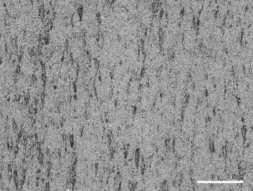
表1中の各成分は下記のとおり。また表中の質量部は、ゴムの総量100質量部あたりの質量部である。
イオン塩:カリウム・ビス(トリフルオロメタンスルホニル)イミド〔三菱マテリアル電子化成(株)製のEF−N112、K−TFSI〕
架橋促進助剤:酸化亜鉛2種〔堺化学工業(株)製〕
受酸剤:ハイドロタルサイト類〔協和化学工業(株)製のDHT−4A(登録商標)−2〕
充填剤:導電性カーボンブラック〔電気化学工業(株)製のデンカブラック(登録商標)、アセチレンブラック、粒状〕
加工助剤:ステアリン酸亜鉛〔堺化学工業(株)製のSZ−2000〕
老化防止剤:ジブチルジチオカルバミン酸ニッケル〔大内新興化学工業(株)製のノクラック(登録商標)NBC〕
次いで混練を続けながら、下記の架橋成分を配合してさらに混練してゴム組成物を調製した。
Each component in Table 1 is as follows. The parts by mass in the table are parts by mass per 100 parts by mass of the total amount of rubber.
Ionic salt: Potassium bis (trifluoromethanesulfonyl) imide [EF-N112, K-TFSI manufactured by Mitsubishi Materials Denshi Kasei Co., Ltd.]
Crosslinking accelerator:
Antacid: Hydrotalcites [DHT-4A (registered trademark) -2 manufactured by Kyowa Chemical Industry Co., Ltd.]
Filler: Conductive carbon black [Denka Black (registered trademark) manufactured by Denki Kagaku Kogyo Co., Ltd., acetylene black, granular]
Processing aid: Zinc stearate [SZ-2000 manufactured by Sakai Chemical Industry Co., Ltd.]
Anti-aging agent: Nickel dibutyldithiocarbamate [Nocrack (registered trademark) NBC manufactured by Ouchi Shinko Kagaku Kogyo Co., Ltd.]
Then, while continuing kneading, the following cross-linking components were blended and further kneaded to prepare a rubber composition.
表2中の各成分は下記のとおり。また表中の質量部は、ゴムの総量100質量部あたりの質量部である。
分散性硫黄:架橋剤〔鶴見化学工業(株)製の商品名サルファックスPS、硫黄分:99.5%〕
促進剤TS:テトラメチルチウラムモノスルフィド〔三新化学工業(株)製のサンセラー(登録商標)TS、チウラム系促進剤〕
促進剤DM:ジ−2−ベンゾチアゾリルジスルフィド〔大内新興化学工業(株)製のノクセラー(登録商標)DM、チアゾール系促進剤〕
チオウレア系架橋剤:エチレンチオウレア〔川口化学工業(株)製のアクセル(登録商標)22−S、2−メルカプトイミダゾリン〕
促進剤DT:1,3−ジ−o−トリルグアニジン〔三新化学工業(株)製のサンセラーDT、グアニジン系促進剤〕
(帯電ローラの製造)
調製したゴム組成物を、φ60の押出機に供給して、外径φ11.0mm、内径φ5.0mmの筒状に押出成形し、カットして架橋用の仮のシャフトに装着して加硫缶内で160℃×30分間架橋させた。
Each component in Table 2 is as follows. The parts by mass in the table are parts by mass per 100 parts by mass of the total amount of rubber.
Dispersible sulfur: Cross-linking agent [trade name Salfax PS manufactured by Tsurumi Chemical Industry Co., Ltd., sulfur content: 99.5%]
Accelerator TS: Tetramethylthiuram Monosulfide [Sunceller (registered trademark) TS manufactured by Sanshin Chemical Industry Co., Ltd., thiuram-based accelerator]
Accelerator DM: Di-2-benzothiazolyl disulfide [Noxeller (registered trademark) DM manufactured by Ouchi Shinko Kagaku Kogyo Co., Ltd., thiazole-based accelerator]
Thiourea-based cross-linking agent: Ethylene thiourea [Axel (registered trademark) 22-S, 2-mercaptoimidazoline manufactured by Kawaguchi Chemical Industry Co., Ltd.]
Accelerator DT: 1,3-di-o-tolylguanidine [Suncella DT manufactured by Sanshin Chemical Industry Co., Ltd., guanidine-based accelerator]
(Manufacturing of charging rollers)
The prepared rubber composition is supplied to a φ60 extruder, extruded into a tubular shape having an outer diameter of φ11.0 mm and an inner diameter of φ5.0 mm, cut, mounted on a temporary shaft for cross-linking, and vulcanized can. It was crosslinked in 160 ° C. for 30 minutes.
次いで、架橋させた筒状体を、外周面に導電性の熱硬化性接着剤(ポリアミド系)を塗布した外径φ6mmの金属シャフトに装着し直して、オーブン中で150℃×60分間加熱して当該金属シャフトに接着させ、次いで両端を整形したのち、外周面を、広幅研磨機を用いて外径がφ9.5mmになるまで乾式研磨した。
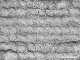
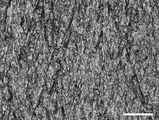
次に、研磨後の外周面をアルコール拭きしたのち、レーザー加工機〔(株)アマダミヤチ製のファイバーレーザー加工機ML−7320DL〕を用いてレーザー加工して、図2に示す、表面うねり成分を構成する低周波数の凹凸を形成した。レーザー加工時のレーザーの、照射位置の移動のピッチは40μm、隣り合う照射位置の重なり度合いは20%とし、それに合わせて出力を調整した。
Next, the crosslinked tubular body is reattached to a metal shaft having an outer diameter of φ6 mm coated with a conductive thermosetting adhesive (polyamide type) on the outer peripheral surface, and heated in an oven at 150 ° C. for 60 minutes. After adhering to the metal shaft and then shaping both ends, the outer peripheral surface was dry-polished using a wide polishing machine until the outer diameter became φ9.5 mm.
Next, after the outer peripheral surface after polishing is wiped with alcohol, laser processing is performed using a laser processing machine [fiber laser processing machine ML-7320DL manufactured by Amada Miyachi Corporation] to form the surface waviness component shown in FIG. The low frequency unevenness was formed. The pitch of movement of the irradiation position of the laser during laser processing was 40 μm, the degree of overlap of adjacent irradiation positions was 20%, and the output was adjusted accordingly.
そして、レーザー加工後の外周面を再びアルコール拭きしたのち、UV光源から外周面までの距離を50mmとしてUV処理装置にセットし、300rpmで回転させながら紫外線を15分間照射することで酸化膜を形成して帯電ローラを製造した。
製造した帯電ローラの、ローラ本体の外周面の、表面粗さ成分の空隙容積Vvは0.20ml/m2(○)、表面うねり成分の空隙容積Vvは1.90ml/m2(○)であった。また表面うねり成分を構成する凹凸の、凹部の深さ(平均値)は6μm、算術平均高さSaは1.3μmであった。
Then, after the outer peripheral surface after laser processing is wiped with alcohol again, the distance from the UV light source to the outer peripheral surface is set to 50 mm, set in a UV processing device, and an oxide film is formed by irradiating with ultraviolet rays for 15 minutes while rotating at 300 rpm. The charging roller was manufactured.
The void volume Vv of the surface roughness component of the manufactured charging roller on the outer peripheral surface of the roller body is 0.20 ml / m 2 (○), and the void volume Vv of the surface waviness component is 1.90 ml / m 2 (○). there were. The depth (average value) of the concave and convex portions constituting the surface waviness component was 6 μm, and the arithmetic average height Sa was 1.3 μm.
〈実施例2〉
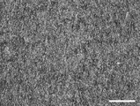
レーザー加工時のレーザーの、照射位置の移動のピッチを60μm、隣り合う照射位置の重なり度合いを30%とし、それに合わせて出力を調整したこと以外は実施例1と同様にして、帯電ローラを製造した。レーザー加工後の外周面を図3に示す。
製造した帯電ローラの、ローラ本体の外周面の、表面粗さ成分の空隙容積Vvは0.20ml/m2(○)、表面うねり成分の空隙容積Vvは4.00ml/m2(○)であった。また表面うねり成分を構成する凹凸の、凹部の深さ(平均値)は9μm、算術平均高さSaは2.7μmであった。
<Example 2>
A charging roller is manufactured in the same manner as in Example 1 except that the pitch of movement of the irradiation position of the laser during laser processing is 60 μm, the degree of overlap of adjacent irradiation positions is 30%, and the output is adjusted accordingly. did. The outer peripheral surface after laser processing is shown in FIG.
The void volume Vv of the surface roughness component of the manufactured charging roller on the outer peripheral surface of the roller body is 0.20 ml / m 2 (○), and the void volume Vv of the surface waviness component is 4.00 ml / m 2 (○). there were. The depth (average value) of the concave and convex portions constituting the surface waviness component was 9 μm, and the arithmetic average height Sa was 2.7 μm.
〈実施例3〉
実施例1と同じゴム組成物を用い、実施例1と同じ工程を経て、金属シャフトに接着させて両端を整形した筒状体の外周面を、円筒研磨機を用いて乾式トラバース研磨し、次いで仕上げ研磨として#1000のラッピングフィルム〔三共理化学(株)製のミラーフィルム(登録商標)〕を用いた鏡面研磨をして、外径をφ9.5mm(公差0.05)に仕上げた。
<Example 3>
Using the same rubber composition as in Example 1, through the same steps as in Example 1, the outer peripheral surface of a tubular body bonded to a metal shaft and shaped at both ends is dry traverse-polished using a cylindrical grinding machine, and then dry traverse polishing is performed. As finish polishing, mirror polishing was performed using a # 1000 wrapping film [mirror film (registered trademark) manufactured by Sankyo Rikagaku Co., Ltd.] to finish the outer diameter to φ9.5 mm (tolerance 0.05).
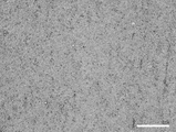
次に、研磨後の外周面をアルコール拭きしたのち、その外周面を、ウェットブラスト装置〔マコー(株)製〕を用いて湿式ブラスト加工した。研磨材の微細粒子としては、(株)不二製作所製のフジランダムA〔褐色溶融アルミナ、新モース硬度:12、平均粒子径:6.7±0.6μm、粒番号2000〕を用いた。また、湿式ブラスト加工の条件は、微細粒子の吹き付けの圧力を0.3MPa、時間を7.5分間とした。ブラスト加工後の外周面を図4に示す。 Next, the outer peripheral surface after polishing was wiped with alcohol, and then the outer peripheral surface was wet-blasted using a wet blasting device [manufactured by Macau Co., Ltd.]. As the fine particles of the abrasive, Fujirandom A [brown molten alumina, new Mohs hardness: 12, average particle diameter: 6.7 ± 0.6 μm, grain number 2000] manufactured by Fuji Seisakusho Co., Ltd. was used. The conditions for wet blasting were a pressure of spraying fine particles of 0.3 MPa and a time of 7.5 minutes. The outer peripheral surface after blasting is shown in FIG.
そして、湿式ブラスト加工後の外周面を再びアルコール拭きしたのち、UV光源から外周面までの距離を50mmとしてUV処理装置にセットし、300rpmで回転させながら紫外線を15分間照射することで酸化膜を形成して帯電ローラを製造した。
製造した帯電ローラの、ローラ本体の外周面の、表面粗さ成分の空隙容積Vvは0.22ml/m2(○)、表面うねり成分の空隙容積Vvは0.28ml/m2(○)であった。また表面うねり成分を構成する凹凸の算術平均高さSaは0.2μmであった。
Then, after the outer peripheral surface after the wet blasting process is wiped with alcohol again, the distance from the UV light source to the outer peripheral surface is set to 50 mm, set in the UV processing device, and the oxide film is irradiated with ultraviolet rays for 15 minutes while rotating at 300 rpm. It was formed to manufacture a charged roller.
The void volume Vv of the surface roughness component of the manufactured charging roller on the outer peripheral surface of the roller body is 0.22 ml / m 2 (○), and the void volume Vv of the surface waviness component is 0.28 ml / m 2 (○). there were. The arithmetic mean height Sa of the unevenness constituting the surface waviness component was 0.2 μm.
〈実施例4〉
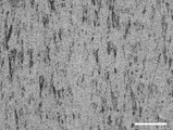
湿式ブラスト加工における、微細粒子の吹き付けの時間を12分間としたこと以外は実施例3と同様にして、帯電ローラを製造した。ブラスト加工後の外周面を図5に示す。
製造した帯電ローラの、ローラ本体の外周面の、表面粗さ成分の空隙容積Vvは0.09ml/m2(○)、表面うねり成分の空隙容積Vvは0.08ml/m2(○)であった。また表面うねり成分を構成する凹凸の算術平均高さSaは0.15μmであった。
<Example 4>
A charged roller was manufactured in the same manner as in Example 3 except that the time for spraying the fine particles in the wet blasting process was 12 minutes. The outer peripheral surface after blasting is shown in FIG.
The void volume Vv of the surface roughness component of the manufactured charging roller on the outer peripheral surface of the roller body is 0.09 ml / m 2 (○), and the void volume Vv of the surface waviness component is 0.08 ml / m 2 (○). there were. The arithmetic mean height Sa of the unevenness constituting the surface waviness component was 0.15 μm.
〈実施例5〉
湿式ブラスト加工における、微細粒子の吹き付けの時間を3分間としたこと以外は実施例3と同様にして、帯電ローラを製造した。ブラスト加工後の外周面を図6に示す。
製造した帯電ローラの、ローラ本体の外周面の、表面粗さ成分の空隙容積Vvは0.26ml/m2(○)、表面うねり成分の空隙容積Vvは0.37ml/m2(○)であった。また表面うねり成分を構成する凹凸の算術平均高さSaは0.35μmであった。
<Example 5>
A charged roller was manufactured in the same manner as in Example 3 except that the time for spraying the fine particles in the wet blasting process was 3 minutes. The outer peripheral surface after blasting is shown in FIG.
The void volume Vv of the surface roughness component of the manufactured charging roller on the outer peripheral surface of the roller body is 0.26 ml / m 2 (○), and the void volume Vv of the surface waviness component is 0.37 ml / m 2 (○). there were. The arithmetic mean height Sa of the unevenness constituting the surface waviness component was 0.35 μm.
〈実施例6〉
実施例1と同じゴム組成物を用い、実施例1と同じ工程を経て、金属シャフトに接着させて両端を整形した筒状体の外周面を、円筒研磨機を用いて乾式トラバース研磨し、次いで仕上げ研磨として#400のラッピングフィルム〔三共理化学(株)製のミラーフィルム〕を用いた鏡面研磨をして、外径をφ9.5mmに仕上げた。
<Example 6>
Using the same rubber composition as in Example 1, through the same steps as in Example 1, the outer peripheral surface of a tubular body bonded to a metal shaft and shaped at both ends was dry traverse-polished using a cylindrical polishing machine, and then dry traverse polishing was performed. As finish polishing, mirror polishing was performed using a # 400 wrapping film [mirror film manufactured by Sankyo Rikagaku Co., Ltd.] to finish the outer diameter to φ9.5 mm.
次に、研磨後の外周面をアルコール拭きしたのち、その外周面を、エアブラストマシン〔厚地鉄工(株)製〕を用いて乾式ブラスト加工した。研磨材の微細粒子としては、(株)不二製作所製のフジランダムA〔褐色溶融アルミナ、新モース硬度:12、平均粒子径:40.0±2.5μm、粒番号320〕を用いた。また、湿式ブラスト加工の条件は、微細粒子の吹き付けの圧力を0.6MPa、時間を3分間とした。ブラスト加工後の外周面を図7に示す。 Next, after the outer peripheral surface after polishing was wiped with alcohol, the outer peripheral surface was dry-blasted using an air blasting machine [manufactured by Atsushi Iron Works Co., Ltd.]. As the fine particles of the abrasive, Fujirandom A [brown molten alumina, new Mohs hardness: 12, average particle size: 40.0 ± 2.5 μm, grain number 320] manufactured by Fuji Seisakusho Co., Ltd. was used. The conditions for wet blasting were a pressure of spraying fine particles of 0.6 MPa and a time of 3 minutes. The outer peripheral surface after blasting is shown in FIG.
そして、乾式ブラスト加工後の外周面を再びアルコール拭きしたのち、UV光源から外周面までの距離を50mmとしてUV処理装置にセットし、300rpmで回転させながら紫外線を15分間照射することで酸化膜を形成して帯電ローラを製造した。
製造した帯電ローラの、ローラ本体の外周面の、表面粗さ成分の空隙容積Vvは0.28ml/m2(○)、表面うねり成分の空隙容積Vvは0.37ml/m2(○)であった。また表面うねり成分を構成する凹凸の算術平均高さSaは0.4μmであった。
Then, after the outer peripheral surface after the dry blasting process is wiped with alcohol again, the distance from the UV light source to the outer peripheral surface is set to 50 mm, set in the UV processing device, and the oxide film is irradiated with ultraviolet rays for 15 minutes while rotating at 300 rpm. It was formed to manufacture a charged roller.
The void volume Vv of the surface roughness component of the manufactured charging roller on the outer peripheral surface of the roller body is 0.28 ml / m 2 (○), and the void volume Vv of the surface waviness component is 0.37 ml / m 2 (○). there were. The arithmetic mean height Sa of the unevenness constituting the surface waviness component was 0.4 μm.
〈比較例1〉
レーザー加工時のレーザーの、照射位置の移動のピッチを80μm、隣り合う照射位置の重なり度合いを30%とし、それに合わせて出力を調整したこと以外は実施例1と同様にして、帯電ローラを製造した。レーザー加工後の外周面を図8に示す。
製造した帯電ローラの、ローラ本体の外周面の、表面粗さ成分の空隙容積Vvは0.20ml/m2(○)、表面うねり成分の空隙容積Vvは7.10ml/m2(×)であった。また表面うねり成分を構成する凹凸の、凹部の深さ(平均値)は15μm、算術平均高さSaは3.6μmであった。
<Comparative example 1>
A charging roller is manufactured in the same manner as in Example 1 except that the pitch of movement of the irradiation position of the laser during laser processing is 80 μm, the degree of overlap of adjacent irradiation positions is 30%, and the output is adjusted accordingly. did. The outer peripheral surface after laser processing is shown in FIG.
The void volume Vv of the surface roughness component of the manufactured charging roller on the outer peripheral surface of the roller body is 0.20 ml / m 2 (○), and the void volume Vv of the surface waviness component is 7.10 ml / m 2 (×). there were. The depth (average value) of the concave and convex portions constituting the surface waviness component was 15 μm, and the arithmetic average height Sa was 3.6 μm.
〈比較例2〉
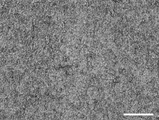
研磨後の外周面をレーザー加工もブラスト加工もせず、直ちに仕上げ研磨として#400のラッピングフィルム〔三共理化学(株)製のミラーフィルム〕を用いた鏡面研磨をしてアルコール拭きしたのち、紫外線を照射して酸化膜を形成したこと以外は実施例1と同様にして、外周面が図9に示す状態の帯電ローラを製造した。
<Comparative example 2>
The outer peripheral surface after polishing is not laser-processed or blasted, and is immediately mirror-polished using a # 400 wrapping film [mirror film manufactured by Sankyo Rikagaku Co., Ltd.], wiped with alcohol, and then irradiated with ultraviolet rays. A charging roller having an outer peripheral surface shown in FIG. 9 was manufactured in the same manner as in Example 1 except that an oxide film was formed.
製造した帯電ローラの、ローラ本体の外周面の、表面粗さ成分の空隙容積Vvは1.19ml/m2(×)、表面うねり成分の空隙容積Vvは1.37ml/m2(○)であった。また算術平均高さSaは2.2μmであった。
〈比較例3〉
研磨後の外周面をレーザー加工もブラスト加工もせず、直ちに仕上げ研磨として#1000のラッピングフィルム〔三共理化学(株)製のミラーフィルム〕を用いた鏡面研磨をしてアルコール拭きしたのち、紫外線を照射して酸化膜を形成したこと以外は実施例1と同様にして、外周面が図10に示す状態の帯電ローラを製造した。
The void volume Vv of the surface roughness component of the manufactured charging roller on the outer peripheral surface of the roller body is 1.19 ml / m 2 (×), and the void volume Vv of the surface waviness component is 1.37 ml / m 2 (○). there were. The arithmetic mean height Sa was 2.2 μm.
<Comparative example 3>
The outer peripheral surface after polishing is not laser-processed or blasted, and is immediately mirror-polished using a # 1000 wrapping film [mirror film manufactured by Sankyo Rikagaku Co., Ltd.], wiped with alcohol, and then irradiated with ultraviolet rays. A charging roller having an outer peripheral surface shown in FIG. 10 was manufactured in the same manner as in Example 1 except that an oxide film was formed.
製造した帯電ローラの、ローラ本体の外周面の、表面粗さ成分の空隙容積Vvは0.68ml/m2(×)、表面うねり成分の空隙容積Vvは0.38ml/m2(○)であった。また算術平均高さSaは0.9μmであった。
〈比較例4〉
研磨後の外周面をレーザー加工もブラスト加工もせずにアルコール拭きしたのち、紫外線を照射して酸化膜を形成したこと以外は実施例1と同様にして、外周面が図11に示す状態の帯電ローラを製造した。
The void volume Vv of the surface roughness component of the manufactured charging roller on the outer peripheral surface of the roller body is 0.68 ml / m 2 (×), and the void volume Vv of the surface waviness component is 0.38 ml / m 2 (○). there were. The arithmetic mean height Sa was 0.9 μm.
<Comparative Example 4>
The outer peripheral surface after polishing was wiped with alcohol without laser processing or blasting, and then the outer peripheral surface was charged in the state shown in FIG. 11 in the same manner as in Example 1 except that an oxide film was formed by irradiating with ultraviolet rays. Manufactured rollers.
製造した帯電ローラの、ローラ本体の外周面の、表面粗さ成分の空隙容積Vvは0.30ml/m2(×)、表面うねり成分の空隙容積Vvは0.10ml/m2(○)であった。また算術平均高さSaは0.2μmであった。
〈実機試験〉
感光体と、当該感光体の表面に常時接触させて配設された帯電ローラとを備え、レーザープリンタ本体に着脱自在とされたフォトコンダクタユニット〔レックスマーク インターナショナル社製〕の、純正の帯電ローラに代えて、実施例、比較例で製造した帯電ローラを組み込んだ。
The void volume Vv of the surface roughness component of the manufactured charged roller on the outer peripheral surface of the roller body is 0.30 ml / m 2 (×), and the void volume Vv of the surface waviness component is 0.10 ml / m 2 (○). there were. The arithmetic mean height Sa was 0.2 μm.
<Actual machine test>
A genuine charging roller of a photoconductor unit [manufactured by Lexmark International] that has a photoconductor and a charging roller that is arranged in constant contact with the surface of the photoconductor and is removable from the laser printer body. Instead, the charging rollers manufactured in Examples and Comparative Examples were incorporated.
そして組み立てたフォトコンダクタユニットを、カラーレーザープリンタ〔レックスマーク インターナショナル社製のカラーレーザープリンタCS510de〕に装填して、30%濃度、300lpiの画像を、2枚/25秒間の速度で30000枚に亘って連続形成し、形成した30000枚の画像に、1枚でも帯電の不均一による画像不良が生じたものを「×」、全く生じなかったものを「○」と評価した。 Then, the assembled photoconductor unit was loaded into a color laser printer [color laser printer CS510de manufactured by Lexmark International Co., Ltd.], and 30% density, 300 lpi images were printed over 30,000 images at a speed of 2 images / 25 seconds. Of the 30,000 images that were continuously formed, those in which image defects due to non-uniform charging occurred were evaluated as "x", and those in which no image defects occurred were evaluated as "◯".
また連続画像形成後に帯電ローラを取り出し、外周面を目視によって観察して、微粉の付着によって著しい白化が生じていたものを「×」、白化が見られたものの「×」より僅かであったものを「△」、白化が生じていなかったものを「○」と評価した。
以上の結果を表3、表4に示す。
In addition, after the continuous image formation, the charging roller was taken out, and the outer peripheral surface was visually observed. Those in which significant whitening was caused by the adhesion of fine powder were marked with "x", and those with whitening were slightly less than "x". Was evaluated as "△", and those without whitening were evaluated as "○".
The above results are shown in Tables 3 and 4.
表3、表4の実施例1〜6、比較例1〜5の結果より、ローラ本体の外周面の空隙容積Vvを、表面粗さ成分において0.3ml/m2未満で、かつ表面うねり成分において0.05ml/m2以上、6ml/m2以下とすることにより、コーティング膜を省略した簡単な構造を維持しながら、なおかつ感光体の表面をできるだけ均一に帯電して画像不良を生じにくい上、微粉の付着や蓄積を良好に抑制できる帯電ローラが得られることが判った。 From the results of Examples 1 to 6 and Comparative Examples 1 to 5 in Tables 3 and 4, the void volume Vv of the outer peripheral surface of the roller body is less than 0.3 ml / m 2 in terms of surface roughness component, and the surface waviness component. By setting the volume to 0.05 ml / m 2 or more and 6 ml / m 2 or less, the surface of the photoconductor is charged as uniformly as possible while maintaining a simple structure in which the coating film is omitted, and image defects are less likely to occur. It was found that a charging roller capable of satisfactorily suppressing the adhesion and accumulation of fine powder can be obtained.
また実施例1〜6の結果より、上記の効果をより一層向上することを考慮すると、表面粗さ成分の空隙容積Vvは、上記の範囲でも0.1ml/m2以上とするのが好ましく、0.28ml/m2以下とするのが好ましいこと、表面うねり成分の空隙容積Vvは、上記の範囲でも0.1ml/m2以上とするのが好ましく、4ml/m2以下とするのが好ましいことが判った。 Further, from the results of Examples 1 to 6, considering that the above effect is further improved, the void volume Vv of the surface roughness component is preferably 0.1 ml / m 2 or more even in the above range. It is preferable that it is 0.28 ml / m 2 or less, and the void volume Vv of the surface waviness component is preferably 0.1 ml / m 2 or more even in the above range, and is preferably 4 ml / m 2 or less. It turned out.
1 帯電ローラ
2 ローラ本体
3 通孔
4 シャフト
5 外周面
6 酸化膜
1 Charging
Claims (4)
Priority Applications (2)
| Application Number | Priority Date | Filing Date | Title |
|---|---|---|---|
| CN201711420161.6A CN108345195B (en) | 2017-01-23 | 2017-12-25 | Charging roller and method for manufacturing same |
| US15/855,222 US10067439B2 (en) | 2017-01-23 | 2017-12-27 | Charging roller, and method of producing the same |
Applications Claiming Priority (2)
| Application Number | Priority Date | Filing Date | Title |
|---|---|---|---|
| JP2017009486 | 2017-01-23 | ||
| JP2017009486 | 2017-01-23 |
Publications (2)
| Publication Number | Publication Date |
|---|---|
| JP2018120198A JP2018120198A (en) | 2018-08-02 |
| JP6889832B2 true JP6889832B2 (en) | 2021-06-18 |
Family
ID=63044405
Family Applications (1)
| Application Number | Title | Priority Date | Filing Date |
|---|---|---|---|
| JP2017076825A Active JP6889832B2 (en) | 2017-01-23 | 2017-04-07 | Charging roller and its manufacturing method |
Country Status (1)
| Country | Link |
|---|---|
| JP (1) | JP6889832B2 (en) |
Families Citing this family (5)
| Publication number | Priority date | Publication date | Assignee | Title |
|---|---|---|---|---|
| JP6913280B2 (en) * | 2017-04-07 | 2021-08-04 | 住友ゴム工業株式会社 | Develop roller and its manufacturing method |
| WO2020158921A1 (en) * | 2019-02-01 | 2020-08-06 | 大日本印刷株式会社 | Decorative material |
| JP7415244B2 (en) * | 2019-12-04 | 2024-01-17 | 住友ゴム工業株式会社 | Developing roller and its manufacturing method |
| JP7621041B2 (en) * | 2021-02-19 | 2025-01-24 | 住友理工株式会社 | Electrophotographic charging rolls |
| JP7011139B1 (en) | 2021-05-20 | 2022-01-26 | 株式会社オカノブラスト | Roughening method of member and roughened member |
Family Cites Families (11)
| Publication number | Priority date | Publication date | Assignee | Title |
|---|---|---|---|---|
| JPH0844141A (en) * | 1994-07-29 | 1996-02-16 | Ricoh Co Ltd | Electrifying member |
| JPH1173006A (en) * | 1997-08-29 | 1999-03-16 | Shin Etsu Polymer Co Ltd | Semiconductive roll and developing device using thereof |
| JP2001317539A (en) * | 2000-05-02 | 2001-11-16 | Shin Etsu Polymer Co Ltd | Highly precise roller and image forming device having it |
| JP4341640B2 (en) * | 2006-05-18 | 2009-10-07 | 東海ゴム工業株式会社 | Conductive roll for electrophotographic equipment and method for producing the same |
| JP2008116869A (en) * | 2006-11-08 | 2008-05-22 | Tokai Rubber Ind Ltd | Process for producing conductive roll and conductive roll obtained thereby |
| JP2008233442A (en) * | 2007-03-20 | 2008-10-02 | Tokai Rubber Ind Ltd | Charging roll |
| US8038591B2 (en) * | 2007-03-27 | 2011-10-18 | Lexmark International, Inc. | Image forming apparatus component with triboelectric properties |
| JP6418695B2 (en) * | 2015-04-06 | 2018-11-07 | 住友ゴム工業株式会社 | Semi-conductive roller |
| JP6769063B2 (en) * | 2016-03-22 | 2020-10-14 | 富士ゼロックス株式会社 | Charging member, charging device, process cartridge, and image forming device |
| JP6769062B2 (en) * | 2016-03-22 | 2020-10-14 | 富士ゼロックス株式会社 | Charging member, charging device, process cartridge, and image forming device |
| JP6701854B2 (en) * | 2016-03-22 | 2020-05-27 | 富士ゼロックス株式会社 | Charging member, charging device, process cartridge, and image forming apparatus |
-
2017
- 2017-04-07 JP JP2017076825A patent/JP6889832B2/en active Active
Also Published As
| Publication number | Publication date |
|---|---|
| JP2018120198A (en) | 2018-08-02 |
Similar Documents
| Publication | Publication Date | Title |
|---|---|---|
| JP6913280B2 (en) | Develop roller and its manufacturing method | |
| JP6889832B2 (en) | Charging roller and its manufacturing method | |
| JP6109117B2 (en) | Semiconductive roller and method for manufacturing the same | |
| CN108345195B (en) | Charging roller and method for manufacturing same | |
| JP6799776B2 (en) | Charging roller and its manufacturing method | |
| JP6323955B2 (en) | Semi-conductive roller | |
| JP2016197218A (en) | Semi-conductive roller | |
| JP2019183002A (en) | Semi-conductive roller and manufacturing method therefor | |
| JP7079412B2 (en) | Develop roller | |
| JP6913282B2 (en) | Semi-conductive roller | |
| JP6172846B2 (en) | Semiconductive roller and image forming apparatus | |
| JP2021026035A (en) | Developing roller and manufacturing method thereof | |
| JP7075590B2 (en) | Develop roller | |
| JP6909401B2 (en) | Charging roller and its manufacturing method | |
| JP7011769B2 (en) | Semi-conductive roller and its manufacturing method | |
| JP2021026034A (en) | Developing roller and manufacturing method thereof | |
| JP7415244B2 (en) | Developing roller and its manufacturing method | |
| JP6802970B2 (en) | Semi-conductive roller and its manufacturing method | |
| US10712685B2 (en) | Developing roller and method of producing the same | |
| JP2021175997A (en) | Developing roller | |
| JP2021076744A (en) | Conductive roller and manufacturing method therefor | |
| JP6963722B2 (en) | Semi-conductive roller and its manufacturing method | |
| JP2020076942A (en) | Developing roller | |
| JP2021182118A (en) | Develop roller and its manufacturing method | |
| JP2021089344A (en) | Development roller |
Legal Events
| Date | Code | Title | Description |
|---|---|---|---|
| A621 | Written request for application examination |
Free format text: JAPANESE INTERMEDIATE CODE: A621 Effective date: 20200225 |
|
| A977 | Report on retrieval |
Free format text: JAPANESE INTERMEDIATE CODE: A971007 Effective date: 20201214 |
|
| A131 | Notification of reasons for refusal |
Free format text: JAPANESE INTERMEDIATE CODE: A131 Effective date: 20210105 |
|
| A521 | Request for written amendment filed |
Free format text: JAPANESE INTERMEDIATE CODE: A523 Effective date: 20210218 |
|
| TRDD | Decision of grant or rejection written | ||
| A01 | Written decision to grant a patent or to grant a registration (utility model) |
Free format text: JAPANESE INTERMEDIATE CODE: A01 Effective date: 20210422 |
|
| A61 | First payment of annual fees (during grant procedure) |
Free format text: JAPANESE INTERMEDIATE CODE: A61 Effective date: 20210505 |
|
| R150 | Certificate of patent or registration of utility model |
Ref document number: 6889832 Country of ref document: JP Free format text: JAPANESE INTERMEDIATE CODE: R150 |
|
| R250 | Receipt of annual fees |
Free format text: JAPANESE INTERMEDIATE CODE: R250 |
|
| R250 | Receipt of annual fees |
Free format text: JAPANESE INTERMEDIATE CODE: R250 |
|
| R250 | Receipt of annual fees |
Free format text: JAPANESE INTERMEDIATE CODE: R250 |