JP6889823B2 - Air hammer bit for crushing reinforced concrete structures - Google Patents
Air hammer bit for crushing reinforced concrete structures Download PDFInfo
- Publication number
- JP6889823B2 JP6889823B2 JP2019561223A JP2019561223A JP6889823B2 JP 6889823 B2 JP6889823 B2 JP 6889823B2 JP 2019561223 A JP2019561223 A JP 2019561223A JP 2019561223 A JP2019561223 A JP 2019561223A JP 6889823 B2 JP6889823 B2 JP 6889823B2
- Authority
- JP
- Japan
- Prior art keywords
- cutting block
- enlarged diameter
- bit
- diameter portion
- inclined surface
- Prior art date
- Legal status (The legal status is an assumption and is not a legal conclusion. Google has not performed a legal analysis and makes no representation as to the accuracy of the status listed.)
- Active
Links
Images
Classifications
-
- E—FIXED CONSTRUCTIONS
- E04—BUILDING
- E04G—SCAFFOLDING; FORMS; SHUTTERING; BUILDING IMPLEMENTS OR AIDS, OR THEIR USE; HANDLING BUILDING MATERIALS ON THE SITE; REPAIRING, BREAKING-UP OR OTHER WORK ON EXISTING BUILDINGS
- E04G23/00—Working measures on existing buildings
- E04G23/08—Wrecking of buildings
-
- B—PERFORMING OPERATIONS; TRANSPORTING
- B28—WORKING CEMENT, CLAY, OR STONE
- B28D—WORKING STONE OR STONE-LIKE MATERIALS
- B28D1/00—Working stone or stone-like materials, e.g. brick, concrete or glass, not provided for elsewhere; Machines, devices, tools therefor
- B28D1/14—Working stone or stone-like materials, e.g. brick, concrete or glass, not provided for elsewhere; Machines, devices, tools therefor by boring or drilling
- B28D1/146—Tools therefor
Landscapes
- Engineering & Computer Science (AREA)
- Architecture (AREA)
- Mechanical Engineering (AREA)
- Civil Engineering (AREA)
- Electrochemistry (AREA)
- Chemical Kinetics & Catalysis (AREA)
- Chemical & Material Sciences (AREA)
- Structural Engineering (AREA)
- Mining & Mineral Resources (AREA)
- Earth Drilling (AREA)
- Percussive Tools And Related Accessories (AREA)
- Working Measures On Existing Buildindgs (AREA)
- Polishing Bodies And Polishing Tools (AREA)
- Processing Of Stones Or Stones Resemblance Materials (AREA)
Description
本発明は鉄筋コンクリート構造物を破砕するために使われるエアーハンマービットに関し、破砕過程でコンクリート構造物に含まれた鉄筋を容易に切断できるカッティング機能が備えられたことを特徴とする。 The present invention relates to an air hammer bit used for crushing a reinforced concrete structure, and is characterized by having a cutting function capable of easily cutting the reinforcing bar contained in the concrete structure in the crushing process.
地盤の掘削に使われる地盤掘削機はモーターによって回転するスクリュー軸を利用して地盤を掘削し、地盤を掘削する途中で硬質の岩盤層にぶつかると前記のスクリュー軸だけでは掘削作業が不可能であるため、スクリュー軸の先端に別途の岩盤掘削用ビット(Bit)が備えられたエアーハンマードリルを設置し、これを利用して岩盤層を粉砕しながら掘削作業を進行することになる。 The ground excavator used for excavating the ground excavates the ground using a screw shaft rotated by a motor, and if it hits a hard rock layer during excavation of the ground, excavation work is not possible with the screw shaft alone. Therefore, an air hammer drill equipped with a separate rock excavation bit (Bit) is installed at the tip of the screw shaft, and the excavation work is carried out while crushing the rock layer using this.
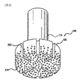
このような従来の岩盤掘削用ビット100は図1に図示された通り、ビット軸110とその下端部に形成される拡径部120で構成され、拡径部120の外周面には粉砕物を運搬する通路となる案内溝220が備えられ、拡径部の下部面および外周面には多数個の超硬チップ210が突出するように拡径部に挿入固定されている。
As shown in FIG. 1, such a conventional
超硬チップ210は岩盤層の粉砕時に岩盤層に直接的に衝突して接触する部位であって、十分な耐久性と強度を維持するために超硬合金が一般的に使われている。
The cemented
このような超硬チップ210が備えられた岩盤掘削用ビット100の場合、一般的な岩盤の掘削作業は効率的に遂行できるものの、既存の鉄筋コンクリート構造物の破砕(例えば、既存の構造物の床スラブの破砕)に使われる場合、既存の構造物のコンクリート層に配筋された鉄筋が破砕作業を妨害するため別途に鉄筋を切断する作業が共に進行されなければならない問題点があり、そのため作業遅延が招かれるとともに安全事故の発生危険が倍加する原因となっている。
In the case of the
前記した問題点を解決するために創作された本発明は、鉄筋コンクリート構造物の破砕時に、作業過程で構造物に含まれた鉄筋を共に切断して迅速かつ安全に破砕作業を遂行できる新しい構造のエアーハンマービットを提供することを目的とする。 The present invention, which was created to solve the above-mentioned problems, is a new structure capable of quickly and safely performing crushing work by cutting together the reinforcing bars contained in the structure during the work process when crushing the reinforced concrete structure. It is intended to provide an air hammer bit.
前記した目的を達成するために創作された本発明の技術的構成は次の通りである。 The technical configuration of the present invention created to achieve the above-mentioned object is as follows.
本発明は、空圧によって作動するエアーシリンダー、エアーシリンダーの内部で上下運動をするピストン、およびピストンと結合して上下振動と回転を通じて鉄筋コンクリート構造物を穿孔するエアーハンマーのビットに関し、ビットの胴体役割をするビット軸100;前記ビット軸100の下端部で直径が拡張されてなる拡径部200;前記拡径部200の表面に突出するように挿入される多数個の掘削用超硬チップ300;および、前記拡径部200に着脱可能に結合され、前記拡径部200の表面に突出してコンクリート構造物の破砕過程で鉄筋を切断するカッティングブロック400;を含んで構成されることを特徴とする。
The present invention relates to a pneumatically operated air cylinder, a piston that moves up and down inside the air cylinder, and a bit of an air hammer that combines with the piston to pierce a reinforced concrete structure through vertical vibration and rotation.
以下では、本発明の具体的な実施例を添付図面を参照してより詳細に説明する。 Hereinafter, specific examples of the present invention will be described in more detail with reference to the accompanying drawings.
本発明は、空圧によって作動するエアーシリンダー、エアーシリンダーの内部で上下運動をするピストン、およびピストンと結合して上下振動と回転を通じて鉄筋コンクリート構造物を破砕するエアーハンマーのビットに関する。 The present invention relates to an air cylinder operated by air pressure, a piston that moves up and down inside the air cylinder, and a bit of an air hammer that combines with the piston and crushes a reinforced concrete structure through vertical vibration and rotation.
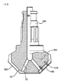
本発明は図2および図3に図示されたように、ビット軸100、拡径部200、超硬チップ300およびカッティングブロック400を含んで構成される。
As shown in FIGS. 2 and 3, the present invention includes a
ビット軸100はビットの胴体役割をし、ビット軸100の下端部には直径が拡張された拡径部200が備えられる。
The
このような拡径部200の下部の表面および外周面には破砕された粉砕物を運搬する案内溝22が備えられており、このような案内溝22はビット軸100と拡径部200の内部を貫通する空気通路11と連結された構造になって、空気通路11を通じて噴出する空気(Air)の力で粉砕物をより便利に外部に排出させることができる。
A
超硬チップ300は拡径部200の表面に多数個が突出するように挿入されるが、このような超硬チップ300は、一般的な掘削作業時に岩盤に直接的に衝突して接触する部位であって、強い耐久性と強度が要求されるため超硬合金で製作される。本発明では、このような超硬チップ300が鉄筋コンクリート構造物に直接的に衝突して接触しながらコンクリートを破砕することになる。
A large number of cemented
カッティングブロック400は拡径部200に着脱可能に結合されるが、カッティングブロック400の上端部は拡径部200の表面に突出してコンクリート構造物の破砕過程で鉄筋を切断する役割をする。
The
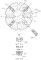
拡径部200の下部は、図2および図3に図示されたように、下部の中央に形成された中央平面210とこのような中央平面210の周囲を囲む傾斜面220で構成され、カッティングブロック400は傾斜面220に沿って放射状に4個が90度間隔で配列されるが、配列されるカッティングブロック400の数量は4個に限定されず、作業現場の条件を考慮して1個、2個、3個または4個以上が配列されてもよい。
As shown in FIGS. 2 and 3, the lower portion of the enlarged
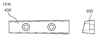
カッティングブロック400は、図3に図示された断面図(D−D’)または図4で確認できるように、拡径部200の傾斜面220の外側に露出する上端部から傾斜面220の内部に挿入された下端部に行くほど断面積が増加する断面を有する。
As can be confirmed in the cross-sectional view (DD') shown in FIG. 3 or FIG. 4, the
併せて、拡径部200の傾斜面220にはカッティングブロック400と対応する形態のカッティングブロック装着溝230が備えられるが、カッティングブロック400がカッティングブロック装着溝230に装着された状態で、カッティングブロック400の上端部は拡径部200が回転する方向の前端が後端よりも高いため拡径部200の傾斜面220の外側に突出する構造となり、破砕過程で鉄筋を切断するカッティングブレードの役割をする。
At the same time, the
また、カッティングブロック装着溝230は、図4に図示されたように、 拡径部200の傾斜面220の上部から中央平面210と会う下部に行くほど左右の幅が次第に減少する形態にテーパー加工され、カッティングブロック400もこのようなカッティングブロック装着溝230と対応するように、図4に図示されたように拡径部200の中央平面210に行くほど左右の幅が次第に減少するようにテーパー加工される。
Further, as shown in FIG. 4, the cutting
このようにカッティングブロック400とカッティングブロック装着溝230がテーパー加工されると、カッティングブロック400をカッティングブロック装着溝230の上部から下部に押し込んで装着する作業を容易に遂行することができ、カッティングブロック400がカッティングブロック装着溝230の内面に密着しながらカッティングブロック400が安定的に装着され得るため、カッティングブロック400の耐久性が向上する。
When the
このようなカッティングブロック400は、図2または図3に図示されたように、カッティングブロック装着溝230にスライディング方式で挿入された状態で、カッティングブロック400を貫通してカッティングブロック装着溝230の底面に締結される固定ボルト410によって固定されるが、カッティングブロック400には固定ボルト410が通過する通過孔の直径が固定ボルト410の直径よりも余裕があるように加工されて製作および組立公差を吸収できるようにする。
As shown in FIG. 2 or 3, such a
前記した通り、本発明の具体的な実施例を添付図面を参照して説明したが、本発明の保護範囲はこのような実施例に限定されず、本発明の技術的な要旨を変更しない範囲内で、多様な設計変更、公知技術の付加や削除、単純な数値限定などの場合も本発明の保護範囲に属することを明確にする。 As described above, specific examples of the present invention have been described with reference to the accompanying drawings, but the scope of protection of the present invention is not limited to such examples and does not change the technical gist of the present invention. Within, it is clarified that various design changes, addition or deletion of known technology, simple numerical limitation, etc. also belong to the protection scope of the present invention.
本発明の構成による技術的効果は次の通りである。 The technical effects of the configuration of the present invention are as follows.
第1、カッティングブロック400が備えられることにより、鉄筋コンクリート構造物の破砕時に鉄筋を共に切断して破砕作業の効率を最大化させることができる。
First, by providing the
第2、カッティングブロック400の損傷時に、該当部品のみをスライディング方式で容易に取り替えて使うことができる。
Second, when the
第3、カッティングブロック400とこれに対応するカッティングブロック装着溝230の形態をテーパー加工することによってカッティングブロック400の装着作業の便宜性を向上させると共に、カッティングブロック400がカッティングブロック装着溝230の内面に完全に密着させることによってカッティングブロック400と拡径部200の耐久性を向上させることができる。
Third, by tapering the shape of the
下記の符号は図1を除いた本発明に関する図面である図2〜図4にのみ適用される。
100:ビット軸
200:拡径部
210:中央平面
220:傾斜面
230:カッティングブロック装着溝
300:超硬チップ
400:カッティングブロック
410:固定ボルト
11:空気通路
22:案内溝
The following reference numerals apply only to FIGS. 2 to 4, which are drawings relating to the present invention except for FIG. 1.
100: Bit shaft 200: Expanded diameter 210: Central plane 220: Inclined surface 230: Cutting block mounting groove 300: Carbide tip 400: Cutting block 410: Fixing bolt 11: Air passage 22: Guide groove
Claims (3)
ビットの胴体役割をするビット軸(100);
前記ビット軸(100)の下端部で直径が拡張されてなる拡径部(200);
前記拡径部(200)の表面に突出するように挿入される多数個の掘削用超硬チップ(300);および、
前記拡径部(200)に着脱可能に結合され、前記拡径部(200)の表面に突出してコンクリート構造物の破砕過程で鉄筋を切断するカッティングブロック(400);を含んで構成され、
前記拡径部(200)の下部は、
中央平面(210)と前記中央平面(210)の周囲を囲む傾斜面(220)で構成され、
前記カッティングブロック(400)は前記傾斜面(220)に沿って放射状に多数配列され、
前記カッティングブロック(400)は、
前記拡径部(200)の傾斜面(220)の外側に露出する上端部から下端部に行くほど断面積が増加し、
前記拡径部(200)の傾斜面(220)には前記カッティングブロック(400)と対応する形態のカッティングブロック装着溝(230)が備えられ、
前記カッティングブロック(400)の上端部は、前記拡径部(200)が回転する方向の前端が後端よりも高いため拡径部(200)の傾斜面(220)の外側に突出する構造であることを特徴とする、鉄筋コンクリート構造物破砕用エアーハンマービット。 It relates to a pneumatically operated air cylinder, a piston that moves up and down inside the air cylinder, and a bit of an air hammer that combines with the piston to crush reinforced concrete structures through vertical vibration and rotation.
Bit axis (100) that acts as the body of the bit;
A diameter-expanded portion (200) whose diameter is expanded at the lower end of the bit shaft (100);
A large number of cemented carbide tips (300) for excavation inserted so as to project onto the surface of the enlarged diameter portion (200);
It is configured to include a cutting block (400); which is detachably connected to the diameter-expanded portion (200), projects to the surface of the diameter-expanded portion (200), and cuts a reinforcing bar in the process of crushing a concrete structure .
The lower part of the enlarged diameter portion (200) is
It is composed of a central plane (210) and an inclined surface (220) surrounding the central plane (210).
A large number of the cutting blocks (400) are arranged radially along the inclined surface (220).
The cutting block (400) is
The cross-sectional area increases from the upper end portion exposed to the outside of the inclined surface (220) of the enlarged diameter portion (200) to the lower end portion.
The inclined surface (220) of the enlarged diameter portion (200) is provided with a cutting block mounting groove (230) having a form corresponding to the cutting block (400).
The upper end of the cutting block (400) has a structure that projects outward from the inclined surface (220) of the enlarged diameter portion (200) because the front end in the direction in which the enlarged diameter portion (200) rotates is higher than the rear end. characterized that, air hammer bit for reinforced concrete structures crushing that there.
前記拡径部(200)の傾斜面(220)の上部から中央平面(210)と会う下部に行くほど左右の幅が次第に減少する形態であり、
前記カッティングブロック(400)も前記カッティングブロック装着溝(230)と対応するように前記拡径部(200)の中央平面(210)に行くほど左右の幅が次第に減少する形態であることを特徴とする、請求項1に記載の鉄筋コンクリート構造物破砕用エアーハンマービット。 The cutting block mounting groove (230) is
The width on the left and right gradually decreases from the upper part of the inclined surface (220) of the enlarged diameter portion (200) to the lower part where it meets the central plane (210).
The cutting block (400) is also characterized in that the left and right widths gradually decrease toward the central plane (210) of the enlarged diameter portion (200) so as to correspond to the cutting block mounting groove (230). The air hammer bit for crushing a reinforced concrete structure according to claim 1.
前記カッティングブロック装着溝(230)にスライディング方式で挿入された状態で前記カッティングブロック(400)を貫通して前記カッティングブロック装着溝(230)の底面に締結される固定ボルト(410);によって固定されることを特徴とする、請求項1または請求項2に記載の鉄筋コンクリート構造物破砕用エアーハンマービット。 The cutting block (400) is
It is fixed by a fixing bolt (410); which penetrates the cutting block (400) and is fastened to the bottom surface of the cutting block mounting groove (230) while being inserted into the cutting block mounting groove (230) by a sliding method. The air hammer bit for crushing a reinforced concrete structure according to claim 1 or 2, wherein the air hammer bit is characterized in that.
Applications Claiming Priority (3)
| Application Number | Priority Date | Filing Date | Title |
|---|---|---|---|
| KR1020170058732A KR102011791B1 (en) | 2017-05-11 | 2017-05-11 | Air Hammer Bit for Crushing Reinforced Concrete Construction |
| KR10-2017-0058732 | 2017-05-11 | ||
| PCT/KR2018/003525 WO2018208008A1 (en) | 2017-05-11 | 2018-03-26 | Air hammer bit for crushing reinforced concrete structure |
Publications (2)
| Publication Number | Publication Date |
|---|---|
| JP2020521895A JP2020521895A (en) | 2020-07-27 |
| JP6889823B2 true JP6889823B2 (en) | 2021-06-18 |
Family
ID=64105611
Family Applications (1)
| Application Number | Title | Priority Date | Filing Date |
|---|---|---|---|
| JP2019561223A Active JP6889823B2 (en) | 2017-05-11 | 2018-03-26 | Air hammer bit for crushing reinforced concrete structures |
Country Status (4)
| Country | Link |
|---|---|
| JP (1) | JP6889823B2 (en) |
| KR (1) | KR102011791B1 (en) |
| CN (1) | CN110637138B (en) |
| WO (1) | WO2018208008A1 (en) |
Family Cites Families (17)
| Publication number | Priority date | Publication date | Assignee | Title |
|---|---|---|---|---|
| JPS586952Y2 (en) * | 1978-11-16 | 1983-02-07 | 三菱マテリアル株式会社 | bit |
| JP2734479B2 (en) * | 1989-12-15 | 1998-03-30 | 三菱重工業株式会社 | Core cutlet |
| JPH06264677A (en) * | 1993-03-10 | 1994-09-20 | Kowa Sangyo Kk | Excavating bit for down-hole hammer |
| DE19916975A1 (en) * | 1999-04-15 | 2000-10-19 | Hilti Ag | Rock drill |
| JP3777890B2 (en) * | 1999-07-28 | 2006-05-24 | 三菱マテリアル株式会社 | Drilling tools |
| JP2002155692A (en) * | 2000-11-20 | 2002-05-31 | Koken Boring Mach Co Ltd | Impact drill bit and retract bit |
| JP4514359B2 (en) * | 2001-04-26 | 2010-07-28 | 株式会社タンガロイ | Drilling bit |
| AR044485A1 (en) * | 2003-06-12 | 2005-09-14 | Shell Int Research | DRILLING MACHINE WITH PERCUSSION, DRILLING SYSTEM THAT INCLUDES SUCH DRILLING MACHINE AND A METHOD FOR DRILLING A WELL |
| US9428822B2 (en) * | 2004-04-28 | 2016-08-30 | Baker Hughes Incorporated | Earth-boring tools and components thereof including material having hard phase in a metallic binder, and metallic binder compositions for use in forming such tools and components |
| JP2006326996A (en) * | 2005-05-25 | 2006-12-07 | Hitachi Koki Co Ltd | Drill bit |
| JP4358164B2 (en) * | 2005-07-20 | 2009-11-04 | 株式会社奥村組 | Drilling bit |
| CN201396073Y (en) * | 2009-03-16 | 2010-02-03 | 美国钻采系统(南京)有限公司 | Compensatory boring bit |
| JP5461253B2 (en) * | 2010-03-16 | 2014-04-02 | 新日鐵住金株式会社 | Drilling machine for reinforced concrete body and method for drilling in reinforced concrete body |
| WO2012039630A1 (en) * | 2010-09-21 | 2012-03-29 | Flexidrill Limited | Hybrid drill bit |
| JP5762877B2 (en) * | 2011-06-30 | 2015-08-12 | 株式会社 中部ロックドリルサービス | Drilling bit, excavator and concrete structure using the same, rock drilling method and crushing method |
| CN203835273U (en) * | 2013-12-23 | 2014-09-17 | 中海油安全技术服务有限公司 | Air hammer drill bit with protective surfaces embedded with PDC cutting teeth |
| KR101536674B1 (en) * | 2014-03-20 | 2015-07-14 | 박영택 | Bolt Joint Type Air Hammer Bit |
-
2017
- 2017-05-11 KR KR1020170058732A patent/KR102011791B1/en active Active
-
2018
- 2018-03-26 CN CN201880030448.4A patent/CN110637138B/en not_active Expired - Fee Related
- 2018-03-26 WO PCT/KR2018/003525 patent/WO2018208008A1/en not_active Ceased
- 2018-03-26 JP JP2019561223A patent/JP6889823B2/en active Active
Also Published As
| Publication number | Publication date |
|---|---|
| KR102011791B1 (en) | 2019-08-19 |
| CN110637138A (en) | 2019-12-31 |
| WO2018208008A1 (en) | 2018-11-15 |
| JP2020521895A (en) | 2020-07-27 |
| KR20180124364A (en) | 2018-11-21 |
| CN110637138B (en) | 2021-11-12 |
Similar Documents
| Publication | Publication Date | Title |
|---|---|---|
| RU2495242C2 (en) | Tool for breakage and extraction of ground with insert of cemented tungsten carbide and ring, machine for extraction of material including such tool and method of this tool manufacturing | |
| CA2320396A1 (en) | Improved rotary cone bit for cutting removal | |
| US10570665B2 (en) | Drill bit | |
| US9828810B2 (en) | Mill-drill cutter and drill bit | |
| US7757778B2 (en) | Ripper boot | |
| JP4954542B2 (en) | Drilling rod, drilling bit and drilling tool | |
| CN108571326A (en) | Combined cut formula hard rock mole cutterhead and its development machine | |
| JP6889823B2 (en) | Air hammer bit for crushing reinforced concrete structures | |
| KR101536674B1 (en) | Bolt Joint Type Air Hammer Bit | |
| RU170442U1 (en) | Drill head for horizontal directional drilling | |
| CN212249856U (en) | A composite drill bit with a blade reinforced structure | |
| RU2652727C1 (en) | Blade chisel with cylindrical cutting structure | |
| JP3235053B2 (en) | Drill bit for drifter drill | |
| JP2520117Y2 (en) | Blade structure of the top pipe for casing method | |
| JP2007023690A (en) | Drilling bit | |
| CN219826718U (en) | Pneumatic drill bit with shearing and crushing functions | |
| US7163070B2 (en) | Drill head | |
| JP3115446U (en) | Leaderless civil engineering foundation machine | |
| JP4062216B2 (en) | Drilling tools | |
| KR100592543B1 (en) | Drill bit | |
| KR200346631Y1 (en) | A drill blade for hydraulic breaker | |
| JP2005314978A (en) | Excavating blade for rotary hole drilling device | |
| JP2006188873A (en) | Drilling rig | |
| CN204646102U (en) | An a kind of novel word drill bit | |
| JPH0932454A (en) | Rock bit |
Legal Events
| Date | Code | Title | Description |
|---|---|---|---|
| A977 | Report on retrieval |
Free format text: JAPANESE INTERMEDIATE CODE: A971007 Effective date: 20201119 |
|
| A131 | Notification of reasons for refusal |
Free format text: JAPANESE INTERMEDIATE CODE: A131 Effective date: 20210112 |
|
| A521 | Request for written amendment filed |
Free format text: JAPANESE INTERMEDIATE CODE: A523 Effective date: 20210317 |
|
| TRDD | Decision of grant or rejection written | ||
| A01 | Written decision to grant a patent or to grant a registration (utility model) |
Free format text: JAPANESE INTERMEDIATE CODE: A01 Effective date: 20210420 |
|
| A61 | First payment of annual fees (during grant procedure) |
Free format text: JAPANESE INTERMEDIATE CODE: A61 Effective date: 20210422 |
|
| R150 | Certificate of patent or registration of utility model |
Ref document number: 6889823 Country of ref document: JP Free format text: JAPANESE INTERMEDIATE CODE: R150 |
|
| R250 | Receipt of annual fees |
Free format text: JAPANESE INTERMEDIATE CODE: R250 |