JP6889817B2 - A mini server device and a security system equipped with the mini server device - Google Patents
A mini server device and a security system equipped with the mini server device Download PDFInfo
- Publication number
- JP6889817B2 JP6889817B2 JP2019138341A JP2019138341A JP6889817B2 JP 6889817 B2 JP6889817 B2 JP 6889817B2 JP 2019138341 A JP2019138341 A JP 2019138341A JP 2019138341 A JP2019138341 A JP 2019138341A JP 6889817 B2 JP6889817 B2 JP 6889817B2
- Authority
- JP
- Japan
- Prior art keywords
- mobile terminal
- server device
- terminal
- mini
- control
- Prior art date
- Legal status (The legal status is an assumption and is not a legal conclusion. Google has not performed a legal analysis and makes no representation as to the accuracy of the status listed.)
- Active
Links
Images


Classifications
-
- G—PHYSICS
- G08—SIGNALLING
- G08B—SIGNALLING SYSTEMS, e.g. PERSONAL CALLING SYSTEMS; ORDER TELEGRAPHS; ALARM SYSTEMS
- G08B25/00—Alarm systems in which the location of the alarm condition is signalled to a central station, e.g. fire or police telegraphic systems
-
- G—PHYSICS
- G08—SIGNALLING
- G08B—SIGNALLING SYSTEMS, e.g. PERSONAL CALLING SYSTEMS; ORDER TELEGRAPHS; ALARM SYSTEMS
- G08B25/00—Alarm systems in which the location of the alarm condition is signalled to a central station, e.g. fire or police telegraphic systems
- G08B25/01—Alarm systems in which the location of the alarm condition is signalled to a central station, e.g. fire or police telegraphic systems characterised by the transmission medium
- G08B25/04—Alarm systems in which the location of the alarm condition is signalled to a central station, e.g. fire or police telegraphic systems characterised by the transmission medium using a single signalling line, e.g. in a closed loop
-
- H—ELECTRICITY
- H04—ELECTRIC COMMUNICATION TECHNIQUE
- H04M—TELEPHONIC COMMUNICATION
- H04M11/00—Telephonic communication systems specially adapted for combination with other electrical systems
-
- H—ELECTRICITY
- H04—ELECTRIC COMMUNICATION TECHNIQUE
- H04N—PICTORIAL COMMUNICATION, e.g. TELEVISION
- H04N21/00—Selective content distribution, e.g. interactive television or video on demand [VOD]
- H04N21/20—Servers specifically adapted for the distribution of content, e.g. VOD servers; Operations thereof
- H04N21/23—Processing of content or additional data; Elementary server operations; Server middleware
- H04N21/239—Interfacing the upstream path of the transmission network, e.g. prioritizing client content requests
-
- H—ELECTRICITY
- H04—ELECTRIC COMMUNICATION TECHNIQUE
- H04N—PICTORIAL COMMUNICATION, e.g. TELEVISION
- H04N7/00—Television systems
- H04N7/18—Closed-circuit television [CCTV] systems, i.e. systems in which the video signal is not broadcast
Landscapes
- Engineering & Computer Science (AREA)
- Signal Processing (AREA)
- Business, Economics & Management (AREA)
- Emergency Management (AREA)
- Physics & Mathematics (AREA)
- General Physics & Mathematics (AREA)
- Multimedia (AREA)
- Telephonic Communication Services (AREA)
- Closed-Circuit Television Systems (AREA)
- Alarm Systems (AREA)
- Two-Way Televisions, Distribution Of Moving Picture Or The Like (AREA)
Description
本発明は、太陽光発電施設などのセキュリティ対策用に設置されるミニサーバ装置及び当該ミニサーバ装置を備えるセキュリティシステムに関する。 The present invention relates to a mini-server device installed for security measures such as a photovoltaic power generation facility and a security system including the mini-server device.
近年、インターネット網が急速に普及し、ユーザは、外出先でインターネットに接続できるスマートフォンなどの携帯端末を操作して制御情報を送り、インターネット及びローカルネットワーク経由で各種機器(例えばカメラや家電など)の遠隔操作を行う。 In recent years, the Internet network has spread rapidly, and users operate mobile terminals such as smartphones that can connect to the Internet on the go to send control information, and various devices (for example, cameras and home appliances) via the Internet and local networks. Perform remote control.
従来、外出先のネットワークからローカルネットワークに接続するに際しては、インターネット網に接続したルータにローカルアドレスが付与された複数の端末装置がローカルネットワークを介して接続されている。そして、ルータからインターネットサービスプロバイダ(ISP)などに通信回線を介してインターネット網への接続を行い、インターネットサービスプロバイダ(ISP)がルータにグローバルアドレスを付与する形態を用いている。 Conventionally, when connecting to a local network from a network on the go, a plurality of terminal devices to which a local address is assigned to a router connected to the Internet network are connected via the local network. Then, the router connects to the Internet service provider (ISP) or the like via a communication line to the Internet network, and the Internet service provider (ISP) assigns a global address to the router.
外出先から携帯端末を用いてローカルネットワークの機器を遠隔制御するには、通常は、携帯端末より管理サーバ装置に制御指令を発し、管理サーバ装置において、ルータのグローバルアドレスを用いてローカルネットワークの端末に対して制御要求を行う。 To remotely control a device on a local network using a mobile terminal from outside, usually, the mobile terminal issues a control command to the management server device, and the management server device uses the global address of the router to control the terminal on the local network. Make a control request to.
例えば、従来の太陽光発電施設にある端末装置を、ユーザが外出先から携帯端末を用いて遠隔操作する際の制御データの流れを図7の点線Xに示す。最初に、携帯端末700のユーザからの送信された制御情報は管理サーバ装置710に送信され、ユーザID、電話番号、パスワード等を用いてネットワークにおけるルータ701のグローバルアドレスを特定する。次に、管理サーバ装置710からグローバルアドレス、端末ID、制御情報などが付与されたパケットが施設内のコントローラ702にルータ701における中継処理を介して送信される。そして、制御要求が含まれるパケットデータをコントローラ702が受信し、その後、制御対象の監視カメラ703や端末装置704を制御する。
For example, the dotted line X in FIG. 7 shows the flow of control data when a user remotely controls a terminal device in a conventional photovoltaic power generation facility from a remote location using a mobile terminal. First, the control information transmitted from the user of the mobile terminal 700 is transmitted to the management server device 710, and the global address of the
そして、外部からローカルネットワーク内の端末装置の遠隔制御を行う手法は様々開示されており、例えば、複雑な事前設定をすることなく、外部の端末装置からIPネットワークを介してルータに接続された端末装置に簡単にアクセスすることを可能とするサーバ装置と分散サーバシステムが開示されている(例えば、特許文献1参照)。また、ユーザが、出先で、携帯端末装置のディスプレイの映像を通じてセキュリティ設備を目視しながら、セキュリティ設備の設定・解除等が行えるセキュリティシステムも開示されている(例えば、特許文献2参照)。さらに、多くの独立した監視対象の監視に適した画像監視記録システム及び画像監視記録方法が開示されている(例えば、特許文献3参照)。 Various methods for remotely controlling a terminal device in a local network from the outside have been disclosed. For example, a terminal connected to a router from an external terminal device via an IP network without complicated preset settings. A server device and a distributed server system that enable easy access to the device are disclosed (see, for example, Patent Document 1). Further, a security system is also disclosed in which a user can set / cancel security equipment while visually observing the security equipment through an image displayed on a display of a mobile terminal device on the go (see, for example, Patent Document 2). Further, an image surveillance recording system and an image surveillance recording method suitable for monitoring many independent monitoring targets are disclosed (see, for example, Patent Document 3).
しかしながら、上記の従来の通信方法では、必ず、管理会社の有する管理サーバ装置を経由して、施設のコントローラにアクセスすることが必要となる。このため、施設を管理するユーザは、管理会社に対して毎月高額の費用を支払い、且つ仮に管理会社が倒産して管理サーバ装置のメンテナンスができなくなったら、施設内のセキュリティシステムが機能しなくなるというリスクがある。 However, in the above-mentioned conventional communication method, it is always necessary to access the controller of the facility via the management server device owned by the management company. For this reason, the user who manages the facility pays a large amount of money to the management company every month, and if the management company goes bankrupt and the management server device cannot be maintained, the security system in the facility will not function. There is a risk.
また、太陽光発電施設など高度なセキュリティが要求される施設では、施設内の端末装置の操作は、サービス提供者(管理会社)側とユーザ側との間で信頼のおける安全な取引が行われることが前提となる。しかしながら、管理サーバ側で常に個人情報、パスワードなど管理され、これらの情報は必ず管理会社に対して公開される。このため、情報が盗用され、悪意のある第三者が情報の改竄やなりすましをすることで、施設内の端末装置を意図的に誤作動させるなどセキュリティ上の危険性が常に伴う。 In addition, in facilities that require a high degree of security, such as solar power generation facilities, reliable and safe transactions are carried out between the service provider (management company) side and the user side for the operation of the terminal device in the facility. Is a prerequisite. However, personal information, passwords, etc. are always managed on the management server side, and these information are always disclosed to the management company. For this reason, information is stolen, and a malicious third party falsifies or spoofs the information, which always poses a security risk such as intentionally malfunctioning the terminal device in the facility.
さらに、従来、セキュリティ設備内に設置された監視カメラを外出先より遠隔操作する際には、携帯端末のユーザは各々の監視カメラ本体に対応したソフトウェアを個別に操作して映像を取得している。このため、携帯端末のユーザは、各監視カメラの切り替えに非常に手間を要する。 Further, conventionally, when remotely controlling a surveillance camera installed in a security facility from outside, a user of a mobile terminal operates software corresponding to each surveillance camera body individually to acquire an image. .. Therefore, the user of the mobile terminal needs a lot of time and effort to switch each surveillance camera.
またさらに、外出先のユーザが、携帯端末を介して管理サーバから人感センサなどセンサ通知を受ける場合においても、センサの位置と監視カメラの位置との連動性がない。このため、たとえ外出先で携帯端末のユーザがセンサ検知を受けても、どの場所の監視カメラを用いて、どの方向を監視すれば良いか判断が非常に難しく煩雑である。また、単なる通知であって地図情報との連動性がなく、どこの施設からの通知かを携帯端末のユーザが直感的に判定できない。 Furthermore, even when a user on the go receives a sensor notification such as a motion sensor from a management server via a mobile terminal, the position of the sensor and the position of the surveillance camera are not linked. Therefore, even if the user of the mobile terminal receives the sensor detection on the go, it is very difficult and complicated to determine which direction should be monitored by which surveillance camera is used. In addition, it is a mere notification and is not linked with the map information, and the user of the mobile terminal cannot intuitively determine from which facility the notification is from.
本発明は、上記課題に鑑みてなされてものであり、太陽光発電施設などのセキュリティ管理に要するコストを削減すると共に、セキュリティ上の危険性を排除し、操作性をより向上したミニサーバ装置、及び当該ミニサーバ装置を用いたセキュリティシステムを提供することを目的とする。 The present invention has been made in view of the above problems, and is a mini server device that reduces the cost required for security management of a photovoltaic power generation facility, eliminates security risks, and improves operability. And the purpose is to provide a security system using the mini server device.
上記目的を達成するために本発明は、外部ネットワークに接続された携帯端末と、当該携帯端末とルータを介して接続され、当該携帯端末とデータの送受信を行うミニサーバ装置とを備えるセキュリティシステムであって、前記ミニサーバ装置には、ローカルネットワークを介して、所定の施設内のセキュリティ管理を行うための複数の端末装置及び監視カメラが接続されており、前記ミニサーバ装置は、前記端末装置からのトリガを受けた場合に、送信先となる前記携帯端末と送信元となる前記ミニサーバ装置とのアドレス情報、及び前記携帯端末への通知内容のデータが付与されたパケットデータを生成するパケット生成部と、前記携帯端末、前記監視カメラ及び前記端末装置との間でデータの送受信を行う通信部と、前記通信部を介して前記携帯端末より前記監視カメラ又は前記端末装置の制御要求コマンドを受信した場合、当該制御要求コマンドに従って制御指令を目的の前記監視カメラ又は前記端末装置に送信して制御処理を行う制御部と、各種の設定値、前記携帯端末のアドレス情報、前記監視カメラ及び前記端末装置の端末ID及びパスワードの少なくとも一つを保持する記録部と、複数の前記監視カメラから受信した複数のカメラビデオストリームのフォーマット変換処理、及び前記監視カメラの撮影データの記録処理を行うカメラ画像処理部と、を備え、前記携帯端末は、前記ルータを介して前記ミニサーバ装置との間でデータの送受信を行う送受信部と、当該携帯端末の構成部を制御して各種機能を実現する第二制御部と、前記第二制御部からの制御指示に応じて画像処理を実行する画像処理部と、前記ミニサーバ装置のアドレス情報、前記ミニサーバ装置が設置された施設の経緯度位置情報、前記セキュリティシステムのユーザインタフェースとしての機能を発揮させるアプリケーションプログラムの少なくとも1つを記憶する記憶部と、送信先情報及び送信元情報を付与して、且つ制御要求を含んだ前記制御要求コマンドを付与したパケットデータを作成する第二パケット生成部と、前記アプリケーションプログラムに基づく前記ユーザインタフェースを表示する表示部と、前記ミニサーバ装置における前記設定値を設定し、ユーザによる制御要求を前記第二制御部へ通知する操作入力部と、を備え、前記携帯端末の前記第二制御部は、前記記憶部より前記ミニサーバ装置が設置された施設の経緯度位置情報を取得し、前記画像処理部は、当該経緯度位置情報に基づいてマップを前記表示部に表示することを特徴とする。
In order to achieve the above object, the present invention is a security system including a mobile terminal connected to an external network and a mini server device connected to the mobile terminal via a router and transmitting / receiving data to / from the mobile terminal. Therefore, a plurality of terminal devices and surveillance cameras for performing security management in a predetermined facility are connected to the mini server device via a local network, and the mini server device is connected to the mini server device from the terminal device. When the trigger is received, the packet generation that generates the packet data to which the address information of the mobile terminal as the transmission destination and the mini server device as the transmission source and the data of the notification contents to the mobile terminal is added. Receives a control request command for the surveillance camera or the terminal device from the mobile terminal via the communication unit and a communication unit that transmits / receives data between the mobile terminal, the surveillance camera, and the terminal device. If so, a control unit that transmits a control command to the target monitoring camera or the terminal device according to the control request command to perform control processing, various set values, address information of the mobile terminal, the monitoring camera and the terminal. A recording unit that holds at least one of the terminal ID and password of the device, format conversion processing of a plurality of camera video streams received from the plurality of surveillance cameras, and camera image processing that performs recording processing of shooting data of the surveillance camera. The mobile terminal is provided with a unit, and the mobile terminal controls a transmission / reception unit that transmits / receives data to / from the mini server device via the router and a component unit of the mobile terminal to realize various functions. A control unit, an image processing unit that executes image processing in response to a control instruction from the second control unit, address information of the mini server device, longitude / latitude position information of a facility in which the mini server device is installed, and the above. A storage unit that stores at least one of the application programs that function as a user interface of the security system, and a packet to which the destination information and the source information are added and the control request command including the control request is added. A second packet generation unit that creates data, a display unit that displays the user interface based on the application program, and the set value in the mini server device are set, and a control request by the user is notified to the second control unit. The second control unit of the mobile terminal is provided with an operation input unit to be operated, and the background of the facility in which the mini server device is installed from the storage unit. The image processing unit acquires the degree position information and displays the map on the display unit based on the latitude and longitude position information .
このセキュリティシステムにおいて、前記操作入力部により設定される設定値には、前記端末装置の名称、前記端末装置である各種セキュリティセンサとの接続条件、当該セキュリティセンサに対応した前記監視カメラの特定、前記監視カメラの撮影条件、施設内で異常が発生した際のアラームの設定、アラームが出るときの前記監視カメラの録画機能の設定、アラームを出す際の警告音の設定、監視する電気システムの待機消費電力又は皮相電力、及び前記端末装置のEnable/Offの少なくとも一つの情報が含まれることが好ましい。 In this security system, the set values set by the operation input unit include the name of the terminal device, connection conditions with various security sensors that are the terminal device, identification of the surveillance camera corresponding to the security sensor, and the above. Shooting conditions of the surveillance camera, setting of alarm when an abnormality occurs in the facility, setting of recording function of the surveillance camera when an alarm is issued, setting of warning sound when issuing an alarm, standby consumption of the electrical system to be monitored It is preferable that at least one information of power or apparent power and Enable / Off of the terminal device is included.
このセキュリティシステムにおいて、前記操作入力部より入力される制御要求には、前記監視カメラの操作情報、前記端末装置の操作情報、及び前記監視カメラの解像度に関する情報の少なくとも一つの情報が含まれることが好ましい。 In this security system, the control request input from the operation input unit may include at least one piece of information regarding the operation information of the surveillance camera, the operation information of the terminal device, and the resolution of the surveillance camera. preferable.
上記目的を達成するために本発明は、外部ネットワークに接続された携帯端末とルータを介して接続され、当該携帯端末とデータの送受信を行う前記ミニサーバ装置に用いる通信方法であって、前記ミニサーバ装置には、ローカルネットワークを介して、所定の施設内のセキュリティ管理を行うための複数の端末装置及び監視カメラが接続されており、前記通信方法は、前記端末装置からのトリガを受けた場合に、送信先となる前記携帯端末と送信元となる前記ミニサーバ装置とのアドレス情報、及び前記携帯端末への通知内容のデータが付与されたパケットデータを生成するパケット生成ステップと、前記携帯端末、前記監視カメラ及び前記端末装置との間でデータの送受信を行う通信ステップと、前記通信ステップを介して前記携帯端末より前記監視カメラ又は前記端末装置の制御要求コマンドを受信した場合、当該制御要求コマンドに従って制御指令を目的の前記監視カメラ又は前記端末装置に送信して制御処理を行う制御ステップと、各種の設定値、前記携帯端末のアドレス情報、前記監視カメラ及び前記端末装置の端末ID及びパスワードの少なくとも一つを保持する記録ステップと、複数の前記監視カメラから受信した複数のカメラビデオストリームのフォーマット変換処理、及び前記監視カメラの撮影データの記録処理を行うカメラ画像処理ステップと、を含むことを特徴とする。
To accomplish the above object, it is connected to a mobile terminal through a router connected to an external network, a communication method to be used for the mini-server apparatus for transmitting and receiving the portable terminal and data, the mini A plurality of terminal devices and surveillance cameras for performing security management in a predetermined facility are connected to the server device via a local network, and the communication method is when a trigger is received from the terminal device. In addition, a packet generation step of generating packet data to which the address information of the mobile terminal as the transmission destination and the mini server device as the transmission source and the data of the notification contents to the mobile terminal are added, and the mobile terminal. When a communication step for transmitting / receiving data between the surveillance camera and the terminal device and a control request command for the surveillance camera or the terminal device are received from the mobile terminal via the communication step, the control request is made. A control step of transmitting a control command to the target monitoring camera or the terminal device according to a command to perform control processing, various setting values, address information of the mobile terminal, terminal ID and password of the monitoring camera and the terminal device. A recording step for holding at least one of the above, a format conversion process for a plurality of camera video streams received from the plurality of surveillance cameras, and a camera image processing step for recording the shooting data of the surveillance cameras. It is characterized by.
上記目的を達成するために本発明は、外部ネットワークに接続された携帯端末とルータを介して接続され、当該携帯端末とデータの送受信を行う前記ミニサーバ装置に用いるプログラムであって、前記ミニサーバ装置には、ローカルネットワークを介して、所定の施設内のセキュリティ管理を行うための複数の端末装置及び監視カメラが接続されており、前記プログラムは、前記端末装置からのトリガを受けた場合に、送信先となる前記携帯端末と送信元となる前記ミニサーバ装置とのアドレス情報、及び前記携帯端末への通知内容のデータが付与されたパケットデータを生成するパケット生成ステップと、前記携帯端末、前記監視カメラ及び前記端末装置との間でデータの送受信を行う通信ステップと、前記通信ステップを介して前記携帯端末より前記監視カメラ又は前記端末装置の制御要求コマンドを受信した場合、当該制御要求コマンドに従って制御指令を目的の前記監視カメラ又は前記端末装置に送信して制御処理を行う制御ステップと、各種の設定値、前記携帯端末のアドレス情報、前記監視カメラ及び前記端末装置の端末ID及びパスワードの少なくとも一つを保持する記録ステップと、複数の前記監視カメラから受信した複数のカメラビデオストリームのフォーマット変換処理、及び前記監視カメラの撮影データの記録処理を行うカメラ画像処理ステップと、をコンピュータに実行させることを特徴とする。
To accomplish the above object, is connected to a mobile terminal through a router connected to an external network, a program used for the mini-server apparatus for transmitting and receiving the portable terminal and data, the mini-server A plurality of terminal devices and surveillance cameras for performing security management in a predetermined facility are connected to the device via a local network, and the program receives a trigger from the terminal device when the device receives a trigger. A packet generation step of generating packet data to which the address information of the mobile terminal as the transmission destination and the mini server device as the transmission source and the data of the notification contents to the mobile terminal are added, and the mobile terminal, the said. When a communication step for transmitting / receiving data between the surveillance camera and the terminal device and a control request command for the surveillance camera or the terminal device are received from the mobile terminal via the communication step, the control request command is followed. At least a control step of transmitting a control command to the target monitoring camera or the terminal device to perform control processing, various set values, address information of the mobile terminal, terminal ID and password of the monitoring camera and the terminal device. Have the computer execute a recording step of holding one, a format conversion process of a plurality of camera video streams received from the plurality of surveillance cameras, and a camera image processing step of recording the shooting data of the surveillance cameras. It is characterized by that.
上記目的を達成するために本発明は、ルータを介してミニサーバ装置と接続され、当該ミニサーバ装置とデータの送受信を行う前記携帯端末に用いるプログラムであって、前記ルータを介して前記ミニサーバ装置との間でデータの送受信を行う送受信ステップと、当該携帯端末の構成部を制御して各種機能を実現する第二制御ステップと、前記第二制御ステップからの制御指示に応じて画像処理を実行する画像処理ステップと、前記ミニサーバ装置のアドレス情報、前記ミニサーバ装置が設置された施設の経緯度位置情報、前記セキュリティシステムのユーザインタフェースとしての機能を発揮させるアプリケーションプログラムの少なくとも1つを記憶する記憶ステップと、送信先情報及び送信元情報を付与して、且つ制御要求を含んだ前記制御要求コマンドを付与したパケットデータを作成する第二パケット生成ステップと、前記アプリケーションプログラムに基づく前記ユーザインタフェースを表示する表示ステップと、前記ミニサーバ装置における前記設定値を設定し、且つユーザによる制御要求を前記第二制御部へ通知する操作入力ステップと、をコンピュータに実行させることを特徴とする。 To accomplish the above object, is connected to a mini server apparatus via the router, a program to be used for the mobile terminal that performs transmission and reception of the mini server device and the data, the mini-server through the router A transmission / reception step for transmitting / receiving data to / from the device, a second control step for controlling a component of the mobile terminal to realize various functions, and an image processing according to a control instruction from the second control step. Stores the image processing step to be executed, the address information of the mini-server device, the latitude and longitude position information of the facility where the mini-server device is installed, and at least one of the application programs that exert the function as the user interface of the security system. A storage step to be performed, a second packet generation step of adding destination information and source information, and creating packet data to which the control request command including a control request is added, and the user interface based on the application program. The computer is characterized in that a display step for displaying the above and an operation input step for setting the set value in the mini server device and notifying the second control unit of a control request by the user.
本発明に係るミニサーバ装置は、ローカルネットワークを介して、所定の施設内のセキュリティ管理を行うための複数の端末装置及び監視カメラと接続されている。このミニサーバ装置は、端末装置からのトリガを受けた場合に、送信先となる携帯端末と送信元となるミニサーバ装置とのアドレス情報、及び携帯端末への通知内容のデータが付与されたパケットデータを生成するパケット生成部と、通信部を介して携帯端末より監視カメラ又は端末装置の制御要求コマンドを受信した場合、制御指令を目的の監視カメラ又は端末装置に送信して制御処理を行う制御部と、監視カメラから受信したデータを処理するカメラ画像処理部とを備える。この構成により、本発明に係るミニサーバ装置は、太陽光発電施設などのセキュリティ管理に要するコストを削減すると共に、セキュリティ上の危険性を排除できる。 The mini server device according to the present invention is connected to a plurality of terminal devices and surveillance cameras for performing security management in a predetermined facility via a local network. When a trigger is received from the terminal device, this mini server device is a packet to which the address information between the mobile terminal as the transmission destination and the mini server device as the transmission source and the data of the notification content to the mobile terminal are added. When a control request command for a surveillance camera or terminal device is received from a mobile terminal via a packet generator that generates data and a communication unit, a control command is transmitted to the target surveillance camera or terminal device to perform control processing. It includes a unit and a camera image processing unit that processes data received from the surveillance camera. With this configuration, the mini server device according to the present invention can reduce the cost required for security management of a photovoltaic power generation facility and the like, and can eliminate the security risk.
(実施の形態)
本発明に係るミニサーバ装置及び当該ミニサーバ装置を備えるセキュリティシステムについて図面を参照して説明する。
(Embodiment)
The mini-server device according to the present invention and the security system including the mini-server device will be described with reference to the drawings.
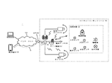
最初に、本実施の形態に係るセキュリティシステムの全体構成に関して図1を参照しながら説明する。セキュリティシステム1は、外部のスマートフォンなどの携帯端末130と太陽光発電施設などのセキュリティ施設に配置されたミニサーバ装置102とが第三者の管理サーバ装置を介さずに送受信できる。すなわち、セキュリティシステム1は、第三者の管理サーバを要することなく、セキュリティ施設における低消費電力プライベートサーバによる自主管理でのセキュリティシステムを実現する。
First, the overall configuration of the security system according to the present embodiment will be described with reference to FIG. In the
セキュリティシステム1は、監視カメラ103及びセキュリティ施設内の端末装置105を管理する専用のミニサーバ装置102と、インターネット網120と、ミニサーバ装置102から通知を受けると共に施設内の監視カメラ103や端末装置105を遠隔制御できる携帯端末130と、グローバルメットワークとローカルネットワークのデータの中継を行うルータ101と、が有線や無線の通信回線を介して接続されて構成される。なお、これらのネットワークは、常時接続されているものとする。
The
ローカルネットワーク100は、例えば太陽光発電施設などのセキュリティ施設におけるLAN(Local Area Network)であり、ルータ101を用いてローカルネットワーク内及びローカルネットワーク外のパケットデータのやり取りが統一的に中継される。また、本実施の形態では、ルータ101とミニサーバ装置102及び監視カメラ103との間はLAN等を用いて互いに接続されている。
The local network 100 is a LAN (Local Area Network) in a security facility such as a photovoltaic power generation facility, and the exchange of packet data inside and outside the local network is uniformly relayed by using the
ルータ101に接続されたミニサーバ装置102は、無線等により複数の端末装置105と接続されており、これらの間は所定の通信プロトコルで通信している。この通信プロトコルは、例えば、遠距離ワイヤレス通信を超低消費電力で実現したSub-1GHz SimpleLink(登録商標)などを利用する。これにより、端末装置105がローカルネットワーク100内でONされると、ミニサーバ装置102は自動検出して該当端末装置105を自動的に登録できる。なお、ローカルネットワーク上の端末装置105とミニサーバ装置102とは無線を介して接続されているが、有線を用いることもできる。セキュリティ施設内に設置される端末装置105は、例えば図1に示すような超低消費電力での動作が可能な人感センサ、動きセンサ、照度センサ、水没センサや火災センサなどのセキュリティセンサ、施錠施設、警報器や照明装置などのセキュリティデバイスである。
The
ミニサーバ装置102は、電流センサ104とは有線で接続されている。このことで、ミニサーバ装置102は、監視する電気システムの待機消費電力又は皮相電力の設定によって、電線が切断されてるかを判断する際の精度を格段に向上させることができる。なお、ミニサーバ装置102と電流センサ104とを無線で接続することも可能である。また、セキュリティシステム1にUPS(Uninterruptible Power Supply)電源を設け、電源が切断された場合において即時にUPS電源に切り替えて所定期間セキュリティシステム1を維持することもできる。
The
ルータ101は、外部と内部のネットワークで送受信されるデータを中継する中継装置であり、ローカルネットワーク内の端末はルータ101を介して統一的に外部ネットワークと接続されている。通常、ルータ101にはインターネットサービスプロバイダ(ISP)140から固有のグローバルアドレスが付与されており、ルータ101から送信されたグローバルパケットはプロバイダのルータに届くこととなる。そして、ネットワーク網を用いて送信先の携帯端末130に送信される。
The
外部ネットワークには、携帯端末130が接続されている。携帯端末130は、セキュリティ施設などのローカルネットワークを監視するユーザが外部にいても通知情報を受けることができると共に、外部から施設内の監視カメラ103及び端末装置105を遠隔操作するためのスマートフォンなどである。なお、本実施の形態に係る説明においては、携帯端末130としてスマートフォンを用いて説明を行うがこれに限定されるものではなく、PC、タブレット端末、PAD等のインターネット網120に接続できる端末装置でも同様の機能を用いることができるのは言うまでもない。
The
携帯端末130には、例えばローカルネットワーク100である太陽光発電施設内の各種機器を操作するための専用のアプリケーションがインストールされている。携帯端末130のユーザは、このアプリケーションを使用することで、専用のユーザインタフェースを用いて、ミニサーバ装置102からの通知を受信してユーザに通知すると共に、必要な際には施設内に設置されている監視カメラ103や端末装置105を外部から遠隔操作する。すなわち、携帯端末130のユーザは、ローカルネットワーク内の端末装置105の遠隔操作を行うため、ミニサーバ装置102に接続して遠隔操作対象の端末装置105の特定及び制御要求の送信を行うことができる。
For example, a dedicated application for operating various devices in a photovoltaic power generation facility, which is a local network 100, is installed in the
図1の点線Yは、本実施の形態に係るセキュリティシステム1において、携帯端末130からミニサーバ装置102側に送信される制御要求の流れを示す。携帯端末130は、ルータ101のグローバルIPアドレスを予め保持している。携帯端末130のユーザが専用のユーザインタフェースを用いて画面操作することで、ユーザID、パスワード、グローバルIPアドレス、制御情報等が付与されたパケットデータ(制御要求)が、ルータ101側に直接配信され、ルータ101の中継を介してミニサーバ装置102に送信される。このように、携帯端末130側では、ミニサーバ装置102に対する統一のユーザインタフェースを用いて全ての監視カメラ103や端末装置105などのセキュリティデバイスを一元に管理できる。なお、LAN間の通信にVPN(Virtual Private Network)ルータを用いることで、ユーザ端末(携帯端末130)のVPNクライアントソフトウェアから直接、他のLANにあるミニサーバ装置102や監視カメラ103にアクセスすることもできる。
The dotted line Y in FIG. 1 shows the flow of the control request transmitted from the
なお、通常、ルータ101のグローバルIPアドレスは、セキュリティのためISP140との間で動的に更新される。本実施の形態においては、ルータ101のグローバルIPアドレスの更新時には、ミニサーバ装置102(ルータ101)から携帯端末130にグローバルIPアドレス更新データ(更新通知)が自動的に(定期的に)送信される。又は、グローバルIPアドレス更新の携帯端末130側に通知して、携帯端末130のユーザが画面に表示されている通知をタップすることで携帯端末130に記憶されているルータのグローバルIPアドレスの更新処理が行われる。このため、携帯端末130は、ルータ101のグローバルIPアドレスとミニサーバ装置102の対応関係を示す対応表を常に保持できる。従って、携帯端末130においてルータ101の現在割振られているグローバルIPアドレスが分からず通信が成立しないという事態を未然に防止でき、リアルタイムに制御要求をグローバル側からローカル側に送信できる。なお、静的IPマスカレードなどグローバルIPアドレスが固定される場合には、ルータ101及び携帯端末130は変換テーブルにグローバルアドレス及びローカルアドレスを事前に固定的に登録しておくこともできる。
Normally, the global IP address of the
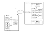
次に、本実施の形態に係るミニサーバ装置102、端末装置105、及びミニサーバ装置102に接続される携帯端末130の機能構成の一例を図2を参照しながら説明する。
Next, an example of the functional configuration of the
<携帯端末130>
携帯端末130は、ミニサーバ装置102からの通知を受けると共に、外出先のユーザが施設内の端末装置105の遠隔操作を行うことができる。携帯端末130のユーザは、インストールされた専用のアプリケーションを用いて、制御要求に送信先アドレス情報を付与したパケットデータを構築して目的のローカルネットワークのミニサーバ装置102に送信する。本実施の形態に係る携帯端末130は、制御部(第二制御部)131、画像処理部132、パケット生成部(第二パケット生成部)133、要求処理部134、記憶部135、送受信部136、表示部137及び操作入力部138を備える。
<
The
制御部131は、CPUなどのプロセッサやメモリを用いて、携帯端末130の構成部を制御して各種機能を実現する。画像処理部132は、GPU又は専用回路等のプロセッサ及びメモリを用い、制御部131からの制御指示に応じて画像処理を実行する。なお、制御部131及び画像処理部132は、CPU,GPU等のプロセッサ、メモリ、さらには記憶部135及び通信部136などを集積した1つのハードウェア(SoC:System on a Chip)として構成されていてもよい。
The control unit 131 uses a processor such as a CPU or a memory to control the components of the
パケット生成部133は、遠隔操作の際にミニサーバ装置102に送信する制御要求を生成する。具体的には、ミニサーバ装置102から送信されたデータの端末IDを用いて、記憶部135に記憶されているテーブルを参照して送信先アドレスを特定して、ヘッダ部に送信先情報及び送信元情報を付与して、データ部に端末IDや制御要求を含んだ制御要求コマンドを付与してパケットデータを作成する。
The packet generation unit 133 generates a control request to be transmitted to the
記憶部135は、RAMなどを用いる。記憶部135には、セキュリティシステム1におけるルータ101とミニサーバ装置102のアドレス情報、及びミニサーバ装置102が設置された施設の経緯度位置情報、セキュリティシステム1のUIとしての機能を発揮させるアプリケーションプログラムなどが記憶されている。
The storage unit 135 uses RAM or the like. The storage unit 135 contains the address information of the
送受信部136は、インターネット等の通信網への通信接続を実現する通信モジュールである。送受信部136は、ミニサーバ装置102側より送信される通知情報、例えば、センサのトリガ情報、監視カメラ103のデータ、電線の切断情報などをインターネットを介して受信する。なお、送受信部136は、ルータ101から受信したパケットの復号化と、ルータ101側に送信するパケットの暗号化を行っても良い。この暗号化及び復号化にはDES等を用いても良い。
The transmission / reception unit 136 is a communication module that realizes a communication connection to a communication network such as the Internet. The transmission / reception unit 136 receives notification information transmitted from the
表示部137は、液晶パネル又は有機EL(Electro Luminescence)ディプレイ等を用いる。表示部137は、制御部131の指示による画像処理部132での処理によってセキュリティシステム1を発揮するためのユーザインタフェースを表示する。
The display unit 137 uses a liquid crystal panel, an organic EL (Electro Luminescence) display, or the like. The display unit 137 displays a user interface for exerting the
操作入力部138は、ミニサーバ装置102における設定値の設定、及びユーザによる操作情報を制御部131へ通知するものであり、タッチパネルなどを含む。携帯端末130の筐体に設けられた物理的ボタンを用いてもよい。携帯端末130のユーザは、操作入力部138を介して、端末装置105の名称、各種セキュリティセンサとの接続条件、各種セキュリティセンサに対応した監視カメラ103の特定、監視カメラ103の撮影条件、施設内で異常が発生した際のアラームの設定、アラームが出るときの監視カメラ103の録画機能の設定、アラームを出す際の警告音の設定、監視する電気システムの待機消費電力又は皮相電力、端末装置105のEnable/Offなどのミニサーバ装置102側における端末装置105に関する設定値を予め設定することができる。また、ミニサーバ装置102に送信される制御要求としては、例えば「監視カメラの操作情報」、「施錠設備の施錠」、「警報器の警報開始」、「照明装置のON/OFF」等の情報である。また、監視カメラ103の解像度などコントロール情報も操作入力部138を介して設定する。
The operation input unit 138 notifies the control unit 131 of the setting of the set value in the
<ミニサーバ装置102>
ミニサーバ装置102は、ローカルネットワーク内の監視カメラ103及び端末装置105を統一的に管理することができる装置であり、ルータ101とLAN等を用いて互いに接続される。ローカルネットワーク上において用いられる通信プロトコルはセキュアなプロトコルである。そして、ミニサーバ装置102はルータ101において固有のローカルIPアドレスが付与される。本実施の形態に係るミニサーバ装置102は、通信部102a、制御部102b、表示部102c、設定入力部102d、パケット生成部102e、記録部102f、及びカメラ画像処理部102gを備える。
<
The
通信部102aは、携帯端末130、監視カメラ103や端末装置105との間でデータの送受信を行う。なお、通信部102aから送信するデータの暗号化と、受信したデータの復号化を行うこともできる。
The communication unit 102a transmits / receives data to / from the
制御部102bは、ルータ101から外出先のユーザが携帯端末130を用いて指定した制御要求コマンドを含むパケットを受信した場合、この制御要求コマンドに従って制御指令を目的の端末装置105に送信して制御処理を行う。また、制御部102bは、端末装置105の各センサ(端末装置105)と監視カメラ103とが連動させる。すなわち、あるセキュリティセンサがトリガされると、予め設定されている1台の監視カメラ103を設定されたポジションに動かして、設定されたズーム、角度でフォーカスさせ、該当センサ近くの映像を鮮明に携帯端末130側に流すための制御を行う。さらに、制御部102bは、ネットワークのスピードに応じて自動的に監視カメラ103の解像度の調整を行うことができる。またさらに、制御部102bは、監視カメラ103に休眠状態を導入し、セキュリティセンサがトリガされてから迅速に起動し、事前に設定されたパラメータに従って監視カメラ103を照準させる。なお、監視カメラ103の撮影データを保存できる場所は、ミニサーバ装置102の記録部102f、監視カメラ本体に装着されたSDカードなどのメモリカード、及び携帯端末130の記憶部135である。
When a user on the go receives a packet including a control request command specified by using the mobile terminal 130 from the
表示部102cは、液晶パネル等である。設定入力部102dは、表示部102cを介してミニサーバ装置102における設定値を予め設定するためのタッチパネルやキーボードである。
The display unit 102c is a liquid crystal panel or the like. The setting input unit 102d is a touch panel or keyboard for presetting setting values in the
パケット生成部102eは、送信先及び送信元のアドレス情報が付与されたヘッダ部、及び携帯端末130への通知内容等のデータが付与されたデータ部を含むパケットデータを生成する。記録部102fは、各種の設定値、携帯端末130を識別する電話番号(又はIPアドレス)などのアドレス情報、監視カメラ103及び端末装置105の端末IDやパスワードを保持する。また監視カメラ103の撮影データを記録することもできる。カメラ画像処理部102gは、複数の監視カメラ103から受信した複数のカメラビデオストリームを処理し、必要であるならば、データのフォーマット変換処理や記録部102fなどに対して監視カメラ103の撮影データの記録処理を行う。
The packet generation unit 102e generates packet data including a header unit to which the address information of the destination and the transmission source is added, and a data unit to which data such as the content of notification to the
<端末装置105>
端末装置105は、通信部105a及び機器制御部105bを具備する。通信部105aは、ミニサーバ装置102の制御部102bと制御情報の送受信を行う処理部である。また、機器制御部105bは、ミニサーバ装置102から制御指令を受信して端末装置105の制御を行う。この制御指令には「警報の開始」、「照明装置のON/OFF」等の命令である。
<
The
<監視カメラ103>
監視カメラ103は、通信部103a及び機器制御部103bを具備する。通信部103aは、ミニサーバ装置102の制御部102bと制御情報の送受信を行う処理部である。また、機器制御部103bは、ミニサーバ装置102から制御指令を受信して監視カメラ103の制御を行う。この制御指令には「カメラの角度の変更」、「ズーム」等の命令である。
<
The
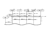
次に、ミニサーバ装置102が施設内のセンサ(端末装置105)からのトリガを受けてから携帯端末130に通知し、その後、携帯端末130から施設内の端末装置105に制御指令を送信するまでの動作手順を、図3のシーケンス図を参照しながら説明する。
Next, after the
最初に、端末装置105(ここでは人感センサも用いて説明)の人感センサから人検知通知がミニサーバ装置102に対してなされる(S31)。すると、ミニサーバ装置102のパケット生成部102eは、人検知通知を通知する通知パケットを生成し、通信部102aはこの通知パケットをルータ101に送信する(S32)。この通知パケットを受信したルータ101は、ローカルIPアドレスをグローバルIPアドレスに変換し、インターネット上の携帯端末130に送信する(S33)。
First, a human detection notification is sent to the
そして、通知パケットを受信した携帯端末130の制御部131は、表示部137に通知を表示し(S34)、ユーザからタップなど指令がある場合にはパスワード入力などを介して専用のアプリケーションを立ち上げる。その際、記憶部135にテーブル情報として記憶されているミニサーバ装置102に紐づけられた位置情報に基づくマップを表示する(S35)。より具体的には、携帯端末130の制御部131は、記憶部135よりミニサーバ装置102が設置された施設の経緯度位置情報を取得し、画像処理部132は、当該経緯度位置情報に基づいてマップを表示部137に表示する。このように、通知パケットを受信した携帯端末130は、地図と連動し、地図上に該当地点の情報を表示させてマックさせることができる。
Then, the control unit 131 of the
次に、画面に表示された地図を見た携帯端末130のユーザが、監視カメラ103からのライブストリーム配信を選択した場合(S36)、パケット生成部133は、ライブストリーム要求を含んだパケットデータをルータ101を介してミニサーバ装置102に送信する(S37,S38)。
Next, when the user of the
そして、ライブストリーム要求を受けたミニサーバ装置102の制御部102bは、休眠状態の監視カメラ103を、人感センサがトリガされてから迅速に起動指令を送信して起動する(S39)。そして、事前に設定されたパラメータに従って監視カメラ103を照準させ、その照準させた撮影データ(ライブストリーム)をミニサーバ装置102に送信する(S40)。次に、ミニサーバ装置102は、監視カメラ103からのストリーム映像を、ルータ101を介して携帯端末130に送信する(S40,S41)。なお、ライブストリーム中においても携帯端末130のユーザは、監視カメラ103からの映像の視点の変更やズームなど様々な指令を行うことができる。
Then, the control unit 102b of the
そして、監視カメラ103の映像で現場を確認した携帯端末130のユーザは、セキュリティデバイスの発動(ここでは警報器)を判断し、警報を行う場合には、ユーザインタフェースを用いて、警報要求をミニサーバ装置102に送信する(S43,S44)。次に、警報要求を受信したミニサーバ装置102では、警報器を特定し、警報器に対して警報指令を送信する(S45)。最後に、警報指令を受けた警報器の機器制御部105bは、警報音を鳴らす制御を行う(S46)。
Then, the user of the
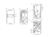
次に、本実施の形態に係る携帯端末130の表示部137に表示されるユーザインタフェース(UI)の表示例を図4に基づいて説明する。
Next, a display example of the user interface (UI) displayed on the display unit 137 of the
図4(a)は、ミニサーバ装置102からの通知を受けた画面401を示す。ここでは、例えば「北施設の人感センサが人検知:1時間前(401a)」及び「南施設外部電源パワーロスト:1時間前(401b)」などの通知がなされている。
FIG. 4A shows a
図4(b)は、図4(a)の画面401から「北施設の人感センサが人検知:1時間前(401a)」をタップした場合の画面例402である。画面402においては、北施設の地図情報及び人検知をした人感センサに関連した監視カメラ103のライブ映像を確認するためのタップ情報が表示される。なお、タップした際にパスワード確認画面が表示されてパスワード入力を行う認証ステップを行っても良い。
FIG. 4B is a screen example 402 when "human detection by the motion sensor of the north facility: 1 hour ago (401a)" is tapped from the
図4(c)は、図4(b)の画面402において設定パネルを選択した際に表示される画面403の一例であり、登録されている施設情報403a、コントロールパネル403b、登録されているライブカメラ403c、検索などの履歴情報403dが表示され、ユーザが所望する情報を選択する。
FIG. 4C is an example of the
図4(d)は、図4(b)の画面402において、ライブ映像を選択した場合の画面例404であり、人感センサが検知されたエリアに設置されている監視カメラ103のライブ映像の配信が開始される。この際、タッチパネル式の画面操作をすることで、視点を移動させたり、ズーム映像とすることが可能となる。例えば、アイコン404aをタッチするとミニサーバ装置102から受信した監視カメラ103の撮影データがダウンロードされて保存され、アイコン404bをタッチすると施設内で警告音が発せられ、アイコン404cをタッチするとカメラの録画が開始され、録画データはミニサーバ装置102において記録される。このように、外出先のユーザが携帯端末130の画面に表示される専用ユーザインタフェースを介して、セキュリティ施設を遠隔監視することが可能となる。
FIG. 4D is a screen example 404 when a live image is selected on the
以上の説明のように、本実施の形態では、セキュリティが要求される施設における低消費電力プライベートサーバ(すなわちミニサーバ装置102)による自主管理セキュリティシステム1を実現し、第三者による管理サーバを必要としない。この構成により、太陽光発電施設など施設のセキュリティ管理に要するコストを大幅に削減すると共に、管理情報が盗難されるなどのセキュリティ上の危険性を排除できる。すなわち、ミニサーバ装置102で個人情報、パスワードなど管理され、管理会社など第三者にみられることはなく、完全にプライベートな施設のセキュリティ管理を実現できる。
As described above, in the present embodiment, the self-managed
また、各センサ(端末装置105)と監視カメラ103が連動し、あるセンサ105がトリガされると、ミニサーバ装置102が予めに設定された1台の監視カメラ103を設定されたポジションに動かして、設定されたズーム、角度でフォーカスさせる。そして、ミニサーバ装置102を介して、該当センサ105の近くの監視カメラ103の映像を鮮明に携帯端末130に送信できる。その際、ミニサーバ装置102が、ネットワークのスピードを判断して自動的に解像度の調整をする。このため、緊急時に監視カメラ103の選定などに時間を要することがない。
Further, each sensor (terminal device 105) and the
また、ミニサーバ装置102は電流センサ104と有線で接続され、監視する電気システムの待機消費電力又は皮相電力を予め設定することによって、電線が切断されてるかを的確に判断することが可能となり、誤報を防止できる。すなわち、防犯効果やユーザ操作性を向上させることができるミニサーバ装置102、及びミニサーバ装置102を用いたセキュリティシステム1を実現できる。
Further, the
また、監視カメラ103に休眠状態を導入し、ミニサーバ装置102でセンサがトリガされてから迅速に監視カメラ103を起動し、事前に設定されたパラメータに従って監視カメラ103を照準させる。このように、ミニサーバ装置102を用いることで、従来に比較して大幅にセキュリティ管理施設に要していた消費電力を低減できる。
Further, a dormant state is introduced into the
また、外部の携帯端末130のユーザは、統一されたユーザインタフェースで、全部のセキュリティ施設の監視カメラ103とセンサ(端末装置105)、セキュリティデバイスを一元に管理できる。このため、ユーザにとっては操作性がよく、また施設の状態を直感的に認識することが可能となる。
Further, the user of the external
(変形例1)
次に、本実施の形態に係るセキュリティシステム1の変形例1について図5を用いて説明を行う。本変形例1では、携帯端末130のユーザは予め、操作入力部138を介してミニサーバ装置102における動作条件を設定している。すなわち、ミニサーバ装置102の記録部102fに予め記録される設定値には、端末装置150のセキュリティデバイスの動作条件が含まれ、ミニサーバ装置102の制御部102bは、セキュリティセンサからのトリガを受けると、当該設定値に基づいて、セキュリティデバイスを自動的に作動する。図5を参照して説明すると、セキュリティセンサが人検知をした時点で(S31)、ミニサーバ装置102は、セキュリティデバイスである照明装置を動作させて、フラッシュライトなどの威嚇動作を自動的に行う(S50)。その後は、上記実施の形態と同様に、携帯端末130のユーザはライブストリーム機能を用いて現場確認を行い、警報音で侵入者に対する威嚇を行う(S37〜S46)。このため、本変形例1では、上記実施の形態の効果に加えて、ミニサーバ装置102がセンサ検知を受けた時点で、自動的に侵入者に対する威嚇動作を開始するため、より一層の防犯効果を実現できる。
(Modification example 1)
Next, a
(変形例2)
次に、本実施の形態に係るセキュリティシステム1の変形例2について図6を用いて説明を行う。本変形例2では、携帯端末130のユーザは、ライブストリームカメラで現場を確認し、携帯端末130の画面上に警察140への通報ボタンが表示されている。次に、ユーザが画面上の通報ボタンをタップすると該当地点の経緯度座標を警察に送って通報するか、警察への電話が開始され(S60)、ユーザ自身は画面上に表示される該当地点の緯度経度情報と住所などを確認しながら警察に通報することができる。このため、本変形例2では、携帯端末130の画面において警察に通報する場合の補助情報が出てきて、ユーザは直感的に警察への通報を行うことができ、より一層の防犯効果を実現できる。
(Modification 2)
Next, a modification 2 of the
なお、本発明は、上記実施の形態の構成に限られず、発明の趣旨を変更しない範囲で種々の変形が可能である。また、本発明の目的を達成するために、本発明は、ミニサーバ装置102や携帯端末130に含まれる特徴的な構成手段をステップとする通信方法としたり、それらの特徴的なステップを含むコンピュータ用のプログラムとして実現することもできる。そして、そのプログラムは、ROM等に格納しておくだけでなく、USBメモリ等の記録媒体や通信ネットワークを介して流通させることもできる。
The present invention is not limited to the configuration of the above embodiment, and various modifications can be made without changing the gist of the invention. Further, in order to achieve the object of the present invention, the present invention uses a communication method in which characteristic configuration means included in the
1 セキュリティシステム
101 ルータ
102 ミニサーバ装置
103 監視カメラ
102a 通信部
102b 制御部
102c 表示部
102d 設定入力部
102e パケット生成部
102f 記録部
102g カメラ画像処理部
103a,105a 通信部
103b,105b 機器制御部
104 電流センサ
105 端末装置
130 携帯端末
131 制御部(第二制御部)
132 画像処理部
133 要求処理部
134 パケット生成部(第二パケット生成部)
135 記憶部
136 送受信部
137 表示部
138 操作入力部
1
132 Image processing unit 133 Request processing unit 134 Packet generation unit (second packet generation unit)
135 Storage unit 136 Transmission / reception unit 137 Display unit 138 Operation input unit
Claims (6)
前記ミニサーバ装置には、ローカルネットワークを介して、所定の施設内のセキュリティ管理を行うための複数の端末装置及び監視カメラが接続されており、
前記ミニサーバ装置は、
前記端末装置からのトリガを受けた場合に、送信先となる前記携帯端末と送信元となる前記ミニサーバ装置とのアドレス情報、及び前記携帯端末への通知内容のデータが付与されたパケットデータを生成するパケット生成部と、
前記携帯端末、前記監視カメラ及び前記端末装置との間でデータの送受信を行う通信部と、
前記通信部を介して前記携帯端末より前記監視カメラ又は前記端末装置の制御要求コマンドを受信した場合、当該制御要求コマンドに従って制御指令を目的の前記監視カメラ又は前記端末装置に送信して制御処理を行う制御部と、
各種の設定値、前記携帯端末のアドレス情報、前記監視カメラ及び前記端末装置の端末ID及びパスワードの少なくとも一つを保持する記録部と、
複数の前記監視カメラから受信した複数のカメラビデオストリームのフォーマット変換処理、及び前記監視カメラの撮影データの記録処理を行うカメラ画像処理部と、を備え、
前記携帯端末は、
前記ルータを介して前記ミニサーバ装置との間でデータの送受信を行う送受信部と、
当該携帯端末の構成部を制御して各種機能を実現する第二制御部と、
前記第二制御部からの制御指示に応じて画像処理を実行する画像処理部と、
前記ミニサーバ装置のアドレス情報、前記ミニサーバ装置が設置された施設の経緯度位置情報、前記セキュリティシステムのユーザインタフェースとしての機能を発揮させるアプリケーションプログラムの少なくとも1つを記憶する記憶部と、
送信先情報及び送信元情報を付与して、且つ制御要求を含んだ前記制御要求コマンドを付与したパケットデータを作成する第二パケット生成部と、
前記アプリケーションプログラムに基づく前記ユーザインタフェースを表示する表示部と、
前記ミニサーバ装置における前記設定値を設定し、且つユーザによる制御要求を前記第二制御部へ通知する操作入力部と、を備え、
前記携帯端末の前記第二制御部は、前記記憶部より前記ミニサーバ装置が設置された施設の経緯度位置情報を取得し、
前記画像処理部は、当該経緯度位置情報に基づいてマップを前記表示部に表示することを特徴とするセキュリティシステム。 A security system including a mobile terminal connected to an external network and a mini server device connected to the mobile terminal via a router and transmitting / receiving data to / from the mobile terminal.
A plurality of terminal devices and surveillance cameras for performing security management in a predetermined facility are connected to the mini server device via a local network.
The mini server device is
When a trigger is received from the terminal device, packet data to which the address information of the mobile terminal as the transmission destination and the mini server device as the transmission source and the data of the notification content to the mobile terminal are added. The packet generator to generate and
A communication unit that transmits / receives data between the mobile terminal, the surveillance camera, and the terminal device.
When a control request command for the surveillance camera or the terminal device is received from the mobile terminal via the communication unit, a control command is transmitted to the target surveillance camera or the terminal device according to the control request command to perform control processing. Control unit to perform and
A recording unit that holds at least one of various set values, the address information of the mobile terminal, the terminal ID and password of the surveillance camera and the terminal device, and the like.
A camera image processing unit that performs format conversion processing of a plurality of camera video streams received from the plurality of surveillance cameras and recording processing of shooting data of the surveillance cameras is provided.
The mobile terminal
A transmission / reception unit that transmits / receives data to / from the mini server device via the router, and a transmission / reception unit.
A second control unit that controls the components of the mobile terminal to realize various functions,
An image processing unit that executes image processing in response to a control instruction from the second control unit, and an image processing unit.
A storage unit that stores the address information of the mini-server device, the latitude and longitude position information of the facility where the mini-server device is installed, and at least one of the application programs that exert the function as the user interface of the security system.
A second packet generation unit that creates packet data to which the destination information and the source information are added and the control request command including the control request is added.
A display unit that displays the user interface based on the application program, and
It includes an operation input unit that sets the set value in the mini server device and notifies the second control unit of a control request by the user .
The second control unit of the mobile terminal acquires the latitude and longitude position information of the facility where the mini server device is installed from the storage unit.
The image processing unit is a security system characterized in that a map is displayed on the display unit based on the latitude and longitude position information.
前記ミニサーバ装置には、ローカルネットワークを介して、所定の施設内のセキュリティ管理を行うための複数の端末装置及び監視カメラが接続されており、
前記通信方法は、
前記端末装置からのトリガを受けた場合に、送信先となる前記携帯端末と送信元となる前記ミニサーバ装置とのアドレス情報、及び前記携帯端末への通知内容のデータが付与されたパケットデータを生成するパケット生成ステップと、
前記携帯端末、前記監視カメラ及び前記端末装置との間でデータの送受信を行う通信ステップと、
前記通信ステップを介して前記携帯端末より前記監視カメラ又は前記端末装置の制御要求コマンドを受信した場合、当該制御要求コマンドに従って制御指令を目的の前記監視カメラ又は前記端末装置に送信して制御処理を行う制御ステップと、
各種の設定値、前記携帯端末のアドレス情報、前記監視カメラ及び前記端末装置の端末ID及びパスワードの少なくとも一つを保持する記録ステップと、
複数の前記監視カメラから受信した複数のカメラビデオストリームのフォーマット変換処理、及び前記監視カメラの撮影データの記録処理を行うカメラ画像処理ステップと、を含むことを特徴とする通信方法。 Is connected to a mobile terminal through a router connected to an external network, are sent and received the mobile terminal and data, a communication method for use in a mini server device of claim 1,
A plurality of terminal devices and surveillance cameras for performing security management in a predetermined facility are connected to the mini server device via a local network.
The communication method is
When a trigger is received from the terminal device, packet data to which the address information of the mobile terminal as the transmission destination and the mini server device as the transmission source and the data of the notification content to the mobile terminal are added. The packet generation step to generate and
A communication step for transmitting and receiving data between the mobile terminal, the surveillance camera, and the terminal device, and
When a control request command for the surveillance camera or the terminal device is received from the mobile terminal via the communication step, a control command is transmitted to the target surveillance camera or the terminal device according to the control request command to perform control processing. Control steps to perform and
A recording step for holding at least one of various set values, the address information of the mobile terminal, the terminal ID and password of the surveillance camera and the terminal device, and the like.
A communication method comprising: a format conversion process of a plurality of camera video streams received from the plurality of surveillance cameras, and a camera image processing step of recording the shooting data of the surveillance cameras.
前記ミニサーバ装置には、ローカルネットワークを介して、所定の施設内のセキュリティ管理を行うための複数の端末装置及び監視カメラが接続されており、
前記プログラムは、
前記端末装置からのトリガを受けた場合に、送信先となる前記携帯端末と送信元となる前記ミニサーバ装置とのアドレス情報、及び前記携帯端末への通知内容のデータが付与されたパケットデータを生成するパケット生成ステップと、
前記携帯端末、前記監視カメラ及び前記端末装置との間でデータの送受信を行う通信ステップと、
前記通信ステップを介して前記携帯端末より前記監視カメラ又は前記端末装置の制御要求コマンドを受信した場合、当該制御要求コマンドに従って制御指令を目的の前記監視カメラ又は前記端末装置に送信して制御処理を行う制御ステップと、
各種の設定値、前記携帯端末のアドレス情報、前記監視カメラ及び前記端末装置の端末ID及びパスワードの少なくとも一つを保持する記録ステップと、
複数の前記監視カメラから受信した複数のカメラビデオストリームのフォーマット変換処理、及び前記監視カメラの撮影データの記録処理を行うカメラ画像処理ステップと、をコンピュータに実行させることを特徴とするプログラム。 Is connected to a mobile terminal through a router connected to an external network, are sent and received the mobile terminal and data, a program used mini server device of claim 1,
A plurality of terminal devices and surveillance cameras for performing security management in a predetermined facility are connected to the mini server device via a local network.
The program
When a trigger is received from the terminal device, packet data to which the address information of the mobile terminal as the transmission destination and the mini server device as the transmission source and the data of the notification content to the mobile terminal are added. The packet generation step to generate and
A communication step for transmitting and receiving data between the mobile terminal, the surveillance camera, and the terminal device, and
When a control request command for the surveillance camera or the terminal device is received from the mobile terminal via the communication step, a control command is transmitted to the target surveillance camera or the terminal device according to the control request command to perform control processing. Control steps to perform and
A recording step for holding at least one of various set values, the address information of the mobile terminal, the terminal ID and password of the surveillance camera and the terminal device, and the like.
A program characterized by having a computer execute a format conversion process of a plurality of camera video streams received from the plurality of surveillance cameras and a camera image processing step of recording the shooting data of the surveillance cameras.
前記ルータを介して前記ミニサーバ装置との間でデータの送受信を行う送受信ステップと、
当該携帯端末の構成部を制御して各種機能を実現する第二制御ステップと、
前記第二制御ステップからの制御指示に応じて画像処理を実行する画像処理ステップと、
前記ミニサーバ装置のアドレス情報、前記ミニサーバ装置が設置された施設の経緯度位置情報、前記セキュリティシステムのユーザインタフェースとしての機能を発揮させるアプリケーションプログラムの少なくとも1つを記憶する記憶ステップと、
送信先情報及び送信元情報を付与して、且つ制御要求を含んだ前記制御要求コマンドを付与したパケットデータを作成する第二パケット生成ステップと、
前記アプリケーションプログラムに基づく前記ユーザインタフェースを表示する表示ステップと、
前記ミニサーバ装置における前記設定値を設定し、且つユーザによる制御要求を前記第二制御部へ通知する操作入力ステップと、をコンピュータに実行させることを特徴とするプログラム。 Is connected to a mini server apparatus via the router, it is sent and received the mini server device and the data, a program used in a portable terminal of claim 1, wherein,
A transmission / reception step of transmitting / receiving data to / from the mini server device via the router, and
A second control step that controls the components of the mobile terminal to realize various functions,
An image processing step that executes image processing in response to a control instruction from the second control step, and
A storage step for storing at least one of the address information of the mini-server device, the latitude and longitude position information of the facility where the mini-server device is installed, and an application program that exerts a function as a user interface of the security system.
A second packet generation step of adding destination information and source information and creating packet data to which the control request command including the control request is added, and
A display step that displays the user interface based on the application program, and
A program characterized by having a computer execute an operation input step of setting the set value in the mini server device and notifying the second control unit of a control request by a user.
Priority Applications (2)
| Application Number | Priority Date | Filing Date | Title |
|---|---|---|---|
| JP2019138341A JP6889817B2 (en) | 2019-07-27 | 2019-07-27 | A mini server device and a security system equipped with the mini server device |
| PCT/JP2020/027343 WO2021020105A1 (en) | 2019-07-27 | 2020-07-14 | Mini server device and security system provided therewith |
Applications Claiming Priority (1)
| Application Number | Priority Date | Filing Date | Title |
|---|---|---|---|
| JP2019138341A JP6889817B2 (en) | 2019-07-27 | 2019-07-27 | A mini server device and a security system equipped with the mini server device |
Publications (2)
| Publication Number | Publication Date |
|---|---|
| JP2021022175A JP2021022175A (en) | 2021-02-18 |
| JP6889817B2 true JP6889817B2 (en) | 2021-06-18 |
Family
ID=74228684
Family Applications (1)
| Application Number | Title | Priority Date | Filing Date |
|---|---|---|---|
| JP2019138341A Active JP6889817B2 (en) | 2019-07-27 | 2019-07-27 | A mini server device and a security system equipped with the mini server device |
Country Status (2)
| Country | Link |
|---|---|
| JP (1) | JP6889817B2 (en) |
| WO (1) | WO2021020105A1 (en) |
Families Citing this family (2)
| Publication number | Priority date | Publication date | Assignee | Title |
|---|---|---|---|---|
| JP7798319B2 (en) * | 2021-05-19 | 2026-01-14 | 株式会社ビットピープス | Management systems, etc. |
| JP7676967B2 (en) * | 2021-06-04 | 2025-05-15 | セイコーエプソン株式会社 | Printing system, information processing device, and control program |
Family Cites Families (7)
| Publication number | Priority date | Publication date | Assignee | Title |
|---|---|---|---|---|
| JP2003032377A (en) * | 2001-07-19 | 2003-01-31 | Nippon Soft Kaihatsu Kk | Security system |
| JP2004128821A (en) * | 2002-10-01 | 2004-04-22 | Procs:Kk | Home security system |
| JP4540456B2 (en) * | 2004-12-01 | 2010-09-08 | 三菱電機ビルテクノサービス株式会社 | Suspicious person detection device |
| JP5627092B2 (en) * | 2010-09-29 | 2014-11-19 | 株式会社セキュリティハウス・センター | Security system |
| JP2015186114A (en) * | 2014-03-25 | 2015-10-22 | 株式会社日立国際電気 | Video surveillance system |
| JP2015204102A (en) * | 2014-12-19 | 2015-11-16 | パナソニックIpマネジメント株式会社 | Monitoring system and setting method |
| JP6452664B2 (en) * | 2016-12-05 | 2019-01-16 | Kddi株式会社 | Flight apparatus and communication control method |
-
2019
- 2019-07-27 JP JP2019138341A patent/JP6889817B2/en active Active
-
2020
- 2020-07-14 WO PCT/JP2020/027343 patent/WO2021020105A1/en not_active Ceased
Also Published As
| Publication number | Publication date |
|---|---|
| JP2021022175A (en) | 2021-02-18 |
| WO2021020105A1 (en) | 2021-02-04 |
Similar Documents
| Publication | Publication Date | Title |
|---|---|---|
| KR102155535B1 (en) | Home monitoring method and apparatus | |
| JP5627092B2 (en) | Security system | |
| CA2414629C (en) | Remote monitoring method and monitor control server | |
| JP5903375B2 (en) | Communication apparatus, method, and program | |
| US20060271695A1 (en) | System for remote secured operation, monitoring and control of security and other types of events | |
| JP2005094702A (en) | Transmission device and method, reception device and method, and transmission / reception system and method | |
| JP6643922B2 (en) | Fire alarm | |
| JP7701421B2 (en) | Mobile terminal, security system and program | |
| JP6889817B2 (en) | A mini server device and a security system equipped with the mini server device | |
| US20160277714A1 (en) | Interactive, self-contained, full view surveillance, capture, and communication device | |
| JP7334086B2 (en) | Security system, mobile terminal and program | |
| US10181261B2 (en) | Mobile user interface for security panel | |
| JP2004129280A (en) | Remote control system, control method and program thereof | |
| JP2023148371A (en) | Information processing systems and programs | |
| JP6000093B2 (en) | Communication apparatus, method, and program | |
| JP2009284250A (en) | In-home monitoring control system, in-home monitoring control method, and monitoring control device | |
| KR20220007772A (en) | A theft-monitoring system for laptop PC using a mouse dongle in which a movement sensor is embedded | |
| JP2005318445A (en) | Home device of remote monitor system | |
| KR20130014954A (en) | System for providing image monitoring information | |
| KR20220006871A (en) | A theft-monitoring system for laptop PC which providing the thief images photographed on occurring of a theft event | |
| KR20140058906A (en) | Home automation system using used mobile device and remote control and monitoring method thereof | |
| JP2018137690A (en) | Monitoring system and monitoring method | |
| JP2024154301A (en) | Information processing system, information processing method, and program | |
| KR20220007774A (en) | A theft-monitoring system for laptop PC using a multi-port hub in which a movement sensor is embedded | |
| KR20220006867A (en) | A theft-monitoring accessory with movement sensor and a theft-monitoring system for laptop PC which the accessory is applied to |
Legal Events
| Date | Code | Title | Description |
|---|---|---|---|
| A521 | Request for written amendment filed |
Free format text: JAPANESE INTERMEDIATE CODE: A523 Effective date: 20190727 |
|
| A621 | Written request for application examination |
Free format text: JAPANESE INTERMEDIATE CODE: A621 Effective date: 20200714 |
|
| A871 | Explanation of circumstances concerning accelerated examination |
Free format text: JAPANESE INTERMEDIATE CODE: A871 Effective date: 20200714 |
|
| A975 | Report on accelerated examination |
Free format text: JAPANESE INTERMEDIATE CODE: A971005 Effective date: 20200727 |
|
| A131 | Notification of reasons for refusal |
Free format text: JAPANESE INTERMEDIATE CODE: A131 Effective date: 20200828 |
|
| A601 | Written request for extension of time |
Free format text: JAPANESE INTERMEDIATE CODE: A601 Effective date: 20201023 |
|
| A521 | Request for written amendment filed |
Free format text: JAPANESE INTERMEDIATE CODE: A523 Effective date: 20201209 |
|
| TRDD | Decision of grant or rejection written | ||
| A01 | Written decision to grant a patent or to grant a registration (utility model) |
Free format text: JAPANESE INTERMEDIATE CODE: A01 Effective date: 20201225 |
|
| A61 | First payment of annual fees (during grant procedure) |
Free format text: JAPANESE INTERMEDIATE CODE: A61 Effective date: 20210105 |
|
| R150 | Certificate of patent or registration of utility model |
Ref document number: 6889817 Country of ref document: JP Free format text: JAPANESE INTERMEDIATE CODE: R150 |
|
| R250 | Receipt of annual fees |
Free format text: JAPANESE INTERMEDIATE CODE: R250 |