JP6888709B2 - Manufacturing method of light emitting device and light emitting device - Google Patents
Manufacturing method of light emitting device and light emitting device Download PDFInfo
- Publication number
- JP6888709B2 JP6888709B2 JP2020070531A JP2020070531A JP6888709B2 JP 6888709 B2 JP6888709 B2 JP 6888709B2 JP 2020070531 A JP2020070531 A JP 2020070531A JP 2020070531 A JP2020070531 A JP 2020070531A JP 6888709 B2 JP6888709 B2 JP 6888709B2
- Authority
- JP
- Japan
- Prior art keywords
- light emitting
- emitting device
- lead frame
- resin
- lead
- Prior art date
- Legal status (The legal status is an assumption and is not a legal conclusion. Google has not performed a legal analysis and makes no representation as to the accuracy of the status listed.)
- Active
Links
- 238000004519 manufacturing process Methods 0.000 title claims description 55
- 229920005989 resin Polymers 0.000 claims description 266
- 239000011347 resin Substances 0.000 claims description 266
- 239000000126 substance Substances 0.000 claims description 33
- 238000000034 method Methods 0.000 claims description 32
- 238000005520 cutting process Methods 0.000 claims description 21
- 238000007789 sealing Methods 0.000 claims description 20
- 239000003822 epoxy resin Substances 0.000 claims description 16
- 229920000647 polyepoxide Polymers 0.000 claims description 16
- 230000000149 penetrating effect Effects 0.000 claims description 3
- 150000003918 triazines Chemical class 0.000 claims description 3
- 229920001187 thermosetting polymer Polymers 0.000 description 62
- 229910052693 Europium Inorganic materials 0.000 description 10
- 235000014676 Phragmites communis Nutrition 0.000 description 10
- 229910052751 metal Inorganic materials 0.000 description 10
- 239000002184 metal Substances 0.000 description 10
- 238000007747 plating Methods 0.000 description 10
- 229910052747 lanthanoid Inorganic materials 0.000 description 9
- 150000002602 lanthanoids Chemical class 0.000 description 9
- 229920002050 silicone resin Polymers 0.000 description 9
- 239000000463 material Substances 0.000 description 8
- 238000000465 moulding Methods 0.000 description 8
- 229910052725 zinc Inorganic materials 0.000 description 8
- 229910052788 barium Inorganic materials 0.000 description 7
- 229910052791 calcium Inorganic materials 0.000 description 7
- 238000001723 curing Methods 0.000 description 7
- 238000005530 etching Methods 0.000 description 7
- 229910052749 magnesium Inorganic materials 0.000 description 7
- 229910052712 strontium Inorganic materials 0.000 description 7
- 229920005992 thermoplastic resin Polymers 0.000 description 7
- 229910052684 Cerium Inorganic materials 0.000 description 6
- OAICVXFJPJFONN-UHFFFAOYSA-N Phosphorus Chemical compound [P] OAICVXFJPJFONN-UHFFFAOYSA-N 0.000 description 6
- GWEVSGVZZGPLCZ-UHFFFAOYSA-N Titan oxide Chemical compound O=[Ti]=O GWEVSGVZZGPLCZ-UHFFFAOYSA-N 0.000 description 6
- 238000002347 injection Methods 0.000 description 6
- 239000007924 injection Substances 0.000 description 6
- 239000004065 semiconductor Substances 0.000 description 6
- 239000003086 colorant Substances 0.000 description 5
- 238000004080 punching Methods 0.000 description 5
- 229910000679 solder Inorganic materials 0.000 description 5
- 229910052736 halogen Inorganic materials 0.000 description 4
- 150000002367 halogens Chemical class 0.000 description 4
- 239000000203 mixture Substances 0.000 description 4
- -1 rare earth aluminate Chemical class 0.000 description 4
- 239000011342 resin composition Substances 0.000 description 4
- 239000000758 substrate Substances 0.000 description 4
- OGIDPMRJRNCKJF-UHFFFAOYSA-N titanium oxide Inorganic materials [Ti]=O OGIDPMRJRNCKJF-UHFFFAOYSA-N 0.000 description 4
- 238000001721 transfer moulding Methods 0.000 description 4
- LYCAIKOWRPUZTN-UHFFFAOYSA-N Ethylene glycol Chemical compound OCCO LYCAIKOWRPUZTN-UHFFFAOYSA-N 0.000 description 3
- 229910052688 Gadolinium Inorganic materials 0.000 description 3
- 229910052784 alkaline earth metal Inorganic materials 0.000 description 3
- 229910052782 aluminium Inorganic materials 0.000 description 3
- 239000003795 chemical substances by application Substances 0.000 description 3
- 238000003780 insertion Methods 0.000 description 3
- 230000037431 insertion Effects 0.000 description 3
- 229910052748 manganese Inorganic materials 0.000 description 3
- 150000004767 nitrides Chemical class 0.000 description 3
- 230000003287 optical effect Effects 0.000 description 3
- 239000000049 pigment Substances 0.000 description 3
- 229910052761 rare earth metal Inorganic materials 0.000 description 3
- 239000004925 Acrylic resin Substances 0.000 description 2
- XEEYBQQBJWHFJM-UHFFFAOYSA-N Iron Chemical compound [Fe] XEEYBQQBJWHFJM-UHFFFAOYSA-N 0.000 description 2
- 229910052765 Lutetium Inorganic materials 0.000 description 2
- 239000004734 Polyphenylene sulfide Substances 0.000 description 2
- UCKMPCXJQFINFW-UHFFFAOYSA-N Sulphide Chemical compound [S-2] UCKMPCXJQFINFW-UHFFFAOYSA-N 0.000 description 2
- 150000008065 acid anhydrides Chemical class 0.000 description 2
- 150000001342 alkaline earth metals Chemical class 0.000 description 2
- 229910052586 apatite Inorganic materials 0.000 description 2
- 229910052794 bromium Inorganic materials 0.000 description 2
- 229910052801 chlorine Inorganic materials 0.000 description 2
- 238000004040 coloring Methods 0.000 description 2
- 229910052731 fluorine Inorganic materials 0.000 description 2
- 229910052733 gallium Inorganic materials 0.000 description 2
- 238000013007 heat curing Methods 0.000 description 2
- VSIIXMUUUJUKCM-UHFFFAOYSA-D pentacalcium;fluoride;triphosphate Chemical compound [F-].[Ca+2].[Ca+2].[Ca+2].[Ca+2].[Ca+2].[O-]P([O-])([O-])=O.[O-]P([O-])([O-])=O.[O-]P([O-])([O-])=O VSIIXMUUUJUKCM-UHFFFAOYSA-D 0.000 description 2
- 229920000069 polyphenylene sulfide Polymers 0.000 description 2
- 229920002803 thermoplastic polyurethane Polymers 0.000 description 2
- 229910052723 transition metal Inorganic materials 0.000 description 2
- 150000003624 transition metals Chemical class 0.000 description 2
- 238000002834 transmittance Methods 0.000 description 2
- 229910052727 yttrium Inorganic materials 0.000 description 2
- MUTGBJKUEZFXGO-OLQVQODUSA-N (3as,7ar)-3a,4,5,6,7,7a-hexahydro-2-benzofuran-1,3-dione Chemical compound C1CCC[C@@H]2C(=O)OC(=O)[C@@H]21 MUTGBJKUEZFXGO-OLQVQODUSA-N 0.000 description 1
- OUPZKGBUJRBPGC-UHFFFAOYSA-N 1,3,5-tris(oxiran-2-ylmethyl)-1,3,5-triazinane-2,4,6-trione Chemical compound O=C1N(CC2OC2)C(=O)N(CC2OC2)C(=O)N1CC1CO1 OUPZKGBUJRBPGC-UHFFFAOYSA-N 0.000 description 1
- QXBYUPMEYVDXIQ-UHFFFAOYSA-N 4-methyl-3a,4,5,6,7,7a-hexahydro-2-benzofuran-1,3-dione Chemical compound CC1CCCC2C(=O)OC(=O)C12 QXBYUPMEYVDXIQ-UHFFFAOYSA-N 0.000 description 1
- FKBMTBAXDISZGN-UHFFFAOYSA-N 5-methyl-3a,4,5,6,7,7a-hexahydro-2-benzofuran-1,3-dione Chemical compound C1C(C)CCC2C(=O)OC(=O)C12 FKBMTBAXDISZGN-UHFFFAOYSA-N 0.000 description 1
- LCFVJGUPQDGYKZ-UHFFFAOYSA-N Bisphenol A diglycidyl ether Chemical compound C=1C=C(OCC2OC2)C=CC=1C(C)(C)C(C=C1)=CC=C1OCC1CO1 LCFVJGUPQDGYKZ-UHFFFAOYSA-N 0.000 description 1
- BTBUEUYNUDRHOZ-UHFFFAOYSA-N Borate Chemical compound [O-]B([O-])[O-] BTBUEUYNUDRHOZ-UHFFFAOYSA-N 0.000 description 1
- 229910000906 Bronze Inorganic materials 0.000 description 1
- RYGMFSIKBFXOCR-UHFFFAOYSA-N Copper Chemical compound [Cu] RYGMFSIKBFXOCR-UHFFFAOYSA-N 0.000 description 1
- 229910000881 Cu alloy Inorganic materials 0.000 description 1
- 229920000106 Liquid crystal polymer Polymers 0.000 description 1
- 239000004977 Liquid-crystal polymers (LCPs) Substances 0.000 description 1
- 239000004677 Nylon Substances 0.000 description 1
- BPQQTUXANYXVAA-UHFFFAOYSA-N Orthosilicate Chemical compound [O-][Si]([O-])([O-])[O-] BPQQTUXANYXVAA-UHFFFAOYSA-N 0.000 description 1
- 244000089486 Phragmites australis subsp australis Species 0.000 description 1
- 229910052581 Si3N4 Inorganic materials 0.000 description 1
- VYPSYNLAJGMNEJ-UHFFFAOYSA-N Silicium dioxide Chemical compound O=[Si]=O VYPSYNLAJGMNEJ-UHFFFAOYSA-N 0.000 description 1
- BQCADISMDOOEFD-UHFFFAOYSA-N Silver Chemical compound [Ag] BQCADISMDOOEFD-UHFFFAOYSA-N 0.000 description 1
- 229910003668 SrAl Inorganic materials 0.000 description 1
- 229910052771 Terbium Inorganic materials 0.000 description 1
- 229910001615 alkaline earth metal halide Inorganic materials 0.000 description 1
- 150000004645 aluminates Chemical class 0.000 description 1
- XAGFODPZIPBFFR-UHFFFAOYSA-N aluminium Chemical compound [Al] XAGFODPZIPBFFR-UHFFFAOYSA-N 0.000 description 1
- 239000003963 antioxidant agent Substances 0.000 description 1
- 230000003078 antioxidant effect Effects 0.000 description 1
- 229910002113 barium titanate Inorganic materials 0.000 description 1
- JRPBQTZRNDNNOP-UHFFFAOYSA-N barium titanate Chemical compound [Ba+2].[Ba+2].[O-][Ti]([O-])([O-])[O-] JRPBQTZRNDNNOP-UHFFFAOYSA-N 0.000 description 1
- 239000010974 bronze Substances 0.000 description 1
- 239000003054 catalyst Substances 0.000 description 1
- 238000006243 chemical reaction Methods 0.000 description 1
- 239000003426 co-catalyst Substances 0.000 description 1
- 239000004020 conductor Substances 0.000 description 1
- 229910052802 copper Inorganic materials 0.000 description 1
- 239000010949 copper Substances 0.000 description 1
- KUNSUQLRTQLHQQ-UHFFFAOYSA-N copper tin Chemical compound [Cu].[Sn] KUNSUQLRTQLHQQ-UHFFFAOYSA-N 0.000 description 1
- 230000006866 deterioration Effects 0.000 description 1
- 238000010586 diagram Methods 0.000 description 1
- 230000000694 effects Effects 0.000 description 1
- 238000009713 electroplating Methods 0.000 description 1
- 239000000945 filler Substances 0.000 description 1
- 239000011888 foil Substances 0.000 description 1
- 239000003365 glass fiber Substances 0.000 description 1
- PCHJSUWPFVWCPO-UHFFFAOYSA-N gold Chemical compound [Au] PCHJSUWPFVWCPO-UHFFFAOYSA-N 0.000 description 1
- 229910052737 gold Inorganic materials 0.000 description 1
- 239000010931 gold Substances 0.000 description 1
- 238000010438 heat treatment Methods 0.000 description 1
- 239000011256 inorganic filler Substances 0.000 description 1
- 229910003475 inorganic filler Inorganic materials 0.000 description 1
- 229910052740 iodine Inorganic materials 0.000 description 1
- 229910052742 iron Inorganic materials 0.000 description 1
- 238000005304 joining Methods 0.000 description 1
- 239000004611 light stabiliser Substances 0.000 description 1
- 239000000314 lubricant Substances 0.000 description 1
- 238000002156 mixing Methods 0.000 description 1
- 229920001778 nylon Polymers 0.000 description 1
- TWNQGVIAIRXVLR-UHFFFAOYSA-N oxo(oxoalumanyloxy)alumane Chemical compound O=[Al]O[Al]=O TWNQGVIAIRXVLR-UHFFFAOYSA-N 0.000 description 1
- 238000001782 photodegradation Methods 0.000 description 1
- 238000003825 pressing Methods 0.000 description 1
- 238000003672 processing method Methods 0.000 description 1
- 230000001681 protective effect Effects 0.000 description 1
- HQVNEWCFYHHQES-UHFFFAOYSA-N silicon nitride Chemical compound N12[Si]34N5[Si]62N3[Si]51N64 HQVNEWCFYHHQES-UHFFFAOYSA-N 0.000 description 1
- 229910052814 silicon oxide Inorganic materials 0.000 description 1
- 229910052709 silver Inorganic materials 0.000 description 1
- 239000004332 silver Substances 0.000 description 1
- 239000007787 solid Substances 0.000 description 1
- 239000004408 titanium dioxide Substances 0.000 description 1
Images


Landscapes
- Led Device Packages (AREA)
Description
本発明は、照明器具、ディスプレイ、携帯電話のバックライト、動画照明補助光源、その他の一般的民生用光源などに用いられる発光装置及び発光装置の製造方法などに関する。 The present invention relates to a light emitting device used for a lighting fixture, a display, a backlight of a mobile phone, an auxiliary light source for moving image lighting, and other general consumer light sources, and a method for manufacturing the light emitting device.
発光素子を用いた発光装置は、小型で電力効率が良く鮮やかな色の発光をする。また、この発光素子は半導体素子であるため球切れなどの心配がない。さらに初期駆動特性が優れ、振動やオン・オフ点灯の繰り返しに強いという特徴を有する。このような優れた特性を有するため、発光ダイオード(LED)、レーザーダイオード(LD)などの発光素子を用いる発光装置は、各種の光源として利用されている。 A light emitting device using a light emitting element is compact, has good power efficiency, and emits bright colors. Further, since this light emitting element is a semiconductor element, there is no need to worry about running out of balls. Furthermore, it has excellent initial drive characteristics and is resistant to vibration and repeated on / off lighting. Since it has such excellent characteristics, a light emitting device using a light emitting element such as a light emitting diode (LED) or a laser diode (LD) is used as various light sources.
図14は、従来の発光装置の製造方法を示す斜視図である。図15は、従来の発光装置の中間体を示す斜視図である。図16は、従来の発光装置を示す斜視図である。 FIG. 14 is a perspective view showing a method of manufacturing a conventional light emitting device. FIG. 15 is a perspective view showing an intermediate of a conventional light emitting device. FIG. 16 is a perspective view showing a conventional light emitting device.
従来、発光装置を製造する方法として、リードフレームを非透光性で光反射性を有する白色樹脂でインサート成形し、リードフレームを介して所定の間隔で凹部形状のカップを有する樹脂成形体を成形する方法が開示されている(例えば、特許文献1参照)。ここでは白色樹脂の材質が明示されていないが、インサート成形することや図面から、一般的な熱可塑性樹脂が用いられる。一般的な熱可塑性樹脂として、例えば、液晶ポリマー、PPS(ポリフェニレンサルファイド)、ナイロン等の熱可塑性樹脂を遮光性の樹脂成形体として用いられることが多い(例えば、特許文献2参照)。 Conventionally, as a method of manufacturing a light emitting device, a lead frame is insert-molded with a non-transmissive and light-reflecting white resin, and a resin molded body having concave cups at predetermined intervals is molded via the lead frame. (See, for example, Patent Document 1). Although the material of the white resin is not specified here, a general thermoplastic resin is used from insert molding and drawings. As a general thermoplastic resin, for example, a thermoplastic resin such as a liquid crystal polymer, PPS (polyphenylene sulfide), or nylon is often used as a light-shielding resin molded product (see, for example, Patent Document 2).
しかしながら、熱可塑性樹脂はリードフレームとの密着性に乏しく、樹脂部とリードフレームとの剥離を生じやすい。また、熱硬化性樹脂は樹脂の流動性が低いため複雑な形状の樹脂成形体を成形するには不適切であり、耐光性にも乏しい。特に近年の発光素子の出力向上はめざましく、発光素子の高出力化が図られるにつれ、熱可塑性樹脂からなるパッケージの光劣化は顕著となってきている。 However, the thermoplastic resin has poor adhesion to the lead frame, and the resin portion and the lead frame are likely to peel off. Further, since the thermosetting resin has low fluidity of the resin, it is not suitable for molding a resin molded product having a complicated shape, and has poor light resistance. In particular, the output of light emitting elements has been remarkably improved in recent years, and as the output of light emitting elements has been increased, the photodegradation of packages made of thermoplastic resins has become remarkable.
これらの問題点を解決するため、樹脂成形体の材料に熱硬化性樹脂を用いる発光装置が開示されている(例えば、特許文献3参照)。図17は、従来の発光装置を示す斜視図及び断面図である。図18は、従来の発光装置の製造方法を示す概略断面図である。この発光装置は、金属箔から打ち抜きやエッチング等の公知の方法により金属配線を形成し、ついで、金属配線を所定形状の金型に配置し、金型の樹脂注入口から熱硬化性樹脂を注入し、トランスファ・モールドすることが開示されている。 In order to solve these problems, a light emitting device using a thermosetting resin as a material of the resin molded body is disclosed (see, for example, Patent Document 3). FIG. 17 is a perspective view and a cross-sectional view showing a conventional light emitting device. FIG. 18 is a schematic cross-sectional view showing a method of manufacturing a conventional light emitting device. In this light emitting device, metal wiring is formed from a metal foil by a known method such as punching or etching, then the metal wiring is arranged in a mold having a predetermined shape, and a thermosetting resin is injected from a resin injection port of the mold. However, transfer molding is disclosed.
しかし、この製造方法は、短時間に多数個の発光装置を製造することが困難である。また、発光装置1個に対して廃棄されるランナー部分の樹脂が大量になるという問題がある。 However, with this manufacturing method, it is difficult to manufacture a large number of light emitting devices in a short time. Further, there is a problem that a large amount of resin in the runner portion is discarded for one light emitting device.
異なる発光装置及びその製造方法として、配線基板状に光反射用熱硬化性樹脂組成物層を有する光半導体素子搭載用パッケージ基板及びその製造方法が開示されている(例えば、特許文献4参照)。図19は、従来の発光装置の製造工程を示す概略図である。この光半導体素子搭載用パッケージ基板は、平板状のプリント配線板を金型に取り付け、光反射用熱硬化性樹脂組成物を注入し、トランスファー成型機により加熱加圧成型し、複数の凹部を有する、マトリックス状の光半導体素子搭載用パッケージ基板を作製している。また、プリント配線板の代わりにリードフレームを用いることも記載されている。 As a different light emitting device and a method for manufacturing the same, a package substrate for mounting an optical semiconductor device having a thermosetting resin composition layer for light reflection in the form of a wiring board and a method for manufacturing the same are disclosed (see, for example, Patent Document 4). FIG. 19 is a schematic view showing a manufacturing process of a conventional light emitting device. This package substrate for mounting an optical semiconductor element has a plurality of recesses, which is obtained by attaching a flat plate-shaped printed wiring board to a mold, injecting a thermosetting resin composition for light reflection, and heat-pressing molding with a transfer molding machine. , A matrix-shaped package substrate for mounting an optical semiconductor element is manufactured. It is also described that a lead frame is used instead of the printed wiring board.
しかし、これらの配線板及びリードフレームは平板状であり、平板状の上に熱硬化性樹脂組成物が配置されており、密着面積が小さいため、ダイシングする際にリードフレーム等と熱硬化性樹脂組成物とが剥離し易いという問題がある。 However, these wiring boards and lead frames have a flat plate shape, and the thermosetting resin composition is arranged on the flat plate shape, and the contact area is small. Therefore, when dicing, the thermosetting resin and the lead frame or the like are used. There is a problem that the composition is easily peeled off.
本発明は上述した問題に鑑みて、リードフレームと熱硬化性樹脂組成物との密着性が高く、短時間に多数個の発光装置を製造する簡易かつ安価な方法を提供することを目的とする。 In view of the above-mentioned problems, it is an object of the present invention to provide a simple and inexpensive method for manufacturing a large number of light emitting devices in a short time with high adhesion between the lead frame and the thermosetting resin composition. ..
そこで本発明は、鋭意検討した結果、本発明を完成するに到った。 Therefore, as a result of diligent studies, the present invention has been completed.
本明細書において、個片化された後の発光装置には、リード、樹脂部、樹脂パッケージなる用語を用い、個片化される前の段階では、リードフレーム、樹脂成形体なる用語を用いる。 In the present specification, the terms reed, resin portion, and resin package are used for the light emitting device after being individualized, and the terms lead frame and resin molded body are used in the stage before being individualized.
本発明は、熱硬化後の、波長350nm〜800nmにおける光反射率が70%以上であり、外側面において樹脂部とリードとが略同一面に形成されている樹脂パッケージを有する発光装置の製造方法であって、切り欠き部を設けたリードフレームを上金型と下金型とで挟み込む工程と、上金型と下金型とで挟み込まれた金型内に、光反射性物質が含有される熱硬化性樹脂をトランスファ・モールドして、リードフレームに樹脂成形体を形成する工程と、切り欠き部に沿って樹脂成形体とリードフレームとを切断する工程と、を有する発光装置の製造方法に関する。かかる構成によれば、切り欠き部に熱硬化性樹脂が充填されるため、リードフレームと熱硬化性樹脂との密着面積が大きくなり、リードフレームと熱硬化性樹脂との密着性を向上することができる。また、熱可塑性樹脂よりも粘度が低い熱硬化性樹脂を用いるため、空隙が残ることなく、切り欠き部に熱硬化性樹脂を充填することができる。また、一度に多数個の発光装置を得ることができ、生産効率の大幅な向上を図ることができる。さらに、廃棄されるランナーを低減することができ、安価な発光装置を提供することができる。 The present invention is a method for manufacturing a light emitting device having a resin package having a light reflectance at a wavelength of 350 nm to 800 nm after thermosetting of 70% or more and a resin portion and a lead formed on substantially the same surface on the outer surface. Therefore, a light-reflecting substance is contained in the step of sandwiching the lead frame provided with the notched portion between the upper mold and the lower mold and the mold sandwiched between the upper mold and the lower mold. A method for manufacturing a light emitting device, which comprises a step of transferring and molding a thermosetting resin to form a resin molded body on a lead frame, and a step of cutting the resin molded body and the lead frame along a notch. Regarding. According to this configuration, since the notch is filled with the thermosetting resin, the contact area between the lead frame and the thermosetting resin is increased, and the adhesion between the lead frame and the thermosetting resin is improved. Can be done. Further, since a thermosetting resin having a viscosity lower than that of the thermoplastic resin is used, the notch portion can be filled with the thermosetting resin without leaving voids. In addition, a large number of light emitting devices can be obtained at one time, and the production efficiency can be significantly improved. Further, the number of runners to be discarded can be reduced, and an inexpensive light emitting device can be provided.
上金型と下金型とで挟み込む前に、リードフレームにメッキ処理を施すことが好ましい。このとき、製造された発光装置には切断された面にメッキ処理が施されておらず、それ以外の部分にはメッキ処理が施されている。個片化された発光装置毎にメッキ処理を施す必要がなくなり、製造方法を簡略化することができる。 It is preferable that the lead frame is plated before being sandwiched between the upper mold and the lower mold. At this time, the cut surface of the manufactured light emitting device is not plated, and the other parts are plated. It is not necessary to perform plating treatment for each individualized light emitting device, and the manufacturing method can be simplified.
リードフレームは、切断部分における切り欠き部が全包囲周の約1/2以上であることが好ましい。これによりリードフレームを軽量化でき、安価な発光装置を提供することができる。また、リードフレームにおける切断される部分が少なくなり、リードフレームと熱硬化性樹脂との剥離をより抑制することができる。 The lead frame preferably has a notch in the cut portion of about 1/2 or more of the total surrounding circumference. As a result, the weight of the lead frame can be reduced, and an inexpensive light emitting device can be provided. In addition, the number of cut portions in the lead frame is reduced, and peeling between the lead frame and the thermosetting resin can be further suppressed.
なお、切り欠き部には熱硬化性樹脂が充填されるのに対し、後述する孔部には熱硬化性樹脂が充填されない点で異なる。切り欠き部及び孔部はリードフレームを貫通しているのに対し、後述する溝はリードフレームを貫通していない。 It should be noted that the notch portion is filled with the thermosetting resin, whereas the hole portion described later is not filled with the thermosetting resin. The notch and the hole penetrate the lead frame, whereas the groove described later does not penetrate the lead frame.
上金型と下金型とで挟み込まれる前のリードフレームは、孔部が設けられていることが好ましい。これによりリードフレームを軽量化でき、安価な発光装置を提供することができる。孔部にメッキ処理を施すことができるため、リードフレームの露出を抑えることができる。 It is preferable that the lead frame before being sandwiched between the upper mold and the lower mold is provided with a hole. As a result, the weight of the lead frame can be reduced, and an inexpensive light emitting device can be provided. Since the holes can be plated, the exposure of the lead frame can be suppressed.
上金型と下金型とで挟み込まれる前のリードフレームは、溝が設けられていることが好ましい。これによりリードフレームを軽量化でき、安価な発光装置を提供することができる。溝にメッキ処理を施すことができるため、リードフレームの露出を抑えることができる。 It is preferable that the lead frame before being sandwiched between the upper mold and the lower mold is provided with a groove. As a result, the weight of the lead frame can be reduced, and an inexpensive light emitting device can be provided. Since the grooves can be plated, the exposure of the lead frame can be suppressed.
上金型と下金型とは、発光素子が載置される部分、若しくは、孔部の近傍の部分のリードフレームを挟み込んでいることが好ましい。これによりリードフレームのばたつきを防止し、バリの発生を低減することができる。 It is preferable that the upper mold and the lower mold sandwich the lead frame in the portion where the light emitting element is placed or the portion in the vicinity of the hole portion. As a result, it is possible to prevent the lead frame from fluttering and reduce the occurrence of burrs.
本発明は、熱硬化後の、波長350nm〜800nmにおける光反射率が70%以上であり、外側面において樹脂部とリードとが略同一面に形成されている樹脂パッケージを有する発光装置であって、リードは底面及び上面の少なくともいずれか一面にメッキ処理が施されており、かつ、外側面はメッキ処理が施されていない部分を有する発光装置に関する。これによりメッキ処理されていないリードの露出を防止でき、かつ、一度に多数個の発光装置を得ることができる。また、発光素子からの光を反射する部分のみメッキを施すことにより発光装置からの光取り出し効率を向上することができる。 The present invention is a light emitting device having a resin package having a light reflectance of 70% or more at a wavelength of 350 nm to 800 nm after thermosetting, and a resin portion and a lead formed on substantially the same surface on the outer surface. The reed relates to a light emitting device having a portion in which at least one of a bottom surface and an upper surface is plated and an outer surface is not plated. As a result, it is possible to prevent the reeds that have not been plated from being exposed, and it is possible to obtain a large number of light emitting devices at one time. Further, the efficiency of extracting light from the light emitting device can be improved by plating only the portion that reflects the light from the light emitting element.
樹脂パッケージは、四隅からリードが露出されていることが好ましい。樹脂パッケージの一側面全体にリードを設けるよりも、リードの露出部分を低減するができるため、樹脂部とリードとの密着性の向上を図ることができる。また、正負の異なるリード間に絶縁性の樹脂部が設けられているため短絡を防止することができる。 The resin package preferably has leads exposed from the four corners. Since the exposed portion of the lead can be reduced as compared with the case where the lead is provided on the entire one side surface of the resin package, the adhesion between the resin portion and the lead can be improved. Further, since the insulating resin portion is provided between the leads having different positive and negative directions, a short circuit can be prevented.
樹脂パッケージは、底面側から視認して四隅が弧状に形成されていることが好ましい。弧状に形成されている部分は、メッキ処理が施されており、切断面にはメッキ処理が施されていない構成を採ることもできる。これにより半田等との接合面積が拡がり、接合強度を向上することができる。 It is preferable that the four corners of the resin package are formed in an arc shape when viewed from the bottom surface side. The arc-shaped portion is plated, and the cut surface may not be plated. As a result, the bonding area with solder or the like is expanded, and the bonding strength can be improved.
リードは、段差が設けられていることが好ましい。この段差は樹脂パッケージの底面に設けられていることが好ましい。段差が形成されている部分は、メッキ処理が施されており、切断面にはメッキ処理が施されていない構成を採ることもできる。これにより半田等との接合面積が拡がり、接合強度を向上することができる。 The lead is preferably provided with a step. This step is preferably provided on the bottom surface of the resin package. The portion where the step is formed is plated, and the cut surface may not be plated. As a result, the bonding area with solder or the like is expanded, and the bonding strength can be improved.
本発明は、熱硬化後の、波長350nm〜800nmにおける光反射率が70%以上であり、外側面において樹脂部とリードとが略同一面に形成されている樹脂パッケージの製造方法であって、切り欠き部を設けたリードフレームを上金型と下金型とで挟み込む工程と、上金型と下金型とで挟み込まれた金型内に、光反射性物質が含有される熱硬化性樹脂をトランスファ・モールドして、リードフレームに樹脂成形体を形成する工程と、切り欠き部に沿って樹脂成形体とリードフレームとを切断する工程と、を有する樹脂パッケージの製造方法に関する。かかる構成によれば、切り欠き部に熱硬化性樹脂が充填されるため
、リードフレームと熱硬化性樹脂との密着面積が大きくなり、リードフレームと熱硬化性樹脂との密着性を向上することができる。また、熱可塑性樹脂よりも粘度が低い熱硬化性樹脂を用いるため、空隙が残ることなく、切り欠き部に熱硬化性樹脂を充填することができる。また、一度に多数個の樹脂パッケージを得ることができ、生産効率の大幅な向上を図ることができる。さらに、廃棄されるランナーを低減することができ、安価な樹脂パッケージを提供することができる。
The present invention is a method for producing a resin package in which the light reflectance at a wavelength of 350 nm to 800 nm after thermosetting is 70% or more, and the resin portion and the lead are formed on substantially the same surface on the outer surface. A process of sandwiching a lead frame provided with a notch between an upper mold and a lower mold, and a thermosetting substance containing a light-reflecting substance in the mold sandwiched between the upper mold and the lower mold. The present invention relates to a method for manufacturing a resin package, which comprises a step of transferring and molding a resin to form a resin molded body on a lead frame, and a step of cutting the resin molded body and the lead frame along a notch. According to this configuration, since the notch is filled with the thermosetting resin, the contact area between the lead frame and the thermosetting resin is increased, and the adhesion between the lead frame and the thermosetting resin is improved. Can be done. Further, since a thermosetting resin having a viscosity lower than that of the thermoplastic resin is used, the notch portion can be filled with the thermosetting resin without leaving voids. In addition, a large number of resin packages can be obtained at one time, and the production efficiency can be significantly improved. Further, the number of runners to be discarded can be reduced, and an inexpensive resin package can be provided.
上金型と下金型とで挟み込む前に、リードフレームにメッキ処理を施すことが好ましい。このとき、製造された樹脂パッケージには切断された面にメッキ処理が施されておらず、それ以外の部分にはメッキ処理が施されている。個片化された樹脂パッケージ毎にメッキ処理を施す必要がなくなり、製造方法を簡略化することができる。 It is preferable that the lead frame is plated before being sandwiched between the upper mold and the lower mold. At this time, the cut surface of the manufactured resin package is not plated, and the other parts are plated. It is not necessary to perform plating treatment for each individualized resin package, and the manufacturing method can be simplified.
本発明は、熱硬化後の、波長350nm〜800nmにおける光反射率が70%以上であり、外側面において樹脂部とリードとが略同一面に形成されている樹脂パッケージであって、リードは底面及び上面の少なくともいずれか一面にメッキ処理が施されており、かつ、外側面はメッキ処理が施されていない部分を有する樹脂パッケージに関する。これによりメッキ処理されていないリードの露出を防止でき、かつ、一度に多数個の樹脂パッケージを得ることができる。また、発光素子からの光を反射する部分のみメッキを施すことにより発光装置からの光取り出し効率を向上することができる。 The present invention is a resin package in which the light reflectance at a wavelength of 350 nm to 800 nm after thermosetting is 70% or more, and the resin portion and the lead are formed on substantially the same surface on the outer surface, and the lead is a bottom surface. The present invention relates to a resin package having a portion in which at least one of the upper surfaces is plated and the outer surface is not plated. As a result, it is possible to prevent the unplated leads from being exposed, and it is possible to obtain a large number of resin packages at one time. Further, the efficiency of extracting light from the light emitting device can be improved by plating only the portion that reflects the light from the light emitting element.
本発明は、熱硬化後の、波長350nm〜800nmにおける光反射率が70%以上であり、凹部が複数形成され、該凹部の内底面は、リードフレームの一部が露出されている、樹脂成形体の製造方法であって、切り欠き部を設けたリードフレームを用い、樹脂成形体において隣り合う凹部が成形される位置に凸部を有する上金型と下金型とでリードフレームを挟み込む工程と、上金型と下金型とで挟み込まれた金型内に、光反射性物質が含有される熱硬化性樹脂をトランスファ・モールドして、切り欠き部に熱硬化性樹脂を充填させ、かつ、リードフレームに樹脂成形体を形成する工程と、を有する樹脂成形体の製造方
法に関する。かかる構成によれば、一度に多数個の発光装置を得ることができ、生産効率の大幅な向上を図ることができる。
In the present invention, after thermosetting, the light reflectance at a wavelength of 350 nm to 800 nm is 70% or more, a plurality of recesses are formed, and the inner bottom surface of the recesses is resin molded with a part of the lead frame exposed. A method of manufacturing a body, in which a lead frame provided with a notch is used, and the lead frame is sandwiched between an upper mold and a lower mold having a convex portion at a position where adjacent concave portions are formed in a resin molded body. A thermosetting resin containing a light-reflecting substance is transferred and molded into a mold sandwiched between the upper mold and the lower mold, and the notch is filled with the thermosetting resin. The present invention relates to a method for producing a resin molded product, which comprises a step of forming a resin molded product on a lead frame. According to such a configuration, a large number of light emitting devices can be obtained at one time, and the production efficiency can be significantly improved.
本発明は、熱硬化後の、波長350nm〜800nmにおける光反射率が70%以上であり、凹部が複数形成され、該凹部の内底面は、リードフレームの一部が露出されている、樹脂成形体であって、リードフレームは切り欠き部を有しており、該切り欠き部に樹脂成形体となる熱硬化性樹脂が充填されており、隣り合う凹部の間に側壁を有している樹脂成形体に関する。これにより、耐熱性、耐光性に優れた樹脂成形体を提供することができる。 In the present invention, after thermosetting, the light reflectance at a wavelength of 350 nm to 800 nm is 70% or more, a plurality of recesses are formed, and the inner bottom surface of the recesses is resin molded with a part of the lead frame exposed. In the body, the lead frame has a notch, and the notch is filled with a thermosetting resin to be a resin molded product, and a resin having a side wall between adjacent recesses. Regarding molded products. This makes it possible to provide a resin molded product having excellent heat resistance and light resistance.
本発明にかかる発光装置及びその製造方法によれば、リードフレームと樹脂成形体との密着性の高い発光装置を提供することができる。また、短時間に多数個の発光装置を得ることができ、生産効率の大幅な向上を図ることができる。さらに、廃棄されるランナーを低減することができ、安価な発光装置を提供することができる。 According to the light emitting device according to the present invention and the manufacturing method thereof, it is possible to provide a light emitting device having high adhesion between the lead frame and the resin molded body. In addition, a large number of light emitting devices can be obtained in a short time, and the production efficiency can be significantly improved. Further, the number of runners to be discarded can be reduced, and an inexpensive light emitting device can be provided.
以下、本発明に係る発光装置の製造方法および発光装置の最良の実施の形態を図面と共に詳細に説明する。だたし、本発明は、この実施の形態に限定されない。 Hereinafter, a method for manufacturing a light emitting device according to the present invention and the best embodiment of the light emitting device will be described in detail together with drawings. However, the present invention is not limited to this embodiment.
<第1の実施の形態>
(発光装置)
第1の実施の形態に係る発光装置を説明する。図1は、第1の実施の形態に係る発光装置を示す斜視図である。図2は、第1の実施の形態に係る発光装置を示す断面図である。図2は図1に示すII−IIの断面図である。図3は、第1の実施の形態に用いられるリードフレームを示す平面図である。
<First Embodiment>
(Light emitting device)
The light emitting device according to the first embodiment will be described. FIG. 1 is a perspective view showing a light emitting device according to the first embodiment. FIG. 2 is a cross-sectional view showing a light emitting device according to the first embodiment. FIG. 2 is a cross-sectional view of II-II shown in FIG. FIG. 3 is a plan view showing a lead frame used in the first embodiment.
第1の実施の形態に係る発光装置100は、熱硬化後の、波長350nm〜800nmにおける光反射率が70%以上であり、外側面20bにおいて樹脂部25とリード22とを略同一面に形成する樹脂パッケージ20を有する。リード22は底面(樹脂パッケージ20の外底面20a)及び上面(凹部27の内底面27a)の少なくともいずれか一面にメッキ処理を施している。一方、リード22の側面(樹脂パッケージ20の外側面20b)はメッキ処理が施されていない。樹脂パッケージ20の外側面20bは、樹脂部25が大面積を占めており、リード22が隅部から露出している。
The
樹脂パッケージ20は、主に光反射性物質26を含有する樹脂部25と、リード22と、から構成されている。樹脂パッケージ20はリード22を配置している外底面20aと、リード22の一部が露出している外側面20bと、開口する凹部27を形成する外上面20cと、を有する。樹脂パッケージ20には内底面27aと内側面27bとを有する凹部27が形成されている。樹脂パッケージ20の内底面27aにはリード22が露出しており、リード22に発光素子10が載置されている。樹脂パッケージ20の凹部27内には発光素子10を被覆する封止部材30を配置する。封止部材30は蛍光物質40を含有
している。発光素子10は、ワイヤ50を介してリード20と電気的に接続している。樹脂パッケージ20の外上面20cはリード20が配置されていない。
The
樹脂パッケージ20の外側面20bの全包囲の長さにおいて、リード22が露出している部分は1/2より短い長さである。後述する発光装置の製造方法において、リードフレーム21に切り欠き部21aを設け、その切り欠き部21aに沿って切断するため、リードフレーム21の切断部分が樹脂パッケージ20から露出される部分である。
In the total surrounding length of the
樹脂パッケージ20は、四隅からリード22が露出している。リード22は外側面20bにおいて露出しており、メッキ処理を施していない。また、リード22は外底面20aにも露出する構造を採ることができ、メッキ処理を施すこともできる。なお、個片化された後にリード22の外側面20bにメッキ処理を施すことは可能である。
The leads 22 of the
発光装置100は、熱硬化後の、波長350nm〜800nmにおける光反射率が70%以上である。これは主に可視光領域の光反射率が高いことを示す。発光素子10は、発光ピーク波長が360nm〜520nmにあるものが好ましいが、350nm〜800nmのものも使用することができる。特に、発光素子10は420nm〜480nmの可視光の短波長領域に発光ピーク波長を有するものが好ましい。この樹脂パッケージ20は、480nm以下の短波長側の光に対して優れた耐光性を有しており劣化し難いものである。また、この樹脂パッケージ20は、電流を投入することにより発光素子10が発熱しても劣化しにくく耐熱性に優れたものである。
The
樹脂パッケージ20は透光性の熱硬化性樹脂に光反射性物質を高充填したものを使用することが好ましい。例えば、350nm〜800nmにおける光透過率が80%以上の熱硬化性樹脂を用いることが好ましく、特に、光透過率が90%以上の熱硬化性樹脂が好ましい。熱硬化性樹脂に吸収される光を低減することにより、樹脂パッケージ20の劣化を抑制することができるからである。光反射性物質26は発光素子10からの光を90%以上反射するものが好ましく、特に95%以上反射するものが好ましい。また、光反射性物質26は蛍光物質40からの光を90%以上反射するものが好ましく、特に95%以上反射するものが好ましい。光反射性物質26に吸収される光量を低減することにより発光装置100からの光取り出し効率を向上することができる。
It is preferable to use the
発光装置100の形状は特に問わないが、略直方体、略立方体、略六角柱などの多角形形状としてもよい。凹部27は、開口方向に拡がっていることが好ましいが、筒状でも良い。凹部27の形状は略円形状、略楕円形状、略多角形形状などを採ることができる。
The shape of the
以下、各部材について詳述する。
(発光素子)
発光素子は、基板上にGaAlN、ZnS、SnSe、SiC、GaP、GaAlAs、AlN、InN、AlInGaP、InGaN、GaN、AlInGaN等の半導体を発光層として形成したものが好適に用いられるが、これに特に限定されない。発光ピーク波長が360nm〜520nmにあるものが好ましいが、350nm〜800nmのものも使用することができる。特に、発光素子10は420nm〜480nmの可視光の短波長領域に発光ピーク波長を有するものが好ましい。
Hereinafter, each member will be described in detail.
(Light emitting element)
As the light emitting element, those in which semiconductors such as GaAlN, ZnS, SnSe, SiC, GaP, GaAlAs, AlN, InN, AlInGaP, InGaN, GaN, and AlInGaN are formed as a light emitting layer on a substrate are preferably used. Not limited. The emission peak wavelength is preferably 360 nm to 520 nm, but 350 nm to 800 nm can also be used. In particular, the
発光素子は、フェイスアップ構造のものを使用することができる他、フェイスダウン構
造のものも使用することができる。発光素子の大きさは特に限定されず、□350μm、□500μm、□1mmのものなども使用することができる。また発光素子は複数個使用することができ、全て同種類のものでもよく、光の三原色となる赤・緑・青の発光色を示す異種類のものでもよい。
(樹脂パッケージ)
樹脂パッケージは、熱硬化性樹脂からなる樹脂部とリードとを有し、一体成形している。樹脂パッケージは、350nm〜800nmにおける光反射率が70%以上であるが、420nm〜520nmの光反射率が80%以上であることが特に好ましい。また、発光素子の発光領域と蛍光物質の発光領域とにおいて高い反射率を有していることが好ましい。
As the light emitting element, one having a face-up structure can be used, and one having a face-down structure can also be used. The size of the light emitting element is not particularly limited, and □ 350 μm, □ 500 μm, □ 1 mm and the like can also be used. Further, a plurality of light emitting elements can be used, and all of them may be of the same type, or may be of different types showing red, green, and blue emission colors which are the three primary colors of light.
(Resin package)
The resin package has a resin portion made of a thermosetting resin and a lead, and is integrally molded. The resin package has a light reflectance of 70% or more at 350 nm to 800 nm, and a light reflectance of 80% or more at 420 nm to 520 nm is particularly preferable. Further, it is preferable that the light emitting region of the light emitting element and the light emitting region of the fluorescent substance have high reflectance.
樹脂パッケージは、外底面と外側面と外上面とを有する。樹脂パッケージの外側面からリードが露出している。樹脂部とリードとは略同一面に形成されている。この略同一面とは同じ切断工程で形成されたことを意味する。 The resin package has an outer bottom surface, an outer surface, and an outer upper surface. The reed is exposed from the outer surface of the resin package. The resin portion and the lead are formed on substantially the same surface. This substantially identical surface means that they were formed in the same cutting process.
樹脂パッケージの外形は、略直方体に限定されず略立方体、略六角柱又は他の多角形形状としてもよい。また、外上面側から見て、略三角形、略四角形、略五角形、略六角形などの形状を採ることもできる。 The outer shape of the resin package is not limited to a substantially rectangular parallelepiped, and may be a substantially cube, a substantially hexagonal column, or another polygonal shape. Further, when viewed from the outer upper surface side, shapes such as a substantially triangular shape, a substantially quadrangle, a substantially pentagonal shape, and a substantially hexagonal shape can be adopted.
樹脂パッケージは内底面と内側面とを持つ凹部を形成している。凹部の内底面にはリードを配置している。凹部は外上面側から見て、略円形形状、略楕円形状、略四角形形状、略多角形形状及びこれらの組合せなど種々の形状を採ることができる。凹部は開口方向に拡がる形状となっていることが好ましいが、筒状となっていても良い。凹部は滑らかな傾斜を設けても良いが、表面に細かい凹凸を設け、光を散乱させる形状としてもよい。 The resin package forms a recess having an inner bottom surface and an inner side surface. Leads are arranged on the inner bottom surface of the recess. The recess can take various shapes such as a substantially circular shape, a substantially elliptical shape, a substantially quadrangular shape, a substantially polygonal shape, and a combination thereof when viewed from the outer upper surface side. The recess is preferably shaped to expand in the opening direction, but may be tubular. The concave portion may be provided with a smooth slope, but the concave portion may be provided with fine irregularities on the surface to scatter light.
リードは正負一対となるように所定の間隔を空けて設けている。凹部の内定面のリード及び樹脂パッケージの外底面のリードはメッキ処理を施している。このメッキ処理は樹脂成形体を切り出す前に行うこともできるが、予めメッキ処理を施したリードフレームを用いる方が好ましい。一方、リードの側面はメッキ処理を施していない。
(樹脂部、樹脂成形体)
樹脂部及び樹脂成形体の材質は熱硬化性樹脂であるトリアジン誘導体エポキシ樹脂を用いることが好ましい。また、熱硬化性樹脂は、酸無水物、酸化防止剤、離型材、光反射部材、無機充填材、硬化触媒、光安定剤、滑剤を含有できる。光反射部材は二酸化チタンを用い、10〜60wt%充填されている。
The leads are provided at predetermined intervals so as to form a pair of positive and negative. The leads on the inner surface of the recess and the leads on the outer bottom surface of the resin package are plated. Although this plating treatment can be performed before cutting out the resin molded product, it is preferable to use a lead frame that has been previously plated. On the other hand, the side surface of the reed is not plated.
(Resin part, resin molded body)
It is preferable to use a triazine derivative epoxy resin which is a thermosetting resin as the material of the resin part and the resin molded body. Further, the thermosetting resin can contain an acid anhydride, an antioxidant, a mold release material, a light reflecting member, an inorganic filler, a curing catalyst, a light stabilizer, and a lubricant. The light reflecting member uses titanium dioxide and is filled with 10 to 60 wt%.
樹脂パッケージは、上述の形態に限らず、熱硬化性樹脂のうち、エポキシ樹脂、変性エポキシ樹脂、シリコーン樹脂、変性シリコーン樹脂、アクリレート樹脂、ウレタン樹脂からなる群から選択される少なくとも1種により形成することが好ましい。特にエポキシ樹脂、変性エポキシ樹脂、シリコーン樹脂、変性シリコーン樹脂が好ましい。例えば、トリグリシジルイソシアヌレート、水素化ビスフェノールAジグリシジルエーテル他よりなるエポキシ樹脂と、ヘキサヒドロ無水フタル酸、3−メチルヘキサヒドロ無水フタル酸、4−メチルヘキサヒドロ無水フタル酸他よりなる酸無水物とを、エポキシ樹脂へ当量となるよう溶解混合した無色透明な混合物100重量部へ、硬化促進剤としてDBU(1,8-Diazabicyclo(5,4,0) undecene-7)を0.5重量部、助触媒としてエチレングリコールを1重量部、酸化チタン顔料を10重量部、ガラス繊維を50重量部添加し、加熱により部分的に硬化反応させBステージ化した固形状エポキシ樹脂組成物を使用することができる。
(リード、リードフレーム)
リードフレームは平板状の金属板を用いることができるが、段差や凹凸を設けた金属板も用いることができる。
The resin package is not limited to the above-mentioned form, and is formed of at least one selected from the group consisting of epoxy resin, modified epoxy resin, silicone resin, modified silicone resin, acrylate resin, and urethane resin among thermosetting resins. Is preferable. In particular, epoxy resin, modified epoxy resin, silicone resin, and modified silicone resin are preferable. For example, an epoxy resin consisting of triglycidyl isocyanurate, hydrided bisphenol A diglycidyl ether, etc., and an acid anhydride consisting of hexahydrophthalic anhydride, 3-methylhexahydrophthalic anhydride, 4-methylhexahydrophthalic anhydride, etc. To 100 parts by weight of a colorless and transparent mixture prepared by dissolving and mixing the epoxy resin in an equivalent amount, 0.5 part by weight of DBU (1,8-Diazabicyclo (5,4,0) undecene-7) as a curing accelerator. As a co-catalyst, a solid epoxy resin composition obtained by adding 1 part by weight of ethylene glycol, 10 parts by weight of a titanium oxide pigment, and 50 parts by weight of glass fiber and partially curing the reaction by heating to form a B stage can be used. it can.
(Lead, lead frame)
A flat metal plate can be used for the lead frame, but a metal plate having steps or irregularities can also be used.
リードフレームは、平板状の金属板に打ち抜き加工やエッチング加工等を行ったものである。エッチング加工されたリードフレームは断面形状において凹凸が形成されており、樹脂成形体との密着性を向上することができる。特に、薄いリードフレームを用いた場合、打ち抜き加工ではリードフレームと樹脂成形体と密着性を上げるため、段差や凹凸形状を形成させるが、その段差、凹凸形状は小さくなるので、密着性向上の効果は小さい。しかし、エッチング加工では、リードフレームの断面(エッチング部分)部分すべてに、凹凸形状を形成させることができるので、リードフレームと樹脂成形体との接合面積が大きくでき、より密着性に富む樹脂パッケージを成形することができる。 The lead frame is a flat metal plate that has been punched or etched. The etched lead frame has irregularities in the cross-sectional shape, and the adhesion to the resin molded body can be improved. In particular, when a thin lead frame is used, a step or uneven shape is formed in order to improve the adhesion between the lead frame and the resin molded body in the punching process, but the step or uneven shape becomes smaller, so that the effect of improving the adhesion is improved. Is small. However, in the etching process, it is possible to form an uneven shape on the entire cross section (etched portion) of the lead frame, so that the joint area between the lead frame and the resin molded body can be increased, and a resin package with better adhesion can be obtained. Can be molded.
一方で、平板状の金属板を打ち抜く加工方法では、打ち抜きに伴う金型の摩耗で、交換部品に要する費用が高くなり、リードフレームの製作費用が高くなる。それに対し、エッチング加工では、打ち抜き用金型は使用せず、1フレームあたりのパッケージの取り数が多い場合は、1パッケージあたりのリードフレーム製作費用を安価にすることができる。 On the other hand, in the processing method of punching a flat metal plate, the cost required for replacement parts becomes high due to the wear of the die due to the punching, and the manufacturing cost of the lead frame becomes high. On the other hand, in the etching process, when the punching die is not used and the number of packages taken per frame is large, the lead frame manufacturing cost per package can be reduced.
エッチング加工は、リードフレームを貫通するように形成する他、貫通しない程度に片面のみからエッチング加工を行うものであってもよい。 In addition to being formed so as to penetrate the lead frame, the etching process may be performed from only one side to the extent that it does not penetrate.
切り欠き部は、樹脂成形体を個片化して樹脂パッケージとした際、リードが正負一対となるように形成されている。また、切り欠き部は、樹脂成形体を切断する際に、リードを切断する面積を少なくするように形成されている。例えば、正負一対のリードとなるように横方向に切り欠き部を設け、また、樹脂成形体を個片化する際の切り出し部分に相当する位置に切り欠き部を設ける。ただし、リードフレームの一部が脱落しないように、又は、樹脂パッケージの外側面にリードを露出させるためにリードフレームの一部を連結しておく。ダイシングソーを用いて樹脂成形体をダイシングするため、切り欠き部は、縦及び横若しくは斜めに直線的に形成されていることが好ましい。 The cutout portion is formed so that the leads form a positive / negative pair when the resin molded body is individually separated into a resin package. Further, the notch portion is formed so as to reduce the area for cutting the reed when cutting the resin molded body. For example, a notch portion is provided in the lateral direction so as to form a pair of positive and negative leads, and a notch portion is provided at a position corresponding to the cutout portion when the resin molded product is individualized. However, a part of the lead frame is connected so that a part of the lead frame does not fall off or the lead is exposed on the outer surface of the resin package. Since the resin molded product is diced using a dicing saw, it is preferable that the notch portion is formed vertically and horizontally or diagonally linearly.
リードフレームは、例えば、鉄、リン青銅、銅合金などの電気良導体を用いて形成される。また、発光素子からの光の反射率を高めるために、銀、アルミニウム、銅及び金などの金属メッキを施すことができる。切り欠き部を設けた後やエッチング処理を行った後など上金型と下金型とで挟み込む前に金属メッキを施すことが好ましいが、リードフレームが熱硬化性樹脂と一体成形される前に金属メッキを施すこともできる。
(封止部材)
封止部材の材質は熱硬化性樹脂である。熱硬化性樹脂のうち、エポキシ樹脂、変性エポキシ樹脂、シリコーン樹脂、変性シリコーン樹脂、アクリレート樹脂、ウレタン樹脂からなる群から選択される少なくとも1種により形成することが好ましく、特にエポキシ樹脂、変性エポキシ樹脂、シリコーン樹脂、変性シリコーン樹脂が好ましい。封止部材は、発光素子を保護するため硬質のものが好ましい。また、封止部材は、耐熱性、耐候性、耐光性に優れた樹脂を用いることが好ましい。封止部材は、所定の機能を持たせるため、フィラー、拡散剤、顔料、蛍光物質、反射性物質からなる群から選択される少なくとも1種を混合することもできる。封止部材中には拡散剤を含有させても良い。具体的な拡散剤としては、チタン酸バリウム、酸化チタン、酸化アルミニウム、酸化珪素等を好適に用いることができる。また、所望外の波長をカットする目的で有機や無機の着色染料や着色顔料を含有させることができる。さらに、封止部材は、発光素子からの光を吸収し、波長変換する蛍光物質を含有させることもできる。
(蛍光物質)
蛍光物質は、発光素子からの光を吸収し異なる波長の光に波長変換するものであればよい。例えば、Eu、Ce等のランタノイド系元素で主に賦活される窒化物系蛍光体・酸窒化物系蛍光体・サイアロン系蛍光体、Eu等のランタノイド系、Mn等の遷移金属系の元素により主に付活されるアルカリ土類ハロゲンアパタイト蛍光体、アルカリ土類金属ホウ酸ハロゲン蛍光体、アルカリ土類金属アルミン酸塩蛍光体、アルカリ土類ケイ酸塩、アルカリ土類硫化物、アルカリ土類チオガレート、アルカリ土類窒化ケイ素、ゲルマン酸塩、又は、Ce等のランタノイド系元素で主に付活される希土類アルミン酸塩、希土類ケイ酸塩又はEu等のランタノイド系元素で主に賦活される有機及び有機錯体等から選ばれる少なくともいずれか1以上であることが好ましい。具体例として、下記の蛍光体を使用することができるが、これに限定されない。
The lead frame is formed by using a good electric conductor such as iron, phosphor bronze, or a copper alloy. Further, in order to increase the reflectance of light from the light emitting element, metal plating such as silver, aluminum, copper and gold can be applied. It is preferable to apply metal plating before sandwiching between the upper mold and the lower mold, such as after providing the notch or etching, but before the lead frame is integrally molded with the thermosetting resin. It can also be metal plated.
(Sealing member)
The material of the sealing member is a thermosetting resin. Among the thermosetting resins, it is preferably formed by at least one selected from the group consisting of epoxy resin, modified epoxy resin, silicone resin, modified silicone resin, acrylate resin, and urethane resin, and particularly epoxy resin and modified epoxy resin. , Silicone resin, modified silicone resin are preferable. The sealing member is preferably a hard one in order to protect the light emitting element. Further, it is preferable to use a resin having excellent heat resistance, weather resistance, and light resistance as the sealing member. The sealing member may be mixed with at least one selected from the group consisting of fillers, diffusing agents, pigments, fluorescent substances and reflective substances in order to have a predetermined function. A diffusing agent may be contained in the sealing member. As a specific diffusing agent, barium titanate, titanium oxide, aluminum oxide, silicon oxide and the like can be preferably used. Further, an organic or inorganic coloring dye or coloring pigment can be contained for the purpose of cutting an undesired wavelength. Further, the sealing member can also contain a fluorescent substance that absorbs light from the light emitting element and converts the wavelength.
(Fluorescent substance)
The fluorescent substance may be any substance that absorbs the light from the light emitting element and converts the wavelength into light having a different wavelength. For example, nitride-based phosphors, oxynitride-based phosphors, sialone-based phosphors, which are mainly activated by lanthanoid-based elements such as Eu and Ce, lanthanoid-based elements such as Eu, and transition metal-based elements such as Mn. Alkaline earth halogen apatite phosphor, alkaline earth metal borate halogen phosphor, alkaline earth metal aluminate phosphor, alkaline earth silicate, alkaline earth sulfide, alkaline earth thiogallate , Alkaline earth Silicon nitride, germanate, or organic and mainly activated by lanthanoid elements such as Ce and other lanthanoid elements such as rare earth aluminate, rare earth silicate or Eu. It is preferably at least one or more selected from organic complexes and the like. As a specific example, the following phosphors can be used, but the present invention is not limited thereto.
Eu、Ce等のランタノイド系元素で主に賦活される窒化物系蛍光体は、M2Si5N8:Eu、MAlSiN3:Eu(Mは、Sr、Ca、Ba、Mg、Znから選ばれる少なくとも1種以上である。)などがある。また、M2Si5N8:EuのほかMSi7N10:Eu、M1.8Si5O0.2N8:Eu、M0.9Si7O0.1N10:Eu(Mは、Sr、Ca、Ba、Mg、Znから選ばれる少なくとも1種以上である。)などもある。 Nitride-based phosphors mainly activated by lanthanoid elements such as Eu and Ce are selected from M 2 Si 5 N 8 : Eu and MalSiN 3 : Eu (M is selected from Sr, Ca, Ba, Mg and Zn). At least one kind or more.) And so on. In addition to M 2 Si 5 N 8 : Eu , M Si 7 N 10 : Eu, M 1.8 Si 5 O 0.2 N 8 : Eu, M 0.9 Si 7 O 0.1 N 10 : Eu (M) Is at least one selected from Sr, Ca, Ba, Mg, Zn.) And the like.
Eu、Ce等のランタノイド系元素で主に賦活される酸窒化物系蛍光体は、MSi2O2N2:Eu(Mは、Sr、Ca、Ba、Mg、Znから選ばれる少なくとも1種以上である。)などがある。 The oxynitride phosphors mainly activated by lanthanoid elements such as Eu and Ce are MSi 2 O 2 N 2 : Eu (M is at least one selected from Sr, Ca, Ba, Mg and Zn). There are.) And so on.
Eu、Ce等のランタノイド系元素で主に賦活されるサイアロン系蛍光体は、Mp/2Si12−p−qAlp+qOqN16−p:Ce、M−Al−Si−O−N(Mは、Sr、Ca、Ba、Mg、Znから選ばれる少なくとも1種以上である。qは0〜2.5、pは1.5〜3である。)などがある。 The sialone-based phosphors mainly activated by lanthanoid-based elements such as Eu and Ce are M p / 2 Si 12-p-q Al p + q O q N 16-p : Ce, M-Al-Si-ON. (M is at least one selected from Sr, Ca, Ba, Mg, and Zn. Q is 0 to 2.5, and p is 1.5 to 3.).
Eu等のランタノイド系、Mn等の遷移金属系の元素により主に付活されるアルカリ土類ハロゲンアパタイト蛍光体には、M5(PO4)3X:R(Mは、Sr、Ca、Ba、Mg、Znから選ばれる少なくとも1種以上である。Xは、F、Cl、Br、Iから選ばれる少なくとも1種以上である。Rは、Eu、Mn、EuとMn、のいずれか1以上である。)などがある。 For alkaline earth halogen apatite phosphors that are mainly activated by lanthanoid-based elements such as Eu and transition metal-based elements such as Mn, M 5 (PO 4 ) 3 X: R (M is Sr, Ca, Ba). , Mg, Zn at least one selected. X is at least one selected from F, Cl, Br, I. R is any one or more of Eu, Mn, Eu and Mn. There are.) And so on.
アルカリ土類金属ホウ酸ハロゲン蛍光体には、M2B5O9X:R(Mは、Sr、Ca、Ba、Mg、Znから選ばれる少なくとも1種以上である。Xは、F、Cl、Br、Iから選ばれる少なくとも1種以上である。Rは、Eu、Mn、EuとMn、のいずれか1以上である。)などがある。 The alkaline earth metal halide halogen phosphor is at least one selected from M 2 B 5 O 9 X: R (M is Sr, Ca, Ba, Mg, Zn. X is F, Cl. , Br, and at least one selected from I. R is any one or more of Eu, Mn, Eu and Mn) and the like.
アルカリ土類金属アルミン酸塩蛍光体には、SrAl2O4:R、Sr4Al14O25:R、CaAl2O4:R、BaMg2Al16O27:R、BaMg2Al16O12:R、BaMgAl10O17:R(Rは、Eu、Mn、EuとMn、のいずれか1以上である。)などがある。 Alkaline earth metal aluminate aluminate phosphors include SrAl 2 O 4 : R, Sr 4 Al 14 O 25 : R, CaAl 2 O 4 : R, BaMg 2 Al 16 O 27 : R, BaMg 2 Al 16 O 12 : R, BaMgAl 10 O 17 : R (R is any one or more of Eu, Mn, Eu and Mn) and the like.
アルカリ土類硫化物蛍光体には、La2O2S:Eu、Y2O2S:Eu、Gd2O2S:Euなどがある。 Alkaline earth sulfide phosphors include La 2 O 2 S: Eu, Y 2 O 2 S: Eu, Gd 2 O 2 S: Eu and the like.
Ce等のランタノイド系元素で主に賦活される希土類アルミン酸塩蛍光体には、Y3Al5O12:Ce、(Y0.8Gd0.2)3Al5O12:Ce、Y3(Al0.8Ga0.2)5O12:Ce、(Y,Gd)3(Al,Ga)5O12:Ceの組成式で表されるYAG系蛍光体などがある。また、Yの一部若しくは全部をTb、Lu等で置換したTb3Al5O12:Ce、Lu3Al5O12:Ceなどもある。 Rare earth aluminate phosphors that are mainly activated by lanthanoid elements such as Ce include Y 3 Al 5 O 12 : Ce, (Y 0.8 Gd 0.2 ) 3 Al 5 O 12 : Ce, Y 3 (Al 0.8 Ga 0.2 ) 5 O 12 : Ce, (Y, Gd) 3 (Al, Ga) 5 O 12 : YAG-based phosphor represented by the composition formula of Ce. Further, there are also Tb 3 Al 5 O 12 : Ce and Lu 3 Al 5 O 12 : Ce in which part or all of Y is replaced with Tb, Lu or the like.
その他の蛍光体には、ZnS:Eu、Zn2GeO4:Mn、MGa2S4:Eu(Mは、Sr、Ca、Ba、Mg、Znから選ばれる少なくとも1種以上である。)などがある。 Other phosphors include ZnS: Eu, Zn 2 GeO 4 : Mn, Mga 2 S 4 : Eu (M is at least one selected from Sr, Ca, Ba, Mg, Zn) and the like. is there.
これらの蛍光体は、単独若しくは2種以上組み合わせて使用することにより、青色、緑色、黄色、赤色などの他、これらの中間色である青緑色、黄緑色、橙色などの色味を実現することができる。 These phosphors can be used alone or in combination of two or more to realize colors such as blue, green, yellow, and red, as well as intermediate colors such as blue-green, yellow-green, and orange. it can.
(その他)
発光装置には、さらに保護素子としてツェナーダイオードを設けることもできる。ツェナーダイオードは、発光素子と離れて凹部の内底面のリードに載置することができる。また、ツェナーダイオードは、凹部の内底面のリードに載置され、その上に発光素子を載置する構成を採ることもできる。□280μmサイズの他、□300μmサイズ等も使用することができる。
(第1の実施の形態に係る発光装置の製造方法)
第1の実施の形態に係る発光装置の製造方法について説明する。図4は、第1の実施の
形態に係る発光装置の製造方法を示す概略断面図である。図5は、第1の実施の形態に係る樹脂成形体を示す平面図である。
(Other)
The light emitting device may be further provided with a Zener diode as a protective element. The Zener diode can be placed on the lead on the inner bottom surface of the recess apart from the light emitting element. Further, the Zener diode may be mounted on the lead on the inner bottom surface of the recess, and the light emitting element may be mounted on the lead. In addition to □ 280 μm size, □ 300 μm size and the like can also be used.
(Manufacturing method of light emitting device according to the first embodiment)
A method of manufacturing a light emitting device according to the first embodiment will be described. FIG. 4 is a schematic cross-sectional view showing a method of manufacturing the light emitting device according to the first embodiment. FIG. 5 is a plan view showing the resin molded product according to the first embodiment.
第1の実施の形態に係る発光装置の製造方法は、切り欠き部21aを設けたリードフレーム21を上金型61と下金型62とで挟み込む工程と、上金型61と下金型62とで挟み込まれた金型60内に、光反射性物質26が含有される熱硬化性樹脂23をトランスファ・モールドして、リードフレーム21に樹脂成形体24を形成する工程と、切り欠き部21aに沿って樹脂成形体24とリードフレーム21とを切断する工程と、を有する。
The method for manufacturing the light emitting device according to the first embodiment includes a step of sandwiching the
まず、トランスファ・モールドに用いる上金型61及び下金型62からなる金型60について説明する。
First, a
上金型61は、上金型の上部を構成する平板の本体部と、本体部の端部から枠状に形成された外壁部と、本体部から突出した複数の突出部と、外壁部の一部を水平方向に貫通する注入口とを有する。
The
外壁部は、本体部の端部から垂直に突出されており、樹脂成形体の第一外側面、第二外側面、第三外側面及び第四外側面をそれぞれ成形する第一外壁部、第二外壁部、第三外壁部及び第四外壁部を備えている。即ち、外壁部は樹脂成形体の外郭を成形する部分であって、平面視長方形に形成されている。外壁部の形状は、所望の樹脂成形体の形状に応じて適宜形成すればよい。 The outer wall portion protrudes vertically from the end portion of the main body portion, and the first outer wall portion and the first outer wall portion for molding the first outer surface, the second outer surface, the third outer surface, and the fourth outer surface of the resin molded body, respectively. (Ii) It is provided with an outer wall portion, a third outer wall portion, and a fourth outer wall portion. That is, the outer wall portion is a portion for molding the outer shell of the resin molded body, and is formed in a rectangular shape in a plan view. The shape of the outer wall portion may be appropriately formed according to the desired shape of the resin molded body.
突出部はトランスファ・モールドの際にリードフレーム21と接触する部分であって、その接触部分に熱硬化性樹脂23が流れ込まないようにすることにより、リードフレーム21の一部が樹脂成形体24から露出される露出部を形成できる。突出部は、本体部から下方に突出しており、外壁に囲まれるように形成されている。突出部は、リードフレーム21と接触する部分が平坦に形成されている。樹脂成形体24の上面の面積あたりに効率よく凹部を形成するためには、一方向かつ等間隔に突出部が形成され、各突出部においてその一方向から90°方向かつ等間隔に突出部が形成されることが好ましい。
The protruding portion is a portion that comes into contact with the
注入口は、熱硬化性樹脂23を注入するためであって、外壁部の略中央下端に、水平方向に貫通して形成されている。注入口は、半円形状の断面を有し、注入口の入口部分から出口部分に向けて幅が狭くなるように形成されている。
The injection port is for injecting the
また、特に図示はしないが、上金型61の上部には、本体部を貫通するピン挿入孔が形成されている。ピン挿入孔は、上金型61から樹脂成形体24を脱型するときにピンを挿入させるための孔である。
Further, although not particularly shown, a pin insertion hole penetrating the main body is formed in the upper part of the
下金型62は、所定の厚みを有する板材であって、表面が平坦に形成されている。下金型62は、上金型61と接触させることにより、空間部を成形するものである。
The
次に、各製造工程について説明する。 Next, each manufacturing process will be described.
リードフレーム21は、切り欠き部21aを設けた後、金属メッキ処理を行っておく。
The
まず、切り欠き部21aを設けたリードフレーム21を上金型61と下金型62とで挟み込む。上金型61と下金型62とで挟み込むことによって金型60内に空間が設けられる。
First, the
このとき、凹部27が形成される位置にある切り欠き部21aが上金型61の有する突出部と下金型62とで挟まれるように配置する。これにより切り欠き部21aにおけるリードフレーム21のバタつきが抑制され、バリの発生を低減することができる。
At this time, the
次に、上金型61と下金型62とで挟み込まれた金型内に、光反射性物質26が含有される熱硬化性樹脂23をトランスファ・モールドして、リードフレーム21に樹脂成形体24を形成する
金型60内に設けられた空間に、注入口から光反射性物質26が含有される熱硬化性樹脂23を注入して、所定の温度と圧力とを加えてトランスファ・モールドする。上金型61と下金型62とで切り欠き部21a付近のリードフレーム21を挟み込んでいるため、熱硬化性樹脂23をトランスファ・モールドする際に、リードフレーム21がバタつかず、凹部27の内底面27aにおいてバリの発生を抑制できる。
Next, the
ピン挿入部にピンを挿入させて樹脂成形体24を上金型61から抜脱する。金型60内において所定の温度を加えて仮硬化を行い、その後、金型60から抜脱して、仮硬化よりも高い温度を加えて本硬化を行うことが好ましい。
A pin is inserted into the pin insertion portion to remove the resin molded
次に、樹脂成形体24に形成された凹部27の内底面27aのリードフレーム21に発光素子10を載置し、ワイヤ50によりリードフレーム21と電気的に接続する。発光素子10を載置する工程は、樹脂成形体24を金型60から抜脱した後に載置できる他、樹脂成形体24を切断し個片化した樹脂パッケージ20に発光素子10を載置してもよい。また、ワイヤを用いず発光素子をフェイスダウンして実装してもよい。発光素子10をリードフレーム21に実装した後、蛍光物質40を含有した封止部材30を凹部27内に充填し硬化する。
Next, the
次に、切り欠き部21aに沿って樹脂成形体24とリードフレーム21とを切断する。
複数の凹部27が形成された樹脂成形体24は、隣接する凹部27の間にある側壁を略中央で分離されるように長手方向及び短手方向に切断する。切断方法はダイシングソーを用いて樹脂成形体24側からダイシングする。これにより切断面は樹脂成形体24とリードフレーム21とが略同一面となっており、リードフレーム21が樹脂成形体24から露出している。このように切り欠き部21aを設けることにより、切断されるリードフレーム21は少なくなりリードフレーム21と樹脂成形体24との剥離を抑制することができる。また、リードフレーム21の上面だけでなく、切り欠き部21aに相当する側面も樹脂成形体24と密着するため、リードフレーム21と樹脂成形体24との密着強度が向上する。
<第2の実施の形態>
第2の実施の形態に係る発光装置について説明する。図6は、第2の実施の形態に係る発光装置を示す斜視図である。図7は、第2の実施の形態に用いられるリードフレームを示す平面図である。図8は、第2の実施の形態に係る樹脂成形体を示す平面図である。第1の実施の形態に係る発光装置とほぼ同様の構成を採るところは説明を省略することもある。
Next, the resin molded
The resin molded
<Second embodiment>
The light emitting device according to the second embodiment will be described. FIG. 6 is a perspective view showing a light emitting device according to the second embodiment. FIG. 7 is a plan view showing a lead frame used in the second embodiment. FIG. 8 is a plan view showing the resin molded product according to the second embodiment. The description may be omitted where a configuration substantially similar to that of the light emitting device according to the first embodiment is adopted.
第2の実施の形態に係る発光装置は、樹脂パッケージ120に設けられた凹部内に発光素子10を載置する。樹脂パッケージ120の外上面120cは、隅部が円弧状に形成されている。また、リード122の側面は上面から見て円弧状に形成されており、リード122は、上面から見て樹脂部125からやや突出するように段差を設けている。突出されているリード122の上面及び外底面120a、円弧状の局面部分はメッキ処理を施している。一方、リード122の円弧状以外の外側面120b部分はメッキ処理が施されていない。このようにメッキ処理を施した部分を広くすることにより半田等の導電性部材との接合強度が増す。
(第2の実施の形態に係る発光装置の製造方法)
第2の実施の形態に係る発光装置の製造方法において、リードフレーム121には切り欠き部121a及び孔部121bを設ける。この孔部121bの形状は円形状であることが好ましいが、四角形状、六角形状などの多角形状や楕円形状などを採ることができる。リードフレーム121における孔部121bの位置は切り欠き部121aの延長線上であって、互いに交差する点付近に設けることが好ましい。孔部121bの大きさは特に問わないが、電極として用い導電性部材との接合強度を高める場合、広口の方が好ましい。また、導電性部材との密着面積を拡げ、接合強度を高めることができる。
In the light emitting device according to the second embodiment, the
(Manufacturing method of light emitting device according to the second embodiment)
In the method for manufacturing a light emitting device according to the second embodiment, the
リードフレーム121の孔部121b近傍を覆うように、孔部121bの形状よりもやや大きめの孔を設ける。
A hole slightly larger than the shape of the
切り欠き部121aを設けたリードフレーム121を上金型と下金型とで挟み込む。このとき、孔部121bの近傍も金型で挟み込む。これによりトランスファ・モールドの際、熱硬化性樹脂が孔部121b内に流れ込まず、孔部121b内の熱硬化性樹脂を除去する必要がない。
The
上金型と下金型とで挟み込まれた金型内に、光反射性物質が含有される熱硬化性樹脂をトランスファ・モールドして、リードフレーム121に樹脂成形体124を形成する。
A thermosetting resin containing a light-reflecting substance is transfer-molded in a mold sandwiched between an upper mold and a lower mold to form a resin molded
樹脂成形体124のリードフレーム121の露出部分にメッキ処理を施す。凹部の内底面、樹脂パッケージ120の外底面120a、リードフレーム121の円形状の内面及びそこから延びる上面にメッキ処理を施す。
The exposed portion of the
切り欠き部121aに沿って樹脂成形体124とリードフレーム121とを切断する。
The resin molded
以上の工程を経ることにより第2の実施の形態に係る発光装置を提供することができる。切り欠き部121aの延長線上に孔部121bを設けているため、ダイシングソーを用いてダイシングを行う際、切断するリードフレーム121が少なくてすむため切断時間を短縮できる。この製造方法によれば、簡易かつ短時間でリードフレーム121にメッキ処理された部分を多く有する発光装置を提供することができる。
By going through the above steps, the light emitting device according to the second embodiment can be provided. Since the
<第3の実施の形態>
第3の実施の形態に係る発光装置について説明する。図9は、第3の実施の形態に係る発光装置を示す斜視図である。図10は、第3の実施の形態に用いられるリードフレームを示す平面図である。第1の実施の形態に係る発光装置とほぼ同様の構成を採るところは説明を省略することもある。
<Third embodiment>
The light emitting device according to the third embodiment will be described. FIG. 9 is a perspective view showing a light emitting device according to a third embodiment. FIG. 10 is a plan view showing a lead frame used in the third embodiment. The description may be omitted where a configuration substantially similar to that of the light emitting device according to the first embodiment is adopted.
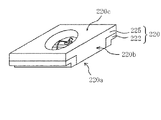
第3の実施の形態に係る発光装置は、熱硬化後の、波長350nm〜800nmにおける光反射率が70%以上であり、外側面220bにおいて樹脂部225とリード222とが略同一面に形成されている樹脂パッケージ220を有する発光装置である。リード222は底面及び上面にメッキ処理を施しており、かつ、外側面はメッキ処理が施されていない部分を有する。リード222は、所定の厚みを有しており、樹脂パッケージ220の外側面付近に段差を設けている。この段差の一段奥まった側面側とわずかに外側に張り出した底面側にはメッキ処理を施している。このようにリード222にメッキ処理を施した段差を設けることにより、接合面積が増え、半田等の導電性部材との接合強度を向上させることができる。また、ダイシングソーを用いて切断する部分のリード222の厚みを薄くすることができるため、切断時間の短縮を図ることができる。また、樹脂パッケージ220の外上面側からダイシングソーを用いてダイシングを行うため、リード222の切断面において外底面方向に延びるバリが生じやすい。リードの切断面が外底面と同一面である場合、発光装置を実装する際にバリにより発光装置が傾くことが生じる場合もあるが、リードの切断面に段差を設けることにより、バリが外底面まで届かずバリにより発光装置が傾くことはない。
The light emitting device according to the third embodiment has a light reflectance of 70% or more at a wavelength of 350 nm to 800 nm after heat curing, and the
段差は、樹脂パッケージ220から露出されたリード222において、樹脂パッケージ220の外底面220aで露出された第一面と、外底面220aから上方方向に略直角に形成された第二面と、第二面から樹脂パッケージ220の外側面方向に略直角に形成された第三面と、樹脂パッケージ220の外側面で露出された第四面とからなる。第一面、第二面及び第三面は、メッキ処理を施しているが、第四面はメッキ処理を施していない。第二面および第三面はひとつの曲面にすることもできる。第二面および第三面を曲面にすることにより、段差部内において半田が広がり易い。
In the
樹脂パッケージ220は、外上面220cにおいて略正方形形状を成しており、樹脂部225に覆われている。樹脂パッケージ220の外上面220c側には略円錐台形の凹部を設けている。
(第3の実施の形態に係る発光装置の製造方法)
第3の実施の形態に係る発光装置の製造方法において、リードフレーム221には発光装置の外底面側に相当する側に略直線上の溝221cを設ける。この溝221cの深さはリードフレーム221の厚みの半分程度であることが好ましいが、1/4〜4/5程度の深さでもよい。この溝221cの幅は、隣り合う凹部までの距離、発光装置の大きさ等により、種々変更されるが、その溝の中心を切断した場合に発光装置に段差があると認識できる程度のものであればよい。
The
(Manufacturing method of light emitting device according to the third embodiment)
In the method for manufacturing a light emitting device according to the third embodiment, the
切り欠き部221aを設けたリードフレーム221を上金型と下金型とで挟み込む。切り欠き部221aがトランスファ・モールドの際、バタつかないように上金型と下金型とで挟み込む。
The
上金型と下金型とで挟み込まれた金型内に、光反射性物質が含有される熱硬化性樹脂をトランスファ・モールドして、リードフレーム221に樹脂成形体を形成する。
A thermosetting resin containing a light-reflecting substance is transfer-molded in a mold sandwiched between an upper mold and a lower mold to form a resin molded body on a
樹脂成形体のリードフレーム221の露出部分にメッキ処理を施す。凹部の内底面、リードフレーム221の外底面220a、溝221cにメッキ処理を施す。この溝221cのメッキ処理は、発光装置における段差の第一面、第二面、第三面に相当する。
The exposed portion of the
切り欠き部221aに沿って樹脂成形体とリードフレームとを切断する。また、溝221cに沿って樹脂成形体を切断する。
The resin molded body and the lead frame are cut along the
以上の工程を経ることにより第3の実施の形態に係る発光装置を提供することができる。この製造方法によれば、簡易かつ短時間でリードフレーム121にメッキ処理された部分を多く有する発光装置を提供することができる。
By going through the above steps, the light emitting device according to the third embodiment can be provided. According to this manufacturing method, it is possible to provide a light emitting device having a large number of plated portions on the
<第4の実施の形態>
第4の実施の形態に係る発光装置について説明する。図11は、第4の実施の形態に係る発光装置を示す斜視図である。第1の実施の形態に係る発光装置とほぼ同様の構成を採るところは説明を省略することもある。
<Fourth Embodiment>
The light emitting device according to the fourth embodiment will be described. FIG. 11 is a perspective view showing a light emitting device according to a fourth embodiment. The description may be omitted where a configuration substantially similar to that of the light emitting device according to the first embodiment is adopted.
第4の実施の形態に係る発光装置は、樹脂パッケージ320の外側面320bのリード322において、一部のみ外側面320bから凹んだ段差を有している。段差は、樹脂パッケージ320から露出されたリード322において、樹脂パッケージ320の外底面320aに設けられた第一面と、外底面320aから上方方向に略直角に形成された第二面と、第二面から樹脂パッケージ320の外側面方向に略直角に形成された第三面と、樹脂パッケージ320の外側面の第四面とからなる。樹脂パッケージ320の外上面320cは樹脂部325からなる略長方形に形成されている。外底面320a、第一面、段差を設けた第二面、第三面及び凹部の内底面はメッキ処理を施している。一方、段差を設けていない外側面320bは、メッキ処理を施していない。
The light emitting device according to the fourth embodiment has a step recessed from the
リード322はエッチング加工されたリードフレームを用いる。樹脂成形体の切断面において、エッチング加工されたリード322は凹凸を有している。この凹凸が樹脂部とリードとの密着性の向上を図っている。
The
リード322の一部に段差を設けることによって実装時における導電性部材との接合面積を広くすることができ、接合強度を高くすることができる。また、リードフレームに凹みを設けているため、切断し易くなり、切断に要する時間も短縮することができる。
<第5の実施の形態>
第5の実施の形態に係る発光装置について説明する。図12は、第5の実施の形態に係る発光装置を示す斜視図である。第1の実施の形態に係る発光装置とほぼ同様の構成を採るところは説明を省略することもある。
By providing a step on a part of the
<Fifth Embodiment>
The light emitting device according to the fifth embodiment will be described. FIG. 12 is a perspective view showing a light emitting device according to a fifth embodiment. The description may be omitted where a configuration substantially similar to that of the light emitting device according to the first embodiment is adopted.
第5の実施の形態に係る発光装置は、樹脂パッケージ420の外側面420bのリード422において、一部のみ外側面420bから凹んだ段差を有している。段差は、樹脂パッケージ420から露出されたリード422において、樹脂パッケージ420の外底面420aに設けられた第一面と、外底面420aから上方方向に略直角に形成された第二面と、第二面から樹脂パッケージ420の外側面方向に略直角に形成された第三面と、樹脂パッケージ420の外側面の第四面とからなる。樹脂パッケージ420の外側面420bは、リード422が6つに分離されている。リード422はそれぞれ分離されていてもよく、連結されていてもよい。リード422は平板状よりも切り欠き部を設けている方が樹脂部425とリード422との接合強度がより高くなるため好ましい。樹脂パッケージ420の外上面420cは樹脂部425からなる略長方形に形成されている。外底面420a、第一面、段差を設けた第二面、第三面及び凹部の内底面はメッキ処理を施している。一方、段差を設けていない外側面420bは、メッキ処理を施していない。
The light emitting device according to the fifth embodiment has a step recessed from the
リード422の一部に段差を設けることによって導電性部材との接合面積を広くすることができ、接合強度を高くすることができる。また、リードフレームに凹みを設けているため、切断し易くなり、切断に要する時間も短縮することができる。
<第6の実施の形態>
第6の実施の形態に係る樹脂パッケージについて説明する。図13は、第6の実施の形態に係る樹脂パッケージを示す斜視図である。第1の実施の形態に係る樹脂パッケージ、第5の実施の形態に係る樹脂パッケージとほぼ同様の構成を採るところは説明を省略することもある。
By providing a step on a part of the
<Sixth Embodiment>
The resin package according to the sixth embodiment will be described. FIG. 13 is a perspective view showing the resin package according to the sixth embodiment. The description may be omitted where the resin package according to the first embodiment and the resin package according to the fifth embodiment have substantially the same configurations.
第6の実施の形態に係る樹脂パッケージは、樹脂パッケージ520の外側面520bのリード522において、隅部が凹んだ段差を有している。この段差は、樹脂パッケージ520から露出されたリード522において、外底面520a側から見て円弧形状になっている。この円弧形状は、円を四分割したものである。この円弧形状は、リード522を貫通しないように、厚みの略半分程度までのエッチング処理を行い、その後、四分割したものである。この円弧形状の部分にはメッキ処理が施されている。この円弧形状部分へのメッキ処理及び外底面520aへのメッキ処理は、四分割する前に行っている。一方、段差を設けていない外側面520bは、メッキ処理を施していない。樹脂パッケージ520は外上面520cから見ると略正方形形状を成しており、樹脂部525が露出している。
The resin package according to the sixth embodiment has a step with a recessed corner in the
リード522の一部に段差を設けることによって導電性部材との接合面積を広くすることができ、接合強度を高くすることができる。また、樹脂成形体の切断時において段差部分にバリが生じても外底面520aよりも上方であるため、導電部材との接合時にぐらつきを生じない。更に、リードフレームに凹みを設けているため、切断し易くなり、切断に要する時間も短縮することができる。
By providing a step on a part of the
実施例1に係る発光装置を説明する。第1の実施の形態で説明したところと重複するところは説明を省略することもある。図1は、第1の実施の形態に係る発光装置を示す斜視図である。図2は、第1の実施の形態に係る発光装置を示す断面図である。図2は図1に示すII−IIの断面図である。図3は、第1の実施の形態に用いられるリードフレームを示す平面図である。 The light emitting device according to the first embodiment will be described. The description may be omitted if it overlaps with the description in the first embodiment. FIG. 1 is a perspective view showing a light emitting device according to the first embodiment. FIG. 2 is a cross-sectional view showing a light emitting device according to the first embodiment. FIG. 2 is a cross-sectional view of II-II shown in FIG. FIG. 3 is a plan view showing a lead frame used in the first embodiment.
発光装置100は、発光素子10と、光反射物質26を含有する樹脂部25とリード22とが一体成形された樹脂パッケージ20と、を有する。発光素子10は450nmに発光ピーク波長を持ち青色に発光する窒化物半導体発光素子である。樹脂パッケージ20はすり鉢状の凹部27を持つ略直方体の形状を成している。樹脂パッケージ20の大きさは縦35mm、横35mm、高さ0.8mmであり、凹部27の外上面20c側の略直径は2.9mm、内底面27aの略直径は2.6mm、深さは0.6mmである。リード22の厚みは0.2mmである。光反射物質26には酸化チタンを使用する。樹脂部25には熱硬化性樹脂であるエポキシ樹脂を用いる。酸化チタンはエポキシ樹脂中に20重量%程度含有している。樹脂パッケージ20は、熱硬化後の、波長450nmにおける光反射率が81%である。樹脂パッケージ20の外側面20bにおいて樹脂部25とリード22とは略同一面に形成されている。リード22は樹脂パッケージ20の四隅から露出している。リード22は樹脂パッケージ20の外底面20a及び凹部27の内底面27aにメッキ処理を施している。一方、リード22は樹脂パッケージ20の外側面20bにメッキ処理を施していない。凹部27内に黄色に発光する蛍光物質40を含有する封止部材30を充填する。蛍光物質40として(Y,Gd)3(Al,Ga)5O12:Ceを使用する。封止部材30としてシリコーン樹脂を使用する。
The
この発光装置は以下のようにして製造される。 This light emitting device is manufactured as follows.
リードフレームはエッチング加工により切り欠き部21aを設ける。図示しないが切り欠き部21aの断面は凹凸が形成されている。そのリードフレームにAgを電解メッキにより付着させる。切り欠き部21aが設けられメッキ処理が施されたリードフレーム21を用いる。
The lead frame is provided with a
次に、所定の大きさのリードフレーム21を上金型61と下金型62とで挟み込む。リードフレーム21は平板状であって、個片化する発光装置の大きさに応じた切り欠き部21aを設けている。切り欠き部21aは樹脂パッケージ20に個片化した際に四隅が露出し、四隅以外は露出しないように縦横に設けられている。また、切り欠き部21aは、樹脂パッケージ20に個片化した際に電気的に絶縁されるように横方向に設けられており、上金型61と下金型62とでこの切り欠き部21aを挟み込んでいる。
Next, a
上金型61と下金型62とで挟み込まれた金型60内に、光反射性物質26を含有する熱硬化性樹脂23をトランスファ・モールドして、リードフレーム21に樹脂成形体24を形成する。光反射性物質26を含有した熱硬化性樹脂23をペレット状にし、熱と圧力を加えて金型60内に流し込む。このとき切り欠き部21aにも熱硬化性樹脂23が充填される。流し込まれた熱硬化性樹脂23を仮硬化した後、上金型61を取り外し、更に熱を加えて本硬化を行う。これによりリードフレーム21と熱硬化性樹脂23とが一体成形された樹脂成形体24が製造される。
A
次に、発光素子10を凹部27の内底面27aのリード22上にダイボンド部材を用いて実装する。発光素子10を載置した後、発光素子10とリード22とをワイヤ50を用いて電気的に接続する。次に、蛍光物質40を含有した封止部材30を凹部27内に充填する。
Next, the
最後に、切り欠き部21aに沿って樹脂成形体24とリードフレーム21とを切断して個々の発光装置100となるように個片化する。これにより切断部分においてリード22はメッキ処理されていない。
Finally, the resin molded
以上の工程を経ることにより、一度に多数個の発光装置100を製造することができる。
By going through the above steps, a large number of light emitting
本発明は、照明器具、ディスプレイ、携帯電話のバックライト、動画照明補助光源、その他の一般的民生用光源などに利用することができる。 The present invention can be used for lighting equipment, displays, backlights for mobile phones, auxiliary light sources for moving images, and other general consumer light sources.
10、110 発光素子
20、120、220、320、420、520 樹脂パッケージ
20a、120a、220a、320a、420a、520a 外底面
20b、120b、220b、320b、420b、520b 外側面
20c、120c、220c、320c、420c、520c 外上面
21、121、221 リードフレーム
21a、121a、221a 切り欠き部
121b 孔部
221c 溝
22、122、222、322、422、522 リード
23 熱硬化性樹脂
24 樹脂成形体
25、125、225、325、425、525 樹脂部
26 光反射性物質
27 凹部
27a 内底面
27b 内側面
30 封止部材
40 蛍光物質
50 ワイヤ
60 金型
61 上金型
62 下金型
70 ダイシングソー
100 発光装置
10, 110
Claims (21)
(a)前記樹脂成形体付リードフレームの上側には、上面視において互いに垂直な複数の切断予定ラインにより区切られてなる複数の四角形の領域それぞれに凹部が設けられており、
(b)前記凹部の底面には、前記リードフレームが前記樹脂成形体で分割されて露出しており、
(c)前記樹脂成形体付リードフレームの底面には、前記リードフレームが露出しており、
(d)前記リードフレームには、前記切断予定ラインの何れかに沿って配列された、上面及び下面を貫通する複数の切り欠き部と、前記切断予定ラインの何れかに沿って配列された、前記上面及び前記下面を貫通する複数の孔部と、が形成されており、前記複数の切り欠き部それぞれには前記樹脂成形体の一部が入り込んでおり、かつ、前記複数の孔部それぞれには前記樹脂成形体の一部が入り込んでいない、樹脂成形体付リードフレームを準備する工程と、
前記複数の凹部それぞれの底面に発光素子を載置する工程と、
前記凹部内に、前記発光素子を被覆する封止部材を配置する工程と、
前記切断予定ラインに沿って前記樹脂成形体付リードフレームを切断することにより、製造される複数の発光装置それぞれにおいて、前記リードフレームの一部及び前記切り欠き部に入り込んだ前記樹脂成形体の一部を切断面において略同一面に形成するとともに、前記リードフレームの前記孔部の内側面を切断面よりも内側の位置で前記樹脂成形体から露出させる工程と、を有することを特徴とする発光装置の製造方法。
This is a step of preparing a lead frame and a lead frame with a resin molded body having a resin molded body.
(A) On the upper side of the lead frame with a resin molded body, recesses are provided in each of a plurality of quadrangular regions separated by a plurality of planned cutting lines perpendicular to each other in the top view.
(B) The lead frame is divided and exposed by the resin molded body on the bottom surface of the recess.
(C) The lead frame is exposed on the bottom surface of the lead frame with a resin molded body.
(D) The lead frame has a plurality of notches arranged along any of the planned cutting lines, penetrating the upper surface and the lower surface, and arranged along any of the planned cutting lines. A plurality of holes penetrating the upper surface and the lower surface are formed, and a part of the resin molded body is inserted into each of the plurality of notches, and each of the plurality of holes has a portion of the resin molded body. Is the process of preparing a lead frame with a resin molded body in which a part of the resin molded body is not contained, and
A step of placing a light emitting element on the bottom surface of each of the plurality of recesses, and
A step of arranging a sealing member covering the light emitting element in the recess, and
One of the resin molded bodies that has entered a part of the lead frame and the notch in each of the plurality of light emitting devices manufactured by cutting the lead frame with the resin molded body along the planned cutting line. Light emission is characterized by having a step of forming the portions on substantially the same surface on the cut surface and exposing the inner side surface of the hole portion of the lead frame from the resin molded body at a position inside the cut surface. Manufacturing method of the device.
The method for manufacturing a light emitting device according to claim 1, wherein the cutout portion is provided over ½ or more of the entire surrounding circumference of the light emitting device to be manufactured.
The method for manufacturing a light emitting device according to claim 1 or 2, wherein in the step of preparing the lead frame with a resin molded body, the entire surface of the lead frame is silver-plated.
The step according to any one of claims 1 to 3, wherein in the step of preparing the lead frame with a resin molded body, the lead frame has steps or irregularities in all the portions defining the cutout portion. The method for manufacturing a light emitting device according to the description.
The step according to any one of claims 1 to 4, wherein in the step of preparing the lead frame with a resin molded body, the lead frame has a portion etched from one side so as not to penetrate the lead frame. The method for manufacturing a light emitting device according to the description.
The method for manufacturing a light emitting device according to any one of claims 1 to 5, wherein the resin molded body contains a triazine derivative epoxy resin.
The method for manufacturing a light emitting device according to any one of claims 1 to 6, wherein a sealing member containing a fluorescent substance is used as the sealing member in the step of arranging the sealing member.
前記複数の発光装置を得る工程において、前記溝を通って前記リードフレームを切断することを特徴とする請求項1〜7のいずれか1項に記載の発光装置の製造方法。
The lead frame further has at least one groove on any of the lines to be cut.
The method for manufacturing a light emitting device according to any one of claims 1 to 7, wherein in the step of obtaining the plurality of light emitting devices, the lead frame is cut through the groove.
前記切断面に露出する前記リードフレームの一部の切断面は凹凸を有することを特徴とする請求項1〜8のいずれか1項に記載の発光装置の製造方法。
In the step of obtaining the plurality of light emitting devices,
The method for manufacturing a light emitting device according to any one of claims 1 to 8, wherein a part of the cut surface of the lead frame exposed to the cut surface has irregularities.
The method for manufacturing a light emitting device according to any one of claims 1 to 9, wherein at least one of the plurality of cutout portions is inclined with respect to the planned cutting line.
前記リードフレームには前記外側面となる4つの位置のいずれにも前記切り欠き部が設けられていることを特徴とする請求項1〜10のいずれか1項に記載の発光装置の製造方法。
The light emitting device has a substantially quadrangular outer shape when viewed from above and has four outer surfaces.
The method for manufacturing a light emitting device according to any one of claims 1 to 10, wherein the lead frame is provided with the notch at any of the four positions on the outer surface.
上面視において、前記リードフレームの前記孔部と連続する上面の一部を、前記樹脂成形体から突出するように露出させる、請求項1〜11のいずれか1項に記載の発光装置の製造方法。
In the step of exposing the inner side surface of the hole portion of the lead frame from the resin molded body at a position inside the cut surface.
The method for manufacturing a light emitting device according to any one of claims 1 to 11, wherein a part of the upper surface continuous with the hole of the lead frame is exposed so as to protrude from the resin molded body in a top view. ..
前記リードは、前記発光装置の底面にて露出し、少なくとも2つの対向する前記外側面それぞれに切り欠き部を有し、
前記樹脂部の一部は、前記切り欠き部のそれぞれに入り込んでおり、
前記切り欠き部に入り込んだ樹脂部は、前記リードの側面の一部と略同一平面上にあり、前記リードの側面は、上面視において前記外側面から内側に凹み、前記樹脂部から露出した露出面を有する、
発光装置。
A resin package having a lead having a positive lead and a lead having a negative lead and a resin portion, and having a recess having a bottom surface in which a part of the positive lead and a part of the negative lead are exposed, and a bottom surface of the recess. A light emitting device having a light emitting element mounted on a light emitting element and a sealing member for covering the light emitting element in the recess, and having four outer surfaces which are substantially quadrangular in a top view.
The leads are exposed on the bottom surface of the light emitting device and have notches on at least two opposing outer surfaces.
A part of the resin portion is inserted into each of the notch portions.
The resin portion that has entered the cutout portion is substantially on the same plane as a part of the side surface of the lead, and the side surface of the lead is recessed inward from the outer surface in a top view and is exposed from the resin portion. Have a face,
Light emitting device.
The light emitting device according to claim 13, wherein the cutout portion is provided over ½ or more of the entire surrounding circumference of the light emitting device to be manufactured.
The light emitting device according to claim 13 or 14, wherein the lead is silver-plated on the entire surface except the outer surface.
The light emitting device according to any one of claims 13 to 15, wherein the lead has steps or irregularities in all the portions defining the cutout portion.
The light emitting device according to any one of claims 13 to 16, wherein the lead has a portion etched from one side so as not to penetrate the lead.
The light emitting device according to any one of claims 13 to 17, wherein the resin portion contains a triazine derivative epoxy resin.
The light emitting device according to any one of claims 13 to 18, wherein the sealing member contains a fluorescent substance.
The light emitting device according to any one of claims 13 to 19, wherein the notch portions are provided on all four sides of the light emitting device which is a substantially quadrangular shape.
Priority Applications (3)
| Application Number | Priority Date | Filing Date | Title |
|---|---|---|---|
| JP2020070531A JP6888709B2 (en) | 2020-04-09 | 2020-04-09 | Manufacturing method of light emitting device and light emitting device |
| JP2021084519A JP7108221B2 (en) | 2020-04-09 | 2021-05-19 | Light-emitting device manufacturing method and light-emitting device |
| JP2022110506A JP7252503B2 (en) | 2020-04-09 | 2022-07-08 | Light-emitting device manufacturing method and light-emitting device |
Applications Claiming Priority (1)
| Application Number | Priority Date | Filing Date | Title |
|---|---|---|---|
| JP2020070531A JP6888709B2 (en) | 2020-04-09 | 2020-04-09 | Manufacturing method of light emitting device and light emitting device |
Related Parent Applications (1)
| Application Number | Title | Priority Date | Filing Date |
|---|---|---|---|
| JP2018090362A Division JP6797861B2 (en) | 2018-05-09 | 2018-05-09 | Manufacturing method of light emitting device and light emitting device |
Related Child Applications (1)
| Application Number | Title | Priority Date | Filing Date |
|---|---|---|---|
| JP2021084519A Division JP7108221B2 (en) | 2020-04-09 | 2021-05-19 | Light-emitting device manufacturing method and light-emitting device |
Publications (2)
| Publication Number | Publication Date |
|---|---|
| JP2020127026A JP2020127026A (en) | 2020-08-20 |
| JP6888709B2 true JP6888709B2 (en) | 2021-06-16 |
Family
ID=72084304
Family Applications (2)
| Application Number | Title | Priority Date | Filing Date |
|---|---|---|---|
| JP2020070531A Active JP6888709B2 (en) | 2020-04-09 | 2020-04-09 | Manufacturing method of light emitting device and light emitting device |
| JP2021084519A Active JP7108221B2 (en) | 2020-04-09 | 2021-05-19 | Light-emitting device manufacturing method and light-emitting device |
Family Applications After (1)
| Application Number | Title | Priority Date | Filing Date |
|---|---|---|---|
| JP2021084519A Active JP7108221B2 (en) | 2020-04-09 | 2021-05-19 | Light-emitting device manufacturing method and light-emitting device |
Country Status (1)
| Country | Link |
|---|---|
| JP (2) | JP6888709B2 (en) |
Family Cites Families (7)
| Publication number | Priority date | Publication date | Assignee | Title |
|---|---|---|---|---|
| JP3217322B2 (en) | 1999-02-18 | 2001-10-09 | 日亜化学工業株式会社 | Chip component type light emitting device |
| JP2002314143A (en) * | 2001-04-09 | 2002-10-25 | Toshiba Corp | Light emitting device |
| JP3915794B2 (en) * | 2003-04-02 | 2007-05-16 | ヤマハ株式会社 | Semiconductor package, manufacturing method thereof, and lead frame used for the same |
| JP2006086178A (en) * | 2004-09-14 | 2006-03-30 | Toshiba Corp | Resin-sealed optical semiconductor device |
| JP5232369B2 (en) * | 2006-02-03 | 2013-07-10 | 日立化成株式会社 | Manufacturing method of package substrate for mounting optical semiconductor element and manufacturing method of optical semiconductor device using the same |
| JP5057707B2 (en) * | 2006-06-16 | 2012-10-24 | 日亜化学工業株式会社 | Light emitting device |
| JP4872683B2 (en) * | 2007-01-29 | 2012-02-08 | 株式会社デンソー | Mold package manufacturing method |
-
2020
- 2020-04-09 JP JP2020070531A patent/JP6888709B2/en active Active
-
2021
- 2021-05-19 JP JP2021084519A patent/JP7108221B2/en active Active
Also Published As
| Publication number | Publication date |
|---|---|
| JP7108221B2 (en) | 2022-07-28 |
| JP2021121033A (en) | 2021-08-19 |
| JP2020127026A (en) | 2020-08-20 |
Similar Documents
| Publication | Publication Date | Title |
|---|---|---|
| US11094854B2 (en) | Light emitting device, resin package, resin-molded body, and methods for manufacturing light emitting device, resin package and resin-molded body | |
| JP6056934B2 (en) | Light emitting device, resin package, resin molded body, and manufacturing method thereof | |
| JP6797861B2 (en) | Manufacturing method of light emitting device and light emitting device | |
| JP5527450B2 (en) | Light emitting device, resin package, resin molded body, and manufacturing method thereof | |
| JP6164355B2 (en) | Light emitting device, resin package, resin molded body, and manufacturing method thereof | |
| JP6888709B2 (en) | Manufacturing method of light emitting device and light emitting device | |
| JP5825390B2 (en) | Light emitting device, resin package, resin molded body, and manufacturing method thereof | |
| JP2013145908A (en) | Light-emitting device, resin package, resin molding and method for manufacturing them | |
| JP7252503B2 (en) | Light-emitting device manufacturing method and light-emitting device | |
| JP6489162B2 (en) | Lead frame with resin molded body, method of manufacturing the same, and lead frame used in the same | |
| JP7469722B2 (en) | Light emitting device manufacturing method and light emitting device |
Legal Events
| Date | Code | Title | Description |
|---|---|---|---|
| A621 | Written request for application examination |
Free format text: JAPANESE INTERMEDIATE CODE: A621 Effective date: 20200409 |
|
| A977 | Report on retrieval |
Free format text: JAPANESE INTERMEDIATE CODE: A971007 Effective date: 20210324 |
|
| TRDD | Decision of grant or rejection written | ||
| A01 | Written decision to grant a patent or to grant a registration (utility model) |
Free format text: JAPANESE INTERMEDIATE CODE: A01 Effective date: 20210420 |
|
| A61 | First payment of annual fees (during grant procedure) |
Free format text: JAPANESE INTERMEDIATE CODE: A61 Effective date: 20210503 |
|
| R150 | Certificate of patent or registration of utility model |
Ref document number: 6888709 Country of ref document: JP Free format text: JAPANESE INTERMEDIATE CODE: R150 |
|
| R250 | Receipt of annual fees |
Free format text: JAPANESE INTERMEDIATE CODE: R250 |