JP6888391B2 - Pachinko machine - Google Patents
Pachinko machine Download PDFInfo
- Publication number
- JP6888391B2 JP6888391B2 JP2017083382A JP2017083382A JP6888391B2 JP 6888391 B2 JP6888391 B2 JP 6888391B2 JP 2017083382 A JP2017083382 A JP 2017083382A JP 2017083382 A JP2017083382 A JP 2017083382A JP 6888391 B2 JP6888391 B2 JP 6888391B2
- Authority
- JP
- Japan
- Prior art keywords
- symbol
- discrimination
- notice effect
- image
- advance notice
- Prior art date
- Legal status (The legal status is an assumption and is not a legal conclusion. Google has not performed a legal analysis and makes no representation as to the accuracy of the status listed.)
- Active
Links
Images


Description
本発明は、パチンコ機に代表される遊技機に関するものである。 The present invention relates to a gaming machine represented by a pachinko machine.
パチンコ機等の遊技機において、液晶表示装置等の表示装置が設けられた遊技機が知られている。この従来型の遊技機では、表示装置において図柄の変動表示が行われ、予め定められた図柄が停止表示されることで、遊技者に有利な当たり遊技が付与される。また、表示装置には、図柄以外にもキャラクタや風景等の様々な画像が表示され、多種多様な興趣演出を実行することで遊技の興趣向上を図っていた。 Among gaming machines such as pachinko machines, gaming machines provided with a display device such as a liquid crystal display device are known. In this conventional gaming machine, a variable display of symbols is performed on a display device, and a predetermined symbol is stopped and displayed, so that a winning game advantageous to the player is given. In addition to the symbols, various images such as characters and landscapes are displayed on the display device, and a wide variety of entertainment effects are performed to improve the interest of the game.
しかしながら、さらなる興趣向上が求められている。本発明は、上記例示した問題点等を解決するためになされたものであり、遊技者の遊技に対する興趣を向上させることができる遊技機を提供することを目的とする。 However, further improvement of interest is required. The present invention has been made to solve the above-exemplified problems and the like, and an object of the present invention is to provide a gaming machine capable of improving a player's interest in playing a game.
この目的を達成するために請求項1記載の遊技機は、遊技に関する主な制御を実行する主制御手段と、その主制御手段から出力される制御信号に基づいて制御を行う従制御手段と、を備えたものであって、前記主制御手段は、判別条件の成立に基づいて判別を実行する判別手段と、その判別手段の判別結果が予め定められた特定の判別結果となったことに基づいて、遊技者に有利な特典遊技を実行する特典遊技実行手段と、前記判別手段の判別結果を示す判別結果信号を前記従制御手段に出力する第1出力手段と、所定の取得条件の成立に基づいて、前記判別手段の判別に用いる判別情報を取得する判別情報取得手段と、その判別情報取得手段により取得された前記判別情報を、予め定められた特定の情報数を上限として、当該取得された判別情報が前記判別手段の判別に用いられるまで記憶可能に構成された判別情報記憶手段と、前記判別情報取得手段によって取得された前記判別情報に基づく判別情報信号を、前記判別条件が成立するよりも前に前記従制御手段に出力可能な第2出力手段と、を備え、前記従制御手段は、前記第1出力手段により出力された前記判別結果信号と、前記第2出力手段により出力された前記判別情報信号と、を少なくとも受信可能に構成された信号受信手段と、その信号受信手段により前記判別結果信号が受信されたことに基づいて、その受信された判別結果信号が示す判別結果に応じた第1演出を実行する第1演出実行手段と、前記信号受信手段により前記判別情報信号が受信されたことに基づいて、その受信された判別情報信号に応じて第2演出を実行するか判別する第1実行判別手段と、その第1実行判別手段による判別で前記第2演出を実行すると判別されたことに基づいて、当該判別よりも後に実行される1又は複数の前記第1演出の実行期間に渡る前記第2演出の実行を設定する第1設定手段と、前記信号受信手段により前記判別情報信号が受信されたことに基づいて、その受信された前記判別情報信号に応じた特定情報を、所定の情報数を上限として、対応する前記判別結果信号が前記信号受信手段により受信されるまで記憶可能に構成された情報記憶手段と、所定の設定条件の成立に基づいて、前記第2演出の実行の設定が抑制される抑制状態を設定する状態設定手段と、予め定められた所定条件が成立したことに基づいて、前記情報記憶手段に記憶された全ての前記特定情報に対して、一度に予め定められた法則に従った所定の処理を行うための所定処理手段と、一群のデータで構成されたデータであって、前記所定の処理の結果である所定のデータを所定の記憶領域に記憶する手段と、前記抑制状態が設定された後で予め定められた特定条件が成立したことを契機として、前記抑制状態を終了させる終了手段と、前記特定条件が成立したことを契機として、前記所定の記憶領域に記憶された前記所定のデータを用いて、前記第2演出を実行するか判別する第2実行判別手段と、その第2実行判別手段による判別で前記第2演出を実行すると判別されたことに基づいて、当該判別よりも後に実行される1又は複数の前記第1演出の実行期間に渡る前記第2演出の実行を設定する第2設定手段と、を備え、前記所定条件は、少なくとも前記抑制状態が設定されてから前記第2実行判別手段による判別が実行されるまでの間に成立し得る条件で構成されており、前記所定のデータは、前記情報記憶手段に記憶された前記特定情報の中に、前記特定の判別結果に対応する前記判別情報に基づく前記特定情報が含まれているか否かを少なくとも識別可能なデータで構成されており、前記所定処理手段は、所定の前記特定情報に対応するデータが前記所定のデータとして前記所定の記憶領域に反映されることを抑制可能であり、前記所定のデータは、1の前記特定情報のデータ量以下のデータ量で構成されている。
In order to achieve this object, the gaming machine according to
請求項2記載の遊技機は、請求項1記載の遊技機において、前記主制御手段を収納可能な収納手段を備える。The gaming machine according to
本発明の遊技機によれば、遊技に関する主な制御を実行する主制御手段と、その主制御手段から出力される制御信号に基づいて制御を行う従制御手段と、を備えたものであって、前記主制御手段は、判別条件の成立に基づいて判別を実行する判別手段と、その判別手段の判別結果が予め定められた特定の判別結果となったことに基づいて、遊技者に有利な特典遊技を実行する特典遊技実行手段と、前記判別手段の判別結果を示す判別結果信号を前記従制御手段に出力する第1出力手段と、所定の取得条件の成立に基づいて、前記判別手段の判別に用いる判別情報を取得する判別情報取得手段と、その判別情報取得手段により取得された前記判別情報を、予め定められた特定の情報数を上限として、当該取得された判別情報が前記判別手段の判別に用いられるまで記憶可能に構成された判別情報記憶手段と、前記判別情報取得手段によって取得された前記判別情報に基づく判別情報信号を、前記判別条件が成立するよりも前に前記従制御手段に出力可能な第2出力手段と、を備え、前記従制御手段は、前記第1出力手段により出力された前記判別結果信号と、前記第2出力手段により出力された前記判別情報信号と、を少なくとも受信可能に構成された信号受信手段と、その信号受信手段により前記判別結果信号が受信されたことに基づいて、その受信された判別結果信号が示す判別結果に応じた第1演出を実行する第1演出実行手段と、前記信号受信手段により前記判別情報信号が受信されたことに基づいて、その受信された判別情報信号に応じて第2演出を実行するか判別する第1実行判別手段と、その第1実行判別手段による判別で前記第2演出を実行すると判別されたことに基づいて、当該判別よりも後に実行される1又は複数の前記第1演出の実行期間に渡る前記第2演出の実行を設定する第1設定手段と、前記信号受信手段により前記判別情報信号が受信されたことに基づいて、その受信された前記判別情報信号に応じた特定情報を、所定の情報数を上限として、対応する前記判別結果信号が前記信号受信手段により受信されるまで記憶可能に構成された情報記憶手段と、所定の設定条件の成立に基づいて、前記第2演出の実行の設定が抑制される抑制状態を設定する状態設定手段と、予め定められた所定条件が成立したことに基づいて、前記情報記憶手段に記憶された全ての前記特定情報に対して、一度に予め定められた法則に従った所定の処理を行うための所定処理手段と、一群のデータで構成されたデータであって、前記所定の処理の結果である所定のデータを所定の記憶領域に記憶する手段と、前記抑制状態が設定された後で予め定められた特定条件が成立したことを契機として、前記抑制状態を終了させる終了手段と、前記特定条件が成立したことを契機として、前記所定の記憶領域に記憶された前記所定のデータを用いて、前記第2演出を実行するか判別する第2実行判別手段と、その第2実行判別手段による判別で前記第2演出を実行すると判別されたことに基づいて、当該判別よりも後に実行される1又は複数の前記第1演出の実行期間に渡る前記第2演出の実行を設定する第2設定手段と、を備え、前記所定条件は、少なくとも前記抑制状態が設定されてから前記第2実行判別手段による判別が実行されるまでの間に成立し得る条件で構成されており、前記所定のデータは、前記情報記憶手段に記憶された前記特定情報の中に、前記特定の判別結果に対応する前記判別情報に基づく前記特定情報が含まれているか否かを少なくとも識別可能なデータで構成されており、前記所定処理手段は、所定の前記特定情報に対応するデータが前記所定のデータとして前記所定の記憶領域に反映されることを抑制可能であり、前記所定のデータは、1の前記特定情報のデータ量以下のデータ量で構成されている。 According to the gaming machine of the present invention , the main control means for executing the main control related to the game and the sub-control means for performing the control based on the control signal output from the main control means are provided. The main control means is advantageous to the player based on the discriminating means that executes the discriminating based on the establishment of the discriminating condition and the discriminating result of the discriminating means becoming a predetermined specific discriminant result. Based on the establishment of a predetermined acquisition condition, the privilege game executing means for executing the privilege game, the first output means for outputting the discrimination result signal indicating the discrimination result of the discrimination means to the slave control means, and the discrimination means The discrimination information acquisition means for acquiring the discrimination information used for discrimination and the discrimination information acquired by the discrimination information acquisition means are limited to a predetermined number of specific information, and the acquired discrimination information is the discrimination means. The discriminant information storage means configured to be memorable until it is used for the discrimination and the discriminant information signal based on the discriminant information acquired by the discriminant information acquisition means are controlled by the slave control before the discriminant condition is satisfied. A second output means capable of being output to the means is provided, and the slave control means includes the discrimination result signal output by the first output means, the discrimination information signal output by the second output means, and the discrimination information signal. Based on the signal receiving means configured to be able to receive at least the above and the discrimination result signal received by the signal receiving means, the first effect according to the discrimination result indicated by the received discrimination result signal is executed. The first effect determining means for determining whether to execute the second effect according to the received discrimination information signal based on the reception of the discrimination information signal by the signal receiving means. Based on the determination that the second effect is to be executed by the determination by the first execution determination means, the second effect over the execution period of one or a plurality of the first effects executed after the determination. Based on the fact that the discrimination information signal is received by the first setting means for setting the execution of the effect and the signal receiving means, specific information according to the received discrimination information signal is provided with a predetermined number of information. As an upper limit, the setting of the execution of the second effect is suppressed based on the information storage means configured to be memorable until the corresponding determination result signal is received by the signal receiving means and the establishment of a predetermined setting condition. Based on the fact that the state setting means for setting the suppression state to be performed and the predetermined predetermined condition are satisfied , all the specific information stored in the information storage means can be stored in advance at once. A predetermined processing means for performing a predetermined process according to a predetermined rule and a data composed of a group of data, which is a result of the predetermined process, is stored in a predetermined storage area. The predetermined means and the termination means for terminating the suppression state when a predetermined specific condition is satisfied after the suppression state is set, and the predetermined condition when the specific condition is satisfied. Using the predetermined data stored in the storage area, it is determined that the second effect is executed by the second execution determination means for determining whether to execute the second effect and the determination by the second execution determination means. Based on the above, the predetermined condition includes at least one or a second setting means for setting the execution of the second effect over the execution period of the first effect, which is executed after the determination. It is composed of conditions that can be satisfied between the time when the suppression state is set and the time when the determination by the second execution determination means is executed, and the predetermined data is the specific data stored in the information storage means. The information is composed of data that can at least identify whether or not the specific information based on the discrimination information corresponding to the specific discrimination result is included in the information, and the predetermined processing means is the predetermined identification. it is possible to suppress the data corresponding to the information is reflected in the predetermined storage area as the predetermined data, the predetermined data, that contains the data amount less data amount of the specific information of 1 ..
これにより、遊技者の遊技に対する興趣を向上させることができるという効果がある。 This has the effect of improving the interest of the player in the game.
<第1実施形態>
以下、本発明の第1実施形態について、添付図面を参照して説明する。図1は、第1実施形態におけるパチンコ機10の正面図であり、図2はパチンコ機10の遊技盤13の正面図であり、図3はパチンコ機10の背面図である。
<First Embodiment>
Hereinafter, the first embodiment of the present invention will be described with reference to the accompanying drawings. FIG. 1 is a front view of the
パチンコ機10は、図1に示すように、略矩形状に組み合わせた木枠により外殻が形成される外枠11と、その外枠11と略同一の外形形状に形成され外枠11に対して開閉可能に支持された内枠12とを備えている。外枠11には、内枠12を支持するために正面視(図1参照)左側の上下2カ所に金属製のヒンジ18が取り付けられ、そのヒンジ18が設けられた側を開閉の軸として内枠12が正面手前側へ開閉可能に支持されている。
As shown in FIG. 1, the
内枠12には、多数の釘や入賞口63,64等を有する遊技盤13(図2参照)が裏面側から着脱可能に装着される。この遊技盤13の前面を遊技球が流下することにより弾球遊技が行われる。なお、内枠12には、遊技球を遊技盤13の前面領域に発射する球発射ユニット112a(図8参照)やその球発射ユニット112aから発射された遊技球を遊技盤13の前面領域まで誘導する発射レール(図示せず)等が取り付けられている。
A game board 13 (see FIG. 2) having a large number of nails, winning
内枠12の前面側には、その前面上側を覆う前面枠14と、その下側を覆う下皿ユニット15とが設けられている。前面枠14及び下皿ユニット15を支持するために正面視(図1参照)左側の上下2カ所に金属製のヒンジ19が取り付けられ、そのヒンジ19が設けられた側を開閉の軸として前面枠14及び下皿ユニット15が正面手前側へ開閉可能に支持されている。なお、内枠12の施錠と前面枠14の施錠とは、シリンダ錠20の鍵穴21に専用の鍵を差し込んで所定の操作を行うことでそれぞれ解除される。
On the front side of the
前面枠14は、装飾用の樹脂部品や電気部品等を組み付けたものであり、その略中央部には略楕円形状に開口形成された窓部14cが設けられている。前面枠14の裏面側には2枚の板ガラスを有するガラスユニット16が配設され、そのガラスユニット16を介して遊技盤13の前面がパチンコ機10の正面側に視認可能となっている。
The front frame 14 is formed by assembling decorative resin parts, electric parts, and the like, and a
前面枠14には、遊技球を貯留する上皿17が前方へ張り出して上面を開放した略箱状に形成されており、この上皿17に賞球や貸出球などが排出される。上皿17の底面は正面視(図1参照)右側に下降傾斜して形成され、その傾斜により上皿17に投入された遊技球が球発射ユニット112aへと案内される。また、上皿17の上方には、枠ボタン22が設けられている。この枠ボタン22は、例えば、後述する第3図柄表示装置81(図2参照)で表示される演出のステージを変更したり、スーパーリーチの演出内容を変更したりする場合などに、遊技者により操作される。
On the front frame 14, an
ステージとは、第3図柄表示装置81に表示される各種演出に統一性を持たせた演出モードのことで、本パチンコ機10では「砂浜ステージ」,「深海ステージ」の2つのステージが設けられている。そして、後述する第1入球口64への入球(始動入賞)に伴って行われる変動演出やリーチ演出などの各種演出は、それぞれのステージに与えられたテーマに合わせて行われるように設計されている。ステージの変更は、変動演出が行われていない期間や高速変動中に遊技者によって枠ボタン22が操作された場合に行われ、枠ボタン22が操作される度に「砂浜ステージ」→「深海ステージ」→「砂浜ステージ」→・・・の順で繰り返し変更される。また、電源投入後の直後は、初期ステージとして「砂浜ステージ」が設定される。
The stage is an effect mode in which various effects displayed on the third
一方、第3図柄表示装置81には、ノーマルリーチ演出が開始された場合に、ノーマルリーチからスーパーリーチに発展させるときは、ノーマルリーチ中にスーパーリーチの演出態様の選択画面が表示されるように構成されており、その選択画面が表示されている間に、枠ボタン22が遊技者に操作されると、スーパーリーチ時の演出内容が変更される。
On the other hand, the third
前面枠14には、その周囲(例えばコーナー部分)に各種ランプ等の発光手段が設けられている。これら発光手段は、大当たり時や所定のリーチ時等における遊技状態の変化に応じて、点灯又は点滅することにより発光態様が変更制御され、遊技中の演出効果を高める役割を果たす。窓部14cの周縁には、LED等の発光手段を内蔵した電飾部29〜33が設けられている。パチンコ機10においては、これら電飾部29〜33が大当たりランプ等の演出ランプとして機能し、大当たり時やリーチ演出時等には内蔵するLEDの点灯や点滅によって各電飾部29〜33が点灯または点滅して、大当たり中である旨、或いは大当たり一歩手前のリーチ中である旨が報知される。また、前面枠14の正面視(図1参照)左上部には、LED等の発光手段が内蔵され賞球の払い出し中とエラー発生時とを表示可能な表示ランプ34が設けられている。
The front frame 14 is provided with light emitting means such as various lamps around the front frame 14 (for example, a corner portion). These light emitting means change and control the light emitting mode by lighting or blinking according to a change in the gaming state at the time of a big hit or a predetermined reach, and play a role of enhancing the effect during the game.
また、右側の電飾部32下側には、前面枠14の裏面側を視認できるように裏面側より透明樹脂を取り付けて小窓35が形成され、遊技盤13前面の貼着スペースK1(図2参照)に貼付される証紙等はパチンコ機10の前面から視認可能とされている。また、パチンコ機10においては、より煌びやかさを醸し出すために、電飾部29〜33の周りの領域にクロムメッキを施したABS樹脂製のメッキ部材36が取り付けられている。
Further, on the lower side of the illuminated
窓部14cの下方には、貸球操作部40が配設されている。貸球操作部40には度数表示部41と、球貸しボタン42と、返却ボタン43とが設けられている。パチンコ機10の側方に配置されるカードユニット(球貸しユニット)(図示せず)に紙幣やカード等を投入した状態で貸球操作部40が操作されると、その操作に応じて遊技球の貸出が行われる。具体的には、度数表示部41はカード等の残額情報が表示される領域であり、内蔵されたLEDが点灯して残額情報として残額が数字で表示される。球貸しボタン42は、カード等(記録媒体)に記録された情報に基づいて貸出球を得るために操作されるものであり、カード等に残額が存在する限りにおいて貸出球が上皿17に供給される。返却ボタン43は、カードユニットに挿入されたカード等の返却を求める際に操作される。なお、カードユニットを介さずに球貸し装置等から上皿17に遊技球が直接貸し出されるパチンコ機、いわゆる現金機では貸球操作部40が不要となるが、この場合には、貸球操作部40の設置部分に飾りシール等を付加して部品構成は共通のものとしても良い。カードユニットを用いたパチンコ機と現金機との共通化を図ることができる。
A ball
上皿17の下側に位置する下皿ユニット15には、その中央部に上皿17に貯留しきれなかった遊技球を貯留するための下皿50が上面を開放した略箱状に形成されている。下皿50の右側には、遊技球を遊技盤13の前面へ打ち込むために遊技者によって操作される操作ハンドル51が配設され、かかる操作ハンドル51の内部には球発射ユニット112aの駆動を許可するためのタッチセンサ51aと、押下操作している期間中には遊技球の発射を停止する押しボタン式の打ち止めスイッチ51bと、操作ハンドル51の回動操作量を電気抵抗の変化により検出する可変抵抗器(図示せず)とが内蔵されている。操作ハンドル51が遊技者によって右回りに回転操作されると、タッチセンサ51aがオンされると共に可変抵抗器の抵抗値が操作量に対応して変化し、操作ハンドル51の回動操作量に応じて変化する可変抵抗器の抵抗値に対応した強さ(発射強度)で遊技球が発射され、これにより遊技者の操作に対応した飛び量で遊技盤13の前面へ遊技球が打ち込まれる。また、操作ハンドル51が遊技者により操作されていない状態においては、タッチセンサ51aおよび打ち止めスイッチ51bがオフとなっている。
In the
下皿50の正面視下方部には、下皿50に貯留された遊技球を下方へ排出する際に操作するための球抜きレバー52が設けられている。この球抜きレバー52は、常時、右方向に付勢されており、その付勢に抗して左方向へスライドさせることにより、下皿50の底面に形成された底面口が開口して、その底面口から遊技球が自然落下して排出される。かかる球抜きレバー52の操作は、通常、下皿50の下方に下皿50から排出された遊技球を受け取る箱(一般に「千両箱」と称される)を置いた状態で行われる。下皿50の右方には、上述したように操作ハンドル51が配設され、下皿50の左方には灰皿53が取り付けられている。
A
図2に示すように、遊技盤13は、正面視略正方形状に切削加工した木製のベース板60に、球案内用の多数の釘や風車およびレール61,62、一般入賞口63、第1入球口64、可変入賞装置65、可変表示装置ユニット80等を組み付けて構成され、その周縁部が内枠12の裏面側に取り付けられる。一般入賞口63、第1入球口64、可変入賞装置65、可変表示装置ユニット80は、ルータ加工によってベース板60に形成された貫通穴に配設され、遊技盤13の前面側から木ネジ等により固定されている。また、遊技盤13の前面中央部分は、前面枠14の窓部14c(図1参照)を通じて内枠12の前面側から視認することができる。以下に、主に図2を参照して、遊技盤13の構成について説明する。
As shown in FIG. 2, the
遊技盤13の前面には、帯状の金属板を略円弧状に屈曲加工して形成した外レール62が植立され、その外レール62の内側位置には外レール62と同様に帯状の金属板で形成した円弧状の内レール61が植立される。この内レール61と外レール62とにより遊技盤13の前面外周が囲まれ、遊技盤13とガラスユニット16(図1参照)とにより前後が囲まれることにより、遊技盤13の前面には、遊技球の挙動により遊技が行われる遊技領域が形成される。遊技領域は、遊技盤13の前面であって2本のレール61,62と円弧部材70とにより区画して形成される略円形状の領域(入賞口等が配設され、発射された遊技球が流下する領域)である。
An
2本のレール61,62は、球発射ユニット112a(図8参照)から発射された遊技球を遊技盤13上部へ案内するために設けられたものである。内レール61の先端部分(図2の左上部)には戻り球防止部材68が取り付けられ、一旦、遊技盤13の上部へ案内された遊技球が再度球案内通路内に戻ってしまうといった事態が防止される。外レール62の先端部(図2の右上部)には、遊技球の最大飛翔部分に対応する位置に返しゴム69が取り付けられ、所定以上の勢いで発射された遊技球は、返しゴム69に当たって、勢いが減衰されつつ中央部側へ跳ね返される。また、内レール61の右下側の先端部と外レール62の右上側の先端部との間には、レール間を繋ぐ円弧を内面側に設けて形成された樹脂製の円弧部材70がベース板60に打ち込んで固定されている。
The two
本パチンコ機10では、遊技球が第1入球口64へ入球した場合に特別図柄(第1図柄)の抽選が行われ、遊技球が普通入球口67を通過した場合に普通図柄(第2図柄)の抽選が行われる。第1入球口64への入球に対して行われる特別図柄の抽選では、特別図柄の大当たりか否かの当否判定が行われると共に、特別図柄の大当たりと判定された場合にはその大当たり種別の判定も行われる。特別図柄の大当たりになると、パチンコ機10が特別遊技状態へ移行すると共に、通常時には閉鎖されている特定入賞口65aが所定時間(例えば、30秒経過するまで、或いは、遊技球が10個入賞するまで)開放され、その開放が16回(16ラウンド)繰り返される。その結果、その特定入賞口65aに多量の遊技球が入賞するので、通常時より多量の賞球の払い出しが行われる。特別図柄の大当たり種別としては、「大当たりA」、「大当たりB」の2種類が設けられており、特別遊技状態の終了後には大当たり終了後の付加価値として、これらの大当たり種別に応じた遊技上の価値(遊技価値)が遊技者に付与される。
In the
また、特別図柄(第1図柄)の抽選が行われると、第1図柄表示装置37において特別図柄の変動表示が開始されて、所定時間(例えば、7秒〜90秒など)が経過した後に、抽選結果を示す特別図柄が停止表示される。第1図柄表示装置37において変動表示が行われている間に遊技球が第1入球口64へ入球すると、その入球回数は最大4回まで保留され、その保留球数が第1図柄表示装置37により示されると共に、第3図柄表示装置81においても示される。第1図柄表示装置37において変動表示が終了した場合に、第1入球口64についての保留球数が残っていれば、次の特別図柄の抽選が行われると共に、その抽選に応じた変動表示が開始される。なお、パチンコ機10が特別遊技状態へ移行すると開閉される特定入賞口65aは、第1入球口64の直ぐ下に設けられている。よって、特別遊技状態中は、遊技者が特定入賞口65aに入賞させようとして遊技球を打つので、第1入球口64にも遊技球が多く入球する。従って、殆どの場合、パチンコ機10が特別遊技状態に移行している間に、第1入球口64についての保留球数は最大(4回)になる。
Further, when the special symbol (first symbol) is drawn, the variable display of the special symbol is started on the first
一方、普通入球口67における遊技球の通過に対して行われる普通図柄の抽選では、普通図柄の当たりか否かの当否判定が行われる。普通図柄の当たりになると、所定時間(例えば、0.2秒または1秒)だけ第1入球口64に付随する電動役物64aが開放され、第1入球口64へ遊技球が入球し易い状態になる。つまり、普通図柄の当たりになると、遊技球が第1入球口64へ入球し易くなり、その結果、特別図柄の抽選が行われ易くなる。
On the other hand, in the lottery of the normal symbol performed for the passage of the game ball at the
また、普通図柄(第2図柄)の抽選が行われると、第2図柄表示装置83において普通図柄の変動表示が開始されて、所定時間(例えば、3秒や30秒など)が経過した後に、抽選結果を示す普通図柄が停止表示される。第2図柄表示装置83において変動表示が行われている間に遊技球が普通入球口67を通過すると、その通過回数は最大4回まで保留され、その保留球数が第1図柄表示装置37により表示されると共に、第2図柄保留ランプ84においても示される。第2図柄表示装置83において変動表示が終了した場合に、普通入球口67についての保留球数が残っていれば、次の普通図柄の抽選が行われると共に、その抽選に応じた変動表示が開始される。
Further, when the lottery of the normal symbol (second symbol) is performed, the variable display of the normal symbol is started on the second
上述したように、特別図柄の大当たり種別としては、「大当たりA」、「大当たりB」の2種類が設けられている。「大当たりA」、及び「大当たりB」になるといずれも、ラウンド数が16ラウンドの特別遊技状態(16R大当たり)となる。また、大当たり種別が「大当たりA」の場合は、大当たり終了後の付加価値としてパチンコ機10が特別図柄の高確率状態(特別図柄の確変中)へ移行する。この特別図柄の高確率状態は次に特別図柄の大当たりとなるまで継続する。一方、「大当たりB」の終了後は付加価値として特別図柄の抽選が100回終了するまで普通図柄の当たり確率がアップする。
As described above, there are two types of special symbols, "big hit A" and "big hit B". In both cases of "big hit A" and "big hit B", the number of rounds is 16 rounds in a special gaming state (16R big hit). When the jackpot type is "big hit A", the
ここで、「特別図柄の高確率状態」とは、特別図柄の大当たり確率がアップした状態、いわゆる特別図柄の確率状態(特別図柄の確変中)をいい、換言すれば、特別遊技状態(16R大当たり)へ移行し易い遊技の状態のことである。対して、「特別図柄の高確率状態」でない場合を「特別図柄の低確率状態」といい、これは特別図柄の確変状態よりも大当たり確率が低い状態、即ち、特別図柄の大当たり確率が通常の状態(特別図柄の通常状態)のことを示す。また、「普通図柄の時短状態」(普通図柄の時短中)とは、普通図柄の当たり確率がアップして、第1入球口64へ遊技球が入球し易い遊技の状態のことをいう。対して、「普通図柄の時短状態」でない時を「普通図柄の通常状態」といい、これは普通図柄の当たり確率が通常の状態(時短中よりも当たり確率が低い状態)のことを示す。
Here, the "high probability state of the special symbol" means a state in which the jackpot probability of the special symbol is increased, that is, the probability state of the so-called special symbol (during the probability change of the special symbol), in other words, the special game state (16R jackpot). ) Is a state of the game that is easy to shift to. On the other hand, the case where it is not the "high probability state of the special symbol" is called the "low probability state of the special symbol", which means that the jackpot probability is lower than the probability variation state of the special symbol, that is, the jackpot probability of the special symbol is normal. Indicates a state (normal state of a special symbol). In addition, the "normal symbol time reduction state" (normal symbol time reduction medium) refers to a game state in which the probability of hitting the normal symbol is increased and the game ball can easily enter the
上述したように、本実施形態における特別図柄の大当たりでは、大当たりの種別に関わらず大当たり時のラウンド数を共通とし、大当たりの種別に応じて大当たりの終了後に「特別図柄の高確率状態」となるか「普通図柄の時短状態」となるかを変えている。これに対して、大当たりの種別に応じてラウンド数を変えても良いし、大当たりの種別の一部のみラウンド数を変えても良い。また、例えば、大当たりの種別に応じて「普通図柄の時短状態」となる期間を変えてもよい。また、普通図柄の時短状態として、第1入球口64に付随する電動役物64aを開放する時間を長くしたり、1回の普通図柄の当たりで電動役物64aを開放する回数を増やしても良い。
As described above, in the jackpot of the special symbol in the present embodiment, the number of rounds at the time of the jackpot is common regardless of the type of jackpot, and the "high probability state of the special symbol" is reached after the jackpot ends according to the type of jackpot. It is changing whether it becomes "normal symbol time saving state". On the other hand, the number of rounds may be changed according to the type of jackpot, or the number of rounds may be changed only for a part of the type of jackpot. Further, for example, the period of the "normal symbol time saving state" may be changed according to the type of jackpot. In addition, as a time saving state of the normal symbol, the time for opening the
遊技領域の正面視右側上部(図2の右側上部)には、発光手段である複数の発光ダイオード(以下、「LED」と略す。)37aと7セグメント表示器37bとが設けられた第1図柄表示装置37が配設されている。第1図柄表示装置37は、後述する主制御装置110で行われる各制御に応じた表示がなされるものであり、主にパチンコ機10の遊技状態の表示が行われる。複数のLED37aは、第1入球口64への入球(始動入賞)に伴って行われる特別図柄の抽選が実行中であるか否かを点灯状態により示すことによって変動表示を行ったり、変動終了後の停止図柄として、その特別図柄の抽選結果に応じた特別図柄(第1図柄)を点灯状態により示したり、第1入球口64に入球された遊技球のうち変動が未実行である遊技球(保留球)の数である保留球数を点灯状態により示すものである。
A first symbol provided with a plurality of light emitting diodes (hereinafter abbreviated as "LED") 37a and a 7-
この第1図柄表示装置37において特別図柄(第1図柄)の変動表示が行われている間に遊技球が第1入球口64へ入球した場合、その入球回数は最大4回まで保留され、その保留球数は第1図柄表示装置37により示されると共に、第3図柄表示装置81においても示される。なお、本実施形態においては、第1入球口64への入球は、最大4回まで保留されるように構成したが、最大保留回数は4回に限定されるものでなく、3回以下、又は、5回以上の回数(例えば、8回)に設定しても良い。
If a game ball enters the
7セグメント表示器37bは、大当たり中のラウンド数やエラー表示を行うものである。なお、LED37aは、それぞれのLEDの発光色(例えば、赤、緑、青)が異なるよう構成され、その発光色の組み合わせにより、少ないLEDでパチンコ機10の各種遊技状態(特別図柄の高確率状態や、普通図柄の時短中など)を表示することができる。また、LED37aには、変動終了後の停止図柄として特別図柄の抽選結果が大当たりであるか否かが示されるだけでなく、大当たりである場合はその大当たり種別(大当たりA、大当たりB)に応じた特別図柄(第1図柄)が示される。
The 7-
また、遊技領域には、遊技球が入賞することにより5個から15個の遊技球が賞球として払い出される複数の一般入賞口63が配設されている。また、遊技領域の中央部分には、可変表示装置ユニット80が配設されている。可変表示装置ユニット80には、液晶ディスプレイ(以下単に「表示装置」と略す。)で構成された第3図柄表示装置81と、LEDで構成された第2図柄表示装置83とが設けられている。この可変表示装置ユニット80には、第3図柄表示装置81の外周を囲むようにして、センターフレーム86が配設されている。
Further, in the game area, a plurality of general winning
第3図柄表示装置81は、第1図柄表示装置37の表示に応じた装飾的な表示を行うものである。例えば、第1入球口64へ遊技球が入球(始動入賞)すると、それをトリガとして、第1図柄表示装置37において特別図柄(第1図柄)の変動表示が実行される。更に、第3図柄表示装置81では、その特別図柄の変動表示に同期して、その特別図柄の変動表示に対応する第3図柄の変動表示が行われる。
The third
第3図柄表示装置81は、8インチの液晶ディスプレイで構成されるものであり、後述する表示制御装置114によって表示内容が制御されることにより、例えば左、中及び右の3つの図柄列が表示される。各図柄列は複数の図柄によって構成され、これらの図柄が図柄列毎に縦スクロールして第3図柄表示装置81の表示画面上にて第3図柄が可変表示されるようになっている。本実施形態では、主制御装置110の制御に伴った遊技状態の表示が第1図柄表示装置37で行われるのに対して、第3図柄表示装置81はその第1図柄表示装置37の表示に応じた装飾的な表示が行われる。なお、表示装置に代えて、例えば、リール等を用いて第3図柄表示装置81を構成するようにしても良い。
The third
ここで、図4を参照して、第3図柄表示装置81の表示内容について説明する。第3図柄表示装置81に表示される絵柄の一種である図柄は、「1」〜「9」の数字が各々付された9種類の主図柄と、貝形状の絵図柄からなる副図柄とにより構成されている。より詳しくは、タコ等の9種類のキャラクタ図柄に「1」〜「9」の数字がそれぞれ付されて主図柄が構成されている。本第1実施形態のパチンコ機10においては、後述する主制御装置110(図8参照)により行われる特別図柄の抽選結果が大当たりであった場合に、同一の主図柄が揃う変動表示が行われ、その変動表示が終わった後に大当たりが発生するよう構成されている。一方、特別図柄の抽選結果が外れであった場合は、同一の主図柄が揃わない変動表示が行われる。
Here, the display contents of the third
図4(a)に示すように、第3図柄表示装置81の表示画面は、大きくは上下に2分割され、上側の約5/6が第3図柄を変動表示する主表示領域Dm、それ以外の下側の1/6が、保留球数を示す保留球数図柄や予告キャラ等を表示する副表示領域Dsとなっている。
As shown in FIG. 4A, the display screen of the third
主表示領域Dmの表示画面(表示領域)には、複数の表示領域として、上段・中断・下段の3つの図柄列Z1,Z2,Z3が設定されている。下図柄列Z3には、「1」〜「9」の9種類の主図柄が数字の昇順に配列されると共に、各主図柄の間に副図柄が1つずつ配されている。 On the display screen (display area) of the main display area Dm, three symbol rows Z1, Z2, and Z3 of upper row, interruption, and lower row are set as a plurality of display areas. In the lower symbol row Z3, nine types of main symbols "1" to "9" are arranged in ascending order of numbers, and one sub symbol is arranged between each main symbol.
つまり、上図柄列Z1と下図柄列Z3は、18個の図柄により構成されている。これに対し、中図柄列Z2には、数字の昇順に「1」〜「9」の9種類の主図柄が配列された上で「9」の主図柄と「1」の主図柄との間に「4」の主図柄が付加的に配列され、これら主図柄の間に副図柄が1つずつ配されている。つまり、中図柄列Z2に限っては、10個の主図柄と10個の副図柄との20個の図柄で構成されている。そして、表示画面では、これら各図柄列Z1〜Z3の図柄が周期性をもって、所定の向きにスクロールするように変動表示される。 That is, the upper symbol row Z1 and the lower symbol row Z3 are composed of 18 symbols. On the other hand, in the middle symbol string Z2, nine types of main symbols "1" to "9" are arranged in ascending order of numbers, and then between the main symbol of "9" and the main symbol of "1". The main symbol of "4" is additionally arranged in the above, and one sub symbol is arranged between these main symbols. That is, only the middle symbol row Z2 is composed of 20 symbols including 10 main symbols and 10 sub symbols. Then, on the display screen, the symbols of each of the symbol rows Z1 to Z3 are variably displayed so as to scroll in a predetermined direction with periodicity.
図4(b)に示すように、主表示領域Dmには、図柄列毎に3個の図柄が停止表示されるようになっており、結果として3×3の計9個の図柄が停止表示されるようになっている。また、表示画面には、5つの有効ライン、即ち、左ラインL1、中ラインL2、右ラインL3、右下がりラインL4、右上がりラインL5が設定されている(図4(a)参照)。そして、上図柄列Z1→下図柄列Z3、中図柄列Z2の順に変動表示が停止し、いずれかの有効ラインに同一の数字が付された図柄の組み合わせが形成された状態で全図柄列Z1〜Z3の変動表示が終了すれば、大当たりが発生したとして、大当たり動画が表示されるようになっている。 As shown in FIG. 4B, in the main display area Dm, three symbols are stopped and displayed for each symbol row, and as a result, a total of nine symbols of 3 × 3 are stopped and displayed. It is supposed to be done. Further, five effective lines, that is, a left line L1, a middle line L2, a right line L3, a right-down line L4, and a right-up line L5 are set on the display screen (see FIG. 4A). Then, the variable display is stopped in the order of the upper symbol row Z1 → the lower symbol row Z3, and the middle symbol row Z2, and all the symbol rows Z1 are formed in a state where a combination of symbols with the same number is formed on any of the effective lines. When the variable display of ~ Z3 is completed, the jackpot moving image is displayed on the assumption that a jackpot has occurred.
本パチンコ機10では、偶数番号(2,4,6,8)が付された主図柄は、「通常図柄」に相当する。16R通常大当たりである「大当たりB」が発生する場合には、同一の通常図柄の組み合わせが停止表示される。また、奇数番号(1,3,5,7,9)が付された主図柄は「確変図柄」に相当する。同一の確変図柄の組み合わせが停止表示された場合には、16R確変大当たりである「大当たりA」が発生する。なお、「大当たりA」が発生する場合の一部では、同一の通常図柄の組み合わせが一旦停止表示された後で、当該通常図柄が確変図柄に変更される演出(所謂、昇格演出)が実行される。これにより、通常図柄が揃った(又は揃いそうな)場合にも、確変大当たりに対する期待感を遊技者に持続して抱かせることができる。
In the
なお、第3図柄表示装置81における図柄の変動表示の態様は、上記のものに限定されることはなく任意であり、図柄列の数、図柄列における図柄の変動表示の方向、各図柄列の図柄数などは適宜変更可能である。また、第3図柄表示装置81にて変動表示される図柄は上記に限られることはなく、例えば図柄として数字のみが変動表示される構成としてもよい。
The mode of the variable display of the symbol in the third
また、第3図柄表示装置81(第1図柄表示装置37)にて変動表示が行われている間に遊技球が第1入賞口64へ入球した場合、その入球回数は最大4回まで保留され、その保留球数は第1図柄表示装置37により示されると共に、第3図柄表示装置81においても示される。第3図柄表示装置81の副表示領域Dsには、保留球数1球につき1つの保留球数図柄(「○」の図柄)が表示され、その保留球数図柄の表示数に応じて、保留球数が表示される。即ち、第3図柄表示装置81に1つの保留球数図柄が表示されている場合は、保留球数が1球であることを示し、4つの保留球数図柄が表示されている場合は、保留球数が4球であることを示す。また、第3図柄表示装置81に保留球数図柄が表示されていない場合は、保留球数が0球である、即ち、保留球が存在しないことを示す。図4(b)の例では、保留球数図柄が2個表示されている例を示しており、保留球数が2個であることを示している。
In addition, if a game ball enters the first winning
なお、本実施形態においては、第1入賞口64への入球は、最大4回まで保留されるように構成したが、最大保留球数は4回に限定されるものでなく、3回以下、又は、5回以上の回数(例えば、8回)に設定しても良い。また、第3図柄表示装置81における保留球数図柄の表示に代えて、保留球数を第3図柄表示装置81の一部に数字で、或いは、4つに区画された領域を保留球数分だけ異なる態様(例えば、色や点灯パターン)にして表示するようにしても良い。また、第1図柄表示装置37により保留球数が示されるので、第3図柄表示装置81に保留球数を表示させないものとしてもよい。更に、可変表示装置ユニット80に、保留球数を示す保留ランプを最大保留数分の4つ設け、点灯状態の保留ランプの数に応じて、保留球数を表示するものとしてもよい。
In the present embodiment, the number of balls entered into the first winning
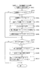
次に、図5から図7を参照して、本実施形態のパチンコ機10における表示演出の1種である連続予告演出について説明を行う。連続予告演出は、連続する複数回の変動表示に渡って同系統の予告演出が実行される演出である。この連続予告演出は、第1入球口64に対する新たな始動入賞を検出した場合に、実行可否が判定される。連続予告演出の実行が決定された場合には、新たな始動入賞を検出した時点で保留されている保留球に基づく変動表示、および当該新たな始動入賞に基づく変動表示に渡って実行される。なお、詳細については後述するが、新たな始動入賞の抽選結果が外れの場合よりも、大当たりの場合の方が、連続予告演出の決定割合が高くなる。よって、連続予告演出が実行された場合に、遊技者に対して大当たりに対する期待感を抱かせることができる。
Next, with reference to FIGS. 5 to 7, a continuous advance notice effect, which is one type of display effect in the
図5(a),(b)は、連続予告演出が設定されている保留球のうち、最後に実行される保留球以外に基づいて実行される変動表示の表示態様の一例を示した図である。図5(a)は、上図柄列Z1、および下図柄列Z3が停止表示され、中図柄列Z2が変動中の状態を示している。図5(a)に示した通り、連続予告演出の実行中は、上図柄列Z1、および下図柄列Z3に同一の数字が付された第3図柄が停止表示される。図5(a)の例では、「3」の数字が付された主図柄が、それぞれ上図柄列Z1の真ん中と、下図柄列Z2の右側とに表示される。また、図5(a)に示した通り、同一の数字が付された主図柄は、その周囲が発光した態様(他の第3図柄とは異なる態様)で表示される。これにより、遊技者に対して連続予告演出の実行中であることを容易に認識させることができる。以下、この主図柄の周囲が発光した態様のことを、「オーラを纏った態様」と称する。 5 (a) and 5 (b) are diagrams showing an example of the display mode of the variable display executed based on the reserved spheres other than the last reserved spheres for which the continuous advance notice effect is set. is there. FIG. 5A shows a state in which the upper symbol row Z1 and the lower symbol row Z3 are stopped and displayed, and the middle symbol row Z2 is changing. As shown in FIG. 5A, during the execution of the continuous advance notice effect, the third symbol with the same number attached to the upper symbol row Z1 and the lower symbol row Z3 is stopped and displayed. In the example of FIG. 5A, the main symbols with the number "3" are displayed in the center of the upper symbol row Z1 and on the right side of the lower symbol row Z2, respectively. Further, as shown in FIG. 5A, the main symbols with the same numbers are displayed in a mode in which the surroundings emit light (a mode different from the other third symbols). As a result, the player can easily recognize that the continuous advance notice effect is being executed. Hereinafter, the mode in which the surroundings of the main symbol emit light is referred to as "a mode wearing an aura".
そして、図5(b)に示した通り、連続予告演出の実行中は、中図柄列Z2が停止表示された場合も、中図柄列Z2のうち「3」の数字が付された主図柄がオーラを纏った態様で停止表示される。これにより、表示された図柄の組み合わせは外れの組み合わせとなるにも拘わらず、大当たりとなること(保留球の中に大当たりに対応する抽選結果が含まれていること)に対する期待感を向上させることができる。よって、遊技者の遊技に対する興趣を向上させることができる。 Then, as shown in FIG. 5B, even when the middle symbol row Z2 is stopped and displayed during the execution of the continuous advance notice effect, the main symbol with the number "3" in the middle symbol row Z2 is displayed. It is stopped and displayed in the form of wearing an aura. As a result, even though the combination of the displayed symbols is an out-of-order combination, the expectation that it will be a big hit (the lottery result corresponding to the big hit is included in the reserved ball) will be improved. Can be done. Therefore, it is possible to improve the interest of the player in the game.
図6は、連続予告演出における最後の変動表示が実行されている場合の表示態様を示した図である。図6(a)に示した通り、連続予告演出の最後の変動表示において、上図柄列Z1と、下図柄列Z3とが停止表示されると、いずれかの有効ライン上に同一の数字が付された主図柄が停止表示されると共に、当該同一の数字が付された主図柄がオーラを纏った態様で表示される。図6(a)の例では、「3」の数字が付された主図柄が有効ラインL4上にそれぞれ停止表示されている場合を例示している。この、1の図柄列(中図柄列Z2)が変動中の状態で、且つ、有効ライン上に同一の数字が付された主図柄が停止表示された状態を、リーチ状態と称する。なお、本第1実施形態では、連続予告演出の最後の変動表示では必ずリーチ状態が発生するように構成している。即ち、新たな始動入賞がリーチ状態を伴う変動表示に対応する抽選結果である場合にのみ、連続予告演出の開始が判定され得る構成としている。このように構成することで、連続予告演出が開始された時点で、その後に少なくともリーチ状態が発生することを遊技者に認識させることができるので、遊技者の大当たりに対する期待感を向上させることができる。 FIG. 6 is a diagram showing a display mode when the final variable display in the continuous advance notice effect is executed. As shown in FIG. 6A, when the upper symbol row Z1 and the lower symbol row Z3 are stopped and displayed in the final variation display of the continuous advance notice effect, the same number is added on one of the effective lines. The main symbol is displayed as a stop, and the main symbol with the same number is displayed in an aura-clad manner. In the example of FIG. 6A, the case where the main symbols with the numbers “3” are stopped and displayed on the effective line L4 is illustrated. The state in which the symbol sequence of 1 (middle symbol sequence Z2) is changing and the main symbol with the same number is stopped and displayed on the effective line is referred to as a reach state. In the first embodiment, the reach state is always generated at the final variable display of the continuous advance notice effect. That is, the start of the continuous advance notice effect can be determined only when the new start prize is the lottery result corresponding to the variable display accompanied by the reach state. With this configuration, it is possible to make the player recognize that at least a reach state will occur at the time when the continuous advance notice effect is started, so that the player's expectation for the jackpot can be improved. it can.
図6(a)に示した通り、リーチ状態が発生すると、主表示領域Dmにおける右上に横長略長方形形状の表示領域HR1が形成されると共に、当該表示領域HR1に対して、「リーチ!!!」という文字が表示される。この表示領域HR1の表示内容により、遊技者に対してリーチ状態が発生したことをより容易に理解させることができる。 As shown in FIG. 6A, when the reach state occurs, a horizontally long rectangular display area HR1 is formed in the upper right of the main display area Dm, and the display area HR1 is "reached !!". Is displayed. The display content of the display area HR1 makes it easier for the player to understand that the reach state has occurred.
図6(b)は、連続予告演出の最後の変動表示において中図柄列Z2が停止表示され、大当たりが報知される場合の表示態様の一例を示している。連続予告演出で大当たりが報知される場合には、上図柄列Z1、及び下図柄列Z3においてそれぞれ停止表示されている、オーラを纏った主図柄と同一の数字が付された主図柄が、既に停止表示されている主図柄が配置されている有効ライン上に停止表示される。つまり、同一の数字が付され、且つ、オーラを纏った態様の主図柄が、1の有効ライン上に揃う演出が実行される。図6(b)では、「3」の数字が付された主図柄が、有効ラインL4上に揃った場合を例示している。有効ライン上に同一の数字が付された主図柄が3つ揃うことにより、遊技者に対して大当たりとなったことを容易に理解させることができる。なお、主表示領域Dmの右上側に形成された表示領域HR1には、大当たりとなったことを祝福する「おめでとう!!」という文字が表示される。これにより、遊技者に対してより大きな満足感を与えることができる。 FIG. 6B shows an example of a display mode in which the middle symbol row Z2 is stopped and displayed in the final variable display of the continuous advance notice effect, and a big hit is notified. When the jackpot is notified by the continuous notice effect, the main symbol with the same number as the main symbol wearing the aura, which is stopped and displayed in the upper symbol row Z1 and the lower symbol row Z3, respectively, has already been displayed. It is stopped and displayed on the effective line where the main symbol that is displayed as stopped is placed. That is, an effect is executed in which the same numbers are attached and the main symbols in the aura-clad manner are aligned on the effective line of 1. FIG. 6B illustrates a case where the main symbols with the numbers “3” are aligned on the effective line L4. By aligning three main symbols with the same number on the effective line, it is possible to easily make the player understand that the jackpot has been achieved. In the display area HR1 formed on the upper right side of the main display area Dm, the characters "Congratulations !!" are displayed to congratulate the big hit. This can give the player a greater sense of satisfaction.
なお、本第1実施形態では、連続予告演出が設定された各変動表示において、オーラを纏って停止表示される主図柄を、全て同一の数字が付された主図柄となるように構成している。つまり、連続予告演出の1回目の変動表示において、「3」の数字が付された主図柄が各図柄列Z1〜Z3にオーラを纏った状態で停止表示された場合は、2回目以降の変動表示でも、「3」の数字が付された3つの主図柄がオーラを纏った状態で停止表示される。このように構成することで、1の連続予告演出における各変動表示の態様に統一感を持たせることができる。 In the first embodiment, in each variation display in which the continuous notice effect is set, the main symbols that are stopped and displayed with the aura are all configured to be the main symbols with the same numbers. There is. That is, in the first variation display of the continuous notice effect, if the main symbol with the number "3" is stopped and displayed with the aura in each symbol column Z1 to Z3, the variation after the second time is displayed. Also in the display, the three main symbols with the number "3" are stopped and displayed with the aura. With this configuration, it is possible to give a sense of unity to each variation display mode in the continuous advance notice effect of 1.
また、図示については省略したが、連続予告演出が設定されている各変動表示において実行される予告演出は、停止図柄がオーラを纏った態様に変更される演出(予告演出A)以外にも複数存在する。具体的には、各図柄列Z1〜Z3の変動停止時に、同一の数字が付された主図柄が氷結する演出(予告演出B)と、同一の数字が付された主図柄が稲妻に打たれる演出(予告演出C)とが連続予告演出の種別として少なくとも設けられている。予告演出Cは、大当たりとなる期待度が最も高い種別であり、予告演出Aは、大当たりとなる期待度が最も低い種別である。また、予告演出Bの期待度は、予告演出Aより高く、予告演出Cより低い期待度に設定されている。このように、連続予告演出の種別に応じて大当たりとなる期待度を異ならせることにより、遊技者に対して連続予告演出の種別にも注目して遊技を行わせることができる。 In addition, although the illustration is omitted, there are a plurality of advance notice effects executed in each variable display in which the continuous advance notice effect is set, in addition to the effect in which the stop symbol is changed to a mode wearing an aura (notice effect A). Exists. Specifically, when the fluctuation of each symbol row Z1 to Z3 is stopped, the main symbol with the same number freezes (notice effect B) and the main symbol with the same number hits the lightning bolt. The effect (notice effect C) is provided at least as a type of continuous advance notice effect. The notice effect C is the type with the highest expectation of a big hit, and the notice effect A is the type with the lowest expectation of a big hit. Further, the expectation level of the advance notice effect B is set to be higher than that of the advance notice effect A and lower than that of the advance notice effect C. In this way, by making the degree of expectation of a big hit different depending on the type of continuous advance notice effect, it is possible to make the player play the game paying attention to the type of continuous advance notice effect.
次に、図7を参照して、連続予告演出が設定された場合における演出態様の経時変化について説明する。図7は、保留球が2個存在する状態で、新たな始動入賞を検出して連続予告演出が決定される場合における、演出態様の経時変化の様子を模式的に示した図である。 Next, with reference to FIG. 7, a time-dependent change in the effect mode when the continuous notice effect is set will be described. FIG. 7 is a diagram schematically showing a state of time-dependent changes in the effect mode when a new start winning prize is detected and a continuous advance notice effect is determined in a state where two reserved balls are present.
図7に示した通り、保留球が2個存在する状態における通常の(即ち、連続予告演出が設定されていない)変動表示の実行中に、始動入賞(図7左上の入賞A)を検出すると、連続予告演出の実行可否の判定が実行される。入賞Aに基づく判定で連続予告演出の実行が決定された場合は、その時点で保留されている2個の保留球に基づく変動表示と、入賞Aに基づく変動表示との変動時間に渡って連続予告演出が実行されるように設定する。より具体的には、連続予告演出の残り回数を示す予告回数カウンタ223iの値に連続予告演出の実行回数である3を設定すると共に、決定された連続予告演出の種別(予告演出A〜Cの何れか)に応じて予告種別フラグ223kの値を更新する。これにより、次の変動表示(連続予告演出の実行が決定された時点で保留されている最も古い保留球に基づく変動表示)から連続予告演出が開始される。
As shown in FIG. 7, when the start winning prize (winning A in the upper left of FIG. 7) is detected during the execution of the normal variable display (that is, the continuous advance notice effect is not set) in the state where two reserved balls exist. , The determination of whether or not the continuous advance notice effect can be executed is executed. If it is decided to execute the continuous notice effect by the judgment based on the winning A, the fluctuation display based on the two reserved balls held at that time and the fluctuation display based on the winning A are continuous over the fluctuation time. Set so that the notice effect is executed. More specifically, the value of the advance notice number counter 223i indicating the remaining number of continuous advance notice effects is set to 3, which is the number of times the continuous advance notice effects are executed, and the determined types of continuous advance notice effects (notice effects A to C). The value of the
また、本第1実施形態では、連続予告演出の実行が決定されると、連続予告演出の抽選を禁止する状態(以下、予告抽選禁止状態と称する)が設定される。これは、連続予告演出の実行中に、連続予告演出が重複して決定されてしまうことを防止(抑制)するためである。より詳述すると、連続予告演出の実行中にも、新たな始動入賞を検出したことに基づいて連続予告演出の実行可否を判定する構成とした場合、連続予告演出の途中で予告演出の種別が切り替わってしまう可能性がある。例えば、予告演出Bが設定された連続予告演出の実行中に、新たな始動入賞を検出して連続予告演出の実行可否を判別し、予告演出Aの実行が決定されてしまうと、予告演出Bが打ち切られてしまい、次の変動から予告演出Aに切り替わってしまう虞がある。つまり、比較的期待度が高い演出種別(予告演出B)から、期待度が低い演出種別(予告演出A)に切り替わることで、遊技者をがっかりさせてしまう可能性がある。また、同一の演出種別の連続予告演出が、連続予告演出の実行中に新たに決定された場合、連続予告演出の開始時に保留されていた保留球の個数以上の回数の変動表示に渡って連続予告演出が実行されることになる。これにより、遊技者がどの保留球に期待感を抱けばいいのか分かり難くなってしまう虞があるので、演出の意味が分かり難くなってしまう場合がある。 Further, in the first embodiment, when the execution of the continuous notice effect is decided, a state in which the lottery of the continuous notice effect is prohibited (hereinafter, referred to as a notice lottery prohibition state) is set. This is to prevent (suppress) the continuous advance notice effect from being determined in duplicate during the execution of the continuous advance notice effect. More specifically, if the configuration is such that whether or not the continuous advance notice effect can be executed is determined based on the detection of a new start prize even during the execution of the continuous advance notice effect, the type of the advance notice effect is changed in the middle of the continuous advance notice effect. There is a possibility of switching. For example, if a new start prize is detected to determine whether or not the continuous advance notice effect can be executed during the execution of the continuous advance notice effect in which the advance notice effect B is set, and the execution of the advance notice effect A is decided, the advance notice effect B is executed. Is cut off, and there is a risk that the next fluctuation will switch to the advance notice production A. That is, switching from a production type with a relatively high expectation (notice production B) to a production type with a low expectation (notice production A) may disappoint the player. In addition, when a continuous advance notice effect of the same effect type is newly determined during execution of the continuous advance notice effect, the continuous advance notice effect is continuously displayed over a number of variable displays equal to or greater than the number of reserved balls held at the start of the continuous advance notice effect. The notice production will be executed. As a result, it may be difficult for the player to understand which reserved ball should be expected, so that the meaning of the production may be difficult to understand.
また、これらの問題点を解決する方法として、最終的に外れとなる連続予告演出の実行中に、大当たりに対応する始動入賞を検出した場合にのみ、連続予告演出の実行可否の判定を許容し、且つ、追加で決定された連続予告演出の演出種別は、実行中の連続予告演出の演出種別以上の期待度となるように構成する方法も考えられる。しかしながら、この場合は連続予告演出の実行中に始動入賞を検出する毎に、複数の条件を判別して連続予告演出の実行可否や、予告種別を決定するための制御処理を行う必要があるため、処理負荷が増大してしまう可能性があるという問題点がある。 In addition, as a method of solving these problems, it is allowed to judge whether or not the continuous advance notice effect can be executed only when the start winning prize corresponding to the big hit is detected during the execution of the continuous advance notice effect that is finally out of order. In addition, it is also conceivable to configure the effect type of the continuous advance notice effect additionally determined to have an expectation degree higher than that of the effect type of the continuous advance notice effect being executed. However, in this case, every time a start prize is detected during the execution of the continuous advance notice effect, it is necessary to determine a plurality of conditions and perform control processing for determining whether or not the continuous advance notice effect can be executed and the advance notice type. However, there is a problem that the processing load may increase.
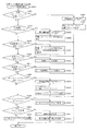
そこで、本第1実施形態では、図7に示した通り、連続予告演出の実行が決定されてから、当該連続予告演出の終了後、1回の変動表示(予告抽選禁止状態において最初に検出された入賞Bに基づく変動表示)が終了するまでの間に渡って、新たに連続予告演出の実行可否を判定することが禁止される構成としている。これにより、連続予告演出の実行中に、演出種別が切り替わってしまったり、連続予告演出の開始時における保留球数を超えて連続予告演出が継続してしまうことを抑制することができる。更に、始動入賞時には、予告抽選禁止状態か否か(後述する、予告演出禁止フラグ223hがオンであるか否か)を判定して、予告抽選禁止状態である場合には連続予告演出の実行可否の判定処理をスキップするという単純な制御を行うだけでよいので、パチンコ機10の処理負荷を軽減できる。
Therefore, in the first embodiment, as shown in FIG. 7, after the execution of the continuous advance notice effect is determined, and after the end of the continuous advance notice effect, one variable display (first detected in the advance notice lottery prohibited state). It is prohibited to newly determine whether or not the continuous advance notice effect can be executed until the end of the variable display based on the winning prize B). As a result, it is possible to prevent the effect type from being switched during the execution of the continuous advance notice effect, or to prevent the continuous advance notice effect from continuing beyond the number of reserved balls at the start of the continuous advance notice effect. Further, at the time of the start winning, it is determined whether or not the advance notice lottery is prohibited (whether or not the advance notice
図7に示した通り、連続予告演出が設定された3回の変動表示の実行中は、上述した予告抽選禁止状態が設定される。よって、例えば、図7に示したように、連続予告演出の2回目や3回目の変動表示の実行中に始動入賞を検出した場合には、当該始動入賞に対する連続予告演出の実行可否の判定処理はスキップされる。また、予告抽選禁止状態は、連続予告演出が終了した後、1回目に実行される変動表示の実行期間中も継続し、連続予告演出の終了後1回目の変動表示が終了した時点で予告抽選禁止状態が解除される。このため、連続予告演出が終了した後、1回目の変動表示の実行中に新たな始動入賞を検出した場合には、当該始動入賞に対する連続予告演出の実行可否の判定処理は、連続予告演出の実行中と同様にスキップされる。これにより、連続予告演出の終了直後に再度連続予告演出が開始されてしまい、連続予告演出が延々と続いてしまうことを防止(抑制)することができる。仮に、連続予告演出の終了後、最初に実行される変動表示から連続予告演出の設定を許容してしまうと、最初の連続予告演出の実行開始の契機となった始動入賞に基づく変動表示が終了した後も、連続予告演出が継続しているかのような演出態様となってしまう。この場合、連続予告演出が何に基づいて開始されたのかが遊技者にとって不明となってしまう可能性があり、連続予告演出の意味を誤解させてしまう虞がある。つまり、連続予告演出が、始動入賞時に先読みされた抽選結果(変動種別)に基づいて実行されるのではなく、単に決まった回数の変動表示に渡って演出態様を変更するだけの演出であると誤解する虞がある。これに対して本第1実施形態では、連続予告演出が終了した後、少なくとも1回の変動表示を通常の態様(予告演出を伴わない態様)で実行することができるので、1の連続予告演出が終了したか否かを遊技者に対して容易に理解させることができる。これにより、連続予告演出の実行中に、何回目に実行される変動表示(何番目の保留球)に対して期待感を抱けば良いのかを、遊技者により分かり易くすることができる。 As shown in FIG. 7, the above-mentioned advance notice lottery prohibition state is set during the execution of the three variable displays in which the continuous advance notice effect is set. Therefore, for example, as shown in FIG. 7, when a start prize is detected during the execution of the second or third variation display of the continuous notice effect, the process of determining whether or not the continuous notice effect can be executed for the start prize is determined. Is skipped. In addition, the advance notice lottery prohibition state continues during the execution period of the variable display executed for the first time after the continuous advance notice effect is completed, and when the first variable display is completed after the continuous advance notice effect is completed, the advance notice lottery is performed. The prohibited state is released. Therefore, if a new start prize is detected during the execution of the first variable display after the continuous notice effect is completed, the process of determining whether or not the continuous notice effect can be executed for the start prize is performed by the continuous notice effect. It will be skipped as if it were running. As a result, it is possible to prevent (suppress) the continuous advance notice effect from being started again immediately after the end of the continuous advance notice effect and the continuous advance notice effect from continuing endlessly. If the setting of the continuous advance notice effect is allowed from the first variable display executed after the end of the continuous advance notice effect, the variable display based on the start prize that triggered the start of execution of the first continuous advance notice effect ends. Even after that, the production mode will be as if the continuous advance notice production is continuing. In this case, there is a possibility that the player may not know what the continuous advance notice effect was based on, and the meaning of the continuous advance notice effect may be misunderstood. In other words, the continuous advance notice effect is not executed based on the lottery result (variation type) pre-read at the time of the start winning, but is an effect that simply changes the effect mode over a fixed number of variation displays. There is a risk of misunderstanding. On the other hand, in the first embodiment, after the continuous advance notice effect is completed, at least one variation display can be executed in a normal mode (a mode without a notice effect), so that one continuous advance notice effect can be performed. It is possible to easily make the player understand whether or not the game has been completed. As a result, it is possible for the player to easily understand how many times the variable display (what number of the reserved ball) should be expected during the execution of the continuous advance notice effect.
また、本第1実施形態では、図7に示した通り、予告抽選禁止状態が解除されたことを契機として、その時点で保留されている全ての保留球の抽選結果を判別し、当該判別結果に基づいて、連続予告演出の実行可否を判定する構成としている。判別方法の詳細については後述するが、全ての保留球の抽選結果を加味して連続予告演出の実行可否を判別することによって、より期待度の高い保留球が保留されているにも拘わらず、期待度の低い保留球に基づいて連続予告演出の実行が設定されてしまうことを抑制することができる。 Further, in the first embodiment, as shown in FIG. 7, when the advance notice lottery prohibition state is lifted, the lottery results of all the reserved balls held at that time are determined, and the determination result is determined. Based on the above, it is configured to determine whether or not the continuous advance notice effect can be executed. The details of the determination method will be described later, but by determining whether or not the continuous advance notice effect can be executed by taking into account the lottery results of all the reserved balls, the reserved balls with higher expectations are reserved. It is possible to prevent the execution of the continuous advance notice effect from being set based on the reserved ball with a low degree of expectation.
つまり、仮に、始動入賞を検出したタイミングが時間的に古い保留球から順に連続予告演出の実行可否を判別していく構成にしてしまうと、時間的に新しい保留球を判別せずに連続予告演出が決定されてしまう可能性がある。この場合において、連続予告演出が決定された保留球が比較的期待度の低い抽選結果(例えば、ノーマルリーチ後に外れとなる保留球)であり、且つ、時間的に新しい保留球の中に期待度が高い保留球(例えば、スーパーリーチが発生して大当たりとなる保留球)が含まれている場合には、期待度の低い保留球に対して連続予告演出が設定されたにも拘わらず、期待度の高い保留球に対して連続予告演出が設定されないという状況が発生してしまう可能性がある。よって、連続予告演出に対する期待感を損なってしまう可能性がある。 In other words, if the configuration is such that whether or not the continuous advance notice effect can be executed is determined in order from the reserved ball whose start winning is detected in order from the oldest reserved ball, the continuous advance notice effect is not determined in terms of time. May be decided. In this case, the reserved ball for which the continuous advance notice effect is determined is a lottery result with a relatively low expectation (for example, a reserved ball that is out of the normal reach), and the expected degree is in the new reserved ball in time. When a high hold ball (for example, a hold ball that causes a super reach and becomes a big hit) is included, the expectation level is set even though the continuous notice effect is set for the hold ball with a low expectation level. There is a possibility that a situation may occur in which a continuous advance notice effect is not set for a high hold ball. Therefore, there is a possibility that the expectation for the continuous advance notice production will be impaired.
また、逆に、始動入賞を検出したタイミングが時間的に新しい保留球から順に連続予告演出の実行可否を判別していく構成にしてしまうと、時間的に古い保留球を判別せずに連続予告演出が決定されてしまう可能性がある。この場合において、連続予告演出が決定された保留球が比較的期待度の低い抽選結果(例えば、ノーマルリーチ後に外れとなる保留球)であり、且つ、時間的に古い保留球の中に期待度が高い保留球(例えば、スーパーリーチが発生して大当たりとなる保留球)が含まれている場合には、先に実行される期待度の高い保留球で連続予告演出が終了せずに、期待度の低い保留球に基づく変動表示まで連続予告演出が継続してしまう。即ち、連続予告演出が尻すぼみになってしまった印象を遊技者に対して抱かせてしまう虞がある。 On the contrary, if the timing of detecting the start winning is set to determine whether or not the continuous advance notice effect can be executed in order from the new hold ball in time, the continuous notice is not determined in terms of the old hold ball. There is a possibility that the production will be decided. In this case, the reserved ball for which the continuous advance notice effect is determined is a lottery result with a relatively low expectation (for example, a reserved ball that comes off after normal reach), and the expected degree is among the reserved balls that are old in time. If a high hold ball (for example, a hold ball that causes a super reach and becomes a big hit) is included, the expectation level does not end with the hold ball with high expectation that is executed first. The continuous notice production will continue until the fluctuation display based on the low hold ball. That is, there is a risk that the player will have the impression that the continuous advance notice production has become a dent.
これに対して本第1実施形態では、予告抽選禁止状態が解除された時点で、全ての保留球の抽選結果を加味して連続予告演出の実行可否を判定することができるので、保留球の中で最も期待度が高い抽選結果まで継続する連続予告演出を設定することができる。よって、期待度が低い保留球に連続予告演出が設定されたにも拘わらず、期待度が高い保留球には連続予告演出が設定されないという状況や、連続予告演出の途中で期待度の高い保留球が消化され、連続予告演出の最後の変動表示で期待度の低い保留球が消化されてしまう状況等が発生することを抑制することができる。よって、連続予告演出を好適に実行することができる。 On the other hand, in the first embodiment, when the advance notice lottery prohibition state is released, it is possible to determine whether or not the continuous advance notice effect can be executed in consideration of the lottery results of all the reserved balls. It is possible to set a continuous advance notice effect that continues until the lottery result with the highest expectation. Therefore, even though the continuous notice effect is set for the hold ball with low expectation, the continuous notice effect is not set for the hold ball with high expectation, or the hold with high expectation in the middle of the continuous notice effect. It is possible to prevent a situation in which a ball is digested and a reserved ball having a low expectation is digested at the final variable display of the continuous advance notice effect. Therefore, the continuous advance notice effect can be preferably executed.
なお、本第1実施形態では、予告抽選禁止状態を、連続予告演出の実行が決定されてから、連続予告演出の終了後、1回目の変動表示が終了するまでに渡って設定する構成としていたが、これに限られるものではない。予告抽選禁止状態が解除される条件は、任意に定めてもよく、例えば、予告抽選禁止状態が設定される変動表示の回数を増加させても(例えば、5回にしても)よい。このように構成することで、1の連続予告演出が終了してから次の連続予告演出が開始されるまでの間に、より多くの通常の態様(予告演出を伴わない態様)の変動表示を実行することができるので、1の連続予告演出が終了したか否かを、より確実に遊技者に認識させることができる。また、予告抽選禁止状態が設定される変動表示の回数を増加させる程、連続予告演出を決定する機会が少なくなるので、連続予告演出の希少性を高めることができる。よって、連続予告演出が開始されただけで、珍しい演出を見ることができたと遊技者に感じさせることができるので、遊技者の遊技に対する興趣を向上させることができる。 In the first embodiment, the advance notice lottery prohibition state is set from the time when the execution of the continuous advance notice effect is determined to the end of the continuous advance notice effect until the end of the first variable display. However, it is not limited to this. The conditions for canceling the advance notice lottery prohibition state may be arbitrarily set, and for example, the number of variable displays in which the advance notice lottery prohibition state is set may be increased (for example, 5 times). With this configuration, more normal modes (modes without notice effects) of variable display can be displayed between the end of one continuous notice effect and the start of the next continuous notice effect. Since it can be executed, it is possible to make the player more surely recognize whether or not one continuous advance notice effect has been completed. Further, as the number of times of the variable display in which the advance notice lottery prohibition state is set is increased, the chance of determining the continuous advance notice effect decreases, so that the rarity of the continuous advance notice effect can be increased. Therefore, it is possible to make the player feel that he / she was able to see the unusual production just by starting the continuous advance notice production, so that the player's interest in the game can be improved.
また、本第1実施形態では、予告抽選禁止状態の解除条件を、変動表示の回数(連続予告演出の終了後、1回の変動表示が終了するまで)で規定していたが、解除条件は必ずしも変動表示の回数に限定されるものではない。例えば、連続予告演出の終了後における経過時間により解除条件を定める構成としてもよい。より具体的には、連続予告演出が終了した後、所定期間(例えば、30秒間)が経過した場合に予告抽選禁止状態を解除する構成としてもよい。このように構成することで、連続予告演出の終了とともに遊技を終了した遊技者がいた場合にも、次の遊技者が所定期間の経過後に遊技を開始していれば、予告抽選禁止状態が解除されている状態で遊技を行わせることができる。よって、後任の遊技者が予告抽選禁止状態から遊技を開始することになるという状況が生じることを抑制できるので、連続予告演出をより楽しませることができる。 Further, in the first embodiment, the cancellation condition of the advance notice lottery prohibition state is defined by the number of variable display times (after the end of the continuous advance notice effect until the end of one variable display), but the cancellation condition is It is not necessarily limited to the number of variable displays. For example, the cancellation condition may be determined by the elapsed time after the end of the continuous advance notice effect. More specifically, the advance notice lottery prohibition state may be canceled when a predetermined period (for example, 30 seconds) elapses after the continuous advance notice effect is completed. With this configuration, even if there is a player who has finished the game at the end of the continuous notice production, if the next player starts the game after the lapse of a predetermined period, the notice lottery prohibition state will be canceled. It is possible to play the game in the state where it is played. Therefore, it is possible to prevent a situation in which a successor player starts the game from the state in which the advance notice lottery is prohibited, so that the continuous advance notice effect can be further enjoyed.
本第1実施形態では、予告抽選禁止状態を、連続予告演出が終了した後、1回の変動表示が終了するまでの間に渡って設定する構成としていたが、連続予告演出の終了直後に予告抽選禁止状態を解除する構成としてもよい。この場合において、連続予告演出の最後の変動表示であるか否かを、演出態様から遊技者が容易に識別可能となるように構成してもよい。このように構成することで、予告抽選禁止状態が設定される期間をより短くすることができるので、連続予告演出の実行機会をより増加させることができる。なお、連続予告演出の最後の変動表示であるか否かを示す演出態様の具体例としては、例えば、連続予告演出の残りの変動回数をカウントダウン表示する構成としてもよい。また、最後の変動表示において終了を示唆する表示(例えば、「終了」という文字等)を表示させる構成としてもよいし、連続予告演出中に同一の楽曲を継続して流す構成とし、連続予告演出における最後の変動表示が終了したタイミングで楽曲を止める構成としてもよい。また、連続予告演出の実行中は、最後の変動表示以外の変動表示では第3図柄表示装置81においてリーチ状態が発生しない構成としてもよい。即ち、連続予告演出の実行中は、リーチ状態が表示されることにより、連続予告演出の最後の変動表示であることを示唆する構成としてもよい。
In the first embodiment, the advance notice lottery prohibition state is set from the end of the continuous advance notice effect to the end of one variable display, but the advance notice is made immediately after the end of the continuous advance notice effect. The lottery prohibition state may be released. In this case, it may be configured so that the player can easily identify whether or not it is the final variable display of the continuous advance notice effect from the effect mode. With this configuration, the period for which the advance notice lottery prohibition state is set can be shortened, so that the chances of executing the continuous advance notice effect can be further increased. As a specific example of the effect mode indicating whether or not it is the last variation display of the continuous notice effect, for example, a configuration may be configured in which the remaining number of fluctuations of the continuous notice effect is countdown displayed. In addition, a display suggesting the end (for example, the character "end") may be displayed in the final variable display, or the same song may be continuously played during the continuous advance notice effect. The music may be stopped at the timing when the last fluctuation display in the above is completed. Further, during the execution of the continuous advance notice effect, the third
図2に戻って、説明を続ける。第2図柄表示装置83は、遊技球が普通入球口67を通過することに伴って行われる普通図柄の抽選が実行中であるか否かを点灯状態により示すことによって変動表示を行ったり、変動終了後の停止図柄として、その普通図柄の抽選結果に応じた普通図柄(第2図柄)を点灯状態により示すものである。
Returning to FIG. 2, the description will be continued. The second
より具体的には、第2図柄表示装置83では、遊技球が普通入球口67を通過する毎に、第2図柄としての「○」の図柄と「×」の図柄とを交互に点灯させる変動表示が行われる。パチンコ機10は、第2図柄表示装置83における変動表示が所定図柄(本実施形態においては「○」の図柄)で停止すると、第1入球口64に付随する電動役物64aが所定時間だけ作動状態となり(開放される)、その結果、第1入球口64に遊技球が入り易い状態となるように構成されている。遊技球が普通入球口67を通過した通過回数は最大4回まで保留され、その保留球数が上述した第1図柄表示装置37により表示されると共に第2図柄保留ランプ84においても点灯表示される。第2図柄保留ランプ84は、最大保留数分の4つ設けられ、第3図柄表示装置81の下方に左右対称に配設されている。
More specifically, in the second
なお、普通図柄(第2図柄)の変動表示は、本実施形態のように、第2図柄表示装置83において複数のランプの点灯と非点灯を切り換えることにより行うものの他、第1図柄表示装置37及び第3図柄表示装置81の一部を使用して行うようにしても良い。同様に、第2図柄保留ランプ84の点灯を第3図柄表示装置81の一部で行うようにしても良い。また、普通入球口67における遊技球の通過は、第1入球口64と同様に、最大保留球数は4回に限定されるものでなく、3回以下、又は、5回以上の回数(例えば、8回)に設定しても良い。また、第1図柄表示装置37により保留球数が示されるので、第2図柄保留ランプ84により点灯表示を行わないものとしても良い。
The variation display of the normal symbol (second symbol) is performed by switching the lighting and non-lighting of a plurality of lamps in the second
可変表示装置ユニット80の下方には、遊技球が入球し得る第1入球口64が配設されている。この第1入球口64へ遊技球が入球すると遊技盤13の裏面側に設けられる第1入球口スイッチ(図示せず)がオンとなり、その第1入球口スイッチのオンに起因して主制御装置110で特別図柄の抽選がなされ、その抽選結果に応じた表示が第1図柄表示装置37のLED37aで示される。また、第1入球口64は、遊技球が入球すると5個の遊技球が賞球として払い出される入賞口の1つにもなっている。
Below the variable
第1入球口64の下方には可変入賞装置65が配設されており、その略中央部分に横長矩形状の特定入賞口(大開放口)65aが設けられている。パチンコ機10においては、主制御装置110で行われる特別図柄の抽選が大当たりとなると、所定時間(変動時間)が経過した後に、大当たりの停止図柄となるよう第1図柄表示装置37のLED37aを点灯させると共に、その大当たりに対応した第3図柄の停止図柄を第3図柄表示装置81に表示させて、大当たりの発生が示される。その後、通常時より多量の賞球の払い出しが行われる特別遊技状態(16ラウンドの大当たり)に遊技状態が遷移する。この特別遊技状態として、通常時には閉鎖されている特定入賞口65aが、所定時間(例えば、30秒経過するまで、或いは、遊技球が10個入賞するまで)開放される。
A variable winning
この特定入賞口65aは、所定時間が経過すると閉鎖され、その閉鎖後、再度、その特定入賞口65aが所定時間開放される。この特定入賞口65aの開閉動作は、16回(16ラウンド)繰り返し可能にされている。この開閉動作が行われている状態が、遊技者にとって有利な特別遊技状態の一形態であり、遊技者には、遊技上の価値(遊技価値)の付与として通常時より多量の賞球の払い出しが行われる。
The
可変入賞装置65は、具体的には、特定入賞口65aを覆う横長矩形状の開閉板と、その開閉板の下辺を軸として前方側に開閉駆動するための大開放口ソレノイド(図示せず)とを備えている。特定入賞口65aは、通常時は、遊技球が入賞できないか又は入賞し難い閉状態になっている。大当たりの際には大開放口ソレノイドを駆動して開閉板を前面下側に傾倒し、遊技球が特定入賞口65aに入賞しやすい開状態を一時的に形成し、その開状態と通常時の閉状態との状態を交互に繰り返すように作動する。
Specifically, the variable winning
なお、特別遊技状態は上記した形態に限定されるものではない。特定入賞口65aとは別に開閉される大開放口を遊技領域に設け、第1図柄表示装置37において大当たりに対応したLED37aが点灯した場合に、特定入賞口65aが所定時間開放され、その特定入賞口65aの開放中に、遊技球が特定入賞口65a内へ入賞することを契機として特定入賞口65aとは別に設けられた大開放口が所定時間、所定回数開放される遊技状態を特別遊技状態として形成するようにしても良い。
The special gaming state is not limited to the above-mentioned form. A large opening that opens and closes separately from the specific winning
遊技盤13の下側における左右の隅部には、証紙や識別ラベル等を貼着するための貼着スペースK1,K2が設けられ、貼着スペースK1に貼られた証紙等は、前面枠14の小窓35(図1参照)を通じて視認することができる。
Attachment spaces K1 and K2 for attaching certificate stamps, identification labels, etc. are provided at the left and right corners on the lower side of the
更に、遊技盤13には、アウト口66が設けられている。いずれの入賞口63,64,65aにも入球しなかった遊技球はアウト口66を通って図示しない球排出路へと案内される。遊技盤13には、遊技球の落下方向を適宜分散、調整等するために多数の釘が植設されているとともに、風車等の各種部材(役物)が配設されている。
Further, the
図3に示すように、パチンコ機10の背面側には、制御基板ユニット90,91と、裏パックユニット94とが主に備えられている。制御基板ユニット90は、主基板(主制御装置110)と音声ランプ制御基板(音声ランプ制御装置113)と表示制御基板(表示制御装置114)とが搭載されてユニット化されている。制御基板ユニット91は、払出制御基板(払出制御装置111)と発射制御基板(発射制御装置112)と電源基板(電源装置115)とカードユニット接続基板116とが搭載されてユニット化されている。
As shown in FIG. 3, the
裏パックユニット94は、保護カバー部を形成する裏パック92と払出ユニット93とがユニット化されている。また、各制御基板には、各制御を司る1チップマイコンとしてのMPU、各種機器との連絡をとるポート、各種抽選の際に用いられる乱数発生器、時間計数や同期を図る場合などに使用されるクロックパルス発生回路等が、必要に応じて搭載されている。
In the
なお、主制御装置110、音声ランプ制御装置113及び表示制御装置114、払出制御装置111及び発射制御装置112、電源装置115、カードユニット接続基板116は、それぞれ基板ボックス100〜104に収納されている。基板ボックス100〜104は、ボックスベースと該ボックスベースの開口部を覆うボックスカバーとを備えており、そのボックスベースとボックスカバーとが互いに連結されて、各制御装置や各基板が収納される。
The
また、基板ボックス100(主制御装置110)及び基板ボックス102(払出制御装置111及び発射制御装置112)は、ボックスベースとボックスカバーとを封印ユニット(図示せず)によって開封不能に連結(かしめ構造による連結)している。また、ボックスベースとボックスカバーとの連結部には、ボックスベースとボックスカバーとに亘って封印シール(図示せず)が貼着されている。この封印シールは、脆性な素材で構成されており、基板ボックス100,102を開封するために封印シールを剥がそうとしたり、基板ボックス100,102を無理に開封しようとすると、ボックスベース側とボックスカバー側とに切断される。よって、封印ユニット又は封印シールを確認することで、基板ボックス100,102が開封されたかどうかを知ることができる。
Further, in the board box 100 (main control device 110) and the board box 102 (payout control device 111 and launch control device 112), the box base and the box cover are connected by a sealing unit (not shown) so as not to be opened (caulking structure). (Consolidated by). Further, a sealing sticker (not shown) is attached to the connecting portion between the box base and the box cover over the box base and the box cover. This sealing seal is made of a brittle material, and if the sealing seal is to be peeled off in order to open the
払出ユニット93は、裏パックユニット94の最上部に位置して上方に開口したタンク130と、タンク130の下方に連結され下流側に向けて緩やかに傾斜するタンクレール131と、タンクレール131の下流側に縦向きに連結されるケースレール132と、ケースレール132の最下流部に設けられ、払出モータ216(図8参照)の所定の電気的構成により遊技球の払出を行う払出装置133とを備えている。タンク130には、遊技ホールの島設備から供給される遊技球が逐次補給され、払出装置133により必要個数の遊技球の払い出しが適宜行われる。タンクレール131には、当該タンクレール131に振動を付加するためのバイブレータ134が取り付けられている。
The
また、払出制御装置111には状態復帰スイッチ120が設けられ、発射制御装置112には可変抵抗器の操作つまみ121が設けられ、電源装置115にはRAM消去スイッチ122が設けられている。状態復帰スイッチ120は、例えば、払出モータ216(図8参照)部の球詰まり等、払出エラーの発生時に球詰まりを解消(正常状態への復帰)するために操作される。操作つまみ121は、発射ソレノイドの発射力を調整するために操作される。RAM消去スイッチ122は、パチンコ機10を初期状態に戻したい場合に電源投入時に操作される。
Further, the payout control device 111 is provided with a
<第1実施形態における電気的構成について>
次に、図8を参照して、本パチンコ機10の電気的構成について説明する。図8は、パチンコ機10の電気的構成を示すブロック図である。
<About the electrical configuration in the first embodiment>
Next, the electrical configuration of the
主制御装置110には、演算装置である1チップマイコンとしてのMPU201が搭載されている。MPU201には、該MPU201により実行される各種の制御プログラムや固定値データを記憶したROM202と、そのROM202内に記憶される制御プログラムの実行に際して各種のデータ等を一時的に記憶するためのメモリであるRAM203と、そのほか、割込回路やタイマ回路、データ送受信回路などの各種回路が内蔵されている。なお、払出制御装置111や音声ランプ制御装置113などのサブ制御装置に対して動作を指示するために、主制御装置110から該サブ制御装置へ各種のコマンドがデータ送受信回路によって送信されるが、かかるコマンドは、主制御装置110からサブ制御装置へ一方向にのみ送信される。
The
まず、ROM202の内容について、図9,10を参照して説明する。図9(a)に示すように、主制御装置110のROM202には、上記した固定値データの一部として、第1当たり乱数テーブル202a、第1当たり種別選択テーブル202b、第2当たり乱数テーブル202c、および変動パターン選択テーブル202dが少なくとも記憶されている。
First, the contents of the
第1当たり乱数テーブル202a(図示せず)は、後述する第1当たり乱数カウンタC1の大当たり判定値が記憶されているデータテーブルである。詳細については、第1当たり乱数カウンタC1の説明と共に後述するが、始動入賞に基づいて取得した第1当たり乱数カウンタC1の値が、第1当たり乱数テーブル202aに規定されているいずれかの判定値と一致した場合に、特別図柄の大当たりであると判別される。 The first hit random number table 202a (not shown) is a data table in which the jackpot determination value of the first hit random number counter C1 described later is stored. The details will be described later together with the description of the first random number counter C1, but the value of the first random number counter C1 acquired based on the starting prize is any determination value specified in the first random number table 202a. If it matches, it is determined that it is a big hit of a special symbol.
第1当たり種別選択テーブル202b(図9(b)参照)は、大当たり種別を決定するための判定値が記憶されているデータテーブルであり、第1当たり種別カウンタC2の判定値が、各大当たり種別に対応付けて規定されている。具体的には、第1当たり種別カウンタC2の値が「0〜49」の範囲には、大当たりAが対応付けられて規定されている(図9(b)の202b1参照)。また、第1当たり種別カウンタC2の値が「50〜99」の範囲には、大当たりBが対応付けられて規定されている(図9(b)の202b2参照)。本実施形態のパチンコ機10では特別図柄の大当たりと判定された場合に、始動入賞に基づいて取得した第1当たり種別カウンタC2の値と、第1当たり種別選択テーブル202bとが比較され、第1当たり種別カウンタC2の値に対応する大当たり種別が選択される。
The first hit type selection table 202b (see FIG. 9B) is a data table in which judgment values for determining the jackpot type are stored, and the judgment value of the first hit type counter C2 is each jackpot type. It is specified in association with. Specifically, the jackpot A is associated with the range in which the value of the first hit type counter C2 is "0 to 49" (see 202b1 in FIG. 9B). Further, the jackpot B is associated with the range in which the value of the first hit type counter C2 is "50 to 99" (see 202b2 in FIG. 9B). In the
第2当たり乱数テーブル202c(図9(c)参照)は、普通図柄の当たり判定値が記憶されているデータテーブルである。具体的には、普通図柄の通常状態において、普通図柄の当たりとなる判定値として、「5〜28」が規定されている(図9(c)の202c1参照)。また、普通図柄の高確率状態において、普通図柄の当たりとなる判定値として、「5〜204」が規定されている(図9(c)の202c2参照)。本実施形態のパチンコ機10では、普通入球口67を遊技球が通過することに基づいて取得される第2当たり乱数カウンタC4の値と、第2当たり乱数テーブル202cとを参照し、普通図柄の当たりであるか否かを判定している。
The second hit random number table 202c (see FIG. 9C) is a data table in which hit determination values of ordinary symbols are stored. Specifically, in the normal state of the normal symbol, "5-28" is defined as a determination value for hitting the normal symbol (see 202c1 in FIG. 9 (c)). Further, in the high probability state of the normal symbol, "5-204" is defined as a determination value for hitting the normal symbol (see 202c2 in FIG. 9 (c)). In the
変動パターン選択テーブル202d(図10参照)は、変動パターンの表示態様を決定するための変動種別カウンタCS1の判定値が表示態様毎にそれぞれ規定されているデータテーブルである。なお、変動パターン選択テーブル202dの詳細については、変動種別カウンタCS1の説明と共に後述する。 The variation pattern selection table 202d (see FIG. 10) is a data table in which the determination value of the variation type counter CS1 for determining the display mode of the variation pattern is defined for each display mode. The details of the fluctuation pattern selection table 202d will be described later together with the description of the fluctuation type counter CS1.
主制御装置110では、特別図柄の抽選、普通図柄の抽選、第1図柄表示装置37における表示の設定、第2図柄表示装置83における表示の設定、および、第3図柄表示装置81における表示の設定といったパチンコ機10の主要な処理を実行する。そして、RAM203には、これらの処理を制御するための各種カウンタが設けられている。ここで、図11を参照して、主制御装置110のRAM203内に設けられるカウンタ等について説明する。これらのカウンタ等は、特別図柄の抽選、普通図柄の抽選、第1図柄表示装置37における表示の設定、第2図柄表示装置83における表示の設定、および、第3図柄表示装置81における表示の設定などを行うために、主制御装置110のMPU201で使用される。
In the
特別図柄の抽選や、第1図柄表示装置37および第3図柄表示装置81の表示の設定には、特別図柄の抽選に使用する第1当たり乱数カウンタC1と、特別図柄の大当たり種別を選択するために使用する第1当たり種別カウンタC2と、特別図柄における外れの停止種別を選択するために使用する停止種別選択カウンタC3と、第1当たり乱数カウンタC1の初期値設定に使用する第1初期値乱数カウンタCINI1と、変動パターン選択に使用する変動種別カウンタCS1とが用いられる。また、普通図柄の抽選には、第2当たり乱数カウンタC4が用いられ、第2当たり乱数カウンタC4の初期値設定には第2初期値乱数カウンタCINI2が用いられる。これら各カウンタは、更新の都度、前回値に1が加算され、最大値に達した後0に戻るループカウンタとなっている。
To set the display of the special symbol lottery and the display of the first
各カウンタは、例えば、タイマ割込処理(図21参照)の実行間隔である2ミリ秒間隔で更新され、また、一部のカウンタは、メイン処理(図29参照)の中で不定期に更新されて、その更新値がRAM203の所定領域に設定されたカウンタ用バッファに適宜格納される。RAM203には、1つの実行エリアと4つの保留エリア(保留第1〜第4エリア)とからなる特別図柄保留球格納エリア203aが設けられており、これらの各エリアには、第1入球口64への入球タイミングに合わせて、第1当たり乱数カウンタC1、第1当たり種別カウンタC2及び停止種別選択カウンタC3の各値がそれぞれ格納される。また、RAM203には、1つの実行エリアと4つの保留エリア(保留第1〜第4エリア)とからなる普通図柄保留球格納エリア203bが設けられており、これらの各エリアには、遊技球が左右何れかの普通入球口(スルーゲート)67を通過したタイミングに合わせて、第2当たり乱数カウンタC4の値が格納される。
Each counter is updated, for example, at intervals of 2 milliseconds, which is the execution interval of the timer interrupt process (see FIG. 21), and some counters are updated irregularly in the main process (see FIG. 29). Then, the updated value is appropriately stored in the counter buffer set in the predetermined area of the
各カウンタについて詳しく説明する。第1当たり乱数カウンタC1は、所定の範囲(例えば、0〜399)内で順に1ずつ加算され、最大値(例えば、0〜399の値を取り得るカウンタの場合は399)に達した後0に戻る構成となっている。特に、第1当たり乱数カウンタC1が1周した場合、その時点の第1初期値乱数カウンタCINI1の値が当該第1当たり乱数カウンタC1の初期値として読み込まれる。 Each counter will be described in detail. The first random number counter C1 is incremented by 1 in order within a predetermined range (for example, 0 to 399), and after reaching the maximum value (for example, 399 in the case of a counter capable of taking a value of 0 to 399), it is 0. It is configured to return to. In particular, when the first random number counter C1 makes one round, the value of the first initial value random number counter CINI1 at that time is read as the initial value of the first random number counter C1.
また、第1初期値乱数カウンタCINI1は、第1当たり乱数カウンタC1と同一範囲で更新されるループカウンタとして構成される。即ち、例えば、第1当たり乱数カウンタC1が0〜399の値を取り得るループカウンタである場合には、第1初期値乱数カウンタCINI1もまた、0〜399の範囲のループカウンタである。この第1初期値乱数カウンタCINI1は、タイマ割込処理(図21参照)の実行毎に1回更新されると共に、メイン処理(図29参照)の残余時間内で繰り返し更新される。 Further, the first initial value random number counter CINI1 is configured as a loop counter that is updated in the same range as the first random number counter C1. That is, for example, when the first random number counter C1 is a loop counter capable of taking a value of 0 to 399, the first initial value random number counter CINI1 is also a loop counter in the range of 0 to 399. The first initial value random number counter CINI1 is updated once for each execution of the timer interrupt process (see FIG. 21), and is repeatedly updated within the remaining time of the main process (see FIG. 29).
第1当たり乱数カウンタC1の値は、例えば定期的に(本実施形態ではタイマ割込処理毎に1回)更新され、遊技球が第1入球口64に入賞したタイミングでRAM203の特別図柄保留球格納エリア203aに格納される。そして、特別図柄の大当たりとなる乱数の値は、主制御装置110のROM202に格納される第1当たり乱数テーブル202a(図示せず)によって設定されており、第1当たり乱数カウンタC1の値が、第1当たり乱数テーブルによって設定された大当たりとなる乱数の値と一致する場合に、特別図柄の大当たりと判定する。また、この第1当たり乱数テーブル202aは、特別図柄の低確率時(特別図柄の低確率状態である期間)用と、その低確率時より特別図柄の大当たりとなる確率の高い高確率時(特別図柄の高確率状態である期間)用との2種類に分けられ、それぞれに含まれる大当たりとなる乱数の個数が異なって設定されている。このように、大当たりとなる乱数の個数を異ならせることにより、特別図柄の低確率時と特別図柄の高確率時とで、大当たりとなる確率が変更される。
The value of the first random number counter C1 is updated periodically (once for each timer interrupt process in this embodiment), and the special symbol of the
ここで、第1当たり乱数テーブル202aについて説明する。第1当たり乱数テーブル202aは、特別図柄の抽選において、各遊技状態で当たりと判定される乱数値(判定値)が設定されたテーブルである。具体的には、特別図柄の確変状態である場合には、特別図柄の抽選において、取得した第1当たり乱数カウンタC1の値が「0〜9」のいずれであるか判別されて、「0〜9」のいずれかであれば、大当たりであると判別される。第1当たり乱数カウンタC1の取り得る値が「0〜399」の400個ある中で、大当たりとなる判定値が「0〜9」の10個なので、特別図柄の確変中に特別図柄の大当たりとなる確率は、1/40(10/400)となる。また、特別図柄の低確率状態である場合には、取得した第1当たり乱数カウンタC1の値が「0」であるか判別されて、「0」であれば大当たりであると判別される。第1当たり乱数カウンタC1の取り得る値が「0〜399」の400個ある中で、大当たりとなる判定値が「0」の1個のみなので、特別図柄の低確率状態おいてに特別図柄の大当たりとなる確率は、1/400となる。 Here, the first random number table 202a will be described. The first hit random number table 202a is a table in which a random number value (determination value) determined to be a hit in each game state is set in the special symbol lottery. Specifically, in the case of the probabilistic state of the special symbol, in the special symbol lottery, it is determined whether the value of the acquired first random number counter C1 is "0 to 9", and "0 to 9". If it is any of 9 ”, it is determined that it is a big hit. The first hit random number counter C1 has 400 possible values of "0 to 399", and the judgment value that becomes a big hit is 10 of "0 to 9". The probability of becoming is 1/40 (10/400). Further, in the case of the low probability state of the special symbol, it is determined whether the value of the acquired first random number counter C1 is "0", and if it is "0", it is determined to be a big hit. Of the 400 possible values of the first random number counter C1 of "0 to 399", only one of the judgment values that becomes a big hit is "0", so the special symbol is placed in the low probability state of the special symbol. The probability of winning a jackpot is 1/400.
なお、本実施形態では、低確率時用の第1当たり乱数テーブルに格納されている大当たりとなる乱数値と、高確率時用の第1当たり乱数テーブルに格納されている大当たりとなる乱数値とで、重複した値とならないように、それぞれの大当たりとなる乱数値を設定している。ここで、大当たりとなる乱数値としてパチンコ機10の状況にかかわらず常に用いられる値が存在すれば、その乱数値が外部より入力されて、不正に大当たりを引き当てられやすくなるおそれがある。これに対して、本実施形態のように、状況に応じて(即ち、パチンコ機10が特別図柄の高確率状態か、特別図柄の低確率状態かに応じて)、大当たりとなる乱数値を変えることで、特別図柄の大当たりとなる乱数値が予測され難くすることができるので、不正に対する抑制を図ることができる。
In the present embodiment, the random number value that is the jackpot stored in the first hit random number table for the low probability time and the random number value that is the jackpot stored in the first hit random number table for the high probability time. So, the random number values that are the jackpots for each are set so that the values do not overlap. Here, if there is a value that is always used as a random value for the jackpot regardless of the situation of the
第1当たり種別カウンタC2は、特別図柄の大当たりとなった場合に、第1図柄表示装置37の表示態様を決定するものであり、所定の範囲(例えば、0〜99)内で順に1ずつ加算され、最大値(例えば、0〜99の値を取り得るカウンタの場合は99)に達した後0に戻る構成となっている。第1当たり種別カウンタC2の値は、例えば、定期的に(本実施形態ではタイマ割込処理毎に1回)更新され、遊技球が第1入球口64に入賞したタイミングでRAM203の特別図柄保留球格納エリア203aに格納される。
The first hit type counter C2 determines the display mode of the first
ここで、特別図柄保留球格納エリア203aに格納された第1当たり乱数カウンタC1の値が、特別図柄の大当たりとなる乱数でなければ、即ち、特別図柄の外れとなる乱数であれば、第1図柄表示装置37に表示される停止図柄に対応した表示態様は、特別図柄の外れ時のものとなる。
Here, if the value of the first hit random number counter C1 stored in the special symbol holding
一方で、特別図柄保留球格納エリア203aに格納された第1当たり乱数カウンタC1の値が、特別図柄の大当たりとなる乱数であれば、第1図柄表示装置37に表示される停止図柄に対応した表示態様は、特別図柄の大当たり時のものとなる。この場合、その大当たり時の具体的な表示態様は、同じ特別図柄保留球格納エリア203aに格納されている第1当たり種別カウンタC2の値が示す表示態様となる。
On the other hand, if the value of the first hit random number counter C1 stored in the special symbol holding
また、本実施形態のパチンコ機10における第1当たり種別カウンタC2の値は、0〜99の範囲のループカウンタとして構成されている。そして、図9(b)を参照して上述したように、この第1当たり種別カウンタC2において、乱数値が「0〜49」であった場合の大当たり種別は「大当たりA」となる(図9(b)の202b1参照)。また、値が「50〜99」であった場合の大当たり種別は「大当たりB」となる(図9(c)の202b2参照)。このように、本第1実施形態のパチンコ機10は、第1当たり種別カウンタC2が示す乱数の値によって、2種類の当たり種別(大当たりA、大当たりB)が決定されるように構成されている。
Further, the value of the first type counter C2 in the
停止種別選択カウンタC3は、例えば0〜99の範囲内で順に1ずつ加算され、最大値(つまり99)に達した後0に戻る構成となっている。本実施形態では、停止種別選択カウンタC3によって、第3図柄表示装置81で表示される外れ時の停止種別が選択され、リーチが発生した後、最終停止図柄がリーチ図柄の前後に1つだけずれて停止する「前後外れリーチ」(例えば98,99)と、同じくリーチ発生した後、最終停止図柄がリーチ図柄の前後以外で停止する「前後外れ以外リーチ」(例えば90〜97の範囲)と、リーチ発生しない「完全外れ」(例えば0〜89の範囲)との3つの停止(演出)パターンが選択される。停止種別選択カウンタC3の値は、例えば定期的に(本実施形態ではタイマ割込処理毎に1回)更新され、遊技球が第1入球口64に入賞したタイミングでRAM203の特別図柄保留球格納エリア203aに格納される。
The stop type selection counter C3 is configured to be incremented by 1 in order within the range of 0 to 99, and return to 0 after reaching the maximum value (that is, 99). In the present embodiment, the stop type selection counter C3 selects the stop type at the time of disconnection displayed by the third
なお、停止種別選択カウンタC3の値(乱数値)から、特別図柄の停止種別を決定するための乱数値は、停止種別選択テーブル(図示せず)により設定されており、このテーブルは、主制御装置110のROM202内に設けられている。また、本実施形態ではこのテーブルを、特別図柄の高確率時用と、特別図柄の低確率時用とに分けており、テーブルに応じて、外れの停止種別ごとに設定される乱数値の範囲を変えている。これは、パチンコ機10が特別図柄の高確率状態であるか、特別図柄の低確率状態であるか等に応じて、停止種別の選択比率を変更するためである。
From the value (random value) of the stop type selection counter C3, the random number value for determining the stop type of the special symbol is set by the stop type selection table (not shown), and this table is the main control. It is provided in the
例えば、高確率状態では、大当たりが発生し易いため必要以上にリーチ演出が選択されないように、「完全外れ」の停止種別に対応した乱数値の範囲が0〜89と広い高確率時用のテーブルが選択され、「完全外れ」が選択され易くなる。このテーブルは、「前後外れリーチ」が98,99と狭くなると共に「前後外れ以外リーチ」も90〜97と狭くなり、「前後外れリーチ」や「前後外れ以外リーチ」が選択され難くなる。また、低確率状態であれば、第1入球口64への遊技球の入球時間を確保するために「完全外れ」の停止種別に対応した乱数値の範囲が0〜79と狭い低確率時用のテーブルが選択され、「完全外れ」が選択され難くなる。
For example, in a high-probability state, a table for high-probability times has a wide range of random numbers from 0 to 89 corresponding to the stop type of "completely off" so that the reach effect is not selected more than necessary because a big hit is likely to occur. Is selected, and "completely off" is easily selected. In this table, the "reach outside the front and rear" is narrowed to 98,99 and the "reach other than the front and rear" is also narrowed to 90 to 97, making it difficult to select "reach outside the front and rear" and "reach other than the front and rear". Further, in the low probability state, the range of the random number value corresponding to the stop type of "completely off" is narrow as 0 to 79 in order to secure the entry time of the game ball into the
この停止種別選択テーブルは、「前後外れ以外リーチ」の停止種別に対応した乱数値の範囲が80〜97と広くなり、「前後外れ以外リーチ」が選択され易くなっている。よって、低確率状態では、演出時間の長いリーチ表示を多く行うことできるので、第1入球口64への遊技球の入球時間を確保でき、第3図柄表示装置81による変動表示が継続して行われ易くなる。なお、後者のテーブルにおいても、「前後外れリーチ」の停止種別に対応した乱数値の範囲は98,99に設定される。
In this stop type selection table, the range of random value corresponding to the stop type of "reach other than front and rear deviation" is widened to 80 to 97, and "reach other than front and rear deviation" can be easily selected. Therefore, in the low probability state, it is possible to perform a lot of reach display with a long effect time, so that it is possible to secure the ball entry time of the game ball into the first
変動種別カウンタCS1は、例えば0〜198の範囲内で順に1ずつ加算され、最大値(つまり198)に達した後0に戻る構成となっている。変動種別カウンタCS1によって、いわゆるノーマルリーチ、スーパーリーチ等の大まかな表示態様が決定される。表示態様の決定は、具体的には、図柄変動の変動時間の決定である。変動種別カウンタCS1により決定された変動時間に基づいて、音声ランプ制御装置113や表示制御装置114により第3図柄表示装置81で表示される第3図柄のリーチ種別や細かな図柄変動態様が決定される。変動種別カウンタCS1の値は、後述するメイン処理(図29参照)が1回実行される毎に1回更新され、当該メイン処理内の残余時間内でも繰り返し更新される。なお、変動種別カウンタCS1の値(乱数値)から、図柄変動の変動時間を一つ決定する乱数値を格納した変動パターン選択テーブル202d(図10参照)は、上述した通り、主制御装置110のROM202内に設けられている。
The variation type counter CS1 is configured to be incremented by 1 in order within the range of 0 to 198, and return to 0 after reaching the maximum value (that is, 198). The variable type counter CS1 determines a rough display mode such as so-called normal reach and super reach. Specifically, the determination of the display mode is the determination of the fluctuation time of the symbol variation. Based on the fluctuation time determined by the variation type counter CS1, the reach type and the detailed symbol variation mode of the third symbol displayed on the third
ここで、図10(a)〜(d)を参照して変動パターン選択テーブル202dの詳細について説明する。この変動パターン選択テーブル202dは、図10(a)に示すように、大当たり用変動パターンテーブル202d1(図10(b)参照)と、外れ用(通常)変動パターンテーブル202d2(図10(c)参照)と、外れ用(確変)変動パターンテーブル202d3(図10(d)参照)とが少なくとも設定されている。 Here, the details of the variation pattern selection table 202d will be described with reference to FIGS. 10A to 10D. As shown in FIG. 10A, the fluctuation pattern selection table 202d includes a jackpot fluctuation pattern table 202d1 (see FIG. 10B) and a deviation (normal) fluctuation pattern table 202d2 (see FIG. 10C). ) And the deviation pattern table 202d3 (see FIG. 10D) are set at least.
まず、図10(b)を参照して、大当たり用変動パターンテーブル202d1について説明する。図10(b)は、この大当たり用変動パターンテーブル202d1の内容を模式的に示した模式図である。大当たり用変動パターンテーブル202d1は、特別図柄の抽選結果が大当たりである場合に、選択される変動パターンの種別(変動時間)が規定されたデータテーブルである。大当たりの変動パターンとしては、ノーマルリーチ各種(30秒)、スーパーリーチ各種(60秒)、スペシャルリーチ(90秒)がそれぞれ規定されている。大当たり用変動パターンテーブル202d1には、変動種別カウンタCS1の値毎に、各変動パターンが対応付けられている。 First, the jackpot variation pattern table 202d1 will be described with reference to FIG. 10B. FIG. 10B is a schematic diagram schematically showing the contents of the jackpot variation pattern table 202d1. The jackpot variation pattern table 202d1 is a data table in which the type (variation time) of the variation pattern to be selected when the lottery result of the special symbol is a jackpot is defined. As the fluctuation pattern of the jackpot, various normal reach (30 seconds), various super reach (60 seconds), and special reach (90 seconds) are defined respectively. In the jackpot fluctuation pattern table 202d1, each fluctuation pattern is associated with each value of the fluctuation type counter CS1.
具体的には、変動種別カウンタCS1の値の判定値として「0〜50」の範囲にはノーマルリーチ各種(30秒)の変動パターンが対応付けられ、「51〜179」の範囲にはスーパーリーチ各種(60秒)の変動パターンが対応付けられ、「180〜198」の範囲にはスペシャルリーチ各種(90秒)の変動パターンが対応付けられている。主制御装置110のMPU201は、特別図柄の抽選結果が大当たりとなる場合の変動パターンを選択する場合に、取得している変動種別カウンタCS1の値に対応する判定値が設定されている変動パターンを大当たり用変動パターンテーブル202d1より選択する。
Specifically, as a judgment value of the value of the fluctuation type counter CS1, various fluctuation patterns of normal reach (30 seconds) are associated with the range of "0 to 50", and various super reach are associated with the range of "51 to 179". Fluctuation patterns of (60 seconds) are associated, and variation patterns of various special reach (90 seconds) are associated with the range of "180 to 198". The
図10(c)は、外れ用(通常)変動パターンテーブル202d2の内容を模式的に示した模式図である。外れ用(通常)変動パターンテーブル202d2は、特別図柄の低確率状態において、特別図柄の抽選結果が外れであった場合に選択される変動パターンの種別(変動時間)が規定されたデータテーブルである。特別図柄の抽選結果が外れである場合には、上述したように、図示しない停止種別選択テーブルより停止種別が完全外れ(非リーチ)であるか、リーチ外れ(リーチ共通)であるかが停止種別選択カウンタC3の値によって決定される。具体的には、例えば、特別図柄の低確率状態において停止種別選択カウンタC3の値が「0〜79」の範囲にあれば完全外れを設定し、「80〜99」の範囲にあれば外れリーチ(前後外れリーチ、前後外れ以外リーチ)を設定する。 FIG. 10 (c) is a schematic diagram schematically showing the contents of the deviation pattern table 202d2 for detachment (normal). The deviation pattern table 202d2 is a data table in which the type (variation time) of the variation pattern selected when the lottery result of the special symbol is out of order in the low probability state of the special symbol is defined. .. If the lottery result of the special symbol is out of order, as described above, the stop type is completely out of reach (non-reach) or out of reach (common to reach) from the stop type selection table (not shown). It is determined by the value of the selection counter C3. Specifically, for example, in a low probability state of a special symbol, if the value of the stop type selection counter C3 is in the range of "0 to 79", a complete deviation is set, and if it is in the range of "80 to 99", the deviation reach is set. Set (reach out of front and back, reach other than out of front and back).
ここで、変動パターン種別が、完全外れである場合には、変動時間が比較的短い短外れ(7秒)と、変動時間が比較的長い長外れ(10秒)のいずれかが設定される。短外れ(7秒)に対しては、「0〜98」が、長外れ(10秒)に対しては、「99〜198」が変動種別カウンタCS1の判定値として設定されている。 Here, when the fluctuation pattern type is a complete deviation, either a short deviation (7 seconds) in which the fluctuation time is relatively short or a long deviation (10 seconds) in which the fluctuation time is relatively long is set. For a short deviation (7 seconds), "0 to 98" is set as a determination value, and for a long deviation (10 seconds), "99 to 198" is set as a determination value of the variation type counter CS1.
また、外れリーチに対しては、変動種別カウンタCS1の判定値が「0〜149」の範囲には外れのノーマルリーチ各種(30秒)が、「150〜197」の範囲には外れのスーパーリーチ各種(60秒)が、「198」には外れのスペシャルリーチ各種(90秒)がそれぞれ設定されている。 For the out-of-reach, various normal reach (30 seconds) out of the range of "0 to 149" for the judgment value of the fluctuation type counter CS1 and various super reach out of the range of "150 to 197". (60 seconds), but "198" is set with various special reach (90 seconds).
このように、主制御装置110のMPU201は、通常遊技状態時に特別図柄の抽選結果が外れである場合には、停止種別が決定され、外れ用(通常)変動パターンテーブル202d2より取得している変動種別カウンタCS1の値に基づいて、外れ用(通常)変動パターンテーブル202d2より変動パターンを選択する。
As described above, in the
図10(d)は、外れ用(確変)変動パターンテーブル202d3の内容を模式的に示した模式図である。この外れ用(確変)変動パターンテーブル202d3は、特別図柄の確変状態において、特別図柄の抽選が外れとなった場合に選択される変動パターンの種別(変動時間)が規定されたデータテーブルである。この外れ用(確変)変動パターンテーブル202d3では、設定されている変動種別カウンタCS1の値が、上述した外れ用(通常)変動パターンテーブル202d2とは異なっている。 FIG. 10D is a schematic diagram schematically showing the contents of the deviation pattern table 202d3 for deviation (probability variation). The deviation pattern table 202d3 is a data table in which the type (variation time) of the variation pattern selected when the lottery of the special symbol is lost in the probability variation state of the special symbol is defined. In the deviation (probability variation) fluctuation pattern table 202d3, the value of the variation type counter CS1 set is different from the deviation (normal) variation pattern table 202d2 described above.
なお、上述したように、遊技状態が確変遊技状態である場合には、図示しない停止種別選択テーブルにより停止種別選択カウンタC3の値が「0〜89」の範囲にあれば、完全外れが決定され、「90〜99」の範囲にあれば外れリーチ(前後外れリーチ、前後外れ以外リーチ)が決定される。 As described above, when the gaming state is the probabilistic gaming state, if the value of the stop type selection counter C3 is in the range of "0 to 89" by the stop type selection table (not shown), complete deviation is determined. , If it is in the range of "90 to 99", the out-of-reach (reach out of front and back, reach other than out of front and back) is determined.
このように、通常遊技状態よりも確変遊技状態である場合には、外れである場合にリーチとなる確率が低く設定されている。よって、確変時に外れの変動時間が長くなってしまい、大当たりとなるまでの期間が長くなってしまうことを抑制できる。よって、大当たりし易い確変遊技状態時に遊技が間延びしてしまい、遊技者が退屈に感じる不具合を抑制できる。 As described above, in the case of the probabilistic gaming state than in the normal gaming state, the probability of reaching is set lower when the game is out of the game. Therefore, it is possible to prevent the fluctuation time of the deviation from becoming long at the time of the probability change and the period until the jackpot becomes long. Therefore, it is possible to suppress a problem that the player feels bored because the game is delayed in the probabilistic game state where it is easy to hit the jackpot.
図11に戻って説明を続ける。第2当たり乱数カウンタC4は、例えば0〜239の範囲内で順に1ずつ加算され、最大値(つまり239)に達した後0に戻るループカウンタとして構成されている。また、第2当たり乱数カウンタC4が1周した場合、その時点の第2初期値乱数カウンタCINI2の値が当該第2当たり乱数カウンタC4の初期値として読み込まれる。第2当たり乱数カウンタC4の値は、本実施形態ではタイマ割込処理毎に、例えば定期的に更新され、遊技球が左右何れかの普通入球口(スルーゲート)67を通過したことが検知された時に取得され、RAM203の普通図柄保留球格納エリア203bに格納される。
The explanation will be continued by returning to FIG. The second random number counter C4 is configured as a loop counter in which, for example, 1 is sequentially added in the range of 0 to 239, the maximum value (that is, 239) is reached, and then the counter returns to 0. Further, when the second hit random number counter C4 makes one round, the value of the second initial value random number counter CINI2 at that time is read as the initial value of the second hit random number counter C4. In the present embodiment, the value of the second random number counter C4 is updated periodically, for example, for each timer interrupt process, and it is detected that the game ball has passed through the normal entry port (through gate) 67 on either the left or right side. It is acquired at the time of this, and is stored in the normal symbol holding
そして、普通図柄の当たりとなる乱数の値は、主制御装置のROM202に格納される第2当たり乱数テーブル202c(図9(c)参照)によって設定されており、第2当たり乱数カウンタC4の値が、第2当たり乱数テーブルによって設定された当たりとなる乱数の値と一致する場合に、普通図柄の当たりと判定する。また、この第2当たり乱数テーブルは、普通図柄の低確率時(普通図柄の通常状態である期間)用と、その低確率時より普通図柄の当たりとなる確率の高い高確率時(普通図柄の時短状態である期間)用との2種類に分けられ、それぞれに含まれる大当たりとなる乱数の個数が異なって設定されている。このように、当たりとなる乱数の個数を異ならせることにより、普通図柄の低確率時と普通図柄の高確率時とで、当たりとなる確率が変更される。
The value of the random number that normally hits the symbol is set by the second hit random number table 202c (see FIG. 9C) stored in the
図9(c)を参照して上述した通り、普通図柄の低確率時に、普通図柄の当たりとなる乱数値は24個あり、その範囲は「5〜28」となっている(図9(c)の202c1参照)。これら乱数値は、低確率時用の第2当たり乱数テーブルに格納されている。このように普通図柄の低確率時には、乱数値の総数が240ある中で、大当たりとなる乱数値の総数が24なので、特別図柄の大当たりとなる確率は、「1/10」となる。 As described above with reference to FIG. 9 (c), there are 24 random numbers that can be hit by the normal symbol at a low probability of the normal symbol, and the range is "5-28" (FIG. 9 (c) ) 202c1). These random number values are stored in the second random number table for low probability. As described above, when the probability of a normal symbol is low, the total number of random numbers that become a jackpot is 24 while the total number of random numbers is 240, so the probability of a jackpot of a special symbol is "1/10".
パチンコ機10が普通図柄の低確率時である場合に、遊技球が普通入球口67を通過すると、第2当たり乱数カウンタC4の値が取得されると共に、第2図柄表示装置83において普通図柄の変動表示が30秒間実行される。そして、取得された第2当たり乱数カウンタC4の値が「5〜28」の範囲であれば当選と判定されて、第2図柄表示装置83における変動表示が終了した後に、停止図柄(第2図柄)として「○」の図柄が点灯表示されると共に、第1入球口64が「0.2秒間×1回」だけ開放される。なお、本実施形態では、パチンコ機10が普通図柄の低確率時である場合に、普通図柄の当たりとなったら第1入球口64が「0.2秒間×1回」だけ開放されるが、開放時間や回数は任意に設定すれば良い。例えば、「0.5秒間×2回」に設定しても良い。
When the
一方で、普通図柄の高確率時に、普通図柄の大当たりとなる乱数値は200個あり、その範囲は「5〜204」となっている(図9(c)の202c2参照)。これらの乱数値は、高確率時用の第2当たり乱数テーブルに格納されている。このように特別図柄の低確率時には、乱数値の総数が240ある中で、大当たりとなる乱数値の総数が200なので、特別図柄の大当たりとなる確率は、「1/1.2」となる。 On the other hand, when there is a high probability of a normal symbol, there are 200 random values that are big hits of the normal symbol, and the range is "5-204" (see 202c2 in FIG. 9 (c)). These random number values are stored in the second random number table for high probability. As described above, when the probability of the special symbol is low, the total number of random numbers is 200 while the total number of random numbers is 240, so the probability of the special symbol being a jackpot is "1 / 1.2".
パチンコ機10が普通図柄の高確率時である場合に、遊技球が普通入球口67を通過すると、第2当たり乱数カウンタC4の値が取得されると共に、第2図柄表示装置83において普通図柄の変動表示が3秒間実行される。そして、取得された第2当たり乱数カウンタC4の値が「5〜204」の範囲であれば当選と判定されて、第2図柄表示装置83における変動表示が終了した後に、停止図柄(第2図柄)として「○」の図柄が点灯表示されると共に、第1入球口64が「1秒間×2回」開放される。このように、普通図柄の高確率時には、普通図柄の低確率時と比較して、変動表示の時間が「30秒→3秒」と非常に短くなり、更に、第1入球口64の開放期間が「0.2秒×1回→1秒間×2回」と非常に長くなるので、第1入球口64へ遊技球が入球し易い状態となる。なお、本実施形態では、パチンコ機10が普通図柄の高確率時である場合に、普通図柄の当たりとなったら第1入球口64が「1秒間×2回」だけ開放されるが、開放時間や回数は任意に設定すれば良い。例えば、「3秒間×3回」開放しても良い。
When the
第2初期値乱数カウンタCINI2は、第2当たり乱数カウンタC4と同一範囲で更新されるループカウンタとして構成され(値=0〜239)、タイマ割込処理(図21参照)毎に1回更新されると共に、メイン処理(図29参照)の残余時間内で繰り返し更新される。 The second initial value random number counter CINI2 is configured as a loop counter that is updated in the same range as the second random number counter C4 (value = 0 to 239), and is updated once for each timer interrupt process (see FIG. 21). At the same time, it is repeatedly updated within the remaining time of the main process (see FIG. 29).
このように、RAM203には種々のカウンタ等が設けられており、主制御装置110では、このカウンタ等の値に応じて大当たり抽選や第1図柄表示装置37および第3図柄表示装置81における表示の設定、第2図柄表示装置83における表示結果の抽選といったパチンコ機10の主要な処理を実行することができる。
As described above, the
図8に戻り、説明を続ける。RAM203は、図11に図示した各種カウンタのほか、MPU201の内部レジスタの内容やMPU201により実行される制御プログラムの戻り先番地などが記憶されるスタックエリアと、各種のフラグおよびカウンタ、I/O等の値が記憶される作業エリア(作業領域)とを有している。
Returning to FIG. 8, the description will be continued. In addition to the various counters shown in FIG. 11, the
なお、RAM203は、パチンコ機10の電源の遮断後においても電源装置115からバックアップ電圧が供給されてデータを保持(バックアップ)できる構成となっており、RAM203に記憶されるデータは、すべてバックアップされる。
The
停電などの発生により電源が遮断されると、その電源遮断時(停電発生時を含む。以下同様)のスタックポインタや、各レジスタの値がRAM203に記憶される。一方、電源投入時(停電解消による電源投入を含む。以下同様)には、RAM203に記憶される情報に基づいて、パチンコ機10の状態が電源遮断前の状態に復帰される。RAM203への書き込みはメイン処理(図29参照)によって電源遮断時に実行され、RAM203に書き込まれた各値の復帰は電源投入時の立ち上げ処理(図28参照)において実行される。なお、MPU201のNMI端子(ノンマスカブル割込端子)には、停電等の発生による電源遮断時に、停電監視回路252からの停電信号SG1が入力されるように構成されており、その停電信号SG1がMPU201へ入力されると、停電時処理としてのNMI割込処理(図27参照)が即座に実行される。
When the power supply is cut off due to the occurrence of a power failure or the like, the stack pointer at the time of the power failure (including the time when the power failure occurs; the same applies hereinafter) and the value of each register are stored in the
また、RAM203は、図8に示すように、特別図柄保留球格納エリア203aと、普通図柄保留球格納エリア203bと、特別図柄保留球数カウンタ203cと、普通図柄保留球数カウンタ203dと、確変フラグ203eと、時短中カウンタ203fとを少なくとも有している。
Further, as shown in FIG. 8, the
特別図柄保留球格納エリア203aは、1つの実行エリアと、4つの保留エリア(保留第1エリア〜保留第4エリア)とを有しており、これらの各エリアには、第1当たり乱数カウンタC1、第1当たり種別カウンタC2、及び停止種別選択カウンタC3の各値がそれぞれ格納される。
The special symbol holding
より具体的には、遊技球が第1入球口64へ入賞(始動入賞)したタイミングで、各カウンタC1〜C3の各値が取得され、その取得されたデータが、4つの保留エリア(保留第1エリア〜保留第4エリア)の空いているエリアの中で、エリア番号(第1〜第4)の小さいエリアから順番に記憶される。つまり、エリア番号の小さいエリアほど、時間的に古い入賞に対応するデータが記憶され、保留第1エリアには、時間的に最も古い入賞に対応するデータが記憶される。なお、4つの保留エリアの全てにデータが記憶されている場合には、新たに何も記憶されない。 More specifically, each value of each counter C1 to C3 is acquired at the timing when the game ball wins a prize (starting prize) in the first ball opening 64, and the acquired data is stored in four holding areas (holding). Among the vacant areas (1st area to 4th reserved area), the areas with the smallest area numbers (1st to 4th) are stored in order. That is, the smaller the area number, the data corresponding to the time-old winning prize is stored, and the data corresponding to the time-oldest winning prize is stored in the reserved first area. If data is stored in all four holding areas, nothing is newly stored.
その後、主制御装置110において、特別図柄の抽選が行われる場合には、特別図柄保留球格納エリア203aの保留第1エリアに記憶されている各カウンタC1〜C3の各値が、実行エリアへシフトされ(移動させられ)、その実行エリアに記憶された各カウンタC1〜C3の各値に基づいて、特別図柄の抽選などの判定が行われる。
After that, when the special symbol lottery is performed in the
なお、保留第1エリアから実行エリアへデータをシフトすると、保留第1エリアが空き状態となる。そこで、他の保留エリア(保留第2エリア〜保留第4エリア)に記憶されている入賞のデータを、エリア番号の1小さい保留エリア(保留第1エリア〜保留第3エリア)に詰めるシフト処理が行われる。本実施形態では、特別図柄保留球格納エリア203aにおいて、入賞のデータが記憶されている保留エリア(第2保留エリア〜第4保留エリア)についてのみデータのシフトが行われる。
When the data is shifted from the hold 1st area to the execution area, the hold 1st area becomes empty. Therefore, a shift process is performed in which the winning data stored in the other holding areas (holding 2nd area to holding 4th area) is packed into the holding area (holding 1st area to holding 3rd area) whose area number is 1 smaller. Will be done. In the present embodiment, in the special symbol holding
本パチンコ機10では、遊技球が第1入球口64へ入賞(始動入賞)し、その始動入賞に応じて各カウンタC1〜C3の各値が取得されると直ちに、本来の特別図柄の大当たり抽選とは別に、その取得された各カウンタC1〜C3の各値から、本来の抽選が行われた場合に得られる各種情報が予測(推定)される。このように、本来の特別図柄の抽選が行われる前に、始動入賞に対応するデータ(各カウンタC1〜C3の各値)に基づいて、本来の抽選が行われた場合に得られる各種情報を予測することを、以後、特別図柄の抽選結果を先読みすると記載する。なお、各種情報としては、当否、停止種別、変動パターンなどが該当する。
In this
そして、先読みが終了すると、先読みにより得られた各種情報(当否、停止種別、変動パターン)を含む入賞情報コマンドが音声ランプ制御装置113へ送信される。入賞情報コマンドが音声ランプ制御装置113によって受信されると、音声ランプ制御装置113は、入賞情報コマンドから、当否、停止種別、および変動パターンを抽出し、それらを入賞情報としてRAM223の入賞情報格納エリア223aに格納する。また、予告抽選禁止状態でなければ、入賞情報コマンドにより通知された各種情報に基づいて、連続予告演出の実行可否を判定する。
Then, when the look-ahead is completed, a winning information command including various information (whether or not, stop type, fluctuation pattern) obtained by the look-ahead is transmitted to the voice
普通図柄保留球格納エリア203bは、特別図柄保留球格納エリア203aと同様に、1つの実行エリアと、4つの保留エリア(保留第1エリア〜保留第4エリア)とを有している。これらの各エリアには、第2当たり乱数カウンタC4が格納される。
Like the special symbol holding
より具体的には、遊技球が左右何れかの普通入球口67を通過したタイミングで、カウンタC4の値が取得され、その取得されたデータが、4つの保留エリア(保留第1エリア〜保留第4エリア)の空いているエリアの中で、エリア番号(第1〜第4)の小さいエリアから順番に記憶される。つまり、特別図柄保留球格納エリア203aと同様に、入賞した順序が保持されつつ、入賞に対応するデータが格納される。なお、4つの保留エリアの全てにデータが記憶されている場合には、新たに何も記憶されない。
More specifically, the value of the counter C4 is acquired at the timing when the game ball passes through either the left or right
その後、主制御装置110において、普通図柄の当たりの抽選が行われる場合には、普通図柄保留球格納エリア203bの保留第1エリアに記憶されているカウンタC4の値が、実行エリアへシフトされ(移動させられ)、その実行エリアに記憶されたカウンタC4の値に基づいて、普通図柄の当たりの抽選などの判定が行われる。
After that, when the lottery for winning the normal symbol is performed in the
なお、保留第1エリアから実行エリアへデータをシフトすると、保留第1エリアが空き状態となるので、特別図柄保留球格納エリア203aの場合と同様に、他の保留エリアに記憶されている入賞のデータを、エリア番号の1小さい保留エリアに詰めるシフト処理が行われる。また、データのシフトも、入賞のデータが記憶されている保留エリアについてのみ行われる。
When the data is shifted from the hold 1st area to the execution area, the hold 1st area becomes empty. Therefore, as in the case of the special symbol hold
特別図柄保留球数カウンタ203cは、第1入球口64への入球(始動入賞)に基づいて第1図柄表示装置37で行われる特別図柄(第1図柄)の変動表示(第3図柄表示装置81で行われる変動表示)の保留球数(待機回数)を最大4回まで計数するカウンタである。この特別図柄保留球数カウンタ203cは、初期値がゼロに設定されており、第1入球口64へ遊技球が入球して変動表示の保留球数が増加する毎に、最大値4まで1加算される(図24のS404参照)。一方、特別図柄保留球数カウンタ203cは、新たに特別図柄の変動表示が実行される毎に、1減算される(図22のS205参照)。
The special symbol reserved
この特別図柄保留球数カウンタ203cの値(特別図柄における変動表示の保留回数N)は、保留球数コマンドによって音声ランプ制御装置113に通知される(図22のS206、図24のS405参照)。保留球数コマンドは、特別図柄保留球数カウンタ203cの値が変更される度に、主制御装置110から音声ランプ制御装置113に対して送信されるコマンドである。
The value of the special symbol reserved
音声ランプ制御装置113は、特別図柄保留球数カウンタ203cの値が変更される度に、主制御装置110より送信される保留球数コマンドによって、主制御装置110に保留された変動表示の保留球数そのものの値を取得することができる。これにより、音声ランプ制御装置113の特別図柄保留球数カウンタ223bによって管理される変動表示の保留球数が、ノイズ等の影響によって、主制御装置110に保留された実際の変動表示の保留球数からずれてしまった場合であっても、次に受信する保留球数コマンドによって、そのずれを修正することができる。
The voice
なお、音声ランプ制御装置113は、保留球数コマンドに基づいて保留球数を管理し、保留球数が変化する度に表示制御装置114に対して、保留球数を通知するための表示用保留球数コマンドを送信する。表示制御装置114は、この表示用保留球数コマンドによって通知された保留球数を基に、第3図柄表示装置81の副表示領域Dsに保留球数図柄を表示する。
The voice
普通図柄保留球数カウンタ203dは、普通入球口67における遊技球の通過に基づいて第2図柄表示装置83で行われる普通図柄(第2図柄)の変動表示の保留球数(待機回数)を最大4回まで計数するカウンタである。この普通図柄保留球数カウンタ203dは、初期値がゼロに設定されており、遊技球が普通入球口67を通過して変動表示の保留球数が増加する毎に、最大値4まで1加算される(図26のS604参照)。一方、普通図柄保留球数カウンタ203dは、新たに普通図柄(第2図柄)の変動表示が実行される毎に、1減算される(図25のS505参照)。
The normal symbol reserved
遊技球が左右何れかの普通入球口67を通過した場合に、この普通図柄保留球数カウンタ203dの値(普通図柄における変動表示の保留回数M)が4未満であれば、第2当たり乱数カウンタC4の値が取得され、その取得されたデータが、普通図柄保留球格納エリア203bに記憶される(図26のS605)。一方、遊技球が左右何れかの普通入球口67を通過した場合に、この普通図柄保留球数カウンタ203dの値が4であれば、普通図柄保留球格納エリア203bには新たに何も記憶されない(図26のS603:No)。
When the game ball passes through either the left or right
確変フラグ203eは、パチンコ機10が特別図柄の確変状態(特別図柄の高確率状態)であるか否かを示すフラグであり、確変フラグ203eの値が1以上であれば、パチンコ機10が特別図柄の確変状態であることを示し、確変フラグ203eの値が0であれば、パチンコ機10が特別図柄の通常状態(特別図柄の低確率状態)であることを示す。この確変フラグ203eは、初期状態がオフに設定されており、特別図柄の大当たりAの終了時にオンに設定される(図30のS1014参照)。一方、特別図柄の抽選において大当たりとなった場合には、その大当たりの開始を設定する際にオフに設定される(図22のS213参照)。
The
MPU201によって特別図柄変動開始処理(図23参照)が実行されると、特別図柄の抽選が行われる。特別図柄変動開始処理では、確変フラグ203eが参照され、その状態がオンであれば、高確率時用の第1当たり乱数テーブルに基づいて、特別図柄の抽選が行われる一方、確変フラグ203eの状態がオフであれば、低確率時用の第1当たり乱数テーブルに基づいて、特別図柄の抽選が行われる(図23のS303,S304参照)。
When the special symbol change start process (see FIG. 23) is executed by the
時短中カウンタ203fは、パチンコ機10が普通図柄の時短状態であるか否かを示すカウンタであり、時短中カウンタ203fの値が1以上であれば、パチンコ機10が普通図柄の時短状態であることを示し、時短中カウンタ203fの値が0であれば、パチンコ機10が普通図柄の通常状態であることを示す。この時短中カウンタ203fは、初期値がゼロに設定されており、主制御装置110において特別図柄の抽選が行われ、大当たりBとなる度に、その大当たりBの終了時に値が100にセットされる(図30のS1013参照)。また、大当たり種別に関わらず、特別図柄の抽選により大当たりとなった場合は、その大当たりの開始を設定する中で値が0に設定される。
The time saving
普通図柄の当たりの抽選が行われる場合には、時短中カウンタ203fの値、および確変フラグ203eの状態が参照され、時短中カウンタ203fの値が1以上であるか、確変フラグ203eの状態がオンであれば、普通図柄の時短中と判別される。この場合、高確率時用の第2当たり乱数テーブルに基づいて、普通図柄の抽選が行われる(図25のS509参照)。一方、時短中カウンタ203fの値が0であり、且つ、確変フラグ203eの状態がオフであれば、普通図柄の通常状態と判別されて、低確率時用の第2当たり乱数テーブルに基づいて、普通図柄の抽選が行われる(図25のS510参照)。
When a lottery for winning a normal symbol is performed, the value of the time saving
主制御装置110のMPU201には、アドレスバス及びデータバスで構成されるバスライン204を介して入出力ポート205が接続されている。入出力ポート205には、払出制御装置111、音声ランプ制御装置113、第1図柄表示装置37、第2図柄表示装置83、第2図柄保留ランプ84、特定入賞口65aの開閉板の下辺を軸として前方側に開閉駆動するための大開放口ソレノイドや電動役物64aを駆動するためのソレノイドなどからなるソレノイド209が接続され、MPU201は、入出力ポート205を介してこれらに対し各種コマンドや制御信号を送信する。
An input /
また、入出力ポート205には、図示しないスイッチ群やセンサ群などからなる各種スイッチ208や、電源装置115に設けられた後述のRAM消去スイッチ回路253が接続され、MPU201は各種スイッチ208から出力される信号や、RAM消去スイッチ回路253より出力されるRAM消去信号SG2に基づいて各種処理を実行する。
Further,
払出制御装置111は、払出モータ216を駆動させて賞球や貸出球の払出制御を行うものである。演算装置であるMPU211は、そのMPU211により実行される制御プログラムや固定値データ等を記憶したROM212と、ワークメモリ等として使用されるRAM213とを有している。
The payout control device 111 drives the
払出制御装置111のRAM213は、主制御装置110のRAM203と同様に、MPU211の内部レジスタの内容やMPU211により実行される制御プログラムの戻り先番地などが記憶されるスタックエリアと、各種のフラグおよびカウンタ、I/O等の値が記憶される作業エリア(作業領域)とを有している。RAM213は、パチンコ機10の電源の遮断後においても電源装置115からバックアップ電圧が供給されてデータを保持(バックアップ)できる構成となっており、RAM213に記憶されるデータは、すべてバックアップされる。なお、主制御装置110のMPU201と同様、MPU211のNMI端子にも、停電等の発生による電源遮断時に停電監視回路252から停電信号SG1が入力されるように構成されており、その停電信号SG1がMPU211へ入力されると、停電時処理としてのNMI割込処理が即座に実行される。
The
払出制御装置111のMPU211には、アドレスバス及びデータバスで構成されるバスライン214を介して入出力ポート215が接続されている。入出力ポート215には、主制御装置110や払出モータ216、発射制御装置112などがそれぞれ接続されている。また、図示はしないが、払出制御装置111には、払い出された賞球を検出するための賞球検出スイッチが接続されている。なお、該賞球検出スイッチは、払出制御装置111に接続されるが、主制御装置110には接続されていない。
An input /
発射制御装置112は、主制御装置110により遊技球の発射の指示がなされた場合に、操作ハンドル51の回転操作量に応じた遊技球の打ち出し強さとなるよう球発射ユニット112aを制御するものである。球発射ユニット112aは、図示しない発射ソレノイドおよび電磁石を備えており、その発射ソレノイドおよび電磁石は、所定条件が整っている場合に駆動が許可される。具体的には、遊技者が操作ハンドル51に触れていることをタッチセンサ51aにより検出し、遊技球の発射を停止させるための打ち止めスイッチ51bがオフ(操作されていないこと)を条件に、操作ハンドル51の回動量に対応して発射ソレノイドが励磁され、操作ハンドル51の操作量に応じた強さで遊技球が発射される。
The
音声ランプ制御装置113は、音声出力装置(図示しないスピーカなど)226における音声の出力、ランプ表示装置(電飾部29〜33、表示ランプ34など)227における点灯および消灯の出力、変動演出(変動表示)や連続予告演出といった表示制御装置114で行われる第3図柄表示装置81の表示態様の設定などを制御するものである。演算装置であるMPU221は、そのMPU221により実行される制御プログラムや固定値データ等を記憶したROM222と、ワークメモリ等として使用されるRAM223とを有している。
The audio
音声ランプ制御装置113のMPU221には、アドレスバス及びデータバスで構成されるバスライン224を介して入出力ポート225が接続されている。入出力ポート225には、主制御装置110、表示制御装置114、音声出力装置226、ランプ表示装置227、枠ボタン22などがそれぞれ接続されている。
An input /
音声ランプ制御装置113は、枠ボタン22からの入力を監視し、遊技者によって枠ボタン22が操作された場合は、第3図柄表示装置81で表示されるステージを変更したり、スーパーリーチ時の演出内容を変更したりするように、音声出力装置226、ランプ表示装置227を制御し、また、表示制御装置114へ指示する。ステージが変更される場合は、変更後のステージに応じた背面画像を第3図柄表示装置81に表示させるべく、変更後のステージに関する情報を含めた背面画像変更コマンドを表示制御装置114へ送信する。ここで、背面画像とは、第3図柄表示装置81に表示させる主要な画像である第3図柄の背面側に表示される画像のことである。
The voice
音声ランプ制御装置113は、主制御装置110からのコマンドや、音声ランプ制御装置113に接続された各種装置等の状況に応じてエラーを判定し、そのエラーの種別を含めてエラーコマンドを表示制御装置114へ送信する。表示制御装置114では、受信したエラーコマンドによって示されるエラー種別(例えば、振動エラー)に応じたエラーメッセージ画像を第3図柄表示装置81に遅滞無く表示させる制御が行われる。
The voice
ここで、図12から図13を参照して、音声ランプ制御装置113のMPU221が有するROM222、及びRAM223の詳細について説明する。まず、図12(a)は、ROM222の構成を示したブロック図である。図12(a)に示した通り、ROM222には、変動パターン選択テーブル222aと、予告選択テーブル222bとが少なくとも設けられている。
Here, the details of the
変動パターンテーブル222aは、主制御装置110において変動パターン選択テーブル202dを参照して選択された変動演出の大まかな表示態様(変動時間)に基づき、変動演出の詳細な表示態様を特定するために用いられる。より具体的には、主制御装置110により選択された表示態様を通知するための変動パターンコマンドを受信した場合に、変動表示設定処理(図36参照)の中の1処理である予告演出設定処理(図37参照)において、変動パターンテーブル222aに規定されている変動パターンの中から1の変動パターン(変動演出の詳細な表示態様)を決定(特定)する(図37のS4603,S4605参照)。この変動パターンテーブル222aに規定された変動パターンには、予告演出の有無、および予告演出の種別も含んだ情報が規定されている。
The variation pattern table 222a is used to specify a detailed display mode of the variation effect based on a rough display mode (variation time) of the variation effect selected by referring to the variation pattern selection table 202d in the
予告選択テーブル222bは、連続予告演出の実行可否を判定する際に参照されるデータテーブルである。この予告選択テーブル222bの詳細について、図13を参照して説明する。図13は、この予告選択テーブル222bの規定内容を示した図である。 The advance notice selection table 222b is a data table that is referred to when determining whether or not the continuous advance notice effect can be executed. The details of the advance notice selection table 222b will be described with reference to FIG. FIG. 13 is a diagram showing the specified contents of the advance notice selection table 222b.
図13に示した通り、予告選択テーブル222bは、予告演出A〜Cのそれぞれが決定される乱数値(演出抽選カウンタ223fの値)の範囲を、変動種別毎に規定したデータテーブルである。連続予告演出の実行可否を判定する際は、演出抽選カウンタ223fの値が、各予告演出に対応付けられている乱数値(演出抽選カウンタ223fの値)の範囲の何れかに属している場合に、当該範囲に対応付けられている演出種別の連続予告演出の実行が決定される。一方、演出抽選カウンタ223fの値が、予告選択テーブル222bに規定されている何れの乱数値の範囲にも属していない場合には、連続予告演出を実行しないことが決定される。
As shown in FIG. 13, the advance notice selection table 222b is a data table in which the range of random number values (values of the
この予告選択テーブル222bには、変動種別としてスペシャルリーチ当たり、スーパーリーチ当たり、ノーマルリーチ当たり、スペシャルリーチ外れ、スーパ−リーチ外れ、ノーマルリーチ外れの6種類が規定されている。その他の変動種別(長外れ、短外れ)については、規定されていないため、連続予告演出の実行可否の対象外となる。連続予告演出が実行され得る対象を、リーチ状態が発生する変動種別に限ることにより、連続予告演出が開始された時点で、少なくともリーチ状態に発展することが保証される。よって、遊技者に対して大当たりに対する期待感を抱かせることができる。 The notice selection table 222b defines six types of variation: special reach, super reach, normal reach, special reach, super reach, and normal reach. Other types of fluctuation (long deviation, short deviation) are not specified, so they are not subject to the execution of continuous notice production. By limiting the target for which the continuous advance notice effect can be executed to the variable type in which the reach state occurs, it is guaranteed that at least the reach state is developed when the continuous advance notice effect is started. Therefore, it is possible to give the player a sense of expectation for the big hit.
図13に示した通り、変動種別がスペシャルリーチ当たりの場合は、「0〜9」の10個の乱数値(演出抽選カウンタ223fの値)の範囲に対して「予告演出A」が対応付けて規定され、「10〜44」の35個の乱数値(演出抽選カウンタ223fの値)の範囲に対して「予告演出B」が対応付けて規定され、「45〜59」の15個の乱数値(演出抽選カウンタ223fの値)の範囲に対して「予告演出C」が対応付けて規定されている(図13の222b1参照)。演出抽選カウンタ223fは、「0〜99」の100個の値の範囲で更新されるので、変動種別がスペシャルリーチ当たりの場合に、「予告演出A」が決定される割合は10%(10/100)であり、「予告演出B」が決定される割合は35%(35/100)であり、「予告演出C」が決定される割合は15%(15/100)である。また、連続予告演出が決定されない割合は40%(40/100)である。
As shown in FIG. 13, when the variation type is per special reach, the "notice effect A" is associated with the range of 10 random values (values of the
また、図13に示した通り、変動種別がスーパーリーチ当たりの場合は、「0〜9」の10個の乱数値(演出抽選カウンタ223fの値)の範囲に対して「予告演出A」が対応付けて規定され、「10〜39」の30個の乱数値(演出抽選カウンタ223fの値)の範囲に対して「予告演出B」が対応付けて規定され、「40〜49」の10個の乱数値(演出抽選カウンタ223fの値)の範囲に対して「予告演出C」が対応付けて規定されている(図13の222b2参照)。よって、変動種別がスーパーリーチ当たりの場合に、「予告演出A」が決定される割合は10%(10/100)であり、「予告演出B」が決定される割合は30%(30/100)であり、「予告演出C」が決定される割合は10%(10/100)である。また、連続予告演出が決定されない割合は50%(50/100)である。即ち、スペシャルリーチ当たりの場合よりも、連続予告演出が決定される割合が低くなる。また、連続予告演出の実行される場合において、予告演出Aが決定される割合がスペシャルリーチ当たりよりも高くなる一方で、予告演出Cが決定される割合が低くなる。
Further, as shown in FIG. 13, when the variation type is per super reach, the "notice effect A" corresponds to the range of 10 random values (values of the
また、図13に示した通り、変動種別がノーマルリーチ当たりの場合は、「0〜9」の10個の乱数値(演出抽選カウンタ223fの値)の範囲に対して「予告演出A」が対応付けて規定され、「10〜24」の15個の乱数値(演出抽選カウンタ223fの値)の範囲に対して「予告演出B」が対応付けて規定され、「25〜29」の5個の乱数値(演出抽選カウンタ223fの値)の範囲に対して「予告演出C」が対応付けて規定されている(図13の222b3参照)。よって、変動種別がノーマルリーチ当たりの場合に、「予告演出A」が決定される割合は10%(10/100)であり、「予告演出B」が決定される割合は15%(15/100)であり、「予告演出C」が決定される割合は5%(5/100)である。また、連続予告演出が決定されない割合は70%(70/100)である。即ち、スペシャルリーチ当たりや、スーパーリーチ当たりの場合よりも、連続予告演出が決定される割合が低くなる。また、連続予告演出の実行される場合において、予告演出Aが決定される割合がスペシャルリーチ当たりやスーパーリーチ当たりよりも高くなる一方で、予告演出Cが決定される割合が低くなる。
Further, as shown in FIG. 13, when the variation type is per normal reach, the "notice effect A" is associated with the range of 10 random values (values of the
また、図13に示した通り、変動種別がスペシャルリーチ外れの場合は、「0〜9」の10個の乱数値(演出抽選カウンタ223fの値)の範囲に対して「予告演出A」が対応付けて規定され、「10〜17」の8個の乱数値(演出抽選カウンタ223fの値)の範囲に対して「予告演出B」が対応付けて規定され、「18,19」の2個の乱数値(演出抽選カウンタ223fの値)の範囲に対して「予告演出C」が対応付けて規定されている(図13の222b4参照)。よって、変動種別がスペシャルリーチ外れの場合に、「予告演出A」が決定される割合は10%(10/100)であり、「予告演出B」が決定される割合は8%(8/100)であり、「予告演出C」が決定される割合は2%(2/100)である。また、連続予告演出が決定されない割合は80%(80/100)である。即ち、スペシャルリーチ当たり、スーパーリーチ当たり、およびノーマルリーチ当たりの場合よりも、連続予告演出が決定される割合が低くなる。また、連続予告演出の実行される場合において、予告演出Aが決定される割合がスペシャルリーチ当たり、スーパーリーチ当たり、ノーマルリーチ当たりよりも高くなる一方で、予告演出B,Cが決定される割合が低くなる。
Further, as shown in FIG. 13, when the fluctuation type is out of the special reach, the "notice effect A" corresponds to the range of 10 random values (values of the
また、図13に示した通り、変動種別がスーパーリーチ外れの場合は、「0〜8」の9個の乱数値(演出抽選カウンタ223fの値)の範囲に対して「予告演出A」が対応付けて規定され、1個の乱数値(演出抽選カウンタ223fの値)「9」に対して「予告演出B」が対応付けて規定されている(図13の222b5参照)。よって、変動種別がスーパーリーチ外れの場合に、「予告演出A」が決定される割合は9%(9/100)であり、「予告演出B」が決定される割合は1%(1/100)である一方、「予告演出C」が決定される可能性はない。また、連続予告演出が決定されない割合は90%(90/100)である。即ち、スペシャルリーチ当たり、スーパーリーチ当たり、ノーマルリーチ当たり、およびスペシャルリーチ外れの場合よりも、連続予告演出が決定される割合が低くなる。また、連続予告演出の実行される場合において、予告演出Aが決定される割合がスペシャルリーチ当たり、スーパーリーチ当たり、ノーマルリーチ当たり、およびスペシャルリーチ外れよりも高くなる一方で、予告演出Bが決定される割合が低くなる。また、予告演出Cは決定される可能性が0となる。
Further, as shown in FIG. 13, when the fluctuation type is out of super reach, "notice effect A" corresponds to the range of 9 random values (values of the
また、図13に示した通り、変動種別がノーマルリーチ外れの場合は、「0〜4」の5個の乱数値(演出抽選カウンタ223fの値)の範囲に対して「予告演出A」が対応付けて規定されている(図13の222b6参照)。よって、変動種別がスペシャルリーチ外れの場合に、「予告演出A」が決定される割合は5%(5/100)である一方、予告演出B,Cが決定される可能性はない。また、連続予告演出が決定されない割合は95%(95/100)である。即ち、連続予告演出の実行可否の判定対象となる他の変動種別よりも、連続予告演出が決定される割合が低くなる。また、連続予告演出の実行される場合において、予告演出Aが決定される割合が他の変動種別よりも高くなる一方で、予告演出B,Cが決定される可能性が0となる。
Further, as shown in FIG. 13, when the fluctuation type is out of the normal reach, the "notice effect A" is associated with the range of five random values (values of the
このように、本第1実施形態では、大当たりとなる場合の方が、外れの場合よりも連続予告演出を決定する割合が高くなるように構成している。また、期待度が高い(変動時間が長い)変動種別の方が、期待度が低い(変動時間が短い)変動種別よりも連続予告演出を決定する割合が高くなるように構成している。これにより、連続予告演出の実行が開始された時点で、遊技者の大当たりに対する期待感を向上させることができる。 As described above, in the first embodiment, the rate of determining the continuous advance notice effect is higher in the case of a big hit than in the case of a miss. Further, the fluctuation type having a high expectation (long fluctuation time) is configured so that the ratio of determining the continuous advance notice effect is higher than the fluctuation type having a low expectation (short fluctuation time). As a result, when the execution of the continuous advance notice effect is started, the player's expectation for the jackpot can be improved.
また、本第1実施形態では、期待度が高い変動種別の方が、期待度が低い変動種別よりも、予告演出Aが決定される割合が低くなる一方で、予告演出Cが決定される割合が高くなるように構成している。このため、予告演出Cが開始された場合には、遊技者に対して大当たりとなることを強く期待させることができる一方、予告演出Aが開始された場合には、連続予告演出の最後の変動表示まで緊張感を持って演出を見守らせることができる。よって、予告演出の種別に注目して遊技を行わせることができる。 Further, in the first embodiment, the rate at which the notice effect A is determined is lower in the variation type with a high expectation than in the variation type with a low expectation, while the rate at which the notice effect C is determined. Is configured to be high. Therefore, when the advance notice effect C is started, the player can be strongly expected to be a big hit, while when the advance notice effect A is started, the final change of the continuous advance notice effect can be expected. You can watch the production with a sense of tension until the display. Therefore, it is possible to pay attention to the type of advance notice effect and perform the game.
また、予告演出Bは、ノーマルリーチ外れでは選択(決定)されない構成としているので、予告演出Bが開始された時点で、スーパーリーチ以上(スーパーリーチ外れ、スペシャルリーチ外れ)に発展するか、大当たりとなることが確定する。よって、遊技者に対して大当たりに対する期待感を抱かせることができる。更に、予告演出Cは、ノーマルリーチ外れ、およびスーパーリーチ外れでは選択(決定)されない構成としているので、予告演出Cが開始された時点で、スペシャルリーチに発展するか、大当たりとなることが確定する。よって、予告演出Cが開始された場合には、遊技者に対して大当たりとなることに対するより強い期待感を抱かせることができる。 In addition, since the advance notice production B is configured so that it is not selected (determined) when the normal reach is out of reach, when the advance notice effect B is started, it will develop to be more than super reach (out of super reach, out of special reach) or will be a big hit. Is confirmed. Therefore, it is possible to give the player a sense of expectation for the big hit. Further, since the notice effect C is configured not to be selected (determined) when the normal reach is out and the super reach is out, it is confirmed that the notice effect C will develop into a special reach or become a big hit when the notice effect C is started. Therefore, when the advance notice effect C is started, it is possible to give the player a stronger expectation that the player will be a big hit.
次に、図12(b)を参照して、音声ランプ制御装置113のMPU221が有するRAM223の詳細について説明する。図12(b)は、RAM223の規定内容を示したブロック図である。
Next, the details of the
図12(b)に示した通り、音声ランプ制御装置113のRAM223には、入賞情報格納エリア223aと、特別図柄保留球数カウンタ223bと、変動開始フラグ223cと、停止種別選択フラグ223dと、変動時間カウンタ223eと、演出抽選カウンタ223fと、遊技状態格納エリア223gと、予告演出禁止フラグ223hと、予告回数カウンタ223iと、予告禁止解除フラグ223jと、予告種別フラグ223kと、その他メモリエリア223zとが少なくとも設けられている。
As shown in FIG. 12B, the
入賞情報格納エリア223aは、1つの実行エリアと、4つのエリア(第1エリア〜第4エリア)とを有しており、これらの各エリアには、入賞情報がそれぞれ格納される。本パチンコ機10では、主制御装置110において始動入賞を検出した場合に、その始動入賞に応じて取得された第1当たり乱数カウンタC1、第1当たり種別カウンタC2及び停止種別選択カウンタC3の各値から、その始動入賞に対応する特別図柄の抽選が行われた場合に得られる各種情報(当否、停止種別、変動パターン)が主制御装置110において予測(推定)され、その予測された各種情報が、主制御装置110から音声ランプ制御装置113へ入賞情報コマンドによって通知される。
The prize
音声ランプ制御装置113では、入賞情報コマンドが受信されると、その入賞情報コマンドにより通知された各種情報(当否、停止種別、変動パターン)が入賞情報として抽出されて、その入賞情報が、入賞情報格納エリア223aに記憶される。より具体的には、抽出された入賞情報が、4つのエリア(保留第1エリア〜保留第4エリア)の空いているエリアの中で、エリア番号(第1〜第4)の小さいエリアから順番に記憶される。つまり、エリア番号の小さいエリアほど、時間的に古い入賞に対応するデータが記憶され、第1エリアには、時間的に最も古い入賞に対応するデータが記憶される。言い換えれば、入賞情報格納エリア223aの保留第1エリア〜保留第4エリアは、それぞれ、主制御装置110の特別図柄保留球格納エリア203aにおける保留第1エリア〜第4エリアに格納されている各カウンタ値に基づく抽選結果に対応したデータが格納される。
When the winning information command is received, the voice
また、音声ランプ制御装置113では、入賞情報コマンドにより新たな始動入賞に基づく各種情報が通知された場合に、当該各種情報に基づいて連続予告演出を実行するか否か判別する。即ち、通知された各種情報と、演出抽選カウンタ223fの値とから、上述した予告選択テーブル222bを参照して連続予告演出を実行するか否か、および連続予告演出の演出種別を決定する。連続予告演出を実行することにより、複数回の変動表示に渡って大当たりに対する期待感を持続的に抱かせることができるので、遊技者の遊技に対する興趣を向上させることができる。
Further, the voice
更に、上述した通り、本第1実施形態では、連続予告演出の実行が決定されると、連続予告演出の実行可否の判定を禁止する予告抽選禁止状態が設定される。そして、予告抽選禁止状態が終了すると、入賞情報格納エリア223aの全てのエリアに格納された情報に基づいて、連続予告演出の実行可否を判定する。また、連続予告演出を実行する場合には、どの保留球までに渡って連続予告演出を継続させるかについても判別を実行する。この、予告抽選禁止状態が終了したことに基づいて実行される、連続予告演出の実行可否の判定方法について、図14を参照して詳細に説明する。
Further, as described above, in the first embodiment, when the execution of the continuous advance notice effect is determined, the advance notice lottery prohibition state for prohibiting the determination of whether or not the continuous advance notice effect can be executed is set. Then, when the advance notice lottery prohibition state ends, it is determined whether or not the continuous advance notice effect can be executed based on the information stored in all the areas of the winning
図14は、予告抽選禁止状態が終了(解除)された場合に、入賞情報格納エリア223aの各エリアの情報を参照して実行される制御処理の一部を説明するための図である。図14の横長略長方形形状の破線内に示した通り、入賞情報格納エリア223aの各エリアは、それぞれ1バイト(8ビット)のデータを格納可能に構成されている。1バイトデータの各ビットには、図14に示した通り、変動種別が対応付けられており、オンのビットが当該エリアに格納された入賞情報の変動種別を示している。より具体的には、図14に示した通り、上位ビットから順に、「スペシャルリーチ当たり」、「スーパーリーチ当たり」、「ノーマルリーチ当たり」、「スペシャルリーチ外れ」、「スーパーリーチ外れ」、「ノーマルリーチ外れ」、「長外れ」、「短外れ」がそれぞれ対応付けられている。図14に示した例では、保留第1エリアの2ビット目が1(オン)で、その他のビットがオフであるので、2ビット目に対応付けられている「長外れ」が、保留第1エリアに格納されているデータが示す抽選結果(変動種別)となる。同様に、入賞情報格納エリア223aの保留第2エリアは、「スペシャルリーチ外れ」が対応付けられている5ビット目が1(オン)に設定されているので、保留第2エリアのデータが示す抽選結果(変動種別)は「スペシャルリーチ外れ」である。以下同様に、保留第2エリアのデータが示す抽選結果(変動種別)は、「短外れ」であり、保留第3エリアのデータが示す抽選結果(変動種別)は「スーパーリーチ当たり」である。なお、実行エリアのデータについては本制御に用いられないため、図示については省略している。
FIG. 14 is a diagram for explaining a part of the control process executed with reference to the information of each area of the winning
予告抽選禁止状態が解除されると、図14に示した通り、各保留エリアのうち、保留第1エリアを除く各保留エリアの上位6ビットの論理和を算出する。論理和とは、複数のデータのうち、少なくとも1のデータが真(1)であれば、真(1)となり、複数のデータの全てが偽(0)であれば偽(0)となる論理演算である。図14の例では、上位6ビットの論理和として「010100」というデータが生成(演算)される。なお、保留第1エリアを除外しているのは、本第1実施形態における連続予告演出が、少なくとも2回の変動表示に渡って実行する構成としているからである。言い換えれば、保留第1エリアを連続予告演出の実行可否の判定の対象としてしまうと、保留第1エリアのデータに基づく1の変動表示のみに対して連続予告演出が設定されてしまう場合が生じてしまうので、これを防止(抑制)する趣旨である。
When the advance notice lottery prohibition state is released, as shown in FIG. 14, the logical sum of the upper 6 bits of each hold area excluding the hold first area is calculated. The logical sum is a logic that is true (1) if at least one of the data is true (1), and false (0) if all of the plurality of data is false (0). It is an operation. In the example of FIG. 14, the data "010100" is generated (calculated) as the logical sum of the upper 6 bits. The reason why the reserved first area is excluded is that the continuous advance notice effect in the first embodiment is configured to be executed over at least two variable displays. In other words, if the hold 1st area is targeted for determining whether or not the continuous notice effect can be executed, the continuous notice effect may be set only for the variable display of 1 based on the data of the
本第1実施形態では、生成した論理和データに基づいて、入賞情報格納エリア223aの各保留エリアに格納されているデータのうち、最も期待度(連続予告演出の実行可否の判定の優先度)が高い保留球に対応するデータが何であるかを特定する。より具体的には、論理和データは、上位ビットにいくほど期待度が高い保留球に対応するデータであることを示しているので、論理和データの中にオン(1)のビットがあるか否かを上位ビット側から判別していき、オンのビットを検出した場合に、当該ビットに対応する変動種別に基づいて、予告選択テーブル222bと演出抽選カウンタ223fの値とから連続予告演出の実行可否の抽選を実行する。そして、連続予告演出を実行すると判別した場合には、論理和データのオン(1)のビットと同一の期待度(変動種別)に対応するビットがオン(1)となっている保留エリアを検索して、論理和データと同一のビットがオンになっている保留エリアに対応する保留球まで継続する連続予告演出を設定する。
In the first embodiment, the highest degree of expectation (priority for determining whether or not the continuous advance notice effect can be executed) among the data stored in each holding area of the winning
このように、本第1実施形態では、予告抽選禁止状態が解除された場合に、入賞情報格納エリア223aの全ての保留エリアのデータに基づいて、論理和データを生成し、当該論理和データに基づいて連続予告演出の実行可否を判定する構成としている。このように構成することで、全ての保留エリアのデータの詳細を確認した上で、連続予告演出の実行可否を判定する場合に比較して、音声ランプ制御装置113の処理負荷を軽減することができる。より具体的には、例えば、全ての保留球が長外れ、又は短外れ(即ち、連続予告演出の実行可否の判定の対象外の抽選結果)だった場合に、本第1実施形態では、論理和データの全てのビットが0となるので、その時点で処理を終了させることができる。よって、全ての保留エリアの各ビットを1つずつ判定していく方法に比べて、処理負荷を軽減することができる。また、例えば、連続予告演出の実行可否の判定対象となる保留球が複数存在する場合でも、論理和データに基づいて判別すれば、1のデータが設定されている最上位のビットを判別するだけで、容易に保留内で最も期待度(連続予告演出の実行可否の判定の優先度)が高い変動種別を特定することができる。よって、全ての保留エリアの各ビットを判別し、連続予告演出の実行可否の判定対象となる複数の変動種別のうち、期待度が最も高い変動種別を特定するといった処理を行う必要がなくなる。よって、処理負荷を軽減することができる。
As described above, in the first embodiment, when the advance notice lottery prohibition state is canceled, the logical sum data is generated based on the data of all the holding areas of the winning
特別図柄保留球数カウンタ223bは、主制御装置110の特別図柄保留球数カウンタ203cと同様に、第1図柄表示装置37(および第3図柄表示装置81)で行われる変動演出(変動表示)であって、主制御装置110において保留されている変動演出の保留球数(待機回数)を最大4回まで計数するカウンタである。
The special symbol reservation
上述したように、音声ランプ制御装置113は、主制御装置110に直接アクセスして、主制御装置110のRAM203に格納されている特別図柄保留球数カウンタ203cの値を取得することができない。よって、音声ランプ制御装置113では、主制御装置110から送信される保留球数コマンドに基づいて保留球数をカウントし、特別図柄保留球数カウンタ223bにて、その保留球数を管理するようになっている。
As described above, the voice
具体的には、主制御装置110では、第1入球口64への入球によって変動表示の保留球数が加算された場合、又は、主制御装置110において特別図柄における変動表示が実行されて保留球数が減算された場合に、加算後または減算後の特別図柄保留球数カウンタ203cの値を示す保留球数コマンドを、音声ランプ制御装置113へ送信する。
Specifically, in the
音声ランプ制御装置113は、主制御装置110より送信される保留球数コマンドを受信すると、その保留球数コマンドから、主制御装置110の特別図柄保留球数カウンタ203cの値を取得して、特別図柄保留球数カウンタ223bに格納する(図33のS4208参照)。このように、音声ランプ制御装置113では、主制御装置110より送信される保留球数コマンドに従って、特別図柄保留球数カウンタ223bの値を更新するので、主制御装置110の特別図柄保留球数カウンタ203cと同期させながら、その値を更新することができる。
When the voice
特別図柄保留球数カウンタ223bの値は、第3図柄表示装置81における保留球数図柄の表示に用いられる。即ち、音声ランプ制御装置113は、保留球数コマンドの受信に応じて、そのコマンドにより示される保留球数を特別図柄保留球数カウンタ223bに格納すると共に、格納後の特別図柄保留球数カウンタ223bの値を表示制御装置114に通知するべく、表示用保留球数コマンドを表示制御装置114に対して送信する。
The value of the special symbol reserved
表示制御装置114では、この表示用保留球数コマンドを受信すると、そのコマンドにより示される保留球数の値、即ち、音声ランプ制御装置113の特別図柄保留球数カウンタ223bの値分の保留球数図柄を第3図柄表示装置81の副表示領域Dsに表示するように、画像の描画を制御する。上述したように、特別図柄保留球数カウンタ223bは、主制御装置110の特別図柄保留球数カウンタ203cと同期しながら、その値が変更される。従って、第3図柄表示装置81の副表示領域Dsに表示される保留球数図柄の数も、主制御装置110の特別図柄保留球数カウンタ203cの値に同期させながら、変化させることができる。よって、第3図柄表示装置81には、変動表示が保留されている保留球の数を正確に表示させることができる。
When the
変動開始フラグ223cは、主制御装置110から送信される変動パターンコマンドを受信した場合にオンされ(図33のS4202参照)、第3図柄表示装置81における変動表示の設定がなされるときにオフされる(図36のS4502参照)。変動開始フラグ223cがオンになると、受信した変動パターンコマンドから抽出された変動パターンに基づいて、表示用変動パターンコマンドが設定される。
The
ここで設定された表示用変動パターンコマンドは、RAM223に設けられたコマンド送信用のリングバッファに記憶され、MPU221により実行されるメイン処理のコマンド出力処理(図32のS4102参照)の中で、表示制御装置114に送信される。表示制御装置114では、この表示用変動パターンコマンドを受信することによって、この表示用変動パターンコマンドによって示される変動パターンで、第3図柄表示装置81において第3図柄の変動表示が行われるように、その変動演出の表示制御が開始される。
The display variation pattern command set here is stored in the command transmission ring buffer provided in the
停止種別選択フラグ223dは、主制御装置110から送信される停止種別コマンドを受信した場合にオンされ(図33のS4205参照)、第3図柄表示装置81における停止種別の設定がなされるときにオフされる(図36のS4508参照)。停止種別選択フラグ223dがオンになると、受信した停止種別コマンドから抽出された停止種別(大当たりの場合には大当たり種別)に基づいて、停止種別が設定される(図36のS4510参照)。
The stop
変動時間カウンタ223eは、変動時間をカウントするためのカウンタである。この変動時間カウンタは、変動表示の開始時に、変動パターンコマンドにより通知された変動パターンに対応する変動時間(カウンタ値)が設定され、例えば、メイン処理(図32参照)が実行される毎に更新される。この変動時間カウンタ223eにより、主制御装置110において実行される特別図柄の変動表示の残りの変動時間を、音声ランプ制御装置113側で正確に把握することができる。よって、第1表示装置37における特別図柄の変動表示の変動時間と、第3図柄表示装置81において実行される第3図柄の変動表示の変動時間とを一致させることができる。
The
演出抽選カウンタ223fは、連続予告演出の実行可否の判定(抽選)等、演出態様の抽選に用いられるカウンタである。この演出抽選カウンタ223fは。「0〜99」の範囲で値が更新される。連続予告演出を抽選する際は、予告選択テーブル222bから、この演出抽選カウンタ223fの値に対応する予告種別が参照されて、連続予告演出が決定される。
The
遊技状態格納エリア223gは、パチンコ機10の遊技状態に応じたデータを格納しておくための記憶領域である。この遊技状態格納エリア223gは、主制御装置110から、パチンコ機10の遊技状態に変更が生じる毎に出力される状態コマンドを受信する毎に更新される(図33のS4210参照)。なお、遊技状態格納エリア223gは、例えば1バイトの記憶領域で構成され、下位2ビットの状態によって遊技状態を特定可能に構成されている。より具体的には、例えば、最下位のビットが普通図柄の時短状態であるか否かを示し、下位2ビット目のビットが特別図柄の確変状態であるか否かを示す。音声ランプ制御装置113のMPU221は、この遊技状態格納エリア223gに格納されたデータに基づいて、音声ランプ制御装置113側でパチンコ機10の遊技状態を把握することができる。
The game
予告演出禁止フラグ223hは、予告抽選禁止状態であるか否かを示すフラグであり、この予告演出禁止フラグ223hがオンであれば、予告抽選禁止状態であることを意味する。一方、予告演出禁止フラグ223hがオフであれば、予告抽選禁止状態ではないことを意味する。この予告演出禁止フラグ223hがオンの間は、連続予告演出の実行可否の判定(抽選)が禁止される。この予告演出禁止フラグ223hは、連続予告演出の実行可否の判定(抽選)に当選した場合にオンに設定される(図34のS4311、図35のS4415参照)。また、この予告演出禁止フラグ223hは、連続予告演出の終了後、1回目に実行される通常の(即ち、予告演出を伴わない)変動表示の変動停止時にオフに設定される(図35のS4402参照)。
The advance notice
予告回数カウンタ223iは、連続予告演出の残りの変動表示の回数をカウントするためのカウンタである。この予告回数カウンタ223iは、連続予告演出の実行が決定された場合に、実行する連続予告演出の回数に応じた値が設定される(図34のS4310、図35のS4414参照)。また、この予告回数カウンタ223iの値が1以上の間は、新たに変動表示を開始するタイミングとなる毎に値が1ずつ減算される(図37のS4604参照)。 The notice number counter 223i is a counter for counting the number of times of the remaining fluctuation display of the continuous notice effect. When the execution of the continuous advance notice effect is determined, the value of the advance notice number counter 223i is set according to the number of times of the continuous advance notice effect to be executed (see S4310 in FIG. 34 and S4414 in FIG. 35). Further, while the value of the advance notice number counter 223i is 1 or more, the value is decremented by 1 each time the timing for newly starting the variable display is reached (see S4604 in FIG. 37).
予告禁止解除フラグ223jは、連続予告演出が終了した後、1回目の変動表示の実行中であるか否かを示すフラグである。即ち、変動後に予告抽選禁止状態が解除される変動表示の実行中であるか否かを示すフラグである。この予告禁止解除フラグ223jがオンであれば、連続予告演出が終了した後、1回目の変動表示の実行中であることを意味し、オフであれば、連続予告演出が終了した後、1回目の変動表示の実行中以外の状態であることを意味する。この予告禁止解除フラグ223jは、連続予告演出が終了した後、1回目の変動表示の開始時にオンに設定される(図37のS4607参照)。一方、この予告禁止解除フラグ223jは、予告抽選禁止状態が解除されると共にオフに設定される(図35のS4402参照)。
The advance notice
予告種別フラグ223kは、連続予告演出の演出種別を示すフラグであり、例えば、3ビットの記憶領域が割り当てられている。1ビット目が予告演出A、2ビット目が予告演出B、3ビット目が予告演出Cにそれぞれ対応しており、オン(1)のビットに対応する予告演出が設定されていることを示す。また、全ビットがオフ(0)の場合には、連続予告演出が設定されていないことを意味する。
The
その他メモリエリア223zは上述したデータ以外のデータを格納する領域として設けられており、音声ランプ制御装置113のMPU221が使用するその他カウンタ値などを一時的に記憶しておくための領域である。
The
RAM223は、その他、主制御装置110より受信したコマンドを、そのコマンドに対応した処理が行われるまで一時的に記憶するコマンド記憶領域(図示せず)などを有している。なお、コマンド記憶領域はリングバッファで構成され、FIFO(First In First Out)方式によってデータの読み書きが行われる。音声ランプ処理装置113のコマンド判定処理(図33参照)が実行されると、コマンド記憶領域に記憶された未処理のコマンドのうち、最初に格納されたコマンドが読み出され、コマンド判定処理によって、そのコマンドが解析されて、そのコマンドに応じた処理が行われる。
The
表示制御装置114は、音声ランプ制御装置113及び第3図柄表示装置81が接続され、音声ランプ制御装置113より受信したコマンドに基づいて、第3図柄表示装置81における第3図柄の変動表示(変動演出)や連続予告演出を制御するものである。この表示制御装置114の詳細については、図15を参照して後述する。
The
電源装置115は、パチンコ機10の各部に電源を供給するための電源部251と、停電等による電源遮断を監視する停電監視回路252と、RAM消去スイッチ122(図3参照)が設けられたRAM消去スイッチ回路253とを有している。電源部251は、図示しない電源経路を通じて、各制御装置110〜114等に対して各々に必要な動作電圧を供給する装置である。その概要としては、電源部251は、外部より供給される交流24ボルトの電圧を取り込み、各種スイッチ208などの各種スイッチや、ソレノイド209などのソレノイド、モータ等を駆動するための12ボルトの電圧、ロジック用の5ボルトの電圧、RAMバックアップ用のバックアップ電圧などを生成し、これら12ボルトの電圧、5ボルトの電圧及びバックアップ電圧を各制御装置110〜114等に対して必要な電圧を供給する。
The
停電監視回路252は、停電等の発生による電源遮断時に、主制御装置110のMPU201及び払出制御装置111のMPU211の各NMI端子へ停電信号SG1を出力するための回路である。停電監視回路252は、電源部251から出力される最大電圧である直流安定24ボルトの電圧を監視し、この電圧が22ボルト未満になった場合に停電(電源断、電源遮断)の発生と判断して、停電信号SG1を主制御装置110及び払出制御装置111へ出力する。停電信号SG1の出力によって、主制御装置110及び払出制御装置111は、停電の発生を認識し、NMI割込処理を実行する。なお、電源部251は、直流安定24ボルトの電圧が22ボルト未満になった後においても、NMI割込処理の実行に充分な時間の間、制御系の駆動電圧である5ボルトの電圧の出力を正常値に維持するように構成されている。よって、主制御装置110及び払出制御装置111は、NMI割込処理(図27参照)を正常に実行し完了することができる。
The power failure monitoring circuit 252 is a circuit for outputting a power failure signal SG1 to each NMI terminal of the
RAM消去スイッチ回路253は、RAM消去スイッチ122(図3参照)が押下された場合に、主制御装置110へ、バックアップデータをクリアさせるためのRAM消去信号SG2を出力するための回路である。主制御装置110は、パチンコ機10の電源投入時に、RAM消去信号SG2を入力した場合に、バックアップデータをクリアすると共に、払出制御装置111においてバックアップデータをクリアさせるための払出初期化コマンドを払出制御装置111に対して送信する。
The RAM erase switch circuit 253 is a circuit for outputting the RAM erase signal SG2 for clearing the backup data to the
次に、図15を参照して、表示制御装置114の電気的構成について説明する。図15は、表示制御装置114の電気的構成を示すブロック図である。表示制御装置114は、MPU231と、ワークRAM233と、キャラクタROM234と、常駐用ビデオRAM235と、通常用ビデオRAM236と、画像コントローラ237と、入力ポート238と、出力ポート239と、バスライン240,241とを有している。
Next, the electrical configuration of the
入力ポート238の入力側には音声ランプ制御装置113の出力側が接続され、入力ポート238の出力側には、MPU231、ワークRAM233、キャラクタROM234、画像コントローラ237がバスライン240を介して接続されている。画像コントローラ237には、常駐用ビデオRAM235及び通常用ビデオRAM236が接続されると共に、バスライン241を介して出力ポート239が接続されている。また、出力ポート239の出力側には、第3図柄表示装置81が接続されている。
The output side of the voice
なお、パチンコ機10は、特別図柄の大当たりとなる抽選確率や、1回の特別図柄の大当たりで払い出される賞球数が異なる別機種であっても、第3図柄表示装置81で表示される図柄構成が全く同じ仕様の機種があるので、表示制御装置114は共通部品化されコスト低減が図られている。
Even if the
以下では、先にMPU231、キャラクタROM234、画像コントローラ237、常駐用ビデオRAM235、通常用ビデオRAM236について説明し、次いで、ワークRAM233について説明する。
In the following, the
まず、MPU231は、主制御装置110の変動パターンコマンドに基づく音声ランプ制御装置113から出力された表示用変動パターンコマンドに基づいて、第3図柄表示装置81の表示内容を制御するものである。MPU231は、命令ポインタ231aを内蔵しており、命令ポインタ231aで示されるアドレスに格納された命令コードを読み出してフェッチし、その命令コードに従って各種処理を実行する。MPU231には、電源投入(停電からの復電を含む。以下、同じ。)直後に、電源装置115からシステムリセットがかけられるようになっており、そのシステムリセットが解除されると、命令ポインタ231aは、MPU231のハードウェアによって自動的に「0000H」に設定される。そして、命令コードがフェッチされる度に、命令ポインタ231aは、その値が1ずつ加算される。また、MPU231が命令ポインタの設定命令を実行した場合は、その設定命令により指示されたポインタの値が命令ポインタ231aにセットされる。
First, the
なお、詳細については後述するが、本実施形態において、MPU231によって実行される制御プログラムや、その制御プログラムで使用される各種の固定値データは、従来の遊技機のように専用のプログラムROMを設けて記憶させるのではなく、第3図柄表示装置81に表示させる画像のデータを記憶させるために設けられたキャラクタROM234に記憶させている。
Although details will be described later, in the present embodiment, the control program executed by the
詳細については後述するが、キャラクタROM234は、小面積で大容量化を図ることが可能なNAND型フラッシュメモリ234aによって構成されている。これにより、画像データだけでなく制御プログラム等を十分に記憶させておくことができる。そして、キャラクタROM234に制御プログラム等を記憶させておけば、制御プログラム等を記憶する専用のプログラムROMを設ける必要がない。よって、表示制御装置114における部品点数を削減することができ、製造コストを削減できるほか、部品数増加による故障発生率の増加を抑制することができる。
Although details will be described later, the
一方で、一般的にNAND型フラッシュメモリは、特にランダムアクセスを行う場合において読み出し速度が遅くなるという問題点がある。例えば、複数のページに連続して並んだデータの読み出しを行う場合において、2ページ目以降のデータは高速読み出しが可能であるが、最初の1ページ目のデータの読み出しには、アドレスが指定されてからデータが出力されるまでに大きな時間を要する。また、連続していないデータを読み出す場合は、そのデータを読み出す度に大きな時間を要する。このように、NAND型フラッシュメモリは、その読み出しに係る速度が遅いため、MPU231が直接キャラクタROM234から制御プログラムを読み出して各種処理を実行するように構成すると、制御プログラムを構成する命令の読み出しに時間がかかる場合が発生し、MPU231として高性能のプロセッサを用いても、表示制御装置114の処理性能を悪化させてしまうおそれがある。
On the other hand, in general, NAND flash memory has a problem that the read speed becomes slow, especially when random access is performed. For example, when reading data arranged continuously on a plurality of pages, the data on the second and subsequent pages can be read at high speed, but an address is specified for reading the data on the first page. It takes a long time to output the data. Further, when reading non-continuous data, it takes a long time to read the data. As described above, since the speed of reading the NAND flash memory is slow, if the
そこで、本実施形態では、MPU231のシステムリセットが解除されると、まず、キャラクタROM234のNAND型フラッシュメモリ234aに記憶されている制御プログラムを、各種データの一時記憶用に設けたワークRAM233に転送して格納する。そして、MPU231はワークRAM233に格納された制御プログラムに従って、各種処理を実行する。ワークRAM233は、後述するようにDRAM(Dynamic RAM)によって構成され、高速でデータの読み書きが行われるので、MPU231は遅滞なく制御プログラムを構成する命令の読み出しを行うことができる。よって、表示制御装置114において高い処理性能を保つことができ、第3図柄表示装置81を用いて、多様化、複雑化させた演出を容易に実行することができる。
Therefore, in the present embodiment, when the system reset of the
キャラクタROM234は、MPU231において実行される制御プログラムや、第3図柄表示装置81に表示される画像のデータを記憶したメモリであり、MPU231とバスライン240を介して接続されている。MPU231は、バスライン240を介してシステムリセット解除後にキャラクタROM234に直接アクセスし、そのキャラクタROM234の後述する第2プログラム記憶エリア234a1に記憶された制御プログラムを、ワークRAM233のプログラム格納エリア233aへ転送する。また、バスライン240には画像コントローラ237も接続されており、画像コントローラ237はキャラクタROM234の後述するキャラクタ記憶エリア234a2に格納された画像データを、画像コントローラ237に接続されている常駐用ビデオRAM235や通常用ビデオRAM236へ転送する。
The
このキャラクタROM234は、NAND型フラッシュメモリ234a、ROMコントローラ234b、バッファRAM234c、NOR型ROM234dをモジュール化して構成されている。
The
NAND型フラッシュメモリ234aは、キャラクタROM234におけるメインの記憶部として設けられる不揮発性のメモリであり、MPU231によって実行される制御プログラムの大部分や第3図柄表示装置81を駆動させるための固定値データを記憶する第2プログラム記憶エリア234a1と、第3図柄表示装置81に表示させる画像(キャラクタ等)のデータを格納するキャラクタ記憶エリア234a2とを少なくとも有する。
The
ここで、NAND型フラッシュメモリは、小さな面積で大きな記憶容量が得られる特徴を有しており、キャラクタROM234を容易に大容量化することができる。これにより、本パチンコ機において、例えば2ギガバイトの容量を持つNAND型フラッシュメモリ234aを用いることにより、第3図柄表示装置81に表示させる画像として、多くの画像をキャラクタ記憶エリア234a2に記憶させることができる。よって、遊技者の興趣をより高めるために、第3図柄表示装置81に表示される画像を多様化、複雑化することができる。
Here, the NAND flash memory has a feature that a large storage capacity can be obtained in a small area, and the
また、NAND型フラッシュメモリ234aは、多くの画像データをキャラクタ記憶エリア234a2に記憶させた状態で、更に、制御プログラムや固定値データも第2プログラム記憶エリア234a1に記憶させることができる。このように、制御プログラムや固定値データを、従来の遊技機のように専用のプログラムROMを設けて記憶させることなく、第3図柄表示装置81に表示させる画像のデータを記憶させるために設けられたキャラクタROM234に記憶させることができるので、表示制御装置114における部品点数を削減することができ、製造コストを削減できるほか、部品数増加による故障発生率の増加を抑制することができる。
Further, the
ROMコントローラ234bは、キャラクタROM234の動作を制御するためのコントローラであり、例えば、バスライン240を介してMPU231や画像コントローラ237から伝達されたアドレスに基づいて、NAND型フラッシュメモリ234a等から該当するデータを読み出し、バスライン240を介してMPU231又は画像コントローラ237へ出力する。
The
ここで、NAND型フラッシュメモリ234aは、その性質上、データの書き込み時にエラービット(誤ったデータが書き込まれたビット)が比較的多く発生したり、データを書き込むことができない不良データブロックが発生したりする。そこで、ROMコントローラ234bは、NAND型フラッシュメモリ234aから読み出したデータに対して公知の誤り訂正を施し、また、不良データブロックを避けてNAND型フラッシュメモリ234aへのデータの読み書きが行われるように公知のデータアドレスの変換を実行する。
Here, due to the nature of the
このROMコントローラ234bにより、エラービットを含むNAND型フラッシュメモリ234aから読み出されたデータに対して誤り訂正が行われるので、キャラクタROM234としてNAND型フラッシュメモリ234aを用いたとしても、誤ったデータに基づいてMPU231が処理を行ったり、画像コントローラ237が各種画像を生成したりすることを抑制することができる。
Since the
また、ROMコントローラ234bによってNAND型フラッシュメモリ234aの不良データブロックが解析され、その不良データブロックへのアクセスが回避されるので、MPU231や画像コントローラ237は、個々のNAND型フラッシュメモリ234aで異なる不良データブロックのアドレス位置を考慮することなく、キャラクタROM234へのアクセスを容易に行うことができる。よって、キャラクタROM234にNAND型フラッシュメモリ234aを用いても、キャラクタROM234へのアクセス制御が複雑化することを抑制することができる。
Further, since the defective data block of the
バッファRAM234cは、NAND型フラッシュメモリ234aから読み出したデータを一時的に記憶するバッファとして用いられるメモリである。MPU231や画像コントローラ237からバスライン240を介してキャラクタROM234に割り振られたアドレスが指定されると、ROMコントローラ234bは、その指定されたアドレスに対応するデータを含む1ページ分(例えば、2キロバイト)のデータがバッファRAM234cにセットされているか否かを判断する。そして、セットされていなければ、その指定されたアドレスに対応するデータを含む1ページ分(例えば、2キロバイト)のデータをNAND型フラッシュメモリ234a(またはNOR型ROM234d)より読み出してバッファRAM234cに一旦セットする。そして、ROMコントローラ234bは、公知の誤り訂正処理を施した上で、指定されたアドレスに対応するデータを、バスライン240を介してMPU231や画像コントローラ237に出力する。
The
このバッファRAM234cは、2バンクで構成されており、1バンク当たりNAND型フラッシュメモリ234aの1ページ分のデータがセットできるようになっている。これにより、ROMコントローラ234bは、例えば、一方のバンクにデータをセットした状態のまま他方のバンクを使用して、NAND型フラッシュメモリ234aのデータを外部に出力したり、MPU231や画像コントローラ237より指定されたアドレスに対応するデータを含む1ページ分のデータをNAND型フラッシュメモリ234aから一方のバンクに転送してセットする処理と、MPU231や画像コントローラ237によって指定されたアドレスに対応するデータを他方のバンクから読み出してMPU231や画像コントローラ237に対して出力する処理とを、並列して処理したりすることができる。よって、キャラクタROM234の読み出しにおける応答性を向上させることができる。
The
NOR型ROM234dは、キャラクタROM234におけるサブの記憶部として設けられる不揮発性のメモリであり、NAND型フラッシュメモリ234aを補完することを目的にそのNAND型フラッシュメモリ234aよりも極めて小容量(例えば、2キロバイト)に構成されている。このNOR型ROM234dには、キャラクタROM234に記憶される制御プログラムのうち、NAND型フラッシュメモリ234aの第2プログラム記憶エリア234a1に記憶されていないプログラム、具体的には、MPU231においてシステムリセット解除後に最初に実行されるブートプログラムの一部を格納する第1プログラム記憶エリア234d1が少なくとも設けられている。
The NOR
ブートプログラムは、第3図柄表示装置81に対する各種制御が実行可能となるように表示制御装置114を起動するための制御プログラムであり、システムリセット解除後にMPU231が先ずこのブートプログラムを実行する。これにより、表示制御装置114において各種制御が実行可能に状態とすることができる。第1プログラム記憶エリア234d1は、このブートプログラムのうち、バッファRAM234cの1バンク分(即ち、NAND型フラッシュメモリ234aの1ページ分)の容量の範囲で、システムリセット解除後にMPU231によって最初に処理すべき命令から所定数の命令(例えば、1ページの容量が2キロバイトであれば、1024ワード(1ワード=2バイト)分の命令)を格納する。なお、第1プログラム記憶エリア234d1に格納されるブートプログラムの命令数は、バッファRAM234cの1バンク分の容量以下に収まっていればよく、表示制御装置114の仕様に合わせて適宜設定されるものであってもよい。
The boot program is a control program for activating the
MPU231は、システムリセットが解除されると、ハードウェアによって命令ポインタ231aの値を「0000H」に設定すると共に、バスライン240に対して命令ポインタ231aにて示されるアドレス「0000H」を指定するように構成されている。一方、キャラクタROM234のROMコントローラ234bは、バスライン240にアドレス「0000H」が指定されたことを検知すると、NOR型ROM234dの第1プログラム記憶エリア234d1に記憶されたブートプログラムをバッファRAM234cの一方のバンクにセットして、対応するデータ(命令コード)をMPU231へ出力する。
When the system reset is released, the
MPU231は、キャラクタROM234から受け取った命令コードをフェッチすると、そのフェッチした命令コードに従って各種処理を実行するとともに、命令ポインタ231aを1だけ加算し、命令ポインタ231aにて示されるアドレスをバスライン240に対して指定する。そして、キャラクタROM234のROMコントローラ234bは、バスライン240によって指定されたアドレスがNOR型ROM234dに記憶されたプログラムを指し示すアドレスである間、先にNOR型ROM234dからバッファRAM234cにセットされたプログラムの中から、対応するアドレスの命令コードをバッファRAM234cより読み出して、MPU231に対して出力する。
When the
ここで、本実施形態において、制御プログラムを全てNAND型フラッシュメモリ234aに格納するのではなく、ブートプログラムのうち、システムリセット解除後にMPU231によって最初に処理すべき命令から所定数の命令をNOR型ROM234dに格納するのは、次の理由による。即ち、NAND型フラッシュメモリ234aは、上述したように、最初の1ページ目のデータの読み出しにおいて、アドレスを指定してからデータが出力されるまでに大きな時間を要する、というNAND型フラッシュメモリ特有の問題がある。
Here, in the present embodiment, instead of storing all the control programs in the
このようなNAND型フラッシュメモリ234aに対して制御プログラムを全て格納すると、システムリセット解除後にMPU231が最初に実行すべき命令コードをフェッチするためにMPU231からバスライン240を介してアドレス「0000H」が指定された場合、キャラクタROM234はアドレス「0000H」に対応するデータ(命令コード)を含む1ページ分のデータをNAND型フラッシュメモリ234aから読み出してバッファRAM234cにセットしなければならい。そして、NAND型フラッシュメモリ234aの性質上、その読み出しからバッファRAM234cへのセットに多大な時間を要することになるので、MPU231は、アドレス「0000H」を指定してからアドレス「0000H」に対応する命令コードを受け取るまでに多くの待ち時間を消費する。よって、MPU231の起動にかかる時間が長くなるので、結果として、表示制御装置114における第3図柄表示装置81の制御が即座に開始されないおそれがあるという問題点が生じる。
When all the control programs are stored in such a
これに対し、NOR型ROMは高速にデータを読み出すことが可能なメモリであるので、ブートプログラムのうち、システムリセット解除後にMPU231によって最初に処理すべき命令から所定数の命令をNOR型ROM234dに格納することによって、システムリセット解除後にMPU231からバスライン240を介してアドレス「0000H」が指定されると、キャラクタROM234は即座にNOR型ROM234dの第1プログラム記憶エリア234d1に記憶されたブートプログラムをバッファRAM234cにセットして、対応するデータ(命令コード)をMPU231へ出力することができる。よって、MPU231は、アドレス「0000H」を指定してから短い時間でアドレス「0000H」に対応する命令コードを受け取ることができ、MPU231の起動を短時間で行うことができる。従って、読み出し速度の遅いNAND型フラッシュメモリ234aで構成されたキャラクタROM234に制御プログラムを格納しても、表示制御装置114における第3図柄表示装置81の制御を即座に開始することができる。
On the other hand, since the NOR type ROM is a memory capable of reading data at high speed, a predetermined number of instructions from the instruction to be processed first by the
さて、ブートプログラムは、NAND型フラッシュメモリ234aの第2プログラム記憶エリア234a1に記憶されている制御プログラム、即ち、NOR型ROM234dの第1プログラム記憶エリア234d1に記憶されているブートプログラムを除く制御プログラムや、その制御プログラムで用いられる固定値データ(例えば、後述する表示データテーブル、転送データテーブルなど)を、所定量(例えば、NAND型フラッシュメモリ234aの1ページ分の容量)ずつワークRAM233のプログラム格納エリア233aやデータテーブル格納エリア233bへ転送するようにプログラミングされている。そして、MPU231は、まず、システムリセット解除後に第1プログラム記憶エリア234d1から読み出したブートプログラムに従って、第2プログラム記憶エリア234a1に記憶されている制御プログラムを、第1プログラム記憶エリア234d1のブートプログラムがセットされているバッファRAM234cのバンクとは異なるバンクを使用しながら、所定量だけプログラム格納エリア233aに転送し、格納する。
The boot program includes a control program stored in the second program storage area 234a1 of the
ここで、第1プログラム記憶エリア234d1に記憶されているブートプログラムは、上述したように、バッファRAM234cの1バンク分に相当する容量で構成されているので、内部バスのアドレスが「0000H」に指定されたことを受けて第1プログラム記憶エリア234d1のブートプログラムがバッファRAM234cにセットされる場合、そのブートプログラムはバッファRAM234cの一方のバンクにのみセットされる。よって、第1プログラム記憶エリア234d1のブートプログラムに従って、第2プログラム記憶エリア234a1に記憶されている制御プログラムをプログラム格納エリア233aに転送する場合は、バッファRAM234cの一方のバンクにセットされた第1プログラム記憶エリア234d1のブートプログラムを残したまま、他方のバンクを使用してその転送処理を実行することができる。従って、その転送処理後に、第1プログラム記憶エリア234d1のブートプログラムを再度バッファRAM234cにセットし直すといった処理が不要であるので、ブート処理に係る時間を短くすることができる。
Here, since the boot program stored in the first program storage area 234d1 has a capacity corresponding to one bank of the
第1プログラム記憶エリア234d1に記憶されているブートプログラムは、第2プログラム記憶エリア234a1に記憶されている制御プログラムを所定量だけプログラム格納エリア233aに転送すると、命令ポインタ231aをプログラム格納エリア233a内の第1の所定番地に設定するようにプログラミングされている。これにより、システムリセット解除後、MPU231によって第2プログラム記憶エリア234a1に記憶されている制御プログラムが所定量だけプログラム格納エリア233aに転送されると、命令ポインタ231aがプログラム格納エリア233aの第1の所定番地に設定される。
When the boot program stored in the first program storage area 234d1 transfers the control program stored in the second program storage area 234a1 to the
よって、第2プログラム記憶エリア234a1に記憶されている制御プログラムのうち所定量のプログラムがプログラム格納エリア233aに格納されると、MPU231は、そのプログラム格納エリア233aに格納された制御プログラムを読み出して、各種処理を実行することができる。即ち、MPU231は、第2プログラム記憶エリア234a1を有するNAND型フラッシュメモリ234aから制御プログラムを読み出して命令フェッチするのではなく、プログラム格納エリア233aを有するワークRAM233に転送された制御プログラムを読み出して命令フェッチし、各種処理を実行することになる。後述するように、ワークRAM233はDRAMによって構成されるため、高速に読み出し動作が行われる。よって、制御プログラムの殆どを読み出し速度の遅いNAND型フラッシュメモリ234aに記憶させた場合であっても、MPU231は高速に命令をフェッチし、その命令に対する処理を実行することができる。
Therefore, when a predetermined amount of the control programs stored in the second program storage area 234a1 are stored in the
ここで、第2プログラム記憶エリア234a1に記憶されている制御プログラムには、第1プログラム記憶エリア234d1に記憶されていない残りのブートプログラムが含まれている。一方、第1プログラム記憶エリア234d1に記憶されているブートプログラムは、ワークRAM233のプログラム格納エリア233aに所定量だけ第2プログラム記憶エリア234a1から転送される制御プログラムの中に、その残りのブートプログラムが含まれるようにプログラミングされていると共に、プログラム格納エリア233aに格納されたその残りのブートプログラムの先頭アドレスを第1の所定番地として命令ポインタ231aを設定するようにプログラミングされている。
Here, the control program stored in the second program storage area 234a1 includes the remaining boot programs that are not stored in the first program storage area 234d1. On the other hand, the boot program stored in the first program storage area 234d1 has the remaining boot programs in the control program transferred from the second program storage area 234a1 by a predetermined amount to the
これにより、MPU231は、第1プログラム記憶エリア234d1に記憶されているブートプログラムによって、第2プログラム記憶エリア234a1に記憶されている制御プログラムを所定量だけプログラム格納エリア233aに転送した後、その転送した制御プログラムに含まれる残りのブートプログラムを実行する。
As a result, the
この残りのブートプログラムでは、プログラム格納エリア233aに転送されていない残りの制御プログラムやその制御プログラムで用いられる固定値データ(例えば、後述する表示データテーブル、転送データテーブルなど)を全て第2プログラム記憶エリア234a1から所定量ずつプログラム格納エリア233a又はデータテーブル格納エリア233bに転送する処理を実行する。また、ブートプログラムの最後で、命令ポインタ231aをプログラム格納エリア233a内の第2の所定番地に設定する。具体的には、この第2の所定番地として、プログラム格納エリア233aに格納された、ブートプログラムによるブート処理(図38のS6001参照)の終了後に実行される初期設定処理(図38のS6002参照)に対応するプログラムの先頭アドレスを設定する。
In this remaining boot program, the remaining control programs that have not been transferred to the
MPU231は、この残りのブートプログラムを実行することによって、第2プログラム記憶エリア234a1に記憶されている制御プログラムや固定値データが全てプログラム格納エリア233a又はデータテーブル格納エリア233bに転送される。そして、ブートプログラムがMPU231により最後まで実行されると、命令ポインタ231aが第2の所定番地に設定され、以後、MPU231は、NAND型フラッシュメモリ234aを参照することなく、プログラム格納エリア233aに転送された制御プログラムを用いて各種処理を実行する。
By executing the remaining boot program, the
よって、制御プログラムの殆どを読み出し速度の遅いNAND型フラッシュメモリ234aによって構成されるキャラクタROM234に記憶させた場合であっても、システムリセット解除後にその制御プログラムをワークRAM233のプログラム格納エリア233aに転送することで、MPU231は、読み出し速度が高速なDRAMによって構成されるワークRAMから制御プログラムを読み出して各種制御を行うことができる。従って、表示制御装置114において高い処理性能を保つことができ、第3図柄表示装置81を用いて、多様化、複雑化させた演出を容易に実行することができる。
Therefore, even when most of the control programs are stored in the
また、上述したように、NOR型ROM234dにブートプログラムを全て格納せずに、システムリセット解除後にMPU231によって最初に処理すべき命令から所定数の命令を格納しておき、残りのブートプログラムについては、NAND型フラッシュメモリ234aの第2プログラム記憶エリア234a1に記憶させても、第2プログラム記憶エリア234a1に記憶されている制御プログラムを確実にプログラム格納エリア233aに転送することができる。よって、キャラクタROM234は、極めて小容量のNOR型ROM234dを追加するだけで、MPU231の起動を短時間で行うことができるようになるので、その短時間化に伴うキャラクタROM234のコスト増加を抑制することができる。
Further, as described above, instead of storing all the boot programs in the NOR
画像コントローラ237は、画像を描画し、その描画した画像を所定のタイミングで第3図柄表示装置81に表示させるデジタル信号プロセッサ(DSP)である。画像コントローラ237は、MPU231から送信される後述の描画リスト(図20参照)に基づき1フレーム分の画像を描画して、後述する第1フレームバッファ236bおよび第2フレームバッファ236cのいずれか一方のフレームバッファに描画した画像を展開すると共に、他方のフレームバッファにおいて先に展開された1フレーム分の画像情報を第3図柄表示装置81へ出力することによって、第3図柄表示装置81に画像を表示させる。画像コントローラ237は、この1フレーム分の画像の描画処理と1フレーム分の画像の表示処理とを、第3図柄表示装置81における1フレーム分の画像表示時間(本実施形態では、20ミリ秒)の中で並列処理する。
The
画像コントローラ237は、1フレーム分の画像の描画処理が完了する20ミリ秒毎に、MPU231に対して垂直同期割込信号(以下、「V割込信号」と称す)を送信する。MPU231は、このV割込信号を検出する度に、V割込処理(図40(b)参照)を実行し、画像コントローラ237に対して、次の1フレーム分の画像の描画を指示する。この指示により、画像コントローラ237は、次の1フレーム分の画像の描画処理を実行すると共に、先に描画によって展開された画像を第3図柄表示装置81に表示させる処理を実行する。
The
このように、MPU231は、画像コントローラ237からのV割込信号に伴ってV割込処理を実行し、画像コントローラ237に対して描画指示を行うので、画像コントローラ237は、画像の描画処理および表示処理間隔(20ミリ秒)毎に、画像の描画指示をMPU231より受け取ることができる。よって、画像コントローラ237では、画像の描画処理や表示処理が終了していない段階で、次の画像の描画指示を受け取ることがないので、画像の描画途中で新たな画像の描画を開始したり、表示中の画像情報が格納されているフレームバッファに、新たな描画指示に伴って画像が展開されたりすることを防止することができる。
In this way, the
画像コントローラ237は、また、MPU231からの転送指示や、描画リストに含まれる転送データ情報に基づいて、画像データをキャラクタROM234から常駐用ビデオRAM235や通常用ビデオRAM236に転送する処理も実行する。
The
なお、画像の描画は、常駐用ビデオRAM235および通常用ビデオRAM236に格納された画像データを用いて行われる。即ち、描画の際に必要となる画像データは、その描画が行われる前に、MPU231からの指示に基づき、キャラクタROM234から常駐用ビデオRAM235または通常用ビデオRAM236へ転送される。
The drawing of the image is performed using the image data stored in the
ここで、一般的にNAND型フラッシュメモリは、ROMの大容量化を容易にする一方、読み出し速度がその他のROM(マスクROMやEEPROMなど)と比して遅い。これに対し、表示制御装置114では、MPU231が、キャラクタROM234に格納されている画像データのうち一部の画像データを電源投入後に常駐用ビデオRAM235に転送するように、画像コントローラ237に対して指示するよう構成されている。そして、後述するように、常駐用ビデオRAM235に格納された画像データは、上書きされることなく常駐されるように制御される。
Here, in general, the NAND flash memory facilitates a large capacity of the ROM, but has a slower read speed than other ROMs (mask ROM, EEPROM, etc.). On the other hand, in the
これにより、電源が投入されてから常駐用ビデオRAM235に常駐すべき画像データの転送が終了した後は、常駐用ビデオRAM235に常駐された画像データを使用しながら、画像コントローラ237にて画像の描画処理を行うことができる。よって、描画処理に使用する画像データが常駐用ビデオRAM235に常駐されていれば、画像描画時に読み出し速度の遅いNAND型フラッシュメモリ234aで構成されたキャラクタROM234から対応する画像データを読み出す必要がないため、その読み出しにかかる時間を省略でき、画像の描画を即座に行って第3図柄表示装置81に描画した画像を表示することができる。
As a result, after the transfer of the image data to be resident in the
特に、常駐用ビデオRAM235には、頻繁に表示される画像の画像データや、主制御装置110または表示制御装置114によって表示が決定された後、即座に表示すべき画像の画像データを常駐させるので、キャラクタROM234をNAND型フラッシュメモリ234aで構成しても、第3図柄表示装置81に何らかの画像を表示させるまでの応答性を高く保つことができる。
In particular, since the
また、表示制御装置114は、常駐用ビデオRAM235に非常駐の画像データを用いて画像の描画を行う場合は、その描画が行われる前に、キャラクタROM234から通常用ビデオRAM236に対して描画に必要な画像データを転送するように、MPU231が画像コントローラ237に対して指示するよう構成されている。後述するように、通常用ビデオRAM236に転送された画像データは、画像の描画に用いられた後、上書きによって削除される可能性はあるものの、画像描画時には、読み出し速度の遅いNAND型フラッシュメモリ234aで構成されたキャラクタROM234から対応する画像データを読み出す必要がなく、その読み出しにかかる時間を省略できるので、画像の描画を即座に行って第3図柄表示装置81に描画した画像を表示することができる。
Further, when drawing an image using non-resident image data in the
また、通常用ビデオRAM236にも画像データを格納することによって、全ての画像データを常駐用ビデオRAM235に常駐させておく必要がないため、大容量の常駐用ビデオRAM235を用意する必要がない。よって、常駐用ビデオRAM235を設けたことによるコスト増大を抑えることができる。
Further, by storing the image data in the
画像コントローラ237は、NAND型フラッシュメモリ234aの1ブロック分の容量である132キロバイトのSRAMによって構成されたバッファRAM237aを有している。
The
MPU231が、転送指示や描画リストの転送データ情報によって画像コントローラ237に対して行う画像データの転送指示には、転送すべき画像データが格納されているキャラクタROM234の先頭アドレス(格納元先頭アドレス)と最終アドレス(格納元最終アドレス)、転送先の情報(常駐用ビデオRAM235及び通常用ビデオRAM236のいずれに転送するかを示す情報)、及び転送先(常駐用ビデオRAM235又は通常用ビデオRAM236)の先頭アドレスが含まれる。なお、格納元最終アドレスに代えて、転送すべき画像データのデータサイズを含めてもよい。
The image data transfer instruction given by the
画像コントローラ237は、この転送指示の各種情報に従って、キャラクタROM234の所定アドレスから1ブロック分のデータを読み出して一旦バッファRAM237aに格納し、常駐用ビデオRAM235または通常用ビデオRAM236の未使用時に、バッファRAM237aに格納された画像データを常駐RAM235または通常用ビデオRAM236に転送する。そして、転送指示により示された格納元先頭アドレスから格納元最終アドレスに格納された画像データが全て転送されるまで、その処理を繰り返し実行する。
The
これにより、キャラクタROM234から時間をかけて読み出された画像データを一旦そのバッファRAM237aに格納し、その後、その画像データをバッファRAM237aから常駐用ビデオRAM235又は通常用ビデオRAM236へ短時間で転送することができる。よって、キャラクタROM234から画像データが常駐用ビデオRAM235又は通常用ビデオRAM236へ転送される間に、常駐用ビデオRAM235又は通常用ビデオRAM236が、その画像データの転送で長時間占有されるのを防止することができる。従って、画像データの転送により常駐用ビデオRAM235や通常用ビデオRAM236が占有されることで、画像の描画処理にそれらのビデオRAM235,236が使用できず、結果として必要な時間までに画像の描画や、第3図柄表示装置81への表示が間に合わないことを防止することができる。
As a result, the image data read from the
また、バッファRAM234cから常駐用ビデオRAM235又は通常用ビデオRAM236への画像データへの転送は、画像コントローラ237によって行われるので、常駐用ビデオRAM235及び通常用ビデオRAM236が画像の描画処理や第3図柄表示装置81への表示処理に未使用である期間を容易に判定することができ、処理の単純化を図ることができる。
Further, since the transfer of the image data from the
常駐用ビデオRAM235は、キャラクタROM234より転送された画像データが、電源投入中、上書きされることがなく保持され続けるように用いられ、電源投入時主画像エリア235a、背面画像エリア235c、キャラクタ図柄エリア235e、エラーメッセージ画像エリア235fが設けられているほか、電源投入時変動画像エリア235b、第3図柄エリア235dが少なくとも設けられている。
The
電源投入時主画像エリア235aは、電源が投入されてから常駐用ビデオRAM235に常駐すべき全ての画像データが格納されるまでの間に第3図柄表示装置81に表示する電源投入時主画像に対応するデータを格納する領域である。また、電源投入時変動画像エリア235bは、第3図柄表示装置81に電源投入時主画像が表示されている間に遊技者によって遊技が開始され、第1入球口64、または第2入球口640への入球が検出された場合に、主制御装置110において行われた抽選結果を変動演出によって表示する電源投入時変動画像に対応する画像データを格納する領域である。
The main image area 235a at power-on is used as the main image at power-on to be displayed on the third
MPU231は、電源部251から電源供給が開始されたときに、キャラクタROM234から電源投入時主画像および電源投入時変動画像に対応する画像データを電源投入時主画像エリア235aへ転送するように、画像コントローラ237へ転送指示を送信する(図38のS6003,S6004参照)。
When the power supply is started from the
ここで、図16を参照して、電源投入時変動画像について説明する。図16は、表示制御装置114が電源投入直後において、常駐用ビデオRAM235に対して格納すべき画像データをキャラクタROM234から転送している間に、第3図柄表示装置81にて表示される電源投入時画像を説明する説明図である。
Here, a variation image when the power is turned on will be described with reference to FIG. In FIG. 16, immediately after the power is turned on by the
表示制御装置114は、電源投入直後に、キャラクタROM234から電源投入時主画像および電源投入時変動画像に対応する画像データを、電源投入時主画像エリア235aおよび電源投入時変動画像エリア235bへ転送すると、続いて、常駐用ビデオRAM235に格納すべき残りの画像データを、キャラクタROM234から常駐用ビデオRAM235に対して転送する。この残りの画像データの転送が行われている間、表示制御装置114は、先に電源投入時主画像エリア235aに格納された画像データを用いて、図16(a)に示す電源投入時主画像を第3図柄表示装置81に表示させる。
Immediately after the power is turned on, the
このとき、変動開始の指示コマンドである主制御装置110からの変動パターンコマンドに基づき音声ランプ制御装置113から送信される表示用変動パターンコマンドを受信すると、表示制御装置114は、図16(b)に示すように、電源投入時主画像の表示画面上に、画面に向かって右下の位置に「○」図柄の電源投入時変動画像と、図16(c)に示すように、「○」図柄と同位置に「×」図柄の電源投入時変動画像とを、変動期間中、交互に繰り返して表示する。そして、主制御装置110からの変動パターンコマンドや停止種別コマンドに基づき音声ランプ制御装置113から送信される表示用変動パターンコマンドおよび表示用停止種別コマンドから、主制御装置110にて行われた抽選の結果を判断し、「特別図柄の大当たり」である場合は図16(b)に示す画像を変動演出の停止後に一定期間表示させ、「特別図柄の外れ」である場合は図16(c)に示す画像を変動演出の停止後に一定期間表示させる。
At this time, when the display fluctuation pattern command transmitted from the voice
MPU231は、常駐用ビデオRAM235に常駐すべき全ての画像データが常駐用ビデオRAM235に対して転送されるまで、画像コントローラ237に対し、電源投入時主画像エリア235aに格納された画像データを用いて電源投入時主画像の描画を行うよう指示する。これにより、残りの常駐すべき画像データが常駐用ビデオRAM235に転送されている間、遊技者やホール関係者は、第3図柄表示装置81に表示された電源投入時主画像を確認することができる。よって、表示制御装置114は、電源投入時主画像を第3図柄表示装置81に表示させている間に、時間をかけて残りの常駐すべき画像データをキャラクタROM234から常駐用ビデオRAM235に転送することができる。また、遊技者等は、電源投入時主画像が第3図柄表示装置81に表示されている間、何らかの処理が行われていることを認識できるので、残りの常駐用ビデオRAM235に常駐すべき画像データが、キャラクタROM234から常駐用ビデオRAM235に転送されるまでの間、動作が停止していないか、といった不安を持つことなく、常駐用ビデオRAM235への画像データの転送が完了するまで待機することができる。
The
また、製造時の工場等における動作チェックにおいても、電源投入時主画像がすぐに第3図柄表示装置81に表示されることによって、第3図柄表示装置81が電源投入によって問題なく動作が開始されていることをすぐに確認することができ、更に、キャラクタROM234に読み出し速度の遅いNAND型フラッシュメモリ234aを用いることにより動作チェックの効率が悪化することを抑制できる。
Further, even in the operation check in a factory or the like at the time of manufacturing, the main image at the time of turning on the power is immediately displayed on the third
また、電源投入時主画像が第3図柄表示装置81に表示されている間に遊技者が遊技を開始し、第1入球口64、または第2入球口640に入球が検出された場合は、電源投入時変動画像エリア235bに常駐された電源投入時変動画像に対応する画像データを用いて電源投入時変動画像が描画され、図16(b)及び(c)に示す画像が交互に第3図柄表示装置81に表示されるように、MPU231から画像コントローラ237に対して指示される。これにより、電源投入時変動画像を用いて簡単な変動演出を行うことができる。よって、遊技者は、電源投入時主画像が第3図柄表示装置81に表示されている間であっても、その簡単な変動演出によって確実に抽選が行われたことを確認することができる。
Further, when the power is turned on, the player starts the game while the main image is displayed on the third
また、電源投入時主画像が第3図柄表示装置81に表示される段階で、すでに電源投入時変動演出画像に対応する画像データが電源投入時変動画像エリア235bに常駐されているので、電源投入時主画像が第3図柄表示装置81に表示されている間に第1入球口64、または第2入球口640に入球が検出された場合は、対応する変動演出を第3図柄表示装置81に即座に表示させることができる。
Further, since the image data corresponding to the power-on fluctuation effect image is already resident in the power-on fluctuation image area 235b at the stage when the power-on main image is displayed on the third
図15に戻って、説明を続ける。背面画像エリア235cは、第3図柄表示装置81に表示される背面画像に対応する画像データを格納する領域である。ここで、図17を参照して、背面画像と、その背面画像のうち、背面画像エリア235cに格納される背面画像の範囲について説明する。図17は、4種類の背面画像と、各背面画像に対して常駐用ビデオRAM235の背面画像エリア235cに格納される背面画像の範囲を説明する説明図であり、図17(a)は、「砂浜ステージ」に対応する背面Aに対して、図17(b)は、「深海ステージ」に対応する背面Bに対してそれぞれ示したものである。
Returning to FIG. 15, the description will be continued. The
各背面A,Bに対応する背面画像は、図17に示すように、いずれも第3図柄表示装置81において表示される表示領域よりも水平方向に長い画像が、キャラクタROM234に用意されている。画像コントローラ237は、その画像を水平方向に左から右へスクロールさせながら背面画像が第3図柄表示装置81に表示されるように、画像の描画をおこなう。
As shown in FIG. 17, as the rear image corresponding to each of the rear surfaces A and B, an image longer in the horizontal direction than the display area displayed on the third
各背面A,Bに用意された画像(以下、「スクロール用画像」と称す。)は、いずれも位置aおよび位置cのところで背面画像が連続するように画像が構成されている。そして、位置cから位置dの間の画像および位置aから位置a’の間の画像は、表示領域の水平方向の幅分の画像によって構成されており、位置cから位置dの間にある画像が表示領域として第3図柄表示装置81に表示された後に、位置aから位置a’の間にある画像を表示領域として第3図柄表示装置81に表示させると、第3図柄表示装置81にスムーズなつながりで背面画像がスクロール表示されるようになっている。
The images prepared on the back surfaces A and B (hereinafter, referred to as "scrolling images") are configured so that the back image is continuous at the positions a and c. The image between the position c and the position d and the image between the position a and the position a'are composed of an image corresponding to the width of the display area in the horizontal direction, and the image between the position c and the position d. Is displayed on the third
背面種別の変更が決定され、ステージが「砂浜ステージ」または「深海ステージ」に変更されると、MPU231は、対応する背面画像のまず位置aから位置a’の間を表示領域の初期位置として設定し、その初期位置の画像が第3図柄表示装置81に表示されるように、画像コントローラ237を制御する。そして、時間の経過とともに、表示領域をスクロール用画像に対して左から右に移動させ、順次その表示領域が第3図柄表示装置81に表示されるように画像コントローラ237を制御し、更に、表示領域が位置cから位置dの間の画像に到達した場合、再び表示領域を位置aから位置a’の画像として第3図柄表示装置81に表示されるように画像コントローラ237を制御する。よって、第3図柄表示装置81には、位置a〜位置cの間の画像を、左方向に向かって流れるように、スムーズなつながりで繰り返しスクロールされて表示させることができる。
When the change of the back type is decided and the stage is changed to "sandy beach stage" or "deep sea stage", the
次いで、各背面画像において、背面画像エリア235cに格納される背面画像の範囲について説明する。初期ステージである砂浜ステージに対応する背面Aは、図17(a)に示すように、その背面Aの全範囲、即ち、位置aから位置dに対応する画像データが全て常駐用ビデオRAM235の背面画像エリア235cに格納される。通常、初期ステージである「砂浜ステージ」を表示させたまま、ステージを変更せずに遊技が行われる場合が多いので、多頻度で表示される「砂浜ステージ」に対応する背面Aの画像データを全て背面画像エリア235cに常駐させておくことで、キャラクタROM234へのデータアクセス回数を減らすことができる。よって、表示制御装置114にかかる処理負荷を軽減することができる。
Next, in each back image, the range of the back image stored in the
一方、「深海ステージ」に対応する背面Bは、図17(b)に示すように、その背面の一部領域、即ち、位置aから位置bの間の画像に対応する画像データだけが常駐用ビデオRAM235の背面画像エリア235cに格納される。
On the other hand, as shown in FIG. 17B, the back surface B corresponding to the "deep sea stage" is resident only in a part of the back surface, that is, the image data corresponding to the image between the position a and the position b. It is stored in the
ここで、即座に背面画像を変更するためには、全ての背面画像について全範囲の画像データを常駐用ビデオRAM235に常駐させておくことが理想的であるが、そのようにすると常駐用ビデオRAM235として非常に大きな容量のRAMを用いなければならず、コストの増大につながるおそれがある。
Here, in order to change the rear image immediately, it is ideal to make the entire range of image data resident in the
これに対し、本パチンコ機10では、ステージが変更された場合に最初に表示される背面画像の初期位置を、位置aから位置a’の範囲(または図17(a)〜(b)の範囲)に固定し、その初期位置を含む位置aから位置bの間の画像(または図17(a)〜(b)の間の画像)に対応する画像データを常駐用ビデオRAM235の背面画像エリア235cに格納しておく構成としているので、キャラクタROM234を読み出し速度の遅いNAND型フラッシュメモリ234aで構成しても、変動開始時の抽選によりステージの変更が決定された場合に、常駐用ビデオRAM235の背面画像エリア235cに常駐されている画像データを用いることによって、即座にその背面Bの初期位置を第3図柄表示装置81に表示させることができ、また、時間経過とともにスクロール表示または色調を変化させながら表示させることができる。また、背面Bについては、一部範囲の画像に対応する画像データだけを格納するので、常駐用ビデオRAM235の記憶容量の増大を抑制でき、コストの増大を抑えることができる。
On the other hand, in the
また、背面Bは、初期位置の画像が表示された後、常駐用ビデオRAM235の背面画像エリア235cに常駐された画像データを用いて位置aから位置bの範囲を左から右に向けてスクロールさせている間に、位置b’から位置dの画像に対応する画像データをキャラクタROM234から通常用RAM236へ転送完了できるように、その位置aから位置bの範囲が設定されている。これにより、位置aから位置bの範囲をスクロールさせる間に位置b’から位置dの画像データを通常用ビデオRAM236へ転送できるので、常駐用ビデオRAM235の背面画像エリア235cに格納された画像データを用いて位置aから位置bの範囲をスクロールさせた後、遅滞なく通常用ビデオRAM236に格納された背面画像に対応する画像データを用いて、位置b’から位置dの範囲をスクロールさせて第3図柄表示装置81に表示させることができる。
Further, on the back surface B, after the image at the initial position is displayed, the range from the position a to the position b is scrolled from left to right using the image data resident in the
なお、背面Bにおいて、通常用ビデオRAM236に格納される画像データは、通常用ビデオRAM236の画像格納エリア236a(図15参照)に設けられた背面画像専用のサブエリアに格納される。これにより、背面画像専用のサブエリアに格納された背面画像データが、他の画像データによって上書きされることがないので、背面画像を確実に表示させることができる。
On the back surface B, the image data stored in the
また、背面Bにおいて、常駐用ビデオRAM235の背面画像エリア235cに格納される画像データと、通常用ビデオRAM236に格納される画像データとでは、位置b’から位置bの間の画像に対応する画像データが重複して格納される。そして、MPU231による画像コントローラ237の制御により、常駐用ビデオRAM235の背面画像エリア235cに格納された画像データを用いて位置bまでの画像を第3図柄表示装置81に表示させ、次いで、通常用ビデオRAM236に格納された画像データを用いて位置b’からの画像を第3図柄表示装置81に表示させることで、第3図柄表示装置81にスムーズなつながりで背面画像がスクロール表示されるようになっている。
Further, on the back surface B, the image data stored in the
更に、MPU231は、通常用ビデオRAM236の画像データを用いて、位置cから位置dの間の画像を表示領域として第3図柄表示装置81に表示されるように画像コントローラ237を制御すると、次いで、MPU231は、常駐用ビデオRAM235の背面画像エリア235cの画像データを用いて、位置aから位置a’の間の画像を表示領域として第3図柄表示装置81に表示されるように画像コントローラ237を制御する。これにより、第3図柄表示装置81には、位置a〜位置cの間の画像が、左方向に向かって流れるように、スムーズなつながりで繰り返しスクロールされて表示させることができる。
Further, the
図15に戻って、説明を続ける。第3図柄エリア235dは、第3図柄表示装置81に表示される変動演出において使用される第3図柄を常駐するためのエリアである。即ち、第3図柄エリア235dには、第3図柄である「1」から「9」の数字を付した上述の9種類の主図柄(図4参照)に対応する画像データが常駐される。これにより、第3図柄表示装置81にて変動演出を行う場合、逐一キャラクタROM234から画像データを読み出す必要がないので、キャラクタROM234にNAND型フラッシュメモリ234aを用いても、第3図柄表示装置81において素早く変動演出を開始することができる。よって、第1入球口64、または第2入球口640への入球が発生してから、第1図柄表示装置37では変動演出が開始されているにも関わらず、第3図柄表示装置81において変動演出が即座に開始されないような状態が発生するのを抑制することができる。
Returning to FIG. 15, the description will be continued. The
また、第3図柄エリア235dには、「1」から「9」の数字が付されていない主図柄に対応する画像データも常駐される。これらの画像データは、一の変動演出が停止してから所定時間経過しても、始動入賞に伴う次の変動演出が開始されない場合に、第3図柄表示装置81に表示されるデモ演出に用いられる。これにより、デモ演出が第3図柄表示装置81に表示されると、そのデモ演出において、第3図柄として数字の付されていない主図柄が表示される。よって、遊技者は、数字の付されていない主図柄を第3図柄表示装置81の表示画像から視認することによって、当該パチンコ機10がデモ状態にあることを容易に認識することができる。
Further, in the
キャラクタ図柄エリア235eは、第3図柄表示装置81に表示される各種演出で使用されるキャラクタ図柄に対応する画像データを格納する領域である。本パチンコ機10では、「青年」や「女性」をはじめとする様々なキャラクタが各種演出にあわせて表示されるようになっており、これらに対応するデータがキャラクタ図柄エリア235eに常駐されることにより、表示制御装置114は、音声ランプ制御装置113より受信したコマンドの内容に基づいてキャラクタ図柄を変更する場合、キャラクタROM234から対応の画像データを新たに読み出すのではなく、常駐用ビデオRAM235のキャラクタ図柄エリア235eに予め常駐されている画像データを読み出すことによって、画像コントローラ237にて所定の画像を描画できるようになっている。これにより、キャラクタROM234から対応の画像データを読み出す必要がないので、キャラクタROM234に読み出し速度の遅いNAND型フラッシュメモリ234aを用いても、キャラクタ図柄を即座に変更することができる。
The
エラーメッセージ画像エリア235fは、パチンコ機10内にエラーが発生した場合に表示されるエラーメッセージに対応する画像データを格納する領域である。本パチンコ機10では、例えば、遊技盤13の裏面に取り付けられた振動センサ(図示せず)の出力から、音声ランプ制御装置113によって振動を検出すると、音声ランプ制御装置113は振動エラーの発生をエラーコマンドによって表示制御装置114に通知する。また、音声ランプ制御装置113により、その他のエラーの発生が検出された場合にも、音声ランプ制御装置113は、エラーコマンドによって、そのエラーの発生をそのエラー種別と共に表示制御装置114へ通知する。表示制御装置114では、エラーコマンドを受信すると、その受信したエラーに対応するエラーメッセージを第3図柄表示装置81に表示させるように構成されている。
The error
ここで、エラーメッセージは、遊技者の不正防止やエラーに対する遊技者の保護の観点から、エラーの発生とほぼ同時に表示されることが求められる。本パチンコ機10では、エラーメッセージ画像エリア235fに、各種エラーメッセージに対応する画像データが予め常駐されているので、表示制御装置114は、受信したエラーコマンドに基づいて、常駐用ビデオRAM235のエラーメッセージ画像エリア235fに予め常駐されている画像データを読み出すことによって、画像コントローラ237にて各エラーメッセージ画像を即座に描画できるようになっている。これにより、キャラクタROM234から逐次エラーメッセージに対応する画像データを読み出す必要がないので、キャラクタROM234に読み出し速度の遅いNAND型フラッシュメモリ234aを用いても、エラーコマンドを受信してから対応するエラーメッセージを即座に表示させることができる。
Here, from the viewpoint of preventing fraud of the player and protecting the player against the error, the error message is required to be displayed almost at the same time as the occurrence of the error. In the
通常用ビデオRAM236は、データが随時上書きされ更新されるように用いられるもので、画像格納エリア236a、第1フレームバッファ236b、第2フレームバッファ236cが少なくとも設けられている。
The
画像格納エリア236aは、第3図柄表示装置81に表示させる画像の描画に必要な画像データのうち、常駐用ビデオRAM235に常駐されていない画像データを格納するためのエリアである。画像格納エリア236aは、複数のサブエリアに分割されており、サブエリア毎に、そのサブエリアに格納される画像データの種別が予め定められている。
The
MPU231は、常駐用ビデオRAM235に常駐されていない画像データのうち、その後の画像の描画で必要となる画像データを、キャラクタROM234から通常用ビデオRAM236の画像格納エリア236aに設けられたサブエリアのうち、その画像データの種別を格納すべき所定のサブエリアに転送するように、画像コントローラ237に対して指示をする。これにより画像コントローラ237は、MPU231により指示された画像データをキャラクタROM234から読み出し、バッファRAM237aを介して、画像格納エリア236aの指定された所定のサブエリアにその読み出した画像データを転送する。
Of the image data that is not resident in the
なお、画像データの転送指示は、MPU231が画像コントローラ237に対して画像の描画を指示する後述の描画リストの中に、転送データ情報を含めることによって行われる。これにより、MPU231は、画像の描画指示と、画像データの転送指示とを、描画リストを画像コントローラ237に送信するだけで行うことができるので、処理負荷を低減することができる。
The image data transfer instruction is given by including the transfer data information in the drawing list described later in which the
第1フレームバッファ236bおよび第2フレームバッファ236cは、第3図柄表示装置81に表示すべき画像を展開するためのバッファである。画像コントローラ237は、MPU231からの指示に従って描画した1フレーム分の画像を、第1フレームバッファ236bおよび第2フレームバッファ236cのいずれか一方のフレームバッファに書き込むことによって、そのフレームバッファに1フレーム分の画像を展開すると共に、その一方のフレームバッファに画像を展開している間、他方のフレームバッファから先に展開された1フレーム分の画像情報を読み出し、駆動信号と共に第3図柄表示装置81に対してその画像情報を送信することによって、第3図柄表示装置81に、その1フレーム分の画像を表示させる処理を実行する。
The
このように、フレームバッファとして、第1フレームバッファ236bおよび第2フレームバッファ236cの2つを設けることによって、画像コントローラ237は、一方のフレームバッファに描画した1フレーム分の画像を展開しながら、同時に、他方のフレームバッファから先に展開された1フレーム分の画像を読み出して、第3図柄表示装置81にその読み出した1フレーム分の画像を表示させることができる。
In this way, by providing two frame buffers, the
そして、1フレーム分の画像を展開するフレームバッファと、第3図柄表示装置81に画像を表示させるために1フレーム分の画像情報が読み出されるフレームバッファとは、1フレーム分の画像の描画処理が完了する20ミリ秒毎に、MPU231によって、それぞれ第1フレームバッファ236bおよび第2フレームバッファ236cのいずれかが交互に入れ替えて指定される。
Then, the frame buffer that expands the image for one frame and the frame buffer for reading the image information for one frame in order to display the image on the third
即ち、あるタイミングで、1フレーム分の画像を展開するフレームバッファとして第1フレームバッファ236bが指定され、1フレーム分の画像情報が読み出されるフレームバッファとして第2フレームバッファ236cが指定されて、画像の描画処理および表示処理が実行されると、1フレーム分の画像の描画処理が完了する20ミリ秒後に、1フレーム分の画像を展開するフレームバッファとして第2フレームバッファ236cが指定され、1フレーム分の画像情報が読み出されるフレームバッファとして第1フレームバッファ236bが指定される。これにより、先に第1フレームバッファ236bに展開された画像の画像情報が読み出されて第3図柄表示装置81に表示させることができると同時に、第2フレームバッファ236cに新たな画像が展開される。
That is, at a certain timing, the
そして、更に次の20ミリ秒後には、1フレーム分の画像を展開するフレームバッファとして第1フレームバッファ236bが指定され、1フレーム分の画像情報が読み出されるフレームバッファとして第2フレームバッファ236cが指定される。これにより、先に第2フレームバッファ236cに展開された画像の画像情報が読み出されて第3図柄表示装置81に表示させることができると同時に、第1フレームバッファ236bに新たな画像が展開される。以後、1フレーム分の画像を展開するフレームバッファと、1フレーム分の画像情報が読み出されるフレームバッファとを、20ミリ秒毎に、それぞれ第1フレームバッファ236bおよび第2フレームバッファ236cのいずれかを交互に入れ替えて指定することによって、1フレーム分の画像の描画処理を行いながら、1フレーム分の画像の表示処理を20ミリ秒単位で連続的に行わせることができる。
Then, after the next 20 milliseconds, the
ワークRAM233は、キャラクタROM234に記憶された制御プログラムや固定値データを格納したり、MPU231による各種制御プログラムの実行時に使用されるワークデータやフラグを一時的に記憶するためのメモリであり、DRAMによって構成される。このワークRAM233は、プログラム格納エリア233a、データテーブル格納エリア233b、簡易画像表示フラグ233c、表示データテーブルバッファ233d、転送データテーブルバッファ233e、ポインタ233f、描画リストエリア233g、計時カウンタ233h、格納画像データ判別フラグ233i、描画対象バッファフラグ233jを少なくとも有している。
The
プログラム格納エリア233aは、MPU231によって実行される制御プログラムを格納するためのエリアである。MPU231は、システムリセットが解除されると、キャラクタROM234から制御プログラムを読み出してワークRAM233へ転送し、このプログラム格納エリア233aに格納する。そして、全ての制御プログラムをプログラム格納エリア233aに格納すると、以後、MPU231はプログラム格納エリア233aに格納された制御プログラムを用いて各種制御を実行する。上述したように、ワークRAM233はDRAMによって構成されるため、高速に読み出し動作が行われる。よって、制御プログラムを読み出し速度の遅いNAND型フラッシュメモリ234aによって構成されるキャラクタROM234に記憶させた場合であっても、表示制御装置114において高い処理性能を保つことができ、第3図柄表示装置81を用いて、多様化、複雑化させた演出を容易に実行することができる。
The
データテーブル格納エリア233bは、主制御装置110からのコマンドに基づき表示させる一の演出に対し、時間経過に伴い第3図柄表示装置81に表示すべき表示内容を記載した表示データテーブルと、表示データテーブルにより表示される一の演出において使用される画像データのうち常駐用ビデオRAM235に常駐されていない画像データの転送データ情報ならびに転送タイミングを規定した転送データテーブルとが格納される領域である。
The data
これらのデータテーブルは、通常、キャラクタROM234のNAND型フラッシュメモリ234aに設けられた第2プログラム記憶エリア234a1に固定値データの一種として記憶されており、システムリセット解除後にMPU231によって実行されるブートプログラムに従って、これらのデータテーブルがキャラクタROM234からワークRAM233へ転送され、このデータテーブル格納エリア233bに格納される。そして、全てのデータテーブルがデータテーブル格納エリア233bに格納されると、以後、MPU231は、データテーブル格納エリア233bに格納されたデータテーブルを用いて第3図柄表示装置81の表示を制御する。上述したように、ワークRAM233はDRAMによって構成されるため、高速に読み出し動作が行われる。よって、各種データテーブルを読み出し速度の遅いNAND型フラッシュメモリ234aによって構成されるキャラクタROM234に記憶させた場合であっても、表示制御装置114において高い処理性能を保つことができ、第3図柄表示装置81を用いて、多様化、複雑化させた演出を容易に実行することができる。
These data tables are usually stored as a kind of fixed value data in the second program storage area 234a1 provided in the
ここで、各種データテーブルの詳細について説明する。まず、表示データテーブルは、主制御装置110からのコマンドに基づいて第3図柄表示装置81に表示される各演出の演出態様毎に1つずつ用意されるもので、例えば、変動演出、オープニング演出、ラウンド演出、エンディング演出、デモ演出に対応する表示データテーブルが用意されている。
Here, the details of various data tables will be described. First, one display data table is prepared for each effect mode displayed on the third
変動演出は、音声ランプ制御装置113からの表示用変動パターンコマンドを受信した場合に、第3図柄表示装置81おいて開始される演出である。なお、表示用変動パターンコマンドが受信される場合には、変動演出の停止種別を示す表示用停止種別コマンドも受信される。例えば、変動演出が開始された場合に、その変動演出の停止種別が外れであれば、外れを示す停止図柄が最終的に停止表示される一方、その変動演出の停止種別が大当たりA、大当たりBのいずれかであれば、それぞれの大当たり示す停止図柄が最終的に停止表示される。遊技者は、この変動演出における停止図柄を視認することで大当たり種別を認識でき、大当たり種別に応じて付与される遊技価値を容易に判断することができる。
The variation effect is an effect started by the third
オープニング演出は、これからパチンコ機10が特別遊技状態へ移行して、通常時には閉鎖されている特定入賞口65aが繰り返し開放されることを遊技者に報知するための演出であり、ラウンド演出は、これから開始されるラウンド数を遊技者に報知するための演出である。エンディング演出は、特別遊技状態の終了を遊技者に報知するための演出である。
The opening production is a production for notifying the player that the
なお、デモ演出は、上述したように、一の変動演出が停止してから所定時間経過しても、始動入賞に伴う次の変動演出が開始されない場合に、第3図柄表示装置81に表示される演出であり、「0」から「9」の数字が付されていない主図柄からなる第3図柄が停止表示されると共に、背面画像のみが変化する。第3図柄表示装置81にデモ演出が表示されていれば、遊技者やホール関係者が、当該パチンコ機10において遊技が行われていないことを認識することができる。
As described above, the demo effect is displayed on the third
データテーブル格納エリア233bには、オープニング演出、ラウンド演出、エンディング演出およびデモ演出に対応する表示データテーブルをそれぞれ1つずつ格納する。また、変動演出用の表示データテーブルである変動表示データテーブルは、設定される変動演出パターンが32パターンあれば、1変動演出パターンに1テーブル、合計で32テーブルが用意される。
In the data
ここで、図18を参照して、表示データテーブルの詳細について説明する。図18は、表示データテーブルのうち、変動表示データテーブルの一例を模式的に示した模式図である。表示データテーブルは、第3図柄表示装置81において1フレーム分の画像が表示される時間(本実施形態では、20ミリ秒)を1単位として表したアドレスに対応させて、その時間に表示すべき1フレーム分の画像の内容(描画内容)を詳細に規定したものである。
Here, the details of the display data table will be described with reference to FIG. FIG. 18 is a schematic diagram schematically showing an example of a variable display data table among the display data tables. The display data table should be displayed at the time corresponding to the address represented by the time (20 milliseconds in this embodiment) in which the image for one frame is displayed on the third
描画内容には、1フレーム分の画像を構成する表示物であるスプライト毎に、そのスプライトの種別を規定すると共に、そのスプライトの種別に応じて、表示位置座標、拡大率、回転角度、半透明値、αブレンディング情報、色情報、フィルタ指定情報といった、スプライトを第3図柄表示装置81に描画させるための描画情報が規定されている。
In the drawing content, the type of sprite is specified for each sprite that is a display object that constitutes an image for one frame, and the display position coordinates, enlargement ratio, rotation angle, and translucency are defined according to the type of sprite. Drawing information for causing the third
スプライトの種別は、表示すべきスプライトを特定するための情報である。表示位置座標は、そのスプライトを表示すべき第3図柄表示装置81上の座標を特定するための情報である。拡大率は、そのスプライトに対して予め設定された標準的な表示サイズに対する拡大率を指定するための情報で、その拡大率に従って表示されるスプライトの大きさが特定される。なお、拡大率が100%より大きい場合は、そのスプライトが標準的な大きさよりも拡大されて表示され、拡大率が100%未満の場合は、そのスプライトが標準的な大きさもよりも縮小されて表示される。
The sprite type is information for identifying the sprite to be displayed. The display position coordinates are information for specifying the coordinates on the third
回転角度は、スプライトを回転させて表示させる場合の回転角度を特定するための情報である。半透明値は、スプライト全体の透明度を特定するためのものであり、半透明値が高いほど、スプライトの背面側に表示される画像が透けて見えるように画像が表示される。αブレンディング情報は、他のスプライトとの重ね合わせ処理を行う場合に用いられる既知のαブレンディング係数を特定するための情報である。色情報は、表示すべきスプライトの色調を指定するための情報である。そして、フィルタ指定情報は、指定されたスプライトを描画する場合に、そのスプライトに対して施すべき画像フィルタを指定するための情報である。 The rotation angle is information for specifying the rotation angle when the sprite is rotated and displayed. The translucency value is for specifying the transparency of the entire sprite, and the higher the translucency value, the more the image displayed on the back side of the sprite can be seen through. The α-blending information is information for identifying a known α-blending coefficient used when performing a superposition process with another sprite. The color information is information for designating the color tone of the sprite to be displayed. Then, the filter designation information is information for designating an image filter to be applied to the sprite when drawing the designated sprite.
変動表示データテーブルでは、各アドレスに対応して規定される1フレーム分の描画内容として、1つの背面画像、9個の第3図柄(図柄1,図柄2,・・・)、その画像において光の差し込みなどを表現するエフェクト、少年画像や文字などの各種演出に用いられるキャラクタといった各スプライトに対する描画情報が、アドレス毎に規定されている。なお、エフェクトやキャラクタに関する情報は、そのフレームに表示すべき内容に合わせて、1つ又は複数規定される。
In the variable display data table, one back image, nine third symbols (
ここで、背面画像は、表示位置は第3図柄表示装置81の画面全体に固定され、拡大率、回転角度、半透明値、αブレンディング情報、色情報およびフィルタ指定情報は、時間経過に対して一定とされるので、変動表示データテーブルでは、背面画像の種別を特定するための情報である背面種別のみが規定されている。この背面種別は、遊技者によって選択されているステージ(「砂浜ステージ」、「深海ステージ」のいずれか)に対応する背面A,Bのいずれかを表示させるか、背面A,Bとは異なる背面画像を表示させるかを特定する情報が記載されている。また、背面種別は、背面A,Bとは異なる背面画像を表示させることを特定する場合、どの背面画像を表示させるかを特定する情報も合わせて記載されている。
Here, the display position of the rear image is fixed to the entire screen of the third
MPU231は、この背面種別によって、背面A,Bのいずれかを表示させることが特定される場合は、背面A,Bのうち抽選により決定されたステージに対応する背面画像を描画対象として特定し、また、そのフレームに対して表示すべき背面画像の範囲を時間経過に合わせて特定する。一方、背面A,Bとは異なる背面画像を表示させることが特定される場合は、背面種別から表示させるべき背面画像を特定する。
When it is specified that either the back surface A or the back surface A or B is to be displayed by the back surface type, the
なお、本実施形態では、表示データテーブルにおいて、背面画像の描画内容として背面種別のみを規定する場合について説明するが、これに代えて、背面種別と、その背面種別に対応する背面画像のどの範囲を表示すべきかを示す位置情報とを規定するようにしてもよい。この位置情報は、例えば、初期位置に対応する範囲の背面画像が表示されてからの経過時間を示す情報であってもよい。この場合、MPU231は、そのフレームに対して表示すべき背面画像の範囲を、位置情報により示される初期位置に対応する範囲の背面画像が表示されてからの経過時間に基づいて特定する。
In the present embodiment, the case where only the back type is specified as the drawing content of the back image in the display data table will be described. Instead, the back type and the range of the back image corresponding to the back type are described. It may be specified as the position information indicating whether or not to be displayed. This position information may be, for example, information indicating the elapsed time since the back image of the range corresponding to the initial position is displayed. In this case, the
また、位置情報は、この表示データテーブルに基づく画像の描画(もしくは、第3図柄表示装置81の表示)が開始されてからの経過時間を示す情報であってもよい。この場合、MPU231は、そのフレームに対して表示すべき背面画像の範囲を、表示用データベースに基づき画像の描画(もしくは、第3図柄表示装置81の表示)が開始された段階で表示されていた背面画像の位置と、位置情報により示される該画像の描画(もしくは、第3図柄表示装置81の表示)が開始されてからの経過時間とに基づいて特定する。
Further, the position information may be information indicating the elapsed time from the start of drawing the image (or the display of the third symbol display device 81) based on the display data table. In this case, the
更に、位置情報は、背面種別に応じて、初期位置に対応する範囲の背面画像が表示されてからの経過時間を示す情報および表示データテーブルに基づく画像の描画(もしくは、第3図柄表示装置81の表示)が開始されてからの経過時間を示す情報のいずれかを示すものであってもよいし、背面種別および位置情報とともに、その位置情報の種別情報(例えば、初期位置に対応する範囲の背面画像が表示されてからの経過時間を示す情報であるか、表示用データベースに基づく画像の描画(もしくは、第3図柄表示装置81の表示)が開始されてからの経過時間を示す情報であるかを示す情報)を、背面画像の描画内容として規定してもよい。その他、位置情報は、経過時間を示す情報ではなく、表示すべき背面画像の範囲が格納されたアドレスを示す情報であってもよい。 Further, the position information is information indicating the elapsed time from the display of the rear image in the range corresponding to the initial position and the drawing of the image based on the display data table (or the third symbol display device 81) according to the rear type. It may indicate any of the information indicating the elapsed time since the start of the display), and the type information of the position information (for example, the range corresponding to the initial position) together with the back type and the position information. It is information indicating the elapsed time since the back image is displayed, or information indicating the elapsed time since the drawing of the image based on the display database (or the display of the third symbol display device 81) is started. Information indicating the above) may be specified as the drawing content of the back image. In addition, the position information may not be information indicating the elapsed time, but may be information indicating an address in which the range of the rear image to be displayed is stored.
第3図柄(図柄1,図柄2,・・・)は、表示すべき第3図柄を特定するための図柄種別情報として、図柄種別オフセット情報が記載されている。このオフセット情報は、各第3図柄に付された数字の差分を表す情報である。第3図柄の種別を直接特定するのではなく、オフセット情報を特定するのは、変動演出における第3図柄の表示は、1つ前に行われた変動演出の停止図柄および今回行われる変動演出の停止図柄に応じて変わるためであり、変動が開始されてから所定時間経過するまでの図柄オフセット情報では、1つ前に行われた変動演出の停止図柄からのオフセット情報を記載する。これにより、1つ前の変動演出における停止図柄から変動演出が開始される。
In the third symbol (
一方、変動が開始されてから所定時間経過後は、音声ランプ制御装置113を介して主制御装置110より受信した停止種別コマンド(表示用停止種別コマンド)に応じて設定される停止図柄からのオフセット情報を記載する。これにより、変動演出を、主制御装置110より指定された停止種別に応じた停止図柄で停止させることができる。
On the other hand, after a predetermined time has elapsed from the start of the fluctuation, the offset from the stop symbol set according to the stop type command (display stop type command) received from the
なお、各第3図柄には固有の数字が付されているので、1つ前の変動演出における変動図柄や、主制御装置110より指定された停止種別に応じた停止図柄を、その第3図柄に付された数字で管理し、また、オフセット情報を、各第3図柄に付された数字の差分で表すことにより、そのオフセット情報から容易に表示すべき第3図柄を特定することができる。
Since each third symbol is assigned a unique number, the fluctuation symbol in the previous variation effect and the stop symbol according to the stop type specified by the
また、図柄オフセット情報において、1つ前に行われた変動演出の停止図柄のオフセット情報から今回行われている変動演出の停止図柄のオフセット情報に切り替えられる所定時間は、第3図柄が高速に変動表示されている時間となるように設定されている。第3図柄が高速に変動表示されている間は、その第3図柄が遊技者に視認不能な状態であるので、その間に、図柄オフセット情報を1つ前に行われた変動演出の停止図柄のオフセット情報から今回行われている変動演出の停止図柄のオフセット情報に切り替えることによって、第3図柄の数字の連続性が途切れても、その数字の連続性の途切れを遊技者に認識させないようにすることができる。 Further, in the symbol offset information, the third symbol fluctuates at high speed for a predetermined time during which the offset information of the stop symbol of the fluctuation effect performed immediately before is switched to the offset information of the stop symbol of the fluctuation effect performed this time. It is set to be the displayed time. While the third symbol is fluctuating at high speed, the third symbol is invisible to the player. Therefore, during that time, the stop symbol of the fluctuation effect performed immediately before the symbol offset information is displayed. By switching from the offset information to the offset information of the stop symbol of the fluctuation effect that is being performed this time, even if the continuity of the numbers of the third symbol is interrupted, the player is prevented from recognizing the interruption of the continuity of the numbers. be able to.
表示データテーブルの先頭アドレスである「0000H」には、データテーブルの開始を示す「Start」情報が記載され、表示データテーブルの最終アドレス(図18の例では、「02F0H」)には、データテーブルの終了を示す「End」情報が記載されている。そして、「Start」情報が記載されたアドレス「0000H」と「End」情報が記載されたアドレスとの間の各アドレスに対して、その表示データテーブルで規定すべき演出態様に対応させた描画内容が記載されている。 "Start" information indicating the start of the data table is described in the start address "0000H" of the display data table, and the data table is described in the final address of the display data table ("02F0H" in the example of FIG. 18). "End" information indicating the end of is described. Then, for each address between the address "0000H" in which the "Start" information is described and the address in which the "End" information is described, the drawing content corresponding to the effect mode to be specified in the display data table is obtained. Is described.
MPU231は、主制御装置110からのコマンド等に基づき音声ランプ制御装置113から送信されるコマンド(例えば、表示用変動パターンコマンド)等に応じて、使用する表示データテーブルを選定し、その選定した表示データテーブルをデータテーブル格納エリア233bから読み出して、表示データテーブルバッファ233dに格納すると共に、ポインタ233fを初期化する。そして、1フレーム分の描画処理が完了する度にポインタ233fを1加算し、表示データテーブルバッファ233dに格納された表示データテーブルにおいて、ポインタ233fが示すアドレスに規定された描画内容に基づき、次に描画すべき画像内容を特定して後述する描画リスト(図20参照)を作成する。この描画リストを画像コントローラ237に送信することで、その画像の描画指示を行う。これにより、ポインタ233fの更新に従って、表示データテーブルで規定された順に描画内容が特定されるので、その表示データテーブルで規定された通りの画像が第3図柄表示装置81に表示される。
The
このように、本パチンコ機10では、表示制御装置114において、主制御装置110からのコマンド等に基づき音声ランプ制御装置113から送信されるコマンド(例えば、表示用変動パターンコマンド)等に応じて、MPU231により実行すべきプログラムを変更するのではなく、表示データテーブルを表示データテーブルバッファ233dに適宜置き換えるという単純な操作だけで、第3図柄表示装置81に表示すべき演出画像を変更することができる。
As described above, in the
ここで、従来のパチンコ機のように、第3図柄表示装置81に表示させる演出画像を変更する度にMPU231で実行されるプログラムを起動するように構成した場合、演出画像の多種多様化に伴って複雑かつ膨大化するプログラムの起動や実行の処理に多大な負荷がかかるため、表示制御装置114における処理能力が制限となって、制御可能な演出画像の多様化に限界が生じてしまうおそれがあった。これに対し、本パチンコ機10では、表示データテーブルを表示データテーブルバッファ233dに適宜置き換えるという単純な操作だけで、第3図柄表示装置81に表示すべき演出画像を変更することができるので、表示制御装置114の処理能力に関係なく、多種多様な演出画像を第3図柄表示装置81に表示させることができる。
Here, when the program executed by the
また、このように各演出態様に対応して表示データテーブルを用意し、表示すべき演出態様に応じた表示データテーブルバッファを設定して、その設定されたデータテーブルに従い、1フレームずつ描画リストを作成することができるのは、パチンコ機10では、始動入賞に基づいて行われる抽選の結果に基づいて、予め第3図柄表示装置81に表示させる演出が決定されるためである。これに対し、パチンコ機といった遊技機を除くゲーム機などでは、ユーザの操作に基づいてその場その場で表示内容が変わるため、表示内容を予測することができず、よって、上述したような各演出態様に対応する表示データテーブルを持たせることはできない。このように、各演出態様に対応して表示データテーブルを用意し、表示すべき演出態様に応じた表示データテーブルバッファを設定して、その設定されたデータテーブルに従い、1フレームずつ描画リストを作成する構成は、パチンコ機10が、始動入賞に基づいて行われる抽選の結果に基づき予め第3図柄表示装置81に表示させる演出態様を決定する構成であることに基づいて初めて実現できるものである。
Further, in this way, a display data table is prepared corresponding to each effect mode, a display data table buffer is set according to the effect mode to be displayed, and a drawing list is drawn frame by frame according to the set data table. This can be created because, in the
次いで、図19を参照して、転送データテーブルの詳細について説明する。図19は、転送データテーブルの一例を模式的に示した模式図である。転送データテーブルは、演出毎に用意された表示データテーブルに対応して用意されるもので、上述したように、表示データテーブルで規定されている演出において使用されるスプライトの画像データのうち、常駐用ビデオRAM235に常駐されていない画像データをキャラクタROM234から通常用ビデオRAM236の画像格納エリア236aに転送するための転送データ情報ならびにその転送タイミングが規定されている。
Next, the details of the transfer data table will be described with reference to FIG. FIG. 19 is a schematic diagram schematically showing an example of a transfer data table. The transfer data table is prepared corresponding to the display data table prepared for each effect, and as described above, among the sprite image data used in the effect specified by the display data table, it is resident. The transfer data information for transferring the image data not resident in the
なお、表示データテーブルに規定された演出において使用されるスプライトの画像データが、全て常駐用ビデオRAM235に格納されていれば、その表示データテーブルに対応する転送データテーブルは用意されていない。これにより、データテーブル格納エリア233bの容量増大を抑制することができる。
If all the sprite image data used in the effect specified in the display data table is stored in the
転送データテーブルは、表示データテーブルにおいて規定されるアドレスに対応させて、そのアドレスで示される時間に転送を開始すべきスプライトの画像データ(以下、「転送対象画像データ」と称す)の転送データ情報が記載されている(図19のアドレス「0001H」及び「0097H」が該当)。ここで、表示データテーブルに従って所定のスプライトの描画が開始されるまでに、その所定のスプライトに対応する画像データが画像格納エリア236aに格納されるように、その転送対象画像データの転送開始タイミングが設定されており、転送データテーブルでは、その転送開始タイミングに対応するアドレスに対応させて、転送対象画像データの転送データ情報が規定される。
The transfer data table corresponds to the address specified in the display data table, and the transfer data information of the sprite image data (hereinafter referred to as "transfer target image data") for which transfer should be started at the time indicated by the address. (Corresponding to the addresses "0001H" and "097H" in FIG. 19). Here, the transfer start timing of the transfer target image data is set so that the image data corresponding to the predetermined sprite is stored in the
一方、表示データテーブルにおいて規定されるアドレスで示される時間に、転送を開始すべき転送対象画像データが存在しない場合は、そのアドレスに対応して転送を開始すべき転送対象画像データが存在しないことを意味するNullデータが規定される(図19のアドレス「0002H」が該当)。 On the other hand, if there is no transfer target image data to start transfer at the time indicated by the address specified in the display data table, there is no transfer target image data to start transfer corresponding to that address. Null data is defined (corresponding to the address "0002H" in FIG. 19).
転送データ情報としては、その転送対象画像データが格納されているキャラクタROM234の先頭アドレス(格納元先頭アドレス)と最終アドレス(格納元最終アドレス)、及び、転送先(通常用ビデオRAM236)の先頭アドレスが含まれる。
The transfer data information includes the start address (storage source start address) and end address (storage source final address) of the
なお、転送データテーブルの先頭アドレスである「0000H」には、表示データテーブルと同様に、データテーブルの開始を示す「Start」情報が記載され、転送データテーブルの最終アドレス(図19の例では、「02F0H」)には、データテーブルの終了を示す「End」情報が記載されている。そして、「Start」情報が記載されたアドレス「0000H」と「End」情報が記載されたアドレスとの間の各アドレスに対して、その転送データテーブルで規定すべき転送対象画像データの転送データ情報が記載されている。 As with the display data table, "Start" information indicating the start of the data table is described in the start address "0000H" of the transfer data table, and the final address of the transfer data table (in the example of FIG. 19 in the example of FIG. In "02F0H"), "End" information indicating the end of the data table is described. Then, for each address between the address "0000H" in which the "Start" information is described and the address in which the "End" information is described, the transfer data information of the image data to be transferred that should be specified in the transfer data table. Is described.
MPU231は、主制御装置110からのコマンド等に基づき音声ランプ制御装置113から送信されるコマンド(例えば、表示用変動パターンコマンド)等に応じて、使用する表示データテーブルを選定すると、その表示データテーブルに対応する転送データテーブルが存在する場合は、その転送データテーブルをデータテーブル格納エリア233bから読み出して、後述するワークRAM233の転送データテーブルバッファ233eに格納する。そして、ポインタ233fの更新毎に、表示データテーブルバッファ233dに格納された表示データテーブルから、ポインタ233fが示すアドレスに規定された描画内容を特定して、後述する描画リスト(図20参照)を作成すると共に、転送データテーブルバッファ233eに格納された転送データテーブルから、その時点において転送を開始すべき所定のスプライトの画像データの転送データ情報を取得して、その転送データ情報を作成した描画リストに追加する。
When the
例えば、図19の例では、ポインタ233fが「0001H」や「0097H」となった場合に、MPU231は、転送データテーブルの当該アドレスに規定された転送データ情報を、表示データテーブルに基づいて作成した描画リストに追加して、その追加後の描画リストを画像コントローラ237へ送信する。一方、ポインタ233fが「0002H」である場合、転送データテーブルのアドレス「0002H」には、Nullデータが規定されているので、転送を開始すべき転送対象画像データが存在しないと判断し、生成した描画リストに転送データ情報を追加せずに、描画リストを画像コントローラ237へ送信する。
For example, in the example of FIG. 19, when the
そして、画像コントローラ237は、MPU231より受信した描画リストに転送データ情報が記載されていた場合、その転送データ情報に従って、転送対象画像データを、キャラクタROM234から画像格納エリア236aの所定のサブエリアに転送する処理を実行する。
Then, when the transfer data information is described in the drawing list received from the
ここで、上述したように、表示データテーブルに従って所定のスプライトの描画が開始されるまでに、その所定のスプライトに対応する画像データが画像格納エリア236aに格納されるように、転送データテーブルでは、転送対象画像データの転送データ情報が所定のアドレスに対して規定されているので、この転送データテーブルに規定された転送データ情報に従って、画像データをキャラクタROM234から画像格納エリア236aに転送することにより、表示データテーブルに従って所定のスプライトを描画する場合に、そのスプライトの描画に必要な常駐用ビデオRAM235に常駐されていない画像データを、必ず画像格納エリア236aに格納させておくことができる。そして、その画像格納エリア236aに格納された画像データを用いて、表示データテーブルに基づき、所定のスプライトの描画を行うことができる。
Here, as described above, in the transfer data table, the image data corresponding to the predetermined sprite is stored in the
これにより、読み出し速度の遅いNAND型フラッシュメモリ234aによってキャラクタROM234を構成しても、遅滞なく表示に必要な画像を予めキャラクタROM234から読み出し、通常用ビデオRAM236へ転送しておくことができるので、表示データテーブルで指定された各スプライトの画像を描画しながら、対応する演出を第3図柄表示装置81に表示させることができる。また、転送データテーブルの記載によって、常駐用ビデオRAM235に非常駐の画像データだけを容易に且つ確実にキャラクタROM234から通常用ビデオRAM236へ転送することができる。
As a result, even if the
また、本パチンコ機10では、表示制御装置114において、主制御装置110からのコマンド等に基づき音声ランプ制御装置113から送信されるコマンド(例えば、表示用変動パターンコマンド)等に応じて、表示データテーブルを表示データテーブルバッファ233dに設定するのに合わせて、その表示データテーブルに対応する転送データテーブルが転送データテーブルバッファ233eに設定されるので、その表示データテーブルで用いられるスプライトの画像データを、所望のタイミングで確実にキャラクタROM234から通常用ビデオRAM236へ転送することができる。
Further, in the
また、転送データテーブルでは、スプライトに対応する画像データ毎にキャラクタROM234から通常用ビデオRAM236へ画像データが転送されるように、その転送データ情報を規定する。これにより、その画像データの転送をスプライト毎に管理し、また、制御することができるので、その転送に係る処理を容易に行うことができる。そして、スプライト単位でキャラクタROM234から通常用ビデオRAM236への画像データの転送を制御することにより、その処理を容易にしつつ、詳細に画像データの転送を制御できる。よって、転送にかかる負荷の増大を効率よく抑制することができる。
Further, in the transfer data table, the transfer data information is defined so that the image data is transferred from the
また、転送データテーブルは、表示データテーブルと同様のデータ構造を有し、表示データテーブルにおいて規定されるアドレスに対応させて、そのアドレスで示される時間に転送を開始すべき転送対象画像データの転送データ情報が規定されているので、表示データテーブルバッファ233dに設定された表示データテーブルに基づいて所定のスプライトの画像データが用いられる前に、確実にその画像データが通常用ビデオRAM236へ格納されるように、転送開始のタイミングを指示することができるので、読み出し速度の遅いNAND型フラッシュメモリ234aによってキャラクタROM234を構成しても、多種多様な演出画像を容易に第3図柄表示装置81に表示させることができる。
Further, the transfer data table has the same data structure as the display data table, and is associated with the address specified in the display data table, and the transfer of the transfer target image data to be started at the time indicated by the address is transferred. Since the data information is specified, the image data of a predetermined sprite is surely stored in the
簡易画像表示フラグ233cは、第3図柄表示装置81に、図16(a)〜(c)に示す電源投入時画像(電源投入時主画像および電源投入時変動画像)を表示するか否かを示すフラグである。この簡易画像表示フラグ233cは、電源投入時主画像および電源投入時変動画像に対応する画像データが常駐用ビデオRAMの電源投入時主画像エリア235a又は電源投入時変動画像エリア235bに転送された後に、MPU231により実行されるメイン処理(図38参照)の中でオンに設定される(図38のS6005参照)。そして、画像転送処理の常駐画像転送処理によって、全ての常駐対象画像データが常駐用ビデオRAM235に格納された段階で、第3図柄表示装置81に電源投入時画像以外の画像を表示させるために、オフに設定される(図49(b)のS7605参照)。
The simple
この簡易画像表示フラグ233cは、画像コントローラ237から送信されるV割込信号を検出する毎にMPU231によって実行されるV割込処理の中で参照され(図40(b)のS6301参照)、簡易画像表示フラグ233cがオンである場合は、電源投入時画像が第3図柄表示装置81に表示されるように、簡易コマンド判定処理(図40(b)のS6308参照)および簡易表示設定処理(図40(b)のS6309参照)が実行される。一方、簡易画像表示フラグ233cがオフである場合は、主制御装置110からのコマンド等に基づき音声ランプ制御装置113から送信されるコマンドに応じて、種々の画像が表示されるように、コマンド判定処理(図41〜図45参照)および表示設定処理(図46〜図48参照)が実行される。
This simple
また、簡易画像表示フラグ233cは、V割込処理の中でMPU231により実行される転送設定処理の中で参照され(図49(a)のS7501参照)、簡易画像表示フラグ233cがオンである場合は、常駐用ビデオRAM235に格納されていない常駐対象画像データが存在するため、常駐対象画像データをキャラクタROM234から常駐用ビデオRAM235へ転送する常駐画像転送設定処理(図49(b)参照)を実行し、簡易画像表示フラグ233cがオフである場合は、描画処理に必要な画像データをキャラクタROM234から通常用ビデオRAM236へ転送する通常画像転送設定処理(図50参照)を実行する。
Further, the simple
表示データテーブルバッファ233dは、主制御装置110からのコマンド等に基づき音声ランプ制御装置113から送信されるコマンド等に応じて第3図柄表示装置81に表示させる演出態様に対応する表示データテーブルを格納するためのバッファである。MPU231は、その音声ランプ制御装置113から送信されるコマンド等に基づいて、第3図柄表示装置81に表示させる演出態様を判断し、その演出態様に対応する表示データテーブルをデータテーブル格納エリア233bから選定して、その選定された表示データテーブルを表示データテーブルバッファ233dに格納する。そして、MPU231は、ポインタ233fを1ずつ加算しながら、表示データテーブルバッファ233dに格納された表示データテーブルにおいてそのポインタ233fで示されるアドレスに規定された描画内容に基づき、1フレーム毎に画像コントローラ237に対する画像描画の指示内容を記載した後述の描画リスト(図20参照)を生成する。これにより、第3図柄表示装置81には、表示データテーブルバッファ233dに格納された表示データテーブルに対応する演出が表示される。
The display
MPU231は、ポインタ233fを1ずつ加算しながら、表示データテーブルバッファ233dに格納された表示データテーブルにおいてそのポインタ233fで示されるアドレスに規定された描画内容に基づき、1フレーム毎に画像コントローラ237に対する画像描画の指示内容を記載した後述の描画リスト(図20参照)を生成する。これにより、第3図柄表示装置81には、表示データテーブルに対応する演出が表示される。
The
転送データテーブルバッファ233eは、主制御装置110からのコマンド等に基づき音声ランプ制御装置113から送信されるコマンド等に応じて、表示データテーブルバッファ233dに格納された表示データテーブルに対応する転送データテーブルを格納するためのバッファである。MPU231は、表示データテーブルバッファ233dに表示データテーブルを格納するのに合わせて、その表示データテーブルに対応する転送データテーブルをデータテーブル格納エリア233bから選定して、その選定された転送データテーブルを転送データテーブルバッファ233eに格納する。なお、表示データテーブルバッファ233dに格納される表示データテーブルにおいて用いられるスプライトの画像データが全て常駐用ビデオRAM235に格納されている場合は、その表示データテーブルに対応する転送データテーブルが用意されていないので、MPU231は、転送データテーブルバッファ233eに転送対象画像データが存在しないことを意味するNullデータを書き込むことで、その内容をクリアする。
The transfer
そして、MPU231は、ポインタ233fを1ずつ加算しながら、転送データテーブルバッファ233eに格納された転送データテーブルにおいてそのポインタ233fで示されるアドレスに規定された転送対象画像データの転送データ情報が規定されていれば(即ち、Nullデータが記載されていなければ)、1フレーム毎に生成される画像コントローラ237に対する画像描画の指示内容を記載した後述の描画リスト(図20参照)に、その転送データ情報を追加する。
Then, the
これにより、画像コントローラ237は、MPU231より受信した描画リストに転送データ情報が記載されていた場合、その転送データ情報に従って、転送対象画像データを、キャラクタROM234から画像格納エリア236aの所定のサブエリアに転送する処理を実行する。ここで、上述したように、表示データテーブルに従って所定のスプライトの描画が開始されるまでに、その所定のスプライトに対応する画像データが画像格納エリア236aに格納されるように、転送データテーブルでは、転送対象画像データの転送データ情報が所定のアドレスに対して規定されている。よって、この転送データテーブルに規定された転送データ情報に従って、画像データをキャラクタROM234から画像格納エリア236aに転送することにより、表示データテーブルに従って所定のスプライトを描画する場合に、そのスプライトの描画に必要な常駐用ビデオRAM235に常駐されていない画像データを、必ず画像格納エリア236aに格納させておくことができる。
As a result, when the transfer data information is described in the drawing list received from the
これにより、読み出し速度の遅いNAND型フラッシュメモリ234aによってキャラクタROM234を構成しても、遅滞なく表示に必要な画像を予めキャラクタROM234から読み出し、通常用ビデオRAM236へ転送しておくことができるので、表示データテーブルで指定された各スプライトの画像を描画しながら、対応する演出を第3図柄表示装置81に表示させることができる。また、転送データテーブルの記載によって、常駐用ビデオRAM235に非常駐の画像データだけを容易に且つ確実にキャラクタROM234から通常用ビデオRAM236へ転送することができる。
As a result, even if the
ポインタ233fは、表示データテーブルバッファ233dおよび転送データテーブルバッファ233eの各バッファにそれぞれ格納された表示データテーブルおよび転送データテーブルから、対応する描画内容もしくは転送対象画像データの転送データ情報を取得すべきアドレスを指定するためのものである。MPU231は、表示データテーブルバッファ233dに表示データテーブルが格納されるのに合わせて、ポインタ233fを一旦0に初期化する。そして、画像コントローラ237から1フレーム分の画像の描画処理が完了する20ミリ秒ごとに送信されるV割込信号に基づいてMPU231により実行されるV割込処理の表示設定処理(図40(b)のS6303参照)の中で、ポインタ更新処理(図46のS7205参照)が実行され、ポインタ233fの値が1ずつ加算される。
The
MPU231は、このようなポインタ233fの更新が行われる毎に、表示データテーブルバッファ233dに格納された表示データテーブルから、ポインタ233fが示すアドレスに規定された描画内容を特定して、後述する描画リスト(図20参照)を作成すると共に、転送データテーブルバッファ233eに格納された転送データテーブルから、その時点において転送を開始すべき所定のスプライトの画像データの転送データ情報を取得して、その転送データ情報を作成した描画リストに追加する。
Each time the
これにより、表示データテーブルバッファ233dに格納された表示データテーブルに対応する演出が第3図柄表示装置81に表示される。よって、表示データテーブルバッファ233dに格納する表示データテーブルを変更するだけで、容易に第3図柄表示装置81に表示させる演出を変更することができる。従って、表示制御装置341の処理能力に関わらず、多種多様な演出を表示させることができる。
As a result, the effect corresponding to the display data table stored in the display
また、転送データテーブルバッファ233eに格納された転送データテーブルが格納されている場合は、その転送データテーブルに基づいて、対応する表示データテーブルによって所定のスプライトの描画が開始されるまでに、そのスプライトの描画で用いられる常駐用ビデオRAM235に常駐されていない画像データを、必ず画像格納エリア236aに格納させておくことができる。これにより、読み出し速度の遅いNAND型フラッシュメモリ234aによってキャラクタROM234を構成しても、遅滞なく表示に必要な画像を予めキャラクタROM234から読み出し、通常用ビデオRAM236へ転送しておくことができるので、表示データテーブルで指定された各スプライトの画像を描画しながら、対応する演出を第3図柄表示装置81に表示させることができる。また、転送データテーブルの記載によって、常駐用ビデオRAM235に非常駐の画像データだけを容易に且つ確実にキャラクタROM234から通常用ビデオRAM236へ転送することができる。
If the transfer data table stored in the transfer
描画リストエリア233gは、表示データテーブルバッファ233dに格納された表示データテーブル、及び、転送データテーブルバッファ233eに格納された転送データテーブルに基づいて生成される、1フレーム分の画像の描画を画像コントローラ237に指示する描画リストを格納するためのエリアである。
The
ここで、図20を参照して、描画リストの詳細について説明する。図20は、描画リストの内容を模式的に示した模式図である。描画リストは、画像コントローラ237に対して、1フレーム分の画像の描画を指示する指示表であり、図20に示すように、1フレームの画像で使用する背面画像、第3図柄(図柄1,図柄2,・・・)、エフェクト(エフェクト1,エフェクト2,・・・)、キャラクタ(キャラクタ1,キャラクタ2,・・・,保留球数図柄1,保留球数図柄2,・・・,エラー図柄)といったスプライト毎に、そのスプライトの詳細な描画情報(詳細情報)を記述したものである。また、描画リストには、画像コントローラ237に対して所定の画像データをキャラクタROM234から通常用ビデオRAM236へ転送させるための転送データ情報もあわせて記述される。
Here, the details of the drawing list will be described with reference to FIG. FIG. 20 is a schematic diagram schematically showing the contents of the drawing list. The drawing list is an instruction table for instructing the
各スプライトの詳細な描画情報(詳細情報)には、対応するスプライト(表示物)の画像データが格納されているRAM種別(常駐用ビデオRAM235か、通常用ビデオRAM236か)を示す情報と、そのアドレスとが記述されており、画像コントローラ237は、そのRAM種別およびアドレスによって指定されるメモリ領域から、当該スプライトの画像データを取得する。また、その詳細な描画情報(詳細情報)には、表示位置座標、拡大率、回転角度、半透明値、αブレンディング情報、色情報およびフィルタ指定情報が含まれており、画像コントローラ237は、各種ビデオRAMより読み出した当該スプライトの画像データにより生成される標準的な画像に対し、拡大率に応じて拡大縮小処理を施し、回転角度に応じて回転処理を施し、半透明値に応じて半透明化処理を施し、αブレンディング情報に応じて他のスプライトとの合成処理を施し、色情報に応じて色調補正処理を施し、フィルタ指定情報に応じてその情報により指定された方法でフィルタリング処理を施した上で、表示位置座標に示される表示位置に各種処理を施して得られた画像を描画する。そして、描画した画像は、画像コントローラ237によって、描画対象バッファフラグ233jで指定される第1フレームバッファ236b又は第2フレームバッファ236cのいずれかに展開される。
The detailed drawing information (detailed information) of each sprite includes information indicating the RAM type (
MPU231は、表示データテーブルバッファ233dに格納された表示データテーブルにおいて、ポインタ233fによって示されるアドレスに規定された描画内容と、その他の描画すべき画像の内容(例えば、保留球数図柄を表示する保留画像や、エラーの発生を通知する警告画像など)とに基づき、1フレーム分の画像の描画に用いられる全スプライトに対する詳細な描画情報(詳細情報)を生成すると共に、その詳細情報をスプライト毎に並び替えることによって描画リストを作成する。
The
ここで、各スプライトの詳細情報のうち、スプライト(表示物)のデータの格納RAM種別とアドレスとは、表示データテーブルに規定されるスプライト種別や、その他の画像の内容から特定されるスプライト種別に応じて生成される。即ち、スプライト毎に、そのスプライトの画像データが格納される常駐用ビデオRAM235のエリア、又は、通常用ビデオRAM236の画像格納エリア236aのサブエリアが固定されているので、MPU231は、スプライト種別に応じて、そのスプライトの画像データが格納されている格納RAM種別とアドレスとを即座に特定し、それらの情報を描画リストの詳細情報に容易に含めることができる。
Here, among the detailed information of each sprite, the storage RAM type and address of the sprite (display object) data are the sprite type specified in the display data table and the sprite type specified from the contents of other images. Generated accordingly. That is, for each sprite, the area of the
また、MPU231は、各スプライトの詳細情報のうち、その他の情報(表示位置座標、拡大率、回転角度、半透明値、αブレンディング情報、色情報およびフィルタ指定情報)について、表示データテーブルに規定されるそれらの情報をそのままコピーする。
Further, the
また、MPU231は、描画リストを生成するにあたり、1フレーム分の画像の中で、最も背面側に配置すべきスプライトから前面側に配置すべきスプライト順に並び替えて、それぞれのスプライトに対する詳細な描画情報(詳細情報)を記述する。即ち、描画リストでは、最初に背面画像に対応する詳細情報が記述され、次いで、第3図柄(図柄1,図柄2,・・・)、エフェクト(エフェクト1,エフェクト2,・・・)、キャラクタ(キャラクタ1,キャラクタ2,・・・,保留球数図柄1,保留球数図柄2,・・・,エラー図柄)の順に、それぞれのスプライトに対応する詳細情報が記述される。
Further, when generating the drawing list, the
画像コントローラ237では、描画リストに記述された順番に従って、各スプライトの描画処理を実行し、フレームバッファにその描画されたスプライトを上書きによって展開していく。従って、描画リストによって生成した1フレーム分の画像において、最初に描画したスプライトが最も背面側に配置させ、最後に描画したスプライトが最も前面側に配置させることができるのである。
The
また、MPU231は、転送データテーブルバッファ233eに格納された転送データテーブルにおいて、ポインタ233fによって示されるアドレスに転送データ情報が記載されている場合、その転送データ情報(転送対象画像データが格納されたキャラクタROM234における格納元先頭アドレスおよび格納元最終アドレスと、その転送対象画像データを格納すべき画像格納エリア236aに設けられたサブエリアの格納先先頭アドレス)を、描画リストの最後に追加する。画像コントローラ237は、描画リストにこの転送データ情報が含まれていれば、その転送データ情報に基づいて、キャラクタROM234の所定の領域(格納元先頭アドレスおよび格納元最終アドレスによって示される領域)から画像データを読み出して、通常用ビデオRAM236の画像格納エリア236aに設けられた所定のサブエリア(格納先アドレス)に、転送対象となる画像データを転送する。
Further, when the transfer data information is described in the transfer data table stored in the transfer
計時カウンタ233hは、表示データテーブルバッファ233dに格納された表示データテーブルにより第3図柄表示装置81にて表示される演出の演出時間をカウントするカウンタである。MPU231は、表示データテーブルバッファ233dに一の表示データテーブルを格納するのに合わせて、その表示データテーブルに基づいて表示される演出の演出時間を示す時間データを設定する。この時間データは、演出時間を第3図柄表示装置81における1フレーム分の画像表示時間(本実施形態では、20ミリ秒)で割った値である。
The
そして、1フレーム分の画像の描画処理および表示処理が完了する20ミリ秒毎に画像コントローラ237から送信されるV割込信号に基づいて、MPU231により実行されるV割込処理(図40(b)参照)の表示設定処理が実行される度に、計時カウンタ233hが1ずつ減算される(図46のS7207参照)。その結果、計時カウンタ233hの値が0以下となった場合、MPU231は、表示データテーブルバッファ233dに格納された表示データテーブルにより表示される演出が終了したことを判断し、演出終了に合わせて行うべき種々の処理を実行する。
Then, the V interrupt process executed by the
格納画像データ判別フラグ233iは、対応する画像データが常駐用ビデオRAM235に常駐されない全てのスプライトに対して、それぞれ、そのスプライトに対応する画像データが通常用ビデオRAM236の画像格納エリア236aに格納されているか否かを表す格納状態を示すフラグである。
The stored image data discrimination flag 233i stores the image data corresponding to the sprite in the
この格納画像データ判別フラグ233iは、電源投入時にメイン処理の中でMPU231により実行される初期設定処理(図38のS6002参照)によって生成される。ここで生成される格納画像データ判別フラグ233iは、全てのスプライトに対する格納状態が、画像格納エリア236aに格納されていないことを示す「オフ」に設定される。
The stored image data discrimination flag 233i is generated by the initial setting process (see S6002 in FIG. 38) executed by the
そして、格納画像データ判別フラグ233iの更新は、MPU231により実行される通常画像転送設定処理(図50参照)の中で、一のスプライトに対応する転送対象画像データの転送指示を設定した場合に行われる。この更新では、転送指示が設定された一のスプライトに対応する格納状態を、対応する画像データが画像格納エリア236aに格納されていることを示す「オン」に設定する。また、その一のスプライトと同じ画像格納エリア236aのサブエリアに格納されることになっているその他のスプライトの画像データは、一のスプライトの画像データが格納されることによって必ず未格納状態となるので、その他のスプライトに対応する格納状態を「オフ」に設定する。
Then, the stored image data discrimination flag 233i is updated when a transfer instruction of the transfer target image data corresponding to one sprite is set in the normal image transfer setting process (see FIG. 50) executed by the
また、MPU231は、常駐用ビデオRAM235に画像データが常駐されていないスプライトの画像データをキャラクタROM234から通常用ビデオRAM236へ転送する際に、格納画像データ判別フラグ233iを参照し、転送対象のスプライトの画像データが、既に通常用ビデオRAM236の画像格納エリア236aに格納されているか否かを判断する(図50のS7713参照)。そして、転送対象のスプライトに対応する格納状態が「オフ」であり、対応する画像データが画像格納エリア236aに格納されていなければ、その画像データの転送指示を設定し(図50のS7714参照)、画像コントローラ237に対して、その画像データをキャラクタROM234から画像格納エリア236aの所定サブエリアに転送させる。一方、転送対象のスプライトに対応する格納状態が「オン」であれば、既に対応する画像データが画像格納エリア236aに格納されているので、その画像データの転送処理を中止する。これにより、無駄にキャラクタROM234から通常用ビデオRAM236に対して転送されるのを抑制することができ、表示制御装置114の各部における処理負担の軽減や、バスライン240におけるトラフィックの軽減を図ることができる。
Further, the
描画対象バッファフラグ233jは、2つのフレームバッファ(第1フレームバッファ236bおよび第2フレームバッファ236c)の中から、画像コントローラ237によって描画された画像を展開するフレームバッファ(以下、「描画対象バッファ」と称す)を指定するためのフラグで、描画対象バッファフラグ233jが0である場合は描画対象バッファとして第1フレームバッファ236bを指定し、1である場合は第2フレームバッファ236cを指定する。そして、この指定された描画対象バッファの情報は、描画リストと共に画像コントローラ237に送信される(図51のS7802参照)。
The drawing
これにより、画像コントローラ237は、描画リストに基づいて描画した画像を、指定された描画対象バッファ上に展開する描画処理を実行する。また、画像コントローラ237は、描画処理と同時並列的に、描画対象バッファとは異なるフレームバッファから先に展開済みの描画画像情報を読み出し、駆動信号と共に第3図柄表示装置81に対して、その画像情報を転送することで、第3図柄表示装置81に画像を表示させる表示処理を実行する。
As a result, the
描画対象バッファフラグ233jは、描画対象バッファ情報が描画リストと共に画像コントローラ237に対して送信されるのに合わせて、更新される。この更新は、描画対象バッファフラグ233jの値を反転させることにより、即ち、その値が「0」であった場合は「1」に、「1」であった場合は「0」に設定することによって行われる。これにより、描画対象バッファは、描画リストが送信される度に、第1フレームバッファ236bと第2フレームバッファ236cとの間で交互に設定される。また、描画リストの送信は、1フレーム分の画像の描画処理および表示処理が完了する20ミリ秒毎に画像コントローラ237から送信されるV割込信号に基づいて、MPU231により実行されるV割込処理の描画処理(図40(b)のS6306参照)が実行される度に行われる。
The drawing
即ち、あるタイミングで、1フレーム分の画像を展開するフレームバッファとして第1フレームバッファ236bが指定され、1フレーム分の画像情報が読み出されるフレームバッファとして第2フレームバッファ236cが指定されて、画像の描画処理および表示処理が実行されると、1フレーム分の画像の描画処理が完了する20ミリ秒後に、1フレーム分の画像を展開するフレームバッファとして第2フレームバッファ236cが指定され、1フレーム分の画像情報が読み出されるフレームバッファとして第1フレームバッファ236bが指定される。これにより、先に第1フレームバッファ236bに展開された画像の画像情報が読み出されて第3図柄表示装置81に表示させることができると同時に、第2フレームバッファ236cに新たな画像が展開される。
That is, at a certain timing, the
そして、更に次の20ミリ秒後には、1フレーム分の画像を展開するフレームバッファとして第1フレームバッファ236bが指定され、1フレーム分の画像情報が読み出されるフレームバッファとして第2フレームバッファ236cが指定される。これにより、先に第2フレームバッファ236cに展開された画像の画像情報が読み出されて第3図柄表示装置81に表示させることができると同時に、第1フレームバッファ236bに新たな画像が展開される。以後、1フレーム分の画像を展開するフレームバッファと、1フレーム分の画像情報が読み出されるフレームバッファとを、20ミリ秒毎に、それぞれ第1フレームバッファ236bおよび第2フレームバッファ236cのいずれかを交互に入れ替えて指定することによって、1フレーム分の画像の描画処理を行いながら、1フレーム分の画像の表示処理を20ミリ秒単位で連続的に行わせることができる。
Then, after the next 20 milliseconds, the
<第1実施形態における主制御装置の制御処理について>
次に、図21から図30のフローチャートを参照して、主制御装置110内のMPU201により実行される各制御処理を説明する。かかるMPU201の処理としては大別して、電源投入に伴い起動される立ち上げ処理と、その立ち上げ処理後に実行されるメイン処理と、定期的に(本実施形態では2m秒間隔で)起動されるタイマ割込処理と、NMI端子への停電信号SG1の入力により起動されるNMI割込処理とがあり、説明の便宜上、はじめにタイマ割込処理とNMI割込処理とを説明し、その後、立ち上げ処理とメイン処理とを説明する。
<Regarding the control process of the main control device in the first embodiment>
Next, each control process executed by the
図21は、主制御装置110内のMPU201により実行されるタイマ割込処理を示すフローチャートである。タイマ割込処理は、例えば2ミリ秒毎に実行される定期処理である。タイマ割込処理では、まず、各種入賞スイッチの読み込み処理を実行する(S101)。即ち、主制御装置110に接続されている各種スイッチの状態を読み込むと共に、当該スイッチの状態を判定して検出情報(入賞検知情報)を保存する。
FIG. 21 is a flowchart showing a timer interrupt process executed by the
次に、第1初期値乱数カウンタCINI1と第2初期値乱数カウンタCINI2の更新を実行する(S102)。具体的には、第1初期値乱数カウンタCINI1を1加算すると共に、そのカウンタ値が最大値(本実施形態では399)に達した場合に0にクリアする。そして、第1初期値乱数カウンタCINI1の更新値を、RAM203の該当するバッファ領域に格納する。同様に、第2初期値乱数カウンタCINI2を1加算すると共に、そのカウンタ値が最大値(本実施形態では239)に達した際、0にクリアし、その第2初期値乱数カウンタCINI2の更新値をRAM203の該当するバッファ領域に格納する。
Next, the first initial value random number counter CINI1 and the second initial value random number counter CINI2 are updated (S102). Specifically, the first initial value random number counter CINI1 is added by 1, and when the counter value reaches the maximum value (399 in the present embodiment), it is cleared to 0. Then, the updated value of the first initial value random number counter CINI1 is stored in the corresponding buffer area of the
更に、第1当たり乱数カウンタC1、第1当たり種別カウンタC2、停止種別選択カウンタC3及び第2当たり乱数カウンタC4の更新を実行する(S103)。具体的には、第1当たり乱数カウンタC1、第1当たり種別カウンタC2、停止種別選択カウンタC3及び第2当たり乱数カウンタC4をそれぞれ1加算すると共に、それらのカウンタ値が最大値(本実施形態ではそれぞれ、399,99,99,239)に達した際、それぞれ0にクリアする。そして、各カウンタC1〜C4の更新値を、RAM203の該当するバッファ領域に格納する。
Further, the first hit random number counter C1, the first hit type counter C2, the stop type selection counter C3, and the second hit random number counter C4 are updated (S103). Specifically, the first per random number counter C1, the first per type counter C2, the stop type selection counter C3, and the second per random number counter C4 are each added by 1, and their counter values are the maximum values (in the present embodiment). When it reaches 399, 99, 99, 239), it clears to 0, respectively. Then, the updated values of the counters C1 to C4 are stored in the corresponding buffer area of the
次に、第1図柄表示装置37において表示を行うための処理であると共に、第3図柄表示装置81による第3図柄の変動パターンなどを設定する特別図柄変動処理を実行し(S104)、第1入球口64への入賞(始動入賞)に伴う始動入賞処理を実行する(S105)。なお、特別図柄変動処理、及び始動入賞処理の詳細は、図22〜図24を参照して後述する。
Next, in addition to the process for displaying on the first
始動入賞処理を実行した後は、第2図柄表示装置83において表示を行うための処理である普通図柄変動処理を実行し(S106)、普通入球口67における遊技球の通過に伴うスルーゲート通過処理を実行する(S107)。なお、普通図柄変動処理、及び、スルーゲート通過処理の詳細は、図25および図26を参照して後述する。スルーゲート通過処理を実行した後は、発射制御処理を実行し(S108)、更に、定期的に実行すべきその他の処理を実行して(S109)、タイマ割込処理を終了する。なお、発射制御処理は、遊技者が操作ハンドル51に触れていることをタッチセンサ51aにより検出し、且つ、発射を停止させるための打ち止めスイッチ51bが操作されていないことを条件に、遊技球の発射のオン/オフを決定する処理である。主制御装置110は、遊技球の発射がオンである場合に、発射制御装置112に対して遊技球の発射指示をする。
After the start winning process is executed, the normal symbol variation process, which is a process for displaying on the second
次に、図22を参照して、主制御装置110内のMPU201により実行される特別図柄変動処理(S104)について説明する。図22は、この特別図柄変動処理(S104)を示すフローチャートである。この特別図柄変動処理(S104)は、タイマ割込処理(図21参照)の中で実行され、第1図柄表示装置37において行う特別図柄(第1図柄)の変動表示や、第3図柄表示装置81において行う第3図柄の変動表示などを制御するための処理である。
Next, with reference to FIG. 22, the special symbol variation processing (S104) executed by the
この特別図柄変動処理では、まず、今現在が、特別図柄の大当たり中であるか否かを判定する(S201)。特別図柄の大当たり中としては、第1図柄表示装置37及び第3図柄表示装置81において特別図柄の大当たり(特別図柄の大当たり遊技中も含む)を示す表示がなされている最中と、特別図柄の大当たり遊技終了後の所定時間の最中とが含まれる。判定の結果、特別図柄の大当たり中であれば(S201:Yes)、そのまま本処理を終了する。
In this special symbol variation processing, first, it is determined whether or not the special symbol is currently in the jackpot (S201). Among the special symbol jackpots, the first
特別図柄の大当たり中でなければ(S201:No)、第1図柄表示装置37の表示態様が変動中であるか否かを判定し(S202)、第1図柄表示装置37の表示態様が変動中でなければ(S202:No)、特別図柄保留球数カウンタ203cの値(特別図柄における変動表示の保留回数N)を取得する(S203)。次に、特別図柄保留球数カウンタ203cの値(N)が0よりも大きいか否かを判別し(S204)、特別図柄保留球数カウンタ203cの値(N)が0であると判別した場合は(S204:No)、そのまま本処理を終了する。
Unless the special symbol is in the jackpot (S201: No), it is determined whether or not the display mode of the first
一方、特別図柄保留球数カウンタ203cの値(N)が0でなければ(S204:Yes)、特別図柄保留球数カウンタ203cの値(N)を1減算し(S205)、演算により変更された特別図柄保留球数カウンタ203cの値を示す保留球数コマンドを設定する(S206)。ここで設定された保留球数コマンドは、RAM203に設けられたコマンド送信用のリングバッファに記憶され、MPU201により実行される後述のメイン処理(図29参照)の外部出力処理(S901)の中で、音声ランプ制御装置113に向けて送信される。音声ランプ制御装置113は、保留球数コマンドを受信すると、その保留球数コマンドから特別図柄保留球数カウンタ203cの値を抽出し、抽出した値をRAM223の特別図柄保留球数カウンタ223bに格納する。
On the other hand, if the value (N) of the special symbol reserved
S206の処理により保留球数コマンドを設定した後は、特別図柄保留球格納エリア203aに格納されたデータをシフトする(S207)。S207の処理では、特別図柄保留球格納エリア203aの保留第1エリア〜保留第4エリアに格納されているデータを、実行エリア側に順にシフトさせる処理を行う。より具体的には、保留第1エリア→実行エリア、保留第2エリア→保留第1エリア、保留第3エリア→保留第2エリア、保留第4エリア→保留第3エリアといった具合に各エリア内のデータをシフトする。データをシフトした後は、第1図柄表示装置37において変動表示を開始するための特別図柄変動開始処理を実行する(S208)。なお、特別図柄変動開始処理については、図23を参照して後述する。
After setting the hold ball number command by the process of S206, the data stored in the special symbol hold
S202の処理において、第1図柄表示装置37の表示態様が変動中であれば(S202:Yes)、第1図柄表示装置37において実行している変動表示の変動時間が経過したか否かを判別する(S209)。第1図柄表示装置37において実行される変動表示の変動時間は、変動種別カウンタCS1により選択された変動パターンに応じて決められており(変動パターンコマンドに応じて決められており)、この変動時間が経過していなければ(S209:No)、第1図柄表示装置37の表示態様を更新して(S210)、本処理を終了する。
In the process of S202, if the display mode of the first
一方、S209の処理において、実行している変動表示の変動時間が経過していれば(S209:Yes)、第1図柄表示装置37の停止図柄に対応した表示態様を設定する(S211)。停止図柄の設定は、図23を参照して後述する特別図柄変動開始処理(S208)によって予め行われる。この特別図柄変動開始処理が実行されると、特別図柄保留球格納エリア203aの実行エリアに格納された各種カウンタの値に基づいて、特別図柄の抽選が行われる。より具体的には、第1当たり乱数カウンタC1の値に応じて特別図柄の大当たりか否かが決定されると共に、特別図柄の大当たりである場合には、第1当たり種別カウンタC2の値に応じて大当たりAとなるか、大当たりBとなるかが決定される。
On the other hand, in the process of S209, if the fluctuation time of the variable display being executed has elapsed (S209: Yes), the display mode corresponding to the stop symbol of the first
なお、本実施形態では、大当たりAになる場合には、第1図柄表示装置37において青色のLEDを点灯させ、大当たりBになる場合には赤色のLEDを点灯させる。また、外れである場合には赤色のLEDと緑色のLEDとを点灯させる。なお、各LEDの表示は、次の変動表示が開始される場合に点灯が解除されるが、変動の停止後数秒間のみ点灯させるものとしても良い。
In the present embodiment, when the jackpot A is reached, the blue LED is turned on in the first
S211の処理が終了した後は、第1図柄表示装置37において実行中の変動表示が開始されたときに、特別図柄変動開始処理によって行われた特別図柄の抽選結果(今回の抽選結果)が、特別図柄の大当たりであるかを判定する(S212)。今回の抽選結果が特別図柄の大当たりであれば(S212:Yes)、確変フラグ203eをオフにリセットすると共に、時短中カウンタ203fの値を0にリセットして(S213)、大当たりの開始を設定し(S214)、処理をS217へと移行する。S214の処理によって、特別図柄の大当たりの開始が設定されると、メイン処理(図29参照)の大当たり制御処理(S904)が実行された場合に、S1001:Yesへ分岐して、オープニングコマンドが設定される。その結果、第3図柄表示装置81において、大当たり演出が開始される。
After the processing of S211 is completed, when the variation display being executed by the first
S212の処理において、今回の抽選結果が特別図柄の外れであれば(S212:No)、時短中カウンタ203fの値が0より大きい値(1以上の値)であるかを判定し(S215)、時短中カウンタ203fの値が1以上であれば(S215:Yes)、時短中カウンタ203fの値を1減算して(S216)、処理をS217へと移行する。一方、時短中カウンタ203fの値が0であれば(S215:No)、S216の処理をスキップして、処理をS217へと移行する。S217の処理では、特別図柄の変動停止を示す停止コマンドを設定して(S217)、本処理を終了する。
In the processing of S212, if the result of the lottery this time is out of the special symbol (S212: No), it is determined whether the value of the time saving /
次に、図23を参照して、主制御装置110内のMPU201により実行される特別図柄変動開始処理(S208)について説明する。図23は、特別図柄変動開始処理(S208)を示したフローチャートである。この特別図柄変動開始処理(S208)は、タイマ割込処理(図21参照)の特別図柄変動処理(図22参照)の中で実行される処理であり、特別図柄保留球格納エリア203aの実行エリアに格納された各種カウンタの値に基づいて、「特別図柄の大当たり」又は「特別図柄の外れ」の抽選(当否判定)を行うと共に、第1図柄表示装置37および第3図柄表示装置81で行われる変動演出の演出パターン(変動演出パターン)を決定するための処理である。
Next, the special symbol variation start processing (S208) executed by the
特別図柄変動開始処理では、まず、特別図柄保留球格納エリア203aの実行エリアに格納されている第1当たり乱数カウンタC1、第1当たり種別カウンタC2、及び、停止種別選択カウンタC3の各値を取得する(S301)。
In the special symbol fluctuation start processing, first, each value of the first random number counter C1, the first hit type counter C2, and the stop type selection counter C3 stored in the execution area of the special symbol holding
次に、現在が特別図柄の確変状態であるか(RAM203の確変フラグ203eがオンであるか)を判定する(S302)。確変フラグ203eは、パチンコ機10が特別図柄の確変状態であるか否かを示すフラグであり、確変フラグ203eがオンであれば、パチンコ機10が特別図柄の確変状態であることを示し、確変フラグ203eがオフであれば、パチンコ機10が特別図柄の通常状態(低確率状態)であることを示す。
Next, it is determined whether or not the present is the probabilistic state of the special symbol (whether the
特別図柄の確変状態である(確変フラグ203eがオンである)と判定した場合は(S302:Yes)、パチンコ機10が特別図柄の確変状態であるので、S301の処理で取得した第1当たり乱数カウンタC1の値と、高確率時用の第1当たり乱数テーブルとに基づいて、特別図柄の大当たりか否かの抽選結果を取得する(S303)。具体的には、第1当たり乱数カウンタC1の値を、高確率時用の第1当たり乱数テーブルに格納されている10の乱数値と1つ1つ比較する。上述したように、特別図柄の大当たりとなる乱数値としては、「0〜9」の10個が設定されており、第1当たり乱数カウンタC1の値と、これらの当たりとなる乱数値とが一致する場合に、特別図柄の大当たりであると判定する。特別図柄の抽選結果を取得したら、S305の処理へ移行する。
When it is determined that the special symbol is in the probabilistic state (
一方、S302の処理において、特別図柄の確変状態でない(確変フラグ203eがオフである)と判定した場合は(S302:No)、パチンコ機10が特別図柄の通常状態(低確率状態)であるので、S301の処理で取得した第1当たり乱数カウンタC1の値と、低確率時用の第1当たり乱数テーブルとに基づいて、特別図柄の大当たりか否かの抽選結果を取得する(S304)。具体的には、第1当たり乱数カウンタC1の値を、低確率時用の第1当たり乱数テーブルに格納されている1の乱数値と比較する。特別図柄の大当たりとなる乱数値としては、「0」のみが設定されており、第1当たり乱数カウンタC1の値が「0」に一致する場合に、特別図柄の大当たりであると判定する。特別図柄の抽選結果を取得したら、S305の処理へ移行する。
On the other hand, in the processing of S302, when it is determined that the special symbol is not in the probabilistic state (
S305の処理では、S303またはS304の処理によって取得した特別図柄の抽選結果が、特別図柄の大当たりであるかを判定し(S305)、特別図柄の大当たりであると判定された場合には(S305:Yes)、S301の処理で取得した第1当たり種別カウンタC2の値に基づいて、大当たり時の表示態様を設定する(S306)。より具体的には、S301の処理で取得した第1当たり種別カウンタC2の値と、第1当たり種別選択テーブルに格納されている乱数値とを比較し、2種類ある特別図柄の大当たり(大当たりA、大当たりB)のうち、大当たり種別が何であるかを判定する。上述したように、第1当たり種別カウンタC2の値が「0〜49」の範囲にあれば、大当たりA(16R確変大当たり)であると判定し(図9(b)の202b1参照)、「50〜99」の範囲にあれば、大当たりB(16R時短大当たり)であると判定する(図9(b)の202b2参照)。 In the processing of S305, it is determined whether the lottery result of the special symbol acquired by the processing of S303 or S304 is a jackpot of the special symbol (S305), and if it is determined to be a jackpot of the special symbol (S305: Yes), the display mode at the time of big hit is set based on the value of the first hit type counter C2 acquired in the process of S301 (S306). More specifically, the value of the first hit type counter C2 acquired in the process of S301 is compared with the random number value stored in the first hit type selection table, and the jackpot of two types of special symbols (big hit A). , Jackpot B), it is determined what kind of jackpot is. As described above, if the value of the first hit type counter C2 is in the range of "0 to 49", it is determined that the jackpot is A (16R probability variation jackpot) (see 202b1 in FIG. 9B), and "50". If it is in the range of "~ 99", it is determined that it is a jackpot B (16R time saving jackpot) (see 202b2 in FIG. 9B).
このS306の処理では、判定された大当たり種別(大当たりA、大当たりB)に応じて、第1図柄表示装置37の表示態様(LED37aの点灯状態)が設定される。また、大当たり種別に対応した停止図柄を、第3図柄表示装置81において停止表示させるべく、大当たり種別(大当たりA、大当たりB)が停止種別として設定される。
In the process of S306, the display mode (lighting state of the
次に、大当たり時の変動パターンを決定する(S307)。S307の処理で変動パターンが設定されると、第1図柄表示装置37における変動演出の変動時間(表示時間)が設定されると共に、第3図柄表示装置81において大当たり図柄で停止するまでの第3図柄の変動時間が決定される。このとき、RAM203のカウンタ用バッファに格納されている変動種別カウンタCS1の値を確認し、変動種別カウンタCS1の値に基づいてノーマルリーチ、スーパーリーチ、スペシャルリーチ等の図柄変動の変動時間を決定する。なお、変動種別カウンタCS1の数値と変動時間との関係は、上述した通り、変動パターン選択テーブル202d(図10参照)に規定されている。S307の処理が終了すると、処理をS310へと移行する。
Next, the fluctuation pattern at the time of big hit is determined (S307). When the variation pattern is set in the process of S307, the variation time (display time) of the variation effect in the first
一方、S305の処理において、特別図柄の外れであると判定された場合には(S305:No)、外れ時の表示態様を設定する(S308)。S308の処理では、第1図柄表示装置37の表示態様を外れ図柄に対応した表示態様に設定すると共に、特別図柄保留球格納エリア203aの実行エリアに格納されている停止種別選択カウンタC3の値に基づいて、第3図柄表示装置81において表示させる停止種別として、前後外れリーチであるか、前後外れ以外リーチであるか、完全外れであるかを設定する。
On the other hand, in the process of S305, when it is determined that the special symbol is out of alignment (S305: No), the display mode at the time of deviation is set (S308). In the process of S308, the display mode of the first
ここでは、パチンコ機10が特別図柄の確変状態であれば、S301の処理で取得した停止種別選択カウンタC3の値と、高確率時用の停止種別選択テーブルに格納されている乱数値とを比較して、停止種別を設定する。具体的には、停止種別選択カウンタC3の値が「0〜89」の範囲にあれば、完全外れを設定し、「90〜97」の範囲にあれば前後外れ以外リーチを設定し、「98,99」であれば前後外れリーチを設定する。一方、パチンコ機10が特別図柄の通常状態であれば、停止種別選択カウンタC3の値と、低確率時用の停止種別選択テーブルに格納されている乱数値とを比較して、停止種別を設定する。具体的には、停止種別選択カウンタC3の値が「0〜79」の範囲にあれば、完全外れを設定し、「80〜97」の範囲にあれば前後外れ以外リーチを設定し、「98,99」であれば前後外れリーチを設定する。
Here, if the
次に、外れ時の変動パターンを決定する(S309)。ここでは、第1図柄表示装置37の表示時間が設定されると共に、第3図柄表示装置81において外れ図柄で停止するまでの第3図柄の変動時間が決定される。このとき、S308の処理と同様に、RAM203のカウンタ用バッファに格納されている変動種別カウンタCS1の値と、変動パターン選択テーブル202d(図10参照)の規定内容とを比較することにより、ノーマルリーチ、スーパーリーチ等の図柄変動の変動時間を決定する。S309の処理が終了すると、処理をS310へと移行する。
Next, the fluctuation pattern at the time of disconnection is determined (S309). Here, the display time of the first
S307の処理またはS309の処理が終了した後で実行されるS310の処理では、S307の処理またはS309の処理で決定した変動パターンを表示制御装置114へ通知するための変動パターンコマンドを設定する(S310)。次いで、S306又はS308の処理で設定された停止種別を表示制御装置114へ通知するための停止種別コマンドを設定する(S311)。これらの変動パターンコマンドおよび停止種別コマンドは、RAM203に設けられたコマンド送信用のリングバッファに記憶され、メイン処理(図29参照)のS901の処理で、これらのコマンドが音声ランプ制御装置113に送信される。音声ランプ制御装置113は、停止種別コマンドをそのまま表示制御装置114へ送信する。S311の処理が終わると、特別図柄変動処理へ戻る。
In the process of S310 executed after the process of S307 or the process of S309 is completed, a variation pattern command for notifying the
次に、図24のフローチャートを参照して、主制御装置110内のMPU201により実行される始動入賞処理(S105)を説明する。図24は、この始動入賞処理(S105)を示すフローチャートである。この始動入賞処理(S105)は、タイマ割込処理(図21参照)の中で実行され、第1入球口64への入賞(始動入賞)の有無を判断し、始動入賞があった場合に、各種乱数カウンタが示す値の保留処理と、その保留された各種乱数カウンタが示す値から、特別図柄における抽選結果の先読みを実行するための処理である。
Next, the start winning process (S105) executed by the
始動入賞処理が実行されると、まず、遊技球が第1入球口64に入賞(始動入賞)したか否かを判定する(S401)。ここでは、第1入球口64への入球(入賞)を3回のタイマ割込処理にわたって検出する。そして、遊技球が第1入球口64に入球(入賞)したと判別されると(S401:Yes)、特別図柄保留球数カウンタ203cの値(特別図柄における変動表示の保留回数N)を取得する(S402)。そして、特別図柄保留球数カウンタ203cの値(N)が上限値(本実施形態では4)未満であるか否かを判定する(S403)。
When the start winning process is executed, first, it is determined whether or not the game ball has won a prize (starting prize) in the first ball opening 64 (S401). Here, the entry (winning) into the
そして、第1入球口64への入賞がないか(S401:No)、或いは、第1入球口64への入賞があっても特別図柄保留球数カウンタ203cの値(N)が4未満でなければ(S403:No)、そのまま本処理を終了する。一方、第1入球口64への入賞があり(S401:Yes)、且つ、特別図柄保留球数カウンタ203cの値(N)が4未満であれば(S403:Yes)、特別図柄保留球数カウンタ203cの値(N)を1加算する(S404)。そして、演算により変更された特別図柄保留球数カウンタ203cの値を示す保留球数コマンドを設定する(S405)。
Then, whether or not there is a prize in the first ball opening 64 (S401: No), or even if there is a prize in the first ball opening 64, the value (N) of the special symbol reserved
ここで設定された保留球数コマンドは、RAM203に設けられたコマンド送信用のリングバッファに記憶され、MPU201により実行される後述のメイン処理(図29参照)の外部出力処理(S901)の中で、音声ランプ制御装置113に向けて送信される。音声ランプ制御装置113は、保留球数コマンドを受信すると、その保留球数コマンドから特別図柄保留球数カウンタ203cの値を抽出し、抽出した値をRAM223の特別図柄保留球数カウンタ223bに格納する。
The reserved ball count command set here is stored in the ring buffer for command transmission provided in the
S405の処理により保留球数コマンドを設定した後は、上述したタイマ割込処理のS103で更新した第1当たり乱数カウンタC1、第1当たり種別カウンタC2、停止種別選択カウンタC3、及び変動種別カウンタCS1の各値を、RAM203の特別図柄保留球格納エリア203aの空き保留エリア(保留第1エリア〜保留第4エリア)のうち最初のエリアに格納する(S406)。なお、S406の処理では、特別図柄保留球カウンタ203cの値を参照し、その値が0であれば、保留第1エリアを最初のエリアとする。同様に、その値が1であれば保留第2エリアを、その値が2であれば保留第3エリアを、その値が3であれば保留第4エリアを、それぞれ最初のエリアとする。
After setting the hold ball number command by the processing of S405, the first random number counter C1, the first hit type counter C2, the stop type selection counter C3, and the variation type counter CS1 updated in S103 of the timer interrupt processing described above. Each value of is stored in the first area of the free hold area (hold 1st area to hold 4th area) of the special symbol hold
次いで、S406の処理で格納された各種カウンタ値に基づいて、特別図柄における抽選の当否(大当たりか否か)と、その停止種別(大当たりの場合には大当たり種別)と、その変動パターンとを予測する(S407)。 Next, based on the various counter values stored in the processing of S406, the winning / failing of the lottery in the special symbol (whether it is a big hit or not), the stop type (in the case of a big hit, the big hit type), and the fluctuation pattern are predicted. (S407).
S407の処理によって、特別図柄における抽選の当否と、停止種別(大当たりの場合には大当たり種別)と、変動パターンとが予測されたら、次に、予測した抽選の当否と、予測した停止種別と、予測した変動パターンとを含む入賞情報コマンドを設定し(S408)、本処理を終了する。 If the winning / failing of the lottery in the special symbol, the stop type (in the case of a big hit, the big hit type), and the fluctuation pattern are predicted by the processing of S407, then the predicted winning / failing of the lottery, the predicted stopping type, and the predicted stopping type are determined. A winning information command including the predicted fluctuation pattern is set (S408), and this process is terminated.
ここで設定された入賞情報コマンドは、RAM203に設けられたコマンド送信用のリングバッファに記憶され、MPU201により実行される後述のメイン処理(図29参照)の外部出力処理(S901)の中で、音声ランプ制御装置113に向けて送信される。音声ランプ制御装置113は、入賞情報コマンドを受信すると、その入賞情報コマンドから、当否と、停止種別と、変動パターンとを抽出し、それらの情報を入賞情報として入賞情報格納エリア223aに格納する。
The winning information command set here is stored in the ring buffer for command transmission provided in the
次に、図25を参照して、主制御装置110内のMPU201により実行される普通図柄変動処理(S106)について説明する。図25は、この普通図柄変動処理(S106)を示すフローチャートである。この普通図柄変動処理(S106)は、タイマ割込処理(図21参照)の中で実行され、第2図柄表示装置83において行う第2図柄の変動表示や、第1入球口64に付随する電動役物64aの開放時間などを制御するための処理である。
Next, with reference to FIG. 25, the normal symbol variation processing (S106) executed by the
この普通図柄変動処理では、まず、今現在が、普通図柄(第2図柄)の当たり中であるか否かを判定する(S501)。普通図柄(第2図柄)の当たり中としては、第2図柄表示装置83において当たりを示す表示がなされている最中と、第1入球口64に付随する電動役物64aの開閉制御がなされている最中とが含まれる。判定の結果、普通図柄(第2図柄)の当たり中であれば(S501:Yes)、そのまま本処理を終了する。
In this normal symbol variation processing, first, it is determined whether or not the normal symbol (second symbol) is currently being hit (S501). As for the hitting of the normal symbol (second symbol), the opening / closing control of the
一方、普通図柄(第2図柄)の当たり中でなければ(S501:No)、第2図柄表示装置83の表示態様が変動中であるか否かを判定し(S502)、第2図柄表示装置83の表示態様が変動中でなければ(S502:No)、普通図柄保留球数カウンタ203dの値(普通図柄における変動表示の保留回数M)を取得する(S503)。次に、普通図柄保留球数カウンタ203dの値(M)が0よりも大きいか否かを判別し(S504)、普通図柄保留球数カウンタ203dの値(M)が0であれば(S504:No)、そのまま本処理を終了する。一方、普通図柄保留球数カウンタ203dの値(M)が0でなければ(S504:Yes)、普通図柄保留球数カウンタ203dの値(M)を1減算する(S505)。
On the other hand, if the normal symbol (second symbol) is not hit (S501: No), it is determined whether or not the display mode of the second
次に、普通図柄保留球格納エリア203bに格納されたデータをシフトする(S506)。S506の処理では、普通図柄保留球格納エリア203bの保留第1エリア〜保留第4エリアに格納されているデータを、実行エリア側に順にシフトさせる処理を行う。より具体的には、保留第1エリア→実行エリア、保留第2エリア→保留第1エリア、保留第3エリア→保留第2エリア、保留第4エリア→保留第3エリアといった具合に各エリア内のデータをシフトする。データをシフトした後は、普通図柄保留球格納エリア203bの実行エリアに格納されている第2当たり乱数カウンタC4の値を取得する(S507)。
Next, the data stored in the normal symbol holding
次に、現在が普通図柄の時短状態中であるかを判別する(S508)。具体的には、RAM203の時短中カウンタ203fの値が1以上であるか、または、確変フラグ203eがオンの場合に普通図柄の時短状態であると判別し、時短中カウンタ203fの値が0、且つ、確変フラグ203eがオフであれば、普通図柄の通常状態である(時短状態でない)と判別する。
Next, it is determined whether or not the current symbol is in the time saving state of the normal symbol (S508). Specifically, when the value of the time saving /
S508の処理において、普通図柄の時短状態であると判別した場合は(S508:Yes)、S507の処理で取得した第2当たり乱数カウンタC4の値と、高確率時用の第2当たり乱数テーブルと基づいて、普通図柄の当たりか否かの抽選結果を取得する(S509)。具体的には、第2当たり乱数カウンタC4の値と、高確率時用の第2当たり乱数テーブルに格納されている乱数値と比較する。上述したように、第2当たり種別カウンタC4の値が「5〜204」の範囲にあれば、普通図柄の当たりであると判定し、「0〜4,205〜239」の範囲にあれば、普通図柄の外れであると判定する(図9(c)の202c2参照)。 In the processing of S508, when it is determined that the normal symbol is in the time saving state (S508: Yes), the value of the second random number counter C4 acquired in the processing of S507 and the second random number table for high probability time are used. Based on this, the lottery result of whether or not the normal symbol is a hit is acquired (S509). Specifically, the value of the second random number counter C4 is compared with the random number value stored in the second random number table for high probability. As described above, if the value of the second hit type counter C4 is in the range of "5-204", it is determined that the hit is a normal symbol, and if it is in the range of "0-4,205-239", it is determined. It is determined that the normal symbol is out of alignment (see 202c2 in FIG. 9C).
一方、S508の処理において、普通図柄の時短状態中ではないと判別した場合は(S508:No)、S507の処理で取得した第2当たり乱数カウンタC4の値と、低確率時用の第2当たり乱数テーブルとに基づいて、普通図柄の当たりか否かの抽選結果を取得する(S510)。具体的には、第2当たり乱数カウンタC4の値と、低確率時用の第2当たり乱数テーブルに格納されている乱数値と比較する。上述したように、第2当たり種別カウンタC4の値が「5〜28」の範囲にあれば、普通図柄の当たりであると判定し、「0〜4,29〜239」の範囲にあれば、普通図柄の外れであると判定する(図9(c)の202c1参照)。 On the other hand, in the processing of S508, when it is determined that the normal symbol is not in the time saving state (S508: No), the value of the second random number counter C4 acquired in the processing of S507 and the second hit for the low probability time. Based on the random number table, the lottery result of whether or not the normal symbol is hit is acquired (S510). Specifically, the value of the second random number counter C4 is compared with the random number value stored in the second random number table for low probability. As described above, if the value of the second hit type counter C4 is in the range of "5-28", it is determined that the hit is a normal symbol, and if it is in the range of "0-4, 29-239", it is determined. It is determined that the normal symbol is out of alignment (see 202c1 in FIG. 9C).
次に、S509またはS510の処理によって取得した普通図柄の抽選結果が、普通図柄の当たりであるかを判定し(S511)、普通図柄の当たりであると判定された場合には(S511:Yes)、当たり時の表示態様を設定する(S512)。このS512の処理では、第2図柄表示装置83における変動表示が終了した後に、停止図柄(第2図柄)として「○」の図柄が点灯表示されるように設定し、処理をS514へと移行する。
Next, it is determined whether the lottery result of the ordinary symbol acquired by the processing of S509 or S510 is a hit of the ordinary symbol (S511), and if it is determined to be a hit of the ordinary symbol (S511: Yes). , The display mode at the time of hitting is set (S512). In the process of S512, after the variation display in the second
一方、S511の処理において、普通図柄の外れであると判定された場合には(S511:No)、外れ時の表示態様を設定する(S513)。このS513の処理では、第2図柄表示装置83における変動表示が終了した後に、停止図柄(第2図柄)として「×」の図柄が点灯表示されるように設定する。外れ時の表示態様の設定が終了したら、S514の処理へ移行する。
On the other hand, in the process of S511, when it is determined that the normal symbol is out of alignment (S511: No), the display mode at the time of deviation is set (S513). In the process of S513, after the variation display in the second
S514の処理では、普通図柄の時短状態中であるか否かを判別し(S514)、普通図柄の時短状態中であれば(S514:Yes)、第2図柄表示装置83における変動表示の変動時間を3秒間に設定して(S515)、本処理を終了する。一方、S514の処理において、普通図柄の通常状態であると判別した場合は(S514:No)、第2図柄表示装置83における変動表示の変動時間を30秒間に設定して(S516)、本処理を終了する。このように、特別図柄の大当たり中を除き、普通図柄の高確率時には、普通図柄の低確率時と比較して、変動表示の時間が「30秒→3秒」と非常に短くなるので、普通図柄の抽選頻度が高くなる。よって、普通図柄の抽選で当たりとなる頻度が高くなることにより、第1入球口64に付随する電動役物64aが開放され易くなるので、第1入球口64へ遊技球が入球し易い状態となる。
In the process of S514, it is determined whether or not the normal symbol is in the time saving state (S514), and if it is in the normal symbol time saving state (S514: Yes), the fluctuation time of the fluctuation display in the second
S502の処理において、第2図柄表示装置83の表示態様が変動中であれば(S502:Yes)、第2図柄表示装置83において実行している変動表示の変動時間が経過したか否かを判別する(S517)。なお、ここでの変動時間は、第2図柄表示装置83において変動表示が開始される前に、S515の処理またはS516の処理によって予め設定された時間である。
In the process of S502, if the display mode of the second
S517の処理において、変動時間が経過していないと判別した場合は(S517:No)、本処理を終了する。一方、S517の処理において、実行している変動表示の変動時間が経過したと判別した場合は(S517:Yes)、第2図柄表示装置83の停止表示を設定する(S518)。S518の処理では、普通図柄の抽選が当たりとなって、S512の処理により表示態様が設定されていれば、第2図柄としての「○」図柄が、第2図柄表示装置83において停止表示(点灯表示)されるように設定される。一方、普通図柄の抽選が外れとなって、S513の処理により表示態様が設定されていれば、第2図柄としての「×」図柄が、第2図柄表示装置83において停止表示(点灯表示)されるように設定される。S518の処理により、停止表示が設定されると、次にメイン処理(図29参照)の第2図柄表示更新処理(S907参照)が実行された場合に、第2図柄表示装置83における変動表示が終了し、S512の処理またはS513の処理で設定された表示態様で、停止図柄(普通図柄)が第2図柄表示装置83に停止表示される。
If it is determined in the process of S517 that the fluctuation time has not elapsed (S517: No), this process is terminated. On the other hand, in the process of S517, when it is determined that the fluctuation time of the fluctuation display being executed has elapsed (S517: Yes), the stop display of the second
次に、第2図柄表示装置83において実行中の変動表示が開始されたときに、普通図柄変動処理によって行われた普通図柄の抽選結果(今回の抽選結果)が、普通図柄の当たりであるかを判定する(S519)。今回の抽選結果が普通図柄の当たりであれば(S519:Yes)、次に、現在が普通図柄の時短状態中であるか否かを判別し(S520)、時短状態中であると判別した場合は(S520:Yes)、第1入球口64に付随する電動役物64aの開放時間、および開放回数として、「1秒間×2回」を設定し(S522)、S523の処理へと移行する。一方、S520の処理において、普通図柄の通常状態である(時短状態でない)と判別した場合は(S520:No)、第1入球口64に付随する電動役物64aの開放時間、および開放回数として、「0.2秒間×1回」を設定し(S521)、S523の処理へと移行する。
Next, when the variable display being executed by the second
S523の処理では、S521、又はS522の処理で設定された時間および開放回数の、電動役物64aの開閉制御開始を設定し(S523)、本処理を終了する。S523の処理によって、電動役物64aの開閉制御開始が設定されると、次にメイン処理(図29参照)の電動役物開閉処理(S905参照)が実行された場合に、電動役物64aの開閉制御が開始され、S521の処理またはS522の処理で設定された開放時間および開放回数が終了するまで電動役物64aの開閉制御が継続される。一方、S519の処理において、今回の抽選結果が普通図柄の外れであると判別した場合は(S519:No)、S520〜S523の処理をスキップして、本処理を終了する。
In the process of S523, the opening / closing control start of the
次に、図26のフローチャートを参照して、主制御装置110内のMPU201により実行されるスルーゲート通過処理(S107)を説明する。図26は、このスルーゲート通過処理(S107)を示すフローチャートである。このスルーゲート通過処理(S107)は、タイマ割込処理(図21参照)の中で実行され、普通入球口(スルーゲート)67における遊技球の通過の有無を判断し、遊技球の通過があった場合に、第2当たり乱数カウンタC4が示す値を取得し保留するための処理である。
Next, the through-gate passage process (S107) executed by the
スルーゲート通過処理では、まず、遊技球が普通入球口(スルーゲート)67を通過したか否かを判定する(S601)。ここでは、普通入球口(スルーゲート)67における遊技球の通過を3回のタイマ割込処理にわたって検出する。そして、遊技球が普通入球口67を通過したと判定した場合は(S601:Yes)、普通図柄保留球数カウンタ203dの値(普通図柄における変動表示の保留回数M)を取得する(S602)。そして、普通図柄保留球数カウンタ203dの値(M)が上限値(本実施形態では4)未満であるか否かを判定する(S603)。
In the through-gate passing process, first, it is determined whether or not the game ball has passed through the normal entry port (through gate) 67 (S601). Here, the passage of the game ball at the normal ball entry port (through gate) 67 is detected over three timer interrupt processes. Then, when it is determined that the game ball has passed through the normal entry port 67 (S601: Yes), the value of the normal symbol reserved
遊技球が普通入球口67を通過していないか(S601:No)、或いは、遊技球が普通入球口(スルーゲート)67を通過していても普通図柄保留球数カウンタ203dの値(M)が4未満でなければ(S603:No)、そのまま本処理を終了する。一方、遊技球が普通入球口(スルーゲート)67を通過し(S601:Yes)、且つ、普通図柄保留球数カウンタ203dの値(M)が4未満であれば(S603:Yes)、普通図柄保留球数カウンタ203dの値(M)を1加算する(S604)。そして、上述したタイマ割込処理のS103で更新した第2当たり乱数カウンタC4の値を、RAM203の普通図柄保留球格納エリア203bの空き保留エリア(保留第1エリア〜保留第4エリア)のうち最初のエリアに格納して(S605)、本処理を終了する。なお、S605の処理では、普通図柄保留球カウンタ203dの値を参照し、その値が0であれば、保留第1エリアを最初のエリアとする。同様に、その値が1であれば保留第2エリアを、その値が2であれば保留第3エリアを、その値が3であれば保留第4エリアを、それぞれ最初のエリアとする。
Whether the game ball has passed through the normal entry port 67 (S601: No), or even if the game ball has passed through the normal entry port (through gate) 67, the value of the normal symbol reserved
次に、図27を参照して、主制御装置110内のMPU201により実行されるNMI割込処理について説明する。図27は、NMI割込処理を示すフローチャートである。NMI割込処理は、停電の発生等によるパチンコ機10の電源遮断時に、主制御装置110のMPU201により実行される処理である。このNMI割込処理により、電源断の発生情報がRAM203に記憶される。即ち、停電の発生等によりパチンコ機10の電源が遮断されると、停電信号SG1が停電監視回路252から主制御装置110内のMPU201のNMI端子に出力される。すると、MPU201は、実行中の制御を中断してNMI割込処理を開始し、電源断の発生情報の設定として、電源断の発生情報をRAM203に記憶し(S701)、NMI割込処理を終了する。
Next, the NMI interrupt process executed by the
なお、上記のNMI割込処理は、払出発射制御装置111でも同様に実行され、かかるNMI割込処理により、電源断の発生情報がRAM213に記憶される。即ち、停電の発生等によりパチンコ機10の電源が遮断されると、停電信号SG1が停電監視回路252から払出制御装置111内のMPU211のNMI端子に出力され、MPU211は実行中の制御を中断して、NMI割込処理を開始するのである。
The above NMI interrupt process is also executed in the payout launch control device 111, and the power outage occurrence information is stored in the
次に、図28を参照して、主制御装置110に電源が投入された場合に主制御装置110内のMPU201により実行される立ち上げ処理について説明する。図28は、この立ち上げ処理を示すフローチャートである。この立ち上げ処理は電源投入時のリセットにより起動される。立ち上げ処理では、まず、電源投入に伴う初期設定処理を実行する(S801)。例えば、スタックポインタに予め決められた所定値を設定する。次いで、サブ側の制御装置(音声ランプ制御装置113、払出制御装置111等の周辺制御装置)が動作可能な状態になるのを待つために、ウエイト処理(本実施形態では1秒)を実行する(S802)。そして、RAM203のアクセスを許可する(S803)。
Next, with reference to FIG. 28, the start-up process executed by the
その後は、電源装置115に設けたRAM消去スイッチ122(図3参照)がオンされているか否かを判別し(S804)、オンされていれば(S804:Yes)、処理をS814へ移行する。一方、RAM消去スイッチ122がオンされていなければ(S804:No)、更にRAM203に電源断の発生情報が記憶されているか否かを判別し(S805)、記憶されていなければ(S805:No)、前回の電源遮断時の処理が正常に終了しなかった可能性があるので、この場合も、処理をS814へ移行する。
After that, it is determined whether or not the RAM erase switch 122 (see FIG. 3) provided in the
RAM203に電源断の発生情報が記憶されていれば(S805:Yes)、RAM判定値を算出し(S806)、算出したRAM判定値が正常でなければ(S807:No)、即ち、算出したRAM判定値が電源遮断時に保存したRAM判定値と一致しなければ、バックアップされたデータは破壊されているので、かかる場合にも処理をS814へ移行する。なお、図29のS914の処理で後述する通り、RAM判定値は、例えばRAM203の作業領域アドレスにおけるチェックサム値である。このRAM判定値に代えて、RAM203の所定のエリアに書き込まれたキーワードが正しく保存されているか否かによりバックアップの有効性を判断するようにしても良い。
If the power outage occurrence information is stored in the RAM 203 (S805: Yes), the RAM determination value is calculated (S806), and if the calculated RAM determination value is not normal (S807: No), that is, the calculated RAM If the determination value does not match the RAM determination value saved when the power is cut off, the backed up data has been destroyed, and the process is shifted to S814 even in such a case. As will be described later in the process of S914 of FIG. 29, the RAM determination value is, for example, a checksum value at the work area address of the
S814の処理では、サブ側の制御装置(周辺制御装置)となる払出制御装置111を初期化するために払出初期化コマンドを送信する(S814)。払出制御装置111は、この払出初期化コマンドを受信すると、RAM213のスタックエリア以外のエリア(作業領域)をクリアし、初期値を設定して、遊技球の払い出し制御を開始可能な状態となる。主制御装置110は、払出初期化コマンドの送信後は、RAM203の初期化処理(S815,S816)を実行する。
In the process of S814, a payout initialization command is transmitted to initialize the payout control device 111 which is a control device (peripheral control device) on the sub side (S814). Upon receiving this payout initialization command, the payout control device 111 clears an area (work area) other than the stack area of the
上述したように、本パチンコ機10では、例えばホールの営業開始時など、電源投入時にRAMデータを初期化する場合にはRAM消去スイッチ122を押しながら電源が投入される。従って、立ち上げ処理の実行時にRAM消去スイッチ122が押されていれば、RAMの初期化処理(S815,S816)を実行する。また、電源断の発生情報が設定されていない場合や、RAM判定値(チェックサム値等)によりバックアップの異常が確認された場合も同様に、RAM203の初期化処理(S815,S816)を実行する。RAMの初期化処理(S815,S816)では、RAM203の使用領域を0クリアし(S815)、その後、RAM203の初期値を設定する(S816)。RAM203の初期化処理の実行後は、S810の処理へ移行する。
As described above, in the
一方、RAM消去スイッチ122がオンされておらず(S804:No)、電源断の発生情報が記憶されており(S805:Yes)、更にRAM判定値(チェックサム値等)が正常であれば(S807:Yes)、RAM203にバックアップされたデータを保持したまま、電源断の発生情報をクリアする(S808)。次に、サブ側の制御装置(周辺制御装置)を駆動電源遮断時の遊技状態に復帰させるための復電時の払出復帰コマンドを送信し(S809)、S810の処理へ移行する。払出制御装置111は、この払出復帰コマンドを受信すると、RAM213に記憶されたデータを保持したまま、遊技球の払い出し制御を開始可能な状態となる。
On the other hand, if the RAM erase
S810の処理では、演出許可コマンドを音声ランプ制御装置113へ送信し、音声ランプ制御装置113および表示制御装置114に対して各種演出の実行を許可する。次いで、確変フラグ203e、および時短中カウンタ203fの値を読み出して(S811))、読み出した各値が示す遊技状態を音声ランプ制御装置113に通知するための状態コマンドを設定する(S812)。ここで設定された状態コマンドは、RAM203に設けられたコマンド送信用のリングバッファに記憶され、MPU201により実行される後述のメイン処理(図29参照)の外部出力処理(S901)の中で、音声ランプ制御装置113に向けて送信される。音声ランプ制御装置113は、状態コマンドを受信すると、その状態コマンドが示す遊技状態に応じて、RAM223の遊技状態格納エリア223gのデータを更新する。これにより、音声ランプ制御装置113に対して、電源投入の直後に正確な遊技状態を把握させることができる。S812の処理が終了した後は、割込みを許可して(S813)、後述するメイン処理に移行する。なお、状態コマンドは、例えば1バイトのデータで構成され、下位2ビット分のデータによって遊技状態を通知することができる。即ち、最下位のビットが時短状態であるか否かを示すビットであり、最下位のビットがオンであれば、現在が普通図柄の時短状態であることを示す。一方、最下位のビットがオフである場合は、現在が普通図柄の通常状態であることを示す。また、下位2ビット目のデータが確変状態であるか否かを示すビットであり、下位2ビット目がオンであれば現在が特別図柄の確変状態であることを示す。一方、下位2ビット目がオフの場合は、現在が特別図柄の低確率状態であることを示す。この状態コマンドの各ビットのオン・オフを判別することで、音声ランプ制御装置113側で容易に遊技状態を識別することができる。
In the process of S810, the effect permission command is transmitted to the voice
次に、図29を参照して、上記した立ち上げ処理後に主制御装置110内のMPU201により実行されるメイン処理について説明する。図29は、このメイン処理を示すフローチャートである。このメイン処理では遊技の主要な処理が実行される。その概要として、4m秒周期の定期処理としてS901〜S907の各処理が実行され、その残余時間でS910,S911のカウンタ更新処理が実行される構成となっている。
Next, with reference to FIG. 29, the main process executed by the
メイン処理においては、まず、タイマ割込処理(図21参照)の実行中に、RAM203に設けられたコマンド送信用のリングバッファに記憶されたコマンド等の出力データをサブ側の各制御装置(周辺制御装置)に送信する外部出力処理を実行する(S901)。具体的には、タイマ割込処理(図21参照)におけるS101のスイッチ読み込み処理で検出した入賞検知情報の有無を判別し、入賞検知情報があれば払出制御装置111に対して獲得球数に対応する賞球コマンドを送信する。また、特別図柄変動処理(図22参照)や始動入賞処理(図24参照)で設定された保留球数コマンドを音声ランプ制御装置113に送信する。また、始動入賞処理(図24参照)で設定された入賞情報コマンドを音声ランプ制御装置113に送信する。更に、この外部出力処理により、第3図柄表示装置81による第3図柄の変動表示に必要な変動パターンコマンド、停止種別コマンド等を音声ランプ制御装置113に送信する。また、大当たり制御処理(図30参照)で設定されたオープニングコマンド、ラウンド数コマンド、エンディングコマンドを音声ランプ制御装置113へ送信する。加えて、遊技球の発射を行う場合には、発射制御装置112へ球発射信号を送信する。
In the main process, first, during the execution of the timer interrupt process (see FIG. 21), the output data such as commands stored in the ring buffer for command transmission provided in the
次に、変動種別カウンタCS1の値を更新する(S902)。具体的には、変動種別カウンタCS1を1加算すると共に、そのカウンタ値が最大値(本実施形態では198)に達した際、0にクリアする。そして、変動種別カウンタCS1の更新値を、RAM203の該当するバッファ領域に格納する。
Next, the value of the fluctuation type counter CS1 is updated (S902). Specifically, the variation type counter CS1 is added by 1, and when the counter value reaches the maximum value (198 in the present embodiment), it is cleared to 0. Then, the update value of the variation type counter CS1 is stored in the corresponding buffer area of the
変動種別カウンタCS1の更新が終わると、払出制御装置111より受信した賞球計数信号や払出異常信号を読み込み(S903)、次いで、特別図柄の大当たり状態である場合に、大当たり演出の実行や、可変入賞装置65の特定入賞口(大開放口)65aを開放又は閉鎖するための大当たり制御処理を実行する(S904)。大当たり制御処理では、大当たり状態のラウンド毎に特定入賞口65aを開放し、特定入賞口65aの最大開放時間が経過したか、又は特定入賞口65aに遊技球が規定数入賞したかを判定する。そして、これら何れかの条件が成立すると特定入賞口65aを閉鎖する。この特定入賞口65aの開放と閉鎖とを所定ラウンド数繰り返し実行する。なお、本実施形態では、大当たり制御処理(S904)をメイン処理において実行しているが、タイマ割込処理において実行しても良い。
When the update of the variable type counter CS1 is completed, the prize ball counting signal and the payout abnormality signal received from the payout control device 111 are read (S903), and then, when the special symbol is in the jackpot state, the jackpot effect is executed or variable. A jackpot control process for opening or closing the specific winning opening (large opening opening) 65a of the winning
次に、第1入球口64に付随する電動役物64aの開閉制御を行う電動役物開閉処理を実行する(S905)。電動役物開閉処理では、普通図柄変動処理(図25参照)のS523の処理によって電動役物64aの開閉制御開始が設定された場合に、電動役物64aの開閉制御を開始する。なお、この電動役物64aの開閉制御は、普通図柄変動処理におけるS521の処理またはS522の処理で設定された開放時間および開放回数が終了するまで継続される。
Next, the electric accessory opening / closing process for controlling the opening / closing of the
次に、第1図柄表示装置37の表示を更新する第1図柄表示更新処理を実行する(S906)。第1図柄表示更新処理では、特別図柄変動開始処理(図23参照)のS307の処理またはS309の処理によって変動パターンが設定された場合に、その変動パターンに応じた変動表示を、第1図柄表示装置37において開始する。本実施形態では、第1図柄表示装置37のLED37aの内、変動が開始されてから変動時間が経過するまでは、例えば、現在点灯しているLEDが赤であれば、その赤のLEDを消灯すると共に緑のLEDを点灯させ、緑のLEDが点灯していれば、その緑のLEDを消灯すると共に青のLEDを点灯させ、青のLEDが点灯していれば、その青のLEDを消灯すると共に赤のLEDを点灯させる。
Next, the first symbol display update process for updating the display of the first
なお、メイン処理は4ミリ秒毎に実行されるが、そのメイン処理の実行毎にLEDの点灯色を変更すると、LEDの点灯色の変化を遊技者が確認することができない。そこで、遊技者がLEDの点灯色の変化を確認することができるように、メイン処理が実行される毎にカウンタ(図示せず)を1カウントし、そのカウンタが100に達した場合に、LEDの点灯色の変更を行う。即ち、0.4s毎にLEDの点灯色の変更を行う。なお、カウンタの値は、LEDの点灯色が変更されたら、0にリセットされる。 The main process is executed every 4 milliseconds, but if the LED lighting color is changed each time the main process is executed, the player cannot confirm the change in the LED lighting color. Therefore, a counter (not shown) is counted by 1 each time the main process is executed so that the player can confirm the change in the lighting color of the LED, and when the counter reaches 100, the LED is displayed. Change the lighting color of. That is, the lighting color of the LED is changed every 0.4 s. The value of the counter is reset to 0 when the lighting color of the LED is changed.
また、第1図柄表示更新処理では、特別図柄変動開始処理(図23参照)のS307の処理またはS309の処理によって設定された変動パターンに対応する変動時間が終了した場合に、第1図柄表示装置37において実行されている変動表示を終了し、特別図柄変動開始処理(図23参照)のS306の処理またはS308の処理によって設定された表示態様で、停止図柄(第1図柄)を第1図柄表示装置37に停止表示(点灯表示)する。
Further, in the first symbol display update process, when the variation time corresponding to the variation pattern set by the process of S307 or the process of S309 of the special symbol variation start process (see FIG. 23) ends, the first symbol display device The stop symbol (first symbol) is displayed as the first symbol in the display mode set by the processing of S306 or the processing of S308 of the special symbol variation start processing (see FIG. 23) after ending the variation display executed in 37. A stop display (lighting display) is displayed on the
次に、第2図柄表示装置83の表示を更新する第2図柄表示更新処理を実行する(S907)。第2図柄表示更新処理では、普通図柄変動処理(図25参照)のS515の処理またはS516の処理によって普通図柄(第2図柄)の変動時間が設定された場合に、第2図柄表示装置83において変動表示を開始する。これにより、第2図柄表示装置83では、第2図柄としての「○」の図柄と「×」の図柄とを交互に点灯させる変動表示が行われる。また、第2図柄表示更新処理では、普通図柄変動処理(図25参照)のS518の処理によって第2図柄表示装置83の停止表示が設定された場合に、第2図柄表示装置83において実行されている変動表示を終了し、普通図柄変動処理(図25参照)のS512の処理またはS513の処理によって設定された表示態様で、停止図柄(第2図柄)を第2図柄表示装置83に停止表示(点灯表示)する。
Next, the second symbol display update process for updating the display of the second
その後は、RAM203に電源断の発生情報が記憶されているか否かを判別し(S908)、RAM203に電源断の発生情報が記憶されていなければ(S908:No)、停電監視回路252から停電信号SG1は出力されておらず、電源は遮断されていない。よって、かかる場合には、次のメイン処理の実行タイミングに至ったか否か、即ち今回のメイン処理の開始から所定時間(本実施形態では4m秒)が経過したか否かを判別し(S909)、既に所定時間が経過していれば(S909:Yes)、処理をS901へ移行し、上述したS901以降の各処理を繰り返し実行する。 After that, it is determined whether or not the power failure occurrence information is stored in the RAM 203 (S908), and if the power failure occurrence information is not stored in the RAM 203 (S908: No), the power failure signal from the power failure monitoring circuit 252 SG1 is not output and the power supply is not cut off. Therefore, in such a case, it is determined whether or not the execution timing of the next main process has been reached, that is, whether or not a predetermined time (4 msec in the present embodiment) has elapsed from the start of the main process this time (S909). If the predetermined time has already passed (S909: Yes), the process is shifted to S901, and each process after S901 described above is repeatedly executed.
一方、今回のメイン処理の開始から未だ所定時間が経過していなければ(S909:No)、所定時間に至るまで間、即ち、次のメイン処理の実行タイミングに至るまでの残余時間内において、第1初期値乱数カウンタCINI1、第2初期値乱数カウンタCINI2及び変動種別カウンタCS1の更新を繰り返し実行する(S910,S911)。 On the other hand, if the predetermined time has not yet elapsed from the start of the main process this time (S909: No), the first is within the period until the predetermined time is reached, that is, within the remaining time until the next main process is executed. 1 The initial value random number counter CINI1, the second initial value random number counter CINI2, and the variation type counter CS1 are repeatedly updated (S910, S911).
まず、第1初期値乱数カウンタCINI1と第2初期値乱数カウンタCINI2との更新を実行する(S910)。具体的には、第1初期値乱数カウンタCINI1と第2初期値乱数カウンタCINI2を1加算すると共に、そのカウンタ値が最大値(本実施形態では399、239)に達した際、0にクリアする。そして、第1初期値乱数カウンタCINI1と第2初期値乱数カウンタCINI2の更新値を、RAM203の該当するバッファ領域にそれぞれ格納する。次に、変動種別カウンタCS1の更新を、S902の処理と同一の方法によって実行する(S911)。
First, the first initial value random number counter CINI1 and the second initial value random number counter CINI2 are updated (S910). Specifically, the first initial value random number counter CINI1 and the second initial value random number counter CINI2 are added by 1, and when the counter value reaches the maximum value (399, 239 in the present embodiment), it is cleared to 0. .. Then, the updated values of the first initial value random number counter CINI1 and the second initial value random number counter CINI2 are stored in the corresponding buffer areas of the
ここで、S901〜S907の各処理の実行時間は遊技の状態に応じて変化するため、次のメイン処理の実行タイミングに至るまでの残余時間は一定でなく変動する。故に、かかる残余時間を使用して第1初期値乱数カウンタCINI1と第2初期値乱数カウンタCINI2の更新を繰り返し実行することにより、第1初期値乱数カウンタCINI1と第2初期値乱数カウンタCINI2(即ち、第1当たり乱数カウンタC1の初期値、第2当たり乱数カウンタC4の初期値)をランダムに更新することができ、同様に変動種別カウンタCS1についてもランダムに更新することができる。 Here, since the execution time of each process of S901 to S907 changes according to the state of the game, the remaining time until the execution timing of the next main process is not constant and fluctuates. Therefore, by repeatedly updating the first initial value random number counter CINI1 and the second initial value random number counter CINI2 using the remaining time, the first initial value random number counter CINI1 and the second initial value random number counter CINI2 (that is, , The initial value of the first random number counter C1 and the initial value of the second random number counter C4) can be updated at random, and similarly, the variation type counter CS1 can also be updated at random.
また、S908の処理において、RAM203に電源断の発生情報が記憶されていれば(S908:Yes)、停電の発生または電源のオフにより電源が遮断され、停電監視回路252から停電信号SG1が出力された結果、図27のNMI割込処理が実行されたということなので、S912以降の電源遮断時の処理が実行される。まず、各割込処理の発生を禁止し(S912)、電源が遮断されたことを示す電源断コマンドを他の制御装置(払出制御装置111や音声ランプ制御装置113等の周辺制御装置)に対して送信する(S913)。そして、RAM判定値を算出して、その値を保存し(S914)、RAM203のアクセスを禁止して(S915)、電源が完全に遮断して処理が実行できなくなるまで無限ループを継続する。ここで、RAM判定値は、例えば、RAM203のバックアップされるスタックエリア及び作業エリアにおけるチェックサム値である。
Further, in the processing of S908, if the power failure occurrence information is stored in the RAM 203 (S908: Yes), the power is cut off due to the occurrence of a power failure or the power is turned off, and the power failure signal SG1 is output from the power failure monitoring circuit 252. As a result, since the NMI interrupt process shown in FIG. 27 has been executed, the process when the power is cut off after S912 is executed. First, the occurrence of each interrupt process is prohibited (S912), and a power off command indicating that the power is cut off is issued to other control devices (peripheral control devices such as the payout control device 111 and the voice lamp control device 113). And transmit (S913). Then, the RAM determination value is calculated, the value is saved (S914), the access of the
なお、S908の処理は、S901〜S907で行われる遊技の状態変化に対応した一連の処理の終了時、又は、残余時間内に行われるS910とS911の処理の1サイクルの終了時となるタイミングで実行されている。よって、主制御装置110のメイン処理において、各設定が終わったタイミングで電源断の発生情報を確認しているので、電源遮断の状態から復帰する場合には、立ち上げ処理の終了後、処理をS901の処理から開始することができる。即ち、立ち上げ処理において初期化された場合と同様に、処理をS901の処理から開始することができる。よって、電源遮断時の処理において、MPU201が使用している各レジスタの内容をスタックエリアへ退避したり、スタックポインタの値を保存しなくても、初期設定の処理(図28のS801参照)において、スタックポインタが所定値(初期値)に設定されることで、S901の処理から開始することができる。従って、主制御装置110の制御負担を軽減することができると共に、主制御装置110が誤動作したり暴走することなく正確な制御を行うことができる。
The processing of S908 is performed at the end of a series of processing corresponding to the state change of the game performed in S901 to S907, or at the end of one cycle of the processing of S910 and S911 performed within the remaining time. It is running. Therefore, in the main process of the
次に、図30のフローチャートを参照して、主制御装置110内のMPU201により実行される大当たり制御処理(S904)を説明する。図30は、この大当たり制御処理(S904)を示すフローチャートである。この大当たり制御処理(S904)は、メイン処理(図29参照)の中で実行され、パチンコ機10が特別図柄の大当たり状態である場合に、大当たりに応じた各種演出の実行や、特定入賞口(大開放口)65aを開放又は閉鎖するための処理である。
Next, the jackpot control process (S904) executed by the
大当たり制御処理では、まず、特別図柄の大当たりが開始されるかを判定する(S1001)。具体的には、特別図柄変動処理(図22参照)のS214の処理が実行され、特別図柄の大当たりの開始が設定されていれば、特別図柄の大当たりが開始されると判定する。S1001の処理において、特別図柄の大当たりが開始される場合には(S1001:Yes)、オープニングコマンドを設定して(S1002)、本処理を終了する。 In the jackpot control process, first, it is determined whether or not the jackpot of the special symbol is started (S1001). Specifically, if the processing of S214 of the special symbol variation processing (see FIG. 22) is executed and the start of the jackpot of the special symbol is set, it is determined that the jackpot of the special symbol is started. In the process of S1001, when the jackpot of the special symbol is started (S1001: Yes), the opening command is set (S1002), and this process is terminated.
ここで設定されたオープニングコマンドは、RAM203に設けられたコマンド送信用のリングバッファに記憶され、MPU201により実行されるメイン処理(図29参照)の外部出力処理(S901)の中で、音声ランプ制御装置113に向けて送信される。音声ランプ制御装置113は、オープニングコマンドを受信すると、表示用オープニングコマンドを表示制御装置114へ送信する。表示制御装置114によって表示用オープニングコマンドが受信されると、第3図柄表示装置81においてオープニング演出が開始される。
The opening command set here is stored in the ring buffer for command transmission provided in the
一方、S1001の処理において、特別図柄の大当たりが開始されない場合には(S1001:No)、特別図柄の大当たり中であるかを判定する(S1003)。特別図柄の大当たり中としては、第1図柄表示装置37及び第3図柄表示装置81において特別図柄の大当たり(特別図柄の大当たり遊技中も含む)を示す表示がなされている最中と、特別図柄の大当たり遊技終了後の所定時間の最中とが含まれる。S1003の処理において、特別図柄の大当たり中でなければ(S1003:No)、そのまま本処理を終了する。
On the other hand, in the process of S1001, if the jackpot of the special symbol is not started (S1001: No), it is determined whether the jackpot of the special symbol is in progress (S1003). Among the special symbol jackpots, the first
一方、S1003の処理において、特別図柄の大当たり中であれば(1003:Yes)、新たなラウンドの開始タイミングであるかを判定する(S1004)。新たなラウンドの開始タイミングであれば(S1004:Yes)、特定入賞口(大開放口)65aを開放し(S1005)、新たに開始するラウンド数を示すラウンド数コマンドを設定する(S1006)。ラウンド数コマンドを設定した後は、本処理を終了する。ここで設定されたラウンド数コマンドは、RAM203に設けられたコマンド送信用のリングバッファに記憶され、MPU201により実行されるメイン処理(図29参照)の外部出力処理(S901)の中で、音声ランプ制御装置113に向けて送信される。音声ランプ制御装置113は、ラウンド数コマンドを受信すると、そのラウンド数コマンドからラウンド数を抽出する。そして、抽出したラウンド数に応じた表示用ラウンド数コマンドを表示制御装置114へ送信する。表示制御装置114によって表示用ラウンド数コマンドが受信されると、第3図柄表示装置81において新たなラウンド演出が開始される。
On the other hand, in the processing of S1003, if the special symbol is in the big hit (1003: Yes), it is determined whether it is the start timing of a new round (S1004). If it is the start timing of a new round (S1004: Yes), the specific winning opening (large opening opening) 65a is opened (S1005), and a round number command indicating the number of newly started rounds is set (S1006). After setting the number of rounds command, this process ends. The round number command set here is stored in the ring buffer for command transmission provided in the
一方、S1004の処理において、新たなラウンドの開始タイミングでないと判定した場合は(S1004:No)、特定入賞口(大開放口)65aの閉鎖条件が成立したかを判定する(S1007)。具体的には、特定入賞口(大開放口)65aを開放した後に所定時間(例えば、30秒)が経過した場合、または、特定入賞口(大開放口)65aを開放した後に遊技球が所定数(例えば、10個)入賞した場合に、閉鎖条件が成立したと判定する。 On the other hand, in the process of S1004, when it is determined that it is not the start timing of a new round (S1004: No), it is determined whether the closing condition of the specific winning opening (large opening opening) 65a is satisfied (S1007). Specifically, when a predetermined time (for example, 30 seconds) elapses after opening the specific winning opening (large opening) 65a, or after opening the specific winning opening (large opening) 65a, the game ball is predetermined. When a number (for example, 10) is won, it is determined that the closing condition is satisfied.
S1007の処理において、特定入賞口(大開放口)65aの閉鎖条件が成立した場合には(S1007:Yes)、特定入賞口(大開放口)65aを閉鎖して(S1008)、本処理を終了する。一方、特定入賞口(大開放口)65aの閉鎖条件が成立していない場合には(S1007:No)、エンディング演出の開始タイミングであるかを判定する(S1009)。具体的には、通常時より多量の賞球の払い出しが行われる特別遊技状態(16ラウンド全て)が終了した場合に、エンディング演出の開始タイミングであると判定する。 In the process of S1007, if the closing condition of the specific winning opening (large opening) 65a is satisfied (S1007: Yes), the specific winning opening (large opening) 65a is closed (S1008), and this processing is completed. To do. On the other hand, when the closing condition of the specific winning opening (large opening opening) 65a is not satisfied (S1007: No), it is determined whether it is the start timing of the ending effect (S1009). Specifically, when the special game state (all 16 rounds) in which a larger amount of prize balls are paid out than in the normal state is completed, it is determined that the ending effect is started.
S1009の処理において、エンディング演出の開始タイミングである場合には(S1009:Yes)、エンディングコマンドを設定し(S1010)、本処理を終了する。ここで設定されたエンディングコマンドは、RAM203に設けられたコマンド送信用のリングバッファに記憶され、MPU201により実行されるメイン処理(図29参照)の外部出力処理(S901)の中で、音声ランプ制御装置113に向けて送信される。音声ランプ制御装置113は、エンディングコマンドを受信すると表示用エンディングコマンドを表示制御装置114へ送信する。表示制御装置114によって表示用エンディングコマンドが受信されると、第3図柄表示装置81においてエンディング演出が開始される。
In the process of S1009, when it is the start timing of the ending effect (S1009: Yes), the ending command is set (S1010), and this process ends. The ending command set here is stored in the ring buffer for command transmission provided in the
S1009の処理において、エンディングの演出の開始タイミングでないと判定した場合は(S1009:No)、次いで、エンディング演出の終了タイミングであるか否かを判別し(S1011)、エンディング演出の終了タイミングでないと判別した場合は(S1011:No)、そのまま本処理を終了する。一方、S1011の処理において、エンディング演出の終了タイミングであると判別した場合は(S1011:Yes)、今回の大当たりが大当たりAであるか否かを判別する(S1012)。 In the process of S1009, if it is determined that it is not the start timing of the ending effect (S1009: No), then it is determined whether or not it is the end timing of the ending effect (S1011), and it is determined that it is not the end timing of the ending effect. If this is the case (S1011: No), the present process is terminated as it is. On the other hand, in the process of S1011 when it is determined that it is the end timing of the ending effect (S1011: Yes), it is determined whether or not the current jackpot is the jackpot A (S1012).
S1012の処理において、大当たりAでない(即ち、大当たりBである)と判別した場合は(S1012:No)、時短中カウンタ203fの値に100を上書きすることにより、大当たり終了後に100回の普通図柄の時短期間が付与されるように設定して(S1013)、処理をS1015へと移行する。一方、S1012の処理において、今回の大当たりが大当たりAであると判別した場合は(S1012:Yes)、確変フラグ203eをオンとすることで、大当たりの終了後に特別図柄の確変状態が付与されるように設定し(S1014)、処理をS1015へと移行する。
In the processing of S1012, when it is determined that the jackpot is not A (that is, the jackpot is B) (S1012: No), 100 is overwritten on the value of the time saving /
S1013の処理、又はS1014の処理後に実行されるS1015の処理では、大当たりが終了した後の特別図柄の抽選状態(特別図柄の確変状態であるか、特別図柄の低確率状態であるか)を音声ランプ制御装置113に対して通知するための状態コマンドを設定し(S1015)、大当たりの終了を設定して(S1016)、本処理を終了する。
In the processing of S1013 or the processing of S1015 executed after the processing of S1014, the lottery state of the special symbol (whether it is the probability variation state of the special symbol or the low probability state of the special symbol) after the jackpot is completed is voiced. A status command for notifying the
<第1実施形態における音声ランプ制御装置の制御処理について>
次に、図31から図37を参照して、音声ランプ制御装置113内のMPU221により実行される各制御処理を説明する。かかるMPU221の処理としては大別して、電源投入に伴い起動される立ち上げ処理と、その立ち上げ処理後に実行されるメイン処理とがある。
<Regarding the control process of the audio lamp control device in the first embodiment>
Next, with reference to FIGS. 31 to 37, each control process executed by the
まず、図31を参照して、音声ランプ制御装置113内のMPU221により実行される立ち上げ処理について説明する。図31は、この立ち上げ処理を示したフローチャートである。この立ち上げ処理は電源投入時に起動される。
First, with reference to FIG. 31, the start-up process executed by the
立ち上げ処理が実行されると、まず、電源投入に伴う初期設定処理を実行する(S4001)。具体的には、スタックポインタに予め決められた所定値を設定する。その後、電源断処理中フラグがオンしているか否かによって、今回の立ち上げ処理が瞬間的な電圧降下(瞬間的な停電、所謂「瞬停」)によって、S4116の電源断処理(図32参照)の実行途中に開始されたものであるか否かが判断される(S4002)。図32を参照して後述する通り、音声ランプ制御装置113は、主制御装置110から電源断コマンドを受信すると(図32のS4113:Yes参照)、S4116の電源断処理を実行する。かかる電源断処理の実行前に、電源断処理中フラグがオンされ、該電源断処理の終了後に、電源断処理中フラグはオフされる。よって、S4116の電源断処理が実行途中であるか否かは、電源断処理中フラグの状態によって判断できる。
When the start-up process is executed, first, the initial setting process associated with the power-on is executed (S4001). Specifically, a predetermined value is set in the stack pointer. After that, depending on whether or not the power-off processing flag is turned on, the power-off processing of S4116 is performed by a momentary voltage drop (instantaneous power failure, so-called "instantaneous power failure") (see FIG. 32). ) Is started in the middle of execution (S4002). As will be described later with reference to FIG. 32, when the voice
S4002の処理において、電源断処理中フラグがオフであれば(S4002:No)、今回の立ち上げ処理は、電源が完全に遮断された後に開始されたか、瞬間的な停電が生じた後であってS4116の電源断処理の実行を完了した後に開始されたか、或いは、ノイズなどによって音声ランプ制御装置113のMPU221にのみリセットがかかって(主制御装置110からの電源断コマンドを受信することなく)開始されたものである。よって、これらの場合には、RAM223のデータが破壊されているか否かを確認する(S4003)。
In the processing of S4002, if the power off processing flag is off (S4002: No), the startup processing this time is started after the power is completely cut off, or after a momentary power failure occurs. It was started after the execution of the power off processing of S4116 was completed, or only the
RAM223のデータ破壊の確認は、次のように行われる。即ち、RAM223の特定の領域には、S4006の処理によって「55AAh」のキーワードとしてのデータが書き込まれている。よって、その特定領域に記憶されるデータをチェックし、該データが「55AAh」であればRAM223のデータ破壊は無く、逆に「55AAh」でなければRAM223のデータ破壊を確認することができる。RAM223のデータ破壊が確認されれば(S4003:Yes)、S4004へ移行して、RAM223の初期化を開始する。一方、RAM223のデータ破壊が確認されなければ(S4003:No)、S4008へ移行する。
Confirmation of data corruption in
なお、今回の立ち上げ処理が、電源が完全に遮断された後に開始された場合には、RAM223の特定領域に「55AAh」のキーワードは記憶されていないので(電源断によってRAM223の記憶は喪失するから)、RAM223のデータ破壊と判断され(S4003:Yes)、S4004へ移行する。一方、今回の立ち上げ処理が、瞬間的な停電が生じた後であってS4116の電源断処理の実行を完了した後に開始されたか、或いは、ノイズなどによって音声ランプ制御装置113のMPU221にのみリセットがかかって開始された場合には、RAM223の特定領域には「55AAh」のキーワードが記憶されているので、RAM223のデータは正常と判断されて(S4003:No)、S4008へ移行する。
If the start-up process is started after the power is completely cut off, the keyword "55AAh" is not stored in the specific area of the RAM 223 (the memory of the
電源断処理中フラグがオンであれば(S4002:Yes)、今回の立ち上げ処理は、瞬間的な停電が生じた後であって、S4116の電源断処理の実行途中に、音声ランプ制御装置113のMPU221にリセットがかかって開始されたものである。かかる場合は電源断処理の実行途中なので、RAM223の記憶状態は必ずしも正しくない。よって、かかる場合には制御を継続することはできないので、処理をS4004へ移行して、RAM223の初期化を開始する。
If the power off processing flag is on (S4002: Yes), the start-up process this time is after a momentary power failure occurs, and during the execution of the power off process of S4116, the voice
S4004の処理では、RAM223の全範囲の記憶領域をチェックする(S4004)。チェック方法としては、まず、1バイト毎に「0FFh」を書き込み、それを1バイト毎に読み出して「0FFh」であるか否かを確認し、「0FFh」であれば正常と判別する。かかる1バイト毎の書き込み及び確認を、「0FFh」に次いで、「55h」、「0AAh」、「00h」の順に行う。このRAM223の読み書きチェックにより、RAM223のすべての記憶領域が0クリアされる。
In the process of S4004, the storage area of the entire range of the
RAM223の全ての記憶領域について、読み書きチェックが正常と判別されれば(S4005:Yes)、RAM223の特定領域に「55AAh」のキーワードを書き込んで、RAM破壊チェックデータを設定する(S4006)。この特定領域に書き込まれた「55AAh」のキーワードを確認することにより、RAM223にデータ破壊があるか否かがチェックされる。一方、RAM223のいずれかの記憶領域で読み書きチェックの異常が検出されれば(S4005:No)、RAM223の異常を報知して(S4007)、電源が遮断されるまで無限ループする。RAM223の異常は、表示ランプ34により報知される。なお、音声出力装置226により音声を出力してRAM223の異常報知を行うようにしても良いし、表示制御装置114にエラーコマンドを送信して、第3図柄表示装置81にエラーメッセージを表示させるようにしてもよい。
If it is determined that the read / write check is normal for all the storage areas of the RAM 223 (S4005: Yes), the keyword "55AAh" is written in the specific area of the
S4008の処理では、電源断フラグがオンされているか否かを判別する(S4008)。電源断フラグはS4116の電源断処理の実行時にオンされる(図32のS4115参照)。つまり、電源断フラグは、S4116の電源断処理が実行される前にオンされるので、電源断フラグがオンされた状態でS4008の処理に至るのは、今回の立ち上げ処理が、瞬間的な停電が生じた後であってS4116の電源断処理の実行を完了した状態で開始された場合である。従って、かかる場合には(S4008:Yes)、音声ランプ制御装置113の各処理を初期化するためにRAMの作業エリアをクリアし(S4009)、RAM223の初期値を設定した後(S4010)、主制御装置110の立ち上げ処理(図28参照)の中で出力された状態コマンドが示す電源投入時の遊技状態を解析して(S4011)、状態コマンドにより通知された遊技状態に応じて遊技状態格納エリア223gのデータを更新する(S4012)。次に、割込み許可を設定して(S4013)、メイン処理へ移行する。なお、RAM223の作業エリアとしては、主制御装置110から受信したコマンド等を記憶する領域以外の領域をいう。
In the process of S4008, it is determined whether or not the power off flag is turned on (S4008). The power-off flag is turned on when the power-off process of S4116 is executed (see S4115 of FIG. 32). That is, since the power-off flag is turned on before the power-off process of S4116 is executed, the process of S4008 is reached with the power-off flag turned on because the start-up process is instantaneous. This is a case where the power is started after the power failure has occurred and the execution of the power cutoff process of S4116 has been completed. Therefore, in such a case (S4008: Yes), after clearing the work area of the RAM in order to initialize each process of the voice lamp control device 113 (S4009) and setting the initial value of the RAM 223 (S4010), the main The game state at power-on indicated by the state command output in the start-up process of the control device 110 (see FIG. 28) is analyzed (S4011), and the game state is stored according to the game state notified by the state command. The data of the
一方、電源断フラグがオフされた状態でS4008の処理に至るのは、今回の立ち上げ処理が、例えば電源が完全に遮断された後に開始されたためにS4004からS4006の処理を経由してS4008の処理へ至ったか、或いは、ノイズなどによって音声ランプ制御装置113のMPU221にのみリセットがかかって(主制御装置110からの電源断コマンドを受信することなく)開始された場合である。よって、かかる場合には(S4008:No)、RAM223の作業領域のクリア処理であるS4009をスキップして、処理をS4010へ移行し、RAM223の初期値を設定した後(S4010)、主制御装置110の立ち上げ処理(図28参照)の中で出力された状態コマンドが示す電源投入時の遊技状態を解析して(S4011)、状態コマンドにより通知された遊技状態に応じて遊技状態格納エリア223gのデータを更新する(S4012)。次いで、割込み許可を設定して(S4013)、メイン処理へ移行する。
On the other hand, the reason why the processing of S4008 is reached with the power off flag turned off is that the startup processing of this time is started after the power is completely shut off, for example, so that the processing of S4008 is performed via the processing of S4004 to S4006. This is the case where the processing is reached, or only the
なお、S4009のクリア処理をスキップするのは、S4004からS4006の処理を経由してS4008の処理へ至った場合には、S4004の処理によって、既にRAM223のすべての記憶領域はクリアされているし、ノイズなどによって音声ランプ制御装置113のMPU221にのみリセットがかかって、立ち上げ処理が開始された場合には、RAM223の作業領域のデータをクリアせず保存しておくことにより、音声ランプ制御装置113の制御を継続できるからである。
The reason for skipping the clearing process of S4009 is that when the processing of S4008 is reached via the processing of S4004 to S4006, all the storage areas of the
次に、図32を参照して、音声ランプ制御装置113の立ち上げ処理後に音声ランプ制御装置113内のMPU221により実行されるメイン処理について説明する。図32は、このメイン処理を示したフローチャートである。メイン処理が実行されると、まず、メイン処理が開始されてから、又は、今回のS4101の処理が実行されてから1m秒以上が経過したか否かが判別され(S4101)、1m秒以上経過していなければ(S4101:No)、S4102〜S4110の処理を行わずにS4111の処理へ移行する。S4101の処理で、1m秒経過したか否かを判別するのは、S4102〜S4110が主に表示(演出)に関する処理であり、短い周期(1m秒以内)で編集する必要がないのに対して、S4111のコマンド判定処理や、S4112の変動表示設定処理を更新する処理を短い周期で実行する方が好ましいからである。S4111の処理が短い周期で実行されることにより、主制御装置110から送信されるコマンドの受信洩れを防止でき、S4112の処理が短い周期で実行されることにより、コマンド判定処理によって受信されたコマンドに基づき、変動演出に関する設定を遅滞なく行うことができる。
Next, with reference to FIG. 32, the main process executed by the
S4101の処理で1m秒以上経過していれば(S4101:Yes)、まず、S4103〜S4112の各処理によって設定された、表示制御装置114に対する各種コマンドを表示制御装置114に対して送信する(S4102)。次いで、表示ランプ34の点灯態様の設定や後述するS4108の処理で編集されるランプの点灯態様となるよう各ランプの出力を設定し(S4103)、その後、電源投入報知処理を実行する(S4104)。電源投入報知処理は、電源が投入された場合に所定の時間(例えば30秒)電源が投入されたことを知らせる報知を行うものであり、その報知は音声出力装置226やランプ表示装置227により行われる。また、第3図柄表示装置81の画面において電源が供給されたことを報知するようコマンドを表示制御装置114に送信するものとしても良い。なお、電源投入時でなければ、電源投入報知処理による報知は行わずにS4105の処理へ移行する。
If 1 msec or more has passed in the process of S4101 (S4101: Yes), first, various commands for the
S4105の処理では客待ち演出処理が実行され、その後、保留個数表示更新処理が実行される(S4106)。客待ち演出処理では、パチンコ機10が遊技者により遊技されない時間が所定時間経過した場合に、第3図柄表示装置81の表示をタイトル画面に切り替える設定などが行われ、その設定がコマンドとして表示制御装置114に送信される。保留個数表示更新処理では、特別図柄保留球数カウンタ223bの値に応じて保留ランプ(図示せず)を点灯させる処理が行われる。
In the process of S4105, the customer waiting effect process is executed, and then the hold quantity display update process is executed (S4106). In the customer waiting effect processing, when a predetermined time elapses when the
その後、枠ボタン入力監視・演出処理が実行される(S4107)。この枠ボタン入力監視・演出処理では、枠ボタン22が押下されたか否かの入力を監視し、枠ボタン22の入力が確認された場合に対応した演出を設定する処理である。即ち、連続変身演出の操作有効期間において枠ボタン22が押下された場合に、成功報知態様、または失敗報知態様を表示させるための処理である。
After that, the frame button input monitoring / effect processing is executed (S4107). In this frame button input monitoring / effect processing, the input of whether or not the
枠ボタン入力監視・演出処理が終わると、ランプ編集処理を実行し(S4108)、その後音編集・出力処理を実行する(S4109)。ランプ編集処理では、第3図柄表示装置81で行われる表示に対応するよう電飾部29〜33の点灯パターンなどが設定される。音編集・出力処理では、第3図柄表示装置81で行われる表示に対応するよう音声出力装置226の出力パターンなどが設定され、その設定に応じて音声出力装置226から音が出力される。
When the frame button input monitoring / effect processing is completed, the lamp editing process is executed (S4108), and then the sound editing / output processing is executed (S4109). In the lamp editing process, the lighting patterns of the
S4109の処理後、液晶演出実行管理処理を実行して(S4110)、処理をS4111へと移行する。液晶演出実行管理処理では、主制御装置110から送信される変動パターンコマンドに基づいて第3図柄表示装置81で行われる変動表示に要する時間と同期した時間が設定される。この液晶演出実行監視処理で設定された時間に基づいてS4108のランプ編集処理が実行される。なお、S4109の音編集・出力処理も第3図柄表示装置81で行われる変動表示に要する時間と同期した時間で実行される。
After the process of S4109, the liquid crystal effect execution management process is executed (S4110), and the process shifts to S4111. In the liquid crystal effect execution management process, a time synchronized with the time required for the fluctuation display performed by the third
S4111の処理では、主制御装置110より受信したコマンドに応じた処理を行うコマンド判定処理を行う(S4111)。このコマンド判定処理の詳細については、図33を参照して後述する。そして、コマンド判定処理が終了すると、変動表示設定処理が実行される(S4112)。変動表示設定処理では、第3図柄表示装置81において変動演出を実行させるために、主制御装置110より受信した変動パターンコマンドに基づいて表示用変動パターンコマンドが生成されて設定される。その結果、そのコマンドが表示制御装置114に送信される。なお、この変動表示設定処理の詳細については、図36を参照して後述する。
In the process of S4111, a command determination process for performing a process according to a command received from the
S4112の処理が終わると、ワークRAM233に電源断の発生情報が記憶されているか否かを判別する(S4113)。電源断の発生情報は、主制御装置110から電源断コマンドを受信した場合に記憶される。S4113の処理で電源断の発生情報が記憶されていれば(S4113:Yes)、電源断フラグ及び電源断処理中フラグを共にオンして(S4115)、電源断処理を実行する(S4116)。電源断処理の実行後は、電源断処理中フラグをオフし(S4117)、その後、処理を、無限ループする。電源断処理では、割込処理の発生を禁止すると共に、各出力ポートをオフして、音声出力装置226およびランプ表示装置227からの出力をオフする。また、電源断の発生情報の記憶も消去する。
When the processing of S4112 is completed, it is determined whether or not the power failure occurrence information is stored in the work RAM 233 (S4113). The power-off occurrence information is stored when a power-off command is received from the
一方、S4113の処理で電源断の発生情報が記憶されていなければ(S4113:No)、RAM223に記憶されるキーワードに基づき、RAM223が破壊されているか否かが判別され(S4114)、RAM223が破壊されていなければ(S4114:No)、S4101の処理へ戻り、繰り返しメイン処理が実行される。一方、RAM223が破壊されていれば(S4114:Yes)、以降の処理の実行を停止させるために、処理を無限ループする。ここで、RAM破壊と判別されて無限ループするとメイン処理が実行されないので、その後、第3図柄表示装置81による表示が変化しない。よって、遊技者は、異常が発生したことを知ることができるので、ホールの店員などを呼びパチンコ機10の修復などを頼むことができる。また、RAM223が破壊されていると確認された場合に、音声出力装置226やランプ表示装置227によりRAM破壊の報知を行うものとしても良い。
On the other hand, if the power failure occurrence information is not stored in the process of S4113 (S4113: No), it is determined whether or not the
次に、図33を参照して、音声ランプ制御装置113内のMPU221により実行されるコマンド判定処理(S4111)について説明する。図33は、このコマンド判定処理(S4111)を示したフローチャートである。コマンド判定処理(S4111)は、音声ランプ制御装置113内のMPU221により実行されるメイン処理(図32参照)の中で実行され、上述したように、主制御装置110から受信したコマンドを判定する。
Next, the command determination process (S4111) executed by the
コマンド判定処理では、まず、RAM223に設けられたコマンド記憶領域から、未処理のコマンドのうち主制御装置110より受信した最初のコマンドを読み出し、解析して、主制御装置110より変動パターンコマンドを受信したか否かを判別する(S4201)。変動パターンコマンドを受信したと判別した場合には(S4201:Yes)、RAM223に設けられた変動開始フラグ223cをオンに設定し(S4202)、受信した変動パターンコマンドから変動パターン種別を抽出して(S4203)、メイン処理に戻る。ここで抽出された変動パターン種別は、RAM223に記憶され、後述の変動表示設定処理(図36参照)が実行される場合に参照される。そして、表示制御装置114に対して変動演出の開始とその変動パターン種別を通知する表示用変動パターンコマンドを設定するために用いられる。
In the command determination process, first, the first unprocessed command received from the
一方、変動パターンコマンドを受信していないと判別した場合には(S4201:No)、次いで、主制御装置110より停止種別コマンドを受信したか否かを判定する(S4204)。そして、停止種別コマンドを受信した場合には(S4204:Yes)、RAM223の停止種別選択フラグ223dをオンに設定し(S4205)、受信した停止種別コマンドから停止種別を抽出して(S4206)、メイン処理に戻る。ここで抽出された停止種別は、RAM223に記憶され、後述の変動表示設定処理(図36参照)が実行される場合に参照される。そして、表示制御装置114に対して変動演出の停止種別を通知する表示用停止種別コマンドを設定するために用いられる。
On the other hand, if it is determined that the variation pattern command has not been received (S4201: No), then it is determined whether or not the stop type command has been received from the main controller 110 (S4204). Then, when the stop type command is received (S4204: Yes), the stop
一方、停止種別コマンドを受信していない場合には(S4204:No)、次いで、主制御装置110より保留球数コマンドを受信したか否かを判定する(S4207)。そして、保留球数コマンドを受信した場合には(S4207:Yes)、受信した保留球数コマンドに含まれている値、即ち、主制御装置110の特別図柄保留球数カウンタ203cの値(特別図柄における変動表示の保留回数N)を抽出し、これを音声ランプ制御装置113の特別図柄保留球数カウンタ223bに格納する(S4208)。また、S4208の処理では、更新された特別図柄保留球数カウンタ223bの値を表示制御装置114へ通知するための表示用保留球数コマンドを設定する。S4208の処理の終了後は、メイン処理に戻る。
On the other hand, if the stop type command has not been received (S4204: No), then it is determined whether or not the hold ball number command has been received from the main controller 110 (S4207). Then, when the hold ball number command is received (S4207: Yes), the value included in the received hold ball number command, that is, the value of the special symbol hold
ここで、保留球数コマンドは、遊技球が第1入球口64に入賞(始動入賞)したとき、又は、特別図柄の抽選が行われたときに主制御装置110から送信されるので、始動入賞が検出される毎に、又は、特別図柄の抽選が行われる毎に、S4208の処理によって音声ランプ制御装置113の特別図柄保留球数カウンタ223bの値を主制御装置110の特別図柄保留球数カウンタ203cの値に合わせることができる。よって、ノイズなどの影響により、音声ランプ制御装置113の特別図柄保留球数カウンタ223bの値が主制御装置110の特別図柄保留球数カウンタ203cの値とずれても、始動入賞の検出時や特別図柄の抽選時に、音声ランプ制御装置113の特別図柄保留球数カウンタ223bの値を修正し、主制御装置110の特別図柄保留球数カウンタ203cの値に合わせることができる。なお、S4208の処理が実行されると、更新された特別図柄保留球数カウンタ223bの値を表示制御装置114へ通知する表示用保留球数コマンドが設定される。これにより、表示制御装置114では、保留球数に応じた保留球数図柄が第3図柄表示装置81に表示される。
Here, the hold ball number command is transmitted from the
S4207の処理において、保留球数コマンドを受信していないと判定した場合には(S4207:No)、次いで、主制御装置110より状態コマンドを受信したか否かを判定する(S4209)。そして、状態コマンドを受信したと判定した場合には(S4209:Yes)、受信した状態コマンドが示す遊技状態に応じて、遊技状態格納エリア223gのデータを更新し(S4210)、メイン処理に戻る。
In the process of S4207, when it is determined that the hold ball number command has not been received (S4207: No), then it is determined whether or not the state command has been received from the main controller 110 (S4209). Then, when it is determined that the state command has been received (S4209: Yes), the data of the game
S4209の処理において、状態コマンドを受信していないと判定した場合には(S4209:No)、次いで、主制御装置110より入賞情報コマンドを受信したか否かを判定する(S4211)。そして、入賞情報コマンドを受信したと判定した場合には(S4211:Yes)、受信した入賞コマンドを解析して、連続予告演出の実行判定を行うための入賞情報コマンド処理を実行して(S4212)、メイン処理に戻る。この入賞情報コマンド処理(S4212)の詳細については、図34を参照して後述する。 In the process of S4209, if it is determined that the status command has not been received (S4209: No), then it is determined whether or not the winning information command has been received from the main control device 110 (S4211). Then, when it is determined that the winning information command has been received (S4211: Yes), the received winning command is analyzed and the winning information command processing for determining the execution of the continuous advance notice effect is executed (S4212). , Return to the main process. The details of the winning information command processing (S4212) will be described later with reference to FIG. 34.
一方、S4211の処理において、入賞情報コマンドを受信していないと判定した場合は(S4211:No)、次いで、停止コマンドを受信したか否かを判定する(S4213)。そして、停止コマンドを受信したと判定した場合には(S4213:Yes)、予告抽選禁止状態が解除されるタイミングかを判別して、予告抽選禁止状態の解除タイミングであれば保留されている全ての保留球の抽選結果に基づいて連続予告演出の実行可否の判定を行うための停止コマンド処理を実行する(S4214)。この停止コマンド処理(S4214)の詳細については、図35を参照して後述する。S4214の処理が終了すると、次いで、変動中の第3図柄の停止表示を設定して(S4215)、メイン処理に戻る。 On the other hand, in the process of S4211, when it is determined that the winning information command has not been received (S4211: No), then it is determined whether or not the stop command has been received (S4213). Then, when it is determined that the stop command has been received (S4213: Yes), it is determined whether or not the advance notice lottery prohibition state is released, and if it is the release timing of the advance notice lottery prohibition state, all the reserved states are held. Based on the lottery result of the reserved ball, the stop command process for determining whether or not the continuous advance notice effect can be executed is executed (S4214). Details of this stop command processing (S4214) will be described later with reference to FIG. 35. When the process of S4214 is completed, the stop display of the changing third symbol is set (S4215), and the process returns to the main process.
一方、S4213の処理において、停止コマンドを受信していない場合には(S4213:No)、その他のコマンドを受信したか否かを判定し、その受信したコマンドに応じた処理を実行して(S4216)、メイン処理に戻る。例えば、その他のコマンドが、オープニングコマンドであれば、表示制御装置114に対して表示用オープニングコマンドを設定することにより表示制御装置114に対して大当たりのオープニング演出の開始を指示する。また、例えば、その他のコマンドがエンディングコマンドであれば、表示制御装置114に対して表示用エンディングコマンドを設定することにより表示制御装置114に対して大当たりのエンディング演出の開始を指示する。
On the other hand, in the process of S4213, if the stop command is not received (S4213: No), it is determined whether or not another command has been received, and the process corresponding to the received command is executed (S4216). ), Return to the main process. For example, if the other command is an opening command, the
このコマンド判定処理を実行することにより、主制御装置110から出力されたコマンドに応じて適切な処理を実行することができる。
By executing this command determination process, it is possible to execute an appropriate process according to the command output from the
次に、図34を参照して、上述した入賞情報コマンド処理(S4212)の詳細について説明する。この入賞情報コマンド処理(S4212)は、上述した通り、受信した入賞コマンドを解析して、連続予告演出の実行判定を行うための処理である。 Next, with reference to FIG. 34, the details of the above-mentioned winning information command processing (S4212) will be described. As described above, the winning information command processing (S4212) is a process for analyzing the received winning command and determining the execution of the continuous advance notice effect.
入賞情報コマンド処理(図34参照)では、まず、受信した入賞情報コマンドにより通知された情報を、入賞情報格納エリア223aの保留第1〜第4エリアの空きエリアのうち、最も番号の若い保留エリアに格納する(S4301)。次に、特別図柄保留球数カウンタ223bの値を読み出して(S4302)、読み出したカウンタ値が2以上であるか否かを判別する(S4303)。
In the winning information command processing (see FIG. 34), first, the information notified by the received winning information command is sent to the holding area with the youngest number among the vacant areas of the holding first to fourth areas of the winning
S4303の処理により、特別図柄保留球数カウンタ223bの値が2未満であると判別した場合は(S4303:No)、連続予告演出を実行するのに必要な保留球数(2以上)に満たないことを意味するため、そのまま本処理を終了する。一方、S4303の処理において、特別図柄保留球数カウンタ223bの値が2以上であると判別した場合は(S4303:Yes)、次いで、予告演出禁止フラグ223hがオンであるか否かを判別する(S4304)。S4304の処理において、予告演出禁止フラグ223hがオンであると判別した場合は(S4304:Yes)、現在が予告抽選禁止状態であり、連続予告演出の実行可否の判定(実行抽選)が禁止されている状態なので、連続予告演出の実行抽選を行うためのS4305〜S4311の処理をスキップして、そのまま本処理を終了する。
When it is determined by the processing of S4303 that the value of the special symbol reserved
一方、S4304の処理において、予告演出禁止フラグ223hがオフであると判別した場合には(S4304:No)、予告選択テーブル222b(図13参照)を読み出して(S4305)、読み出した予告選択テーブル222bのうち、今回入賞情報コマンドにより通知された変動種別に対応して規定された乱数値(カウンタ値)と、演出抽選カウンタ223fの値とを比較することにより、連続予告演出の実行可否を判定する(S4306)。即ち、予告演出A〜Cのそれぞれに対応付けて規定された乱数値の範囲のうち、いずれかと、演出抽選カウンタ223fの値とが一致するか否かを判定する。
On the other hand, in the process of S4304, when it is determined that the notice
次いで、S4306の処理による判定結果が、連続予告演出の実行に対応する判定結果であるかを判別し(S4307)、連続予告演出の非実行に対応する判定結果の場合には(S4307:No)、そのまま本処理を終了する。一方、S4307の処理において、連続予告演出の実行に対応する判定結果であると判別した場合には(S4307:Yes)、まず、予告選択テーブル222bから特定された今回の連続予告演出の演出種別に応じて予告種別フラグ223kを更新する(S4308)。即ち、今回の演出種別が予告演出Aであれば、予告種別フラグ223kの1ビット目をオン(1)、その他のビットをオフ(0)に設定し、予告演出Bであれば、予告種別フラグ223kの2ビット目をオン(1)、その他のビットをオフ(0)に設定し、予告演出Cであれば、予告種別フラグ223kの3ビット目をオン(1)、その他のビットをオフ(0)に設定する。
Next, it is determined whether the determination result by the process of S4306 is the determination result corresponding to the execution of the continuous advance notice effect (S4307), and in the case of the determination result corresponding to the non-execution of the continuous advance notice effect (S4307: No). , Ends this process as it is. On the other hand, in the process of S4307, when it is determined that the determination result corresponds to the execution of the continuous advance notice effect (S4307: Yes), first, the effect type of the current continuous advance notice effect specified from the advance notice selection table 222b is selected. The
S4308の処理が終了すると、次に、特別図柄保留球数カウンタ223bの値を読み出して(S4309)、読み出したカウンタ値を予告回数カウンタ223iに設定する(S4310)。これにより、現在保留されている全ての保留球に基づく変動表示に渡って、連続予告演出の実行を設定することができる。S4310の処理が終了すると、予告演出禁止フラグ223hをオンに設定することで、予告抽選禁止状態を設定して(S4311)、本処理を終了する。
When the processing of S4308 is completed, next, the value of the special symbol reserved
この入賞情報コマンド処理(図34参照)を実行することにより、今回の入賞情報コマンドを受信した時点で保留されている保留球に基づく変動表示、および当該入賞情報コマンドに基づく変動表示に渡って実行される連続予告演出を設定することができる。上述した通り、入賞情報コマンドにより通知された抽選結果が外れの場合よりも、大当たりの場合の方が、連続予告演出の決定割合が高くなる。よって、連続予告演出が実行された場合に、遊技者に対して大当たりに対する期待感を抱かせることができる。 By executing this winning information command processing (see FIG. 34), the variation display based on the reserved ball held at the time of receiving the current winning information command and the variation display based on the winning information command are executed. It is possible to set a continuous advance notice effect to be performed. As described above, the decision rate of the continuous advance notice production is higher in the case of a big hit than in the case where the lottery result notified by the winning information command is out of order. Therefore, when the continuous advance notice effect is executed, it is possible to give the player a sense of expectation for the big hit.
次に、図35を参照して、上述した停止コマンド処理(S4214)の詳細について説明する。この停止コマンド処理(S4214)は、上述した通り、予告抽選禁止状態が解除されるタイミングかを判別して、予告抽選禁止状態の解除タイミングであれば保留されている全ての保留球の抽選結果に基づいて連続予告演出の実行可否の判定を行うための処理である。 Next, the details of the stop command processing (S4214) described above will be described with reference to FIG. 35. As described above, this stop command process (S4214) determines whether the advance notice lottery prohibition state is released, and if it is the release timing of the advance notice lottery prohibition state, the lottery results of all the reserved balls held Based on this, it is a process for determining whether or not the continuous advance notice effect can be executed.
図35に示した通り、停止コマンド処理(図35参照)が実行されると、予告禁止解除フラグ223jがオンであるかを判別し(S4401)、オフであると判別した場合は(S4401:No)予告抽選禁止状態の解除タイミングではないことを意味するので、そのまま本処理を終了する。
As shown in FIG. 35, when the stop command process (see FIG. 35) is executed, it is determined whether the advance notice
一方、予告禁止解除フラグ223jがオンである(即ち、予告抽選禁止状態の解除タイミングである)と判別した場合は(S4401:Yes)、予告抽選禁止状態を解除するために、予告演出禁止フラグ223hをオフに設定すると共に、予告禁止解除フラグ223jをオフに設定する(S4402)。次に、特別図柄保留球数カウンタ223bのカウンタ値を読み出して(S4403)、読み出したカウンタ値が2以上であるかを判別する(S4404)。
On the other hand, when it is determined that the advance notice
S4404の処理において、読み出した特別図柄保留球数カウンタ223bの値が1以下であると判別した場合は(S4404:No)、連続予告演出を実行するのに必要な保留球数に満たないので、そのまま本処理を終了する。一方、S4404の処理において、特別図柄保留球数カウンタ223bの値が2以上であると判別した場合は(S4404:Yes)、連続予告演出を実行するのに必要な保留球数以上の保留球が保留されていることを意味するので、各保留球の抽選結果(変動種別)に基づいて連続予告演出の実行可否を判定するためのS4405〜S4415の各処理を実行する。
In the process of S4404, if it is determined that the value of the read special symbol reserved
より具体的には、まず、入賞情報格納エリア223aの各保留エリアのうち、保留第1エリアを除く各エリアにおける上位6ビットのデータの論理和(図14参照)を算出する(S4405)。そして、算出した論理和の最上位ビットが1(オン)であるかを判別して(S4406)、オンであれば(S4406:Yes)、オンのビットの変動種別(即ち、スペシャルリーチ当たり)に対応する割合で連続予告演出の実行可否を判定するためのS4409〜S4415の各処理を実行する。
More specifically, first, among the reserved areas of the winning
一方、S4406の処理において、論理和データの最上位ビットが1でない(即ち、0である)と判別した場合は(S4406:No)、次いで、今回判別したビットよりも1ビット分下位のビットが1(オン)であるかを判別する(S4407)。S4407の処理において、1ビット分下位のビットも1ではない(即ち、0である)と判別した場合は(S4407:No)、今回判別したビットが論理和データにおける最下位のビットであるかを判別する(S4408)。 On the other hand, in the processing of S4406, when it is determined that the most significant bit of the OR data is not 1 (that is, 0) (S4406: No), then the bit lower by 1 bit than the bit determined this time is It is determined whether it is 1 (on) (S4407). In the processing of S4407, when it is determined that the bit lower by one bit is not 1 (that is, 0) (S4407: No), it is determined whether the bit determined this time is the lowest bit in the OR data. Determine (S4408).
S4408の処理において、今回の判別を行った対象ビットが論理和データにおける最下位のビットではないと判別した場合は(S4408:No)、処理をS4407へと移行させ、これ以降、S4407の処理による判別で1(オン)のビットが検出される(S4407:Yes)か、S4408の処理において、最下位のビットまで全てが1(オン)ではない(即ち、0である)と判別される(S4408)まで、S4407,S4408の各処理が繰り返し実行される。 In the processing of S4408, if it is determined that the target bit for which the determination is performed this time is not the lowest bit in the OR data (S4408: No), the processing is shifted to S4407, and thereafter, the processing of S4407 is performed. It is determined that 1 (on) bits are detected by discrimination (S4407: Yes), or that not all bits up to the lowest bit are 1 (on) (that is, 0) in the processing of S4408 (S4408). ), Each process of S4407 and S4408 is repeatedly executed.
S4407の処理において、1(オン)のビットを検出した場合は(S4407:Yes)、当該1(オン)のビットが対応付けられている変動種別に応じた割合で連続予告演出の実行可否を判定するためのS4409〜S4415の各処理を実行する。一方、S4408の処理において、最下位のビットまで全てが1(オン)ではない(即ち、0である)と判別した場合は(S4408:No)、現状保留されている保留球の中に、連続予告演出の実行可否の判定の対象となる抽選結果が含まれていないことを意味するので、そのまま本処理を終了する。 When a 1 (on) bit is detected in the process of S4407 (S4407: Yes), it is determined whether or not the continuous advance notice effect can be executed at a ratio according to the variation type to which the 1 (on) bit is associated. Each process of S4409 to S4415 is executed. On the other hand, in the processing of S4408, when it is determined that not all the bits up to the lowest bit are 1 (on) (that is, 0) (S4408: No), the balls are continuously held in the currently held balls. Since it means that the lottery result that is the target of the determination of whether or not the advance notice effect can be executed is not included, this process is terminated as it is.
S4406の処理、またはS4407の処理において、論理和データの中から1(オン)のビットを検出した場合は(S4406:Yes、またはS4407:Yes)、まず、予告選択テーブル222b(図13参照)を読み出す(S4409)。次いで、S4406、またはS4407の処理で1(オン)であるこが検出されたビットに対応付けられた変動種別と、演出抽選カウンタ223fの値とに基づいて、読み出した予告選択テーブル222bを参照して連続予告演出を実行するか否か(演出抽選カウンタ223fが予告選択テーブル222bに規定されたいずれかの乱数値と一致するか)を判別する(S4410)。
When 1 (on) bit is detected from the OR data in the processing of S4406 or S4407 (S4406: Yes or S4407: Yes), first, the advance notice selection table 222b (see FIG. 13) is displayed. Read (S4409). Next, with reference to the read advance notice selection table 222b based on the variation type associated with the bit detected to be 1 (on) in the processing of S4406 or S4407 and the value of the
S4410の処理が終了すると、次いで、S4410の処理による判別において、連続予告演出の実行に対応する判別結果になった(演出抽選カウンタ223fが予告選択テーブル222bに規定されたいずれかの乱数値と一致した)かを判別し(S4411)、連続予告演出の実行に非対応の判別結果であれば(S4411:No)、そのまま本処理を終了する。一方、S4411の処理において、連続予告演出の実行に対応する判別結果になったと判別した場合は(S4411:Yes)、まず、予告選択テーブル222bから特定された今回の連続予告演出の演出種別に応じて予告種別フラグ223kを更新する(S4412)。即ち、今回の演出種別が予告演出Aであれば、予告種別フラグ223kの1ビット目をオン(1)、その他のビットをオフ(0)に設定し、予告演出Bであれば、予告種別フラグ223kの2ビット目をオン(1)、その他のビットをオフ(0)に設定し、予告演出Cであれば、予告種別フラグ223kの3ビット目をオン(1)、その他のビットをオフ(0)に設定する。
When the processing of S4410 was completed, the determination by the processing of S4410 then resulted in a determination result corresponding to the execution of the continuous advance notice effect (the
S4412の処理が終了すると、次に、今回の判定の対象となった変動種別に対応するビットが1(オン)に設定されている保留エリアを、保留第4エリア側から順番に検索して(S4413)、検索した保留エリアに対応する値を、予告回数カウンタ223iに設定する(S4414)。例えば、検索結果が保留第4エリアであれば、予告回数カウンタ223iに4を設定し、例えば、検索結果が保留第2エリアであれば、予告回数カウンタ223iに2を設定する。 When the processing of S4412 is completed, the holding area in which the bit corresponding to the variation type to be determined this time is set to 1 (on) is searched in order from the holding fourth area side (). S4413), the value corresponding to the searched hold area is set in the advance notice number counter 223i (S4414). For example, if the search result is the reserved fourth area, the advance notice number counter 223i is set to 4, and for example, if the search result is the hold second area, the advance notice number counter 223i is set to 2.
なお、保留第4エリア側から検索するのは、S4413の検索対象のビットが1(オン)の保留エリアが複数存在する場合に、より多くの保留球に渡って連続予告演出を設定するためである。具体的には、例えば、今回の連続予告演出の実行可否の判定をスーパーリーチ外れの変動種別に対応する抽選結果で判定し、且つ、保留第4エリアと、保留第2エリアとにスーパーリーチ外れに対応するデータが格納されていた場合には、保留第4エリア側から検索することで、保留第4エリアのスーパーリーチ外れを最初に検出することができる。よって、4回の変動表示に渡る連続予告演出の実行を設定することができる。これに対して保留第1エリアから検索を行う構成とした場合は、保留第2エリアのスーパーリーチ外れのデータを検出した時点で検索を終了してしまうため、連続予告演出の対象となる変動表示が少なくなってしまう(保留第1、第2エリアに格納されたデータに基づく2回分の変動表示となってしまう)。よって、保留第4エリア側から検索を行うことにより、より多くの変動表示に渡って連続予告演出を設定することができるので、遊技者の期待感をより長い期間に渡って持続的に抱かせることができる。
The reason for searching from the hold 4th area side is to set a continuous notice effect over a larger number of hold balls when there are a plurality of hold areas in which the bit to be searched in S4413 is 1 (on). is there. Specifically, for example, the determination as to whether or not the continuous advance notice effect can be executed is determined by the lottery result corresponding to the variation type of the super reach out, and the
S4414の処理が終了すると、予告演出禁止フラグ223hをオンにすることで予告抽選禁止状態を設定し(S4415)、本処理を終了する。
When the process of S4414 is completed, the advance notice lottery prohibition state is set by turning on the advance notice
この停止コマンド処理により、予告抽選禁止状態が解除されたタイミングで、入賞情報格納エリア223aのうち、第1保留エリアを除く全ての保留エリアのデータに基づいて、論理和データを生成し、当該論理和データに基づいて連続予告演出の実行可否を判定することができる。このように構成することで、全ての保留エリアのデータの詳細を確認した上で、連続予告演出の実行可否を判定する場合に比較して、音声ランプ制御装置113の処理負荷を軽減することができる。より具体的には、例えば、全ての保留球が長外れ、又は短外れ(即ち、連続予告演出の実行可否の判定の対象外の抽選結果)だった場合に、本第1実施形態では、論理和データの全てのビットが0となるので、その時点で処理を終了させることができる。よって、全ての保留エリアの各ビットを1つずつ判定していく方法に比べて、処理負荷を軽減することができる。また、例えば、連続予告演出の実行可否の判定対象となる保留球が複数存在する場合でも、論理和データに基づいて判別すれば、1のデータが設定されている最上位のビットを判別するだけで、容易に保留内で最も期待度(連続予告演出の実行可否の判定の優先度)が高い変動種別を特定することができる。よって、全ての保留エリアの各ビットを判別し、連続予告演出の実行可否の判定対象となる複数の変動種別のうち、期待度(連続予告演出の実行可否の判定の優先度)が最も高い変動種別を特定するといった処理を行う必要がなくなる。よって、処理負荷を軽減することができる。
By this stop command processing, at the timing when the advance notice lottery prohibition state is released, the logical sum data is generated based on the data of all the holding areas other than the first holding area in the winning
なお、本第1実施形態では、S4413の処理において、連続予告演出の判定対象となった変動種別に対応するビットがオンとなっている保留エリアの検索を、保留第4エリアから順番に実行する構成としていたが、これに限られるものではない。例えば、保留第1エリアから順に検索する構成としてもよい。このように構成することで、論理和データに基づいて特定された今回の連続予告演出の実行可否の判定対象となる変動種別の保留球が保留内に複数存在する場合において、連続予告演出の実行中に複数回、期待度が同一の変動種別の変動表示が実行されることを抑制できる。つまり、例えば、保留第2エリアと保留第4エリアとにスーパーリーチ外れの変動種別に対応するデータが格納されている場合において、保留第4エリア側から保留エリアの検索を行うと、保留第4エリアのデータに対応する変動表示までに渡って連続予告演出が実行されることになる。この場合、1の連続予告演出において、スーパーリーチ外れ(期待度の高い変動表示)が2回(複数回)発生することとなる。期待度の高い変動表示が立て続けに発生し、且つ、その間に連続予告演出が実行されることにより更に大当たりに対する期待感が高められたにも拘わらず、最終的に外れとなってしまうと、遊技者の遊技に対するモチベーションを大きく低下させてしまう可能性がある。これに対して保留エリアの検索を保留第1エリア側から行う構成とすれば、1の連続予告演出において期待度の高い変動種別の変動表示が実行される回数を最低限に限ることができるので、連続予告演出で外れになった場合でも、遊技者の遊技に対するモチベーションを低下させ難くできる。
In the first embodiment, in the process of S4413, the search of the hold area in which the bit corresponding to the variation type for which the continuous notice effect is determined is turned on is executed in order from the hold fourth area. Although it was composed, it is not limited to this. For example, the search may be performed in order from the reserved first area. With this configuration, when there are a plurality of holding balls of variable types to be determined whether or not to execute the continuous notice effect specified based on the OR data, the continuous notice effect is executed. It is possible to prevent the variable display of the variable type having the same expectation from being executed multiple times during the process. That is, for example, when data corresponding to the fluctuation type out of super reach is stored in the hold 2nd area and the hold 4th area, when the hold area is searched from the
次に、図36を参照して、音声ランプ制御装置113内のMPU221により実行される変動表示設定処理(S4112)について説明する。図36は、この変動表示設定処理(S4112)を示したフローチャートである。この変動表示設定処理(S4112)は、音声ランプ制御装置113内のMPU221により実行されるメイン処理(図32参照)の中で実行され、第3図柄表示装置81において変動演出を実行させるために、主制御装置110より受信した変動パターンコマンドに基づいて表示用変動パターンコマンドを生成し設定する処理である。
Next, with reference to FIG. 36, the variation display setting process (S4112) executed by the
変動表示設定処理では、まず、RAM223に設けられた変動開始フラグ223cがオンか否かを判別する(S4501)。そして、変動開始フラグ223cがオンではない(即ち、オフである)と判別された場合(S4501:No)、主制御装置110より変動パターンコマンドを受信していない状態であるので、S4507の処理へ移行する。一方、変動開始フラグ223cがオンであると判別された場合(S4501:Yes)、変動開始フラグ223cをオフし(S4502)、次いで、コマンド判定処理(図33参照)のS4203の処理において、変動パターンコマンドから抽出した変動演出における変動パターン種別を取得する(S4503)。
In the variation display setting process, first, it is determined whether or not the
次に、今回の変動パターンコマンドに基づいて開始させる変動表示に連続予告演出が設定されているかを判別し、設定されていれば予告演出を設定するための予告演出設定処理を実行する(S4504)。この予告演出設定処理(S4504)の詳細については、図37を参照して後述する。S4504の処理が終了すると、次いで、S4504の処理の中で決定された変動表示の態様を表示制御装置114に対して通知するための表示用変動パターンコマンドを生成して、そのコマンドを表示制御装置114へ送信するために設定する(S4505)。表示制御装置114では、この表示用変動パターンコマンドを受信することによって、この表示用変動パターンコマンドによって示される変動パターンで、第3図柄表示装置81において第3図柄の変動表示が行われるように、その変動演出の表示制御が開始される。
Next, it is determined whether or not the continuous advance notice effect is set for the variation display to be started based on the current variation pattern command, and if it is set, the advance notice effect setting process for setting the advance notice effect is executed (S4504). .. Details of this advance notice effect setting process (S4504) will be described later with reference to FIG. 37. When the processing of S4504 is completed, then, a display variation pattern command for notifying the
次いで、入賞情報格納エリア223aに格納されたデータをシフトする(S4506)。S4506の処理では、入賞情報格納エリア223aの保留第1エリア〜第4エリアに格納されているデータを、実行エリア側に順にシフトさせる処理を行う。より具体的には、第1エリア→実行エリア、第2エリア→第1エリア、第3エリア→第2エリア、第4エリア→第3エリアといった具合に各エリア内のデータをシフトする。データをシフトした後は、S4507の処理へ移行する。
Next, the data stored in the winning
S4507の処理では、RAM233に設けられた停止種別選択フラグ223dがオンか否かを判別する(S4507)。そして、停止種別選択フラグ223dがオンではない(即ち、オフである)と判別された場合(S4507:No)、主制御装置110より停止種別コマンドを受信していない状態であるので、この変動表示設定処理を終了し、メイン処理に戻る。一方、停止種別選択フラグ223dがオンであると判別された場合(S4507:Yes)、停止種別選択フラグ223dをオフし(S4508)、次いで、コマンド判定処理(図33参照)のS4206の処理において、停止種別コマンドから抽出された変動演出における停止種別を、RAM223より取得する(S4509)。
In the process of S4507, it is determined whether or not the stop
次に、主制御装置110からの停止種別コマンドによって指示された停止種別を第3図柄表示装置81における変動演出の停止種別として設定すると共に、設定された停止種別に基づいて、表示制御装置114へ通知するための表示用停止種別コマンドを生成して、そのコマンドを表示制御装置114へ送信するために設定し(S4510)、本処理を終了する。表示制御装置114では、この表示用停止種別コマンドを受信することによって、この表示用停止種別コマンドによって示される停止種別に応じた停止図柄が、第3図柄表示装置81で停止表示されるように、変動演出の停止表示が制御される。
Next, the stop type instructed by the stop type command from the
次に、図37のフローチャートを参照して、上述した予告演出設定処理(S4504)の詳細について説明する。この予告演出設定処理(S4504)は、変動表示設定処理(図36参照)の中で実行される処理であり、上述した通り、今回の変動パターンコマンドに基づいて開始させる変動表示に連続予告演出が設定されているかを判別し、設定されていれば予告演出を設定するための処理である。 Next, the details of the above-mentioned advance notice effect setting process (S4504) will be described with reference to the flowchart of FIG. 37. This advance notice effect setting process (S4504) is a process executed in the variation display setting process (see FIG. 36), and as described above, the continuous advance notice effect is added to the variation display started based on the current variation pattern command. It is a process for determining whether or not it is set, and if it is set, for setting a notice effect.
図37に示した通り、予告演出設定処理(図37参照)では、まず、予告回数カウンタ223iの値が0より大きい値であるか否かを判別し(S4601)、0より大きい値であれば(S4601:Yes)、今回の変動表示に連続予告演出が設定されていることを意味するので、予告種別フラグ223kを読み出す(S4602)。次いで、予告種別フラグ223kが示す態様の予告演出を伴う変動パターンを、変動パターン選択テーブル222aを参照して決定し(S4603)、予告回数カウンタ223iの値を1減算して(S4604)、本処理を終了する。
As shown in FIG. 37, in the advance notice effect setting process (see FIG. 37), first, it is determined whether or not the value of the advance notice number counter 223i is greater than 0 (S4601), and if the value is greater than 0, it is determined. (S4601: Yes), since it means that the continuous notice effect is set for the variation display this time, the
一方、S4601の処理において、予告回数カウンタ223iの値が0であると判別した場合は(S4601:No)、まず、予告演出を伴わない態様の変動パターンを、変動パターン選択テーブル222aを参照して決定し(S4605)、次に、予告演出禁止フラグ223hがオンであるかを判別する(S4606)。S4606の処理において、予告演出禁止フラグ223hがオンであると判別した場合は(S4606:Yes)、連続予告演出の終了後、1回目の変動表示の開始タイミングであることを意味するので、予告禁止解除フラグ223jをオンに設定して(S4607)、本処理を終了する。S4607の処理で予告禁止解除フラグ223jをオンに設定しておくことにより、今回開始する変動表示(連続予告演出の終了後、1回目の変動表示)の変動期間の間、予告抽選禁止状態を継続させることができ、変動終了時に停止コマンド処理(図35参照)の中で予告抽選禁止状態を解除させることができる(図35のS4402参照)。連続予告演出の終了後、1回目の変動表示まで予告抽選禁止状態を継続させる構成とすることで、連続予告演出の終了後、間隔無く連続予告演出が再度実行されてしまうことを抑制することができる。
On the other hand, when it is determined that the value of the advance notice number counter 223i is 0 in the process of S4601 (S4601: No), first, the variation pattern of the mode not accompanied by the advance notice effect is referred to the variation pattern selection table 222a. It is determined (S4605), and then it is determined whether or not the advance notice
<第1実施形態における表示制御装置の制御処理について>
次に、図38から図51を参照して、表示制御装置114のMPU231により実行される各制御について説明する。かかるMPU231の処理としては大別して、電源投入後から繰り返し実行されるメイン処理と、音声ランプ制御装置113よりコマンドを受信した場合に実行されるコマンド割込処理と、画像コントローラ237より1フレーム分の画像の描画処理が完了する20ミリ秒毎に送信されるV割込信号をMPU231が検出した場合に実行されるV割込処理とがある。MPU231は、通常、メイン処理を実行し、コマンドの受信やV割込信号の検出に合わせて、コマンド割込処理やV割込処理を実行する。なお、コマンドの受信とV割込信号の検出とが同時に行われた場合は、コマンド受信処理を優先的に実行する。これにより、音声ランプ制御装置113より受信したコマンドの内容を素早く反映して、V割込処理を実行させることができる。
<Regarding the control process of the display control device in the first embodiment>
Next, each control executed by the
まず、図38を参照して、表示制御装置114内のMPU231により実行されるメイン処理について説明する。図38は、このメイン処理を示したフローチャートである。メイン処理は、電源投入時の初期化処理を実行するものである。
First, with reference to FIG. 38, the main process executed by the
このメイン処理の起動は、具体的には、以下の流れに従って行われる。電源装置115から表示制御装置114に対して電源が投入され、システムリセットが解除されると、MPU231は、そのハードウェア構成によって、MPU231内に設けられた命令ポインタ231aを「0000H」に設定すると共に、命令ポインタ231aにて示されるアドレス「0000H」をバスライン240に対して指定する。キャラクタROM234のROMコントローラ234bは、バスライン240に指定されたアドレスが「0000H」であることを検知すると、NOR型ROM234dの第1プログラム記憶エリア234d1に記憶されたブートプログラムをバッファRAM234cにセットして、対応するデータ(命令コード)をMPU231へ出力する。そして、MPU231は、キャラクタROM234から受け取った命令コードをフェッチし、そのフェッチした命令に応じた処理の実行を開始することで、メイン処理を起動する。
Specifically, the activation of this main process is performed according to the following flow. When the power is turned on from the
ここで、仮にシステムリセット解除後にMPU231によって最初に処理されるブートプログラムを全てNAND型フラッシュメモリ234aに記憶させた場合、キャラクタROM234は、バスライン240に指定されたアドレスが「0000H」であることを検知すると、アドレス「0000H」に対応するデータ(命令コード)を含む1ページ分のデータをNAND型フラッシュメモリ234aから読み出してバッファRAM234cにセットしなければならない。そして、NAND型フラッシュメモリ234aの性質上、その読み出しからバッファRAM234cへのセットに多大な時間を要するので、MPU231は、アドレス「0000H」を指定してからアドレス「0000H」に対応する命令コードを受け取るまでに多くの待ち時間を消費することとなる。よって、MPU231の起動にかかる時間が長くなるので、結果として、表示制御装置114における第3図柄表示装置81の制御が即座に開始されないおそれがあるという問題点が生じる。
Here, if all the boot programs first processed by the
これに対し、本実施形態のように、ブートプログラムのうち、システムリセット解除後にMPU231によって最初に処理すべき命令から所定数の命令がNOR型ROM234dに格納されることにより、NOR型ROMは高速にデータを読み出すことが可能なメモリであるため、システムリセット解除後にMPU231からバスライン240を介してアドレス「0000H」が指定されると、キャラクタROM234は即座にNOR型ROM234dの第1プログラム記憶エリア234d1に記憶されたブートプログラムをバッファRAM234cにセットして、対応するデータ(命令コード)をMPU231へ出力することができる。よって、MPU231は、アドレス「0000H」を指定してから短い時間でアドレス「0000H」に対応する命令コードを受け取ることができるので、MPU231においてメイン処理の起動を短時間で行うことができる。従って、読み出し速度の遅いNAND型フラッシュメモリ234aで構成されたキャラクタROM234に制御プログラムを格納しても、表示制御装置114における第3図柄表示装置81の制御を即座に開始することができる。
On the other hand, as in the present embodiment, in the boot program, a predetermined number of instructions from the instruction to be processed first by the
以上のようにしてメイン処理が実行されると、まず、ブートプログラムによって実行されるブート処理を実行し(S6001)、第3図柄表示装置81に対する各種制御が実行可能となるように表示制御装置114を起動する。
When the main process is executed as described above, first, the boot process executed by the boot program is executed (S6001), and the
ここで、図39を参照して、ブート処理(S6001)について説明する。図39は、表示制御装置114のMPU231において、メイン処理の中で実行されるブート処理(S6001)を示すフローチャートである。
Here, the boot process (S6001) will be described with reference to FIG. 39. FIG. 39 is a flowchart showing a boot process (S6001) executed in the main process in the
上述したように、本実施形態では、MPU231によって実行される制御プログラムや固定値データは、従来の遊技機のように専用のプログラムROMを設けて記憶させるのではなく、第3図柄表示装置81に表示させる画像のデータを記憶させるために設けられたキャラクタROM234に記憶させている。そしてキャラクタROM234は、小面積で大容量化を図ることが可能なNAND型フラッシュメモリ234aによって構成されているため、画像データだけでなく制御プログラム等を十分に記憶させておくことができる一方、制御プログラム等を記憶する専用のプログラムROMを設ける必要がない。よって、表示制御装置114における部品点数を削減することができ、製造コストを削減できるほか、部品数増加による故障発生率の増加を抑制することができる。
As described above, in the present embodiment, the control program and the fixed value data executed by the
一方、NAND型フラッシュメモリは、特にランダムアクセスを行う場合において読み出し速度が遅いため、MPU231がNAND型フラッシュメモリ234aに格納された制御プログラムや固定値データを直接読み出して処理していては、MPU231として高性能のプロセッサを用いても、表示制御装置114の処理性能を悪化させてしまうおそれがある。そこで、本ブート処理では、NAND型フラッシュメモリ234aの第2プログラム記憶エリア234a1に記憶されている制御プログラム及び固定値データを、DRAMによって構成されるワークRAM233に設けられたプログラム格納エリア233aやデータテーブル格納エリア233bへ転送し格納する処理を実行する。
On the other hand, since the NAND flash memory has a slow read speed especially when performing random access, if the
具体的には、まず、上述のMPU231及びキャラクタROM234のハードウェアによる動作に基づき、システムリセット解除後にNOR型ROM234dの第1プログラム記憶エリア234d1より読み出されバッファRAM234cにセットされたブートプログラムに従って、第2プログラム記憶エリア234a1に記憶されている制御プログラムのうち、所定量だけプログラム格納エリア233aへ転送する(S6101)。ここで転送される所定量の制御プログラムには、第1プログラム記憶エリア234d1に記憶されていない残りのブートプログラムが含まれる。
Specifically, first, based on the above-mentioned operation by the hardware of the
そして、命令ポインタ231aをプログラム格納エリア233aの第1の所定番地、即ち、プログラム格納エリア233aに格納されたその残りのブートプログラムの先頭アドレスを設定する(S6102)。これにより、MPU231は、S6101の処理によってプログラム格納エリア233aに転送され格納された制御プログラムに含まれる残りのブートプログラムの実行を開始する。
Then, the
また、S6102の処理により命令ポインタ231aをプログラム格納エリア233aの所定番地に設定することで、MPU231は、そのワークRAM233のプログラム格納エリア233aに格納された制御プログラムを読み出しながら、各種処理を実行することになる。即ち、MPU231は、第2プログラム記憶エリア234a1を有するNAND型フラッシュメモリ234aから制御プログラムを読み出して命令フェッチするのではなく、プログラム格納エリア233aを有するワークRAM233に転送された制御プログラムを読み出して命令フェッチし、各種処理を実行する。上述したように、ワークRAM233はDRAMによって構成されるため、高速に読み出し動作が行われる。よって、制御プログラムを読み出し速度の遅いNAND型フラッシュメモリ234aによって構成されるキャラクタROM234に記憶させた場合であっても、MPU231は高速に命令をフェッチし、その命令に対する処理を実行することができる。
Further, by setting the
S6102の処理により命令ポインタ231aが設定されると、続いて、その設定された命令ポインタ231aによって実行が開始される残りのブートプログラムに従って、NAND型フラッシュメモリ234aの第2プログラム記憶エリア234a1に記憶されている制御プログラムのうちプログラム格納エリア233aに未転送である残りの制御プログラムと固定値データとを、所定量ずつプログラム格納エリア233a又はデータテーブル格納エリア233bへ転送する(S6103)。具体的には、制御プログラムおよび一部の固定データを、ワークRAM233のプログラム格納エリア233aに格納し、また、固定値データのうち上述の各種データテーブル(表示データテーブル、転送データテーブル)をデータテーブル格納エリア233bに転送する。
When the
そして、ブート処理に必要なその他の処理を実行(S6104)した後、命令ポインタ231aをプログラム格納エリア233aの第2の所定番地、即ち、このブート処理(図38のS6001参照)の終了後に実行すべき初期化処理(図38のS6002参照)に対応するプログラムの先頭アドレスを設定することで(S6105)、ブートプログラムの実行を終え、本ブート処理を終了する。
Then, after executing other processing necessary for the boot processing (S6104), the
このように、ブート処理(S6001)が実行されることによって、NAND型フラッシュメモリ234aの第2プログラム記憶エリア234a1に記憶されている制御プログラム及び固定値データは、全てDRAMによって構成されたワークRAM233のプログラム格納エリア233a及びデータテーブル格納エリア233bに転送され、格納される。そして、ブート処理の終了時に、命令ポインタ231aが上述の第2の所定番地に設定され、以後、MPU231は、NAND型フラッシュメモリ234aを参照することなく、プログラム格納エリア233aに転送された制御プログラムを用いて各種処理を実行する。
By executing the boot process (S6001) in this way, the control program and the fixed value data stored in the second program storage area 234a1 of the
よって、制御プログラムを読み出し速度の遅いNAND型フラッシュメモリ234aによって構成されるキャラクタROM234に記憶させた場合であっても、システムリセット解除後にその制御プログラムや固定値データをワークRAM233のプログラム格納エリア233a及びデータテーブル格納エリア233bに転送することで、MPU231は、読み出し速度が高速なDRAMによって構成されるワークRAMから制御プログラムや固定値データを読み出して各種制御を行うことができるので、表示制御装置114において高い処理性能を保つことができ、補助演出部を用いて多様化、複雑化させた演出を容易に実行することができる。
Therefore, even when the control program is stored in the
一方、NOR型ROM234dにブートプログラムを全て格納せずに、システムリセット解除後にMPU231によって最初に処理すべき命令から所定数の命令を格納しておき、残りのブートプログラムについては、NAND型フラッシュメモリ234aの第2プログラム記憶エリア234a1に記憶させても、第2プログラム記憶エリア234a1に記憶されている制御プログラムを確実にプログラム格納エリア233aに転送することができる。よって、キャラクタROM234は、極めて小容量のNOR型ROM234dを追加するだけで、MPU231の起動を短時間で行うことができるようになるので、その短時間化に伴うキャラクタROM234のコスト増加を抑制することができる。
On the other hand, instead of storing all the boot programs in the NOR
なお、図39に示すブート処理では、S6101の処理によってプログラム格納エリア233aに転送される所定量の制御プログラムに、第1プログラム記憶エリア234d1に記憶されていない残りのブートプログラムが全て含まれるように構成されているが、必ずしもこれに限られるものではなく、S6101の処理によってプログラム格納エリア233aに転送される所定量の制御プログラムは、S6102の処理に続いて処理すべきブート処理を実行するブートプログラムの一部としてもよい。ここで転送されるブートプログラムは、残りのブートプログラムを全て含む制御プログラムを所定量だけプログラム格納エリア233aに転送し、更に、これによりプログラム格納エリア233aに格納されたブートプログラムの先頭アドレスを命令ポインタ231aに設定する処理を実行するものであってもよい。そして、プログラム格納エリア233aに格納された残り全てのブートプログラムによって、S6103〜S6105の処理を実行するようにしてもよい。
In the boot process shown in FIG. 39, the predetermined amount of control programs transferred to the
また、S6101の処理によって転送されるブートプログラムは、残りのブートプログラムの一部を更に所定量だけプログラム格納エリア233aに転送し、続いて、これによりプログラム格納エリア233aに格納されたブートプログラムの先頭アドレスを命令ポインタ231aに設定する処理を実行するものであってもよい。また、この処理によってプログラム格納エリア233aに格納された一部のブートプログラムは、更に残りのブートプログラムの一部を所定量だけプログラム格納エリア233aに転送し、続いて、これによりプログラム格納エリア233aに格納されたブートプログラムの先頭アドレスを命令ポインタ231aに設定する処理を実行するものであってもよい。そして、残りのブートプログラムの一部を所定量だけプログラム格納エリア233aに転送し、続いて、これによりプログラム格納エリア233aに格納されたブートプログラムの先頭アドレスを命令ポインタ231aに設定する処理を、S6101及びS6102の処理を含めて複数回繰り返した後、S6103〜S6105の処理を実行するようにしてもよい。
Further, the boot program transferred by the process of S6101 further transfers a part of the remaining boot program to the
これにより、ブートプログラムのプログラムサイズが大きく、第1プログラム記憶エリア234d1に記憶されていない残りのブートプログラムが一度にプログラム格納エリア233aへ転送できなくても、MPU231はプログラム格納エリア233aに既に格納されたブートプログラムを使用して、所定量ずつプログラム格納エリア233aに転送することができる。
As a result, even if the program size of the boot program is large and the remaining boot programs that are not stored in the first program storage area 234d1 cannot be transferred to the
また、本実施形態では、第1プログラム記憶エリア234d1に、ブートプログラムのうち、システムリセット解除時にまずMPU231によって実行されるブートプログラムの一部を記憶させる場合について説明したが、全てのブートプログラムを第1プログラム記憶エリア234d1に記憶させてもよい。この場合、MPU231は、ブート処理を開始すると、S6101及びS6102の処理を行わずに、S6103〜S6105の処理を実行してもよい。これにより、ブートプログラムをプログラム格納エリア233aへ転送する処理が不要となるので、キャラクタROM234かプログラム格納エリア233aへのプログラムの転送処理回数が減るため、ブート処理の処理時間を減らすことができる。よって、ブート処理後に可能となるMPU231における補助演出部の制御の開始をより早く行うことができる。
Further, in the present embodiment, the case where a part of the boot program executed by the
ここで、図38の説明に戻る。ブート処理を終了すると、次いで、ワークRAM233のプログラム格納エリア233aに転送され格納された制御プログラムに従って、初期設定処理を実行する(S6002)。具体的には、スタックポインタの値をMPU231内に設定すると共に、MPU231内のレジスタ群や、I/O装置等に対する各種の設定などを行う。また、ワークRAM233、常駐用ビデオRAM235、通常用ビデオRAM236の記憶をクリアする処理などが行われる。更に、ワークRAM233に各種フラグを設け、それぞれのフラグに初期値を設定する。なお、各フラグの初期値として、特に明示した場合を除き、「オフ」又は「0」が設定される。
Here, the description returns to FIG. 38. When the boot process is completed, the initial setting process is then executed according to the control program transferred and stored in the
更に、初期設定処理では、画像コントローラ237の初期設定を行った後、第3図柄表示装置81に特定の色の画像が画面全体に表示されるように、画像コントローラ237に対して、画像の描画および表示処理の実行を指示する。これにより、電源投入直後において、第3図柄表示装置81には、まず、特定の色の画像が画面全体に表示される。ここで、電源投入直後に第3図柄表示装置81の画面全体に表示される画像の色が、パチンコ機の機種に応じて異なる色となるように設定されている。これにより、製造時の工場等における動作チェックにおいて、電源投入直後に、その機種に応じた色の画像が第3図柄表示装置81に表示されるか否かを検査することで、パチンコ機10が正常に起動開始できるか否かを簡易かつ即座に判断することができる。
Further, in the initial setting process, after the initial setting of the
次いで、電源投入時主画像に対応する画像データを常駐用ビデオRAM235の電源投入時主画像エリア235aへ転送するように、画像コントローラ237に対して転送指示を送信する(S6003)。この転送指示には、電源投入時主画像に対応する画像データが格納されているキャラクタROM234の先頭アドレスおよび最終アドレスと、転送先の情報(ここでは、常駐用ビデオRAM235)と、転送先である電源投入時主画像エリア235aの先頭アドレスとが含まれており、画像コントローラ237は、この転送指示に従って、電源投入時主画像に対応する画像データがキャラクタROM234から常駐用ビデオRAM235の電源投入時主画像エリア235aに転送される。
Next, a transfer instruction is transmitted to the
そして、転送指示により示された画像データの転送が全て完了すると、画像コントローラ237は、MPU231に対して転送終了を示す転送終了信号を送信する。MPU231はこの転送終了信号を受信することにより、転送指示で指定した画像データの転送が終了したことを把握することができる。なお、画像コントローラ237は、転送指示により示された画像データの転送を全て完了した場合、画像コントローラ237の内部に設けられたレジスタまたは内蔵メモリの一部領域に、転送終了を示す転送終了情報を書き込むようにしてもよい。そして、MPU231は随時このレジスタまたは内蔵メモリの一部領域の情報を読み出し、画像コントローラ237による転送終了情報の書き込みを検出することによって、転送指示で指定した画像データの転送が終了したことを把握するようにしてもよい。
Then, when all the transfer of the image data indicated by the transfer instruction is completed, the
電源投入時主画像エリア235aに転送された画像データは、電源が遮断されるまで上書きされないように保持される。S6003の処理により画像コントローラ237に対して送信された転送指示に基づき、電源投入時主画像に対応する画像データの電源投入時主画像エリア235aへの転送が終了すると、次いで、電源投入時変動画像に対応する画像データを常駐用ビデオRAM235の電源投入時変動画像エリア235bへ転送するように、画像コントローラに対して転送指示を送信する(S6004)。この転送指示には、電源投入時変動画像に対応する画像データが格納されているキャラクタROM234の先頭アドレスと、その画像データのデータサイズと、転送先の情報(ここでは、常駐用ビデオRAM235)と、転送先である電源投入時変動画像エリア235bの先頭アドレスとが含まれており、画像コントローラは、この転送指示に従って、電源投入時変動画像に対応する画像データがキャラクタROM234から常駐用ビデオRAM235の電源投入時変動画像エリア235bに転送される。そして、電源投入時変動画像エリア235bに転送された画像データは、電源が遮断されるまで上書きされないように保持される。
The image data transferred to the main image area 235a when the power is turned on is retained so as not to be overwritten until the power is turned off. When the transfer of the image data corresponding to the main image at power-on to the main image area 235a at power-on is completed based on the transfer instruction transmitted to the
S6004の処理により画像コントローラ237に対して送信された転送指示に基づき、電源投入時変動画像に対応する画像データの電源投入時変動画像エリア235bへの転送が終了すると、次いで、簡易画像表示フラグ233cをオンする(S6005)。これにより、簡易画像表示フラグ233cがオンの間は、後述する転送設定処理(図49(a)参照)において、常駐用ビデオRAM235に常駐すべき全ての画像データをキャラクタROM234から常駐用ビデオRAM235へ転送するように画像コントローラ237へ転送を指示する常駐画像転送設定処理が実行される(図49(a)のS7502参照)。
When the transfer of the image data corresponding to the power-on variable image to the power-on variable image area 235b is completed based on the transfer instruction transmitted to the
また、簡易画像表示フラグ233cは、この常駐画像転送設定処理による画像コントローラ237への転送指示に基づき、常駐用ビデオRAM235に常駐すべき全ての画像データのキャラクタROM234から常駐用ビデオRAM235への転送が終了するまでの間、オンに維持される。これにより、その間は、V割込処理(図40(b)参照)において、図16に示す電源投入時画像(電源投入時主画像や電源投入時変動画像)が描画されるように、簡易コマンド判定処理(図40(b)のS6308参照)および簡易表示設定処理(図40(b)のS6309参照)が実行される。
Further, the simple
上述したように、本パチンコ機10では、キャラクタROM234にNAND型フラッシュメモリ234aを用いているため、その読み出し速度が遅いことに起因して、常駐用ビデオRAM235に格納すべき全ての画像データが、キャラクタROM234から常駐用ビデオRAM235に転送されるまでに多くの時間を要する。そこで、本メイン処理のように、電源が投入された後、まず先に電源投入時主画像および電源投入時変動画像をキャラクタROM234から常駐用ビデオRAM235へ転送し、電源投入時主画像を第3図柄表示装置81に表示することで、残りの常駐すべき画像データが常駐用ビデオRAM235に転送されている間、遊技者やホール関係者は、第3図柄表示装置81に表示された電源投入時主画像を確認することができる。よって、表示制御装置114は、電源投入時主画像を第3図柄表示装置81に表示させている間に、時間をかけて残りの常駐すべき画像データをキャラクタROM234から常駐用ビデオRAM235に転送することができる。一方、遊技者等は、電源投入時主画像が第3図柄表示装置81に表示されている間、何らかの初期化処理が行われていることを認識できるので、残りの常駐用ビデオRAM235に常駐すべき画像データがキャラクタROM234から常駐用ビデオRAM235に転送されるまでの間、動作が停止していないか、といった不安を持つことなく、初期化が完了するまで待機することができる。
As described above, in the
また、製造時の工場等における動作チェックにおいても、電源投入時主画像がすぐに第3図柄表示装置81に表示されることによって、第3図柄表示装置81が電源投入によって問題なく動作が開始されていることをすぐに確認することができ、キャラクタROM234に読み出し速度の遅いNAND型フラッシュメモリ234aを用いることにより動作チェックの効率が悪化することを抑制できる。
Further, even in the operation check in a factory or the like at the time of manufacturing, the main image at the time of turning on the power is immediately displayed on the third
また、パチンコ機10の表示制御装置114では、電源投入後に電源投入時主画像とあわせて電源投入時変動画像もキャラクタROM234から常駐用ビデオRAM235へ転送するので、電源投入時主画像が第3図柄表示装置81に表示されている間に遊技者が遊技を開始したことにより、第1入球口64、または第2入球口640へ入球(始動入賞)があり、変動演出の開始指示が主制御装置110より音声ランプ制御装置113を介してあった場合、即ち、表示用変動パターンコマンドを受信した場合は、電源投入時変動画像をその変動演出期間中に即座に表示させ、簡単な変動演出を行うことができる。よって、遊技者は、電源投入時主画像が第3図柄表示装置81に表示されている間であっても、その簡単な変動演出によって確実に抽選が行われたことを確認することができる。
Further, in the
また、上述したように、残りの常駐すべき画像データがキャラクタROM234から常駐用ビデオRAM235に転送されている間は、第3図柄表示装置81に電源投入時主画像が表示され続けるが、キャラクタROM234は読み出し速度の遅いNAND型フラッシュメモリ234aによって構成されており、その転送に時間がかかるので、電源投入後、電源投入時主画像が表示され続ける時間も長くなる。しかしながら、本パチンコ機10では、電源投入後に常駐用ビデオRAM235に転送された電源投入時変動画像を用いて簡易的な変動演出を行うことができるので、電源が投入された直後、例えば、停電復帰直後などにおいて、電源投入時主画像が表示されている間であっても、遊技者に安心して遊技を行わせることができる。
Further, as described above, while the remaining image data to be resident is transferred from the
S6005の処理の後、割込許可を設定し(S6006)、以後、メイン処理は電源が切断されるまで、無限ループ処理を実行する。これにより、S6006の処理によって割込許可が設定されて以降、コマンドの受信およびV割込信号の検出に従って、コマンド割込処理およびV割込処理を実行する。 After the process of S6005, the interrupt permission is set (S6006), and thereafter, the main process executes an infinite loop process until the power is turned off. As a result, after the interrupt permission is set by the process of S6006, the command interrupt process and the V interrupt process are executed according to the reception of the command and the detection of the V interrupt signal.
次いで、図40(a)を参照して、表示制御装置114のMPU231で実行されるコマンド割込処理について説明する。図40(a)は、そのコマンド割込処理を示すフローチャートである。上述したように、音声ランプ制御装置113からコマンドを受信すると、MPU231によってコマンド割込処理が実行される。
Next, the command interrupt process executed by the
このコマンド割込処理では、受信したコマンドデータを抽出し、ワークRAM233に設けられたコマンドバッファ領域に、その抽出したコマンドデータを順次格納して(S6201)、終了する。このコマンド割込処理によってコマンドバッファ領域に格納された各種コマンドは、後述するV割込処理のコマンド判定処理または簡易コマンド判定処理によって読み出され、そのコマンドに応じた処理が行われる。 In this command interrupt process, the received command data is extracted, the extracted command data is sequentially stored in the command buffer area provided in the work RAM 233 (S6201), and the process ends. Various commands stored in the command buffer area by this command interrupt process are read by the command determination process or the simple command determination process of the V interrupt process described later, and the process corresponding to the command is performed.
次いで、図40(b)を参照して、表示制御装置114のMPU231で実行されるV割込処理について説明する。図40(b)は、そのV割込処理を示すフローチャートである。このV割込処理では、コマンド割込処理によってコマンドバッファ領域に格納されたコマンドに対応する各種処理を実行すると共に、第3図柄表示装置81に表示させる画像を特定した上で、その画像の描画リストを作成し、その描画リストを画像コントローラ237に送信することで、画像コントローラ237に対し、その画像の描画処理および表示処理の実行を指示するものである。
Next, the V interrupt process executed by the
上述したように、このV割込処理は、画像コントローラ237からのV割込信号が検出されることによって実行が開始される。このV割込信号は、画像コントローラ237において、1フレーム分の画像の描画処理が完了する20ミリ秒毎に生成され、MPU231に対して送信される信号である。よって、このV割込信号に同期させてV割込処理を実行することにより、画像コントローラ237に対して描画指示が、1フレーム分の画像の描画処理が完了する20ミリ秒毎に行われることになる。よって、画像コントローラ237では、画像の描画処理や表示処理が終了していない段階で、次の画像の描画指示を受け取ることがないので、画像の描画途中で新たな画像の描画を開始したり、表示中の画像情報が格納されているフレームバッファに、新たな描画指示に伴って画像が展開されたりすることを防止することができる。
As described above, the execution of this V interrupt process is started when the V interrupt signal from the
ここでは、まず、V割込処理のフローの概略について説明し、次いで、各処理の詳細について他の図面を参照して説明する。このV割込処理では、図40(b)に示すように、まず、簡易画像表示フラグ233cがオンであるか否かを判別し(S6301)、簡易画像表示フラグ233cがオンではない、即ち、オフであれば(S6301:No)、常駐用ビデオRAM235に常駐すべき全ての画像データの転送が完了していることを意味するので、電源投入時画像ではなく、通常の演出画像を第3図柄表示装置81に表示させるべく、コマンド判定処理(S6302)を実行し、次いで、表示設定処理(S6303)を実行する。
Here, first, the outline of the flow of the V interrupt processing will be described, and then the details of each processing will be described with reference to other drawings. In this V interrupt process, as shown in FIG. 40 (b), first, it is determined whether or not the simple
コマンド判定処理(S6302)では、コマンド割込処理によってコマンドバッファ領域に格納された音声ランプ制御装置113からのコマンドの内容を解析し、そのコマンドに応じた処理を実行すると共に、表示用デモコマンドや表示用変動パターンコマンドが格納されていた場合は、デモ用表示データテーブル又は変動パターン種別に応じた変動表示データテーブルを表示データテーブルバッファ233dに設定すると共に、設定された表示データテーブルに対応する転送データテーブルを転送データテーブルバッファ233eに設定する。
In the command determination process (S6302), the content of the command from the voice
このコマンド判定処理では、その時点でコマンドバッファ領域に格納されている全てのコマンドを解析して、処理を実行する。これは、コマンド判定処理が、V割込処理の実行される20ミリ秒間隔で行われるため、その20ミリ秒の間に複数のコマンドがコマンドバッファ領域に格納されている可能性が高いためである。特に、主制御装置110において、変動演出の開始が決定された場合、表示用変動パターンコマンドや表示用停止種別コマンドなどが同時にコマンドバッファ領域に格納されている可能性が高い。従って、これらのコマンドを一度に解析して実行することによって、主制御装置110や音声ランプ制御装置113によって選定された変動演出の態様や停止種別を素早く把握し、その態様に応じた演出画像を第3図柄表示装置81に表示させるように、画像の描画を制御することができる。なお、このコマンド判定処理の詳細については、図41〜図45を参照して後述する。
In this command determination process, all commands stored in the command buffer area at that time are analyzed and the process is executed. This is because the command determination process is performed at intervals of 20 milliseconds when the V interrupt process is executed, so there is a high possibility that multiple commands are stored in the command buffer area during that 20 milliseconds. is there. In particular, when the
表示設定処理(S6303)では、コマンド判定処理(S6302)などによって表示データテーブルバッファ233dに設定された表示データテーブルの内容に基づき、第3図柄表示装置81において次に表示すべき1フレーム分の画像の内容を具体的に特定する。また、処理の状況などに応じて、第3図柄表示装置81に表示すべき演出態様を決定し、その決定した演出態様に対応する表示データテーブルを表示データテーブルバッファ233dに設定する。なお、この表示設定処理の詳細については、図46〜図48を参照して後述する。
In the display setting process (S6303), one frame of images to be displayed next on the third
表示設定処理が実行された後、次いで、タスク処理を実行する(S6304)。このタスク処理では、表示設定処理(S6303)もしくは簡易表示設定処理(S6309)によって特定された、第3図柄表示装置81に表示すべき次の1フレーム分の画像の内容に基づき、その画像を構成するスプライト(表示物)の種別を特定すると共に、スプライト毎に、表示座標位置や拡大率、回転角度といった描画に必要な各種パラメータを決定する。
After the display setting process is executed, the task process is then executed (S6304). In this task process, the image is configured based on the content of the image for the next frame to be displayed on the third
次に、転送設定処理を実行する(S6305)。この転送設定処理では、簡易画像表示フラグ233cがオンである間は、画像コントローラ237に対して、常駐用ビデオRAM235に常駐すべき画像データをキャラクタROM234から常駐用ビデオRAM235の所定エリアへ転送させる転送指示を設定する。また、簡易画像表示フラグ233cがオフである間は、転送データテーブルバッファ233eに設定される転送データテーブルの転送データ情報に基づき、画像コントローラ237に対して、所定の画像データをキャラクタROM234から通常用ビデオRAM236の画像格納エリア236aの所定サブエリアへ転送させる転送指示を設定すると共に、音声ランプ制御装置113から連続予告コマンドや背面画像変更コマンドを受信した場合にも、画像コントローラ237に対して、連続予告演出で使用する連続予告画像の画像データや変更後の背面画像の画像データをキャラクタROM234から通常用ビデオRAM236の画像格納エリア236aの所定サブエリアへ転送させる転送指示を設定する。なお、転送設定処理の詳細については、図49および図50を参照して後述する。
Next, the transfer setting process is executed (S6305). In this transfer setting process, while the simple
次いで、描画処理を実行する(S6306)。この描画処理では、タスク処理(S6304)で決定された、1フレームを構成する各種スプライトの種別やそれぞれのスプライトの描画に必要なパラメータと、転送設定処理(S6305)により設定された転送指示とから、図20に示す描画リストを生成し、描画対象バッファ情報と共に、その描画リストを画像コントローラ237に対して送信する。これにより、画像コントローラ237では、描画リストに従って、画像の描画処理を実行する(S6306)。なお、描画処理の詳細については、図51を参照して後述する。
Next, the drawing process is executed (S6306). In this drawing process, the types of various sprites constituting one frame, the parameters required for drawing each sprite, and the transfer instruction set by the transfer setting process (S6305), which are determined in the task process (S6304), are used. , The drawing list shown in FIG. 20 is generated, and the drawing list is transmitted to the
次いで、表示制御装置114に設けられた各種カウンタの更新処理を実行する(S6307)。そして、V割込処理を終了する。S6307の処理によって更新されるカウンタとしては、例えば、停止図柄を決定するための停止図柄カウンタ(図示せず)がある。この停止図柄カウンタの値は、ワークRAM233に格納され、V割込処理が実行される度に、更新処理が行われる。そして、コマンド判定処理において、表示用停止種別コマンドの受信が検出されると、表示用停止種別コマンドにより示される停止種別(大当たりA〜F、小当たり、前後外れリーチ、前後外れ以外リーチ、完全外れ)に対応する停止種別テーブルと停止種別カウンタとが比較され、第3図柄表示装置81に表示される変動演出後の停止図柄が最終的に設定される。
Next, update processing of various counters provided in the
一方、S6301の処理において、簡易画像表示フラグ233cがオンであると判別されると(S6301:Yes)、常駐用ビデオRAM235に常駐すべき全ての画像データの転送が完了していないことを意味するので、電源投入時画像を第3図柄表示装置81に表示させるべく、簡易コマンド判定処理(S6308)を実行し、次いで、簡易表示設定処理(S6309)を実行して、S6304の処理へ移行する。
On the other hand, if it is determined in the process of S6301 that the simple
次いで、図41〜図45を参照して、表示制御装置114のMPU231で実行されるV割込処理の一処理である上述のコマンド判定処理(S6302)の詳細について説明する。まず、図41は、このコマンド判定処理を示すフローチャートである。
Next, with reference to FIGS. 41 to 45, the details of the above-mentioned command determination process (S6302), which is one process of the V interrupt process executed by the
このコマンド判定処理では、図41に示すように、まず、コマンドバッファ領域に未処理の新規コマンドがあるか否かを判別し(S6401)、未処理の新規コマンドがなければ(S6401:No)、コマンド判定処理を終了してV割込処理に戻る。一方、未処理の新規コマンドがあれば(S6401:Yes)、オン状態で新規コマンドを処理したことを表示設定処理(S6303)に通知する新規コマンドフラグをオンに設定し(S6402)、次いで、コマンドバッファ領域に格納されている未処理のコマンドすべてについて、そのコマンドの種別を解析する(S6403)。 In this command determination process, as shown in FIG. 41, first, it is determined whether or not there is an unprocessed new command in the command buffer area (S6401), and if there is no unprocessed new command (S6401: No), The command judgment process is terminated and the process returns to the V interrupt process. On the other hand, if there is an unprocessed new command (S6401: Yes), the new command flag that notifies the display setting process (S6303) that the new command has been processed in the ON state is set to ON (S6402), and then the command For all unprocessed commands stored in the buffer area, the command type is analyzed (S6403).
そして、未処理のコマンドの中に、表示用変動パターンコマンドがあるか否かを判別する(S6404)。そして、表示用変動パターンコマンドがあれば(S6404:Yes)、変動パターンコマンド処理を実行して(S6405)、S6401の処理へ戻る。 Then, it is determined whether or not there is a display variation pattern command among the unprocessed commands (S6404). Then, if there is a display variation pattern command (S6404: Yes), the variation pattern command process is executed (S6405), and the process returns to the process of S6401.
ここで、図42(a)を参照して、変動パターンコマンド処理(S6405)の詳細について説明する。図42(a)は、変動パターンコマンド処理(S6405)を示すフローチャートである。この変動パターンコマンド処理(S6405)は、音声ランプ制御装置113より受信した表示用変動パターンコマンドに対応する処理を実行するものである。
Here, the details of the variation pattern command processing (S6405) will be described with reference to FIG. 42 (a). FIG. 42A is a flowchart showing the variation pattern command processing (S6405). This fluctuation pattern command processing (S6405) executes the processing corresponding to the display fluctuation pattern command received from the voice
変動パターンコマンド処理では、まず、表示用変動パターンコマンドによって示される変動演出パターンに対応した変動表示データテーブルを決定し、その決定した変動表示データテーブルをデータテーブル格納エリア233bから読み出して、表示データテーブルバッファ233dに設定する(S6501)。
In the variation pattern command processing, first, a variation display data table corresponding to the variation effect pattern indicated by the display variation pattern command is determined, and the determined variation display data table is read from the data
ここで、主制御装置110において変動の開始の判断は、必ず数秒以上離れて行われるので、20ミリ秒以内に2以上の表示用変動パターンコマンドを受信することはなく、したがって、コマンド判定処理を実行する場合に、コマンドバッファ領域に2以上の表示用変動パターンコマンドが格納されている場合はあり得ないが、ノイズ等の影響によってコマンドの一部が変化し、別のコマンドが誤って表示用変動パターンコマンドとして解釈されるおそれもあり得る。S6501の処理では、このような場合に備え、2以上の表示用変動パターンコマンドがコマンドバッファ領域に格納されていると判断される場合は、変動時間が最も短い変動パターンに対応する変動表示データテーブルを表示データテーブルバッファ233dに設定する。
Here, since the determination of the start of fluctuation is always made at a distance of several seconds or more in the
仮に、変動時間の長い変動パターンに対応する変動表示データテーブルを表示データテーブルバッファ233dに設定してしまうと、実際には、設定した表示データテーブルよりも短い変動時間を有する変動演出が主制御装置110によって指示されていた場合に、設定された変動表示データテーブルに従った変動演出を第3図柄表示装置81に表示させている最中に主制御装置110から次の表示用変動パターンコマンドを受信することとなり、別の変動表示が急に開始されてしまうので、遊技者に対して違和感を持たせるおそれがあった。
If a variation display data table corresponding to a variation pattern having a long variation time is set in the display
これに対し、本実施形態のように、変動時間が最も短い変動パターンに対応する変動表示データテーブルを表示データテーブルバッファ233dに設定することで、実際には、設定した表示データテーブルよりも長い変動時間を有する変動演出が主制御装置110によって指示されていた場合であっても、後述するように、表示データテーブルバッファ233dに従った変動演出が終了したのち、主制御装置110から次の表示用パターンコマンドを受信するまでの間、デモ演出が表示されるように、表示設定処理によって、第3図柄表示装置81の表示が制御されるので、遊技者は違和感なく第3図柄表示装置81における第3図柄の変動を見続けることができる。
On the other hand, as in the present embodiment, by setting the variation display data table corresponding to the variation pattern having the shortest variation time in the display
次いで、S6501で設定された表示データテーブルに対応する転送データテーブルを決定してデータテーブル格納エリア233bから読み出し、それを転送データテーブルバッファ233eに設定する(S6502)。そして、S6501の処理によって表示データテーブルバッファ233dに設定された変動表示データテーブルに対応する変動パターンの変動時間を基に、その変動時間を表す時間データを計時カウンタ233hに設定し(S6503)、ポインタ233fを0に初期化する(S6504)。そして、デモ表示フラグおよび確定表示フラグをいずれもオフに設定して(S6505)、変動パターンコマンドを終了し、コマンド判定処理に戻る。
Next, the transfer data table corresponding to the display data table set in S6501 is determined, read from the data
この変動パターンコマンド処理が実行されることにより、表示設定処理では、S6505の処理によって初期化されたポインタ233fを更新しながら、S6501の処理によって表示データテーブルバッファ233dに設定された変動表示データテーブルから、ポインタ233fに示されるアドレスに規定された描画内容を抽出し、第3図柄表示装置81において次に表示すべき1フレーム分の画像の内容を特定すると同時に、S6502の処理によって転送データテーブルバッファ233eに設定された転送データテーブルから、ポインタ233fに示されるアドレスに規定された転送データ情報を抽出し、設定された変動表示データテーブルにおいて必要なスプライトの画像データが、予めキャラクタROM234から通常用ビデオRAM236の画像格納エリア236aに転送されるように、画像コントローラ237を制御する。
By executing this fluctuation pattern command processing, in the display setting processing, while updating the
また、表示設定処理では、S6503の処理によって時間データが設定された計時カウンタ233hを用いて、変動表示データテーブルで規定された変動演出の時間を計時し、変動表示データテーブルにおける変動演出が終了すると判断された場合、主制御装置110からの表示用停止種別コマンドに応じた停止図柄を第3図柄表示装置81に表示するように、その停止表示の設定を制御する。
Further, in the display setting process, when the time of the variation effect defined in the variation display data table is measured by using the
ここで、図41の説明に戻る。S6404の処理において、表示用変動パターンコマンドがないと判別されると(S6404:No)、次いで、未処理のコマンドの中に、表示用停止種別コマンドがあるか否かを判別し(S6406)、表示用停止種別コマンドがあれば(S6406:Yes)、停止種別コマンド処理を実行して(S6407)、S6401の処理へ戻る。 Here, the description returns to FIG. 41. In the processing of S6404, if it is determined that there is no display variation pattern command (S6404: No), then it is determined whether or not there is a display stop type command among the unprocessed commands (S6406). If there is a stop type command for display (S6406: Yes), the stop type command process is executed (S6407), and the process returns to the process of S6401.
ここで、図42(b)を参照して、停止種別コマンド処理(S6407)の詳細について説明する。図42(b)は、停止種別コマンド処理を示すフローチャートである。この停止種別コマンド処理は、音声ランプ制御装置113より受信した表示用変動種別コマンドに対応する処理を実行するものである。
Here, the details of the stop type command processing (S6407) will be described with reference to FIG. 42 (b). FIG. 42B is a flowchart showing the stop type command processing. This stop type command process executes the process corresponding to the display variation type command received from the voice
停止種別コマンド処理(S6407)では、まず、表示用停止種別コマンドによって示される停止種別情報(大当たりA〜F、小当たり、リーチ外れ、完全外れ、のいずれか)に対応する停止種別テーブルを決定し(S6601)、その停止種別テーブルと、V割込処理(図40(b)参照)が実行されるたびに更新される停止種別カウンタの値とを比較して、第3図柄表示装置81に表示される変動演出後の停止図柄を最終的に設定する(S6602)。
In the stop type command processing (S6407), first, the stop type table corresponding to the stop type information (one of big hit A to F, small hit, reach loss, and complete loss) indicated by the display stop type command is determined. (S6601), the stop type table is compared with the value of the stop type counter that is updated every time the V interrupt process (see FIG. 40B) is executed, and is displayed on the third
そして、停止図柄毎に設けられた停止図柄判別フラグのうち、S6602の処理によって設定された停止図柄に対応する停止図柄判別フラグをオンすると共に、その他の停止図柄に対応する停止図柄判別フラグをオンに設定し(S6603)、コマンド判定処理に戻る。 Then, among the stop symbol discrimination flags provided for each stop symbol, the stop symbol discrimination flag corresponding to the stop symbol set by the process of S6602 is turned on, and the stop symbol discrimination flag corresponding to other stop symbols is turned on. Is set to (S6603), and the process returns to the command determination process.
ここで、上述したように、変動表示データテーブルでは、そのデータテーブルに基づく変動が開始されてから所定時間経過後において、第3図柄表示装置81に表示すべき第3図柄を特定する種別情報として、S6602の処理によって設定された停止図柄からのオフセット情報(図柄オフセット情報)が記載されている。上述のタスク処理(S6304)では、変動が開始されてから所定時間が経過した後、S6603によって設定された停止図柄判別フラグからS6602の処理によって設定された停止図柄を特定すると共に、その特定した停止図柄に対して表示設定処理により取得された図柄オフセット情報を加算することによって、実際に表示すべき第3図柄を特定する。そして、この特定された第3図柄に対応する画像データが格納されたアドレスを特定する。第3図柄に対応する画像データは、上述したように、常駐用ビデオRAM235の第3図柄エリア235dに格納されている。
Here, as described above, in the variation display data table, as the type information for specifying the third symbol to be displayed on the third
なお、主制御装置110において変動の開始の判断は、必ず数秒以上離れて行われるので、20ミリ秒以内に2以上の表示用停止種別コマンドを受信することはなく、したがって、コマンド判定処理を実行する場合に、コマンドバッファ領域に2以上の表示用停止種別コマンドが格納されている場合はあり得ないが、ノイズ等の影響によってコマンドの一部が変化し、別のコマンドが誤って表示用停止種別コマンドとして解釈されるおそれもあり得る。S6601の処理では、このような場合に備え、2以上の表示用停止種別コマンドがコマンドバッファ領域に格納されていると判断される場合は、停止種別が完全外れであると仮定して、停止種別テーブルを決定する。これにより、完全外れに対応する停止図柄がS6602の処理によって設定される。
Since the determination of the start of fluctuation is always made at a distance of several seconds or more in the
仮に、「特別図柄の大当たり」に対応する停止図柄が設定されてしまうと、実際には、「特別図柄の外れ」であった場合であっても、第3図柄表示装置81には「特別図柄の大当たり」に対応する停止図柄が表示されることとなり、遊技者にパチンコ機10が「特別図柄の大当たり」となったと勘違いさせてしまい、パチンコ機10の信頼性を低下させるおそれがあった。これに対し、本実施形態のように、完全外れに対応する停止図柄が設定されることで、実際には、「特別図柄の大当たり」であれば、第3図柄表示装置81に完全外れの停止図柄が表示されても、パチンコ機10が「特別図柄の大当たり」になるので、遊技者を喜ばせることができる。
If a stop symbol corresponding to the "big hit of the special symbol" is set, the third
図41に戻り、説明を続ける。S6406の処理において、表示用停止種別コマンドがないと判別されると(S6406:No)、次いで、未処理のコマンドの中に、表示用オープニングコマンドがあるか否かを判別し(S6408)、表示用オープニングコマンドがあれば(S6408:Yes)、オープニングコマンド処理を実行して(S6409)、S6401の処理へ戻る。 Returning to FIG. 41, the description will be continued. In the processing of S6406, if it is determined that there is no display stop type command (S6406: No), then it is determined whether or not there is a display opening command among the unprocessed commands (S6408), and the display is displayed. If there is an opening command for (S6408: Yes), the opening command process is executed (S6409), and the process returns to the process of S6401.
ここで、図43(a)を参照して、オープニングコマンド処理(S6409)の詳細について説明する。図43(a)は、オープニングコマンド処理を示すフローチャートである。このオープニングコマンド処理は、音声ランプ制御装置113より受信したオープニングコマンドに対応する処理を実行するものである。
Here, the details of the opening command processing (S6409) will be described with reference to FIG. 43A. FIG. 43A is a flowchart showing the opening command processing. This opening command process executes the process corresponding to the opening command received from the voice
オープニングコマンド処理では、まず、オープニング表示データテーブルを表示データテーブルバッファ233dに設定する(S6701)。その後、オープニング表示データテーブルに対応する転送データテーブルを転送データテーブルバッファ233eに設定し(S6702)、設定したオープニング表示データテーブルを基に、時間データを計時カウンタ233hに設定する(S6703)。その後、ポインタ233fを0に初期化する(S6704)。そして、デモ表示フラグ、および確定表示フラグをいずれもオフに設定して(S6705)、オープニングコマンドを終了し、コマンド判定処理に戻る。
In the opening command processing, first, the opening display data table is set in the display
図41に戻り、説明を続ける。S6408の処理において、表示用オープニングコマンドがないと判別されると(S6408:No)、次いで、未処理のコマンドの中に、表示用ラウンド数コマンドがあるか否かを判別し(S6410)、表示用ラウンド数コマンドがあれば(S6410:Yes)、ラウンド数コマンド処理を実行して(S6411)、S6401の処理へ戻る。 Returning to FIG. 41, the description will be continued. In the processing of S6408, if it is determined that there is no display opening command (S6408: No), then it is determined whether or not there is a display round number command among the unprocessed commands (S6410), and the display is performed. If there is a round number command (S6410: Yes), the round number command process is executed (S6411), and the process returns to the process of S6401.
ここで、図43(b)を参照して、ラウンド数コマンド処理(S6411)の詳細について説明する。図43(b)は、ラウンド数コマンド処理を示すフローチャートである。このラウンド数コマンド処理は、音声ランプ制御装置113より受信した表示用ラウンド数コマンドに対応する処理を実行するものである。
Here, the details of the round number command processing (S6411) will be described with reference to FIG. 43 (b). FIG. 43B is a flowchart showing the round number command processing. This round number command process executes the process corresponding to the display round number command received from the voice
ラウンド数コマンド処理では、まず、表示用ラウンド数コマンドによって示されるラウンド数に対応したラウンド数表示データテーブルを決定し、その決定したラウンド数表示データテーブルをデータテーブル格納エリア233bから読み出して、表示データテーブルバッファ233dに設定する(S6801)。次いで、転送データテーブルバッファ233eにNullデータを書き込むことで、その内容をクリアする(S6802)。
In the round number command processing, first, the round number display data table corresponding to the round number indicated by the display round number command is determined, and the determined round number display data table is read from the data
そして、S6801の処理によって表示データテーブルバッファ233dに設定されたラウンド数表示データテーブルを基に、その演出時間を表す時間データを計時カウンタ233hに設定し(S6803)、ポインタ233fを0に初期化する(S6804)。そして、デモ表示フラグ、および確定表示フラグをいずれもオフに設定して(S6805)、ラウンド数コマンド処理を終了し、コマンド判定処理に戻る。
Then, based on the round number display data table set in the display
図41に戻って説明を続ける。S6410の処理において、表示用ラウンド数コマンドがないと判別されると(S6410:No)、次いで、未処理のコマンドの中に、表示用エンディングコマンドがあるか否かを判別し(S6412)、表示用エンディングコマンドがあれば(S6412:Yes)、エンディングコマンド処理を実行して(S6413)、S6401の処理へ戻る。 Returning to FIG. 41, the description will be continued. In the processing of S6410, if it is determined that there is no display round number command (S6410: No), then it is determined whether or not there is a display ending command among the unprocessed commands (S6412), and the display is performed. If there is an ending command for (S6412: Yes), the ending command process is executed (S6413), and the process returns to the process of S6401.
ここで、図44を参照して、エンディングコマンド処理(S6413)の詳細について説明する。図44は、エンディングコマンド処理を示すフローチャートである。このエンディングコマンド処理は、音声ランプ制御装置113より受信した表示用エンディングコマンドに対応する処理を実行するものである。
Here, the details of the ending command processing (S6413) will be described with reference to FIG. 44. FIG. 44 is a flowchart showing the ending command processing. This ending command process executes the process corresponding to the display ending command received from the voice
エンディングコマンド処理では、まず、表示用エンディングコマンドによって示されるエンディング演出の表示態様に対応したエンディング表示データテーブルを決定し、その決定したエンディング表示データテーブルをデータテーブル格納エリア233bから読み出して、表示データテーブルバッファ233dに設定する(S6901)。次いで、転送データテーブルバッファ233eにNullデータを書き込むことで、その内容をクリアする(S6902)。
In the ending command processing, first, an ending display data table corresponding to the display mode of the ending effect indicated by the display ending command is determined, and the determined ending display data table is read from the data
次いで、S6901の処理によって表示データテーブルバッファ233dに設定されたエンディング表示データテーブルを基に、その演出時間を表す時間データを計時カウンタ233hに設定し(S6903)、ポインタ233fを0に初期化する(S6904)。そして、デモ表示フラグ、および確定表示フラグをいずれもオフに設定して(S6905)、エンディングコマンド処理を終了し、コマンド判定処理に戻る。
Next, based on the ending display data table set in the display
図41に戻り、説明を続ける。S6412の処理において、表示用エンディングコマンドがないと判別されると(S6412:No)、次いで、未処理のコマンドの中に、背面画像変更コマンドがあるか否かを判別し(S6414)、背面画像変更コマンドがあれば(S6414:Yes)、背面画像変更コマンド処理を実行して(S6415)、S6401の処理へ戻る。 Returning to FIG. 41, the description will be continued. In the processing of S6412, if it is determined that there is no display ending command (S6412: No), then it is determined whether or not there is a rear image change command among the unprocessed commands (S6414), and the rear image is determined. If there is a change command (S6414: Yes), the rear image change command process is executed (S6415), and the process returns to the process of S6401.
ここで、図45(a)を参照して、背面画像変更コマンド処理(S6415)の詳細について説明する。図45(a)は、背面画像変更コマンド処理を示すフローチャートである。この背面画像変更コマンド処理は、音声ランプ制御装置113より受信した背面画像変更コマンドに対応する処理を実行するものである。
Here, the details of the rear image change command processing (S6415) will be described with reference to FIG. 45 (a). FIG. 45A is a flowchart showing the rear image change command processing. This rear image change command process executes the process corresponding to the rear image change command received from the voice
背面画像変更コマンド処理では、まず、オン状態で背面画像変更コマンドを受信したことに伴う背面画像の変更を通常画像転送設定処理(S7503)に通知する背面画像変更フラグをオンに設定する(S7001)。そして、背面画像種別(背面A,B)毎に設けられた背面画像判別フラグの各ビットのうち、背面画像変更コマンドによって示された背面画像種別に対応するビットをオンに設定すると共に、その他の背面画像種別に対応するビットをオフに設定して(S7002)、この背面画像変更コマンド処理を終了し、コマンド判定処理に戻る。 In the rear image change command process, first, the rear image change flag for notifying the normal image transfer setting process (S7503) of the change of the rear image due to the reception of the rear image change command in the on state is set to on (S7001). .. Then, among the bits of the back image discrimination flag provided for each back image type (back A, B), the bit corresponding to the back image type indicated by the back image change command is set to on, and the other bits are set to on. The bit corresponding to the rear image type is set to off (S7002), the rear image change command process is terminated, and the process returns to the command determination process.
通常画像転送設定処理では、S7001の処理により設定される背面画像変更フラグがオンされていることを検出すると、S7002の処理によって設定される背面画像判別フラグから、変更後の背面画像種別を特定する。 In the normal image transfer setting process, when it is detected that the rear image change flag set by the process of S7001 is turned on, the rear image type after the change is specified from the rear image discrimination flag set by the process of S7002. ..
また、タスク処理では、表示データテーブルに規定された背面画像の背面種別によって、背面A,Bのいずれかを表示させることが規定されていた場合、S7002によって設定された背面画像判別フラグから、その時点において表示すべき背面画像種別を特定し、更に、表示すべき背面画像の範囲を時間経過に合わせて特定して、その背面画像の範囲に対応する画像データが格納されているRAM種別(常駐用ビデオRAM235か、通常用ビデオRAM236か)と、そのRAMのアドレスを特定する。
Further, in the task processing, when it is specified to display either the back side A or B according to the back side type of the back side image specified in the display data table, the back side image discrimination flag set by S7002 is used to display the back side image. The type of back image to be displayed at the time is specified, the range of the back image to be displayed is specified according to the passage of time, and the RAM type (resident) in which the image data corresponding to the range of the back image is stored.
なお、遊技者が枠ボタン22を20ミリ秒以下で連続して操作することはないので、20ミリ秒以内に2以上の背面画像変更コマンドを受信することはなく、したがって、コマンド判定処理を実行する場合に、コマンドバッファ領域に2以上の背面画像変更コマンドが格納されている場合はないはずであるが、ノイズ等の影響によってコマンドの一部が変化し、別のコマンドが誤って背面画像変更コマンドとして解釈されるおそれもあり得る。S7002の処理では、2以上の背面画像コマンドがコマンドバッファ領域に格納されていると判断される場合、先に受信した背面画像コマンドによって示される背面画像種別に対応する背面画像判別フラグをオンしてもよいし、後に受信した背面画像コマンドによって示される背面画像種別に対応する背面画像判別フラグをオンしてもよい。また、任意の1の背面画像変更コマンドを抽出し、そのコマンドによって示される背面画像種別に対応する背面画像判別フラグをオンしてもよい。この背面画像の変更は、パチンコ機10における遊技価値の直接影響を与えるものではないので、パチンコ機10の特性や操作性に応じて、適宜設定するのが好ましい。
Since the player does not continuously operate the
ここで、図41の説明に戻る。S6414の処理において、背面画像変更コマンドがないと判別されると(S6414:No)、次いで、未処理のコマンドの中に、エラーコマンドがあるか否かを判別し(S6416)、エラーコマンドがあれば(S6416:Yes)、エラーコマンド処理を実行して(S6417)、S6401の処理へ戻る。 Here, the description returns to FIG. 41. In the processing of S6414, if it is determined that there is no rear image change command (S6414: No), then it is determined whether or not there is an error command among the unprocessed commands (S6416), and there is an error command. If (S6416: Yes), the error command processing is executed (S6417), and the process returns to the processing of S6401.
ここで、図45(b)を参照して、エラーコマンド処理(S6417)の詳細について説明する。図45(b)は、エラーコマンド処理を示すフローチャートである。このエラーコマンド処理は、音声ランプ制御装置113より受信したエラーコマンドに対応する処理を実行するものである。
Here, the details of the error command processing (S6417) will be described with reference to FIG. 45 (b). FIG. 45B is a flowchart showing error command processing. This error command processing executes the processing corresponding to the error command received from the voice
エラーコマンド処理では、まず、オン状態でエラーが発生していることを示すエラー発生フラグをオンに設定する(S7101)。そして、エラー種別毎に設けられたエラー判別フラグのうち、エラーコマンドによって示されるエラー種別に対応するエラー判別フラグをオンすると共に、その他のエラー判別フラグをオフに設定して(S7102)、エラーコマンド処理を終了し、コマンド判定処理に戻る。 In the error command processing, first, the error occurrence flag indicating that an error has occurred in the ON state is set to ON (S7101). Then, among the error discrimination flags provided for each error type, the error discrimination flag corresponding to the error type indicated by the error command is turned on, and the other error discrimination flags are set to off (S7102), and the error command is set. The process ends and the process returns to the command judgment process.
表示設定処理では、S7101の処理によって設定されたエラー発生フラグに基づいて、エラーの発生を検出すると、S7102の処理によって設定されたエラー判別フラグから発生したエラー種別を判断し、そのエラー種別に対応する警告画像を第3図柄表示装置81に表示させるように処理を実行する。
In the display setting process, when the occurrence of an error is detected based on the error occurrence flag set by the process of S7101, the error type generated from the error determination flag set by the process of S7102 is determined, and the error type is dealt with. The process is executed so that the warning image to be displayed is displayed on the third
なお、2以上のエラーコマンドがコマンドバッファ領域に格納されていると判断される場合、S7102に処理では、それぞれのエラーコマンドによって示される全てのエラー種別に対応するエラー判別フラグをオンに設定する。これにより、全てのエラー種別に対応する警告画像が第3図柄表示装置81に表示されるので、遊技者やホール関係者が、エラーの発生状況を正しく把握することができる。
When it is determined that two or more error commands are stored in the command buffer area, the processing in S7102 sets the error discrimination flags corresponding to all the error types indicated by the respective error commands to ON. As a result, warning images corresponding to all error types are displayed on the third
ここで、図41の説明に戻る。S6416の処理において、エラーコマンドがないと判別されると(S6416:No)、次いで、その他の未処理のコマンドに対応する処理を実行し(S6418)、S6401の処理へ戻る。 Here, the description returns to FIG. 41. If it is determined that there is no error command in the process of S6416 (S6416: No), then the process corresponding to the other unprocessed command is executed (S6418), and the process returns to the process of S6401.
各コマンドの処理が実行された後に再び実行されるS6401の処理では、再度、コマンドバッファ領域に未処理の新規コマンドがあるか否かを判別し、未処理の新規コマンドがあれば(S6401:Yes)、再びS6402〜S6418の処理を実行する。そして、コマンドバッファ領域に未処理の新規コマンドがなくなるまで、S6401〜S6418の処理が繰り返し実行され、S6401の処理で、コマンドバッファ領域に未処理の新規コマンドがないと判別されると、このコマンド判定処理を終了する。 In the processing of S6401 that is executed again after the processing of each command is executed, it is determined again whether or not there is an unprocessed new command in the command buffer area, and if there is an unprocessed new command (S6401: Yes). ), The processing of S6402 to S6418 is executed again. Then, the processes of S6401 to S6418 are repeatedly executed until there are no unprocessed new commands in the command buffer area, and when it is determined in the process of S6401 that there are no unprocessed new commands in the command buffer area, this command determination is made. End the process.
なお、V割込処理(図40(b)参照)において簡易画像表示フラグ233cがオンの場合に実行される簡易コマンド判定処理(S6308)も、コマンド判定処理と同様の処理が行われる。ただし、簡易コマンド判定処理では、コマンドバッファ領域に格納されている未処理のコマンドから、電源投入時画像を表示するのに必要なコマンド、即ち、表示用変動パターンコマンドおよび表示用停止種別コマンドだけを抽出して、それぞれのコマンドに対応する処理である、変動パターンコマンド処理(図42(a)参照)および停止種別コマンド処理(図42(b)参照)を実行すると共に、その他のコマンドについては、そのコマンドに対応する処理を実行せずに破棄する処理を行う。
The simple command determination process (S6308) executed when the simple
ここで、この場合に実行される、変動パターンコマンド処理(図42(a)参照)では、S6501の処理で、電源投入時変動画像の表示に対応した表示データテーブルバッファが表示データテーブルバッファ233dに設定され、また、その場合に必要となる電源投入時主画像および電源投入時変動画像の画像データは常駐用ビデオRAM235の電源投入時主画像エリア235aおよび電源投入時変動画像エリア235bに格納されているので、S6502の処理では、転送データテーブルバッファ233eにはNullデータを書き込み、その内容をクリアする処理が行われる。
Here, in the fluctuation pattern command processing (see FIG. 42A) executed in this case, the display data table buffer corresponding to the display of the fluctuation image at power-on is changed to the display
次いで、図46〜図48を参照して、表示制御装置114のMPU231で実行されるV割込処理の一処理である上述の表示設定処理(S6303)の詳細について説明する。図46は、この表示設定処理を示すフローチャートである。
Next, with reference to FIGS. 46 to 48, the details of the above-mentioned display setting process (S6303), which is one process of the V interrupt process executed by the
この表示設定処理では、図46に示すように、まず、新規コマンドフラグがオンであるか否かを判別し(S7201)、新規コマンドフラグがオンではない、即ち、オフであれば(S7201:No)、先に実行されるコマンド判定処理において新規コマンドが処理されていないと判断して、S7202〜S7204の処理をスキップし、S7205の処理へ移行する。一方、新規コマンドフラグがオンであれば(S7201:Yes)、先に実行されるコマンド判定処理において新規コマンドが処理されたと判断し、新規コマンドフラグをオフに設定した後(S7202)、S7203〜S7204の処理によって、新規コマンドに対応する処理を実行する。 In this display setting process, as shown in FIG. 46, first, it is determined whether or not the new command flag is on (S7201), and if the new command flag is not on, that is, it is off (S7201: No). ), It is determined that the new command has not been processed in the command determination process executed earlier, the processes of S7202 to S7204 are skipped, and the process proceeds to the process of S7205. On the other hand, if the new command flag is on (S7201: Yes), it is determined that the new command has been processed in the command determination process executed first, and after the new command flag is set to off (S7202), S7203 to S7204 Executes the process corresponding to the new command by the process of.
S7203の処理では、エラー発生フラグがオンであるか否かを判別する(S7203)。そして、エラー発生フラグがオンであれば(S7203:Yes)、警告画像設定処理を実行する(S7204)。 In the process of S7203, it is determined whether or not the error occurrence flag is on (S7203). Then, if the error occurrence flag is on (S7203: Yes), the warning image setting process is executed (S7204).
ここで、図47を参照して、警告画像設定処理の詳細について説明する。図47は、警告画像設定処理を示すフローチャートである。この処理は、発生したエラーに対応する警告画像を第3図柄表示装置81に表示させる画像データを展開するための処理で、まず、エラー判別フラグを参照し、オンが設定された全てのエラー判別フラグに対応したエラーの警告画像を第3図柄表示装置81に表示させる警告画像データを展開する(S7301)。
Here, the details of the warning image setting process will be described with reference to FIG. 47. FIG. 47 is a flowchart showing the warning image setting process. This process is a process for expanding the image data for displaying the warning image corresponding to the generated error on the third
タスク処理(S6304)では、この展開された警告画像データを元に、その警告画像を構成するスプライト(表示物)の種別を特定すると共に、スプライト毎に、表示座標位置や拡大率、回転角度といった描画に必要な各種パラメータを決定する。 In the task processing (S6304), based on the expanded warning image data, the type of sprite (display object) constituting the warning image is specified, and the display coordinate position, enlargement ratio, rotation angle, etc. are obtained for each sprite. Determine various parameters required for drawing.
そして、警告画像設定処理では、S7301の処理の後、エラー発生フラグをオフに設定して(S7302)、表示設定処理に戻る。 Then, in the warning image setting process, after the process of S7301, the error occurrence flag is set to off (S7302), and the process returns to the display setting process.
ここで、図46の説明に戻る。警告画像設定処理(S7204)の後、又は、S7203の処理において、エラー発生フラグがオンではない、即ち、オフであると判別されると(S7203:No)、次いで、S7205の処理へ移行する。 Here, the description returns to FIG. 46. After the warning image setting process (S7204) or in the process of S7203, when it is determined that the error occurrence flag is not on, that is, it is off (S7203: No), the process proceeds to the process of S7205.
S7205では、ポインタ更新処理を実行する(S7205)。ここで、図48を参照して、ポインタ更新処理の詳細について説明する。図48は、ポインタ更新処理を示すフローチャートである。このポインタ更新処理は、表示データテーブルバッファ233dおよび転送データテーブルバッファ233eの各バッファにそれぞれ格納された表示データテーブルおよび転送データテーブルから、対応する描画内容もしくは転送対象画像データの転送データ情報を取得すべきアドレスを指定するポインタ233fの更新を行う処理である。
In S7205, the pointer update process is executed (S7205). Here, the details of the pointer update process will be described with reference to FIG. 48. FIG. 48 is a flowchart showing the pointer update process. This pointer update process acquires the transfer data information of the corresponding drawing contents or transfer target image data from the display data table and transfer data table stored in the display
このポインタ更新処理では、まず、ポインタ233fに1を加算する(S7401)。即ち、ポインタ233fは、原則、V割込処理が実行される度に1だけ加算されるように更新処理が行われる。また、上述したように、各種データテーブルは、アドレス「0000H」には、Start情報が記載されており、それぞれのデータの実体はアドレス「0001H」以降に規定されているところ、表示データテーブルが表示データテーブルバッファ233dに格納されるのに合わせてポインタ233fの値が0に初期化された場合は、このポインタ更新処理によってその値が1に更新されるので、アドレス「0001H」から順に、それぞれのデータテーブルから実体的なデータを読み出すことができる。
In this pointer update process, first, 1 is added to the
S7401の処理によって、ポインタ233fの値を更新した後、次いで、表示データテーブルバッファ233dに設定された表示データテーブルにおいて、その更新後のポインタ233fで示されるアドレスのデータがEnd情報であるか否かを判別する(S7402)。その結果、End情報であれば(S7402:Yes)、表示データテーブルバッファ233dに設定された表示データテーブルにおいて、その実体データが記載されたアドレスを過ぎてポインタ233fが更新されたことを意味する。
After updating the value of the
そこで、表示データテーブルバッファ233dに格納されている表示データテーブルがデモ用表示データテーブルであるか否かを判別して(S7403)、デモ用表示データテーブルであれば(S7403:Yes)、表示データテーブルバッファ233dに設定されているデモ用表示データテーブルの演出時間に対応する時間データを計時カウンタ233hに設定し(S7404)、ポインタ233fを1に設定して初期化し(S7405)、本処理を終了し、表示設定処理に戻る。これにより、表示設定処理では、デモ用表示データテーブルの先頭から順に描画内容を展開することができるので、第3図柄表示装置81には、デモ演出を繰り返し表示させることができる。
Therefore, it is determined whether or not the display data table stored in the display
一方、S7403の処理において、表示データテーブルバッファ233dに格納されている表示データテーブルがデモ用表示データテーブルでないと判別された場合は(S7403:No)、ポインタ233fの値を1だけ減算して(S7406)、本処理を終了し、表示設定処理に戻る。これにより、表示設定処理では、表示データテーブルバッファ233dにデモ用表示データテーブル以外の表示データテーブル、例えば、変動表示データテーブルが設定されている場合は、End情報が記載された1つ前のアドレスの描画内容が常に展開されるので、第3図柄表示装置81には、その表示データテーブルで規定される最後の画像を停止させた状態で表示させることができる。一方、S7402の処理において、更新後のポインタ233fで示されるアドレスのデータがEnd情報でなければ(S7402:No)、本処理を終了し、表示設定処理に戻る。
On the other hand, in the process of S7403, when it is determined that the display data table stored in the display
ここで、図46に戻り説明を続ける。ポインタ更新処理の後、表示データテーブルバッファ233dに設定されている表示データテーブルから、ポインタ更新処理によって更新されたポインタ233fで示されるアドレスの描画内容を取得する(S7206)。タスク処理(S6304)では、先に展開された警告画像などと共に、S7206の処理で展開された描画内容を元に、画像を構成するスプライト(表示物)の種別を特定すると共に、スプライト毎に、表示座標位置や拡大率、回転角度といった描画に必要な各種パラメータを決定する。
Here, the process returns to FIG. 46 to continue the description. After the pointer update process, the drawing contents of the address indicated by the
次いで、計時カウンタ233hの値を1だけ減算し(S7207)、減算後の計時カウンタ233hの値が0以下であるか否かを判別する(S7208)。そして、計時カウンタ233hの値が1以上である場合は(S7208:No)、そのまま表示設定処理を終了してV割込処理に戻る。一方、計時カウンタ233hの値が0以下である場合は(S7208:Yes)、表示データテーブルバッファ233dに設定されている表示データテーブルに対応する演出の演出時間が経過したことを意味する。このとき、表示データテーブルバッファ233dに変動表示データテーブルが設定されている場合は、その変動表示を終了すると共に停止表示を行うタイミングであるので、確定表示フラグがオンであるか否かを確認する(S7209)。
Next, the value of the
その結果、確定表示フラグがオフであれば(S7209:No)、まだ確定表示の演出を行っておらず、確定表示の演出を行うタイミングなので、まず、確定表示データテーブルを表示データテーブルバッファ233dに設定し(S7210)、次いで、転送データテーブルバッファ233eにNullデータを書き込むことで、その内容をクリアする(S7211)。そして、確定表示データテーブルの演出時間に対応する時間データを計時カウンタ233hに設定し(S7212)、更に、ポインタ233fの値を0に初期化する(S7213)。そして、オン状態で確定表示演出中であることを示す確定表示フラグをオンに設定した後(S7214)、停止図柄判別フラグの内容をそのままワークRAM233に設けられた前回停止図柄判別フラグにコピーして(S7215)、V割込処理に戻る。
As a result, if the definite display flag is off (S7209: No), the definite display effect has not been performed yet, and it is the timing to produce the definite display effect. It is set (S7210), and then the contents are cleared by writing the Null data to the transfer
これにより、表示データテーブルバッファ233dに変動表示データテーブルが設定されている場合などにおいて、その演出の終了に合わせて、変動演出における停止図柄の確定表示演出が第3図柄表示装置81に表示されるように、その描画内容を設定することができる。また、表示データテーブルバッファ233dに設定される表示データテーブルを確定表示データテーブルに変更するだけで、容易に、第3図柄表示装置81に表示させる演出を確定表示演出に変更することができる。そして、従来のように、別のプログラムを起動させることによって表示内容を変更する場合と比較して、プログラムが複雑かつ肥大化することなく、よって、MPU231に多大な負荷がかかることがないので、表示制御装置114の処理能力に関係なく、多種多様な演出画像を第3図柄表示装置81に表示させることができる。
As a result, when the variable display data table is set in the display
なお、S7215の処理によって設定された前回停止図柄判別フラグは、次に行われる変動演出において第3図柄表示装置81に表示すべき第3図柄を特定するために用いられる。即ち、上述したように、変動演出における第3図柄の表示は、1つ前に行われた変動演出の停止図柄に応じて変わるためであり、変動表示データテーブルでは、そのデータテーブルに基づく変動が開始されてから所定時間経過するまでは、1つ前に行われた変動演出の停止図柄からの図柄オフセット情報が記載されている。タスク処理(S6304)では、変動が開始されてから所定時間が経過するまで、S7215によって設定された前回停止図柄判別フラグから、1つ前に行われた変動演出の停止図柄を特定すると共に、その特定した停止図柄に対して表示設定処理により取得された図柄オフセット情報を加算することによって、実際に表示すべき第3図柄を特定する。これにより、1つ前の変動演出における停止図柄から変動演出が開始される。
The previous stop symbol determination flag set by the process of S7215 is used to specify the third symbol to be displayed on the third
一方、S7209の処理において、確定表示フラグがオンであれば(S7209:Yes)、デモ表示フラグがオンであるか否かを判別する(S7216)。そして、デモ表示フラグがオフであれば(S7216:No)、確定表示演出の終了に伴って計時カウンタ233hの値が0以下になったことを意味するので、確定表示演出の終了から一定時間経過後に、第3図柄表示装置81にデモ演出を表示させるための処理を行う。
On the other hand, in the process of S7209, if the confirmation display flag is on (S7209: Yes), it is determined whether or not the demo display flag is on (S7216). If the demo display flag is off (S7216: No), it means that the value of the
まず、デモ表示データテーブルを取得して表示データテーブルバッファ233dへ設定し(S7217)、転送データテーブルバッファ233eにNullデータを書き込むことで、その内容をクリアする(S7218)。そして、デモ表示データテーブルの演出時間に対応する時間データを計時カウンタ233hに設定する(S7219)。そして、ポインタ233fを0に初期化し(S7220)、オン状態でデモ演出中であることを示すデモ表示フラグをオンに設定して(S7221)、本処理を終了し、V割込処理に戻る。
First, the demo display data table is acquired and set in the display
これにより、確定表示演出が終了した後に、次の変動演出開始を示す表示用変動パターンコマンドを受信しなかった場合には、自動的に、第3図柄表示装置81にデモ演出が表示されるように、その描画内容を設定することができる。
As a result, if the display variation pattern command indicating the start of the next variation effect is not received after the final display effect is completed, the demo effect is automatically displayed on the third
S7216の処理において、デモ表示フラグがオンであれば(S7216:Yes)、確定表示演出が終了した後にデモ演出が行われ、そのデモ演出が終了したことを意味するので、そのまま表示設定処理を終了し、V割込処理に戻る。そして、この場合、次回のV割込処理の中で実行されるポインタ更新処理によって、上述したように、再びデモ演出が開始されるように、各種設定が行われるので、音声ランプ制御装置113より新たな表示用変動パターンコマンドを受信するまでは、デモ演出を繰り返し第3図柄表示装置81に表示させることができる。
In the process of S7216, if the demo display flag is on (S7216: Yes), it means that the demo effect is performed after the final display effect is completed, and the demo effect is completed. Therefore, the display setting process is terminated as it is. Then, the process returns to the V interrupt process. Then, in this case, various settings are made so that the demo effect is started again as described above by the pointer update process executed in the next V interrupt process, so that the voice
なお、V割込処理(図40(b)参照)において簡易画像表示フラグ233cがオンの場合に実行される簡易表示設定処理(S6309)でも、表示設定処理と同様の処理が行われる。ただし、簡易表示設定処理では、電源投入時変動画像による変動演出の演出時間が終了した後、所定時間、表示用停止種別コマンドに基づいて設定された停止図柄に応じた電源投入時変動画像の一方の画像を停止表示させることを規定した表示データテーブルを、表示データテーブルバッファ233dに設定する処理が行われる。
The simple display setting process (S6309) executed when the simple
次いで、図49及び図50を参照して、表示制御装置114のMPU231で実行されるV割込処理の一処理である上述の転送設定処理(S6305)の詳細について説明する。まず、図49(a)は、この転送設定処理を示すフローチャートである。
Next, with reference to FIGS. 49 and 50, the details of the transfer setting process (S6305) described above, which is one process of the V interrupt process executed by the
この転送設定処理では、まず、簡易画像表示フラグ233cがオンか否かを判別する(S7501)。そして、簡易画像表示フラグ233cがオンであれば、(S7501:Yes)、常駐用ビデオRAM235に常駐すべき全ての画像データがキャラクタROM234から常駐用ビデオRAM235に転送されていないので、常駐画像転送設定処理を実行して(S7502)、転送設定処理を終了し、V割込処理へ戻る。これにより、画像コントローラ237に対して、常駐用ビデオRAM235に常駐すべき画像データをキャラクタROM234から常駐用ビデオRAM235へ転送させるための転送指示が設定される。なお、常駐画像転送設定処理の詳細については、図49(b)を参照して後述する。
In this transfer setting process, first, it is determined whether or not the simple
一方、S7501の処理の結果、簡易画像表示フラグ233cがオンではない、即ち、オフであれば、(S7501:No)、常駐用ビデオRAM235に常駐すべき全ての画像データがキャラクタROM234から常駐用ビデオRAM235に転送されている。この場合は、通常画像転送設定処理を実行し(S7503)、転送設定処理を終了して、V割込処理へ戻る。これにより、以後のキャラクタROM234からの画像データの転送は、通常用ビデオRAM236に対して行われるように転送指示が設定される。なお、通常画像転送設定処理の詳細については、図50を参照して後述する。
On the other hand, if the simple
次いで、図49(b)を参照して、表示制御装置114のMPU231で実行される転送設定処理(S6305)の一処理である常駐画像転送設定処理(S7502)について説明する。図49(b)は、この常駐画像転送設定処理(S7502)を示すフローチャートである。
Next, the resident image transfer setting process (S7502), which is one of the transfer setting processes (S6305) executed by the
この常駐画像転送設定処理では、まず、画像コントローラ237に対して、未転送の画像データの転送指示をしているか否かを判別し(S7601)、転送指示を送信していれば(S7601:Yes)、更に、その転送指示に基づき画像コントローラ237により行われる画像データの転送処理が終了したか否かを判別する(S7602)。このS7602の処理では、画像コントローラ237に対して画像データの転送指示を行った後、画像コントローラ237から、転送処理の終了を示す転送終了信号を受信した場合に、転送処理が終了したと判断する。そして、S7602の処理により、転送処理が終了していないと判別される場合(S7602:No)、画像コントローラ237において画像の転送処理が継続して行われているので、この常駐画像転送設定処理を終了する。一方、転送処理が終了したと判別される場合(S7602:Yes)、S7603の処理へ移行する。また、S7601の処理の結果、画像コントローラ237に対して、未転送の画像データの転送指示を送信していない場合も(S7601:No)、S7603の処理へ移行する。
In this resident image transfer setting process, first, it is determined whether or not the
S7603の処理では、常駐用ビデオRAM235に常駐すべき全ての常駐対象画像データを転送したか否かを判別し(S7603)、未転送の常駐対象画像データがあれば(S7603:No)、その未転送の常駐対象画像データをキャラクタROM234から常駐用ビデオRAM235へ転送するように、画像コントローラ237に対する転送指示を設定し(S7604)、本処理を終了する。
In the process of S7603, it is determined whether or not all the resident target image data to be resident in the
これにより、描画処理において画像コントローラ237に対して送信される描画リストに、未転送の常駐対象画像データに関する転送データ情報が含められることになり、画像コントローラ237は、その描画リストに記載された転送データ情報を基に、常駐対象画像データをキャラクタROM234から常駐用ビデオRAM235へ転送することができる。なお、転送データ情報には、常駐対象画像データが格納されているキャラクタROM234の先頭アドレスと最終アドレス、転送先の情報(この場合は、常駐用ビデオRAM235)、及び転送先(ここで転送される常駐対象画像データを格納すべき常駐用ビデオRAM235に設けられたエリア)の先頭アドレスが含められる。画像コントローラ237は、この転送データ情報に基づいて画像転送処理を実行し、転送処理で指定された画像データをキャラクタROM234から読み出して一旦バッファRAM237aに格納した後、常駐用ビデオRAM235の未使用期間中に、常駐用ビデオRAM235の指定されたアドレスに転送する。そして、転送が完了すると、MPU231に対して、転送終了信号を送信する。
As a result, the drawing list transmitted to the
S7603の処理の結果、全ての常駐対象画像データが転送されていれば(S7603:Yes)、簡易画像表示フラグ233cをオフに設定して(S7605)、本処理を終了する。これにより、V割込処理(図40(b)参照)において、簡易コマンド判定処理(図40(b)のS6308参照)および簡易表示設定処理(図40(b)のS6309参照)ではなく、コマンド判定処理(図41〜図45参照)および表示設定処理(図46〜図48参照)が実行されるので、通常時の画像の描画が設定されることになり、第3図柄表示装置81には通常時の画像が表示される。また、以後のキャラクタROM234からの画像データの転送は、通常画像転送設定処理(図50参照)により、通常用ビデオRAM236に対して行われる(図49(a)のS7501:No参照)。
If all the resident target image data has been transferred as a result of the process of S7603 (S7603: Yes), the simple
MPU231は、この常駐画像転送設定処理を実行することにより、既にメイン処理の中で転送されている電源投入時主画像および電源投入時変動画像を除く、常駐用ビデオRAM235に常駐すべき全ての常駐対象画像データをキャラクタROM234から常駐用ビデオRAM235に対して転送することができる。そして、MPU231は、常駐用ビデオRAM235に転送された画像データを、電源投入中、上書きすることなく保持され続けるよう制御する。これにより、常駐画像転送設定処理によって常駐用ビデオRAM235に転送された画像データは、電源投入中、常駐用ビデオRAM235に常駐されることになる。
By executing this resident image transfer setting process, the
よって、常駐用ビデオRAM235に常駐すべき全ての画像データが常駐用ビデオRAM235に転送された後、表示制御装置114は、この常駐用ビデオRAM235に常駐された画像データを使用しながら、画像コントローラ237にて画像の描画処理を行うことができる。これにより、描画処理に使用する画像データが常駐用ビデオRAM235に常駐されていれば、画像描画時に読み出し速度の遅いNAND型フラッシュメモリ234aで構成されたキャラクタROM234から対応する画像データを読み出す必要がないため、その読み出しにかかる時間を省略でき、画像の描画を即座に行って第3図柄表示装置81に描画した画像を表示することができる。
Therefore, after all the image data that should be resident in the
特に、常駐用ビデオRAM235には、背面画像や、第3図柄、キャラクタ図柄、エラーメッセージといった、頻繁に表示される画像の画像データや、主制御装置110、音声ランプ制御装置113や表示制御装置114などによって表示が決定された後、即座に表示すべき画像の画像データを常駐させるので、キャラクタROM234をNAND型フラッシュメモリ234aで構成しても、遊技者によって任意のタイミングで行われる種々の操作から、第3図柄表示装置81に何らかの画像を表示させるまでの応答性を高く保つことができる。
In particular, the
次いで、図50を参照して、表示制御装置114のMPU231で実行される転送設定処理(S6305)の一処理である通常画像転送設定処理(S7503)について説明する。図50は、この通常画像転送設定処理(S7503)を示すフローチャートである。
Next, with reference to FIG. 50, a normal image transfer setting process (S7503), which is one process of the transfer setting process (S6305) executed by the
この通常画像転送設定処理では、まず、転送データテーブルバッファ233eに設定されている転送データテーブルから、先に実行された表示設定処理(S6303)のポインタ更新処理(S7205)によって更新されたポインタ233fで示されるアドレスに記載された情報を取得する(S7701)。そして、取得した情報が転送データ情報であるか否かを判別し(S7702)、転送データ情報であれば(S7702:Yes)、その転送データ情報から、転送対象画像データが格納されているキャラクタROM234の先頭アドレス(格納元先頭アドレス)と最終アドレス(格納元最終アドレス)、及び、転送先(通常用ビデオRAM236)の先頭アドレスを抽出して、ワークRAM233に設けられた転送データバッファに格納し(S7703)、更に、ワークRAM233に設けられ、オン状態で転送開始すべき画像データが存在することを示す転送開始フラグをオンに設定して(S7704)、S7705の処理へ移行する。
In this normal image transfer setting process, first, from the transfer data table set in the transfer
また、S7702の処理において、取得した情報が転送データ情報ではなく、Nullデータであれば(S7702:No)、S7703及びS7704の処理をスキップして、S7705の処理へ移行する。S7705の処理では、画像コントローラ237に対して、前回行われた画像データの転送が終了した後に、新たに画像データの転送指示を設定したか否かを判別し(S7705)、転送指示を設定していれば(S7705:Yes)、更に、その転送指示に基づき画像コントローラ237により行われる画像データの転送が終了したか否かを判別する(S7706)。
Further, in the process of S7702, if the acquired information is not the transfer data information but the Null data (S7702: No), the processes of S7703 and S7704 are skipped and the process proceeds to the process of S7705. In the process of S7705, it is determined whether or not a new image data transfer instruction has been set for the
このS7706の処理では、画像コントローラ237に対して画像データの転送指示を設定した後、画像コントローラ237から、転送処理の終了を示す転送終了信号を受信した場合に、転送処理が終了したと判断する。そして、S7706の処理により、転送処理が終了していないと判別される場合(S7706:No)、画像コントローラ237において画像の転送処理が継続して行われているので、この通常画像転送設定処理を終了する。一方、転送処理が終了したと判別される場合(S7706:Yes)、S7707の処理へ移行する。また、S7705の処理の結果、前回の転送処理の終了後に、画像コントローラ237に対して画像データの転送指示を設定していない場合も(S7705:No)、S7707の処理へ移行する。
In the process of S7706, after setting the image data transfer instruction to the
S7707の処理では、転送開始フラグがオンか否かを判別し(S7707)、転送開始フラグがオンであれば(S7707:Yes)、転送開始すべき画像データが存在しているので、転送開始フラグをオフにし(S7708)、S7703の処理によって転送データバッファに格納した各種情報によって示されるスプライトの画像データを転送対象画像データに設定した上で、S7713の処理へ移行する。一方、転送開始フラグがオンではなく、オフであれば(S7707:No)、次いで、背面画像変更フラグはオンか否かを判別する(S7709)。そして、背面画像変更フラグがオンではなく、オフであれば(S7709:No)、転送開始すべき画像データが存在していないので、そのまま通常画像転送設定処理を終了する。 In the process of S7707, it is determined whether or not the transfer start flag is on (S7707), and if the transfer start flag is on (S7707: Yes), the image data to be transferred exists, so that the transfer start flag is present. Is turned off (S7708), the image data of the sprite indicated by various information stored in the transfer data buffer by the process of S7703 is set as the image data to be transferred, and then the process proceeds to the process of S7713. On the other hand, if the transfer start flag is not on but off (S7707: No), then it is determined whether or not the rear image change flag is on (S7709). If the rear image change flag is not on but off (S7709: No), the image data to be transferred does not exist, so the normal image transfer setting process is terminated as it is.
一方、背面画像変更フラグがオンであれば(S7709:Yes)、背面画像の変更を意味するので、背面画像変更フラグをオフに設定した後(S7710)、背面画像種別毎に設けられた背面画像判別フラグのうち、オン状態にある背面画像判別フラグに対応する背面画像の画像データを特定し、その画像データを転送対象画像データに設定する(S7711)。更に、オン状態にある背面画像判別フラグに対応する背面画像の画像データが格納されているキャラクタROM234の先頭アドレス(格納元先頭アドレス)と最終アドレス(格納元最終アドレス)、及び、転送先(通常用ビデオRAM236)の先頭アドレスを取得し(S7712)、S7713の処理へ移行する。
On the other hand, if the rear image change flag is on (S7709: Yes), it means that the rear image is changed. Therefore, after the rear image change flag is set to off (S7710), the rear image provided for each rear image type is provided. Among the discrimination flags, the image data of the back image corresponding to the back image discrimination flag in the on state is specified, and the image data is set as the transfer target image data (S7711). Further, the start address (storage source start address) and end address (storage source final address) of the
S7713の処理では、転送対象画像データが通常用ビデオRAM236に既に格納されているか否かを判別する(S7713)。このS7713の処理における判別では、格納画像データ判別フラグ233iを参照することによって行われる。即ち、転送対象画像データとされたスプライトに対応する格納状態を格納画像データ判別フラグ233iより読み出して、その格納状態が「オン」であれば、転送対象となったスプライトの画像データが通常用ビデオRAM236に格納されていると判断し、格納状態が「オフ」であれば、転送対象となったスプライトの画像データが通常用ビデオRAM236に格納されていないと判断する。
In the process of S7713, it is determined whether or not the image data to be transferred is already stored in the normal video RAM 236 (S7713). The discrimination in the processing of S7713 is performed by referring to the stored image data discrimination flag 233i. That is, the storage state corresponding to the sprite that is the transfer target image data is read from the stored image data discrimination flag 233i, and if the storage state is "on", the image data of the sprite that is the transfer target is the normal video. It is determined that the data is stored in the
そして、S7713の処理の結果、転送対象画像データが通常用ビデオRAM236に格納されていれば(S7713:Yes)、キャラクタROM234から通常用ビデオRAM236に対して、その画像データを転送する必要がないので、そのまま通常画像転送設定処理を終了する。これにより、無駄に画像データがキャラクタROM234から通常用ビデオRAM236に対して転送されるのを抑制することができ、表示制御装置114の各部における処理負担の軽減や、バスライン240におけるトラフィックの軽減を図ることができる。
Then, as a result of the processing of S7713, if the image data to be transferred is stored in the normal video RAM 236 (S7713: Yes), it is not necessary to transfer the image data from the
一方、S7713の処理の結果、転送対象画像データが通常用ビデオRAM236に格納されていなければ(S7713:No)、その転送対象画像データの転送指示を設定する(S7714)。これにより、描画処理において画像コントローラ237に対して送信される描画リストに、転送対象画像データの転送データ情報が含められることになり、画像コントローラ237は、その描画リストに記載された転送データ情報を基に、転送対象画像の画像データをキャラクタROM234から通常用ビデオRAM236へ転送することができる。なお、転送データ情報には、転送対象画像の画像データが格納されているキャラクタROM234の先頭アドレスと最終アドレス、転送先の情報(この場合は、通常用ビデオRAM236)、及び転送先(ここで転送される転送対象画像の画像データを格納すべき通常用ビデオRAM236の画像格納エリア236aに設けられたサブエリア)の先頭アドレスが含められる。画像コントローラ237は、この転送データ情報に基づいて画像転送処理を実行し、転送処理で指定された画像データをキャラクタROM234から読み出して、指定されたビデオRAM(ここでは、通常用ビデオRAM236)の指定されたアドレスに転送する。そして、転送が完了すると、MPU231に対して、転送終了信号を送信する。
On the other hand, if the transfer target image data is not stored in the
S7714の処理の後、格納画像データ判別フラグ233iを更新し(S7715)、この通常画像転送設定処理を終了する。格納画像データ判別フラグ233iの更新は、上述したように、転送対象画像データとなったスプライトに対応する格納状態を「オン」に設定し、また、その一のスプライトと同じ画像格納エリア236aのサブエリアに格納されることになっているその他のスプライトに対応する格納状態を「オフ」に設定することによって行われる。
After the process of S7714, the stored image data determination flag 233i is updated (S7715), and this normal image transfer setting process is terminated. To update the stored image data discrimination flag 233i, as described above, the storage state corresponding to the sprite that is the transfer target image data is set to "on", and the sub of the same
このように、この通常画像転送処理を実行することによって、先に実行されたコマンド判定処理の中で、表示用停止種別コマンドに対応する処理が実行され、その結果、表示用停止種別コマンドによって示される停止種別情報が大当たりの停止種別であると判別された場合は、ファンファーレ演出において使用する画像データを遅滞なくキャラクタROM234から通常用ビデオRAM236に転送させることができる。また、先に実行されたコマンド判定処理の中で背面画像変更コマンドの受信に基づいて背面画像の変更が行われた場合は、その背面画像で用いられる画像データのうち、常駐用ビデオRAM235の背面画像エリア235cに格納されていない画像データを、遅滞なく、キャラクタROM234から通常用ビデオRAM236に転送させることができる。
In this way, by executing this normal image transfer process, the process corresponding to the display stop type command is executed in the command determination process executed earlier, and as a result, it is indicated by the display stop type command. When it is determined that the stop type information is the stop type of the jackpot, the image data used in the fanfare effect can be transferred from the
また、本実施形態では、主制御装置110からのコマンド等に基づき音声ランプ制御装置113から送信されるコマンド(例えば、表示用変動パターンコマンド)等に応じて、表示データテーブルが表示データテーブルバッファ233dに設定されるのに合わせて、その表示データテーブルに対応する転送データテーブルが転送データテーブルバッファ233eに設定される。そして、MPU231は、通常画像転送設定処理を実行することにより、転送データテーブルバッファ233eに設定された転送データテーブルのポインタ233fで示されるエリアに記載されている転送データ情報に従って、画像コントローラ237に対し転送対象画像データの転送指示を設定するので、表示データテーブルバッファ233dに設定された表示データテーブルで用いられるスプライトの画像データを、所望のタイミングで確実にキャラクタROM234から通常用ビデオRAM236へ転送することができる。
Further, in the present embodiment, the display data table is displayed as the display
ここで、表示データテーブルに従って所定のスプライトの描画が開始されるまでに、その所定のスプライトに対応する画像データが画像格納エリア236aに格納されるように、転送データテーブルでは、転送対象画像データの転送データ情報が所定のアドレスに対して規定されているので、この転送データテーブルに規定された転送データ情報に従って、画像データをキャラクタROM234から画像格納エリア236aに転送することにより、表示データテーブルに従って所定のスプライトを描画する場合に、そのスプライトの描画に必要な常駐用ビデオRAM235に常駐されていない画像データを、必ず画像格納エリア236aに格納させておくことができる。
Here, in the transfer data table, the image data to be transferred is stored in the
これにより、読み出し速度の遅いNAND型フラッシュメモリ234aによってキャラクタROM234を構成しても、遅滞なく表示に必要な画像を予めキャラクタROM234から読み出し、通常用ビデオRAM236へ転送しておくことができるので、表示データテーブルで指定された各スプライトの画像を描画しながら、対応する演出を第3図柄表示装置81に表示させることができる。また、転送データテーブルの記載によって、常駐用ビデオRAM235に非常駐の画像データだけを容易に且つ確実にキャラクタROM234から通常用ビデオRAM236へ転送することができる。
As a result, even if the
また、転送データテーブルでは、スプライトに対応する画像データ毎にキャラクタROM234から通常用ビデオRAM236へ画像データが転送されるように、その転送データ情報を規定する。これにより、その画像データの転送をスプライト毎に管理し、また、制御することができるので、その転送に係る処理を容易に行うことができる。そして、スプライト単位でキャラクタROM234から通常用ビデオRAM236への画像データの転送を制御することにより、その処理を容易にしつつ、詳細に画像データの転送を制御できる。よって、転送にかかる負荷の増大を効率よく抑制することができる。
Further, in the transfer data table, the transfer data information is defined so that the image data is transferred from the
次いで、図51を参照して、表示制御装置114のMPU231で実行されるV割込処理の一処理である上述の描画処理(S6306)の詳細について説明する。図51は、この描画処理を示すフローチャートである。
Next, with reference to FIG. 51, the details of the above-mentioned drawing process (S6306), which is one process of the V interrupt process executed by the
描画処理では、タスク処理(S6304)で決定された1フレームを構成する各種スプライトの種別ならびにそれぞれのスプライトの描画に必要なパラメータ(表示位置座標、拡大率、回転角度、半透明値、αブレンディング情報、色情報、フィルタ指定情報)、及び、転送設定処理(S6305)により設定された転送指示から、描画リスト(図20参照)を生成する(S7801)。即ち、S7801の処理では、タスク処理(S6304)で決定された1フレームを構成する各種スプライトの種別から、スプライト毎に、そのスプライトの画像データが格納されている格納RAM種別とアドレスとを特定し、その特定された格納RAM種別とアドレスとに対して、タスク処理で決定されたそのスプライトに必要なパラメータを対応付ける。そして、各スプライトを、1フレーム分の画像の中で最も背面側に配置すべきスプライトから前面側に配置すべきスプライト順に並び替えた上で、その並び替え後のスプライト順に、それぞれのスプライトに対する詳細な描画情報(詳細情報)として、スプライトの画像データが格納されている格納RAM種別ならびにアドレスおよびそのスプライトの描画に必要なパラメータを記述することで、描画リストを生成する。また、転送設定処理(S6305)により転送指示が設定された場合は、その描画リストの末尾に、転送データ情報として、転送対象画像データが格納されているキャラクタROM234の先頭アドレス(格納元先頭アドレス)と最終アドレス(格納元最終アドレス)、及び、転送先(通常用ビデオRAM236)の先頭アドレスを追記する。
In the drawing process, the types of various sprites constituting one frame determined in the task process (S6304) and the parameters required for drawing each sprite (display position coordinates, enlargement ratio, rotation angle, translucent value, α blending information). , Color information, filter designation information), and a drawing list (see FIG. 20) is generated from the transfer instruction set by the transfer setting process (S6305) (S7801). That is, in the processing of S7801, the storage RAM type and address in which the image data of the sprite is stored are specified for each sprite from the types of various sprites constituting one frame determined in the task processing (S6304). , The specified storage RAM type and address are associated with the parameters required for the sprite determined by the task processing. Then, each sprite is rearranged in the order of the sprites to be arranged on the front side from the sprites to be arranged on the back side in the image for one frame, and then the details for each sprite are arranged in the order of the sprites after the rearrangement. A drawing list is generated by describing the storage RAM type and address in which the sprite image data is stored and the parameters required for drawing the sprite as various drawing information (detailed information). When a transfer instruction is set by the transfer setting process (S6305), the start address (storage source start address) of the
なお、上述したように、スプライト毎に、そのスプライトの画像データが格納される常駐用ビデオRAM235のエリア、又は、通常用ビデオRAM236の画像格納エリア236aのサブエリアが固定されているので、MPU231は、スプライト種別に応じて、そのスプライトの画像データが格納されている格納RAM種別とアドレスとを即座に特定し、それらの情報を描画リストの詳細情報に容易に含めることができる。
As described above, for each sprite, the area of the
描画リストを生成すると、その生成した描画リストと、描画対象バッファフラグ233jによって特定される描画対象バッファ情報とを画像コントローラへ送信する(S7802)。ここでは、描画対象バッファフラグ233jが0である場合は、描画対象バッファ情報として第1フレームバッファ236bに描画された画像を展開するよう指示する情報を含め、描画対象バッファフラグ233jが1である場合は、描画対象バッファ情報として第2フレームバッファ236cに描画された画像を展開するよう指示する情報を含める。
When the drawing list is generated, the generated drawing list and the drawing target buffer information specified by the drawing
画像コントローラ237は、MPU231より受信した描画リストに基づいて、その描画リストの先頭に記述されたスプライトから順に画像を描画し、それを描画対象バッファ情報によって指示されたフレームバッファに上書きによって展開する。これにより、描画リストによって生成された1フレーム分の画像において、最初に描画したスプライトが最も背面側に配置させ、最後に描画したスプライトが最も前面側に配置させることができる。
The
また、描画リストに転送データ情報が含まれている場合は、その転送データ情報から、転送対象画像データが格納されているキャラクタROM234の先頭アドレス(格納元先頭アドレス)と最終アドレス(格納元最終アドレス)、及び、転送先(通常用ビデオRAM236)の先頭アドレスを抽出し、その格納元先頭アドレスから格納元最終アドレスまでに格納された画像データを順にキャラクタROM234から読み出してバッファRAM237aに一時的に格納した後、通常用ビデオRAM236が未使用状態にあるときを見計らって、バッファRAM237aに格納した画像データを通常用ビデオRAM236の転送先先頭アドレスによって示されるエリアに順次転送する。そして、この通常用ビデオRAM236に格納された画像データは、その後にMPU231より送信される描画リストに基づいて使用され、描画リストに従った画像の描画が行われる。
If the drawing list contains transfer data information, the transfer data information is used to determine the start address (storage source start address) and final address (storage source final address) of the
なお、画像コントローラ237は、描画対象バッファ情報によって指示されたフレームバッファとは異なるフレームバッファから、先に展開された画像の画像情報を読み出して、駆動信号と共にその画像情報を第3図柄表示装置81に送信する。これにより、第3図柄表示装置81に対して、フレームバッファに展開した画像を表示させることができる。また、一方のフレームバッファに描画した画像を展開しながら、一方のフレームバッファから展開した画像を第3図柄表示装置81に表示させることができ、描画処理と表示処理とを同時並列的に処理することができる。
The
描画処理は、S7802の処理の後、描画対象バッファフラグ233jを更新する(S7803)。そして、描画処理を終了して、V割込処理に戻る。描画対象バッファフラグ233jの更新は、その値を反転させることにより、即ち、値が「0」であった場合は「1」に、「1」であった場合は「0」に設定することによって行われる。これにより、描画対象バッファは、描画リストが送信される度に、第1フレームバッファ236bと第2フレームバッファ236cとの間で交互に設定される。
The drawing process updates the drawing
ここで、描画リストの送信は、1フレーム分の画像の描画処理および表示処理が完了する20ミリ秒毎に画像コントローラ237から送信されるV割込信号に基づいて、MPU231により実行されるV割込処理(図40(b)参照)の描画処理が実行される度に、行われることになる。これにより、あるタイミングで、1フレーム分の画像を展開するフレームバッファとして第1フレームバッファ236bが指定され、1フレーム分の画像情報が読み出されるフレームバッファとして第2フレームバッファ236cが指定されて、画像の描画処理および表示処理が実行されると、1フレーム分の画像の描画処理が完了する20ミリ秒後に、1フレーム分の画像を展開するフレームバッファとして第2フレームバッファ236cが指定され、1フレーム分の画像情報が読み出されるフレームバッファとして第1フレームバッファ236bが指定される。よって、先に第1フレームバッファ236bに展開された画像の画像情報が読み出されて第3図柄表示装置81に表示させることができると同時に、第2フレームバッファ236cに新たな画像が展開される。
Here, the drawing list is transmitted by the
そして、更に次の20ミリ秒後には、1フレーム分の画像を展開するフレームバッファとして第1フレームバッファ236bが指定され、1フレーム分の画像情報が読み出されるフレームバッファとして第2フレームバッファ236cが指定される。よって、先に第2フレームバッファ236cに展開された画像の画像情報が読み出されて第3図柄表示装置81に表示させることができると同時に、第1フレームバッファ236bに新たな画像が展開される。以後、1フレーム分の画像を展開するフレームバッファと、1フレーム分の画像情報が読み出されるフレームバッファとを、20ミリ秒毎に、それぞれ第1フレームバッファ236bおよび第2フレームバッファ236cのいずれかを交互に指定することによって、1フレーム分の画像の描画処理を行いながら、1フレーム分の画像の表示処理を20ミリ秒単位で連続的に行わせることができる。
Then, after the next 20 milliseconds, the
以上説明した通り、本第1実施形態のパチンコ機10では、連続する複数回の変動表示に渡って同系統の予告演出が実行される連続予告演出を実行可能に構成している。この連続予告演出は、基本的に第1入球口64に対する新たな始動入賞を検出した場合に、実行可否が判定される。連続予告演出の実行が決定された場合には、新たな始動入賞を検出した時点で保留されている保留球に基づく変動表示、および当該新たな始動入賞に基づく変動表示に渡って実行される。この連続予告演出は、新たな始動入賞の抽選結果が外れの場合よりも、大当たりの場合の方が、決定される割合が高くなるので、連続予告演出が実行された場合に、遊技者に対して大当たりに対する期待感を抱かせることができる。
As described above, the
また、本第1実施形態では、連続予告演出の実行が決定されると、連続予告演出の抽選を禁止する予告抽選禁止状態が設定される。これは、連続予告演出の実行中に、連続予告演出が重複して決定されてしまうことを防止(抑制)するためである。より詳述すると、連続予告演出の実行中にも、新たな始動入賞を検出したことに基づいて連続予告演出の実行可否を判定する構成とした場合、連続予告演出の途中で予告演出の種別が切り替わってしまう可能性がある。例えば、予告演出Bが設定された連続予告演出の実行中に、新たな始動入賞を検出して連続予告演出の実行可否を判別し、予告演出Aの実行が決定されてしまうと、予告演出Bが打ち切られてしまい、次の変動から予告演出Aに切り替わってしまう虞がある。つまり、比較的期待度が高い演出種別(予告演出B)から、期待度が低い演出種別(予告演出A)に切り替わることで、遊技者をがっかりさせてしまう可能性がある。また、同一の演出種別の連続予告演出が、連続予告演出の実行中に新たに決定された場合、連続予告演出の開始時に保留されていた保留球の個数以上の回数の変動表示に渡って連続予告演出が実行されることになる。これにより、遊技者がどの保留球に期待感を抱けばいいのか分かり難くなってしまう虞があるので、演出の意味が分かり難くなってしまう場合がある。また、これらの問題点を解決する方法として、最終的に外れとなる連続予告演出の実行中に、大当たりに対応する始動入賞を検出した場合にのみ、連続予告演出の実行可否の判定を許容し、且つ、追加で決定された連続予告演出の演出種別は、実行中の連続予告演出の演出種別以上の期待度となるように構成する方法も考えられる。しかしながら、この場合は連続予告演出の実行中に始動入賞を検出する毎に、複数の条件を判別して連続予告演出の実行可否や、予告種別を決定するための制御処理を行う必要があるため、処理負荷が増大してしまう可能性があるという問題点がある。 Further, in the first embodiment, when the execution of the continuous advance notice effect is determined, the advance notice lottery prohibition state for prohibiting the lottery of the continuous advance notice effect is set. This is to prevent (suppress) the continuous advance notice effect from being determined in duplicate during the execution of the continuous advance notice effect. More specifically, if the configuration is such that whether or not the continuous advance notice effect can be executed is determined based on the detection of a new start prize even during the execution of the continuous advance notice effect, the type of the advance notice effect is changed in the middle of the continuous advance notice effect. There is a possibility of switching. For example, if a new start prize is detected to determine whether or not the continuous advance notice effect can be executed during the execution of the continuous advance notice effect in which the advance notice effect B is set, and the execution of the advance notice effect A is decided, the advance notice effect B is executed. Is cut off, and there is a risk that the next fluctuation will switch to the advance notice production A. That is, switching from a production type with a relatively high expectation (notice production B) to a production type with a low expectation (notice production A) may disappoint the player. In addition, when a continuous advance notice effect of the same effect type is newly determined during execution of the continuous advance notice effect, the continuous advance notice effect is continuously displayed over a number of variable displays equal to or greater than the number of reserved balls held at the start of the continuous advance notice effect. The notice production will be executed. As a result, it may be difficult for the player to understand which reserved ball should be expected, so that the meaning of the production may be difficult to understand. In addition, as a method of solving these problems, it is allowed to judge whether or not the continuous advance notice effect can be executed only when the start winning prize corresponding to the big hit is detected during the execution of the continuous advance notice effect that is finally out of order. In addition, it is also conceivable to configure the effect type of the continuous advance notice effect additionally determined to have an expectation degree higher than that of the effect type of the continuous advance notice effect being executed. However, in this case, every time a start prize is detected during the execution of the continuous advance notice effect, it is necessary to determine a plurality of conditions and perform control processing for determining whether or not the continuous advance notice effect can be executed and the advance notice type. However, there is a problem that the processing load may increase.
そこで、本第1実施形態では、連続予告演出の実行が決定されてから、当該連続予告演出の終了後、1回の変動表示が終了するまでの間に渡って、新たに連続予告演出の実行可否を判定することが禁止される構成としている。このように構成することで、連続予告演出の実行中に、演出種別が切り替わってしまったり、連続予告演出の開始時における保留球数を超えて連続予告演出が継続してしまうことを抑制することができる。更に、始動入賞時には、予告抽選禁止状態か否かを判定して、予告抽選禁止状態である場合には連続予告演出の実行可否の判定処理をスキップするという単純な制御を行うだけでよいので、パチンコ機10の処理負荷を軽減できる。
Therefore, in the first embodiment, a new continuous advance notice effect is executed from the time when the execution of the continuous advance notice effect is determined to the end of the continuous advance notice effect until the end of one variable display. The configuration is such that it is prohibited to judge whether or not it is possible. By configuring in this way, it is possible to prevent the production type from being switched during the execution of the continuous advance notice effect, or to prevent the continuous advance notice effect from continuing beyond the number of reserved balls at the start of the continuous advance notice effect. Can be done. Further, at the time of starting winning, it is sufficient to perform a simple control of determining whether or not the advance notice lottery is prohibited, and skipping the process of determining whether or not the continuous advance notice effect can be executed if the advance notice lottery is prohibited. The processing load of the
また、本第1実施形態では、予告抽選禁止状態が解除されたことを契機として、その時点で保留されている全ての保留球の抽選結果を判別し、当該判別結果に基づいて、連続予告演出の実行可否を判定する構成としている。判別方法の詳細については後述するが、全ての保留球の抽選結果を加味して連続予告演出の実行可否を判別することによって、より期待度の高い保留球が保留されているにも拘わらず、期待度の低い保留球に基づいて連続予告演出の実行が設定されてしまうことを抑制することができる。よって、期待度が低い保留球に連続予告演出が設定されたにも拘わらず、期待度が高い保留球には連続予告演出が設定されないという状況や、連続予告演出の途中で期待度の高い保留球が消化され、連続予告演出の最後の変動表示で期待度の低い保留球が消化されてしまう状況等が発生することを抑制することができる。よって、連続予告演出を好適に実行することができる。 Further, in the first embodiment, when the advance notice lottery prohibition state is lifted, the lottery results of all the reserved balls held at that time are determined, and based on the determination result, the continuous advance notice effect is produced. It is configured to judge whether or not it can be executed. The details of the determination method will be described later, but by determining whether or not the continuous advance notice effect can be executed by taking into account the lottery results of all the reserved balls, the reserved balls with higher expectations are reserved. It is possible to prevent the execution of the continuous advance notice effect from being set based on the reserved ball with a low degree of expectation. Therefore, even though the continuous notice effect is set for the hold ball with low expectation, the continuous notice effect is not set for the hold ball with high expectation, or the hold with high expectation in the middle of the continuous notice effect. It is possible to prevent a situation in which a ball is digested and a reserved ball having a low expectation is digested at the final variable display of the continuous advance notice effect. Therefore, the continuous advance notice effect can be preferably executed.
また、本第1実施形態では、予告抽選禁止状態を、連続予告演出の終了後、1回の通常の(予告演出が設定されない)変動表示が終了するまで継続させる構成としている。このように構成することで、連続予告演出が終了してから、次に連続予告演出が開始されるまでに、少なくとも1回の通常の変動表示を実行することができる。これにより、連続予告演出の終了直後に再度連続予告演出が開始されてしまい、連続予告演出が延々と続いてしまうことを抑制防止(抑制)することができる。従って、連続予告演出の実行中に、何れの保留球に対して期待感を抱けば良いのかを分かり易くすることができる。 Further, in the first embodiment, the advance notice lottery prohibition state is continued after the end of the continuous advance notice effect until the end of one normal (not set of advance notice effect) variable display. With this configuration, it is possible to execute at least one normal variable display from the end of the continuous advance notice effect to the start of the next continuous advance notice effect. As a result, it is possible to prevent (suppress) the continuous advance notice effect from being started again immediately after the end of the continuous advance notice effect and the continuous advance notice effect from continuing endlessly. Therefore, it is possible to make it easy to understand which reserved ball should be expected during the execution of the continuous advance notice effect.
なお、本第1実施形態では、予告抽選禁止状態が解除された場合に、入賞情報格納エリア223aの各保留エリアに格納されたデータに基づいて論理和データを生成し、当該論理和データに基づいて連続予告演出の実行可否を判定する構成としていたが、これに限られるものではない。例えば、入賞情報コマンドを受信する毎に、論理和データを生成し、RAM223の所定の記憶領域に格納しておく構成としてもよい。このように構成することで、予告抽選禁止状態が解除された場合に論理和データを算出する処理を省略することができるので、予告抽選禁止状態が解除された場合における連続予告演出の実行可否の判別に要する処理負荷を軽減することができる。
In the first embodiment, when the advance notice lottery prohibition state is canceled, the logical sum data is generated based on the data stored in each holding area of the winning
本第1実施形態では、連続予告演出の実行が決定された場合に、当該決定の時点で保留されている全ての保留球に渡って連続予告演出を実行する構成としていたが、これに限られるものではない。例えば、連続予告演出の実行が決定された場合に、更に、連続予告演出を行う保留球の範囲を抽選結果等に応じて決定する構成としてもよい。より具体的には、例えば、最終的に外れが報知される連続予告演出の場合には、予告演出の連続回数が3回以下となるように構成する一方で、最終的に当たりが報知される連続予告演出の場合には、予告演出の連続回数が最大で4回まで許容される構成としてもよい。このように構成することで、予告演出の連続回数にも注目して遊技を行わせることができるので、遊技者の遊技に対する興趣をより向上させることができる。 In the first embodiment, when the execution of the continuous notice effect is decided, the continuous notice effect is executed over all the reserved balls held at the time of the decision, but the present invention is limited to this. It's not a thing. For example, when the execution of the continuous advance notice effect is decided, the range of the reserved balls for which the continuous advance notice effect is to be performed may be further determined according to the lottery result or the like. More specifically, for example, in the case of a continuous advance notice effect in which the deviation is finally notified, the number of consecutive notice effects is set to 3 or less, while the continuous notification of the final hit is notified. In the case of the advance notice effect, the number of consecutive advance notice effects may be up to 4 times. With this configuration, it is possible to play the game while paying attention to the number of consecutive times of the advance notice effect, so that the player's interest in the game can be further improved.
本第1実施形態では、連続予告演出の実行が決定された場合に、当該決定の時点で保留されている全ての保留球に渡る連続予告演出を設定した上で、当該連続予告演出が終了するまで予告抽選禁止状態を設定する構成としていた。即ち、連続予告演出における予告演出の連続回数が一旦決定されると、当該連続回数を増減させない構成としていたが、これに限られるものではない。例えば、連続予告演出の実行が決定した場合にも、当該連続予告演出の実行中に新たな入賞情報コマンドを受信した場合には、連続予告演出の実行抽選を行う構成としてもよい。即ち、新たな入賞情報に対応する変動表示まで連続予告演出を延長するか否かの抽選(連続予告延長抽選)を実行する構成としてもよい。この場合において、連続予告延長抽選を行うのは、実行中の連続予告演出が最終的に外れを報知する連続予告演出の場合に限る構成としてもよい。このように構成することで、連続予告演出をより多い回数に渡って連続して実行することができるので、遊技者の興趣向上を図ることができる。また、連続予告演出の延長が決定されるのは、新たな始動入賞が当たりの場合のみとしてもよい。このように構成することで、連続予告演出が保留球数の上限値である4を超えた場合には、遊技者に対して連続予告延長抽選に当選したことに加えて、大当たりとなることまでも理解させることができる。よって、連続予告演出の実行中における予告演出の連続回数により注目して遊技を行わせることができる。 In the first embodiment, when the execution of the continuous advance notice effect is decided, the continuous advance notice effect is set for all the reserved balls held at the time of the decision, and then the continuous advance notice effect ends. It was configured to set the advance notice lottery prohibition state. That is, once the number of consecutive notice effects in the continuous notice effect is determined, the number of consecutive times is not increased or decreased, but the present invention is not limited to this. For example, even if the execution of the continuous advance notice effect is decided, if a new winning information command is received during the execution of the continuous advance notice effect, the execution lottery for the continuous advance notice effect may be performed. That is, a lottery (continuous notice extension lottery) may be executed as to whether or not the continuous notice effect is extended to the variable display corresponding to the new winning information. In this case, the continuous advance notice extension lottery may be performed only in the case of the continuous notice effect in which the continuous notice effect being executed finally notifies the deviation. With this configuration, the continuous advance notice effect can be continuously executed over a larger number of times, so that the player's interest can be improved. In addition, the extension of the continuous advance notice production may be decided only when a new start prize is won. With this configuration, if the continuous notice effect exceeds the upper limit of 4 reserved balls, in addition to winning the continuous notice extension lottery for the player, it will be a big hit. Can also be understood. Therefore, the game can be played by paying attention to the number of consecutive times of the advance notice effect during the execution of the continuous advance notice effect.
本第1実施形態では、各保留エリアの上位6ビットの論理和を算出して連続予告演出の実行判定に用いる構成としていたが、6ビットに限定されるものではなく、パチンコ機10の仕様等に応じて任意に設定して良い。また、各抽選結果に対応する連続予告演出の抽選確率(判定割合)についても、任意に定めて良い。
In the first embodiment, the logical sum of the upper 6 bits of each holding area is calculated and used for determining the execution of the continuous advance notice effect, but the configuration is not limited to 6 bits, and the specifications of the
本第1実施形態では、保留球数が2以上の場合にのみ、連続予告演出を実行可能に構成していたが、これに限られるものではない。保留球数が1個の場合にも、予告演出の実行可否を抽選する構成としてもよい。この場合において、1の変動時間の中で予告演出を伴う第3図柄の変動表示が単発で行われる(即ち、第1図柄の変動時間と第3図柄の変動時間とを一致させる)構成としてもよいし、1の変動時間の中で予告演出を伴う第3図柄の変動表示を複数回実行する(即ち、第1図柄の変動時間よりも短い変動時間の第3図柄の変動表示を複数回実行する)構成としてもよい。 In the first embodiment, the continuous advance notice effect can be executed only when the number of reserved balls is 2 or more, but the present invention is not limited to this. Even when the number of reserved balls is one, a lottery may be made to determine whether or not the advance notice effect can be executed. In this case, the fluctuation display of the third symbol accompanied by the advance notice effect is performed in a single shot within the fluctuation time of 1 (that is, the fluctuation time of the first symbol and the fluctuation time of the third symbol are matched). It is good, the fluctuation display of the third symbol accompanied by the advance notice effect is executed a plurality of times within the fluctuation time of 1 (that is, the fluctuation display of the third symbol having a fluctuation time shorter than the fluctuation time of the first symbol is executed multiple times. It may be configured.
本第1実施形態では、連続予告演出として、第3図柄表示装置81の表示画面内に同一の第3図柄が3つ表示され、且つ、当該3つの第3図柄の停止表示時に第3図柄が燃え上がる態様で表示する予告演出を説明したが、予告演出の態様はこれに限られるものではない。例えば、連続予告演出の実行中は、各変動における所定タイミング(例えば、変動開始時)に同一の(又は態様が類似した)エフェクトが発生する構成としてもよいし、所定タイミング(例えば、変動停止時)に同一の(又は態様が類似した)キャラクタが出現する構成としてもよい。また、ストーリー性のある一連の演出(例えば、敵と戦って勝利することで大当たりが報知される演出や、敵から逃げ切ることができれば大当たりが報知される演出等)を、連続予告演出が設定された全ての変動表示に渡って実行する構成としてもよい。更に、連続予告演出が設定された場合に、必ずしも設定範囲内における全ての変動表示で同系統の予告演出を実行する必要はなく、例えば、予告演出が決定された場合に、当該予告演出の決定に対応する保留球を示す保留図柄の態様を変動終了まで通常とは異なる態様に変更する構成(例えば、保留図柄の色を可変させたり、保留図柄を所定のキャラクタに変更する等)としてもよい。このように構成することで、態様が変更された保留図柄に対応する保留球に基づく変動表示が開始されるよりも前に、当該保留球に対して期待感を抱かせることができる。
In the first embodiment, as a continuous advance notice effect, three identical third symbols are displayed on the display screen of the third
本第1実施形態では、連続予告演出が設定されている場合に、各図柄列に表示される互いに同一の数字が付された主図柄が他の第3図柄とは異なる態様(オーラを纏った態様)で表示されるように構成したが、連続予告演出の実行中以外でも、異なる態様に変更する演出を実行してもよい。具体的には、例えば、上図柄列Z1の停止表示時にのみ、1の主図柄を予告演出と同一の態様で表示させ、中図柄列Z2、下図柄列Z3には、態様が変更された主図柄と同一の数字が付された主図柄が停止表示されない演出を実行してもよい。また、上図柄列Z1、および下図柄列Z3の停止表示時に、互いに同一の数字が付された主図柄が予告演出と同一の態様で表示され、中図柄列Z2の停止表示時には、態様が変更された主図柄と同一の数字が付された主図柄が停止表示されない演出を実行してもよい。即ち、途中までは予告演出が設定された場合と同一の演出態様で推移し、途中で予告演出とは異なる演出態様となる演出(所謂、フェイク演出)を実行する構成としてもよい。このように構成することで、予告演出と異なる演出態様になるまでは、遊技者に対して連続予告演出が開始されたかのように思わせることができるので、連続予告演出の実行抽選に長い期間当選することができなかった場合にも、連続予告演出に対する期待感を抱かせることができる。 In the first embodiment, when the continuous advance notice effect is set, the main symbols with the same numbers displayed in each symbol row are different from the other third symbols (wearing an aura). Although it is configured to be displayed in the mode), an effect of changing to a different mode may be executed even when the continuous advance notice effect is not being executed. Specifically, for example, only when the upper symbol row Z1 is stopped and displayed, the main symbol of 1 is displayed in the same mode as the advance notice effect, and the middle symbol row Z2 and the lower symbol row Z3 are changed in mode. An effect may be performed in which the main symbol with the same number as the symbol is not stopped and displayed. Further, when the upper symbol row Z1 and the lower symbol row Z3 are stopped and displayed, the main symbols with the same numbers are displayed in the same manner as the advance notice effect, and when the middle symbol row Z2 is stopped and displayed, the mode is changed. An effect may be performed in which the main symbol with the same number as the main symbol is not stopped and displayed. That is, it may be configured to execute an effect (so-called fake effect) in which the effect mode is the same as that in the case where the advance notice effect is set up to the middle, and the effect mode is different from the advance notice effect in the middle. With this configuration, it is possible to make the player think that the continuous advance notice effect has been started until the effect mode is different from that of the advance notice effect. Therefore, the lottery for executing the continuous advance notice effect is won for a long period of time. Even if it is not possible to do so, it is possible to have a sense of expectation for the continuous advance notice production.
本第1実施形態では、変動種別に応じて連続予告演出が決定される割合や、各予告演出の種別の比率が可変する構成としていたが、これに限られるものではない。例えば、変動種別に加えて、大当たり種別に応じても連続予告演出が決定される割合や、各予告演出の種別の比率を可変させる構成としてもよい。このように構成することで、連続予告演出の実行有無や、予告演出の種別に応じて、大当たりとなった場合における大当たり種別を予測させることができるので、遊技者の連続予告演出に対する興趣をより向上させることができる。 In the first embodiment, the ratio of the continuous advance notice effect to be determined according to the variation type and the ratio of each type of advance notice effect are variable, but the present invention is not limited to this. For example, in addition to the variable type, the ratio of the continuous advance notice effect being determined according to the jackpot type and the ratio of each type of advance notice effect may be changed. With this configuration, it is possible to predict the type of jackpot in the case of a big hit according to whether or not the continuous advance notice effect is executed and the type of the advance notice effect. Can be improved.
本第1実施形態では、予告抽選禁止状態ではない(予告演出禁止フラグ223hがオンである)状態で始動入賞を検出し、入賞情報コマンドが音声ランプ制御装置113へと出力されると、必ず予告選択テーブル222bのうち、今回の変動種別に対応する乱数値(演出抽選カウンタ223fの値)の範囲を参照して連続予告演出の実行可否を判定(抽選)する構成としていたが、これに限られるものではない。例えば、今回の始動入賞よりも期待度が高い(遊技者にとって有利な抽選結果の)保留球が既に保留されている場合には、連続予告演出を抽選しないように構成してもよい。仮に、今回の始動入賞よりも期待度が高い保留球が既に保留されている状態で連続予告演出を決定してしまうと、連続予告演出の途中で期待度が高い変動表示が実行された後で、連続予告演出の最後の変動表示において、期待度が比較的低い変動表示が実行されてしまう状況が発生する。つまり、期待度が尻すぼみの演出となってしまう虞がある。これに対して、期待度が高い保留球が既に保留されている場合には、連続予告演出の抽選自体を実行しない構成とすることで、期待度が尻すぼみとなることを防止(抑制)できるので、連続予告演出の最後に実行される変動表示により大きな期待感を抱かせることができる。よって、遊技者の遊技に対する興趣を向上させることができる。
In the first embodiment, when the start winning is detected in the state where the notice lottery prohibition state is not (the notice
本第1実施形態では、連続予告演出が終了してから変動が1回終了した場合に予告抽選禁止状態を解除する構成としていたが、これに限られるものではない。例えば、連続予告演出の最後の変動表示が終了した時点で予告抽選禁止状態を解除する構成としてもよい。 In the first embodiment, the advance notice lottery prohibition state is canceled when the change is completed once after the continuous advance notice effect is completed, but the present invention is not limited to this. For example, the advance notice lottery prohibition state may be canceled when the final variable display of the continuous advance notice effect is completed.
本第1実施形態では、予告抽選禁止状態ではない状態で始動入賞を検出した場合に、制限無く連続予告演出の実行可否の判定を実行する構成としていたが、これに限られるものではない。例えば、保留内に大当たりが既に含まれている場合には、連続予告演出の実行可否の判定を回避するように構成してもよい。これにより、連続予告演出の途中で大当たりとなり、連続予告演出が途切れてしまうことを抑制できる。また、例えば、保留第1エリアに大当たりの抽選結果が保留されている場合には、連続予告演出の実行可否の判定を回避するように構成してもよい。このように構成することで、新たな始動入賞を検出した時点で保留内に大当たりが既に存在していたとしても、当該大当たりが報知されるまでの間に、少なくとも2回の予告演出を伴う変動表示を実行することができる。即ち、予告演出を伴う変動表示が1回のみ実行されて大当たりが報知されることを抑制できる。よって、連続予告演出が、大当たりを報知するために実行されたのだと遊技者に思わせることができるので、演出が不自然となってしまうことを抑制できる。この場合において、大当たりとなった時点で連続予告演出の設定をリセットし、大当たりが終了したタイミングで、保留されている各保留球の抽選結果(変動種別)に基づいて連続予告演出の実行可否の判定を行う構成としてもよい。 In the first embodiment, when the start winning prize is detected in a state where the advance notice lottery is not prohibited, the determination as to whether or not the continuous advance notice effect can be executed is executed without limitation, but the present invention is not limited to this. For example, when the jackpot is already included in the hold, it may be configured to avoid the determination of whether or not the continuous advance notice effect can be executed. As a result, it is possible to prevent a big hit in the middle of the continuous advance notice effect and the interruption of the continuous advance notice effect. Further, for example, when the lottery result of the big hit is held in the hold first area, it may be configured to avoid the determination of whether or not the continuous advance notice effect can be executed. With this configuration, even if a jackpot already exists in the hold when a new start prize is detected, fluctuations accompanied by at least two notice effects before the jackpot is notified. The display can be performed. That is, it is possible to suppress that the variable display accompanied by the advance notice effect is executed only once and the big hit is notified. Therefore, since the player can be made to think that the continuous advance notice effect is executed to notify the jackpot, it is possible to prevent the effect from becoming unnatural. In this case, the setting of the continuous notice effect is reset when the jackpot is reached, and at the timing when the jackpot ends, whether or not the continuous notice effect can be executed based on the lottery result (variation type) of each reserved ball is held. It may be configured to make a determination.
<第2実施形態>
次に、図52から図59を参照して、第2実施形態におけるパチンコ機10について説明する。上述した第1実施形態では、始動入賞を検出する毎に、当該始動入賞に基づいて取得された各種カウンタ値(乱数値)から特別図柄の抽選結果(当否や変動パターン等)を先読みして、音声ランプ制御装置113に対して先読み結果を入賞情報コマンドによって通知する構成としていた。そして、音声ランプ制御装置113では、入賞情報コマンドにより通知された先読み結果に基づいて、連続予告演出の実行判定を行う構成としていた。また、第1実施形態では、連続予告演出の実行が決定された時点で、予告抽選禁止状態を設定することにより、連続予告演出が重複して決定されることを防止(抑制)する構成としていた。そして、予告抽選禁止状態が解除された場合に、その解除時点で入賞情報格納エリア223aの各保留エリアに格納されているデータの論理和を算出し、当該論理和に基づいて連続予告演出の実行可否を判定する構成としていた。即ち、論理和データに基づいて、保留球の中に連続予告演出の実行可否の判定対象となる変動種別の保留球が含まれているか、および現状の保留球の中で最も期待度の高い変動種別は何であるかを判定する構成としていた。そして、連続予告演出の実行可否の判定対象となる変動種別が含まれている場合には、最も期待度が高い変動種別に対応する判定割合(抽選確率)で連続予告演出の実行可否を判定(抽選)する構成としていた。
<Second Embodiment>
Next, the
これに対して第2実施形態では、変動種別に応じてポイントを設定しておき、入賞情報格納エリア223aに格納されている1または複数のデータに対応するポイントの合計値を把握可能に構成した。そして、予告抽選禁止状態の間は、新たな入賞情報コマンドを受信する毎に、ポイントの合計を更新する構成とし、予告抽選禁止状態が解除された場合には、ポイントの合計値に基づいて保留球に含まれる変動種別を把握して連続予告演出の実行可否の判定を行う構成としている。
On the other hand, in the second embodiment, points are set according to the variation type so that the total value of points corresponding to one or more data stored in the winning
また、本第2実施形態では、主制御装置110において始動入賞を検出したことに基づいて各種カウンタ値を取得した場合に、その取得した各種カウンタ値が属する値の範囲を判別して、判別した値の範囲を音声ランプ制御装置113に対して通知する構成としている。即ち、第2実施形態における主制御装置110は、先読みを行わないで、取得した値の範囲のみを判別する構成としている。そして、音声ランプ制御装置113では、主制御装置110から入賞情報コマンドに変えて出力される乱数範囲コマンドによって通知された乱数値(カウンタ値)の範囲に基づいて、各種カウンタ値の範囲を判別し、音声ランプ制御装置113側で先読みを実行する構成とした。
Further, in the second embodiment, when various counter values are acquired based on the detection of the start winning prize in the
この第2実施形態におけるパチンコ機10が、第1実施形態におけるパチンコ機10と構成上において相違する点は、主制御装置110におけるROM202の構成が一部変更となっている点、音声ランプ制御装置113におけるROM222、およびRAM223の構成が一部変更となっている点、主制御装置110のMPU201により実行される制御処理が一部変更となっている点、および音声ランプ制御装置113のMPU221により実行される制御処理が一部変更となっている点である。その他の構成や、主制御装置110のMPU201によって実行されるその他の処理、音声ランプ制御装置113のMPU221によって実行されるその他の処理、表示制御装置114のMPU231によって実行される各種処理については、第1実施形態におけるパチンコ機10と同一である。以下、第1実施形態と同一の要素には同一の符号を付し、その図示と説明とを省略する。
The configuration of the
<第2実施形態における電気的構成>
まず、図52を参照して、第2実施形態における主制御装置110のROM202の構成について説明する。図52(a)は、本第2実施形態における主制御装置110のROM202の構成を示したブロック図である。図52(a)に示した通り、本第2実施形態のROM202は、第1実施形態におけるROM202の構成(図9(a)参照)に加えて、乱数範囲選択テーブル202eが追加されている点で相違している。その他の構成については、上述した第1実施形態と同一なので、その詳細な説明については省略する。
<Electrical configuration in the second embodiment>
First, the configuration of the
乱数範囲選択テーブル202eは、第1入球口64に対する始動入賞に基づいて取得された各種カウンタ値(乱数値)が属する値の範囲を特定するために参照されるデータテーブルである。始動入賞時は、各種カウンタ値と、この乱数範囲選択テーブル202eとが比較されて、カウンタ値(乱数値)の属する値の範囲が特定される(図55のS412参照)。特定されたカウンタ値(乱数値)の値の範囲は、乱数範囲コマンドにより音声ランプ制御装置113に対して出力される(図55のS413参照)。
The random number range selection table 202e is a data table referred to for specifying a range of values to which various counter values (random number values) acquired based on the starting winning prize for the first ball opening 64 belong. At the time of starting winning, various counter values are compared with the random number range selection table 202e, and the range of values to which the counter values (random number values) belong is specified (see S412 in FIG. 55). The value range of the specified counter value (random number value) is output to the voice
この乱数範囲選択テーブル202eの詳細について、図52(b),(c)を参照して説明する。図52(b)は、乱数範囲選択テーブル202eの構成を示したブロック図である。図52(b)に示した通り、乱数範囲選択テーブル202eは、第1当たり乱数カウンタC1の値の範囲を特定するための当たり乱数範囲テーブル202e1と、第1当たり種別カウンタC2の値の範囲を特定するための当たり種別範囲テーブル202e2と、変動種別カウンタCS1の値の範囲を特定するための変動種別範囲テーブル202e3とで少なくとも構成されている。 The details of the random number range selection table 202e will be described with reference to FIGS. 52 (b) and 52 (c). FIG. 52B is a block diagram showing the configuration of the random number range selection table 202e. As shown in FIG. 52 (b), the random number range selection table 202e sets the range of the values of the first hit random number counter C1 and the hit random number range table 202e1 for specifying the value range of the first hit type counter C2. It is composed of at least a hit type range table 202e2 for specifying and a variation type range table 202e3 for specifying a range of values of the variation type counter CS1.
図52(c)を参照して、乱数範囲選択テーブル202eを構成する各テーブルのうち、当たり乱数範囲テーブル202e1を例にとって、乱数範囲選択テーブル202eを構成する各テーブルの規定内容の概要について説明する。 With reference to FIG. 52 (c), among the tables constituting the random number range selection table 202e, the hit random number range table 202e1 will be taken as an example to explain the outline of the defined contents of each table constituting the random number range selection table 202e. ..
図52(c)に示した通り、当たり乱数範囲テーブル202e1には、乱数値(カウンタ値)の範囲を示すデータ(範囲パラメータ)と、第1当たり乱数カウンタC1の値の範囲とが対応付けて規定されている。より具体的には、第1当たり乱数カウンタC1の値「0」(即ち、特別図柄の低確率状態、および確変状態における大当たり乱数)に対しては、範囲パラメータ「00H」が対応付けて規定され、第1当たり乱数カウンタC1の値の範囲「1〜9」(即ち、特別図柄の確変状態における大当たり乱数)に対しては、範囲パラメータ「01H」が対応付けて規定され、第1当たり乱数カウンタC1の値の範囲「10〜49」に対しては、範囲パラメータ「02H」が対応付けて規定され、第1当たり乱数カウンタC1の値の範囲「50〜99」に対しては、範囲パラメータ「03H」が対応付けて規定され、第1当たり乱数カウンタC1の値の範囲「100〜149」に対しては、範囲パラメータ「04H」が対応付けて規定されている。以降も、乱数値の値の範囲が50個毎に、異なる範囲パラメータの値が対応付けて規定されている。 As shown in FIG. 52 (c), in the hit random number range table 202e1, the data (range parameter) indicating the range of the random number value (counter value) and the value range of the first random number counter C1 are associated with each other. It is stipulated. More specifically, the range parameter "00H" is defined in association with the value "0" of the first random number counter C1 (that is, the big hit random number in the low probability state and the probability variation state of the special symbol). , The range parameter "01H" is defined in association with the range "1 to 9" of the value of the first random number counter C1 (that is, the jackpot random number in the probability variation state of the special symbol), and the first random number counter. The range parameter "02H" is defined in association with the range "10 to 49" of the value of C1, and the range parameter "50 to 99" is defined for the range "50 to 99" of the value of the random number counter C1 per first. "03H" is associated with each other, and the range parameter "04H" is associated with the range "100 to 149" of the value of the random number counter C1 per first. After that, the values of different range parameters are defined in association with each 50 range of random value values.
この当たり乱数範囲テーブル202e1を参照して、例えば、始動入賞に基づいて取得された第1当たり乱数カウンタC1の値が「60」であれば、第1当たり乱数カウンタC1の値が属する範囲が「50〜99」であるため、今回の乱数値の範囲を示す範囲パラメータとして、「03H」が特定される。また、例えば、取得された第1当たり乱数カウンタC1の値が「375」であれば、第1当たり乱数カウンタC1の値が属する範囲が「350〜399」であるため、今回の乱数値の範囲を示す範囲パラメータとして、「09H」が特定される。 With reference to the winning random number range table 202e1, for example, if the value of the first random number counter C1 acquired based on the starting prize is "60", the range to which the value of the first random number counter C1 belongs is " Since it is "50 to 99", "03H" is specified as a range parameter indicating the range of the random number value this time. Further, for example, if the acquired value of the first random number counter C1 is "375", the range to which the value of the first random number counter C1 belongs is "350 to 399", so that the range of the random number value this time is As a range parameter indicating, "09H" is specified.
なお、各範囲には、同一の判定結果に対応する判定値のみが規定されている。つまり、範囲パラメータ「00H」に対応する範囲には、特別図柄の低確率状態において大当たりと判定される判定値のみが規定されている。また、範囲パラメータ「01H」に対応する範囲には、特別図柄の高確率状態において大当たりと判定される判定値のみが規定されている。また、範囲パラメータ「02H」〜「09H」に対応する範囲には、外れと判定される判定値のみが規定されている。このように、各範囲を同種の判定値のみで構成することで、各範囲と、判定結果とを一対一対応にすることができる。つまり、1の範囲の中に複数の判定結果に対応する判定値が混在してしまい、範囲が特定されたとしても当該範囲のカウンタ値(乱数値)を用いた判定結果を特定できなくなってしまうことを抑制することができる。よって、当たり乱数範囲テーブル202e1を参照して特定され、通知された範囲パラメータに基づいて、音声ランプ制御装置113側で正確に先読み処理を実行することができる。
In each range, only the determination values corresponding to the same determination result are defined. That is, in the range corresponding to the range parameter "00H", only the determination value determined to be a big hit in the low probability state of the special symbol is defined. Further, in the range corresponding to the range parameter "01H", only the determination value determined to be a big hit in the high probability state of the special symbol is defined. Further, in the range corresponding to the range parameters "02H" to "09H", only the determination value determined to be out of alignment is defined. In this way, by configuring each range with only the same type of determination values, it is possible to make a one-to-one correspondence between each range and the determination result. That is, the judgment values corresponding to a plurality of judgment results are mixed in the range of 1, and even if the range is specified, the judgment result using the counter value (random value) in the range cannot be specified. Can be suppressed. Therefore, the pre-reading process can be accurately executed on the voice
なお、図示については省略したが、乱数範囲選択テーブル202eを構成する他のテーブル(当たり種別範囲テーブル202e2、変動種別範囲テーブル202e3)についても同様に、第1当たり種別カウンタC2、または変動種別カウンタCS1の値の範囲と、範囲パラメータの値とが対応付けて規定されている。また、各テーブルに設定されている複数の範囲は、全て同一の判定結果に対応する判定値のみで構成されている。 Although not shown, the other tables (hit type range table 202e2, variable type range table 202e3) constituting the random number range selection table 202e are also similarly the first hit type counter C2 or the variable type counter CS1. The range of values of and the value of the range parameter are defined in association with each other. Further, the plurality of ranges set in each table are all composed of only the determination values corresponding to the same determination result.
上述した通り、当たり乱数範囲テーブル202e1等の、乱数範囲選択テーブル202eに規定された各データテーブルを参照して特定された範囲パラメータは、乱数範囲コマンドによって音声ランプ制御装置113に対して出力される。音声ランプ制御装置113では、乱数範囲コマンドによって通知された各種カウンタ値(乱数値)が属する値の範囲に基づいて、各種抽選結果(特別図柄の抽選結果、大当たり種別、変動パターン)を先読みする。なお、詳細については後述するが音声ランプ制御装置113のROM222には、乱数範囲コマンドによって通知され得る各種カウンタ値(乱数値)の範囲と、各種カウンタ値に基づく抽選結果とが対応付けて規定されたデータテーブルが設けられている。音声ランプ制御装置113は、乱数範囲コマンドを受信すると、各データテーブルに基づいて、カウンタの種別毎に抽選結果の先読みを行う。
As described above, the range parameters specified by referring to each data table defined in the random number range selection table 202e such as the hit random number range table 202e1 are output to the voice
このように、始動入賞に基づいて取得された各種カウンタ値(乱数値)の値が属する範囲を音声ランプ制御装置113に対して出力し、音声ランプ制御装置113側で、受信した各種カウンタ値(乱数値)の値が属する範囲と、抽選結果との対応関係を規定したデータテーブルに基づいて先読みを実行する構成とすることにより、主制御装置110側の処理負荷を軽減することができる。即ち、始動入賞を検出した場合に、主制御装置110では、各種データテーブルに規定された乱数値1つ1つと今回取得したカウンタ値とを比較して抽選結果を先読みする処理を実行する必要がなく、乱数範囲選択テーブル202eに規定された値の範囲と、今回取得したカウンタ値とを比較するだけで済む。よって、大当たりの抽選や、第1図柄の表示態様の更新等、遊技に関する主要な制御を行う主制御装置110において、処理負荷の軽減を図ることにより、遊技に関する主要な制御を確実に遅滞なく実行することができる。また、始動入賞に基づいて取得したカウンタ値(乱数値)そのものを音声ランプ制御装置113に対して出力するのでなく、カウンタ値(乱数値)が属する値の範囲に変換して音声ランプ制御装置113に対して出力する構成としているので、不正に乱数範囲コマンドを外部から取得されたとしても、その不正に取得された乱数範囲コマンドから大当たりとなる乱数値(第1当たり乱数カウンタC1の値)を予測され難くすることができる。よって、不正行為に対する抑止効果を高めることができる。また、音声ランプ制御装置113側では、通知されたカウンタ値(乱数値)の範囲に基づいて、各種カウンタに対応する先読み処理を実行することができるので、主制御装置110において特別図柄変動開始処理(図23参照)の中で実行される各種抽選により近い条件で先読みを実行することができる。よって、音声ランプ制御装置113において、より正確に先読み結果を把握することができる。
In this way, the range to which the values of the various counter values (random values) acquired based on the start winning prize belong is output to the voice
次に、図53、図54を参照して、本第2実施形態における音声ランプ制御装置113のROM222、およびRAM223について説明する。まず、図53(a)は、本第2実施形態における音声ランプ制御装置113のROM222の構成を示したブロック図である。図53(a)に示した通り、第2実施形態におけるROM222は、上述した第1実施形態におけるROM222の構成(図12(a)参照)に対して、ポイント選択テーブル222cと、従当たり乱数テーブル222dと、従当たり種別テーブル222eと、従変動種別テーブル222fと、解除時用選択テーブル222gとが少なくとも追加されている。
Next, the
ポイント選択テーブル222cは、先読みにより特定された変動種別に応じたポイントを特定するために参照されるデータテーブルである。予告抽選禁止状態の間は、先読みによって変動種別が特定される毎に、このポイント選択テーブル222cが参照されてポイントの合計値が更新される。 The point selection table 222c is a data table that is referred to for specifying points according to the variation type specified by look-ahead. During the advance notice lottery prohibition state, the point selection table 222c is referred to and the total value of points is updated every time the variation type is specified by the look-ahead.
このポイント選択テーブル222cの詳細について、図54(a)を参照して説明する。図54(a)は、ポイント選択テーブル222cの規定内容を示した図である。図54(a)に示した通り、このポイント選択テーブル222cには、変動種別毎に、ポイントが対応付けて規定されている。 The details of the point selection table 222c will be described with reference to FIG. 54 (a). FIG. 54A is a diagram showing the specified contents of the point selection table 222c. As shown in FIG. 54 (a), in the point selection table 222c, points are associated and defined for each variation type.
具体的には、図54(a)に示した通り、変動種別が「スペシャルリーチ当たり」に対しては、「30ポイント」が対応付けて規定され(図54(a)の222c1参照)、変動種別が「スーパーリーチ当たり」、および「ノーマルリーチ当たり」に対しては、「5ポイント」が対応付けて規定され(図54(a)の222c2,222c3参照)、「スペシャルリーチ外れ」、「スーパーリーチ外れ」、「ノーマルリーチ外れ」に対しては、「1ポイント」が対応付けて規定されている(図54(a)の222c4〜222c6参照)。一方、その他の変動種別(「長外れ」、「短外れ」)に対しては、「0ポイント」が対応付けて規定されている(図54(a)の222c7参照)。 Specifically, as shown in FIG. 54 (a), for the fluctuation type "per special reach", "30 points" are defined in association with each other (see 222c1 in FIG. 54 (a)), and the fluctuation For the types "per super reach" and "per normal reach", "5 points" are defined in association with each other (see 222c2 and 222c3 in FIG. 54 (a)), "out of special reach", and "super reach". “1 point” is defined in association with “off” and “normal reach out” (see 222c4 to 222c6 in FIG. 54 (a)). On the other hand, for other fluctuation types (“long deviation”, “short deviation”), “0 points” are defined in association with each other (see 222c7 in FIG. 54 (a)).
本第2実施形態では、予告抽選禁止状態において、乱数範囲コマンドに基づいて先読みにより変動種別を特定すると、このポイント選択テーブル222cが参照されて、今回の先読み結果に対応するポイントが特定される。特定されたポイントは、後述するポイント格納エリア223mに対して加算される。これにより、予告抽選禁止状態において、常に、全ての保留球に応じたポイントを先読みと同時に更新して行くことができる。 In the second embodiment, when the variation type is specified by look-ahead based on the random number range command in the advance notice lottery prohibited state, the point selection table 222c is referred to, and the point corresponding to the current look-ahead result is specified. The specified points are added to the point storage area 223 m, which will be described later. As a result, in the advance notice lottery prohibited state, the points corresponding to all the reserved balls can be updated at the same time as the look-ahead.
図53(a)に戻って説明を続ける。従当たり乱数テーブル222d、従当たり種別テーブル222e、および従変動種別テーブル222fは、それぞれ乱数範囲コマンドにより主制御装置110から出力された第1当たり乱数カウンタC1、第1当たり種別カウンタC2、変動種別カウンタCS1のそれぞれが属する値の範囲に基づいて、特別図柄の当否、大当たり種別、および変動パターンを先読みするために参照されるデータテーブルである。これらの各テーブルの構成について、従当たり乱数テーブル222dを例にとって、図54(b)を参照して説明する。
The explanation will be continued by returning to FIG. 53 (a). The subordinate random number table 222d, the subordinate type table 222e, and the subordinate variation type table 222f are the first per random number counter C1, the first per type counter C2, and the variation type counter output from the
図54(b)は、従当たり乱数テーブル222dの規定内容を示した図である。図54(b)に示した通り、この従当たり乱数テーブル222dには、遊技状態(特別図柄の低確率状態、高確率状態)毎に、特別図柄の大当たりと判定される乱数値の範囲(範囲パラメータ)が対応付けて規定されている。具体的には、図54(b)に示した通り、特別図柄の低確率状態において大当たりと判定される乱数値の範囲(範囲パラメータ)として、「00H」が対応付けて規定され(図54(b)の222d1参照)、特別図柄の高確率状態において大当たりと判定される乱数値の範囲(範囲パラメータ)として、「00H,01H」が対応付けて規定されている(図54(b)の222d2参照)。 FIG. 54B is a diagram showing the specified contents of the subordinate random number table 222d. As shown in FIG. 54 (b), in this parameter table 222d, a range (range) of random numbers determined to be a jackpot of the special symbol for each game state (low probability state and high probability state of the special symbol). Parameters) are specified in association with each other. Specifically, as shown in FIG. 54 (b), "00H" is defined in association with the range (range parameter) of the random number value determined to be a big hit in the low probability state of the special symbol (FIG. 54 (b). (Refer to 222d1 in b)), “00H, 01H” is defined in association with the range (range parameter) of the random number value determined to be a big hit in the high probability state of the special symbol (222d2 in FIG. 54 (b)). reference).
なお、図示については省略したが、他のデータテーブル(従当たり種別テーブル222e、従変動種別テーブル222f)についても同様に、第1当たり種別カウンタC2、または変動種別カウンタCS1に対応する範囲パラメータの値と、決定される大当たり種別、または変動パターンとが対応付けて規定されている。 Although not shown, the values of the range parameters corresponding to the first hit type counter C2 or the variable type counter CS1 are similarly obtained for the other data tables (secondary hit type table 222e, dependent variable type table 222f). And the determined jackpot type or fluctuation pattern are defined in association with each other.
音声ランプ制御装置113は、乱数範囲コマンドを受信すると、コマンドにより通知された第1当たり乱数カウンタC1、第1当たり種別カウンタC2、変動種別カウンタCS1のそれぞれに対応する範囲パラメータを抽出し、抽出した各範囲パラメータの値と、従当たり乱数テーブル222d、従当たり種別テーブル222e、従変動種別テーブル222fとを比較して特別図柄の抽選結果、大当たり種別、および変動パターンの先読みを実行する。通知されたカウンタ値(乱数値)の範囲に基づいて、各種カウンタに対応する先読み処理を実行することができるので、主制御装置110において特別図柄変動開始処理(図23参照)の中で実行される各種抽選により近い条件で先読みを実行することができる。よって、音声ランプ制御装置113において、より正確に先読み結果を把握することができる。先読み処理が終了すると、第1実施形態と同様に、連続予告演出の実行可否が判定される。また、予告抽選禁止状態においては、連続予告演出の実行可否の判定に代えて、先読みにより特定された変動種別に応じたポイントを、ポイント選択テーブルを参照して特定し、ポイント格納エリア223mのデータを更新する処理を行う。
Upon receiving the random number range command, the voice
図53(a)に戻って説明を続ける。解除時用選択テーブル222gは、予告抽選禁止状態が解除された場合において、連続予告演出の抽選を行う際に参照されるデータテーブルである。予告抽選禁止状態が解除された場合には、ポイント格納エリア223mに格納されたポイントを保留球数で割ったポイントの平均値と、この解除時用選択テーブル222gとを比較することにより、連続予告演出の実行可否を判定する。 The explanation will be continued by returning to FIG. 53 (a). The release selection table 222g is a data table that is referred to when the lottery for the continuous advance notice effect is performed when the advance notice lottery prohibition state is released. When the advance notice lottery prohibition state is canceled, continuous advance notice is made by comparing the average value of the points stored in the point storage area 223 m divided by the number of reserved balls with the selection table 222g for cancellation. Judge whether the effect can be executed.
ここで、図54(c)を参照して、解除時用選択テーブル222gの詳細について説明する。図54(c)は、解除時用選択テーブル222gの規定内容を示した図である。図54(c)に示した通り、解除時用選択テーブル222gには、ポイント格納エリア223mに格納されているポイントの平均値の範囲毎に、連続予告演出の実行が決定される演出抽選カウンタ223fの値の範囲がそれぞれ規定されている。
Here, the details of the selection table 222g for cancellation will be described with reference to FIG. 54 (c). FIG. 54 (c) is a diagram showing the specified contents of the selection table 222g for release. As shown in FIG. 54 (c), in the release selection table 222g, the
具体的には、図54(c)に示した通り、ポイントの平均値(A)が5より大きい値の場合には、予告演出Aに対応する演出抽選カウンタ223fの値の範囲として、「0〜19」が対応付けて規定され、予告演出Bに対応する演出抽選カウンタ223fの値の範囲として、「20〜49」が対応付けて規定され、予告演出Cに対応する演出抽選カウンタ223fの値の範囲として、「50〜59」が対応付けて規定されている(図54(c)の222g1参照)。
Specifically, as shown in FIG. 54 (c), when the average value (A) of the points is larger than 5, the value range of the
また、ポイントの平均値(A)が5以下で、且つ、1より大きい値の場合には、予告演出Aに対応する演出抽選カウンタ223fの値の範囲として、「0〜4」が対応付けて規定され、予告演出Bに対応する演出抽選カウンタ223fの値の範囲として、「5〜19」が対応付けて規定され、予告演出Cに対応する演出抽選カウンタ223fの値の範囲として、「20〜29」が対応付けて規定されている(図54(c)の222g2参照)。また、ポイントの平均値(A)が1以下の値の場合には、予告演出Aに対応する演出抽選カウンタ223fの値の範囲として、「0〜8」が対応付けて規定され、予告演出Bに対応する演出抽選カウンタ223fの値として、「9」が対応付けて規定されている(図54(c)の222g3参照)。この解除時用選択テーブル222gにより、予告抽選禁止状態が解除された場合に、ポイントの平均値に応じた抽選確率(判定割合)で連続予告演出の実行可否を抽選(判定)することができる。
Further, when the average value (A) of the points is 5 or less and is larger than 1, "0 to 4" is associated with the value range of the
次に、図53(b)を参照して、第2実施形態における音声ランプ制御装置113のRAM223の構成について説明する。本第2実施形態におけるRAM223では、上述した第1実施形態におけるRAM223の構成(図12(b)参照)に対して、ポイント格納エリア223mが追加されている点で相違している。その他の構成については、第1実施形態におけるRAM223の構成と同一なので、その詳細な説明については省略する。
Next, the configuration of the
ポイント格納エリア223mは、保留されている各保留球の変動種別に対応するポイントの合計値を、予告抽選禁止状態の間に格納し、更新するための記憶領域である。このポイント格納エリア223mには、連続予告演出の実行が決定された時点で、保留されている全ての保留球に応じた変動種別をポイントに変換した値の合計値が格納される(図57のS4713参照)。このポイント格納エリア223mに格納されたポイントは、新たな始動入賞に基づいて乱数範囲コマンドを受信し、当該コマンドにより通知された乱数値(カウンタ値)の範囲に基づいて先読み処理を実行する毎に、先読みにより特定された変動種別に対応するポイントが加算されて更新される(図57のS4705参照)。また、予告抽選禁止状態の間に新たな変動表示を開始させる場合に、当該開始させる変動表示の変動種別に対応するポイントが減算されて更新される(図59のS4613参照)。 The point storage area 223m is a storage area for storing and updating the total value of points corresponding to the fluctuation type of each reserved ball during the advance notice lottery prohibition state. In this point storage area 223m, when the execution of the continuous advance notice effect is decided, the total value of the values obtained by converting the variation types corresponding to all the reserved balls into points is stored (FIG. 57). See S4713). The points stored in the point storage area 223m receive a random number range command based on a new start winning prize, and each time the look-ahead process is executed based on the range of the random number value (counter value) notified by the command. , Points corresponding to the variation type specified by look-ahead are added and updated (see S4705 in FIG. 57). Further, when a new variation display is started during the advance notice lottery prohibition state, the points corresponding to the variation type of the variation display to be started are subtracted and updated (see S4613 in FIG. 59).
<第2実施形態における主制御装置の制御処理について>
次に、図55を参照して、本第2実施形態における主制御装置110のMPU201により実行される制御処理について説明する。図55は、本第2実施形態における始動入賞処理2(S111)を示すフローチャートである。この始動入賞処理2(S111)は、第1実施形態における始動入賞処理(図24参照)に代えて実行される処理であり、始動入賞処理(図24参照)と同様に、第1入球口64への入賞(始動入賞)に伴って実行される処理である。
<Regarding the control process of the main control device in the second embodiment>
Next, with reference to FIG. 55, the control process executed by the
この第2実施形態における始動入賞処理2(図55参照)のうち、S401〜S406の各処理では、それぞれ第1実施形態における始動入賞処理(図24参照)のS401〜S406の各処理と同一の処理が実行される。また、本第2実施形態における始動入賞処理2(図55参照)では、S406の処理が終了すると、次に、乱数範囲選択テーブル202e(図52(b)参照)を読み出して(S411)、読み出した乱数範囲選択テーブル202eと、取得した各種カウンタ値(乱数値)とを比較することにより各カウンタ値(乱数値)が属する値の範囲(範囲パラメータ)を特定する(S412)。次に、特定したカウンタ値(乱数値)が属する値の範囲(範囲パラメータ)を通知するための乱数範囲コマンドを設定して(S413)、本処理を終了する。 Of the start winning process 2 (see FIG. 55) in the second embodiment, each process of S401 to S406 is the same as each process of S401 to S406 of the start winning process (see FIG. 24) in the first embodiment, respectively. The process is executed. Further, in the start winning process 2 (see FIG. 55) in the second embodiment, when the process of S406 is completed, the random number range selection table 202e (see FIG. 52 (b)) is next read (S411) and read. By comparing the random number range selection table 202e and the acquired various counter values (random number values), the range (range parameter) of the value to which each counter value (random number value) belongs is specified (S412). Next, a random number range command for notifying the range (range parameter) of the value to which the specified counter value (random number value) belongs is set (S413), and this process is terminated.
ここで設定された乱数範囲コマンドは、RAM203に設けられたコマンド送信用のリングバッファに記憶され、MPU201により実行される後述のメイン処理(図29参照)の外部出力処理(S901)の中で、音声ランプ制御装置113に向けて送信される。音声ランプ制御装置113は、乱数範囲コマンドを受信すると、その乱数範囲コマンドから各種カウンタ値(乱数値)に対応する範囲パラメータを抽出し、ROM222の従当たり乱数テーブル222d、従当たり種別テーブル222e、従変動種別テーブル222fと比較することで今回の始動入賞に基づく抽選結果を先読みする。
The random number range command set here is stored in the ring buffer for command transmission provided in the
<第2実施形態における音声ランプ制御装置の制御処理について>
次いで、図56から図59を参照して、本第2実施形態における音声ランプ制御装置113のMPU221により実行される制御処理について説明する。まず、図56のフローチャートを参照して、本第2実施形態におけるコマンド判定処理2(S4121)について説明する。このコマンド判定処理2(4121)は、第1実施形態におけるコマンド判定処理(図33参照)に代えて実行される処理であり、第1実施形態におけるコマンド判定処理(図33参照)と同様に、主制御装置110から受信したコマンドを判定して、対応する制御を実行するための処理である。
<Regarding the control process of the audio lamp control device in the second embodiment>
Next, the control process executed by the
この第2実施形態におけるコマンド判定処理2(図56参照)のうち、S4201〜S4210、S4213、S4215、およびS4216の各処理では、それぞれ第1実施形態におけるコマンド判定処理(図33参照)のS4201〜S4210、S4213、S4215、およびS4216の各処理と同一の処理が実行される。 Of the command determination processes 2 (see FIG. 56) in the second embodiment, in each of the processes S4201 to S4210, S4213, S4215, and S4216, S4201 to the command determination process (see FIG. 33) in the first embodiment, respectively. The same processing as each processing of S4210, S4213, S4215, and S4216 is executed.
また、第2実施形態におけるコマンド判定処理2(図56参照)では、S4209の処理において、状態コマンドを受信していないと判別した場合に(S4209:No)、次いで、乱数範囲コマンドを受信したか判別し(S4221)、乱数範囲コマンドを受信したと判別した場合は(S4221:Yes)、乱数範囲コマンドによって通知された、各種カウンタ値が属する値の範囲(範囲パラメータ)に基づいて先読みを行うための乱数範囲コマンド処理を実行し(S4222)、本処理を終了する。この乱数範囲コマンド処理(S4222)の詳細については、図57を参照して後述する。 Further, in the command determination process 2 (see FIG. 56) in the second embodiment, when it is determined that the state command has not been received in the process of S4209 (S4209: No), then whether the random number range command has been received? When it is determined (S4221) and it is determined that the random number range command has been received (S4221: Yes), pre-reading is performed based on the range (range parameter) of the value to which various counter values belong, which is notified by the random number range command. Random number range command processing of (S4222) is executed, and this processing is terminated. The details of this random number range command processing (S4222) will be described later with reference to FIG. 57.
一方、S4221の処理において、乱数範囲コマンド処理を受信していないと判別した場合は(S4221:No)、S4213の処理へ移行する。このS4213の処理において、主制御装置110から停止コマンドを受信したと判別した場合は(S4213:Yes)、第1実施形態における停止コマンド処理(図35参照)に代えて、停止コマンド処理2を実行し(S4223)、処理をS4215へと移行する。この停止コマンド処理2(S4223)の詳細については、図58を参照して後述する。
On the other hand, if it is determined that the random number range command process has not been received in the process of S4221 (S4221: No), the process proceeds to the process of S4213. When it is determined that the stop command has been received from the
次に、図57を参照して、上述したコマンド判定処理2(図56参照)の中で乱数範囲コマンドを受信した場合に実行される乱数範囲コマンド処理(S4222)の詳細について説明する。この乱数範囲コマンド処理(S4222)は、上述した通り、乱数範囲コマンドによって通知された範囲パラメータに基づいて先読みを行うための処理である。 Next, with reference to FIG. 57, the details of the random number range command process (S4222) executed when the random number range command is received in the above-mentioned command determination process 2 (see FIG. 56) will be described. As described above, this random number range command process (S4222) is a process for performing look-ahead based on the range parameter notified by the random number range command.
この乱数範囲コマンド処理(図57参照)では、まず、乱数範囲コマンドにより通知されたカウンタ種別毎の範囲パラメータを、従当たり乱数テーブル222d、従当たり種別テーブル222e、および従変動種別テーブル222fとそれぞれ比較する(S4701)。即ち、第1当たり乱数カウンタC1に対応する範囲パラメータを従当たり乱数テーブル222dと、第1当たり種別カウンタC2に対応する範囲パラメータを従当たり種別テーブル222eと、変動種別カウンタCS1に対応する範囲パラメータを従変動種別テーブル222fと、それぞれ比較することにより、抽選結果を先読みする。そして、S4701の処理による先読み結果を、入賞情報格納エリア223aの空きエリアに格納する(S4702)。
In this random number range command processing (see FIG. 57), first, the range parameters for each counter type notified by the random number range command are compared with the subordinate random number table 222d, the subordinate type table 222e, and the subordinate variation type table 222f, respectively. (S4701). That is, the range parameter corresponding to the first random number counter C1 is the subordinate random number table 222d, the range parameter corresponding to the first per type counter C2 is the subordinate type table 222e, and the range parameter corresponding to the variable type counter CS1 is. The lottery result is pre-read by comparing with the parameter type table 222f. Then, the pre-reading result obtained by the processing of S4701 is stored in the empty area of the winning
次いで、予告演出禁止フラグ223hがオンであるかを判別して(S4703)、予告演出禁止フラグ223hがオンであると判別した場合は(S4703:Yes)、予告抽選禁止状態であるので、ポイント格納エリア223mに格納されているポイントを更新するための処理を実行する。具体的には、ポイント選択テーブル222cを読み出す(S4704)。そして、S4701の処理による先読み結果に対応するポイントを、ポイント選択テーブル222cから読み出して、その読み出したポイントをポイント格納エリア223mに格納された値に加算し(S4705)、本処理を終了する。
Next, if it is determined whether the advance notice
一方、S4703の処理において、予告演出禁止フラグ223hがオフであると判別した場合は(S4703:No)、次いで、保留球数が2以上であるかを判別する(S4706)。即ち、連続予告演出の実行に必要な最低限の保留球が保留されているかを判別する。S4706の処理において、保留球数が1以下であると判別した場合は(S4706:No)、連続予告演出の実行に必要な最低限の保留球に満たないことを意味するので、そのまま本処理を終了する。これに対し、S4706の処理において、保留球数が2以上であると判別した場合は(S4706:Yes)、連続予告演出の実行に必要な最低限の保留球が保留されていることを意味するので、今回の乱数範囲コマンドにより通知された範囲パラメータから特定された変動種別に基づいて連続予告演出の実行可否を判定するための処理を実行する。
On the other hand, in the process of S4703, when it is determined that the advance notice
具体的には、まず、予告選択テーブル222b(図13参照)を読み出して(S4707)、今回の先読みにより特定された変動種別と、演出抽選カウンタ223fの値とを読み出した予告選択テーブル222bと比較することにより、連続予告演出の実行可否を判定する(S4708)。次いで、S4708の判定で、連続予告演出の実行に対応する判定結果となったかを判別し(S4709)、連続予告演出を実行しない場合は(S4709:No)、そのまま本処理を終了する。
Specifically, first, the advance notice selection table 222b (see FIG. 13) is read out (S4707), and the variation type specified by the pre-reading this time is compared with the advance notice selection table 222b which reads out the value of the
一方、S4709の処理において、連続予告演出を実行すると判別した場合は(S4709:Yes)、まず、予告選択テーブル222bから特定された予告演出の演出種別に応じて、予告種別フラグ223kを更新する(S4710)。次に、特別図柄保留球数カウンタ223bの値を読み出して(S4711)、読み出したカウンタ値を予告回数カウンタ223iの値として設定する(S4712)。次いで、入賞情報格納エリア223aに格納されている各保留球の抽選結果(変動種別)に対応するデータと、ポイント選択テーブル222cとを比較することにより、各保留球の変動種別をポイントに変換する(S4713)。そして、ポイントの合計値をポイント格納エリア223mに格納し(S4714)、予告演出禁止フラグ223hをオンに設定して(S4715)、本処理を終了する。
On the other hand, when it is determined in the process of S4709 that the continuous advance notice effect is to be executed (S4709: Yes), first, the advance
この乱数範囲コマンド処理(図57参照)により、乱数範囲コマンドで通知された範囲パラメータに基づいて正確に先読み処理を実行することができる。 By this random number range command processing (see FIG. 57), the look-ahead processing can be accurately executed based on the range parameter notified by the random number range command.
次に、図58を参照して、上述した停止コマンド処理2(S4223)の詳細について説明する。この停止コマンド処理2(S4223)は、上述した通り、第1実施形態における停止コマンド処理(図35参照)に代えて実行される処理である。 Next, the details of the stop command process 2 (S4223) described above will be described with reference to FIG. 58. As described above, the stop command process 2 (S4223) is a process executed in place of the stop command process (see FIG. 35) in the first embodiment.
この第2実施形態における停止コマンド処理2(S4223)のうち、S4401〜S4404、S4411,S4412,S4414、およびS4415の各処理では、それぞれ第1実施形態における停止コマンド処理(図35参照)のS4401〜S4404,S4411,S4412,S4414、およびS4415の各処理と同一の処理が実行される。 Of the stop command processes 2 (S4223) in the second embodiment, in each of the processes S4401 to S4404, S4411, S4412, S4414, and S4415, S4401 to the stop command process (see FIG. 35) in the first embodiment, respectively. The same processing as each processing of S4404, S4411, S4412, S4414, and S4415 is executed.
また、本第2実施形態における停止コマンド処理2(S4223)では、S4404の処理が終了すると、次いで、ポイント格納エリア223mに格納されているポイントを読み出して(S4421)、読み出したポイントが0であるかを判別する(S4422)。S4422の処理において、読み出したポイントが0であると判別した場合は(S4422:Yes)、保留されている保留球の中に、連続予告演出の実行可否の判定対象となる保留球が含まれていないことを意味するので、そのまま本処理を終了する。一方、S4422の処理において、読み出した値が0でない(即ち、1以上である)と判別した場合は(S4422:No)、連続予告演出の実行可否の判定対象となる変動種別に対応する保留球が少なくとも1個保留されていることを示すので、まず、ポイント格納エリア223mから読み出したポイントを保留球数(特別図柄保留球数カウンタ223bの値)で割った平均値(A)を算出する(S4423)。 Further, in the stop command processing 2 (S4223) in the second embodiment, when the processing of S4404 is completed, the points stored in the point storage area 223m are read (S4421), and the read points are 0. (S4422). In the process of S4422, when it is determined that the read point is 0 (S4422: Yes), the reserved spheres to be determined whether or not the continuous advance notice effect can be executed are included in the reserved spheres. Since it means that there is no such thing, this process is terminated as it is. On the other hand, in the processing of S4422, when it is determined that the read value is not 0 (that is, 1 or more) (S4422: No), the holding ball corresponding to the variation type to be determined whether or not the continuous advance notice effect can be executed. Indicates that at least one is reserved, so first, the average value (A) obtained by dividing the points read from the point storage area 223m by the number of reserved balls (value of the special symbol reserved ball counter 223b) is calculated (A). S4423).
次いで、S4423の処理で算出した平均値(A)と、解除時用選択テーブル222g(図54(c)参照)とを比較することにより、連続予告演出の実行可否を判定して(S4424)、処理をS4411へと移行する。 Next, by comparing the average value (A) calculated in the process of S4423 with the release selection table 222 g (see FIG. 54 (c)), it is determined whether or not the continuous advance notice effect can be executed (S4424). The process shifts to S4411.
また、本第2実施形態における停止コマンド処理2(図58参照)では、S4412の処理が終了すると、平均値の範囲に対応する期待度の保留球に対応するデータが格納されている保留エリアを、入賞情報格納エリア223aにおける保留第4エリアから順に検索し(S4425)、処理をS4414へと移行する。例えば、平均値(A)が1以下であれば、保留球の中にスペシャルリーチ外れ、スーパーリーチ外れ、ノーマルリーチ外れのうち、いずれかが少なくとも1つ含まれていることを意味するので、保留第4エリアから順に、リーチを伴う外れに対応する変動種別に対応するデータが格納されている保留エリアを検索する。
Further, in the stop command process 2 (see FIG. 58) in the second embodiment, when the process of S4412 is completed, the hold area in which the data corresponding to the hold ball of the expected degree corresponding to the range of the average value is stored is stored. , Searches in order from the reserved fourth area in the winning
また、本第2実施形態における停止コマンド処理2(図58参照)では、S4415の処理が終了すると、ポイント格納エリア223mに格納されているポイントを0にリセットして(S4426)、本処理を終了する。 Further, in the stop command process 2 (see FIG. 58) in the second embodiment, when the process of S4415 is completed, the points stored in the point storage area 223 m are reset to 0 (S4426), and this process is completed. To do.
次に、図59を参照して、本第2実施形態における予告演出設定処理2(S4521)の詳細について説明する。図59は、この予告演出設定処理2(S4521)を示したフローチャートである。この予告演出設定処理2(S4521)は、第1実施形態における予告演出設定処理(図37参照)に代えて実行される処理であり、第1実施形態における予告演設定処理(図37参照)と同様に、今回の変動パターンコマンドに基づいて開始させる変動表示に連続予告演出が設定されているかを判別し、設定されていれば予告演出を設定するための処理である。 Next, with reference to FIG. 59, the details of the advance notice effect setting process 2 (S4521) in the second embodiment will be described. FIG. 59 is a flowchart showing the advance notice effect setting process 2 (S4521). This advance notice effect setting process 2 (S4521) is a process executed in place of the advance notice effect setting process (see FIG. 37) in the first embodiment, and is the same as the advance notice effect setting process (see FIG. 37) in the first embodiment. Similarly, it is a process for determining whether a continuous advance notice effect is set for the variation display to be started based on the current variation pattern command, and if it is set, setting the advance notice effect.
この第2実施形態における予告演出設定処理2(図59参照)のうち、S4601〜S4607の各処理では、それぞれ第1実施形態における予告演出設定処理(図37参照)のS4601〜S4607の各処理と同一の処理が実行される。 In the notice effect setting process 2 (see FIG. 59) in the second embodiment, each process of S4601 to S4607 is the same as each process of S4601 to S4607 of the notice effect setting process (see FIG. The same process is executed.
また、本第2実施形態における予告演出設定処理2(図59参照)では、S4604、又はS4607の処理が終了すると、次いで、ポイント選択テーブル222cを読み出して(S4611)、読み出したテーブルから今回実行を開始する変動表示の変動種別に対応するポイントを特定する(S4612)。そして、S4612の処理で特定したポイントをポイント格納エリア223mに格納されている値から減算することにより更新して(S4613)、本処理を終了する。この予告演出設定処理2(図59参照)を実行することにより、ポイント格納エリア223mに格納されているポイントを、常に、保留されている保留球のポイントの合計値に維持することができる。 Further, in the advance notice effect setting process 2 (see FIG. 59) in the second embodiment, when the process of S4604 or S4607 is completed, the point selection table 222c is then read (S4611), and this execution is executed from the read table. The point corresponding to the variation type of the variation display to be started is specified (S4612). Then, the point specified in the process of S4612 is updated by subtracting it from the value stored in the point storage area 223 m (S4613), and this process is terminated. By executing this advance notice effect setting process 2 (see FIG. 59), the points stored in the point storage area 223 m can always be maintained at the total value of the points of the reserved balls held.
以上説明した通り、第2実施形態におけるパチンコ機10では、変動種別に応じてポイントを設定しておき、入賞情報格納エリア223aに格納されている1または複数のデータに対応するポイントの合計値を把握可能に構成した。そして、予告抽選禁止状態の間は、新たな入賞情報コマンドを受信する毎に、ポイントの合計を更新する構成とし、予告抽選禁止状態が解除された場合には、ポイントの合計値に基づいて保留球に含まれる変動種別を把握して連続予告演出の実行可否の判定を行う構成としている。このように構成することにより、ポイントの値から連続予告演出の実行可否の判定対象となる変動種別に対応する保留球が保留されているかや、実行可否の判定対象となる変動種別の種類等を容易に判別することができる。また、予告抽選禁止状態が解除されてから、全ての保留球の変動種別を1つ1つ判別して、その判別結果に応じて連続予告演出の実行可否の判定を行う構成とする場合に比較して、処理負荷を軽減することができる。
As described above, in the
また、本第2実施形態では、主制御装置110において始動入賞を検出したことに基づいて各種カウンタ値を取得した場合に、その取得した各種カウンタ値が属する値の範囲を判別して、判別した値の範囲に対応する範囲パラメータを音声ランプ制御装置113に対して通知する構成としている。即ち、第2実施形態における主制御装置110は、先読みを行わないで、取得した値の範囲のみを判別する構成としている。そして、音声ランプ制御装置113では、主制御装置110から出力される乱数範囲コマンドによって通知された範囲パラメータの値に基づいて、各種カウンタ値の範囲を判別し、音声ランプ制御装置113側で先読みを実行する構成としている。このように構成することで、始動入賞を検出した場合に、主制御装置110では、各種データテーブルに規定された乱数値1つ1つと今回取得したカウンタ値とを比較して抽選結果を先読みする処理を実行する必要がなく、乱数範囲選択テーブル202eに規定された値の範囲と、今回取得したカウンタ値とを比較するだけで済むので、処理負荷を軽減することができる。よって、大当たりの抽選や、第1図柄の表示態様の更新等、遊技に関する主要な制御を行う主制御装置110において、処理が重くなってしまうことを抑制できるので、遊技に関する主要な制御を確実に遅滞なく実行することができる。また、始動入賞に基づいて取得したカウンタ値(乱数値)そのものを音声ランプ制御装置113に対して出力するのでなく、カウンタ値(乱数値)が属する値の範囲に変換して音声ランプ制御装置113に対して出力する構成としているので、不正に乱数範囲コマンドを外部から取得されたとしても、その不正に取得された乱数範囲コマンドから大当たりとなる乱数値(第1当たり乱数カウンタC1の値)を予測され難くすることができる。よって、不正行為に対する抑止効果を高めることができる。また、音声ランプ制御装置113側では、通知されたカウンタ値(乱数値)の範囲に基づいて、各種カウンタに対応する先読み処理を実行することができるので、主制御装置110において特別図柄変動開始処理(図23参照)の中で実行される各種抽選により近い条件で先読みを実行することができる。よって、音声ランプ制御装置113において、より正確に先読み結果を把握することができる。
Further, in the second embodiment, when various counter values are acquired based on the detection of the start winning prize in the
なお、本第2実施形態では、新たな始動入賞を検出した場合に取得された各種カウンタ値を、範囲パラメータに変換して乱数範囲コマンドにより音声ランプ制御装置113に通知する構成としていたが、必ずしも範囲パラメータに変換する必要はない。例えば、各種カウンタ値(乱数値)が取り得る値の個数と、同数の変換パラメータを用意しておき、各種カウンタ値が取り得る各値と、変換パラメータの値とが一対一対応となるように設定する構成としてもよい。そして、始動入賞に基づいて各種カウンタ値が取得された場合には、各種カウンタ値を変換パラメータの値に変換して音声ランプ制御装置113に通知する構成としてもよい。また、音声ランプ制御装置113側には、変換パラメータと抽選結果との対応関係を規定した各種のデータテーブルを設ける構成としてもよい。このように構成することで、主制御装置110側で実行する各種の抽選により近い条件で、音声ランプ制御装置113側で抽選結果を先読みすることができるので、先読みをより正確に実行することができる。
In the second embodiment, various counter values acquired when a new start winning prize is detected are converted into range parameters and notified to the voice
本第2実施形態では、始動入賞に基づいて取得された第1当たり乱数カウンタC1、第1当たり種別カウンタC2、および変動種別カウンタCS1が属する値の範囲を乱数範囲選択テーブル202eにより特定して、その特定した範囲を乱数範囲コマンドによって音声ランプ制御装置113に対して通知する構成としていたが、本制御の対象となるカウンタの種別はこれに限られず、任意に定めてもよい。
In the second embodiment, the range of values to which the first hit random number counter C1, the first hit type counter C2, and the variation type counter CS1 acquired based on the start winning is specified by the random number range selection table 202e is specified. The specified range is notified to the voice
本第2実施形態では、始動入賞に基づいて取得された各種カウンタ値が属する範囲を特定して、音声ランプ制御装置113に対して乱数範囲コマンドにより通知する構成としていたが、範囲以外の情報を通知する構成としてもよい。例えば、始動入賞時に各種カウンタ値と比較するテーブルとして、乱数値と、抽選結果とが対応付けられて規定されたデータテーブルをカウンタ値の分だけ用意しておき、始動入賞に基づいて各種カウンタ値に対応する抽選結果を特定し、コマンドによって音声ランプ制御装置113に対して出力する構成としてもよい。このように構成することで、音声ランプ制御装置113側の処理負荷を軽減することができる。また、この場合において、始動入賞時に各種カウンタ値の抽選結果を特定するために参照する専用のデータテーブルを設ける必要は無く、変動開始時に特別図柄の抽選等を実行するために用いるデータテーブルを共用で用いる構成としてもよい。
In the second embodiment, the range to which the various counter values acquired based on the start winning prize belongs is specified, and the voice
<第3実施形態>
次に、図60から図63を参照して、第3実施形態におけるパチンコ機10について説明する。上述した第1実施形態におけるパチンコ機10では、予告抽選禁止状態が解除された場合に、その解除時点で入賞情報格納エリア223aに格納されているデータの論理和を算出し、算出した論理和データに基づいて保留球に含まれる変動種別を判別する構成としていた。そして、判別された変動種別に基づいて、連続予告演出の実行可否を判定する構成としていた。
<Third Embodiment>
Next, the
これに対して第3実施形態では、予告抽選禁止状態の間は、全ての保留球に基づく抽選結果のうち、最も期待度が高い抽選結果(変動種別)の種類と、その期待度が高い抽選結果に対応する保留球が保留されている保留エリアとを記憶しておくことが可能に構成している。この記憶しておいた情報は、入賞情報コマンドによって新たな始動入賞に基づく先読み結果が通知される毎に更新される。即ち、新たな始動入賞に基づく抽選結果(変動種別)の種類と、既に記憶しておいた最も期待度が高い抽選結果の種類とを比較して、新たな抽選結果が示す期待度が、既に記憶されている中で最も期待度の高い抽選結果が示す期待度よりも高ければ、新たな入賞情報に基づく抽選結果の種類と、新たな入賞情報が格納された保留エリアの位置とを上書きする構成としている。 On the other hand, in the third embodiment, during the advance notice lottery prohibition state, among the lottery results based on all the reserved balls, the type of the lottery result (variable type) with the highest expectation and the lottery with the highest expectation. It is configured so that it is possible to memorize the holding area in which the holding ball corresponding to the result is held. This stored information is updated every time the prize information command notifies the look-ahead result based on the new start prize. That is, by comparing the type of lottery result (variable type) based on the new start prize with the type of lottery result with the highest expectation already memorized, the degree of expectation indicated by the new lottery result has already been obtained. If the lottery result with the highest expectation in memory is higher than the expected degree, the type of lottery result based on the new winning information and the position of the holding area where the new winning information is stored are overwritten. It has a structure.
この第3実施形態におけるパチンコ機10が、第1実施形態におけるパチンコ機10と構成上において相違する点は、音声ランプ制御装置113におけるRAM223の構成が一部変更となっている点、および音声ランプ制御装置113のMPU221により実行される制御処理が一部変更となっている点である。その他の構成や、主制御装置110のMPU201によって実行される各種処理、音声ランプ制御装置113のMPU221によって実行されるその他の処理、表示制御装置114のMPU231によって実行される各種処理については、第1実施形態におけるパチンコ機10と同一である。以下、第1実施形態と同一の要素には同一の符号を付し、その図示と説明とを省略する。
The configuration of the
<第3実施形態における電気的構成>
次に、図60を参照して、本第3実施形態における音声ランプ制御装置113に設けられているRAM223について説明する。図60(a)は、本第3実施形態における音声ランプ制御装置113のRAM223の構成を示したブロック図である。図60(a)に示した通り、本第3実施形態におけるRAM223は、第1実施形態におけるRAM223の構成(図12(b)参照)に加えて、高期待度種別フラグ223nと、高期待度位置格納エリア223pとが設けられている点で相違している。
<Electrical configuration in the third embodiment>
Next, the
高期待度種別フラグ223nは、保留されている各保留球に対応する各抽選結果(変動種別)のうち、最も期待度が高い抽選結果(変動種別)の種類(種別)を示すフラグである。予告抽選禁止状態が解除された場合には、この高期待度種別フラグ223nの状態に基づいて、連続予告演出の実行可否の判定対象となる変動種別が保留されているか否かが判別される(図62のS4432参照)。この高期待度種別フラグ223nの状態と、期待度との対応関係について、図60(b)を参照して詳しく説明する。
The high
図60(b)は、高期待度種別フラグ223nの状態(値)と、期待度との対応関係を説明するための説明図である。図60(b)に示した通り、高期待度種別フラグ223nは、00H〜04Hの5種類の状態が設定され得る構成となっている。図60(b)に示した通り、高期待度種別フラグ223nの値「00H」は、期待度が最も低い変動種別である「長外れ」、および「短外れ」に対応しており、「01H」は、期待度が2番目に低い(4番目に高い)変動種別である「ノーマルリーチ外れ」に対応している。また、高期待度種別フラグ223nの値「02H」は、期待度が3番目に低い(3番目に高い)変動種別である「スーパーリーチ外れ」に対応しており、「03H」は、期待度が2番目に高い(4番目に低い)変動種別である「スペシャルリーチ外れ」に対応している。
FIG. 60B is an explanatory diagram for explaining the correspondence between the state (value) of the high
そして、高期待度種別フラグ223nの値「04H」は、期待度が最も高い「各種当たり」(スペシャルリーチ当たり、スーパーリーチ当たり、ノーマルリーチ当たり)に対応している。即ち、本第3実施形態では、抽選結果が大当たりの場合は変動種別に関係なく、同一の期待度に設定する構成としている。これは、連続予告演出の途中で大当たりとなり、連続予告演出が中断されてしまうことを抑制する趣旨である。つまり、大当たりの変動種別に期待度の差をつける構成とした場合、先に期待度が低い変動種別の大当たりに対応する始動入賞が発生し、その後に期待度が高い変動種別の大当たりに対応する始動入賞が発生した場合に、期待度が高い変動種別の大当たりに基づいて高期待度種別フラグ223n、および後述する高期待度位置格納エリア223pが更新されてしまう場合がある。つまり、予告抽選禁止状態が解除された時点で大当たりに対応する保留球が複数保留されている場合において、時間的に後で検出された始動入賞に基づく大当たり保留が、連続予告演出の実行可否の判定の対象となってしまう可能性がある。この場合に連続予告演出の実行が決定されると、時間的に後で検出された始動入賞に基づく大当たりの変動表示までに渡って連続予告演出が実行されるので、時間的に先に検出され足し導入賞に基づく大当たりの変動表示でも予告演出が設定されてしまう。よって、当該先に変動が開始される変動表示後に大当たりとなるので、その大当たりを報知するために連続予告演出が実行されたかのように遊技者に誤解させてしまう可能性がある。よって、本第3実施形態では、大当たりに対応する変動種別に期待度の差をつけない構成とし、既に大当たりに対応する保留球が存在する状態で、新たに大当たりに対応する始動入賞を検出したとしても、高期待度種別フラグ223n、および後述する高期待度位置格納エリア223pが当該新たな始動入賞に対応する変動種別に基づいて更新されないように構成した。これにより、連続予告演出の途中で大当たりとなり、大当たり後に再度、連続予告演出が再開されるという状況が生じることを防止(抑制)できるので、連続予告演出の最後の変動表示がどれであったのかをより明確に遊技者に理解させることができる。よって、より分かり易い演出を実現することができる。
The value "04H" of the high
この高期待度種別フラグ223nは、連続予告演出の実行が決定された場合に初期値である「00H」にリセット(設定)される(図61のS4326、図62のS4436参照)。また、入賞情報コマンドを受信する毎(即ち、新たな始動入賞を検出する毎)に、当該入賞情報コマンドが示す変動種別と、高期待度種別フラグ223nが示す保留内の最も期待度が高い変動種別とを比較し、入賞情報コマンドが示す変動種別の期待度の方が高ければ、この高期待度種別フラグ223nの値が新たに入賞情報コマンドにより通知された変動種別の期待度に対応する値に更新される(図61のS4324参照)。そして、予告抽選禁止状態が解除され、連続予告演出の実行が決定された場合には、この高期待度位置格納エリア223pが示す保留エリアのデータに基づく変動表示までに渡る連続予告演出が実行されるように設定される(図62のS4434参照)。
The high
ここで、図示については省略したが、本第3実施形態では、大当たりとなる全ての変動種別の期待度を同一(「04H」)としたのに合わせて、予告選択テーブル222bの規定内容についても、大当たりとなる変動種別については、変動種別によらず、共通の判定値が参照されるように構成している。即ち、例えば、第1実施形態において、新たな始動入賞に基づく変動種別が「スーパーリーチ当たり」の場合に連続予告演出の実行可否の判定に用いられる判定値(図13の222b2参照)を、本第3実施形態では、大当たりに対応する全ての変動種別で連続予告演出の実行可否の判定に用いる構成としている。 Here, although the illustration is omitted, in the third embodiment, the expected degree of all the fluctuation types that are big hits is set to be the same (“04H”), and the specified contents of the advance notice selection table 222b are also set. , The variable type that is a big hit is configured so that a common judgment value is referred to regardless of the variable type. That is, for example, in the first embodiment, when the variation type based on the new start winning is "per super reach", the determination value (see 222b2 in FIG. 13) used for determining whether or not the continuous advance notice effect can be executed is shown in the present invention. In the third embodiment, it is configured to be used for determining whether or not the continuous advance notice effect can be executed in all the variation types corresponding to the jackpot.
なお、新たに検出された始動入賞に基づく変動種別が大当たりの変動種別の場合に、連続予告演出の実行可否の判定に用いる判定値は、これに限られるものではない。第1実施形態におけるノーマルリーチ当たりの場合に判定に用いる判定値(図13の222b3)を用いる構成としてもよいし、第1実施形態における予告選択テーブル222bには規定されていない判定値の範囲を用いる構成としてもよい。これにより、設計の自由度を高めることができる。 In addition, when the variation type based on the newly detected start winning is the variation type of the jackpot, the determination value used for determining whether or not the continuous advance notice effect can be executed is not limited to this. A determination value (222b3 in FIG. 13) used for determination in the case of normal reach in the first embodiment may be used, or a range of determination values not specified in the advance notice selection table 222b in the first embodiment is used. It may be configured. As a result, the degree of freedom in design can be increased.
図60(a)に戻って説明を続ける。高期待度位置格納エリア223pは、保留球のうち、最も期待度が高い変動種別(即ち、高期待度種別フラグ223nの値が示す期待度の変動種別)が保留されている保留エリアの位置に対応するデータを格納しておくための記憶領域である。具体的には、最も期待度が高い変動種別に対応する保留球が保留されている保留エリアが保留第1エリアであれば、高期待度位置格納エリア223pに対して「01H」が格納され、保留第2エリアであれば、高期待度位置格納エリア223pに対して「02H」が格納され、保留第3エリアであれば、高期待度位置格納エリア223pに対して「03H」が格納され、保留第4エリアであれば、高期待度位置格納エリア223pに対して「03H」が格納される。この高期待度位置格納エリア223pは、連続予告演出の実行が決定された場合(即ち、予告抽選禁止状態となった場合)に、初期値である「00H」にリセット(設定)される(図61のS4326、図62のS4436参照)。また、入賞情報コマンドを受信する毎(即ち、新たな始動入賞を検出する毎)に、当該入賞情報コマンドが示す変動種別と、高期待度種別フラグ223nが示す保留内の最も期待度が高い変動種別とを比較し、入賞情報コマンドが示す変動種別の期待度の方が高ければ、新たに入賞情報コマンドにより通知された入賞情報に対応するデータが格納された保留エリアに対応する値が、高期待度位置格納エリア223pに上書きされる(図61のS4325参照)。予告抽選禁止状態が解除され、連続予告演出の実行が決定された場合には、この高期待度位置格納エリア223pが示す保留エリアのデータに基づく変動表示までに渡る連続予告演出が実行されるように設定される(図62のS4434参照)。
The explanation will be continued by returning to FIG. 60 (a). The high expectation
このように、本第3実施形態では、予告抽選禁止状態において、保留球のうち最も期待度が高い抽選結果(変動種別)の種類(種別)と、その期待度が最も高い抽選結果が格納されている保留エリアとを、高期待度種別フラグ223nの値、および高期待度位置格納エリア223pに格納されたデータによって把握可能に構成している。これにより、予告抽選禁止状態が解除された場合に実行される連続予告演出の実行可否の判定では、単に高期待度種別フラグ223nが示す変動種別に対応する判定割合(抽選確率)で連続予告演出の実行可否を判定すればよく、全ての保留球の変動種別を1つ1つ判別する等の複雑な制御を行う必要がないため、音声ランプ制御装置113の処理負荷を軽減することができる。更に、最も期待度が高い抽選結果(変動種別)に対応するデータが格納されている保留エリアを、高期待度位置格納エリア223pに格納されているデータに基づいて容易に特定することが可能なので、連続予告演出を実行する保留球の範囲を特定するための処理を、より簡素な制御によって実現することができる。従って、予告抽選禁止状態が解除されてから、連続予告演出を設定するまでの間における処理負荷をより低減することができる。
As described above, in the third embodiment, the type (type) of the lottery result (variable type) having the highest expectation among the reserved balls and the lottery result having the highest expectation among the reserved balls are stored in the advance notice lottery prohibited state. The reserved area is configured to be recognizable by the value of the high
<第3実施形態における音声ランプ制御装置の制御処理について>
次いで、図61から図63を参照して、第3実施形態における音声ランプ制御装置113のMPU221により実行される制御処理について説明する。まず、図61のフローチャートを参照して、本第3実施形態における入賞情報コマンド処理3(S4231)について説明する。
<Regarding the control process of the audio lamp control device in the third embodiment>
Next, with reference to FIGS. 61 to 63, the control process executed by the
入賞情報コマンド処理3(図61参照)は、第1実施形態における入賞情報コマンド処理(図34参照)に代えて実行される処理であり、第1実施形態における入賞情報コマンド処理(図34参照)と同様に、受信した入賞コマンドを解析して、連続予告演出の実行判定を行うための処理である。 The winning information command process 3 (see FIG. 61) is a process executed in place of the winning information command processing (see FIG. 34) in the first embodiment, and the winning information command processing 3 (see FIG. 34) in the first embodiment. Similar to the above, this is a process for analyzing the received winning command and determining the execution of the continuous advance notice effect.
この第3実施形態における入賞情報コマンド処理3(図61参照)のうち、S4301〜S4311の各処理では、それぞれ第1実施形態における入賞情報コマンド処理(図34参照)のS4301〜S4311の各処理と同一の処理が実行される。また、本第3実施形態における入賞情報コマンド処理3(図61参照)では、S4304の処理において、予告演出禁止フラグ223hがオンであると判別した場合は(S4304:Yes)、高期待度種別フラグ223nを読み出して(S4321)、読み出した高期待度種別フラグ223nが示す期待度と、受信した入賞情報コマンドが示す変動種別の期待度とを比較する(S4322)。そして、今回新たに受信した入賞情報コマンドにより通知された変動種別に対応する期待度の方が高期待度であるかを判別し(S4323)、新たに通知された変動種別の方が高期待度であると判別した場合は(S4323:Yes)、高期待度種別フラグ223nを、今回の入賞情報コマンドにより通知された変動種別の期待度に対応する値(図60(b)参照)に更新する(S4324)。
Of the winning information command processing 3 (see FIG. 61) in the third embodiment, each processing of S4301 to S4311 includes each processing of S4301 to S4311 of the winning information command processing (see FIG. 34) in the first embodiment, respectively. The same process is executed. Further, in the winning information command processing 3 (see FIG. 61) in the third embodiment, when it is determined in the processing of S4304 that the advance notice
S4324の処理後は、今回の入賞情報コマンドにより通知されたデータを格納した保留エリアの種別(保留第1〜第4エリアのいずれか)に対応する値を、高期待度位置格納エリア223pに上書き(格納)して(S4325)、本処理を終了する。一方、S4323の処理において、新たに通知された変動種別の期待度が、高期待度種別フラグ223nが示す期待度以下であると判別した場合は(S4323:No)、S4324,S4325の各処理をスキップして、そのまま本処理を終了する。
After the processing of S4324, the value corresponding to the type of the holding area (any of the holding 1st to 4th areas) storing the data notified by the winning information command this time is overwritten in the high expectation
また、本第3実施形態における入賞情報コマンド処理3(図61参照)では、S4310の処理が終了した後(即ち、連続予告演出を設定した後)で、高期待度種別フラグ223n、および高期待度位置格納エリア223pを共に初期値にリセットして(S4326)、処理をS4311へと移行する。
Further, in the winning information command processing 3 (see FIG. 61) in the third embodiment, after the processing of S4310 is completed (that is, after the continuous advance notice effect is set), the high
この入賞情報コマンド処理3(図61参照)を実行することにより、予告抽選禁止状態において新たな始動入賞に基づく入賞情報を受信する毎に、当該入賞情報に基づく新たな保留球も含めた全ての保留球の中で最も期待度が高い抽選結果(変動種別)の種類(種別)と、格納されている保留エリアとを判別し直すことができる。よって、予告抽選禁止状態が解除された場合に、保留球の中で最も期待度が高い抽選結果(変動種別)の種類(種別)と、格納されている保留エリアとを、高期待度種別フラグ223nの値(状態)、および高期待度位置格納エリア223pのデータに基づいて容易に判別することができる。従って、予告抽選禁止状態が解除されてから、連続予告演出の設定が完了するまでの間における処理負荷を軽減することができるので、連続予告演出の設定処理をより好適に実行できる。
By executing this prize information command process 3 (see FIG. 61), every time the prize information based on the new start prize is received in the advance notice lottery prohibited state, all the balls including the new reserved ball based on the prize information are received. It is possible to re-determine the type (type) of the lottery result (variable type) having the highest expectation among the reserved balls and the stored holding area. Therefore, when the advance notice lottery prohibition state is canceled, the type (type) of the lottery result (variable type) having the highest expectation among the reserved balls and the stored holding area are set as the high expectation type flag. It can be easily determined based on the value (state) of 223n and the data of the high expectation
次に、図62のフローチャートを参照して、停止コマンド処理3(S4232)の詳細について説明する。この第3実施形態における停止コマンド処理3(S4232)は、第1実施形態における停止コマンド処理(図35参照)に代えて実行される処理であり、第1実施形態における停止コマンド処理(図35参照)と同様に、予告抽選禁止状態が解除されるタイミングかを判別して、予告抽選禁止状態の解除タイミングであれば保留されている全ての保留球の抽選結果に基づいて連続予告演出の実行可否の判定を行うための処理である。 Next, the details of the stop command process 3 (S4232) will be described with reference to the flowchart of FIG. 62. The stop command process 3 (S4322) in the third embodiment is a process executed in place of the stop command process (see FIG. 35) in the first embodiment, and is a stop command process (see FIG. 35) in the first embodiment. ), It is determined whether the advance notice lottery prohibition state is released, and if it is the release timing of the advance notice lottery prohibition state, whether or not the continuous advance notice effect can be executed based on the lottery results of all the reserved balls held. This is a process for determining.
この第3実施形態における停止コマンド処理3(図62参照)のうち、S4401〜S4404,S4409,S4411,S4412、およびS4415の各処理では、それぞれ第1実施形態における停止コマンド処理(図35参照)のS4401〜S4404,S4409,S4411,S4412、およびS4415の各処理と同一の処理が実行される。また、本第3実施形態における停止コマンド処理3(図62参照)では、S4404の処理が終了すると、高期待度種別フラグ223nを読み出して(S4431)、読み出した高期待度種別フラグ223nの値(状態)が「00H」であるか否かを判別する(S4432)。つまり、保留内に連続予告演出の実行可否の判定対象となる保留球が含まれていないかを判別する。
Of the stop command processes 3 (see FIG. 62) in the third embodiment, the processes S4401 to S4404, S4409, S4411, S4412, and S4415 are the stop command processes (see FIG. 35) in the first embodiment, respectively. The same processing as each processing of S4401 to S4404, S4409, S4411, S4412, and S4415 is executed. Further, in the stop command process 3 (see FIG. 62) in the third embodiment, when the process of S4404 is completed, the high
S4432の処理において、高期待度種別フラグ223nの値が「00H」であれば(S4432:Yes)、保留内における最も期待度が高い変動種別は「長外れ」、または「短外れ」であり、保留内に連続予告演出の実行可否の判定対象となる保留球が含まれていないことを意味するので、連続予告演出の実行可否の判定を実行せずに、そのまま本処理を終了する。一方、S4432の処理において、高期待度種別フラグ223nの値が「00H」ではないと判別した場合は(S4432:No)、次に、高期待度位置格納エリア223pに格納されているデータが「02H」以上であるかを判別し(S4433)、「01H」であると判別した場合には(S4433:No)、最も期待度が高い変動種別に対応する保留球が保留第1エリアに格納されており、複数の変動表示に渡って予告演出を実行することができないことを意味するため、そのまま本処理を終了する。
In the processing of S4432, if the value of the high
これに対して、S4433の処理において、高期待度位置格納エリア223pに格納されているデータが「02H」以上であると判別した場合は(S4433:Yes)、連続予告演出の実行可否の判定対象となる変動種別が保留内に含まれており、且つ、当該変動種別が保留第2エリア以降に保留されていることを意味するため、連続予告演出の実行可否の判定を行う。具体的には、予告選択テーブル222bを読み出して(S4409)、読み出した予告選択テーブル222bと、高期待度種別フラグ223nの値(状態)に対応する変動種別とに基づいて、連続予告演出の実行可否を判定(抽選)し(S4434)、処理をS4411へと移行する。
On the other hand, in the processing of S4433, when it is determined that the data stored in the high expectation
また、本第3実施形態における停止コマンド処理3(図62参照)では、S4412の処理が終了すると、高期待度位置格納エリア223pに格納された値を予告回数カウンタ223iの値として設定し(S4435)、高期待度種別フラグ223n、および高期待度位置格納エリア223pを共に初期値である「00H」にリセットして(S4436)、処理をS4415へと移行する。
Further, in the stop command process 3 (see FIG. 62) in the third embodiment, when the process of S4412 is completed, the value stored in the high expectation
この停止コマンド処理3(図62参照)を実行することにより、予告抽選禁止状態が解除された場合に、高期待度種別フラグ223nの状態(値)が示す変動種別に基づいて連続予告演出の実行可否を容易に判定することができる。また、連続予告演出の実行が決定された場合には、高期待度位置格納エリア223pに格納されたデータに基づいて、連続予告演出の設定対象となる保留エリアの範囲を容易に特定することができる。よって、予告抽選禁止状態が解除されてから、連続予告演出の設定が終了するまでの間の処理負荷を軽減することができる。
By executing this stop command process 3 (see FIG. 62), when the advance notice lottery prohibition state is canceled, the continuous advance notice effect is executed based on the variation type indicated by the state (value) of the high
次に、図63を参照して、本第3実施形態における予告演出設定処理3(S4531)の詳細について説明する。この第3実施形態における予告演出設定処理3(S4531)は、第1実施形態における予告演出設定処理(図37参照)に代えて実行される処理であり、第1実施形態における予告演出設定処理(図37参照)と同様に、今回の変動パターンコマンドに基づいて開始させる変動表示に連続予告演出が設定されているかを判別し、設定されていれば予告演出を設定するための処理である。 Next, with reference to FIG. 63, the details of the advance notice effect setting process 3 (S4531) in the third embodiment will be described. The advance notice effect setting process 3 (S4531) in the third embodiment is a process executed in place of the advance notice effect setting process (see FIG. 37) in the first embodiment, and the advance notice effect setting process 3 (S4531) in the first embodiment (see FIG. 37). Similarly to FIG. 37), it is a process for determining whether a continuous advance notice effect is set for the variation display to be started based on the current variation pattern command, and if it is set, for setting the advance notice effect.
この第3実施形態における予告演出設定処理3(図63参照)のうち、S4601〜S4607の各処理では、それぞれ第1実施形態における予告演出設定処理(図37参照)のS4601〜S4607の各処理と同一の処理が実行される。 In each of the notice effect setting processes 3 (see FIG. 63) in the third embodiment, each process of S4601 to S4607 is the same as each process of S4601 to S4607 of the notice effect setting process (see FIG. 37) in the first embodiment. The same process is executed.
また、本第3実施形態における予告演出設定処理3(図63参照)では、S4604、またはS4607の処理が終了すると(即ち、予告抽選禁止状態の間における変動開始タイミングの場合)、次に、高期待度種別フラグ223nの状態(値)が「00H」であるかを判別し(S4621)、「00H」以外の値であれば(S4621:No)、高期待度位置格納エリア223pのデータを1減算することにより更新して(S4622)、本処理を終了する。これにより、新たな変動表示の開始が設定され、各保留エリアのデータがシフトされるのに合わせて、最も期待度が高い変動種別に対応する保留球が格納されている位置(保留エリア)を示すデータ(高期待度位置格納エリア223pのデータ)を更新することができる。一方、S4621の処理において、高期待度種別フラグ223nの状態が「00H」であると判別した場合は(S4621:Yes)、S4622の処理をスキップして、そのまま本処理を終了する。高期待度種別フラグ223nの状態が「00H」である場合は、今回の予告抽選禁止状態において、入賞情報コマンド処理3(図61参照)が1度も実行されていないか、入賞情報コマンド処理3(図61参照)のS4323の処理で1度も新たな入賞情報に対応する変動種別の方が高期待度であると判別されていないことを意味するので、高期待度位置格納エリア223pのデータが初期値である「00H」のままだからである。
Further, in the advance notice effect setting process 3 (see FIG. 63) in the third embodiment, when the process of S4604 or S4607 is completed (that is, in the case of the fluctuation start timing during the advance notice lottery prohibition state), the next is high. It is determined whether the state (value) of the
この予告演出設定処理3(図63参照)を実行することにより、予告抽選禁止状態において新たな変動表示の開始が設定される毎に、高期待度位置格納エリア223pのデータを実際の入賞情報格納エリア223aのデータにリンクさせて更新することができる。
By executing this advance notice effect setting process 3 (see FIG. 63), every time the start of a new variation display is set in the advance notice lottery prohibited state, the data of the high expectation
以上説明した通り、第3実施形態におけるパチンコ機10では、予告抽選禁止状態の間は、全ての保留球に基づく抽選結果のうち、最も期待度が高い抽選結果(変動種別)の種類と、その期待度が高い抽選結果に対応する保留球が保留されている保留エリアとを高期待度種別フラグ223nの状態、および高期待度位置格納エリア223pに格納されているデータによって把握可能に構成している。そして、予告抽選禁止状態が解除された場合には、保留球の中で最も期待度が高い抽選結果(変動種別)の種類(種別)と、格納されている保留エリアとを、高期待度種別フラグ223nの値(状態)、および高期待度位置格納エリア223pのデータに基づいて判別する構成としている。
As described above, in the
このように構成することで、予告抽選禁止状態が解除された場合に、高期待度種別フラグ223nの状態(値)が示す変動種別に基づいて連続予告演出の実行可否を容易に判定することができる。即ち、入賞情報格納エリア223aに格納されている全てのデータから各保留球の変動種別を1つ1つ判別して、最も期待度が高い変動種別を特定する場合に比較して、簡素な処理で連続予告演出の実行可否を判定することができるので、予告抽選禁止状態が解除された場合におけるMPU221の処理負荷を軽減することができる。また、連続予告演出の実行が決定された場合には、高期待度位置格納エリア223pに格納されたデータに基づいて、連続予告演出の設定対象となる保留エリアの範囲を容易に特定することができる。即ち、連続予告演出の実行可否の判定対象となった変動種別に対応するデータが格納されている保留エリアを検索する処理を省略し、単に高期待度位置格納エリア223pに格納されているデータを読み出すという簡素な処理で代替することができるので、連続予告演出の対象となる保留球の範囲を設定する際の処理負荷を軽減することができる。
With this configuration, when the advance notice lottery prohibition state is canceled, it is possible to easily determine whether or not the continuous advance notice effect can be executed based on the variation type indicated by the state (value) of the high
なお、本第3実施形態では、入賞情報コマンドによって大当たりに対応する抽選結果が通知された場合、および予告抽選禁止状態が解除された時点で保留されている保留球の中に大当たりに対応する抽選結果が保留されている場合には、当該大当たりに対応する変動種別にはよらず、同一の判定値によって連続予告演出の実行可否を判定する構成としていたが、これに限られるものではない。第1実施形態と同様に、変動種別に応じて連続予告演出の実行が決定される割合を変動種別に応じて異ならせる構成としてもよい。 In the third embodiment, the lottery corresponding to the big hit is notified by the winning information command, and the lottery corresponding to the big hit is included in the reserved balls held at the time when the advance notice lottery prohibition state is released. When the result is reserved, the configuration is such that whether or not the continuous advance notice effect can be executed is determined by the same determination value regardless of the variation type corresponding to the jackpot, but the present invention is not limited to this. Similar to the first embodiment, the rate at which the execution of the continuous advance notice effect is determined according to the variation type may be different depending on the variation type.
本第3実施形態では、高期待度種別フラグ223nの値と、高期待度位置格納エリア223pに格納されたデータとの2種類の情報に基づいて、予告抽選禁止状態が解除された場合に連続予告演出の実行可否を判定する構成としていたが、これに限られるものではない。何れか一方のみをRAM223に設ける構成とし、入賞情報格納エリア223aに格納されているデータと合わせて連続予告演出の実行可否を判定する構成としてもよい。このように構成することで、RAM223の記憶容量を削減することができる。
In the third embodiment, it is continuous when the advance notice lottery prohibition state is canceled based on two types of information, the value of the high
本第3実施形態では、入賞情報コマンドにより通知された入賞情報を入賞情報格納エリア223aの空きエリアに格納する構成としていたが、入賞情報格納エリア223aを削除してもよい。通常時は、入賞情報コマンドにより通知された入賞情報のみに基づいて連続予告演出の実行可否を判定可能であるし、予告抽選禁止状態においては、高期待度種別フラグ223nと、高期待度位置格納エリア223pとに格納されているデータのみに基づいて、予告抽選禁止状態が解除された場合における連続予告演出の実行可否の判定を実行することが可能であるためである。入賞情報格納エリア223aを削除することにより、音声ランプ制御装置113のRAM223の容量を削減することができる。
In the third embodiment, the winning information notified by the winning information command is stored in the empty area of the winning
<第4実施形態>
次に、図64から図68を参照して、第4実施形態におけるパチンコ機10について説明する。上述した第1実施形態では、連続予告演出の実行が決定された時点で、予告抽選禁止状態を設定することにより、連続予告演出が重複して決定されることを防止(抑制)する構成としていた。そして、予告抽選禁止状態が解除された場合に、その解除時点で入賞情報格納エリア223aの各保留エリアに格納されているデータの論理和を算出し、当該論理和に基づいて連続予告演出の実行可否を判定する構成としていた。即ち、論理和データに基づいて、保留球の中に連続予告演出の実行可否の判定対象となる変動種別の保留球が含まれているか、および現状の保留球の中で最も期待度の高い変動種別は何であるかを判定する構成としていた。そして、連続予告演出の実行可否の判定対象となる変動種別が含まれている場合には、最も期待度が高い変動種別に対応する判定割合(抽選確率)で連続予告演出の実行可否を判定(抽選)する構成としていた。
<Fourth Embodiment>
Next, the
これに対して第4実施形態におけるパチンコ機10では、連続予告演出の実行が決定された場合だけでなく、大当たりとなった場合にも予告抽選禁止状態を設定する構成としている。そして、大当たりの終了時にも予告抽選禁止状態を解除して、論理和データの算出、および連続予告演出の実行可否の判定を実行する構成としている。これにより、大当たりの終了時に保留されている全ての保留球の変動種別を加味して連続予告演出の実行可否の判定を行うことができるので、より期待度の高い保留球が保留されているにも拘わらず、期待度の低い保留球に基づいて連続予告演出の実行が設定されてしまうことを抑制することができる。よって、大当たりが終了した直後において、期待度が低い保留球に連続予告演出が設定されたにも拘わらず、期待度が高い保留球には連続予告演出が設定されないという状況や、連続予告演出の途中で期待度の高い保留球が消化され、連続予告演出の最後の変動表示で期待度の低い保留球が消化されてしまう状況等が発生することを抑制することができる。従って、連続予告演出を好適に実行することができる。
On the other hand, the
この第4実施形態におけるパチンコ機10が、第1実施形態におけるパチンコ機10と構成上において相違する点は、音声ランプ制御装置113のMPU221により実行される制御処理が一部変更となっている点である。各種電気的構成や、主制御装置110のMPU201によって実行される各種処理、音声ランプ制御装置113のMPU221によって実行されるその他の処理、表示制御装置114のMPU231によって実行される各種処理については、第1実施形態におけるパチンコ機10と同一である。以下、第1実施形態と同一の要素には同一の符号を付し、その図示と説明とを省略する。
The difference in configuration between the
まず、図64を参照して、本第4実施形態において大当たりに当選してからの連続予告演出の抽選(判定)状態の経時変化について説明する。図64に示した通り、大当たりに当選し、大当たりの開始タイミング(オープニング期間の開始タイミング)になると、予告抽選禁止状態が設定される。これにより、大当たりの間は、始動入賞が検出されたとしても、連続予告演出の実行可否の判定(抽選)が実行されることはない。図64の例では、大当たり中に2回の始動入賞(入賞a、および入賞b)が検出された場合を図示しているが、入賞aを検出した場合も、入賞bを検出した場合も予告抽選禁止状態が設定されているため、連続予告演出の実行可否の判定は実行されない。 First, with reference to FIG. 64, the time course of the lottery (determination) state of the continuous advance notice effect after winning the jackpot in the fourth embodiment will be described. As shown in FIG. 64, when the jackpot is won and the jackpot start timing (opening period start timing) is reached, the advance notice lottery prohibition state is set. As a result, during the jackpot, even if the starting prize is detected, the determination (lottery) as to whether or not the continuous advance notice effect can be executed is not executed. In the example of FIG. 64, the case where two starting prizes (winning a and winning b) are detected during the jackpot is shown, but both when the winning a is detected and when the winning b is detected, a notice is given. Since the lottery prohibition state is set, the determination as to whether or not the continuous advance notice effect can be executed is not executed.
図64に示した通り、予告抽選禁止状態は、大当たりのエンディング期間となっても継続し、エンディング期間が終了した場合(即ち、大当たりの終了タイミングとなった場合)に予告抽選禁止状態が解除される。予告抽選禁止状態が解除されると、大当たり中に保留された保留球(入賞a、および入賞b)と、大当たりが開始された時点で既に保留されていた保留球との内容(変動種別)に基づいて、連続予告演出の実行可否が判定される。即ち、上述した第1実施形態における予告抽選禁止状態が解除された場合と同様に、入賞情報格納エリア223aの各保留エリアに格納されているデータの論理和を算出して、最も期待度が高い変動種別を特定する。そして、当該期待度が高い変動種別に応じた抽選確率(判定割合)で、連続予告演出の実行可否を判定する。
As shown in FIG. 64, the advance notice lottery prohibition state continues even during the jackpot ending period, and when the ending period ends (that is, when the jackpot end timing comes), the advance notice lottery prohibition state is canceled. To. When the notice lottery prohibition state is released, the contents (variation type) of the reserved balls held during the jackpot (winning a and winning b) and the reserved balls already held at the time when the jackpot started Based on this, it is determined whether or not the continuous advance notice effect can be executed. That is, the logical sum of the data stored in each holding area of the winning
このように構成することで、大当たりの終了時に保留されている全ての保留球の変動種別を加味して連続予告演出の実行可否の判定を行うことができるので、より期待度の高い保留球が保留されているにも拘わらず、期待度の低い保留球に基づいて連続予告演出の実行が設定されてしまうことを抑制することができる。仮に、大当たりの実行中において通常時と同様に連続予告演出の実行が決定されるまで、始動入賞を検出する毎に連続予告演出の実行可否を判定する構成とした場合、期待度の低い変動種別の始動入賞に対して連続予告演出の実行を決定した後で、期待度の高い変動種別の始動入賞を検出する可能性がある。この場合、大当たりが終了した直後の変動から開始される連続予告演出が、期待度の低い変動種別まで継続し、連続予告演出の終了直後に期待度の高い変動表示が実行されてしまうので、遊技者の連続予告演出に対する信頼度を低下させてしまう虞がある。これに対して本第4実施形態では、大当たりの間、予告抽選禁止状態を設定する構成としているので、大当たりが終了した直後において、期待度が低い保留球に連続予告演出が設定されたにも拘わらず、期待度が高い保留球には連続予告演出が設定されないという状況や、連続予告演出の途中で期待度の高い保留球が消化され、連続予告演出の最後の変動表示で期待度の低い保留球が消化されてしまう状況等が発生することを抑制することができる。従って、連続予告演出を好適に実行することができる。 With this configuration, it is possible to determine whether or not the continuous advance notice effect can be executed by taking into account the fluctuation types of all the reserved balls that are held at the end of the jackpot. It is possible to prevent the execution of the continuous advance notice effect from being set based on the reserved ball having a low expectation even though it is reserved. If the configuration is such that the execution of the continuous advance notice effect is determined every time the start winning is detected until the execution of the continuous advance notice effect is decided during the execution of the jackpot, the variation type with low expectation. After deciding to execute the continuous advance notice effect for the start prize of, there is a possibility of detecting the start prize of the variable type with high expectation. In this case, the continuous advance notice effect that starts from the fluctuation immediately after the jackpot ends continues to the variation type with low expectation, and the variation display with high expectation is executed immediately after the end of the continuous advance notice effect. There is a risk that the reliability of the continuous advance notice production of the person will be reduced. On the other hand, in the fourth embodiment, since the notice lottery prohibition state is set during the big hit, the continuous notice effect is set for the reserved ball with low expectation immediately after the big hit is finished. In spite of this, the situation where the continuous notice effect is not set for the hold ball with high expectation, or the hold ball with high expectation is digested in the middle of the continuous notice effect, the expectation is low at the last fluctuation display of the continuous notice effect. It is possible to suppress the occurrence of a situation in which the reserved ball is digested. Therefore, the continuous advance notice effect can be preferably executed.
なお、図示については省略したが、大当たりの開始タイミングとなった時点で既に連続予告演出が設定されていた場合には、予告抽選禁止状態を設定する際に、連続予告演出の設定を一旦クリアする構成としている。このように構成することで、大当たりの開始以前の連続予告演出の設定が残ったまま大当たりが終了してしまうことを抑制できるので、より確実に、大当たり当選時の保留球、および大当たりの間に増加した保留球の変動種別を全て加味した上で、大当たり後における連続予告演出の実行可否を好適に判定することができる。 Although not shown, if the continuous notice effect has already been set at the start timing of the jackpot, the setting of the continuous notice effect is temporarily cleared when setting the notice lottery prohibition state. It has a structure. By configuring in this way, it is possible to prevent the jackpot from ending with the setting of the continuous notice effect before the start of the jackpot remaining, so it is more reliable between the reserved ball at the time of winning the jackpot and the jackpot. After taking into account all the fluctuation types of the increased reserved balls, it is possible to preferably determine whether or not the continuous advance notice effect can be executed after the big hit.
なお、本第4実施形態では、大当たりの開始タイミングとなった時点で、大当たりが開始される以前に既に設定されていた連続予告演出の設定をクリアする構成としていたが、連続予告演出の設定をクリアするタイミングはこれに限られるものではなく、任意に定めることができる。例えば、大当たりにおける最初の始動入賞を検出したことに基づいて、連続予告演出の設定をクリアする構成としてもよい。このように構成することで、例えば、大当たり中に一度も始動入賞が検出されなかった場合等には、大当たりの開始以前の連続予告演出の設定をそのまま大当たり後の設定として流用することができる。つまり、予告抽選禁止状態が解除された場合に、大当たりの開始以前と全く同一の保留球に対して改めて連続予告演出の実行可否を判定するという無駄な処理が発生することを防止できるので、音声ランプ制御装置113の処理負荷を軽減することができる。
In the fourth embodiment, when the start timing of the jackpot is reached, the setting of the continuous advance notice effect that has already been set before the start of the jackpot is cleared, but the setting of the continuous advance notice effect is set. The timing of clearing is not limited to this, and can be set arbitrarily. For example, it may be configured to clear the setting of the continuous advance notice effect based on the detection of the first start winning prize in the jackpot. With this configuration, for example, when the start prize is not detected even once during the big hit, the setting of the continuous advance notice effect before the start of the big hit can be diverted as it is as the setting after the big hit. That is, when the advance notice lottery prohibition state is canceled, it is possible to prevent unnecessary processing of determining whether or not the continuous advance notice effect can be executed for the same reserved ball as before the start of the jackpot. The processing load of the
<第4実施形態における音声ランプ制御装置の制御処理について>
次に、図65から図68を参照して、第4実施形態における音声ランプ制御装置113のMPU221により実行される制御処理について説明する。まず、図65のフローチャートを参照して、本第4実施形態におけるコマンド判定処理4(S4131)について説明する。このコマンド判定処理4(S4131)は、上述した第1実施形態におけるコマンド判定処理(図33参照)に代えて実行される処理であり、第1実施形態におけるコマンド判定処理(図33参照)と同様に、主制御装置110より受信したコマンドに応じた制御を行うための処理である。
<Regarding the control process of the audio lamp control device in the fourth embodiment>
Next, the control process executed by the
この第4実施形態におけるコマンド判定処理4(図65参照)のうち、S4201〜S4209,S4211,S4213,S4215、およびS4216の各処理では、それぞれ第1実施形態におけるコマンド判定処理(図33参照)のS4201〜S4209,S4211,S4213,S4215、およびS4216の各処理と同一の処理が実行される。 Of the command determination processes 4 (see FIG. 65) in the fourth embodiment, the processes S4201 to S4209, S4211, S4213, S4215, and S4216 are the command determination processes (see FIG. 33) in the first embodiment, respectively. The same processes as those of S4201 to S4209, S4211, S4213, S4215, and S4216 are executed.
また、本第4実施形態におけるコマンド判定処理4(図65参照)では、S4209の処理において状態コマンドを受信したと判別した場合に(S4209:Yes)、状態コマンドが示す遊技状態に応じて遊技状態格納エリア223gのデータを更新するための状態コマンド処理を実行し(S4231)、本処理を終了する。この状態コマンド処理(S4231)の詳細については、図66を参照して後述する。
Further, in the command determination process 4 (see FIG. 65) in the fourth embodiment, when it is determined that the state command has been received in the process of S4209 (S4209: Yes), the game state is determined according to the game state indicated by the state command. A state command process for updating the data in the
また、本第4実施形態におけるコマンド判定処理4(図65参照)では、S4211の処理において入賞情報コマンドを受信したと判別した場合に(S4211:Yes)、第1実施形態における入賞情報コマンド処理(図34参照)に代えて、入賞情報コマンド処理4を実行し(S4232)、本処理を終了する。なお、この入賞情報コマンド処理4(S4232)の詳細については、図67を参照して後述する。一方、S4211の処理において、入賞情報コマンドを受信していないと判別した場合は(S4211:No)、次に、主制御装置110から受信したコマンドの中にオープニングコマンドがあるかを判別し(S4233)、オープニングコマンドを受信したと判別した場合は(S4233:Yes)、まず、予告演出禁止フラグ223hをオンに設定する(S4234)。これにより、大当たりのオープニング期間が開始された時点で、予告抽選禁止状態を設定することができる。
Further, in the command determination process 4 (see FIG. 65) in the fourth embodiment, when it is determined that the prize information command has been received in the process of S4211 (S4211: Yes), the prize information command process in the first embodiment (see FIG. 65). Instead of (see FIG. 34), the winning
S4234の処理が終了すると、次に、予告回数カウンタ223iのカウンタ値を0にリセットすると共に、予告種別フラグ223kを初期値である「00H」にリセットすることで、連続予告演出の設定をリセットし(S4235)、表示用オープニングコマンドを設定して(S4236)、本処理を終了する。一方で、S4233の処理において、オープニングコマンドを受信していないと判別した場合は(S4233:No)、処理をS4213へと移行する。
When the processing of S4234 is completed, the counter value of the advance notice number counter 223i is reset to 0, and the advance
また、本第4実施形態におけるコマンド判定処理4(図65参照)では、S4213の処理において停止コマンドを受信したと判別した場合に(S4213:Yes)、停止コマンド処理(図35参照)に代えて、解除時判別処理を実行して(S4237)、処理をS4215へと移行する。この解除時判別処理(S4237)は、予告抽選禁止状態が解除されたか否かを判別し、予告抽選禁止状態が解除された場合に、各保留球の変動種別に応じて連続予告演出の実行可否を判定するための処理である。この解除時判別処理(S4237)の詳細については、図68を参照して後述する。 Further, in the command determination process 4 (see FIG. 65) in the fourth embodiment, when it is determined that the stop command has been received in the process of S4213 (S4213: Yes), the stop command process (see FIG. 35) is replaced. , The release time determination process is executed (S4237), and the process shifts to S4215. This release time determination process (S4237) determines whether or not the advance notice lottery prohibition state has been released, and when the advance notice lottery prohibition state is released, whether or not the continuous advance notice effect can be executed according to the variation type of each reserved ball. It is a process for determining. The details of the release determination process (S4237) will be described later with reference to FIG. 68.
次いで、図66を参照して、上述した状態コマンド処理(S4231)の詳細について説明する。この状態コマンド処理(S4231)は、上述した通り、状態コマンドが示す遊技状態に応じて遊技状態格納エリア223gのデータを更新するための処理である。
Next, with reference to FIG. 66, the details of the above-mentioned state command processing (S4231) will be described. As described above, this state command process (S4231) is a process for updating the data of the game
この状態コマンド処理(図66参照)では、まず、受信した状態コマンドが示す遊技状態に応じて、遊技状態格納エリア223gに格納されているデータを更新し(S4801)、次いで、今回の状態コマンドが、大当たり終了時に出力された状態コマンドであるか否かを判別する(S4802)。即ち、主制御装置110のMPU201により実行される大当たり制御処理(図30参照)のS1015の処理により設定された状態コマンドであるか否かを判別する。なお、上述した通り、1バイトのデータで構成される状態コマンドのうち、下位2ビットが遊技状態を示すデータである。つまり、最下位のビットが普通図柄の時短状態であるか否かを示すビットであり、下位2ビット目が特別図柄の確変状態であるか否かを示すビットである。本第4実施形態では、下位2ビット以外の所定のビット(例えば、最上位ビット)がオンである場合に、大当たりの終了時に出力した状態コマンドであることを示し、オフであれば、大当たりの終了時以外で出力した状態コマンドであることを示す。つまり、主制御装置110のMPU201により実行される大当たり制御処理(図30参照)のS1015の処理では、大当たり後の遊技状態に応じて状態コマンドの下位2ビットのデータを設定すると共に、所定のビット(例えば、最上位ビット)をオンに設定した状態コマンドを生成する。これにより、S4802の処理では、所定のビット(例えば、最上位ビット)がオンであるかを判別するだけで、容易に大当たり終了時に出力された状態コマンドであるかを判別することができる。
In this state command processing (see FIG. 66), first, the data stored in the game
S4802の処理において、大当たり終了時に出力された状態コマンドであると判別した場合は(S4802:Yes)、大当たりの終了タイミングであることを意味するので、予告禁止解除フラグ223jをオンに設定し(S4803)、上述した解除時判別処理を実行して(S4804)、本処理を終了する。S4802の処理において予告禁止解除フラグ223jをオンに設定しておくことにより、解除時判別処理(S4804)において、大当たり開始時に保留されていた保留球、および大当たりの実行中に新たに取得された保留球の変動種別に基づいて、連続予告演出の実行可否を判別することができる。このように、本第4実施形態では、連続予告演出の実行が終了した後で予告抽選禁止状態が解除された場合と、大当たりの終了時とで、全く同一の処理である解除時判別処理(図68参照)によって連続予告演出の実行可否を判定する構成としている。これにより、予告抽選禁止状態の解除契機に応じて別個の処理で連続予告演出の実行可否を判定する構成とする場合に比較して、制御プログラムの記述を簡素化することができる。よって、開発時における開発者の作業量を削減することができる。
In the processing of S4802, if it is determined that the command is the state command output at the end of the jackpot (S4802: Yes), it means that it is the end timing of the jackpot, so the advance notice
一方、S4802の処理において、主制御装置110より受信した状態コマンドが、大当たり終了時に出力されたコマンドではないと判別した場合は(S4802:No)、S4803,S4804の各処理をスキップして、そのまま本処理を終了する。
On the other hand, in the process of S4802, if it is determined that the state command received from the
次に、図67を参照して、上述した入賞情報コマンド処理4(S4232)、の詳細について説明する。この入賞情報コマンド処理4(S4232)は、上述した通り、第1実施形態における入賞情報コマンド処理(図34参照)に代えて実行される処理である。 Next, with reference to FIG. 67, the details of the above-mentioned winning information command processing 4 (S4232) will be described. As described above, the winning information command processing 4 (S4232) is a processing executed in place of the winning information command processing (see FIG. 34) in the first embodiment.
この第4実施形態における入賞情報コマンド処理4(S4232)のうち、S4301〜S4311の各処理では、それぞれ第1実施形態における入賞情報コマンド処理(図34参照)のS4301〜S4311の各処理と同一の処理が実行される。 Of the winning information command processing 4 (S4322) in the fourth embodiment, each processing of S4301 to S4311 is the same as each processing of S4301 to S4311 of the winning information command processing (see FIG. 34) in the first embodiment, respectively. The process is executed.
また、本第4実施形態における入賞情報コマンド処理4(図67参照)では、S4301の処理が終了した後で、今回の入賞情報コマンドを出力する契機となった始動入賞以前に大当たりに対応する保留球が既に保留されているか否かを判別する(S4331)。より具体的には、入賞情報格納エリア223aの実行エリア、および各保留エリアのデータを読み出して、少なくとも1のデータが大当たりに対応する変動種別(スペシャルリーチ当たり、スーパーリーチ当たり、ノーマルリーチ当たりのいずれか)であるかを判別する。即ち、今回の入賞情報コマンドに基づくデータを格納した保留エリア以外の全ての保留エリアの論理和を算出し、上位3ビットのうち少なくとも1つのビットがオンであるかを判別する。
Further, in the winning information command processing 4 (see FIG. 67) in the fourth embodiment, after the processing of S4301 is completed and before the start winning that triggered the output of the winning information command this time, the holding corresponding to the jackpot is held. It is determined whether or not the ball is already held (S4331). More specifically, the execution area of the winning
S4331の処理において、大当たりに対応する保留球が既に保留されている(論理和の上位3ビットのいずれかがオンである)と判別した場合は(S4331:Yes)、今回の始動入賞に基づく保留球までに渡る連続予告演出を設定したとしても、途中で大当たりとなることで連続予告演出がリセットされてしまうので、連続予告演出が中途半端となってしまう(例えば、3回の変動に渡る連続予告演出を設定したはずが、1回目の変動で大当たりとなってしまう等)。よって、この場合には連続予告演出の実行可否を判定せずに、そのまま本処理を終了する。一方、S4331の処理において、大当たりに対応する保留球が保留されていないと判別した場合は(S4331:No)、今回の入賞情報コマンドが示す変動種別に基づいて連続予告演出の実行可否を判定するためのS4302〜S4311の各処理を実行する。 In the process of S4331, if it is determined that the hold ball corresponding to the jackpot is already held (one of the upper 3 bits of the logical sum is on) (S4331: Yes), the hold is based on the current start winning prize. Even if the continuous notice effect that extends to the ball is set, the continuous notice effect will be reset due to a big hit in the middle, so the continuous notice effect will be halfway (for example, continuous over 3 fluctuations). I should have set a notice effect, but the first change will be a big hit, etc.). Therefore, in this case, the present process is terminated as it is without determining whether or not the continuous advance notice effect can be executed. On the other hand, in the process of S4331, if it is determined that the reserved ball corresponding to the jackpot is not held (S4331: No), it is determined whether or not the continuous advance notice effect can be executed based on the variation type indicated by the current winning information command. Each process of S4302 to S4311 for the purpose is executed.
次に、図68を参照して、上述した解除時判別処理(S4237,S4804)の詳細について説明する。この解除時判別処理(S4237,S4804)は、予告抽選禁止状態が解除された場合に、各保留球の変動種別に基づいて連続予告演出の実行可否、および実行範囲を判定するための処理である。即ち、第1実施形態における停止コマンド処理(図35参照)に相当する処理である。なお、第1実施形態では、予告抽選禁止状態が解除され得るタイミングが、停止コマンドを受信したタイミングのみであったが、本第4実施形態では、大当たりの終了タイミングとなった場合にも予告抽選禁止状態が解除される構成としている。このため、処理の名称を、「解除時判別処理」と改めた。 Next, with reference to FIG. 68, the details of the above-mentioned release determination process (S4237, S4804) will be described. This release time determination process (S4237, S4804) is a process for determining whether or not the continuous advance notice effect can be executed and the execution range based on the fluctuation type of each reserved ball when the advance notice lottery prohibition state is released. .. That is, it is a process corresponding to the stop command process (see FIG. 35) in the first embodiment. In the first embodiment, the advance notice lottery prohibition state can be canceled only when the stop command is received, but in the fourth embodiment, the advance notice lottery is also performed when the jackpot end timing is reached. The prohibited state is released. Therefore, the name of the process has been changed to "discrimination process at the time of cancellation".
この第4実施形態における解除時判別処理(図68参照)のうち、S4401〜S4415の各処理では、それぞれ第1実施形態における停止コマンド処理(図35参照)のS4401〜S4415の各処理と同一の処理が実行される。また、本第4実施形態における解除時判別処理(図68参照)では、S4403の処理が終了すると、次いで、実行中の変動表示、または次に実行される変動表示が大当たりを報知するための変動表示であるかを判別する(S4441)。より具体的には、入賞情報格納エリア223aの実行エリア、および保留第1エリアのデータを読み出して、どちらかのエリアに大当たりの変動種別に対応するデータが格納されているかを判別する。S4441の処理において、大当たりの変動種別に対応するデータが格納されていると判別した場合は(S4441:Yes)、連続予告演出を設定したとしても、複数の変動表示に渡って連続して予告演出が実行されるよりも前に、大当たりとなり、連続予告演出の設定がリセットされてしまうことを意味する。よって、この場合は、連続予告演出の実行可否を判定することなく、本処理を終了する。
Of the release time determination processes (see FIG. 68) in the fourth embodiment, each process of S4401 to S4415 is the same as each process of S4401 to S4415 of the stop command process (see FIG. 35) in the first embodiment, respectively. The process is executed. Further, in the release time determination process (see FIG. 68) in the fourth embodiment, when the process of S4403 is completed, the variation display during execution or the variation display executed next is the variation for notifying the jackpot. It is determined whether it is a display (S4441). More specifically, the data of the execution area of the winning
一方、S4441の処理において、実行中の変動表示、および次に実行される変動表示がいずれも大当たりではないと判別した場合は(S4441:No)、連続予告演出の実行可否、および実行範囲を判定するためのS4404〜S4415の各処理を実行して、本処理を終了する。 On the other hand, in the process of S4441, when it is determined that neither the variable display being executed nor the variable display executed next is a big hit (S4441: No), it is determined whether or not the continuous advance notice effect can be executed and the execution range. Each process of S4404 to S4415 is executed to finish this process.
以上説明した通り、本第4実施形態におけるパチンコ機10では、連続予告演出の実行が決定された場合だけでなく、大当たりとなった場合にも予告抽選禁止状態を設定する構成としている。そして、大当たりの終了時にも予告抽選禁止状態を解除して、論理和データの算出、および連続予告演出の実行可否の判定を実行する構成としている。これにより、大当たりの終了時に保留されている全ての保留球の変動種別を加味して連続予告演出の実行可否の判定を行うことができるので、より期待度の高い保留球が保留されているにも拘わらず、期待度の低い保留球に基づいて連続予告演出の実行が設定されてしまうことを抑制することができる。よって、大当たりが終了した直後において、期待度が低い保留球に連続予告演出が設定されたにも拘わらず、期待度が高い保留球には連続予告演出が設定されないという状況や、連続予告演出の途中で期待度の高い保留球が消化され、連続予告演出の最後の変動表示で期待度の低い保留球が消化されてしまう状況等が発生することを抑制することができる。従って、連続予告演出を好適に実行することができる。
As described above, the
また、本第4実施形態では、連続予告演出の実行が終了した後で予告抽選禁止状態が解除された場合と、大当たりの終了時とで、全く同一の処理である解除時判別処理(図68参照)を実行することにより連続予告演出の実行可否を判定する構成としている。このように構成することで、予告抽選禁止状態の解除契機に応じて別個の処理で連続予告演出の実行可否を判定する構成とする場合に比較して、制御プログラムの記述を簡素化することができる。よって、開発時における開発者の作業量を削減することができる。 Further, in the fourth embodiment, the release time determination process (FIG. 68) is exactly the same process when the advance notice lottery prohibition state is canceled after the execution of the continuous advance notice effect is completed and when the jackpot ends. By executing (see), it is determined whether or not the continuous advance notice effect can be executed. With this configuration, it is possible to simplify the description of the control program as compared with the case where the execution possibility of the continuous advance notice effect is determined by a separate process according to the cancellation trigger of the advance notice lottery prohibition state. it can. Therefore, the amount of work of the developer at the time of development can be reduced.
なお、本第4実施形態では、大当たりの終了タイミングで予告抽選禁止状態を解除すると共に、大当たりの開始時点で既に保留されていた保留球、および大当たり中に新たに検出された始動入賞に基づく保留球のそれぞれの変動種別から、大当たりの終了後に連続予告演出を実行するか否かの判定を実行する構成としていたが、予告抽選禁止状態の解除タイミング、および連続予告演出の実行可否の判定タイミングはこれに限られるものではない。例えば、大当たり中に始動入賞を検出し、保留球数が最大となった時点で、予告抽選禁止状態を解除して連続予告演出の実行可否を判定する構成としてもよい。保留球数が最大となった時点で、その後に保留球が増加することはあり得ない(即ち、期待度が最も高い変動種別が大当たり終了まで変わらない)ので、大当たりの終了タイミングで連続予告演出の実行可否の判定を行うのと同一の結果を得ることができるためである。このように構成することで、大当たり終了時における音声ランプ制御装置113の処理負荷を軽減することができる。よって、大当たりの終了後に第3図柄表示装置81において第3図柄の変動表示を開始するタイミングが遅れてしまう等の不具合が発生してしまうことを防止(抑制)できる。
In the fourth embodiment, the advance notice lottery prohibition state is released at the end timing of the jackpot, the reserved ball already held at the start of the jackpot, and the hold based on the newly detected start prize during the jackpot. From each variation type of the ball, it was configured to determine whether or not to execute the continuous advance notice effect after the end of the jackpot, but the timing of canceling the advance notice lottery prohibition state and the timing of determining whether or not to execute the continuous advance notice effect It is not limited to this. For example, the start winning prize may be detected during the jackpot, and when the number of reserved balls reaches the maximum, the advance notice lottery prohibition state may be canceled to determine whether or not the continuous advance notice effect can be executed. When the number of reserved balls reaches the maximum, the number of reserved balls cannot increase after that (that is, the fluctuation type with the highest expectation does not change until the end of the jackpot), so continuous notice production at the end timing of the jackpot This is because it is possible to obtain the same result as the determination of whether or not the execution of the above is performed. With this configuration, the processing load of the voice
本第4実施形態では、大当たりが終了したことに基づいて予告抽選禁止状態が解除された場合と、連続予告演出が終了したことに基づいて予告抽選禁止状態が解除された場合とで、同一の処理である解除時判別処理(図68参照)を実行する構成としていたが、必ずしも同一の処理を実行する必要はない。別個の処理を用意しておいてもよい。このように構成することで、大当たり終了時と、連続予告演出の終了時とで、処理を異ならせることができるので、連続予告演出の実行条件を異ならせることができる。これにより、例えば、大当たり終了後には最終的に当たりとなる場合にしか連続予告演出の実行を許可しない、等の特殊な制御を実現することができる。よって、予告抽選禁止状態の解除条件にも注目して遊技を行わせることができるので、遊技者の遊技に対する興趣をより向上させることができる。 In the fourth embodiment, the case where the advance notice lottery prohibition state is canceled based on the end of the jackpot and the case where the advance notice lottery prohibition state is canceled based on the end of the continuous advance notice effect are the same. Although the configuration is such that the release determination process (see FIG. 68), which is a process, is executed, it is not always necessary to execute the same process. A separate process may be prepared. With this configuration, the processing can be different between the end of the jackpot and the end of the continuous advance notice effect, so that the execution conditions of the continuous advance notice effect can be different. Thereby, for example, it is possible to realize a special control such that the execution of the continuous advance notice effect is permitted only when the final hit is made after the big hit is completed. Therefore, it is possible to play the game while paying attention to the condition for canceling the advance notice lottery prohibition state, so that the player's interest in the game can be further improved.
<第4実施形態の変形例>
次に、図69から図73を参照して、上述した第4実施形態の変形例におけるパチンコ機10について説明する。上述した第4実施形態では、大当たり中に予告抽選禁止状態を設定し、大当たりの終了タイミングで予告抽選禁止状態を解除して連続予告演出の実行可否を判定する構成としていた。
<Modified example of the fourth embodiment>
Next, the
これに対して本変形例では、大当たり中の所定のタイミング(エンディング期間の開始時)に予告抽選禁止状態を解除して連続予告演出の実行可否を判定する構成としている。そして、大当たりのエンディング演出において、大当たりの終了後に連続予告演出が開始されるか否かの期待度を示唆することが可能に構成している。これにより、連続予告演出が実行される期待度が高い態様のエンディング演出が実行された場合には、第3図柄表示装置81において第3図柄の変動表示が開始されるよりも前から、連続予告演出に対する期待感をより強く遊技者に抱かせることができる。
On the other hand, in this modified example, the advance notice lottery prohibition state is canceled at a predetermined timing (at the start of the ending period) during the jackpot, and it is determined whether or not the continuous advance notice effect can be executed. Then, in the ending effect of the jackpot, it is possible to suggest the degree of expectation of whether or not the continuous notice effect is started after the end of the jackpot. As a result, when the ending effect in a mode in which the continuous notice effect is executed is executed, the continuous notice effect is performed even before the variable display of the third symbol is started on the third
この第4実施形態の変形例におけるパチンコ機10が、上述した第4実施形態におけるパチンコ機10と構成上において相違する点は、音声ランプ制御装置113におけるROM222、およびRAM223の構成が一部変更となっている点、音声ランプ制御装置113のMPU221により実行される制御処理が一部変更となっている点である。その他の構成や、主制御装置110のMPU201によって実行される各種処理、音声ランプ制御装置113のMPU221によって実行されるその他の処理、表示制御装置114のMPU231によって実行される各種処理については、第1実施形態におけるパチンコ機10と同一である。以下、第1実施形態と同一の要素には同一の符号を付し、その図示と説明とを省略する。
The difference in configuration between the
<第4実施形態の変形例における電気的構成>
まず、図69(a)を参照して、本変形例における音声ランプ制御装置113のROM222の構成について説明する。図69(a)は、ROM222の構成を示したブロック図である。図69(a)に示した通り、第4実施形態の変形例におけるROM222は、上述した第4実施形態におけるROM222の構成(第1実施形態におけるROM222の構成(図12(a)参照)と同一)に対して、エンディング選択テーブル222hが追加されている点で相違している。その他の構成については、上述した第4実施形態と同一のため、その詳細については省略する。
<Electrical configuration in a modified example of the fourth embodiment>
First, the configuration of the
エンディング選択テーブル222hは、大当たりのエンディング期間が開始される際に、エンディング演出の態様を決定するために参照されるデータテーブルである。上述した通り、本変形例では、大当たり終了後に連続予告演出が実行される期待度を、エンディング演出の態様により示唆する構成としている。本変形例では、大当たりのエンディング期間となったことに基づいて実行される連続予告演出の実行可否の判定結果に応じた割合で、通常の態様(連続予告演出が実行される期待度の低い態様)のエンディング演出と、特殊な態様(連続予告演出が実行される期待度の高い態様)のエンディング演出とのうちどちらかを、エンディング選択テーブル222hから決定する(図72のS4910参照)。 The ending selection table 222h is a data table that is referred to for determining the mode of the ending effect when the ending period of the jackpot is started. As described above, in this modification, the degree of expectation that the continuous advance notice effect is executed after the end of the big hit is suggested by the mode of the ending effect. In this modified example, a normal mode (a mode with a low expectation that the continuous notice effect is executed) is performed at a ratio according to the judgment result of whether or not the continuous notice effect is executed based on the ending period of the jackpot. ), Or the ending effect of a special mode (a mode with a high expectation that the continuous advance notice effect is executed) is determined from the ending selection table 222h (see S4910 in FIG. 72).
このエンディング選択テーブル222hの詳細について、図70を参照して説明する。図70は、エンディング選択テーブル222hの規定内容を示した図である。図70に示した通り、エンディング演出選択テーブル222hには、連続予告演出が実行される期待度の低い通常エンディングが決定される演出抽選カウンタ223fの値(乱数値)の範囲と、連続予告演出が実行される期待度の高い予告示唆エンディングが決定される乱数値(カウンタ値)の範囲とが、連続予告演出の実行可否、および予告種別の判定結果毎に対応付けて規定されている。なお、図示については省略したが、通常エンディングでは、エンディング演出中の背景の色を青色に設定する一方で、予告示唆エンディングでは、背景の色を赤色に設定する構成としている。このように構成することで、遊技者は、背景の色を確認するだけで容易に通常エンディングであるか、予告示唆エンディングであるかを識別することができる。よって、大当たりのエンディング期間の開始時に、遊技者に対して背景が赤色になることを期待して遊技を行わせることができる。
The details of the ending selection table 222h will be described with reference to FIG. 70. FIG. 70 is a diagram showing the specified contents of the ending selection table 222h. As shown in FIG. 70, in the ending effect selection table 222h, the range of the value (random value) of the
図70に示した通り、「予告演出A」に対しては、通常エンディングに対応する乱数値(カウンタ値)の範囲として、「0〜49」が対応付けて規定され、予告示唆エンディングに対応する乱数値(カウンタ値)の範囲として「50〜99」が対応付けて規定されている(図70の222h1参照)。このため、大当たり中に実行される連続予告演出の実行可否の抽選で、「予告演出A」が決定された場合には、50%の割合(50/100)で大当たりのエンディング演出として予告示唆エンディングが設定される。 As shown in FIG. 70, for the "notice effect A", "0 to 49" is defined in association with the range of the random number value (counter value) corresponding to the normal ending, and corresponds to the notice suggestion ending. "50 to 99" is defined in association with the range of the random number value (counter value) (see 222h1 in FIG. 70). For this reason, if "notice effect A" is decided in the lottery for whether or not the continuous advance notice effect to be executed during the jackpot is executed, the notice suggestion ending is used as the ending effect of the jackpot at a rate of 50% (50/100). Is set.
また、「予告演出B」に対しては、通常エンディングに対応する乱数値(カウンタ値)の範囲として、「0〜24」が対応付けて規定され、予告示唆エンディングに対応する乱数値(カウンタ値)の範囲として「25〜99」が対応付けて規定されている(図70の222h2参照)。このため、大当たり中に実行される連続予告演出の実行可否の抽選で、「予告演出B」が決定された場合には、75%の割合(75/100)で大当たりのエンディング演出として予告示唆エンディングが設定される。「予告演出C」に対しては、通常エンディングに対応する乱数値(カウンタ値)の範囲として、「0〜9」が対応付けて規定され、予告示唆エンディングに対応する乱数値(カウンタ値)の範囲として「10〜99」が対応付けて規定されている(図70の222h3参照)。このため、大当たり中に実行される連続予告演出の実行可否の抽選で、「予告演出C」が決定された場合には、90%の割合(90/100)で大当たりのエンディング演出として予告示唆エンディングが設定される。 Further, for the "notice effect B", "0 to 24" is defined in association with the range of the random number value (counter value) corresponding to the normal ending, and the random number value (counter value) corresponding to the notice suggestion ending is defined. ) Is defined in association with "25 to 99" (see 222h2 in FIG. 70). For this reason, if "notice effect B" is determined in the lottery for whether or not the continuous advance notice effect to be executed during the jackpot is executed, the notice suggestion ending will be used as the ending effect of the jackpot at a rate of 75% (75/100). Is set. For the "notice effect C", "0 to 9" is defined in association with the range of the random number value (counter value) corresponding to the normal ending, and the random number value (counter value) corresponding to the notice suggestion ending. The range is defined as "10 to 99" in association with each other (see 222h3 in FIG. 70). For this reason, if "notice effect C" is determined in the lottery for whether or not to execute the continuous advance notice effect executed during the jackpot, 90% (90/100) of the end of the notice suggestion will be given as the end of the jackpot. Is set.
一方で、大当たり後に連続予告演出が実行されない場合(連続予告演出が非実行の場合)に対応する乱数値(カウンタ値)の範囲として、「0〜94」が対応付けて規定され、予告示唆エンディングに対応する乱数値(カウンタ値)の範囲として「95〜99」が対応付けて規定されている(図70の222h4参照)。このため、大当たり中に実行される連続予告演出の実行可否の抽選で、連続予告演出の非実行が決定された場合には、5%の割合(5/100)でしか、大当たりのエンディング演出として予告示唆エンディングが設定されない。 On the other hand, "0 to 94" is defined in association with the range of the random number value (counter value) corresponding to the case where the continuous notice effect is not executed after the big hit (when the continuous notice effect is not executed), and the notice suggestion ending. As a range of random value (counter value) corresponding to, "95 to 99" is associated and defined (see 222h4 in FIG. 70). For this reason, if it is decided not to execute the continuous advance notice effect in the lottery for whether or not the continuous advance notice effect is executed during the jackpot, only 5% (5/100) of the end effect of the big hit will be used. Notice suggestion ending is not set.
このように、本変形例では、連続予告演出が実行されない場合には、エンディング演出として予告示唆エンディングが設定される割合が極めて低く(5%の割合に)設定されているので、予告示唆エンディングが実行された時点で、連続予告演出の実行に対する期待感を向上させることができる。また、本変形例では、大当たりとなる期待度が高い予告種別が決定されている程、予告示唆エンディングの決定割合が高くなるように構成している。即ち、大当たりの期待度が比較的低い「予告演出A」の場合には、50%の割合で予告示唆エンディングが決定され、「予告演出A」よりも大当たりの期待度が高い「予告演出B」の場合には、75%の割合で予告示唆エンディングが決定され、大当たりの期待度が最も高い「予告演出C」の場合には、90%の割合で予告示唆エンディングが決定される。このように構成することで、予告示唆エンディングが実行された場合に、「予告演出C」が決定されていることを遊技者に期待させることができる。即ち、予告示唆エンディングが実行された場合に、遊技者の大当たりに対する期待感をより高めることができるので、エンディング演出の態様により注目して遊技を行わせることができる。 As described above, in this modification, when the continuous advance notice effect is not executed, the ratio of the advance notice suggestion ending set as the ending effect is set extremely low (at a ratio of 5%), so that the advance notice suggestion ending is set. At the time of execution, it is possible to improve the expectation for the execution of the continuous advance notice effect. Further, in this modified example, the more the notice type with a high expectation of a big hit is decided, the higher the decision rate of the notice suggestion ending is set. That is, in the case of "notice effect A" in which the expectation of the jackpot is relatively low, the notice suggestion ending is determined at a rate of 50%, and "notice effect B" has a higher expectation of the jackpot than "notice effect A". In the case of, the notice suggestion ending is decided at a rate of 75%, and in the case of "notice effect C", which has the highest expectation of a big hit, the notice suggestion ending is decided at a rate of 90%. With this configuration, it is possible to make the player expect that the "notice effect C" is determined when the notice suggestion ending is executed. That is, when the advance notice suggestion ending is executed, the player's expectation for the jackpot can be further increased, so that the game can be performed by paying more attention to the mode of the ending effect.
なお、本変形例では、通常エンディングと、予告示唆エンディングとで、エンディング演出の実行中における背景の色を異ならせる構成としていたが、これはあくまでも一例であり、遊技者が通常エンディングと、予告示唆エンディングとを区別可能な範囲で任意の演出態様とすることができる。具体的には、例えば、通常エンディングと予告示唆エンディングとで、エンディング演出中に表示される文字を異ならせてもよいし(例えば、通常エンディングでは「またね!」という文字を表示し、予告示唆エンディングでは「チャンス!」という文字を表示する等)、エンディング演出中に表示されるキャラクタを異ならせてもよい(例えば、通常エンディングでは女性のキャラクタを表示し、予告示唆エンディングでは男性のキャラクタを表示する等)。更に、通常エンディングと予告示唆エンディングとで、態様を異ならせるのは第3図柄表示装置81の表示態様に限られるものではなく、例えば、エンディング演出中に再生される楽曲を異ならせたり、電飾部29〜33の発光色や発光パターンを異ならせたりすることで、通常エンディングと予告示唆エンディングとで演出態様を異ならせる構成としてもよい。
In this modified example, the normal ending and the notice suggestion ending have different background colors during the execution of the ending effect, but this is just an example, and the player suggests the normal ending and the notice suggestion. Any effect mode can be used as long as the ending can be distinguished. Specifically, for example, the characters displayed during the ending effect may be different between the normal ending and the notice suggestion ending (for example, in the normal ending, the characters "See you again!" Are displayed to suggest the notice. In the ending, the characters "Chance!" May be displayed, etc.), and the characters displayed during the ending effect may be different (for example, a female character is displayed in the normal ending, and a male character is displayed in the notice suggestion ending. Etc.). Further, the mode of the normal ending and the notice suggestion ending is not limited to the display mode of the third
また、本変形例では、エンディング演出の態様として、通常エンディングと、予告示唆エンディングとの2種類のみを設ける構成としていたが、これに限られるものではない。例えば、4種類のエンディング演出の態様を設ける構成とし、それぞれ大当たり後に予告演出Aが実行される場合に選択される割合が高い種別、予告演出Bが実行される場合に選択される割合が高い種別、予告演出Cが実行される場合に選択される割合が高い種別、連続予告演出が実行されない場合に選択される割合が高い種別として設定しておいてもよい。このように構成することで、エンディング演出の態様から、連続予告演出が実行される期待度だけでなく、実行される可能性が高い予告演出の演出種別もエンディング期間中に予測させることができるので、エンディング演出の態様により注目して遊技を行わせることができる。 Further, in the present modification, as the mode of the ending effect, only two types, a normal ending and a notice suggestion ending, are provided, but the present invention is not limited to this. For example, four types of ending effects are provided, each of which has a high rate of selection when the notice effect A is executed after a big hit and a type with a high rate of selection when the notice effect B is executed. , The type with a high selection rate when the advance notice effect C is executed, and the type with a high selection rate when the continuous advance notice effect C is not executed may be set. With this configuration, it is possible to predict not only the degree of expectation that the continuous advance notice effect will be executed but also the effect type of the advance notice effect that is likely to be executed during the ending period from the aspect of the ending effect. , The game can be played by paying attention to the mode of the ending effect.
次に、図69(b)を参照して、本変形例における音声ランプ制御装置113のRAM223の構成について説明する。図69(b)は、本変形例におけるRAM223の構成を示すブロック図である。図69(b)に示した通り、本変形例におけるRAM223は、上述した第4実施形態におけるRAM223の構成(第1実施形態におけるRAM223の構成(図12(b)参照)と同一)に対して、判定未実行フラグ223qが追加されている点で相違している。その他の構成については、上述した第4実施形態と同一のため、その詳細については省略する。
Next, the configuration of the
判定未実行フラグ223qは、エンディング期間の開始時に、連続予告演出の実行可否を判別したか否かを示すフラグである。判定未実行フラグ223qがオンであれば、エンディング期間の開始時に連続予告演出の実行可否が未実行であることを示し、オフであれば、連続予告演出の実行可否を判定済みであることを示す。
The determination non-execution
ここで、本変形例では、エンディング期間の開始時点で保留球数が上限値(4個)まで貯まっている場合にのみ、連続予告演出の実行可否を判別する構成としている。保留球数が上限に満たない状態で連続予告演出の実行可否を判定してしまうと、その後、エンディング演出の実行中に新たな始動入賞を検出し、且つ、当該新たな始動入賞の変動種別が、既に連続予告演出が設定されている各保留球の変動種別よりも高い期待度の場合に、連続予告演出が終了した直後に期待度が高い変動表示が実行されるという状況が発生してしまう。 Here, in this modification, it is configured to determine whether or not the continuous advance notice effect can be executed only when the number of reserved balls is accumulated up to the upper limit value (4 pieces) at the start of the ending period. If it is determined whether or not the continuous advance notice effect can be executed when the number of reserved balls is less than the upper limit, then a new start prize is detected during the execution of the ending effect, and the variation type of the new start prize is changed. , In the case of a higher expectation level than the fluctuation type of each reserved ball for which the continuous notice effect has already been set, a situation occurs in which the highly expected fluctuation display is executed immediately after the continuous notice effect is completed. ..
そこで、本変形例では、エンディング期間の開始時点で保留球数が上限値まで貯まっており、エンディング期間中に保留球の状況が変わる可能性が無い場合に限り、連続予告演出の実行可否を判定する構成としている。そして、エンディング期間の開始時に連続予告演出の実行可否を判定しなかった場合には、大当たりの終了時に連続予告演出の実行可否を判定する構成としている。このように構成することで、大当たりの終了時点で保留されている全ての保留球の変動種別を加味して連続予告演出の実行可否を判定することができるので、連続予告演出を好適に実行することができる。 Therefore, in this modification, it is determined whether or not the continuous advance notice effect can be executed only when the number of reserved balls is accumulated up to the upper limit value at the start of the ending period and there is no possibility that the status of the reserved balls will change during the ending period. It is configured to be. Then, when it is not determined whether or not the continuous advance notice effect can be executed at the start of the ending period, it is determined whether or not the continuous advance notice effect can be executed at the end of the jackpot. With this configuration, it is possible to determine whether or not the continuous advance notice effect can be executed in consideration of the fluctuation types of all the reserved balls held at the end of the jackpot, so that the continuous advance notice effect is preferably executed. be able to.
判定未実行フラグ223qは、エンディング期間の開始時に連続予告演出の実行可否を判定しなかった場合にオンに設定され(図73のS4908参照)、大当たりの終了時に連続予告演出の実行可否を判定する場合にオフに設定される(図72のS4812参照)。
The determination non-execution
<第4実施形態の変形例における音声ランプ制御装置の制御処理について>
次に、図71から図73を参照して、第4実施形態の変形例における音声ランプ制御装置113内のMPU221により実行される各制御処理について説明する。まず、図71を参照して、コマンド判定処理5(S4141)の詳細について説明する。このコマンド判定処理5(S4141)は、第4実施形態におけるコマンド判定処理4(図65参照)に代えて実行される処理であり、第4実施形態におけるコマンド判定処理4(図65参照参照)と同様に、主制御装置110より受信したコマンドに応じた制御を行うための処理である。
<Regarding the control process of the audio lamp control device in the modified example of the fourth embodiment>
Next, with reference to FIGS. 71 to 73, each control process executed by the
この第4実施形態の変形例におけるコマンド判定処理5(図71参照)のうち、S4201〜S4209,S4211,S4213,S4215,S4216,およびS4232〜S4237の各処理では、それぞれ第4実施形態におけるコマンド判定処理4(図65参照)のS4201〜S4209,S4211,S4213,S4215,S4216,およびS4232〜S4237の各処理と同一の処理が実行される。 Of the command determination processes 5 (see FIG. 71) in the modified example of the fourth embodiment, in each of the processes S4201 to S4209, S4211, S4213, S4215, S4216, and S4232 to S4237, the command determination in the fourth embodiment is performed. The same processes as those of S4201 to S4209, S4211, S4213, S4215, S4216, and S4232 to S4237 of process 4 (see FIG. 65) are executed.
また、第4実施形態の変形例におけるコマンド判定処理5(図71参照)では、S4209の処理において、状態コマンドを受信したと判別した場合に(S4209:Yes)、第4実施形態における状態コマンド処理(図66参照)に代えて、状態コマンド処理5を実行し(S4241)、本処理を終了する。この状態コマンド処理5(S4241)の詳細については、図72を参照して後述する。
Further, in the command determination process 5 (see FIG. 71) in the modified example of the fourth embodiment, when it is determined that the state command has been received in the process of S4209 (S4209: Yes), the state command process in the fourth embodiment. Instead of (see FIG. 66), the
また、第4実施形態の変形例におけるコマンド判定処理5(図71参照)では、S4233の処理において、主制御装置110から受信したコマンドの中にオープニングコマンドが含まれていないと判別した場合に(S4233:No)、主制御装置110から受信したコマンドの中にエンディングコマンドがあるかを判別する(S4242)。そして、S4242の処理において、主制御装置110からエンディングコマンドを受信していると判別した場合は(S4242:Yes)、エンディング演出の態様を選択するためのエンディングコマンド処理を実行し(S4243)、本処理を終了する。このエンディングコマンド処理(S4243)の詳細については、図73を参照して後述する。
Further, in the command determination process 5 (see FIG. 71) in the modified example of the fourth embodiment, when it is determined that the command received from the
次に、図72を参照して、上述した状態コマンド処理5(S4241)の詳細について説明する。この状態コマンド処理5(S4241)は、第4実施形態における状態コマンド処理(図66参照)と同様に、主制御装置110から受信した状態コマンドが示す遊技状態に応じて遊技状態格納エリア223gのデータを更新するための処理である。
Next, the details of the above-described state command process 5 (S4241) will be described with reference to FIG. 72. Similar to the state command process (see FIG. 66) in the fourth embodiment, the state command process 5 (S4241) is the data of the game
この第4実施形態の変形例における状態コマンド処理5(図72参照)のうち、S4801〜S4804の各処理では、それぞれ第4実施形態における状態コマンド処理(図66参照)のS4801〜S4804の各処理と同一の処理が実行される。 Of the state command processes 5 (see FIG. 72) in the modified example of the fourth embodiment, in each process of S4801 to S4804, each process of S4801 to S4804 of the state command process (see FIG. 66) in the fourth embodiment, respectively. The same process as is executed.
また、第4実施形態の変形例における状態コマンド処理5(図72参照)では、S4802の処理において、今回の状態コマンドが、大当たり終了時に出力されたコマンドであると判別された場合に(S4802:Yes)、判定未実行フラグ223qがオンであるかを判別し(S4811)、判定未実行フラグ223qがオンであれば(S4811:Yes)、エンディング期間の開始時に連続予告演出の実行可否の判定が実行されていないことを示すので、判定未実行フラグ223qをオフに設定した上で(S4812)、連続予告演出の実行可否を判定するためのS4803,S4804の各処理を実行し、本処理を終了する。一方、S4811の処理において、判定未実行フラグ223qがオフであると判別した場合は(S4811:No)、エンディング期間の開始時に保留球が上限数に達していたことにより、連続予告演出の実行可否を既に判定済みであることを意味するので、S4812,S4803,S4804の各処理をスキップして、そのまま本処理を終了する。
Further, in the state command process 5 (see FIG. 72) in the modified example of the fourth embodiment, when it is determined in the process of S4802 that the current state command is the command output at the end of the jackpot (S4802: Yes), it is determined whether the determination
この状態コマンド処理5(図72参照)を実行することにより、エンディング期間の開始時に連続予告演出の実行可否を判定していなかった場合にも、大当たりの終了時に実行可否の判定を実行することができるので、毎回の大当たりにおいて、大当たりの開始時に保留されていた保留球、および大当たり中に増加した保留球の変動種別に応じて確実に連続予告演出の実行可否を判定することができる。 By executing this state command process 5 (see FIG. 72), even if it is not determined whether or not the continuous advance notice effect can be executed at the start of the ending period, it is possible to execute the determination of whether or not the continuous advance notice effect can be executed at the end of the jackpot. Therefore, in each jackpot, it is possible to reliably determine whether or not the continuous advance notice effect can be executed according to the variation type of the reserved ball that was held at the start of the jackpot and the reserved ball that increased during the jackpot.
次に、図73を参照して、上述したエンディングコマンド処理(S4243)の詳細について説明する。このエンディングコマンド処理は、上述した通り、エンディング演出の態様を選択するための処理である。 Next, the details of the ending command processing (S4243) described above will be described with reference to FIG. 73. As described above, this ending command process is a process for selecting the mode of the ending effect.
このエンディングコマンド処理(図73参照)では、まず、特別図柄保留球数カウンタ223bの値を読み出して(S4901)、読み出したカウンタ値が4であるかを判別する(S4902)。即ち、保留球数が上限値に達しているか否かを判別する。S4902の処理において、特別図柄保留球数カウンタ223bの値が4であると判別した場合は(S4902:Yes)、エンディング期間の間により期待度の高い変動種別に対応する保留球が増加する可能性が無いため、連続予告演出の実行可否の判定を実行するためのS4903,S4904の各処理を実行する。即ち、予告禁止解除フラグ223jをオンに設定し(S4903)、解除時判別処理を実行して(S4904)、処理をS4905に移行する。なお、この解除時判別処理は、第4実施形態における解除時判別処理(図68参照)と全く同一の処理であるため、その説明については省略する。
In this ending command processing (see FIG. 73), first, the value of the special symbol reserved
S4905の処理では、予告回数カウンタ223iのカウンタ値が0より大きいかを判別する。つまり、解除時判別処理(S4904)において連続予告演出の実行が決定され、予告回数カウンタ223iに対して予告演出の連続回数に対応する値が設定されたか否かを判別する。S4905の処理において、予告回数カウンタ223iのカウンタ値が0より大きい値であると判別した場合は(S4905:Yes)、予告種別フラグ223kの状態から、今回決定された連続予告演出の演出種別を特定し(S4906)、エンディング選択テーブル222h(図70参照)のうち、S4906の処理で特定した演出種別に対応する乱数値(カウンタ値)の範囲と、演出抽選カウンタ223fの値とを比較する(S4907)。
In the process of S4905, it is determined whether the counter value of the advance notice number counter 223i is larger than 0. That is, the execution of the continuous advance notice effect is determined in the release time determination process (S4904), and it is determined whether or not a value corresponding to the continuous number of advance notice effects is set for the advance notice number counter 223i. In the process of S4905, when it is determined that the counter value of the advance notice number counter 223i is larger than 0 (S4905: Yes), the effect type of the continuous advance notice effect determined this time is specified from the state of the advance
次いで、S4907の処理による比較結果から、演出抽選カウンタ223fの値に対応するエンディング種別(通常エンディング、予告示唆エンディングのいずれか)を決定し(S4910)、決定したエンディング種別を表示制御装置114に通知するための表示用エンディングコマンドを設定して(S4911)、本処理を終了する。
Next, the ending type (either the normal ending or the notice suggestion ending) corresponding to the value of the
これに対して、S4902の処理において、読み出した特別図柄保留球数カウンタ223bの値が4未満であると判別した場合は(S4902:No)、連続予告演出の実行可否の判定を行ってしまうと、エンディング期間中に期待度がより高い変動種別に対応する始動入賞を検出してしまう可能性がある(大当たりの終了時点で保留されている最も期待度が高い変動種別に基づく連続予告演出の実行可否の判定を行うことができなくなる可能性がある)ので、判定未実行フラグ223qをオンに設定して(S4908)、処理をS4909へと移行する。また、S4905の処理において、予告回数カウンタ223iの値が0である(即ち、連続予告演出の実行が決定されなかった)と判別した場合にも(S4905:No)、処理をS4909へと移行する。
On the other hand, in the process of S4902, if it is determined that the value of the read special symbol reserved
S4909の処理では、エンディン選択テーブル222h(図70参照)のうち、連続予告演出の非実行に対応する乱数値(カウンタ値)の範囲(図70の222h4参照)と、演出抽選カウンタ223fのカウンタ値とを比較して(S4909)、処理をS4910に移行し、連続予告演出の実行が決定された場合と同様に、エンディング種別の決定、および表示用エンディングコマンドの設定を行う。
In the processing of S4909, in the ending selection table 222h (see FIG. 70), the range of random values (counter values) corresponding to the non-execution of the continuous advance notice effect (see 222h4 in FIG. 70) and the counter value of the
このエンディングコマンド処理(図73参照)を実行することにより、連続予告演出の実行可否の判定結果に応じた割合で、エンディング演出の態様を選択することができるので、遊技者に対して連続予告演出の実行有無や、予告種別に応じた期待度を示すことができる。 By executing this ending command process (see FIG. 73), the mode of the ending effect can be selected at a ratio according to the determination result of whether or not the continuous advance notice effect can be executed. It is possible to indicate whether or not the command is executed and the degree of expectation according to the type of notice.
以上説明した通り、第4実施形態の変形例におけるパチンコ機10では、大当たり中の所定のタイミング(エンディング期間の開始時)に予告抽選禁止状態を解除して連続予告演出の実行可否を判定する構成としている。そして、大当たりのエンディング演出の態様によって、大当たりの終了後に連続予告演出が開始されるか否かの期待度を示唆することが可能に構成している。これにより、連続予告演出が実行される期待度が高い態様のエンディング演出が実行された場合には、第3図柄表示装置81において第3図柄の変動表示が開始されるよりも前から、連続予告演出に対する期待感をより強く遊技者に抱かせることができる。
As described above, in the
なお、第4実施形態の変形例では、通常エンディングと、予告示唆エンディングとで、エンディング演出の実行中における背景の色を異ならせる構成としていたが、これはあくまでも一例であり、遊技者が通常エンディングと、予告示唆エンディングとを区別可能な範囲で任意の演出態様とすることができる。具体的には、例えば、通常エンディングと予告示唆エンディングとで、エンディング演出中に表示される文字を異ならせてもよいし(例えば、通常エンディングでは「またね!」という文字を表示し、予告示唆エンディングでは「チャンス!」という文字を表示する等)、エンディング演出中に表示されるキャラクタを異ならせてもよい(例えば、通常エンディングでは女性のキャラクタを表示し、予告示唆エンディングでは男性のキャラクタを表示する等)。更に、通常エンディングと予告示唆エンディングとで、態様を異ならせるのは第3図柄表示装置81の表示態様に限られるものではなく、例えば、エンディング演出中に再生される楽曲を異ならせたり、電飾部29〜33の発光色や発光パターンを異ならせたりすることで、通常エンディングと予告示唆エンディングとで演出態様を異ならせる構成としてもよい。
In the modified example of the fourth embodiment, the normal ending and the notice suggestion ending have different background colors during the execution of the ending effect, but this is just an example, and the player usually ends. And the notice suggestion ending can be made into an arbitrary production mode within a distinguishable range. Specifically, for example, the characters displayed during the ending effect may be different between the normal ending and the notice suggestion ending (for example, in the normal ending, the characters "See you again!" Are displayed to suggest the notice. In the ending, the characters "Chance!" May be displayed, etc.), and the characters displayed during the ending effect may be different (for example, a female character is displayed in the normal ending, and a male character is displayed in the notice suggestion ending. Etc.). Further, the mode of the normal ending and the notice suggestion ending is not limited to the display mode of the third
第4実施形態の変形例では、エンディング演出の態様として、通常エンディングと、予告示唆エンディングとの2種類のみを設ける構成としていたが、これに限られるものではない。例えば、4種類のエンディング演出の態様を設ける構成とし、それぞれ大当たり後に予告演出Aが実行される場合に選択される割合が高い種別、予告演出Bが実行される場合に選択される割合が高い種別、予告演出Cが実行される場合に選択される割合が高い種別、連続予告演出が実行されない場合に選択される割合が高い種別として設定しておいてもよい。このように構成することで、エンディング演出の態様から、連続予告演出が実行される期待度だけでなく、実行される可能性が高い予告演出の演出種別もエンディング期間中に予測させることができるので、エンディング演出の態様により注目して遊技を行わせることができる。また、これらに代えて、または加えて、大当たりの終了時点で保留されていた保留球、および大当たり中に新たに検出した始動入賞に基づく保留球の中に大当たりが含まれる期待度をエンディング演出の態様により示唆する構成としてもよい。また、この場合において、期待度を示唆するのではなく、大当たりが含まれている場合にしか選択されないエンディング演出の態様を設ける構成としてもよい。このように構成することで、エンディング演出の態様により注目して遊技を行わせることができる。 In the modified example of the fourth embodiment, as the mode of the ending effect, only two types, a normal ending and a notice suggestion ending, are provided, but the present invention is not limited to this. For example, four types of ending effects are provided, each of which has a high rate of selection when the notice effect A is executed after a big hit and a type with a high rate of selection when the notice effect B is executed. , The type with a high selection rate when the advance notice effect C is executed, and the type with a high selection rate when the continuous advance notice effect C is not executed may be set. With this configuration, it is possible to predict not only the degree of expectation that the continuous advance notice effect will be executed but also the effect type of the advance notice effect that is likely to be executed during the ending period from the aspect of the ending effect. , The game can be played by paying attention to the mode of the ending effect. In addition, instead of or in addition to these, the expectation that the jackpot will be included in the reserved ball that was held at the end of the jackpot and the reserved ball based on the newly detected start prize during the jackpot is added to the ending effect. The configuration may be suggested by the aspect. Further, in this case, instead of suggesting the degree of expectation, a configuration may be provided in which an ending effect mode that is selected only when a big hit is included is provided. With this configuration, it is possible to pay attention to the mode of the ending effect and perform the game.
第4実施形態の変形例では、エンディング期間の開始タイミングにおいて保留球数が上限値(4個)に達していると判別された場合に予告抽選禁止状態を解除して連続予告演出の実行可否を判定する構成としていたが、予告抽選禁止状態の解除タイミング、および連続予告演出の実行可否の判定タイミングはこれに限られるものではない。例えば、大当たり中に始動入賞を検出し、保留球数が最大となった時点で、エンディング期間の開始タイミングとなっていなくても連続予告演出の実行可否を判定する構成としてもよい。このように構成することで、エンディング期間の開始タイミングにおいては、エンディング演出の態様の選択処理のみを実行すればよく、連続予告演出の実行可否の判定を行うタイミングを異ならせることができる。よって、エンディング期間の開始タイミングにおける音声ランプ制御装置113の処理負荷を軽減することができるので、エンディング演出の態様の選択が遅れてしまい、エンディング演出の実行が遅れてしまったり、連続予告演出の実行可否の判定結果に対応した態様を正常に選択することができなくなってしまったりすることを防止(抑制)することができる。
In the modified example of the fourth embodiment, when it is determined that the number of reserved balls has reached the upper limit value (4) at the start timing of the ending period, the advance notice lottery prohibition state is canceled and whether or not the continuous advance notice effect can be executed is determined. Although it was configured to determine, the timing of canceling the advance notice lottery prohibition state and the timing of determining whether or not the continuous advance notice effect can be executed are not limited to this. For example, a configuration may be configured in which a start winning prize is detected during a big hit, and when the number of reserved balls reaches the maximum, it is determined whether or not the continuous advance notice effect can be executed even if it is not the start timing of the ending period. With this configuration, at the start timing of the ending period, it is only necessary to execute the selection process of the mode of the ending effect, and the timing of determining whether or not the continuous advance notice effect can be executed can be different. Therefore, since the processing load of the voice
<第5実施形態>
次に、図74から図76を参照して、第5実施形態におけるパチンコ機10について説明する。上述した第1実施形態では、遊技盤13の盤面構成(釘の配置や風車の配置等)がほぼ左右対称となっており、遊技盤13において可変表示装置ユニット80の右側に設けられている流路に向けて発射された遊技球(右打ちされた遊技球)と、左側に設けられている流路に向けて発射された遊技球(左打ちされた遊技球)とで、遊技球が発射されてから第1入球口64、または可変入賞装置65に到達するまでの期間が略同一となるように構成されていた。
<Fifth Embodiment>
Next, the
これに対して本第5実施形態では、遊技盤13において可変表示装置ユニット80の右側に設けられている流路に向けて発射された遊技球(右打ちされた遊技球)の方が、左側に設けられている流路に向けて発射された遊技球(左打ちされた遊技球)よりも、第1入球口64や可変入賞装置65に到達するまでの期間が長くなるように構成した。加えて、本第4実施形態では、特定入賞口65aが開放されている場合において、可変表示装置ユニット80の右側に設けられている流路を流下した遊技球よりも、可変表示装置ユニット80の左側に設けられている流路を流下した遊技球の方が、特定入賞口65aに入球する割合が高くなるように構成されている。
On the other hand, in the fifth embodiment, the game ball (right-struck game ball) launched toward the flow path provided on the right side of the variable
この第5実施形態におけるパチンコ機10が、第1実施形態におけるパチンコ機10と構成上において相違する点は、遊技盤13の盤面構成が一部変更となっている点である。その他の構成や、主制御装置110のMPU201によって実行される各種処理、音声ランプ制御装置113のMPU221によって実行される各種処理、表示制御装置114のMPU231によって実行される各種処理については、第1実施形態におけるパチンコ機10と同一である。以下、第1実施形態と同一の要素には同一の符号を付し、その図示と説明とを省略する。
The difference in configuration between the
図74は、本第5実施形態における遊技盤13の盤面構成を示し図である。図74に示した通り、第5実施形態における遊技盤13の盤面構成は、上述した第1実施形態における遊技盤13の盤面構成(図2参照)に対して、遊技盤13における可変表示装置ユニット80の右側には、遊球が内部へと入球可能な迂回役物700が設けられている。詳細については図75を参照して後述するが、この迂回役物700は、右打ち(遊技盤13の右側に打ち出された)遊技球が特定入賞口65aへと到達するまでの時間を長くするために設けられている。言い換えれば、迂回役物700は、左打ちにより発射された遊技球が特定入賞口65aへと到達するまでの期間よりも、右打ちにより発射された遊技球が特定入賞口65aへと到達するまでの時間の方が長くなるように、右打ちされた遊技球の流下時間を長くすることができる。なお、本第5実施形態では、左打ちされた遊技球が特定入賞口65aに到達するまでの期間が1秒間〜2秒間となるのに対して、右打ちされた遊技球が特定入賞口65aに到達するまでの期間は7秒間〜8秒間となるように構成されている。
FIG. 74 is a diagram showing a board surface configuration of the
ここで、図75を参照して、本第5実施形態における迂回役物700の詳細について説明する。図75は、迂回役物700を模式的に示した模式図である。図75に示した通り、迂回役物700は、その上部に開口部710が設けられている。右打ちにより発射された遊技球は、この開口部710を介して迂回役物700の内部へと進入できる。また、迂回役物700の下部には、迂回役物700内を流下した遊技球を迂回役物700の外部へと排出するための開口部720が設けられている。更に、迂回役物700には、内部に進行した球が開口部720を介さずに外部へと排出されることを防止するために、周縁部730によって正面視手前側、奥側、および左右方向の4方向を囲まれている。この周縁部730は、半透明な部材(例えば、PS材)によって構成されているので、球が流下する様子を遊技者が容易に視認することができる。
Here, the details of the
また、周縁部730のうち、正面視奥側の平面は、ベース板60と略同一平面となるように組み付けることができるので、周縁部730とベース板60との間に隙間が生じることで、球がその隙間に挟まってしまうことを抑制することができる。更に、周縁部730のうち、正面視手前側の平面と、ガラスユニット16とは、前面枠14が閉鎖された状態において隙間無く接触するように構成されているので、周縁部730とガラスユニット16との間に隙間が生じることで、球がその隙間に挟まってしまうことを抑制することができる。
Further, of the
図75に示した通り、迂回役物700の内部には、迂回役物700の下方へ向かって傾斜した複数の流路(誘導流路740〜790)が設けられている。各誘導流路740〜790において、球が接触する面は略平板形状となっており、その幅は周縁部730の内側部分の幅(正面視奥側の内壁と、正面視手前側の内壁との間の距離)と略同一となるように構成されている。即ち、周縁部730の内側部分と、各誘導流路740〜790との間に隙間が生じることで、その隙間を球が通過してしまうことを防止できるように構成されている。
As shown in FIG. 75, a plurality of flow paths (
図75に示した通り、誘導流路740,760,780は、正面視右上方向から左下方向へ下る向きに傾斜している。また、誘導流路750,770,790は、正面視左上方向から右下方向へ下る向きに傾斜している。そして、迂回役物700の上側から順番に、誘導流路740,750,760,770,780,790が配置されている。即ち、正面視右上方向から左下方向へ下る向きに傾斜した流路と、正面視左上方向から右下方向へ下る向きに傾斜した流路とが交互に設けられている。
As shown in FIG. 75, the
開口部710へと入球した遊技球は、まず、誘導流路740へと落下し、その誘導流路740の成す傾斜に沿って、正面視左下方向へと流下する。そして、遊技球が誘導流路740の下端まで到達すると、遊技球は誘導流路740から誘導流路750に向けて落下する。そして、落下した遊技球は、誘導流路750に沿って正面視右下方向へと流下する。流下した遊技球が誘導流路750の下端へ到達すると、遊技球は誘導流路760へと落下し、誘導流路760の成す傾斜に沿って、正面視左下方向へと流下する。
The game ball that has entered the
遊技球は、以降も流路に沿って流下する動作と、下側の流路へと落下する動作とを交互に繰り返す。そして、最終的に遊技球は誘導流路790の下端へ到達し、誘導流路790の下端から開口部720に向けて落下する。これにより、迂回役物700へと入球した球が開口部720を介して迂回役物700の外部へと排出される。遊技球の流下する流路が変わる度に、遊技球が流下する向きが変わるので(即ち、右下方向から左下方向、若しくは左下方向から右下方向に変わるので)、流路が変わる度に遊技球の流下する勢い(流下速度)を削ぐことができる。よって、開口部710を介して迂回役物700へと入球した遊技球が、開口部720を介して外部へと排出されるまでの時間を長くすることができる。これにより、遊技盤13の左側へと遊技球を発射するのに比べて、遊技盤13の右側へと球を発射した場合に球が遊技盤13の下部(第1入球口64や可変入賞装置65が配設されている領域)へと到達する時間を長くする(7秒以上にする)ことができる。
After that, the game ball alternately repeats the operation of flowing down along the flow path and the operation of falling down to the lower flow path. Finally, the game ball reaches the lower end of the
また、図75に示した通り、各誘導流路740〜790は、それぞれ流路支持軸741〜791によって軸支されており、各流路支持軸を回転軸として、時計回り、または反時計回りに回動可能に構成されている。また、回動動作は、各誘導流路740〜790の下側に設けられた回動停止部材742a〜792a、又は回動停止部材742b〜792bに対して各誘導流路740〜790の下面が接触することにより停止する。この回動動作について、誘導流路740を例に取って説明する。
Further, as shown in FIG. 75, each of the
上述した通り、誘導流路740は、流路支持軸741を回転軸として回動可能に構成されている。この回動動作は、誘導流路740を流下する遊技球の重みに基づいて行われる。具体的には、遊技球が誘導流路740の上半分を流下する場合に、遊技球の重みによる負荷が誘導流路740の上半分にかかることにより、誘導流路740の上半分を下方向へ回動させる向きの力が生じる。即ち、誘導流路740を正面視で時計回りに回動させる向きの力が働くので、誘導流路740は流路支持軸741を回転軸として時計回りに回動する。回動動作は、誘導流路740の下面が回動停止部材742bに接触することで停止する。この回動停止部材742bにより、誘導流路740が時計回りに回動しすぎてしまい、誘導流路740の傾きが逆向きになってしまうことを抑制できる。
As described above, the
ここで、回動停止部材742bは、略円柱形状の部材であり、周縁部730の手前側の内壁、および奥側の内壁とそれぞれ接合されている。即ち、誘導流路740の下面が接触した際の衝撃で、その位置がずれてしまわないように構成されている。なお、他の回動停止部材742a〜792a、および回動停止部材752b〜792bについても、その構造は回動停止部材742bと同様である。
Here, the
一方、球が誘導流路740の下半分を流下する場合は、遊技球の重みによる負荷が誘導流路740の下半分にかかるので、誘導流路740の下半分を下方向へと回動させる向きの力が生じる。即ち、誘導流路740を正面視で反時計回りに回動させる向きの力が働くので、誘導流路740は流路支持軸741を回転軸として反時計回りに回動する。回動動作は、誘導流路740の下面が回動停止部材742aに接触することで停止する。この回動停止部材742aにより、誘導流路740が反時計回りに回動しすぎてしまうことを抑制することができる。つまり、誘導流路740の傾きが大きくなりすぎて、遊技球の勢いを削げなくなってしまうことを抑制することができる。よって、右打ちにより発射された遊技球を、確実に7秒以上かけて遊技盤13の下方(第1入球口64や特定入賞口65aが配設されている領域)に流下させることができる。なお、各誘導流路740〜790の傾きが最大となった状態で遊技球が流下すると、遊技球が第2入球口640へと到達するまでに7秒となるように、各誘導流路740〜790の経路長、および最大傾斜角度が設定されている。全ての誘導流路740〜790が最大傾斜角を保ったまま遊技球が流下するのは稀であるので、遊技球が第2入球口640へと到達する時間を確実に7秒以上とすることができる。
On the other hand, when the ball flows down the lower half of the
このように、遊技球の重みによる負荷に基づいて各誘導流路740〜790の傾きが変化するように構成することで、各誘導流路740〜790を流下する遊技球の流下速度を可変させることができる。よって、遊技球が迂回役物700を通過し終わるまでの時間をばらつかせることができる。また、上記の説明では1個の球が誘導流路740上を進行した場合について説明したが、実際の遊技中には複数の球が同一の誘導流路上を進行する状態も起こり得る。この場合には、各誘導流路740〜790の回動動作を更に不規則とすることができるので、遊技球が迂回役物700を通過し終わるまでの時間をばらつかせることができる。
In this way, by configuring the slopes of the
また、図75に示した通り、各誘導流路740〜790は、上面の左右両端の角に比べて、下面の左右両端の角が丸くなるように加工している。このように構成することで、各誘導流路740〜790が回動する場合に、下面の角と周縁部730の内壁部分とを接触し難くすることができる。よって、各誘導流路740〜790を、周縁部730に対してより近い位置に配置できるので、各誘導流路740〜790と、周縁部730との間に隙間ができ、その隙間に遊技球が挟まってしまったり、その隙間を遊技球が通過してしまったりすることを抑制することができる。なお、各誘導流路740〜790は、遊技球が流下していない状態において、自重により傾きの最も大きい配置へと戻るように構成されている。例えば、球が誘導流路740を流下していない状態においては、誘導流路740の自重により、流路支持軸741を回転軸として正面視反時計回りに回動する。この回動動作は、誘導流路の下面が回動停止部材742aに接触するまで行われ、回動停止部材742aへと接触することにより停止する。同様に、誘導流路750〜790は、遊技球が流下していない状態において、自重により各回動停止部材752a〜792aへと接触するまで回動動作を行うように構成されている。これにより、各誘導流路750〜790が回動動作を行っている途中で遊技球が流下するか、各誘導流路750〜790の回動動作が終了した状態で遊技球が流下するかに応じて球の流下速度を異ならせることができる。よって、遊技者が第2入球口640を狙い難くすることができる。
Further, as shown in FIG. 75, each of the
なお、各誘導流路740〜790が自重では回動せず、遊技球の通過によってのみ回動するように構成してもよい。また、例えば、各誘導流路740〜790をモータ等により規則的に、或いは不規則に回動させるように構成してもよい。
It should be noted that each of the
図74に戻って説明を続ける。図74に示した通り、迂回役物700の下方には、迂回役物700の下端側の開口部720を介して迂回役物700から流出した遊技球の流下方向を制限するように多数の釘が配置されている。これらの釘によって、迂回役物700から流出した全ての遊技球を、可変入賞装置65に対して正面視左側に設けられている曲面部材800に落下させることができる(第1入球口64の方向へ遊技球が流下してしまうことを抑制できる)。この曲面部材800に落下した遊技球は、曲面部材800の上面を転動し、可変入賞装置65の方向へと誘導される。図74に示した通り、可変入賞装置65と、曲面部材800との間は非常に狭い(遊技球一個分未満の幅しかない)ため、特定入賞口65aが開放されている状態において、曲面部材800の左端まで誘導されたほぼ全ての遊技球を、特定入賞口65aへと入賞(入球)させることができる。これに対し、可変入賞装置65に対して正面視左側には、可変入賞装置65の下方のアウト口66へと遊技球を誘導するための比較的広い(遊技球一個分を上回る幅の)スペース(流路)が設けられている。このため、特定入賞口65aが開放されている場合において、遊技球を左打ちによって発射した場合、多くの遊技球が特定入賞口65aへと入球するものの、一部の遊技球(例えば、10球に1球の割合)が特定入賞口65aへと入球せずに、可変入賞装置65の左側からアウト口66へと誘導される。
Returning to FIG. 74, the description will be continued. As shown in FIG. 74, below the
このように、本第5実施形態では、遊技盤13における正面視右側の流路に対して迂回役物700と、曲面部材800とを設ける構成としている。これらにより、右打ちされた遊技球が特定入賞口65aに到達するまでの期間を、左打ちされた遊技球が特定入賞口65aに到達するまでの期間よりも長くすることができる。なお、基本的には右打ちの方が特定入賞口65aに到達するまでの期間が長くなるが、遊技球の反射方向や射出状況等に応じては、左打ちの方が特定入賞口65aに到達するまでの期間が長くなる可能性も0ではない(例えば、左方向に発射した遊技球が一時的に静止した場合や、可変表示装置ユニット80の左側の流路で球詰まりが生じた場合等)。このため、可変表示装置ユニット80の右側の流路を流下(通過)した遊技球は、左側の流路を流下(通過)した遊技球に比較して、特定入賞口65aに到達するまでの期間が長くなり易くなる(左側の流路を流下した遊技球の方が、特定入賞口65aに到達するまでの期間が短くなり易くなる)とも言い換えることができる。
As described above, in the fifth embodiment, the
また、本第5実施形態では、特定入賞口65aが開放されている場合において、右打ちされた遊技球が特定入賞口65aに入球する割合を、左打ちされた遊技球が特定入賞口65aに入球する割合よりも高くすることができる。これにより、スピーディーに大当たり遊技を進行させたい(早期に大当たり遊技を終わらせたい)と考える遊技者に対して、大当たり遊技の実行中に、多少の損失(10球に1球程度の割合の無駄球)を覚悟の上で、左打ちにより特定入賞口65aを狙って遊技を行わせることができる。一方で、無駄球(損失)を可能な限り発生させたくないという遊技者に対して、大当たり遊技の期間が長くなることを覚悟の上で、右打ちにより特定入賞口65aを狙って遊技を行わせることができる。よって、遊技者毎に、大当たり遊技の実行中において、好みの遊技性を選択させることができるので、遊技者毎の趣向に合わせた遊技性を実現することができる。なお、大当たりの各ラウンドは、各ラウンドが開始してから30秒間が経過するか、或いは、30秒間が経過する前に10個以上の遊技球が特定入賞口65aへと入球した場合に終了される。大当たりの各ラウンドが開始してから遊技球を右打ちにより発射し始めたとしても、30秒間が経過するよりも前に10個の遊技球を、迂回役物700を通過させて特定入賞口65aへと入球させることができる(13秒〜14秒程度で10個の遊技球を入球させることができる)。よって、右打ちを行った場合に、賞球面で不利となる(規定個数の遊技球が特定入賞口65aに入賞する前にラウンドが終了してしまう)ことを抑制できる。
Further, in the fifth embodiment, when the specific winning
次に、図76を参照して、本第5実施形態における大当たり遊技の実行中の表示態様について説明する。図76は、大当たり中における第3図柄表示装置81の主表示領域Dmの表示態様の一例を示した図である。
Next, with reference to FIG. 76, a display mode during execution of the jackpot game in the fifth embodiment will be described. FIG. 76 is a diagram showing an example of a display mode of the main display area Dm of the third
図76に示した通り、本第5実施形態では、大当たりになると、主表示領域Dmにおける正面視左上側と、正面視右上側とに、略長方形形状の表示領域HR2,HR3が形成されると共に、表示領域HR2、および表示領域HR3の下方に、略長方形形状で表示領域HR2,HR3よりも面積が大きい表示領域HR4が形成される。表示領域HR2に対しては、左向きの矢印を模した画像が表示されると共に、「左打ちで高速モード」という文字と、「大当たりを素早く消化できるよ」という文字とが表示される。これらの表示内容により、大当たり中に左打ちを行うと、大当たりを比較的短い期間で消化することができる(大当たりが比較的高速で進行する)ということを遊技者に対して容易に理解させることができる。 As shown in FIG. 76, in the fifth embodiment, when a big hit occurs, substantially rectangular display areas HR2 and HR3 are formed on the upper left side of the front view and the upper right side of the front view in the main display area Dm. , A display area HR4 having a substantially rectangular shape and a larger area than the display areas HR2 and HR3 is formed below the display area HR2 and the display area HR3. In the display area HR2, an image imitating a left-pointing arrow is displayed, and the characters "left-handed high-speed mode" and "the jackpot can be quickly digested" are displayed. With these display contents, it is easy for the player to understand that if the jackpot is hit to the left during the jackpot, the jackpot can be digested in a relatively short period of time (the jackpot progresses at a relatively high speed). Can be done.
また、図76に示した通り、表示領域HR3に対しては、右向きの矢印を模した画像が表示されると共に、「右打ちで低速モード」という文字と、「大当たりをじっくり消化できるよ」という文字とが表示される。これらの表示内容により、大当たり中に右打ちを行うと、大当たりを比較的長い時間をかけて消化することができる(大当たりが比較的低速で進行する)ということを遊技者に対して容易に理解させることができる。 Further, as shown in FIG. 76, an image imitating a right-pointing arrow is displayed in the display area HR3, and the characters "right-handed low-speed mode" and "the jackpot can be thoroughly digested" are displayed. Characters and are displayed. From these display contents, it is easy for the player to understand that if the jackpot is hit right during the jackpot, the jackpot can be digested over a relatively long time (the jackpot progresses at a relatively slow speed). Can be made to.
なお、図76に示した通り、表示領域HR4に対しては、大当たり中であることを示す各種の画像や情報が表示される。具体的には、図76に示した通り、表示領域HR4における中央部分に、金貨が大量に入っている宝箱を模した画像TBが表示されると共に、表示領域HR4の内部における右上側に、「大当たり」という文字が付された表示領域HR6が形成される。これらの表示内容によって、大当たり遊技の実行中であることを遊技者に対して容易に理解させることができる。また、表示領域HR4の内部における左上側には、大当たりの進行状況(ラウンド数や、払い出された賞球数)を示す文字を表示するための表示領域HR5が形成される。図76の例では、「ROUND:01/16」という文字(現在のラウンド数と、最大のラウンド数との対比を示す情報)と、「GET:0000/1600」という文字(現在までの賞球の払い出し個数と、最大の払い出し個数との対比を示す情報)とが表示される。これらの表示領域HR5に表示される表示内容により、大当たりの進行状況を遊技者に対して容易に理解させることができる。 As shown in FIG. 76, various images and information indicating that the jackpot is being hit are displayed in the display area HR4. Specifically, as shown in FIG. 76, an image TB imitating a treasure box containing a large amount of gold coins is displayed in the central portion of the display area HR4, and " A display area HR6 with the characters "big hit" is formed. With these display contents, it is possible to easily make the player understand that the jackpot game is being executed. Further, on the upper left side inside the display area HR4, a display area HR5 for displaying characters indicating the progress of the jackpot (the number of rounds and the number of prize balls paid out) is formed. In the example of FIG. 76, the characters "ROUND: 01/16" (information indicating the comparison between the current number of rounds and the maximum number of rounds) and the characters "GET: 0000/1600" (prize balls up to now). Information indicating the comparison between the number of payouts and the maximum number of payouts) is displayed. The display contents displayed in these display areas HR5 make it possible for the player to easily understand the progress of the jackpot.
以上説明した通り、本第5実施形態では、右打ちされた遊技球が特定入賞口65aに到達するまでの期間が、左打ちされた遊技球が特定入賞口65aに到達するまでの期間よりも長くなるように構成している。加えて、本第5実施形態では、特定入賞口65aが開放されている場合において、右打ちされた遊技球が特定入賞口65aに入球する割合を、左打ちされた遊技球が特定入賞口65aに入球する割合よりも高くする構成としている。これらの構成により、スピーディーに大当たり遊技を進行させたい(より短い時間で多量の賞球を獲得したい)と考える遊技者に対して、大当たり遊技の実行中に、多少の損失(10球に1球程度の割合の無駄球)を覚悟の上で、左打ちにより特定入賞口65aを狙って遊技を行わせることができる。一方で、無駄球(損失)を可能な限り発生させたくないと考える遊技者に対しては、大当たり遊技の期間が長くなることを覚悟の上で、右打ちにより特定入賞口65aを狙って遊技を行わせることができる。よって、遊技者毎に、大当たり遊技の実行中において、好みの遊技性を選択させることができるので、遊技者毎の趣向に合わせた遊技性を実現することができる。
As described above, in the fifth embodiment, the period until the right-handed game ball reaches the specific winning
なお、本第5実施形態では、迂回役物700を可変表示装置ユニット80の右側に設けることで、右打ちにより発射された遊技球が可変入賞装置65へと到達するまでの期間を、左打ちにより発射された遊技球が可変入賞装置65へと到達するまでの期間よりも長くなるように構成していた。即ち、右打ちにより発射された遊技球が流下する際の経路長を、左打ちにより発射された遊技球が流下する際の経路長よりも長くすることにより、右打ちを行った方が、左打ちを行うよりも流下時間が長くなるように構成していたが、これに限られるものではない。例えば、可変表示装置ユニット80に対して正面視右側の流路において、迂回役物700に代えて公知のクルーン手段を設ける構成としてもよい。このように構成することで、クルーン手段に到達してからクルーン手段を通過するまでの期間を長くすることができるので、右打ちにより発射された遊技球の流下時間を長くすることができる。また、例えば、迂回役物700に代えて、遊技球の流下を所定期間停止させる役物を可変表示装置ユニット80の右側に設けられている流路に設ける構成としてもよいし、ベース板60のうち、遊技盤13の右側を、左側よりも摩擦係数が高い物質(例えば、ゴム等の弾性体)で構成することにより、遊技盤13の右側を流下する遊技球の流下速度がベース板60との摩擦によって減速され易く構成してもよい。また、迂回役物700に代えて、可変表示装置ユニット80の左側の流路と、右側の流路とで釘の配置を異ならせることにより、右側の流路を流下した方が、左側の流路を流下した場合よりも遊技盤13における下方の領域(第1入球口64や可変入賞装置65が配置されている領域)に到達するまでの期間が長くなるように構成してもよい。
In the fifth embodiment, by providing the
本第5実施形態では、大当たり中に第3図柄表示装置81において、左打ちを行った場合の遊技性と、右打ちを行った場合の遊技性とをそれぞれ表示領域HR2、および表示領域HR3に対して表示させる構成としていたが、これに限られるものではない。例えば、大当たり中には、左打ちを促す画像のみを表示させる構成としてもよいし、右打ちを促す画像のみを表示させる構成としてもよい。左打ちを促す画像のみを表示させる構成とすることにより、大当たりを短時間で終了させることができるので、多量の賞球を短い時間で獲得させることができる。よって、遊技者の興趣を向上させることができる。また、右打ちを促す画像のみを表示させる構成とすることにより、無駄球(特定入賞口65aに入球せずにアウト口66に入球してしまう遊技球)を減らすことができるので、1の大当たりにおける遊技者の利益をより大きくすることができる。
In the fifth embodiment, in the third
また、大当たり中に遊技者に対して発射方向を報知する場合において、大当たりの種別や、大当たり中に実行される演出の種別等に応じて、報知する発射方向を異ならせる構成としてもよい。より具体的には、例えば、確変大当たりになった場合に、奇数の数字が付された主図柄(確変図柄)が揃う変動表示演出(確変大当たりになった場合のみ実行される演出態様)を実行するか、偶数の数字が付された主図柄(通常図柄)が揃う変動表示演出(通常大当たりとなった場合に必ず実行される演出態様)を実行するかを抽選により決定する構成とする。そして、通常大当たりとなるか、確変大当たりになり、且つ、抽選により通常図柄が揃う演出が決定された場合には、大当たり中に確変大当たりであるか否かを報知する演出を実行する構成とする。この場合において、確変大当たりであるか否かを報知するための演出態様(例えば、大当たりの最終ラウンドまで確変大当たりであるか否かが分からない態様の演出と、1ラウンド目の終了時に即座に報知される演出態様と、大当たりの各ラウンドのどこで報知されるか分からない演出態様とのいずれか)を、遊技者に対して選択させる(即ち、遊技者が操作可能なボタンやレバー等の操作手段を設け、操作内容に対応する演出態様を決定する)構成とした上で、当該演出態様の選択を1ラウンド目に実行してもよい。そして、演出態様を選択させるための時間をより長く確保するために、通常図柄が揃う変動表示演出により報知された大当たり(通常図柄報知の大当たり)の1ラウンド目においては、右打ちを示唆する構成としてもよい。このように構成することで、遊技者に対して演出態様を選択させるための期間をより長く確保することができるので、遊技者に対してより確実に好みの演出態様を選択させることができる。一方で、1ラウンド目において遊技者に何らの選択も促さない場合(例えば、確変図柄が揃う変動表示演出により大当たりが報知された場合)には、大当たり中に左打ちを報知する構成としてもよい。このように構成することで、大当たりが終了するまでの期間を短くすることができるので、比較的短時間で多量の賞球の払出を受けることができる。 Further, when the player is notified of the firing direction during the jackpot, the firing direction to be notified may be different depending on the type of the jackpot, the type of the effect executed during the jackpot, and the like. More specifically, for example, when a probability variation jackpot is reached, a variable display effect (an effect mode that is executed only when the probability variation jackpot is reached) is executed in which the main symbols (probability variation symbols) with odd numbers are aligned. It is configured to decide by lottery whether to execute a variable display effect (an effect mode that is always executed when a normal big hit is made) in which the main symbols (normal symbols) with even numbers are aligned. Then, when it becomes a normal jackpot or a probabilistic jackpot, and a production in which the normal symbols are aligned is determined by lottery, an effect of notifying whether or not the jackpot is a probabilistic jackpot is executed. .. In this case, an effect mode for notifying whether or not it is a probabilistic jackpot (for example, an effect in which it is not known whether or not it is a probabilistic jackpot until the final round of the jackpot, and an immediate notification at the end of the first round The player is made to select (that is, an operation means such as a button or a lever that can be operated by the player) between the effect mode to be performed and the effect mode in which the notification is not known in each round of the jackpot. Is provided to determine the effect mode corresponding to the operation content), and then the selection of the effect mode may be executed in the first round. Then, in order to secure a longer time for selecting the effect mode, in the first round of the jackpot (the jackpot of the normal symbol notification) notified by the variable display effect in which the normal symbols are aligned, the configuration suggests right-handed strike. May be. With this configuration, it is possible to secure a longer period for the player to select the effect mode, so that the player can more reliably select the desired effect mode. On the other hand, if the player is not prompted to make any selection in the first round (for example, when a jackpot is notified by a variable display effect in which probabilistic symbols are aligned), a left-handed hit may be notified during the jackpot. .. With this configuration, the period until the jackpot ends can be shortened, so that a large number of prize balls can be paid out in a relatively short time.
また、例えば、通常大当たりとなるか、確変大当たりになり、且つ、抽選により通常図柄が揃う演出が決定された場合に、大当たりの1ラウンド目において確変大当たりか否かを報知する演出を実行する構成とし、当該演出の中で、操作手段に対する操作を促す演出(操作演出)を実行する構成としてもよい。より具体的には、例えば、操作手段として遊技者が押下可能なプッシュボタンを設ける構成とし、所定期間内にプッシュボタンを連続して押下するように促す演出を実行する。そして、プッシュボタンに対する押下回数に応じて、表示態様が可変する(例えば、インジケータのゲージが貯まっていく)構成とし、押下に連動して表示態様が特定の表示態様に可変する(例えば、ゲージがインジケータの最大まで貯まる)ことにより確変大当たりであることが報知される構成としてもよい。この場合において、通常大当たりとなるか、確変大当たりになり、且つ、抽選により通常図柄が揃う演出が決定された場合(操作演出が実行される場合)には大当たりの1ラウンド目に右打ちを報知する構成とすることで、1ラウンドのラウンド期間を比較的長くすることができるため、操作演出を行うための期間をより長く確保することができる。よって、操作演出の演出効果をより高めることができる。一方で、確変大当たりになり、且つ、抽選により確変図柄が揃う演出が決定された場合(操作演出が実行されない場合)には、1ラウンド目に左打ちを報知する構成とすることで、大当たりが終了するまでの期間を短くすることができる。よって、比較的短時間で多量の賞球の払出を受けることができる。 Further, for example, when a normal jackpot or a probabilistic jackpot is achieved and a production in which the normal symbols are aligned is determined by lottery, an effect of notifying whether or not the jackpot is a probabilistic jackpot is executed in the first round of the jackpot. Then, in the effect, an effect (operation effect) for prompting the operation of the operation means may be executed. More specifically, for example, a push button that can be pressed by the player is provided as an operation means, and an effect of prompting the player to continuously press the push button within a predetermined period is executed. Then, the display mode changes according to the number of times the push button is pressed (for example, the gauge of the indicator accumulates), and the display mode changes to a specific display mode in conjunction with the pressing (for example, the gauge changes). It may be configured to notify that it is a probabilistic jackpot by accumulating up to the maximum of the indicator). In this case, if it becomes a normal jackpot or a probabilistic jackpot, and if the effect that the normal symbols are aligned is determined by the lottery (when the operation effect is executed), the right-handed hit is notified in the first round of the jackpot. Since the round period of one round can be made relatively long, it is possible to secure a longer period for performing the operation effect. Therefore, the effect of the operation effect can be further enhanced. On the other hand, if it becomes a probabilistic jackpot and the effect that the probabilistic symbols are aligned is determined by lottery (when the operation effect is not executed), the jackpot is made by notifying the left-handed hit in the first round. The period until the end can be shortened. Therefore, a large amount of prize balls can be paid out in a relatively short time.
また、確変大当たりであるか否かの報知を行う際の演出態様を選択させるのに代えて、例えば、1ラウンド目において、大当たり遊技の実行中に再生される楽曲(音声による演出)の種別を選択可能に構成し、楽曲を選択するための期間(選曲期間)の間は少なくとも右打ちを報知する構成としてもよい。より具体的には、大当たりの1ラウンド目において、楽曲(音声による演出)の種別を選択するための選曲メニュー画面を第3図柄表示装置81に対して表示させる。この選曲メニュー画面には、パチンコ機10に設定されている複数(例えば、10個)の楽曲のそれぞれに対応する画像が表示される。また、パチンコ機10に対して、枠ボタン22に代えて、又は加えて、遊技者が操作可能なボタン等の操作手段を設ける構成とし、操作手段に対する操作内容に応じて選曲メニュー画面に表示されている1の画像を選択可能に構成する。例えば、選曲メニュー画面において、各楽曲に対応する画像を縦一列に配置させると共に、1の画像(例えば、中央に表示されている画像)が点灯した見た目となり、その他の画像が消灯した見た目となるように構成する。また、操作手段として、上移動に対応するボタン(上ボタン)と、下移動に対応するボタン(下ボタン)と、決定操作に対応するボタン(決定ボタン)との3種のボタンを設ける構成とする。そして、選曲期間中に上ボタンに対する押下を検出することで、押下直前まで点灯した見た目となっていた画像が消灯した見た目に切り替わると共に、1つ上側に配置されていた画像が点灯した見た目に切り替わるように構成する(点灯した見た目の画像が1つ分だけ上側に移動する)。また、下ボタンに対する押下を検出した場合も同様に、点灯した見た目の画像が1つ分だけ下側に移動するように構成する。更に、選曲期間中に決定ボタンに対する押下を検出することで、押下の時点で点灯した見た目となっている画像に対応する楽曲を、今回の大当たり中に再生させる楽曲として決定する構成とする。即ち、1ラウンド目の終了時から大当たりの最終ラウンドの終了まで再生させる楽曲として設定する。このように構成することで、大当たり中に遊技者の好みの楽曲を再生させることができるので、大当たり遊技中における遊技者の遊技に対する興趣をより向上させることができる。
In addition, instead of letting the user select the effect mode when notifying whether or not the jackpot is a probability variation jackpot, for example, in the first round, the type of music (voice effect) played during the execution of the jackpot game is selected. It may be configured to be selectable, and at least right-handed may be notified during the period for selecting a song (music selection period). More specifically, in the first round of the jackpot, the music selection menu screen for selecting the type of music (directed by voice) is displayed on the third
係る状況下において、大当たりの1ラウンド目において左打ちを報知する構成とした場合、1ラウンド目が比較的早期に終了してしまうため、選曲期間も短くなってしまう。このため、遊技者が好みの楽曲を上ボタン、および下ボタンに対する操作により選択し、決定ボタンにより再生を設定させるよりも前に選曲期間が終了してしまう可能性がある。これに対して選曲期間が設定される大当たり(楽曲を選択する演出の実行が決定されている大当たり)の1ラウンド目(選曲期間)の間に右打ちを報知する構成とすることにより、1ラウンド目のラウンド期間を比較的長い期間にすることができるので、遊技者が選曲メニュー画面の中から好みの楽曲を探して(対応する画像が点灯した見た目となるように上ボタンや下ボタンを操作して)決定する(決定ボタンを押下する)ための期間をより長く確保することができる。これにより、遊技者を焦らせることなく、好みの楽曲を確実に選択させることができるので、楽曲を選択する際における遊技者の利便性を高めることができる。また、選曲期間が設定されない大当たり(通常の大当たり演出が実行される大当たり)の1ラウンド目の間に左打ちを報知する構成とすることにより、遊技が間延びしてしまうことを防止し、スピーディーに大当たり遊技を消化させることができる。よって、大当たり中に実行される演出態様に応じて適切な発射方向を遊技者に対して報知することができる。 Under such circumstances, if the configuration is such that the left-handed hit is notified in the first round of the jackpot, the first round ends relatively early, so that the song selection period is shortened. Therefore, there is a possibility that the music selection period ends before the player selects a favorite music by operating the up button and the down button and sets the playback by the enter button. On the other hand, one round is configured to notify the right-handed hit during the first round (song selection period) of the jackpot (the jackpot for which the execution of the effect of selecting a song is determined) in which the song selection period is set. Since the round period of the eyes can be set to a relatively long period, the player searches for a favorite song from the song selection menu screen (operates the up button and the down button so that the corresponding image looks lit. It is possible to secure a longer period for making a decision (pressing the decision button). As a result, it is possible to reliably select a favorite song without irritating the player, so that the convenience of the player when selecting a song can be enhanced. In addition, by configuring the configuration to notify the left-handed hit during the first round of the jackpot for which the song selection period is not set (the jackpot in which the normal jackpot effect is executed), it is possible to prevent the game from being delayed and speedily. You can digest the jackpot game. Therefore, it is possible to notify the player of an appropriate firing direction according to the effect mode executed during the jackpot.
更に、1ラウンド目に選曲期間を設定する等、遊技者に対して操作手段に対する操作を促す演出(操作演出)が大当たりとなった場合における所定割合で実行される場合において、遊技者の過去の操作状況(操作履歴)に応じて1ラウンド目に報知する発射方向を可変させる構成としてもよい。より具体的には、例えば、操作演出が設定された大当たりの1ラウンド目において遊技者が操作手段に対する操作を行ったか否かの情報(操作履歴)を記憶しておくことが可能に構成する。そして、操作演出が設定された大当たりを開始する場合には、記憶しておいた過去の操作履歴に基づき、過去の所定回数(例えば、5回)の操作演出が設定された大当たりに渡って遊技者が操作を行っていない場合には、左打ちを報知する構成とする一方で、所定回数以内の大当たりにおいて遊技者が操作を行っていた場合には右打ちを報知する構成としてもよい。即ち、操作演出が実行されても操作を行わない傾向の遊技者に対しては、左打ちを報知することにより大当たりの1ラウンド目をより早期に終了させることで短時間に多量の賞球を獲得できる遊技性を実現する一方、操作演出中に積極的に操作を行う傾向の遊技者に対しては、右打ちを報知することにより操作演出の実行期間を長期化し、操作演出において遊技者が操作手段に対する十分な操作を行うための期間を確保することができる。よって、遊技者の傾向に応じた遊技性を実現することができる。 Further, in the case where the effect (operation effect) for urging the player to operate the operation means, such as setting the song selection period in the first round, is executed at a predetermined ratio when the big hit is obtained, the player's past The firing direction to be notified in the first round may be changed according to the operation status (operation history). More specifically, for example, it is possible to store information (operation history) as to whether or not the player has performed an operation on the operation means in the first round of the jackpot in which the operation effect is set. Then, when starting the jackpot with the operation effect set, the game is played over the jackpot with the operation effect set for a predetermined number of times (for example, 5 times) in the past based on the stored past operation history. If the player is not performing the operation, the left-handed hit may be notified, while if the player has operated the jackpot within a predetermined number of times, the right-handed hit may be notified. That is, for a player who tends not to perform an operation even if an operation effect is executed, a large number of prize balls are given in a short time by notifying the left-handed hit and ending the first round of the jackpot earlier. While realizing the playability that can be acquired, for the player who tends to actively operate during the operation effect, the execution period of the operation effect is extended by notifying the right-handed hit, and the player can perform the operation effect. It is possible to secure a period for performing sufficient operations on the operating means. Therefore, it is possible to realize playability according to the tendency of the player.
本第5実施形態では、右打ちを行った方が、左打ちを行った場合よりも特定入賞口65aへの入球率が高くなる盤面構成とすることにより、右打ちの方が賞球面で若干有利となる構成としていたが、右打ちを賞球面で有利にするための構成は、これに限られるものではない。例えば、右打ちにより発射された遊技球と、左打ちにより発射された遊技球とで特定入賞口65aに入球する割合は同一としておく代わりに、特定入賞口65の右側(即ち、左打ちされた遊技球が入球困難となり、且つ、右打ちされた遊技球が入球可能となる位置)に、賞球数が比較的多い(例えば、15個)一般入賞口を設ける構成としてもよい。即ち、特定入賞口65aが開放されている状態において、左打ちされた遊技球は基本的に特定入賞口65aに入球し、一部の遊技球は特定入賞口65aへ入球できずにアウト口66に流下する一方で、右打ちされた遊技球は基本的に特定入賞口65aに入球し、一部の遊技球が一般入賞口へ入球する構成としてもよい。このように構成することで、右打ちを行った場合には、一般入賞口に入球して得られる賞球が、大当たりによる賞球(即ち、特定入賞口65aに遊技球が入球したことによる賞球)に加えて付与されるので、大当たり中に右打ちを行った方が賞球面で有利とすることができる。よって、より多くの賞球を獲得したいと考える遊技者に対して、大当たりの期間が長くなることを覚悟の上で、右打ちを行わせることができる。一方で、より短い期間で大当たりの賞球を獲得したいと考える遊技者に対しては、賞球面で右打ちよりも多少不利になることを覚悟の上で、大当たり中に左打ちを行わせることができる。
In the fifth embodiment, the right-handed hit is a winning spherical surface because the board surface configuration is such that the right-handed hit has a higher ball entry rate to the specific winning
本第5実施形態では、大当たりとなった場合に、単に右打ちした場合の特徴と、左打ちした場合の特徴とを表示領域HR2、およびHR3に対して表示させる構成としていたが(図76参照)、これに限られるものではない。例えば、遊技盤13の所定箇所(例えば、可変表示装置ユニット80の左側の流路、および右側の流路の途中)に、右打ちされているのか、左打ちされているのかを検出可能なセンサ等の検出手段を設ける構成とし、検出手段による検出結果から遊技者が遊技球を発射している方向を判別する構成としてもよい。そして、判別した発射方向に応じて大当たり中の演出を可変させる構成としてもよい。例えば、右打ちを検出した場合には、表示領域HR2が消灯し、表示領域HR3が点灯した見た目とする一方で、左打ちを検出した場合には、表示領域HR2が点灯し、表示領域HR3が消灯した見た目とする構成としてもよい。このように構成することで、遊技者に対して、自己の選択した発射方向によりどのような遊技性になるのかを容易に理解させることができる。
In the fifth embodiment, when a big hit is made, the feature when the player hits the right side and the feature when the player hits the left side are displayed on the display areas HR2 and HR3 (see FIG. 76). ), Not limited to this. For example, a sensor capable of detecting whether the
<第6実施形態>
次に、図77から図89を参照して、第6実施形態におけるパチンコ機10について説明を行う。上述した第5実施形態におけるパチンコ機10では、遊技盤13において、可変表示装置ユニット80の左側に設けられた流路を遊技球が流下した場合よりも、右側に設けられた流路を遊技球が流下した場合の方が、遊技盤13の下方の領域(第1入球口64や、可変入賞装置65が配置されている領域)に到達するまでの時間が長くなり易くなるように、各流路の経路長や遊技球の流下方向等を構成していた。加えて、第6実施形態におけるパチンコ機10では、特定入賞口65aが開放されている場合(即ち、大当たり遊技の実行中)において、左打ちによって遊技球を発射した場合よりも、右打ちによって遊技球を発射した場合の方が高い割合で特定入賞口65aに入賞(入球)し易くなるような盤面構成の遊技盤13を採用していた。
<Sixth Embodiment>
Next, the
これに対して第6実施形態におけるパチンコ機10では、大当たり中に開閉される可変入賞装置として、可変入賞装置65に加えて、右可変入賞装置650が設けられている。この右可変入賞装置650の右特定入賞口650aは、大当たりの1ラウンド目において入球可能な開放状態に設定され、大当たり中に遊技球が入球することで大当たり終了後に特別図柄の確変状態が付与される。一方、可変入賞装置65の特定入賞口65aは、大当たりの2ラウンド目以降に開放され、遊技球が入球することで所定数の賞球のみが付与される。また、右特定入賞口650aは、左打ちを行った場合も、右打ちを行った場合も遊技球が到達し得る位置に配置されており、詳細については後述するが、1ラウンド目において左打ちをし続けると、右特定入賞口650aが入球可能な状態の間に右可変入賞装置650に到達する遊技球の個数は多くなるものの、到達した遊技球が右特定入賞口650a入球する割合は低くなるように構成されている。一方で、1ラウンド目において右打ちをし続けた場合は、右特定入賞口650aが入球可能な状態の間に右可変入賞装置650に到達する遊技球の個数は少なくなるものの、到達した遊技球が右特定入賞口650a入球する割合が高くなるように構成されている。これらによって、大当たりの1ラウンド目における遊技性を、遊技球の打ち出し方向に応じて異ならせることができるので、遊技者毎に、好みの遊技性(右特定入賞口650aへの入球率が低い代わりに到達する遊技球数が多くなる遊技性と、到達個数が少ない代わりに入球率が高くなる遊技性とのいずれか)を選択させることができる。
On the other hand, in the
この第6実施形態におけるパチンコ機10が、第5実施形態におけるパチンコ機10と構成上において相違する点は、遊技盤13の盤面構成が一部変更となっている点、主制御装置110におけるROM202、およびRAM203の構成が一部変更となっている点、および主制御装置110のMPU201により実行される制御処理が一部変更となっている点である。その他の構成や、主制御装置110のMPU201によって実行されるその他の処理、音声ランプ制御装置113のMPU221によって実行される各種処理、表示制御装置114のMPU231によって実行される各種処理については、第6実施形態におけるパチンコ機10と同一である。以下、第6実施形態と同一の要素には同一の符号を付し、その図示と説明とを省略する。
The difference in configuration between the
まず、図77を参照して、本第6実施形態における遊技盤13の構成について説明する。図77は、本第6実施形態における遊技盤13の正面図である。図77に示した通り、本第6実施形態における遊技盤13では、第5実施形態における遊技盤13(図74参照)に設けられていた曲面部材800に代えて、曲面部材810が設けられている点で相違している。この曲面部材810の斜面の一部には、図77に示した通り、右可変入賞装置650が配置されている。
First, the configuration of the
右可変入賞装置650は、その略中央部分に横長矩形状の右特定入賞口650aが設けられている。この特定入賞口650aは、通常時には開閉扉650f1によって閉鎖されており(即ち、入球が困難な状態に設定されており)、大当たりの1ラウンド目が開始されると、開閉扉650f1が大当たり種別毎に予め定められている開閉パターンで開閉される。言い換えれば、大当たりの1ラウンド目において右特定入賞口650aに入球可能な状態と、入球困難な状態とが特定の切り替えパターンで切り替えられる。そして、開閉扉650f1が開放されている間(右特定入賞口650aに入球可能な状態の間)に、遊技球が右特定入賞口650aへと入球すると、大当たりの終了後の遊技状態が、特別図柄の確変状態、且つ、普通図柄の時短状態に設定される(大当たり終了時に確変フラグ203eがオンに設定される)。これに対し、1の大当たりにおいて一度も右特定入賞口650aへと遊技球が入球しなかった場合は、大当たり終了後の遊技状態が特別図柄の低確率状態、且つ、普通図柄の時短状態に設定される(時短中カウンタ203fの値に100が設定される)。言い換えれば、大当たり中に右特定入賞口650aへと遊技球が一度も入球しなかった場合よりも、右特定入賞口650aへと遊技球が入球した場合の方が、遊技者にとって有利となる(大当たり終了後の遊技状態が有利となる)。
The right
図77に示した通り、右特定入賞口650aは、曲面部材810の上面の曲面状の経路に沿って配置されているので、迂回役物700を通過して曲面部材810に落下した遊技球は、曲面部材810の上面に沿って転動することにより、容易に右特定入賞口650aに到達することができる。加えて、図77に示した通り、曲面部材810の上面における左端と、右特定入賞口650aの左端とは、略同一水平面上に配置されている。また、遊技盤13における左側の流路の下方に設けられている曲面部材820は、その上面における右端の高さが、曲面部材810の条件における左端の高さよりも高くなるように構成されている。そして、曲面部材820と曲面部材810の間には、図77に示した通り、曲面部材820から曲面部材810に向かって下る向きの傾斜を形成するように複数の釘が配置されている。これらの構成により、左打ちされて可変表示装置ユニット80の左側の流路を通過した遊技球が曲面部材820の上面に到達した場合は、曲面部材820の上面を転動して曲面部材820の右端に到達する。そして、曲面部材820の右端から正面視右方へと射出された遊技球は、曲面部材820と曲面部材810との間に植立されている釘と干渉しながら正面視右下方向へと流下し、曲面部材810の左端へと到達する。曲面部材810に対して左側から曲面部材810の上面に到達した遊技球は、曲面部材810の上面を正面視右方向に転動していくことにより、右特定入賞口650aまで容易に到達することができる。このため、大当たりの1ラウンド目においては、右打ちを行った場合も、左打ちを行った場合も右可変入賞装置650に対して遊技球を到達させることができる。よって、大当たりの1ラウンド目において、好みの方向に遊技球を発射させることができる。
As shown in FIG. 77, since the right specific winning
次に、図78を参照して、右可変入賞装置650の構造についてより詳細に説明する。図78(a)は、右可変入賞装置650の開閉扉650f1が閉鎖された状態(右特定入賞口650aに遊技球が入球困難な状態)における右可変入賞装置650の正面斜視図であり、図78(b)は、右可変入賞装置650の開閉扉650f1が閉鎖状態から開放状態に切り替わる(右特定入賞口650aに遊技球が入球困難な状態から入球可能な状態に切り替わる)途中の状態における右可変入賞装置650の正面斜視図である。
Next, the structure of the right
図78(a)に示した通り、右特定入賞口650aが閉鎖されている状態において、右特定入賞口650aを閉鎖する開閉扉650f1の左端と、曲面部材810の上面のうち、右可変入賞装置650よりも左側の部分(左床面810b)とは、ほぼ段差無く滑らかに繋がっている。一方、開閉扉650f1の右端には、正面視左方から転動してきた遊技球が開閉扉650f1の上面を通過して右方向へと転動して行くことを抑制するための凸部650g1が設けられている。この凸部650g1は、開閉扉650f1の上面に対して突出しているため、開閉扉650f1の左方から開閉扉650f1上を転動してきた遊技球は、凸部650g1によって転動を妨げられて転動が停止する。図78(a)に示した通り、開閉扉650f1の上面は正面視右上方向から左下方向に向かって下る向きに傾斜しているので、凸部650g1によって転動が妨げられた遊技球は、開閉扉650f1の上面を正面視左下方向に向けて流下する。そして、左床面810bを正面視左方向に転動して、曲面部材810の左端からアウト口66の方向へと落下する。なお、右可変入賞装置650よりも右側から流下してきた(右床面810aに沿って転動してきた)遊技球は、右床面810の傾斜によって流下の勢いが強くなっているため、開閉扉650f1が閉鎖されている状態においては、凸部650g1を乗り越えて、アウト口66の方向まで流下させることができる。このように、右可変入賞装置650を傾斜させて配置したことにより、開閉扉650f1が閉鎖されている期間において、遊技球が開閉扉650f1の上部に貯まってしまうことを抑制し、アウト口66へと流下させることができる。
As shown in FIG. 78 (a), in a state where the right specific winning
図78(b)に示した通り、大当たりの1ラウンド目において、右特定入賞口650aが入球可能な状態に切り替わる場合には、右特定入賞口650aの上方を塞いでいた開閉扉650f1が、正面視左方向にスライド移動することにより、開閉扉650f1が開放される。図78(b)に示した通り、開閉扉650f1の開放途中においては、正面視右側から転動してきた遊技球が右特定入賞口650aへと入球することができるものの、正面視左側から転動してきた遊技球は凸部650g1に阻まれて右特定入賞口650に入球することが困難になる。なお、詳細については図79を参照して後述するが、開閉扉650f1が完全に開放されると、凸部650g1の上端と左床面810bとがほぼ同一の高さとなる(ほぼ滑らかに連結される)ので、右可変入賞装置650に対して左側から転動してきた遊技球も凸部650g1を通過して右特定入賞口650aに入球することができるようになる。
As shown in FIG. 78 (b), in the first round of the jackpot, when the right specific winning
次に、図79を参照して、右可変入賞装置650の開閉扉650f1が閉鎖されている場合、および開放されている場合における、右可変入賞装置650に到達した遊技球の流下方向について説明する。まず、図79(a)は、開閉扉650f1が完全に開放されている状態における右可変入賞装置650、および曲面部材810の断面図である。図79(a)に示した通り、開閉扉650f1が完全に開放された状態では、開閉扉650f1の右端に設けられている凸部650g1の上端と、左床面810bとの高さが略同一となるので、右可変入賞装置650に対して正面視左方向から転動してきた遊技球は、凸部650g1を容易に通過することができる。即ち、凸部650g1に妨げられることなく、右特定入賞口650aに対して容易に入球(入賞)することができる。また、右可変入賞装置650に対して正面視右方向から転動してきた(右床面810aに沿って流下してきた)遊技球についても、右特定入賞口650aに対する入球(入賞)を妨げるものが存在しないため、容易に右特定入賞口650aに入球(入賞)することができる。
Next, with reference to FIG. 79, the flow direction of the game ball reaching the right
図79(b)は、開閉扉650f1が完全に閉鎖されている状態における右可変入賞装置650、および曲面部材810の断面図である。図79(b)に示した通り、開閉扉650f1が閉鎖された状態においては、右特定入賞口650aが開閉扉650f1によって塞がれてしまうため、遊技球が入球不可能となる。この状態において、右可変入賞装置650に対して正面視左方向から転動してきた遊技球は、開閉扉650f1が形成する右上方向に登る向きの傾斜により、左下方向に下る向きの重力が作用するため、転動の勢いが削がれる。また、開閉扉650f1の右端には、開閉扉650f1の他の部分よりも上方に突出した凸部650g1が設けられているため、仮に右方向へ向かう転動の勢いが強く、開閉扉650f1をほぼ登りきることができたとしても、凸部650g1によって右床面810a側に到達することが妨げられる。よって、開閉扉650f1の傾斜に沿って左下方向へと流下し、曲面部材810の左端からアウト口66に向けて落下する。
FIG. 79B is a cross-sectional view of the right
一方で、右可変入賞装置650に対して正面視右方向から転動してきた遊技球は、右床面810aが成す傾斜によって凸部650g1を乗り越えるための十分な勢いが付加された状態となっているので、凸部650g1を乗り越えて開閉扉650f1を通過することができる。これにより、曲面部材810の左端からアウト口66に向けて落下させることができる。
On the other hand, the game ball that has rolled from the right direction when viewed from the front with respect to the right
次に、図80、および図81を参照して、大当たりの1ラウンド目における開閉扉650f1(右特定入賞口650a)の開放パターンについて説明する。ここで、本第6実施形態では、大当たりの1ラウンド目において、右特定入賞口650aが比較的長い期間入球可能な状態に設定される大当たり種別(大当たりA6)と、比較的短い期間入球可能な状態に設定される大当たり種別(大当たりB6)とが設けられている。入球可能な状態が長くなると、遊技球を右特定入賞口650aに入球させる機会が多くなるので、大当たり終了後の遊技状態が有利な状態(特別図柄の確変状態、且つ、普通図柄の時短状態)に設定される可能性が高くなる。よって、大当たりA6の方が、大当たりB6よりも遊技者にとって有利な(大当たり終了後の遊技状態が有利な状態になり易い)大当たり種別であると言える。以降、説明の簡略化のため、大当たりA6の1ラウンド目において設定される右特定入賞口650aの開放パターンを、V入賞可能な開放パターンと称し、大当たりB6の1ラウンド目において設定される右特定入賞口650aの開放パターンを、V入賞困難な開放パターンと称する。
Next, with reference to FIGS. 80 and 81, the opening pattern of the opening / closing door 650f1 (right specific winning
図80(a)は、V入賞可能な開放パターン(大当たりA6の1ラウンド目で設定される開放パターン)が設定された場合における、右特定入賞口650aの状態の経時変化を示した図である。V入賞可能な開放パターンが設定されると、まず、1ラウンド目の開始から1.5秒間の間、右特定入賞口650aが閉鎖された状態に保たれる。そして、1.5秒経過時点において、右特定入賞口650aが閉鎖状態から開放状態に切り替えられる。なお、図80(a)に示した通り、右特定入賞口650aの開放動作が開始されてから右特定入賞口650aが完全に開放された状態となるまでには0.3秒を要する。このため、1ラウンド目の開始から1.8秒経過時点で完全に開放された状態となる。この完全に開放された状態は0.2秒間継続し、0.2秒経過時(即ち、1ラウンド目の開始から2.0秒経過時)に右特定入賞口650aの閉鎖動作が開始される。この閉鎖動作は、開放動作と同様に、0.3秒間で完了する(1ラウンドの開始から2.3秒が経過すると完全に閉鎖される)。そして、右特定入賞口650aが完全に閉鎖されると、右特定入賞口650aが閉鎖された状態が0.5秒間継続する。そして、0.5秒間が経過すると(即ち、1ラウンド目の開始から2.8秒間が経過すると)、再度、右特定入賞口650aが開放される。この開放動作では、1回目の開放動作と同一の動作が繰り返される。即ち、0.3秒間かけて完全に開放され、開放された状態が0.2秒間維持され、0.3秒間かけて閉鎖される。
FIG. 80A is a diagram showing changes over time in the state of the right specific winning
その後も、0.5秒間の完全に閉鎖された状態と、0.8秒間の開放動作(右特定入賞口650aが0.3秒間かけて完全に開放され、開放された状態が0.2秒間維持され、0.3秒間かけて閉鎖される一連の動作)とが繰り返される。この繰り返し動作により、V入賞可能な開放パターンでは、大当たりの1ラウンド目において、0.8秒間の開放動作が6回繰り返される。また、図80(a)に示した通り、最後の開閉動作は1ラウンド目の開始から8.0秒間が経過した後で実行される。ここで、本第6実施形態では、第5実施形態と同様に、可変表示装置ユニット80の右側の流路に、遊技球の流下時間を長くするための迂回役物700が配設されている。右打ちされた遊技球が迂回役物700を通過することにより、遊技盤13の下方の領域(第1入球口64や可変入賞装置65、右可変入賞装置650が等配設されている領域)に到達するまでの期間が、第5実施形態と同様に7秒〜8秒となる。よって、大当たりの1ラウンド目に右打ちを開始した場合は、ラウンドの開始から少なくとも7秒間以上の時間をかけて遊技球が右可変入賞装置650に到達する。よって、右打ちを行った場合には、V入賞可能な開放パターンにおける最後の開放期間の開始時(1ラウンド目の開始から8秒間経過時)前後で遊技球が右可変入賞装置650に到達する。このため、1ラウンド目に右打ちを行った場合は、6回の開放期間のうち、最後の開放期間でのみ、右特定入賞口650aに対して遊技球を入球させることができる可能性がある。
After that, the state of being completely closed for 0.5 seconds and the opening operation for 0.8 seconds (the right specific winning
これに対して大当たりの1ラウンド目に左打ちをし続けた場合は、1秒間〜2秒間程度で遊技盤13の下方の領域(第1入球口64や可変入賞装置65、右可変入賞装置650が等配設されている領域)に遊技球が到達するので、1ラウンド目の開始時に即座に左打ちをすれば、1回目の開放期間から遊技球を特定入賞口650aに到達させることができる。即ち、右特定入賞口650aへと入球させる機会を最大で6回得ることができる。しかしながら、上述した通り、左側から右特定入賞口650aに向けて転動してきた遊技球は、右側から転動してきた遊技球に比べて1の開放期間(開放が開始されてから完全に閉鎖されるまでの0.8秒間)において、右特定入賞口650aに対して入球可能となる期間が短くなる。更に、左打ちを行った場合には、右打ちを行った場合に比較して右可変入賞装置650に到達することができない遊技球が多くなる。即ち、曲面部材820と曲面部材810との間に植立されている複数の釘の間をすり抜けることにより、遊技球が曲面部材810に到達できずにアウト口66へ入球する場合や、第1入球口64に入球する場合がある。よって、V入賞可能な開放パターンが設定された場合には、1ラウンド目に左打ちを行うことにより、右特定入賞口650aが開放されている間に到達する遊技球の個数は多いが、入球する割合が低くなり、且つ、無駄球も多くなる遊技性となる。これに対し、大当たりの1ラウンド目に右打ちを行った場合には、右特定入賞口650aが開放されている間に到達する遊技球の個数は少ないが、入球する割合が高くなる遊技性となる。よって、1ラウンド目の遊技性を、遊技球の発射方向に応じて可変させることができるので、大当たりの1ラウンド目における遊技者の興趣を向上させることができる。なお、大当たりの1ラウンド目において右打ちを行った場合も、左打ちを行った場合も1ラウンドの間に遊技球が入球する可能性は略同一(例えば、約80%の割合)となるように、開放期間や盤面構成等が設定されている。
On the other hand, if you continue to hit left in the first round of the jackpot, it takes about 1 to 2 seconds to reach the area below the game board 13 (first ball opening 64, variable winning
図80(b)は、V入賞が困難な開放パターン(大当たりB6の1ラウンド目で設定される開放パターン)が設定された場合における、右特定入賞口650aの状態の経時変化を示した図である。V入賞が困難な開放パターンが設定された場合には、図80(b)に示した通り、1ラウンド目の開始と同時に右特定入賞口650aが開放され、完全に開放された直後に閉鎖される。よって、左打ちを行った場合も、右打ちを行った場合も、右特定入賞口650aが開放されている間に右特定入賞口650aへと遊技球を入球させることは極めて困難になる(1ラウンドの間に遊技球が入球する可能性はほぼ0%となる)。このため、大当たりに当選した場合に、遊技者に対して、大当たり種別が大当たりA6になる(V入賞可能な開放パターンが設定される)ことを期待させることができる。
FIG. 80B is a diagram showing the time course of the state of the right specific winning
図81は、V入賞可能な開放パターンが設定された場合における1の開放期間の間の開閉扉650f1の状態をより詳細に示した図である。図81に示した通り、開放動作が開始されるまでの間は、開閉扉650f1によって右特定入賞口650aの上部が塞がれた状態になるので、右特定入賞口650aに対して遊技球が入球不可能となる(図81(a)参照)。そして、開閉扉650f1の開放開始タイミングになると、開閉扉650f1が正面視左方向にスライド移動することにより、曲面部材810の内部へと収納されていく。開放動作の開始から0.1秒間が経過すると、右特定入賞口650aのうち、上方を開閉扉650f1で塞がれていない部分の幅が、遊技球1個分以上の幅となる(図81(b)参照)。これにより、右方向から転動してきた遊技球が右特定入賞口650aへと入球可能となる。一方で、左方向から転動してきた遊技球は、開閉扉650f1のうち、曲面部材810の内部に収納されていない部分が形成する右上方向に上る向きの傾斜と、凸部650g1とにより、右特定入賞口650aへと入球することが妨げられる。即ち、左側から転動してきた遊技球は、開閉扉650f1が完全に閉鎖されている状態と同様に、右特定入賞口650aへの入球が不可能となる。この、右側から転動してきた遊技球が右特定入賞口650aへと入球可能となり、且つ、左側から転動してきた遊技球が入球不可能となる状態は、0.1秒間の間継続し、0.1秒間が経過すると(即ち、開放動作の開始から0.2秒間が経過すると)、開閉扉650f1のほとんどが曲面810の内部に収納される(凸部650g1と左床面810bの右端との間の幅が遊技球1個分未満となる)ことにより、左床面810bの右端に到達した遊技球が、開閉扉650f1の上面を介さずに、直接凸部650g1の上方を通過することが可能となる(図81(c)参照)。よって、右可変入賞装置650に対して正面視左側から転動してきた遊技球についても、凸部650g1を通過して右特定入賞口650aに入球可能となる。即ち、右方向から転動してきた遊技球(右打ちにより発射された遊技球)も、左方向から転動してきた遊技球(左打ちにより発射された遊技球)も、共に右特定入賞口650aに入球可能な状態となる。以降は、開閉扉650f1が完全に開放されるまでの間、両方向(右側、および左側の両方)から転動してきた遊技球が右特定入賞口650aに入球可能な状態となる。
FIG. 81 is a diagram showing in more detail the state of the opening / closing door 650f1 during the opening period of 1 when the V winning open pattern is set. As shown in FIG. 81, until the opening operation is started, the upper part of the right specific winning
図81に示した通り、開放動作が開始されてから0.3秒間が経過すると、開閉扉650f1が曲面部材810の内部に完全に収納され、凸部650g1のみが外部に露出した状態(開閉扉650f1が完全に開放された状態)となる(図81(d)参照)。この完全に開放された状態は、上述した通り0.2秒間継続し、0.2秒間が経過すると、閉鎖動作が開始される。この閉鎖動作は、開放動作と逆の動作が同一の時間(即ち、0.3秒)をかけて実行される。このため、開放動作が開始されてから開閉扉650f1が再度閉鎖されるまでの間において、右可変入賞装置650aに対して遊技球が入球可能となる期間は、右打ち時において、開放動作の開始から0.1秒経過時から、開閉扉650f1が完全に閉鎖される0.1秒前までの0.6秒間となる。一方、左打ち時においては、開放動作の開始から0.2秒経過時から、開閉扉650f1が完全に閉鎖される0.2秒前までの0.4秒間となる。即ち、左打ちを行った場合よりも、右打ちを行った方が、右可変入賞装置650に到達した遊技球が入球する割合は高くなる。
As shown in FIG. 81, 0.3 seconds after the opening operation is started, the opening / closing door 650f1 is completely housed inside the
このように、本第6実施形態では、右特定入賞口650aに対して遊技球が可能となる期間を、右可変入賞装置650に対して右側から到達した遊技球であるか、左側から到達した遊技球であるかに応じて可変させる構成としている。これにより、右可変入賞装置650に対して右側から遊技球が到達した場合には、右特定入賞口650aへと入球することをより強く期待させることができる。更に、本第6実施形態では、上述した通り、右打ちを行った場合よりも、左打ちを行った場合の方が、大当たりの1ラウンド目においてより多くの遊技球が右可変入賞装置650に対して到達する構成となっている。よって、大当たりの1ラウンド目において左打ちを行った場合には、遊技球が右特定入賞口650aに入球し難いが、入球させる機会が多い遊技性を実現することができる一方で、右打ちを行った場合には、遊技球が左特定入賞口650aに入球し易いが、入球させる機会が少ない遊技性を実現することができる。よって、遊技球の発射方向により大当たりの1ラウンド目における遊技性を変更することができるので、1ラウンド目における遊技者の遊技に対する興趣を向上させることができる。
As described above, in the sixth embodiment, the period during which the game ball is possible for the right specific winning
なお、本第6実施形態では、開閉扉650f1の右端に凸部650g1を設けることで、左側から転動してきた遊技球が右特定入賞口650aへと入球可能となる期間を、右側から転動してきた遊技球が入球可能となる期間よりも短くする構成としていたが、必ずしも凸部650g1を設ける必要はない。凸部650g1を削除したとしても、開閉扉650f1が形成する右上方向に登る向きの傾斜によって、開閉扉650f1の開放動作の途中(例えば、図81(b)に示す配置)において左側から転動してきた遊技球が右特定入賞口650aに入球することを抑制することができる。
In the sixth embodiment, by providing the convex portion 650g1 at the right end of the opening / closing door 650f1, the period during which the game ball that has rolled from the left side can enter the right specific winning
次に、図82を参照して、本第6実施形態における大当たりA6(V入賞可能な開放パターンが設定される大当たり)の1ラウンド目における表示態様の一例を示した図である。図82に示した通り、大当たりA6の1ラウンド目が開始されると、第3図柄表示装置81の表示画面における表示領域HR2に対して、「左打ちで数打ちゃ当たるモード」という文字と、「到達数は多いけどVに入りにくいよ!」という文字と、左向きの矢印を模した画像とが表示される。これらの表示内容により、左打ちを行うと、右可変入賞装置650に対して遊技球をより多く到達させることができる一方で、右特定入賞口650aに遊技球が入球し難くなる(V入賞し難くなる)遊技性になるということを遊技者に対して容易に理解させることができる。
Next, with reference to FIG. 82, it is a figure which showed an example of the display mode in the 1st round of the jackpot A6 (the jackpot in which a V winning open pattern is set) in the sixth embodiment. As shown in FIG. 82, when the first round of the jackpot A6 is started, the characters "a mode in which a few hits are hit by left-handed" and "a mode in which several hits are hit by left-handed" are added to the display area HR2 on the display screen of the third
また、図82に示した通り、表示領域HR3に対して、「右打ちで一撃必殺モード」という文字と、「到達数は少ないけどVに入り易いよ!」という文字と、右向きの矢印を模した画像とが表示される。これらの表示内容により、右打ちを行うと、右可変入賞装置650に到達する遊技球が少なくなる一方で、右特定入賞口650aに遊技球が入球し易くなる(V入賞し易くなる)遊技性になるということを遊技者に対して容易に理解させることができる。
In addition, as shown in FIG. 82, for the display area HR3, the characters "Right-handed one-shot deadly mode", "The number of arrivals is small, but it is easy to enter V!" The image is displayed. According to these display contents, when right-handed hitting is performed, the number of game balls reaching the right
また、図82に示した通り、第3図柄表示装置81における表示領域HR4には、右可変入賞装置650、および曲面部材810を模した画像が表示される。また、可変入賞装置650の正面視手前側には、アルファベットの「V」を模した装飾が施された状態が表示されると共に、表示領域HR4における正面視左上側には、「Vを狙え!!」という文字が表示された表示領域HR7が表示される。これらの表示内容により、「V」という文字を模した装飾が施されている右可変入賞装置650に対して遊技球を入球させることにより、遊技者にとって有利な結果になること(大当たり終了後に特別図柄の確変状態となること)を遊技者に対して容易に理解させることができる。
Further, as shown in FIG. 82, an image imitating the right
加えて、図82に示した通り、表示領域HR4に対しては、右可変入賞装置650を模した画像に対して正面視左側、および右上側に、それぞれ右可変入賞装置650の方向を向いた矢印の画像が表示されている。右可変入賞装置650を模した画像に対して正面視左側に表示されている矢印の画像には、「数打ちゃ当たる」という文字が付されており、正面視右上側に表示されている矢印の画像には、「一撃必殺」という文字が付されている。これらの表示内容により、遊技者が表示領域HR2の表示内容に従って左打ちを行った(数打ちゃ当たるモードを選択した)場合には、右可変入賞装置650に対して正面視左方向から遊技球が転動してくるということを遊技者に対して容易に理解させることができる。また、遊技者が表示領域HR3の表示内容に従って右打ちを行った(一撃必殺モードを選択した)場合には、右可変入賞装置650に対して正面視右上方向から遊技球が転動してくるということを遊技者に対して容易に理解させることができる。よって、いずれの方向に注目すれば右特定入賞口650aに遊技球が入球するかどうかを確認できるのかということを遊技者に対して容易に理解させることができる。
In addition, as shown in FIG. 82, with respect to the display area HR4, the right
<第6実施形態における電気的構成>
次に、図83を参照して、本第6実施形態における主制御装置110に設けられているROM202の構成について説明する。図83(a)は、本第6実施形態におけるROM202の構成を示したブロック図である。図83(a)に示した通り、第6実施形態におけるROM202の構成は、上述した第5実施形態(および第1実施形態)におけるROM202の構成(図9(a)参照)に対して、開放パターンテーブル202aaが追加されている点で相違している。また、第1当たり種別選択テーブル202bの内容が変更となっている。その他の構成については第5実施形態と同一であるので、その詳細な説明については省略する。
<Electrical configuration in the sixth embodiment>
Next, the configuration of the
開放パターンテーブル202aaは、大当たりの1ラウンド目における右特定入賞口650aの開放パターン(V入賞可能な開放パターン、およびV入賞困難な開放パターンのいずれか)を大当たり種別毎に規定したデータテーブルである。この開放パターンテーブル202aaには、開閉扉650f1の開閉動作の開始タイミングを示すデータが規定されている。大当たりの1ラウンド目の開始時には、この開放パターンテーブル202aaから、大当たり種別に対応する開放パターンが選択されて、1ラウンド目の開放パターンとして設定される。開放パターン(開閉動作の開始タイミング)を予め開放パターンテーブル202aaに規定しておくことにより、毎回の大当たりにおいて、同一の開放パターンで開閉扉650f1を開閉動作させることができる。
The opening pattern table 202aa is a data table that defines the opening pattern of the right specific winning
次に、図83(b)を参照して、本第6実施形態における第1当たり種別選択テーブル202bの詳細について説明する。図83(b)は、本第6実施形態における第1当たり種別選択テーブル202bの規定内容を示した図である。図83(b)に示した通り、本第6実施形態における第1当たり種別選択テーブル202bにおいて、第1当たり種別カウンタC2の値が「0〜79」の範囲に対しては、「大当たりA6」が対応付けて規定されている(図83の202b1参照)。この「大当たりA6」は、ラウンド数が16ラウンドであり、大当たりの1ラウンド目においてV入賞可能な開放パターン(約80%の割合で右特定入賞口650aに遊技球を入球させることが可能な開放パターン)が設定される大当たり種別である。第1当たり種別カウンタC2が取り得る100個のカウンタ値(乱数値)のうち、「大当たりA6」に対応付けられているカウンタ値(乱数値)が「0〜79」の80個であるので、大当たりとなった場合に「大当たりA6」が決定される割合は80%(80/100)である。
Next, the details of the first type selection table 202b in the sixth embodiment will be described with reference to FIG. 83 (b). FIG. 83B is a diagram showing the specified contents of the first type selection table 202b in the sixth embodiment. As shown in FIG. 83 (b), in the first hit type selection table 202b in the sixth embodiment, the value of the first hit type counter C2 is "big hit A6" for the range of "0 to 79". Are associated with each other (see 202b1 in FIG. 83). This "big hit A6" has 16 rounds, and it is possible to put a game ball into the right specific winning
また、図83(b)に示した通り、本第6実施形態における第1当たり種別選択テーブル202bにおいて、第1当たり種別カウンタC2の値が「80〜99」の範囲に対しては、「大当たりB6」が対応付けて規定されている(図83の202b2参照)。この「大当たりB6」は、ラウンド数が16ラウンドであり、大当たりの1ラウンド目においてV入賞困難な開放パターン(右特定入賞口650aに遊技球を入球させることがほぼ不可能な開放パターン)が設定される大当たり種別である。第1当たり種別カウンタC2が取り得る100個のカウンタ値(乱数値)のうち、「大当たりB6」に対応付けられているカウンタ値(乱数値)が「80〜99」の20個であるので、大当たりとなった場合に「大当たりB6」が決定される割合は20%(20/100)である。
Further, as shown in FIG. 83 (b), in the first hit type selection table 202b in the sixth embodiment, the value of the first hit type counter C2 is "big hit" for the range of "80 to 99". "B6" is specified in association with each other (see 202b2 in FIG. 83). This "big hit B6" has 16 rounds, and there is an opening pattern in which it is difficult to win a V in the first round of the jackpot (an opening pattern in which it is almost impossible to put a game ball into the right specific winning
なお、本第6実施形態では、V入賞困難な開放パターンが設定される大当たり種別を設ける構成としていたが、必ずしもV入賞困難な開放パターンを設ける必要はない。例えば、大当たりになると必ずV入賞可能な開放パターンが設定される構成とする代わりに、V入賞する割合を低下させることで、大当たり終了後に確変状態が設定される割合を本第6実施形態と同等になるように調節してもよい。このように構成することで、開放パターンの数を少なくすることができるので、開放パターンテーブル202aaのデータ量を削減することができる。 In the sixth embodiment, the jackpot type in which the opening pattern that makes it difficult to win V is provided, but it is not always necessary to provide the opening pattern that makes it difficult to win V. For example, instead of setting an open pattern in which a V-winning is possible whenever a big hit occurs, by reducing the V-winning rate, the rate at which the probability change state is set after the big hit is the same as in the sixth embodiment. It may be adjusted so as to be. With this configuration, the number of open patterns can be reduced, so that the amount of data in the open pattern table 202aa can be reduced.
次に、図84を参照して、本第6実施形態における主制御装置110に設けられているRAM203の構成について説明する。図84は、本第6実施形態におけるRAM203の構成を示したブロック図である。図84に示した通り、本第6実施形態におけるRAM203は、上述した第5実施形態(および第1実施形態)におけるRAM203の構成(図8参照)に対して、確変設定フラグ203aaと、確変通過カウンタ203abと、入賞個数カウンタ203acと、残球タイマフラグ203adと、残球タイマ203aeと、確変有効フラグ203agと、確変有効タイマ203ahと、排出個数カウンタ203afとが追加されている点で相違している。
Next, the configuration of the
確変設定フラグ203aaは、大当たり遊技後に遊技状態を確変状態に移行させるか否かを示すフラグである。本パチンコ機10では、遊技状態が確変状態に設定されるか否かは、大当たり遊技中に右特定入賞口650aに遊技球が入球したか否かにより決定される。ここで、右可変入賞装置650の内部には、右特定入賞口650aから入球した遊技球が必ず通過する位置に確変スイッチ650e(図示せず)が配設されている。この確変スイッチ650eの出力がオンになった場合に、右特定入賞口650aへと遊技球が入球したと判断されて、確変設定フラグ203aaがオンに設定される(図88のS1305、図89のS1410参照)。一方、この確変設定フラグ203aaは、大当たりの終了時にオフに設定される(図87のS1205参照)。なお、この確変設定フラグ203aaは、電源断時にはバックアップされ、復帰時(電源投入時)には電源断直前の状態に設定される。また、パチンコ機10が初期化された状態ではオフに設定される。
The probability change setting flag 203aa is a flag indicating whether or not to shift the game state to the probability change state after the big hit game. In the
なお、電源投入時に確変設定フラグ203aaがオンに設定されている場合には、電源断が遮断される前に遊技球が確変スイッチ650eを通過していたかを判別し、通過していたと判別できた場合にのみ、確変設定フラグ203aaを正式にオンに設定して復帰するように構成してもよい。この場合、電源断前に確変スイッチ650eを通過しているかの判別は、後述する確変通過カウンタ203abが0より大きい値であるかにより判別できる。このように構成することで、電源断されている状態で、確変設定フラグ203aaのみをオンに書き換えて電源を再投入されるような不正を判別して、ホールの被害を低減することができる。 When the probability change setting flag 203aa was set to on when the power was turned on, it was determined whether the game ball had passed the probability change switch 650e before the power off was cut off, and it was determined that the game ball had passed. Only in that case, the probability variation setting flag 203aa may be formally set to on and configured to return. In this case, it can be determined whether or not the probability change switch 650e has passed before the power is turned off by checking whether the probability change passage counter 203ab, which will be described later, has a value larger than 0. With this configuration, it is possible to reduce the damage to the hall by determining an illegality in which only the probability change setting flag 203aa is rewritten to be turned on and the power is turned on again in the state where the power is turned off.
確変通過カウンタ203abは、大当たり遊技中の1つのラウンド(本実施形態では、大当たりの1ラウンド)の終了後に確変スイッチ650eを通過した遊技球の数をカウントするためのカウンタである。なお、この確変通過カウンタ203abと後述する排出個数カウンタ203afとの合計により、1ラウンド目において右可変入賞装置650の右特定入賞口650aに入賞した遊技球が全て排出されたかを判別することができる。この確変通過カウンタ203abは、1ラウンドが終了した後の所定期間(所謂、球はけ期間)において、確変スイッチ650eの通過を検出する毎に値が1ずつ加算されて更新される(図89のS1409)。また、右特定入賞口650aに入賞した遊技球の数と排出個数が一致するかの処理を実行した後に、初期値である「0」にリセットされる(図89のS1415)。なお、この確変通過カウンタ203abは、電源断時にはバックアップされる。また、初期化された状態では、0に設定される。
The probability variation passage counter 203ab is a counter for counting the number of game balls that have passed through the probability variation switch 650e after the end of one round during the jackpot game (in the present embodiment, one round of jackpot). It is possible to determine whether all the game balls that have won in the right specific winning
入賞個数カウンタ203acは、大当たり遊技における各ラウンドにおいて、可変入賞装置65の特定入賞口65a、または右可変入賞装置650の右特定入賞口650aに入賞した遊技球の数をカウントするためのカウンタである。具体的には、可変入賞装置65に設けられた入球検出スイッチ(図示せず)、または右可変入賞装置650に設けられた上述した確変スイッチ650eを遊技球が通過したと検出されたことに基づいて、1ずつ加算されて更新される(図88のS1303)。一方、1のラウンドが終了した場合に、可変入賞装置65、および右可変入賞装置650に入賞した個数(入賞個数カウンタ203acの値と確変通過カウンタ203abとの合計値)と、排出された個数(排出個数カウンタ203afの値)とが一致しているか判別された後に、初期値である「0」にリセットされる(図89のS1415参照)。なお、この入賞個数カウンタ203acの値は、電源断時にはバックアップされる。また、初期化された状態では、0に設定される。
The winning number counter 203ac is a counter for counting the number of game balls that have won in the specific winning
残球タイマフラグ203adは、ラウンドが終了した時点において可変入賞装置65、または右可変入賞装置650の内部に遊技球が残存している場合に、残存している遊技球を排出させるための球はけ期間であるか否かを示すフラグである。この残球タイマフラグ203adがオンに設定されている場合は、球はけ期間であることを意味する。この残球タイマフラグ203adがオンに設定されている間は、後述する残球タイマ203aeが1ずつ加算されて更新される(図89のS1405参照)。
The remaining ball timer flag 203ad is a ball for discharging the remaining game ball when the game ball remains inside the variable winning
残球タイマ203aeは、1のラウンドが終了して特定入賞口65aまたは右特定入賞口650aが閉鎖した時点において、可変入賞装置65、または右可変入賞装置650の内部に遊技球が残存していた場合に、当該残存していた遊技球が排出されるのに必要な時間が経過したかを判別するためのカウンタである。遊技球が排出されるまでに必要な時間は0.5秒であり、本第6実施形態では、予め0.8秒に対応するカウンタ値が残球タイマ203aeの上限値として設定されている。この残球タイマ203aeの上限値(本実施形態では、0.8秒)となったことに基づいて、可変入賞装置65、または右可変入賞装置650への入賞個数と、排出個数とが一致しているかの判別が実行される(図89のS1411)。一致しない場合には、エラーコマンドが設定されて、その旨が報知される。よって、可変入賞装置65、または右可変入賞装置650内で遊技球が球詰まりしていることを早期に知らせることができる。また、不正に右可変入賞装置650内に遊技球を残存させておき、大当たりの1ラウンド目となったタイミングを見計らって遊技球を確変スイッチ65eに流下させる不正行為を抑制できる。
In the remaining ball timer 203ae, when one round was completed and the specific winning
なお、入賞個数と排出個数が一致しない場合には、専用のフラグをオンに設定しておき、そのフラグがオンである場合には確変スイッチ650eを遊技球が通過しても確変設定フラグ203aaをオンに設定しない構成にしてもよい。このように構成することで、不正に確変状態が付与されることを抑制できる。 If the number of prizes and the number of discharges do not match, a dedicated flag is set to ON, and if the flag is ON, the probability change setting flag 203aa is set even if the game ball passes through the probability change switch 650e. The configuration may not be set to on. With such a configuration, it is possible to prevent an illegally assigned probabilistic state.
排出個数カウンタ203afは、大当たりの各ラウンドにおいて、可変入賞装置65、または右可変入賞装置650から外部に排出された遊技球の数をカウントするためのカウンタである。この排出個数カウンタ203afは、各可変入賞装置(可変入賞装置65、または右可変入賞装置650)から遊技球を排出するための球排出口を遊技球が通過する(球排出口に設けられている球排出口スイッチが遊技球の通過によりオンになる)毎に、値が1ずつ加算されて更新される(図89のS1403参照)この排出個数カウンタ203afは、可変入賞装置65、または右可変入賞装置650に入賞した球の数と排出個数との一致が判別された後に、初期値である0にリセットされる(図89のS1414)。
The discharge number counter 203af is a counter for counting the number of game balls discharged to the outside from the variable winning
<第6実施形態における主制御装置の制御処理について>
次に、図85から図89を参照して、本第6実施形態における主制御装置110のMPU201によって実行される各種制御処理について説明を行う。まず、図85を参照して、本第6実施形態における大当たり制御処理7(S921)について説明する。この大当たり制御処理7(S921)は、主制御装置110のメイン処理(図29参照)において、第5実施形態(および第1実施形態)における大当たり制御処理(図30、S904参照)に代えて実行される処理である。
<Regarding the control process of the main control device in the sixth embodiment>
Next, various control processes executed by the
この第6実施形態における大当たり制御処理7(図85参照)のうち、S1001〜S1004、およびS1009〜S1011の各処理では、それぞれ第5実施形態(および第1実施形態)における大当たり制御処理(図30参照)のS1001〜S1004、およびS1009〜S1011の各処理と同一の処理が実行される。また、本第6実施形態における大当たり制御処理7(図85参照)では、S1004の処理において新たなラウンドの開始タイミングであると判別した場合に(S1004:Yes)、ラウンドおよび大当たり種別に応じた開放動作を設定するための大当たり動作設定処理を実行して(S1021)、本処理を終了する。この大当たり動作設定処理(S1021)の詳細については、図86を参照して後述する。 Of the jackpot control processes 7 (see FIG. 85) in the sixth embodiment, in each of the processes S1001 to S1004 and S1009 to S1011, the jackpot control process (and FIG. 30) in the fifth embodiment (and the first embodiment), respectively. The same processes as those of S1001 to S1004 and S1009 to S1011 of (see) are executed. Further, in the jackpot control process 7 (see FIG. 85) in the sixth embodiment, when it is determined in the process of S1004 that it is the start timing of a new round (S1004: Yes), the opening according to the round and the jackpot type The jackpot operation setting process for setting the operation is executed (S1021), and this process is terminated. The details of this jackpot operation setting process (S1021) will be described later with reference to FIG. 86.
また、本第6実施形態における大当たり制御処理7(図85参照)では、S1011の処理において、エンディング演出の終了タイミングであると判別した場合に(S1011Yes)、大当たり終了後の遊技状態を設定するための大当たり終了処理を実行して(S1022)、本処理を終了する。この大当たり終了処理(S1022)の詳細については、図87を参照して後述する。 Further, in the jackpot control process 7 (see FIG. 85) in the sixth embodiment, when it is determined in the process of S1011 that it is the end timing of the ending effect (S1011Yes), the game state after the jackpot ends is set. The jackpot end processing of (S1022) is executed to end this processing. The details of this jackpot end processing (S1022) will be described later with reference to FIG. 87.
また、本第6実施形態における大当たり制御処理7(図85参照)では、S1011の処理において、エンディング演出の終了タイミングでないと判定した場合には(S1011:No)、特定入賞口65a、および右特定入賞口650aへの入賞に応じた処理を行うための入賞処理を実行する(S1023)。尚、この入賞処理(S1023)の詳細については、図88を参照して後述する。入賞処理(S1023)の終了後は、特定入賞口65a、および右特定入賞口650aに対して入球した遊技球が正常に排出されたかを判別するための異常処理を実行して(S1024)、本処理を終了する。この異常処理(S1024)の詳細については、図89を参照して後述する。
Further, in the jackpot control process 7 (see FIG. 85) in the sixth embodiment, when it is determined in the process of S1011 that it is not the end timing of the ending effect (S1011: No), the specific winning
次に、図86を参照して、上述した大当たり動作設定処理(S1021)の詳細について説明する。図86は、大当たり動作設定処理(S1021)を示したフローチャートである。この大当たり動作設定処理(S1021)は、上述した通り、ラウンドおよび大当たり種別に応じた開放動作を設定するための処理である。 Next, with reference to FIG. 86, the details of the jackpot operation setting process (S1021) described above will be described. FIG. 86 is a flowchart showing the jackpot operation setting process (S1021). As described above, this jackpot operation setting process (S1021) is a process for setting the opening operation according to the round and the jackpot type.
大当たり動作設定処理(図86参照)では、まず、1ラウンド目の開始タイミングであるか否かを判別し(S1101)、大当たりの1ラウンド目の開始タイミングではないと判別した場合は(S1101:No)、特定入賞口65aの開放を設定して(S1102)、処理をS1105に移行する。
In the jackpot operation setting process (see FIG. 86), first, it is determined whether or not it is the start timing of the first round (S1101), and when it is determined that it is not the start timing of the first round of the jackpot (S1101: No). ), The opening of the specific winning
一方、S1101の処理において、1ラウンド目の開始タイミングであると判別した場合は(S1101:Yes)、今回の大当たり種別に対応する開放パターンを、開放パターンテーブル202aaから読み出す(S1103)。このS1103の処理では、今回の大当たり種別が大当たりA6であれば、V入賞可能な開放パターン(図80(a)参照)を読み出す一方で、今回の大当たり種別が大当たりB6であれば、V入賞困難な開放パターン(図80(b)参照)を読み出す。 On the other hand, when it is determined in the process of S1101 that it is the start timing of the first round (S1101: Yes), the opening pattern corresponding to the current jackpot type is read from the opening pattern table 202aa (S1103). In the processing of S1103, if the jackpot type this time is jackpot A6, the opening pattern that can win V (see FIG. 80 (a)) is read, but if the jackpot type this time is jackpot B6, it is difficult to win V. Open pattern (see FIG. 80 (b)) is read out.
S1103の処理が終了すると、次いで、S1103の処理で読み出された開放パターンの開始を設定して(S1104)、処理をS1105に移行する。S1102、またはS1104の処理後に実行されるS1105の処理では、新たに開始するラウンド数を示すラウンド数コマンドを設定して(S1105)、本処理を終了する。この大当たり動作設定処理(図86参照)を実行することにより、大当たり種別に応じて、右特定入賞口650aを適切な開放パターンで開閉制御することができる。
When the process of S1103 is completed, the start of the open pattern read in the process of S1103 is set (S1104), and the process is shifted to S1105. In the process of S1105 executed after the process of S1102 or S1104, a round number command indicating the number of newly started rounds is set (S1105), and this process is terminated. By executing this jackpot operation setting process (see FIG. 86), the right specific winning
次に、図87を参照して、大当たり終了処理(S1022)の詳細について説明する。この大当たり終了処理(S1022)は、上述した通り、大当たり終了後の遊技状態を設定するための処理である。この大当たり終了処理(S1022)では、まず、確変設定フラグ203aaがオンであるか否かを判別し(S1201)、確変設定フラグ203aaがオフであると判別した場合は(S1201:No)、今回の大当たりの間に右特定入賞口650aへと遊技球が1個も入球(入賞)しなかったことを意味するので、時短中カウンタ203fの値に100を設定することで大当たり終了後の遊技状態を特別図柄の低確率状態、且つ、普通図柄の時短状態に設定して(S1202)、処理をS1204に移行する。
Next, the details of the jackpot end processing (S1022) will be described with reference to FIG. 87. As described above, this jackpot end process (S1022) is a process for setting the game state after the jackpot ends. In this jackpot end processing (S1022), first, it is determined whether or not the probability variation setting flag 203aa is on (S1201), and when it is determined that the probability variation setting flag 203aa is off (S1201: No), this time. Since it means that no game ball has entered (winned) into the right specific winning
一方、S1201の処理において、確変設定フラグ203aaがオンであると判別した場合は(S1201:Yes)、今回の大当たりの間に右特定入賞口650aへと遊技球が入球したことを意味するので、確変フラグ203eをオンに設定することで大当たり終了後の遊技状態を特別図柄の確変状態、且つ、普通図柄の時短状態に設定して(S1203)、処理をS1204へ移行する。
On the other hand, if it is determined in the processing of S1201 that the probability variation setting flag 203aa is on (S1201: Yes), it means that the game ball has entered the right specific winning
S1202、又はS1203の処理後に実行されるS1204の処理では、S1202、又はS1203の処理によって設定した大当たり後の状態を音声ランプ制御装置113に対して通知するための状態コマンドを設定し(S1204)、確変設定フラグ203aaをオフに設定して(S1205)、本処理を終了する。この大当たり終了処理(図87参照)を実行することにより、確変設定フラグ203aaの状態に応じて適切な遊技状態を設定することができる。
In the process of S1204 executed after the process of S1202 or S1203, a state command for notifying the voice
次に、図88を参照して、入賞処理(S1023)の詳細について説明する。この入賞処理(S1023)は、上述した通り、特定入賞口65a、および右特定入賞口650aへの入賞に応じた処理を行うための処理である。この入賞処理(S1023)では、まず、現在がラウンド有効期間であるかを判別する(S1301)。ここで、ラウンド有効期間とは、ラウンド遊技が設定されている期間、即ち、特定入賞口65a、または右特定入賞口650aの開放状態からインターバル期間が終了するまでの期間である。S1301の処理において、ラウンド有効期間でなければ(S1301:No)、そのまま本処理を終了する。
Next, the details of the winning process (S1023) will be described with reference to FIG. 88. As described above, this winning process (S1023) is a process for performing processing according to the winning of the specific winning
一方、S1301の処理において、現在がラウンド有効期間であると判別した場合は(S1301:Yes)、次いで、いずれかの特定入賞口(特定入賞口65a、または右特定入賞口650a)への入賞を検出したかを判別し(S1302)、特定入賞口(特定入賞口65a、または右特定入賞口650a)への入賞を検出していないと判別した場合は(S1302:No)、処理をS1306へと移行する。一方、特定入賞口(特定入賞口65a、または右特定入賞口650a)に対する入賞を検出したと判別した場合は(S1302:Yes)、入賞個数カウンタ203acの値に1を加算して更新する(S1303)。次いで、今回のラウンドが1ラウンド目であるか否かを判別して(S1304)、1ラウンド目であると判別した場合は(S1304:Yes)、大当たりの1ラウンド目において右特定入賞口650aに入球(入賞)したことを意味するので、確変設定フラグ203aaをオンに設定して(S1305)、処理をS1306に移行する。これに対し、S1304の処理において、今回のラウンドが1ラウンド目ではないと判別した場合は(S1304:No)、S1305の処理をスキップして、処理をS1306へと移行する。
On the other hand, in the processing of S1301, if it is determined that the current round validity period is (S1301: Yes), then one of the specific winning openings (specific winning
S1306の処理では、入賞個数カウンタ203acの値が10以上の値となったか否かを判別して(S1306)、入賞個数カウンタ203acの値が10以上の値になったと判別した場合は(S1306:Yes)、S1308の処理へと移行して、今回のラウンドの終了を設定する。一方、S1306の処理において、入賞個数カウンタ203acの値が10未満であると判別した場合は(S1306:No)、次に、ラウンド時間が経過したか否かを判別し(S1307)、ラウンド時間が経過していれば(S1307:Yes)、S1308の処理へと移行して、今回のラウンドの終了を設定する。一方、ラウンド期間が経過していないと判別した場合は(S1307:No)、ラウンドを終了する必要がないため、そのまま本処理を終了する。なお、S1307の処理では、今回のラウンドが1ラウンド目の場合、設定されている開放パターンの終了タイミングとなっていればラウンド時間が経過したと判別する一方で、2ラウンド目以降の場合は、ラウンドの開始から30秒間が経過した場合にラウンド時間が経過したと判別する。 In the process of S1306, it is determined whether or not the value of the winning number counter 203ac is 10 or more (S1306), and when it is determined that the value of the winning number counter 203ac is 10 or more (S1306: Yes), move to the process of S1308 and set the end of this round. On the other hand, in the processing of S1306, when it is determined that the value of the winning number counter 203ac is less than 10 (S1306: No), then it is determined whether or not the round time has elapsed (S1307), and the round time is determined. If it has passed (S1307: Yes), the process proceeds to S1308 and the end of this round is set. On the other hand, if it is determined that the round period has not elapsed (S1307: No), it is not necessary to end the round, so this process is terminated as it is. In the processing of S1307, when the current round is the first round, it is determined that the round time has elapsed if the end timing of the set open pattern is reached, while in the case of the second and subsequent rounds, it is determined. When 30 seconds have passed from the start of the round, it is determined that the round time has passed.
S1308の処理では、特定入賞口(特定入賞口65a、または右特定入賞口650a)の閉鎖を設定し(S1308)、特定入賞口が閉鎖されたことを示す閉鎖コマンドを設定する(S1309)。次いで、残球タイマフラグ203adをオンに設定することで球はけ期間を設定して(S1310)、本処理を終了する。
In the process of S1308, the closure of the specific winning opening (specific winning
次いで、図89を参照して、異常処理(S1024)の詳細について説明する。この異常処理(S1024)は、上述した通り、特定入賞口65a、および右特定入賞口650aに対して入球した遊技球が正常に排出されたかを判別するための処理である。この異常処理(S1024)では、まず、現在がラウンド有効期間であるかを判別し(S1401)、ラウンド有効期間でなければ(S1401:No)、そのまま本処理を終了する。一方、ラウンド有効期間であると判別した場合は(S1401:Yes)、次いで、遊技球が球排出口スイッチを通過したか(各可変入賞装置から遊技球を排出するための排出口から遊技球が排出されたか)を判別する(S1402)。
Next, the details of the abnormality handling (S1024) will be described with reference to FIG. 89. As described above, this abnormal processing (S1024) is a processing for determining whether or not the game ball that has entered the specific winning
S1402の処理において、遊技球が球排出口スイッチを通過したと判別した場合は(S1402:Yes)、排出個数カウンタ203afの値に1を加算し(S1403)、S1404の処理へ移行する。一方、S1402の処理において、遊技球が球排出口スイッチを通過していなければ(S1402:No)、S1403の処理をスキップしS1404の処理へ移行する。 In the process of S1402, when it is determined that the game ball has passed the ball discharge port switch (S1402: Yes), 1 is added to the value of the discharge number counter 203af (S1403), and the process proceeds to the process of S1404. On the other hand, in the process of S1402, if the game ball has not passed through the ball discharge port switch (S1402: No), the process of S1403 is skipped and the process proceeds to the process of S1404.
S1404の処理では、残球タイマフラグ203adがオンであるかを判別し(S1404)、残球タイマフラグ203adがオフであると判別した場合は(S1404:No)、そのまま本処理を終了する。一方、S1404の処理において、残球タイマフラグ203adがオンであると判別した場合は(S1404:Yes)、現在が球はけ期間中であることを意味するので、残球タイマ203aeの値に1を加算して更新する(S1405)。次に、残球タイマ203aeの値が上限値であるか(即ち、球はけ期間の終了タイミング(ラウンド終了から0.8秒経過時)であるか)を判別し(S1406)、残球タイマ203aeの値が上限値でない(球はけ期間の終了タイミングではない)と判別した場合は(S1406:No)、現在が1ラウンド目の終了後の球はけ期間であるか否かを判別し(S1407)、1ラウンドが終了した後の球はけ期間であると判別した場合は(S1407:Yes)、次いで、確変スイッチ650eを遊技球が通過したか否か判別し(S1408)、確変スイッチ650eを遊技球が通過していないと判別した場合は(S1408:No)、そのまま本処理を終了する。一方、S1408の処理において、確変スイッチ650eを遊技球が通過したと判別した場合は(S1408:Yes)、確変通過カウンタ203abの値に1を加算し(S1409)、確変設定フラグ203aaをオンに設定して(S1410)、本処理を終了する。これに対し、S1407の処理において、今回の球はけ期間が、2ラウンド目以降のラウンドが終了した後の球はけ期間であると判別した場合は(S1407:No)、S1408〜S1410の各処理をスキップして、そのまま本処理を終了する。 In the process of S1404, it is determined whether the remaining ball timer flag 203ad is on (S1404), and if it is determined that the remaining ball timer flag 203ad is off (S1404: No), the present process is terminated as it is. On the other hand, in the process of S1404, when it is determined that the remaining ball timer flag 203ad is on (S1404: Yes), it means that the ball is currently in the ball brushing period, so the value of the remaining ball timer 203ae is set to 1. Is added and updated (S1405). Next, it is determined whether the value of the remaining ball timer 203ae is the upper limit value (that is, whether it is the end timing of the ball brushing period (when 0.8 seconds have passed from the end of the round)) (S1406), and the remaining ball timer When it is determined that the value of 203ae is not the upper limit value (it is not the end timing of the ball brushing period) (S1406: No), it is determined whether or not the present is the ball brushing period after the end of the first round. (S1407) If it is determined that the ball brushing period is after the end of one round (S1407: Yes), then it is determined whether or not the game ball has passed through the probability change switch 650e (S1408), and the probability change switch. If it is determined that the game ball has not passed through 650e (S1408: No), this process ends as it is. On the other hand, in the process of S1408, when it is determined that the game ball has passed through the probability change switch 650e (S1408: Yes), 1 is added to the value of the probability change passage counter 203ab (S1409), and the probability change setting flag 203aa is set to ON. Then (S1410), this process is terminated. On the other hand, in the processing of S1407, if it is determined that the current ball-brushing period is the ball-brushing period after the second and subsequent rounds are completed (S1407: No), each of S1408 to S1410. This process is skipped and this process ends as it is.
また、S1406の処理において、残球タイマ203aeの値が上限値である(球はけ期間の終了タイミングである)と判別した場合は(S1406:Yes)、次いで、排出個数(排出個数カウンタ203afの値)が、入賞個数(入賞個数カウンタ203acの値と、確変通過カウンタ203abの値との合計値)と一致しているかを判別する(S1411)。 Further, in the processing of S1406, when it is determined that the value of the remaining ball timer 203ae is the upper limit value (the end timing of the ball brushing period) (S1406: Yes), then the number of discharges (the number of discharge counters 203af) It is determined whether the number of winnings (value) matches the number of winnings (the total value of the value of the winning number counter 203ac and the value of the probability variation passing counter 203ab) (S1411).
S1411の処理において、排出個数と入賞個数とが一致していないと判別した場合は(S1411:No)、エラーコマンドを設定し(S1412)、S1413の処理へ移行する。エラーコマンドを音声ランプ制御装置113が受信することにより、エラー表示(例えば、入賞個数不一致エラーの文字を表示)がされ、ホールコンピュータに対して、エラー信号の出力がされる。よって、右特定入賞口650aが閉鎖されている間に確変スイッチ650e3に遊技球を通過させる不正行為を抑制できる。
In the process of S1411, if it is determined that the number of discharged items and the number of winning items do not match (S1411: No), an error command is set (S1412), and the process proceeds to the process of S1413. When the voice
一方、S1411の処理において、排出個数と入賞個数とが一致したと判別した場合は(S1411:Yes)、S1412の処理をスキップし、S1413の処理へと移行する。S1413の処理では、残球タイマフラグ203adをオフに設定し(S1413)、次いで、残球タイマ203aeの値をリセットする(S1414)。その後、入賞個数カウンタ203ac、排出個数カウンタ203af、確変通過カウンタ203abの値をそれぞれリセットし(S1415)、本処理を終了する。 On the other hand, in the process of S1411, if it is determined that the number of discharged items and the number of winning items match (S1411: Yes), the process of S1412 is skipped and the process proceeds to S1413. In the process of S1413, the remaining ball timer flag 203ad is set to off (S1413), and then the value of the remaining ball timer 203ae is reset (S1414). After that, the values of the winning number counter 203ac, the discharging number counter 203af, and the probability variation passing counter 203ab are reset (S1415), and this process ends.
この異常処理(図89参照)を実行することにより、各可変入賞装置(可変入賞装置65、および右可変入賞装置650)の内部で球詰まりが生じる等により、各特定入賞口(特定入賞口65a、および右可変入賞装置650a)へと入球した遊技球が正常に排出されなくなってしまう不具合の発生を早期に検出し、報知することができる。
By executing this abnormal processing (see FIG. 89), ball clogging occurs inside each variable winning device (variable winning
以上説明した通り、第6実施形態におけるパチンコ機10では、大当たり遊技の実行中(特別遊技状態中)に遊技球が入球することで遊技者に対して特典(賞球)が付与される可変入賞装置として、可変入賞装置65と、右可変入賞装置650との2種類を設ける構成としている。右可変入賞装置650の右特定入賞口650aは、大当たりの1ラウンド目において入球可能な開放状態に設定され、大当たり中に遊技球が入球することで、賞球に加え、大当たり終了後に特別図柄の確変状態が付与される。よって、右特定入賞口650aに遊技球が入球するか否かによって、大当たり後の遊技状態が遊技者にとって有利となるか否かが変わるので、大当たりの1ラウンド目において右特定入賞口650aへと遊技球が入球するか否かに注目して遊技を行わせることができる。
As described above, in the
右特定入賞口650aは、左打ちを行った場合も、右打ちを行った場合も遊技球が到達し得る位置に配置されており、1ラウンド目において左打ちをし続けると、右特定入賞口650aが入球可能な状態の間に右可変入賞装置650に到達する遊技球の個数は多くなるものの、到達した遊技球が右特定入賞口650a入球する割合は低くなるように構成されている。一方で、1ラウンド目において右打ちをし続けた場合は、右特定入賞口650aが入球可能な状態の間に右可変入賞装置650に到達する遊技球の個数は少なくなるものの、到達した遊技球が右特定入賞口650a入球する割合が高くなるように構成されている。即ち、所定期間(1ラウンドの開放パターンが終了するまでの期間)の間に右可変入賞装置650に到達する遊技球の個数(右特定入賞口650aへと入賞させる機会の多さ)の面(要素)は、右打ちよりも左打ちの方が有利となるように構成している。また、右可変入賞装置650に対する入球し易さ(入球率)の面(要素)は、左打ちよりも右打ちの方が有利となるように構成している。これらによって、大当たりの1ラウンド目における遊技性を、遊技球の打ち出し方向に応じて異ならせることができるので、遊技者毎に、好みの遊技性(右特定入賞口650aへの入球率が低い代わりに到達する遊技球数が多くなる遊技性と、到達個数が少ない代わりに入球率が高くなる遊技性とのいずれか)を選択させることができる。よって、より多くの遊技者の趣向に適合する遊技性を実現できるので、パチンコ機10の稼働率を向上させることができる。
The right specific winning
なお、本第6実施形態では、大当たりの所定期間(1ラウンド目)において、右打ちを行った場合には、左打ちを行った場合に比較して入球率の面で有利になる(右可変入賞装置650aに到達した遊技球が右特定入賞口650aに入球し易くなる)構成とする一方で、左打ちを行った場合には、右打ちを行った場合に比較して到達個数の面で有利になる(より多くの遊技球が右可変入賞装置650aに到達し易くなる)構成としていた。これにより、右打ちを行った場合と、左打ちを行った場合とで有利な面、および不利な面を異ならせる構成とすることにより、右打ちを行うか、左打ちを行うかを遊技者に選択させることができる遊技性を実現していたが、右打ちと左打ちとの優位性の違いはこれに限られるものではない。例えば、左打ちを行った場合に遊技球が入球し易い(右打ちを行うと入球困難な)位置に、開放時間が短い(例えば、最大1秒間)が、遊技球の入球を検出した場合に付与される賞球が多い(例えば、入球1回あたり15個)特定入賞口を設け、右打ちを行った場合に遊技球が入球し易い(左打ちを行うと入球困難な)位置に、開放時間が長い(例えば、最大5秒間)が、付与される賞球が少ない(例えば、入球1回あたり3個)特定入賞口を設ける構成としてもよい。そして、ラウンド毎に、開放される特定入賞口を交互に切り替える構成とし、ラウンド間のインターバルを極端に短くする(例えば、0.1秒にする)構成としてもよい。このように構成することで、大当たり中に左打ちをし続けた場合は、特定入賞口へと入球する遊技球の個数が少なくなり易いが、特定入賞口へ入球した場合に付与される賞球が多くなる遊技性を実現することができる。一方、大当たり中に右打ちをし続けた場合には、特定入賞口へとより多くの遊技球が入球し易いが、特定入賞口へ入球した場合に付与される賞球が少なくなる遊技性を実現することができる。よって、遊技者に対して好みの遊技性を選択して遊技を行わせることができる。また、例えば、左打ちを行った場合に遊技球が入球し易い(右打ちを行うと入球困難な)位置に、可変入賞装置65を設け、右打ちを行った場合に遊技球が入球し易い(左打ちを行うと入球困難な)位置に、右可変入賞装置650を設ける構成とし、1の大当たりにおいて右可変入賞装置650が開放される期間を、可変入賞装置65が開放される期間よりも短くなるように構成してもよい。即ち、1の大当たりにおいて右打ちをし続けると、右特定入賞口650aへと入球して大当たり後に確変状態が付与される可能性が高くなる一方で、得られる賞球が少なくなる構成とし、左打ちをし続けると、特定入賞口65aに多くの遊技球が入球することで多量の賞球を獲得可能となる一方で、右特定入賞口650aへと入球させることが困難になることで大当たり後の遊技状態が不利となる構成としてもよい。このように構成した場合も、大当たり中の発射方向毎に、優位性を異ならせることができるので、遊技者の遊技に対する興趣を向上させることができる。なお、この場合において、可変入賞装置65(入球に対して賞球のみが付与される可変入賞装置)と、右可変入賞装置650(入球に対して賞球が付与される上に確変状態も付与される可変入賞装置)との位置関係を逆にしてもよい。また、右打ちの方が有利な面(要素)と、左打ちの方が有利な面(要素)とを設定するのは、大当たりの1ラウンド目に限られるものではない。例えば、通常遊技中において、右打ちよりも左打ちの方が有利となる要素と、左打ちよりも右打ちの方が有利となる要素とを設ける構成としてもよい。より具体的には、例えば、左打ちで発射された遊技球が入球可能な左入球口と、右打ちで発射された遊技球が入球可能な右入球口とを設ける構成とし、いずれかの入球口に遊技球が入球した場合に特別図柄の抽選を実行する構成とする。そして、普通図柄の時短状態では、右打ちで右入球口を狙って遊技を行うことにより、左打ちよりも遊技効率の面で有利となる一方で、左打ちを行うと、遊技効率の面では右打ちよりも不利になるが、大当たりに当選した場合に右打ちよりも有利な大当たり種別(ラウンド数、または有利状態の継続率の面で有利になる種別)が選択され易くなる構成としてもよい。
In the sixth embodiment, when a right-handed hit is made in a predetermined period (first round) of a big hit, it is more advantageous in terms of the ball entry rate than when a left-handed hit is made (right). The game ball that has reached the
本第6実施形態では、大当たりの所定期間(1ラウンド目)において、右打ちを行った場合には、左打ちを行った場合に比較して右可変入賞装置650aに到達した遊技球が右特定入賞口650aに入球し易くなる構成とする一方で、左打ちを行った場合には、右打ちを行った場合に比較してより多くの遊技球が右可変入賞装置650aに到達し易くなる構成としていた。これに加えて、大当たりの1ラウンド目における遊技球の発射方向を検出可能なセンサ等を遊技盤13に設ける構成としてもよい。そして、センサによって検出した発射方向に応じて、対応する演出を実行する構成としてもよい。より具体的には、例えば、左打ちを検出した場合には、1ラウンド目の表示態様(図82参照)として、表示領域HR2が点灯し、表示領域HR3が消灯した見た目の表示態様とする一方で、右打ちを検出した場合には、表示領域HR3が点灯し、表示領域HR2が消灯した見た目の表示態様となるように設定してもよい。このように構成することで、遊技者に対して事故が選択した遊技性をより容易に理解させることができる。
In the sixth embodiment, when a right-handed hit is made in a predetermined period (first round) of a jackpot, a game ball that has reached the right
本第6実施形態では、右可変入賞装置650の開閉扉650f1が正面視左方向にスライドすることで開放される構成とすることにより、右可変入賞装置650に対して右側から転動してきた遊技球の方が、左側から転動してきた遊技球よりも入球可能となる期間が長くなるように構成していたが、開閉扉650f1の形状および動作内容はこれに限られるものではない。例えば、開閉扉650f1は、正面視手前側から奥側に向けて開放される構成としてもよい。そして、開閉扉650f1における正面視右手前側の長さを、遊技球1個分以上、正面視左手前側の長さよりも短く構成してもよい。即ち、開閉扉650f1が正面視奥側に収納されていく際に、開閉扉650f1における左側よりも右側の方が早く遊技球が入球可能な状態となり、且つ、開閉扉650f1が閉鎖される際は、開閉扉650f1が正面して前側に突出していく際に、開閉扉650f1における左側の方が早く遊技球が入給付可能な状態となるように構成してもよい。このように構成した場合も、上述した第6実施形態と同様に、右可変入賞装置650に対して右側から転動してきた遊技球の方が、左側から転動してきた遊技球よりも入球可能となる期間が長くなるように構成することができる。
In the sixth embodiment, the opening / closing door 650f1 of the right
本第6実施形態では、盤面構成によって物理的に、右打ちよりも左打ちの方が有利となる面(即ち、右可変入賞装置650に到達した遊技球が右特定入賞口650aへと入球する割合)と、左打ちよりも右打ちの方が有利となる面(即ち、1ラウンド中に右可変入賞装置650へと到達可能な遊技球の個数)とを設ける構成としていたが、これに限られるものではない。例えば、制御的に実現しても良い。より具体的には、例えば、右打ちを行っても、左打ちを行っても遊技球の到達割合が同等となる位置に右特定入賞口650aを設ける。そして、大当たりの1ラウンド目において、遊技者が右打ちを行ったか、左打ちを行ったかを検出可能に構成し、右打ちを行っていると検出した場合と、左打ちを行っていると検出した場合とで開放パターンを異ならせる構成としてもよい。即ち、右打ちを検出した場合は、右特定入賞口650aの開放回数は少ないが、各開放の開放期間が比較的長い開放パターンで右特定入賞口650aを開放させる一方で、左打ちを検出した場合は、右特定入賞口650aの開放回数が比較的多い一方で、各開放の開放期間が比較的短い開放パターンで右特定入賞口650aを開放させる構成としてもよい。また、遊技球の発射方向ではなく、ボタン等の操作手段を操作することにより、大当たりの遊技性を遊技者に選択させる構成としてもよい。
In the sixth embodiment, a surface in which left-handed hitting is physically more advantageous than right-handed hitting depending on the board surface configuration (that is, a game ball that has reached the right
<第7実施形態>
次に、図90から図95を参照して、第7実施形態におけるパチンコ機10について説明する。上述した第5実施形態では、右打ちにより発射された遊技球は、全て迂回役物700を通過する構成としていた。即ち、右打ちを行うと、必ず7秒〜8秒の時間をかけて遊技盤13における下方の領域(第1入球口64や、可変入賞装置65が設けられている領域)まで流下する構成としていた。即ち、大当たり遊技の実行中以外の通常遊技状態において、右打ちを行うと遊技効率が悪化してしまう構成となっていた。
<7th Embodiment>
Next, the
これに対して本第7実施形態では、可変表示装置ユニット80の右側に2種類の流路を設ける構成とし、一方の流路を流下すると第5実施形態と同様に迂回役物700を通過して可変入賞装置65へと遊技球が流下するのに対し、他方の流路を流下すると、迂回役物700への入球が回避され、且つ、特定入賞口65aにも入球し難くなる構成としている。即ち、遊技球がいずれかの入球口(第1入球口64、特定入賞口65、アウト口66、一般入賞口63等)に入球するまでの期間が比較的長くなる流路と、いずれかの入球口に入球するまでの期間が比較的短くなる流路との2種類を可変表示装置ユニット80の右側に設ける構成としている。これにより、大当たり中において遊技球の発射方向に応じて遊技性を異ならせる(多少の無駄球が発生する可能性があるが、大当たりを早期に消化できる遊技性と、無駄球が発生し難いが、大当たりの消化期間が長くなる遊技性とを選択する)ことを可能としつつ、右打ちによって遊技を行った場合における遊技効率の悪化を防止することができる。
On the other hand, in the seventh embodiment, two types of flow paths are provided on the right side of the variable
この第7実施形態におけるパチンコ機10が、第5実施形態におけるパチンコ機10と構成上において相違する点は、遊技盤13の盤面構成が一部変更となっている点、主制御装置110に設けられているROM202、およびRAM203の構成が一部変更となっている点、主制御装置110のMPU201により実行される制御処理が一部変更となっている点である。である。その他の構成や、主制御装置110のMPU201によって実行されるその他の処理、音声ランプ制御装置113のMPU221によって実行される各種処理、表示制御装置114のMPU231によって実行される各種処理については、第5実施形態におけるパチンコ機10と同一である。以下、第5実施形態と同一の要素には同一の符号を付し、その図示と説明とを省略する。
The difference in configuration between the
まず、図90を参照して、本第7実施形態における遊技盤13の盤面構成について説明する。図90は、本第7実施形態における遊技盤13の正面図である。図90に示した通り、本第7実施形態における遊技盤13では、可変表示装置ユニット80に対して正面視右側、且つ、迂回役物700に対して正面視左側に、遊技球が流下可能な流路が設けられている点で、第5実施形態における遊技盤13と相違している。また、第1入球口64に付随して設けられていた電動役物64aが削除されている点で相違している。以降、説明の簡略化のため、迂回役物700が設けられている流路を、右第1流路と称し、可変表示装置ユニット80に対して正面視右側、且つ、迂回役物700に対して正面視左側に設けられている流路を、右第2流路と称する。
First, with reference to FIG. 90, the board surface configuration of the
図90に示した通り、右第2流路における上方には、遊技球が通過可能な普通入球口(スルーゲート)67が設けられており、遊技球が普通入球口67を通過することにより、第5実施形態等と同様に、普通図柄の抽選が実行される。この普通入球口67には、図90に示した通り、「GO」という文字が付されている。普通入球口67の下方には、遊技球が入球可能な第2入球口640が設けられている。この第2入球口640に遊技球が入球すると、第1入球口64に遊技球が入球した場合と同様に、特別図柄の抽選が実行される。なお、第1入球口64へと入球したことに基づいて実行される特別図柄の抽選(第1特別図柄の抽選)と、第2入球口640へと入球したことに基づいて実行される特別図柄の抽選(第2特別図柄の抽選)とでは、大当たりに当選する割合が、状態(特別図柄の低確率状態であるか、特別図柄の確変状態であるか)によらず同一となるように構成されている。一方、特別図柄の抽選で大当たりとなった場合に決定される大当たり種別は、第1特別図柄の抽選により大当たりとなった場合と、第2特別図柄の抽選により大当たりになった場合とで異なるように構成している(図92(a)参照)。より具体的には、第1特別図柄の抽選で大当たりになった場合よりも、第2特別図柄の抽選で大当たりになった場合の方が、多いラウンド数の大当たり種別が決定され易くなるように構成されている。これにより、第1特別図柄の抽選で大当たりになるよりも、第2特別図柄の抽選で大当たりとなった方が、遊技者に対してより大きな喜びを抱かせることができる。
As shown in FIG. 90, a normal entry port (through gate) 67 through which the game ball can pass is provided above the right second flow path, and the game ball passes through the
第2入球口640には、正面視右方向に開放動作を行うことが可能な電動役物640aが付随して設けられている。この電動役物640aが閉鎖されている(縦方向に起立した状態となっている)間は、右第2流路に流入した遊技球が第2入球口640へと入球不可能となる一方で、電動役物640aが開放されている(正面視右方向に傾倒した状態となっている)間は、右第2流路に流入した遊技球のほとんどが第2入球口640に入球可能となる。この電動役物640aは、第5実施形態等の電動役物64aと同一の条件で開放状態に可変する。より具体的には、普通図柄の通常状態において、普通図柄の抽選で当たりとなった場合に、「0.2秒×1回」の開放期間、および開放回数が設定される一方で、普通図柄の時短状態では、普通図柄の抽選で当たりとなった場合に、「1秒×2回」の開放期間、および開放回数が設定される。これに加え、第5実施形態等と同様に、普通図柄の通常状態では、普通図柄の変動時間が30秒であるのに対し、普通図柄の時短状態では、普通図柄の変動時間が3秒と非常に短くなる。よって、普通図柄の通常状態において右第2流路を狙って遊技球を発射する遊技方法を行うと、ほとんど第2入球口640へと遊技球を入球させることができない(遊技球を無駄に消費してしまう)のに対して、普通図柄の時短状態では、右第2流路を狙って遊技球を発射する遊技方法により、頻繁に(発射した遊技球の個数と、第2入球口640に入球したことにより払い出される賞球数とがほぼ同等となる程度に)第2入球口640へと遊技球を入球させることができる。よって、普通図柄の時短状態が設定される遊技状態(特別図柄の確変状態、且つ、普通図柄の時短状態、または特別図柄の低確率状態、且つ、普通図柄の時短状態)においては、右第2流路を狙って遊技球を発射し続けることにより、大当たりとなった場合に有利な大当たり種別(ラウンド数が比較的多い大当たり種別)が決定され易い第2特別図柄の抽選を、持ち球をほとんど減らすことなく連続して実行させることができる。一方、普通図柄の通常状態においては、右第2流路を狙ってもほとんどの遊技球が無駄になってしまうため、左打ちにより第1入球口64を狙って遊技球を発射することで遊技を行う必要がある。第1特別図柄の抽選により大当たりになっても、不利な大当たり種別(ラウンド数が比較的少ない大当たり種別)が決定され易い上に、左打ちをし続けるほどに、持ち球が減っていく。このため、普通図柄の時短状態が設定される遊技状態になることをより強く期待して遊技を行わせることができる。
The
また、第2入球口640の下方には、アウト口66が設けられている。このアウト口66に遊技球が入球すると、賞球が付与されずに遊技球がパチンコ機10の外部へと排出される。このアウト口66により、右第2流路内で遊技球が球詰まりを起こしてしまうことを防止することができる。なお、図90に示した通り、右第2流路には、いずれかの入球口(第2入球口640、またはアウト口66)へと遊技球が入球するまでの間に、遊技球の流下を妨げる(進行方向を可変させたり、減速させたりする)構成がほぼ存在しない。よって、右第1流路に比較すると、遊技球の発射からいずれかの入球口への入球までの期間が極めて短く(例えば、1秒間程度に)なる。よって、右第2流路を狙って遊技球を発射することにより、効率良く遊技を行うことができる。
Further, an
このように、本第7実施形態では、可変表示装置ユニット80の右側に、迂回役物700が設けられている右第1流路に加えて、普通入球口67、および第2入球口640が設けられている右第2流路が設けられている。第2入球口640は、普通図柄の時短状態が設定される遊技状態の間、入球し易い(電動役物640aが開放され易い)状態となるので、普通図柄の通常状態では、左打ちを行わせ、普通図柄の高確率状態では右打ちを行わせることができる。即ち、迂回役物700の存在下においても、遊技者に対して通常遊技中(大当たり遊技中以外の遊技状態)において遊技状態に応じて遊技球を発射する方向を切り替える楽しみを与えることができる。
As described above, in the seventh embodiment, in addition to the right first flow path provided with the
次に、図91を参照して、本第7実施形態における第3図柄表示装置81に表示される表示内容について説明する。図91は、普通図柄の時短状態が設定される遊技状態(特別図柄の確変状態、且つ、普通図柄の時短状態、および特別図柄の低確率状態、且つ、普通図柄の時短状態)における表示態様の一例を示した図である。図91に示した通り、普通図柄の時短状態が設定された場合は、第3図柄表示装置81の主表示領域Dmにおける正面視上側(第3図柄の変動表示が実行されている表示領域の上方)に、横長略長方形形状の表示領域HR8が形成される。この表示領域HR8に対しては、図91に示した通り、「右打ちで「GO」を狙え!!」という文字と、右向きの矢印を模した画像とが表示される。これらの表示内容により、遊技者に対して、「GO」という文字が付されている普通入球口(スルーゲート)67を通過する発射強度(発射速度)で遊技球を右打ちすることにより、第2入球口640へも遊技球を入球させることができるということを容易に理解させることができる。
Next, with reference to FIG. 91, the display contents displayed on the third
なお、本第7実施形態では、発射強度85%〜100%で遊技球を発射することにより(即ち、操作ハンドル51の可動範囲の85%〜100%の位置まで回動させることにより)、右第1流路へと遊技球が流入可能となり、60%〜90%の発射強度で遊技球を発射することにより(即ち、操作ハンドル51の可動範囲の60%〜90%の位置まで回動させることにより)、右第2流路へと遊技球が流入可能となる。ここで、85%〜90%の発射強度の範囲で遊技球を発射させた場合には、遊技球の反発方向等により、右第1流路へも、右第2流路へも流入する可能性がある。また、60%〜65%の発射強度で遊技球を発射させた場合には、右第2流路へ流入する可能性、および可変表示装置ユニット80の左側の流路に流入する可能性がある。一方で、発射強度91%〜100%の範囲内で遊技球を発射した場合は、ほぼ確実に右第1流路へと遊技球が流入する。また、発射強度66%〜84%の範囲内で遊技球を発射した場合は、ほぼ確実に右第2流路へと遊技球が流入する。なお、25%〜59%の発射強度で遊技球を発射させた場合には、ほぼ確実に可変表示装置ユニット80の左側の流路へと遊技球が流入する。また、25%未満の発射強度で遊技球を発射させた場合には、戻り球防止部材68を越えることができないため、遊技球が遊技領域に発射されることはない。
In the seventh embodiment, by firing the game ball with a firing intensity of 85% to 100% (that is, by rotating the operating handle 51 to a position of 85% to 100% of the movable range), the right side is obtained. The game ball can flow into the first flow path, and by firing the game ball with a firing intensity of 60% to 90% (that is, it is rotated to a position of 60% to 90% of the movable range of the operation handle 51). As a result), the game ball can flow into the second right flow path. Here, when the game ball is launched in the range of the firing intensity of 85% to 90%, it can flow into the right first flow path or the right second flow path depending on the repulsive direction of the game ball or the like. There is sex. Further, when the game ball is launched with a firing intensity of 60% to 65%, it may flow into the right second flow path and may flow into the left flow path of the variable
<第7実施形態における電気的構成>
次に、図92を参照して、本第7実施形態における主制御装置110のROM202に設けられている第1当たり種別選択テーブル202bについて説明する。なお、本第7実施形態における主制御装置110のROM202の構成は、第5実施形態(および第1実施形態)におけるROM202の構成(図9(a)参照)に対して、第1当たり種別選択テーブル202bの規定内容が一部変更となっているのみである。図92(a)に示した通り、本第7実施形態における第1当たり種別選択テーブル202bは、大当たりに当選した際の抽選が第1特別図柄の抽選であるか、第2特別図柄の抽選であるかに応じて、異なる大当たり種別が規定されている。
<Electrical configuration in the seventh embodiment>
Next, with reference to FIG. 92, the first type selection table 202b provided in the
具体的には、図92(a)に示した通り、第1特別図柄の抽選による大当たりのうち、第1当たり種別カウンタC2の値の範囲が「0〜4」に対しては、大当たり種別として「大当たりA7」が対応付けて規定されている(図92(a)の202b1参照)。この「大当たりA7」は、ラウンド数が16ラウンドであり、大当たり終了後の遊技状態が特別図柄の確変状態、且つ、普通図柄の時短状態に設定される大当たり種別である。第1当たり種別カウンタC2の取り得る100個のカウンタ値(乱数値)のうち、「大当たりA7」に対応付けられているカウンタ値(乱数値)が「0〜4」の5個なので、第1特別図柄の抽選で大当たりとなった場合に「大当たりA7」が決定される割合(確率)は5%(5/100)である。 Specifically, as shown in FIG. 92 (a), among the jackpots by the lottery of the first special symbol, the value range of the first hit type counter C2 is "0 to 4", as the jackpot type. "Big hit A7" is defined in association with each other (see 202b1 in FIG. 92 (a)). This "big hit A7" has 16 rounds, and is a jackpot type in which the game state after the end of the big hit is set to the probabilistic state of the special symbol and the time saving state of the normal symbol. Of the 100 counter values (random values) that the first hit type counter C2 can take, the counter values (random values) associated with the "big hit A7" are 5 of "0-4", so the first The rate (probability) at which "big hit A7" is determined when a big hit is obtained in a special symbol lottery is 5% (5/100).
また、図92(a)に示した通り、第1特別図柄の抽選による大当たりのうち、第1当たり種別カウンタC2の値の範囲が「5〜59」に対しては、大当たり種別として「大当たりB7」が対応付けて規定されている(図92(a)の202b2参照)。この「大当たりB7」は、ラウンド数が8ラウンドであり、大当たり終了後の遊技状態が特別図柄の確変状態、且つ、普通図柄の時短状態に設定される大当たり種別である。即ち、ラウンド数は「大当たりA7」よりも少ないものの、大当たり終了後の遊技状態が最も有利な遊技状態となるので、比較的遊技者に有利な大当たり種別である。第1当たり種別カウンタC2の取り得る100個のカウンタ値(乱数値)のうち、「大当たりB7」に対応付けられているカウンタ値(乱数値)が「5〜59」の55個なので、第1特別図柄の抽選で大当たりとなった場合に「大当たりB7」が決定される割合(確率)は55%(55/100)である。 Further, as shown in FIG. 92 (a), among the jackpots by the lottery of the first special symbol, when the value range of the first hit type counter C2 is "5 to 59", the jackpot type is "big hit B7". Is specified in association with each other (see 202b2 in FIG. 92 (a)). This "big hit B7" is a jackpot type in which the number of rounds is eight, and the game state after the end of the big hit is set to the probabilistic state of the special symbol and the time saving state of the normal symbol. That is, although the number of rounds is smaller than that of "big hit A7", the gaming state after the end of the big hit is the most advantageous gaming state, so that it is a jackpot type that is relatively advantageous to the player. Of the 100 counter values (random values) that the first hit type counter C2 can take, the counter values (random values) associated with the "big hit B7" are 55 of "5 to 59", so that is the first. The rate (probability) that "big hit B7" is determined when a big hit is made in a special symbol lottery is 55% (55/100).
また、図92(a)に示した通り、第1特別図柄の抽選による大当たりのうち、第1当たり種別カウンタC2の値の範囲が「60〜99」に対しては、大当たり種別として「大当たりC7」が対応付けて規定されている(図92(a)の202b3参照)。この「大当たりC7」は、ラウンド数が8ラウンドであり、大当たり終了後の遊技状態が特別図柄の低確率状態、且つ、普通図柄の時短状態に設定される大当たり種別である。即ち、ラウンド数が最も少ない上に、大当たり終了後の遊技状態も比較的不利な状態となるため、「大当たりC7」は、最も不利な大当たり種別である。第1当たり種別カウンタC2の取り得る100個のカウンタ値(乱数値)のうち、「大当たりC7」に対応付けられているカウンタ値(乱数値)が「60〜99」の40個なので、第1特別図柄の抽選で大当たりとなった場合に「大当たりC7」が決定される割合(確率)は40%(40/100)である。 Further, as shown in FIG. 92 (a), among the jackpots by the lottery of the first special symbol, when the value range of the first hit type counter C2 is "60 to 99", the jackpot type is "big hit C7". Is specified in association with each other (see 202b3 in FIG. 92 (a)). This "big hit C7" is a big hit type in which the number of rounds is eight, and the game state after the big hit is set to the low probability state of the special symbol and the time saving state of the normal symbol. That is, since the number of rounds is the smallest and the gaming state after the end of the jackpot is also relatively disadvantageous, "big hit C7" is the most disadvantageous jackpot type. Of the 100 counter values (random values) that the first hit type counter C2 can take, the counter values (random values) associated with the "big hit C7" are 40, which are "60 to 99", so that is the first. The rate (probability) at which "big hit C7" is determined when a big hit is obtained in a special symbol lottery is 40% (40/100).
一方、図92(a)に示した通り、第2特別図柄の抽選による大当たりのうち、第1当たり種別カウンタC2の値の範囲が「0〜59」に対しては、大当たり種別として「大当たりD7」が対応付けて規定されている(図92(a)の202b4参照)。この「大当たりD7」は、ラウンド数が16ラウンドであり、大当たり終了後の遊技状態が特別図柄の確変状態、且つ、普通図柄の時短状態に設定される大当たり種別である。即ち、「大当たりA7」と同様に、ラウンド数の点でも、大当たり後の遊技状態の点でも、遊技者にとって最も有利となる大当たり種別である。第1当たり種別カウンタC2の取り得る100個のカウンタ値(乱数値)のうち、「大当たりD7」に対応付けられているカウンタ値(乱数値)が「0〜59」の60個なので、第1特別図柄の抽選で大当たりとなった場合に「大当たりD7」が決定される割合(確率)は60%(60/100)である。 On the other hand, as shown in FIG. 92 (a), among the jackpots by the lottery of the second special symbol, when the value range of the first hit type counter C2 is "0 to 59", the jackpot type is "big hit D7". Is specified in association with each other (see 202b4 in FIG. 92 (a)). This "big hit D7" is a jackpot type in which the number of rounds is 16 and the gaming state after the end of the big hit is set to the probabilistic state of the special symbol and the time saving state of the normal symbol. That is, like the "big hit A7", it is the jackpot type that is most advantageous for the player in terms of the number of rounds and the game state after the jackpot. Of the 100 counter values (random values) that the first hit type counter C2 can take, the counter values (random values) associated with the "big hit D7" are 60, which are "0 to 59". The rate (probability) that "big hit D7" is determined when a big hit is obtained in a special symbol lottery is 60% (60/100).
また、図92(a)に示した通り、第2特別図柄の抽選による大当たりのうち、第1当たり種別カウンタC2の値の範囲が「60〜99」に対しては、大当たり種別として「大当たりE7」が対応付けて規定されている(図92(a)の202b5参照)。この「大当たりE7」は、ラウンド数が16ラウンドであり、大当たり終了後の遊技状態が特別図柄の低確率状態、且つ、普通図柄の時短状態に設定される大当たり種別である。即ち、ラウンド数は最も多いものの、大当たり後の遊技状態は比較的不利な遊技状態に設定される大当たり種別である。第1当たり種別カウンタC2の取り得る100個のカウンタ値(乱数値)のうち、「大当たりE7」に対応付けられているカウンタ値(乱数値)が「60〜99」の40個なので、第1特別図柄の抽選で大当たりとなった場合に「大当たりE7」が決定される割合(確率)は40%(40/100)である。 Further, as shown in FIG. 92 (a), among the jackpots by the lottery of the second special symbol, when the value range of the first hit type counter C2 is "60 to 99", the jackpot type is "big hit E7". Is specified in association with each other (see 202b5 in FIG. 92 (a)). This "big hit E7" is a big hit type in which the number of rounds is 16 and the game state after the big hit is set to the low probability state of the special symbol and the time saving state of the normal symbol. That is, although the number of rounds is the largest, the gaming state after the jackpot is a jackpot type that is set to a relatively disadvantageous gaming state. Of the 100 counter values (random values) that the first hit type counter C2 can take, the counter values (random values) associated with the "big hit E7" are 40 of "60 to 99", so that is the first. The rate (probability) at which "big hit E7" is determined when a big hit is obtained in a special symbol lottery is 40% (40/100).
このように、本第7実施形態では、第1特別図柄の抽選で大当たりとなった場合に、95%の割合で8ラウンド(比較的少ないラウンド数)の大当たり(大当たりB7、および大当たりC7のいずれか)が決定され、5%の割合でのみ、16ラウンド(比較的多いラウンド数)の大当たり(大当たりA7)が決定される構成としている。一方、第2特別図柄の抽選で大当たりとなった場合には、100%の割合で16ラウンド(比較的多いラウンド数)の大当たり(大当たりD7、および大当たりE7のいずれか)が決定される構成としている。これにより、第1特別図柄の抽選で大当たりとなるよりも、第2特別図柄の抽選で大当たりとなった方が、多いラウンド数が決定され易くなるので、第2特別図柄の抽選で大当たりとなった場合に、遊技者に対してより大きな期待感を抱かせることができる。 As described above, in the seventh embodiment, when a big hit is obtained in the lottery of the first special symbol, either of the big hits (big hit B7 and big hit C7) of 8 rounds (relatively small number of rounds) at a rate of 95%. Is determined, and the jackpot (big hit A7) of 16 rounds (relatively large number of rounds) is determined only at a rate of 5%. On the other hand, if a jackpot is won in the lottery of the second special symbol, the jackpot (either jackpot D7 or jackpot E7) of 16 rounds (a relatively large number of rounds) is determined at a rate of 100%. There is. As a result, it is easier to determine the number of rounds when the lottery of the second special symbol is a big hit than when the lottery of the first special symbol is a big hit. Therefore, the lottery of the second special symbol is a big hit. In that case, it is possible to give the player a greater sense of expectation.
なお、第2特別図柄の抽選による大当たりを第1特別図柄の抽選による大当たりよりも有利にする方法は、これに限られるものではない。例えば、ラウンド数に代えて、または加えて、大当たり終了後に特別図柄の確変状態となる大当たり種別が決定される割合を、第2特別図柄の抽選による大当たりの方が高くなるように構成してもよい。また、例えば、通常大当たりとなった場合の時短回数として、第2特別図柄の大当たりの方が多い時短回数が選択され易くなるように構成してもよい。 The method of making the jackpot by the lottery of the second special symbol more advantageous than the jackpot by the lottery of the first special symbol is not limited to this. For example, instead of or in addition to the number of rounds, the rate at which the jackpot type that becomes the probable change state of the special symbol after the jackpot ends is determined so that the jackpot by the second special symbol lottery is higher. Good. Further, for example, as the number of time reductions in the case of a normal jackpot, the number of time reductions in which the number of jackpots of the second special symbol is larger may be easily selected.
次に、図92(b)を参照して、本第7実施形態における主制御装置110に設けられているRAM203について説明する。図92(b)は、RAM203の構成を示すブロック図である。図92(b)に示した通り、本第7実施形態におけるRAM203は、第5実施形態(および第1実施形態)におけるRAM203の構成(図8参照)に対して、特別図柄保留球格納エリア203aに代えて、第1特別図柄保留球格納エリア203a1と、第2特別図柄保留球格納エリア203a2とが設けられている点、および特別図柄保留球数カウンタ203cに代えて、第1特別図柄保留球数カウンタ203c1と、第2特別図柄保留球数カウンタ203c2とが設けられている点で相違している。
Next, the
第1特別図柄保留球格納エリア203a1は、第1入球口64へ入球したタイミングで取得された各種カウンタ値を格納するための記憶領域であり、第2特別図柄保留球格納エリア203a2は、第2入球口640へ入球したタイミングで取得された各種カウンタ値を格納するための記憶領域である。第1特別図柄保留球格納エリア203a1と、第2特別図柄保留球格納エリア203a2とは、それぞれ第5実施形態(および第1実施形態)における特別図柄保留球格納エリア203aと同様の構成となっている。即ち、4つの保留エリア(保留第1エリア〜保留第4エリア)を有しており、これらの各エリアには、第1当たり乱数カウンタC1、第1当たり種別カウンタC2、及び停止種別選択カウンタC3の各値がそれぞれ格納される。特別図柄の抽選が行われる場合には、第2特別図柄保留球格納エリア203a2の保留第1エリアに記憶されている各カウンタC1〜C3の値が、実行エリア(図11参照)へシフトされ(移動させられ)、その実行エリアに記憶された各カウンタC1〜C3の各値に基づいて、特別図柄の抽選などの判定が行われる。一方、第2特別図柄保留球格納エリア203a2の保留第1エリアに各カウンタ値が格納されていない場合(第2特別図柄の保留球が0の場合)は、第1特別図柄保留球格納エリア203a1の保留第1エリアに記憶されている各カウンタC1〜C3の値が、実行エリア(図11参照)へシフトされ(移動させられ)、その実行エリアに記憶された各カウンタC1〜C3の各値に基づいて、特別図柄の抽選などの判定が行われる。即ち、本第7実施形態では、第2特別図柄の抽選の方が、第1特別図柄の抽選よりも優先して実行される。
The first special symbol holding ball storage area 203a1 is a storage area for storing various counter values acquired at the timing of entering the first
第1特別図柄保留球数カウンタ203c1は、第1入球口64への入球(始動入賞)に基づいて第1図柄表示装置37で行われる特別図柄(第1図柄)の変動表示(第3図柄表示装置81で行われる変動表示)の保留球数(待機回数)を最大4回まで計数するカウンタであり、第2特別図柄保留球数カウンタ203c2は、第2入球口640への入球(始動入賞)に基づいて第1図柄表示装置37で行われる特別図柄(第1図柄)の変動表示(第3図柄表示装置81で行われる変動表示)の保留球数(待機回数)を最大4回まで計数するカウンタである。第1特別図柄保留球数カウンタ203c1は、初期値がゼロに設定されており、第1入球口64へ球が入球して変動表示の保留球数が増加する毎に、最大値4まで1ずつ加算される(図94のS424参照)。一方、第1特別図柄保留球数カウンタ203c1は、新たに特別図柄の変動表示が実行される毎に、1減算される(図93のS228参照)。第2特別図柄保留球数カウンタ203c2は、初期値がゼロに設定されており、第2入球口640へ球が入球して変動表示の保留球数が増加する毎に、最大値4まで1ずつ加算される(図94のS430参照)。一方、第2特別図柄保留球数カウンタ203c2は、新たに特別図柄の変動表示が実行される毎に、1減算される(図93のS223参照)。
The first special symbol reserved ball number counter 203c1 is a variable display (third) of the special symbol (first symbol) performed by the first
<第7実施形態における主制御装置の制御処理について>
次に、図93から図95を参照して、本第7実施形態における主制御装置110のMPU201により実行される各種制御処理について説明する。まず、図93を参照して、本第7実施形態における特別図柄変動処理8(S121)について説明する。この特別図柄変動処理8(S121)は、タイマ割込処理(図21参照)の中で、第5実施形態(および第1実施形態)における特別図柄変動処理(図22参照)に代えて実行される処理であり、特別図柄変動処理(図22参照)と同様に、第1図柄表示装置37における変動表示、および第3図柄表示装置81による第3図柄の変動パターン等を設定するための処理である。
<Regarding the control process of the main control device in the seventh embodiment>
Next, various control processes executed by the
この第7実施形態における特別図柄変動処理8(図93参照)のうち、S201,S202、およびS208〜S217の各処理では、それぞれ第5実施形態(第1実施形態)における特別図柄変動処理(図22参照)のS201,S202、およびS208〜S217の各処理と同一の処理が実行される。また、本第7実施形態における特別図柄変動処理8(図93参照)では、S202の処理において、特別図柄の変動中ではないと判別した場合に(S202:No)、第2特別図柄保留球数カウンタ203c2の値(N2)を取得して(S221)、取得した第2特別図柄保留球数カウンタ203c2の値(N2)が0より大きい値であるか否かを判別する(S222)。 Of the special symbol variation processing 8 (see FIG. 93) in the seventh embodiment, in each of the processes S201, S202, and S208 to S217, the special symbol variation processing (FIG. 22) The same processes as those of S201, S202, and S208 to S217 are executed. Further, in the special symbol variation processing 8 (see FIG. 93) in the seventh embodiment, when it is determined in the processing of S202 that the special symbol is not changing (S202: No), the number of second special symbol reserved balls is determined. The value (N2) of the counter 203c2 is acquired (S221), and it is determined whether or not the acquired value (N2) of the second special symbol reserved ball number counter 203c2 is greater than 0 (S222).
S222の処理において、第2特別図柄保留球数カウンタ203c2の値(N2)が0より大きい値(1以上の値)であると判別した場合は(S222:Yes)、次いで、第2特別図柄保留球数カウンタ203c2の値(N2)から1を減算して更新し(S223)、更新後の第2特別図柄保留球数カウンタ203c2の値を示す特図2保留球数コマンドを設定する(S224)。ここで設定された保留球数コマンドは、RAM203に設けられたコマンド送信用のリングバッファに記憶され、MPU201により実行されるメイン処理(図29参照)の外部出力処理(S901)の中で、音声ランプ制御装置113に向けて送信される。音声ランプ制御装置113は、保留球数コマンドを受信すると、その保留球数コマンドから特別図柄保留球数カウンタ203cの値を抽出し、抽出した値をRAM223の特別図柄保留球数カウンタ223bに格納する。
In the process of S222, when it is determined that the value (N2) of the second special symbol reserved ball counter 203c2 is a value greater than 0 (value of 1 or more) (S222: Yes), then the second special symbol is reserved. Update by subtracting 1 from the value (N2) of the ball count counter 203c2 (S223), and set the special figure 2 hold ball count command indicating the value of the second special symbol reserved ball counter 203c2 after the update (S224). .. The reserved ball count command set here is stored in the ring buffer for command transmission provided in the
S224の処理により特図2保留球数コマンドを設定した後は、第2特別図柄保留球格納エリア203a2に格納されたデータをシフトする(S225)。S225の処理では、第2特別図柄保留球格納エリア203a2の保留第1エリア〜保留第4エリアに格納されているデータを、実行エリア側に順にシフトさせる処理を行う。より具体的には、保留第1エリア→実行エリア、保留第2エリア→保留第1エリア、保留第3エリア→保留第2エリア、保留第4エリア→保留第3エリアといった具合に各エリア内のデータをシフトする。データをシフトした後は、処理をS208へと移行する。 After the special figure 2 reserved ball number command is set by the process of S224, the data stored in the second special symbol reserved ball storage area 203a2 is shifted (S225). In the process of S225, the data stored in the hold 1st area to the hold 4th area of the second special symbol hold ball storage area 203a2 is sequentially shifted to the execution area side. More specifically, within each area, such as hold 1st area → execution area, hold 2nd area → hold 1st area, hold 3rd area → hold 2nd area, hold 4th area → hold 3rd area, and so on. Shift the data. After shifting the data, the process shifts to S208.
一方、S222の処理において、第2特別図柄保留球数カウンタ203c2の値(N2)が0より大きい値(1以上の値)でない(即ち、0である)と判別した場合は(S222:No)、次いで、第1特別図柄保留球数カウンタ203c1の値(N1)を取得して(S226)、取得した第1特別図柄保留球数カウンタ203c1の値(N1)が0より大きい値であるか否かを判別する(S227)。 On the other hand, in the process of S222, when it is determined that the value (N2) of the second special symbol reserved ball number counter 203c2 is not a value greater than 0 (value of 1 or more) (that is, 0) (S222: No). Then, the value (N1) of the first special symbol reserved ball counter 203c1 is acquired (S226), and whether or not the acquired value (N1) of the first special symbol reserved ball counter 203c1 is greater than 0. (S227).
S227の処理において、第1特別図柄保留球数カウンタ203c1の値(N1)が0より大きい値(1以上の値)でない(即ち、0である)と判別した場合は(S227:No)、第1特別図柄の保留球も、第2特別図柄の保留球も存在せず、特別図柄の変動表示を新たに開始させることができないことを意味するため、そのまま本処理を終了する。 In the process of S227, when it is determined that the value (N1) of the first special symbol reserved ball number counter 203c1 is not a value greater than 0 (value of 1 or more) (that is, 0) (S227: No), the first Since neither the reserved ball of the 1 special symbol nor the reserved ball of the second special symbol exists, which means that the variable display of the special symbol cannot be newly started, this process is terminated as it is.
一方、S227の処理において、第1特別図柄保留球数カウンタ203c1の値(N1)が0より大きい値(1以上の値)であると判別した場合は(S227:Yes)、次いで、第1特別図柄保留球数カウンタ203c1の値(N1)から1を減算して更新し(S228)、更新後の第1特別図柄保留球数カウンタ203c1の値を示す特図1保留球数コマンドを設定する(S229)。ここで設定された保留球数コマンドは、特図1保留球数コマンドと同様に、RAM203に設けられたコマンド送信用のリングバッファに記憶され、MPU201により実行されるメイン処理(図29参照)の外部出力処理(S901)の中で、音声ランプ制御装置113に向けて送信される。
On the other hand, in the processing of S227, when it is determined that the value (N1) of the first special symbol reserved ball number counter 203c1 is a value greater than 0 (value of 1 or more) (S227: Yes), then the first special Update by subtracting 1 from the value (N1) of the symbol reserved ball counter 203c1 (S228), and set the special figure 1 reserved ball number command indicating the updated value of the first special symbol reserved ball counter 203c1 (S228). S229). The reserved ball number command set here is stored in the ring buffer for command transmission provided in the
S229の処理により特図1保留球数コマンドを設定した後は、第1特別図柄保留球格納エリア203a1に格納されたデータを、S225の処理と同様の方法によりシフトして(S230)、処理をS208へと移行する。 After setting the special figure 1 reserved ball number command by the process of S229, the data stored in the first special symbol reserved ball storage area 203a1 is shifted by the same method as the process of S225 (S230), and the process is performed. Move to S208.
次に、図94を参照して、本第7実施形態における始動入賞処理8(S122)の詳細について説明する。この始動入賞処理8(S122)は、タイマ割込処理(図21参照)の中で、第5実施形態(および第1実施形態)における始動入賞処理(図24参照)に代えて実行される処理であり、第1入球口64、および第2入球口640への入球を検出した場合に、対応する制御を実行するための処理である。
Next, with reference to FIG. 94, the details of the start winning process 8 (S122) in the seventh embodiment will be described. This start winning process 8 (S122) is a process executed in place of the start winning process (see FIG. 24) in the fifth embodiment (and the first embodiment) in the timer interrupt process (see FIG. 21). This is a process for executing the corresponding control when the ball enters the first
この始動入賞処理8(S122)では、まず、遊技球が第1入球口64に入賞(始動入賞)したか否かを判別する(S421)。ここでは、第1入球口64への入球を3回のタイマ割込処理にわたって検出する。そして、S421の処理において、遊技球が第1入球口64に入賞したと判別した場合は(S421:Yes)、第1特別図柄保留球数カウンタ203c1の値(第1特別図柄の抽選に対応する変動表示の保留回数N1)を取得する(S422)。そして、第1特別図柄保留球数カウンタ203c1の値(N1)が上限値(本実施形態では4)未満であるか否かを判定する(S423)。
In the start winning process 8 (S122), first, it is determined whether or not the game ball has won a prize (starting prize) in the first ball opening 64 (S421). Here, the ball entering the first
そして、S421の処理において、第1入球口64へ入賞していないと判別した場合(S421:No)、或いは、第1入球口64への遊技球の入賞があっても、S423の処理において、第1特別図柄保留球数カウンタ203c1の値(N1)が4未満でない(即ち、4である)と判別した場合は(S423:No)、処理をS427へと移行する。一方、第1入球口64への入賞があり(S421:Yes)、且つ、第1特別図柄保留球数カウンタ203c1の値(N1)が4未満であれば(S423:Yes)、第1特別図柄保留球数カウンタ203c1の値(N1)を1加算する(S424)。そして、演算により変更された第1特別図柄保留球数カウンタ203c1の値を示す特図1保留球数コマンドを設定する(S425)。 Then, in the process of S421, when it is determined that the first ball opening 64 has not won a prize (S421: No), or even if the game ball has won a prize in the first ball opening 64, the process of S423 When it is determined that the value (N1) of the first special symbol reserved ball number counter 203c1 is not less than 4 (that is, 4) (S423: No), the process shifts to S427. On the other hand, if there is a prize in the first ball opening 64 (S421: Yes) and the value (N1) of the first special symbol reserved ball number counter 203c1 is less than 4 (S423: Yes), the first special The value (N1) of the symbol reserved ball number counter 203c1 is added by 1 (S424). Then, the special figure 1 reserved ball number command indicating the value of the first special symbol reserved ball number counter 203c1 changed by the calculation is set (S425).
ここで設定された特図1保留球数コマンドは、RAM203に設けられたコマンド送信用のリングバッファに記憶され、MPU201により実行される後述のメイン処理(図29参照)の外部出力処理(S901)の中で、音声ランプ制御装置113に向けて送信される。音声ランプ制御装置113は、保留球数コマンドを受信すると、その保留球数コマンドから第1特別図柄保留球数カウンタ203c1の値を抽出し、抽出した値をRAM223の特別図柄保留球数カウンタ223bに格納する。
The special figure 1 reserved ball count command set here is stored in the ring buffer for command transmission provided in the
S425の処理により特図1保留球数コマンドを設定した後は、上述したタイマ割込処理(図21参照)のS103の処理で更新した第1当たり乱数カウンタC1、第1当たり種別カウンタC2及び停止種別カウンタC3の各値を、RAM203の第1特別図柄保留球格納エリア203a1の空き保留エリア(保留第1エリア〜保留第4エリア)のうち最初のエリアに格納して(S426)、処理をS427へと移行する。尚、S426の処理では、第1特別図柄保留球数カウンタ203c1の値を参照し、その値が0であれば、保留第1エリアを最初のエリアとする。同様に、その値が1であれば保留第2エリアを、その値が2であれば保留第3エリアを、その値が3であれば保留第4エリアを、それぞれ最初のエリアとする。 After setting the special figure 1 hold ball number command by the process of S425, the first random number counter C1, the first type counter C2, and the stop updated in the process of S103 of the timer interrupt process (see FIG. 21) described above. Each value of the type counter C3 is stored in the first free holding area (holding first area to holding fourth area) of the first special symbol holding ball storage area 203a1 of the RAM 203 (S426), and the process is performed in S427. Move to. In the process of S426, the value of the first special symbol reserved ball number counter 203c1 is referred to, and if the value is 0, the reserved first area is set as the first area. Similarly, if the value is 1, the second area on hold is set as the first area, if the value is 2, the third area on hold is set as the first area, and if the value is 3, the fourth area on hold is set as the first area.
S427の処理では、遊技球が第2入球口640に入賞(始動入賞)したか否かを判別する(S427)。本処理でも、S421の処理と同様に、第2入球口640への入球を3回のタイマ割込処理に渡って検出する。そして、S427の処理において、遊技球が第2入球口640に入賞したと判別された場合は(S427:Yes)、第2特別図柄保留球数カウンタ203c2の値(第2特別図柄の抽選に対応する変動表示の保留回数N2)を取得し(S428)、第2特別図柄保留球数カウンタ203c2の値(N2)が上限値(本実施形態では4)未満であるか否かを判定する(S429)。
In the process of S427, it is determined whether or not the game ball has won a prize (starting prize) in the second entrance 640 (S427). Also in this process, similarly to the process of S421, the ball entering the second
そして、第2入球口640への入賞がないか(S427:No)、或いは、第2入球口640への入賞があっても第2特別図柄保留球数カウンタ203c2の値(N2)が4未満でない(即ち、4である)と判定した場合は(S429:No)、処理をS433へと移行する。一方、第2入球口640への入賞があり(S427:Yes)、且つ、第2特別図柄保留球数カウンタ203c2の値(N2)が4未満であれば(S429:Yes)、第2特別図柄保留球数カウンタ203c2の値(N2)に1を加算する(S430)。そして、演算により変更された第2特別図柄保留球数カウンタ203c2の値を示す特図2保留球数コマンドを設定する(S431)。
Then, whether or not there is a prize in the second entrance 640 (S427: No), or even if there is a prize in the
ここで設定された保留球数コマンドは、RAM203に設けられたコマンド送信用のリングバッファに記憶され、MPU201により実行される後述のメイン処理(図29参照)の外部出力処理(S901)の中で、音声ランプ制御装置113に向けて送信される。音声ランプ制御装置113は、特図2保留球数コマンドを受信すると、その特図2保留球数コマンドから第2特別図柄保留球数カウンタ203c2の値を抽出し、抽出した値をRAM223の特別図柄保留球数カウンタ223bに格納する。
The reserved ball count command set here is stored in the ring buffer for command transmission provided in the
S431の処理により特図2保留球数コマンドを設定した後は、上述したタイマ割込処理(図21参照)のS103の処理で更新した第1当たり乱数カウンタC1、第1当たり種別カウンタC2及び停止種別カウンタC3の各値を、RAM203の第2特別図柄保留球格納エリア203a2の空き保留エリア(保留第1エリア〜保留第4エリア)のうち最初のエリアに格納し(S432)、S433の処理へ移行する。尚、S432の処理では、S426の処理と同様に、第2特別図柄保留球数カウンタ203c2の値を参照し、その値が0であれば、保留第1エリアを最初のエリアとする。同様に、その値が1であれば保留第2エリアを、その値が2であれば保留第3エリアを、その値が3であれば保留第4エリアを、それぞれ最初のエリアとする。 After setting the special figure 2 hold ball number command by the processing of S431, the first random number counter C1, the first hit type counter C2, and the stop updated in the processing of S103 of the timer interrupt processing (see FIG. 21) described above. Each value of the type counter C3 is stored in the first area of the free hold area (hold 1st area to hold 4th area) of the second special symbol hold ball storage area 203a2 of the RAM 203 (S432), and the process proceeds to S433. Transition. In the process of S432, as in the process of S426, the value of the second special symbol reserved ball number counter 203c2 is referred to, and if the value is 0, the reserved first area is set as the first area. Similarly, if the value is 1, the second area on hold is set as the first area, if the value is 2, the third area on hold is set as the first area, and if the value is 3, the fourth area on hold is set as the first area.
S433の処理では、始動入賞に基づいて取得した各種カウンタ値から当否を先読みするための先読み処理を実行して(S433)、本処理を終了する。この先読み処理の詳細について、図95を参照して説明する。 In the process of S433, a pre-reading process for pre-reading whether or not the result is obtained from various counter values acquired based on the start winning is executed (S433), and this process is terminated. The details of this look-ahead process will be described with reference to FIG. 95.
図95は、先読み処理(S433)を示すフローチャートである。この先読み処理(S433)では、まず、今回の始動入賞処理8(図94参照)において第1入球口64、または第2入球口640に対する新たな入球を検出していたか否かを判別し(S1501)、新たな入球を検出していないと判別した場合は(S1501:No)、そのまま本処理を終了する。 FIG. 95 is a flowchart showing the look-ahead process (S433). In this look-ahead processing (S433), first, it is determined whether or not a new ball has been detected for the first ball opening 64 or the second ball opening 640 in the starting winning process 8 (see FIG. 94). If it is determined that a new ball has not been detected (S1501: No), this process is terminated as it is.
一方、S1501の処理において、新たな入球を検出していたと判別した場合は(S1501:Yes)、次に、検出した入球に対応する保留球数が上限値(即ち、4)であるか否かを判別し(S1502)、上限値であると判別した場合は(S1502:Yes)、そのまま本処理を終了する。これに対し、S1502の処理において、保留球数が上限値未満であると判別した場合は(S1502:No)、入球を検出した時点で取得された各種カウンタ値(始動入賞処理8(図94参照)のS426、またはS432の処理で格納された各種カウンタ値)に基づいて、特別図柄における抽選の当否(大当たりか否か)と、その停止種別(大当たりの場合には大当たり種別)と、その変動パターンとを予測する(S1503)。 On the other hand, if it is determined that a new ball has been detected in the process of S1501 (S1501: Yes), then whether the number of reserved balls corresponding to the detected ball is the upper limit value (that is, 4). Whether or not it is determined (S1502), and if it is determined that it is the upper limit value (S1502: Yes), this process is terminated as it is. On the other hand, in the process of S1502, when it is determined that the number of reserved balls is less than the upper limit value (S1502: No), various counter values acquired at the time when the ball entry is detected (starting winning process 8 (FIG. 94)). Based on (see) S426 or various counter values stored in the process of S432), whether or not the lottery in the special symbol is successful (whether or not it is a big hit), its stop type (in the case of a big hit, the big hit type), and its Predict the fluctuation pattern (S1503).
S1503の処理によって、特別図柄における抽選の当否と、停止種別(大当たりの場合には大当たり種別)と、変動パターンとが予測されたら、次に、予測した抽選の当否と、予測した停止種別と、予測した変動パターンとを含む入賞情報コマンドを設定し(S1504)、本処理を終了する。 If the winning / failing of the lottery in the special symbol, the stop type (in the case of a big hit, the big hit type), and the fluctuation pattern are predicted by the processing of S1503, then the predicted winning / failing of the lottery, the predicted stopping type, and A winning information command including the predicted fluctuation pattern is set (S1504), and this process is terminated.
ここで設定された入賞情報コマンドは、RAM203に設けられたコマンド送信用のリングバッファに記憶され、MPU201により実行されるメイン処理(図29参照)の外部出力処理(S901)の中で、音声ランプ制御装置113に向けて送信される。音声ランプ制御装置113は、入賞情報コマンドを受信すると、その入賞情報コマンドから、当否と、停止種別と、変動パターンとを抽出し、それらの情報を入賞情報として入賞情報格納エリア223aに格納する。
The winning information command set here is stored in the ring buffer for command transmission provided in the
以上説明した通り、第7実施形態におけるパチンコ機10では、可変表示装置ユニット80の右側に、通過した遊技球がいずれかの入球口に入球するまでの期間(遊技盤13の下方の領域に到達するまでの期間)が比較的長くなる(7秒〜8秒を要する)右第1流路と、通過した遊技球がいずれかの入球口に入球するまでの期間が比較的短くなる(1秒程度)右第2流路との2つの流路を設ける構成としている。大当たりにおいて右第1流路を狙って遊技球を発射することにより、上述した第5実施形態と同様に、特定入賞口65aへと到達するまでの期間は長くなる(即ち、大当たりが終了するまでの期間が長くなる)が、左打ちにより特定入賞口65aを狙って遊技球を発射した場合よりも高い割合で特定入賞口65aに遊技球を入球(入賞)させることができる。
As described above, in the
また、遊技球を右第2流路に向けて発射した場合、特定入賞口65aへと入球する可能性はほぼ0であるが、第2入球口640へと比較的短い期間(1秒間程度)で到達させることができる。よって、第2入球口640に付随する電動役物640aが開放され易くなる普通図柄の高確率状態においては、右第2流路に向けて遊技球を発射し続ける(66%〜84%の発射強度で右打ちを行う)ことによって、持ち球をほとんど減らさずに第2特別図柄の抽選を連続して行わせることができる。一方で、左打ちを行うと、第2入球口640に入球する可能性はほぼ0であるが、第1入球口64へと入球可能となる上に、特定入賞口65aにも入球可能になる。また、右第1流路に向けて遊技球を発射した場合よりも、短い期間(1秒〜2秒程度)で遊技盤13の下方の領域(第1入球口64や特定入賞口65が設けられている領域)に遊技球を到達させることができる。よって、大当たりを短い期間で終了させたい(短時間で多くの賞球を獲得したい)と考える遊技者に対して、左打ちを行わせることができる。また、電動役物640aが開放され難い普通図柄の通常状態においても、左打ちにより第1入球口64へと遊技球が入球することを狙って遊技を行わせることができる。このように、本第7実施形態では、遊技状態や遊技者の趣向等に応じて、遊技球を流下させる流路を可変させることができる。よって、遊技球の発射方向を打ち分ける楽しみを遊技者に与えることができるので、遊技者の遊技に対する興趣をより向上させることができる。
In addition, when the game ball is launched toward the right second flow path, the possibility of entering the specific winning
なお、本第7実施形態では、右第2流路を流下した遊技球は、第2入球口640、またはアウト口66のどちらかに入球する構成としていたが、これに限られるものではない。例えば、右第2流路へと流入した遊技球の一部が、第1入球口64や特定入賞口65等に到達可能となるように構成してもよい。また、逆に、右第1流路へと流入した遊技球の一部が第2入球口640に到達可能となるように構成してもよい。
In the seventh embodiment, the game ball flowing down the right second flow path is configured to enter either the
本第7実施形態では、特定入賞口65aに入球し易く、第2入球口640に入球し難い右第1流路と、特定入賞口65aに入球し難く、第2入球口640に入球し易い右第2流路とを可変表示装置ユニット80に対して正面視右側に設ける構成としていたが、これに限られるものではない。例えば、右第2流路を流下した遊技球が、第1入球口64へと入球可能となり、且つ、特定入賞口65aへの入賞率が右第1流路を流下した場合よりも低くなるように構成してもよい。このように構成することで、通常時において左打ちにより遊技を行った場合も、右打ちにより右第2流路を狙って遊技を行った場合も、第1入球口64へと遊技球が入球可能となるので、通常遊技中において、遊技者の好みの発射方向に遊技球を発射させることができる。また、例えば、遊技盤13の左側において、特定入賞口65aに入球し易く、且つ、第1入球口64に入球し難い左第1流路と、左第1流路よりも特定入賞口65aに入球し難く、且つ、左第1流路よりも第1入球口64に入球し易い左第2流路とを設ける構成としてもよい。
In the seventh embodiment, the right first flow path, which is easy to enter the specific winning
本第7実施形態では、普通図柄の時短状態が設定される遊技状態の間、普通入球口67を狙って遊技球を発射するように示唆する演出(図91参照)を実行する構成としていたが、これに加えて、普通図柄の時短状態が設定されているにも拘わらず遊技者が左打ちを行っている場合(例えば、第1入球口64に遊技球が入球したことを検出した場合)には、普通入球口67を狙って遊技球を発射することをより強く要請する態様の演出(警告演出)を実行する構成としてもよい。また、同様に、普通図柄の通常状態において右打ちを行っていることを検出した(例えば、普通入球口67を遊技球が通過したことを検出した)場合にも、左打ちを行うように強く要請する態様の演出(警告演出)を実行する構成としてもよい。このように構成することで、遊技者が遊技球の発射方向を誤ったまま遊技を継続してしまい、遊技者が損をしてしまうことを防止(抑制)することができる。
In the seventh embodiment, during the game state in which the time saving state of the normal symbol is set, an effect (see FIG. 91) suggesting that the game ball is launched aiming at the normal
<第7実施形態の第1の変形例>
次いで、図96から図98を参照して、第7実施形態の各種変形例について説明を行う。まず、図96を参照して、第7実施形態における第1の変形例について説明を行う。上述した第7実施形態では、右第1流路を遊技球が流下した場合は特定入賞口65aに対する入賞率が最も高くなる一方で、特定入賞口65aに到達するまでの期間が長くなる構成としていた。また、右第2流路を遊技球が流下した場合は、第2入球口640へと遊技球が入球し易くなる一方で、特定入賞口65aには入球し難くなる構成としていた。
<First modification of the seventh embodiment>
Next, various modifications of the seventh embodiment will be described with reference to FIGS. 96 to 98. First, a first modification of the seventh embodiment will be described with reference to FIG. 96. In the seventh embodiment described above, when the game ball flows down the first right flow path, the winning rate for the specific winning
これに対して第1の変形例では、右第1流路を流下した遊技球と、右第2流路を流下した遊技球とが、共に特定入賞口65aに到達可能となる構成としている。また、詳細については後述するが、大当たり遊技の実行中に連続して右打ちをし続けることにより、右第1流路を流下した遊技球と、右第2流路を流下した遊技球とがほぼ同時に可変入賞装置65に到達する構成としている。これにより、大当たり遊技の実行中に、特定入賞口65aに対して遊技球が2個ずつ入賞(入球)するので、各ラウンドにおいて、特定入賞口65aへの最大の入賞回数を超えて遊技球を入賞させることが容易となる。より詳述すると、上述した通り、大当たりの各ラウンドでは、特定入賞口65aに対する10個目の入賞を検出した時点で、ラウンドの終了条件が成立したと判別されて特定入賞口65aが閉鎖される。この状況下において、9個の遊技球が既に特定入賞口65aに入賞済みの状態で2個の遊技球がほぼ同時に特定入賞口65aに到達すると、10個目の入賞を検出してから特定入賞口65aを閉鎖させるまでの間に、10個目の遊技球とほぼ同時に到達した11個目の遊技球も特定入賞口65aへと入賞させることができる。即ち、1のラウンドにおいて、11個分の入賞に対する賞球(規定回数を上回る回数の入賞に対する賞球)を比較的容易に得ることができる。よって、パチンコ機10の本来の大当たりの仕様を超えて賞球を獲得させることができるので、遊技者の大当たり遊技に対する興趣を向上させることができる。
On the other hand, in the first modification, both the game ball flowing down the right first flow path and the game ball flowing down the right second flow path can reach the specific winning
この第7実施形態における第1の変形例におけるパチンコ機10の遊技盤13について、図96を参照して説明する。図96は、第1の変形例における遊技盤13の正面図である。図96に示した通り、本第1の変形例における遊技盤13では、右第1流路(遊技盤13における最も右側に形成されている流路)には、第7実施形態における迂回役物700に代えて、複数の釘が設けられている。この複数の釘により、遊技球の流下方向を複数回、切り替え可能に構成している。一方で、右第2流路(可変表示装置ユニット80と、右第1流路との間に形成されている流路)には、右第1流路に比較して遊技球の流下を妨げる(減速させる)構造物が少ない。よって、右第1流路を流下した場合よりも、右第2流路を流下した場合の方が、遊技球が発射されてから遊技盤13における下方の領域(第1入球口64や可変入賞装置65が配置されている領域)へと到達するまでの期間が短くなる。より具体的には、第1流路を流下した場合よりも、第2流路を流下した場合の方が、遊技球が発射されてから可変入賞装置65へと到達するまでの期間が0.6秒程度短くなる。
The
また、右第1流路、および右第2流路の上方には、遊技球を右第1流路、または右第2流路のどちらかへと振り分ける振分部材850が設けられている。右打ちにより発射された遊技球は、必ずこの振分部材850に到達し、振分部材850によって何れかの流路(右第1流路、または右第2流路のどちらか)へと振り分けられる。図96に示した通り、この振分部材850は、流下してきた遊技球を受け止めて一時的に保持可能な2つの保持部850a,850bを有している。振分部材850は、基本的に保持部850a,850bのどちらかが上方を向いて静止した状態となり、右打ちにより発射された遊技球が上方を向いた保持部によって受け止められる。図96では、保持部850aが上方を向いて静止した状態において、右打ちにより発射された遊技球が受け止められた状況を例示している。
Further, above the right first flow path and the right second flow path, a
保持部850a,850bのいずれかによって遊技球が受け止められると、遊技球の重さによる重力が、振分部材850に対して作用する。この結果、保持部850aによって遊技球が受け止められた場合は、振分部材850が回転軸850cを回転軸として反時計回りに回動し、保持部850bが上方を向いた状態となる。この状態において、保持部850aは、左下方向に下る向きの傾斜を形成するため、保持部850aに保持されていた遊技球は、正面視左下方向に落下する。即ち、右第2流路を流下する。一方、保持部850bによって遊技球が受け止められた場合は、振分部材850が回転軸850cを回転軸として時計回りに回動し、保持部850aが上方を向いた状態となる。この状態において、保持部850bは、右下方向に下る向きの傾斜を形成するため、保持部850bに保持されていた遊技球は、正面視右下方向に落下する。即ち、右第1流路を流下する。このため、振分部材850は、遊技球をいずれかの流路に振り分ける毎に、異なる保持部が上方を向いた状態となる。よって、遊技球が振分部材650に到達する毎に、右第1流路と、右第2流路とに交互に遊技球を振り分けることができる。
When the game ball is received by either the holding
上述した通り、右第1流路を流下するよりも、右第2流路を流下した方が、可変入賞装置65へと到達するまでの期間が約0.6秒短くなる。そして、上述した通り、遊技球の発射間隔は最短で0.6秒となるように構成されている。よって、連続して右打ちを行うと、右第1流路に振り分けられた1の遊技球と、当該1の遊技球の次に発射されて右第2流路に振り分けられた遊技球とが、ほぼ同時に可変入賞装置65に到達し、ほぼ同時に特定入賞口65aへと入賞する。このため、大当たりの各ラウンドにおいて、9個の遊技球が既に特定入賞口65aへと入賞済みの状態(あと1回入賞を検出すると特定入賞口65aが閉鎖される状態)で、右第1流路、および右第2流路を流下した2個の遊技球がほぼ同時に特定入賞口65aへと到達した場合は、1のラウンドで11個の遊技球を入球させることができる。即ち、連続して右打ちを行い続けるだけで、容易に大当たりの各ラウンドにおける上限の入賞個数である10個(ラウンドの終了条件となる入賞個数)を超えて遊技球を特定入賞口65aに入球させる(所謂、オーバー入賞を発生させる)ことができる。よって、大当たり遊技における遊技者の興趣をより向上させることができる。
As described above, the time required to reach the variable winning
なお、本第1の変形例では、遊技球を右打ちし続けるだけで振分部材850によって右第1流路と、右第2流路とに交互に遊技球が振り分けられる構成としていたが、これに限られるものではない。振分部材850を削除し、遊技者自身に発射強度を調節させることにより、オーバー入賞を狙わせる構成としてもよい。この場合は、各ラウンドにおいて特定入賞口65に対する入賞数が9個(規定個数より1少ない入賞数)となった場合に、まず、右第1流路を狙って遊技球を発射し、続けて右第2流路を狙って遊技球を発射することにより、右第1流路を流下した遊技球と、右第2流路を流下した遊技球とをほぼ同時に可変入賞装置65へと到達させることができる。つまり、10個目の遊技球の入賞を検出してから特定入賞口65aが閉鎖されるまでの間に、11個目の遊技球を特定入賞口65aに入賞させることができる。よって、上述した第1の変形例に比べると、発射方向を素早く切り替える技術が必要となるが、正確に発射方向を切り替える遊技者にとっては、より確実にオーバー入賞を発生させることができる。即ち、上述した第1の変形例では、1のラウンドにおいて10個目の遊技球が右第1流路に振り分けられなければ、オーバー入賞が発生しない構成となっている。つまり、ラウンド開始時の振分部材850の状態に応じて、オーバー入賞し易い状態であるか否かが異なっている。これに対して振分部材850を削除した場合、発射方向を切り替える技術を有した遊技者であれば、10個目、および11個目の遊技球を必ず右第1流路と、右第2流路とに流下させることができるので、より確実にオーバー入賞を発生させることができる。
In the first modification, the game ball is alternately distributed to the right first flow path and the right second flow path by the
<第7実施形態における第2の変形例>
次に、図97を参照して、第7実施形態における第2の変形例について説明する。上述した第7実施形態では、右第1流路を遊技球が流下した場合は特定入賞口65aに対する入賞率が最も高くなる一方で、特定入賞口65aに到達するまでの期間が長くなる構成としていた。また、右第2流路を遊技球が流下した場合は、第2入球口640へと遊技球が入球し易くなる一方で、特定入賞口65aには入球し難くなる構成としていた。
<Second modification in the seventh embodiment>
Next, a second modification of the seventh embodiment will be described with reference to FIG. 97. In the seventh embodiment described above, when the game ball flows down the first right flow path, the winning rate for the specific winning
これに対して第2の変形例では、大当たり中に遊技球が入球することで賞球が付与される可変入賞装置として、第7実施形態における可変入賞装置65に代えて、可変入賞装置6500を左打ちで発射された遊技球が入球不可能となる位置に設ける構成としている。この可変入賞装置6500は、右第1流路を流下した遊技球と、右第2流路を流下した遊技球とが入球可能となるように構成されている。そして、右第1流路は、右第2流路よりも可変入賞装置6500へと到達するまでの期間が長くなるように構成されており、且つ、可変入賞装置6500が開放されている間において、特定入賞口6500aへと入球する割合が高くなるように構成されている。これにより、大当たりにおいて、右第1流路を狙って遊技球を発射した場合と、右第2流路を狙って遊技球を発射した場合とで異なる遊技性を実現することができる。即ち、右第1流路を狙って遊技球を発射し続けることで、大当たり遊技の実行期間が長くなるが、無駄球が発生しにくい遊技性となる一方で、右第2流路を狙って遊技球を発射し続けることで、大当たり遊技の実行期間が短くなるが、無駄球が発生し得る遊技性となる。
On the other hand, in the second modification, as the variable winning device in which the winning ball is given when the game ball enters during the jackpot, the
この第7実施形態の第2の変形例におけるパチンコ機10の遊技盤13について、図97を参照して説明を行う。図97は、遊技盤13の正面図である。図97に示した通り、本第2の変形例では、第7実施形態における遊技盤13(図90参照)に対して、可変入賞装置65が削除されている点、右第2流路の下方が、遊技盤13の下方の領域と繋げられている点、および右第1流路と、右第2流路との間に可変入賞装置6500が設けられている点でのみ相違する。
The
図97に示した通り、可変入賞装置6500は、遊技球が入球可能な特定入賞口6500aへの入球を検出する毎に、賞球が付与される。この可変入賞装置6500には、遊技球の入球を妨げることが可能な一対の電動役物6500a1,6500a2が付随して設けられている。この電動役物6500a1,6500a2は、通常時には特定入賞口6500aへの入球が不可能となるように閉鎖されており、大当たりの各ラウンドにおいて所定期間(30秒間が経過するまで、或いは、遊技球が10個入球するまで)開放される。
As shown in FIG. 97, the
また、図97に示した通り、右第1流路側に設けられている電動役物6500a1が開放されることにより、迂回役物700の内部の1の誘導流路(誘導流路780)の下端と、電動役物6500a1の先端とが近接する。即ち、誘導流路780と、電動役物6500a1との間を遊技球が通過することが不可能になる結果、誘導流路780を流下した遊技球がほぼ確実に特定入賞口6500aに入賞する。
Further, as shown in FIG. 97, by opening the electric accessory 6500a1 provided on the right first flow path side, the lower end of the induction flow path (induction flow path 780) of 1 inside the
一方で、右第2流路側に設けられている電動役物6500a2が開放された場合、電動役物6500aの先端(上端)よりも左側に遊技球1個分以上の隙間が空く。よって、右第2流路を流下した遊技球は、開放されている電動役物6500a2に誘導されて特定入賞口6500aへと入球し易くなるが、電動役物6500a2の先端(上端)よりも左側を抜けて、遊技盤13の下方の領域(第1入球口64やアウト口66が設けられている領域)に流下する可能性もある。
On the other hand, when the electric accessory 6500a2 provided on the right second flow path side is opened, a gap of one game ball or more is left on the left side of the tip (upper end) of the
このように、第7実施形態における第2の変形例では、右第2流路に向けて遊技球を発射した場合に、特定入賞口6500aへと遊技球を入球可能に構成した。そして、大当たり中に右第1流路に向けて遊技球を発射し続けた場合は、遊技球が可変入賞装置6500へと到達するまでの期間が長い(大当たり遊技の実行期間が長い)が、特定入賞口6500aが開放されている間に到達したほぼ全ての遊技球を特定入賞口6500aに入球させることができる遊技性となる。一方、大当たり中に右第2流路に向けて遊技球を発射示続けた場合は、遊技球が可変入賞装置6500へと到達するまでの期間が短い(大当たり遊技を短期間で終わらせることができる)が、一部(例えば、10球に1球の割合)の遊技球が特定入賞口6500aへと入球せずにアウト口66へと入球してしまうというリスクがある遊技性となる。よって、上述した第5実施形態と同様に、大当たりの期間が長くなる代わりに無駄球(特定入賞口6500aに入球せずにアウト口66に入球してしまう遊技球)を少なくすることができる遊技性と、大当たりをスピーディーに消化できる代わりに無駄球が比較的多くなってしまう遊技性とを遊技者に選択させることができる。
As described above, in the second modification of the seventh embodiment, when the game ball is launched toward the right second flow path, the game ball can be inserted into the specific winning
<第7実施形態の第3の変形例>
次に、図98を参照して、第7実施形態における第3の変形例について説明を行う。上述した第7実施形態では、右第1流路に設けられている迂回役物700により、右第1流路を通過する期間を長期化する構成としていた。これにより、右第1流路を遊技球が流下した場合は特定入賞口65aに対する入賞率が最も高くなる一方で、特定入賞口65aに到達するまでの期間を長期化する構成としていた。
<Third variant of the seventh embodiment>
Next, a third modification of the seventh embodiment will be described with reference to FIG. 98. In the seventh embodiment described above, the
これに対して第3の変形例では、右第1流路において迂回役物700を削除すると共に、流路の幅が遊技球2個分未満となるように(即ち、迂回役物700が設けられている場合よりも流路の幅が狭くなるように)構成した。そして、遊技球が右第1流路を流下する期間を長期化させるための構成として、右第1流路に対して複数の回転体861〜863を配置させる構成とした。右第1流路の幅を狭くしたことにより、遊技盤13の盤面の面積に占める右第1流路の面積の割合を小さくすることができるので、盤面における釘や風車等の配置の自由度を高めることができる。
On the other hand, in the third modification, the
この第7実施形態における第3の変形例におけるパチンコ機10の遊技盤13について、図98を参照して説明する。図98は、第3の変形例における遊技盤13の正面図である。図98に示した通り、本第3の変形例における遊技盤13では、第7実施形態における遊技盤13の盤面構成(図90参照)に対して、右第1流路において迂回役物700に代えて複数の回転体861〜863が設けられている点、右第1流路の幅が狭くなると共に右第2流路の幅が広くなっている点が相違している。
The
上述した回転体861〜863について、より詳細に説明する。図98に示した通り、右第1流路には3つの回転体861〜863が設けられている。この3つの回転体861〜863の動作について、回転体861を例にとって説明する。図98に示した通り、回転体861は、円形の一部が抉れた略三日月型の形状で構成されており、回転軸861bを回転軸として正面視反時計回りに回転動作を行うことが可能に構成されている。また、回転体861には、流下してきた遊技球を1個に限り受け止めることが可能な球止め部861aが設けられている。球止め部861aが右第1流路の上流方向を向いた状態では、回転体861に到達した遊技球が球止め部861aにより受け止められる。球止め部861aは、回転体861の回転動作に連動して回転動作するので、球止め部861aに受け止められた遊技球も、回転軸861bを回転軸として回転する。そして、球止め部861aが右第1流路における下流側を向いた状態になると、遊技球に作用する重力により右第1流路の下流側に落下する。
The above-mentioned
一方で、球止め部861aが右第1流路における上流方向を向いていない状態で遊技球が回転体861に到達した場合には、回転体861の外周部分のうち、上流方向側に接触した状態となる。この外周部分に遊技球が接触した状態は、回転体861が回転動作することにより球止め部861aが右第1流路の上流方向を向いた状態となるまで継続する。球止め部861aが右第1流路の上流方向を向いた状態になると、遊技球は球止め部861aへと流下し、以降は上述した通り、回転体861の回転動作に連動して回転軸861bを回転軸とした回転動作を行った後、右第1流路における下流側へと落下する。
On the other hand, when the game ball reaches the
このように、右第1流路に対して回転体861〜863を設ける構成とすることにより、各回転体に到達する毎に、遊技球の流下を妨げることができる。各回転体に到達した遊技球を一旦停止させ、球止め部に遊技球を受け止めさせ、回転体の回転動作に連動して回転軸を中心とした回転動作を行わせるという複数の動作を遊技球に行わせることができる。よって、回転体861〜863が設けられて以内場合に比較して、右第1流路に到達した遊技球が右第1流路を流下しきるまでに要する期間を長期化することができる。よって、左打ちにより発射された遊技球に比較して、右第1流路に向けて発射された遊技球が遊技盤13における下方の領域に到達するまでの期間を長期化することができる。
By providing the
このように、第7実施形態における第3の変形例では、迂回役物700に代えて、比較的設置面積が小さくて済む複数の回転体861〜863を右第1流路に配置させる構成としている。そして、各回転体861〜863により遊技球の流下速度を低下させる(流下を妨げる)ことにより、右第1流路に向けて発射された遊技球が遊技盤13における下方の領域に到達するまでの間の期間が、左打ちにより発射された遊技球が下方の領域に到達するまでの期間よりも長くなるように構成している。これらにより、上述した第7実施形態と同様の遊技性を実現しつつ、右第1流路の占める面積を小さくすることができるので、盤面構成の自由度をより向上させることができる。
As described above, in the third modification of the seventh embodiment, instead of the
なお、本第7実施形態における第3の変形例では、右第1流路に対して3つの回転体を設ける構成としていたが、回転体の個数および配置は本第3の変形例の形態に限られるものではなく、任意に定めることができる。 In the third modification of the seventh embodiment, three rotating bodies are provided for the right first flow path, but the number and arrangement of the rotating bodies are the same as those of the third modification. It is not limited and can be determined arbitrarily.
以上、上記実施形態に基づき本発明を説明したが、本発明は上記形態に何ら限定されるものではなく、本発明の趣旨を逸脱しない範囲で種々の変形改良が可能であることは容易に推察できるものである。 Although the present invention has been described above based on the above-described embodiment, the present invention is not limited to the above-described embodiment, and it can be easily inferred that various modifications and improvements can be made without departing from the spirit of the present invention. It can be done.
上記第5から第7実施形態、およびその変形例では、可変表示装置ユニット80に対して正面視右側に迂回役物700を有した流路を配置する構成としていたが、盤面構成は任意に変更することができる。例えば、可変表示装置ユニット890の左側に迂回役物700を配置する構成としてもよい。
In the fifth to seventh embodiments and the modified examples thereof, the flow path having the
上記第5から第7実施形態、およびその変形例では、迂回役物700の各誘導流路740〜790を、遊技盤13のベース板60よりも手前側に突出させて構成していたが、これに限られるものではない。例えば、迂回役物700をベース板60よりも奥側に設ける構成としてもよい。即ち、迂回役物700をベース板60の裏側に配置させると共に、ベース板60のうち、迂回役物700の前面側を少なくとも透明な材質で構成することで、遊技球の流下状況を目視可能とする。そして、ベース板60のうち、迂回役物700の上流側(ベース板60の奥側へと進行した遊技球が開口部710へと流入可能となる位置)、および下流側(開口部720から流出した遊技球がベース板60の手前側へと流出可能な位置)に、ベース板60を貫通し、且つ、遊技球が通過可能な大きさの開口部を設ける構成としてもよい。このように構成することで、ベース板60のうち、迂回役物700の手前側に、釘や風車等を配置させることができる。即ち、遊技盤13の盤面を有効利用することができる。
In the fifth to seventh embodiments and the modified examples thereof, each
上記各実施形態では、当否および変動パターンの先読み結果(変動種別)に基づいて連続予告演出の実行可否を判定する構成としていたが、これに限られるものではない。例えば、これらに代えて、または加えて、大当たり種別に基づいて連続予告演出の実行可否の判定を実行する構成としてもよい。このように構成することで、連続予告演出の実行有無や予告演出の演出種別から、大当たりとなった場合の大当たり種別を予測させることができるので、遊技者の連続予告演出に対する興趣を向上させることができる。 In each of the above embodiments, it is determined whether or not the continuous advance notice effect can be executed based on the result of pre-reading the success / failure and the fluctuation pattern (variation type), but the present invention is not limited to this. For example, instead of or in addition to these, the determination of whether or not the continuous advance notice effect can be executed may be executed based on the jackpot type. With this configuration, it is possible to predict the jackpot type in the case of a big hit from the presence / absence of execution of the continuous notice effect and the effect type of the notice effect, so that the player's interest in the continuous advance notice effect can be improved. Can be done.
上記各実施形態では、期待度が高い抽選結果になるほど連続予告演出が実行され易くなる構成としていたが、これに限られるものではない。例えば、期待度が低い抽選結果ほど連続予告演出が実行されやすくなる構成としてもよい。このように構成することで、連続予告演出が実行されないことを期待して遊技を行わせる斬新な遊技性を実現することができる。また、上記各実施形態では、連続予告演出の実行が決定された場合に、複数の変動表示に渡って連続して予告演出を伴う変動表示が実行される構成としていたが、必ずしも連続する複数の変動表示に渡って予告演出を実行する必要はない。例えば、連続予告演出が設定されている各変動表示の開始時に、予告演出を設定するか否かを抽選する構成としてもよい。また、この場合において、連続予告演出の設定の契機となった入賞情報の期待度が高い程、各変動表示において予告演出を設定する抽選確率が高くなるように構成してもよい。このように構成することで、予告演出が連続するほど大当たりに対する期待感を高めることができるので、遊技者の遊技に対する興趣を向上させることができる。 In each of the above embodiments, the more highly expected the lottery result is, the easier it is for the continuous advance notice effect to be executed, but the present invention is not limited to this. For example, the lottery result with a lower degree of expectation may be configured so that the continuous advance notice effect is more likely to be executed. With such a configuration, it is possible to realize a novel game property in which the game is performed with the expectation that the continuous advance notice effect will not be executed. Further, in each of the above embodiments, when the execution of the continuous advance notice effect is determined, the variable display accompanied by the advance notice effect is continuously executed over the plurality of variable displays, but a plurality of consecutive variable displays are necessarily executed. It is not necessary to execute the advance notice effect over the variable display. For example, at the start of each variable display in which the continuous notice effect is set, a lottery may be made as to whether or not to set the notice effect. Further, in this case, the higher the expectation of the winning information that triggered the setting of the continuous advance notice effect, the higher the lottery probability of setting the advance notice effect in each variation display may be configured. With such a configuration, the more the advance notice effect is continued, the higher the expectation for the big hit can be raised, so that the player's interest in the game can be improved.
上記各実施形態では、予告抽選禁止状態が解除された場合に、入賞情報格納エリア223aに格納されている1又は複数のデータを1つ1つ判別するのではなく、論理和データ(第1実施形態)やポイント(第2実施形態)、高期待度種別フラグ223nの値(第3実施形態)等、保留されている抽選結果の内容を示すデータに基づいて連続予告演出の実行可否を判定する構成としていたが、これに限られるものではない。入賞情報格納エリア223aに格納されている1又は複数のデータを1つ1つ判別する構成としてもよい。また、上記各実施形態では、予告抽選禁止状態が解除された場合にのみ、論理和データ(第1実施形態)やポイント(第2実施形態)、高期待度種別フラグ223nの値(第3実施形態)等、保留されている抽選結果の内容を示すデータに基づいて連続予告演出の実行可否を判定する構成としていたが、これに限られるものではなく、通常時に実行される連続予告演出の実行可否の判定の一部または全部においても、保留されている抽選結果の内容を示すデータに基づいて判定を行ってもよい。また、逆に、予告抽選禁止状態以外の状態(通常の状態)では、常に、入賞情報コマンド(乱数範囲コマンド)により通知された抽選結果のみに基づいて連続予告演出の実行可否の判定を行う構成としてもよい。
In each of the above embodiments, when the advance notice lottery prohibition state is canceled, one or a plurality of data stored in the winning
上記各実施形態では、連続予告演出の実行が決定されたことを契機として予告抽選禁止状態を設定する構成としていたが、予告抽選禁止状態の設定タイミングは、これに限られるものではなく、任意に定めてもよい。具体的には、例えば、最終的に大当たりとなる連続予告演出の実行が決定された場合にのみ、予告抽選禁止状態を設定してもよい。即ち、外れとなる連続予告演出の実行中には、連続予告演出を上書き可能に構成してもよい。このように構成することで、連続予告演出の実行頻度を高めることができるので、遊技者の遊技に対する興趣を向上させることができる。また、例えば、大当たりの開始に基づいて予告抽選禁止状態を設定してもよいし、特別図柄の確変状態、または普通図柄の時短状態が開始されたことに基づいて予告抽選禁止状態を設定してもよい。また、例えば、変動開始タイミングとなる毎に抽選により予告抽選禁止状態を設定するか否かを判別する構成としてもよいし、例えば、遊技者が操作可能な操作手段を設けておき、操作手段に対する操作内容に応じて予告抽選禁止状態の設定及び解除を切り替える構成としてもよい。同様に、予告抽選禁止状態が解除されるタイミングについても、連続予告演出が終了した後、1回の通常の変動表示が終了するタイミングに限られるものではなく、任意に定めてもよい。例えば、連続予告演出が終了してから5回の変動表示が終了するまでは予告抽選禁止状態が解除されない構成としてもよいし、逆に、連続予告演出が終了した時点で予告抽選禁止状態を解除してもよい。または、連続予告演出の実行中における所定タイミングで解除してもよいし、連続予告演出とは無関係に解除してもよい。例えば、大当たりや確変状態、時短状態等の終了に基づいて解除する構成としてもよいし、予告抽選禁止状態が設定されている間は、変動表示を実行する毎に、抽選により解除するか否かを判別する構成としてもよい。また、遊技者の操作に基づいて解除可能に構成してもよい。更に、予告抽選禁止状態を設けなくてもよい。 In each of the above embodiments, the advance notice lottery prohibition state is set when the execution of the continuous advance notice effect is decided, but the setting timing of the advance notice lottery prohibition state is not limited to this, and may be arbitrary. You may decide. Specifically, for example, the advance notice lottery prohibition state may be set only when it is finally decided to execute the continuous advance notice effect that will be a big hit. That is, the continuous advance notice effect may be overwritten while the continuous advance notice effect is being executed. With this configuration, the frequency of execution of the continuous advance notice effect can be increased, so that the player's interest in the game can be improved. Further, for example, the advance notice lottery prohibition state may be set based on the start of the jackpot, or the advance notice lottery prohibition state may be set based on the start of the probability change state of the special symbol or the time reduction state of the normal symbol. May be good. Further, for example, it may be configured to determine whether or not to set the advance notice lottery prohibition state by lottery every time the fluctuation start timing is reached. For example, an operation means that can be operated by the player may be provided for the operation means. The setting and cancellation of the advance notice lottery prohibition state may be switched according to the operation content. Similarly, the timing at which the advance notice lottery prohibition state is released is not limited to the timing at which one normal variable display ends after the continuous advance notice effect ends, and may be arbitrarily determined. For example, the advance notice lottery prohibition state may not be released from the end of the continuous advance notice effect until the end of the five variable displays, or conversely, the advance notice lottery prohibition state is released when the continuous advance notice effect ends. You may. Alternatively, it may be canceled at a predetermined timing during the execution of the continuous advance notice effect, or may be released regardless of the continuous advance notice effect. For example, it may be canceled based on the end of a big hit, a probable change state, a time saving state, etc., or while the advance notice lottery prohibition state is set, whether or not to cancel by lottery each time the variable display is executed. It may be configured to discriminate. Further, it may be configured so that it can be released based on the operation of the player. Further, it is not necessary to set the advance notice lottery prohibition state.
上記各実施形態では、主制御装置110から出力される始動入賞コマンド(乱数範囲コマンド)に基づいて、音声ランプ制御装置113において連続予告演出の実行可否を判定する構成としていたが、これに限られるものではない。例えば、主制御装置110側で連続予告演出の実行可否を判定し、判定結果を音声ランプ制御装置113に対して通知する構成としてもよい。この場合において、連続予告演出が設定された変動パターンであるか否かを示す情報を変動パターンコマンドに含めて送信してもよいし、別のコマンドにより送信してもよい。また、連続予告演出の実行が決定されたことのみを音声ランプ制御装置113に対して出力する構成とし、連続予告演出が継続する期間は音声ランプ制御装置113側で把握しておく構成としてもよい。
In each of the above embodiments, the voice
上記各実施形態では、予告抽選禁止状態を、連続予告演出の実行が決定されてから、その連続予告演出の終了後、1回の変動表示が終了するまでの間に限り設定する構成としていたが、これに限られるものではない。例えば、大当たりとなった場合にも、予告抽選禁止状態を設定する構成としてもよい。そして、大当たりの終了時に予告抽選禁止状態を解除して、その時点で保留されている各保留球の抽選結果(変動種別)を示すデータ(論理和データ(第1実施形態)、ポイント(第2実施形態)、または高期待度種別フラグ223nの値(第3実施形態))に基づいて連続予告演出の実行可否を判定する構成としてもよい。ここで、大当たりの間は、遊技者が特定入賞口65aを狙って球を発射するので、特定入賞口65aの鉛直上方に設けられている第1入球口64(図2参照)へも大当たり中に球が複数入球する可能性が高い。即ち、大当たりが開始されてから終了するまでの間に、保留球が複数増加する可能性が高い。この状況下において、大当たり中に発生した第1入球口64に対する始動入賞を検出する毎に連続予告演出の実行可否を判定する構成とすると、先に期待度が低い変動種別に対応する始動入賞に基づいて連続予告演出が決定され、予告抽選禁止状態が設定された後で、期待度が高い変動種別に対応する始動入賞が発生してしまう可能性がある。つまり、期待度が高い変動種別に対応する保留球が保留内に存在するにも拘わらず、その期待度が高い変動種別に基づく変動表示に基づいて連続予告演出の実行可否を判定することができなくなってしまう虞がある。これに対して、大当たり中は予告抽選禁止状態を設定しておき、大当たりの終了時に予告抽選禁止状態を解除して、その時点で保留されている各保留球の抽選結果に基づいて連続予告演出の実行可否を判定する構成としておけば、大当たりの終了時点で保留されている保留球の中で、期待度が最も高い変動種別の保留球に基づいて連続予告演出の実行可否を判定することができる。よって、連続予告演出をより好適に設定することができる。
In each of the above embodiments, the advance notice lottery prohibition state is set only from the time when the execution of the continuous advance notice effect is determined to the end of the continuous advance notice effect and the end of one variable display. , Not limited to this. For example, even if a big hit occurs, the advance notice lottery prohibition state may be set. Then, at the end of the jackpot, the advance notice lottery prohibition state is canceled, and data (logical sum data (first embodiment), points (second embodiment) indicating the lottery result (variation type) of each reserved ball held at that time are released. The configuration may be configured to determine whether or not the continuous advance notice effect can be executed based on (the embodiment) or the value of the high
上記各実施形態では、予告抽選禁止状態が解除された場合に、連続予告演出の実行可否の判定を複数の保留球の変動種別に応じて実行する例について説明したが、連続予告演出の実行可否の判定に限られるものではない。例えば、保留図柄の態様を通常とは異なる態様に変更することが可能に構成された遊技機(所謂、保留予告演出を搭載した遊技機)について、上記各実施形態の技術を適用してもよい。即ち、保留図柄の態様を変化することが禁止される禁止状態が、所定条件の成立(例えば、保留予告演出の実行が決定された場合や、大当たりが開始された場合)に基づいて設定され、当該禁止状態が解除された場合に、その解除時点で保留されている複数の保留球の変動種別を判別し、最も期待度が高い変動種別に応じた抽選確率で、保留予告の実行可否、および保留予告を実行する場合における保留図柄の態様を決定する構成としてもよい。また、上記各実施形態の技術は、連続予告演出や保留予告演出等を実行するために、保留球の変動種別を判定する場合に限定されるものではない。複数の保留球に対して何らかの判定を実行する場合に、上記各実施形態の技術を適用することができる。 In each of the above embodiments, when the advance notice lottery prohibition state is canceled, an example in which the determination of whether or not the continuous advance notice effect can be executed is executed according to the variation type of the plurality of reserved balls has been described. It is not limited to the judgment of. For example, the techniques of the above embodiments may be applied to a gaming machine (a so-called gaming machine equipped with a holding notice effect) configured so that the mode of the reserved symbol can be changed to a mode different from the usual mode. .. That is, a prohibited state in which changing the mode of the reserved symbol is prohibited is set based on the establishment of a predetermined condition (for example, when the execution of the reserved notice effect is decided or when the jackpot is started). When the prohibited state is lifted, the fluctuation types of the plurality of reserved balls held at the time of the cancellation are determined, and the hold notice can be executed or not with the lottery probability according to the fluctuation type with the highest expectation. It may be configured to determine the mode of the pending symbol when executing the pending notice. Further, the technique of each of the above embodiments is not limited to the case of determining the variation type of the reserved ball in order to execute the continuous advance notice effect, the hold advance notice effect, and the like. When performing some determination on a plurality of reserved balls, the techniques of each of the above embodiments can be applied.
上記各実施形態では、予告抽選禁止状態が解除された場合に、連続予告演出の実行可否の判定を複数の保留球の変動種別に応じて実行する構成としていたが、これに限られるものではない。例えば、予告抽選禁止状態を設定せず、始動入賞を検出する毎に、その時点で保留されている各保留球の変動種別に応じて連続予告演出の実行可否の判定(連続予告演出が実行中であれば、連続予告演出の延長可否の判定)を実行する構成としてもよい。このように構成することで、予告抽選禁止状態か否かで制御を変更する必要が無いので、制御プログラムの記述内容を簡素化することができる。よって、開発者の開発負荷を低減することができる。 In each of the above embodiments, when the advance notice lottery prohibition state is canceled, the determination of whether or not the continuous advance notice effect can be executed is executed according to the variation type of the plurality of reserved balls, but the present invention is not limited to this. .. For example, every time a start winning is detected without setting the advance notice lottery prohibition state, it is determined whether or not the continuous advance notice effect can be executed according to the fluctuation type of each reserved ball held at that time (continuous advance notice effect is being executed). If so, the configuration may be such that the determination of whether or not the continuous advance notice effect can be extended) is executed. With this configuration, it is not necessary to change the control depending on whether or not the advance notice lottery is prohibited, so that the description content of the control program can be simplified. Therefore, the development load of the developer can be reduced.
上記した各実施形態についてその全部またはその一部を組み合わせて構成してもよい。より具体的には、例えば、第2実施形態における各種カウンタ値(乱数値)が属する値の範囲を主制御装置110から音声ランプ制御装置113に対して通知し、音声ランプ制御装置113側で、各種カウンタ値(乱数値)が属する値の範囲に基づいて先読み処理を行う一連の制御を、第1実施形態や第3実施形態に適用してもよい。
Each of the above-described embodiments may be configured in whole or in combination thereof. More specifically, for example, the range of values to which various counter values (random values) in the second embodiment belong is notified from the
以下に、本発明の遊技機に加えて上述した実施形態に含まれる各種発明の概念を示す。 The concepts of various inventions included in the above-described embodiments in addition to the gaming machine of the present invention are shown below.
<特徴A群>(先読み禁止状態が解除された場合に、全保留を先読みする)
遊技に関する主な制御を実行する主制御手段と、その主制御手段から出力される制御信号に基づいて制御を行う従制御手段と、を備えた遊技機において、前記主制御手段は、判別条件の成立に基づいて判別を実行する判別手段と、その判別手段による判別で第1の判別結果となったことに基づいて、遊技者に有利な特典遊技を実行する特典遊技実行手段と、前記判別手段による判別結果を示す判別結果信号を前記従制御手段に出力する第1出力手段と、所定の取得条件の成立に基づいて、前記判別手段による判別に用いる判別情報を取得する判別情報取得手段と、前記判別情報取得手段によって取得された前記判別情報に基づく判別情報信号を、前記判別条件が成立するよりも前に前記従制御手段に出力可能な第2出力手段と、を備え、前記従制御手段は、前記第1出力手段により出力された前記判別結果信号、および前記第2出力手段により出力された前記判別情報信号を少なくとも受信可能に構成された信号受信手段と、その信号受信手段により前記判別結果信号が受信されたことに基づいて、その受信された判別結果信号が示す判別結果に応じた第1演出を実行する第1演出実行手段と、前記信号受信手段により前記判別情報信号が受信されたことに基づいて、その受信された前記判別情報信号に応じた情報を、所定の情報数を上限として、対応する前記判別結果信号が前記信号受信手段により受信されるまで少なくとも記憶可能な情報記憶手段と、特定条件の成立を契機として、前記情報記憶手段に記憶された複数の前記判別情報信号に応じた情報に基づいて特定の判別を実行可能な特定判別手段と、その特定判別手段による判別で第2の判別結果となったことに基づいて、当該判別よりも後に実行される1又は複数の前記第1演出の実行期間に渡って第2演出を実行する第2演出実行手段と、を備えることを特徴とする遊技機A1。
<Feature A group> (When the read-ahead prohibition state is canceled, all holds are read ahead)
In a game machine including a main control means for executing main control related to a game and a subordinate control means for performing control based on a control signal output from the main control means, the main control means is a discriminating condition. A discrimination means that executes discrimination based on the establishment, a privilege game execution means that executes a privilege game that is advantageous to the player based on the first discrimination result obtained by the discrimination by the discrimination means, and the discrimination means. A first output means that outputs a discrimination result signal indicating a discrimination result by the discrimination means, a discrimination information acquisition means that acquires discrimination information used for discrimination by the discrimination means based on the establishment of a predetermined acquisition condition, and a discrimination information acquisition means. The slave control means includes a second output means capable of outputting the discrimination information signal based on the discrimination information acquired by the discrimination information acquisition means to the slave control means before the discrimination condition is satisfied. Is a signal receiving means configured to at least be able to receive the discrimination result signal output by the first output means and the discrimination information signal output by the second output means, and the discrimination by the signal receiving means. Based on the reception of the result signal, the discrimination information signal is received by the first effect executing means for executing the first effect according to the discrimination result indicated by the received discrimination result signal and the signal receiving means. Based on the above, information corresponding to the received discrimination information signal can be stored at least until the corresponding discrimination result signal is received by the signal receiving means, up to a predetermined number of pieces of information. A specific discrimination means capable of executing a specific discrimination based on information corresponding to a plurality of the discrimination information signals stored in the information storage means and a discrimination by the specific discrimination means when the specific condition is satisfied. Based on the result of the second determination, the second effect execution means for executing the second effect over the execution period of one or a plurality of the first effects executed after the determination. A game machine A1 characterized by being provided.
ここで、パチンコ機等の遊技機において、液晶表示装置等の表示装置が設けられた遊技機が知られている。この従来型の遊技機では、表示装置において図柄の変動表示が行われ、図柄が予め定められた組み合わせで停止表示されることで、遊技者に有利な大当たり遊技が付与される。また、表示装置には、図柄以外にもキャラクタや風景等の様々な画像が表示され、多種多様な興趣演出を実行することで遊技の興趣向上を図っていた(例えば、特許文献1:特開2003−325886号公報)。 Here, in a gaming machine such as a pachinko machine, a gaming machine provided with a display device such as a liquid crystal display device is known. In this conventional gaming machine, a variable display of symbols is performed on a display device, and the symbols are stopped and displayed in a predetermined combination, so that a jackpot game advantageous to the player is given. Further, various images such as characters and landscapes are displayed on the display device in addition to the design, and the interest of the game is improved by executing a wide variety of interest effects (for example, Patent Document 1: Japanese Patent Application Laid-Open No. 2003-325886 (Ab. 2003-325886).
また、係る従来型の遊技機の中には、複数の変動表示の実行期間にまたがって、同系統の演出を実行する(所謂、連続予告演出を実行する)ことで、複数回の連続して実行される変動表示に渡って遊技者に対して持続的に期待感を抱かせ続けることができるものも存在する。 In addition, in the conventional gaming machine, the same system of production is executed (so-called continuous notice production is executed) over a plurality of variable display execution periods, so that the conventional game machine can be continuously produced a plurality of times. There are also things that can keep the player feeling a sense of expectation over the variable display that is executed.
しかしながら、係る従来型の遊技機では、1の連続予告演出の実行中に、再度、連続予告演出の実行判定に当選し、重複して連続予告演出が実行される場合があった。この場合、連続予告演出における何れの変動表示に対して期待感を抱けば良いのかが遊技者に分かり難くなってしまうという問題点があった。 However, in the conventional gaming machine, during the execution of one continuous advance notice effect, the execution determination of the continuous advance notice effect may be won again, and the continuous advance notice effect may be executed in duplicate. In this case, there is a problem that it becomes difficult for the player to understand which variable display in the continuous advance notice production should have a sense of expectation.
これに対して遊技機A1では、主制御手段において、判別条件の成立に基づいて実行される判別手段による判別で第1の判別結果となったことに基づいて、特典遊技実行手段により遊技者に有利な特典遊技が実行される。判別手段による判別結果を示す判別結果信号が、第1出力手段によって従制御手段に出力される。所定の取得条件の成立に基づいて、判別手段による判別に用いる判別情報が判別情報取得手段によって取得され、その取得された判別情報に基づく判別情報信号が、判別条件が成立するよりも前に第2出力手段により従制御手段に出力される。また、従制御手段において、第1出力手段により出力された判別結果信号、および第2出力手段により出力された判別情報信号が信号受信手段によって受信される。信号受信手段により判別結果信号が受信されたことに基づいて、その受信された判別結果信号が示す判別結果に応じた第1演出が第1演出実行手段によって実行される。信号受信手段により判別情報信号が受信されたことに基づいて、その受信された判別情報信号に応じた情報が、所定の情報数を上限として、少なくとも対応する判別結果信号が信号受信手段により受信されるまで、情報記憶手段によって記憶される。特定条件の成立を契機として、情報記憶手段に記憶された複数の判別情報信号に応じた情報に基づいて特定の判別が特定判別手段によって実行され、その特定判別手段による判別で第2の判別結果となったことに基づいて、当該判別よりも後に実行される1又は複数の第1演出の実行期間に渡って第2演出実行手段により第2演出が実行される。 On the other hand, in the gaming machine A1, the player is notified by the privilege game executing means based on the fact that the discrimination by the discriminating means executed based on the establishment of the discriminating condition in the main control means results in the first discriminating result. An advantageous privilege game is executed. A discrimination result signal indicating the discrimination result by the discrimination means is output to the slave control means by the first output means. Based on the establishment of a predetermined acquisition condition, the discrimination information used for discrimination by the discrimination means is acquired by the discrimination information acquisition means, and the discrimination information signal based on the acquired discrimination information is the first before the discrimination condition is satisfied. 2 It is output to the slave control means by the output means. Further, in the slave control means, the discrimination result signal output by the first output means and the discrimination information signal output by the second output means are received by the signal receiving means. Based on the fact that the discrimination result signal is received by the signal receiving means, the first effect executing means executes the first effect according to the discrimination result indicated by the received discrimination result signal. Based on the fact that the discrimination information signal is received by the signal receiving means, the information corresponding to the received discrimination information signal is received by the signal receiving means at least the corresponding discrimination result signal up to a predetermined number of pieces of information. Until then, it is stored by information storage means. When the specific condition is satisfied, the specific discrimination means executes a specific discrimination based on the information corresponding to the plurality of discrimination information signals stored in the information storage means, and the discrimination by the specific discrimination means results in the second discrimination. Based on the above, the second effect is executed by the second effect execution means over the execution period of one or a plurality of first effects executed after the determination.
これにより、1又は複数の第1演出の実行期間に渡って第2演出を実行することができるので、演出を多様化させることができる。よって、遊技者の遊技に対する興趣を向上させることができるという効果がある。 As a result, the second effect can be executed over the execution period of one or a plurality of first effects, so that the effects can be diversified. Therefore, there is an effect that the player's interest in the game can be improved.
遊技機A1において、前記信号受信手段により前記判別情報信号が受信されたことを契機として、その受信された前記判別情報信号に応じた情報に基づいて前記第2演出を実行するか判別する受信時判別手段を備えることを特徴とする遊技機A2。 At the time of reception, when the gaming machine A1 determines whether to execute the second effect based on the information corresponding to the received discrimination information signal, triggered by the reception of the discrimination information signal by the signal receiving means. A gaming machine A2 comprising a discriminating means.
遊技機A2によれば、遊技機A1が奏する効果に加え、信号受信手段により判別情報信号が受信されたことを契機として、その受信された判別情報信号に応じた情報に基づいて第2演出を実行するかが受信時判別手段により判別されるので、第2演出が実行される機会をより多くすることができるので、演出をより多様化させることができるという効果がある。 According to the gaming machine A2, in addition to the effect of the gaming machine A1, when the discrimination information signal is received by the signal receiving means, the second effect is performed based on the information corresponding to the received discrimination information signal. Since it is determined by the receiving determination means whether or not to execute the second effect, the chances of the second effect being executed can be increased, which has the effect of further diversifying the effect.
遊技機A2において、前記第2演出実行手段は、前記受信時判別手段により前記第2演出を実行すると判別された場合に、当該判別の契機となった前記判別情報信号に対応する前記第1演出を少なくとも含む複数の前記第1演出の実行期間に渡って前記第2演出を実行するものであることを特徴とする遊技機A3。 In the gaming machine A2, when the second effect execution means is determined to execute the second effect by the reception time determination means, the first effect corresponding to the determination information signal that triggered the determination. The gaming machine A3 is characterized in that the second effect is executed over an execution period of a plurality of the first effects including at least.
遊技機A3によれば、遊技機A2の奏する効果に加え、受信時判別手段により第2演出を実行すると判別された場合に、当該判別の契機となった判別情報信号に対応する第1演出を少なくとも含む複数の第1演出の実行期間に渡って、第2演出実行手段により第2演出が実行されるので、演出を多様化させることができるという効果がある。 According to the gaming machine A3, in addition to the effect of the gaming machine A2, when it is determined that the second effect is to be executed by the receiving discrimination means, the first effect corresponding to the discrimination information signal that triggered the determination is performed. Since the second effect is executed by the second effect execution means over at least a plurality of execution periods of the first effect, there is an effect that the effect can be diversified.
遊技機A2又はA3において、前記受信時判別手段による判別が制限される判別制限状態を、所定の設定条件の成立に基づいて設定する制限状態設定手段と、その制限状態設定手段により前記判別制限状態が設定されている場合に、所定の解除条件の成立に基づいて前記判別制限状態を解除する解除手段と、を備え、前記特定条件は、前記所定の解除条件が成立したことに基づいて成立するものであることを特徴とする遊技機A4。 In the gaming machine A2 or A3, the discriminant limiting state in which the discriminating by the receiving discriminating means is restricted is set based on the establishment of a predetermined setting condition, and the discriminating limiting state is set by the limiting state setting means. When is set, the specific condition is satisfied based on the establishment of the predetermined cancellation condition, and the release means for canceling the discrimination restriction state based on the establishment of the predetermined cancellation condition. A gaming machine A4 characterized by being a thing.
遊技機A4によれば、遊技機A2又はA3の奏する効果に加え、次の効果を奏する。即ち、受信時判別手段による判別が制限される判別制限状態が、制限状態設定手段により所定の設定条件の成立に基づいて設定される。制限状態設定手段により判別制限状態が設定されている場合に、所定の解除条件の成立に基づいて判別制限状態が解除手段により解除される。所定の解除条件が成立した場合に、特定条件が成立する。 According to the gaming machine A4, in addition to the effects produced by the gaming machines A2 or A3, the following effects are exhibited. That is, a discrimination limiting state in which discrimination by the receiving discrimination means is restricted is set by the limiting state setting means based on the establishment of a predetermined setting condition. When the discrimination restriction state is set by the restriction state setting means, the discrimination restriction state is released by the release means based on the establishment of the predetermined release condition. When a predetermined cancellation condition is satisfied, a specific condition is satisfied.
これにより、判別制限状態が解除された場合に、既に情報記憶手段に記憶されている複数の判別結果信号に応じた情報に基づいて特定判別手段による判別を実行することができるので、第2演出の実行可否の判別を、より多くの判別結果信号に応じた情報に基づいて行うことができるという効果がある。 As a result, when the discrimination restriction state is released, the discrimination by the specific discrimination means can be executed based on the information corresponding to the plurality of discrimination result signals already stored in the information storage means. There is an effect that it is possible to determine whether or not the execution of the above is possible based on the information corresponding to more discrimination result signals.
遊技機A4において、前記制限状態設定手段は、前記受信時判別手段により前記第2演出を実行すると判別されたことに基づいて前記判別制限状態を設定するものであることを特徴とする遊技機A5。 In the gaming machine A4, the limiting state setting means sets the discrimination limiting state based on the determination that the second effect is to be executed by the receiving discrimination means. ..
遊技機A5によれば、遊技機A4の奏する効果に加え、受信時判別手段により第2演出を実行すると判別されたことに基づいて、制限状態設定手段により判別制限状態が設定されるので、第2演出の実行中に受信時判別手段により第2演出の実行が重複して判別されてしまうことを抑制できるという効果がある。 According to the gaming machine A5, in addition to the effect played by the gaming machine A4, the discrimination limiting state is set by the limiting state setting means based on the determination that the second effect is to be executed by the receiving discrimination means. There is an effect that it is possible to prevent the execution of the second effect from being duplicately determined by the reception-time determining means during the execution of the two effects.
遊技機A5において、前記所定の解除条件は、前記第2演出が終了した後、少なくとも1の前記第1演出が実行されたことに基づいて成立するものであることを特徴とする遊技機A6。 The gaming machine A6 is characterized in that the predetermined release condition is satisfied based on the execution of at least one of the first effects after the end of the second effect.
遊技機A6によれば、遊技機A5が奏する効果に加え、第2演出が終了した後、少なくとも1の第1演出が実行されたことに基づいて所定の解除条件が成立するので、第2演出の実行中、および第2演出が終了した後、少なくとも1の第1演出が実行されている場合は、第2演出を実行するかの判別が行われることを制限できる。よって、第2演出が終了してから、次に第2演出が開始されるまでには少なくとも1回、第2演出を伴わない第1演出を実行させることができるので、第2演出がいずれの第1演出まで継続したのかを遊技者に対して容易に理解させることができる。従って、より分かり易い演出を実現することができるという効果がある。 According to the gaming machine A6, in addition to the effect played by the gaming machine A5, a predetermined cancellation condition is satisfied based on the execution of at least one first effect after the second effect is completed, so that the second effect is satisfied. When at least one of the first effects is executed during the execution of and after the second effect is completed, it is possible to limit the determination of whether to execute the second effect. Therefore, since the first effect without the second effect can be executed at least once from the end of the second effect to the start of the second effect, any of the second effects can be executed. It is possible to easily make the player understand whether or not the first production has been continued. Therefore, there is an effect that a more understandable effect can be realized.
遊技機A1からA6のいずれかにおいて、前記特定判別手段は、前記情報記憶手段に記憶されている前記判別情報信号に応じた情報の中に、前記第1の判別結果に対応する情報が含まれている場合の方が、前記第1の判別結果に対応する情報が含まれていない場合よりも前記第2の判別結果となる割合が高くなるものであることを特徴とする遊技機A7。 In any of the gaming machines A1 to A6, the specific discrimination means includes information corresponding to the first discrimination result in the information corresponding to the discrimination information signal stored in the information storage means. The gaming machine A7 is characterized in that the case where the information is provided is higher than the case where the information corresponding to the first determination result is not included.
遊技機A7によれば、遊技機A1からA6のいずれかが奏する効果に加え、情報記憶手段に記憶されている判別情報信号に応じた情報の中に、第1の判別結果に対応する情報が含まれている場合の方が、第1の判別結果に対応する情報が含まれていない場合よりも第2の判別結果となる割合が高くなるように特定判別手段による判別が実行されるので、第2演出が実行された場合に、遊技者に対して特典遊技が実行されることを期待して遊技を行わせることができるという効果がある。 According to the game machine A7, in addition to the effect of any of the game machines A1 to A6, the information corresponding to the first discrimination result is included in the information corresponding to the discrimination information signal stored in the information storage means. Since the discrimination by the specific discrimination means is executed so that the ratio of the second discrimination result is higher in the case where the information is included than in the case where the information corresponding to the first discrimination result is not included. When the second effect is executed, there is an effect that the player can be made to play the game in the expectation that the privilege game will be executed.
<特徴B群>(各保留エリアの論理和データから保留されている変動種別を判別)
遊技に関する主な制御を実行する主制御手段と、その主制御手段から出力される制御信号に基づいて制御を行う従制御手段と、を備えた遊技機において、前記主制御手段は、判別条件の成立に基づいて判別を実行する判別手段と、その判別手段による判別で第1の判別結果となったことに基づいて、遊技者に有利な特典遊技を実行する特典遊技実行手段と、前記判別手段による判別結果を示す判別結果信号を前記従制御手段に出力する第1出力手段と、所定の取得条件の成立に基づいて、前記判別手段による判別に用いる判別情報を取得する判別情報取得手段と、前記判別情報取得手段によって取得された前記判別情報に基づく判別情報信号を、前記判別条件が成立するよりも前に前記従制御手段に出力可能な第2出力手段と、を備え、前記従制御手段は、前記第1出力手段により出力された前記判別結果信号、および前記第2出力手段により出力された前記判別情報信号を少なくとも受信可能に構成された信号受信手段と、その信号受信手段により前記判別結果信号が受信されたことに基づいて、その受信された判別結果信号が示す判別結果に応じた第1演出を実行する第1演出実行手段と、前記信号受信手段により前記判別情報信号が受信されたことに基づいて、その受信された前記判別情報信号に応じた情報を、所定の情報数を上限として、対応する前記判別結果信号が前記信号受信手段により受信されるまで少なくとも記憶可能な情報記憶手段と、特定条件の成立を契機として、前記情報記憶手段に記憶された複数の前記判別情報信号に応じた情報に対して所定の演算を行うことで所定の演算データを算出する演算データ算出手段と、その演算データ算出手段により算出された前記所定の演算データに基づいて、第2演出を実行するか判別する第2演出実行判別手段と、その第2演出実行判別手段による判別で前記第2演出を実行すると判別されたことに基づいて、当該判別よりも後に実行される1又は複数の前記第1演出の実行期間に渡って前記第2演出を実行する第2演出実行手段と、を備えることを特徴とする遊技機B1。
<Characteristic B group> (The type of variation held is determined from the OR data of each holding area)
In a game machine including a main control means for executing main control related to a game and a subordinate control means for performing control based on a control signal output from the main control means, the main control means is a discriminating condition. A discrimination means that executes discrimination based on the establishment, a privilege game execution means that executes a privilege game that is advantageous to the player based on the first discrimination result obtained by the discrimination by the discrimination means, and the discrimination means. A first output means that outputs a discrimination result signal indicating a discrimination result by the discrimination means, a discrimination information acquisition means that acquires discrimination information used for discrimination by the discrimination means based on the establishment of a predetermined acquisition condition, and a discrimination information acquisition means. The slave control means includes a second output means capable of outputting a discrimination information signal based on the discrimination information acquired by the discrimination information acquisition means to the slave control means before the discrimination condition is satisfied. Is a signal receiving means configured to at least be able to receive the discrimination result signal output by the first output means and the discrimination information signal output by the second output means, and the discrimination by the signal receiving means. Based on the reception of the result signal, the discrimination information signal is received by the first effect executing means for executing the first effect according to the discrimination result indicated by the received discrimination result signal and the signal receiving means. Based on this, information corresponding to the received discrimination information signal can be stored at least until the corresponding discrimination result signal is received by the signal receiving means, up to a predetermined number of pieces of information. A calculation data calculation means that calculates predetermined calculation data by performing a predetermined calculation on information corresponding to a plurality of the discrimination information signals stored in the information storage means when the means and a specific condition are satisfied. The second effect execution discriminating means for determining whether to execute the second effect based on the predetermined calculation data calculated by the calculation data calculation means, and the second effect execution discriminating means for determining whether to execute the second effect. A second effect executing means for executing the second effect over an execution period of one or a plurality of the first effects executed after the determination based on the determination that the effect is to be executed is provided. A game machine B1 characterized by this.
ここで、パチンコ機等の遊技機において、液晶表示装置等の表示装置が設けられた遊技機が知られている。この従来型の遊技機では、表示装置において図柄の変動表示が行われ、図柄が予め定められた組み合わせで停止表示されることで、遊技者に有利な大当たり遊技が付与される。また、表示装置には、図柄以外にもキャラクタや風景等の様々な画像が表示され、多種多様な興趣演出を実行することで遊技の興趣向上を図っていた(例えば、特許文献1:特開2003−325886号公報)。 Here, in a gaming machine such as a pachinko machine, a gaming machine provided with a display device such as a liquid crystal display device is known. In this conventional gaming machine, a variable display of symbols is performed on a display device, and the symbols are stopped and displayed in a predetermined combination, so that a jackpot game advantageous to the player is given. Further, various images such as characters and landscapes are displayed on the display device in addition to the design, and the interest of the game is improved by executing a wide variety of interest effects (for example, Patent Document 1: Japanese Patent Application Laid-Open No. 2003-325886 (Ab. 2003-325886).
また、係る従来型の遊技機の中には、複数の変動表示の実行期間にまたがって、同系統の演出を実行する(所謂、連続予告演出を実行する)ことで、複数回の連続して実行される変動表示に渡って遊技者に対して持続的に期待感を抱かせ続けることができるものも存在する。 In addition, in the conventional gaming machine, the same system of production is executed (so-called continuous notice production is executed) over a plurality of variable display execution periods, so that the conventional game machine can be continuously produced a plurality of times. There are also things that can keep the player feeling a sense of expectation over the variable display that is executed.
しかしながら、係る従来型の遊技機では、1の連続予告演出の実行中に、再度、連続予告演出の実行判定に当選し、重複して連続予告演出が実行される場合があった。この場合、連続予告演出における何れの変動表示に対して期待感を抱けば良いのかが遊技者に分かり難くなってしまうという問題点があった。また、これを解決するために、1の連続予告演出が決定された場合に、その連続予告演出が終了するまでの間、連続予告演出の実行可否の判定を制限する方法が考えられるが、この場合、連続予告演出の実行中に検出された始動入賞に基づく保留球に対して連続予告演出を実行することができないので、1の連続予告演出が終了してから、次の連続予告演出が実行されるまでの間に比較的長い期間が空いてしまう場合があった。更に、連続予告演出中に保留された全ての保留球の抽選結果に基づいて、連続予告演出の終了後に、連続予告演出を実行するか否かの判定を行うという方法も考えられるが、全ての保留球の抽選結果を判別する必要があるため、通常の連続予告演出の実行可否の判定に比較して処理負荷が増大してしまうという問題点があった。 However, in the conventional gaming machine, during the execution of one continuous advance notice effect, the execution determination of the continuous advance notice effect may be won again, and the continuous advance notice effect may be executed in duplicate. In this case, there is a problem that it becomes difficult for the player to understand which variable display in the continuous advance notice production should have a sense of expectation. Further, in order to solve this, when one continuous advance notice effect is determined, a method of limiting the determination of whether or not the continuous advance notice effect can be executed is conceivable until the continuous advance notice effect is completed. In this case, since the continuous advance notice effect cannot be executed for the reserved ball based on the start winning prize detected during the execution of the continuous advance notice effect, the next continuous advance notice effect is executed after the continuous advance notice effect of 1 is completed. In some cases, there was a relatively long period of time before it was done. Further, based on the lottery results of all the reserved balls held during the continuous advance notice effect, it is conceivable to determine whether or not to execute the continuous advance notice effect after the end of the continuous advance notice effect. Since it is necessary to determine the lottery result of the reserved ball, there is a problem that the processing load increases as compared with the determination of whether or not the normal continuous advance notice effect can be executed.
これに対して遊技機B1によれば、主制御手段において、判別手段による判別で第1の判別結果となったことに基づいて、特典遊技実行手段により遊技者に有利な特典遊技が実行される。判別手段による判別結果を示す判別結果信号が第1出力手段により従制御手段に出力される。所定の取得条件の成立に基づいて、判別手段による判別に用いる判別情報が判別情報取得手段によって取得され、その取得された判別情報に基づく判別情報信号が、第2出力手段により判別条件が成立するよりも前に従制御手段に出力される。また、従制御手段において、第1出力手段により出力された判別結果信号、および第2出力手段により出力された判別情報信号が信号受信手段により受信される。信号受信手段により判別結果信号が受信されたことに基づいて、その受信された判別結果信号が示す判別結果に応じた第1演出が第1演出実行手段により実行される。信号受信手段により判別情報信号が受信されたことに基づいて、その受信された判別情報信号に応じた情報が、所定の情報数を上限として、少なくとも対応する判別結果信号が信号受信手段により受信されるまで情報記憶手段により記憶される。特定条件の成立を契機として、情報記憶手段に記憶された複数の判別情報信号に応じた情報に対して演算データ算出手段により所定の演算が行われて所定の演算データが算出される。演算データ算出手段により算出された所定の演算データに基づいて、第2演出実行判別手段により第2演出を実行するかが判別される。第2演出実行判別手段による判別で第2演出を実行すると判別されたことに基づいて、当該判別よりも後に実行される1又は複数の第1演出の実行期間に渡って第2演出実行手段により第2演出が実行される。 On the other hand, according to the gaming machine B1, in the main control means, the privileged game is executed by the privileged game executing means, which is advantageous to the player, based on the first determination result obtained by the discrimination by the discriminating means. .. A discrimination result signal indicating the discrimination result by the discrimination means is output to the slave control means by the first output means. Based on the establishment of a predetermined acquisition condition, the discrimination information used for discrimination by the discrimination means is acquired by the discrimination information acquisition means, and the discrimination information signal based on the acquired discrimination information satisfies the discrimination condition by the second output means. It is output to the control means before. Further, in the slave control means, the discrimination result signal output by the first output means and the discrimination information signal output by the second output means are received by the signal receiving means. Based on the fact that the discrimination result signal is received by the signal receiving means, the first effect executing means executes the first effect according to the discrimination result indicated by the received discrimination result signal. Based on the fact that the discrimination information signal is received by the signal receiving means, the information corresponding to the received discrimination information signal is received by the signal receiving means at least the corresponding discrimination result signal up to a predetermined number of pieces of information. It is stored by information storage means until it is reached. When the specific condition is satisfied, the calculation data calculation means performs a predetermined calculation on the information corresponding to the plurality of discrimination information signals stored in the information storage means, and the predetermined calculation data is calculated. Based on the predetermined calculation data calculated by the calculation data calculation means, it is determined whether to execute the second effect by the second effect execution determination means. Based on the determination by the second effect execution determination means that the second effect is to be executed, the second effect execution means extends over the execution period of one or a plurality of first effects executed after the determination. The second production is executed.
これにより、複数の判別情報信号に応じた情報に対して所定の演算を行った結果得られる所定の演算データに基づいて第2演出を実行するかの判別を行うことができるので、情報記憶手段に記憶されている全ての情報を1つ1つ判別して、各判別結果をふまえて第2演出を実行するかの判別を実行する場合に比較して、従制御手段の処理負荷を軽減することができるという効果がある。 As a result, it is possible to determine whether to execute the second effect based on the predetermined calculation data obtained as a result of performing a predetermined calculation on the information corresponding to the plurality of discrimination information signals. Therefore, the information storage means. The processing load of the slave control means is reduced as compared with the case where all the information stored in is discriminated one by one and the determination of whether to execute the second effect is executed based on each discriminant result. It has the effect of being able to.
遊技機B1において、前記演算データ算出手段により算出された前記所定の演算データに基づいて、前記所定の演算の対象となった複数の前記判別情報信号に応じた情報の中に予め定められた特定の判別情報に対応する情報が含まれているかを判別する情報判別手段を備え、前記第2演出実行判別手段は、前記情報判別手段により前記特定の判別情報に対応する情報が含まれていると判別された場合に、前記所定の演算データに基づいて前記第2演出を実行するか判別するものであることを特徴とする遊技機B2。 In the game machine B1, based on the predetermined calculation data calculated by the calculation data calculation means, a predetermined specification is provided in the information corresponding to the plurality of the discrimination information signals that are the targets of the predetermined calculation. The second effect execution discriminating means includes the information discriminating means for discriminating whether or not the information corresponding to the discriminating information is included, and the second effect execution discriminating means includes the information corresponding to the specific discriminating information by the information discriminating means. The gaming machine B2 is characterized in that, when it is determined, it is determined whether or not to execute the second effect based on the predetermined calculation data.
遊技機B2によれば、遊技機B1の奏する効果に加え、次の効果を奏する。即ち、演算データ算出手段により算出された所定の演算データに基づいて、所定の演算の対象となった複数の判別情報信号に応じた情報の中に予め定められた特定の判別情報に対応する情報が含まれているかが情報判別手段により判別される。情報判別手段により特定の判別情報に対応する情報が含まれていると判別された場合に、所定の演算データに基づいて第2演出実行判別手段により第2演出を実行するか判別される。 According to the gaming machine B2, in addition to the effects produced by the gaming machine B1, the following effects are exhibited. That is, based on the predetermined calculation data calculated by the calculation data calculation means, the information corresponding to the specific discrimination information predetermined in the information corresponding to the plurality of discrimination information signals that are the targets of the predetermined calculation. Is included or not, it is determined by the information determination means. When it is determined by the information discriminating means that the information corresponding to the specific discriminating information is included, it is determined whether or not the second effect is executed by the second effect execution discriminating means based on the predetermined calculation data.
これにより、第2演出実行判別手段による判別が実行される機会を、特定の判別情報に対応する情報が含まれている場合に限定できるので、判別処理の頻度を低減することができる。よって、従制御手段の処理負荷を軽減することができるという効果がある。 As a result, the opportunity for the determination by the second effect execution determination means to be executed can be limited to the case where the information corresponding to the specific determination information is included, so that the frequency of the determination processing can be reduced. Therefore, there is an effect that the processing load of the slave control means can be reduced.
遊技機B2において、前記予め定められた特定の判別情報の種別には、前記第1の判別結果に対応する第1判別情報と、前記第1の判別結果とは異なる判別結果に対応する第2判別情報とが少なくとも設けられているものであり、前記第2演出実行判別手段は、前記情報判別手段により前記第2判別情報が含まれていると判別されるよりも、前記第1判別情報が含まれていると判別された場合の方が高い割合で前記第2演出を実行すると判別するものであることを特徴とする遊技機B3。 In the gaming machine B2, the predetermined type of specific discrimination information includes the first discrimination information corresponding to the first discrimination result and the second discrimination result corresponding to the discrimination result different from the first discrimination result. Discrimination information is provided at least, and the second effect execution discriminating means is provided with the first discriminating information rather than being discriminated by the information discriminating means as including the second discriminating information. The gaming machine B3 is characterized in that it is determined that the second effect is executed at a higher rate when it is determined to be included.
遊技機B3によれば、遊技機B2の奏する効果に加え、次の効果を奏する。即ち、予め定められた特定の判別情報の種別として、第1の判別結果に対応する第1判別情報と、第1の判別結果とは異なる判別結果に対応する第2判別情報とが少なくとも設けられている。情報判別手段により第2判別情報が含まれていると判別されるよりも、第1判別情報が含まれていると判別された場合の方が、第2演出実行判別手段により高い割合で第2演出を実行すると判別される。 According to the gaming machine B3, in addition to the effects produced by the gaming machine B2, the following effects are exhibited. That is, as a predetermined type of specific discrimination information, at least the first discrimination information corresponding to the first discrimination result and the second discrimination information corresponding to the discrimination result different from the first discrimination result are provided. ing. When it is determined that the first discrimination information is included, the second effect execution discriminating means has a higher rate of the second than when the information discriminating means determines that the second discrimination information is included. It is determined when the effect is executed.
これにより、第2演出が実行された場合に、第1の判別結果となって特典遊技が実行されることを遊技者に期待させることができるという効果がある。 As a result, when the second effect is executed, it is possible to make the player expect that the privilege game will be executed as the first determination result.
遊技機B2又はB3において、前記主制御手段は、前記判別情報取得手段により前記判別情報が取得されたことに基づいて、前記判別手段による判別結果を前記判別条件が成立するよりも前に特定する事前特定手段と、その事前特定手段により特定された判別結果に対応する情報を少なくとも含ませて前記判別情報信号を生成する判別情報信号生成手段と、を備え、前記情報記憶手段は、前記事前特定手段により特定され得る複数の判別結果のそれぞれに対応した複数のビットで構成された記憶領域を、少なくとも前記所定の情報数分有して構成され、前記従制御手段は、前記信号受信手段により前記判別情報信号が受信されたことに基づいて、前記情報記憶手段に設けられた1の記憶領域のうち、前記判別情報信号が示す判別結果に対応するビットを、特定の状態に設定するビット設定手段を備え、前記演算データ算出手段は、前記所定の演算として、前記情報記憶手段に記憶された複数の前記判別情報信号に応じた情報の論理和を前記所定の演算データとして算出するものであり、前記情報判別手段は、前記論理和の特定のビットが前記特定の状態になっている場合に、特定の判別情報に対応する情報が含まれていると判別するものであることを特徴とする遊技機B4。 In the game machine B2 or B3, the main control means identifies the discrimination result by the discrimination means before the discrimination condition is satisfied, based on the acquisition of the discrimination information by the discrimination information acquisition means. The information storage means includes a pre-identifying means and a discriminating information signal generating means that generates the discriminant information signal by including at least information corresponding to the discriminant result specified by the pre-specified means. A storage area composed of a plurality of bits corresponding to each of a plurality of determination results that can be specified by the specific means is configured to have at least the predetermined number of pieces of information, and the slave control means is configured by the signal receiving means. Bit setting for setting a bit corresponding to a discrimination result indicated by the discrimination information signal in a specific state in one storage area provided in the information storage means based on the reception of the discrimination information signal. The calculation data calculation means includes means, and calculates the logical sum of information corresponding to a plurality of the discrimination information signals stored in the information storage means as the predetermined calculation data as the predetermined calculation. The information discriminating means is characterized in that, when a specific bit of the logical sum is in the specific state, it is determined that the information corresponding to the specific discriminating information is included. Game machine B4.
遊技機B4によれば、遊技機B2又はB3の奏する効果に加え、次の効果を奏する。即ち、主制御手段において、判別情報取得手段により判別情報が取得されたことに基づいて、判別条件が成立するよりも前に判別手段による判別結果が事前特定手段によって特定される。事前特定手段により特定された判別結果に対応する情報を少なくとも含んだ判別情報信号が、判別情報信号生成手段によって生成される。事前特定手段により特定され得る複数の判別結果のそれぞれに対応した複数のビットで構成された記憶領域が、少なくとも所定の情報数の分だけ情報記憶手段に設けられている。従制御手段において、信号受信手段により判別情報信号が受信されたことに基づいて、情報記憶手段に設けられた1の記憶領域のうち、判別情報信号が示す判別結果に対応するビットが、ビット設定手段により特定の状態に設定される。所定の演算として、情報記憶手段に記憶された複数の判別情報信号に応じた情報の論理和が、演算データ算出手段により所定の演算データとして算出される。論理和の特定ビットが特定の状態になっている場合に、特定の判別情報に対応する情報が含まれていると情報判別手段により判別される。 According to the gaming machine B4, in addition to the effects produced by the gaming machines B2 or B3, the following effects are exhibited. That is, based on the fact that the discrimination information is acquired by the discrimination information acquisition means in the main control means, the discrimination result by the discrimination means is specified by the prior identification means before the discrimination condition is satisfied. A discrimination information signal including at least information corresponding to the discrimination result specified by the prior identification means is generated by the discrimination information signal generation means. A storage area composed of a plurality of bits corresponding to each of a plurality of determination results that can be specified by the prior identification means is provided in the information storage means for at least a predetermined number of pieces of information. In the slave control means, the bit corresponding to the discrimination result indicated by the discrimination information signal is set as a bit in the storage area of 1 provided in the information storage means based on the reception of the discrimination information signal by the signal receiving means. It is set to a specific state by means. As a predetermined calculation, the logical sum of the information corresponding to the plurality of discrimination information signals stored in the information storage means is calculated as the predetermined calculation data by the calculation data calculation means. When the specific bit of the OR is in a specific state, it is determined by the information determination means that the information corresponding to the specific determination information is included.
これにより、論理和の特定のビットの状態を判別するだけで、論理和の演算に用いられた全ての情報を判別したのと同等の結果を得ることができるので、従制御手段の処理負荷を軽減することができるという効果がある。 As a result, it is possible to obtain the same result as discriminating all the information used in the operation of the logical sum only by discriminating the state of a specific bit of the logical sum, so that the processing load of the slave control means can be increased. It has the effect of being able to reduce it.
遊技機B4において、前記ビット設定手段は、前記判別情報信号が示す判別結果に対応するビットをオン状態に設定し、他のビットをオフ状態に設定するものであることを特徴とする遊技機B5。 In the gaming machine B4, the bit setting means sets the bit corresponding to the discrimination result indicated by the discrimination information signal in the on state and sets the other bits in the off state. ..
遊技機B5によれば、遊技機B4の奏する効果に加え、判別情報信号が示す判別結果に対応するビットがビット設定手段によってオン状態に設定される一方で、他のビットがオフ状態に設定されるので、第2演出実行判別手段による判別を正確に実行することができるという効果がある。 According to the gaming machine B5, in addition to the effect of the gaming machine B4, the bit corresponding to the discrimination result indicated by the discrimination information signal is set to the on state by the bit setting means, while the other bits are set to the off state. Therefore, there is an effect that the determination by the second effect execution determination means can be accurately executed.
遊技機B4又はB5において、前記特定の判別情報の種別には、前記第2演出実行判別手段による判別の対象とする優先度が異なる複数の種別が設定されているものであり、前記情報判別手段は、前記特定の状態となっているビットのうち、前記優先度が最も高い判別結果に対応するビットを判別するものであり、前記第2演出実行判別手段は、前記判別手段により判別されたビットに対応する判別割合で前記第2演出を実行するか判別するものであることを特徴とする遊技機B6。 In the gaming machine B4 or B5, a plurality of types having different priorities to be discriminated by the second effect execution discriminating means are set as the types of the specific discriminating information, and the information discriminating means Is to discriminate the bit corresponding to the discriminant result having the highest priority among the bits in the specific state, and the second effect execution discriminating means is the bit discriminated by the discriminating means. The gaming machine B6 is characterized in that it determines whether or not to execute the second effect at a determination ratio corresponding to.
遊技機B6によれば、遊技機B4又はB5の奏する効果に加え、次の効果を奏する。即ち、第2演出実行判別手段による判別の対象とする優先度が異なる複数の種別が特定の判別結果の種別として設定されている。特定の状態となっているビットのうち、優先度が最も高い判別結果に対応するビットが情報判別手段により判別される。判別手段により判別されたビットに対応する判別割合で、第2演出実行判別手段により第2演出を実行するかが判別される。 According to the gaming machine B6, in addition to the effects produced by the gaming machine B4 or B5, the following effects are exhibited. That is, a plurality of types having different priorities to be discriminated by the second effect execution discriminating means are set as the types of the specific discriminating result. Among the bits in the specific state, the bit corresponding to the determination result having the highest priority is determined by the information discrimination means. Whether or not to execute the second effect is determined by the second effect execution determination means at the determination ratio corresponding to the bit determined by the determination means.
これにより、事前特定手段によって特定された判別手段による判別結果に応じて第2演出を実行すると判別される割合を異ならせることができるので、第2演出判別手段による判別結果を第2演出の実行有無から遊技者に推測させることができるという効果がある。 As a result, it is possible to make the ratio of determination to execute the second effect different according to the determination result by the determination means specified by the prior identification means. There is an effect that the player can guess from the presence or absence.
遊技機B6において、前記情報判別手段は、前記特定のビットを判別する場合に、前記優先度が最も高い判別結果に対応するビットから前記優先度が高い順に前記特定の状態になっているかを判別するものであり、前記従制御手段は、前記情報判別手段により前記特定の状態になっていると判別されたことに基づいて、前記情報判別手段による判別を打ち切る判別打切手段を備えることを特徴とする遊技機B7。 In the gaming machine B6, when discriminating the specific bit, the information discriminating means determines whether or not the specific state is in the order of highest priority from the bit corresponding to the discriminating result having the highest priority. The slave control means is characterized by comprising a discrimination discontinuing means for discontinuing the discrimination by the information discriminating means based on the determination that the information discriminating means is in the specific state. Game machine B7 to play.
遊技機B7によれば、遊技機B6の奏する効果に加え、次の効果を奏する。即ち、特定のビットが情報判別手段によって判別される場合には、優先度が最も高い判別結果に対応するビットから優先度が高い順に特定の状態になっているかが判別される。従制御手段において、情報判別手段により特定の状態になっていると判別されたことに基づいて、情報判別手段による判別が判別打切手段によって打ち切られる。 According to the gaming machine B7, in addition to the effects produced by the gaming machine B6, the following effects are exhibited. That is, when a specific bit is discriminated by the information discriminating means, it is discriminated whether the bit corresponding to the discriminating result having the highest priority is in the specific state in descending order of priority. Based on the fact that the information discriminating means determines that the slave control means is in a specific state, the discriminating by the information discriminating means is terminated by the discriminating discontinuing means.
これにより、特定のビットを構成する全てのビットを判別せずに判別処理を打ち切ることができるので、従制御手段の処理負荷を軽減することができるという効果がある。 As a result, the discrimination process can be terminated without discriminating all the bits constituting the specific bit, so that there is an effect that the processing load of the slave control means can be reduced.
<特徴C群>(保留内容を示す特定情報をサブで更新し、特定情報に基づいて連続予告の実行可否を判別)
遊技に関する主な制御を実行する主制御手段と、その主制御手段から出力される制御信号に基づいて制御を行う従制御手段と、を備えた遊技機において、前記主制御手段は、判別条件の成立に基づいて判別を実行する判別手段と、その判別手段による判別で第1の判別結果となったことに基づいて、遊技者に有利な特典遊技を実行する特典遊技実行手段と、前記判別手段による判別結果を示す判別結果信号を前記従制御手段に出力する第1出力手段と、所定の取得条件の成立に基づいて、前記判別手段による判別に用いる判別情報を取得する判別情報取得手段と、前記判別情報取得手段によって取得された前記判別情報に基づく判別情報信号を、前記判別条件が成立するよりも前に前記従制御手段に出力可能な第2出力手段と、を備え、前記従制御手段は、前記第1出力手段により出力された前記判別結果信号、および前記第2出力手段により出力された前記判別情報信号を少なくとも受信可能に構成された信号受信手段と、その信号受信手段により前記判別結果信号を受信したことに基づいて、当該判別結果信号が示す判別結果に応じた第1演出を実行する第1演出実行手段と、特定情報を記憶した特定情報記憶手段と、前記信号受信手段により前記判別情報信号を受信したことに基づいて、当該受信した判別情報信号に対応する前記判別手段による判別結果を特定する判別結果特定手段と、その判別結果特定手段によって特定された前記判別結果に基づいて、前記特定情報を更新可能な情報更新手段と、前記特定情報記憶手段に記憶された前記特定情報に基づいて、第2演出を実行するか判別する第2演出実行判別手段と、その第2演出実行判別手段による判別で前記第2演出を実行すると判別されたことに基づいて、当該判別よりも後に実行される1又は複数の前記第1演出の実行期間に渡って前記第2演出を実行する第2演出実行手段と、を備えることを特徴とする遊技機C1。
<Characteristic C group> (Specific information indicating the pending content is updated in the sub, and whether or not continuous notice can be executed is determined based on the specific information)
In a game machine including a main control means for executing main control related to a game and a subordinate control means for performing control based on a control signal output from the main control means, the main control means is a discriminating condition. A discrimination means that executes discrimination based on the establishment, a privilege game execution means that executes a privilege game that is advantageous to the player based on the first discrimination result obtained by the discrimination by the discrimination means, and the discrimination means. A first output means that outputs a discrimination result signal indicating a discrimination result by the discrimination means, a discrimination information acquisition means that acquires discrimination information used for discrimination by the discrimination means based on the establishment of a predetermined acquisition condition, and a discrimination information acquisition means. The slave control means includes a second output means capable of outputting the discrimination information signal based on the discrimination information acquired by the discrimination information acquisition means to the slave control means before the discrimination condition is satisfied. Is a signal receiving means configured to at least be able to receive the discrimination result signal output by the first output means and the discrimination information signal output by the second output means, and the discrimination by the signal receiving means. Based on the reception of the result signal, the first effect executing means for executing the first effect according to the discrimination result indicated by the discrimination result signal, the specific information storage means for storing the specific information, and the signal receiving means. Based on the discrimination result specifying means for specifying the discrimination result by the discrimination means corresponding to the received discrimination information signal based on the reception of the discrimination information signal, and the discrimination result specified by the discrimination result specifying means. An information updating means capable of updating the specific information, a second effect execution determining means for determining whether to execute the second effect based on the specific information stored in the specific information storage means, and a second effect thereof. Based on the determination by the effect execution determination means that the second effect is to be executed, the second effect is executed over the execution period of one or a plurality of the first effects executed after the determination. A game machine C1 characterized by comprising a second effect executing means.
ここで、パチンコ機等の遊技機において、液晶表示装置等の表示装置が設けられた遊技機が知られている。この従来型の遊技機では、表示装置において図柄の変動表示が行われ、図柄が予め定められた組み合わせで停止表示されることで、遊技者に有利な大当たり遊技が付与される。また、表示装置には、図柄以外にもキャラクタや風景等の様々な画像が表示され、多種多様な興趣演出を実行することで遊技の興趣向上を図っていた(例えば、特許文献1:特開2003−325886号公報)。 Here, in a gaming machine such as a pachinko machine, a gaming machine provided with a display device such as a liquid crystal display device is known. In this conventional gaming machine, a variable display of symbols is performed on a display device, and the symbols are stopped and displayed in a predetermined combination, so that a jackpot game advantageous to the player is given. Further, various images such as characters and landscapes are displayed on the display device in addition to the design, and the interest of the game is improved by executing a wide variety of interest effects (for example, Patent Document 1: Japanese Patent Application Laid-Open No. 2003-325886 (Ab. 2003-325886).
また、係る従来型の遊技機の中には、複数の変動表示の実行期間にまたがって、同系統の演出を実行する(所謂、連続予告演出を実行する)ことで、複数回の連続して実行される変動表示に渡って遊技者に対して持続的に期待感を抱かせ続けることができるものも存在する。 In addition, in the conventional gaming machine, the same system of production is executed (so-called continuous notice production is executed) over a plurality of variable display execution periods, so that the conventional game machine can be continuously produced a plurality of times. There are also things that can keep the player feeling a sense of expectation over the variable display that is executed.
しかしながら、係る従来型の遊技機では、1の連続予告演出の実行中に、再度、連続予告演出の実行判定に当選し、重複して連続予告演出が実行される場合があった。この場合、連続予告演出における何れの変動表示に対して期待感を抱けば良いのかが遊技者に分かり難くなってしまうという問題点があった。 However, in the conventional gaming machine, during the execution of one continuous advance notice effect, the execution determination of the continuous advance notice effect may be won again, and the continuous advance notice effect may be executed in duplicate. In this case, there is a problem that it becomes difficult for the player to understand which variable display in the continuous advance notice production should have a sense of expectation.
これに対して遊技機C1によれば、主制御手段において、判別手段による判別で第1の判別結果となったことに基づいて、特典遊技実行手段により遊技者に有利な特典遊技が実行される。判別手段による判別結果を示す判別結果信号が第1出力手段により従制御手段に出力される。所定の取得条件の成立に基づいて、判別手段による判別に用いる判別情報が判別情報取得手段により取得され、その取得された判別情報に基づく判別情報信号が、第2出力手段により判別条件が成立するよりも前に従制御手段に出力される。また、従制御手段において、第1出力手段により出力された判別結果信号、および第2出力手段により出力された判別情報信号が信号受信手段によって受信される。信号受信手段により判別結果信号が受信されたことに基づいて、当該判別結果信号が示す判別結果に応じた第1演出が第1演出実行手段により実行される。信号受信手段により判別情報信号が受信されたことに基づいて、当該受信した判別情報信号に対応する判別手段による判別結果が判別結果特定手段により特定され、その判別結果特定手段により特定された判別結果に基づいて、特定情報記憶手段に記憶されている特定情報が情報更新手段により更新される。特定情報記憶手段に記憶された特定情報に基づいて、第2演出を実行するかが第2演出実行判別手段により判別され、その第2演出実行判別手段により第2演出を実行すると判別されたことに基づいて、当該判別よりも後に実行される1又は複数の第1演出の実行期間に渡って第2演出実行手段により第2演出が実行される。 On the other hand, according to the gaming machine C1, in the main control means, the privileged game is executed by the privileged game executing means, which is advantageous to the player, based on the first determination result obtained by the discrimination by the discriminating means. .. A discrimination result signal indicating the discrimination result by the discrimination means is output to the slave control means by the first output means. Based on the establishment of a predetermined acquisition condition, the discrimination information used for discrimination by the discrimination means is acquired by the discrimination information acquisition means, and the discrimination information signal based on the acquired discrimination information satisfies the discrimination condition by the second output means. It is output to the control means before. Further, in the slave control means, the discrimination result signal output by the first output means and the discrimination information signal output by the second output means are received by the signal receiving means. Based on the fact that the discrimination result signal is received by the signal receiving means, the first effect is executed by the first effect executing means according to the discrimination result indicated by the discrimination result signal. Based on the fact that the discrimination information signal is received by the signal receiving means, the discrimination result by the discrimination means corresponding to the received discrimination information signal is specified by the discrimination result specifying means, and the discrimination result specified by the discrimination result specifying means is specified. The specific information stored in the specific information storage means is updated by the information update means based on the above. Based on the specific information stored in the specific information storage means, it is determined by the second effect execution determination means whether to execute the second effect, and it is determined that the second effect is executed by the second effect execution determination means. Based on the above, the second effect is executed by the second effect execution means over the execution period of one or a plurality of first effects executed after the determination.
これにより、1又は複数の第1演出の実行期間に渡って第2演出を実行することができるので、演出を多様化させることができる。よって、遊技者の遊技に対する興趣を向上させることができるという効果がある。 As a result, the second effect can be executed over the execution period of one or a plurality of first effects, so that the effects can be diversified. Therefore, there is an effect that the player's interest in the game can be improved.
遊技機C1において、前記判別結果特定手段により前記判別結果が特定されたことを契機として、その特定された前記判別結果に基づいて前記第2演出を実行するか判別する受信判別手段と、前記第2演出を実行するかの判別を、前記第2演出実行判別手段に行わせるか、前記受信判別手段に行わせるかを切り替える切替手段と、を備えることを特徴とする遊技機C2。 In the gaming machine C1, the reception discriminating means for discriminating whether or not to execute the second effect based on the identified discriminating result, triggered by the discriminating result being identified by the discriminating result specifying means, and the first 2. The gaming machine C2 is characterized by comprising a switching means for switching between having the second effect execution determining means perform the determination of whether to execute the effect or the reception determining means.
遊技機C2によれば、遊技機C1が奏する効果に加え、次の効果を奏する。即ち、判別結果特定手段により判別結果が特定されたことを契機として、その特定された判別結果に基づいて受信判別手段によりだい2演出を実行するかが判別される。第2演出を実行するかの判別を、第2演出実行手段に行わせるか、受信判別手段に行わせるかが切替手段により切り替えられる。 According to the gaming machine C2, in addition to the effects produced by the gaming machine C1, the following effects are exhibited. That is, when the discrimination result is specified by the discrimination result specifying means, it is determined whether or not the reception discrimination means executes the two effects based on the identified discrimination result. The switching means switches whether to let the second effect executing means or the reception discriminating means determine whether to execute the second effect.
これにより、第2演出を実行するかの判別の自由度を高めることができるという効果がある。 This has the effect of increasing the degree of freedom in determining whether to execute the second effect.
遊技機C2において、所定の設定条件の成立に基づいて、前記受信判別手段による判別が制限される判別制限状態を設定する制限状態設定手段と、その制限状態設定手段により前記判別制限状態が設定されている場合に、所定の解除条件の成立に基づいて前記判別制限状態を解除する解除手段と、を備え、前記切替手段は、前記所定の解除条件が成立したことに基づいて、前記第2演出を実行するかの判別が前記第2演出実行判別手段によって行われるように切り替えるものであることを特徴とする遊技機C3。 In the gaming machine C2, the discrimination limiting state is set by the limiting state setting means for setting the discrimination limiting state in which the discrimination by the reception discriminating means is restricted based on the establishment of the predetermined setting condition, and the limiting state setting means. If the case is satisfied, the switching means includes a canceling means for canceling the discrimination restriction state based on the establishment of the predetermined canceling condition, and the switching means has the second effect based on the fulfillment of the predetermined canceling condition. The gaming machine C3 is characterized in that the determination as to whether or not to execute is performed by the second effect execution determination means.
遊技機C3によれば、遊技機C2の奏する効果に加え、次の効果を奏する。即ち、所定の設定条件の成立に基づいて、受信判別手段による判別が制限される判別制限状態が制限状態設定手段により設定され、その制限状態設定手段により判別制限状態が設定されている場合に、所定の解除条件の成立に基づいて判別制限状態が解除手段により解除される。所定の解除条件が成立したことに基づいて、第2演出を実行するかの判別が第2演出実行判別手段によって行われるように切替手段によって切り替えられる。 According to the gaming machine C3, in addition to the effects produced by the gaming machine C2, the following effects are exhibited. That is, when a discrimination limiting state in which discrimination by the reception discrimination means is restricted is set by the limiting state setting means based on the establishment of a predetermined setting condition, and the discrimination limiting state is set by the limiting state setting means, The determination restriction state is released by the release means based on the establishment of the predetermined release condition. Based on the establishment of the predetermined release condition, the switching means switches so that the determination as to whether or not to execute the second effect is performed by the second effect execution determining means.
これにより、判別制限状態が解除された場合に、判別制限状態の間に更新された特定情報に基づいて第2演出実行判別手段によって第2演出を実行するかの判別を行うことができるので、判別制限状態の間に受信された判別情報信号に対応する判別結果を加味して、第2演出実行判別手段による判別を行わせることができるという効果がある。 As a result, when the discrimination restriction state is released, it is possible to determine whether to execute the second effect by the second effect execution determination means based on the specific information updated during the discrimination restriction state. There is an effect that the discrimination by the second effect execution discriminant means can be performed by adding the discriminant result corresponding to the discriminant information signal received during the discriminant restriction state.
遊技機C3において、前記切替手段は、前記第2演出実行判別手段によって前記第2演出を実行するかの判別が実行されたことに基づいて、前記第2演出を実行するかの判別が前記受信判別手段によって行われるように切り替えるものであることを特徴とする遊技機C4。 In the gaming machine C3, the switching means receives the determination of whether to execute the second effect based on the determination of whether to execute the second effect by the second effect execution determining means. A gaming machine C4 characterized in that it is switched so as to be performed by a discriminating means.
遊技機C4によれば、遊技機C3の奏する効果に加え、第2演出実行判別手段によって第2演出を実行するかの判別が実行されたことに基づいて、第2演出を実行するかの判別が受信判別手段によって行われるように切替手段によって切り替えられるので、第2演出を実行するかを好適に判別することができるという効果がある。 According to the gaming machine C4, in addition to the effect of the gaming machine C3, it is determined whether to execute the second effect based on the determination of whether to execute the second effect by the second effect execution determining means. Is switched by the switching means as is performed by the reception discriminating means, so that there is an effect that it is possible to preferably determine whether to execute the second effect.
遊技機C3又はC4において、前記解除手段により前記判別制限状態が解除されてから、次に前記制限状態設定手段によって判別制限状態が設定されるまでの間、前記情報更新手段により前記特定情報が更新されることを回避する更新回避手段を備えることを特徴とする遊技機C5。 In the gaming machine C3 or C4, the specific information is updated by the information updating means from the time when the discrimination limiting state is released by the releasing means until the discrimination limiting state is set next by the limiting state setting means. The gaming machine C5, which is provided with an update avoidance means for avoiding being played.
遊技機C4によれば、遊技機C3又はC4の奏する効果に加え、解除手段により判別制限状態が解除されてから、次に制限状態設定手段によって判別制限状態が設定されるまでの間、情報更新手段により特定情報が更新されることが更新回避手段により回避されるので、第2演出実行手段による特定情報を用いた判別が実行され難い期間において、無駄に特定情報を更新してしまうことを抑制できる。よって、従制御手段の処理負荷を軽減することができるという効果がある。 According to the gaming machine C4, in addition to the effect of the gaming machine C3 or C4, the information is updated from the time when the discrimination limiting state is released by the releasing means until the next setting of the discrimination limiting state by the limiting state setting means. Since the update avoidance means avoids the update of the specific information by the means, it is possible to prevent the specific information from being unnecessarily updated during the period when the determination using the specific information by the second effect executing means is difficult to be executed. it can. Therefore, there is an effect that the processing load of the slave control means can be reduced.
遊技機C1からC5のいずれかにおいて、前記従制御手段は、前記判別結果特定手段により特定され得る前記判別結果毎に、数値データを対応付けて規定した規定情報を記憶している規定情報記憶手段を備え、前記情報更新手段は、前記判別結果特定手段によって特定された前記判別結果に対応付けて前記規定情報に規定されている前記数値データを用いた所定の演算を行うことにより、前記特定情報を更新するものであることを特徴とする遊技機C6。 In any of the gaming machines C1 to C5, the slave control means stores the specified information defined by associating numerical data with each of the determination results that can be specified by the determination result specifying means. The specific information is provided by the information updating means by performing a predetermined calculation using the numerical data specified in the specified information in association with the determination result specified by the determination result specifying means. The gaming machine C6, which is characterized by updating the above.
遊技機C6によれば、遊技機C1からC5のいずれかが奏する効果に加え、次の効果を奏する。即ち、従制御手段において、判別結果特定手段により特定され得る判別結果毎に、数値データを対応付けて規定した規定情報が規定情報記憶手段に記憶されている。判別結果特定手段によって特定された判別結果に対応付けて規定されている数値データを用いて、情報更新手段により所定の演算が行われて特定情報が更新される。 According to the gaming machine C6, in addition to the effect produced by any of the gaming machines C1 to C5, the following effects are exhibited. That is, in the slave control means, the specified information defined by associating the numerical data with each determination result that can be specified by the determination result specifying means is stored in the specified information storage means. Using the numerical data defined in association with the discrimination result specified by the discrimination result specifying means, the information updating means performs a predetermined operation to update the specific information.
これにより、判別結果毎に規定されている数値データを読み出して所定の演算を行うという単純な処理により特定情報を更新できるので、特定情報を更新する際の処理負荷を軽減することができるという効果がある。 As a result, the specific information can be updated by a simple process of reading the numerical data specified for each discrimination result and performing a predetermined operation, so that the processing load when updating the specific information can be reduced. There is.
遊技機C1からC5のいずれかにおいて、前記特定情報記憶手段は、前記特定情報として、前記判別結果特定手段により特定された1の判別結果を示す情報を記憶するものであり、前記従制御手段は、前記判別結果特定手段により特定され得る前記判別結果毎に予め定められている優先度に基づいて、前記判別結果特定手段により新たに特定された前記判別結果に対応する前記優先度が、前記特定情報記憶手段に既に記憶されている前記特定情報が示す判別結果に対応する前記優先度よりも高いかを判別する優先度判別手段を備え、前記情報更新手段は、前記優先度判別手段により前記新たに特定された前記判別結果に対応する前記優先度の方が高いと判別された場合に、前記特定情報を、前記新たに特定された前記判別結果を示す情報に更新するものであることを特徴とする遊技機C7。 In any of the gaming machines C1 to C5, the specific information storage means stores, as the specific information, information indicating the discrimination result of 1 specified by the discrimination result specifying means, and the slave control means The priority corresponding to the discrimination result newly specified by the discrimination result specifying means is specified based on the priority predetermined for each discrimination result that can be specified by the discrimination result specifying means. The information storage means includes a priority determination means for determining whether or not the priority is higher than the priority corresponding to the determination result indicated by the specific information already stored in the information storage means, and the information update means is newly added by the priority determination means. When it is determined that the priority corresponding to the determination result specified in is higher, the specific information is updated with the information indicating the newly specified determination result. Game machine C7.
遊技機C7によれば、遊技機C1からC5のいずれかが奏する効果に加え、次の効果を奏する。即ち、特定情報として、判別結果特定手段により特定された1の判別結果を示す情報が特定情報記憶手段に記憶される。従制御手段において、判別結果特定手段により特定され得る判別結果毎に予め定められている優先度に基づいて、判別結果特定手段により新たに特定された判別結果に対応する優先度が、特定情報記憶手段に既に記憶されている特定情報が示す判別結果に対応する優先度よりも高いかが優先度判別手段により判別される。優先度判別手段により新たに特定された判別結果に対応する優先度の方が高いと判別された場合に、情報更新手段により、特定情報が、新たに特定された判別結果を示す情報に更新される。 According to the gaming machine C7, in addition to the effect produced by any of the gaming machines C1 to C5, the following effects are exhibited. That is, as the specific information, the information indicating the determination result of 1 specified by the determination result specifying means is stored in the specific information storage means. In the slave control means, the priority corresponding to the discrimination result newly specified by the discrimination result specifying means is stored in the specific information based on the priority predetermined for each discrimination result that can be specified by the discrimination result specifying means. The priority determination means determines whether the priority is higher than the priority corresponding to the determination result indicated by the specific information already stored in the means. When it is determined by the priority determination means that the priority corresponding to the newly specified determination result is higher, the information update means updates the specific information to the information indicating the newly specified determination result. To.
これにより、判別情報信号が複数回出力された場合であっても、特定情報記憶手段には、複数回の判別情報信号により通知された複数の判別結果のうち、優先度が最も高い1の判別結果を示す情報のみを記憶しておくことができるので、第2演出を実行するかを、最も優先度が高い判別情報に基づいて実行することができるという効果がある。 As a result, even when the discrimination information signal is output a plurality of times, the specific information storage means has the highest priority of the discrimination result among the plurality of discrimination results notified by the multiple discrimination information signals. Since only the information indicating the result can be stored, there is an effect that it is possible to execute the second effect based on the determination information having the highest priority.
遊技機C7において、前記従制御手段は、前記情報更新手段により前記特定情報が更新されたことに基づいて、前記新たに特定された前記判別結果となる前記判別手段による判別が実行されるまでの間に実行される前記第1演出の回数を特定する回数特定手段と、その回数特定手段により特定された前記第1演出の回数に対応する演出回数情報を記憶する演出回数情報記憶手段と、を備え、前記第2演出実行手段は、前記演出回数情報記憶手段に記憶されている前記演出回数情報が示す回数の前記第1演出の実行期間に渡って前記第2演出を実行するものであることを特徴とする遊技機C8。 In the game machine C7, the slave control means until the discrimination by the discrimination means, which is the newly identified discrimination result, is executed based on the update of the specific information by the information updating means. The number-of-times specifying means for specifying the number of times of the first effect executed between them, and the effect number-of-times information storage means for storing the effect number-of-times information corresponding to the number of times of the first effect specified by the number-of-times specifying means. The second effect execution means executes the second effect over the execution period of the first effect for the number of times indicated by the effect number information stored in the effect number information storage means. A game machine C8 characterized by.
遊技機C8によれば、遊技機C7の奏する効果に加え、次の効果を奏する。即ち、従制御手段において、情報更新手段により特定情報が更新されたことに基づいて、新たに特定された判別結果となる判別手段による判別が実行されるまでの間に実行される第1演出の回数が回数特定手段により特定される。回数特定手段により特定された第1演出の回数に対応する演出回数情報が演出回数情報記憶手段により記憶される。演出回数情報記憶手段に記憶されている演出回数情報が示す回数の第1演出の実行期間に渡って、第2演出実行手段により第2演出が実行される。 According to the gaming machine C8, in addition to the effects produced by the gaming machine C7, the following effects are exhibited. That is, in the slave control means, the first effect is executed until the discrimination by the discrimination means, which is the newly specified discrimination result, is executed based on the fact that the specific information is updated by the information updating means. The number of times is specified by the number of times specifying means. The effect number information storage means stores the effect number information corresponding to the number of times of the first effect specified by the number number specifying means. The second effect is executed by the second effect execution means over the execution period of the first effect of the number of times indicated by the effect number information stored in the effect number information storage means.
これにより、第2演出を実行すると第2演出実行判別手段によって判別された場合に、演出回数情報記憶手段に記憶された演出回数情報が示す回数の第1演出の実行期間を、第2演出の実行期間として設定するという単純な制御によって第2演出を実行することができるので、第2演出を実行する場合における処理負荷を低減することができるという効果がある。 As a result, when the execution of the second effect is determined by the second effect execution determination means, the execution period of the first effect is set to the number of times indicated by the effect number information stored in the effect number information storage means. Since the second effect can be executed by a simple control of setting the execution period, there is an effect that the processing load when the second effect is executed can be reduced.
遊技機C8において、前記従制御手段は、前記信号受信手段により前記判別結果信号を受信したことに基づいて、前記演出回数情報記憶手段に記憶されている前記演出回数情報を、1回少ない回数に対応する前記演出回数情報に更新する演出回数情報更新手段を備えることを特徴とする遊技機C9。 In the gaming machine C8, the slave control means reduces the number of times the effect number information stored in the effect number information storage means by one less, based on the reception of the determination result signal by the signal receiving means. The gaming machine C9 is provided with a production number information updating means for updating to the corresponding effect number information.
遊技機C9によれば、遊技機C8の奏する効果に加え、従制御手段において、信号受信手段により判別結果信号を受信したことに基づいて、演出回数情報記憶手段に記憶されている演出回数情報が、1回少ない回数に対応する演出回数情報に演出回数情報更新手段によって更新されるので、より確実に、最も優先度が高い判別情報に対応する第1演出の実行期間まで第2演出を継続させることができるという効果がある。 According to the gaming machine C9, in addition to the effect played by the gaming machine C8, the effect number information stored in the effect number information storage means is stored in the effect number information storage means based on the fact that the slave control means receives the determination result signal by the signal receiving means. Since the effect number information is updated to the effect number information corresponding to one less number of times by the effect number information updating means, the second effect is more reliably continued until the execution period of the first effect corresponding to the determination information having the highest priority. It has the effect of being able to.
<特徴D群>(始動入賞時に取得した乱数値の範囲を入賞情報としてサブに送信)
遊技に関する主な制御を実行する主制御手段と、その主制御手段から出力される制御信号に基づいて制御を行う従制御手段と、を備えた遊技機において、前記主制御手段は、所定範囲で判定値を更新して生成することが可能な判定値生成手段と、その判定値生成手段により生成された前記判定値を、所定の取得条件の成立に基づいて取得する判定値取得手段と、その判定値取得手段により取得された前記判定値が予め定められた特定値と一致するかを判別する判別手段と、その判別手段により前記特定値と一致すると判別された場合に、その特定値に対応して設定された処理を実行する制御処理実行手段と、前記判定値取得手段により前記判定値が取得されたことに基づいて、前記所定範囲を複数に分割した複数の小範囲のうち、今回取得した前記判定値がいずれの前記小範囲に属する値であるかを特定する小範囲特定手段と、その小範囲特定手段によって特定された前記小範囲を示す小範囲信号を前記従制御手段に出力する信号出力手段と、を備え、前記従制御手段は、前記信号出力手段によって出力された前記小範囲信号を受信する信号受信手段と、その信号受信手段により前記小範囲信号を受信したことを契機として、その小範囲信号が示す前記小範囲に基づいて前記判別手段による判別結果を特定する判別結果特定手段と、を備えることを特徴とする遊技機D1。
<Characteristic D group> (The range of random numbers acquired at the time of starting prize is sent to the sub as prize information)
In a gaming machine provided with a main control means for executing main control related to a game and a slave control means for performing control based on a control signal output from the main control means, the main control means is provided within a predetermined range. A judgment value generation means capable of updating and generating a judgment value, a judgment value acquisition means for acquiring the judgment value generated by the judgment value generation means based on the satisfaction of a predetermined acquisition condition, and a judgment value acquisition means thereof. Corresponding to the determination means for determining whether the determination value acquired by the determination value acquisition means matches a predetermined specific value, and when the determination means determines that the determination value matches the specific value. Of the plurality of small ranges obtained by dividing the predetermined range into a plurality of, based on the control process executing means for executing the set process and the determination value acquisition means, the acquisition is performed this time. A small range specifying means for specifying which of the small ranges the determined value belongs to, and a small range signal indicating the small range specified by the small range specifying means are output to the slave control means. The slave control means includes a signal output means, and the slave control means receives the signal receiving means for receiving the small range signal output by the signal output means and the signal receiving means for receiving the small range signal. D1 is a gaming machine D1 comprising:, a discrimination result specifying means for specifying a discrimination result by the discrimination means based on the small range indicated by the small range signal.
遊技機D1によれば、主制御手段において、判定値生成手段により所定範囲内で生成された判定値が、所定の取得条件の成立に基づいて判定値取得手段により取得される。判定値取得手段により取得された判定値が、判別手段により予め定められた特定値と一致するかが判別される。判別手段により特定値と一致すると判別された場合に、その特定値に対応して設定された処理が制御処理実行手段により実行される。判定値取得手段により判定値が取得されたことに基づいて、所定範囲を複数に分割した複数の小範囲のうち、今回取得した判定値がいずれの小範囲に属する値であるかが小範囲特定手段により特定される。小範囲特定手段によって特定された小範囲を示す小範囲信号が、信号出力手段により従制御手段に出力される。また、従制御手段において、信号出力手段によって出力された小範囲信号が信号受信手段により受信され、その信号受信手段により小範囲信号が受信されたことを契機として、その小範囲信号が示す小範囲に基づいて判別手段による判別結果が判別結果特定手段により特定される。 According to the gaming machine D1, in the main control means, the determination value generated within the predetermined range by the determination value generation means is acquired by the determination value acquisition means based on the establishment of the predetermined acquisition condition. It is determined whether or not the determination value acquired by the determination value acquisition means matches a predetermined specific value by the determination means. When it is determined by the determination means that it matches the specific value, the process set corresponding to the specific value is executed by the control process execution means. Based on the fact that the judgment value is acquired by the judgment value acquisition means, the small range is specified which of the small ranges the judgment value acquired this time belongs to among the plurality of small ranges obtained by dividing the predetermined range into a plurality of parts. Identified by means. A small range signal indicating a small range specified by the small range specifying means is output to the slave control means by the signal output means. Further, in the slave control means, when the small range signal output by the signal output means is received by the signal receiving means and the small range signal is received by the signal receiving means, the small range indicated by the small range signal is received. The discrimination result by the discrimination means is specified by the discrimination result specifying means based on the above.
これにより、従制御手段において、判別手段による判別結果を好適に判別することができるという効果がある。 This has the effect that the slave control means can suitably discriminate the discriminant result by the discriminating means.
遊技機D1において、前記従制御手段は、前記小範囲信号により通知され得る前記小範囲の種別と、前記判別手段による判別結果との対応関係が規定された規定情報を記憶した規定情報記憶手段を備え、前記判別結果特定手段は、前記小範囲信号が示す前記小範囲の種別と、前記規定情報記憶手段に記憶された前記規定情報とに基づいて前記判別手段による判別結果を特定するものであることを特徴とする遊技機D2。 In the game machine D1, the slave control means stores a specified information storage means that stores specified information in which the correspondence between the type of the small range that can be notified by the small range signal and the determination result by the determination means is specified. The discriminant result specifying means identifies the discriminant result by the discriminating means based on the type of the small range indicated by the small range signal and the specified information stored in the specified information storage means. A game machine D2 characterized by this.
遊技機D2によれば、遊技機D1の奏する効果に加え、次の効果を奏する。即ち、小範囲信号により通知され得る小範囲の種別と、判別手段による判別結果との対応関係が規定された規定情報が規定情報記憶手段に記憶されている。小範囲信号が示す小範囲の種別と、規定情報記憶手段に記憶された規定情報とに基づいて、判別結果特定手段により判別手段による判別結果が特定される。 According to the gaming machine D2, in addition to the effects produced by the gaming machine D1, the following effects are exhibited. That is, the specified information that defines the correspondence between the type of the small range that can be notified by the small range signal and the determination result by the determination means is stored in the specified information storage means. Based on the type of the small range indicated by the small range signal and the specified information stored in the specified information storage means, the discrimination result specifying means specifies the discrimination result by the discrimination means.
これにより、規定情報に規定された対応関係に基づいて判別結果を容易に特定することができるという効果がある。 This has the effect that the determination result can be easily specified based on the correspondence relationship specified in the specified information.
遊技機D1又はD2において、前記特定値には、第1の特定値として設定された1又は複数の値と、第2の特定値として設定された1又は複数の値とを少なくとも含む複数の種別が設けられているものであり、前記制御処理実行手段は、前記判定値が前記第1の特定値と一致した場合に第1の処理を実行し、前記判定値が第2の特定値と一致した場合に前記第1の処理とは異なる第2の処理を実行するものであることを特徴とする遊技機D3。 In the gaming machine D1 or D2, the specific value includes at least one or a plurality of values set as a first specific value and one or a plurality of values set as a second specific value. Is provided, and the control processing execution means executes the first process when the determination value matches the first specific value, and the determination value matches the second specific value. The gaming machine D3 is characterized in that a second process different from the first process is executed when the above is performed.
遊技機D3によれば、遊技機D1又はD2の奏する効果に加え、次の効果を奏する。即ち、特定値には、第1の特定値として設定された1又は複数の値と、第2の特定値として設定された1又は複数の値とを少なくとも含む複数の種別が設けられている。判定値が第1の特定値と一致した場合には、制御処理実行手段により第1の処理が実行される一方で、判定値が第2の特定値と一致した場合には、制御処理実行手段により第1の処理とは異なる第2の処理が実行される。 According to the gaming machine D3, in addition to the effects produced by the gaming machines D1 or D2, the following effects are exhibited. That is, the specific value is provided with a plurality of types including at least one or a plurality of values set as the first specific value and one or a plurality of values set as the second specific value. When the determination value matches the first specific value, the control process execution means executes the first process, while when the determination value matches the second specific value, the control process execution means. A second process different from the first process is executed.
これにより、判定値が一致した特定値の種別に応じて多様な処理を実行することができるという効果がある。 As a result, there is an effect that various processes can be executed according to the types of specific values with which the determination values match.
遊技機D3において、前記小範囲のうち、前記特定値が含まれている小範囲は、同一の種別の特定値のみで構成されているものであることを特徴とする遊技機D4。 The gaming machine D4 is characterized in that, of the small ranges, the small range including the specific value is composed of only specific values of the same type.
遊技機D4によれば、遊技機D3の奏する効果に加え、特定値が含まれている小範囲が、同一の種別の特定値のみで構成されているので、種別が異なる特定値が混在する小範囲や、特定値と、特定値とは異なる値とが混在する小範囲が生じることを抑制できる。よって小範囲と、判別手段による判別結果とを一対一対応とすることができるので、判別結果特定手段による判別を、判別手段による判別により近い条件で実行することができるという効果がある。 According to the gaming machine D4, in addition to the effect of the gaming machine D3, the small range including the specific value is composed of only the specific values of the same type, so that the specific values of different types are mixed. It is possible to suppress the occurrence of a range or a small range in which a specific value and a value different from the specific value are mixed. Therefore, since the small range and the discrimination result by the discrimination means can have a one-to-one correspondence, there is an effect that the discrimination by the discrimination result specifying means can be executed under the conditions closer to the discrimination by the discrimination means.
遊技機D1からD4のいずれかにおいて、前記主制御手段は、判定値取得手段により取得された前記判定値を、前記判別手段による判別を実行するための判別条件が成立するまで少なくとも記憶する判定値記憶手段を備え、前記信号出力手段は、前記判別条件が成立するよりも前に前記小範囲信号を前記従制御手段に出力可能なものであることを特徴とする遊技機D5。 In any of the gaming machines D1 to D4, the main control means stores at least the determination value acquired by the determination value acquisition means until the determination condition for executing the determination by the determination means is satisfied. The gaming machine D5 comprising a storage means, wherein the signal output means can output the small range signal to the slave control means before the determination condition is satisfied.
遊技機D5によれば、遊技機D1からD4のいずれかが奏する効果に加え、次の効果を奏する。即ち、主制御手段において、判定値取得手段により取得された判定値が、判別手段による判別を実行するための判別条件が成立するまで少なくとも判定値記憶手段により記憶される。判別条件が成立するよりも前に、信号出力手段により小範囲信号が従制御手段に対して出力される。 According to the gaming machine D5, in addition to the effect produced by any of the gaming machines D1 to D4, the following effects are exhibited. That is, in the main control means, the determination value acquired by the determination value acquisition means is stored at least by the determination value storage means until the determination condition for executing the determination by the determination means is satisfied. Before the determination condition is satisfied, the signal output means outputs a small range signal to the slave control means.
これにより、従制御手段において、判別条件が成立するよりも前に判別手段による判別結果を特定することができるという効果がある。 This has the effect that the slave control means can specify the discrimination result by the discrimination means before the discrimination condition is satisfied.
遊技機D5において、前記主制御手段は、前記判別手段による判別結果を示す判別結果信号を出力する判別結果信号出力手段を備え、前記従制御手段は、前記判別結果信号が前記信号受信手段によって受信されたことに基づいて、その受信された判別結果信号により通知された判別結果を示す第1演出を実行する第1演出実行手段と、前記判別結果特定手段によって特定された前記判別結果に基づいて、第2演出を実行するか判別する第2演出実行判別手段と、その第2演出実行判別手段によって前記第2演出を実行すると判別されたことに基づいて、当該判別の対象となった判別結果を示す第1演出を少なくとも含む複数の前記第1演出の実行期間に渡って前記第2演出を実行する第2演出実行手段と、を備えることを特徴とする遊技機D6。 In the gaming machine D5, the main control means includes a discrimination result signal output means for outputting a discrimination result signal indicating the discrimination result by the discrimination means, and the slave control means receives the discrimination result signal by the signal receiving means. Based on the first effect executing means for executing the first effect indicating the discrimination result notified by the received discrimination result signal, and the discrimination result specified by the discrimination result specifying means. , The determination result that is the target of the determination based on the determination that the second effect is to be executed by the second effect execution determination means for determining whether to execute the second effect and the second effect execution determination means. D6 is a gaming machine D6 comprising: a second effect executing means for executing the second effect over an execution period of a plurality of the first effects including at least the first effect.
遊技機D6によれば、遊技機D5の奏する効果に加え、次の効果を奏する。即ち、主制御手段において、判別手段による判別結果を示す判別結果信号が判別結果信号出力手段により出力される。また、従制御手段において、判別結果信号が信号受信手段によって受信されたことに基づいて、その受信された判別結果信号により通知された判別結果を示す第1演出が、第1演出実行手段により実行される。判別結果特定手段によって特定された判別結果に基づいて、第2演出を実行するかが第2演出実行判別手段により判別される。第2演出実行判別手段によって第2演出を実行すると判別されたことに基づいて、当該判別の対象となった判別結果を示す第1演出を少なくとも含む複数の第1演出の実行期間に渡って第2演出実行手段により第2演出が実行される。 According to the gaming machine D6, in addition to the effects produced by the gaming machine D5, the following effects are exhibited. That is, in the main control means, the discrimination result signal indicating the discrimination result by the discrimination means is output by the discrimination result signal output means. Further, in the slave control means, based on the fact that the discrimination result signal is received by the signal receiving means, the first effect indicating the discrimination result notified by the received discrimination result signal is executed by the first effect executing means. Will be done. Based on the determination result specified by the determination result specifying means, the second effect execution determination means determines whether to execute the second effect. Based on the determination that the second effect is to be executed by the second effect execution determination means, the first effect is executed over a plurality of execution periods including at least the first effect indicating the determination result that is the target of the determination. 2 The second effect is executed by the effect execution means.
これにより、演出態様を多様化させることができるという効果がある。 This has the effect that the production mode can be diversified.
遊技機D6において、前記従制御手段は、前記第2演出実行判別手段により前記第2演出を実行すると判別されたことに基づいて、前記第2演出実行判別手段による判別が制限される判別制限状態を設定する判別制限状態設定手段と、前記第2演出の実行が終了した後、少なくとも1の第1演出が実行されたことに基づいて、前記判別制限状態を解除する解除手段と、を備えることを特徴とする遊技機D7。 In the gaming machine D6, the discrimination limiting state in which the discrimination by the second effect execution determination means is restricted based on the determination that the slave control means executes the second effect by the second effect execution determination means. The discriminant restriction state setting means for setting the above, and the release means for canceling the discrimination restriction state based on the execution of at least one first effect after the execution of the second effect is completed. The gaming machine D7 characterized by.
遊技機D7によれば、遊技機D6の奏する効果に加え、次の効果を奏する。即ち、従制御手段において、第2演出実行判別手段により第2演出を実行すると判別されたことに基づいて、第2演出実行判別手段による判別が制限される判別制限状態が判別制限状態設定手段により設定される。第2演出の実行が終了した後、少なくとも1の第1演出が実行されたことに基づいて、判別制限状態が解除手段により解除される。 According to the gaming machine D7, in addition to the effects produced by the gaming machine D6, the following effects are exhibited. That is, based on the determination that the second effect execution determination means executes the second effect in the slave control means, the determination restriction state in which the determination by the second effect execution determination means is restricted is determined by the determination restriction state setting means. Set. After the execution of the second effect is completed, the determination restriction state is released by the release means based on the execution of at least one first effect.
これにより、第2演出の実行中、および第2演出が終了した後、少なくとも1の第1演出が実行されている場合には、第2演出が新たに実行されることを抑制することができるので、第2演出が終了してから次の第2演出が開始されるまでに、少なくとも1の、第2演出を伴わない第1演出を実行することができる。よって、第2演出が終了したタイミングを遊技者に対して容易に理解させることができるので、より分かり易い演出を実現することができるという効果がある。 As a result, if at least one first effect is being executed during the execution of the second effect and after the second effect is completed, it is possible to prevent the second effect from being newly executed. Therefore, at least one first effect without the second effect can be executed from the end of the second effect to the start of the next second effect. Therefore, since the player can easily understand the timing when the second effect is completed, there is an effect that a more understandable effect can be realized.
遊技機D7において、前記従制御手段は、前記判別結果特定手段により特定された前記判別結果を示す判別結果情報を、所定の情報数を上限として記憶可能な判別結果情報記憶手段と、前記解除手段により前記判別制限状態が解除される場合に、前記判別結果情報記憶手段に記憶されている複数の前記判別結果情報に基づいて、前記第2演出を実行するか判別する解除時判別手段と、その解除時判別手段により前記第2演出を実行すると判別されたことに基づいて、当該判別よりも後に実行される1又は複数の前記第1演出の実行期間に渡って前記第2演出を実行する解除時実行手段と、を備えることを特徴とする遊技機D8。 In the game machine D7, the slave control means can store the discrimination result information indicating the discrimination result specified by the discrimination result specifying means up to a predetermined number of pieces of information, the discrimination result information storage means, and the release means. When the discrimination restriction state is released, the cancellation determination means for determining whether to execute the second effect based on the plurality of determination result information stored in the determination result information storage means, and the release determination means thereof. Based on the determination that the second effect is to be executed by the release determination means, the release of executing the second effect over the execution period of one or a plurality of the first effects executed after the determination. A game machine D8 comprising a time execution means.
遊技機D8によれば、遊技機D7の奏する効果に加え、次の効果を奏する。即ち、従制御手段において、判別結果特定手段により特定された判別結果を示す判別結果情報が、所定の情報数を上限として判別結果情報記憶手段により記憶される。解除手段により判別制限状態が解除される場合に、判別結果情報記憶手段に記憶されている複数の判別結果情報に基づいて、解除時判別手段により第2演出を実行するかが判別される。解除時判別手段により第2演出を実行すると判別されたことに基づいて、当該判別よりも後に実行される1又は複数の第1演出の実行期間に渡って、解除時実行手段により第2演出が実行される。 According to the gaming machine D8, in addition to the effects produced by the gaming machine D7, the following effects are exhibited. That is, in the slave control means, the discrimination result information indicating the discrimination result specified by the discrimination result specifying means is stored by the discrimination result information storage means up to a predetermined number of pieces of information. When the determination restriction state is released by the release means, it is determined whether to execute the second effect by the release determination means based on the plurality of determination result information stored in the determination result information storage means. Based on the determination that the second effect is to be executed by the release time determination means, the release time execution means causes the second effect to be executed over the execution period of one or a plurality of first effects executed after the determination. Will be executed.
これにより、判別制限状態が解除された場合に、新たに小範囲信号が主制御手段から出力されるまで待たなくても、第2演出の実行を設定することができる。また、判別制限状態の間に出力された小範囲信号に基づいて判別結果特定手段により特定された判別結果も加味して第2演出を実行するか判別することができる。よって、より好適に第2演出を実行するか判別することができるという効果がある。 As a result, when the discrimination restriction state is released, the execution of the second effect can be set without waiting for a new small range signal to be output from the main control means. Further, it is possible to determine whether to execute the second effect by taking into account the discrimination result specified by the discrimination result specifying means based on the small range signal output during the discrimination restriction state. Therefore, there is an effect that it is possible to determine whether or not to execute the second effect more preferably.
<特徴E群>(右打ちされた球がアタッカーに到達するまでの期間を左打ちした場合よりも長くする)
第1方向に発射された遊技球が流下可能な第1流路と、前記第1方向とは異なる第2方向に発射された遊技球が流下可能な第2流路と、前記第1流路を流下した遊技球と、前記第2流路を流下した遊技球とが少なくとも入球可能な位置に設けられた入球手段と、その入球手段に遊技球が入球したことに基づいて所定の特典を付与する特典付与手段と、を備え、前記第2流路は、前記第1方向に発射された遊技球が前記入球手段に到達するまでの期間よりも、前記第2方向に発射された遊技球が前記入球手段に到達するまでの期間の方が長くなるように構成されているものであることを特徴とする遊技機E1。
<Characteristic E group> (The time it takes for a right-handed ball to reach the attacker is longer than when it is left-handed)
A first flow path through which a game ball launched in the first direction can flow down, a second flow path through which a game ball launched in a second direction different from the first direction can flow down, and the first flow path. A ball entering means provided at least at a position where the gaming ball flowing down the second flow path and the gaming ball flowing down the second flow path can enter, and a predetermined value based on the gaming ball entering the ball entering means. The second flow path is provided with a privilege granting means for granting the privilege of the above, and the second flow path is launched in the second direction rather than the period until the gaming ball launched in the first direction reaches the ball entering means. The gaming machine E1 is characterized in that the period until the played gaming ball reaches the ball entry means is longer.
ここで、パチンコ機等の遊技機には、始動入賞口への遊技球の入賞に基づいて行われる抽選の結果が当たりだった場合に、大入賞口が所定回数開閉される当たり状態に移行するものがある。係る従来型の遊技機では当たり状態の間に大入賞口へと遊技球を入賞させる毎に所定個数の賞球が付与されるので、遊技者に対して当たり状態を1つの楽しみに遊技を行わせることができる。 Here, in a gaming machine such as a pachinko machine, when the result of a lottery performed based on the winning of the game ball to the starting winning opening is a winning, the large winning opening shifts to a winning state in which the large winning opening is opened and closed a predetermined number of times. There is something. In such a conventional gaming machine, a predetermined number of prize balls are given each time a game ball is awarded to the large winning opening during the hit state, so that the player can play the game with one pleasure in the hit state. Can be made.
しかしながら、係る従来型の遊技機において、大入賞口へと遊技球を入賞させるためには、遊技機毎に決まった方向へと遊技球を発射する必要があるため、当たり状態中における遊技が単調となってしまうという問題点があった。 However, in the conventional gaming machine, in order to win the gaming ball to the large winning opening, it is necessary to launch the gaming ball in a direction determined for each gaming machine, so that the game in the hit state is monotonous. There was a problem that it became.
これに対して遊技機E1によれば、第1方向に発射された遊技球が第1流路を流下し、第1方向とは異なる第2方向に発射された遊技球が第2流路を流下する。第1流路を流下した遊技球と、第2流路を流下した遊技球とが少なくとも入球可能な位置に入球手段が設けられている。入球手段に遊技球が入球したことに基づいて所定の特典が特典付与手段によって付与される。第1方向に発射された遊技球が入球手段に到達するまでの期間よりも、第2方向に発射された遊技球が入球手段に到達するまでの期間の方が長くなるように第2流路が構成されている。 On the other hand, according to the gaming machine E1, the gaming ball launched in the first direction flows down the first flow path, and the gaming ball launched in the second direction different from the first direction flows down the second flow path. Flow down. A ball entry means is provided at a position where the game ball flowing down the first flow path and the game ball flowing down the second flow path can enter at least. A predetermined privilege is given by the privilege giving means based on the fact that the game ball has entered the ball entering means. The second is such that the period until the game ball launched in the second direction reaches the entry means is longer than the period until the game ball launched in the first direction reaches the entry means. A flow path is configured.
これにより、少しでも早く遊技球を入球手段に到達させたいと考える遊技者に対して、第1流路を狙って遊技球を発射させることができる一方、比較的長い時間をかけて遊技球を入球手段に到達させたいと考える遊技者に対して、第2流路を狙って遊技球を発射させることができる。よって、遊技者毎の好みの発射方向を選択して遊技を行わせることができるので、遊技が単調となってしまうことを抑制できるという効果がある。 As a result, the player who wants to reach the ball entry means as soon as possible can launch the game ball aiming at the first flow path, while the game ball takes a relatively long time. A player who wants to reach the ball entry means can launch the game ball aiming at the second flow path. Therefore, since it is possible to select a preferred firing direction for each player and perform the game, there is an effect that it is possible to prevent the game from becoming monotonous.
遊技機E1において、前記入球手段は、前記第2流路を流下した遊技球が入球する割合の方が、前記第1流路を流下した遊技球が入球する割合よりも高くなる位置に配置されているものであることを特徴とする遊技機E2。 In the gaming machine E1, the ball-entry means is at a position where the rate at which the game ball flowing down the second flow path enters is higher than the rate at which the game ball flowing down the first flow path enters. The gaming machine E2, which is characterized in that it is arranged in.
遊技機E2によれば、遊技機E1の奏する効果に加え、第2流路を流下した遊技球が入球する割合の方が、第1流路を流下した遊技球が入球する割合よりも高くなる位置に入球手段が配置されているので、第1流路を流下すると、入球手段へと到達するまでの期間が短くなる反面、入球手段へと入球し難くなってしまう。一方、第2流路を流下すると、入球手段へ入球し易くなるものの、入球手段へと到達するまでの期間が長くなってしまう。よって、遊技者毎の趣向に合った発射方向を遊技者自身に選択させることができるという効果がある。 According to the game machine E2, in addition to the effect of the game machine E1, the ratio of the game balls flowing down the second flow path is higher than the ratio of the game balls flowing down the first flow path. Since the ball entry means is arranged at a higher position, when the ball flows down the first flow path, the period until reaching the ball entry means is shortened, but it becomes difficult to enter the ball entry means. On the other hand, when the ball flows down the second flow path, it becomes easier to enter the ball entry means, but the period until reaching the ball entry means becomes long. Therefore, there is an effect that the player can select the firing direction that suits the taste of each player.
遊技機E1又はE2において、前記第2流路を流下する遊技球の流下速度を減速させる減速手段を備えることを特徴とする遊技機E3。 The gaming machine E3 is characterized in that the gaming machine E1 or E2 includes a deceleration means for reducing the flowing speed of the gaming ball flowing down the second flow path.
遊技機E3によれば、遊技機E1又はE2の奏する効果に加え、第2流路を流下する遊技球の流下速度が減速手段によって減速されるので、第2方向に発射された遊技球が入球手段へと到達するまでの期間を、より確実に第1方向に発射された遊技球が入球手段に到達するまでの期間よりも長くすることができるという効果がある。 According to the gaming machine E3, in addition to the effect of the gaming machine E1 or E2, the flowing speed of the gaming ball flowing down the second flow path is reduced by the deceleration means, so that the gaming ball launched in the second direction enters. There is an effect that the period until reaching the ball means can be made longer than the period until the game ball launched in the first direction reaches the ball entry means more reliably.
遊技機E1からE3のいずれかにおいて、前記入球手段に遊技球が入球可能となる第1位置と、その第1位置よりも遊技球が入球困難となる第2位置とに可変可能な可変手段と、判別条件の成立に基づいて判別を実行する判別手段と、その判別手段による判別で特定の判別結果となったことに基づいて、前記可変手段が所定回数、前記第2位置から前記第1位置に可変する可変遊技を実行する可変遊技実行手段と、を備えることを特徴とする遊技機E4。 In any of the game machines E1 to E3, it is possible to change the position to a first position where the game ball can enter the ball entry means and a second position where the game ball is more difficult to enter than the first position. Based on the variable means, the discriminating means that executes the discriminating based on the establishment of the discriminating condition, and the discriminating result by the discriminating means, the variable means performs the discriminant number of times from the second position. A gaming machine E4 comprising: a variable gaming execution means for executing a variable gaming variable to a first position.
遊技機E4によれば、遊技機E1からE3のいずれかが奏する効果に加え、次の効果を奏する。即ち、入球手段に遊技球が入球可能となる第1位置と、その第1位置よりも遊技球が入球困難となる第2位置とに可変手段が可変される。判別条件の成立に基づいて判別手段により判別が実行される。判別手段による判別で特定の判別結果となったことに基づいて、可変手段が所定回数、第2位置から第1位置に可変する可変遊技が可変遊技実行手段によって実行される。 According to the gaming machine E4, in addition to the effect produced by any of the gaming machines E1 to E3, the following effects are exhibited. That is, the variable means is variable to a first position where the game ball can enter the ball entering means and a second position where the game ball is more difficult to enter than the first position. The discrimination is executed by the discrimination means based on the establishment of the discrimination condition. A variable game in which the variable means changes from the second position to the first position a predetermined number of times is executed by the variable game executing means based on the result of the determination by the determination means.
これにより、判別手段による判別で特定の判別結果となることを期待して遊技を行わせることができるという効果がある。 This has the effect that the game can be performed with the expectation that the discrimination by the discrimination means will result in a specific discrimination result.
遊技機E4において、特定の発射間隔以上の発射間隔で遊技球を前記第1方向、および前記第2方向に発射可能な発射手段と、前記可変遊技の実行中において、前記可変手段が前記第2位置から前記第1位置に可変されてから予め定められた特定個数以上の遊技球が前記入球手段へと入球したことに基づいて、前記可変手段を前記第2位置に可変させる第1可変制御手段と、前記可変遊技の実行中において、前記可変手段が前記第2位置から前記第1位置に可変されてから予め定められた特定期間が経過したことに基づいて、前記可変手段を前記第2位置に可変させる第2可変制御手段と、を備え、前記特定期間は、前記第2方向に向けて遊技球の発射を開始してから、前記特定の発射間隔で前記第2方向に発射された前記特定個数の遊技球が前記第2流路を流下し終わるまでの期間よりも少なくとも長いものであることを特徴とする遊技機E5。 In the gaming machine E4, a launching means capable of launching a game ball in the first direction and the second direction at a firing interval equal to or longer than a specific firing interval, and the variable means during execution of the variable game, the variable means is said to be the second. The first variable that changes the variable means to the second position based on the fact that a predetermined number or more of game balls have entered the ball entry means after being changed from the position to the first position. The variable means is subjected to the first variable means based on the elapse of a predetermined specific period after the variable means is changed from the second position to the first position during the execution of the control means and the variable game. A second variable control means that is variable to two positions is provided, and during the specific period, the gaming ball is launched in the second direction at the specific firing interval after the gaming ball is started to be launched in the second direction. The gaming machine E5 is characterized in that the specified number of gaming balls is at least longer than the period until the specified number of gaming balls have finished flowing down the second flow path.
遊技機E5によれば、遊技機E4の奏する効果に加え、次の効果を奏する。即ち、発射手段が、特定の発射間隔以上の発射間隔で遊技球を第1方向、および第2方向に発射可能に構成されている。可変遊技の実行中において、可変手段が第2位置から第1位置に可変されてから予め定められた特定個数以上の遊技球が入球手段へと入球したことに基づいて、可変手段が第1可変制御手段によって第2位置に可変される。可変遊技の実行中において、可変手段が第2位置から第1位置に可変されてから予め定められた特定期間が経過したことに基づいて、第2可変制御手段により可変手段が第2位置に可変される。第2方向に向けて遊技球の発射を開始してから、特定の発射間隔で第2方向に発射された特定個数の遊技球が第2流路を流下し終わるまでの期間よりも少なくとも特定期間の方が長くなるように構成されている。 According to the gaming machine E5, in addition to the effects produced by the gaming machine E4, the following effects are exhibited. That is, the launching means is configured to be able to launch the game ball in the first direction and the second direction at a firing interval equal to or longer than a specific firing interval. During the execution of the variable game, the variable means becomes the first based on the fact that a predetermined number or more of game balls have entered the ball entry means after the variable means is changed from the second position to the first position. 1 It is variable to the second position by the variable control means. During the execution of the variable game, the variable means is changed to the second position by the second variable control means based on the elapse of a predetermined specific period after the variable means is changed from the second position to the first position. Will be done. At least a specific period from the start of firing the game balls in the second direction to the end of the specific number of game balls launched in the second direction flowing down the second flow path at specific firing intervals. Is configured to be longer.
これにより、可変遊技の実行中において第2方向へと遊技球を発射した場合に、特定期間が経過するよりも前に特定個数の遊技球を入球手段に入球させることができるので、遊技者が損をしてしまうことを抑制できるという効果がある。 As a result, when the game ball is launched in the second direction during the execution of the variable game, a specific number of game balls can be entered into the ball entry means before the specific period elapses. It has the effect of suppressing the loss of a person.
遊技機E4において、前記可変遊技実行手段は、前記可変遊技の実行中に特定条件が成立したことを契機として、前記可変手段が前記第1位置に可変されてから予め定められた第1期間が経過した後で前記第2位置に可変される第1可変動作を前記所定回数含む特定の可変パターンで、前記可変手段が可変するように制御するものであり、前記特定の可変パターンにおける1又は複数の前記第1可変動作の実行期間は、前記特定の可変パターンが開始されてから前記第1方向に発射された遊技球が到達可能となり、且つ、前記特定の可変パターンが開始されてから前記第2方向に発射された遊技球が到達困難となるものであることを特徴とする遊技機E6。 In the gaming machine E4, the variable game executing means has a predetermined first period after the variable means is changed to the first position when a specific condition is satisfied during the execution of the variable game. The first variable operation that is changed to the second position after the lapse of time is controlled to be variable by the variable means in a specific variable pattern including the predetermined number of times, and one or more in the specific variable pattern. The execution period of the first variable operation is such that the gaming ball launched in the first direction can be reached after the specific variable pattern is started, and the first variable pattern is started. A gaming machine E6 characterized in that a gaming ball launched in two directions is difficult to reach.
遊技機E6によれば、遊技機E4の奏する効果に加え、次の効果を奏する。即ち、可変遊技の実行中に特定条件が成立したことを契機として、可変手段が第1位置に可変されてから予め定められた第1期間が経過した後で第2位置に可変される第1可変動作を所定回数含む特定の可変パターンで、可変遊技実行手段により可変手段が可変するように制御される。特定の可変パターンにおける1又は複数の第1可変動作の実行期間が、特定の可変パターンが開始されてから第1方向に発射された遊技球が到達可能となり、且つ、特定の可変パターンが開始されてから第2方向に発射された遊技球が到達困難となる。 According to the gaming machine E6, in addition to the effects produced by the gaming machine E4, the following effects are exhibited. That is, when a specific condition is satisfied during the execution of the variable game, the variable means is changed to the first position, and after a predetermined first period elapses, the variable means is changed to the second position. The variable means is controlled to be variable by the variable game execution means in a specific variable pattern including the variable operation a predetermined number of times. The execution period of one or more first variable movements in the specific variable pattern is such that the game ball launched in the first direction after the start of the specific variable pattern can be reached, and the specific variable pattern is started. After that, the game ball launched in the second direction becomes difficult to reach.
これにより、第2方向に遊技球を発射すると、第1方向へ発射した場合よりも、入球手段へと遊技球が入球する機会が少なくなるので、第1方向に発射したいと遊技者に思わせることができるという効果がある。 As a result, when the game ball is launched in the second direction, there is less chance that the game ball enters the ball entry means than when the game ball is launched in the first direction. Therefore, the player who wants to launch the game ball in the first direction It has the effect of being able to remind you.
遊技機E6において、前記可変遊技の実行が終了した後の遊技状態として、1の前記可変遊技において前記入球手段へと遊技球が入球しなかった場合に第1遊技状態を設定し、1の前記可変遊技において前記入球手段へと遊技球が入球した場合に前記第1遊技状態よりも遊技者に有利な第2遊技状態を設定する遊技状態設定手段を備えることを特徴とする遊技機E7。 In the game machine E6, as the game state after the execution of the variable game is completed, the first game state is set when the game ball does not enter the ball entry means in the variable game of 1. The game is characterized by comprising a game state setting means for setting a second game state that is more advantageous to the player than the first game state when the game ball enters the ball entry means in the variable game. Machine E7.
遊技機E7によれば、遊技機E6の奏する効果に加え、可変遊技の実行が終了した後の遊技状態として、1の可変遊技において入球手段へと遊技球が入球しなかった場合に遊技状態設定手段によって第1遊技状態が設定される一方、1の可変遊技において入球手段へと遊技球が入球した場合に遊技状態設定手段によって第1遊技状態よりも遊技者に有利な第2遊技状態が設定されるので、入球手段へと遊技球が入球するか否かに対してより注目して可変遊技の実行中における遊技を行わせることができるという効果がある。 According to the game machine E7, in addition to the effect played by the game machine E6, as a game state after the execution of the variable game is completed, the game is played when the game ball does not enter the ball entry means in the variable game of 1. While the first gaming state is set by the state setting means, when the gaming ball enters the ball entering means in one variable game, the gaming state setting means is more advantageous to the player than the first gaming state. Since the game state is set, there is an effect that the game can be performed during the execution of the variable game by paying more attention to whether or not the game ball enters the ball entry means.
遊技機E6又はE7において、前記第1流路は、流下した遊技球を第3方向から前記入球手段に到達させるものであり、前記第2流路は、流下した遊技球を前記第3方向とは異なる第4方向から前記入球手段に到達させるものであり、前記可変手段は、前記第2位置に可変されている間に、その上面を遊技球が流下可能に構成され、且つ、前記第4方向側の方が前記第3方向側よりも高くなるように傾斜して配置されているものであり、前記入球手段は、前記可変手段が前記第1位置に可変されている状態において、遊技球が上方から入球可能となり、且つ、前記可変手段が前記第2位置に可変されている状態において、上方を前記可変手段により塞がれた状態となるものであり、前記可変手段は、前記第4方向側から前記第3方向側に向かう向きにスライドすることにより前記第2位置から前記第1位置に可変するものであることを特徴とする遊技機E8。 In the gaming machine E6 or E7, the first flow path causes the flowed game ball to reach the ball entry means from the third direction, and the second flow path causes the flowed game ball to reach the third direction. The ball entering means is reached from a fourth direction different from that of the above, and the variable means is configured so that the game ball can flow down the upper surface of the variable means while being changed to the second position. The fourth direction side is inclined so as to be higher than the third direction side, and the ball entry means is in a state where the variable means is changed to the first position. In a state where the gaming ball can be entered from above and the variable means is changed to the second position, the upper side is closed by the variable means, and the variable means is The gaming machine E8 is characterized in that it can be changed from the second position to the first position by sliding in a direction from the fourth direction side to the third direction side.
遊技機E8によれば、遊技機E6又はE7が奏する効果に加え、次の効果を奏する。即ち、第1流路を流下した遊技球が第3方向から入球手段へと到達する一方で、第2流路を流下した遊技球が第3方向とは異なる第4方向から入球手段へと到達する。可変手段が第2位置に可変されている間に、その上面を遊技球が流下可能に構成され、且つ、第4方向側の方が第3方向側よりも高くなるように可変手段が傾斜して配置されている。可変手段が第1位置に可変されている状態において、遊技球が上方から入球可能となるように入球手段が構成されている。また、可変手段が第2位置に可変されている状態において、入球手段の上方が可変手段によって塞がれた状態となる。第4方向側から第3方向側に向かう向きにスライドすることにより可変手段が第2位置から第1位置に可変する。 According to the gaming machine E8, in addition to the effects produced by the gaming machine E6 or E7, the following effects are exhibited. That is, the game ball flowing down the first flow path reaches the ball entry means from the third direction, while the game ball flowing down the second flow path reaches the ball entry means from the fourth direction different from the third direction. To reach. While the variable means is variable to the second position, the variable means is tilted so that the game ball can flow down the upper surface thereof and the fourth direction side is higher than the third direction side. Are arranged. The ball entry means is configured so that the game ball can enter the ball from above in a state where the variable means is variable to the first position. Further, in the state where the variable means is changed to the second position, the upper part of the ball entry means is blocked by the variable means. The variable means is variable from the second position to the first position by sliding in the direction from the fourth direction side to the third direction side.
これにより、可変手段が第1位置に可変する途中において、第3方向側から到達した遊技球が入球手段へと入球し難くなる一方で、第4方向側から到達した遊技球が入球し易くなる。よって、可変遊技の実行中において第1方向に遊技球を発射するよりも、第2方向に発射した場合の方が入球手段へと到達した遊技球が入球手段に入球する可能性を高くすることができるという効果がある。 As a result, while the variable means is changing to the first position, it becomes difficult for the game ball arriving from the third direction side to enter the ball entry means, while the game ball arriving from the fourth direction side enters the ball. It becomes easier to do. Therefore, there is a possibility that the game ball that has reached the ball entry means will enter the ball entry means when the game ball is launched in the second direction rather than the game ball is launched in the first direction during the execution of the variable game. It has the effect of being able to be raised.
<特徴F群>(大当たり中に右打ちすると、ある面では左打ちよりも有利になるが、別の面では左打ちよりも不利になる)
第1方向と、その第1方向とは異なる第2方向とに少なくとも遊技球を発射可能な発射手段と、判別条件の成立に基づいて判別を実行する判別手段と、その判別手段による判別で特定の判別結果となったことに基づいて遊技者に有利な特典遊技を実行する特典遊技実行手段と、前記特典遊技における遊技者の有利度合いに関する第1要素を、前記特典遊技の実行期間に含まれる特定期間の間に前記第2方向に遊技球が発射され続けるよりも、前記第1方向に遊技球が発射され続けた方が遊技者に有利とする第1要素有利化手段と、前記第1要素とは異なる第2要素を、前記特定期間の間に前記第1方向に遊技球が発射され続けるよりも、前記第2方向に遊技球が発射され続けた方が遊技者に有利とする第2要素有利化手段と、を備えることを特徴とする遊技機F1。
<Characteristic F group> (Right-handed during a big hit is more advantageous than left-handed on one side, but more disadvantageous than left-handed on another side)
Specified by a launching means capable of launching at least a game ball in a first direction and a second direction different from the first direction, a discriminating means that executes discrimination based on the establishment of a discriminant condition, and discrimination by the discriminating means The privilege game execution means for executing the privilege game advantageous to the player based on the determination result of the above, and the first element regarding the degree of advantage of the player in the privilege game are included in the execution period of the privilege game. The first element advantage means, in which it is more advantageous for the player to keep firing the game ball in the first direction than to keep firing the game ball in the second direction during a specific period, and the first A second element different from the element is advantageous to the player if the game ball continues to be fired in the second direction rather than the game ball continues to be fired in the first direction during the specific period. A gaming machine F1 characterized by comprising two-element advantage means.
ここで、パチンコ機等の遊技機には、始動入賞口への遊技球の入賞に基づいて行われる抽選の結果が当たりだった場合に、大入賞口が所定回数開閉される当たり状態に移行するものがある。係る従来型の遊技機では当たり状態の間に大入賞口へと遊技球を入賞させることにより、賞球等の遊技者に有利となる所定の特典が付与されるので、遊技者に対して当たり状態を1つの楽しみに遊技を行わせることができる。 Here, in a gaming machine such as a pachinko machine, when the result of a lottery performed based on the winning of the game ball to the starting winning opening is a winning, the large winning opening shifts to a winning state in which the large winning opening is opened and closed a predetermined number of times. There is something. In such a conventional gaming machine, by winning a game ball into the large winning opening during the winning state, a predetermined privilege such as a prize ball is given to the player, so that the player is hit. The state can be made to play a game in one fun.
しかしながら、係る従来型の遊技機において、大入賞口へと遊技球を入賞させるためには、遊技機毎に決まった方向へと遊技球を発射する必要がある上に、当たり状態における有利度合い(獲得できる所定の特典の量)は予め定まっているので、当たり状態が、単に決まった方向へと遊技球を発射し続けるだけの作業のようになってしまう虞があった。よって、従来型の遊技機では、遊技者の遊技に対する興趣を向上させることが困難になってしまうという問題点があった。 However, in the conventional gaming machine, in order to win the gaming ball to the large winning opening, it is necessary to launch the gaming ball in a direction determined for each gaming machine, and the degree of advantage in the hit state ( Since the amount of the predetermined privilege that can be obtained) is predetermined, there is a possibility that the hit state may become a work of simply continuing to shoot the game ball in a fixed direction. Therefore, there is a problem that it becomes difficult for the conventional gaming machine to improve the interest of the player in the game.
これに対して遊技機F1によれば、第1方向と、その第1方向とは異なる第2方向とに少なくとも遊技球を発射可能に発射手段が構成されている。判別条件の成立に基づいて判別手段により判別が実行され、その判別手段による判別で特定の判別結果となったことに基づいて遊技者に有利な特典遊技が特典遊技実行手段によって実行される。特典遊技における遊技者の有利度合いに関する第1要素が、特典遊技の実行期間に含まれる特定期間の間に第2方向に遊技球が発射され続けるよりも、第1方向に遊技球が発射され続けた方が第1要素有利化手段によって有利とされる。特典遊技における遊技者の有利度合いに関する第2要素が、特典遊技の実行期間に含まれる特定期間の間に第1方向に遊技球が発射され続けるよりも、第2方向に遊技球が発射され続けた方が第2要素有利化手段によって有利とされる。 On the other hand, according to the gaming machine F1, the launching means is configured so that at least the gaming ball can be launched in the first direction and the second direction different from the first direction. The determination is executed by the determination means based on the establishment of the determination condition, and the privilege game that is advantageous to the player is executed by the privilege game execution means based on the fact that the determination by the determination means results in a specific determination. The first factor regarding the degree of advantage of the player in the award game is that the game ball continues to be fired in the first direction rather than the game ball being continuously fired in the second direction during a specific period included in the execution period of the award game. It is considered to be advantageous by the first element advantageous means. The second factor regarding the degree of advantage of the player in the award game is that the game ball continues to be fired in the second direction rather than the game ball being continuously fired in the first direction during a specific period included in the execution period of the award game. It is considered to be advantageous by the second element advantageous means.
これにより、特典遊技の実行中に第1要素を有利にしたい遊技者に対して第1方向へと遊技球を発射させることができる一方で、第2要素を有利にしたい遊技者に対して第2方向へと遊技球を発射させることができる。よって、遊技者毎の趣向に合った遊技性を提供することができるという効果がある。 As a result, the game ball can be launched in the first direction to the player who wants to make the first element advantageous during the execution of the privilege game, while the second element can be made to be advantageous to the player who wants to make the second element advantageous. The game ball can be fired in two directions. Therefore, there is an effect that it is possible to provide playability that suits the taste of each player.
遊技機F1において、前記第1方向に発射された遊技球と、前記第2方向に発射された遊技球とが少なくとも入球可能な位置に設けられている入球手段と、その入球手段へと遊技球が入球したことに基づいて所定の特典を付与する特典付与手段と、前記入球手段に遊技球が入球可能となる第1位置と、その第1位置よりも前記入球手段に入球困難となる第2位置とに可変可能な可変手段と、前記特典遊技の実行中に、前記可変手段を予め定めた第1回数、前記第2位置から前記第1位置に可変させる可変制御手段と、を備えることを特徴とする遊技機F2。 In the game machine F1, to the ball entry means provided at least at a position where the game ball launched in the first direction and the game ball launched in the second direction can enter, and the ball entry means thereof. A privilege granting means for granting a predetermined privilege based on the ball entering the ball, a first position at which the game ball can enter the ball entering means, and the ball entering means rather than the first position. A variable means that can be changed to a second position that makes it difficult to enter the ball, and a variable means that changes the variable means from the second position to the first position a predetermined number of times during execution of the privilege game. A gaming machine F2 comprising a control means.
遊技機F2によれば、遊技機F1の奏する効果に加え、次の効果を奏する。即ち、第1方向に発射された遊技球と、第2方向に発射された遊技球とが少なくとも入球可能な位置に入球手段が設けられている。入球手段へと遊技球が入球したことに基づいて特典付与手段により所定の特典が付与される。入球手段に遊技球が入球可能となる第1位置と、その第1位置よりも入球手段に入球困難となる第2位置とに可変手段が可変される。特典遊技の実行中に、可変手段が予め定めた第1回数、第2位置から第1位置に可変制御手段によって可変される。 According to the gaming machine F2, in addition to the effects produced by the gaming machine F1, the following effects are exhibited. That is, the ball entry means is provided at a position where the game ball launched in the first direction and the game ball launched in the second direction can enter at least. A predetermined privilege is given by the privilege giving means based on the fact that the game ball enters the ball entering means. The variable means is variable to a first position where the game ball can enter the ball entry means and a second position where the ball entry means is more difficult to enter than the first position. During the execution of the privilege game, the variable means is variable by the variable control means from the second position to the first position a predetermined number of times.
これにより、入球手段へと遊技球が入球するか否かに注目して遊技を行わせることができるので、特典遊技の実行中における興趣をより向上させることができるという効果がある。 As a result, the game can be performed by paying attention to whether or not the game ball enters the ball entry means, so that there is an effect that the interest during the execution of the privilege game can be further improved.
遊技機F2において、前記第1要素有利化手段は、前記特典遊技の実行期間の間に前記第2方向に遊技球が発射され続けるよりも、前記第1方向に遊技球が発射され続けた方が前記入球手段へと入球する割合を高くするものであることを特徴とする遊技機F3。 In the gaming machine F2, the first element advantageous means is a method in which the gaming ball is continuously launched in the first direction rather than the gaming ball being continuously launched in the second direction during the execution period of the privilege game. The gaming machine F3 is characterized in that the rate of entering the ball into the ball entry means is increased.
遊技機F3によれば、遊技機F2の奏する効果に加え、特典遊技の実行期間の間に第2方向に遊技球が発射され続けるよりも、第1方向に遊技球が発射され続けた方が入球手段へと入球する割合が第1要素有利化手段によって高くされるので、入球手段へと入球する割合が高い遊技性で特典遊技の実行中における遊技を行いたいと考える遊技者に対して、積極的に第1方向へと遊技球を発射させることができるという効果がある。 According to the game machine F3, in addition to the effect of the game machine F2, it is better that the game ball is continuously fired in the first direction than the game ball is continuously fired in the second direction during the execution period of the privilege game. Since the rate of entering the ball into the ball entry means is increased by the first factor advantage means, the player who wants to play the game during the execution of the privilege game with a high rate of entering the ball entry means. On the other hand, there is an effect that the game ball can be positively launched in the first direction.
遊技機F2又はF3において、前記第2要素有利化手段は、前記第1方向に遊技球が発射され続けるよりも、前記第2方向に遊技球が発射され続けた方が、前記特定期間の間に前記入球手段に到達する遊技球の個数を多くするものであることを特徴とする遊技機F4。 In the gaming machine F2 or F3, the second element advantage means means that the gaming ball is continuously launched in the second direction rather than the gaming ball is continuously launched in the first direction during the specific period. The gaming machine F4 is characterized in that the number of gaming balls reaching the ball entry means is increased.
遊技機F4によれば、遊技機F2又はF3の奏する効果に加え、第1方向に遊技球が発射され続けるよりも、第2方向に遊技球が発射され続けた方が、特定期間の間に入球手段に到達する遊技球の個数が第2要素有利化手段によって多くされるので、より多くの遊技球を入球手段に到達させたいと考える遊技者に対して、積極的に第2方向に遊技球を発射させることができるという効果がある。 According to the gaming machine F4, in addition to the effect of the gaming machine F2 or F3, it is more likely that the gaming ball is continuously launched in the second direction than that the gaming ball is continuously launched in the first direction during a specific period. Since the number of game balls reaching the ball entry means is increased by the second factor advantage means, the player who wants to reach more game balls to the ball entry means is positively directed to the second direction. Has the effect of being able to fire a game ball.
遊技機F4において、前記可変制御手段は、前記可変手段が前記第1位置に可変されてから予め定められた第1期間が経過した後で前記第2位置に可変される第1可変動作を前記特定期間の間に前記第1回数実行するものであり、前記第2要素有利化手段は、前記特定期間が開始されてから前記第1方向に発射された遊技球が、所定回数の前記第1可変動作の実行期間が終了するまでの間に前記入球手段に到達することを抑制するものであり、前記所定回数の前記第1可変動作の実行期間のうち少なくとも一部は、前記特定期間が開始されてから前記第2方向に発射された遊技球が到達可能となる期間であることを特徴とする遊技機F5。 In the gaming machine F4, the variable control means performs a first variable operation that is changed to the second position after a predetermined first period has elapsed after the variable means is changed to the first position. The first number of times is executed during the specific period, and in the second element advantageous means, the gaming ball launched in the first direction after the start of the specific period is the first number of times. It is intended to suppress the arrival of the ball entering means before the execution period of the variable operation ends, and at least a part of the execution period of the first variable operation of the predetermined number of times is the specific period. The gaming machine F5 is characterized in that it is a period during which the gaming balls launched in the second direction can be reached after the start.
遊技機F5によれば、遊技機F4の奏する効果に加え、次の効果を奏する。即ち、可変手段が第1位置に可変されてから予め定められた第1期間が経過した後で第2位置に可変される第1可変動作が可変制御手段によって特定期間の間に第1回数実行される。特定期間が開始されてから第1方向に発射された遊技球が、所定回数の第1可変動作の実行期間が終了するまでの間に入球手段に到達することが第2要素有利化手段によって抑制される。所定回数の第1可変動作の実行期間のうち少なくとも一部は、特定期間が開始されてから第2方向に発射された遊技球が到達可能となる期間で構成されている。 According to the gaming machine F5, in addition to the effects produced by the gaming machine F4, the following effects are exhibited. That is, the first variable operation, which is changed to the second position after the predetermined first period elapses after the variable means is changed to the first position, is executed the first time by the variable control means during the specific period. Will be done. The second factor advantage means means that the game ball launched in the first direction reaches the ball entry means between the start of the specific period and the end of the execution period of the first variable operation a predetermined number of times. It is suppressed. At least a part of the execution period of the first variable operation of a predetermined number of times is composed of a period during which the game ball launched in the second direction can be reached after the start of the specific period.
これにより、第2方向に遊技球を発射した方が、第1方向に遊技球を発射した場合よりも多くの回数の第1可変動作の実行中に入球手段へと遊技球を到達させることができるので、入球手段へと入球させる機会をより多く得ることができるという効果がある。 As a result, when the game ball is launched in the second direction, the game ball reaches the ball entry means during the execution of the first variable motion more times than when the game ball is launched in the first direction. Therefore, there is an effect that more opportunities to enter the ball into the ball entry means can be obtained.
遊技機F5において、前記第2要素有利化手段は、前記第1方向に発射された遊技球が前記入球手段へと到達するまでの期間が、前記第2方向に発射された遊技球が前記入球手段へと到達するまでの期間よりも長くなるように前記第1方向に発射された遊技球の流下速度を抑制するものであることを特徴とする遊技機F6。 In the gaming machine F5, in the second element advantageous means, the period until the gaming ball launched in the first direction reaches the entering means is before the gaming ball launched in the second direction. The gaming machine F6 is characterized in that the flow speed of the gaming ball launched in the first direction is suppressed so as to be longer than the period until reaching the entry ball means.
遊技機F6によれば、遊技機F5の奏する効果に加え、第1方向に発射された遊技球が入球手段へと到達するまでの期間が、第2方向に発射された遊技球が入球手段へと到達するまでの期間よりも長くなるように、第2要素有利化手段によって第1方向に発射された遊技球の流下速度が抑制されるので、第1方向に発射された遊技球が、所定回数の第1可変動作が終了するよりも前に入球手段に到達することをより確実に防止できる。よって、第2方向に遊技球を発射した方が、より確実に入球手段へと入球させる機会を多くすることができるという効果がある。 According to the gaming machine F6, in addition to the effect of the gaming machine F5, the period until the gaming ball launched in the first direction reaches the ball entry means is the period until the gaming ball launched in the second direction enters the ball. Since the flow speed of the game ball launched in the first direction is suppressed by the second element advantage means so that the period until reaching the means is longer, the game ball launched in the first direction is suppressed. , It is possible to more reliably prevent the ball entering means from being reached before the predetermined number of first variable operations are completed. Therefore, launching the game ball in the second direction has the effect of increasing the chances of more reliably entering the ball into the ball entry means.
遊技機F5又はF6において、前記第1可変動作は、前記第2位置から前記第1位置への可変が開始されてから、前記第1位置への可変が終了するまでの期間が予め定められた第2期間となるように前記可変手段が可変されるものであり、前記第1要素有利化手段は、前記第2方向に発射された遊技球が前記第2期間の間に前記入球手段へと到達した場合よりも、前記第1方向に発射された遊技球が前記第2期間の間に前記入球手段へと到達した方が前記入球手段に入球し易くするものであることを特徴とする遊技機F7。 In the gaming machine F5 or F6, in the first variable operation, a period from the start of the change from the second position to the first position to the end of the change to the first position is predetermined. The variable means is variable so as to be in the second period, and the first element advantage means means that the gaming ball launched in the second direction is sent to the ball entry means during the second period. It is said that it is easier for the gaming ball launched in the first direction to reach the ball entry means during the second period than to reach the ball entry means. Characteristic gaming machine F7.
遊技機F7によれば、遊技機F5又はF6の奏する効果に加え、次の効果を奏する。即ち、第1可変動作では、第2位置から第1位置への可変が開始されてから、第1位置への可変が終了するまでの期間が予め定められた第2期間となるように可変手段が可変される。第2方向に発射された遊技球が第2期間の間に入球手段へと到達した場合よりも、第1方向に発射された遊技球が第2期間の間に入球手段へと到達した方が第1要素有利化手段によって入球手段に入球し易くされる。 According to the gaming machine F7, in addition to the effects produced by the gaming machine F5 or F6, the following effects are exhibited. That is, in the first variable operation, the variable means is such that the period from the start of the variable from the second position to the first position to the end of the variable to the first position is a predetermined second period. Is variable. The game ball launched in the first direction reaches the entry means during the second period than the game ball launched in the second direction reaches the entry means during the second period. It is easier to enter the ball entry means by the first element advantage means.
これにより、第1方向に遊技球を発射した場合は、可変手段が第1位置に可変されている第1期間に加えて、第2位置から第1位置に可変する途中の第2期間においても入球手段へと入球する可能性があるため、第1方向に遊技球を発射した方が、入球手段へと入球可能となる期間を長くすることができる。よって、遊技球を第1方向に発射した方が、第2方向に発射した場合よりも、入球手段に到達した遊技球が入球手段へと入球する可能性を高くすることができるという効果がある。 As a result, when the game ball is launched in the first direction, in addition to the first period in which the variable means is changed to the first position, the second period in the middle of changing from the second position to the first position is also performed. Since there is a possibility of entering the ball entering means, it is possible to prolong the period during which the ball can enter the ball entering means by launching the game ball in the first direction. Therefore, it is possible to increase the possibility that the game ball that has reached the ball entry means enters the ball entry means when the game ball is launched in the first direction, as compared with the case where the game ball is launched in the second direction. effective.
遊技機F7において、前記第1方向に発射された遊技球が流下可能であり、且つ、流下した遊技球を第3方向から前記入球手段に到達させる第1流路と、前記第2方向に発射された遊技球が流下可能であり、且つ、流下した遊技球を前記第3方向とは異なる第4方向から前記入球手段に到達させる第2流路と、を備え、前記可変手段は、前記第2位置に可変されている間に、その上面を遊技球が流下可能に構成され、且つ、上面における前記第3方向側の方が前記第4方向側よりも高くなるように傾斜して構成されているものであり、前記入球手段は、前記可変手段が前記第1位置に可変されている状態において、遊技球が上方から入球可能となり、且つ、前記可変手段が前記第2位置に可変されている状態において、上方を前記可変手段により塞がれた状態となるものであり、前記第1要素有利化手段は、前記第3方向側から前記第4方向側に向かう向きに前記可変手段をスライドさせることにより前記可変手段を前記第2位置から前記第1位置に可変させるものであることを特徴とする遊技機F8。 In the gaming machine F7, the gaming ball launched in the first direction can flow down, and the flowing gaming ball reaches the ball entry means from the third direction in the first flow path and in the second direction. The variable means includes a second flow path in which the launched game ball can flow down and the flowed-down game ball reaches the ball entry means from a fourth direction different from the third direction. While being changed to the second position, the game ball is configured to flow down on the upper surface thereof, and the upper surface is inclined so that the third direction side is higher than the fourth direction side. The ball-entry means is configured so that the game ball can enter from above in a state where the variable means is changed to the first position, and the variable means is at the second position. In the state of being variable to, the upper part is closed by the variable means, and the first element advantageous means is said to be in the direction from the third direction side to the fourth direction side. The gaming machine F8 is characterized in that the variable means is changed from the second position to the first position by sliding the variable means.
遊技機F8によれば、遊技機F7の奏する効果に加え、次の効果を奏する。即ち、第1方向に発射された遊技球が、第1流路によって第3方向から入球手段に到達される。第2方向に発射された遊技球が、第2流路によって第3方向とは異なる第4方向から入球手段に到達される。可変手段が第2位置に可変されている間に、その上面を遊技球が可能となる。また、可変手段の上面における第3方向側の方が、第4方向側よりも高くなるように傾斜して構成されている。可変手段が第1位置に可変されている状態において、入球手段に対して遊技球が上方から入球可能となる一方で、可変手段が第2位置に可変されている状態において、入球手段の上方が可変手段によって塞がれた状態となる。可変手段が第2位置から第1位置に可変される際に、第1要素有利化手段によって第3方向側から第4方向側に向かう向きに可変手段がスライドされる。 According to the gaming machine F8, in addition to the effects produced by the gaming machine F7, the following effects are exhibited. That is, the game ball launched in the first direction reaches the ball entry means from the third direction through the first flow path. The game ball launched in the second direction reaches the ball entry means from a fourth direction different from the third direction by the second flow path. While the variable means is variable to the second position, a game ball can be played on the upper surface thereof. Further, the upper surface of the variable means is inclined so that the third direction side is higher than the fourth direction side. In the state where the variable means is changed to the first position, the game ball can enter the ball entering means from above, while in the state where the variable means is changed to the second position, the ball entering means The upper part of the is blocked by the variable means. When the variable means is changed from the second position to the first position, the variable means is slid in the direction from the third direction side to the fourth direction side by the first element advantage means.
これにより、第2方向に発射され、第2期間の間に第4方向側から可変手段の上面に到達した遊技球に対して、可変手段の上面の傾斜によって第4方向側へと戻す向きの重力を作用させることができるので、入球手段へと入球し難くすることができる。一方、入球手段の上方における第3方向側は、第4方向側よりも早く上方から入球可能な状態となるため、第1方向に発射され、第2期間の間に第3方向側から入球手段に到達した遊技球を入球し易くすることができる。よって、第2方向に発射された遊技球よりも、第1方向に発射された遊技球の方が、より確実に入球手段へと到達した場合の入球率を高くすることができる。 As a result, the game ball that is launched in the second direction and reaches the upper surface of the variable means from the fourth direction side during the second period is returned to the fourth direction side by the inclination of the upper surface of the variable means. Since gravity can be applied, it is possible to make it difficult to enter the ball entry means. On the other hand, the third direction side above the ball entry means is in a state where the ball can enter from above earlier than the fourth direction side, so that the ball is launched in the first direction and is launched from the third direction side during the second period. It is possible to facilitate the entry of a game ball that has reached the entry means. Therefore, it is possible to increase the ball entry rate when the game ball launched in the first direction reaches the ball entry means more reliably than the game ball launched in the second direction.
遊技機F2からF8のいずれかにおいて、前記特典遊技の実行が終了した後の遊技状態として、1の前記特典遊技の実行中に前記入球手段へと遊技球が入球しなかった場合に第1遊技状態を設定し、1の前記特典遊技の実行中に前記入球手段へと遊技球が入球した場合に前記第1遊技状態よりも有利な第2遊技状態を設定する遊技状態設定手段を備えることを特徴とする遊技機F8。
In any of the gaming machines F2 to F8, as a gaming state after the execution of the privileged game is completed, when the game ball does not enter the ball-entry means during the execution of the privileged game of 1. 1 Game state setting means for setting a game state and setting a second game state that is more advantageous than the first game state when a game ball enters the ball entry means during the execution of the
遊技機F8によれば、遊技機F2からF8のいずれかが奏する効果に加え、特典遊技の実行が終了した後の遊技状態として、1の特典遊技の実行中に入球手段へと遊技球が入球しなかった場合に遊技状態設定手段によって第1遊技状態が設定される。一方、1の特典遊技の実行中に入球手段へと遊技球が入球した場合に第1遊技状態よりも有利な第2遊技状態が遊技状態設定手段によって設定される。よって、入球手段へと遊技球が入球することによって、特典遊技の実行が終了した後の遊技状態が有利な第2遊技状態に設定されるので、入球手段へと遊技球が入球するか否かにより注目して特典遊技の実行中における遊技を行わせることができるという効果がある。 According to the gaming machine F8, in addition to the effect played by any of the gaming machines F2 to F8, as a gaming state after the execution of the privileged game is completed, the gaming ball is sent to the ball entry means during the execution of the privileged game of 1. When the ball is not entered, the first gaming state is set by the gaming state setting means. On the other hand, when the game ball enters the ball entry means during the execution of the privilege game of 1, the second game state, which is more advantageous than the first game state, is set by the game state setting means. Therefore, when the game ball enters the ball entry means, the game state after the execution of the privilege game is completed is set to the advantageous second game state, so that the game ball enters the ball entry means. There is an effect that the game can be played during the execution of the privilege game by paying attention to whether or not the game is played.
<特徴G群>(電チューに入賞し易いがアタッカーに入賞し難いルートと、アタッカーに入賞し易いが電チューに入賞し難いルートとを右側に設ける)
遊技球を発射可能な発射手段と、その発射手段により特定範囲内の発射強度で発射された遊技球が流下可能な第1流路と、その第1流路とは異なる第2流路と、前記第1流路を流下した遊技球が入球可能であり、且つ、前記第2流路を流下した遊技球が入球困難な位置に設けられた第1入球手段と、その第1入球手段に遊技球が入球したことに基づいて所定の特典を付与する特典付与手段と、前記第1入球手段に遊技球が入球可能となる第1位置と、その第1位置よりも前記第1入球手段に入球困難となる第2位置とに可変可能な可変手段と、予め定められた特定条件が成立したことに基づいて、前記可変手段を前記第2位置から前記第1位置に可変させる可変制御手段と、前記第2流路を流下した遊技球が入球可能であり、且つ、前記第1流路を流下した遊技球が入球困難な位置に設けられた第2入球手段と、を備えることを特徴とする遊技機G1。
<Characteristic G group> (A route that is easy to win an electric chew but difficult to win an attacker and a route that is easy to win an attacker but difficult to win an electric chew are provided on the right side)
A launching means capable of launching a game ball, a first flow path capable of flowing down a game ball launched by the launching means with a firing intensity within a specific range, and a second flow path different from the first flow path. A first ball-entry means provided at a position where a game ball flowing down the first flow path can enter and a game ball flowing down the second flow path is difficult to enter, and a first entry thereof. A privilege-giving means for granting a predetermined privilege based on a game ball entering the ball means, a first position at which the game ball can enter the first ball-entry means, and a position higher than the first position. Based on the fact that a variable means that can be changed to a second position that makes it difficult to enter the first ball entry means and a predetermined specific condition are satisfied, the variable means is moved from the second position to the first position. A second variable control means that changes the position and a second game ball that has flowed down the second flow path can enter the ball, and a second game ball that has flowed down the first flow path is provided at a position where it is difficult to enter. A gaming machine G1 characterized by having a ball entry means.
ここで、パチンコ機等の遊技機には、盤面に複数の入球口が設けられているものがある。より具体的には、当たり状態に移行させるか否かの抽選の契機となる始動口や、当たり状態に移行した場合に遊技球が入球可能となる大入賞口等、遊技球が入球した場合に異なる制御が行われる複数の入球口が設けられているものがある。係る従来型の遊技機では、遊技状態に応じて狙うべき入球口が可変されるので、遊技状態に応じて発射方向を可変指せる楽しみを遊技者に与えることができる。 Here, some gaming machines such as pachinko machines are provided with a plurality of entrances on the board surface. More specifically, a game ball has entered, such as a start opening that triggers a lottery to decide whether or not to shift to the hit state, and a large winning opening that allows the game ball to enter when the hit state is entered. Some are provided with a plurality of entrances where different controls are performed in some cases. In such a conventional gaming machine, since the entrance to be aimed at is changed according to the gaming state, it is possible to give the player the enjoyment of being able to change the firing direction according to the gaming state.
しかしながら、係る従来型の遊技機において、遊技状態が変更されるまでは、現在の遊技状態に応じた発射方向に遊技球を発射し続ける必要があるため、遊技が単調となってしまい、遊技者の遊技に対する興趣を向上させることが困難になってしまうという問題点があった。 However, in such a conventional gaming machine, until the gaming state is changed, it is necessary to continue firing the gaming ball in the firing direction according to the current gaming state, so that the game becomes monotonous and the player There was a problem that it became difficult to improve the interest in the game.
また、遊技球が入球可能となる発射方向が複数設定されている特定の入球口を設け、少なくとも1の遊技状態において、特定の入球口を狙って遊技を行わせる構成とする方法も考えられるが、特定の入球口へ向かう複数の流路により盤面構成の自由度が低減してしまうという問題点があった。 In addition, there is also a method in which a specific entry port in which a plurality of launch directions are set so that the game ball can enter is provided, and the game is performed aiming at the specific entry port in at least one game state. Although it is conceivable, there is a problem that the degree of freedom in board configuration is reduced by a plurality of flow paths leading to a specific entry port.
これに対して遊技機G1によれば、発射手段により特定範囲内の発射強度で発射された遊技球が第1流路と、その第1流路とは異なる第2流路とを流下可能となる。第1流路を流下した遊技球が入球可能となり、且つ、第2流路を流下した遊技球が入球困難な位置に第1入球手段が設けられている。第1入球手段に遊技球が入球したことに基づいて所定の特典が特典付与手段によって付与される。第1入球手段に遊技球が入球可能となる第1位置と、その第1位置よりも第1入球手段に入球困難となる第2位置とに可変手段が可変可能に構成されている。予め定められた特定条件が成立したことに基づいて、可変制御手段により可変手段が第2位置から第1位置に可変される。第2流路を流下した遊技球が入球可能であり、且つ、第1流路を流下した遊技球が入球困難な位置に第2入球手段が設けられている。 On the other hand, according to the gaming machine G1, a gaming ball launched by a launching means with a firing intensity within a specific range can flow down a first flow path and a second flow path different from the first flow path. Become. The first ball entry means is provided at a position where the game ball flowing down the first flow path can enter the ball and the game ball flowing down the second flow path is difficult to enter. A predetermined privilege is given by the privilege giving means based on the fact that the game ball has entered the first ball entry means. The variable means is variably configured at a first position where a game ball can enter the first ball entry means and a second position where it is more difficult to enter the first ball entry means than the first position. There is. Based on the satisfaction of the predetermined specific conditions, the variable control means changes the variable means from the second position to the first position. The second ball entry means is provided at a position where the game ball flowing down the second flow path can enter and the game ball flowing down the first flow path is difficult to enter.
これにより、特定範囲内の発射強度で遊技球を発射することにより、第1流路へも第2流路へも遊技球が流入する可能性があるので、遊技球の流下方向に注目させることができる。よって、遊技者の遊技に対する興趣を向上させることができるという効果がある。 As a result, by launching the game ball with a firing intensity within a specific range, the game ball may flow into both the first flow path and the second flow path. Therefore, pay attention to the flow direction of the game ball. Can be done. Therefore, there is an effect that the player's interest in the game can be improved.
遊技機G1において、前記第1流路は、前記特定範囲に含まれる第1範囲内の発射強度で発射された遊技球が流下可能なものであり、前記第2流路は、前記特定範囲に含まれ、且つ、前記第1範囲とは異なる第2範囲内の発射強度で発射された遊技球が流下可能なものであることを特徴とする遊技機G2。 In the gaming machine G1, the first flow path allows a game ball launched with a firing intensity within the first range included in the specific range to flow down, and the second flow path is in the specific range. The gaming machine G2, which is included and is characterized in that a gaming ball launched with a firing intensity within a second range different from the first range can flow down.
遊技機G2によれば、遊技機G1の奏する効果に加え、次の効果を奏する。即ち、特定範囲に含まれる第1範囲内の発射強度で発射された遊技球が第1流路を流下可能となる。また、特定範囲に含まれ、且つ、第1範囲とは異なる第2範囲内の発射強度で発射された遊技球が第2流路を流下可能となる。 According to the gaming machine G2, in addition to the effects produced by the gaming machine G1, the following effects are exhibited. That is, the game ball launched with the firing intensity within the first range included in the specific range can flow down the first flow path. In addition, a game ball included in a specific range and launched with a firing intensity within a second range different from the first range can flow down the second flow path.
これにより、第1範囲内の発射強度で遊技球を発射するか、第2範囲内の発射強度で遊技球を発射するかによって遊技球が流入する流路を異ならせることができるので、遊技者の任意の流路に遊技球を流入させることができる。よって、遊技者の利便性を高めることができるという効果がある。 As a result, the flow path through which the game ball flows can be different depending on whether the game ball is launched with the firing intensity within the first range or the game ball is launched with the firing intensity within the second range. The game ball can flow into any flow path of. Therefore, there is an effect that the convenience of the player can be enhanced.
遊技機G2において、前記特定範囲外の発射強度で発射された遊技球が流下可能であり、且つ、流下した遊技球が前記第2入球手段に入球することが困難となる第3流路と、その第3流路を流下した遊技球が入球可能な第3入球手段と、前記第2入球手段、および前記第3入球手段のいずれかに遊技球が入球したことに基づいて判別を実行する判別手段と、所定の設定条件の成立に基づいて、第1遊技状態と、その第1遊技状態とは異なる第2遊技状態とを少なくとも含む複数の遊技状態の中から1の遊技状態を設定する遊技状態設定手段と、を備え、前記第1遊技状態は、前記第2流路を流下した遊技球が前記第2入球手段に入球する割合よりも、前記第3流路を流下した遊技球が前記第3入球手段に入球する割合が高くなるものであり、前記第2遊技状態は、前記第3流路を流下した遊技球が前記第3入球手段に入球する割合よりも、前記第2流路を流下した遊技球が前記第2入球手段に入球する割合が高くなるものであり、前記可変制御手段は、前記判別手段による判別で特定の判別結果となったことを前記特定条件の成立として、前記可変手段が前記第2位置から前記第1位置へと所定回数可変される可変遊技を実行するものであることを特徴とする遊技機G3。 In the gaming machine G2, a third flow path in which a gaming ball launched with a firing intensity outside the specific range can flow down, and it becomes difficult for the flowing gaming ball to enter the second entering means. And, the game ball has entered any of the third entry means, the second entry means, and the third entry means, which allows the game ball flowing down the third flow path to enter. One from a plurality of gaming states including at least a first gaming state and a second gaming state different from the first gaming state based on the determination means that executes the determination based on the determination and the establishment of a predetermined setting condition. The first gaming state includes a gaming state setting means for setting the gaming state of the above, and the first gaming state is higher than the ratio of the gaming balls flowing down the second flow path into the second entering means. The rate at which the game ball flowing down the flow path enters the third ball entry means increases, and in the second game state, the game ball flowing down the third flow path enters the third ball entry means. The rate at which the game ball flowing down the second flow path enters the second ball entry means is higher than the rate at which the ball enters the second flow path, and the variable control means is specified by discrimination by the discriminating means. The gaming machine is characterized in that the variable means executes a variable game that is variable a predetermined number of times from the second position to the first position, assuming that the determination result of the above is satisfied. G3.
遊技機G3によれば、遊技機G2の奏する効果に加え、次の効果を奏する。即ち、第3流路が、特定範囲外の発射強度で発射された遊技球が流下可能となるように構成されている。第3流路を流下した遊技球は、第3入球手段へと入球可能となり、且つ、第2入球手段に入球することが困難となる。第2入球手段、および第3入球手段のいずれかに遊技球が入球したことに基づいて判別手段により判別が実行される。所定の設定条件の成立に基づいて、第1遊技状態と、その第1遊技状態とは異なる第2遊技状態とを少なくとも含む複数の遊技状態の中から1の遊技状態が遊技状態設定手段によって設定される。第1遊技状態では、第2流路を流下した遊技球が第2入球手段に入球する割合よりも、第3流路を流下した遊技球が第3入球手段に入球する割合の方が高くなる。第2遊技状態では、第3流路を流下した遊技球が第3入球手段に入球する割合よりも、第2流路を流下した遊技球が第2入球手段に入球する割合が高くなる。判別手段による判別で特定の判別結果となったことを特定条件の成立として、可変手段が第2位置から第1位置へと所定回数か偏される可変遊技が可変制御手段によって実行される。 According to the gaming machine G3, in addition to the effects produced by the gaming machine G2, the following effects are exhibited. That is, the third flow path is configured so that a game ball launched with a firing intensity outside the specific range can flow down. The game ball that has flowed down the third flow path can enter the third entry means, and it becomes difficult to enter the second entry means. Discrimination is executed by the discriminating means based on the fact that the game ball has entered either the second ball entering means or the third ball entering means. Based on the establishment of a predetermined setting condition, one game state is set by the game state setting means from a plurality of game states including at least a first game state and a second game state different from the first game state. Will be done. In the first game state, the ratio of the game ball flowing down the third flow path to the third entry means is higher than the ratio of the game ball flowing down the second flow path to the second entry means. Is higher. In the second gaming state, the rate at which the game ball flowing down the second flow path enters the second ball entry means is higher than the rate at which the game ball flowing down the third flow path enters the third entry means. It gets higher. The variable control means executes a variable game in which the variable means is biased from the second position to the first position a predetermined number of times, assuming that a specific determination result is obtained by the determination by the determination means.
これにより、第1遊技状態では、第3流路を流下させた方が判別手段による判別を効率良く実行させることができる一方で、第2遊技状態では、第2流路を流下させた方が判別手段による判別を効率良く実行させることができる。よって、遊技状態に応じて遊技球の発射方向を切り替える楽しみを遊技者に与えることができるという効果がある。 As a result, in the first game state, it is possible to efficiently execute the discrimination by the discriminating means when the third flow path is allowed to flow down, while in the second game state, it is better to let the second flow path flow down. The discrimination by the discrimination means can be efficiently executed. Therefore, there is an effect that the player can be given the pleasure of switching the launch direction of the game ball according to the game state.
遊技機G3において、前記第1入球手段は、前記第1流路を流下した遊技球と、前記第3流路を流下した遊技球とが入球可能な位置に設けられているものであることを特徴とする遊技機G4。 In the gaming machine G3, the first ball entry means is provided at a position where a game ball flowing down the first flow path and a game ball flowing down the third flow path can enter. The gaming machine G4 characterized by this.
遊技機G4によれば、遊技機G3の奏する効果に加え、第1流路を流下した遊技球と、第3流路を流下した遊技球とが入球可能な位置に第1入球手段が設けられているので、可変遊技の実行中に、遊技者に対して好みの流路を選択させることができるという効果がある。 According to the gaming machine G4, in addition to the effect of the gaming machine G3, the first ball entering means is located at a position where the gaming ball flowing down the first flow path and the gaming ball flowing down the third flow path can enter. Since it is provided, there is an effect that the player can select a favorite flow path during the execution of the variable game.
遊技機G4において、前記第1流路に向けて発射された遊技球が前記第1入球手段へと到達するまでの期間が、前記第3流路に向けて発射された遊技球が前記第1入球手段へと到達するまでの期間よりも長くなるように前記第1流路における遊技球の流下を抑制する抑制手段を備えることを特徴とする遊技機G5。 In the gaming machine G4, the period until the gaming ball launched toward the first flow path reaches the first ball entry means is such that the gaming ball launched toward the third flow path is the first. 1. The gaming machine G5 is provided with a suppressing means for suppressing the flow of the gaming ball in the first flow path so as to be longer than the period until reaching the ball entering means.
遊技機G5によれば、遊技機G4の奏する効果に加え、第1流路に向けて発射された遊技球が第1入球手段へと到達するまでの期間が、第3流路に向けて発射された遊技球が第1入球手段へと到達するまでの期間よりも長くなるように第1流路における遊技球の流下が抑制手段によって抑制されるので、可変遊技の実行中に早く第1入球手段へと到達させたいと考える遊技者に対しては、第3流路を狙って遊技球を発射させることができる一方、可変遊技をより長く楽しみたいと考える遊技者に対しては、第1流路を狙って遊技球を発射させることができるという効果がある。 According to the gaming machine G5, in addition to the effect of the gaming machine G4, the period until the gaming ball launched toward the first flow path reaches the first ball entry means is toward the third flow path. Since the flow of the game ball in the first flow path is suppressed by the suppressing means so that the launched game ball reaches the first ball entry means for a longer period of time, the first is earlier during the execution of the variable game. 1 For a player who wants to reach the ball entry means, the game ball can be launched aiming at the third flow path, while for a player who wants to enjoy the variable game for a longer time. , There is an effect that the game ball can be launched aiming at the first flow path.
遊技機G5において、前記発射手段は、特定の発射間隔以上の発射間隔で遊技球を発射可能なものであり、前記可変制御手段は、前記可変遊技の実行中において、前記可変手段が前記第2位置から前記第1位置に可変されてから予め定められた特定個数以上の遊技球が前記入球手段へと入球したことに基づいて、前記可変手段を前記第2位置に可変させる第1可変制御手段と、前記可変遊技の実行中において、前記可変手段が前記第2位置から前記第1位置に可変されてから予め定められた特定期間が経過したことに基づいて、前記可変手段を前記第2位置に可変させる第2可変制御手段と、有し、前記特定期間は、前記第1流路に向けて遊技球の発射を開始してから、前記特定の発射間隔で発射された前記特定個数の遊技球が前記第1流路を流下し終わるまでの期間よりも少なくとも長いものであることを特徴とする遊技機G6。 In the gaming machine G5, the launching means can launch a game ball at a firing interval equal to or longer than a specific firing interval, and the variable control means can be used by the variable means while the variable game is being executed. The first variable that changes the variable means to the second position based on the fact that a predetermined number or more of game balls have entered the ball entry means after being changed from the position to the first position. The variable means is subjected to the first variable means based on the elapse of a predetermined specific period after the variable means is changed from the second position to the first position during the execution of the control means and the variable game. It has a second variable control means that is variable to two positions, and during the specific period, the specific number of balls fired at the specific firing interval after starting the firing of the game ball toward the first flow path. The gaming machine G6 is characterized in that the gaming ball is at least longer than the period until it finishes flowing down the first flow path.
遊技機G6によれば、遊技機G5の奏する効果に加え、次の効果を奏する。即ち、発射手段が、特定の発射間隔以上の発射間隔で遊技球を発射可能に構成されている。可変遊技の実行中において、可変手段が第2位置から第1位置に可変されてから予め定められた特定個数以上の遊技球が入球手段へと入球したことに基づいて、第1可変制御手段によって可変手段が第2位置に可変される。また、可変遊技の実行中において、可変手段が第2位置から第1位置に可変されてから予め定められた特定期間が経過したことに基づいて、第2可変制御手段によって可変手段が第2位置に可変される。第1流路に向けて遊技球の発射を開始してから、特定の発射間隔で発射された特定個数の遊技球が第1流路を流下し終わるまでの期間よりも特定期間の方が長くなるように構成されている。 According to the gaming machine G6, in addition to the effects produced by the gaming machine G5, the following effects are exhibited. That is, the launching means is configured to be able to launch the game ball at a firing interval equal to or longer than a specific firing interval. During execution of the variable game, the first variable control is based on the fact that a predetermined number or more of game balls have entered the ball entry means after the variable means is changed from the second position to the first position. The variable means is variable to the second position by the means. Further, during the execution of the variable game, the variable means is moved to the second position by the second variable control means based on the elapse of a predetermined specific period after the variable means is changed from the second position to the first position. It is variable to. The specific period is longer than the period from when the game balls are launched toward the first flow path until the specific number of game balls launched at specific firing intervals finish flowing down the first flow path. It is configured to be.
これにより、第1流路に遊技球を発射した場合に、特定個数の遊技球が第1入球手段へと到達するよりも前に可変手段が第1位置に可変されてしまうことを抑制できるので、可変遊技の実行中に第1流路に遊技球を発射した場合に付与される所定の特典が少なくなってしまうことを抑制できるという効果がある。 As a result, when a game ball is launched into the first flow path, it is possible to prevent the variable means from being changed to the first position before a specific number of game balls reach the first entry means. Therefore, there is an effect that it is possible to prevent the predetermined privilege given when the game ball is launched into the first flow path during the execution of the variable game from being reduced.
遊技機G4からG6のいずれかにおいて、前記第1入球手段は、前記可変手段が前記第1位置に可変されている場合において、前記第3流路を流下した遊技球よりも、前記第1流路を流下した遊技球の方が入球する割合が高くなるように構成されているものであることを特徴とする遊技機G7。 In any of the gaming machines G4 to G6, the first ball-entry means is more than the gaming ball flowing down the third flow path when the variable means is changed to the first position. The gaming machine G7 is characterized in that the gaming ball flowing down the flow path is configured to have a higher rate of entering the ball.
遊技機G7によれば、遊技機G4からG6のいずれかが奏する効果に加え、可変手段が第1位置に可変されている場合において、第3流路を流下した遊技球よりも、第1流路を流下した遊技球の方が入球する割合が高くなるように第1入球手段が構成されているので、無駄球を発生させたくないと考える遊技者に対して、可変遊技の実行中に第1流路を狙って遊技球を発射させることができるという効果がある。 According to the gaming machine G7, in addition to the effect of any of the gaming machines G4 to G6, when the variable means is changed to the first position, the first flow is higher than that of the gaming ball flowing down the third flow path. Since the first ball entry means is configured so that the game ball that has flowed down the road has a higher rate of entry, the variable game is being executed for the player who does not want to generate a waste ball. There is an effect that the game ball can be launched aiming at the first flow path.
遊技機G3からG7のいずれかにおいて、前記第2入球手段へと遊技球が入球可能となる第3位置と、その第3位置よりも遊技球が入球困難になる第4位置とに可変可能な第2可変手段と、第1条件の成立に基づいて、前記第2可変手段を前記第4位置から前記第3位置へと可変するように制御する制御手段と、を備え、前記第1遊技状態は、前記第2遊技状態よりも前記第1条件が成立し難いものであることを特徴とする遊技機G8。 In any of the game machines G3 to G7, the third position where the game ball can enter the second ball entry means and the fourth position where the game ball is more difficult to enter than the third position. A second variable means that can be changed and a control means that controls the second variable means so as to be variable from the fourth position to the third position based on the establishment of the first condition are provided. The gaming machine G8 is characterized in that the first condition is less likely to be satisfied than in the second gaming state.
遊技機G8によれば、遊技機G3からG7のいずれかが奏する効果に加え、次の効果を奏する。即ち、第2入球手段へと遊技球が入球可能となる第3位置と、その第3位置よりも遊技球が入球困難になる第4位置とに第2可変手段が可変可能に構成されている。第1条件の成立に基づいて、第2可変手段が第4位置から第3位置へと可変するように制御手段によって制御される。第2遊技状態よりも、第1遊技状態の方が、第1条件が成立し難くなるように構成されている。 According to the gaming machine G8, in addition to the effect produced by any of the gaming machines G3 to G7, the following effects are exhibited. That is, the second variable means is variably configured at a third position where the game ball can enter the second ball entry means and a fourth position where the game ball is more difficult to enter than the third position. Has been done. Based on the establishment of the first condition, the second variable means is controlled by the control means so as to be variable from the fourth position to the third position. The first condition is more difficult to be satisfied in the first game state than in the second game state.
これにより、第1遊技状態では、第3流路を流下させた方がより確実に判別手段による判別を効率良く実行させることができる一方で、第2遊技状態では、第2流路を流下させた方がより確実に判別手段による判別を効率良く実行させることができるという効果がある。 As a result, in the first game state, it is possible to more reliably execute the discrimination by the discriminating means when the third flow path is allowed to flow down, while in the second game state, the second flow path is allowed to flow down. This has the effect that the discrimination by the discrimination means can be performed more reliably and efficiently.
<特徴H群>(大当たり演出の態様に応じて、対応する消化時間の発射方向を報知)
遊技球を発射可能な発射手段と、その発射手段により第1方向に発射された遊技球が流下可能な第1流路と、前記発射手段により前記第1方向とは異なる第2方向に発射された遊技球が流下可能な第2流路と、第1条件が成立したことに基づいて特定期間を設定する特定期間設定手段と、その特定期間設定手段により前記特定期間が設定された後で、前記第1流路、または前記第2流路を遊技球が流下した場合に成立し得る第2条件が成立したことに基づいて前記特定期間を終了させる特定期間終了手段と、前記特定期間の間に特定演出を実行する特定演出実行手段と、その特定演出実行手段により実行される前記特定演出の種別として、第1特定演出と、その第1特定演出とは異なる第2特定演出とを少なくとも含む複数の種別の中から1の種別を決定する種別決定手段と、前記特定期間において、遊技球の発射方向を示唆する示唆演出を実行する示唆演出実行手段と、その示唆演出実行手段により実行される前記示唆演出として、前記種別決定手段によって前記第1特定演出が決定されたことに基づいて前記第1方向を示唆する第1示唆演出を決定し、前記第2特定演出が決定されたことに基づいて前記第2方向を示唆する第2示唆演出を決定する示唆演出決定手段と、を備えることを特徴とする遊技機H1。
<Characteristic H group> (Notifies the firing direction of the corresponding digestion time according to the mode of jackpot production)
A launching means capable of launching a game ball, a first flow path through which the gaming ball launched in the first direction by the launching means can flow down, and a second direction different from the first direction by the launching means. After the specific period is set by the second flow path through which the pachinko ball can flow, the specific period setting means for setting the specific period based on the satisfaction of the first condition, and the specific period setting means. Between the specific period ending means for ending the specific period and the specific period based on the fact that the second condition that can be satisfied when the game ball flows down the first flow path or the second flow path is satisfied. The specific effect executing means for executing the specific effect and the type of the specific effect executed by the specific effect executing means include at least a first specific effect and a second specific effect different from the first specific effect. It is executed by the type determining means for determining one type from a plurality of types, the suggestion effect executing means for executing the suggestion effect suggesting the launch direction of the game ball in the specific period, and the suggestion effect executing means. As the suggestion effect, the first suggestion effect suggesting the first direction is determined based on the determination of the first specific effect by the type determining means, and based on the determination of the second specific effect. The gaming machine H1 is provided with a suggestion effect determining means for determining a second suggestion effect suggesting the second direction.
ここで、パチンコ機等の遊技機には、盤面に複数の入球口が設けられているものがある。より具体的には、当たり状態に移行させるか否かの抽選の契機となる始動口や、当たり状態に移行した場合に遊技球が入球可能となる大入賞口等、遊技球が入球した場合に異なる制御が行われる複数の入球口が設けられているものがある。係る従来型の遊技機では、遊技状態に応じて狙うべき入球口が可変されるので、遊技状態に応じて発射方向を可変指せる楽しみを遊技者に与えることができる。 Here, some gaming machines such as pachinko machines are provided with a plurality of entrances on the board surface. More specifically, a game ball has entered, such as a start opening that triggers a lottery to decide whether or not to shift to the hit state, and a large winning opening that allows the game ball to enter when the hit state is entered. Some are provided with a plurality of entrances where different controls are performed in some cases. In such a conventional gaming machine, since the entrance to be aimed at is changed according to the gaming state, it is possible to give the player the enjoyment of being able to change the firing direction according to the gaming state.
しかしながら、係る従来型の遊技機において、遊技状態が変更されるまでは、現在の遊技状態に応じた発射方向に遊技球を発射し続ける必要があるため、遊技が単調となってしまい、遊技者の遊技に対する興趣を向上させることが困難になってしまうという問題点があった。 However, in such a conventional gaming machine, until the gaming state is changed, it is necessary to continue firing the gaming ball in the firing direction according to the current gaming state, so that the game becomes monotonous and the player There was a problem that it became difficult to improve the interest in the game.
また、遊技球が入球可能となる発射方向が複数設定されている特定の入球口を設け、少なくとも1の遊技状態において、特定の入球口を狙って遊技を行わせる構成とする方法も考えられるが、特定の入球口へ向かう複数の流路により盤面構成の自由度が低減してしまうという問題点があった。 In addition, there is also a method in which a specific entry port in which a plurality of launch directions are set so that the game ball can enter is provided, and the game is performed aiming at the specific entry port in at least one game state. Although it is conceivable, there is a problem that the degree of freedom in board configuration is reduced by a plurality of flow paths leading to a specific entry port.
遊技機H1によれば、遊技球を発射可能な発射手段により第1方向に発射された遊技球は第1流路を流下可能となり、発射手段により第1方向とは異なる第2方向に発射された遊技球は第2流路を流下可能となる。第1条件が成立したことに基づいて特定期間設定手段により特定期間が設定され、その特定期間設定手段により特定期間が設定された後で、第1流路、または第2流路を遊技球が流下した場合に成立し得る第2条件が成立したことに基づいて特定期間終了手段によって特定期間が終了される。特定期間の間に特定演出実行手段によって特定演出が実行される。特定演出実行手段により実行される特定演出の種別として、第1特定演出と、その第1特定演出とは異なる第2特定演出とを少なくとも含む複数の種別の中から1の種別が決定される。特定期間において、遊技球の発射方向を示唆する示唆演出が示唆演出実行手段によって実行される。示唆演出実行手段により実行される示唆演出として、種別決定手段によって第1特定演出が決定されたことに基づいて、示唆演出決定手段により第1方向を示唆する第1示唆演出が決定される一方で、第2特定演出が決定されたことに基づいて第2方向を示唆する第2示唆演出が決定される。 According to the gaming machine H1, the gaming ball launched in the first direction by the launching means capable of launching the gaming ball can flow down the first flow path, and is launched by the launching means in the second direction different from the first direction. The game ball can flow down the second flow path. A specific period is set by the specific period setting means based on the establishment of the first condition, and after the specific period is set by the specific period setting means, the game ball passes through the first flow path or the second flow path. The specific period is terminated by the specific period end means based on the fact that the second condition that can be satisfied in the case of flowing down is satisfied. The specific effect is executed by the specific effect execution means during the specific period. As the type of the specific effect executed by the specific effect executing means, one type is determined from a plurality of types including at least a first specific effect and a second specific effect different from the first specific effect. In a specific period, a suggestion effect suggesting the launch direction of the game ball is executed by the suggestion effect execution means. As the suggestion effect executed by the suggestion effect execution means, the first suggestion effect suggesting the first direction is determined by the suggestion effect determination means based on the determination of the first specific effect by the type determination means. , The second suggestion effect suggesting the second direction is determined based on the determination of the second specific effect.
これにより、特定演出の種別に応じて適切な発射方向を示唆演出によって示唆することができるので、演出態様を好適に設定することができるという効果がある。 As a result, an appropriate firing direction can be suggested by the suggestion effect according to the type of the specific effect, so that there is an effect that the effect mode can be preferably set.
遊技機H1において、前記第1流路を流下した遊技球と、前記第2流路を流下した遊技球とが入球可能な位置に設けられている入球手段を備え、前記第2条件は、前記入球手段へと遊技球が入球したことに基づいて成立し得るものであり、前記第2流路は、前記第1流路よりも、流下した遊技球が前記入球手段へと到達するまでの期間が長くなり易く構成されているものであることを特徴とする遊技機H2。 The gaming machine H1 includes a ball-entry means provided at a position where a game ball flowing down the first flow path and a game ball flowing down the second flow path can enter, and the second condition is , It can be established based on the fact that the game ball enters the ball entry means, and in the second flow path, the game ball that has flowed down from the first flow path reaches the ball entry means. The gaming machine H2 is characterized in that the period until it is reached is likely to be long.
遊技機H2によれば、遊技機H1の奏する効果に加え、次の効果を奏する。即ち、第1流路を流下した遊技球と、第2流路を流下した遊技球とが入球可能な位置に入球手段が設けられている。入球手段へと遊技球が入球したことに基づいて第2条件が成立する。第2流路は、第1流路よりも流下した遊技球が入球手段へと到達するまでの期間が長くなり易く構成されている。 According to the gaming machine H2, in addition to the effects produced by the gaming machine H1, the following effects are exhibited. That is, the ball entry means is provided at a position where the game ball flowing down the first flow path and the game ball flowing down the second flow path can enter. The second condition is satisfied based on the fact that the game ball has entered the ball entry means. The second flow path is configured such that the period until the game ball flowing down from the first flow path reaches the ball entry means tends to be longer.
これにより、第2特定演出が決定された場合には、第2条件が成立するまでの期間を比較的長期化させることができるので、第2特定演出を実行するための十分な演出期間を確保することができるという効果がある。 As a result, when the second specific effect is determined, the period until the second condition is satisfied can be relatively extended, so that a sufficient effect period for executing the second specific effect can be secured. It has the effect of being able to.
遊技機H2において、前記入球手段へと遊技球が入球可能になる第1位置と、その第1位置よりも前記入球手段に遊技球が入球困難になる第2位置とに可変可能な可変手段と、判別条件の成立に基づいて判別を実行する判別手段と、その判別手段による判別で特定の判別結果となったことに基づいて前記可変手段が前記第2位置から前記第1位置に所定回数可変する可変遊技を実行する可変遊技実行手段と、を備え、前記特定期間設定手段は、前記可変遊技の実行が開始されたことを前記第1条件の成立として前記特定期間を設定するものであることを特徴とする遊技機H3。 In the game machine H2, it is possible to change between a first position where the game ball can enter the ball entry means and a second position where the game ball becomes more difficult to enter the ball entry means than the first position. Variable means, a discrimination means that executes discrimination based on the establishment of a discrimination condition, and the variable means from the second position to the first position based on a specific discrimination result obtained by the discrimination by the discrimination means. The specific period setting means sets the specific period as the first condition is satisfied when the execution of the variable game is started. A gaming machine H3 characterized by being a thing.
遊技機H3によれば、遊技機H2の奏する効果に加え、次の効果を奏する。即ち、入球手段へと遊技球が入球可能になる第1位置と、その第1位置よりも入球手段に遊技球が入球困難になる第2位置とに可変手段が可変可能に構成されている。判別条件の成立に基づいて判別手段によって判別が実行され、その判別手段による判別で特定の判別結果となったことに基づいて可変手段が第2位置から第1位置に所定回数可変する可変遊技が可変遊技実行手段によって実行される。可変遊技の実行が開始されたことを第1条件の成立として、特定期間設定手段により特定期間が設定される。 According to the gaming machine H3, in addition to the effects produced by the gaming machine H2, the following effects are exhibited. That is, the variable means can be changed to a first position where the game ball can enter the ball entry means and a second position where the game ball is more difficult to enter the ball entry means than the first position. Has been done. A variable game in which the discriminating means executes discrimination based on the establishment of the discriminating condition, and the variable means changes a predetermined number of times from the second position to the first position based on the discrimination by the discriminating means resulting in a specific discriminant result. It is executed by the variable game execution means. A specific period is set by the specific period setting means, assuming that the execution of the variable game is started as the first condition is satisfied.
これにより、可変遊技の実行中において、演出態様を好適に設定することができるという効果がある。 This has the effect that the effect mode can be preferably set during the execution of the variable game.
遊技機H2又はH3のいずれかにおいて、前記第2条件は、前記第1条件の成立後に前記入球手段へと予め定めた特定個数の遊技球が入球した場合に成立するものであることを特徴とする遊技機H4。 In either the gaming machines H2 or H3, the second condition is satisfied when a predetermined number of gaming balls are entered into the ball-entry means after the first condition is satisfied. The featured gaming machine H4.
遊技機H4によれば、遊技機H2又はH3のいずれかが奏する効果に加え、第2条件は、第1条件の成立後に入球手段へと予め定めた特定個数の遊技球が入球した場合に成立するので、第2方向に遊技球を発射した方が、第1方向に遊技球を発射するよりも第2条件が成立するまでの期間を長くすることができる。よって、第2特定演出を実行するための十分な演出期間を確保することができるという効果がある。 According to the gaming machine H4, in addition to the effect of either the gaming machine H2 or H3, the second condition is that a predetermined number of gaming balls enter the ball entry means after the first condition is satisfied. Therefore, it is possible to lengthen the period until the second condition is satisfied when the game ball is launched in the second direction than when the game ball is launched in the first direction. Therefore, there is an effect that a sufficient effect period for executing the second specific effect can be secured.
遊技機H1からH4のいずれかにおいて、遊技者が操作可能な操作手段と、前記種別決定手段により前記第2特定演出が決定された場合に、前記第2特定演出の実行期間中に、前記操作手段に対する操作を有効とする操作有効期間を設定する操作有効期間設定手段と、を備え、前記第2特定演出は、複数の演出態様の中から前記操作手段に対する操作内容に応じた1の演出態様を遊技者に選択させる態様の演出で構成され、前記第2条件が成立したことに基づいて、前記第2特定演出の実行中に遊技者により選択された1の演出態様を実行する選択演出実行手段を備えるものであることを特徴とする遊技機H5。 In any of the gaming machines H1 to H4, when the second specific effect is determined by the operation means that can be operated by the player and the type determination means, the operation is performed during the execution period of the second specific effect. The second specific effect includes an operation validity period setting means for setting an operation validity period for enabling an operation on the means, and the second specific effect is one effect mode according to the operation content for the operation means from a plurality of effect modes. Is composed of an effect of a mode in which the player is made to select, and based on the satisfaction of the second condition, the selection effect execution of executing one effect mode selected by the player during the execution of the second specific effect. A gaming machine H5 characterized by being provided with means.
遊技機H5によれば、遊技機H1からH4の奏する効果に加え、次の効果を奏する。即ち、種別決定手段により第2特定演出が決定された場合に、第2特定演出の実行期間中に、操作手段に対する操作を有効とする操作有効期間が操作有効期間設定手段によって設定される。第2特定演出が、複数の演出態様の中から操作手段に対する操作内容に応じた1の演出態様を遊技者に選択させる態様の演出で構成されている。第2条件が成立したことに基づいて、第2特定演出の実行中に遊技者により選択された1の演出態様が選択演出実行手段によって実行される。 According to the gaming machine H5, in addition to the effects produced by the gaming machines H1 to H4, the following effects are exhibited. That is, when the second specific effect is determined by the type determining means, the operation valid period for validating the operation on the operation means is set by the operation valid period setting means during the execution period of the second specific effect. The second specific effect is composed of an effect that allows the player to select one effect mode according to the operation content for the operating means from the plurality of effect modes. Based on the fact that the second condition is satisfied, one effect mode selected by the player during the execution of the second specific effect is executed by the selected effect executing means.
これにより、第2特定演出が実行された場合に、第2条件が成立した後で実行される演出態様として、遊技者の好みの演出態様を選択させることができるので、第2条件が成立した後における遊技者の遊技に対する興趣を向上させることができるという効果がある。 As a result, when the second specific effect is executed, the player's favorite effect mode can be selected as the effect mode to be executed after the second condition is satisfied, so that the second condition is satisfied. It has the effect of improving the interest of the player in the game later.
遊技機H5において、画像を表示可能な表示手段を備え、前記第2特定演出は、前記複数の演出態様のそれぞれに対応する複数の画像が前記表示手段に表示され、且つ、前記複数の画像のうち1の画像が特定の表示態様で表示される表示態様を少なくとも含むものであり、前記操作有効期間の間に前記操作手段に対する第1の操作内容の操作を検出したことに基づいて、前記特定の表示態様で表示される画像を可変させる態様可変手段と、前記操作有効期間の間に前記操作手段に対する第2の操作内容の操作を検出したことに基づいて、前記特定の表示態様で表示されている画像に対応する演出態様を、前記選択演出実行手段によって実行される演出態様として設定する実行設定手段と、を備えるものであることを特徴とする遊技機H6。 The gaming machine H5 includes display means capable of displaying images, and in the second specific effect, a plurality of images corresponding to each of the plurality of effect modes are displayed on the display means, and the plurality of images are displayed. One of the images includes at least a display mode in which the image is displayed in a specific display mode, and the specification is based on the fact that the operation of the first operation content with respect to the operation means is detected during the operation validity period. It is displayed in the specific display mode based on the mode variable means for varying the image displayed in the display mode and the detection of the operation of the second operation content with respect to the operation means during the operation valid period. The gaming machine H6 is characterized by comprising an execution setting means for setting an effect mode corresponding to an image to be an effect mode executed by the selected effect execution means.
遊技機H6によれば、遊技機H5の奏する効果に加え、次の効果を奏する。即ち、第2特定演出には、複数の演出態様のそれぞれに対応する複数の画像が表示手段に表示され、且つ、複数の画像のうち1の画像が特定の態様で表示される表示態様が少なくとも含まれている。操作有効期間の間に操作手段に対する第1の操作内容の操作を検出したことに基づいて、特定の表示態様で表示される画像が態様可変手段によって可変される。操作有効期間の間に操作手段に対する第2の操作内容の操作を検出したことに基づいて、特定の表示態様で表示されている画像に対応する演出態様が、実行設定手段により選択演出実行手段によって実行される演出態様として設定される。 According to the gaming machine H6, in addition to the effects produced by the gaming machine H5, the following effects are exhibited. That is, in the second specific effect, at least a display mode in which a plurality of images corresponding to each of the plurality of effect modes are displayed on the display means and one of the plurality of images is displayed in the specific mode. include. Based on the detection of the operation of the first operation content with respect to the operation means during the operation validity period, the image displayed in a specific display mode is changed by the mode variable means. Based on the detection of the operation of the second operation content with respect to the operation means during the operation valid period, the effect mode corresponding to the image displayed in the specific display mode is selected by the execution setting means by the effect execution means. It is set as an effect mode to be executed.
これにより、操作手段に対する操作内容を可変させることで、画像の選択と、演出の決定とを遊技者に対して容易に行わせることができるという効果がある。 As a result, there is an effect that the player can easily select the image and determine the effect by changing the operation content for the operation means.
遊技機H1からH4のいずれかにおいて、遊技者が操作可能な操作手段と、前記種別決定手段により前記第2特定演出が決定された場合に、前記第2特定演出の実行期間中に、前記操作手段に対する操作を有効とする操作有効期間を設定する操作有効期間設定手段と、を備え、前記第2特定演出は、前記操作手段に対する所定の操作を促す演出態様を少なくとも含むものであることを特徴とする遊技機H7。 In any of the gaming machines H1 to H4, when the second specific effect is determined by the operation means that can be operated by the player and the type determination means, the operation is performed during the execution period of the second specific effect. The second specific effect includes at least an effect mode for urging a predetermined operation on the operation means, including an operation validity period setting means for setting an operation validity period for enabling an operation on the means. Game machine H7.
遊技機H7によれば、遊技機H1からH4のいずれかが奏する効果に加え、次の効果を奏する。即ち、種別決定手段により第2特定演出が決定された場合に、第2特定演出の実行期間中に、操作手段に対する操作を有効とする操作有効期間が操作有効期間設定手段により設定される。第2特定演出には、操作手段に対する所定の操作を促す演出態様が少なくとも含まれて構成される。 According to the gaming machine H7, in addition to the effect produced by any of the gaming machines H1 to H4, the following effects are exhibited. That is, when the second specific effect is determined by the type determining means, the operation valid period for validating the operation on the operation means is set by the operation valid period setting means during the execution period of the second specific effect. The second specific effect is configured to include at least an effect mode for encouraging a predetermined operation on the operating means.
これにより、第2特定演出の実行中に遊技者に対して操作手段を積極的に操作させることができるので、遊技者の遊技に対する興趣を向上させることができるという効果がある。 As a result, the player can positively operate the operating means during the execution of the second specific effect, which has the effect of improving the player's interest in the game.
遊技機H5からH7において、前記操作有効期間の間に前記操作手段に対する操作が実行されたか否かを判別する操作判別手段と、少なくとも所定回数の前記操作有効期間に渡って連続して前記操作判別手段により前記操作手段に対する操作が実行されたと判別されていない場合に、前記示唆演出実行手段により前記第1示唆演出が決定されるように制御する決定制御手段と、を備えることを特徴とする遊技機H8。 In the gaming machines H5 to H7, an operation determining means for determining whether or not an operation for the operating means has been executed during the operating valid period, and the operation determining continuously for at least a predetermined number of times of the operating valid period. A game characterized by comprising: a determination control means for controlling the first suggestion effect to be determined by the suggestion effect execution means when it is not determined that the operation for the operation means has been executed by the means. Machine H8.
遊技機H8によれば、遊技機H5からH7のいずれかが奏する効果に加え、次の効果を奏する。即ち、操作有効期間の間に操作手段に対する操作が実行されたか否かが操作判別手段により判別される。少なくとも所定回数の操作有効期間に渡って連続して操作判別手段により操作手段に対する操作が実行されたと判別されていない場合に、示唆演出実行手段により第1示唆演出が決定されるように決定制御手段により制御される。 According to the gaming machine H8, in addition to the effect produced by any of the gaming machines H5 to H7, the following effects are exhibited. That is, it is determined by the operation determining means whether or not the operation on the operating means is executed during the operation valid period. The determination control means so that the suggestion effect execution means determines the first suggestion effect when it is not determined that the operation for the operation means has been executed continuously by the operation determination means for at least a predetermined number of operation valid periods. Is controlled by.
これにより、遊技者の操作手段に対する操作の傾向を加味して示唆演出の種別を決定することができるので、演出態様をより好適に設定することができるという効果がある。 As a result, the type of suggestive effect can be determined in consideration of the tendency of the player to operate the operation means, so that there is an effect that the effect mode can be set more preferably.
遊技機A1からA7、B1からB7、C1からC9、D1からD8、E1からE8、F1からF8、G1からG8、H1からH8のいずれかにおいて、前記遊技機はパチンコ遊技機であることを特徴とする遊技機Z1。中でも、パチンコ遊技機の基本構成としては操作ハンドルを備え、その操作ハンドルの操作に応じて球を所定の遊技領域へ発射し、球が遊技領域内の所定の位置に配設された作動口に入賞(又は作動口を通過)することを必要条件として、表示装置において動的表示されている識別情報が所定時間後に確定停止されるものが挙げられる。また、特別遊技状態の発生時には、遊技領域内の所定の位置に配設された可変入賞装置(特定入賞口)が所定の態様で開放されて球を入賞可能とし、その入賞個数に応じた有価価値(景品球のみならず、磁気カードへ書き込まれるデータ等も含む)が付与されるものが挙げられる。 In any of the gaming machines A1 to A7, B1 to B7, C1 to C9, D1 to D8, E1 to E8, F1 to F8, G1 to G8, and H1 to H8, the gaming machine is a pachinko gaming machine. The gaming machine Z1. Among them, the basic configuration of the pachinko gaming machine is provided with an operation handle, and the ball is launched into a predetermined game area according to the operation of the operation handle, and the ball is placed in a predetermined position in the game area. As a prerequisite for winning a prize (or passing through the operating port), the identification information dynamically displayed on the display device may be fixedly stopped after a predetermined time. In addition, when a special gaming state occurs, a variable winning device (specific winning opening) arranged at a predetermined position in the gaming area is opened in a predetermined manner to enable a ball to be won, and is valuable according to the number of winnings. Some are given value (including not only prize balls but also data written on a magnetic card).
遊技機A1からA7、B1からB7、C1からC9、D1からD8、E1からE8、F1からF8、G1からG8、H1からH8のいずれかにおいて、前記遊技機はスロットマシンであることを特徴とする遊技機Z2。中でも、スロットマシンの基本構成としては、「複数の識別情報からなる識別情報列を動的表示した後に識別情報を確定表示する可変表示手段を備え、始動用操作手段(例えば操作レバー)の操作に起因して識別情報の動的表示が開始され、停止用操作手段(ストップボタン)の操作に起因して、或いは、所定時間経過することにより、識別情報の動的表示が停止され、その停止時の確定識別情報が特定識別情報であることを必要条件として、遊技者に有利な特別遊技状態を発生させる特別遊技状態発生手段とを備えた遊技機」となる。この場合、遊技媒体はコイン、メダル等が代表例として挙げられる。 In any of the gaming machines A1 to A7, B1 to B7, C1 to C9, D1 to D8, E1 to E8, F1 to F8, G1 to G8, and H1 to H8, the gaming machine is a slot machine. Game machine Z2 to play. Among them, as a basic configuration of a slot machine, "a variable display means for dynamically displaying an identification information string composed of a plurality of identification information and then confirming the identification information is provided for operating a starting operation means (for example, an operation lever). Due to this, the dynamic display of the identification information is started, and the dynamic display of the identification information is stopped due to the operation of the stop operation means (stop button) or after a predetermined time has elapsed, and at the time of the stop. A gaming machine provided with a special gaming state generating means for generating a special gaming state advantageous to the player, provided that the definite identification information of the above is the specific identification information. In this case, coins, medals, and the like are typical examples of the game medium.
遊技機A1からA7、B1からB7、C1からC9、D1からD8、E1からE8、F1からF8、G1からG8、H1からH8のいずれかにおいて、前記遊技機はパチンコ遊技機とスロットマシンとを融合させたものであることを特徴とする遊技機Z3。中でも、融合させた遊技機の基本構成としては、「複数の識別情報からなる識別情報列を動的表示した後に識別情報を確定表示する可変表示手段を備え、始動用操作手段(例えば操作レバー)の操作に起因して識別情報の変動が開始され、停止用操作手段(例えばストップボタン)の操作に起因して、或いは、所定時間経過することにより、識別情報の動的表示が停止され、その停止時の確定識別情報が特定識別情報であることを必要条件として、遊技者に有利な特別遊技状態を発生させる特別遊技状態発生手段とを備え、遊技媒体として球を使用すると共に、前記識別情報の動的表示の開始に際しては所定数の球を必要とし、特別遊技状態の発生に際しては多くの球が払い出されるように構成されている遊技機」となる。
<その他>
パチンコ機等の遊技機において、液晶表示装置等の表示装置が設けられた遊技機が知られている。この従来型の遊技機では、表示装置において図柄の変動表示が行われ、図柄が予め定められた組み合わせで停止表示されることで、遊技者に有利な大当たり遊技が付与される。また、表示装置には、図柄以外にもキャラクタや風景等の様々な画像が表示され、多種多様な興趣演出を実行することで遊技の興趣向上を図っていた(例えば、特許文献1:特開2003−325886号公報)。
しかしながら、さらなる興趣向上が求められている。
<手段>
この目的を達成するために技術的思想1の遊技機は、遊技に関する主な制御を実行する主制御手段と、その主制御手段から出力される制御信号に基づいて制御を行う従制御手段と、を備えたものであって、前記主制御手段は、判別条件の成立に基づいて判別を実行する判別手段と、その判別手段による判別で第1の判別結果となったことに基づいて、遊技者に有利な特典遊技を実行する特典遊技実行手段と、前記判別手段による判別結果を示す判別結果信号を前記従制御手段に出力する第1出力手段と、所定の取得条件の成立に基づいて、前記判別手段による判別に用いる判別情報を取得する判別情報取得手段と、前記判別情報取得手段によって取得された前記判別情報に基づく判別情報信号を、前記判別条件が成立するよりも前に前記従制御手段に出力可能な第2出力手段と、を備え、前記従制御手段は、前記第1出力手段により出力された前記判別結果信号、および前記第2出力手段により出力された前記判別情報信号を少なくとも受信可能に構成された信号受信手段と、その信号受信手段により前記判別結果信号が受信されたことに基づいて、その受信された判別結果信号が示す判別結果に応じた第1演出を実行する第1演出実行手段と、前記信号受信手段により前記判別情報信号が受信されたことに基づいて、その受信された前記判別情報信号に応じた情報を、所定の情報数を上限として、対応する前記判別結果信号が前記信号受信手段により受信されるまで少なくとも記憶可能な情報記憶手段と、特定条件の成立を契機として、前記情報記憶手段に記憶された複数の前記判別情報信号に応じた情報に対して所定の演算を行うことで所定の演算データを算出する演算データ算出手段と、その演算データ算出手段により算出された前記所定の演算データに基づいて、第2演出を実行するか判別する第2演出実行判別手段と、その第2演出実行判別手段による判別で前記第2演出を実行すると判別されたことに基づいて、当該判別よりも後に実行される1又は複数の前記第1演出の実行期間に渡って前記第2演出を実行する第2演出実行手段と、を備える。
技術的思想2の遊技機は、技術的思想1記載の遊技機において、前記演算データ算出手段により算出された前記所定の演算データに基づいて、前記所定の演算の対象となった複数の前記判別情報信号に応じた情報の中に予め定められた特定の判別情報に対応する情報が含まれているかを判別する情報判別手段を備え、前記第2演出実行判別手段は、前記情報判別手段により前記特定の判別情報に対応する情報が含まれていると判別された場合に、前記所定の演算データに基づいて前記第2演出を実行するか判別するものである。
技術的思想3の遊技機は、技術的思想2に記載の遊技機において、前記主制御手段は、前記判別情報取得手段により前記判別情報が取得されたことに基づいて、前記判別手段による判別結果を前記判別条件が成立するよりも前に特定する事前特定手段と、その事前特定手段により特定された判別結果に対応する情報を少なくとも含ませて前記判別情報信号を生成する判別情報信号生成手段と、を備え、前記情報記憶手段は、前記事前特定手段により特定され得る複数の判別結果のそれぞれに対応した複数のビットで構成された記憶領域を、少なくとも前記所定の情報数分有して構成され、前記従制御手段は、前記信号受信手段により前記判別情報信号が受信されたことに基づいて、前記情報記憶手段に設けられた1の記憶領域のうち、前記判別情報信号が示す判別結果に対応するビットを、特定の状態に設定するビット設定手段を備え、前記演算データ算出手段は、前記所定の演算として、前記情報記憶手段に記憶された複数の前記判別情報信号に応じた情報の論理和を前記所定の演算データとして算出するものであり、前記情報判別手段は、前記論理和の特定のビットが前記特定の状態になっている場合に、前記特定の判別情報に対応する情報が含まれていると判別するものである。
技術的思想4の遊技機は、技術的思想3に記載の遊技機において、前記特定の判別情報の種別には、前記第2演出実行判別手段による判別の対象とする優先度が異なる複数の種別が設定されているものであり、前記情報判別手段は、前記特定の状態となっているビットのうち、前記優先度が最も高い判別結果に対応するビットを判別するものであり、前記第2演出実行判別手段は、前記判別手段により判別されたビットに対応する判別割合で前記第2演出を実行するか判別するものである。
技術的思想5の遊技機は、技術的思想4記載の遊技機において、前記情報判別手段は、前記特定のビットを判別する場合に、前記優先度が最も高い判別結果に対応するビットから前記優先度が高い順に前記特定の状態になっているかを判別するものであり、前記従制御手段は、前記情報判別手段により前記特定の状態になっていると判別されたことに基づいて、前記情報判別手段による判別を打ち切る判別打切手段を備える。
<効果>
技術的思想1記載の遊技機によれば、主制御手段において、判別手段による判別で第1の判別結果となったことに基づいて、特典遊技実行手段により遊技者に有利な特典遊技が実行される。判別手段による判別結果を示す判別結果信号が第1出力手段により従制御手段に出力される。所定の取得条件の成立に基づいて、判別手段による判別に用いる判別情報が判別情報取得手段によって取得され、その取得された判別情報に基づく判別情報信号が、第2出力手段により判別条件が成立するよりも前に従制御手段に出力される。また、従制御手段において、第1出力手段により出力された判別結果信号、および第2出力手段により出力された判別情報信号が信号受信手段により受信される。信号受信手段により判別結果信号が受信されたことに基づいて、その受信された判別結果信号が示す判別結果に応じた第1演出が第1演出実行手段により実行される。信号受信手段により判別情報信号が受信されたことに基づいて、その受信された判別情報信号に応じた情報が、所定の情報数を上限として、少なくとも対応する判別結果信号が信号受信手段により受信されるまで情報記憶手段により記憶される。特定条件の成立を契機として、情報記憶手段に記憶された複数の判別情報信号に応じた情報に対して演算データ算出手段により所定の演算が行われて所定の演算データが算出される。演算データ算出手段により算出された所定の演算データに基づいて、第2演出実行判別手段により第2演出を実行するかが判別される。第2演出実行判別手段による判別で第2演出を実行すると判別されたことに基づいて、当該判別よりも後に実行される1又は複数の第1演出の実行期間に渡って第2演出実行手段により第2演出が実行される。
これにより、遊技者の遊技に対する興趣を向上させることができるという効果がある。
技術的思想2記載の遊技機によれば、技術的思想1記載の遊技機の奏する効果に加え、次の効果を奏する。即ち、演算データ算出手段により算出された所定の演算データに基づいて、所定の演算の対象となった複数の判別情報信号に応じた情報の中に予め定められた特定の判別情報に対応する情報が含まれているかが情報判別手段により判別される。情報判別手段により特定の判別情報に対応する情報が含まれていると判別された場合に、所定の演算データに基づいて第2演出実行判別手段により第2演出を実行するか判別される。
これにより、第2演出実行判別手段による判別が実行される機会を、特定の判別情報に対応する情報が含まれている場合に限定できるので、判別処理の頻度を低減することができる。よって、従制御手段の処理負荷を軽減することができるという効果がある。
技術的思想3記載の遊技機によれば、技術的思想2に記載の遊技機の奏する効果に加え、次の効果を奏する。即ち、主制御手段において、判別情報取得手段により判別情報が取得されたことに基づいて、判別条件が成立するよりも前に判別手段による判別結果が事前特定手段によって特定される。事前特定手段により特定された判別結果に対応する情報を少なくとも含んだ判別情報信号が、判別情報信号生成手段によって生成される。事前特定手段により特定され得る複数の判別結果のそれぞれに対応した複数のビットで構成された記憶領域が、少なくとも所定の情報数の分だけ情報記憶手段に設けられている。従制御手段において、信号受信手段により判別情報信号が受信されたことに基づいて、情報記憶手段に設けられた1の記憶領域のうち、判別情報信号が示す判別結果に対応するビットが、ビット設定手段により特定の状態に設定される。所定の演算として、情報記憶手段に記憶された複数の判別情報信号に応じた情報の論理和が、演算データ算出手段により所定の演算データとして算出される。論理和の特定ビットが特定の状態になっている場合に、特定の判別情報に対応する情報が含まれていると情報判別手段により判別される。
これにより、論理和の特定のビットの状態を判別するだけで、論理和の演算に用いられた全ての情報を判別したのと同等の結果を得ることができるので、従制御手段の処理負荷を軽減することができるという効果がある。
技術的思想4記載の遊技機によれば、技術的思想3に記載の遊技機の奏する効果に加え、次の効果を奏する。即ち、第2演出実行判別手段による判別の対象とする優先度が異なる複数の種別が特定の判別結果の種別として設定されている。特定の状態となっているビットのうち、優先度が最も高い判別結果に対応するビットが情報判別手段により判別される。判別手段により判別されたビットに対応する判別割合で、第2演出実行判別手段により第2演出を実行するかが判別される。
これにより、事前特定手段によって特定された判別手段による判別結果に応じて第2演出を実行すると判別される割合を異ならせることができるので、第2演出判別手段による判別結果を第2演出の実行有無から遊技者に推測させることができるという効果がある。
技術的思想5記載の遊技機によれば、技術的思想4に記載の遊技機の奏する効果に加え、次の効果を奏する。即ち、特定のビットが情報判別手段によって判別される場合には、優先度が最も高い判別結果に対応するビットから優先度が高い順に特定の状態になっているかが判別される。従制御手段において、情報判別手段により特定の状態になっていると判別されたことに基づいて、情報判別手段による判別が判別打切手段によって打ち切られる。
これにより、特定のビットを構成する全てのビットを判別せずに判別処理を打ち切ることができるので、従制御手段の処理負荷を軽減することができるという効果がある。
In any of the gaming machines A1 to A7, B1 to B7, C1 to C9, D1 to D8, E1 to E8, F1 to F8, G1 to G8, and H1 to H8, the gaming machine is a pachinko gaming machine and a slot machine. A gaming machine Z3 characterized by being fused. Among them, as a basic configuration of the fused gaming machine, "a variable display means for dynamically displaying an identification information string composed of a plurality of identification information and then confirming and displaying the identification information is provided, and a starting operation means (for example, an operation lever). The variation of the identification information is started due to the operation of, and the dynamic display of the identification information is stopped due to the operation of the stop operation means (for example, the stop button) or after a predetermined time elapses. A special gaming state generating means for generating a special gaming state advantageous to the player is provided on the condition that the definite identification information at the time of stopping is the specific identification information, the ball is used as the game medium, and the identification information is described. A game machine that requires a predetermined number of balls to start the dynamic display of the game, and is configured to pay out a large number of balls when a special game state occurs. "
<Others>
Among gaming machines such as pachinko machines, gaming machines provided with a display device such as a liquid crystal display device are known. In this conventional gaming machine, a variable display of symbols is performed on a display device, and the symbols are stopped and displayed in a predetermined combination, so that a jackpot game advantageous to the player is given. Further, various images such as characters and landscapes are displayed on the display device in addition to the design, and the interest of the game is improved by executing a wide variety of interest effects (for example, Patent Document 1: Japanese Patent Application Laid-Open No. 2003-325886 (Ab. 2003-325886).
However, further improvement of interest is required.
<Means>
In order to achieve this purpose, the gaming machine of the
The gaming machine of the
The gaming machine of the
The gaming machine of the
The gaming machine of the
<Effect>
According to the gaming machine described in
This has the effect of improving the interest of the player in the game.
According to the gaming machine described in
As a result, the opportunity for the determination by the second effect execution determination means to be executed can be limited to the case where the information corresponding to the specific determination information is included, so that the frequency of the determination processing can be reduced. Therefore, there is an effect that the processing load of the slave control means can be reduced.
According to the gaming machine described in
As a result, it is possible to obtain the same result as discriminating all the information used in the operation of the logical sum only by discriminating the state of a specific bit of the logical sum, so that the processing load of the slave control means can be increased. It has the effect of being able to reduce it.
According to the gaming machine described in
As a result, it is possible to make the ratio of determination to execute the second effect different according to the determination result by the determination means specified by the prior identification means, so that the determination result by the second effect determination means is executed by the second effect. There is an effect that the player can guess from the presence or absence.
According to the gaming machine described in
As a result, the discrimination process can be terminated without discriminating all the bits constituting the specific bit, so that there is an effect that the processing load of the slave control means can be reduced.
10 パチンコ機(遊技機)
100 基板ボックス(収納手段)
110 主制御装置(主制御手段)
113 音声ランプ制御装置(従制御手段)
223a 入賞情報格納エリア(情報記憶手段)
S214 特典遊技実行手段
S305 判別手段
S310 第1出力手段の一部
S406 判別情報取得手段
S407 事前特定手段
S408 第2出力手段の一部、判別情報信号生成手段
S901 第1出力手段の一部、第2出力手段の一部
S4111 信号受信手段
S4301 ビット設定手段
S4311 状態設定手段
S4405 所定処理手段
S4406〜S4408 情報判別手段、第1実行判別手段、第1設定手段
S4411 第2実行判別手段
S4412,S4414 第2演出実行手段、第2設定手段
S4505 第1演出実行手段
10 Pachinko machine (game machine)
100 board box (storage means)
110 Main controller (main control means)
113 Voice lamp control device (subordinate control means)
223a Winning information storage area (information storage means)
S214 Bonus game execution means S305 Discrimination means S310 Part of the first output means S406 Discrimination information acquisition means S407 Pre-identification means S408 Part of the second output means, discrimination information signal generation means S901 Part of the first output means, second Part of output means S4111 Signal receiving means S4301 Bit setting means S4311 State setting means S4405 Predetermined processing means S4406 to S4408 Information discrimination means, first execution discrimination means, first setting means S4411 Second execution discrimination means S4412, S4414 Second production Execution means, second setting means S4505 First effect execution means
Claims (2)
その主制御手段から出力される制御信号に基づいて制御を行う従制御手段と、を備えた遊技機において、
前記主制御手段は、
判別条件の成立に基づいて判別を実行する判別手段と、
その判別手段の判別結果が予め定められた特定の判別結果となったことに基づいて、遊技者に有利な特典遊技を実行する特典遊技実行手段と、
前記判別手段の判別結果を示す判別結果信号を前記従制御手段に出力する第1出力手段と、
所定の取得条件の成立に基づいて、前記判別手段の判別に用いる判別情報を取得する判別情報取得手段と、
その判別情報取得手段により取得された前記判別情報を、予め定められた特定の情報数を上限として、当該取得された判別情報が前記判別手段の判別に用いられるまで記憶可能に構成された判別情報記憶手段と、
前記判別情報取得手段によって取得された前記判別情報に基づく判別情報信号を、前記判別条件が成立するよりも前に前記従制御手段に出力可能な第2出力手段と、を備え、
前記従制御手段は、
前記第1出力手段により出力された前記判別結果信号と、前記第2出力手段により出力された前記判別情報信号と、を少なくとも受信可能に構成された信号受信手段と、
その信号受信手段により前記判別結果信号が受信されたことに基づいて、その受信された判別結果信号が示す判別結果に応じた第1演出を実行する第1演出実行手段と、
前記信号受信手段により前記判別情報信号が受信されたことに基づいて、その受信された判別情報信号に応じて第2演出を実行するか判別する第1実行判別手段と、
その第1実行判別手段による判別で前記第2演出を実行すると判別されたことに基づいて、当該判別よりも後に実行される1又は複数の前記第1演出の実行期間に渡る前記第2演出の実行を設定する第1設定手段と、
前記信号受信手段により前記判別情報信号が受信されたことに基づいて、その受信された前記判別情報信号に応じた特定情報を、所定の情報数を上限として、対応する前記判別結果信号が前記信号受信手段により受信されるまで記憶可能に構成された情報記憶手段と、
所定の設定条件の成立に基づいて、前記第2演出の実行の設定が抑制される抑制状態を設定する状態設定手段と、
予め定められた所定条件が成立したことに基づいて、前記情報記憶手段に記憶された全ての前記特定情報に対して、一度に予め定められた法則に従った所定の処理を行うための所定処理手段と、
一群のデータで構成されたデータであって、前記所定の処理の結果である所定のデータを所定の記憶領域に記憶する手段と、
前記抑制状態が設定された後で予め定められた特定条件が成立したことを契機として、前記抑制状態を終了させる終了手段と、
前記特定条件が成立したことを契機として、前記所定の記憶領域に記憶された前記所定のデータを用いて、前記第2演出を実行するか判別する第2実行判別手段と、
その第2実行判別手段による判別で前記第2演出を実行すると判別されたことに基づいて、当該判別よりも後に実行される1又は複数の前記第1演出の実行期間に渡る前記第2演出の実行を設定する第2設定手段と、を備え、
前記所定条件は、少なくとも前記抑制状態が設定されてから前記第2実行判別手段による判別が実行されるまでの間に成立し得る条件で構成されており、
前記所定のデータは、前記情報記憶手段に記憶された前記特定情報の中に、前記特定の判別結果に対応する前記判別情報に基づく前記特定情報が含まれているか否かを少なくとも識別可能なデータで構成されており、
前記所定処理手段は、所定の前記特定情報に対応するデータが前記所定のデータとして前記所定の記憶領域に反映されることを抑制可能であり、
前記所定のデータは、1の前記特定情報のデータ量以下のデータ量で構成されていることを特徴とする遊技機。 The main control means that executes the main control related to the game,
In a gaming machine provided with a slave control means that performs control based on a control signal output from the main control means.
The main control means
Discrimination means that executes discrimination based on the establishment of discrimination conditions,
Based on the determination result of the determination means becoming a predetermined specific determination result, the privilege game execution means for executing the privilege game advantageous to the player, and the privilege game execution means.
A first output means that outputs a discrimination result signal indicating a discrimination result of the discrimination means to the slave control means, and
A discrimination information acquisition means for acquiring discrimination information used for discrimination of the discrimination means based on the establishment of a predetermined acquisition condition, and a discrimination information acquisition means.
The discrimination information acquired by the discrimination information acquisition means is configured to be memorable until the acquired discrimination information is used for the discrimination of the discrimination means, up to a predetermined number of specific information. Memories and
A second output means capable of outputting a discrimination information signal based on the discrimination information acquired by the discrimination information acquisition means to the slave control means before the discrimination condition is satisfied is provided.
The slave control means
A signal receiving means configured to at least be able to receive the discrimination result signal output by the first output means and the discrimination information signal output by the second output means.
Based on the reception of the discrimination result signal by the signal receiving means, the first effect executing means for executing the first effect according to the discrimination result indicated by the received discrimination result signal, and the first effect executing means.
Based on the reception of the discrimination information signal by the signal receiving means, the first execution discriminating means for determining whether to execute the second effect according to the received discrimination information signal, and the first execution discriminating means.
Based on the determination by the first execution determination means that the second effect is to be executed, the second effect over the execution period of one or a plurality of the first effects executed after the determination. The first setting means to set the execution and
Based on the fact that the discrimination information signal is received by the signal receiving means, the specific information corresponding to the received discrimination information signal is up to a predetermined number of pieces of information, and the corresponding discrimination result signal is the signal. An information storage means configured to be memorable until it is received by the receiving means,
A state setting means for setting a suppression state in which the setting of execution of the second effect is suppressed based on the establishment of a predetermined setting condition, and
Predetermined processing for performing predetermined processing according to a predetermined rule at a time for all the specific information stored in the information storage means based on the establishment of a predetermined predetermined condition. Means and
A means for storing a predetermined data, which is a data composed of a group of data and is a result of the predetermined processing, in a predetermined storage area.
When the predetermined specific condition is satisfied after the suppression state is set, the termination means for terminating the suppression state and the termination means.
A second execution determination means for determining whether to execute the second effect using the predetermined data stored in the predetermined storage area when the specific condition is satisfied.
Based on the determination by the second execution determination means that the second effect is to be executed, the second effect over the execution period of one or a plurality of the first effects executed after the determination. With a second setting means to set the execution ,
The predetermined condition is composed of at least a condition that can be satisfied between the time when the suppression state is set and the time when the determination by the second execution determination means is executed.
The predetermined data is data that can at least identify whether or not the specific information stored in the information storage means includes the specific information based on the discrimination information corresponding to the specific discrimination result. Consists of
The predetermined processing means can suppress that the data corresponding to the predetermined specific information is reflected in the predetermined storage area as the predetermined data.
The predetermined data, the gaming machine characterized that you have been configured by the data amount less data amount of the specific information of 1.
Priority Applications (2)
| Application Number | Priority Date | Filing Date | Title |
|---|---|---|---|
| JP2017083382A JP6888391B2 (en) | 2017-04-20 | 2017-04-20 | Pachinko machine |
| JP2021084539A JP2021121345A (en) | 2017-04-20 | 2021-05-19 | Game machine |
Applications Claiming Priority (1)
| Application Number | Priority Date | Filing Date | Title |
|---|---|---|---|
| JP2017083382A JP6888391B2 (en) | 2017-04-20 | 2017-04-20 | Pachinko machine |
Related Child Applications (1)
| Application Number | Title | Priority Date | Filing Date |
|---|---|---|---|
| JP2021084539A Division JP2021121345A (en) | 2017-04-20 | 2021-05-19 | Game machine |
Publications (3)
| Publication Number | Publication Date |
|---|---|
| JP2018175686A JP2018175686A (en) | 2018-11-15 |
| JP2018175686A5 JP2018175686A5 (en) | 2021-03-25 |
| JP6888391B2 true JP6888391B2 (en) | 2021-06-16 |
Family
ID=64281756
Family Applications (2)
| Application Number | Title | Priority Date | Filing Date |
|---|---|---|---|
| JP2017083382A Active JP6888391B2 (en) | 2017-04-20 | 2017-04-20 | Pachinko machine |
| JP2021084539A Withdrawn JP2021121345A (en) | 2017-04-20 | 2021-05-19 | Game machine |
Family Applications After (1)
| Application Number | Title | Priority Date | Filing Date |
|---|---|---|---|
| JP2021084539A Withdrawn JP2021121345A (en) | 2017-04-20 | 2021-05-19 | Game machine |
Country Status (1)
| Country | Link |
|---|---|
| JP (2) | JP6888391B2 (en) |
Family Cites Families (23)
| Publication number | Priority date | Publication date | Assignee | Title |
|---|---|---|---|---|
| JP2004033234A (en) * | 2002-06-28 | 2004-02-05 | Heiwa Corp | Game machine |
| JP5261791B2 (en) * | 2008-08-11 | 2013-08-14 | 株式会社三共 | Game machine |
| JP5488007B2 (en) * | 2010-01-31 | 2014-05-14 | 株式会社三洋物産 | Game machine |
| JP5576201B2 (en) * | 2010-07-15 | 2014-08-20 | 株式会社大都技研 | Amusement stand |
| JP5362787B2 (en) * | 2011-07-31 | 2013-12-11 | 株式会社藤商事 | Bullet ball machine |
| JP5378473B2 (en) * | 2011-09-21 | 2013-12-25 | 株式会社三共 | Game machine |
| JP2013081603A (en) * | 2011-10-07 | 2013-05-09 | Daito Giken:Kk | Game machine |
| JP5643181B2 (en) * | 2011-12-02 | 2014-12-17 | 株式会社三共 | Game machine |
| JP5899066B2 (en) * | 2012-06-27 | 2016-04-06 | 株式会社平和 | Game machine |
| JP5834362B2 (en) * | 2012-09-26 | 2015-12-16 | 株式会社大都技研 | Amusement stand |
| JP6273673B2 (en) * | 2012-11-30 | 2018-02-07 | 株式会社三洋物産 | Game machine |
| JP2015016254A (en) * | 2013-07-12 | 2015-01-29 | 株式会社平和 | Game machine |
| JP5657758B1 (en) * | 2013-08-12 | 2015-01-21 | 株式会社平和 | Game machine |
| JP2016120113A (en) * | 2014-12-25 | 2016-07-07 | 株式会社大一商会 | Game machine |
| JP6544314B2 (en) * | 2016-08-04 | 2019-07-17 | 株式会社三洋物産 | Gaming machine |
| JP6772641B2 (en) * | 2016-08-04 | 2020-10-21 | 株式会社三洋物産 | Game machine |
| JP6848993B2 (en) * | 2019-02-20 | 2021-03-24 | 株式会社三洋物産 | Game machine |
| JP6835147B2 (en) * | 2019-06-19 | 2021-02-24 | 株式会社三洋物産 | Game machine |
| JP6835146B2 (en) * | 2019-06-19 | 2021-02-24 | 株式会社三洋物産 | Game machine |
| JP7345720B2 (en) * | 2019-11-28 | 2023-09-19 | 株式会社アドヴィックス | Vehicle automatic braking system |
| JP2021084537A (en) * | 2019-11-28 | 2021-06-03 | トヨタ自動車株式会社 | Hybrid vehicle |
| JP7407572B2 (en) * | 2019-11-28 | 2024-01-04 | 株式会社今仙電機製作所 | seat slide device |
| JP7335549B2 (en) * | 2019-11-28 | 2023-08-30 | スズキ株式会社 | Seat rail structure for motorcycle |
-
2017
- 2017-04-20 JP JP2017083382A patent/JP6888391B2/en active Active
-
2021
- 2021-05-19 JP JP2021084539A patent/JP2021121345A/en not_active Withdrawn
Also Published As
| Publication number | Publication date |
|---|---|
| JP2018175686A (en) | 2018-11-15 |
| JP2021121345A (en) | 2021-08-26 |
Similar Documents
| Publication | Publication Date | Title |
|---|---|---|
| JP6798593B2 (en) | Game machine | |
| JP6953721B2 (en) | Pachinko machine | |
| JP6927250B2 (en) | Pachinko machine | |
| JP6888303B2 (en) | Pachinko machine | |
| JP6926480B2 (en) | Pachinko machine | |
| JP6926481B2 (en) | Pachinko machine | |
| JP6953719B2 (en) | Pachinko machine | |
| JP6953720B2 (en) | Pachinko machine | |
| JP2018110776A5 (en) | ||
| JP2019150723A5 (en) | ||
| JP2018110773A5 (en) | ||
| JP2018110771A5 (en) | ||
| JP2018110772A5 (en) | ||
| JP2018110774A5 (en) | ||
| JP2018110775A5 (en) | ||
| JP2021130016A (en) | Game machine | |
| JP2021121346A (en) | Game machine | |
| JP6908165B2 (en) | Pachinko machine | |
| JP6888391B2 (en) | Pachinko machine | |
| JP6888390B2 (en) | Pachinko machine | |
| JP6888389B2 (en) | Pachinko machine | |
| JP6897271B2 (en) | Pachinko machine | |
| JP7019966B2 (en) | Pachinko machine | |
| JP7013679B2 (en) | Pachinko machine | |
| JP7019965B2 (en) | Pachinko machine |
Legal Events
| Date | Code | Title | Description |
|---|---|---|---|
| A521 | Written amendment |
Free format text: JAPANESE INTERMEDIATE CODE: A523 Effective date: 20200415 |
|
| A621 | Written request for application examination |
Free format text: JAPANESE INTERMEDIATE CODE: A621 Effective date: 20200415 |
|
| A521 | Written amendment |
Free format text: JAPANESE INTERMEDIATE CODE: A523 Effective date: 20200514 |
|
| A521 | Written amendment |
Free format text: JAPANESE INTERMEDIATE CODE: A523 Effective date: 20210205 |
|
| A871 | Explanation of circumstances concerning accelerated examination |
Free format text: JAPANESE INTERMEDIATE CODE: A871 Effective date: 20210205 |
|
| TRDD | Decision of grant or rejection written | ||
| A975 | Report on accelerated examination |
Free format text: JAPANESE INTERMEDIATE CODE: A971005 Effective date: 20210409 |
|
| A977 | Report on retrieval |
Free format text: JAPANESE INTERMEDIATE CODE: A971007 Effective date: 20210414 |
|
| A01 | Written decision to grant a patent or to grant a registration (utility model) |
Free format text: JAPANESE INTERMEDIATE CODE: A01 Effective date: 20210420 |
|
| A61 | First payment of annual fees (during grant procedure) |
Free format text: JAPANESE INTERMEDIATE CODE: A61 Effective date: 20210503 |
|
| R150 | Certificate of patent or registration of utility model |
Ref document number: 6888391 Country of ref document: JP Free format text: JAPANESE INTERMEDIATE CODE: R150 |