JP6887708B1 - Hybrid optical system - Google Patents
Hybrid optical system Download PDFInfo
- Publication number
- JP6887708B1 JP6887708B1 JP2020563803A JP2020563803A JP6887708B1 JP 6887708 B1 JP6887708 B1 JP 6887708B1 JP 2020563803 A JP2020563803 A JP 2020563803A JP 2020563803 A JP2020563803 A JP 2020563803A JP 6887708 B1 JP6887708 B1 JP 6887708B1
- Authority
- JP
- Japan
- Prior art keywords
- light
- wavelength region
- cars
- target
- optical
- Prior art date
- Legal status (The legal status is an assumption and is not a legal conclusion. Google has not performed a legal analysis and makes no representation as to the accuracy of the status listed.)
- Active
Links
- 230000003287 optical effect Effects 0.000 title claims abstract description 186
- 238000001514 detection method Methods 0.000 claims abstract description 57
- 239000000523 sample Substances 0.000 claims description 92
- 238000000034 method Methods 0.000 claims description 17
- 239000000835 fiber Substances 0.000 claims description 12
- 239000000203 mixture Substances 0.000 claims description 7
- 230000002452 interceptive effect Effects 0.000 claims description 6
- 239000004038 photonic crystal Substances 0.000 claims description 4
- 238000004590 computer program Methods 0.000 claims description 3
- 238000007599 discharging Methods 0.000 claims 1
- 238000007689 inspection Methods 0.000 claims 1
- 238000012014 optical coherence tomography Methods 0.000 description 85
- 238000001228 spectrum Methods 0.000 description 20
- 230000004907 flux Effects 0.000 description 14
- 230000004044 response Effects 0.000 description 9
- 238000001069 Raman spectroscopy Methods 0.000 description 7
- 230000005284 excitation Effects 0.000 description 7
- 230000005855 radiation Effects 0.000 description 7
- 230000003595 spectral effect Effects 0.000 description 7
- 230000003111 delayed effect Effects 0.000 description 6
- 238000003384 imaging method Methods 0.000 description 6
- 230000001427 coherent effect Effects 0.000 description 5
- 238000012545 processing Methods 0.000 description 4
- 210000004027 cell Anatomy 0.000 description 3
- 238000013461 design Methods 0.000 description 3
- 238000005516 engineering process Methods 0.000 description 3
- 238000005259 measurement Methods 0.000 description 3
- WQZGKKKJIJFFOK-GASJEMHNSA-N Glucose Natural products OC[C@H]1OC(O)[C@H](O)[C@@H](O)[C@@H]1O WQZGKKKJIJFFOK-GASJEMHNSA-N 0.000 description 2
- 102000001554 Hemoglobins Human genes 0.000 description 2
- 108010054147 Hemoglobins Proteins 0.000 description 2
- XUMBMVFBXHLACL-UHFFFAOYSA-N Melanin Chemical compound O=C1C(=O)C(C2=CNC3=C(C(C(=O)C4=C32)=O)C)=C2C4=CNC2=C1C XUMBMVFBXHLACL-UHFFFAOYSA-N 0.000 description 2
- 238000004458 analytical method Methods 0.000 description 2
- 230000007423 decrease Effects 0.000 description 2
- 238000010586 diagram Methods 0.000 description 2
- 239000008103 glucose Substances 0.000 description 2
- 238000004611 spectroscopical analysis Methods 0.000 description 2
- 238000003325 tomography Methods 0.000 description 2
- DJEQZVQFEPKLOY-UHFFFAOYSA-N CCCCN(C)C Chemical compound CCCCN(C)C DJEQZVQFEPKLOY-UHFFFAOYSA-N 0.000 description 1
- 238000002835 absorbance Methods 0.000 description 1
- 230000006978 adaptation Effects 0.000 description 1
- 238000012512 characterization method Methods 0.000 description 1
- 230000000295 complement effect Effects 0.000 description 1
- 239000002131 composite material Substances 0.000 description 1
- 238000011156 evaluation Methods 0.000 description 1
- 230000014509 gene expression Effects 0.000 description 1
- 210000003701 histiocyte Anatomy 0.000 description 1
- 238000012986 modification Methods 0.000 description 1
- 230000004048 modification Effects 0.000 description 1
- 238000012544 monitoring process Methods 0.000 description 1
- 238000012634 optical imaging Methods 0.000 description 1
- 230000010355 oscillation Effects 0.000 description 1
- 230000002688 persistence Effects 0.000 description 1
- 230000001568 sexual effect Effects 0.000 description 1
- 239000000126 substance Substances 0.000 description 1
- 230000036962 time dependent Effects 0.000 description 1
- 230000001052 transient effect Effects 0.000 description 1
- XLYOFNOQVPJJNP-UHFFFAOYSA-N water Substances O XLYOFNOQVPJJNP-UHFFFAOYSA-N 0.000 description 1
Images


Classifications
-
- G—PHYSICS
- G01—MEASURING; TESTING
- G01J—MEASUREMENT OF INTENSITY, VELOCITY, SPECTRAL CONTENT, POLARISATION, PHASE OR PULSE CHARACTERISTICS OF INFRARED, VISIBLE OR ULTRAVIOLET LIGHT; COLORIMETRY; RADIATION PYROMETRY
- G01J3/00—Spectrometry; Spectrophotometry; Monochromators; Measuring colours
- G01J3/02—Details
- G01J3/0205—Optical elements not provided otherwise, e.g. optical manifolds, diffusers, windows
-
- G—PHYSICS
- G01—MEASURING; TESTING
- G01N—INVESTIGATING OR ANALYSING MATERIALS BY DETERMINING THEIR CHEMICAL OR PHYSICAL PROPERTIES
- G01N21/00—Investigating or analysing materials by the use of optical means, i.e. using sub-millimetre waves, infrared, visible or ultraviolet light
- G01N21/62—Systems in which the material investigated is excited whereby it emits light or causes a change in wavelength of the incident light
- G01N21/63—Systems in which the material investigated is excited whereby it emits light or causes a change in wavelength of the incident light optically excited
- G01N21/65—Raman scattering
-
- A—HUMAN NECESSITIES
- A61—MEDICAL OR VETERINARY SCIENCE; HYGIENE
- A61B—DIAGNOSIS; SURGERY; IDENTIFICATION
- A61B5/00—Measuring for diagnostic purposes; Identification of persons
- A61B5/0059—Measuring for diagnostic purposes; Identification of persons using light, e.g. diagnosis by transillumination, diascopy, fluorescence
- A61B5/0062—Arrangements for scanning
- A61B5/0066—Optical coherence imaging
-
- A—HUMAN NECESSITIES
- A61—MEDICAL OR VETERINARY SCIENCE; HYGIENE
- A61B—DIAGNOSIS; SURGERY; IDENTIFICATION
- A61B5/00—Measuring for diagnostic purposes; Identification of persons
- A61B5/0059—Measuring for diagnostic purposes; Identification of persons using light, e.g. diagnosis by transillumination, diascopy, fluorescence
- A61B5/0073—Measuring for diagnostic purposes; Identification of persons using light, e.g. diagnosis by transillumination, diascopy, fluorescence by tomography, i.e. reconstruction of 3D images from 2D projections
-
- A—HUMAN NECESSITIES
- A61—MEDICAL OR VETERINARY SCIENCE; HYGIENE
- A61B—DIAGNOSIS; SURGERY; IDENTIFICATION
- A61B5/00—Measuring for diagnostic purposes; Identification of persons
- A61B5/0059—Measuring for diagnostic purposes; Identification of persons using light, e.g. diagnosis by transillumination, diascopy, fluorescence
- A61B5/0075—Measuring for diagnostic purposes; Identification of persons using light, e.g. diagnosis by transillumination, diascopy, fluorescence by spectroscopy, i.e. measuring spectra, e.g. Raman spectroscopy, infrared absorption spectroscopy
-
- A—HUMAN NECESSITIES
- A61—MEDICAL OR VETERINARY SCIENCE; HYGIENE
- A61B—DIAGNOSIS; SURGERY; IDENTIFICATION
- A61B5/00—Measuring for diagnostic purposes; Identification of persons
- A61B5/145—Measuring characteristics of blood in vivo, e.g. gas concentration, pH value; Measuring characteristics of body fluids or tissues, e.g. interstitial fluid, cerebral tissue
- A61B5/14532—Measuring characteristics of blood in vivo, e.g. gas concentration, pH value; Measuring characteristics of body fluids or tissues, e.g. interstitial fluid, cerebral tissue for measuring glucose, e.g. by tissue impedance measurement
-
- A—HUMAN NECESSITIES
- A61—MEDICAL OR VETERINARY SCIENCE; HYGIENE
- A61B—DIAGNOSIS; SURGERY; IDENTIFICATION
- A61B5/00—Measuring for diagnostic purposes; Identification of persons
- A61B5/145—Measuring characteristics of blood in vivo, e.g. gas concentration, pH value; Measuring characteristics of body fluids or tissues, e.g. interstitial fluid, cerebral tissue
- A61B5/1455—Measuring characteristics of blood in vivo, e.g. gas concentration, pH value; Measuring characteristics of body fluids or tissues, e.g. interstitial fluid, cerebral tissue using optical sensors, e.g. spectral photometrical oximeters
- A61B5/14551—Measuring characteristics of blood in vivo, e.g. gas concentration, pH value; Measuring characteristics of body fluids or tissues, e.g. interstitial fluid, cerebral tissue using optical sensors, e.g. spectral photometrical oximeters for measuring blood gases
-
- G—PHYSICS
- G01—MEASURING; TESTING
- G01B—MEASURING LENGTH, THICKNESS OR SIMILAR LINEAR DIMENSIONS; MEASURING ANGLES; MEASURING AREAS; MEASURING IRREGULARITIES OF SURFACES OR CONTOURS
- G01B9/00—Measuring instruments characterised by the use of optical techniques
- G01B9/02—Interferometers
- G01B9/0209—Low-coherence interferometers
- G01B9/02091—Tomographic interferometers, e.g. based on optical coherence
-
- G—PHYSICS
- G01—MEASURING; TESTING
- G01J—MEASUREMENT OF INTENSITY, VELOCITY, SPECTRAL CONTENT, POLARISATION, PHASE OR PULSE CHARACTERISTICS OF INFRARED, VISIBLE OR ULTRAVIOLET LIGHT; COLORIMETRY; RADIATION PYROMETRY
- G01J3/00—Spectrometry; Spectrophotometry; Monochromators; Measuring colours
- G01J3/02—Details
- G01J3/10—Arrangements of light sources specially adapted for spectrometry or colorimetry
-
- G—PHYSICS
- G01—MEASURING; TESTING
- G01J—MEASUREMENT OF INTENSITY, VELOCITY, SPECTRAL CONTENT, POLARISATION, PHASE OR PULSE CHARACTERISTICS OF INFRARED, VISIBLE OR ULTRAVIOLET LIGHT; COLORIMETRY; RADIATION PYROMETRY
- G01J3/00—Spectrometry; Spectrophotometry; Monochromators; Measuring colours
- G01J3/28—Investigating the spectrum
- G01J3/44—Raman spectrometry; Scattering spectrometry ; Fluorescence spectrometry
-
- G—PHYSICS
- G01—MEASURING; TESTING
- G01N—INVESTIGATING OR ANALYSING MATERIALS BY DETERMINING THEIR CHEMICAL OR PHYSICAL PROPERTIES
- G01N21/00—Investigating or analysing materials by the use of optical means, i.e. using sub-millimetre waves, infrared, visible or ultraviolet light
- G01N21/17—Systems in which incident light is modified in accordance with the properties of the material investigated
- G01N21/47—Scattering, i.e. diffuse reflection
- G01N21/4795—Scattering, i.e. diffuse reflection spatially resolved investigating of object in scattering medium
-
- G—PHYSICS
- G02—OPTICS
- G02B—OPTICAL ELEMENTS, SYSTEMS OR APPARATUS
- G02B21/00—Microscopes
- G02B21/0004—Microscopes specially adapted for specific applications
-
- G—PHYSICS
- G02—OPTICS
- G02B—OPTICAL ELEMENTS, SYSTEMS OR APPARATUS
- G02B21/00—Microscopes
- G02B21/0004—Microscopes specially adapted for specific applications
- G02B21/002—Scanning microscopes
-
- G—PHYSICS
- G02—OPTICS
- G02B—OPTICAL ELEMENTS, SYSTEMS OR APPARATUS
- G02B21/00—Microscopes
- G02B21/06—Means for illuminating specimens
-
- G—PHYSICS
- G02—OPTICS
- G02B—OPTICAL ELEMENTS, SYSTEMS OR APPARATUS
- G02B21/00—Microscopes
- G02B21/16—Microscopes adapted for ultraviolet illumination ; Fluorescence microscopes
-
- G—PHYSICS
- G01—MEASURING; TESTING
- G01N—INVESTIGATING OR ANALYSING MATERIALS BY DETERMINING THEIR CHEMICAL OR PHYSICAL PROPERTIES
- G01N21/00—Investigating or analysing materials by the use of optical means, i.e. using sub-millimetre waves, infrared, visible or ultraviolet light
- G01N21/62—Systems in which the material investigated is excited whereby it emits light or causes a change in wavelength of the incident light
- G01N21/63—Systems in which the material investigated is excited whereby it emits light or causes a change in wavelength of the incident light optically excited
- G01N21/65—Raman scattering
- G01N2021/653—Coherent methods [CARS]
-
- G—PHYSICS
- G01—MEASURING; TESTING
- G01N—INVESTIGATING OR ANALYSING MATERIALS BY DETERMINING THEIR CHEMICAL OR PHYSICAL PROPERTIES
- G01N2201/00—Features of devices classified in G01N21/00
- G01N2201/06—Illumination; Optics
- G01N2201/061—Sources
- G01N2201/06113—Coherent sources; lasers
Abstract
光学システム(10)は、第1の波長領域の第1の光(11)を供給するように構成された第1の光路(21)と、第1の波長領域よりも短い第2の波長領域の第2の光(12)を供給するように構成された第2の光路(22)と、第2の波長領域よりも短い第3の波長領域の第3の光(13)を供給するように構成された第3の光路(23)と、第1の光、第2の光および第3の光をターゲット(5)へ放出し、ターゲットからの光を取得するように構成された光入出力ユニット(25)と、第3の光から参照光(13r)を分離するように構成された参照ユニットと、CARS光(17)と干渉光(16)とに共通の検出波長領域を含む検出装置(50)とを有する。The optical system (10) has a first optical path (21) configured to supply the first light (11) in the first wavelength region and a second wavelength region shorter than the first wavelength region. A second light path (22) configured to supply the second light (12) and a third light (13) in a third wavelength region shorter than the second wavelength region. A third light path (23) configured in, and a light inlet configured to emit the first light, the second light, and the third light to the target (5) and acquire the light from the target. A detection including an output unit (25), a reference unit configured to separate the reference light (13r) from the third light, and a detection wavelength region common to the CARS light (17) and the interference light (16). It has a device (50).
Description
本発明は、ラマン分光法(RS)と断層映像法(光コヒーレンストモグラフィー、OCT)を一体化したハイブリッド光学系に関するものである。 The present invention relates to a hybrid optical system that integrates Raman spectroscopy (RS) and tomography (optical coherence tomography, OCT).
国際公開番号WO2014/061147では、顕微鏡が開示されている。当該顕微鏡は、光源からの光束を第1のポンプ光束と第2のポンプ光束とに分割する第1の光分割部と、第2のポンプ光束を入力として受け取りストークス光束を出力するストークス光源と、第1のポンプ光束とストークス光束を合波して合波光束を生成する合波部と、合波光束をサンプルに集光する第1の集光部と、サンプルから生成されたCARS光で合波光束とは異なる波長のCARS光を検出する第1の検出装置と、第2のポンプ光束およびストークス光束の少なくとも一方を参照光束として部分的に分岐させる第2の光分割部と、サンプルからの光束と参照光束とを合波して干渉光を発生させる第2の合波部と、干渉光を検出する第2の検出装置とを含む。 International publication number WO2014 / 061147 discloses a microscope. The microscope includes a first light dividing unit that divides the luminous flux from the light source into a first pump luminous flux and a second pump luminous flux, a Stokes light source that receives the second pump luminous flux as an input and outputs a Stokes luminous flux. The first pump light flux and the Stokes light flux are combined to generate a combined light beam, the first light collecting part that collects the combined wave light flux to the sample, and the CARS light generated from the sample are combined. A first detector that detects CARS light with a wavelength different from the wave luminous flux, a second optical divider that partially branches at least one of the second pump luminous flux and the Stokes luminous flux as a reference luminous flux, and a sample. It includes a second confluence unit that combines a luminous flux and a reference luminous flux to generate interfering light, and a second detecting device that detects the interfering light.
本発明は、ラマン分光法(RS)と断層映像法(光断層干渉映像法、光コヒーレンストモグラフィー、OCT)とを、RSおよびOCTの両方に共通の検出システムにより一体化したシステムに関するものであり、より詳細には、コヒーレントアンチストークスラマン散乱(コヒーレント反ストークスラマン散乱、CARS)とOCTを一体化(統合)したシステムに関するものである。本システムは、生体の関心対象の部分(ターゲット)の生化学的および構造的な特性評価のためのシステムに適用することができ、より具体的には、生体の関心対象の部分の生化学的な組成物を非侵襲で評価するためのシステムおよびそのアプリケーションに適用することができる。 The present invention relates to a system in which Raman spectroscopy (RS) and tomography (optical coherence tomography, optical coherence tomography, OCT) are integrated by a detection system common to both RS and OCT. More specifically, it relates to a system in which coherent anti-Stoke Raman scattering (coherent anti-Stoke Raman scattering, CARS) and OCT are integrated (integrated). This system can be applied to a system for evaluating the biochemical and structural characteristics of the part of interest of the living body (target), and more specifically, the biochemical of the part of interest of the living body. The composition can be applied to systems and applications for non-invasive evaluation.
光学イメージングと分光法とは共に対象物の非侵襲による特性評価に適用されてきた。OCTなどのイメージング技術(画像化技術)は、対象物の微細構造の画像を伝達することに優れており、CARSなどの分光法は、対象物の分子組成を高い精度で調べることができる。 Both optical imaging and spectroscopy have been applied to non-invasive characterization of objects. Imaging technology (imaging technology) such as OCT is excellent in transmitting an image of the fine structure of an object, and spectroscopy such as CARS can examine the molecular composition of an object with high accuracy.
OCTは、形状に関する情報を得る方法であって、対象物(物体、サンプル、ターゲット)からの反射光と、対象物に放射していない参照光との間の干渉を利用して、屈折率の変化を反映する。CARSは、波長の異なる2本の光ビームを物体に投射すると、対象物を形成する分子の振動に対応した波長を持つCARS光が得られるという非線形光学現象に基づく。ポンプ光とストークス光の入射方向に対するCARS光の検出方向に関して、透過型CARSや反射型CARSなどの複数の異なる方法を適用できる。 OCT is a method of obtaining information about the shape, which utilizes the interference between the reflected light from an object (object, sample, target) and the reference light not radiated to the object to determine the refractive index. Reflect the change. CARS is based on a nonlinear optical phenomenon in which when two light beams having different wavelengths are projected onto an object, CARS light having a wavelength corresponding to the vibration of the molecules forming the object is obtained. A plurality of different methods, such as transmissive CARS and reflective CARS, can be applied with respect to the detection direction of CARS light with respect to the incident direction of pump light and Stokes light.
CARSは測定対象物についての分子情報を得ることができ、OCTは形状に関する情報を得ることができる。このように、両技術は相互に補完的な関係にあり、CARSとOCTとをコンパクトなサイズに一体化(統合)したシステムは、多くの用途において有用である。 CARS can obtain molecular information about the object to be measured, and OCT can obtain information about the shape. As described above, the two technologies are complementary to each other, and a system in which CARS and OCT are integrated (integrated) into a compact size is useful in many applications.
本発明の1つの態様は、第1の波長領域の第1の光を供給するように構成された第1の光路と、第1の波長領域よりも短い第2の波長領域の第2の光を供給するように構成された第2の光路と、第2の波長領域よりも短い第3の波長領域の第3の光を供給するように構成された第3の光路と、第1の光、第2の光、および第3の光をターゲット(対象物、測定対象物)に向けて放出(放射)し、ターゲットからの光を取得するように構成された光入出力(光I/O、光学I/O)ユニットと、第3の光から参照光を分離するように構成された参照ユニットと、検出波長の領域を含む検出装置とを有するシステムであり、検出波長の領域の少なくとも一部は、少なくとも第1の光および第2の光によりターゲットにおいて生じ、第3の波長領域と少なくとも一部が重なる波長領域のCARS光と、参照光およびターゲットからの反射光により生ずる干渉光との両方に共通する。第1の光はストークス光(ストークスビーム)であってもよく、第2の光はポンプ光(ポンプビーム、励起ブーム)であってもよく、第3の光はOCT用の光(ビーム)であってもよい。 One aspect of the present invention is a first light path configured to supply a first light in a first wavelength region and a second light in a second wavelength region shorter than the first wavelength region. A second light path configured to supply light, a third light path configured to supply a third light in a third wavelength region shorter than the second wavelength region, and a first light. , Second light, and third light are emitted (radiated) toward a target (object, measurement object), and optical input / output (optical I / O) configured to acquire light from the target. , Optical I / O) unit, a reference unit configured to separate the reference light from the third light, and a detection device including a detection wavelength region, at least one of the detection wavelength regions. The part is generated by at least the first light and the second light at the target, and the CARS light in the wavelength region at least partially overlapping the third wavelength region, and the interference light generated by the reference light and the reflected light from the target. Common to both. The first light may be Stokes light (Stokes beam), the second light may be pump light (pump beam, excitation boom), and the third light is OCT light (beam). There may be.
本発明の他の態様は以下を有する方法である。
(i)第1の波長領域の第1の光と、第1の波長領域よりも短い第2の波長領域の第2の光とを、第1の光および第2の光をターゲットに出力し、ターゲットからの光を取得するように構成された光学ユニットを介して放出すること。
(ii)検出装置により、少なくとも第1の光および第2の光により、ターゲットにおいて生じるCARS光を検出すること。
(iii)第2の波長領域よりも短い第3の波長領域の第3の光を、光学ユニットを介してターゲットへ放出すること。
(iv)検出装置により干渉光を検出すること。第3の波長領域は、CARS光の波長領域と少なくとも部分的に重なっており、干渉光は、第3の光から分離された参照光とターゲットからの反射光とにより生じ、検出装置は、CARS光および干渉光に共通する検出波長領域を含む。
Another aspect of the present invention is a method having the following:
(I) The first light in the first wavelength region and the second light in the second wavelength region shorter than the first wavelength region are output to the target with the first light and the second light. , Emitting light through an optical unit configured to capture light from the target.
(Ii) The detection device detects the CARS light generated at the target by at least the first light and the second light.
(Iii) To emit a third light in a third wavelength region shorter than the second wavelength region to a target via an optical unit.
(Iv) Detecting interference light with a detection device. The third wavelength region at least partially overlaps the wavelength region of the CARS light, the interference light is generated by the reference light separated from the third light and the reflected light from the target, and the detection device is CARS. Includes detection wavelength range common to light and interfering light.
上記のシステムおよび方法において、第2の光(ポンプ光)および第1の光(ストークス光)の波長領域よりも短い波長領域(第3の領域)を有する第3の光(ビーム)をOCT光に用いることにより、第1の光および第2の光の波長領域よりも短い波長領域(第3の領域)を有するOCTの干渉光を得ることが可能となり、干渉光の波長領域(第3の領域)はCARS光の波長領域と少なくとも部分的に重なる。したがって、CARSおよびOCTの両方の検出に共通する検出波長の領域を備えた共通の検出装置を採用でき、システム構成を簡素化するとともに、CARS検出装置としての分光分解能およびOCT撮像深度を改善する(増加させる)ことができる。本システムおよび方法では、CARS光およびOCT信号の両方を、インターフェロミタ(干渉器)を通してもよく、インターフェロミタの後でOCT信号のルートを変えたりせずにCARS光と重ねて検出装置に当ててもよい。 In the above system and method, OCT light is a third light (beam) having a wavelength region (third region) shorter than the wavelength region of the second light (pump light) and the first light (Stokes light). By using the above, it becomes possible to obtain the interference light of OCT having a wavelength region (third region) shorter than the wavelength regions of the first light and the second light, and the wavelength region of the interference light (third region). The region) overlaps at least partially with the wavelength region of CARS light. Therefore, a common detection device having a detection wavelength region common to both CARS and OCT detection can be adopted, which simplifies the system configuration and improves the spectral resolution and OCT imaging depth as the CARS detection device (). Can be increased). In this system and method, both the CARS light and the OCT signal may be passed through an interferomiter (interferer) and superimposed on the CARS light to the detector without changing the route of the OCT signal after the interferomiter. You may guess.
本システムは、第2の波長領域よりも短く、第3の波長領域よりも大きいか、あるいは第3の波長領域に含まれる第4の波長領域の第4の光(プローブ光、プローブビーム)を光I/Oユニットを介して放出するために供給するように構成された第4の光路を有してもよく、第1の光、第2の光、および第4の光によるCARS(TD−CARS、時間遅延CARS、時間分解CARS)光を生成してもよい。CARS(TD−CARS)は、OCT信号の第3の波長領域と少なくとも部分的に重なり、第4の波長領域よりも短い波長領域を有する。第4の光路は、第4の光の放出と第2の光の放出との間の時間差を制御するように構成された時間遅延ユニットを含んでもよい。また、本方法は、第2の領域よりも短く、第3の領域より大きいか、あるいは第3の領域に含まれる第4の波長領域を有する第4の光を、第2の光の放出から時間差を設けて放出することをさらに含んでもよく、第4の領域よりも波長が短く、少なくとも一部が第3の領域と重なっているTD−CARSを生成してもよい。 This system emits fourth light (probe light, probe beam) in a fourth wavelength region that is shorter than the second wavelength region, larger than the third wavelength region, or contained in the third wavelength region. It may have a fourth light path configured to be supplied for emission through an optical I / O unit, CARS (TD-] by the first light, the second light, and the fourth light. CARS, time-delayed CARS, time-resolved CARS) light may be generated. CARS (TD-CARS) has a wavelength region that overlaps at least partially with the third wavelength region of the OCT signal and is shorter than the fourth wavelength region. The fourth optical path may include a time delay unit configured to control the time difference between the emission of the fourth light and the emission of the second light. The method also emits a fourth light, which is shorter than the second region, larger than the third region, or has a fourth wavelength region contained in the third region, from the emission of the second light. It may further include emitting with a time lag, and may generate TD-CARS having a shorter wavelength than the fourth region and at least partially overlapping the third region.
本発明のさらに異なる態様の1つは、第1の波長領域のストークス光を、光学ユニットを介してターゲットへ放出(放射)するために供給するように構成されたストークスユニットと、第1の波長領域よりも短い第2の波長領域のポンプ光(励起光)を、光学ユニットを介してターゲットへ放出するために供給するように構成されたポンプユニットと、ストークス光とポンプ光とにより生じるCARS光の波長領域よりも短い波長領域のプローブ光を、ポンプ光の放出から時間差を設けて、光学ユニットを介してターゲットへ放出するために供給するように構成されたプローブユニットと、ストークス光、ポンプ光、およびプローブ光によりターゲットにおいて生成される第4の領域よりも短い波長領域のTD−CARS光を検出するように構成された検出装置とを有するシステムである。 One of the further different aspects of the present invention is a Stokes unit configured to supply Stokes light in a first wavelength region for emission (emission) to a target via an optical unit, and a first wavelength. A pump unit configured to supply pump light (excitation light) in a second wavelength region shorter than the region to be emitted to a target via an optical unit, and CARS light generated by Stokes light and pump light. A probe unit configured to supply probe light in a wavelength region shorter than that of the pump light to be emitted to a target via an optical unit with a time lag from the emission of the pump light, and Stokes light and pump light. , And a detector configured to detect TD-CARS light in a wavelength region shorter than the fourth region generated in the target by the probe light.
本発明の異なる態様の1つは、第1の波長領域のストークス光と、第1の波長領域よりも短い第2の波長領域のポンプ光とをターゲットへ放出することと、ストークス光およびポンプ光により生じるCARS光の波長領域よりも短い第4の波長領域のプローブ光を、ポンプ光の放出から時間差を設けてターゲットへ放出することと、ストークス光、ポンプ光、およびプローブ光によりターゲットで生じる、第4の領域よりも短い波長領域のTD−CARS光を検出することとを有する方法である。 One of the different aspects of the present invention is to emit Stokes light in a first wavelength region and pump light in a second wavelength region shorter than the first wavelength region to a target, and Stokes light and pump light. The probe light in the fourth wavelength region, which is shorter than the wavelength region of the CARS light generated by the above, is emitted to the target with a time lag from the emission of the pump light, and the Stokes light, the pump light, and the probe light are generated at the target. It is a method having the detection of TD-CARS light in a wavelength region shorter than the fourth region.
TD−CARSは、ストークス光、ポンプ光、およびプローブ光により、プローブ光の第4の波長領域よりも短い波長領域において生成され、ストークス光およびポンプ光により生成されるCARSの領域から分離される。そのため、CARSと干渉することなく、TD−CARSを検出することができる。 The TD-CARS is generated by the Stokes light, the pump light, and the probe light in a wavelength region shorter than the fourth wavelength region of the probe light, and is separated from the CARS region generated by the Stokes light and the pump light. Therefore, TD-CARS can be detected without interfering with CARS.
本発明のさらに異なる態様の1つは、ターゲットに光学ユニットを介して光を放出するためのユニットと前記ターゲットからの光を検出するための検出器とを含む装置(デバイス)を操作するコンピュータのためのコンピュータプログラムである。コンピュータプログラムは、以下のステップを実行するための実行可能なコードを含む。
(a)第1の波長領域の第1の光と、第1の波長領域よりも短い第2の波長領域の第2の光とを光学ユニットを介してターゲットに放出する。
(b)第1の光および第2の光によりターゲットにおいて生ずるCARS光を検出器により検出する。
(c)第2の波長領域よりも短い第3の波長領域の第3の光であって、第3の波長領域が、CARS光の波長領域と少なくとも部分的に重なる第3の光を、光学ユニットを介してターゲットに放出する。
(d)第3の光から分離された参照光と、光学ユニットを介して得られる反射光とにより生ずる干渉光を検出器により検出する。
One of the further different aspects of the present invention is a computer that operates a device that includes a unit for emitting light to a target via an optical unit and a detector for detecting light from the target. Is a computer program for. The computer program contains executable code to perform the following steps.
(A) The first light in the first wavelength region and the second light in the second wavelength region shorter than the first wavelength region are emitted to the target via the optical unit.
(B) The CARS light generated at the target by the first light and the second light is detected by the detector.
(C) Optical third light in a third wavelength region shorter than the second wavelength region, wherein the third wavelength region at least partially overlaps the wavelength region of the CARS light. Emit to the target through the unit.
(D) The detector detects the interference light generated by the reference light separated from the third light and the reflected light obtained through the optical unit.
また、本発明には、上記の装置を制御および操作するための、または、上記の装置を用いて検出および分析するための上記プログラム(プログラム製品、ソフトウェア)を格納した、コンピュータで読み取り可能な持続性(非一過性)の媒体も含まれる。 The present invention also contains a computer-readable persistence of the program (program product, software) for controlling and operating the device or for detecting and analyzing using the device. Sexual (non-transient) media are also included.
本明細書の実施形態は、図面を参照し、以下の詳細な説明からより良く理解されるであろう。
添付の図面に図示されて以下の説明で詳述される非限定的な実施形態を参照することにより、本明細書の実施形態およびその様々な特徴と有利な詳細は、より詳しく説明される。本明細書の実施形態を必要もなく不明瞭にしないために、周知の構成要素および処理技術の説明は省略される。本明細書で説明される例は、本明細書の実施形態が実施され得る方法の理解を容易にし、当業者であれば本願の実施形態を実践できるようにすることを意図しているに過ぎない。したがって、実施例は、本明細書の実施可能な形態の範囲を制限するものとして解釈されるべきではない。 The embodiments and their various features and advantageous details are described in more detail by reference to the non-limiting embodiments illustrated in the accompanying drawings and detailed in the following description. Descriptions of well-known components and processing techniques are omitted in order not to obscure the embodiments of the present specification without need. The examples described herein are merely intended to facilitate an understanding of how the embodiments herein may be implemented and to allow one of ordinary skill in the art to practice the embodiments of the present application. Absent. Therefore, the examples should not be construed as limiting the scope of the feasible embodiments herein.
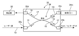
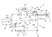
図1は、ハイブリッド光学システム10を含むシステム1の1つの実施形態を示す。システム1は、ハイブリッド光学システム10と制御装置55とを含む。ハイブリッド光学システム(混合光学システム、複合光学システム)10は、OCT(光コヒーレンストモグラフィー、断層映像法、光干渉断層映像)およびCARS(コヒーレントアンチストークスラマン分光法、コヒーレント反ストークスラマン散乱)を用いて、人体などのターゲット(対象物、測定対象)5の表面および内部の状態および組成を示すデータを取得する。制御装置(コントローラ)55は、OCTによりターゲット5の状態を検証(確認)し、CARSにより内部組成(成分)の分析を行う分析装置(分析器)56を含む。
FIG. 1 shows one embodiment of
ハイブリッド光学システム(光学システム)10は、レーザーソース(レーザー源)30を有し、レーザー源30は、ストークス光(ストークスビーム、ストークスパルス、第1の光)11およびポンプ光(励起光、ポンプビーム、ポンプパルス、第2の光)12のための第1の波長1040nmの第1のレーザ30aと、OCT光13およびプローブ光(プローブビーム、第4の光)14のための第2の波長780nmを有する第2のレーザー30bとを出力する。好ましいレーザー源30の1つは、ファイバレーザーである。第1のレーザー30aは、数10から数100mWの1から数100fS(フェムト秒)オーダーのパルスを含んでもよい。第2のレーザ30bは、数10から数100mWの1から数10pS(ピコ秒)オーダーのパルスを含んでもよく、波長780nmの第2のレーザ30bは、波長1560nmの発振源から生成されてもよい。
The hybrid optical system (optical system) 10 has a laser source (laser source) 30, and the
光学システム10は、光路を形成するためのフィルタ、ミラー、ダイクロイックミラー、プリズムなどの複数の光学素子32を含み、レーザー光を分離し、また、組み合わせる(結合するする)。光学システム10は、波長1080から1300nmの第1の領域(波長領域)R1のストークス光(第1の光)11を、ポンプ光12と共通の第1のレーザー30aから、PCF(フォトニッククリスタルファイバ、またはファイバ)21を通して供給するように構成されたストークス光路(第1の光路、ストークスユニット)21を含む。光学システム10は、第1の波長領域(第1の領域)R1よりも短い波長1070nmの第2の領域(波長領域)R2のポンプ光(第2の光)12を、ストークス光11と共通する第1のレーザー30aから供給するように構成されたポンプ光路(第2の光路、ポンプユニット)22を含む。光学システム10は、光路21から供給されるストークス光11と、光路22から供給されるポンプ光12とを光入出力ユニット25に供給する共通の光路28aを含む。光路21、22、および28aは、各光路を構成するために必要なフィルタ、ファイバ、ダイクロイックミラー、プリズム等の光学素子32を含む。後述する光路についても同様である。
The
光学システム10は、第2の波長領域R2よりも短い波長620から780nmの第3の領域(波長領域)R3のOCT光(第3の光)13を、プローブ光14と共通する第2のレーザー30bからのファイバ23aを通して供給するように構成されたOCT光路(第3の光路)23をさらに含む。光学システム10は、第2の波長領域R2よりも短く、第3の波長領域R3より大きいかまたは含まれる波長780nmの第4の領域(波長領域)R4のプローブ光(プローブビーム、プローブパルス、第4の光)14を、OCT光13と共通の第2のレーザー30bから供給するように構成されたプローブ光路(第4の光路、プローブユニット)24をさらに含む。光学システム10は、光路23から干渉器(インターフェロミタ)35を介して供給されるOCT光13と、光路24から供給されるプローブ光14を、光入出力ユニット25に供給する共通の光路28bを含む。
The
プローブ光路24は、プローブ光(第4の光)14の放出(放射)とポンプ光(第2の光)12の放出(放射)との間の時間差を制御するように構成された時間遅延ユニット24aを含む。時間遅延ユニット(タイムディレイユニット)は、複数のコリメータと、コリメータ間の距離を制御することができる電動の遅延ステージとを有してもよい。時間遅延は、制御装置55のレーザー制御ユニット58によって制御されてもよい。時間遅延ユニット24aを用いることにより、プローブ光路24は、ポンプ光12の放出から時間差を設けてプローブ光14を供給し、光入出力ユニット25を介してターゲット5に放出(放射)することができる。
The probe
光学システム10は、共通光路28cを介して、ストークス光11、ポンプ光12、プローブ光14、およびOCT光13をターゲット5に同軸状に出力し、ターゲットからの光を取得するように構成された光入出力ユニット(光I/Oユニット、光学ユニット)25をさらに含む。典型的な光入出力ユニット25は、対物レンズまたはレンズシステムであり、ターゲット5に対面(対向)し、レンズ25を通して、ストークス光11、ポンプ光12およびプローブ光14をターゲット5に向けて放出または放射し、CARS光(TD−CARS光)17をターゲット5から取得または受信する。さらに、レンズ25を通して、OCT光13がターゲットへ放出または放射され、反射光15がターゲット5から取得または受信される。したがって、光学システム(光システム)10は、後方散乱CARS光(Epi−CARS)17を取得し、後方散乱CARS17を光学I/Oユニット25から導くように構成された第1の入力光路28cを含む。
The
図2は、インターフェロミタ(干渉器)35の一例を示す。インターフェロミタ35は、OCT光13から参照光13rを分離するように構成され、参照ミラー34mを含む参照ユニット34を含む。ファイバインターフェロミタ35は、光を分離および組み合わせるための4つのアーム(光路)を含む。OCT光13においては、ポート35aから入力された光の一部が参照光13rとして分離され、ポート35cを通って参照ミラー34mに向かい、他の部分は、ポート35bを通ってサンプル(物体、ターゲット)5に出力される。ターゲット5から返された(戻った、反射された)OCT光15は、ポート35bを介して入力され、参照光13rと重畳され、または結合(組み合わされ)され、干渉光16が生成される。干渉光16は、ポート35dを介して検出装置50に出力される。また、CARS光17は、ポート35bおよび35dを用いて、干渉器35を通って、検出装置50に供給される。
FIG. 2 shows an example of the interferomita (interferer) 35. The
光学システム10では、上記光路を用いて、レーザー源30側から順に、OCT光13がプローブ光14と組み合わされ、組み合わされた光はさらにストークス光11およびポンプ光12と組み合わされ、それから対物レンズ(レンズシステム)などの光学入出力ユニット25を介して、組み合わされた光を、人の皮膚などのターゲット5に向けて放出、または放射する。ターゲット5からの反射光または生成された光(反射光15およびCARS光17)は、光学ユニット25の対物レンズを通して取得され、光学システム10の光路に戻る。
In the
OCT光13とプローブ光14とを組み合わせるためのダイクロイックミラー等の光学素子は、波長620から780nmのOCT光の反射光15およびCARS光を選択するように構成されたセパレータまたは選択ユニットであってもよい。本システム10では、波長領域R4よりも短く、第3の波長領域R3と少なくとも一部が重なる、波長680から760nmの領域(波長領域)R5のTD−CARS光17が、取得した光から分離され、検出装置50に供給される。TD−CARS光17は、ターゲット5において、ストークス光11、ポンプ光12およびプローブ光14により生成される。この光学システム10では、TD−CARS光17および干渉光16の両方が、インターフェロミタ35を介して検出装置50に供給されるが、干渉光16を生成し、干渉光16およびTD−CARS光17を検出装置50に供給するための他の光路を備えた光学システム10であってもよい。
An optical element such as a dichroic mirror for combining the
光学システム10の検出装置(検出器)50は、TD−CARS光17および干渉光16の両方に共通の検出波長領域DRを含む。典型的には、検出装置50は、OCT光13の波長領域R3およびTD−CARS光17の波長領域R5のうちの大きい方と同じ検出領域(測定領域)DRを有してもよい。例えば、この光学システム10では、TD−CARS光17が検出対象であり、波長680から760nmの領域R5を有する。したがって、波長620から780nmの第3の領域R3のOCT光13が適用され、検出領域DRを、波長620から780nmの領域、またはそれ以上の領域をカバーするように設定できる。CARS検出とOCT検出とで検出波長領域DRが共有される、単一で共通の検出装置50を採用することにより、システム構成が簡素化され、CARSの検出装置としての分光分解能を向上でき、OCT画像の深度も向上できる。ストークス光11とポンプ光12とで生成されるCARS光(すなわち、ポンプ光12の波長領域R2と同じ波長領域のプローブ光を用いる場合)を検出対象とする場合、CARS光は、波長領域R2よりも短い900から1000nm程度の波長領域を有する。このため、波長900から1000nmの領域を超える波長領域を有するOCT光13が適用され、検出領域DRをOCT光の波長領域、例えば波長800から1000nmをカバーするように設定してもよい。いずれにせよ、検出装置50の検出波長領域DRは、第2の波長領域R2以下に設定される。この光学システム10では、CARS光17とOCT光13が、単一の検出装置50の同じスペクトル領域を使用することから、時分割スキャンを適用してもよい。
The detection device (detector) 50 of the
光学システム10は、さらに、CARS光17と干渉光16とを時分割的な方法で生成または供給するように切り替えるための光学素子33aを含む。光学システム10は、さらに、第2のレーザー光(共通光源)30bからOCT光(第3の光)13およびプローブ光(第4の光)14の少なくとも一方を生成するように構成された生成光路33を備え、この光路33は、光学素子(スイッチングユニット)33aを含み、OCT光(第3の光)13とプローブ光(第4の光)14とを切り替えて生成する。光学素子33aは、制御装置55内のレーザー制御部58の制御下で、プローブ光路24とOCT光路23とに対し、供給源のレーザー30bの方向を変更するMEMSミラーであってもよい。光の方向を可動ミラー33aで変えることにより、光学素子33aに入射した全ての光を、CARS光17またはOCT光13のどちらかの生成に利用できる。この光学システムでは、プローブ光14と同じ光源からOCT光13が生成され、OCT光の生成はストークス光の生成とは独立している。このため、OCT光13に適した、良好なスペクトルをより柔軟かつ容易に得ることができる。一方、OCT光の生成とストークス光の生成のそれぞれのため、PCF(フォトニッククリスタルファイバ)23aおよび21aが必要となる。
The
この光学システム10では、光学素子33aを用いてプローブ光14をカット(切断)することにより、ターゲット5において領域R5のTD−CARS光17は生成されず、後述するように、ストークス光11とポンプ光12とにより、領域R3よりも長い波長領域のCARS光のみが生成され、ストークス光11とポンプ光12のみで生成されたCARS光は、この光学システム10の検出装置50では検出されない。制御装置55内の分析装置(分析器)56は、光学素子33のスイッチングに同期して、検出装置50からの信号がOCTかTD−CARSかを把握し、各信号を適切に分析することができる。
In this
CARS顕微鏡とOCTを組み合わせる従来のシステムでは、2つの検出装置を使用するか、あるいは1つの検出装置をCARSを検出するために半分、OCTを検出するために半分に分割して使用していた。これは、CARS光とOCT光のスペクトル領域が異なるためである。2つの検出装置を使用するシステムは複雑で大型になり、単一の検出装置を使用するシステムは、CARSのスペクトル分解能とOCTの撮像深度が低下する。図1に示すシステム1は、1つの検出装置50を使用するが、CARSおよびOCTのため同じ(ほぼ同じ)スペクトル領域を有する。単一の検出装置50を用いる場合、干渉器35を通過した後のOCT信号(干渉光)16のルーティングを変えて、TD−CARS光17と重ね、単一の検出装置50に供給するようにしてもよい。この光学システム10では、TD−CARS光17とOCT信号(反射光)16の両方を干渉器35を通して供給できる。
In conventional systems that combine a CARS microscope and OCT, two detectors are used, or one detector is split in half to detect CARS and in half to detect OCT. This is because the spectral regions of CARS light and OCT light are different. Systems using two detectors are complex and large, and systems using a single detector reduce the spectral resolution of CARS and the imaging depth of OCT.
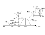
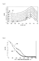
図3は、この光学システム10の波長プラン(波長設計)の一例を示す。光学システム10は、最小限のハードウェアとコストで、いくつかの作動モードに対する要求を満たすようになっている。この光学システム10に対する要件の1つが、CARS放射がTD−CARS放射と重複しないことであってもよい。この光学システム10に対する異なる要件の1つが、スペクトロメータの領域を共有するために、TD−CARS放射が、OCT励起と重複させることであってもよい。この光学システム10に対するさらに異なる要件の1つが、図4に示すように、励起に関する光を、組織細胞を効率的に通過させることであってもよい。
FIG. 3 shows an example of the wavelength plan (wavelength design) of the
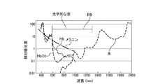
図4は、人体等の生体の内部状態を検出するのに有効な細胞組織(細胞)についての光学的な窓(光学的な開放領域)R9の一例を示す図である。図4に、水、メラニン、還元ヘモグロビン(Hb)、酸素化ヘモグロビン(HbO2)などの生体の主要物質の相対的な吸光度を示している。波長領域600nmから1300nmの光は吸収されにくく、生体の測定に適している。図4に示す光学的な窓に基づくと、第1の領域R1のストークス光11、第2の領域R2のポンプ光12、第4の領域のプローブ光14、および第3の領域R3およびR5のOCT光13およびTD−CARS光17を、600nmから1300nmの間の光学的な窓の領域に設けられることが望ましい。
FIG. 4 is a diagram showing an example of an optical window (optical open region) R9 for a cell tissue (cell) effective for detecting an internal state of a living body such as a human body. FIG. 4 shows the relative absorbances of major substances in the living body such as water, melanin, reduced hemoglobin (Hb), and oxygenated hemoglobin (HbO2). Light in the wavelength region of 600 nm to 1300 nm is difficult to be absorbed and is suitable for measuring living organisms. Based on the optical window shown in FIG. 4, the Stokes light 11 in the first region R1, the pump light 12 in the second region R2, the
図3に示されたプラン(計画、設計)では、ストークス光11は、波長1085から1230nm(400cm−1から1500cm−1)の第1の領域R1を有し、ポンプ光12は、波長1040nmの第2の領域R2を有し、プローブ光14は、波長780nmの第4の領域R4を有し、OCT光13は、波長620から780nmの第3の領域R3を有し、TD−CARS光17は、波長680から760nmの第5の領域R5を有する。領域R1、R2、R3、R4およびR5の全てが、波長600nmから1300nmの領域に含まれる。第2の領域R2は、第1の領域R1よりも短く、第3の領域R3は第2の領域R2よりも短く、第4の領域R4は第2の領域R2よりも短く、第3の領域R3よりも大きいか、またはその領域に含まれ、TD−CARS17の領域R5は、第4の領域R4よりも短く、少なくとも一部が第3の領域R3と重なる。
In the plan shown in FIG. 3, the
図5から7は、ポンプ光(非遅延プローブ)12と同じ波長、例えば1040nmのプローブ光(時間遅延プローブ)14を適用した場合のいくつかの波長プランを示す。プローブ光14によるTD−CARS17は、ストークス光11およびポンプ光12のみにより生成されるCARS18と同じ領域で、ポンプ光12の波長に対する分子振動Ωに対応する波長において生成されるので、TD−CARS信号17は、CARS信号18と干渉し、あるいは埋没してしまい、CARS信号18と区別できない。したがって、時間遅延信号は、異なる周波数で生成される必要があり、そのためにプローブパルス14をシフトさせる(ずらす)必要がある。
5 to 7 show some wavelength plans when the same wavelength as the pump light (non-delayed probe) 12, for example, the probe light (time delayed probe) 14 of 1040 nm is applied. Since the TD-CARS17 by the
図8および図9は、ポンプ光12の領域R2よりも短い波長領域R4、例えば780nmを有するプローブ光14を適用した場合の波長プラン(波長設計、波長計画)を示している。プローブ光14の領域R4よりも短い波長領域R5を有するTD−CARS17が生成される。すなわち、ストークス光11およびポンプ光12のみにより生じるCARS光の波長領域より短い波長領域R4のプローブ光14を用いて、ポンプ光12の放射からの時間差を設けることにより、CARS光18の波長領域よりも短い波長領域R5を有するTD−CARS17が生成される。したがって、TD−CARS17とCARS18との間に干渉は生じず、CARS18の干渉なしに、明瞭なTD−CARS17を検出することができる。ストークス光11とポンプ光12のみにより生成されるCARS18の波長領域より短い波長領域のプローブ光14は、ストークス光11、ポンプ光12およびプローブ光14により生じる時間差CARS(時間依存CARS、TD−CARS)17を検出するために必要とされるものであってもよい。
8 and 9 show a wavelength plan (wavelength design, wavelength planning) when a
図10は、狭い帯域のプローブ光14による明瞭なTD−CARSスペクトル17を示し、図11は、幅広のプローブ光14による、より幅広のTD−CARSスペクトル17を示す。周波数領域(周波数ドメイン、周波数空間)では、プローブ波長R4を、ポンプ波長12から所定の最小量だけシフトする必要がある。これらの図から明らかなように、プローブの帯域幅が狭いと、明確なスペクトルが生成される。幅広のプローブは、いくつかの狭い周波数成分の組み合わせであることを示唆し、それぞれの周波数成分は、同じスペクトルを異なる位置に生成する。このため、スペクトルをなめらかにすると、特徴は洗い流されてしまい、スペクトルの分解能が失われる。プローブ光14は、最適なスペクトル分解能を確保するために、分子の共振の線幅のオーダー程度の狭い帯域幅R4である必要がある。典型的なラマン線幅(Raman linewidth)は、約5から15cm−1であるので、プローブ帯域幅R4もまた、15cm−1程度であることが望ましい。時間領域(時間ドメイン、時間空間)では、プローブ光14は、時間で探査(プロービング)して励起を分離するために、数ピコ秒のオーダーの時間幅を有してもよい。ポンプ光12およびストークス光11は、例えば、fs領域でなければならず、ポンプ光12およびストークス光11は、約200fs以下の持続時間を有してもよい。
FIG. 10 shows a clear TD-
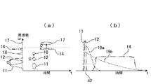
図12(a)は、ストークス光11、ポンプ光12、およびプローブ光14の時間領域を示す。また、図12(a)は、ポンプ光12による信号(CARS光)18と、遅延プローブ光14による信号(TD−CARS光)17とを含む。より高い周波数と狭いスペクトルの遅延されたプローブ光14が、明瞭なTD−CARS信号17を得るために要望される。
FIG. 12A shows the time domain of the
図12(b)は、TD−CARS信号がどのように働くかを示している。時刻t0において、ストークス光11とポンプ光12がfsオーダーで励起される。線19aは電子応答(NRB、負応答バイアス)を示し、線19bは振動応答を示す。時間遅延プローブ信号14を用いることで、振動応答はTD−CARS信号17として検出可能である。
FIG. 12B shows how the TD-CARS signal works. At time t0, the
図13(a)は、遅延時間(時間差)を変化させたTD−CARSスペクトルの例を示す。図13(a)は高濃度グルコース溶液のスペクトルを示し、線41は遅延なしのスペクトルを示し、線42は400fs(フェムト秒)後のスペクトルを示し、線43は600fs後のスペクトルを示し、線44は750fs後のスペクトルを示し、線45は850fs後のスペクトルを示し、線46は950fs後のスペクトルを示し、線47は1025fs後のスペクトルを示す。
FIG. 13A shows an example of a TD-CARS spectrum in which the delay time (time difference) is changed. FIG. 13 (a) shows the spectrum of the high concentration glucose solution,
図13(b)は、TD−CARS信号17の全信号強度が低下する様子を示す。線48は波長621から635nmの信号を示し、線49は波長685から745nmの信号を示す。図示されているように、プローブが遅延すると、信号強度はゆっくりと減少し、電子応答(NRB、ネガティブレスポンスバイアス)が急速に減衰するので、コントラストを改善できる。グルコースのピークは、プローブを遅延させるに伴って明らかに強調される。プローブパルス14は、ピコ秒パルスであってもよく、電子応答の終端または終端近くから生成されてもよく、振動応答を非共振成分から分離することができる。
FIG. 13B shows how the total signal strength of the TD-
図14は、プローブ光14の異なる実施形態を示す。プローブパルス14は、ストークス光11およびポンプ光12に先立って、またはそれらと同時に生成され、振動応答の持続時間まで放出されてもよい。
FIG. 14 shows a different embodiment of the
図15は、本実施形態のシステム1により実行される処理の一例を示すフロー図(フローチャート)である。本実施形態では、制御装置55のメモリに格納されたプログラム(プログラム生産、ソフトウェア、アプリケーション)59が提供され、メモリ、CPU等のコンピュータ資源を備えた制御装置55で処理が実行される。プログラム(ソフトウェア)59は、プロセッサあるいはコンピュータで読み取り可能な他の媒体に記録されて提供されてもよい。
FIG. 15 is a flow chart (flow chart) showing an example of processing executed by the
ステップ71において、レーザー制御装置58は、レーザー源30および光学システム10を制御し、第1の波長領域R1のストークス光(第1の光)11と、第1の波長領域R1よりも短い第2の波長領域R2のポンプ光(第2の光)12とを、光入出力ユニット(光学ユニット)25を通して放出(放射)する。ステップ72において、レーザー制御装置58は、レーザー源30と光学システム10とを制御して、ポンプ光12の放出から時間差を設けて第4の波長領域R4のプローブ光(第4の光)14を放出する。ステップ72において、時間遅延ユニット24aを用いて、プローブ光14を、ポンプ光の放射からの時間差を変化させながらターゲット5へ放出してもよい。
In
ステップ73において、検出装置50は、ストークス光11、ポンプ光12およびプローブ光14によりターゲット5において生じた(生成された)TD−CARS光を検出する。ステップ74において、分析装置56のTD−CARS分析モジュール56bは、TD−CARS光17の検出結果を用いて、ターゲット5の一部の組成の少なくとも一部を分析してもよい。
In
ステップ75において、ステップ74の前後あるいは並行して、レーザー制御装置58は、レーザー源30と光学システム10とを制御して、第3の波長領域R3のOCT光13(第3の光)を、光学ユニット25を通して、プローブ光14に対し時分割で、ターゲット5へ放出する。ステップ76において、検出装置50は、参照光13rとターゲット5からの反射光15とで生成された干渉光16を、TD−CARS光17に対し時分割で検出する。干渉光16の第3の領域R3は、TD−CARS光17の領域R5と少なくとも部分的に重なっており、検出装置50は、TD−CARS光17と干渉光16とで共有される検出波長領域を含むためである。
In
ステップ77において、分析装置56のOCT分析モジュール56aは、検出装置50によって検出された干渉光16からOCT画像を生成してもよく、分析装置56のモニタリングモジュール56cは、TD−CARS光17が生じたターゲット5の部分を確認(検証)してもよく、TD−CARS光17による情報の信頼性を確認し、OCT画像の情報とTD−CARS光の情報とを連携させてターゲット5を分析することができる。
In
図16は、システム1の異なる実施形態を示し、光学システム10aを含む。この光学システム10aは、光入出力ユニット25に対しターゲット(サンプル)5の反対側に設けられた光入力ユニット26と、光入力ユニット26からのCARS光(前方向TD−CARS光)17を、OCT光13と反射光15とで共有される共通光路28bに導くように構成された第2の入力光路27とを含む。この図に示された光学システム10aの他の光路および素子は、図1に示された光学システム10の光路および素子と共通する。
FIG. 16 shows a different embodiment of the
図17は、システム1のさらに異なる実施形態を示し、光学システム10bを含む。この光学システム10bは、TD−CARS17を生成するための光とは独立して、波長領域R3のOCT光13を供給するように構成されたレーザー源31を含む。レーザー源31は、波長領域R3のレーザー光31aを出力してもよく、波長領域を拡張または広帯化するためのファイバ24aを含んでもよい。ストークス光11、ポンプ光12およびプローブ光14を出力するためのレーザー源30と、OCT光13を出力するためのレーザー源31とは、制御装置55のレーザー制御ユニット58により、各レーザー光を時分割で、または交互に放出するように制御されてもよい。プローブ光14とOCT光13とを供給するためにレーザー光30bをスイッチングする光学素子33aは必要とされない。光学システム10bの他の光路および素子は、図1に示した光学システム10と共通する。
FIG. 17 shows a further different embodiment of the
図18は、システム1のさらに異なる実施形態を示し、光学システム10cを含む。この光学システム10cは、ストークス光(第1の光)11と共通の光源37からのOCT光(第3の光)13を生成するように構成された生成光路36を備える。この光学システム10cでは、PCF(フォトニッククリスタルファイバ)21aが、レーザー光30aを拡張(広帯域化)し、ストークス光11の波長領域R1およびOCT光13の波長領域R3の帯域をカバーし、ダイクロイックミラー21bがOCT光13をOCT光路23に分離する。
FIG. 18 shows a further different embodiment of
図19は、システム1のさらに異なる実施形態を示し、光学システム10dを含む。この光学システム10dは、ストークス光(第1の光)11と共通の光源37からOCT光(第3の光)13を生成するように構成された生成光路36を含む。この光学システム10dでは、PCF21aがレーザー光30aを拡張してストークス光11の領域R1をカバーし、ダイクロイックミラー21bが、850nm付近の光13xをOCT光路23に分離して第2のファイバ23aの入力とし、領域R3のOCT光13を生成する。この光学システム10dでは、ストークス光11と共通の光37からOCT光13が生成されるが、ファイバ21aおよび23aのそれぞれが、ストークス光11およびOCT光13を生成するために用いられ、CARS光17およびOCT干渉光16のそれぞれを生成するための最適なスペクトルを得ることができる。
FIG. 19 shows a further different embodiment of the
図20は、システム1のさらに異なる実施形態を示し、光学システム10eを含む。この光学システム10eは、ストークス光(第1の光)11およびポンプ光(第2の光)12に共通のレーザー光30aからOCT光(第3の光)13を生成するように構成された生成光路38を含む。この光学システム10eでは、プローブ信号14がピコ秒パルス、ポンプ信号12のためのレーザー源30aがフェムト秒パルスであることから、生成されるOCTスペクトルの特性は、上記で説明した実施形態とは大きく異なる可能性がある。
FIG. 20 shows a further different embodiment of the
図21は、システム1のさらに異なる実施形態を示し、光学システム10fを含む。この光学システム10fは、レーザー光30aを、スイッチング素子38aにより、OCT光路23と、ストークス光11およびポンプ光12のための光路21および22とに時分割で切り替えて共通のレーザー光30aによりOCT光(第3の光)13を生成するように構成された生成光路38を含む。
FIG. 21 shows a further different embodiment of the
本明細書では、CARS光とOCT光を用いるシステム1は、(a)第1の波長領域を有する第1の光11を放出(放射、照射)するように構成された第1のユニット21と、(b)第1の波長領域よりも短い第2の波長領域を有する第2の光12を放出するように構成された第2のユニット22と、(c)第2の波長領域よりも短い第3の波長領域を有する第3の光13を放出するように構成された第3のユニット23と、(d)第1の光11、第2の光12、および第3の光13を同軸状にターゲット(サンプル)5に出力し、ターゲット5からの光を取得するように構成された光学ユニット25と、(e)第3の光13から参照光13rを分離するように構成された参照ユニット34と、(f)取得した光から、第3の光の反射光15と、第1の光および第2の光によりターゲットで生じるCARS光であって、第3の領域と少なくとも部分的に重なる波長領域を有するCARS光17とを選択するように構成された選択ユニット28bと、(g)CARS光17と、参照光13rおよび第3の光の反射光15の組み合わせである干渉光16とを検出するように構成された検出装置50とを有する。なお、第1の光11はストークス光(ストークスビーム)であってもよく、第2の光12はポンプ光(ポンプビーム、励起光)であってもよく、第3の光13はOCT用の光(ビーム)であってもよい。
In the present specification, the
本明細書には、方法も開示されている。この方法は、(i)第1の波長領域の第1の光11と、第1の波長領域よりも短い第2の波長領域の第2の光12とを、それらの光11および12を同軸状にターゲット5に出力するように構成された光学ユニット25を介して放出(放射、照射)し、ターゲット5からの光を取得することと、(ii)第1の光11および第2の光12により生成されたCARS光17を、取得された光から選択するように構成された選択ユニット28bを通して、検出装置(検出器)によりCARS光17を検出することと、(iii)第2の領域よりも短い第3の波長領域の第3の光13であって、第3の波長領域がCARS光17の波長領域に少なくとも部分的に重なる第3の光13を、光学ユニット25を通して、ターゲット5へ放出することと、(iv)第3の光13から分離された参照光13rおよび光学ユニット25を通じて取得された第3の光の反射光16を組み合わせた(重ね合わせた)干渉光16を、検出装置50により検出することとを有する。
Methods are also disclosed herein. In this method, (i) the
また、第4のユニット24をさらに含むシステム1も本明細書に開示されている。第4のユニット24は、第2の波長領域よりも短く、第3の波長領域よりも大きい第4の波長領域の第4の光(プローブ光、プローブビーム)14を放射するように構成され、OCT光13の第3の領域と少なくとも部分的に重なり、第4の領域よりも短い波長領域を有するCARS(TD−CARS、時間遅延CARS、時間分解CARS)光17を生成する。第4のユニット24は、第4の光と第2の光との間の時間差(時間遅れ)を制御するように構成された時間遅延ユニット24aを含んでもよい。また、上記の方法であって、第4の光14を放射することをさらに含む方法が本明細書に開示されている。
A
特定の実施形態に関する上記の説明は、本明細書の実施形態の一般的な性質を十分に明らかにするものであり、現在の知識を応用することにより、一般的な概念から逸脱することなく、そのような特定の実施形態を様々な用途のために容易に修正および/または適合が可能であり、したがって、そのような適合および修正は、開示された実施形態の等価のものとして、および範囲内として理解されるべきであり、そのように意図される。本明細書で採用されている表現または用語は、説明するためのものであり、限定するためのものではないことを理解されたい。したがって、本明細書の実施形態は好ましい実施形態の観点から説明されてきたが、当業者であれば、本明細書の実施形態は添付の特許請求の範囲の精神および範囲内で修正を加えて実施することができることを認識するであろう。 The above description of a particular embodiment is sufficient to clarify the general nature of the embodiments herein, and by applying current knowledge, without departing from the general concept. Such specific embodiments can be easily modified and / or adapted for a variety of applications, and therefore such adaptations and modifications are equivalent to and within the scope of the disclosed embodiments. Should be understood as, and is intended as such. It should be understood that the expressions or terms used herein are for illustration purposes only and not for limitation purposes. Accordingly, embodiments herein have been described in terms of preferred embodiments, but those skilled in the art will modify the embodiments herein within the spirit and scope of the appended claims. You will recognize that it can be done.
Claims (22)
前記第1の波長領域よりも短い第2の波長領域の第2の光を供給するように構成された第2の光路と、
前記第2の波長領域よりも短い第3の波長領域の第3の光を供給するように構成された第3の光路と、
前記第1の光、前記第2の光、および前記第3の光をターゲットに向けて放出し、前記ターゲットからの光を得るように構成された光入出力ユニットと、
前記第3の光から参照光を分離するように構成された参照ユニットと、
検出波長領域を含む検出装置であって、少なくとも前記第1の光および前記第2の光により前記ターゲットにおいて生じ、前記第3の波長領域と少なくとも一部が重複する波長領域を含むCARS光と、前記ターゲットからの反射光および前記参照光により生ずる干渉光との両方に前記検査波長領域の少なくとも一部が共通する検出装置とを有するシステム。 A first optical path configured to supply the first light in the first wavelength region,
A second optical path configured to supply a second light in a second wavelength region shorter than the first wavelength region.
A third optical path configured to supply a third light in a third wavelength region shorter than the second wavelength region.
An optical input / output unit configured to emit the first light, the second light, and the third light toward the target to obtain light from the target.
A reference unit configured to separate the reference light from the third light,
A detection device including a detection wavelength region, the CARS light including at least a wavelength region generated in the target by the first light and the second light and at least partially overlapping the third wavelength region. A system having a detection device in which at least a part of the inspection wavelength region is common to both the reflected light from the target and the interference light generated by the reference light.
前記CARS光と前記干渉光とを、時分割で生成または供給するためのスイッチング用の光学素子を、さらに有する、システム。 In claim 1,
A system further comprising a switching optical element for producing or supplying the CARS light and the interference light in a time-division manner.
前記第2の波長領域よりも短く、前記第3の波長領域よりも大きいか、または含まれる第4の波長領域の第4の光を、前記光入出力ユニットを介して放出するために供給するように構成された第4の光路をさらに有し、
前記第4の波長領域よりも短く、前記第3の波長領域と少なくとも一部が重なる波長領域の前記CARS光を、前記第1の光、前記第2の光、および前記第4の光により生じさせる、システム。 In claim 1 or 2,
A fourth light in the fourth wavelength region, which is shorter than the second wavelength region and larger than or contained in the third wavelength region, is supplied to be emitted through the optical input / output unit. Further having a fourth optical path configured as
The CARS light in a wavelength region shorter than the fourth wavelength region and at least partially overlapping the third wavelength region is generated by the first light, the second light, and the fourth light. Let the system.
前記第4の光路は、前記第4の光の放出と前記第2の光の放出との間の時間差を制御するように構成された時間遅延ユニットを含む、システム。 In claim 3,
The fourth optical path comprises a time delay unit configured to control the time difference between the emission of the fourth light and the emission of the second light.
さらに、前記第3の光および前記第4の光の少なくともいずれかを共通の光源から生成するように構成された生成用の光路を備える、システム。 In claim 3 or 4,
Further, a system comprising an optical path for generation configured to generate at least one of the third light and the fourth light from a common light source.
前記生成用の光路は、前記第3の光と前記第4の光とを切り替えて生成するスイッチングユニットを含む、システム。 In claim 5,
The generation optical path is a system including a switching unit that switches between the third light and the fourth light to generate.
前記第1の光または前記第2の光と共通の光源から前記第3の光を生成するように構成された生成用の光路を、さらに有する、システム。 In any of claims 1 to 4,
A system further comprising a generational optical path configured to generate the third light from the first light or a light source common to the second light.
前記光入出力ユニットから前記CARS光を導くように構成された第1の入力用の光路を、さらに有する、システム。 In any of claims 1 to 7,
A system further comprising a first input optical path configured to guide the CARS light from the optical input / output unit.
前記ターゲットに対し、前記光入出力ユニットの反対側に配置された光入力ユニットから前記CARS光を導くように構成された第2の入力用の光路を、さらに有する、システム。 In any of claims 1 to 8,
A system further comprising, with respect to the target, a second input optical path configured to guide the CARS light from an optical input unit located on the opposite side of the optical input / output unit.
PCF(フォトニッククリスタルファイバ)を用いて前記第2の光から前記第1の光を生成するように構成された第2の生成用の経路を、さらに有する、システム。 In any of claims 1 to 9,
A system further comprising a second generation path configured to generate the first light from the second light using a PCF (photonic crystal fiber).
前記第1の波長領域、前記第2の波長領域、および前記第3の波長領域が、600nmから1300nmの間の波長領域に含まれる、システム。 In any of claims 1 to 10,
A system in which the first wavelength region, the second wavelength region, and the third wavelength region are included in a wavelength region between 600 nm and 1300 nm.
前記CARS光の検出結果を用いて前記ターゲットの組成の少なくとも一部を分析するための分析装置を、さらに有する、システム。 In any of claims 1 to 11,
A system further comprising an analyzer for analyzing at least a portion of the composition of the target using the detection results of the CARS light.
前記分析装置は、前記干渉光によって確認された前記ターゲットの一部を分析するためのユニットを含む、システム。 In claim 12,
The analyzer comprises a unit for analyzing a part of the target identified by the interfering light.
少なくとも前記第1の光および前記第2の光により前記ターゲットにおいて生じたCARS光を検出装置によって検出することと、
前記第2の波長領域よりも短い第3の波長領域の第3の光であって、前記第3の波長領域が前記CARS光の波長領域と少なくとも部分的に重なる第3の光を、前記光学ユニットを介して前記ターゲットへ放出することと、
前記第3の光から分離された参照光と前記ターゲットからの反射光とにより生じる干渉光を、前記CARS光および前記干渉光に共通する検出波長領域を含む前記検出装置により検出することとを有する方法。 The first light in the first wavelength region and the second light in the second wavelength region shorter than the first wavelength region are output to the target of the first light and the second light. , Emitting and emitting light through an optical unit configured to acquire light from said target.
At least the CARS light generated at the target by the first light and the second light is detected by the detection device, and
The optical third light in a third wavelength region shorter than the second wavelength region, wherein the third wavelength region at least partially overlaps the wavelength region of the CARS light. Discharging to the target via the unit
It includes detecting the interference light generated by the reference light separated from the third light and the reflected light from the target by the detection device including the detection wavelength region common to the CARS light and the interference light. Method.
前記第2の波長領域よりも短く、前記第3の波長領域よりも大きいか、または含まれる第4の波長領域の第4の光を、前記第2の光の放出から時間差で放出することを、さらに有し、
前記CARS光を検出することは、前記第1の光、前記第2の光、および前記第4の光によって生じるCARS光であって、前記第4の波長領域よりも短い波長を含むCARS光を検出することを含む、方法。 In claim 14,
To emit the fourth light in the fourth wavelength region, which is shorter than the second wavelength region and larger than or included in the third wavelength region, with a time lag from the emission of the second light. , And have more
To detect the CARS light is the CARS light generated by the first light, the second light, and the fourth light, and the CARS light including a wavelength shorter than the fourth wavelength region is detected. Methods, including detection.
前記第4の光を放出することは、前記第2の光の放出からの前記時間差を可変することを含む、方法。 15.
The method of emitting the fourth light comprises varying the time difference from the emission of the second light.
分析対象の前記ターゲットの部分を確認することと、
前記CARS光の検出結果を用いて、前記ターゲットの前記部分の組成の少なくとも一部を分析することとを、さらに有する、方法。 In any of claims 14 to 16,
Confirming the target part to be analyzed and
A method further comprising analyzing at least a portion of the composition of said portion of the target using the detection result of the CARS light.
前記第1の波長領域よりも短い第2の波長領域のポンプ光を、前記光学ユニットを介して前記ターゲットへ放出するために供給するように構成されたポンプユニットと、
前記ストークス光と前記ポンプ光とにより生ずるCARS光の波長領域よりも短い第4の波長領域のプローブ光を、前記ポンプ光の放出から時間差を設けて前記光学ユニットを介して前記ターゲットへ放出するために供給するように構成されたプローブユニットと、
前記ストークス光、前記ポンプ光、および前記プローブ光により前記ターゲットで生ずる、前記第4の波長領域よりも短い波長領域のTD−CARS光を検出するように構成された検出装置とを有するシステム。 A Stokes unit configured to deliver Stokes light in the first wavelength region for emission to a target via an optical unit.
A pump unit configured to supply pump light in a second wavelength region shorter than the first wavelength region for emission to the target via the optical unit.
To emit probe light in a fourth wavelength region shorter than the wavelength region of CARS light generated by the Stokes light and the pump light to the target via the optical unit with a time lag from the emission of the pump light. With a probe unit configured to supply
A system including a detection device configured to detect TD-CARS light in a wavelength region shorter than the fourth wavelength region generated by the target by the Stokes light, the pump light, and the probe light.
前記プローブユニットは、前記プローブ光の放出と前記ポンプ光の放出との時間差を制御するように構成された時間遅延ユニットを含む、システム。 In claim 18,
The probe unit comprises a time delay unit configured to control the time difference between the emission of the probe light and the emission of the pump light.
前記ストークス光と前記ポンプ光とにより生じるCARS光の波長領域よりも短い第4の波長領域のプローブ光を、前記ポンプ光の放出に対し時間差を設けて前記ターゲットへ放出することと、
前記ストークス光、前記ポンプ光、および前記プローブ光により前記ターゲットで生じる、前記第4の波長領域よりも短い波長領域のTD−CARS光を検出することとを有する方法。 To emit the Stokes light in the first wavelength region and the pump light in the second wavelength region shorter than the above-mentioned 1 wavelength region to the target.
The probe light in the fourth wavelength region, which is shorter than the wavelength region of the CARS light generated by the Stokes light and the pump light, is emitted to the target with a time lag from the emission of the pump light.
A method comprising detecting TD-CARS light in a wavelength region shorter than the fourth wavelength region generated at the target by the Stokes light, the pump light, and the probe light.
前記プローブ光を放出することは、前記ストークス光および前記ポンプ光の放出からの前記時間差を変化させて前記プローブ光を放出することを含む、方法。 In claim 20,
The method of emitting the probe light comprises emitting the probe light by varying the time difference from the emission of the Stokes light and the pump light.
第1の波長領域の第1の光と、前記第1の波長領域よりも短い第2の波長領域の第2の光とを前記光学ユニットを介して前記ターゲットに放出するステップと、
前記第1の光および前記第2の光によりターゲットにおいて生ずるCARS光を前記検出器により検出するステップと、
前記第2の波長領域よりも短い第3の波長領域の第3の光であって、前記第3の波長領域が、前記CARS光の波長領域と少なくとも部分的に重なる第3の光を、前記光学ユニットを介して前記ターゲットに放出するステップと、
前記第3の光から分離された参照光と、前記光学ユニットを介して得られる反射光とにより生ずる干渉光を前記検出器により検出するステップとを実行するための実行可能なコードを含む、コンピュータプログラム。 A computer program for a computer that operates a device that includes a unit for emitting light to a target via an optical unit and a detector for detecting light from the target.
A step of emitting a first light in a first wavelength region and a second light in a second wavelength region shorter than the first wavelength region to the target via the optical unit.
The step of detecting the CARS light generated at the target by the first light and the second light by the detector, and
The third light in a third wavelength region shorter than the second wavelength region, wherein the third wavelength region at least partially overlaps the wavelength region of the CARS light. The step of emitting light to the target via the optical unit,
A computer comprising an executable code for performing a step of detecting interference light generated by a reference light separated from the third light and reflected light obtained through the optical unit by the detector. program.
Priority Applications (1)
| Application Number | Priority Date | Filing Date | Title |
|---|---|---|---|
| JP2021080786A JP7477882B2 (en) | 2019-04-29 | 2021-05-12 | Hybrid Optical System |
Applications Claiming Priority (3)
| Application Number | Priority Date | Filing Date | Title |
|---|---|---|---|
| US201962840001P | 2019-04-29 | 2019-04-29 | |
| US62/840,001 | 2019-04-29 | ||
| PCT/JP2020/017447 WO2020222300A1 (en) | 2019-04-29 | 2020-04-23 | Hybrid optical system |
Related Child Applications (1)
| Application Number | Title | Priority Date | Filing Date |
|---|---|---|---|
| JP2021080786A Division JP7477882B2 (en) | 2019-04-29 | 2021-05-12 | Hybrid Optical System |
Publications (2)
| Publication Number | Publication Date |
|---|---|
| JP6887708B1 true JP6887708B1 (en) | 2021-06-16 |
| JP2021519437A JP2021519437A (en) | 2021-08-10 |
Family
ID=73028975
Family Applications (1)
| Application Number | Title | Priority Date | Filing Date |
|---|---|---|---|
| JP2020563803A Active JP6887708B1 (en) | 2019-04-29 | 2020-04-23 | Hybrid optical system |
Country Status (6)
| Country | Link |
|---|---|
| US (1) | US11944407B2 (en) |
| JP (1) | JP6887708B1 (en) |
| KR (1) | KR20220005449A (en) |
| CN (1) | CN113631897A (en) |
| TW (1) | TW202107067A (en) |
| WO (1) | WO2020222300A1 (en) |
Cited By (1)
| Publication number | Priority date | Publication date | Assignee | Title |
|---|---|---|---|---|
| JP7477882B2 (en) | 2019-04-29 | 2024-05-02 | アトナープ株式会社 | Hybrid Optical System |
Families Citing this family (6)
| Publication number | Priority date | Publication date | Assignee | Title |
|---|---|---|---|---|
| EP4327079A1 (en) * | 2021-04-22 | 2024-02-28 | Atonarp Inc. | Method and system for acquiring cars spectrum |
| WO2023022037A1 (en) * | 2021-08-20 | 2023-02-23 | Atonarp Inc. | Method and system for acquiring cars spectrum |
| WO2023058710A1 (en) * | 2021-10-06 | 2023-04-13 | Atonarp Inc. | Method and system for acquiring cars spectrum |
| WO2023063415A1 (en) * | 2021-10-14 | 2023-04-20 | Atonarp Inc. | System including a laser module |
| WO2023191801A1 (en) * | 2022-03-31 | 2023-10-05 | Onto Innovation Inc. | System and method for performing characterization of a sample using multi-wavelength laser acoustics |
| GB202212043D0 (en) * | 2022-08-18 | 2022-10-05 | Univ Of Lancaster | Glucose concentration measuring device |
Family Cites Families (17)
| Publication number | Priority date | Publication date | Assignee | Title |
|---|---|---|---|---|
| EP1754033B1 (en) | 2004-05-27 | 2011-06-22 | Yeda Research And Development Co., Ltd. | Coherently controlled nonlinear raman spectroscopy |
| JP5100461B2 (en) * | 2008-03-14 | 2012-12-19 | 英明 加納 | LIGHT SOURCE DEVICE FOR NONLINEAR SPECTROSCOPY MEASUREMENT SYSTEM |
| JP2009258071A (en) | 2008-03-28 | 2009-11-05 | Fujifilm Corp | Particle analyzer and particle analysis method |
| JP2010002256A (en) * | 2008-06-19 | 2010-01-07 | Fujifilm Corp | Nonlinear raman scattering light measuring device |
| US9285575B2 (en) * | 2009-01-26 | 2016-03-15 | President And Fellows Of Harvard College | Systems and methods for selective detection and imaging in coherent Raman microscopy by spectral excitation shaping |
| GB0904739D0 (en) * | 2009-03-19 | 2009-05-06 | Univ Cardiff | Coherent anti-stokes raman spectroscopy |
| US8553219B2 (en) * | 2011-01-24 | 2013-10-08 | Vanderbilt University | Common detector for combined raman spectroscopy-optical coherence tomography |
| US9599454B2 (en) | 2011-09-30 | 2017-03-21 | Tokyo University Of Science Foundation | Optical interferometer, data acquisition device, and data acquisition method |
| CN104704349B (en) | 2012-10-19 | 2018-01-02 | 株式会社日立制作所 | CARS microscopes |
| WO2014180986A1 (en) * | 2013-05-10 | 2014-11-13 | Ludwig-Maximilians-Universität München | A system and method for stimulated raman spectroscopy |
| EP2806263A1 (en) * | 2013-05-24 | 2014-11-26 | Nederlandse Organisatie voor toegepast -natuurwetenschappelijk onderzoek TNO | Method and detector for detecting an analyte |
| WO2015025389A1 (en) * | 2013-08-22 | 2015-02-26 | 株式会社日立製作所 | Cars microscope |
| US20160007840A1 (en) * | 2014-07-10 | 2016-01-14 | The Board Of Trustees Of The University Of Illinois | Handheld Device for Identification of Microbiological Constituents in the Middle Ear |
| EP3474001B1 (en) * | 2016-06-17 | 2021-11-17 | Saitama Medical University | Test object visualizing device |
| JP6765648B2 (en) * | 2016-07-13 | 2020-10-07 | 国立大学法人東京農工大学 | Photodetector, photodetector and photodetector |
| WO2018089865A1 (en) * | 2016-11-12 | 2018-05-17 | The Trustees Of Columbia University In The City Of New York | Microscopy devices, methods and systems |
| WO2018231724A1 (en) * | 2017-06-12 | 2018-12-20 | Trustees Of Boston University | Systems and methods for oblique laser scanning |
-
2020
- 2020-04-23 KR KR1020217033027A patent/KR20220005449A/en active Search and Examination
- 2020-04-23 JP JP2020563803A patent/JP6887708B1/en active Active
- 2020-04-23 US US17/420,152 patent/US11944407B2/en active Active
- 2020-04-23 CN CN202080022563.4A patent/CN113631897A/en active Pending
- 2020-04-23 WO PCT/JP2020/017447 patent/WO2020222300A1/en active Application Filing
- 2020-04-24 TW TW109113755A patent/TW202107067A/en unknown
Cited By (1)
| Publication number | Priority date | Publication date | Assignee | Title |
|---|---|---|---|---|
| JP7477882B2 (en) | 2019-04-29 | 2024-05-02 | アトナープ株式会社 | Hybrid Optical System |
Also Published As
| Publication number | Publication date |
|---|---|
| US11944407B2 (en) | 2024-04-02 |
| TW202107067A (en) | 2021-02-16 |
| US20220087530A1 (en) | 2022-03-24 |
| JP2021113831A (en) | 2021-08-05 |
| CN113631897A (en) | 2021-11-09 |
| JP2021519437A (en) | 2021-08-10 |
| KR20220005449A (en) | 2022-01-13 |
| WO2020222300A1 (en) | 2020-11-05 |
Similar Documents
| Publication | Publication Date | Title |
|---|---|---|
| JP6887708B1 (en) | Hybrid optical system | |
| JP5329449B2 (en) | How to perform microscopic imaging | |
| EP1754033B1 (en) | Coherently controlled nonlinear raman spectroscopy | |
| JP6008299B2 (en) | Optical interferometer, information acquisition apparatus, and information acquisition method | |
| US9494522B2 (en) | Device and method for stimulated Raman detection | |
| US20120050733A1 (en) | Laser microscope | |
| JPWO2006104237A1 (en) | Spatial information detector | |
| US11041760B2 (en) | Optical measurement device and optical measurement method | |
| CN106990095A (en) | Reflection-type confocal CARS micro-spectrometer method and devices | |
| US20190094133A1 (en) | Observation apparatus and observation method | |
| CN107037031A (en) | The confocal CARS micro-spectrometers method and device of reflection type differential | |
| JP2009047435A (en) | Laser microscope | |
| JP6453487B2 (en) | Optical measuring device and optical measuring method | |
| WO2017217534A1 (en) | Test object visualizing device | |
| JP2015197513A (en) | Light source device, and information acquisition device using the same | |
| JP7477882B2 (en) | Hybrid Optical System | |
| JP7475707B2 (en) | System including CARS optical system | |
| JP2017036925A (en) | Optical measurement device and optical measurement method | |
| JP2009058405A (en) | Optical analysis apparatus | |
| WO2020262513A1 (en) | A system including a cars optical system | |
| WO2023022037A1 (en) | Method and system for acquiring cars spectrum | |
| JP2014126491A (en) | Information acquisition system, information acquisition device and information acquisition method | |
| JP3222270B2 (en) | Spectral fiberscope | |
| JP2009058578A (en) | Device of calculating sample observation condition, and microscope system equipped therewith |
Legal Events
| Date | Code | Title | Description |
|---|---|---|---|
| A521 | Request for written amendment filed |
Free format text: JAPANESE INTERMEDIATE CODE: A523 Effective date: 20201127 |
|
| A621 | Written request for application examination |
Free format text: JAPANESE INTERMEDIATE CODE: A621 Effective date: 20201127 |
|
| A871 | Explanation of circumstances concerning accelerated examination |
Free format text: JAPANESE INTERMEDIATE CODE: A871 Effective date: 20201127 |
|
| TRDD | Decision of grant or rejection written | ||
| A975 | Report on accelerated examination |
Free format text: JAPANESE INTERMEDIATE CODE: A971005 Effective date: 20210408 |
|
| A01 | Written decision to grant a patent or to grant a registration (utility model) |
Free format text: JAPANESE INTERMEDIATE CODE: A01 Effective date: 20210414 |
|
| A61 | First payment of annual fees (during grant procedure) |
Free format text: JAPANESE INTERMEDIATE CODE: A61 Effective date: 20210512 |
|
| R150 | Certificate of patent or registration of utility model |
Ref document number: 6887708 Country of ref document: JP Free format text: JAPANESE INTERMEDIATE CODE: R150 |
|
| R250 | Receipt of annual fees |
Free format text: JAPANESE INTERMEDIATE CODE: R250 |