JP6887060B2 - Position indicator and information processing device - Google Patents
Position indicator and information processing device Download PDFInfo
- Publication number
- JP6887060B2 JP6887060B2 JP2020519507A JP2020519507A JP6887060B2 JP 6887060 B2 JP6887060 B2 JP 6887060B2 JP 2020519507 A JP2020519507 A JP 2020519507A JP 2020519507 A JP2020519507 A JP 2020519507A JP 6887060 B2 JP6887060 B2 JP 6887060B2
- Authority
- JP
- Japan
- Prior art keywords
- pressure
- sensor
- pen
- space
- communication unit
- Prior art date
- Legal status (The legal status is an assumption and is not a legal conclusion. Google has not performed a legal analysis and makes no representation as to the accuracy of the status listed.)
- Active
Links
Images


Classifications
-
- G—PHYSICS
- G06—COMPUTING; CALCULATING OR COUNTING
- G06F—ELECTRIC DIGITAL DATA PROCESSING
- G06F3/00—Input arrangements for transferring data to be processed into a form capable of being handled by the computer; Output arrangements for transferring data from processing unit to output unit, e.g. interface arrangements
- G06F3/01—Input arrangements or combined input and output arrangements for interaction between user and computer
- G06F3/03—Arrangements for converting the position or the displacement of a member into a coded form
- G06F3/033—Pointing devices displaced or positioned by the user, e.g. mice, trackballs, pens or joysticks; Accessories therefor
- G06F3/0354—Pointing devices displaced or positioned by the user, e.g. mice, trackballs, pens or joysticks; Accessories therefor with detection of 2D relative movements between the device, or an operating part thereof, and a plane or surface, e.g. 2D mice, trackballs, pens or pucks
- G06F3/03545—Pens or stylus
-
- G—PHYSICS
- G06—COMPUTING; CALCULATING OR COUNTING
- G06F—ELECTRIC DIGITAL DATA PROCESSING
- G06F3/00—Input arrangements for transferring data to be processed into a form capable of being handled by the computer; Output arrangements for transferring data from processing unit to output unit, e.g. interface arrangements
- G06F3/01—Input arrangements or combined input and output arrangements for interaction between user and computer
- G06F3/03—Arrangements for converting the position or the displacement of a member into a coded form
- G06F3/0304—Detection arrangements using opto-electronic means
- G06F3/0317—Detection arrangements using opto-electronic means in co-operation with a patterned surface, e.g. absolute position or relative movement detection for an optical mouse or pen positioned with respect to a coded surface
-
- G—PHYSICS
- G06—COMPUTING; CALCULATING OR COUNTING
- G06F—ELECTRIC DIGITAL DATA PROCESSING
- G06F3/00—Input arrangements for transferring data to be processed into a form capable of being handled by the computer; Output arrangements for transferring data from processing unit to output unit, e.g. interface arrangements
- G06F3/01—Input arrangements or combined input and output arrangements for interaction between user and computer
- G06F3/011—Arrangements for interaction with the human body, e.g. for user immersion in virtual reality
-
- G—PHYSICS
- G06—COMPUTING; CALCULATING OR COUNTING
- G06F—ELECTRIC DIGITAL DATA PROCESSING
- G06F3/00—Input arrangements for transferring data to be processed into a form capable of being handled by the computer; Output arrangements for transferring data from processing unit to output unit, e.g. interface arrangements
- G06F3/01—Input arrangements or combined input and output arrangements for interaction between user and computer
- G06F3/03—Arrangements for converting the position or the displacement of a member into a coded form
- G06F3/0304—Detection arrangements using opto-electronic means
-
- G—PHYSICS
- G06—COMPUTING; CALCULATING OR COUNTING
- G06F—ELECTRIC DIGITAL DATA PROCESSING
- G06F3/00—Input arrangements for transferring data to be processed into a form capable of being handled by the computer; Output arrangements for transferring data from processing unit to output unit, e.g. interface arrangements
- G06F3/01—Input arrangements or combined input and output arrangements for interaction between user and computer
- G06F3/03—Arrangements for converting the position or the displacement of a member into a coded form
- G06F3/033—Pointing devices displaced or positioned by the user, e.g. mice, trackballs, pens or joysticks; Accessories therefor
- G06F3/0346—Pointing devices displaced or positioned by the user, e.g. mice, trackballs, pens or joysticks; Accessories therefor with detection of the device orientation or free movement in a 3D space, e.g. 3D mice, 6-DOF [six degrees of freedom] pointers using gyroscopes, accelerometers or tilt-sensors
-
- G—PHYSICS
- G06—COMPUTING; CALCULATING OR COUNTING
- G06F—ELECTRIC DIGITAL DATA PROCESSING
- G06F3/00—Input arrangements for transferring data to be processed into a form capable of being handled by the computer; Output arrangements for transferring data from processing unit to output unit, e.g. interface arrangements
- G06F3/01—Input arrangements or combined input and output arrangements for interaction between user and computer
- G06F3/03—Arrangements for converting the position or the displacement of a member into a coded form
- G06F3/033—Pointing devices displaced or positioned by the user, e.g. mice, trackballs, pens or joysticks; Accessories therefor
- G06F3/0354—Pointing devices displaced or positioned by the user, e.g. mice, trackballs, pens or joysticks; Accessories therefor with detection of 2D relative movements between the device, or an operating part thereof, and a plane or surface, e.g. 2D mice, trackballs, pens or pucks
- G06F3/03545—Pens or stylus
- G06F3/03546—Pens or stylus using a rotatable ball at the tip as position detecting member
-
- G—PHYSICS
- G06—COMPUTING; CALCULATING OR COUNTING
- G06F—ELECTRIC DIGITAL DATA PROCESSING
- G06F3/00—Input arrangements for transferring data to be processed into a form capable of being handled by the computer; Output arrangements for transferring data from processing unit to output unit, e.g. interface arrangements
- G06F3/01—Input arrangements or combined input and output arrangements for interaction between user and computer
- G06F3/03—Arrangements for converting the position or the displacement of a member into a coded form
- G06F3/041—Digitisers, e.g. for touch screens or touch pads, characterised by the transducing means
- G06F3/0414—Digitisers, e.g. for touch screens or touch pads, characterised by the transducing means using force sensing means to determine a position
- G06F3/04146—Digitisers, e.g. for touch screens or touch pads, characterised by the transducing means using force sensing means to determine a position using pressure sensitive conductive elements delivering a boolean signal and located between crossing sensing lines, e.g. located between X and Y sensing line layers
-
- G—PHYSICS
- G06—COMPUTING; CALCULATING OR COUNTING
- G06F—ELECTRIC DIGITAL DATA PROCESSING
- G06F3/00—Input arrangements for transferring data to be processed into a form capable of being handled by the computer; Output arrangements for transferring data from processing unit to output unit, e.g. interface arrangements
- G06F3/01—Input arrangements or combined input and output arrangements for interaction between user and computer
- G06F3/03—Arrangements for converting the position or the displacement of a member into a coded form
- G06F3/041—Digitisers, e.g. for touch screens or touch pads, characterised by the transducing means
- G06F3/0416—Control or interface arrangements specially adapted for digitisers
- G06F3/04162—Control or interface arrangements specially adapted for digitisers for exchanging data with external devices, e.g. smart pens, via the digitiser sensing hardware
-
- G—PHYSICS
- G06—COMPUTING; CALCULATING OR COUNTING
- G06F—ELECTRIC DIGITAL DATA PROCESSING
- G06F3/00—Input arrangements for transferring data to be processed into a form capable of being handled by the computer; Output arrangements for transferring data from processing unit to output unit, e.g. interface arrangements
- G06F3/01—Input arrangements or combined input and output arrangements for interaction between user and computer
- G06F3/048—Interaction techniques based on graphical user interfaces [GUI]
- G06F3/0481—Interaction techniques based on graphical user interfaces [GUI] based on specific properties of the displayed interaction object or a metaphor-based environment, e.g. interaction with desktop elements like windows or icons, or assisted by a cursor's changing behaviour or appearance
- G06F3/04815—Interaction with a metaphor-based environment or interaction object displayed as three-dimensional, e.g. changing the user viewpoint with respect to the environment or object
-
- G—PHYSICS
- G06—COMPUTING; CALCULATING OR COUNTING
- G06F—ELECTRIC DIGITAL DATA PROCESSING
- G06F3/00—Input arrangements for transferring data to be processed into a form capable of being handled by the computer; Output arrangements for transferring data from processing unit to output unit, e.g. interface arrangements
- G06F3/01—Input arrangements or combined input and output arrangements for interaction between user and computer
- G06F3/048—Interaction techniques based on graphical user interfaces [GUI]
- G06F3/0484—Interaction techniques based on graphical user interfaces [GUI] for the control of specific functions or operations, e.g. selecting or manipulating an object, an image or a displayed text element, setting a parameter value or selecting a range
- G06F3/04845—Interaction techniques based on graphical user interfaces [GUI] for the control of specific functions or operations, e.g. selecting or manipulating an object, an image or a displayed text element, setting a parameter value or selecting a range for image manipulation, e.g. dragging, rotation, expansion or change of colour
-
- G—PHYSICS
- G06—COMPUTING; CALCULATING OR COUNTING
- G06F—ELECTRIC DIGITAL DATA PROCESSING
- G06F3/00—Input arrangements for transferring data to be processed into a form capable of being handled by the computer; Output arrangements for transferring data from processing unit to output unit, e.g. interface arrangements
- G06F3/01—Input arrangements or combined input and output arrangements for interaction between user and computer
- G06F3/048—Interaction techniques based on graphical user interfaces [GUI]
- G06F3/0487—Interaction techniques based on graphical user interfaces [GUI] using specific features provided by the input device, e.g. functions controlled by the rotation of a mouse with dual sensing arrangements, or of the nature of the input device, e.g. tap gestures based on pressure sensed by a digitiser
- G06F3/0488—Interaction techniques based on graphical user interfaces [GUI] using specific features provided by the input device, e.g. functions controlled by the rotation of a mouse with dual sensing arrangements, or of the nature of the input device, e.g. tap gestures based on pressure sensed by a digitiser using a touch-screen or digitiser, e.g. input of commands through traced gestures
- G06F3/04883—Interaction techniques based on graphical user interfaces [GUI] using specific features provided by the input device, e.g. functions controlled by the rotation of a mouse with dual sensing arrangements, or of the nature of the input device, e.g. tap gestures based on pressure sensed by a digitiser using a touch-screen or digitiser, e.g. input of commands through traced gestures for inputting data by handwriting, e.g. gesture or text
-
- G—PHYSICS
- G06—COMPUTING; CALCULATING OR COUNTING
- G06F—ELECTRIC DIGITAL DATA PROCESSING
- G06F2203/00—Indexing scheme relating to G06F3/00 - G06F3/048
- G06F2203/041—Indexing scheme relating to G06F3/041 - G06F3/045
- G06F2203/04105—Pressure sensors for measuring the pressure or force exerted on the touch surface without providing the touch position
-
- G—PHYSICS
- G06—COMPUTING; CALCULATING OR COUNTING
- G06F—ELECTRIC DIGITAL DATA PROCESSING
- G06F3/00—Input arrangements for transferring data to be processed into a form capable of being handled by the computer; Output arrangements for transferring data from processing unit to output unit, e.g. interface arrangements
- G06F3/01—Input arrangements or combined input and output arrangements for interaction between user and computer
- G06F3/03—Arrangements for converting the position or the displacement of a member into a coded form
- G06F3/041—Digitisers, e.g. for touch screens or touch pads, characterised by the transducing means
Description
本発明は位置指示装置及び情報処理装置に関し、特に、タッチ面内の位置及び空間内の位置の両方を指示するために用いられるペン型の位置指示装置、及び、そのような位置指示装置と接続される情報処理装置に関する。 The present invention relates to a position-indicating device and an information processing device, and in particular, is connected to a pen-type position-indicating device used for instructing both a position in a touch surface and a position in space, and such a position-indicating device. Regarding the information processing device to be processed.
近年、タブレット型のコンピュータと組み合わせて使うペン型の位置指示装置(以下、「電子ペン」という。)が注目されている。この種の電子ペンには、通常、ペン先に加わる圧力(筆圧)を検出する筆圧センサが設けられる。コンピュータは、タッチ面内における電子ペンの位置を検出する際、電子ペンから筆圧値を受信する。そして、検出した位置に応じて線画を描画する際に、受信した筆圧値に応じてその線幅や透明度を制御するように構成される。こうすることで、例えば、ペン先をタッチ面に押し当てる力が強いほど太い線を描く、というように、インクを吐出する従来型のペンに似た書き味を演出することが可能になる。 In recent years, a pen-type position indicator (hereinafter referred to as "electronic pen") used in combination with a tablet-type computer has attracted attention. This type of electronic pen is usually provided with a pen pressure sensor that detects the pressure (pen pressure) applied to the pen tip. The computer receives the pen pressure value from the electronic pen when detecting the position of the electronic pen in the touch surface. Then, when drawing a line drawing according to the detected position, the line width and transparency are controlled according to the received pen pressure value. By doing so, for example, the stronger the force with which the pen tip is pressed against the touch surface, the thicker the line is drawn, and it is possible to produce a writing taste similar to that of a conventional pen that ejects ink.
また、特許文献1にはタッチ面を必要としないペン型入力装置が開示されている。このペン型入力装置は側面に圧力センサを有しており、ユーザのグリップ力を検出可能に構成される。特許文献1の見解によれば、ペンを持って文字や図形を描画する際には、グリップ力の変化に、描こうとしている文字や図形に応じた特徴が現れる。特許文献1の技術は、この特徴を文字や図形として認識することで、タッチ面内におけるペン先の位置を検出しなくても文字や図形の入力をできるようにしようとするものである。 Further, Patent Document 1 discloses a pen-type input device that does not require a touch surface. This pen-type input device has a pressure sensor on the side surface, and is configured to be able to detect the grip force of the user. According to the view of Patent Document 1, when drawing a character or a figure with a pen, a feature corresponding to the character or the figure to be drawn appears in the change of the grip force. The technique of Patent Document 1 is to recognize this feature as a character or a figure so that the character or the figure can be input without detecting the position of the pen tip in the touch surface.
ところで、本願の発明者は、仮想現実(VR:Virtual Reality、AR:Augmented Reality、MR:Mixed Realityを含む)空間内において、上述した電子ペンを用いて仮想平面に字を書いたり絵を描いたりできるようにすることを検討している。この場合、現実のタッチ面が存在しないので、上述した筆圧センサによって筆圧値を検出することができない。筆圧値がないと筆圧値に応じた線幅や透明度の制御ができず、従来型のペンに似た書き味を演出することができなくなるため、好適に線幅や透明度の制御が行える他の方法が必要とされていた。 By the way, the inventor of the present application uses the above-mentioned electronic pen to write or draw a picture on a virtual plane in a virtual reality (including VR: Virtual Reality, AR: Augmented Reality, MR: Mixed Reality) space. I am considering making it possible. In this case, since there is no actual touch surface, the pen pressure value cannot be detected by the pen pressure sensor described above. If there is no pen pressure value, the line width and transparency cannot be controlled according to the pen pressure value, and it is not possible to produce a writing taste similar to that of a conventional pen. Therefore, the line width and transparency can be preferably controlled. Other methods were needed.
したがって、本発明の目的の一つは、現実のタッチ面が存在しない場合であっても好適に線幅や透明度の制御が行える位置指示装置及び情報処理装置を提供することにある。 Therefore, one of the objects of the present invention is to provide a position indicating device and an information processing device capable of suitably controlling the line width and transparency even when the actual touch surface does not exist.
本発明による位置指示装置は、筐体と、位置を指示する位置指示部と、前記位置指示部に加わる第1の圧力を検出する第1のセンサと、前記筐体に加わる第2の圧力を検出する第2のセンサと、前記第1のセンサによって検出された前記第1の圧力を送信する第1の通信部と、前記第2のセンサによって検出された前記第2の圧力を送信する第2の通信部と、を備える位置指示装置である。 The position indicating device according to the present invention has a housing, a position indicating unit for instructing a position, a first sensor for detecting a first pressure applied to the position indicating unit, and a second pressure applied to the housing. A second sensor to detect, a first communication unit that transmits the first pressure detected by the first sensor, and a second communication unit that transmits the second pressure detected by the second sensor. It is a position indicating device including 2 communication units.
なお、本発明による位置指示装置は、平面位置センサの入力面における位置指示を行うための位置指示部を収納する筒状の外部筐体と、空間内における前記位置指示装置の位置を示すための空間位置情報を外部装置とのインタラクションにより検出する空間位置検出部と、前記外部筐体に対する力を検出する圧力センサと、前記空間位置検出部によって検出された前記空間位置情報、前記入力面内における前記位置指示部の位置を示すための平面位置情報、及び、前記圧力センサによって検出された力に関する圧力情報を出力可能に構成された処理部と、を備える位置指示装置であるとしてもよい。 The position indicating device according to the present invention is for indicating the position of the position indicating device in the space and the tubular outer housing for accommodating the position indicating portion for instructing the position on the input surface of the plane position sensor. A spatial position detection unit that detects spatial position information by interaction with an external device, a pressure sensor that detects a force on the external housing, the spatial position information detected by the spatial position detection unit, and the spatial position information in the input surface. The position indicating device may include a plane position information for indicating the position of the position indicating unit and a processing unit configured to be able to output pressure information regarding a force detected by the pressure sensor.
本発明による情報処理装置は、筐体、位置を指示する位置指示部、及び、前記筐体に加わる力を検出する圧力センサを有する位置指示装置と通信可能な情報処理装置であって、前記圧力センサによって検出された圧力を受信する通信部と、空間内における前記位置指示装置の位置及び前記通信部によって受信した圧力に基づいて、仮想現実空間における3Dオブジェクトの生成を制御するコントローラと、を有する情報処理装置である。 The information processing device according to the present invention is an information processing device capable of communicating with a position indicating device having a housing, a position indicating unit for instructing a position, and a pressure sensor for detecting a force applied to the housing, and the pressure. It has a communication unit that receives the pressure detected by the sensor, and a controller that controls the generation of a 3D object in the virtual real space based on the position of the position indicating device in the space and the pressure received by the communication unit. It is an information processing device.
なお、本発明による情報処理装置は、平面位置センサの入力面における位置指示を行う位置指示部を収納する筒状の外部筐体、及び、前記外部筐体の表面に対する力を検出する圧力センサを有する位置指示装置と接続されるコンピュータであって、前記位置指示装置から、空間内における前記位置指示装置の位置を示すための空間位置情報、前記入力面内における前記位置指示部の位置を示すための平面位置情報、及び、前記圧力センサによって検出された力に関する圧力情報を受信可能に構成され、前記空間位置情報及び前記圧力情報を受信した場合に、受信した前記空間位置情報に基づいて前記空間内における前記位置指示装置の位置を示す空間位置を検出し、検出した前記空間位置及び受信した前記圧力情報に基づいて3D描画を行い、前記平面位置情報及び前記圧力情報を受信した場合に、受信した前記平面位置情報に基づいて前記タッチ面内における前記位置指示部の位置を示す平面位置を検出し、検出した前記平面位置及び受信した前記圧力情報に基づいて2D描画を行う、コンピュータであるとしてもよい。 The information processing device according to the present invention includes a tubular outer housing that houses a position indicating portion that gives a position instruction on the input surface of the plane position sensor, and a pressure sensor that detects a force on the surface of the outer housing. A computer connected to a position indicating device having the space indicating device, in order to indicate spatial position information for indicating the position of the position indicating device in space and the position of the position indicating unit in the input surface. The space position information and the pressure information related to the force detected by the pressure sensor can be received, and when the space position information and the pressure information are received, the space is based on the received space position information. When the spatial position indicating the position of the position indicating device is detected, 3D drawing is performed based on the detected spatial position and the received pressure information, and the plane position information and the pressure information are received, it is received. Assuming that the computer is a computer that detects a plane position indicating the position of the position indicating portion in the touch surface based on the plane position information, and draws 2D based on the detected plane position and the received pressure information. May be good.
ユーザが仮想平面上に字を書いたり絵を描いたりする際、圧力センサによって検出される力(=グリップ力)は、現実のタッチ面上に字を書いたり絵を描いたりする際に検出される筆圧との間に一定の相関関係を有する。したがって、圧力センサによって検出される圧力を送信できる本発明による位置指示装置、及び、圧力センサによって検出された圧力に基づいて3D描画を実行できる本発明による情報処理装置によれば、現実のタッチ面が存在しない場合であっても好適に線幅や透明度を制御することが可能になる。 The force (= grip force) detected by the pressure sensor when the user writes or draws on the virtual plane is detected when writing or drawing on the actual touch surface. It has a certain correlation with the writing pressure. Therefore, according to the position indicating device according to the present invention capable of transmitting the pressure detected by the pressure sensor and the information processing device according to the present invention capable of executing 3D drawing based on the pressure detected by the pressure sensor, the actual touch surface. It becomes possible to control the line width and the transparency suitably even when there is no.
以下、添付図面を参照しながら、本発明の実施の形態について詳細に説明する。 Hereinafter, embodiments of the present invention will be described in detail with reference to the accompanying drawings.
図1は、本発明の実施の形態による空間位置指示システム1の構成を示す図である。同図に示すように、本実施の形態による空間位置指示システム1は、コンピュータ2と、仮想現実ディスプレイ3と、平面位置センサ4と、電子ペン5と、位置検出用機器7a,7bと、空間位置センサ8a〜8cとを含んで構成される。空間位置センサ8a〜8cはそれぞれ、平面位置センサ4、仮想現実ディスプレイ3、及び電子ペン5に設けられる。
FIG. 1 is a diagram showing a configuration of a space position indicating system 1 according to an embodiment of the present invention. As shown in the figure, the space position indicating system 1 according to the present embodiment includes a
図1に示した各装置は、原則として部屋の中に配置される。空間位置指示システム1においては、この部屋のほぼ全体が仮想現実空間として利用され得る。 As a general rule, each device shown in FIG. 1 is arranged in a room. In the space position indicating system 1, almost the entire room can be used as a virtual reality space.
コンピュータ2は、制御部2aとメモリ2bとを含む。以下で説明するコンピュータ2が行う各処理は、制御部2aがメモリ2b内に記憶されるプログラムを読み出して実行することにより実現される。
The
コンピュータ2は、仮想現実ディスプレイ3、位置検出用機器7a,7b、平面位置センサ4のそれぞれと、有線又は無線により接続される。有線による場合、例えばUSB(Universal Serial Bus)を用いることが好適である。無線による場合、例えばWi−Fi(登録商標)などの無線LAN、又は、ブルートゥース(登録商標)などの近距離無線通信を用いることが好適である。なお、平面位置センサ4や仮想現実ディスプレイ3がコンピュータとしての機能を内蔵する場合には、そのコンピュータによりコンピュータ2の一部又は全部を構成することとしてもよい。
The
コンピュータ2は、仮想現実ディスプレイ3上に仮想現実空間を表示する機能を有して構成される。この仮想現実空間は、VR(Virtual Reality)空間であってもよいし、AR(Augmented Reality)空間であってもよいし、MR(Mixed Reality)空間であってもよい。VR空間を表示する場合、仮想現実ディスプレイ3を装着したユーザは、仮想現実を認識し、現実世界と切り離される。一方、AR空間又はMR空間を表示する場合、仮想現実ディスプレイ3を装着したユーザは、仮想現実と現実世界とが混合した空間を認識することになる。
The
コンピュータ2は、位置検出用機器7a,7bの位置を基準として設定された仮想現実空間内において様々な3Dオブジェクト(物体)をレンダリングするレンダリング装置として機能するとともに、レンダリングの結果により仮想現実ディスプレイ3の表示を更新するよう構成される。これにより、仮想現実ディスプレイ3上に表示される仮想現実空間内には、様々な3Dオブジェクトが現れることになる。コンピュータ2によるレンダリングは、メモリ2b内に記憶される3Dオブジェクト情報に基づいて実行される。3Dオブジェクト情報は、コンピュータ2により設定された仮想現実空間を示す仮想現実空間における3Dオブジェクトの形状、位置、及び向きを示す情報であり、レンダリング対象の3Dオブジェクトごとにメモリ2b内に記憶される。
The
コンピュータ2によりレンダリングされる3Dオブジェクトには、図1に示した平面位置センサ4、電子ペン5のように現実にも存在する3Dオブジェクト(以下、「第1の3Dオブジェクト」と称する)と、仮想タブレット(図示せず)のような現実には存在しない3Dオブジェクト(以下、「第2の3Dオブジェクト」と称する)とが含まれる。これらの3Dオブジェクトをレンダリングするにあたり、コンピュータ2はまず、現実空間における空間位置センサ8bの位置及び向きを検出し、検出結果に基づいて、ユーザの視点を示す視点情報を取得する。
The 3D objects rendered by the
第1の3Dオブジェクトをレンダリングする場合、コンピュータ2はさらに、対応する物体に取り付けられている空間位置センサ(例えば、空間位置センサ8a,8c)の現実空間における位置及び向きを検出し、検出結果をメモリ2bに格納する。そして、格納した位置及び向きと、上述した視点情報と、第1の3Dオブジェクトについて記憶している形状とに基づき、第1の3Dオブジェクトを仮想現実空間内にレンダリングする。また、コンピュータ2は、電子ペン5に関して特に、空間位置センサ8cの位置を検出することによって仮想現実空間内でユーザが行った操作を検出し、その結果に基づいて第2の3Dオブジェクトを新規に作成し(すなわち、メモリ2bに3Dオブジェクト情報を新規に格納し)、又は、既に保持している第2の3Dオブジェクトを移動ないし更新する(すなわち、メモリ2bに格納済みの3Dオブジェクト情報を更新する)処理を行う。
When rendering the first 3D object, the
一方、第2の3Dオブジェクトをレンダリングする場合、コンピュータ2は、メモリ2bに格納されている3Dオブジェクト情報と、上述した視点情報とに基づき、第2の3Dオブジェクトを仮想現実空間内にレンダリングするよう構成される。
On the other hand, when rendering the second 3D object, the
仮想現実ディスプレイ3は、人間の頭部に装着して用いるVRディスプレイ(ヘッドマウントディスプレイ)である。一般に市販される仮想現実ディスプレイには、「透過型」又は「非透過型」、「メガネ型」又は「帽子型」など各種のものがあるが、仮想現実ディスプレイ3としては、そのいずれを用いることも可能である。
The
仮想現実ディスプレイ3は、空間位置センサ8a及び電子ペン5(空間位置センサ8cを含む)のそれぞれと有線又は無線により接続される。空間位置センサ8a,8cは、この接続を通じて、後述する受光レベル情報を仮想現実ディスプレイ3に通知するよう構成される。仮想現実ディスプレイ3は、空間位置センサ8a,8cのそれぞれから通知された受光レベル情報を、自身に内蔵している空間位置センサ8bの受光レベル情報とともにコンピュータ2に通知する。コンピュータ2は、こうして通知された受光レベル情報に基づき、現実空間内における空間位置センサ8a〜8cそれぞれの位置及び向きを検出する。
The
平面位置センサ4は、入力面4aと、この入力面4aの全体をカバーするように配置された複数の電極(図示せず)とを有する装置である。入力面4aは平らな表面であることが好ましく、電子ペン5のペン先を滑らせるのに適した材料によって構成され得る。複数の電極は、電子ペン5が送信したペン信号(後述)を検出する役割を果たす。各電極によって検出されたペン信号はコンピュータ2に供給され、コンピュータ2は、供給されたペン信号に基づいて、入力面4a内における電子ペン5の指示位置や、電子ペン5が送信した各種データの取得を行う。平面位置センサ4は、例えばディスプレイ機能及びプロセッサを有するタブレット端末に内蔵されるものであってよく、この場合、タブレット端末のプロセッサによりコンピュータ2の一部又は全部を構成することが可能である。
The plane position sensor 4 is a device having an
空間位置センサ8aは、平面位置センサ4の表面に固定設置される。したがって、コンピュータ2によって検出される空間位置センサ8aの位置及び向きは、仮想現実空間座標系における入力面4aの位置及び向きを示している。
The
電子ペン5は、ペン型の形状を有する位置指示装置であり、平面位置センサ4への入力装置としての機能(以下、「タブレット入力機能」と称する)と、コンピュータ2への入力装置としての機能(以下、「仮想現実空間入力機能」と称する)とを有して構成される。タブレット入力機能には、平面位置センサ4の入力面4a内の位置を指示する機能が含まれる。一方、仮想現実空間入力機能には、仮想現実空間内の位置を指示する機能が含まれる。各機能の詳細については、別途後述する。
The
位置検出用機器7a,7bは、空間位置センサ8a〜8cの位置を検出するための位置検出システムを構成する基地局装置であり、それぞれ、コンピュータ2による制御に従って方向を変えながらレーザー信号を射出可能に構成される。空間位置センサ8a〜8cは、それぞれ複数の受光センサによって構成されており、位置検出用機器7a,7bのそれぞれが照射したレーザー信号を各受光センサによって受光し、それぞれの受光レベルを含む受光レベル情報を取得するよう構成される。こうして取得された受光レベル情報は、上述したように、仮想現実ディスプレイ3を介してコンピュータ2に供給される。なお、本実施の形態では、位置検出用機器7a,7bはレーザ信号を射出可能な構成としたが、この構成に限定されない。例えば、その他の非可視光センサ、可視光線センサ又はこれらの組み合わせを用いた構成としてもよい。
The
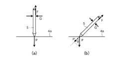
図2(a)は、電子ペン5の外観を示す斜視図である。同図に示すように、電子ペン5は、平面位置センサ4の入力面4aにおける位置指示を行うためのペン先5b(位置指示部)を収納する筒状の外部筐体5aを有して構成される。なお、実際の電子ペン5の表面には、後述するグリップ力センサ55や各種スイッチを構成する各種部材が取り付けられるが、図2(a)では描画を省略している。
FIG. 2A is a perspective view showing the appearance of the
タブレット入力機能による入力を行う場合、ユーザは、片方の手によって外部筐体5aを把持し、ペン先5bを平面位置センサ4の入力面4aに当接させる。そして、当接状態を保ちながら入力面4a上でペン先5bを移動させることによって、電子ペン5による入力操作を行う。一方、仮想現実空間入力機能による入力を行う場合、ユーザは、片方の手によって外部筐体5aを把持し、空中で電子ペン5を移動させることによって、電子ペン5による入力操作を行う。仮想現実空間入力機能による入力には、上述した仮想タブレットへの入力が含まれる。
When inputting by the tablet input function, the user grasps the
図2(b)は、電子ペン5の機能ブロックを示す略ブロック図である。同図に示すように、電子ペン5は、処理部50、平面通信部51、空間通信部52、空間位置検出部53、筆圧センサ54、グリップ力センサ55(圧力センサ)、及び力覚発生部56を有して構成される。なお、電子ペン5は筆圧センサ54及びグリップ力センサ55の一方のみを有することとしてもよいので、以下では、そのような場合も含めて説明する。
FIG. 2B is a schematic block diagram showing a functional block of the
処理部50は、電子ペン5内の他の各部と接続され、これらを制御するとともに、後述する各種の処理を行うプロセッサにより構成される。処理部50は、図示しない内部メモリに記憶されるプログラムを読み出して実行することにより、電子ペン5内の他の各部の制御及び後述する各種の処理を実行する。
The
平面通信部51は、処理部50の制御に従い、コンピュータ2との間で平面位置センサ4を介して信号の送受信を行う機能部である。この送受信では、平面位置センサ4の入力面4a内に配置される複数の電極と、電子ペン5のペン先5bの近傍に設けられるペン先電極(図示せず)とがアンテナとして利用される。また、この送受信には、電子ペン5から平面位置センサ4に対して一方的に信号を送信する場合と、電子ペン5と平面位置センサ4の間で双方向に信号の送受信を行う場合とが含まれるが、以下では、後者を前提として説明を続け、平面位置センサ4から電子ペン5に向けて送信される信号を「ビーコン信号」、電子ペン5から平面位置センサ4に向けて送信される信号を「ペン信号」と称することとする。この場合の信号送受信の具体的な方式としては、例えば電磁誘導方式又はアクティブ静電方式が用いられ得る。
The
ビーコン信号は、コンピュータ2が例えば所定の時間間隔で送信する信号であり、コンピュータ2から電子ペン5を制御するためのコマンドを含む。ペン信号には、無変調の搬送波であるバースト信号(入力面4a内におけるペン先5bの位置を示すための平面位置情報)と、コマンドによって送信を要求されたデータによって搬送波を変調することにより得られるデータ信号とが含まれる。
The beacon signal is a signal transmitted by the
空間通信部52は、処理部50の制御に従い、仮想現実ディスプレイ3を介してコンピュータ2との間で信号の送受信を行う機能を有する。この信号の送受信は、上述したように、有線又は無線によって実現される。空間通信部52とコンピュータ2との間での信号の送受信には、平面位置センサ4は介在しない。
The
空間位置検出部53は、図1に示した空間位置センサ8cによって構成される機能部であり、外部装置(具体的には、位置検出用機器7a,7b)とのインタラクションにより、上述した受光レベル情報(空間内における電子ペン5の位置を示すための空間位置情報)を検出する役割を果たす。具体的には、位置検出用機器7a,7bが送信しているレーザー信号の検出動作を周期的又は連続的に行い、検出したレーザー信号に応じた受光レベル情報を生成し、その都度、処理部50に供給する処理を行う。
The spatial
筆圧センサ54は、ペン先5bに加わる力(筆圧)を検出可能に構成されたセンサであり、例えば、筆圧によって容量値が変化する容量センサ(図示せず)によって構成される。処理部50は、筆圧センサ54によって検出されている筆圧を取得し、取得した筆圧に関する筆圧情報を生成する機能を有する。筆圧情報は、例えば、アナログ情報である筆圧にアナログデジタル変換を施すことによって得られるデジタル値である。
The pen pressure sensor 54 is a sensor configured to be able to detect a force (pen pressure) applied to the
グリップ力センサ55は、電子ペン5の外部筐体5aの表面に対する力(=グリップ力)を検出可能に構成されたセンサである。グリップ力センサ55の具体的な構成については、後ほど図面を参照しながら詳しく説明する。処理部50は、グリップ力センサ55によって検出されているグリップ力を取得し、取得したグリップ力に関する圧力情報を生成する機能を有する。圧力情報は、例えば、アナログ情報であるグリップ力にアナログデジタル変換を施すことによって得られるデジタル値である。
The
力覚発生部56は、コンピュータ2から供給される制御信号に応じて力覚を発生する機能を有する。ここでいう力覚は、例えば外部筐体5aの振動である。コンピュータ2は、例えばペン先5bが仮想タブレットの表面に接触している場合(より正確には、仮想タブレットの表面から所定の距離内にペン先5bが存在している場合)に、上記制御信号を空間通信部52を介して電子ペン5に供給することによって、力覚発生部56に力覚を発生させる。これによりユーザは、現実には存在しない仮想タブレットの表面にペン先5bが衝突した感覚を得ることができる。
The force
タブレット入力機能による入力を行う場合、処理部50はまず、平面通信部51を介して、コンピュータ2が送信するビーコン信号の検出動作を行う。その結果、ビーコン信号が検出された場合、処理部50は、ビーコン信号への応答として、上述したバースト信号及びデータ信号を順次平面通信部51に出力する。こうして出力されるデータ信号には、上述した筆圧情報又は圧力情報が含まれ得る。平面通信部51は、こうして入力されたバースト信号及びデータ信号を、平面位置センサ4を介してコンピュータ2に対して送信するよう構成される。
When inputting by the tablet input function, the
コンピュータ2は、平面位置センサ4を介してバースト信号を受信すると、入力面4a内に配置される複数の電極のそれぞれにおけるバースト信号の受信強度に基づき、入力面4a内におけるペン先5bの位置を示す平面位置を検出する。また、入力面4a内に配置される複数の電極のうち、検出した平面位置に最も近い電極を用いてデータ信号を受信することにより、電子ペン5が送信したデータを取得する。そしてコンピュータ2は、検出した平面位置及び受信したデータに基づいて2D描画を行う。2D描画の詳細については、後述する。タブレット入力機能は、こうして実現される。
When the
一方、仮想現実空間入力機能による入力を行う場合、処理部50は、空間位置検出部53から供給された受光レベル情報を、逐次、空間通信部52に対して出力するよう構成される。また、処理部50は、受光レベル情報の出力に併せて、上述したようにして生成した筆圧情報又は圧力情報も空間通信部52に対して出力するよう構成される。空間通信部52は、こうして入力された各情報を、コンピュータ2に対して送信するよう構成される。
On the other hand, when inputting by the virtual reality space input function, the
コンピュータ2は、空間通信部52から上記各情報を受信すると、受信した受光レベル情報に基づき、空間内における電子ペン5の位置を示す空間位置を検出する。この場合において、電子ペン5の形状及び空間位置検出部53とペン先5bの相対的位置関係を示す情報を予めコンピュータ2に記憶させておき、コンピュータ2は、受光レベル情報から直接的に求められる位置をこの情報に基づいてペン先5bの位置に変換し、変換によって得た位置を空間位置として検出することとしてもよい。コンピュータ2は、検出した空間位置及び受信した筆圧情報又は圧力情報に基づいて3D描画を行う。3D描画の詳細についても、後述する。仮想現実空間入力機能は、こうして実現される。
When the
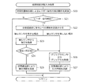
図3は、電子ペン5の処理部50が行う処理を示す処理フロー図である。また、図4は、図3に示したタブレット入力処理(ステップS1)の詳細を示す処理フロー図であり、図5は、図3に示した仮想現実空間入力処理(ステップS2)の詳細を示す処理フロー図である。以下、これら図3〜図5を参照しながら、電子ペン5の動作について詳しく説明する。
FIG. 3 is a processing flow chart showing processing performed by the
まず図3に示すように、処理部50は、タブレット入力処理(ステップS1)と、仮想現実空間入力処理(ステップS2)とを時分割で行う。
First, as shown in FIG. 3, the
次に図4を参照すると、タブレット入力処理を行う処理部50は、まず、平面通信部51によるビーコン信号の検出動作を実施する(ステップS10,S11)。この検出動作において平面通信部51は、上述したペン先電極に到来する信号を復調することによって、ビーコン信号の検出を試みる。その結果、ビーコン信号が検出されない場合には、タブレット入力処理を終了する。一方、ビーコン信号が検出された場合、処理部50は、平面通信部51に対してバースト信号を出力することにより、平面通信部51にバースト信号を送信させる(ステップS12)。
Next, referring to FIG. 4, the
この後の処理は、電子ペン5が筆圧センサ54を有する場合と筆圧センサ54を有しない場合とで異なる。前者の場合、処理部50は、筆圧センサ54の出力から筆圧を取得し(ステップS13)、取得した筆圧に関する筆圧情報を含むデータ信号を平面通信部51により送信する(ステップS14)。一方、後者の場合、処理部50は、グリップ力センサ55の出力からグリップ力を取得し(ステップS15)、取得したグリップ力に関する圧力情報を含むデータ信号を平面通信部51により送信する(ステップS16)。ステップS14又はステップS16における送信の後、処理部50はタブレット入力処理を終了し、図3から理解されるように、次の仮想現実空間入力処理(ステップS2)を開始する。
The subsequent processing differs between the case where the
次に図5を参照すると、仮想現実空間入力処理を行う処理部50は、まず、空間位置検出部53によるレーザー信号の検出動作を実施する(ステップS20,S21)。その結果、レーザー信号が検出されない場合には、仮想現実空間入力処理を終了する。一方、レーザー信号が検出された場合、処理部50は、レーザー信号に応じた受光レベル情報を空間位置検出部53から取得し、空間通信部52に送信させる(ステップS22)。
Next, referring to FIG. 5, the
この後の処理は、電子ペン5が筆圧センサ54を有する場合と筆圧センサ54を有しない場合とで異なる。後者の場合、処理部50は、グリップ力センサ55の出力からグリップ力を取得し(ステップS26)、取得したグリップ力に関する圧力情報を空間通信部52により送信する(ステップS27)。一方、前者の場合、処理部50は、筆圧センサ54の出力から筆圧を取得し(ステップS23)、取得した筆圧が所定値を上回っているか否かを判定する(ステップS24)。この判定は、ペン先5bが現実の表面に当接しているか否かの判定であり、当接していない場合には筆圧を使用しないようにするために行われる。なお、ここでいう現実の表面には、単なる板などの表面が相当する。これによれば、例えば仮想タブレットの表示位置に合わせて現実の板を配置しておくことにより、仮想タブレットに関しても、筆圧センサ54を使用することが可能になる。
The subsequent processing differs between the case where the
ステップS24で上回っていると判定した場合、処理部50は、取得した筆圧に関する筆圧情報を空間通信部52により送信する(ステップS25)。一方、ステップS24で上回っていないと判定した場合、処理部50は、ステップS26に処理を移し、圧力情報の送信を実行する(ステップS26,S27)。ステップS25又はステップS27における送信の後、処理部50は仮想現実空間入力処理を終了し、図3から理解されるように、次のタブレット入力処理(ステップS1)を開始する。
If it is determined in step S24 that the pen pressure is exceeded, the
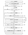
図6は、コンピュータ2の制御部2aが行う処理を示す処理フロー図である。また、図7は、図6に示した相関性取得処理(ステップS30)の詳細を示す処理フロー図であり、図10は、図6に示したタブレット描画処理(ステップS35)の詳細を示す処理フロー図であり、図11は、図6に示した仮想現実空間描画処理(ステップS41)の詳細を示す処理フロー図である。以下、これらの図を参照しながら、コンピュータ2の動作について詳しく説明する。
FIG. 6 is a processing flow diagram showing processing performed by the
図6に示すように、制御部2aは、まず初めに相関性取得処理を実行する(ステップS30)。
As shown in FIG. 6, the
相関性取得処理は、筆圧センサ54によって検出される筆圧と、グリップ力センサ55によって検出されるグリップ力との相関性fを取得する処理である。この処理において制御部2aは、図7に示すように、まず初めに所定回数にわたり、筆圧センサ54による筆圧の検出動作と、グリップ力センサ55によるグリップ力の検出動作とを電子ペン5に同時に実行させ、その都度、筆圧情報及び圧力情報を電子ペン5から受信する(ステップS50〜S52)。
The correlation acquisition process is a process for acquiring the correlation f between the pen pressure detected by the pen pressure sensor 54 and the grip force detected by the
所定回数の繰り返しの後、制御部2aは、得られた筆圧とグリップ力の複数の組み合わせに基づいて筆圧とグリップ力の相関性fを取得し(ステップS53)、相関性取得処理を終了する。こうして取得される相関性fは、例えば筆圧とグリップ力の間の相関を表す相関関数であり、一例では筆圧=f(グリップ力)の形式で表される。以下、このような相関性fを用いることを前提に説明を続ける。
After repeating the predetermined number of times, the
図8(a)(b)は、筆圧とグリップ力の相関性fを説明する図である。同図において、Pは筆圧、Gはグリップ力、Fはユーザの手と電子ペン5の表面の間の摩擦力を示している。
8 (a) and 8 (b) are diagrams for explaining the correlation f between the writing pressure and the grip force. In the figure, P is the writing pressure, G is the grip force, and F is the frictional force between the user's hand and the surface of the
初めに図8(a)を参照すると、ユーザが入力面4aに対して垂直に電子ペン5を把持しながら線を書こうとするとき、P≒Fが成り立つ。また、グリップ力Gと摩擦力Fとの間には、F≒μGの関係が成り立つ。ただし、μは、ユーザの手と電子ペン5の表面の間の摩擦係数である。したがって、P≒μGが成り立つ。
First, referring to FIG. 8A, when the user tries to draw a line while holding the
次に図8(b)を参照すると、ユーザが入力面4aの法線方向に対し角度θだけ傾けて電子ペン5を把持しながら線を書こうとするとき、F≒P'=Pcosθが成り立つ。ただし、P'は、筆圧Pのペン軸方向の分力である。したがって、上述したF≒μGの関係から、この場合にはPcosθ=μGが成り立つ。
Next, referring to FIG. 8B, when the user tries to draw a line while holding the
このPcosθ=μGという関係は、図8(a)に示した場合も包含している。したがって、f(G)=μG/cosθとすれば、相関性fを普遍的に表現することが可能になる。ただし、この中に現れる摩擦係数μ及び角度θはユーザによって異なり得る量であることから、結局、ユーザごとに筆圧=f(グリップ力)を求める必要がある。したがって、図7を参照して説明したような相関性取得処理を実行する必要があることになる。 This relationship of Pcos θ = μG also includes the case shown in FIG. 8 (a). Therefore, if f (G) = μG / cosθ, the correlation f can be universally expressed. However, since the friction coefficient μ and the angle θ appearing in this are quantities that may differ depending on the user, it is necessary to obtain the writing pressure = f (grip force) for each user after all. Therefore, it is necessary to execute the correlation acquisition process as described with reference to FIG. 7.
図6に戻る。相関性取得処理を終了した制御部2aは、続いて、仮想現実空間内に描画領域を設定する(ステップS31)。描画領域は、電子ペン5による3D描画が実行される領域である。
Return to FIG. The
図9(a)(b)はそれぞれ、描画領域の具体的な例を示す図である。図9(a)には、仮想タブレットBの表示面から所定距離内の領域を描画領域Aとして設定する例を示している。この例による描画領域Aは、仮想タブレットBへの入力を可能とする領域である。検出された空間位置がこの種の描画領域A内にある場合、制御部2aは、後述するステップS35に示す仮想現実空間描画処理の中で、検出された空間位置を仮想タブレットBの表示面上に射影してなる空間位置に置き換えたうえで3D描画を実行する。これによりユーザは、仮想タブレットBの表示面に平面図形を描画することが可能になる。なお、上記所定距離は0より大きい値とすることが好ましい。これは、ユーザが電子ペン5によって仮想タブレットBの表示面に入力を行おうとする場合に、物理的に存在しているわけではない表示面に電子ペン5を接触させ続けることが困難であることによる。
9 (a) and 9 (b) are diagrams showing specific examples of drawing areas, respectively. FIG. 9A shows an example in which an area within a predetermined distance from the display surface of the virtual tablet B is set as the drawing area A. The drawing area A according to this example is an area that enables input to the virtual tablet B. When the detected space position is in this type of drawing area A, the
図9(b)は、任意の3次元空間を描画領域Aとして設定する例を示している。制御部2aは、検出された空間位置がこの描画領域A内にある場合、図9(a)の例のような置き換えは行わずに3D描画を実行する。これによりユーザは、描画領域A内に立体図形を描画することが可能になる。
FIG. 9B shows an example in which an arbitrary three-dimensional space is set as the drawing area A. When the detected spatial position is in the drawing area A, the
図6に戻る。続いて制御部2aは、受光レベル情報及びバースト信号の検出動作を実施する(ステップS32)。この処理は、具体的には、電子ペン5から有線又は無線により受光レベル情報を受信する処理と、電子ペン5から平面位置センサ4を介してバースト信号を受信する処理とを含む。制御部2aは、ステップS32を実施した結果、バースト信号を検出した場合(ステップS33の肯定判定)にはステップS34に処理を進め、バースト信号を検出しなかった場合(ステップS33の否定判定)にはステップS36に処理を進める。
Return to FIG. Subsequently, the
ステップS34に処理を進めた制御部2aは、検出したバースト信号に基づいて上述した平面位置(入力面4a内におけるペン先5bの位置)を検出した後(ステップS34)、例えば平面位置センサ4を含むタブレット端末のディスプレイ上に2D描画を行うためのタブレット描画処理を実行する(ステップS35)。
After detecting the above-mentioned plane position (position of the
タブレット描画処理において制御部2aは、図10に示すように、まず電子ペン5が平面位置センサ4を介して送信するデータ信号の検出動作を行う(ステップS60)。そして、データ信号の中に筆圧情報及び圧力情報のいずれが含まれているかを判定する(ステップS61)。
In the tablet drawing process, as shown in FIG. 10, the
ステップS61で筆圧情報が含まれていると判定した場合、制御部2aは、筆圧情報により示される筆圧が所定の通常ON荷重(例えば、0)以下であるか否かをさらに判定する(ステップS68)。その結果、通常ON荷重以下であると判定した場合には、2D描画を行わずに処理を終了する。これは、電子ペン5のペン先5bが入力面4aに接していないと考えられる場合(いわゆる、ホバー状態)の処理である。一方、ステップS68において通常ON荷重より大きいと判定した場合には、制御部2aは、ステップS34で検出した平面位置と、筆圧情報により示される筆圧とに基づいて、例えば平面位置センサ4であるタブレット端末のディスプレイ上に2D描画を行う(ステップS69)。
When it is determined in step S61 that the pen pressure information is included, the
ここで、ステップS69で実施される2D描画について具体的に説明すると、2D描画には、レンダリング処理と表示処理とが含まれる。レンダリング処理において制御部2aは、順次検出される一連の平面位置のそれぞれに、対応する筆圧に応じた半径を有する円を配置する。そして、各円の円周を滑らかに繋いでいくことにより、筆圧に応じた幅を有する2次元の曲線データ(インクデータ)を生成する。表示処理は、こうして生成された曲線データを、例えば平面位置センサ4であるタブレット端末のディスプレイに表示する処理である。
Here, the 2D drawing performed in step S69 will be specifically described. The 2D drawing includes a rendering process and a display process. In the rendering process, the
ステップS61で圧力情報が含まれていると判定した場合、制御部2aは、圧力情報により示されるグリップ力を筆圧に変換するための処理を実行する(ステップS62〜S67)。具体的に説明すると、制御部2aはまず、リセットフラグAが真及び偽のいずれであるかを判定する(ステップS62)。リセットフラグAは、バースト信号が平面位置センサ4に届く範囲に電子ペン5が入ってきた直後か否かを示すフラグであり、直後である場合には、ステップS62の判定結果が偽となる。
When it is determined in step S61 that the pressure information is included, the
ステップS62で偽と判定した制御部2aはさらに、圧力情報により示されるグリップ力が所定値以上であるか否かを判定する(ステップS63)。そして、所定値未満であると判定した場合には、圧力情報により示されるグリップ力を初期グリップ力に設定し(ステップS64)、所定値以上であると判定した場合には、その所定値を初期グリップ力に設定する(ステップS65)。なお、初期グリップ力は、バースト信号が平面位置センサ4に届く範囲に電子ペン5が入ってきたとき(ペンダウン時)のグリップ力を0として取り扱うために使用される変数である。また、ステップS65は初期グリップ力の上限を定めるもので、例えば線幅を太くするために必要なグリップ力が大きくなりすぎてユーザが十分な筆圧を出せなくなることを防止するために用いられる。
The
図12は、初期グリップ力の意味を説明する図である。同図には、外部筐体5aの表面に対する力を横軸とし、グリップ力センサ55により検出されたグリップ力を縦軸とするグラフを示している。制御部2aは、グリップ力センサ55により検出されたグリップ力そのものではなく、そのグリップ力から初期グリップ力を減じてなる値をグリップ力として使用するよう構成される。こうすることによりユーザは、ペンダウン時のグリップ力を基準にグリップ力を増減することで、グリップ力による筆圧の入力を行うことが可能になる。
FIG. 12 is a diagram illustrating the meaning of the initial grip force. The figure shows a graph in which the force on the surface of the
図10に戻る。ステップS64又はステップS65を実行した場合、制御部2aは、リセットフラグAに真を設定した後(ステップS66)、相関性fを用いてグリップ力を筆圧に変換する処理を行う(ステップS67)。このステップS67は、ステップS62で真と判定した場合にも実行される。ステップS67において制御部2aは、圧力情報により示されるグリップ力から初期グリップ力を減じてなる値をグリップ力として相関性fに代入する。これによりユーザは、図12を参照して説明したように、ペンダウン時のグリップ力を基準にグリップ力を増減することで、グリップ力による筆圧の入力を行うことが可能になる。
Return to FIG. When step S64 or step S65 is executed, the
ステップS67で筆圧を得た制御部2aは、この筆圧を用いて、ステップS68,S69を実行する。これにより、データ信号に筆圧情報が含まれていた場合と同様の2D描画が実現される。
The
ステップS69を実行した制御部2aは、タブレット描画処理を終了する。そして、図6のステップS32に戻り、次の受光レベル情報及びバースト信号の検出動作を実行する。
The
図6のステップS36に処理を進めた制御部2aは、まず、リセットフラグAに偽を設定する(ステップS36)。これにより、バースト信号が平面位置センサ4に届く範囲から電子ペン5が離脱した場合に、リセットフラグAを偽に戻すことが可能になる。
The
続いて制御部2aは、ステップS32の検出動作により受光レベル情報を検出したか否かを判定する(ステップS37)。そして、検出したと判定した場合、制御部2aは、検出した受光レベル情報に基づいて、上述した空間位置(空間内における電子ペン5(又は、そのペン先5b)の位置)を検出する(ステップS38)。続いて制御部2aは、検出した空間位置がステップS31で設定した描画領域内の位置であるか否かを判定する(ステップS39)。
Subsequently, the
ステップS39で描画領域内の位置であると判定した制御部2aは、仮想現実空間内に3D描画を行うための仮想現実空間描画処理を実行する(ステップS41)。ここで、図6に破線で示すように、ステップS39とステップS41の間に、検出された空間位置を仮想タブレットの表示面上に射影してなる空間位置に置き換える処理を挿入してもよい(ステップS40)。このステップS40は、検出した空間位置を含む描画領域が図9(a)に示したように仮想タブレットBの表示面上に設定される領域である場合にのみ実行され得る処理である。これによりユーザは、上述したように、仮想タブレットの表示面に平面図形を描画することが可能になる。
The
仮想現実空間描画処理において制御部2aは、図11に示すように、まず筆圧情報又は圧力情報の受信動作を実施する(ステップS70)。そして、筆圧情報及び圧力情報のいずれが受信されたかを判定する(ステップS71)。
In the virtual reality space drawing process, as shown in FIG. 11, the
ステップS71で筆圧情報が受信されたと判定した場合、制御部2aは、筆圧情報により示される筆圧が所定の通常ON荷重(例えば、0)以下であるか否かをさらに判定する(ステップS80)。その結果、通常ON荷重以下であると判定した場合には、3D描画を行わずに処理を終了する。これは、電子ペン5のペン先5bが上述した現実の板(例えば、仮想タブレットの表示位置に合わせて配置されるもの)に接していないと考えられる場合の処理である。一方、ステップS80において通常ON荷重より大きいと判定した場合には、制御部2aは、ステップS38で検出した空間位置(又は、ステップS40で取得した空間位置)と、筆圧情報により示される筆圧とに基づいて、仮想現実空間内に3D描画を行う(ステップS81)。
When it is determined in step S71 that the pen pressure information has been received, the
2D描画の場合と同様、ステップS79で実施される3D描画にも、レンダリング処理と表示処理とが含まれる。レンダリング処理において制御部2aは、順次検出される一連の空間位置のそれぞれに、対応する筆圧に応じた半径を有する球を配置する。そして、各球の表面を滑らかに繋いでいくことにより、筆圧に応じた断面径を有する3次元の曲線データを生成する。表示処理は、こうして生成された曲線データを、仮想現実空間内に表示する処理である。ただし、ステップS40を実行することにより空間位置を仮想タブレットの表示面内の位置に固定する場合には、3D描画に代え、表示面内における2D描画を行うこととしてもよい。
Similar to the case of 2D drawing, the 3D drawing performed in step S79 also includes a rendering process and a display process. In the rendering process, the
ステップS71で圧力情報が受信されたと判定した場合、制御部2aは、圧力情報により示されるグリップ力を筆圧に変換するための処理を実行する(ステップS72〜S77)。この処理の詳細は、図10に示したステップS62〜S67の処理と同様であり、ステップS77において、変換結果としての筆圧が取得される。ただし、ステップS72〜S77においては、リセットフラグAに代え、リセットフラグBが用いられる。リセットフラグBは、描画領域内に電子ペン5が入ってきた直後か否かを示すフラグであり、直後である場合には、ステップS72の判定結果が偽となる。
When it is determined in step S71 that the pressure information has been received, the
ステップS77で筆圧を得た制御部2aは、この筆圧を用いて、ステップS78,S79を実行する。ステップS78,S79は、通常ON荷重に代え、通常ON荷重とは異なる値、好適には通常ON荷重よりも大きな値に設定される空間ON荷重を用いる(すなわち、ステップS78において、圧力情報により示される筆圧が所定の空間ON荷重(>通常ON荷重)以下であるか否かを判定する)ことの他は、ステップS80,S81と同じ処理である。これにより、筆圧情報が受信された場合と同様の3D描画が実現される。
The
ステップS78において通常ON荷重ではなく空間ON荷重を用いるのは、空中に浮かせた状態で電子ペン5を操作する場合、入力面4aなどの固定面に当接させた状態で操作する場合に比べ、電子ペン5の自重を支えるために必要な分だけグリップ力が大きくなることに対応するものである。ステップS78において通常ON荷重より大きな空間ON荷重を用いることにより、このようなグリップ力の増加があるにもかかわらず、適切に3D描画を行うことが可能になる。
In step S78, the use of the space ON load instead of the normal ON load is used when the
ステップS79を実行した制御部2aは、仮想現実空間描画処理を終了する。そして、図6のステップS32に戻り、次の受光レベル情報及びバースト信号の検出動作を実行する。また、制御部2aは、図6のステップS37で受光レベル情報を検出していないと判定した場合、及び、図6のステップS39で描画領域内の位置でないと判定した場合、リセットフラグBに偽を設定した後(ステップS42)、ステップS32に戻り、次の受光レベル情報及びバースト信号の検出動作を実行する。ステップS42を実行することにより、描画領域内から電子ペン5が離脱した場合(仮想現実空間内から電子ペン5が離脱した場合を含む)に、リセットフラグBを偽に戻すことが可能になる。
The
以上説明したように、本実施の形態によれば、グリップ力に関する圧力情報を出力できるように電子ペン5を構成し、グリップ力に関する圧力情報に基づいて3D描画及び2D描画を実行できるようにコンピュータ2を構成したので、現実のタッチ面が存在しない場合であっても、好適に線幅や透明度を制御することが可能になる。
As described above, according to the present embodiment, the
以下、グリップ力センサ55の具体的な構成について、図面を参照しながら詳しく説明する。
Hereinafter, the specific configuration of the
図13は、第1の例によるグリップ力センサ55の構造を示す図である。本例によるグリップ力センサ55は、例えば感圧方式により押圧力を感知可能に構成されたタッチセンサによって構成され、外部筐体5aの側面に配置される。この場合の処理部50は、グリップ力センサ55によって検出された押圧力をグリップ力として取得する。
FIG. 13 is a diagram showing the structure of the
図14は、第2の例によるグリップ力センサ55の構造を示す図である。本例によるグリップ力センサ55は、段階的又は連続的に押下量を検出可能に構成されたボタン機構によって構成され、外部筐体5aの側面に配置される。この場合の処理部50は、グリップ力センサ55によって検出された押下量をグリップ力として取得する。ボタン機構の具体的な例としては、アクチュエータ、ホール素子、ストレインゲージなどが挙げられる。
FIG. 14 is a diagram showing the structure of the
図15は、第3の例によるグリップ力センサ55の構造を示す図である。本例によるグリップ力センサ55は筆圧センサ54を兼ねており、2枚の電極板10,12の間に誘電体11が配置された構造を有するキャパシタにより構成される。電極板10は、一端がペン先5bを構成する芯体13の他端に接続される。また、電極板12は、外部筐体5aの側面に配置されたボタン機構14に接続される。
FIG. 15 is a diagram showing the structure of the
本例によるキャパシタは、ペン先5bに加わる力に応じて電極板10と電極板12の間の距離が変化し、その結果として静電容量も変化するように構成される。また、本例によるキャパシタは、図15(a)と図15(b)とを比較すると理解されるように、ボタン機構14の押下量に応じて電極板12が横方向に移動し、その結果として静電容量が変化するように構成される。本例による処理部50は、図4に示したタブレット入力処理においては、本例によるキャパシタを筆圧センサ54とみなし、その静電容量から筆圧を取得する。一方、図5に示した仮想現実空間入力処理においては、本例によるキャパシタをグリップ力センサ55とみなし、その静電容量からグリップ力を取得する。本例によれば、1つのキャパシタにより、グリップ力センサ55と筆圧センサ54の両方を実現することが可能になる。
The capacitor according to this example is configured such that the distance between the
なお、図15ではキャパシタを用いる例を説明したが、ロードセルによってもグリップ力センサ55と筆圧センサ54とを兼ねることができる。ロードセルは、X方向,Y方向,Z方向のそれぞれについて個別に応力を測定することができるので、測定した個々の応力に基づいて、ペン軸方向の力である筆圧と、ペン軸方向に垂直な力であるグリップ力とを個別に算出することができる。
Although an example of using a capacitor has been described with reference to FIG. 15, the
図16は、第4の例によるグリップ力センサ55の構造を示す図である。本例によるグリップ力センサ55は、感圧センサ15、基板16、ドームボタン17が積層されてなる構造を有し、ドームボタン17側の表面が露出するように外部筐体5aの側面に配置される。感圧センサ15は、外部筐体5aの表面に対する押圧力を感知可能に構成されたセンサであり、ドームボタン17は、ユーザによってオンオフ可能に構成されたボタン機構である。
FIG. 16 is a diagram showing the structure of the
図17は、第4の例によるグリップ力センサ55を用いる場合に電子ペン5の処理部50が行う処理を示す処理フロー図である。図17(a)は、図3に示した処理フロー図にステップS90〜S95を追加したものとなっている。また、図17(b)は、図4又は図5に示した処理フロー図にステップS96を追加したものとなっている。以下、この図17を参照しながら、第4の例によるグリップ力センサ55を備える電子ペン5の動作について説明する。
FIG. 17 is a processing flow diagram showing processing performed by the
まず図17(a)に示すように、処理部50は、まずドームボタン17がオンであるかオフであるかを判定する(ステップS90)。その結果、オフであると判定した場合には、リセットフラグCに偽を設定し(ステップS95)、ステップS1のタブレット入力処理を開始する。リセットフラグCは、ドームボタン17が押された直後であるか否かを示すフラグであり、直後である場合には、後述するステップS91の判定結果が偽となる。
First, as shown in FIG. 17A, the
ステップS90でオンであると判定した処理部50は次に、リセットフラグCが真及び偽のいずれであるかを判定する(ステップS91)。ここで真と判定した処理部50は、直ちにステップS1のタブレット入力処理を開始する。一方、偽と判定した場合には、処理部50は、グリップ力センサ55からグリップ力を取得し(ステップS92)、取得したグリップ力を初期グリップ力に設定する(ステップS93)。ここでの初期グリップ力は、ドームボタン17が押下されたときのグリップ力を0として取り扱うために使用する変数であり、コンピュータ2内で使用される初期グリップ力(図10又は図11に示した処理フロー中で使用されるもの)とは無関係である。ステップS93を実行した処理部50は、リセットフラグCに真を設定し(ステップS94)、ステップS1のタブレット入力処理を開始する。
The
次に図17(b)に示すように、処理部50は、図4のステップS15で取得したグリップ力、及び、図5のステップS26で取得したグリップ力のそれぞれから初期グリップ力を減算したものをグリップ力として使用する(ステップS96)。すなわち、ステップS15,S26で取得されるグリップ力そのものではなく、ステップS96の減算により得られたグリップ力に関する圧力情報をコンピュータ2に対して送信する。
Next, as shown in FIG. 17B, the
処理部50が以上のような処理を実行することにより、本例による電子ペン5のユーザは、自らの意思でドームボタン17をオンしたタイミングのグリップ力を基準にグリップ力を増減することで、グリップ力による筆圧の入力を行うことが可能になる。
By executing the above processing by the
図18は、第5の例によるグリップ力センサ55の構造を示す図である。本例によるグリップ力センサ55は、2枚の電極板18,21の間に誘電体19及びラバー20が配置された構造を有するキャパシタにより構成され、外部筐体5aの側面に配置される。本例による処理部50は、グリップ力センサ55であるキャパシタの静電容量をグリップ力として取得するよう構成される。
FIG. 18 is a diagram showing the structure of the
本例によるキャパシタは、外側に位置する電極板21をユーザが押下した場合に、その押圧力に応じてラバー20がつぶれ、その分、電極板18と電極板21の間の距離が短くなり、その結果として静電容量が大きくなることに加え、外側に位置する電極板21にユーザがペン軸方向の力を加えた場合にも、ラバー20の変形によって電極板21が図18(b)に示すようにペン軸方向にスライドし、その結果として静電容量が小さくなる。したがって、本例によるグリップ力センサ55によれば、押圧力に加え、ペン軸方向への力をもグリップ力として検出することが可能になる。なお、電極板18と電極板21の間の距離をd、スライドがない状態での電極板18,21のオーバーラップ面積をS、スライドによるオーバーラップ面積の変化量をΔS、誘電体19及びラバー20により構成される部材の誘電率をεとすると、本例によるキャパシタの静電容量は次の式(1)で表される。
C=ε(S−ΔS)/d・・・(1)In the capacitor according to this example, when the user presses the electrode plate 21 located on the outside, the rubber 20 is crushed according to the pressing force, and the distance between the electrode plate 18 and the electrode plate 21 is shortened by that amount. As a result, in addition to the increase in capacitance, even when the user applies a force in the pen axial direction to the electrode plate 21 located on the outside, the electrode plate 21 is shown in FIG. 18 (b) due to the deformation of the rubber 20. As shown, it slides in the direction of the pen axis, resulting in a smaller capacitance. Therefore, according to the
C = ε (S−ΔS) / d ... (1)
図19は、第6の例によるグリップ力センサ55の構造を示す図である。同図に示すように、本例による電子ペン5は外部筐体5aに取り付けられるグリップ部材22を有しており、本例によるグリップ力センサ55は、このグリップ部材22に内蔵される。図19(a)は、グリップ部材22を取り付けた状態の電子ペン5の側面、図19(b)は、グリップ部材22を取り付けた状態の電子ペン5の上面、図19(c)は、グリップ部材22を取り付けた状態の電子ペン5の使用状態をそれぞれ示している。
FIG. 19 is a diagram showing the structure of the
図19(a)〜(c)に示すように、グリップ部材22は、外部筐体5aに嵌合する筒状の基台22aと、この基台22aの一端からアーチ状に延在するフィンガーレスト22bとを有して構成される。ユーザは、図19(c)に示すように、フィンガーレスト22bに人差し指を置いた状態で電子ペン5を使用することになる。なお、図19には、グリップ部材22が外部筐体5aとは別体である例を描いているが、これらを一体形成することとしてもよい。
As shown in FIGS. 19A to 19C, the
グリップ力センサ55は、例えば、フィンガーレスト22b内に埋め込まれた歪みゲージであり、ユーザの人差し指に込められている力(フィンガーレスト22bの押圧力)を検出可能に構成される。本例による処理部50は、こうして検出された力をグリップ力として取得するよう構成される。
The
ここで、電子ペン5又はグリップ部材22内に加速度センサを内蔵することで、処理部50は、電子ペン5を振るというユーザ動作をも検出することが可能になる。これをグリップ力センサ55によるフィンガーレスト22bの押圧力の検出と組み合わせれば、タッチ面のタップ動作を模擬することも可能である。
Here, by incorporating the acceleration sensor in the
以上、本発明の好ましい実施の形態について説明したが、本発明はこうした実施の形態に何等限定されるものではなく、本発明が、その要旨を逸脱しない範囲において、種々なる態様で実施され得ることは勿論である。 Although the preferred embodiments of the present invention have been described above, the present invention is not limited to these embodiments, and the present invention can be implemented in various embodiments without departing from the gist thereof. Of course.
1 空間位置指示システム
2 コンピュータ
2a 制御部
2b メモリ
3 仮想現実ディスプレイ
4 平面位置センサ
4a 入力面
5 電子ペン
5a 外部筐体
5b ペン先
7a,7b 位置検出用機器
8a〜8c 空間位置センサ
10,12 電極板
11 誘電体
13 芯体
14 ボタン機構
15 感圧センサ
16 基板
17 ドームボタン
18,21 電極板
19 誘電体
20 ラバー
22 グリップ部材
22a 基台
22b フィンガーレスト
50 処理部
51 平面通信部
52 空間通信部
53 空間位置検出部
54 筆圧センサ
55 グリップ力センサ
56 力覚発生部
A 描画領域
B 仮想タブレット1 Spatial
Claims (14)
位置を指示する位置指示部と、
前記位置指示部に加わる第1の圧力を検出する第1のセンサと、
前記筐体に加わる第2の圧力を検出する第2のセンサと、
前記第1のセンサによって検出された前記第1の圧力を送信する第1の通信部と、
前記第2のセンサによって検出された前記第2の圧力を送信する第2の通信部と、
を備える位置指示装置。 With the housing
A position indicator that indicates the position and
A first sensor that detects the first pressure applied to the position indicator, and
A second sensor that detects the second pressure applied to the housing, and
A first communication unit that transmits the first pressure detected by the first sensor, and
A second communication unit that transmits the second pressure detected by the second sensor, and
A position indicator equipped with.
前記第2の通信部は、仮想現実空間における3Dオブジェクトの生成を制御する第2の装置に前記第2の圧力を送信する通信部である、
請求項1に記載の位置指示装置。 The first communication unit is a communication unit that transmits the first pressure to the first device that applies the first pressure to the position indicating unit.
The second communication unit is a communication unit that transmits the second pressure to a second device that controls the generation of a 3D object in virtual reality space.
The position indicating device according to claim 1.
前記第2の通信部は、前記コントローラによる比較の結果に応じて、前記第1の圧力または前記第2の圧力を送信する通信部である、
請求項1または2に記載の位置指示装置。 It further has a controller that compares the first pressure detected by the first sensor with a predetermined value.
The second communication unit is a communication unit that transmits the first pressure or the second pressure according to the result of comparison by the controller.
The position indicating device according to claim 1 or 2.
請求項1に記載の位置指示装置。 The first and second sensors are composed of a common sensor configured to be able to detect both the first and second pressures.
The position indicating device according to claim 1.
請求項1乃至3のいずれか一項に記載の位置指示装置。 The second sensor is composed of a touch sensor that senses a pressing force on the housing.
The position indicating device according to any one of claims 1 to 3.
請求項1乃至3のいずれか一項に記載の位置指示装置。 The second sensor is composed of a button mechanism that detects a pressing amount stepwise or continuously.
The position indicating device according to any one of claims 1 to 3.
請求項4に記載の位置指示装置。 The common sensor is composed of a capacitance sensor whose capacitance changes depending on both the pressing amount of the button mechanism arranged in the housing and the first pressure.
The position indicating device according to claim 4.
請求項1乃至3のいずれか一項に記載の位置指示装置。 The second sensor is composed of a dome button that can be turned on and off and a pressure-sensitive sensor that senses a pressing force on the housing.
The position indicating device according to any one of claims 1 to 3.
前記圧力センサによって検出された圧力を受信する通信部と、
空間内における前記位置指示装置の位置及び前記通信部によって受信した圧力に基づいて、仮想現実空間における3Dオブジェクトの生成を制御するとともに前記3Dオブジェクトの線幅を制御するコントローラと、
を有する情報処理装置。 An information processing device capable of communicating with a position indicating device having a housing, a position indicating unit for instructing a position, and a pressure sensor for detecting a force applied to the housing.
A communication unit that receives the pressure detected by the pressure sensor, and
A controller that controls the generation of the 3D object in the virtual reality space and controls the line width of the 3D object based on the position of the position indicating device in the space and the pressure received by the communication unit.
Information processing device with.
仮想現実空間に描画領域を設定し、
前記空間内における前記位置指示装置の位置が前記仮想現実空間に設定される描画領域内にあるか否かを判定し、
前記空間内における前記位置指示装置の位置が前記描画領域内にあると判定した場合に前記3Dオブジェクトの生成を制御する
請求項9に記載の情報処理装置。 The controller
Set the drawing area in the virtual reality space and
It is determined whether or not the position of the position indicating device in the space is within the drawing area set in the virtual reality space.
The information processing device according to claim 9, which controls the generation of the 3D object when it is determined that the position of the position indicating device in the space is within the drawing area.
前記位置指示部に加わる第1の圧力と前記圧力センサによって検出される第2の圧力との相関性を取得し、
前記取得した相関性に基づいて前記第2の圧力を変換することによって生成される圧力に基づいて前記3Dオブジェクトの生成を制御する
請求項9に記載の情報処理装置。 The controller
Obtaining the correlation between the first pressure applied to the position indicator and the second pressure detected by the pressure sensor,
The information processing apparatus according to claim 9, wherein the generation of the 3D object is controlled based on the pressure generated by converting the second pressure based on the acquired correlation.
前記空間内における前記位置指示装置の位置及び前記位置指示部に加わる圧力に基づいて、仮想現実空間における3Dオブジェクトの生成を制御する、
請求項9に記載の情報処理装置。 The controller
Controls the generation of 3D objects in virtual reality space based on the position of the position indicator in the space and the pressure applied to the position indicator.
The information processing device according to claim 9.
前記位置指示装置に圧力を加える外部の装置が有する入力面における前記位置指示装置によって指示される位置及び前記位置指示部に加わる圧力に基づいて、2D描画を制御する
請求項9に記載の情報処理装置。 The controller
The information processing according to claim 9, wherein 2D drawing is controlled based on the position indicated by the position indicating device on the input surface of the external device that applies pressure to the position indicating device and the pressure applied to the position indicating unit. apparatus.
前記位置指示装置の前記位置指示部が接触面に接触している場合に、空間内における前記位置指示装置の位置および前記通信部によって受信した前記位置指示部に加わる圧力に基づいて、仮想現実空間における3Dオブジェクトの生成を制御するとともに前記3Dオブジェクトの線幅を制御し、
前記位置指示装置の前記位置指示部が接触面に接触していない場合に、空間内における前記位置指示装置の位置及び前記通信部によって受信した前記圧力センサによって検出された圧力に基づいて、仮想現実空間における3Dオブジェクトの生成を制御するとともに前記3Dオブジェクトの線幅を制御する、
請求項9に記載の情報処理装置。 The controller
A virtual reality space based on the position of the position indicator in space and the pressure applied to the position indicator received by the communication unit when the position indicator of the position indicator is in contact with the contact surface. Controls the generation of the 3D object and controls the line width of the 3D object.
Virtual reality based on the position of the position indicator in space and the pressure detected by the pressure sensor received by the communication unit when the position indicator of the position indicator is not in contact with the contact surface. Control the generation of the 3D object in space and control the line width of the 3D object.
The information processing device according to claim 9.
Priority Applications (2)
| Application Number | Priority Date | Filing Date | Title |
|---|---|---|---|
| JP2021083044A JP7373258B2 (en) | 2018-05-18 | 2021-05-17 | Position indicating device, computer, control method |
| JP2023180098A JP2023174898A (en) | 2018-05-18 | 2023-10-19 | Position indication device, computer, and control method |
Applications Claiming Priority (3)
| Application Number | Priority Date | Filing Date | Title |
|---|---|---|---|
| JP2018096313 | 2018-05-18 | ||
| JP2018096313 | 2018-05-18 | ||
| PCT/JP2019/015042 WO2019220803A1 (en) | 2018-05-18 | 2019-04-04 | Position indication device and information processing device |
Related Child Applications (1)
| Application Number | Title | Priority Date | Filing Date |
|---|---|---|---|
| JP2021083044A Division JP7373258B2 (en) | 2018-05-18 | 2021-05-17 | Position indicating device, computer, control method |
Publications (2)
| Publication Number | Publication Date |
|---|---|
| JPWO2019220803A1 JPWO2019220803A1 (en) | 2021-06-10 |
| JP6887060B2 true JP6887060B2 (en) | 2021-06-16 |
Family
ID=68540195
Family Applications (3)
| Application Number | Title | Priority Date | Filing Date |
|---|---|---|---|
| JP2020519507A Active JP6887060B2 (en) | 2018-05-18 | 2019-04-04 | Position indicator and information processing device |
| JP2021083044A Active JP7373258B2 (en) | 2018-05-18 | 2021-05-17 | Position indicating device, computer, control method |
| JP2023180098A Pending JP2023174898A (en) | 2018-05-18 | 2023-10-19 | Position indication device, computer, and control method |
Family Applications After (2)
| Application Number | Title | Priority Date | Filing Date |
|---|---|---|---|
| JP2021083044A Active JP7373258B2 (en) | 2018-05-18 | 2021-05-17 | Position indicating device, computer, control method |
| JP2023180098A Pending JP2023174898A (en) | 2018-05-18 | 2023-10-19 | Position indication device, computer, and control method |
Country Status (5)
| Country | Link |
|---|---|
| US (1) | US20210048897A1 (en) |
| EP (1) | EP3796136A4 (en) |
| JP (3) | JP6887060B2 (en) |
| CN (1) | CN112074802A (en) |
| WO (1) | WO2019220803A1 (en) |
Families Citing this family (8)
| Publication number | Priority date | Publication date | Assignee | Title |
|---|---|---|---|---|
| US11815968B2 (en) * | 2017-12-14 | 2023-11-14 | Societe Bic | Stylus for a touchscreen |
| EP3770732B1 (en) * | 2018-03-23 | 2023-06-14 | Wacom Co., Ltd. | Three-dimensional pointing device and three-dimensional position detection system |
| CN112041789A (en) * | 2018-05-21 | 2020-12-04 | 株式会社和冠 | Position indicating device and spatial position indicating system |
| US20220004299A1 (en) * | 2020-07-01 | 2022-01-06 | Wacom Co., Ltd. | Systems and methods for dynamic shape sketching |
| KR20220012073A (en) | 2020-07-22 | 2022-02-03 | 삼성전자주식회사 | Method and apparatus for performing virtual user interaction |
| CN112835457A (en) * | 2021-02-06 | 2021-05-25 | 上海萃钛智能科技有限公司 | 3D magic pen, display system based on 3D magic pen and use method of display system |
| EP4328717A1 (en) | 2021-04-23 | 2024-02-28 | Wacom Co., Ltd. | Controller and computer |
| CN117377932A (en) | 2021-05-06 | 2024-01-09 | 三星电子株式会社 | Electronic device and control method thereof |
Family Cites Families (15)
| Publication number | Priority date | Publication date | Assignee | Title |
|---|---|---|---|---|
| DE4430488A1 (en) | 1994-08-27 | 1996-02-29 | Porsche Ag | Wheel for a motor vehicle |
| JPH10333815A (en) * | 1997-06-04 | 1998-12-18 | Brother Ind Ltd | Device for recognizing picture |
| JP4677269B2 (en) * | 2005-04-08 | 2011-04-27 | キヤノン株式会社 | Information processing method and system |
| JP2009266097A (en) * | 2008-04-28 | 2009-11-12 | Toshiba Corp | Input device |
| US8988398B2 (en) * | 2011-02-11 | 2015-03-24 | Microsoft Corporation | Multi-touch input device with orientation sensing |
| JP2013084096A (en) | 2011-10-07 | 2013-05-09 | Sharp Corp | Information processing apparatus |
| JP2013242819A (en) * | 2012-05-23 | 2013-12-05 | Hitachi Consumer Electronics Co Ltd | Pen type input device |
| JP2014062962A (en) | 2012-09-20 | 2014-04-10 | Sony Corp | Information processing apparatus, writing instrument, information processing method, and program |
| KR101360980B1 (en) * | 2013-02-05 | 2014-02-11 | 주식회사 카이언스 | Writing utensil-type electronic input device |
| JP6286846B2 (en) | 2013-03-25 | 2018-03-07 | セイコーエプソン株式会社 | Projector, indicator, interactive system, and control method |
| US9489048B2 (en) * | 2013-12-13 | 2016-11-08 | Immersion Corporation | Systems and methods for optical transmission of haptic display parameters |
| CN107533390B (en) * | 2015-04-20 | 2021-05-28 | 株式会社和冠 | System and method for two-way communication between a stylus and a stylus sensor controller |
| CN105551339A (en) * | 2015-12-31 | 2016-05-04 | 英华达(南京)科技有限公司 | Calligraphy practicing system and method based on virtual reality system |
| JP6916506B2 (en) * | 2016-07-08 | 2021-08-11 | 国立大学法人大阪大学 | Writing equipment and computer programs |
| US10073548B2 (en) * | 2016-11-08 | 2018-09-11 | Wacom Co., Ltd. | Stylus having variable transmit signal strength, and sensor for detecting such stylus |
-
2019
- 2019-04-04 CN CN201980029211.9A patent/CN112074802A/en active Pending
- 2019-04-04 EP EP19804098.2A patent/EP3796136A4/en active Pending
- 2019-04-04 WO PCT/JP2019/015042 patent/WO2019220803A1/en active Application Filing
- 2019-04-04 JP JP2020519507A patent/JP6887060B2/en active Active
-
2020
- 2020-10-29 US US17/084,444 patent/US20210048897A1/en active Pending
-
2021
- 2021-05-17 JP JP2021083044A patent/JP7373258B2/en active Active
-
2023
- 2023-10-19 JP JP2023180098A patent/JP2023174898A/en active Pending
Also Published As
| Publication number | Publication date |
|---|---|
| WO2019220803A1 (en) | 2019-11-21 |
| US20210048897A1 (en) | 2021-02-18 |
| EP3796136A1 (en) | 2021-03-24 |
| JP2021114346A (en) | 2021-08-05 |
| CN112074802A (en) | 2020-12-11 |
| JPWO2019220803A1 (en) | 2021-06-10 |
| JP2023174898A (en) | 2023-12-08 |
| EP3796136A4 (en) | 2021-07-14 |
| JP7373258B2 (en) | 2023-11-02 |
Similar Documents
| Publication | Publication Date | Title |
|---|---|---|
| JP6887060B2 (en) | Position indicator and information processing device | |
| US8237656B2 (en) | Multi-axis motion-based remote control | |
| US20100090949A1 (en) | Method and Apparatus for Input Device | |
| CN111344663B (en) | Rendering device and rendering method | |
| CN104272218A (en) | Virtual hand based on combined data | |
| US11853486B2 (en) | Stylus and position calculation method | |
| CN111819524A (en) | Input device using electronic pen | |
| CN109189245A (en) | A kind of method that smart pen and the smart pen realize mouse function | |
| KR20100009023A (en) | Apparatus and method for recognizing movement | |
| US20150002486A1 (en) | Multifunctional pencil input peripheral computer controller | |
| US10082885B2 (en) | Information input and output apparatus and information input and output method | |
| KR102572675B1 (en) | Method and electronic device for adaptively configuring user interface | |
| US20150103052A1 (en) | Direction input device and method for operating user interface using same | |
| CN208999971U (en) | A kind of smart pen with mouse function | |
| KR20050116041A (en) | Digital pen composed with accelerometer | |
| KR20040020262A (en) | A pen type mouse input device with multi function | |
| WO2013032410A1 (en) | Multifunctional pencil input peripheral computer controller | |
| JP7339470B2 (en) | controller and computer | |
| KR102337816B1 (en) | Input apparatus and data input method | |
| CN115968465A (en) | Computer, method, and program | |
| KR100349757B1 (en) | Input Device for Computer | |
| KR101066829B1 (en) | Three-dimensional input device and it's input method | |
| CN116648926A (en) | System with peripheral device having magnetic field tracking | |
| WO2010090608A2 (en) | Pencil input peripheral computer controller |
Legal Events
| Date | Code | Title | Description |
|---|---|---|---|
| A521 | Request for written amendment filed |
Free format text: JAPANESE INTERMEDIATE CODE: A523 Effective date: 20210304 |
|
| A621 | Written request for application examination |
Free format text: JAPANESE INTERMEDIATE CODE: A621 Effective date: 20210304 |
|
| A871 | Explanation of circumstances concerning accelerated examination |
Free format text: JAPANESE INTERMEDIATE CODE: A871 Effective date: 20210304 |
|
| A975 | Report on accelerated examination |
Free format text: JAPANESE INTERMEDIATE CODE: A971005 Effective date: 20210315 |
|
| A131 | Notification of reasons for refusal |
Free format text: JAPANESE INTERMEDIATE CODE: A131 Effective date: 20210330 |
|
| A521 | Request for written amendment filed |
Free format text: JAPANESE INTERMEDIATE CODE: A523 Effective date: 20210408 |
|
| TRDD | Decision of grant or rejection written | ||
| A01 | Written decision to grant a patent or to grant a registration (utility model) |
Free format text: JAPANESE INTERMEDIATE CODE: A01 Effective date: 20210420 |
|
| A61 | First payment of annual fees (during grant procedure) |
Free format text: JAPANESE INTERMEDIATE CODE: A61 Effective date: 20210517 |
|
| R150 | Certificate of patent or registration of utility model |
Ref document number: 6887060 Country of ref document: JP Free format text: JAPANESE INTERMEDIATE CODE: R150 |