JP7339470B2 - controller and computer - Google Patents
controller and computer Download PDFInfo
- Publication number
- JP7339470B2 JP7339470B2 JP2023516312A JP2023516312A JP7339470B2 JP 7339470 B2 JP7339470 B2 JP 7339470B2 JP 2023516312 A JP2023516312 A JP 2023516312A JP 2023516312 A JP2023516312 A JP 2023516312A JP 7339470 B2 JP7339470 B2 JP 7339470B2
- Authority
- JP
- Japan
- Prior art keywords
- pressure
- pen
- controller
- pressure pad
- user
- Prior art date
- Legal status (The legal status is an assumption and is not a legal conclusion. Google has not performed a legal analysis and makes no representation as to the accuracy of the status listed.)
- Active
Links
- 238000001514 detection method Methods 0.000 claims description 37
- 238000004891 communication Methods 0.000 claims description 29
- 210000003811 finger Anatomy 0.000 claims description 25
- 210000003813 thumb Anatomy 0.000 claims description 7
- 238000010586 diagram Methods 0.000 description 16
- 238000009434 installation Methods 0.000 description 10
- 238000000034 method Methods 0.000 description 7
- 238000003825 pressing Methods 0.000 description 5
- 238000007639 printing Methods 0.000 description 3
- 238000009877 rendering Methods 0.000 description 3
- 239000000758 substrate Substances 0.000 description 3
- 230000010365 information processing Effects 0.000 description 2
- 230000002093 peripheral effect Effects 0.000 description 2
- 230000003190 augmentative effect Effects 0.000 description 1
- 239000004020 conductor Substances 0.000 description 1
- 238000012790 confirmation Methods 0.000 description 1
- 238000005516 engineering process Methods 0.000 description 1
- 238000003384 imaging method Methods 0.000 description 1
- 230000006698 induction Effects 0.000 description 1
- 239000000463 material Substances 0.000 description 1
- 239000004033 plastic Substances 0.000 description 1
- 230000003068 static effect Effects 0.000 description 1
- 239000012780 transparent material Substances 0.000 description 1
Images


Classifications
-
- G—PHYSICS
- G06—COMPUTING; CALCULATING OR COUNTING
- G06F—ELECTRIC DIGITAL DATA PROCESSING
- G06F3/00—Input arrangements for transferring data to be processed into a form capable of being handled by the computer; Output arrangements for transferring data from processing unit to output unit, e.g. interface arrangements
- G06F3/01—Input arrangements or combined input and output arrangements for interaction between user and computer
- G06F3/03—Arrangements for converting the position or the displacement of a member into a coded form
- G06F3/041—Digitisers, e.g. for touch screens or touch pads, characterised by the transducing means
- G06F3/0414—Digitisers, e.g. for touch screens or touch pads, characterised by the transducing means using force sensing means to determine a position
-
- G—PHYSICS
- G06—COMPUTING; CALCULATING OR COUNTING
- G06F—ELECTRIC DIGITAL DATA PROCESSING
- G06F3/00—Input arrangements for transferring data to be processed into a form capable of being handled by the computer; Output arrangements for transferring data from processing unit to output unit, e.g. interface arrangements
- G06F3/01—Input arrangements or combined input and output arrangements for interaction between user and computer
- G06F3/03—Arrangements for converting the position or the displacement of a member into a coded form
- G06F3/033—Pointing devices displaced or positioned by the user, e.g. mice, trackballs, pens or joysticks; Accessories therefor
- G06F3/0354—Pointing devices displaced or positioned by the user, e.g. mice, trackballs, pens or joysticks; Accessories therefor with detection of 2D relative movements between the device, or an operating part thereof, and a plane or surface, e.g. 2D mice, trackballs, pens or pucks
- G06F3/03545—Pens or stylus
-
- G—PHYSICS
- G06—COMPUTING; CALCULATING OR COUNTING
- G06F—ELECTRIC DIGITAL DATA PROCESSING
- G06F3/00—Input arrangements for transferring data to be processed into a form capable of being handled by the computer; Output arrangements for transferring data from processing unit to output unit, e.g. interface arrangements
- G06F3/01—Input arrangements or combined input and output arrangements for interaction between user and computer
- G06F3/011—Arrangements for interaction with the human body, e.g. for user immersion in virtual reality
-
- G—PHYSICS
- G06—COMPUTING; CALCULATING OR COUNTING
- G06F—ELECTRIC DIGITAL DATA PROCESSING
- G06F3/00—Input arrangements for transferring data to be processed into a form capable of being handled by the computer; Output arrangements for transferring data from processing unit to output unit, e.g. interface arrangements
- G06F3/01—Input arrangements or combined input and output arrangements for interaction between user and computer
- G06F3/016—Input arrangements with force or tactile feedback as computer generated output to the user
-
- G—PHYSICS
- G06—COMPUTING; CALCULATING OR COUNTING
- G06F—ELECTRIC DIGITAL DATA PROCESSING
- G06F3/00—Input arrangements for transferring data to be processed into a form capable of being handled by the computer; Output arrangements for transferring data from processing unit to output unit, e.g. interface arrangements
- G06F3/01—Input arrangements or combined input and output arrangements for interaction between user and computer
- G06F3/03—Arrangements for converting the position or the displacement of a member into a coded form
- G06F3/0304—Detection arrangements using opto-electronic means
-
- G—PHYSICS
- G06—COMPUTING; CALCULATING OR COUNTING
- G06F—ELECTRIC DIGITAL DATA PROCESSING
- G06F3/00—Input arrangements for transferring data to be processed into a form capable of being handled by the computer; Output arrangements for transferring data from processing unit to output unit, e.g. interface arrangements
- G06F3/01—Input arrangements or combined input and output arrangements for interaction between user and computer
- G06F3/03—Arrangements for converting the position or the displacement of a member into a coded form
- G06F3/041—Digitisers, e.g. for touch screens or touch pads, characterised by the transducing means
- G06F3/044—Digitisers, e.g. for touch screens or touch pads, characterised by the transducing means by capacitive means
-
- H—ELECTRICITY
- H04—ELECTRIC COMMUNICATION TECHNIQUE
- H04W—WIRELESS COMMUNICATION NETWORKS
- H04W4/00—Services specially adapted for wireless communication networks; Facilities therefor
- H04W4/80—Services using short range communication, e.g. near-field communication [NFC], radio-frequency identification [RFID] or low energy communication
-
- G—PHYSICS
- G06—COMPUTING; CALCULATING OR COUNTING
- G06F—ELECTRIC DIGITAL DATA PROCESSING
- G06F2203/00—Indexing scheme relating to G06F3/00 - G06F3/048
- G06F2203/041—Indexing scheme relating to G06F3/041 - G06F3/045
- G06F2203/04105—Pressure sensors for measuring the pressure or force exerted on the touch surface without providing the touch position
Landscapes
- Engineering & Computer Science (AREA)
- General Engineering & Computer Science (AREA)
- Theoretical Computer Science (AREA)
- Human Computer Interaction (AREA)
- Physics & Mathematics (AREA)
- General Physics & Mathematics (AREA)
- Computer Networks & Wireless Communication (AREA)
- Signal Processing (AREA)
- Position Input By Displaying (AREA)
Description
本発明はコントローラ及びコンピュータに関し、特に、VR(Virtual Reality)、AR(Augmented Reality)、MR(Mixed Reality)、SR(Substitutional Reality)などのXR技術により構成された空間(以下「XR空間」という)内において使用されるコントローラ及びそのようなコントローラと通信可能なコンピュータに関する。 The present invention relates to a controller and a computer, and in particular, a space configured by XR technology such as VR (Virtual Reality), AR (Augmented Reality), MR (Mixed Reality), and SR (Substitutional Reality) (hereinafter referred to as "XR Space"). controllers used within and computers capable of communicating with such controllers.
ユーザがXR空間内の位置を指示するために、ペン型のコントローラが用いられる。特許文献1には、ペン型のコントローラの例が開示されている。
A pen-type controller is used for the user to indicate a position in XR space.
ペン型のコントローラには、バッテリが内蔵されることがある。このバッテリから供給される電力は、集積回路の動作、近距離無線通信方式による通信などのために利用される。 A pen-type controller may have a built-in battery. The power supplied from this battery is used for the operation of the integrated circuit, communication by the short-range wireless communication system, and the like.
しかしながら、バッテリを内蔵しているペン型のコントローラは、重量のバランスが悪く、使用に際してユーザが違和感を感じてしまうという課題があった。 However, the pen-type controller with a built-in battery has a problem that the weight is poorly balanced and the user feels uncomfortable when using it.
したがって、本発明の目的の一つは、ユーザが感じる違和感を軽減できるコントローラを提供することにある。 SUMMARY OF THE INVENTION Accordingly, it is an object of the present invention to provide a controller that can reduce the sense of discomfort felt by the user.
また、ペン型のコントローラにプレッシャーパッドを設ける場合、複数のプレッシャーパッドを設けることが考えられる。 Moreover, when providing a pen-type controller with a pressure pad, it is conceivable to provide a plurality of pressure pads.
本発明の目的の他の一つは、複数のプレッシャーパッドを有するコントローラから送信される情報に基づいて動作するコンピュータを提供することにある。 Another object of the present invention is to provide a computer that operates based on information transmitted from a controller having a plurality of pressure pads.
本発明の第1の側面によるコントローラは、ペン形状に形成されたペン部と、前記ペン部の軸方向と交差するグリップ部と、前記グリップ部内に配置されるバッテリと、を含むコントローラである。 A controller according to a first aspect of the present invention is a controller including a pen portion formed in a pen shape, a grip portion intersecting the axial direction of the pen portion, and a battery arranged in the grip portion.
本発明の第2の側面によるコンピュータは、ペン形状に形成されたペン部と、前記ペン部の軸方向と交差するグリップ部と、前記グリップ部内に配置されるバッテリと、を含むコントローラであって、前記ペン部は、第1の静電タッチセンサ及び第1の感圧センサを含む第1のプレッシャーパッド及び第2の静電タッチセンサ及び第2の感圧センサを含む第2のプレッシャーパッドを有するコントローラと通信可能なコンピュータであり、前記コントローラから送信される情報を受信する通信部と、プロセッサと、を有し、前記プロセッサは、前記通信部によって受信される情報であり前記第1の静電タッチセンサによって検出される情報又は前記通信部によって受信される情報であり前記第2の静電タッチセンサによって検出される情報に基づいて、前記通信部によって受信される情報であり前記第1の感圧センサによって検出される押圧値に関する筆圧値を出力するように制御する、又は、前記通信部によって受信される情報であり前記第2の感圧センサによって検出される押圧値に関する筆圧値を出力するように制御する、コンピュータである。 A computer according to a second aspect of the present invention is a controller including a pen portion formed in the shape of a pen, a grip portion intersecting the axial direction of the pen portion, and a battery arranged in the grip portion. , the pen unit includes a first pressure pad including a first capacitive touch sensor and a first pressure sensor and a second pressure pad including a second capacitive touch sensor and a second pressure sensor; and a processor, wherein the processor receives information received by the communication unit and the first static The information received by the communication unit based on the information detected by the electric touch sensor or the information received by the communication unit and detected by the second electrostatic touch sensor, the first Control to output a writing pressure value related to the pressure value detected by the pressure sensor, or a writing pressure value related to the pressure value detected by the second pressure sensor that is information received by the communication unit It is a computer that controls to output
本発明の第1の側面によれば、ユーザが感じる違和感を軽減できるコントローラを提供することが可能になる。 ADVANTAGE OF THE INVENTION According to the 1st side surface of this invention, it becomes possible to provide the controller which can reduce the discomfort which a user feels.
本発明の第2の側面によれば、複数のプレッシャーパッドを有するコントローラから送信される情報に基づいて動作するコンピュータを提供することが可能となる。 According to the second aspect of the present invention, it is possible to provide a computer that operates based on information transmitted from a controller having a plurality of pressure pads.
以下、添付図面を参照しながら、本発明の実施の形態について詳細に説明する。 BEST MODE FOR CARRYING OUT THE INVENTION Hereinafter, embodiments of the present invention will be described in detail with reference to the accompanying drawings.
図1は、本実施の形態によるグリップ付きペン型コントローラ6を含むトラッキングシステム1の使用状態を示す図である。同図に示すように、トラッキングシステム1は、コントローラ6の他、コンピュータ2と、位置検出装置3と、3台のカメラ4a~4cと、ヘッドマウントディスプレイ5とを有して構成される。コンピュータ2と、位置検出装置3、カメラ4a~4c、ヘッドマウントディスプレイ5、コントローラ6のそれぞれとは、有線又は無線により通信可能に構成される。
FIG. 1 is a diagram showing a usage state of a
図1に示すように、ユーザは、デスクチェア61に腰掛け、頭部にヘッドマウントディスプレイ5を装着し、コントローラ6を右手に持った状態で、トラッキングシステム1を使用する。ヘッドマウントディスプレイ5の表示面にはコンピュータ2によってレンダリングされたXR空間が表示されており、ユーザは、このXR空間を見ながら、デスク60の上方でコントローラ6を操作することになる。コントローラ6は、ペンにグリップが付いた形状を有するペン型のデバイスであり、XR空間内に表示される3Dオブジェクトの制御(具体的には、3Dオブジェクトの描画、3Dオブジェクトの移動など)を行う。さらに、コントローラ6は、位置検出装置3を用いて2D入力を行うために用いられる。
As shown in FIG. 1, the user uses the
コンピュータ2は、図1の例では、デスク60の中央に配置されたノート型のパーソナルコンピュータにより構成される。ただし、コンピュータ2を必ずしもデスク60中央に配置する必要はなく、位置検出装置3、カメラ4a~4c、ヘッドマウントディスプレイ5、及び、コントローラ6と通信可能な位置に配置すればよい。また、コンピュータ2は、ノート型のパーソナルコンピュータの他にも、デスクトップ型のパーソナルコンピュータ、タブレット型のパーソナルコンピュータ、スマートフォン、サーバコンピュータなど、様々なタイプのコンピュータにより構成され得る。
The
図2は、コンピュータ2のハードウェア構成の一例を示す図である。同図に示すように、コンピュータ2は、CPU(Central Processing Unit)101、記憶装置102、入力装置103、出力装置104、及び通信装置105を有して構成される。
FIG. 2 is a diagram showing an example of the hardware configuration of the
CPU101は、コンピュータ2の各部を制御するとともに、記憶装置102に記憶される各種のプログラムを読み出して実行するプロセッサである。後述するコンピュータ2が実行する処理は、CPU101が記憶装置102に記憶されるプログラムを実行することによって実現される。
The
記憶装置102は、DRAM(Dynamic Random Access Memory)などの主記憶装置と、ハードディスクなどの補助記憶装置とを含み、コンピュータ2のオペレーティングシステムや各種のアプリケーションを実行するための各種のプログラム、及び、これらのプログラムによって利用されるデータを記憶する役割を果たす装置である。
The
入力装置103は、ユーザーの入力操作を受け付けてCPU101に供給する装置であり、例えばキーボード、マウス、タッチパネルを含んで構成される。出力装置104は、CPU101の処理結果をユーザーに対して出力する装置であり、例えばディスプレイ、スピーカーを含んで構成される。通信装置105は、位置検出装置3、カメラ4a~4c、ヘッドマウントディスプレイ5、コントローラ6を含む外部の装置と通信するための装置であり、CPU101の制御にしたがい、これらの装置との間でデータの送受信を行う。
The
図1に戻る。コンピュータ2は、カメラ4a~4cによって撮影された映像に基づいてヘッドマウントディスプレイ5、コントローラ6、及び位置検出装置3それぞれの位置及び傾きを周期的に検出することにより、これらの動きをトラッキングする役割を果たす。位置及び傾きの検出は、具体的には、ヘッドマウントディスプレイ5、コントローラ6、及び位置検出装置3それぞれの表面に取り付けられた1以上のLEDを用いて実行される。すなわち、コンピュータ2は、カメラ4a~4cによって撮影された映像の中からこれらのLEDが発している光を検出することにより、各装置の位置及び傾きを検出するよう構成される。
Return to FIG. The
コンピュータ2は、トラッキングしている各装置の動きと、コントローラ6に設けられる各スイッチ等(後述)の状態とに基づいてXR空間及びその中に表示する3Dオブジェクトを生成し、生成したXR空間及び3Dオブジェクトをレンダリングして、ヘッドマウントディスプレイ5に送信する処理を行う。ヘッドマウントディスプレイ5は、コンピュータ2から送信されたレンダリング画像を表示することにより、1以上の3Dオブジェクトを含むXR空間を表示する役割を果たす。
The
位置検出装置3は、図1の例では、デスク60の上面のうちユーザから見てコンピュータ2の手前側に相当する位置に配置されたタブレットにより構成される。ただし、位置検出装置3を必ずしもこの位置に配置する必要はなく、デスクチェア61に腰掛けたユーザの手の届く範囲に配置すればよい。また、位置検出装置3及びコンピュータ2を、例えばタブレット端末などの一体の装置により構成することとしてもよい。
In the example of FIG. 1, the
位置検出装置3は、タッチ面上におけるコントローラ6のペン先の位置を周期的に検出し、検出した位置を逐次コンピュータ2に送信する機能を有する。コンピュータ2は、送信された位置に基づき、2Dオブジェクト又は3Dオブジェクトを構成するストロークデータの生成及びレンダリングを行う。このレンダリングには、描画する線の太さ又は透明度を後述する筆圧値に応じて制御する処理が含まれる。位置検出装置3による位置検出の具体的な方式は特に限定されないが、例えばアクティブ静電方式又は静電誘導方式を用いることが好適である。
The
カメラ4a~4cはそれぞれ静止画又は動画を撮影するための撮像装置であり、撮影によって得られた映像を逐次コンピュータ2に供給するよう構成される。カメラ4aはデスク60を挟んでユーザと相対する位置に、カメラ4bはユーザの左側上方に、カメラ4cはユーザの右側上方に、それぞれデスク60の上面を撮影できる向きで配置される。
The
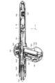
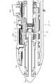
図3は、ユーザがコントローラ6を右手で把持している状態を示す図である。また、図4(a)及び図4(b)は、互いに異なる角度から見たコントローラ6の斜視図であり、図5は、図3に示したA-A線に対応するコントローラ6の断面図であり、図6(a)(b)は、互いに異なる角度から見たコントローラ6の内部構造を示す分解斜視図であり、図7は、コントローラ6の機能ブロックを示す略ブロック図である。以下、これらの図を参照しながら、コントローラ6の構成について詳しく説明する。
FIG. 3 is a diagram showing a state in which the user holds the
まず図4(a)及び図4(b)に示すように、コントローラ6は、ペン形状に形成されたペン部6pと、長手方向がペン部6pの軸方向と交差するようにペン部6pに固定されたグリップ部6gとを有して構成される。ユーザがこのコントローラ6を把持する際には、図3に示すように、親指、人差し指、中指でグリップ部6gを握るような形でコントローラ6を把持することになる。以下、ペン部6pの軸方向をx方向と称し、x方向とグリップ部6gの長手方向とにより構成される平面内の方向であって、かつ、x方向に直交する方向をz方向と称し、x方向及びz方向のそれぞれに直交する方向をy方向と称する。
First, as shown in FIGS. 4(a) and 4(b), the
図4(a)及び図4(b)に示すように、ペン部6pのペン先にはニブ6paが設けられ、側面には、左右のプレッシャーパッド6pbL,6pbRと、左右のシフトボタン6pcL,6pcRと、USB(Universal Serial Bus)コネクタ6pdとが設けられる。また、グリップ部6gには、タクトトップボタン6gaと、ダイヤルボタン6gbと、グラブボタン6gcと、左右のタクトボタン6gdL,6gdRと、凹部6geとが設けられる。これらの他、図5、図6(a)、図6(b)に示すように、ペン部6pの内部には、ペン先電極6peと、プリント回路基板アセンブリ6pfと、フレキシブルプリント回路基板6pgとが配置され、グリップ部6gの内部には、ハプティクス素子6gfと、バッテリ6ggと、メインボード6ghとが配置される。これらの部品のうちプリント回路基板アセンブリ6pfはコントローラ6の基幹をなす部品であり、コントローラ6は、完成品としてのプリント回路基板アセンブリ6pfに他の部品を装着することによって製造される。
As shown in FIGS. 4(a) and 4(b), a nib 6pa is provided at the pen tip of the
また、図7に示すように、コントローラ6は機能的に、処理回路50、筆圧センサ51、無線通信回路52、及び電源回路53を有して構成される。このうち処理回路50は、プリント回路基板アセンブリ6pf内に実装された集積回路によって構成され、無線通信回路52及び電源回路53は、フレキシブルプリント回路基板6pg上に実装された集積回路によって構成される。
Further, as shown in FIG. 7, the
処理回路50はコントローラ6の中央処理装置として機能する回路であり、プレッシャーパッド6pbL,6pbR、シフトボタン6pcL,6pcR、タクトトップボタン6ga、ダイヤルボタン6gb、グラブボタン6gc、タクトボタン6gdL,6gdR、筆圧センサ51それぞれの状態(操作状態、検出状態)を取得し、ペン先電極6pe又は無線通信回路52を通じて位置検出装置3又はコンピュータ2に供給する機能と、位置検出装置3又はコンピュータ2が送信した信号をペン先電極6pe又は無線通信回路52を通じて受信する機能と、位置検出装置3又はコンピュータ2から受信した信号に応じた処理を行う機能とを有して構成される。位置検出装置3又はコンピュータ2から受信した信号に応じた処理には、受信した信号に応じた信号を生成して返送する処理と、ハプティクス素子6gfの制御とが含まれる。処理回路50はまた、コントローラ6の表面に取り付けられた1以上のLEDそれぞれの点灯状態の制御も行う。
A
無線通信回路52は、ブルートゥース(登録商標)や無線LAN(Local Area Network)などの無線通信を行う回路である。処理回路50は、この無線通信回路52を用い、図1に示したコンピュータ2との間で通信を行う。
The
ニブ6paはペン先を構成する略棒状の部材であり、先端方向に向かって付勢された状態で、先端がペン部6pの筐体からわずかに突出するように配置される。ニブ6paの後端は、筆圧センサ51に当接している。ユーザがニブ6paの先端を位置検出装置3のタッチ面に押し当てると、ニブ6paは後方に向かって移動する。筆圧センサ51は、この移動を検出することによってニブ6paの先端に加わっている圧力を検出するセンサであり、検出した圧力の値を「筆圧値」として処理回路50に通知する役割を果たす。
The nib 6pa is a substantially bar-shaped member that constitutes the pen tip, and is arranged so that the tip slightly protrudes from the housing of the
ペン先電極6peは、図5、図6(a)、図6(b)に示すようにニブ6paの周囲を囲むように配置された導電体であり、図7に示すように、処理回路50と電気的に接続されている。処理回路50は、ペン先電極6peを介して、位置検出装置3との間での信号の送受信を実行する。位置検出装置3は、こうして送受信される信号により、タッチ面上におけるニブ6paの位置を検出するとともに、処理回路50から上記筆圧値の取得を行う。
The pen tip electrode 6pe is a conductor disposed so as to surround the nib 6pa as shown in FIGS. 5, 6(a) and 6(b). is electrically connected to The
USBコネクタ6pdは、USBケーブルを接続可能に構成されたコネクタであり、処理回路50及び電源回路53に接続されている。処理回路50は、USBケーブルを通じて外部からファームウェアにより、自身のファームウェアを更新するよう構成される。一方、電源回路53は、USBケーブルを通じて外部から供給される電力により、バッテリ6ggを充電するよう構成される。電源回路53とバッテリ6ggの間は、フレキシブルプリント回路基板6pgからメインボード6ghにかけて延設される配線により接続される。充電されたバッテリ6ggは、処理回路50及びハプティクス素子6gfを含むコントローラ6内の各部に動作電力を供給する役割を果たす。
The USB connector 6pd is a connector that can be connected with a USB cable, and is connected to the
従来のペン型コントローラであれば、バッテリ6ggはペン部6p内の位置に設けられることになる。しかし、本実施の形態によるコントローラ6においては、図5に示したように、グリップ部6g内の位置にバッテリ6ggが設けられる。別の言い方をすれば、バッテリ6ggは、ペン部6p内に配置されるプリント回路基板アセンブリ6pfの下側(プリント回路基板アセンブリ6pfから見て、グリップ部6gの長手方向の両端部のうちペン部6pの軸方向から遠い方の端部側)に配置される。さらに別の言い方をすれば、バッテリ6ggは、ハプティクス素子6gfと凹部6geとの間に配置される。このような配置を採用することで、ペン部6p及びグリップ部6gのうちユーザが握っている部分より上側の部分を従来より軽くすることができるので、ユーザがグリップ部6gを握ってコントローラ6の操作を行う場合の違和感の軽減が実現される。
In the case of a conventional pen-type controller, the battery 6gg would be provided at a position within the
プレッシャーパッド6pbL,6pbRはそれぞれ、表面にユーザの指が触れていること、及び、表面内におけるその指の位置を検出するタッチセンサと、表面に加わっている圧力を検出するための感圧センサとを有するデバイスである。プレッシャーパッド6pbL,6pbRの具体的な構造については、後ほど図8を参照しながら詳しく説明する。プレッシャーパッド6pbL,6pbRの検出結果は処理回路50を通じてコンピュータ2に供給され、各種の処理のために使用される。具体的な例では、感圧センサによって検出された圧力は、アプリケーション上での選択及び描画のために用いられる。例えば、あたかも上述した筆圧値のように、描画する線の太さ又は透明度を圧力に応じて制御するために使用される。一方、タッチセンサによって検出されたタッチの有無を示す情報は、感圧センサ出力のオンオフ判定、及び、軽いダブルタップを実現するために用いられる。
Each of the pressure pads 6pbL and 6pbR includes a touch sensor for detecting that the user's finger is touching the surface and the position of the finger within the surface, and a pressure sensor for detecting pressure applied to the surface. is a device having A specific structure of the pressure pads 6pbL and 6pbR will be described later in detail with reference to FIG. The detection results of the pressure pads 6pbL and 6pbR are supplied to the
図4(a)に示すように、プレッシャーパッド6pbL,6pbRはそれぞれ、ペン部6pの上面のうちグリップ部6gよりもペン先寄りの位置に、xz平面を挟んで左右対称となるように配置される。右手でコントローラ6を把持しているユーザは、図3から理解されるように、親指によりプレッシャーパッド6pbLの操作を、人差し指によりプレッシャーパッド6pbRの操作を、それぞれ行うことになる。
As shown in FIG. 4(a), the pressure pads 6pbL and 6pbR are arranged symmetrically with respect to the xz plane at positions closer to the pen tip than the
シフトボタン6pcL,6pcR、グラブボタン6gc、タクトボタン6gdL,6gdRはそれぞれ、オンオフ可能に構成されたスイッチである。シフトボタン6pcL,6pcRはそれぞれ、アプリケーションのメニューに割り当てられる。グラブボタン6gcは、オブジェクトを掴んで移動するために用いられる。タクトボタン6gdL,6gdRはそれぞれマウスの右ボタンのようなボタン補助のために用いられる。処理回路50は、これらのスイッチの操作状態も検出し、検出した状態に基づく情報をコンピュータ2又は位置検出装置3に供給するよう構成される。コンピュータ2及び位置検出装置3はそれぞれ、こうして供給された情報に応じた処理を行う。
The shift buttons 6pcL and 6pcR, the grab button 6gc, and the tact buttons 6gdL and 6gdR are switches that can be turned on and off. The shift buttons 6pcL and 6pcR are assigned to application menus, respectively. A grab button 6gc is used to grab and move an object. The tact buttons 6gdL and 6gdR are used for button assistance such as the right mouse button. The
図4(a)に示すように、シフトボタン6pcL,6pcRはそれぞれ、ペン部6pの上面のうちプレッシャーパッド6pbL,6pbRとグリップ部6gの間の位置に、xz平面を挟んで左右対称となるように配置される。また、グラブボタン6gcは、グリップ部6gのペン先側側面のうち下側端部近傍の位置に配置される。また、タクトボタン6gdL,6gdRはそれぞれ、グリップ部6gのペン先側側面のうちz方向に見てペン部6pと重なる位置に、xz平面を挟んで左右対称となるように配置される。右手でコントローラ6を把持しているユーザは、図3から理解されるように、中指によりグラブボタン6gcの押下操作を、人差し指によりタクトボタン6gdRの押下操作を、親指によりタクトボタン6gdLの押下操作を、それぞれ行うことになる。
As shown in FIG. 4(a), the shift buttons 6pcL and 6pcR are positioned on the upper surface of the
タクトトップボタン6gaは、長押しにより電源ボタンとして機能するスイッチである。また、ダイヤルボタン6gbは回転可能に構成されたリング状の部材であり、操作状態として回転量を出力するように構成される。この回転量は、例えば選択中のオブジェクトを回転させるために使用される。タクトトップボタン6ga及びダイヤルボタン6gbの具体的な構造については、後ほど図12及び図13を参照しながら詳しく説明する。処理回路50は、タクトトップボタン6ga及びダイヤルボタン6gbの操作状態も検出し、検出した状態に基づく情報をコンピュータ2又は位置検出装置3に供給するよう構成される。コンピュータ2及び位置検出装置3はそれぞれ、こうして供給された情報に応じた処理を行う。
The tact top button 6ga is a switch that functions as a power button when pressed for a long time. The dial button 6gb is a rotatable ring-shaped member, and is configured to output the amount of rotation as an operating state. This rotation amount is used, for example, to rotate the selected object. Specific structures of the tact top button 6ga and the dial button 6gb will be described later in detail with reference to FIGS. 12 and 13. FIG. The
図4(a)に示すように、ダイヤルボタン6gbはグリップ部6gの上側端部(グリップ部6gの長手方向の両端部のうちペン部6pの軸方向から近い方の端部)に配置されており、タクトトップボタン6gaはダイヤルボタン6gbの中空部分に配置される。右手でコントローラ6を把持しているユーザは、図3から理解されるように、親指によりダイヤルボタン6gbの回転操作及びタクトトップボタン6gaの押下操作を行うことになる。ただし、タクトトップボタン6ga及びダイヤルボタン6gbはユーザが親指を意図的にグリップ部6gの上側端部まで持ち上げなければ操作できない位置にあるため、通常状態では、ユーザの手によって隠されることなく露出している。
As shown in FIG. 4A, the dial button 6gb is arranged at the upper end portion of the
凹部6geは、図3に示すように、ユーザがコントローラ6を把持した場合に人差し指の付け根から親指の付け根にかけての部分がちょうど嵌まるように構成された部分であり、ペン部6pのペン尻に向かって開口するように形成される。コントローラ6にこの凹部6geを設けたことにより、コントローラ6を使用するユーザの疲れが軽減される。
As shown in FIG. 3, the concave portion 6ge is a portion configured so that when the user grips the
図5、図6(a)、図6(b)、図7に示したハプティクス素子6gfはハプティクスのための動作を行う素子であり、例えば振動素子によって構成される。図5に示すように、ハプティクス素子6gfは、グリップ部6g内においてユーザが握る部分の近傍に配置される。別の言い方をすれば、ハプティクス素子6gfは、グリップ部6gのうちペン部6pと隣接する位置に設けられる。ハプティクス素子6gfから見てグリップ部6gの反対側には凹部6geが位置しており、これにより、図3から理解されるように、ユーザの中指にハプティクスを与えることが可能とされている。
A haptic element 6gf shown in FIGS. 5, 6(a), 6(b), and 7 is an element that operates for haptics, and is configured by, for example, a vibrating element. As shown in FIG. 5, the haptic element 6gf is arranged in the
図8は、プレッシャーパッド6pbLの断面を含むコントローラ6の断面図である。また、図9は、図8に示したA-A線におけるコントローラ6の断面図であり、図10(a)は、図8に示したプレッシャーパッド6pbLの断面構造を模式的に示す図である。以下では、これらの図を参照しながらプレッシャーパッド6pbLの断面構造について説明するが、図9から理解されるように、プレッシャーパッド6pbRも同様の構造を有している。
FIG. 8 is a cross-sectional view of the
図8、図9、及び図10(a)に示すように、プレッシャーパッド6pbLは、表面部材10と、静電タッチセンサ11と、感圧センサ13と、弾性体12とが、ペン部6pの筐体に固定された設置台30の上に配置された構成を有している。図9に示すように、設置台30は筒状の形状を有しており、プレッシャーパッド6pbLはその外周面に配置される。なお、図10(a)においては、弾性体12の記載を省略している。この点は、後述する図10(b)~図10(d)においても同様である。
As shown in FIGS. 8, 9, and 10(a), the pressure pad 6pbL includes a
表面部材10は、例えばプラスチックによって、表面をユーザが押しやすい形状に形成された部材である。静電タッチセンサ11は、自己容量方式又は相互容量方式のタッチセンサであり、図10(a)の例においては、表面部材10の下面(内側の表面)に貼り付けられたリジッドフレキシブル基板又はフィルム上に搭載されている。なお、表面部材10の下面に導電性のインクで印刷することにより、静電タッチセンサ11を構成してもよい。静電タッチセンサ11は、表面部材10の表面にユーザの指が触れていること、及び、表面部材10の表面内におけるその指の位置を検出する役割を果たす。
The
弾性体12は、一端が表面部材10に固定され、他端が設置台30に固定された弾性部材であり、典型的には、図8に示すようにバネによって構成される。ただし、ゴムなど他の種類の弾性体によって弾性体12を構成してもよい。感圧センサ13は、押圧力によって抵抗値が変化するセンサであり、設置台30の表面(外周面)に固定される。感圧センサ13として具体的には、ストロークのあるセンサ(押したときに形状が変化するセンサ)と、ストロークのないセンサ(押したときに形状が変化しないセンサ)との両方を用いることが可能であるが、指の動きに伴ってコントローラ6自体が動いてしまうことを防止する観点から、後者を用いることが特に好適である。
The
表面部材10、静電タッチセンサ11(及びリジッドフレキシブル基板等)、及び感圧センサ13は相互に固定されており、所定の範囲内で表面部材10の表面の法線方向に移動可能に構成されるとともに、弾性体12によって外向きに付勢されている。この付勢により、表面部材10の表面に力が加わっていない場合には、感圧センサ13と設置台30の間に隙間が形成されている。一方、ユーザが表面部材10を押圧することによって感圧センサ13が下向きに移動すると、感圧センサ13が設置台30によって押圧され、感圧センサ13の抵抗値が変化する。
The
図7に示した処理回路50は、静電タッチセンサ11の検出結果と、感圧センサ13の抵抗値(以下「押圧値」という)とを取得することによって、プレッシャーパッド6pbLの検出結果を取得する。そして、取得した検出結果を示す情報を生成し、コンピュータ2に供給するよう構成される。
The
図10(b)は、プレッシャーパッド6pbLの断面構造の他の例を模式的に示す図である。同図に示すように、静電タッチセンサ11の搭載されたリジッドフレキシブル基板又はフィルムを表面部材10の上面(外側の表面)に貼り付けることとしてもよい。また、表面部材10の上面に導電性のインクで印刷することにより、静電タッチセンサ11を構成してもよい。
FIG. 10(b) is a diagram schematically showing another example of the cross-sectional structure of the pressure pad 6pbL. As shown in the figure, a rigid flexible substrate or film on which the
図10(c)は、プレッシャーパッド6pbLの断面構造のさらに他の例を模式的に示す図である。図10(d)は、図10(c)の例によるプレッシャーパッド6pbLの平面図である。ただし、図10(d)においては、表面部材10の記載を省略している。この例では、静電タッチセンサ11の搭載されたリジッドフレキシブル基板又はフィルムをロの字型に形成し、中央の中空部分に感圧センサ13が位置するように設置台30の上面に貼り付けている。このようにすることで、表面部材10の表面に静電タッチセンサ11を配置することが難しい場合であっても、静電タッチセンサ11を利用することが可能になる。この場合においても、設置台30の上面に導電性のインクで印刷することにより、静電タッチセンサ11を構成してもよい。
FIG. 10(c) is a diagram schematically showing still another example of the cross-sectional structure of the pressure pad 6pbL. FIG. 10(d) is a plan view of the pressure pad 6pbL according to the example of FIG. 10(c). However, the illustration of the
コントローラ6の処理回路50は、無線通信回路52を通じて、プレッシャーパッド6pbL,6pbRによって検出された情報、すなわち、プレッシャーパッド6pbRの静電タッチセンサ11において検出される情報、プレッシャーパッド6pbRの感圧センサ13によって検出される情報、プレッシャーパッド6pbLの静電タッチセンサ11において検出される情報、又は、プレッシャーパッド6pbLの感圧センサ13によって検出される情報を、コンピュータ2に送信する。そして、コンピュータ2は、プレッシャーパッド6pbRの静電タッチセンサ11において検出される情報、又は、プレッシャーパッド6pbRの感圧センサ13によって検出される情報に基づいて、プレッシャーパッド6pbRの感圧センサ13によって検出される情報に関連する筆圧値を出力し、又は、プレッシャーパッド6pbLの感圧センサ13によって検出される情報に関連する筆圧値を出力する。以下に、処理回路50からプレッシャーパッド6pbL,6pbRの検出結果を示す情報の供給を受けたコンピュータ2によって実行される処理の一例を説明する。
The
図11は、処理回路50からプレッシャーパッド6pbL,6pbRの検出結果を示す情報の供給を受けたコンピュータ2によって実行される処理の一例を示す図である。なお、同図に示す処理は、コンピュータ2において動作するコントローラ6のデバイスドライバによって実行される処理であるとすることが好ましい。ただし、アプリケーションなど、デバイスドライバ以外のプログラムによって実行されることとしてもよい。
FIG. 11 is a diagram showing an example of processing executed by the
図11において「右静電タッチ」はプレッシャーパッド6pbRの静電タッチセンサ11において検出されるタッチ操作を指し、「右感圧タッチ」はプレッシャーパッド6pbRの感圧センサ13によって検出される押圧操作を指し、「左静電タッチ」はプレッシャーパッド6pbLの静電タッチセンサ11において検出されるタッチ操作を指し、「左感圧タッチ」はプレッシャーパッド6pbLの感圧センサ13によって検出される押圧操作を指す。図11に示すように、コンピュータ2はまず、右静電タッチ及び左静電タッチをオン(対応する情報の処理回路50からの入力を受け付ける状態)とし、右感圧タッチ及び左感圧タッチをオフ(対応する情報の処理回路50からの入力を無視する状態)とする(ステップS1)。
In FIG. 11, "right electrostatic touch" refers to a touch operation detected by the
コンピュー2は、処理回路50から供給される情報を参照することにより、プレッシャーパッド6pbL,6pbRそれぞれの静電タッチセンサ11の検出結果を取得する(ステップS2)。そして、取得した検出結果を参照することにより、右静電タッチ又は左静電タッチが検出されたか否かを判定する(ステップS3)。
The
ステップS3において、右静電タッチ又は左静電タッチのいずれも検出されていないと判定したコンピュータ2は、ステップS2に戻って処理を続ける。一方、左静電タッチが検出されたと判定したコンピュータ2は、右静電タッチ及び左静電タッチをオフとする一方、左感圧タッチをオンとする(ステップS4)。そして、処理回路50から供給される情報を参照することによりプレッシャーパッド6pbLの感圧センサ13の押圧値を取得し(ステップS5)、取得した押圧値が所定の閾値を上回っているか否かを判定する(ステップS6)。この判定において上回っていると判定したコンピュータ2は、取得した押圧値を筆圧値としてアプリケーションに出力した後(ステップS7)、ステップS5に戻って次の押圧値を取得する。一方、ステップS6の判定において上回っていないと判定したコンピュータ2は、ステップS1に戻って処理を繰り返す。
The
ステップS3において右静電タッチが検出されたと判定した場合のコンピュータ2の処理は、左右の違いを除き、左静電タッチが検出されたと場合と同様である。具体的に説明すると、コンピュータ2は、右静電タッチ及び左静電タッチをオフとする一方、右感圧タッチをオンとする(ステップS8)。そして、処理回路50から供給される情報を参照することによりプレッシャーパッド6pbRの感圧センサ13の押圧値を取得し(ステップS9)、取得した押圧値が所定の閾値を上回っているか否かを判定する(ステップS10)。この判定において上回っていると判定したコンピュータ2は、取得した押圧値を筆圧値としてアプリケーションに出力した後(ステップS11)、ステップS9に戻って次の押圧値を取得する。一方、ステップS10の判定において上回っていないと判定したコンピュータ2は、ステップS1に戻って処理を繰り返す。
The processing of the
コンピュータ2が以上のような処理を行うことにより、プレッシャーパッド6pbL,6pbRのうちユーザが最初に触れた一方の感圧センサ13を有効にする一方、他方の感圧センサ13を無効にすることができるので、ユーザは、プレッシャーパッド6pbL,6pbRを有するコントローラ6をストレスなく操作することが可能になる。詳しく説明すると、上述したようにストロークのない感圧センサ13を用いる場合、ユーザが意識的に押圧しなくても、感圧センサ13が反応してしまう場合がある。これはユーザにとってストレスになるが、図11を参照して説明した処理によれば、プレッシャーパッド6pbL,6pbRのうちユーザが最初に触れた一方を静電タッチセンサ11によって検出し、検出した一方のみの感圧センサ13を有効にしているので、上記のような感圧センサ13の反応を抑止し、ユーザのストレスを軽減することが可能になる。
By the
図12は、タクトトップボタン6ga及びダイヤルボタン6gbの断面図である。また、図13(a)~図13(d)は、タクトトップボタン6ga及びダイヤルボタン6gbの構造を示す分解斜視図である。初めに図12を参照すると、タクトトップボタン6ga及びダイヤルボタン6gbは、ペン部6pの筐体に固定された平坦な表面を有する設置台31の上に配置される。ダイヤルボタン6gbは、エンコーダ20及び回転体21を含んで構成され、タクトトップボタン6gaは、タクトスイッチ22、カバー23、弾性体24、押し子25、及びレンズ26を有して構成される。押し子25の上面には、上述した1以上のLED(コンピュータ2による検出の対象となる1以上のLED)のうちの1つであるLED27が設置される。
FIG. 12 is a cross-sectional view of the tact top button 6ga and the dial button 6gb. 13(a) to 13(d) are exploded perspective views showing the structures of the tact top button 6ga and the dial button 6gb. First, referring to FIG. 12, the tact top button 6ga and the dial button 6gb are placed on a mounting
回転体21は、設置台31の中心部を中心として配置されたリング形状の部材であり、ユーザ操作により中心の周りを回動可能に構成される。エンコーダ20は回転体21の回転量を検出する装置であり、図13(b)に示すように、設置台31の中心を囲むように配置された円形の部材によって構成される。エンコーダ20の外周は回転体21の内周と係合しており、エンコーダ20は、この係合を通じて回転体21の回転量を検出するよう構成される。カバー23はエンコーダ20の上面を覆う部材であり、設置台31及びエンコーダ20に対して固定される。
The
タクトスイッチ22は押圧によってオンオフ可能に構成されたスイッチであり、図13(a)に示すように、略円形の設置台31の中央に配置される。弾性体24は、一端がカバー23の上面に固定され、他端が押し子25の下面に固定された弾性部材であり、典型的には、図13(b)に示すようにバネによって構成される。ただし、ゴムなど他の種類の弾性体によって弾性体24を構成してもよい。
The
押し子25は、レンズ26の表面の押圧力をタクトスイッチ22に伝えるための硬質部材である。また、レンズ26は、レンズ26は透明かつ硬質な材料によって構成された半球状の部材であり、タクトトップボタン6gaの上面を構成している。レンズ26を透明材料により構成しているのは、レンズ26の下に配置されたLED27をコントローラ6の外部から見ることができるようにし、それによって、コンピュータ2がカメラ4a~4cの映像内でLED27の光を確認できるようにするためである。
The
押し子25及びレンズ26は互いに固定されており、所定の範囲内で設置台30の法線方向に移動可能に構成されるとともに、弾性体24によって外向きに付勢されている。この付勢力により、レンズ26に力が加わっていない場合には、タクトスイッチ22は押し子25によって押圧されていない状態となる。一方、ユーザがレンズ26を押圧することによってレンズ26及び押し子25が下向きに移動すると、タクトスイッチ22が押し子25によって押圧され、タクトスイッチ22のオンオフ状態が切り替わる。
The
図7に示した処理回路50は、エンコーダ20によって検出された回転量及びタクトスイッチ22のオンオフ状態を取得することによって、タクトトップボタン6ga及びダイヤルボタン6gbの操作状態を取得する。そして、取得した操作状態を示す情報を生成し、コンピュータ2に供給するよう構成される。
The
以上説明したように、本実施の形態によるグリップ付きペン型コントローラ6によれば、重量部品であるバッテリ6ggがペン部6pではなくグリップ部6g内に配置される。したがって、重量のバランスが改善するので、グリップ部6gを握って操作を行う場合にユーザが感じる違和感を軽減することが可能になる。
As described above, according to the pen-
また、本実施の形態によるグリップ付きペン型コントローラ6によれば、凹部6geから見てグリップ部6gの反対側にハプティクス素子6gfを設けたので、ユーザの中指に好適にハプティクスを与えることが可能になる。
Further, according to the pen-
また、本実施の形態によるグリップ付きペン型コントローラ6によれば、静電タッチセンサ11及び感圧センサ13を含むプレッシャーパッド6pbL,6pbRを設けたので、プレッシャーパッド6pbL,6pbRの表面にユーザの指が触れていること、及び、表面内におけるその指の位置を検出するとともに、プレッシャーパッド6pbL,6pbRの表面に加わっている圧力を検出し、検出の結果を3Dオブジェクトのレンダリングのために使用することが可能になる。
Further, according to the pen-
また、本実施の形態によるグリップ付きペン型コントローラ6によれば、通常状態ではユーザの手によって隠されることなく露出しているグリップ部6gの上側端部にタクトトップボタン6gaを設け、その中にLED27を配置したので、コンピュータ2がコントローラ6のトラッキングに失敗する可能性を低減することが可能になる。
Further, according to the pen-
また、本実施の形態によるトラッキングシステム1によれば、プレッシャーパッド6pbL,6pbRのうちユーザが最初に触れた一方の感圧センサ13を有効にする一方、他方の感圧センサ13を無効にすることができるので、ユーザは、プレッシャーパッド6pbL,6pbRを有するコントローラ6をストレスなく操作できるようになる。
Further, according to the
以上、本発明の好ましい実施の形態について説明したが、本発明はこうした実施の形態に何等限定されるものではなく、本発明が、その要旨を逸脱しない範囲において、種々なる態様で実施され得ることは勿論である。 Although preferred embodiments of the present invention have been described above, the present invention is by no means limited to such embodiments, and the present invention can be implemented in various forms without departing from the gist thereof. is of course.
1 トラッキングシステム
2 コンピュータ
3 位置検出装置
4a~4c カメラ
5 ヘッドマウントディスプレイ
6 グリップ付きペン型コントローラ
6g グリップ部
6ga タクトトップボタン
6gb ダイヤルボタン
6gc グラブボタン
6gdL,6gdR タクトボタン
6ge 凹部
6gf ハプティクス素子
6gg バッテリ
6gh メインボード
6p ペン部
6pa ニブ
6pbL,6pbR プレッシャーパッド
6pcL,6pcR シフトボタン
6pd USBコネクタ
6pe ペン先電極
6pf プリント回路基板アセンブリ
6pg フレキシブルプリント回路基板
10 表面部材
11 静電タッチセンサ
12 弾性体
13 感圧センサ
20 エンコーダ
21 回転体
22 タクトスイッチ
23 カバー
24 弾性体
25 押し子
26 レンズ
30,31 設置台
50 処理回路
51 筆圧センサ
52 無線通信回路
53 電源回路
60 デスク
61 デスクチェア
101 CPU
102 記憶装置
103 入力装置
104 出力装置
105 通信装置1
102
Claims (19)
ペン形状に形成されたペン部と、
前記ペン部に設けられる第1のプレッシャーパッドであり、前記3Dオブジェクトの線の太さを変えるときに前記ユーザの第1の指による前記空中での操作に応じて変わる圧力を検出する第1のプレッシャーパッドと、
前記ペン部に設けられる第2のプレッシャーパッドであり、前記3Dオブジェクトの線の太さを変えるときに前記ユーザの第2の指による前記空中での操作に応じて変わる圧力を検出する第2のプレッシャーパッドと、を有し、
前記第1のプレッシャーパッドは、前記ユーザが前記第1の指および前記第2の指で前記第1のプレッシャーパッドおよび前記第2のプレッシャーパッドを摘むように握る状態において前記ユーザの前記第1の指と触れる位置に設けられ、
前記第2のプレッシャーパッドは、前記ユーザが前記第1の指および前記第2の指で前記第1のプレッシャーパッドおよび前記第2のプレッシャーパッドを摘むように握る状態において前記ユーザの前記第2の指と触れる位置に設けられ、
前記第1のプレッシャーパッドと並んで配置されるプレッシャーパッドは前記第2のプレッシャーパッドのみである、
コントローラ。 A controller for controlling the line thickness of a 3D object in XR space based on pressure that varies in response to manipulation by a user in the air away from the surface ;
a pen part formed in a pen shape;
A first pressure pad provided in the pen unit for detecting a pressure that changes according to the operation in the air with the first finger of the user when changing the line thickness of the 3D object. a pressure pad of
A second pressure pad provided on the pen unit for detecting a pressure that changes according to the operation in the air with the second finger of the user when changing the line thickness of the 3D object. and a pressure pad of
The first pressure pad is held by the first finger of the user in a state in which the user pinches the first pressure pad and the second pressure pad with the first finger and the second finger. It is provided at a position where it touches the
The second pressure pad is held by the second finger of the user in a state in which the user pinches the first pressure pad and the second pressure pad with the first finger and the second finger. It is provided at a position where it touches the
The second pressure pad is the only pressure pad arranged in line with the first pressure pad,
controller.
前記グリップ部の長手方向に沿って、前記グリップ部内に配置されるバッテリと、
を含む請求項1に記載のコントローラ。 a grip section that intersects with the axial direction of the pen section;
a battery arranged in the grip along the longitudinal direction of the grip;
2. The controller of claim 1, comprising:
前記バッテリは、前記グリップ部の前記第2の部分内に配置される、
請求項2に記載のコントローラ。 The grip portion has a first portion including a first end portion closer to the axial direction of the pen portion and a second portion including a second end portion farther from the axial direction of the pen portion,
the battery is positioned within the second portion of the grip;
3. The controller of claim 2.
前記バッテリは、前記回路に電力を供給する、
請求項2又は3のいずれか一項に記載のコントローラ。 The pen unit has a circuit,
the battery powers the circuit;
4. A controller as claimed in any one of claims 2 or 3.
前記ハプティクス素子は、前記グリップ部内に配置される、
請求項2に記載のコントローラ。 further having a haptic element,
the haptic element is disposed within the grip portion;
3. The controller of claim 2.
請求項5に記載のコントローラ。 the haptic element is positioned within the grip portion near a portion to be grasped by the user;
6. A controller as claimed in claim 5.
請求項5又は6に記載のコントローラ。 the haptic element is positioned within the grip portion adjacent to the pen portion;
A controller according to claim 5 or 6.
前記ハプティクス素子は、前記第1の側面の近傍に配置される、
請求項5乃至7のいずれか一項に記載のコントローラ。 The grip portion has a first side surface located on the pen tip side of the pen portion and a second side surface located on the pen rear side of the pen portion,
the haptic element is positioned proximate the first side;
8. A controller according to any one of claims 5-7.
前記ハプティクス素子は、前記グリップ部の前記第2の部分内に配置される、
請求項5乃至8に記載のコントローラ。 The grip portion has a first portion including a first end portion closer to the axial direction of the pen portion and a second portion including a second end portion farther from the axial direction of the pen portion,
the haptic element is disposed within the second portion of the grip portion;
A controller as claimed in any one of claims 5 to 8.
請求項8に記載のコントローラ。 The grip portion has a recess provided near the second side surface,
9. A controller as claimed in claim 8.
請求項10に記載のコントローラ。 the battery is positioned between the haptic element and the recess;
11. A controller as claimed in claim 10.
前記第2のプレッシャーパッドは、第2の静電タッチセンサ及び第2の感圧センサを含む、
請求項1乃至11のいずれか一項に記載のコントローラ。 the first pressure pad includes a first capacitive touch sensor and a first pressure sensor;
the second pressure pad includes a second capacitive touch sensor and a second pressure sensor;
12. A controller as claimed in any preceding claim.
前記ボタンは、
オンオフ可能に構成されたタクトスイッチと、
コンピュータによる当該コントローラの検出のためのLEDと、を含む、
請求項2乃至11のいずれか一項に記載のコントローラ。 The grip part has a button that can be pressed by a user,
The button is
a tact switch that can be turned on and off;
an LED for detection of the controller by a computer;
12. A controller as claimed in any one of claims 2 to 11.
前記LEDは前記透明部材の下に配置される、
請求項13に記載のコントローラ。 The upper surface of the button is made of a transparent member,
the LED is positioned under the transparent member;
14. The controller of Claim 13 .
ことを特徴とする請求項1に記載のコントローラ。 When the user grips the pen unit with a plurality of fingers, the user's thumb contacts the first pressure pad and the user's index finger contacts the second pressure pad.
The controller according to claim 1, characterized in that:
を有する請求項1に記載のコントローラ。 A first communication unit that transmits the pressure detected by the first pressure pad or the pressure detected by the second pressure pad,
2. The controller of claim 1, comprising:
ことを特徴とする請求項16に記載のコントローラ。 The first communication unit controls the line thickness of the 3D object in the XR space based on the pressure detected by the first pressure pad or the pressure detected by the second pressure pad. , a communication unit that transmits the pressure detected by the first pressure pad or the pressure detected by the second pressure pad,
17. The controller of claim 16 , wherein:
前記筆圧センサによって検出された圧力を送信する通信部であり前記第1の通信部と異なる第2の通信部、
をさらに有する請求項16に記載のコントローラ。 a pen pressure sensor that detects pressure applied to the pen tip of the pen unit;
a second communication unit that is a communication unit that transmits the pressure detected by the pen pressure sensor and that is different from the first communication unit;
17. The controller of Claim 16 , further comprising:
前記コントローラから送信される情報を受信する通信部と、
プロセッサと、を有し、
前記プロセッサは、前記通信部によって受信される情報であり前記第1の静電タッチセンサによって検出される情報又は前記通信部によって受信される情報であり前記第2の静電タッチセンサによって検出される情報に基づいて、前記通信部によって受信される情報であり前記第1の感圧センサによって検出される押圧値に関する筆圧値を出力するように制御する、又は、前記通信部によって受信される情報であり前記第2の感圧センサによって検出される押圧値に関する筆圧値を出力するように制御する、
コンピュータ。 A pen portion formed in a pen shape, a first pressure pad including a first electrostatic touch sensor and a first pressure sensor provided in the pen portion, and a second electrostatic pressure pad provided in the pen portion. a second pressure pad that includes a touch sensor and a second pressure sensor, and is communicable with a controller;
a communication unit that receives information transmitted from the controller;
a processor;
The processor receives information received by the communication unit and is detected by the first capacitive touch sensor or information received by the communication unit and is detected by the second capacitive touch sensor. Based on the information, control is performed to output a writing pressure value related to the pressure value detected by the first pressure-sensitive sensor, which is the information received by the communication unit, or the information received by the communication unit. is controlled to output a pen pressure value related to the pressure value detected by the second pressure sensor,
Computer.
Priority Applications (1)
| Application Number | Priority Date | Filing Date | Title |
|---|---|---|---|
| JP2023136034A JP2023153347A (en) | 2021-04-23 | 2023-08-24 | controller |
Applications Claiming Priority (5)
| Application Number | Priority Date | Filing Date | Title |
|---|---|---|---|
| JP2021073433 | 2021-04-23 | ||
| JP2021073433 | 2021-04-23 | ||
| JP2021128570 | 2021-08-04 | ||
| JP2021128570 | 2021-08-04 | ||
| PCT/JP2022/006951 WO2022224578A1 (en) | 2021-04-23 | 2022-02-21 | Controller and computer |
Related Child Applications (1)
| Application Number | Title | Priority Date | Filing Date |
|---|---|---|---|
| JP2023136034A Division JP2023153347A (en) | 2021-04-23 | 2023-08-24 | controller |
Publications (3)
| Publication Number | Publication Date |
|---|---|
| JPWO2022224578A1 JPWO2022224578A1 (en) | 2022-10-27 |
| JPWO2022224578A5 JPWO2022224578A5 (en) | 2023-07-24 |
| JP7339470B2 true JP7339470B2 (en) | 2023-09-05 |
Family
ID=83722808
Family Applications (2)
| Application Number | Title | Priority Date | Filing Date |
|---|---|---|---|
| JP2023516312A Active JP7339470B2 (en) | 2021-04-23 | 2022-02-21 | controller and computer |
| JP2023136034A Pending JP2023153347A (en) | 2021-04-23 | 2023-08-24 | controller |
Family Applications After (1)
| Application Number | Title | Priority Date | Filing Date |
|---|---|---|---|
| JP2023136034A Pending JP2023153347A (en) | 2021-04-23 | 2023-08-24 | controller |
Country Status (6)
| Country | Link |
|---|---|
| US (1) | US20240045536A1 (en) |
| EP (1) | EP4328717A1 (en) |
| JP (2) | JP7339470B2 (en) |
| KR (1) | KR20230138548A (en) |
| TW (1) | TW202242613A (en) |
| WO (1) | WO2022224578A1 (en) |
Citations (4)
| Publication number | Priority date | Publication date | Assignee | Title |
|---|---|---|---|---|
| JP2018001721A (en) | 2016-07-08 | 2018-01-11 | 国立大学法人大阪大学 | Writing device and computer program |
| JP2018124619A (en) | 2017-01-30 | 2018-08-09 | 京セラドキュメントソリューションズ株式会社 | Pen type input apparatus and display input system |
| WO2019102825A1 (en) | 2017-11-21 | 2019-05-31 | 株式会社ワコム | Rendering device and rendering method |
| JP2019168506A (en) | 2018-03-22 | 2019-10-03 | 株式会社東海理化電機製作所 | Rod-like object |
Family Cites Families (15)
| Publication number | Priority date | Publication date | Assignee | Title |
|---|---|---|---|---|
| US6259438B1 (en) * | 1998-06-04 | 2001-07-10 | Wacom Co., Ltd. | Coordinate input stylus |
| JP3696365B2 (en) * | 1996-11-15 | 2005-09-14 | 株式会社リコー | Pen-type input device |
| JP2006259267A (en) * | 2005-03-17 | 2006-09-28 | Fujinon Corp | Light pen |
| JP5052357B2 (en) * | 2008-01-22 | 2012-10-17 | 京セラ株式会社 | Terminal apparatus and key control method |
| JP5233887B2 (en) * | 2009-07-21 | 2013-07-10 | 株式会社リコー | Input key control device, input key control method and program |
| JP2012063844A (en) * | 2010-09-14 | 2012-03-29 | Fuji Xerox Co Ltd | System, device and program for identifying user |
| US20130234967A1 (en) * | 2012-03-12 | 2013-09-12 | Matthew Stoddard | Pressure sensitive multi-tip stylus for capacitive touchscreens and methods of using same |
| KR101282430B1 (en) * | 2012-03-26 | 2013-07-04 | 삼성디스플레이 주식회사 | Stylus, pressure detecting system and the driving method thereof |
| TW201441873A (en) * | 2013-04-30 | 2014-11-01 | Acer Inc | Stylus, system and method for providing haptic feedback |
| US9575573B2 (en) * | 2014-12-18 | 2017-02-21 | Apple Inc. | Stylus with touch sensor |
| JP6887060B2 (en) | 2018-05-18 | 2021-06-16 | 株式会社ワコム | Position indicator and information processing device |
| CN112041789B (en) * | 2018-05-21 | 2024-05-31 | 株式会社和冠 | Position indication device and spatial position indication system |
| US11334212B2 (en) * | 2019-06-07 | 2022-05-17 | Facebook Technologies, Llc | Detecting input in artificial reality systems based on a pinch and pull gesture |
| TWI722624B (en) * | 2019-10-28 | 2021-03-21 | 翰碩電子股份有限公司 | Stylus structure |
| JP7547875B2 (en) * | 2020-09-02 | 2024-09-10 | 富士フイルムビジネスイノベーション株式会社 | Information processing device and program |
-
2022
- 2022-02-21 JP JP2023516312A patent/JP7339470B2/en active Active
- 2022-02-21 WO PCT/JP2022/006951 patent/WO2022224578A1/en active Application Filing
- 2022-02-21 EP EP22790203.8A patent/EP4328717A1/en active Pending
- 2022-02-21 KR KR1020237030964A patent/KR20230138548A/en active Search and Examination
- 2022-02-25 TW TW111106935A patent/TW202242613A/en unknown
-
2023
- 2023-08-24 JP JP2023136034A patent/JP2023153347A/en active Pending
- 2023-10-20 US US18/491,424 patent/US20240045536A1/en active Pending
Patent Citations (4)
| Publication number | Priority date | Publication date | Assignee | Title |
|---|---|---|---|---|
| JP2018001721A (en) | 2016-07-08 | 2018-01-11 | 国立大学法人大阪大学 | Writing device and computer program |
| JP2018124619A (en) | 2017-01-30 | 2018-08-09 | 京セラドキュメントソリューションズ株式会社 | Pen type input apparatus and display input system |
| WO2019102825A1 (en) | 2017-11-21 | 2019-05-31 | 株式会社ワコム | Rendering device and rendering method |
| JP2019168506A (en) | 2018-03-22 | 2019-10-03 | 株式会社東海理化電機製作所 | Rod-like object |
Also Published As
| Publication number | Publication date |
|---|---|
| JPWO2022224578A1 (en) | 2022-10-27 |
| WO2022224578A1 (en) | 2022-10-27 |
| KR20230138548A (en) | 2023-10-05 |
| US20240045536A1 (en) | 2024-02-08 |
| EP4328717A1 (en) | 2024-02-28 |
| JP2023153347A (en) | 2023-10-17 |
| TW202242613A (en) | 2022-11-01 |
Similar Documents
| Publication | Publication Date | Title |
|---|---|---|
| CN210573659U (en) | Computer system, head-mounted device, finger device, and electronic device | |
| US10514780B2 (en) | Input device | |
| US10459495B2 (en) | Wearable electronic devices having an inward facing input device and methods of use thereof | |
| US8686959B2 (en) | Touch screen multi-control emulator | |
| US9977520B2 (en) | Stylus with capacitive slide and grip sensors | |
| JP7373258B2 (en) | Position indicating device, computer, control method | |
| US20130201162A1 (en) | Multi-purpose pen input device for use with mobile computers | |
| JP3176588U (en) | Remote touch circuit and attachment | |
| US11275456B2 (en) | Finger-wearable input assembly for controlling an electronic device | |
| US11064060B2 (en) | Foldable electronic device | |
| US10540023B2 (en) | User interface devices for virtual reality system | |
| US10509489B2 (en) | Systems and related methods for facilitating pen input in a virtual reality environment | |
| US11216082B2 (en) | Active stylus | |
| JP4940294B2 (en) | Information processing system, operation device, and information processing method | |
| JP7339470B2 (en) | controller and computer | |
| CN111813247A (en) | Mouse pen and electronic equipment | |
| CN116888565A (en) | Controller and computer | |
| KR20100120423A (en) | Apparatus and method for controlling smart fluid of portable terminal | |
| EP2511792A1 (en) | Hand-mountable device for providing user input | |
| WO2024070266A1 (en) | Finger-mounted controller | |
| US11625104B1 (en) | Click pads travel reductions | |
| KR20040009310A (en) | Pen-type mouse and amending method of character-type thereby | |
| WO2021061249A1 (en) | Finger-wearable input assembly for controlling an electronic device | |
| KR20220117508A (en) | Electronic device for controlling movement of pointer and method for operating thereof | |
| CN115951780A (en) | Handheld interactive controller and rendering method of hand gesture |
Legal Events
| Date | Code | Title | Description |
|---|---|---|---|
| A529 | Written submission of copy of amendment under article 34 pct |
Free format text: JAPANESE INTERMEDIATE CODE: A5211 Effective date: 20230522 |
|
| A621 | Written request for application examination |
Free format text: JAPANESE INTERMEDIATE CODE: A621 Effective date: 20230522 |
|
| A871 | Explanation of circumstances concerning accelerated examination |
Free format text: JAPANESE INTERMEDIATE CODE: A871 Effective date: 20230522 |
|
| A521 | Request for written amendment filed |
Free format text: JAPANESE INTERMEDIATE CODE: A523 Effective date: 20230630 |
|
| TRDD | Decision of grant or rejection written | ||
| A01 | Written decision to grant a patent or to grant a registration (utility model) |
Free format text: JAPANESE INTERMEDIATE CODE: A01 Effective date: 20230725 |
|
| A61 | First payment of annual fees (during grant procedure) |
Free format text: JAPANESE INTERMEDIATE CODE: A61 Effective date: 20230824 |
|
| R150 | Certificate of patent or registration of utility model |
Ref document number: 7339470 Country of ref document: JP Free format text: JAPANESE INTERMEDIATE CODE: R150 |