JP6884995B2 - Ophthalmologic imaging equipment and image processing program - Google Patents
Ophthalmologic imaging equipment and image processing program Download PDFInfo
- Publication number
- JP6884995B2 JP6884995B2 JP2016111746A JP2016111746A JP6884995B2 JP 6884995 B2 JP6884995 B2 JP 6884995B2 JP 2016111746 A JP2016111746 A JP 2016111746A JP 2016111746 A JP2016111746 A JP 2016111746A JP 6884995 B2 JP6884995 B2 JP 6884995B2
- Authority
- JP
- Japan
- Prior art keywords
- image
- front image
- eye
- light
- inspected
- Prior art date
- Legal status (The legal status is an assumption and is not a legal conclusion. Google has not performed a legal analysis and makes no representation as to the accuracy of the status listed.)
- Active
Links
Images


Classifications
-
- A—HUMAN NECESSITIES
- A61—MEDICAL OR VETERINARY SCIENCE; HYGIENE
- A61B—DIAGNOSIS; SURGERY; IDENTIFICATION
- A61B3/00—Apparatus for testing the eyes; Instruments for examining the eyes
- A61B3/0016—Operational features thereof
- A61B3/0025—Operational features thereof characterised by electronic signal processing, e.g. eye models
-
- A—HUMAN NECESSITIES
- A61—MEDICAL OR VETERINARY SCIENCE; HYGIENE
- A61B—DIAGNOSIS; SURGERY; IDENTIFICATION
- A61B3/00—Apparatus for testing the eyes; Instruments for examining the eyes
- A61B3/10—Objective types, i.e. instruments for examining the eyes independent of the patients' perceptions or reactions
- A61B3/14—Arrangements specially adapted for eye photography
- A61B3/15—Arrangements specially adapted for eye photography with means for aligning, spacing or blocking spurious reflection ; with means for relaxing
- A61B3/154—Arrangements specially adapted for eye photography with means for aligning, spacing or blocking spurious reflection ; with means for relaxing for spacing
-
- G—PHYSICS
- G06—COMPUTING; CALCULATING OR COUNTING
- G06T—IMAGE DATA PROCESSING OR GENERATION, IN GENERAL
- G06T5/00—Image enhancement or restoration
- G06T5/50—Image enhancement or restoration by the use of more than one image, e.g. averaging, subtraction
-
- A—HUMAN NECESSITIES
- A61—MEDICAL OR VETERINARY SCIENCE; HYGIENE
- A61B—DIAGNOSIS; SURGERY; IDENTIFICATION
- A61B3/00—Apparatus for testing the eyes; Instruments for examining the eyes
- A61B3/0083—Apparatus for testing the eyes; Instruments for examining the eyes provided with means for patient positioning
-
- A—HUMAN NECESSITIES
- A61—MEDICAL OR VETERINARY SCIENCE; HYGIENE
- A61B—DIAGNOSIS; SURGERY; IDENTIFICATION
- A61B3/00—Apparatus for testing the eyes; Instruments for examining the eyes
- A61B3/10—Objective types, i.e. instruments for examining the eyes independent of the patients' perceptions or reactions
- A61B3/1025—Objective types, i.e. instruments for examining the eyes independent of the patients' perceptions or reactions for confocal scanning
-
- A—HUMAN NECESSITIES
- A61—MEDICAL OR VETERINARY SCIENCE; HYGIENE
- A61B—DIAGNOSIS; SURGERY; IDENTIFICATION
- A61B3/00—Apparatus for testing the eyes; Instruments for examining the eyes
- A61B3/10—Objective types, i.e. instruments for examining the eyes independent of the patients' perceptions or reactions
- A61B3/117—Objective types, i.e. instruments for examining the eyes independent of the patients' perceptions or reactions for examining the anterior chamber or the anterior chamber angle, e.g. gonioscopes
-
- A—HUMAN NECESSITIES
- A61—MEDICAL OR VETERINARY SCIENCE; HYGIENE
- A61B—DIAGNOSIS; SURGERY; IDENTIFICATION
- A61B3/00—Apparatus for testing the eyes; Instruments for examining the eyes
- A61B3/10—Objective types, i.e. instruments for examining the eyes independent of the patients' perceptions or reactions
- A61B3/12—Objective types, i.e. instruments for examining the eyes independent of the patients' perceptions or reactions for looking at the eye fundus, e.g. ophthalmoscopes
- A61B3/1225—Objective types, i.e. instruments for examining the eyes independent of the patients' perceptions or reactions for looking at the eye fundus, e.g. ophthalmoscopes using coherent radiation
-
- G—PHYSICS
- G06—COMPUTING; CALCULATING OR COUNTING
- G06T—IMAGE DATA PROCESSING OR GENERATION, IN GENERAL
- G06T2207/00—Indexing scheme for image analysis or image enhancement
- G06T2207/10—Image acquisition modality
- G06T2207/10141—Special mode during image acquisition
- G06T2207/10152—Varying illumination
-
- G—PHYSICS
- G06—COMPUTING; CALCULATING OR COUNTING
- G06T—IMAGE DATA PROCESSING OR GENERATION, IN GENERAL
- G06T2207/00—Indexing scheme for image analysis or image enhancement
- G06T2207/20—Special algorithmic details
- G06T2207/20212—Image combination
- G06T2207/20221—Image fusion; Image merging
-
- G—PHYSICS
- G06—COMPUTING; CALCULATING OR COUNTING
- G06T—IMAGE DATA PROCESSING OR GENERATION, IN GENERAL
- G06T2207/00—Indexing scheme for image analysis or image enhancement
- G06T2207/30—Subject of image; Context of image processing
- G06T2207/30004—Biomedical image processing
- G06T2207/30041—Eye; Retina; Ophthalmic
Description
本開示は、被検眼の正面画像を得るための眼科撮影装置および画像処理プログムに関する。 The present disclosure relates to an ophthalmologic imaging apparatus and an image processing program for obtaining a frontal image of an eye to be inspected.
従来より、被検眼の正面画像を撮影する眼科撮影装置が知られている。例えば、特許文献1のように、眼科撮影装置の一種である眼底撮影装置の対物光学系に,レンズ系(屈折系)を適用すると共に、照明光の眼底への照射と、眼底反射光の受光との両方で、レンズ系を含む対物光学系を介して撮影を行う装置が知られている。
Conventionally, an ophthalmologic imaging device that captures a frontal image of an eye to be inspected has been known. For example, as in
ここで、対物光学系にレンズ系が適用された装置において、被検眼の正面画像を得ようとすると、対物光学系のレンズ面での反射による反射像が、撮影画像に含まれてしまう場合がありうる。 Here, in a device in which a lens system is applied to the objective optical system, when trying to obtain a front image of the eye to be inspected, a reflected image due to reflection on the lens surface of the objective optical system may be included in the captured image. It is possible.
本開示は、上記従来技術の問題点に鑑みてなされたものであり、被検眼の正面画像を良好に得ることができる眼科撮影装置および画像処理プログラムを提供することを技術課題とする。 The present disclosure has been made in view of the above-mentioned problems of the prior art, and it is a technical subject to provide an ophthalmologic imaging apparatus and an image processing program capable of obtaining a good front image of an eye to be inspected.
本開示の第1態様に係る走査型の眼科撮影装置は、少なくとも1つのレンズを含む対物レンズ系を介して,光源からの可視光による照明光を被検眼に照射すると共に走査部によって被検眼上で前記照明光を走査する照射光学系と、前記対物レンズ系を介して,被検眼による前記照明光の反射光を受光する受光素子を有する受光光学系と、を含む撮影光学系と、被検眼の正面画像として被検眼のカラー眼底画像を、前記走査部によって被検眼上で前記照明光を走査し、可視光による照明光の反射光を受光した前記受光素子からの信号に基づいて取得する画像取得手段と、前記撮影光学系の光軸と,被検眼の視軸と,の位置関係を変更して、前記正面画像中の前記被検眼の組織に対して前記対物レンズ系による前記照明光の反射像が形成される位置を調整するための位置調整手段と、第1正面画像と、前記被検眼の組織に対する前記反射像の位置が前記第1正面画像とは異なり,且つ,前記第1正面画像において前記反射像の位置する領域を含む第2正面画像と、の少なくとも2枚に基づいて合成正面画像を得る画像処理手段と、を備え、前記画像処理手段は、更に、前記第2正面画像において上下方向および左右方向のそれぞれの外縁から離れた位置にあり前記第2正面画像における前記反射像とは異なる領域であって、前記第1正面画像において前記反射像の位置する領域を切り出し、前記切り出した領域を、前記第1正面画像に対して合成することによって、前記合成正面画像を得る。 The scanning ophthalmologic imaging apparatus according to the first aspect of the present disclosure irradiates the eye to be inspected with illumination light by visible light from a light source through an objective lens system including at least one lens, and is placed on the eye to be inspected by a scanning unit. An imaging optical system including an irradiation optical system that scans the illumination light and a light receiving optical system having a light receiving element that receives the reflected light of the illumination light by the eye to be inspected via the objective lens system, and an eye to be inspected. An image obtained by scanning the illumination light on the eye to be inspected by the scanning unit and acquiring a color fundus image of the eye to be inspected as a frontal image based on a signal from the light receiving element that has received the reflected light of the illumination light by visible light. By changing the positional relationship between the acquisition means, the optical axis of the photographing optical system, and the visual axis of the eye to be inspected, the illumination light of the objective lens system with respect to the tissue of the eye to be inspected in the front image. The position adjusting means for adjusting the position where the reflection image is formed, the first front image, and the position of the reflection image with respect to the tissue of the eye to be examined are different from the first front image, and the first front image is formed. The image includes a second front image including a region where the reflected image is located, and an image processing means for obtaining a composite front image based on at least two images, and the image processing means further comprises the second front image. vertical and from said reflection image in the lateral direction of the respective positions near away from the outer edge Ri said second front image a region that different cut out area located in the reflected image in the first front image in , The combined front image is obtained by synthesizing the cut-out region with respect to the first front image.
本開示の第2態様に係る画像処理プログラムは、少なくとも1つのレンズを含む対物レンズ系を介して,光源からの照明光を被検眼に照射すると共に被検眼上で前記照明光を走査し、被検眼の正面画像として被検眼のカラー眼底画像を被検眼上で前記照明光を走査したときの被検眼による前記照明光の反射光に基づいて撮影する走査型の眼科撮影装置によって得られる前記正面画像を処理するための画像処理プログムであって、コンピュータのプロセッサで実行されることにより、メモリに記憶される前記正面画像の中から、第1正面画像と、前記被検眼の組織に対する前記対物レンズ系による前記照明光の反射像の位置が前記第1正面画像とは異なり,且つ,前記第1正面画像において前記反射像が位置する領域が含まれる第2正面画像と、の少なくとも2枚に基づいて合成正面画像を得る画像処理ステップであって、前記第2正面画像において上下方向および左右方向のそれぞれの縁部から離れた位置にあり前記第2正面画像における前記反射像とは異なる領域であって、前記第1正面画像において前記反射像の位置する領域を切り出し、前記切り出した領域を、前記第1正面画像に対して合成することによって、前記合成正面画像を得る、画像処理ステップを、前記コンピュータに実行させる。 The image processing program according to the second aspect of the present disclosure irradiates the eye to be inspected with illumination light from a light source through an objective lens system including at least one lens, and scans the illumination light on the eye to be inspected. the front obtained by the subject's eye color fundus image ophthalmologic photographing apparatus of a scanning type of shooting based on the reflected light of the illumination light by the subject's eye when scanning the illumination light on the subject's eye as eye front image An image processing program for processing an image, the first front image and the objective lens for the tissue of the eye to be inspected from among the front images stored in the memory by being executed by a computer processor. The position of the reflected image of the illumination light by the system is different from the first front image, and is based on at least two images of the first front image and the second front image including the region where the reflected image is located. regional composite front image an image processing step of obtaining, that is different from the reflective image in the vertical and horizontal directions of the respective positions near away from the edge Ri said second front image in the second front image Te The image processing step of obtaining the composite front image by cutting out the region where the reflected image is located in the first front image and synthesizing the cut out region with respect to the first front image. , The computer is made to execute.
本開示によれば、被検眼の正面画像を良好に得ることができる。 According to the present disclosure, a frontal image of the eye to be inspected can be obtained satisfactorily.
以下、図面を参照しつつ、本開示に係る眼科撮影装置、および、画像処理プログラムの実施形態を説明する。 Hereinafter, embodiments of the ophthalmologic imaging apparatus and the image processing program according to the present disclosure will be described with reference to the drawings.
眼科撮影装置は、被検眼の正面画像(反射画像)を取得する。眼科撮影装置は、例えば、眼底の正面画像を取得する装置であってもよいし、前眼部の正面画像を取得する装置であってもよい。本開示において、眼科撮影装置は、撮影光学系と、画像取得部(画像生成部)と、位置調整部と、画像処理部と、を有していてもよい。 The ophthalmologic imaging apparatus acquires a frontal image (reflection image) of the eye to be inspected. The ophthalmologic imaging device may be, for example, a device that acquires a frontal image of the fundus, or a device that acquires a frontal image of the anterior segment of the eye. In the present disclosure, the ophthalmologic imaging apparatus may include an imaging optical system, an image acquisition unit (image generation unit), a position adjustment unit, and an image processing unit.
<撮影光学系>
撮影光学系は、眼底画像の正面画像を取得するために利用される主要な光学系である。撮影光学系は、照射光学系と、受光光学系と、を含む。照射光学系は、対物レンズ系を介して,光源からの照明光を被検眼に照射する。受光光学系は、対物レンズ系を介して,被検眼による照明光の反射光を受光する受光素子を有する。
<Shooting optical system>
The photographic optical system is a main optical system used to acquire a frontal image of a fundus image. The photographing optical system includes an irradiation optical system and a light receiving optical system. The irradiation optical system irradiates the eye to be inspected with illumination light from a light source via an objective lens system. The light receiving optical system has a light receiving element that receives the reflected light of the illumination light by the eye to be inspected through the objective lens system.
対物レンズ系は、少なくとも1つのレンズを含む。対物レンズ系には、レンズ等の屈折要素のみが含まれていてもよいし、レンズの他にミラー等の反射要素が含まれていてもよい。 The objective lens system includes at least one lens. The objective lens system may include only a refracting element such as a lens, or may include a reflecting element such as a mirror in addition to the lens.
<画像取得部>
画像取得部(画像生成部)は、被検眼の正面画像を、受光素子からの信号に基づいて取得(生成)する。例えば、SLOのような走査型の眼科撮影装置においては、光スキャナによって1フレーム分の照明光の走査が行われる度に、受光素子から出力される1フレーム分の受光信号が画像取得部によって処理され、その結果として、1フレームの正面画像が生成される。
<Image acquisition section>
The image acquisition unit (image generation unit) acquires (generates) a front image of the eye to be inspected based on a signal from the light receiving element. For example, in a scanning type ophthalmologic imaging device such as SLO, each time one frame of illumination light is scanned by an optical scanner, one frame of light receiving signal output from a light receiving element is processed by an image acquisition unit. As a result, a one-frame front image is generated.
画像取得部によって取得される正面画像は、撮影画像であってもよいし、観察画像であってもよい。撮影画像は、例えば、レリーズ時にメモリに記憶される静止画像である。レリーズのタイミングは、例えば、検者による所定の操作のタイミングであってもよいし、撮影プログラムにおいて予め規定されたタイミングであってもよい。観察画像は、受光素子からの信号に基づいて随時取得され,動画像としてモニタに表示される正面画像である。観察画像と撮影画像とは、互いに異なる波長域の光を照明光とする画像であってもよい。 The front image acquired by the image acquisition unit may be a captured image or an observation image. The captured image is, for example, a still image stored in the memory at the time of release. The release timing may be, for example, a predetermined operation timing by the examiner or a predetermined timing in the photographing program. The observation image is a front image that is acquired at any time based on the signal from the light receiving element and displayed on the monitor as a moving image. The observed image and the captured image may be images in which light in different wavelength ranges is used as illumination light.
画像取得部によって取得される正面画像には、対物レンズ系による照明光の反射像が、アーチファクトの一種として生じてしまう場合がある。以下、この対物レンズ系による反射像を、「対物反射像」と称す。 In the front image acquired by the image acquisition unit, a reflected image of the illumination light by the objective lens system may occur as a kind of artifact. Hereinafter, the reflection image by this objective lens system will be referred to as an "objective reflection image".
<位置調整部>
位置調整部は、撮影光学系の光軸と,被検眼の視軸と,の位置関係を変更して、正面画像において対物反射像が形成される位置を、正面画像中の被検眼の組織(例えば、前眼部、眼底のいずれか等)に対して調整するために利用される。撮影光学系の光軸と視軸との位置関係が変化すると、被検眼の正面画像における被検眼の組織と撮影光学系の光軸との位置関係が変化する。一方、正面画像における対物反射像の位置は、撮影光学系の光軸と視軸との位置関係に関わらず、撮影光学系の光軸に対して一定である。このため、撮影光学系の光軸と視軸との位置関係に応じて、正面画像における対物反射像の位置が被検眼の組織に対して変化する。
<Position adjustment unit>
The position adjusting unit changes the positional relationship between the optical axis of the photographing optical system and the visual axis of the eye to be inspected, and determines the position where the objective reflection image is formed in the frontal image of the tissue of the eye to be inspected in the frontal image ( For example, it is used to adjust to the anterior segment of the eye, the fundus, etc.). When the positional relationship between the optical axis of the photographing optical system and the visual axis changes, the positional relationship between the tissue of the eye to be inspected and the optical axis of the photographing optical system in the front image of the eye to be inspected changes. On the other hand, the position of the objective reflection image in the front image is constant with respect to the optical axis of the photographing optical system regardless of the positional relationship between the optical axis of the photographing optical system and the visual axis. Therefore, the position of the objective reflection image in the front image changes with respect to the tissue of the eye to be inspected according to the positional relationship between the optical axis and the visual axis of the photographing optical system.
位置調整部は、固視光学系を含んでいてもよいし、撮影光学系駆動機構を含んでいてもよいし、それら両方を含んでいてもよい。眼底撮影装置においては、位置調整部は、撮影光学系の光軸の向きと,被検眼の視軸の向きと,の角度を調整する。 The position adjusting unit may include an optometry optical system, may include a photographing optical system drive mechanism, or may include both of them. In the fundus photography apparatus, the position adjusting unit adjusts the angle between the direction of the optical axis of the photographing optical system and the direction of the visual axis of the eye to be inspected.
固視光学系は、被検眼に対して固視標を呈示することで、固視を誘導する。固視光学系は、内部固視光学系であってもよいし、外部固視光学系(外部固視灯)であってもよいし、それら両方を含んでいてもよい。内部固視光学系は、装置の筐体内に配置され、被検眼に対して固視標を呈示する。外部固視光学系は、筐体外に配置され、被検眼とは左右反対の眼に対して固視標を呈示する。固視光学系は、撮影光学系の光軸と交差する方向に関し、固視標の呈示位置を複数の位置に切換え可能であってもよい。このような固視光学系における固視標には、固視灯が利用されてもよいし、LCD等のディスプレイの画面が利用されてもよい。また、固視光学系は、照射光学系と兼用されていてもよい。例えば、光源から間欠的に点灯される可視光が、固視光束(換言すれば、固視標)として利用されてもよい。詳細は、後述する。 The fixation optical system induces fixation by presenting a fixation target to the eye to be inspected. The optometry optical system may be an internal optometry optical system, an external optometry optical system (external optometry lamp), or both of them. The internal fixation optical system is arranged in the housing of the device and presents the fixation target to the eye to be inspected. The external fixation optical system is arranged outside the housing and presents the fixation target to the eye opposite to the eye to be inspected. The fixation optical system may be capable of switching the presentation position of the fixation target to a plurality of positions with respect to the direction intersecting the optical axis of the photographing optical system. As the optometry target in such an optometry optical system, an optometry lamp may be used, or a screen of a display such as an LCD may be used. Further, the optometry optical system may also be used as an irradiation optical system. For example, visible light intermittently lit from a light source may be used as a fixed-point luminous flux (in other words, a fixed-point target). Details will be described later.
撮影光学系駆動機構は、被検眼Eの視軸と,撮影光学系の光軸(撮影光軸ともいう)と,の位置関係を変化させる駆動機構である。眼底撮影装置においては、撮影光学系駆動機構は、被検眼を基準に撮影光学系を俯仰または旋回させる駆動機構であってもよい。駆動機構には、制御信号に基づいて撮影光学系を変位させるアクチュエータが含まれていてもよい。撮影光学系駆動機構によって撮影光学系が変位される構成では、撮影光学系が変位したときも、固視標の呈示位置が空間に対し一定位置に配置されることが望ましい。例えば、固視標呈示部がアクチュエータと連動して制御されてもよい。この場合、撮影光学系の変位と逆相に、固視標の呈示位置が変位されてもよい。また、撮影光学系とは独立に設けられており、空間に対し固定的に配置された外部固視灯によって固視が誘導される構成でもよい。 The photographing optical system drive mechanism is a drive mechanism that changes the positional relationship between the visual axis of the eye E to be inspected and the optical axis of the photographing optical system (also referred to as the photographing optical axis). In the fundus photography apparatus, the photographing optical system drive mechanism may be a drive mechanism that raises or lowers or turns the photographing optical system with reference to the eye to be inspected. The drive mechanism may include an actuator that displaces the photographing optical system based on a control signal. In a configuration in which the photographing optical system is displaced by the photographing optical system drive mechanism, it is desirable that the presentation position of the fixation target is arranged at a constant position with respect to space even when the photographing optical system is displaced. For example, the fixation target presenting unit may be controlled in conjunction with the actuator. In this case, the presentation position of the fixation target may be displaced in the opposite phase to the displacement of the photographing optical system. Further, the fixation may be guided by an external fixation lamp which is provided independently of the photographing optical system and is fixedly arranged with respect to the space.
<画像処理部>
画像処理部は、第1正面画像と、第2正面画像と、の少なくとも2枚に基づいて合成正面画像を得る(図1,図2参照)。合成正面画像は、第1正面画像と第2正面画像との少なくとも2枚が合成された画像であってもよい。第1正面画像と、第2正面画像と、は、何れも、画像取得部によって取得される正面画像である。第2正面画像は、被検眼の組織に対する対物反射像の位置が第1正面画像とは異なり,且つ,第1正面画像において対物反射像が位置する領域を含んでいる。なお、対物反射像は、図1および図2において、符号Sで示す。第2正面画像は、第1正面画像において対物反射像が形成された領域における,被検眼の組織の情報を持っている。故に、第1正面画像において対物反射像が含まれる領域を、その領域と被検眼の組織に対する位置関係が同じ画像領域であって,第2正面画像に含まれる画像領域によって、補完することができる。結果として、合成正面画像において対物反射像を抑制できる。第1正面画像と第2正面画像との「合成」は、「第1正面画像において対物反射像を含む領域を、その領域と被検眼の組織に対する位置関係が同じ画像領域であって,第2正面画像に含まれる画像領域によって、補完すること」と換言されてもよい。また、合成正面画像は、第1正面画像と第2正面画像とを少なくとも含む複数枚の正面画像の合成結果であればよい。つまり、第1正面画像と第2正面画像の他に、更に、1枚以上の正面画像を合成することで合成正面画像が形成されてもよい。なお、「第1正面画像において対物反射像が含まれる領域」は、対物反射の影響を受けた主だった画素を含む領域であってもよい。例えば、対物反射像における輝度分布の2σ(σ=標準偏差)程度の大きさを持つ領域であってもよいし、それ以上、又は、それ以下であってもよい。
<Image processing unit>
The image processing unit obtains a composite front image based on at least two images of the first front image and the second front image (see FIGS. 1 and 2). The composite front image may be an image in which at least two images of the first front image and the second front image are combined. Both the first front image and the second front image are front images acquired by the image acquisition unit. The second front image includes a region in which the position of the objective reflection image with respect to the tissue of the eye to be inspected is different from that of the first front image and the objective reflection image is located in the first front image. The objective reflection image is indicated by reference numeral S in FIGS. 1 and 2. The second front image has information on the tissue of the eye to be inspected in the region where the objective reflection image is formed in the first front image. Therefore, the region including the objective reflection image in the first front image can be complemented by the image region included in the second front image, which is an image region having the same positional relationship with respect to the tissue of the eye to be inspected. .. As a result, the objective reflection image can be suppressed in the composite front image. The "composite" of the first front image and the second front image is "a region including the objective reflection image in the first front image, which is an image region in which the positional relationship between the region and the tissue of the eye to be inspected is the same, and the second It may be paraphrased as "complementing by the image area included in the front image". Further, the composite front image may be a composite result of a plurality of front images including at least the first front image and the second front image. That is, in addition to the first front image and the second front image, a composite front image may be formed by further synthesizing one or more front images. The "region including the objective reflection image in the first front image" may be a region including the main pixels affected by the objective reflection. For example, it may be a region having a magnitude of about 2σ (σ = standard deviation) of the luminance distribution in the objective reflection image, or may be more or less than that.
第1正面画像と第2正面画像とは、撮影範囲が実質的に同一な関係にある画像であってもよい。ここでいう実質的に同一な場合には、第1正面画像と第2正面画像との撮影範囲が完全同一である場合のみならず、両者の撮影範囲にズレがある場合が含まれてもよい。例えば、第1正面画像と第2正面画像との重複部分の面積が、各画像の面積の半分以上である場合が、実質的に同一な場合に含まれてもよい。第1正面画像と第2正面画像とは、被検眼において同じ深度の部位における正面画像であってもよい。また、第1正面画像と第2正面画像とは、被検眼において同じ深度の部位における正面画像であってもよい。例えば、眼底撮影装置の場合は、各正面画像は、網膜表面の画像であってもよい。また、本開示が前眼部カメラに適用される場合は、各正面画像は、前眼部表面の画像であってもよい。 The first front image and the second front image may be images having substantially the same shooting range. The cases where they are substantially the same here may include not only the case where the shooting ranges of the first front image and the second front image are completely the same, but also the case where there is a difference in the shooting ranges of both. .. For example, the case where the area of the overlapping portion between the first front image and the second front image is half or more of the area of each image may be included in the case where they are substantially the same. The first front image and the second front image may be front images at the same depth in the eye to be inspected. Further, the first front image and the second front image may be front images at a portion having the same depth in the eye to be inspected. For example, in the case of a fundus camera, each frontal image may be an image of the surface of the retina. Further, when the present disclosure is applied to an anterior segment camera, each frontal image may be an image of the surface of the anterior segment.
合成に際し、第1正面画像と第2正面画像との位置合わせ(イメージレジストレーション)が画像処理部によって行われてもよい。ここでいう位置合わせには、平行移動,回転,拡大縮小,アフィン変換,および,非線形変形,等の少なくとも何れかが含まれていてもよい。位置合わせには、例えば、正面画像における被検眼の特徴部分(例えば、眼底正面画像においては、血管、黄斑、乳頭、の何れか等)の位置情報、正面画像の位相情報の何れか等が利用されてもよい。また、第1正面画像と第2正面画像と間におけるズレ量は、既知の値である場合があり得る。例えば、ズレ量は、第1正面画像の撮影時と,第2正面画像の撮影時と,の間における、撮影光学系の光軸と視軸との位置関係の変位量に応じた値である。この変位量が予め定められた値であってもよい。また、位置関係の変位量は、センサによる検出量であってもよい。画像処理部は、このような値に基づくズレ量を用いて第1正面画像と第2正面画像との位置合わせを行ってもよい。 At the time of compositing, the image processing unit may perform alignment (image registration) between the first front image and the second front image. The alignment referred to here may include at least one of translation, rotation, scaling, affine transformation, non-linear deformation, and the like. For alignment, for example, the position information of the characteristic portion of the eye to be inspected in the front image (for example, blood vessel, macula, papilla, etc. in the front image of the fundus), the phase information of the front image, etc. are used. May be done. Further, the amount of deviation between the first front image and the second front image may be a known value. For example, the amount of deviation is a value corresponding to the amount of displacement of the positional relationship between the optical axis and the visual axis of the photographing optical system between the time when the first front image is taken and the time when the second front image is taken. .. This displacement amount may be a predetermined value. Further, the displacement amount in the positional relationship may be the amount detected by the sensor. The image processing unit may align the first front image and the second front image by using the amount of deviation based on such a value.
なお、第1正面画像と第2正面画像とは互いに位置合わせした際に、対物反射像同士が完全に分離する関係であることが好ましいが、必ずしもこれに限られるものではない。上記の位置合わせによって、対物反射像同士が一部重なり合う場合であっても、第1正面画像において対物反射像が形成された領域の少なくとも一部については、第2正面画像によって補完できるので、合成正面画像において、対物反射像が元の画像に比べて軽減される。 It is preferable that the first front image and the second front image are completely separated from each other when they are aligned with each other, but the relationship is not limited to this. Even if the objective reflection images partially overlap each other due to the above alignment, at least a part of the region where the objective reflection image is formed in the first front image can be complemented by the second front image. In the front image, the objective reflection image is reduced as compared with the original image.
正面画像には、光学系に起因する歪みが含まれており、この歪みは、画像の周辺部ほど大きくなっている。画像の各領域における歪の程度を示す情報(歪み情報)は、設計値、または、キャリブレーション等の結果として、予め取得可能である。画像処理部は、歪み情報に基づいて、各正面画像における歪みを補正したうえで、上記の位置合わせ,および,合成処理を実行してもよい。これにより良好な画質の合成正面画像が形成され易くなる。 The front image contains distortion caused by the optical system, and this distortion becomes larger toward the periphery of the image. Information indicating the degree of distortion in each region of the image (distortion information) can be acquired in advance as a result of design values, calibration, or the like. The image processing unit may perform the above-mentioned alignment and compositing processing after correcting the distortion in each front image based on the distortion information. This facilitates the formation of a composite front image with good image quality.
<「置き換え」による合成>
例えば、第1正面画像において対物反射像を含む領域(置換対象領域)が、第2正面画像の一部の画像領域と置き換えられることで、第1正面画像と第2正面画像とが「合成(または「補完」)」されてもよい(図1参照)。置き換えに利用される第2正面画像の一部は、第1正面画像における置換対象領域と、被検眼の組織に対する位置が同一となる画像領域であってもよい。この場合、対物反射像の一部または全部が被検眼の組織によって置き換えられた第1正面画像が、合成正面画像として得られる。
<Synthesis by "replacement">
For example, the area including the objective reflection image (replacement target area) in the first front image is replaced with a part of the image area of the second front image, so that the first front image and the second front image are "combined (combined (replacement target area)". Alternatively, it may be "complemented" (see FIG. 1). A part of the second front image used for replacement may be an image area in which the position of the eye to be inspected with respect to the tissue is the same as the area to be replaced in the first front image. In this case, a first front image in which a part or all of the objective reflection image is replaced by the tissue of the eye to be inspected is obtained as a composite front image.
画像処理部は、第1正面画像から対物反射像を画像処理によって検出し、検出結果に応じて置換対象領域を特定してもよい。また、正面画像において、対物反射像は、主に、撮影光学系の光軸近傍に生じるので、第1正面画像における置換対象領域は、光軸近傍の一定範囲に予め設定されていてもよい。また、第2正面画像において、第1正面画像の置換対象領域と置き換える画像領域は、例えば、次のようにして求めてもよい。即ち、画像処理部は、第1正面画像と第2正面画像との位置合わせにより、第1正面画像と、第2正面画像との位置情報の対応付を行い、第1正面画像の置換対象領域との対応箇所を、第2正面画像上で求めてもよい。但し、必ずしもこの手法に限定されるものではない。 The image processing unit may detect the objective reflection image from the first front image by image processing and specify the replacement target region according to the detection result. Further, since the objective reflection image is mainly generated in the vicinity of the optical axis of the photographing optical system in the front image, the replacement target region in the first front image may be set in advance in a certain range in the vicinity of the optical axis. Further, in the second front image, the image area to be replaced with the replacement target area of the first front image may be obtained, for example, as follows. That is, the image processing unit associates the position information between the first front image and the second front image by aligning the first front image and the second front image, and replaces the first front image with the target area. The corresponding portion may be obtained on the second front image. However, the method is not necessarily limited to this method.
画像処理部は、第1正面画像における置換対象領域の大きさ,および,第2正面画像において置換対象領域と置き換えられる画像領域の大きさ、を対物反射像の大きさに応じて設定してもよい。ここで、対物反射像の大きさは、視度の調整量,照明光(例えば、レーザー光)の波長域,照明光の出力,および,ゲイン等の撮影条件に応じて変化する。これらの撮影条件の何れかが考慮されて、置換対象領域の大きさ,および,第2正面画像において置換対象領域と置き換えられる画像領域の大きさ,が設定されてもよい。例えば、対物反射像の大きさと撮影条件との関係を示す,関数またはルックアップテーブル等が、キャリブレーションの結果に基づいて予め作成され、装置のメモリに記憶されていてもよい。その関数またはルックアップテーブルを、第1正面画像および第2正面画像の取得時における撮影条件に基づいて参照することで、対物反射像の大きさ(或いは、置換対象領域等の大きさでもよい)を取得してもよい。また、対物反射像の大きさは、第1正面画像または第2正面画像への画像処理によって検出されてもよい。 The image processing unit may set the size of the replacement target area in the first front image and the size of the image area to be replaced with the replacement target area in the second front image according to the size of the objective reflection image. Good. Here, the size of the objective reflection image changes according to the imaging conditions such as the diopter adjustment amount, the wavelength range of the illumination light (for example, laser light), the output of the illumination light, and the gain. In consideration of any of these imaging conditions, the size of the replacement target area and the size of the image area to be replaced with the replacement target area in the second front image may be set. For example, a function or a look-up table showing the relationship between the size of the objective reflection image and the imaging conditions may be created in advance based on the calibration result and stored in the memory of the apparatus. By referring to the function or the look-up table based on the shooting conditions at the time of acquiring the first front image and the second front image, the size of the objective reflection image (or the size of the replacement target area or the like may be used). May be obtained. Further, the size of the objective reflection image may be detected by image processing on the first front image or the second front image.
画像処理部は、第1正面画像と第2正面画像との接合部分における輝度変化を滑らかにする処理(例えば、クロスフェード処理)を、第1正面画像と第2正面画像とを「合成」する際に実行してもよい。 The image processing unit "combines" the first front image and the second front image with a process (for example, crossfade processing) for smoothing the change in brightness at the joint portion between the first front image and the second front image. It may be executed at the time.
<加算(主には、加算平均)による合成>
画像処理部による第1正面画像と第2正面画像とを「合成(または「補完」)」する処理には、例えば、第1正面画像と第2正面画像との加算処理が含まれてもよい(図2参照)。なお、単純に画像同士を加算すると、輝度値が飽和することが考えられるので、加算に用いた画像の枚数に応じて輝度値を減少させる平均化処理が、加算処理に伴い、適宜、実行されてもよい。つまり、第1正面画像と第2正面画像とを少なくとも含む複数枚の正面画像の加算平均処理によって、合成正面画像が生成されてもよい。
<Synthesis by addition (mainly addition average)>
The process of "combining (or" complementing ") the first front image and the second front image by the image processing unit may include, for example, an addition process of the first front image and the second front image. (See FIG. 2). Since it is conceivable that the brightness value will be saturated if the images are simply added together, an averaging process for reducing the brightness value according to the number of images used for the addition is appropriately executed in accordance with the addition process. You may. That is, the composite front image may be generated by the addition averaging process of a plurality of front images including at least the first front image and the second front image.
ここで、合成正面画像が、第1正面画像と第2正面画像とを単純に加算(または加算平均)しただけの画像である場合、合成正面画像において、第1正面画像および第2正面画像における対物反射像の箇所が、その周囲とは大きく異なる輝度で表現されてしまう可能性がある。そこで、例えば、画像処理手段は、第1正面画像と第2正面画像との一方または両方における対物反射像を含む領域に対し、マスク領域を掛け合わせ、そのうえで、加算処理(又は、加算平均処理)を行ってもよい。 Here, when the composite front image is an image in which the first front image and the second front image are simply added (or added and averaged), the composite front image is the first front image and the second front image. There is a possibility that the part of the objective reflection image will be expressed with a brightness that is significantly different from its surroundings. Therefore, for example, the image processing means multiplies the area including the objective reflection image in one or both of the first front image and the second front image by a mask area, and then adds processing (or addition averaging processing). May be done.
マスク領域を対物反射像が含まれる領域に掛け合わせることで、対物反射像が含まれる領域の輝度分布が、背景の輝度にて平坦化される。背景の輝度は、例えば、黒背景の画像であれば、最も低い輝度値であってもよく、白背景の画像であれば、最も高い輝度値であってもよい。対物反射像に対して重ねられるマスク領域は、平坦部を持った2次元窓関数で形成されていてもよい。平坦部の全長は、例えば、対物反射像の輝度分布の2σ(σ=標準偏差)程度であってもよいし、それ以上、それ以下であってもよい。2次元窓関数は、区間外から平坦部までが連続的に変化した形状であることが好ましい。このような2次元窓関数の種類は、適宜選択されてもよい。例えば、図3に示すように、Butterworth窓であってもよい。また、台形状の窓であってもよい。詳細は後述するが、区間外から平坦部までが連続的に変化した形状であることによって、合成正面画像において、第1正面画像および第2正面画像における対物反射像の箇所が目立ちにくくなり得る。対物反射像に重ねられるマスクのサイズまたは形状は、固定であってもよいし、対物反射像のサイズまたは形状に応じて調整されてもよい。対物反射像のサイズまたは形状は、正面画像から直接検出されてもよいし、前述の撮影条件に基づいて推定されてもよい。 By multiplying the mask area by the area including the objective reflection image, the brightness distribution of the area including the objective reflection image is flattened by the brightness of the background. The brightness of the background may be, for example, the lowest brightness value in the case of an image with a black background, and may be the highest brightness value in the case of an image with a white background. The mask region superimposed on the objective reflection image may be formed by a two-dimensional window function having a flat portion. The total length of the flat portion may be, for example, about 2σ (σ = standard deviation) of the luminance distribution of the objective reflection image, or more or less. The two-dimensional window function preferably has a shape in which the outside of the section to the flat portion continuously changes. The type of such a two-dimensional window function may be appropriately selected. For example, it may be a Butterworth window, as shown in FIG. Further, it may be a trapezoidal window. Although the details will be described later, the shape of the continuous change from the outside of the section to the flat portion may make the portion of the objective reflection image in the first front image and the second front image less conspicuous in the composite front image. The size or shape of the mask superimposed on the objective reflection image may be fixed or may be adjusted according to the size or shape of the objective reflection image. The size or shape of the objective reflection image may be detected directly from the front image or estimated based on the above-mentioned imaging conditions.
マスク処理後における,第1正面画像および第2正面画像の重複部分を、単純に加算した場合(単純に加算平均した場合)、マスク領域がかけ合わされた箇所が、加算後の画像において目立ってしまう場合がありうる。そこで、画像処理部は、例えば、第1正面画像と第2正面画像との加算を、領域毎に加算比率を異ならせて行うことで(換言すれば、加重平均することで)、合成正面画像を得てもよい。少なくとも第1正面画像と第2正面画像との重複部分においては、マスク領域(マスク領域が掛け合わせられた領域)と、その周囲とにおいて、互いに異なる加算比率が設定される。 When the overlapping parts of the first front image and the second front image after the mask processing are simply added (when simply added and averaged), the portion where the mask areas are crossed becomes conspicuous in the added image. There can be cases. Therefore, for example, the image processing unit performs addition of the first front image and the second front image at different addition ratios for each region (in other words, by weighted averaging) to create a composite front image. May be obtained. At least in the overlapping portion between the first front image and the second front image, different addition ratios are set in the mask area (the area where the mask areas are multiplied) and the surroundings thereof.
例えば、加算比率は、領域毎の平均化の重み付けを示す値であってもよい。一例として、図2の加算比率分布において示される加算比率は、マスク領域がかけ合わされた後の第1正面画像と第2正面画像との単純加算画像の輝度値を、除算する値である。なお、除算後の値が、合成正面画像の輝度値となる。 For example, the addition ratio may be a value indicating the weighting of averaging for each region. As an example, the addition ratio shown in the addition ratio distribution of FIG. 2 is a value obtained by dividing the brightness value of the simple addition image of the first front image and the second front image after the mask regions are multiplied. The value after division is the brightness value of the composite front image.
加算比率分布は、例えば、単純加算画像と同様の位置関係にて、第1正面画像および第2正面画像におけるマスク同士を加算することで得られる。この場合、加算比率の値は、単純加算画像における第1正面画像と第2正面画像との重複部分については、マスク領域の平坦部で「1」であり、マスク領域の区間外では「2」であり、マスク領域の区間外から平坦部までの移行部では「2」から「1」の間の値となる。また、第1正面画像と第2正面画像とが重なり合わない部分についての加算比率は「1」となる。 The addition ratio distribution can be obtained, for example, by adding the masks in the first front image and the second front image in the same positional relationship as in the simple addition image. In this case, the value of the addition ratio is "1" in the flat portion of the mask area for the overlapping portion of the first front image and the second front image in the simple addition image, and is "2" outside the section of the mask area. In the transition portion from the outside of the mask region to the flat portion, the value is between "2" and "1". Further, the addition ratio for the portion where the first front image and the second front image do not overlap is "1".
但し、加算平均の手法は、必ずしも図2の例に限定されるものではない。例えば、第1正面画像における輝度値と、第2正面画像における輝度値と、にそれぞれ重み付けを行ったうえで、加算が行われることで、合成正面画像を生成してもよい。 However, the method of addition averaging is not necessarily limited to the example of FIG. For example, a composite front image may be generated by weighting the brightness value in the first front image and the brightness value in the second front image and then adding them.
以上のような第1正面画像と第2正面画像との加算平均(加重平均)の結果として、マスク領域の痕跡が目立ちにくい合成正面画像が得られる。なお、上述した加算比率の値は、2枚の正面画像の加算平均(加重平均)を行う場合についての一例に過ぎず、合成される正面画像の枚数,および,マスク領域における2次元窓関数の特性に応じて、適宜変更されうる。 As a result of the added average (weighted average) of the first front image and the second front image as described above, a composite front image in which the trace of the mask region is inconspicuous can be obtained. The above-mentioned value of the addition ratio is only an example of the case where the addition averaging (weighted averaging) of two front images is performed, and the number of front images to be combined and the two-dimensional window function in the mask area. It can be changed as appropriate according to the characteristics.
但し、上記のようにマスク領域を掛け合わせ(マスク処理)、その領域を他の重複部分とは異なる加算比率で平均化する処理は、加算によって合成正面画像を得るうえで、必ずしも必須ではない。 However, the process of multiplying the mask areas (mask processing) as described above and averaging the areas at an addition ratio different from that of other overlapping portions is not always essential for obtaining a composite front image by addition.
また、例えば、画像中の被検眼の組織に対して対物反射像の位置が互いに異なる正面画像を、より多くの枚数用いて加算することも、対物反射像を抑制するための有用な手法である。また、画像中の被検眼の組織に対して対物反射像の位置が互いに異なる正面画像を3枚以上用いて加算される場合は、対物反射像の形成位置においても、加算によるノイズ低減効果等(例えば、画像毎に発生位置および強度等が変化するランダムノイズの低減効果)が期待される。 Further, for example, adding a front image in which the positions of the objective reflection images are different from each other with respect to the tissue of the eye to be inspected in the image by using a larger number is also a useful technique for suppressing the objective reflection image. .. In addition, when three or more front images in which the positions of the objective reflection images are different from each other with respect to the tissue of the eye to be inspected in the image are added, the noise reduction effect due to the addition can be obtained even at the formation position of the objective reflection image. For example, the effect of reducing random noise in which the generation position and intensity change for each image) is expected.
加算によって合成正面画像を生成する場合、必ずしも、第1正面画像と第2正面画像との全体同士が加算される必要はない。第1正面画像と第2正面画像との一方の正面画像についての一部部分のみが切り出され、切り出された範囲が他方の正面画像と加算されてもよい。一方の正面画像において切り出される範囲には、少なくとも他方の正面画像において対物反射像が位置する組織が含まれる。 When a composite front image is generated by addition, it is not always necessary to add the entire first front image and the second front image to each other. Only a part of one front image of the first front image and the second front image may be cut out, and the cut out range may be added to the other front image. The range cut out in one front image includes at least the tissue in which the objective reflection image is located in the other front image.
<正面画像同士の輝度の差を軽減>
画像処理部は、第1正面画像と第2正面画像とのうち少なくとも合成に利用される箇所に対し、画像同士の輝度の差を抑制する処理を行ったうえで、両者を合成してもよい。具体的には、少なくとも一方の画像における、コントラスト,ブライトネス,または,その両方が調整されてもよい。これにより、第1正面画像と第2正面画像との接合部分等における輝度の変化が抑制されるので、接合部分が目立ちにくくなる。
<Reduce the difference in brightness between front images>
The image processing unit may synthesize the first front image and the second front image after performing processing for suppressing the difference in brightness between the images at least for the portion used for compositing. .. Specifically, contrast, brightness, or both in at least one image may be adjusted. As a result, the change in brightness at the joint portion between the first front image and the second front image is suppressed, so that the joint portion becomes less noticeable.
<広範囲な正面画像の生成>
画像処理部は、第1正面画像と第2正面画像との重複部分だけでなく、重複しない部分についても利用して、合成正面画像を、第1正面画像および第2正面画像の何れよりも広範囲な画像として形成してもよい(図4参照)。前述したように、正面画像は光学系による歪みが画像の端ほど大きくなっているので、例えば、各正面画像の端部にあたる一定の領域については除去された状態で合成されてもよい。なお、上記の広範囲な合成正面画像を形成する際に、対物反射像を抑制するために正面画像同士を合成する手法は、加算による手法であってもよいし、置き換えによる手法であってもよい。置き換えによる手法である場合、例えば、画像処理部による第1正面画像と第2正面画像との合成処理には、第1正面画像および第2正面画像において重なりあわない画像領域を、対物反射像を含む領域が置き換えられた一方の正面画像に対して接合させる処理が行われてもよい。
<Generation of a wide range of front images>
The image processing unit uses not only the overlapping portion between the first front image and the second front image but also the non-overlapping portion to make the composite front image wider than both the first front image and the second front image. It may be formed as an image (see FIG. 4). As described above, since the distortion due to the optical system of the front image becomes larger toward the edge of the image, for example, a certain region corresponding to the edge of each front image may be combined in a removed state. When forming the above-mentioned wide-range composite front image, the method of synthesizing the front images in order to suppress the objective reflection image may be a method of addition or a method of replacement. .. In the case of the replacement method, for example, in the compositing process of the first front image and the second front image by the image processing unit, the objective reflection image is used for the image regions that do not overlap in the first front image and the second front image. A process of joining may be performed on one front image in which the included area has been replaced.
<正面画像の取得動作>
正面画像の取得動作を制御する制御部が、眼科撮影装置に設けられていてもよい。制御部は、第1正面画像,および,第2正面画像の少なくとも一方を取得するために、撮影光学系の光軸と,被検眼の視軸と,の位置関係を位置調整部の制御によって調整してもよい。また、制御部は、ガイド情報を出力してもよい。勿論、これら両方が併用されてもよい。位置関係の調整制御、又は、ガイド情報は、第1正面画像と前記第2正面画像として撮影される画像において、対物反射像の形成される位置が互いに重なり合わないような位置関係に変位させるためのものであってもよい。ガイド情報は、例えば、撮影光学系の光軸と,被検眼の視軸と,の位置関係を調整するための動作を、検者または被検者に促す情報であってもよい。例えば、検者に対する操作の案内であってもよい。また、被検者に対し、固視位置の変更を案内する情報であってもよい。このようなガイド情報は、例えば、スピーカから出力される音声情報であってもよいし、モニタに表示されるグラフィカルな情報(例えば、文字情報、図形情報等、詳細は後述する)であってもよいし、これら以外の検者,又は,被検者に伝達される情報であってもよい。
<Front image acquisition operation>
A control unit that controls the acquisition operation of the front image may be provided in the ophthalmologic imaging apparatus. The control unit adjusts the positional relationship between the optical axis of the photographing optical system and the visual axis of the eye to be inspected by controlling the position adjustment unit in order to acquire at least one of the first front image and the second front image. You may. Further, the control unit may output guide information. Of course, both of these may be used in combination. The positional relationship adjustment control or guide information is used to displace the position where the objective reflection image is formed in the first front image and the image captured as the second front image so that they do not overlap each other. It may be. The guide information may be, for example, information that prompts the examiner or the examinee to perform an operation for adjusting the positional relationship between the optical axis of the photographing optical system and the visual axis of the eye to be inspected. For example, it may be an operation guide to the examiner. In addition, the information may be information that guides the subject to change the fixation position. Such guide information may be, for example, audio information output from a speaker, or graphical information displayed on a monitor (for example, character information, graphic information, etc., details will be described later). Alternatively, the information may be transmitted to the examiner or the examinee other than these.
撮影光学系の光軸と,被検眼の視軸と,の位置関係の調整制御,または,ガイド情報の出力制御は、例えば、少なくとも第1正面画像と第2正面画像との何れか一方が撮影されてから、他方が撮影されるまでの期間に実行されてもよい。例えば、何れか一方の正面画像の撮影をトリガとして、撮影光学系の光軸と,被検眼の視軸と,の位置関係の調整制御,または,ガイド情報の出力制御が開始されてもよい。勿論、何れの正面画像が取得される前から実行されていてもよい。 For example, at least one of the first front image and the second front image is photographed for the adjustment control of the positional relationship between the optical axis of the photographing optical system and the visual axis of the eye to be inspected, or the output control of the guide information. It may be executed in the period from the time when the other is taken until the other is taken. For example, the adjustment control of the positional relationship between the optical axis of the photographing optical system and the visual axis of the eye to be inspected, or the output control of the guide information may be started by taking one of the front images as a trigger. Of course, it may be executed before any front image is acquired.
撮影光学系の光軸と,被検眼の視軸と,の位置関係の調整制御が行われる場合、制御部は、位置調整部の制御によって撮影光学系の光軸と,被検眼の視軸と,の位置関係を切換えつつ、第1正面画像または第2正面画像の何れかを少なくとも含む複数枚の正面画像を撮影してもよい。例えば、制御部は、トリガ信号の入力を契機として、位置調整部を予め定められた駆動範囲で駆動させると共に、駆動の間に、合成正面画像に利用される複数枚の正面画像を撮影し(換言すれば、画像取得部に取得させ)てもよい。このとき、制御部は、例えば、固視標の呈示位置,または,撮影光学系を、予め定められた始点と終点との間で変位させてもよい。また、このとき、固視標の呈示位置,または,撮影光学系は、予め定められた一方向に変位されてもよい。 When the adjustment control of the positional relationship between the optical axis of the photographing optical system and the visual axis of the eye to be inspected is performed, the control unit controls the optical axis of the photographing optical system and the visual axis of the eye to be inspected by the control of the position adjusting unit. A plurality of front images including at least one of the first front image and the second front image may be taken while switching the positional relationship of. For example, the control unit drives the position adjustment unit within a predetermined drive range triggered by the input of the trigger signal, and during the drive, captures a plurality of front images used for the composite front image ( In other words, the image acquisition unit may acquire the image). At this time, the control unit may, for example, displace the presentation position of the fixation target or the photographing optical system between a predetermined start point and end point. Further, at this time, the presentation position of the fixation target or the photographing optical system may be displaced in a predetermined one direction.
トリガ信号の入力を契機として、位置調整部の駆動と、複数枚の正面画像の撮影とが実行される場合、合成正面画像の更新表示が行われてもよい。例えば、トリガ信号の入力以降、新たに正面画像が取得される都度、それまでに撮影された1又は複数枚の正面画像との合成正面画像が、画像処理部によって生成され、モニタに表示されてもよい。 When the position adjustment unit is driven and a plurality of front images are taken with the input of the trigger signal as a trigger, the composite front image may be updated and displayed. For example, each time a new front image is acquired after the input of the trigger signal, a composite front image with one or more front images taken up to that point is generated by the image processing unit and displayed on the monitor. May be good.
各々の正面画像は、撮影光学系の光軸と,被検眼の視軸と,が予め定められた位置関係となった際に、自動的に撮影されてもよい。また、予め定められた位置関係となった場合にのみ、検者によるレリーズ操作を受け付けて、手動での撮影が可能となる制御が行われてもよい。各場合において、各々の正面画像が撮影される位置関係は、検者によって指定されたものであってもよいし、各合成正面画像に関し、一定であってもよい。検者によって指定される場合、例えば、合成に利用される各正面画像における対物反射像の目標位置を、ある正面画像上(例えば、観察画像上)で指定および登録するステップが、撮影前、或いは、一部の正面画像撮影後に実行されてもよい。撮影光学系の光軸と,被検眼の視軸と,が予め定められた位置関係となったか否かは、例えば、位置関係調整部の制御量、または、観察画像として得られる正面画像に基づいて検出されてもよい。 Each front image may be automatically captured when the optical axis of the photographing optical system and the visual axis of the eye to be inspected have a predetermined positional relationship. Further, the release operation by the inspector may be accepted only when the positional relationship is predetermined, and the control may be performed so that the photograph can be taken manually. In each case, the positional relationship in which each front image is taken may be the one specified by the examiner, or may be constant with respect to each composite front image. When specified by the examiner, for example, the step of designating and registering the target position of the objective reflection image in each front image used for compositing on a certain front image (for example, on the observation image) is performed before shooting or , May be executed after taking some frontal images. Whether or not the optical axis of the photographing optical system and the visual axis of the eye to be inspected have a predetermined positional relationship is based on, for example, the control amount of the positional relationship adjusting unit or the front image obtained as an observation image. May be detected.
但し、第1正面画像または第2正面画像を含む各々の正面画像を取得するうえで、撮影光学系の光軸と,被検眼の視軸と,の位置関係が,予め各正面画像と対応付けられている必要はない。例えば、撮影光学系の光軸と,被検眼の視軸と,の位置関係の調整しながら、画像中の被検眼の組織に対して対物反射像の位置が互いに異なる複数枚の正面画像を撮影し、撮影された複数枚の正面画像の中から、合成に利用されるもの(第1正面画像および第2正面画像を含む)を、事後的に決定してもよい。事後的に決定する手法については、後述する。 However, in acquiring each front image including the first front image or the second front image, the positional relationship between the optical axis of the photographing optical system and the visual axis of the eye to be inspected is associated with each front image in advance. It doesn't have to be. For example, while adjusting the positional relationship between the optical axis of the imaging optical system and the visual axis of the eye to be inspected, a plurality of front images in which the positions of the objective reflection images are different from each other with respect to the tissue of the eye to be inspected in the image are taken. Then, from the plurality of captured front images, the one used for compositing (including the first front image and the second front image) may be determined after the fact. The method of determining after the fact will be described later.
<モニタに表示されるガイド情報>
ガイド情報は、モニタに表示されるグラフィカルな情報であってもよい。例えば、図5に示すように、ガイド情報は、観察画像上に重畳される情報であってもよい。ガイド情報は、例えば、第1正面画像および第2正面画像のうち、既に撮影されたものにおける対物反射像の位置を示す情報(例えば、グラフィックH)であってもよい。グラフィックHは、撮影光学系の光軸と,被検眼の視軸と,の位置関係に応じて観察画像上で変位する。一方、観察画像上の一定位置には、実際の対物反射像が表示されるので、観察画像における対物反射像とグラフィックHとが分離された状態となるように位置関係を調整して撮影を行うことで、合成正面画像に適した一組の正面画像を得ることができる。また、このとき、グラフィックHと共に、観察画像における対物反射像を囲む領域に、グラフィックIがガイド情報として表示されてもよい。グラフィックIは、例えば、グラフィックHが配置されるべきでない領域を示す情報であり、これを避けた位置で撮影されることが好ましい。例えば、制御部は、グラフィックHが、観察画像上の対物反射像から、または、グラフィックHから重ならなくなったことをトリガとして、正面画像を自動的に撮影してもよい。
<Guide information displayed on the monitor>
The guide information may be graphical information displayed on the monitor. For example, as shown in FIG. 5, the guide information may be information superimposed on the observation image. The guide information may be, for example, information (for example, graphic H) indicating the position of the objective reflection image in the first front image and the second front image that have already been taken. The graphic H is displaced on the observation image according to the positional relationship between the optical axis of the photographing optical system and the visual axis of the eye to be inspected. On the other hand, since the actual objective reflection image is displayed at a fixed position on the observation image, the positional relationship is adjusted so that the objective reflection image and the graphic H in the observation image are separated from each other. This makes it possible to obtain a set of frontal images suitable for the composite frontal image. Further, at this time, the graphic I may be displayed as guide information in the area surrounding the objective reflection image in the observation image together with the graphic H. The graphic I is, for example, information indicating an area in which the graphic H should not be arranged, and it is preferable that the graphic I is photographed at a position avoiding this. For example, the control unit may automatically take a front image from the objective reflection image on the observation image or when the graphic H no longer overlaps with the graphic H as a trigger.
また、グラフィックHと共に、撮影が予定されている正面画像を得るうえでのグラフィックHの目標位置を示す情報(例えば、グラフィックJ)がガイド情報として示されてもよい。グラフィックJは、撮影光学系の光軸と,被検眼の視軸と,の位置関係に関わらず、観察画像上の一定位置に表示される。グラフィックHがグラフィックJに重なるように位置関係を調整して撮影を行うことで、合成正面画像に適した一組の正面画像が得られてもよい。その際、制御部は、グラフィックHがグラフィックJに完全に重なったことをトリガとして、正面画像を自動的に撮影してもよい。 Further, along with the graphic H, information (for example, graphic J) indicating a target position of the graphic H for obtaining a front image to be photographed may be shown as guide information. The graphic J is displayed at a fixed position on the observation image regardless of the positional relationship between the optical axis of the photographing optical system and the visual axis of the eye to be inspected. By adjusting the positional relationship so that the graphic H overlaps the graphic J and performing shooting, a set of front images suitable for the composite front image may be obtained. At that time, the control unit may automatically take a front image with the trigger that the graphic H completely overlaps the graphic J.
なお、ガイド情報は、第1正面画像および第2正面画像のうち、既に撮影されたものにおける対物反射像の位置が観察画像上の対物反射像から分離されているか否かを、色の切換によって示すような表示態様であってもよい。例えば、観察画像と同時に表示されるグラフィックの色を、等の何れかが切換えられてもよい。 In addition, the guide information determines whether or not the position of the objective reflection image in the first front image and the second front image that has already been taken is separated from the objective reflection image on the observation image by color switching. The display mode may be as shown. For example, the color of the graphic displayed at the same time as the observation image may be switched.
<合成に利用される画像の選択>
上記のように、合成正面画像を得るうえで利用される第1正面画像と第2正面画像とは、上記のような撮影動作の制御結果として得られる画像であってもよいが、必ずしもこれに限られるものではない。例えば、制御部は、予め取得された,被検眼に対する対物反射像の位置が互いに異なる複数枚の正面画像の中から、第1正面画像と,第2正面画像とを、事後的に選択してもよい。このとき、制御部は、正面画像同士の重複部分に,各々の正面画像における対物反射像が位置し,且つ,対物反射像が互いに重なり合わない関係にある2枚の正面画像を、それぞれ、第1正面画像,第2正面画像として、選択してもよい。
<Selection of images used for compositing>
As described above, the first front image and the second front image used for obtaining the composite front image may be images obtained as a result of controlling the shooting operation as described above, but are not necessarily limited to this. It is not limited. For example, the control unit subsequently selects a first front image and a second front image from a plurality of front images in which the positions of the objective reflection images with respect to the eye to be examined are different from each other. May be good. At this time, the control unit displays two front images in which the objective reflection images in the front images are located in the overlapping portions of the front images and the objective reflection images do not overlap each other. It may be selected as the first front image and the second front image.
<照明光の入射角と眼底形状とに起因する反射像の欠けを抑制>
正面画像が眼底正面画像である場合、眼底正面画像には、照明光の入射角と眼底形状とに起因する反射像(以下、「第2反射像」と称す)が、アーチファクトとして映り込む場合がある。第2反射像の例としては、例えば、図6に示す、黄斑部輪状反射等が挙げられる。黄斑部輪状反射は、黄斑付近の網膜の窪みによって生じる,黄斑を囲むような反射像である。
<Suppresses the chipping of the reflected image due to the incident angle of the illumination light and the shape of the fundus>
When the frontal image is a frontal image of the fundus, a reflection image (hereinafter referred to as "second reflection image") due to the incident angle of the illumination light and the shape of the fundus may be reflected as an artifact in the frontal image of the fundus. is there. Examples of the second reflection image include, for example, the ring-shaped reflection of the macula shown in FIG. The macula ring-shaped reflex is a reflection image that surrounds the macula caused by a depression in the retina near the macula.
撮影光学系の光軸と,被検眼の視軸と,の位置関係が互いに異なる2枚の画像は、眼底の各位置に対する照明光の入射角が互いに異なる。このため、第1正面画像と第2正面画像のうち、一方の画像に生じている第2反射像が、他方において生じない場合がありうる。また、このとき一方の画像において生じている第2反射像の一部が、対物反射像と重なっている(条件1)、他方の画像によって置き換えられる(又は、他方と置き換える)領域の境界をまたいでいる(条件2)ことが考えられる。この場合、合成正面画像における第2反射像が、元の正面画像での第2反射像に対して一部欠けた像として表現されてしまう場合が考えられる。 Two images having different positional relationships between the optical axis of the photographing optical system and the visual axis of the eye to be inspected have different incident angles of illumination light with respect to each position of the fundus. Therefore, of the first front image and the second front image, the second reflection image generated in one image may not be generated in the other. Further, at this time, a part of the second reflection image generated in one image overlaps the objective reflection image (condition 1), and straddles the boundary of the region to be replaced (or replaced by the other) by the other image. (Condition 2) is conceivable. In this case, it is conceivable that the second reflected image in the composite front image may be expressed as an image that is partially missing from the second reflected image in the original front image.
一部が欠けた第2反射像があると、第2反射像がアーチファクトではなく眼底の組織の情報であると、検者に誤解させてしまう可能性が考えられる。また、第2反射像は、眼底正面画像を用いた画像診断において、眼底の形状、加齢の進行状況についての指標として活用される場合がある。このため、合成正面画像においては、第2反射像に欠けが無く完全であるか、或いは、第2反射像が映り込んでいないか、の何れかであることがより好ましいと考えられる。 If there is a second reflection image that is partially missing, it is possible that the examiner may misunderstand that the second reflection image is not an artifact but information on the tissue of the fundus. In addition, the second reflection image may be used as an index for the shape of the fundus and the progress of aging in the image diagnosis using the frontal image of the fundus. Therefore, in the composite front image, it is more preferable that the second reflected image is complete without any chipping, or that the second reflected image is not reflected.
これに対し、眼科撮影装置は、第2反射像が含まれない合成正面画像,または,元の正面画像に対して欠けの無い第2反射像を含む合成正面画像,を形成するための構成を、有していてもよい。 On the other hand, the ophthalmologic imaging apparatus has a configuration for forming a composite front image that does not include the second reflection image or a composite front image that includes the second reflection image that is not chipped with respect to the original front image. , May have.
例えば、眼科撮影装置は、正面画像から第2反射像を検出する検出部を有していてもよい。また、制御部が、検出部による第2反射像の検出結果に基づいて、第1正面画像,および,第2正面画像の少なくとも一方を取得する際の位置関係を調整してもよく、また、ガイド情報を出力してもよい。より詳細には、検出部によって検出される第2反射像の一部が合成正面画像において「欠ける条件」を満たす場合に、位置関係の調整,または,前記ガイド情報の出力が行われてもよい。例えば、「欠ける条件」は、例えば、前述の(条件1)または(条件2)として定義されてもよい。 For example, the ophthalmologic imaging apparatus may have a detection unit that detects a second reflected image from a front image. Further, the control unit may adjust the positional relationship when acquiring at least one of the first front image and the second front image based on the detection result of the second reflection image by the detection unit. Guide information may be output. More specifically, when a part of the second reflection image detected by the detection unit satisfies the "missing condition" in the composite front image, the positional relationship may be adjusted or the guide information may be output. .. For example, the "missing condition" may be defined as, for example, the above-mentioned (condition 1) or (condition 2).
例えば、制御手段は、対物反射像、或いは、対物反射像を含む領域と置き換えられる画像領域の境界に、第2反射像が含まれていない眼底正面画像を、第1正面画像および第2正面画像として、設定し、取得する構成を有していてもよい。例えば、観察画像に対する検出部による検出の結果、「欠ける条件」を満たすと判定される場合に、撮影光学系の光軸と,被検眼の視軸と,の位置関係を更に変位させるための制御、或いは、ガイド情報の出力を行うことで、観察画像が「欠ける条件」を満たさない位置関係で、第1正面画像,または,第2正面画像が撮影されてもよい。また、一旦撮影された第1正面画像および第2正面画像において、検出部による検出を行い、「欠ける条件」を満たすと判定される場合は、当該正面画像の再撮影を前回撮影時とは位置関係を変更したうえで、実行するようにしてもよい。第2反射像が正面画像に対して映り込むか否かは、照明光の波長、光源の出力、ゲイン等の影響を受けるので、第2反射像が観察画像において生じなくても、撮影画像に生じてしまう場合がある。このような場合において、再撮影が行われることは有用である。 For example, the control means sets the fundus frontal image, which does not include the second reflection image, at the boundary of the objective reflection image or the image region to be replaced with the region including the objective reflection image, as a first front image and a second front image. May have a configuration to be set and acquired. For example, when it is determined that the "missing condition" is satisfied as a result of detection by the detection unit for the observed image, control for further shifting the positional relationship between the optical axis of the photographing optical system and the visual axis of the eye to be inspected. Alternatively, by outputting the guide information, the first front image or the second front image may be taken in a positional relationship in which the observed image does not satisfy the “missing condition”. In addition, when the detection unit detects the first front image and the second front image once taken and it is determined that the "missing condition" is satisfied, the re-shooting of the front image is performed at a position different from that at the time of the previous shooting. You may change the relationship and then execute it. Whether or not the second reflected image is reflected on the front image is affected by the wavelength of the illumination light, the output of the light source, the gain, etc. Therefore, even if the second reflected image does not occur in the observed image, it is reflected in the captured image. It may occur. In such a case, it is useful that re-imaging is performed.
<画像処理プログラムへの適用>
本開示は、画像処理プログラムへ適用されてよい。この場合、画像処理プログラムは、例えば、上記の撮影光学系を持つ眼科撮影装置、眼科撮影装置とネットワークで接続されたコンピュータ(例えば、サーバコンピュータ)、PC,タブレット,スマートフォンのような汎用コンピュータ等のうち、何れかのコンピュータのプロセッサによって実行される。画像処理プログラムは、上記何れかのコンピュータのメモリに記憶される。何れの場合においても、上記の撮影光学系を持つ眼科撮影装置によって撮影された正面画像が、処理される。
<Application to image processing programs>
The present disclosure may be applied to an image processing program. In this case, the image processing program is, for example, an ophthalmic imaging device having the above-mentioned imaging optical system, a computer (for example, a server computer) connected to the ophthalmic imaging device via a network, a general-purpose computer such as a PC, a tablet, or a smartphone. Of these, it is executed by the processor of one of the computers. The image processing program is stored in the memory of any of the above computers. In either case, the front image taken by the ophthalmologic imaging apparatus having the above-mentioned imaging optical system is processed.
画像処理プログラムがプロセッサによって実行されることによって、画像処理ステップが少なくとも実行される。画像処理ステップでは、メモリに記憶される正面画像の中から、第1正面画像と、第2正面画像と、の少なくとも2枚を合成することで合成正面画像を得る。メモリには、眼科撮影装置によって撮影された正面画像が、予め,または,撮影によって、記憶される。合成する処理については、眼科撮影装置における実施形態と、同様の内容であってもよいため、詳細な説明は省略する。 By executing the image processing program by the processor, at least the image processing step is executed. In the image processing step, a composite front image is obtained by synthesizing at least two images of the first front image and the second front image from the front images stored in the memory. The front image taken by the ophthalmologic photographing apparatus is stored in the memory in advance or by taking a picture. Since the processing for synthesizing may have the same contents as that of the embodiment in the ophthalmologic imaging apparatus, detailed description thereof will be omitted.
<実施例>
次に、一つの実施例として、本開示における眼科撮影装置を、走査型レーザー検眼鏡(Scanning Laser Ophthalmoscope:SLO)に適用した装置を示す。走査型レーザー検眼鏡(以下、「SLO」と記す)1は、照明光(レーザー光)を眼底上で走査し、眼底からの照明光の戻り光を受光することによって眼底の正面画像を取得する装置である。SLO1は、光干渉断層計(OCT:Optical Coherence Tomography)、視野計などの他の眼科装置と一体化された装置であってもよい。
<Example>
Next, as one example, an apparatus in which the ophthalmologic imaging apparatus of the present disclosure is applied to a scanning laser ophthalmoscope (SLO) is shown. The scanning laser ophthalmoscope (hereinafter referred to as "SLO") 1 scans the illumination light (laser light) on the fundus and acquires the front image of the fundus by receiving the return light of the illumination light from the fundus. It is a device. The SLO1 may be a device integrated with other ophthalmic devices such as an optical coherence tomography (OCT) and a perimeter.
SLO1は、照明光(レーザー光)を眼底上で走査し、眼底反射光を受光することによって眼底の正面画像を取得する装置である。SLO1は、観察面上でスポット状に集光されるレーザー光を、走査部の動作に基づき,2次元的に走査する装置であるものとする。但し、必ずしもこれに限られるものではない。例えば、本開示は、いわゆるラインスキャンSLOに適用されてもよい。この場合、走査部の動作に基づいて、ライン状のレーザー光束が観察面上で一次元的に走査される。 The SLO1 is a device that scans illumination light (laser light) on the fundus and receives a fundus reflected light to acquire a frontal image of the fundus. The SLO1 is a device that two-dimensionally scans the laser beam focused in a spot shape on the observation surface based on the operation of the scanning unit. However, it is not necessarily limited to this. For example, the present disclosure may apply to so-called line scan SLOs. In this case, the linear laser luminous flux is unilaterally scanned on the observation surface based on the operation of the scanning unit.
<装置の外観>
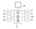
はじめに、図7から図9を参照して、SLO1の概略構成を説明する。図7に示すように、SLO1は、撮影ユニット4を、主に備える。撮影ユニット4には、SLO1における主要な光学系(図8参照)が、少なくとも含まれる。
<Appearance of the device>
First, a schematic configuration of SLO1 will be described with reference to FIGS. 7 to 9. As shown in FIG. 7, the
SLO1は、アライメント機構と、撮影光学系駆動機構と、の少なくとも何れかを備えていてもよい。SLO1におけるアライメント機構は、例えば、レーザー光の旋回点が形成される位置を、被検眼Eに対して適正な位置に配置するために利用される。アライメント機構は、被検眼と撮影ユニット4(撮影光学系)との相対位置を調節する駆動機構である。アライメント機構は、X(左右),Y(上下),Z(前後)の各方向に関し、被検眼と撮影ユニット4(撮影光学系)との位置関係を調整してもよい。図7に示す具体例では、基台5,移動台6,および,Z駆動機構7が、水平方向(XZ方向)および上下方向(Y方向)に関するアライメント機構として利用される。即ち、移動台6は、撮影ユニット4を載せた状態で、基台5上をXZ方向に移動可能である。また、Z駆動機構7は、移動台6に載置されており、撮影ユニット4をZ方向に変位させる。これにより、被検眼と撮影ユニット4(撮影光学系)とのXYZ方向の位置関係が調整される。
The
撮影光学系駆動機構は、撮影ユニット4で取得される正面画像の撮影位置(被検眼上での撮影位置)を、調整するためのメカニカルな駆動機構である。撮影光学系駆動機構は、撮影ユニット4を直接的に、または、間接的に支持(例えば、保持)してもよい。眼科撮影装置一般において、撮影光学系駆動機構は、被検眼Eの視軸と,撮影ユニット4(撮影光学系)の光軸(撮影光軸ともいう)と,の位置関係を変化させる。SLO1のような眼底撮影装置に適用される場合、撮影光学系駆動機構は、被検眼Eの視軸の向きと、撮影ユニット4の光軸の向きと、の角度を調節する。これにより、眼底上の撮影位置が変更される。具体例として、図7に示す具体例では、スイング・チルトユニット8が、撮影光学系駆動機構として利用される。スイング・チルトユニット8は、被検眼Eに対して撮影ユニット4を左右に旋回させる。また、スイング・チルトユニット8は、被検眼Eに対して撮影ユニット4を俯仰させる。
The photographing optical system drive mechanism is a mechanical drive mechanism for adjusting the photographing position (the photographing position on the eye to be inspected) of the front image acquired by the photographing unit 4. The photographing optical system drive mechanism may directly or indirectly support (for example, hold) the photographing unit 4. In the ophthalmologic imaging apparatus in general, the photographing optical system drive mechanism changes the positional relationship between the visual axis of the eye E to be inspected and the optical axis (also referred to as the photographing optical axis) of the photographing unit 4 (photographing optical system). When applied to a fundus photography device such as SLO1, the photographing optical system drive mechanism adjusts the angle between the direction of the visual axis of the eye E to be inspected and the direction of the optical axis of the photographing unit 4. As a result, the imaging position on the fundus is changed. As a specific example, in the specific example shown in FIG. 7, the swing /
アライメント機構,および,撮影光学系駆動機構の一方または両方は、制御信号に基づいて所定の動作を行うアクチュエータを持ち、アクチュエータの駆動制御によって、上記の動作を実現してもよい。 One or both of the alignment mechanism and the photographing optical system drive mechanism may have an actuator that performs a predetermined operation based on a control signal, and the above operation may be realized by the drive control of the actuator.
<撮影光学系>
次に、SLO1の光学系を説明する。図8に示すように、SLO1は、照射光学系10と、受光光学系20と、を有する(まとめて、「撮影光学系」と称す)。本実施形態において、これらの光学系10,20は、撮影ユニット4に設けられている。SLO1は、これらの光学系10,20を用いて眼底の正面画像を撮影する。前述のとおり、SLO1の撮影光学系は、ポイントスキャン方式の光学系であってもよいし、ラインスキャン方式の光学系であってもよい。
<Shooting optical system>
Next, the optical system of SLO1 will be described. As shown in FIG. 8, the
照射光学系10は、少なくとも走査部(光スキャナともいう)16と、対物レンズ系17と、を含む。また、図8に示すように、照射光学系10は、更に、レーザー光出射部11、コリメーティングレンズ12、穴開きミラー13、レンズ14(本実施形態において、視度調節部40の一部)、および、レンズ15を有してもよい。ポイントスキャン方式の場合、光スキャナは、2次元光スキャナであってもよい。2次元光スキャナは、照明光を眼底上で2次元スキャンさせる(詳細構成は後述する)。また、ラインスキャン方式の場合、光スキャナは、1次元光スキャナであってもよい。
The irradiation
レーザー光出射部11は、照射光学系10の光源である。レーザー光出射部11は、例えば、レーザーダイオード(LD)、および、スーパールミネッセントダイオード(SLD)等の少なくとも何れかを含んでいてもよい。具体的な構造についての説明は省略するが、レーザー光出射部11は、少なくとも1種類の波長域の光を出射する。本実施形態では、複数色の光が、同時に、又は選択的に、レーザー光出射部11から出射されるものとする。例えば、本実施形態では、レーザー光出射部11から、青,緑,赤の可視域の3色と、赤外域の1色と、の計4色の光が出射される。青,緑,赤の可視域の3色は、例えば、カラー撮影に利用される。例えば、光源11から青,緑,赤の3色が実質的に同時に出射されることによって、カラー撮影が行われる。また、可視域の3色のうち、何れか1色が、可視蛍光撮影に利用されてもよい。例えば、青色の光が、可視蛍光撮影の一種であるFAG撮影(フルオレセイン蛍光造影撮影)に利用されてもよい。また、例えば、赤外域の光は、赤外域の眼底反射光を用いる赤外撮影の他、赤外蛍光撮影に利用されてもよい。例えば、赤外蛍光撮影には、ICG撮影(インドシアニングリーン蛍光造影撮影)が知られている。この場合、レーザー光源11から出射される赤外光は、ICG撮影で使用されるインドシアニングリーンの蛍光波長とは異なる波長域に設定されていることが好ましい。
The laser
レーザー光は、図8に示した光線の経路にて眼底Erに導かれる。つまり、レーザー光出射部11からのレーザー光は、コリメーティングレンズ12を経て穴開きミラー13に形成された開口部を通り、レンズ14およびレンズ15を介した後、走査部16に向かう。走査部16によって反射されたレーザー光は、対物レンズ系17を通過した後、被検眼Eの眼底Erに照射される。その結果、レーザー光は、眼底Erで反射・散乱される。或いは、眼底に存在する蛍光物質を励起させ、眼底からの蛍光を生じさせる。これらの光(つまり、反射・散乱光および蛍光等)が、戻り光として、瞳孔から出射される。
The laser beam is guided to the fundus Er in the path of the light beam shown in FIG. That is, the laser light from the laser
本実施形態において、図8に示すレンズ14は、視度調節部40の一部である。視度調節部40は、被検眼Eの視度の誤差を矯正(軽減)するために利用される。例えば、レンズ14は、駆動機構14aによって、照射光学系10の光軸方向へ移動可能である。レンズ14の位置に応じて、照射光学系10および受光光学系20の視度が変わる。このため、レンズ14の位置が調節されることで、被検眼Eの視度の誤差が軽減され、その結果として、レーザー光の集光位置が、眼底Erの観察部位(例えば、網膜表面)に設定可能となる。なお、視度調節部40は、例えば、バダール光学系など、図8とは異なる光学系が適用されてもよい。
In the present embodiment, the
走査部16は、光源(レーザー光出射部11)から発せられたレーザー光を、眼底上で走査するためのユニットである。以下の説明では、特に断りが無い限り、走査部16は、レーザー光の走査方向が互いに異なる2つの光スキャナを含むものとする。それらの2つの光スキャナは、互いに異なる位置に配置される。即ち、主走査用(例えば、X方向への走査用)の光スキャナ16aと、副走査用(例えば、Y方向への走査用)の光スキャナ16bと、を含む。主走査用の光スキャナ16aと、副走査用の光スキャナ16bとは、それぞれ、レゾナントスキャナと、ガルバノミラーとであってもよい。但し必ずしもこれに限られるものではなく、各光スキャナ16a,16bに対し、他の反射ミラー(ガルバノミラー、ポリゴンミラー、レゾナントスキャナ、および、MEMS等)の他、光の進行(偏向)方向を変化させる音響光学素子(AOM)等が適用されてもよい。なお、走査部16は、必ずしも複数の光スキャナである必要はなく、1つの光スキャナであってもよい。2次元的にレーザー光を走査する単一の光スキャナとしては、例えば、MEMSデバイス、及び、音響光学素子(AOM)等の何れかを利用したものが提案されている。
The
対物レンズ系17は、SLO1の対物光学系である。対物レンズ系17は、少なくとも1つのレンズを含む。図8に示すように、複数のレンズを組み合わせて対物レンズ系17が構成されてもよい。また、対物レンズ系17は、必ずしもレンズ(換言すれば、屈折要素)のみからなる光学系である必要はなく、ミラー(換言すれば、反射要素)が含まれていてもよい。対物レンズ系17は、走査部16によって走査されるレーザー光を、眼底Erに導くために利用される。そのために、対物レンズ系17は、走査部16を経たレーザー光が旋回される旋回点Pを形成する。旋回点Pは、照射光学系10の光軸L1上であって、対物レンズ系17に関して走査部16と光学的に共役な位置に形成される。なお、本開示において「共役」とは、必ずしも完全な共役関係に限定されるものではなく、「略共役」を含むものとする。即ち、眼底画像の利用目的(例えば、観察、解析等)との関係で許容される範囲で、完全な共役位置からズレて配置される場合も、本開示における「共役」に含まれる。
The
走査部16を経たレーザー光は、対物レンズ系17を通過することによって、旋回点Pを経て、眼底Erに照射される。このため、対物レンズ系17を通過したレーザー光は、走査部16の動作に伴って旋回点Pを中心に旋回される。その結果として、本実施形態では、眼底Er上でレーザー光が2次元的に走査される。眼底Erに照射されたレーザー光は、集光位置(例えば、網膜表面)にて反射される。また、レーザー光は、集光位置の前後の組織にて散乱される。反射光および散乱光は、平行光としてそれぞれ瞳孔から出射する。
The laser light that has passed through the
次に、受光光学系20について説明する。受光光学系20は、対物レンズ系17を照射光学系10と共用する。受光光学系20は、対物レンズ系17を介して,被検眼Eによる照明光の反射光を、受光素子によって受光する。本実施例のように、ポイントスキャン方式のSLOでは、受光素子は、例えば、ポイントセンサであってもよい。また、ラインスキャン方式である場合、受光素子は、例えば、ラインセンサであってもよい。受光光学系20は、1つ,または,2つ以上の受光素子を有する。例えば、図8に示すように、3つの受光素子25,27,29を有してもよい。
Next, the light receiving optical system 20 will be described. The light receiving optical system 20 shares the
図8に示すように、本実施形態における受光光学系20は、対物レンズ系17から穴開きミラー13までに配置された各部材を、照射光学系10と共用してもよい。この場合、眼底からの光は、照射光学系10の光路を遡って、穴開きミラー(本実施形態における光路分岐部材)13まで導かれる。また、穴開きミラー13は、照射光学系10と受光光学系20とを分岐させる。本実施形態では、眼底Erからの光は、穴開きミラー13の反射面によって反射されることで、受光光学系20の独立光路(受光素子25,27,29側の光路)へ導かれる。照射光学系10と受光光学系20との共通光路から,穴開きミラーへ向かう光には、レーザー光の主光線における光軸L2の近傍の領域に、ノイズ光が含まれやすい。なお、ここでいうノイズ光は、主に、眼底Erの集光位置(例えば、網膜表面)等、撮影および観察の目標以外からの光を指す。具体的には、角膜による反射光、および、装置内部の光学系からの反射光等が挙げられる。穴開きミラー13は、このようなノイズ光の少なくとも一部を取り除きつつ、眼底Erからの光を、受光光学系20の独立光路へ導く。本実施形態において、穴開きミラー13は、前眼部との共役位置に配置されている。このため、角膜による反射光、および、装置内部の光学系からの反射光等が、穴開きミラー13の開口によって取り除かれる。一方、眼底Erからの光のうち、瞳孔周辺を通過する光が、穴開きミラー13の反射面で反射されて、独立光路へ導かれる。
As shown in FIG. 8, in the light receiving optical system 20 in the present embodiment, each member arranged from the
なお、照射光学系10と受光光学系20とを分岐させる光路分岐部材は、穴開きミラー13に限られるものではない。例えば、穴開きミラー13に代えて、穴開きミラー13における開口と反射面とを互いに置き換えた部材を光路分岐部として利用できる。但し、例えば、図8に適用する場合、更に、照射光学系10の独立光路(光源11から穴開きミラー13からまで)と、受光光学系20の独立光路(穴開きミラー13から受光素子25,27,29まで)とを、互いに置き換えて配置することが必要となる。なお、光路分岐部材は、その他のビームスプリッターであってもよい。
The optical path branching member that branches the irradiation
受光光学系20は、穴開きミラー13の反射光路に、レンズ21、遮光部22、ピンホール板23、および、光分離部(光分離ユニット)30を有する。また、光分離部30と各受光素子25,27,29との間に、レンズ24,26,28が設けられている。
The light receiving optical system 20 has a
詳細は後述するが、遮光部22は、受光光学系20の光軸L2の近傍において遮光する。眼底共役面からの光は、遮光部22を通過し、ノイズ光の少なくとも一部が遮光部22によって遮光される。 Although the details will be described later, the light-shielding unit 22 blocks light in the vicinity of the optical axis L2 of the light-receiving optical system 20. The light from the fundus conjugate surface passes through the light-shielding portion 22, and at least a part of the noise light is blocked by the light-shielding portion 22.
また、ピンホール板23は、眼底共役面に配置されており、SLO1における共焦点絞りとして機能する。すなわち、視度調節部40によって視度が適正に補正される場合において、レンズ21を通過した眼底Erからの光は、ピンホール板23の開口において焦点を結ぶ。ピンホール板23によって、眼底Erの集光点(あるいは、焦点面)以外の位置からの光が取り除かれ、残り(集光点からの光)が主に受光素子25,27,29へ導かれる。
Further, the
光分離部30は、眼底Erからの光を分離させる。本実施形態では、光分離部30によって、眼底Erからの光が波長選択的に光分離される。また、光分離部30は、受光光学系20の光路を分岐させる光分岐部を兼用していてもよい。例えば、図8に示すように、光分離部30は、光分離特性(波長分離特性)が互いに異なる2つのダイクロイックミラー(ダイクロイックフィルター)31,32を含んでいてもよい。受光光学系20の光路は、2つのダイクロイックミラー31,32によって、3つに分岐される。また、それぞれの分岐光路の先には、受光素子25,27,29の1つがそれぞれ配置される。
The
例えば、光分離部30は、眼底Erからの光の波長を分離させ、3つの受光素子25,27,29に、互いに異なる波長域の光を受光させる。例えば、青,緑,赤の3色の光を、受光素子25,27,29に1色ずつ受光させてもよい。この場合、各受光素子25,27,29の受光結果から、カラー画像を容易に得ることができる。
For example, the
また、光分離部30は、赤外撮影で使用される赤外域の光を、受光素子25,27,29の少なくとも1つに受光させてもよい。この場合において、例えば、蛍光撮影で使用される蛍光と、赤外撮影で使用される赤外域の光とが、互いに異なる受光素子に受光されてもよい。
Further, the
各受光素子25,27,29が感度を持つ波長帯は、互いに異なっていてもよい。また、受光素子25,27,29のうち、少なくとも2つが、共通の波長域に感度を持っていてもよい。それぞれの受光素子25,27,29は、受光した光の強度に応じた信号(以下、受光信号と称す)をそれぞれ出力する。本実施形態において、受光信号は、受光素子毎に別々に処理されて画像が生成される。つまり、本実施形態では、最大で3種類の眼底画像が、並行して生成される。
The wavelength bands in which the
<固視光学系>
また、SLO1は、固視光学系を有してもよい。図8の例において、固視光学系は、照射光学系10と兼用されている。レーザー光出射部11から間欠的に点灯される可視光が、固視光束(換言すれば、固視標)として利用される。詳細は、後述する。
<Optometry optical system>
Further, SLO1 may have an optometry optical system. In the example of FIG. 8, the optometry optical system is also used as the irradiation
<制御系の構成>
次に、図9を参照して、SLO1の制御系を説明する。SLO1は、制御部70によっての各部の制御が行われる。制御部70は、SLO1の各部の制御処理と、演算処理とを行う電子回路を有する処理装置(プロセッサ)である。制御部70は、CPU(Central Processing Unit)およびメモリ等で実現される。制御部70は、記憶部71と、バス等を介して電気的に接続されている。また、制御部70は、レーザー光出射部11、受光素子25,27,29、駆動機構14a、走査部16、入力インターフェイス75、およびモニタ80等の各部とも電気的に接続されている。
<Control system configuration>
Next, the control system of SLO1 will be described with reference to FIG. Each unit of SLO1 is controlled by the
記憶部71には、各種の制御プログラムおよび固定データ等が格納される。また、記憶部71には、一時データ等が記憶されてもよい。SLO1による撮影画像は、記憶部71に記憶されていてもよい。但し、必ずしもこれに限られるものではなく、外部の記憶装置(例えば、LANおよびWANで制御部70に接続される記憶装置)へ撮影画像が記憶されてもよい。
Various control programs, fixed data, and the like are stored in the
便宜上、本実施形態では、制御部70が画像取得部、および、画像処理部を兼用するものとする。例えば、制御部70は、何れかの受光素子25,27,29からの受光信号を基に、眼底画像を形成する。また、眼底画像に対する画像処理(画像の加工、解析等)についても、制御部70によって行われる。なお、図9に示すように、制御部70は、各受光素子25,27,29からの信号に基づいて、それぞれの受光素子25,27,29からの信号に基づく最大3種類の画像を、略同時に生成する。勿論、本実施例に限定されるものではなく、画像処理部、または、画像取得部は、制御部70とは別体の装置であってもよい。
For convenience, in this embodiment, the
また、制御部70は、観察画像として、赤外域の眼底反射光に基づく眼底正面画像を取得し、モニタ80に表示させる。観察画像は、ほぼリアルタイムに取得される動画像である。
Further, the
また、制御部70は、入力インターフェイス75(操作入力部)から出力される操作信号に基づいて、上記の各部材を制御する。入力インターフェイス75は、検者の操作を受け付ける操作入力部である。例えば、マウスおよびキーボード等であってもよい。
Further, the
<動作説明>
一般に、対物レンズ系に関する眼底共役面(中間像面ともいう)の近くに、レーザー光を大きく折り曲げるレンズの光源側レンズ面が配置されていると、共焦点絞り,および,穴開きミラー等では取り除ききれないノイズ光が生じやすくなる。また、レーザー光を眼底に適正に集光させるために、視度補正が行われる場合がある。このとき、対物レンズ系を介して形成される眼底共役面は、視度の補正量に応じて移動する。例えば、被検眼の近視が強い場合ほど、視度補正の結果として、対物レンズ系に関する眼底共役面は被検眼E(および、レンズ面)に接近してしまう。このように、視度補正の影響によって、ノイズ光が発生しやすくなる場合も考えられる。
<Operation explanation>
Generally, if the light source side lens surface of a lens that greatly bends the laser beam is placed near the fundus conjugate surface (also called the intermediate image surface) related to the objective lens system, it is removed by a confocal diaphragm, a perforated mirror, or the like. Uncut noise light is likely to occur. In addition, diopter correction may be performed in order to properly focus the laser beam on the fundus. At this time, the fundus conjugate surface formed via the objective lens system moves according to the amount of diopter correction. For example, the stronger the myopia of the eye to be inspected, the closer the fundus conjugate surface of the objective lens system is to the eye E (and the lens surface) to be inspected as a result of the diopter correction. As described above, it is conceivable that noise light is likely to be generated due to the influence of diopter correction.
光学系に設けられた有害光除去部(例えば、共焦点絞り,黒点板等)によって、対物レンズ系による照明光の反射像が眼底画像に映り込むことは軽減される。但し、映り込みの抑制効果と、受光素子へ導かれる眼底反射の光量とは、トレードオフの関係になる場合が考えられるので、対物レンズ系17による反射像(以下、便宜上、「対物反射像」と称す)の映り込みを許容するような設計解および撮影条件も考えられる。 The harmful light removing unit provided in the optical system (for example, a confocal diaphragm, a black dot plate, etc.) reduces the reflection image of the illumination light by the objective lens system on the fundus image. However, since the effect of suppressing reflection and the amount of light reflected from the fundus guided to the light receiving element may be in a trade-off relationship, the reflected image by the objective lens system 17 (hereinafter, "objective reflection image" for convenience). Design solutions and shooting conditions that allow reflections (referred to as) are also conceivable.
本実施例のSLO1は、画像処理を活用して、対物反射像の映り込みを軽減する。SLO1における具体的な動作を、図10に示すフローチャートを参照して説明する。 The SLO1 of this embodiment utilizes image processing to reduce the reflection of the objective reflection image. The specific operation in SLO1 will be described with reference to the flowchart shown in FIG.
初めに、制御部70は、固視標の呈示を開始させる(S1)と共に、観察画像の取得を開始させる(S2)。次に、アライメント機構が観察画像に基づいて自動または手動で駆動されることによって、被検眼と装置とのアライメントが行われる(S3)。
First, the
アライメント完了後、撮影シーケンス(S4〜S7)が実行される。本撮影シーケンスでは、第1正面画像と、第2正面画像と、の2枚の正面画像が撮影される。本実施例では、少なくとも第2反射像として黄斑部輪状反射が含まれない合成正面画像を生成するものとする。 After the alignment is completed, the photographing sequence (S4 to S7) is executed. In this shooting sequence, two front images, a first front image and a second front image, are taken. In this embodiment, it is assumed that a composite front image that does not include the ring-shaped reflection of the macula is generated as at least the second reflection image.
本実施例の撮影シーケンスでは、各々の正面画像が撮影される際に、撮影光学系の光軸と,被検眼の視軸と,の位置関係が、観察画像に基づいて調整される。まず、制御部70は、撮影光学系の光軸と,被検眼の視軸と,の位置関係を、第1の位置関係に調整する(S4)。次いで、第1正面画像を撮影する(S5)。
In the photographing sequence of this embodiment, when each front image is photographed, the positional relationship between the optical axis of the photographing optical system and the visual axis of the eye to be inspected is adjusted based on the observed image. First, the
本実施例では、第1正面画像および第2正面画像として、カラー眼底画像が得られる場合を示す。但し、カラー眼底画像に限定されるものではなく、赤外眼底画像、可視光による反射画像等、眼底反射光により形成される他の正面画像に対し、本実施例の処理が適用されてもよい。例えば、制御部70は、レーザー光出射部11からの赤外光の照射を中断し、赤、緑、青の3色の可視光を、撮影用の照明光として、同時に(略同時に)出射する。3つの受光素子25,27,29から出力される信号に基づいて、赤、緑、青の各成分についての眼底正面画像が形成され、これらが合成されることによって、カラー眼底画像が形成される。
In this embodiment, a case where a color fundus image can be obtained as the first front image and the second front image is shown. However, the process is not limited to the color fundus image, and the process of this embodiment may be applied to other frontal images formed by the fundus reflected light such as an infrared fundus image and an image reflected by visible light. .. For example, the
次いで、制御部70は、撮影光学系の光軸と,被検眼の視軸と,の位置関係を、第2の位置関係に調整する(S6)。次いで、第2正面画像を撮影する(S7)。
Next, the
本実施例において、第1の位置関係と、第2の位置関係との調整は、何れも、固視灯の呈示位置を切換えることで行われる。本実施例では、レーザー光出射部11からの可視光が、固視標として利用される。具体的には、制御部70は、レーザー光出射部11からの可視光を、呈示位置に応じたタイミングで間欠的に出射させる。走査部16によって眼底画像1フレーム分の走査がされる間に可視光が出射されるタイミングを変更することで、固視標の呈示位置が変更される。
In this embodiment, the adjustment between the first positional relationship and the second positional relationship is performed by switching the presentation position of the fixation lamp. In this embodiment, the visible light from the laser
また、本実施例において、第1の位置関係と、第2の位置関係とに調整する際、観察画像において黄斑部輪状反射の検出が、制御部70によって行われてもよい。本実施例において、制御部70は、観察画像において黄斑部輪状反射が検出されない位置関係にて、第1正面画像または第2正面画像の撮影を実行する。黄斑部輪状反射が観察画像中に検出される場合、撮影光学系の光軸と,被検眼の視軸と,の位置関係を更に調節する。
Further, in the present embodiment, when adjusting the first positional relationship and the second positional relationship, the
第1正面画像と第2正面画像の撮影後、制御部70は、それら2枚の正面画像を合成し、合成正面画像を得る(S8)。本実施例では、合成正面画像において、欠けのある黄斑部輪状反射が含まれているか否かが検出される。欠けのある黄斑部輪状反射が含まれている場合(S9:Yes)、制御部70は、撮影光学系の光軸と,被検眼の視軸と,の位置関係を、これまでとは変更して、第1正面画像および第2正面画像の再撮影を実行し、新たな合成正面画像を形成してもよい。本実施例では、S4〜S9の処理によって、トライアンドエラーで、欠けのある黄斑部輪状反射が含まれない合成正面画像が形成される。一方、S8の処理において、合成正面画像に黄斑部輪状反射が含まれていないと判定される場合は(S9:No)、処理を終了してもよい。
After taking the first front image and the second front image, the
以上、実施形態に基づいて説明を行ったが、本開示を実施するうえで、実施形態の内容を適宜変更することができる。 Although the above description has been given based on the embodiments, the contents of the embodiments can be changed as appropriate in carrying out the present disclosure.
例えば、眼科撮影装置における対物レンズ系を、交換レンズ,または,ズームレンズとすることによって、撮影画角が可変する構成であってもよい。この場合、撮影画角が第1の画角に設定された場合には、明確な対物反射像が正面画像上に生じ、第1の画角とは異なる第2の画角では、目立った対物反射像が生じない場合が考えられる。そこで、例えば、レリーズ操作に基づいて、合成正面画像を生成するための撮影シーケンス,および,合成正面画像の生成処理を実行する第1モードと、レリーズ操作に基づいてレリーズ操作を受けたときの撮影光学系の光軸と、被検眼の視軸との位置関係にて眼底画像を撮影する第2モードとに、切換可能な構成であってもよい。第1モードと第2モードとの切換制御は、検者によるモード切換操作に基づいて実行されてもよい。また、対物レンズ系のレンズ交換、または、ズームの状態に応じて、自動的に切換えられてもよい。なお、交換レンズは、対物レンズ系を、他の対物レンズ系とそっくりそのまま置き換える構成に限定されるものではなく、対物レンズ系に対し、レンズアタッチメントを着脱することで画角を切換える構成であってもよい。 For example, the angle of view may be variable by using an interchangeable lens or a zoom lens as the objective lens system in the ophthalmologic photographing apparatus. In this case, when the shooting angle of view is set to the first angle of view, a clear objective reflection image is generated on the front image, and in the second angle of view different from the first angle of view, the objective is conspicuous. It is conceivable that a reflected image does not occur. Therefore, for example, a shooting sequence for generating a composite front image based on a release operation, a first mode for executing a composite front image generation process, and shooting when a release operation is received based on the release operation. The configuration may be switchable between a second mode for capturing a fundus image based on the positional relationship between the optical axis of the optical system and the visual axis of the eye to be inspected. The switching control between the first mode and the second mode may be executed based on the mode switching operation by the examiner. Further, the switching may be automatically performed according to the lens replacement of the objective lens system or the zoom state. The interchangeable lens is not limited to a configuration in which the objective lens system is replaced with another objective lens system as it is, but is a configuration in which the angle of view is switched by attaching / detaching a lens attachment to the objective lens system. May be good.
また、例えば、上記説明した合成正面画像を生成するための処理は、SLOへの適用に限定されるものではなく、それ以外の、『少なくとも1つのレンズを含む対物レンズ系と、光源から発せられた照明光を前記対物レンズ系を介して被検眼に照射する照射光学系と、照明光の被検眼による反射光を対物レンズ系を介して受光する受光素子を備える受光光学系と、を含む撮影光学系と、を備え、受光素子からの信号に基づいて撮影画像を生成する眼科撮影装置』に対しても適用されてもよい。このような眼科撮影装置は、眼底撮影装置であってもよい。この場合、照射光学系によって、照明光が被検眼の眼底に照射され、且つ、受光光学系によって、照明光の眼底反射光が受光素子に受光される。SLO以外の眼底撮影装置としては、例えば、眼底カメラ等が考えられる。また、眼科撮影装置は、前眼部撮影装置であってもよい。 Further, for example, the process for generating the composite front image described above is not limited to application to SLO, and other than that, "is emitted from an objective lens system including at least one lens and a light source. Imaging including an irradiation optical system that irradiates the eye to be inspected with the illumination light through the objective lens system, and a light receiving optical system including a light receiving element that receives the reflected light of the illumination light by the eye to be inspected through the objective lens system. It may also be applied to an ophthalmologic imaging apparatus that includes an optical system and generates a captured image based on a signal from a light receiving element. Such an ophthalmologic imaging apparatus may be a fundus imaging apparatus. In this case, the irradiation optical system irradiates the fundus of the eye to be inspected with illumination light, and the light receiving optical system receives the reflected light from the fundus of the illumination light to the light receiving element. As a fundus imaging device other than SLO, for example, a fundus camera or the like can be considered. Further, the ophthalmologic imaging device may be an anterior ocular segment imaging device.
1 SLO
8 スイングチルト機構
10 照射光学系(固視光学系)
17 対物レンズ系
20 受光光学系
25,27,29 受光素子
70 制御部
S 対物反射像
1 SLO
8
17 Objective lens system 20 Light receiving
Claims (4)
被検眼の正面画像として被検眼のカラー眼底画像を、前記走査部によって被検眼上で前記照明光を走査し、可視光による照明光の反射光を受光した前記受光素子からの信号に基づいて取得する画像取得手段と、
前記撮影光学系の光軸と,被検眼の視軸と,の位置関係を変更して、前記正面画像中の前記被検眼の組織に対して前記対物レンズ系による前記照明光の反射像が形成される位置を調整するための位置調整手段と、
第1正面画像と、前記被検眼の組織に対する前記反射像の位置が前記第1正面画像とは異なり,且つ,前記第1正面画像において前記反射像の位置する領域を含む第2正面画像と、の少なくとも2枚に基づいて合成正面画像を得る画像処理手段と、を備え、
前記画像処理手段は、更に、前記第2正面画像において上下方向および左右方向のそれぞれの外縁から離れた位置にあり前記第2正面画像における前記反射像とは異なる領域であって、前記第1正面画像において前記反射像の位置する領域を切り出し、前記切り出した領域を、前記第1正面画像に対して合成することによって、前記合成正面画像を得る走査型の眼科撮影装置。 An irradiation optical system that irradiates the eye to be inspected with illumination light by visible light from a light source through an objective lens system including at least one lens and scans the illumination light on the eye to be inspected by a scanning unit, and the objective lens system. An imaging optical system including a light receiving optical system having a light receiving element that receives the reflected light of the illumination light by the eye to be inspected.
A color fundus image of the eye to be inspected is obtained as a frontal image of the eye to be inspected based on a signal from the light receiving element that receives the reflected light of the illumination light by the visible light by scanning the illumination light on the eye to be inspected by the scanning unit. Image acquisition means and
By changing the positional relationship between the optical axis of the photographing optical system and the visual axis of the eye to be inspected, a reflected image of the illumination light by the objective lens system is formed on the tissue of the eye to be inspected in the front image. Position adjustment means for adjusting the position to be
The first front image and the second front image in which the position of the reflected image with respect to the tissue of the eye to be inspected is different from that of the first front image and includes the region where the reflected image is located in the first front image. An image processing means for obtaining a composite front image based on at least two images of
Said image processing means further wherein a region that is different from the reflection image at the second front image in the vertical direction and the lateral position near apart from each outer edge Ri said second front image, the first (1) A scanning ophthalmologic imaging apparatus that obtains a composite front image by cutting out a region where the reflected image is located in a front image and synthesizing the cut out region with respect to the first front image.
メモリに記憶される前記正面画像の中から、第1正面画像と、前記被検眼の組織に対する前記対物レンズ系による前記照明光の反射像の位置が前記第1正面画像とは異なり,且つ,前記第1正面画像において前記反射像が位置する領域が含まれる第2正面画像と、の少なくとも2枚に基づいて合成正面画像を得る画像処理ステップであって、前記第2正面画像において上下方向および左右方向のそれぞれの縁部から離れた位置にあり前記第2正面画像における前記反射像とは異なる領域であって、前記第1正面画像において前記反射像の位置する領域を切り出し、前記切り出した領域を、前記第1正面画像に対して合成することによって、前記合成正面画像を得る、画像処理ステップを、前記コンピュータに実行させる画像処理プログラム。 Through the objective lens system comprising at least one lens, the illumination light from the light source to scan the illumination light on the subject's eye irradiates the subject's eye, a color fundus image of the eye as a front image of the eye to be an image processing Purogumu for processing the front image obtained by scanning the ophthalmic imaging apparatus for shooting based on the reflected light of the illumination light by the eye to be examined when on eye and scanning the illumination light, By running on the computer's processor
From the front images stored in the memory, the positions of the first front image and the reflected image of the illumination light by the objective lens system with respect to the tissue of the eye to be inspected are different from those of the first front image, and the above. An image processing step of obtaining a composite front image based on at least two images of a second front image including a region where the reflected image is located in the first front image, in the vertical direction and left and right in the second front image. a region that is different from the a reflection image at each location near Ri said second front image away from the edge direction, cut out area located in the reflected image in the first front image, said cutout An image processing program that causes the computer to perform an image processing step of obtaining the composite front image by synthesizing a region with respect to the first front image.
Priority Applications (2)
| Application Number | Priority Date | Filing Date | Title |
|---|---|---|---|
| JP2016111746A JP6884995B2 (en) | 2016-06-03 | 2016-06-03 | Ophthalmologic imaging equipment and image processing program |
| EP17174304.0A EP3257433B1 (en) | 2016-06-03 | 2017-06-02 | Ophthalmic imaging device and generation method of ophthalmic synthetic image |
Applications Claiming Priority (1)
| Application Number | Priority Date | Filing Date | Title |
|---|---|---|---|
| JP2016111746A JP6884995B2 (en) | 2016-06-03 | 2016-06-03 | Ophthalmologic imaging equipment and image processing program |
Related Child Applications (1)
| Application Number | Title | Priority Date | Filing Date |
|---|---|---|---|
| JP2021011513A Division JP7051042B2 (en) | 2021-01-27 | 2021-01-27 | Ophthalmologic photography equipment |
Publications (3)
| Publication Number | Publication Date |
|---|---|
| JP2017217076A JP2017217076A (en) | 2017-12-14 |
| JP2017217076A5 JP2017217076A5 (en) | 2019-06-06 |
| JP6884995B2 true JP6884995B2 (en) | 2021-06-09 |
Family
ID=58992770
Family Applications (1)
| Application Number | Title | Priority Date | Filing Date |
|---|---|---|---|
| JP2016111746A Active JP6884995B2 (en) | 2016-06-03 | 2016-06-03 | Ophthalmologic imaging equipment and image processing program |
Country Status (2)
| Country | Link |
|---|---|
| EP (1) | EP3257433B1 (en) |
| JP (1) | JP6884995B2 (en) |
Families Citing this family (4)
| Publication number | Priority date | Publication date | Assignee | Title |
|---|---|---|---|---|
| US11219362B2 (en) | 2018-07-02 | 2022-01-11 | Nidek Co., Ltd. | Fundus imaging apparatus |
| JP7375323B2 (en) | 2019-03-29 | 2023-11-08 | 株式会社ニデック | fundus imaging device |
| JP7200516B2 (en) | 2018-07-02 | 2023-01-10 | 株式会社ニデック | Fundus camera |
| WO2021246291A1 (en) * | 2020-06-03 | 2021-12-09 | 株式会社ニデック | Oct data processing device and oct data processing program |
Family Cites Families (10)
| Publication number | Priority date | Publication date | Assignee | Title |
|---|---|---|---|---|
| JP2802758B2 (en) * | 1988-05-31 | 1998-09-24 | キヤノン株式会社 | Ophthalmic image correction device |
| US6829383B1 (en) * | 2000-04-28 | 2004-12-07 | Canon Kabushiki Kaisha | Stochastic adjustment of differently-illuminated images |
| JP3784247B2 (en) * | 2000-08-31 | 2006-06-07 | 株式会社ニデック | Fundus camera |
| JP3897643B2 (en) * | 2002-05-22 | 2007-03-28 | キヤノン株式会社 | Ophthalmic imaging equipment |
| JP4901201B2 (en) * | 2005-12-08 | 2012-03-21 | 興和株式会社 | Fundus image processing method and apparatus |
| JP5231802B2 (en) * | 2007-12-29 | 2013-07-10 | 株式会社ニデック | Ophthalmic imaging equipment |
| US7854510B2 (en) * | 2008-10-16 | 2010-12-21 | Steven Roger Verdooner | Apparatus and method for imaging the eye |
| AU2011232625B2 (en) * | 2010-03-23 | 2014-01-16 | Neurovision Imaging, Inc. | Apparatus and method for imaging an eye |
| JP2016028687A (en) | 2014-07-23 | 2016-03-03 | 株式会社ニデック | Scan type laser ophthalmoscope |
| JP6775302B2 (en) * | 2016-02-24 | 2020-10-28 | 株式会社トプコン | Ophthalmologic imaging equipment |
-
2016
- 2016-06-03 JP JP2016111746A patent/JP6884995B2/en active Active
-
2017
- 2017-06-02 EP EP17174304.0A patent/EP3257433B1/en active Active
Also Published As
| Publication number | Publication date |
|---|---|
| EP3257433B1 (en) | 2023-08-09 |
| EP3257433A1 (en) | 2017-12-20 |
| JP2017217076A (en) | 2017-12-14 |
Similar Documents
| Publication | Publication Date | Title |
|---|---|---|
| JP6884995B2 (en) | Ophthalmologic imaging equipment and image processing program | |
| JP7302342B2 (en) | Fundus camera | |
| JP7134324B2 (en) | OPHTHALMIC PHOTOGRAPHIC APPARATUS, CONTROL METHOD, PROGRAM, AND RECORDING MEDIUM THEREOF | |
| JP2017184787A (en) | Ophthalmology imaging apparatus and image processing program | |
| JP7376847B2 (en) | Fundus image processing device and fundus image processing program | |
| JP7226426B2 (en) | Fundus camera | |
| JP7098964B2 (en) | Fundus photography device | |
| JP6319616B2 (en) | Scanning laser ophthalmoscope | |
| JP7051042B2 (en) | Ophthalmologic photography equipment | |
| JP7037904B2 (en) | Ophthalmologic photography equipment and image processing program | |
| JP2018000620A (en) | Ophthalmological imaging apparatus | |
| JP7050488B2 (en) | Ophthalmologic imaging equipment, its control method, programs, and recording media | |
| JP6957842B2 (en) | Fundus photography device | |
| JP7024294B2 (en) | Ophthalmologic photography equipment | |
| JP6848207B2 (en) | Ophthalmologic imaging equipment | |
| JP2021079013A (en) | Medical image processing device, processing method for medical image processing device and program | |
| CN114599267A (en) | Image processing method, image processing apparatus, and program | |
| WO2019065219A1 (en) | Ophthalmological device | |
| JP7421062B2 (en) | fundus imaging device | |
| JP7375323B2 (en) | fundus imaging device | |
| JP2019154987A (en) | Ophthalmologic apparatus, control method therefor, program, and storage medium | |
| JP6958367B2 (en) | Fundus photography device | |
| JP7200516B2 (en) | Fundus camera | |
| JP6836212B2 (en) | Ophthalmologic imaging equipment | |
| JP2023150195A (en) | Fundus imaging apparatus |
Legal Events
| Date | Code | Title | Description |
|---|---|---|---|
| A521 | Request for written amendment filed |
Free format text: JAPANESE INTERMEDIATE CODE: A523 Effective date: 20190424 |
|
| A621 | Written request for application examination |
Free format text: JAPANESE INTERMEDIATE CODE: A621 Effective date: 20190424 |
|
| A977 | Report on retrieval |
Free format text: JAPANESE INTERMEDIATE CODE: A971007 Effective date: 20191212 |
|
| A131 | Notification of reasons for refusal |
Free format text: JAPANESE INTERMEDIATE CODE: A131 Effective date: 20200114 |
|
| A521 | Request for written amendment filed |
Free format text: JAPANESE INTERMEDIATE CODE: A523 Effective date: 20200313 |
|
| A131 | Notification of reasons for refusal |
Free format text: JAPANESE INTERMEDIATE CODE: A131 Effective date: 20200623 |
|
| A521 | Request for written amendment filed |
Free format text: JAPANESE INTERMEDIATE CODE: A523 Effective date: 20200824 |
|
| A02 | Decision of refusal |
Free format text: JAPANESE INTERMEDIATE CODE: A02 Effective date: 20201027 |
|
| A521 | Request for written amendment filed |
Free format text: JAPANESE INTERMEDIATE CODE: A523 Effective date: 20210127 |
|
| C60 | Trial request (containing other claim documents, opposition documents) |
Free format text: JAPANESE INTERMEDIATE CODE: C60 Effective date: 20210127 |
|
| A911 | Transfer to examiner for re-examination before appeal (zenchi) |
Free format text: JAPANESE INTERMEDIATE CODE: A911 Effective date: 20210204 |
|
| C21 | Notice of transfer of a case for reconsideration by examiners before appeal proceedings |
Free format text: JAPANESE INTERMEDIATE CODE: C21 Effective date: 20210210 |
|
| TRDD | Decision of grant or rejection written | ||
| A01 | Written decision to grant a patent or to grant a registration (utility model) |
Free format text: JAPANESE INTERMEDIATE CODE: A01 Effective date: 20210413 |
|
| A61 | First payment of annual fees (during grant procedure) |
Free format text: JAPANESE INTERMEDIATE CODE: A61 Effective date: 20210426 |
|
| R150 | Certificate of patent or registration of utility model |
Ref document number: 6884995 Country of ref document: JP Free format text: JAPANESE INTERMEDIATE CODE: R150 |