JP6958367B2 - Fundus photography device - Google Patents
Fundus photography device Download PDFInfo
- Publication number
- JP6958367B2 JP6958367B2 JP2018002250A JP2018002250A JP6958367B2 JP 6958367 B2 JP6958367 B2 JP 6958367B2 JP 2018002250 A JP2018002250 A JP 2018002250A JP 2018002250 A JP2018002250 A JP 2018002250A JP 6958367 B2 JP6958367 B2 JP 6958367B2
- Authority
- JP
- Japan
- Prior art keywords
- light
- fundus
- eye
- image
- pupil
- Prior art date
- Legal status (The legal status is an assumption and is not a legal conclusion. Google has not performed a legal analysis and makes no representation as to the accuracy of the status listed.)
- Active
Links
Images


Description
本開示は、眼底の正面画像を得るための眼底撮影装置に関する。 The present disclosure relates to a fundus photography device for obtaining a frontal image of the fundus.
被検眼の眼底の正面画像を撮影する眼底撮影装置が、眼科分野において広く利用されている。 A fundus camera that captures a frontal image of the fundus of an eye to be inspected is widely used in the field of ophthalmology.
眼底撮影装置の1種として、例えば、眼底上でスリット状の照明光を走査し、照明された眼底領域の像を、走査に従って2次元的な撮像面に逐次投影させることで、眼底の正面画像を得る装置が知られている。この種の装置として、特許文献1には、2つの開口がスリットの走査方向に沿って形成された2つ孔絞りを、投光系の瞳孔と共役な面に配置して、照明光を2つ孔絞りの2つの開口から同時に照射させると共に、瞳上において投影される2つ穴絞りの隙間から眼底反射光を取り出して撮影する装置が開示されている。
As a kind of fundus photography device, for example, a slit-shaped illumination light is scanned on the fundus, and an image of the illuminated fundus region is sequentially projected onto a two-dimensional imaging surface according to the scanning to obtain a frontal image of the fundus. The device to obtain is known. As a device of this type, in
しかしながら、特許文献1の装置では、被検眼の瞳孔径が小さい場合に、2つ孔絞りによる2つの開口の像を、被検眼の瞳孔内に配置できず、虹彩で照明光がケラレてしまい、眼底画像が暗くなってしまう場合が考えられる。
However, in the apparatus of
本開示は、従来技術の問題点に鑑みてなされたものであり、より瞳孔径の小さな被検眼を撮影しやすい眼底撮影装置を提供すること、を技術課題とする。 The present disclosure has been made in view of the problems of the prior art, and it is a technical subject to provide a fundus photography apparatus that facilitates imaging of an eye to be examined having a smaller pupil diameter.
本開示の第1態様に係る眼底撮影装置は、被検眼の瞳上において照明光が通過する投光領域と、被検眼の瞳上において前記照明光の眼底反射光が取り出される受光領域とを、互いに異なる位置に形成する、投受光分離手段、および、前記受光領域から取り出された前記眼底反射光を受光する受光素子、を備える撮影光学系と、被検眼と前記撮影光学系との位置関係を調整する駆動部と、を備え、前記受光素子からの信号に基づいて眼底画像を取得する眼底撮影装置であって、更に、前記投受光分離手段は、被検眼の瞳上において互いに位置が異なる2つの投光領域を形成し、被検眼と前記撮影光学系とのアライメントの基準となるアライメント基準位置として、前記2つの投光領域および前記受光領域の全部が被検眼の瞳孔領域内に形成されることを想定した第1基準位置と、第1基準位置とは異なる第2基準位置であって、前記受光領域と共に2つの前記投光領域のうち1つが、残り1つの前記投光領域よりも優先的に被検眼の瞳孔内に配置されることを想定した第2基準位置と、のいずれかを選択的に設定可能であり、設定した前記アライメント基準位置からのアライメントずれに基づいてアライメントを誘導すると共に、前記第1基準位置へアライメントを誘導する場合は、眼底画像を撮影する際に、2つの前記投光領域のうち両方から前記照明光を眼底へ投光させ、前記第2基準位置へアライメントを誘導する場合は、眼底画像を撮影する際に、2つの前記投光領域のうち、優先的に瞳孔内に配置される一方のみから前記照明光を眼底へ投光させる撮影制御手段、を備える。
本開示の第2態様に係る眼底撮影装置は、被検眼の瞳上において照明光が通過する投光領域と、被検眼の瞳上において前記照明光の眼底反射光が取り出される受光領域とを、互いに異なる位置に形成する、投受光分離手段、および、前記受光領域から取り出された前記眼底反射光を受光する受光素子、を備える撮影光学系と、被検眼と前記撮影光学系との位置関係を調整する駆動部と、を備え、前記受光素子からの信号に基づいて眼底画像を取得する眼底撮影装置であって、更に、前記撮影光学系は、被検眼の眼底上で照明光をスリット状に形成するスリット形成部、スリット状に形成された照明光を、スリットに対して直交する方向へ眼底上で走査する走査部、更に有し、前記投受光分離手段は、被検眼の瞳上において前記投光領域を、前記走査部の走査方向に関して互いに分離した2つの位置に形成すると共に、被検眼の瞳上において前記受光領域を、2つの前記投光領域に挟まれるように形成し、被検眼と前記撮影光学系とのアライメントの基準となるアライメント基準位置として、前記2つの投光領域および前記受光領域の全部が被検眼の瞳孔領域内に形成されることを想定した第1基準位置と、第1基準位置とは異なる第2基準位置であって、前記受光領域と共に2つの前記投光領域のうち1つが、残り1つの前記投光領域よりも優先的に被検眼の瞳孔内に配置されることを想定した第2基準位置と、のいずれかを選択的に設定可能であり、設定した前記アライメント基準位置からのアライメントずれに基づいてアライメントを誘導する撮影制御手段、を備える。
In the fundus imaging apparatus according to the first aspect of the present disclosure, a light projecting region through which the illumination light passes on the pupil of the eye to be inspected and a light receiving region in which the reflected light from the fundus of the illumination light is taken out on the pupil of the eye to be inspected. The positional relationship between the eye to be inspected and the photographing optical system is that the photographing optical system including the light emitting / receiving separating means formed at different positions and the light receiving element that receives the reflected light from the fundus of the eye taken out from the light receiving region is provided. It is a fundus imaging device that includes a drive unit for adjusting and acquires a fundus image based on a signal from the light receiving element. Two light projection regions are formed, and the entire two light projection regions and the light receiving region are formed in the pupil region of the eye to be inspected as an alignment reference position that serves as a reference for alignment between the eye to be inspected and the imaging optical system. It is assumed that the first reference position and the second reference position are different from the first reference position, and one of the two light projection areas together with the light receiving area has priority over the remaining one light projection area. to a second reference position assumed to be arranged in the pupil of the eye, a one of the possible selectively set to induce alignment based on the alignment deviation from the alignment reference position set At the same time, when the alignment is guided to the first reference position, when the fundus image is taken, the illumination light is projected onto the fundus from both of the two projection regions and aligned to the second reference position. When the fundus image is captured, the imaging control means for projecting the illumination light onto the fundus from only one of the two projection regions preferentially arranged in the pupil is provided. ..
In the fundus imaging apparatus according to the second aspect of the present disclosure, a light projecting region through which the illumination light passes on the pupil of the eye to be inspected and a light receiving region in which the reflected light from the fundus of the illumination light is taken out on the pupil of the eye to be inspected. The positional relationship between the eye to be inspected and the photographing optical system and the photographing optical system including the light receiving and receiving separating means formed at different positions and the light receiving element for receiving the fundus reflected light taken out from the light receiving region. It is a fundus imaging device that includes a drive unit for adjusting and acquires an image of the fundus of the eye based on a signal from the light receiving element. Further, the imaging optical system has a slit-shaped illumination light on the fundus of the eye to be inspected. The slit-forming portion to be formed, a scanning portion for scanning the illumination light formed in the slit shape on the fundus in a direction orthogonal to the slit, and the light-emitting separation means are said to be on the pupil of the eye to be inspected. The light projecting region is formed at two positions separated from each other with respect to the scanning direction of the scanning unit, and the light receiving region is formed so as to be sandwiched between the two light projecting regions on the pupil of the eye to be inspected. As an alignment reference position that serves as a reference for alignment with the imaging optical system, a first reference position assuming that the entire two light projection regions and the light receiving region are formed in the pupil region of the eye to be inspected. It is a second reference position different from the first reference position, and one of the two projection regions together with the light receiving region is arranged in the pupil of the eye to be inspected with priority over the remaining one projection region. It is possible to selectively set any of the second reference position, which is assumed to be the case, and includes an imaging control means that guides the alignment based on the alignment deviation from the set alignment reference position.
以下、図面を参照しつつ、本開示に係る眼底撮影装置の実施形態を説明する。以下では、第1実施形態として、被検眼または装置内部での反射・散乱によって生じるアーチファクトが抑制される装置を開示する。また、第2実施形態として、被検眼の瞳孔径が小さい場合であっても、良好に眼底画像を撮影できる装置を開示する。各実施形態は、他の実施形態の一部を適宜利用できる。 Hereinafter, embodiments of the fundus photography apparatus according to the present disclosure will be described with reference to the drawings. In the following, as the first embodiment, an apparatus in which artifacts caused by reflection / scattering inside the eye to be inspected or the apparatus are suppressed will be disclosed. Further, as a second embodiment, a device capable of satisfactorily capturing a fundus image even when the pupil diameter of the eye to be inspected is small is disclosed. As for each embodiment, a part of other embodiments can be appropriately used.
<第1実施形態>
まず、第1実施形態について説明する。第1実施形態において、眼底撮影装置は、少なくとも、撮影光学系(図10参照)と、制御部(図12参照)と、を有する。追加的に、眼底撮影装置は、画像処理部を有していてもよい。
<First Embodiment>
First, the first embodiment will be described. In the first embodiment, the fundus photography apparatus has at least a photographing optical system (see FIG. 10) and a control unit (see FIG. 12). In addition, the fundus photography apparatus may have an image processing unit.
<撮影光学系>
撮影光学系は、被検眼の眼底へ照明光を投受光して、眼底画像を撮影するために利用される。より詳細には、被検眼の眼底上で照明光がスリット状に形成されるように、照明光が投光される。スリット状の照明光は、眼底上で走査される。走査範囲を撮影範囲として、眼底画像が撮影される。
<Shooting optical system>
The photographing optical system is used to shoot an image of the fundus by projecting and receiving illumination light on the fundus of the eye to be inspected. More specifically, the illumination light is projected so that the illumination light is formed in a slit shape on the fundus of the eye to be inspected. The slit-shaped illumination light is scanned on the fundus. The fundus image is captured with the scanning range as the imaging range.
撮影光学系は、スリット形成部、走査部、および、投受光分離部、を少なくとも有する。追加的に、撮影光学系は、光源、撮像素子、および、光路分岐部等を有していてもよい。 The photographing optical system has at least a slit forming portion, a scanning portion, and a light emitting / receiving separating portion. In addition, the photographing optical system may include a light source, an image pickup device, an optical path branching portion, and the like.
スリット形成部は、被検眼の眼底上で照明光をスリット状に形成する。スリット形成部は、例えば、スリット状の透光部(例えば、開口)が、眼底と共役な面内に配置されたものであってもよい。 The slit forming portion forms the illumination light in a slit shape on the fundus of the eye to be inspected. The slit-forming portion may have, for example, a slit-shaped translucent portion (for example, an opening) arranged in a plane conjugate with the fundus.
なお、本開示において「共役」とは、必ずしも完全な共役関係に限定されるものではなく、「略共役」を含むものとする。即ち、各部の技術意義との関係で許容される範囲で、完全な共役位置からズレて配置される場合についても、本開示における「共役」に含まれる。 In the present disclosure, the term "conjugate" is not necessarily limited to a perfect conjugation relationship, but includes "substantially conjugation". That is, the case where the parts are arranged so as to be deviated from the perfect conjugation position within the permissible range in relation to the technical significance of each part is also included in the "conjugation" in the present disclosure.
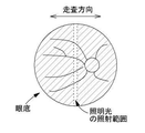
図1に示すように、走査部は、スリット状に形成された照明光を、眼底上で、スリットと交差する方向(詳細には、スリットの長手方向と交差する方向)に走査する。走査部は、スリット形成部をスリットと交差する方向に移動させることによって、照明光を走査するものであってもよい。この種の走査部としては、メカニカルシャッター、液晶シャッター、オプティカルチョッパー、および、ドラムリール等が例示される。 As shown in FIG. 1, the scanning unit scans the illumination light formed in the shape of a slit on the fundus in a direction intersecting the slit (specifically, a direction intersecting the longitudinal direction of the slit). The scanning unit may scan the illumination light by moving the slit forming portion in a direction intersecting the slit. Examples of this type of scanning unit include mechanical shutters, liquid crystal shutters, optical choppers, drum reels, and the like.
スリットの走査方向は、好ましくは、スリットと直交する方向である。但し、スリットの直交方向に対して斜め方向であってもよい。 The scanning direction of the slit is preferably a direction orthogonal to the slit. However, it may be oblique to the direction orthogonal to the slit.
また、走査部は、スリット形成部を通過した光の向きを、変化させる部材であってもよい。例えば、ガルバノスキャナ等の各種の光スキャナが、走査部として利用されてもよい。光を旋回させて走査を行うタイプの走査部は、被検眼の瞳と共役な位置に置かれてもよい。 Further, the scanning portion may be a member that changes the direction of the light that has passed through the slit forming portion. For example, various optical scanners such as a galvano scanner may be used as a scanning unit. The scanning unit of the type in which light is swirled to perform scanning may be placed at a position conjugate with the pupil of the eye to be inspected.
撮影光学系は、更に、光路結合部、および、対物レンズを有していてもよい。 The photographing optical system may further include an optical path coupling portion and an objective lens.
光路結合部は、照明光の投光光路と眼底反射光の受光光路とを結合および分離する。光路結合部によって形成される、投光光路と受光光路との共通光路上に、対物レンズは配置される。このとき、撮影光学系の光軸(以下、「撮影光軸」ともいう)と、対物レンズの光軸とが一致していることが望ましい。 The optical path coupling portion combines and separates the projected light path of the illumination light and the received light path of the fundus reflected light. The objective lens is arranged on the common optical path of the light projecting light path and the light receiving light path formed by the optical path coupling portion. At this time, it is desirable that the optical axis of the photographing optical system (hereinafter, also referred to as “photographing optical axis”) coincides with the optical axis of the objective lens.
各種のビームスプリッターを、光路結合部として利用できる。この場合、光路結合部は、穴開きミラーであってもよいし、単なるミラーであってもよいし、ハーフミラーであってもよいし、その他のビームスプリッターであってもよい。 Various beam splitters can be used as optical path couplings. In this case, the optical path coupling portion may be a perforated mirror, a simple mirror, a half mirror, or another beam splitter.
<被検眼瞳上の投受光分離>
投受光分離部は、被検眼の瞳上において、照明光が投光される区域(投光領域)と、照明光による眼底反射光が取り出される区域(受光領域)と、を分離する。
<Separation of light and reception on the pupil of the eye to be inspected>
The light emitting / receiving separation unit separates an area where the illumination light is projected (light projection area) and an area where the fundus reflected light due to the illumination light is extracted (light receiving area) on the pupil of the eye to be inspected.
詳細には、図2に示すように、投受光分離部によって、投光領域が、照明光の走査方向に関して互いに分離した2つの位置に形成される。2つの投光領域は、撮影光軸を挟むように形成されてもよい。なお、第1実施形態において、投受光分離部は、投光領域を少なくとも2つ形成するものであればよく、3つ以上の投光領域を形成するものであってもよい。各々の投光領域を通過した照明光は、眼底上で、同一のスリット状領域を照射する。そして、走査部の駆動に伴い、スリット状の領域が走査される。 Specifically, as shown in FIG. 2, the light emitting / receiving separating unit forms the light emitting region at two positions separated from each other with respect to the scanning direction of the illumination light. The two light projection regions may be formed so as to sandwich the photographing optical axis. In the first embodiment, the light emitting / receiving separation unit may be one that forms at least two light emitting regions, and may be one that forms three or more light emitting regions. The illumination light that has passed through each projection region irradiates the same slit-shaped region on the fundus. Then, as the scanning unit is driven, the slit-shaped region is scanned.
図2に示すように、投受光分離部によって、受光領域が、2つの投光領域に挟まれるように形成される。つまり、一方の投光領域、受光領域、他方の投光領域、の順に、各領域が一列に並んで形成される。また、受光領域は、撮影光軸上に形成されてもよい。投光領域と受光領域とは、互いに重なり合わないように配置されてもよい。その場合、角膜や中間透光体で、照明光の一部が反射および散乱を起こし、眼底画像にフレアーを生じさせることが軽減される。 As shown in FIG. 2, the light emitting / receiving separating portion is formed so that the light receiving region is sandwiched between the two light emitting regions. That is, each region is formed in a row in the order of one projection region, the light receiving region, and the other projection region. Further, the light receiving region may be formed on the photographing optical axis. The light projecting area and the light receiving area may be arranged so as not to overlap each other. In that case, it is reduced that a part of the illumination light is reflected and scattered in the cornea or the intermediate translucent body to cause flare in the fundus image.
投受光分離部は、照明光の投光光路、および、受光光路にそれぞれ配置される複数の部材を含んでいてもよい。 The light emitting / receiving separation unit may include a light emitting path for illumination light and a plurality of members arranged in the light receiving path.
投受光分離部は、その一部が、例えば、照明光の投光光路における瞳共役面上において、照明光の走査方向に関して互いに離れた少なくとも2つの位置に照明光の照射位置を設定するものであってもよい。この場合、2つの照射位置に、照明光を発する光源がそれぞれ配置されてもよいし、2つの照射位置に、照明光を通過させる開口がそれぞれ配置されてもよい。 A part of the light emitting / receiving separation unit sets the irradiation position of the illumination light at at least two positions separated from each other with respect to the scanning direction of the illumination light on the pupil conjugate surface in the light projection path of the illumination light. There may be. In this case, light sources that emit illumination light may be arranged at the two irradiation positions, or openings for passing the illumination light may be arranged at the two irradiation positions.
換言すれば、投受光分離部は、被検眼の瞳と共役な位置において走査方向に関して互いに異なる位置に配置される、2つの照明光源、または、2つの見かけ上の照明光源を、少なくとも含むものであってもよい。これにより、投光領域は、照明光の走査方向に関して互いに分離した2つの位置に形成される。より好ましくは、2つの照明光源、または、2つの見かけ上の照明光源は、撮影光軸に対して対称に配置されてもよい。これにより、2つの投光領域を、撮影光軸に関して対称に形成できる。2つの光源、または、2つの見かけ上の光源からの投光状態は、後述の制御部によって、光源毎に制御可能であってもよい。投光状態が光源毎に制御される結果として、照明光を通過させるか否かが、各々の投光領域に対して個別に設定される。勿論、投受光分離部は、3つ以上の照明光源、または、3つ以上の見かけ上の照明光源を含むものであってもよい。 In other words, the light emitting / receiving separation unit includes at least two illumination light sources, or two apparent illumination light sources, which are arranged at positions conjugate with the pupil of the eye to be inspected and at different positions with respect to the scanning direction. There may be. As a result, the projection region is formed at two positions separated from each other with respect to the scanning direction of the illumination light. More preferably, the two illumination sources, or the two apparent illumination sources, may be arranged symmetrically with respect to the imaging optical axis. As a result, the two projection regions can be formed symmetrically with respect to the shooting optical axis. The light projection state from the two light sources or the two apparent light sources may be controllable for each light source by a control unit described later. As a result of controlling the projection state for each light source, whether or not to pass the illumination light is individually set for each projection region. Of course, the light emitting / receiving separation unit may include three or more illumination light sources or three or more apparent illumination light sources.
なお、投光状態としては、光源または見かけ上の光源からの照明光が被検眼に到達する状態と、到達しない状態と、の2種類の状態が少なくともあり得る。投光状態の切換は、光源の点灯制御によって実現されてもよい。また、光源、又は、見かけ上の光源から、被検眼へ向かう光束を、選択的に遮ぎるシャッターを駆動制御することによって、投光状態の切換が実現されてもよい。 There can be at least two types of light projection states: a state in which the illumination light from the light source or an apparent light source reaches the eye to be inspected, and a state in which the illumination light does not reach the eye to be inspected. The switching of the flooded state may be realized by the lighting control of the light source. Further, the switching of the light projection state may be realized by driving and controlling a shutter that selectively blocks the light beam from the light source or the apparent light source toward the eye to be inspected.
また、投受光分離部は、その一部が、照明光の受光光路における瞳共役面上において、2つの投光領域に挟まれる領域である受光領域からの眼底反射光を撮像面側へ通過させ、それ以外の光を撮像面側へ通過させなくするものであってもよい。例えば、投受光分離部は、受光領域からの眼底反射光を撮像面側へ通過させ、それ以外の光を遮光する遮光部材を含むものであってもよい。遮光部材は、例えば、受光光路において瞳共役面上に配置されてもよい。例えば、遮光部材として、撮影光軸を中心に開口を有する絞りが設けられた場合、絞りの開口像によって、受光領域が形成される。 Further, a part of the light emitting / receiving separation unit allows the reflected light from the fundus of the eye from the light receiving region, which is a region sandwiched between the two light projecting regions, to pass to the imaging surface side on the pupil conjugate surface in the light receiving optical path of the illumination light. , Other light may not pass to the image pickup surface side. For example, the light emitting / receiving separating unit may include a light shielding member that allows the fundus reflected light from the light receiving region to pass toward the imaging surface side and blocks other light. The light-shielding member may be arranged on the pupil conjugate surface in the light receiving optical path, for example. For example, when a diaphragm having an aperture centered on the optical axis of photography is provided as a light-shielding member, a light receiving region is formed by the aperture image of the diaphragm.
投受光分離部に遮光部材が含まれる場合、遮光部材は、前述の光路結合部と共用されていてもよいし、別体であってもよい。 When the light emitting / receiving separating portion includes a light-shielding member, the light-shielding member may be shared with the above-mentioned optical path coupling portion or may be a separate body.
<制御部>
制御部は、各部の制御処理と、演算処理とを行う処理装置(プロセッサ)である。例えば、制御部は、CPU(Central Processing Unit)およびメモリ等で実現される。
<Control unit>
The control unit is a processing device (processor) that performs control processing of each unit and arithmetic processing. For example, the control unit is realized by a CPU (Central Processing Unit), a memory, or the like.
第1実施形態において、制御部は、照明光を通過させるか否かを、被検眼の瞳上の2つの投光領域に対して個別に設定する。また、2つの投光領域の一方(いずれか)から選択的に投光された照明光に基づいて、眼底画像を撮影する。 In the first embodiment, the control unit individually sets whether or not to allow the illumination light to pass through the two light projection regions on the pupil of the eye to be inspected. In addition, a fundus image is taken based on the illumination light selectively projected from one (either) of the two projection regions.
ところで、眼底画像における撮影光軸の近傍位置には、対物レンズのレンズ面の中心部で照明光が反射されることによる、反射像(輝点像、アーチファクトの一種)が生じる場合がある。投光領域は撮影光軸から離れていることから、反射像は、眼底画像における撮影光軸の位置からややズレた位置に出現しやすい。一例として、2つの投光領域の両方から照明光を同時に投光して撮影した眼底画像を、図3に示す。図3に示すように、2つの投光領域に対応して、眼底画像の画像中心部において、撮影光軸を挟んだ2箇所で、反射像が生じ得る。2つの反射像は、走査方向に並んで(つまり、走査方向に関して異なる位置に)出現する。 By the way, a reflected image (bright spot image, a kind of artifact) may be generated at a position near the photographing optical axis in the fundus image due to the reflection of the illumination light at the center of the lens surface of the objective lens. Since the projection region is far from the shooting optical axis, the reflected image tends to appear at a position slightly deviated from the position of the shooting optical axis in the fundus image. As an example, FIG. 3 shows a fundus image taken by simultaneously projecting illumination light from both of the two projection regions. As shown in FIG. 3, a reflected image can be generated at two locations on the image center of the fundus image with the photographing optical axis in between, corresponding to the two light projection regions. The two reflected images appear side by side in the scanning direction (that is, at different positions with respect to the scanning direction).
これに対し、本実施形態では、2つの投光領域のうち一方から選択的に照明光を眼底へ投光して、眼底画像が撮影される。これによって、対物レンズにおいて、反射像を生じさせる箇所が上記の場合に対して半減するので、図4に示すように、眼底画像における反射像を半減できる。このように、被検眼の瞳上の2つの投光領域のうち、一方から選択的に照明光を眼底へ投光して、眼底画像を撮影することは、アーチファクトを軽減するうえで、有利である。 On the other hand, in the present embodiment, the fundus image is captured by selectively projecting the illumination light onto the fundus from one of the two projection regions. As a result, in the objective lens, the portion where the reflected image is generated is halved as compared with the above case, so that the reflected image in the fundus image can be halved as shown in FIG. In this way, it is advantageous to selectively project the illumination light to the fundus from one of the two projection areas on the pupil of the eye to be inspected to take the fundus image in order to reduce the artifacts. be.
なお、2つの投光領域のうち、一方から選択的に照明光を眼底へ投光して眼底画像を撮影することは、瞳孔径が小さい被検眼を撮影する場合に有利である。瞳孔径が小さく、2つの投光領域を瞳孔領域内に満足に配置できない場合でも、1つの投光領域と受光領域との配置を許容するだけの瞳孔径があれば、良好に眼底画像を撮影できる。 It should be noted that it is advantageous to photograph the fundus image by selectively projecting the illumination light from one of the two projection regions to the fundus when photographing the eye to be inspected having a small pupil diameter. Even if the pupil diameter is small and the two projection regions cannot be satisfactorily arranged in the pupil region, if the pupil diameter is sufficient to allow the arrangement of one projection region and the light receiving region, a good fundus image can be taken. can.
<投光領域と受光領域との間のクリアランスの変更>
投受光分離部は、被検眼の瞳上における、2つの投光領域と受光領域との間のクリアランスを変更可能であってもよい。クリアランスが大きいほど、対物レンズによる反射像は生じ難くなる。クリアランスが小さければ、投光領域と受光領域とがより近づくので小瞳孔眼の撮影に有利になる。
<Change of clearance between light emitting area and light receiving area>
The light emitting / receiving separation unit may be capable of changing the clearance between the two light emitting regions and the light receiving region on the pupil of the eye to be inspected. The larger the clearance, the less likely it is that a reflected image from the objective lens will occur. If the clearance is small, the light projecting region and the light receiving region are closer to each other, which is advantageous for photographing the small pupil eye.
この場合、例えば、瞳共役面上で撮影光軸から離れた位置に光源が配置されることで、被検眼の瞳上に投光領域を形成する場合、2つ1組の光源を、図5に示すように、2組配置してもよい。2組の間では、撮影光軸から光源までの距離が互いに異なっていてもよい。また、すべての光源は、走査方向に並んで配置される。図5は、被検眼の瞳上に結像した2組の光源の像と、絞りの開口像と、を示している。この場合、2組の光源の像によって、瞳上には投光領域が形成され、絞りの開口像によって受光領域が形成される。 In this case, for example, when a light source is arranged on the pupil conjugate surface at a position away from the photographing optical axis to form a light projection region on the pupil of the eye to be inspected, a pair of light sources is shown in FIG. As shown in, two sets may be arranged. The distance from the shooting optical axis to the light source may be different between the two sets. Also, all light sources are arranged side by side in the scanning direction. FIG. 5 shows an image of two sets of light sources formed on the pupil of the eye to be inspected and an aperture image of the diaphragm. In this case, a light projecting region is formed on the pupil by the images of the two sets of light sources, and a light receiving region is formed by the aperture image of the diaphragm.
2組のうち、いずれを用いて撮影するかは、被検眼の瞳孔径に応じて選択されてもよい。つまり、瞳孔径が十分に大きい場合は、より外側に配置された1組の中から光源を選択してもよい。この場合、反射像が低減されやすい。また、瞳孔径が小さい場合は、より内側に配置された1組の中から光源を選択してもよい。 Which of the two sets is used for imaging may be selected according to the pupil diameter of the eye to be inspected. That is, when the pupil diameter is sufficiently large, the light source may be selected from a set arranged on the outer side. In this case, the reflected image is likely to be reduced. When the pupil diameter is small, the light source may be selected from a set arranged inside.
また、例えば、受光領域の大きさ又は形状を切換えることで、クリアランスが変更されてもよい。例えば、受光領域が絞りの開口像として形成される場合、開口の大きさが互いに異なる複数個の絞りの間で、光路上に配置される1つを切換えることで、クリアランスが変更されてもよい。また、絞りとして、可変開口絞りを用いることで、クリアランスが変更されてもよい。 Further, for example, the clearance may be changed by switching the size or shape of the light receiving region. For example, when the light receiving region is formed as an aperture image of a diaphragm, the clearance may be changed by switching one arranged on the optical path between a plurality of diaphragms having different aperture sizes. .. Further, the clearance may be changed by using a variable aperture diaphragm as the diaphragm.
<画像処理によるアーチファクト除去>
制御部は、2つの投光領域のうち一方から選択的に照明光を眼底へ投光して1枚目の眼底画像を撮影した後、更に、照明光が投光される投光領域を他方へ切換え、他方から選択的に照明光を投光して2枚目の眼底画像を撮影してもよい。このような2回の撮影によって、対物レンズによる反射像等のアーチファクトの出現位置が、撮影に利用した投光領域に応じて互いに異なる、2枚の眼底画像が得られる。1回目の撮影と2回目の撮影の間で、被検眼と撮影光学系との位置関係を変化させずに撮影が行われてもよい。また、2枚目の眼底画像の撮影は、1枚目の眼底画像の撮影から連続的に、且つ、自動的に実行されることが望ましい。
<Removal of artifacts by image processing>
The control unit selectively projects the illumination light from one of the two projection regions to the fundus of the eye to capture the first fundus image, and then further sets the projection area to which the illumination light is projected to the other. It may be switched to, and the illumination light may be selectively projected from the other side to take a second fundus image. By taking such two shots, it is possible to obtain two fundus images in which the appearance positions of artifacts such as the reflected image by the objective lens are different from each other depending on the light projection region used for the shooting. The imaging may be performed between the first imaging and the second imaging without changing the positional relationship between the eye to be inspected and the imaging optical system. Further, it is desirable that the acquisition of the second fundus image is continuously and automatically executed from the acquisition of the first fundus image.
本実施形態では、2枚の眼底画像を撮影する際に、被検眼と撮影光学系との位置関係を変化させる必要が無く、しかも、光源の点灯切換、あるいは、シャッターの駆動等により、比較的短時間で、被検眼の瞳上における投光領域を切換えできる。よって、2枚の眼底画像が短時間で撮影可能である。結果、1枚目の眼底画像と2枚目の眼底画像とを連続的に撮影しても、被検者の負担が抑制される。また、照明光が可視光であったとしても、1枚目の撮影後、速やかに2枚目の撮影が行われるので、1枚目の撮影に起因する縮瞳が2枚目の撮影において与える影響を抑制できる。 In the present embodiment, when two fundus images are taken, it is not necessary to change the positional relationship between the eye to be inspected and the taking optical system, and moreover, it is relatively possible to switch the lighting of the light source or drive the shutter. The light projection area on the pupil of the eye to be inspected can be switched in a short time. Therefore, two fundus images can be taken in a short time. As a result, even if the first fundus image and the second fundus image are continuously captured, the burden on the subject is suppressed. Further, even if the illumination light is visible light, the second image is taken immediately after the first image is taken, so that the miosis caused by the first image is given in the second image. The effect can be suppressed.
ここで、縮瞳の影響としては、照明光および眼底反射光が虹彩でケラレることで、眼底画像が暗くなること等が例示される。画像中心部と画像周辺部との間におけるケラレの影響(明るさの変化)は、必ずしも一様ではない。例えば、画像の周辺部では、撮影画角が大きくなるほどケラレの影響を受けやすくなることがあり得る。 Here, examples of the effect of miosis include vignetting of the illumination light and the fundus reflected light with the iris, resulting in darkening of the fundus image. The effect of vignetting (change in brightness) between the central part of the image and the peripheral part of the image is not always uniform. For example, in the peripheral portion of an image, the larger the shooting angle of view, the more likely it is to be affected by vignetting.
本実施形態では、これらの2枚の眼底画像を合成処理することによって、1枚の眼底画像(以下、「合成画像」と称する)を生成してもよい。合成処理は、画像処理部によって実行される。画像処理部は、制御部とは別体の画像処理プロセッサであってもよいし、制御部のプロセッサによって一部または全部が兼用されていてもよい。 In the present embodiment, one fundus image (hereinafter, referred to as “composite image”) may be generated by combining these two fundus images. The compositing process is executed by the image processing unit. The image processing unit may be an image processing processor separate from the control unit, or may be partially or wholly used by the processor of the control unit.
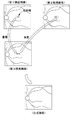
本実施形態では、アーチファクトの影響が抑制された画像を得るために、合成処理が行われる。合成手法には、以下に例示するように、種々の手法がありうる。 In the present embodiment, a compositing process is performed in order to obtain an image in which the influence of the artifact is suppressed. As the synthesis method, there may be various methods as illustrated below.
例えば、2枚の眼底画像のうち、一方の眼底画像におけるアーチファクトを含む領域を、その領域と対応する他方の眼底画像の一部と置き換えることで、合成画像が生成されてもよい(図6参照)。このとき、走査線単位で置き換えが行われてもよい。例えば、アーチファクトとして前述の反射像が生じる場合、一方の眼底画像の画像中心部に生じる反射像を、他方の眼底画像において対応する領域と置き換えられることで、合成画像が生成されてもよい。 For example, a composite image may be generated by replacing a region containing an artifact in one of the two fundus images with a part of the other fundus image corresponding to the region (see FIG. 6). ). At this time, the replacement may be performed in units of scanning lines. For example, when the above-mentioned reflected image is generated as an artifact, a composite image may be generated by replacing the reflected image generated at the center of the image of one fundus image with the corresponding region in the other fundus image.
また、2枚の眼底画像の加算平均画像として、合成画像を生成してもよい。この場合、反射像と、それ以外の領域との間で、異なる加算比率を与えて加算平均処理が行われてもよい。 Further, a composite image may be generated as an averaging image of the two fundus images. In this case, the addition averaging process may be performed by giving different addition ratios between the reflected image and the other regions.
なお、反射像が生じる領域は、視度によって多少の変動はあるものの、撮影光軸を基準とする略一定の範囲となる。このため、2枚の眼底画像において、合成処理で他方の画像と合成される領域は、予め定められていてもよい。但し、必ずしもこれに限られるものではなく、眼底画像に対して反射像の検出処理を行い、検出処理の結果に基づいて、合成される領域を個別に設定してもよい。また、視度に応じて合成される領域が設定されてもよい。また、被検眼の視度に応じて、合成処理の実行/非実行が選択されてもよい。 The region where the reflected image is generated is a substantially constant range with respect to the shooting optical axis, although there is some variation depending on the diopter. Therefore, in the two fundus images, the region to be combined with the other image in the composition process may be predetermined. However, the present invention is not limited to this, and a reflection image detection process may be performed on the fundus image, and a region to be combined may be individually set based on the result of the detection process. In addition, a region to be combined may be set according to the diopter. Further, execution / non-execution of the synthesis process may be selected according to the diopter of the eye to be inspected.
なお、制御部は、合成画像と対応する走査範囲の一部のみの走査に基づいて1枚目の眼底画像を撮影し、投光領域を切換えたうえで、残り一部の走査に基づいて2枚目の眼底画像を撮影し、各眼底画像を合成(コラージュ)することで、合成画像を生成してもよい。この場合、走査範囲は、撮影光軸を中心として2分割され、分割された2つの走査範囲において、それぞれ眼底画像を撮影することが好ましい。なお、この場合、合成処理は、必ずしも画像処理に限定されるものでは無い。例えば、照明光が、走査範囲の分割位置に到来したタイミングで、照明光を投光させる投光領域を切換えることで、撮像面上に、合成画像を形成できる。 The control unit captures the first fundus image based on scanning only a part of the scanning range corresponding to the composite image, switches the light projection area, and then scans the remaining part. A composite image may be generated by taking a first image of the fundus and synthesizing (collaborating) each image of the fundus. In this case, it is preferable that the scanning range is divided into two around the photographing optical axis, and the fundus image is photographed in each of the divided two scanning ranges. In this case, the compositing process is not necessarily limited to the image processing. For example, a composite image can be formed on the imaging surface by switching the projection region for projecting the illumination light at the timing when the illumination light reaches the divided position of the scanning range.
この場合において、2枚の眼底画像の間で、眼底上の走査範囲と照明光が投光される投光領域との関係は、2枚の眼底画像の間で交差していることが好ましい。例えば、2つの投光領域が上下方向に並べて配置されると共に、眼底上で照明光が上下方向に走査される場合、上側の投光領域から照明光を通過させるときは、眼底の下半分の走査に基づいて1枚目の眼底画像を撮影し、下側の投光領域から照明光を通過させるときは、眼底の上半分の走査に基づいて2枚目の眼底画像を撮影し、両者から合成画像を生成してもよい。この場合、各々の投光領域との関係で、対物レンズの反射像、および、フレアー等のアーチファクトが含まれ難い部分を撮影した画像同士が合成される。従って、アーチファクトが抑制された合成画像を得ることができる。 In this case, it is preferable that the relationship between the scanning range on the fundus and the projection area where the illumination light is projected intersects between the two fundus images. For example, when two projection regions are arranged side by side in the vertical direction and the illumination light is scanned in the vertical direction on the fundus, when the illumination light is passed from the upper projection area, the lower half of the fundus is used. When the first fundus image is taken based on the scan and the illumination light is passed from the lower projection area, the second fundus image is taken based on the scan of the upper half of the fundus and both are used. A composite image may be generated. In this case, the reflected image of the objective lens and the image of the portion where the artifact such as flare is hard to be included are combined with each other in relation to each light projection region. Therefore, it is possible to obtain a composite image in which artifacts are suppressed.
この合成処理に代えて、次のような撮影制御が実行されてもよい。即ち、撮影時に眼底上を走査する照明光が、2分割の境界位置に到来したタイミングで、投光領域が制御部によって切換えられてもよい。合成処理を必要とせずに、反射像が抑制された合成画像が生成される。 Instead of this compositing process, the following shooting control may be executed. That is, the projection region may be switched by the control unit at the timing when the illumination light scanning on the fundus during imaging reaches the boundary position of the two divisions. A composite image in which the reflected image is suppressed is generated without the need for a composite process.
<3枚の眼底画像による合成>
図7に示すように、2つの投光領域の一方から照明光を選択的に照射させて撮影した第1眼底画像と、他方から照明光を選択的に照射させて撮影した第2眼底画像と、に加え、更に、2つの投光領域の両方から照明光を同時に照射させて撮影した第3眼底画像と、の撮影を行い、これら3枚の眼底画像を合成することによって、アーチファクトの抑制された合成画像を生成するようにしてもよい。この場合、第3眼底画像における画像中心部(2か所の反射像の領域)を、第1眼底画像において対応する領域の一部、および、第2眼底画像において対応する領域の一部と、それぞれ置き換えることにより、合成正面画像を生成してもよい。
<Composite of 3 fundus images>
As shown in FIG. 7, a first fundus image taken by selectively irradiating illumination light from one of the two projection regions and a second fundus image taken by selectively irradiating illumination light from the other. In addition to, the artifacts are suppressed by taking a picture of the third fundus image taken by simultaneously irradiating the illumination light from both of the two projection regions and synthesizing these three fundus images. You may want to generate a composite image. In this case, the central part of the image (the area of the two reflected images) in the third fundus image is a part of the corresponding area in the first fundus image and a part of the corresponding area in the second fundus image. A composite front image may be generated by replacing each of them.
第3眼底画像は、2つの投光領域の両方から照明光を同時に照射されて撮影されたことから、明るさのムラが第1眼底画像,第2眼底画像に比べて少ない。合成画像は、第3眼底画像においてアーチファクトの周辺領域のみが第3眼底画像から変更されたものなので、明るさのムラを抑制できる。 Since the third fundus image was taken by simultaneously irradiating the illumination light from both of the two projection regions, the unevenness of brightness is smaller than that of the first fundus image and the second fundus image. In the composite image, only the peripheral region of the artifact is changed from the third fundus image in the third fundus image, so that the unevenness of brightness can be suppressed.
<補正処理>
上記の合成処理では、複数枚の眼底画像を合成する際に、各種の補正処理を伴ってもよい。例えば、つなぎ目を滑らかにするために、シェーディングが行われてもよい。また、画像間の明るさの違いが補正されてもよい。明るさ補正は、可視光を用いて複数枚の眼底画像を撮影した際に、縮瞳の影響を軽減するうえで有用である。
<Correction processing>
In the above compositing process, various correction processes may be involved when compositing a plurality of fundus images. For example, shading may be performed to smooth the seams. Moreover, the difference in brightness between images may be corrected. Brightness correction is useful for reducing the effect of miosis when a plurality of fundus images are taken using visible light.
<画像間の位置合わせ>
合成処理に際し、各眼底画像の位置合わせ(イメージレジストレーション)が画像処理部によって行われてもよい。ここでいう位置合わせには、平行移動,回転,拡大縮小,アフィン変換,および,非線形変形,等の少なくともいずれかが含まれていてもよい。位置合わせには、例えば、眼底画像における位相情報、および、特徴部分(例えば、血管、黄斑、乳頭、のいずれか等)の位置情報等のいずれかが利用されてもよい。
<Alignment between images>
In the compositing process, the image processing unit may perform the alignment (image registration) of each fundus image. The alignment referred to here may include at least one of translation, rotation, scaling, affine transformation, non-linear deformation, and the like. For the alignment, for example, either the phase information in the fundus image, the positional information of the characteristic portion (for example, blood vessel, macula, papilla, etc.) or the like may be used.
<撮影順序について>
上記の置き換えによる合成処理のように、合成処理に用いる複数の眼底画像のうち、1枚の眼底画像をベース画像とし、ベース画像におけるアーチファクトの近傍領域のみに対して、他の眼底画像を合成し、合成画像を生成する場合、複数の眼底画像のうち、いずれをベース画像とし、いずれを他の眼底画像とするかについては、各画像の撮影順序に応じて選択されてもよい。
<About shooting order>
As in the compositing process by the above replacement, one of the fundus images used in the compositing process is used as the base image, and the other fundus images are synthesized only in the vicinity of the artifact in the base image. When generating a composite image, which of the plurality of fundus images is used as the base image and which is used as the other fundus image may be selected according to the shooting order of each image.
例えば、可視光を照明光として、複数の眼底画像を連続的に撮影した場合、最初の1枚の撮影直後から縮瞳が始まるので、その後に撮影される眼底画像は、縮瞳の影響を受けている恐れがある。そこで、上記のような合成処理では、最初に撮影された1枚をベース画像とすることで、縮瞳の影響が軽減された合成画像が得られる。
<他のアーチファクトへの適用>
以上の説明では、対物レンズのレンズ面による反射像を、合成処理によって抑制する場合を説明したが、上記の合成処理は、反射像以外のアーチファクトに対しても適用可能である。詳細には、2つの投光領域の一方から照明光を選択的に照射させて撮影した第1眼底画像と、他方から照明光を選択的に照射させて撮影した第2眼底画像と、において、互いに異なる位置に発生するアーチファクトに対して適用可能である。一例として、まつ毛、および、フレアー等を対象として、上記の合成処理を適用できる。
For example, when a plurality of fundus images are continuously photographed using visible light as illumination light, miosis starts immediately after the first image is photographed, so that the fundus images captured thereafter are affected by the miosis. There is a risk of Therefore, in the above-mentioned compositing process, a composite image in which the influence of miosis is reduced can be obtained by using the first captured image as a base image.
<Application to other artifacts>
In the above description, the case where the reflected image on the lens surface of the objective lens is suppressed by the compositing process has been described, but the above compositing process can be applied to artifacts other than the reflected image. Specifically, in the first fundus image taken by selectively irradiating the illumination light from one of the two projection regions and the second fundus image taken by selectively irradiating the illumination light from the other. It is applicable to artifacts that occur at different positions. As an example, the above synthetic treatment can be applied to eyelashes, flares and the like.
<第2実施形態>
次に、第2実施形態について説明する。第2実施形態において、眼底撮影装置は、少なくとも、撮影光学系(図10参照)と、駆動部(図9、図12参照)と、制御部(図12参照)と、を有していてもよい。追加的に、眼底撮影装置は、前眼部観察光学系、入力インターフェイス、および、モニタの少なくともいずれかを有していてもよい。
<Second Embodiment>
Next, the second embodiment will be described. In the second embodiment, the fundus photography apparatus may include at least a photographing optical system (see FIG. 10), a driving unit (see FIGS. 9 and 12), and a control unit (see FIG. 12). good. In addition, the fundus camera may have at least one of an anterior eye observation optics, an input interface, and a monitor.
<撮影光学系>
第2実施形態における撮影光学系は、被検眼の眼底へ照明光を投受光して、眼底画像を撮影するために利用される。第2実施形態における撮影光学系は、投受光分離部と、受光素子と、を少なくとも有する。追加的に、撮影光学系は、光源、対物光学系(例えば、対物レンズ)、および、光路分岐部等の少なくともいずれかを有していてもよい。
<Shooting optical system>
The photographing optical system in the second embodiment is used for photographing a fundus image by projecting and receiving illumination light on the fundus of the eye to be inspected. The photographing optical system according to the second embodiment includes at least a light emitting / receiving separating unit and a light receiving element. In addition, the photographing optical system may have at least one of a light source, an objective optical system (for example, an objective lens), an optical path branching portion, and the like.
第2実施形態では、撮影光学系として、少なくとも第1実施形態と同様の光学系を利用できる。但し、これに限らず、種々の光学系を、第2実施形態の撮影光学系として利用できる。より詳細には、撮影光学系は、被検眼の組織上で撮影光をスキャンして撮影を行う走査型の光学系であってもよいし、非走査型の光学系であってもよい。走査型の光学系の一例としては、組織上でスポット状の撮影光を二次元的にスキャンするスポットスキャンタイプの光学系であってもよいし、ライン状の撮影光を一方向にスキャンするラインスキャンタイプの光学系であってもよい。この場合、点受光素子、ラインセンサ、二次元受光素子(撮影素子)等の中からいずれかを、受光素子として適宜採用し得る。なお、第1実施形態の光学系は、ラインスキャンタイプの光学系の一例である。また、非走査型の光学系の一例としては、一般的な眼底カメラの光学系等が挙げられる。 In the second embodiment, at least the same optical system as in the first embodiment can be used as the photographing optical system. However, the present invention is not limited to this, and various optical systems can be used as the photographing optical system of the second embodiment. More specifically, the photographing optical system may be a scanning type optical system that scans the photographing light on the tissue of the eye to be inspected for photographing, or may be a non-scanning type optical system. As an example of the scanning type optical system, a spot scanning type optical system that two-dimensionally scans the spot-shaped photographing light on the tissue may be used, or a line that scans the line-shaped photographing light in one direction. It may be a scan type optical system. In this case, any one of a point light receiving element, a line sensor, a two-dimensional light receiving element (photographing element), and the like can be appropriately adopted as the light receiving element. The optical system of the first embodiment is an example of a line scan type optical system. Further, as an example of the non-scanning type optical system, an optical system of a general fundus camera and the like can be mentioned.
第2実施形態における投受光分離部は、少なくとも、被検眼の瞳上において、照明光が投光される区域(投光領域)と、照明光による眼底反射光が取り出される区域(受光領域)と、を分離する。そして、受光領域から取り出された眼底反射光が、受光素子によって受光される。 The light emitting / receiving separation unit in the second embodiment includes, at least, an area where the illumination light is projected (light projection area) and an area where the fundus reflected light due to the illumination light is extracted (light receiving area) on the pupil of the eye to be inspected. , Is separated. Then, the fundus reflected light taken out from the light receiving region is received by the light receiving element.
投受光分離部は、瞳共役面上において、投光領域および受光領域の一方が他方を挟むように、各領域を形成するものであってもよい。具体例として、第1実施形態のように、一方の領域(第1実施形態では投光領域)が、完全に分離した2つの位置に形成され、その間に、他方の領域(第1実施形態では受光領域)を形成されてもよい。また、別の具体例として、一般的な眼底カメラらのように、投光領域および受光領域が同心円状に形成されてもよい。 The light emitting / receiving separating unit may form each region on the pupil conjugate surface so that one of the light emitting region and the light receiving region sandwiches the other. As a specific example, as in the first embodiment, one region (the projection region in the first embodiment) is formed at two completely separated positions, and the other region (in the first embodiment) is formed between them. A light receiving region) may be formed. Further, as another specific example, the light emitting region and the light receiving region may be formed concentrically as in a general fundus camera or the like.
第2実施形態において、投受光分離部は、投光光路および受光光路の一方または両方に配置される、1つ以上の部材からなる。第1実施形態のように、投受光分離部は、照明光の投光光路、および、受光光路にそれぞれ配置される複数の部材を含んでいてもよい。例えば、投光光路と受光光路とを結合・分岐する光路分岐部が、投受光分離部と兼用されていてもよい。 In the second embodiment, the light emitting / receiving separation unit is composed of one or more members arranged in one or both of the light emitting light path and the light receiving light path. As in the first embodiment, the light emitting / receiving separating unit may include a light emitting path of the illumination light and a plurality of members arranged in the light receiving path. For example, an optical path branching portion that combines and branches a light projecting light path and a light receiving light path may also be used as a light emitting and receiving separating unit.
<前眼部観察光学系>
第2実施形態の眼科撮影装置は、前眼部観察光学系(図10参照)を持ち、前眼部観察光学系を介して前眼部観察画像を取得可能であってもよい。前眼部観察光学系は、撮像素子を少なくとも有していてもよい。前眼部観察画像は、被検眼と撮影光学系との位置関係を調整するために(つまり、アライメント、トラッキング等に)利用される。前眼部観察画像は、例えば、前眼部の正面画像であってもよい。アライメントの際、前眼部観察画像は、モニタに表示されてもよい。これにより、リアルタイムなアライメント状態を、検者に把握させることができる。
<Anterior eye observation optical system>
The ophthalmologic imaging apparatus of the second embodiment may have an anterior eye observation optical system (see FIG. 10) and may be able to acquire an anterior eye observation image via the anterior eye observation optical system. The anterior eye observation optical system may have at least an image sensor. The anterior eye observation image is used to adjust the positional relationship between the eye to be inspected and the photographing optical system (that is, for alignment, tracking, etc.). The anterior segment observation image may be, for example, a frontal image of the anterior segment. At the time of alignment, the anterior ocular segment observation image may be displayed on the monitor. As a result, the examiner can grasp the real-time alignment state.
前眼部観察光学系は、撮影光学系と光学系の一部が共用されていてもよい。撮影光学系と、前眼部観察光学系と、は、ユニット化されていてもよく、後述の駆動部によって、両者は一体的に、被検眼との位置関係が変化されてもよい。 The anterior eye observation optical system may share a part of the photographing optical system and the optical system. The photographing optical system and the anterior eye observation optical system may be unitized, and the positional relationship between the two may be integrally changed with the eye to be inspected by a driving unit described later.
前眼部観察画像は、撮影光学系の撮像素子とは別体の撮像素子で撮像されてもよい。この撮像素子の他に、前眼部観察光学系は、光源等の種々の光学素子を備えていてもよい。 The anterior eye observation image may be imaged by an image pickup element separate from the image pickup element of the photographing optical system. In addition to this image pickup element, the anterior eye observation optical system may include various optical elements such as a light source.
更に、眼底撮影装置は、被検眼にアライメント指標を投影するアライメント指標投影光学系を有していてもよい。そして、前眼部または眼底の観察画像に形成されるアライメント指標に基づいて、アライメントが誘導されてもよい。 Further, the fundus photography apparatus may have an alignment index projection optical system that projects an alignment index onto the eye to be inspected. Then, the alignment may be guided based on the alignment index formed on the observation image of the anterior segment or the fundus.
<駆動部>
駆動部は、被検眼と撮影光学系との位置関係を変更(調整)する機構である。位置関係が変更されることで、被検眼の瞳上における投光領域および受光領域と、瞳孔領域との位置関係が変化する。
<Drive>
The drive unit is a mechanism for changing (adjusting) the positional relationship between the eye to be inspected and the photographing optical system. By changing the positional relationship, the positional relationship between the light projecting region and the light receiving region on the pupil of the eye to be inspected and the pupil region changes.
なお、駆動部は、被検眼と撮影光学系との位置関係を制御部からの信号に基づいて変更するアクチュエータを有していてもよいし、被検眼と撮影光学系との位置関係を検者から与えられる力に応じて変更するメカニカルな機構であってもよい。 The drive unit may have an actuator that changes the positional relationship between the eye to be inspected and the photographing optical system based on a signal from the control unit, or the examiner may change the positional relationship between the eye to be inspected and the photographing optical system. It may be a mechanical mechanism that changes according to the force given by.
駆動部は、例えば、撮影光学系(および前眼部観察光学系)を含む撮影ユニットを、変位させるものであってもよいし、被検者の顔を支持する顔支持ユニット(例えば、顎受け台)を変位させるものであってもよいし、両者を組み合わせたものであってもよい。 The drive unit may, for example, displace the imaging unit including the imaging optical system (and the anterior eye observation optical system), or the face support unit (for example, the jaw receiver) that supports the subject's face. The table) may be displaced, or both may be combined.
<制御部>
第2実施形態において、制御部は、アライメント基準位置の設定処理と、アライメント誘導処理と、を実行する。設定処理において、制御部は、被検眼と撮影光学系とのアライメントの基準(アライメントずれの基準)となるアライメント基準位置を、投光領域および受光領域を通過する光束のケラレを考慮して設定する。アライメント基準位置を目標として、被検眼と撮影光学系との位置関係が調整(つまり、アライメント)される。
<Control unit>
In the second embodiment, the control unit executes the alignment reference position setting process and the alignment guidance process. In the setting process, the control unit sets the alignment reference position, which is the alignment reference (alignment deviation reference) between the eye to be inspected and the photographing optical system, in consideration of vignetting of the luminous flux passing through the light projecting region and the light receiving region. .. The positional relationship between the eye to be inspected and the imaging optical system is adjusted (that is, alignment) with the alignment reference position as the target.
制御部は、第1基準位置と、第1基準位置とは異なる第2基準位置との少なくともいずれかを、選択的に設定可能であってもよい。ここでいう、第1基準位置は、投光領域および受光領域の全部が被検眼の瞳孔領域内に形成されることを想定した位置である。第2基準位置は、投光領域および受光領域のうちいずれかの領域の一部が被検眼の瞳孔領域外に形成されることを想定した位置である。なお、第2基準位置は、投光領域および受光領域のうち残り一部(投光領域および受光領域の少なくとも各一部)については、瞳孔領域内に形成されることを想定した位置である。 The control unit may selectively be able to set at least one of a first reference position and a second reference position different from the first reference position. The first reference position referred to here is a position assuming that the entire light emitting region and the light receiving region are formed in the pupil region of the eye to be inspected. The second reference position is a position assuming that a part of either the light projecting region or the light receiving region is formed outside the pupil region of the eye to be inspected. The second reference position is a position that is assumed to be formed in the pupil region for the remaining part of the light projecting region and the light receiving region (at least a part of each of the light projecting region and the light receiving region).
例えば、第1基準位置および第2基準位置のそれぞれは、予め定められていてもよいし、被検眼毎に設定可能であってもよい。例えば、第1基準位置および第2基準位置のそれぞれは、前眼部または眼底の観察画像に基づいて設定されてもよい。眼底観察画像は、撮影光学系を介して取得される眼底画像の一種であり、赤外光等の不可視光を照明光として撮影される動画像であってもよい。 For example, each of the first reference position and the second reference position may be predetermined or may be set for each eye to be inspected. For example, each of the first reference position and the second reference position may be set based on the observation image of the anterior eye portion or the fundus. The fundus observation image is a kind of fundus image acquired through a photographing optical system, and may be a moving image captured by using invisible light such as infrared light as illumination light.
第1基準位置は、例えば、所要瞳孔径(設計値)において、投光領域および受光領域の全部が瞳孔領域内に形成されることが想定される位置であってもよい。この場合、例えば、第1基準位置は、撮影光軸と被検眼の中心(例えば、角膜頂点、又は、瞳孔中心)とが一致するような位置であってもよい。 The first reference position may be, for example, a position where it is assumed that the entire light projecting region and the light receiving region are formed in the pupil region in the required pupil diameter (design value). In this case, for example, the first reference position may be a position where the imaging optical axis and the center of the eye to be inspected (for example, the apex of the cornea or the center of the pupil) coincide with each other.
第2基準位置は、第1基準位置に対して、被検眼と撮影光学系との位置関係が撮影光軸と交差する方向にオフセットされた位置であってもよい。また、第2基準位置は、撮影光軸と角膜頂点とが一致する位置、および、撮影光軸と瞳孔中心とが一致する位置とのいずれとも異なる位置であってもよい。オフセットによって投光領域および受光領域と、被検眼の瞳孔領域との位置関係が、第1基準位置の場合とは変化するので、ケラレの影響が改善され得る。 The second reference position may be a position where the positional relationship between the eye to be inspected and the photographing optical system is offset in the direction intersecting the photographing optical axis with respect to the first reference position. Further, the second reference position may be a position different from both the position where the photographing optical axis and the corneal apex coincide with each other and the position where the photographing optical axis and the pupil center coincide with each other. Since the positional relationship between the light projecting region and the light receiving region and the pupil region of the eye to be inspected changes depending on the offset, the influence of vignetting can be improved.
第1基準位置に対する第2基準位置のオフセットの方向および量は、例えば、瞳孔径と第1基準位置とに基づいて、投光領域および受光領域の各々のいずれかの領域の一部が被検眼の瞳孔領域外に形成され、且つ、残り一部(投光領域および受光領域の少なくとも各一部)が瞳孔領域内に形成される範囲で、適宜設定されてもよい。このとき、オフセットを定めるうえで利用される瞳孔径は、例えば、設計値であってもよいし、実測値であってもよい。 The direction and amount of the offset of the second reference position with respect to the first reference position are, for example, based on the pupil diameter and the first reference position. It may be appropriately set as long as it is formed outside the pupil region and the remaining part (at least a part of each of the light projecting region and the light receiving region) is formed inside the pupil region. At this time, the pupil diameter used for determining the offset may be, for example, a design value or an actually measured value.
また、第1基準位置に対する第2基準位置のオフセットの方向および量の少なくとも一方は、投光領域と受光領域との位置関係に応じて予め定められていてもよい。例えば、オフセットの方向は、瞳孔領域内に含まれる投光領域と受光領域との比率が変化する方向に定められていてもよい。 Further, at least one of the direction and the amount of the offset of the second reference position with respect to the first reference position may be predetermined according to the positional relationship between the light projecting region and the light receiving region. For example, the offset direction may be set in the direction in which the ratio of the light emitting region to the light receiving region included in the pupil region changes.
また、オフセットする方向および量の少なくとも一方は、前眼部または眼底の観察画像に基づいて設定されてもよい。例えば、前眼部画像に基づいて瞳孔領域内に配置される投光領域と受光領域との面積比を算出し、その面積比に応じて、オフセットする方向および量の少なくとも一方が設定されてもよい。 Further, at least one of the offset direction and the amount may be set based on the observation image of the anterior segment of the eye or the fundus. For example, even if the area ratio of the light projecting region and the light receiving region arranged in the pupil region is calculated based on the anterior eye image, and at least one of the offset direction and the amount is set according to the area ratio. good.
ここでは、虹彩によるケラレが考慮されて、アライメント基準位置が設定されてもよい。これに代えて、又は、追加的に、アライメント基準位置の設定に際し、瞼によるケラレが考慮されてもよい。ケラレの状態は、例えば、前眼部または眼底の観察画像から把握されてもよい。 Here, the alignment reference position may be set in consideration of vignetting due to the iris. Alternatively or additionally, vignetting due to the eyelids may be taken into consideration when setting the alignment reference position. The state of vignetting may be grasped from, for example, an observation image of the anterior segment of the eye or the fundus.
ここで、制御部は、被検眼の瞳孔領域に関する情報に基づいて、アライメント基準位置を設定してもよい。瞳孔領域に関する情報は、例えば、少なくとも瞳孔領域の大きさを示す情報(具体例としては、瞳孔領域の面積情報、瞳孔径情報等)であってもよい。また、瞳孔領域に関する情報は、瞳孔領域の位置、および、形状を示す情報であってもよい。投光領域および受光領域は、被検眼の瞳上において、ほぼ既知の位置および大きさで形成される。このため、第1基準位置と第2基準位置とのいずれの場合で投受光がより好適に行われるのかを、瞳孔領域に関する情報に基づいて判別可能となる。そこで、例えば、制御部は、第1基準位置と第2基準位置とのうち、投光領域および受光領域の両者が、より万遍なく瞳孔領域内に配置可能な一方の位置を、選択的に設定してもよい。 Here, the control unit may set the alignment reference position based on the information regarding the pupil region of the eye to be inspected. The information regarding the pupil region may be, for example, at least information indicating the size of the pupil region (specific examples, area information of the pupil region, pupil diameter information, etc.). Further, the information regarding the pupil region may be information indicating the position and shape of the pupil region. The light projecting area and the light receiving area are formed at substantially known positions and sizes on the pupil of the eye to be inspected. Therefore, it is possible to determine in which case the first reference position or the second reference position the light emitting / receiving is performed more preferably based on the information regarding the pupil region. Therefore, for example, the control unit selectively selects one of the first reference position and the second reference position in which both the light emitting region and the light receiving region can be arranged more evenly in the pupil region. It may be set.
なお、瞳孔領域に関する情報は、前眼部観察画像から取得されてもよいし、他の装置での測定または撮影の結果として、取得されてもよい。前眼部観察画像から瞳孔領域を設定する手法としては、種々の処理が知られており、それらが適宜利用され得る。また、他の装置で測定または撮影に基づいて取得される場合、瞳孔領域に関する情報は、眼科撮影装置に接続されるネットワーク、外部記憶媒体、及び、入力インターフェイス、等のいずれかを介して、取得されてもよい。 Information about the pupillary region may be acquired from the anterior ocular segment observation image, or may be acquired as a result of measurement or imaging with another device. Various processes are known as methods for setting the pupil region from the anterior segment observation image, and these can be appropriately used. Also, when acquired on the basis of measurements or imaging with other devices, information about the pupillary region is acquired via any of the networks connected to the ophthalmologic imaging device, external storage media, input interfaces, etc. May be done.
また、制御部は、眼底観察画像における明るさに関する情報に基づいてアライメント基準位置を設定してもよい。本実施形態では、少なくとも第2基準位置が、眼底観察画像における明るさに関する情報に基づいて設定されてもよい。明るさに関する情報は、例えば、眼底画像の輝度値のヒストグラムから取得される各種の統計量に基づく情報であってもよい。ここで、ケラレの影響が少ないほど、眼底観察画像は明るくなり、各位置における明るさのムラが低減される。そこで、例えば、制御部は、被検眼と撮影光学系との位置関係が互いに異なる複数のアライメント状態で、複数枚の眼底観察画像を取得し、その複数の眼底観察画像の明るさに関する情報に基づいて、アライメント基準位置を設定してもよい。例えば、眼底画像における輝度の分散が最大化する位置を複数枚の眼底観察画像から予測して、当該位置をアライメント基準位置として設定してもよい。また、例えば、眼底画像における平均輝度値が最大化する位置を複数枚の眼底観察画像から予測して、当該位置をアライメント基準位置として設定してもよい。この場合、より投受光の効率が良好になる位置関係が、アライメント基準位置として設定され得る。 Further, the control unit may set the alignment reference position based on the information regarding the brightness in the fundus observation image. In the present embodiment, at least the second reference position may be set based on the information regarding the brightness in the fundus observation image. The information on the brightness may be, for example, information based on various statistics obtained from the histogram of the brightness value of the fundus image. Here, the less the influence of vignetting is, the brighter the fundus observation image is, and the unevenness of brightness at each position is reduced. Therefore, for example, the control unit acquires a plurality of fundus observation images in a plurality of alignment states in which the positional relationship between the eye to be inspected and the photographing optical system is different from each other, and is based on information on the brightness of the plurality of fundus observation images. The alignment reference position may be set. For example, the position where the dispersion of the brightness in the fundus image is maximized may be predicted from a plurality of fundus observation images, and the position may be set as the alignment reference position. Further, for example, the position where the average brightness value in the fundus image is maximized may be predicted from a plurality of fundus observation images, and the position may be set as the alignment reference position. In this case, a positional relationship in which the efficiency of light reception and reception is improved can be set as the alignment reference position.
制御部は、アライメント基準位置からのアライメントずれに基づいてアライメントを誘導する。ここで、アライメントの誘導は、いわゆるオートアライメント方式であってもよいし、マニュアルアライメント方式であってもよい。オートアライメント方式では、制御部は、アライメント基準位置からのアライメントずれに基づいて駆動部を駆動制御してもよい。 The control unit guides the alignment based on the alignment deviation from the alignment reference position. Here, the alignment guidance may be a so-called auto alignment method or a manual alignment method. In the auto-alignment method, the control unit may drive and control the drive unit based on the alignment deviation from the alignment reference position.
また、マニュアルアライメント方式では、制御部は、モニタに前眼部観察画像を表示させると共に、前眼部観察画像上に、目標位置への操作を案内するガイド(例えば、電子的なレチクル)を、設定されたアライメント基準位置に基づいて表示させてもよい。この場合、眼科撮影装置は、検者の操作を受け付け、操作に応じて駆動部を駆動させて相対位置を調整する、操作入力部を備えてもよい。操作入力部としては、駆動部のアクチュエータを駆動させるための操作を入力する入力インターフェイスであってもよいし、メカニカルな駆動部へ直接作用するものであってもよい。 Further, in the manual alignment method, the control unit displays the front eye observation image on the monitor and guides the operation to the target position (for example, an electronic reticle) on the front eye observation image. It may be displayed based on the set alignment reference position. In this case, the ophthalmologic imaging apparatus may include an operation input unit that accepts the operation of the examiner and drives the drive unit according to the operation to adjust the relative position. The operation input unit may be an input interface for inputting an operation for driving the actuator of the drive unit, or may directly act on the mechanical drive unit.
アライメント誘導の結果として、アライメント基準位置からのズレが、許容範囲となった段階で、アライメントが完了されてもよい。引き続き、眼底観察画像に基づく微調整、視度補正等が実行されてもよい。そして、各種調整の完了後、制御部は、眼底撮影を自動的に実行してもよい。また、検者によるレリーズ操作に基づいて撮影が行われる場合、モニタ上に、レリーズ操作を促す表示が行われてもよい。 As a result of the alignment guidance, the alignment may be completed when the deviation from the alignment reference position is within the allowable range. Subsequently, fine adjustment, diopter correction, etc. based on the fundus observation image may be executed. Then, after the completion of various adjustments, the control unit may automatically perform fundus photography. Further, when shooting is performed based on the release operation by the examiner, a display prompting the release operation may be displayed on the monitor.
<固視標の呈示位置に応じたアライメント基準位置設定>
また、アライメント基準位置の設定は、固視標の呈示位置と連動して行われてもよい。この場合、眼科撮影装置は、被検眼に対して固視標を呈示する固視光学系を、更に備えていてもよい。固視光学系は、固視標の位置を切換えることで、固視の向きを変更可能であってもよい。
<Alignment reference position setting according to the presentation position of the fixation target>
Further, the alignment reference position may be set in conjunction with the presentation position of the fixation target. In this case, the ophthalmologic imaging apparatus may further include an fixation optical system that presents an fixation target to the eye to be inspected. The optometry optical system may be able to change the direction of optometry by switching the position of the optometry target.
固視標の呈示位置が切換り、被検眼の視軸と撮影光軸との角度が変わることで、瞳共役面上における瞳孔領域の形状等が変化する。そこで、制御部は、固視標の呈示位置に応じてアライメント基準位置を設定することで、各々の固視標の呈示位置において、被検眼の眼底画像を良好に撮影できる。 The shape of the pupil region on the pupil conjugate surface changes by switching the presentation position of the fixation target and changing the angle between the visual axis of the eye to be inspected and the optical axis of photography. Therefore, the control unit can satisfactorily capture the fundus image of the eye to be inspected at each of the fixation target presentation positions by setting the alignment reference position according to the fixation target presentation position.
<投受光分離部が少なくとも2つの投光領域を形成する態様での動作>
投受光分離部は、第1実施形態と同様に、被検眼の瞳上において互いに位置が異なる少なくとも2つの投光領域を形成するものであってもよい。受光領域は、2つの投光領域に挟まれるように形成されることが好ましい。
<Operation in a mode in which the light emitting / receiving separation unit forms at least two light emitting regions>
Similar to the first embodiment, the light emitting / receiving separation unit may form at least two light emitting regions having different positions on the pupil of the eye to be inspected. The light receiving region is preferably formed so as to be sandwiched between the two projection regions.
この場合、第2基準位置では、受光領域と共に2つの投光領域のうち1つが、残り1つの投光領域よりも優先的に被検眼の瞳孔領域内に配置される位置であってもよい。制御部は、第1基準位置と第2基準位置との少なくとも2つからいずれかを選択してアライメントを誘導してもよい。なお、第1基準位置は、被検眼の中心(例えば、角膜頂点、および、瞳孔中心のいずれか等)と、撮影光軸とが一致する位置であってもよいし、第1基準位置は、被検眼の中心と、2つの投光領域および受光領域の重心位置と、が一致する位置であってもよい。 In this case, in the second reference position, one of the two light projection regions together with the light receiving region may be arranged in the pupil region of the eye to be inspected with priority over the remaining one light projection region. The control unit may guide the alignment by selecting at least two of the first reference position and the second reference position. The first reference position may be a position where the center of the eye to be inspected (for example, either the apex of the cornea or the center of the pupil) coincides with the optical axis of imaging, and the first reference position is The center of the eye to be inspected and the positions of the centers of gravity of the two light emitting regions and the light receiving regions may coincide with each other.
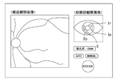
このように、第1基準位置を基準としてアライメントが行われる場合、受光領域と共に2つの投光領域が被検眼の瞳孔領域内に均等に配置されるので、被検眼の瞳孔領域が十分に大きい場合に、十分な光量で、良好な眼底画像を撮影しやすい。しかし、瞳孔径が小さい場合は、2つの投光領域の両方を同時に瞳孔内に配置することが困難であったり、2つの投光領域のそれぞれを一部虹彩と重なる状態で配置させると、眼底へ到達する照明光の光量が不足したり、することが考えられる(図8(a)参照)。そこで、この場合は、第2基準位置を基準としてにアライメントが行われるが好ましい。第2基準位置では、2つの投光領域のうち1つが受光領域と共に、残り1つの投光領域よりも優先的に被検眼の瞳孔内に配置される(図8(b)参照)。このとき、残り1つの投光領域は、瞳孔外に配置されていてもよい。第2基準位置へのアライメントが完了した場合、瞳孔内に1つの投光領域と受光領域との両方が良好に配置されるので、より瞳孔径の小さな被検眼を良好に撮影できる。 In this way, when the alignment is performed with reference to the first reference position, the two light projection regions are evenly arranged in the pupil region of the eye to be inspected together with the light receiving region, so that the pupil region of the eye to be inspected is sufficiently large. In addition, it is easy to take a good fundus image with a sufficient amount of light. However, when the pupil diameter is small, it is difficult to arrange both of the two projection regions in the pupil at the same time, or if each of the two projection regions is arranged so as to partially overlap the iris, the fundus It is conceivable that the amount of illumination light that reaches the area is insufficient (see FIG. 8A). Therefore, in this case, it is preferable that the alignment is performed with the second reference position as a reference. At the second reference position, one of the two projection regions is arranged together with the light receiving region in the pupil of the eye to be inspected with priority over the remaining one projection region (see FIG. 8B). At this time, the remaining one projection region may be arranged outside the pupil. When the alignment to the second reference position is completed, both the one light emitting region and the light receiving region are well arranged in the pupil, so that the eye to be inspected having a smaller pupil diameter can be photographed satisfactorily.
第1基準位置と、第2基準位置とは、例えば、被検眼の瞳孔領域の大きさに応じて選択されてもよい。例えば、瞳孔領域の大きさが、閾値に対して大きい場合には、第1基準位置を選択し、瞳孔領域が閾値に対して小さい場合には第2基準位置が設定されるようにしてもよい。つまり、第2撮影モードは、相対的に瞳孔径の小さな眼を撮影するために利用される。このとき、閾値は、例えば、被検眼の瞳上における2つの投光領域の配置間隔に応じた値であってもよい。 The first reference position and the second reference position may be selected, for example, according to the size of the pupil region of the eye to be inspected. For example, if the size of the pupil region is larger than the threshold value, the first reference position may be selected, and if the pupil region is smaller than the threshold value, the second reference position may be set. .. That is, the second photographing mode is used to photograph an eye having a relatively small pupil diameter. At this time, the threshold value may be, for example, a value corresponding to the arrangement interval of the two light projection regions on the pupil of the eye to be inspected.
また、瞳共役面上に形成される2つの投光領域のうち、眼底撮影において照明光を通過させる領域が、第1基準位置と第2基準位置との間で、互いに異なっていてもよい。例えば、第1基準位置へアライメントされる場合に、瞳共役面上に形成される2つの投光領域のうち両方から照明光を眼底へ投光させて眼底画像を撮影してもよい。このとき、2つの投光領域の両方から同時に照明光を通過させて眼底画像を撮影してもよい。また、第1実施形態のように、2つの投光領域の間で照明光を通過させるものを交互に切換え、切換え毎に眼底画像を撮影してもよい。更に、交互に投光して撮影された少なくとも2枚の眼底画像から、合成画像が生成されてもよい。 Further, of the two projection regions formed on the pupil conjugate surface, the regions through which the illumination light passes in the fundus photography may be different from each other between the first reference position and the second reference position. For example, when the alignment is performed at the first reference position, the fundus image may be taken by projecting the illumination light onto the fundus from both of the two projection regions formed on the pupil conjugate surface. At this time, the fundus image may be taken by passing the illumination light from both of the two projection regions at the same time. Further, as in the first embodiment, the one that allows the illumination light to pass between the two projection regions may be alternately switched, and the fundus image may be taken at each switching. Further, a composite image may be generated from at least two fundus images taken by alternately projecting light.
また、第2基準位置へアライメントされる場合に、2つの投光領域のうち一方のみから照明光を眼底へ投光させて眼底画像を撮影してもよい。このとき、2つの投光領域のうち瞳孔領域内に優先配置されているものから照明光が投光されることが好ましい。 Further, when the alignment is performed at the second reference position, the fundus image may be taken by projecting the illumination light onto the fundus from only one of the two projection regions. At this time, it is preferable that the illumination light is projected from the two projection regions that are preferentially arranged in the pupil region.
また、第2基準位置へアライメントして撮影を行う場合には、照明光の光量または撮像素子のゲインのうち少なくとも一方を、第1基準位置へアライメントし撮影する場合に対して増大させて眼底画像を撮影してもよい。光量またはゲインは、瞳孔領域の大きさに応じて設定されてもよい。また、光量またはゲインは、瞳孔領域内に配置される投光領域および受光領域の一部についての、投光領域および受光領域の全体面積に対する割合に応じて設定されてもよい。 Further, when the image is taken by aligning with the second reference position, at least one of the amount of illumination light and the gain of the image sensor is increased as compared with the case of aligning with the first reference position and taking an image of the fundus of the eye. May be photographed. The amount of light or gain may be set according to the size of the pupil area. Further, the amount of light or the gain may be set according to the ratio of the light projecting region and a part of the light receiving region arranged in the pupil region to the total area of the light projecting region and the light receiving region.
<2つの投光領域と受光領域との並べ方>
投受光分離部は、2つの投光領域、および、受光領域を、瞳共役面上において、左右方向に分離した位置に形成してもよい。この場合、これら3つの領域における左右方向の全長に比べて、上下方向の幅を狭くしやすくなる。その結果、瞼が投光領域、および、受光領域と重なり難くなり、瞬きによるケラレが抑制されやすくなる。
<How to arrange the two light emitting areas and the light receiving areas>
The light emitting / receiving separating unit may form the two light emitting regions and the light receiving region at positions separated in the left-right direction on the pupil conjugate surface. In this case, the width in the vertical direction tends to be narrower than the total length in the horizontal direction in these three regions. As a result, the eyelids are less likely to overlap the light emitting area and the light receiving area, and vignetting due to blinking is easily suppressed.
また、投受光分離部は、2つの投光領域を、被検眼の瞳共役面上において、上下方向に分離した位置に形成してもよい。この場合、第2基準位置は、2つの投光領域のうち下側に形成される一方が瞳孔内に優先配置されるように定められていてもよい。そして、制御部は、第2基準位置へアライメントし、眼底画像を撮影する際に、優先配置された一方の投光領域から照明光を投光させて、眼底画像を撮影してもよい。この場合、瞬きの際に投光領域が瞼と重なり難くなるので、瞬きによるケラレが抑制されやすくなる。 Further, the light emitting / receiving separating unit may be formed at positions where the two light emitting regions are separated in the vertical direction on the pupil conjugate surface of the eye to be inspected. In this case, the second reference position may be set so that one of the two light projection regions formed on the lower side is preferentially arranged in the pupil. Then, the control unit may align with the second reference position, and when taking the fundus image, may shoot the fundus image by projecting the illumination light from one of the preferentially arranged light projection regions. In this case, since the projected light region is less likely to overlap with the eyelids during blinking, vignetting due to blinking is likely to be suppressed.
<第2基準位置で撮影した眼底画像のアーチファクト補正>
投受光分離部が少なくとも2つの投光領域を形成する場合において、制御部は、更に、第3基準位置をアライメント基準位置として選択して眼底画像を撮影してもよい。
<Artifact correction of fundus image taken at the second reference position>
When the light emitting / receiving separation unit forms at least two light emitting regions, the control unit may further select a third reference position as the alignment reference position and take a fundus image.
ここで、第3基準位置は、2つの投光領域のうち第2基準位置において瞳孔領域に優先配置される一方に比べて、他方の投光領域が受光領域と共に優先配置される位置である。 Here, the third reference position is a position in which the other light projection region is preferentially arranged together with the light receiving region as compared with one which is preferentially arranged in the pupil region in the second reference position of the two light projection regions.
制御部は、まず第2基準位置にアライメントを誘導して、2つの投光領域のうち第2基準位置において瞳孔領域に優先配置されるものからの照明光に少なくとも基づいて1枚目の眼底画像を撮影した後、更に、第3基準位置へアライメントを誘導して、2つの投光領域のうち第3基準位置において瞳孔領域に優先配置されるものからの照明光に少なくとも基づいて2枚目の眼底画像を撮影してもよい。ここで、1枚目の眼底画像と、2枚目の眼底画像とは、対物レンズの反射像およびフレアー等のアーチファクトの発生位置が互いに異なると考えられる。そこで、第1実施形態のように、2枚の眼底画像による合成画像を生成してもよい。 The control unit first guides the alignment to the second reference position, and the first fundus image is based on at least the illumination light from the two light projecting regions that are preferentially arranged in the pupil region in the second reference position. After taking a picture of the image, the alignment is further guided to the third reference position, and the second image is based on at least the illumination light from the one that is preferentially arranged in the pupil region in the third reference position among the two projection regions. An image of the fundus of the eye may be taken. Here, it is considered that the first fundus image and the second fundus image have different positions of occurrence of artifacts such as the reflected image of the objective lens and flare. Therefore, as in the first embodiment, a composite image of two fundus images may be generated.
<実施例>
次に、図9から図15を参照して、第1実施形態及び第2実施形態に係る眼底撮影装置の実施例を示す。
<Example>
Next, with reference to FIGS. 9 to 15, examples of the fundus photography apparatus according to the first embodiment and the second embodiment will be shown.
眼底撮影装置1(以下、単に、「撮影装置1」と省略する)は、被検眼の眼底上で照明光をスリット状に形成し、眼底上でスリット状に形成された領域を走査し、照明光の眼底反射光を受光することで、眼底の正面画像を撮影する。
The fundus photography device 1 (hereinafter, simply abbreviated as “photographing
<装置の外観>
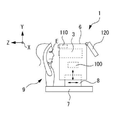
図9を参照して、撮影装置1の外観構成を説明する。撮影装置1は、撮影ユニット3を有する。撮影ユニット3は、図10で示す光学系を主に備える。撮影装置1は、基台7、駆動部8、顔支持ユニット9、および、顔撮影カメラ110を有し、これらを用いて、被検眼Eと撮影ユニット3との位置関係を調整する。
<Appearance of the device>
The appearance configuration of the photographing
駆動部8は、基台7に対して左右方向(X方向)及び前後方向(Z方向であり、換言すれば、作動距離方向)に移動できる。また、駆動部8は、更に、撮影ユニット3を、駆動部8上で被検眼Eに対して3次元方向に移動させる。駆動部8には、予め定められた各可動方向に駆動部8または撮影ユニット3を移動させるためのアクチュエータを有しており、制御部80からの制御信号に基づいて駆動される。顔支持ユニット9は、被検者の顔を支持する。顔支持ユニット9は基台7に固定されている。
The
顔撮影カメラ110は、撮影ユニット3に対する位置関係が一定となるように、筐体6に固定されている。顔撮影カメラ110は、被検者の顔を撮影する。制御部100は、撮影された顔画像から被検眼Eの位置を特定し、駆動部8を駆動制御することで、特定した被検眼Eの位置に対して撮影ユニット3を位置合わせする。
The
また、撮影装置1は、モニタ120を更に有している。モニタ120には、眼底観察像、眼底撮影像、前眼部観察像等が表示される。
Further, the photographing
<実施例の光学系>
次に、図10を参照して、撮影装置1の光学系を説明する。撮影装置1は、撮影光学系(眼底撮影光学系)10と、前眼部観察光学系40と、を有している。これらの光学系は、撮影ユニット3に設けられている。
<Optical system of the example>
Next, the optical system of the photographing
図10において、被検眼の瞳と共役な位置には撮影光軸上に『△』を、眼底共役位置には撮影光軸上に『×』を付して、それぞれ示す。 In FIG. 10, a position conjugate with the pupil of the eye to be inspected is indicated by an “Δ” on the imaging optical axis, and a fundus conjugate position is indicated by an “x” on the imaging optical axis.
撮影光学系10は、照射光学系10aと、受光光学系10bと、を有する。実施例において、照射光学系10aは、光源ユニット11、レンズ13、スリット状部材15a、レンズ16,17、ミラー18、穴開きミラー20、および、対物レンズ22を有する。受光光学系10bは、対物レンズ22、穴開きミラー20、レンズ24,26、スリット状部材15b、および、撮像素子28を有する。なお、穴開きミラー20は、照射光学系10aと受光光学系10bとの光路を結合する光路結合部である。穴開きミラー20は、光源からの照明光を、被検眼E側へ反射し、被検眼Eからの眼底反射光のうち、開口を通過した一部を、撮像素子側へ通過させる。穴開きミラー20以外の種々のビームスプリッターを用いることができる。例えば、穴開きミラー20に代えて、穴開きミラー20と透光部と反射部が逆転したミラーが光路結合部として用いられてもよい。但し、この場合、ミラーの反射側に受光光学系10bの独立光路が置かれ、ミラーの透過側に投光光学系10aの独立光路が置かれる。また、穴開きミラー、および、その代替手段としてのミラーは、それぞれ、ハーフミラーと遮光部との組み合わせに、更に置き換えることができる。
The photographing
本実施例において、光源ユニット11は、波長帯が異なる複数種類の光源を有している。例えば、光源ユニット11は、可視光源11a,11bと、赤外光源11c,11dとを有する。このように、本実施例の光源ユニット11には、波長毎に光源が2つずつ設けられている。同じ波長の2つの光源は、瞳共役面上において、撮影光軸Lから離れて配置される。2つの光源は、図10における走査方向であるX方向に沿って並べられており、撮影光軸Lに関して軸対称に配置される。図10に示すように、2つの光源の外周形状は、走査方向に比べて、走査方向と交差する方向が長い矩形形状であってもよい。
In this embodiment, the light source unit 11 has a plurality of types of light sources having different wavelength bands. For example, the light source unit 11 has
2つの光源からの光は、レンズ13を通過して、スリット状部材15に照射される。本実施例において、スリット状部材15aは、Y方向に沿って細長く形成された透光部(開口)を持つ。これにより、眼底共役面において、照明光がスリット状に形成される(眼底上でスリット状に照明された領域を、符号Bとして図示する)。
Light from the two light sources passes through the
図10において、スリット状部材15aは、透光部が撮影光軸LをX方向に横切るようにして、駆動部15cによって変位される。これにより、本実施例における照明光の走査が実現される。なお、本実施例では、受光系側でも、スリット状部材15bによる走査が行われる。本実施例では、投光側と受光側のスリット状部材は、1つの駆動部(アクチュエータ)によって、連動して駆動される。
In FIG. 10, the slit-shaped
照射光学系10aでは、各光源の像が、レンズ13から対物レンズ22までの光学系によってリレーされて、瞳共役面上で結像される。つまり、瞳共役面上において、走査方向に関して分離した位置に、2つの光源の像が形成される。このようにして、本実施例では、瞳共役面上における2つの投光領域P1,P2は、2つの光源の像として形成される。
In the irradiation
また、スリット状部材15aを通過したスリット状の光は、レンズ16から対物レンズ22までの光学系によってリレーされて、眼底Er上に結像する。これにより、眼底Er上で照明光がスリット状に形成される。照明光は、眼底Er上で反射され、瞳孔Epから取り出される。
Further, the slit-shaped light that has passed through the slit-shaped
ここで、穴開きミラー20の開口は、被検眼の瞳と共役なので、眼底画像の撮影に利用される眼底反射光は、被検眼の瞳上において穴開きミラー開口の像(瞳像)を通過する一部に制限される。このように、被検眼の瞳上における開口の像が、本実施例における受光領域Rとなる。受光領域Rは、2つの投光領域P1,P2(2つの光源の像)に挟まれて形成される。また、各像の結像倍率、開口の径、2つの光源の配置間隔が適宜設定された結果として、受光領域Rと、2つの投光領域P1,P2とは、瞳上において互いに重ならないように形成される。これにより、フレアーの発生が良好に軽減される。
Here, since the opening of the
対物レンズ22および穴開きミラー20の開口を通過した眼底反射光は、レンズ24,26を介して、眼底共役位置に、眼底Erのスリット状領域を結像する。このとき、結像の位置にスリット状部材15bの透光部が配置されていることで、有害光が除去される。
The fundus reflected light that has passed through the openings of the
撮像素子28は、眼底共役位置に配置されている。本実施例では、スリット状部材15bと撮像素子28の間にリレー系27が設けられており、これにより、スリット状部材15bと撮像素子28との双方が、眼底共役位置で配置される。その結果、有害光の除去と、結像との両方が、良好に行われる。これに代えて、撮像素子28とスリット状部材15bとの間のリレー系27を省略し、両者を近接配置してもよい。本実施例では、撮像素子28として、2次元的な受光面を持つデバイスが用いられている。例えば、CMOS、二次元CCD等であってもよい。撮像素子28には、スリット状部材15bの透光部で結像した、眼底Erのスリット状領域の像が投影される。撮像素子28は、赤外光および可視光の両方に感度を持つ。
The
本実施例では、スリット状の照明光が眼底Er上で走査されるに従って、撮像素子28の走査線毎に、眼底Er上の走査位置の像(スリット状の像)が順次投影される。このように、撮像素子には、時分割で走査範囲の全体像が投影される。結果として、走査範囲の全体像として、眼底Erの正面画像が撮像される。
In this embodiment, as the slit-shaped illumination light is scanned on the fundus Er, an image (slit-shaped image) of the scanning position on the fundus Er is sequentially projected for each scanning line of the
なお、実施例において受光系における走査部は、メカニカルにスリットを走査するデバイスであったが、必ずしもこれに限定されるものではない。例えば、受光光学系側の走査部は、電子的にスリットを走査するデバイスであってもよい。一例として、撮像素子28がCMOSである場合、CMOSのローリングシャッター機能によって、スリットの走査が実現されてもよい。この場合、撮像面上で露光される領域を、投光系における走査部と同期して変位させることで、有害光を除去しつつ、効率良く撮影できる。また、液晶シャッター等を、電子的にスリットを走査する走査部として用いることもできる。
In the embodiment, the scanning unit in the light receiving system is a device that mechanically scans the slit, but the scanning unit is not necessarily limited to this. For example, the scanning unit on the light receiving optical system side may be a device that electronically scans the slit. As an example, when the
撮影光学系10は、視度補正部を有している。本実施例では、照射光学系10aの独立光路、受光光学系10bの独立光路、のそれぞれに視度補正部が設けられている。投光光学系10aは、レンズ16,17の間隔を、受光光学系10bは、レンズ24,26の間隔を変更でき、これにより視度補正が行われる。撮影装置1は、各々のレンズ間隔を変更するための駆動部16a,26a(図12参照)を有しており、照射光学系10a,受光光学系10bの各々の駆動部16a,26aは、互いに連動して駆動される。
The photographing
なお、視度補正部は、これに限られるものではない。例えば、光源11a〜11d、スリット状部材15a,15b、および撮像素子28の少なくとも3者の位置関係が維持されたまま、これが光軸方向へ移動されることで、視度補正が行われてもよい。
The diopter correction unit is not limited to this. For example, even if the diopter correction is performed by moving the
なお、眼科装置の走査部は、例えば、図11に示すようなオプティカルチョッパーであってもよい。オプティカルチョッパーは、外周に複数のスリットが形成されたホイール持ち、ホイールを回転させることで、高速にスリットをスキャンできる。 The scanning unit of the ophthalmic apparatus may be, for example, an optical chopper as shown in FIG. The optical chopper has a wheel with a plurality of slits formed on the outer circumference, and by rotating the wheel, the slits can be scanned at high speed.
ここで、図10では、照射光学系10aの光源ユニット11からミラー18までと、受光光学系10bの穴開きミラー20から撮像素子28までとが、X方向に並列されているが、例えば、穴開きミラー20とミラー18との向きを、図示した状態から90°回転させ、両者をY方向に並列させることによって、オプティカルチョッパーを走査部として適用可能になる。この場合、ホイールの上端と下端との2箇所で、照射光学系10aの光軸と受光光学系10bの光軸とをそれぞれ横切らせることで、1体のオプティカルチョッパーで、投光系および受光系の走査を、容易に同期させることができる。
Here, in FIG. 10, the light source unit 11 to the
<前眼部観察光学系>
次いで、前眼部観察光学系40を説明する。前眼部観察光学系40は、対物レンズ22とダイクロイックミラー43と、を撮影光学系10と共用する。前眼部観察光学系40は、更に、光源41、ハーフミラー45、撮像素子47等を含む。撮像素子47は、二次元撮像素子であり、例えば瞳孔Epと光学的に共役な位置に配置される。前眼部観察光学系40は、赤外光で前眼部を照明し、前眼部の正面画像を撮影する。
<Anterior eye observation optical system>
Next, the anterior segment observation
なお、図10に示した前眼部観察光学系40は一例に過ぎず、他の光学系とは独立した光路で前眼部を撮像してもよい。
The anterior segment observation
<実施例の制御系>
次に、図12を参照して、撮影装置1の制御系を説明する。本実施例では、制御部100によって、撮影装置1の各部の制御が行われる。また、便宜上、撮影装置1で得られた各種画像の画像処理についても、制御部100によって行われるものとする。換言すれば、本実施例では、制御部100が、画像処理部を兼用している。
<Control system of the embodiment>
Next, the control system of the photographing
制御部100は、各部の制御処理と、演算処理とを行う電子回路を有する処理装置(プロセッサ)である。制御部100は、CPU(Central Processing Unit)およびメモリ等で実現される。制御部100は、記憶部101と、バス等を介して電気的に接続されている。
The
記憶部101には、各種の制御プログラムおよび固定データ等が格納される。また、記憶部101には、一時データ等が記憶されてもよい。
Various control programs, fixed data, and the like are stored in the
撮影装置1による撮影画像は、記憶部101に記憶されていてもよい。但し、必ずしもこれに限られるものではなく、外部の記憶装置(例えば、LANおよびWANで制御部100に接続される記憶装置)へ撮影画像が記憶されてもよい。
The image captured by the photographing
また、制御部100は、駆動部8、光源11a〜11d、駆動部15c、駆動部16a、駆動部26a、撮像素子28、光源41、撮像素子47、入力インターフェイス110、およびモニタ120等の各部とも電気的に接続されている。
Further, the
また、制御部100は、入力インターフェイス110(操作入力部)から出力される操作信号に基づいて、上記の各部材を制御する。入力インターフェイス110は、検者の操作を受け付ける操作入力部である。例えば、マウスおよびキーボード等であってもよい。
Further, the
<実施例の動作説明>
次に、図13,図14のフローチャートに基づいて、撮影動作を説明する。
<Explanation of operation of the example>
Next, the shooting operation will be described based on the flowcharts of FIGS. 13 and 14.
撮影装置1は、被検者の顔が顔支持部9に対して配置され、顔検出カメラ110の撮影範囲に含まれることによって、自動的に撮影動作がスタートしてもよい。
The photographing
まず、顔検出カメラ110と前眼部観察光学系40とによる撮影が並行して行われるようになり(S1)、両者の撮影結果を用いたアライメント調整が実行される(S2)。
First, imaging by the
詳細には、制御部100は、顔画像に含まれる左右眼の一方の位置を検出し、その位置情報に基づいて駆動部8を駆動させる。これにより、前眼部観察が可能な位置まで、撮影ユニット4の位置を調整する。
Specifically, the
次に、前眼部正面画像に基づいて、アライメント基準位置が設定され、設定されたアライメント基準位置へとアライメントが誘導される。本実施例では、前眼部正面画像に基づいて被検眼Eと撮影ユニット3との位置関係が、制御部100によって調整される。本実施例において、制御部100は撮像素子47からの信号に基づいて、前眼部観察像における瞳孔中心と、画像中心(本実施例では、撮影光軸Lの位置)とが略一致する位置関係を目標とする第1基準位置が、設定される。そして、第1基準位置からのアライメントずれを検出し、アライメントずれが解消される方向へと撮影ユニット4を上下左右方向へ移動させる。このとき、例えば、前眼部観察画像上における瞳孔中心と撮影光軸とのズレ量に基づいて第1基準位置とのアライメントずれが検出されてもよい。また、眼底撮影装置1が、例えば、角膜頂点にアライメント指標を投影するアライメント投影光学系を有している場合、アライメント指標と撮影光軸とのズレ量に基づいてアライメントずれが検出されてもよい。
Next, the alignment reference position is set based on the front image of the anterior segment of the eye, and the alignment is guided to the set alignment reference position. In this embodiment, the positional relationship between the eye to be inspected E and the photographing
また、制御部100は、瞳孔Epに前眼部観察画像のピントが合うように撮影ユニット4を前後方向へ移動させる。
Further, the
このように、本実施例では、S2のアライメント調整の結果として、被検眼と撮影ユニット4との位置関係が、被検眼の瞳上における受光領域Rの中心(つまり、撮影光軸)が瞳孔中心と一致するような位置(本実施例における第1基準位置)へと調整される。 As described above, in this embodiment, as a result of the alignment adjustment of S2, the positional relationship between the eye to be inspected and the imaging unit 4 is such that the center of the light receiving region R (that is, the optical axis of imaging) on the pupil of the eye to be inspected is the center of the pupil. It is adjusted to a position that matches (the first reference position in this embodiment).
本実施例では、第1基準位置へのアライメント完了後、瞳孔径検出処理(瞳孔情報取得処理)が実行される(S3)。本実施例では、前眼部観察画像から瞳孔領域Epを検出し、検出された瞳孔領域Epの直径を求める。本実施例では、走査方向の直径を求めることが好ましい。本実施例では、S3の処理で取得された瞳孔領域Epの直径の値が、瞳孔径情報として取得され、メモリに記憶される。 In this embodiment, after the alignment to the first reference position is completed, the pupil diameter detection process (pupil information acquisition process) is executed (S3). In this embodiment, the pupil region Ep is detected from the observation image of the anterior segment of the eye, and the diameter of the detected pupil region Ep is determined. In this embodiment, it is preferable to obtain the diameter in the scanning direction. In this embodiment, the value of the diameter of the pupil region Ep acquired in the process of S3 is acquired as the pupil diameter information and stored in the memory.
次に、制御部100は、取得された瞳孔径に応じて、撮影モードを設定する(S4,S5,S11)。本実施例では、まず、瞳孔径が閾値と比較される(S4)。閾値は、被検眼の瞳上における2つの投光領域P1、P2の配置間隔に応じた値であって、本実施例では、全長W(図10参照)が、閾値の一例として用いられる。全長Wの代わりに、例えば、投光領域P1,P2の中心間距離が、閾値として用いられてもよい。ここで、本実施例では、閾値は、視度補正量によらず、固定値であるものとする。例えば、0D眼を想定した固定値が、閾値として用いられる。
Next, the
但し、2つの投光領域P1、P2の配置間隔は、視度補正の状態に応じて変動するので、被検眼の視度の誤差に応じて(或いは、スリット像が眼底Erに結像するときの視度補正量に応じて)、都度、閾値を求め、求めた閾値と瞳孔径とを比較するようにしてもよい。 However, since the arrangement interval between the two projection regions P1 and P2 varies depending on the diopter correction state, it depends on the diopter error of the eye to be inspected (or when the slit image is formed on the fundus Er). A threshold value may be obtained each time (according to the amount of diopter correction), and the obtained threshold value may be compared with the pupil diameter.
瞳孔径と閾値との比較の結果、瞳孔径が閾値に対して大きい場合は(S4;Yes)、第1撮影モードが設定される(S5)。一方、瞳孔径が閾値以下である場合は(S4;No)、第2撮影モードが設定される(S11)。 As a result of comparison between the pupil diameter and the threshold value, when the pupil diameter is larger than the threshold value (S4; Yes), the first imaging mode is set (S5). On the other hand, when the pupil diameter is equal to or less than the threshold value (S4; No), the second imaging mode is set (S11).
<第1撮影モード>
上記の閾値に対して瞳孔径が大きければ、瞳孔Ep内に2つの投光領域P1、P2および受光領域Rの3者を配置できる。そこで、制御部100は、受光領域Rの中心(本実施例では、撮影光軸Lの位置であり、2つの投光領域P1,P2と受光領域Rとの重心でもある)が瞳孔中心と略一致するアライメント状態を目標に(つまり、第1基準位置を目標に)、被検眼Eと撮影ユニット4との位置関係を、駆動部8を駆動させ調整する。
<First shooting mode>
If the pupil diameter is larger than the above threshold value, the two projection regions P1 and P2 and the light receiving region R can be arranged in the pupil Ep. Therefore, in the
第1撮影モードが設定された後、制御部100は、眼底観察画像の撮影および表示を開始する(S6)。詳細には、制御部100は、光源11c,11dを同時に点灯させると共に、駆動部15cの駆動を開始させ、眼底Er上の所定の範囲で、スリット状の照明光が、繰り返し走査される。所定回数(少なくとも1回)の走査毎に、撮像素子28から出力される信号に基づいて、略リアルタイムに撮影された眼底画像が、眼底観察画像として、随時生成される。制御部100は、眼底観察画像を、略リアルタイムな動画像として、モニタ120へ表示させてもよい。
After the first photographing mode is set, the
次に、眼底観察画像に基づいて、各種の調整処理が実行される(S7)。例えば、視度補正、アライメント目標位置の微調整等が実行されてもよい。 Next, various adjustment processes are executed based on the fundus observation image (S7). For example, diopter correction, fine adjustment of the alignment target position, and the like may be executed.
その後、眼底撮影画像の撮影制御が、自動的に、又は、レリーズ操作に基づいて、実行される。 After that, the acquisition control of the fundus photographed image is executed automatically or based on the release operation.
本実施例において、制御部100は、可視光を発する光源11a,11bを交互に点灯させると共に、各光源11a,11bが点灯される度に、眼底Er上で照明光を走査し、第1眼底画像と、第2眼底画像と、を撮影する(S8,S9)。
In this embodiment, the
そして、制御部100は、第1眼底画像と、第2眼底画像とを合成して、合成画像を生成する。第1眼底画像の撮影が行われた直後から縮瞳が始まるので、2枚の眼底画像のうち、後から撮影された第2眼底画像は、縮瞳によるケラレの影響で、第1眼底画像に比べて画像が暗くなっているおそれがある。
Then, the
そこで、本実施例では、第1眼底画像において中心部の反射像が生じる領域を、第2眼底画像において対応する領域によって置き換えた画像を、合成画像として生成する。その結果、第1眼底画像、および、第2眼底画像に対して、反射像の影響が抑制された眼底画像を合成画像として得ることができるうえ、縮瞳によるケラレの影響を抑制できる。 Therefore, in this embodiment, an image in which the region where the reflection image of the central portion is generated in the first fundus image is replaced by the corresponding region in the second fundus image is generated as a composite image. As a result, it is possible to obtain a fundus image in which the influence of the reflected image is suppressed on the first fundus image and the second fundus image as a composite image, and it is possible to suppress the influence of vignetting due to miosis.
<第2撮影モード>
次に、第2撮影モードが設定された場合の動作を説明する。S4の処理で判定されたように、瞳孔径が閾値以下であると、瞳孔Ep内に2つの投光領域P1、P2および受光領域Rの3者を満足に配置できない。そこで、制御部100は、アライメント状態を再調整する。その際、制御部100は、第2基準位置を前眼部観察画像に基づいて設定する。第2基準位置は、2つの投光領域P1,P2のうち一方(ここでは、領域P1)を、他方に優先して、受光領域Rと共に瞳孔Ep内に配置されるようなアライメント基準位置である(S12)。一例として、投光領域P1と、受光領域Rとの中間点が、瞳孔中心に一致するアライメント状態を目標とする、第2基準位置が設定される。ここでは、例えば、S2のアライメント処理におけるアライメント基準位置(つまり、第1基準位置)に対してX方向に、被検眼と撮影光学系との位置関係がオフセットされてもよい。ここでは、W/4だけ(Wについては、図10参照)だけ、オフセットされるものする。但し、オフセット量は、必ずしもこれに限られるものでは無い。
<Second shooting mode>
Next, the operation when the second shooting mode is set will be described. As determined in the process of S4, when the pupil diameter is equal to or less than the threshold value, the two light emitting regions P1 and P2 and the light receiving region R cannot be satisfactorily arranged in the pupil Ep. Therefore, the
そして、制御部100は、第2基準位置からのアライメントずれを検出し、アライメントずれが解消される方向へと撮影ユニット4を上下左右方向へ移動させる。このとき、例えば、前眼部観察画像上における瞳孔中心(又は、角膜頂点)と撮影光軸とのズレ量と、上記のオフセットとに基づいて第2基準位置とのアライメントずれが検出されてもよい。第2基準位置に対するアライメントの結果、投光領域P1と受光領域Rとについては、瞳孔Ep内に良好に配置されるようになる。なお、2つの投光領域P1,P2のうちいずれを、瞳孔Ep内に優先配置するかについては、予め定められていてもよいし、選択可能であってもよい。
Then, the
アライメント状態の再調整後、眼底観察画像の撮影が開始される。ここで、第1撮影モードで眼底観察画像を得る際には、2つの光源11c,11dを同時に点灯させるものとしたが、第2撮影モードでは、瞳孔Ep内に優先配置された投光領域P1と対応する光源(本実施例では、光源11c)のみを点灯させてもよい。これにより、投光領域P1のみから観察用の照明光を眼底へ照射して、眼底Erの観察画像を取得してもよい。但し、必ずしもこれに限られるものではなく、投光領域P1とP2の両方とと対応する光源を点灯させて、眼底Erの観察画像を取得してもよい。
After the alignment state is readjusted, the acquisition of the fundus observation image is started. Here, when the fundus observation image is obtained in the first shooting mode, the two
そして、眼底観察画像に基づいて、各種の調整処理が実行され(S14)、調整完了後、自動的に、又は、レリーズ操作に基づいて、第2撮影モードにおける眼底撮影画像の撮影動作が実行される(S15)。 Then, various adjustment processes are executed based on the fundus observation image (S14), and after the adjustment is completed, the operation of photographing the fundus photographed image in the second photographing mode is executed automatically or based on the release operation. (S15).
本実施例の第2撮影モードにおいて、制御部100は、可視光を発する2つの光源11a,11bのうち、瞳孔Ep内に優先配置された投光領域P1と対応する、光源11aのみを点灯させて眼底画像を撮影する。この眼底画像が、撮影画像として、メモリに記憶される。この撮影画像は、2つの光源11a,11bを同時に点灯させる場合に比べて、対物レンズ22上で強く反射が生じる箇所が少なくなるので、反射像の影響が軽減される。また、虹彩、強膜等の瞳孔Ep外に照明光が照射され、その反射光が有害光となって眼底画像に影響することが抑制される。従って、被検眼の瞳孔径が小さい場合でも、良好な眼底画像を撮影することができる。
In the second shooting mode of this embodiment, the
ここで、本実施例において、制御部100は、制御部100は、第2撮影モードの撮影時発せられる光源11a,11bからの光量、および、眼底反射光を受光する撮像素子28におけるゲインのうち少なくともいずれかを、第1撮影モードでの撮影時に対して増加させる。これにより、第2撮影モードにおいて撮影される眼底画像の、明るさおよびコントラストを、向上させることができる。なお、光量およびゲインは、被検者の瞳孔領域の大きさ(例えば、瞳孔径)に応じて設定されてもよい。
Here, in the present embodiment, the
以上、実施形態に基づいて説明を行ったが、本開示を実施するうえで、実施形態の内容を適宜変更することができる。 Although the above description has been given based on the embodiments, the contents of the embodiments can be changed as appropriate in carrying out the present disclosure.
例えば、上記実施例では、被検眼と撮影ユニットとの位置関係が、制御部によって自動的に調整された。しかし、必ずしもこれに限られるものではなく、被検眼と撮影ユニットとの位置関係は、検者が手動で調整可能であってもよい。 For example, in the above embodiment, the positional relationship between the eye to be inspected and the imaging unit is automatically adjusted by the control unit. However, the present invention is not necessarily limited to this, and the positional relationship between the eye to be inspected and the imaging unit may be manually adjusted by the examiner.
この場合、図15に示すように、制御部は、少なくとも前眼部観察画像をモニタ上に表示させてもよい。これにより、検者は、前眼部観察画像を見ながら被検眼と撮影ユニットとの位置関係を調整できる。また、前眼部観察画像上には、少なくとも2つの投光領域と対応する電子的な指標Ipが表示されることが好ましい。更に、受光領域と対応する指標Ipが表示されてもよい。指標Ip,Irの位置および大きさは、前眼部観察画像上において一定であってもよいし、撮影光学系における視度補正量に応じて変更されてもよい。 In this case, as shown in FIG. 15, the control unit may display at least the anterior eye portion observation image on the monitor. As a result, the examiner can adjust the positional relationship between the eye to be inspected and the photographing unit while looking at the anterior eye observation image. Further, it is preferable that an electronic index Ip corresponding to at least two projection regions is displayed on the anterior segment observation image. Further, the index Ip corresponding to the light receiving region may be displayed. The positions and sizes of the indexes Ip and Ir may be constant on the front eye observation image, or may be changed according to the diopter correction amount in the photographing optical system.
指標Ip,Irが表示されることで、投光領域および受光領域と、瞳孔との位置関係をリアルタイムに確認しながら、被検眼と撮影ユニットの位置関係を調整できる。 By displaying the indexes Ip and Ir, the positional relationship between the eye to be inspected and the imaging unit can be adjusted while confirming the positional relationship between the light projecting region and the light receiving region and the pupil in real time.
更にこのとき、眼底観察画像が同時にモニタ上に表示されていてもよい。眼底画像における明るさのムラの状態等を確認しながら、被検眼と撮影ユニットの位置関係を調整できるので、より良好な眼底画像が得られる位置関係へと調整しやすい。 Further, at this time, the fundus observation image may be displayed on the monitor at the same time. Since the positional relationship between the eye to be inspected and the imaging unit can be adjusted while checking the state of uneven brightness in the fundus image, it is easy to adjust the positional relationship so that a better fundus image can be obtained.
更に、制御部は、前眼部観察画像、および、眼底観察画像の表示と共に、入力インターフェイスに対する操作に基づいて、各投光領域からの照明光を照射状態(照明光のON/OFF)を個別に設定してもよい。そして、設定された照射状態を、眼底観察画像の撮影に反映させてもよい。これにより、被検眼と撮影ユニットの位置関係、および、各投光領域からの照明光を照射状態を手動で変更しながら、良好な眼底画像が得られる撮影条件を、検者は探すことができる。なお、図15の例では、前眼部画像上の指標IpにカーソルCを併せて、選択することで、指標Ipと対応する投光領域からの照明光のON/OFFを切換えできる。 Further, the control unit displays the anterior eye portion observation image and the fundus observation image, and individually irradiates the illumination light from each projection area (ON / OFF of the illumination light) based on the operation on the input interface. May be set to. Then, the set irradiation state may be reflected in the acquisition of the fundus observation image. As a result, the examiner can search for the imaging conditions that can obtain a good fundus image while manually changing the positional relationship between the eye to be inspected and the imaging unit and the irradiation state of the illumination light from each projection area. .. In the example of FIG. 15, by selecting the index Ip on the anterior eye portion image in combination with the cursor C, it is possible to switch ON / OFF of the illumination light from the projection region corresponding to the index Ip.
1 眼底撮影装置
10 撮影光学系
15a,15b スリット状部材
15c 駆動部
100 制御部
P1,P2 投光領域
R 受光領域
1
Claims (5)
被検眼と前記撮影光学系との位置関係を調整する駆動部と、を備え、前記受光素子からの信号に基づいて眼底画像を取得する眼底撮影装置であって、
更に、
前記投受光分離手段は、被検眼の瞳上において互いに位置が異なる2つの投光領域を形成し、
被検眼と前記撮影光学系とのアライメントの基準となるアライメント基準位置として、前記2つの投光領域および前記受光領域の全部が被検眼の瞳孔領域内に形成されることを想定した第1基準位置と、第1基準位置とは異なる第2基準位置であって、前記受光領域と共に2つの前記投光領域のうち1つが、残り1つの前記投光領域よりも優先的に被検眼の瞳孔内に配置されることを想定した第2基準位置と、のいずれかを選択的に設定可能であり、設定した前記アライメント基準位置からのアライメントずれに基づいてアライメントを誘導すると共に、前記第1基準位置へアライメントを誘導する場合は、眼底画像を撮影する際に、2つの前記投光領域のうち両方から前記照明光を眼底へ投光させ、前記第2基準位置へアライメントを誘導する場合は、眼底画像を撮影する際に、2つの前記投光領域のうち、優先的に瞳孔内に配置される一方のみから前記照明光を眼底へ投光させる撮影制御手段、を備える眼底撮影装置。 A light projecting separation means and a light receiving / receiving separating means for forming a light projecting region through which the illumination light passes on the pupil of the eye to be inspected and a light receiving region on the pupil of the eye to be examined from which the fundus reflected light of the illumination light is taken out at different positions. An imaging optical system including a light receiving element that receives the reflected light from the fundus of the eye taken out from the light receiving region.
A fundus photography device that includes a drive unit that adjusts the positional relationship between the eye to be inspected and the photographing optical system, and acquires a fundus image based on a signal from the light receiving element.
In addition
The light emitting / receiving separating means forms two light emitting regions having different positions on the pupil of the eye to be inspected.
As an alignment reference position that serves as a reference for alignment between the eye to be inspected and the photographing optical system, a first reference position assuming that the entire two light projection regions and the light receiving region are formed in the pupil region of the eye to be inspected. In the second reference position different from the first reference position, one of the two light projection regions together with the light receiving region is preferentially placed in the pupil of the eye to be inspected over the remaining one light projection region. It is possible to selectively set either the second reference position that is supposed to be arranged, and the alignment is guided based on the alignment deviation from the set alignment reference position, and the alignment is moved to the first reference position. When guiding the alignment, when the fundus image is taken, the illumination light is projected onto the fundus from both of the two projection regions, and when the alignment is guided to the second reference position, the fundus image is used. An optometry imaging device comprising a imaging control means for projecting the illumination light onto the fundus of the eye from only one of the two projection regions preferentially arranged in the pupil.
被検眼と前記撮影光学系との位置関係を調整する駆動部と、を備え、前記受光素子からの信号に基づいて眼底画像を取得する眼底撮影装置であって、A fundus photography device that includes a drive unit that adjusts the positional relationship between the eye to be inspected and the photographing optical system, and acquires a fundus image based on a signal from the light receiving element.
更に、In addition
前記撮影光学系は、The photographing optical system is
被検眼の眼底上で照明光をスリット状に形成するスリット形成部、A slit-forming portion that forms illumination light in a slit shape on the fundus of the eye to be inspected.
スリット状に形成された照明光を、スリットに対して直交する方向へ眼底上で走査する走査部、更に有し、It also has a scanning unit that scans the illumination light formed in the shape of a slit on the fundus in a direction orthogonal to the slit.
前記投受光分離手段は、被検眼の瞳上において前記投光領域を、前記走査部の走査方向に関して互いに分離した2つの位置に形成すると共に、被検眼の瞳上において前記受光領域を、2つの前記投光領域に挟まれるように形成し、The light emitting / receiving separating means forms the light emitting region on the pupil of the eye to be inspected at two positions separated from each other with respect to the scanning direction of the scanning portion, and has two light receiving regions on the pupil of the eye to be inspected. It is formed so as to be sandwiched between the light projection regions.
被検眼と前記撮影光学系とのアライメントの基準となるアライメント基準位置として、前記2つの投光領域および前記受光領域の全部が被検眼の瞳孔領域内に形成されることを想定した第1基準位置と、第1基準位置とは異なる第2基準位置であって、前記受光領域と共に2つの前記投光領域のうち1つが、残り1つの前記投光領域よりも優先的に被検眼の瞳孔内に配置されることを想定した第2基準位置と、のいずれかを選択的に設定可能であり、設定した前記アライメント基準位置からのアライメントずれに基づいてアライメントを誘導する撮影制御手段、を備える眼底撮影装置。As an alignment reference position that serves as a reference for alignment between the eye to be inspected and the photographing optical system, a first reference position assuming that the entire two light projection regions and the light receiving region are formed in the pupil region of the eye to be inspected. And, in the second reference position different from the first reference position, one of the two projection regions together with the light receiving region is preferentially placed in the pupil of the eye to be inspected over the remaining one projection region. Fundus photography including a second reference position that is supposed to be arranged and an imaging control means that can selectively set any of them and guides alignment based on the alignment deviation from the set alignment reference position. Device.
前記撮影制御手段は、前記前眼部観察画像から取得される被検眼の瞳孔領域に関する情報に基づいて前記アライメント基準位置を設定する請求項1〜3の何れかに記載の眼底撮影装置。 Equipped with an anterior segment observation optical system for acquiring anterior segment observation images
The fundus photography device according to any one of claims 1 to 3, wherein the imaging control means sets the alignment reference position based on the information about the pupil region of the eye to be inspected acquired from the anterior segment observation image.
前記撮影制御手段は、前記眼底観察画像の明るさに関する情報に基づいて前記アライメント基準位置を設定する請求項1〜4の何れかに記載の眼底撮影装置。The fundus imaging device according to any one of claims 1 to 4, wherein the imaging control means sets the alignment reference position based on information on the brightness of the fundus observation image.
Priority Applications (3)
| Application Number | Priority Date | Filing Date | Title |
|---|---|---|---|
| JP2018002250A JP6958367B2 (en) | 2018-01-10 | 2018-01-10 | Fundus photography device |
| EP18899048.5A EP3738501A4 (en) | 2018-01-10 | 2018-12-27 | Fundus imaging device |
| PCT/JP2018/048339 WO2019138916A1 (en) | 2018-01-10 | 2018-12-27 | Fundus imaging device |
Applications Claiming Priority (1)
| Application Number | Priority Date | Filing Date | Title |
|---|---|---|---|
| JP2018002250A JP6958367B2 (en) | 2018-01-10 | 2018-01-10 | Fundus photography device |
Publications (3)
| Publication Number | Publication Date |
|---|---|
| JP2019118721A JP2019118721A (en) | 2019-07-22 |
| JP2019118721A5 JP2019118721A5 (en) | 2021-01-21 |
| JP6958367B2 true JP6958367B2 (en) | 2021-11-02 |
Family
ID=67305766
Family Applications (1)
| Application Number | Title | Priority Date | Filing Date |
|---|---|---|---|
| JP2018002250A Active JP6958367B2 (en) | 2018-01-10 | 2018-01-10 | Fundus photography device |
Country Status (1)
| Country | Link |
|---|---|
| JP (1) | JP6958367B2 (en) |
Family Cites Families (13)
| Publication number | Priority date | Publication date | Assignee | Title |
|---|---|---|---|---|
| JPS6148940A (en) * | 1984-08-16 | 1986-03-10 | Matsushita Electronics Corp | Method of forming electrode of semiconductor device |
| US4732466A (en) * | 1985-04-04 | 1988-03-22 | Humphrey Instruments, Inc. | Fundus camera |
| JP3964035B2 (en) * | 1998-03-12 | 2007-08-22 | 興和株式会社 | Ophthalmic equipment |
| JP2002051985A (en) * | 2000-08-10 | 2002-02-19 | Kowa Co | Fundus camera |
| US6758564B2 (en) * | 2002-06-14 | 2004-07-06 | Physical Sciences, Inc. | Line-scan laser ophthalmoscope |
| JP2005087546A (en) * | 2003-09-18 | 2005-04-07 | Canon Inc | Ophthalmologic photographing apparatus |
| JP4615891B2 (en) * | 2004-04-30 | 2011-01-19 | 株式会社ニデック | Fundus camera |
| US7174094B2 (en) * | 2005-02-07 | 2007-02-06 | Peter Norman Steinkamp | System and method for reflex-free coaxial illumination |
| DE102012204259A1 (en) * | 2011-03-31 | 2012-10-04 | Canon Kabushiki Kaisha | Control device, ophthalmic device, system, control method and program |
| JP6112846B2 (en) * | 2012-12-11 | 2017-04-12 | 株式会社トプコン | Ophthalmic equipment |
| JP2016030181A (en) * | 2014-07-30 | 2016-03-07 | 興和株式会社 | Ophthalmographic apparatus |
| JP2016049368A (en) * | 2014-09-01 | 2016-04-11 | 株式会社ニデック | Ophthalmological photographing apparatus |
| JP2016185192A (en) * | 2015-03-27 | 2016-10-27 | キヤノン株式会社 | Ophthalmologic apparatus, and control method of ophthalmologic apparatus |
-
2018
- 2018-01-10 JP JP2018002250A patent/JP6958367B2/en active Active
Also Published As
| Publication number | Publication date |
|---|---|
| JP2019118721A (en) | 2019-07-22 |
Similar Documents
| Publication | Publication Date | Title |
|---|---|---|
| JP6354979B2 (en) | Fundus photographing device | |
| JP4231146B2 (en) | Fundus camera | |
| JP5606813B2 (en) | Ophthalmic equipment | |
| JP6899632B2 (en) | Ophthalmologic imaging equipment | |
| JP6349878B2 (en) | Ophthalmic photographing apparatus, ophthalmic photographing method, and ophthalmic photographing program | |
| JP2015066242A (en) | Ophthalmology imaging apparatus | |
| JP7302342B2 (en) | Fundus camera | |
| WO2019138916A1 (en) | Fundus imaging device | |
| JP2016185192A (en) | Ophthalmologic apparatus, and control method of ophthalmologic apparatus | |
| JP2015091309A (en) | Ophthalmologic image processor and image processing program | |
| JP2019118720A (en) | Ophthalmography device | |
| JP7183617B2 (en) | Fundus camera | |
| JP6319616B2 (en) | Scanning laser ophthalmoscope | |
| JP5522841B2 (en) | Fundus photographing device | |
| JP6739183B2 (en) | Ophthalmic equipment | |
| JP6713297B2 (en) | Ophthalmic equipment | |
| JP6958367B2 (en) | Fundus photography device | |
| US11219362B2 (en) | Fundus imaging apparatus | |
| JP7200516B2 (en) | Fundus camera | |
| JP7375323B2 (en) | fundus imaging device | |
| JP7421062B2 (en) | fundus imaging device | |
| JP7355194B2 (en) | fundus imaging device | |
| JP6617790B2 (en) | Ophthalmic imaging equipment | |
| JP6877824B2 (en) | Ophthalmic equipment | |
| JP2023150195A (en) | Fundus imaging apparatus |
Legal Events
| Date | Code | Title | Description |
|---|---|---|---|
| A521 | Written amendment |
Free format text: JAPANESE INTERMEDIATE CODE: A523 Effective date: 20201203 |
|
| A621 | Written request for application examination |
Free format text: JAPANESE INTERMEDIATE CODE: A621 Effective date: 20201203 |
|
| A131 | Notification of reasons for refusal |
Free format text: JAPANESE INTERMEDIATE CODE: A131 Effective date: 20210406 |
|
| A521 | Written amendment |
Free format text: JAPANESE INTERMEDIATE CODE: A523 Effective date: 20210607 |
|
| TRDD | Decision of grant or rejection written | ||
| A01 | Written decision to grant a patent or to grant a registration (utility model) |
Free format text: JAPANESE INTERMEDIATE CODE: A01 Effective date: 20210907 |
|
| A61 | First payment of annual fees (during grant procedure) |
Free format text: JAPANESE INTERMEDIATE CODE: A61 Effective date: 20210920 |
|
| R150 | Certificate of patent or registration of utility model |
Ref document number: 6958367 Country of ref document: JP Free format text: JAPANESE INTERMEDIATE CODE: R150 |