JP6882983B2 - Systems, methods, and equipment for thermal management of ultrasonic transducers - Google Patents
Systems, methods, and equipment for thermal management of ultrasonic transducers Download PDFInfo
- Publication number
- JP6882983B2 JP6882983B2 JP2017540877A JP2017540877A JP6882983B2 JP 6882983 B2 JP6882983 B2 JP 6882983B2 JP 2017540877 A JP2017540877 A JP 2017540877A JP 2017540877 A JP2017540877 A JP 2017540877A JP 6882983 B2 JP6882983 B2 JP 6882983B2
- Authority
- JP
- Japan
- Prior art keywords
- heat
- flexible circuit
- ultrasonic probe
- conductive
- cover
- Prior art date
- Legal status (The legal status is an assumption and is not a legal conclusion. Google has not performed a legal analysis and makes no representation as to the accuracy of the status listed.)
- Active
Links
Images


Classifications
-
- A—HUMAN NECESSITIES
- A61—MEDICAL OR VETERINARY SCIENCE; HYGIENE
- A61B—DIAGNOSIS; SURGERY; IDENTIFICATION
- A61B8/00—Diagnosis using ultrasonic, sonic or infrasonic waves
- A61B8/54—Control of the diagnostic device
- A61B8/546—Control of the diagnostic device involving monitoring or regulation of device temperature
-
- A—HUMAN NECESSITIES
- A61—MEDICAL OR VETERINARY SCIENCE; HYGIENE
- A61B—DIAGNOSIS; SURGERY; IDENTIFICATION
- A61B8/00—Diagnosis using ultrasonic, sonic or infrasonic waves
- A61B8/44—Constructional features of the ultrasonic, sonic or infrasonic diagnostic device
- A61B8/4444—Constructional features of the ultrasonic, sonic or infrasonic diagnostic device related to the probe
-
- A—HUMAN NECESSITIES
- A61—MEDICAL OR VETERINARY SCIENCE; HYGIENE
- A61B—DIAGNOSIS; SURGERY; IDENTIFICATION
- A61B8/00—Diagnosis using ultrasonic, sonic or infrasonic waves
- A61B8/44—Constructional features of the ultrasonic, sonic or infrasonic diagnostic device
- A61B8/4483—Constructional features of the ultrasonic, sonic or infrasonic diagnostic device characterised by features of the ultrasound transducer
Description
超音波トランスデューサアレイは、組織のイメージング、洗浄、及び治療処置などの様々な用途のための超音波を生成する。 Ultrasound transducer arrays generate ultrasound for a variety of applications such as tissue imaging, irrigation, and therapeutic procedures.
多くの超音波トランスデューサは、電気エネルギを超音波に変換し、熱は変換の副産物として生成され得る。トランスデューサ及び/又は超音波トランスデューサが接触している表面の損傷を避けるために、熱は放散を必要とする。例えば、医用超音波トランスデューサは、トランスデューサによって生成される熱が適切に放散されない場合、患者の皮膚を焼き得る。 Many ultrasonic transducers convert electrical energy into ultrasonic waves, and heat can be generated as a by-product of the conversion. Heat needs to be dissipated to avoid damage to the surface with which the transducer and / or ultrasonic transducer is in contact. For example, a medical ultrasound transducer can burn the patient's skin if the heat generated by the transducer is not properly dissipated.
超音波トランスデューサは、能動及び/又は受動熱管理システムを有することができる。受動システムはトランスデューサから熱を引き出す材料を含む。例えば、超音波プローブは、トランスデューサ表面から熱を放散させるトランスデューサの下にバッキング材を含むことができる。しかしながら、現在の受動熱管理システムは、せん断波イメージングのような新たな高出力超音波アプリケーションには適切ではない。能動熱管理システムは、例えば、トランスデューサアレイに隣接する、循環液体冷却剤及び/又は回転ファンを含むことができる。能動熱管理システムは、受動システムよりも多くの熱を放散することができるが、能動システムは、超音波システムのサイズ、コスト、及び電力消費を増加させる。 Ultrasonic transducers can have active and / or passive thermal management systems. Passive systems include materials that draw heat from the transducer. For example, an ultrasonic probe can include a backing material underneath the transducer that dissipates heat from the transducer surface. However, current passive thermal management systems are not suitable for new high power ultrasound applications such as shear wave imaging. The active heat management system can include, for example, a circulating liquid coolant and / or a rotating fan adjacent to the transducer array. Active heat management systems can dissipate more heat than passive systems, but active systems increase the size, cost, and power consumption of ultrasonic systems.
本開示の一実施形態による例示的な超音波プローブは、トランスデューサスタックと、第1の表面、前記第1の表面に対向する第2の表面、及び前記第1の表面と前記第2の表面との間に延在する側面とを有し、前記フレキシブル回路は、前記トランスデューサスタックと前記バッキングブロックとの間に配置される中央部分と、前記中央部分に結合されるウィング部分であって、前記バッキングブロックの側面に隣接して折り畳まれるように構成される、ウィング部分と、前記中央ブロックの下に配置され、前記バッキングブロックの前記第1の表面に隣接して配置される第1のヒートカバーであって、前記トランスデューサスタックからの熱を放散するように構成される、第1のヒートカバーと、前記ウイング部分に渡って配置される第2のヒートカバーであって、トランスデューサスタックから熱を放散するように構成される、第2のヒートカバーとを含む。超音波プローブは、第2のヒートカバーと熱接触するボルスタプレートと、ボルスタプレートと熱接触するハンドルヒートスプレッダであって、ボルスタプレートから熱を放散するように構成されるハンドルヒートスプレッダとをさらに含む。 An exemplary ultrasonic probe according to an embodiment of the present disclosure includes a transducer stack, a first surface, a second surface facing the first surface, and the first surface and the second surface. The flexible circuit is a central portion arranged between the transducer stack and the backing block and a wing portion coupled to the central portion, which has a side surface extending between the backing. With a wing portion configured to fold adjacent to the side surface of the block and a first heat cover located below the central block and adjacent to the first surface of the backing block. A first heat cover configured to dissipate heat from the transducer stack and a second heat cover located across the wing portion to dissipate heat from the transducer stack. Includes a second heat cover and is configured as such. The ultrasonic probe further includes a bolster plate that is in thermal contact with the second heat cover and a handle heat spreader that is in thermal contact with the bolster plate and is configured to dissipate heat from the bolster plate.
本開示の一実施形態による例示的な熱管理システムは、フレキシブル回路の上面に適用されるように構成されるトップヒートカバーであって、トランスデューサスタックから熱を放散するように構成される、トップヒートカバーと、トップヒートカバーと熱接触するボルスタプレートと、ボルスタプレートと熱接触するハンドルヒートスプレッダとを含み、前記ハンドルヒートスプレッダは、前記ボルスタプレートからの熱を放散するように構成され、前記ハンドルヒートスプレッダは、プローブハウジングの内部表面に適合するように構成され、前記プローブハウジングは、前記熱管理システムを少なくとも部分的に囲むように構成される。 An exemplary thermal management system according to an embodiment of the present disclosure is a top heat cover configured to be applied to the top surface of a flexible circuit, the top heat configured to dissipate heat from the transducer stack. The handle heat spreader comprises a cover, a bolster plate that is in thermal contact with the top heat cover, and a handle heat spreader that is in thermal contact with the bolster plate, the handle heat spreader being configured to dissipate heat from the bolster plate. It is configured to fit the internal surface of the probe housing, which is configured to at least partially surround the thermal management system.
本開示の一実施形態による例示的な超音波プローブは、トランスデューサスタックと、フレキシブル回路であって、前記トランスデューサスタックの下に配置される中央部分と、前記中央部分の平行な側面から延在するウイング部分と、前記中央部分上の第1のヒートカバーであって、前記第1のヒートカバーは前記トランスデューサスタックから熱を放散するように構成される、第1のヒートカバーと、前記ウイング部分上の第1の非導電層であって、前記第1のヒートカバーの2つの平行な側面に結合される、第1の非導電層と、前記第1のヒートカバー上の第2の非導電層と、前記第1及び第2の非導電層上の第1の導電トレース層と、前記第1の導電性トレース層上の非導電性基板と、前記第1の非導電性基板上の第2の導電性トレース層と、前記ウイング部分上の前記第2の導電性トレース層上の非導電性トップカバーと、前記非導電性トップカバーの少なくとも一部の上の第2のヒートカバーであって、前記第1のヒートカバーから熱を放散するように構成される、第2のヒートカバーとを含む、フレキシブル回路とを含む。超音波プローブは、前記第2のヒートカバーと熱接触するハンドルヒートスプレッダであって、前記第2のヒートカバーから熱を放散するように構成される、ハンドルヒートスプレッダを含む。 An exemplary ultrasonic probe according to an embodiment of the present disclosure is a conductor stack, a flexible circuit, a central portion located beneath the transducer stack, and a wing extending from a parallel side surface of the central portion. A portion and a first heat cover on the central portion, wherein the first heat cover is configured to dissipate heat from the transducer stack on the first heat cover and the wing portion. A first non-conductive layer, the first non-conductive layer coupled to two parallel sides of the first heat cover, and a second non-conductive layer on the first heat cover. , The first conductive trace layer on the first and second non-conductive trace layers, the non-conductive substrate on the first conductive trace layer, and the second on the first non-conductive substrate. A conductive trace layer, a non-conductive top cover on the second conductive trace layer on the wing portion, and a second heat cover on at least a portion of the non-conductive top cover. Includes a flexible circuit, including a second heat cover configured to dissipate heat from the first heat cover. The ultrasonic probe includes a handle heat spreader that is in thermal contact with the second heat cover and is configured to dissipate heat from the second heat cover.
ある例示的な実施形態の以下の説明は、事実上単なる例示に過ぎず、決して本発明又はその応用又は用途を限定するものではない。本システム及び方法の実施形態の以下の詳細な説明では、本明細書の一部を構成し、説明されるシステム及び方法が実施され得る具体的な実施形態が例示される添付の図面が参照される。これらの実施形態は、当業者が本開示のシステム及び方法を実施することを可能にするように十分に詳細に記載される。言うまでもなく、他の実施形態を利用してもよく、構造的及び論理的な変更は、本システムの精神と範囲から逸脱することなく、行うことができる。 The following description of an exemplary embodiment is merely exemplary in nature and is by no means limiting the invention or its application or use. In the following detailed description of embodiments of the system and methods, reference is made to the accompanying drawings that form part of this specification and illustrate specific embodiments in which the systems and methods described may be implemented. To. These embodiments will be described in sufficient detail to allow one of ordinary skill in the art to implement the systems and methods of the present disclosure. Needless to say, other embodiments may be utilized and structural and logical changes can be made without departing from the spirit and scope of the system.
それゆえ、以下の詳細な説明は、限定的な意味に取ってはならず、本システムの範囲は添付した請求項により規定される。図中の参照番号の先頭の桁は、一般的に、図の番号に対応するが、例外として、複数の図に現れる同一の構成要素が同じ参照番号によって識別される。さらに、明りょう化のために、ある特徴は、当業者には明らかである場合、本システムの説明を不明瞭にしないように、詳細には説明しない。 Therefore, the following detailed description should not be taken in a limited sense and the scope of the system is defined by the appended claims. The first digit of the reference number in the figure generally corresponds to the figure number, with the exception that the same components appearing in multiple figures are identified by the same reference number. Moreover, for the sake of clarity, certain features will not be described in detail, if apparent to those skilled in the art, so as not to obscure the description of the system.
超音波プローブは、イメージング、医療療法、又は他の用途に使用されてもよい。超音波プローブは、超音波信号(例えば、波、パルス、シーケンス)を生成し受信する超音波トランスデューサを含む。トランスデューサは、超音波信号を生成及び/又は受信する際に、熱を発生させる。トランスデューサの温度が閾値温度を超えて上昇すると、トランスデューサ及び/又はトランスデューサと接触する対象が損傷する可能性がある。 Ultrasound probes may be used for imaging, medical therapy, or other applications. Ultrasonic probes include ultrasonic transducers that generate and receive ultrasonic signals (eg, waves, pulses, sequences). Transducers generate heat as they generate and / or receive ultrasonic signals. If the temperature of the transducer rises above the threshold temperature, the transducer and / or the object in contact with the transducer can be damaged.
トランスデューサの温度上昇を管理するために、プローブは、トランスデューサによって生成される熱を受動的に放散させるための構成要素を含むことができる。構成要素は、トランスデューサと熱接触する熱伝導材料を含み、複数の熱経路を通じてトランスデューサから熱を放散し得る。これらの構成要素は、互いに結合されてもよく、及び/又はプローブにおいて互いに平行に位置されてもよい。構成要素のいくつかは、熱伝導材料の層及び/又は膜であって、プローブサイズの増加を必要とせずに、及び/又はユーザが操作するのは困難になるようにプローブの重量を増加させることなく、熱を放散することができる。構成要素は、広範囲に渡って熱を放散する。これは、「ホットスポット」、すなわち周囲のプローブよりも高い温度を有する超音波プローブの局部的なセクションの発生を防止することができる。ホットスポットは、超音波プローブの他の部分に損傷を与える可能性があり、及び/又は超音波プローブを、ユーザによる取り扱いに対して不快又は危険なものにする可能性がある。トランスデューサから熱を放散するための構成要素は、一般的に熱管理システムと呼ばれる。 To control the temperature rise of the transducer, the probe can include components for passively dissipating the heat generated by the transducer. The components include a heat conductive material that is in thermal contact with the transducer and can dissipate heat from the transducer through multiple heat paths. These components may be coupled to each other and / or may be located parallel to each other in the probe. Some of the components are layers and / or membranes of heat conductive material that increase the weight of the probe without requiring an increase in probe size and / or to make it difficult for the user to operate. Heat can be dissipated without any need. The components dissipate heat over a wide area. This can prevent the occurrence of "hot spots", i.e., local sections of the ultrasonic probe that have a higher temperature than the surrounding probe. Hotspots can damage other parts of the ultrasonic probe and / or make the ultrasonic probe uncomfortable or dangerous for user handling. The component for dissipating heat from the transducer is commonly referred to as a thermal management system.
図1は、本開示の一実施形態による超音波プローブ10の分解図の概略図である。超音波プローブ10は、使用中に超音波検査者によって保持されるプローブのハンドル部分を形成するハウジング22を含む。プローブ10の遠位端は、ノーズピースハウジング24によって囲まれていてもよい。遠位端を覆うレンズ36の後に、トランスデューサスタック12がある。トランスデューサスタック12は、マトリックスアレイトランスデューサ又は他のトランスデューサタイプであってもよい。トランスデューサスタック12は、フレキシブル回路と、熱管理システム(図1には図示せず)の部分とを含むことができる。トランスデューサスタック12の後ろには、トランスデューサアレイの背面からの音響残響を減衰させるバッキングブロック14があり、トランスデューサスタック12内で広がる熱をプローブの遠位端から遠ざけるように伝導させることができる。いくつかの実施形態において、バッキングブロック14はグラファイトを含むことができる。バッキングブロック14は、2つの平行な側面13と2つの平行な側面15とを含むことができる。側面13と側面15とは、互いに垂直であってもよい。いくつかの実施形態において、側面13及び側面15は同じ長さであってもよい。
FIG. 1 is a schematic view of an exploded view of the
プローブフレーム16は、バッキングブロック14の背面と熱接触していてもよく、プローブ10の遠位端から遠く離れるように熱を伝導してもよい。プローブフレーム16は、アルミニウム、マグネシウム、鋼及び/又は材料の組み合わせを使って実現されてもよい。フレーム16は、プローブ10の電気部品のためのマウントとして使用されることができる。例えば、電気部品は、フレーム16に取り付けることができるプリント回路基板(PCB)18a-b上に搭載されることができる。図1は2つのPCB18a-bを示すが、いくつかの実施形態において、1つのPCB又は2つより多くのPCBが含まれてもよい。 PCB18a-bは、トランスデューサスタック12のフレキシブル回路に結合されることができる。
The
プローブ10の背面において、ケーブル28はプローブ10の近位端から延在する。いくつかの実施形態において、ケーブル28は、クランプ26a-bによってフレーム16の後部にクランプされてもよい。他の取り付け方法が使用されることもできる。ケーブル28は、プローブ10を超音波イメージングシステム(図示せず)に結合することができる。いくつかの実施形態において、ケーブル28は、フレーム16と熱接触しているメタルブレイド(図示せず)を含むことができる。メタルブレイドは、ケーブル28に沿ってケーブル16から熱を伝導することができる。フレーム16、回路基板18a-b、及び/又はプローブ10の他の内部構成要素は、ハウジング22内に封入されてもよい。ハウジング22は、超音波構成要素を電磁場干渉、液体、及び/又は破片から保護するための不浸透性ハウジングを形成するため、互いに、及びノーズハウジング24と嵌合するように構成される2つの別個の部分22a-bを含むことができる。ハウジング22は、プラスチック、金属、ゴム、及び/又は材料の組合せを含むことができる。いくつかの実施形態において、ノーズハウジング24は省略されてもよく、ハウジング22は、トランスデューサスタック12及びバッキングブロック14を囲むように構成されてもよい。
On the back of
ハウジング22は、ハウジング22a-bの各部分の内部表面21a-b上にハンドルヒートスプレッダ20を含むことができる(図1において1つのハンドルヒートスプレッダ20のみが示される)。ハンドルヒートスプレッダ20は、プローブ熱管理システムの構成要素であってもよい。ハンドルヒートスプレッダ20は、銅層を含むことができる。他の金属及び/又は熱伝導性材料が使用されることもできる。ハンドルヒートスプレッダ20は、接着剤によってハウジング22に結合されてもよく、又は他の取り付け方法が使用されてもよい。ハンドルヒートスプレッダ20は、ハウジング22a-bの内部表面21a-bに適合してもよい。ハンドルヒートスプレッダ20は、トランスデューサスタック12に含まれる熱管理システムの一つ又はそれより多くの他の構成要素に結合されてもよい。
The
図2は、本開示の一実施形態による超音波プローブ10のさらなる分解図の概略図である。明確にするために、図1に示される特定の要素は図2から省略される。ハウジング部分22bは、ハウジング部分22bの内部表面上のハンドルヒートスプレッダ20のビューを提供するために半透明の図2として示される。しかしながら、ハウジング部分22a-bは実際には不透明であってもよいことは理解される。フレーム16は、図2のトランスデューサスタック12及びバッキングブロック14の側に図示されるが、組み立てられるとき、図1に示されるように、フレーム16は、トランスデューサスタック12及びバッキングブロック14と一直線上にあってもよい。フレキシブル回路30は、図1を参照して説明されるように、トランスデューサスタック12に含まれる。フレキシブル回路30は、トランスデューサスタック12とバッキングブロック14との間に配置されることができる。いくつかの実施形態において、フレキシブル回路30は、トランスデューサスタック12内の層になる。フレキシブル回路30は、屈曲し、折り畳み、及び/又は捻ることができる。これにより、フレキシブル回路30は、他の構成要素の周りで湾曲し、及び/又は表面に適合することができる。フレキシブル回路30のフレキシビリティの程度は、少なくとも部分的に、フレキシブル回路30用に選択される材料(例えば、フィルム、導電性要素、回路部品)によって決定されてもよい。フレキシブル回路30は、一方の表面に適用される導電性要素(例えば、ワイヤ)を備える絶縁ポリマーフィルムを含むことができる。第2の絶縁ポリマーフィルムは、導電性要素及び第1のポリマーフィルムの上に適用されてもよい。導電性要素は、金属、導電性ポリマー、又は他の導電性材料から作られることができる。いくつかのフレキシブル回路は、複数の交互の要素の層及び絶縁膜を含むことができる。
FIG. 2 is a schematic view of a further exploded view of the
フレキシブル回路30は、トランスデューサスタック12及び/又はバッキングブロック14を超えて延在してもよく、バッキングブロック14の長い側面13のいずれかに折り畳まれ、プリント回路基板(PCB)18a- bに延在するように構成される。フレキシブル回路30は、PCB18a-bに結合されてもよい。 PCB18a-bは、フレキシブル回路30を通じてトランスデューサスタック12に電力及び制御信号を提供することができる。PCB18a-bは、フレキシブル回路30を通じてトランスデューサスタック12から信号を受信することもできる。いくつかの実施形態において、フレキシブル回路30の部分は、ハンドルヒートスプレッダ20に接触しているか、及び/又は結合されていてもよい。フレキシブル回路30からの熱は、ハウジングヒートスプレッダ20に伝導され、ハウジング22を通じて熱を放散する。
The
いくつかの実施形態、例えば図2に示す実施形態において、ボルスタプレート32a-bは、フレーム16の各側のフレキシブル回路30のトップ層に結合されてもよい(図2では1つのボルスタプレート32bのみが見える)。ボルスタプレート32a-bは、ねじ、接着剤、及び/又は他の結合方法によってフレキシブル回路30に固定されてもよい。ボルスタプレート32a-bは、銅、アルミニウム、及び/又は他の熱伝導性材料を含むことができる。ボルスタプレート32a-bは、プローブ10の熱管理システムの構成要素であってもよい。ボルスタプレート32a-bは、フレキシブル回路30上の一つ又はそれより多くの熱管理システム構成要素をハンドルヒートスプレッダ20に熱的に結合することができる。これにより、トランスデューサスタック12からフレキシブル回路30に伝えられた熱がプローブ10のハンドルに放散されることが可能になる。熱はプローブ10を囲む空気に放散される。トランスデューサスタック12からの熱は、バッキングブロック14を通じてフレーム16に伝達される。これは、トランスデューサスタック12から熱を放散するための単一の熱経路ではなく、(1)フレーム16及び(2-3)ハウジング22a-bの各側のハンドルヒートスプレッダ20を通って3つの熱経路を提供し得る。その結果、より多くの熱がトランスデューサスタック12から放散され、及び/又は熱放散レートを増加させることができる。
In some embodiments, eg, the embodiment shown in FIG. 2, the bolster plates 32a-b may be coupled to the top layer of the
いくつかの実施形態において、圧縮可能ブロック34が、ボルスタプレート32bに対向するヒートスプレッダ20に含まれてもよい。圧縮可能ブロック34は、ハウジング22とハンドルヒートスプレッダ20との間に結合されてもよい。いくつかの実施形態において、圧縮可能ブロック34は、ハンドルヒートスプレッダ20の部分に結合されてもよく、ハンドルヒートスプレッダ20の長さは、図2に示されるように圧縮可能なブロック34の周りに巻き付けられている。他の構成も可能である。圧縮性ブロック34は、プローブ10が組み立てられるとき、ハンドルヒートスプレッダ20をボルスタプレート32及び/又はフレキシブル回路30と接触させるように付勢してもよい。圧縮可能ブロック34は、ボルスタプレート32b及び/又はフレキシブル回路30とヒートスプレッダ20との間の熱接触を増加させることができる。圧縮可能ブロック34と同様の第2の圧縮可能ブロックは、ボルスタプレート32aに対向するハンドルヒートスプレッダ20に含まれる(図2に示されない)。いくつかの実施形態において、圧縮性ブロック34は、ポリマー発泡体で実施されてもよい。
In some embodiments, the
いくつかの実施形態において、ボルスタプレート32a-bに対して押し付けられたハンドルヒートスプレッダ20の部分は、熱抵抗を低減することができるラミネート(積層体)(図示せず)で被覆されてもよい。代替的に、ボルスタプレート32a-bは、ハンドルヒートスプレッダ20に隣接する表面上のラミネートで被覆されてもよい。ラミネートは、ボルスタプレート32a-bからハンドルヒートスプレッダ20への熱伝達を改善することができる。 Parker Chomericsから入手可能なTherm-a-Gap(商標)G974は可能なラミネートの例である。耐熱性を低下させる他のラミネートも使用することができる。
In some embodiments, the portion of the
図3は、本開示の一実施形態による熱管理システム構成要素を含むフレキシブル回路300内の層の概略図である。フレキシブル回路300は、いくつかの実施形態において、図2に示されるフレキシブル回路30を実装するために使用されてもよい。フレキシブル回路300は、例えば図2に示されるバッキングブロック14のようなバッキングブロックの上面に渡って配置されることができる中央部分350を含むことができる。フレキシブル回路300は、中央部分350の何れかの側面にウイング部分360a-bを含むことができる。ウィング部分360a-bは、バッキングブロックの上面のエッジの上に折り畳まれるように構成されてもよい。第1の層は、非導電層305であってもよい。第1の非導電層305は、ウィング部分360a-bに含まれ、ボトムヒートカバー310のいずれかの側面に結合されてもよい。ボトムヒートカバー310は、中央部分350に含まれる。ボトムヒートカバー310は、トランスデューサスタックから熱を放散する熱管理システムの構成要素であってもよい。ボトムヒートカバー310は、第2の非導電層315によって覆われてもよい。第1の導電トレース層320は、第2の非導電層315上に適用されてもよい。第1の導電トレース層320は、トランスデューサスタック及び/又は超音波プローブの他の電気的構成要素を含むことができる。非導電性基板325は、第1の導電性トレース層320上に配置されることができる。第2の導電性トレース層330は基板325上に適用されることができる。第2の導電性トレース層330のすべて又は部分は、第1の導電性トレース層320から絶縁分離される。非導電性トップカバー335は第2の導電性トレース層330の上に配置されてもよい。トップヒートカバー340はトップカバー335上に適用されてもよい。トップヒートカバー340は、バッキングブロックの垂直側から延在するフレキシブル回路300のウイング部分360a-bを覆う。いくつかの実施形態において、ウイング部分360a-bは、図2に示される一つ又はそれより多くのプリント回路基板(PCB)、例えばPCB18a-bに延在することができる。いくつかの実施形態において、トップヒートカバー340は、バッキングブロックの上面を覆うフレキシブル回路300の中央部分350を少なくとも部分的に覆う。すなわち、トランスデューサスタックがフレキシブル回路300上に配置されるとき、トップヒートカバー340の部分がトランスデューサスタックによって覆われてもよい。トップヒートカバー340は、トランスデューサスタックから熱を放散するための熱管理システムの他の構成要素であってもよい。トップヒートカバー340は、一つ又はそれより多くのボルスタプレート、例えば図2に示されるボルスタプレート32bと熱接触してもよい。いくつかの実施形態において、トップヒートカバー340は、ハンドルヒートスプレッダトップ、例えば図2に示されるハンドルヒートスプレッダ20と熱接触してもよい。ヒートカバー340は、ボトムヒートカバー310を含むフレキシブル回路300から、一つ又はそれより多くのボルスタプレート及び/又はハンドルヒートスプレッダに熱を伝導することができる。
FIG. 3 is a schematic view of the layers in the
いくつかの実施形態において、トップ及びボトムヒートカバー340,310は、銅層で実現されることができる。他の熱伝導性材料が使用されてもよい。ボトムヒートカバー310は、フレキシブル回路300とバッキングブロックとの間の熱抵抗を低減し、フレキシブル回路300を通じてトランスデューサからバッキングブロックへの熱放散を増加させることができる。いくつかの実施形態において、ボトムヒートカバー310は省略されることができる。トップヒートカバー340は、トランスデューサスタックからボルスタプレート及び/又はハンドルヒートスプレッダに熱を伝えることができる。トップヒートカバー340は、フレキシブル回路300を通じてボトムヒートカバー310及び/又はバッキングブロックからボルスタプレートに熱を伝えることができる。
In some embodiments, the top and bottom heat covers 340,310 can be implemented with a copper layer. Other thermally conductive materials may be used. The
2つの導電性トレース層及び4つの非導電層がフレキシブル回路300に示されるが、フレキシブル回路は、より多く又はより少ない導電性トレース層及び/又は非導電層を有することができる。いくつかの実施形態において、導電性トレース層は銅トレースを含む。いくつかの実施形態において、非導電層は、ポリイミド及び/又はポリイミド/接着複合材を含む。
Although two conductive trace layers and four non-conductive layers are shown in the
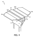
図4は、本開示の一実施形態による超音波プローブ10の部分の概略図である。トップにレンズ36を備えるトランスデューサスタック12は、フレーム16に結合されるバッキングブロック14に沿ってフレキシブル回路30の上に配置される。図4に示されるように、フレキシブル回路30はバッキングブロック14の側面13にまだ折り畳まれていない。トップヒートカバー440a-bの2つの部分は、フレキシブル回路30の各端部に位置される。ヒートカバー440は、図3に示されるヒートカバー340と同様である。2つのボルスタプレート32a-bは、それぞれトップヒートカバー440a-bのそれぞれの部分上に配置される。しかしながら、いくつかの実施形態において、ボルスタプレート32a-bは、フレキシブル回路30がバッキングブロック14上に折り畳まれ、フレーム16の何れかの側でPCB(図4には示されていない)に固定されるまで、トップヒートカバー440a-bに結合されない。いくつかの実施形態において、ボルスタプレート32a-bは省略されてもよい。
FIG. 4 is a schematic view of a portion of the
図5は、本開示の一実施形態による超音波プローブ10の側面図の概略図である。 3つの熱経路が矢印550,560,570で示される。熱は、トランスデューサスタック12内の超音波トランスデューサによって生成されることができる。矢印550で示されるように、熱は、トランスデューサスタック12、フレキシブル回路30、フレキシブル回路30のボトムヒートカバー410を通じて、バッキングブロック14に放散される。矢印550で示されるように、バッキングブロック14から、熱は、プローブ10の中央部分を通じてプローブフレーム16に伝導される。矢印560,570で示されるように、熱は、トランスデューサスタック12、フレキシブル回路30のトップヒートカバー440を通じてボルスタプレート32に放散される。熱は、ボルスタプレート32からハンドルヒートスプレッダ20に放散されてもよく、矢印560,570で示されるように、プローブハウジング22に沿って熱が放散される。矢印で示されていないが、いくらかの熱は、バッキングブロック14の側からフレキシブル回路30に放散され、熱はトップヒートカバー440を介してボルスタプレート32に放散される。図5に示されるように、3つの熱経路は、トランスデューサスタック12から熱を放散することができる。いくつかの実施形態において、矢印560,570によって示される熱経路のうちの1つのみが存在してもよい。いくつかの実施形態において、矢印560,570で示されるものへの更なる熱経路及び/又は代替の熱経路がプローブ10内に構成されることができる。例えば、更なるボルスタプレートは、フレキシブル回路30が覆うことができる側面に隣接する側のバッキングブロックに結合されることができる。更なるボルスタプレートは、更なるハンドルヒートスプレッダ及び/又はハンドルヒートスプレッダ20の異なるセクションに結合されることができる。他の例において、ボルスタプレート32は省略されてもよく、熱は、フレキシブル回路30のトップヒートカバー440を通じてハンドルヒートスプレッダ20に放散される。
FIG. 5 is a schematic side view of the
超音波プローブの熱管理システムは、受動熱管理システムであってもよい。これは、能動熱管理システムと比較して、プローブのコスト、サイズ、及び重量要件を低減することができる。熱管理システムは、フレキシブル回路のトップ及びボトムヒートカバーと、フレキシブル回路に結合される枕プレートと、ボルスタプレート内で熱接触して超音波プローブハウジングに配置されるハンドルヒートスプレッダとを含むことができる。熱管理システムは、バッキングブロックに結合されるプローブフレーム及びバッキングブロックのみが超音波プローブから熱を放散するために使用される場合と比較して、プローブのトランスデューサスタックからの熱の放散を改善することができる。これは、トランスデューサスタックがより高いエネルギの超音波、パルス、及び/又はシーケンスを使用することを可能にする。熱管理システムは、トランスデューサスタックがより高い周波数の超音波、パルス、及び/又はシーケンスを生成することを可能にし、超音波プローブがより広い範囲のイメージング及び/又は治療技術のために使用されることを可能にすることができる。 The thermal management system of the ultrasonic probe may be a passive thermal management system. This can reduce probe cost, size, and weight requirements compared to active thermal management systems. The thermal management system can include top and bottom heat covers for the flexible circuit, a pillow plate coupled to the flexible circuit, and a handle heat spreader that is placed in the ultrasonic probe housing in thermal contact within the bolster plate. The thermal management system should improve heat dissipation from the probe's transducer stack compared to when only the probe frame and backing block coupled to the backing block are used to dissipate heat from the ultrasonic probe. Can be done. This allows the transducer stack to use higher energy ultrasound, pulses, and / or sequences. Thermal management systems allow transducer stacks to generate higher frequency ultrasound, pulses, and / or sequences, and ultrasound probes are used for a wider range of imaging and / or therapeutic techniques. Can be made possible.
本システムは、超音波イメージングシステムを参照して説明しているが、本システムは、他の超音波トランスデューサにも拡張されてもよい。さらに、本システムは、これらに限定されないが、腎臓、精巣、前立腺、乳房、卵巣、子宮、甲状腺、肝臓、肺、筋骨格、脾臓、神経、心臓、動脈系及び血管系に関連する画像情報、更に超音波誘導介入及びリアルタイム医用イメージングによってガイドされ得る他の介入に関連する他のイメージングアプリケーションを取得及び/又は記録することに用いることができる。さらに、本システムは、本システムの特徴及び利点を提供することができるように、リアルタイムイメージング構成要素を有する又は有さない非超音波イメージングシステムと共に使用され得る1つ又は複数の要素を含むこともできる。 Although the system is described with reference to an ultrasonic imaging system, the system may be extended to other ultrasonic transducers. In addition, the system includes, but is not limited to, image information related to the kidney, testis, prostate, breast, ovary, uterus, thyroid, liver, lung, musculoskeletal system, spleen, nerve, heart, arterial and vascular system. In addition, it can be used to acquire and / or record other imaging applications related to ultrasound-guided interventions and other interventions that can be guided by real-time medical imaging. In addition, the system may also include one or more elements that can be used with non-ultrasonic imaging systems with or without real-time imaging components so that they can provide the features and benefits of the system. it can.
さらに、本システム、装置、及び方法は、例えば、超音波イメージングシステムのような既存のイメージングシステムに適用することができる。好適な超音波イメージングシステムは、例えば、小部分イメージングに適した従来の広帯域リニアアレイトランスデューサをサポートすることができるフィリップス(Philips)(登録商標)超音波システムを含むことができる。 In addition, the systems, devices, and methods can be applied to existing imaging systems, such as, for example, ultrasonic imaging systems. Suitable ultrasound imaging systems can include, for example, a Philips® ultrasound system capable of supporting conventional wideband linear array transducers suitable for small partial imaging.
本発明の特定の更なる利点及び特徴は、本開示を検討する際に当業者には明らかであり得るか、又は本発明の新規のシステム及び方法が使用される人によって経験され得るものであり、その主なものとして超音波トランスデューサでの放熱及びその動作方法が提供される。本システム及び方法の他の利点は、従来の医用画像システムが、本システム、装置及び方法の特徴及び利点を組み込むように容易にアップグレードされることができることである。 Certain additional advantages and features of the invention may be apparent to those skilled in the art when considering the disclosure or may be experienced by those who use the novel systems and methods of the invention. As the main ones thereof, heat dissipation by an ultrasonic transducer and a method of its operation are provided. Another advantage of the system and method is that conventional medical imaging systems can be easily upgraded to incorporate the features and advantages of the system, equipment and methods.
当然のことながら、上記の実施形態又はプロセスの何れも、1つ又は複数の他の実施形態及び/又はプロセスと組み合わせることができ、又は本システム、デバイス及び方法にしたがって別々のデバイス又はデバイス部分の間で分離及び/又は実行されてもよい。 Of course, any of the above embodiments or processes can be combined with one or more other embodiments and / or processes, or of separate devices or device parts according to the system, devices and methods. Separation and / or may be performed between.
最後に、上記の説明は本システムを単に例示することを目的としたものであり、添付した請求項をいずれかの実施形態又は実施形態のグループに限定するものと解釈してはならない。したがって、本システムは、例示的な実施形態を参照して詳細に説明されるが、以下の特許請求の範囲に記載される本システムの広範かつ意図される思想及び範囲から逸脱することなく、当業者によって多くの修正及び代替実施形態が考案され得ることも理解されるべきである。従って、明細書と図面は例示であるとみなすべきで、添付した請求項の範囲を限定するものと考えるべきではない。 Finally, the above description is for the purpose of merely exemplifying the system and should not be construed as limiting the attached claims to any of the embodiments or groups of embodiments. Accordingly, the system will be described in detail with reference to exemplary embodiments, but without departing from the broad and intended ideas and scope of the system as described in the claims below. It should also be understood that many modifications and alternative embodiments can be devised by those skilled in the art. Therefore, the specification and drawings should be considered as illustrations and not to limit the scope of the appended claims.
Claims (12)
トランスデューサスタックと、
第1の表面、前記第1の表面に対向する第2の表面、及び前記第1の表面と前記第2の表面との間に延在する側面を含むバッキングブロックと、
フレキシブル回路であって、
前記トランスデューサスタックと前記バッキングブロックとの間に配置される中央部分と、
前記中央部分に結合されるウイング部分であって、前記ウイング部分は前記バッキングブロックの前記側面に隣接して折り畳まれるように構成され、
前記バッキングブロックの前記第1の表面に隣接して前記中央部分の下に配置される第1のヒートカバーであって、前記トランスデューサスタックから前記バッキングブロックへ熱を放散するように構成される第1のヒートカバーと、
前記ウイング部分の上に配置される第2のヒートカバーであって、前記トランスデューサスタックから熱を放散するように構成される第2のヒートカバーと
を含む、フレキシブル回路と、
前記第2のヒートカバーと熱接触して前記第2のヒートカバーからの熱を放散するボルスタプレートと、
前記ボルスタプレートと熱接触するハンドルヒートスプレッダであって、前記ボルスタプレートから熱を放散するように構成される、ハンドルヒートスプレッダと、
前記バッキングブロックの前記第2の表面に結合されるプローブフレームであって、前記バッキングブロックから熱を放散するように構成される、プローブフレームと、
前記プローブフレーム及び前記フレキシブル回路の間に結合されるプリント回路基板と
を有する、超音波プローブ。 It ’s an ultrasonic probe,
Transducer stack and
A backing block including a first surface, a second surface facing the first surface, and a side surface extending between the first surface and the second surface.
It's a flexible circuit
A central portion located between the transducer stack and the backing block,
A wing portion coupled to the central portion, wherein the wing portion is configured to be folded adjacent to the side surface of the backing block.
A first heat cover located below the central portion adjacent to the first surface of the backing block and configured to dissipate heat from the transducer stack to the backing block. Heat cover and
A flexible circuit comprising a second heat cover disposed over the wing portion, the second heat cover configured to dissipate heat from the transducer stack.
A bolster plate that makes thermal contact with the second heat cover and dissipates heat from the second heat cover.
A handle heat spreader that is in thermal contact with the bolster plate and is configured to dissipate heat from the bolster plate .
A probe frame coupled to the second surface of the backing block, the probe frame configured to dissipate heat from the backing block.
An ultrasonic probe having a printed circuit board coupled between the probe frame and the flexible circuit.
前記ウイング部分上の第1の非導電層であって、前記第1のヒートカバーの2つの平行な側面に結合される、第1の非導電層と、 A first non-conductive layer on the wing portion, the first non-conductive layer coupled to two parallel sides of the first heat cover.
前記第1のヒートカバー上の第2の非導電層と、 With the second non-conductive layer on the first heat cover,
前記第1及び第2の非導電層上の第1の導電トレース層と、 The first conductive trace layer on the first and second non-conductive layers,
前記第1の導電性トレース層上の非導電性基板と、 The non-conductive substrate on the first conductive trace layer and
前記非導電性基板上の第2の導電性トレース層と、 The second conductive trace layer on the non-conductive substrate and
前記ウイング部分上の前記第2の導電性トレース層上の非導電性トップカバーと With the non-conductive top cover on the second conductive trace layer on the wing portion
を更に有する、請求項1に記載の超音波プローブ。The ultrasonic probe according to claim 1, further comprising.
Applications Claiming Priority (3)
| Application Number | Priority Date | Filing Date | Title |
|---|---|---|---|
| US201562112723P | 2015-02-06 | 2015-02-06 | |
| US62/112,723 | 2015-02-06 | ||
| PCT/IB2016/050310 WO2016125040A2 (en) | 2015-02-06 | 2016-01-22 | Systems, methods, and apparatuses for thermal management of ultrasound transducers |
Related Child Applications (1)
| Application Number | Title | Priority Date | Filing Date |
|---|---|---|---|
| JP2021035180A Division JP7057849B6 (en) | 2015-02-06 | 2021-03-05 | Systems, methods, and equipment for thermal management of ultrasonic transducers |
Publications (3)
| Publication Number | Publication Date |
|---|---|
| JP2018504228A JP2018504228A (en) | 2018-02-15 |
| JP2018504228A5 JP2018504228A5 (en) | 2020-07-02 |
| JP6882983B2 true JP6882983B2 (en) | 2021-06-02 |
Family
ID=55456841
Family Applications (2)
| Application Number | Title | Priority Date | Filing Date |
|---|---|---|---|
| JP2017540877A Active JP6882983B2 (en) | 2015-02-06 | 2016-01-22 | Systems, methods, and equipment for thermal management of ultrasonic transducers |
| JP2021035180A Active JP7057849B6 (en) | 2015-02-06 | 2021-03-05 | Systems, methods, and equipment for thermal management of ultrasonic transducers |
Family Applications After (1)
| Application Number | Title | Priority Date | Filing Date |
|---|---|---|---|
| JP2021035180A Active JP7057849B6 (en) | 2015-02-06 | 2021-03-05 | Systems, methods, and equipment for thermal management of ultrasonic transducers |
Country Status (5)
| Country | Link |
|---|---|
| US (1) | US11090031B2 (en) |
| EP (1) | EP3253294B1 (en) |
| JP (2) | JP6882983B2 (en) |
| CN (1) | CN107205723B (en) |
| WO (1) | WO2016125040A2 (en) |
Families Citing this family (5)
| Publication number | Priority date | Publication date | Assignee | Title |
|---|---|---|---|---|
| US10488502B2 (en) * | 2017-04-26 | 2019-11-26 | General Electric Company | Ultrasound probe with thin film flex circuit and methods of providing same |
| EP3773227B1 (en) | 2018-03-30 | 2024-01-31 | Koninklijke Philips N.V. | Thermally-conductive material layer and internal structure for ultrasound imaging probe |
| AU2019343169A1 (en) | 2018-09-21 | 2021-03-25 | Butterfly Network, Inc. | Acoustic damping for ultrasound imaging devices |
| WO2020062258A1 (en) * | 2018-09-30 | 2020-04-02 | 深圳迈瑞生物医疗电子股份有限公司 | Ultrasonic probe |
| US20230233192A1 (en) * | 2022-01-25 | 2023-07-27 | GE Precision Healthcare LLC | Phase Change Insert for Ultrasound Imaging Probe |
Family Cites Families (33)
| Publication number | Priority date | Publication date | Assignee | Title |
|---|---|---|---|---|
| US5545942A (en) * | 1994-11-21 | 1996-08-13 | General Electric Company | Method and apparatus for dissipating heat from a transducer element array of an ultrasound probe |
| US5961465A (en) | 1998-02-10 | 1999-10-05 | Hewlett-Packard Company | Ultrasound signal processing electronics with active cooling |
| JP3420954B2 (en) | 1998-12-14 | 2003-06-30 | 松下電器産業株式会社 | Ultrasonic probe |
| JP2001074710A (en) * | 1999-09-07 | 2001-03-23 | Matsushita Electric Ind Co Ltd | Ultrasonic probe |
| JP2003168882A (en) | 2001-11-30 | 2003-06-13 | Sony Corp | Heat conductive sheet |
| US7314447B2 (en) | 2002-06-27 | 2008-01-01 | Siemens Medical Solutions Usa, Inc. | System and method for actively cooling transducer assembly electronics |
| JP4332706B2 (en) | 2003-05-06 | 2009-09-16 | 株式会社日立メディコ | Ultrasonic probe |
| JP4624659B2 (en) * | 2003-09-30 | 2011-02-02 | パナソニック株式会社 | Ultrasonic probe |
| US7105986B2 (en) * | 2004-08-27 | 2006-09-12 | General Electric Company | Ultrasound transducer with enhanced thermal conductivity |
| CN2865867Y (en) * | 2006-03-09 | 2007-02-07 | 上海爱培克电子科技有限公司 | Ultrasonic transducer |
| JP4843395B2 (en) * | 2006-07-10 | 2011-12-21 | 日本電波工業株式会社 | Ultrasonic probe |
| US7834522B2 (en) * | 2007-08-03 | 2010-11-16 | Mr Holdings (Hk) Limited | Diagnostic ultrasound transducer |
| JP2009060501A (en) | 2007-09-03 | 2009-03-19 | Fujifilm Corp | Backing material, ultrasonic probe, ultrasonic endoscope, ultrasonic diagnostic device, and ultrasonic endoscope device |
| JP2009061112A (en) * | 2007-09-06 | 2009-03-26 | Ge Medical Systems Global Technology Co Llc | Ultrasonic probe and ultrasonic imaging apparatus |
| US20120143060A1 (en) * | 2007-12-27 | 2012-06-07 | Koninklijke Philips Electronics N.V. | Ultrasound transducer assembly with improved thermal behavior |
| KR101112658B1 (en) * | 2008-11-19 | 2012-02-15 | 삼성메디슨 주식회사 | Probe for ultrasonic diagnostic apparatus and manufacturing method thereof |
| KR101064601B1 (en) * | 2009-02-10 | 2011-09-15 | 주식회사 휴먼스캔 | Ultrasonic Probe, Ultrasonic Imaging Apparatus and Fabricating Method Thereof |
| KR101137262B1 (en) * | 2009-03-18 | 2012-04-20 | 삼성메디슨 주식회사 | Probe for ultrasonic diagnostic apparatus and manufacturing method thereof |
| JP5619380B2 (en) * | 2009-06-24 | 2014-11-05 | 株式会社東芝 | Ultrasonic probe |
| EP2444166A1 (en) * | 2009-09-15 | 2012-04-25 | Fujifilm Corporation | Ultrasonic transducer, ultrasonic probe and producing method |
| US8232705B2 (en) * | 2010-07-09 | 2012-07-31 | General Electric Company | Thermal transfer and acoustic matching layers for ultrasound transducer |
| JP5215372B2 (en) * | 2010-12-08 | 2013-06-19 | 富士フイルム株式会社 | Ultrasonic probe |
| JP2014516686A (en) * | 2011-05-17 | 2014-07-17 | コーニンクレッカ フィリップス エヌ ヴェ | Matrix ultrasound probe using passive heat dissipation |
| JP2013115537A (en) * | 2011-11-28 | 2013-06-10 | Ge Medical Systems Global Technology Co Llc | Backing member, ultrasonic probe and ultrasonic image display device |
| CN103142244B (en) * | 2011-12-07 | 2015-01-14 | 深圳迈瑞生物医疗电子股份有限公司 | Ultrasonic probe |
| KR101330733B1 (en) * | 2012-04-30 | 2013-11-20 | 삼성전자주식회사 | Ultrasonic Probe |
| US9072487B2 (en) * | 2012-05-11 | 2015-07-07 | General Electric Company | Ultrasound probe thermal drain |
| JP5550706B2 (en) | 2012-10-31 | 2014-07-16 | 日立アロカメディカル株式会社 | Ultrasonic probe |
| WO2014080312A1 (en) * | 2012-11-20 | 2014-05-30 | Koninklijke Philips N.V. | Frameless ultrasound probes with heat dissipation |
| CN103300889B (en) * | 2013-05-17 | 2015-04-29 | 深圳市理邦精密仪器股份有限公司 | Ultrasonic array probe signal acquisition component and preparation method thereof, and probe |
| US9419202B2 (en) * | 2013-06-21 | 2016-08-16 | General Electric Company | Ultrasound transducer and method for manufacturing an ultrasound transducer |
| KR20150006519A (en) * | 2013-07-08 | 2015-01-19 | 삼성메디슨 주식회사 | Ultrasound Probe and Manufacturing Method thereof |
| EP2992829B1 (en) * | 2014-09-02 | 2018-06-20 | Esaote S.p.A. | Ultrasound probe with optimized thermal management |
-
2016
- 2016-01-22 EP EP16708204.9A patent/EP3253294B1/en active Active
- 2016-01-22 CN CN201680008868.3A patent/CN107205723B/en active Active
- 2016-01-22 WO PCT/IB2016/050310 patent/WO2016125040A2/en active Application Filing
- 2016-01-22 US US15/548,119 patent/US11090031B2/en active Active
- 2016-01-22 JP JP2017540877A patent/JP6882983B2/en active Active
-
2021
- 2021-03-05 JP JP2021035180A patent/JP7057849B6/en active Active
Also Published As
| Publication number | Publication date |
|---|---|
| JP7057849B6 (en) | 2022-06-02 |
| WO2016125040A2 (en) | 2016-08-11 |
| CN107205723B (en) | 2021-09-28 |
| US11090031B2 (en) | 2021-08-17 |
| CN107205723A (en) | 2017-09-26 |
| JP2018504228A (en) | 2018-02-15 |
| JP7057849B2 (en) | 2022-04-20 |
| EP3253294B1 (en) | 2020-07-15 |
| EP3253294A2 (en) | 2017-12-13 |
| WO2016125040A3 (en) | 2017-01-05 |
| JP2021100587A (en) | 2021-07-08 |
| US20180263604A1 (en) | 2018-09-20 |
Similar Documents
| Publication | Publication Date | Title |
|---|---|---|
| JP7057849B6 (en) | Systems, methods, and equipment for thermal management of ultrasonic transducers | |
| RU2604705C2 (en) | Matrix ultrasound probe with passive heat dissipation | |
| US11540814B2 (en) | Systems, methods, and apparatuses for active thermal management of ultrasound transducers | |
| JP5305723B2 (en) | Ultrasonic probe and ultrasonic diagnostic apparatus | |
| US20190282207A1 (en) | High intensity focused ultrasound (hifu) device and system | |
| KR20150101699A (en) | Acoustic Probe with Improved Thermal Dissipation Properties | |
| JP6900753B2 (en) | Ultrasonic probe and ultrasonic diagnostic equipment | |
| JP2024511771A (en) | Ultrasonic probe heat dissipation | |
| CN110960252A (en) | Ultrasonic probe | |
| WO2020062259A1 (en) | Ultrasound probe and surface array ultrasound probe | |
| WO2020062272A1 (en) | Ultrasound probe and area array ultrasound probe | |
| JP2017104203A (en) | Ultrasonic probe | |
| CN219089342U (en) | Ultrasonic probe and sound head radiating structure thereof | |
| EP4066746A1 (en) | Heat dissipation in ultrasound probes | |
| CN210170073U (en) | Ultrasonic probe | |
| WO2020062274A1 (en) | Ultrasonic probe | |
| CN110960255A (en) | Ultrasonic probe |
Legal Events
| Date | Code | Title | Description |
|---|---|---|---|
| A521 | Request for written amendment filed |
Free format text: JAPANESE INTERMEDIATE CODE: A523 Effective date: 20190115 |
|
| A621 | Written request for application examination |
Free format text: JAPANESE INTERMEDIATE CODE: A621 Effective date: 20190115 |
|
| A977 | Report on retrieval |
Free format text: JAPANESE INTERMEDIATE CODE: A971007 Effective date: 20191120 |
|
| A131 | Notification of reasons for refusal |
Free format text: JAPANESE INTERMEDIATE CODE: A131 Effective date: 20191203 |
|
| A601 | Written request for extension of time |
Free format text: JAPANESE INTERMEDIATE CODE: A601 Effective date: 20200226 |
|
| A524 | Written submission of copy of amendment under article 19 pct |
Free format text: JAPANESE INTERMEDIATE CODE: A524 Effective date: 20200525 |
|
| A02 | Decision of refusal |
Free format text: JAPANESE INTERMEDIATE CODE: A02 Effective date: 20201105 |
|
| A521 | Request for written amendment filed |
Free format text: JAPANESE INTERMEDIATE CODE: A523 Effective date: 20210305 |
|
| C60 | Trial request (containing other claim documents, opposition documents) |
Free format text: JAPANESE INTERMEDIATE CODE: C60 Effective date: 20210305 |
|
| A911 | Transfer to examiner for re-examination before appeal (zenchi) |
Free format text: JAPANESE INTERMEDIATE CODE: A911 Effective date: 20210316 |
|
| C21 | Notice of transfer of a case for reconsideration by examiners before appeal proceedings |
Free format text: JAPANESE INTERMEDIATE CODE: C21 Effective date: 20210318 |
|
| TRDD | Decision of grant or rejection written | ||
| A01 | Written decision to grant a patent or to grant a registration (utility model) |
Free format text: JAPANESE INTERMEDIATE CODE: A01 Effective date: 20210420 |
|
| A61 | First payment of annual fees (during grant procedure) |
Free format text: JAPANESE INTERMEDIATE CODE: A61 Effective date: 20210507 |
|
| R150 | Certificate of patent or registration of utility model |
Ref document number: 6882983 Country of ref document: JP Free format text: JAPANESE INTERMEDIATE CODE: R150 |