JP6882700B2 - Pile holding jig and holding method to hold the pile - Google Patents
Pile holding jig and holding method to hold the pile Download PDFInfo
- Publication number
- JP6882700B2 JP6882700B2 JP2019107919A JP2019107919A JP6882700B2 JP 6882700 B2 JP6882700 B2 JP 6882700B2 JP 2019107919 A JP2019107919 A JP 2019107919A JP 2019107919 A JP2019107919 A JP 2019107919A JP 6882700 B2 JP6882700 B2 JP 6882700B2
- Authority
- JP
- Japan
- Prior art keywords
- pile
- wire
- wire rod
- rod
- holding
- Prior art date
- Legal status (The legal status is an assumption and is not a legal conclusion. Google has not performed a legal analysis and makes no representation as to the accuracy of the status listed.)
- Active
Links
- 238000000034 method Methods 0.000 title claims description 17
- 238000000926 separation method Methods 0.000 claims description 6
- 239000007788 liquid Substances 0.000 claims description 5
- 239000000696 magnetic material Substances 0.000 claims description 5
- 230000002093 peripheral effect Effects 0.000 claims description 3
- 239000002184 metal Substances 0.000 description 40
- 238000003780 insertion Methods 0.000 description 18
- 230000037431 insertion Effects 0.000 description 18
- 239000000463 material Substances 0.000 description 11
- 229910000831 Steel Inorganic materials 0.000 description 9
- 239000010959 steel Substances 0.000 description 9
- 238000010276 construction Methods 0.000 description 3
- 230000004048 modification Effects 0.000 description 3
- 238000012986 modification Methods 0.000 description 3
- 238000010586 diagram Methods 0.000 description 2
- 229920000049 Carbon (fiber) Polymers 0.000 description 1
- 239000004917 carbon fiber Substances 0.000 description 1
- 230000009194 climbing Effects 0.000 description 1
- 230000002301 combined effect Effects 0.000 description 1
- 230000005484 gravity Effects 0.000 description 1
- 239000011347 resin Substances 0.000 description 1
- 229920005989 resin Polymers 0.000 description 1
- 230000003313 weakening effect Effects 0.000 description 1
- 238000003466 welding Methods 0.000 description 1
Images


Landscapes
- Placing Or Removing Of Piles Or Sheet Piles, Or Accessories Thereof (AREA)
Description
この発明は、杭保持治具及び杭を保持する保持方法に関する。 The present invention relates to a pile holding jig and a holding method for holding a pile.
杭の下端の杭先端位置と杭穴の底面との間に距離を取る工法が用いられる場合がある。この工法が採用される場合、杭を杭穴に対して所望の位置まで埋設して固定するため、例えば特許文献1に開示されている施工方法が用いられることがある。 In some cases, a method of keeping a distance between the position of the tip of the pile at the lower end of the pile and the bottom of the pile hole is used. When this construction method is adopted, for example, the construction method disclosed in Patent Document 1 may be used in order to bury and fix the pile to a desired position with respect to the pile hole.
特許文献2に開示されているように、杭の杭頭に複数の金属ブロックを固定し、ロッドの下端の回転キャップを金属ブロックに係合させ、回転キャップを杭の杭頭に対して連結/連結解除させる技術が知られている。
As disclosed in
この発明は、杭先端位置と杭穴の底面との間に距離を確保した状態で杭を保持可能な、杭保持治具、及び杭を保持する保持方法を提供することを目的とする。 An object of the present invention is to provide a pile holding jig capable of holding a pile in a state where a distance is secured between a pile tip position and a bottom surface of a pile hole, and a holding method for holding the pile.
一態様に係る、杭穴に杭を建て込む際に、前記杭穴の開口部で前記杭を鉛直方向に保持する杭保持治具は、第1の線材と、第2の線材と、振れ止めと、第1の保持体と、第2の保持体とを有する。第1の線材は、下端で杭を支持可能で、上端が杭の杭頭よりも上側に延びる。第2の線材は、第1の線材に対して離間し、下端で杭を支持可能で、上端が杭の杭頭よりも上側に延びる。振れ止めは、第1の線材及び第2の線材の下端で杭を支持した状態で、第1の線材及び第2の線材の下端と上端との間の位置が、所定の位置に対して離隔することを抑制する。第1の保持体は、第1の線材の下端と上端との間の適宜の位置に配置され、地面よりも上側に保持された状態で、第1の線材を介して、杭を吊り下げるのに用いる。第2の保持体は、第2の線材の下端と上端との間の適宜の位置に配置され、地面よりも上側に保持された状態で、第2の線材を介して、杭を吊り下げるのに用いる。杭を杭穴に入れる際、第1の線材及び前記第2の線材は、振れ止めに遊嵌されている。
他の一態様に係る、杭穴に杭を建て込む際に、前記杭穴の開口部で前記杭を鉛直方向に保持する杭保持治具は、第1の線材と、第2の線材と、振れ止めと、第1の保持体と、第2の保持体とを有する。第1の線材は、下端が杭に着脱可能に接続され、上端が杭の杭頭よりも上側に延びており杭に対する上端側の操作によって杭への着脱が可能である。第2の線材は、第1の線材に対して離間し、下端が杭に着脱可能に接続され、上端が杭の杭頭よりも上側に延びており杭に対する上端側の操作によって杭への着脱が可能である。振れ止めは、第1の線材及び第2の線材の下端を杭に接続した状態で、第1の線材及び第2の線材の下端と上端との間の位置が、所定の位置に対して離隔することを抑制する。第1の保持体は、第1の線材の下端と上端との間に配置され、地面よりも上側に保持された状態で、第1の線材を介して、杭の杭頭を地面に対して杭穴内の所望の深さに保持するのに用いる。第2の保持体は、第2の線材の下端と上端との間に配置され、地面よりも上側に保持された状態で、第2の線材を介して、杭の杭頭を前記地面に対して杭穴内の所望の深さに保持するのに用いる。杭穴内の根固め液が硬化した後、地面よりも上側から第1の線材及び第2の線材を操作して第1の線材及び第2の線材を杭から取り外し可能である。
When a pile is built in a pile hole according to one aspect, the pile holding jig for holding the pile in the vertical direction at the opening of the pile hole includes a first wire rod, a second wire rod, and a steady rest. And a first holding body and a second holding body. The first wire, piles and the possible support at the lower end, extending building above the upper end of the pile the pile head. The second wire, spaced apart against the first wire, piles and the possible support at the lower end, extending building above the upper end of the pile the pile head. The steady rest is a state in which the pile is supported by the lower ends of the first wire and the second wire, and the position between the lower end and the upper end of the first wire and the second wire is separated from the predetermined position. that it suppresses that. The first holding body is arranged at an appropriate position between the lower end and the upper end of the first wire, and the pile is suspended through the first wire while being held above the ground. Used for. The second holder is arranged at an appropriate position between the lower end and the upper end of the second wire, and is held above the ground to suspend the pile through the second wire. Used for. When the pile is put into the pile hole, the first wire rod and the second wire rod are loosely fitted in the steady rest.
When a pile is built in a pile hole according to another aspect, the pile holding jig for holding the pile in the vertical direction at the opening of the pile hole includes a first wire rod, a second wire rod, and the second wire rod. It has a steady rest, a first holding body, and a second holding body. The lower end of the first wire rod is detachably connected to the pile, the upper end extends above the pile head of the pile, and the first wire can be attached to and detached from the pile by operating the upper end side of the pile. The second wire is separated from the first wire, the lower end is detachably connected to the pile, the upper end extends above the pile head of the pile, and the upper end is attached to and detached from the pile by operating the upper end side of the pile. Is possible. The steady rest is a state in which the lower ends of the first wire and the second wire are connected to the pile, and the position between the lower end and the upper end of the first wire and the second wire is separated from the predetermined position. Suppress doing. The first holding body is arranged between the lower end and the upper end of the first wire, and is held above the ground, and the pile head of the pile is placed against the ground through the first wire. Used to hold to the desired depth in the pile hole. The second holding body is arranged between the lower end and the upper end of the second wire rod, and while being held above the ground, the pile head of the pile is placed with respect to the ground through the second wire rod. Used to hold to the desired depth in the pile hole. After the root hardening liquid in the pile hole has hardened, the first wire and the second wire can be removed from the pile by operating the first wire and the second wire from above the ground.
この態様によれば、杭先端位置と杭穴の底面との間に距離を確保した状態で杭の位置を保持可能な、杭保持治具が提供される。 According to this aspect, a pile holding jig capable of holding the position of the pile while securing a distance between the position of the tip of the pile and the bottom surface of the pile hole is provided.
前記振れ止めは、前記杭の前記杭頭に係合する回転キャップが接続されたロッドに取り付けられるハブと、前記ハブから径方向外方に突出し、前記ハブに対して遠位の位置で前記第1の線材及び前記第2の線材を支持及び解放可能なアームとを有することが好適である。 The steady rest is a hub attached to a rod to which a rotary cap that engages with the pile head of the pile is connected, and a position that protrudes radially outward from the hub and is distal to the hub. It is preferable to have one wire rod and an arm capable of supporting and releasing the second wire rod.
この態様によれば、第1の線材及び第2の線材が振れ止めのアームにより、支持及び解放可能であるため、第1の線材及び第2の線材が意図せず、振れるのが防止されている。 According to this aspect, since the first wire and the second wire can be supported and released by the steady rest arm, the first wire and the second wire are prevented from unintentionally swinging. There is.
前記アームは、基端が前記ハブに支持され、遠位端が前記ハブから離間した、アーム本体と、前記アーム本体の前記遠位端に設けられたフックとを有することが好適である。前記フックは、前記第1の線材を遊嵌可能で前記第1の線材が前記所定の位置から外側に移動するのを抑制する状態と、前記第1の線材を解放可能な状態とを切り替え可能であることが好適である。 The arm preferably has an arm body with a proximal end supported by the hub and a distal end separated from the hub, and a hook provided at the distal end of the arm body. The hook can switch between a state in which the first wire can be loosely fitted and suppresses the first wire from moving outward from the predetermined position, and a state in which the first wire can be released. Is preferable.
この態様によれば、第1の線材がフックにより、所定の位置から外側に移動するのを抑制する状態と、第1の線材を解放可能な状態とを切り替え可能であるため、第1の線材が意図しない方向(所定の位置から外側)に振れるのが防止されている。 According to this aspect, since it is possible to switch between a state in which the first wire rod is prevented from moving outward from a predetermined position by the hook and a state in which the first wire rod can be released, the first wire rod can be released. Is prevented from swinging in an unintended direction (outside from a predetermined position).
前記アーム本体と前記フックとの一方は磁石を有し、前記アーム本体と前記フックとの他方は前記磁石に引き寄せられる磁石又は前記磁石に対して引き寄せられる磁性体で形成されていることが好適である。 It is preferable that one of the arm body and the hook has a magnet, and the other of the arm body and the hook is formed of a magnet attracted to the magnet or a magnetic material attracted to the magnet. is there.
この態様によれば、アーム本体及びフックは、磁力により着脱可能である。 According to this aspect, the arm body and the hook can be attached and detached by magnetic force.
前記アームは、基端が前記ハブに支持され、遠位端が前記ハブに対して離間し、前記杭の前記杭頭に向かう位置と、前記遠位端が前記杭の前記杭頭に向かう位置から離された位置との間を回動可能であることが好適である。 The arm has a base end supported by the hub, a distal end separated from the hub, a position toward the pile head of the pile, and a position at which the distal end faces the pile head of the pile. It is preferable that it can be rotated between the position and the position separated from the position.
この態様によれば、例えば運搬時や倉庫への格納時などに、アームをロッドに対して径方向外方に突出させておく必要がなく、杭保持治具の省スペース化を図ることができる。 According to this aspect, it is not necessary to project the arm radially outward with respect to the rod at the time of transportation or storage in a warehouse, for example, and the space of the pile holding jig can be saved. ..
前記振れ止めは、前記第1の線材及び前記第2の線材の外側をまとめて支持する管状体であることが好適である。 The steady rest is preferably a tubular body that collectively supports the outside of the first wire rod and the second wire rod.
この態様によれば、管状体の内側に第1の線材及び第2の線材を支持することができるので、第1の線材及び第2の線材が意図しない方向(所定の位置から外側)に振れるのが防止されている。 According to this aspect, since the first wire rod and the second wire rod can be supported inside the tubular body, the first wire rod and the second wire rod swing in an unintended direction (outside from a predetermined position). Is prevented.
前記管状体は、前記管状体の周面を開口させる扉を有することが好適である。前記管状体は、前記管状体の前記扉が閉じた状態で、前記第1の線材及び前記第2の線材を前記所定の位置から外側に移動するのを抑制する。前記管状体は、前記管状体の前記扉が開いた状態で、前記第1の線材及び前記第2の線材が前記管状体の内側から外側に相対的に移動するのを許容する。 The tubular body preferably has a door that opens the peripheral surface of the tubular body. The tubular body suppresses the movement of the first wire rod and the second wire rod outward from the predetermined position in a state where the door of the tubular body is closed. The tubular body allows the first wire rod and the second wire rod to move relatively from the inside to the outside of the tubular body in a state where the door of the tubular body is open.
この態様によれば、第1の線材及び第2の線材を、管状体に対して支持可能であるとともに、解放可能である。 According to this aspect, the first wire rod and the second wire rod can be supported and released with respect to the tubular body.
前記第1の線材及び前記第2の線材にはそれぞれネジが切られており、前記第1の保持体は、前記第1の線材の前記ネジに沿って移動可能なナットであり、前記第2の保持体は、前記第2の線材の前記ネジに沿って移動可能なナットであることが好適である。 The first wire rod and the second wire rod are each threaded, and the first holding body is a nut that can move along the screw of the first wire rod, and the second wire rod. It is preferable that the holding body of the second wire is a nut that can move along the screw of the second wire.
この態様によれば、第1の保持体を第1の線材に沿って適宜の位置に配置し、第2の保持体を第2の線材に沿って適宜の位置に配置することで、杭の中心軸の向きを調整することができる。 According to this aspect, by arranging the first holding body at an appropriate position along the first wire rod and arranging the second holding body at an appropriate position along the second wire rod, the pile The orientation of the central axis can be adjusted.
他の一態様に係る、杭保持治具を用いて、杭穴に対して前記杭の位置を保持する保持方法は、前記第1の線材の前記下端で前記杭を支持するとともに、前記第2の線材の前記下端で前記杭を支持すること、ロッドの下端の回転キャップに、前記杭の前記杭頭を係合させること、前記第1の線材及び前記第2の線材の振れを前記振れ止めでの遊嵌により抑制した状態で、前記ロッドを下げて前記杭を前記杭穴に対して沈設し、前記杭の前記杭頭を前記地面に対して所望の深さに配置すること、杭先端位置と前記杭穴の底面との間に距離を確保した状態で、前記第1の線材及び前記第2の線材から、前記振れ止めを解放すること、前記第1の線材の前記下端と前記上端との間の適宜の位置に前記第1の保持体を配置するとともに、前記第2の線材の前記下端と前記上端との間の適宜の位置に前記第2の保持体を配置すること、前記第1の保持体及び前記第2の保持体をそれぞれ前記地面よりも上側で支持すること、前記杭の前記杭頭に係合させた前記回転キャップの係合を解除し、前記回転キャップを前記杭の前記杭頭から離すことを含む。 In the holding method for holding the position of the pile with respect to the pile hole by using the pile holding jig according to another aspect, the pile is supported by the lower end of the first wire rod and the second is supported. to support the pile at the lower end of the wire rod, the lower end of the rotary cap rod, engaging the pile head of the pile, shake the deflection before Symbol first wire and the second wire while suppressing the loosely fitted in the stopper to lower the rod and sinking the pile to the pile hole, is positioned at the desired depth the pile head of the pile relative to the ground surface that, stakes With the distance between the tip position and the bottom surface of the pile hole secured , the steady rest is released from the first wire rod and the second wire rod, and the lower end of the first wire rod and the said The first holding body is arranged at an appropriate position between the upper end and the second holding body is arranged at an appropriate position between the lower end and the upper end of the second wire rod. Supporting the first holding body and the second holding body above the ground, respectively, disengages the rotating cap engaged with the pile head of the pile, and disengages the rotating cap. This includes separating the pile from the pile head.
この態様によれば、杭先端位置と杭穴の底面との間に距離を確保した状態で杭の位置を保持可能な保持方法が提供される。 According to this aspect, a holding method capable of holding the position of the pile while securing a distance between the position of the tip of the pile and the bottom surface of the pile hole is provided.
この発明によれば、杭先端位置と杭穴の底面との間に距離を確保した状態で杭の位置を保持可能な、杭保持治具、及び杭を保持する保持方法を提供することができる。 According to the present invention, it is possible to provide a pile holding jig capable of holding the position of the pile while securing a distance between the position of the tip of the pile and the bottom surface of the pile hole, and a holding method for holding the pile. ..
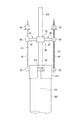
図1から図8を用いて、杭保持治具12の実施形態について説明する。ここでは、杭先端位置524と杭穴530の底面532との間に距離を確保した状態で杭520を保持する例について説明する。
An embodiment of the
ここでの杭520は、杭520の中心軸C0に直交する断面がドーナツ状であるものを例にして説明する。杭520の形状は、これに限られない。例えば、杭520の長手軸(中心軸C0)に直交する断面がH形状(H鋼)であるなど、種々の形状のものを用いることができる。
The
(第1実施形態)
図1から図2Bに示すように、本実施形態に係る杭520は複数の回転金具(ヨーカン)22,24,26,28を有する。
(First Embodiment)
As shown in FIGS. 1 to 2B, the
金具22,24,26,28は、例えば略直方体状の鋼材で形成されている。金具22,24,26,28は、杭520を吊るすのに用いるため、杭520の重量により破断しない耐力を有する大きさに形成されている。
The
金具22,24,26,28の一端は杭520の杭頭522の例えばドーナツ状の上面522aに、中心軸C0に対して互いに90°離間して固定されている。
One ends of the
ここでは、4つの回転金具22,24,26,28を用いる例について説明するが、2つ又は3つであってもよい。杭520の杭頭522に対する金具22,24,26,28の固定位置は、図示しない杭打機に接続されるロッド510の下端に設けられた回転キャップ512の係合部(凹溝)514との関係で決められる。
Here, an example in which the four
金具22,24,26,28は、杭520の上面522aに、例えばボルト締結及び/又は溶接により固定されている。このとき、金具22,24,26,28の他端は、杭520の杭頭522の上面522aから、杭520の外周面に対して径方向外方に突出している。このため、金具22,24,26,28の他端は、杭520の杭頭522の外周を覆うように杭頭522に係合可能な回転キャップ512の凹溝(係合部)514に係合/係合解除可能な係合凸部として用いられる。
The
金具22,24,26,28の他端には、それぞれネジ穴22a,24a,26a,28aが形成されている。これらネジ穴22a,24a,26a,28aは、後述する線材42,44の下端及びその近傍のネジ部42a,44aに螺合可能である。このため、金具22,24,26,28の他端は、線材42,44の下端及びその近傍を支持可能である。
なお、金具22,24,26,28の他端のネジ穴22a,24a,26a,28aは、杭520の杭頭522に固定された金具22,24,26,28に回転キャップ512が係合されたときに、回転キャップ512のさらに径方向外方に突出する状態に形成されている。
The screw holes 22a, 24a, 26a, 28a at the other ends of the
杭保持治具12は、第1の線材42と、第2の線材44と、振れ止め46と、第1の保持体48と、第2の保持体50とを有する。線材42,44の数は、金具22,24,26,28と同数又はそれよりも少なくてよい。本実施形態では、線材42,44の中心軸をそれぞれC1,C2とする。
The
後述する略コ字状の杭受(フネ)540上に載置される1対の受梁546,548は、杭保持治具12の一部として用いられ得る。
A pair of receiving
第1の線材42は、その下端部で杭520を支持可能で、その上端が杭520の杭頭522よりも上方に配置される。第2の線材44は、第1の線材42に離間して、その下端部で杭520を支持可能で、その上端が杭520の杭頭522よりも上方に配置される。両線材42,44は、杭520の傾きを防止するため、杭520の中心軸C0を挟んで対称の位置に配置されることが好適である。
4つの線材を用いる場合、線材は、杭520の中心軸C0に対して90°ずつ、ずらした位置に配置することが好適である。3つの線材が用いられる場合、線材は、杭520の中心軸C0に対して120°ずつ、ずらした位置に配置することが好適である。すなわち、隣接する線材同士の間隔が均等になるように配置することが好適である。
The
When four wire rods are used, it is preferable to arrange the wire rods at positions shifted by 90 ° with respect to the central axis C0 of the
両線材42,44としては、協働して杭520を吊り下げたときに、破断しない強度が要求される。両線材42,44の素材、外径、長さは杭520の種類や長さ、すなわち重量等により適宜に設定される。
Both
図4から図7に示すように、杭520の杭頭522が地面Gよりも下方の所望の位置に配置され、両線材42,44の下端が地面Gよりも下側にあるとき、両線材42,44は、地面Gに対して例えば1メートル以上、数メートル程度突出させる、適宜の長さに形成されている。
As shown in FIGS. 4 to 7, when the
両線材42,44として、例えばPC鋼棒(ゲビン棒)などの棒状の鋼材を用いる。両線材42,44は、杭520を吊り下げたときに、破断しない強度を有していれば、鋼材でなくてもよく、ヒモ状の炭素繊維等を用いてもよい。また、線材42,44として、鋼管等のパイプを用いることも可能である。
As both
両線材42,44の下部には、それぞれネジが切られ、ネジ部42a,44aが形成されている。各線材42,44の上端から下端に向かって所定の長さでネジが切られ、それぞれネジ部42b,44bが形成されている。なお、両線材42,44の全長にわたってネジが切られていてもよい。
Threads are cut at the lower portions of both
振れ止め46は、両線材42,44で杭520を支持した状態で、両線材42,44の下端と上端との間の位置が、所定の位置(ここでは、中心軸C0)に対して所定の状態(中心軸C0に対して中心軸C1,C2が平行な状態)から外側に移動し離隔するのを抑制する状態、及び、所定の位置(中心軸C0)に対して所定の状態(中心軸C0に対して中心軸C1,C2が平行な状態)から外側に移動し離隔するのを許容する状態を切り替え可能である。このため、振れ止め46は、両線材42,44が遊嵌するように両線材42,44の外周を囲って、両線材42,44が杭520の径外方向へ移動することを防止する。
In the
ここで、説明の簡略化のため、杭520の中心軸C0とロッド510の中心軸と回転キャップ512の中心軸とが一致するものとする。
Here, for the sake of simplification of the description, it is assumed that the central axis C0 of the
中心軸C0と、第1の線材42の中心軸C1との距離をDaとする。中心軸C0と第1の線材42の中心軸C1との間の距離をD1とする。このとき、振れ止め46は、Da≒D1となるように、第1の線材42の移動を規制することが好適である。同様に、中心軸C0と、第2の線材44の中心軸C2との距離をDbとする。中心軸C0と第2の線材44の中心軸C2との間の距離をD2とする。このとき、振れ止め46は、Db≒D2となるように、第2の線材44の移動を規制することが好適である。
Let Da be the distance between the central axis C0 and the central axis C1 of the
なお、振れ止め46の後述するフック64が第1の線材42の上端にあると仮定したとき、振れ止め46が存在していても、例えば数センチメートル程度であれば、DaよりもD1が大きくなってもよい(Da<D1)。同様に、振れ止め46のフック64が第2の線材44の上端にあると仮定したとき、振れ止め46が存在していても、例えば数センチメートル程度であれば、DbよりもD2が大きくなってもよい(Db<D2)。振れ止め46は、両線材42,44が金具22,24を介して杭520に接続されるときから、実際に杭520が所望の位置に沈設されるまでの間に、第1の線材42の中心軸C1及び第2の線材44の中心軸C2が意図せず中心軸C0から離れたり、中心軸C0に近づいたりする事が防止されていればよい。
Assuming that the
振れ止め46は、図1及び図3Aに示すように、ロッド510に固定可能なハブ52と、ハブ52から径方向外方に突出する複数のアーム54,56とを有する。
As shown in FIGS. 1 and 3A, the
複数のアーム54,56は、両線材42,44をそれぞれ支持及び解放可能である。なお、図1及び図3A中、アーム54,56は、中心軸C0に直交する方向に真っすぐに延びているが、適宜に曲がっていてもよい。アーム54,56の長手軸L1,L2は、ロッド510の中心軸C0に対して180°の関係にある。
The plurality of
アーム54,56は、それぞれ、アーム本体62と、フック64とを有する。アーム本体62は、一端(基端)がハブ52に支持され、他端(遠位端)がハブ52から離間している。
The
ここで、ハブ52は、ロッド510に対して別体として形成されていてもよく、一体的に形成されていてもよい。前者の場合、アーム本体62は、ハブ52から延びていることになる。後者の場合、アーム本体62がロッド510から延びていることになる。
Here, the
アーム本体62は、PC鋼棒のような変形し難い剛性材でも良く、ロープのような可撓性を有するヒモであってもよい。アーム本体62が可撓性を有する場合、伸びにくい素材で形成されていることが好適である。ここでは、図1に示すように、アーム本体62は、変形し難い剛性材で形成されているものとして説明する。
The
フック64は、アーム本体62の遠位端に設けられている。図3Bに示すように、フック64は、例えばアーム本体62の遠位端にヒンジ接続された略C字状のリングとして形成されている。フック64としては、例えば登山で用いられるカラビナのように、一部が開閉可能なものが用いられることも好適である。
The
アーム54のフック64は、第1の線材42を所定の位置(中心軸C0)に対して所定の状態(中心軸C1)から離隔するのを抑制するときに第1の線材42をフック64の内側に遊嵌させることが可能である。フック64は、第1の線材42を解放可能であるとき、第1の線材42を所定の位置(中心軸C0)に対して所定の状態(中心軸C1)から離隔するのを許容する。このため、フック64は、例えば、第1の線材42を遊嵌可能であるとともに、解放可能である。アーム54のアーム本体62及びフック64は、第1の線材42とハブ52との距離D1が所定の距離以下となるように、第1の線材42を支持する。
The
同様に、アーム56のフック64は、例えば、第2の線材44をフック64の内側に遊嵌可能であるとともに、解放可能である。アーム56のアーム本体62及びフック64は、第2の線材44とハブ52との距離D2が所定の距離以下となるように、第2の線材44を支持する。
Similarly, the
図3A中に破線で示すように、振れ止め46は、アーム54,56の他に、ハブ52からロッド510の径方向外方に突出した複数のアーム58,60を有することも好適である。アーム58,60の長手軸は、アーム54,56の長手軸L1,L2に対して90°の関係にある。これらアーム58,60があれば、杭520に対して両線材42,44を支持させる位置を選択することができる。また、ロッド510に対して振れ止め46のハブ52を固定する際に、向きの調整を行いやすい。また、4つの線材を用いて杭520を吊るす場合に対処することができる。
As shown by the broken line in FIG. 3A, it is also preferable that the
アーム58,60はアーム54,56と同様に形成されていることが好適である。このため、アーム58,60について、ここでの説明を省略する。
It is preferable that the
図1に示す第1の保持体48は、第1の線材42の下端と上端との間の適宜の位置に配置され、地面Gよりも上側で保持された状態で、第1の線材42及び第1の金具22を介して、杭520を吊り下げるのに用いる。第1の保持体48は、後述する受梁546の切り欠き(挿通部)546aの幅よりも大径の外形を有する。第2の保持体50は、第2の線材44の下端と上端との間の適宜の位置に配置され、地面Gよりも上側で保持された状態で、第2の線材44及び第2の金具24を介して、杭520を吊り下げるのに用いる。第2の保持体50は、後述する受梁548の切り欠き(挿通部)548aの幅よりも大径の外形を有する。
The
したがって、保持体48,50は、杭穴530の開口部を跨いで配置される受梁546,548の切り欠き(挿通部)546a,548aに線材42,44を挿通させた状態で、受梁546,548よりも上方で線材42,44に係合するとともに、切り欠き(挿通部)546a,548aの幅よりも大径の外形を有する。
Therefore, in the holding
本実施形態では、保持体48,50としては、ナットやワッシャーが用いられる。保持体48,50には、杭520の重量が負荷されるため、このような重量に耐え得る素材及びサイズのものが用いられる。
In this embodiment, nuts and washers are used as the holding
(作業手順(施工方法))
次に、杭保持治具12を用いて、杭520を杭穴530に対して沈設した(建て込んだ)状態で杭520の上下方向の位置を保持する保持方法について、説明する。
(Work procedure (construction method))
Next, a holding method for holding the vertical position of the
ロッド510の中心軸C0が鉛直方向と一致していると仮定したとき、回転キャップ512から所望の距離だけ上側に離れた位置に振れ止め46を取り付ける。ロッド510の長手軸Lを鉛直方向に配置したとき、回転キャップ512の凹溝514の鉛直方向上方の位置にフック64が配置される。
Assuming that the central axis C0 of the
なお、本明細書において、鉛直方向とは、完全に鉛直方向である場合だけでなく、略鉛直方向も含むものとする。このため、ロッド510及び杭520を鉛直方向に保持する際にロッド510及び杭520の中心軸C0を完全に鉛直方向に一致させる必要はなく、多少の誤差は許容される。
In the present specification, the vertical direction includes not only the case of being completely vertical but also the case of being substantially vertical. Therefore, when holding the
杭520を杭穴53内で保持する際は、杭打機にロッド510を介して接続されている回転キャップ512の凹溝514に、杭頭522の金具22,24,26,28を係合させた状態で、杭520、回転キャップ512及びロッド510の中心軸C0を鉛直方向に合わせる。
When holding the
そして、図4に示すように、第1の金具22のネジ穴22aに第1の線材42の下端及びその近傍のネジ部42aを螺合させる。このため、第1の線材42は、杭520に固定された第1の金具22に下端が支持され、上端が杭520の杭頭522よりも上側に延びた状態に配置される。振れ止め46のアーム54のフック64に第1の線材42を遊嵌する。
Then, as shown in FIG. 4, the lower end of the
同様に、第2の金具24のネジ穴24aに第2の線材44の下端及びその近傍のネジ部44aを螺合させる。このため、第2の線材44は、杭520に固定された第2の金具24に下端が支持され、上端が杭520の杭頭522よりも上側に延びた状態に配置される。振れ止め46のアーム56のフック64に第2の線材44を遊嵌する。
Similarly, the lower end of the
ロッド510、両線材42,44の、地面Gから例えば1メートルとすべき位置など、適宜の位置に、レベル止め印72,74,76を付す。
Level stop marks 72, 74, 76 are attached to the
この状態で杭打機を動かし、図5に示すように、ロッド510及び杭520を杭穴530に対して沈設する(建て込む)。そして、杭打機により、ロッド510、両線材42,44のレベル止め印72,74,76が地面Gから例えば1メートルの位置に配置した状態を維持する。このため、杭520の杭頭522は、地面Gに対して所望の深さに配置されている。このとき、杭520の下端の杭先端位置524と杭穴530の底面532との間に距離を取っている。
In this state, the pile driver is operated, and as shown in FIG. 5, the
杭520を杭穴530に沈設する際、両線材42,44が振れ止め46に遊嵌されているので、両線材42,44に対して意図せず負荷がかけられるのが抑制されている。また、第1の線材42の中心軸C1及び第2の線材44の中心軸C2がロッド510の中心軸C0に平行な状態(所定の状態)から不意に離されるのが抑制されている。
When the
レベル止め印72,74,76が異なる高さにある場合、杭520、回転キャップ512及びロッド510の中心軸C0が傾斜していることが想定される。かかる場合には、傾斜の出来形が確認できる。出来形の許容値から外れた際は杭打機によって傾斜を再調整して中心軸C0を鉛直方向に沿って配置し、レベル止め印72,74,76を同じ高さにする。
When the level stop marks 72, 74, and 76 are at different heights, it is assumed that the central axis C0 of the
図6に示すように、保持体48を第1の線材42の上端近傍から、ネジ部42bに沿って下側に移動させる。同様に、保持体50を第2の線材44の上端近傍から、ネジ部44bに沿って下側に移動させる。このとき、アーム本体62の遠位端に配置したフック64を図3B中に破線で示す状態に回動させるなどして、両線材42,44が遊嵌された状態を解除する。このため、第1の線材42の所望の位置に保持体48を配置する。また、第2の線材44の所望の位置に保持体50を配置する。
As shown in FIG. 6, the holding
すなわち、第1の線材42の例えば上端から、ネジ部42bに保持体(例えばワッシャー付ナット)48を配置して、保持体48を所望の位置に配置する。このとき、振れ止め46のフック64から、第1の線材42を解放する。第2の線材44の例えば上端から、ネジ部44bに保持体(例えばワッシャー付ナット)50を配置して、保持体50を所望の位置に配置する。このとき、振れ止め46のフック64から、第2の線材44を解放する。
That is, the holding body (for example, a nut with a washer) 48 is arranged on the
図7に示すように、例えば略コ字状の杭受(フネ)540を地面Gに載置する。杭受540に橋渡しするように、杭受540上に1対の受梁546,548を載置する。1対の受梁546,548は、杭穴530の開口部を跨いで配置される。
As shown in FIG. 7, for example, a substantially U-shaped pile receiver (Fune) 540 is placed on the ground G. A pair of receiving
図8に示すように、第1の受梁546に切り欠き(例えば第1の線材42を挿通可能な幅を有する挿通部)として形成された係合部(第1の係合部)546aに第1の線材42を入れるとともに保持体48を第1の受梁546の上側に載置する。第2の受梁548に切り欠き(例えば第2の線材44を挿通可能な幅を有する挿通部)として形成された係合部(第2の係合部)548aに第2の線材44を入れるとともに保持体50を第2の受梁548の上側に載置する。このため、図7及び図8に示すように、地面Gよりも上側に保持体48,50を保持して、金具22,24を介して線材42,44により杭520を吊り下げる。このとき、両線材42,44に杭520の重力により張力が負荷される。このように、第1の保持体48が地面Gよりも上側に保持された状態で、第1の線材42を介して、杭520を吊り下げているとともに、第2の保持体50が地面Gよりも上側に保持された状態で、第2の線材44を介して、杭520を吊り下げている。
As shown in FIG. 8, the engaging portion (first engaging portion) 546a formed as a notch (for example, an insertion portion having a width capable of inserting the first wire rod 42) in the
地上にある第1の保持体48は第1の受梁546に載置され、その位置が変化しない。第1の保持体48と第1の線材42との位置関係は変化しない。同様に、地上にある第2の保持体50は第2の受梁548に載置され、その位置が変化しない。第2の保持体50と第2の線材44との位置関係は変化しない。このため、両線材42,44に吊るされた杭520は、その位置が変化しない。したがって、杭保持治具12を用いることで、杭520が杭穴530に対して維持し、動かない状態に支持されている。すなわち、杭保持治具12は、第1の線材42を杭520に接続した状態で、第1の線材42に係合するとともに受梁546の挿通部(切り欠き)546aの幅よりも大径の外形の保持体48を、受梁546よりも上方から挿通部(切り欠き)546aに当接させ、かつ、第2の線材44を杭520に接続した状態で、第2の線材44に係合するとともに受梁548の挿通部(切り欠き)548aの幅よりも大径の外形の保持体50を、受梁548よりも上方から挿通部(切り欠き)548aに当接させることで杭穴530に対する杭520の沈下を防止するようにしている。
The
杭520及び杭穴530に対してロッド510及び回転キャップ512を少し下げた後、ロッド510及び回転キャップ512を回転させ、回転キャップ512の凹溝514に対する金具22,24,26,28の係合を解除する。そして、杭520及び杭穴530に対してロッド510及び回転キャップ512を上側に移動させる。
After slightly lowering the
下端に回転キャップ512があるロッド510及び杭打機は、別の杭(図示せず)の杭打ち作業に用いることができる。このとき、ロッド510に固定された杭保持治具12の振れ止め46をロッド510から取り外すことなく、そのまま別の杭の杭打ち作業に用いることができる。
A
図7に示すように、杭穴530の底面532に対して、杭先端位置524が距離を保った所望の位置に維持される。杭520は、例えば数時間から数日など、根固め液534が硬化するまで、そのまま維持される。
As shown in FIG. 7, the
根固め液534が硬化した後、第1の線材42を金具22のネジ穴22aに対して回転させ、金具22のネジ穴22aから、第1の線材42を取り外す。同様に、第2の線材44を金具24のネジ穴24aに対して回転させ、金具24のネジ穴24aから、第2の線材44を取り外す。金具22,24,26,28は、必要に応じて杭520の杭頭522の上面522aから切断又は取り外す。
After the
なお、図7及び図8に示す杭受540を地面Gに載置するタイミングは、杭520を杭穴530に沈設し始める前であってもよい。杭受540を地面Gに載置するタイミングは、保持体48,50を受梁546,548に係合させる前であればいつでも良い。
The timing of placing the
このように、本実施形態によれば、杭520の下端の杭先端位置524と杭穴530の底面532との間に距離を取る工法を用いる場合に、杭先端位置524と杭穴530の底面532との間に距離を確保した状態で、杭穴530に対して杭520の位置を保持可能な、杭保持治具12、及び、杭穴530に対して杭520の位置を保持する保持方法を提供することができる。
As described above, according to the present embodiment, when a method of taking a distance between the
本実施形態では、保持体48,50としてワッシャー付きナットを用いる例について説明した。両線材42,44に、重量物である杭520を吊るした状態で、保持体48,50に対して両線材42,44が動かないようにすることができるのであれば、ナットを用いる必要はない。この場合、ネジ部42b,44bも不要となり得る。
In this embodiment, an example in which a nut with a washer is used as the holding
例えば、第1の線材42に対して、第1の線材42の中心軸C1の軸方向から外れた位置から取り付け可能な保持体48、及び、第2の線材44に対して、第2の線材42の中心軸C2の軸方向から外れた位置から取り付け可能な保持体50を用いることができる。第1の線材42が鋼棒である場合、中心軸C1に直交する穴を形成し、その穴にロックピン(図示せず)を咬ませ、そのロックピンを受梁546,548で支持してもよい。
For example, the holding
両線材42,44がワイヤや撚線である場合、保持体48,50として、ナットやピンとは異なるブロック(図示せず)を用い、そのブロックをワイヤや撚線の適宜の位置に固定し、そのブロックを受梁546,548で支持してもよい。
When both
本実施形態では、受梁546,548に形成した切り欠き546a,548aを用いて保持体48,50を受梁546,548上に支持するものとしたが、例えば図9Aに示す杭受540に、図9Bに示す支持金具552を配置して、支持金具552の上に保持体48を支持してもよい。
In the present embodiment, the holding
図9Aに示す杭受540は、L字体部554と、I字体部556とを有する。L字体部554及びI字体部556には、互いに対向する位置に、支持金具552を支持する固定部558が固定されている。I字体部556には、開口556aが形成され、L字体部554の一端が貫通している。このため、L字体部554及びI字体部556は、所定の範囲内を接離可能である。このため、この杭受540は、杭穴530(図4から図7参照)の大きさ(径)や、杭520の外径(図4から図7参照)に合わせて、固定部558の間隔を調整して用いることができる。なお、L字体部554に対してI字体部556をクサビ556bにより固定してもよい。
The
支持金具552は、離間した1対の板552a,552bを有する。支持金具552は、固定部558上に支持されている。この状態で、図9Bに示すように、1対の板552a,552b間に第1の線材42が配設され、支持金具552の上に保持体48が支持されている。
The support metal fitting 552 has a pair of separated
(第2実施形態)
図10から図12を用いて第2実施形態について説明する。この実施形態は第1実施形態の変形例であって、第1実施形態で説明した部材と同一の部材又は同一の機能を有する部材に極力同一の符号を付し、詳しい説明を省略する。
(Second Embodiment)
The second embodiment will be described with reference to FIGS. 10 to 12. This embodiment is a modification of the first embodiment, and the same members as those described in the first embodiment or members having the same functions are designated by the same reference numerals as possible, and detailed description thereof will be omitted.
本実施形態の杭保持治具12では、両線材42,44がそれぞれ磁性体で形成されている。
In the
図10及び図11に示すように、振れ止め46のアーム54,56は、それぞれ、アーム本体62と、フック66とを有する。アーム本体62とフック66との一方は磁力を有する部位(ここでは説明の簡略化のため、単に磁石とする)を有する。アーム本体62とフック66との他方は、磁石で形成され、又は、磁石に対して引き寄せられる磁性体で形成されている。一例として、アーム本体62の遠位端が磁石として形成されているものとする。フック66が磁石として形成され、又は、磁性体で形成されているものとする。このため、フック66は、アーム本体62に対して磁力によりくっつけることが可能であるとともに、磁力に抗して離すことができる。すなわち、フック66は、アーム本体62に対して着脱可能である。
As shown in FIGS. 10 and 11, the
複数のアーム54,56は、アーム本体62とフック66との間の磁力により、アーム本体62の遠位端にフック66を維持し、両線材42、線材44が所定の位置(中心軸C0)に対して離隔するのを抑制する。また、複数のアーム54,56は、アーム本体62とフック66との間を離すなど、アーム本体62とフック66との間の磁力の影響を弱めることにより、両線材42,44が所定の位置(中心軸C0)に対して離隔するのを許容する。
The plurality of
両線材42,44がふらつくのを抑制するため、第1実施形態で説明したフック64の代わりに、フック(磁力を有する部位)66を用いることができる。
In order to prevent the
フック66は、アーム本体62の遠位端に対して脱落しないように第1実施形態で説明したのと同様にヒンジ接続されていてもよく、着脱可能であってもよい。アーム本体62の遠位端が磁石である場合、フック66は、アーム本体62に対して容易に着脱可能である。
The
両線材42,44が磁性体であり、アーム本体62の遠位端に磁石が固定されている場合、フック66は不要となり得る。
If both
この場合、アーム本体62に両線材42,44を引き寄せ、くっつけることができる。また、アーム本体62との間の磁力に抗して、両線材42,44をアーム本体62からそれぞれ離すことができる。
In this case, both
図12に示す例では、アーム本体62に対してフック66が除去されることで、保持体48が第1の棒材32の中心軸C1に沿って自在に移動可能であるとともに、保持体50が第2の棒材34の中心軸C2に沿って自在に移動可能である。
In the example shown in FIG. 12, by removing the
(第3実施形態)
図13を用いて第3実施形態について説明する。この実施形態は第1実施形態及び第2実施形態の変形例であって、第1実施形態及び第2実施形態で説明した部材と同一の部材又は同一の機能を有する部材に極力同一の符号を付し、詳しい説明を省略する。
(Third Embodiment)
The third embodiment will be described with reference to FIG. This embodiment is a modification of the first embodiment and the second embodiment, and has the same reference numerals as possible to the members having the same functions or the same functions as the members described in the first embodiment and the second embodiment. A detailed explanation will be omitted.
図13に示すように、複数のアーム54,56は、それぞれ、基端がハブ52に支持され、遠位端(図1に示すフック64、又は、図10に示す磁石66)がハブ52に対して離間している。複数のアーム54,56は、杭520の杭頭522に向かう位置と、遠位端が杭520の杭頭522に向かう位置から離された位置との間を回動可能である。アーム本体62は、実線と破線との間を移動可能である。このため、例えばロッド510及び回転キャップ512を運搬する場合、振れ止め46のアーム54,56の長手軸L1,L2をロッド510の中心軸C0に例えば平行に配置することができる。このため、振れ止め46をより省スペースにして、適宜の位置に運搬することができる。
As shown in FIG. 13, each of the plurality of
一方、使用時には、第1実施形態で説明したのと同様に、振れ止め46のアーム54,56の長手軸L1,L2をロッド510の中心軸C0に直交する方向に配置することができる。
On the other hand, at the time of use, the longitudinal axes L1 and L2 of the
(第4実施形態)
図14を用いて第4実施形態について説明する。この実施形態は第1から第3実施形態の変形例であって、第1から第3実施形態で説明した部材と同一の部材又は同一の機能を有する部材に極力同一の符号を付し、詳しい説明を省略する。
(Fourth Embodiment)
The fourth embodiment will be described with reference to FIG. This embodiment is a modification of the first to third embodiments, and the same members as those described in the first to third embodiments or members having the same functions are designated by the same reference numerals as much as possible. The explanation is omitted.
図14に示すように、振れ止め46は、ロッド510に固定されるものに限られない。図14に示す振れ止め46は、管状体82を有する。管状体82は、杭打機に接続されるロッド510とともに移動する移動機構502に支持されている。このため、杭打機の移動機構502が動くのに伴ってロッド510が管状体82と一緒に移動する。
As shown in FIG. 14, the
管状体82は、例えばフェンスのような網状に形成されていてもよく、構造材で形成されていてもよい。管状体82は、鋼材で形成されていてもよく、樹脂材で形成されていてもよい。
The
管状体82は、開口可能な扉84,86を有する。本実施形態では、管状体82の扉84,86が観音開きのような両開きとして開閉する例について説明する。管状体82の開き方は片開きでも良く、種々設定することができる。また、扉84,86は、いわゆるスライドドアとして形成されていてもよい。
The
図14中に実線で示すように扉84,86が閉じられた状態では、管状体82は、両線材42,44の下端と上端との間の位置が、所定の位置(中心軸C0及び/又は移動機構502)に対して所定の状態(中心軸C0に対して中心軸C1,C2が平行な状態)から離隔するのを抑制する。扉84,86が開いた状態では、管状体82は、両線材42,44の下端と上端との間の位置が、所定の位置(中心軸C0及び/又は移動機構502)に対して所定の状態(中心軸C0に対して中心軸C1,C2が平行な状態)から離隔するのを許容する。すなわち、管状体82は、管状体82の扉84,86が開いた状態で、両線材42,44が管状体82の内側から外側に相対的に移動するのを許容する。
When the
保持体48,50を所望の位置に配置する場合、扉84,86が開けられ、管状体82の内壁との間に隙間が形成される。
When the holding
管状体82は、図14に示すように、4つの線材を内側に保持可能な円管状に図示している。図15に示す管状体92は、2つの線材42,44のみを内側に保持可能な楕円管状である。管状体92と移動機構502との間には、連結部504が配設されている。
As shown in FIG. 14, the
なお、管状体92は、扉84,86と同様に開閉されることが好適である。
The
本願発明は、上記実施形態に限定されるものではなく、実施段階ではその要旨を逸脱しない範囲で種々に変形することが可能である。また、各実施形態は可能な限り適宜組み合わせて実施してもよく、その場合組み合わせた効果が得られる。更に、上記実施形態には種々の段階の発明が含まれており、開示される複数の構成要件における適当な組み合わせにより種々の発明が抽出され得る。
[付記]
以下、出願時特許請求の範囲の内容を付記する。
[付記1]
下端で杭を支持可能で、上端が前記杭の杭頭よりも上側に延びた状態に配置される、第1の線材と、
前記第1の線材に離間し、下端で前記杭を支持可能で、上端が前記杭の前記杭頭よりも上側に延びた状態に配置される、第2の線材と、
前記第1の線材及び前記第2の線材の前記下端で前記杭を支持した状態で、前記第1の線材及び前記第2の線材の前記下端と前記上端との間の位置が、所定の位置に対して離隔するのを抑制するように構成された、振れ止めと、
前記第1の線材の前記下端と前記上端との間の適宜の位置に配置され、地面よりも上側に保持された状態で、前記第1の線材を介して、前記杭を吊り下げるのに用いる第1の保持体と、
前記第2の線材の前記下端と前記上端との間の適宜の位置に配置され、前記地面よりも上側に保持された状態で、前記第2の線材を介して、前記杭を吊り下げるのに用いる第2の保持体と
を有する、杭保持治具。
[付記2]
杭穴に杭を建て込む際に、前記杭穴の開口部で前記杭を鉛直方向に保持する杭保持治具であって、
前記杭の長手軸に沿って配置され、下端が前記杭の杭頭に接続される棒状の線材と、
前記杭穴の開口部を跨いで配置された受梁のうち前記線材を挿通可能な挿通部に前記線材を挿通させた状態で、前記受梁よりも上方で前記線材に係合するとともに、前記挿通部の幅よりも大径の外形を有する保持体と、
前記線材が遊嵌するように前記線材の外周を囲って、前記線材が前記杭の径外方向へ移動することを防止する振れ止めと、
を有し、
前記線材を前記杭に接続した状態で、前記線材に係合するとともに前記挿通部の幅よりも大径の外形の前記保持体を、前記受梁よりも上方から前記挿通部に当接させることで前記杭の沈下を防止する杭保持治具。
[付記3]
付記1に記載の杭保持治具を用いて、杭穴に対して前記杭の位置を保持する保持方法であって、
前記第1の線材の前記下端で前記杭を支持するとともに、前記第2の線材の前記下端で前記杭を支持すること、
ロッドの下端の回転キャップに、前記杭の前記杭頭を係合させること、
前記振れ止めで前記第1の線材及び前記第2の線材の振れを抑制した状態で、前記ロッドを下げて前記杭を前記杭穴に対して沈設し、前記杭の前記杭頭を前記地面に対して所望の深さに配置すること、
前記第1の線材及び前記第2の線材から、前記振れ止めを解放すること、
前記第1の線材の前記下端と前記上端との間の適宜の位置に前記第1の保持体を配置するとともに、前記第2の線材の前記下端と前記上端との間の適宜の位置に前記第2の保持体を配置すること、
前記第1の保持体及び前記第2の保持体をそれぞれ前記地面よりも上側で支持すること、
前記杭の前記杭頭に係合させた前記回転キャップの係合を解除し、前記回転キャップを前記杭の前記杭頭から離すこと
を含む、保持方法。
[付記4]
杭穴に杭を建て込む際に、前記杭穴の開口部で前記杭を鉛直方向に保持する杭保持治具であって、
前記杭の長手軸に沿って配置され、下端が前記杭の杭頭に着脱可能に接続される棒状の線材と、
前記杭穴の開口部を跨いで配置された受梁のうち前記線材を挿通可能な挿通部に前記線材を挿通させた状態で、前記受梁よりも上方で前記線材に係合するとともに、前記挿通部の幅よりも大径の外形を有する保持体と、
前記線材が遊嵌するように前記線材の外周を囲い、前記線材が前記杭の径外方向へ移動することを防止する振れ止めと、
を有し、
前記線材を前記杭に接続した状態で、前記線材に係合するとともに前記挿通部の幅よりも大径の外形の前記保持体を、前記受梁よりも上方から前記挿通部に当接させることで前記杭の前記杭頭を地面に対して前記杭穴内の所望の深さに保持し、
前記杭穴内の根固め液が硬化した後、前記地面よりも上側から前記線材を前記杭から取り外し可能である、杭保持治具。
The invention of the present application is not limited to the above-described embodiment, and can be variously modified at the implementation stage without departing from the gist thereof. In addition, each embodiment may be carried out in combination as appropriate as possible, and in that case, the combined effect can be obtained. Further, the above-described embodiment includes inventions at various stages, and various inventions can be extracted by an appropriate combination in a plurality of disclosed constitutional requirements.
[Additional Notes]
The contents of the claims at the time of filing are added below.
[Appendix 1]
A first wire rod that can support a pile at the lower end and is arranged so that the upper end extends above the pile head of the pile.
A second wire rod that is separated from the first wire rod, can support the pile at the lower end, and is arranged so that the upper end extends above the pile head of the pile.
With the pile supported by the lower end of the first wire and the second wire, the position between the lower end and the upper end of the first wire and the second wire is a predetermined position. With a steady rest, which is configured to prevent separation from
Used to suspend the pile via the first wire while being arranged at an appropriate position between the lower end and the upper end of the first wire and held above the ground. The first holder and
To suspend the pile via the second wire while being arranged at an appropriate position between the lower end and the upper end of the second wire and held above the ground. A pile holding jig having a second holding body to be used.
[Appendix 2]
A pile holding jig that holds the pile in the vertical direction at the opening of the pile hole when the pile is built in the pile hole.
A rod-shaped wire rod arranged along the longitudinal axis of the pile and having a lower end connected to the pile head of the pile.
In a state where the wire rod is inserted into an insertion portion through which the wire rod can be inserted among the receiving beams arranged so as to straddle the opening of the pile hole, the wire rod is engaged with the wire rod above the receiving beam and described as described above. A holder with an outer diameter larger than the width of the insertion part,
A steady rest that surrounds the outer circumference of the wire so that the wire can be loosely fitted and prevents the wire from moving in the out-of-diameter direction of the pile.
Have,
With the wire rod connected to the pile, the holding body having an outer diameter larger than the width of the insertion portion is brought into contact with the insertion portion from above the receiving beam while engaging with the wire rod. A pile holding jig that prevents the pile from sinking.
[Appendix 3]
A holding method for holding the position of the pile with respect to the pile hole by using the pile holding jig described in Appendix 1.
Supporting the pile at the lower end of the first wire and supporting the pile at the lower end of the second wire.
Engaging the pile head of the pile with the rotating cap at the lower end of the rod,
With the steady rest suppressing the runout of the first wire and the second wire, the rod is lowered to lay the pile in the pile hole, and the pile head of the pile is placed on the ground. On the other hand, it should be placed at the desired depth.
To release the steady rest from the first wire and the second wire.
The first holding body is arranged at an appropriate position between the lower end and the upper end of the first wire, and the first holding body is arranged at an appropriate position between the lower end and the upper end of the second wire. Placing a second retainer,
Supporting the first holding body and the second holding body above the ground, respectively.
A holding method comprising disengaging the rotating cap engaged with the pile head of the pile and separating the rotating cap from the pile head of the pile.
[Appendix 4]
A pile holding jig that holds the pile in the vertical direction at the opening of the pile hole when the pile is built in the pile hole.
A rod-shaped wire rod that is arranged along the longitudinal axis of the pile and whose lower end is detachably connected to the pile head of the pile.
In a state where the wire rod is inserted into an insertion portion through which the wire rod can be inserted among the receiving beams arranged so as to straddle the opening of the pile hole, the wire rod is engaged with the wire rod above the receiving beam and described as described above. A holder with an outer diameter larger than the width of the insertion part,
A steady rest that surrounds the outer circumference of the wire so that the wire can be loosely fitted and prevents the wire from moving in the out-of-diameter direction of the pile.
Have,
With the wire rod connected to the pile, the holding body having an outer diameter larger than the width of the insertion portion is brought into contact with the insertion portion from above the receiving beam while engaging with the wire rod. Holds the pile head of the pile at a desired depth in the pile hole with respect to the ground.
A pile holding jig capable of removing the wire rod from the pile from above the ground after the root hardening liquid in the pile hole has hardened.
12…杭保持治具、22,24,26,28…回転金具、22a,24a…ネジ穴、42…第1の線材、42a…ネジ部、42b…ネジ部、44…第2の線材、44a…ネジ部、44b…ネジ部、46…振れ止め、48…第1の保持体、50…第2の保持体、52…ハブ、54,56…アーム、62…アーム本体、64…フック、510…ロッド、512…回転キャップ、514…凹溝(係合部)、520…杭、522…杭頭、524…杭先端位置、530…杭穴、532…底面、540…杭受、546,548…受梁、546a,548a…切り欠き、C0,C1,C2…中心軸 12 ... Pile holding jig, 22, 24, 26, 28 ... Rotating metal fittings, 22a, 24a ... Screw holes, 42 ... First wire, 42a ... Screw, 42b ... Screw, 44 ... Second wire, 44a ... screw part, 44b ... screw part, 46 ... steady rest, 48 ... first holder, 50 ... second holder, 52 ... hub, 54, 56 ... arm, 62 ... arm body, 64 ... hook, 510 ... Rod, 512 ... Rotating cap, 514 ... Recessed groove (engagement part), 520 ... Pile, 522 ... Pile head, 524 ... Pile tip position, 530 ... Pile hole, 532 ... Bottom surface, 540 ... Pile receiver, 546,548 ... Receiving beam, 546a, 548a ... Notch, C0, C1, C2 ... Central axis
Claims (10)
下端で前記杭を支持可能で、上端が前記杭の杭頭よりも上側に延びる、第1の線材と、
前記第1の線材に対して離間し、下端で前記杭を支持可能で、上端が前記杭の前記杭頭よりも上側に延びる、第2の線材と、
前記第1の線材及び前記第2の線材の前記下端で前記杭を支持した状態で、前記第1の線材及び前記第2の線材の前記下端と前記上端との間の位置が、所定の位置に対して離隔することを抑制する振れ止めと、
前記第1の線材の前記下端と前記上端との間の適宜の位置に配置され、地面よりも上側に保持された状態で、前記第1の線材を介して、前記杭を吊り下げるのに用いる第1の保持体と、
前記第2の線材の前記下端と前記上端との間の適宜の位置に配置され、前記地面よりも上側に保持された状態で、前記第2の線材を介して、前記杭を吊り下げるのに用いる第2の保持体と
を有し、
前記杭を前記杭穴に入れる際、前記第1の線材及び前記第2の線材は、前記振れ止めに遊嵌されている、杭保持治具。 A pile holding jig that holds the pile in the vertical direction at the opening of the pile hole when the pile is built in the pile hole.
A first wire rod that can support the pile at the lower end and the upper end extends above the pile head of the pile.
A second wire rod that is separated from the first wire rod, can support the pile at the lower end, and has an upper end extending above the pile head of the pile.
With the pile supported by the lower end of the first wire and the second wire, the position between the lower end and the upper end of the first wire and the second wire is a predetermined position. With a steady rest that suppresses separation from
Used to suspend the pile via the first wire while being arranged at an appropriate position between the lower end and the upper end of the first wire and held above the ground. The first holder and
To suspend the pile via the second wire while being arranged at an appropriate position between the lower end and the upper end of the second wire and held above the ground. Has a second retainer to be used
A pile holding jig in which the first wire rod and the second wire rod are loosely fitted in the steady rest when the pile is inserted into the pile hole.
下端が前記杭に着脱可能に接続され、上端が前記杭の杭頭よりも上側に延びており前記杭に対する当該上端側の操作によって前記杭への着脱が可能な、第1の線材と、
前記第1の線材に対して離間し、下端が前記杭に着脱可能に接続され、上端が前記杭の前記杭頭よりも上側に延びており前記杭に対する当該上端側の操作によって前記杭への着脱が可能な、第2の線材と、
前記第1の線材及び前記第2の線材の前記下端を前記杭に接続した状態で、前記第1の線材及び前記第2の線材の前記下端と前記上端との間の位置が、所定の位置に対して離隔することを抑制する振れ止めと、
前記第1の線材の前記下端と前記上端との間に配置され、地面よりも上側に保持された状態で、前記第1の線材を介して、前記杭の前記杭頭を前記地面に対して前記杭穴内の所望の深さに保持するのに用いる第1の保持体と、
前記第2の線材の前記下端と前記上端との間に配置され、前記地面よりも上側に保持された状態で、前記第2の線材を介して、前記杭の前記杭頭を前記地面に対して前記杭穴内の前記所望の深さに保持するのに用いる第2の保持体と
を有し、
前記杭穴内の根固め液が硬化した後、前記地面よりも上側から前記第1の線材及び前記第2の線材を操作して前記第1の線材及び前記第2の線材を前記杭から取り外し可能である、杭保持治具。 A pile holding jig that holds the pile in the vertical direction at the opening of the pile hole when the pile is built in the pile hole.
A first wire rod whose lower end is detachably connected to the pile, whose upper end extends upward from the pile head of the pile, and which can be attached to and detached from the pile by operating the upper end side of the pile.
Separated from the first wire rod, the lower end is detachably connected to the pile, the upper end extends above the pile head of the pile, and the operation of the upper end side with respect to the pile leads to the pile. Detachable second wire and
With the lower end of the first wire and the second wire connected to the pile, the position between the lower end and the upper end of the first wire and the second wire is a predetermined position. With a steady rest that suppresses separation from
The pile head of the pile is placed with respect to the ground through the first wire while being arranged between the lower end and the upper end of the first wire and held above the ground. A first retainer used to hold the pile hole to a desired depth, and
The pile head of the pile is placed with respect to the ground through the second wire while being arranged between the lower end and the upper end of the second wire and held above the ground. With a second retainer used to hold it to the desired depth in the pile hole.
After the root hardening liquid in the pile hole is hardened, the first wire rod and the second wire rod can be operated from above the ground to remove the first wire rod and the second wire rod from the pile. Is a pile holding jig.
前記杭の前記杭頭に係合する回転キャップが接続されたロッドに取り付けられるハブと、
前記ハブから径方向外方に突出し、前記ハブに対して遠位の位置で前記第1の線材及び前記第2の線材を支持及び解放可能なアームと
を有する、請求項1又は請求項2に記載の杭保持治具。 The steady rest is
A hub attached to a rod to which a rotating cap that engages the pile head of the pile is connected,
The first or second aspect of the present invention, wherein the first wire rod and an arm capable of supporting and releasing the first wire rod and the second wire rod projecting radially outward from the hub are provided at a position distal to the hub. The described pile holding jig.
基端が前記ハブに支持され、遠位端が前記ハブから離間した、アーム本体と、
前記アーム本体の前記遠位端に設けられたフックと
を有し、
前記フックは、
前記第1の線材を遊嵌可能で前記第1の線材が前記所定の位置から外側に移動することを抑制する状態と、
前記第1の線材を解放可能な状態と
を切り替え可能である、請求項3に記載の杭保持治具。 The arm
An arm body with a proximal end supported by the hub and a distal end separated from the hub.
It has a hook provided at the distal end of the arm body and
The hook
A state in which the first wire can be loosely fitted and the first wire is prevented from moving outward from the predetermined position.
The pile holding jig according to claim 3, wherein the state in which the first wire can be released can be switched.
前記管状体は、前記管状体の前記扉が閉じた状態で、前記第1の線材及び前記第2の線材を前記所定の位置から外側に移動することを抑制し、
前記管状体は、前記管状体の前記扉が開いた状態で、前記第1の線材及び前記第2の線材が前記管状体の内側から外側に相対的に移動することを許容するようにした、請求項7に記載の杭保持治具。 The tubular body has a door that opens the peripheral surface of the tubular body.
The tubular body suppresses the movement of the first wire rod and the second wire rod outward from the predetermined position in a state where the door of the tubular body is closed.
The tubular body allows the first wire rod and the second wire rod to move relatively from the inside to the outside of the tubular body in a state where the door of the tubular body is open. The pile holding jig according to claim 7.
前記第1の保持体は、前記第1の線材の前記ネジに沿って移動可能なナットであり、
前記第2の保持体は、前記第2の線材の前記ネジに沿って移動可能なナットである、請求項1ないし請求項8のいずれか1に記載の杭保持治具。 The first wire and the second wire are each threaded.
The first holder is a nut that is movable along the screw of the first wire.
The pile holding jig according to any one of claims 1 to 8, wherein the second holding body is a nut that can move along the screw of the second wire rod.
前記第1の線材の前記下端で前記杭を支持するとともに、前記第2の線材の前記下端で前記杭を支持すること、
ロッドの下端の回転キャップに、前記杭の前記杭頭を係合させること、
前記第1の線材及び前記第2の線材の振れを前記振れ止めでの遊嵌により抑制した状態で、前記ロッドを下げて前記杭を前記杭穴に対して沈設し、前記杭の前記杭頭を前記地面に対して所望の深さに配置すること、
杭先端位置と前記杭穴の底面との間に距離を確保した状態で、前記第1の線材及び前記第2の線材から、前記振れ止めを解放すること、
前記第1の線材の前記下端と前記上端との間の適宜の位置に前記第1の保持体を配置するとともに、前記第2の線材の前記下端と前記上端との間の適宜の位置に前記第2の保持体を配置すること、
前記第1の保持体及び前記第2の保持体をそれぞれ前記地面よりも上側で支持すること、
前記杭の前記杭頭に係合させた前記回転キャップの係合を解除し、前記回転キャップを前記杭の前記杭頭から離すこと
を含む、保持方法。 A holding method for holding the position of the pile with respect to a pile hole by using the pile holding jig according to any one of claims 1 to 9.
Supporting the pile at the lower end of the first wire and supporting the pile at the lower end of the second wire.
Engaging the pile head of the pile with the rotating cap at the lower end of the rod,
In a state where the runout of the first wire rod and the second wire rod is suppressed by loose fitting with the steady rest, the rod is lowered and the pile is sunk in the pile hole, and the pile head of the pile is sunk. To the desired depth with respect to the ground,
Releasing the steady rest from the first wire rod and the second wire rod while ensuring a distance between the pile tip position and the bottom surface of the pile hole.
The first holding body is arranged at an appropriate position between the lower end and the upper end of the first wire, and the first holding body is arranged at an appropriate position between the lower end and the upper end of the second wire. Placing a second retainer,
Supporting the first holding body and the second holding body above the ground, respectively.
A holding method comprising disengaging the rotating cap engaged with the pile head of the pile and separating the rotating cap from the pile head of the pile.
Priority Applications (1)
| Application Number | Priority Date | Filing Date | Title |
|---|---|---|---|
| JP2019107919A JP6882700B2 (en) | 2019-06-10 | 2019-06-10 | Pile holding jig and holding method to hold the pile |
Applications Claiming Priority (1)
| Application Number | Priority Date | Filing Date | Title |
|---|---|---|---|
| JP2019107919A JP6882700B2 (en) | 2019-06-10 | 2019-06-10 | Pile holding jig and holding method to hold the pile |
Publications (2)
| Publication Number | Publication Date |
|---|---|
| JP2020200650A JP2020200650A (en) | 2020-12-17 |
| JP6882700B2 true JP6882700B2 (en) | 2021-06-02 |
Family
ID=73741993
Family Applications (1)
| Application Number | Title | Priority Date | Filing Date |
|---|---|---|---|
| JP2019107919A Active JP6882700B2 (en) | 2019-06-10 | 2019-06-10 | Pile holding jig and holding method to hold the pile |
Country Status (1)
| Country | Link |
|---|---|
| JP (1) | JP6882700B2 (en) |
Families Citing this family (1)
| Publication number | Priority date | Publication date | Assignee | Title |
|---|---|---|---|---|
| JP7004940B1 (en) * | 2021-09-21 | 2022-01-21 | ジャパンパイル株式会社 | Inclination measuring device and inclination measuring method for ready-made piles |
Family Cites Families (6)
| Publication number | Priority date | Publication date | Assignee | Title |
|---|---|---|---|---|
| JPH06346441A (en) * | 1993-06-08 | 1994-12-20 | Chiyouwa Kogyo Kk | Method for driving pile using hull and device thereof |
| JP2007002567A (en) * | 2005-06-24 | 2007-01-11 | Geotop Corp | Pile suspending tool |
| JP5160121B2 (en) * | 2007-03-29 | 2013-03-13 | 三谷セキサン株式会社 | Pile holder to be attached to ready-made piles |
| JP5483912B2 (en) * | 2009-03-16 | 2014-05-07 | 日本高圧コンクリート株式会社 | Pile locking device and pile locking method |
| JP5580869B2 (en) * | 2012-11-30 | 2014-08-27 | 株式会社ダイヘン | Two-wire welding torch and two-wire welding apparatus using the same |
| JP5837242B1 (en) * | 2015-02-13 | 2015-12-24 | 国立研究開発法人土木研究所 | Rope connecting material |
-
2019
- 2019-06-10 JP JP2019107919A patent/JP6882700B2/en active Active
Also Published As
| Publication number | Publication date |
|---|---|
| JP2020200650A (en) | 2020-12-17 |
Similar Documents
| Publication | Publication Date | Title |
|---|---|---|
| JP2008069577A (en) | Pile cage building method and pile cage building apparatus | |
| JP6882700B2 (en) | Pile holding jig and holding method to hold the pile | |
| ES2603581T3 (en) | Factory or masonry prop, construction system and method | |
| US9493326B2 (en) | Clasp-and-lug system | |
| JP6274596B1 (en) | Reinforcement construction method for deep foundation pile and hanging jig | |
| JP2009108611A (en) | Reinforcement erecting tool and reinforcement erecting method | |
| JP5160121B2 (en) | Pile holder to be attached to ready-made piles | |
| JP2014129705A (en) | Burying method and tool for burning for pipe for heat exchange | |
| JP6548773B1 (en) | Anchor hole positioning tool | |
| JP3194193U (en) | Holding device that stores the holding rod attached to the crane | |
| JP6994311B2 (en) | Hanging tools and operating tools and mounting devices equipped with them | |
| JP2010121395A (en) | Fall preventive device for preventing fall of deviation correcting device from erection piece | |
| JP5974571B2 (en) | Stabilizing jig for slant pile | |
| EP3387190A1 (en) | A platform arrangement for offshore energy exploitation | |
| JP6518717B2 (en) | Temporary fixture | |
| JP6309153B1 (en) | Connecting suspension bracket | |
| JP2012225006A (en) | Demolition method | |
| JP2006021898A (en) | Crane lifting tool | |
| JP2015178394A (en) | Cylindrical body hanging device | |
| KR101804044B1 (en) | hook assembly for lifting heavy object | |
| JP2015183367A (en) | Precast pile and support method of precast pile | |
| KR20190005453A (en) | Anchor for stow net | |
| JP4863982B2 (en) | Support structure for pile and superstructure | |
| JP2011106228A (en) | Anchor bolt fixing tool and fixing method of anchor bolt | |
| JP6983190B2 (en) | How to reinforce tubular reinforcements and existing concrete columns |
Legal Events
| Date | Code | Title | Description |
|---|---|---|---|
| A621 | Written request for application examination |
Free format text: JAPANESE INTERMEDIATE CODE: A621 Effective date: 20190610 |
|
| A131 | Notification of reasons for refusal |
Free format text: JAPANESE INTERMEDIATE CODE: A131 Effective date: 20200602 |
|
| A521 | Request for written amendment filed |
Free format text: JAPANESE INTERMEDIATE CODE: A523 Effective date: 20200729 |
|
| A131 | Notification of reasons for refusal |
Free format text: JAPANESE INTERMEDIATE CODE: A131 Effective date: 20201222 |
|
| A521 | Request for written amendment filed |
Free format text: JAPANESE INTERMEDIATE CODE: A523 Effective date: 20210107 |
|
| TRDD | Decision of grant or rejection written | ||
| A01 | Written decision to grant a patent or to grant a registration (utility model) |
Free format text: JAPANESE INTERMEDIATE CODE: A01 Effective date: 20210406 |
|
| A61 | First payment of annual fees (during grant procedure) |
Free format text: JAPANESE INTERMEDIATE CODE: A61 Effective date: 20210419 |
|
| R150 | Certificate of patent or registration of utility model |
Ref document number: 6882700 Country of ref document: JP Free format text: JAPANESE INTERMEDIATE CODE: R150 |
|
| R250 | Receipt of annual fees |
Free format text: JAPANESE INTERMEDIATE CODE: R250 |