JP6880932B2 - Actuator breather structure - Google Patents
Actuator breather structure Download PDFInfo
- Publication number
- JP6880932B2 JP6880932B2 JP2017070036A JP2017070036A JP6880932B2 JP 6880932 B2 JP6880932 B2 JP 6880932B2 JP 2017070036 A JP2017070036 A JP 2017070036A JP 2017070036 A JP2017070036 A JP 2017070036A JP 6880932 B2 JP6880932 B2 JP 6880932B2
- Authority
- JP
- Japan
- Prior art keywords
- actuator
- breather
- housing
- breather structure
- concave groove
- Prior art date
- Legal status (The legal status is an assumption and is not a legal conclusion. Google has not performed a legal analysis and makes no representation as to the accuracy of the status listed.)
- Active
Links
Images


Classifications
-
- F—MECHANICAL ENGINEERING; LIGHTING; HEATING; WEAPONS; BLASTING
- F16—ENGINEERING ELEMENTS AND UNITS; GENERAL MEASURES FOR PRODUCING AND MAINTAINING EFFECTIVE FUNCTIONING OF MACHINES OR INSTALLATIONS; THERMAL INSULATION IN GENERAL
- F16H—GEARING
- F16H57/00—General details of gearing
- F16H57/02—Gearboxes; Mounting gearing therein
- F16H57/027—Gearboxes; Mounting gearing therein characterised by means for venting gearboxes, e.g. air breathers
-
- H—ELECTRICITY
- H02—GENERATION; CONVERSION OR DISTRIBUTION OF ELECTRIC POWER
- H02K—DYNAMO-ELECTRIC MACHINES
- H02K5/00—Casings; Enclosures; Supports
- H02K5/04—Casings or enclosures characterised by the shape, form or construction thereof
- H02K5/10—Casings or enclosures characterised by the shape, form or construction thereof with arrangements for protection from ingress, e.g. water or fingers
-
- H—ELECTRICITY
- H02—GENERATION; CONVERSION OR DISTRIBUTION OF ELECTRIC POWER
- H02K—DYNAMO-ELECTRIC MACHINES
- H02K7/00—Arrangements for handling mechanical energy structurally associated with dynamo-electric machines, e.g. structural association with mechanical driving motors or auxiliary dynamo-electric machines
- H02K7/10—Structural association with clutches, brakes, gears, pulleys or mechanical starters
- H02K7/116—Structural association with clutches, brakes, gears, pulleys or mechanical starters with gears
-
- H—ELECTRICITY
- H02—GENERATION; CONVERSION OR DISTRIBUTION OF ELECTRIC POWER
- H02K—DYNAMO-ELECTRIC MACHINES
- H02K2205/00—Specific aspects not provided for in the other groups of this subclass relating to casings, enclosures, supports
- H02K2205/09—Machines characterised by drain passages or by venting, breathing or pressure compensating means
-
- H—ELECTRICITY
- H02—GENERATION; CONVERSION OR DISTRIBUTION OF ELECTRIC POWER
- H02K—DYNAMO-ELECTRIC MACHINES
- H02K5/00—Casings; Enclosures; Supports
- H02K5/04—Casings or enclosures characterised by the shape, form or construction thereof
- H02K5/15—Mounting arrangements for bearing-shields or end plates
-
- H—ELECTRICITY
- H02—GENERATION; CONVERSION OR DISTRIBUTION OF ELECTRIC POWER
- H02K—DYNAMO-ELECTRIC MACHINES
- H02K5/00—Casings; Enclosures; Supports
- H02K5/04—Casings or enclosures characterised by the shape, form or construction thereof
- H02K5/16—Means for supporting bearings, e.g. insulating supports or means for fitting bearings in the bearing-shields
- H02K5/173—Means for supporting bearings, e.g. insulating supports or means for fitting bearings in the bearing-shields using bearings with rolling contact, e.g. ball bearings
- H02K5/1732—Means for supporting bearings, e.g. insulating supports or means for fitting bearings in the bearing-shields using bearings with rolling contact, e.g. ball bearings radially supporting the rotary shaft at both ends of the rotor
Description
本発明は、アクチュエータのブリーザ構造に関する。 The present invention relates to a breather structure of an actuator.
従来から、防水性を備えたアクチュエータには、圧力調整のためのブリーザが設けられる。ブリーザ構造としては、呼吸孔の内側にベントフィルタが設けられた構成が知られている(例えば特許文献1参照)。 Conventionally, a breather for adjusting pressure is provided in a waterproof actuator. As a breather structure, a configuration in which a vent filter is provided inside a breathing hole is known (see, for example, Patent Document 1).
ベントフィルタは呼吸孔の筐体内の開口部に接着されるが、呼吸孔に高圧の液体が流れ込んだ場合に、液体の圧力によってベントフィルタが剥がれたり、損傷するおそれがあった。 The vent filter is adhered to the opening in the housing of the breathing hole, but when a high-pressure liquid flows into the breathing hole, the vent filter may be peeled off or damaged by the pressure of the liquid.
本発明の一態様は、高圧の液体が流入した場合にもフィルタを保護できるアクチュエータのブリーザ構造を提供することを目的の一つとする。 One aspect of the present invention is to provide a breather structure of an actuator that can protect a filter even when a high-pressure liquid flows in.
本発明の第1の態様によれば、アクチュエータのハウジングに設けられるブリーザ構造であって、前記ハウジングの外表面に位置する凹溝と、前記凹溝の底面に位置し、前記ハウジングを第1方向に貫通する呼吸孔と、前記ハウジングの内側から前記呼吸孔に固定されるフィルタと、前記第1方向から見て前記呼吸孔を含む前記凹溝の一部領域を前記ハウジングの外側から覆う蓋体と、前記凹溝の前記蓋体から露出する部位に位置するブリーザ開口部と、前記凹溝の底面から前記蓋体側へ突出する突起部と、を備える、アクチュエータのブリーザ構造が提供される。 According to the first aspect of the present invention, there is a breather structure provided in the housing of the actuator, the recessed groove located on the outer surface of the housing and the recessed groove located on the bottom surface of the recessed groove, with the housing in the first direction. A lid penetrating the housing, a filter fixed to the breathing hole from the inside of the housing, and a lid covering a part of the concave groove including the breathing hole when viewed from the first direction from the outside of the housing. Provided is an actuator breather structure including a breather opening located at a portion of the recessed groove exposed from the lid and a protrusion protruding from the bottom surface of the recessed groove toward the lid.
本発明の態様によれば、高圧の液体が流入した場合にもフィルタを保護できるアクチュエータのブリーザ構造が提供される。 According to an aspect of the present invention, there is provided an actuator breather structure capable of protecting the filter even when a high pressure liquid flows in.
(電動アクチュエータ)
以下、実施形態の電動アクチュエータについて、図面を参照しつつ説明する。
図1は、本実施形態の電動アクチュエータの断面図である。図2は、本実施形態の電動アクチュエータの部分平面図である。図3は、図2のA−A線に沿う断面図である。
(Electric actuator)
Hereinafter, the electric actuator of the embodiment will be described with reference to the drawings.
FIG. 1 is a cross-sectional view of the electric actuator of the present embodiment. FIG. 2 is a partial plan view of the electric actuator of the present embodiment. FIG. 3 is a cross-sectional view taken along the line AA of FIG.
本実施形態の電動アクチュエータ10は、被駆動シャフト90に連結されて使用される。電動アクチュエータ10は、被駆動シャフト90を軸周りに回転させる。
電動アクチュエータ10は、ハウジング11と、第1中心軸J1の軸方向に延びるモータシャフト21を有するモータ部20と、減速機構30と、出力部40と、制御基板60と、第1ベアリング51と、第2ベアリング52と、第3ベアリング53と、第4ベアリング54と、外部コネクタ80と、を備える。第1ベアリング51〜第4ベアリング54は、例えば、ボールベアリングである。第1中心軸J1の軸方向は、図1の上下方向と平行である。
The
The
以下の説明においては、第1中心軸J1の軸方向を単に「軸方向」と呼び、軸方向における図1の上側を単に「上側」と呼び、軸方向における図1の下側を単に「下側」と呼ぶ。また、第1中心軸J1を中心とする径方向を単に「径方向」と呼び、第1中心軸J1を中心とする周方向を単に「周方向」と呼ぶ。なお、上側および下側とは、単に各部の相対位置関係を説明するための名称であり、実際の配置関係等は、これらの名称で示される配置関係等以外の配置関係等であってもよい。なお、上側は、軸方向他方側に相当し、下側は、軸方向一方側に相当する。 In the following description, the axial direction of the first central axis J1 is simply referred to as "axial direction", the upper side of FIG. 1 in the axial direction is simply referred to as "upper side", and the lower side of FIG. 1 in the axial direction is simply referred to as "lower side". Called "side". Further, the radial direction centered on the first central axis J1 is simply referred to as "diameter direction", and the circumferential direction centered on the first central axis J1 is simply referred to as "circumferential direction". It should be noted that the upper side and the lower side are simply names for explaining the relative positional relationship of each part, and the actual arrangement relationship and the like may be an arrangement relationship and the like other than the arrangement relationship and the like indicated by these names. .. The upper side corresponds to the other side in the axial direction, and the lower side corresponds to one side in the axial direction.
ハウジング11は、モータ部20、減速機構30、および出力部40を収容するハウジング本体12と、ハウジング本体12の下側に配置される下側カバー部材13と、ハウジング本体12の上側に配置される上側カバー部材14と、を有する。
The
ハウジング本体12は、上側に開口する有底の箱形容器である。ハウジング本体12は、第1中心軸J1と直交する方向に拡がる底壁12aと、底壁12aの外周端から上側へ延びる周壁12bとを有する。底壁12aは、底壁12aを軸方向に貫通する貫通孔12cと、貫通孔12cの端縁から軸方向の下側へ延びる筒状の突出壁部12dと、を有する。すなわち、ハウジング11は、貫通孔12cおよび突出壁部12dを有する。
The
ハウジング本体12は、モータ部20を保持するモータ保持部122と、出力部40を保持する出力部保持部123と、を有する。モータ保持部122と出力部保持部123は、貫通孔12cの内側において径方向に並んで配置される。ハウジング本体12は、周壁12bを径方向に貫通する貫通部12eを有する。貫通部12eに外部コネクタ80が挿入され、固定される。
The
モータ保持部122は、軸方向に延びる円筒状の筒部122aと、筒部122aの上端から径方向内側へ拡がる円環状の蓋部122bとを有する。筒部122aの下側の開口部は、貫通孔12cの内側に位置する。筒部122aはモータ部20の径方向外側を囲む。蓋部122bはモータ部20の上側を覆う。蓋部122bは、中央に第4ベアリング54を保持する円筒状のベアリング保持部122cを有する。
The
出力部保持部123は、貫通孔12cの内側において、モータ保持部122と径方向に隣り合って配置される。出力部保持部123は、第2中心軸J2を中心として軸方向に延びる円筒状の筒部123aと、筒部123aの下端から径方向外側へ拡がり、貫通孔12cの周縁と接続される支持壁部123bとを有する。
The output
貫通孔12cを取り囲む突出壁部12dは、減速機構30および出力部40の一部のギアを収容する。突出壁部12dに囲まれる領域のうち、モータ保持部122と軸方向に重なる領域が減速機構30のギアを収容する領域であり、出力部保持部123と軸方向に重なる領域が出力部40のギアを収容する領域である。
The
下側カバー部材13は、ハウジング本体12の突出壁部12dに固定される。下側カバー部材13は貫通孔12cを下側から塞ぐ。下側カバー部材13は、軸方向と直交する方向に拡がる蓋板部13aと、蓋板部13aの端縁から上側へ軸方向に延びる筒状の側壁部13bとを有する。側壁部13bは、ハウジング本体12の突出壁部12dの外周を取り囲み、軸方向と直交する方向に対向する。下側カバー部材13の側壁部13bは、複数箇所において突出壁部12dにカシメ固定される。
The
下側カバー部材13は、減速機構30を軸方向に覆う減速機構カバー131と、出力部40を軸方向に覆う出力部カバー132とを有する。
減速機構カバー131は、下側から見て、第1中心軸J1を中心とする円板状である。減速機構カバー131は、下側へ凹む複数の収容凹部131a、131bを有する。収容凹部131a、131bは、いずれも第1中心軸J1を中心とする有底の円筒状である。収容凹部131aは、径方向の中央部に配置され、第1ベアリング51を収容する。収容凹部131bは、収容凹部131bの上側に位置し、減速機構30のギアを収容する。
The
The speed
出力部カバー132は、下側から見て、第2中心軸J2を中心とする円板状である。出力部カバー132は、第2中心軸J2を中心として軸方向の下側に延びる円筒状の筒部132aを有する。筒部132aは、出力部カバー132を貫通する貫通孔132bを有する。筒部132aの内側には円筒状のブッシュ49が配置される。ブッシュ49は、貫通孔132bに嵌め合わされる。ブッシュ49は、上端部に径方向外側に突出するフランジ部を有する。ブッシュ49のフランジ部は、出力部カバー132の上面に上側から接触する。
The
図1に戻り、上側カバー部材14は、ハウジング本体12の周壁12bの上端部に固定される。上側カバー部材14は、ハウジング本体12の上側の開口を塞ぐ。モータ保持部122の上面と、上側カバー部材14との間に、制御基板60が配置される。制御基板60は、軸方向と直交する方向に拡がる板状である。制御基板60は、ハウジング本体12内において、モータ保持部122と出力部保持部123を上側から覆う位置に固定される。制御基板60は、モータ部20から延びるコイル線、および外部コネクタ80から延びる金属端子80aと電気的に接続される。
Returning to FIG. 1, the
モータ部20は、モータシャフト21と、ロータ22と、ステータ23と、を有する。モータシャフト21は、第1ベアリング51と第4ベアリング54とによって、第1中心軸J1周りに回転可能に支持される。モータシャフト21は、ロータ22から下側へ延び、減速機構30と連結される。
The
ロータ22は、モータシャフト21の外周面に固定される円筒状のロータコアと、ロータコアの外周面に固定されるマグネットと、を有する。ステータ23は、ロータ22の径方向外側を囲む環状のステータコアと、ステータコアに装着される複数のコイルと、を有する。ステータ23は、筒部122aの内周面に固定される。
The
モータシャフト21の上端には、マグネットホルダ73を介して、リング状のモータ部用センサマグネット74が取り付けられる。マグネットホルダ73およびモータ部用センサマグネット74はモータ保持部122の蓋部122bと、制御基板60との間に配置される。制御基板60のモータ部用センサマグネット74と対向する位置に、モータ部センサ71が配置される。モータ部センサ71は、例えばホール素子またはMR素子(磁気抵抗素子)である。ホール素子からなるモータ部センサ71は、第1中心軸J1の軸周りに例えば3つ配置される。
A ring-shaped
減速機構30は、モータ部20の下側に配置される。モータシャフト21は減速機構30を軸方向に貫通する。減速機構30は、モータシャフト21の下側部分の径方向外側に配置される。減速機構30は、モータ部20と、減速機構カバー131との間に収容される。減速機構30は、外歯ギア31と、内歯ギア33と、出力ギア34と、を有する。
The
外歯ギア31は、モータシャフト21の偏心部21aを中心として軸方向と直交する平面に拡がる略円環板状である。外歯ギア31の径方向外側面には、歯車部が設けられる。外歯ギア31は、偏心部21aに第2ベアリング52を介して接続される。外歯ギア31は、外歯ギア31を軸方向に貫通する複数のピン孔31aを有する。複数のピン孔31aは、例えば8つ設けられる。複数のピン孔31aは、外歯ギア31の中心軸周りに一周にわたって等間隔に配置される。
The
内歯ギア33は、外歯ギア31の径方向外側を囲んで固定され、外歯ギア31と噛み合う。内歯ギア33は、第1中心軸J1を中心とする略円環状である。内歯ギア33の外形は、多角形状(本実施形態では正十二角形状)であり、同一の多角形状とされた減速機構カバー131の収容凹部131bに嵌め合わされて固定される。内歯ギア33の内周面には、歯車部が設けられる。内歯ギア33の歯車部は、外歯ギア31の歯車部と噛み合う。
The
出力ギア34は、外歯ギア31の上側に配置される外歯ギアである。出力ギア34は、円環部34aと、複数のキャリアピン34bとを有する。円環部34aは、第1中心軸J1を中心として径方向に拡がる円環板状である。複数のキャリアピン34bは、円環部34aの下面から下側に突出する円柱状である。キャリアピン34bは、例えば、8本設けられる。複数のキャリアピン34bは、第1中心軸J1を中心として一周に亘って等間隔に配置される。キャリアピン34bは、それぞれピン孔31aに挿入される。出力ギア34は後述する駆動ギア42と噛み合う。
The
出力部40は、電動アクチュエータ10の駆動力を出力する部分である。出力部40は、出力軸41と、駆動ギア42と、出力部用センサマグネット43と、マグネットホルダ44と、を有する。出力部40は、出力部保持部123と、出力部カバー132とに保持される。
The
出力軸41は、第2中心軸J2に沿って延びる円筒状である。出力軸41は、内周面の下部にスプライン溝を有する。出力軸41は、上端に軸方向に凹む凹部41aを有する。出力軸41の外周面には駆動ギア42が固定される。駆動ギア42は第2中心軸J2を中心として径方向に拡がる円環板状である。出力軸41の下部は出力部カバー132のブッシュ49に上側から挿入される。出力軸41の上部は、出力部保持部123の筒部123aに下側から挿入される。
The
マグネットホルダ44は、第2中心軸J2に沿って延びる略円筒状の部材である。マグネットホルダ44は、軸方向に延びる筒状部44aと、筒状部44aの上部から径方向に拡がる円環状のフランジ部44bとを有する。フランジ部44bの上面に円環状の出力部用センサマグネット43が固定される。
The
マグネットホルダ44の筒状部44aは、出力部保持部123の筒部123aに挿入される。マグネットホルダ44は、筒状部44aの下端部の外周面から径方向外側へ突出する突起からなる移動抑制部44cを有する。移動抑制部44cは、筒部123aの内周面に設けられ周方向に延びる凹溝123cに挿入される。移動抑制部44cは、マグネットホルダ44の軸方向の移動を抑制する。マグネットホルダ44は、内周面の上部側に、断面六角形状の六角孔部44dを有する。マグネットホルダ44は、筒状部44aの下端に、軸方向の下側へ突出する突起部44eを有する。突起部44eは、出力軸41の凹部41aに挿入される。
The
出力部用センサマグネット43は、出力部保持部123と制御基板60との間に配置される。制御基板60の出力部用センサマグネット43と対向する位置に、出力部センサ72が配置される。出力部センサ72は、例えばMR素子である。出力部センサ72として、MR素子とホール素子を併用してもよい。
The output
出力部40は、被駆動シャフト90と連結可能である。被駆動シャフト90は、電動アクチュエータ10に挿入される先端部分に、断面正六角形の六角部91と、六角部91よりも下側(被駆動シャフト90の基端側)に位置するスプライン部92とを有する。六角部91が、マグネットホルダ44の六角孔部44dに嵌め合わされることで、被駆動シャフト90とマグネットホルダ44とがつながる。また、スプライン部92と出力軸41のスプライン溝とが嵌め合わされることで、被駆動シャフト90と出力軸41とがつながる。
The
(ブリーザ構造)
以下、本実施形態の電動アクチュエータ10が備えるブリーザ構造について説明する。
図4は、接続ブラケットを備えた電動アクチュエータ10の部分平面図である。図5は、図4のB−B線に沿う断面図である。
(Breather structure)
Hereinafter, the breather structure included in the
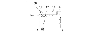
FIG. 4 is a partial plan view of the
電動アクチュエータ10は、出力部カバー132の側方の底壁12aの外面に、接続ブラケット81を有する。接続ブラケット81は、図4および図5に示すように、下側から見て、底壁12aを概ね覆う平面形状を有する。接続ブラケット81は、底壁12aの外面と対向する平板部81aと、底壁12aの角部から下側に延びるコーナー壁82b、82cとを有する。コーナー壁82b、82cは、下側から見てL形である。
The
平板部81aの三辺はハウジング本体12の外形辺に沿って延びる直線状である。平板部81aの下側カバー部材13と対向する辺81dは、軸方向に見て円弧状である。辺81dと下側カバー部材13との間には、辺81dに沿って延びる円弧状の隙間82が存在する。
The three sides of the
電動アクチュエータ10は、接続ブラケット81と底壁12aとの間に、ハウジング11の内部と外部を通気路でつなぐブリーザ構造100を有する。
ブリーザ構造100は、図2から図5に示すように、ハウジング本体12の底壁12aに設けられる凹溝15、呼吸孔16、および壁部17と、接続ブラケット81と、フィルタ83と、を含む。ブリーザ構造100は、接続ブラケット81と下側カバー部材13との間に開口するブリーザ開口部18を有する。ブリーザ構造100は、ブリーザ開口部18から凹溝15および呼吸孔16を経由してハウジング11の内部に達する通気路を有する。
The
As shown in FIGS. 2 to 5, the
凹溝15は、底壁12aの外面において、下側カバー部材13の外周端近傍から径方向外側へ延びる直線状の凹溝である。凹溝15の延びる方向における両端は、先端に向かうに従って幅が狭くなる半円状である。呼吸孔16は、底壁12aを軸方向(第1方向)に貫通する貫通孔である。呼吸孔16は、凹溝15の底面に開口する。呼吸孔16は、凹溝15の下側カバー部材13側とは反対側の端部に位置する。フィルタ83は、底壁12aの内面側の呼吸孔16の開口部を閉塞する。フィルタ83は、ベントフィルタである。
The
壁部17は、図5に示すように、凹溝15の底面から接続ブラケット81側へ延びる突起部である。壁部17は、図2に示すように、凹溝15の内側において、呼吸孔16の周囲に沿って円弧状に延びる。壁部17の高さは、凹溝15の深さと同等である。
As shown in FIG. 5, the
接続ブラケット81は、図5に示すように、底壁12aの外面に接して配置される。これにより、接続ブラケット81により凹溝15の一部領域が覆われ、凹溝15の内部が管状の通気路となる。すなわち、本実施形態の接続ブラケット81は、ブリーザ構造100において凹溝15を部分的に覆う蓋体である。凹溝15の下側カバー部材13側の端部が接続ブラケット81の外側に露出し、ブリーザ開口部18となる。
As shown in FIG. 5, the
ブリーザ構造100では、凹溝15の呼吸孔16が設けられた部位を接続ブラケット81が覆っているので、呼吸孔16は、凹溝15と接続ブラケット81に囲まれる通気路と、ブリーザ開口部18を介して外部空間につながる。長く延びる通気路を設けることで、ブリーザ開口部18から内部へ流入する水などの液体は、呼吸孔16へ達する前に凹溝15または接続ブラケット81の壁面に必ず衝突する。また、凹溝15内に壁部17が配置されていることで、通気路に流入した液体は壁部17にも衝突する。これらの作用により、通気路内を進行する液体の勢いが弱まるため、呼吸孔16に高圧の液体が流れ込むのを抑制できる。その結果、ハウジング11の内部のフィルタ83を液体から保護できる。本実施形態では、凹溝15内に配置される突起部を、呼吸孔16の周囲に沿って延びる形状の壁部17としたことで、通気路に流入した液体の進路を遮る面積が大きくなり、液体の勢いを効果的に弱めることができる。
In the
壁部17は、壁部17を厚さ方向に貫通する貫通部17aを有する。壁部17の厚さ方向は、呼吸孔16が底壁12aを貫通する方向(第1方向)と直交する方向である。貫通部17aは、下側から見て、呼吸孔16からブリーザ開口部18と反対側へ延びる。すなわち、壁部17は、呼吸孔16とブリーザ開口部18との間に位置する。
上記構成により、通気路に流入した液体は、呼吸孔16に達する前に必ず壁部17に衝突する。これにより、液体の勢いが弱まるので、フィルタ83をより確実に保護できる。
また、壁部17に貫通部17aを設けていることで、通気路に液体や異物が進入して壁部17に達した場合でも、呼吸孔16と凹溝15内との通気を確保しやすい。
The
With the above configuration, the liquid flowing into the air passage always collides with the
Further, by providing the penetrating
なお、貫通部17aは、呼吸孔16の径方向において壁部17の内外をつなぐ通気路であればよい。したがって、貫通部17aは、壁部17において、他の部分と比較して低くされた部位であってもよい。貫通部17aは、壁部17の側面に開口する貫通孔であってもよい。
The penetrating
本実施形態において、壁部17は、下側から見て、呼吸孔16の周囲の半分以上を囲む。この構成により、通気路に流入した液体が呼吸孔16に進入するのを抑制できる。壁部17は、呼吸孔16の周囲の3/4以上を囲んでいてもよい。これにより、呼吸孔16の四方のうち三方を壁部17が囲むので、さらに液体が進入しにくくなる。
In the present embodiment, the
本実施形態では、ブリーザ構造100を構成する蓋体として、接続ブラケット81を用いる。これにより、凹溝15を覆う蓋体を別途設ける必要が無くなる。よって、部材数を削減でき、簡素な構造でフィルタ83を保護できる。
In this embodiment, the
本実施形態の電動アクチュエータ10は、例えば、トランスミッション装置におけるマニュアルシャフト駆動用のアクチュエータ、クラッチ駆動用のアクチュエータ、テールゲート開閉用のアクチュエータなどの車両用アクチュエータとして用いることができる。車両用アクチュエータは、車両底面などに露出された状態で設置されるため、運転時や洗車時に水にさらされやすい。本実施形態の電動アクチュエータ10は、液体の流入からフィルタを保護できるブリーザ構造100を備えているため、車両用アクチュエータとして好適である。また電動アクチュエータ10は、車両用に限らず、他の用途にも使用可能である。
The
(第1変形例)
図6は、第1変形例のブリーザ構造を備えた電動アクチュエータの部分平面図である。図7は、図6のC−C線に沿う断面図である。
図6および図7に示す第1変形例のブリーザ構造101は、凹溝15Aと、呼吸孔16と、壁部17と、ブリーザ開口部18Aと、接続ブラケット81Aと、フィルタ83と、を有する。
(First modification)
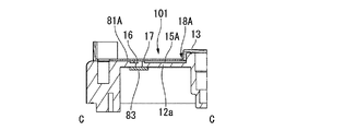
FIG. 6 is a partial plan view of the electric actuator provided with the breather structure of the first modification. FIG. 7 is a cross-sectional view taken along the line CC of FIG.
The
第1変形例のブリーザ構造101では、凹溝15Aの下側カバー部材13側の端部が、下側から見て、下側カバー部材13と重なる位置まで延びる。具体的には、凹溝15Aは、下側から見て、減速機構カバー131と重なる位置まで延びる。すなわち本実施形態では、減速機構カバー131は、ブリーザ構造101における蓋体の一部である。
なお、本実施形態において、減速機構カバー131(下側カバー部材13)が径方向外側へさらに延び、凹溝15Aを覆う形状であってもよい。この場合には、減速機構カバー131がブリーザ構造101の蓋体である。
In the
In the present embodiment, the speed reduction mechanism cover 131 (lower cover member 13) may be further extended outward in the radial direction to cover the
接続ブラケット81Aは、図4に示す接続ブラケット81と比較して、下側カバー部材13のより近くまで延びる。接続ブラケット81Aと下側カバー部材13との隙間82Aは、図4に示す隙間82と比較して幅が狭い。ブリーザ開口部18Aは、凹溝15Aのうち、隙間82に露出する部位に位置する。第1変形例のブリーザ構造101は、ブリーザ開口部18Aの開口面積が狭いため、電動アクチュエータ10が高圧の液体に曝された場合でも、ブリーザ開口部18Aから内部へ液体が進入しにくい。これにより、フィルタ83を効果的に保護できる。
The
なお、上記実施形態および第1変形例では、接続ブラケット81、81Aや、下側カバー部材13の減速機構カバー131が、ブリーザ構造100、100Aの蓋体である構成としたが、これらの構成に限定されない。例えば、ブリーザ構造100、100Aの蓋体として、電動アクチュエータ10と接続される機器(例えばロボットなど)の筐体の一部を用いることもできる。
In the above embodiment and the first modification, the
(第2変形例)
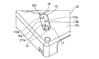
図8は、第2変形例のブリーザ構造を備えるハウジング本体12の部分斜視図である。
図8に示す第2変形例のブリーザ構造102は、凹溝15と、呼吸孔16と、壁部17と、ブリーザ開口部18と、3つの突起部171、172、173と、を有する。第2変形例のブリーザ構造102は、実施形態のブリーザ構造100において、凹溝15内に3つの突起部171〜173が配置された構成である。
(Second modification)
FIG. 8 is a partial perspective view of the
The
突起部171〜173は、凹溝15の底面から下側へ突出する。突起部171〜173は、下側から見て凹溝15の幅方向に直線状に延びる形状を有する。突起部171〜173は、ブリーザ開口部18と呼吸孔16との間に等間隔に配置される。突起部171〜173の高さは、凹溝15の深さよりも小さい。そのため、底壁12a上に接続ブラケット81が配置されたときに、突起部171〜173と接続ブラケット81との間には隙間が存在する。したがって、突起部171〜173は、ブリーザ開口部18から呼吸孔16に至る通気路を閉塞しない。
The protruding
上記構成を備えた第2変形例のブリーザ構造102では、呼吸孔16とブリーザ開口部18と間の通気路に、複数の突起部171〜173が配置される。これにより、突起部171〜173の位置において通気路が狭くなるので、ブリーザ開口部18から液体が流入したとしても、呼吸孔16側へ進入しにくくなる。また、液体が突起部171〜173に衝突することで、液体の勢いが弱まる。その結果、呼吸孔16に液体が流入しにくくなり、内部のフィルタ83をより確実に保護できる。
In the
(第3変形例)
図9は、第3変形例のブリーザ構造を備えるハウジング本体12の部分斜視図である。
図9に示す第3変形例のブリーザ構造103は、凹溝15と、呼吸孔16と、壁部17と、ブリーザ開口部18と、3つの突起部171a、172a、173aと、を有する。第3変形例のブリーザ構造103は、第2変形例のブリーザ構造102に対して、3つの突起部171a、172a、173aの形状が異なる。
(Third modification example)
FIG. 9 is a partial perspective view of the
The
ブリーザ構造103において、突起部171a、172a、173aは、いずれも凹溝15の幅の半分程度の長さである。突起部171a、173aは、凹溝15の一方の側面15aから他方の側面15bに向かって延びる。突起部172aは、凹溝15の側面15bから側面15aへ向かって延びる。突起部171a、172a、173aは、凹溝15の延びる方向に沿ってジグザグに配置される。ここで、ジグザグに配置とは、凹溝15の延びる方向に直交する方向に複数突出する配置である。突起部171a、172a、173aの高さは、凹溝15の深さと一致する。そのため、底壁12a上に接続ブラケット81が配置されたときに、突起部171a、172a、173aは接続ブラケット81の面と接触し、通気路を部分的に塞ぐ。
In the
上記の構成により、ブリーザ構造103は、ブリーザ開口部18から呼吸孔16へ向かう通気路が、凹溝15が延びる方向に対して蛇行する形状となる。これにより、ブリーザ開口部18から液体が流入したとしても、呼吸孔16側へ進行しにくくなる。また、液体が突起部171a、172a、173aに衝突することで、液体の勢いが弱まる。その結果、呼吸孔16に液体が流入しにくくなり、内部のフィルタ83をより確実に保護できる。
With the above configuration, the
10…電動アクチュエータ、11…ハウジング、12…ハウジング本体、17a…貫通部、15,15A…凹溝、16…呼吸孔、17…壁部、18,18A…ブリーザ開口部、30…減速機構、171,171a,172a…突起部、81,81A…接続ブラケット、83…フィルタ、100,101,102,103…ブリーザ構造、131…減速機構カバー 10 ... electric actuator, 11 ... housing, 12 ... housing body, 17a ... penetration, 15, 15A ... concave groove, 16 ... breathing hole, 17 ... wall, 18, 18A ... breather opening, 30 ... deceleration mechanism, 171 , 171a, 172a ... Protrusions, 81, 81A ... Connection bracket, 83 ... Filter, 100, 101, 102, 103 ... Breather structure, 131 ... Reduction mechanism cover
Claims (9)
前記ハウジングの外表面に位置する凹溝と、
前記凹溝の底面に位置し、前記ハウジングを第1方向に貫通する呼吸孔と、
前記ハウジングの内側から前記呼吸孔に固定されるフィルタと、
前記第1方向から見て前記呼吸孔を含む前記凹溝の一部領域を前記ハウジングの外側から覆う蓋体と、
前記凹溝の前記蓋体から露出する部位に位置するブリーザ開口部と、
前記凹溝の底面から前記蓋体側へ突出する突起部と、
を備え、
前記突起部は、前記呼吸孔の周囲に沿って延びる壁部であり、
前記壁部を側面から厚さ方向に貫通する貫通部を有し、
前記貫通部は、平面視において前記ブリーザ開口部と反対側に開口する、アクチュエータのブリーザ構造。 It is a breather structure provided in the housing of the actuator.
A concave groove located on the outer surface of the housing and
A breathing hole located on the bottom surface of the recess and penetrating the housing in the first direction,
A filter fixed to the breathing hole from the inside of the housing,
A lid that covers a part of the concave groove including the breathing hole from the outside of the housing when viewed from the first direction.
A breather opening located at a portion of the concave groove exposed from the lid, and
A protrusion protruding from the bottom surface of the concave groove toward the lid body,
Equipped with a,
The protrusion is a wall portion extending along the periphery of the breathing hole.
It has a penetrating portion that penetrates the wall portion from the side surface in the thickness direction.
The penetrating portion is an actuator breather structure that opens on the opposite side of the breather opening in a plan view.
前記ハウジングは、前記減速機構を保持するハウジング本体と減速機構カバーとを有し、
前記蓋体は、前記アクチュエータの減速機構カバーである、請求項1から5のいずれか1項に記載のアクチュエータのブリーザ構造。 The actuator has a deceleration mechanism housed in the housing.
The housing has a housing body for holding the deceleration mechanism and a deceleration mechanism cover.
The breather structure of the actuator according to any one of claims 1 to 5 , wherein the lid is a reduction mechanism cover of the actuator.
Priority Applications (3)
| Application Number | Priority Date | Filing Date | Title |
|---|---|---|---|
| JP2017070036A JP6880932B2 (en) | 2017-03-31 | 2017-03-31 | Actuator breather structure |
| US15/936,530 US10443702B2 (en) | 2017-03-31 | 2018-03-27 | Breather structure of actuator |
| CN201820441960.5U CN207994781U (en) | 2017-03-31 | 2018-03-29 | The ventilating structure of actuator |
Applications Claiming Priority (1)
| Application Number | Priority Date | Filing Date | Title |
|---|---|---|---|
| JP2017070036A JP6880932B2 (en) | 2017-03-31 | 2017-03-31 | Actuator breather structure |
Publications (3)
| Publication Number | Publication Date |
|---|---|
| JP2018174629A JP2018174629A (en) | 2018-11-08 |
| JP2018174629A5 JP2018174629A5 (en) | 2020-03-26 |
| JP6880932B2 true JP6880932B2 (en) | 2021-06-02 |
Family
ID=63672248
Family Applications (1)
| Application Number | Title | Priority Date | Filing Date |
|---|---|---|---|
| JP2017070036A Active JP6880932B2 (en) | 2017-03-31 | 2017-03-31 | Actuator breather structure |
Country Status (3)
| Country | Link |
|---|---|
| US (1) | US10443702B2 (en) |
| JP (1) | JP6880932B2 (en) |
| CN (1) | CN207994781U (en) |
Families Citing this family (7)
| Publication number | Priority date | Publication date | Assignee | Title |
|---|---|---|---|---|
| JP6822282B2 (en) * | 2017-03-31 | 2021-01-27 | 日本電産トーソク株式会社 | Electric actuator |
| JP7261603B2 (en) * | 2019-02-13 | 2023-04-20 | 日立Astemo株式会社 | Electric driving device and electric power steering device |
| JP7195226B2 (en) * | 2019-06-27 | 2022-12-23 | 日立Astemo株式会社 | electric liquid feed pump |
| JP7272305B2 (en) * | 2020-03-19 | 2023-05-12 | 株式会社デンソー | Actuator breather structure |
| JP7367576B2 (en) | 2020-03-19 | 2023-10-24 | 株式会社デンソー | rotary actuator |
| CN113738841A (en) * | 2020-05-28 | 2021-12-03 | 日本电产株式会社 | Drive device |
| US11787551B1 (en) | 2022-10-06 | 2023-10-17 | Archer Aviation, Inc. | Vertical takeoff and landing aircraft electric engine configuration |
Family Cites Families (21)
| Publication number | Priority date | Publication date | Assignee | Title |
|---|---|---|---|---|
| DE2124434A1 (en) * | 1971-05-17 | 1972-11-30 | Porsche Kg | Closure for ventilating and ventilating oil-bearing spaces, especially for gear boxes |
| JPS56120871A (en) * | 1980-02-28 | 1981-09-22 | Nissan Motor Co Ltd | Air breezer |
| JPS59219527A (en) * | 1983-05-26 | 1984-12-10 | Fuji Tekkosho:Kk | Waterproof structure of clutch ventilating device |
| JPS6246744A (en) * | 1985-08-26 | 1987-02-28 | Nissan Motor Co Ltd | Wiper motor |
| JPH09172750A (en) * | 1995-10-20 | 1997-06-30 | Mitsubishi Electric Corp | Waterproof structure of electric rotating machine |
| FR2750812B1 (en) * | 1996-07-08 | 1999-04-02 | Valeo Systemes Dessuyage | GEAR GEAR WITH BLADE HOLDER PLATE |
| US6015444A (en) * | 1998-02-27 | 2000-01-18 | Eaton Corporation | Apparatus and system for venting a transmission |
| JP4604322B2 (en) * | 2000-04-13 | 2011-01-05 | Nok株式会社 | Breeza |
| JP2006216157A (en) | 2005-02-03 | 2006-08-17 | Hitachi Global Storage Technologies Netherlands Bv | Magnetic disk device |
| JP2007124798A (en) | 2005-10-27 | 2007-05-17 | Nsk Ltd | Motor unit |
| US7597114B2 (en) * | 2006-03-10 | 2009-10-06 | Chrysler Group Llc | Venting device |
| JP2007329995A (en) * | 2006-06-06 | 2007-12-20 | Asmo Co Ltd | Motor |
| EP1921732A1 (en) * | 2006-11-13 | 2008-05-14 | ArvinMeritor Light Vehicle Systems-France | Housing for a drive unit, and method for manufacturing such housing |
| CN101842615B (en) * | 2007-10-18 | 2013-05-01 | Nok株式会社 | Breather |
| JP2010063224A (en) | 2008-09-02 | 2010-03-18 | Jtekt Corp | Electric motor unit |
| JP5560004B2 (en) * | 2009-08-05 | 2014-07-23 | 株式会社マキタ | Work tools |
| FR2985699B1 (en) * | 2012-01-18 | 2015-02-13 | Valeo Systemes Dessuyage | DEVICE FOR PROTECTING A BREATHING MEMBRANE, MOTORIZING UNIT AND WIPING SYSTEM PROVIDED WITH SUCH A DEVICE |
| JP2015090726A (en) | 2013-11-04 | 2015-05-11 | 株式会社ジェイテクト | Electric oil pump device |
| JP2017034880A (en) * | 2015-08-03 | 2017-02-09 | 株式会社ジェイテクト | Electrically-driven oil pump device |
| CN205004863U (en) * | 2015-10-19 | 2016-01-27 | 瑞安市豪华汽车配件有限公司 | Automobile glass riser's motor element |
| DE202015106214U1 (en) * | 2015-11-17 | 2016-01-08 | ZAE-AntriebsSysteme GmbH & Co KG | Transmission with pressure compensation |
-
2017
- 2017-03-31 JP JP2017070036A patent/JP6880932B2/en active Active
-
2018
- 2018-03-27 US US15/936,530 patent/US10443702B2/en not_active Expired - Fee Related
- 2018-03-29 CN CN201820441960.5U patent/CN207994781U/en active Active
Also Published As
| Publication number | Publication date |
|---|---|
| CN207994781U (en) | 2018-10-19 |
| US20180283524A1 (en) | 2018-10-04 |
| US10443702B2 (en) | 2019-10-15 |
| JP2018174629A (en) | 2018-11-08 |
Similar Documents
| Publication | Publication Date | Title |
|---|---|---|
| JP6880932B2 (en) | Actuator breather structure | |
| JP7020114B2 (en) | Electric actuator | |
| US11230317B2 (en) | Rotor and motor including same | |
| CN210327272U (en) | Electric actuator | |
| JP7110872B2 (en) | electric actuator | |
| JP2019122081A (en) | Electric actuator | |
| US20180283525A1 (en) | Electric actuator | |
| JP2019122079A (en) | Electric actuator | |
| JP5344375B2 (en) | Rotation angle detector | |
| JP2019122078A (en) | Electric actuator | |
| JP7214961B2 (en) | electric actuator | |
| EP2696482B1 (en) | Claw pole type motor | |
| JP2019122080A (en) | Electric actuator | |
| CN112583187A (en) | Motor unit | |
| JP7272305B2 (en) | Actuator breather structure | |
| JP4849328B2 (en) | Double stator type motor | |
| JP7098998B2 (en) | Electric actuator | |
| JP7091799B2 (en) | Electric actuator | |
| CN111670531B (en) | Motor | |
| WO2018180657A1 (en) | Electric actuator | |
| JP4760204B2 (en) | Drive device | |
| JP5606078B2 (en) | motor | |
| JP5820686B2 (en) | motor | |
| JP7356600B2 (en) | motor | |
| EP3715222A1 (en) | Sensor device |
Legal Events
| Date | Code | Title | Description |
|---|---|---|---|
| A521 | Written amendment |
Free format text: JAPANESE INTERMEDIATE CODE: A523 Effective date: 20200212 |
|
| RD02 | Notification of acceptance of power of attorney |
Free format text: JAPANESE INTERMEDIATE CODE: A7422 Effective date: 20200212 |
|
| A621 | Written request for application examination |
Free format text: JAPANESE INTERMEDIATE CODE: A621 Effective date: 20200213 |
|
| A131 | Notification of reasons for refusal |
Free format text: JAPANESE INTERMEDIATE CODE: A131 Effective date: 20201027 |
|
| A977 | Report on retrieval |
Free format text: JAPANESE INTERMEDIATE CODE: A971007 Effective date: 20201030 |
|
| A521 | Written amendment |
Free format text: JAPANESE INTERMEDIATE CODE: A523 Effective date: 20201125 |
|
| TRDD | Decision of grant or rejection written | ||
| A01 | Written decision to grant a patent or to grant a registration (utility model) |
Free format text: JAPANESE INTERMEDIATE CODE: A01 Effective date: 20210406 |
|
| A61 | First payment of annual fees (during grant procedure) |
Free format text: JAPANESE INTERMEDIATE CODE: A61 Effective date: 20210419 |
|
| R150 | Certificate of patent or registration of utility model |
Ref document number: 6880932 Country of ref document: JP Free format text: JAPANESE INTERMEDIATE CODE: R150 |