JP6876796B2 - Methods and systems for automatic real-time adaptive scanning with an optical rangefinder - Google Patents
Methods and systems for automatic real-time adaptive scanning with an optical rangefinder Download PDFInfo
- Publication number
- JP6876796B2 JP6876796B2 JP2019527224A JP2019527224A JP6876796B2 JP 6876796 B2 JP6876796 B2 JP 6876796B2 JP 2019527224 A JP2019527224 A JP 2019527224A JP 2019527224 A JP2019527224 A JP 2019527224A JP 6876796 B2 JP6876796 B2 JP 6876796B2
- Authority
- JP
- Japan
- Prior art keywords
- distance
- gate
- angle
- resolution
- scanning
- Prior art date
- Legal status (The legal status is an assumption and is not a legal conclusion. Google has not performed a legal analysis and makes no representation as to the accuracy of the status listed.)
- Active
Links
- 238000000034 method Methods 0.000 title claims description 56
- 230000003287 optical effect Effects 0.000 title claims description 42
- 230000003044 adaptive effect Effects 0.000 title description 54
- 238000005259 measurement Methods 0.000 claims description 59
- 238000012545 processing Methods 0.000 claims description 17
- 230000008569 process Effects 0.000 claims description 11
- 230000004044 response Effects 0.000 claims description 3
- 238000010586 diagram Methods 0.000 description 25
- 238000005070 sampling Methods 0.000 description 21
- 230000006854 communication Effects 0.000 description 20
- 238000004891 communication Methods 0.000 description 20
- 230000006870 function Effects 0.000 description 18
- 238000001514 detection method Methods 0.000 description 16
- 230000005540 biological transmission Effects 0.000 description 10
- 238000000926 separation method Methods 0.000 description 8
- 230000035559 beat frequency Effects 0.000 description 7
- 230000008901 benefit Effects 0.000 description 6
- 230000008859 change Effects 0.000 description 5
- 230000003068 static effect Effects 0.000 description 5
- 230000001934 delay Effects 0.000 description 4
- 238000002474 experimental method Methods 0.000 description 4
- 238000012986 modification Methods 0.000 description 4
- 230000004048 modification Effects 0.000 description 4
- 240000004050 Pentaglottis sempervirens Species 0.000 description 3
- 235000004522 Pentaglottis sempervirens Nutrition 0.000 description 3
- 230000009471 action Effects 0.000 description 3
- 230000003111 delayed effect Effects 0.000 description 3
- 239000000835 fiber Substances 0.000 description 3
- 238000003384 imaging method Methods 0.000 description 3
- 230000003993 interaction Effects 0.000 description 3
- HPTJABJPZMULFH-UHFFFAOYSA-N 12-[(Cyclohexylcarbamoyl)amino]dodecanoic acid Chemical compound OC(=O)CCCCCCCCCCCNC(=O)NC1CCCCC1 HPTJABJPZMULFH-UHFFFAOYSA-N 0.000 description 2
- 238000004364 calculation method Methods 0.000 description 2
- 230000001186 cumulative effect Effects 0.000 description 2
- 238000007405 data analysis Methods 0.000 description 2
- 230000001419 dependent effect Effects 0.000 description 2
- 230000000670 limiting effect Effects 0.000 description 2
- 230000007246 mechanism Effects 0.000 description 2
- 230000002829 reductive effect Effects 0.000 description 2
- 230000000717 retained effect Effects 0.000 description 2
- 230000002123 temporal effect Effects 0.000 description 2
- RYGMFSIKBFXOCR-UHFFFAOYSA-N Copper Chemical compound [Cu] RYGMFSIKBFXOCR-UHFFFAOYSA-N 0.000 description 1
- 230000006978 adaptation Effects 0.000 description 1
- 238000007792 addition Methods 0.000 description 1
- 238000013459 approach Methods 0.000 description 1
- 238000003491 array Methods 0.000 description 1
- 230000001174 ascending effect Effects 0.000 description 1
- 230000002238 attenuated effect Effects 0.000 description 1
- 230000006399 behavior Effects 0.000 description 1
- 230000007175 bidirectional communication Effects 0.000 description 1
- 230000001427 coherent effect Effects 0.000 description 1
- 239000004020 conductor Substances 0.000 description 1
- 238000010276 construction Methods 0.000 description 1
- 238000007796 conventional method Methods 0.000 description 1
- 229910052802 copper Inorganic materials 0.000 description 1
- 239000010949 copper Substances 0.000 description 1
- 238000013480 data collection Methods 0.000 description 1
- 230000006866 deterioration Effects 0.000 description 1
- 230000009977 dual effect Effects 0.000 description 1
- 230000000694 effects Effects 0.000 description 1
- 238000005516 engineering process Methods 0.000 description 1
- 238000013213 extrapolation Methods 0.000 description 1
- 238000001914 filtration Methods 0.000 description 1
- 238000011835 investigation Methods 0.000 description 1
- 239000004973 liquid crystal related substance Substances 0.000 description 1
- 239000000463 material Substances 0.000 description 1
- 238000000691 measurement method Methods 0.000 description 1
- 238000002156 mixing Methods 0.000 description 1
- 230000001343 mnemonic effect Effects 0.000 description 1
- 238000002360 preparation method Methods 0.000 description 1
- 239000002096 quantum dot Substances 0.000 description 1
- 230000035945 sensitivity Effects 0.000 description 1
- 239000000126 substance Substances 0.000 description 1
- 238000012360 testing method Methods 0.000 description 1
- 238000012546 transfer Methods 0.000 description 1
- 238000013519 translation Methods 0.000 description 1
- 238000011144 upstream manufacturing Methods 0.000 description 1
Images


Classifications
-
- G—PHYSICS
- G01—MEASURING; TESTING
- G01S—RADIO DIRECTION-FINDING; RADIO NAVIGATION; DETERMINING DISTANCE OR VELOCITY BY USE OF RADIO WAVES; LOCATING OR PRESENCE-DETECTING BY USE OF THE REFLECTION OR RERADIATION OF RADIO WAVES; ANALOGOUS ARRANGEMENTS USING OTHER WAVES
- G01S17/00—Systems using the reflection or reradiation of electromagnetic waves other than radio waves, e.g. lidar systems
- G01S17/02—Systems using the reflection of electromagnetic waves other than radio waves
- G01S17/06—Systems determining position data of a target
- G01S17/42—Simultaneous measurement of distance and other co-ordinates
-
- G—PHYSICS
- G01—MEASURING; TESTING
- G01S—RADIO DIRECTION-FINDING; RADIO NAVIGATION; DETERMINING DISTANCE OR VELOCITY BY USE OF RADIO WAVES; LOCATING OR PRESENCE-DETECTING BY USE OF THE REFLECTION OR RERADIATION OF RADIO WAVES; ANALOGOUS ARRANGEMENTS USING OTHER WAVES
- G01S13/00—Systems using the reflection or reradiation of radio waves, e.g. radar systems; Analogous systems using reflection or reradiation of waves whose nature or wavelength is irrelevant or unspecified
- G01S13/02—Systems using reflection of radio waves, e.g. primary radar systems; Analogous systems
- G01S13/06—Systems determining position data of a target
- G01S13/08—Systems for measuring distance only
- G01S13/10—Systems for measuring distance only using transmission of interrupted, pulse modulated waves
- G01S13/18—Systems for measuring distance only using transmission of interrupted, pulse modulated waves wherein range gates are used
-
- G—PHYSICS
- G01—MEASURING; TESTING
- G01S—RADIO DIRECTION-FINDING; RADIO NAVIGATION; DETERMINING DISTANCE OR VELOCITY BY USE OF RADIO WAVES; LOCATING OR PRESENCE-DETECTING BY USE OF THE REFLECTION OR RERADIATION OF RADIO WAVES; ANALOGOUS ARRANGEMENTS USING OTHER WAVES
- G01S13/00—Systems using the reflection or reradiation of radio waves, e.g. radar systems; Analogous systems using reflection or reradiation of waves whose nature or wavelength is irrelevant or unspecified
- G01S13/02—Systems using reflection of radio waves, e.g. primary radar systems; Analogous systems
- G01S13/06—Systems determining position data of a target
- G01S13/08—Systems for measuring distance only
- G01S13/32—Systems for measuring distance only using transmission of continuous waves, whether amplitude-, frequency-, or phase-modulated, or unmodulated
- G01S13/34—Systems for measuring distance only using transmission of continuous waves, whether amplitude-, frequency-, or phase-modulated, or unmodulated using transmission of continuous, frequency-modulated waves while heterodyning the received signal, or a signal derived therefrom, with a locally-generated signal related to the contemporaneously transmitted signal
- G01S13/343—Systems for measuring distance only using transmission of continuous waves, whether amplitude-, frequency-, or phase-modulated, or unmodulated using transmission of continuous, frequency-modulated waves while heterodyning the received signal, or a signal derived therefrom, with a locally-generated signal related to the contemporaneously transmitted signal using sawtooth modulation
-
- G—PHYSICS
- G01—MEASURING; TESTING
- G01S—RADIO DIRECTION-FINDING; RADIO NAVIGATION; DETERMINING DISTANCE OR VELOCITY BY USE OF RADIO WAVES; LOCATING OR PRESENCE-DETECTING BY USE OF THE REFLECTION OR RERADIATION OF RADIO WAVES; ANALOGOUS ARRANGEMENTS USING OTHER WAVES
- G01S13/00—Systems using the reflection or reradiation of radio waves, e.g. radar systems; Analogous systems using reflection or reradiation of waves whose nature or wavelength is irrelevant or unspecified
- G01S13/02—Systems using reflection of radio waves, e.g. primary radar systems; Analogous systems
- G01S13/06—Systems determining position data of a target
- G01S13/42—Simultaneous measurement of distance and other co-ordinates
- G01S13/426—Scanning radar, e.g. 3D radar
- G01S13/428—Scanning radar, e.g. 3D radar within the pulse scanning systems
-
- G—PHYSICS
- G01—MEASURING; TESTING
- G01S—RADIO DIRECTION-FINDING; RADIO NAVIGATION; DETERMINING DISTANCE OR VELOCITY BY USE OF RADIO WAVES; LOCATING OR PRESENCE-DETECTING BY USE OF THE REFLECTION OR RERADIATION OF RADIO WAVES; ANALOGOUS ARRANGEMENTS USING OTHER WAVES
- G01S13/00—Systems using the reflection or reradiation of radio waves, e.g. radar systems; Analogous systems using reflection or reradiation of waves whose nature or wavelength is irrelevant or unspecified
- G01S13/02—Systems using reflection of radio waves, e.g. primary radar systems; Analogous systems
- G01S13/50—Systems of measurement based on relative movement of target
- G01S13/52—Discriminating between fixed and moving objects or between objects moving at different speeds
- G01S13/522—Discriminating between fixed and moving objects or between objects moving at different speeds using transmissions of interrupted pulse modulated waves
- G01S13/524—Discriminating between fixed and moving objects or between objects moving at different speeds using transmissions of interrupted pulse modulated waves based upon the phase or frequency shift resulting from movement of objects, with reference to the transmitted signals, e.g. coherent MTi
- G01S13/526—Discriminating between fixed and moving objects or between objects moving at different speeds using transmissions of interrupted pulse modulated waves based upon the phase or frequency shift resulting from movement of objects, with reference to the transmitted signals, e.g. coherent MTi performing filtering on the whole spectrum without loss of range information, e.g. using delay line cancellers or comb filters
-
- G—PHYSICS
- G01—MEASURING; TESTING
- G01S—RADIO DIRECTION-FINDING; RADIO NAVIGATION; DETERMINING DISTANCE OR VELOCITY BY USE OF RADIO WAVES; LOCATING OR PRESENCE-DETECTING BY USE OF THE REFLECTION OR RERADIATION OF RADIO WAVES; ANALOGOUS ARRANGEMENTS USING OTHER WAVES
- G01S13/00—Systems using the reflection or reradiation of radio waves, e.g. radar systems; Analogous systems using reflection or reradiation of waves whose nature or wavelength is irrelevant or unspecified
- G01S13/02—Systems using reflection of radio waves, e.g. primary radar systems; Analogous systems
- G01S13/50—Systems of measurement based on relative movement of target
- G01S13/58—Velocity or trajectory determination systems; Sense-of-movement determination systems
- G01S13/581—Velocity or trajectory determination systems; Sense-of-movement determination systems using transmission of interrupted pulse modulated waves and based upon the Doppler effect resulting from movement of targets
- G01S13/582—Velocity or trajectory determination systems; Sense-of-movement determination systems using transmission of interrupted pulse modulated waves and based upon the Doppler effect resulting from movement of targets adapted for simultaneous range and velocity measurements
-
- G—PHYSICS
- G01—MEASURING; TESTING
- G01S—RADIO DIRECTION-FINDING; RADIO NAVIGATION; DETERMINING DISTANCE OR VELOCITY BY USE OF RADIO WAVES; LOCATING OR PRESENCE-DETECTING BY USE OF THE REFLECTION OR RERADIATION OF RADIO WAVES; ANALOGOUS ARRANGEMENTS USING OTHER WAVES
- G01S17/00—Systems using the reflection or reradiation of electromagnetic waves other than radio waves, e.g. lidar systems
- G01S17/02—Systems using the reflection of electromagnetic waves other than radio waves
- G01S17/06—Systems determining position data of a target
- G01S17/08—Systems determining position data of a target for measuring distance only
- G01S17/10—Systems determining position data of a target for measuring distance only using transmission of interrupted, pulse-modulated waves
- G01S17/18—Systems determining position data of a target for measuring distance only using transmission of interrupted, pulse-modulated waves wherein range gates are used
-
- G—PHYSICS
- G01—MEASURING; TESTING
- G01S—RADIO DIRECTION-FINDING; RADIO NAVIGATION; DETERMINING DISTANCE OR VELOCITY BY USE OF RADIO WAVES; LOCATING OR PRESENCE-DETECTING BY USE OF THE REFLECTION OR RERADIATION OF RADIO WAVES; ANALOGOUS ARRANGEMENTS USING OTHER WAVES
- G01S17/00—Systems using the reflection or reradiation of electromagnetic waves other than radio waves, e.g. lidar systems
- G01S17/02—Systems using the reflection of electromagnetic waves other than radio waves
- G01S17/06—Systems determining position data of a target
- G01S17/08—Systems determining position data of a target for measuring distance only
- G01S17/10—Systems determining position data of a target for measuring distance only using transmission of interrupted, pulse-modulated waves
- G01S17/26—Systems determining position data of a target for measuring distance only using transmission of interrupted, pulse-modulated waves wherein the transmitted pulses use a frequency-modulated or phase-modulated carrier wave, e.g. for pulse compression of received signals
-
- G—PHYSICS
- G01—MEASURING; TESTING
- G01S—RADIO DIRECTION-FINDING; RADIO NAVIGATION; DETERMINING DISTANCE OR VELOCITY BY USE OF RADIO WAVES; LOCATING OR PRESENCE-DETECTING BY USE OF THE REFLECTION OR RERADIATION OF RADIO WAVES; ANALOGOUS ARRANGEMENTS USING OTHER WAVES
- G01S17/00—Systems using the reflection or reradiation of electromagnetic waves other than radio waves, e.g. lidar systems
- G01S17/02—Systems using the reflection of electromagnetic waves other than radio waves
- G01S17/06—Systems determining position data of a target
- G01S17/08—Systems determining position data of a target for measuring distance only
- G01S17/32—Systems determining position data of a target for measuring distance only using transmission of continuous waves, whether amplitude-, frequency-, or phase-modulated, or unmodulated
- G01S17/34—Systems determining position data of a target for measuring distance only using transmission of continuous waves, whether amplitude-, frequency-, or phase-modulated, or unmodulated using transmission of continuous, frequency-modulated waves while heterodyning the received signal, or a signal derived therefrom, with a locally-generated signal related to the contemporaneously transmitted signal
-
- G—PHYSICS
- G01—MEASURING; TESTING
- G01S—RADIO DIRECTION-FINDING; RADIO NAVIGATION; DETERMINING DISTANCE OR VELOCITY BY USE OF RADIO WAVES; LOCATING OR PRESENCE-DETECTING BY USE OF THE REFLECTION OR RERADIATION OF RADIO WAVES; ANALOGOUS ARRANGEMENTS USING OTHER WAVES
- G01S17/00—Systems using the reflection or reradiation of electromagnetic waves other than radio waves, e.g. lidar systems
- G01S17/88—Lidar systems specially adapted for specific applications
- G01S17/89—Lidar systems specially adapted for specific applications for mapping or imaging
-
- G—PHYSICS
- G01—MEASURING; TESTING
- G01S—RADIO DIRECTION-FINDING; RADIO NAVIGATION; DETERMINING DISTANCE OR VELOCITY BY USE OF RADIO WAVES; LOCATING OR PRESENCE-DETECTING BY USE OF THE REFLECTION OR RERADIATION OF RADIO WAVES; ANALOGOUS ARRANGEMENTS USING OTHER WAVES
- G01S7/00—Details of systems according to groups G01S13/00, G01S15/00, G01S17/00
- G01S7/48—Details of systems according to groups G01S13/00, G01S15/00, G01S17/00 of systems according to group G01S17/00
- G01S7/481—Constructional features, e.g. arrangements of optical elements
- G01S7/4817—Constructional features, e.g. arrangements of optical elements relating to scanning
-
- G—PHYSICS
- G01—MEASURING; TESTING
- G01S—RADIO DIRECTION-FINDING; RADIO NAVIGATION; DETERMINING DISTANCE OR VELOCITY BY USE OF RADIO WAVES; LOCATING OR PRESENCE-DETECTING BY USE OF THE REFLECTION OR RERADIATION OF RADIO WAVES; ANALOGOUS ARRANGEMENTS USING OTHER WAVES
- G01S7/00—Details of systems according to groups G01S13/00, G01S15/00, G01S17/00
- G01S7/48—Details of systems according to groups G01S13/00, G01S15/00, G01S17/00 of systems according to group G01S17/00
- G01S7/497—Means for monitoring or calibrating
Description
関連出願の相互参照
本出願は、2016年11月30日に出願された仮出願番号62/428,117の利益を主張するものであり、35U.S.C.§119(e)にしたがって、本参照により、前記仮出願の全内容が本明細書に組み込まれ、そこに記載されているものとされる。
Cross-reference to related applications This application claims the interests of provisional application Nos. 62 / 428,117 filed on November 30, 2016, at 35 U.S.A. S. C. According to § 119 (e), by reference here, the entire contents of the provisional application shall be incorporated herein and set forth herein.
政府利益の記載
本発明は、陸軍省により与えられた政府支援W9132V−14−C−0002を得て、なされたものである。政府は、本発明に対する一定の権利を有する。
Description of Government Benefits The present invention was made with the government support W9132V-14-C-0002 given by the Ministry of the Army. The government has certain rights to the invention.
ニーモニックによりしばしばLIDARと呼ばれる、光検知と測距のための光学測距は、高度測定から、撮像、衝突回避に至るまで、様々な適用に利用される。LIDARは、無線波検知と測距(RADAR)など、従来のマイクロ波測距システムに比べて、より小さいビームサイズを用いて、より細密な距離解像度を提供する。光学測距は、物体への光パルスの往復時間に基づく直接測距、送信されたチャープ光信号と物体に散乱されて戻って来た信号の間の周波数の差に基づくチャープ検知、自然信号から区別可能な単一周波数の位相変化のシーケンスに基づく位相符号化検知など、いくつかの異なる技術を用いて実現可能である。 Optical rangefinders for photodetection and rangefindering, often referred to by mnemonics as lidar, are used in a variety of applications, from altitude measurement to imaging and collision avoidance. LIDAR provides finer distance resolution using smaller beam sizes than traditional microwave ranging systems, such as radio wave detection and radar. Optical ranging is based on direct ranging time based on the round trip time of the optical pulse to the object, chirp detection based on the frequency difference between the transmitted chirp optical signal and the signal scattered by the object and returned, from the natural signal. It can be achieved using several different techniques, such as phase coding detection based on a sequence of distinguishable single frequency phase changes.
許容可能な距離の確度と検知感度を達成するために、直接長距離測距LIDARシステムは、低パルス反復率と極めて高いパルスピーク電力を有する短いパルスのレーザを用いる。高パルス電力は、光学コンポーネントの急速な劣化につながり得る。チャープLIDARシステムと位相符号化LIDARシステムは、比較的低いピーク光出力を有する長い光パルスを用いる。この構成では、パルス幅ではなく、チャープ帯域幅または位相符号の長さとともに、距離確度が増加するので、いっそう優れた距離確度が達成可能である。 To achieve acceptable range accuracy and detection sensitivity, direct long-range lidar systems use short-pulse lasers with low pulse repetition rates and extremely high pulse peak power. High pulse power can lead to rapid deterioration of optical components. Chirp lidar systems and phase-coded lidar systems use long optical pulses with relatively low peak light output. In this configuration, better distance accuracy can be achieved because the distance accuracy increases with the chirp bandwidth or the length of the phase sign rather than the pulse width.
光搬送波を変調するために広帯域無線周波数(RF)電気信号を用いて、有用な光チャープ帯域幅が実現された。最近のチャープLIDARの進歩としては、光検知器で戻って来た信号と組み合わされる基準信号と同じ変調光搬送波を用いて、基準信号と戻って来た信号の間の周波数または位相の差に比例する、比較的低いビート周波数を、生成電気信号に生じさせることなどがある。検知器における周波数の差の、この種のビート周波数検知は、ヘテロダイン検知と呼ばれる。これは、既成の安価な無線周波数コンポーネントを利用できることなど、この技術分野において既知の利点をいくつか有する。米国特許番号7,742,152に記載された最近の研究は、基準光信号として、送信光信号から分割された光信号を使用する、新規の、より単純な、光コンポーネント配置を示している。この配置は、この特許では、ホモダイン検知と呼ばれている。 A useful optical chirp bandwidth has been achieved using wideband radio frequency (RF) electrical signals to modulate the optical carrier. A recent advance in Charp LIDAR is that it uses the same modulated optical carrier as the reference signal combined with the signal returned by the optical detector and is proportional to the frequency or phase difference between the reference signal and the returned signal. However, a relatively low beat frequency may be generated in the generated electric signal. This type of beat frequency detection of frequency differences in the detector is called heterodyne detection. It has some known advantages in the art, such as the availability of off-the-shelf inexpensive radio frequency components. A recent study described in US Pat. No. 7,742,152 has shown a novel, simpler, optical component arrangement that uses an optical signal segmented from the transmitted optical signal as the reference optical signal. This arrangement is referred to in this patent as homodyne detection.
位相符号化マイクロ波信号で光搬送波を変調するLIDAR検知も、用いられている。この技術は、戻って来た信号の特定周波数の位相(または位相変化)のシーケンスと、送信信号のそれとの相関を用いる。相関におけるピークに関連する時間遅延が、媒質中の光の速度による測距に関連づけられる。この技術の利点は、必要なコンポーネントの数が少ないこと、位相符号化マイクロ波および光通信のために開発された大量生産ハードウェアコンポーネントを使用できることなどである。 LIDAR detection, which modulates an optical carrier with a phase-coded microwave signal, has also been used. This technique uses the correlation between the sequence of the phase (or phase change) of a specific frequency of the returned signal and that of the transmitted signal. The time delay associated with the peak in the correlation is associated with the distance measurement by the speed of light in the medium. Advantages of this technology include the low number of components required and the availability of mass-produced hardware components developed for phase-coded microwave and optical communications.
本発明者は、従来の方法よりも短い時間で、目標とする空間解像度をもって物体を走査するためには、変化が望まれること、また、この目的の達成は、適応走査と呼ばれる、所望の物体に関連する角度範囲内に、光学測距システムによる走査を集中することによって可能になることに気づいた。走査レーザ測距システムによる自動またはリアルタイム適応走査の技術が提供される。 In order to scan an object with a target spatial resolution in a shorter time than the conventional method, the present inventor desires a change, and achievement of this purpose is a desired object called adaptive scanning. We have found that this is possible by concentrating the scans by the optical ranging system within the angular range associated with. Techniques for automatic or real-time adaptive scanning with a scanning laser ranging system are provided.
第1の実施形態のセットにおいては、方法は、走査レーザ測距システムの視野内で目標最大距離での物体の距離測定のための目標空間解像度、および、システムに、目標最大距離での疎角度解像度を生成させる、システムのための疎角度解像度を決定することを含み、この疎空間解像度は目標空間解像度より大きいものである。この方法はまた、走査レーザ測距システムを動作させて、第1の次元の疎開始角と第1の次元の疎停止角の間の疎角解像度に基づく第1の次元の疎角解像度で、第1の次元における、および、第2の次元の疎開始角と第2の次元の疎停止角の間の疎角解像度に基づく第2の次元の疎角解像度で、第2の次元における、複数の疎距離測定値を得ることを含む。さらに、この方法は、疎距離測定値のうちの、第1の次元の整理された距離ゲートのサブセットを決定することを含み、距離ゲートサブセット中の各距離測定値は、サブセットの最小距離以上であり、かつサブセットの最大距離未満である。さらに、この方法は、距離ゲートサブセットに基づいてサブセットの最小距離とサブセットの最大距離の間の特徴的距離を自動的に決定することを含む。さらに、この方法は、特徴的距離と目標空間解像度に基づいて第1の次元の細密角解像度と第2の次元の細密角解像度を自動的に決定することを含む。さらに、第1の次元の細密角解像度が、第1の次元の疎角解像度より細密である場合、または、第2の次元の細密角解像度が、第2の次元の疎角解像度より細密である場合、この方法は、以下の工程を含む。サブセットの第1の次元の角のビンサイズが、第1の次元の疎角解像度に基づいて自動的に決定される。任意の前の第1の次元のスライスからサブセットの第1の次元の角のビンサイズを延長する第1の次元のそれぞれのスライスにおける、第2の次元の最小角と第2の次元の最大角が、自動的に決定される。第2の次元の適応最小角と第2の次元の適応最大角のセットが、すべてのスライスの第2の次元の最小角と第2の次元の最大角を、第1の次元の細密角解像度まで拡張し、内挿補間することによって、自動的に決定される。適応走査特性がシステムに送信され、これは、走査レーザ測距システムに、第1の次元の各スライスについて、第1の次元の細密解像度で、および、第2の次元の最小角と第2の次元の最大角の間における第2の次元の細密角解像度で、距離測定値を得させる、角解像度、第1の次元の開始角、第1の次元のビンサイズ、および第2の次元の適応最小角と第2の次元の適応最大角のセットを送信することを含む。 In a set of first embodiments, the method is a target spatial resolution for measuring the distance of an object at a target maximum distance within the field of view of a scanning laser ranging system, and a sparse angle at the target maximum distance to the system. This sparse spatial resolution is greater than the target spatial resolution, including determining the sparse angular resolution for the system that produces the resolution. This method also operates a scanning laser ranging system with a sparse angle resolution of the first dimension based on the sparse angle resolution between the sparse start angle of the first dimension and the sparse stop angle of the first dimension. A plurality of sparse angle resolutions in the first dimension and in the second dimension based on the sparse angle resolution between the sparse start angle in the second dimension and the sparse stop angle in the second dimension. Includes obtaining sparse distance measurements of. Further, the method involves determining a subset of the first dimension organized distance gates of the sparse distance measurements, where each distance measurement in the distance gate subset is greater than or equal to the minimum distance of the subset. Yes, and less than the maximum distance of the subset. Further, this method involves automatically determining the characteristic distance between the minimum distance of the subset and the maximum distance of the subset based on the distance gate subset. Further, this method includes automatically determining the fine angle resolution of the first dimension and the fine angle resolution of the second dimension based on the characteristic distance and the target spatial resolution. Further, when the fine angle resolution of the first dimension is finer than the sparse angle resolution of the first dimension, or the fine angle resolution of the second dimension is finer than the sparse angle resolution of the second dimension. In the case, this method includes the following steps. The bin size of the corners of the first dimension of the subset is automatically determined based on the sparse angle resolution of the first dimension. The minimum angle of the second dimension and the maximum angle of the second dimension in each slice of the first dimension that extends the bin size of the corners of the first dimension of the subset from any previous slice of the first dimension. Is automatically determined. A set of second-dimensional adaptive minimum angles and second-dimensional adaptive maximum angles sets the second-dimensional minimum and second-dimensional maximum angles of all slices to the first-dimensional fine-angle resolution. It is automatically determined by extending to and interpolating. Adaptive scanning characteristics are transmitted to the system, which tells the scanning laser ranging system that for each slice in the first dimension, in the fine resolution of the first dimension, and the minimum angle and second of the second dimension. Angle resolution, start angle of the first dimension, bin size of the first dimension, and adaptation of the second dimension to obtain distance measurements with fine angle resolution of the second dimension between the maximum angles of the dimension. It involves transmitting a set of minimum angles and adaptive maximum angles in the second dimension.
第1の実施形態のセットのいくつかにおいて、走査レーザ測距システムの走査速度およびローカルオシレータ遅延時間が、自動的に決定され、そして、適応走査特性を送信する工程は、走査速度およびローカルオシレータ遅延時間を走査レーザ測距システムに送信することを、さらに含む。 In some of the first set of embodiments, the scanning speed and local oscillator delay time of the scanning laser ranging system are automatically determined, and the step of transmitting adaptive scanning characteristics is the scanning speed and local oscillator delay. Further comprising transmitting time to a scanning laser ranging system.
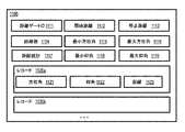
第2の実施形態のセットにおいて、非一時的コンピュータ可読媒体は、走査レーザ測距システムからの観測の第1の距離ゲートサブセットを示す第1のフィールド保持データを含み、観測のこのサブセットは、距離ゲートの最小距離から距離ゲートの最大距離までの間隔における距離を有し、そして、この媒体は、複数のレコードを含む。各レコードは、第1のレコードフィールドと第2のレコードフィールドを含む。第1のレコードフィールドは、サブセットのスライス内の第1の次元の角度を示し、サブセットのスライスは、スライスの第1の次元の最小角からスライスの第1の次元の最大角までの範囲における第1の次元の角度を有する。第2のレコードフィールドは、スライスにおける第2の次元の角度の極値を示すデータを保持し、ここで、極値は、値のセットの最大値、または値のセットの最小値である。レコードは、第1のレコードフィールドの内容の値による順番に従う。 In a second set of embodiments, the non-temporary computer-readable medium comprises first field holding data indicating a first distance gate subset of observations from a scanning laser ranging system, and this subset of observations is distance. It has a distance in the interval from the minimum distance of the gate to the maximum distance of the distance gate, and this medium contains multiple records. Each record contains a first record field and a second record field. The first record field indicates the angle of the first dimension within the slice of the subset, and the slice of the subset is the first in the range from the minimum angle of the first dimension of the slice to the maximum angle of the first dimension of the slice. It has an angle of one dimension. The second record field holds data indicating the extremum of the angle of the second dimension in the slice, where the extremum is the maximum value of the set of values or the minimum value of the set of values. The records follow the order of the contents of the first record field.
第3の実施形態のセットにおいて、走査レーザ測距システムを動作させる方法は、第1の距離測定値を取得するために、第1の基準経路遅延時間で走査レーザ測距システムを動作させることを含む。この方法は、第1の基準経路遅延時間が第1の距離測定のために有利であるか否かを決定することを含む。第1の基準経路遅延時間が第1の距離測定のために有利ではない場合、この方法は、さらに、第1の距離測定のために有利である、第2の基準経路遅延時間を決定し、その後、第2の距離測定値を取得するために、第2の基準経路遅延時間において、走査レーザ測距システムを動作させることを含む。 In the set of third embodiments, the method of operating the scanning laser ranging system is to operate the scanning laser ranging system with a first reference path delay time in order to obtain a first distance measurement. Including. This method involves determining whether the first reference path delay time is advantageous for the first distance measurement. If the first reference path delay time is not advantageous for the first distance measurement, this method further determines the second reference path delay time, which is advantageous for the first distance measurement. Then, in order to obtain the second distance measurement value, the scanning laser distance measurement system is operated at the second reference path delay time.
その他の実施形態において、システムまたは装置またはコンピュータ可読媒体は、上述の方法の1つ以上の工程を実行するように構成される。 In other embodiments, the system or device or computer-readable medium is configured to perform one or more steps of the method described above.
さらに他の態様、特徴、および利点は、以下の詳細な記載から、単に、本発明の実施のために想定される最良の形態を含む、多数の特定の実施形態および実装を例示することにより、十分に明らかである。他の実施形態も、その他の異なる特徴および利点の能力を有し、そのいくつかの詳細は、様々な自明の点において、すべて、本発明の精神と範囲を逸脱することなく、修正可能である。したがって、図面および記述は、例示的性格のものであり、制限的とみなされてはならない。 Yet other embodiments, features, and advantages are provided by simply exemplifying a number of specific embodiments and implementations, including the best possible embodiments for the practice of the present invention, from the detailed description below. It's clear enough. Other embodiments also have the ability of other different features and benefits, some of which, in various obvious points, can all be modified without departing from the spirit and scope of the invention. .. Therefore, drawings and descriptions are of an exemplary nature and should not be considered restrictive.
実施形態は、例示として示されるものであり、制限するものではなく、添付の図面において、同じ参照番号は同様の要素を示す。 The embodiments are shown by way of example and are not limiting, and in the accompanying drawings, the same reference numbers indicate similar elements.
レーザ測距システムによる適応走査のための方法、装置、システム、およびコンピュータ可読媒体を説明する。以下の記載においては、説明のために、本発明の完全な理解を可能にするために、多数の具体的詳細を記述する。ただし、本発明はそれらの具体的詳細なしでも実行可能であることは、当業者には明らかであろう。その他の例では、本発明を不必要にあいまいにすることを避けるために、周知の構造およびデバイスをブロック図に示す。 Methods, devices, systems, and computer-readable media for adaptive scanning with a laser ranging system will be described. In the following description, for illustration purposes, a number of specific details will be described to allow a complete understanding of the present invention. However, it will be apparent to those skilled in the art that the present invention is feasible without those specific details. In other examples, well-known structures and devices are shown on the block diagram to avoid unnecessarily obscuring the invention.
広い適用範囲を表す距離およびパラメータの数値は近似であるけれども、具体的な非制限的例示に示す数値は、可能な限り、正確に報告する。ただし、数値は、本質的に、本明細書作成時の、それぞれの試験測定値に見られる標準偏差に由来する誤差を必然的に含む。さらに、文脈から明らかな場合を除き、本明細書に示される数値は、最下位桁が精度を示すものとする。したがって、値1.1は、1.05と1.15の間の値を表す。「約」という語は、所与の値を中心とする広い範囲を示すために用いられ、文脈から明らかな場合を除き、最下位桁を中心とする広い範囲を表し、例えば、「約1.1」は、1.0から1.2までの範囲を意味する。最下位桁が明確でない場合は、「約」という語は、係数2を意味するものとし、例えば、「約X」は、0.5X〜2Xの範囲の値を表し、また、例えば、約100は、50〜200の範囲の値を表す。さらに、本明細書に開示された範囲はすべて、そこに含まれる任意の、およびすべてのサブレンジを包含するものと理解されなければならない。例えば、「10未満」の範囲は、最小値0と最大値10の間(両端を含む)、すなわち、0以上の最小値かつ10以下の最大値を有する、任意の、およびすべてのサブレンジ、例えば、1〜4を、含むことができる。 Although the distance and parameter numbers that represent a wide range of applications are approximate, the numbers shown in the specific non-limiting examples should be reported as accurately as possible. However, the numerical values necessarily include errors due to the standard deviation found in each test measurement at the time of preparation of the present specification. In addition, unless the context makes clear, the numbers presented herein shall have the least significant digit indicating accuracy. Therefore, the value 1.1 represents a value between 1.05 and 1.15. The word "about" is used to indicate a wide range centered on a given value, and unless it is clear from the context, refers to a wide range centered on the least significant digit, eg, "about 1. "1" means a range from 1.0 to 1.2. If the least significant digit is unclear, the word "about" shall mean a factor of 2, for example, "about X" represents a value in the range 0.5X to 2X, and may, for example, be about 100. Represents a value in the range 50-200. In addition, all scope disclosed herein should be understood to include any and all subranges contained therein. For example, a range of "less than 10" can be any and all subranges between a minimum of 0 and a maximum of 10 (including both ends), i.e. a minimum of 0 or more and a maximum of 10 or less. , 1 to 4, can be included.
本発明のいくつかの実施形態は、線形周波数変調光信号に関連して、下述のように記述されるが、周波数変調光信号を用いなくてもよい。また別の実施形態では、振幅パルス化または位相符号化光信号が用いられる。実施形態は、限定された水平角スイープに対する静止レーザ走査に関連して記述される。また別の実施形態では、全360度の水平角スイープを含む、狭い、または広い、水平角スイープを用いる、可動レーザ測距システムが使用される。多くの実施形態は、垂直方向ののこぎり歯状走査軌跡に関して記述される。一方、別の実施形態では、垂直列順走査軌跡あるいは水平行順走査軌跡、またはそれらの組み合わせが用いられる。例えば、水平方向の運動(遅い)のための回転ステージと垂直方向(速い)のためのガルバノ走査ミラーを備えるハードウェア構成を有する実施形態では、垂直方向のこぎり歯状投影が用いられた。また別の実施形態は、2軸高速ステアリングミラー(2つの次元での高速走査、限定視野)または2軸パン−チルトユニット(2つの次元での低速運動、広大視野)、または組み合わせを用いる。 Some embodiments of the present invention are described as described below in connection with a linear frequency modulated optical signal, but the frequency modulated optical signal may not be used. In yet another embodiment, an amplitude pulsed or phase coded optical signal is used. Embodiments are described in connection with static laser scanning for a limited horizontal angle sweep. In yet another embodiment, a movable laser ranging system is used that uses a narrow or wide horizontal angle sweep, including a total 360 degree horizontal angle sweep. Many embodiments are described with respect to a vertical sawtooth scanning locus. On the other hand, in another embodiment, a vertical column forward scanning locus, a horizontal parallel scanning locus, or a combination thereof is used. For example, in an embodiment having a hardware configuration with a rotating stage for horizontal motion (slow) and a galvano scanning mirror for vertical motion (fast), vertical sawtooth projection was used. Yet another embodiment uses a two-axis high-speed steering mirror (high-speed scanning in two dimensions, limited field of view) or a two-axis pan-tilt unit (low-speed motion in two dimensions, wide field of view), or a combination.
1.チャープ検知の概要
図1Aは、実施形態による光学チャープ距離測定を例示するグラフのセット110、120、130、140である。水平軸112は、4つのグラフのすべてに共通であり、ミリ秒(ms、1ms=10−3s)程度の任意の単位の時間を示す。グラフ110は、送信光信号として使用される光ビームの出力を示す。グラフ110の垂直軸114は、任意の単位での送信信号電力を示す。トレース116は、時刻0に開始する限定的なパルス時間幅τの間、電力がオンであることを示す。グラフ120は、送信信号の周波数を示す。垂直軸124は、任意の単位での送信周波数を示す。トレース126は、パルスの周波数が、パルスの時間幅τを通じて、f1からf2へ増加し、したがって、帯域幅B=f2−f1を有することを示す。周波数変化率は、(f2−f1)/τである。
1. 1. Overview of Chirp Detection FIG. 1A is a set of
戻り信号は、時間を示す水平軸112と、グラフ120と同じように、周波数を示す垂直軸124を有する、グラフ130に描かれている。グラフ120のチャープ126も、グラフ130に、点線としてプロットされている。第1の戻り信号は、トレース136aによって示されており、送信基準信号が強度(図示せず)において減衰し、Δtだけ遅延したものと同じである。戻り信号が、標的までの距離をRとして、外部の物体から2Rの距離を進行した後、受信されると、この戻り信号は、2R/cによって与えられる遅延時間Δtの時に開始し、ここで、cは媒質中の光の速度(約3×108m/s)である。この時間を通じて、周波数は、距離に従属し、周波数の変化率に遅延時間を乗じることに得られる量fRだけ変化している。これは、式1aによって与えられる。
fR=(f2−f1)/τ*2R/c=2BR/cτ (1a)
値fRは、脱チャープ化と呼称される時間領域混合演算において、送信信号126と戻り信号136aの周波数の差によって測定される。したがって、距離Rは、式1bによって与えられる。
R=fRcτ/2B (1b)
当然、パルスが完全に送信された後に戻り信号が到着した場合、すなわち、2R/cがτより大きい場合、式1aと1bは有効ではない。この場合、ローカルオシレータ(LO)とも呼ばれる基準信号は、戻り信号が基準信号と重なり合うように、既知の量または固定量、遅延される。式1bから計算される距離に加えられる追加距離を得るために、基準信号のこの固定または既知の遅延時間ΔtLOに光の速度cが乗算される。絶対距離は、媒質中の光の速度が不確実であるので、得られないかもしれないが、これは、ほぼ一定の誤差であり、周波数の差に基づく相対距離は、なお、非常に精度が高い。
The return signal is depicted in
f R = (f 2- f 1 ) / τ * 2R / c = 2BR / cτ (1a)
The value f R is measured by the frequency difference between the
R = f R cτ / 2B (1b)
Of course, if the return signal arrives after the pulse is completely transmitted, that is, if 2R / c is greater than τ, then equations 1a and 1b are not valid. In this case, the reference signal, also called the local oscillator (LO), is delayed by a known or fixed amount so that the return signal overlaps the reference signal. This fixed or known delay time Δt LO of the reference signal is multiplied by the speed of light c to obtain an additional distance added to the distance calculated from Equation 1b. Absolute distance may not be obtained due to the uncertain speed of light in the medium, but this is a near constant error and the relative distance based on the frequency difference is still very accurate. high.
いくつかの状況においては、送信光ビームによって照明された地点においては、半透明物体の前部と後部、またはLIDARからの距離が異なる、物体の近い部分と遠い部分、または照明された地点内の2つの別個の物体など、異なる距離で2つ以上の異なる散乱体に遭遇する。そのような状況では、グラフ130のトレース136bに示す、第2の減衰強度および異なる遅延の信号も受信される。これは、式1bを用いて異なる距離を与える、異なる測定値fRを得ることになる。いくつかの状況では、複数の戻り信号が受信される。
In some situations, at the point illuminated by the transmitted light beam, the front and back of the translucent object, or the near and far parts of the object at different distances from the lidar, or within the illuminated point. You will encounter two or more different scatterers at different distances, such as two separate objects. In such a situation, signals with a second attenuation intensity and different delays, as shown in
グラフ140は、第1の戻り信号136aと基準チャープ126の間の差周波数fRを描いたものである。水平軸112は、図1Aの他のすべての並ぶグラフと同様の時間を示し、垂直軸134は、大きく拡大した目盛りでの周波数差を示す。トレース146は、送信すなわち基準のチャープ中に測定された定周波数fRを描いたものであり、これは、式1bによって与えられる特定の距離を示す。第2の戻り信号136bは、これが現れた場合、脱チャープ化中に、異なる、より大きな値のfR(図示せず)を引き起こし、その結果、式1bを用いると、より大きな距離が生成される。
脱チャープ化の一般的な方法は、基準光信号と戻って来た光信号の両方を同じ光検知器に誘導することである。検知器の電気出力は、検知器に集まる2つの信号の周波数、位相、および振幅の差に等しいか、またはその他の形で従属する、ビート周波数に支配される。この電気的出力のフーリエ変換は、ビート周波数でのピークを生成する。このビート周波数は、光の周波数レンジであるテラヘルツ(THz、1THz=1012ヘルツ)ではなく、無線周波数レンジであるメガヘルツ(MHz、1MHz=106ヘルツ=106サイクル/秒)である。このような信号は、マイクロプロセッサあるいは特別製のFFT、またはその他のデジタル信号処理(DSP)集積回路上で実行される高速フーリエ変換(FFT)アルゴリズムなど、一般的な安価なRFコンポーネントによって容易に処理可能である。別の実施形態においては、戻り信号は、(ローカルオシレータとしてのチャープとの対比において)ローカルオシレータとして機能する連続波(CW)トーンと混合される。この結果、それ自身チャープである(または、何であれ、送信された波長である)信号が検知される。この場合、検知された信号は、Kachelmyer 1990に記載されたように、デジタル領域において整合フィルタリングを経る。これの欠点は、デジタイザの帯域幅要件が一般に高くなることである。コヒーレント検波の積極面は、別の意味で維持される。 A common method of de-chirping is to guide both the reference light signal and the returned light signal to the same photodetector. The electrical output of the detector is dominated by the beat frequency, which is equal to or otherwise dependent on the difference in frequency, phase, and amplitude of the two signals that collect on the detector. The Fourier transform of this electrical output produces a peak at the beat frequency. The beat frequency is the frequency range of the optical terahertz (THz, 1 THz = 10 12 Hz), but it is a radio frequency range megahertz (MHz, 1 MHz = 10 6 Hz = 10 6 cycles / sec). Such signals are easily processed by common inexpensive RF components such as microprocessors or specially made FFTs, or other Fast Fourier Transform (FFT) algorithms performed on digital signal processing (DSP) integrated circuits. It is possible. In another embodiment, the return signal is mixed with a continuous wave (CW) tone that acts as a local oscillator (in contrast to a chirp as a local oscillator). As a result, a signal that is itself a chirp (or whatever wavelength is transmitted) is detected. In this case, the detected signal undergoes matching filtering in the digital domain, as described in Kachelmyer 1990. The disadvantage of this is that the digitizer's bandwidth requirements are generally high. The positive aspect of coherent detection is maintained in another sense.
図1Bは、実施形態による、脱チャープ化から生じるビート周波数の測定値の例示のグラフであり、距離を示す。水平軸152は、メガヘルツ単位の周波数を示し、垂直軸は、送信電力密度ITに対する戻り信号の電力密度IRをデシベル(dB、dB単位の電力=20 log(IR/IT))単位で示す。トレース156は、例えば、FFT回路によって生成されるような、光検知器による電気信号出力のフーリエ変換であり、プロットされたデータは、Adany et al.,2009が発表したデータに基づく。ピークの垂直位置は、式1bを用いると、距離を示すfRを与える。さらに、ピークの他の特性を用いて、戻り信号を記述することができる。例えば、ピークにおける電力値は、トレース156の最大値によって、さらに通例においては、ピーク値(図1Bにおいては、約−31dB)とピークの肩部におけるノイズフロア(図1Bにおいては、約−50dB)の差157(図1Bにおいては、約19dB)によって特徴づけられ、ピークの幅は、最大値の半分における周波数幅158(図1Bにおいては、約0.08MHz)(FWHM)によって特徴づけられる。複数の識別可能な戻り信号がある場合、光検知器のFFTにおいて、複数の異なる電力レベルと幅を有する、複数のピークが存在することになる。トレースにおいて自動的にピークを発見し、位置、高さ、および幅によってそれらを特徴づける任意の方法を用いることができる。例えば、いくつかの実施形態では、Natick, Massachusetts所在のMATHWORKS(商標)のMTLAB(商標)から入手できる、MATLAB−Signal Processing ToolboxによるFFTWまたはピーク検知が使用される。また、Santa Clara,California所在のNVIDIA(商標)から入手できる、CUDAのFFTWおよびCUDA(商標)のカスタムピーク検知によるカスタム実装を使用することもできる。カスタム実装は、フィールドプログラマブル・ゲートアレイ(FPGA)にプログラムされている。一般的に用いられるアルゴリズムは、距離プロファイルに閾値を設け、質量中心アルゴリズム、ピーク適合アルゴリズム(3点ガウス関数一致)、またはいくつかの関数(ガウス関数などの)についてピークの非線形一致を実行して、ピークの位置をより精度高く決定することである。
FIG. 1B is an exemplary graph of beat frequency measurements resulting from dechirping according to an embodiment, showing distances. The horizontal axis 152 represents the frequency of megahertz, the vertical axis decibel power density I R of the return signal to the transmission power density I T (dB, the dB unit power = 20 log (I R / I T)) units Indicated by.
新たな独立の測定が、可動LIDARシステムの、異なる角度または平行移動位置において、休止tiの後の別のパルスを使用して行われ、したがって、パルスレート(PR)は、式1/(τ+ti)によって与えられる。フレームは、距離の2次元画像であり、そこにおいては、画像の各画素は、送信ビームによって見られた物体の別の部分までの距離を示す。1000個の水平角度かける1000個の垂直角度の各々において、送信信号から組み立てられたフレームについて、各フレームは、106個の画素を含み、フレームレート(FR)は、パルスレートの10−6倍、例えば、10−6/(τ+ti)である。 A new independent measurement is made using another pulse after rest ti at different angles or translation positions of the movable lidar system, so the pulse rate (PR) is given by equation 1 / (τ + ti). Given by. A frame is a two-dimensional image of a distance, where each pixel of the image indicates the distance to another part of the object as seen by the transmitting beam. In each of the 1000 horizontal angle multiplied 1000 vertical angle, the frame assembled from the transmission signal, each frame includes 106 pixels, the frame rate (FR) is 10 -6 times the pulse rate For example, 10-6 / (τ + ti).
2.チャープ検知ハードウェアの概要
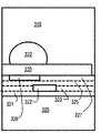
測距方式がどのように実装されるかを描くために、いくつかの一般的なハードウェア方式を説明する。図2Aと図2Bは、様々な実施形態による高解像度LIDARシステムのコンポーネントを例示したブロック図である。図2Aでは、レーザ源212が、搬送波201を発射し、これが、変調器214において、RF波形発生器215からの入力に基づいて、振幅変調、周波数変調、位相変調、またはそれらの組み合わせによって変調されて、帯域幅Bと時間幅τを有するパルスを含む光信号203が生成される。いくつかの実施形態では、RF波形生成器215は、処理システム250からのコマンドでソフトウェア制御される。スプリッタ216は、変調された信号205を、光信号203のエネルギーのほとんどを有する送信信号205と、それよりはるかに小さいエネルギー量であるが、それでも、標的(図示せず)によって散乱された戻り信号への有効なヘテロダインまたはホモダイン干渉を生成するには十分なエネルギー量を有する基準信号207に分割する。いくつかの実施形態では、送信ビームは複数角度にわたって走査し、走査光学装置218を用いて、その経路内にある物体の輪郭を得る。基準信号は、散乱光とともに検知器アレイ230に到達するように、基準経路220において十分に遅延される。いくつかの実施形態では、スプリッタ216は、変調器214の上流側にあり、基準ビーム207は変調されない。いくつかの実施形態では、基準信号は、新たなレーザ(図示せず)を用いて、独立に生成され、基準経路にある別の変調器(図示せず)と生成器215からのRF波形を用いて、別に変調される。いくつかの実施形態では、図2Bを参照して下に述べるように、単一のレーザ源212からの出力は、基準経路220において、独立に変調される。柔軟性の小さいものから、大きなものまで、様々な実施形態において、1)経路長が十分に一致するように送信ビームの一部が反射されて検知器アレイに戻ってくるように、対象場所にミラーを置くこと、2)図2Aに示すように、特定の距離について観測または予想される位相差を補償するための経路長調整の有無にかかわらず、検知器アレイ近傍の光学装置により、経路長をほぼ一致させて、基準ビームをブロードキャストするために、ファイバ遅延を利用すること、または、3)図2Bを参照して下に詳しく述べるように、経路長の不一致を補償するために別の変調を生成するために、周波数偏移デバイス(音響−光学変調器)またはローカルオシレータ波形変調の時間遅延を用いること、または、それらの組み合わせによって、基準信号は、散乱フィールドまたは反射フィールドとともに到着させられる。いくつかの実施形態では、戻り信号が、遅延なしに、基準信号と十分に重なり合うように、標的が十分近く、パルス時間幅が十分長い。いくつかの実施形態では、基準信号207bは、1つ以上の光混合器232において、戻り信号291と光混合される。様々な実施形態において、標的の複数の部分が、各走査ビームについて、それぞれの戻り光291信号を散乱して検知器アレイ230に戻し、それにより、複数のビームおよび複数の戻り光によって、照明された標的の複数部分のそれぞれの距離に基づいて、点クラウドが生成される。
2. Overview of Chirp Detection Hardware In order to describe how the distance measurement method is implemented, some common hardware methods are described. 2A and 2B are block diagrams illustrating components of a high resolution lidar system according to various embodiments. In FIG. 2A, the
検知器アレイ230は、単一の、あるいは平衡対の光検知器、または標的からの戻りビーム291に対しておおむね垂直な平面内に配置される、そのような光検知器の1Dまたは2Dアレイである。インタフェースパターンの位相あるいは振幅、またはそれらの組み合わせが、パルス時間幅τの間、複数の時点で、各検知器について、取得システム240に記録される。パルス時間幅当たりの時間的標本の数は、ダウンレンジ範囲に影響する。この数は、しばしば、パルス反復率および利用可能なカメラのフレームレートに基づいて選択される実際的な考慮事項である。フレームレートは、標本化帯域幅であり、しばしば、「デジタイザ周波数」と呼ばれる。基本的に、Yレンジ幅の解像度ビンで、パルス時間幅の間に、X個の検知器アレイフレームが採取される場合、X*Yのレンジ範囲が観測可能である。取得されたデータは、図8を参照して下に述べるコンピュータシステム、または図9を参照して下に述べるチップセットなどの、処理システム250が使用できるようにされる。いくつかの実施形態では、取得されたデータは、標的の複数部分の複数距離に基づく点クラウドである。
The detector array 230 is a single or balanced pair of photodetectors, or a 1D or 2D array of such photodetectors arranged in a plane approximately perpendicular to the
適応走査モジュール270は、下にさらに詳細に述べるように、走査の対象とされる特定場所について走査光学装置による非均一走査が望ましいか否かを決定する。例えば、適応走査モジュール270は、対象場所の異なる部分について、フレームを構築するための価値のあるパルス、例えば、数秒間に送信される数百万のビームが、走査される物体からの戻り信号が存在する方向に集中され、対象とされない空や近傍の地面が存在する方向が避けられるように、どのような走査角度と解像度が用いられるべきかを決定する。いくつかの実施形態では、適応走査モジュール270は、RF波形生成器215を制御する。
The
図2Bは、ソフトウェアにより制御される遅延が、ローカルオシレータ(LO)信号とも呼ばれる基準信号を生成する基準経路に導入されることを可能にする代替的ハードウェア配置を描いている。レーザ源212、スプリッタ216、送信信号205、走査光学装置218、光混合器232、検知器アレイ230、取得システム240、および処理システム250は、図2Aを参照して、上に述べたものと同様である。図2Bには、生成器215からのRF波形を光搬送波に乗せる、2つの別個の変調器、すなわち、送信経路の214aと基準経路の214bがある。スプリッタ216は、レーザ源212と、変調器214aおよび214bの間を移動して、変調器214aに当たる光信号283と、修正基準経路282において変調器214bに当たる、低い振幅の基準経路信号287aを生成する。この実施形態では、光201は、変調が行われる前に、送信経路(TX)経路ビーム283と、基準/ローカルオシレータ(LO)経路ビーム287aに分割され、各経路には、別個の変調器が使用される。デュアル変調器方式で、いずれの経路も、オフセット開始周波数および/またはオフセット開始時間のチャープをプログラム可能である。これは、ダウンレンジ次元において適応する適応走査方式を可能にするために用いられる。各距離ゲートにおいて用いられる遅延を変化させることにより、このシステムは、他のシステム制限(検知器およびデジタイザの帯域幅、測定時間等)にもかかわらず、高解像度で、明確な測定が可能である。したがって、いくつかの実施形態では、修正適応走査モジュール278が、下に述べる適応走査によって生成される各距離ゲートのために適切な遅延時間を課すように、RF波形生成器を制御する。そこで、ソフトウェアにより制御される遅延基準信号287bは、上に述べたように、戻り信号と混合される。他の実施形態では、ソフトウェアにより制御されるLO基準経路282の遅延はまた、システム280が、チャープドップラ補償のために距離遅延効果を蓄積することを可能にする。
FIG. 2B depicts an alternative hardware arrangement that allows software-controlled delays to be introduced into a reference path that produces a reference signal, also called a local oscillator (LO) signal. The
例えば、いくつかのチャープの実施形態では、使用されたレーザは、レーザを駆動する電流に適用する変調によって、能動的に線形化された。電気−光変調器が変調を提供する実験も行われた。このシステムは、様々な実施形態のために、下にさらに詳しく述べるように、所望のダウンレンジ解像度のために好適な、帯域幅Bと時間幅τのチャープを生成するように構成される。この技術は、チャープ帯域幅10MHz〜5THzに適用される。しかし、3D撮像適用については、典型的なレンジは、チャープ帯域幅が約300MHz〜約20GHz、チャープ時間幅が約250ナノ秒(ns、ns=10−9秒)〜約1ミリ秒(ms、1ms=10−3秒)、標的までの距離が約0メートル〜20キロメートル(km、1km=103m)、標的におけるスポットサイズが約3ミリメートル(mm、1mm=10−3m)〜1メートル(m)、標的における深度解像度が約7.5mm〜0.5mである。いくつかの実施形態では、標的は、400メートル(m)など、最小距離を有する。これらの条件の下で、この距離ウィンドウは数キロメートルまで延ばすことができることも注目される。プロセス、設備、およびデータ構造が、図2Aおよび図2Bには、図示のために、特定の配置の統合ブロックとして描かれているが、別の実施形態においては、1つ以上のプロセスあるいはデータ構造、またはそれらの一部は、別のやり方で、同じ、あるいは異なるホストに、1つ以上のデータベースに配置されるか、または排除されるか、または、1つ以上の異なるプロセスあるいはデータ構造は、同じ、あるいは異なるホストに含まれる。例えば、スプリッタ216と基準経路220は、0個以上の光カプラを含む。
For example, in some chirp embodiments, the laser used was actively linearized by modulation applied to the current driving the laser. Experiments have also been conducted in which electrical-optical modulators provide modulation. The system is configured to generate bandwidth B and time width τ chirps suitable for the desired downrange resolution, as described in more detail below, for various embodiments. This technique applies to chirp bandwidths of 10 MHz to 5 THz. However, for 3D imaging applications, the typical range is a chap bandwidth of about 300 MHz to about 20 GHz and a chap time width of about 250 nanoseconds (ns, ns = 10-9 seconds) to about 1 millisecond (ms, 1 ms = 10-3 seconds), the distance to the target is about 0 m to 20 km (km, 1 km = 10 3 m), and the spot size at the target is about 3 mm (mm, 1 mm = 10 -3 m) to 1 m. (M), the depth resolution at the target is about 7.5 mm to 0.5 m. In some embodiments, the target has a minimum distance, such as 400 meters (m). It is also noted that under these conditions, this distance window can be extended up to several kilometers. Processes, equipment, and data structures are depicted in FIGS. 2A and 2B as integrated blocks of a particular arrangement for illustration purposes, but in another embodiment, one or more processes or data structures. , Or some of them, are otherwise located on the same or different hosts in one or more databases, or excluded, or one or more different processes or data structures. Included in the same or different hosts. For example, the
3.適応走査の概要
図3Aは、実施形態による、走査レーザ測距システムで走査される場所の例示画像である。この画像は、約10センチメートル距離解像度(例えば、5〜20cm)で最大約1キロメートル(例えば、0.5〜2km)の距離のために構成された走査3Dレーザ測距システムの最大水平角および垂直角解像度を用いて生成された。図3Bは、実施形態による、適応走査される図3Aの場所の水平方向部分の例を示す画像である。この水平方向の次元は、相対単位での水平角を示し、垂直方向の次元は、静止LIDARシステムから見た、相対単位での垂直角を示す。戻り信号がない角度での測定を回避し、目標空間解像度を得るために、高い角解像度標本化が望ましい、遠い標的に対してのみ、そのような標本化を用い、目標空間解像度を与えるために、低い角解像度で十分な、近い物体に対しては低い角解像度標本化を用いることにより、所望の測距情報の収集を迅速にするために、適応走査が行われる。
3. 3. Overview of Adaptive Scan FIG. 3A is an exemplary image of a location scanned by a scanning laser ranging system according to an embodiment. This image shows the maximum horizontal angle and maximum horizontal angle of a scanning 3D laser ranging system configured for distances up to about 1 km (eg 0.5-2 km) with a distance resolution of about 10 cm (eg 5-20 cm). Generated using vertical angle resolution. FIG. 3B is an image showing an example of a horizontal portion of the location of FIG. 3A that is adaptively scanned according to an embodiment. This horizontal dimension indicates the horizontal angle in relative units, and the vertical dimension indicates the vertical angle in relative units as seen from the static lidar system. High angular resolution sampling is desirable to avoid measurements at angles where there is no return signal and to obtain target spatial resolution. To use such sampling only for distant targets and to provide target spatial resolution. By using low angular resolution sampling for close objects, where low angular resolution is sufficient, adaptive scanning is performed to expedite the acquisition of desired ranging information.
適応走査の利点を図3Cに図示する。図3Cは、実施形態による、図3Bに明らかに示された形状のための距離のセットの例を示すブロック図である。図3Cは、標本化角空間を表す。エリア310には、戻り信号がなく、角空間のこのエリアを走査はしないことが望ましい。エリア320には、システムの真直ぐ前方には、対象とはならない地面があるのみである(例えば、このエリアは、十分に知られているか、または、特に関心対象とはされない小さな形状である)。角空間のこのエリアも走査しないことが望ましい。遠方のドーム構造物が、角空間のエリア332を占め、このドームの前の構造物が角空間のエリア330を占め、それらの前の壁またはフェンスが角空間のエリア328を占め、より近い構造物および柱状物が角空間のエリア322を占めている。対象にはならないエリア320と、エリア330の構造物の間において、角空間でエリア321、323、325、および327と記された地面は、距離が大きくなっていくことが明らかである。目標空間解像度s、例えば10センチメートル、以上で、場所の形状を特定するためには、用いられる角解像度Δθは、式2に与えられる、物体への距離Rの関数である。
Δθ=arctan(s/R) (2a)
比s/Rの値が小さい場合には、Δθ≒s/Rである。ほとんどの場合、sは、Rよりもはるかに小さいので、多くの実施形態において、処理を迅速にするために、近似値Δθ=s/Rが用いられる。近距離Rnearから遠距離Rfarまでの距離間隔にあるすべての物体について、少なくとも目標空間解像度s、またはそれ以上を確かに達成するために、遠距離を式2に使用して、式2bを得る。
Δθ=arctan(s/Rfar) (2b)
小さい角の近似が有効である場合には、式2bの近似式2cを用いる。
Δθ=s/Rfar (2c)
当然、任意の所与のレーザ測距システムは、個々の光ビームの最小角幅を有し、そのような角ビーム幅よりはるかに小さい角解像度は、実際には、定義できない。したがって、大きな距離では、目標空間解像度sは、達成不可能なこともある。以下の説明では、単純化のために、計算されたΔθは必ずビーム角幅より大きいと仮定する。
The advantages of adaptive scanning are illustrated in FIG. 3C. FIG. 3C is a block diagram showing an example of a set of distances for the shapes clearly shown in FIG. 3B, according to an embodiment. FIG. 3C represents a sampling angle space.
Δθ = arctan (s / R) (2a)
When the value of the ratio s / R is small, Δθ≈s / R. In most cases, s is much smaller than R, so in many embodiments, an approximation Δθ = s / R is used to speed up the process. For all objects in the distance interval from the short range Rnea to the long range Rfar, the long range is used in
Δθ = arctan (s / Rfar) (2b)
When the small angle approximation is valid, the approximation equation 2c of equation 2b is used.
Δθ = s / Rfar (2c)
Of course, any given laser ranging system has a minimum angular width of individual light beams, and angular resolutions well below such angular beam widths cannot be defined in practice. Therefore, at large distances, the target spatial resolution s may not be achievable. In the following description, for simplicity, it is assumed that the calculated Δθ is always greater than the beam angle width.
式2a〜2cは、対象場所における様々な物体への距離が既知であることを意味する。様々な実施形態により、対象場所に関する距離は、初回通過の疎角解像度によって決定される。対象場所において、一方の次元に延びる距離は他方の次元における距離よりも大きい、または、装置が、一方の次元において、他方の次元と比較して、より大きな制御を有することが一般的であり、それゆえ、いくつかの実施形態では、疎の水平角解像度は、疎の垂直角解像度とは異なる。図3Dは、実施形態による、図3Cに描かれた形状に対する疎角走査の例示のブロック図である。水平軸342は、水平角(方位角とも呼ばれる)を示し、垂直軸は、垂直角(仰角とも呼ばれる)を示す。垂直方向のこぎり歯状走査軌跡は、点線346によって示される。図示のために、走査光学装置が通る経路は左下から右上に延びると仮定される。走査軌跡346は、垂直方向のこぎり歯状パターンで、水平方向にAHRとして指示される反復離隔角347を有する。走査軌跡346は、走査LIDAR測距システムが実行し得る細密水平走査に比べて、走査が幅方向に間が空いている。さらに、疎の垂直標本化解像度で、経路346に沿って距離測定が行われる。したがって、走査軌跡346に沿った測定値は、目標フレームレートに比較して短時間に取得できる。水平解像度は、可変であるが、水平反復離隔AHRごとに2つの標本を特徴とするので、平均水平解像度はAHR/2である。他の実施形態では、走査において水平標本離隔と垂直標本離隔の両方とも一定である、行順または列順の走査軌跡が用いられる。そのような実施形態のいくつかにおいては、水平離隔と垂直離隔の両方とも、Δθに設定される。
Equations 2a-2c mean that the distances to various objects at the target location are known. In various embodiments, the distance to the target location is determined by the sparse angle resolution of the first pass. At the location of interest, the distance extending to one dimension is greater than the distance in the other dimension, or the device generally has greater control in one dimension compared to the other dimension. Therefore, in some embodiments, the sparse horizontal angle resolution is different from the sparse vertical angle resolution. FIG. 3D is an exemplary block diagram of sparse-angle scanning for the shape depicted in FIG. 3C, according to an embodiment. The
疎走査の結果として、αを水平方向(方位)走査角とし、εを垂直方向(仰角)走査角とすると、疎最小水平角αminから疎最大水平角αmaxまで、かつ、疎最小垂直角εminから疎最大垂直角εmaxまでの、すべての水平角について、多様な距離R(α,ε)を得ることができ、したがって、点クラウドが形成される。エリア320の距離は排除される。その他の距離は、距離ゲートと呼ばれる複数の距離間隔に分割され、各距離ゲートは、別の重なり合わないRnearとRfarによって与えられる別の重なり合わない間隔によって画定される。距離R(α,ε)は、N個の距離ゲートのうちの、距離ゲート番号n、すなわち、RGnという名称のセットの要素であり、式3を満たす。
Rnearn≦RGn<Rfarn (3)
値Rnearnは、下のような命令を使用して、距離R(α,ε)とそれに関連する角座標(α,ε)を1つの距離ゲートのセットに割り当てるためのゲートとして用いることができる。
For α=αmin to αmax, ε=εmin to εmax
N=0
for i=1 to N, if R(α,ε)≧Rneari, then n=i
add R(α,ε) to set RGn
そこで、距離ゲートのセットにおけるすべての各座標(α,ε)からなる角空間の各部分は、距離ゲートのうちの1つに関連づけることができる。角範囲ゲートに関連するエリアは、距離ゲートエリアと呼ばれる。図3Eは、実施形態による、図3Dに描かれた形状に対する距離ゲート内の距離の一団の内の、角走査空間における走査距離の隣接エリアの例を示すブロック図である。エリア356は、近傍の建物と柱状物のエリア322を含むRG1に割り当てられ、エリア356bは、RG2に割り当てられ、エリア356cは、壁構造物328を含むRG3に割り当てられ、エリア356dは、RG4に割り当てられ、エリア356eは、建物エリア330を含むRG5に割り当てられ、356fは、ドーム構造物332を含むRG6に割り当てられる。
As a result of sparse scanning, where α is the horizontal (azimuth) scanning angle and ε is the vertical (elevation) scanning angle, the sparse minimum horizontal angle αmin to the sparse maximum horizontal angle αmax and from the sparse minimum vertical angle εmin. Various distances R (α, ε) can be obtained for all horizontal angles up to the sparse maximum vertical angle εmax, thus forming a point cloud. The distance in
Rnea n ≤ RGn <Rfar n (3)
The value Rnea n can be used as a gate to assign the distance R (α, ε) and its associated angular coordinates (α, ε) to one set of distance gates using instructions such as: ..
For α = αmin to αmax, ε = εmin to εmax
N = 0
for i = 1 to N, if R (α, ε) ≧ R near i , then n = i
add R (α, ε) to set RGn
Therefore, each part of the angular space consisting of all the coordinates (α, ε) in the set of distance gates can be associated with one of the distance gates. The area associated with the angle range gate is called the distance gate area. FIG. 3E is a block diagram showing an example of adjacent areas of scanning distances in an angular scanning space within a set of distances within a distance gate with respect to the shape depicted in FIG. 3D according to an embodiment. Area 356 is assigned to
様々な実施形態において、水平解像度あるいは垂直解像度、またはそれらの両方は、各距離ゲートnに関連する角空間エリアにおいて、RfarをRfarnとして、式2bまたは式2cを満たすように調整される。いくつかの実施形態では、各距離ゲートエリアは、疎標本化に基づいて、各水平角についての最小垂直角と各水平角についての最大垂直角によって輪郭が定まる。最小垂直角と最大垂直角は、各々、目標角間隔(RfarをRfarnとして、式2bによって与えられる間隔)に合わせて内挿補間される。そして、各距離ゲートエリアは、RfarをRfarnとした式2bによって与えられる水平角解像度と垂直角解像度を用いて、のこぎり歯状走査パターン(または、その他の走査パターン)で、それぞれ別に走査される。走査パターンは、走査軌跡とも呼ばれる。 In various embodiments, the horizontal and / or vertical resolutions are adjusted to satisfy Equation 2b or Equation 2c, where Rfar is Rfar n in the angular space area associated with each distance gate n. In some embodiments, each distance gate area is contoured by a minimum vertical angle for each horizontal angle and a maximum vertical angle for each horizontal angle, based on sparse sampling. The minimum vertical angle and the maximum vertical angle are interpolated and interpolated according to the target angle spacing (the spacing given by Equation 2b, where Rfar is Rfarn), respectively. Each range gate area, using the horizontal angle resolution and the vertical angle resolution given by Equation 2b which was RFAR n the RFAR, sawtooth scan pattern (or other scan pattern), the scanned separately respectively .. The scanning pattern is also called a scanning locus.
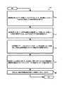
図4は、実施形態による、走査レーザ測距システムによる適応走査の例示の方法を示すフローチャートである。図4とその後のフローチャート図14に、工程は、図示のために、特定の順序の統合的工程として描かれているが、他の実施形態においては、1つ以上の工程、またはその一部が、異なる順序で、または時間的に重なり合うか、順次か、あるいは並行して、実行されるか、または、排除され、または、1つ以上の追加工程が追加され、または、いくつかの組み合わせ方で、方法が変更される。 FIG. 4 is a flowchart illustrating an exemplary method of adaptive scanning by a scanning laser ranging system according to an embodiment. 4 and subsequent Flow Charts In FIG. 14, steps are depicted as integrated steps in a particular order for illustration purposes, but in other embodiments, one or more steps, or a portion thereof. , Performed in different order or in temporal overlap, sequentially or in parallel, or eliminated, or one or more additional steps added, or in some combination. , The method is changed.
工程401では、目標空間解像度sが決定される。任意の方法を用いることができる。これは、ユーザが手入力することもでき、コンピュータ可読媒体上の格納から引き出すこともでき、ローカルまたは遠隔のデータベースまたはサーバから、要求せずに、または問い合わせを行って、受信することもできる。いくつかの実施形態では、対象の物体のサイズ範囲Oが入力され、目標空間解像度sが、例えば、指示された物体サイズOの1/100または1/1000などの、所定の、または指定の、1未満の値に基づいて決定される。いくつかの実施形態では、工程401において、上述の1つ以上の方法を用いて、そのような物体を検知するための最大距離Rmaxも決定される。いくつかの実施形態では、上述の方法のいずれかを用いて、疎角解像度も与えられる。いくつかの実施形態では、疎角解像度は、1つ以上の他の入力に基づいて決定される。例えば、所望の目標空間解像度がsであり、指定の最大距離がRmaxである場合、最も細密な角解像度Δθbestは、式2においてRをRmaxに置き換えることによって得られる。この場合、疎角解像度は、この最も細密な角解像度Δθbestの倍数である。フレームレートに比べて小さい時間量で、この疎走査を完了するためには、倍数の大きさは、例えば、最も細密な解像度の約10〜100倍である(高解像度フレームの1/100〜1/10,000で、疎フレームを完了する)。指定される空間解像度は、適用に依存する(測量は、例えば、3D形状検知とは異なる要件を含むかもしれない)。様々な実験的実施形態において、標的の空間解像度は、約1cm以上であり、これに対して、実験的撮像装置にとって、やや大きめの最終的解像度とみなされるのが、標的に対して10cmである。疎走査解像度のために用いられる倍数は、細密な標的解像度の約10〜約25倍である。そして、疎走査は、総走査時間に1未満の値を乗じたものであり、適応走査パターンの生成のために有用な情報を与える。
In step 401, the target spatial resolution s is determined. Any method can be used. It can be manually entered by the user, retrieved from storage on a computer-readable medium, and received from a local or remote database or server without request or by querying. In some embodiments, the size range O of the object of interest is input and the target spatial resolution s is a predetermined or specified, for example, 1/100 or 1/1000 of the indicated object size O. Determined based on a value less than 1. In some embodiments, in step 401, the maximum distance Rmax for detecting such an object is also determined using one or more of the methods described above. In some embodiments, sparse-angle resolution is also given using any of the methods described above. In some embodiments, the sparse angle resolution is determined based on one or more other inputs. For example, if the desired target spatial resolution is s and the specified maximum distance is Rmax, the finest angular resolution Δθbest is obtained by replacing R with Rmax in
工程403では、対象場所の一般的な3D特徴を得るために、ただし、所望の最終的走査角解像度よりも、はるかに疎な空間標本化によって、疎解像度撮像走査が実行される。この疎走査の結果は、疎3次元(3D)点クラウドであり、このクラウドの各点は、レーザ光後方散乱面の照明されたスポットの3D座標内の位置を示す。3D座標は、測距システムからの、方位角α、仰角ε、および距離Rなどの極座標、または、水平方向x(例として、例えば、基準点または測距システムの位置からの北方向の距離)、水平方向y(例として、基準点からの東方向距離)、およびz(例えば、水平面からの高さ)などの直交座標とすることができる。 In step 403, sparse resolution imaging scans are performed to obtain general 3D features of the location of interest, but with spatial sampling that is much sparser than the desired final scan angle resolution. The result of this sparse scanning is a sparse three-dimensional (3D) point cloud, where each point indicates the position of the illuminated spot on the backscattered surface of the laser beam in 3D coordinates. The 3D coordinates are polar coordinates such as azimuth α, elevation ε, and distance R from the distance measuring system, or horizontal x (for example, the distance north from the reference point or the position of the distance measuring system). , Horizontal direction y (eg, eastward distance from the reference point), and z (eg, height from the horizontal plane) and the like.
工程405では、疎の点クラウドは、例えば上述の式3を用いる距離座標と、式3のすぐ後に続く疑似コードに従う、距離ゲートにさらに分割される。この小分割は、RnearnのN個の固定値でハードコードするか、または、Rnearnのための1〜N個の計算値に基づく適応型とすることができる。例えば、いくつかの実施形態では、5パーセンタイル距離と99パーセンタイル距離、それぞれ、R5とR99が、疎3D点クラウドにおける距離分布から決定され、距離ゲートの数Nが、99パーセンタイル距離と5パーセンタイル距離の差と対象の物体のサイズから決定される(例えば、N=modulus(.R99−R5,M*O)、ここで、Oは、対象の物体のサイズであり、Mは、M=4など、1より大きい倍数である)。この適応型の例では、N個の距離ゲートは、R5とR99の間に均等に分布する。いくつかの実施形態では、工程405は、距離ゲートを決定する前に、取得した疎の点クラウドデータの直交座標表示を、LIDAR測距システムに対する球面座標に変換することを含む。他の実施形態では、N個の距離ゲートの決定は、点密度を距離の関数とする基本的データ分析によって行われた。例示の適応データ分析は、距離ゲートを、最小数の点が存在する密度分布の距離に距離ゲートを配置した。これは、距離ゲートの「継ぎ目」を、システムから見える物体の密度が最小限である所に位置させるために行われた。
In
工程411では、各距離ゲートの点のセットRGnについて、改良された対象場所の標本化のために、適応走査軌跡が決定される。セットRGn内の各物体が、確実に、目標空間解像度s、またはその付近で、解像されるように、式2bまたは式2cで、Rfarの代わりに、距離ゲートにおける特徴的距離を用いて、垂直および水平走査特性のための角解像度を決定する。例えば、距離ゲート内の各物体が、確実に、少なくとも、目標空間解像度sで、標本化されるように、特徴距離は、Rfarnであり、式2bまたは式2cが用いられる。いくつかの実施形態では、のこぎり歯状パターンの水平反復離隔角度AHRは、角解像度Δθに合わせて設定され、したがって、最も悪い水平解像度はΔθであり、平均水平解像度は、Δθ/2でも、より良い。いくつかの実施形態では、平均水平解像度sが許容範囲である場合、平均水平解像度がΔθになるので、AHRは2Δθに設定される。しかし、他の実施形態では、RnearnとRfarnの間にあるものと定義される中距離Rmidnなど、他の特徴距離が用いられる。したがって、角空間内の距離ゲートエリアにおけるすべての水平角において最小垂直角と最大垂直角の間に、適応走査軌跡が決定される。 In step 411, for the set RGn of points at each distance gate, an adaptive scan locus is determined for improved target location sampling. In Equation 2b or 2c, using the characteristic distance at the distance gate instead of Rfar, to ensure that each object in the set RGn is resolved at or near the target spatial resolution s. Determines the angular resolution for vertical and horizontal scanning characteristics. For example, the feature distance is Rfar n and formula 2b or formula 2c is used to ensure that each object in the distance gate is sampled at at least the target spatial resolution s. In some embodiments, the horizontal repeat spacing angle A HR of sawtooth pattern is set in accordance with the angular resolution [Delta] [theta], thus, a worst horizontal resolution [Delta] [theta], the average horizontal resolution, even [Delta] [theta] / 2, Better. In some embodiments, when the average horizontal resolution s is acceptable, the average horizontal resolution is [Delta] [theta], A HR is set to 2.DELTA..theta. However, in other embodiments, other feature distances are used, such as medium distance Rmid n , which is defined as being between Rnea n and Rfar n. Therefore, an adaptive scan locus is determined between the minimum and maximum vertical angles at all horizontal angles in the distance gate area within the angular space.
いくつかの実施形態では、ローカルオシレータの遅延時間ΔtLOnは、n番目の距離ゲートRGnの距離ゲート距離RGRnを用いて、距離ゲートnの各距離ゲート標本化軌跡について、決定され、例えば、RGRnは、Rnearn、または、式4にしたがって、上に定義した特徴距離に等しいか、またはその関数である。
ΔtLOn=RGRn/c (4)
In some embodiments, the delay time Δt LOn of the local oscillator is determined for each distance gate sampling trajectory of the distance gate n using the distance gate distance RGRn of the nth distance gate RGn, eg, RGRn. , Rnea n , or, according to Equation 4, equal to or a function of the feature distance defined above.
Δt LOn = RGRn / c (4)
いくつかの実施形態では、特徴距離は、観測に基づいて適応的に決定される。例えば、遠距離Rfarn、または中距離Rmidnは、現れることはまれかもしれない、また、別の距離の方が、はるかに現れる可能性が高いか、またははるかにありふれているかもしれない。したがって、いくつかの実施形態では、特徴距離は、距離ゲートセットRGnにおいて観測された疎標本距離の平均距離Rmeann、二乗平均平方根距離Rrmsn、中央値距離Rmedn、またはモード(ピーク)距離Rpeaknとして決定される。そして、選択された特徴距離は、角解像度Δθ、および、各空間における距離ゲートエリアのすべての水平角について、最小垂直角と最大垂直角の間の適応走査軌跡を決定するために、式2aにおいて距離Rとして、または、式2cにおいてRfarの代わりに、用いられる。 In some embodiments, the feature distance is adaptively determined based on observations. For example, long-range Rfar n , or medium-range Rmid n , may rarely appear, and other distances may be much more likely or much more common. Thus, in some embodiments, the feature distance is the average distance Rmean n of the sparse sample distance observed in the distance gateset RGn, the root mean square distance Rrms n , the median distance Rmed n , or the mode (peak) distance Rpeak Determined as n. The selected feature distance is then expressed in Equation 2a to determine the angular resolution Δθ and the adaptive scanning locus between the minimum and maximum vertical angles for all horizontal angles of the distance gate area in each space. It is used as the distance R or instead of Rfar in formula 2c.
いくつかの実施形態では、基準経路遅延時間ΔtLOは、距離ゲート設定なしでも、走査パターンにおいて、パルスごとに修正される。これは、次のパルスまたは近傍のパルスが、現パルスから決定された距離であるか、またはそれに近い可能性が高いとの仮定の下では利点がある。例えば、いくつかの実施形態では、走査レーザ測距システムは、第1の距離測定値を得るために、第1の基準経路遅延時間で、動作する。第1の基準経路遅延時間が第1の距離測定のために有益であるか否かが決定される。第1の基準経路遅延時間が、第1の距離測定のために有益ではない場合、第1の距離測定のために有益な第2の基準経路遅延時間が決定される。そして、走査レーザ測距システムは、少なくともその次の1つのパルスに対しては、第2の基準経路遅延時間で動作して、第2の距離測定値を得る。 In some embodiments, the reference path delay time Δt LO is modified pulse by pulse in the scan pattern without the distance gate setting. This is advantageous under the assumption that the next or nearby pulse is likely to be at or near the distance determined from the current pulse. For example, in some embodiments, the scanning laser ranging system operates with a first reference path delay time to obtain a first distance measurement. Whether the first reference path delay time is useful for the first distance measurement is determined. If the first reference path delay time is not useful for the first distance measurement, then a second reference path delay time that is useful for the first distance measurement is determined. The scanning laser ranging system then operates with a second reference path delay time for at least the next pulse to obtain a second distance measurement.
いくつかの実施形態では、工程411の間に、レーザ測距システムのためのパルス時間幅τと間隔周期tiも、最小フレームレートが維持されるように決定される。そのような実施形態では、目標フレームレート、例えば、毎秒4フレームが、設定され、目標空間解像度のために必要な、すべての距離ゲートの軌跡における距離測定値の数が、距離測定当たりの時間を決定する。そして、この測定当たりの時間は、パルス時間幅τとパルス間の間隔tiの合計を決定する。次に、このパルス時間幅は、光検知器において戻り信号を脱チャープ化するために、基準経路に有益に適用される遅延時間を決定する。 In some embodiments, during step 411, the pulse time width τ and interval period ti for the laser ranging system are also determined so that the minimum frame rate is maintained. In such an embodiment, a target frame rate, eg, 4 frames per second, is set and the number of distance measurements in all distance gate trajectories required for the target spatial resolution determines the time per distance measurement. decide. Then, the time per measurement determines the sum of the pulse time width τ and the interval ti between the pulses. This pulse time width then determines the delay time that is beneficially applied to the reference path to dechirp the return signal in the photodetector.
工程421では、各距離ゲートに対応する各適応走査パターンに基づいて、走査光学装置に対するコマンドが、測距システム、またはシステム内の走査光学装置に、転送され、走査レーザ測距システムを動作させて、適応水平角解像度および適応垂直解像度で、適応走査軌跡に沿って、距離測定値を得る。いくつかの実施形態では、工程421は、現距離ゲート、または、N個の異なる距離ゲートのうちのさらなる距離ゲートのための、式4による遅延時間を示すデータを送信することを含む。それらの実施形態のうちのいくつかでは、測距システムは、図2BのRF波形生成器215aと変調器214bを用いて、レーザ光を変調して、計算された遅延時間ΔtLOnを課す。
In
工程431では、角空間における距離ゲートエリアのすべてについて、順次適応走査を用いて、結果として取得した点クラウドの点のセットは、すべての被走査物体について、目標空間解像度sを保存する1つ以上の点クラウドの集まりである最終的3Dデータ生産物を構成するように、組み合わされる。同時に、適応走査は、戻り信号がない所、あるいは測距システムに近すぎる所、またはそれらが組み合わさった所については、角空間の走査を回避する。工程441では、3Dデータ生産物に基づいて、デバイスが動作する。いくつかの実施形態では、これは、3Dデータ生産物を示す画像を表示デバイスに提示することを含む。いくつかの実施形態では、これは、3Dデータ生産物の点クラウドに基づいて、少なくとも1つの物体を認識するデータを、デバイスに送信することを含む。いくつかの実施形態では、これは、認識された物体に接近するように、あるいは、それとの衝突を回避するように、車両を動かすこと、または、兵器システムを動作させて、認識された物体に、兵器を誘導することを含む。 In step 431, sequential adaptive scanning is used for all of the distance gate areas in the angular space, and the resulting set of points in the point cloud is one or more that stores the target spatial resolution s for all objects to be scanned. Points are combined to form the final 3D data product, which is a collection of clouds. At the same time, adaptive scanning avoids scanning in angular space where there is no return signal, or where it is too close to the ranging system, or where they are combined. In step 441, the device operates based on the 3D data product. In some embodiments, this involves presenting an image showing the 3D data product to the display device. In some embodiments, this involves transmitting data recognizing at least one object to the device based on the point cloud of the 3D data product. In some embodiments, this is to move the vehicle or operate the weapon system to approach or avoid a collision with the recognized object to the recognized object. , Including guiding weapons.
いくつかの実施形態では、工程403〜431は、下にいくつかの例示の実施形態について述べるように、個別に、または集合的に、自動的に、かつ、リアルタイムまたは準リアルタイムで、実行される。この説明においては、リアルタイムは、3D点クラウドをキャプチャするために用いられる3Dスキャナ(例えば、LIDAR)のフレームレートに基づく。このフレームレートの逆数は、3Dスキャナが3D点クラウドをキャプチャするキャプチャ時間周期である。いくつかの実施形態では、リアルタイムは、キャプチャ時間周期内の期間と定義される。いくつかの例示の実施形態では、フレームレートは、毎秒約4〜約10フレーム(fps)の範囲にあり、0.1〜0.25秒(s)のキャプチャ時間周期に対応する。この種の時間周期は、戦術的適用および衝突回避の適用のために有益である。準リアルタイムは、リアルタイムの約10倍以内、例えば、上述の例示のキャプチャ時間周期に対しては約2.5秒以内である。 In some embodiments, steps 403 to 431 are performed individually or collectively, automatically, in real time or near real time, as described below for some exemplary embodiments. .. In this description, real time is based on the frame rate of a 3D scanner (eg, lidar) used to capture a 3D point cloud. The reciprocal of this frame rate is the capture time period in which the 3D scanner captures the 3D point cloud. In some embodiments, real-time is defined as a period within the capture time cycle. In some exemplary embodiments, the frame rate ranges from about 4 to about 10 frames per second (fps) and corresponds to a capture time period of 0.1 to 0.25 seconds (s). This type of time cycle is useful for tactical applications and collision avoidance applications. The quasi-real time is within about 10 times the real time, for example, within about 2.5 seconds with respect to the above-exemplified capture time period.
4.例示実施形態
周波数変調連続波(FMCW)チャープLIDAR測距システムでは、距離ウィンドウは、チャープ帯域幅、デジタイザ帯域幅、およびパルス反復周波数(PRF)によって規定される。したがって、基本的FMCWシステムは、より大きなPRFおよび帯域幅については、距離に限界がある。この限界は、長距離で迅速に距離データを取得するシステムの能力を制限する。この制限は、ソフトウェアプログラム可能な距離遅延に影響するように、LOおよびチャープ波形の送信器/戻り信号経路に、別々の変調器(例えば、図2Bを参照して、上に述べたように、基準経路282において、RF波形生成器215、および、別個の変調器214bを用いる)を考慮することによって、克服された。LO波形の時間遅延は、所与の距離遅延のための測距周波数帯域幅Bが低減されて、検知器/デジタイザシステムの帯域に入ることを可能にする。このコンセプトは、非ゼロ距離遅延で、距離ウィンドウ内の迅速な距離データ取得を可能にする。これは、適応走査アルゴリズムと組み合わされて、例えば、それぞれの異なる距離ゲートの走査軌跡のための異なる基準経路遅延を用いて、対象のボリュームの量のデータを、いっそう迅速に取得することができる。
4. In an exemplary embodiment frequency-modulated continuous wave (FMCW) chirp lidar ranging system, the distance window is defined by the chirp bandwidth, digitizer bandwidth, and pulse repetition frequency (PRF). Therefore, basic FMCW systems have limited distances for larger PRFs and bandwidths. This limitation limits the ability of systems to quickly acquire distance data over long distances. This limitation affects the software programmable distance delay, so that the LO and chirp waveform transmitter / return signal paths have separate modulators (eg, see FIG. 2B, as mentioned above). It was overcome by considering the
適応角走査手順は、調査対象のボリュームの角境界に適合する走査を(ビーム走査ハードウェアの能力の範囲内で)生成するように設計される。これは、システムが、「空を走査したり」、「地面を走査したり」することを防ぐ。走査パターンは、ボリュームの疎な非適応走査を考慮することにより、構築される。これは、問題の距離ウィンドウ内の実際のハード標的の境界を画定するために用いられる。この方式の速度と効用を実証するために、調査ソフトウェアが実装された。 The adaptive angle scanning procedure is designed to generate scans (within the capabilities of the beam scanning hardware) that match the angular boundaries of the volume under investigation. This prevents the system from "scanning the sky" or "scanning the ground." The scan pattern is constructed by considering the sparse non-adaptive scan of the volume. It is used to demarcate the actual hard target within the distance window in question. Research software was implemented to demonstrate the speed and utility of this method.
図5は、実施形態による、俯瞰図および斜視図における後方散乱戻り信号への距離の例示を示す画像である。図5Aの上部部分のグレー画素は、実験的実施形態において、走査レーザ測距システムによって、戻り信号が検知された所の、水平角と距離の俯瞰図501を描いている。この実験では、走査レーザ測距システムは、Bozeman, Montana所在のBLACKMORE SENSORS AND ANALYTICS(商標) IncのHRS−3D−AS型適応スキャナを備えた。距離ウィンドウは、3〜96mであった。水平角範囲は、回転ステージで約370°をカバーし、垂直角範囲は、約60°である。距離解像度は、約7.5cmである。図5Aの下部部分のグレー画素は、同じ実験で、走査レーザ測距システムによって戻り信号が検知された、距離、仰角、および水平位置の斜視図511を描いている。両方の図で、走査レーザ測距システムの位置503は、画像の左端である。走査レーザ測距システムの位置503の近くに、戻り信号505が、いくつかの実施形態のために望まれるよりもいっそう高い、高空間密度を与え、したがって、対応する目標空間解像度sよりも細密な解像度を与えている。走査レーザ測距システムの位置503から遠く離れると、戻り信号507は、所望の空間密度よりも低い、低空間密度を与え、したがって、いくつかの実施形態のための、対応する目標空間解像度sよりも疎になる。
FIG. 5 is an image showing an example of the distance to the backscattering return signal in the bird's-eye view and the perspective view according to the embodiment. The gray pixels in the upper part of FIG. 5A depict a bird's-eye view 501 of the horizontal angle and distance where the return signal was detected by the scanning laser ranging system in the experimental embodiment. In this experiment, the scanning laser ranging system was equipped with an HRS-3D-AS adaptive scanner from BLACKMORE SENSORS AND ANALYTICS ™ Inc. located in Bozeman, Montana. The distance window was 3 to 96 m. The horizontal angle range covers about 370 ° on the rotating stage and the vertical angle range is about 60 °. The distance resolution is about 7.5 cm. The gray pixels in the lower part of FIG. 5A depict a perspective view 511 of the distance, elevation, and horizontal positions where the return signal was detected by the scanning laser ranging system in the same experiment. In both figures, the scanning laser ranging
図6Aは、実施形態による、図5の斜視図における後方散乱信号戻りの距離のための距離ゲートの例示画像である。グレー画素は、図5Aの下部部分のものと同じ実験において、走査レーザ測距システムによって戻り信号が検知された所の、距離、仰角、および水平位置の斜視図511を描いている。距離は、4つの距離ゲートに分割され、例えば、N=4で、それらは、距離ゲート1,521、距離ゲート2,522、距離ゲート3,523、および距離ゲート4,524である。 FIG. 6A is an exemplary image of the distance gate for the backscattered signal return distance in the perspective view of FIG. 5 according to the embodiment. The gray pixels depict a perspective view 511 of the distance, elevation, and horizontal position where the return signal was detected by the scanning laser ranging system in the same experiment as in the lower part of FIG. 5A. The distance is divided into four distance gates, for example N = 4, which are distance gates 1,521, distance gates 2,522, distance gates 3,523, and distance gates 4,524.
図6B〜図6Eは、実施形態による、図6Aに図示された4つの距離ゲートの各々における戻り信号の位置を例示する走査角空間におけるマスクである。角空間の黒いエリアは、第一の距離ゲートにおける距離の戻り信号がある所の、方位角と仰角、すなわち、αとεを示し、したがって、細密な解像度の走査が有用であるエリアを示す。疎のマスクは、水平方向に10−3(約0.06°)の解像度と、垂直方向に10−4rad(約0.006°)以下の解像度を有する。水平軸632は、方位角αを示し、これは−0.2〜+0.2radで、約−11.5〜+11.5°に対応する。垂直軸は、仰角εを示し、4つのマスク同士で、その範囲がわずかに異なる。図6Bは、第1の距離ゲートn=1からの戻り信号の角空間位置を描いた2値画像630である。垂直軸634は、約−0.12〜約0radの範囲であり、約−7°から0°、すなわち、水平までである。−0.05rad(約−3°)より上には戻り信号がない。黒マスクエリア635における特徴距離が、目標空間解像度s、および式2aまたは式2cとともに、角解像度Δθを決定するために用いられる。列順または垂直のこぎり歯状走査軌跡については、カバーされるエリアは、最小垂直角約−0.12radから、破線636によって示される最大垂直角までである。行順または水平のこぎり歯状走査軌跡については、最小方位角と最大方位角(図示せず)は、仰角−0.05rad未満について、それぞれ、−0.2radと+0.2radである。
6B-6E are masks in scanning angle space that illustrate the position of the return signal at each of the four distance gates illustrated in FIG. 6A, according to embodiments. The black areas in the angular space indicate the azimuth and elevation angles, ie α and ε, where there is a distance return signal at the first distance gate, and therefore areas where fine resolution scanning is useful. The sparse mask has a resolution of 10 -3 (about 0.06 °) in the horizontal direction and a resolution of 10 -4 rad (about 0.006 °) or less in the vertical direction. The
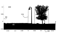
同様に、図6Cは、第2の距離ゲートn=2からの戻り信号を描いたものである。垂直軸644は、約−0.06rad〜約0.11radの範囲であり、これは約−3.5°〜6.3°に一致する。第1の距離ゲートの最大仰角である−0.05rad(約−3°)より下には戻り信号がない。第2の距離ゲートにおける戻り信号は、黒エリア645によって示され、0rad未満の地面レベルとともに、街灯柱と街灯柱の右手の木を表している。黒マスクエリア645における特徴距離が、目標空間解像度s、および式2aまたは式2cとともに、角解像度Δθを決定するために用いられる。列順または垂直のこぎり歯状走査軌跡については、カバーされるエリアは、最小垂直角約−0.5radから、各方位角αにおいて単一の値である、破線646によって示される最大垂直角までである。行順または水平のこぎり歯状走査軌跡については、最小方位角と最大方位角(図示せず)は、仰角εにおいて、各々、単一の値である。最小方位角は、街灯柱の左側にあり、最大方位角は、木の右側にある。
Similarly, FIG. 6C depicts a return signal from the second distance gate n = 2. The
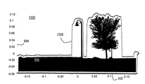
図6Dは、第3の距離ゲートn=3からの信号戻りを描いた2値画像650である。垂直軸654は、約−0.01radから約0.11radまで延び、約−0.6°〜約6.3°に一致する。第2の距離ゲートの地面レベルのほぼ最大仰角である、約−0.01rad(約−0.6°)より下には、戻り信号はない。第3の距離ゲートにおける戻り信号は、黒エリア655によって示され、約0radに、頂部の地面レベルとともに、林、林の右手のいくつか街灯および標識柱、ならびに、さらに右手に遠く藪を表している。黒マスクエリアにおける特徴距離が、目標解像度s、および式2aまたは式2cとともに、角解像度Δθを決定するために用いられる。列順または垂直のこぎり歯状走査軌跡については、カバーされるエリアは、トレース658によって与えられた最小垂直角と、各方位角αにおいて単一の値である、破線トレース656によって与えられた最大垂直角の間である。行順または水平のこぎり歯状走査軌跡については、最小方位角と最大方位角(図示せず)は、仰角εにおいて、各々、単一の値である。最小方位角は、林の左手にあり、最大方位角は、林の右手を柱状物のある仰角まで下がり、そこから、柱状物の右手を藪のある仰角まで下がり、そこから藪の右手に延びる。
FIG. 6D is a
図6Eは、最後の距離ゲートn=4からの信号戻りを描いた2値画像660である。垂直軸664は、(斜視図で、より遠い物体は、より小さく見え、垂直角におけるその延長距離は、より小さいので)約0radから約0.08radまで延び、約0°〜約4.5°に一致する。約0rad未満では、戻り信号はなく、この角度は、第3の距離ゲートの地面レベルのほぼ最大仰角である。第4の距離ゲートにおける戻り信号は、黒エリア665によって示され、林、切り開いた土地、さらに、幅方向に並んだ木々と、その上の約0.01radの地面レベルを表している。黒マスクエリア665における特徴距離が、目標空間解像度s、および式2aまたは式2cとともに、角解像度Δθを決定するために用いられる。列順または垂直のこぎり歯状走査軌跡については、カバーされるエリアは、トレース658によって与えられた最小垂直角と、各方位角αにおいて単一の値である、破線トレース668によって与えられた最大垂直角の間である。行順または水平のこぎり歯状走査軌跡については、最小方位角と最大方位角(図示せず)は、仰角εにおいて、各々、単一の値である。最小方位角は、林の左手に延び、最大方位角は、林の右手を一群の立木のある仰角まで下がり、そこから、右端の0.20radまで下がる。このような行順走査軌跡は、列順またはのこぎり歯状走査軌跡ほどは、多くのエリアを、高精度走査から排除しないことは留意すべきである。点線669は、図7Aと図7Bに高精度走査軌跡で表示されたエリアの水平部分を示す。
FIG. 6E is a
図7Aと図7Bは、実施形態による、それぞれ、異なる特徴距離(または、異なる目標空間解像度)について図6Eに描かれた距離ゲートの一部での、複数の隣接する水平スライスにおける例示の適応走査パターンを図示するグラフである。水平軸712は、方位角がラジアル単位で約−0.085〜約0.005radであることを示し、約−5°〜約0.3°のウィンドウに一致し、これは、図6Eに点線方形669の水平方向範囲として描かれている。垂直軸714は、仰角がラジアン単位で約−0.01rad〜約0.06radであり、約−0.6°〜約3.5°のウィンドウに一致する。現ウィンドウにおける、図6Eからの、トレース668によって与えられた最小垂直角と破線666によって与えられた最大垂直角もプロットされている。両方のトレースは、この適応走査軌跡の細密角解像度に合わせて、内挿補間されている。図7Aは、最小仰角と最大仰角の間の高解像度走査軌跡716のグラフ710である。水平反復離隔角AHRは、約0.0005rad(0.01rad離隔したチェックマーク間に20回の反復があることに留意すること)であり、これは、離隔角0.03°に一致する。この反復離隔角がΔθに等しいと仮定すると、Δθも0.03°に等しい。したがって、こののこぎり歯状走査軌跡に沿って垂直方向0.03°ごとに距離が測定される。
7A and 7B are exemplary adaptive scans of multiple adjacent horizontal slices at some of the distance gates depicted in FIG. 6E for different feature distances (or different target spatial resolutions), respectively, according to embodiments. It is a graph which illustrates the pattern. The
図7Bは、異なる距離または目標解像度条件の下での、最小仰角と最大仰角の間の高解像度走査軌跡726のグラフ720である。図示のために、図7Bでは、図7Aを作成するために用いられた値よりも、特徴距離が、はるかに小さい、または目標空間解像度sが、はるかに疎であると仮定している。その結果、式2aにより決定される角解像度は、はるかに疎である。図7Bでは、水平反復離隔角AHRは、約0.003radであり(0.01rad離隔しているチェックマーク間に約3.3反復があること留意すること)、これは、約0.17°の離隔角に一致し、図7Aよりも、約6倍疎である。反復離隔角がΔθに等しいと仮定すると、Δθは、0.17°に等しい。したがって、距離は、こののこぎり歯状走査軌跡に沿って垂直方向0.17°ごとに測定される。図示において、読者は、点線が、のこぎり歯状走査軌跡を表す点線−破線線分内にある所で、距離測定が行われると仮定することができる。
FIG. 7B is a
いくつかの実施形態では、適応走査は、自動的に、かつリアルタイムで、実行される。そのような実施形態では、特徴距離、走査エリア、走査軌跡、および角解像度の決定を自動化し、毎秒約1フレーム以上の望ましいフレームレートを可能にするために十分迅速に適応走査を実行するために、様々な方法が用いられる。 In some embodiments, adaptive scanning is performed automatically and in real time. In such an embodiment, in order to automate the determination of feature distance, scan area, scan trajectory, and angular resolution and perform adaptive scans quickly enough to allow a desired frame rate of about 1 frame per second or higher. , Various methods are used.
上述のように、いくつかの実施形態では、距離ゲート、例えば、Nの値、およびN個のRnearnの値は、適応走査の前に、手動で、事前決定または設定される。しかし、いくつかの実施形態では、Nの値、あるいはRnearnのN個の値、またはそれらの両方が、疎間隔距離測定においては、観測距離R(α,ε)に基づいて、自動的かつ適応的に決定される。例えば、上述のように、NおよびRnearnは、観測距離の低パーセンタイルと高パーセンタイル(例えば、5パーセンタイルと99パーセンタイル)に基づいて決定される。 As mentioned above, in some embodiments, distance gates, such as N values, and N Rnea n values are manually pre-determined or set prior to adaptive scanning. However, in some embodiments, the N values, or the N values of Rnea n , or both, are automatically and automatically based on the observed distance R (α, ε) in the sparsely spaced distance measurement. Determined adaptively. For example, as described above, N and Rnea n are determined based on the low and high percentiles of the observed distance (eg, the 5th and 99th percentiles).
別の実施形態では、数Nおよび値Rnearnは、疎間隔距離測定におけるR(α,ε)のヒストグラムに基づいて決定される。図10は、実施形態による、対象場所の疎角走査における距離のヒストグラムを例示するグラフ1010である。走査レーザ測距システムは最大距離Rmaxに合わせて構成されるものと仮定される。ヒストグラム軸1012は、Rmaxに比べて小さいビン幅、例えば、Rmaxの1/10〜1/100、または1/1000のビン幅、を有する距離ビンを示す。垂直軸1014は、いずれかの距離ビンに入る測定距離の件数を示す。トレース1016は、例示ヒストグラムを描いたものである。件数は平坦ではなく、いくつかのピーク1017と谷1015を有することに注目すること。大きな形状は、ヒストグラムにおいてピークを生み出す可能性が高く、開けた地域は、谷を生み出す可能性が高い。いくつかの実施形態では、距離ヒストグラムは、一定の角密度で疎走査が実行されることを説明するために、スケールが距離の関数として再設定された。このスケールの再設定は、この食い違いを説明するために、ヒストグラムにおいて、より遠い点の測定に、より重みを与える。
In another embodiment, the number N and the value Rnea n are determined based on the histogram of R (α, ε) in the sparsely spaced distance measurement. FIG. 10 is a
いくつかの実施形態では、1つ以上の距離ゲート値Rnearnが、垂直点線によって示すように、ヒストグラム1016において生起の谷であるように決定される。そして、これらの実施形態のうちのいくつかでは、距離ゲートの特徴距離は、距離ゲートにおける最大生起の距離(例えば、Rpeakn)である。多様な利用可能なソフトウェアルーチンを用いて、最小値とピーク値の両方が、迅速かつ自動的に、決定される。
In some embodiments, one or more distance gate values Rnea n are determined to be valleys of occurrence in
その他の実施形態では、ビン幅の定義を要しない累積ヒストグラムが生成され得る。累積ヒストグラムの変化率が、ピークと谷を発見するために、図10に描かれたトレース1016の代わりに、用いることができる。
In other embodiments, a cumulative histogram that does not require the definition of bin width can be generated. The rate of change of the cumulative histogram can be used in place of the
図11Aは、実施形態による、対象の場所の疎角走査のデータ構造1100の例示のブロック図である。このデータ構造は、本明細書に記載する特定の工程を実行する際、計算効率を良くするために、水平角順に、距離ゲートセットRGnを格納する。当然、列順または水平方向のこぎり歯状走査軌跡を用いる実施形態のためには、上記に代わって、水平角の最小値と最大値が、垂直角順に格納される。ここでは、単純化のために、列順、すなわち、垂直のこぎり歯状走査軌跡が用いられると仮定する。データ構造およびフィールドが、図11Aに、その後、図11Bに、ダイヤグラムが、図示のために、統合ブロックとして、特定の順序で、描かれているが、他の実施形態では、1つ以上のデータ構造あるいはフィールド、またはそれらの一部が、1つ以上のホストあるいはメッセージにおいて、同じ、あるいは異なる数のデータ構造またはデータベースに、異なる順序で、配置され、あるいは排除され、または、1つ以上の追加フィールドが含まれ、または、データ構造あるいはフィールドが、いくつかの組み合わせ方で変更される。
FIG. 11A is an exemplary block diagram of a
疎走査データ構造1100は、距離ゲートIDフィールド1111、開始距離フィールド1112、停止距離フィールド1113、距離数フィールド1114、距離統計フィールド1117、最小方位角フィールド1115、最大方位角フィールド1116、最小仰角フィールド1118、および最大仰角フィールド1119を含む。データ構造1100はまた、以下、長円形で指示し、集合的に疎走査レコードフィールド1120と呼ぶ、1つ以上の疎走査レコードフィールド1120a、1120b、その他を含む。
The sparse
距離ゲートIDフィールド1111は、N個の距離ゲートの各々に対してユニークな識別子、例えば、n番目の距離ゲートに対して数nのような、識別子を指示するデータを保持する。開始距離フィールド1112は、Rnearnを示すデータを保持し、停止距離フィールド1113は、Rfarnを示すデータを保持する。距離数フィールド1114は、どれだけ多くの疎距離が現距離ゲート内に入るかを示すデータを保持する。この数は、例えば、図10における垂直点線の間のビンの総数によって与えられる。距離開始フィールド1117は、例えば、特徴距離として、利用することができる距離ゲート内の距離の、1つ以上の統計特性、例えば、特に、平均距離、あるいは二乗平均平方根距離、あるいは中央値距離、あるいは1つ以上のピーク距離、あるいは1つ以上のパーセンタイル距離などを、単独で、または組み合わせとして、示すデータを保持する。いくつかの実施形態では、フィールド1117は排除される。最小方位角フィールド1115は、距離ゲートにおいて最も小さい水平方向角を示すデータを保持し、最大方位角フィールド1116は、距離ゲートにおいて最も大きい水平方向角を示すデータを保持する。同様に、最小仰角フィールド1118は、距離ゲートにおいて最も小さい知垂直方向角を示すデータを保持し、最大仰角フィールド1119は、距離ゲートにおいて最も大きい垂直方向角を示すデータを保持する。 The distance gate ID field 1111 holds data indicating an identifier unique to each of the N distance gates, for example, a number n for the nth distance gate. The start distance field 1112 holds data indicating Rnea n , and the stop distance field 1113 holds data indicating Rfar n. The distance number field 1114 holds data indicating how many sparse distances enter the current distance gate. This number is given, for example, by the total number of bins between the vertical dotted lines in FIG. The distance start field 1117 is, for example, one or more statistical properties of the distance within the distance gate that can be used as a feature distance, eg, the mean distance, or the root mean square distance, or the median distance, Holds data indicating one or more peak distances, one or more percentile distances, etc., alone or in combination. In some embodiments, field 1117 is excluded. The minimum azimuth field 1115 holds data indicating the smallest horizontal angle at the distance gate, and the maximum azimuth field 1116 holds data indicating the largest horizontal angle at the distance gate. Similarly, the minimum elevation field 1118 holds data indicating the smallest vertical angle at the distance gate, and the maximum elevation field 1119 holds data indicating the largest vertical angle at the distance gate.
疎走査レコード1120は、各々、方位角フィールド1121、仰角フィールド1122、および距離フィールド1123に描かれている疎データのための、それぞれ、方位角、仰角、および距離の3つ一組データR(α,ε)を示すデータを含む。レコードは、データレコードの構築が極めて迅速に行われるように、疎走査データによって集められ、Rnearn値によってゲートに入れられ、方位角値の昇順で配置される。疎データが収集されるまで距離ゲートが定義されない場合でも、収集された生データは、方位角順に高速メモリに格納され、データが収集されると同時に、ヒストグラムが満たされる。ヒストグラムが集められたならば、NおよびRnearnの値が、迅速に計算され、フィールド1111、1112、および1113を満たすために使用される。そして、格納された生データは、すでに方位角順である高速メモリから呼び出され、当然に、かつ自動的に方位角順であるレコードに、対応するデータ構造に、配置される。フィールド1114〜1119の値は、高速メモリに維持され、各レコードがデータ構造に加えられるたびに、増加する。最後の距離が呼びだれた後、フィールド1114〜1119の値は、いったんデータ構造に書き込まれる。その結果、データ構造1100は、レコードごとに、2つの入力/出力(I/O)操作のみによって、満たすことができる。
The sparse scanning record 1120 is a set of azimuth, elevation, and distance data R (α) for the sparse data depicted in the azimuth field 1121, the elevation field 1122, and the distance field 1123, respectively. , Ε) is included. The records are collected by sparsely scanned data, gated by Rnea n values, and arranged in ascending order of azimuth values so that the construction of the data records is very quick. Even if the distance gate is not defined until the sparse data is collected, the collected raw data is stored in high speed memory in azimuth order and the histogram is filled at the same time as the data is collected. Once the histograms are collected, the values of N and Rnea n are quickly calculated and used to fill the fields 1111, 1112, and 1113. Then, the stored raw data is called from the high-speed memory that is already in the azimuth order, and is naturally and automatically arranged in the corresponding data structure in the record that is in the azimuth order. The values of fields 1114 to 1119 are maintained in fast memory and are incremented as each record is added to the data structure. After the last distance is recalled, the values in fields 1114-1119 are once written into the data structure. As a result, the
図11Bに描かれた別のデータ構造は、同じ形状において描かれるような、細密操作軌跡を生成するために、図7Aまたは図7Bに描かれたトレース666および668などの、トレースを定義する際に使用するために、最小走査角および最大走査角を、方位角の関数として格納するために使用される。異なる方位角値が、各々、単一の仰角値を有する、疎走査の、のこぎり歯状走査軌跡で、これを行うために、データは、のこぎり歯状走査軌跡の1つの垂直スイープにおける、すべての仰角標本を取り扱うのに十分な大きさの方位角ビンに配置されなければならない。例えば、データは、少なくとも1つの水平反復離隔角AHRの幅を有する方位角ビンに、有用に配置される。より幅の広い方位角ビンも使用することができ、垂直スイープの開始と適切に位置が合っていれば、幅が半分のビンでも使用可能である。当然、行順、すなわち、水平のこぎり歯状走査軌跡では、方位角と仰角の切り替え機能、および垂直スライス幅が、水平スイープにおいてすべての方位角を含むように選択される。
Another data structure depicted in FIG. 11B is used to define traces, such as
図11Bは、実施形態による、複数の水平角ビンの適応最大角と適応最小角のデータ構造1150を描いた例示のブロック図である。データ構造1150は、距離ゲートIDフィールド1112、特徴距離フィールド1152、方位角ビン幅フィールド1154、およびビン数フィールド1156を含む。距離ゲートIDは、データ構造1100用であって、上述のとおりである。特徴距離フィールド1152は、距離ゲート、例えば、Rfarn、または、データ構造1100のフィールド1117の距離統計の1つのために使用される特徴距離を示すデータを保持する。方位角ビン幅フィールド1154は、0.5〜1以上の可変であるAHR係数など、1スイープの仰角の集合のために使用される方位角ビンの幅を示すデータを保持する。このビンは、最大仰角と最小仰角を方位の関数として定義するために使用されるスライスの水平幅を定義する。ビン数フィールド1156は、データ構造におけるビンの数、ならびに、それらのための最大仰角値の数および最小仰角値を示すデータを保持する。
FIG. 11B is an exemplary block diagram depicting a
データ構造は、集合的にレコード1160と呼ばれる、特に長円形によって示される、レコード1160aと1160bも含む。各レコード1160は、開始方位フィールド1161、最小仰角フィールド1162、および最大仰角フィールド1163を保持する。図示した実施形態では、各レコード1160はまた、シードフラグ・フィールド1164、最小拡張仰角フィールド1172、および最大拡張仰角フィールド1173を含む。開始方位角フィールド1161は、ビンにおいて最も小さい方位角を示すデータを保持し、したがって、データは、方位角の関数としてプロットすることができる。最小仰角フィールド1162は、方位角ビンスライスにおける最小仰角を示すデータを保持する。最大仰角フィールド1163は、方位角ビンスライスにおける最大仰角を示すデータを保持する。シードフラグ・フィールド1164は、最小値および最大値が、細密な解像度での方位角に対して、最小仰角値と最大仰角値の拡張および内挿補間または外挿補間をシードするために使用されるか否かを示すデータを保持する。使用される場合は、最小拡張仰角フィールド1172は、現距離ゲートの構成要素が、疎標本化のゆえに、より密な標本化の時に失われ、のこぎり歯状走査軌跡のために、水平方向に内挿補間される、可能性を低減するために、最小値が小さくされる場合の値を示すデータを保持する。同様に、最大拡張仰角フィールド1173は、現距離ゲートの構成要素が、疎標本化のゆえに、より密な標本化の時に失われ、のこぎり歯状走査軌跡のために、水平方向に内挿補間される、可能性を低減するために、最大仰角値が大きくされる場合の仰角値を示すデータを保持する。
The data structure also includes
図12は、実施形態による、距離ゲートのための、最大垂直角の水平角従属および最小垂直角の水平角従属を例示するグラフである。水平軸1212は、ラジアン単位の方位角(水平角)を示し、垂直軸1214は、ラジアン単位の仰角(垂直角)を示す。トレース1215は、シード点を結ぶ、所望の高解像度のこぎり歯状走査軌跡を示す。トレース1216は、方位角の関数としての最大仰角値のためのシード点を示し、トレース1218は、方位角の関数としての最小仰角値のためのシード点を示す。いくつかのシード点1217が、最大仰角値のトレース1216上に示される。いくつかのシード点1219が、最小仰角値のトレース1218上に示される。シード点は、次に述べるように、所望の細密解像度の、のこぎり歯状走査軌跡に合わせて、最大仰角シード点が、対応する最小仰角シード点から、方位角において、細密解像度Δθ/2分だけ、偏位し、細密解像度Δθの整数倍分だけ、垂直方向に離隔されるように、拡張トレースを内挿補間することによって、発見される。
FIG. 12 is a graph illustrating horizontal angle dependence of the maximum vertical angle and horizontal angle dependence of the minimum vertical angle for a distance gate according to an embodiment. The horizontal axis 1212 indicates an azimuth (horizontal angle) in radians, and the vertical axis 1214 indicates an elevation angle (vertical angle) in radians. Trace 1215 shows the desired high resolution sawtooth scan locus connecting the seed points.
図13Aと図13Bは、実施形態による、図6Cに図示する、1つの距離ゲートの最大仰角と最小仰角、それぞれの、非拡張(緊密)と拡張の例を示す走査角空間におけるマスクである。図13Aは、図のCの図を拡大した2値画像1310であり、最大値1316は、疎距離標本化における観測最大値によって、観測値にしたがって定義されたとおりである。図13Bは、図6Cの図を拡大した2値画像1320であり、最大値1326は、疎距離標本化における観測最大値から外方向に拡張され、最小値は、観測最小仰角から下方向に拡張されている。
13A and 13B are masks according to an embodiment in a scanning angle space showing examples of non-expanded (tight) and expanded, respectively, the maximum and minimum elevation angles of one distance gate illustrated in FIG. 6C. FIG. 13A is a
いくつかの実施形態では、1つの距離ゲートにおいて細密スケールの距離測定が行われたならば、隣接距離ゲートについて走査軌跡が計算される前に、隣接する距離ゲートとの境界を、さらに精密にすることができる。 In some embodiments, if a fine-scale distance measurement is made at one distance gate, the boundary with the adjacent distance gate is further refined before the scan trajectory is calculated for the adjacent distance gate. be able to.
図14は、実施形態による、準リアルタイムでの適応角走査を自動的に決定する例示の方法1400を図示するフローチャートである。方法1400は、各距離ゲートの点のセットについて、適応走査軌跡を計算する、図4の工程411の、自動化されたリアルタイムの実施形態の例である。したがって、図11Aのデータ構造1100は、工程405において、この図を参照して説明したように、データが配置された。
FIG. 14 is a flowchart illustrating an
工程1401では、例えば、データ構造1100において球座標に表された疎入力距離ゲート点クラウドが、定義された各水平角座標ビンについて、垂直角座標における上の境界と下の境界を計算するために使用される。いくつかの実施形態では、工程1401は、この工程を大幅に簡素化するために、(ソフトウェアで明示的に、または、データ収集によって明示的に)水平座標を前ソートすることを含む。この動作の出力は、入力点クラウドの上と下の観測境界、例えば、それぞれ、各々が図11Bに描かれたデータ構造1150のレコード1160において取得可能なフィールド1161における開始方位角の関数である、フィールと1163の最大仰角とフィールド1162の最小仰角、を描く2つのトレースを含む。
In step 1401, for example, a sparse input distance gate point cloud represented in spherical coordinates in
工程1403において、上と下の点クラウド観測境界は、例えば、Haralick,2007に記載されたMinkowski総和タイプの演算を用いて、拡張される。その結果、上部半円形状には、上の境界に追加され、下部半円形状には、下の境界が追加される。この演算の結果は、観測境界と比較して、空間的緩衝の役割を果たす、円滑化され、拡張された上下の境界となる。例えば、この出力は、各々が、図11Bに描かれたデータ構造1150のレコード1160において取得可能なフィールド1161における開始方位角の関数である、フィールド1172の最大拡張仰角とフィールド1173の最小拡張仰角に見られる。
In step 1403, the upper and lower point cloud observation boundaries are extended using, for example, the Minkowski summation type operation described in Haralick, 2007. As a result, the upper semicircular shape is added to the upper boundary, and the lower semicircular shape is added to the lower boundary. The result of this operation is a smoothed, extended upper and lower boundary that acts as a spatial buffer compared to the observation boundary. For example, this output is to the maximum extended azimuth of field 1172 and the minimum extended elevation of field 1173, each of which is a function of the starting azimuth in field 1161 that can be obtained in record 1160 of
工程1405では、走査ハードウェアを駆動するための適応走査波形の計算の第一歩として、細密スケールの走査軌跡のためのシード点が、上と下の境界に沿って計算される。上のシード点セットの位置は、ビン中心から所望の空間解像度の半分(例えば、Δθ/2)だけ偏位され、したがって、上の各シード点は、垂直のこぎり歯状走査軌跡を支えるように、下のシード点に対して偏位される。その他の走査軌跡を用いる、他の実施形態については、シード点の偏位は、行順あるいは列順についてゼロであるか、または、水平のこぎり歯状において、左シード点が、右シード点に対して偏位する。シード点の仰角座標が、反対側の境界からΔθの整数倍になる上と下の円滑かつ拡張された境界に対して、内挿補間されてもよい。疎標本化解像度が、所望の解像度とは大きく異なる場合には、これは有用である。
In
工程1407では、シード点のセットが、走査軌跡にまたがる角標本化さえも提供するという意味で、経時的ビーム位置を定義する(走査速度、標的に対する所望の空間解像度、距離測定速度などのシステムパラメータに関連する)コマンド値を計算する計算の終点として使用される。例えば、ビームステアリング・システムを駆動するデジタル−アナログ変換器(DAC)の出力標本速度で報告される水平と垂直の走査軌跡点は、それぞれ、水平と垂直の境界(水平と垂直のシード点位置)の間に線形に間隔を置いて配置される。DACの出力は、ステッピングミラーなどの走査コンポーネントを駆動する。キーは、境界上に配置される標本の数である。これは、DAC標本速度SRDAC、パルス時間幅τ、および所望の走査密度に従属する。したがって、軌跡のセグメントの開始境界と終止境界(例えば、垂直のこぎり歯状パターンのスライス内セグメントの下境界と上境界)の間の第1の次元角(例えば、垂直角すなわち仰角)の大きさE、DAC標本速度SRDAC、パルス時間幅τ、および所望の走査密度(目標角解像度)Δθについて、軌跡の線分に沿って線形分布する点の数Mが、式5によって与えられるものとして計算される。
M=SRDAC*τ*E/Δθ (5)
式5において、E/Δθは走査軌跡の仰角または方位角走査跡の単位当たりパルス数であることに注目すべきである。SRDAC*τは、パルス当たりの走査光学装置制御標本数である。これらの積は、走査跡単位当たりの制御標本数である。
In
M = SR DAC * τ * E / Δθ (5)
It should be noted that in Equation 5, E / Δθ is the number of pulses per unit of the elevation or azimuth scan trace of the scan locus. SR DAC * τ is the number of scanning optics controlled samples per pulse. These products are the number of controlled samples per scan trace unit.
式5の計算は、さらに、システムパラメータ値を仮定することによって例示される。Δθ=10−4rad(約0.006°)およびE=0.5rad(約30°)については、走査跡単位当たりの数は5,000である。パルス反復周波数(PRF)100キロヘルツ(kHz、1kHz=103Hz、1Hz=毎秒1標本)については、パルス時間幅は、τ=10マイクロ秒(μs、1μs=10−6秒)である。DACからのアナログ信号出力SRDACが250kHzとすると、パルス当たり制御標本数は、SRDAC*τ=2.5であり、走査跡単位当たり500パルスに対して、式5から得られる走査光学装置を制御するための走査跡単位当たり出力制御標本数は、12,500である。これは、いくつかの実施形態において、走査光学装置に送られるコマンドに指示される。いくつかの実施形態では、DAC標本速度は、式5により計算されるもの以外は、固定値を有する。そのような固定値も使用可能である。この固定値と、式5により得られる所望の標本数または時間との食い違いは、処理後に整理可能である。 The calculation of Equation 5 is further illustrated by assuming system parameter values. For Δθ = 10 -4 rad (about 0.006 °) and E = 0.5 rad (about 30 °), the number per scan trace unit is 5,000. Pulse repetition frequency (PRF) 100 kilohertz (kHz, 1kHz = 10 3 Hz , 1Hz = per 1 sample) for the pulse time width is tau = 10 microseconds (μs, 1μs = 10 -6 seconds). Analog signal output from DAC Assuming that SR DAC is 250 kHz, the number of controlled samples per pulse is SR DAC * τ = 2.5, and the scanning optical device obtained from Equation 5 is used for 500 pulses per scanning trace unit. The number of output control samples per scan trace unit for control is 12,500. This is directed by a command sent to the scanning optics in some embodiments. In some embodiments, the DAC sampling rate has a fixed value, except as calculated by Equation 5. Such fixed values are also available. The discrepancy between this fixed value and the desired number of samples or time obtained by Equation 5 can be sorted out after processing.
いくつかの実施形態では、ローカルオシレータのための遅延時間ΔtLOnは、上述のように、式4を用いて、距離ゲートnのための各距離ゲート標本化について決定される。 In some embodiments, the delay time Δt LOn for the local oscillator is determined for each distance gate sampling for the distance gate n using Equation 4 as described above.
工程1409では、各距離ゲートについて計算された適応走査軌跡が、走査レーザ測距システムに与えられる。いくつかの実施形態では、これは、式5により得られる走査速度(走査跡単位当たりの出力制御標本数)、式4による遅延時間、ならびに、最小と最大の垂直角および開始と終止水平角(または、他の軌跡について、対応する開始と終止の第1次元角、および第2の次元の最大値と最小値のセット)を送ることを含む。
In
5.計算ハードウェアの概要
図8は、本発明の実施形態が実装され得るコンピュータシステム800の例示のブロック図である。コンピュータシステム800は、コンピュータシステム800の内部および外部のコンポーネント間で、情報を送受させるためのバス810などの、通信メカニズムを備える。情報は、測定可能な現象、一般的には、電圧であるが、その他の実施形態においては、磁気、電磁気、圧力、化学、分子、原子および量子の相互作用などの現象の物理的信号として表される。例えば、NとSの磁場、または、ゼロと非ゼロの電圧は、2値桁(ビット)の2つの状態(0,1)を表す。他の現象は、より高い基数の桁を表すことができる。測定前の複数の量子状態の重ね合わせは、量子ビット(qubit)を表す。1つ以上の桁のシーケンスは、数または文字のコードを表すために使用される。いくつかの実施形態では、アナログデータと呼ばれる情報は、特定の範囲内の測定可能な値の近似連続体によって表される。コンピュータシステム800、またはその一部は、本明細書に記載する1つ以上の方法の1つ以上の工程を実行するための手段を構成する。
5. Schematic of Computational Hardware FIG. 8 is an exemplary block diagram of a
2値桁のシーケンスは、数または文字コードを表すために使用されるデジタルデータを構成する。バス810は、情報がバス800に接続されたデバイス間に迅速に送達されるように、多数の並列の情報導体を含む。情報を処理するための1つ以上のプロセッサ802が、バス810に接続される。プロセッサ802は、情報に対する動作のセットを実行する。この動作のセットは、バス810から除法を取り込むこと、および、バス810に情報を送り込むことを含む。この動作のセットはまた、典型的には、1つ以上の情報単位を比較すること、情報単位の位置を移動すること、および、加算または乗算などによって、2つ以上の情報単位を組み合わせることを含む。プロセッサ802によって実行されるべき動作のシーケンスは、コンピュータ命令を構成する。
A sequence of binary digits constitutes the digital data used to represent a number or character code.
コンピュータシステム800はまた、バス810に接続されたメモリ804を含む。ランダムアクセスメモリ(RAM)またはその他の動的記憶デバイスなどのメモリ804は、コンピュータ命令を含む情報を記憶する。動的メモリは、そこに記憶された情報が、コンピュータシステム800によって変更されることを可能にする。RAMは、メモリアドレスと呼ばれる位置に格納された情報の単位が、隣接するアドレスにある情報から独立して、格納され、引き出されることを可能にする。メモリ804はまた、プロセッサ802によって、コンピュータ命令の実行の間、一時的な値を格納するために使用される。コンピュータシステム800はまた、コンピュータシステム800によって変更されない、命令を含む、静的情報を記憶するための、バス810に接続された読み出し専用メモリ(ROM)806、または、その他の静的記憶デバイスを含む。コンピュータシステム800が電源オフにされた場合、またはその他、電力を失った場合でも、保持される、命令を含む、情報を記憶するために、磁気ディスクまたは光ディスクなどの、非揮発(永久的)記憶デバイス808も、バス810に接続される。
命令を含む情報は、人間のユーザが操作する英数字キーを備えるキーボード、またはセンサなど、外部入力デバイス812から、プロセッサによる使用のために、バス810に提供される。センサは、その近傍における状態を検知し、その検知を、コンピュータシステム800において情報を表すために使用される信号に変換する。バス800に接続され、主として人間との対話のために使用される、その他の外部デバイスは、画像を提示するための陰極線管(CRT)または液晶ディスプレイ(LCD)などのディスプレイ装置814、および、ディスプレイ814上に提示される小さなカーソル像の位置を制御し、ディスプレイ814上に提示されるグラフィカル要素に関連するコマンドを発するための、マウス、トラックボールまたはカーソル誘導キーなどのポインティングデバイス816を含む。
Information, including instructions, is provided from an
図示された実施形態において、特定用途向け集積回路(IC)820など、特別目的ハードウェアが、バス810に接続される。特別目的ハードウェアは、特別な目的のために十分に迅速に、プロセッサ800によって実行されない動作を実行するように構成される。特定用途向けICの例には、ディスプレイ814のための画像を生成するためのグラフィクスアクセレレータ・カード、ネットワークを介して送られるメッセージを暗号化および解読するための暗号化基盤、ならびに、ハードウェアに実装する方がより効率的な複雑な動作シーケンスを反復実行する、ロボットアームおよび医療用走査機器など、特別な外部デバイスとの音声認識およびインタフェースなどがある。
In the illustrated embodiment, special purpose hardware such as a special purpose integrated circuit (IC) 820 is connected to the
コンピュータシステム800はまた、バス800に接続された通信インタフェース870の1つ以上の例を含む。通信インタフェース870は、プリンタ、スキャナ、外部ディスクなど、それ自身のプロセッサとともに動作する多様な外部デバイスに接続される双方向通信を提供する。一般に、この接続は、それ自身のプロセッサを有する多様な外部デバイスが接続されるローカルネットワーク880に接続されるネットワークリンク878との間になされる。例えば、通信インタフェース870は、パソコン上のシリアルポートまたはユニバーサルシリアルバス(USB)であってもよい。いくつかの実施形態では、通信インタフェース870は、統合サービスデジタルネットワーク(ISDN)カード、デジタル加入者線(DSL)、または、対応する型の電話回線への情報通信接続を提供する電話モデムである。いくつかの実施形態では、通信インタフェース870は、バス810上の信号を、同軸ケーブルを介する通信接続のための信号、または光ファイバケーブルを介する通信接続のための光信号に変換するケーブルモデムである。別の例では、通信インタフェース870は、Ethernetなど、適合LANへのデータ通信接続を提供するローカルエリアネットワーク(LAN)カードとあってもよい。無線リンクが実装されてもよい。音波、および、無線波、光、赤外線波を含む電磁波などの、搬送波は、ワイヤもケーブルもなしに、空間を進行する。信号は、搬送波の振幅、周波数、位相、極、またはその他の物理特性の人工の変動を含む。無線リンクについては、通信インタフェース870は、デジタルデータなど、情報のストリームを運ぶ、電気、音、または、赤外線および光の信号を含む、電磁気の信号を送受する。
The
本明細書において、コンピュータ可読媒体という用語は、プロセッサ802への、実行命令を含む、情報の提供に参加する任意の媒体を指すために用いられる。そのような媒体は、非揮発性媒体、揮発性媒体、送信媒体を含むが、それらに限定されない、多数の形式をとる。揮発性媒体は、例えば、記憶デバイス808など、光または電磁気ディスクを含む。揮発性媒体は、例えば、動的メモリ804を含む。送信媒体は、例えば、同軸ケーブル、銅線ワイヤ、光ファイバケーブル、ならびに、音波、および、無線波、光、赤外線波を含む、電磁波など、ワイヤもケーブルもなしに空間を進行する波を含む。本明細書において、送信媒体を除き、コンピュータ可読媒体という用語は、プロセッサ802への情報の提供に参加する任意の媒体を指すために用いされる。
As used herein, the term computer-readable medium is used to refer to any medium that participates in the provision of information to
一般的な形のコンピュータ可読媒体は、例えば、フロッピーディスク、フレキシブルディスク、ハードディスク、磁気テープ、または、その他の任意の磁気媒体、コンパクトディスクROM(CD−ROM)、デジタルビデオディスク(DVD)、またはその他の任意の光媒体、パンチカード、紙テープ、またはその他の任意の穴パターンを有する物理媒体、RAM、プログラマブルROM(PROM)、消去可能PROM(EPROM)、フラッシュEPROM、またはその他の任意のメモリチップあるいはカートリッジ、搬送波、または、コンピュータが読み出すことができるその他の任意の媒体を含む。本明細書において、非一時的コンピュータ可読記憶媒体という用語は、搬送波およびその他の信号を除き、プロセッサ802への情報提供に参加する媒体を指すために用いられる。
Common forms of computer-readable media include, for example, floppy disks, flexible disks, hard disks, magnetic tapes, or any other magnetic medium, compact disk ROM (CD-ROM), digital video disk (DVD), or the like. Any optical medium, punch card, paper tape, or other physical medium with any hole pattern, RAM, programmable ROM (PROM), erasable PROM (EPROM), flash EPROM, or any other memory chip or cartridge. , Carrier, or any other computer-readable medium. As used herein, the term non-temporary computer-readable storage medium is used to refer to a medium that participates in providing information to
1つ以上の有形媒体に符号化される論理には、コンピュータ可読媒体上のプロセッサ命令と、ASIC 820などの特別目的ハードウェア上のそれのうちの、一方または両方などがある。
Logic encoded on one or more tangible media includes processor instructions on a computer-readable medium and one or both of them on special purpose hardware such as an
ネットワークリンク878は、典型的には、1つ以上のネットワークを通じて、情報を使用または処理する他のデバイスに、情報を提供する。例えば、ネットワークリンク878が、ローカルネットワーク880を介して、ホストコンピュータ882、または、インターネットサービスプロバイダ(ISP)によって運用される設備884への接続を提供してもよい。そして、ISP設備884は、現在では一般にインターネット890と呼称される、全世界公衆パケット交換通信の、ネットワークのネットワークを介して、データ通信サービスを提供する。インターネットに接続されたサーバ892と呼ばれるコンピュータは、インターネットを通じて受け取った情報に応答して、サービスを提供する。例えば、サーバ892は、ディスプレイ814における表現のために、映像データを表す情報を提供する。
The
本発明は、本明細書に記載する技術を実装するためのコンピュータシステム800の使用に関する。本発明の実施形態により、前記の技術は、メモリ804に格納された1つ以上の命令の1つ以上のシーケンスを実行するプロセッサ802に応答して、コンピュータシステム800によって実行される。ソフトウェアおよびプログラムコードとも呼ばれる、そのような命令は、記憶デバイス808など、他のコンピュータ可読媒体から、メモリ804に読み込まれてもよい。メモリ804に格納された命令シーケンスの実行は、プロセッサ802に、本明細書に記載した工程の実行を行わせる。それに代わる別の実施形態では、特定用途向け集積回路820などのハードウェアが、本発明の実装のために、ソフトウェアに代わって、またはソフトウェアと組み合わせて、使用されてもよい。したがって、本発明の実施形態は、個別のハードウェアとソフトウェアの組み合わせに限定されない。
The present invention relates to the use of a
ネットワークリンク878、および通信インタフェース870を介する他のネットワークを通じて送信された信号は、情報を、コンピュータシステム800へ、また、そこから情報を運ぶ。コンピュータシステム800は、ネットワークリンク878および通信インタフェース870を介して、特にネットワーク880,890を通じて、プログラムコードを含む、情報を送受することができる。インターネット890を使用する例において、サーバ892は、コンピュータシステム800から送信されたメッセージによって要求された特定アプリケーションのためのプログラムコードを、インターネット890、ISP設備884、ローカルネットワーク880、および通信インタフェース870を介して、送信する。受信されたコードは、受信と同時に、プロセッサ802によって実行されてもよく、後で実行するために、記憶デバイス808、あるいは、その他の非揮発性記憶装置に格納されてもよく、またはそれらの両方であってもよい。このようにして、コンピュータシステム800は、搬送波上の信号の形で、アプリケーションプログラムコードを取得してもよい。
Signals transmitted through the
多様な形式のコンピュータ可読媒体が、命令あるいはデータ、またはそれらの両方の、1つ以上のシーケンスを、実行のために、プロセッサ802へ運ぶことにかかわってもよい。例えば、命令およびデータは、最初、ホスト882など、遠隔コンピュータの磁気ディスク上に運ばれてもよい。遠隔コンピュータは、命令およびデータを、その動的メモリ内にロードし、命令およびデータを、モデムを使用して、電話回線を通じて送信する。コンピュータシステム800のローカルのモデムが、電話回線を介して、命令およびデータを受信し、ネットワークリンク878として働き、命令およびデータを赤外線搬送波上の信号に変換する赤外線送信器を使用する。通信インタフェース870として働く赤外線検知器が、赤外線信号として運ばれた命令およびデータを受信し、バス810に、命令およびデータを表す情報を乗せる。バス810は、情報をメモリ804に運び、そこから、プロセッサ802が命令を引き出して、命令とともに送られたデータの一部を使用して、命令を実行する。メモリ804に受信された命令およびデータは、任意選択的に、プロセッサ802による実行の前、または後に、記憶デバイス808に格納されてもよい。
Computer-readable media of various forms may be involved in carrying one or more sequences of instructions and / or data to
図9は、本発明の実施形態を実装し得るチップセット900の例示である。チップセット900は、本明細書に記載する方法の1つ以上の工程を実行するようにプログラムされ、例えば、1つ以上の物理的パッケージ(例えば、チップ)に組み込まれた、図8に関して記載されたプロセッサおよびメモリコンポーネントを含む。例示として、物理的パッケージには、物理的強度、サイズの保存、および/または電気的相互作用の制限など、1つ以上の特徴を提供するための構造的アセンブリ(例えば、ベースボード)上の1つ以上の資材、コンポーネント、および/またはワイヤの配置などがある。特定の実施形態においては、チップセットは単一チップに実装可能であると想定される。チップセット900、またはその一部は、本明細書に記載する方法の1つ以上の工程を実行するための手段を構成する。
FIG. 9 is an example of a
1つの実施形態において、チップセット900は、チップセット900のコンポーネント間に情報を送受させるためのバス901などの通信メカニズムを含む。プロセッサ903は、例えば、メモリ905に記憶された命令を実行し、情報を処理するために、バス901への接続能力を有する。プロセッサ903は、1つ以上の処理コアを含むことができ、各コアは独立に実行するように構成される。マルチコアプロセッサは、単一の物理パッケージ内での複数処理を可能にする。マルチコアプロセッサの例としては、2つ、4つ、8つ、または、それより大きい数の処理コアを含む。それとは代替的に、または追加的に、プロセッサ903は、命令の独立的実行、パイプライン化、マルチスレッド化を可能にする、バス901を介して、タンデム状に構成された1つ以上のマイクロプロセッサを含んでもよい。プロセッサ903は、1つ以上のデジタル信号プロセッサ(DSP)907、または1つ以上の特定用途向け集積回路(ASIC)909など、特定の処理機能およびタスクを実行する、1つ以上の特化したコンポーネントを備えて実現されてもよい。DSP907は、典型的には、プロセッサ903からは独立して、リアルタイムで、現実世界の信号(例えば、音)を処理するように構成される。同様に、ASIC909は、汎用プロセッサでは実行が容易でない、特化した機能を実行するように構成することができる。本明細書に記載する発明機能の実行を助ける、他の特化したコンポーネントとしては、1つ以上のフィールドプログラマブル・ゲートアレイ(FPGA)(図示せず)、1つ以上のコントローラ(図示せず)、またはその他の1つ以上の特別目的コンピュータチップなどがある。
In one embodiment, the
プロセッサ903および付随するコンポーネントは、バス901を介するメモリ905への接続能力を有する。メモリ905は、実行可能な命令であって、それが実行されると、本明細書に記載する方法の1つ以上の工程を行う命令を格納するための、動的メモリ(例えば、RAM、磁気ディスク、書き込み可能光ディスク等)と静的メモリ(例えば、ROM、CD−ROM等)の両方を含む。メモリ905は、本明細書に記載する方法の1つ以上の工程の実行に関連する、またはそれによって生成される、データを格納する。
The
6.変形、拡張、および修正
以上の明細において、本発明は、特定の実施形態に照らして記述された。しかし、本発明の広い精神と範囲から逸脱することなく、本発明に様々な修正および変更を加え得ることは明らかであろう。したがって、明細書および図面は、制限的意味ではなく、例示的意味を有するとみなされなければならない。本明細書および請求の範囲を通じて、文脈から別の意味に解すべき場合を除き、comprise、ならびに、comprisesおよびcomprisingなど、その変形は、述べられた項目、要素、あるいは工程、または、項目、要素、あるいは工程の集まりを含むと解されるが、任意のその他の項目、要素、あるいは工程、または、項目、要素、あるいは工程の集まりを排除するものではない。さらに、不定冠詞aまたはanは、それによって修飾される項目、要素、または工程の1つ以上を示すものである。本明細書において使用される場合、文脈から明らかである場合を除き、値は、それが他の値を2で乗除(2または1/2倍)したものである場合、他の値に「約」を付けたものである。例示の範囲が与えられた場合、文脈から明らかな場合を除き、様々な実施形態において、それに含まれる範囲もすべて意図されている。したがって、いくつかの実施形態において、1から10の範囲は、1から4の範囲を含む。
6. Modifications, Extensions, and Modifications In the above specification, the present invention has been described in the light of a particular embodiment. However, it will be clear that various modifications and modifications can be made to the invention without departing from the broad spirit and scope of the invention. Therefore, the specification and drawings must be considered to have an exemplary meaning rather than a restrictive meaning. Throughout the specification and claims, unless the context should be taken to a different meaning, such variations as comprise, as well as comprises and comprising, are the items, elements, or processes, or items, elements, described. Alternatively, it is understood to include a set of processes, but does not exclude any other item, element, or process, or item, element, or set of steps. Further, the indefinite article a or an indicates one or more of the items, elements, or steps modified by it. As used herein, a value "approx." To another value if it is the other value multiplied by 2 (2 or 1/2 times), unless the context makes it clear. "Is added. Given the exemplary scope, all scopes contained therein are also intended in various embodiments, except as is apparent from the context. Therefore, in some embodiments, the range from 1 to 10 includes the range from 1 to 4.
7.参考文献
Adany,P.,C.Allen,and R.Hui,“Chirped Lidar Using Simplified Homodyne Detection,”Jour.Lightwave Tech.,v.27(16),15 August,2009.
Haralick,R.M.,S.R.Sternberg and X.Zhuang,“Image Analysis Using Mathematical Morphology,”IEEE Transactions on Pattern Analysis and Machine Intelligence,v.PAMI−9(4),July 1987.
Hui,R.,C.Allen,and P.Adany,“Coherent detection scheme for FM Chirped laser RADAR,”US patent 7,742,152,22 June 2010.
7. References Aday, P. et al. , C.I. Allen, and R. Hui, "Chirped Lidar Using Simplefied Homodyne Detection," Jour. Lightwave Tech. , V. 27 (16), 15 August, 2009.
Haralick, R.M. M. , S. R. Sternberg and X. Zhuang, "Image Analysis Using Mathematics Morphology," IEEE Transitions on Pattern Analysis and Machine Intelligence, v. et al. PAMI-9 (4), July 1987.
Hui, R.M. , C.I. Allen, and P. et al. Aday, "Coherent detection scheme for FM Chirped laser RADAR," US patent 7,742,152,22 June 2010.
Claims (15)
光信号を生成するように構成されたレーザ源;
光信号の周波数または位相の少なくとも1つを変調するように構成された変調器;
変調光信号を送信するように構成された1つ以上の走査光学装置;および
処理回路であって;
第1の角解像度を使用して、1つ以上の走査光学装置の視野内の複数の第1の距離測定値を取得するために1つ以上の走査光学装置を動作させ;
複数の距離ゲートのうち特定の距離ゲートに対応する1つ以上の第1の距離測定値を使用して、複数の距離ゲートのうち特定の距離ゲートに第2の角解像度を割り当て;
複数の距離ゲートのうち特定の距離ゲートに割り当てられた最小角と最大角を拡張し;
複数の第2の距離測定値を取得するために、複数の距離ゲートのうち特定の距離ゲートに割り当てられた、第2の角解像度、拡張された最小角、および拡張された最大角を使用して、1つ以上の走査光学装置を動作させ;および
複数の第2の距離測定値を使用して、自律走行車を制御するように構成された、
処理回路、を含む、
光検出と測距(LIDAR)システム。 A photodetection and distance measurement (LIDAR) system, which is:
A laser source configured to generate an optical signal;
A modulator configured to modulate at least one of the frequencies or phases of an optical signal;
One or more scanning optics configured to transmit a modulated optical signal; and a processing circuit;
Using the first angular resolution, one or more scanning optics are operated to obtain multiple first distance measurements within the field of view of the one or more scanning optics;
Assign a second angular resolution to a particular distance gate of a plurality of distance gates using one or more first distance measurements corresponding to a particular distance gate of the distance gates;
Extends the minimum and maximum angles assigned to a particular distance gate among multiple distance gates;
To obtain multiple second distance measurements, use the second angle resolution, extended minimum angle, and extended maximum angle assigned to a particular distance gate among the multiple distance gates. To operate one or more scanning optics; and to control an autonomous vehicle using multiple second distance measurements.
Processing circuit, including,
Photodetection and Lidar system.
請求項1に記載のLIDARシステム。 The processing circuit adds the lower semicircle shape to the lower boundary represented by the minimum angle, and the upper semicircle shape to the upper boundary represented by the maximum angle, thereby causing the minimum and maximum angles. Is configured to extend
The lidar system according to claim 1.
請求項1に記載のLIDARシステム。 The processing circuit is configured to use the target spatial resolution for a particular distance gate of the plurality of distance gates and assign a second angular resolution to the particular distance gate of the plurality of distance gates.
The lidar system according to claim 1.
請求項3に記載のLIDARシステム。 The spatial resolution defined by the first angular resolution and the first distance measurement is greater than the target spatial resolution.
The lidar system according to claim 3.
請求項1に記載のLIDARシステム。 The processing circuit is configured to operate one or more scanning optics for scanning using the saw tooth trajectory.
The lidar system according to claim 1.
請求項1に記載のLIDARシステム。 It further comprises a detector array configured to receive a return signal in response to a modulated optical signal transmitted by one or more scanning optics, where the processing circuit uses at least one return signal. Configured to determine a second distance measurement,
The lidar system according to claim 1.
基準経路遅延時間によって複数の第2の距離測定値を取得するために使用される基準信号を遅延させる、ように構成される、
請求項1に記載のLIDARシステム。 The processing circuit uses the characteristic distance of a particular distance gate out of multiple distance gates to determine a reference path delay time to obtain multiple second distance measurements; and by the reference path delay time. It is configured to delay the reference signal used to obtain multiple second distance measurements.
The lidar system according to claim 1.
請求項1に記載のLIDARシステム。 A particular distance gate of multiple distance gates is associated with a portion of the angular space of the field of view of one or more scanning optics, and one or more first distance measurements are assigned to a particular distance gate. Greater than the minimum distance and less than the maximum distance assigned to a particular distance gate,
The lidar system according to claim 1.
複数の距離ゲートのうち特定の距離ゲートに対応する1つ以上の第1の距離測定値を使用して、複数の距離ゲートのうち特定の距離ゲートに第2の角解像度を割り当てる工程;
複数の距離ゲートのうち特定の距離ゲートに割り当てられた最小角と最大角を拡張する工程;
複数の第2の距離測定値を取得するために、複数の距離ゲートのうち特定の距離ゲートに割り当てられた、第2の角解像度、拡張された最小角、および拡張された最大角を使用して、1つ以上の走査光学装置を動作させる工程;および
複数の第2の距離測定値を使用して、自律走行車を制御する工程、を含む、
請求項1−8のいずれか1つに記載のLIDARシステムを動作させる方法。 The step of operating one or more scanning optics using the first angular resolution to obtain a plurality of first distance measurements within the field of view of one or more scanning optics;
The step of assigning a second angular resolution to a particular distance gate of a plurality of distance gates using one or more first distance measurements corresponding to a particular distance gate of the plurality of distance gates;
The process of expanding the minimum and maximum angles assigned to a specific distance gate among multiple distance gates;
To obtain multiple second distance measurements, use the second angle resolution, extended minimum angle, and extended maximum angle assigned to a particular distance gate among the multiple distance gates. A step of operating one or more scanning optics; and a step of controlling an autonomous vehicle using a plurality of second distance measurements.
The method of operating the lidar system according to any one of claims 1-8.
請求項9に記載の方法。 The step of expanding the minimum angle includes adding the lower semicircle shape to the lower boundary represented by the minimum angle, and the step of expanding the maximum angle is the step of adding the upper semicircle shape by the maximum angle. Including the step of adding to the boundary of, where the minimum and maximum angles are elevation angles,
The method according to claim 9.
請求項9に記載の方法。 The step of assigning a second angular resolution to a specific distance gate among a plurality of distance gates includes a step of assigning a second angular resolution using the target spatial resolution for a specific distance gate among the plurality of distance gates. Here, the spatial resolution defined by the first angular resolution and the first distance measurement value is larger than the target spatial resolution.
The method according to claim 9.
請求項11に記載の方法。 It further comprises the step of determining the target spatial resolution using at least one of a predetermined value or a predetermined fraction of the size of the object in the field of view, said predetermined value being 10 centimeters or less.
11. The method of claim 11.
請求項9に記載の方法。 The step of operating one or more scanning optics to obtain at least one of a plurality of first distance measurements or a plurality of second distance measurements is a scan using the trajectory of a saw tooth scan. Including the step of operating one or more scanning optics for the purpose.
The method according to claim 9.
請求項9に記載の方法。 It further comprises the step of determining a reference path delay time to obtain a plurality of second distance measurements using the characteristic distance of a particular distance gate of the plurality of distance gates, wherein one or more. The step of operating the scanning optics includes delaying the reference signal used by one or more scanning optics to obtain a plurality of second distance measurements by reference path delay time.
The method according to claim 9.
請求項9に記載の方法。 A particular distance gate of multiple distance gates is associated with a portion of the angular space of the field of view of one or more scanning optics, and one or more first distance measurements are assigned to a particular distance gate. Greater than the minimum distance and less than the maximum distance assigned to a particular distance gate,
The method according to claim 9.
Applications Claiming Priority (3)
| Application Number | Priority Date | Filing Date | Title |
|---|---|---|---|
| US201662428117P | 2016-11-30 | 2016-11-30 | |
| US62/428,117 | 2016-11-30 | ||
| PCT/US2017/062708 WO2018102188A1 (en) | 2016-11-30 | 2017-11-21 | Method and system for automatic real-time adaptive scanning with optical ranging systems |
Publications (3)
| Publication Number | Publication Date |
|---|---|
| JP2019537013A JP2019537013A (en) | 2019-12-19 |
| JP2019537013A5 JP2019537013A5 (en) | 2020-02-06 |
| JP6876796B2 true JP6876796B2 (en) | 2021-05-26 |
Family
ID=62241864
Family Applications (1)
| Application Number | Title | Priority Date | Filing Date |
|---|---|---|---|
| JP2019527224A Active JP6876796B2 (en) | 2016-11-30 | 2017-11-21 | Methods and systems for automatic real-time adaptive scanning with an optical rangefinder |
Country Status (6)
| Country | Link |
|---|---|
| US (2) | US11249192B2 (en) |
| EP (1) | EP3548925A4 (en) |
| JP (1) | JP6876796B2 (en) |
| KR (2) | KR102380943B1 (en) |
| CN (2) | CN110140064B (en) |
| WO (1) | WO2018102188A1 (en) |
Families Citing this family (35)
| Publication number | Priority date | Publication date | Assignee | Title |
|---|---|---|---|---|
| US10036812B2 (en) | 2015-06-24 | 2018-07-31 | Blackmore Sensors and Analytics Inc. | Method and system for three dimensional digital holographic aperture synthesis |
| CN114296093A (en) | 2016-11-29 | 2022-04-08 | 布莱克莫尔传感器和分析有限责任公司 | Method and system for classifying objects in a point cloud data set |
| CN110140064B (en) | 2016-11-30 | 2023-07-18 | 布莱克莫尔传感器和分析有限责任公司 | Method and system for automatic real-time adaptive scanning by utilizing optical ranging system |
| EP3548926A4 (en) | 2016-11-30 | 2020-07-01 | Blackmore Sensors And Analytics Inc. | Method and system for adaptive scanning with optical ranging systems |
| CN113985427A (en) | 2016-11-30 | 2022-01-28 | 布莱克莫尔传感器和分析有限责任公司 | Method and system for Doppler detection and correction of optical chirp distance detection |
| US10422880B2 (en) | 2017-02-03 | 2019-09-24 | Blackmore Sensors and Analytics Inc. | Method and system for doppler detection and doppler correction of optical phase-encoded range detection |
| EP3637145A4 (en) * | 2017-06-07 | 2021-03-17 | Hesai Photonics Technology Co., Ltd | Multi-line laser radar |
| US10401495B2 (en) | 2017-07-10 | 2019-09-03 | Blackmore Sensors and Analytics Inc. | Method and system for time separated quadrature detection of doppler effects in optical range measurements |
| US10534084B2 (en) | 2017-07-27 | 2020-01-14 | Blackmore Sensors & Analytics, Llc | Method and system for using square wave digital chirp signal for optical chirped range detection |
| US10935670B2 (en) | 2018-03-28 | 2021-03-02 | Psionic, Llc | Navigation system for GPS denied environments |
| KR102405872B1 (en) | 2018-04-23 | 2022-06-03 | 블랙모어 센서스 앤드 애널리틱스, 엘엘씨 | Method and system for controlling autonomous vehicle using coherent range doppler optical sensors |
| CA3226819A1 (en) | 2018-08-10 | 2020-02-13 | Aurora Operations, Inc. | Method and system for scanning of coherent lidar with fan of collimated beams |
| WO2020050959A1 (en) | 2018-09-05 | 2020-03-12 | Blackmore Sensors & Analytics, Llc | Method and system for pitch-catch scanning of coherent lidar |
| EP3664449A1 (en) * | 2018-12-05 | 2020-06-10 | InterDigital VC Holdings, Inc. | Method and device for picture encoding and decoding |
| CN109444855B (en) * | 2018-12-29 | 2021-02-26 | 森思泰克河北科技有限公司 | Laser radar and scanning method thereof |
| US11822010B2 (en) | 2019-01-04 | 2023-11-21 | Blackmore Sensors & Analytics, Llc | LIDAR system |
| CN113748356A (en) * | 2019-01-18 | 2021-12-03 | 感觉光子公司 | Digital pixel and operation method thereof |
| EP3942323A1 (en) * | 2019-03-18 | 2022-01-26 | Telefonaktiebolaget Lm Ericsson (Publ) | Systems and methods for long pulse radar chirp detector for lte licensed assisted access dynamic frequency selection |
| KR20200124838A (en) * | 2019-04-25 | 2020-11-04 | 주식회사 만도 | Radar Apparatus and Objection Detection Method, and Signal Processing Apparatus therefor |
| US11531111B2 (en) * | 2019-05-21 | 2022-12-20 | Northrop Grumman Systems Corporation | 360 degrees field of view scanning lidar with no movable parts |
| US11448732B2 (en) | 2019-05-21 | 2022-09-20 | Northrop Grumman Systems Corporation | Frequency modulated scanning LIDAR with 360 degrees field of view |
| US11555891B2 (en) | 2019-05-21 | 2023-01-17 | Northrop Grumman Systems Corporation | Methods for large angle field of view scanning LIDAR with no movable parts |
| US11933882B2 (en) * | 2019-08-20 | 2024-03-19 | Institut National D'optique | Method and system for detection and synthetic aperture imaging of a target |
| CN110824456B (en) * | 2019-11-05 | 2023-05-30 | 广西大学 | Self-adaptive resolution three-dimensional laser scanning method |
| EP3839551A1 (en) * | 2019-12-16 | 2021-06-23 | Hexagon Technology Center GmbH | Object specific measuring with an opto-electronic measuring device |
| US11698458B2 (en) * | 2020-02-04 | 2023-07-11 | Caterpillar Inc. | Method and system for performing dynamic LIDAR scanning |
| US11480662B2 (en) * | 2020-02-12 | 2022-10-25 | Aptiv Technologies Limited | Fast-scanning frequency-modulated continuous wave (FMCW) lidar systems |
| EP4155763A1 (en) | 2020-05-22 | 2023-03-29 | SOS Lab Co., Ltd. | Lidar device |
| WO2021235640A1 (en) * | 2020-05-22 | 2021-11-25 | 주식회사 에스오에스랩 | Lidar device |
| KR20220059165A (en) | 2020-11-02 | 2022-05-10 | 주식회사 인포웍스 | LiDAR ADAPTIVE SCANNING SYSTEM AND METHODS THROUGH IMAGE INFORMATION CONVERGENCE |
| RU2755650C1 (en) * | 2020-12-24 | 2021-09-17 | Акционерное общество "ЭЙРБУРГ" | Method for scanning underlying surface along course |
| CN113759342B (en) * | 2021-08-31 | 2023-10-24 | 柳州柳工叉车有限公司 | Laser radar scanning method and device, computer equipment and storage medium |
| CN114812391B (en) * | 2022-04-19 | 2023-10-20 | 广东电网有限责任公司 | Minimum safe distance measuring method, device, equipment and storage medium for power equipment |
| CN115657080B (en) * | 2022-12-29 | 2023-03-14 | 南京牧镭激光科技股份有限公司 | Self-adaptive adjustment method for wind measuring distance gate of laser radar |
| CN116884250B (en) * | 2023-07-12 | 2024-01-26 | 凉山州交通运输应急指挥中心 | Early warning method based on laser radar and expressway early warning system |
Family Cites Families (223)
| Publication number | Priority date | Publication date | Assignee | Title |
|---|---|---|---|---|
| US4099249A (en) | 1977-02-22 | 1978-07-04 | The United States Of America As Represented By The Secretary Of The Navy | Doppler processing method and apparatus |
| US4620192A (en) | 1983-09-29 | 1986-10-28 | Raytheon Company | Continuous wave radar with ranging capability |
| US4648276A (en) | 1984-01-27 | 1987-03-10 | Klepper John R | Apparatus for measuring the characteristics of an ultrasonic wave medium |
| FR2568688B1 (en) * | 1984-08-03 | 1986-09-05 | Thomson Csf | LASER IMAGING TRANSCEIVER SYSTEM |
| JPS6371674A (en) | 1986-09-16 | 1988-04-01 | Matsushita Electric Ind Co Ltd | Laser distance measuring instrument |
| US4804893A (en) | 1987-05-11 | 1989-02-14 | Caterpillar Industrial Inc. | Electric braking control |
| US5075864A (en) | 1988-10-03 | 1991-12-24 | Lucas Industries Public Limited Company | Speed and direction sensing apparatus for a vehicle |
| US5223986A (en) | 1990-08-09 | 1993-06-29 | Kaman Aerospace Corporation | Radiation projecting device |
| US5231401A (en) | 1990-08-10 | 1993-07-27 | Kaman Aerospace Corporation | Imaging lidar system |
| JP2765767B2 (en) | 1991-05-20 | 1998-06-18 | 富士通テン株式会社 | FM-CW radar device |
| US5227910A (en) | 1992-03-27 | 1993-07-13 | Khattak Anwar S | High resolution laser beam scanner and method for operation thereof |
| US5216534A (en) | 1992-04-24 | 1993-06-01 | E-Systems, Inc. | Read-write head for an optical tape recorder |
| JPH06148556A (en) | 1992-11-10 | 1994-05-27 | Canon Inc | Optical-scanning device |
| US7610146B2 (en) | 1997-10-22 | 2009-10-27 | Intelligent Technologies International, Inc. | Vehicle position determining system and method |
| US7418346B2 (en) | 1997-10-22 | 2008-08-26 | Intelligent Technologies International, Inc. | Collision avoidance methods and systems |
| JP3060912B2 (en) | 1995-09-11 | 2000-07-10 | 富士通株式会社 | Rotating polygon mirror and manufacturing method thereof |
| US5663734A (en) | 1995-10-09 | 1997-09-02 | Precision Tracking, Inc. | GPS receiver and method for processing GPS signals |
| JP2954871B2 (en) | 1996-03-25 | 1999-09-27 | 株式会社先進材料利用ガスジェネレータ研究所 | Optical fiber sensor |
| DE19637616A1 (en) | 1996-09-16 | 1998-03-19 | Bosch Gmbh Robert | Method for automatically calibrating a displacement sensor and device |
| US5828585A (en) | 1997-01-17 | 1998-10-27 | Delco Electronics Corporation | Vehicle speed signal calibration |
| US5999302A (en) | 1997-06-27 | 1999-12-07 | Speedring Systems, Inc. | Polygon scanner having a fluid film bearing and active correction of cross-scan and in-scan errors |
| JP4126114B2 (en) | 1997-07-07 | 2008-07-30 | 茂雄 大槻 | A method for estimating in-plane flow from Doppler velocity distribution in the observed plane of fluid |
| JP3309067B2 (en) | 1997-09-30 | 2002-07-29 | 福田 孝太郎 | In-plane flow display method |
| JPH11153664A (en) | 1997-09-30 | 1999-06-08 | Sumitomo Electric Ind Ltd | Object detector utilizing repetitively pulsed light |
| JP2000038244A (en) * | 1998-07-24 | 2000-02-08 | Nippei Toyama Corp | Meandering correcting device for sheet material |
| US20020140924A1 (en) | 1999-01-08 | 2002-10-03 | Richard J. Wangler | Vehicle classification and axle counting sensor system and method |
| JP3422720B2 (en) | 1999-04-13 | 2003-06-30 | 富士通株式会社 | Laser module and optical scanning device having the same |
| GB9909323D0 (en) | 1999-04-22 | 1999-06-16 | Thomas Swan & Company Limited | Phase modulator |
| JP2000338244A (en) | 1999-05-28 | 2000-12-08 | Mitsubishi Electric Corp | Coherent laser radar device |
| JP2001050723A (en) * | 1999-08-11 | 2001-02-23 | Minolta Co Ltd | Distance measuring equipment |
| JP5138854B2 (en) | 2000-01-26 | 2013-02-06 | インストロ プレシジョン リミテッド | Optical distance measurement |
| US6931055B1 (en) | 2000-04-18 | 2005-08-16 | Sirf Technology, Inc. | Signal detector employing a doppler phase correction system |
| AU2001280758A1 (en) | 2000-07-24 | 2002-02-05 | University Of Kansas Center For Research, Inc. | Laser radar system and method |
| JP2002249058A (en) | 2001-02-26 | 2002-09-03 | Koyo Seiko Co Ltd | Electric power steering device |
| DE10139237A1 (en) | 2001-08-09 | 2003-03-06 | Conti Temic Microelectronic | Distance measuring device |
| DE10148069A1 (en) | 2001-09-28 | 2003-04-10 | Ibeo Automobile Sensor Gmbh | Object detection and tracking procedures |
| JP3729127B2 (en) | 2001-12-13 | 2005-12-21 | 株式会社村田製作所 | Radar |
| US20040034304A1 (en) | 2001-12-21 | 2004-02-19 | Chikayoshi Sumi | Displacement measurement method and apparatus, strain measurement method and apparatus elasticity and visco-elasticity constants measurement apparatus, and the elasticity and visco-elasticity constants measurement apparatus-based treatment apparatus |
| US6671595B2 (en) | 2002-01-08 | 2003-12-30 | Ford Global Technologies, Llc | Vehicle side slip angle estimation using dynamic blending and considering vehicle attitude information |
| US20040158155A1 (en) | 2002-04-01 | 2004-08-12 | Njemanze Philip Chidi | Transcranial doppler spectroscopy for assessment of brain cognitive functions |
| US6885438B2 (en) | 2002-05-29 | 2005-04-26 | Kent L. Deines | System and method for measuring velocity using frequency modulation of laser output |
| US6871148B2 (en) | 2002-07-02 | 2005-03-22 | Battelle Memorial Institute | Ultrasonic system and technique for fluid characterization |
| US7324393B2 (en) | 2002-09-24 | 2008-01-29 | Sandisk Corporation | Method for compensated sensing in non-volatile memory |
| WO2005008271A2 (en) | 2002-11-26 | 2005-01-27 | Munro James F | An apparatus for high accuracy distance and velocity measurement and methods thereof |
| US20050083513A1 (en) | 2002-12-20 | 2005-04-21 | Rogers Philip L. | Quadrature processed lidar system |
| US7222007B2 (en) | 2004-01-07 | 2007-05-22 | Ford Global Technologies, Llc | Attitude sensing system for an automotive vehicle relative to the road |
| US7122691B2 (en) | 2004-03-30 | 2006-10-17 | Sumitomo Chemical Company, Limited | Process for producing compound, catalyst component for addition polymerization, process for producing catalyst for addition polymerization, and process for producing addition polymer |
| US7486802B2 (en) | 2004-06-07 | 2009-02-03 | Ford Global Technologies Llc | Adaptive template object classification system with a template generator |
| US7697748B2 (en) | 2004-07-06 | 2010-04-13 | Dimsdale Engineering, Llc | Method and apparatus for high resolution 3D imaging as a function of camera position, camera trajectory and range |
| JP2006030147A (en) * | 2004-07-22 | 2006-02-02 | Hitachi Ltd | Environment recognizing system and moving mechanism |
| JP2006148556A (en) | 2004-11-19 | 2006-06-08 | Yaskawa Electric Corp | Monitor data acquisition apparatus |
| US7440084B2 (en) | 2004-12-16 | 2008-10-21 | Arete' Associates | Micromechanical and related lidar apparatus and method, and fast light-routing components |
| EP1850739B1 (en) | 2005-02-14 | 2011-10-26 | Digital Signal Corporation | Laser radar system and method for providing chirped electromagnetic radiation |
| US8488967B2 (en) | 2005-02-18 | 2013-07-16 | Telcordia Technologies, Inc. | System and method for OCDMA-based photonic layer security robustness to archival attack |
| JP4830311B2 (en) | 2005-02-21 | 2011-12-07 | 株式会社デンソー | Automotive radar equipment |
| EP1865337A1 (en) | 2005-03-31 | 2007-12-12 | Matsushita Electric Industrial Co., Ltd. | Spread spectrum type radar device |
| US20060239312A1 (en) | 2005-04-23 | 2006-10-26 | Telaris Inc. | Semiconductor Lasers in Optical Phase-Locked Loops |
| US7451033B2 (en) | 2005-06-10 | 2008-11-11 | Ford Global Technologies, Llc | Lateral and longitudinal velocity determination for an automotive vehicle |
| US7152490B1 (en) | 2005-08-15 | 2006-12-26 | Daniel Measurement And Control, Inc. | Methods for determining transducer delay time and transducer separation in ultrasonic flow meters |
| JP2007155467A (en) | 2005-12-05 | 2007-06-21 | Nidec Sankyo Corp | Light beam scanner |
| US7544945B2 (en) | 2006-02-06 | 2009-06-09 | Avago Technologies General Ip (Singapore) Pte. Ltd. | Vertical cavity surface emitting laser (VCSEL) array laser scanner |
| JP4788365B2 (en) | 2006-02-07 | 2011-10-05 | 株式会社富士通ゼネラル | Remote control signal receiving circuit |
| US7742152B2 (en) | 2006-06-23 | 2010-06-22 | University Of Kansas | Coherent detection scheme for FM chirped laser radar |
| US8174568B2 (en) | 2006-12-01 | 2012-05-08 | Sri International | Unified framework for precise vision-aided navigation |
| DE102007001103A1 (en) | 2007-01-04 | 2008-07-10 | Siemens Ag | Vertical alignment of a lidar sensor |
| WO2008086293A2 (en) | 2007-01-05 | 2008-07-17 | Nestor, Inc. | A system and method for measuring the speed of vehicles or other objects |
| US7917039B1 (en) | 2007-02-09 | 2011-03-29 | University Of Central Florida Research Foundation, Inc. | Signal processing using spectrally phase-encoded optical frequency combs |
| US7639347B2 (en) | 2007-02-14 | 2009-12-29 | Leica Geosystems Ag | High-speed laser ranging system including a fiber laser |
| US7573564B2 (en) | 2007-06-26 | 2009-08-11 | The United States Of America As Represented By The Secretary Of The Army | Systems for doppler tracking using photonic mixing detectors |
| US7835054B2 (en) | 2007-07-02 | 2010-11-16 | Texas Instruments Incorporated | Optical architecture having a rotating polygon for use in imaging systems |
| KR101644476B1 (en) | 2008-01-16 | 2016-08-01 | 코닌클리케 필립스 엔.브이. | Laser sensor system based on self-mixing interference |
| DE112008003633B4 (en) | 2008-02-25 | 2014-02-13 | Mitsubishi Electric Corp. | Vehicle communication device |
| JP4471018B2 (en) | 2008-04-15 | 2010-06-02 | トヨタ自動車株式会社 | Control device for continuously variable transmission |
| US9041915B2 (en) | 2008-05-09 | 2015-05-26 | Ball Aerospace & Technologies Corp. | Systems and methods of scene and action capture using imaging system incorporating 3D LIDAR |
| JP5629052B2 (en) | 2008-06-03 | 2014-11-19 | 日立アロカメディカル株式会社 | Ultrasonic diagnostic equipment |
| WO2010006081A1 (en) | 2008-07-08 | 2010-01-14 | Chiaro Technologies, Inc. | Multiple channel locating |
| EP2329218B1 (en) | 2008-09-11 | 2018-10-24 | Nikon Metrology NV | Compact fiber-optic geometry for a counter chirp fmcw coherent laser radar |
| KR20100037487A (en) | 2008-10-01 | 2010-04-09 | 엘지전자 주식회사 | Mobile vehicle navigation method and apparatus thereof |
| US8437901B2 (en) | 2008-10-15 | 2013-05-07 | Deere & Company | High integrity coordination for multiple off-road vehicles |
| US8913636B2 (en) | 2009-04-29 | 2014-12-16 | Montana State University | Precise broadband frequency modulated laser |
| US8882675B2 (en) | 2009-07-16 | 2014-11-11 | Hitachi Aloka Medical, Ltd. | Methods and apparatus for ultrasound imaging |
| US8441622B2 (en) | 2009-07-28 | 2013-05-14 | Applied Concepts, Inc. | Lidar measurement device for vehicular traffic surveillance and method for use of same |
| US8125622B2 (en) | 2009-07-28 | 2012-02-28 | Applied Concepts, Inc. | Lidar measurement device with target tracking and method for use of same |
| JP2011134373A (en) * | 2009-12-22 | 2011-07-07 | Toshiba Corp | Starting control device and method |
| WO2011102130A1 (en) * | 2010-02-18 | 2011-08-25 | パナソニック株式会社 | Ultrasonic measurement method and ultrasonic measurement device |
| JP5402772B2 (en) | 2010-03-25 | 2014-01-29 | 株式会社日本自動車部品総合研究所 | Optical radar device |
| US20110292371A1 (en) | 2010-05-28 | 2011-12-01 | Optical Air Data Systems, Llc | Method and Apparatus for a Pulsed Coherent Laser Range Finder |
| US9229106B2 (en) * | 2010-08-13 | 2016-01-05 | Ryan Dotson | Enhancement of range measurement resolution using imagery |
| US8692980B2 (en) | 2010-11-01 | 2014-04-08 | Advanced Scientific Concepts, Inc. | Flash LADAR collision avoidance system |
| JP5709476B2 (en) | 2010-11-10 | 2015-04-30 | 富士通テン株式会社 | Radar equipment |
| KR101760344B1 (en) | 2010-11-24 | 2017-07-21 | 에스프린팅솔루션 주식회사 | Polygonal mirror accembly, light scanning unit employing the polygonal mirror accembly and image forming apparatus |
| JP2011044750A (en) | 2010-11-30 | 2011-03-03 | Sanyo Electric Co Ltd | Solar cell module |
| JP5686342B2 (en) * | 2011-01-28 | 2015-03-18 | 国立大学法人東北大学 | Laser radar device and laser synthetic aperture radar device |
| US9323250B2 (en) | 2011-01-28 | 2016-04-26 | Intouch Technologies, Inc. | Time-dependent navigation of telepresence robots |
| WO2012135352A2 (en) | 2011-03-28 | 2012-10-04 | Bruce Hodge | Lidar methods and apparatus |
| US8605998B2 (en) | 2011-05-06 | 2013-12-10 | Toyota Motor Engineering & Manufacturing North America, Inc. | Real-time 3D point cloud obstacle discriminator apparatus and associated methodology for training a classifier via bootstrapping |
| US9504100B2 (en) | 2011-05-31 | 2016-11-22 | Munro Design & Technologies, Llc | Selective radiation utilization apparatuses for high-efficiency photobioreactor illumination and methods thereof |
| EP2697692B1 (en) | 2011-06-10 | 2016-04-06 | Hewlett-Packard Development Company, L.P. | Optical scanning apparatus, system and method |
| US9046909B2 (en) | 2011-09-02 | 2015-06-02 | Rambus Inc. | On-chip regulator with variable load compensation |
| TWI435993B (en) | 2011-11-16 | 2014-05-01 | Univ Nat Central | Special lamps with light changes |
| DE102012200139A1 (en) | 2012-01-05 | 2013-07-11 | Robert Bosch Gmbh | Method and device for wheel-independent speed measurement in a vehicle |
| US8942012B2 (en) | 2012-01-31 | 2015-01-27 | Semiconductor Components Industries, Llc | Method of forming a switched mode power supply controller device with an off mode and structure therefor |
| WO2013148308A1 (en) | 2012-03-28 | 2013-10-03 | Intel Corporation | Systems, methods, and computer program products for low-latency warping of a depth map |
| GB2501466A (en) | 2012-04-02 | 2013-10-30 | Univ Oxford | Localising transportable apparatus |
| US9248725B2 (en) | 2012-04-04 | 2016-02-02 | Ford Global Technologies, Llc | Panoramic roof module for a vehicle |
| WO2014011241A2 (en) * | 2012-04-30 | 2014-01-16 | Zuk David M | System and method for scan range gating |
| WO2013176362A1 (en) * | 2012-05-22 | 2013-11-28 | 한국생산기술연구원 | 3d scanning system, and method for obtaining 3d images using said system |
| EP2867611A4 (en) | 2012-06-27 | 2016-12-07 | Pentair Water Pool & Spa Inc | Pool cleaner with laser range finder system and method |
| US8831780B2 (en) | 2012-07-05 | 2014-09-09 | Stanislav Zelivinski | System and method for creating virtual presence |
| US9007569B2 (en) | 2012-08-03 | 2015-04-14 | The United States Of America As Represented By The Administrator Of The National Aeronautics And Space Administration | Coherent doppler lidar for measuring altitude, ground velocity, and air velocity of aircraft and spaceborne vehicles |
| US9134402B2 (en) | 2012-08-13 | 2015-09-15 | Digital Signal Corporation | System and method for calibrating video and lidar subsystems |
| US9383753B1 (en) | 2012-09-26 | 2016-07-05 | Google Inc. | Wide-view LIDAR with areas of special attention |
| US9196164B1 (en) | 2012-09-27 | 2015-11-24 | Google Inc. | Pedestrian notifications |
| US9488492B2 (en) | 2014-03-18 | 2016-11-08 | Sri International | Real-time system for multi-modal 3D geospatial mapping, object recognition, scene annotation and analytics |
| US9097800B1 (en) | 2012-10-11 | 2015-08-04 | Google Inc. | Solid object detection system using laser and radar sensor fusion |
| US8818609B1 (en) | 2012-11-15 | 2014-08-26 | Google Inc. | Using geometric features and history information to detect features such as car exhaust in point maps |
| JP2014115978A (en) | 2012-11-19 | 2014-06-26 | Ricoh Co Ltd | Mobile object recognition device, notification apparatus using the device, mobile object recognition program for use in the mobile object recognition device, and mobile object with the mobile object recognition device |
| US9618619B2 (en) | 2012-11-21 | 2017-04-11 | Nikon Corporation | Radar systems with dual fiber coupled lasers |
| WO2014083373A1 (en) | 2012-11-28 | 2014-06-05 | B-K Medical Aps | Angle independent velocity spectrum determination |
| US9048824B2 (en) | 2012-12-12 | 2015-06-02 | Intel Corporation | Programmable equalization with compensated impedance |
| JP2014145744A (en) * | 2013-01-30 | 2014-08-14 | Ricoh Co Ltd | Object detection device |
| GB201303540D0 (en) | 2013-02-27 | 2013-04-10 | Arithmetica Ltd | Image processing |
| US9086273B1 (en) | 2013-03-08 | 2015-07-21 | Google Inc. | Microrod compression of laser beam in combination with transmit lens |
| US9618742B1 (en) | 2013-03-08 | 2017-04-11 | Google Inc. | Rotatable mirror assemblies |
| EP2806286B1 (en) | 2013-05-23 | 2019-07-10 | Veoneer Sweden AB | FMCW radar blocking detection |
| US9683928B2 (en) | 2013-06-23 | 2017-06-20 | Eric Swanson | Integrated optical system and components utilizing tunable optical sources and coherent detection and phased array for imaging, ranging, sensing, communications and other applications |
| US9683836B2 (en) | 2013-08-09 | 2017-06-20 | Conduent Business Services, Llc | Vehicle classification from laser scanners using fisher and profile signatures |
| US9424647B2 (en) | 2013-08-12 | 2016-08-23 | Apple Inc. | Visual-based inertial navigation |
| WO2015037173A1 (en) | 2013-09-12 | 2015-03-19 | パナソニック株式会社 | Radar device, vehicle, and moving-body-speed detection method |
| TWI510877B (en) | 2013-10-23 | 2015-12-01 | Ind Tech Res Inst | Voltage compensation circuit and control method thereof |
| US20150130607A1 (en) | 2013-11-11 | 2015-05-14 | David MacArthur | Rear Brake Light System |
| JP6146295B2 (en) * | 2013-12-26 | 2017-06-14 | 株式会社豊田中央研究所 | Radar apparatus and speed direction measuring method |
| KR102185727B1 (en) | 2014-01-28 | 2020-12-02 | 삼성메디슨 주식회사 | Ultrasonic diagnostic apparatus and operating method for the same |
| US10431099B2 (en) | 2014-02-21 | 2019-10-01 | FLIR Belgium BVBA | Collision avoidance systems and methods |
| US10422649B2 (en) | 2014-02-24 | 2019-09-24 | Ford Global Technologies, Llc | Autonomous driving sensing system and method |
| JP6222523B2 (en) | 2014-03-11 | 2017-11-01 | 日本電気株式会社 | Moving target extraction system, moving target extraction method, information processing apparatus, control method thereof, and control program |
| JP2015172491A (en) | 2014-03-11 | 2015-10-01 | 富士通テン株式会社 | Antenna, radar device, and vehicle control system |
| JP2015205176A (en) | 2014-04-08 | 2015-11-19 | 株式会社トプコン | Ophthalmologic apparatus |
| US9098754B1 (en) | 2014-04-25 | 2015-08-04 | Google Inc. | Methods and systems for object detection using laser point clouds |
| US9383442B2 (en) | 2014-05-12 | 2016-07-05 | Autoliv Asp, Inc. | Radar system and method for determining range, relative velocity and bearing of an object using continuous-wave and chirp signals |
| JP5844430B1 (en) | 2014-06-27 | 2016-01-20 | 日立アロカメディカル株式会社 | Ultrasonic diagnostic equipment |
| US9523766B2 (en) | 2014-09-19 | 2016-12-20 | Institut National D'optique | Phase error correction in synthetic aperture imaging |
| PL3207405T3 (en) | 2014-10-17 | 2021-01-25 | Commonwealth Scientific And Industrial Research Organisation | Range finding apparatus and system |
| US10247538B2 (en) | 2014-10-29 | 2019-04-02 | Bridger Photonics, Inc. | Accurate chirped synthetic wavelength interferometer |
| US10568258B2 (en) | 2014-12-23 | 2020-02-25 | Husqvarna Ab | Robotic vehicle with adjustable operating area |
| US9607220B1 (en) | 2015-01-08 | 2017-03-28 | Vaas, Inc. | Image-based vehicle speed estimation |
| CN105844328B (en) | 2015-01-15 | 2021-03-02 | 开利公司 | Method and system for an automated commissioning personnel counting system |
| JP6867947B2 (en) | 2015-01-20 | 2021-05-12 | ディジレンズ インコーポレイテッド | Holographic waveguide rider |
| US10001548B2 (en) | 2015-01-23 | 2018-06-19 | Navico Holding As | Amplitude envelope correction |
| US9921299B2 (en) | 2015-02-20 | 2018-03-20 | Apple Inc. | Dynamic beam spot size for light beam scanning device |
| EP3259615B1 (en) * | 2015-02-20 | 2019-11-20 | Apple Inc. | Actuated optical element for light beam scanning device |
| US10032370B2 (en) | 2015-03-03 | 2018-07-24 | Honda Motor Co., Ltd. | Methods and apparatus for enabling mobile communication device based secure interaction from vehicles through motion signatures |
| US10000000B2 (en) | 2015-03-10 | 2018-06-19 | Raytheon Company | Coherent LADAR using intra-pixel quadrature detection |
| US10168429B2 (en) | 2015-04-07 | 2019-01-01 | GM Global Technology Operations LLC | Compact LIDAR system |
| CN104793619B (en) | 2015-04-17 | 2018-02-09 | 上海交通大学 | Based on the warehouse tunnel automatic guide vehicle guider for swinging single line laser radar |
| CN104914445B (en) * | 2015-05-29 | 2017-07-07 | 长春理工大学 | For the combined type scanning system of laser radar |
| CN204679638U (en) * | 2015-06-24 | 2015-09-30 | 武汉万集信息技术有限公司 | A kind of laser range sensor of variable sweep resolution |
| US10036812B2 (en) | 2015-06-24 | 2018-07-31 | Blackmore Sensors and Analytics Inc. | Method and system for three dimensional digital holographic aperture synthesis |
| US20160377721A1 (en) | 2015-06-26 | 2016-12-29 | Mezmeriz Inc. | Beat signal bandwidth compression method, apparatus, and applications |
| CN105116922B (en) * | 2015-07-14 | 2018-06-12 | 华中科技大学 | A kind of there-dimensional laser scanning device control system |
| EP3118651B1 (en) | 2015-07-17 | 2021-04-21 | Hexagon Technology Center GmbH | Time-of-flight measuring device and time-of-flight measuring method with ambiguity solution in real time |
| US10698089B2 (en) | 2015-07-27 | 2020-06-30 | Konica Minolta, Inc. | Mirror unit and optical-scanning-type object detection device |
| WO2017025885A1 (en) | 2015-08-07 | 2017-02-16 | King Abdullah University Of Science And Technology | Doppler time-of-flight imaging |
| CN105425245B (en) * | 2015-11-06 | 2018-02-09 | 中国人民解放军空军装备研究院雷达与电子对抗研究所 | A kind of remote Gao Zhongying laser three-dimensional scanning device based on coherent detection |
| US10557940B2 (en) | 2015-11-30 | 2020-02-11 | Luminar Technologies, Inc. | Lidar system |
| US9971148B2 (en) | 2015-12-02 | 2018-05-15 | Texas Instruments Incorporated | Compact wedge prism beam steering |
| CN105652282B (en) | 2015-12-29 | 2018-04-06 | 电子科技大学 | A kind of phase-shift laser rangefinder module |
| CN105629258B (en) | 2016-03-02 | 2019-03-29 | 东华大学 | Test the speed range-measurement system and method based on pseudo-random code phases modulation and heterodyne detection |
| WO2017149526A2 (en) | 2016-03-04 | 2017-09-08 | May Patents Ltd. | A method and apparatus for cooperative usage of multiple distance meters |
| CN107193011A (en) | 2016-03-15 | 2017-09-22 | 山东理工大学 | A kind of method for being used to quickly calculate car speed in automatic driving car area-of-interest |
| US20170329332A1 (en) | 2016-05-10 | 2017-11-16 | Uber Technologies, Inc. | Control system to adjust operation of an autonomous vehicle based on a probability of interference by a dynamic object |
| KR102259759B1 (en) | 2016-05-13 | 2021-06-02 | 한국전자기술연구원 | Readout integrated circuit structure capable of inputting and outputing simultaneously and lidar tof sensor including the same |
| US10416292B2 (en) | 2016-05-24 | 2019-09-17 | Veoneer Us, Inc. | Direct detection LiDAR system and method with frequency modulation (FM) transmitter and quadrature receiver |
| US10330778B2 (en) | 2016-06-03 | 2019-06-25 | Nokia Of America Corporation | Coherent lidar system using tunable carrier-suppressed single-sideband modulation |
| US10267915B2 (en) | 2016-06-07 | 2019-04-23 | Raytheon Company | Optical system for object detection and location |
| KR20170138648A (en) | 2016-06-08 | 2017-12-18 | 엘지전자 주식회사 | Lidar apparatus for Vehicle and Vehicle |
| MX2019003863A (en) | 2016-10-04 | 2019-07-08 | Nissan Motor | Parking control method and parking control device. |
| EP3523675A4 (en) | 2016-10-06 | 2020-06-24 | GM Global Technology Operations LLC | Lidar system |
| US11675078B2 (en) | 2016-10-06 | 2023-06-13 | GM Global Technology Operations LLC | LiDAR system |
| US20190154835A1 (en) | 2016-10-06 | 2019-05-23 | GM Global Technology Operations LLC | Lidar system |
| TWI594102B (en) | 2016-11-03 | 2017-08-01 | 緯創資通股份有限公司 | Voltage regulator circuit and control method therefor |
| US11010615B2 (en) | 2016-11-14 | 2021-05-18 | Lyft, Inc. | Rendering a situational-awareness view in an autonomous-vehicle environment |
| KR20180058068A (en) | 2016-11-23 | 2018-05-31 | 전자부품연구원 | Mirror rotational optical structure for 360˚ multichannel scanning and 3d lidar system comprising the same |
| CN114296093A (en) | 2016-11-29 | 2022-04-08 | 布莱克莫尔传感器和分析有限责任公司 | Method and system for classifying objects in a point cloud data set |
| EP3548926A4 (en) | 2016-11-30 | 2020-07-01 | Blackmore Sensors And Analytics Inc. | Method and system for adaptive scanning with optical ranging systems |
| CN110140064B (en) | 2016-11-30 | 2023-07-18 | 布莱克莫尔传感器和分析有限责任公司 | Method and system for automatic real-time adaptive scanning by utilizing optical ranging system |
| CN113985427A (en) | 2016-11-30 | 2022-01-28 | 布莱克莫尔传感器和分析有限责任公司 | Method and system for Doppler detection and correction of optical chirp distance detection |
| CA3046812A1 (en) | 2016-12-16 | 2018-06-21 | Baraja Pty Ltd | Estimation of spatial profile of environment |
| US10942257B2 (en) | 2016-12-31 | 2021-03-09 | Innovusion Ireland Limited | 2D scanning high precision LiDAR using combination of rotating concave mirror and beam steering devices |
| DE102017200692B4 (en) | 2017-01-17 | 2022-08-25 | Fraunhofer-Gesellschaft zur Förderung der angewandten Forschung e.V. | Omnidirectional illumination device and method for scanning a solid angular range |
| US10422880B2 (en) | 2017-02-03 | 2019-09-24 | Blackmore Sensors and Analytics Inc. | Method and system for doppler detection and doppler correction of optical phase-encoded range detection |
| TWI626521B (en) | 2017-02-17 | 2018-06-11 | 旺宏電子股份有限公司 | Low dropout regulating device and operatig method thereof |
| TWI630469B (en) | 2017-03-03 | 2018-07-21 | Faraday Technology Corporation | Voltage regulator |
| US20180276986A1 (en) | 2017-03-22 | 2018-09-27 | Toyota Research Institute, Inc. | Vehicle-to-human communication in an autonomous vehicle operation |
| US11022688B2 (en) | 2017-03-31 | 2021-06-01 | Luminar, Llc | Multi-eye lidar system |
| JP6916578B2 (en) | 2017-03-31 | 2021-08-11 | 株式会社トプコン | Laser scanner |
| US10677897B2 (en) | 2017-04-14 | 2020-06-09 | Luminar Technologies, Inc. | Combining lidar and camera data |
| CN107015238A (en) | 2017-04-27 | 2017-08-04 | 睿舆自动化(上海)有限公司 | Unmanned vehicle autonomic positioning method based on three-dimensional laser radar |
| KR20180126927A (en) | 2017-05-19 | 2018-11-28 | 정종택 | A eight-channel ridar |
| JP6821510B2 (en) | 2017-05-30 | 2021-01-27 | あおみ建設株式会社 | Underwater Acoustic Positioning System and Method |
| WO2019006511A1 (en) | 2017-07-05 | 2019-01-10 | Fastbrick Ip Pty Ltd | Real time position and orientation tracker |
| US10401495B2 (en) | 2017-07-10 | 2019-09-03 | Blackmore Sensors and Analytics Inc. | Method and system for time separated quadrature detection of doppler effects in optical range measurements |
| US10534084B2 (en) | 2017-07-27 | 2020-01-14 | Blackmore Sensors & Analytics, Llc | Method and system for using square wave digital chirp signal for optical chirped range detection |
| US11067993B2 (en) | 2017-08-25 | 2021-07-20 | Magna Electronics Inc. | Vehicle and trailer maneuver assist system |
| WO2019216937A2 (en) | 2017-09-15 | 2019-11-14 | Aeye, Inc. | Intelligent ladar system with low latency motion planning updates |
| US10890919B2 (en) | 2017-09-22 | 2021-01-12 | Waymo Llc | Calculating velocity of an autonomous vehicle using radar technology |
| JP7117092B2 (en) | 2017-09-25 | 2022-08-12 | 株式会社トプコン | LASER MEASUREMENT METHOD AND LASER MEASUREMENT DEVICE |
| US11415675B2 (en) | 2017-10-09 | 2022-08-16 | Luminar, Llc | Lidar system with adjustable pulse period |
| CN207318710U (en) | 2017-11-02 | 2018-05-04 | 厦门市和奕华光电科技有限公司 | A kind of more harness hybrid laser radars of list laser |
| WO2019094843A1 (en) | 2017-11-10 | 2019-05-16 | Nvidia Corporation | Systems and methods for safe and reliable autonomous vehicles |
| US10571567B2 (en) | 2017-11-22 | 2020-02-25 | Luminar Technologies, Inc. | Low profile lidar scanner with polygon mirror |
| US11353556B2 (en) | 2017-12-07 | 2022-06-07 | Ouster, Inc. | Light ranging device with a multi-element bulk lens system |
| US11550061B2 (en) | 2018-04-11 | 2023-01-10 | Aurora Operations, Inc. | Control of autonomous vehicle based on environmental object classification determined using phase coherent LIDAR data |
| US10676085B2 (en) | 2018-04-11 | 2020-06-09 | Aurora Innovation, Inc. | Training machine learning model based on training instances with: training instance input based on autonomous vehicle sensor data, and training instance output based on additional vehicle sensor data |
| JP7167185B2 (en) | 2018-05-08 | 2022-11-08 | コンチネンタル オートモーティブ システムズ インコーポレイテッド | visual object tracker |
| WO2019225965A1 (en) | 2018-05-24 | 2019-11-28 | Samsung Electronics Co., Ltd. | Lidar device |
| KR20200016675A (en) | 2018-08-07 | 2020-02-17 | 삼성전자주식회사 | optical scanner and lidar system including the same |
| TWI671983B (en) | 2018-08-08 | 2019-09-11 | 華邦電子股份有限公司 | Voltage regulator and dynamic bleeder current circuit |
| CA3226819A1 (en) | 2018-08-10 | 2020-02-13 | Aurora Operations, Inc. | Method and system for scanning of coherent lidar with fan of collimated beams |
| CN111263897B (en) | 2018-09-30 | 2023-04-14 | 深圳市大疆创新科技有限公司 | Distance detecting device |
| US11460662B2 (en) | 2018-11-02 | 2022-10-04 | Waymo Llc | Mirror coupling |
| US11520139B2 (en) | 2020-04-20 | 2022-12-06 | Lockheed Martin Corporation | Rotating steering mirror and methods, assemblies, and systems thereof |
| US11921234B2 (en) | 2021-02-16 | 2024-03-05 | Innovusion, Inc. | Attaching a glass mirror to a rotating metal motor frame |
-
2017
- 2017-11-21 CN CN201780081804.0A patent/CN110140064B/en active Active
- 2017-11-21 JP JP2019527224A patent/JP6876796B2/en active Active
- 2017-11-21 KR KR1020217014560A patent/KR102380943B1/en active IP Right Grant
- 2017-11-21 US US16/464,648 patent/US11249192B2/en active Active
- 2017-11-21 EP EP17876081.5A patent/EP3548925A4/en active Pending
- 2017-11-21 CN CN202310820368.1A patent/CN117310731A/en active Pending
- 2017-11-21 KR KR1020197019078A patent/KR102254466B1/en active IP Right Grant
- 2017-11-21 WO PCT/US2017/062708 patent/WO2018102188A1/en unknown
-
2022
- 2022-01-27 US US17/586,523 patent/US11874375B2/en active Active
Also Published As
| Publication number | Publication date |
|---|---|
| CN110140064A (en) | 2019-08-16 |
| CN110140064B (en) | 2023-07-18 |
| KR102254466B1 (en) | 2021-05-20 |
| WO2018102188A1 (en) | 2018-06-07 |
| JP2019537013A (en) | 2019-12-19 |
| US20220326383A1 (en) | 2022-10-13 |
| EP3548925A1 (en) | 2019-10-09 |
| CN117310731A (en) | 2023-12-29 |
| KR20190087615A (en) | 2019-07-24 |
| KR102380943B1 (en) | 2022-03-30 |
| EP3548925A4 (en) | 2020-07-01 |
| KR20210059022A (en) | 2021-05-24 |
| US20190383926A1 (en) | 2019-12-19 |
| US11874375B2 (en) | 2024-01-16 |
| US11249192B2 (en) | 2022-02-15 |
Similar Documents
| Publication | Publication Date | Title |
|---|---|---|
| JP6876796B2 (en) | Methods and systems for automatic real-time adaptive scanning with an optical rangefinder | |
| JP6811862B2 (en) | Adaptive scanning methods and systems with an optical rangefinder | |
| JP6945262B2 (en) | Methods and systems for using square wave digital chirp signals for optical chirp range detection | |
| CN116047534A (en) | Method and system for sector scanning coherent LIDAR with collimated beams | |
| JP7460057B2 (en) | Method and system for pitch-catch scanning of coherent LIDAR | |
| US11714173B2 (en) | LIDAR system for autonomous vehicle | |
| EP3861366B1 (en) | Method and system for optimizing scanning of coherent lidar | |
| Rieger | Range ambiguity resolution technique applying pulse-position modulation in time-of-flight scanning lidar applications | |
| Zhu et al. | High anti-interference 3D imaging LIDAR system based on digital chaotic pulse position modulation |
Legal Events
| Date | Code | Title | Description |
|---|---|---|---|
| A521 | Request for written amendment filed |
Free format text: JAPANESE INTERMEDIATE CODE: A523 Effective date: 20190618 |
|
| A621 | Written request for application examination |
Free format text: JAPANESE INTERMEDIATE CODE: A621 Effective date: 20190905 |
|
| A521 | Request for written amendment filed |
Free format text: JAPANESE INTERMEDIATE CODE: A523 Effective date: 20191219 |
|
| RD02 | Notification of acceptance of power of attorney |
Free format text: JAPANESE INTERMEDIATE CODE: A7422 Effective date: 20200916 |
|
| RD04 | Notification of resignation of power of attorney |
Free format text: JAPANESE INTERMEDIATE CODE: A7424 Effective date: 20200917 |
|
| A977 | Report on retrieval |
Free format text: JAPANESE INTERMEDIATE CODE: A971007 Effective date: 20201027 |
|
| A521 | Request for written amendment filed |
Free format text: JAPANESE INTERMEDIATE CODE: A523 Effective date: 20201124 |
|
| A131 | Notification of reasons for refusal |
Free format text: JAPANESE INTERMEDIATE CODE: A131 Effective date: 20201201 |
|
| A521 | Request for written amendment filed |
Free format text: JAPANESE INTERMEDIATE CODE: A523 Effective date: 20210112 |
|
| TRDD | Decision of grant or rejection written | ||
| A01 | Written decision to grant a patent or to grant a registration (utility model) |
Free format text: JAPANESE INTERMEDIATE CODE: A01 Effective date: 20210406 |
|
| A61 | First payment of annual fees (during grant procedure) |
Free format text: JAPANESE INTERMEDIATE CODE: A61 Effective date: 20210426 |
|
| R150 | Certificate of patent or registration of utility model |
Ref document number: 6876796 Country of ref document: JP Free format text: JAPANESE INTERMEDIATE CODE Ref document number: 6876796 Country of ref document: JP Free format text: JAPANESE INTERMEDIATE CODE: R150 |
|
| S111 | Request for change of ownership or part of ownership |
Free format text: JAPANESE INTERMEDIATE CODE: R313113 |
|
| S531 | Written request for registration of change of domicile |
Free format text: JAPANESE INTERMEDIATE CODE: R313531 |
|
| R350 | Written notification of registration of transfer |
Free format text: JAPANESE INTERMEDIATE CODE: R350 |
|
| RD02 | Notification of acceptance of power of attorney |
Free format text: JAPANESE INTERMEDIATE CODE: R3D02 |