JP6876563B2 - Strike surface flexure structure in golf clubs - Google Patents
Strike surface flexure structure in golf clubs Download PDFInfo
- Publication number
- JP6876563B2 JP6876563B2 JP2017143318A JP2017143318A JP6876563B2 JP 6876563 B2 JP6876563 B2 JP 6876563B2 JP 2017143318 A JP2017143318 A JP 2017143318A JP 2017143318 A JP2017143318 A JP 2017143318A JP 6876563 B2 JP6876563 B2 JP 6876563B2
- Authority
- JP
- Japan
- Prior art keywords
- striking surface
- club head
- golf club
- support structure
- rib
- Prior art date
- Legal status (The legal status is an assumption and is not a legal conclusion. Google has not performed a legal analysis and makes no representation as to the accuracy of the status listed.)
- Active
Links
- XEEYBQQBJWHFJM-UHFFFAOYSA-N Iron Chemical group [Fe] XEEYBQQBJWHFJM-UHFFFAOYSA-N 0.000 claims description 22
- 229910052742 iron Inorganic materials 0.000 claims description 11
- 230000008859 change Effects 0.000 claims description 5
- 230000005484 gravity Effects 0.000 description 12
- 238000005452 bending Methods 0.000 description 7
- 239000000463 material Substances 0.000 description 7
- 238000000034 method Methods 0.000 description 5
- 230000001788 irregular Effects 0.000 description 3
- RTAQQCXQSZGOHL-UHFFFAOYSA-N Titanium Chemical compound [Ti] RTAQQCXQSZGOHL-UHFFFAOYSA-N 0.000 description 2
- XAGFODPZIPBFFR-UHFFFAOYSA-N aluminium Chemical compound [Al] XAGFODPZIPBFFR-UHFFFAOYSA-N 0.000 description 2
- 229910052782 aluminium Inorganic materials 0.000 description 2
- 238000005266 casting Methods 0.000 description 2
- 239000003562 lightweight material Substances 0.000 description 2
- 230000004048 modification Effects 0.000 description 2
- 238000012986 modification Methods 0.000 description 2
- 239000010936 titanium Substances 0.000 description 2
- 229910052719 titanium Inorganic materials 0.000 description 2
- 230000009471 action Effects 0.000 description 1
- 235000009508 confectionery Nutrition 0.000 description 1
- 238000006073 displacement reaction Methods 0.000 description 1
- 238000005516 engineering process Methods 0.000 description 1
- 230000000717 retained effect Effects 0.000 description 1
- 238000004904 shortening Methods 0.000 description 1
- 238000003466 welding Methods 0.000 description 1
Images


Classifications
-
- A—HUMAN NECESSITIES
- A63—SPORTS; GAMES; AMUSEMENTS
- A63B—APPARATUS FOR PHYSICAL TRAINING, GYMNASTICS, SWIMMING, CLIMBING, OR FENCING; BALL GAMES; TRAINING EQUIPMENT
- A63B53/00—Golf clubs
- A63B53/08—Golf clubs with special arrangements for obtaining a variable impact
-
- A—HUMAN NECESSITIES
- A63—SPORTS; GAMES; AMUSEMENTS
- A63B—APPARATUS FOR PHYSICAL TRAINING, GYMNASTICS, SWIMMING, CLIMBING, OR FENCING; BALL GAMES; TRAINING EQUIPMENT
- A63B53/00—Golf clubs
- A63B53/04—Heads
- A63B53/045—Strengthening ribs
- A63B53/0454—Strengthening ribs on the rear surface of the impact face plate
-
- A—HUMAN NECESSITIES
- A63—SPORTS; GAMES; AMUSEMENTS
- A63B—APPARATUS FOR PHYSICAL TRAINING, GYMNASTICS, SWIMMING, CLIMBING, OR FENCING; BALL GAMES; TRAINING EQUIPMENT
- A63B53/00—Golf clubs
- A63B53/04—Heads
- A63B53/047—Heads iron-type
-
- A—HUMAN NECESSITIES
- A63—SPORTS; GAMES; AMUSEMENTS
- A63B—APPARATUS FOR PHYSICAL TRAINING, GYMNASTICS, SWIMMING, CLIMBING, OR FENCING; BALL GAMES; TRAINING EQUIPMENT
- A63B60/00—Details or accessories of golf clubs, bats, rackets or the like
-
- A—HUMAN NECESSITIES
- A63—SPORTS; GAMES; AMUSEMENTS
- A63B—APPARATUS FOR PHYSICAL TRAINING, GYMNASTICS, SWIMMING, CLIMBING, OR FENCING; BALL GAMES; TRAINING EQUIPMENT
- A63B53/00—Golf clubs
- A63B53/04—Heads
- A63B53/0445—Details of grooves or the like on the impact surface
Landscapes
- Health & Medical Sciences (AREA)
- General Health & Medical Sciences (AREA)
- Physical Education & Sports Medicine (AREA)
- Golf Clubs (AREA)
Description
ゴルファーは、ゴルフの1ラウンドを終えるのに必要な総スイング数を減らすことにより総スコアを減らすことを目的とする。この目的を実現するために、一般にゴルファーは、同じゴルフクラブで打ったときに決まった距離(consistent distance)だけボールを飛ばすことが望ましく、いくつかのクラブでは、ボールを長距離飛ばすことが望ましい。例えば、ゴルファーは、ゴルフボールを僅かに打ち損なったときに、ゴルフボールの飛距離が著しく異なるものとなるのを望まない。同時に、ゴルファーはまた、ボールを打つたびに(ゴルファーがゴルフクラブの「スイート・スポット」でボールを打った場合であっても)、全体距離が著しく減少するのを望まない。 Golfers aim to reduce their total score by reducing the total number of swings required to complete a round of golf. To achieve this goal, it is generally desirable for golfers to fly the ball for a fixed distance when hit with the same golf club, and for some clubs it is desirable to fly the ball for a long distance. For example, a golfer does not want the flight distance of a golf ball to be significantly different when the golf ball is slightly missed. At the same time, the golfer also does not want the overall distance to be significantly reduced each time the ball is hit (even if the golfer hits the ball at the "sweet spot" of the golf club).
一態様では、本技術は、背部、トップライン、ソール部、及び打撃面を有するクラブヘッド本体と;クラブヘッド本体の背部から打撃面の後面へ延在するリブと、を有するアイアン型ゴルフクラブヘッドであって、打撃面は、トップライン、ソール部、及びリブとの接触部により画定された略対称部分を有する、アイアン型ゴルフクラブヘッドに関する。一実施形態では、リブ、打撃面、及び背部は、リブの第1側に第1キャビティを少なくとも部分的に画定し、リブの第2側に第2キャビティを少なくとも部分的に画定する。別の実施形態では、リブは、ソール部からトップラインへ延在する。さらに別の実施形態では、リブの一部が、ソール部に略直交する角度で、ソール部からトップラインへ延在する。さらに別の実施形態では、リブの一部が、トップラインに略直交する角度で、ソール部からトップラインへ延在する。 In one aspect, the technique is an iron-type golf club head having a club head body having a back, top line, sole, and striking surface; and ribs extending from the back of the club head body to the posterior surface of the striking surface. The striking surface relates to an iron-type golf club head having a substantially symmetrical portion defined by a top line, a sole portion, and a contact portion with a rib. In one embodiment, the ribs, striking surface, and back portion at least partially define the first cavity on the first side of the rib and at least partially define the second cavity on the second side of the rib. In another embodiment, the ribs extend from the sole to the top line. In yet another embodiment, a portion of the rib extends from the sole portion to the top line at an angle substantially orthogonal to the sole portion. In yet another embodiment, a portion of the rib extends from the sole to the top line at an angle substantially orthogonal to the top line.
上記態様の別の実施形態では、アイアン型ゴルフクラブヘッドは、フレックス支持構造(flex support structure)をさらに含み、打撃面が撓んでいない配置(non−deflected position)にあるとき、フレックス支持構造の一部が打撃面の後面と接触せず、打撃面が撓み配置(deflected position)にあるとき、フレックス支持構造の当該一部が打撃面の後面と接触する。一実施形態では、フレックス支持構造は、第1撓み深さ(deflection depth)で打撃面の後面に接触する第1プロファイルと、第2撓み深さで打撃面の後面に接触するが第1撓み深さで打撃面の後面に接触しない第2プロファイルと、を有する。別の実施形態では、第1プロファイルの曲率の変化率は、第2プロファイルの曲率の変化率より大きい。さらに別の実施形態では、アイアン型ゴルフクラブヘッドは、クラブヘッド本体の背部から打撃面の後面へ延在する第2リブをさらに含む。 In another embodiment of the above embodiment, the iron-type golf club head further comprises a flex support structure, and when the striking surface is in a non-deflected position, it is one of the flex support structures. When the portion does not contact the rear surface of the striking surface and the striking surface is in a deflected position, the portion of the flex support structure is in contact with the rear surface of the striking surface. In one embodiment, the flex support structure has a first profile that contacts the rear surface of the striking surface at a first deflection depth and a first deflection depth that contacts the rear surface of the striking surface at a second deflection depth. It has a second profile that does not come into contact with the rear surface of the striking surface. In another embodiment, the rate of change in curvature of the first profile is greater than the rate of change in curvature of the second profile. In yet another embodiment, the iron-type golf club head further includes a second rib extending from the back of the club head body to the rear surface of the striking surface.
別の態様では、本技術は、背部、背部に取り付けられたトップライン、及び背部に取り付けられたソール部を有するクラブヘッド本体と;背部から延在する第1リブと;背部から延在する第2リブと;トップライン、ソール部、第1リブ、及び第2リブとの接触部により画定された略対称部分を有する打撃面と、を有するアイアン型ゴルフクラブヘッドに関する。一実施形態では、打撃面の略対称部分は、打撃面により画定される平面に直交する平面に関して略対称である。別の実施形態では、打撃面の略対称部分は、略五角形である。さらに別の実施形態では、第1リブは、トップラインからトップライン及びソール部に接続されたトゥ部へ延在する。さらに別の実施形態では、第2リブは、ソール部から延在するとともに第1リブと交差する。 In another aspect, the technique comprises a club head body having a back, a top line attached to the back, and a sole attached to the back; a first rib extending from the back; a first rib extending from the back; With respect to an iron-type golf club head having two ribs; a striking surface having a substantially symmetrical portion defined by a top line, a sole portion, a first rib, and a contact portion with the second rib. In one embodiment, the substantially symmetric portion of the striking surface is substantially symmetric with respect to a plane orthogonal to the plane defined by the striking surface. In another embodiment, the substantially symmetrical portion of the striking surface is a substantially pentagon. In yet another embodiment, the first rib extends from the top line to the toe portion connected to the top line and the sole portion. In yet another embodiment, the second rib extends from the sole portion and intersects the first rib.
上記態様の別の実施形態では、アイアン型ゴルフクラブヘッドは、フレックス支持構造をさらに含み、打撃面が撓んでいない配置にあるとき、フレックス支持構造の一部が打撃面の後面と接触せず、打撃面が撓み配置にあるとき、フレックス支持構造の当該一部が打撃面の後面と接触する。 In another embodiment of the above embodiment, the iron-type golf club head further comprises a flex support structure, and when the striking surface is in a non-flexible arrangement, a part of the flex support structure does not come into contact with the rear surface of the striking surface. When the striking surface is in a flexed arrangement, that part of the flex support structure comes into contact with the rear surface of the striking surface.
別の態様では、本技術は、背部、背部に取り付けられたトップライン、背部に取り付けられたソール部、及び打撃面を有するクラブヘッド本体と;トップライン及びソール部のうち少なくとも一方に取り付けられたフレックス支持構造であって、打撃面が撓んでいない配置にあるとき、フレックス支持構造の一部が打撃面の後面と接触せず、打撃面が撓み配置にあるとき、フレックス支持構造の当該一部が打撃面の後面と接触する、フレックス支持構造と、を有するアイアン型ゴルフクラブヘッドであって、フレックス支持構造は、第1プロファイル及び第2プロファイルを有し、フレックス支持構造の表面は、第1撓み深さで打撃面の後面に接触する第1プロファイルを有し、フレックス支持構造の表面は、第2撓み深さで打撃面の後面に接触するが第1撓み深さで打撃面の後面に接触しない第2プロファイルを有する、アイアン型ゴルフクラブヘッドに関する。一実施形態では、アイアン型ゴルフクラブヘッドは、背部から打撃面の後面へ延在する第1リブをさらに含む。別の実施形態では、第1リブは、ゴルフクラブヘッドの重心の近傍に配置される。さらに別の実施形態では、アイアン型ゴルフクラブヘッドは、背部から打撃面の後面へ延在する第2リブをさらに含み、打撃面は、打撃面とトップライン、ソール部、第1リブ、及び第2リブのそれぞれとの間の接触部により画定された略対称部分を有する。さらに別の実施形態では、打撃面の略対称部分は、略五角形である。 In another aspect, the technique is attached to the back, a top line attached to the back, a sole attached to the back, and a club head body having a striking surface; attached to at least one of the top line and the sole. In a flex support structure, when the striking surface is in a non-flexible arrangement, a part of the flex support structure does not contact the rear surface of the striking surface, and when the striking surface is in a flexible arrangement, the part of the flex support structure is concerned. An iron-type golf club head having a flex support structure, which is in contact with the rear surface of the striking surface, the flex support structure has a first profile and a second profile, and the surface of the flex support structure is a first. It has a first profile that contacts the rear surface of the striking surface at the deflection depth, and the surface of the flex support structure contacts the rear surface of the striking surface at the second deflection depth but on the rear surface of the striking surface at the first deflection depth. It relates to an iron type golf club head having a second profile that does not touch. In one embodiment, the iron-type golf club head further includes a first rib extending from the back to the back of the striking surface. In another embodiment, the first rib is located near the center of gravity of the golf club head. In yet another embodiment, the iron-type golf club head further includes a second rib extending from the back to the rear surface of the striking surface, the striking surface being the striking surface and top line, the sole portion, the first rib, and the first rib. It has a substantially symmetrical portion defined by a contact portion between each of the two ribs. In yet another embodiment, the substantially symmetrical portion of the striking surface is a substantially pentagon.
本概要は、詳細な説明においてさらに後述する各々から選ばれたコンセプトを簡略化した形で紹介するために提供されるものである。本概要は、特許請求の範囲における主題の鍵となる特徴や必須の特徴を特定することを意図したものではなく、特許請求の範囲における主題の範囲を限定するように用いられることを想定したものでもない。 This overview is provided to introduce in a simplified form the concepts selected from each of which will be further described later in the detailed description. This outline is not intended to identify the key features or essential features of the subject matter in the claims, but is intended to be used to limit the scope of the subject matter in the claims. not.
以下の図を参照して、非限定的な非網羅的な実施例を説明する。 Non-limiting, non-exhaustive examples will be described with reference to the following figures.
本明細書に記載される技術では、ゴルフクラブヘッドの打撃面の後面に向けて延在するか後面に近接する一つ以上のフェイス支持要素(face support elements:例えば、リブ、ロッド、支持構造など)を組み込んだアイアン型ゴルフクラブヘッドについて検討がなされる。これらの要素を一つ以上含むことにより、ゴルフクラブの打撃面の撓みパターン(deflection pattern)を制御することができる。従来の中空アイアン型ゴルフクラブでは、打撃面の幾何学的中心において当該打撃面が最大の撓み(deflection)を有するように、打撃面がクラブヘッドに取り付けられている。このような設計では、フェイス(face)の中心で打った場合はゴルフボールの大きな飛距離に繋がり得る一方、ゴルフボールを中心から外れて打った場合はゴルフボールの飛距離が著しく変化することになる。一つ以上のフェイス支持要素をゴルフクラブヘッドに組み込むことにより、より広い面積の打撃面にわたって、ボールを打った際にボール飛距離がより一定となるように、打撃面の撓みパターンが修正され得る。 In the techniques described herein, one or more face support elements that extend toward or close to the rear surface of the striking surface of a golf club head (eg, ribs, rods, support structures, etc.) ) Is incorporated into the iron type golf club head. By including one or more of these elements, it is possible to control the deflection pattern of the hitting surface of the golf club. In a conventional hollow iron type golf club, the striking surface is attached to the club head so that the striking surface has the maximum deflection at the geometric center of the striking surface. In such a design, when hitting at the center of the face, it can lead to a large flight distance of the golf ball, while when hitting the golf ball off the center, the flight distance of the golf ball changes significantly. Become. By incorporating one or more face support elements into the golf club head, the deflection pattern of the striking surface can be modified so that the ball's flight distance is more constant when striking the ball over a wider striking surface. ..
加えて、従来の中空アイアン型ゴルフクラブヘッドでは、ゴルフクラブフェイスの不規則形状により、クラブフェイスからのゴルフボールの打出しに関する問題ももたらされる。例えば、従来のゴルフクラブフェイスは、ゴルフクラブのトゥに向けてより大きな表面積を有し、ゴルフクラブのヒールに向けてより小さな表面積を有する。この形状により、ボールを打ったときのフェイスの撓みが対称的にならず、ゴルフボールを好ましくない角度で打ち出してしまうことがある。本技術により、打撃面の対称部分を形成するように、ゴルフクラブヘッドの背部から打撃面の後面へ延在する一つ以上のリブが提供される。打撃面の対称部分でゴルフボールを打った場合、向上した打出し特性を示す。 In addition, in a conventional hollow iron type golf club head, the irregular shape of the golf club face also poses a problem regarding the launch of a golf ball from the club face. For example, a conventional golf club face has a larger surface area towards the toe of the golf club and a smaller surface area towards the heel of the golf club. Due to this shape, the bending of the face when hitting the ball is not symmetrical, and the golf ball may be hit at an unfavorable angle. The present technology provides one or more ribs extending from the back of the golf club head to the rear surface of the striking surface so as to form symmetrical portions of the striking surface. When a golf ball is hit on a symmetrical portion of the hitting surface, it shows improved launch characteristics.
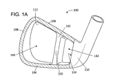
図1A及び図1Bは、ゴルフクラブヘッド100の重心120に近接して配置されたリブ102を有する、ゴルフクラブヘッド100の斜視図を示す。ゴルフクラブヘッド100は、ソール部104、トップライン106、トゥ部108、ヒール部110、及び背部112を含む。リブ102は、ソール部104に略直交する角度で、トップライン106からソール部104へ延在する。リブ102はまた、図1Bに示すように、背部112から打撃面118の後面へ延在する。リブ102を含むことにより、二つのキャビティ140、142が形成される。第1キャビティ140は、背部112、トゥ部108、トップライン106、リブ102、ソール部104、及び打撃面118により画定される。第2キャビティ142は、背部112、リブ102、トップライン106、ヒール部110のフェイスエッジ114、ソール部104、及び打撃面118により画定される。
1A and 1B show a perspective view of the
リブ102は、ゴルフクラブヘッド100のキャスティングプロセスの一部として形成され得る。リブ102はまた、キャスティングプロセス後に挿入されて、溶接その他の取付け方法によりゴルフクラブヘッド100の他の構成要素に取り付けられてもよい。例えば、リブ102は、背部112、トップライン106、及びソール部104に溶接されてもよい。いくつかの例では、リブは、打撃面118の後面に溶接されてもよい。
The
打撃面118はまた、トゥ部108からヒール部110にわたる単一のフェイスインサート(face insert)として取り付けられてもよい。例えば、打撃面118は、ソール部104、トゥ部108、トップライン106、及びヒール部110のフェイスエッジ114に溶接され得る。上述のとおり、打撃面118は、リブ102に溶接されてもよい。別の例では、打撃面118は、二つ以上のピースから成るものであってもよい。打撃面118の第1部分(キャビティ142の上に配置される)は第1厚さを有することができ、打撃面118の第2部分(キャビティ140の上に配置される)は第2厚さを有することができる。さらに別の例では、打撃面118は、キャビティ142の上の打撃面118の第1部分が第1厚さを有し、キャビティ140の上の打撃面118の第2部分が第2厚さを有するように、可変厚さを有する単一のフェイスインサートであってもよい。
The
打撃面118のうちリブ102が後ろに位置する部分でゴルフボールが打撃面118に当たった場合、打撃面118が撓む距離は、リブ102がない場合よりも小さくなる。リブ102が後ろに位置する部分で打つと打撃面118の撓みが小さくなるので、ボールは、リブ102を有さない同じクラブで打った場合より僅かに低い打出し速度を示す。二つのキャビティ140、142のうち一つが後ろに位置する部分でゴルフボールが打撃面118に当たった場合、打撃面118は、各キャビティ内へ撓む。この撓みは、ゴルフボールに追加の打出し速度を与える。しかしながら、各キャビティ内への撓みは、クラブがリブ102を有さない場合よりは依然として小さくなり得る。このような全体的な打出し速度の低下は好ましくないようにも思えるが、打出し速度が僅かに小さくなると、打撃面118全体にわたって、打撃による打出し速度がより一定となる。例えば、ボールが打撃面118の重心120に最も近い部分に当たると、ゴルフボールの打出し速度は最大となることが多い。従って、重心120の位置にリブ102を配置することで重心120におけるフェイスの撓みを取り除くことにより、最大打出し速度が打撃面の他の部分からの打出し速度により近くなるように、当該最大打出し速度が抑えられる。
When the golf ball hits the
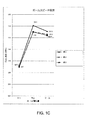
図1Cは、従来の薄型フェイスの中空アイアンと比較した、リブ102を有するゴルフクラブヘッド100の打出し速度の例次的な結果のプロットを図示する。複数の例次的な構成について、打撃面にわたる打出し速度を記録した。例1は、フェイス厚さが2.1mmのベースライン中空アイアンであった。例2は、リブ102を有する複数厚さのフェイスを備えるアイアンであり、打撃面118のうち第1キャビティ140の上の部分は厚さが1.9mmであり、打撃面118のうち第2キャビティ142の上の部分は厚さが1.7mmであった。例3は、フェイス厚さが2.1mmでありリブ102も有するアイアンであった。例1では、フェイスの中心に当たったボールは、打出し速度が約134.1mphであった。トゥの方に当たったボールは、打出し速度を約6.9mph失い、ヒールの方に当たったボールは、打出し速度を約1.0mph失った。例2では、フェイスの中心に当たったボールは、打出し速度が約133.0mphであり、トゥの方に当たったボールは、打出し速度を約6.0mph失い、ヒールの方に当たったボールは、打出し速度を約0.4mph失った。例3では、フェイスの中心に当たったボールは、打出し速度が約133.0mphであり、トゥの方に当たったボールは、打出し速度を約6.0mph失い、ヒールの方に当たったボールは、打出し速度を約0.6mph失った。なお、例2及び例3は、中心での打出し速度及びトゥ側での打出し速度が同じであった。このように、リブ102を有するゴルフクラブヘッドは、最大打出し速度を僅かに減少させるが、ゴルフクラブのフェイスにわたる打出し速度の保持が(厚さが単一でない(multi−thickness)打撃面を有する場合は特に)改善されるので、当該クラブで距離をより一定に制御することができるようになる。
FIG. 1C illustrates a plot of exemplary results of launch speed of a
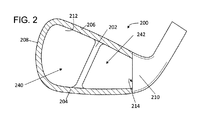
図2は、ゴルフクラブヘッド200のトップライン206に略直交して延在するリブ202を有する、ゴルフクラブヘッド200の部分正面図を図示する。その他の点では、ゴルフクラブヘッド200は、図1A及び図1Bに図示されたゴルフクラブヘッド100と略同様である。リブ202は、背部212及び打撃面の後面(図示せず)に取り付けられ得る。ゴルフクラブヘッド100と同様に、リブ202により二つのキャビティ240、242が形成される。第1キャビティ240は、背部212、トゥ部208、トップライン206、リブ202、及びソール部204により少なくとも部分的に画定される。第2キャビティ242は、背部212、リブ202、トップライン206、ヒール部210のフェイスエッジ214、及びソール部204により少なくとも部分的に画定される。ゴルフクラブヘッド200では、厚さが単一でないフェイスが使用されてもよい。
FIG. 2 illustrates a partial front view of the
図3は、ヒール部310のフェイスエッジ314に略直交して延在するリブ302を有する、ゴルフクラブヘッド300の部分正面図を図示する。その他の点では、ゴルフクラブヘッド300は、図1A及び図1Bに図示されたゴルフクラブヘッド100と略同様である。ゴルフクラブがボールに対してアドレスするとき、リブ302は地面に対して略平行となり得る。リブ202は、背部212及び打撃面の後面に取り付けられ得る。図1A及び図1Bのゴルフクラブヘッド100と同様に、リブ302により、二つのキャビティ340、342が形成される。第1キャビティ340は、背部312、トゥ部308、トップライン306、リブ302、及びヒール部310のフェイスエッジ314により画定される。第2キャビティ342は、背部312、リブ302、ソール部304、ヒール部310、及びトゥ部308により画定される。ゴルフクラブヘッド300では、単一厚さの打撃面が使用されてもよく、厚さが単一でない打撃面が使用されてもよい。
FIG. 3 illustrates a partial front view of a
図4は、ゴルフクラブヘッド400の背部412からゴルフクラブヘッド400の打撃面へ延在するロッド402を備えるキャビティ440を有する、ゴルフクラブヘッド400の斜視図を示す。ロッド402は、背部412から打撃面の後面(図示せず)へ延在する。図1〜図3で説明したリブと異なり、ロッド402は、トップライン406やソール部404、トゥ部408、ヒール部410のフェイスエッジ414に直接接続されたものではない。ロッド402は、ゴルフクラブヘッド400の重心420に配置されてもよい。上述のリブと同様に、打撃面のうちロッド402が後ろに位置する部分にゴルフボールが当たると、ロッドのないゴルフクラブと比較して、打撃面は変位(displacement)が少なくなる。打撃面のうちロッド402が後ろに位置しない部分にゴルフボールが当たると、打撃面に多少の変位が生じて、ゴルフボールの打出し速度が増加する。従って、中心からヒール部410やトゥ部408、トップライン406、ソール部404の方にずれて当たったゴルフボールは、図1Cを参照して説明したリブ102の結果と同様に、より良好に距離が保持される。例えば、直径15mmのロッド402及び厚さ2.1mmの打撃面を有するゴルフクラブでは、フェイスの中心に当たったボールは、打出し速度が132.8mphであり、トゥの方に当たったボールは、打出し速度を6.5mph失い、ヒールの方に当たったボールは、打出し速度を0.4mph失った。
FIG. 4 shows a perspective view of a
図5Aは、打撃面518の対称部分550を形成するように配置されたリブ502を有する、ゴルフクラブヘッド500の部分正面図を示し、図5Bは、ゴルフクラブヘッド500の斜視図を示す。リブ502は、トップライン506からソール部504へ延在し、背部512から打撃面518の後面へ延在する。しかしながら、リブ502は、一直線に延在するわけではない。その代わりに、リブ502は、トップライン506及びヒール部510のフェイスエッジ514の形状に対して略鏡面対称の形状を有する。リブ502がこのような形状を有することにより、打撃面518は、打撃面518のうちトップライン506、ソール部504、ヒール部510のフェイスエッジ514、及びリブ502と接触している部分により画定された対称部分550を有する。対称部分550は、対称線Aに関して対称である。3次元的には、対称部分550は、打撃面518により画定される平面に直交する平面に関して対称である。図5A及び図5Bに示された例では、対称部分550は、ホームベースの形状に似た、二つの平行な辺を有する不規則な五角形形状を有する。その他の可能な対称形状が使用されてもよい。
FIG. 5A shows a partial front view of the
リブ502を有することにより、二つのキャビティ540、542も形成される。第1キャビティ542は、背部512、リブ502、ソール部504、トップライン506、及びヒール部510のフェイスエッジ514により画定される。第2キャビティは、背部512、リブ502、ソール部504、トゥ部508、及びトップライン506により画定される。
By having the
ゴルフクラブヘッド500では、厚さが単一でないタイプの打撃面518が使用されてもよい。例えば、打撃面518の対称部分550が第1厚さを有し、打撃面518の非対称部分552が第2厚さを有してもよい。打撃面518の非対称部分552は、トップライン506、トゥ部508、ソール部504、及びリブ502との接触部により画定される。いくつかの例では、打撃面518の対称部分550の厚さは、打撃面518の非対称部分552の厚さより厚くてもよい。例えば、非対称部分552は統計的に対称領域550より打たれる頻度が少ないので、非対称部分552は、対称部分550よりずっと厚く形成され得る。一例では、非対称部分552における打撃面518の厚さは、対称部分の厚さの約80%以下である。いくつかの実施形態では、非対称部分552の厚さは、約0.5mm〜約1.5mmの範囲である。いくつかの例では、当該範囲は約0.75mm〜約1.25mmであってよく;約0.95〜約1.05mmであってもよい。打撃面518は、二つのピース(一方は対称部分550用であり、他方は非対称部分552用である)から形成されてもよい。このような例では、打撃面の対称部分550は、左利き用ゴルフクラブ及び右利き用ゴルフクラブの両方に修正なしに組み込まれ得る。
In the
異なる打撃面ピースは、異なる材料から形成されてもよい。例えば、非対称部分552は、アルミニウムやチタン、プラスチックなどの軽量材料から形成され得る。別の例では、ゴルフクラブヘッドの重心552を変えるために、非対称部分552に対してより重い材料が使用され得る。第2キャビティ540は、ゴルフクラブヘッド500の重心を変えるための材料で充填されてもよく、部分的に充填されてもよい。
The different striking surface pieces may be made of different materials. For example, the
リブ502を有する対称フェイス部550を形成することにより、ゴルフボールの打出し特性が改善され得る。リブ502のない従来のゴルフクラブでは、打撃面がゴルフクラブの外周のみに取り付けられているので、打撃面は非対称である。この非対称性のため、ゴルフボールがヒールからトゥまで打撃面に沿って色々な位置に当たると、打出し条件が一定にならない。例えば、打撃面のどこにボールが当たるかによって、サイドスピン、バックスピン、打出し方向、及びゴルフボールの打出し速度が一定にならない。打撃面518が対称部分550を有する場合、打撃面518の対称部分550にわたってより一定の打出し特性が見られる。
By forming the
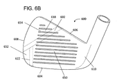
図6Aは、打撃面618の対称部分650を形成するように配置された二つのリブ602、622を有する、ゴルフクラブヘッド600の正面図を示し、図6Bは、ゴルフクラブヘッド600の斜視図を示す。ゴルフクラブヘッド600は、単一のリブではなく二つのリブ602、622を含む。第1リブ602は、トップライン606からトゥ部608へ延在する。第2リブ622は、第1リブ602からソール部604へ延在する。第1リブ602及び第2リブ622はまた、背部612から打撃面618の後面へ延在する。図6A及び図6Bに図示された例では、第1リブ602及び第2リブ622は、トップライン606及びヒール部610のフェイスエッジ614の形状に対して略鏡面対称に配置される。第1リブ602及び第2リブ622をこのような形状に配置することにより、打撃面618は、打撃面518のうちトップライン606、ソール部604、ヒール部610のフェイスエッジ614、第1リブ602、及び第2リブ622と接触している部分により画定された対称部分650を有する。対称部分650は、対称線Aに関して対称である。図6A及び図6Bに示された例では、対称部分650は、ホームベースの形状に似た、二つの平行な辺を有する不規則な五角形形状を有する。その他の可能な対称形状が使用されてもよい。さらに、別の対称形状を形成するために、追加リブがゴルフクラブヘッド600へ組み込まれてもよい。
FIG. 6A shows a front view of the
ゴルフクラブヘッド600に三つのキャビティが形成される。第1キャビティ642は、背部612、トップライン606、第1リブ602、第2リブ622、ソール部604、及びヒール部610のフェイスエッジ614により形成される。第2キャビティ640は、背部612、第1リブ602、第2リブ622、ソール部604、及びトゥ部608により形成される。第3キャビティ644は、トップライン606、トゥ部608、及び第1リブ602により形成される。打撃面618のうち第1キャビティ642が後ろに位置する部分が打撃面618の対称部分650である。
Three cavities are formed in the
図5A及び図5Bのゴルフクラブヘッド500と同様に、ゴルフクラブヘッド600は、厚さが単一でないタイプの打撃面618を有し得る。例えば、打撃面618の対称部分650は第1厚さを有し得る。第2キャビティ640が後ろに位置する打撃面618の第1非対称部分652は第2厚さを有してもよく、第3キャビティ644が後ろに位置する打撃面618の第2非対称部分654は第3厚さを有してもよい。いくつかの例では、第1厚さは第2厚さより大きく、第2厚さは第3厚さより大きい。例えば、第2厚さは、対称部分650の厚さの約80%以下であってよく、第3厚さは、対称部分650の厚さの約50%以下であってよい。いくつかの実施形態では、第2厚さ及び第3厚さは、約0.5mm〜約1.5mmの範囲である。いくつかの例では、当該範囲は、約0.75mm〜約1.25mmであってよく;約0.95〜約0.05mmであってもよい。いくつかの例では、背部612のうち第3キャビティ644の後ろに位置するセクションも、背部の残部より薄くてもよい。打撃面518は、三つのピース(対称部分650用の第1ピース、第1非対称部分652用の第2ピース、及び第2非対称部分654用の第3ピース)で形成されてもよい。別の例では、打撃面618は、二つのピース(対称部分650及び第2キャビティ640が後ろに位置する部分用の第1ピース、並びに第3キャビティ644が後ろに位置する部分用の第2ピース)で形成されてもよい。二つのピースの打撃面618の例でも、三つのピースの打撃面618の例でも、打撃面の対称部分650は、左利き用ゴルフクラブ及び右利き用ゴルフクラブの両方に修正なしに組み込まれ得る。打撃面618の対称部分650は、図5A及び図5Bに示されたゴルフクラブヘッドの対称部分550と同様の打出し特性の利点を提供する。
Similar to the
異なる打撃面ピースは、異なる材料から形成されてもよい。例えば、非対称部分652、654をカバーする打撃面のピースは、アルミニウムやチタン、プラスチックなどの軽量材料から形成されてもよい。別の例では、ゴルフクラブヘッド600の重心を変えるために、非対称部分652、654をカバーする打撃面のピースに対してより重い材料が使用され得る。第2キャビティ640及び第3キャビティ644は、ゴルフクラブヘッド600の重心を変えるための材料で充填されてもよく、部分的に充填されてもよい。
The different striking surface pieces may be made of different materials. For example, the striking surface piece covering the
図7Aは、フレックス支持構造730を有するゴルフクラブヘッド700の正面図を示し、図7Bは、図7Aに示された断面に沿ったゴルフクラブヘッド700の右側断面図を示す。フレックス支持構造730は、ゴルフクラブヘッド700の外周の周りに形成される。一例では、フレックス支持構造730は、トップライン706、トゥ部708、ソール部704、及びヒール部710のフェイスエッジ714に対して形成されるか又は据え付けられ得る。フレックス支持構造730は、打撃面718と背部712との間のキャビティ740へ突出又は延在する。いくつかの例では、フレックス支持構造730は、打撃面718の後面に面する曲面を有する。打撃面が撓んでいない配置(図7Bに示すような)であれば、打撃面718は、フレックス支持構造の曲面の一部とは接触していない。ゴルフボールに当たった場合など、打撃面718が撓むと、打撃面718の後面は、フレックス支持構造730の曲面のより多くの部分に接触する。打撃面718とフレックス支持構造730の曲面との間の接触面積が(打撃面718の撓みが大きくなることにより)増加するにつれて、フレックス支持構造730が打撃面718に対して支持を提供し、打撃面718がさらに撓むにつれて打撃面718のスパンは効果的にさらに減少する。
FIG. 7A shows a front view of the
フレックス支持構造730を組み込むことにより、打撃面718の厚さが低減され得る。従来のゴルフクラブでは、打撃面の厚さは、プレイヤーのスイングスピードに基づくものであり得る。例えば、よりスイングスピードの遅いプレイヤーに対しては、より薄い打撃面がより有用であり得る。これは、打撃面がより容易に撓んで打出し速度がより大きくなるためである。しかしながら、スイングスピードの速いプレイヤーが同じクラブを使用すると、薄い打撃面では、打撃面が撓みすぎてうまくいかない場合がある。従って、一般に、高スイングスピードのプレイヤーにはより厚いフェイスが望ましい。しかしながら、フレックス支持構造730を組み込むことにより、広範囲のスイングスピードに対して単一の薄い打撃面718を使用することが可能になる。スイングスピードが遅い場合は、薄い打撃面718は、フェイスの軽い撓みではフレックス支持構造730の曲面との接触があまり生じないので、従来のゴルフクラブとほとんど同程度の撓みのままとなる。逆に、スイングスピードがより速い場合は、打撃面718は、追加の撓み距離により、フレックス支持構造730から追加の支持を受ける。一般に、フレックス支持構造730の高さ及び曲率により、打撃面718が様々な撓み深さで受ける支持の量が決定される。図7A〜図7Iには打撃面718が溝やスコアラインなしで図示されているが、打撃面718は、上述の打撃面に図示されたようなスコアリングマークを含み得る。
By incorporating the
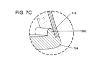
図7C〜図7Eは、様々な構成のフレックス支持構造730の右側断面図を示す。一例では、フレックス支持構造730Cは、キャビティ740へ突出する略半円形状を有する。フレックス支持構造730Cのうち打撃面718に平行な部分は、撓んでいない配置であっても、打撃面と接触していてよい。しかしながら、フレックス支持構造730Cの湾曲部は、打撃面が撓み配置にあるときのみ打撃面718と接触する。キャビティ740への打撃面718の撓み深さが大きいほど、フレックス支持構造730の曲面Cの、打撃面718の後面と接触する面積は大きくなる。図7Dに図示されたフレックス支持構造730Dは、フレックス支持構造730Cと略同じ高さ及び曲率を有する。しかしながら、フレックス支持構造730Dは、フレックス支持構造730Cに追加の強度を提供するために、フレックス支持構造730Dの後ろ側に追加の材料732を有する。上記のとおり、フレックス支持構造730C又はフレックス支持構造730Dの曲率又は高さは、打撃面718が様々な撓み深さで受ける支持の量を調節するように修正され得る。
7C-7E show right side sectional views of
フレックス支持構造730Eは、直線状のフレックス支持構造の一例である。フレックス支持構造730Eは、曲面ではなく傾斜面を含む。打撃面718がキャビティ740へ撓むと、打撃面718の後面は、フレックス支持構造730Eの傾斜部に接触する。湾曲したフレックス支持構造と同様に、打撃面の撓み距離が増加するにつれて、直線状のフレックス支持構造730Eは、打撃面718に対して追加の支持を提供する。傾斜面の高さ及び角度は、打撃面718が様々な深さで受ける支持の量を調節するように修正され得る。
The
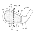
図7Fは、可変フレックス支持構造730Fを有するゴルフクラブヘッド700の正面図を示す。可変フレックス支持構造730Fは、ヒール部710とトゥ部708との間の各位置で異なる高さ及び/又は曲率を有する。可変フレックス支持構造730Fの高さ及び/又は曲率が異なることにより、撓み配置において、打撃面718の異なる部分が異なる量の支持を受ける。可変フレックス支持構造730Fの異なる形状特性は、図7Fの断面線により示された図7G〜図7Iに示す断面図に見ることができる。
FIG. 7F shows a front view of a
図7F〜図7Iに図示された例では、可変フレックス支持構造730Fは、ソール部704に沿って可変高さや可変曲率などの可変プロファイルを有する。トゥ部708の方では、フレックス支持構造730Gは、第1高さ及び第1曲率により規定される第1プロファイルを有する。打撃面718の中心に近づくと、フレックス支持構造730Hは、フレックス支持構造730Gのプロファイルと比較して低い高さ及び小さな曲率の第2プロファイルを有する。ヒール部710の方では、フレックス支持構造730Hは、フレックス支持構造730Gのプロファイル又はフレックス支持構造730Hのプロファイルより大きな高さ及び曲率の第3プロファイルを有する。
In the example illustrated in FIGS. 7F-7I, the variable
一例では、異なる撓み深さにおいて、異なるプロファイルの可変フレックス支持構造730Fが打撃面718に対して支持を提供する。例えば、打撃面718の第1撓み深さでは、打撃面718の後面は、可変フレックス支持構造730Fのうち第1プロファイル及び第2プロファイルを有する部分の表面に接触し得る。しかしながら、第2撓み深さでは、打撃面718の後面は、可変フレックス支持構造730Fのうち第1プロファイルを有する部分のみに接触し得る。
In one example, variable
その他の構成も考えられる。例えば、クラブフェイスの中心近傍のフレックス支持構造730Hが、他のフレックス支持構造730G、730Iと比較して最大の高さを有してもよい。このような例では、打撃面718の中心は、フレックス支持構造730Hにより撓み範囲が限定される。打撃面718の中心の撓み範囲を限定することにより、打撃面718の中心からのゴルフボールの打出し速度が減少する。トゥ部708及びヒール部710に向かうフレックス支持構造730G、730Iを短くすると、打撃面718をさらに撓ませることが可能となるので、より大きな打出し速度に寄与する。このような構成では、上述のリブ102を有する場合と同様に、打撃面718にわたる打出し速度をより均一なものとすることができる。フレックス支持構造730Fの高さ及び曲率は、打撃面718の撓み特性をさらに変えるように、トゥ部708、トップライン706、及びヒールのフェイスエッジ714に沿って変わったり変化したりしてもよい。
Other configurations are also conceivable. For example, the
別の例では、可変フレックス支持構造730Hは、キャビティ740の外周全体の周りに延在しなくてもよい。例えば、ソール部704又はトップライン706の一部のセクションのみがフレックス支持構造730Hを有してもよい。別の例では、ヒール部710のフェイスエッジ714又はトゥ部708は、フレックス支持構造730Hを有していなくてもよい。
In another example, the variable
図8Aは、フレックス支持構造830、832と、打撃面818の対称部分850を形成するように配置されたリブ802と、を有するゴルフクラブヘッド800を図示する。図8B〜図8Dは、図8Aの断面線により示されるゴルフクラブヘッド800の断面図を示す。リブ802は、図5A及び図5Bを参照して説明されたリブ502と類似する。リブ802は、背部812から打撃面818の後面へ延在する。リブ802はまた、トップライン806からソール部804へ延在するとともに、トップライン806及びヒール部810のフェイスエッジ814の形状に対して略鏡面対称の形状である。このような形状を有することにより、打撃面818は、図5A及び図5Bで説明した対称部分550と類似の、打撃面818のうちトップライン806、ソール部804、ヒール部810のフェイスエッジ814、及びリブ802と接触している部分により画定された対称部分850を有する。厚さが単一でない打撃面が利用されてもよい。
FIG. 8A illustrates a
ゴルフクラブヘッド800は、図5A及び図5Bで説明した二つのキャビティ540、542と類似の、二つのキャビティ840、842を含む。第1フレックス支持構造830は、第1キャビティ840の外周に取り付けられ、第2フレックス支持構造832は、第2キャビティ842の外周に取り付けられる。例えば、第1フレックス支持構造830は、トゥ部808、ソール部804、リブ802のトゥ側の面、及びトップライン806に対して取り付けられるか又は形成される。第2フレックス支持構造832は、トップライン806、リブ802のヒール側の面、ソール部804、及びヒール部810のフェイスエッジ814に対して取り付けられるか又は形成される。第1フレックス支持構造830は、第1キャビティ840へ突出又は延在し、第2フレックス支持構造832は、第2キャビティへ突出する。図7A〜図7Iを参照して説明したフレックス支持構造と同様に、フレックス支持構造830、832は、撓み配置において、打撃面818に対して追加の支持を提供する。例えば、打撃面818の対称部分が撓むと、打撃面818の後面が第2フレックス支持構造832の曲面の部分に接触する。打撃面818の非対称部分が撓むと、打撃面818の後面が第1フレックス支持構造830の曲面の一部に接触する。いくつかの実施形態では、ゴルフクラブヘッド800は、第2フレックス支持構造832を含まない。
The
第1フレックス支持構造830及び/又は第2フレックス支持構造832は、図7F〜図7Iを参照して説明した可変フレックス支持構造730Hと類似の可変フレックス支持構造であってもよい。例えば、フレックス支持構造832のプロファイルが第2キャビティ842の外周の周りで変化してもよく、例えば、最大の撓みが生じる点における打撃面818の撓みを低減するように、フレックス支持構造832の高さが対称線Aの近傍でより大きくなってもよい。対称線の近傍でより大きな高さを有するフレックス支持構造832を有することにより、打撃面の対称部分にわたって打出し速度をより一定にすることができる。
The first
フレックス支持構造830、832は、ゴルフクラブヘッドへ組み込むことのできる上述のリブ又はロッド構造及びその他の構造を有するゴルフクラブヘッドへ組み込まれ得る。
The
本明細書において具体的な実施形態及び態様が説明されるとともに具体的な実施例が提供されたが、本発明の範囲は、これらの具体的な実施形態及び実施例に限定されるものではない。当業者であれば、本発明の範囲及び趣旨の範囲内にある別の実施形態又は改良例について認識するであろう。従って、具体的な構造、作用、又は媒体は、例示的な実施形態としてのみ開示されるものである。本発明の範囲は、以下の特許請求の範囲及びその均等物により規定される。 Although specific embodiments and embodiments have been described and specific examples have been provided herein, the scope of the present invention is not limited to these specific embodiments and examples. .. One of ordinary skill in the art will be aware of other embodiments or improvements within the scope and intent of the present invention. Therefore, a specific structure, action, or medium is disclosed only as an exemplary embodiment. The scope of the present invention is defined by the following claims and their equivalents.
100、200、300、400、500、600、700、800 ゴルフクラブヘッド
102、202、302、502、602、622、802 リブ
104、204、304、404、504、604、704、804 ソール部
106、206、306、406、506、606、706、806 トップライン
108、208、308、408、508、608、708、808 トゥ部
110、210、310、410、510、610、710、810 ヒール部
112、212、312、412、512、612、712、812 背部
114、214、314、414、514、614、714、814 フェイスエッジ
118、518、618、718、818 打撃面
140、240、340、542、642、840 第1キャビティ
142、242、342、540、640、842 第2キャビティ
402 ロッド
550、650、850 対称部分
552、652、654 非対称部分
644 第3キャビティ
730、830、832 フレックス支持構造
100, 200, 300, 400, 500, 600, 700, 800
Claims (10)
前記クラブヘッド本体の前記背部から前記打撃面の後面へ延在し、かつ前記トップラインから前記ソール部へ延在するリブと、
を備えるアイアン型ゴルフクラブヘッドであって、
前記打撃面は、前記トップライン、前記ソール部、及び前記リブとの接触部により画定
された略対称部分を有する、アイアン型ゴルフクラブヘッド。 With a club head body that has a back, top line, sole, and striking surface;
And a rib wherein the extend from the back of the club head body to the rear surface of the striking surface, and extends into the sole portion from the top line,
It is an iron type golf club head equipped with
An iron-type golf club head having a striking surface having a substantially symmetrical portion defined by a top line, a sole portion, and a contact portion with the rib.
リブの第2側の第2キャビティを少なくとも部分的に画定する、請求項1に記載のアイア
ン型ゴルフクラブヘッド。 The iron-type golf according to claim 1, wherein the rib, the striking surface, and the back portion at least partially define a first cavity on the first side of the rib and a second cavity on the second side of the rib. Club head.
前記打撃面が撓んでいない配置にあるとき、前記フレックス支持構造の一部が前記打撃
面の前記後面と接触せず、
前記打撃面が撓み配置にあるとき、前記フレックス支持構造の前記一部が前記打撃面の
前記後面と接触する、請求項1に記載のアイアン型ゴルフクラブヘッド。 Further comprising a flex support structure extending in a direction substantially parallel to the striking face,
When the striking surface is in a non-flexible arrangement, part of the flex support structure does not come into contact with the rear surface of the striking surface.
The iron-type golf club head according to claim 1, wherein the part of the flex support structure comes into contact with the rear surface of the striking surface when the striking surface is in a flexible arrangement.
ファイルと、第2撓み深さで前記打撃面の前記後面に接触するが前記第1撓み深さで前記
打撃面の前記後面に接触しない第2プロファイルと、を有する、請求項3に記載のアイア
ン型ゴルフクラブヘッド。 The flex support structure has a first profile that contacts the rear surface of the striking surface at a first deflection depth and a first profile that contacts the rear surface of the striking surface at a second deflection depth but said at the first deflection depth. The iron-type golf club head according to claim 3, further comprising a second profile that does not come into contact with the rear surface of the striking surface.
きい、請求項4に記載のアイアン型ゴルフクラブヘッド。 The iron-type golf club head according to claim 4, wherein the rate of change of the curvature of the first profile is larger than the rate of change of the curvature of the second profile.
に備える、請求項1に記載のアイアン型ゴルフクラブヘッド。 The iron-type golf club head according to claim 1, further comprising a second rib extending from the back portion of the club head body to the rear surface of the striking surface.
部を有するクラブヘッド本体と;
前記背部から延在する第1リブと;
前記背部から延在する第2リブと;
前記トップライン、前記ソール部、前記第1リブ、及び前記第2リブとの接触部により
画定された略対称部分を有する打撃面と、
を備え、
前記第1リブおよび前記第2リブは、それぞれ、前記クラブヘッド本体の前記背部から前記打撃面の後面へ延在し、かつ前記トップラインから前記ソール部へ延在する、アイアン型ゴルフクラブヘッド。 With a back, a club head body having a top line attached to the back, and a sole attached to the back;
With the first rib extending from the back;
With the second rib extending from the back;
A striking surface having a substantially symmetrical portion defined by the top line, the sole portion, the first rib, and the contact portion with the second rib.
Equipped with a,
An iron-type golf club head in which the first rib and the second rib extend from the back portion of the club head body to the rear surface of the striking surface and extend from the top line to the sole portion, respectively.
して略対称である、請求項7に記載のアイアン型ゴルフクラブヘッド。 The iron-type golf club head according to claim 7, wherein the substantially symmetrical portion of the striking surface is substantially symmetrical with respect to a plane orthogonal to the plane defined by the striking surface.
クラブヘッド。 The iron-type golf club head according to claim 7, wherein the substantially symmetrical portion of the striking surface is substantially pentagonal.
及び打撃面を有するクラブヘッド本体と;
前記トップライン及び前記ソール部のうち少なくとも一方に取り付けられたフレックス
支持構造であって、前記打撃面が撓んでいない配置にあるとき、前記フレックス支持構造
の一部が前記打撃面の後面と接触せず、前記打撃面が撓み配置にあるとき、前記フレック
ス支持構造の前記一部が前記打撃面の前記後面と接触する、フレックス支持構造と、
を備えるアイアン型ゴルフクラブヘッドであって、
前記フレックス支持構造は、第1プロファイル及び第2プロファイルを有し、前記フレ
ックス支持構造の表面は、第1撓み深さで前記打撃面の前記後面に接触する前記第1プロ
ファイルを有し、前記フレックス支持構造の表面は、第2撓み深さで前記打撃面の前記後
面に接触するが前記第1撓み深さで前記打撃面の前記後面に接触しない前記第2プロファ
イルを有する、アイアン型ゴルフクラブヘッド。 A iron-type golf club head according to claim 1 or 7, the back portion, the top line which is attached to the back, the sole portion attached to said back,
And with the club head body having a striking surface;
When the flex support structure is attached to at least one of the top line and the sole portion and the striking surface is not bent, a part of the flex support structure comes into contact with the rear surface of the striking surface. The flex support structure, in which the part of the flex support structure comes into contact with the rear surface of the striking surface when the striking surface is in a flexible arrangement.
It is an iron type golf club head equipped with
The flex support structure has a first profile and a second profile, and the surface of the flex support structure has the first profile that contacts the rear surface of the striking surface at a first deflection depth, and the flex. An iron-type golf club head having a second profile in which the surface of the support structure contacts the rear surface of the striking surface at the second deflection depth but does not contact the rear surface of the striking surface at the first deflection depth. ..
Applications Claiming Priority (2)
| Application Number | Priority Date | Filing Date | Title |
|---|---|---|---|
| US15/220,107 | 2016-07-26 | ||
| US15/220,107 US9993704B2 (en) | 2016-07-26 | 2016-07-26 | Striking face deflection structures in a golf club |
Publications (3)
| Publication Number | Publication Date |
|---|---|
| JP2018015564A JP2018015564A (en) | 2018-02-01 |
| JP2018015564A5 JP2018015564A5 (en) | 2020-08-27 |
| JP6876563B2 true JP6876563B2 (en) | 2021-05-26 |
Family
ID=61011540
Family Applications (1)
| Application Number | Title | Priority Date | Filing Date |
|---|---|---|---|
| JP2017143318A Active JP6876563B2 (en) | 2016-07-26 | 2017-07-25 | Strike surface flexure structure in golf clubs |
Country Status (2)
| Country | Link |
|---|---|
| US (1) | US9993704B2 (en) |
| JP (1) | JP6876563B2 (en) |
Families Citing this family (48)
| Publication number | Priority date | Publication date | Assignee | Title |
|---|---|---|---|---|
| US8083612B2 (en) | 2009-08-06 | 2011-12-27 | Nike, Inc. | Golf club head or other ball striking device having one or more face channels |
| US10617920B2 (en) * | 2012-06-27 | 2020-04-14 | Callaway Golf Company | Golf club head having stress-reducing features |
| US11167187B2 (en) | 2014-02-20 | 2021-11-09 | Parsons Xtreme Golf, LLC | Golf club heads and methods to manufacture golf club heads |
| US11731013B2 (en) | 2014-02-20 | 2023-08-22 | Parsons Xtreme Golf, LLC | Golf club heads and methods to manufacture golf club heads |
| US10632349B2 (en) | 2017-11-03 | 2020-04-28 | Parsons Xtreme Golf, LLC | Golf club heads and methods to manufacture golf club heads |
| US11541288B2 (en) | 2014-02-20 | 2023-01-03 | Parsons Xtreme Golf, LLC | Golf club heads and methods to manufacture golf club heads |
| US11344775B2 (en) | 2014-02-20 | 2022-05-31 | Parsons Xtreme Golf, LLC | Golf club heads and methods to manufacture golf club heads |
| US10933286B2 (en) | 2014-02-20 | 2021-03-02 | Parsons Xtreme Golf, LLC | Golf club heads and methods to manufacture golf club heads |
| US10874919B2 (en) | 2017-11-03 | 2020-12-29 | Parsons Xtreme Golf, LLC | Golf club heads and methods to manufacture golf club heads |
| US11291890B2 (en) | 2017-11-03 | 2022-04-05 | Parsons Xtreme Golf, LLC | Golf club heads and methods to manufacture golf club heads |
| US11185747B2 (en) | 2014-10-24 | 2021-11-30 | Karsten Manufacturing Corporation | Golf club head with open back cavity |
| US11027177B2 (en) | 2014-10-24 | 2021-06-08 | Karsten Manufacturing Corporation | Golf club heads with energy storage characteristics |
| US11278772B2 (en) | 2014-10-24 | 2022-03-22 | Karsten Manufacturing Corporation | Golf club heads with energy storage characteristics |
| US20190160347A1 (en) | 2014-10-24 | 2019-05-30 | Karsten Manufacturing Corporation | Golf Club Heads with Energy Storage Characteristics |
| US11794080B2 (en) | 2016-07-26 | 2023-10-24 | Acushnet Company | Golf club having a damping element for ball speed control |
| US10150019B2 (en) | 2016-07-26 | 2018-12-11 | Acushnet Company | Striking face deflection structures in a golf club |
| US11433284B2 (en) | 2016-07-26 | 2022-09-06 | Acushnet Company | Golf club having a damping element for ball speed control |
| US10821338B2 (en) * | 2016-07-26 | 2020-11-03 | Acushnet Company | Striking face deflection structures in a golf club |
| US11202946B2 (en) | 2016-07-26 | 2021-12-21 | Acushnet Company | Golf club having a damping element for ball speed control |
| US11786789B2 (en) | 2016-07-26 | 2023-10-17 | Acushnet Company | Golf club having a damping element for ball speed control |
| US11938387B2 (en) | 2016-07-26 | 2024-03-26 | Acushnet Company | Golf club having a damping element for ball speed control |
| US20220118328A1 (en) * | 2016-07-26 | 2022-04-21 | Acushnet Company | Golf club having a damping element for ball speed control |
| US11826620B2 (en) | 2016-07-26 | 2023-11-28 | Acushnet Company | Golf club having a damping element for ball speed control |
| US11745067B2 (en) | 2017-03-29 | 2023-09-05 | Parsons Xtreme Golf, LLC | Golf club heads and methods to manufacture golf club heads |
| US11369847B2 (en) | 2019-03-07 | 2022-06-28 | Parsons Xtreme Golf, LLC | Golf club heads and methods to manufacture golf club heads |
| US11192003B2 (en) | 2017-11-03 | 2021-12-07 | Parsons Xtreme Golf, LLC | Golf club heads and methods to manufacture golf club heads |
| US11400352B1 (en) | 2018-02-12 | 2022-08-02 | Parsons Xtreme Golf, LLC | Golf club heads and methods to manufacture golf club heads |
| US10449428B2 (en) | 2018-02-12 | 2019-10-22 | Parsons Xtreme Golf, LLC | Golf club heads and methods to manufacture golf club heads |
| US11426640B2 (en) | 2017-11-03 | 2022-08-30 | Parsons Xtreme Golf, LLC | Golf club heads and methods to manufacture golf club heads |
| WO2019075079A1 (en) * | 2017-10-10 | 2019-04-18 | Gross Dakota Taylor | Golf club device |
| US11707653B2 (en) | 2017-11-03 | 2023-07-25 | Parsons Xtreme Golf, LLC | Golf club heads and methods to manufacture golf club heads |
| JP7034671B2 (en) * | 2017-11-07 | 2022-03-14 | ブリヂストンスポーツ株式会社 | Golf club head |
| US11511166B1 (en) | 2017-11-15 | 2022-11-29 | Cobra Golf Incorporated | Structured face for golf club head |
| US11565158B1 (en) | 2018-02-12 | 2023-01-31 | Parsons Xtreme Golf, LLC | Golf club heads and methods to manufacture golf club heads |
| US11944880B2 (en) | 2018-02-12 | 2024-04-02 | Parsons Xtreme Golf, LLC | Golf club heads and methods to manufacture golf club heads |
| US11839800B2 (en) | 2018-02-12 | 2023-12-12 | Parsons Xtreme Golf, LLC | Golf club heads and methods to manufacture golf club heads |
| US11938385B1 (en) | 2018-02-12 | 2024-03-26 | Parsons Xtreme Golf, LLC | Golf club heads and methods to manufacture golf club heads |
| US11786786B2 (en) | 2018-02-12 | 2023-10-17 | Parsons Xtreme Golf, LLC | Golf club heads and methods to manufacture golf club heads |
| US11707655B2 (en) | 2018-02-12 | 2023-07-25 | Parsons Xtreme Golf, LLC | Golf club heads and methods to manufacture golf club heads |
| US11839799B2 (en) | 2019-01-02 | 2023-12-12 | Parsons Xtreme Golf, LLC | Golf club heads and methods to manufacture golf club heads |
| US11806589B2 (en) | 2019-03-11 | 2023-11-07 | Parsons Xtreme Golf, LLC | Golf club heads and methods to manufacture golf club heads |
| JP7120165B2 (en) * | 2019-06-20 | 2022-08-17 | ヤマハ株式会社 | Golf club head and golf club |
| US11986707B2 (en) | 2020-08-21 | 2024-05-21 | Wilson Sporting Goods Co. | Faceplate of a golf club head |
| JP2022065468A (en) * | 2020-10-15 | 2022-04-27 | ヤマハ株式会社 | Iron type golf club head |
| JP2023548329A (en) | 2020-10-30 | 2023-11-16 | カーステン マニュファクチュアリング コーポレーション | Golf club heads with undercuts and inserts |
| US11813506B2 (en) | 2021-08-27 | 2023-11-14 | Acushnet Company | Golf club damping |
| US20230072146A1 (en) * | 2021-09-09 | 2023-03-09 | Acushnet Company | Golf club head with improved striking face |
| US11801426B1 (en) * | 2022-04-20 | 2023-10-31 | Cobra Golf Incorporated | Golf club head |
Family Cites Families (28)
| Publication number | Priority date | Publication date | Assignee | Title |
|---|---|---|---|---|
| US4826172A (en) * | 1987-03-12 | 1989-05-02 | Antonious A J | Golf club head |
| US4938470A (en) * | 1988-12-23 | 1990-07-03 | Antonious A J | Perimeter weighted iron type golf club head with upper alignment and sighting area and complementary weighting system |
| US5328184B1 (en) * | 1988-12-28 | 1995-08-22 | Antonious A J | Iron type golf club head with improved weight configuration |
| FR2654641B1 (en) * | 1989-11-22 | 1991-12-13 | Salomon Sa | GOLF CLUB HEAD AND METHOD FOR PRODUCING SUCH A HEAD. |
| US5290032A (en) * | 1990-04-02 | 1994-03-01 | Lisco, Inc. | Iron with progessive back cavity support bar |
| US5547194A (en) * | 1994-01-19 | 1996-08-20 | Daiwa Seiko, Inc. | Golf club head |
| JP3058035B2 (en) * | 1994-11-17 | 2000-07-04 | ダイワ精工株式会社 | Golf club head |
| US5499814A (en) * | 1994-09-08 | 1996-03-19 | Lu; Clive S. | Hollow club head with deflecting insert face plate |
| US6280348B1 (en) * | 1997-12-12 | 2001-08-28 | Nike Usa, Inc. | Iron-type golf club head |
| JPH11192329A (en) * | 1997-12-29 | 1999-07-21 | Sumitomo Rubber Ind Ltd | Head for golf club |
| US6015354A (en) * | 1998-03-05 | 2000-01-18 | Ahn; Stephen C. | Golf club with adjustable total weight, center of gravity and balance |
| US6165081A (en) * | 1999-02-24 | 2000-12-26 | Chou; Pei Chi | Golf club head for controlling launch velocity of a ball |
| JP2001137398A (en) * | 1999-11-18 | 2001-05-22 | Bridgestone Sports Co Ltd | Wood golf club head |
| JP2001170222A (en) * | 1999-12-17 | 2001-06-26 | Sumitomo Rubber Ind Ltd | Iron golf club head and iron golf club set |
| US6299547B1 (en) * | 1999-12-30 | 2001-10-09 | Callaway Golf Company | Golf club head with an internal striking plate brace |
| US7211006B2 (en) * | 2003-04-10 | 2007-05-01 | Chang Dale U | Golf club including striking member and associated methods |
| JP4528252B2 (en) * | 2005-06-13 | 2010-08-18 | Sriスポーツ株式会社 | Golf club head |
| US20070135233A1 (en) * | 2005-12-08 | 2007-06-14 | Guy Perras | Golf iron club |
| US7798913B2 (en) * | 2008-07-31 | 2010-09-21 | Karsten Manufacturing Corporation | Golf clubs with variable moment of inertia and methods of manufacture thereof |
| JP4616912B2 (en) * | 2008-12-19 | 2011-01-19 | ブリヂストンスポーツ株式会社 | Manufacturing method of golf club head |
| US7935000B2 (en) * | 2009-04-01 | 2011-05-03 | Nike, Inc. | Golf clubs and golf club heads |
| US8187116B2 (en) * | 2009-06-23 | 2012-05-29 | Nike, Inc. | Golf clubs and golf club heads |
| US8353784B2 (en) * | 2009-11-23 | 2013-01-15 | Nike, Inc. | Golf club with a support bracket |
| US8506423B2 (en) * | 2009-11-23 | 2013-08-13 | Nike, Inc. | Golf club with a reinforcing structure |
| US8475293B2 (en) * | 2010-09-13 | 2013-07-02 | Acushnet Company | Iron golf club head with improved performance |
| US8403771B1 (en) * | 2011-12-21 | 2013-03-26 | Callaway Gold Company | Golf club head |
| JP6093853B2 (en) * | 2012-05-31 | 2017-03-08 | ナイキ イノベイト セー. フェー. | Golf club head or other ball striking device having face deformation limiting member |
| US9457241B2 (en) * | 2013-12-18 | 2016-10-04 | Acushnet Company | Golf club head |
-
2016
- 2016-07-26 US US15/220,107 patent/US9993704B2/en active Active
-
2017
- 2017-07-25 JP JP2017143318A patent/JP6876563B2/en active Active
Also Published As
| Publication number | Publication date |
|---|---|
| US20180028882A1 (en) | 2018-02-01 |
| US9993704B2 (en) | 2018-06-12 |
| JP2018015564A (en) | 2018-02-01 |
Similar Documents
| Publication | Publication Date | Title |
|---|---|---|
| JP6876563B2 (en) | Strike surface flexure structure in golf clubs | |
| US10150019B2 (en) | Striking face deflection structures in a golf club | |
| US10821338B2 (en) | Striking face deflection structures in a golf club | |
| US20180133565A1 (en) | Striking face deflection structures in a golf club | |
| JP6450786B2 (en) | Golf club head with body features that affect impact | |
| EP2569061B1 (en) | Golf club heads | |
| JP4723217B2 (en) | Putter type golf club head | |
| US9050510B2 (en) | Putter head | |
| US20130029781A1 (en) | Golf club with selected length to weight ratio | |
| JP5181052B2 (en) | Golf club set | |
| JP2004261451A (en) | Golf club head | |
| JP2022514675A (en) | Golf club with weight adjustment system | |
| JP2007136069A (en) | Golf club head | |
| JP2011005253A (en) | Golf club with improved performance characteristic | |
| JP2010029379A (en) | Wood-type golf club head | |
| JP2008005912A (en) | Golf club head | |
| JP4723397B2 (en) | Golf club head for putter and golf putter | |
| JP5037445B2 (en) | Golf club | |
| CN209752111U (en) | Golf club head | |
| US10155142B2 (en) | Wood-type golf club head | |
| JP7181852B2 (en) | Golf club head and golf club | |
| JP4657484B2 (en) | Golf club head and golf club | |
| JP2018108341A (en) | Wood type golf club head | |
| JP2002191727A (en) | Wood club head | |
| JP2009247408A (en) | Golf club head |
Legal Events
| Date | Code | Title | Description |
|---|---|---|---|
| A521 | Request for written amendment filed |
Free format text: JAPANESE INTERMEDIATE CODE: A523 Effective date: 20200717 |
|
| A621 | Written request for application examination |
Free format text: JAPANESE INTERMEDIATE CODE: A621 Effective date: 20200717 |
|
| A977 | Report on retrieval |
Free format text: JAPANESE INTERMEDIATE CODE: A971007 Effective date: 20201216 |
|
| A131 | Notification of reasons for refusal |
Free format text: JAPANESE INTERMEDIATE CODE: A131 Effective date: 20210104 |
|
| A521 | Request for written amendment filed |
Free format text: JAPANESE INTERMEDIATE CODE: A523 Effective date: 20210330 |
|
| TRDD | Decision of grant or rejection written | ||
| A01 | Written decision to grant a patent or to grant a registration (utility model) |
Free format text: JAPANESE INTERMEDIATE CODE: A01 Effective date: 20210405 |
|
| A61 | First payment of annual fees (during grant procedure) |
Free format text: JAPANESE INTERMEDIATE CODE: A61 Effective date: 20210426 |
|
| R150 | Certificate of patent or registration of utility model |
Ref document number: 6876563 Country of ref document: JP Free format text: JAPANESE INTERMEDIATE CODE Ref document number: 6876563 Country of ref document: JP Free format text: JAPANESE INTERMEDIATE CODE: R150 |
|
| R250 | Receipt of annual fees |
Free format text: JAPANESE INTERMEDIATE CODE: R250 |