JP4723397B2 - Golf club head for putter and golf putter - Google Patents
Golf club head for putter and golf putter Download PDFInfo
- Publication number
- JP4723397B2 JP4723397B2 JP2006038854A JP2006038854A JP4723397B2 JP 4723397 B2 JP4723397 B2 JP 4723397B2 JP 2006038854 A JP2006038854 A JP 2006038854A JP 2006038854 A JP2006038854 A JP 2006038854A JP 4723397 B2 JP4723397 B2 JP 4723397B2
- Authority
- JP
- Japan
- Prior art keywords
- head
- specific gravity
- putter
- face
- low specific
- Prior art date
- Legal status (The legal status is an assumption and is not a legal conclusion. Google has not performed a legal analysis and makes no representation as to the accuracy of the status listed.)
- Expired - Fee Related
Links
Images


Classifications
-
- A—HUMAN NECESSITIES
- A63—SPORTS; GAMES; AMUSEMENTS
- A63B—APPARATUS FOR PHYSICAL TRAINING, GYMNASTICS, SWIMMING, CLIMBING, OR FENCING; BALL GAMES; TRAINING EQUIPMENT
- A63B53/00—Golf clubs
- A63B53/04—Heads
- A63B53/0487—Heads for putters
-
- A—HUMAN NECESSITIES
- A63—SPORTS; GAMES; AMUSEMENTS
- A63B—APPARATUS FOR PHYSICAL TRAINING, GYMNASTICS, SWIMMING, CLIMBING, OR FENCING; BALL GAMES; TRAINING EQUIPMENT
- A63B53/00—Golf clubs
- A63B53/04—Heads
-
- A—HUMAN NECESSITIES
- A63—SPORTS; GAMES; AMUSEMENTS
- A63B—APPARATUS FOR PHYSICAL TRAINING, GYMNASTICS, SWIMMING, CLIMBING, OR FENCING; BALL GAMES; TRAINING EQUIPMENT
- A63B60/00—Details or accessories of golf clubs, bats, rackets or the like
- A63B60/02—Ballast means for adjusting the centre of mass
-
- A—HUMAN NECESSITIES
- A63—SPORTS; GAMES; AMUSEMENTS
- A63B—APPARATUS FOR PHYSICAL TRAINING, GYMNASTICS, SWIMMING, CLIMBING, OR FENCING; BALL GAMES; TRAINING EQUIPMENT
- A63B53/00—Golf clubs
- A63B53/04—Heads
- A63B2053/0491—Heads with added weights, e.g. changeable, replaceable
-
- A—HUMAN NECESSITIES
- A63—SPORTS; GAMES; AMUSEMENTS
- A63B—APPARATUS FOR PHYSICAL TRAINING, GYMNASTICS, SWIMMING, CLIMBING, OR FENCING; BALL GAMES; TRAINING EQUIPMENT
- A63B2209/00—Characteristics of used materials
- A63B2209/02—Characteristics of used materials with reinforcing fibres, e.g. carbon, polyamide fibres
- A63B2209/023—Long, oriented fibres, e.g. wound filaments, woven fabrics, mats
-
- A—HUMAN NECESSITIES
- A63—SPORTS; GAMES; AMUSEMENTS
- A63B—APPARATUS FOR PHYSICAL TRAINING, GYMNASTICS, SWIMMING, CLIMBING, OR FENCING; BALL GAMES; TRAINING EQUIPMENT
- A63B53/00—Golf clubs
- A63B53/04—Heads
- A63B53/0408—Heads characterised by specific dimensions, e.g. thickness
-
- A—HUMAN NECESSITIES
- A63—SPORTS; GAMES; AMUSEMENTS
- A63B—APPARATUS FOR PHYSICAL TRAINING, GYMNASTICS, SWIMMING, CLIMBING, OR FENCING; BALL GAMES; TRAINING EQUIPMENT
- A63B53/00—Golf clubs
- A63B53/04—Heads
- A63B53/0416—Heads having an impact surface provided by a face insert
-
- A—HUMAN NECESSITIES
- A63—SPORTS; GAMES; AMUSEMENTS
- A63B—APPARATUS FOR PHYSICAL TRAINING, GYMNASTICS, SWIMMING, CLIMBING, OR FENCING; BALL GAMES; TRAINING EQUIPMENT
- A63B53/00—Golf clubs
- A63B53/04—Heads
- A63B53/0433—Heads with special sole configurations
Landscapes
- Health & Medical Sciences (AREA)
- General Health & Medical Sciences (AREA)
- Physical Education & Sports Medicine (AREA)
- Golf Clubs (AREA)
Description
本発明は、パター用ゴルフクラブヘッド及びゴルフパターに関するものである。 The present invention relates to a golf club head for a putter and a golf putter.
パッティングは、地表(主としてグリーン上)を転がすことを目的とするものであり、ボールを飛球させることを目的とする他のショットとは異なる性格を有している。 The putting is aimed at rolling the ground surface (mainly on the green) and has a different character from other shots aimed at causing the ball to fly.
目視では認識しにくいが、パターにより打球された直後のボールの挙動は、様々である。パターにより打球された直後のボールの好ましくない挙動として、バックスピン及びバウンドが挙げられる。 Although it is difficult to recognize visually, the behavior of a ball immediately after being hit by a putter varies. Undesirable behavior of the ball immediately after being hit by the putter includes backspin and bounce.
パターにより打球された直後のボールにバックスピンがかかる場合がある。バックスピンがかかっている間、ボールは、地表を転がりながら移動するのではなく、滑りながら移動する。このバックスピンは、地表とボールとの摩擦力により、やがて解消される。バックスピンが解消されたボールは、順回転し、転がりながら移動する。このバックスピンは、ボールの転がり距離を低下させる。このバックスピンは、滑りを伴う為、ボールの転がり軌跡を不安定にする可能性がある。よって、過度のバックスピンは、カップインの確率を低下させる要因となりうる。 A backspin may be applied to the ball immediately after being hit by the putter. During backspin, the ball moves while sliding, not rolling while on the ground. This backspin is eventually eliminated by the frictional force between the ground surface and the ball. The ball whose backspin is eliminated rotates forward and moves while rolling. This backspin reduces the rolling distance of the ball. Since this backspin is accompanied by slipping, there is a possibility that the rolling trajectory of the ball becomes unstable. Thus, excessive backspin can be a factor that reduces the probability of cup-in.
また、バターにより打球されたボールが、飛び上がったりバウンドしたりして一瞬地表から離れる場合がある。地表を離れている間、ボールはグリーンの傾斜の影響を受けない。よって、ボールが地表から離れた場合のパッティングライン(打球位置からカップインまでのボールの軌跡)は、ボールが地表から離れない場合のパッティングラインとは相違する。更に、空中を飛ぶ距離によって、バッティングラインが相違する。このパッティングラインの相違は、パッティングラインの予測を困難とし、カップインの確率を低下させうる。 In addition, the ball hit by the butter may jump off or bounce off the surface for a moment. While off the ground, the ball is not affected by the slope of the green. Therefore, the putting line when the ball is separated from the ground surface (the trajectory of the ball from the hitting position to the cup-in) is different from the putting line when the ball is not separated from the ground surface. Furthermore, the batting line differs depending on the distance of flying in the air. This difference in the putting line makes it difficult to predict the putting line and can reduce the probability of cup-in.
したがって、カップインの確率を高めるためには、打撃されたボールの転がりの良さ(以下、単に、転がりの良さ、又は、転がりの安定性ともいう)が重要と言える。転がりの良い状態とは、打撃後のボールがいち早く順回転するとともに、ボールが過度に空中を飛ぶことが無い状態である。転がりの良さは、パッティングラインを予測しやすくし、、且つ、転がり距離を長くする。登録実用新案第3057456号公報は、通常のロフトとは逆に傾斜したロフト角(以下、逆ロフト角ともいう)を有するとともに、この逆ロフト角を0〜5度とすることにより、オーバースピンが簡単にかけられるとするパター用ゴルフクラブヘッドを開示する。 Accordingly, it can be said that in order to increase the probability of cup-in, the good rolling of the hit ball (hereinafter, also simply referred to as good rolling or stability of rolling) is important. The state of good rolling is a state in which the ball after hitting quickly rotates forward and the ball does not fly in the air excessively. The good rolling makes it easy to predict the putting line and lengthens the rolling distance. The registered utility model No. 3057456 has a loft angle inclined opposite to a normal loft (hereinafter also referred to as a reverse loft angle), and by setting the reverse loft angle to 0 to 5 degrees, A putter golf club head that is easily put on is disclosed.
本発明者の実験によれば、0〜5度の逆ロフト角を有するパター用ゴルフクラブヘッドであっても、オーバースピンが効果的にかからない場合があることが分かった。また、逆ロフト角により、打球の瞬間にボールが地表に押し付けられ、その反動でボールがバウンドしやすいことが分かった。 According to experiments by the present inventors, it has been found that even with a golf club head for putter having a reverse loft angle of 0 to 5 degrees, overspin may not be effectively applied. It was also found that the reverse loft angle caused the ball to be pressed against the ground at the moment of hitting, and the ball would bounce easily due to the reaction.
本発明の目的は、転がりの良いパター用ゴルフクラブヘッド及びゴルフパターの提供にある。 An object of the present invention is to provide a golf club head for a putter with good rolling and a golf putter.
本発明に係るパター用ゴルフクラブヘッドは、金属よりなるヘッド本体と、このヘッド本体を構成する金属よりも比重の低い材料よりなる低比重部材とを備えている。上記低比重部材は、上記ヘッド本体のソール面側に設けられている。このパター用ゴルフクラブヘッドにおいて、ソール面の少なくとも一部は、上記低比重部材により構成されている。 A golf club head for a putter according to the present invention includes a head main body made of metal and a low specific gravity member made of a material having a specific gravity lower than that of the metal constituting the head main body. The low specific gravity member is provided on the sole surface side of the head body. In this golf club head for putters, at least a part of the sole surface is constituted by the low specific gravity member.
好ましくは、上記ヘッド本体が、中空部を有している。 Preferably, the head main body has a hollow portion.
好ましくは、上記低比重部材の重心は、ヘッド重心よりもフェース側に位置している。 Preferably, the center of gravity of the low specific gravity member is located closer to the face than the center of gravity of the head.
ヘッドのトウ・ヒール方向における最大幅が幅W1であり、ヘッドのフェース・バック方向における最大幅が幅W2であるとき、好ましくは、幅W1の幅W2に対する比(W1/W2)が1.05以上1.50以下である。好ましくは、上記幅W1が80mm以上130mm以下である。 When the maximum width in the toe-heel direction of the head is the width W1, and the maximum width in the face-back direction of the head is the width W2, the ratio (W1 / W2) of the width W1 to the width W2 is preferably 1.05. It is 1.50 or less. Preferably, the width W1 is not less than 80 mm and not more than 130 mm.
好ましくは、上記パター用ゴルフクラブヘッドにおいて、上記幅W2の中間位置を通りフェース・バック方向に対して垂直な平面により、ヘッドがフェース側部分とバック側部分とに2分割された場合、上記フェース側部分の重量M1の、上記バック側部分の重量M2に対する比(M1/M2)が0.40以上1.30以下である。 Preferably, in the golf club head for a putter, when the head is divided into a face side portion and a back side portion by a plane passing through an intermediate position of the width W2 and perpendicular to the face / back direction, The ratio (M1 / M2) of the weight M1 of the side portion to the weight M2 of the back side portion is 0.40 or more and 1.30 or less.
本発明により、転がりの良いパター用ゴルフクラブヘッド及びゴルフパターが得られうる。 According to the present invention, a golf club head for a putter and a golf putter with good rolling can be obtained.
以下、適宜図面が参照されつつ、好ましい実施形態に基づいて本発明が詳細に説明される。 Hereinafter, the present invention will be described in detail based on preferred embodiments with appropriate reference to the drawings.
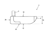
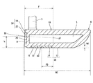
図1は、本発明の一実施形態に係るパター用ゴルフクラブヘッド(以下、パターヘッドとも称される)2を上方(トップ面側)から見た図である。図2は、パターヘッド2を下方(ソール面側)から見た図である。図3は、パターヘッド2を前方(フェース面側)から見た図であり、図4は、パターヘッド2を後方(バック側)から見た図であり、図5は、パターヘッド2をヒール側から見た図である。図6は、図1のVI−VI線に沿った断面図であり、図7は、図1のVII−VII線に沿った断面図である。図3、図4、図5及び図7では、パターヘッド2に装着されたシャフト3の先端部分も図示されている。パターヘッド2に、シャフト3及びグリップ(図示されない)が装着されて、ゴルフパターとなる。なお、図示されていないが、シャフト3の先端部近傍は曲げられている。この曲がりにより、ゴルフパターのライ角及びリアルロフト角が調整される。
FIG. 1 is a view of a golf club head for putter (hereinafter also referred to as a putter head) 2 according to an embodiment of the present invention as viewed from above (top surface side). FIG. 2 is a view of the
パターヘッド2は、ヘッド本体4、低比重部材6及びフェース部材8を備えている。低比重部材6は、ヘッド本体4のソール面側に設けられている(図2参照)。低比重部材6は、パターヘッド2のソール面側に露出している。低比重部材6は、図2において破線ハッチングで示されている。フェース部材8は、パターヘッド2のフェース面の一部を構成している(図3参照)。ヘッド本体4は、全体として略T字型を成している(図1参照)。またパターヘッド2は、シャフト3を挿入し且つ接着するためのシャフト穴5を有している。なお、このパターヘッド2は、上方に突出するホーゼル部(ネック部)を有していないが、ホーゼル部を有する形態としてもよい。。
The
ヘッド本体4は、フェース側からバック側へと延びる後方延在部7を有している(図1参照)。後方延在部7は、フェース・バック方向に対して略平行に延びている。後方延在部7をは、トウ・ヒール方向に対して略垂直に延びている。この後方延在部7は、テークバックのしやすさに役立つ。後方延在部7は、目標方向に沿った真っ直ぐなテークバックをしやすくする。
The
パターヘッド2は、中空部tを有している(図1、図6及び図7参照)。中空部tは、ヘッド本体4に設けられている。図1において破線で示されるのは、中空部tの輪郭線である。中空部tは、外部から視認されない。
The
なお、中空部tは、ヘッド本体4の内部に設けられていなくても良い。例えば、ヘッド本体4に、ソール側に向かって開口した凹部を設け、この凹部の開口を低比重部材6で塞ぐことにより、中空部tが形成されてもよい。また中空部tは、低比重部材6の内部に設けられていても良い。好ましくは、中空部tは、ヘッド本体4の内部に設けられている。中空部tがヘッド本体4に設けられることにより、中空部tの体積が大きくされやすくなる。
The hollow portion t may not be provided inside the
ヘッド本体4は、トップ面(クラウン面とも称される)10を有している。更に、図7が示すように、ヘッド本体4は、ソール面部12と、ソール凹部13とを有している。ソール凹部13は、中空部tの下方に位置している。低比重部材6は、ソール凹部13内に設けられている。低比重部材6は、平板状の部材である。低比重部材6は、ソール凹部13を充填している。低比重部材6の外面14と、ヘッド本体4のソール面部12とは、略面一である(図7参照)。低比重部材6の外面14とソール面部12とは、滑らかに連続している。ソール面部12と、低比重部材6の外面14とにより、パターヘッド2のソール面16が構成されている。ソール面16は、凹部を有さない。ソール面16は、全体として滑らかな曲面又は平面で構成されている。低比重部材6は、ソール面16の一部を構成している。
The
図7が示すように、ヘッド本体4は、フェース面部18と、フェース凹部20とを有している。フェース部材8は、フェース凹部20内に設けられている。フェース部材8は、平板状の部材である。フェース部材8は、フェース凹部20を充填している。フェース部材8の外面22と、ヘッド本体4のフェース面部18とは、略面一である(図7参照)。換言すれば、フェース部材8の外面22とフェース面部18とは、滑らかに連続している。フェース部材8の外面22と、フェース面部18とにより、パターヘッド2のフェース面24が構成されている。フェース面24は、平面である。
As shown in FIG. 7, the head
ヘッド本体4は、金属よりなる。ヘッド本体4を構成する金属として、ステンレス(比重7.8)、銅(比重8.9)、真鍮(比重8.4)、軟鉄(比重7.9)、純チタン(比重4.7)及びチタン合金(比重4.4〜4.8程度)が例示される。ヘッド本体4は、複数の材料を組み合わせて作製されてもよい。ヘッド本体4は、複数の部材を組み合わせて作製されてもよい。中空部tを有するヘッド本体4は、例えば中空のウッド型ゴルフクラブヘッド等と同様にして作製されうる。
The
低比重部材6の材質は限定されない。低比重部材6の材質として、FRP(繊維強化プラスチック)、マグネシウム合金(比重1.8)、アルミニウム(比重2.7)、アルミニウム合金(比重2.6〜2.8程度)が例示される。FRP(繊維強化プラスチック)として、CFRP(炭素繊維強化プラスチック;比重1.6)、GFRP(ガラス繊維強化プラスチック;比重1.8)などが例示される。ヘッド本体4よりも比重を低くする観点から、低比重部材6に用いられる金属としては、軽金属が好ましい。低比重部材6は、複数の材料を組み合わせて作製されてもよい。低比重部材6は、複数の部材を組み合わせて作製されてもよい。
The material of the low
低比重部材6の材質としては、金属(軽金属)よりもFRP(繊維強化プラスチック)が好ましい。低比重部材6にFRP(繊維強化プラスチック)が用いられることにより、金属並み又は金属以上の剛性が確保される。更に、低比重部材6にFRP(繊維強化プラスチック)が用いられることにより、FRP(繊維強化プラスチック)のマトリクス樹脂のエネルギー損失効果により打球時の衝撃が緩和され、打球感が向上する。
The material of the low
低比重部材6は、溶接、嵌合、圧入、接着剤による接着、等の手段により、ヘッド本体4に対して固定されている。低比重部材6及びヘッド本体4の材質により、可能な固定手段が選択されうる。
The low
フェース部材8として、樹脂、エラストマー、ゴム等が用いられる。これらの比較的軟質な材料からなるフェース部材8は、打球感を向上させる。フェース部材8は、パターヘッド2のフェース面24の大半を占めている。
As the
中空部tにより、パターヘッド2の大型化が可能となる。中空部tを設けることにより、ヘッド重量の制約の下でヘッドの慣性モーメントが高められうる。中空部tは、ヘッドの形状自由度の向上に寄与しうる。中空部tは、ヘッド重心g1位置の設計自由度の向上に寄与しうる。
Due to the hollow portion t, the
低比重部材6の重心g2は、ヘッド重心g1よりもフェース側に位置している(図2参照)。即ち、低比重部材6の重心g2は、ヘッド重心g1よりもフェース面24に近い。ヘッド重心g1とは、パターヘッド2の重心である。低比重部材6の重心g2がヘッド重心g1よりもバック側に配置された場合と比較して、重心g2がヘッド重心g1よりもフェース側に配置された場合、ヘッド重心g1の重心深度Fが深くなりやすい。
The center of gravity g2 of the low
図1等においてW1で示されるのは、パターヘッド2のトウ・ヒール方向における最大幅である。図1等においてW2で示されるのは、パターヘッド2のフェース・バック方向における最大幅である。パターヘッド2において、幅W1の幅W2に対する比(W1/W2)は、1.05以上1.50以下である。
In FIG. 1 and the like, W1 indicates the maximum width of the
図1が示すように、上記幅W2の中間位置c1を通りフェース・バック方向に対して垂直な平面Pにより、パターヘッド2がフェース側部分f1とバック側部分b1とに2分割された場合を考える。フェース側部分f1の重量をM1とし、バック側部分b1の重量をM2とする。パターヘッド2において、重量M1の重量M2に対する比(M1/M2)が0.40以上1.30以下とされている。なお、重量M1に重量M2を加えた重量(M1+M2)が、ヘッド総重量である。
As shown in FIG. 1, the
適度なフェース幅を確保してアドレス時の安心感を高める観点から、トウ・ヒール方向における最大幅W1は、80mm以上が好ましく、85mm以上がより好ましく、90mm以上が特に好ましい。トウ・ヒール方向に過度に大きなヘッドによるアドレス時の構えにくさを抑制する観点から、トウ・ヒール方向における最大幅W1は、130mm以下が好ましく、120mm以下がより好ましく、110mm以下が特に好ましい。 From the viewpoint of securing an appropriate face width and improving the security at the time of addressing, the maximum width W1 in the toe-heel direction is preferably 80 mm or more, more preferably 85 mm or more, and particularly preferably 90 mm or more. From the viewpoint of suppressing difficulty in holding at the time of addressing by an excessively large head in the toe-heel direction, the maximum width W1 in the toe-heel direction is preferably 130 mm or less, more preferably 120 mm or less, and particularly preferably 110 mm or less.
重心深度を深くしてミスヒット時の方向性のバラツキを抑制する観点、及び、ストロークの安定性を高める観点から、フェース・バック方向における最大幅W2は50mm以上が好ましく、60mm以上がより好ましく、70mm以上が特に好ましい。重心深度が過度に深くなると、ストローク時にヘッドに作用する遠心力により、インパクト時のロフト角(インパクト時における鉛直方向に対するフェース面24のロフト角)が過度に大きくなる場合がある。インパクト時のロフト角が過度に大きくなると、打球直後のボールが過度に飛び上がり転がりが悪くなる場合がある。この観点から、フェース・バック方向における最大幅W2は、120mm以下が好ましく、110mm以下がより好ましく、100mm以下が特に好ましい。
From the viewpoint of increasing the depth of the center of gravity and suppressing variation in directionality at the time of a miss hit, and from the viewpoint of improving stroke stability, the maximum width W2 in the face-back direction is preferably 50 mm or more, more preferably 60 mm or more, 70 mm or more is particularly preferable. When the depth of the center of gravity is excessively deep, the loft angle at the time of impact (the loft angle of the
重心深度が過度に大きくなることを防止し、且つヘッド形状に起因する構えにくさを抑制する観点から、比(W1/W2)は、1.05以上が好ましく、1.15以上がより好ましく、1.25以上が特に好ましい。重心深度が過度に小さくなることを防止する観点から、比(W1/W2)は1.50以下が好ましく、1.45以下がより好ましく、1.40以下が特に好ましい。 The ratio (W1 / W2) is preferably 1.05 or more, more preferably 1.15 or more, from the viewpoint of preventing the depth of the center of gravity from becoming excessively large and suppressing difficulty in the posture caused by the head shape. 1.25 or more is particularly preferable. From the viewpoint of preventing the depth of the center of gravity from becoming excessively small, the ratio (W1 / W2) is preferably 1.50 or less, more preferably 1.45 or less, and particularly preferably 1.40 or less.
比(W1/W2)を1.05以上1.50以下とし、且つ、幅W1を80mm以上130mm以下とし、且つ、比(M1/M2)を0.40以上1.30以下とすることにより、パッティングに適したフェース幅及びヘッドの大きさと、バターヘッドとして適切な重心深度と、適正な慣性モーメントとを同時に達成することが可能となる。なお、本願において、ヘッドの大きさとは、アドレス時において視覚的に認識されるヘッドの大きさをいうものとする。 By setting the ratio (W1 / W2) to 1.05 to 1.50, the width W1 to 80 mm to 130 mm, and the ratio (M1 / M2) to 0.40 to 1.30, It is possible to simultaneously achieve a face width and head size suitable for putting, a depth of center of gravity appropriate for a butter head, and an appropriate moment of inertia. In the present application, the size of the head means the size of the head visually recognized at the time of addressing.
重心深度が過度に深くなることを抑制して打球直後のボールの過度な飛び上がりを抑制する観点から、フェース側部分f1の重量M1は、100g以上が好ましく、110g以上がより好ましく、120g以上が特に好ましい。重心深度が過度に浅くなることを抑制し、ミスヒット時の方向性のバラツキを抑える観点から、フェース側部分f1の重量M1は200g以下が好ましく、190g以下がより好ましく、180g以下が特に好ましい。 From the viewpoint of suppressing the excessive depth of the center of gravity and suppressing excessive jumping of the ball immediately after hitting, the weight M1 of the face side portion f1 is preferably 100 g or more, more preferably 110 g or more, and particularly preferably 120 g or more. preferable. From the viewpoint of suppressing the depth of the center of gravity from being excessively shallow and suppressing variation in directionality at the time of a miss hit, the weight M1 of the face side portion f1 is preferably 200 g or less, more preferably 190 g or less, and particularly preferably 180 g or less.
重心深度が過度に浅くなることを抑制し、ミスヒット時の方向性のバラツキを抑える観点から、バック側部分b1の重量M2は、150g以上が好ましく、160g以上がより好ましく、170g以上が特に好ましい。重心深度が過度に深くなることを抑制して打球直後のボールの過度な飛び上がりを抑制する観点から、バック側部分b1の重量M2は、250g以下が好ましく、240g以下がより好ましく、230g以下が特に好ましい。 The weight M2 of the back side portion b1 is preferably 150 g or more, more preferably 160 g or more, and particularly preferably 170 g or more from the viewpoint of suppressing the depth of the center of gravity from being excessively shallow and suppressing variation in directionality at the time of a miss hit. . From the viewpoint of suppressing an excessively deep depth of gravity and suppressing an excessive jump of the ball immediately after hitting, the weight M2 of the back side portion b1 is preferably 250 g or less, more preferably 240 g or less, and particularly preferably 230 g or less. preferable.
重心深度が過度に深くなることを抑制して打球直後のボールの過度な飛び上がりを抑制する観点から、比(M1/M2)は、0.40以上が好ましく、0.50以上がより好ましく、0.60以上が特に好ましい。重心深度が過度に浅くなることを抑制し、ミスヒット時の方向性のバラツキを抑える観点から、比(M1/M2)は1.30以下が好ましく、1.20以下がより好ましく、1.10以下が特に好ましい。 From the viewpoint of suppressing the depth of the center of gravity from being excessively deep and suppressing excessive jumping of the ball immediately after hitting, the ratio (M1 / M2) is preferably equal to or greater than 0.40, more preferably equal to or greater than 0.50. .60 or more is particularly preferable. The ratio (M1 / M2) is preferably equal to or less than 1.30, more preferably equal to or less than 1.20, from the viewpoint of suppressing the depth of center of gravity from being excessively shallow and suppressing variation in directionality at the time of a miss hit. The following are particularly preferred:
バッティングにおいて、ハンドファーストの状態でインパクトする場合がある。ハンドファーストの状態でインパクトすると、インパクト時のロフト角がリアルロフト角よりも小さくなる。リアルロフト角が小さいと、インパクト時のロフト角がマイナスとなる場合がある。即ち、前述した逆ロフトの状態が発生しうる。この場合、インパクト時にボールが地表に押し付けられ、ボールがバウンドしやすくなる。インパクト時のロフト角がマイナスになることを抑制する観点から、リアルロフト角は、1.0度以上が好ましく、1.5度以上がより好ましく、2.0度以上が特に好ましい。 In batting, there may be an impact in a hand-first state. When impacting in the hand first state, the loft angle at the time of impact becomes smaller than the real loft angle. If the real loft angle is small, the loft angle at impact may be negative. That is, the reverse loft state described above may occur. In this case, the ball is pressed against the ground surface at the time of impact, and the ball is likely to bounce. From the viewpoint of suppressing the loft angle at impact from becoming negative, the real loft angle is preferably 1.0 degree or more, more preferably 1.5 degree or more, and particularly preferably 2.0 degree or more.
打球直後にボールが過度に飛び上がることを抑制する観点から、リアルロフト角は、6.0度以下が好ましく、5.5度以下がより好ましく、5.0度以下が特に好ましい。 From the viewpoint of suppressing excessive jumping of the ball immediately after hitting, the real loft angle is preferably 6.0 degrees or less, more preferably 5.5 degrees or less, and particularly preferably 5.0 degrees or less.
クラブバランスが過度に軽くなることを抑制しスイングを安定させる観点から、ヘッド総重量は300g以上が好ましく、315g以上がより好ましく、330g以上が特に好ましい。クラブバランスが過度に重くなることを抑制し振りやすくする観点から、ヘッド総重量は、400g以下が好ましく、385g以下がより好ましく、370g以下が特に好ましい。 From the viewpoint of suppressing the club balance from becoming too light and stabilizing the swing, the total head weight is preferably 300 g or more, more preferably 315 g or more, and particularly preferably 330 g or more. From the viewpoint of suppressing the club balance from becoming excessively heavy and facilitating swinging, the total head weight is preferably 400 g or less, more preferably 385 g or less, and particularly preferably 370 g or less.
ストローク時におけるヘッドの安定性を高め打球方向性を向上させる観点から、ヘッドの左右慣性モーメントは、3000(g・cm2)以上が好ましく、3500(g・cm2)以上がより好ましく、4000(g・cm2)以上が特に好ましい。なお、ヘッド総重量の好ましい範囲を考慮すると、ヘッドの左右慣性モーメントは、通常は6000(g・cm2)以下である。 From the viewpoint of enhancing the stability of the head during the stroke and improving the direction of hitting the ball, the moment of inertia of the head is preferably 3000 (g · cm 2 ) or more, more preferably 3500 (g · cm 2 ) or more. g · cm 2 ) or more is particularly preferable. In consideration of a preferable range of the total head weight, the right / left moment of inertia of the head is usually 6000 (g · cm 2 ) or less.
好ましいヘッド総重量の範囲内においてヘッドの大きさが過大となることを抑制し、構えやすいパターヘッドとする観点から、ヘッド本体の比重S1は、3.0以上が好ましく、4.0以上がより好ましく、4.5以上が特に好ましい。ヘッドの大きさが過度に小さいことに起因した構えにくさを抑制する観点、及び、ヘッドの体積を大きくしてヘッド形状の自由度を高める観点から、ヘッド本体の比重S1は、10.0以下が好ましく、9.0以下がより好ましく、8.5以下が特に好ましい。 From the viewpoint of suppressing the head from becoming excessively large within the preferable total head weight range and making the putter head easy to hold, the specific gravity S1 of the head body is preferably 3.0 or more, more preferably 4.0 or more. Preferably, 4.5 or more is particularly preferable. The specific gravity S1 of the head main body is 10.0 or less from the viewpoint of suppressing difficulty in preparation due to the excessively small size of the head and increasing the degree of freedom of the head shape by increasing the volume of the head. Is preferable, 9.0 or less is more preferable, and 8.5 or less is particularly preferable.
低比重部材の耐久性や強度を高める観点から、低比重部材の比重S2は、0.5以上が好ましく、0.7以上がより好ましく、0.9以上が特に好ましい。ソール部近傍を軽量化し、スイートスポット高さを高くする観点から、低比重部材の比重S2は7.0以下が好ましく、6.0以下がより好ましく、5.0以下が特に好ましい。 From the viewpoint of increasing the durability and strength of the low specific gravity member, the specific gravity S2 of the low specific gravity member is preferably 0.5 or more, more preferably 0.7 or more, and particularly preferably 0.9 or more. From the viewpoint of reducing the weight of the vicinity of the sole portion and increasing the sweet spot height, the specific gravity S2 of the low specific gravity member is preferably 7.0 or less, more preferably 6.0 or less, and particularly preferably 5.0 or less.
ソール部近傍を軽量化する観点から、比重S1の比重S2に対する比(S1/S2)は、1.0を超える。ソール部近傍を軽量化する観点から、比(S1/S2)は、1.5以上が好ましく、2.0以上がより好ましい。比(S1/S2)が過度に大きい場合、ヘッド本体の比重S1が過度に大きくなるか、又は、低比重部材の比重S2が過度に小さくなる。ヘッド本体の比重S1の絶対値と、低比重部材の比重S2の絶対値とを、前述した好ましい範囲とする観点から、比(S1/S2)は、20.0以下が好ましく、15.0以下がより好ましく、10.0以下が特に好ましい。 From the viewpoint of reducing the weight of the vicinity of the sole portion, the ratio (S1 / S2) of the specific gravity S1 to the specific gravity S2 exceeds 1.0. From the viewpoint of reducing the weight of the vicinity of the sole portion, the ratio (S1 / S2) is preferably 1.5 or more, and more preferably 2.0 or more. When the ratio (S1 / S2) is excessively large, the specific gravity S1 of the head body is excessively increased, or the specific gravity S2 of the low specific gravity member is excessively decreased. From the viewpoint of setting the absolute value of the specific gravity S1 of the head body and the absolute value of the specific gravity S2 of the low specific gravity member within the above-described preferable range, the ratio (S1 / S2) is preferably 20.0 or less, and 15.0 or less. Is more preferable, and 10.0 or less is particularly preferable.
スイートスポット高さhが低すぎると、ボール打点位置がスイートスポットSSよりも上側となりやすい。ボール打点位置がスイートスポットSSよりも上側の場合、打撃時の衝撃によりヘッドが回転し、この回転によりインパクト時のロフト角が増加する場合がある。このロフト角の増加により、インパクトの直後にボールが飛び上がりやすくなる。このボールの飛び上がりは、転がりの良さを低下させる。この観点から、スイートスポット高さhは、10.0mm以上が好ましく、11.0mm以上がより好ましく、12.0mm以上が特に好ましい。スイートスポット高さhが高すぎると、ボール打点位置からスイートスポットSSまでの距離が過度に増加し、反発性能が低下する場合がある。この観点から、スイートスポット高さhは、16.0mm以下が好ましく、15.5mm以下がより好ましく、15.0mm以下が特に好ましい。 If the sweet spot height h is too low, the ball hitting position tends to be above the sweet spot SS. When the ball hit point position is above the sweet spot SS, the head rotates due to impact at the time of impact, and the rotation may increase the loft angle at impact. This increase in the loft angle makes it easier for the ball to jump immediately after impact. The jumping of the ball reduces the rolling ability. In this respect, the sweet spot height h is preferably 10.0 mm or more, more preferably 11.0 mm or more, and particularly preferably 12.0 mm or more. If the sweet spot height h is too high, the distance from the ball hitting point position to the sweet spot SS may increase excessively, and the resilience performance may decrease. In this respect, the sweet spot height h is preferably 16.0 mm or less, more preferably 15.5 mm or less, and particularly preferably 15.0 mm or less.
市販されているゴルフボールの直径は、通常、約42.7mmである。よって、地表に置かれたボールにおいて、ボールの中心位置の地表からの高さHcは、21.3mm〜21.4mm程度である。この高さHcは、ゴルフボールの半径に等しい。一方、インパクトの瞬間において、パターヘッドと地表との間には所定の隙間距離T(mm)が存在する。打撃時におけるフェース面とボールとの接触位置の中心点を打点とするとき、フェース面上における打点の高さは、(Hc−T)となる。本発明者は、11人のテスターにそれぞれ30球ずつパッティングさせ、合計330球の打点のデータを集計した平均値のデータを取得した。このデータによれば、フェース面上における打点の高さ(ソール面から打点までの高さは、約13mmであることが分かった。上記したスイートスポット高さhの好ましい範囲の決定においては、実際にゴルファーが打球する際における隙間距離Tが考慮されている。スイートスポット高さhが上記の好ましい範囲の場合、打点がスイートスポットSSの下側となりやすくなり、且つ、打点がスイートスポットSSから離れすぎることがない。 Commercially available golf balls typically have a diameter of about 42.7 mm. Therefore, in the ball placed on the ground surface, the height Hc of the center position of the ball from the ground surface is about 21.3 mm to 21.4 mm. This height Hc is equal to the radius of the golf ball. On the other hand, at the moment of impact, a predetermined gap distance T (mm) exists between the putter head and the ground surface. When the hit point is the center point of the contact position between the face surface and the ball at the time of hitting, the height of the hit point on the face surface is (Hc−T). The inventor put 30 balls on 11 testers, respectively, and obtained average data obtained by summing up the data of the hit points of a total of 330 balls. According to this data, it was found that the height of the hitting point on the face surface (the height from the sole surface to the hitting point was about 13 mm. In determining the preferred range of the sweet spot height h described above, The gap distance T when the golfer hits the ball is taken into consideration.If the sweet spot height h is in the above preferred range, the hitting point tends to be below the sweet spot SS, and the hitting point is separated from the sweet spot SS. Never too much.
パターヘッドにおいて、スイートスポット高さhが過度に低いものがある。特に、パターヘッド2のような上方に突出するホーゼル部(ネック部)を有していないパターヘッドや、ソールに重量物が設けられたパターヘッドは、スイートスポット高さhが過度に低くなりやすい。過度に低いスイートスポット高さhは、スイートスポットSSよりも高い位置で打球する確率を増加させる。打点位置がスイートスポットSSよりも高い場合、インパクト直後におけるボールの飛び上がりが増加しやすい。パターヘッド2では、ヘッド本体4のソール面側に設けられた低比重部材6により、ヘッド重心g1の位置が高くされている。低比重部材6が設けられていない場合、即ち、低比重部材6がヘッド本体4と同一の材料で置換された場合と比較して、パターヘッド2はヘッド重心g1の位置が高い。
Some putter heads have an excessively low sweet spot height h. In particular, a putter head that does not have a hosel part (neck part) protruding upward like the
本発明は、低比重部材を有していない状態におけるヘッド重心位置が低すぎるヘッドに対して特に有効である。ヘッド重心位置を高くする上記効果の有効性を高める観点から、パターヘッドのヘッド最大高さhm(図5参照)は、40mm以下が好ましく、35mm以下がより好ましく、30mm以下が特に好ましい。ボールを打球するのに適切なフェース高さを確保する観点から、パターヘッドのヘッド最大高さhmは、15mm以上が好ましく、18mm以上がより好ましく、20mm以上が特に好ましい。 The present invention is particularly effective for a head in which the position of the center of gravity of the head is too low when no low specific gravity member is provided. From the viewpoint of increasing the effectiveness of the above effect of increasing the position of the center of gravity of the head, the maximum head height hm (see FIG. 5) of the putter head is preferably 40 mm or less, more preferably 35 mm or less, and particularly preferably 30 mm or less. From the viewpoint of securing an appropriate face height for hitting a ball, the maximum head height hm of the putter head is preferably 15 mm or more, more preferably 18 mm or more, and particularly preferably 20 mm or more.
ヘッド重心位置を高くする効果を高める観点から、低比重部材6の体積は、1.0cm3以上が好ましく、2.0cm3以上がより好ましく、3.0cm3以上が特に好ましい。ヘッドの過度の大型化を抑制する観点から、低比重部材6の体積は、10.0cm3以下が好ましく、8.0cm3以下がより好ましく、6.0cm3以下が特に好ましい。
From the viewpoint of enhancing the effect of increasing the center of gravity of the head position, the volume of the
低比重部材6を偏平化し、ヘッド重心位置を高くする効果を増加させる観点から、低比重部材6の最大厚みh6(図7参照)は、10mm以下が好ましく、7mm以下がより好ましく、5mm以下が特に好ましい。低比重部材6の剛性及び強度を確保する観点から、低比重部材6の最大厚みh6は、1mm以上が好ましく、2mm以上がより好ましく、3mm以上が特に好ましい。
From the viewpoint of increasing the effect of flattening the low
ヘッド重心位置を高くする効果を高める観点から、低比重部材の表面積Spの、ヘッドのソール面の総面積Stに対する比(Sp/St)は、0.1以上が好ましく、0.15以上がより好ましく、0.2以上が特に好ましい。ヘッドの過度の大型化を抑制する観点から、比(Sp/St)は、0.5以下が好ましく、0.45以下がより好ましく、0.4以下が特に好ましい。 From the viewpoint of enhancing the effect of increasing the center of gravity of the head, the ratio (Sp / St) of the surface area Sp of the low specific gravity member to the total area St of the sole surface of the head is preferably 0.1 or more, more preferably 0.15 or more. 0.2 or more is particularly preferable. In light of suppressing an excessive increase in the size of the head, the ratio (Sp / St) is preferably equal to or less than 0.5, more preferably equal to or less than 0.45, and particularly preferably equal to or less than 0.4.
低比重部材6を設ける代わりに、ヘッドのソール面に凹部を設けた場合も、ヘッド重心g1の位置は高くなる。しかしこの場合、アドレス時においてヘッドの座りが悪くなる。換言すれば、アドレス時においてヘッドの安定性が悪くなる。また、ゴルフプレーにおいて、グリーン上のボールを拾い上げる際に、ボールの位置をマーカーでマーキングする。このマーキングの際に、多くのゴルファーは、マーカーをパターヘッドのソール面で押さえ付ける。ソール面に設けられた凹部により、マーカーの押さえ付けがやりにくくなる。この凹部が深いほど、マーカーの押さえ付けがやりにくくなる。本発明の低比重部材により、ソール面の凹部は、無くなりうるか、又は、浅くなりうる。
When the concave portion is provided on the sole surface of the head instead of providing the low
低比重部材6を設ける代わりに、トップ面10の面積を広くしたり、ソール面16の面積を狭くしたりしても、ヘッド重心g1の高さは高くなる。しかし、トップ面10の面積を過度に広くすると、アドレスの際にヘッドが過度に大きく見え、違和感が生じるおそれがある。また、ソール面16の面積が過度に狭い場合、ヘッドの座りが悪くなる。換言すれば、ソール面16の面積が過度に狭い場合、アドレス時におけるヘッドの安定性が悪くなる。本発明は、低比重部材6を用いることにより、トップ面10の面積やソール面16の面積を変更することなくヘッド重心g1を高くすることができる。
If the area of the
ソール面16に低比重部材6を設ける代わりに、トップ面10に高比重部材を設けた場合も、ヘッド重心g1の高さは高くなる。トップ面10は、アドレス時に目立つ面であるため、トップ面10に設けられた高比重部材は、アドレス時に目立つ。よって、トップ面10に高比重部材を設ける場合、視覚的又はデザイン的な考慮が必要である。視覚的又はデザイン的な考慮に伴い、トップ面10に設けられた高比重材料部材は、形状上の制約を受ける。アドレス時に目立つ高比重部材は、ゴルフプレーヤーに違和感を与える場合もある。これに対して、ソール面16に設けられた低比重部材6は、アドレス時に視認されない。また、トップ面10は、ソール面16に比べて狭い場合が多い。よって、ソール面16に設けられる低比重部材6の設計自由度は、トップ面10に設けられる高比重部材の設計自由度よりも高くされやすい。もちろん、本発明では、ソール面16に設けられる低比重部材6と、トップ面10に設けられる高比重部材とが併用されてもよい。
When the high specific gravity member is provided on the
打球直後のボールの過度な飛び上がりを抑制する観点から、重心深度Fは、50.0mm以下が好ましく、45.0mm以下がより好ましく、40.0mm以下が特に好ましい。フェース面のトウ側やヒール側で打球したミスショット時おけるヘッドの動き(ブレ)を抑えてミスパットを抑制する観点、及びストローク時のヘッドの安定性を高める観点から、重心深度Fは、18.0mm以上が好ましく、20.0mm以上がより好ましく、22.0mm以上が特に好ましい。 From the viewpoint of suppressing excessive jumping of the ball immediately after hitting, the center of gravity depth F is preferably 50.0 mm or less, more preferably 45.0 mm or less, and particularly preferably 40.0 mm or less. From the viewpoint of suppressing the head movement (blur) at the time of a miss shot hit on the toe side or the heel side of the face surface and suppressing the mispatt, and from the viewpoint of increasing the stability of the head during the stroke, the center of gravity depth F is 18. 0 mm or more is preferable, 20.0 mm or more is more preferable, and 22.0 mm or more is particularly preferable.
上記実施形態では、低比重部材6の重心g2を、ヘッド重心g1よりもフェース側に配置することにより、重心深度Fが増大している。重心深度Fを増大させる効果を高める観点から、ヘッド重心g1と、低比重部材の重心g2とのフェース・バック方向距離FD(図7参照)は、10.0mm以上が好ましく、13.0mm以上がより好ましく、16.0mm以上が特に好ましい。重心深度が過度に深くなることを抑制して打球直後のボールの過度な飛び上がりを抑制する観点から、ヘッド重心g1と、低比重部材6の重心g2とのフェース・バック方向距離FDは、30mm以下が好ましく、28mm以下がより好ましく、26mm以下が特に好ましい。
In the above embodiment, the gravity center depth F is increased by arranging the gravity center g2 of the low
なお、本願における各用語は、以下のように定義されうる。 In addition, each term in this application can be defined as follows.
〔トウ・ヒール方向〕
所定のライ角及びロフト角でヘッドを基準水平面K1上に載置した基準状態において、フェース面に対して平行で且つ上記基準水平面K1に対して平行な方向がトウ・ヒール方向とされうる。なお、所定のライ角が不明である場合、所定のライ角は71度とされうる。71度のライ角は、一般的なパタークラブの平均的なライ角である。所定のライ角及びロフト角が不明である場合、上記基準状態は、ヘッドを単体で基準水平面K1上に静置した状態とされうる。
[Toe heel direction]
In a reference state in which the head is placed on the reference horizontal plane K1 at a predetermined lie angle and loft angle, a direction parallel to the face surface and parallel to the reference horizontal plane K1 can be a toe-heel direction. When the predetermined lie angle is unknown, the predetermined lie angle can be 71 degrees. The 71-degree lie angle is an average lie angle of a general putter club. When the predetermined lie angle and loft angle are unknown, the reference state can be a state in which the head is left alone on the reference horizontal plane K1.
〔フェース・バック方向〕
上記基準状態において、上記基準水平面K1に対して平行で且つトウ・ヒール方向に対して垂直な方向がフェース・バック方向とされうる。
[Face / Back direction]
In the reference state, the face-back direction may be a direction parallel to the reference horizontal plane K1 and perpendicular to the toe-heel direction.
〔ヘッドの左右慣性モーメント〕
上記基準状態において、ヘッド重心g1を通り且つ基準水平面K1に対して垂直な線を回転軸とするヘッドの慣性モーメントが、ヘッドの左右慣性モーメントと定義されうる。
[Moment of inertia of head]
In the above reference state, the inertia moment of the head having the rotation axis as a line passing through the head center of gravity g1 and perpendicular to the reference horizontal plane K1 can be defined as the right and left inertia moment of the head.
〔スイートスポットSS〕
ヘッド重心g1からフェース面に下ろした垂線とフェース面との交点が、スイートスポットSSとされうる(図7参照)。
[Sweet Spot SS]
The intersection of the perpendicular line drawn from the head center of gravity g1 to the face surface and the face surface can be a sweet spot SS (see FIG. 7).
〔スイートスポット高さh〕
上記基準状態のヘッドにおいて、スイートスポットSSの基準水平面K1からの高さが、スイートスポット高さhとされうる(図7参照)。
[Sweet spot height h]
In the head in the reference state, the height of the sweet spot SS from the reference horizontal plane K1 can be the sweet spot height h (see FIG. 7).
〔重心深度F〕
上記基準状態のヘッドにおいて、ヘッド重心g1とスイートスポットとのフェース・バック方向距離が、重心深度Fとされうる(図7参照)。
[Center of gravity depth F]
In the head in the reference state, the distance between the head center of gravity g1 and the sweet spot in the face / back direction can be the center of gravity depth F (see FIG. 7).
〔パターヘッドのヘッド最大高さhm〕
上記基準状態のヘッドにおいて、基準水平面K1からのヘッドの最大高さが、パターヘッドのヘッド最大高さhmとされうる。
[Putter head maximum height hm]
In the head in the reference state, the maximum height of the head from the reference horizontal plane K1 can be the maximum head height hm of the putter head.
以下、実施例によって本発明の効果が明らかにされるが、この実施例の記載に基づいて本発明が限定的に解釈されるべきではない。 Hereinafter, the effects of the present invention will be clarified by examples. However, the present invention should not be construed in a limited manner based on the description of the examples.
[実施例1]
実施例1に係るパターヘッドは、図1から図7により示される上記実施形態のパターヘッド2と同様とした。以下において、パターヘッド2に関する上記説明で用いられた符号を用いて、実施例1が説明される。ヘッド本体4の材料は、SUS630とされた。中空部tを有するヘッド本体4は、鋳造された2つの部材を溶接することにより作製された。また、ヘッド本体4のソール凹部13と略同一の形状及び厚みを有する低比重部材6が作製された。低比重部材6は、CFRP(炭素繊維強化プラスチック)製とされた。具体的には、低比重部材6は、三菱レイヨン社製のプリプレグであるMR350C−125Sを複数枚積み重ね、金型により加圧及び加熱して成形することにより得た。このCFRP(炭素繊維強化プラスチック)のマトリックス樹脂は、エポキシ樹脂である。得られた低比重部材6が、接着剤によりソール凹部13に接着された。接着剤として、住友3M社製のEW2010が用いられた。更に、接着剤によりフェース凹部20にフェース部材8が接着された。フェース部材8は、熱可塑性ウレタン樹脂を加熱成型することにより得た。以上のようにして得たパターヘッド2に、シャフト3及びグリップを装着することにより、実施例1に係るゴルフパターを得た。なお、ゴルフパターとして適切なライ角等を実現するため、シャフト3の先端部は適宜曲げられている。
[Example 1]
The putter head according to Example 1 was the same as the
[実施例2]
低比重部材6及びソール凹部13の位置が実施例1よりもバック側とされた点以外は、実施例1と同様にして、実施例2に係るパタークラブを得た。実施例2に係るパターヘッド30をソール面側から見た図が、図8である。図示されないが、パターヘッド30において、低比重部材6の重心位置g2は、パターヘッド30のヘッド重心g1よりもバック側に位置している。
[Example 2]
A putter club according to Example 2 was obtained in the same manner as in Example 1 except that the positions of the low
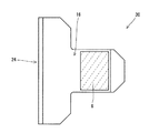
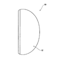
[実施例3]
実施例3に係るパターヘッド34が、図9から図14により示される。図9は、パターヘッド34をトップ面36側から見た図である。図10は、パターヘッド34をソール面38側から見た図である。図11は、パターヘッド34をフェース面40側から見た図である。図12は、パターヘッド34をバック側から見た図である。図13は、パターヘッド34をヒール側から見た図である。図14は、図9のXIV−XIV線に沿った断面図である。
[Example 3]
A
パターヘッド34は、ヘッド本体41と、低比重部材42と、フェース部材44とを有している。ヘッド本体41は、中空部tを有している。図9において破線で示されるのは、中空部tの輪郭線である。ヘッド本体41は、ソール凹部46と、フェース凹部48とを有している。ソール凹部46の深さ及び形状は、低比重部材42に対応している。フェース凹部48の深さ及び形状は、フェース部材44に対応している。ヘッド本体41、低比重部材42及びフェース部材44の材質、製造方法及び固着方法は、実施例1と同様である。図9が示すように、パターヘッド34のバック側の輪郭形状は、略円弧状である。パターヘッド34は、いわゆるマレットタイプのパターヘッドである。またヘッド本体41は、シャフト穴50を有している。図10において、低比重部材42は破線ハッチングで示されている。
The
パターヘッド34において、低比重部材42の重心位置g2は、ヘッド重心g1よりもフェース側に位置している(図示省略)。以上に記載の点以外は、実施例1と同様にして、実施例3に係るパターヘッドを得た。
In the
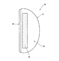
[実施例4]
図15は、実施例4に係るパターヘッド52をソール面54側から見た図である。低比重部材56の位置及び形状が図15に示されるように変更され、これに対応してソール凹部(図示省略)の位置及び形状が変更された以外は、実施例3と同様にして、実施例4に係るパターヘッドを得た。
[Example 4]
FIG. 15 is a view of the
[比較例1]
図16から図21は、比較例1に係るパターヘッド60を示す図である。図16は、パターヘッド60をトップ面62側から見た図である。図17は、パターヘッド60をソール面64側から見た図である。図18は、パターヘッド60をフェース面66側から見た図である。図19は、パターヘッド60をバック側から見た図である。図20は、パターヘッド60をヒール側から見た図である。図21は、図16のXXI−XXI線に沿った断面図である。
[Comparative Example 1]
16 to 21 are views showing a
パターヘッド60は、フェース部材68と、ヘッド本体70とを有している。ヘッド本体70は、フェース凹部72を有している(図21参照)。フェース凹部72の形状及び深さは、フェース部材68に対応している。ヘッド本体70の材質及び製法と、フェース部材68の材質、製法及び固着方法は、実施例1と同様である。
The
ヘッド本体70は、中空部tを有している。図16において破線で示されるのは、中空部tの輪郭線である。ヘッド本体70は、トップ面62側から見て略T字状をなす主要部74と、主要部74のトウ側端部とバック側端部との間に延びるトウ側連結部76と、主要部74のヒール側端部とバック側端部との間に延びるヒール側連結部78とを有している。トウ側連結部76及びヒール側連結部78は、略円弧状に延びている。トウ側連結部76と主要部74との間には、空間部kが存在する(図16参照)。ヒール側連結部78と主要部74との間にも、空間部kが存在する。
The head body 70 has a hollow portion t. In FIG. 16, the broken line indicates the outline of the hollow portion t. The head main body 70 includes a
パターヘッド60は、低比重部材を有さない。
The
以上で説明された点以外は、実施例1と同様にして、比較例1に係るパタークラブを得た。 A putter club according to Comparative Example 1 was obtained in the same manner as Example 1 except for the points described above.
[比較例2]
図22は、比較例2に係るパターヘッド80をソール面82側から見た図である。このパターヘッド80の形状は、前述した実施例3に係るパターヘッド34及び実施例4に係るパターヘッド52を略相似形で縮小させたものである。この比較例2は、低比重部材を有さない。低比重部材42を有さず、当該低比重部材42の部分がヘット本体で占められており、且つヘッドが小型化された点以外は、実施例3と同様にして、比較例2に係るパタークラブを得た。
[Comparative Example 2]
FIG. 22 is a view of the
実施例1から4及び比較例1、2の仕様と評価結果が、下記の表1で示される。 The specifications and evaluation results of Examples 1 to 4 and Comparative Examples 1 and 2 are shown in Table 1 below.

評価方法は、以下の通りである。
[転がり距離]
パターを振り子のようにスイングすることができるパッティングマシンを用いてグリーン上のボールを打球させ、転がり距離を測定した。ボールは、市販の2ピースボールとした。このパッティングマシンは、振り上げ高さの設定によりヘッドスピードを精度よく設定することができる。ヘッドスピードは2.5(m/s)に設定した。インパクト時のロフト角は、4.0度に設定した。グリーン上の同じ位置から同じ方向に5球ずつ打球させ、平均値を評価値とした。この評価値が、「転がり距離」として上記の表1で示されている。
The evaluation method is as follows.
[Rolling distance]
Using a putting machine that can swing the putter like a pendulum, the ball on the green was hit and the rolling distance was measured. The ball was a commercially available two-piece ball. This putting machine can accurately set the head speed by setting the swing-up height. The head speed was set to 2.5 (m / s). The loft angle at impact was set to 4.0 degrees. Five balls were hit in the same direction from the same position on the green, and the average value was used as the evaluation value. This evaluation value is shown in Table 1 as “Rolling distance”.
[転がりズレ]
4m先のカップを狙ってゴルファーがパッティングを行い、左右への方向のズレを計測した。右方向へのズレもプラスの値とし、左方向へのズレもプラスの値として、ズレを積算し、ズレの平均値を計算した。10人のテスターが10球ずつ打球した合計100球のデータの平均値が、[転がりズレ]として上記の表1で示される。
[Rolling misalignment]
A golfer put on the cup 4m ahead and measured the deviation in the left and right direction. The deviation in the right direction was also set to a positive value, and the shift in the left direction was also set to a positive value. The average value of the data of a total of 100 balls shot by 10 testers by 10 balls is shown in Table 1 above as [rolling deviation].
表1に示されるように、実施例の製造方法では、比較例の製造方法に比べて転がり距離が長い。この評価結果から、本発明の優位性は明らかである。 As shown in Table 1, the manufacturing method of the example has a longer rolling distance than the manufacturing method of the comparative example. From this evaluation result, the superiority of the present invention is clear.
2・・・パターヘッド
3・・・シャフト
4・・・ヘッド本体
6、42、56・・・低比重部材
8・・・フェース部材
10・・・トップ面
12・・・ソール面部
13・・・ソール凹部
14・・・低比重部材の外面
16、38、54、82・・・ソール面
18・・・フェース面部
20・・・フェース凹部
22・・・フェース部材の外面
24・・・フェース面
30、34、52、60・・・パターヘッド
t・・・中空部
f1・・・パターヘッドのフェース側部分
b1・・・パターヘッドのバック側部分
W1・・・パターヘッドのトウ・ヒール方向における最大幅
W2・・・パターヘッドのフェース・バック方向における最大幅
F・・・重心深度
h・・・スイートスポット高さ
2 ...
Claims (2)
上記低比重部材は、上記ヘッド本体のソール面側に設けられており、
ソール面の少なくとも一部は、上記低比重部材により構成されており、
上方に突出するホーゼル部を有しておらず、
ヘッド最大高さhmが40mm以下であり、
スイートスポット高さhが12.0mm以上であり、
上記低比重部材の重心は、ヘッド重心よりもフェース側に位置しており、
ヘッドのトウ・ヒール方向における最大幅が幅W1であり、ヘッドのフェース・バック方向における最大幅が幅W2であるとき、幅W1の幅W2に対する比(W1/W2)が1.05以上1.50以下であり、
上記幅W1が80mm以上130mm以下であり、
上記幅W2の中間位置を通りフェース・バック方向に対して垂直な平面により、ヘッドがフェース側部分とバック側部分とに2分割された場合、上記フェース側部分の重量M1の、上記バック側部分の重量M2に対する比(M1/M2)が0.40以上1.30以下であるパター用ゴルフクラブヘッド。 A head main body made of metal and a low specific gravity member made of a material having a specific gravity lower than that of the metal constituting the head main body,
The low specific gravity member is provided on the sole surface side of the head body,
At least a part of the sole surface is configured by the low specific gravity member,
Does not have a hosel part protruding upward,
The maximum head height hm is 40 mm or less,
The sweet spot height h is 12.0 mm or more ,
The center of gravity of the low specific gravity member is located on the face side of the head center of gravity,
When the maximum width of the head in the toe-heel direction is the width W1, and the maximum width of the head in the face-back direction is the width W2, the ratio (W1 / W2) of the width W1 to the width W2 is 1.05 or more. 50 or less,
The width W1 is not less than 80 mm and not more than 130 mm,
When the head is divided into a face side portion and a back side portion by a plane that passes through an intermediate position of the width W2 and is perpendicular to the face / back direction, the back side portion has a weight M1 of the face side portion. A golf club head for putters having a ratio (M1 / M2) to a weight M2 of 0.40 or more and 1.30 or less .
Priority Applications (2)
| Application Number | Priority Date | Filing Date | Title |
|---|---|---|---|
| JP2006038854A JP4723397B2 (en) | 2006-02-16 | 2006-02-16 | Golf club head for putter and golf putter |
| US11/652,063 US8192305B2 (en) | 2006-02-16 | 2007-01-11 | Golf club head for putter, and golf putter |
Applications Claiming Priority (1)
| Application Number | Priority Date | Filing Date | Title |
|---|---|---|---|
| JP2006038854A JP4723397B2 (en) | 2006-02-16 | 2006-02-16 | Golf club head for putter and golf putter |
Publications (2)
| Publication Number | Publication Date |
|---|---|
| JP2007215714A JP2007215714A (en) | 2007-08-30 |
| JP4723397B2 true JP4723397B2 (en) | 2011-07-13 |
Family
ID=38369355
Family Applications (1)
| Application Number | Title | Priority Date | Filing Date |
|---|---|---|---|
| JP2006038854A Expired - Fee Related JP4723397B2 (en) | 2006-02-16 | 2006-02-16 | Golf club head for putter and golf putter |
Country Status (2)
| Country | Link |
|---|---|
| US (1) | US8192305B2 (en) |
| JP (1) | JP4723397B2 (en) |
Families Citing this family (12)
| Publication number | Priority date | Publication date | Assignee | Title |
|---|---|---|---|---|
| JP4840910B2 (en) | 2005-12-27 | 2011-12-21 | ブリヂストンスポーツ株式会社 | Putter head |
| JP5178145B2 (en) * | 2007-10-29 | 2013-04-10 | ダンロップスポーツ株式会社 | Golf putter |
| USD583889S1 (en) | 2008-01-08 | 2008-12-30 | Nike, Inc. | Golf club head for a putter |
| USD571420S1 (en) | 2008-01-08 | 2008-06-17 | Nike, Inc. | Golf club head of a putter |
| USD571885S1 (en) | 2008-01-08 | 2008-06-24 | Nike, Inc. | Golf club head for a putter |
| JP4683353B1 (en) * | 2010-06-30 | 2011-05-18 | 横浜ゴム株式会社 | Golf club head |
| GB201018949D0 (en) * | 2010-11-09 | 2010-12-22 | Woods Derek C | Golf club |
| US9220960B2 (en) | 2012-12-20 | 2015-12-29 | Taylor Made Golf Company, Inc. | Putter head, adjustable shaft and putter |
| US11865418B2 (en) * | 2019-07-01 | 2024-01-09 | Sumitomo Rubber Industries, Ltd. | Golf club head |
| JP7541708B2 (en) | 2020-03-17 | 2024-08-29 | 株式会社 ロア・ジャパン | Golf Club Head |
| US11826621B2 (en) * | 2020-11-13 | 2023-11-28 | Axis1, Llc | Golf club |
| US11911670B2 (en) * | 2022-05-13 | 2024-02-27 | Karsten Manufacturing Corporation | Compact putter head |
Family Cites Families (9)
| Publication number | Priority date | Publication date | Assignee | Title |
|---|---|---|---|---|
| JPH04111370U (en) | 1991-03-12 | 1992-09-28 | ヤマハ株式会社 | golf putter club |
| US5221087A (en) * | 1992-01-17 | 1993-06-22 | Lisco, Inc. | Metal golf clubs with inserts |
| JP3057456U (en) | 1998-06-24 | 1999-06-02 | 和夫 益子 | Over spin pattern |
| US6422950B1 (en) * | 2000-09-11 | 2002-07-23 | Whitlam International, Inc. | Putter sole plate insert system |
| JP2003275353A (en) * | 2002-03-22 | 2003-09-30 | Aniijingu Sports:Kk | Golf putter head |
| US7086961B2 (en) * | 2002-05-20 | 2006-08-08 | Karsten Manufacturing Corporation | Methods and apparatus for using a frequency-selectable insert in a golf club head |
| JP2004290565A (en) * | 2003-03-28 | 2004-10-21 | Mizuno Corp | Putter golf club head and putter golf club |
| JP2007054167A (en) * | 2005-08-23 | 2007-03-08 | Bridgestone Sports Co Ltd | Golf putter head |
| US20070142122A1 (en) * | 2005-12-15 | 2007-06-21 | Bonneau Michael D | Top weighted putter head |
-
2006
- 2006-02-16 JP JP2006038854A patent/JP4723397B2/en not_active Expired - Fee Related
-
2007
- 2007-01-11 US US11/652,063 patent/US8192305B2/en active Active
Also Published As
| Publication number | Publication date |
|---|---|
| JP2007215714A (en) | 2007-08-30 |
| US20070191137A1 (en) | 2007-08-16 |
| US8192305B2 (en) | 2012-06-05 |
Similar Documents
| Publication | Publication Date | Title |
|---|---|---|
| JP5903112B2 (en) | Multi component golf club head | |
| US9908018B2 (en) | Muscle-back, with insert, iron type golf club head | |
| EP2456529B1 (en) | Golf club head or other ball striking device having impact-influence body features | |
| JP5823122B2 (en) | Golf club | |
| JP5181052B2 (en) | Golf club set | |
| JP4410606B2 (en) | Golf club head | |
| US8192305B2 (en) | Golf club head for putter, and golf putter | |
| EP2550998A1 (en) | Golf club with selected length to weight ratio | |
| KR101867270B1 (en) | Golf club head and golf club using the same | |
| US8038546B2 (en) | Wood-type golf club head | |
| CN103167896B (en) | Golf clubs and glof club head | |
| US20090291775A1 (en) | Wood-type golf club head | |
| US6875130B2 (en) | Wood-type golf club head | |
| JP2004008345A (en) | Golf club | |
| JP2009232968A (en) | Golf club head | |
| US8371955B2 (en) | Wood-type golf club set | |
| JP5324992B2 (en) | Golf club head | |
| JP2008093268A (en) | Golf club head | |
| JP2021122732A (en) | Face for golf driver | |
| JP2002253713A (en) | Golf club head | |
| KR102346984B1 (en) | Face for golf drover | |
| JP4657484B2 (en) | Golf club head and golf club | |
| JP2024118244A (en) | Golf club head and golf club | |
| JP2002233597A (en) | Golf club | |
| JP2002191733A (en) | Golf putter and driver head |
Legal Events
| Date | Code | Title | Description |
|---|---|---|---|
| A621 | Written request for application examination |
Free format text: JAPANESE INTERMEDIATE CODE: A621 Effective date: 20071019 |
|
| A977 | Report on retrieval |
Free format text: JAPANESE INTERMEDIATE CODE: A971007 Effective date: 20100309 |
|
| A131 | Notification of reasons for refusal |
Free format text: JAPANESE INTERMEDIATE CODE: A131 Effective date: 20100413 |
|
| A521 | Request for written amendment filed |
Free format text: JAPANESE INTERMEDIATE CODE: A523 Effective date: 20100601 |
|
| A131 | Notification of reasons for refusal |
Free format text: JAPANESE INTERMEDIATE CODE: A131 Effective date: 20100817 |
|
| A02 | Decision of refusal |
Free format text: JAPANESE INTERMEDIATE CODE: A02 Effective date: 20101109 |
|
| A521 | Request for written amendment filed |
Free format text: JAPANESE INTERMEDIATE CODE: A523 Effective date: 20110113 |
|
| A911 | Transfer to examiner for re-examination before appeal (zenchi) |
Free format text: JAPANESE INTERMEDIATE CODE: A911 Effective date: 20110124 |
|
| TRDD | Decision of grant or rejection written | ||
| A01 | Written decision to grant a patent or to grant a registration (utility model) |
Free format text: JAPANESE INTERMEDIATE CODE: A01 Effective date: 20110405 |
|
| A01 | Written decision to grant a patent or to grant a registration (utility model) |
Free format text: JAPANESE INTERMEDIATE CODE: A01 |
|
| A61 | First payment of annual fees (during grant procedure) |
Free format text: JAPANESE INTERMEDIATE CODE: A61 Effective date: 20110407 |
|
| FPAY | Renewal fee payment (event date is renewal date of database) |
Free format text: PAYMENT UNTIL: 20140415 Year of fee payment: 3 |
|
| R150 | Certificate of patent or registration of utility model |
Ref document number: 4723397 Country of ref document: JP Free format text: JAPANESE INTERMEDIATE CODE: R150 Free format text: JAPANESE INTERMEDIATE CODE: R150 |
|
| R250 | Receipt of annual fees |
Free format text: JAPANESE INTERMEDIATE CODE: R250 |
|
| R250 | Receipt of annual fees |
Free format text: JAPANESE INTERMEDIATE CODE: R250 |
|
| R250 | Receipt of annual fees |
Free format text: JAPANESE INTERMEDIATE CODE: R250 |
|
| R250 | Receipt of annual fees |
Free format text: JAPANESE INTERMEDIATE CODE: R250 |
|
| R250 | Receipt of annual fees |
Free format text: JAPANESE INTERMEDIATE CODE: R250 |
|
| R250 | Receipt of annual fees |
Free format text: JAPANESE INTERMEDIATE CODE: R250 |
|
| R250 | Receipt of annual fees |
Free format text: JAPANESE INTERMEDIATE CODE: R250 |
|
| R250 | Receipt of annual fees |
Free format text: JAPANESE INTERMEDIATE CODE: R250 |
|
| R250 | Receipt of annual fees |
Free format text: JAPANESE INTERMEDIATE CODE: R250 |
|
| LAPS | Cancellation because of no payment of annual fees |