JP6875975B2 - Pachinko machine - Google Patents
Pachinko machine Download PDFInfo
- Publication number
- JP6875975B2 JP6875975B2 JP2017201230A JP2017201230A JP6875975B2 JP 6875975 B2 JP6875975 B2 JP 6875975B2 JP 2017201230 A JP2017201230 A JP 2017201230A JP 2017201230 A JP2017201230 A JP 2017201230A JP 6875975 B2 JP6875975 B2 JP 6875975B2
- Authority
- JP
- Japan
- Prior art keywords
- effect
- game
- setting
- display
- state
- Prior art date
- Legal status (The legal status is an assumption and is not a legal conclusion. Google has not performed a legal analysis and makes no representation as to the accuracy of the status listed.)
- Active
Links
- 230000000694 effects Effects 0.000 claims description 730
- 238000000034 method Methods 0.000 description 427
- 230000008569 process Effects 0.000 description 425
- 230000008859 change Effects 0.000 description 214
- 238000012545 processing Methods 0.000 description 103
- 238000012790 confirmation Methods 0.000 description 95
- 238000004519 manufacturing process Methods 0.000 description 90
- 238000001514 detection method Methods 0.000 description 44
- 235000013399 edible fruits Nutrition 0.000 description 27
- 230000009471 action Effects 0.000 description 25
- 238000011161 development Methods 0.000 description 23
- 238000003860 storage Methods 0.000 description 21
- 238000010586 diagram Methods 0.000 description 20
- 230000004913 activation Effects 0.000 description 18
- 238000011084 recovery Methods 0.000 description 15
- 230000006870 function Effects 0.000 description 14
- 230000004048 modification Effects 0.000 description 13
- 238000012986 modification Methods 0.000 description 13
- 239000000872 buffer Substances 0.000 description 12
- 230000015654 memory Effects 0.000 description 11
- 239000011521 glass Substances 0.000 description 10
- 239000004973 liquid crystal related substance Substances 0.000 description 9
- 238000003825 pressing Methods 0.000 description 9
- 239000000758 substrate Substances 0.000 description 9
- 230000004044 response Effects 0.000 description 8
- 230000005856 abnormality Effects 0.000 description 7
- 230000009467 reduction Effects 0.000 description 7
- 210000003128 head Anatomy 0.000 description 6
- 230000005540 biological transmission Effects 0.000 description 5
- 230000001276 controlling effect Effects 0.000 description 5
- 241000032989 Ipomoea lacunosa Species 0.000 description 4
- 230000008901 benefit Effects 0.000 description 4
- 238000004891 communication Methods 0.000 description 4
- 238000013500 data storage Methods 0.000 description 4
- 230000033001 locomotion Effects 0.000 description 4
- 230000014759 maintenance of location Effects 0.000 description 4
- 238000007781 pre-processing Methods 0.000 description 4
- 238000004458 analytical method Methods 0.000 description 3
- 239000011248 coating agent Substances 0.000 description 3
- 238000000576 coating method Methods 0.000 description 3
- 238000005520 cutting process Methods 0.000 description 3
- 238000005401 electroluminescence Methods 0.000 description 3
- 238000007726 management method Methods 0.000 description 3
- 239000000463 material Substances 0.000 description 3
- 230000001105 regulatory effect Effects 0.000 description 3
- 244000241235 Citrullus lanatus Species 0.000 description 2
- 235000012828 Citrullus lanatus var citroides Nutrition 0.000 description 2
- 244000241257 Cucumis melo Species 0.000 description 2
- 235000015510 Cucumis melo subsp melo Nutrition 0.000 description 2
- 235000016623 Fragaria vesca Nutrition 0.000 description 2
- 240000009088 Fragaria x ananassa Species 0.000 description 2
- 235000011363 Fragaria x ananassa Nutrition 0.000 description 2
- 240000008790 Musa x paradisiaca Species 0.000 description 2
- 235000018290 Musa x paradisiaca Nutrition 0.000 description 2
- FJJCIZWZNKZHII-UHFFFAOYSA-N [4,6-bis(cyanoamino)-1,3,5-triazin-2-yl]cyanamide Chemical compound N#CNC1=NC(NC#N)=NC(NC#N)=N1 FJJCIZWZNKZHII-UHFFFAOYSA-N 0.000 description 2
- 238000013459 approach Methods 0.000 description 2
- 230000001174 ascending effect Effects 0.000 description 2
- 230000033228 biological regulation Effects 0.000 description 2
- 239000003086 colorant Substances 0.000 description 2
- 238000004590 computer program Methods 0.000 description 2
- 238000009795 derivation Methods 0.000 description 2
- 238000003745 diagnosis Methods 0.000 description 2
- 230000029087 digestion Effects 0.000 description 2
- 230000014509 gene expression Effects 0.000 description 2
- 238000009434 installation Methods 0.000 description 2
- 230000002265 prevention Effects 0.000 description 2
- 230000001360 synchronised effect Effects 0.000 description 2
- 229920003002 synthetic resin Polymers 0.000 description 2
- 239000000057 synthetic resin Substances 0.000 description 2
- 241000722921 Tulipa gesneriana Species 0.000 description 1
- 230000004397 blinking Effects 0.000 description 1
- 238000010924 continuous production Methods 0.000 description 1
- 238000005034 decoration Methods 0.000 description 1
- 238000013461 design Methods 0.000 description 1
- 210000000887 face Anatomy 0.000 description 1
- 238000005286 illumination Methods 0.000 description 1
- 239000011159 matrix material Substances 0.000 description 1
- 230000008450 motivation Effects 0.000 description 1
- 230000001151 other effect Effects 0.000 description 1
- 238000012805 post-processing Methods 0.000 description 1
- 230000000630 rising effect Effects 0.000 description 1
Images


Landscapes
- Pinball Game Machines (AREA)
- Display Devices Of Pinball Game Machines (AREA)
Description
本発明は、パチンコ遊技機等の遊技機に関する。 The present invention relates to a gaming machine such as a pachinko gaming machine.
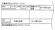
パチンコ遊技機において、大当りの当選確率(出玉率)等の設定値を変更することが可能な遊技機が特許文献1に開示されている。また、設定値を変更するための設定キーの部分がカバーで覆われている遊技機が特許文献2に開示されている。さらに、パチンコ遊技機では、電源投入時に主基板と演出制御基板との立ち上がりに時間差があるため、主基板において所定の時間分だけ演出制御基板へのコマンド送信を禁止する遊技機が特許文献3に開示されている。
しかし、特許文献3に記載されたような遊技機において設定変更を行う場合に、所定の時間分だけ処理を待って設定変更や設定変更報知を行ったのでは、設定する者が煩わしさを感じるなど不便が生じていた。However, when the setting is changed in the gaming machine as described in
この発明は、上記の実状に鑑みてなされたものであり、設定する者が煩わしさを感じることなく設定変更を行える遊技機を提供することを目的とする。 The present invention has been made in view of the above circumstances, and an object of the present invention is to provide a gaming machine capable of changing settings without causing trouble for the setting person.
(1)上記目的を達成するため、本願発明に係る遊技機は、
遊技者にとって有利な有利状態に制御可能な遊技機(例えば、パチンコ遊技機1)であって、
遊技の進行を制御する遊技制御手段(例えば、主基板11)と、
前記遊技制御手段から送信された所定情報(例えば、制御コマンド)に従って演出を制御する演出制御手段(例えば、演出制御基板12)と、
前記有利状態の確率に関する設定値を設定するための設定許可状態に制御可能な設定許可手段と、
前記設定許可状態に制御されているか否かを判定する判定手段(例えば、主基板11は、図22示す条件に基づき設定変更状態に制御されているか否かを判定)と、を備え、
前記演出制御手段は、電源投入から特定期間(例えば、演出制御基板12が制御コマンドを受信可能、またはバッファに受信している制御コマンドを解析可能となるまでの期間)が経過した後に、前記遊技制御手段から送信された前記所定情報が解析可能となり、
前記遊技制御手段は、前記特定期間が経過した後に前記演出制御手段への前記所定情報の送信を開始(例えば、制御コマンドを送信S7,S9,176FS019a)し、
前記判定手段は、前記特定期間が経過する前に、前記設定許可状態に制御されているか否かを判定し(例えば、設定変更処理(176FS016))、
前記遊技制御手段は、前記判定手段が前記設定許可状態であると判定したことに基づき、前記特定期間が経過するよりも前に前記設定許可状態に関する報知を行う(例えば、主基板11で制御可能なスピーカ、LEDや表紙装置などで設定変更報知を行う(176FS040))。
(1) In order to achieve the above object, the gaming machine according to the present invention is
A gaming machine (for example, pachinko gaming machine 1) that can be controlled to an advantageous state that is advantageous to the player.
A game control means (for example, main board 11) that controls the progress of the game,
An effect control means (for example, an effect control board 12) that controls an effect according to predetermined information (for example, a control command) transmitted from the game control means.
Setting permission means that can control the setting permission state for setting the setting value regarding the probability of the advantageous state, and
A determination means for determining whether or not the setting is controlled to the setting permission state (for example, determining whether or not the
The effect control means is the game after a specific period (for example, a period until the
The game control means starts transmitting the predetermined information to the effect control means (for example, transmitting control commands S7, S9, 176FS019a) after the lapse of the specific period.
The determination means determines whether or not the setting permission state is controlled before the lapse of the specific period (for example, setting change processing (176FS016)).
Based on the determination that the determination means is in the setting permission state, the game control means notifies the setting permission state before the lapse of the specific period (for example, the
このような構成によれば、設定変更する場合に煩わしさを感じることがない。 With such a configuration, there is no need to feel annoyed when changing the settings.
(2)上記(1)の遊技機において、
前記示唆演出実行手段は、複数種類の前記示唆演出を実行可能であって、
複数種類の前記示唆演出において、前記所定期間内の演出の少なくとも一部は共通の態様で実行可能であるようにしてもよい(例えば図9(C))。
(2) In the gaming machine of (1) above
The suggestion effect execution means can execute a plurality of types of the suggestion effect, and
In the plurality of types of the suggestion effects, at least a part of the effects within the predetermined period may be feasible in a common manner (for example, FIG. 9C).
このような構成によれば、いずれの示唆演出が実行されるかに注目させることができ、興趣が向上する。 With such a configuration, it is possible to pay attention to which suggestive effect is executed, and the interest is improved.
(3)上記(1)または(2)の遊技機において、
前記示唆演出実行中の複数の実行タイミングにおいて、前記有利状態に制御されることを示唆する特定演出(例えば発展演出や予告演出)を実行可能であり、
前記所定期間中には前記特定演出の実行タイミングが設けられないようにしてもよい。
(3) In the gaming machine of (1) or (2) above
At a plurality of execution timings during the execution of the suggestion effect, it is possible to execute a specific effect (for example, a development effect or a notice effect) that suggests that the effect is controlled to the advantageous state.
The execution timing of the specific effect may not be provided during the predetermined period.
このような構成によれば、タイトルの報知後でも遊技者の期待感を維持することができる。 According to such a configuration, the player's expectation can be maintained even after the title is notified.
(4)上記(1)から(3)のいずれかの遊技機において、
前記示唆演出実行手段は、前記示唆演出として少なくとも第1示唆演出(例えばスーパーリーチAやスーパーリーチBのリーチ演出)と第2示唆演出(例えばスーパーリーチDやスーパーリーチEのリーチ演出)とを実行可能であり、
前記タイトル報知手段は、前記第2示唆演出では、当該第2示唆演出の開始時から当該第2示唆演出に対応したタイトルを報知するようにしてもよい。
(4) In any of the gaming machines (1) to (3) above,
The suggestion effect execution means executes at least the first suggestion effect (for example, the reach effect of super reach A or super reach B) and the second suggestion effect (for example, the reach effect of super reach D or super reach E) as the suggestion effect. It is possible
In the second suggestion effect, the title notification means may notify the title corresponding to the second suggestion effect from the start of the second suggestion effect.
このような構成によれば、示唆演出に応じたタイトルの報知を実行できるので演出効果が向上する。 According to such a configuration, the notification of the title according to the suggestion effect can be executed, so that the effect of the effect is improved.
(5)上記(4)の遊技機において、
前記第2示唆演出が実行された場合よりも前記第1示唆演出が実行された場合の方が前記有利状態に制御される割合が高いようにしてもよい。
(5) In the gaming machine of (4) above
The ratio of being controlled to the advantageous state may be higher when the first suggestion effect is executed than when the second suggestion effect is executed.
このような構成によれば、演出効果が向上する。 According to such a configuration, the effect of production is improved.
(6)上記(1)から(5)のいずれかの遊技機において、
前記示唆演出実行手段は、前記所定期間において報知されるタイトルに関連する演出態様で前記示唆演出を実行可能であるようにしてもよい。
(6) In any of the gaming machines (1) to (5) above,
The suggestion effect execution means may enable the suggestion effect to be executed in an effect mode related to the title notified in the predetermined period.
このような構成によれば、演出効果が向上する。 According to such a configuration, the effect of production is improved.
(7)上記(1)から(6)のいずれかの遊技機において、
遊技者の動作を検出可能な検出手段(例えばスティックコントローラ31Aやプッシュボタン31B)と、
前記検出手段に対応した特定表示(例えば小ボタン画像31AK043、大ボタン画像31AK047、スティック画像31AK051)を行う特定表示実行手段(例えば演出制御用CPU120)と、をさらに備え、
前記特定表示実行手段は、
前記特定表示として、第1特定表示(例えば小ボタン画像31AK043)と、前記第1特定表示よりも遊技者にとって有利度が高い第2特定表示(例えば、大ボタン画像31AK047、スティック画像31AK051)を表示可能であり、
前記検出手段による検出の非有効期間において、前記第1特定表示を表示した後に当該第1特定表示を前記第2特定表示に変化させ(例えば図17(E)、図18(I))、
前記検出手段による検出の有効期間において、変化後の前記第2特定表示を用いた動作演出が実行されるようにしてもよい(例えば図18(J)、(K))。
(7) In any of the gaming machines (1) to (6) above,
Detection means (for example,
A specific display execution means (for example, an effect control CPU 120) for performing a specific display (for example, small button image 31AK043, large button image 31AK047, stick image 31AK051) corresponding to the detection means is further provided.
The specific display execution means is
As the specific display, a first specific display (for example, small button image 31AK043) and a second specific display (for example, large button image 31AK047, stick image 31AK051) that are more advantageous to the player than the first specific display are displayed. It is possible and
During the non-valid period of detection by the detection means, after displaying the first specific display, the first specific display is changed to the second specific display (for example, FIGS. 17 (E) and 18 (I)).
During the valid period of detection by the detection means, the operation effect using the second specific display after the change may be executed (for example, FIGS. 18J and 18K).
このような構成によれば、演出効果が向上する。 According to such a configuration, the effect of production is improved.
(8)上記(1)から(7)のいずれかの遊技機において、
前記有利状態への制御の期待度を示唆する示唆表示として、表示サイズが第1サイズである第1示唆表示(図19(a)に示すシャッター演出時に表示する第1サイズのシャッター画像31AK061による表示等)と、表示サイズが第2サイズである第2示唆表示(図19(d)に示すリーチタイトル演出時に表示する第2サイズのリーチタイトル画像31AK062等)とを表示可能な表示手段(例えば画像表示装置5、演出制御用CPU120)をさらに備え、
前記表示手段は、
態様の異なる複数種類の要素(図19(a)、(d)に示す要素E1(バナナ)、要素E2(メロン)、要素E3(リンゴ)、要素E4(スイカ)、要素E5(イチゴ)等)を含んで構成された特定画像(図19(a)、(d)に示すフルーツ柄等)を表示可能であり、
前記特定画像を含むパターンにて前記第1示唆表示および前記第2示唆表示のいずれを表示するときにも、複数種類の要素が前記第1示唆表示および前記第2示唆表示のいずれにも含まれるように表示する(図19(a)、(d)に示すシャッター画像31AK061、リーチタイトル画像31AK062のいずれにも要素E1〜E5が含まれるように表示する等)ようにしてもよい。
(8) In any of the gaming machines (1) to (7) above,
As a suggestion display suggesting the degree of expectation of control to the advantageous state, a first suggestion display having a display size of the first size (display by the first size shutter image 31AK061 displayed at the time of the shutter effect shown in FIG. 19A). Etc.) and a second suggestion display whose display size is the second size (second size reach title image 31AK062 or the like displayed at the time of the reach title production shown in FIG. 19 (d)) (for example, an image). A
The display means
Multiple types of elements having different aspects (element E1 (banana), element E2 (melon), element E3 (apple), element E4 (watermelon), element E5 (strawberry), etc. shown in FIGS. 19 (a) and 19 (d)) It is possible to display a specific image (such as the fruit pattern shown in FIGS. 19A and 19D) composed of the above.
When either the first suggestion display or the second suggestion display is displayed in the pattern including the specific image, a plurality of types of elements are included in both the first suggestion display and the second suggestion display. (Display so that elements E1 to E5 are included in any of the shutter image 31AK061 and the reach title image 31AK062 shown in FIGS. 19A and 19D).
このような構成によれば、示唆表示の表示サイズに関わらず特定画像を好適に表示することができる。これにより、特定画像が表示されたことを正確に伝えることができる。 According to such a configuration, a specific image can be preferably displayed regardless of the display size of the suggestion display. This makes it possible to accurately convey that a specific image has been displayed.
(基本説明)
まず、パチンコ遊技機1の基本的な構成及び制御(一般的なパチンコ遊技機の構成及び制御でもある。)について説明する。
(パチンコ遊技機1の構成等)
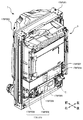
図1は、パチンコ遊技機1の正面図であり、主要部材の配置レイアウトを示す。パチンコ遊技機(遊技機)1は、大別して、遊技盤面を構成する遊技盤(ゲージ盤)2と、遊技盤2を支持固定する遊技機用枠(台枠)3とから構成されている。遊技盤2には、遊技領域が形成され、この遊技領域には、遊技媒体としての遊技球が、所定の打球発射装置から発射されて打ち込まれる。
(Basic explanation)
First, the basic configuration and control of the pachinko gaming machine 1 (also the configuration and control of a general pachinko gaming machine) will be described.
(Configuration of
FIG. 1 is a front view of the
遊技盤2の所定位置(図1に示す例では、遊技領域の右側方)には、複数種類の特別識別情報としての特別図柄(特図ともいう)の可変表示(特図ゲームともいう)を行う第1特別図柄表示装置4A及び第2特別図柄表示装置4Bが設けられている。これらは、それぞれ、7セグメントのLEDなどからなる。特別図柄は、「0」〜「9」を示す数字や「−」などの点灯パターンなどにより表される。特別図柄には、LEDを全て消灯したパターンが含まれてもよい。
At a predetermined position of the game board 2 (in the example shown in FIG. 1, the right side of the game area), a variable display (also referred to as a special figure game) of a special symbol (also referred to as a special figure) as a plurality of types of special identification information is displayed. The first special
なお、特別図柄の「可変表示」とは、例えば、複数種類の特別図柄を変動可能に表示することである(後述の他の図柄についても同じ)。変動としては、複数の図柄の更新表示、複数の図柄のスクロール表示、1以上の図柄の変形、1以上の図柄の拡大/縮小などがある。特別図柄や後述の普通図柄の変動では、複数種類の特別図柄又は普通図柄が更新表示される。後述の飾り図柄の変動では、複数種類の飾り図柄がスクロール表示又は更新表示されたり、1以上の飾り図柄が変形や拡大/縮小されたりする。なお、変動には、ある図柄を点滅表示する態様も含まれる。可変表示の最後には、表示結果として所定の特別図柄が停止表示(導出又は導出表示などともいう)される(後述の他の図柄の可変表示についても同じ)。なお、可変表示を変動表示、変動と表現する場合がある。 The "variable display" of the special symbol is, for example, to display a plurality of types of special symbols in a variable manner (the same applies to other symbols described later). Fluctuations include update display of a plurality of symbols, scroll display of a plurality of symbols, deformation of one or more symbols, enlargement / reduction of one or more symbols, and the like. When the special symbol or the ordinary symbol described later is changed, a plurality of types of special symbols or ordinary symbols are updated and displayed. In the variation of the decorative symbol described later, a plurality of types of decorative symbols are scrolled or updated, and one or more decorative symbols are deformed or enlarged / reduced. The variation also includes a mode in which a certain symbol is blinked and displayed. At the end of the variable display, a predetermined special symbol is stopped (also referred to as derivation or derivation display) as a display result (the same applies to the variable display of other symbols described later). The variable display may be expressed as a variable display or a variable display.
なお、第1特別図柄表示装置4Aにおいて可変表示される特別図柄を「第1特図」ともいい、第2特別図柄表示装置4Bにおいて可変表示される特別図柄を「第2特図」ともいう。また、第1特図を用いた特図ゲームを「第1特図ゲーム」といい、第2特図を用いた特図ゲームを「第2特図ゲーム」ともいう。なお、特別図柄の可変表示を行う特別図柄表示装置は1種類であってもよい。
The special symbol variably displayed on the first special
遊技盤2における遊技領域の中央付近には画像表示装置5が設けられている。画像表示装置5は、例えばLCD(液晶表示装置)や有機EL(Electro Luminescence)等から構成され、各種の演出画像を表示する。画像表示装置5は、プロジェクタ及びスクリーンから構成されていてもよい。画像表示装置5には、各種の演出画像が表示される。
An
例えば、画像表示装置5の画面上では、第1特図ゲームや第2特図ゲームと同期して、特別図柄とは異なる複数種類の装飾識別情報としての飾り図柄(数字などを示す図柄など)の可変表示が行われる。ここでは、第1特図ゲーム又は第2特図ゲームに同期して、「左」、「中」、「右」の各飾り図柄表示エリア5L、5C、5Rにおいて飾り図柄が可変表示(例えば上下方向のスクロール表示や更新表示)される。なお、同期して実行される特図ゲーム及び飾り図柄の可変表示を総称して単に可変表示ともいう。
For example, on the screen of the
画像表示装置5の画面上には、実行が保留されている可変表示に対応する保留表示や、実行中の可変表示に対応するアクティブ表示を表示するための表示エリアが設けられていてもよい。保留表示及びアクティブ表示を総称して可変表示に対応する可変表示対応表示ともいう。
On the screen of the
保留されている可変表示の数は保留記憶数ともいう。第1特図ゲームに対応する保留記憶数を第1保留記憶数、第2特図ゲームに対応する保留記憶数を第2保留記憶数ともいう。また、第1保留記憶数と第2保留記憶数との合計を合計保留記憶数ともいう。 The number of variable displays on hold is also called the number of stored items on hold. The number of reserved storage corresponding to the first special figure game is also referred to as the first reserved storage number, and the number of reserved storage corresponding to the second special figure game is also referred to as the second reserved storage number. Further, the total of the first reserved storage number and the second reserved storage number is also referred to as a total reserved storage number.
また、遊技盤2の所定位置には、複数のLEDを含んで構成された第1保留表示器25Aと第2保留表示器25Bとが設けられ、第1保留表示器25Aは、LEDの点灯個数によって、第1保留記憶数を表示し、第2保留表示器25Bは、LEDの点灯個数によって、第2保留記憶数を表示する。
Further, at a predetermined position of the
画像表示装置5の下方には、入賞球装置6Aと、可変入賞球装置6Bとが設けられている。
Below the
入賞球装置6Aは、例えば所定の玉受部材によって常に遊技球が進入可能な一定の開放状態に保たれる第1始動入賞口を形成する。第1始動入賞口に遊技球が進入したときには、所定個(例えば3個)の賞球が払い出されるとともに、第1特図ゲームが開始され得る。
The winning
可変入賞球装置6B(普通電動役物)は、ソレノイド81(図2参照)によって閉鎖状態と開放状態とに変化する第2始動入賞口を形成する。可変入賞球装置6Bは、例えば、一対の可動翼片を有する電動チューリップ型役物を備え、ソレノイド81がオフ状態であるときに可動翼片が垂直位置となることにより、当該可動翼片の先端が入賞球装置6Aに近接し、第2始動入賞口に遊技球が進入しない閉鎖状態になる(第2始動入賞口が閉鎖状態になるともいう。)。その一方で、可変入賞球装置6Bは、ソレノイド81がオン状態であるときに可動翼片が傾動位置となることにより、第2始動入賞口に遊技球が進入できる開放状態になる(第2始動入賞口が開放状態になるともいう。)。第2始動入賞口に遊技球が進入したときには、所定個(例えば3個)の賞球が払い出されるとともに、第2特図ゲームが開始され得る。なお、可変入賞球装置6Bは、閉鎖状態と開放状態とに変化するものであればよく、電動チューリップ型役物を備えるものに限定されない。
The variable winning
遊技盤2の所定位置(図1に示す例では、遊技領域の左右下方4箇所)には、所定の玉受部材によって常に一定の開放状態に保たれる一般入賞口10が設けられる。この場合には、一般入賞口10のいずれかに進入したときには、所定個数(例えば10個)の遊技球が賞球として払い出される。
A general winning
入賞球装置6Aと可変入賞球装置6Bの下方には、大入賞口を有する特別可変入賞球装置7が設けられている。特別可変入賞球装置7は、ソレノイド82(図2参照)によって開閉駆動される大入賞口扉を備え、その大入賞口扉によって開放状態と閉鎖状態とに変化する特定領域としての大入賞口を形成する。
Below the winning
一例として、特別可変入賞球装置7では、大入賞口扉用(特別電動役物用)のソレノイド82がオフ状態であるときに大入賞口扉が大入賞口を閉鎖状態として、遊技球が大入賞口に進入(通過)できなくなる。その一方で、特別可変入賞球装置7では、大入賞口扉用のソレノイド82がオン状態であるときに大入賞口扉が大入賞口を開放状態として、遊技球が大入賞口に進入しやすくなる。
As an example, in the special variable winning
大入賞口に遊技球が進入したときには、所定個数(例えば14個)の遊技球が賞球として払い出される。大入賞口に遊技球が進入したときには、例えば第1始動入賞口や第2始動入賞口及び一般入賞口10に遊技球が進入したときよりも多くの賞球が払い出される。
When a game ball enters the large prize opening, a predetermined number (for example, 14) of game balls are paid out as prize balls. When a game ball enters the large winning opening, more prize balls are paid out than when the game ball enters, for example, the first starting winning opening, the second starting winning opening, and the general winning
一般入賞口10を含む各入賞口に遊技球が進入することを「入賞」ともいう。特に、始動口(第1始動入賞口、第2始動入賞口始動口)への入賞を始動入賞ともいう。
The entry of a game ball into each winning opening including the general winning
遊技盤2の所定位置(図1に示す例では、遊技領域の左側方)には、普通図柄表示器20が設けられている。一例として、普通図柄表示器20は、7セグメントのLEDなどからなり、特別図柄とは異なる複数種類の普通識別情報としての普通図柄の可変表示を行う。普通図柄は、「0」〜「9」を示す数字や「−」などの点灯パターンなどにより表される。普通図柄には、LEDを全て消灯したパターンが含まれてもよい。このような普通図柄の可変表示は、普図ゲームともいう。
A
画像表示装置5の左方には、遊技球が通過可能な通過ゲート41が設けられている。遊技球が通過ゲート41を通過したことに基づき、普図ゲームが実行される。
A passing gate 41 through which a game ball can pass is provided on the left side of the
普通図柄表示器20の上方には、普図保留表示器25Cが設けられている。普図保留表示器25Cは、例えば4個のLEDを含んで構成され、実行が保留されている普図ゲームの数である普図保留記憶数をLEDの点灯個数により表示する。
Above the
遊技盤2の表面には、上記の構成以外にも、遊技球の流下方向や速度を変化させる風車及び多数の障害釘が設けられている。遊技領域の最下方には、いずれの入賞口にも進入しなかった遊技球が取り込まれるアウト口が設けられている。
In addition to the above configuration, the surface of the
遊技機用枠3の左右上部位置には、効果音等を再生出力するためのスピーカ8L、8Rが設けられており、さらに遊技領域周辺部には、遊技効果用の遊技効果ランプ9が設けられている。遊技効果ランプ9は、LEDを含んで構成されている。
遊技盤2の所定位置(図1では図示略)には、演出に応じて動作する可動体32が設けられている。
At a predetermined position of the game board 2 (not shown in FIG. 1), a
遊技機用枠3の右下部位置には、遊技球を打球発射装置により遊技領域に向けて発射するために遊技者等によって操作される打球操作ハンドル(操作ノブ)30が設けられている。
At the lower right position of the
遊技領域の下方における遊技機用枠3の所定位置には、賞球として払い出された遊技球や所定の球貸機により貸し出された遊技球を、打球発射装置へと供給可能に保持(貯留)する打球供給皿(上皿)が設けられている。上皿の下方には、上皿満タン時に賞球が払い出される打球供給皿(下皿)が設けられている。
At a predetermined position of the
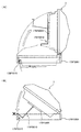
遊技領域の下方における遊技機用枠3の所定位置には、遊技者が把持して傾倒操作が可能なスティックコントローラ31Aが取り付けられている。スティックコントローラ31Aには、遊技者が押下操作可能なトリガボタンが設けられている。スティックコントローラ31Aに対する操作は、コントローラセンサユニット35A(図2参照)により検出される。
A
遊技領域の下方における遊技機用枠3の所定位置には、遊技者が押下操作などにより所定の指示操作を可能なプッシュボタン31Bが設けられている。プッシュボタン31Bに対する操作は、プッシュセンサ35B(図2参照)により検出される。
A
パチンコ遊技機1では、遊技者の動作(操作等)を検出する検出手段として、スティックコントローラ31Aやプッシュボタン31Bが設けられるが、これら以外の検出手段が設けられていてもよい。
(遊技の進行の概略)
パチンコ遊技機1が備える打球操作ハンドル30への遊技者による回転操作により、遊技球が遊技領域に向けて発射される。遊技球が通過ゲート41を通過すると、普通図柄表示器20による普図ゲームが開始される。なお、前回の普図ゲームの実行中の期間等に遊技球が通過ゲート41を通過した場合(遊技球が通過ゲート41を通過したが当該通過に基づく普図ゲームを直ちに実行できない場合)には、当該通過に基づく普図ゲームは所定の上限数(例えば4)まで保留される。
In the
(Outline of the progress of the game)
The game ball is launched toward the game area by the rotation operation of the
この普図ゲームでは、特定の普通図柄(普図当り図柄)が停止表示されれば、普通図柄の表示結果が「普図当り」となる。その一方、確定普通図柄として、普図当り図柄以外の普通図柄(普図ハズレ図柄)が停止表示されれば、普通図柄の表示結果が「普図ハズレ」となる。「普図当り」となると、可変入賞球装置6Bを所定期間開放状態とする開放制御が行われる(第2始動入賞口が開放状態になる)。
In this normal symbol game, if a specific normal symbol (design per normal symbol) is stopped and displayed, the display result of the normal symbol becomes "per normal symbol". On the other hand, if a normal symbol other than a normal symbol (a common symbol lost symbol) is stopped and displayed as a confirmed normal symbol, the display result of the normal symbol becomes "normal symbol lost". When it becomes "per normal drawing", the opening control is performed so that the variable winning
入賞球装置6Aに形成された第1始動入賞口に遊技球が進入すると、第1特別図柄表示装置4Aによる第1特図ゲームが開始される。
When the game ball enters the first starting winning opening formed in the winning
可変入賞球装置6Bに形成された第2始動入賞口に遊技球が進入すると、第2特別図柄表示装置4Bによる第2特図ゲームが開始される。
When the game ball enters the second starting winning opening formed in the variable winning
なお、特図ゲームの実行中の期間や、後述する大当り遊技状態や小当り遊技状態に制御されている期間に、遊技球が始動入賞口へ進入(入賞)した場合(始動入賞が発生したが当該始動入賞に基づく特図ゲームを直ちに実行できない場合)には、当該進入に基づく特図ゲームは所定の上限数(例えば4)までその実行が保留される。 In addition, when the game ball enters (wins) the start winning opening during the period during which the special figure game is being executed or during the period controlled by the big hit game state or the small hit game state described later (the start prize has occurred). If the special figure game based on the start winning cannot be executed immediately), the execution of the special figure game based on the approach is suspended up to a predetermined upper limit (for example, 4).
特図ゲームにおいて、確定特別図柄として特定の特別図柄(大当り図柄、例えば「7」、後述の大当り種別に応じて実際の図柄は異なる。)が停止表示されれば、「大当り」となり、大当り図柄とは異なる所定の特別図柄(小当り図柄、例えば「2」)が停止表示されれば、「小当り」となる。また、大当り図柄や小当り図柄とは異なる特別図柄(ハズレ図柄、例えば「−」)が停止表示されれば「ハズレ」となる。 In the special symbol game, if a specific special symbol (big hit symbol, for example, "7", the actual symbol differs depending on the jackpot type described later) is stopped and displayed as a confirmed special symbol, it becomes a "big hit" and a jackpot symbol. If a predetermined special symbol (small hit symbol, for example, "2") different from the above is stopped and displayed, it becomes "small hit". Further, if a special symbol (missing symbol, for example, "-") different from the big hit symbol or the small hit symbol is stopped and displayed, it becomes "missing".
特図ゲームでの表示結果が「大当り」になった後には、遊技者にとって有利な有利状態として大当り遊技状態に制御される。特図ゲームでの表示結果が「小当り」になった後には、小当り遊技状態に制御される。 After the display result in the special figure game becomes "big hit", it is controlled to the big hit game state as an advantageous state advantageous for the player. After the display result in the special figure game becomes "small hit", it is controlled to the small hit game state.
大当り遊技状態では、特別可変入賞球装置7により形成される大入賞口が所定の態様で開放状態となる。当該開放状態は、所定期間(例えば29秒間や1.8秒間)の経過タイミングと、大入賞口に進入した遊技球の数が所定個数(例えば9個)に達するまでのタイミングと、のうちのいずれか早いタイミングまで継続される。前記所定期間は、1ラウンドにおいて大入賞口を開放することができる上限期間であり、以下、開放上限期間ともいう。このように大入賞口が開放状態となる1のサイクルをラウンド(ラウンド遊技)という。大当り遊技状態では、当該ラウンドが所定の上限回数(15回や2回)に達するまで繰り返し実行可能となっている。
In the big hit game state, the big winning opening formed by the special variable winning
大当り遊技状態においては、遊技者は、遊技球を大入賞口に進入させることで、賞球を得ることができる。従って、大当り遊技状態は、遊技者にとって有利な状態である。大当り遊技状態におけるラウンド数が多い程、また、開放上限期間が長い程遊技者にとって有利となる。 In the big hit game state, the player can obtain the prize ball by letting the game ball enter the big prize opening. Therefore, the jackpot gaming state is an advantageous state for the player. The larger the number of rounds in the jackpot game state and the longer the open upper limit period, the more advantageous it is for the player.
なお、「大当り」には、大当り種別が設定されている。例えば、大入賞口の開放態様(ラウンド数や開放上限期間)や、大当り遊技状態後の遊技状態(後述の、通常状態、時短状態、確変状態など)を複数種類用意し、これらに応じて大当り種別が設定されている。大当り種別として、多くの賞球を得ることができる大当り種別や、賞球の少ない又はほとんど賞球を得ることができない大当り種別が設けられていてもよい。 A jackpot type is set for "big hit". For example, multiple types of opening modes (number of rounds and opening upper limit period) of the big winning opening and game states after the big hit game state (normal state, time saving state, probability change state, etc., which will be described later) are prepared, and the big hit is made according to these. The type is set. As the jackpot type, a jackpot type in which a large number of prize balls can be obtained or a jackpot type in which a small number of prize balls or almost no prize balls can be obtained may be provided.
小当り遊技状態では、特別可変入賞球装置7により形成される大入賞口が所定の開放態様で開放状態となる。例えば、小当り遊技状態では、一部の大当り種別のときの大当り遊技状態と同様の開放態様(大入賞口の開放回数が上記ラウンド数と同じであり、かつ、大入賞口の閉鎖タイミングも同じ等)で大入賞口が開放状態となる。なお、大当り種別と同様に、「小当り」にも小当り種別を設けてもよい。
In the small hit game state, the large winning opening formed by the special variable winning
大当り遊技状態が終了した後は、上記大当り種別に応じて、時短状態や確変状態に制御されることがある。 After the jackpot game state is completed, it may be controlled to a time saving state or a probability change state according to the jackpot type.
時短状態では、平均的な特図変動時間(特図を変動させる期間)を通常状態よりも短縮させる制御(時短制御)が実行される。時短状態では、平均的な普図変動時間(普図を変動させる期間)を通常状態よりも短縮させたり、普図ゲームで「普図当り」となる確率を通常状態よりも向上させる等により、第2始動入賞口に遊技球が進入しやすくなる制御(高開放制御、高ベース制御)も実行される。時短状態は、特別図柄(特に第2特別図柄)の変動効率が向上する状態であるので、遊技者にとって有利な状態である。 In the time saving state, control (time saving control) is executed in which the average special figure fluctuation time (period in which the special figure is changed) is shortened as compared with the normal state. In the time saving state, the average fluctuation time of the normal map (the period during which the normal map is changed) is shortened from the normal state, and the probability of becoming a "normal map hit" in the normal map game is improved from the normal state. Controls (high opening control, high base control) that make it easier for the game ball to enter the second starting winning opening are also executed. The time saving state is a state in which the fluctuation efficiency of the special symbol (particularly the second special symbol) is improved, which is advantageous for the player.
確変状態(確率変動状態)では、時短制御に加えて、表示結果が「大当り」となる確率が通常状態よりも高くなる確変制御が実行される。確変状態は、特別図柄の変動効率が向上することに加えて「大当り」となりやすい状態であるので、遊技者にとってさらに有利な状態である。 In the probability variation state (probability fluctuation state), in addition to the time saving control, the probability variation control in which the probability that the display result becomes a "big hit" is higher than in the normal state is executed. The probabilistic state is a state that is more advantageous for the player because it is a state in which a “big hit” is likely to occur in addition to improving the fluctuation efficiency of the special symbol.
時短状態や確変状態は、所定回数の特図ゲームが実行されたことと、次回の大当り遊技状態が開始されたこと等といった、いずれか1つの終了条件が先に成立するまで継続する。所定回数の特図ゲームが実行されたことが終了条件となるものを、回数切り(回数切り時短、回数切り確変等)ともいう。 The time saving state and the probability change state continue until any one of the end conditions such as the execution of the special figure game a predetermined number of times and the start of the next big hit game state are satisfied first. A game whose end condition is that the special figure game has been executed a predetermined number of times is also referred to as a number-cutting (time-cutting time reduction, number-cutting probability change, etc.).
通常状態とは、遊技者にとって有利な大当り遊技状態等の有利状態、時短状態、確変状態等の特別状態以外の遊技状態のことであり、普図ゲームにおける表示結果が「普図当り」となる確率及び特図ゲームにおける表示結果が「大当り」となる確率などのパチンコ遊技機1が、パチンコ遊技機1の初期設定状態(例えばシステムリセットが行われた場合のように、電源投入後に所定の復帰処理を実行しなかったとき)と同一に制御される状態である。
The normal state is a gaming state other than a special state such as an advantageous state such as a big hit gaming state, a time saving state, or a probability change state, which is advantageous for the player, and the display result in the normal drawing game is "normal drawing hit". The
確変制御が実行されている状態を高確状態、確変制御が実行されていない状態を低確状態ともいう。時短制御が実行されている状態を高ベース状態、時短制御が実行されていない状態を低ベース状態ともいう。これらを組み合わせて、時短状態は低確高ベース状態、確変状態は高確高ベース状態、通常状態は低確低ベース状態などともいわれる。高確状態かつ低ベース状態は高確低ベース状態ともいう。 The state in which the probability change control is executed is also called a high probability state, and the state in which the probability change control is not executed is also called a low probability state. The state in which the time saving control is executed is also called a high base state, and the state in which the time saving control is not executed is also called a low base state. By combining these, the time saving state is also called the low accuracy high base state, the probability variation state is called the high accuracy high base state, and the normal state is also called the low accuracy low base state. The high-accuracy state and low-base state are also called the high-accuracy low-base state.
小当り遊技状態が終了した後は、遊技状態の変更が行われず、特図ゲームの表示結果が「小当り」となる以前の遊技状態に継続して制御される(但し、「小当り」発生時の特図ゲームが、上記回数切りにおける上記所定回数目の特図ゲームである場合には、当然遊技状態が変更される)。なお、特図ゲームの表示結果として「小当り」がなくてもよい。 After the small hit game state ends, the game state is not changed, and the game state is continuously controlled to the game state before the display result of the special figure game becomes "small hit" (however, "small hit" occurs. If the special figure game at the time is the special figure game of the predetermined number of times in the above number of times cut, the game state is naturally changed). It should be noted that there may be no "small hit" as the display result of the special figure game.
なお、遊技状態は、大当り遊技状態中に遊技球が特定領域(例えば、大入賞口内の特定領域)を通過したことに基づいて、変化してもよい。例えば、遊技球が特定領域を通過したとき、その大当り遊技状態後に確変状態に制御してもよい。
(演出の進行など)
パチンコ遊技機1では、遊技の進行に応じて種々の演出(遊技の進行状況を報知したり、遊技を盛り上げたりする演出)が実行される。当該演出について以下説明する。なお、当該演出は、画像表示装置5に各種の演出画像を表示することによって行われるが、当該表示に加えて又は代えて、スピーカ8L、8Rからの音声出力、及び/又は、遊技効果ランプ9の点等/消灯、可動体32の動作等により行われてもよい。
The game state may change based on the fact that the game ball has passed through a specific area (for example, a specific area in the big winning opening) during the big hit game state. For example, when the game ball passes through a specific area, it may be controlled to a probabilistic state after the big hit game state.
(Progress of production, etc.)
In the
遊技の進行に応じて実行される演出として、画像表示装置5に設けられた「左」、「中」、「右」の飾り図柄表示エリア5L、5C、5Rでは、第1特図ゲーム又は第2特図ゲームが開始されることに対応して、飾り図柄の可変表示が開始される。第1特図ゲームや第2特図ゲームにおいて表示結果(確定特別図柄ともいう。)が停止表示されるタイミングでは、飾り図柄の可変表示の表示結果となる確定飾り図柄(3つの飾り図柄の組合せ)も停止表示(導出)される。
As an effect executed according to the progress of the game, in the decorative
飾り図柄の可変表示が開始されてから終了するまでの期間では、飾り図柄の可変表示の態様が所定のリーチ態様となる(リーチが成立する)ことがある。ここで、リーチ態様とは、画像表示装置5の画面上にて停止表示された飾り図柄が後述の大当り組合せの一部を構成しているときに未だ停止表示されていない飾り図柄については可変表示が継続している態様などのことである。
In the period from the start to the end of the variable display of the decorative symbol, the variable display mode of the decorative symbol may be a predetermined reach mode (reach is established). Here, the reach mode is a variable display of a decorative symbol that has not yet been stopped and displayed when the decorative symbol that has been stopped and displayed on the screen of the
また、飾り図柄の可変表示中に上記リーチ態様となったことに対応してリーチ演出が実行される。パチンコ遊技機1では、演出態様に応じて表示結果(特図ゲームの表示結果や飾り図柄の可変表示の表示結果)が「大当り」となる割合(大当り信頼度、大当り期待度とも呼ばれる。)が異なる複数種類のリーチ演出が実行される。リーチ演出には、例えば、ノーマルリーチと、ノーマルリーチよりも大当り信頼度の高いスーパーリーチと、がある。
In addition, the reach effect is executed in response to the above-mentioned reach mode during the variable display of the decorative symbol. In the
特図ゲームの表示結果が「大当り」となるときには、画像表示装置5の画面上において、飾り図柄の可変表示の表示結果として、予め定められた大当り組合せとなる確定飾り図柄が導出される(飾り図柄の可変表示の表示結果が「大当り」となる)。一例として、「左」、「中」、「右」の飾り図柄表示エリア5L、5C、5Rにおける所定の有効ライン上に同一の飾り図柄(例えば、「7」等)が揃って停止表示される。
When the display result of the special figure game is "big hit", a fixed decorative symbol that is a predetermined jackpot combination is derived as a display result of variable display of the decorative symbol on the screen of the image display device 5 (decoration). The display result of the variable display of the symbol is "big hit"). As an example, the same decorative symbols (for example, "7") are aligned and stopped and displayed on predetermined effective lines in the decorative
大当り遊技状態の終了後に確変状態に制御される「確変大当り」である場合には、奇数の飾り図柄(例えば、「7」等)が揃って停止表示され、大当り遊技状態の終了後に確変状態に制御されない「非確変大当り(通常大当り)」である場合には、偶数の飾り図柄(例えば、「6」等)が揃って停止表示されるようにしてもよい。この場合、奇数の飾り図柄を確変図柄、偶数の飾り図柄を非確変図柄(通常図柄)ともいう。非確変図柄でリーチ態様となった後に、最終的に「確変大当り」となる昇格演出を実行するようにしてもよい。 In the case of a "probability change jackpot" that is controlled to a probability change state after the end of the jackpot game state, an odd number of decorative symbols (for example, "7") are aligned and displayed as a stop, and the probability change state is entered after the end of the jackpot game state. In the case of an uncontrolled "non-probability variable jackpot (normal jackpot)", an even number of decorative symbols (for example, "6") may be aligned and displayed as a stop. In this case, the odd-numbered decorative symbol is also referred to as a probabilistic symbol, and the even-numbered decorative symbol is also referred to as a non-probable variable symbol (normal symbol). After the non-probability change symbol becomes the reach mode, the promotion effect that finally becomes the "probability change jackpot" may be executed.
特図ゲームの表示結果が「小当り」となるときには、画像表示装置5の画面上において、飾り図柄の可変表示の表示結果として、予め定められた小当り組合せとなる確定飾り図柄(例えば、「1 3 5」等)が導出される(飾り図柄の可変表示の表示結果が「小当り」となる)。一例として、「左」、「中」、「右」の飾り図柄表示エリア5L、5C、5Rにおける所定の有効ライン上にチャンス目を構成する飾り図柄が停止表示される。なお、特図ゲームの表示結果が、一部の大当り種別(小当り遊技状態と同様の態様の大当り遊技状態の大当り種別)の「大当り」となるときと、「小当り」となるときとで、共通の確定飾り図柄が導出表示されてもよい。
When the display result of the special figure game is "small hit", a fixed decorative symbol (for example, "for example," "is a predetermined small hit combination as a display result of variable display of the decorative symbol on the screen of the
特図ゲームの表示結果が「ハズレ」となる場合には、飾り図柄の可変表示の態様がリーチ態様とならずに、飾り図柄の可変表示の表示結果として、非リーチ組合せの確定飾り図柄(「非リーチハズレ」ともいう。)が停止表示される(飾り図柄の可変表示の表示結果が「非リーチハズレ」となる)ことがある。また、表示結果が「ハズレ」となる場合には、飾り図柄の可変表示の態様がリーチ態様となった後に、飾り図柄の可変表示の表示結果として、大当り組合せでない所定のリーチ組合せ(「リーチハズレ」ともいう)の確定飾り図柄が停止表示される(飾り図柄の可変表示の表示結果が「リーチハズレ」となる)こともある。 When the display result of the special figure game is "missing", the variable display mode of the decorative symbol is not the reach mode, and the variable display result of the decorative symbol is a fixed decorative symbol of a non-reach combination ("" (Also referred to as "non-reach loss") may be stopped and displayed (the display result of the variable display of the decorative pattern may be "non-reach loss"). In addition, when the display result is "missing", after the variable display mode of the decorative symbol becomes the reach mode, the display result of the variable display of the decorative symbol is a predetermined reach combination ("reach loss") that is not a jackpot combination. The fixed decorative symbol (also referred to as) may be stopped and displayed (the display result of the variable display of the decorative symbol may be "reach loss").
パチンコ遊技機1が実行可能な演出には、上記の可変表示対応表示(保留表示やアクティブ表示)を表示することも含まれる。また、他の演出として、例えば、大当り信頼度を予告する予告演出等が飾り図柄の可変表示中に実行される。予告演出には、実行中の可変表示における大当り信頼度を予告する予告演出や、実行前の可変表示(実行が保留されている可変表示)における大当り信頼度を予告する先読み予告演出がある。先読み予告演出として、可変表示対応表示(保留表示やアクティブ表示)の表示態様を通常とは異なる態様に変化させる演出が実行されるようにしてもよい。
The effect that the
また、画像表示装置5において、飾り図柄の可変表示中に飾り図柄を一旦仮停止させた後に可変表示を再開させることで、1回の可変表示を擬似的に複数回の可変表示のように見せる擬似連演出を実行するようにしてもよい。
Further, in the
大当り遊技状態中にも、大当り遊技状態を報知する大当り中演出が実行される。大当り中演出としては、ラウンド数を報知する演出や、大当り遊技状態の価値が向上することを示す昇格演出が実行されてもよい。また、小当り遊技状態中にも、小当り遊技状態を報知する小当り中演出が実行される。なお、小当り遊技状態中と、一部の大当り種別(小当り遊技状態と同様の態様の大当り遊技状態の大当り種別で、例えばその後の遊技状態を高確状態とする大当り種別)での大当り遊技状態とで、共通の演出を実行することで、現在が小当り遊技状態中であるか、大当り遊技状態中であるかを遊技者に分からないようにしてもよい。そのような場合であれば、小当り遊技状態の終了後と大当り遊技状態の終了後とで共通の演出を実行することで、高確状態であるか低確状態であるかを識別できないようにしてもよい。 Even during the big hit game state, the big hit middle effect that notifies the big hit game state is executed. As the big hit middle effect, an effect of notifying the number of rounds and a promotion effect indicating that the value of the big hit gaming state is improved may be executed. Further, even during the small hit game state, the small hit medium effect for notifying the small hit game state is executed. It should be noted that the big hit game during the small hit game state and in some big hit types (the big hit type in the big hit game state in the same mode as the small hit game state, for example, the big hit type in which the subsequent game state is a highly accurate state). By executing a common effect depending on the state, the player may not know whether the player is currently in the small hit game state or the big hit game state. In such a case, by executing a common effect after the end of the small hit game state and after the end of the big hit game state, it is not possible to distinguish between the high accuracy state and the low accuracy state. You may.
また、例えば特図ゲーム等が実行されていないときには、画像表示装置5にデモ(デモンストレーション)画像が表示される(客待ちデモ演出が実行される)。
(基板構成)
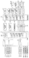
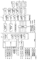
パチンコ遊技機1には、例えば図2に示すような主基板11、演出制御基板12、音声制御基板13、ランプ制御基板14、中継基板15などが搭載されている。その他にも、パチンコ遊技機1の背面には、例えば払出制御基板、情報端子基板、発射制御基板、電源基板などといった、各種の基板が配置されている。
Further, for example, when a special figure game or the like is not executed, a demo (demonstration) image is displayed on the image display device 5 (a customer waiting demo effect is executed).
(Board configuration)
For example, the
主基板11は、メイン側の制御基板であり、パチンコ遊技機1における上記遊技の進行(特図ゲームの実行(保留の管理を含む)、普図ゲームの実行(保留の管理を含む)、大当り遊技状態、小当り遊技状態、遊技状態など)を制御する機能を有する。主基板11は、遊技制御用マイクロコンピュータ100、スイッチ回路110、ソレノイド回路111などを有する。
The
主基板11に搭載された遊技制御用マイクロコンピュータ100は、例えば1チップのマイクロコンピュータであり、ROM(Read Only Memory)101と、RAM(Random Access Memory)102と、CPU(Central Processing Unit)103と、乱数回路104と、I/O(Input/Output port)105とを備える。
The
CPU103は、ROM101に記憶されたプログラムを実行することにより、遊技の進行を制御する処理(主基板11の機能を実現する処理)を行う。このとき、ROM101が記憶する各種データ(後述の変動パターン、後述の演出制御コマンド、後述の各種決定を行う際に参照される各種テーブルなどのデータ)が用いられ、RAM102がメインメモリとして使用される。RAM102は、その一部または全部がパチンコ遊技機1に対する電力供給が停止しても、所定期間記憶内容が保存されるバックアップRAMとなっている。なお、ROM101に記憶されたプログラムの全部又は一部をRAM102に展開して、RAM102上で実行するようにしてもよい。
The
乱数回路104は、遊技の進行を制御するときに使用される各種の乱数値(遊技用乱数)を示す数値データを更新可能にカウントする。遊技用乱数は、CPU103が所定のコンピュータプログラムを実行することで更新されるもの(ソフトウェアで更新されるもの)であってもよい。
The
I/O105は、例えば各種信号(後述の検出信号)が入力される入力ポートと、各種信号(第1特別図柄表示装置4A、第2特別図柄表示装置4B、普通図柄表示器20、第1保留表示器25A、第2保留表示器25B、普図保留表示器25Cなどを制御(駆動)する信号、ソレノイド駆動信号)を伝送するための出力ポートとを含んで構成される。
The I /
スイッチ回路110は、遊技球検出用の各種スイッチ(ゲートスイッチ21、始動口スイッチ(第1始動口スイッチ22Aおよび第2始動口スイッチ22B)、カウントスイッチ23)からの検出信号(遊技球が通過又は進入してスイッチがオンになったことを示す検出信号など)を取り込んで遊技制御用マイクロコンピュータ100に伝送する。検出信号の伝送により、遊技球の通過又は進入が検出されたことになる。
The
ソレノイド回路111は、遊技制御用マイクロコンピュータ100からのソレノイド駆動信号(例えば、ソレノイド81やソレノイド82をオンする信号など)を、普通電動役物用のソレノイド81や大入賞口扉用のソレノイド82に伝送する。
The
主基板11(遊技制御用マイクロコンピュータ100)は、遊技の進行の制御の一部として、遊技の進行に応じて演出制御コマンド(遊技の進行状況等を指定(通知)するコマンド)を演出制御基板12に供給する。主基板11から出力された演出制御コマンドは、中継基板15により中継され、演出制御基板12に供給される。当該演出制御コマンドには、例えば主基板11における各種の決定結果(例えば、特図ゲームの表示結果(大当り種別を含む。)、特図ゲームを実行する際に使用される変動パターン(詳しくは後述))、遊技の状況(例えば、可変表示の開始や終了、大入賞口の開放状況、入賞の発生、保留記憶数、遊技状態)、エラーの発生等を指定するコマンド等が含まれる。
The main board 11 (
演出制御基板12は、主基板11とは独立したサブ側の制御基板であり、演出制御コマンドを受信し、受信した演出制御コマンドに基づいて演出(遊技の進行に応じた種々の演出であり、可動体32の駆動、エラー報知、電断復旧の報知等の各種報知を含む)を実行する機能を有する。
The
演出制御基板12には、演出制御用CPU120と、ROM121と、RAM122と、表示制御部123と、乱数回路124と、I/O125とが搭載されている。
The
演出制御用CPU120は、ROM121に記憶されたプログラムを実行することにより、表示制御部123とともに演出を実行するための処理(演出制御基板12の上記機能を実現するための処理であり、実行する演出の決定等を含む)を行う。このとき、ROM121が記憶する各種データ(各種テーブルなどのデータ)が用いられ、RAM122がメインメモリとして使用される。
The
演出制御用CPU120は、コントローラセンサユニット35Aやプッシュセンサ35Bからの検出信号(遊技者による操作を検出したときに出力される信号であり、操作内容を適宜示す信号)に基づいて演出の実行を表示制御部123に指示することもある。
The
表示制御部123は、VDP(Video Display Processor)、CGROM(Character Generator ROM)、VRAM(Video RAM)などを備え、演出制御用CPU120からの演出の実行指示に基づき、演出を実行する。
The
表示制御部123は、演出制御用CPU120からの演出の実行指示に基づき、実行する演出に応じた映像信号を画像表示装置5に供給することで、演出画像を画像表示装置5に表示させる。表示制御部123は、さらに、演出画像の表示に同期した音声出力や、遊技効果ランプ9の点灯/消灯を行うため、音指定信号(出力する音声を指定する信号)を音声制御基板13に供給したり、ランプ信号(ランプの点灯/消灯態様を指定する信号)をランプ制御基板14に供給したりする。また、表示制御部123は、可動体32を動作させる信号を当該可動体32又は当該可動体32を駆動する駆動回路に供給する。
The
音声制御基板13は、スピーカ8L、8Rを駆動する各種回路を搭載しており、当該音指定信号に基づきスピーカ8L、8Rを駆動し、当該音指定信号が指定する音声をスピーカ8L、8Rから出力させる。
The
ランプ制御基板14は、遊技効果ランプ9を駆動する各種回路を搭載しており、当該ランプ信号に基づき遊技効果ランプ9を駆動し、当該ランプ信号が指定する態様で遊技効果ランプ9を点灯/消灯する。このようにして、表示制御部123は、音声出力、ランプの点灯/消灯を制御する。
The
なお、音声出力、ランプの点灯/消灯の制御(音指定信号やランプ信号の供給等)、可動体32の制御(可動体32を動作させる信号の供給等)は、演出制御用CPU120が実行するようにしてもよい。
The
乱数回路124は、各種演出を実行するために使用される各種の乱数値(演出用乱数)を示す数値データを更新可能にカウントする。演出用乱数は、演出制御用CPU120が所定のコンピュータプログラムを実行することで更新されるもの(ソフトウェアで更新されるもの)であってもよい。
The
演出制御基板12に搭載されたI/O125は、例えば主基板11などから伝送された演出制御コマンドを取り込むための入力ポートと、各種信号(映像信号、音指定信号、ランプ信号)を伝送するための出力ポートとを含んで構成される。
The I /
演出制御基板12、音声制御基板13、ランプ制御基板14といった、主基板11以外の基板をサブ基板ともいう。パチンコ遊技機1のようにサブ基板が機能別に複数設けられていてもよいし、1のサブ基板が複数の機能を有するように構成してもよい。
(動作)
次に、パチンコ遊技機1の動作(作用)を説明する。
(主基板11の主要な動作)
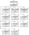
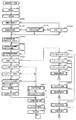
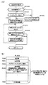
まず、主基板11における主要な動作を説明する。パチンコ遊技機1に対して電力供給が開始されると、遊技制御用マイクロコンピュータ100が起動し、CPU103によって遊技制御メイン処理が実行される。図3は、主基板11におけるCPU103が実行する遊技制御メイン処理を示すフローチャートである。
Boards other than the
(motion)
Next, the operation (action) of the
(Main operation of main board 11)
First, the main operations on the
図3に示す遊技制御メイン処理では、CPU103は、まず、割込禁止に設定する(ステップS1)。続いて、必要な初期設定を行う(ステップS2)。初期設定には、スタックポインタの設定、内蔵デバイス(CTC(カウンタ/タイマ回路)、パラレル入出力ポート等)のレジスタ設定、RAM102をアクセス可能状態にする設定等が含まれる。
In the game control main process shown in FIG. 3, the
次いで、クリアスイッチからの出力信号がオンであるか否かを判定する(ステップS3)。クリアスイッチは、例えば電源基板に搭載されている。クリアスイッチがオンの状態で電源が投入されると、出力信号(クリア信号)が入力ポートを介して遊技制御用マイクロコンピュータ100に入力される。クリアスイッチからの出力信号がオンである場合(ステップS3;Yes)、初期化処理(ステップS8)を実行する。初期化処理では、CPU103は、RAM102に記憶されるフラグ、カウンタ、バッファをクリアするRAMクリア処理を行い、作業領域に初期値を設定する。
Next, it is determined whether or not the output signal from the clear switch is ON (step S3). The clear switch is mounted on the power supply board, for example. When the power is turned on with the clear switch turned on, an output signal (clear signal) is input to the
また、CPU103は、初期化を指示する演出制御コマンドを演出制御基板12に送信する(ステップS9)。演出制御用CPU120は、当該演出制御コマンドを受信すると、例えば画像表示装置5において、遊技機の制御の初期化がなされたことを報知するための画面表示を行う。
Further, the
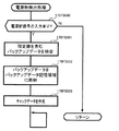
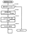
クリアスイッチからの出力信号がオンでない場合には(ステップS3;No)、RAM102(バックアップRAM)にバックアップデータが保存されているか否かを判定する(ステップS4)。不測の停電等(電断)によりパチンコ遊技機1への電力供給が停止したときには、CPU103は、当該電力供給の停止によって動作できなくなる直前に、電源供給停止時処理を実行する。この電源供給停止時処理では、RAM102にデータをバックアップすることを示すバックアップフラグをオンする処理、RAM102のデータ保護処理等が実行される。データ保護処理には、誤り検出符号(チェックサム、パリティビット等)の付加、各種データをバックアップする処理が含まれる。バックアップされるデータには、遊技を進行するための各種データ(各種フラグ、各種タイマの状態等を含む)の他、前記バックアップフラグの状態や誤り検出符号も含まれる。ステップS4では、バックアップフラグがオンであるか否かを判定する。バックアップフラグがオフでRAM102にバックアップデータが記憶されていない場合(ステップS4;No)、初期化処理(ステップS8)を実行する。
If the output signal from the clear switch is not on (step S3; No), it is determined whether or not the backup data is stored in the RAM 102 (backup RAM) (step S4). When the power supply to the
RAM102にバックアップデータが記憶されている場合(ステップS4;Yes)、CPU103は、バックアップしたデータのデータチェックを行い(誤り検出符号を用いて行われる)、データが正常か否かを判定する(ステップS5)。ステップS5では、例えば、パリティビットやチェックサムにより、RAM102のデータが、電力供給停止時のデータと一致するか否かを判定する。これらが一致すると判定された場合、RAM102のデータが正常であると判定する。
When the backup data is stored in the RAM 102 (step S4; Yes), the
RAM102のデータが正常でないと判定された場合(ステップS5;No)、内部状態を電力供給停止時の状態に戻すことができないので、初期化処理(ステップS8)を実行する。
If it is determined that the data in the
RAM102のデータが正常であると判定された場合(ステップS5;Yes)、CPU103は、主基板11の内部状態を電力供給停止時の状態に戻すための復旧処理(ステップS6)を行う。復旧処理では、CPU103は、RAM102の記憶内容(バックアップしたデータの内容)に基づいて作業領域の設定を行う。これにより、電力供給停止時の遊技状態に復旧し、特別図柄の変動中であった場合には、後述の遊技制御用タイマ割込み処理の実行によって、復旧前の状態から特別図柄の変動が再開されることになる。
When it is determined that the data in the
そして、CPU103は、電断からの復旧を指示する演出制御コマンドを演出制御基板12に送信する(ステップS7)。これに合わせて、バックアップされている電断前の遊技状態を指定する演出制御コマンドや、特図ゲームの実行中であった場合には当該実行中の特図ゲームの表示結果を指定する演出制御コマンドを送信するようにしてもよい。これらコマンドは、後述の特別図柄プロセス処理で送信設定されるコマンドと同じコマンドを使用できる。演出制御用CPU120は、電断からの復旧時を特定する演出制御コマンドを受信すると、例えば画像表示装置5において、電断からの復旧がなされたこと又は電断からの復旧中であることを報知するための画面表示を行う。演出制御用CPU120は、前記演出制御コマンドに基づいて、適宜の画面表示を行うようにしてもよい。
Then, the
復旧処理または初期化処理を終了して演出制御基板12に演出制御コマンドを送信した後には、CPU103は、乱数回路104を初期設定する乱数回路設定処理を実行する(ステップS10)。そして、所定時間(例えば2ms)毎に定期的にタイマ割込がかかるように遊技制御用マイクロコンピュータ100に内蔵されているCTCのレジスタの設定を行い(ステップS11)、割込みを許可する(ステップS12)。その後、ループ処理に入る。以後、所定時間(例えば2ms)ごとにCTCから割込み要求信号がCPU103へ送出され、CPU103は定期的にタイマ割込み処理を実行することができる。
After the restoration process or the initialization process is completed and the effect control command is transmitted to the
こうした遊技制御メイン処理を実行したCPU103は、CTCからの割込み要求信号を受信して割込み要求を受け付けると、図4のフローチャートに示す遊技制御用タイマ割込み処理を実行する。図4に示す遊技制御用タイマ割込み処理を開始すると、CPU103は、まず、所定のスイッチ処理を実行することにより、スイッチ回路110を介してゲートスイッチ21、第1始動口スイッチ22A、第2始動口スイッチ22B、カウントスイッチ23といった各種スイッチからの検出信号の受信の有無を判定する(ステップS21)。続いて、所定のメイン側エラー処理を実行することにより、パチンコ遊技機1の異常診断を行い、その診断結果に応じて必要ならば警告を発生可能とする(ステップS22)。この後、所定の情報出力処理を実行することにより、例えばパチンコ遊技機1の外部に設置されたホール管理用コンピュータに供給される大当り情報(大当りの発生回数等を示す情報)、始動情報(始動入賞の回数等を示す情報)、確率変動情報(確変状態となった回数等を示す情報)などのデータを出力する(ステップS23)。
When the
情報出力処理に続いて、主基板11の側で用いられる遊技用乱数の少なくとも一部をソフトウェアにより更新するための遊技用乱数更新処理を実行する(ステップS24)。この後、CPU103は、特別図柄プロセス処理を実行する(ステップS25)。CPU103がタイマ割込み毎に特別図柄プロセス処理を実行することにより、特図ゲームの実行及び保留の管理や、大当り遊技状態や小当り遊技状態の制御、遊技状態の制御などが実現される(詳しくは後述)。
Following the information output process, a game random number update process for updating at least a part of the game random numbers used on the
特別図柄プロセス処理に続いて、普通図柄プロセス処理が実行される(ステップS26)。CPU103がタイマ割込み毎に普通図柄プロセス処理を実行することにより、ゲートスイッチ21からの検出信号に基づく(通過ゲート41に遊技球が通過したことに基づく)普図ゲームの実行及び保留の管理や、「普図当り」に基づく可変入賞球装置6Bの開放制御などを可能にする。普図ゲームの実行は、普通図柄表示器20を駆動することにより行われ、普図保留表示器25Cを点灯させることにより普図保留数を表示する。
Following the special symbol process processing, the normal symbol process processing is executed (step S26). By executing the normal symbol process processing for each timer interrupt, the
普通図柄プロセス処理を実行した後、遊技制御用タイマ割込み処理の一部として、電断が発生したときの処理、賞球を払い出すための処理等などが行われてもよい。その後、CPU103は、コマンド制御処理を実行する(ステップS27)。CPU103は、上記各処理にて演出制御コマンドを送信設定することがある。ステップS27のコマンド制御処理では、送信設定された演出制御コマンドを演出制御基板12などのサブ側の制御基板に対して伝送させる処理が行われる。コマンド制御処理を実行した後には、割込みを許可してから、遊技制御用タイマ割込み処理を終了する。
After executing the normal symbol process process, as a part of the game control timer interrupt process, a process when a power failure occurs, a process for paying out a prize ball, and the like may be performed. After that, the
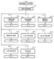
図5は、特別図柄プロセス処理として、図4に示すステップS25にて実行される処理の一例を示すフローチャートである。この特別図柄プロセス処理において、CPU103は、まず、始動入賞判定処理を実行する(ステップS101)。
FIG. 5 is a flowchart showing an example of the process executed in step S25 shown in FIG. 4 as the special symbol process process. In this special symbol process process, the
始動入賞判定処理では、始動入賞の発生を検出し、RAM102の所定領域に保留情報を格納し保留記憶数を更新する処理が実行される。始動入賞が発生すると、表示結果(大当り種別を含む)や変動パターンを決定するための乱数値が抽出され、保留情報として記憶される。また、抽出した乱数値に基づいて、表示結果や変動パターンを先読み判定する処理が実行されてもよい。保留情報や保留記憶数を記憶した後には、演出制御基板12に始動入賞の発生、保留記憶数、先読み判定等の判定結果を指定するための演出制御コマンドを送信するための送信設定が行われる。こうして送信設定された始動入賞時の演出制御コマンドは、例えば特別図柄プロセス処理が終了した後、図4に示すステップS27のコマンド制御処理が実行されることなどにより、主基板11から演出制御基板12に対して伝送される。
In the start winning determination process, a process of detecting the occurrence of a start winning, storing the hold information in a predetermined area of the
S101にて始動入賞判定処理を実行した後、CPU103は、RAM102に設けられた特図プロセスフラグの値に応じて、ステップS110〜S120の処理のいずれかを選択して実行する。なお、特別図柄プロセス処理の各処理(ステップS110〜S120)では、各処理に対応した演出制御コマンドを演出制御基板12に送信するための送信設定が行われる。
After executing the start winning determination process in S101, the
ステップS110の特別図柄通常処理は、特図プロセスフラグの値が“0”(初期値)のときに実行される。この特別図柄通常処理では、保留情報の有無などに基づいて、第1特図ゲーム又は第2特図ゲームを開始するか否かの判定が行われる。また、特別図柄通常処理では、表示結果決定用の乱数値に基づき、特別図柄や飾り図柄の表示結果を「大当り」または「小当り」とするか否かや「大当り」とする場合の大当り種別を、その表示結果が導出表示される以前に決定(事前決定)する。さらに、特別図柄通常処理では、決定された表示結果に対応して、特図ゲームにおいて停止表示させる確定特別図柄(大当り図柄や小当り図柄、ハズレ図柄のいずれか)が設定される。その後、特図プロセスフラグの値が“1”に更新され、特別図柄通常処理は終了する。なお、第2特図を用いた特図ゲームが第1特図を用いた特図ゲームよりも優先して実行されるようにしてもよい(特図2優先消化ともいう)。また、第1始動入賞口及び第2始動入賞口への遊技球の入賞順序を記憶し、入賞順に特図ゲームの開始条件を成立させるようにしてもよい(入賞順消化ともいう)。 The special symbol normal processing in step S110 is executed when the value of the special symbol process flag is “0” (initial value). In this special symbol normal processing, it is determined whether or not to start the first special figure game or the second special figure game based on the presence or absence of the pending information. In addition, in the special symbol normal processing, whether or not the display result of the special symbol or decorative symbol is set to "big hit" or "small hit" based on the random value for determining the display result, and the big hit type when the display result is set to "big hit". Is determined (predetermined) before the display result is derived and displayed. Further, in the special symbol normal processing, a confirmed special symbol (either a big hit symbol, a small hit symbol, or a lost symbol) to be stopped and displayed in the special symbol game is set according to the determined display result. After that, the value of the special symbol process flag is updated to "1", and the special symbol normal processing ends. The special figure game using the second special figure may be executed with priority over the special figure game using the first special figure (also referred to as special figure 2 priority digestion). Further, the winning order of the game balls to the first starting winning opening and the second starting winning opening may be memorized, and the starting condition of the special figure game may be satisfied in the winning order (also referred to as winning order digestion).
乱数値に基づき各種の決定を行う場合には、ROM101に格納されている各種のテーブル(乱数値と比較される決定値が決定結果に割り当てられているテーブル)が参照される。主基板11における他の決定、演出制御基板12における各種の決定についても同じである。演出制御基板12においては、各種のテーブルがROM121に格納されている。
When making various determinations based on the random number value, various tables stored in the ROM 101 (a table in which the determination value to be compared with the random number value is assigned to the determination result) are referred to. The same applies to other decisions on the
ステップS111の変動パターン設定処理は、特図プロセスフラグの値が“1”のときに実行される。この変動パターン設定処理には、表示結果を「大当り」または「小当り」とするか否かの事前決定結果等に基づき、変動パターン決定用の乱数値を用いて変動パターンを複数種類のいずれかに決定する処理などが含まれている。変動パターン設定処理では、変動パターンを決定したときに、特図プロセスフラグの値が“2”に更新され、変動パターン設定処理は終了する。 The variation pattern setting process in step S111 is executed when the value of the special figure process flag is “1”. In this fluctuation pattern setting process, one of a plurality of types of fluctuation patterns is set using a random value for determining the fluctuation pattern based on a preliminary determination result of whether or not the display result is a "big hit" or a "small hit". The process of deciding on is included. In the variation pattern setting process, when the variation pattern is determined, the value of the special figure process flag is updated to "2", and the variation pattern setting process ends.
変動パターンは、特図ゲームの実行時間(特図変動時間)(飾り図柄の可変表示の実行時間でもある)や、飾り図柄の可変表示の態様(リーチの有無等)、飾り図柄の可変表示中の演出内容(リーチ演出の種類等)を指定するものであり、可変表示パターンとも呼ばれる。 The fluctuation pattern includes the execution time of the special symbol game (special symbol fluctuation time) (which is also the execution time of the variable display of the decorative symbol), the mode of the variable display of the decorative symbol (presence or absence of reach, etc.), and the variable display of the decorative symbol. It specifies the content of the effect (type of reach effect, etc.), and is also called a variable display pattern.
ステップS112の特別図柄変動処理は、特図プロセスフラグの値が“2”のときに実行される。この特別図柄変動処理には、第1特別図柄表示装置4Aや第2特別図柄表示装置4Bにおいて特別図柄を変動させるための設定を行う処理や、その特別図柄が変動を開始してからの経過時間を計測する処理などが含まれている。また、計測された経過時間が変動パターンに対応する特図変動時間に達したか否かの判定も行われる。そして、特別図柄の変動を開始してからの経過時間が特図変動時間に達したときには、特図プロセスフラグの値が“3”に更新され、特別図柄変動処理は終了する。
The special symbol variation process in step S112 is executed when the value of the special symbol process flag is “2”. In this special symbol change processing, the first special
ステップS113の特別図柄停止処理は、特図プロセスフラグの値が“3”のときに実行される。この特別図柄停止処理には、第1特別図柄表示装置4Aや第2特別図柄表示装置4Bにて特別図柄の変動を停止させ、特別図柄の表示結果となる確定特別図柄を停止表示(導出)させるための設定を行う処理が含まれている。そして、表示結果が「大当り」である場合には特図プロセスフラグの値が“4”に更新される。その一方で、大当りフラグがオフであり、表示結果が「小当り」である場合には、特図プロセスフラグの値が“8”に更新される。また、表示結果が「ハズレ」である場合には、特図プロセスフラグの値が“0”に更新される。表示結果が「小当り」又は「ハズレ」である場合、時短状態や確変状態に制御されているときであって、回数切りの終了成立する場合には、遊技状態も更新される。特図プロセスフラグの値が更新されると、特別図柄停止処理は終了する。
The special symbol stop process in step S113 is executed when the value of the special symbol process flag is “3”. In this special symbol stop process, the first special
ステップS114の大当り開放前処理は、特図プロセスフラグの値が“4”のときに実行される。この大当り開放前処理には、表示結果が「大当り」となったことなどに基づき、大当り遊技状態においてラウンドの実行を開始して大入賞口を開放状態とするための設定を行う処理などが含まれている。大入賞口を開放状態とするときには、大入賞口扉用のソレノイド82に対してソレノイド駆動信号を供給する処理が実行される。このときには、例えば大当り種別がいずれであるかに対応して、大入賞口を開放状態とする開放上限期間や、ラウンドの上限実行回数を設定する。これらの設定が終了すると、特図プロセスフラグの値が“5”に更新され、大当り開放前処理は終了する。
The jackpot release preprocessing in step S114 is executed when the value of the special figure process flag is “4”. This big hit pre-opening process includes a process of setting to open the big winning opening by starting the execution of the round in the big hit game state based on the display result being "big hit". It has been. When the large winning opening is opened, a process of supplying a solenoid drive signal to the
ステップS115の大当り開放中処理は、特図プロセスフラグの値が“5”のときに実行される。この大当り開放中処理には、大入賞口を開放状態としてからの経過時間を計測する処理や、その計測した経過時間やカウントスイッチ23によって検出された遊技球の個数などに基づいて、大入賞口を開放状態から閉鎖状態に戻すタイミングとなったか否かを判定する処理などが含まれている。そして、大入賞口を閉鎖状態に戻すときには、大入賞口扉用のソレノイド82に対するソレノイド駆動信号の供給を停止させる処理などを実行した後、特図プロセスフラグの値が“6”に更新し、大当り開放中処理を終了する。
The process of opening the jackpot in step S115 is executed when the value of the special figure process flag is “5”. In this big hit opening process, the big winning opening is based on the process of measuring the elapsed time since the big winning opening is opened, the measured elapsed time, the number of game balls detected by the
ステップS116の大当り開放後処理は、特図プロセスフラグの値が“6”のときに実行される。この大当り開放後処理には、大入賞口を開放状態とするラウンドの実行回数が設定された上限実行回数に達したか否かを判定する処理や、上限実行回数に達した場合に大当り遊技状態を終了させるための設定を行う処理などが含まれている。そして、ラウンドの実行回数が上限実行回数に達していないときには、特図プロセスフラグの値が“5”に更新される一方、ラウンドの実行回数が上限実行回数に達したときには、特図プロセスフラグの値が“7”に更新される。特図プロセスフラグの値が更新されると、大当り解放後処理は終了する。 The post-processing after opening the jackpot in step S116 is executed when the value of the special figure process flag is “6”. In this post-opening process of the jackpot, a process of determining whether or not the number of executions of the round that opens the jackpot has reached the set maximum number of executions, and a jackpot game state when the maximum number of executions is reached. It includes processing to make settings to terminate. Then, when the number of round executions has not reached the upper limit, the value of the special figure process flag is updated to "5", while when the number of round executions reaches the upper limit, the special figure process flag is set. The value is updated to "7". When the value of the special figure process flag is updated, the post-launch processing is completed.
ステップS117の大当り終了処理は、特図プロセスフラグの値が“7”のときに実行される。この大当り終了処理には、大当り遊技状態の終了を報知する演出動作としてのエンディング演出が実行される期間に対応した待ち時間が経過するまで待機する処理や、大当り遊技状態の終了に対応して確変制御や時短制御を開始するための各種の設定を行う処理などが含まれている。こうした設定が行われたときには、特図プロセスフラグの値が“0”に更新され、大当り終了処理は終了する。 The jackpot end processing of step S117 is executed when the value of the special figure process flag is “7”. In this jackpot end process, there is a process of waiting until the waiting time corresponding to the period in which the ending effect as an effect action for notifying the end of the jackpot game state is executed, and a probability change corresponding to the end of the jackpot game state It includes processing to make various settings to start control and time reduction control. When such a setting is made, the value of the special figure process flag is updated to "0", and the jackpot end processing ends.
ステップS118の小当り開放前処理は、特図プロセスフラグの値が“8”のときに実行される。この小当り開放前処理には、表示結果が「小当り」となったことに基づき、小当り遊技状態において大入賞口を開放状態とするための設定を行う処理などが含まれている。このときには、特図プロセスフラグの値が“9”に更新され、小当り開放前処理は終了する。 The small hit release preprocessing in step S118 is executed when the value of the special figure process flag is “8”. This small hit pre-opening process includes a process of setting the large winning opening to be in the open state in the small hit game state based on the display result being "small hit". At this time, the value of the special figure process flag is updated to "9", and the small hit release preprocessing ends.
ステップS119の小当り開放中処理は、特図プロセスフラグの値が“9”のときに実行される。この小当り開放中処理には、大入賞口を開放状態としてからの経過時間を計測する処理や、その計測した経過時間などに基づいて、大入賞口を開放状態から閉鎖状態に戻すタイミングとなったか否かを判定する処理などが含まれている。大入賞口を閉鎖状態に戻して小当り遊技状態の終了タイミングとなったときには、特図プロセスフラグの値が“10”に更新され、小当り開放中処理は終了する。 The small hit opening process in step S119 is executed when the value of the special figure process flag is “9”. In this small hit opening process, it is the timing to measure the elapsed time from the opening state of the big winning opening and to return the big winning opening from the open state to the closed state based on the measured elapsed time. It includes processing to determine whether or not it is. When the big winning opening is returned to the closed state and the end timing of the small hit game state is reached, the value of the special figure process flag is updated to "10", and the processing during the small hit opening process ends.
ステップS120の小当り終了処理は、特図プロセスフラグの値が“10”のときに実行される。この小当り終了処理には、小当り遊技状態の終了を報知する演出動作が実行される期間に対応した待ち時間が経過するまで待機する処理などが含まれている。ここで、小当り遊技状態が終了するときには、小当り遊技状態となる以前のパチンコ遊技機1における遊技状態を継続させる。小当り遊技状態の終了時における待ち時間が経過したときには、特図プロセスフラグの値が“0”に更新され、小当り終了処理は終了する。
(演出制御基板12の主要な動作)
次に、演出制御基板12における主要な動作を説明する。演出制御基板12では、電源基板等から電源電圧の供給を受けると、演出制御用CPU120が起動して、図6のフローチャートに示すような演出制御メイン処理を実行する。図6に示す演出制御メイン処理を開始すると、演出制御用CPU120は、まず、所定の初期化処理を実行して(ステップS71)、RAM122のクリアや各種初期値の設定、また演出制御基板12に搭載されたCTC(カウンタ/タイマ回路)のレジスタ設定等を行う。また、初期動作制御処理を実行する(ステップS72)。初期動作制御処理では、可動体32を駆動して初期位置に戻す制御、所定の動作確認を行う制御といった可動体32の初期動作を行う制御が実行される。
The small hit end process in step S120 is executed when the value of the special figure process flag is “10”. The small hit end process includes a process of waiting until a waiting time corresponding to a period in which the effect operation for notifying the end of the small hit game state is executed has elapsed. Here, when the small hit gaming state ends, the gaming state in the
(Main operation of the effect control board 12)
Next, the main operation of the
その後、タイマ割込みフラグがオンとなっているか否かの判定を行う(ステップS73)。タイマ割込みフラグは、例えばCTCのレジスタ設定に基づき、所定時間(例えば2ミリ秒)が経過するごとにオン状態にセットされる。このとき、タイマ割込みフラグがオフであれば(ステップS73;No)、ステップS73の処理を繰り返し実行して待機する。 After that, it is determined whether or not the timer interrupt flag is turned on (step S73). The timer interrupt flag is set to the ON state every time a predetermined time (for example, 2 milliseconds) elapses, based on the register setting of the CTC, for example. At this time, if the timer interrupt flag is off (step S73; No), the process of step S73 is repeatedly executed and waits.
また、演出制御基板12の側では、所定時間が経過するごとに発生するタイマ割込みとは別に、主基板11からの演出制御コマンドを受信するための割込みが発生する。この割込みは、例えば主基板11からの演出制御INT信号がオン状態となることにより発生する割込みである。演出制御INT信号がオン状態となることによる割込みが発生すると、演出制御用CPU120は、自動的に割込み禁止に設定するが、自動的に割込み禁止状態にならないCPUを用いている場合には、割込み禁止命令(DI命令)を発行することが望ましい。演出制御用CPU120は、演出制御INT信号がオン状態となることによる割込みに対応して、例えば所定のコマンド受信割込み処理を実行する。このコマンド受信割込み処理では、I/O125に含まれる入力ポートのうちで、中継基板15を介して主基板11から送信された制御信号を受信する所定の入力ポートより、演出制御コマンドを取り込む。このとき取り込まれた演出制御コマンドは、例えばRAM122に設けられた演出制御コマンド受信用バッファに格納する。その後、演出制御用CPU120は、割込み許可に設定してから、コマンド受信割込み処理を終了する。
Further, on the
ステップS73にてタイマ割込みフラグがオンである場合には(ステップS73;Yes)、タイマ割込みフラグをクリアしてオフ状態にするとともに(ステップS74)、コマンド解析処理を実行する(ステップS75)。コマンド解析処理では、例えば主基板11の遊技制御用マイクロコンピュータ100から送信されて演出制御コマンド受信用バッファに格納されている各種の演出制御コマンドを読み出した後に、その読み出された演出制御コマンドに対応した設定や制御などが行われる。例えば、どの演出制御コマンドを受信したかや演出制御コマンドが特定する内容等を演出制御プロセス処理等で確認できるように、読み出された演出制御コマンドをRAM122の所定領域に格納したり、RAM122に設けられた受信フラグをオンしたりする。また、演出制御コマンドが遊技状態を特定する場合、遊技状態に応じた背景の表示を表示制御部123に指示してもよい。
If the timer interrupt flag is on in step S73 (step S73; Yes), the timer interrupt flag is cleared and turned off (step S74), and the command analysis process is executed (step S75). In the command analysis process, for example, after reading various effect control commands transmitted from the
ステップS75にてコマンド解析処理を実行した後には、演出制御プロセス処理を実行する(ステップS76)。演出制御プロセス処理では、例えば画像表示装置5の表示領域における演出画像の表示動作、スピーカ8L、8Rからの音声出力動作、遊技効果ランプ9及び装飾用LEDといった装飾発光体における点灯動作、可動体32の駆動動作といった、各種の演出装置を動作させる制御が行われる。また、各種の演出装置を用いた演出動作の制御内容について、主基板11から送信された演出制御コマンド等に応じた判定や決定、設定などが行われる。
After executing the command analysis process in step S75, the effect control process process is executed (step S76). In the effect control process processing, for example, an effect image display operation in the display area of the
ステップS76の演出制御プロセス処理に続いて、演出用乱数更新処理が実行され(ステップS77)、演出制御基板12の側で用いられる演出用乱数の少なくとも一部がソフトウェアにより更新される。その後、ステップS73の処理に戻る。ステップS73の処理に戻る前に、他の処理が実行されてもよい。
Following the effect control process process in step S76, the effect random number update process is executed (step S77), and at least a part of the effect random numbers used on the
図7は、演出制御プロセス処理として、図6のステップS76にて実行される処理の一例を示すフローチャートである。図7に示す演出制御プロセス処理において、演出制御用CPU120は、まず、先読予告設定処理を実行する(ステップS161)。先読予告設定処理では、例えば、主基板11から送信された始動入賞時の演出制御コマンドに基づいて、先読み予告演出を実行するための判定や決定、設定などが行われる。また、当該演出制御コマンドから特定される保留記憶数に基づき保留表示を表示するための処理が実行される。
FIG. 7 is a flowchart showing an example of the process executed in step S76 of FIG. 6 as the effect control process process. In the effect control process process shown in FIG. 7, the
ステップS161の処理を実行した後、演出制御用CPU120は、例えばRAM122に設けられた演出プロセスフラグの値に応じて、以下のようなステップS170〜S177の処理のいずれかを選択して実行する。
After executing the process of step S161, the
ステップS170の可変表示開始待ち処理は、演出プロセスフラグの値が“0”(初期値)のときに実行される処理である。この可変表示開始待ち処理は、主基板11から可変表示の開始を指定するコマンドなどを受信したか否かに基づき、画像表示装置5における飾り図柄の可変表示を開始するか否かを判定する処理などを含んでいる。画像表示装置5における飾り図柄の可変表示を開始すると判定された場合、演出プロセスフラグの値を“1”に更新し、可変表示開始待ち処理を終了する。
The variable display start waiting process in step S170 is a process executed when the value of the effect process flag is “0” (initial value). This variable display start waiting process is a process of determining whether or not to start the variable display of the decorative symbol on the
ステップS171の可変表示開始設定処理は、演出プロセスフラグの値が“1”のときに実行される処理である。この可変表示開始設定処理では、演出制御コマンドにより特定される表示結果や変動パターンに基づいて、飾り図柄の可変表示の表示結果(確定飾り図柄)、飾り図柄の可変表示の態様、リーチ演出や各種予告演出などの各種演出の実行の有無やその態様や実行開始タイミングなどを決定する。そして、その決定結果等を反映した演出制御パターン(表示制御部123に演出の実行を指示するための制御データの集まり)を設定する。その後、設定した演出制御パターンに基づいて、飾り図柄の可変表示の実行開始を表示制御部123に指示し、演出プロセスフラグの値を“2”に更新し、可変表示開始設定処理を終了する。表示制御部123は、飾り図柄の可変表示の実行開始の指示により、画像表示装置5において、飾り図柄の可変表示を開始させる。
The variable display start setting process in step S171 is a process executed when the value of the effect process flag is “1”. In this variable display start setting process, the display result of the variable display of the decorative symbol (fixed decorative symbol), the mode of the variable display of the decorative symbol, the reach effect, and various types are based on the display result and the variation pattern specified by the effect control command. It is determined whether or not various effects such as a notice effect are executed, their modes, and the execution start timing. Then, an effect control pattern (a collection of control data for instructing the
ステップS172の可変表示中演出処理は、演出プロセスフラグの値が“2”のときに実行される処理である。この可変表示中演出処理において、演出制御用CPU120は、表示制御部123を指示することで、ステップS171にて設定された演出制御パターンに基づく演出画像を画像表示装置5の表示画面に表示させることや、可動体32を駆動させること、音声制御基板13に対する指令(効果音信号)の出力によりスピーカ8L、8Rから音声や効果音を出力させること、ランプ制御基板14に対する指令(電飾信号)の出力により遊技効果ランプ9や装飾用LEDを点灯/消灯/点滅させることといった、飾り図柄の可変表示中における各種の演出制御を実行する。こうした演出制御を行った後、例えば演出制御パターンから飾り図柄の可変表示終了を示す終了コードが読み出されたこと、あるいは、主基板11から確定飾り図柄を停止表示させることを指定するコマンドを受信したことなどに対応して、飾り図柄の表示結果となる確定飾り図柄を停止表示させる。確定飾り図柄を停止表示したときには、演出プロセスフラグの値が“3”に更新され、可変表示中演出処理は終了する。
The variable display effect process in step S172 is a process executed when the value of the effect process flag is “2”. In this variable display effect processing, the
ステップS173の特図当り待ち処理は、演出プロセスフラグの値が“3”のときに実行される処理である。この特図当り待ち処理において、演出制御用CPU120は、主基板11から大当り遊技状態又は小当り遊技状態を開始することを指定する演出制御コマンドの受信があったか否かを判定する。そして、大当り遊技状態又は小当り遊技状態を開始することを指定する演出制御コマンドを受信したきに、そのコマンドが大当り遊技状態の開始を指定するものであれば、演出プロセスフラグの値を“6”に更新する。これに対して、そのコマンドが小当り遊技状態の開始を指定するものであれば、演出プロセスフラグの値を小当り中演出処理に対応した値である“4”に更新する。また、大当り遊技状態又は小当り遊技状態を開始することを指定するコマンドを受信せずに、当該コマンドの受信待ち時間が経過したときには、特図ゲームにおける表示結果が「ハズレ」であったと判定して、演出プロセスフラグの値を初期値である“0”に更新する。演出プロセスフラグの値を更新すると、特図当り待ち処理を終了する。
The special figure hit waiting process in step S173 is a process executed when the value of the effect process flag is “3”. In this special figure hit waiting process, the
ステップS174の小当り中演出処理は、演出制御プロセスフラグの値が“4”のときに実行される処理である。この小当り中演出処理において、演出制御用CPU120は、例えば小当り遊技状態における演出内容に対応した演出制御パターン等を設定し、その設定内容に基づく小当り遊技状態における各種の演出制御を実行する。また、小当り中演出処理では、例えば主基板11から小当り遊技状態を終了することを指定するコマンドを受信したことに対応して、演出プロセスフラグの値を小当り終了演出に対応した値である“5”に更新し、小当り中演出処理を終了する。
The small hit medium effect process in step S174 is a process executed when the value of the effect control process flag is “4”. In this small hit medium effect process, the
ステップS175の小当り終了演出処理は、演出制御プロセスフラグの値が“5”のときに実行される処理である。この小当り終了演出処理において、演出制御用CPU120は、例えば小当り遊技状態の終了などに対応した演出制御パターン等を設定し、その設定内容に基づく小当り遊技状態の終了時における各種の演出制御を実行する。その後、演出プロセスフラグの値を初期値である“0”に更新し、小当り終了演出処理を終了する。
The small hit end effect process in step S175 is a process executed when the value of the effect control process flag is “5”. In this small hit end effect process, the
ステップS176の大当り中演出処理は、演出プロセスフラグの値が“6”のときに実行される処理である。この大当り中演出処理において、演出制御用CPU120は、例えば大当り遊技状態における演出内容に対応した演出制御パターン等を設定し、その設定内容に基づく大当り遊技状態における各種の演出制御を実行する。また、大当り中演出処理では、例えば主基板11から大当り遊技状態を終了することを指定するコマンドを受信したことに対応して、演出制御プロセスフラグの値をエンディング演出処理に対応した値である“7”に更新し、大当り中演出処理を終了する。
The jackpot effect process in step S176 is a process executed when the value of the effect process flag is “6”. In this big hit middle effect processing, the
ステップS177のエンディング演出処理は、演出プロセスフラグの値が“7”のときに実行される処理である。このエンディング演出処理において、演出制御用CPU120は、例えば大当り遊技状態の終了などに対応した演出制御パターン等を設定し、その設定内容に基づく大当り遊技状態の終了時におけるエンディング演出の各種の演出制御を実行する。その後、演出プロセスフラグの値を初期値である“0”に更新し、エンディング演出処理を終了する。
(基本説明の変形例)
この発明は、上記基本説明で説明したパチンコ遊技機1に限定されず、本発明の趣旨を逸脱しない範囲で、様々な変形及び応用が可能である。
The ending effect process of step S177 is a process executed when the value of the effect process flag is “7”. In this ending effect processing, the
(Modified example of basic explanation)
The present invention is not limited to the
上記基本説明のパチンコ遊技機1は、入賞の発生に基づいて所定数の遊技媒体を景品として払い出す払出式遊技機であったが、遊技媒体を封入し入賞の発生に基づいて得点を付与する封入式遊技機であってもよい。
The
特別図柄の可変表示中に表示されるものは1種類の図柄(例えば、「−」を示す記号)だけで、当該図柄の表示と消灯とを繰り返すことによって可変表示を行うようにしてもよい。さらに可変表示中に当該図柄が表示されるものも、可変表示の停止時には、当該図柄が表示されなくてもよい(表示結果としては「−」を示す記号が表示されなくてもよい)。 Only one type of symbol (for example, a symbol indicating "-") is displayed during the variable display of the special symbol, and the variable display may be performed by repeating the display and extinguishing of the symbol. Further, even if the symbol is displayed during the variable display, the symbol may not be displayed when the variable display is stopped (the symbol indicating "-" may not be displayed as the display result).
上記基本説明では、遊技機としてパチンコ遊技機1を示したが、メダルが投入されて所定の賭け数が設定され、遊技者による操作レバーの操作に応じて複数種類の図柄を回転させ、遊技者によるストップボタンの操作に応じて図柄を停止させたときに停止図柄の組合せが特定の図柄の組み合わせになると、所定数のメダルが遊技者に払い出されるゲームを実行可能なスロット機(例えば、ビッグボーナス、レギュラーボーナス、RT、AT、ART、CZ(以下、ボーナス等)のうち1以上を搭載するスロット機)にも本発明を適用可能である。
In the above basic explanation, the
本発明を実現するためのプログラム及びデータは、パチンコ遊技機1に含まれるコンピュータ装置などに対して、着脱自在の記録媒体により配布・提供される形態に限定されるものではなく、予めコンピュータ装置などの有する記憶装置にインストールしておくことで配布される形態を採っても構わない。さらに、本発明を実現するためのプログラム及びデータは、通信処理部を設けておくことにより、通信回線等を介して接続されたネットワーク上の、他の機器からダウンロードすることによって配布する形態を採っても構わない。
The program and data for realizing the present invention are not limited to the form of being distributed and provided by the detachable recording medium to the computer device included in the
そして、ゲームの実行形態も、着脱自在の記録媒体を装着することにより実行するものだけではなく、通信回線等を介してダウンロードしたプログラム及びデータを、内部メモリ等に一旦格納することにより実行可能とする形態、通信回線等を介して接続されたネットワーク上における、他の機器側のハードウェア資源を用いて直接実行する形態としてもよい。さらには、他のコンピュータ装置等とネットワークを介してデータの交換を行うことによりゲームを実行するような形態とすることもできる。 The game can be executed not only by attaching a detachable recording medium, but also by temporarily storing the programs and data downloaded via the communication line or the like in the internal memory or the like. It may be executed directly using the hardware resources of other devices on the network connected via a communication line or the like. Further, the game can be executed by exchanging data with another computer device or the like via a network.
なお、本明細書において、演出の実行割合などの各種割合の比較の表現(「高い」、「低い」、「異ならせる」などの表現)は、一方が「0%」の割合であることを含んでもよい。例えば、一方が「0%」の割合で、他方が「100%」の割合又は「100%」未満の割合であることも含む。
(特徴部31AKに関する説明)
次に、本実施の形態の特徴部31AKについて説明する。図8は、本実施の形態のパチンコ遊技機1における変動パターンやリーチの種類を説明するための図である。図8(A)に示すように、本実施の形態では、飾り図柄の可変表示の態様がリーチ態様とならずに表示結果が「ハズレ」となる非リーチハズレの変動パターンPA1−1、PA1−2、飾り図柄の可変表示の態様がリーチ態様となって表示結果が「ハズレ」となるリーチハズレの変動パターンPA2−1〜PA2−6、PA3−1〜PA3−4等、表示結果が「大当り」となる変動パターンPB2−1〜PB2−6、PB3−1〜PB3−4等が用意されている。
In this specification, one of the expressions for comparison of various ratios such as the execution ratio of the production (expressions such as "high", "low", and "differentiate") is "0%". It may be included. For example, one may have a proportion of "0%" and the other may have a proportion of "100%" or less than "100%".
(Explanation of feature 31AK)
Next, the feature portion 31AK of the present embodiment will be described. FIG. 8 is a diagram for explaining a variation pattern and a type of reach in the
また、図8(B)に示すように、本実施の形態では、ノーマルリーチ、スーパーリーチA〜Eといったリーチ演出が実行されるようになっている。この実施の形態では、リーチ演出は、大当り状態に制御されることを示唆する示唆演出とも称される。各リーチが実行されたときの信頼度(大当り信頼度)は、図8(B)の黒色の星の数で表すように、ノーマルリーチ<スーパーリーチE<スーパーリーチD<スーパーリーチC<スーパーリーチB<スーパーリーチAの順番に高くなっている。なお、大当りとなることが確定するリーチを設けてもよい。 Further, as shown in FIG. 8B, in the present embodiment, reach effects such as normal reach and super reach A to E are executed. In this embodiment, the reach effect is also referred to as a suggestion effect that suggests that the jackpot state is controlled. The reliability (big hit reliability) when each reach is executed is represented by the number of black stars in FIG. 8 (B). Normal reach <Super reach E <Super reach D <Super reach C <Super reach B <The order is higher in the order of Super Reach A. In addition, a reach that is determined to be a big hit may be provided.
この実施の形態では、スーパーリーチはノーマルリーチを経由して実行されるようになっている。また、スーパーリーチのリーチ演出中に、より信頼度の高いリーチに発展(昇格)する発展演出が実行される場合がある。図8(A)に示す変動パターンPA3−1〜PA3−4等、変動パターンPB3−1〜PB3−4等が、発展演出が実行されることに対応した変動パターンとなっている。なお、図8(A)では、信頼度が一段階上のスーパーリーチに発展する変動パターンが示されているが、信頼度が二段階以上発展する変動パターンも設けられる。また、発展演出が複数回実行される変動パターンを設けてもよい。 In this embodiment, the super reach is performed via the normal reach. In addition, during the reach production of Super Reach, a development production that develops (promotes) to a more reliable reach may be executed. The fluctuation patterns PA3-1 to PA3-4 and the like shown in FIG. 8A and the fluctuation patterns PB3-1 to PB3-4 and the like are fluctuation patterns corresponding to the execution of the development effect. In addition, although FIG. 8A shows a fluctuation pattern in which the reliability develops to a super reach one step higher, a fluctuation pattern in which the reliability develops by two or more steps is also provided. Further, a variation pattern in which the development effect is executed a plurality of times may be provided.
この実施の形態では、信頼度が最も低いノーマルリーチ以外では、リーチ成立後の所定タイミングにおいて、そのリーチのタイトルが報知されるようになっている。図8(B)に示すように、リーチの種類によってタイトルの報知態様が異なっている。具体的には、スーパーリーチの中で最も信頼度の低いスーパーリーチEは、表示のみでリーチのタイトルが報知され、それ以外のスーパーリーチは、表示及び音声によりタイトルが報知される。このように、信頼度の高いリーチの方が信頼度の低いリーチより多くの演出装置によりタイトルの報知が実行されるようになっている。これにより、遊技者の期待感を効果的に煽ることができ演出効果が向上する。なお、タイトルの報知態様は、信頼度によってまたは信頼度によらず任意に変更してもよい。また、同じリーチ演出においても、実際の表示結果等に応じて報知態様を異ならせてもよい。また、リーチの種類によってタイトル文字のフォント(ゴシック体、明朝体等)や書体(行書、楷書等)を異ならせてもよい。 In this embodiment, except for the normal reach having the lowest reliability, the title of the reach is notified at a predetermined timing after the reach is established. As shown in FIG. 8B, the notification mode of the title differs depending on the type of reach. Specifically, Super Reach E, which has the lowest reliability among Super Reach, is notified of the title of the reach only by display, and other Super Reach is notified of the title by display and voice. In this way, the title notification is executed by more production devices in the reach with high reliability than in the reach with low reliability. As a result, the player's expectation can be effectively fueled, and the effect of the effect is improved. The mode of notification of the title may be arbitrarily changed depending on the reliability or regardless of the reliability. Further, even in the same reach effect, the notification mode may be different depending on the actual display result and the like. In addition, the font (Gothic, Mincho, etc.) and typeface (Semi-cursive, regular script, etc.) of the title characters may be different depending on the type of reach.
リーチのタイトルの報知(タイトル報知)とは、リーチの名称といったタイトルそのものを示すものに限定されず、リーチ演出で登場するキャラクタの名称、リーチ演出の演出内容等を示すものであってもよい。
(特徴部31AKの演出動作例)
続いて、本実施の形態における演出動作例について説明する。以下の演出動作は、主基板11から送信される演出制御コマンドに基づいて、演出制御用CPU120が演出制御プロセス処理を実行することで実行される。図9、図10は、本実施の形態におけるスーパーリーチの演出動作例を示す図である。図9(A)は、画像表示装置5の「左」、「中」、「右」の各飾り図柄表示エリア5L、5C、5Rにおいて飾り図柄の可変表示が実行されていることを示している。その後、例えば、図9(B)に示すように、「左」及び「右」に7の数字を示す飾り図柄が停止してリーチ態様となる。その後はリーチの種類に応じて演出が分岐する。
(スーパーリーチA)
スーパーリーチAとなる場合には、図9(C)に示すように、画像表示装置5に味方キャラであるキャラクタ31AK001が表示されてリーチ演出が開始される。ここでは、例えばキャラクタ31AK001を使用したアニメーション等が表示される。スーパーリーチのリーチ演出(スーパーリーチ演出ともいう)の導入部分が終了する等、スーパーリーチ演出が開始されてから所定期間経過すると、図9(D)に示すように、画像表示装置5の画面全体にスーパーリーチAのタイトル31AK002(ここでは「SPリーチA」の文字)が表示されるとともに、スピーカ8からリーチのタイトル名に対応する音声(ここでは「スーパーリーチA」)が出力されることで、スーパーリーチAのタイトルが報知される。その後、スーパーリーチAのタイトル31AK002が消去され、図9(E)に示すように、敵キャラであるキャラクタ31AK003が表示され、キャラクタ31AK001のセリフ31AK004が表示されたり、キャラクタ31AK001とキャラクタ31AK003とが対決するスーパーリーチAのリーチ演出の後続部分が実行される。キャラクタ同士が対決する演出をバトル演出ともいい、バトル演出において味方キャラが勝利すると大当りとなり、味方キャラが敗北するとハズレとなる。
The notification of the title of the reach (title notification) is not limited to the one indicating the title itself such as the name of the reach, and may indicate the name of the character appearing in the reach production, the production content of the reach production, and the like.
(Example of production operation of feature section 31AK)
Subsequently, an example of the effect operation in the present embodiment will be described. The following effect operation is executed by the
(Super Reach A)
In the case of Super Reach A, as shown in FIG. 9C, the character 31AK001, which is a ally character, is displayed on the
なお、スーパーリーチ演出中に画像表示装置5にセリフを表示するときに、スピーカ8からセリフに対応する音声が出力されるようにしてもよい。また、セリフは図9(E)に示すように吹き出しに表示することに限定されず、画像表示装置5の下部等に字幕で表示するようにしてもよい。
(スーパーリーチB)
スーパーリーチBとなる場合には、図9(C)に示すように、画像表示装置5にキャラクタ31AK001が表示されてリーチ演出が開始される。ここでは、例えばキャラクタ31AK001を使用したアニメーション等が表示される。スーパーリーチ演出の導入部分が終了する等、スーパーリーチ演出が開始されてから所定期間経過すると、図9(F)に示すように、画像表示装置5の画面全体にスーパーリーチBのタイトル31AK005(ここでは「SPリーチB」の文字)が表示されるとともに、スピーカ8からリーチのタイトル名に対応する音声(ここでは「スーパーリーチB」)が出力されることで、スーパーリーチBのタイトルが報知される。その後、スーパーリーチBのタイトル31AK005が消去され、図9(G)に示すように、敵キャラであるキャラクタ31AK006が表示され、キャラクタ31AK001のセリフ31AK004が表示されたり、キャラクタ31AK001とキャラクタ31AK006とが対決するスーパーリーチBのリーチ演出の後続部分が実行される。
When displaying the dialogue on the
(Super Reach B)
In the case of super reach B, as shown in FIG. 9C, the character 31AK001 is displayed on the
このように、スーパーリーチAとスーパーリーチBとでは、スーパーリーチ演出が開始されてから所定期間経過したときにリーチのタイトルが報知されるようになっている。このようにすることで、スーパーリーチ演出の導入部分等を遊技者に見せた後にタイトルを報知できるので、タイトル報知の演出効果を高めることができる。 As described above, in the super reach A and the super reach B, the title of the reach is notified when a predetermined period has elapsed from the start of the super reach effect. By doing so, the title can be notified after the introduction portion of the super reach effect is shown to the player, so that the effect of the title notification can be enhanced.
また、スーパーリーチA(図9(C)→(D)→(E)・・・)とスーパーリーチB(図9(C)→(F)→(G)・・・)とでは、タイトルが報知されるまでの導入部分においては、共通の演出態様でスーパーリーチ演出が実行されるようになっている(図9(C))。このようにすることで、スーパーリーチ演出が開始されてからいずれのスーパーリーチとなるか、いずれのタイトルが報知されるかに遊技者を注目させることができる。スーパーリーチAとスーパーリーチBとにおいて、タイトルが報知されるまでの演出態様を完全に共通にすることに限定されず、演出を注視すればいずれのスーパーリーチとなるかを判別できる等、少なくとも一部を共通の演出態様にするようにしてもよい。例えば、スーパーリーチAとスーパーリーチBとの導入部分において、その後に報知されるタイトルに関連する態様でスーパーリーチ演出(例えば敵キャラを表示したり敵キャラを示唆するような演出)を実行するようにしてもよい。このようにすることで、演出効果が向上し、遊技者が演出に注目するようになる。このように、いずれのスーパーリーチとなるかを特定可能にしてからタイトル報知を実行するようにしてもよい。
(スーパーリーチD)
スーパーリーチDとなる場合には、図9(H)に示すように、画像表示装置5の中央の一部にスーパーリーチDのタイトル31AK007(ここでは「SPリーチD」の文字)が表示されるとともに、スピーカ8からリーチのタイトル名に対応する音声(ここでは「敵を倒せ」)が出力されることで、スーパーリーチDのタイトルが報知される。このように、スーパーリーチDでは、スーパーリーチ演出の開始時にタイトルが報知されるようになっている。また、タイトル31AK007の下には、当該リーチの期待度を示唆する期待度示唆表示31AK008が表示される。期待度は、図9(H)に示すように、黒い星の数で表される。ここで、期待度とは大当りとなる期待度であるが、リーチの大当り信頼度と完全に一致していなくてもよい。
In addition, the titles of Super Reach A (Fig. 9 (C) → (D) → (E) ...) and Super Reach B (Fig. 9 (C) → (F) → (G) ...) In the introduction part until the notification, the super reach effect is executed in a common effect mode (FIG. 9 (C)). By doing so, it is possible to draw the player's attention to which super reach will be achieved after the super reach production is started and which title will be notified. Super Reach A and Super Reach B are not limited to completely sharing the production mode until the title is notified, and it is possible to determine which Super Reach will be achieved by paying close attention to the production. The parts may be made to have a common production mode. For example, in the introduction part of Super Reach A and Super Reach B, a super reach effect (for example, an effect of displaying an enemy character or suggesting an enemy character) is executed in a manner related to the title notified thereafter. It may be. By doing so, the effect of the effect is improved, and the player pays attention to the effect. In this way, the title notification may be executed after making it possible to identify which super reach will be achieved.
(Super Reach D)
In the case of Super Reach D, as shown in FIG. 9H, the title 31AK007 of Super Reach D (here, the character “SP Reach D”) is displayed in a part of the center of the
なお、スーパーリーチDの音声による報知は、タイトル名をそのまま報知するのではなく、リーチの内容を報知するようになっている。このように、この実施の形態では、リーチの種類によって音声によるタイトル報知の報知態様を異ならせている。これにより、タイトル報知の報知態様が多彩になり、興趣が向上する。 It should be noted that the voice notification of Super Reach D does not notify the title name as it is, but notifies the content of the reach. As described above, in this embodiment, the notification mode of the title notification by voice is different depending on the type of reach. As a result, the notification mode of the title notification becomes various and the interest is improved.
スーパーリーチDにおいてタイトルが報知された後には、図9(I)に示すように、画像表示装置5にキャラクタ31AK001が表示される。このとき、タイトル31AK007及び期待度示唆表示31AK008は、画像表示装置5の右上部分等に縮小して表示され続ける。このようにすることで、リーチ演出中にも遊技者がリーチの期待度を把握することができる。なお、図9(I)では、図9(C)(スーパーリーチA、スーパーリーチB)と共通の演出内容が示されているが、スーパーリーチD専用のスーパーリーチ演出が実行されてもよい。
After the title is notified in Super Reach D, the character 31AK001 is displayed on the
その後、図9(J)に示すように、敵キャラであるキャラクタ31AK009が表示され、キャラクタ31AK001のセリフ31AK004が表示されたり、キャラクタ31AK001とキャラクタ31AK009とが対決するスーパーリーチDのリーチ演出が実行される。
(スーパーリーチE)
スーパーリーチEとなる場合には、図10(A)に示すように、画像表示装置5の左上の一部にスーパーリーチEのタイトル31AK010(ここでは「SPリーチE」の文字)が表示されることで、スーパーリーチEのタイトルが報知される。なお、スーパーリーチEでは、音声によるタイトルの報知が行われない。また、タイトル31AK010の表示と合わせて、キャラクタ31AK001と敵キャラであるキャラクタ31AK011とが表示され、キャラクタ31AK001のセリフ31AK004が表示されたり、キャラクタ31AK001とキャラクタ31AK011とが対決するスーパーリーチEのリーチ演出が実行される。このように、スーパーリーチEでは、リーチ演出の進行と合わせてタイトルが報知されるようになっている。スーパーリーチEでは、リーチ演出中にタイトル31AK010が表示され続ける。
After that, as shown in FIG. 9 (J), the character 31AK009, which is an enemy character, is displayed, the dialogue 31AK004 of the character 31AK001 is displayed, and the reach effect of the super reach D in which the character 31AK001 and the character 31AK009 confront each other is executed. To.
(Super Reach E)
In the case of Super Reach E, as shown in FIG. 10A, the title 31AK010 of Super Reach E (here, the characters “SP Reach E”) is displayed in a part of the upper left of the
大当り信頼度の低いスーパーリーチEのリーチ演出では、リーチ演出の進行を止めずにタイトル報知を行うことで、遊技者に過度な期待感を与えることを防止できる。これに対して、スーパーリーチA、スーパーリーチB、スーパーリーチDのリーチ演出では、リーチ演出の進行を停止してタイトル報知を行うようになっている(図9(D)、(F)、(H))。このようにすることで、スーパーリーチ演出に応じたタイトル報知を実行でき演出効果が向上する。なお、スーパーリーチA、スーパーリーチB、スーパーリーチDといったスーパーリーチ演出においてもリーチの進行を停止せずにタイトル報知を行うようにしてもよい。また、この実施の形態とは逆に、大当り信頼度の高いスーパーリーチのリーチ演出では、リーチ演出の進行を止めずにタイトル報知を行うようにしてもよい。大当り信頼度の低いスーパーリーチのリーチ演出では、リーチ演出の進行を停止してタイトル報知を行うようにしてもよい。
(タイトルの報知タイミング)
以上のように、この実施の形態では、スーパーリーチA及びスーパーリーチBにおいては、スーパーリーチ演出開始後所定期間経過してからタイトルが報知され、スーパーリーチD及びスーパーリーチEにおいては、スーパーリーチ演出開始時にタイトルが報知されるようになっている。このようにすることで、リーチ演出に応じたタイトル報知を実行でき演出効果が向上する。なお、この実施の形態では、大当り信頼度の高いスーパーリーチA及びスーパーリーチBにおいては、スーパーリーチ演出開始後所定期間経過してからタイトルが報知され、大当り信頼度の低いスーパーリーチD及びスーパーリーチEにおいては、スーパーリーチ演出開始時にタイトルが報知されるようになっていたが、大当り信頼度の高いリーチの場合にスーパーリーチ演出開始時にタイトルが報知され、大当り信頼度の低いリーチの場合にスーパーリーチ演出後所定期間経過してからタイトルが報知されるようにしてもよい。
(タイトルの表示領域)
また、この実施の形態では、スーパーリーチA及びスーパーリーチBにおいては、画像表示装置5の画面全体(第1領域)においてタイトルが報知され、スーパーリーチD及びスーパーリーチEにおいては、画像表示装置5の画面の一部(第2領域)においてタイトルが報知される。このようにすることで、リーチ演出に応じたタイトル報知を実行でき演出効果が向上する。特に、大当り信頼度の高いリーチである場合には、信頼度の低いリーチである場合よりも広い表示領域でタイトル報知が実行されるので効果的なタイトル報知が可能になる。なお、画像表示装置5の画面全体におけるタイトル報知とは、画面いっぱいに収まるサイズでタイトルが表示されるものであってもよいし、背景全体をタイトル報知用の背景としてそこにタイトルが表示されるもの(画面全体を使用したタイトル報知)等であってもよい。また、スーパーリーチAとスーパーリーチBとでタイトル報知を行う表示領域を異ならせてもよいし、スーパーリーチDとスーパーリーチEとでタイトル報知を行う表示領域を異ならせてもよい。
In the reach production of Super Reach E, which has low jackpot reliability, it is possible to prevent the player from giving an excessive sense of expectation by notifying the title without stopping the progress of the reach production. On the other hand, in the reach production of Super Reach A, Super Reach B, and Super Reach D, the progress of the reach production is stopped and the title is notified (FIGS. 9 (D), (F), (FIGS. 9), (F), and (2). H)). By doing so, the title notification according to the super reach effect can be executed, and the effect of the effect is improved. In addition, even in the super reach production such as super reach A, super reach B, and super reach D, the title notification may be performed without stopping the progress of the reach. Further, contrary to this embodiment, in the reach production of the super reach having high jackpot reliability, the title notification may be performed without stopping the progress of the reach production. In the reach production of super reach with low jackpot reliability, the progress of the reach production may be stopped to notify the title.
(Title notification timing)
As described above, in this embodiment, in Super Reach A and Super Reach B, the title is notified after a predetermined period has elapsed from the start of Super Reach production, and in Super Reach D and Super Reach E, Super Reach production is performed. The title is notified at the start. By doing so, the title notification according to the reach effect can be executed, and the effect of the effect is improved. In this embodiment, in Super Reach A and Super Reach B having high jackpot reliability, the title is notified after a predetermined period has passed after the start of the super reach production, and Super Reach D and Super Reach having low jackpot reliability are notified. In E, the title was notified at the start of the super reach production, but in the case of reach with high jackpot reliability, the title is notified at the start of super reach production, and in the case of reach with low jackpot reliability, super The title may be notified after a predetermined period has elapsed after the reach effect.
(Title display area)
Further, in this embodiment, in Super Reach A and Super Reach B, the title is notified on the entire screen (first area) of the
リーチ演出に応じてタイトル報知を行う表示領域を異ならせる方法は、この実施の形態の例に限定されず、リーチ演出に応じてタイトル報知を行う表示領域を任意に異ならせてもよい。例えば、大当り信頼度の高いリーチである場合には、信頼度の低いリーチである場合よりも狭い表示領域でタイトル報知が実行されてもよい。また、リーチ演出に応じてタイトル報知を行う表示領域を異ならせる場合において、この実施の形態のように表示面積を異ならせてもよいし、表示させる場所を異ならせてもよい。
(期待度示唆表示)
この実施の形態では、大当り信頼度の高いスーパーリーチA及びスーパーリーチBにおけるタイトル報知では、期待度示唆表示を表示せずに、スーパーリーチA及びスーパーリーチBよりも大当り信頼度の低いスーパーリーチDにおけるタイトル報知では、期待度示唆表示を表示するようにしていた。このようにすることで、演出がくどくなることを防止できる。また、スーパーリーチDよりも大当り信頼度の低いスーパーリーチEにおけるタイトル報知では、期待度示唆表示を表示しないようになっていた。このようにすることで、信頼度の低いリーチにおいて信頼度が低いことを示す期待度示唆表示が表示されることで遊技者が期待感を失うことを防止できる。なお、スーパーリーチA、スーパーリーチB、スーパーリーチEの少なくとも一部において期待度示唆表示を表示するようにしてもよい。
The method of changing the display area for performing the title notification according to the reach effect is not limited to the example of this embodiment, and the display area for performing the title notification may be arbitrarily changed according to the reach effect. For example, in the case of reach with high jackpot reliability, title notification may be executed in a narrower display area than in the case of reach with low reliability. Further, when the display area for performing the title notification is different according to the reach effect, the display area may be different or the display place may be different as in this embodiment.
(Expectation suggestion display)
In this embodiment, in the title notification in Super Reach A and Super Reach B having high jackpot reliability, the expectation suggestion display is not displayed, and Super Reach D having a lower jackpot reliability than Super Reach A and Super Reach B is displayed. In the title notification in, the expectation degree suggestion display was displayed. By doing so, it is possible to prevent the production from becoming dull. Further, in the title notification in Super Reach E, which has a lower jackpot reliability than Super Reach D, the expectation degree suggestion display is not displayed. By doing so, it is possible to prevent the player from losing the sense of expectation by displaying the expectation suggestion display indicating that the reliability is low in the reach with low reliability. In addition, the expectation degree suggestion display may be displayed in at least a part of Super Reach A, Super Reach B, and Super Reach E.
なお期待度示唆表示は、図9(H)等に示すように、黒い星の数によって示すものに限定されず、メーターやゲージにより期待度を示唆するようにしてもよいし、期待度に対応した数値を表示するようにしてもよい。また、図9(H)等に示すように、黒い星の数によって示す場合において、半個相当(半分)の黒い星を表示可能ようにして、期待度の段階数を増やしてもよい。
(タイトルの表示終了タイミング)
また、この実施の形態では、スーパーリーチA及びスーパーリーチBにおいては、タイトルが表示された後、タイトルが消去されてスーパーリーチ演出が実行される。これにより、スーパーリーチA及びスーパーリーチBにおいては、リーチ演出に注目させることができる。また、スーパーリーチD及びスーパーリーチEにおいては、タイトルが表示された後、後述の決め演出が実行されるまでタイトルが表示され続ける。これにより、スーパーリーチD及びスーパーリーチEにおいては、スーパーリーチ演出中もリーチの種類を把握することができる。また、以上のようにすることで、リーチ演出に応じたタイトル報知を実行でき演出効果が向上する。なお、タイトルの表示終了タイミングは、いずれであっても演出効果の向上を図れるため、任意に変更してもよい。
As shown in FIG. 9H and the like, the expectation degree suggestion display is not limited to the one indicated by the number of black stars, and the expectation degree may be suggested by a meter or a gauge, and corresponds to the expectation degree. The numerical value may be displayed. Further, as shown in FIG. 9H or the like, when the number of black stars is used, half of the black stars may be displayed so that the number of stages of expectation may be increased.
(Title display end timing)
Further, in this embodiment, in Super Reach A and Super Reach B, after the title is displayed, the title is deleted and the super reach effect is executed. As a result, in Super Reach A and Super Reach B, attention can be paid to the reach effect. Further, in Super Reach D and Super Reach E, after the title is displayed, the title continues to be displayed until the determined effect described later is executed. As a result, in Super Reach D and Super Reach E, the type of reach can be grasped even during the super reach production. Further, by doing the above, the title notification according to the reach effect can be executed and the effect of the effect is improved. It should be noted that the display end timing of the title may be arbitrarily changed in order to improve the effect of the effect.
なお、ここではスーパーリーチCのリーチ演出の演出動作については省略するが、例えば大当り信頼度に応じたタイトル報知や期待度示唆表示が実行されればよい。
(決め演出)
各リーチ演出が実行されてから、表示結果を導出するタイミング(可変表示の終盤)になると、表示結果が「大当り」となるか否かを報知するための決め演出が実行される。決め演出には、表示結果が「大当り」となることを示す決め演出と、表示結果が「ハズレ」となることを示す決め演出と、が含まれる。この実施の形態では、図10(B)に示すように、画像表示装置5に画像31AK012が表示される決め演出が実行される。その後、表示結果が「大当り」であれば、図10(C)に示すように、味方キャラが勝利したことを示す画像31AK013が表示され、図10(D)に示すように、大当り組合せとなる確定飾り図柄が導出される。なお、表示結果が「ハズレ」であれば、味方キャラが敗北したことを示す画像が表示され、リーチハズレ組合せとなる確定飾り図柄が導出される。
Although the production operation of the reach effect of the super reach C is omitted here, for example, the title notification and the expectation degree suggestion display according to the jackpot reliability may be executed.
(Decisive production)
After each reach effect is executed, when the timing for deriving the display result (the final stage of the variable display) is reached, a determined effect for notifying whether or not the display result becomes a "big hit" is executed. The deciding effect includes a deciding effect indicating that the display result is "big hit" and a deciding effect indicating that the display result is "missing". In this embodiment, as shown in FIG. 10B, a determination effect in which the image 31AK012 is displayed on the
この実施の形態では、リーチ演出中も継続してタイトルを報知する場合でも、決め演出が実行される前にタイトルの報知を終了するようになっている。これにより、決め演出に注目させることができ、また、メリハリのあるタイトル報知を実行できる。 In this embodiment, even if the title is continuously notified even during the reach production, the notification of the title is terminated before the determined production is executed. As a result, it is possible to draw attention to the determined production, and it is possible to execute a sharp title notification.
図9、図10に示した演出動作例では、スーパーリーチのリーチ演出中は画像表示装置5の右下部分で飾り図柄を縮小して可変表示を実行するようになっていたが、リーチ演出中の飾り図柄の表示のさせ方は任意でよい。例えば、リーチ演出中は飾り図柄が表示されなくてもよいし、リーチ演出の種類によって表示態様(大きさ、位置、濃淡、数等)を異ならせてもよい。
In the effect operation examples shown in FIGS. 9 and 10, during the reach effect of the super reach, the decorative pattern is reduced in the lower right portion of the
なお、画像表示装置5に保留表示、アクティブ表示、可変表示中に常駐表示されるキャラクタ、携帯連動関連の表示を表示する場合、スーパーリーチのリーチ演出中はリーチ演出に注目させるために適宜非表示としてもよい。その際に、スーパーリーチEといった低信頼度のリーチ演出中には、これらの表示を表示したままにするようにしてもよい。このようにすることで、低信頼度のリーチ演出により遊技者を過度に期待させてしまうことを防止できるとともに、高信頼度のリーチ演出ではリーチ演出に注目させることができる。
(発展演出)
続いて、発展演出が実行される場合の演出動作例について説明する。図11(A)に示すように、スーパーリーチDのリーチ演出が実行されている(スーパーリーチDのタイトル報知が実行されている)ときに発展演出が実行される場合、図11(B)に示すように、リーチ演出が中断して画面が裂けるような演出が実行される。その後、スーパーリーチAに発展する場合には、図11(C)に示すように、スーパーリーチAのタイトルが報知され、スーパーリーチAのリーチ演出が実行される。スーパーリーチBに発展する場合には、図11(D)に示すように、スーパーリーチBのタイトルが報知され、スーパーリーチのリーチ演出が実行される。このように、発展演出が実行された場合には、発展元のリーチのタイトル報知から発展先のリーチのタイトル報知に切り替えられるで、いずれのリーチに発展したかがわかりやすくなる。図11に示すように、発展先のリーチが表示及び音声によりタイトル報知を行うリーチである場合には、表示及び音声によるタイトル報知が改めて実行される。
When the
(Development production)
Subsequently, an example of the effect operation when the development effect is executed will be described. As shown in FIG. 11 (A), when the development effect is executed while the reach effect of Super Reach D is being executed (the title notification of Super Reach D is being executed), FIG. 11 (B) shows. As shown, the reach effect is interrupted and the screen is torn. After that, when developing into Super Reach A, as shown in FIG. 11C, the title of Super Reach A is notified, and the reach effect of Super Reach A is executed. When developing into Super Reach B, as shown in FIG. 11D, the title of Super Reach B is notified, and the reach effect of Super Reach is executed. In this way, when the development effect is executed, the title notification of the reach of the development source is switched to the title notification of the reach of the development destination, so that it becomes easy to understand which reach has been developed. As shown in FIG. 11, when the reach of the development destination is the reach of performing the title notification by display and voice, the title notification by display and voice is executed again.
なお、発展演出は図11(B)に示すような例に限定されず、画面に徐々にヒビが入って割れるような演出であってもよいし、砂嵐(故障したような表示)を表示するようにしてもよい。このような演出とすることで、意外性のある演出を実行できる。なお、画面に徐々にヒビが入るがリーチが発展しない演出といった、ガセの発展演出があってもよい。
(期待度示唆演出)
図9(H)に示す演出動作例では、期待度示唆表示31AK008が期待度を示す黒い星が最初から表示されるようになっていたが、最初に5つの白い星を表示し、段階的に黒い星となることで期待度示唆する期待度示唆演出を実行するようにしてもよい。
The development effect is not limited to the example shown in FIG. 11 (B), and may be an effect in which the screen is gradually cracked and cracked, or a sandstorm (display as if it has failed) is displayed. You may do so. By making such an effect, it is possible to perform an unexpected effect. In addition, there may be a development effect of Gase, such as a production in which the screen gradually cracks but the reach does not develop.
(Expectation suggestion production)
In the production operation example shown in FIG. 9 (H), the expectation degree suggestion display 31AK008 was designed to display the black star indicating the expectation degree from the beginning, but five white stars are displayed first and gradually. It is also possible to execute the expectation suggestion effect that suggests the expectation by becoming a black star.
例えば、図12(A)に示すように、スーパーリーチDのタイトルを報知する際に、最初に5つの白い星の期待度示唆表示31AK021が表示される。そして、図12(B)に示すように、期待度示唆表示31AK021の星より大きな黒い星31AK022が表示され、図12(C)に示すように、黒い星31AK022が移動して期待度示唆表示31AK021の白い星の一つに収まるような演出が実行される。このとき、スピーカ8から期待度を示す黒い星が増加したことを示す「ピン」という音声が出力される。図12(D)、(E)に示すように、リーチの期待度に対応した回数同じ演出が繰り返される。このときに、繰り返される毎(星の数毎)にスピーカ8から出力される音声(音量、音階、音質等)を段階的に変化させるようにしてもよい。期待度示唆表示31AK021に期待度に対応した数の黒い星が収まった段階で、図12(F)に示すように、その黒い星が光るといったように強調表示される。このようにすることで、期待度示唆演出が終了したことがわかりやすくなる。
For example, as shown in FIG. 12A, when notifying the title of Super Reach D, the expectation suggestion display 31AK021 of five white stars is displayed first. Then, as shown in FIG. 12B, a black star 31AK022 larger than the star of the expectation suggestion display 31AK021 is displayed, and as shown in FIG. 12C, the black star 31AK022 moves and the expectation suggestion display 31AK0221. The production is performed so that it fits in one of the white stars. At this time, a voice "pin" indicating that the number of black stars indicating the degree of expectation has increased is output from the
図12(A)〜(F)に示す例では、黒い星が1つずつ表示されて期待度示唆表示により示される期待度が1段階ずつ上がるようになっていたが、黒い星が2つ以上表示されて期待度が2段階以上上がるようにしてもよい。また、半分の黒い星が表示されて期待度が半段階上がるようにしてもよい。この場合において、表示される星の数(上昇する期待度の段階数)に応じて、異なる音声を出力するようにしてもよいし、同じ音声を出力するようにしてもよい。例えば、半分の黒い星が表示されるときと1つの黒い星が表示されるときとで同じ音声を出力するようにしてもよい。2つ半の黒い星が表示されるときと3つの黒い星が表示されるときとで同じ音声を出力するようにしてもよい。また、音声を出力しない場合があってもよい。このようにすることで、期待度示唆演出が多彩になり、演出効果が向上する。なお、一度に増加する期待度の段階数によらず、同じ黒い星の画像が表示されて、期待度示唆表示の白い星に収まって、増加する期待度の段階数に応じた黒い星が増加するような演出を実行するようにしてもよい。
(演出モード)
画像表示装置5、スピーカ8、遊技効果ランプ9といった演出装置における演出モードが複数あってもよい。異なる演出モードでは、主基板11から同じコマンド(例えば変動パターンを指定するコマンド)が送信された場合でも、当該コマンドに基づく演出が異なる演出態様で実行される。各演出モードでは、画像表示装置5に表示される背景、キャラクタ、モチーフ、スピーカ8から出力される音声等が異なっていればよい。演出モードは、可変表示の回数や遊技状態に応じて自動的に変更されるようにしてもよいし、遊技者の操作により変更可能にしてもよい。
In the examples shown in FIGS. 12A to 12F, black stars are displayed one by one and the expectation degree indicated by the expectation degree suggestion display is increased by one step, but two or more black stars are displayed. It may be displayed and the degree of expectation may be raised by two or more steps. Also, half a black star may be displayed to raise the degree of expectation by half a step. In this case, different sounds may be output or the same sound may be output depending on the number of displayed stars (the number of steps of the rising expectation). For example, the same sound may be output when a half black star is displayed and when one black star is displayed. The same sound may be output when two and a half black stars are displayed and when three and a half black stars are displayed. In addition, audio may not be output in some cases. By doing so, the expectation suggestion effect becomes various and the effect is improved. The same black star image is displayed regardless of the number of stages of expectation that increases at one time, and the number of black stars increases according to the number of stages of expectation that increases within the white star of the expectation suggestion display. You may try to perform such an effect.
(Direction mode)
There may be a plurality of effect modes in the effect device such as the
図12(G)〜(L)は、演出モードとして通常モード及び特別モードが設けられる場合において、特別モードとなっている場合のタイトル報知及び期待度示唆演出の演出動作例である。通常モードでは、図12(A)〜(F)に示すようタイトル報知及び期待度示唆演出が実行される。特別モードでは、スーパーリーチDの変動パターンに基づくリーチ演出は、スーパーリーチDのリーチ演出とは演出態様の異なるスーパーリーチD2のリーチ演出となる。従って、スーパーリーチDの変動パターンが指定された場合、図12(G)に示すように、スーパーリーチD2のタイトル31AK023が表示される。このとき、スピーカ8からリーチのタイトル名に対応する音声が出力されるが、通常モードとは異なる音声(例えば声色が異なる音声)が出力される。また、スーパーリーチD2における期待度示唆表示31AK024は、星型ではなく菱形となっている。
12 (G) to 12 (L) are examples of the effect operation of the title notification and the expectation suggestion effect when the normal mode and the special mode are provided as the effect modes. In the normal mode, the title notification and the expectation degree suggestion effect are executed as shown in FIGS. 12A to 12F. In the special mode, the reach effect based on the fluctuation pattern of the super reach D is the reach effect of the super reach D2, which is different from the reach effect of the super reach D. Therefore, when the fluctuation pattern of the super reach D is specified, the title 31AK023 of the super reach D2 is displayed as shown in FIG. 12 (G). At this time, the sound corresponding to the title name of the reach is output from the
その後、図12(H)に示すように、期待度示唆表示31AK024の星より大きな黒い菱形31AK025が表示され、図12(I)に示すように、黒い菱形31AK025が移動して期待度示唆表示31AK024の白い菱形の一つに収まるような演出が実行される。このとき、スピーカ8から期待度を示す黒い菱形が増加したことを示す「ポン」という音声が出力される。図12(J)、(K)に示すように、リーチの期待度に対応した回数同じ演出が繰り返される。期待度示唆表示31AK024に期待度に対応した数の黒菱形が収まった段階で、図12(L)に示すように、その黒い菱形が光るといったように強調表示される。このように、遊技者の選択や遊技状態等に応じて決定される演出モード(リーチ演出が実行されるときの状態)によって、タイトルの報知態様を異ならせることで演出が多彩になり演出効果が向上する。
After that, as shown in FIG. 12 (H), a black rhombus 31AK025 larger than the star of the expectation suggestion display 31AK024 is displayed, and as shown in FIG. 12 (I), the black rhombus 31AK025 moves and the expectation suggestion display 31AK024. The production is performed so that it fits in one of the white rhombuses. At this time, the
図12では、スーパーリーチDの変動パターンが指定された場合の演出動作例を示したが、演出モード(リーチ演出が実行されるときの状態)によって他のリーチ演出(タイトル報知、期待度示唆演出を含む)の演出態様を異ならせるようにしてもよい。演出モード(リーチ演出が実行されるときの状態)によって、リーチのタイトルを報知するか否かやタイトル報知の実行割合を異ならせてもよい。例えば、所定の演出モードが選択された場合には、リーチのタイトルが報知されないようにしてもよい。このようにすることで、遊技者の好みに応じた演出を実行でき演出効果が向上する。 FIG. 12 shows an example of the effect operation when the fluctuation pattern of the super reach D is specified, but other reach effects (title notification, expectation suggestion effect) depending on the effect mode (state when the reach effect is executed). ) May be different. Depending on the effect mode (state when the reach effect is executed), whether or not to notify the reach title and the execution rate of the title notification may be different. For example, when a predetermined effect mode is selected, the reach title may not be notified. By doing so, it is possible to execute an effect according to the player's preference, and the effect of the effect is improved.
なお、この実施の形態では、期待度示唆表示における黒い星の数によって期待度を示唆し、黒い星の数を段階的に増加させる期待度示唆演出を実行するようになっていたが、期待度を示唆する表示の数を段階的に減少させる期待度示唆演出を実行するようにしてもよい。そのような期待度示唆演出をこの実施の形態の期待度示唆演出に加えて実行するようにしてもよいし、代えて実行するようにしてもよい。
(発展演出の他の例)
期待度示唆表示の期待度を示す表示を段階的に増加させる期待度示唆演出を実行する場合において、期待度を示す表示を増加させた後に発展演出を実行するようにしてもよい。この場合において、発展演出後に期待度を示す表示を増加させる場合、増加させる表示については段階的ではなく一度に表示するようにしてもよい。例えば図13(A)に示すように、スーパーリーチDのタイトルが報知され、黒い星を段階的に増加させる演出が完了した後に、図13(B)に示すように、画像表示装置5にボタン画像31AK031が表示される発展演出が実行される。ここで、プッシュボタン31Bへの操作が検出されると、図13(C)に示すように、スーパーリーチCのタイトル31AK032(ここでは「SPリーチC」の文字)が表示されることで、スーパーリーチCのタイトルが報知される。このように、発展演出が実行された場合には、発展元のリーチのタイトル報知から発展先のリーチのタイトル報知に切り替えられるで、いずれのリーチに発展したかがわかりやすくなる。また、タイトル31AK032の下には、黒い星の数が3個である期待度示唆表示31AK033が強調表示される。なお、黒い星の数が2個以上増加する場合でも一度に表示される。なお、可動体32が動作した後に、タイトルや期待度示唆表示が変化する発展演出を実行するようにしてもよい。
(予告演出)
この実施の形態では、予告演出として、タイトルの報知態様(例えばタイトルの表示色等)によって、大当り信頼度を予告するタイトル予告を実行するようになっている。例えば図14(A)に示すように、スーパーリーチAのタイトル31AK036が黒色で表示されるとともに、スピーカ8からリーチのタイトル名に対応する音声が出力されることで、スーパーリーチAのタイトルが報知された後、図14(B)に示すようにタイトル31AK036の表示色が赤色に変化するタイトル予告を実行するようになっている。このように、タイトル予告が実行されない場合はタイトルが黒色で表示され、タイトル予告が実行される場合はタイトルが黒色以外の色で表示される。図14に示すタイトル予告では、音声によりリーチのタイトルが報知された後に、タイトルの表示態様(表示色)が変化する場合がある。このようにすることで、予告演出の演出効果を高めることができる。なお、タイトルが黒色以外で表示されるタイミングはこれに限定されず、タイトルの表示開始時から黒色以外で表示されるようにしてもよい。
In this embodiment, the expectation degree is suggested by the number of black stars in the expectation degree suggestion display, and the expectation degree suggestion effect that gradually increases the number of black stars is executed. It is also possible to execute an expectation suggestion effect that gradually reduces the number of indications suggesting. Such an expectation degree suggestion effect may be executed in addition to the expectation degree suggestion effect of this embodiment, or may be executed instead.
(Other examples of development production)
In the case of executing the expectation suggestion effect for gradually increasing the display indicating the expectation of the expectation suggestion display, the development effect may be executed after increasing the display indicating the expectation. In this case, when the display showing the degree of expectation is increased after the development effect, the display to be increased may be displayed at once instead of stepwise. For example, as shown in FIG. 13 (A), after the title of Super Reach D is notified and the effect of gradually increasing the number of black stars is completed, a button is displayed on the
(Notice production)
In this embodiment, as a notice effect, a title notice for notifying the jackpot reliability is executed according to a title notification mode (for example, the display color of the title). For example, as shown in FIG. 14 (A), the title 31AK036 of the super reach A is displayed in black, and the sound corresponding to the title name of the reach is output from the
また、タイトルの表示態様(表示色)が変化するタイトル予告が実行された場合には、タイトルの表示態様が変化した後に、変化後の表示態様に応じた音声を出力するようにしてもよい。このようにすることで、予告演出の演出効果を高めることができる。また、音声によるタイトル報知は、タイトルの表示態様(表示色)が変化した後に実行されるようにしてもよい。この場合、変化後のタイトルの表示態様(表示色)に応じた音声が出力するようにしてもよい。
(タイトル報知の実行タイミング)
リーチ中のタイトルの報知は、予告演出や発展演出といった、大当り有利状態に制御される期待度が向上する演出(特定演出)の実行タイミング以外で実行することが好ましい。このようにすることで、一旦タイトルが報知された場合、期待度が向上する演出が実行され得るので、遊技者の期待感を維持することができる。
Further, when the title notice in which the display mode (display color) of the title changes is executed, the sound may be output according to the display mode after the change in the title display mode. By doing so, it is possible to enhance the effect of the advance notice effect. Further, the title notification by voice may be executed after the display mode (display color) of the title is changed. In this case, the sound may be output according to the display mode (display color) of the title after the change.
(Execution timing of title notification)
It is preferable that the notification of the title during reach is executed at a timing other than the execution timing of the effect (specific effect) such as the advance notice effect or the development effect, which is controlled to the jackpot advantageous state and improves the expectation. By doing so, once the title is notified, an effect of improving the degree of expectation can be executed, so that the player's sense of expectation can be maintained.
図15は、予告演出の実行の有無や演出態様を決定するための予告演出決定処理の一例を示すフローチャートである。予告演出決定処理は、演出制御用CPU120が図7のステップS171の可変表示開始設定処理内で実行する。予告演出決定処理では、演出制御用CPU120は、先ず、主基板11から送信されるコマンドから特定される変動パターンがスーパーリーチの変動パターンであるか否かを判定する(ステップ31AKS001)。
FIG. 15 is a flowchart showing an example of the advance notice effect determination process for determining whether or not the advance notice effect is executed and the effect mode. The advance notice effect determination process is executed by the
スーパーリーチの変動パターンである場合には(ステップ31AKS001;Yes)、スーパーリーチのタイトルの表示色(タイトル予告の実行の有無)を決定する(ステップ31AKS002)。 In the case of the fluctuation pattern of the super reach (step 31AKS001; Yes), the display color of the title of the superreach (whether or not the title notice is executed) is determined (step 31AKS002).
ステップ31AKS002では、表示結果が「大当り」となるか「ハズレ」となるかに応じて、例えば図16(A)に示す決定割合で、スーパーリーチのタイトルの表示色を決定する。スーパーリーチのタイトルの表示色は、図16(A)に示すように、「黒」、「赤」、「黒」から「赤」に変化するもの、「黒」から「フルーツ柄」に変化するもの、「赤」から「フルーツ柄」に変化するものが設けられており、この順番(昇順)で大当り信頼度が高くなっている。即ち、タイトルの表示色の変化タイミングに応じて大当り信頼度が異なっている。このようにすることで、遊技者がタイトルの表示色の変化タイミングに注目するようになり、演出効果が向上する。 In step 31AKS002, the display color of the title of the super reach is determined, for example, at the determination ratio shown in FIG. 16A, depending on whether the display result is “big hit” or “missing”. As shown in FIG. 16A, the display color of the title of Super Reach changes from "black", "red", "black" to "red", and from "black" to "fruit pattern". Things that change from "red" to "fruit pattern" are provided, and the jackpot reliability is high in this order (ascending order). That is, the jackpot reliability differs depending on the timing of the change in the display color of the title. By doing so, the player pays attention to the change timing of the display color of the title, and the effect of the effect is improved.
なお、「フルーツ柄」は、タイトルの文字が太字で表示され文字そのものが「フルーツ柄」であってもよいし、タイトルの表示領域の背景部分が「フルーツ柄」となるものであってもよい。最初から「フルーツ柄」で表示されるパターンがあってもよい。表示色が変化するものについては、図14に示したように、タイトル報知が実行された後に表示色が変化すればよい。表示色が変化するものについて、表示色が変化するタイミングが複数あってもよい。そして、表示色が変化するタイミングに応じて大当り信頼度を異ならせてもよい。また、スーパーリーチの種類によって、タイトルの表示期間が異なるため、スーパーリーチの種類によって表示色が変化するタイミングが異なるようにしてもよい。タイトルの表示期間が長いスーパーリーチ(例えばスーパーリーチDやスーパーリーチE)の場合には、変化するタイミングを複数設けて、変化タイミングをいずれかに決定するようにしてもよい。そして、タイトルの表示期間が短いスーパーリーチ(例えばスーパーリーチAやスーパーリーチB)の場合には、変化するタイミングの数を1つ又はタイトルの表示期間が長いスーパーリーチよりも少数にしてもよい。 In the "fruit pattern", the characters of the title may be displayed in bold and the characters themselves may be the "fruit pattern", or the background portion of the display area of the title may be the "fruit pattern". .. There may be a pattern displayed as a "fruit pattern" from the beginning. For those whose display color changes, as shown in FIG. 14, the display color may change after the title notification is executed. For those whose display color changes, there may be a plurality of timings at which the display color changes. Then, the jackpot reliability may be different depending on the timing at which the display color changes. Further, since the title display period differs depending on the type of super reach, the timing at which the display color changes may differ depending on the type of super reach. In the case of super reach (for example, super reach D or super reach E) in which the title display period is long, a plurality of change timings may be provided and the change timing may be determined as one of them. Then, in the case of a super reach with a short title display period (for example, super reach A or super reach B), the number of changing timings may be one or less than the number of super reach with a long title display period.
演出モードとして、通常モードと特別モードとがある場合、通常モードでは図16(A)に示す決定割合でタイトルの表示色を決定し、特別モードでは図16(B)に示すような通常モードと異なる割合でタイトルの表示色を決定する。なお、特別モードでは、表示色のパターンや信頼度の順位が通常モードと異なるようにしてもよい。このように、演出モードによってタイトル予告の実行態様(表示色や表示色の変化タイミング)を異ならせることで、演出が多彩になり演出効果が向上する。 When there are a normal mode and a special mode as the effect mode, the display color of the title is determined at the determination ratio shown in FIG. 16 (A) in the normal mode, and the normal mode as shown in FIG. 16 (B) is used in the special mode. Determine the title display color at different rates. In the special mode, the display color pattern and the order of reliability may be different from those in the normal mode. In this way, by making the execution mode (display color and change timing of the display color) of the title notice different depending on the effect mode, the effect is diversified and the effect is improved.
この実施の形態では、予告演出として、スーパーリーチのリーチ演出におけるキャラクタのセリフの表示態様(例えばセリフの表示色等)によって、大当り信頼度を予告するセリフ予告を実行するようになっている。 In this embodiment, as a notice effect, a line notice for notifying the jackpot reliability is executed depending on the display mode of the character's lines (for example, the display color of the lines) in the reach effect of the super reach.
スーパーリーチのタイトルの表示色を決定した後には、スーパーリーチのリーチ演出におけるキャラクタのセリフの表示色(セリフ予告の実行の有無)を決定する(ステップ31AKS003)。 After determining the display color of the title of the super reach, the display color of the character's dialogue (whether or not the dialogue notice is executed) in the reach production of the super reach is determined (step 31AKS003).
ステップ31AKS003では、表示結果が「大当り」となるか「ハズレ」となるかに応じて、例えば図16(C)に示す決定割合で、リーチ演出におけるセリフの表示色を決定する。リーチ演出におけるセリフの表示色は、図16(C)に示すように、「白」、「赤」、「白」から「赤」に変化するものが設けられており、この順番(昇順)で大当り信頼度が高くなっている。即ち、セリフの表示色の変化タイミングに応じて大当り信頼度が異なっている。このようにすることで、遊技者がセリフの表示色の変化タイミングに注目するようになり、演出効果が向上する。なお、表示色が変化するものについては、セリフが表示された後に表示色が変化すればよい。表示色が変化するものについて、表示色が変化するタイミングが複数あってもよい。そして、表示色が変化するタイミングに応じて大当り信頼度を異ならせてもよい。 In step 31AKS003, the display color of the dialogue in the reach effect is determined, for example, at the determination ratio shown in FIG. 16C, depending on whether the display result is “big hit” or “missing”. As shown in FIG. 16C, the display colors of the lines in the reach production are provided to change from "white", "red", and "white" to "red", and in this order (ascending order). The jackpot reliability is high. That is, the jackpot reliability differs depending on the change timing of the display color of the dialogue. By doing so, the player pays attention to the change timing of the display color of the dialogue, and the effect of the effect is improved. If the display color changes, the display color may change after the dialogue is displayed. For those whose display color changes, there may be a plurality of timings at which the display color changes. Then, the jackpot reliability may be different depending on the timing at which the display color changes.
また、タイトル予告とセリフ予告との演出態様の組み合わせで、大当り信頼度が異なるようにしてもよい。例えば、タイトル予告とセリフ予告とで同じ演出態様(表示色)が含まれる場合、同じ演出態様となった場合には大当り信頼度が高くなるようにしてもよい。また、タイトル予告とセリフ予告との演出態様の変化タイミングの組み合わせで、大当り信頼度が異なるようにしてもよい。例えば、変化タイミングが同じ場合に変化タイミングが異なる場合より大当り信頼度が高くなるようにしたり、いずれの変化が先かで大当り信頼度を異ならせてもよい。このようにすることで、タイトル予告とセリフ予告とのそれぞれの変化タイミングに注目させることができる。 In addition, the jackpot reliability may be different depending on the combination of the title notice and the dialogue notice. For example, when the title notice and the dialogue notice include the same effect mode (display color), the jackpot reliability may be increased when the same effect mode is used. Further, the jackpot reliability may be different depending on the combination of the change timing of the production mode between the title notice and the dialogue notice. For example, when the change timings are the same, the jackpot reliability may be higher than when the change timings are different, or the jackpot reliability may be different depending on which change comes first. By doing so, it is possible to pay attention to the timing of each change between the title notice and the dialogue notice.
演出モードとして、通常モードと特別モードとがある場合、特別モードでは通常モードと異なる割合でセリフの表示色を決定するようにしてもよい。なお、特別モードでは、表示色のパターンや信頼度の順位が通常モードと異なるようにしてもよい。 When there are a normal mode and a special mode as the effect mode, the display color of the dialogue may be determined in the special mode at a ratio different from that in the normal mode. In the special mode, the display color pattern and the order of reliability may be different from those in the normal mode.
なお、セリフ予告に代えてリーチ演出の演出態様の変化によって大当り信頼度を予告する予告演出を実行するようにしてもよい。その場合、その予告演出において、演出態様の変化タイミングを複数設けて、変化タイミングに応じて大当り信頼度が異なるようにすればよい。 In addition, instead of the dialogue notice, a notice effect for notifying the jackpot reliability may be executed by changing the effect mode of the reach effect. In that case, in the advance notice effect, a plurality of change timings of the effect mode may be provided so that the jackpot reliability differs according to the change timing.
リーチ演出におけるセリフの表示色を決定した後や、スーパーリーチの変動パターンでないと判定された場合(ステップAK31S001;No)、その他の予告演出に実行有無や演出態様を決定する(ステップAK31S004)。その後、31AKS002〜31AKS004における決定結果をRAM122の所定領域に保存し(ステップAK31S005)、予告演出決定処理を終了する。 After determining the display color of the dialogue in the reach effect, or when it is determined that the pattern is not the fluctuation pattern of the super reach (step AK31S001; No), whether or not to execute the other advance notice effect and the effect mode are determined (step AK31S004). After that, the determination results in 31AKS002 to 31AKS004 are saved in a predetermined area of the RAM 122 (step AK31S005), and the advance notice effect determination process is completed.
なお、この実施の形態では、スーパーリーチである場合に、タイトル予告及びセリフ予告を実行可能となっているが、特定のスーパーリーチ(例えば信頼度の低いスーパーリーチ以外)である場合に、タイトル予告及びセリフ予告のうち少なくとも一方を実行可能にしてもよい。また、タイトル予告及びセリフ予告については、図16に示す決定割合で決定されるものとして説明したが、決定割合は任意であり、例えばスーパーリーチの種類に応じて決定割合を異ならせてもよい。このようにすることで、リーチの種類に応じた予告演出を実行でき、演出効果が向上する。 In this embodiment, the title notice and the dialogue notice can be executed in the case of super reach, but the title notice is given in the case of a specific super reach (for example, other than the unreliable super reach). And at least one of the dialogue notices may be executable. Further, the title notice and the dialogue notice have been described as being determined by the determination ratio shown in FIG. 16, but the determination ratio is arbitrary, and for example, the determination ratio may be different depending on the type of super reach. By doing so, it is possible to execute the advance notice effect according to the type of reach, and the effect of the effect is improved.
この実施の形態では、タイトル予告とセリフ予告とでは、実行可能な演出態様の数(表示可能な表示色の数)が異なっている。このようにすることで、演出が多彩になり演出効果が高まる。タイトル予告とセリフ予告とにおいて、実行可能な演出態様の数は任意に変更してもよく、実行可能な演出態様の数や種類が同じであってもよい。このようにすることで、統一感ある予告演出が実行でき、遊技者は大当り信頼度を把握しやすくなる。
(作用演出)
このタイトル予告とセリフ予告との演出態様が変化するときに、演出態様が変化することを示す演出を実行するようにしてもよい。例えば、画像表示装置5に作用演出画像を表示し、その画像がタイトル及びセリフのうち少なくとも1つに作用する作用演出を実行するようにしてもよい。そして、作用演出が実行された後に、タイトルやセリフの演出態様(表示色)が変化するようにしてもよい。作用演出の演出態様(作用演出画像等)はタイトル及びセリフにいずれに作用する場合でも共通としてもよい。なお、作用演出が実行されたにも関わらず、タイトルやセリフの演出態様が変化しない場合があってもよい。作用演出を実行する場合には、タイトル予告とセリフ予告に係る決定結果に基づいて、作用演出の実行の有無や実行タイミング、演出態様を決定するようにすればよい。そのような決定はステップAK31S004の処理で実行されればよい。例えば、作用演出の演出態様に応じて、タイトル予告とセリフ予告との少なくとも一方の演出態様が変化する割合(作用演出により演出態様が変化する割合)が異なるようにしてもよいし、タイトル予告とセリフ予告といずれの演出態様が変化するかの割合(いずれに作用するかの割合)が異なるようにしてもよいし、何色に(何段階)変化するかの割合が異なるようにしてもよい。このような作用演出を実行することで、遊技者はいずれ作用演出画像が表示されたときに、タイトルとセリフのいずれに作用するかに注目するようになり演出効果が向上する。なお、複数の演出モードがある場合、演出モードに応じて異なる割合で作用演出の実行有無や演出態様を決定するようにしてもよい。このようにすることで、演出モードに応じた作用演出を実行でき、演出効果が向上する。
In this embodiment, the number of executable production modes (the number of display colors that can be displayed) differs between the title notice and the dialogue notice. By doing so, the production becomes diverse and the production effect is enhanced. In the title notice and the dialogue notice, the number of feasible production modes may be arbitrarily changed, and the number and types of feasible production modes may be the same. By doing so, it is possible to execute a unified notice effect, and it becomes easier for the player to grasp the jackpot reliability.
(Action production)
When the effect mode of the title notice and the dialogue notice changes, an effect indicating that the effect mode changes may be executed. For example, the action effect image may be displayed on the
このような作用演出の他の例として、リーチ演出の演出内容(例えばキャラクタの動作やバトル演出における演出内容等)に応じて、タイトル及びセリフのいずれかのうち少なくとも1つの演出態様(表示色)が変化するようにしてもよい。このようにすることで、遊技者はリーチ演出の演出内容に注目するようになる。 As another example of such an action effect, at least one of the title and the dialogue is produced (display color) according to the effect content of the reach effect (for example, the action content of the character or the effect content in the battle effect). May change. By doing so, the player pays attention to the production content of the reach production.
この発明は、上記特徴部31AKで説明したパチンコ遊技機1に限定されず、本発明の趣旨を逸脱しない範囲で、様々な変形及び応用が可能である。例えば、上記実施の形態で説明した特徴部分は、全てが必須構成ではなく、適宜省略可能である。
(サブ液晶)
画像表示装置5とは異なるサブ表示装置として、遊技盤2または遊技機用枠3にサブ液晶が設けられていてもよい。ここではサブ液晶と表現するが、サブ表示装置は、有機ELやドットマトリクスのLEDにより構成されてもよい。サブ液晶装置は、例えば画像表示装置5の近傍等に固定されるものであってもよいし、可動式または収納式であってもよい。サブ液晶においては、予告演出や保留表示の表示といった各種演出を実行する。例えば、サブ液晶においてタイトル報知を実行するようにしてもよい。上記実施の形態のスーパーリーチD及びスーパーリーチEのように、タイトル報知後にも継続してタイトルを表示する場合に、サブ液晶においてタイトルや期待度示唆表示を表示するようにしてもよい。この場合、画像表示装置5においてタイトルを報知した後に、サブ液晶においてタイトルや期待度示唆表示を表示するようにしてもよい。このようにすることで、画像表示装置5におけるスーパーリーチ演出を阻害することなくタイトルや期待度示唆表示を表示することができる、タイトルや期待度示唆表示もわかりやすくなる。
The present invention is not limited to the
(Sub liquid crystal)
As a sub-display device different from the
上記実施の形態では、示唆演出としてのリーチ演出のタイトルの報知について、本発明を適用した例を説明したが、他の演出に関するタイトル報知(主に文字を表示する報知)に本発明を適用してもよい。例えば、予告演出(例えば先読み予告演出)として、画像表示装置5における背景画像や演出態様がそれぞれ異なる複数のゾーン(ステージ、演出モード等)に移行させる先読みゾーン演出を実行する場合において、移行したゾーンのタイトル報知に本発明を適用してもよい。ミッション(「7でリーチをかけろ」、「スティックコントローラを使って敵を全滅させろ」等)を提示し、当該ミッションを達成したときに遊技者に有利な状態となるミッション演出を実行する場合に、ミッションのタイトル報知に本発明を適用してもよい。
(特徴部31AKの変形例1)
上記実施の形態では、表示結果を導出するタイミングになると、表示結果が「大当り」となるか否かを報知するための決め演出が実行され、その後、表示結果が示されるようになっていた(図10(B)〜(D))。このような決め演出に代えて、表示結果を導出する前の所定タイミングになると、スティックコントローラ31Aやプッシュボタン31Bの操作を促す操作演出が実行され、操作有効期間に所定の操作が検出されるとバトル演出の勝敗が表示されたり、表示結果が仮停止される等により、表示結果が示されるようにしてもよい。このようにすることで、遊技者の操作に応じて表示結果が示されるため、遊技者の遊技参加意欲を高めることができ、興趣が向上する。
In the above embodiment, an example in which the present invention is applied to the notification of the title of the reach effect as the suggestion effect has been described, but the present invention is applied to the title notification (mainly the notification for displaying characters) related to other effects. You may. For example, as a advance notice effect (for example, a look-ahead advance notice effect), when a look-ahead zone effect for shifting to a plurality of zones (stage, effect mode, etc.) in which the background image and the effect mode are different in the
(Modification example 1 of feature portion 31AK)
In the above embodiment, when it is time to derive the display result, a deciding effect for notifying whether or not the display result becomes a "big hit" is executed, and then the display result is shown (). 10 (B) to (D)). Instead of such a determined effect, at a predetermined timing before deriving the display result, an operation effect for prompting the operation of the
図17、図18は、操作演出が実行され、その操作に応じて表示結果が示される変形例におけるスーパーリーチの演出動作例を示す図である。図17(A)に示すように、画像表示装置5においてリーチ態様となった後、例えば図17(B)に示すように、味方キャラであるのキャラクタ31AK041と敵キャラであるキャラクタ31AK042とが表示され、図17(C)〜(F)、図18(G)〜(I)に示すように、キャラクタ31AK041とキャラクタ31AK042とが対決するリーチ演出が実行される。
17 and 18 are diagrams showing an example of a super reach effect operation in a modified example in which an operation effect is executed and a display result is shown according to the operation. As shown in FIG. 17 (A), after the
リーチ演出に伴い、図17(C)に示すように、画像表示装置5の右下に小ボタン画像31AK043と小ボタン画像31AK043に重畳する規制線31AK044とが表示される。これにより、プッシュボタン31Bを使用する操作演出が実行されるが、現状は操作の受付が規制されていることが示唆される。
Along with the reach effect, as shown in FIG. 17C, a small button image 31AK043 and a regulation line 31AK044 superimposed on the small button image 31AK043 are displayed at the lower right of the
この変形例では、操作演出が実行されることを示す操作演出画像が複数種類用意されている。そして、いずれの操作演出画像が表示されて操作演出が実行されるかによって大当り信頼度が異なるようになっている。また、リーチ演出中に操作演出が実行されることを示す画像がより信頼度の高い態様に変化する場合があるようになっている。 In this modification, a plurality of types of operation effect images indicating that the operation effect is executed are prepared. Then, the jackpot reliability differs depending on which operation effect image is displayed and the operation effect is executed. In addition, the image indicating that the operation effect is executed during the reach effect may change to a more reliable mode.
例えば、図17(D)に示すように、祈るキャラクタ31AK045が表示され、図17(E)に示すように、祈るキャラクタ31AK045が喜ぶキャラクタ31AK046に変化するとともに、小ボタン画像31AK043が大ボタン画像31AK047に変化する。 For example, as shown in FIG. 17 (D), the praying character 31AK045 is displayed, and as shown in FIG. 17 (E), the praying character 31AK045 changes to the happy character 31AK046, and the small button image 31AK043 changes to the large button image 31AK047. Changes to.
その後、図18(H)に示すように、大砲31AK048が表示され、図18(I)に示すように、大砲31AK048から弾が発射されるエフェクト31AK049が表示され、大ボタン画像31AK047に弾が命中するエフェクト31AK050が表示される。そして、大ボタン画像31AK047がスティック画像31AK051に変化する。 After that, as shown in FIG. 18 (H), the cannon 31AK048 is displayed, and as shown in FIG. 18 (I), the effect 31AK049 in which a bullet is fired from the cannon 31AK048 is displayed, and the bullet hits the large button image 31AK047. The effect 31AK050 is displayed. Then, the large button image 31AK047 changes to the stick image 31AK051.
このように、この変形例では、操作演出画像が変化する場合には操作演出画像が変化することを示す作用演出が実行される。なお、作用演出を伴わずに操作演出画像が変化する場合があってもよい。また、作用演出が実行されたにも関わらず操作演出画像が変化しない場合があってもよい。作用演出の種類によって、操作演出画像が変化する割合が異なっていてもよい。 As described above, in this modification, when the operation effect image changes, the action effect indicating that the operation effect image changes is executed. In addition, the operation effect image may change without the action effect. In addition, the operation effect image may not change even though the action effect is executed. The rate at which the operation effect image changes may differ depending on the type of action effect.
その後、表示結果が導出される所定時間前に、図18(J)に示すように、規制線31AK044が消去され、図18(K)に示すように、スティック画像31AK051が中央部に拡大表示され、スティックコントローラ31Aを引く操作を促す表示がされる。また、このときスティックコントローラ31Aへの操作が有効な操作有効期間となる。
Then, before the predetermined time from which the display result is derived, the regulation line 31AK044 is erased as shown in FIG. 18 (J), and the stick image 31AK051 is enlarged and displayed in the center as shown in FIG. 18 (K). , A display prompting the operation of pulling the
ここで、スティックコントローラ31Aを引く操作が検出されると、図18(L)に示すように、味方キャラが勝利したことを示す画像31AK052が表示される。その後、変動時間の終了するタイミングで、図18(M)に示すように、大当り組合せとなる確定飾り図柄が導出される。なお、予め定められた操作有効期間内に操作が検出されなかった場合には、自動的に図18(L)に示す画像が表示される。
Here, when the operation of pulling the
この変形例では、操作演出画像として、小ボタン画像、大ボタン画像、スティック画像とがあり、小ボタン画像<大ボタン画像<スティック画像の順でこれらの画像を用いた操作演出が実行された場合の大当り信頼度が高くなっている。信頼度の低い操作演出画像が表示された場合であっても、リーチ演出中に信頼度の高い操作演出画像に変化する場合があるので、演出効果が向上し、また、遊技者の期待感を維持することができる。 In this modification, there are a small button image, a large button image, and a stick image as operation effect images, and when an operation effect using these images is executed in the order of small button image <large button image <stick image. The jackpot reliability of is high. Even if an operation effect image with low reliability is displayed, it may change to a highly reliable operation effect image during the reach effect, so that the effect is improved and the player's expectation is increased. Can be maintained.
なお、図17、図18に示した演出動作例では、リーチのタイトル報知や、期待度示唆表示は省略しているが、図17、図18に示したリーチ演出や操作演出と並行して適宜実行されるようにしてもよい。操作演出や操作演出画像に係る決定(操作演出の有無、表示する操作演出画像、作用演出の有無等)は、図15のステップ31AKS004にて実行されればよい。
(特徴部31AKの変形例2)
大当り遊技状態等の有利状態への制御の期待度を示唆する示唆表示を行なうようにしてもよい。例えば、第1示唆表示を行うシャッター演出と、第2示唆表示を行うリーチタイトル演出と、実行するようにしてもよい。シャッター演出では、可変表示開始後に画面上をシャッター表示で覆う演出が実行される。また、リーチタイトル演出では、リーチ後にリーチ演出の発展先を示すリーチタイトル表示をする演出が実行される。シャッター表示およびリーチタイトル表示のいずれを表示するときにも特定画像が含まれて表示される場合がある。リーチタイトル演出は、上記実施の形態のタイトル予告と同じであってもよいし、別の処理で決定される別の演出であってもよい。
Although the reach title notification and the expectation degree suggestion display are omitted in the effect operation examples shown in FIGS. 17 and 18, they are appropriately performed in parallel with the reach effect and operation effect shown in FIGS. 17 and 18. It may be executed. The determination regarding the operation effect and the operation effect image (presence / absence of operation effect, display of operation effect image, presence / absence of action effect, etc.) may be executed in step 31AKS004 of FIG.
(Modification example 2 of feature portion 31AK)
A suggestion display suggesting the degree of expectation of control to an advantageous state such as a jackpot game state may be performed. For example, the shutter effect of performing the first suggestion display and the reach title effect of performing the second suggestion display may be executed. In the shutter effect, an effect of covering the screen with the shutter display is executed after the variable display is started. Further, in the reach title production, the production of displaying the reach title indicating the development destination of the reach production is executed after the reach. When displaying either the shutter display or the reach title display, a specific image may be included and displayed. The reach title effect may be the same as the title notice of the above embodiment, or may be another effect determined by another process.
特定画像とは、画像内に複数種類の要素を含んで表示される大当り信頼度の高い画像のことである。複数種類の要素としては、要素E1のバナナ画像、要素E2のメロン画像、要素E3のリンゴ画像、要素E4のスイカ画像、要素E5のイチゴ画像が含まれる。これら要素E1〜E5を含んで構成されたフルーツ柄画像が特定画像である。シャッター表示およびリーチタイトル表示のいずれにおいても、要素E1〜E5の全てが視認可能となるように表示される。また、特定画像を構成する要素E1〜E5の表示サイズは、シャッター表示とリーチタイトル表示との表示サイズの違いに応じて変更して表示される。また、要素E1〜E5のすべてがシャッター表示およびリーチタイトル表示のそれぞれに収まるように表示される。 The specific image is an image with high jackpot reliability that is displayed including a plurality of types of elements in the image. The plurality of types of elements include a banana image of element E1, a melon image of element E2, an apple image of element E3, a watermelon image of element E4, and a strawberry image of element E5. A fruit pattern image composed of these elements E1 to E5 is a specific image. In both the shutter display and the reach title display, all of the elements E1 to E5 are displayed so as to be visible. Further, the display sizes of the elements E1 to E5 constituting the specific image are changed and displayed according to the difference in display size between the shutter display and the reach title display. Further, all of the elements E1 to E5 are displayed so as to fit in each of the shutter display and the reach title display.
可変表示開始後にシャッター演出が実行された場合に、フルーツ柄画像が表示されるときには、フルーツ柄画像が表示されないときよりも大当り信頼度が高い。また、リーチ演出実行中に、リーチタイトル表示をする際に、フルーツ柄画像で表示がされるときには、フルーツ柄画像で表示がされないときよりも大当り信頼度が高い。フルーツ柄が表示されないときには、たとえば、各要素E1〜E5を含まない無地の画像が表示される。なお、シャッター演出およびリーチタイトル演出が実行されたときの大当り信頼度を示す画像として、フルーツ柄画像以外の画像のパターンが用意されていてもよい。たとえば、大当り信頼度の順に白画像<青画像<赤画像<フルーツ柄画像が用意されていてもよい(たとえば、赤色のシャッターや赤文字のリーチタイトル等)。そして、可変表示の表示結果が大当りとなるか否かにより、所定の乱数抽選でいずれか1つの画像パターンが選択されるようにしてもよい。 When the shutter effect is executed after the start of the variable display, when the fruit pattern image is displayed, the jackpot reliability is higher than when the fruit pattern image is not displayed. Further, when the reach title is displayed during the reach effect, when the fruit pattern image is displayed, the jackpot reliability is higher than when the fruit pattern image is not displayed. When the fruit pattern is not displayed, for example, a plain image that does not include each element E1 to E5 is displayed. An image pattern other than the fruit pattern image may be prepared as an image showing the reliability of the jackpot when the shutter effect and the reach title effect are executed. For example, a white image <blue image <red image <fruit pattern image may be prepared in the order of jackpot reliability (for example, a red shutter or a reach title in red letters). Then, any one image pattern may be selected by a predetermined random number lottery depending on whether or not the display result of the variable display is a big hit.
シャッター表示およびリーチタイトル表示を行なう際に、フルーツ柄が表示される際においても、スピーカ8による共通音(メロディ)を出力する報知を行なうとともに遊技効果ランプ9の発光による報知を行なう。共通音および遊技効果ランプ9の発光制御により、フルーツ柄が特別な画像であることが遊技者に示される。このような、シャッター表示およびリーチタイトル表示を行なう際には、フルーツ柄に対する共通報知が実行される。また、リーチタイトル表示では、共通報知の後に、特定音(ボイス)がさらに出力される。なお、共通音と特定音とは、出力期間が一部重なるようにしてもよい。
When the shutter display and the reach title are displayed, even when the fruit pattern is displayed, the
図19は、シャッター演出およびリーチタイトル演出が実行されるときの表示画面図である。図19(a)に示すように、シャッター演出が実行される場合、画像表示装置5において可変表示の開始時にシャッター画像31AK061が表示される。シャッター画像31AK061には、要素E1〜E5全てを含むフルーツ柄の画像が表示される。また、シャッター演出実行時には、スピーカ8による共通音(メロディ)を出力する報知が実行されるとともに遊技効果ランプ9の発光による報知が実行される。閉じていたシャッターが開くと、図19(b)に示すように、飾り図柄の可変表示が開始される。下向きの矢印が左、中、右図柄の可変表示を示している。左図柄および右図柄の可変表示が仮停止すると、図19(c)に示すように、リーチ状態となる。
FIG. 19 is a display screen view when the shutter effect and the reach title effect are executed. As shown in FIG. 19A, when the shutter effect is executed, the shutter image 31AK061 is displayed at the start of the variable display on the
次いで、図19(d)に示すように、スーパーリーチ演出が開始される。可変表示は例えば画面右上に小さく表示され、画面左側にキャラクタが表示される。画面右下には、リーチタイトル画像31AK062が表示され、これから実行されるスーパーリーチの内容がリーチタイトル表示として示される。リーチタイトル画像31AK062には、要素E1〜E5全てを含むフルーツ柄の画像が表示される。また、リーチタイトル画像31AK062には、バトル演出を伴うリーチ演出が実行されることを示す「バトルリーチ」の文字が表示される。 Then, as shown in FIG. 19D, the super reach effect is started. The variable display is displayed small, for example, in the upper right corner of the screen, and the character is displayed on the left side of the screen. The reach title image 31AK062 is displayed at the lower right of the screen, and the content of the super reach to be executed is shown as the reach title display. In the reach title image 31AK062, an image of a fruit pattern including all the elements E1 to E5 is displayed. Further, in the reach title image 31AK062, the characters "battle reach" indicating that the reach effect accompanied by the battle effect is executed are displayed.
また、リーチタイトル演出実行時には、スピーカ8による共通音(メロディ)を出力する報知が実行されるとともに遊技効果ランプ9の発光による報知が実行される。さらに、共通音を出力後に、キャラクタが「アツイアツイ」のような大当り信頼度が高いことを示す特定音(ボイス)を発する演出が実行される。ここで、リーチタイトル演出ではシャッター演出に比べ表示する示唆表示のサイズが小さい。しかし、このように、リーチタイトル演出においては、特定音を出力することで、フルーツ柄画像が表示されたことを遊技者により認識させやすくすることができる。なお、共通音と特定音とは、出力期間が完全に分かれている場合を説明したが、出力期間が一部重なるようにしてもよい。
Further, when the reach title effect is executed, the
その後、図19(e)に示すような、バトルリーチ演出が実行される。画面左には敵キャラクタが表示され、画面右には味方キャラクタが表示される。味方キャラクタが敵キャラクタとのバトルに勝利すると、画面左上には「バトル勝利!」の文字が表示される。バトルに勝利したことで大当りが確定したことが報知される。バトル演出が終了すると元の数字図柄による可変表示画面に戻る。図19(f)に示すように、全ての図柄が停止し、「777」の大当り図柄が表示される。 After that, the battle reach effect as shown in FIG. 19E is executed. Enemy characters are displayed on the left side of the screen, and ally characters are displayed on the right side of the screen. When a friendly character wins a battle with an enemy character, the characters "Battle win!" Are displayed in the upper left of the screen. It is notified that the big hit has been confirmed by winning the battle. When the battle effect is completed, the screen returns to the variable display screen with the original number pattern. As shown in FIG. 19 (f), all the symbols are stopped and the jackpot symbol of "777" is displayed.
図19(a)、(d)に示すように、シャッター画像31AK061およびリーチタイトル画像31AK062のいずれにもフルーツ柄画像を構成する全ての要素E1〜E5を含んで表示される。このようにすれば、表示サイズの異なるシャッター画像31AK061とリーチタイトル画像31AK062とのいずれにおいても、フルーツ柄画像を好適に表示することができる。これにより、大当り信頼度の高いフルーツ柄画像が表示されたことを正確に伝えることができる。 As shown in FIGS. 19A and 19D, both the shutter image 31AK061 and the reach title image 31AK062 include all the elements E1 to E5 constituting the fruit pattern image and are displayed. In this way, the fruit pattern image can be suitably displayed in both the shutter image 31AK061 and the reach title image 31AK062 having different display sizes. As a result, it is possible to accurately convey that the fruit pattern image with high jackpot reliability is displayed.
また、図19(a)に示すシャッター画像31AK061の表示サイズは、図19(d)に示すリーチタイトル画像31AK062の表示サイズよりも大きく表示される。よって、シャッター画像31AK061の表示サイズとリーチタイトル画像31AK062の表示サイズとの違いに注目させることができる。 Further, the display size of the shutter image 31AK061 shown in FIG. 19A is displayed larger than the display size of the reach title image 31AK062 shown in FIG. 19D. Therefore, it is possible to pay attention to the difference between the display size of the shutter image 31AK061 and the display size of the reach title image 31AK062.
また、図19(a)に示すシャッター画像31AK061と図19(d)に示すリーチタイトル画像31AK062とは異なるタイミングで表示される。このようにすれば、実行タイミングが重なることにより特定画像であるフルーツ柄画像が見えづらくなってしまうことを防止することができる。 Further, the shutter image 31AK061 shown in FIG. 19A and the reach title image 31AK062 shown in FIG. 19D are displayed at different timings. By doing so, it is possible to prevent the fruit pattern image, which is a specific image, from becoming difficult to see due to overlapping execution timings.
シャッター演出に係る決定(シャッター演出の有無や演出態様)は、図15のステップ31AKS004にて実行されればよい。その際には、図15のステップ31AKS002におけるタイトルの表示色の決定結果に基づいてシャッター演出に係る決定を行うようにしてもよい。例えば、タイトルの表示色がフルーツ柄になるものが決定されている場合は、フルーツ柄のシャッター演出が実行されやすくしてもよい。また、リーチタイトル演出の係る決定もシャッター演出に係る決定と合わせて図15のステップ31AKS004にて実行されるようにしてもよい。 The determination regarding the shutter effect (presence / absence of shutter effect and effect mode) may be executed in step 31AKS004 of FIG. In that case, the determination related to the shutter effect may be made based on the determination result of the display color of the title in step 31AKS002 of FIG. For example, when the display color of the title is determined to be a fruit pattern, the shutter effect of the fruit pattern may be easily executed. Further, the determination related to the reach title effect may be executed in step 31AKS004 of FIG. 15 together with the determination related to the shutter effect.
(特徴部176Fに関する説明)
パチンコ遊技機において、大当りの当選確率(出玉率)等の設定値を変更することが可能な遊技機が特許文献A(特開2017−60546)に開示されている。また、設定値を変更するための設定キーの部分がカバーで覆われている遊技機が特許文献B(特開2010−233645)に開示されている。さらに、パチンコ遊技機では、電源投入時に主基板と演出制御基板との立ち上がりに時間差があるため、主基板において所定の時間分だけ演出制御基板へのコマンド送信を禁止する遊技機が特許文献C(特開2001−321545)に開示されている。
(Explanation of feature section 176F)
Patent Document A (Japanese Patent Laid-Open No. 2017-60546) discloses a pachinko gaming machine capable of changing set values such as a jackpot winning probability (ball output rate). Further, Patent Document B (Japanese Patent Laid-Open No. 2010-233645) discloses a gaming machine in which a portion of a setting key for changing a set value is covered with a cover. Further, in pachinko gaming machines, since there is a time lag between the main board and the effect control board when the power is turned on, a gaming machine that prohibits command transmission to the effect control board for a predetermined time on the main board is described in Patent Document C (Pachinko machine). It is disclosed in Japanese Patent Application Laid-Open No. 2001-321545).
しかし、特許文献Cに記載されたような遊技機において設定変更を行う場合に、所定の時間分だけ処理を待って設定変更や設定変更報知を行ったのでは、設定する者が煩わしさを感じるなど不便が生じていた。 However, when the setting is changed in a gaming machine as described in Patent Document C, if the setting change or the setting change notification is performed after waiting for the processing for a predetermined time, the setting person feels annoyed. There was inconvenience.
この特徴部176Fは、上記の実状に鑑みてなされたものであり、設定する者が煩わしさを感じることなく設定変更を行える遊技機を提供することを目的とする。 The feature unit 176F is made in view of the above-mentioned actual situation, and an object of the feature unit 176F is to provide a gaming machine capable of changing settings without causing trouble for the setting person.
以下に、本実施の形態の特徴部176Fについて説明する。なお、本実施の形態の特徴部176Fにおけるパチンコ遊技機1の正面図は、前述した特徴部31AKと同一であるため省略する。図20は、特徴部176Fに関するパチンコ遊技機1の背面斜視図である。図21は、特徴部176Fに関するパチンコ遊技機1に搭載された各種の制御基板などを示す構成図である。パチンコ遊技機(遊技機)1は、大別して、縦長の方形枠状に形成された外枠176F001と、遊技盤面を構成する遊技盤(ゲージ盤)2と、遊技盤2を支持固定する遊技機用枠(台枠)3とから構成されている。遊技盤2には、遊技領域が形成され、この遊技領域には、遊技媒体としての遊技球が所定の打球発射装置から発射されて打ち込まれる。また、遊技機用枠3には、ガラス窓を有するガラス扉枠176F003が左側辺を中心として遊技機用枠3の前面を開放する扉開放位置と該前面を閉鎖する扉閉鎖位置との間で回動可能に設けられ、該ガラス扉枠176F003により遊技領域を開閉できるようになっており、ガラス扉枠176F003を閉鎖したときにガラス窓を通して遊技領域を透視できるようになっている。
The feature portion 176F of the present embodiment will be described below. The front view of the
図20及び図21に示すように、本実施の形態の特徴部176Fにおける主基板11は、カシメなどの不正防止対策が施されている基板ケース176F004に収納された状態でパチンコ遊技機1の背面に搭載されている。また、主基板11には、パチンコ遊技機1の設定値を変更可能な設定変更状態、または、パチンコ遊技機1に設定されている設定値を確認可能な設定確認状態に切り替えるための設定キースイッチ176F005と、通常時においてはRAM102に記憶されるフラグ、カウンタ、バッファをクリアするためのクリアスイッチとして機能し、設定変更状態において後述する大当りの当選確率(出玉率)等の設定値を変更するための設定スイッチとして機能するクリア/設定スイッチ176F006が設けられている。なお、主基板11は、クリアスイッチと設定スイッチとの兼用するクリア/設定スイッチ176F006を設けるとして説明したが、クリアスイッチとは別に設定値を変更するための専用の設定スイッチを設けてもよい。
As shown in FIGS. 20 and 21, the
これら設定キースイッチ176F005及びクリア/設定スイッチ176F006といった遊技者が操作可能な操作部が設けられた設定切替本体部は、主基板11とともに基板ケース176F004内に収容されており、設定キースイッチ176F005及びクリア/設定スイッチ176F006は、基板ケース176F004を開放しなくても操作可能となるように基板ケース176F004の背面左部に形成された開口を介して背面側に露出している。
The setting switching main body unit provided with the operation unit that can be operated by the player such as the setting key switch 176F005 and the clear / setting switch 176F006 is housed in the board case 176F004 together with the
設定キースイッチ176F005及びクリア/設定スイッチ176F006を有する基板ケース176F004は、パチンコ遊技機1の背面に設けられているため、遊技機用枠3を閉鎖した状態では操作が極めて困難であり、所定の扉キーを用いて遊技機用枠3を開放することで操作が可能となる。また、設定キースイッチ176F005は、遊技場の店員等が所有する設定キーの操作を要することから、設定キーを所持する店員のみ操作が可能とされている。また、設定キースイッチ176F005は、設定キーによって、後述するONとOFFの切替操作及び該切替操作とは異なる操作(例えば、押込み操作)を実行可能なスイッチでもある。なお、本実施の形態の特徴部176Fでは、扉キーと設定キーとが別個のキーである形態を例示したが、これらは1のキーにて兼用されていてもよい。
Since the board case 176F004 having the setting key switch 176F005 and the clear / setting switch 176F006 is provided on the back surface of the
主基板11は、遊技機用枠3を開放していない状態では視認できないので、主基板11を視認する際の正面とは、遊技機用枠3を開放した状態における遊技盤2の裏面側を視認する際の正面であり、パチンコ遊技機1の正面とは異なる。ただし、主基板11を視認する際の正面とパチンコ遊技機1の正面とが共通するようにしてもよい。
Since the
主基板11から演出制御基板12に向けて伝送される制御信号は、中継基板15によって中継される。中継基板15を介して主基板11から演出制御基板12に対して制御コマンドが伝送されるが、電源投入後、それぞれのCPUでの処理能力の違いや処理する内容の違いから、主基板11のCPU103に対して演出制御基板12の演出制御用CPU120の立ち上がりが遅くなっている。そのため、主基板11は、演出制御基板12が立ち上がる前に制御コマンドを送信しても、演出制御基板12が制御コマンドを取りこぼすため、演出制御基板12の立ち上がりを待って演出制御基板12に対して制御コマンドを送信している。
The control signal transmitted from the
制御コマンドには、例えば電気信号として送受信される演出制御コマンドである。演出制御コマンドには、例えば画像表示装置5における画像表示動作を制御するために用いられる表示制御コマンドや、スピーカ8L、8Rからの音声出力を制御するために用いられる音声制御コマンド、遊技効果ランプ9や装飾用LEDの点灯動作などを制御するために用いられるLED制御コマンドが含まれている。さらに、制御コマンドには、電断復旧時に送信される電断復旧コマンド(図23に示すS7)や、RAMクリア処理後に送信される初期化指定コマンド(図23に示すS9)などのコマンドも含まれている。
The control command is, for example, an effect control command transmitted and received as an electric signal. The effect control commands include, for example, a display control command used to control an image display operation in the
また、基板ケース176F004には、表示モニタ176F007(例えば、7セグメント)が配置されている。この表示モニタ176F007は、主基板11に接続されているとともに、基板ケース176F004の左上部に配置されている。
A display monitor 176F007 (for example, 7 segments) is arranged on the substrate case 176F004. The display monitor 176F007 is connected to the
主基板11(遊技制御用マイクロコンピュータ100)は、各入賞口(第1大入賞口、第2大入賞口、第2始動入賞口、第1始動入賞口、第1〜第4一般入賞口、以下、「進入領域」ともいう)への遊技球の進入数の集計を行い、該集計による連比、役比などの各種の入賞情報を表示モニタ176F007に表示されるようになっている。表示モニタ176F007では、これら入賞情報を表示されることで、遊技場に設置後における連比、役比などの各種の入賞情報を確認することができる。さらに、表示モニタ176F007は、設定変更状態や設定確認状態において、設定されている設定値や変更した設定値などの設定値の設定状況が表示することが可能である。もちろん、主基板11は、設定されている設定値や変更した設定値などの設定値の設定状況を表示するための専用の表示モニタを設けてもよい。
The main board 11 (
本実施の形態の特徴部176Fのパチンコ遊技機1は、設定値に応じて大当り及び小当りの当選確率(出玉率)が変わる構成とされている。詳しくは、特別図柄プロセス処理(S25)の特別図柄通常処理(S110)において、設定値に応じた表示結果判定テーブル(当選確率)を用いることにより、大当り及び小当りの当選確率(出玉率)が変わるようになっている。例えば、設定値は1〜6の6段階からなり、1が最も出玉率が高く、1〜6の順に値が大きくなるほど出玉率が低くなる。すなわち、設定値として1が設定されている場合には遊技者にとって最も有利度が高く、2〜6の順に値が大きくなるほど有利度が段階的に低くなる。
The
本実施の形態の176Fでは、パチンコ遊技機1に設定される設定値に応じて大当り及び小当りの当選確率(出玉率)が変化するとしているが、大当り及び小当りの当選確率(出玉率)以外に、確変となる確率、時短回数、出玉数などを変化させてもよい。また、パチンコ遊技機1は、設定される設定値に応じて遊技性が変化するようにしてもよい。
In the 176F of the present embodiment, it is said that the winning probability of the big hit and the small hit (ball output rate) changes according to the set value set in the
例えば、パチンコ遊技機1の設定値が1である場合、通常状態での大当り確率が1/320、確変状態が65%の割合でループする遊技性(所謂確変ループタイプ)とする。パチンコ遊技機1の設定値が2である場合、通常状態での大当り確率が1/200、大当り遊技中に遊技球が、特別可変入賞球装置7内に設けられた所定スイッチを通過することに基づいて大当り遊技終了後の遊技状態を確変状態に制御する一方で、変動特図に応じて大当り遊技中に遊技球が該所定スイッチを通過する割合が異なる遊技性(所謂V確変タイプ)とする。パチンコ遊技機1の設定値が3である場合、大当り確率が1/320且つ小当り確率が1/50であり、高ベース中(時短制御中)に遊技球が特別可変入賞球装置7内に設けられた所定スイッチを通過することに基づいて大当り遊技状態に制御する遊技性(所謂1種2種混合タイプ)とする。
For example, when the set value of the
次に、設定キースイッチ176F005及びクリア/設定スイッチ176F006の操作について説明する。図22は、設定キースイッチ176F005及びクリア/設定スイッチ176F006の操作とその状態を説明するための図である。まず、設定キースイッチ176F005に所定の設定キーを挿して、当該設定キーを操作してOFFからONにした状態で、電源投入時にクリア/設定スイッチ176F006をON状態にしていれば、設定変更状態となる。設定キースイッチ176F005に所定の設定キーを挿して、当該設定キーを操作してOFFからONにした状態で、電源投入時にクリア/設定スイッチ176F006をOFF状態にしていれば、設定確認状態となる。なお、クリア/設定スイッチ176F006は、鍵穴を有しており、当該鍵穴に所定の設定キーを挿入しなければON・OFFの操作ができないようになっている。 Next, the operation of the setting key switch 176F005 and the clear / setting switch 176F006 will be described. FIG. 22 is a diagram for explaining the operation of the setting key switch 176F005 and the clear / setting switch 176F006 and their states. First, if a predetermined setting key is inserted into the setting key switch 176F005 and the setting key is operated to turn it from OFF to ON, and the clear / setting switch 176F006 is turned ON when the power is turned on, the setting is changed. Become. If a predetermined setting key is inserted into the setting key switch 176F005 and the setting key is operated to turn it from OFF to ON, and the clear / setting switch 176F006 is turned OFF when the power is turned on, the setting confirmation state is set. The clear / setting switch 176F006 has a keyhole, and the ON / OFF operation cannot be performed unless a predetermined setting key is inserted into the keyhole.
ここで、設定変更状態とは、クリア/設定スイッチ176F006の押下することにより設定値が変化する状態であり、設定確認状態とは、設定値を確認することだけでクリア/設定スイッチ176F006を押下しても設定値を変更できない状態である。一方、設定キースイッチ176F005をOFFにした状態で、電源投入時にクリア/設定スイッチ176F006をON状態にしていれば、RAM102の記憶がクリア(RAMクリア)する。設定キースイッチ176F005をOFFにした状態で、電源投入時にクリア/設定スイッチ176F006をOFF状態にしていれば、復電する。
Here, the setting change state is a state in which the set value is changed by pressing the clear / setting switch 176F006, and the setting confirmation state is a state in which the clear / setting switch 176F006 is pressed only by confirming the set value. However, the set value cannot be changed. On the other hand, if the setting key switch 176F005 is turned off and the clear / setting switch 176F006 is turned on when the power is turned on, the memory of the
次に、本実施の形態の特徴部176Fにおける遊技制御メイン処理について説明する。図23は、特徴部176Fに関するCPU103が実行する遊技制御メイン処理を示すフローチャートである。なお、図3に示す遊技制御メイン処理のフローチャートと同じ処理には、同じ符号を付している。遊技制御メイン処理では、CPU103は、先ず、割込禁止に設定する(S1)。続いて、必要な初期設定を行う(S2)。初期設定には、スタックポインタの設定、内蔵デバイス(CTC(カウンタ/タイマ回路)、パラレル入出力ポート等)のレジスタ設定、RAM102をアクセス可能状態にする設定等が含まれる。
Next, the game control main process in the feature unit 176F of the present embodiment will be described. FIG. 23 is a flowchart showing a game control main process executed by the
次いで、クリア/設定スイッチ176F006がONであるか否かを判定する(S3)。クリア/設定スイッチ176F006がONの状態で電源が投入されると、出力信号(クリア信号)が入力ポートを介して遊技制御用マイクロコンピュータ100に入力される。クリア/設定スイッチ176F006がONである場合(S3;Yes)は、176FS011に進む。
Next, it is determined whether or not the clear / setting switch 176F006 is ON (S3). When the power is turned on with the clear / setting switch 176F006 turned on, an output signal (clear signal) is input to the
また、クリア/設定スイッチ176F006がOFFである場合(S3;No)は、更に、RAM102(バックアップRAM)にバックアップデータが保存されているか否かを判定する(S4)。不測の停電等(電断)によりパチンコ遊技機1への電力供給が停止したときには、CPU103は、当該電力供給の停止によって動作できなくなる直前に、電源供給停止時処理を実行する。この電源供給停止時処理では、RAM102にデータをバックアップすることを示すバックアップフラグをオンする処理、RAM102のデータ保護処理等が実行される。データ保護処理には、誤り検出符号(チェックサム、パリティビット等)の付加、各種データをバックアップする処理が含まれる。バックアップされるデータには、遊技を進行するための各種データ(各種フラグ、各種タイマの状態等を含む)の他、前記バックアップフラグの状態や誤り検出符号も含まれる。ステップS4では、バックアップフラグがONであるか否かを判定する。バックアップフラグがOFFでRAM102にバックアップデータが記憶されていない場合(S4;No)は、176FS011に進む。
When the clear / setting switch 176F006 is OFF (S3; No), it is further determined whether or not the backup data is stored in the RAM 102 (backup RAM) (S4). When the power supply to the
RAM102にバックアップデータが記憶されている場合(S4;Yes)、CPU103は、バックアップしたデータのデータチェックを行い(誤り検出符号を用いて行われる)、データが正常か否かを判定する(S5)。S5では、例えば、パリティビットやチェックサムにより、RAM102のデータが、電力供給停止時のデータと一致するか否かを判定する。これらが一致すると判定された場合、RAM102のデータが正常であると判定する。RAM102のデータが正常でないと判定された場合(S5;No)、176FS011に進む。
When the backup data is stored in the RAM 102 (S4; Yes), the
RAM102のデータが正常であると判定された場合(S5;Yes)、CPU103は、設定キースイッチ176F005がONであるか否かを判定する(176FS006)。設定キースイッチ176F005がONである場合(176FS006;Yes)は、表示モニタ176F007にパチンコ遊技機1に設定されている設定値を表示するための設定値確認処理を実行し、遊技場の店員等が表示モニタ176F007を視認することによってパチンコ遊技機1に設定されている設定値を確認可能な状態(設定確認状態)とする(176FS007)。
When it is determined that the data in the
また、設定キースイッチ176F005がOFFである場合(176FS006;No)、CPU103は、初期設定(S2)からの経過時間に基づき演出制御基板起動開始待ちタイマをセットする(176FS008)。なお、設定キースイッチ176F005がOFFである場合(176FS006;No)、表示モニタ176F007にベース値などの遊技に関する情報の表示が開始される。本実施の形態の特徴部176Fでは、CPU103が立ち上がり後、設定確認状態とすることが可能であるため、設定確認状態で経過した時間を考慮して演出制御基板12が起動するまで待機する期間(特定期間)を変更している。そして、該演出制御基板起動開始待ちタイマの値を−1し(176FS009)、演出制御基板起動開始待ちタイマがタイマアウトしたか否かを判定する(176FS010)。演出制御基板起動開始待ちタイマがタイマアウトしていない場合(176FS010;No)は、176FS009を再度実行して演出制御基板12が起動するまでの期間待機する。
When the setting key switch 176F005 is OFF (176FS006; No), the
また、演出制御基板起動開始待ちタイマがタイマアウトしている場合(176FS010;Yes)、CPU103は、主基板11の内部状態を電力供給停止時の状態に戻すための復旧処理を行う(S6)。復旧処理(S6)では、CPU103は、RAM102の記憶内容(バックアップしたデータの内容)に基づいて作業領域の設定を行う。これにより、電力供給停止時の遊技状態に復旧し、特別図柄の変動中であった場合には、後述の遊技制御用タイマ割込み処理の実行によって、復旧前の状態から特別図柄の変動が再開されることになる。
Further, when the effect control board activation start waiting timer is out of the timer (176FS010; Yes), the
そして、CPU103は、パチンコ遊技機1が電断前の状態で復旧したとして、演出制御基板12に対して復旧時の制御コマンドを送信する(S7)。CPU103は、復旧時の制御コマンド送信後、S10に進む。
Then, the
クリア/設定スイッチ176F006がONである場合(S3;Yes)、RAM102にバックアップデータが記憶されていない場合(S4;No)、RAM102のデータが正常でないと判定された場合(S5;No)、176FS011に進む。CPU103は、RAM102の内容をクリアするためのRAMクリア処理を実行する(176FS011)。CPU103は、RAMクリア処理を実行後、設定キースイッチ176F005がONであるか否かを判定する(176FS012)。
When the clear / setting switch 176F006 is ON (S3; Yes), when the backup data is not stored in the RAM 102 (S4; No), when it is determined that the data in the
設定キースイッチ176F005がOFFである場合(176FS012;No)、CPU103は、初期設定(S2)からの経過時間に基づき演出制御基板起動開始待ちタイマをセットする(176FS013)。なお、設定キースイッチ176F005がOFFである場合(176FS012;No)、表示モニタ176F007にベース値などの遊技に関する情報の表示が開始される。そして、該演出制御基板起動開始待ちタイマの値を−1し(176FS014)、演出制御基板起動開始待ちタイマがタイマアウトしたか否かを判定する(176FS015)。演出制御基板起動開始待ちタイマがタイマアウトしていない場合(176FS015;No)は、176FS014を再度実行して演出制御基板12が起動するまでの期間待機する。CPU103は、演出制御基板12の起動後、初期化を指示する制御コマンドを演出制御基板12に送信する(S9)。CPU103は、初期化を指示する制御コマンドを演出制御基板12に送信後、S10に進む。
When the setting key switch 176F005 is OFF (176FS012; No), the
設定キースイッチ176F005がONである場合(176FS012;Yes)は、CPU103は、パチンコ遊技機1に設定されている設定値を変更するための設定変更処理を実行する(176F016)。CPU103は、設定変更処理を実行することで、遊技場の店員等がクリア/設定スイッチ176F006を操作することによってパチンコ遊技機1に設定されている設定値を変更可能な状態(設定変更状態)とする。
When the setting key switch 176F005 is ON (176FS012; Yes), the
CPU103は、設定変更処理(176F016)を実行後、初期設定(S2)からの経過時間に基づき演出制御基板起動開始待ちタイマをセットする(176FS017)。本実施の形態の特徴部176Fでは、CPU103が立ち上がり後、設定変更状態とすることが可能であるため、設定変更状態で経過した時間を考慮して演出制御基板12が起動するまで待機する期間(特定期間)を変更している。そして、該演出制御基板起動開始待ちタイマの値を−1し(176FS018)、演出制御基板起動開始待ちタイマがタイマアウトしたか否かを判定する(176FS019)。演出制御基板起動開始待ちタイマがタイマアウトしていない場合(176FS019;No)は、176FS018を再度実行して演出制御基板12が起動するまでの期間待機する。CPU103は、演出制御基板12の起動後、RAM102のアドレスF000に格納されている設定値に応じた制御コマンドを演出制御基板12に送信する(176FS019a)。CPU103は、制御コマンドを演出制御基板12に送信後、S10に進む。
After executing the setting change process (176F016), the
復旧時の制御コマンド送信(S7)後、初期化を指示する制御コマンドを演出制御基板12に送信(S9)後、制御コマンドを演出制御基板12に送信(176019a)後、S10に進む。CPU103は、乱数回路104を初期設定する乱数回路設定処理を実行する(S10)。そして、所定時間(例えば2ms)毎に定期的にタイマ割込がかかるように遊技制御用マイクロコンピュータ100に内蔵されているCTCのレジスタの設定を行い(S11)、割込みを許可する(S12)。その後、ループ処理に入る。以後、所定時間(例えば2ms)ごとにCTCから割込み要求信号がCPU103へ送出され、CPU103は定期的にタイマ割込み処理を実行することができる。
After transmitting the control command at the time of restoration (S7), the control command instructing the initialization is transmitted to the effect control board 12 (S9), the control command is transmitted to the effect control board 12 (176019a), and then the process proceeds to S10. The
図24は、特徴部176Fに関するCPU103が実行する設定値確認処理を示すフローチャートである。設定値確認処理では、CPU103は、先ず、RAM102におけるアドレスF000(図25(B)参照)に格納されている設定値を表示モニタ176F007に表示する(176FS020)。そして、CPU103は、主基板11で制御可能なスピーカ、LEDや表紙装置などで設定確認報知を行いつつ、パチンコ遊技機1の外部端子板からセキュリティ信号をホールコンなどに出力(外部情報ON)して「設定確認状態」であることを知らせる(176FS021)。なお、設定確認報知及びセキュリティ信号の出力は、設定確認状態を終了するまで続ける構成でも、1回のみの構成でもよい。
FIG. 24 is a flowchart showing a set value confirmation process executed by the
次に、設定キースイッチ176F005がONであるか否かを判定する(176FS022)。設定キースイッチ176F005がONである場合(176FS022;Y)、CPU103は、176FS022を繰り返し実行することで設定確認状態を維持し、設定キースイッチ176F005がOFFとなるまで待機する。
Next, it is determined whether or not the setting key switch 176F005 is ON (176FS022). When the setting key switch 176F005 is ON (176FS022; Y), the
なお、設定キースイッチ176F005がOFFである場合(176FS022;N)は、CPU103は、表示モニタ176F007における設定値の表示を終了するとともに(176FS023)、設定確認状態を終了する。
When the setting key switch 176F005 is OFF (176FS022; N), the
図25は、特徴部176Fに関するCPU103が実行するRAMクリア処理を説明するための図である。図25(A)は、CPU103が実行するRAMクリア処理を示すフローチャートである。RAMクリア処理では、CPU103は、先ず、RAM102に格納されているデータが正常であるか否かを判定する(176FS030)。RAM102に格納されているデータが正常である場合(176FS030;N)は、更にRAM102にバックアップデータが保存されているか否かを判定する(176FS031)。RAM102にバックアップデータが保存されている場合(176FS031;Y)、CPU103は、RAM102における先頭から2番目のアドレスを指定して176FS034に進む(176FS032)。
FIG. 25 is a diagram for explaining the RAM clearing process executed by the
一方、RAM102に異常が有る場合(176FS030;Y)や、RAM102にバックアップデータが保存されていない場合(176FS031;N)は、RAM102における先頭のアドレスに初期値(例えば”1”)をセットして176FS032に進む(176FS033)。
On the other hand, when there is an abnormality in the RAM 102 (176FS030; Y) or when the backup data is not saved in the RAM 102 (176FS031; N), an initial value (for example, "1") is set at the first address in the
176FS034においてCPU103は、指定したアドレスに「00H」をセット(格納)する。そして、指定されたアドレスがRAM102の最後のアドレス(後述するFXXX)であるか否かを判定する(176FS035)。指定されたアドレスがRAM102の最後のアドレスでない場合(176FS035;N)は、RAM102における次のアドレスを指定して176FS034に進み(176FS036)、指定されたアドレスがRAM102の最後のアドレスである場合(176FS035;Y)は、RAMクリア処理を終了する。
In 176FS034, the
なお、本実施の形態の特徴部176FにおけるRAM102は、図25(B)に示すように、格納領域毎にアドレス(F000〜FXXX)が割り当てられている。これら格納領域のうち、RAM102の先頭のアドレス(F000)には、パチンコ遊技機1に設定されている設定値が格納されており、RAM102の先頭から2番目のアドレス(F001)には、後述する仮設定値が格納されている。更に、その他のアドレス(F002やF003等)には、パチンコ遊技機1が起動したときにクリアスイッチがONであったか否かを特定可能なクリアスイチバックアップ情報の他、特図保留記憶や普図保留記憶、各種カウンタの値、各種タイマ、各種フラグ、パチンコ遊技機1にて発生したエラー情報を含む遊技情報が格納されている。
As shown in FIG. 25B, addresses (F000 to FXXX) are assigned to the
つまり、本実施の形態の特徴部176FにおけるRAMクリア処理とは、RAM102に異常が無く、且つバックアップデータが有る場合には、設定値が格納されているアドレス(F000)を除くアドレス(F001〜FXXX)に「00H」を格納することによって設定値以外のデータをクリアする一方で、RAM102に異状が有る場合やバックアップデータが無い場合には、設定値が格納されているアドレス(F000)に初期値(例えば”1”)をセットし、RAM102における残りのアドレス(F001〜FXXX)に「00H」を格納することによって、設定値を初期値にしつつ、残りのデータをクリアする処理である。
That is, the RAM clear processing in the feature unit 176F of the present embodiment is an address (F001 to FXXX) excluding the address (F000) in which the set value is stored when there is no abnormality in the
なお、本実施の形態における特徴部176Fでは、RAM102の先頭のアドレスF000に設定値を格納したが、本発明はこれに限定されるものではなく、RAM102の最後のアドレスに設定値を格納してもよい。なお、このようにRAM102の最後のアドレスに設定値を格納する場合は、図25(A)に示すRAMクリア処理を実行する際に、データをクリアするアドレスとしてRAM102の最後のアドレスの直前のアドレスを指定し、アドレスF000から該直前のアドレスに順次「00H」を格納していけばよい。
In the feature unit 176F of the present embodiment, the set value is stored in the head address F000 of the
更に、本実施の形態では、パチンコ遊技機1が設定変更状態で起動した場合に、RAM102の設定値を除くデータをクリアする形態を例示しているが、本発明はこれに限定されるものではなく、パチンコ遊技機1が設定変更状態で起動した場合は、RAM102の所定のアドレス(本実施の形態の特徴部176FではアドレスF003)に格納されている遊技情報のみをクリアするようにしてもよい。
Further, in the present embodiment, when the
図26は、特徴部176Fに関するCPU103が実行する設定変更処理を示すフローチャートである。設定変更処理では、CPU103は、先ず、主基板11で制御可能なスピーカ、LEDや表紙装置などで設定変更報知を行いつつ、パチンコ遊技機1の外部端子板からセキュリティ信号をホールコンなどに出力(外部情報ON)して「設定変更状態」であることを知らせる(176FS040)。なお、設定変更報知及びセキュリティ信号の出力は、設定変更状態を終了するまで続ける構成でも、1回のみの構成でもよい。そして、RAM102におけるアドレスF000(図25(B)参照)に格納されている設定値を特定し(176FS041)、該特定した設定値を表示モニタ176F007に表示する(176FS042)。
FIG. 26 is a flowchart showing a setting change process executed by the
次にCPU103は、クリア/設定スイッチ176F006の操作が有りか否かを判定する(176FS043)。クリア/設定スイッチ176F006の操作が有る場合(176FS043;Y)は、主基板11で制御可能なスピーカ、LEDや表紙装置などで報知を行いつつ、パチンコ遊技機1の外部端子板からセキュリティ信号をホールコンなどに出力(外部情報ON)して、設定変更操作があったことを知らせる(176FS044)。なお、設定変更操作があったことを知らせる設定変更報知及びセキュリティ信号の出力は、設定変更状態を終了するまで続ける構成でも、1回のみの構成でもよい。
Next, the
クリア/設定スイッチ176F006の操作が有る場合、RAM102におけるアドレスF001の内容を更新する(176FS045)。具体的には、表示モニタ176F007に表示されている設定値が「1」である場合は、該「1」よりも遊技者にとって1段階不利な設定値である「2」を仮の設定値としてRAM102のアドレスF001に格納し、表示モニタ176F007に表示されている設定値が「2」である場合は、該「2」よりも遊技者にとって1段階不利な設定値である「3」を仮の設定値としてRAM102のアドレスF001に格納する。なお、表示モニタ176F007に表示されている設定値が「3」である場合は、「1」を仮の設定値としてRAM102のアドレスF001に格納すればよい。
When the clear / setting switch 176F006 is operated, the contents of the address F001 in the
そして、CPU103は、RAM102におけるアドレスF001格納されている設定値(仮の設定値)を表示モニタ176F007に表示し(176FS046)、設定キースイッチ176F005がONであるか否かを判定する(176FS047)。なお、176FS043において設定切替スイッチの操作が無い場合(176FS043;N)は、176FS044〜176FS046の処理を実行せずに176FS047の処理を実行する。
Then, the
設定キースイッチ176F005がONである場合(176FS047;Y)、CPU103は、176FS043〜176FS046の処理を繰り返し実行することによってRAM102のアドレスF001に新たな仮の設定値を格納する処理や、アドレスF001に格納されている設定値を表示モニタ176F007に表示する処理を実行する。
When the setting key switch 176F005 is ON (176FS047; Y), the
また、176FS047において設定キースイッチ176F005がOFFである場合(176FS047;N)、CPU103は、RAM102におけるアドレスF001に格納されている設定値をアドレスF000に格納する。つまり、CPU103は、アドレスF001に格納されている設定値(表示モニタ176F007に表示されている仮の設定値)をアドレスF000に格納することで、アドレスF001に格納されている設定値を本設定値として記憶する(パチンコ遊技機1の設定値を変更する)(176FS048)。
When the setting key switch 176F005 is OFF in 176FS047 (176FS047; N), the
なお、本実施の形態の特徴部176Fにおいては、設定キースイッチ176F005をOFFとすることで、パチンコ遊技機1に新たな設定値が設定される(RAM102におけるアドレスF001に格納されている仮の設定値をアドレスF000に格納する)形態を例示しているが、本発明はこれに限定されるものではなく、始動入賞口への遊技球の入賞や、クリアスイッチの操作、設定キースイッチ176F005の押込み操作等の操作を実行してから設定キースイッチ176F005をOFFとすることで、パチンコ遊技機1に新たな設定値が設定されるようにしてもよい。
In the feature unit 176F of the present embodiment, a new setting value is set in the
更に、本実施の形態の特徴部176Fにおいては、パチンコ遊技機1が設定変更状態で起動した場合は、パチンコ遊技機1の設定値が変更されるよりも前にRAMクリア処理を実行する形態を例示しているが、本発明はこれに限定されるものではなく、パチンコ遊技機1の設定値が変更された後に再びRAMクリア処理を実行する(RAM102のアドレスF000に格納されている設定値以外のデータをクリアする)ようにしてもよい。このようにすることで、RAM内に不正なデータが記憶されたまま遊技が開始されてしまうことを等の不具合を防ぐことができる。
Further, in the feature unit 176F of the present embodiment, when the
次に、本実施の形態の特徴部176Fにおける遊技制御タイマ割込処理について説明する。図27は、特徴部176Fに関する遊技制御タイマ割込処理を示すフローチャートである。図27に示すように、CPU103は、遊技制御タイマ割込処理において先ず電源断検出処理(176F050)を実行した後、スイッチ処理(S21)〜コマンド制御処理(S27)の処理を実行する。図28は、特徴部176Fに関する電源断検出処理を示すフローチャートである。図28に示すように、電源断検出処理において、CPU103は、先ず、電源基板(図示略)からの電源電圧が所定値以下に低下したことを示す電源断信号の入力が有るか否かを判定する(176FS060)。電源断信号の入力が無い場合は(176FS060;N)、処理を終了し、電源断信号の入力が有る場合は(176FS060;Y)、RAM102に記憶されている設定値を含むバックアップデータを特定し(176FS061)、該特定したバックアップデータをRAM102に設けられたバックアップデータ記憶領域に格納する(176FS062)。そして、バックアップデータを復旧させるときに用いるチェックデータを作成(176FS063)し、バックアップデータ記憶領域に格納した後、パチンコ遊技機1が電断するまでいずれの処理も実行しないループ処理に移行する。
Next, the game control timer interrupt processing in the feature unit 176F of the present embodiment will be described. FIG. 27 is a flowchart showing a game control timer interrupt process for the feature unit 176F. As shown in FIG. 27, the
さらに、設定変更状態での操作について説明する。図29は、特徴部176Fに関する設定変更状態での操作について説明するための図である。まず、電源がOFFの状態では、設定表示LEDである表示モニタ176F007は消灯している。次に、設定キースイッチ176F005に所定の設定キーを挿して、当該設定キーを操作してOFFからONにする。設定キースイッチ176F005をONにした状態でも、設定表示LEDである表示モニタ176F007は消灯している。 Further, the operation in the setting change state will be described. FIG. 29 is a diagram for explaining the operation of the feature unit 176F in the setting change state. First, when the power is off, the display monitor 176F007, which is the setting display LED, is off. Next, a predetermined setting key is inserted into the setting key switch 176F005, and the setting key is operated to turn the setting key from OFF to ON. Even when the setting key switch 176F005 is turned on, the display monitor 176F007, which is the setting display LED, is off.
次に、クリア/設定スイッチ176F006をON状態にしたまま、電源投入(電源ON)することで「設定変更状態」へ処理が移行する。主基板11は、「設定変更状態」に移行したことを報知するため、主基板11で制御可能なスピーカ、LEDや表紙装置などで設定変更報知を行う。主基板11での設定変更報知は、後述するが演出制御基板12の立ち上がりを待たずに行われる。さらに、主基板11は、「設定変更状態」に移行したことを外部に報知するため、パチンコ遊技機1の外部端子板からセキュリティ信号をホールコンなどに出力(外部情報ON)して「設定変更状態」であることを知らせる。「設定変更状態」に移行した場合、RAM102の記憶もクリア(RAMクリア)され、表示モニタ176F007に、設定されている設定値が表示される。なお、「設定変更状態」中は、遊技開始前の状態であり、例えば、遊技玉が始動口に入賞したことに基づく抽選処理や、賞球の払い出しなどの遊技に関する処理は実行されない。
Next, the process shifts to the "setting change state" by turning on the power (power ON) while the clear / setting switch 176F006 is in the ON state. In order to notify that the
次に、「設定変更状態」中に、クリア/設定スイッチ176F006を押下する毎に設定値が変更される。主基板11は、設定値が変更されたことを報知するため、主基板11で制御可能なスピーカ、LEDや表紙装置などで設定変更報知を行う。主基板11で設定値が変更されたことによる設定変更報知も、後述するが演出制御基板12の立ち上がりを待たずに行われる。さらに、主基板11は、設定値が変更されたことを外部に報知するため、パチンコ遊技機1の外部端子板からセキュリティ信号をホールコンなどに出力(外部情報ON)して設定値が変更されたことを知らせる。表示モニタ176F007には、クリア/設定スイッチ176F006の押下に従って変更された設定値が表示される。なお、設定値が変更されている間は「設定変更状態」中で遊技開始前の状態であるので、例えば、遊技玉が始動口に入賞したことに基づく抽選処理、賞球の払い出しなどの遊技に関する処理は実行されない。
Next, the set value is changed each time the clear / setting switch 176F006 is pressed during the "setting change state". In order to notify that the set value has been changed, the
次に、設定キースイッチ176F005に挿した設定キーを操作してONからOFFにする(設定キーOFF)。設定キースイッチ176F005をOFFにすることで、主基板11は、クリア/設定スイッチ176F006が押下されて変更された設定値を採用して遊技を開始する。主基板11は、「設定変更状態」中にRAMクリアされたことを報知するため、主基板11で制御可能なスピーカ、LEDや表紙装置などでRAMクリア報知を行う。なお、主基板11は、演出制御基板12の立ち上がり後に、演出制御基板12で制御可能なスピーカ、LEDや表紙装置などでRAMクリア報知を行ってもよい。表示モニタ176F007には、ベース値など遊技に関する情報が表示される。主基板11は、設定キースイッチ176F005をOFF状態にすることで遊技が開始され遊技中となる。
Next, the setting key inserted in the setting key switch 176F005 is operated to turn it from ON to OFF (setting key OFF). By turning off the setting key switch 176F005, the
さらに、設定確認状態での操作について説明する。図30は、特徴部176Fに関する設定確認状態での操作について説明するための図である。まず、電源がOFFの状態では、設定表示LEDである表示モニタ176F007は消灯している。次に、設定キースイッチ176F005に所定の設定キーを挿して、当該設定キーを操作してOFFからONにする。設定キースイッチ176F005をONにした状態でも、設定表示LEDである表示モニタ176F007は消灯している。 Further, the operation in the setting confirmation state will be described. FIG. 30 is a diagram for explaining the operation of the feature unit 176F in the setting confirmation state. First, when the power is off, the display monitor 176F007, which is the setting display LED, is off. Next, a predetermined setting key is inserted into the setting key switch 176F005, and the setting key is operated to turn the setting key from OFF to ON. Even when the setting key switch 176F005 is turned on, the display monitor 176F007, which is the setting display LED, is off.
次に、クリア/設定スイッチ176F006をOFF状態にしたまま、電源投入(電源ON)することで「設定確認状態」へ処理が移行する。主基板11は、「設定確認状態」に移行したことを報知するため、主基板11で制御可能なスピーカ、LEDや表紙装置などで設定確認報知を行う。主基板11での設定確認報知は、演出制御基板12の立ち上がりを待たずに行われる。さらに、主基板11は、「設定確認状態」に移行したことを外部に報知するため、パチンコ遊技機1の外部端子板からセキュリティ信号をホールコンなどに出力(外部情報ON)して「設定確認状態」であることを知らせる。「設定確認状態」に移行した場合、表示モニタ176F007に、設定されている設定値が表示される。なお、「設定確認状態」中は、遊技開始前の状態であり、例えば、遊技玉が始動口に入賞したことに基づく抽選処理、賞球の払い出しなどの遊技に関する処理は実行されない。
Next, the process shifts to the "setting confirmation state" by turning on the power (power on) while the clear / setting switch 176F006 is in the OFF state. In order to notify that the
次に、設定キースイッチ176F005に挿した設定キーを操作してONからOFFにする(設定キーOFF)。設定キースイッチ176F005をOFFにすることで、主基板11は、「設定確認状態」中に表示モニタ176F007において表示された設定値で遊技を開始する。表示モニタ176F007には、ベース値など遊技に関する情報が表示される。主基板11は、設定キースイッチ176F005をOFF状態にすることで遊技が開始され遊技中となる。
Next, the setting key inserted in the setting key switch 176F005 is operated to turn it from ON to OFF (setting key OFF). By turning off the setting key switch 176F005, the
設定キースイッチ176F005の操作は、電源がOFFの状態において有効で、電源がONの状態においては無効である。具体的に、電源がONの状態で、設定キースイッチ176F005に挿した設定キーを操作してOFFからONにしても、「設定変更状態」や「設定確認状態」へ処理が移行することはない。これにより、遊技中に「設定変更状態」や「設定確認状態」へ処理が移行されて、遊技制御用マイクロコンピュータ100の負荷が増加することを防止することができる。
The operation of the setting key switch 176F005 is valid when the power is off and invalid when the power is on. Specifically, even if the setting key inserted in the setting key switch 176F005 is operated from OFF to ON while the power is ON, the process does not shift to the "setting change state" or the "setting confirmation state". .. As a result, it is possible to prevent the process from shifting to the "setting change state" or the "setting confirmation state" during the game and increasing the load on the
図21に示すように、主基板11と演出制御基板12とには、それぞれのCPUが設けられており、電源投入から遊技が開始されるまでの間に、それぞれのCPUにおいて立ち上がりの処理(シーケンス)が実行される。しかし、それぞれのCPUでの処理能力の違いや処理する内容の違いから、主基板11のCPU103に対して演出制御基板12の演出制御用CPU120の立ち上がりが遅くなっている。そのため、主基板11は、演出制御基板12が立ち上がる前に制御コマンドを送信して、演出制御基板12が制御コマンドを受信できない、またはバッファに受信しているが解析できないことを防止するため、演出制御基板12の立ち上がりを待って演出制御基板12に対して制御コマンドを送信している。
As shown in FIG. 21, each CPU is provided on the
図31は、主基板11及び演出制御基板12の立ち上がりタイミングを説明するための図である。主基板11の立ち上がりシーケンスは、CPU103が立ち上がった後、ウェイト処理(例えば、図23に示す176FS008〜176FS010の処理など)を行う。なお、ウェイト処理には、ハードウェアによるウェイト処理(ハードによるウェイト)とソフトウェアによるウェイト処理(ソフトによるウェイト)とが含まれる。一方、演出制御基板12の立ち上がりシーケンスは、演出制御用CPU120が立ち上がり、演出制御基板12の初期化処理が実行されて特定期間が経過した後に、タイマ割り込みが開始され主基板11から送信された制御コマンドが受信可能となる。そのため、主基板11は、特定期間が経過するのを待つため、ハードウェアによるウェイト処理(例えば、WAIT信号によるハードウェア)とソフトウェアによるウェイト処理(例えば、プログラムによるループ処理)とを行う。つまり、主基板11は、演出制御基板12の初期化処理が終了し、タイマ割り込みが開始されるのを待って、制御コマンドを演出制御基板12に送信している。主基板11は、制御コマンドを送信後に、タイマ割り込みが開始される。
FIG. 31 is a diagram for explaining the rise timing of the
上述したように、設定変更や設定確認の処理は、主基板11で実行されるため、CPU103が立ち上がった後に実行可能である。そのため、主基板11で設定変更や設定確認の処理を実行し、設定変更報知や設定確認報知を行う場合、演出制御基板12では、特定期間が経過しておらず、当該特定期間が経過を待って設定変更報知や設定確認報知を行う必要がある。しかし、本実施の形態に係る主基板11では、当該特定期間が経過を待たずに、主基板11で制御可能なスピーカ、LEDや表紙装置などで設定変更報知や設定確認報知を行うことができる。
As described above, since the processing of setting change and setting confirmation is executed on the
具体的に、設定変更状態における処理を、主基板11と演出制御基板12とのシーケンスを用いて説明する。図32は、設定変更状態における処理を説明するための図である。まず、主基板11側で、設定キースイッチ176F005に所定の設定キーを挿して、当該設定キーを操作してOFFからONにする。さらに、主基板11側で、クリア/設定スイッチ176F006をON状態にしたまま、電源投入(電源ON)する。主基板11側では、CPU103が立ち上がり、設定変更状態へ処理を移行する。一方、演出制御基板12側では、演出制御用CPU120が立ち上がり、初期化処理を開始する。
Specifically, the process in the setting change state will be described using a sequence of the
主基板11側では、設定変更状態へ処理が移行すると、設定変更報知及び外部情報出力を行う。また、主基板11側では、設定変更状態中にクリア/設定スイッチ176F006が押下され、設定変更操作が行われる毎に設定変更報知及び外部情報出力を行う。その後、主基板11側では、設定変更状態を終了するために設定キースイッチ176F005に挿した設定キーを操作してONからOFFにする(設定キーOFF)。主基板11は、設定キーOFFとなり遊技可能状態に処理が移行されると、特定期間が経過するのを待つためのウェイト処理(ハードウェアによるウェイト処理またはソフトウェアによるウェイト処理)を開始する。
On the
一方、演出制御基板12側では、初期化処理が終了して、タイマ割り込みが開始され主基板11から送信された制御コマンドが受信可能となる。主基板11は、特定期間が経過した場合、ウェイト処理を終了して、電源コマンドを演出制御基板12に送信している。主基板11は、演出制御基板12に電源コマンドを送信後に、タイマ割り込みを開始する。
On the other hand, on the
特定期間は、電源投入から演出制御基板12が制御コマンドを受信可能、またはバッファに受信している制御コマンドを解析可能となるまでの期間で、例えば演出制御基板12で実行される初期化処理などの処理から予め決まった時間とする。そのため、主基板11は、設定キーOFFとなった時点で、特定期間が経過した場合、ウェイト処理を開始せずに演出制御基板12に電源コマンドを送信してもよい。つまり、主基板11は、設定変更状態に制御されている期間が特定期間以上であるか否かを判定し、設定変更状態に制御されている期間が特定期間以上であると判定された場合には、特定期間の経過を待たずに演出制御基板12に電源コマンドの送信を開始する。
The specific period is the period from when the power is turned on until the
なお、主基板11は、電源投入後からの時間をタイマ等で計時しておき、設定キーOFFにした時点の時間で設定変更状態に制御されている期間が特定期間以上であるか否かを判定することができる。さらに、主基板11は、電源投入後から設定キーOFFにした時点までの時間に基づいてウェイト処理の期間を変更する構成でもよい。つまり、主基板11は、設定変更での処理の期間に応じて、ウェイト処理の期間を可変させることで、演出制御基板12で制御コマンドを受信できない、またはバッファに受信しているが解析できないことを防止しつつ、ウェイト処理より期間を短縮することができる。
The
図32に示すシーケンスでは、設定変更状態での制御について説明したが、同じように設定確認状態での制御についても適用することができる。つまり、主基板11は、設定キーOFFとなり設定確認状態から遊技可能状態に処理が移行されると、特定期間が経過するのを待つためのウェイト処理が開始される。
In the sequence shown in FIG. 32, the control in the setting change state has been described, but the control in the setting confirmation state can also be applied in the same manner. That is, when the setting key is turned off and the processing is shifted from the setting confirmation state to the game-enabled state, the
(特徴部176Fの手段)
(1) 以上、本実施の形態では、遊技に関する設定を変更可能な遊技機(例えば、パチンコ遊技機1)であって、
遊技の進行を制御する遊技制御手段(例えば、主基板11)と、
前記遊技制御手段から送信された所定コマンド(例えば、制御コマンド)に従って演出を制御する演出制御手段(例えば、演出制御基板12)と、
設定を変更可能な設定変更状態に制御されているか否かを判定する判定手段(例えば、主基板11は、図22示す条件に基づき設定変更状態に制御されているか否かを判定)とを備え、
前記演出制御手段は、電源投入から特定期間(例えば、演出制御基板12が制御コマンドを受信可能、またはバッファに受信している制御コマンドを解析可能となるまでの期間)が経過した後に、前記遊技制御手段から送信された所定コマンドが解析可能となり、
前記遊技制御手段は、前記特定期間が経過した後に前記演出制御手段への所定コマンドの送信を開始(例えば、制御コマンドを送信S7,S9,176FS019a)し、
前記判定手段は、前記特定期間が経過する前に、前記設定変更状態に制御されているか否かを判定し(例えば、設定変更処理(176FS016))、
前記遊技制御手段は、前記判定手段が設定を変更可能であると判定したことに基づき、前記特定期間の経過を待たずに設定変更に関する報知を制御する(例えば、主基板11で制御可能なスピーカ、LEDや表紙装置などで設定変更報知を行う(176FS040))。
(Means of feature unit 176F)
(1) As described above, in the present embodiment, the gaming machine (for example, pachinko gaming machine 1) whose game-related settings can be changed.
A game control means (for example, main board 11) that controls the progress of the game,
An effect control means (for example, an effect control board 12) that controls an effect according to a predetermined command (for example, a control command) transmitted from the game control means.
It is provided with a determination means for determining whether or not the setting is controlled to a changeable setting state (for example, the
The effect control means is the game after a specific period (for example, a period until the
The game control means starts transmitting a predetermined command to the effect control means (for example, transmitting a control command S7, S9, 176FS019a) after the lapse of the specific period.
The determination means determines whether or not the setting change state is controlled before the lapse of the specific period (for example, the setting change process (176FS016)).
The game control means controls the notification regarding the setting change without waiting for the elapse of the specific period based on the determination that the determination means can change the setting (for example, the speaker that can be controlled by the main board 11). , LED, cover device, etc. are used to notify the setting change (176FS040)).
このような構成によれば、特定期間の経過を待たずに設定変更状態への移行が可能となり、設定変更する場合に煩わしさを感じることがない。 According to such a configuration, it is possible to shift to the setting change state without waiting for the elapse of a specific period, and there is no trouble when changing the setting.
(2) 上記(1)の遊技機において、
前記判定手段は、所定操作により前記設定変更状態から遊技可能状態に制御されたことを判定(例えば、設定キースイッチ176F005がONであるか否かを判定(176FS047))し、
前記遊技制御手段は、前記判定手段により前記遊技可能状態に制御されたと判定された後、前記特定期間の経過を待って所定コマンドの送信を開始する(例えば、設定値に応じた制御コマンドを演出制御基板12に送信(176FS019a))。
(2) In the gaming machine of (1) above
The determination means determines that the game has been controlled from the setting change state to the playable state by a predetermined operation (for example, determines whether or not the setting key switch 176F005 is ON (176FS047)).
After it is determined by the determination means that the game control means has been controlled to the game-enabled state, the game control means waits for the elapse of the specific period and starts transmitting a predetermined command (for example, producing a control command according to a set value). Transmitted to control board 12 (176FS019a)).
このような構成によれば、演出制御手段が立ち上がった後に、所定コマンドを送信することができるので、所定コマンドを受信できない、またはバッファに受信しているが解析できないことを防止できる。 According to such a configuration, since the predetermined command can be transmitted after the effect control means is activated, it is possible to prevent the predetermined command from being unable to be received or being received in the buffer but being unable to be analyzed.
(3) 上記(1)または(2)の遊技機において、
前記判定手段は、電源投入前から特定操作(例えば、設定キースイッチ176F005がON)が行われ電源投入されたことにより、前記設定変更状態に制御されたことを判定する(例えば、設定キースイッチ176F005がONである場合(176FS012;Yes)は、設定変更処理を実行する)。
(3) In the gaming machine of (1) or (2) above
The determination means determines that the setting change state is controlled by performing a specific operation (for example, the setting key switch 176F005 is ON) and turning on the power before the power is turned on (for example, the setting key switch 176F005). Is ON (176FS012; Yes), the setting change process is executed).
このような構成によれば、設定変更を行わない場合は、電源投入するだけであるため、迅速に行うことができる。 According to such a configuration, if the setting is not changed, the power is only turned on, so that the setting can be performed quickly.
(4) 上記(1)の遊技機において、
前記判定手段は、前記設定変更状態に制御されている期間が前記特定期間以上であるか否かを判定し、
前記遊技制御手段は、前記判定手段により前記設定変更状態に制御されている期間が前記特定期間以上であると判定された場合、前記特定期間の経過を待たずに所定コマンドの送信を開始する(例えば、初期設定(S2)からの経過時間に基づき演出制御基板起動開始待ちタイマをセットする(176FS008))。
(4) In the gaming machine of (1) above
The determination means determines whether or not the period controlled in the setting change state is equal to or longer than the specific period.
When it is determined that the period controlled by the determination means to the setting change state is equal to or longer than the specific period, the game control means starts transmitting a predetermined command without waiting for the elapse of the specific period ( For example, the effect control board start-up wait timer is set based on the elapsed time from the initial setting (S2) (176FS008)).
このような構成によれば、設定確認状態で経過した時間を考慮して演出制御手段が立ち上がるまで待機する期間(特定期間)を変更できるので、無駄な処理を省略することができる。 According to such a configuration, the period of waiting until the effect control means starts up (specific period) can be changed in consideration of the time elapsed in the setting confirmation state, so that unnecessary processing can be omitted.
(5) 上記(1)〜(4)の遊技機において、
前記遊技制御手段は、前記設定変更状態において、外部に信号(例えば、セキュリティ信号)を出力する(例えば、パチンコ遊技機1の外部端子板からセキュリティ信号をホールコンなどに出力(176FS040))。
(5) In the gaming machines (1) to (4) above,
The game control means outputs a signal (for example, a security signal) to the outside in the setting change state (for example, outputs a security signal from the external terminal plate of the
このような構成によれば、店員等が設定変更を行っていることを遊技機の傍で確認しなくとも把握することが可能となり、不正を防止することができる。 According to such a configuration, it is possible to grasp that the clerk or the like is changing the setting without confirming it near the gaming machine, and it is possible to prevent fraud.
(6) 上記(1)〜(6)の遊技機において、
前記遊技制御手段は、前記設定変更状態が継続している間、所定処理(例えば、遊技に関する処理)を実行しない。特に、前記所定処理は、遊技媒体が始動口に入賞したことに基づく抽選処理である。
(6) In the gaming machines (1) to (6) above,
The game control means does not execute a predetermined process (for example, a process related to the game) while the setting change state continues. In particular, the predetermined process is a lottery process based on the game medium winning a prize at the start opening.
このような構成によれば、設定値が未確定な状態で遊技が行われ、抽選処理等により賞球の払い出しが行われてしまうことを防止できる。 According to such a configuration, it is possible to prevent the game from being played in a state where the set value is undecided and the prize balls being paid out by the lottery process or the like.
(特徴部176Fの変形例)
(1) 設定キースイッチ176F005は、鍵穴が設けてあり、当該鍵穴に合う所定の設定キーを挿して、ON、OFFの操作を行なうと説明した。しかし、設定キーは、鍵に限定されるものではなく、鍵に類するものであればよい。また、設定キーは、同じ機種、または同じメーカであれば共通に使えるものであってもよい。
(Modification example of feature part 176F)
(1) It has been explained that the setting key switch 176F005 is provided with a keyhole, and an ON / OFF operation is performed by inserting a predetermined setting key that matches the keyhole. However, the setting key is not limited to the key, and may be similar to the key. Further, the setting key may be a common one that can be used by the same model or the same manufacturer.
(2) クリア/設定スイッチ176F006は、通常時においてはRAM102をクリアするためのクリアスイッチとして機能し、設定変更状態においては内部抽選の当選確率(出玉率)の設定値を変更するための設定スイッチとして機能すると説明した。しかし、RAM102をクリアするためのクリアスイッチと、設定値を変更するための設定スイッチとを分けて主基板11に設けてもよい。また、設定スイッチは、エラー解除スイッチや遊技開始スイッチと共用してもよい。
(2) The clear / setting switch 176F006 functions as a clear switch for clearing the
(3) 設定変更状態や設定確認状態において設定情報などの表示を、表示モニタ176F007で行うと説明したが、設定情報を表示するための設定表示LEDを別途、主基板11に設けてもよい。
(3) Although it has been explained that the display monitor 176F007 displays the setting information and the like in the setting change state and the setting confirmation state, the setting display LED for displaying the setting information may be separately provided on the
(特徴部178Fに関する説明)
パチンコ遊技機において、大当りの当選確率(出玉率)等の設定値を変更することが可能な遊技機が特許文献A(特開2017−60546)に開示されている。また、設定値を変更するための設定キーの部分がカバーで覆われている遊技機が特許文献B(特開2010−233645)に開示されている。
(Explanation of
Patent Document A (Japanese Patent Laid-Open No. 2017-60546) discloses a pachinko gaming machine capable of changing set values such as a jackpot winning probability (ball output rate). Further, Patent Document B (Japanese Patent Laid-Open No. 2010-233645) discloses a gaming machine in which a portion of a setting key for changing a set value is covered with a cover.
しかし、特許文献Bに記載されたような遊技機において遊技機用枠が開放されていない場合に設定キーの部分(変更操作手段)を覆うカバー(開閉部)が開いて不正の可能性が高い状態になっても、何ら対策がなされていなかった。 However, in a gaming machine as described in Patent Document B, when the gaming machine frame is not opened, the cover (opening / closing portion) covering the setting key portion (changing operation means) is opened, and there is a high possibility of fraud. No measures were taken when the situation was reached.
この特徴部178Fは、上記の実状に鑑みてなされたものであり、変更操作手段を覆う開閉部の開閉に関して不正を防止することができる遊技機を提供することを目的とする。
The
以下に、本実施の形態の特徴部178Fについて説明する。なお、本実施の形態の特徴部178Fにおけるパチンコ遊技機1の正面図は、前述した特徴部31AKと同一であるため省略する。図33は、特徴部178Fに関するパチンコ遊技機1の背面斜視図である。図34は、特徴部178Fに関するパチンコ遊技機1に搭載された各種の制御基板などを示す構成図である。パチンコ遊技機(遊技機)1は、大別して、縦長の方形枠状に形成された外枠178F001と、遊技盤面を構成する遊技盤(ゲージ盤)2と、遊技盤2を支持固定する遊技機用枠(台枠)3とから構成されている。遊技盤2には、遊技領域が形成され、この遊技領域には、遊技媒体としての遊技球が所定の打球発射装置から発射されて打ち込まれる。また、遊技機用枠3には、ガラス窓を有するガラス扉枠178F003が左側辺を中心として遊技機用枠3の前面を開放する扉開放位置と該前面を閉鎖する扉閉鎖位置との間で回動可能に設けられ、該ガラス扉枠178F003により遊技領域を開閉できるようになっており、ガラス扉枠178F003を閉鎖したときにガラス窓を通して遊技領域を透視できるようになっている。
The
図33及び図34に示すように、本実施の形態の特徴部178Fにおける主基板11は、カシメなどの不正防止対策が施されている基板ケース178F004に収納された状態でパチンコ遊技機1の背面に搭載されている。また、主基板11には、パチンコ遊技機1の設定値を変更可能な設定変更状態、または、パチンコ遊技機1に設定されている設定値を確認可能な設定確認状態に切り替えるための設定キースイッチ178F005と、通常時においてはRAM102に記憶されるフラグ、カウンタ、バッファをクリアするためのクリアスイッチとして機能し、設定変更状態において後述する大当りの当選確率(出玉率)等の設定値を変更するための設定スイッチとして機能するクリア/設定スイッチ178F006が設けられている。なお、主基板11は、クリアスイッチと設定スイッチとの兼用するクリア/設定スイッチ178F006を設けるとして説明したが、クリアスイッチとは別に設定値を変更するための専用の設定スイッチを設けてもよい。
As shown in FIGS. 33 and 34, the
これら設定キースイッチ178F005及びクリア/設定スイッチ178F006といった遊技者が操作可能な操作部が設けられた設定切替本体部は、主基板11とともに基板ケース178F004内に収容されており、設定キースイッチ178F005及びクリア/設定スイッチ178F006は、基板ケース178F004を開放しなくても操作可能となるように基板ケース178F004の背面左部に形成された開口を介して背面側に露出している。
The setting switching main body unit provided with the operation unit that can be operated by the player such as the setting key switch 178F005 and the clear / setting switch 178F006 is housed in the board case 178F004 together with the
しかし、外枠178F001の右端部には、遊技機用枠3の閉鎖時に、設定キースイッチ178F005及びクリア/設定スイッチ178F006を含む基板ケース178F004の右側部を背面側から被覆する開閉部178F010(セキュリティカバー)が取り付けられている。この開閉部178F010は、前後方向を向く短片178F009と、該短片178F009の後端部からパチンコ遊技機1の左側方に向けて伸びる長片178F008と、を備える略L字状の部材であって、透過性を有する板状の合成樹脂材によって構成されている。短片178F009の上下寸法は、基板ケース178F004の背板の上下寸法とほぼ同寸とされている。また、開閉部178F010は、短片178F009の前端部を介して外枠178F001の右端部に固定されている。なお、開閉部178F010は、後述するように、左端部が基板ケース178F004の背面側に設けられた上下方向を向く枢軸と接続されており、当該枢軸を中心に回動可能に枢支されている。
However, at the right end of the outer frame 178F001, when the
なお、図33示すように、長片178F008は、遊技機用枠3が閉鎖されている状態において、基板ケース178F004の右部にパチンコ遊技機1の後方から当接(または近接)することによって設定キースイッチ178F005及びクリア/設定スイッチ178F006を含む基板ケース178F004の右側部をパチンコ遊技機1の背面側から被覆する。このため、設定キースイッチ178F005及びクリア/設定スイッチ178F006は、長片178F008によって操作不能な状態となる。一方、遊技機用枠3が開放されている状態においては、設定キースイッチ178F005及びクリア/設定スイッチ178F006は、遊技機用枠3とともに移動して長片178F008から離間することによって長片178F008による被覆状態が解除されることで操作可能な状態となる。
As shown in FIG. 33, the long piece 178F008 is set by abutting (or approaching) the right portion of the board case 178F004 from the rear of the
つまり、本実施の形態におけるパチンコ遊技機1は、遊技機用枠3が閉鎖されている状態においては、開閉部178F010によって設定キースイッチ178F005及びクリア/設定スイッチ178F006を含む操作部に対する操作が規制される規制状態に維持される一方で、遊技機用枠3が開放されている状態においては、前述した開閉部178F010による規制状態が解除され、設定キースイッチ178F005及びクリア/設定スイッチ178F006の操作が許容される許容状態となる。
That is, in the
なお、遊技機用枠3の開放(前面扉開放)は、遊技機用枠3に設けられた開放検出センサ178F011からの信号に基づき主基板11で検出される。また、開閉部178F010の開放は、開閉部178F010に設けられた開閉検出センサ178F012からの信号に基づき主基板11で検出される。
The opening of the gaming machine frame 3 (opening of the front door) is detected by the
遊技機用枠3の開放は、所定の扉キーを用いた操作で可能となる。また、設定キースイッチ178F005は、遊技場の店員等が所有する設定キーの操作を要することから、設定キーを所持する店員のみ操作が可能とされている。また、設定キースイッチ178F005は、設定キーによって、後述するONとOFFの切替操作及び該切替操作とは異なる操作(例えば、押込み操作)を実行可能なスイッチでもある。なお、本実施の形態の特徴部178Fでは、扉キーと設定キーとが別個のキーである形態を例示したが、これらは1のキーにて兼用されていてもよい。
The
主基板11は、遊技機用枠3を開放していない状態では視認できないので、主基板11を視認する際の正面とは、遊技機用枠3を開放した状態における遊技盤2の裏面側を視認する際の正面であり、パチンコ遊技機1の正面とは異なる。ただし、主基板11を視認する際の正面とパチンコ遊技機1の正面とが共通するようにしてもよい。
Since the
主基板11から演出制御基板12に向けて伝送される制御信号は、中継基板15によって中継される。中継基板15を介して主基板11から演出制御基板12に対して制御コマンドが伝送されるが、電源投入後、それぞれのCPUでの処理能力の違いや処理する内容の違いから、主基板11のCPU103に対して演出制御基板12の演出制御用CPU120の立ち上がりが遅くなっている。そのため、主基板11は、演出制御基板12が立ち上がる前に制御コマンドを送信しても、演出制御基板12が制御コマンドを取りこぼすため、演出制御基板12の立ち上がりを待って演出制御基板12に対して制御コマンドを送信している。
The control signal transmitted from the
制御コマンドには、例えば電気信号として送受信される演出制御コマンドである。演出制御コマンドには、例えば画像表示装置5における画像表示動作を制御するために用いられる表示制御コマンドや、スピーカ8L、8Rからの音声出力を制御するために用いられる音声制御コマンド、遊技効果ランプ9や装飾用LEDの点灯動作などを制御するために用いられるLED制御コマンドが含まれている。さらに、制御コマンドには、電断復旧時に送信される電断復旧コマンド(図36に示すS7)や、RAMクリア処理後に送信される初期化指定コマンド(図36に示すS9)などのコマンドも含まれている。
The control command is, for example, an effect control command transmitted and received as an electric signal. The effect control commands include, for example, a display control command used to control an image display operation in the
また、基板ケース178F004には、表示モニタ178F007(例えば、7セグメント)が配置されている。この表示モニタ178F007は、主基板11に接続されているとともに、基板ケース178F004の左上部に配置されている。
Further, a display monitor 178F007 (for example, 7 segments) is arranged in the substrate case 178F004. The display monitor 178F007 is connected to the
主基板11(遊技制御用マイクロコンピュータ100)は、各入賞口(第1大入賞口、第2大入賞口、第2始動入賞口、第1始動入賞口、第1〜第4一般入賞口、以下、「進入領域」ともいう)への遊技球の進入数の集計を行い、該集計による連比、役比などの各種の入賞情報を表示モニタ178F007に表示されるようになっている。表示モニタ178F007では、これら入賞情報を表示されることで、遊技場に設置後における連比、役比などの各種の入賞情報を確認することができる。さらに、表示モニタ178F007は、設定変更状態や設定確認状態において、設定されている設定値や変更した設定値などの設定値の設定状況が表示することが可能である。もちろん、主基板11は、設定されている設定値や変更した設定値などの設定値の設定状況を表示するための専用の表示モニタを設けてもよい。
The main board 11 (
本実施の形態の特徴部178Fのパチンコ遊技機1は、設定値に応じて大当り及び小当りの当選確率(出玉率)が変わる構成とされている。詳しくは、特別図柄プロセス処理(S25)の特別図柄通常処理(S110)において、設定値に応じた表示結果判定テーブル(当選確率)を用いることにより、大当り及び小当りの当選確率(出玉率)が変わるようになっている。例えば、設定値は1〜6の6段階からなり、1が最も出玉率が高く、1〜6の順に値が大きくなるほど出玉率が低くなる。すなわち、設定値として1が設定されている場合には遊技者にとって最も有利度が高く、2〜6の順に値が大きくなるほど有利度が段階的に低くなる。
The
本実施の形態の178Fでは、パチンコ遊技機1に設定される設定値に応じて大当り及び小当りの当選確率(出玉率)が変化するとしているが、大当り及び小当りの当選確率(出玉率)以外に、確変となる確率、時短回数、出玉数などを変化させてもよい。また、パチンコ遊技機1は、設定される設定値に応じて遊技性が変化するようにしてもよい。
In the 178F of the present embodiment, the winning probability of the big hit and the small hit (ball output rate) changes according to the set value set in the
例えば、パチンコ遊技機1の設定値が1である場合、通常状態での大当り確率が1/320、確変状態が65%の割合でループする遊技性(所謂確変ループタイプ)とする。パチンコ遊技機1の設定値が2である場合、通常状態での大当り確率が1/200、大当り遊技中に遊技球が、特別可変入賞球装置7内に設けられた所定スイッチを通過することに基づいて大当り遊技終了後の遊技状態を確変状態に制御する一方で、変動特図に応じて大当り遊技中に遊技球が該所定スイッチを通過する割合が異なる遊技性(所謂V確変タイプ)とする。パチンコ遊技機1の設定値が3である場合、大当り確率が1/320且つ小当り確率が1/50であり、高ベース中(時短制御中)に遊技球が特別可変入賞球装置7内に設けられた所定スイッチを通過することに基づいて大当り遊技状態に制御する遊技性(所謂1種2種混合タイプ)とする。
For example, when the set value of the
次に、設定キースイッチ178F005及びクリア/設定スイッチ178F006の操作について説明する。図35は、設定キースイッチ178F005及びクリア/設定スイッチ178F006の操作とその状態を説明するための図である。まず、設定キースイッチ178F005に所定の設定キーを挿して、当該設定キーを操作してOFFからONにした状態で、電源投入時にクリア/設定スイッチ178F006をON状態にしていれば、設定変更状態となる。設定キースイッチ178F005に所定の設定キーを挿して、当該設定キーを操作してOFFからONにした状態で、電源投入時にクリア/設定スイッチ178F006をOFF状態にしていれば、設定確認状態となる。なお、クリア/設定スイッチ178F006は、鍵穴を有しており、当該鍵穴に所定の設定キーを挿入しなければON・OFFの操作ができないようになっている。 Next, the operation of the setting key switch 178F005 and the clear / setting switch 178F006 will be described. FIG. 35 is a diagram for explaining the operation of the setting key switch 178F005 and the clear / setting switch 178F006 and their states. First, if a predetermined setting key is inserted into the setting key switch 178F005 and the setting key is operated to turn it from OFF to ON, and the clear / setting switch 178F006 is turned ON when the power is turned on, the setting is changed. Become. If a predetermined setting key is inserted into the setting key switch 178F005 and the setting key is operated to turn it from OFF to ON, and the clear / setting switch 178F006 is turned OFF when the power is turned on, the setting confirmation state is set. The clear / setting switch 178F006 has a keyhole, and the ON / OFF operation cannot be performed unless a predetermined setting key is inserted into the keyhole.
ここで、設定変更状態とは、クリア/設定スイッチ178F006の押下することにより設定値が変化する状態であり、設定確認状態とは、設定値を確認することだけでクリア/設定スイッチ178F006を押下しても設定値を変更できない状態である。一方、設定キースイッチ178F005をOFFにした状態で、電源投入時にクリア/設定スイッチ178F006をON状態にしていれば、RAM102の記憶がクリア(RAMクリア)する。設定キースイッチ178F005をOFFにした状態で、電源投入時にクリア/設定スイッチ178F006をOFF状態にしていれば、復電する。
Here, the setting change state is a state in which the set value is changed by pressing the clear / setting switch 178F006, and the setting confirmation state is a state in which the clear / setting switch 178F006 is pressed only by confirming the set value. However, the set value cannot be changed. On the other hand, if the setting key switch 178F005 is turned off and the clear / setting switch 178F006 is turned on when the power is turned on, the memory of the
次に、本実施の形態の特徴部178Fにおける遊技制御メイン処理について説明する。図36は、特徴部178Fに関するCPU103が実行する遊技制御メイン処理を示すフローチャートである。なお、図3に示す遊技制御メイン処理のフローチャートと同じ処理には、同じ符号を付している。遊技制御メイン処理では、CPU103は、先ず、割込禁止に設定する(S1)。続いて、必要な初期設定を行う(S2)。初期設定には、スタックポインタの設定、内蔵デバイス(CTC(カウンタ/タイマ回路)、パラレル入出力ポート等)のレジスタ設定、RAM102をアクセス可能状態にする設定等が含まれる。
Next, the game control main process in the
次いで、CPU103は、開閉部178F010が開状態か否かを判定する(178FS003)。開閉部178F010に設けられた開閉検出センサ178F012からの信号に基づき、CPU103が開閉部178F010の開閉を判定する。開閉部178F010が開いている(開状態)場合(178FS003;Yes)、CPU103は、遊技機用枠3が開放されているか否かを判定する(178FS004)。パチンコ遊技機1の遊技機用枠3に設けられた開放検出センサ178F011からの信号に基づき、CPU103が遊技機用枠3の開放を判定する。
Next, the
遊技機用枠3が開放されていない場合(178FS004;No)、遊技機用枠3を開放せずに開閉部178F010を開ける不正が行われたとして、CPU103は主基板11でエラー報知を行うとともに、エラーフラグを設定する(178FS005)。主基板11で行うエラー報知は、主基板11で制御可能なスピーカ、LEDや表紙装置などを用いて主基板11自体で行う報知である。一方、演出制御基板12で制御可能なスピーカ、LEDや表紙装置などを用いてエラー報知を行う場合、設定したエラーフラグを含む制御コマンドが主基板11から演出制御基板12に送信されることで演出制御基板12での報知が可能となる。なお、CPU103は、エラー報知を行っている間、遊技に関する処理(例えば、遊技球が始動口に入賞したことに基づく抽選処理や、入賞したことに基づく賞球の払出し処理など)を実行しない、または遊技を停止させる。また、エラーフラグが設定された場合、以降の設定値確認処理や設定変更処理で行った操作を無効にしてもよい。例えば、設定変更処理で設定値を変更する操作をしても、設定値として記憶させない。
When the
178FS003に戻って、開閉部178F010が閉じている(閉状態)場合(178FS003;No)、CPU103は、設定キースイッチ178F005がONであるか否かを判定する(178FS006)。設定キースイッチ178F005がONである場合(178FS006;Yes)は、開閉部178F010を開けずに設定キースイッチ178F005を操作する不正が行われたとして、CPU103は主基板11でエラー報知を行うとともに、エラーフラグを設定する。
Returning to 178FS003, when the opening / closing unit 178F010 is closed (closed state) (178FS003; No), the
遊技機用枠3が開放されている場合(178FS004;Yes)、エラーフラグが設定された場合(178FS005)、設定キースイッチ178F005がOFFである場合(178FS006;No)、CPU103は、演出制御基板起動開始待ちタイマをセットする(178FS007)。そして、該演出制御基板起動開始待ちタイマの値を−1し(178FS008)、演出制御基板起動開始待ちタイマがタイマアウトしたか否かを判定する(178FS09)。演出制御基板起動開始待ちタイマがタイマアウトしていない場合(178FS09;No)は、178FS009を再度実行して演出制御基板12が起動するまでの期間(特定期間)待機する。
When the
また、演出制御基板起動開始待ちタイマがタイマアウトしている場合(178FS010;Yes)、CPU103は、設定キースイッチ178F005がONであるか否かを判定する(178FS010)。設定キースイッチ178F005がOFFである場合(178FS010;No)は、CPU103は、クリア/設定スイッチ178F006がONであるか否かを判定する(S3)。クリア/設定スイッチ178F006がONの状態で電源が投入されると、出力信号(クリア信号)が入力ポートを介して遊技制御用マイクロコンピュータ100に入力される。クリア/設定スイッチ178F006がONである場合(S3;Yes)は、178FS011に進む。
Further, when the effect control board activation start waiting timer is out of the timer (178FS010; Yes), the
また、クリア/設定スイッチ178F006がOFFである場合(S3;No)は、更に、RAM102(バックアップRAM)にバックアップデータが保存されているか否かを判定する(S4)。不測の停電等(電断)によりパチンコ遊技機1への電力供給が停止したときには、CPU103は、当該電力供給の停止によって動作できなくなる直前に、電源供給停止時処理を実行する。この電源供給停止時処理では、RAM102にデータをバックアップすることを示すバックアップフラグをオンする処理、RAM102のデータ保護処理等が実行される。データ保護処理には、誤り検出符号(チェックサム、パリティビット等)の付加、各種データをバックアップする処理が含まれる。バックアップされるデータには、遊技を進行するための各種データ(各種フラグ、各種タイマの状態等を含む)の他、前記バックアップフラグの状態や誤り検出符号も含まれる。ステップS4では、バックアップフラグがONであるか否かを判定する。バックアップフラグがOFFでRAM102にバックアップデータが記憶されていない場合(S4;No)は、178FS011に進む。
Further, when the clear / setting switch 178F006 is OFF (S3; No), it is further determined whether or not the backup data is stored in the RAM 102 (backup RAM) (S4). When the power supply to the
RAM102にバックアップデータが記憶されている場合(S4;Yes)、CPU103は、バックアップしたデータのデータチェックを行い(誤り検出符号を用いて行われる)、データが正常か否かを判定する(S5)。S5では、例えば、パリティビットやチェックサムにより、RAM102のデータが、電力供給停止時のデータと一致するか否かを判定する。これらが一致すると判定された場合、RAM102のデータが正常であると判定する。RAM102のデータが正常でないと判定された場合(S5;No)、178FS011に進む。
When the backup data is stored in the RAM 102 (S4; Yes), the
RAM102のデータが正常であると判定された場合(S5;Yes)、CPU103は、主基板11の内部状態を電力供給停止時の状態に戻すための復旧処理を行う(S6)。復旧処理(S6)では、CPU103は、RAM102の記憶内容(バックアップしたデータの内容)に基づいて作業領域の設定を行う。これにより、電力供給停止時の遊技状態に復旧し、特別図柄の変動中であった場合には、後述の遊技制御用タイマ割込み処理の実行によって、復旧前の状態から特別図柄の変動が再開されることになる。
When it is determined that the data in the
そして、CPU103は、パチンコ遊技機1が電断前の状態で復旧したとして、演出制御基板12に対して復旧時の制御コマンドを送信する(S7)。CPU103は、復旧時の制御コマンド送信後、S10に進む。
Then, the
クリア/設定スイッチ178F006がONである場合(S3;Yes)、RAM102にバックアップデータが記憶されていない場合(S4;No)、RAM102のデータが正常でないと判定された場合(S5;No)、178FS011に進む。CPU103は、RAM102の内容をクリアするためのRAMクリア処理を実行する(178FS011)。CPU103は、RAMクリア処理を実行後、初期化を指示する制御コマンドを演出制御基板12に送信する(S9)。CPU103は、初期化を指示する制御コマンドを演出制御基板12に送信後、S10に進む。
When the clear / setting switch 178F006 is ON (S3; Yes), when the backup data is not stored in the RAM 102 (S4; No), when it is determined that the data in the
CPU103は、乱数回路104を初期設定する乱数回路設定処理を実行する(S10)。そして、所定時間(例えば2ms)毎に定期的にタイマ割込がかかるように遊技制御用マイクロコンピュータ100に内蔵されているCTCのレジスタの設定を行い(S11)、割込みを許可する(S12)。その後、ループ処理に入る。以後、所定時間(例えば2ms)ごとにCTCから割込み要求信号がCPU103へ送出され、CPU103は定期的にタイマ割込み処理を実行することができる。
The
178FS010に戻って、設定キースイッチ178F005がONである場合(178FS010;No)は、CPU103は、クリア/設定スイッチ178F006がONであるか否かを判定する(178FS012)。クリア/設定スイッチ178F006がONの状態で電源が投入されると、出力信号(クリア信号)が入力ポートを介して遊技制御用マイクロコンピュータ100に入力される。クリア/設定スイッチ178F006がONである場合(178FS012;Yes)は、178FS018に進む。
Returning to 178FS010, when the setting key switch 178F005 is ON (178FS010; No), the
クリア/設定スイッチ178F006がOFFである場合(178FS012;No)は、更に、RAM102(バックアップRAM)にバックアップデータが保存されているか否かを判定する(178FS013)。ステップ178FS013では、バックアップフラグがONであるか否かを判定する。バックアップフラグがOFFでRAM102にバックアップデータが記憶されていない場合(178FS013;No)は、178FS016に進む。 When the clear / setting switch 178F006 is OFF (178FS012; No), it is further determined whether or not the backup data is stored in the RAM 102 (backup RAM) (178FS013). In step 178FS013, it is determined whether or not the backup flag is ON. When the backup flag is OFF and the backup data is not stored in the RAM 102 (178FS013; No), the process proceeds to 178FS016.
RAM102にバックアップデータが記憶されている場合(178FS013;Yes)、CPU103は、バックアップしたデータのデータチェックを行い(誤り検出符号を用いて行われる)、データが正常か否かを判定する(178FS014)。178FS014では、例えば、パリティビットやチェックサムにより、RAM102のデータが、電力供給停止時のデータと一致するか否かを判定する。これらが一致すると判定された場合、RAM102のデータが正常であると判定する。RAM102のデータが正常でないと判定された場合(178FS014;No)、178FS016に進む。
When the backup data is stored in the RAM 102 (178FS013; Yes), the
RAM102のデータが正常であると判定された場合(178FS014;Yes)、CPU103は、表示モニタ178F007にパチンコ遊技機1に設定されている設定値を表示するための設定値確認処理を実行し、遊技場の店員等が表示モニタ178F007を視認することによってパチンコ遊技機1に設定されている設定値を確認可能な状態(設定確認状態)とする(178FS015)。その後、S6に進む。
When it is determined that the data in the
また、バックアップフラグがOFFでRAM102にバックアップデータが記憶されていない場合(178FS013;No)や、RAM102のデータが正常でないと判定された場合(178FS014;No)には、CPU103は、RAM102の内容をクリアするためのRAMクリア処理を実行する(178F016)。CPU103は、RAMクリア処理を実行後、表示モニタ178F007にパチンコ遊技機1に設定されている設定値を表示するための設定値確認処理を実行する(178FS017)。その後、S9に進む。
Further, when the backup flag is OFF and the backup data is not stored in the RAM 102 (178FS013; No), or when it is determined that the data in the
178FS012に戻って、クリア/設定スイッチ178F006がONである場合(178FS012;Yes)は、CPU103は、RAM102の内容をクリアするためのRAMクリア処理を実行する(178F018)。CPU103は、RAMクリア処理を実行後、パチンコ遊技機1に設定されている設定値を変更するための設定変更処理を実行する(178F019)。CPU103は、設定変更処理を実行することで、遊技場の店員等がクリア/設定スイッチ178F006を操作することによってパチンコ遊技機1に設定されている設定値を変更可能な状態(設定変更状態)とする。その後、S9に進む。
Returning to 178FS012, when the clear / setting switch 178F006 is ON (178FS012; Yes), the
図37は、特徴部178Fに関するCPU103が実行する設定値確認処理を示すフローチャートである。設定値確認処理では、CPU103は、先ず、設定確認報知フラグを設定する(178FS020)。設定した設定確認報知フラグを含む制御コマンドが主基板11から演出制御基板12に送信されることで、演出制御基板12は、演出制御基板12で制御可能なスピーカ、LEDや表紙装置などを用いて設定確認報知を行う。設定確認報知を行うことで、設定値確認処理が実行されていることを周りに認知させることができる。更に、パチンコ遊技機1の外部端子板からセキュリティ信号をホールコンなどに出力(外部情報ON)して「設定確認状態」であることを知らせてもよい。
FIG. 37 is a flowchart showing a set value confirmation process executed by the
次に、CPU103は、RAM102におけるアドレスF000(図38(B)参照)に格納されている設定値を表示モニタ178F007に表示する(178FS021)。
Next, the
次に、設定キースイッチ178F005がONであるか否かを判定する(178FS022)。設定キースイッチ178F005がONである場合(178FS022;Y)、CPU103は、178FS022を繰り返し実行することで設定確認状態を維持し、設定キースイッチ178F005がOFFとなるまで待機する。
Next, it is determined whether or not the setting key switch 178F005 is ON (178FS022). When the setting key switch 178F005 is ON (178FS022; Y), the
なお、設定キースイッチ178F005がOFFである場合(178FS022;N)は、CPU103は、表示モニタ178F007における設定値の表示を終了するとともに(178FS023)、設定確認状態を終了する。更に、設定確認報知フラグを解除する(178FS024)。設定確認報知フラグを解除した制御コマンドが主基板11から演出制御基板12に送信されることで、演出制御基板12は、設定確認報知を停止する。
When the setting key switch 178F005 is OFF (178FS022; N), the
図38は、特徴部178Fに関するCPU103が実行するRAMクリア処理を説明するための図である。図38(A)は、CPU103が実行するRAMクリア処理を示すフローチャートである。RAMクリア処理では、CPU103は、先ず、RAM102に格納されているデータが正常であるか否かを判定する(178FS030)。RAM102に格納されているデータが正常である場合(178FS030;N)は、更にRAM102にバックアップデータが保存されているか否かを判定する(178FS031)。RAM102にバックアップデータが保存されている場合(178FS031;Y)、CPU103は、RAM102における先頭から2番目のアドレスを指定して178FS034に進む(178FS032)。
FIG. 38 is a diagram for explaining the RAM clearing process executed by the
一方、RAM102に異常が有る場合(178FS030;Y)や、RAM102にバックアップデータが保存されていない場合(178FS031;N)は、RAM102における先頭のアドレスに初期値(例えば”1”)をセットして178FS032に進む(178FS033)。
On the other hand, when there is an abnormality in the RAM 102 (178FS030; Y) or when the backup data is not saved in the RAM 102 (178FS031; N), an initial value (for example, "1") is set at the first address in the
178FS034においてCPU103は、指定したアドレスに「00H」をセット(格納)する。そして、指定されたアドレスがRAM102の最後のアドレス(後述するFXXX)であるか否かを判定する(178FS035)。指定されたアドレスがRAM102の最後のアドレスでない場合(178FS035;N)は、RAM102における次のアドレスを指定して178FS034に進み(178FS036)、指定されたアドレスがRAM102の最後のアドレスである場合(178FS035;Y)は、RAMクリア処理を終了する。
In 178FS034, the
なお、本実施の形態の特徴部178FにおけるRAM102は、図38(B)に示すように、格納領域毎にアドレス(F000〜FXXX)が割り当てられている。これら格納領域のうち、RAM102の先頭のアドレス(F000)には、パチンコ遊技機1に設定されている設定値が格納されており、RAM102の先頭から2番目のアドレス(F001)には、後述する仮設定値が格納されている。更に、その他のアドレス(F002やF003等)には、パチンコ遊技機1が起動したときにクリアスイッチがONであったか否かを特定可能なクリアスイチバックアップ情報の他、特図保留記憶や普図保留記憶、各種カウンタの値、各種タイマ、各種フラグ、パチンコ遊技機1にて発生したエラー情報を含む遊技情報が格納されている。
As shown in FIG. 38B, addresses (F000 to FXXX) are assigned to the
つまり、本実施の形態の特徴部178FにおけるRAMクリア処理とは、RAM102に異常が無く、且つバックアップデータが有る場合には、設定値が格納されているアドレス(F000)を除くアドレス(F001〜FXXX)に「00H」を格納することによって設定値以外のデータをクリアする一方で、RAM102に異状が有る場合やバックアップデータが無い場合には、設定値が格納されているアドレス(F000)に初期値(例えば”1”)をセットし、RAM102における残りのアドレス(F001〜FXXX)に「00H」を格納することによって、設定値を初期値にしつつ、残りのデータをクリアする処理である。
That is, the RAM clear processing in the
なお、本実施の形態における特徴部178Fでは、RAM102の先頭のアドレスF000に設定値を格納したが、本発明はこれに限定されるものではなく、RAM102の最後のアドレスに設定値を格納してもよい。なお、このようにRAM102の最後のアドレスに設定値を格納する場合は、図38(A)に示すRAMクリア処理を実行する際に、データをクリアするアドレスとしてRAM102の最後のアドレスの直前のアドレスを指定し、アドレスF000から該直前のアドレスに順次「00H」を格納していけばよい。
In the
更に、本実施の形態では、パチンコ遊技機1が設定変更状態で起動した場合に、RAM102の設定値を除くデータをクリアする形態を例示しているが、本発明はこれに限定されるものではなく、パチンコ遊技機1が設定変更状態で起動した場合は、RAM102の所定のアドレス(本実施の形態の特徴部178FではアドレスF003)に格納されている遊技情報のみをクリアするようにしてもよい。
Further, in the present embodiment, when the
図39は、特徴部178Fに関するCPU103が実行する設定変更処理を示すフローチャートである。設定変更処理では、CPU103は、先ず、設定変更処理の実行を知らせる設定変更報知フラグを設定する(178FS040)。設定した設定変更報知フラグを含む制御コマンドが主基板11から演出制御基板12に送信されることで、演出制御基板12は、演出制御基板12で制御可能なスピーカ、LEDや表紙装置などを用いて設定変更処理の実行を知らせる設定変更報知を行う。当該設定変更報知を行うことで、設定変更処理が実行されていることを周りに認知させることができる。更に、パチンコ遊技機1の外部端子板からセキュリティ信号をホールコンなどに出力(外部情報ON)して「設定変更状態」であることを知らせてもよい。
FIG. 39 is a flowchart showing a setting change process executed by the
次に、CPU103は、RAM102におけるアドレスF000(図38(B)参照)に格納されている設定値を特定し(178FS041)、該特定した設定値を表示モニタ178F007に表示する(178FS042)。
Next, the
次にCPU103は、クリア/設定スイッチ178F006の操作が有りか否かを判定する(178FS043)。クリア/設定スイッチ178F006の操作が有る場合(178FS043;Y)は、設定変更操作があったことを知らせる設定変更報知フラグを設定する(178FS044)。設定した設定変更報知フラグを含む制御コマンドが主基板11から演出制御基板12に送信されることで、演出制御基板12は、演出制御基板12で制御可能なスピーカ、LEDや表紙装置などを用いて設定変更操作があったことを知らせる設定変更報知を行う。当該設定変更報知を行うことで、設定変更操作があったことを周りに認知させることができる。更に、パチンコ遊技機1の外部端子板からセキュリティ信号をホールコンなどに出力(外部情報ON)して「設定変更状態」であることを知らせてもよい。
Next, the
次にCPU103は、RAM102におけるアドレスF001の内容を更新する(178FS045)。具体的には、表示モニタ178F007に表示されている設定値が「1」である場合は、該「1」よりも遊技者にとって1段階不利な設定値である「2」を仮の設定値としてRAM102のアドレスF001に格納し、表示モニタ178F007に表示されている設定値が「2」である場合は、該「2」よりも遊技者にとって1段階不利な設定値である「3」を仮の設定値としてRAM102のアドレスF001に格納する。なお、表示モニタ178F007に表示されている設定値が「3」である場合は、「1」を仮の設定値としてRAM102のアドレスF001に格納すればよい。
Next, the
そして、CPU103は、RAM102におけるアドレスF001格納されている設定値(仮の設定値)を表示モニタ178F007に表示し(178FS046)、設定キースイッチ178F005がONであるか否かを判定する(178FS047)。なお、178FS043において設定切替スイッチの操作が無い場合(178FS043;N)は、178FS044〜178FS046の処理を実行せずに178FS047の処理を実行する。
Then, the
設定キースイッチ178F005がONである場合(178FS047;Y)、CPU103は、178FS043〜178FS046の処理を繰り返し実行することによってRAM102のアドレスF001に新たな仮の設定値を格納する処理や、アドレスF001に格納されている設定値を表示モニタ178F007に表示する処理を実行する。
When the setting key switch 178F005 is ON (178FS047; Y), the
また、178FS047において設定キースイッチ178F005がOFFである場合(178FS047;N)、CPU103は、RAM102におけるアドレスF001に格納されている設定値をアドレスF000に格納する。つまり、CPU103は、アドレスF001に格納されている設定値(表示モニタ178F007に表示されている仮の設定値)をアドレスF000に格納することで、アドレスF001に格納されている設定値を本設定値として記憶する(パチンコ遊技機1の設定値を変更する)(178FS048)。更に、設定変更報知フラグを解除する(178FS049)。設定変更報知フラグを解除した制御コマンドが主基板11から演出制御基板12に送信されることで、演出制御基板12は、設定変更報知を停止する。
When the setting key switch 178F005 is OFF in 178FS047 (178FS047; N), the
なお、本実施の形態の特徴部178Fにおいては、設定キースイッチ178F005をOFFとすることで、パチンコ遊技機1に新たな設定値が設定される(RAM102におけるアドレスF001に格納されている仮の設定値をアドレスF000に格納する)形態を例示しているが、本発明はこれに限定されるものではなく、始動入賞口への遊技球の入賞や、クリアスイッチの操作、設定キースイッチ178F005の押込み操作等の操作を実行してから設定キースイッチ178F005をOFFとすることで、パチンコ遊技機1に新たな設定値が設定されるようにしてもよい。
In the
更に、本実施の形態の特徴部178Fにおいては、パチンコ遊技機1が設定変更状態で起動した場合は、パチンコ遊技機1の設定値が変更されるよりも前にRAMクリア処理を実行する形態を例示しているが、本発明はこれに限定されるものではなく、パチンコ遊技機1の設定値が変更された後に再びRAMクリア処理を実行する(RAM102のアドレスF000に格納されている設定値以外のデータをクリアする)ようにしてもよい。このようにすることで、RAM内に不正なデータが記憶されたまま遊技が開始されてしまうことを等の不具合を防ぐことができる。
Further, in the
次に、本実施の形態の特徴部178Fにおける遊技制御タイマ割込処理について説明する。図40は、特徴部178Fに関する遊技制御タイマ割込処理を示すフローチャートである。図40に示すように、CPU103は、遊技制御タイマ割込処理において先ず電源断検出処理(178F050)を実行し、開閉部確認処理(178FS051)を実行した後、スイッチ処理(S21)〜コマンド制御処理(S27)の処理を実行する。図41は、特徴部178Fに関する電源断検出処理を示すフローチャートである。図41に示すように、電源断検出処理において、CPU103は、先ず、電源基板(図示略)からの電源電圧が所定値以下に低下したことを示す電源断信号の入力が有るか否かを判定する(178FS060)。電源断信号の入力が無い場合は(178FS060;N)、処理を終了し、電源断信号の入力が有る場合は(178FS060;Y)、RAM102に記憶されている設定値を含むバックアップデータを特定し(178FS061)、該特定したバックアップデータをRAM102に設けられたバックアップデータ記憶領域に格納する(178FS062)。そして、バックアップデータを復旧させるときに用いるチェックデータを作成(178FS063)し、バックアップデータ記憶領域に格納した後、パチンコ遊技機1が電断するまでいずれの処理も実行しないループ処理に移行する。
Next, the game control timer interrupt processing in the
次に、開閉部確認処理について説明する。主基板11に設けられた設定キースイッチ178F005及びクリア/設定スイッチ178F006を操作する場合、パチンコ遊技機1の遊技機用枠3を開放して遊技盤2の裏面にアクセスする必要がある。しかし、パチンコ遊技機1の遊技機用枠3を開放せずに、遊技島の反対側からパチンコ遊技機1の裏面にある主基板11に対して不正を行う場合が考えられる。そこで、本実施の形態の特徴部178Fでは、電源立ち上がり後に図36の178FS003〜178FS006に示す開閉部確認処理を行うとともに、遊技制御タイマ割込処理においても開閉部確認処理を行っている。つまり、設定キースイッチ178F005及びクリア/設定スイッチ178F006を開閉部178F010で覆い、開閉部178F010を開けなければ設定キースイッチ178F005及びクリア/設定スイッチ178F006を操作できない構成にしてある。
Next, the opening / closing part confirmation process will be described. When operating the setting key switch 178F005 and the clear / setting switch 178F006 provided on the
遊技制御タイマ割込処理における開閉部確認処理について、さらに詳しく説明する。図42は、開閉部確認処理のフローチャートである。まず、CPU103は、開閉部178F010に設けられた開閉検出センサ178F012からの信号に基づき、開閉部178F010が開いている(開状態)か否かを判定する(178FS070)。開閉部178F010が開いている(開状態)場合(178FS070;Yes)、CPU103は、開閉部178F010の開状態が所定時間以上か否かを判定する(178FS071)。開閉部178F010の開状態が所定時間以上の場合(178FS071;Yes)、CPU103は、パチンコ遊技機1の遊技機用枠3に設けられた開放検出センサ178F011からの信号に基づき、遊技機用枠3が開放されているか否かを判定する(178FS072)。遊技機用枠3が開放されていない場合(178FS072;No)、CPU103は、エラーフラグを設定する(178FS073)。設定したエラーフラグを含む制御コマンドが主基板11から演出制御基板12に送信されることで、演出制御基板12は、演出制御基板12で制御可能なスピーカ、LEDや表紙装置などを用いて設定確認報知を行う。
The opening / closing part confirmation process in the game control timer interrupt process will be described in more detail. FIG. 42 is a flowchart of the opening / closing part confirmation process. First, the
178FS071に戻って、開閉部178F010の開状態が所定時間未満の場合(178FS071;No)、エラーフラグを設定しない。つまり、開閉部178F010が開いている場合(178FS070;Yes)であっても、直ちにエラー報知を行わず、例えば、開閉部178F010が3秒以上開いている場合に限りエラー報知を行う。これにより、例えば、ボタンの連打や役物の動作などによる振動等で、遊技機用枠3が開放されていないにもかかわらず、開閉部178F010が一時的に開状態となってもエラー報知を行わないようにすることができる。
Returning to 178FS071 and when the opening / closing unit 178F010 is opened for less than a predetermined time (178FS071; No), the error flag is not set. That is, even when the opening / closing unit 178F010 is open (178FS070; Yes), the error notification is not immediately performed, and for example, the error notification is performed only when the opening / closing unit 178F010 is open for 3 seconds or longer. As a result, for example, even if the opening / closing unit 178F010 is temporarily opened even though the
なお、エラーフラグを設定した場合、それまでに行った設定を変更する操作を無効にしてもよい。例えば、図38(B)で説明した仮の設定値を本設定値として記憶させない。また、CPU103は、大当り中など遊技者にとって有利な有利状態中にエラー報知を行う場合、大当りの遊技が終わってから遊技を停止する。これにより、遊技者が大当りの遊技により得られた賞球を確実に得られるようにして、遊技者に不利益を与えることを防止している。
When the error flag is set, the operation for changing the setting performed up to that point may be invalidated. For example, the provisional set value described in FIG. 38 (B) is not stored as the main set value. Further, when the error notification is performed during an advantageous state that is advantageous to the player such as during a big hit, the
178FS070に戻って、開閉部178F010が開いていない(閉状態)場合(178FS070;No)、CPU103は、設定キースイッチ178F005がONであるか否かを判定する(178FS074)。設定キースイッチ178F005がONである場合(178FS074;Yes)は、開閉部178F010を開けずに設定キースイッチ178F005を操作する不正が行われたとして、CPU103はエラーフラグを設定する(178FS073)。設定キースイッチ178F005がOFFである場合(178FS074;No)、エラーフラグを設定しない。
Returning to 178FS070, when the opening / closing unit 178F010 is not open (closed state) (178FS070; No), the
178FS072に戻って、遊技機用枠3が開放されている場合(178FS072;Yes)、CPU103は、開閉部178F010が開いていることを報知する(178FS075)。例えば、演出制御基板12の表紙装置に「開閉部が開放中」と表示させて、開閉部178F010の閉め忘れを防止する。もちろん、CPU103は、開閉部178F010が開いていることを報知しなくてもよい。また、CPU103は、設定変更可能状態である旨を報知してもよい。
Returning to 178FS072, when the
更に、開閉部178F010の開閉について、さらに詳しく説明する。図43及び図44は、開閉部178F010の開閉を説明するための図である。図43及び図44に示すように、開閉部178F010の左端部を基板ケース178F004の背面側に設けられた上下方向を向く枢軸178F010aを中心として、設定キースイッチ178F005とクリア/設定スイッチ178F006とを含む基板ケース178F004の右側部を被覆する被覆位置と該被覆位置から回動した被覆解除位置との間で回動可能に枢支されている。このような場合は、遊技機用枠3の閉鎖時には、短片178F009の前端部が外枠178F001の左側辺に設けられた係止部178F015に係止され、長片178F008が設定キースイッチ178F005とクリア/設定スイッチ178F006とを背面側から被覆している状態から背面側への回動が規制されるようにすればよい。
Further, the opening and closing of the opening / closing unit 178F010 will be described in more detail. 43 and 44 are diagrams for explaining the opening and closing of the opening / closing portion 178F010. As shown in FIGS. 43 and 44, the left end portion of the opening / closing portion 178F010 is centered on the vertically facing pivot axis 178F010a provided on the back side of the substrate case 178F004, and includes the setting key switch 178F005 and the clear / setting switch 178F006. It is rotatably pivotally supported between a coating position that covers the right side portion of the substrate case 178F004 and a coating release position that is rotated from the coating position. In such a case, when the
そして、遊技機用枠3を開放した際には、基板ケース178F004に対して開閉部178F010を枢軸178F010a周り(平面視で反時計回り)に回動させることによって設定キースイッチ178F005とクリア/設定スイッチ178F006とを被覆した状態を解除して操作可能となる。つまり、遊技機用枠3が閉鎖されているときは、開閉部178F010(長片178F008)が設定キースイッチ178F005とクリア/設定スイッチ178F006とを被覆した状態で回動が規制されることによってパチンコ遊技機1が規制状態に維持される。一方で、遊技機用枠3が開放されているときには、基板ケース178F004に対して開閉部178F010を枢軸178F010a周り(平面視で反時計回り)に回動させて設定キースイッチ178F005とクリア/設定スイッチ178F006とを被覆した状態を解除することによって、パチンコ遊技機1が規制状態から解除可能(許容状態に変化させることが可能)な状態とすることができる。
Then, when the
より詳しくは、図44(A)に示すように、開閉部178F010は、枢軸178F010a周りに回動する(パチンコ遊技機1を許容状態とする)ことで、遊技場の店員等が設定キースイッチ178F005やクリア/設定スイッチ178F006を操作することによってパチンコ遊技機1の設定値を変更可能となっている。一方で、該パチンコ遊技機1が許容状態である場合は、図44(B)に示すように、開閉部178F010を平面視で時計回り方向に回動して該開閉部178F010によって設定キースイッチ178F005とクリア/設定スイッチ178F006とを被覆しなければ(パチンコ遊技機1を規制状態に変化させなければ)、開閉部178F010が外枠178F001の前端部に当接してしまい、遊技機用枠3を閉鎖することが不可能となっている。
More specifically, as shown in FIG. 44 (A), the opening / closing portion 178F010 rotates around the pivot axis 178F010a (the
このため、当該構成の開閉部178F010では、パチンコ遊技機1が許容状態のまま遊技機用枠3が閉鎖されてしまうことを防止することが可能となっているので、開閉部178F010による設定キースイッチ178F005及びクリア/設定スイッチ178F006の被覆し忘れ、つまり、操作部に対する操作を規制しないまま遊技機用枠3を閉鎖してしまうことを防ぐことができ、セキュリティ性を向上できるようになっている。また、開閉部178F010は、設定キースイッチ178F005及びクリア/設定スイッチ178F006を被覆しなければ閉じることが不可能となっているので、仮に設定キースイッチ178F005に設定キーを挿したままでは閉じることができない。
Therefore, in the opening / closing section 178F010 having the configuration, it is possible to prevent the
ここで、設定変更状態及び設定確認状態での操作について整理するために、表にまとめて詳しく説明する。まず、設定変更状態での操作について説明する。図45は、特徴部178Fに関する設定変更状態での操作について説明するための図である。まず、電源がOFFの状態では、設定表示LEDである表示モニタ178F007は消灯している。次に、設定キースイッチ178F005に所定の設定キーを挿して、当該設定キーを操作してOFFからONにする。設定キースイッチ178F005をONにした状態でも、設定表示LEDである表示モニタ178F007は消灯している。
Here, in order to organize the operations in the setting change state and the setting confirmation state, they will be described in detail in a table. First, the operation in the setting change state will be described. FIG. 45 is a diagram for explaining the operation of the
次に、クリア/設定スイッチ178F006をON状態にしたまま、電源投入(電源ON)することで「設定変更状態」へ処理が移行する。主基板11及び演出制御基板12は、「設定変更状態」に移行したことを報知するため設定変更報知を行う。さらに、パチンコ遊技機1の外部端子板からセキュリティ信号をホールコンなどに出力(外部情報ON)して「設定変更状態」であることを知らせる。「設定変更状態」に移行した場合、RAM102の記憶もクリア(RAMクリア)され、表示モニタ178F007に、設定されている設定値が表示される。なお、「設定変更状態」中は、遊技開始前の状態であり、例えば、遊技玉が始動口に入賞したことに基づく抽選処理や、賞球の払い出しなどの遊技に関する処理は実行されない。
Next, the process shifts to the "setting change state" by turning on the power (power ON) while keeping the clear / setting switch 178F006 in the ON state. The
次に、「設定変更状態」中に、クリア/設定スイッチ178F006を押下する毎に設定値が変更される。主基板11及び演出制御基板12は、設定値が変更されたことを報知するため設定変更報知を行う。さらに、パチンコ遊技機1の外部端子板からセキュリティ信号をホールコンなどに出力(外部情報ON)して設定値が変更されたことを知らせる。表示モニタ178F007には、クリア/設定スイッチ178F006の押下に従って変更された設定値が表示される。なお、設定値が変更されている間は「設定変更状態」中で遊技開始前の状態であるので、例えば、遊技玉が始動口に入賞したことに基づく抽選処理、賞球の払い出しなどの遊技に関する処理は実行されない。
Next, the set value is changed each time the clear / setting switch 178F006 is pressed during the "setting change state". The
次に、設定キースイッチ178F005に挿した設定キーを操作してONからOFFにする(設定キーOFF)。設定キースイッチ178F005をOFFにすることで、主基板11は、クリア/設定スイッチ178F006が押下されて変更された設定値を採用して遊技を開始する。主基板11及び演出制御基板12は、「設定変更状態」中にRAMクリアされたことを報知するためRAMクリア報知を行う。表示モニタ178F007には、ベース値など遊技に関する情報が表示される。主基板11は、設定キースイッチ178F005をOFF状態にすることで遊技が開始され遊技中となる。
Next, the setting key inserted in the setting key switch 178F005 is operated to turn it from ON to OFF (setting key OFF). By turning off the setting key switch 178F005, the
さらに、設定確認状態での操作について説明する。図46は、特徴部178Fに関する設定確認状態での操作について説明するための図である。まず、電源がOFFの状態では、設定表示LEDである表示モニタ178F007は消灯している。次に、設定キースイッチ178F005に所定の設定キーを挿して、当該設定キーを操作してOFFからONにする。設定キースイッチ178F005をONにした状態でも、設定表示LEDである表示モニタ178F007は消灯している。
Further, the operation in the setting confirmation state will be described. FIG. 46 is a diagram for explaining the operation of the
次に、クリア/設定スイッチ178F006をOFF状態にしたまま、電源投入(電源ON)することで「設定確認状態」へ処理が移行する。主基板11及び演出制御基板12は、「設定確認状態」に移行したことを報知するため設定確認報知を行う。さらに、パチンコ遊技機1の外部端子板からセキュリティ信号をホールコンなどに出力(外部情報ON)して「設定確認状態」であることを知らせる。「設定確認状態」に移行した場合、表示モニタ178F007に、設定されている設定値が表示される。なお、「設定確認状態」中は、遊技開始前の状態であり、例えば、遊技玉が始動口に入賞したことに基づく抽選処理、賞球の払い出しなどの遊技に関する処理は実行されない。
Next, the process shifts to the "setting confirmation state" by turning on the power (turning on the power) while keeping the clear / setting switch 178F006 in the OFF state. The
次に、設定キースイッチ178F005に挿した設定キーを操作してONからOFFにする(設定キーOFF)。設定キースイッチ178F005をOFFにすることで、主基板11は、「設定確認状態」中に表示モニタ178F007において表示された設定値で遊技を開始する。表示モニタ178F007には、ベース値など遊技に関する情報が表示される。主基板11は、設定キースイッチ178F005をOFF状態にすることで遊技が開始され遊技中となる。
Next, the setting key inserted in the setting key switch 178F005 is operated to turn it from ON to OFF (setting key OFF). By turning off the setting key switch 178F005, the
設定キースイッチ178F005の操作は、電源がOFFの状態において有効で、電源がONの状態においては無効である。具体的に、電源がONの状態で、設定キースイッチ178F005に挿した設定キーを操作してOFFからONにしても、「設定変更状態」や「設定確認状態」へ処理が移行することはない。これにより、遊技中に「設定変更状態」や「設定確認状態」へ処理が移行されて、遊技制御用マイクロコンピュータ100の負荷が増加することを防止することができる。
The operation of the setting key switch 178F005 is valid when the power is off and invalid when the power is on. Specifically, even if the setting key inserted in the setting key switch 178F005 is operated from OFF to ON while the power is ON, the process does not shift to the "setting change state" or the "setting confirmation state". .. As a result, it is possible to prevent the process from shifting to the "setting change state" or the "setting confirmation state" during the game and increasing the load on the
(特徴部178Fの手段)
(1) 以上、本実施の形態では、遊技者に関する設定を変更可能な遊技機(例えば、パチンコ遊技機1)であって、
操作を行うことで設定の変更を可能とする変更操作手段(例えば、設定キースイッチ178F005及びクリア/設定スイッチ178F006の操作)と、
開閉可能に設けられ、開状態であるときに前記変更操作手段への操作が可能となる開閉部(例えば、開閉部178F010)と、
エラー報知を行う報知手段(例えば、主基板11で制御可能なスピーカ、LEDや表紙装置など)とを備え、
前記報知手段は、
特定条件(例えば、遊技機用枠3が開放されていることを条件)が成立しているときに、前記開閉部が開状態である場合には前記エラー報知を行わず(例えば、遊技機用枠3が開放されている場合(178FS004;Yes)にエラー報知を行わない)、
前記特定条件が成立していないときに、前記開閉部が開状態である場合には前記エラー報知を行う(例えば、遊技機用枠3が開放されていない場合(178FS004;No)で開閉部178F010が開放されていれば(178FS003;Yes)、CPU103は、エラー報知を行う(178FS005))。
(Means of
(1) As described above, in the present embodiment, the gaming machine (for example, pachinko gaming machine 1) whose settings related to the player can be changed.
Changing operation means (for example, operation of the setting key switch 178F005 and the clear / setting switch 178F006) that enable the setting to be changed by performing the operation, and
An opening / closing unit (for example, an opening / closing unit 178F010) that is provided so as to be openable and closable so that the change operation means can be operated when it is in the open state
It is equipped with a notification means for performing error notification (for example, a speaker, an LED, a cover device, etc. that can be controlled by the main board 11).
The notification means is
When a specific condition (for example, a condition that the
When the specific condition is not satisfied, the error notification is performed when the opening / closing portion is in the open state (for example, when the
このような構成によれば、特定条件が成立していないときの開閉部の開状態による不正を防止することができる。なお、設定変更可能状態において開閉部が閉状態である場合に、エラー報知の意味合いではなく「セキュリティカバーを開けてください」などのアナウンスを行う構成でもよい。 According to such a configuration, it is possible to prevent fraud due to the open state of the opening / closing portion when the specific condition is not satisfied. In addition, when the opening / closing part is in the closed state in the setting changeable state, an announcement such as "Please open the security cover" may be made instead of the meaning of error notification.
(2) 上記(1)の遊技機において、
前記遊技機の前面に設けられた開閉可能な開閉体(例えば、遊技機用枠3)を備え、
前記報知手段は、前記開閉体が開放状態であるとき(例えば、遊技機用枠3が開放されている場合(178FS004;Yes))、前記特定条件が成立していると判定する。
(2) In the gaming machine of (1) above
An opening / closing body (for example, a gaming machine frame 3) provided on the front surface of the gaming machine is provided.
When the opening / closing body is in the open state (for example, when the
このような構成によれば、開閉体が開放状態でないときの開閉部の開状態による不正を防止することができる。 According to such a configuration, it is possible to prevent fraud due to the open state of the opening / closing portion when the opening / closing body is not in the open state.
(3) 上記(1)または(2)の遊技機において、
前記報知手段が前記エラー報知を行っている場合、前記変更操作手段による設定を変更する操作が無効となる(例えば、エラー報知を行った場合、それまでに行った設定を変更する操作を無効にし、例えば、図38(B)で説明した仮の設定値を本設定値として記憶させない。)。
(3) In the gaming machine of (1) or (2) above
When the notification means performs the error notification, the operation of changing the setting by the change operation means becomes invalid (for example, when the error notification is performed, the operation of changing the setting performed so far is invalidated. For example, the provisional set value described with reference to FIG. 38 (B) is not stored as the present set value).
このような構成によれば、不正が行われている可能性がある状況において操作された設定変更を、設定変更として認めないことで不正を防止することができる。 According to such a configuration, fraud can be prevented by not accepting a setting change operated in a situation where fraud may have been performed as a setting change.
(4) 上記(1)〜(3)の遊技機において、
遊技の進行を制御する遊技制御手段(例えば、主基板11)を備え、
前記遊技制御手段は、前記報知手段が前記エラー報知を行っている間、所定処理(例えば、遊技に関する処理)を実行しない。特に、前記所定処理は、遊技媒体が始動口に入賞したことに基づく抽選処理である。
(4) In the gaming machines (1) to (3) above,
A game control means (for example, a main board 11) for controlling the progress of a game is provided.
The game control means does not execute a predetermined process (for example, a process related to the game) while the notification means is performing the error notification. In particular, the predetermined process is a lottery process based on the game medium winning a prize at the start opening.
このような構成によれば、不正な設定変更が行われた可能性がある状態で遊技が行われ、抽選処理等により賞球の払い出しが行われてしまうことを防止できる。 According to such a configuration, it is possible to prevent the game from being played in a state where there is a possibility that an illegal setting change has been made, and the prize balls being paid out due to a lottery process or the like.
(5) 上記(1)〜(4)の遊技機において、
前記報知手段は、前記特定条件が成立していないときに、前記開閉部の開状態が所定期間以上継続した場合に前記エラー報知を行う(例えば、遊技機用枠3が開放されていない場合(178FS072;No)に、開閉部178F010が所定時間(例えば10秒程度)開放されているとき(178FS071;Yes)にエラーフラグ設定を行うようにしてもよい)。
(5) In the gaming machines (1) to (4) above,
The notification means performs the error notification when the open state of the opening / closing portion continues for a predetermined period or more when the specific condition is not satisfied (for example, when the
このような構成によれば、明らかな不正行為のみに対してエラー報知を行うことが可能となる。 According to such a configuration, it is possible to perform error notification only for obvious fraudulent acts.
(6) 上記(1)〜(5)の遊技機において、
前記遊技制御手段は、遊技者にとって有利な有利状態中(例えば、大当り中)に前記報知手段が前記エラー報知を行った場合、前記有利状態の終了後に遊技を停止する(例えば、大当り中など遊技者にとって有利な有利状態中にエラー報知を行う場合、大当りの遊技が終わってから遊技を停止する)。
(6) In the gaming machines (1) to (5) above,
When the notification means gives the error notification during an advantageous state (for example, during a big hit) that is advantageous to the player, the game control means stops the game after the end of the advantageous state (for example, during a big hit). If an error is notified during an advantageous state that is advantageous to the person, the game is stopped after the jackpot game is over).
このような構成によれば、有利状態中に得られた出玉を失ってしまう不利益を遊技者に与えることを防止できる。 According to such a configuration, it is possible to prevent the player from being given a disadvantage of losing the ball output obtained during the advantageous state.
(特徴部178Fの変形例)
(1) 特徴部178Fで説明した構成では、正しく開閉部178F010が開状態となっているか否かの条件(特定条件)として、遊技機用枠3が開放(前面扉開放)されていることを条件としていた。しかし、当該条件に限定されず、例えば、設定キースイッチ178F005に設定キーを挿入しているか否かの条件を、正しく開閉部178F010が開状態となっているか否かの条件(特定条件)としてもよい。
(Modification example of
(1) In the configuration described in the
なお、正しく開閉部178F010が開状態となっているか否かの条件(特定条件)として、設定キースイッチ178F005に設定キーを挿入しているか否かを条件とする場合、開閉部178F010が閉状態でも設定キースイッチ178F005に設定キーを挿入することができるような構成を採用する必要がある。しかし、図33に示す開閉部178F010の構成では、閉状態時に設定キースイッチ178F005も被覆しているので、設定キースイッチ178F005に設定キーを挿入することができない。そこで、特定条件として、設定キースイッチ178F005に設定キーを挿入しているか否かの条件を採用する場合、開閉部178F010で基板ケース178F004を被覆する構成として、以下のような別の構成を採用する。 If the condition (specific condition) for whether or not the opening / closing unit 178F010 is correctly opened is whether or not the setting key is inserted into the setting key switch 178F005, even if the opening / closing unit 178F010 is in the closed state. It is necessary to adopt a configuration in which the setting key can be inserted into the setting key switch 178F005. However, in the configuration of the opening / closing portion 178F010 shown in FIG. 33, since the setting key switch 178F005 is also covered in the closed state, the setting key cannot be inserted into the setting key switch 178F005. Therefore, when adopting the condition of whether or not the setting key is inserted into the setting key switch 178F005 as a specific condition, another configuration as follows is adopted as the configuration in which the opening / closing unit 178F010 covers the board case 178F004. ..
図47は、開閉部178F010の別の構成を説明するための図である。図47に示すように、開閉部178F010の左端部がクリア/設定スイッチ178F006を含む基板ケース178F004の左側部を被覆する。しかし、開閉部178F010は、設定キースイッチ178F005を設けてある基板ケース178F004の部分を被覆していない。そのため、開閉部178F010を開状態にしなくても設定キースイッチ178F005に設定キーを挿入することが可能となる。 FIG. 47 is a diagram for explaining another configuration of the opening / closing unit 178F010. As shown in FIG. 47, the left end portion of the opening / closing portion 178F010 covers the left end portion of the substrate case 178F004 including the clear / setting switch 178F006. However, the opening / closing portion 178F010 does not cover the portion of the substrate case 178F004 provided with the setting key switch 178F005. Therefore, the setting key can be inserted into the setting key switch 178F005 without opening the opening / closing unit 178F010.
このような構成を採用することで、正しく開閉部178F010が開状態となっているか否かの条件(特定条件)として、遊技機用枠3が開放されているか否かの条件ではなく、設定キースイッチ178F005に設定キーを挿入しているか否かの条件とすることができる。
By adopting such a configuration, the condition (specific condition) for whether or not the opening / closing unit 178F010 is correctly opened is not the condition for whether or not the
上記の遊技機において、
前記報知手段は、設定を変更可能な設定変更状態に制御するために前記変更操作手段が特定操作(例えば、設定キースイッチ178F005に設定キーを挿入する)されたとき、前記特定条件が成立していると判定する。
In the above game machines
When the change operation means performs a specific operation (for example, inserting a setting key into the setting key switch 178F005) in order to control the setting to a changeable setting change state, the notification means satisfies the specific condition. Judge that there is.
このような構成によれば、設定キースイッチ178F005に設定キーを挿入していないときの開閉部の開状態による不正を防止することができる。 According to such a configuration, it is possible to prevent fraud due to the open state of the opening / closing portion when the setting key is not inserted into the setting key switch 178F005.
(2) 特徴部178Fで説明した構成では、CPU103が演出制御基板12の立ち上がりを待って設定値確認処理(178FS015,178FS017)及び設定変更処理(178FS019)を実行すると説明したが、演出制御基板12の立ち上がりを待たずに設定値確認処理及び設定変更処理を実行してもよい。図48は、CPU103が実行する別の遊技制御メイン処理を示すフローチャートである。なお、図36に示す遊技制御メイン処理のフローチャートと同じ処理には、同じ符号を付している。遊技制御メイン処理では、CPU103は、先ず、割込禁止に設定する(S1)。続いて、必要な初期設定を行う(S2)。初期設定には、スタックポインタの設定、内蔵デバイス(CTC(カウンタ/タイマ回路)、パラレル入出力ポート等)のレジスタ設定、RAM102をアクセス可能状態にする設定等が含まれる。
(2) In the configuration described in the
次いで、CPU103は、開閉部178F010が開状態か否かを判定する(178FS003)。開閉部178F010に設けられた開閉検出センサ178F012からの信号に基づき、CPU103が開閉部178F010の開閉を判定する。開閉部178F010が開いている(開状態)場合(178FS003;Yes)、CPU103は、遊技機用枠3が開放されているか否かを判定する(178FS004)。パチンコ遊技機1の遊技機用枠3に設けられた開放検出センサ178F011からの信号に基づき、CPU103が遊技機用枠3の開放を判定する。
Next, the
遊技機用枠3が開放されていない場合(178FS004;No)、遊技機用枠3を開放せずに開閉部178F010を開ける不正が行われたとして、CPU103は主基板11でエラー報知を行うとともに、エラーフラグを設定する。
When the
178FS003に戻って、開閉部178F010が閉じている(閉状態)場合(178FS003;No)、CPU103は、設定キースイッチ178F005がONであるか否かを判定する(178FS006)。設定キースイッチ178F005がONである場合(178FS006;Yes)は、開閉部178F010を開けずに設定キースイッチ178F005を操作する不正が行われたとして、CPU103は主基板11でエラー報知を行うとともに、エラーフラグを設定する。
Returning to 178FS003, when the opening / closing unit 178F010 is closed (closed state) (178FS003; No), the
遊技機用枠3が開放されている場合(178FS004;Yes)、エラーフラグが設定された場合(178FS005)、設定キースイッチ178F005がOFFである場合(178FS006;No)、CPU103は、クリア/設定スイッチ178F006がONであるか否かを判定する(S3)。クリア/設定スイッチ178F006がONの状態で電源が投入されると、出力信号(クリア信号)が入力ポートを介して遊技制御用マイクロコンピュータ100に入力される。クリア/設定スイッチ178F006がONである場合(S3;Yes)は、178FS011に進む。
When the
また、クリア/設定スイッチ178F006がOFFである場合(S3;No)は、更に、RAM102(バックアップRAM)にバックアップデータが保存されているか否かを判定する(S4)。不測の停電等(電断)によりパチンコ遊技機1への電力供給が停止したときには、CPU103は、当該電力供給の停止によって動作できなくなる直前に、電源供給停止時処理を実行する。この電源供給停止時処理では、RAM102にデータをバックアップすることを示すバックアップフラグをオンする処理、RAM102のデータ保護処理等が実行される。データ保護処理には、誤り検出符号(チェックサム、パリティビット等)の付加、各種データをバックアップする処理が含まれる。バックアップされるデータには、遊技を進行するための各種データ(各種フラグ、各種タイマの状態等を含む)の他、前記バックアップフラグの状態や誤り検出符号も含まれる。ステップS4では、バックアップフラグがONであるか否かを判定する。バックアップフラグがOFFでRAM102にバックアップデータが記憶されていない場合(S4;No)は、178FS011に進む。
Further, when the clear / setting switch 178F006 is OFF (S3; No), it is further determined whether or not the backup data is stored in the RAM 102 (backup RAM) (S4). When the power supply to the
RAM102にバックアップデータが記憶されている場合(S4;Yes)、CPU103は、バックアップしたデータのデータチェックを行い(誤り検出符号を用いて行われる)、データが正常か否かを判定する(S5)。S5では、例えば、パリティビットやチェックサムにより、RAM102のデータが、電力供給停止時のデータと一致するか否かを判定する。これらが一致すると判定された場合、RAM102のデータが正常であると判定する。RAM102のデータが正常でないと判定された場合(S5;No)、178FS011に進む。
When the backup data is stored in the RAM 102 (S4; Yes), the
RAM102のデータが正常であると判定された場合(S5;Yes)、CPU103は、設定キースイッチ178F005がONであるか否かを判定する(178FS106)。設定キースイッチ178F005がONである場合(178FS106;Yes)は、表示モニタ178F007にパチンコ遊技機1に設定されている設定値を表示するための設定値確認処理を実行し、遊技場の店員等が表示モニタ178F007を視認することによってパチンコ遊技機1に設定されている設定値を確認可能な状態(設定確認状態)とする(178FS107)。なお、設定値確認処理(178FS107)では、図37に示す設定値確認処理において、CPU103が、設定確認フラグの設定(178FS020)を行わずに、主基板11で制御可能なスピーカ、LEDや表紙装置などで設定確認報知を行うものとする。
When it is determined that the data in the
また、設定キースイッチ178F005がOFFである場合(178FS106;No)、CPU103は、初期設定(S2)からの経過時間に基づき演出制御基板起動開始待ちタイマをセットする(178FS108)。なお、設定キースイッチ178F005がOFFである場合(178FS106;No)、表示モニタ178F007にベース値などの遊技に関する情報の表示が開始される。本実施の形態の特徴部178Fでは、CPU103が立ち上がり後、設定確認状態とすることが可能であるため、設定確認状態で経過した時間を考慮して演出制御基板12が起動するまで待機する期間を変更している。そして、該演出制御基板起動開始待ちタイマの値を−1し(178FS109)、演出制御基板起動開始待ちタイマがタイマアウトしたか否かを判定する(178FS110)。演出制御基板起動開始待ちタイマがタイマアウトしていない場合(178FS110;No)は、178FS109を再度実行して演出制御基板12が起動するまでの期間待機する。
When the setting key switch 178F005 is OFF (178FS106; No), the
また、演出制御基板起動開始待ちタイマがタイマアウトしている場合(178FS110;Yes)、CPU103は、主基板11の内部状態を電力供給停止時の状態に戻すための復旧処理を行う(S6)。復旧処理(S6)では、CPU103は、RAM102の記憶内容(バックアップしたデータの内容)に基づいて作業領域の設定を行う。これにより、電力供給停止時の遊技状態に復旧し、特別図柄の変動中であった場合には、後述の遊技制御用タイマ割込み処理の実行によって、復旧前の状態から特別図柄の変動が再開されることになる。
Further, when the effect control board activation start waiting timer is out of the timer (178FS110; Yes), the
そして、CPU103は、パチンコ遊技機1が電断前の状態で復旧したとして、演出制御基板12に対して復旧時の制御コマンドを送信する(S7)。CPU103は、復旧時の制御コマンド送信後、S10に進む。
Then, the
クリア/設定スイッチ178F006がONである場合(S3;Yes)、RAM102にバックアップデータが記憶されていない場合(S4;No)、RAM102のデータが正常でないと判定された場合(S5;No)、178FS111に進む。CPU103は、RAM102の内容をクリアするためのRAMクリア処理を実行する(178FS111)。RAMクリア処理(178FS111)は、図38に示すRAMクリア処理と同じ処理である。CPU103は、RAMクリア処理を実行後、設定キースイッチ178F005がONであるか否かを判定する(178FS112)。
When the clear / setting switch 178F006 is ON (S3; Yes), when the backup data is not stored in the RAM 102 (S4; No), when it is determined that the data in the
設定キースイッチ178F005がOFFである場合(178FS112;No)、CPU103は、初期設定(S2)からの経過時間に基づき演出制御基板起動開始待ちタイマをセットする(178FS113)。なお、設定キースイッチ178F005がOFFである場合(178FS112;No)、表示モニタ178F007にベース値などの遊技に関する情報の表示が開始される。そして、該演出制御基板起動開始待ちタイマの値を−1し(178FS114)、演出制御基板起動開始待ちタイマがタイマアウトしたか否かを判定する(178FS115)。演出制御基板起動開始待ちタイマがタイマアウトしていない場合(178FS115;No)は、178FS114を再度実行して演出制御基板12が起動するまでの期間待機する。CPU103は、演出制御基板12の起動後、初期化を指示する制御コマンドを演出制御基板12に送信する(S9)。CPU103は、初期化を指示する制御コマンドを演出制御基板12に送信後、S10に進む。
When the setting key switch 178F005 is OFF (178FS112; No), the
設定キースイッチ178F005がONである場合(178FS112;Yes)は、CPU103は、パチンコ遊技機1に設定されている設定値を変更するための設定変更処理を実行する(178F116)。CPU103は、設定変更処理を実行することで、遊技場の店員等がクリア/設定スイッチ178F006を操作することによってパチンコ遊技機1に設定されている設定値を変更可能な状態(設定変更状態)とする。なお、設定変更処理(178FS116)では、図39に示す設定変更処理において、CPU103が、設定変更フラグの設定(178FS040)を行わずに、主基板11で制御可能なスピーカ、LEDや表紙装置などで設定変更報知を行うものとする。
When the setting key switch 178F005 is ON (178FS112; Yes), the
CPU103は、設定変更処理(178F116)を実行後、初期設定(S2)からの経過時間に基づき演出制御基板起動開始待ちタイマをセットする(178FS117)。本実施の形態の特徴部178Fでは、CPU103が立ち上がり後、設定変更状態とすることが可能であるため、設定変更状態で経過した時間を考慮して演出制御基板12が起動するまで待機する期間を変更している。そして、該演出制御基板起動開始待ちタイマの値を−1し(178FS118)、演出制御基板起動開始待ちタイマがタイマアウトしたか否かを判定する(178FS119)。演出制御基板起動開始待ちタイマがタイマアウトしていない場合(178FS119;No)は、178FS118を再度実行して演出制御基板12が起動するまでの期間待機する。CPU103は、演出制御基板12の起動後、RAM102のアドレスF000に格納されている設定値に応じた制御コマンドを演出制御基板12に送信する(178FS119a)。CPU103は、制御コマンドを演出制御基板12に送信後、S10に進む。
After executing the setting change process (178F116), the
復旧時の制御コマンド送信(S7)後、初期化を指示する制御コマンドを演出制御基板12に送信(S9)後、制御コマンドを演出制御基板12に送信(178119a)後、S10に進む。CPU103は、乱数回路104を初期設定する乱数回路設定処理を実行する(S10)。そして、所定時間(例えば2ms)毎に定期的にタイマ割込がかかるように遊技制御用マイクロコンピュータ100に内蔵されているCTCのレジスタの設定を行い(S11)、割込みを許可する(S12)。その後、ループ処理に入る。以後、所定時間(例えば2ms)ごとにCTCから割込み要求信号がCPU103へ送出され、CPU103は定期的にタイマ割込み処理を実行することができる。
After transmitting the control command at the time of restoration (S7), the control command instructing the initialization is transmitted to the effect control board 12 (S9), the control command is transmitted to the effect control board 12 (178119a), and then the process proceeds to S10. The
図48に示す構成を採用することで、電源投入から演出制御基板12が制御コマンドを受信可能、またはバッファに受信している制御コマンドを解析可能となるまでの期間(特定期間)の経過を待たずに設定確認状態及び設定変更状態への移行が可能となり、設定確認及び設定変更する場合に煩わしさを感じることがない。
By adopting the configuration shown in FIG. 48, the elapse of a period (specific period) from when the power is turned on until the
(3) 設定キースイッチ178F005は、鍵穴が設けてあり、当該鍵穴に合う所定の設定キーを挿して、ON、OFFの操作を行なうと説明した。しかし、設定キーは、鍵に限定されるものではなく、鍵に類するものであればよい。また、設定キーは、同じ機種、または同じメーカであれば共通に使えるものであってもよい。さらに、設定キースイッチ178F005は、開閉部178F010が開状態でないとON、OFFの操作ができないようにしてもよい。 (3) It has been explained that the setting key switch 178F005 is provided with a keyhole, and an ON / OFF operation is performed by inserting a predetermined setting key that matches the keyhole. However, the setting key is not limited to the key, and may be similar to the key. Further, the setting key may be a common one that can be used by the same model or the same manufacturer. Further, the setting key switch 178F005 may not be able to be turned ON or OFF unless the opening / closing portion 178F010 is in the open state.
(4) クリア/設定スイッチ178F006は、通常時においてはRAM102をクリアするためのクリアスイッチとして機能し、設定変更状態においては内部抽選の当選確率(出玉率)の設定値を変更するための設定スイッチとして機能すると説明した。しかし、RAM102をクリアするためのクリアスイッチと、設定値を変更するための設定スイッチとを分けて主基板11に設けてもよい。また、設定スイッチは、エラー解除スイッチや遊技開始スイッチと共用してもよい。
(4) The clear / setting switch 178F006 functions as a clear switch for clearing the
(5) 設定変更状態や設定確認状態において設定情報などの表示を、表示モニタ178F007で行うと説明したが、設定情報を表示するための設定表示LEDを別途、主基板11に設けてもよい。
(5) Although it has been explained that the display monitor 178F007 displays the setting information in the setting change state or the setting confirmation state, the setting display LED for displaying the setting information may be separately provided on the
(6) 開閉部178F010は、前後方向を向く短片178F009と、該短片178F009の後端部からパチンコ遊技機1の左側方に向けて伸びる長片178F008と、を備える略L字状の部材であって、透過性を有する板状の合成樹脂材によって構成されていると説明したが、これに限定されない。開閉部は、設定キースイッチ178F005及びクリア/設定スイッチ178F006を被覆することができれば、何れの形状でもよく、設定キースイッチ178F005及びクリア/設定スイッチ178F006のみを被覆する形状でも、基板ケース全体を被覆する形状でもよい。また、開閉部は、回動させて開閉させる形状以外に、設定キースイッチ178F005及びクリア/設定スイッチ178F006を被覆している部分を取外したり、スライドさせたりして開閉させる形状でもよい。
(6) The opening / closing portion 178F010 is a substantially L-shaped member including a short piece 178F009 facing in the front-rear direction and a long piece 178F008 extending from the rear end of the short piece 178F009 toward the left side of the
今回開示された実施の形態はすべての点で例示であって制限的なものではないと考えられるべきである。本発明の範囲は上記した説明ではなくて特許請求の範囲によって示され、特許請求の範囲と均等の意味及び範囲内でのすべての変更が含まれることが意図される。 It should be considered that the embodiments disclosed this time are exemplary in all respects and not restrictive. The scope of the present invention is shown by the scope of claims rather than the above description, and it is intended to include all modifications within the meaning and scope equivalent to the scope of claims.
1 パチンコ遊技機、2 遊技盤、3 遊技機用枠、4A,4B 特別図柄表示装置、5 画像表示装置、6A 入賞球装置、6B 可変入賞球装置、7 特別可変入賞球装置、8L,8R スピーカ、9 遊技効果ランプ、10 一般入賞口、11 主基板、12 演出制御基板、13 音声制御基板、14 ランプ制御基板、15 中継基板、20 普通図柄表示器、21 ゲートスイッチ、22A,22B 始動口スイッチ、23 カウントスイッチ、30 打球操作ハンドル、31A スティックコントローラ、31B プッシュボタン、32 可動体、100 遊技制御用マイクロコンピュータ、101,121 ROM、102,122 RAM、103 CPU、104,124 乱数回路、105,125 I/O、120 演出制御用CPU、123 表示制御部。 1 Pachinko game machine, 2 game board, 3 game machine frame, 4A, 4B special symbol display device, 5 image display device, 6A winning ball device, 6B variable winning ball device, 7 special variable winning ball device, 8L, 8R speaker , 9 Game effect lamp, 10 General winning opening, 11 Main board, 12 Production control board, 13 Voice control board, 14 Lamp control board, 15 Relay board, 20 Ordinary symbol display, 21 Gate switch, 22A, 22B Start port switch , 23 count switch, 30 ball hitting operation handle, 31A stick controller, 31B push button, 32 movable body, 100 game control microcomputer, 101,121 ROM, 102,122 RAM, 103 CPU, 104,124 random number circuit, 105, 125 I / O, 120 effect control CPU, 123 display control unit.
Claims (1)
遊技の進行を制御する遊技制御手段と、
前記遊技制御手段から送信された所定情報に従って演出を制御する演出制御手段と、
前記有利状態の確率に関する設定値を設定するための設定許可状態に制御可能な設定許可手段と、
前記設定許可状態に制御されているか否かを判定する判定手段と、を備え、
前記演出制御手段は、電源投入から特定期間が経過した後に、前記遊技制御手段から送信された前記所定情報が解析可能となり、
前記遊技制御手段は、前記特定期間が経過した後に前記演出制御手段への前記所定情報の送信を開始し、
前記判定手段は、前記特定期間が経過する前に、前記設定許可状態に制御されているか否かを判定し、
前記遊技制御手段は、前記判定手段が前記設定許可状態であると判定したことに基づき、前記特定期間が経過するよりも前に前記設定許可状態に関する報知を行う、遊技機。 A gaming machine that can be controlled to an advantageous state that is advantageous to the player.
A game control means that controls the progress of the game,
An effect control means that controls the effect according to predetermined information transmitted from the game control means, and
Setting permission means that can control the setting permission state for setting the setting value regarding the probability of the advantageous state, and
A determination means for determining whether or not the setting permission state is controlled is provided.
The effect control means can analyze the predetermined information transmitted from the game control means after a specific period has elapsed from the power-on.
The game control means starts transmitting the predetermined information to the effect control means after the lapse of the specific period.
The determination means determines whether or not the setting permission state is controlled before the lapse of the specific period.
The game control means is a gaming machine that notifies the setting permission state before the specific period elapses, based on the determination that the determination means determines that the setting permission state is in the setting permission state.
Priority Applications (1)
| Application Number | Priority Date | Filing Date | Title |
|---|---|---|---|
| JP2017201230A JP6875975B2 (en) | 2017-10-17 | 2017-10-17 | Pachinko machine |
Applications Claiming Priority (1)
| Application Number | Priority Date | Filing Date | Title |
|---|---|---|---|
| JP2017201230A JP6875975B2 (en) | 2017-10-17 | 2017-10-17 | Pachinko machine |
Publications (3)
| Publication Number | Publication Date |
|---|---|
| JP2019072256A JP2019072256A (en) | 2019-05-16 |
| JP2019072256A5 JP2019072256A5 (en) | 2020-09-10 |
| JP6875975B2 true JP6875975B2 (en) | 2021-05-26 |
Family
ID=66543473
Family Applications (1)
| Application Number | Title | Priority Date | Filing Date |
|---|---|---|---|
| JP2017201230A Active JP6875975B2 (en) | 2017-10-17 | 2017-10-17 | Pachinko machine |
Country Status (1)
| Country | Link |
|---|---|
| JP (1) | JP6875975B2 (en) |
Cited By (2)
| Publication number | Priority date | Publication date | Assignee | Title |
|---|---|---|---|---|
| JP2019076564A (en) * | 2017-10-26 | 2019-05-23 | 株式会社三共 | Game machine |
| JP2020116207A (en) * | 2019-01-25 | 2020-08-06 | 株式会社三共 | Game machine |
Family Cites Families (3)
| Publication number | Priority date | Publication date | Assignee | Title |
|---|---|---|---|---|
| JP2004008794A (en) * | 2003-05-21 | 2004-01-15 | Sanyo Product Co Ltd | Game machine |
| JP5839373B1 (en) * | 2014-06-30 | 2016-01-06 | サミー株式会社 | Game machine |
| JP6986257B2 (en) * | 2017-10-10 | 2021-12-22 | 株式会社ソフイア | Pachinko machine |
-
2017
- 2017-10-17 JP JP2017201230A patent/JP6875975B2/en active Active
Cited By (3)
| Publication number | Priority date | Publication date | Assignee | Title |
|---|---|---|---|---|
| JP2019076564A (en) * | 2017-10-26 | 2019-05-23 | 株式会社三共 | Game machine |
| JP2020116207A (en) * | 2019-01-25 | 2020-08-06 | 株式会社三共 | Game machine |
| JP7191709B2 (en) | 2019-01-25 | 2022-12-19 | 株式会社三共 | game machine |
Also Published As
| Publication number | Publication date |
|---|---|
| JP2019072256A (en) | 2019-05-16 |
Similar Documents
| Publication | Publication Date | Title |
|---|---|---|
| JP6953218B2 (en) | Pachinko machine | |
| JP6912312B2 (en) | Pachinko machine | |
| JP6978331B2 (en) | Pachinko machine | |
| JP6933607B2 (en) | Pachinko machine | |
| JP6940381B2 (en) | Pachinko machine | |
| JP2019072257A (en) | Game machine | |
| JP6770020B2 (en) | Game machine | |
| JP6912311B2 (en) | Pachinko machine | |
| JP6912309B2 (en) | Pachinko machine | |
| JP6912308B2 (en) | Pachinko machine | |
| JP7080599B2 (en) | Pachinko machine | |
| JP6920909B2 (en) | Pachinko machine | |
| JP6898837B2 (en) | Pachinko machine | |
| JP6785253B2 (en) | Game machine | |
| JP6875975B2 (en) | Pachinko machine | |
| JP2020189218A (en) | Game machine | |
| JP6820818B2 (en) | Game machine | |
| JP6953281B2 (en) | Pachinko machine | |
| JP6980461B2 (en) | Pachinko machine | |
| JP6989661B2 (en) | Pachinko machine | |
| JP6985091B2 (en) | Pachinko machine | |
| JP6989337B2 (en) | Pachinko machine | |
| JP6940376B2 (en) | Pachinko machine | |
| JP6892377B2 (en) | Pachinko machine | |
| JP6912310B2 (en) | Pachinko machine |
Legal Events
| Date | Code | Title | Description |
|---|---|---|---|
| A621 | Written request for application examination |
Free format text: JAPANESE INTERMEDIATE CODE: A621 Effective date: 20200203 |
|
| A521 | Request for written amendment filed |
Free format text: JAPANESE INTERMEDIATE CODE: A523 Effective date: 20200731 |
|
| TRDD | Decision of grant or rejection written | ||
| A01 | Written decision to grant a patent or to grant a registration (utility model) |
Free format text: JAPANESE INTERMEDIATE CODE: A01 Effective date: 20210421 |
|
| A61 | First payment of annual fees (during grant procedure) |
Free format text: JAPANESE INTERMEDIATE CODE: A61 Effective date: 20210423 |
|
| R150 | Certificate of patent or registration of utility model |
Ref document number: 6875975 Country of ref document: JP Free format text: JAPANESE INTERMEDIATE CODE Ref document number: 6875975 Country of ref document: JP Free format text: JAPANESE INTERMEDIATE CODE: R150 |
|
| R250 | Receipt of annual fees |
Free format text: JAPANESE INTERMEDIATE CODE: R250 |