JP6873947B2 - Drainage members and gutters - Google Patents
Drainage members and gutters Download PDFInfo
- Publication number
- JP6873947B2 JP6873947B2 JP2018119246A JP2018119246A JP6873947B2 JP 6873947 B2 JP6873947 B2 JP 6873947B2 JP 2018119246 A JP2018119246 A JP 2018119246A JP 2018119246 A JP2018119246 A JP 2018119246A JP 6873947 B2 JP6873947 B2 JP 6873947B2
- Authority
- JP
- Japan
- Prior art keywords
- gutter
- opening
- lid member
- eaves gutter
- lid
- Prior art date
- Legal status (The legal status is an assumption and is not a legal conclusion. Google has not performed a legal analysis and makes no representation as to the accuracy of the status listed.)
- Active
Links
Images


Classifications
-
- Y—GENERAL TAGGING OF NEW TECHNOLOGICAL DEVELOPMENTS; GENERAL TAGGING OF CROSS-SECTIONAL TECHNOLOGIES SPANNING OVER SEVERAL SECTIONS OF THE IPC; TECHNICAL SUBJECTS COVERED BY FORMER USPC CROSS-REFERENCE ART COLLECTIONS [XRACs] AND DIGESTS
- Y02—TECHNOLOGIES OR APPLICATIONS FOR MITIGATION OR ADAPTATION AGAINST CLIMATE CHANGE
- Y02A—TECHNOLOGIES FOR ADAPTATION TO CLIMATE CHANGE
- Y02A20/00—Water conservation; Efficient water supply; Efficient water use
- Y02A20/108—Rainwater harvesting
Description
本発明は、排水部材及び雨樋に関する。 The present invention relates to a drainage member and a rain gutter .
従来、屋根の軒先から流れ落ちる雨水を軒樋で受け下方に排水する雨樋システムとして、家屋の屋根の軒先に取付けられた軒樋に呼び樋や竪樋を竪樋継手によって接続し、外壁に沿って垂下させて地中に埋設された排水管に接続しているのが一般的である。
一方、この種の雨樋システムには、住宅などの外観を損なうことなく単位時間当たりの排水量を増加させて、大雨時でも好適に雨水を排水管に排出できるようにすることが求められている。そこで、軒樋で処理できる水の流量を増やすには、軒樋自体の断面寸法を大きくしたり、呼び樋や竪樋の口径の拡大、本数の増加を図る必要がある。しかし、これらは、コストの上昇、見栄えの低下といった問題がある。
Conventionally, as a rain gutter system that receives rainwater flowing down from the eaves of the roof with an eaves gutter and drains it downward, a gutter or gutter is connected to the eaves gutter attached to the eaves of the roof of the house with a gutter joint and along the outer wall. It is generally hung down and connected to a drainage pipe buried in the ground.
On the other hand, this type of rain gutter system is required to increase the amount of drainage per unit time without spoiling the appearance of a house or the like so that rainwater can be suitably discharged to the drainage pipe even during heavy rain. .. Therefore, in order to increase the flow rate of water that can be treated by the eaves gutter, it is necessary to increase the cross-sectional dimension of the eaves gutter itself, increase the diameter of the gutters and gutters, and increase the number of gutters. However, these have problems such as increased cost and decreased appearance.
そこで、口径の拡大や本数を増やすことがなく排水処理量を増加させる雨樋装置として、例えば特許文献1に記載されているような竪樋及び呼び樋の開口面積を適正な寸法とすることで大雨のときにサイフォン作用により大量の雨水を極めて効率良く排水できるサイフォン式排水装置が知られている。特許文献1の排水装置は、軒樋の下面側でサイフォン管の上端部に渦流防止部材を取り付け、渦流による空気の吸い込みをなくすことで、サイフォン作用による排水の安定性を図る構成となっている。
Therefore, as a rain gutter device that increases the amount of wastewater treated without increasing the diameter or the number of gutters, for example, by setting the opening area of the gutter and the gutter as described in
しかしながら、上述した特許文献1に示すような従来のサイフォン式排水装置では、サイフォン管の上端部に渦流防止部材(排水部材)を取り付ける構造となっているが、軒樋の底面近傍に手を差し込んで取り付けることとなり、作業性の点で課題があった。また、渦流防止部材を竪樋の管内面に沿わせた形状となるため、例えば軒樋から流入した異物が渦流防止部材で詰まったときに取り外し作業がし難く、作業にかかる手間と時間を要することから、その点で改善の余地があった。
また、竪樋の開口面積が20cm2以下と小さいため、サイフォン作用を利用しても最大排水流量は十分ではなかった。
しかも、竪樋の口径毎に適合する排水部材を用意する必要があることから、経済性の点で課題があり、軒樋や竪樋の大きさに対応して現場で簡単に調整することで、好適なサイフォン性能をもたせることが求められていた。
However, the conventional siphon type drainage device as shown in
Moreover, since the opening area of the gutter is as small as 20 cm 2 or less, the maximum drainage flow rate is not sufficient even if the siphon action is used.
Moreover, since it is necessary to prepare drainage members suitable for each diameter of the gutter, there is a problem in terms of economy, and by easily adjusting on-site according to the size of the eaves gutter or gutter, It has been required to have suitable siphon performance.
そこで、本発明は、上記問題点に鑑みてなされたもので、コストを抑え、作業性に優れた簡単な構造で、優れたサイフォン性能を発揮することができる排水部材を提供することを目的としている。 Therefore, the present invention has been made in view of the above problems, and an object of the present invention is to provide a drainage member capable of exhibiting excellent siphon performance with a simple structure excellent in cost reduction and workability. There is.
上記目的を達成するため、本発明に係る排水部材は、軒樋と、該軒樋の底面側に開口を形成する落し口部に接続された竪樋と、を備えた雨樋に設けられる排水部材であって、前記落し口部を形成する筒部と、前記筒部の上端から径方向の外側に延びる板状の鍔部と、前記鍔部に設けられた複数の縦リブと、を有する装着筒と、前記軒樋の内側で、前記底面から上方に離間した位置に設置されるとともに、前記底面との間に前記軒樋内の雨水を落し口へ流入させる流入開口を形成する蓋部材と、を有し、前記筒部と前記鍔部との接続部分はテーパー面、或いは曲面に形成され、前記鍔部の外周側の下面には、前記軒樋の底面上に係止される段差部を備え、前記蓋部材は、前記落し口部の上方に配置され、前記蓋部材の下面には、誘導ガイドが形成され、前記蓋部材の前記底面からの高さHが10mm以上50mm以下であり、前記落し口部の開口面積は、30cm2以上190cm2以下であり、前記蓋部材の高さHに対する前記落し口部の開口外径R1の比率であるR1/Hが1.5〜5.5であり、前記蓋部材の蓋直径R2が、前記開口外径R1より大きく、かつ前記開口外径R1の245%以下であることを特徴とする。
また、前記蓋直径R2が、前記開口外径R1の195%以下であることを特徴としてもよい。
また、前記誘導ガイドは円錐状であることを特徴としてもよい。
また、軒樋と、前記軒樋の底面に設置された前記排水部材と、前記軒樋の底部から下方に突出した前記装着筒に接続される竪樋継手と、前記竪樋継手に接続された第1エルボと、前記竪樋継手に前記第1エルボを介して接続される呼び樋と、前記呼び樋に接続された第2エルボと、前記呼び樋に前記第2エルボを介して接続される竪樋と、を備える雨樋であって、前記竪樋の長さは2.0m以上であることを特徴としてもよい。
また、前記第1エルボおよび前記第2エルボは、曲管部の両端に設けられた受け口を有し、前記第1および第2エルボの管軸を含む断面で見たときの前記曲管部の内周側の内壁面の曲率半径は少なくとも64mmより大きく、且つ125mよりも小さいことを特徴としてもよい。
また、前記呼び樋の長さは0m以上2.0m以下であることを特徴としてよい。
また、本発明に係る排水部材は、軒樋と、該軒樋の底面側に開口を形成する落し口部に接続された竪樋と、を備えた雨樋に設けられる排水部材であって、前記軒樋の内側で、前記底面から上方に離間した位置に設置されるとともに、前記底面との間に前記軒樋内の雨水を落し口へ流入させる流入開口を形成する蓋部材を有し、前記蓋部材は、鉛直方向の上方から見て前記落し口部の開口を塞ぐように配置され、鉛直方向に直交する面に対する前記蓋部材の投影面積が前記落し口部の開口の投影面積より大きく設定され、前記底面から上方に10〜50mmの高さの位置に設けられ、前記流入開口の面積は前記落し口部の開口面積よりも大きいことを特徴としている。
In order to achieve the above object, the drainage member according to the present invention is a drainage gutter provided in a rain gutter provided with an eaves gutter and a gutter connected to a drop opening forming an opening on the bottom surface side of the eaves gutter. A member having a tubular portion forming the drop opening portion, a plate-shaped flange portion extending radially outward from the upper end of the tubular portion, and a plurality of vertical ribs provided on the flange portion. A lid member that is installed at a position above the bottom surface of the mounting cylinder and the inside of the eaves gutter, and forms an inflow opening that allows rainwater in the eaves gutter to drop and flow into the opening between the bottom surface. The connecting portion between the tubular portion and the flange portion is formed on a tapered surface or a curved surface, and a step on the lower surface on the outer peripheral side of the flange portion is locked on the bottom surface of the eaves gutter. The lid member is provided above the drop opening portion, a guide guide is formed on the lower surface of the lid member, and the height H of the lid member from the bottom surface is 10 mm or more and 50 mm or less. The opening area of the gutter is 30 cm 2 or more and 190 cm 2 or less, and R1 / H, which is the ratio of the outer diameter R1 of the opening of the gutter to the height H of the lid member, is 1.5 to 5. .5 der is, the lid member of the lid diameter R2 is the larger than the opening outer diameter R1, and wherein said at most 245% of the open outer diameter R1.
Further, the lid diameter R2 may be characterized in that said at most 195% of the open outer diameter R1.
Further, the guidance guide may be characterized in that it has a conical shape.
Further, the eaves gutter, the drainage member installed on the bottom surface of the eaves gutter, the gutter joint connected to the mounting cylinder protruding downward from the bottom of the eaves gutter, and the gutter joint were connected. The first elbow, the gutter joint connected to the gutter joint via the first elbow, the second elbow connected to the gutter, and the gutter connected to the gutter via the second elbow. A rain gutter including a gutter, which may be characterized in that the length of the gutter is 2.0 m or more.
Further, the first elbow and the second elbow have receiving ports provided at both ends of the curved pipe portion, and the curved pipe portion when viewed in a cross section including the pipe shafts of the first and second elbows. The radius of curvature of the inner wall surface on the inner peripheral side may be at least larger than 64 mm and smaller than 125 m.
Further, the length of the gutter may be 0 m or more and 2.0 m or less.
Further, the drainage member according to the present invention is a drainage member provided in a rain gutter provided with an eaves gutter and a gutter connected to a drop opening forming an opening on the bottom surface side of the eaves gutter. Inside the eaves gutter, it is installed at a position separated upward from the bottom surface, and has a lid member that forms an inflow opening that allows rainwater in the eaves gutter to drop and flow into the opening between the eaves gutter and the bottom surface. The lid member is arranged so as to close the opening of the gutter when viewed from above in the vertical direction, and the projected area of the lid member with respect to the plane orthogonal to the vertical direction is larger than the projected area of the opening of the gutter. It is set and provided at a height of 10 to 50 mm above the bottom surface, and the area of the inflow opening is larger than the opening area of the gutter portion.
本発明では、鉛直方向の上方から見て落し口部の開口を塞ぐとともに、軒樋の底面から上方に10〜50mmの高さとなるように蓋部材の位置を設定することで、大雨時に多量の雨水が流入開口から流入したときにも空気を吸い込むことなく竪樋が満水状態となって水封される。したがって、竪樋にサイフォン現象を発生させることができ、且つ落ち葉などの異物の詰まりを防ぐことができるため、優れたサイフォン性能が得られる。
つまり、蓋部材の軒樋の底面からの高さが10mmより小さい場合には落ち葉などの異物が流入開口部分で詰まり易くなるうえ、流入開口面積が小さくなることから、所望の排水流量を確保することができない。また、蓋部材の軒樋の底面からの高さが50mmを超える場合には、サイフォンの発生に必要な雨水の水位が上がりすぎてしまい、空気を吸い込みやすくなるためサイフォンが発生し難くなり、排水性能が低下する。そのため、上述したような蓋部材の高さを10〜50mmの範囲とすることが好適である。
In the present invention, by closing the opening of the drop opening when viewed from above in the vertical direction and setting the position of the lid member so as to be 10 to 50 mm above the bottom surface of the eaves gutter, a large amount of water may be present during heavy rain. Even when rainwater flows in through the inflow opening, the gutter is filled with water and sealed without sucking air. Therefore, the siphon phenomenon can be generated in the downspout, and the clogging of foreign substances such as fallen leaves can be prevented, so that excellent siphon performance can be obtained.
That is, when the height of the lid member from the bottom surface of the eaves gutter is less than 10 mm, foreign matter such as fallen leaves is likely to be clogged at the inflow opening portion, and the inflow opening area becomes small, so that a desired drainage flow rate is secured. Can't. In addition, if the height of the lid member from the bottom of the eaves gutter exceeds 50 mm, the water level of rainwater required for siphon generation will rise too much, and it will be easier to suck in air, making it difficult for siphon to occur and drainage. Performance is reduced. Therefore, it is preferable that the height of the lid member as described above is in the range of 10 to 50 mm.
また、本発明では、蓋部材の投影面積が落し口部の開口の投影面積より大きい蓋部材を軒樋の底面からの所定の高さの位置に設定するという構成となる。そのため、蓋部材を軒樋の上側から取り付ける作業となり、軒樋の下面側における作業を低減することができ、蓋部材の取り付け、取り外しにかかる手間や時間を低減することができる。しかも、軒樋の形状(底面幅)や落し口部の開口面積に応じて蓋部材の底面からの高さを変えることで、サイフォン性能を調整できるため、蓋部材のバリエーションを少なく抑えることができ、コストの低減を図ることができる。 Further, in the present invention, the lid member whose projected area is larger than the projected area of the opening of the opening is set at a predetermined height from the bottom surface of the eaves gutter. Therefore, the work of attaching the lid member from the upper side of the eaves gutter can be reduced, the work on the lower surface side of the eaves gutter can be reduced, and the labor and time required for attaching and detaching the lid member can be reduced. Moreover, the siphon performance can be adjusted by changing the height of the lid member from the bottom surface according to the shape of the eaves gutter (bottom width) and the opening area of the drop opening, so the variation of the lid member can be suppressed to a small extent. , Cost can be reduced.
また、本発明に係る排水部材は、前記蓋部材の蓋直径または最小幅寸法は、前記落し口部の開口外径より大きく、かつ該開口外径の245%以下であることが好ましい。 Further, in the drainage member according to the present invention, it is preferable that the lid diameter or the minimum width dimension of the lid member is larger than the opening outer diameter of the drop opening portion and is 245% or less of the opening outer diameter.
この場合には、蓋部材の下面側に形成される流入開口から流入される雨水の水流がより安定した状態となり、軒樋内の水位も安定し、確実にサイフォンを発生させることができることから、排水性能を高めることができる。とくに、蓋部材の蓋直径または最小幅寸法が落し口部の開口外径の245%を超えると、流入開口に流入しようとする雨水の多くが蓋部材に衝突して水位が上がってしまう現象が生じることになる。そのため、上述したような蓋部材の蓋直径または最小幅寸法が落し口部の開口外径より大きく、かつ開口外径の245%以下の範囲とすることが好適である。 In this case, the flow of rainwater flowing in from the inflow opening formed on the lower surface side of the lid member becomes more stable, the water level in the eaves gutter is also stable, and the siphon can be reliably generated. Drainage performance can be improved. In particular, when the lid diameter or the minimum width dimension of the lid member exceeds 245% of the opening outer diameter of the opening, most of the rainwater that tries to flow into the inflow opening collides with the lid member and the water level rises. It will occur. Therefore, it is preferable that the lid diameter or the minimum width dimension of the lid member as described above is larger than the opening outer diameter of the drop opening portion and is in the range of 245% or less of the opening outer diameter.
また、本発明に係る排水部材は、前記蓋部材の高さは、前記底面から上方に30〜40mmの位置であることがより好ましい。 Further, in the drainage member according to the present invention, the height of the lid member is more preferably 30 to 40 mm upward from the bottom surface.
この場合には、蓋部材の高さを底面から上方に30〜40mmの位置の範囲とすることにより、蓋部材の下面側に形成される流入開口から流入される雨水の水流がより安定した状態となり、軒樋内の水位も安定し、確実にサイフォンを発生させることができることから、排水性能を高めることができる。 In this case, by setting the height of the lid member in the range of 30 to 40 mm upward from the bottom surface, the flow of rainwater flowing in from the inflow opening formed on the lower surface side of the lid member is more stable. Therefore, the water level in the eaves gutter is stable and siphons can be generated reliably, so that the drainage performance can be improved.
また、本発明に係る排水部材は、前記蓋部材の蓋直径または最小幅寸法は、前記落し口部の開口外径の150〜200%であることがより好ましい。 Further, in the drainage member according to the present invention, the lid diameter or the minimum width dimension of the lid member is more preferably 150 to 200% of the opening outer diameter of the drop opening portion.
この場合には、蓋部材の蓋直径または最小幅寸法を落し口部の開口外径の150〜200%の範囲とすることにより、蓋部材の下面側に形成される流入開口から流入される雨水の水流がより安定した状態となり、軒樋内の水位も安定し、確実にサイフォンを発生させることができることから、排水性能を高めることができる。 In this case, rainwater flowing in from the inflow opening formed on the lower surface side of the lid member by reducing the lid diameter or the minimum width dimension of the lid member to a range of 150 to 200% of the opening outer diameter of the opening portion. The water flow becomes more stable, the water level in the eaves gutter is stable, and the siphon can be generated reliably, so that the drainage performance can be improved.
また、本発明に係る排水部材は、板状に形成された前記蓋部材と、前記落し口部を有して前記竪樋に嵌合される装着筒と、前記蓋部材と前記装着筒とを接続し、鉛直方向の上方から見て前記落し口部の開口に重ならない位置で周方向に間隔をあけて配置された縦リブと、を備え、前記蓋部材と前記装着筒との間に前記流入開口が形成されていることが好ましい。 Further, the drainage member according to the present invention includes the lid member formed in a plate shape, a mounting cylinder having the drop opening portion and fitted to the gutter, and the lid member and the mounting cylinder. It is provided with vertical ribs that are connected and arranged at intervals in the circumferential direction at positions that do not overlap the opening of the drop opening when viewed from above in the vertical direction, and are provided between the lid member and the mounting cylinder. It is preferable that an inflow opening is formed.
この場合には、蓋部材を縦リブを介して一体的に設けた装着筒を竪樋に対して嵌合することで、蓋部材を所定の位置に配置することができ、蓋部材の下面側で軒樋の底面との間に好適な大きさの流入開口が形成され、排水部材の取り付け作業を容易に行うことができる。しかも、本発明に係る排水部材では、雨水を落し口に流入させるための流入開口部分に縦リブが設けられているので、この縦リブに整流効果をもたせることが可能であり、雨水が空気を吸い込むことをより確実に抑制することができる。 In this case, the lid member can be arranged at a predetermined position by fitting the mounting cylinder in which the lid member is integrally provided via the vertical rib to the gutter, and the lower surface side of the lid member can be arranged. An inflow opening having a suitable size is formed between the eaves and the bottom surface of the eaves gutter, so that the drainage member can be easily attached. Moreover, in the drainage member according to the present invention, since the vertical rib is provided at the inflow opening portion for allowing rainwater to flow into the outlet, it is possible to give a rectifying effect to the vertical rib, and the rainwater can provide air. Inhalation can be suppressed more reliably.
また、本発明に係る排水部材は、前記蓋部材の下面には、平面視で蓋中心に向かうに従い漸次下方に延びる曲線部が形成された誘導ガイドが形成され、前記誘導ガイドは、前記流入開口から流入した雨水を前記曲線部に案内させて前記落し口へ向けて誘導するように設けられていることが好ましい。 Further, in the drainage member according to the present invention, a guide guide is formed on the lower surface of the lid member so as to form a curved portion gradually extending downward toward the center of the lid in a plan view, and the guide guide is the inflow opening. It is preferable that the rainwater flowing in from the water is guided to the curved portion and guided toward the drop opening.
この場合には、流入開口から流入した雨水が誘導ガイドの曲線部に案内されて落し口へ向けて誘導されることから、雨水が空気を吸い込むことをより確実に抑制することができる。 In this case, since the rainwater flowing in from the inflow opening is guided by the curved portion of the guidance guide and guided toward the drop opening, it is possible to more reliably suppress the rainwater from sucking in the air.
本発明の排水部材によれば、コストを抑え、作業性に優れた簡単な構造で、優れたサイフォン性能を発揮することができる。 According to the drainage member of the present invention, excellent siphon performance can be exhibited with a simple structure that suppresses cost and is excellent in workability.
以下、本発明による実施の形態の排水部材について、図面に基づいて詳細に説明する。 Hereinafter, the drainage member of the embodiment according to the present invention will be described in detail with reference to the drawings.
図1に示すように、本実施の形態によるサイフォンドレン部材2(排水部材)は、高排水機能を有するものであり、例えば工場やショッピングセンター等の大型施設の建物に取り付けられている雨樋1のうち軒先に配置される大型の軒樋10の内側に設けられている。
As shown in FIG. 1, the siphon drain member 2 (drainage member) according to the present embodiment has a high drainage function, and is attached to a building of a large facility such as a factory or a shopping center, for example, a
雨樋1は、図1に示すように、上記の軒樋10と、軒樋10の底面10aに形成される円形の貫通穴10bに呼び樋12を介して接続された竪樋11と、を有している。呼び樋12は、軒樋10に設けられたサイフォンドレン部材2から流下した雨水Wを水平に導水するもので、一端側が第1エルボ12Aによって竪樋継手13を介して軒樋10の下面10cに接続され、他端側が第2エルボ12Bによって竪樋11の上端に接続されるようになっている。このような雨樋1では、竪樋11が建物の外壁Pに沿って上下方向に配設され、その竪樋11の下端が地中に埋設された不図示の排水管に接続され、屋根の軒先から流下した雨水を軒樋10で受けて上側に溢流させて呼び樋12及び竪樋11を介して前記排水管側に排水する構成となっている。
ここで、図1及び図4において、紙面右側が建物側である。そして、雨樋1において、建物側を後方、後側といい、建物から離れる側を前方、前側という。
As shown in FIG. 1, the
Here, in FIGS. 1 and 4, the right side of the paper is the building side. In the
軒樋10は、硬質塩化ビニル樹脂やABS、AES等の合成樹脂の押出成形品であり、本体部が平坦な底壁14の前端から前壁15が立設され、かつ底壁14の後端から後壁16が立設された溝形断面に形成されている。そして、軒樋10は、不図示の鼻隠し板に取り付けられた雨樋吊具(図示省略)により吊設されて、屋根の軒先から流下した雨水を受けるようになっている。
なお、熱による伸縮防止のため、軒樋10は線膨張係数が2.0×10⁻⁵/℃以下であることが好ましく、軒樋10の厚さ方向の中心に延伸したPET樹脂製シートや鉄製のシートなど低伸縮性シートを内挿したり、軒樋10を構成する合成樹脂自体にワラストナイトや炭素繊維などの低伸縮性の添加物を配合することで線膨張係数を小さくすることができる。なお、合成樹脂に限るものではなく、金属の押出成形品であっても良い。
軒樋10は、底面幅が100mm以上200mm以下、高さが90mm以上150mm以下とされ、例えば流量4リットル/sec以上20リットル/sec以下の雨水を流すことができる大口径の竪樋に適用可能とされている。
The
In order to prevent expansion and contraction due to heat, the linear expansion coefficient of the eaves gutter 10 is preferably 2.0 × 10⁻⁵ / ° C., and a PET resin sheet stretched in the center of the
The
第1エルボ12Aは、サイフォンドレン部材2の下流側に設置される継手である。図2に示すように、サイフォンドレン部材2が設けられた軒樋10の下流側(即ち、雨水が集まる側)の集水口6には、第1エルボ12Aの一方の第1受け口(一端)60Aが接続される。
The
図3に示すように、第1エルボ12Aは、曲管部121と、曲管部121の両端に設けられた受け口60A,60Bとを備える。曲管部121は、側面視でほぼ90°に屈曲する。
As shown in FIG. 3, the
曲管部121の管軸6Cを含む断面(平面、図3の紙面)で見たときの曲管部121の内周側の内壁面122の曲率半径r1及び外壁面123の曲率半径r2は、少なくとも64mmより大きく、且つ125mmよりも小さい。第1受け口60Aから流入した雨水Wの流速を低下させず、雨水Wをより円滑に流動させる点をふまえたうえで、曲率半径r1,r2は、収まりや輸送などの点からは64mmよりも大きく、且つ90mmよりも小さいことが好ましく、排水性能の点からは80mmよりも大きく、且つ100mmよりも小さいことが好ましい。
The radius of curvature r1 of the
図2に示すように、第1エルボ12Aの第2受け口60Bには、呼び樋12の上流端部12aが接続される。呼び樋12は、第1エルボ12Aを流下した雨水Wを横引きする部材であり前後方向D2に沿って伸びる、又は下流側に進むほど前後方向D2に対して離間が大きくなるように延在している直管である。上流端部12aから呼び樋12の下流端部12bまでの長さ(呼び樋長さF1)は、0mより大きく、2.0m以下であり、0.6m以上1.5m以下が好ましく、0.6m以上1.0m以下がより好ましい。呼び樋長さF1が前述の範囲内であることによって、第1エルボ12Aから流下した雨水が満水状態で円滑に流下する。
As shown in FIG. 2, the
呼び樋12の下流端部12bには、第2エルボ12Bの第1受け口60Aが接続されている。第2エルボ12Bは、第1エルボ12Aと同一の構成を有している。
The first receiving
第2エルボ12Bの第2受け口60Bには、竪樋11の上端部11aが接続される。竪樋11は、第2エルボ12Bを流下した雨水Wを縦引きする部材であり、上下方向D3(鉛直方向及びその逆の方向)に沿って延びる直管である。竪樋11の下端部11bは、地面Gに接続され、地中に埋設された公知の集水マス80に接続される。集水マス80は、連結管81を介して、下水管82等の排水構造に接続される。集水マス80は、竪樋11より大きな幅を有する。
The
竪樋11の上端部11aから下端部11bまでの長さ(竪樋長さF2)は、2.0m以上であり、3.0m以上が好ましく、4.0m以上がより好ましい。竪樋長さF2が前述の範囲内であることによって、竪樋11におけるサイフォン現象が良好に発生及び維持される。
竪樋長さF2が長くなると、下端部11bに流下する雨水Wの排水量が多くなり、集水マス80の内部に雨水Wが勢いよく流入する。
The length from the
When the gutter length F2 becomes long, the amount of drainage of the rainwater W flowing down to the
図4に示すサイフォンドレン部材2は、大雨時に軒樋10内に流入した雨水W(図1参照)の排水能力を向上させるための高排水機能を有する排水部材である。図5乃至図7に示すように、サイフォンドレン部材2は、板状に形成された蓋部材21と、落し口部20を有して竪樋11(正確には竪樋11上の呼び樋12)に嵌合される装着筒22と、蓋部材21と装着筒22とを接続し、上面視で落し口部20に重ならない位置で周方向に間隔をあけて配置された複数の縦リブ23と、を備えている。
本実施の形態において、サイフォンドレン部材2は硬質塩化ビニル樹脂やポリカーボネート、ABS、AES等の合成樹脂の射出成型品である。なお、合成樹脂に限るものではなく、鋳型を用いた鋳鉄製であっても良い。
The siphon
In the present embodiment, the siphon
ここで本実施の形態では、蓋部材21は円盤状に形成され、装着筒22は筒状に形成されていて、これらの各中心軸は共通軸上に配置され、鉛直方向に一致している。以下、この共通軸をドレン軸Oといい、ドレン軸O方向に沿うサイフォンドレン部材2の装着筒22側を下側といい、蓋部材21側を上側という。そして、サイフォンドレン部材2をドレン軸O方向から見た平面視において、ドレン軸Oに直交する方向を径方向といい、ドレン軸O回りに周回する方向を周方向という。
Here, in the present embodiment, the
装着筒22は、落し口部20を形成する筒部22Aと、筒部22Aの上端から径方向の外側に延びる板状の鍔部22Bと、を有している。ここで、落し口部20の開口外径R1は筒部22Aの内径に相当し、落し口部20の開口面積A1は筒部22Aの内径(落し口部20の開口外径R1)を直径とした面積に相当する。本実施の形態においては、開口面積A1は20cm2以上300cm2以下とされ、30cm2以上190cm2以下が好ましく、40cm2以上100cm2以下がより好ましい。
なお、本実施の形態では、サイフォンドレン部材2の中心軸に相当するドレン軸Oが鉛直方向に一致しているので、蓋部材21の蓋面積A2と落し口部20の開口面積A1は、それぞれ鉛直方向に直交する面に対する蓋部材21の投影面積、及び落し口部20の開口の投影面積に相当している。
The mounting
In the present embodiment, since the drain shaft O corresponding to the central axis of the siphon
装着筒22において、落し口部20に相当する筒部22Aと、鍔部22Bとが連設される内面側の接続部分22aは、テーパー面、或いは曲面に形成されたベルマウス形状をなしている。この内面側の接続部分22aが曲面である場合、ドレン軸Oと平行な方向の断面の曲率半径は5mm〜20mmであることが好ましい。
筒部22Aは、軒樋10の貫通穴10b(図7参照)に上方から貫通され、竪樋継手13の内側に挿入された状態で配置される。
なお、筒部22Aの外周面には、図示しない雄ねじが形成されていてもよい。この場合には、装着筒22を回転させることで竪樋継手13の内面に形成される雌ねじ(図示省略)に筒部22Aの雄ねじを螺合させて締め込むことで装着することができる。
In the mounting
The
A male screw (not shown) may be formed on the outer peripheral surface of the
鍔部22Bは、外周側の下面に全周にわたって薄肉に切り欠かれた段差部22bが形成されており、この段差部22bが軒樋10の底壁14(底面10a)上に係止される。本実施の形態では、鍔部22Bと蓋部材21の外径寸法が略同径となっている。
そして、蓋部材21の外周縁21aと鍔部22Bの外周縁22cとの間に形成される部分が、軒樋10に溜まった雨水Wが落し口部20の開口に流入する流入開口2Aとなる。
なお、流入開口2Aは、水平面に対して直交する方向について、蓋部材21の外周縁21aと軒樋10の底面10aとの間、または装着筒22の鍔部22Bとの間のことをいう。例えば、蓋部材21の外周縁21aが装着筒22の鍔部22Bの外周縁22cより大きい場合、流入開口2Aは蓋部材21の外周縁21aと軒樋10の底面10aとの間に形成される部分となり、蓋部材21の外周縁21aが装着筒22の鍔部22Bの外周縁22cより小さい場合、流入開口2Aは蓋部材21の外周縁21aと装着筒22の鍔部22Bの上面22dとの間に形成される部分となる。
この流入開口2Aの面積は、上述した落し口部20の開口面積A1よりも大きい面積となるよう、後述する蓋部材21の大きさや高さ、形状が調整される。本実施の形態では、流入開口2Aの面積は、円形の蓋部材21の円周、即ち外周縁21aの長さに、後述する蓋部材21の高さHとの積により求めることができる。
The
Then, the portion formed between the outer
The
The size, height, and shape of the
複数の縦リブ23は、図5に示すように、装着筒22の鍔部22Bの上面22dと、蓋部材21の下面21cの外周部とを連結している。すなわち、蓋部材21は、複数の縦リブ23、23、…によって下方から支持され、軒樋10の底面10aから所定高さHを確保した位置で保持されている。これら縦リブ23は、流入開口2Aに設けられ、平面視で径方向に対して交差し、かつ湾曲して形成されている。つまり縦リブ23は、流入開口2Aから落し口部20に流入される雨水Wを整流する機能を有している。
As shown in FIG. 5, the plurality of
蓋部材21は、上述したように複数の縦リブ23、23、…に下方から支持された状態で装着筒22に支持されている。蓋部材21は、上述したように軒樋10の内側に配置され、落し口部20から上方に離間した位置に設置されるとともに、蓋部材21の下側となる軒樋10の底面10aに落し口部20へ雨水Wを流入させる流入開口2Aを形成している。
As described above, the
蓋部材21は、鉛直方向の上方から見て落し口部20の開口を塞ぐように配置されるとともに、図8に示す蓋面積A2が落し口部20の開口面積A1(図5参照)より大きく設定されている。
なお、本実施の形態では蓋部材21の中心と落し口部20の開口の中心が鉛直方向に一致しているが、軒樋10自体が傾いて蓋部材21と落し口部20が共に斜めになっている場合には、蓋面積A2が落し口部20の開口面積A1と同じ面積とすると、鉛直方向から見て落し口部20の開口を塞ぐことができず、蓋部材21と落し口部20の間に空気が入る隙間(渦流による空気芯)が生じることになる。そのため、蓋部材21は、鉛直方向に直交する面に対する蓋部材21の投影面積が落し口部20の開口の投影面積より大きく設定されていることが好ましい。
The
In the present embodiment, the center of the
蓋部材21は、軒樋10の底面10aから上方に向けた高さHで10〜50mmの位置に設定されている。そして、蓋部材21は、蓋直径R2が落し口部20の開口外径R1より大きく、かつこの開口外径R1の245%以下に設定されていることが好ましい。これは、開口外径R1が75mmのときに、蓋直径R2が185mm以下(すなわち185mm/75mm≒245%)であれば軒樋10内に良好な水位を保つことができる。なお、蓋部材21の蓋直径R2が落し口部20の開口外径R1の245%を超えると、流入開口に流入しようとする雨水の多くが蓋部材に衝突して水位が上がってしまう現象が生じてしまう。
例えば、蓋部材21の蓋直径R2としては、例えば落し口部20の開口外径R1が75mmの場合に、75mmを超え185mm以下のものを採用することができる。
なお、蓋部材21が傾いているなどして高さが一定でなくても、高さHが10〜50mmの範囲内であれば良い。
The
For example, as the lid diameter R2 of the
Even if the height is not constant due to the
さらに、蓋部材21の高さHが軒樋10の底面10aから上方に30〜40mmの位置に設定され、かつ蓋直径R2が落し口部20の開口外径R1の150〜200%に設定されていることがより好ましい。
蓋直径R2が落し口部20の開口外径R1の150%よりも小さい場合には、軒樋10内の水位が蓋部材21よりも低くなり、蓋部材21が流入する水に接しない虞がある。また、200%を超えると、流入開口から流入する水流が蓋部材21に衝突する割合が大きくなり、軒樋10内の水位が蓋部材21よりも高くなり過ぎてしまい、サイフォン性能を低下させる可能性がある。
そして、150%以上とすることで、軒樋10全体が前方や後方に傾いている場合であっても、確実に落し口部20の開口を塞ぐことができる。200%以下とすることで収まりが小さくなり、継手や支持具の大型化を防ぐことができる。
Further, the height H of the
When the lid diameter R2 is smaller than 150% of the opening outer diameter R1 of the
By setting it to 150% or more, even when the
なお、サイフォン作用発生のためには流入開口2Aより軒樋10内の水位が高くなる必要があるため、蓋部材21の高さHは軒樋10内の最大水位よりも低い必要がある。安定的なサイフォン作用発生のため、蓋部材21の高さHは、軒樋10内の最大水位の0.1〜0.5倍の高さであることが好ましく、0.2〜0.45倍の高さであることがより好ましい。
なお、軒樋10内の最大水位は、軒樋の前壁15または後壁16のうち、底面14からの高さが低い方の高さのことをいう。また、蓋部材21が傾いているなどして高さが一定でない場合、蓋部材21の高さHのうち最大の高さが軒樋10内の最大水位の0.1〜0.5倍の高さとされていればよい。
Since the water level in the
The maximum water level in the
また、上記のような位置に設定される蓋部材21を設けるための好適な落し口部20の開口外径R1は、50mm以上170mm以下が好ましい。すなわち、落し口部20の開口外径R1を下限の50mm以上とすることで、サイフォン発生部(サイフォンドレン部材2)で発生する大流量の排水をスムーズに排水することができる。そして、上限の170mm以下とすることで収まりが小さくなり、継手や支持具の大型化を防ぐことができる。
Further, the opening outer diameter R1 of the
また、蓋部材21には、図5及び図8に示すように、上面21bから上方に突出し、周方向に間隔をあけて配置される把持リブ24が設けられている。この把持リブ24を掴むことで、サイフォンドレン部材2を締め込む際の回転操作を容易に行うことができる。把持リブ24は、円周方向に延びるリブ本体24Aと、リブ本体24Aの両端から外周側に向けて突出する延出部24Bと、からなる。周方向に隣り合う把持リブ24、24同士の間には、例えばサイフォンドレン部材2を竪樋継手13に装着するときに例えば棒状部材を係合させて、その棒状部材を回転させることで、締め込むことができる。また、把持リブ24、24同士の間に隙間が形成されているので、軒樋10内の落ち葉などのゴミが通過し易くなり、絡まってしまうことを防ぐことができる。
Further, as shown in FIGS. 5 and 8, the
また、蓋部材21には、図5乃至図7に示すように、下面21cの平面視中央部においてドレン軸O(蓋中心)に向かうに従い漸次下方に延びる曲線を有する複数の誘導ガイド25がドレン軸Oから径方向に向けて放射状に延びて設けられている。誘導ガイド25は、軒樋10内の雨水Wを流入開口2Aから落し口(落し口部20の開口)へ誘導するためのものである。
Further, as shown in FIGS. 5 to 7, a plurality of guide guides 25 having a curve gradually extending downward toward the drain axis O (center of the lid) at the center of the
次に、上述したサイフォンドレン部材2を有する雨樋1(軒樋10、竪樋11、及びサイフォンドレン部材2)を組み立てる手順について、具体的に説明する。
先ず、図7に示すように、軒樋10の底壁14のサイフォンドレン部材2を取り付ける位置に貫通穴10bを開ける。続いて、サイフォンドレン部材2を軒樋10内に進入させ、軒樋10の貫通穴10bから装着筒22の筒部22Aを挿入して下方に突出させ、装着筒22の鍔部22Bの段差部22bを軒樋10の底面10aの貫通穴10bの周縁にパッキン等を介在させて係止させて固定する。これにより、図6に示すように、サイフォンドレン部材2が軒樋10内の所定位置に配置され、蓋部材21も落し口部20に対して所定の高さHの位置で保持された状態で固定される。
Next, the procedure for assembling the rain gutter 1 (the
First, as shown in FIG. 7, a through
続いて、軒樋10の貫通穴10bから下方に突出された筒部22Aに対して竪樋継手13を接続してから、図1に示すように、第1エルボ12A、及び第2エルボ12Bを使用して呼び樋12を取り付け、その後、呼び樋12の一端の第2エルボ12Bに竪樋11を接続する。竪樋11は、上述した地下に埋設される排水管までの距離に合わせて、適宜な本数で継手を使用して連結される。
Subsequently, after connecting the gutter joint 13 to the
このように組み立てられた雨樋1においては、屋根に降った雨が軒樋10に設けられたサイフォンドレン部材2に流入開口2Aから流入し、落し口部20を通って呼び樋12を流れて竪樋11に流下する。そして、呼び樋12から竪樋11に流れ込んだ雨水Wは、地中に埋設されている不図示の排水管に流下する。このとき、竪樋11のサイフォンドレン部材2の下流側は満水状態で水封されることから、竪樋11の中を満水状態にして流下することになり、落し口部20と呼び樋12及び竪樋11内でサイフォン現象をおこして、竪樋11から排水管側に勢いよく排水されることになる。
In the
なお、本実施の形態の雨樋1の組み立て手順として、上述したように、先行してサイフォンドレン部材2を軒樋10の所定位置に固定してから、呼び樋12と竪樋11を設ける手順は一例であって、例えば先行して竪樋11と呼び樋12を組み立てた後に、呼び樋12に接続された竪樋継手13に対してサイフォンドレン部材2を装着する手順など他の手順で組み立てることも可能である。
As an assembly procedure of the
次に、上述したサイフォンドレン部材2の作用について図面を用いて詳細に説明する。
本実施の形態では、図5に示すように、鉛直方向の上方から見て落し口部20の開口を塞ぐとともに、図9(a)に示すように、軒樋10の底面10aから上方に10〜50mmの高さとなるようにサイフォンドレン部材2の蓋部材21の位置を設定することで、大雨時に多量の雨水が流入開口から流入したときにも空気を吸い込むことなく竪樋11が満水状態となって水封される。したがって、竪樋11にサイフォン現象を発生させることができ、且つ落ち葉などの異物の詰まりを防ぐことができるため、優れたサイフォン性能が得られる。
Next, the operation of the siphon
In the present embodiment, as shown in FIG. 5, the opening of the
つまり、蓋部材21の軒樋10の底面10aからの高さHが10mmより小さい場合には、図9(c)に示すように、落ち葉などの異物が流入開口2A部分で詰まり易くなるうえ、流入開口2Aの面積が小さくなることから、所望の排水流量を確保することができない。また、図9(b)に示すように、蓋部材21の軒樋10の底面10aからの高さHが50mmを超える場合には、サイフォンの発生に必要な雨水Wの水位が上がりすぎてしまい、空気を吸い込みやすくなるためサイフォンが発生し難くなり、排水性能が低下する。
そのため、上述したような蓋部材21の高さを10〜50mmの範囲とすることが好適であり、30〜40mmの範囲とすることがより好適である。
ここで、蓋部材21の高さHと、落し口部20の口径(開口外径R1)の関係は、R1/H=1.0〜16.0が好適であり、より好ましくは1.3〜8.0であり、最も好ましくは1.5〜〜5.5である。このような範囲とすることで確実にサイフォンを発生させることができる。
That is, when the height H from the
Therefore, the height of the
Here, the relationship between the height H of the
また、本実施の形態では、図5に示すように、落し口部20の開口面積A1より大きい蓋面積A2(図8参照)を有する蓋部材21を軒樋10の底面10aからの所定の高さHの位置に設定するという構成となる。そのため、蓋部材21を軒樋10の上側から取り付ける作業となり、軒樋10の下面10c(図1参照)側における作業を低減することができ、蓋部材21の取り付け、取り外しにかかる手間や時間を低減することができる。
しかも、軒樋10の形状(底面幅)や落し口部20の開口面積A1に応じて蓋部材21の底面10aからの高さHを変えることで、サイフォン性能を調整できるため、蓋部材21のバリエーションを少なく抑えることができ、コストの低減を図ることができる。
Further, in the present embodiment, as shown in FIG. 5, a
Moreover, the siphon performance can be adjusted by changing the height H of the
また、本実施の形態のように蓋部材21の蓋直径R2において、落し口部20の開口外径R1より大きく、かつ開口外径R1の245%以下の範囲とすることで、蓋部材21の下面21c側に形成される流入開口2Aから流入される雨水Wの水流がより安定した状態となり、軒樋10内の水位も安定し、確実にサイフォンを発生させることができることから、排水性能を高めることができる。とくに、蓋部材21の蓋直径R2または最小幅寸法が落し口部20の開口外径R1の245%を超えると、流入開口2Aに流入しようとする雨水Wの多くが蓋部材21に衝突して水位が上がってしまう現象が生じることになる。そのため、上述したような蓋部材21の蓋直径R2が落し口部20の開口外径R1より大きく、かつ開口外径R1の245%以下の範囲とすることが好適である。また、蓋部材21の蓋直径R2の最小外径が落し口部20の開口外径R1より大きく、かつ蓋直径R2の外周の長さが開口外径R1の外周の長さ以上245%以下としてもよい。
Further, as in the present embodiment, the lid diameter R2 of the
また、本実施の形態のサイフォンドレン部材2において、蓋部材21の高さHを底面10aから上方に30〜40mmの位置の範囲とすることにより、蓋部材21の下面21c側に形成される流入開口2Aから流入される雨水Wの水流がより安定した状態となり、軒樋10内の水位も安定し、確実にサイフォンを発生させることができることから、排水性能を高めることができる。
Further, in the siphon
また、本実施の形態のサイフォンドレン部材2において、蓋部材21の蓋直径R2を落し口部20の開口外径R1の150〜200%の範囲とすることにより、蓋部材21の下面21c側に形成される流入開口2Aから流入される雨水Wの水流がより安定した状態となり、軒樋10内の水位も安定し、確実にサイフォンを発生させることができることから、排水性能を高めることができる。
Further, in the siphon
また、本実施の形態のサイフォンドレン部材2では、蓋部材21を縦リブ23を介して一体的に設けた装着筒22を竪樋11上に設けられる竪樋継手13に対して嵌合することで、蓋部材21を所定の位置に配置することができる。そして、蓋部材21の下面21c側で軒樋10の底面10aとの間に好適な大きさの流入開口2Aが形成され、サイフォンドレン部材2の取り付け作業を容易に行うことができる。しかも、本実施の形態のサイフォンドレン部材2では、雨水Wを落し口に流入させるための流入開口2A部分に縦リブ23が設けられているので、この縦リブ23に整流効果をもたせることが可能であり、雨水Wが空気を吸い込むことをより確実に抑制することができる。
Further, in the siphon
また、本実施の形態では、流入開口2Aから流入した雨水Wが誘導ガイド25の曲線部に案内されて落し口部20の開口へ向けて誘導されることから、雨水Wが空気を吸い込むことをより確実に抑制することができる。
Further, in the present embodiment, the rainwater W flowing in from the
このように本実施の形態では、コストを抑え、作業性に優れた簡単な構造で、優れたサイフォン性能を発揮することができる。 As described above, in the present embodiment, it is possible to exhibit excellent siphon performance with a simple structure that suppresses cost and is excellent in workability.
次に、上述した実施の形態による排水部材の効果を裏付けるために行った実施例について以下説明する。 Next, an example carried out to support the effect of the drainage member according to the above-described embodiment will be described below.
(第1実施例)
第1実施例は、上述の実施の形態の蓋部材21に相当する蓋部材21を使用し、その蓋部材21における軒樋31の底面31aからの高さ、蓋部材21の直径を変化させてサイフォンを発生させた実験を行い、排水状態を確認した。
(First Example)
In the first embodiment, the
図10には、本第1実施例で使用した実験装置を示している。蓋部材30は、円盤状のものを使用し、軒樋31の耳部31bに固定される吊り具32から下方に向けて支持されたボルト部材33を使用して高さ変更可能に吊り支持させている。つまり、吊り具32によって吊り支持された蓋部材30は軒樋31の底面31aからの高さが変更可能であり、下記のような5段階の高さに変えて実験を行った。また、蓋部材30は、上述した実施の形態と同様に、下記18ケースの実験の全てで上面視において竪樋継手36の内側の落し口部34の開口を塞ぐように配置され、蓋部材30の蓋直径R2が落し口部34の開口外径R1(75mm、100mmに設定)より大きいものとした。なお、図10では、エルボ35の下流側に竪樋が接続される。
表1は、第1実施例における開口外径R1が75mmの実験の条件と実験結果を示している。表2は、第1実施例における開口外径R1が100mmの実験の条件と実験結果を示している。
FIG. 10 shows the experimental apparatus used in the first embodiment. The
Table 1 shows the experimental conditions and experimental results in which the opening outer diameter R1 in the first embodiment is 75 mm. Table 2 shows the experimental conditions and experimental results in which the opening outer diameter R1 in the first embodiment is 100 mm.

表1及び表2に示すように、実験は、軒樋31の底面幅(mm)と蓋部材30の蓋直径(mm)を変えた18ケース(ケース1〜18)を行った。
表1に示す開口外径R1が75mmの場合において、軒樋31として底面幅が120mm、150mm、200mmの3種類のものを使用し、底面幅120mmで蓋直径が70mm、80mm、95mmの3ケースとし、底面幅150mmで蓋直径が110mm、125mmの2ケースとし、底面幅200mmで蓋直径が140mm、155mm、170mm、185mm、195mmの5ケースとした。
表2に示す開口外径R1が100mmの場合において、軒樋31として底面幅が150mm、200mmの2種類のものを使用し、底面幅150mmで蓋直径が90mm、105mm、120mmの3ケースとし、底面幅200mmで蓋直径が135mm、150mm、165mm、180mm、195mmの5ケースとした。
なお、表1及び表2における右欄には、各ケースにおける開口外径R1に対する蓋直径R2の比率(%)を示している。
As shown in Tables 1 and 2, 18 cases (
When the opening outer diameter R1 shown in Table 1 is 75 mm, three types of eaves gutters with bottom widths of 120 mm, 150 mm, and 200 mm are used, and three cases with a bottom width of 120 mm and lid diameters of 70 mm, 80 mm, and 95 mm are used. There were two cases with a bottom width of 150 mm and lid diameters of 110 mm and 125 mm, and five cases with a bottom width of 200 mm and lid diameters of 140 mm, 155 mm, 170 mm, 185 mm and 195 mm.
When the opening outer diameter R1 shown in Table 2 is 100 mm, two types of eaves gutters with bottom widths of 150 mm and 200 mm are used, and three cases with a bottom width of 150 mm and lid diameters of 90 mm, 105 mm and 120 mm are used. Five cases with a bottom width of 200 mm and lid diameters of 135 mm, 150 mm, 165 mm, 180 mm and 195 mm were used.
The right column in Tables 1 and 2 shows the ratio (%) of the lid diameter R2 to the opening outer diameter R1 in each case.
そして、上記18ケースにおける実験では、蓋部材30の軒樋31の底面31aからの高さHを5mm、10mm、20mm、30mm、40mm、50mm、60mmの7段階で変えて、それぞれ軒樋31に対して開口外径R1が75mmの場合で流量6リットル/sec(降雨100mm/hに相当)の水を流し、開口外径R1が100mmの場合で流量18リットル/sec(降雨300mm/hに相当)の水を流し、落し口部34の開口中心から軒樋31の延長方向で150mmの位置で水位を測定するとともに、各実験においてサイフォン現象の状態を目視により確認した。
また、表1及び表2における下欄には、各蓋部材30の軒樋31の底面31aからの高さHにおける、蓋部材の底面からの高さHに対する開口外径R1の割合を示している。
Then, in the experiment in the above 18 cases, the height H from the
Further, the lower column in Tables 1 and 2 shows the ratio of the opening outer diameter R1 to the height H from the bottom surface of the lid member in the height H from the
表1及び表2に示すように、実験の結果、ケース1〜18で蓋部材30の高さHを変えた全て(5〜60mmの高さの位置)において、サイフォン現象が生じていることを確認できた。
このときの蓋部材30の蓋直径は、開口外径R1が75mmのケース2〜9で落し口部34の開口外径(75mm)より大きく、かつ185mm以下(開口外径の245%以下)の範囲となり、開口外径R1が100mmのケース12〜18で落し口部34の開口外径(100mm)より大きく、かつ195mm以下(開口外径の245%以下)の範囲となることが確認された。
As shown in Tables 1 and 2, as a result of the experiment, it was found that the siphon phenomenon occurred in all cases (positions having a height of 5 to 60 mm) in which the height H of the
At this time, the lid diameter of the
表1及び表2において、一点鎖線で囲まれた範囲では、蓋部材30の高さと蓋直径のバランスが良いため水位が低く保たれることが確認できた。特に、太線で囲まれた範囲では、図9(a)に示すように、流入開口に流入する水流と蓋部材30の高さ、蓋直径のバランスが良いため水位が低く保たれ、良好なサイフォン現象となることが確認できた。
一方、蓋部材30の高さが大きく(本実験で40mmを超える場合)、蓋直径が小さい(本実験で95mmより小さい場合)場合には、図9(b)に示すように、軒樋31内の水位が蓋部材30よりも低くなり、サイフォン作用が発生しにくい可能性があることが確認された。
また、蓋部材30の高さが小さく(本実験で30mmより小さい場合)、蓋直径が大きい(本実験で155mmより大きい場合)場合には、図9(c)に示すように、流入開口から流入する水流が蓋部材30に衝突する割合が大きくなるため水流が乱れてサイフォン性能を低下させ、また、開口面積が小さいため流量が低くなる可能性があることが確認された。
In Tables 1 and 2, it was confirmed that the water level was kept low because the height of the
On the other hand, when the height of the
Further, when the height of the
このように、蓋部材30は、底面31aからの高さHが低く、かつ蓋直径が大きいほど早くサイフォン現象が起動することがわかった。そして、好ましくは表1及び表2の一点鎖線で囲まれた好適な範囲で示す様に、蓋部材30の高さHが20〜50mmであり、さらに蓋部材30の蓋直径が95〜185mmの範囲となり、落し口部34の開口外径の120〜250%(95/75〜185/75)であることが確認できた。さらに好ましくは表1及び表2の太線で囲まれた最も好適な範囲で示すように、蓋部材30の高さHが30〜40mmであり、さらに蓋部材30の蓋直径が110〜155mmの範囲となり、落し口部34の開口外径の150〜200%(110/75〜155/75)、或いは120〜150(120/100〜150/100)であることが確認できた。
As described above, it was found that the siphon phenomenon of the
(第2実施例)
本第2実施例は、上述した実施の形態のサイフォンドレン部材2の形状に関する優位性を実験により確認した。
すなわち、第2実施例では、表3に示すように、15種の異なる形状の排水部材のケース(A、B、C、D、E、G、H、T、V、F、S、W、X、既存)において、底面幅150mmの軒樋を使用し、軒樋に流量4リットル/sec、5リットル/sec、及び6リットル/sec(降雨100mm/hに相当)の水を流し、落し口部の開口中心から軒樋の延長方向で150mmの位置で水位を測定するとともに、各ケースにおいてサイフォン現象、排水性能、騒音、成形・組立のしやすさ等の評価項目を確認して評価した。
(Second Example)
In this second embodiment, the superiority of the shape of the siphon
That is, in the second embodiment, as shown in Table 3, 15 types of drainage member cases (A, B, C, D, E, G, H, T, V, F, S, W, In (X, existing), an eaves gutter with a bottom width of 150 mm is used, and water with a flow rate of 4 liters / sec, 5 liters / sec, and 6 liters / sec (equivalent to 100 mm / h of rainfall) is poured into the eaves gutter. The water level was measured at a position 150 mm in the extension direction of the eaves gutter from the center of the opening of the part, and evaluation items such as siphon phenomenon, drainage performance, noise, and ease of molding / assembly were confirmed and evaluated in each case.
各ケースにおける排水部材の構成、形状は、表3に示す通りである。具体的には、各排水部材で蓋直径(mm)、蓋部材の軒樋の底面からの高さ(mm)、縦リブのリブ数(枚)、縦リブのリブ幅(mm)、装着筒の接続部分の曲率半径(mm)、誘導ガイドの形状を変えたものである。なお、リブ幅は、蓋部材の中心から外周に向かう方向の幅である。また、落し口部34の開口外径は75mmに設定した。
表3において、誘導ガイドは、円錐形状のものを「R」とし、上述した実施の形態のような放射状のものを「放射状」とし、誘導ガイドが無いものを「なし」としている。ここで、ケースGの形状は、上述した実施の形態のサイフォンドレン部材2に相当している。
The configuration and shape of the drainage member in each case are as shown in Table 3. Specifically, for each drainage member, the lid diameter (mm), the height of the lid member from the bottom of the eaves gutter (mm), the number of vertical rib ribs (sheets), the rib width of the vertical ribs (mm), and the mounting cylinder. The radius of curvature (mm) of the connecting part and the shape of the guide guide are changed. The rib width is the width in the direction from the center of the lid member to the outer circumference. Further, the outer diameter of the opening of the
In Table 3, the conical guide is “R”, the radial guide as in the above-described embodiment is “radial”, and the guide guide is “none”. Here, the shape of the case G corresponds to the siphon
図11は、第2実施例の実験結果を示しており、各ケースの水位(mm)を示している。
図11に示す実験の結果、ケースC、D、E、G、H、Tの排水部材では、水位、サイフォン現象、排水性能の点で安定した状態であることが確認できた。一方で、ケースA、B、V、F、S、W、X、既存の排水部材の場合には、水位が40mmを超えて高く不安定な状態であった。さらに、ケースGの排水部材は、上述した評価項目において総合的に優れていることが確認できた。
FIG. 11 shows the experimental results of the second embodiment and shows the water level (mm) of each case.
As a result of the experiment shown in FIG. 11, it was confirmed that the drainage members of cases C, D, E, G, H, and T were in a stable state in terms of water level, siphon phenomenon, and drainage performance. On the other hand, in the case of cases A, B, V, F, S, W, X and the existing drainage member, the water level exceeded 40 mm and was in an unstable state. Furthermore, it was confirmed that the drainage member of Case G was comprehensively superior in the above-mentioned evaluation items.
また、これらの結果より、排水部材の構成毎に確認できた点として、蓋直径は130mmが好ましく、蓋部材の軒樋の底面からの高さは35mmが好ましい。縦リブのリブ数に関しては、6枚が好ましく、4枚(ケースA)が若干悪く、8枚(ケースE)が若干良い。リブ幅では、25mmが好ましく、ケースBのように55mmと大きい場合には水位が高くなった。また、装着筒の接続部分の曲率半径は、15mmが好ましい。さらに、誘導ガイドの形状としては、ケースGのように放射状のものが静音、渦防止、水溜り防止に有利になることが確認できた。 Further, from these results, as a point confirmed for each configuration of the drainage member, the lid diameter is preferably 130 mm, and the height of the lid member from the bottom surface of the eaves gutter is preferably 35 mm. Regarding the number of ribs of the vertical ribs, 6 is preferable, 4 (case A) is slightly worse, and 8 (case E) is slightly better. The rib width is preferably 25 mm, and the water level is high when the rib width is as large as 55 mm as in case B. The radius of curvature of the connecting portion of the mounting cylinder is preferably 15 mm. Further, it was confirmed that the shape of the guide guide, such as the case G, which is radial is advantageous for noise reduction, vortex prevention, and water pool prevention.
以上、本発明による排水部材の実施の形態について説明したが、本発明は上記の実施の形態に限定されるものではなく、その趣旨を逸脱しない範囲で適宜変更可能である。 Although the embodiment of the drainage member according to the present invention has been described above, the present invention is not limited to the above-described embodiment and can be appropriately modified without departing from the spirit of the present invention.
例えば、図12乃至図14に示す第1変形例のように、延長方向に延びる軒樋10、10の端部同士を互いに突き合わせた状態で接続するじょうご10Aの底面10aにサイフォンドレン部材2が設けられた構成とすることも可能である。じょうご10Aは、接続される図4に示す軒樋10の底壁14、前壁15、後壁16に対してそれぞれ軒樋10の延在方向に連設される底壁14A、前壁15A、後壁16Aを有し、底壁14Aには貫通穴10b(図14参照)が形成されている。
この場合においても、サイフォンドレン部材2をじょうご10A内に進入させ、じょうご10Aの貫通穴10bから装着筒22の筒部22Aを挿入して下方に突出させ、装着筒22の鍔部22Bの段差部22bをじょうご10Aの底面10aの貫通穴10bの周縁にパッキン等を介在させて係止させて固定する。これにより、サイフォンドレン部材2がじょうご10A内の所定位置に配置され、図13に示す蓋部材21も落し口部20に対して所定の高さの位置で保持された状態で固定される。
For example, as in the first modification shown in FIGS. 12 to 14, the siphon
Also in this case, the siphon
また、上述した実施の形態では、軒樋10の底面10aに形成された貫通穴10bに装着筒22を嵌合させることでサイフォンドレン部材2を取り付ける構成であって、これによりサイフォンドレン部材2の蓋部材21の位置(底面10aからの高さH)が決まる構成としているが、このような底面10aに対する設置型であることに限定されることはない。すなわち、蓋部材が上述したサイフォンドレン部材2のように、装着筒22や縦リブ23と一体的に組み合わされた構成の排水部材であることに限定されず、板状の蓋部材のみが軒樋10の内側で底面10aから間隔をあけた高さに配置される構成であってもよい。
要は、蓋部材が軒樋の内側で、底面から上方に離間した位置に設置され、鉛直方向の上方から見て落し口部の開口を塞ぐように配置され、蓋面積が落し口部の開口面積より大きく設定され、底面から上方に10〜50mmの高さの位置に設けられていればよく、蓋部材の取り付け構造に関してはとくに制限されることはない。
Further, in the above-described embodiment, the siphon
The point is that the lid member is installed inside the eaves gutter at a position separated upward from the bottom surface, and is arranged so as to close the opening of the drop opening when viewed from above in the vertical direction, and the lid area is reduced and the opening of the drop opening. It suffices if it is set larger than the area and is provided at a position at a height of 10 to 50 mm above the bottom surface, and the mounting structure of the lid member is not particularly limited.
例えば、図16〜図18に示す第2変形例による吊下げ型の蓋部材40(排水部材)を採用することも可能である。この蓋部材40は、平面視で四角形状の板部材からなり、軒樋10の内側に配置されるとともに、上述した実施の形態の装着筒22(図7参照)が分離されている。蓋部材40は、軒樋10の幅方向の両端から上方に向けて延在する側壁部41、41を有し、各側壁部41の上端には軒樋10の耳部17に上方から引っ掛けるようにして係止される係止部41aが設けられている。
For example, it is also possible to adopt the hanging type lid member 40 (drainage member) according to the second modification shown in FIGS. 16 to 18. The
蓋部材40は、係止部41aが軒樋10の耳部17に係止して固定された状態で、図17に示すように、軒樋10の底面10aから上方に離間した位置に設置される。そして、蓋部材40の下面40b側には、底面10aとの間に軒樋10内の雨水を落し口へ流入させる流入開口2Aが形成されることになる。本変形例による蓋部材40もまた、鉛直方向の上方から見て装着筒22の図13に示す落し口部20を塞ぐように配置され、蓋面積A2が落し口部20の開口面積A1より大きく設定され、底面10aから上方に10〜50mmの高さの位置に設けられている。
また、蓋部材40の下面40bには、鉛直方向の上方から見て落し口部20の開口に重ならない領域において放射状に複数の縦リブ42が設けられている。
The
Further, a plurality of
また、蓋部材の平面視形状として、上述した実施の形態では円形としているが、とくに円形であることに限定されることはなく、上記の変形例のように四角形(矩形)であってもよいし、要は鉛直方向の上方から見て落し口部の開口を塞ぐように配置される形状であれば良いのである。
なお、例えば、矩形の蓋部材の場合には、矩形の最小幅寸法が落し口部の開口外径より大きく、かつ開口外径の245%以下となるように設定される。
Further, the shape of the lid member in a plan view is circular in the above-described embodiment, but the shape is not particularly limited to circular, and may be quadrangular (rectangular) as in the above modified example. However, the point is that the shape may be arranged so as to close the opening of the drop opening when viewed from above in the vertical direction.
For example, in the case of a rectangular lid member, the minimum width dimension of the rectangle is set to be larger than the outer diameter of the opening of the drop opening portion and 245% or less of the outer diameter of the opening.
また、蓋部材の断面視形状として、上述した実施の形態では平面としているが、とくに平面であることに限定されることはなく、上に突出した形状や、下に凹んだ形状であってもよく、凹部と凸部の両方を備えた形状であってもよい。さらに、その突出や凹みの程度はなだらかであったり、急峻であってもよい。例えば、断面視形状が上に向かって大きな曲率半径Rをなす突出した蓋部材であれば、蓋上面に雨水が溜まるのを防ぐことができ、断面視形状が下に向かって大きな曲率半径Rをなす突出した蓋部材であれば、軒樋底面の開口に向かって軒樋内の雨水をスムーズに流すことができる。 Further, the cross-sectional view shape of the lid member is a flat surface in the above-described embodiment, but the shape is not particularly limited to a flat surface, and the shape may be a shape protruding upward or a shape recessed downward. It may be a shape having both a concave portion and a convex portion. Further, the degree of protrusion or dent may be gentle or steep. For example, if the lid member has a protruding radius of curvature R whose cross-sectional shape has a large radius of curvature R upward, it is possible to prevent rainwater from accumulating on the upper surface of the lid, and the shape of the cross-sectional view has a large radius of curvature R downward. With the protruding lid member, the rainwater in the eaves can be smoothly flowed toward the opening on the bottom of the eaves.
さらに、本実施の形態では蓋部材21の下面21cに誘導ガイド25が設けられ、上面21bに把持リブ24を備えた構成となっているが、これら誘導ガイド25や把持リブ24を省略することも可能であり、本実施の形態のような形状であることにも限定されることはない。さらに縦リブ23の形状、数量についても本実施の形態に限定されることはなく、例えば図10に示す実験装置のように縦リブ23を無くし、吊り具32から蓋部材30を吊り支持しても良い。
Further, in the present embodiment, the
例えば、図19及び図20に示す第3変形例のように、サイフォンドレン部材2として、蓋部材21と、装着筒22および縦リブ23とから構成される部材が別部材となっていても良い。この場合には、装着筒22に縦リブ23が固定されており、その縦リブ23の上端に固定されている円盤状の支持板23aに対して蓋部材21を同軸に組み付けることが可能に構成されている。具体的には、縦リブ23の支持板23aの中心部に貫通穴23bが形成されており、この貫通穴23bに蓋部材21の下面に形成されている不図示の係止凸部を挿入させて係合することで組み付けることができる。
For example, as in the third modification shown in FIGS. 19 and 20, as the siphon
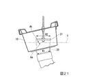
また、図21に示す第4変形例のように、落し口部20を傾ける一方で蓋部材21を水平とし、落し口部20の水平面Tへの投影面積Aaが蓋部材21の水平面Tへの投影面積Abよりも大きくなるようにしてもよい。この場合、蓋直径R2は落し口部20の開口外径R1と同じでもよい。
Further, as in the fourth modification shown in FIG. 21, the
なお、本実施の形態では、蓋部材21の上面21bが平面になっているが、例えば平面視で中央部分が上に突となる緩やかな球面に形成されていてもよい。この場合には蓋部材21の上面21bに水や異物が溜まることを防止することができる。
In the present embodiment, the
また、軒樋10、竪樋11、呼び樋12等の形状、各部の寸法、材質等の構成は、上述した実施の形態に限定されることはなく、適宜な範囲で設定することができる。例えば、呼び樋12を水平に配設したが、斜め下向きに傾斜させてもよい。
Further, the configuration of the shapes of the
例えば、図22〜図24に示す変形例のような上述した実施の形態とは異なるじょうご(軒樋)にも、本願発明の蓋部材からなる排水部材を採用することができる。
すなわち、図22に示す第5変形例の第1じょうご10Bは、底面10aより下方に凹んだ第1凹部10dが形成された洋風じょうご型のものである。この場合の蓋部材50は、竪樋11の直上の位置で、かつ第1凹部10dが形成されていない底面10aから上方に10〜50mmの高さHの位置に設けられている。
For example, a drainage member made of the lid member of the present invention can be adopted for a funnel (eave gutter) different from the above-described embodiment such as the modified example shown in FIGS. 22 to 24.
That is, the
図23に示す第6変形例の第2じょうご10Cは、底面10aより下方に凹み上述した第1凹部10dよりも深さが浅い第2凹部10eが形成された軒チーズ型のものである。
この場合の蓋部材50は、竪樋11の直上の位置で、かつ第2凹部10eが形成されていない底面10aから上方に10〜50mmの高さHの位置に設けられている。
The second funnel 10C of the sixth modification shown in FIG. 23 is an eaves cheese type having a
In this case, the
図24に示す第7変形例の第3じょうご10Dは、底面10aより下方に凹み上述した第1凹部10dよりもさらに深さが深い第3凹部10fが形成されたものである。この場合の蓋部材50もまた、竪樋11の直上の位置で、かつ第3凹部10fが形成されていない底面10aから上方に10〜50mmの高さHの位置に設けられている。
The
また、本発明の趣旨を逸脱しない範囲で、上記した実施の形態における構成要素を周知の構成要素に置き換えることは適宜可能である。 Further, it is possible to replace the components in the above-described embodiment with well-known components as appropriate without departing from the spirit of the present invention.
1 雨樋
2 サイフォンドレン部材(排水部材)
2A 流入開口
10 軒樋
10A、10B、10C、10D じょうご
10a 底面
10b 貫通穴
11 竪樋
12 呼び樋
20 落し口部
21 蓋部材
22 装着筒
23 縦リブ
24 把持リブ
25 誘導ガイド
40 蓋部材
O ドレン軸
R1 落し口部の開口外径
R2 蓋直径
A1 落し口部の開口面積
A2 蓋面積
W 雨水
1
2A Inflow opening 10
Claims (6)
前記落し口部を形成する筒部と、前記筒部の上端から径方向の外側に延びる板状の鍔部と、前記鍔部に設けられた複数の縦リブと、を有する装着筒と、
前記軒樋の内側で、前記底面から上方に離間した位置に設置されるとともに、前記底面との間に前記軒樋内の雨水を落し口へ流入させる流入開口を形成する蓋部材と、
を有し、
前記筒部と前記鍔部との接続部分はテーパー面、或いは曲面に形成され、
前記鍔部の外周側の下面には、前記軒樋の底面上に係止される段差部を備え、
前記蓋部材は、前記落し口部の上方に配置され、
前記蓋部材の下面には、誘導ガイドが形成され、
前記蓋部材の前記底面からの高さHが10mm以上50mm以下であり、
前記落し口部の開口面積は、30cm2以上190cm2以下であり、
前記蓋部材の高さHに対する前記落し口部の開口外径R1の比率であるR1/Hが1.5〜5.5であり、
前記蓋部材の蓋直径R2が、前記開口外径R1より大きく、かつ前記開口外径R1の245%以下であることを特徴とする排水部材。 A drainage member provided in a rain gutter provided with an eaves gutter and a gutter connected to a drop opening forming an opening on the bottom surface side of the eaves gutter.
A mounting cylinder having a cylinder portion forming the drop opening portion, a plate-shaped collar portion extending radially outward from the upper end of the cylinder portion, and a plurality of vertical ribs provided on the collar portion.
A lid member that is installed inside the eaves gutter at a position separated upward from the bottom surface and forms an inflow opening that allows rainwater in the eaves gutter to drop and flow into the opening between the eaves gutter and the bottom surface.
Have,
The connecting portion between the tubular portion and the flange portion is formed on a tapered surface or a curved surface.
The lower surface of the collar portion on the outer peripheral side is provided with a step portion that is locked on the bottom surface of the eaves gutter.
The lid member is arranged above the drop opening portion.
A guide guide is formed on the lower surface of the lid member.
The height H of the lid member from the bottom surface is 10 mm or more and 50 mm or less.
The opening area of the drop opening is 30 cm 2 or more and 190 cm 2 or less.
Wherein the ratio of the open outer diameter R1 of the chute portion to the height H is R1 / H of the lid member Ri der 1.5-5.5,
A drainage member having a lid diameter R2 of the lid member larger than the opening outer diameter R1 and 245% or less of the opening outer diameter R1.
前記軒樋の底面に設置された請求項1乃至3のいずれか1項に記載の排水部材と、
前記軒樋の底部から下方に突出した前記装着筒に接続される竪樋継手と、
前記竪樋継手に接続された第1エルボと、
前記竪樋継手に前記第1エルボを介して接続される呼び樋と、
前記呼び樋に接続された第2エルボと、
前記呼び樋に前記第2エルボを介して接続される竪樋と、
を備える雨樋であって、
前記竪樋の長さは2.0m以上であることを特徴とする雨樋。 Eaves gutter and
The drainage member according to any one of claims 1 to 3 installed on the bottom surface of the eaves gutter, and the drainage member.
A gutter joint connected to the mounting cylinder protruding downward from the bottom of the eaves gutter, and
The first elbow connected to the gutter joint and
A gutter connected to the gutter joint via the first elbow, and a gutter.
The second elbow connected to the gutter and
A gutter connected to the gutter via the second elbow, and
It is a rain gutter equipped with
A rain gutter characterized in that the length of the gutter is 2.0 m or more.
前記第1および第2エルボの管軸を含む断面で見たときの前記曲管部の内周側の内壁面の曲率半径は少なくとも64mmより大きく、且つ125mmよりも小さいことを特徴とする、請求項4に記載の雨樋。 The first elbow and the second elbow have sockets provided at both ends of the curved pipe portion, and have sockets provided at both ends.
A claim that the radius of curvature of the inner wall surface on the inner peripheral side of the curved pipe portion when viewed in a cross section including the pipe shafts of the first and second elbows is at least 64 mm and smaller than 125 mm. Item 4 The rain gutter.
Priority Applications (3)
| Application Number | Priority Date | Filing Date | Title |
|---|---|---|---|
| JP2021070949A JP7284778B2 (en) | 2017-06-22 | 2021-04-20 | Drainage members and rain gutters |
| JP2022140664A JP7239774B2 (en) | 2017-06-22 | 2022-09-05 | Drainage materials and rain gutters |
| JP2023019263A JP2023053162A (en) | 2017-06-22 | 2023-02-10 | Drainage member and rain gutter |
Applications Claiming Priority (2)
| Application Number | Priority Date | Filing Date | Title |
|---|---|---|---|
| JP2017122377 | 2017-06-22 | ||
| JP2017122377 | 2017-06-22 |
Related Child Applications (1)
| Application Number | Title | Priority Date | Filing Date |
|---|---|---|---|
| JP2021070949A Division JP7284778B2 (en) | 2017-06-22 | 2021-04-20 | Drainage members and rain gutters |
Publications (3)
| Publication Number | Publication Date |
|---|---|
| JP2019007340A JP2019007340A (en) | 2019-01-17 |
| JP2019007340A5 JP2019007340A5 (en) | 2020-07-16 |
| JP6873947B2 true JP6873947B2 (en) | 2021-05-19 |
Family
ID=65029356
Family Applications (4)
| Application Number | Title | Priority Date | Filing Date |
|---|---|---|---|
| JP2018119246A Active JP6873947B2 (en) | 2017-06-22 | 2018-06-22 | Drainage members and gutters |
| JP2021070949A Active JP7284778B2 (en) | 2017-06-22 | 2021-04-20 | Drainage members and rain gutters |
| JP2022140664A Active JP7239774B2 (en) | 2017-06-22 | 2022-09-05 | Drainage materials and rain gutters |
| JP2023019263A Pending JP2023053162A (en) | 2017-06-22 | 2023-02-10 | Drainage member and rain gutter |
Family Applications After (3)
| Application Number | Title | Priority Date | Filing Date |
|---|---|---|---|
| JP2021070949A Active JP7284778B2 (en) | 2017-06-22 | 2021-04-20 | Drainage members and rain gutters |
| JP2022140664A Active JP7239774B2 (en) | 2017-06-22 | 2022-09-05 | Drainage materials and rain gutters |
| JP2023019263A Pending JP2023053162A (en) | 2017-06-22 | 2023-02-10 | Drainage member and rain gutter |
Country Status (1)
| Country | Link |
|---|---|
| JP (4) | JP6873947B2 (en) |
Families Citing this family (4)
| Publication number | Priority date | Publication date | Assignee | Title |
|---|---|---|---|---|
| JP6873947B2 (en) * | 2017-06-22 | 2021-05-19 | 積水化学工業株式会社 | Drainage members and gutters |
| JP7262308B2 (en) * | 2019-05-31 | 2023-04-21 | 積水化学工業株式会社 | drainage system |
| JP7262309B2 (en) | 2019-05-31 | 2023-04-21 | 積水化学工業株式会社 | drainage system |
| DE112022002454T5 (en) | 2021-06-29 | 2024-02-22 | Tohoku University | Film for folding batteries, folding battery and method for producing a folding battery |
Family Cites Families (4)
| Publication number | Priority date | Publication date | Assignee | Title |
|---|---|---|---|---|
| JP4130616B2 (en) * | 2003-02-21 | 2008-08-06 | タキロン株式会社 | Siphon rainwater drainage system |
| CN2908643Y (en) * | 2006-04-14 | 2007-06-06 | 伍栩闻 | Anti-block diversion syphon drainage dipper |
| JP5828066B2 (en) * | 2010-12-21 | 2015-12-02 | パナソニックIpマネジメント株式会社 | Gutter structure |
| JP6873947B2 (en) | 2017-06-22 | 2021-05-19 | 積水化学工業株式会社 | Drainage members and gutters |
-
2018
- 2018-06-22 JP JP2018119246A patent/JP6873947B2/en active Active
-
2021
- 2021-04-20 JP JP2021070949A patent/JP7284778B2/en active Active
-
2022
- 2022-09-05 JP JP2022140664A patent/JP7239774B2/en active Active
-
2023
- 2023-02-10 JP JP2023019263A patent/JP2023053162A/en active Pending
Also Published As
| Publication number | Publication date |
|---|---|
| JP7239774B2 (en) | 2023-03-14 |
| JP2023053162A (en) | 2023-04-12 |
| JP2019007340A (en) | 2019-01-17 |
| JP2021107684A (en) | 2021-07-29 |
| JP7284778B2 (en) | 2023-05-31 |
| JP2022164917A (en) | 2022-10-27 |
Similar Documents
| Publication | Publication Date | Title |
|---|---|---|
| JP6873947B2 (en) | Drainage members and gutters | |
| US8286390B2 (en) | Removable downspout for a gutter system | |
| JP6279795B1 (en) | Drainage member | |
| EP3303724B1 (en) | Cover for water flow inlet | |
| JP2019007340A5 (en) | Drainage member and rain gutter | |
| JP6908537B2 (en) | Drainage member | |
| JP2016194214A (en) | Rainwater drainage system | |
| JP5616568B2 (en) | Leg joint and drainage system using the leg joint | |
| JP6835995B1 (en) | Rain gutter system | |
| JP5117043B2 (en) | Rainwater flow facilitator for vertical pipes | |
| JP2020197030A (en) | Drainage system | |
| US20170121978A1 (en) | Water Directing Apparatus | |
| JP6789359B1 (en) | Rainwater drainage piping structure | |
| AU2006100723A4 (en) | Rainhead Arrangement | |
| JP5601784B2 (en) | Drain trap device | |
| JP3322963B2 (en) | Drainage pipe | |
| JP4471712B2 (en) | Pipe for drainage | |
| JP2009062701A (en) | Gutter piping system | |
| JP2002348926A (en) | Drain system | |
| JP6253351B2 (en) | Leg bend pipe and drainage pipe structure using the same | |
| JP2022077075A (en) | Rain gutter system | |
| JP4747147B2 (en) | Eaves drain | |
| JP2022183812A (en) | Eaves gutter structure | |
| JP2021123846A (en) | Rain gutter system | |
| JP7188931B2 (en) | rainwater drainage |
Legal Events
| Date | Code | Title | Description |
|---|---|---|---|
| A80 | Written request to apply exceptions to lack of novelty of invention |
Free format text: JAPANESE INTERMEDIATE CODE: A80 Effective date: 20180719 |
|
| A521 | Request for written amendment filed |
Free format text: JAPANESE INTERMEDIATE CODE: A523 Effective date: 20200601 |
|
| A621 | Written request for application examination |
Free format text: JAPANESE INTERMEDIATE CODE: A621 Effective date: 20200601 |
|
| A871 | Explanation of circumstances concerning accelerated examination |
Free format text: JAPANESE INTERMEDIATE CODE: A871 Effective date: 20200601 |
|
| A975 | Report on accelerated examination |
Free format text: JAPANESE INTERMEDIATE CODE: A971005 Effective date: 20200702 |
|
| A131 | Notification of reasons for refusal |
Free format text: JAPANESE INTERMEDIATE CODE: A131 Effective date: 20200707 |
|
| A521 | Request for written amendment filed |
Free format text: JAPANESE INTERMEDIATE CODE: A523 Effective date: 20200902 |
|
| A131 | Notification of reasons for refusal |
Free format text: JAPANESE INTERMEDIATE CODE: A131 Effective date: 20200923 |
|
| A521 | Request for written amendment filed |
Free format text: JAPANESE INTERMEDIATE CODE: A523 Effective date: 20201120 |
|
| A131 | Notification of reasons for refusal |
Free format text: JAPANESE INTERMEDIATE CODE: A131 Effective date: 20201215 |
|
| A521 | Request for written amendment filed |
Free format text: JAPANESE INTERMEDIATE CODE: A523 Effective date: 20210215 |
|
| TRDD | Decision of grant or rejection written | ||
| A01 | Written decision to grant a patent or to grant a registration (utility model) |
Free format text: JAPANESE INTERMEDIATE CODE: A01 Effective date: 20210323 |
|
| A61 | First payment of annual fees (during grant procedure) |
Free format text: JAPANESE INTERMEDIATE CODE: A61 Effective date: 20210421 |
|
| R150 | Certificate of patent or registration of utility model |
Ref document number: 6873947 Country of ref document: JP Free format text: JAPANESE INTERMEDIATE CODE: R150 |